D VEHICLE - Citroen klub Slovenije
450
DTAV ( TECHNICAL ASSISTANCE) REPAIR MANUAL NO814 VOLUME I MARCH 1974 D VEHICLE (D vehicles all types produced since september 1965) CHARACTERISTICS ADJUSTMENTS CHECKS PRINTED IN FRANCE SOCIETE ANONYME AUTOMOBILES CITROEN CAPITAL 600 000 000 F - HEAD OFFICE 117 to 167. QUAI ANDRE CITROEN 75015 PARIS - R C SEINE 6 4 B 5019 DTAV (TECHNICAL ASSISTANCE - 163. Av Georges Clemenceau - 92000 NANTERRE FRANCE - TeI 204 - 40 - 00 Extens~on 577 and 578 CITROEN CARS Ltd - SLOUGH - BUCKS GREAT BRITAIN
-
Upload
khangminh22 -
Category
Documents
-
view
0 -
download
0
Transcript of D VEHICLE - Citroen klub Slovenije

D T A V
( TECHNICAL ASSISTANCE)
R E P A I R M A N U A L N O 8 1 4
VOLUME I
MARCH 1974
D VEHICLE ( D vehicles all types produced
since september 1965)
CHARACTERISTICS
ADJUSTMENTS
CHECKS
PRINTED I N FRANCE
SOCIETE ANONYME AUTOMOBILES CITROEN
CAPITAL 6 0 0 0 0 0 0 0 0 F - HEAD OFFICE 117 t o 1 6 7 . QUAI ANDRE CITROEN 75015 PARIS - R C SEINE 6 4 B 5019
DTAV (TECHNICAL ASSISTANCE - 1 6 3 . Av Georges Clemenceau - 9 2 0 0 0 NANTERRE FRANCE - TeI 2 0 4 -4 0 -0 0 Ex tens~on 577 and 578
CITROEN CARS L t d - SLOUGH - BUCKS GREAT BRITAIN

USING THE MANUAL
PRESENTATION
To facilitate the use of the Manual we have arranged the repair operations into two
volumes :
- Volume 1 contains :
- the CHARACTERISTICS - ADJUSTMENTS - CHECKS necessary at all repair work- shops for adjustment or simple repairs.
- Volume II contains the operations of:
- DISMANTLING and ASSEMBLING.
- RECONDITIONING.
- ELECTRICAL SYSTEM - HEATING - AIR CONDITIONING.
- BODYWORK.
Each volume is sold separately and it is presented in a red Fibrex with a ” MULTO ”type clasp to facilitate adding amendments or taking out an operation needed by the repairworkshop.
COMPOSITION
Each volume contains :
- a list of the operations appearing in the volume.
- the operations arranged in numerical order
- a list of all the tools mentioned in the operations and drawings for making the specialtools that are not sold but that can be made by the repairer himself.
OPERATIONS
The operation sequence has been compiled to ensure the best quality of work in theshortest possible time,
The numbers of the operations are composed of :
a) letters indicating the vehicle :
- “D” concerns operations on D of all types (DTT)
- “D h” concerns operations on vehicles equipped with hylaudric gear-change
- “D m” concerns operations on vehicles equipped with a manual gear-change
- “DbW” concerns operations on vehicles equipped with automatic gear-change (DBW)
- “D.I.E.” concerns operations on vehicles equipped with Electronic Fuel Injection
(D.I.E. -operations are printed on pink paper).
- “DX” “DY” “DV” “DT”, etc... concern operations on these types of vehicles only.

b) a number with three figures indicating the unit or unit component.
c) a figure indicating the nature of the section.- figures 0 0 0 indicate the characteristics of the vehicle- figures 0 0 indicate the characteristics of the unit- figure 0 indicate checks and adjustment- figures 1 4 7 indicate the removal and fitting- figures 2 5 8 indicate stripping down and reassembly- figures 3 6 9 indicate reconditioningThe arrows corresponding to the operation list marks allow the required operation to be
found quickly.
TOOLS
Special tools are indicated in the text by a number followed by the letter T.These tools are sold by :- Etablissements FENWICK Department AMA 24 Bd. Biron - 93404 St Ouen FRANCEAdditional tools are indicated in the text by a number preceded by the letters MR.The drawings for making these tools, arranged in numerical order, occur at the end ofeach volume.
TIGHTENING TORQUES
These torques are expressed in :- Metre-Newtons (m Λ N) , the legal in France- Metre-Kilogramme (mkg), since most torsion-spanners in current use are so graduated
1 mkg = 9.81 m Λ N exactly
The figures quoted are “rounded off”, taking 1 mkg at 10m Λ N, thus :
2 m Λ N is taken to equal 0.2 mkg ( 1.4 ft. lbs)
60 m Λ N is taken to equal 6 mkg ( 43 ft. lbs)- Foot pounds (ft. lbs) converted at 7.22 ft. lbs = 1 mkg, and rounded off to practical
figures.
Important . When a tightening torque figure is followed by the words “torsion spanner”,the operation must of necessity be carried out with a torsion spanner.
ADVISORY SERVICE
For all technical information concerning these vehicles, please contact :- The Service Department,
Citroen Cars Limited,SLOUGH - BUCKS - GREAT - BRITAIN
or :- Département Technique Après-Vente
Assistance technique163, Avenue G. Clémenceau92000 NANTERRE - FRANCE

LIST OF OPERATIONS SHOWN IN VOLUME No 1 OF MANUAL814 Vehic les D «all types», except IE
DESCRIPTION
CHARACTERISTICS
General characterist ics (general dimensions, various capaci t ies ) Protection of the electr ical units Work on the hydraulic s y s tem (precautions) Ingredients recommended
ENGINE - CARBURATION - IGNITION
Engine characterist ics Adjusting the valve rocker c learances Adjusting the engine mountings (engine removed) Characterist ics and particular features of carburettors Adjusting the carburettors and controls
- Basic adjustments (vehic les with hydraulic gearchange) - Idling adjustment (vehic les with manual gearchange) - Accelerator control adjustment
Idling adjustment (Borg Warner) Checking and adjusting the petrol pump
- Adjusting the output - Checking the pressure - Checking for l eaks
Characterist ics and particular fea tures of the ignition (distr ibutors, sparking plugs, coils) Checking and adjusting the ignition
- Adjusting the ini t ial s t a t i c se t t ing
- Principle of the method for measuring advance with a stroboscopic lamp - Adjusting the ignition se t t ing by stroboscopic lamp - Adjusting the ignition set t ing by stroboscopic lamp with dephaser - Test-bench check of a distributor - Cleaning and adjusting the sparking plugs - Checking a coil
Checking the oil pressure on the vehicle Checking the cooling system (thermostat) Adjustments of pulleys and be l t s
- Alignment of t he pulleys - Belt tens ions
Characterist ics and control of clutch 10/1972Characterist ics and control of clutch 10/1972 Checks and adjustments on clutch control (vehic les with hydraulic gearchange)
- Checking for l eaks in the clutch cylinder - Bleeding the centrifugal regulator - Checking clutch disengagement - Checking the clutch engagement pressure - Checking the pressure supplied by the hydraulic se lec tor
Checking and adjust ing the clutch control (vehic les with m a n u a l gearchange) - Simple pedal gear 9/1968 - Pedal gear with over-centre spring 9 / 1 9 6 8
Characterist ics and particular points of torque converter

LIST OF OPE RATIONS SHOWN IN VOLUME No 1 OF MANUAL814
Vehicles D o all t y p e s ,
Operation Number
DESCRIPTION
GEARBOX @ Charac te r i s t i cs and part icular features of the gearbox. Checking and a d j u s t i n g the gear control ( V e h i c l e s w i t h h y d r a u l i c gearchange I
- Adjust ing t h e gear engagement s t roke - Checking a c lu tch re-engagement lock - Adjust ing a c l u t c h re-engagement l o c k
Checking and a d j u s t i n g t h e gear control (Vehicles with manual gearchange) - Adjust ing t h e fourth gear engagement s t roke
Charac te r i s t i cs a n d part icular fea tures of the f ive- speed gearbox Checking and a d j u s t i n g the g e a r control ( f ice-speed gearbox, see operatiorr l)rn.33 1-01 Charac te r i s t i cs a n d part icular points of automatic gearbox Pr inc ip les of hydraul ical ly controlled gearchange o n automatic gearbox Checking and a d j u s t i n g t h e gearchange control
- Adjust ing t h e brake bands - Adjus t ing t h e (( kick-down)) c a b l e - Adjus t ing t h e se lec tor - Adjus t ing s w i t c h e s of s ta r te r motor and revers ing l ights - Road c h e c k s - Checkinq the pressure of the o i l in the gearchange control circuit.
T RANSMI SSION @ C h a r a c t e r i s t i c s and particular fea tures of t h e dr ive-shafts Checking and ad jus t ing the dr ive-shafts
- Adjust ing t h e end f loat of t h e c ross-heads
SOURCE AND RESERVE OF PRESSURE @ Charac te r i s t i cs and particular fea tures of t h e source and rese rve of p r e s s u r e Checking t h e hydraul ic un i t s on the v e h i c l e s (P'crhicles DV.131') Checking a s u s p e n s i o n sphere
FRONT AXLE @ C h a r a c t e r i s t i c s and part icular fea tures of t h e front a x l e Checking and ad jus t ing t h e front a x l e
- Adjust ing t h e camber - Adjust ing t h e wheel alignment
REAR AXLE @ C h a r a c t e r i s t i c s and part icular fea tures of t h e rear a x l e
C h a r a c t e r i s t i c s and part icular f e a t u r e s of t h e s u s p e n s i o n Checking and ad jus t ing t h e suspens ion and i t s con t ro l s
- Ini t ia l s e t t i n g of car he igh ts - Adjust ing t h e ca r he igh ts - Adjust ing t h e front anti-roll bar - Adjust inq t h e manual heiqht control
STEERING @ C h a r a c t e r i s t i c s and ~ a r t i c u ' l a r f e a t u r e s of t h e s tee r ing (power-steering and manual
s tee r ing) . Checking and ad jus t ing the s tee r ing
- Adjus t ing t h e la te ra l posi t ion of t h e s t e e r i n g - Adjus t ing the s tee r ing lock - Adjus t ing t h e angular posi t ion Power -s tee r ing
- Adjus t ing t h e s t raight -ahead s t e e r i n g - Adjust ing the crossover p ressure
Adjust ing the s t ra igh t ahead s tee r ing pos i t i an on power-steering

LIST OF OPERATIONS SHOWN I N VOLUME N o 1 OF MANUAL814 Vehic les a D B All types , except IE
Operation
Number F DESCRIPTION
BRAKES @ Charac te r i s t i cs and part icular f e a t u r e s of the brake sys tem Checking and ad jus t ing t h e brake u n i t s Checking and ad jus t ing the brake control
- Bleeding t h e c i r c u i t s - P e d a l gear control ('411 types except DV.DT) - Control by meter ing v a l v e (DV.DT)
Checking and ad jus t ing t h e parking brake
ELECTRICAL SYSTEM @ Arrangement of t h e e lec t r ica l s y s t e m (DY.DJ 9/ 190 7- 9 / 1966) Arrangement of the e l e c t r i c a l s y s t e m (DY-DL-DE 9/ 196 5- 9 / 1966) Arrangement of t h e e l e c t r i c a l s y s t e m (Dl-Dl-DY-DL 9 /1966- .1 )19 / 1967) Arrangement of the e l e c t r i c a l system(1)v 9 / 1966 -* 9/ 1967)
Arrangement of t h e e l e c t r i c a l s y s t e m (DA-D/-DY-DL - 9/ 1967-+12/ 1967) Arrangement of t h e e l e c t r i c a l s y s t e m (DV T 9 / 1 9 6 7 4 2/ 1967) Arrangement of the e l e c t r i c a l s y s t e m (All t y p e s ) -1 2/ 1967 +lo/ 19681
Arrangement of t h e e lec t r ica l s y s t e m (DX-Dl -10 1968 + 1/1969) Arrangement of t h e e lec t r ica l s y s t e m (DY-DL-D V-DT- 9 / 1963 -1/ 1969)
Arrangement of the e l e c t r i c a l s y s t e m (DX-Dl C--, I / 1969 -9,'1969 Arranqement of t h e e l e c t r i c a l s y s t e m (DX-DL 1 / 1969'. 9 / 1969 Arrangement of t h e e l e c t r i c a l s y s t e m (Al l types - 9 1 1969) Arrangement of t h e e l e c t r i c a l s y s t e m (DJ-DT-DV * 4/ 1971)
Arrangement of the e l e c t r i c a l s y s t e m (Manual gearchange -9/1971) Arrangement of t h e e lec t r ica l s y s t e m (Hydraulic gearchangec t9 / 1971) Arrangement of t h e e l e c t r i c a l s y s t e m (Borg Warner) Elec t r ica l sys tem of air condit ioning Charac te r i s t i cs and c h e c k s of e l e c t r i c a l u n i t s (dynamo, al ternator , regulator, s t a r te r motor)
- Checking an al ternator - Checking a regulator - Adjust ing s ta r te r motor control pinion
Adjustments of head lamps and cont ro l s ( A l l t y p e s ) W 9 / 1 9 6 7 - Self-levelling control - Directional control
Adjustments of head lamps and cont ro l s IDX-I)JI * 9/ '1967 Adjustments of head lamps ( f ixed)
- All t y p e s excep t DX-DJ- 9 /1967 - All t y p e s 9.'1967
Checking and ad jus t ing t h e windscreen wipers. Charac te r i s t i cs and part icular p o i n t s of a ir conditioning sys tem Checking and ad jus t ing t h e air condit ioning sys tem
- Fi l l ing t h e a i r condit ioning c i rcu i t
BODYWORK @ Interior d imens ions Adjustments on body ~ a n e l s Adjust ing the doors Adjust ing t h e bonnet ( lock ing and u'rilocking)
Checkinq and repair ing of t h e h e a t e d rear window
TOOLS @ L i s t of s p e c i a l too l s appear ing in t h i s volume. Drawings for marking t o o l s recommended for repairs .

LIST OF OPERATIONS SHOWN IN VOLUME No 1 OF MANUAL814
DS 21 vehicles with Electronic Fuel Iniection(DX.1E and DJ.IE)
The operations for this type of vehicle alone have been covered.
For operations that do not appear on the l i s t below, refer to the l i s t of operations relating to "Dm vehicles a l l types.
Operation Numbers
DESCRIPTION
CHARACTERISTICS 0 Cenod characteristics - (See Op.D,. 000)
ENGINE - FUEL-SUPPLY - IGNITION @ Engine characteristics Adjusting the valve rocker clearances Basic adjustments (vehicles with hydraulic gearchange) Adjusting the idling (vehic les with manual ,gearchange) Idling adjustment (6w.lE vehic les) Charaaer is t ics of the electronic fuel injection device Checking the electronic fuel injection device (Citroen Tes ter 1494) Checking the electronic fuel injection device (Bosch Tester EFAV 22&S-11) Checking and adjusting the ignition Characteristics of fuel supply
- Adjusting the distributor a t init ial setting - Checking a distributor on test-bench - Adjustment of ignition sett ing with stroboscopic lamp. - Adjustment of ignition sett ing with stroboscopic lamp with dephaser - Cleaning and adjusting the sparking plugs 1 See Op. 0.-210-0 - Checking a coil
CLUTCH @ Characteristics and checks on the clutch. -lo/ 1972 Characteristics and checks on the clutch ' l o / 1972 (See Op. D. 312-CO a)
SUSPENSION @
Characteristics and particular features of the suspension
ELECTRICAL SYSTEM @ Arrangement of the electrical installation ( see Op. D,%. 510-00 /) Arrangement of the electrical installation (DI . IE -41' 1971 ( s e e Op. Dm 510-00) Arrangement of the electrical installation of the electronic fuel injection device D.IE All T y p e s +3/ 1970 Arrangement of the electrical installation of the electronic fuel injection device D.IE 411 Types -3/ 1970 - 4 / 1971 Arrangement of the electrical installation of the electronic fuel injection device D Y J E -4/1971 Arrangement of the electrical installation of the electronic fuel injection device Dl.1E -4/ 1971

OPERATION NO D. 000 : General characteristics Op. D. 000 1
:TERISTICS
Official Commercial
I. GENERAL CHAR.
General Symbols
ENGINE Fiscal rating Cubic capacity Gearbox ratios
TYPE - BRAKE HORSEPOWER - TORQUE Bore - Stroke (french) I Introduced Symbols
DS 21 DS 21 Ct l0/1965 Hydraulic 10/1972
DX 4 10/1968 ~ D X 2 (21 N) b 10/1968 100 CV DIN AT 5500:RPM 1 106 CV DIN AT 5500 RPM
2.175 cc 90 x 85,5 mm
16.7MG(121 FT LBSI A T ~ ~ M ~ R P M ( D I N ) ! L7MKG(123FTLBS)AT3500RPM(DIN) 4 gears
Ds21 I DS 21 k 10/1971 Automatic 4 10/1972
DX 2 (21 N) 106 CV DIN AT 5500 RPM 17 MKG (123 FT LBS) AT 3500 RPM (DIN)
3 gears
DS 23 DS 23 10/1972 Serie FE Hydraulic
DX 4 (19 N) 115 CV DIN AT 5500 RPM 2,.350 cc 18,s MKG (133 FT LBS) HT 3500 RPM (DIN) 93,5 x 85.5 mm 4 gears 13 CV
DS 23 DS 23 k 10/1972 Serie FE Automatic
DX 4 (19 N) 115 CV DIN AT 5500 RPM 18,s MKG (133 FT'LBS) AT 3500 RPM (DIN)
3 gears
DS DS 21
serie FA Electronic injection k+ 10/ 1969 4 10/1972
Hydraulic
DX 3 (12 N) 125 CV DIN AT 5250 RPM 18.7 MKG(135 FT LBS) AT 2500 RPM (DIN) 4 gems
DS DS 21
Electmnic injection k 10/1971
Serie FA 4 10/1972 Hydraulic
DX 3 (12 N) 125 CV DIN AT 5250 RPM 18.7MKG (135 FT LBS) AT 2500 RPM (DIN)
3 gears
DS 23 DS 23 Electronic injection k 10/1972
Serie FG Hydraulic DX 5 429 N) 130. CV DIN AT 5250 RPM
19,9 MKG (144 FT LBS) AT 2500 RPM (Dl N ) 4 gears
DS 23 DS 23
Electronic injection 10/1972 Serie FG Automatic
DX 5 (29 N) 130 CV DIN AT 5250 RPM 19.9 MKG (144FT LBS) AT 2500 RPM (DIN)
3 gears
ID 21 Break 21 CL 2/1968 Serie FH Hydraulic 4 10/1972
DS Break 23 k 10/1972 Serie F F Hydraulic
DX 2 (21 N ) 106 CV DIN AT 5500 RPM 2.175 cc 17 MKG (123 FT LBS) AT 3500 RPM (DIN) 90. x 85,5 mm 5 gears 12 CV
DX 4 (19 N) 115 CV DIN AT 5500 RPM 2.350 cc 18.5 MKG (133 FT LBS) AT 3500 RPM (DIN)
5 gems 93.5 x 85,5 mm
13 CV
DS 21 DS 21 b 10/1965 Serie M Mechanical 4 10/1972
DX 10/1968 I DX 2 (21 N) I-+ 10/1968 2.175 cc 4 10/1970 4 gears 100 CV DIN AT 5500 RPM 1 106 CV DIN AT 5500 RPM 90 X RS.5.mm I-- 10L1970 5 aears I 12CV
--,- 16.7MKG(lZlFTLBS) AT3il3ORPM(DIN) i 17MKG(123 FTLBS) AT3WORPU(DIN)
DX 3 (12 N) 125 CV DIN AT 5500 RPM 2.175 cc 4 10/ 1970 4 gears 18.7 MKG (135 FT LBS) AT 2500 RPM (DIN) 90 x 85,s mm
12 cv 10/ 1970 5 gears
DS DS 21
Electronic injection + 10/1969 Serie FB Mechanical 4 10/1972
DS I 10/1972 Serie FE Mechanical
DX 4 (19 N) 115 CV DIN' AT 5500 RPM 18.5 MKG (133 FT LBS) AT 3500 RPM (DIN)
5 gears
DS Electronic injection k 10/1972 Serie FG Mechanical
DX 5 (29 N) 130 CV DIN AT 5500 RPM 19.9 MKG (144 FT LBS) AT 2500 RPM (DIN)
DX 4 10/1965 i DX 2 (21 N) t-- 10/1968 2.1.75 c c 100 .CV DIN AT 5500 RPM 106 CV DIN AT 5500 RPM 90 X 85,5 mm 4 gears 12 CV
16.7 MKG(121FTLBS) AT3M)O RPMDIN) !17 W G ( ~ ~ ~ F T L B S ) A T ~ ~ R P M ( D I N )
Break 21 I Cc 10/1965 Serie F Mechanical 4 10/1972
I I
DS Break 23 b 10/1972 Serie FF Mechanical
I I I I
DX 4 (19 N) 115 .C'J DIN AT 5500.RPM 2.350 cc 18.5 MKG (133 FT LBS) AT 3500 RPM (DIN) 4 gears 93 ~ ' 8 5 . 5 mm

OPERATION W D. 000 : General characteristics Op. D. 000
Official Commercial General Symbols I synboIs 1 symbols
ENGINE Cubic capacity Gearbox ratios
-. -1sca1 rotin!
(French) MAXIMUM TORQUE
DS 19 DS 19 Serie A Hydraulic
DY 84 CV DIN AT 5250 RPM 14.6 MKG 1106 LBSl AT 3500 RPM (DIN)
1,985 cc 86 X 85,5 mm I 4 gears
DY 2 4 10/ 1971 DY 3 (17 N) I-+ 10/1971 91 CV DIN AT 5900 RPM 99 CV DIN AT 5500 RPM
14.4MKU104 FT LBS) AT 3500RPM(DIN) 15.lMKG(11OFT LBS)AT3500RPM(DIN)
DY -4 10/ 1968 DY 2 b 10/1968 84 CV DIN AT 5250 RPM 91 CV DIN AT 5900 RPM
14.6MKG(106FT LBS) AT 3500RPM(DIN) 14.4MKG(104FT LBS)AT3500RPM(DIN:
1.985 cc 86 x 85,s mm 4 gears
ID 20 Break 20 Serie FH Hydrrrulic
1,985 cc 86 x 85.5 mm
DY 2 91 CV DIN AT 5900 RPM 14.4 MKG (104 FT LBS) AT 3500 RPM (DIN)
4 gears
DY 84 CV DIN AT 5250 RPM 14.6 MKG (106 FT LBS) AT 3500 RPM (DIN)
1,985 cc 86 X 85;5 mm
1,985 cc 86 x 85,s mm I 4 gears
4 gears
DY 2 91 CV DIN AT 5900 RPM 14.4 MKG (104 FT LBS) AT 3500 RPM (DIN)
DY 84 CV DIN AT 5250 RPM 14.6 MKG I106 FT LBS) AT 3500 RPM (DIN)
1,985 cc I 4 gears 86 X 85.5 mm
1.985 cc 86 x 85,5 mm
I Serie A I Mechanical
4 gears
ID 20 F Break 20 Mechanical
DY 2 4 LO/ 1971 DY 3 (17 N) 10/1971 91 CV DIN AT 5900 RPM 99 CV DIN AT 5500 RPM
4 4MKG(104FT LBS)AT3500RPMIDIN) 15.1MKG{11OFT LBS)AT350ORPM(DIN
DV 4 10/1968 DV 2 + 10/1968 78 CV DIN AT 5250 RPM 81 CV DIN AT 5500 RPM
4.3MKG(104FT LBS) AT3000RPM(DIN) 13.7MKC(99FT LBSIAT 3000RPM (DIN:
1D 19 ID 19 Serie B B
1.985 cc 86 x 85,s rnrn I 4 gears
I ID 19 1 D Special DV 2 81 CV DIN AT 5500 RPM 13.7 MKG (99 FT LBS) AT 3000 RPM (DIN)
DV 3 (3 N) 89 CV DIN AT 5500 RPM 14.7 MKG (106 FT LBS) AT 2500 RPM (DIN)
1,985 cc 86 x 85,5 mm 4 gears
DS D Special SerieFD
1,985 cc 86 X 85,5 mm
DY 3 (17 N) 99 CV DIN AT 5500 RPM 15.1 MKG (110 FT LBS) AT 3500 RPM (DIN)
4 gears
DY 2 91 CV DIN AT 5900 RPM 14.4 MKG (104 FT LBS) AT 3500 RPM (DIN)
1.985 cc 86 x 85.5 mm
1,985 cc I 4 gears 86 x 85,5 mrn
4 gears
I ID 20 1 D Super DY 2 91 CV DIN AT 5900 RPM 14.4 MKG (104 FT LBS) AT 3500 RPM (DIN)
DY 2 91 CV DIN AT 5900 RPM 14.4 MKG (104 FT LBS) AT 3500 RPM (DIN)
1,985 cc I 4 gears "serie" 86 X 85,5 mm 5 gears "option"
1,985 cc 86 X 85,5 mm
DY 3 (17 N) 99 CV DIN AT 5500 RPM 15.1 MKG (110 FT LBS) AT 3500 RPM (DIN)
4 gears " serie' 10/ 1970 5 gears
"option'
1,985 cc 86 X 85,5 mm I 4 gears
DS 21 D Super 5 DX 2 (21 Nl 106 CV DIN AT 5500 RPM 17. MKG (123 FT LBS) AT 3500 RPM (DIN)

O P E R A T I O N No D, 000 : General c h a r a c t e r i s r ~ c s Op. D . 000 3
T y p e s of t y r e s and wheel r ims :
D, A L L T Y P E S l e x c e ~ t D.IE I 4 lo/ 1968 ALL TYPES ) DY-DT-DV- DL-DX 1 180 380 XAS 1 DJ-Safari-All Types- DP
- Front 180 HR 380 XAS - -
. . . . . . . . . . . . . . . . . . . . . . . . . . . . . . D.IE A L L T Y P E S . I 185 HR 380 XAS
155 HR 380 XAS 165 H R 380 XAS 180 HR 380 XAS 185 HR 380 XAS
D. A L L T Y P E S ( e x c e p t D.IE A L L T Y P E S ) and Safa r i A L L T Y P E S . . . . . . DY-DT-DV-DL . . . . . . . . . . . . . . . . . . . . . . . . . . . . . . . . DX-DJ-DP . . . . . . . . . . . . . . . . . . . . . . . . . . . . . . . . . . . - R e a r
155 x 380 XAS
Safari . . . . . . . . . . . . . . . . . . . . . . . 180 x 380 XAS D.IE A L L T Y P E S . . . . . . . . . . . . . . . :I: : . . . . . . . . . . . . D. A L L T Y P E S ( e x c e p t D J E A L L T Y P E S ) a n d Safa r i A L L T Y P E S . . . . . . .
155 HR 380 XAS 165 HR 380 XAS 180 HR 380 XAS 185 HR 380 XAS
155 x 380 XAS DY-DT-DV-DL . . . . . . . . . . . . . . . . . . . . . . . . . . . . . . . . DX-DJ-DP . . . . . . . . . . . . . . . . . . . . . . . . . . . . . . . . . . . . Safari . . . . . . . . . . . . : . . . . . . . . . . .
. . . . . . . . . . . . . . . . . . . . . . . . . . . . . D - I E A L L T Y P E S .
- Spare 180 380 XAS
- Rims
D. A L L T Y P E S ( e x c e p t D.IE A L L T Y P E S ) DY-DL-DV-DT . . . . . . . . . . . . . . . . . D.IE A L L T Y P E S - D P I 4 3/1970 1 31'1970 DY-DL-DV-DT . . . . . . . . . . . . . . . . . . . 5 5 5 1 / 2 J
Inflation pressures (in bars ) r
.5 J . . . . . . . . . . . . . . . . . . . . . . . . . . . .
0011
R e a r
25 P.I.S. (1.7)
28 P.I.S. (1.9)
5 1 / 2 J 5 1 / 2 J
Safar i Ambulance
s I
180 x 380 XAS 28 P.I.S. (1.9)
1 155 380 XAS I In jec t ion
k+ 10/ 1968 DX-DJ-DP DY-DL-DT-DV Break I Ambulance
Fron t I Reur Fron t I Rear Fron t I R e a r I F r o n t I R e a r
185 HR 380 XAS 30P.I.S 26PI.S 12.1) (1.8)
I 180 HR 380 XAS I I 1 165 HR 380 XAS I I 1 155 HR 380 XAS I I
Number of seats : D ALL T Y P E S and Commercial . . . . . . . . . . . . . . . . . . . . . . . D Fami ly and Break . . . . . . . . . . . . . . . . . . . . . . . . . . . . . . .
I I . G E N E R A L DIMENSIONS
Wheel b a s e D. All T y p e s 10 F T 3 I n s (3.125mm . . . . . . . . . . . . . . . . . . . . . . . . . . . . . . . . . . . . . . . . .
R e a r t rack DX-DJ-Break All T y p e s 4 10,' 1968 4 F T 3 3/ 16Ins + lo / 1968 4 F T 3 13/ 16 I n s DY-DV-DT I 3/ 19701 (1.300 m m i I b 3 / 1 9 7 0 1 l l 3 1 6 m m i
F r o n t t rack
D. All T y p e s e x c e p t Break All T y p e s : . . . . . . . . . . . . . . . . . . . . High pos i t ion 9 7/8 I n s (1.470mm) Break All T y p e s : . . . . . . . . . . . . . . . . . . . . . . . . . . . . . . . . 5 1/4 I n s (1.530 m m )
D X - D J - B r ~ a k All T y p e s 1 4 101 1968 4 F T 11 I n s
DY-DV-DT 4 3/ 1970 (1.500 rnrn)
Overa l l l eng th
Overa l l width
f--)- lo/ 1965
3/ 1970
D. All T y p e s e x c e p t Break Break All T y p e s
Break All T y p e s
4 F T 11 11/16Ins
(1.516 m m )
4 1 0 / 1967
-lo/
15 FT 10 1 /2 Ins (4.838 m m )
16 F T 4 11'2 I n s (4.990,rnm)
5 F T 10 1/2Ins (1.790 m m )
+ l o / 1967
tt10/1967
15 F T 11 7/8 I n s (4.874 m m )
16 FT 5 7/8Ins (5.026 m m )
5 F T 11 Ins ( l 8 0 3 m m )

4 OPERATION No D. 000 : C e n e r a l chnmctprisrirs
Ground c learance :
Low position
Normal position
1 s t intermediate position
D. All Types (except Safari a l l Types) . . . . . . . . . . . . . 2 1 / 2 Ins (0.065 m) Safari All Types 3 Ins (0.075 m) . . . . . . . . . . . . . . . . . . . . . . . . . . . D. All Types (except D.IE and Safari All Types . . . . . . . 6 Ins (0.150 m) D.IE All Types . . . . . . . . . . . . . . . . . . . . . . . . . . . . 5 1 /2 Ins (0.145 m) Safari All Types . . . . . . . . . . . . . . . . . . . . . . . . . . . 6 Ins (0.152 m)
D. All Types (except Safari All Types) . . . . . . . . . . . . 6 3 / 4 Ins (0.170 m) Safari All Types . . . . . . . . . . . . . . . . . . . . . . . . . . . 7 5/ 16 Ins (0.185 m)
2nd intermediate position
I Rear floor height I Safari All Types . . . . . . . . . . . . . . . . . . . . . . . . . . . 1 FT 6 Ins (0.458 m) I
D. All Types (except Safari All Types) . . . . . . . . . . . . 8 7 / 8 Ins (0.225 m) Safari All Types . . . . . . . . . . . . . . . . . . . . . . . . . . . 9 Ins (0.228 m)
High position
Turning radius
Weights ( C W T and Kg) :
. . . . . . . . . . . . D. All Types (except Safari All Types) 9 7 / 8 Ins (0.250 m) Safari All Types . . . . . . . . . . . . . . . . . . . . . . . . . . . 10 Ins (0.252 m)
D All Types . . . . . . . . . . . . . . . . . . . . . . . . . . . . . . 18 F T (5.500 m)
DATES
Unladen we igh t : DX . . . . . . . . . . . . . . DJ . . . . . . . . . . . . . . DX Pal las . . . . . . . . .
DL . . . . . . . . . . . . . . . . . . . . . . . DY Pal las
DL . . . . . . . . . . . . . . D v . . . . . . . . . . . . . . DT . . . . . . . . . . . . . . DP . . . . . . . . . . . . . . DXF . . . . . . . . . . . . . DJF . . . . . . . . . . . . . DYF . . . . . . . . . . . . . DLF . . . . . . . . . . . . . P a y l o a d :
DV . . . . . . . . . . . . . . DT . . . . . . . . . . . . . . DP . . . . . . . . . . . . . . DXF . . . . . . . . . . . . . DJF . . . . . . . . . . . . . DYF . . . . . . . . . . . . . DL F . . . . . . . . . . . . . Max. laden we igh t : DX-DJ-DX Pallas-DJ Pallas D.IE-D.IE P a l l a s . . . . . DY-DL-DY Pallas-DL Pallas DV . . . . . . . . . . . . . . DT . . . . . . . . . . . . . . DP . . . . . . . . . . . . . .
. . . . . . . . . . . . . DXF DJF . . . . . . . . . . . . . DYF . . . . . . . . . . . . . DLF . . . . . . . . . . . . .

OPERATION No D. 000 : General characteristics Op. D. 000 5
I l l . DIVER CAPACITIES
. . . . . . . . . . . . . . . . . . . . . . . . . . . . . . . . . . . . . . . . . . . . . . . . . . - Petrol tank. 65 l i tres (14 Galls Imp) . . . . . . . . i . . . . . . . . . . . . . . . . . . . . . . . . . . . . . . .
DX-DJ All Types ( 10/1972) - D.IE All Types 13 l i tres (23 P t s Imp) Cooling system DX-DJ All Types -DP 10.8 l i tres (19 P t s Imp)
. . . . . . . . . . . . . . . . . . . . . . . . . . . . . . . . . . DL -DY-DV-DT. 10.6 l i tres (18 i P t s Imp) . . . . . . . . . . . . . . . . . . . . . . . . . . . . . . . . . . . . . . . . - Hydraulic system (approx.). 6 l i tres (10 ;P t s I m p )
. . . . . . . . . . . . . . . . . . . . . . . . . . . . . . . . . . . . . . . . . . . . . . - Engine (draining) 4.5 l i tres (8 P t s Imp) . . . . . . . . . . . . . . . . . . . . . . . . . . . . . . . . . . . - Four speeds 2 l i tres ( 3 & P t s Imp) . . . . . . . . . . . . . . . . . . . . . . . . . . . . . . . . . . . . Gearbox(dra ining) 1 - Five speeds 2.25 l i tres ( 4 P t s Imp)
. . . . . . . . . . . . . . . . . . . . . . . . . . . . . . . . . . . . . . . - Maximum weight on roof rack 80 Kg (176 lbs) - Maximum gradient for garage access :
. . . . . . . . . . . . . . . . . . . . . . . . . . . . . . . . . . . . . . . . . . . . . . - Normal position 15 % (1 In 6 i )
. . . . . . . . . . . . . . . . . . . . . . . . . . . . . . . . . . . . . . . . . . . . . . - High position 30 % ( 1 In 3) . . . . . . . . . . . . . I Safari all types 10 7, ( 1 In 10)
. . . . . . . . . . . . . . - Maximum starting slope with trailer of DV-DT-DY-DL 11 % ( 1 In 9) 1800 Kg (3.960 lbs) . . . . . . . . . . . . DJ-DX All Types 11.5 % (1 In 8.7)
- Towing capacity :
. . . . . . . . . . . . . . . . . . . . . . . . . . . . . . . . . . . . . . . . . . - Trailer without brake. 630 Kg (12 2 CWT) . . . . . . . . . . . . . . . . . . . . . . . . . . . . . . . . . . . . . . . - Trailer with overrun brake 1250 Kg (24 2 CWT)
. . . . . . . . . . . . . . . . . . . . . . . . . . . . . . . . . . . . . - Trailer with continuous brake 1800 Kg (35 4 CWT)

OPERATION No D.01 Protection of the electrical units. Op. D.01 1
PROTECTION OF THE ELECTRICAL UNITS
PRECAUTIONS TO BE TAKEN WHILE WORKING ON A VEHICLE
Certain actions must be avoided at all costs as they would damage some of the electrical components or cause the electrical system lo be short-circuited. (Fire risk)
1. Battery : a ) Disconnect the lead terminals, negative first
b ) Ensure that battery is correctly connected. Negative terminal must be earthed.
c ) Connect both leads carefully. Earth lead last. Before clamping the negative on thebattery terminal, bring them intermittently together to ensure that current doesnot pass. No spark must occur. If it does, a short-circuit in the electricalsystem is to be eliminated.
d ) Before actuating the starter, ensure that both clamp terminals are correctlysecured on the battery.
2. Alternator-Regulator a ) Do not allow the alternator to turn without being connected to the battery.
b ) Before connecting the alternator, ensure that battery is correctly fitted(negative earthed)
c) Do not check the operation of the alternator by short-circuiting the negative or« EXC » terminals to earth.
d ) Do not reverse the leads connected to the alternator.
e) Never try to prime the alternator. This would damage the component as wellas the regulator
f ) Do not connect a suppressor either to the alternator or regulator « EXC »terminals,
g ) Do not connect battery to a charger and never carry out arc or spot welding onthe car chassis without having first disconnected both positive and negativebattery leads
3. Electronic fuel Certain actions must be avoided at all costs as they would damage the components of the injection system electronic fuel injection system, in particular the electronic control unit.
a ) Never use a rapid charger and never carry out arc or spot welding on the car chassis without having first disconnected both battery leads and isolated the + earth lead.
b ) Never use a test lamp to check the continuity of a circuit.

2 OPERATION No D.01 Protection of the electrical units.
c) Never strike a spark to check the continuity of a lead.
d) Never start a vehicle with a voltage exceeding 12 volts.
e) Never force a connector onto the unit concerned.Take note of the inhibitor chamfers.
f) Only withdraw the connectors by taking hold of the sides and never by pullingon the leads. Check that the rubber caps completely cover the connectorswhen they are fully inserted.
g) The precautions to be taken during the alternator check also apply in thiscase.
h) Never alter the adjustment the exterior potentiometer of the electronic controlunits fitted since April 1971.
4. Ignition coil : a) Connect the supply lead of the coil to the ballast resistor terminal and not to thecoil itself.
b) Connect the suppressor with a jump lead to the ballast resistor terminal and notto the coil itself. Only fit the suppressor recommended by the factory.
5. Quartz-iodine Bulb : a) Switch off the headlamps to replace a bulb. If the headlamps have just beenused, it is advisable to allow the bulbs to cool a few minutes before handlingthe faulty one.
b) Do not touch the Q.I. bulb with the fingers. Should you accidentally touch abulb, it should be wiped with soapy water and dried with a lint-free cloth.

OPERATION No D.02: Work on the Hydraulic system. Op. D. 02 1
CARS WITH SYNTHETIC HYDRAULIC FLUID.
L.H.S.2The D vehicles produced up to September 1966 use a red fluid of synthetic base in their hydraulic circuits(Fluid L.H.S.2)
The main reservoir, steering unit, HP pump ( 7 pistons ), suspension spheres and accumulators are painted black.
The general instructions given earlier apply to these cars, provided that the following instructions are scrupulouslyobserved :
Cleaning :
Use alcohol only.
Assembly :
Follow the detailed operations in the Manual.
If seals or components need lubricating before assembly, use only synthetic fluid L.H.S.2.
If a component in contact with the suspension fluid must be greased ( e.g. steering pinion needles ) use only acastor grease, such as ANTAR RC.
7 Rubber parts :
Use only those seals, tubes and diaphragms made for use with synthetic fluid L.H.S.2. Never fit parts of the samedimensions but intended for use with other fluids.
All seals with white markings must of necessity be renewed after dismantling. We have sent you a « Table of Seals »giving you the part numbers of the only items suitable for use with the synthetic fluid.
Units :
Use only units intended for use in systems containing L.H.S. fluid. Certain units are painted black, but in nocase must units with green markings be used.
Testing :
Use test - bench 2290-T.
This test bench is painted grey and the accessories bear no marking.
These accessories, as well as the gauges, must only be used on vehicles functioning with synthetic fluid L.H.S.2.
Never use them with any other fluid or free testing units intended to function with any other fluid.
Hydraulic Fluid :
Use only factory approved fluids bearing the symbol L.H.S.2.
BLACK RESERVOIR : use SYNTHETIC FLUID L.H.S.2.

2 OPERATION No D.02: Work on the Hydraulic system.
CARS WITH MINERAL HYDRAULIC FLUID.
L.H.MD vehicles produced since September 1966, with the exception of certain models for export markets, use a green fluid of mineral base in their hydraulic circuits (fluid L.H.M. ).
The main reservoir and the hydraulic units are printed green or bear green identification marks.
The general instructions given earlier apply to these vehicles provided that the following instructions are scrupu-lously observed.
Cleaning :
Use petrol or white spirit only.
Assembly :
Follow the detailed operations in the Manual.
If seals or units need lubricating before assembly, use only mineral fluid L.H.M.
If a component in contact with the suspension fluid must be greased, use only a mineral grease «universal joint grease» or bearing grease (see table of oils and greases ).
Rubber parts :
Use only those seals, tubes and diaphragms made for use with mineral fluid L.H.M.
Never fit parts of the same dimensions but intended for use with other fluids.
All seals bearing white markings must of necessity be renewed after dismantling.
We have sent you a « Table of Seals » giving you the part numbers of the only items suitable for use with mineral fluid.
Units :
Use only units with the green identification colour and intended for use in systems containing mineral fluid L.H.M.
Testing :
Use test-bench 3654 - T and its accessories 3655 -T.
This test-bench is painted green and the accessories bear green markings.
These accessories and the gauges must only be used on vehicles functioning with mineral fluid L.H.M.
Never use them with any other fluid or for testing units intended to function with any other fluid.
NOTE : The « Le Bozec » pump used on test-benches for injectors in Diesel engines can be used, after cleaning,for testing units functioning with mineral fluid L.H.M. The tests must be carried out, of course, with mineral fluid L.H.M.
Hydraulic fluid :
Use only factory approved fluids bearing the symbol L.H.M.
GREEN RESERVOIR : use MINERAL FLUID L.H.M.

OPERATION No D.02: Work on the Hydraulic system. Op. D. 02 3
VEHICLES ALL TYPES
WORK ON THE HYDRAULIC SYSTEMS
To ensure correct functioning of the hydraulic systems it is essential that the hydraulic fluid and all thecomponent parts shall be perfectly clean. The most stringent precautions must be taken when workingon the car and for the storage of fluids and parts.
1. STORAGE.
All pipes, units and spare parts must be protected from dust and possible knocks.
Seals and rubber pipes must not be exposed to dust, air, light, or heat, hydraulic fluid must be kept inits original containers, securely sealed. We recommend the use of one litre (1 3
4 Imp. pt) containersfor topping up or five litres. (8.8 Imp. pts. approx.) when draining and refilling in order to avoid keepingseveral open containers.
2. PRECAUTIONS DURING THE WORK.
Before starting work, wash the car carefully or at least the area in which work is to be carried out.Example :- When replacing a rear suspension cylinder, carefully wash the corresponding wheel arch.Before disconnecting a union, wash it and the surrounding area carefully with an appropriate solvent
Release the pressure.
Then proceed as follows :
a) Work on all units except brakes and brake control :1 ) Unscrew the bleed screw on the pressure regulator.2 ) Place the manual height control lever in the « low » position.
b) Work on the brake circuits :1 ) Unscrew the bleed screw on the pressure regulator.2 ) Place the manual height control in the « low » position
3 ) Connect a flexible pipe (plastic or rubber) to a front brake unit bleed screw or on the rear bleedscrew of the centrifugal regulator or on the bleed screw of the hydraulic fast idling device .Slacken the bleed screw and depress the brake pedal to release the pressure in the brake accumu-lator.
c ) Unions :If the union is situated below the level of fluid in the reservoir, drain the latter to avoid loss of fluidor close the pipe immediately with an appropriate plug or cap.The unions or union flange sealing plates must be fitted « freely » and without strain.

4 OPERATION No D. 02 : Work on the hydraulic s y s t e m
3, PRECAUTIONS AFTER DISCONNECTING THE UNIONS.
C l o s e t h e open e n d s of a l l p ipes For the metal p ipes use sc rewed unions. For pipe a s s e m b l i e s protect t h e union f l a n g e s with se l f - adhes ive masking-tape. Pro tec t p l a s t i c p i p e s i n t h e s a m e way. For rubber p ipes u s e cyl indrical plugs : diameter = 8 mm length = 5 0 mm diameter = 12 mm length = 5 0 mm
4. PROTECTION OF HYDRAULIC UNITS AFTER REMOVAL :
S e a l a l l t h e openings i n t h e un i t s a s d i smant l ing proceeds.
IMPORTANT NOTE : All t h e plugs a n d c a p s must b e careful ly c l e a n e d before use.
5. PRECAUTIONS BEFORE ASSEMBLY.
All s t e e l p i p e s must be blown through with compressed air . Rubber p ipes and ring s e a l s must be careful ly washed in a n appropriate solvent then blown dry with compressed air . All hydraul ic un i t s must b e c leaned with a n appropriate so lven t only. Nothing e l s e must be used for t h i s purpose. After c leaning, blow dry thoroughly with compressed air .
6. FITTING THE JOINT SEALS.
MOST IMPORTANT : Only u s e joint s e a l s corresponding t o t h e fluid used i n t h e hydraul ic circui t of the vehicle; ( s y n t h e t i c or mineral f lu id) . For t h i s , c o n s u l t the ( ( t ab le of s e a l s ) ) that w e have s e n t you.
a ) Sealing plates :
Before f i t t ing a s e a l i n q plate , make s u r e t h a t the r ing s e a l s a r e correct ly ~ o s i t i o n e d and in good condit ion It is preferable t o renew the r ing s e a l s a t e a c h dismantling. When assembl ing in pos i t ion , make qu i te s u r e tha t the fluid h o l e s in the s e a l p l a t e s co inc ide with t h o s e in the f langes.
b ) Sealing sleeves : T T . 00 -5

OPERATION No D.02: Work on the Hydraulic system. Op. D. 02. 5
NOTE : All sealing sleeves must be renewed-after each dismantling operation :
1) Place a sealing sleeve « a » on the pipe. This sleeve should be set back 2 mm from the end ofthe pipe.
2) Centralise the pipe in the bore by aligning it with the axis of the bore.
MOST IMPORTANT : Make quite sure that the end of the pipe enters the small bore « b ».
3) Screw up the union nut by hand. On certain units the axis of the bore is oblique relative to theface of the boss for the nut.
4) Lightly tighten the nut.
Vehicles using synthetic fluid LHS ( main reservoir painted black)
Tighten the nut to 5,9 to 7,5 mΛN (0.6 to 0,8 m.kg ) ( 4 12 to 6 ft.lbs )
Vehicles using mineral fluid LHM ( main reservoir painted green )
Tighten the nut to 9 to 11 mΛN ( 9.9 to 1.1 m.kg ) ( 6 12 to 8 ft.lbs )
This slight tightening of the nut is sufficient to ensure a good seal. Excessive tightening willcause leakage.
c) Ring seals :
NOTE : These ring seals are so designed that their efficiency increases proportionately with the pressurein the pipes. Tightening the union does not increase sealing efficiency.
7. TACHOMETERS ( REVOLUTION INDICATORS )
Certain checks and adjustments cannot be effectively carried out without the use of a tachometer.To ensure accuracy when making these checks a precision instrument must be used. At 600 r.p.m.. particularly,it must be accurate to within ± 20 r.p.m.
Electric tachometers
The following instruments have been tested by us with satisfactory results :
« SOURIAU, type 1494» sold by Société SOURIAU, 13 rue du~Général Gallieni - 92 - BOULOGNE
« BOSCH, ref. 0681.199.592 » sold by the Société BOSCH-FRANCE, 32 Avenue Michelet, 93 - SAINT-OUEN
« SUN, model TDT. 12 » sold by the Société SUN-OVERSEAS, 19 rue de Paris - 92 - CLICHY
« CRIPTON, model BC. 40l/FA 7418 » sold by the Société NAUDER, 23 rue Boissière - 75 - PARIS (16e)
Electric tachometers should be checked periodically ( about once a month ). This check can be made by meansof a stroboscopic disc MR 630- 58/ 9.
Stroboscopic disc.
This simple instrument can be made by you. For the constructional dimensions ask for note MR. 630--58/9 fromour Service ‘ Division Technique Après- Vente ” 163, avenue Georges Clemenceau, 92-NANTERRE.The pulleys and belts must be in good condition, the pulleys correctly aligned and the belt tension correct.
Checking the tachometer.
The stroboscopic disc is used for checking the electric tachometer. It enables the following engine speeds to bechecked : 600 engine r.p.m. i.e. 300 HP pump r.p.m. : 1200 engine r.p.m. i.e. 600 pump r.p.m., and all the mul-tiples of 300 r.p.m. on the high pressure pump, but at engine speeds over 1200 r p m reading becomes verydifficult.

6 OPERATION No D.02: Work on the Hydraulic system.
8. PRESSURE GAUGES.
When carrying out checks or adjustments on hydraulic units of the car, the use of pressure gauges is essential.In just the same way as precision tachometers are necessary for accurate checking and adjustment, so it isnecessary to use sufficiently accurate pressure gauges.
The pressure gauges of test benches 2290-T and 3654-T are of the required accuracy. To preserve this accuracyit is necessary to protect the gauges by using dashpots ( dampers ). These are sold by Société FENWICK.
We strongly advise periodic checking of these pressure gauges, by comparison with a new pressure gaugereserved for the purpose, This pressure gauge can only be used with one hydraulic fluid (synthetic or mineral ).It must therefore be very clearly marked ( in red or in green accordingly).
9. CHECKS BEFORE COMMENCING OVERHAUL.
If any irregularity of operation occurs, make quite sure that the H.P. hydraulic circuit is under pressure beforedoing anything else :
To do this, proceed as follows :With the engine running at idling speed :
- Unscrew the pressure regulator bleed screw 1-1
2 turns (one should be able to bear the pressure release )
- Tighten the bleed screw,and the valve must cut-out in less than 20 seconds (the moment of cut-out is indi-cated by a reduction in the noise of operation)
If this check is negative, check the following points in the order given :
- That there is sufficient hydraulic fluid in the reservoir.
- That the reservoir filter is perfectly clean, and in good condition.
- That air is not entering the suction pipe of the pump,
- That the belts of the high pressure pump are not slipping.
- That the bleed screw is securely closed.
10, CHECKS AFTER WORK HAS BEEN CARRIED OUT.
After all work, check the following :
1 ) All unions for possible leaks.
2 ) The clearance between pipes : the pipes must not touch each other nor must they touch any part of the vehicle,fixed or movable. Pay particular attention when assembling a steering rack or steering wheel.

O P E R A T I O N No D. 02 Work on the hydraulic s y s t e m Op. D. 02 7
D R A I N I N G T H E H Y D R A U L I C C I R C U I T .
( Fluid LHS 2 or L H M )
DRAINING.
1. P o s i t i o n t h e v e h i c l e on a p i t or car- l i f t . 1 6 2 7
2. P l a c e t h e manua l he igh t con t ro l i n t h e e low +
pos i t ion .
3. Unscrew t h e b l e e d s c r e w on t h e pressure- regula tor
4. On v e h i c l e s w i t h p o w e r - s t e e r i n g :
Move the s t e e r i n g t o l e f t a n d r igh t s e v e r a l t i m e s .
I i 5. R e l e a s e t h e p r e s s u r e i n the b r a k e -c i r c u i t . A
v Opera te t h e hydrau l i c b rake con t ro l by p r e s s i n g 4 w on t h e b rake p e d a l s e v e r a l t i m e s in s u c c e s s i o n . A
tl 7
NOTE : c On DS u e h i c l e s p roduced before September 1960: g t h e b rake p r e s s u r e r e s e r v e i s cons t i tu t ed by two
a c c u m u l a t o r s , o n e front a n d o n e r ea r . On u e h i c l e s p roduced s ince September 1960 : t h e p r e s s u r e r e s e r v e c o n s i s t s of on ly o n e f ront accumula to r . T h e r e a r b r a k e s a r e f ed by t h e r e a r s u s p e n s i o n .
6. Empty the dust-shields ( 1 ) on the front suspen- 3 2 7 4 sion cylinders.
Compress t h e d u s t - s h i e l d s ( 1 ) by h a n d , s o tha t a s much of t h e f lu id c o n t a i n e d in them as p o s s i - b l e r e tu rns t o t h e r e se rvo i r .
7. Drain the reservoir. ( 2 )
V e h i c l e s p roduced s ince September 1967.
T h e r e s e r v o i r s ( 2 ) h a v e a f l e x i b l e d ra in t u b e ( 6 ) .
S l a c k e n t h e h o s e c l i p ( 4 ) s i t u a t e d a t t h e upper end of t he f l e x i b l e tube ( 6 ).
F r e e t h e f l ex ib le t u b e ( 6 ) from the sp r ing c l i p ( 5 ) .
Remove t h e plug ( 3 ).
Drain t h e r e se rvo i r .
V e h i c l e s p roduced be lo re September 1967.
U s e a s y r i n g e to empty t h e r e se rvo i r

8 O P E R A T I O N D. 02 : Work on the hydraulic sys tem
REFILLING.
8: On uehicles produced since September 1967.
- P l a c e the plug ( 1 ) on the f lexible pipe ( 3 ). Inser t the f lexible tube ( 3 ) into t h e spring-clip ( 2 ).
9. Clean the reservoir f i l ter - with alcohol for the I,.H.S.2. fluid. - with petrol or white sp i r i t for the L.H.M. fluid Blow i t through with compressed air .
10. Ref i l l the reservoir with hydraul ic fluid ( L H S 2 or LHM a s appropriate ).
11 . Prime the high pressure pump.
- Fi l l the pump with hydraul ic fluid by pouring some in to the inverted reservoir f i l ter housing.
- Start the eng ine , allow to run for s e v e r a l minutes.
12. Tighten the pressure-regulator bleed screw.
13. F i l l up the hydraulic f lu id reservoir .
a ) Vehicles produced s ince September 1960. - P l a c e the manual height control in the ((high ))
posi t ion. - T h e leve l of hydraul ic fluid in the reservoir
must be between the min. and max. on the t ransparent gauge ( 4 ) .
6 ) Vehic les produced before September 1960.
- The level of hydraul ic fluid in the reservoir i s e s tab l i shed when the veh ic le is in t h e (1 normal running)) posi t ion.

OPERATION No D. 02 : Work on t h e hydraulic s y s t e m . Op. D. 02 9

10 OPERATION No D.02: Work on the Hydraulic system.
REPAIRING A PLASTIC PIPE
NOTE :
a ). This operation can be carried out by sleeving the pipe.
b ). A pipe cannot have more than two sleeves which must be approx. 800 mm apart in order to preserve its flexibility.
C ). The glue to be used is RILSAN cement sold in 60 cc bottle by : Société BOYRIVEN, 37 bis rue de Villiers, 92200 NEUILLY sur SEINE - FRANCEPhone : Maillot 36-11(RILSAN glue inflames the skin and should be spread exclusively with a wooden spatula).
1. Cut off the pipe and roughen about 90 mm at each end with abrasive paper. Nº 600.
2. Clean both ends and sleeve carefully with trichlorethylene.
3. Warm up rilsan glue in water bath to 60º C (140º F)Do not exceed this temperature.
NOTE : It is essential to operate as described above in order to reduce the drying-time.
4. Coat the pipe ends and the sleeve inner part with glue.Allow to dry for a few minutes.Insert pipe ends in the sleeve.Allow the assembly to dry for 3 to 4 hours before making use of the repaired pipe.

OPERATION No D.03: Approved pastes, glues and solvents. Op. D. 03 1
APPROVED PASTES, GLUES AND SOLVENTS
PRODUCTS
POLYCLENS
ADEXOLIN 56
RILSAN GLUE
PROTOJOINT
CURTYLON
DEVCON
LOCTITE AUTOFORM
METALIT
SILASTIC 733 RTV
MOLYKOTE 557
USES
Grease remover for mecha-nical assemblies when cold. Can be in pure or dilutedform. Rinse off with plentyof water.
Glue for gasket of waterpump turbine.
Glue for plastic tube.
Sealing of the housing-halfs or covers.Resistant to hydrocarbons
Paste for casing gaskets
Sealing porosities incasings.
Sealing of the housing-halfs or covers.Resistant to hydrocarbons
Sealing porosities incasings.
Sealing porosities incasings.
Silicone grease for waterpump.
SUPPLIERS
ACBIMEX S.A.M.12, avenue F.D. Roosevelt75008 - PARISTeI. : 359-84-32or : Palais de la ScalaMONTECARLOTel. : 30-53-79
AREXONS (S.I.P.A.L.)406, tours Emile ZOLA69100 - VILLEURBANNETeI. : 84-17-35
BOYRIVEN37 bis, rue de Villiers92200 - NEUILLY S’SEINETel. : 624-36-11
Jean BRASSART44, rue La Boetie75008 - PARISTel. : 359-54-82
CEFILACDepartement Joints CURTY25, rue Aristide Briand : 69800 SAINT-PRIESTTeI. : 20-08-94or 7 to 11, rue de la Py - 75020 - PARISTel. : 797-01-49
COMET10, rue Emile Cazeau60300 - Z.I. de SENLISTel. : 455-35-40
DISIMPEX1, rue Goethe75016 - PARISTeI. : 727-89-59
DOW CORNING S.A.R.L.q 140, avenue Paul Doumer92500 - RUEIL-MALMAISONTel. : 977-00-40

2 OPERATION No D.03: Approved pastes, glues and solvents.
PRODUCTS
METOLUX A
OIL AND GREASEREMOVER
ROCOL ASP
GREASE GSI 160
ARALDITE
MASTI-JOINT HD 37
PLATE-LOWAC
PLASTISOL D.C.O. 625
HEXYLENE GLYCOL
MASTIC GLUERef. 1500 (COLLAFEU)
USES
Sealing porosities incasings
Grease remover for mechani- cal units when cold
Grease for water pump
Silica grease for bearings
Glue
Gasket paste
Gasket paste (resistant tohydrocarbons)
Sealing paste for casing studs
Rinsing out hydraulic piping (L.H.S. 2)
Sealing paste for inletmanifold heating pipes
SUPPLIERS
METOLUX167, avenue de Fontenay94300 - VINCENNESTel. : 808-55-11
MULLER et Cie 28, avenue de l’Opéra75002 - PARISTel. : 742-58-36
LAB0 INDUSTRIE1, rue Lavoisier92000 - NANTERRETel. : 204-51-60
P.C.S.A.23, rue Bossuet91160 - LONJUMEAUTel. : 920-00-71
PROCHAL5, rue Bellini92800 - PUTEAUXTel. : 772-18-33
REXON33, avenue du General Bizot75012 - PARISTel. : 344-48-31
S.E.B.I.S.3 - 5, rue de Metz75010 - PARISTel. : 770-13-08
SYNTHESIA28 rue de l’Arbroust94130 - NOGENT S’MARNETel. : 871-09-36
FRANÇAISE DES MATIERES COLORANTES15, boulevard de l’Amiral Bruix75016 - PARISTel. : 525-52-00
Ets BARTHELEMY61 64, 71, rue DEFRANCE94300 - VINCENNESTel. : 328-42-87
LOCTITE The spare parts dept sells two types of LOCTITE under the following numbers :GX. 01.459 01 AGX. 01.460 01 A
as well as the catalyst LOCQUIC-T GX. 01 461 01 A
USE : LOCQUIC-T is a catalyst meant for parts to which LOCTITE is to beapplied. Non-metallic parts require previous treatment with LOCQUIC-T. Mostzinc, cadmium and aluminium plated parts also require this treatment to allowthe LOCTITE to harden quickly. LOCQUIC-T can also be used to clean greasefrom the parts. Use it also to give a better surface for adhesion.
Spray the surfaces to which the LOCTITE is to be applied. Brush or wipe toremove grease. Spray again to make perfectly clean. Repeat the operation ifnecessary. Do not apply the LOCTITE until the catalyst is completely dry.
WARNING : Precautions to be taken. Ensure good ventilation when usingLOCTITE. Avoid prolonged or repeated contact with the skin. Do not swallow.Do not spray onto painted surfaces, keep the can of LOCTITE at a temperature of less than 44ºC (111º F)

O P E R A T I O N No D. 100-00 : Charac te r i s t i cs and par t i cu la r features of engine. Op. D. 100-00 1
V E H I C L E S A L L T Y P E S
I. GENERAL C H A R A C T E R I S T I C S
1. Engine type DX, DJ, DXF, DJF. -1 10/1972 ( In le t mani fo ld ex te rna l , d i s t r ibu to r at f ront )
- Fiscal rating (French). ............. 12 CV .................. - Number of cylinders 4 in line
.................... - Cubic capacity.. ..2.175 cc
- Brake horsepower :
--I10 ' 1968 109 HP SAE at 5500 rpm 100 HP DIN at 5500 rpm
M I
-a' 8 - 115 HP SAE at 5750 rprn (I) A
+lo' lah8 106 HP DIN at 5500 rpm
a 3 C
2. Engine type D X 4 (19 N ) -+ 10/1972
- Fiscal rating (French) ............. 13 CV - Number of cylinders ................ 4 in line - Cubic capacity .... .., ............... 2.350 cc
- Brake horsepower :
+ lo ' 197-1 124 HP SAE at 5750 rpm 115 HP DIN AT 5500 rpm
........................................ - Bore 90 mm - Stroke. ................................... .85.5 mm
...................... - Compression ratio. 8.75/ 1
- Maximum torque : 17.7 mkg (128 f t Ibs) at 3000 rpm {SAE) 16.7 mkg (120 ft Ibs) at 3QO0 rpm(D1N)
17.4 mkg (125 ft Ibs) at 4000 rprn (SAE) 1 0 1 9 6 8 17 mkg (123 ft Ibs) at 3500 rpm (DIN)
......................................... - Bore 93.5 mm - Stroke. ..................................... .85.5 mm
...................... - Compression ratio. 8.75/ 1
- Maximum torque : 19.1 mkg (140 ft Ibs) at 4000 rpm (SAE)
e10'1972 18.7 mkg (133 ft Ibs) at 3500 rprn (DIN)
- Fiscal rating (French). ............ 11 CV - Number of cylinders ................ 4 in line - Cubic capacity ............. .. ..... . . 1.985 cc
- Brake horsepower :
) 90 HP SAE at 5250 rpm - I 0 19hq 84 HP DIN at 5250 rpm I
(103 HP SAE at 6000 rpm +lo ' 1 1 6 8 ( 91 HP DIN at 5900 rpm
1108 HP SAE at 5780 rpm *Io "" 1 99 HP DIN at 5500 rpm
...................................... - Bore.. .86 mm - Stroke ....................................... 85.5 mm
..................... - Compression ratio. .8.75/ 1
- Maximum torque :
15.2 mkg (110 f t Ibs) at 3500 rprn (SAE) 14.6 mkq (106 f t ibs) at 3500 rpm (DIN)
14.9 mkg (108 ft lbs) at 3400 rprn (SAE) 14.4 mkg (104 f t lbs) at 3500 rpm (DIN)
15.5 mkg (1 12 ft lbs) at 4000 rprn (SAE) tlo' I"' 15.3 mkq i l l 0 f t lbs) at 3500 r j m (DIN)

2 OPERATION No D. 100-00: Characteristics and particular features of engine.
4. Engine type DV
(Inlet manifold internal, distributor at rear 4 1011968 (Inlet manifold external , distributor at [ront +e 10/ 1968
- Fiscal rating (French). ....................... . l l CV ............................ - Number of cylinders 4 in line
- Cubic capacity. ................................. 1.985 cc
- Brake horsepower :
84 HP SAE at 5250 rpm lo' 19" 78 HP DIN at 5250 rpm
91 HP SAE at 5750 rpm lo' 8 1 HP DIN at 5500 rpm
1971 98 HP SAE at 5750 rpm 89 HP DIN at 5500 rpm
.............................................. - Bore. .86 mrn - Stroke.. ...................................... 8 . 5 mm
...... - Compression ratio 4 10/ 1971 8/ 1 l o / 1971. ..... 8.75,' 1
- Maximum torque :
\ 14.7 mkg (106 ft Ibs) at 3000 rpm (SAE) lo' 1 9 6 X ( 14.3 mkg (104 ft Ibs) at 3000 rpm (DIN)
14 mkg (101 ft Ibs) at 3000 rpm (SAE) 13.7 mkg ( 99 ft Ibs) at 3000 rprn (DIN)
b 1 0 / 1971 15 mkg (108 ft Ibs) at 3000 rpm (SAE) 14.7 mkg (106 ft Ibs) at 2500 rpm (DIN)
5. Oil c i rculat ion diagram.
P i s t o n crown
Smal l X P i s t o n crown
Smal l X P i s t o n crown
Smal l X P i s t o n crown
Smal l
end end end end
beor in b e a r i n
Engine o i l g a l l e r y - - 1 1 1 I I w tensioner
Cerstrol b e o -
I ....,. . - , . . ~ r shaf t A A A

OPERATION No D. 100-00 : C h a r a c t e r i s t i c s a n d particular features of the eng ine . Op. D. 100-00 3
ENGINE
CROSS SECTION

OPERATION No D. 100-00 : Characteristics and particr~lar features of the engine.
ENGINE LONGITUDINAL SECTION

5
OPERATION No D. 100-00 : Charac ter i s t i c s and particular feulures of the engine. Op. D. 100-00
II - PARTICULAR FEATURES
1. Housings. a) Cylinder block.
- Crankcase and crankshaft bearing caps are matched. - The crankshaft bearing caps are marked from the front - Bore of crankshaft bearings ................................. - General out-of-flat on the securing face of the
cylinder head .................................................... - Tighten screws securing main bearing caps to ..........
b) Crankcase. - Tighten securing screws to .................................. - Tighten drain plug to ........................................... - Tighten screws securing closing panel of clutch
casing to ..........................................................
c ) Timing gear housing. .................... - Tighten securing screws and nuts to
2. Crankshaft and connecting rods.
a ) Crankshaft with 5 bearings.
............ 1s t possibility - Diameter of journals
2nd possibility ............ H
4 4 m + ............ u 1 s t possibility a E - Diameter of crank pins 5i 2nd possibility ............
- Crankshaft bearings : Bore (two possibilities) ......................................
Width.. .............................................................
Outside diameter ..............................................
of the engine (flywheel end) by the figures 1-2-3-4. 68.7.' .0.005 .mm
0.05 mm max. 90 to 100 mAN (9 to 10 mkg) (65 to 72 ft lbs)
14 to 9 mAN (1.4 to 1.9 mkg) (10.1 to 13.75 ft lbs) 35 to 45 mAN (3.5 to 4.5 mkg) (25.3 to 32.5 f t lbs)
9 to 12 mAN (0.9 to 1.2 mkg) (6.5 to 6.68 ft lbs)
14 to 10 mAN (1.4 to 1.9 mkg) (10.01 to 13.75 ft lbs)
64.04 and 63.54 mm
NOTE : On all types of engines, crankshafts are made of aluminium-alloy, except on those fitted with a Borg-Warner gearbox, which are made of cupro-lead.
....................................... - End float of crankshaft 0.045 to 0.160 mm
NOTE : The adjustment of the end float crankshaft i s made by choosing one of the lower half-cheeks of the central bearing, except for engines fitted with a Borg-Warner gearbox, where two half-cheeks can be found (upper und lower) on one s ide , or, the other of the central bearing.
- ...... 3.10 to 3.14 mm Half-cheek of central bearing (two possibilities).
3.14 to 3.18 mm
- Tighten main bearing cap screws to ........................ 90 to 100 mAN (9 to 10 mkg) (65 to 72 ft Ibs)
b) Connecting rods.
- Centre distance ................................................. 160 2 0.050 mm
- Bore of small end bushes 25.005 t 0.009 ..................................... - a.003 mm .................... - Clearance of gugdeon pin in small end Q.012 to Q.018 mm
+ 0.005 - Bore of big end ................................................ 57 69
- 0.015 mrn

6 OPERATION No D. 100-00 : Characteris t ics and particular features of the engine.
- Big end bearings : . Bore (two possibilities) ................................................ 54 and 53.5 mm
+ 0.100 Width.. .............................................................................
25 - 0.150 mrn
t 1.200 . Outside diameter ............................................................... 57.695 - o.200 mm
- Diametrical clearance of connecting rods on crank pins ..................................................................... 0.013 to 0.050 mm
- Weight variation of connecting rods on an engine. ............................................................................. 7 g max.
- Tighten nuts on connecting rod caps to .................................... 68 to 75 mAN (6.8 to 7.5 mkg) (49 to 54 ft lbs) - Assembly : numbers marked on connecting rod bodies
............................................................... and caps (at ( (a , ) ) towards camshaft 1190
Note :
2,' 1968 on DY-DL-DYF-DLF
+ 10,' 1968 on all types except DV
The big end bearings, connecting rod and small end bush bear holes to ensure that oil i s ejected to cool the underside of the piston crown. I '
to change the small bushes. - It is not possible, without special equipment,
3. Pistons and piston rings. a) Pistons :
- Height of piston ring groove :
. Compression rings ...........
. Scraper rings
Oil control ring (with expander)..
- Weight
- Bore (for gudgeon pin)
/ - Diameter
- Gudgeon pin I \ - Length -
Piston 4 93,s mm Piston 4 90 mm I Piston 4 86 mm
60 5 grams I 25+ 0,010 ,, ................................................................................... + 0,003
..25 ............................................................................... O mm - 0,004
Piston 4 93,s mm ...................................... 81,9 - 0,100 ,, - 0,300
Piston 4 90 rnm ........................................ 4 '1 loo mm - 0,300
Piston 4 86 mm 74,4 - 0,100 ,, ..................................... - 0,400

OPERATION No D. 100-00 : ( . l taracter is t ics and porticulur leurtcres o f the engine. Op.D.lOO-00 7
b) Piston rings :
' NOTE : For pistons of <,6 93.5 rnrn, the thickness of the oil control ring i s 4 - 0.010 - 0.022 rnrn.
Piston ring
Compression ring (3)
Scraper ring (2)
Oil control ring (1)
NOTE : Certain engines are fitted with simple oil control rings (1) (e.g. DV-DY-DL) or rings with expander and spring (DX-DJ). During repairs the ring with expander leaf-spring must be fitted on to a l l types of engine.
4. Barrels and cylinder head gasket : a ) Paper joint for base of barrel :
1 4 9,'1968 : Joint with packing for barrels 4 90 rnrn only. I-+ 9/ 1968 : Joint without packing for barrels 4 86 and 90 rnrn. + 9/ 1971 : Joint without packing for barrels 493.5rnm
b) Cylinder head gasket : two types of gasket, corresponding to the two types of joints on the barrel bases : - Gasket wi th circular s e a l : to be fitted with barrel joints with packing. - Gasket with ova l s e a l . to be fitted with barrel joints without packing.
Qu.
1
1
1
IMPORTANT : Observe this difference when changing the cylinder head gasket.
c ) Pistons and barrels are matched.
Tickness (mm)
- 0'010 - 0.022
- 0.010 - 0.022
- 0.010 * 5 - 0 . 0 2 2
5. Cylinder head :
- Original thickness ........................................................................................ 90 rnm - Max. bow .................................................................................................... 0.10 mrn - Max. regrind (surface). .................................................................................. 0.10 rnrn
a ) Valve s e a t s : . - Valve sea t -angle : Inlet .............................................................................. 120'
Width (rnrn)
Exhaust ........................................................................ 90' - Width of valve seat : ................................................................................. 0.8 to 1.2 rnrn - Nominal diameter of valve seat :
.................................................... I 4 10/1968 45 rnrn Inlet
W 10/ 1968.. .................................................. 47 rnm
4 93.5
4 + 0.12
4 +- 0.12
2.9'0.12
Gap (rnrn)
Exhaust ........................................................................ 37.5 rnrn
4 93.5
0.35 to 0.55
0.35 to 0.55
b) Valve guides : I Outside 4 of guide I Cylinder head bore I Bore of guide
4 90
3.9 + 0.12
3.9 2 0.12
3 k 0 . 1 2
4 86
3.82 O - 0.25
0 3.82-0.25
- 0 3.17-Q.25
4 90
0.35 to 0.55
Q.35 to 0.55
a.25 t00 .400.25 t~0 .400.20 t00 .40
4 86
0.20 to 0.40
0.20 to 0.40
Inlet
Exhaust
1s t possibility
2nd possibility
1s t possibility
2nd possibility
+ 0.075 l3 + 0.055 rnm
+ 0.075 13.25 rnrn + 0.055
+ 0.023 l3 - 0.003 rnrn
+ 0.023 13.25 rnrn + 0.003
+ 0.065 13+ 0.045 rnrn
+ 0.065 13.25+ 0.045
rnrn
t 0.023 l3 0.003 rnrn
+ 0.023 13'25- 0.003
mrn
8.99 t 0.015
mm - 0.010

8 OPERATION No D. 100-00 : Characteristics and particular features of the engine.
C ) Changing and positioning the guides : Use instrument 3079-T.
d ) Tightening torques : ........................... 1st tightening 30 mAN (3 mkg) (23 ft lbs)
- Cylinder head screws ........................ Final tightening 60 to 65 mAN (6 to 6.5 mkg) (43 to 47 ft Ibs)
NOTE : Observe tightening sequence. ................................... - Nut on exhaust rocker shaft 21 to 28 rnAN (2.1 to 2.8 mkg) (15.19 to 20.3 ft Ibs)
....................... - Screw securing cylinder head cover -6 to 8 mAN (0.5 to 0.8 mkg) (3.6 to 5.8 ft lbs) - Nut securing closing plate .................................... 21 to 28 mAN (2.1 to 2.8 mkg) (15.19 to 20.3 ft 1bs)
6. Valves.
a ) Valves : INLET
- Valve seat angle .................................... 120•‹ - Outside diameter of head ......................... 49 mm
1 7.95 t 0.015
- Diameter of stem .................................... 0
rnrn
b) Valve springs :
- Total length (mm) ...................................
- Winding direction .............. - Length under load .............
EXHAUST
t0.600 115.47
- 0.250
Al l Types I
t0.600 116.05
- Q.250
OUTER INNER
All Types
c) Upper cups :
right hand 39 mrn under 28.9 f 1..6 kg 30.5mm under60 f 3.2 kg
4 10/ 1968 : The upper cups for the inlet-valve springs are different from those for the exhaust-vulues. Do not confuse them.
10/ 1968 : They are identical.
A11 Types -q 10/ 1968
d) Split cotters : 4 lo/ 1968 : The split cotters for the inlet valves are different from those for the exhaust valves.
Do not confuse them. + 10/ 1968 : They are identical.
All Types + 10/ I968
left hand
7. Valve timing. a ) Camshaft :
- End-float ...........................
30.7 mrn under 7.4 +- 0.5kg 22 mm under 12 f 1 kg
- Cam lift ...................................................................... + 10/1968 6.199 f 0.02 mrn
Inlet w 10/1968 ....................................................................... 6.638 2 0.02 mm
31 rnrn under 12.6 f 1 kg 22.5 m m under 25 + 1 kg
............................................................................................ Exhaust. 6.144 k 0.02 mm
b) Cam followers : + 0.05 - Diameter ............................................................................................ 24- 0.01 m m
+ 0.05 - Lenght ............................................................................................... 45 rnrn
- 1

OPERATION N o D. 100-00 : Character is t ics and particular l ea tures of t h e engine. Op. D. 100-00 9
e ) Camshaft drive chain :
c ) Setting :
Clearance between tensioner and limiting device. . ...... fl. 1 to r1.5 mm.
Theoretical valve clearance .................................................... Inlet opens BTDC ........................................................... Inlet c lo ses ABDC .......................................................... Exhaust opens BBDC ........................................................... Exhaust c l o s e s ATDC ...........................................................
f ) Tightening torques : .......................................... Screw for camshaft fork 14 t o 19 mAN (1.4 to 1.9 mkg) (10.01 to 13.75 ft Ibs)
............................. Screw securing timing gear wheel 14 to 19 mAN (1.4 t o 1.9 mkg) (10.01 t o 13.75 ft Ibs) . Screw securing chain guide .................................... 14 t o 19 mAN (1.4 to 1.9 mkg) (10.01 t o 13.75 ft Ibs)
................................ Screw securing chain tensioner 9 t o 11 mAN (0.9 to 1.1 mkg) (6.5 to 7.9 ft Ibs)
8. Valve rockers.
d ) Engine timing : With p is tons 1 and 4 a t TDC place t he marks on the camshaft and crankshaft pinions opposite each other and aligned with the pinion axes.
4 10/1968
1 mm 5"
3 7" 40" 30'
6' 30'
4 a ) Pushrods : I I w' Inlet ............... ..:. ................... 189.10
+ 0.3 H 43 - Total lenght
- 0.75 mm - 9 +.0.3 ............................... Exhaust.. 213.36 - E 0.75 mm ............................................... 2 - Max. eccentrici ty 1 mm
+ 1 0 / 1 9 6 8 .
1.1 mm 0" 30'
42' 30' 38' 30' 4" 30'
b) Valve rocker running clearances : .....................................
HOT ................................. Inlet Q.20 mm (0.008 in) Exhaust 0.25 mm (0.010 i n )
...................................... COLD .................................
Inlet 0.15 mm Exhaust 0.20 mm
9. Flywheel. - Max. regrind.. ...................................................... .0.5 mm - Tighten securing screws to ...................................... 65 t o 70 mAN (6.5 to 7 mkg)
10. O i l c i rcui t .
- Factory approved : - France :
TOTAL GTS 20 W 50 (or GT 20 W 40) - Cold countries :
TOTAL GTS 10 W 30 (or GT 10 W 30) ........................... - Sump capaci ty : - After draining 4.5 l i t res (8 pints Imp) I - After dismantling or changing
the filter element ..................... .5 l i t res (8.8 pints Imp) ........................... - Difference between min. or maxi 1 litre (1: p t s ) .......................... - Pres su re : oil a t 60' a t 2000 rpm 3.8 bars min. (54 psi min)
- Tightening torques : ...................... - Screw securing oil pump housing 10 mAN (1 mkg) (7 ft Ibs)
............................... - Pointed screw fixing pump 6 mAN (0.6 mkg) (4.5 ft Ibs) - Screw securing pump bracket on crankshaft
........................................................ bearing 35 f 5 mAN (3.5 i: 0.5 mkg) (22-29 ft Ibs) - Union screw outer lubrification pipe
for cy l inderhead ........................................... 14 t o 19 rnAN (1.4 to 1.9 mkg) (10.01 t o 13.75 ft I b s ) - Oil pressure switch. . ...................................... 22 rnAN (2.2 mkg) (15.91 ft Ibs)

ENGINE
OPERATION No D.IE - 100-00 : Churucter ist ics and features of the engine. 0 p . D . I E - 1 0 0 - 0 0 1
I . GENERAL CHARACTERISTICS D. IE VEHICLES - A L L T Y P E S
T h e engines of vehcctes wcth electronic fuel differ lrom those o / other vehlcles o n l y i n the fo l lowing poinfs :
1. Engine (type DX) 4 10/1972
- . . . . . . . . . . . . . . . . . . F i s c a l r a t ing ( f rench) . . . . . . . 12 CV B o r e . 9 0 mm . - , . . . . . . . . . . . . . . . . . Number of c y l i n d e r s . . . . . . . . 4 i n l i n e - St roke 85,s mm
. . . . . . . . . . C u b i c c a p a c i t y . . . . . . . . . . . 2.175 cc Compress ion rat io .9 / 1 .
139 CV SAE a t 5500 rprn
125 CV DIN at 5250 rprn
T y p e
20 mkg (144.66 f t I b s ) a t 4000 rpm (SAE)
18.7 mkg (135.25 ft Ibs ) a t 2500 rprn (DIN)
- . . . . . . . . . . . . . . . . . . . F i s c a l ra t ing ( f r e n c h ) . 13 CV - . . . . . . B o r e 93,s mm Number of c y l i n d e r s . 4 i n l i n e - . . . . . . . . . . . . . . . . . - . . . . . . . St roke . 85 ,5 mm C u b i c c a p a c i t y 2.350 cc - . . . . . . . . . . - . . . . . . . . . . . Compress ion ra t io 8,75/ 1
Broke horsepower Maximum torque
14 1 CV SAE a t 5750 rpm
130 CV DIN a t 5500 rprn
T y p e
20.5 mkg (144 ft Ibs) a t 4000 rprn (SAE)
19.9 mkg (140 ft l b s ) a t 2500 rprn ( DIN )
2. Corburot ion - BOSCH e l e c t r o n i c fuel in jec t ion dev ice .
Brake horsepower
3. Ignition - Dis t r ibu tor with triggering c o n t a c t c a s s e t t e . . . . . . . . . . . . . . . . . . . . . . . . . . BOSCH ZV 11/7 A 3 A
Maximum torque
I I . PARTICULAR F E A T U R E S
- T h e v a l v e r o c k e r s a r e a d j u s t e d cold. - T h e c r a n k c a s e i s different : t h e o i l c i rcu i t is different and i n c l u d e s an o i l cooler .
( e x c e p t o n DJ . IE v e h i c l e s + 9/ 1970)

2 OPERATION No D.IE - 100-00 : C h a r a c t e r i s t i c s a n d par t icular features of the eng ine .
ENGINE
LONGITUDINAL SECTION

OPERATION No D.IE-100-00: C h a r a c t e r i s t i c s a n d particular features of engine Op. D.IE-100-00 5
ENGINE
CROSS SECTION

4 OPERATION Nº D.IE- 100-00 : Characteristics and particular features of engine
OIL CIRCULATION DIAGRAMD.22-2
NOTE : The cooler is no longer fitted to DJ.IEvehicles 1970
Engine oil gallery
Pistoncrown
Pistoncrown
Pistoncrown
Smallend
Smallend
Smallend
Big end Big end
Pistoncrown
Smallend
Big end Big end
Front bearingMain
bearing nº 2Main
bearing nº 3Main
bearing nº 4Main
bearing nº 5Timingchain
Pressureswitch
Oil pumpChain
tensioner
Rear bearing Camshaft
Front bearing camshaft
Centre bearing camshaft
Inlet valve rocker shaft
Exhaust rockers
Rocker stemsand push rods
Petrol pumppush rod
1 3
Oil cooler gallery
2 4
2 431
Oil cooler

OPERATION No D. 112-0 : Adjusting the valve rocker clearances. Op. D. 1 12-0 1
ADJUSTING T H E VALVE ROCKER CLEARANCES VEHICLES A L L TYPES
ADJUSTMENT
EXHAUST
1. Place the auxiliary clutch control in the engaged position. (Hydraulic ,gearchange vehicles only).
2. Disconnect the earth cable from the battery.
3. Remove the cylinder head cover : Disconnect the spark plug leads. Remove the cylinder head cover with i t s gasket. (Do not lose the s e a l s for the spark plug wellsf.
4.Adiust the clearances of the valve rockers (hot) to : 0,20 mm (0,008 ins) for the inlet va lves 0 ,25 mm (0,010 ins) for the exhaust valves
NOTE : The adjustment is carried out while the engine i s hot.
I Valve to be fully open I Adjust the valve rockers I
a ) All types of vehicle except D. bw :
Turn the engine with the s t a r t i ng handle, (after having operated the auxiliary clutch control, on vehicle with hydraulic gearchange). b ) D. bw Vehicles : Place selector in position "P". Turn the engine using the starter motor fed by a correctly charged 6 volt battery.
Exhaust 1s t cylinder Exhaust 3rd cylinder Exhaust 4th cylinder
Exhaust 2nd cylinder
IMPORTANT : Never try to turn the engine by the tightening nut of the camsh,aft pulley.
OBSERVATION :
Inlet
3rd 4th 2nd 1s t
It is preferable to carry out the adjustment while the engine i s hot. If i t i s not possible, adjust the valve rockers, engine cold, to :
Exhaust
4th 2nd 1 s t 3r d
I N L E T 0 ,15 mm (0,006 in) for the inlet valves 0 ,20 mm (0,008 in) for the exhaust valves.

2 OPERATION No D. 112-0. Adjusting the valve rocker clearances.
5. F i t the cylinder head cover with its gasket. Make sure that the gasket is correctly positioned. Tighten the bolts 7 mAN (0.75 m.kg 5.4 ft.lbs). (Copper washers under the heads of the securing bolts).
6. Connect up the plug leads and the battery earth lead.
7. Put the hydraulic circuit under pressure by operating the auxiliary clutch control (on hydraulic gearchange vehicles only).
8. If valve rocker noise persi ts after adjustment, procede a s follows :
- Remove the battery.
- Loosen the securing bolts of the alternator and the HP pump. Free the belts of the drive pulley.
- Engage the parking brake.
- Loosen the nut securing the drive pulley (1) and withdraw the pulley forwards a s far a s possible.
- Loosen the s e c u ~ i n g bolts (2) of the housing for the front camshaft bearing.
- Turn the crankshaft to bring the exhaust valve of cylinder 4 to full opening.
- Lock the securing bolts (2) of the bearing housing.
- Fi t the drive pulley. F i t a new securing nut and tighten it to 72 - 80 mAN (7 - 8 m.kg) (51 - 57 ft. lbs).
- Release the parking brake.
- Fi t and tension the belts. Tighten the securing bolts of the alternator and the HP pump.
- F i t the battery and i t s support fmme.
- Adjust the rockers a s previously described (8 8 1 - 7).

OPERATION No D. I E 112-0 : Adjusting the v a l v e rocker clearances Op. D. I E 112-0 1
ADJUSTING THE VALVE ROCKER CLEARANCES
5850
INLET
D.IE VEHICLES ALL TYPES
1. Place the auxilary clutch control in the ((engaged)) position (only on vehicles with hydraulic gearchange)
2. Disconnect the earth cable from the battery.
3: Disconnect the inlet air manifold.
4. Remove the cylinder head cover : Disconnect the sparking plug leads. Remove the cylinder head cover with i t s gasket ( do not lose the s e a l s for the spark plug wells )
5. Adjust the valve rocker clearances ( cold ) to : 0,15 mm (0,006 in) for the inlet valve. 0,20 mrn (0,008 in) for the exhaust valve.
Exhaust 1st cylinder I 3rd cylinder I 4th cylinder
4
EXHAUST
Valve to be fully open
4
9 c 3
a ) All t ypes of vehicle excep t D. b w : . .
Turn over the engine using the starting handle.
b ) D. bw Vehicles :
Place the s e l e c t o r l e v e r in position "P". Turn over the engine using the starter - motor fed by a correctly charged 6 volt battery. IMPORTANT : Never turn over the engine using the tightening nut of the camshaft pulley.
Adjust the valve rockers
Exhaust 3rd cylinder
Exhaust 4th cylinder
Exhaust 2nd cylinder
. Fit the cylinder head cover with i t s gasket. Check that the gasket i s correctly positionned. Tighten the screws to 7 nAN (0,75 m.kg) (5 1/2 f t lbs)
Inlet
(copper washers under the heads of the securing screws).
Exhaust
4th cylinder
2nd cylinder
1st cylinder
7. Fi t the inlet air manifold.
2nd cylinder
1 s t cylinder
3rd cylinder
8. Connect the spark plug leads and the earth cable of the battery.
9. Put the hydraulic clutch circuit under pressure by operating the auxiliary control (only on vehic les wi th hydraulic gearchange).

2 OPERATION No D. I E 112-0 : Adjusting the valve rocker clearances
10. If valve rocker noise persists after adjustment, proceed as follows :
- Remove the battery
- Slacken the alternator and the H.P. pump moun- ting bolts. Disengage the belts from the drive pulley.
- Engage the parking brake
- Remove the nut securing the drive pulley ( 1 ) and withdraw the pulley a s far a s possible towards the front.
- Slacken the screws ( 2 ) securing the camshaft front bearing housing.
- Turn the crankshaft s o that the exhaust valve of the 4th cylinder is fully open.
- Tighten the screws ( 2 ) securing the bearing hou- sing
- Put the drive pulley in place. Fit a new securing nut and tighten i t by 72 to 80 mAN (7 to 8 mkg) (50 to 57 ft lbs)
- Release the parking brake.
- Fit and tension the belts. Tighten the securing screws and nuts on the alternator and H.P. pump.
- Fi t the battery and the battery frame.
- Adjust the valve rockers a s indicated in Zi 5 1 to 9

OPERATION No D. 133-0 : Adjusting the engine mountings Op. D.133-0 1
ADJUSTMENT OF THE ENGINE MOUNTINGS
( Engine out of car )
3388
VEHICLES ALL TYPES
ADJUSTMENT
NOTE : The adjustment of the rear flexible moun- t ings must be made under load; the engine comple- t e , in running order and rest ing on i t s four support points.
1 P l a c e the engine-gearbox assembly on s tand 3083-T-bis and stand MR 630-42/ 13.
Raise the engine-gearbox assembly by the
ends of the front crossmember, in order to free the front end of the crankcase from the engine stand a t ((a)) .
The engine gearbox assembly will then res t only on i t s four support points.
2 . Release lock-nut ( 1 ).
Adjust the nuts ( 2 ) s o a s to obtain a dimen- sion L = 91 + 2 mm on each flexible mounting
0 ( t h i s measurement will be made by us ing tem- p la te MR 630 -51/38 ).
Tighten the nuts ( 1 ) to 100 mAN ( 1 0 mkg ) ( 72 f t Ibs ).

OPERATION No D. 142-00 : Characteristics and particular features of the carburettors Op. 142-00 1
I VEHICLES ALL TYPES
CARBURETTORS
CHARACTERISTICS AND PARTICULAR FEATURES

2 OPERATION No D. 142-00 : Characteristics and particular features of the carburettors.
WEBERCARBURETTOR D. 14-1

OPERATION N o D. 142-00 : Characteris i ics and particular feaiures o j the carburettors. Op. D. 142-00 3
WEBER C A R B U R E T T O R S 1 - Characteristics :
Introduced
V e h i c l e s with hyd-gearchange V e h i c l e s with man-gearchange V e h i c l e s with Borg-Warner
28 X 3 6 DDE 28 X 3 6 DDE A1
28 X 3 6 D L E 28 X 3 6 D L E A1
28 X 36 DM 2 28 X 3 6 DMA 4 28 X 3 6 DMA 5 D L E AS
Second. Choke
28 X 31
Primary Choke
I tems Primary Choke
Second. Choke
Venturi diameter Main jet Air correct ion jet Emulsion tube Idling air jet Idling jet Progress ion h o l e s dia . Brass f loat (weight i n gr.) Needle va lve Accelerator pump injector Accelerator pump va lve Diffuser
Vehic le types
DX - D X F - DJ - D J F
11 175 6 0 5 5
3 . 5 1 3 . 5
for h yd . I I
' 7 0 /or man and Borg Warner - 75 , ,
Introduced
V e h i c l e s with hyd-gearchange V e h i c l e s with man-gearchange V e h i c l e s with Borg-Warner
28 X 3 6 DDE 2 28 X 3 6 DDE A 2
!8 X 36 D L E 2 !8 X 3 6 D L E A 2
28 X 36 DM 1 28 X 3 6 DMA 3
I tems
Venturi diameter Main jet Air correct ion jet Emulsion tube Idling air jet Idling jet Progress ion h o l e s dia . Brass f loat (weight i n gr.) Needle v a l v e Accelerator pump injector Accelerator pump va lve Diffuser
Primary Choke
Second. Choke
Primary Choke
Second. Choke
Primary Choke
Second. Choke
Vehic le types
DY - DYF - DL - D L F - DT
* 7 0 /or man and Bore Warner - 75 for h yd.
2 - Special points :
- Strangler f l a p se t t ing :
With t h e s t rangler f lap c losed , and t h e carburet tor in idl ing posi t ion, the d i s t a n c e between the point of the s c r e w ( 1 ) (Thro t t l e s t o p s c r e w ) and t h e lug ( 2 ) on t h e primary choke , must be : a = 3.8 mm.
I f n e c e s s a r y bend t h e l u g ( 2 ) to obtain his d i s tance .
- Id l ing adjustment on primary choke
With t h e butterfly c l o s e d , the e d g e of t h e s c r e w ( 1 ) in con tac t , turn the s c r e w 1 / 3 of a turn. At t h i s moment a fee le r -gauge of 5 / 100 must p a s s between t h e butterfly edge and t h e bore.
- Adjustment of t h e float l e v e l s :
With t h e cover turned up-side down, t h e d i s t a n c e between the float and t h e cover gaske t must b e b = 4.75 + 0 . 1 mm
If i t i s no t , ad jus t the tongue ( 3 ) which mus t , in t h i s posi t ion, be paral le l to t h e joint f a c e of t h e cover and 19.75 mrn a w a y from the paper gaske t .
- When t h i s cover i s in i t s normal p o s i t i o n , t h e d i s t a n c e between the f loa t and t h e cover rqasket must b e : c = 11.5 f 0.1 mm
If i t i s no t , a d j u s t the tongue ( 4 ) .

4 OPE RATION No D. 142-00 : Characteristics and particular features of the carburettors
SOLEX CARBURETTOR D. 14-50

OPERATION No D. 142-00 : (.hurac.teribtlc,s unti puticulur feuiurea of the c't~rt~urrtlr~rs Op. D. 142-00 5
II - SOLEX CARBURETTORS 1. Characteristics :
a) Vehicles DV.
Carburettor types
Introduced
I tems I Key
Mark on choke lever . . . . . . . . . . . . . Choke tube . . . . . . . . . . . . . . . . . . . . . Main jet . . . . . . . . . . . . . . . . . . . . . . Air correction jet . . . . . . . . . . . . . . . . Emulsion tube No . . . . . . . . . . . . . . . Idling jet . . . . . . . . . . . . . . . . . . . . . Idling air jet . . . . . . . . . . . ; . . . . . . . Mixture screw ( type ) . . . . . . . . . . . . . Accelerator pump ( type ). . . . . . . . . . . . Pump j e t . . . . . . . . . . . . . . . . . . . . . .
. . . . Accelerator pump injector, low type
Starting jet . . . . . . . . . . . . . . . . . . . . Nylon float (weight in g ) . . . . . . . . . . Standard needle valve . . . . . . . . . . . . . Progression holes . . . . . . . . . . . . . . . Movable air correction jet for choke . . . .
34 PBIC I 34 PBIC 2 34 PBIC 3 1 32 BIC
9 3 97 27 2 2
142,s 125
260 or AH 250 or A F
130 25
5 5 50
X standard
7 2 without
50 without
60 without
145 145
5,7 5,7
1,7 1,7 2q5=120.14=140 2 4 = 115
6 6
* Butterfly opening limited to 9 . 6 mrn (be tween butlerfly edge and bore )
i c les IjE
Carburettor type 32 SDID 2
Items I Primary choke I Secondary choke
Venturi diameter . . . . . . . . . . . . . . . . . . . . . . . . Main jet ( inverted type ) . . . . . . . . . . . . . . . . . . . Air correction jet . . . . . . . . . . . . . . . . . . . . . . . . Short diffuser . . . . . . . . . . . . . . . . . . . . . . . . . . Progression holes . . . . . . . . . . . . . . . . . . . . . . . . Idling jet . . . . . . . . . . . . . . . . . . . . . . . . . . . . . Idling air jet . . . . . . . . . . . . . . . . . . . . . . . . . . . Pump injector . . . . . . . . . . . . . . . . . . . . . . . . . . Econostat -.L( 3/ 1966 . . . . . . . . . . . . . . . .
3 / 1966 . . . . . . . . . . . . . . . . Nylon float . . . . . . . . . . . . . . . . . . . . . . . . . . . . Needle valve with spring, s e a t . . . . . . . . . . . . . . .

6 OPERATION No D. 142 - 00 : Cf~arncler is t ics and parlicular fenrures of he car41crettors
NOTE : Since February 1970 a certain number o f DT zlehicles have been fitted with S O L E X carhurettors, 28 X 36 S F I F .
Carburettor T y p e s
I tems
. . . . . . . . . . . . . . . . . . . . . . . . . . . Choke t u b e
. . . . . . . . . . . . . . . . . . . . . . . . . . . . . Main jet
Air correct ion jet . . . . . . . . . . . . . . . . . . . . . . .
. . . . . . . . . . . . . . . . . . . . . . . . . . . . . Diffuser
Emulsion t u b e . . . . . . . . . . . . . . . . . . . . . . . . .
. . . . . . . . . . . . . . . . . . . . . . . . . . . . Idling jet
. . . . . . . . . . . . . . . . . . . . . . . . . . Idling a i r jet
Progress ion h o l e s 1 s t hole . . . . . . . . . . . . . . . .
. . . . . . . . . . . . . . . . 2nd hole
. . . . . . . . . . . . . . . . 3rd h o l e
Nylon f loa t . . . . . . . . . . . . . . . . . . . . . . . . . . .
Needle v a l v e with spr ing . . . . . . . . . . . . . . . . . .
. . . . . . . . . . . . . . . . . . . . . . . Accelerator pump
Upper acce le ra tor pump injector ( s t e e l ba l l ) . . . . .
Device for co ld s ta r t ing . . . . . . . . . . . . . . . . . . .
Stranaler f l a p c l o s e d : butterfly of primary . . . . . . . . . . . . . . . . . . . . . . . . . choke open by
SOLEX 28 X 36 SFIF ( MARK 26 )
I diaphragm - type
4 60
Primary choke
I A s s i s t e d mechanical s t rangler f l ap
Secondary choke

OPERATION No D. 142-0 : Adjusting carburettors and controls. Op. D. 142-0 1
BASIC ADJUSTMENTS.
OBSERVA TlONS : - The basic adjustments are to be carried out
when the vehicle gives an uncomfortable ride or when the engine stalls frequently.
- They consist of s ix separate operations which must of necess i ty be carried out completely and in the order indicated.
- The engine must be hot and the vehicle must have run for at least several minutes, otherwise these adjustments will change with time.
- The basic adjustments must be carried out.with the greatest of care
1408
VEHICLES with HYDRAULIC GEARCHANGE.
I. ADJUSTING THE CLUTCH CLEARANCE.
1. Pre-adiustment : NOTE : The engine must be hot. Any adjust- ment made with the engine cold may be incor- rect when the engine i s hot. Run the engine a t idling speed. Put the s ta r t ing handle extension into position. Unscrew the adjusting screw (1) of the clutch fork by fract ions of a turn, until the starting handle extension just begins t o turn but may be stopped by hand.
2. Adiustment : Tighten the screw (1) by two turns.
II. CHECKING THE CLUTCH CLEARANCE.
3. Check that the re lease spring on the fork i s in good order and i s firmly fixed. Reduce the pressure in the cylinder by means of the auxiliary clutch control lever below the dashboard.
Check that the fork i s free. If it i s not free, recommence the clutch clear- ance adjustment, which h a s probably been overdone.
Ill. ADJUSTING THE IDLING SPEED.
NOTE : Thi s adjustment must be carried out when the engine i s hot.
4. Screw in fully, without forcing, the accelerated idling adjusting screw (4).
5. Turn the secondary butterfly stop screw (2 ) to obtain a speed of : - 550 r.p.m. approx. (vehicles -4 9/ 1968) - 625 r.p.m. (vehicles + 9/ 1968)
6. Turn the mixture screw (3) in one direction or the other until the point of maximum speed i s reached for the butterfly opening a s above.
7. Slowly unscrew the stop screw (2) until the speed i s between : - 550 and 600 r.p.m. (vehicles-== 9/ 1968) - 625 and 675 r.p.m. (vehicles I-- 9/ 1968) Ensure that the H.P. pump does not charge while the tachometer i s being read.
8. If the running i s erratic, re-adjust the mixture screw (3) (do th is very slowly).
NOTE : After each adjustment on the secondary butterfly adjusting screw (2) flip the throttle open sl ightly, with the manual clutch control in the engaged position, t o ensure that the butter- fly returns fully t o the stop screw.

2 OPERATION No D. 142-0 : Adjus t ing curburettors and controls
NOTE : T h e u s e of an e lec t r ic tachometer (2436-T), i s e s s e n t i a l for t h e following operat ions. T h i s tachometer i s connec ted t o t h e outlet terminal ( red s l e e v e of t h e co i l ) . T h e e lec t r ic tachometer h a s to be checked periodi- c a l l y according t o amount of u s e . T h e e lec t r ic tachometer must conform to t h e follow- ing s tandards : - dial of large diameter graduated from 0 t o 1500
!.p.m. max. - needle s t e a d y when in use .
IV. ADJUSTING THE CLUTCH DRAG SPEED.
NOTE : T h i s adjustment must be carried out with the engine hot , and the veh ic le s tanding on a f l a t , horizontal surface.
9 . Start up t h e eng ine , engage f i rs t gear and a c c e - l e ra te very s lowly. Clutch drag should commence between : - 700 and 750 r.p.m. ( v e h i c l e s 4 9 / 1968) - 725 and 775 r.p.m. (veh ic les -9/ 1968)
10. If it d o e s n o t , proceed a s fol lows : Stop t h e engine. Loosen the lock-nut (1 ) on the adjust ing sc rew ( 2 ) of t h e centrifugal regulator. If t h e c lu tch (( drags )) a t a speed l e s s than 700 or 725 r.p.m., t ighten t h e screw. Unscrew the ad jus t ing sc rew if t h e clutch drag begins a t a s p e e d greater than 750 or 775 r.p.m. Tighten the lock-nut (1 ) .
V. ADJUSTING THE ACCELERATED IDLING.
NOTE : T h i s adjustment must be carried out with the engine hot.
11. With the engine idling : unscrew t h e adjust ing screw ( 3 ) for acce le ra ted idling unt i l t h e speed i s between : - 875 and 925 r.p.m. (veh ic les 4 9/ 1968) - 850 and 900 r.p.m. ( v e h i c l e s 1- 3/ 1968) Ensure that t h e H.P. pump d o e s not charge during t h e tachometer reading.
IV. ADJUSTING THE CLUTCH RE-ENGAGEMENT CONTROL. NOTE : T h i s adjustment must b e carried out on the
road with t h e engine hot
12. If t h e clutch re-engagement time i s too short , unscrew the screw ( 4 ) (ant i-clockwise) . If the time i s too long, tighten the screw ( 4 ) . If the b o s s (( a )) c o n t a c t s i t s s top before t h e cor- rect adjustment i s obtained : - Unscrew t h e grub screw inside b o s s (( a N. - Turn t h e ring (5) and position it s o a s t o afford
the maximum adjustment in both direct ions. - Tighten t h e grub sc rew.

OPERATION N o D. 142-0 : Adlusting carburettors and controls. Op.D.142-0 3
VEHICLES with MANUAL GEARCHANGE
VII. ADJUSTING THE IDLING SPEED. NOTE :
T h i s adjustment must b e made with the engine hot.
U s e of a tachometer i s e s s e n t i a l . It must be exac t and e a s y to read from 0 to 1500 r.p.rn.
T h e reading i s rendered incorrect during t h e time that t h e HP pump charges : wait unt i l i t h a s f in i shed . (It i s poss ib le t o put t h e veh ic le in t h e (( low posi t ion) .
13. Turn t h e throt t le s t o p screw (1) t o obtain a speed of 550 r.p.m. approximately.
14. At t h i s se t t ing , find t h e maximum s p e e d by means of t h e mixture screw ( 2 ) .
15. Unscrew t h e throt t le s t o p sc rew (1) s lowly until t h e engine speed i s between : - 550 and 600 r.p.m. Vehic les --t( 10/ 1968. - 625 and 675 r.p.rn. Vehic les 10/ 1968.

4 OPERATION No D. 142-0 : Adjusting carburettors and controls.
VEHICLES ALL TYPES.
VIII. ADJUSTING THE ACCELERATOR CONTROL. 16. Check the measurement (( a )); i t should be :
a = 135 mm. If i t i s not, move the hooking plate for the accelerator return springs to obtain the measurement :
a = 135 mm.
17. a ) With the accelerator pedal held fully down, open the butterfly or butterflies to the maximum and check the measurement (( b )) between the parts (2) and (3). This measurement should be : b = 1-4 mm.
b) If i t i t not, adjust the nut and the lock-nut (1) on the accelerator control rod to obtain the correct measurement.

OPERATION No D. 142-0 : Adjusting carburettor. Op. D. 142-0 5
D. VEHICLES ALL TYPES - September 1972
ADJUSTING THE IDLING SPEED IMPORTANT NOTE :
4 On no account must the throttle stop screws (2) and (3) of the primary.and secondary throttle butterflies be
4 altered, a s t h e s e have been micrometer s e t by t h e manufacturer. 4
43
ADJUSTING THE IDLING SPEED (AND THE CO AND co2 MIXTURES) : 1 E: Idling adjustments must only b e carr ied out on a n engine having the va lve rockers and ignition correctly ' &,usled, and a cLean air filter.
1. Ensure that the primary and secondary choke but terf l ies c l o s e properly. 2. Loosen t h e pressure regulator screw. 3. Warm up the engine t o bring t h e oil temperature from 700 t o 800 C (158' to 176' F). Keep th i s temperature
during the whole of the idl ing adjustment operat ions. 4. On DBW v e h i c l e s , place the gear change se lec tor in posi t ion ( ( N )) or ((P,). 5. Operate the mixture screw (1) t o obtain a normal running s p e e d , according t o t h e model of the vehicle :
a ) D Vehic les all t y p e s ( e x c e pt DBW) : 650 2 25 rpm b) DBW V e h i c l e s : 825 ? 25 rpm
6. Operate the rich mixture screw (4) t o obtain ( u s e a tachmometer for CO and ~ 0 ~ ) : : a ) DX-DJ-DJF V e h i c l e s : Mixture i n carbon monoxide (CO) : 2 t o 3 , 6 %
: Mixture in carbonic g a s ( ~ 0 2 ) : superior t o 8 %
b ) DP-DY-DT-DV-DLF V e h i c l e s : Mixture in carbon monoxide (CO) : 1.8 t o 3.6 % 2 : Mixture in carbonic g a s (CO ) : superior to 8.7 %
2 NOTE : T h e s e mixtures in CO and CO must be obtained with the engine a t the correct idl ing speed . If n e c e s s a r y , operate s imultaneously on the mixture s c r e w s (1) and (4). Finally operate mixture screw (4). NOTE : T h e authorised CO and CO' mixtures, correspond t o a n ou ts ide a i r temperarure of between 15'
and 30' (67' and 86' F ) 7. On V e h i c l e s with hydraulic gear change : Adjust idl ing screw (5) a c c e l e r a t e to bring the engine t o a
idling s p e e d of 900 2 2 5 rpm.

OPERATION No Dbw. 142-0 : Adjusting the carburettor Op. Dbw. 142-0 1
DBW VEHICLES J
ADJUSTING THE IDLING SPEED NOTE
This adjustment should be carried out with the engine warm.
The use of a tachometer i s indispensable. It should b e accurate and eas i ly readable between 0 and 1500 r.p.m.
While reading the tachometer make sure that the H . P. pump is not working.
1 . Put the selector lever in the "N " or "P " position.
2. Operate the butterfly s top screw ( I ) t o obtain a speed of around 550 r.p.m.
3. For th is adjustment find the fas tes t speed using the mixture screw (2).
4. Next slowly s lacken the s top screw (1) then bring the engine speed to between :
800 and 850 r.p.m.

O P E R A T I O N N o Dh. I E - 142-0 : B a s i c a d j u s t m e n t s . Op. Dh. I E - 142-0 1
E.F . I . V E H I C L E S with H Y D R A U L I C GEARCHANGE
BASIC ADJUSTMENTS.
7 0 4 6 NOTE : It i s e s s e n t i a l t o proceed in t h e following order :
I. ADJUSTING T H E A C C E L E R A T O R C O N T R O L A N D THE T H R O T T L E V A L V E . 1 . Adjust the throttle closing :
a) Detach the spring (1) from t h e throt t le housing a t (( a )) and d i sconnec t the accelerator cab le from t h e throttle control a t (( b n. Hold the c a b l e , t o prevent it from sl ipping from i t s guide wheel (9) .
b) Adjust t h e screw ( 2 ) unt i l , with t h e control (6) in contact with the eccen t r ic (3), the butterfly i s on t h e point of s t i ck ing in the housing duct .
c ) Unscrew the sc rew ( 2 ) s l igh t ly and tighten the lock- nut (4).
d ) Connect the accelerator cab le , t o the control me- chanism ( 6 ) a t (( b n, and a t tach t h e spring (1) t o the throt t le housing a t (( a n.
2. Adiust the accelerator control : a ) Check that the throt t le opens and c l c s e s correctly
If i t d o e s no t , loosen the lock-nut (8) and ad jus t t h e cable- sheath s top screw ( 7 ) .
b) With the throt t le c l o s e d , the c lea rance between the screw (10) and the s t o p ( 1 1) should be 1 mm.
3. Adiust the throttle spindle switch.
I I . ADJUSTING T H E C L U T C H C L E A R A N C E . 4. Pre-adiustment :
NOTE . T h e engLnc mus t be hot An ad lus tmen t made w ~ t h the e n g m e cold would he tncorrect when the englne 1s hot
- Run the engine a t idl ing speed .
- Put into pcsi t ion extension MR. 630-55/6 (if
unavai lable , u s e t h e s tar t ing handle extension) .
Unscrew the adjust ing sc rew of the clutch fork by fract ions of a turn a t a t ime, until t h e extension just begins t o turn but may be s topped by hand.
5. Adiustrnent : Tighten the ad jus t ing sc rew of t h e clutch fork by one turn, to one and a quarter turn. Ensuring that the reverse gear engages without ((grinding n.

2 OPERATION No Dh. IE - 142-0 : Basic adjustments.
Ill. CHECKING THE CLUTCH CLEARANCE.
6. Check that the fork release spring i s in good order and correctly fitted. - Reduce the pressure in the clutch cylinder by means of
the auxiliary clutch control. - Check that the fork i s free. - If.it i s not, recommence the clutch clearance adjustment
which will have been overdone.
IV. ADJUSTING THE IDLING SPEED.
NOTE : This adjustment must be made with the engine hot.
7. Screw in fully, without forcing, the accelerated idling adjusting screw ( 1) .
8. Whilst adjusting the normal idling speed cut off the supply to the additional air control by blocking the hole (3) on the throttle valve housing, after removing the flexible pipe.
9. Adjust the screw (2) to obtain an engine speed of :
750 + 25 rpm.
Make sure that the HP pump i s not functioning whilst you read the tachometer.
NOTE : It i s essential to use a workshop tachometer whose accuracy i s checked periodically (at least once a year).
Do not use the dashboard tachometer.
N.B. : On vehicles manufactured after March 1st 1971, the idling air circuit has been modified.
Vehicles manufactured before this date : if the regulating screw (2) becomes dirty (irregular idling), i t i s possible to modify these vehicles : see operation D.IE 14-2-6 of Manual 583-3.

OPERATION No Dh. IE - 142-0 : B a s i c a d ~ u s t m e n t s . Op. Dh.lE - 142-0 3
V. ADJUSTING THE CLUTCH DRAG SPEED.
IMPORTANT : T h i s a d ~ u s t m e n t m u s t be made w i t h the
eng ine hot and the o e h i c l e p l a c e d o n a f lat , ho r i zon ta l
surface.
10. Switch on the engine, engage f i rs t gear and accelerate very slowly. Clutch drag should begin a t
850 + 2 5 rpm
11. If i t does not, proceed a s follows : s t o p the engine. Loosen the lock nut ( 1) of the regulating screw (2) on the centrifugal governor. If c lu tch drag begins a t a speed of l e s s t h a n 8 2 5 rpm, tighten the sc rew, loosen i t if c lutch drag begins a t a s p e e d of more than 875 rpm Tighten the lock nut (1)
VI. ADJUSTING THE ACCELE RATED IDLING SPEEDS.
IMPORTANT : T h i s ad;ustment m u s t be made w i t h t h e
engine hot .
12. With the engine idl ing, undo the adjust ing screw (3) For accelerated idl ing until a s p e e d of 925 ? 2 5 rpm i s obtained. Ensure that the HP pump d o e s not charge during the reading of the tachometer.
VII. ADJUSTING THE CLUTCH RE-ENGAGEMENT CONTROL.
NOTE : T h i s ad ius tmen t s h o u l d be made o n t h e road
w i t h t h e eng ine hot .
13. If the time for re-engagement i s too short, unscrew the screw (5) (anti-clockwise). If t h e time i s too long, tighten the screw.
P a s s a long screwdriver through the hole (a) in the manifold. If the pin con tac t s i t s s t o p before the correct adjustment i s obtained :
- Slacken the sc rew locking the ring (6) - Turn the ring (6) and posi t ion it s o a s t o afford the
maximum adjustment in both direct ions - Tighten the screw.

OPERATION No Dm. IE - 142-0 : Adjusting the idling speed. Op. Dm. IE - 142-0 1
IDLING SPEED ADJUSTMENT
VEHICLES with MANUAL
I GEARCHANGE
NOTE : This adjustment must be made with the engine hot. Use of a workshop tachometer i s essential . Do not u se the dashboard tachometer.
4 I
w 1. Connect the electr ic tachometer onto the terminal ((Rup H or N- n of the ignition coil. a0 4
u + 2. Adjust the screw (2) t o obtain an idling speed of 750 - 25 r.p.m. - Ensure that the H . P. pump does not charge during the tachometer reading. - After each adjustment of the screw (2) flip the throttle open slightly to ensure that the butterfly returns fully to
i t s stop.
NOTE : If the idling speed i s difficult to obtain or i s erractic : Check that there i s no additional air inlet between : - the throttle-housing and the air inlet manifold. - the air inlet manifold and the air inlet hoses. Check : - the adjustment : a ) - Disconnect the spring (4) from the throttle-housing, and disconnect the accelerator cable from the
throttle control. Hold the cable to prevent i t from slipping from i t s guide wheel, s i tuated under the engine mounting.
b) - Adjust the screw (5) s o that , when the control (3) i s in contact with the eccentric ( I ) , the butterfly i s on the point of sticking in i t s housing.
c ) - Unscrew the screw (5) sl ightly and tighten up i t s lock-nut. d ) - Connect the accelerator cable and the sprinq (4). = adjust the throttle spindle switch.(D.IE 144-0 or Op. D.IE-144-Oa). = the ignition set t ing ( b y means of o stroboscopic lamp). When the engine i s turning a t 1800 ? 50 rpm,
check that the mark remains stable,

OPERATION No Dbw. IE - 142-0 : Adjust ing the idling s p e e d Op. Dbw. I E - 142-0 1
ADJUSTING THE IDLING SPEED 10 388
DBW. IE VEHICLES
NOTE : This adjustment must be made with the engine hot. Use of a workshop tachometer i s essential . -Do not use the dashboard tachometer.
1. Shunt the electr ic tachometer onto the terminal NRUP )) or ((--H of the ignition coil.
2. Pos i t ion the s e l e c t o r l e v e r i n the position < N or U P ,.
A 3. Adjust the screw (2) to obtain a n idling speed of 975 + 25 r.p.m..
I w' 4
- Ensure that the H.P. pump does not charge during the tachometer reading. w - After each adjustment of the screw (2) flip the throttle open slightly to ensure that the butterfly returns fully t o 4
0 s i t s stop. E e
NOTE : If the idling speed i s difficult to obtain or i s erract ic : a ) Check that there i s no additional air inlet between :
- the throttle-housing and the air inlet manifold. - the air inlet manifold and the a i r inlet hoses.
b) Check the adjustment of the a i r inlet butterfly : - Disconnect the spring (5) from the throttle-housing, and disconnect the accelerator cable from the
throttle control. Hold the cable to prevent i t from slipping from i t s guide wheel, s i tuated under the engine mounting.
- Adjust the screw (6) s o that, when the control (3) i s in contact with the eccentric (4) the butterfly i s bn the point of s t icking in i t s housing.
- Unscrew the screw (6) slightly and tighten up i t s lock-nut. - Connect the accelerator cable and the spring (5).
c ) Adjust the throttle spindle switch ( s e e Op. D.IE 144-0 or Op. D.IE 144-0 a).
d ) Adjust the ignition set t ing (by means of a stroboscopic lamp). When the engine i s turning a t 1800 1800 + 50 r.p.m., check that the mark remains stable.
4. Check the throttle valve damper (1) : After the engine speed has set t led a t 3000 r.p.m. r e l ea se the accelerator pedal. The time taken by the engine to decelerate from 2600 to 1100 r.p.m. should be2-4 s e c o n d s . In order to obtain th is , operate the throttle valve damper (1) on i t s support.

OPERATION No D.IE 144-0 : Checking the electronic fuel injection system Op. D.IE 144-0 1 (CITROEN 1494 Tes t e r )
D.IE VEHICLES A L L TYPES
CHECKING THE ELECTRONIC FUEL INJECTION SYSTEM BY MEANS OF
THE CITROEN 1494 TESTER, A VOLTMETER, AND AN OHMMETER 7898
NOTE : The 1494 Tester allows each one of the components of the iniection system to be checked, with the excep- tion of the electronic control unit i tself.
This tester i s sold by S.G.O.S, Company 59-63 Avenue Jean-Baptiste Clement 92100 - BOULOGNE - SUR - SEINE (Tel. 603 - 92 - 00)
Characteristics of the instruments to be used : VOLTMETER : Resis tance of the galvanometer in direct current : 10000 ohms/volt minimum, with a t leas t two sca les :
a ) 0 to 3 or 5 volts D.C. b) 0 to 1 5 or 30 volts D.C.
OHMMETER : Portable instrument powered by battery, not a comparison instrument of the (( Weaston Bridge)) or magneto type.
This ohmmeter should comprise :
a ) A sca l e from 0 to 1 MQ ( 1 000 000 ohms) minimum which will OF NECESSITY be used for checking all circuits including a contact, open or closed, i.e. to check :
- The throttle-spindle switch
- The distributor triggering contacts
- The full-load switch.
b) A s c a l e which registers O,1 Q for values between 0 and 5 In. inclusive.
NOTE : The tester CENTRAD 819, the voltmeter-ohmmeter SOURIAU or CHAUVIN-ARNOUX C.D.A. 23, 1493 fulf i ls t he se conditions.

DIAGRAM D.IE 511-00 ELECTRONIC FUEL INJECTION SYSTEM
(D.Y./E vehicles produced up to March 1970) (see operation D.1.E 51 1-00)
Colour Code
White Bc
Yellow J Brown Mr Mauve Mv Black N
Green Ve Violet Vi
COMPONENTS 1 Dlstrlbutor 2 Battery 3 General feed relay 4 Pump Relay 5 Impulse Relay 6 Thermal sensor 7 Cold start time delay
/thermal swltch 8 Starter mtr cntrl relay 9 Cold start Injector 10 Throttle spindle sw. 11 Cyllnder 1 Injector 12 Cyllnder 2 Injector 13 Cyllnder 3 Injector 14 Cyllnder 4 Injector 15 lgnltlon toll 16 Full load swltch 17 Pressure sensor 18 Electr. Control unit 19 Fuel pump A lgnltlon swltch B Starter motor swltch

2 OPERATION No D.IE 144-0: Checking the electronic fuel injection system. ( CITROEN 1494 Tester )
WARNING :
Certain actions must be avoided at ail costs as they would damage the components of the electronic fuel in-jection system, in particular the electronic control unit :
1) Never use a rapid charger, and never carry out arc or spot welding on the car chassis without first havingdisconnected BOTH battery leads and isolated the « + » earth lead.
2) Never use a test lamp lo check the continuity of a circuit.
3) Never strike a spark to check whether a lead is live.
4) Never start a vehicle with a voltage exceeding 12 volts.
5) Never force a connector onto the unit concerned. Take note of the inhibitor chamfers.
6) Only withdraw the connectors by taking hold of the sides, and never by pulling on the leads. Check thatthe rubber caps completely cover the connectors when these are fully inserted.
7) The precautions to be taken to protect the alternator also apply in this case.
8) Never alter the adjustment of the external potentiometer of one of the new control units.
If faults occuring on the vehicle seem to be attributable to the electronic fuel injection system, it is essen-tial to :
- Check the ignition
- Check the basic adjustments
- Check the electronic fuel injection system.
Checking the electronic fuel injection system
Preparation :
1) Check that the battery is fully charged (use a shunted voltmeter).
2) Carry out the full test procedure in the sequence stated.
3) Refer to operation D.IE 511-00 a or D.IE 511-00 or DJ. IE 511-00 or DX.IE 511-00 for identification of thevarious leads.
4) Remedy any faults as they are discovered before continuing the check.
5) Check the continuity of the leads by the use of the ohmmeter
( ∞ indicates that the circuit is broken, 0 indicates that the circuit is correct)
6) Check that the flat female connectors particularly those of the harness terminal blocks, are correctly fitted
onto the contact blades of the various components. To check this, pull back the rubber covers on the
terminal blocks ; the connectors of these must not be pushed outside the plastic casings.

Manual 814-1
0 'P rn n b 1 9 Z, P - rn I
f b
s z 2 : 0 S. h a s 2, ;;; 2- 2 2 ; & -
2 E 2.
D
2' h
s. L.
D C) C .
0 a h
Y - ;
0 ? P - rn I
4
k b
tu n
ORIGINAL EQUIPMENT REPLACEMENT COMPONENTS (essential fitting)
DATE CONTROL UNIT PRESSURE SENSOR 1) CONTROL UNIT ONLY 2) PRESSURE SENSOR ONLY
from
September 1969
No mark Standard - Fi t a control unit No 5.439.822 A (Ref. BOSCH No 0.280.000.042) (or the Standard Change control unit No 5.417.266 B)
- Keep original pressure sensor
- Fit a Standard pressure sensor : No DX. 144.263 A
No DX. 144.906 A No DX. 144.263 A to
July 1970 (Ref. BOSCH No 0.280.000.011
(Ref. BOSCH No 0.280.100.011)
- Keep original electronic control unit
from Mark : 1 yellow dot Mark : 1 black dot - Fi t a control unit - Fit a sensor : 1 black dot
No DX. 144.263 B July 1970 No DX. 144.906 A No DX. 144.263 B No ZC. 9.851.101 U
(Ref. BOSCH NO 0.280.000.042) (or the Standard Change control UNIT No 5.439.822 A)
(Ref. BOSCH No 0.280.000.01 1 )
(Ref. BOSCH No 0.280.000.023)
to December 1970
from
January 1970
to April 1971
Mark : 2 yelloi~l dots Mark : 1 black dot
No DX. 144.263 B - Replace the original sensor - by a Standard pressure sensor :
No DX. 144.263 A
- Keep original electronic control unit
(Ref. BOSCH No 0.280.000.011)
(Ref. BOSCH NO 0.28o.ioa.023)
- Fi t a Standard sensor : No DX. 144.263 A
With external poten- tiometer No DX. 144.906 B (Ref. BOSCH N O a.28o.ooa.022)
Standard - Fi t a control unit : No DX. 144.906 B
(Ref. BOSCH No 0.280.000.022) (or the Standard Change control unit No 5.417.265 R )
- Keep original pressure sensor
from April 1971
to September 1972
No DX. 144.263 A (Ref. BOSCH NO 0.28a.ioa.011)
AIR TEMPERATURE SENSOR No 1 D 5.412.360 A
- Keep original electronic control
unit
U'ith external poten- tiometer No 5.429.447 D (Ref. BOSCH No 0.280.000.047
Mark : 1 blue dot - Fi t a control unit : No 5.429.447 D (Ref. BOSCH IVo 280.000.047) (or the Standard Change control unit No 5.436.493)
- Keep original pressure sensor (I blue dot)
- Fit a sensor : 1 blue dot No 5.429.448 P (Ref. BOSCH NO 0.280.100.048) No 5.429.448 P
(Ref. BOSCH No 0.280.100.048)
Since
September 1972 AIR TEMPERATURE SENSOR
No 1 D 5.412.360 A - Keep original control unit

2 b OPERATION No. D.IE 144-0 : Checking the electronic fuel injection system Op. B.IE 144-0 (CITROEN tester 1494)
IDENTIFICATION OF COMPONENTS : the control units and the sensors (pressure and temperature) always bear the supplier's reference number.
NOTE :
1. A pressure sensor No DX. 144.119 A (1 green dot) has been fitted as a repair on a few vehicles only, this sensor is not on sale but i t can be replace by pressure sensor No DX. 144.263 B (I black dot)
2. New components, the Replacement Parts Dept. supplies only three types of control units ;
a) The control unit NO 5.439.822 A (Bosch Ref. No 0280.000.042) replacing control units N q X . 144.906 A (unmarked or with I ello ow dot) and No 2 D 5.402.234 K ( 2 yellow dots). IMPORTANT : With control unit No 5.439.822 A : - a standard pressure sensor No DX. 144.263 A must be fitted - never f i t an air temperature sensor.
b ) The control unit N O D X . 144.906 B (Bosch Ref. No 02.800.000.22) replacing on identical control unit.
c ) The control unit NO 5.429.447 D (Bosch Ref. No 0.280.000.047) replacing an identical control unit.
NOTE : These three control units are fitted with an externally controlled potentiometer : never alter i t s adjustment.

OPERATION No D.1 E 144-0 : Checking the electronic fuel injection system Op. D.IE 144-0 3 (CITROEN 1494 Tester)
FIRST PART
The following checks are to be carried out with the electronic control unit disconnected.
Remove the electronic control unit. Disconnect the harness terminal block from the electronic control unit and check, by the sleeves that the leads of the 25 way terminal block are in the correct position, referring to the wiring diagrams on pages 17 or 18 and to the table on page 19, same operation. Connect the terminal block of the CITROEN TESTER 1494 to the terminal block of the injection system harness.
Operations to be carried out Additional checks to be carried out if the value stated is not obtained
I
1: Check the feed voltage of the electronic control unit :
- Switch on the ignition (discon- nect the lead M-,) or (( RUP n ter- minal from the ignition coil to prevent the coil from heating).
- Connect the voltmeter (0-15 V scale )
a ) The (( - N at terminal ( 11 ) of the tester [ earth ) The (( + H at terminal 16 of the tester The voltmeter should read 11 to 12.5 volts.
a) I f the voltmeter indicates no voltage : Check whether there i s any voltage at terminals 30/51 , 86, 87 of gene ral feed relay ( 3 ) , using a separate voltmeter.
- terminal 30/51 : If voltage = 0. The lead black 1 from the starter mo- tor relay ( 8 ) to terminal 30/51 of general feed relay ( 3 ) i s O/ C or disconnected.
- terminal 86 : If voltage = 0 : . The ignition switch A is defective . Or one of the excitation leads on relay ( 3 ) is O/ C or disconnected.
- either the feed wire from the coil ( 1 5 ) to terminal ( 1 5 ) of the vehi- c le harness.
- or the lead Violet 3 from the coil ( 1 5 ) to terminal 86 of the relay ( 3 ) ( 3 ) (mauve).
- terminal 87 : If voltage = 0. The general feed relay ( 3 ) i s not operating. . Lead yellow 26 from terminal 8 5 of the relay ( 3 ) to earth 26, on regu-
lator, 0/ C or disconnected. . Relay is defective.
- If there i s voltage at terminals 30/51, 86, 87 of relay ( 3 ) : . Lead white ( 2 ) from terminal 87 of relay ( 3 ) to yellow-brown 2 of
electronic control unit ( 18 ) terminal 16 is O/ C or disconnected. . Lead yellow-blue 26 from electronic control unit ( 1 8 ) to terminal 11
to earth 26 on the regulator i s O/ C or disconnected.
b) I f the voltme~er indicates less than I 1 volts. 1) Check whether there i s any contact resistance in the leads :
- Black 1 from starter motor relay ( 8 ) to terminal 30/51 of relay ( 3 ). - White 2 from terminal 87 of relay ( 3 ) to terminal 16, yellow-brown 2
of electronic control unit ( 18 ). - Yellow-blue 26 from electronic control unit ( 18 ) to earth 26 on the
regulator.
2) Using a separate voltmeter, check whether there is any contact resis- tance a t the points of general feed relay ( 3 ) (voltage drop between terminals 30/ 51 and 87 ).

4 OPERATION No D.IE 144-0 : Checking [he electronic fuel injection system ( CI TROEN 1494 Tester )
Operations to be carried out
b) The u - )) at terminal 1 1 of the t e s - ter ( earth ). The (( +N at terminal 24 of the tes. ter. Voltmeter should read 11 to 12.5 volts. Switch off the ignition (connect the lead to the coil )
2. Check the starting voltage
Connect the voltmeter ( e.g. 0-15 volt sca le ). - the (( - H at terminal 11 ( earth ) - the (( t )) at terminal 18.
Operate the starter motor control
Voltmeter must read 9 volts min.
Additional checks to be carried out if the value stated i s not obtained
Check lead white 2 from terminal 87 of general feed relay ( 3 ) to brown 2 of the electronic control unit ( 1 8 ) terminal 24.
a ) If the voltmeter shows no v o l ~ a ~ e , but the starter operates : Check whether there i s any voltage at terminals 30/51 and 85 of impulse relay ( 5 ). Terminal 30/ 51 : if no voltage . The lead black 1 from starter relay ( 8 ) to black 1 terminal 30/ 51 of relay ( 5 ) is O/ C or disconnected. Terminal 8 5 : i f no voltage. The lead black 1 from starter relay ( 8 ) to yellow 1 terminal 8 5 of relay ( 5 ) i s O/ C or disconnected. Check the lead mauve 6 from terminal 86 of the relay ( 5 ) to connection of red 6 with vehicle wiring harness. ( l e a d from starter switch B). Check whether there is voltage at terminal 87 of relay ( 5 ) . If voltage i s 0 when the starter motor is operated, replace the impulse relay ( 5) . Check lead, white 7, from relay ( 5 ) terminal 87 to violet 7 of the electro- nic control unit ( 18 ) terminal 18 ( 0/ C or disconnected ).
b)lf the voltmeter shows no voltage and the starter does not operate : In addition to the above t e s t : - The starter motor switch B and the starter relay ( 8 ) - The lead red 6 from the injection system harness to the stmter motor
switch B - The starter switch emth through the charge warning light relay'( terminal
L on regulator ). - The starter motor
C) If the voltmeter indicates l e s s than 9 volts : - Check the voltage drop across the contacts of the stmter motor relay (8)
and in the connection of the starter motor feed cable on the solenoid. Use a separate voltmeter and measure the voltaqe at the ((to terminal of the solenoid when the starter motor i s operated.
- Check the voltage drop across the contacts of the impulse relay ( 5 ) . Use a separate voltmeter and check the voltage at terminal 30/51 and the voltage at terminal 8 7 of the impulse relay ( 5 ) : The voltage at terminal 8 7 of the impulse relay ( 5 ) must be the same a s that at terminal 18 of the electronic control unit ( read on the tester volt scale ); if i t i s not, the lead white 7 from terminal 87 of the impulse relay ( 5 ) to violet 7 of terminal 18 of the electronic control unit 'has a high resistance.
- Check the starter motor.

OPERATION No. D.IE 144-0 : Checking the electronic luel injeclion sys tem (CITROEN TESTER 1494)
DJ.IE VEHICLES manufactured since 26th April 1971
On these vehicles, the starter motor and impulsion relays are no longer fitted (for the identification of the leads, refer to the diagrams showing the principles on the following page and to operation DJ.IE 511-00).
For these vehicles, the checking of the starting voltage is as follows :
(refer to diagram DJ.IE 511-00 and to the lead identification table on page 21).
2. Checking the starting voltage
Connect the voltmeter (e.g 0 - 15 v sca le ) - Negative to terminal 1.1 (eprth) - Positive to terminal 18
Activate the starter motor.
Should read 9 volts minimum
a ) The starter motor works and the voltmeter shows no voltuge :
Check :
- the shunt, on the ledds marked M" 18 and Bc 18 - the lead (Bc 18, 18) from the shunt to terminal 18 of the elec-
tronic control unit (18) (interrupted)
b ) The voltmeter shows no tension and the srarter motor does not work .. In addition to the previous check test :
- the supply lead of starter switch B (Free lead to the supply lead of the light switch).
- the starter switch B
- the connecting lead R 18 from the harness of L. electronic fuel injection system to the starter switch B
- the starter motor.
C ) The voltmeter shows a voltage of less than 9 volts :
- Check the voltage drop in the connection of the starter motor supply cable. Use the voltmeter to measure the voltage a t the "f" terminal of the battery and the voltage at the "t" terminal of the solenoid, when the starter motor i s activcrted.
- Check the voltage drop in the connections : - of the starter switch supply lead B
(Free lead onto the light switch supply lead) - the contacts of the starter switch B - the connecting lead R 18 from the harness of the electronic
fuel injection system to the starter switch B - the lead (Bc. 18, 18) of the shunt to the terminal 18 of the
electronic control unit (18).

4 b OPERATION No D.IE 144-0 : Checking the electronic fuel in iec t ion s y s t e m i C l T R O E N T E S T E R 1494)
DIAGRAMS SHOWING THE PRINCIPLES OF THE STARTER MOTOR CONTROL
D.IE V e h i c l e s all t y p e s DJ.1E Vehic les produced up to April 1971
DJ. lE, manufactured s i n c e April 1971
The s ta r te r motor and impulsion relays a r e no longer fitted

O P E R A T I O N N O D . I E 144-0 : Checking the electronic fuel inject ion system ( CITROEN T E S T E R 1 4 9 4 )
Op. D . IE 144-0 5
Operations to be carried out Additional checks to be carried out
if the value specified i s not obtained
3: Check the insulation of the pressure sensor
scale ) a ) between terminals 11 and 7.
b) between terminals 11 and 8.
Pointer must read .o
a ) I f the ohmmeter indicates zero resistance ( shor t c i r cu i t ) : Withdraw the connector from the pressure sensor ( 17) . Two possibil i t ies now exist :
- I f the ohmmeter nozc indicates u .o r resistance : the pressure sensor i s defective; replace it.
- I / the ohmmeter now indicates zero res i s tance : one or several of the following leads are short-circuited :
- Green-grey 8 from terminal 7 of the electronic control unit ( 1 8 ) to to grey 8 of the pressure sensor ( 1 7 )
- Green-brown 9 from terminal 8 of the electronic control unit ( 18 ) to brown 9 of the pressure sensor ( 17 )
- Yellow-violet 10 from terminal 10 of the electronic control unit ( 1 8 ) to violet 10 of the pressure sensor ( 17 )
- Yellow-green 11 from terminal 1 5 of the electronic control unit ( 18 ) to yellow 1 l of the pressure sensor ( 17 )
Replace the injection system wiring harness
b) I f the ohmmeter indicates a resistance l e s s than 30, but not zero ( f a u l t y
insulation ) r Carry out the same check a s above.
4: Check the resistance of the windings of the pressure sensor.
- Connect the ohmmeter
a ) Primary winding.:
- between terminals 7 and 15
Pointer should read 90 R
I Yellow Grey
a ) Check that the connector on the pressure sensor i s correctly fitted.
b) I f the ohmmeter indicates a resistance considerably l e s s than the value speci f ied : Withdraw the connector from the pressure sensor : - If the ohmmeter now indicates =, t he pressure sensor i s defective;
replace it. - If the ohmmeter s t i l l indicates a res is tance considerably l e s s than the
specified value, replace the injection system wiring harness.
C) I / the ohmmeter indicates zero res i s tance : Withdraw the connector from the pressure sensor : - if the ohmmeter now indicates =, the pressure sensor i s defective; re-
place it. - If the ohmmeter now indicates 0, replace the injection system wiring
harness.
d) I / the ohmmeter indicates a resistance considerably higher than the spe - ci f ied uulue : Check the following leads and their connections for excessive resistan- c e : Green-grey 8 to grey 8, yellow-green 11 to yellow 11, from terminals 7 and 15 on the electronic control unit ( 18 ) to the pressure sensor ( 1 7 ).
e ) I f he ohmmeter indicates = resistance : Withdraw the connector from the pressure sensor and connect a jumper lead across the outer terminals (yellow and grey) of the connector :
- If the ohmmeter now indicates 0, the pressu- r e sensor i s defective, replace it.
- If the ohmmeter now indicates 1-, check the leads green-grey 8 to grey 8 , yellow-green 11 to yellow 11, and their connections.

6 OPERATION No D.IE 144-0 : Chec.klng (h(4 electronic /riel inler .(~on sjsterrc ( C I T R O E l T E S T E R 1494)
I Operations to be carried out T Additional checks to be carried out if the specified value i s not obtained
b) Secondary winding :
- between terminals 8 and 10.
read 350 R
Check !.dentical to a ) , b) , c).
d) If ( h e ohmmeter indicates a resistance considerabl) higher than the spt,-
ci j ied value :
Check the following l eads and their connections for excess ive res is tance : Green-brown 9 to brown 9, and yellow-violet 10 to violet 10, from terminals 8 and 10 of the electronic control unit ( 18 ) t o the pressure sensor ( 1 7 ) .
e) If the ohmmeter indicates m :'
/--.---n-, Withdraw the connector from the pressure sensor and connect a jumper lead between 1 a !IZ! 1 the inner terminals ( violet and brown ).
Violet Brown
- If the ohmmeter now indicates 0. the pressure sensor ( 1 7 ) i s defective; rep lace i t .
- If the ohmmeter now indica tes W , check the l eads green-brown 9 to brown 9 and yellow-violet 10 to violet 10, and their connections.
I
5. Check resistance of triggering contacts in distributor ( 1 ) :
- Connect the ohmmeter (OF N E -
CESSITY ON THE 1 MR min)
a ) Between terminals 12 and 21
Operate starter motor t o turn' the distributor
The ohmmeter pointer should oscillate. b) Between terminals 12 and 22
Operate starter motor to turn the distributor
The ohmmeter pointer should
oscillate.
If the ohmmeter pointer does not osc i l la te , or if i t remains a t either = or 0 :
- Check that the connector on the distributor i s correctly fitted.
- Replace the triggering contact casse t te .
6. Check the resistance of the throttle-spindle switch ( 1 0 ) :
( O n vehic les with hydraulic gear select ion, p lace manual clutch control in ((engaged)) pos i t ion)
Connect t h e ohmmeter (OF N E -
CESSITY ON SCALE 1 M !J min. ) a ) Between terminals 20 and 14
Depress t he accelerator pedal
s lowly to the end of t h i s travel. Ohmmeter pointer should show
8 to 10 oscillations between 0 and P
b) Between terminals 9 and 14 Carry out same check a s above.
- Check that the connector on the throttle-spindle switch ( 1 0 ) i s correctly f i t ted, if s t i l l incorrect :
- Fi t a new throttle-spindle switch ( 1 0 ) and adjus t i t ( s e e paragraph 6 opposite ).

OPERATION No D.IE 144-0 : Checking the electronic fuel injection system ( CITROEN T E S T E R 1494)
Op. D.IE 144-0 7
Operations to be carried out Additional checks to be carried out
if the specified value i s not obtained I
7. Check the throttle-spindle switch ( 10)
Connect the ohmmeter (OF NE CESSITY ON SCALE 1 M Q min. )
Between terminals 17 and 14 a) ilccelerator pedal released :
Should read 0
1) Accelerator pedal released
a ) I f the ohmmeter indicates m the throttle-spindle switch ( 1 0 ) is incor- rectly adjusted. Adjust the switch as follows : - With the throttle closed ( accelerator pedal released) the contacts
of the throttle-spindle switch ( 10 ) must be closed. They must open for a movement of 2' of the throttle. To facilitate this adjustment the switch mountings are graduated ( 1 division = 2' )
- Slightly slacken the two retaining screws ( 1 ) for the throttle-spin dle switch ( 10 ).
- With the tester ohmmeter indicating m and the throttle in idling position, place a feeler gauge of 0.7 mm between the eccentric adjuster of the throttle stop and the lever on the throttle spindle. Then gently turn the switch ( 1 0 ) until the exact moment when the contatcs c lose ( t h e pointer then indicates 0). Tighten the two switch retaining screws.
- Check the adjustment : with the accelerator pedal released, place a feeler gauge of 0.7 mm as above : the pointer must indicate 0. Insert a feeler gauge of 1.4 mm : the pointer must indicates W.
b ) I f the ohmmeter still indicates m :
Check that the connector on the throttle-spindle switch ( 1 0 ) i s pro- perly fitted. If it i s correct :
- Withdraw the connector from the throttle-spin- d le switch ( 10 ) and connect a jumper lead between terminals gTey cmd white of the con- nector.
Grey White C) I f the ohmmeter st i l l indicates m
- Check : The lead white 16 between the switch ( 1 0 ) and the e lec tronic control unit ( 18 ) terminal 17 ( white 16 ) The lead grey 15 between switch ( 10) and the electronic control unit ( 18 ) terminal 14 ( yellow-grey 15 ).

8 OPERATION No D.IE 144-0 : ChecXing f h c e lec f ronic fuel i n ~ e c t i o n s y s t e m ( CITROE$ TESTER 1 # 9 # )
I Operat ions t o be ca r r ied out T Additional c h e c k s t o be carr ied out if t h e spec i f ied value is not obtained
OHMMETER : must read -.
d) Refi t t h e connector on t h e swi tch and ad jus t t h e switch ( 1 0 ) as i n 5 a above.
e ) I f the ohmmeter s t i l l ind ica tes m
R e p l a c e t h e throttle-spindle swi tch ( 1 0 ) .
2. Accelerator pedal slight1 y depressed
( butterfly opening = 2' )
a) I f the t e s t ohmmeter indicutes 0 : t h e throt t le-spindle swi tch ( 1 0 ) is incor rez t ly adjusted. Re- se t i t ( s e e 5 7-1 a )
b) I f the ohmmeter s t i l l ind ica tes 0 : withdraw t h e connector from t h e throt t le- spindle s w i t c h ( 1 0 ).
c ) I f the ohmmeter s t i l l ind ica tes 0 . r e p l a c e t h e inject ion system wiring
h a r n e s s .
d ) Ref i t t h e connector and proceed a s . i n 5 a above.
e ) I f t h e ohmmeter s t i l l ind ica tes 0: rep lace t h e throttle-spindle swi tch ( 1 0 1.
18. Check the resistance of the thermal sensor ( 6 ) :
Connect t h e ohmmeter between terminals 11 and 23.
Ohmmeter should read 2500Q
( t h i s va lue cor responds to 20' C. At a higher temperature res i s tan ce is lower ).
a ) I / ' the ohmmeter ind ica tes =
Check tha t t h e connector is properly f i t t ed to t h e thermal sensor . If i t is correct , withdraw t h e connector from t h e thermal sensor ( 6 ) and connec t l e a d green 18 t o ear th.
- If t h e ohmmeter i n d i c a t e s 0. c h e c k t h e l e a d 26 between t h e thermal s e n s o r ( 6 ) and ear th on t h e regulator.
- If i t i s cor rec t , r ep lace t h e thermal s e n s o r ( 6 ). - If t h e ohmmeter i n d i c a t e s x, c h e c k t h e l e a d , green 18 t o green 18,
between terminal 23 on t h e e l e c t r o n i c control unit ( 1 8 ) and the ther- mal s e n s o r ( 6 ) .
b) I f tht* ohmmeter ind ica tes 0 :
Withdraw t h e connector from t h e thermal s e n s o r ( 6 ) . - If t h e ohmmeter i n d i c a t e s 0 , c h e c k t h e lead , green 18 t o green 18, between
between terminal 23 of t h e e lec t ron ic control uni t and t h e thermal
s e n s o r ( 6 ) . - If t h e ohmmeter i n d i c a t e s =, r e p l a c e t h e thermal s e n s o r ( 6 ) .
I 9. Check the winding of the iniectors
I Connect t h e ohrneter s u c e s s i v e l y to I terminals : 1 1 and 3 in jec tor of cyl inder 1 I 1 and 4 in jec tor of cyl inder 3 1 1 and 5 in jec tor of cyl inder 2 11 and 6 in jec tor of cy l inder 4
Read 2 ,4 R ( t h i s v a l u e cor responds to 20' C ( 68' F )
a ) I / ' d l t, olrnrnwler ind ica tes 0. or u rc~ . s i s func~e c o n . s i d c r a 6 l ~ 1ori.c.r than 2. 1 f2 : Withdraw the connector from t h e correspomding i n j e c t ~ r , If t h e ohm- meter now ind ica tes -, r e p l a c e t h e injector .
- If t h e ohmmeter i n d i c a t e s 0 or a v a l u e cons iderab ly lower than 2.4 : r e p l a c e t h e inject ion s y s t e m h u n e s s .

OPERATION No D.IE 144-0 : Checking the electronic fuel injection sys tem (CITROEN TESTER 1494)
Op. D.IE 144-0 8 a
D.IE VEHICLES A L L TYPES (produced since 5th Apri l 1971)
The electronic fuel injection control has been modified a s follows on these models :
- Addition of an air temperature sensor fitted on the air filter. - Modification of the electronic control unit : ( see pages 2 a and 2 b) - Modification of the injection system wiring harness (see operations DX.1E 51 1-00 and DJ.IE 51--140)
On these vehicles the checking of the electronic fuel injection system differs only to the extent that the air temperature sensor must a lso be checked.
For these vehicles after checking the resistance of the thermal sensor (58, page 8), the resistance of the air temperature sensor must also be checked :
(refer to diagrams DX.IE 511-00 and DJ.IE 511-00 and to the lead identification tables on pages 20 and 21).
8 a Checking the resistance of the air temperature sensor. (D.IE All T y p e s 4 / 1971)
Connect the ohmeter to terminals 11 and 1
Should read 300 Z1 + 40 Z1
(for a temperature of 20' C (68' F)
When the temperature is higher, the res is tance is weaker, and vice verso.
a ) Ohmmeter indicates ao :
Check the positioning of the connector on the air temperature sensor. If i t is correct, remove the connector of the air temperature sensor (21) and earth lead (1) :
- If the ohmmeter indicates 0 : check lead 11 between the air tempera- ture sensor and the earth on the relay voltage regulator. If i t i s i n order, replace the air temperature sensor (21).
- If the ohmmeter indicates : check the lead 1,l between terminal (1) of the control unit (18) and the air temperature sensor (21).
b ) The ohmmeter indicates 0 :
Remove the connector from the air temperature sensor (21) :
- If the ohmmeter indicates 0 : check the lead 1,l between terminal (1) of the control unit and the air temperature sensor (21).
- If the ohmmeter indicates : replace the air temperature sensor (21).

OPERATION No D.IE 144-0 : Checking the electronic fuel inject ion s y s t em (CITROEN T E S T E R 1494)
Op. D.IE 144-0 9
Operations to be carried out
10. Check the full- load switch.
Connect the ohmmeter (OF N E - CESSITY ON S C A L E 1 M Q min.)
Between terminals 2 and1 1 .
Should read 0 Withdraw the connector of the full-load switch.
Should read W.
Refit t he connector.
Additional checks t o be carried out if the specified value i s not obtained
b) If the tes ler ohmmeter indicates w. or a value cons idera f ly higher than 2.4: Check that the connector i s properly fitted on the injector. If i t i s correct ly
fitted, withdraw the connector from the correspon-
Dl ding injector and connect a jumper lead ac ros s the terminals. The ohmmeter should indicate 0.
E.g. No 1 cylinder
If the ohmmeter indica tes m, or a value considerably higher than 2.4 Q : Check the feed wire and the earth lead of the injector in question and the general earth lead.
E.g. No 1 injector :
- Lead between electronic control unit ( 1 8 ) terminal 3 ( green-white 22 ) cmd injector ( 11 ) of the 1 s t cylinder ( white 22 ).
- Earth lead 26 of t h e corresponding injector and general earth lead ( 26) at t he regulator :
Refit the connector on the injector. If the ohmmeter indicates m or a value considerably higher than 2.4, replace the corresponding injector.
a ) If the ohmmeter ind ica tes w :
Check that t he connector on the full-load switch ( 1 6 ) i s properly fitted. If i t i s correct , withdraw the connector from the full-load switch ( 16 )
and connect a jumper lead between the terminals.
If t he pointer indicates :
Check : -The lead between the electronic control unit ( 18 ) terminal 2 ( red-blue 12 ) and the full-load switch ( 16 ) (b lue 1 2 ) .
- The lead 26 between the full-load sa. c h ( 1 6 ) and the earth 26 on the regulator.
-The earth 26 on the regdator.
If these l eads and the earth ( 2 6 ) are correct, the full-load switch i s defec- t ive; rep lace i t .
b) If the p o i n ~ e r i n d i c a ~ e s 0.
Replace the inject ion system harness.

10 O P E R A T I O N No D.1 E 144-0 : Checking the electronic fuel injection sys tem (CITROEN T E S T E R 1494)
Operations t o be carried out Additional checks to be carried out
if the specified value i s not obtained
11. Check the fuel-feed pressure :
- Firs t remove the cold start injector ( 9 ) from the induction air manifold, and disconnect the fuel pipe ( 1 ) from the injector ( 9 ).
- Connect the pressure gauge A onto the cold start injector ( 9 ) a s show1 in the photograph above.
- Use the 3-way union C, flexible pipes B and D and ((quick-acting c l ips )) E.
NOTE : A, B, C, D, E are supplied with the tester 1494.
Switch on the ignition,. a ) Press the push-button P on the
Tester
PRESSURE GAUGE : should read 1.92 to 2 bars ( 27 psi to 28 1 / 2 p s i )
a ) I f the gauge registers 0 ( t h e fuel pump i s not working) Check that the 2-pole connector on the fuel pump i s properly fitted. If so , withdraw the 2-pole connector from the pump and measure the voltage across the ter- minals using a separate voltmeter.
- If the voltmeter indicates 12 volts. The fuel pump i s defective; repla- ce it.
- If the vol~meter indicates 0 volts. Listen to determine whether the fuel pump relay ( 4 ) i s operating when the button ((P )) i s pressed on the tes- ter.
- If the fuel pump relay ( 4 ) i s operating : Check the voltage a t terminal 87 of relay ( 4 ) when button (( P )) of the tester i s pressed. - If voltage = 0, check that there i s current at terminal 30/51. If there
i s , replace fuel pump relay ( 4) . - If voltage = 12 volts , check leads and connections for continuity : . Lead white 5 from fuel pump relay ( 4 ) , terminal 87, to fuel pump
connector ( 1 9 ) . . Lead 27 from fuel pump connector ( 1 9 ) to earth ( o n the c h a s s i s
side-member ). If leads , white 5 and 27, and their connections a r e not faulty, the fuel pump relay ( 4 ) is defective. Replace it.

OPERATION No D.IE 144-0 : Checking the electronic fuel injection system Op. D.IE 144-0 11
( CITROEN TESTER 1494)
Operations to be carried out
I) Press button (( Pn briefly
;AUGE : hould register a rapid pressure rop to 1.2 bars ( 18.5 psi ). Wait pproximatively 30 seconds, the ressure should not drop visibly ny more.
Additional checks to be carried out if the specified value is not obtained
I f the fuel pump relay ( 4 ) does not operate : check the leads and connections for continuity : - Lead white 2 from the general feed relay ( 3 ) terminal 87 to mauve 2 of the
fuel pump relay ( 4 ) terminal 86. - Lead yellow 4 from the fuel pump relay ( 4 ) terminal 8 5 to yellow 4 ot the
electronic control unit ( 18 ) terminal 19. If the leads white 4 and yellow 4 and their connections are not faulty, the fuel pump relay ( 4 ) i s defective. Replace it.
b) I f the pressure gauge registers a pressure lower than 1.92 bars or higher than 2 bars :(27 psi to 28 1 / 2 p s i )
The fuel pressure regulator i s maladjusted, i t must be reset. For this : Slacken the lock-nut ( 3 ) cmd turn the adjusting screw ( 2 ) until the gauge registers a pressure between 1.92 cmd 2 bars ( 27 to 28 1/ 2 psi ). If this pressure ccnnot be ob- tained by adjusting the pressure regulator ( 1 ) i s defec- tive ; replace it.
IMPORTANT : The setting of the fuel pressure regulator
has a great influence on fuel consumption and on the com-
position of the exhaust gases.
I f the pressure falls rapidly below 1.2 bars (18.5 p s i ) when the button a P* i s released : isolate the fuel pump.
To do this : Place the clamp 3903 T in the middle of the rubber part of fuel feed line ( 4 ) before the injector for No 1 cylinder.
Press the button ctP)) to pressurise the circuit and quickly c lose the fuel feed line ( 4 ) by means of clamp when the pump operates.

12 OPERATION No D.IE 144-0 : ( ,herk lng t h e e l c r t r o n ~ r /urzl rrrlec / loo in
I CI LROEN T E CTER 1491 i
Operations to be carried out Additional checks to be carried out
if the specif ied value i s not obtained
C ) I / ' t h e pressure drops to 0 : - Check the fuel t ightness of the cold-starting injector. Look to determine
whether fuel i s escaping. If i t i s , rep lace the injector.
- Check the fuel t ightness of the unions of the fuel feed p ipes , on the in- jectors and on the fuel pressure regulator.
- Check the fuel-tightness of each injector , eliminating them one by one.
TO do th is : - Disconnect the fuel feed manifold from the rubber attached to the iniec-
tor to be checked and plug the end. ( u s e a flexible pipe, inside d = 7 mm, length = 50 mm, plugged at one end. Ensure fuel-tightness at the plug and on the fuel-feed manifold by ((quick-acting)) cl ips. * )
- Re-pressurise the circuit a s shown above.
th r prcassurP riotnc not drop: the injector being checked i s leaking and must must be repoired. I / / / I C pres5urt' sl111 drop to 0 check the remaining injectors I / rht, \ ) r ( ' s 5 u r ~ drops lo I) a f t e r a l l the in jec tors have been c h e c k e d and
c,lin~inuted . the pressure regulator i s leaking and must be replaced.
Remove clamp 3903- T
12: Check the action of the iniectors.
- Check the warning-lamp bulb ( 12 V - 4 w) of the Tester, To d o th is fit the flying-lead to terminal 11 and p re s s push-button I ; i t should light up. If it does not, replace i t .
- Pres su r i s e the fuel circuit by briefly depressing button ((Po.
- Fi t the flying-lead in turn to each of the male pins marked 3, 4, 5, 6 corresponding to the injectors of cylin- de r s No 1, 2, 3, and 4 respectively.
E.g. : Connect onto 3. Quickly dep res s button 1, During the very short period of injector operation :
- The warning lamp should light and enable the pass ing of current into the injector in question to be checked.
- The pressure gauge needle should descend ( pressure drop ). It s t ops when the button 1 i s released. / 1 r r 1 1 t o d o rr,~)/ucc. /k t , rnlc,c,/or In q u e a l ~ o n
NOTE :
This check should not be carried out severa l t imes in succes s ion , or the engine may $<flood,)

OPERATION No D.IE 144-0 : Checking the e lec~ronic fuel injection system Op. D.IE 144-0 13 ( CITKOEN T E S T E R 1494)
Operations to be carried out Additional checks to be carried out
if the specified value i s not obtained
I 13. Check the action of the cold-start iniector and of the time-delay thermal switch.
- Switch on the ignition
- Pressurise the fuel circuit by brie fly pressing button P.
- Activate the starter motor after having placed a container under the injector.
- The cold-start injector should funclion ( fuel-spray ).
- Remove the gauge with the fle- xible pipes.
- First connect the feed pipe of the cold-start injector and fit the in- jector onto the air inlet manifold.
1) I f the engine coolant temperature i s higher than 370 C ( the cold-start in- jector will not operate ) ( 37' C = 98,6 ' F ) If this i s the case , disconnect the lead grey 17 from the thermal switch ( 7 ) for cold-starting and earth it. The cold-start injector should operate in these conditions for the time that the starter motor i s activated. If it does not :
Check : - The lead between the impulse relay ( 5 ) terminal 87 (whi te 7 ) and the electronic control unit ( 1 8 ) terminal 18 ( violet 7 ) .
- The lead between the impulse relay ( 5 ) terminal 87 ( white 7 ) and the cold-start injector I violet 7 )
- The lead between the impulse relay ( 5 ) terminal 87 (white 7 ) and the thermal switch ( 7 ) ( blue 7 )
- The lead between the cold-start injector ( 9 ) ( grey 17) and the thermal switch ( 7 ) ( grey 1 7 )
Check the resistance of winding of cold-start injector ( 9 ) :
It should be 4.2 ohms at 20•‹C. If not, replace the cold-start in- jector ( 9 ). ( 20' C = 68' F )
2) I f the engine coolant temperature i s l e s s than 1 6 0 C ( t h e cold-start injec- tor will operate ). ( 16' C = 60.8' F )
If it does not operate, carry out the above check ( 8 13-1 )
With the thermal switch ( 7 ) connected, if the cold-start injector ( 9 ) sti l l does not operate, the thermal switch ( 7 ) i s defective. Replace it.

OPERATION No D.IE 144-0 : Checking the electronic fuel injection system Op. D.IE 144-0 15 (CITROEN TESTER 1494)
1. SECOND PART
The following checks are carried out without the Tester 1494,
the electronic control unit being connected as normally.
14. Check the movement of the triggering contacts in the distributor.
Put the intermediary wiring harness ( 5 ) into position between the connector ( 6 ) of the triggering contact holder and the vehicle harness. Ensure that the inhibition chamfers ( (a* on the 3-way connectors ( 3 ) and ( 4 ) correspond.
- Run the engine at 1500 rpm approx.
- Connect the voltmeter,
The N- )) on plug ( 2 ) ( black )
The 1( + )) in turn on plugs ( 1 ) ( red ).
The pointer moves first towards the max. end of the scale , then oscil lates about an average reading of 2.8 volts approx. Take note of this average reading for each of two red plugs (1).
The variation between the two average readings must be : 0.2 volts.
I f the variation exceeds 1 volt : the triggering contacts are defective. Replace the contact holder. Remove the intermediary harness ( 5 ) and put the connector and the rubber cap into position on the distributor triggering contact holder.
15. Check the operation of the throttle-spindle switch,
With the engine idling, disconnect from the air inlet manifold, the rubber pipe leading to the supplementary air control : the engine speed should oscil late between 1100 and 1800 rpm. Slightly open the throttle ; the engine speed should stabilise. If i t does not, adjust the throttle-spindle switch ( see 5 7 - l a )

16 OPERATION N o D.IE 144-0 : Check ing the e lectronic fuel in jec t ion s y s t e m Op. D.IE 144-0 (CITROEN T e s t e r 1494)
16. Check the full-load switch (16).
Withdraw the wiring connector from the full-load switch.
Remove the full-load switch from the chass is leaving the rubber pipe on the full-load switch connected to be air-inlet manifold.
1 ) Start the engine. With the engine a t idling speed, connect the ohmmeter (WHICH MUST BE ON SCALE 1 M minimum) to the two terminals of the full-load switch. The ohmmeter must read -
2) Stop the engine, disconnect the flexible pipe from the full-load switch.
The ohmmeter must read 0. If it does not, the full-load switch is defective and must be replaced.
NOTE
a ) If the flexible pipe is disconnected from the full-load switch when the engine is running a t idling speed, the idling will ((hunt )) due to too rich a mixture.
b ) If the flexible pipe of the pressure sensor and that of the full-load switch are reversed on the inlet housing, flat-spots will appear during engine acceleration.
IMPORTANT NOTE :
The tes ts carried out above enable every part of the electronic fuel injection system to be checked except for the electronic control unit itself.
If no fault is found during the tests, the electronic control unit should not yet be pronounced faulty.
1) First check the five earth leads careffully :
- From the voltage regulator ((a I) - From the injection system harness (( b )) - From the battery ct c )) See illustration on opposite page. - From the electrical fuel pump ctd )) - From the car chass i s (( d ))
Check the tightness of the bolts and pull gently on the leads to ensure that they are properly secured to their terminals.
2 ) Since it is difficult to check the contacts of the harness connections on the various iniection system compo- nents, it is necessary to carry out a test-run with a new wiring harness.
3 ) Carry out a road tes t . If trouble persists, disconnect the excitation lead (yellow sleeve) from the alternator, insulate i t and repeat the road-test :
If the trouble d i s a p pe a r s : either the alternator or the regulator is defective. Check them and replace whichever i s faulty.
I f the trouble p e r s i s t s : the electronic control unit is defective and must be replaced.

OPERATION No D.IE 144-0 : Checking the electronic fuel injection sys tem (CITROEN T E S T E R 1494)
Op. D.IE 144-0 17

Manual 814-1
Colour Code Blue BI White Bc Grey Gr Yellow J Brown Mr Mauve Mv Black N Red R Green Ve Violet Vi
COMPONENTS 1 Dlstrlbutor 2 Battery 3 General feed relay 4 Pump Relay 5 Impulse Relay 6 Thermal sensor 7 Cold start time delay
/thermal swltch 8 Starter mtr cntrl rela. 9 Cold start Injector 10 Throttle spindle sw. 11 Cyllnder 1 Injector 12 Cyllnder 2 Injector 13 Cyllnder 3 Injector 14 Cyllnder 4 Injector 15 lgnltlon toll 16 Full load swltch 17 Pressure sensor 18 Electr. Control unit 19 Fuel pump 20 12-wav union A lgnltlon swltch B Starter motor swltch

OPERATION No D . I E . 144-0 : Check ing the e lectronic fuel inject ion s y s t e m Op . D . I E . 144-0 19
(CITROEN TESTER 1494)
D . l E VEHICLES (All Types) produced be tween March 1970 and April 1971
Wiring diagram D . IE 511-00 a differs from the wiring diagram D . IE 51 1-00 only in the following points :
1 ) Wiring harness in two parts : a 12-way terminal block with pins (20) links these two parts :
2) Marking of the various leads is partly modified : self-adhesive numbers replace the colour identification marks .
The check for the electronic fuel injection system described in this section corresponds to wiring diagram D . IE 511.00 . To apply this section to the new wiring diagram D . IE 511-00 a it must be remembered that the wires correspond a s follows :
DIAGRAM : D . I E 511-00
J 1 . N l . . . . . . . . . . . . . . . . . . . . . . . . J . M r 2 . M r 2 . B c 2 . Mv2
. . . . . . . . . . . . . . . Mv 3. Vi 3 5 4 . . . . . . . . . . . . . . . . . . . . Bc 5 . . . . . . . . . . . . . . . . . . . Mv6. R 6 . . . . . . . . . . . . . . . .
. . . . . . . . . . . . Vi 7. Bc 7. B 1 7 . . . . . . . . . . . . . . . Ve-Gr 8. Gr
. . . . . . . . . . . . . Ve-Mr 9. Mr 9
. . . . . . . . . . . . . J - V i 10. Vi 10 J - V e 11. J 11 . . . . . . . . . . . . .
. . . . . . . . . . . . R-B1 12. B1 12 . . . . . . . . . . . . . J - B C 13. J 1 3
B1 14. B1 14 . . . . . . . . . . . . . . . . . . . . . . . . . . . J - G r 1 5 . G r 1 5
. . . . . . . . . . . . . . Bc 16. Bc 16
. . . . . . . . . . . . . . Gr 17. Gr 17 Ve 18. Ve 18 . . . . . . . . . . . . . . J - R 19. J 19 . . . . . . . . . . . . . . R 20. R 20 . . . . . . . . . . . . . . . .
. . . . . . . . . . . . . . Gr 21. Gr 21 Ve- Bc 22. Bc 22 . . . . . . . . . . . Ve - B1 23. B1 23 . . . . . . . . . . .
. . . . . . . . . . . . Ve- vi 24. Vi 24
. . . . . . . . . . . . Ve.R25. R 2 5 . . . . . . . . . . . J -B1 26. J 26. 26
27 . . . . . . . . . . . . . . . . . . . . .
DIAGRAM : D . I E . 51 1-00 a
NOTE : The figures in brackets show the markings of the leyds of the terminal block (20) .

OPERATION No D. IE - 144-0 : Check ing the e lectronic fuel inject ion s y s t e m
(CITROEN TESTER 1494)

v26 Colour Code Blue BI White Bc
17 Grey Gr Yellow J Brown Mr Mauve Mv Black N
U L----+ Red R Green Ve
I Violet Vi
Cold start time delay /thermal swltch Cold start Injector Throttle spindle sw.
COMPONENTS 1 Dlstrlbutor 2 Battery 3 General feed relay 4 Pump Relay 6 Thermal sensor
I I 11 Cyllnder 1 Injector 12 Cyllnder 2 Injector 13 Cyllnder 3 Injector 14 Cvllnder 4 Inlector 15 lgnltlon toll 16 Full load swltch 17 Pressure sensor 18 Electr. Control unit 19 Fuel pump 20 12-way union 21 Alr temp. sensor A lgnltlon swltch B Starter motor swltch

20 OPERATION No D.IE 144-0 : Checking the electronic fuel injection system (CITROEN Tester 1494)
D.IE VEHICLES (all types ) p o d u c e d since April 1971
The wiring diagrams DX.IE 511-00 and DJ.IE 511-00 of these vehicles differ from wiring diagram D.IE 511-00 only in the following points (vehicles introduced before March 1970) :
1 ) The wiring harness i s in two parts . A 12-way terminal block with pins (20) connects the two parts . 2) The addition of a n air temperature sensor (modified control unit) . 3 ) The starter motor and impulsion relays are no longer fitted . 4 ) The markings of the various wires have been partly modified . Self adhesive numbers replace the
colour markings .
The check for the electronic fuel injection system described in this sect ion corresponds to the wiring diagram D.IE 511.00 . In order to apply th is to the new wiring diagrams DX.IE 511-00 and DJ.IE 511.00. it must be remembered that the leads correspond as follows .
D.IE 511-00
J1. N1 ............................................ J . M r 2 . M r 2 . B c 2 . M v 2 ................... Mv 3. Vi 3 ....................................... J 4 . J 4 ............................................ Bc 5 . Bc 5 ........................................ Mv6. R 6 ......................................... Vi 7. Bc 7. B1 7 ................................. Ve . Gr 8. Gr 8 ................................. Ve - Mr 9. Mr 9 .................................. J . Vi lo. Vi 10 .................................
.................................. J . Ve 11. J 11 R - B1 12. B1 12 ................................. J - BC 13. J 13 .................................. B1 14. El 14 ...................................... J . Gr 15. Gr 15 ................................. Bc 16. Bc 16 .................................... Gr 17. Gr 17 .................................... Ve 18. Ve 1 8 .................................... J . R l 9 . J 1 9 .................................. R 20. R 20 ..................................... Gr 21. Gr 21 ..................................... Ve . Bc 22. Bc 22 .............................. Ve . B1 23. B1 23 .................... .. ...... Ve . Vi 24. Vi 24 .............................. Ve . R 25. R 25 ................................. J . B1 26. J 26. 26 .............................. 27 ...................................................
.................. Air temperature sensor (21)
DIAGRAMS
N. J. ( insulated) 16. 24. Bc 16. Mv 16 Mv 26. Mv 26 J 1 9 19. Bc 27. Bc 27 Mv 18. R 1 8 18. Bc 18 (13). B1 18 7. 7 8 3 10. 10 15. 15 212 919 20. 20 14. 14 17. 17 35. (35). Gr 35 23. (23). 23 12. (12). 12 21. (21). 21 22. (22). 22 3. (3). 3 5. (5); 5 4 1 4 (4). 6. (6). 6 11. J 1 1 11. (11). 29 1
NOTE : The figures in brackets indicate the markings of the terminal block leads (20) .

22 OPERATION No D.1 E - 144-0 : Checking the electronic fuel injection system (CITROEN tester 1494)
I . A i r f i l ter
2 . P i lo t valve
3 . Throt t le housing
1. F u l l load switch
5 . pressure sensor I I \ \ I 5. Supplementary oir
control d
I DJ.IE VEHICLES + 9/1972
"DECEL" circuit :
Vehicles DJ.IE released Since September 1972,
To comply with anti-pollution standards, a supplemen- tary supply of air i s accomplised when releasing the accelerator (butterfly air intake closed). During de- acceleration, there i s no injection cut-out l ike on the preceded models. Supplementary air intake i s by way of a PILOT valve, having a favourable sweeping effect t o burn the exhaust gases . Consequently, when de- accelerating, the injection is held, and the fuel injected i s proportioned according to the quantity of air intake accepted by the "DECEL system" (PILOT valve) t o allow a perfect combustable mixture.
NOTE : On vehicles DX-IE, the anti-pollution circuit i s constituted by the idling system being accelerated. On these models released since Septem- ber 1972, a s on models DJ.IE. These i s no injection cut down. The supplementary air intake system i s cut-off when releasing the accelerator and pressing on the foot brake.
Anti-pollution supply checker "DECEL" :
Bring the engine speed to about 2500-3000 rpm, and disconnect the tube " a " from the PILOT valve (2)
With the index finger, check to s e e if the depression (suction) can be fel t , if not, check the pipes B and C and their connection. If these are in good condition, the PILOT valve must be faulty, replace it.

OPERATION No D. IE - 144-0 a : Checking the electronic fuel inject ion sys tem Op. D. I E - 144-0 1
(BOSCH EFAW 228 - S 10 T e s t Unit)
I D. IE VEHICLES ALL TYPES
CHECKING THE ELECTRONIC CONTROL UNlT USING
BOSCH EFAW 228 - S 10 TEST UNlT
EFAW 228 - S 11 : Markings in French EFAW 228 - S 10 : Markings in English E FAW 218 : Markings in German
NOTE : The test unit can be used to check every component of the electronic fuel injection except the electronic control unit itself.

Colour Code Blue BI White Bc Grey Gr Yellow J Brown Mr Mauve Mv Black N Red R Green Ve Violet Vi
COMPONENTS 1 Dlstrlbutor 2 Battery 3 General feed relay 4 Pump Relay 5 Impulse Relay 6 Thermal sensor 7 Cold start time dela)
/thermal swltch 8 Starter mtr cntrl reli 9 Cold start Injector 10 Throttle spindle sw. 11 Cyllnder 1 Injector 12 Cyllnder 2 Injector 13 Cyllnder 3 Injector 14 Cyllnder 4 Injector 15 lgnltlon toll 16 Full load swltch 17 Pressure sensor 18 Electr. Control unit 19 Fuel pump A lgnltlon swltch B Starter motor swltck

OPERATION No D. I E - 144-0 a : Checking the electronic /uel injection system (BOSCH Test Unit E F A W 228 - S 10)
VEHICLES D. I E ALL TYPES I IMPORTANT :
Certains actions must be avoided a t a l l cos ts a s they would damage the components of the electronic fuel injection system, in particular the electronic control unit itself.
1 ) Never use a rapid charger, and never carry out arc or spot welding on the car chassis without first having discon- nected both battery leads and isolated the "t " earth lead.
2 ) Never use a tes t lamp to check the continuity of a circuit. 3) Never strike a spark to check whether a lead i s live. 4 ) Never start a vehicle with a voltage exceeding 12 volts. 5 ) Never force a connector onto the unit concerned. Take note of the inhibitor chamfers.
6 ) Only withdraw the connectors by taking hold o f the sides and nerter by pulling on the leads. Check that ~ h r rubher caps completely cover the connectors when these are fully inserted.
7 ) The precautions to be taken during the allernator check also apply in this case. 8 ) Never alter the adjustment of the external potentiometer on the new control units.
If faults occuring on the vehicle seems to be attributable to the electronic fuel injection system, i t i s essential to : - Check the ignition. - Check the basic adjustments. - Check the electronic fuel injection system.
Checking the electronic fuel iniection system :
1) Check the charge of the battery (voltmeter shunted) 2) Carry out the full check in the correct order. 3) Refer to operations D. IE 511-00, D. I E 511-00 a , DX.IE 5 1 1 4 0 or DJ.IE 51140 in order to identify the various
leads. 4) Repair faults discovered before continuing check up. 5) Check the conductivity of the leads using a;, ohmmeter.
( m = circuit broken 0 = correct circuit) 6) Check that the flat female terminals, in particular those of harness terminal block are pushed right over the lugs
of the difference components. To ensure this, remove the rubber hoods of the connectors; the f la t terminals of the latter must not be pushed out of the plastic housings.

Manual 814-1
ORIGINAL EQUIPMENT REPLACEMENT COMPONENTS (essential fitting)
DATE CONTROL UNIT PRESSURE SENSOR 1) CONTROL UNIT ONLY 2) PRESSURE SENSOR ONLY
from
September 1969
No mark Standard - Fi t a control unit : No ZC. 9.851.101 U
(Ref. BOSCH No 0.280.000.042) (or the Standard Change control unit No 5.417.266 B)
- Keep original pressure sensor
- Fit a Standard pressure sensor : No DX. 144.263 A
No DX. 144.906 A No DX. 144.263 A to
July 1970 (Ref. BOSCH No 0.280.000.011
(Ref. BOSCH No 0.280.100.011)
- Keep original electronic control unit
from Mark : 1 yellow dot Mark : 1 black dot - Fi t a control unit - Fit a sensor : 1 black dot
No DX. 144.263 B July 1970 No DX. 144.906 A No DX. 144.263 B No ZC. 9.851.101 U
(Ref. BOSCH NO 0.280.000.042) (or the Standard Change control UNIT No 5.439.822 A)
(Ref. BOSCH No 0.280.000.01 1 )
(Ref. BOSCH No 0.280.000.023)
to December 1970
from
January 1970
to April 1971
Mark : 2 yelloi~l dots Mark : 1 black dot
No DX. 144.263 B - Replace the original sensor
- by a Standard pressure sensor : No DX. 144.263 A
- Keep original electronic control
unit (Ref. BOSCH No 0.280.000.011)
(Ref. BOSCH NO 0.28o.ioa.023)
- Fi t a Standard sensor : No DX. 144.263 A
With external poten- tiometer No DX. 144.906 B (Ref. BOSCH N O a.28o.ooa.022)
Standard - Fi t a control unit : No DX. 144.906 B
(Ref. BOSCH No 0.280.000.022) (or the Standard Change control unit No 5.417.265 R )
- Keep original pressure sensor
from April 1971
to September 1972
No DX. 144.263 A (Ref. BOSCH NO 0.28a.ioa.011)
AIR TEMPERATURE SENSOR No 1 D 5.412.360 A
- Keep original electronic control
unit
- Fit a control unit : No 5.429.447 0 (Re/. HO.SCH No 0.280.000.047) (or the Standard control unit No 5.436.493 R)
U'ith external poten- tiometer No 5.429.447 D (Ref. BOSCH No 0.280.000.047
Mark : 1 blue dot - Fi t a sensor : I blue dot No DX. 144.263 A (Ref. HOSCH NO 0.280.100.048) No 5.429.448 P
(Ref. BOSCH No 0.280.100.048)
Since
September 1972 AIR TEMPERATURE SENSOR
No 1 D 5.412.360 A - Keep original electronic control
unit - Keep original pressure sensor
(illarlt : I hlut , tk,t )

4 OPERATION No D. I E - 144-0 a : Checking the electronic fuel injection sys tem (BOSCH Tes t Unit EFAW 228 - S 10)
IDENTIFICATION O F COMPONENTS : The control units and the sensors (pressure and temperature) always bear the supplier 's reference number.
NOTE :
1. A pressure sensor No DX. 144.119 A (1 green dot) h a s been fitted a s a repair on a few vehicles only. This sensor i s not on s a l e but i t can be replaced by pressure sensor No DX. 144.263 B (1 black dot).
2. New components; the Replacement Parts Dept. supplies only three types of control units :
a ) The control m i t No ZC. 9.851.101 U (Bosch ref. No 0.280.000.042) replacing control units No DX. 144.906 A (unmarked or with 1 yellow dot) and No 2 D 5.402.234 K (2 yellow dots). IMPORTANT : With control unit No ZC. 9.851.101 U. - a standard pressure sensor No DX. 144.263 A must be fitted. - never fit a n air temperature sensor.
b) The control unit No D X . 144.906 B (Bosch ref. No 02.800.000.22) replacing a n identical control unit.
c) The control unit No 5.4-39.447 D (Bosch Ref. No 0.280.000.047) replacing a n identical control unit.
NOTE : These three control units a re fitted with an externally controlled potentiometer : never aker i t s adjustment.
I. FIRST PART
Connect the terminal block (1) of the BOSCH Test Unit EFAW 228 - S 10 and the terminal block (2) of the electronic control unit.
IMPORTANT NOTE : Do not connect up the electronic control unit otherwise the readings would be distorted. To do this : - Remove the electronic control unit. - Disconnect the terminal block (2) of the control unit harness and check the positionninq of the leads of the
25 way connector using the reference marks and referring to the wiring diagrams. - Connect the terminal blocks (1) and (2).

a ) Switch B : in position "voltoge 1" Switch on the ignition
OPERATION No D . I E - 144-0 a : Checking the e lectronic fuel inject ion s y s t e m 0 p . D . I E - 1 4 4 - 0 a 5 : (BOSCH T e s t Unit EFAW 228 - S 10)
TURN T H E SWITCH TO T H E "MEASURE" POSITION Precautions : - It i s necessary to switch on the ignition to carry out the following checks. - To avoid heating the ignition coi l , disconnect it . (Disconnect the lead from the "-" or t he "RUP" terminal o n t h e
coi 1).
VOLTMETER : should read 11 to 12.5 volts.
Operations to be carried out
b) Switch B : in position "voltage II"
Additional checks t o be carried out i f the value specified i s not obtained
VOLTMETER : should read 11 to 12.5 volts
1. Check the feed voltage of electronic control unit.
a ) If the vo l tmeter ind ica tes no vol tage : Check whether there i s voltage a t terminals 30/51, 86 , 87 of general feed relay (31, using a separa te voltmeter - terminal 30/51 : if voltage = 0
The black lead N 1 from the s ta r te r motor relay (8) t o the terminal 30/51 of the general feed re lay (3) i s O/ C or disconnected.
- terminal 8 6 : i f voltage = 0 The ignition switch (A) i s defect ive, or the excita- tion l eads on relay (3) a r e O / C or disconnected. Either : feed wire from the coi l (15) t o the vehicle
harness, or lead (violet 3) from coil (15) tm terminal 86
of relay (3) (mauve 3), defective. - terminal 8 7 : if voltage = 0
the general feed relay i s defective : - Yellow lead 26 from terminal 8 5 or re lay (3) to earth
26, on regulator, 0/ C or disconnected. - Relay (3) i s defective.
- If there i s voltage a t terminals 30/51, 86, 8 7 of relay (3) : - The lead (white 2) from terminal 87 of relay (3) t o terminal 16 (yellow
brown 2) of electronic control unit (18) i s O / C or disconnected. - The lead (yellow-blue 26) from electronic control unit (18) terminal 1 1
to earth 26 on the regulator i s O / C or disconnected.
b) I f the vol tmeter ind ica tes l e s s than I I t ,olts :
Check whether there i s any contact res i s tance in the l e a d s : - Black (1) from starter motor relay (8) to terminal 301'51 of general
feed relay (3). - White (2) from terminal 8 7 of relay (3) to yellow-brown 2, terminal
16 of electronic control unit (18). - Yellow-blue (26) from electronic control unit terminal block (18)
terminal 11 to earth 26 a t regulator.
Using a separa te voltmeter check wheter there i s contact res i s tance across the points of t h e general feed relay (3) (voltage drop between terminals 30/ 51 and 87) .
Check lead (white 2) from terminal 8 7 of the general feed relay (3) to terminal 24 (brown 2) of the electronic control unit.

6 OPERATION No D. I E - 144-0 a : Checking the electronic fuel injection system (BOSCH Tester EFAW 228 - S 10)
Operations to be carried out Further checks to be carried out
if the specified value i s not obtained
2. Check the starting voltage at terminal 87 of impulse relay (5).
- Switch B : in "Starting voltagew
position
- Operate the starter s o that the pointer just s tabi l i ses .
- VOLTMETER : should read 9 volts minimum
a ) If the tjoltrneter shows no voltage, but the starter operates : - Check whether there is any voltage a t terminals 30/51 and 8 5 of
impulse relay (5). - Terminal 30/51 : If no voltage :
The lead (black 1) from s tar ter relay (8) to black 1, terminal 30/ 51 of impulse relay (5) i s O/ C or disconnected.
- Terminal 8 5 : If no voltage : The lead , black 1 , from starter relay (8) t o yellow 1 , terminal 8 5 of impulse relay (5 ) i s O / C o or disconnected.
- Check the lead mauve 6 from terminal 8 6 of impulse relay (5) to connection of lead, red 6, with vehicle wiring harness (lead from starter switch B).
- Check whether there is any voltage a t terminal 87 of impulse relay (5) (5). If voltage i s s t i l l 0 when starter motor i s operated, replace the impulse relay (5).
- Check the lead, white 7, from impulse relay (5) terminal 8 7 to violet 7 of electronic control unit (18), terminal (18) ( O / C or disconnected).
b ) I f he t:oltnteter i d i c a t e s no i,olrage and the starter does nok
operate . - In addition t o the t e s t above, check :
- The starter motor swi tch B and the starter motor relay (8). - The lead, red 6 , from the harness of the injection system to s tar ter
motor switch B. - The starter switch earth B through the charge warning light relay
(terminal L on regulator). - The s tar ter motor.
C) I/ the voltmeter indicates l e s s than 9 volts : - Check the voltage drop across the contacts of the s tar ter motor
relay (8) and in the connection of the starter motor feed cable on the solenoid. Use a sepa ra t e voltmeter and measure the voltage a t the "+" terminal of the battery and the voltage a t the " t" terminal of the solenoid when the s tar ter motor is operated.
- Check the voltage drop ac ross the contacts of the impulse relay (5). Use a separa te voltmeter and check the voltage a t terminal 301 51 and the voltage a t terminal 8 7 of the impulse relay (5) : The voltage a t terminal 8 7 of the impulse relay (5) must be the same as that a t terminal 1 8 of the electronic control unit (read on the tester volts s c a l e ) ; if it is not, the lead white 7 from terminal 8 7 of the impulse relay (5) to violet 7 of terminal 18 of the electronic control.
- Check the starter motor.

OPERATION No D. I E - 144-0 a : Checking the electronic fuel injection system 0p.D. IE-144-Oa 7 (BOSCH Test Unit EFAW 228 - S 10)
DJ.IE VEHICLES PRODUCED SINCE 26th. APRIL 1971
The starter motor and impulsion relays are not fitted on these vehicles (refer to the diagrams on the following page and to opemtion DJ.IE 511-00 to identify the markings of the leads).
For these vehicles, the check on the starter motor voltage becomes as follows : (refer to diagram DJ.IE 511-00 and to the lead identification table).
Operations to be carried out I Further checks to be carried out if the specified value i s not obtained
2. Check the starter motor voltage
- Switch B in position 'starter motor voltage"
- Operate the starter motor long enough to allow the needle to become steady
- VOLTMETER : should read 9 volts minimum
a) The starter motor works and the voltmeter shows no voltage : - Check the shunt on the leads (mauve 18) and (white 18) - The lead (white 18, 18) from the shunt to the terminal 18 on the
electronic control unit (18) (interrupted)
b) The voltmeter shows no voltage and the starter motor does not zvork : In addition to the preceding checks, test : - The feed wire of the starter motor switch B (jump lead on the
lighting feed wire). - The starter motor switch B - The connecting lead (red 18) from the electronic fuel injection
system harness to the starter motor switch B. - The starter motor.
c ) The voltmeter shows a voltage o/ l e s s than 9 volts : - Check the voltage drop in the connection of the starter motor feed
cable. Use the voltmeter to measure the voltage a t the "+" terminal of the battery and a t the "+" terminal of the solenoid when the starter motor is operated.
- Check the voltage drop in the connections. - Of the feed wire of the starter motor switch B. (jump lead on the
lighting switch feed wire). - Of the contacts of the starter motor switch B. - Of the connecting lead (red 18) from the electronic fuel injection
system harness to the starter motor switch B. - From the shunt lead (white 18.18) to the terminal (18) of the
electronic control unit (18)

8 OPERATION No D.IE 144-00 : Checking the electronic fuel in iec t ion s y s t e m (BOSCH EFAW 228 - S l O T e s t U n i t )
DIAGRAMS SHOWING THE PRINCIPLES OF THE STARTER CONTROL
D.IE V e h i c l e s all t y p e s DJ. IE Veh ic les produced up to April 1971
DJ.IE Vehicles produced s ince April 1971 The starter motor and impulsion relays are no longer fitted.

OPERATION No D. I E 144-0 0 : Checking the ~ l ~ c t r o n i ~ . fuel in lc r t lon a jste~rr Op. No D. l E 144-0 a ( HOSCH Tester EFAW 238 5 1 0 )
Switch B : in position ((Adjust m 11
Pressure sensor. - Adjust the tester (ohmmeter) to
position m by turning the ((Adiusf - 11 control.
- Press button marked (( Earth
Operations t o be carried out
OHMMETER : pointer on ohms sca le should read =
Additional checks to be carried out if the specified value i s not obtained
3 ) I f ohmmeter indicates zero resistunce ( short circulL )
Withdraw the connector from the pressure sensor ( 17 ) Two poss ib i l i t ies now exis t :
3. Check the resistance between the windings of the pressure sensor ( 17 ) and earth :
- I / the ohmmc~tc~r now indicate? N W resistance :
The pressure sensor i s defect ive; replace i t .
- If the ohmmc,ter nozo indicutcs zero resLftunre :
One or several of the following l eads are short-circuited.
- Green-grey 8 from terminal 7 of t he electronic control unit ( 1 8 ) to Grey 8 of the pressure sensor ( 17 )
- Green-brown 9 from terminal 8 of the electronic control unit ( 18 ) to brown 9 of t he pressure sensor ( 17 )
- Yellow-violet 10 from terminal 10 of the electronic control unit ( 1 8 ) t o violet 10 of the pressure sensor ( 17 )
- Yellow-green 11 from terminal 15 of the electronic control unit ( 18 ) t o yellow 11 of t he pressure sensor ( 17 )
If s o , rep lace the injection system wiring harness.
0) I\ the ohmmeter indicates a resistance less than m, but not zero ( f a u l t y
insulat ion )
Carry out t he s ame check a s at a) .
4. Check the resistance of the primary winding of pressure sensor ( 1 7 ) :
Switch B : in position (( Adjust - pressure sensor I)
Press (( Primary I) button..
OHMMETER : should.read 0.8 to 1.2 on the lower s c a l e (actual value 90 Ohms approx.).
a) Check that the connector on the pressure sensor i s correctly fitted.
b) If the ohmmeter indicates a resistance considerably less than the spec; f i ed value :
Withdraw the connector from the pressure sensor : - If t he ohmmeter indicates w, the pressure sensor i s defect ive; rep lace
i t , - If t he ohmmeter s t i l l indicates a res is tance considerably l e s s than the
specif ied value, replace the injection system wiring harness.
2) I f lhe ohmmeter indicates zero resistance :
Withdraw the connector from the pressure sensor : - If t he ohmmeter now indicates m the pressure sensor i s defect ive;
rep lace it. - If the ohmmeter indica tes 0, replace the injection system wiring
harness. 1) I / the ohmmeter indicates a resistance considerably higher than the
spec i f ied value :
Check the following l eads and their connections for exces s ive r e s i s - tance :
Green-grey 8 t o grey 8 , yellow-green I1 t o yellow 11, from terminals 7 and 1 5 on the electronic control unit ( 1 8 ) to the pressure sensor ( 1 7 )
?) I f the ohmmeter indicates m reststance :
Withdraw the connector from the pressure sensor and connect a jumper
lead ac ros s t he outer terminals (yellow and qrey) of the connector : - -
I- - If the ohmmeter now indica tes 0 , the pressure sensor i s defect ive, rep lace i t . - If the ohmmeter indicates m, check
Yellow Grey the l eads green-grey 8 to grey 8 , yel- low-green l l to yellow l l , and the i r connections.

1 0 OPERATION No D. l E - 144-0 a : Checking the e lectronic fuel inject ion s y s t e m (BOSCH Tes ter EFAW 228 - S 10)
Operat ions t o be ca r r ied out Additional c h e c k s to be carr ied out if t h e spec i f ied va lue i s not obtained
5. Check resistance of secondary winding of pressure sensor ( 17 ) :
Switch B : i n posi t ion (( Adjust
pressure sensor ))
Press (( Secondary)) button
OHMMETER : should read 3 t o 4 on t h e Rx s c a l e ( 350 ohms approx. )
- C h e c k s iden t ica l to 4 a ) , b) , c ) . d ) If the ohmmeter ind ica tes rz rr*\i\tunct. conc idrrub / ) highc.r lhtrrr ~ h f .
s p e c i f i e d value : Check t h e fol lowing l e a d s and their connec t ions for e x c e s s i v e r e s i s t a n c e : Green-brown 9 t o brown 9, and yellow-violet 1 0 t o violet 10, from terminal 8 and 1 0 of the e l e c t r o n i c control uni t ( 18 ) t o t h e p ressure s e n s o r ( 1 7 )
e ) If the ohmmeter ind ica tes Withdraw the connector from t h e p r e s s u r e s e n s o r and connec t a jumper 1 l ead between t h e inner t e rmina ls (violet and brown).
- If t h e ohmmeter now ind icq tes 0, t h e pres- s u r e s e n s o r ( 1 7 ) is defect ive. Replace i t .
- If the ohmmeter now i n d i c a t e s w, c h e c k t h e l e a d s green-brown 9 t o brown 9 and yel-
Violet Brown low-violet 1 0 t o violet 10, and their c o n n e c
t ions.
6. Check resistance of triggering contacts in distributor ( 1 ) .
Switch B : in pos i t ion (( Distrib. contact I ,b
Operate starter motor to turn dis t r ibutor
OHMMETER : t h e pointer should o s c i l l a t e .
Switch B : i n pos i t ion (( Distrib.
Contact I I j t
Carry out s a m e check as above ( 8 6 - 1 )
If t h e ohmmeter pointer d o e s not o s c i l l a t e , or if i t remains a t e i ther .. or 0
- Check tha t t h e connector on t h e dis t r ibutor is correct ly fitted.
- R e p l a c e t h e triqgertng contac t c a s s e t t e .
7. Check the correct operation of the throttle-spindle switch (10) (pulse-width)
1 ) Switch B . in posi t ion ((Throttle
value switch I)) Depress the accelerator pedal
slowly to the end of its travel. ( On o e h i r l e s w i t h hyd gearchan- ge place manual c lu tch control in u engaged n posi i ion )
OHMMETER : m u s t show 8 t o 1 0 o s c i l l a t i o n s between 0 and .. 2) Switch B : in pos i t ion (( Throttle
value switch 1 1 ) ) Carry out s a m e c h e c k as above ( 9 7 - 1 )
- Check t h a t t h e connec tor on t h e throt t le-spindle swi tch ( PO) is correct ly f i t t ed ; if s t i l l incorrect :
- F i t a n e w throt t le-spindle swi tch ( 10) and ad jus t it ( s e e 9 8 - 1 a , below]

1 I OPERATION No D. l E 144-0 a : Checking the electronic fuel inject ion system op. D. I E - 144.0 a
( BOSCH EFAW 228-S 10 T e s t U n i t )
8. Check resistance of the contacts of the throttle-spindle switch ( 10 ) :
I
Operations to be carried out Additional checks to be carried out
if the specified value i s not obtained
1) Accelerator pedal released I - O H M M E T E R : m u s t r e a d O 5872
Switch B : in position ((Throttle valve switch Ill ))
With accelerator pedal very slightls depressed ( butterfly opening = 2'
a ) I f the ohmmeter indicates m : t he throttle-spindle switch ( 1 0 ) i s incor- rect ly adjusted. Adjust the switch.
- OHMMETER : must read m
With the throttle closed ( accelerator pedal released ) the contac ts of the throttle-spindle switch ( 1 0 ) must be closed. They must open for a movement of 2' of
I the throttle. -
To fac i l i ta te th is adjustment the switch mountings a r e graduated ( 1 division = 2' )
Slightly slacken the two retaining screws ( 1 ) for the throttle-spindle switch ( 10 ).
With the ohmmeter needle indicating and the throt- t le in idling positiop, place a feeler gauge of 0.7mm between the eccentric adjuster of the throttle s top and the lever on the throttle-spindle.
- Then gently turn the switch ( 1 0 ) until the exact moment when the con- t ac t s c lose ( t h e pointer then indicates 0 ) . Tighten the two switch retaining screws.
- Check the adjustment . With the accelerator pedal released, place a feeler gauge of 0.7 mm a s above : the pointer must indicate 0. Insert a feeler gauge of 1.4 mm : the pointer must indicate m.
b) I f the ohmmeter s t i l l indicates m :
Check that the connector on the throttle-spindle switch ( 10 ) i s properly fitted.
- If i t i s correct, withdraw the connector from the throttle-spindle switch ( 10 ) and connect a jumper lead between terminals grey and white of the connector.
Grey White
c) I f the ohmmeter s t i l l indicates m :
Check : - The lead white 16 between the switch ( 1 0 ) and the electronic control unit ( 18 ) terminal 17 (white 1 6 ) .
- The lead grey 15 between switch ( 1 0 ) and the electronic con- trol unit ( 18 ) terminal 14 ( yellow-grey 1 5 )
d) Refit the connector on the switch and adjust the switch ( 1 0 ) a s in 5 a above,
e) I f the ohmmeter s t i l l i n d i c a ~ e s m :
Replace the throttle-spindle switch ( 10) .
a ) I f the tes t ohmmeter indicates 0 : The throttle-spindle switch ( 1 0 ) i s incorrectly adjusted. Re-set i t (see 5 8 - 1 a )
b) I f the ohmmeter s t i l l indicates 11 : Withdraw the connector from the throttle- spindle switch ( 10 ).
c) I f the ohmmeter s t i l l indicates 0 : Replace the injection system wiring harness.
d) Refit the connector and proceed as in 5 a above.
e ) I f he ohmmeter s t i l l indicates 0 : Replace the throttle-spindle switch (10)

12 OPERATION No D. I E 144-0 a : Checking the electronic fuel injection system
( BOSCH E F A W 228-S 10 Tes t Unit )
Operations to be carried out Additional checks to be carried out if the specified value i s not obtained
I
9. Check the resistance of the thermal sensor ( 6 )
Switch B in position (( Temperature
Sensor I I ,)
- OHMMETER : must read 0.3 to 2.5 on Rx scale ( 2500 Ohms approx. ut 20•‹C)
NOTE : The specified value, of 2500 Ohms corresponds to 20•‹C. At a higher temperature resistance i s lower.
a) I\ lhe ohmmeter indicates :
Check that the connector i s properly fitted to the thermal sensor. If it i s correct, withdraw the connector from the thermal sensor ( 6 ) and connect lead green 18 to earth. - If the ohmmeter indicates 0, check the lead 26 between the thermal sen
sor ( 6 ) and earth on the regulator. - If it i s correct,'replace the thermal sensor (6 ). - If the ohmmetzr indicates m, check the lead, green 18 to green 18, bet-
ween terminal 23 on the electronic control unit ( 18 ) und the thermal sensor ( 6) ,
b) I\ the ohmmeter indicates O : Withdraw the connector from the thermal sensor ( 6 ). - If the ohmmeter indicates 0, check the lead, green 18 to green 18, bet-
ween terminal 23 of the electronic control unit and the thermal sensor (6) - If the ohmmeter indicates rn, replace the thermal sensor ( 6 ).
110. Check the iniectors (11 ). (12). ( 13). and (14 ) :
- Switch B : in position ctlniectors~t
- Adjust pointer to m on scale, using ((Adjust m n knob.
- Press valve buttons 1,2,3 and 4 in sequence corresponding to lniectors no 1,2,3 and 4
- OHMMETER : must read 2 to 3 on Rx scale ( 2.4 Ohms at 20•‹C).
a ) If the tester ohmmeter indicates 0, or a value considerably lower than 2 : Withdraw the connector from the corresponding injector. If the ohmmeter now indicates m, replace the injector. - If the ohmmeter s t i l l indicates 0 or a value considerably lower than 2,
replace the injection system harness.
b) I f the tester ohmmeter indicates m, or a value considerably higher than 3 Check that the connector is properly fitted on the ihjector. If it i s correc- tly fitted, withdraw the connector from the correspon- ding injector and connect a jumper lead across the terminals. The ohmmeter should indicate 0. 6m - If the ohmmeter indicates m, or a value considerably higher than 3 :
Check the feed wire and the earth lead of the injector in question and the general earth lead.
E.g. 1st injector.
- Lead between electronic control unit ( 1 8 ) terminal 3 (green-white 22) and injector ( 11 ) of the 1st cylinder (white 22 ).
- Earth lead 26 of the corresponding injector and general earth lead ( 26) at the regulator : Refit the connector on the injector. If the ohmmeter indicates m or a va- lue considerably higher than 3, replace the corresponding injector.

OPERATION No D. IE - 144-0 a : Checking the electronic fuel injection sys tem Op. 6. IE - 1144 8 1.2 a (BOSCH T e s t Unit EFA R. 228 - s 10)
D.IE VEHICLES (A l l types) produced since 5 th April 1971
T h e e lec t ron ic inject ion control of t h e s e v e h i c l e s h a s been modified as fo l lows : - the addi t ion of a n a i r temperature s e n s o r
- modif icat ion of t h e control uni t ( s e e p a g e s 3 and 4) - modif icat ion of t h e e lec t r ica l h a r n e s s of t h e in jec t ion system.
( s e e opera t ions DX.IE 511-0 and D J J E 511-00)
T h e opera t ions involved i n check ing t h e e lec t ron ic f u e l inject ion s y s t e m of t h e s e v e h i c l e s differ only t o t h e extent that a n addi t ional check on t h e a i r temperature s e n s o r is n e c e s s a r y .
F o r t h e s e v e h i c l e s , af ter check ing t h e r e s i s t a n c e of t h e thermal s e n s o r ( 5 9 p a g e 7) t h e a i r temperature 2 s e n s o r mus t b e checked. m -- (Refer t o d iagrams DX.IE 511-00 and DJ.IE 511-00 a n d t o t h e l ead iden t i f i ca t ion t a b l e ) S E:
2
9a Check the resistance of the air temperature sensor (D.IE All types since 4/ 19711
- Switch 8 i n posi t ion Thermal sensor 1
- Ohmmeter, should read 2 t o 5 o n t h e lower s c a t e (real value around 300 Q a t lo0 C).
N O T E : T h e s p e c i f i e d va lue of 300 Q c o r r e s p o n d s t o 20•‹C. At a higher temperature r e s i s t a n c e i s lower
a ) Ohmmeter shows w :
Check that t h e connector i s properly f i t ted to t h e a i r temperature sensor . If i t is cor rec t remove t h e connec tor from t h e a i r temperature s e n s o r (2) and connec t t h e l e a d 1 to e a r t h : - If t h e ohmmeter s h o w s 0 : c h e c k t h e l e a d 11 between t h e air temperature
s e n s o r (21) a n d t h e ea r th o n t h e regulator. If i t is correct , r e p l a c e the a i r temperature s e n s o r (21 ).
- If t h e ohmmeter s h o w s w : c h e c k t h e l e a d 1,1, between terminal (1) of t h e e l e c t r o n i c control uni t (18) and t h e a i r temperature s e n s o r (21).
b) Ohmmeter shows 0 : Remove t h e connec tor from t h e a i r temperature s e n s o r (21) - If t h e ohmmeter s h o w s 0 : c h e c k t h e l e a d 1 , l between t h e terminal (1)
of t h e e l e c t r o n i c control uni t a n d t h e a i r temperature s e n s o r (21) - If t h e ohmmeter s h o w s w : r e p l a c e t h e a i r temperature s e n s o r (21).

OPERATION No D. I E 144-0 a : Checking the electronic fuel injection system Op. D. I E - 144-0 a 13
/ ROSCf! EFAW 228-S 10 Tes t Unit )
Operations to be carr ied out I Additional c h e c k s t o D e carried out if t h e specif ied va lue i s not obtained
1. Check the fuel-feed pressure :
- Fi rs t remove the co ld s ta r t injec- tor ( 9 ) from the induction a i r ma- nifold, and disconnect t h e fuel pipe ( 1 ) from the injector ( 9 ).
- Connect the pressure gau e A on- to the co ld s ta r t injector 7 9 ) a s shown in the photograph above.
- Use the 3-way union G, f lexible p i p e s B and D and(cquick-acting c l i p s ) ) E.
NOTE : A, B, C , D, E a r e supplied with the BOSCH Tes te r EFAW 228- S 1 0 - Switch A : in position ( (Valve
check )) ( position of swi tch B unimportant )
1. Press the button marked (( Pump))
PRESSURE G.4UGE : should read 2 kg/cm2( 28.5 p s i )
1) I f the gauge registers 0 ( t h e f u e l p u m p is not working ). Check that t h e 2-pole connector on the fuel pump i s properly fitted. If s o , withdraw the 2-pole connector from the pump and measure t h e vol tage a c r o s s the ter- mina ls us ing a separa te voltmeter :
- I f the voltmeter indicates I2 volts : T h e fuel pump is defect ive; rep lace it .
- I f the voltmeter indicates 0 volts : L i s t e n t o determine whether the fuel pump re lay ( 4 ) is operat ing when the ((Pump )) button is pressed on the tes te r .
- I / the fuel pump relay ( 4 ) i s operating : Check the vol tage a t terminal 8 7 of relay ( 4 ) when t h e ( (Pump)) button of the t es te r is pressed . . If voltage = 0 : check that there i s current at terminal 30/51. If there
i s , r ep lace fuel pump re lay ( 4 ). . If vol tage = 12 vol t s : check l e a d s and connect ions for cont inui ty :
- L e a d white 5 from fuel pump re lay ( 4 ) , terminal 87, t o fuel pump connector ( 1 9 ).
- L e a d 27 from fuel pump connector ( 1 9 ) to ear th ( on t h e c h a s s i s sidemember ).
If l e a d s white 5 and 27, and their connect ions a re not faul ty, the fuel pump re lay ( 4 ) is defect ive. Replace i t .
- I f the fuel pump relay ( 4 ) does not operate : check the l e a d s and connec t ions for cont inui ty :
. Lead white 2 from t h e general feed re lay ( 3 ) terminal 8 7 to mauve 2 of the fuel pump relay ( 4 ) terminal 86.
. L e a d yellow 4 from fuel pump re lay ( 4 ) terminal 85 t o yellow 4 of the e lec t ron ic control unit ( 18 ) terminal 19.
If the l e a d s white 4 and yellow 4 and their connect ions a r e not faulty, the fuel pump r e l a y ( 4 ) i s defect ive.
Replace it .

14 OPERATION No D.IE 144-0 a : Checking the electronic fuel injection system (BOSCH EFAW 228-S 10 Tes t Unit)
Operations to be carried out Additional checks to be carried out if the specified value i s not obtained
I b) I f the gauge registers a higher or lower pressure than 2 kg /cm2 (28.5psi) The fuel-pressure regulator i s maladjusted ; i t must be re s e t For th is :
2. Press the ((Pump)) button briefly GAUGE': should register a rapid pressure drop to 1.2 kg/cm2 (18.5 psi). Wait approximately 30 seconds; the pressure should not drop visibly any more. I
Slacken the lock-nut (3) and turn the adjusting screw (2) until the gauge registers a pressure of 2 kg/cm2 (28.5 psi). If this pressure cannot be obtained by adjusting, the pressure regulator (1) i s defective ; replace it.
IMPORTANT The setting of the pressure regulator has a great influence on fuel consumption and on the composi- tion of the exhaust gases.
a ) I f the pressure falls rapidly below 1.2 kg /cm2 (17 psi) when the <Pump 8 button i s released.
Iso la te the fuel pump. To do th is : Place clamp 3903-T in the middle of the rubber part of fuel feed l ine (4) before the injector for No 1 cylinder.
P r e s s the ((Pump i ) button to pressurise the cir- cuit and quickly c lo se the fuel feed l ine (4) by means of clamp 3903-T when the pump operates.
b)lf the pressure does not drop : Check the union of the fuel outlet pipe on the pump for leaks.
c) I f the pressure drop to 0 :
- Check the fuel- tightness of the cold-starting injector. Look to determine whether fue l i s escaping. If i t i s , replace the injector.
- Check the fuel-tightness of the unions of the fuel feed pipes, on the in- jectors and on the pressure regulator.
- Check the fuel t ightness of each injector, eliminating them one by one. To do th is : - Disconnect the fuel feed manifold from the rubber at tached to the injector
to be checked and plug the end (use a flexible pipe, ins ide diameter = 7 mm, length = 50 mm, plugged a t one end. Ensure fuel-tightness a t the plug and on the fuel-feed manifold by ((quick-acting)) cl ips * ).
Re-pressurise the circuit a s shown above. I f the pressure does not drop : the injector being checked i s leaking and must be replaced. I f the pressure drop to 0 : check the remaining injectors. I f the pressure drops to 0 after all the injectors have been checked and eliminated : the pressure regulator i s leaking and must be replaced. Remove clamp 3903-T.

OPERATION N o D. IE 144-0 a : Checking the electronic fuel inject ion sys tem ( BOSCH E F A W 228-S 10 Tes t Unit ) Op. D. lE - 144-0 a 14a
Operat ions t o b e carr ied out Additional c h e c k s t o be carr ied out if the s p e c i f i e d value i s not obtained
12. Check the ac t ion of the iniectors :
Switch A : in posi t ion *In jec tor check a
P r e s s u r i s e t h e circui t by br ief ly p ress ing the N Pump)) button.
P r e s s very briefly on each of t h e (c valve )) buttons 1, 2, 3 and 4 in turn.
While e a c h button i s d e p r e s s e d , the n e e d l e of t h e p ressure gauge should drop. I t must s t o p a s soon a s t h e button i s r e l e a s e d .
- If [he pressure does not drop : rep lace the corresponding injector .
13. Check the act ion of t h e co ld -s ta r t injector ( 9 ) and of the t i m e d e l a y thermal swi tch ( 7 ) :
Switch A : in posi t ion (( Injector :heck,,
With the fuel c ircui t p ressur i sed , sriefly a c t i v a t e the s ta r te r motor, ~ f t e r having p laced a conta iner un- ler the co ld- s ta r t injector ( 9 )
The co ld- s ta r t injector should s p r a y u e l .
0) If the engtne coolant temperature 1s hrgher than 37'C T h e co id- s ta r t injector will not operate . If th i s i s the c a s e , d i sconnec t t h e l e a d Grey 17 from t h e thermal s w i t c h ( 7 ) for cold-star t ing and ear th i t . The cold-star t injector should opera te in t h e s e condi t ions all the t lme that t h e s ta r te r motor i s ac t iva ted . If i t d o e s not :
Check : - T h e lead between t h e impulse re lay ( 5 ) terminal 8 7 ( w h i t e 7 ) and t h e e lec t ron ic control uni t ( 1 8 ) terminai 18 ( violet 7 ) .
- T h e lead between the impulse re lay ( 5 ) terminal 8 7 ( white 7 ) and t h e cold-star t injector ( b l u e 7 ) .
- T h e lead between t h e impulse relay ( 5 ) terminal 8 7 ( w h i t e 7 ) and the terminal swi tch ( 7 ) ( blue 7 ).
- T h e lead between t h e co ld- s ta r t injector ( 9 ) ( grey 1 7 ) and t h e thermal swi tch ( 7 ) ( g r e y 17 )
Check t h e r e s i s t a n c e of t h e winding of c o l d - s ta r t injector ( 9 ) : It should be 4.2 ohms a t 20•‹C. if not , r ep lace t h e cold-star t injector ( 9 ) .
b) I f the engine coolant temperature i s l e s s than 160 C : T h e co ld- s ta r t in- jector will opera te
If i t d o e s not opera te , ca r ry out t h e above check . With t h e thermal swi tch ( 7 ) connec ted . if the cold-star t in jec tor ( 9 ) s t i l l d o e s not opera te , the thermal s w i t c h ( 7 ) i s defect ive. R e p l a c e it .
14. Remove t h e pressure gauge, t h e f lexible p ipes and t h e ((quick-act ing)) c l i p s .
F i r s t c o n n e c t the co ld -s ta r t injector f e e d pipe to t h e injector and then refit t h e cold-star t injector on to t h e a i r i n l e t manifold.

OPERATION No D. IE 144-0 a : Checking the electronic fuel injection system Op. D. l E 144-0 a 1 5 ( BOSCH TESTER EFAW 228 S-10 Tes t Unit )
II. SECOND PART
With the terminal block ( 1 ) of BOSCH tester EFAW 228 S-10 s t i l l connected to the terminal block ( 2 ) of the iniec-
t ion system harness, CONNECT THE ELECTRONIC CONTROL UNIT ( 3 ) to the other side of the terminal block
( 1 ) of the BOSCH tester. 7 193
Check the movement of the triggering contacts in the distributor
- Switch A : in position ((Distrib. Contact 1 r) . - Run the engine at 1500 rpm approx. and turn switch A from position (( Distrib. Contact 1 w to (i Distrib. Contact
II n alternately. - VOLTMETER - The needle should move towards the max. end of the s c a l e then osci l late about an avera e
upper scale-voltmeter) between positions ((Distrib. Contact I )) and ((Contact II n. 1 reading. The variation between the two average readings must not be more than two divisions (Read on t e
I f the variation exceeds two divisions ( upper scale-voltmeter) : The triggering contacts are defective. Replace the contact casse t te .
16. Check the operation of the throttle-spindle switch :
- Switch A : in position (( Distrib. Contact I (( or (( Distrib. Contact 11)). - With the engine idling, disconnect from the air inlet manifold, the rubber pipe leading to the supplementary
air control : the engine speed should osci l late between 1100 and 1800 rpm. - Slightly open the throttle : the engine speed should stabil ise. If i t does not, adjust the throttle-spindle
switch (see 8 8 - 1 a ) .
17. Check the full-load switch (16) :
- Switch A : in position (( Pressure switch n Check that the connector on the full-load switch i s properly fitted. 1) With the engine stopped and ignition on, the voltmeter needle should indicate a value lower than 6 (upper
scale-voltmeter ) 2) Start the engine
With the engine idling, the needle should indicate a value above 17 (upper scale-voltmeter ) ; otherwise : I f the needle indicates 0 : Withdraw the connector from the full-load switch ( 1 6 ) and connect a jumper lead between the terminals : If the needle indicates a value above 17, Check : - The lead between the electronic control unit ( 18 ) terminal
2 ( r ed to blue 12 ) and the full-load switch ( 1 6 ) ( blue 12 ),
G 9 - The lead 26 from the full-load switch ( 1 6 ) to earth ( 2 6 ) on the electr ic regulator. - The earth ( 26 ) on the regulator.
If these leads and the earth ( 2 6 ) are correct, the full-load switch ) 1 6 ) i s defective and must be replaced.

16 OPERATION No D. IE 144-0 a : Checkin& the electronic luel inlection system
( KOSCH T E S T L R EFAW 228 S-I0 Test llnit )
3) Snap open the throttle : the needle must me7-e smartly between the two va lues indicated previously. / [ t h e needle only drops sloud) :
- Disconnect from the air inlet manifold the f lexible pipe leading to the switch ( 1 6 ) :
The engine idling should become ((jumpy)) (mixture too r ich) .
If i t does not, replace the full-load switch.
18. Switch off the ignition
Remove the BOSCH TESTER EFAW 228 S-10.
Refit the electronic control unit.
111. PART THREE
IMPORTANT NOTE :
The BOSCH TESTER EFAW 228 S-10 enables every part of the electronic fuel iniection system to be checked ex-
cept for the electronic control unit i tself.
If no fault i s found during the tests, the electronic control unit should not yet be pronounced faulty :
1 ) Firs t check the f ive earth leads carefully :
- From the voltage regulator (a)
- From the injection system harness ( b )
- From the battery ( c )
- From the electr ical fuol pump ( d )
- From the cc r c h a s s i s ( e )
See i l lustrat ions on page 17.
Check the t ightness of the bolts and pull gently on the leads to ensure that they are properly secured to their terminals.
2) Due to the di f f icul ty of checking the contocts of the wiring harness terminals on the various components of
the electronic iniection system, a new wiring harness must be tried.
3) Carry out o road test. If the trouble pers i s t s disconnect the excitat ion lead (yellow s leeve) from the alternator, insula te i t , and repeat the road-test :
I / the trouble t l ~ s u ~ ~ ~ ~ e u r s . either the alternator or the regulator i s defective. Check them and replace whichever i s faulty.
I / the tr~rclrle ~ ) e r s i s t s : the electronic control unit i s defective and must be replaced.

OPERATION No D. I E 144-0 a : Checking the electronic fuel injection system Op. D. l E 144-0 a 17 ( BOSCH T E S T E R EFAW 228 S-10 Tes t Unit )

Manual 814-1
Colour Code Blue BI White Bc Grey Gr Yellow J Brown Mr Mauve Mv Black N Red R Green Ve Violet Vi
COMPONENTS 1 Dlstrlbutor 2 Battery 3 General feed relay 4 Pump Relay 5 Impulse Relay 6 Thermal sensor 7 Cold start time delay
/thermal swltch 8 Starter mtr cntrl rela 9 Cold start Injector 10 Throttle spindle sw. 11 Cyllnder 1 Injector 12 Cyllnder 2 Injector 13 Cyllnder 3 Injector 14 Cyllnder 4 Injector 15 lgnltlon toll 16 Full load swltch 17 Pressure sensor 18 Electr. Control unit 19 Fuel pump 20 12-wav union A lgnltlon swltch B Starter motor swltch

OPERATION No D . IE . 144-0 a : Checking the e lectronic fuel in lect ion system Op . D . l E . 144-0a 19
(BOSCH E F A W 228 S 10 Test Unit )
D . IE VEHICLES (All Types) produced betweenMarch 1970 and Apri l 1971
Wiring diagram D . IE 511-00 a d i f fe r s from the wiring diagram D . IE 511-00 only in t h e following points :
1 ) Niring harness in two p a r t s : a 12-way terminal block with pins (20) l inks t h e s e two par t s :
2 ) Marking of the various l e a d s is part ly modified : self-adhesive numbers r e p l a c e t h e colour iden t i f i ca t ion marks .
The c h e c k for t h e electronic f u e l in jec t ion s y s t e m descr ibed i n t h i s s e c t i o n corresponds t o wiring diagram D . IE 511.00 . T o apply th i s s e c t i o n t o the new wir ing diagram D . IE 511-00 a it must b e remembered that the w i r e s correspond as follows :
DIAGRAM : D . IE 511-00 DIAGRAM : D . IE . 51 1-00 a
5 4 . . . . . . . . . . . . . . . . . . . . B c 5 . . . . . . . . . . . . . . . . . . . M v 6 . R 6 . . . . . . . . . . . . . . . .
. . . . . . . . . . . . Vi 7. B c 7. B 1 7 . . . . . . . . . . . . . . . V e - G r 8. Gr
. . . . . . . . . . . . . V e- M r 9. Mr 9
. . . . . . . . . . . . . J - V i 10. Vi 1 0 J - V e 11. J 11 . . . . . . . . . . . . .
. . . . . . . . . . . . R - B l 12 . B 1 1 2 J - B C 13. J 1 3 . . . . . . . . . . . . . B1 14. B1 1 4 . . . . . . . . . . . . . . .
. . . . . . . . . . . . J - G r 15. Gr 1 5 . . . . . . . . . . . . . . B c 1 6 . B c 1 6
G r 1 7 . Gr 1 7 . . . . . . . . . . . . . . Ve 18. V e 1 8 . . . . . . . . . . . . . .
. . . . . . . . . . . . . . J - R 19. J 1 9 R 20. R 2 0 . . . . . . . . . . . . . . . . Gr 21. Gr 21 . . . . . . . . . . . . . . V e - B c 22. B c 22 . . . . . . . . . . . V e . B l 2 3 . B1 2 3 . . . . . . . . . . .
. . . . . . . . . . . . V e - vi 24. Vi 2 4
. . . . . . . . . . . . V e . R 2 5 . R 2 5 J -B1 26. J 26. 2 6 . . . . . . . . . . . 27 . . . . . . . . . . . . . . . . . . . . .
NOTE : T h e f igures i n brackets show the markings of t h e l e a d s of the terminal block ( 2 0 ) .

OPERATION NO D. IE - 144-0a : Check ing the e lectronic fuel inject ion s y s t e m
(BOSCH E FAW228-S 10 Test Uni t )
DIAGRAM DX.IE - 511-00 ELECTRONIC FUEL INJECTION SYSTEM
DX.1E V e h i c l e s produced s i n c e April 1971 (See Operot ion DX.IE - 51 1-00)

Colour Code Blue BI White Bc Grey Gr Yellow J Brown Mr Mauve Mv Black N Red R Green Ve Violet Vi
COMPONENTS 1 Dlstrlbutor 2 Battery 3 General feed relay 4 Pump Relay 6 Thermal sensor 7 Cold start time delay
/thermal swltch 9 Cold start Injector 10 Throttle spindle sw. 11 Cyllnder 1 Injector 12 Cyllnder 2 Injector 13 Cyllnder 3 Injector 14 Cyllnder 4 Injector 15 lgnltlon toll 16 Full load swltch 17 Pressure sensor 18 Electr. Control unit 19 Fuel pump 20 12-way union 21 Alr temp. sensor A lgnltlon swltch B Starter motor swltch

OPERATION No D.IE . 144-0 a ; Checking the electronic fuel injection s y s t e m Op . D.IE . 144-o9 (BOSCII Test Unit E F.4 A 218 . S 10)
D.IE VEHICLES (All Types) produced s ince ' lpr i l 1971
The wiring diagrams DX.IE 511-00 and DJ.IE 511-00 for these vehicles differ from the wiring diagram D.IE 511-00 only in the following points :
1) The harness i s in two parts . A 12-way terminal block (20) connects the two parts . 2) The addition of an air temperature sensor (21) (modified control unit] . 3) The starter motor and impulsion relays are no longer fitted on the DJ.IE models . 4) The markings of the various leads have been partly modified . Self-adhesive numbers replace
the colour markings .
The check fot the electronic fuel injection system griven in this section corresponds to the wiring diagram D.IE 511.00 . To apply this section to the new wiring diagrams DX.IE 511-00 and DJ.IE 511.00. it must be remembered that the wires correspond a s follows .
DIAGRAMS
J 1 . N 1 ............................................. J - M r 2 , M r 2 . B c 2 , Mv2 ...................... Mv 3 . Vi 3 ......................................... J 4 , J 4 ............................................ Bc 5, Bc 5 ......................................... Mv6, R 6 ......................................... Vi 7, Bc 7. bl 7 .................................. Ve - Gr 8, Gr 8 ................................... Ve - Mr 9, Mr 9 ................................... J . Vi 10, Vi 10 ...................................
.................................... . J Ve 11.. J 11 .................................. R . B1 12, B1 12
J . BC 13. J 1 3 ................................... B1 14, B1 14 ....................................... J . Gr 15. Gr 15 .................................. Bc 16, Ec 16 ...................................... Gr 17. Gr 17 ..................................... Ve 18. Ve 18 ................. : ....................
....................................... J - R 19, 19 R 20, R 20 ......................................... Gr 21, Gr 21 .......................................
............................... Ve . Bc 22, Bc 22 ................................. Ve . I31 23. B1 23 ................................ Ve . Vi 24, Vi 24
................................... . Ve R 25, R 2 5 J . B1 26. J 26. 26 ............................... 27 .................................................... Air temperature sensor .........................
N. J (insulated) 16. 24. Bc 16. Mv 16 Mv 26. Mv 26 J 1 9 19. Bc 27. Bc 27 Mv 28. R 2 8 18. Bc 18. (13). B118 7. 7 8. 8 10. 10 15. 15 2. 2 9. 9 20. 20 14. 14 17. 117 35. (35). Gr 35 23. (23). 23 12. (12). 12 21. (21). 21 22. (22). 22 3. (3). 3 5. (5). 5 4. (4). 4 6. (6). 6 11. J 1 1 11. (11). 29 1
NOTE : The figures in brackets show the markings of the leads of the terminal block (20) .

22 O P E R A T I O N No D . I E - 144-0a : Checking the electronic injection sys tem (BOSCH Test Unit EFAW 228 S-10)
I
I
1 . A i r f i l t e r
2 . P i l o t va lve
3 . Thro t t le hous ing
4 . F u l l load swi tch
5 . Pressure sensor \ \ 6. Supplementary a i r \ \ I I I
contro l
I DJ. IE V E H I C L E S 9/1972
" D E C E L " circuit
DJ.IE Vehicles released since September 1972.
T o comply with anti-pollution s tandards , a supple- mentary intake of air is accomplished when re leas ing the accelerator (butterfly air intake valve c losed) . During a period of t h e de-accelera- tion s t a g e , there i s no inject ion cut -out l ike on the preceded models. Supplementary a i r intake i s carried out by t h e P I L O T va lve , having a favou- rable sweeping effect t o burn t h e e x h a u s t g a s e s . Consequently, during t h e de-accelerat ion period, the ' inject ion i s held, and the fuel injected i s proportioned according t o t h e quant i ty of a i r intake accep ted by t h e "DECEL sys tem" (PILOT valve) to allow a perfect combustable mixture.
NOTE : On DX.IE vehic les , the anti-pollution circuit is s e t up by the idling sys tem beinq accelerated. On models released since. September 1972 a s on DJ.IE.models there i s n o more inject ion cut-out. T h e supplementary air intake sys tem i s cut-off when releasing the accelerator and press ing on t h e foot brake.
17 Checking the anti-pollution circuit " D E C E L "
Disconnect the tube " a " from the pilot va lve (2). Bring the engine speed t o about 2500-3000 rpm,
and r e l e a s e t h e accelerator .
Using the index finger, check t o s e e if the depress ion ( suc t ion) c a n b e fe l t . If not, check the p ipes " b " and " c " and there connection. If t h e s e a r e i n good condit ion, the PILOT valve must b e faulty, rep lace it .

OPERATION No. D. lE, 173-00 : Characteristics of the petrol feed Op. D. I E. 173-00 1
I D.IE VEHICLES, ALL TYPES
1. CHARACTERISTICS OF THE FUEL PUMP
- Electr ic fuel pump - Reference number. . . . . . . BOSCH O F 525 H - Output : . . . . . . . . . . . . . 60-80 litres/hour
(13 gal. 2 pt - 17 gal. 5 pt (Imp.) /Hour) - Regulated pressure : . . . . . 4 bars (58 psi) - Power : . . . . . . . . . . . . . 40 watts (approx).
I I CHARACTERISTICS OF THE FUEL FILTER
- Fil ter of the paper type - Reference number : BOSCH, FJ 629 K - Renewal : every 30,000 km (18,000 miles)
NOTE : On these vehic les t he suction feed tube in the fuel tank i s not fitted with a filter. Do not fit one.
Ill. RENEWING A FUEL FILTER
REMOVAL
1 . Remove the double finishing panel under the R.H. sidemember.
2. Undo the clamps (1) and (2) and disconnect the pipes from the filter.
FITTING.
3. Offer up the f i l ter , the arrow "a" positioned towards the front of the vehicle.
Connect the pipes and tighten the clamps (1) and (2).
4. F i t the double finishing panel under the R.H. sidemember.

OPERATION No D. 173-0 : Checking and adjusting the petrol pump Op. D. 173-0 1
VEHICLES ALL TYPES I. ADJUSTING THE PUMP OUTPUT
NOTE : This operation i s to be carried out i f i t i s noted that the petrol feed i s not correct or after the replacement of a spacer, push- rod guide, cylinder block or engine. It i s not carried out if a pump alone has been replaced .. This operation i s done by determining the length of the push-rod to be fitted. Push-rod are supplied in three different lengths : - 48,06 mm : one reference groove on the
pus h-rod - 48,57 mm : two reference grooves on the
pus h-rod - 49,08 mm : three reference grooves on
the push-rod
1. Remove the pump
2. Fi t plate A (3087- T assembly) on the pump assembly studs. Tighten the nuts (1) by 21 to 28 mAN (2,2 to 2,8 m.kg) (flat washer under nut) (16 to 20 ft.Ibs)
H
w H 03 3. Check the length of the push-rod -
a ) First condition
Turn the engine over s o a s to bring the push-rod (2) to i t s outermost position. In this position the push-rod (2) must not stand proud of the outer face of plate A (at most it may be flush). Check by means of a straight-edge.
b) Second condition :
Turn the engine over s o a s to bring the push- rod to i t s innermost position. Fit gauge B into plate A (3087-T assembly) When the end of the small diameter of the gau- ge bears upon the push-rod the larger dia- meter must not be inserted into the aperture in plate A.
c ) Choose amongst the push-rods the one that fulfills these two conditions.
4. Remove assembly 3087-T.
5. Refit the pump

2 OPERATION N0.D. 173-0 : Checking and a&usting the petrol pump
I I . CHECKING THE FUEL PRESSURE USING THE 4005-T TESTER (on vehicle).
1 . P l a c e the tes te r on the vehicle : a ) Disconnect the fuel conduit from the carburettor,
and connect it t o t h e fuel t es te r (2) on (tc n. b) Connect the cofiduit ( ( a ) ) from t h e tes te r (2) t o
the manometer. c ) Connect the conduit ( t b ~ from t h e tes te r , t o the
carburettor. d ) Loosen the thumb screw (1) about one and a
half turns. Start the engine.
2. Check the fuel pressure (output n i l ) : Tighten the thumb screw (1). Read t h e s tab i l i zed pressure on t h e manomete~ which should b e : 3.30 12lillihars maximum.
3. Check the t igh tness of the fuel pump return ualue Stop the engine : T h e pressure should not fal l too quickly.
4 Check the t igh tness of the carburettor ualue : a ) Losen the thumb screw (1). b) Start the eng ine , and le t i t turn over for a few
minutes. c ) Stop t h e engine : The pressure should not
fa l l too quickly
5. Remove the 4005-T tes te r . Connect the fuel feed pipe t o the carburettor
I l l . CHECKING FOR LEAKS (fuel pump removed)
1 C l o s e the carburettor feed ho le cth )) with a
plug. F i t a rubber tube t o the suc t ion hole ( (g ) ) .
2 Submerge the pump completely in a v e s s e l containing c l e a n petrol.
3. Through t h e tube connected to ho le ( ( g ~ , blow compressed a i r a t a pressure of 100 to 300g/ cm2 (1.4 to 4.2 psi) .
4. T o begin, some bubbling may occur , due t o t h e ac t ion of the diaphragm. Maintain t h e pressure for a few seconds . If bubbles of a i r e s c a p e v ia the hole for the control lever a t ct f ) r , it means that the diaphragm i s leaking and the lower body must b e replaced. If a i r bubbles e s c a p e between the con tac t f a c e s of the upper body and t h e lower body a t ( ( e ~ or round the securing s c r e w s a t ttd)) i t means that the joint f a c e s a r e defect ive or that the s c r e w s a r e not suff icient ly tight.

IGNITION
CENTRIFUGAL ADVANCE
OPERATION No D. 210-00 : Characteris t ics and particular features of the ignition. Op. D. 210-00 1
VEHICLES ALL TYPES. listributor advance
CENTRIFUGAL ADVANCE
5 0 0 1 0 0 0 1 5 0 0 2 0 0 0 2 5 0 0 D i s t r i
- - 5
CENTRIFUGAL ADVANCE c3
-
- "! I Distributor advance I
Distributor advance
20
1 5
1 0 '
5
0 500 1 0 0 0 1 5 0 0 2 0 0 0 2 5 0 0 D i s t r i b u t o r
I - DISTRIBUTORS
Distributor with two contact breakers
Adjust the synchronisation of-the breakers
Condensers: 0.18 to 0.27 p F - . . . . . . .
- References : DUCELLIER 3491 A or SEV-MARCHAL N4C-FG/ L B
- Force necessary to separate the breaker points.
SEV-MARCHAL . . . . . . 850 to 1000 gm. DUCELLIER . . . . . . . .700 to 850 gm.
- Dwell angles of the contact- breakers.
. . . . . . . . . . . SEV-MARCHAL 59 + 2" DUCELLIER . . . . . . . . . . . . . 57 + 2'
. . . . . . . . - Condenser 0,18 t o 0,27 ,U F.
- References : DUCELLIER 3944 A SEV-MARCHAL N4-YG
ID - 2/ 1964 + 9 / 1964
- References: DUCELLIER 3941 B SEV-MARCHAL N41 C-YG/ LB
- Force necessary to separate the breaker points.
. . . . . . SEV-MARCHAL 850 to 1000 gm, DUCELLIER . . . . . . . . 700 to 850 gm.
- Dwell angles of the contact-breakers. . . . . . . . . . . . SEV-MARCHAL 59 +_ 2"
DUCELLIER . . . . . . . . . . . . . 57 +_ 2' - Condenser . . . . . . . 0,18 to 0,27 p F.

2 OPERATION No D. 210-00 : Charac ter i s t i c s and particular features o[ the ign i t ion
- References : DUCELLIER 3941 A SEV-MARCHAL N4C-FG/ L B
CENTRIFUGAL ADVANCE
LOW-PRESSURE OPERATED ADVANCE D l m
ID - 2 1961-W!, 19t11
I D i s t r i b u t o r advance
1 D i s t r i b u t o r advance ,-.
CENTRIFUGAL ADVANCE
References : DUCELLIER 3941 B
D i s t r i b u t o r r . 0 . m .
D i s t r i b u t o r advance
SEV-MARCHAL N 41 C - Y G / LB
- Force necessary to separate the breaker points.
. . . . . SEV-MARCHAL .85.0 to 1000 gm.
. . . . . . . . DUCELLIER 700 tc 850 gm.
- Dwell angles of the contact-breakers.
SEV-MARCHAL . . . . . . . . . . .59 t- 2O DUCELLIER . . . . . . . . . . . . .57 i- 2'
. . . . . . . - Condenser. 0,18 to 0,27 11 F.
10-9 1961 - W 9 ' 1 9 6 5
- References : DUCELLIER 4141 A SEV MARCHAL N41 A 123
- Force necessary to separate the breaker points.
. . . . . SEV-MARCHAL 850 to 1000 gm. DUCELLIER . . . . . . . 7nO to 850 gm.
- Dwell angles of the contact-breakers.
SEV-MARCHAL . . . . . . . . . . 59 + 2" DUCELLIER . . . . . . . . . . . . 57 + 2"
- Condenser . . . . . . . 0,18 to 0,27 11 F.
- References : DUCELLIER 3944 A SEV-MARCHAL N4.'i G
- Force necessary to separate the breaker points.
. . . . . SEV-MARCHAL 850 to 1000 qlr
DUCELLIER . . . . . . . 700 to 750 qm.
- Dwell angles of the contact-breakers.
. . . . . . . . . SEV MARCllAL . 5 9 -t 2O . . . . . . . . . . . . DUCELLIER 57 r 2'
- condenser
-q9 1 9 6 9 . . . . . .I7 18 t o 0 , 2 7 / 1 F. 1-9 1965 . . . . . .0,15 t o 0,3011 F.
D i s t r i b u t o r r .p.rn.

OPERATION No D. 210-00 : Characteristics and particular features of the ignition. D. 210-00 3
: DUCELLIER 4155 B SEV - MARCHAL A 147
SEV - MARCHAL 850 a 1000 g DUCELLIER 700 a 850 g
SEV - MARCHAL .............................. 59' f 2' . . . . . . . . . . . . . . . . . . . . . . . . . . . . . . . . . . DUCELLIER 57' f 2'
: DUCELLIER 4169 A SEV - MARCHAL A 158
SEV MARCHAL 850 a 1000 cj DUCELLIER 700 a 850 g
... . . . . . . . . . . . SEV - MARCHAI. . . . . 59' f 2' DUCELLIER . . . . . . . . . . . . . . . . . . . . . . . . . . 57' f 2'
: DUCELLIER 4173 A SEV - MARCHAL A 154
SEV - MARCHAL . . . . . . . . . . . . . . . . . . . . 850 a 1000 g . . . . . . . . . . . . . . . . . . . . . . . . . . . DUCELLIER 700 a 8 50 g
SEV MARCHAL .. 59' f 2' DUCELLIER ... 57' f 2'
Condenser . . . 0,18 a 0,27,t F

4 OPERATION No D. 210-00 : Characteristics and particular features of the ignition.
CENTRIFUGAL ADVANCE c 9
CENTRIFUGAL ADVANCE c 10
CENTRIFUGAL ADVANCE c11
DX - DJ - DXF - DJF h 10/ 1968 --t( 9/ 1972
DP +9/1972
- References : DUCELLIER 4253 A et 4253 B SEV - MARCHAL A 222
N O T E :Since February 1972, SEV-MARCHAL distribu- tors are litted with a cassette. The curued marks and adlustments are identical to the preceded distributors.
- Force necessary to separate the breaker points : SEV . MARCHAL .................................. 850 a 1000 g DUCELLIER ......................................... 700 a 850 g
- Dwell angles of the contact-breakers. SEV -MARCHAL ................................ 59' + 2'
......................................... DUCELLIER 57' + 2'
- Condenser : ................................... + 9 /1969 0,18 a 0,2711 F
DY - DL - DYF - DLF - DT - DV
+ 101 1968 5/ 1969
- References : DUCELLIER 4254 A SEV - MARCHAL A 224
NOTE . Since Februar) 1972, SEV-MARCHAL distribu- tors are litted with a cassette. The curued marks and adlustments are identical to the preceded distribu~ors.
- Force necessary to separate the breaker points : ................................ SEV - MARCHAL 850 a 1000 g
.......................................... DUCELLIER 700 a 850 g
- Dwell angles of the contact-breakers. ................................... SEV - MARCHAL 59' + 2'
......................................... DUCELLIER 57' + 2'
DY - DL - DYF - DLF - DT b 5 / 1969
DV *9 1972
- References : DUCELLIER 4291 A et 4291 B SEV - MARCHAL A 251
SEV . MARCHAL .................................. 59' + 2' DUCELLIER ......................................... 57' + 2'
Condenser
-* 9 /1969 . ................................ 0.18 h 0,27 p F 9/1969 .................................... 0,25 b 0,30 ,v F

OPERATION No D. 210-00 : Characteris t ics and particular features of the igni t ion. Op D. 210-00 5
CENTRIFUGAL ADVANCE c 12
Type of vehicle
DX - DJ
DXF - DJF
DY - DL - DT
DYF - D L F
- References : DUCELLIER 4254 B 4254 C SEV-MARCHAL A 252
N O T E : Since February 1972, SEV -MARCHAL distribu- tors are l i t ted with a c a s s e t t e . T h e curued marks and ad lus tments are ident ical t o the preceded dis tr ibulors .
- Force necessary to separate the breaker points . SEV-MARCHAL ................................ 850 a 1000 g DUCELLIER ................................... 700 a 850 y
- ; w e l l angles of the contact-breakers. .............................. SEV-MARCHAL 59" + 2"
DUCELLIER .................................... 57' + 2" - Condenser :
RECAPITULATORY TABLE OF ADVANCEDCURVES
Curve and type of distributor ( DUCELLIER or SEV-MARCHAL )
C 7 (4169 A o r / C l O
( 4254 A or I 14291 A or I C l l f 4291 A or I ll i 4291 B 01
A 158) A 224 ) A 251 ) A 251 ) A 251 )
211964
c 2 (3941 A or and
I I . SPARKING PLUGS.
For the brands and t y p e s o / plugs recommended re/er l o / h e appr-opriate technical hul le l ins which appeal periodically.
Ill. COILS
-4 9 / 1969 : SEV-MARCHAL 3 H I-+ 9 / 1969: SEV-MARCHAL E 44 910 312 or DUCELLIER 2070 B or DUCELLIEH 2777 B
IMPORTANT NOTE : The new ignition coils (with external ballast-resistance) m u s t of necessity be fitted w i t h t h e ignition condensers of 0 ,25 to 0,30 F .
-21 1964 4 911964
6 3 ( 3 9 4 1 B o r and
-9i1964 4 9 / 1 9 6 5
C 4 (4141 A or

OPERATION No D. 210-0 : Checking and adjusting the ignition Op. D. 210-0 1
I
I = PRE-S ETTINC O F STATIC TIMING
1. Check the gap between the contact breaker points (cam angle).
2, Find the position of static timing on the engine :
a ) Release the pressure in the clutch cylinder. To do this operate the manual clutch control (Vehicles with hyd. gearchange)
b) Bring the first cylinder to the beginning of the compression stroke, noting the position of the distributor rotor. Insert a timing pin "A" of diameter 6 mm into the hole provided in the clutch bell housing (under the generator).
Slowly turn the engine until the timing pin enters the slot in the flywheel. In this posi- tion the engine is a t the firing point. (First cylinder) i.e. 12' before T.D.C.
NOTE : On a vehicle fitted with a 5-speed gearbox raise the front, L.H. s ide s o that the wheel is off the ground. Engage 5th. gear and turn the front, L.H. wheel in order to turn the engine.
WITHDRAW THE TIMING PIN. 4 I
3. Adiust the distributor : aD 4
u 5 c Connect a test-lamp to the condenser terminal
2 and to earth. Switch the ignition on.
Loosen the screw (2) securing the distributor clamp.
Place the spark control in the position "SUP" if i t i s marked and tighten the securing nut (1)
Slowly turn the body of the distributor in an anti- clockwise direction. Stop the moment the lamp lights, which i s the point a t which the contacts just open.
Tighten the screw (2) securing the distributor clamp.
Switch the ignition off.
Put the manual clutch control in the drive position (vehicles with hydraulic ,gearchange).
I VEHICLES ALL TYPES - 7/1971
IMPORTANT :
T he pre-setting of static timing using a test lamp is only intended for starting the engine. In no case wil l i t suffice for the distributor timing (firing point) which must be carried out with a strobe lamp ( s e e setting of static timing).

2 OPERATION No D. 210-0 : Checking and adjusting the ignition.
T.T. VEHICLES 7/1971
NOTE ; On a vehicle fitted with a 5-speed gearbox, ra i se the front, L.H. s i d e of the vehicle s o that the wheels a re off the ground. Engage 5th. gear and turn the front L.H. wheel s o a s to turn the engine.
II. PRE-SETTING O F STATIC TIMING
As from 1st July 1971 the engine flywheels have been modified :
The notch in the engine flywheel for the pre-setting of the s ta t ic timing corresponds to the top dead centre of cylinders 1 and 4 when the timing pin in the clutch housing i s engaged in this notch.
A gauge A i s fixed t o the water pump (see diagram opposite).
One graduation on the gauge corresponds to one contact breaker degree.
Pre-setting of static timing :
1. Check the gap between the contact breaker points (cam angle).
2. Bring the f irs t cylinder piston to the end of the compression stroke, noting the position of the distributor rotor.
3. Insert the timing pin B (c,b = 6 mm) into the hole in the clutch housing and slowly turn the engine until the pin en ters the flywheel notch. At this point the first cylinder position is at top dead centre, end o f compression stroke.
4. WITHDRAW THE TIMING PIN
5. Make sure that the mark on the drive pulley (1) (yellow mark) i s s i tuated opposite the zero point on the gauge. If necessary make th is mark (in c a s e s where the drive pulley i s being removed).
6. Turn the distributor s o that the contact breaker points just begin to open (u se a t e s t lamp).
IMPORTANT :
1 The pre-setting of static timing using a test lamp is only intended for starting the engine. In no case wil l
1 i t suffice for the distributor timing (firing point) which must be carried out with a strobe lamp (see set t ing of s t a t i c timing).

500 1000 1500 2000 2500 tr/mn allumeur

f ig 3
Tracing the mark on the dr ive pulley, engine s topped, timing pin in p lace in the eng ine flywheel :
Mark " a" opposi te the "zero" of the gauge.
f ig . 4
With the eng ine turning a t 2000 r.p.m., the posi t ion of the mark on the pul ley when the distributor i s s e t correct
b 4' distributor
f ig 5
With the eng ine idling, the mark on the pulley may b e below the "zero" of the graduated gauge
t. m m V)

OPERATION No D. 210 - 0 : Checking and adjusting thc ignitlon Op. D. 210-0 3
NOTE :
It may be noted on figure 2 that when the engine turns a t a speed 6f l e s s than 700 r.p.m. approximately the advance point read on the stroboscope is l e s s than 12'
When the engine i s idling i t i s possible for the mark on the drive pulley to take the position shown in figure 5.
Ill. PRINCIPLE OF THE METHOD OF MEASURING THE ADVANCE BY USE OF STROBOSCOPIC LAMP.
Figure 1 represents the advance curve obtained on the t e s t bench of the distributor alone (advance in distributor degrees in relation to the speed of rotation in distributor r.p.m.), the point 0' being the point a t which the breakers open when the distributor i s a t rest.
On the engine, the spark advance a t a given speed repre- sents the number of crankshaft advance degrees between the moment when the spark occurs (firing point) and the T.D.C. of the piston.
Figure 2 represents the advance curve of the preceding distributor assembled on the engine. The curves in figure 1 and figure 2 are identical but displaced vertically from the s t a t i c ignition value; moreover turning the distributor a l so displaces the advance curve vertically : the advance curve r i ses when the distributor is turned in the advance- increase direction, and vice-versa.
Setting the ignition advance by stroboscope i s done by passing the advance curve through a determined point. When timing the distributor, with the engine stopped in a position determined by the mark on the engine flywheel, the point through which the distributor advance curve passes i s s i tuated on the line 0 engine r.p.m. (a t A , figure 2).
If the timing i s carried out by stroboscope, the point through which the advance curve p a s s e s , corresponds to a determined engine speed (a t C , figure 2). In the example chosen (DX engine, s ince October 1968) the timing point i s 20' crankshaft a t 2000 engine r.p.m.
The position of the engine flywheel found with the locating pin, allows the crankshaft position t o be obtained that corresponds to the s t a t i c advance position 12' in relation t o the T.D.C. (a t A, figure 2)
Distance B represents the number of degrees between the s t a t i c advance point and the firing point required. In the example chosen distance B represents 8' crankshaft.
Practical method :
- With the engine at rest , place the timing pin in the engine flywheel (the crankshaft i s s t i l l in the 12' advance position) : make a mark " a " o n the camshaft drive pulley opposite a fixed reference ( the zero of the gauge) (fig. 3)
- With the engine running at 2000 r.p.m. the advance point should be a t 20' crankshaft. This point i s therefore displaced by :
20' - 12' = 8' crankshaft in relation to the s t a t i c advance point. The s t a t i c advance point having been marked on the drive pulley the position of the mark "aa" indicates the distribu- tor advance : the difference "b"shou1d therefore be 4' (fig. 4).

4 OPERATION No D. 210-0 : Checking and adjusting the ignition.
TABLE OF VALUES FOR ADJUSTING THE STATIC IGNITION TIMING - Column A : engine s p e e d a t which t h e timing must be carr ied out - Column B : total ang le of spark advance i n crankshaft degrees in relat ion t o the T.D.C. - Column C : anqle of advance i n relat ion t o the s t a t i c iqnition timinq i n dis t r ibutor deqrees.
Vehicle type Remarks
- -
-
-
-
-
-
-
-
-
-
-
-
-
-
-
- * If the distributor is changed on veh ic les DX.DJ.DJF. produced between September 1965 and
poss ib le t o fit the distributor of veh ic les DX.DJ.DXF.DJF. produced s i n c e October 1968, i.e.
Advance i n relat ion
t o s t a t i c s e t t i n g i n distributor degrees
-
-
-
-
-
-
-
-
-
-
-
-
-
-
-
September 1968 i t is :
Speed in eng ine
r.p.m. to carry
out timing
Distributor with double Contact Breakers
Curve C1
.............................. - ei ther distributor SEV-MARCHAL (supplier 's mark A 222) DX. 211-014 a. .................................. - or distributor DUCELLIER (supplier 's mark 4253-A) : DX. 211-05 j'.
Distributor timing therefore t a k e s p lace a t :
Tota l advance
i n crankshaft
degrees
DS (Oct. 55 to Ju ly 59 )
Vacuum a d v a n c e c a p s u l e d i sconnec ted
Curve C2 and Dl ID
(Until Feh. 1964)
DS (Ju ly 59 to Sept. 6 5 )
ID (Feb. 6 4 to Sept. 64 )
ID (Sept. 64 to Sept. 6 5 )
DE (Sept. 6 5 to S e p . 6 6 )
DX.DJ.DXF.DJF. * (Sept. 6 5 to Sept . 6 8 )
DY.DL.DYF.DLF. (Sept . 65 t o Sept. 6 8 )
DV (Sept. 66 to Sept . 68 )
Curve C3
Vacuum advance c a p s u l e d i sconnec ted
Curve C3 and D l
Curve C4
Curve C5
Mark on distributor DX-05 b Curve C6
Mark on dis tr ibutor DY-05
Curve C7
Mark on distributor Curve C8
BX.DJ.BXF.BJF. (Oct. 6 8 t o Sept. 72) DP (Since Sept. 72 )
Mark on distributor DX-051
Curve C9
Mark on dis tr ibutor DV-05 d
Curve C10 DY.DL.DYF. DLF. DV. DT.
(Oct. 68 t o May 69 )
DY.DL.DYF.DLF.DT. (Since May 6 9 )
DV (Since Sept . 7 2 )
Mark on distributor DY-O1OA Curve C11
Mark on dis tr ibutor DV-O1OA Curve C12
DV (Mar 69 to Sept. 7 2 )
Mark on distributor DV-0 1 OA Curve C12
DX.DXBW.DJ.DXF.DJF. (Since Sept. 7 2 )
I Advance in relat ion Tota l advance
t o t h e s t a t i c s e t t i n q I

OPERATION NO D. 210-0 : Checking and adjusting the ignition Op. D. 210- 0 5
IV. ADJUSTING THE STATIC TIMING VEHICLES ALL TYPES
(With a stroboscopic lamp)
If the distributor has been removed, pre-set i t s o that the engine can run ( s e e same operation 5 I)
Connect the tachometer.
F i t instrument 3078 - T onto the alternator bar ( 3 ) s o that the gauge i s level with the edge of the drive pulley ( 2 ). Put the engine a t the s t a t i c ignition setting inserting the timing pin into i t s hole.
Paint a thin white l ine on the drive pulley ( 2 ) opposite the ((zero )) mark on the gauge ( see fig. 3 page 3 ).
WITHDRAW THE TIMING PIN.
Power the stroboscopic lamp and connect i t s high voltage lead to the plug lead cylinder no 1.
Light up the mark with the stroboscopic lamp. The mark seems to move when the engine speed increases : - Let the engine run a t the speed indicated in column A of the table on page 4. - The mark should be opposite the graduation corresponding to the value given in column C of the table on
page 4 (each graduation on the gauge represents 2' distributor : see fig. 4 page 3 )
I f i t i s not, unscrew the screw on the distributor clamp and turn the distributor s o that the mark i s in l ine with the correct sect ion ( the ignition advance angle increases when the distributor turns anti - clockwise ).
Tighten the distributor clamp screw to 3 mAN ( 0 , 3 m.kg) (2.16 ft.lbs)
Switch off the ignition.
Remove the stroboscopic lamp, instrument 3078 - T and the tachometer.

6 OPERATION No D. 210-0 : Checking and adjusting the ignztion
I VEHICLES ALL TYPES V. ADJUST1 __ 7/ 1971 (With a strobc
NG THE STATIC TIMING ~scopic lamp with dephaser)
1. If the distributor h a s been removedpreset i t s o that the engine can run (see same operation 5 I)
2. Connect the tachometer.
3. Fi t instrument 3078- T onto the alternator bar ( 4 ) so that the gauge i s level with the edge of the drive pulley
4. Put the engine a t the initial s t a t i c set t ing by inserting the timing pin into i t s hole . 5. Paint a small white l ine on the drive pulley ( 3 ) opposite the mark (( 0 )) on the gauge ( s e e fig. 3 page 3 ).
WITHDRAW THE TIMING PIN.
6. Feed the stroboscopic lamp and connect i t s high voltage lead to the plug lead of cylinder no 1. Adjust the dephaser ( 1 ) to ((zero )).
7. Le t the engine run a t the speed indicated in column A of the table on page 4.
8. Light up the mark with the stroboscopic lamp ( 2 ).
9, Using the dephaser control bring the mark on the drive pulley ( 3 ) opposite the ((zero D mark on the gauge. - Take a reading from the dephaser dial.The result shown by the needle should correspond to the ignition
advance angle given in column C of the table on page 4.
10. If i t does not, unscrew the screw on the distributor clamp and turn the distributor until the mark gives the correct result. ( The ignition advance angle increases when the distributor i s turned ant i- clockwise).
11. Tighten the distributor clamp screw to 3mAN ( 0 , 3 m.kg.) (2.16 ft.lbs) Switch off the ignition
12, Remove the stroboscopic lamp,instrument 3078 - T and the tachometer.

OPERATION No D. 210-0 : Check ing and adjusting the ignition Op. D. 210-0 7
VI - ADJUSTING THE STATIC TIMING
1014
I VEHICLES A L L TYPES
1. If the distributor has been removed, pre-set i t s o that the engine can run ( see same operation,•˜ 11).
2. Bring the piston of the first cylinder to TDC (see same operation, 5 11).
3. Make sure that the mark on the drive pulley (1) (yellow mark) is situated opposite the "zero"mark of the gauge "S". If necessary, make this mark.
4. Use the table on page 4 to read off, for the type of vehicle in question, the engine speed (column A)and the w A corresponding total advance in crankshaft degrees (column B). OD H
u ZI 5. Convert this value into distributor degrees : C:
ii crankshaft advance 2 4"
distributor advance = E.g. for a DV : distributor advance = - 12 = 12O 2
a ) When using a strobe lamp :
- Let the engine run a t the speed indicated (column A).
- The drive pulley mark (illuminated by the strobe lamp) should be opposite the division corresponding to the value just calculated. If this i s not the case , alter the angular position of the distributor. During the adjust- ing openation, check and, if necessary, correct the engine speed.
b) When using a strobe lamp with a dephaser :
- Let the engine run a t the speed indicated (column A ) .
- Operate the dephaser control to keep the drive pulley mark (illuminated by the strobe lamp) opposite the "zero" mark of the gauge.
- Read the value of the advance on the dephaser dial and make sure that i t corresponds to the one expected. If this i s not the case , alter the angular position of the distributor. During the adjusting operation,check and, if necessary, correct the engine speed.
NOTE : The dephaser dials normally have two scales : - one indicating crankshaft degrees, - the other indicating distributor degrees.

8 OPERATION No D. 210 - 0 : Checking and adjust ing the ignition
VII. TEST BENCH CHECK OF A DISTRIBUTOR.
The curves and characterislics of lhe di f ferent t ypes of distributor are shown in operation D. 210-00.
1. Check the condition of the contact breaker points and adjust the contact gap.
2. Posit ion the distributor on the t e s t bench and connect the bench coil negative t o the primary terminal of the dis- tributor.
3, Check the insulation of the secondary circuit, Adjust the spark gaps to 7 mm. Connect the s econda ry terminal of the coil t o the central contact of the distributor and the spark plug l eads t o the contact breakers.
Allow the distributor to turn at 1000 r.p.m. for fifteenminutes. There must be no misfiring.
4. Check the spark grouping :
The angular difference must not exceed 1•‹30i max. a t al l s p e e d s (max. distributor speed : 3000 r.p.m. ). At each opening point the max. variation of t he spark posi t ions must not be more than l o 30'.
5. Check the dwell angles of the contact breakers.
DUCELLIER distributor 57 f 2 O SEV-MARCHAL distributor 59 f 2"
6. Check the adiustment of the automatic ignition advance curve.
The actual curve must be between the minimum and maximum curves on the graph.
NOTE : a ) I t i s poss ib le to modify the tension of the flyweight springs by bending the spring anchor clips.
b ) If there a re sparks a t any other than the four normal posi t ions the cam follower contact i s bouncing. Check the force necessary to separa te the points.( 1.
7. Check the primary circuit insulation. With the condenser removed bring the temperature of the distributor to 60" (140' F). When the contact points a re open apply 110 volts alternating current between the insulated posi t ive terminal and earth, inserting a lamp in series. Maintain th is voltage for 1 min. The lamp must not light up. If i t does the insulation i s defective.
8, Check the condenser. a ) Check the insulat ion :
Apply 110 vol t s alternating current between the condenser and i t s ca s ing for 1 min. Insert a mains lamp in s e r i e s in t h e circuit. If the lamp l ights the insulat ion i s defective.
b ) Check the capac i t i e s : Use a capaci tance -meter.
VII I . CLEANING AND ADJUSTING THE SPARK PLUGS,
NOTE : Thi s operation i s necessary after prolonged town driving a t low speed. Such use of the vehicle induces considerable fouling of the plugs.
9. Eliminate a l l lead and oil depos i t s on the insulator and electrodes by using a hardwood spatula. Do not u se any metallic object.
Clean the plugs in petrol and blow out with compressed air.
Clean the plugs with a sand-blas t ing machine, supplied with compressed a i r a t 6 bars max. ( 8 5 p.s.i.)
Blow out with an air jet a t a maximum pressure of 4 bars ( 5 6 p.s.i. ) to remove the sand without forcing any between the insulator and the body of the plug.
IMPORTANT NOTE : Incomplete clenning of [he plugs after sand- blast ing can cause r c ~ p i d c,ngine 14 ear. It 1s therefore essent ia l to eliminate al l traces o / sand after t h i s operation.
Remove al l sand tha tmay be left on the base of the insulator by scraping with a very hard wood spatula.
Maintaining the sand-blasting machine. a ) Use only the sand supplied by the manufacturer of the machine.
b ) Store the sand in a very dry place.
c ) Renew the sand in the machine after cleaning about 100 plugs.
14. Adjust t he electrode gaps t o0 ,60 mm - 0.70 mm (0.024 to 0.028 in)

OPERATION No D. 210-0 : Checking and adjusting the ignition Op. D. 210-0 9
I X - CHECKING AN IGNITION COIL
1. Check the insulation of the primary circuit.
Check the insulation of the primary circuit usinq a n ohmmeter connected between the primary terminal marked ( x or BAT) and the housing. Res i s t ance must be infinite
This check may a l so be carried out with a lamp supplied with 110 volts , connected a s the ohmmeter. The lamp must not light.
2, Check the secondary circuit.
Place the coil (with or without external resistun- c e ) on a t e s t bench, with a shunted spark gap (50 K ohms) adjusted a s shown oppositq.
a ) Run the distributor a t 500 r.p.m.
wi th the spark gap a t 1 5 mm min. s lowly bring the moving contact A closer and lock i t when the f irst spark appears. At th is moment the spark gap must be "d".
Repeat this t e s t a t leas t three times and take the average of the gaps measured. T h e average gap must be a t minimum 9 mm. (0,35 in s )
b ) Run the distributor a t 2000 r.p.m.
Repeat the t e s t shown in 5 2 a.
The average gap must be a t minimum 4 mm. (0,16 ins)
IMPORTANT NOTE :
Since Sepfernher 1969 the new ignition coi l with external resistance i s fitted together with a new ignition condenser with increased capaci ty : 0,25 t o 0,30 p F instead of 0,18 to 0,27 p F.
N.B. : The coil should be capable of carrying 12 volts for ten hours.

OPERATION No D. IE. 210-0 : Checking and adjusting the ignition. Op. D. IE. 210-0 1 I
I. ADJUSTMENT O F THE DISTRIBUTOR AT THE STATIC SETTING I D. IE VEHICLES ALL TYPES 7/1971
NOTE : Ensure that the distributor i s properly poeitioned, the connector (4) of the triggering contact mast be on the opposite s ide to the engine.
1. Check the contact-breaker setting.
a ) Using a se t of feeler gauges. Remove the distributor head and check that the gap a t the contact breaker points is 0 ,402 :1•‹5mm (0,014 to 0,018 in) if not, ad jus t it t o this.
b) Using a dwellmeter. With the engine running, the dwell reading should be 56 9b f 3 if i t is not remove the distri- butor head, turn distributor by means of the starter motor and adjust the contact breaker gap.
C ) Using a cam-angle (dwell-angle) tester or an oscil loscope. With the engine running the closing angles of the breaker should be 50' + 3'. If i t i s not, remove the distributor head turn the distributor by means of the starter motor and adjust the contact breaker.
gap. 2. To find the position of initial advance on the engine.
a ) Bring no 1 cylinder to the end of i t s compression stroke. NOTE : On vehicles fitted with a 5-speed gearbox place the front L.H. s ide of the car on supports, s o that the wheel i s clear of the ground engage 5th. gear and use the L.H. wheel to turn the engine.
b) Insert a 6 mm diameter locating pin "An into the hole (si tuated under the alternator) provided in the clutch bell-housing To d o this : Gently turn the engine until pin f a l l s into the flywheel slot. In this position the engine is a t firing point (no 1 cylinder) i.e. 8' 30' before T.D.C.
c ) WITHDRAW THE LOCATING PIN. 3. Adiust the distributor to the static setting.
Connect a warning lamp to the terminal "-" or "RUP" of the ignition coil and to earth. Switch on the ignition. Slacken the securing screw (1) of the distributor clamp plate. Turn the advance control (2 ) to the end of the s lo t in the direction of the arrow and tighten the securing nut (3) . Slowly turn the distributor body in a n anti-clock wise direction. Stop a s soon a s the lamp lights which i s the point a t which the contacts open. Tighten the screw (1) securing the distributor clamp plate to 3 mnN (0 ,3 m.kg). (2,16 ft.lbs). Switch off the ignition.
IMPORTANT : The pre-setting of the static timing using a check lamp allows only the starting of the engine, under no circumstances i s i t sufficient for setting the distri- butor (static timing). This must be done using a strobe lamp ( s e e corresponding operation).

2 OPERATION No D. I E - 210-0 : Checking and adjusting the ignition
D. I E VEHICLES A L L TYPES
7 / 1 9 7 1 II. PRE-SETTING THE STATIC TIMING
NOTE : Make sure that the distributor i s properly positioned, the connector of the triggering contact must be on the opposite s ide to the engine.
Since 1st. July 1971, the engines have been modified. - The notch of the ensine flywheel, intended for the pre-
set t ing of the s ta t ic timing,corresponds to toc of pistons 1 and 4 when the s ta t ic timing pin engages in this notch on being inserted into the clutch casing.
- A graduated sca l e a i s fixed to the water pump (see illustration opposite) 1 graduation of the scale corresponds to 10 of the distributor.
Pre-setting of the static timing.
1. Check the contact-breaker gap (cam-angle).
2. Bring the piston of cylinder 1 to the end of i t s compression stroke whilst keeping the distributor rotor in position. NOTE : On vehicles equipped with five speed gearbox, place the front L.H. s ide of the vehicle on supports s o that the front L.H. wheel i s clear of the ground. Engage 5th. gear and use the wheel to turn the engine.
3. Insert the pin B (4 = 6 mm) in the hole in the clutch cas ing and turn the engine slowly until the pin enters the notch of the flywheel. 4t this moment the piston of cylinder 1 i s a t top dead centre, the end of i t s compression stroke.
4. WITHDRAW THE PIN.
5. Make sure that the exist ing mark on the drive pulley (1) (yellow mark) is positioned opposite the zero graduation on the sca le . If necessary , make this mark (if the drive pulley i s removed).
6. Turn the distributor to the point where the contact- breakers start to open (use check lamp)
IMPORTANT : The pre-setting of the static timing using a check lamp permits only the starting of the engine, under no circumstances is i t sufficient for the setting of
the distributor (static timing) which must be done using a strobe lamp ( s e e relevant operation).

OPERATION No D. IE. 210-0 : Checking and adjust ing the ignition Op. D. lE. - 210-0 3
Ill. TEST BENCH CHECK O F A DISTRIBUTOR D. 21-68
tributor advance
20
15'
10'
5"
0 500 1000 1500 2000 2500 trlmn
CENTRIFUGAL ADVANCE CURVE FOR BOSCH ZV 11/7A 3 A DISTRIBUTOR
1. Check the condition of the contact breaker points m d 6. Check the odiustment of the centrifugal advance adjust their gap to 0,40 f 'bo5mm (0,016 to 0,018 i n ) C U N ~ :
The actual curve must be between the min. and 2. Place the distributor in position on the test bench and max. curves on the graph.
connect the tes t bench coil negative to the distributor primary terminal. NOTE :
If there w e sparks a t any other than the four normal positions for speeds equal to or lower
3. Check the insulation of the secondary circuit. than 3200 r.p.m, the cam follower contact i s bouncing.
Adjust the spark gaps to 7 mm.(0.27 ins) Replace the contact breaker. Connect the coil secondary terminal to the distributor central terminal and the spark plug leads to the spark gaps Turn the distributor at 1000 r.p.m. for 15 minutes there 7- Check the primary circuit insulation. should be no misfiring a t the spark gaps.
Bring the temperature of the distributor, with the 4. Check the spark grouping. condenser removed to 60' C ( 140•‹ F). With the contact
The angular difference must not,exceed lo max. a t open apply 110 volts alternating current between the all speeds. (max. distributor speed 3000 r.p.m.) positive terminal and earth inserting a mains lamp At each opening point the maximum variation of the in series. Maintain this voltage for 1 min. The sparking positions must not exceed lo . lamp should not light, if it does, the insulation i s
defective.
5 -Check the dwell angles of the contact breaker.
The dwell angle must be 50•‹ f 3O. 8.. Check the condenser.
Checking the capacities : Use a capacitance - meter. The capacitance must be between 0,15 and 0,25 u F.

4 OPERATION N o D.IE. - 210-0 : Checking and adjusting the ignition on.
D.IE VEHICLES A L L TYPES -. 7/1971 I IV . ADJUSTING THE STATIC TIMING
(With a stroboscopic lamp)
NOTE : The distributor must be timed, with the engine running at 1800 r.p.m.. Ignition advance must be 22' ( crankshaft degrees in relation to T.D.C. )
1. If the distributor h a s been removed, se t it a t the s ta t ic setting s o that the engine can run ( s e e same operation chap. 1).
2. Connect the tachometer ( 4 )
3. Fit the bracket of the gauge 3078- T onto the alternator bar ( 2 ) so that the gauge i s leve l with the edge of the drive pulley ) 3 ) ( each division of the gauge represents 2' distributor ).
4. When the engine i s a t the s ta t ic set t ing, point a thin white line on the drive pulley ( 3 ) opposite the ( (0) ) mark
on the gauge.
WITHDRAW THE TIMING PIN.
5. Connect the stroboscopic lamp ( 1 ) to the voltage source feeding the instrument, and to the plug lead of no 1 cylinder.
IMPORTANT NOTE : The secondary voltage of the first cylinder's ignition circuit must be picked up a t the distributor head.
6. Light up the mark with the stroboscopic lamp. The mark seems to move when the engine speed increases. When the engine runs a t 1800 * 50 r.p.m. the mark should correspond to 6'45' distributor ( 3 1 / 3 divisions approx .)
7. If i t does not,unscrew the screw on the distributor c l a n p s and turn the distributor so that the mark corresponds to the correct section ( the ignition advance angle increases when the distributor i s turned ant i -clockwise ).
8. Tighten the distributor clamp screw to 3 mAN ( 0 , 3 m.kg) (2.16 ft.lbs)
9. Switch off the ignition.
10. Remove the stroboscopic lamp ( 1 )graduated sca l e 3078-T and tachometer (4).

OPERATION No D. lE - 210-0 : Checking and adjusting the ignition Op. D. IE - 210-0 5
NOTE : The distributor must be timed engine running a t 1800 r.p.m. Ignition advance must be 22' (crankshaft degrees in relation T.D.C. )
V. ADJUSTING THE STATIC TIMING
1. If the distributor h a s been removed s e t i t a t the s ta t ic set t ing so that the engine can run ( s e e same operation chap. 1).
D. IE VEHICLES - ALL TYPES
2. Connect the tachometer.
(With a stroboscopic lamp with dephaser --- 7/1971
3. Fit the bracket of graduated sca le 3078-T on to the alternator bar (2) s o that the s ca l e i s level with the edge of the drive pulley (3).
4. When the engine i s a t the s t a t i c setting,point a thin white l ine on the drive pulley ( 3 ) opposite the timing pointer mark.
WITHDRAW THE TIMING PIN.
Connect the instrument to the voltage source and to the plug lead of no 1 cylinder. Adjust the dephaser ( 1 ) to ((zero n.
Run the engine a t 1800 f 50 r.p.m..
Light up the marks with the stroboscopic lamp ( 4 ) .
Using the dephaser control, bring the mark on the drive pulley ( 3 ) in l ine with the timing pointer mark. With the engine running a t 1800 + 50 r.p.m. the division shown by the needle on the dephaser s ca l e corresponds to t he ignition advance angle. If the setting i s correct , i t should read 6O45' distributor.
If the reading varies from this loosen the distributor clamp and turn the lat ter s o a s t o bring the mark on the drive pulley (3) into line with the mark of timing pointer 3078-T. The distributor advance angle increases a s the distributor i s turned anticlockwise.
Tighten the clamp of the distributor to 3 mAN (0.3 m.kg 2.16 ft. lbs) . Switch off the ignition.
Remove the strobe lamp (4) and the dephaser ( I ) , the graduated sca l e 3978-T, and the tachometer.

1. If the distributor has been removed, pre-set i t s o that the engine can turn over (see this operation, chap. 11)
6 OPERATION No D. I E - 210-0 : Checking and adjusting the ignition.
2. Bring the piston of cylinder 1 to TDC (see same operation, chap. 11)
D. I€ VEHICLES A L L TYPES 7 /1971
3. Make sure that the mark on the drive pulley (1) (yellow mark) i s opposite the zero graduation of the sca le "S". If necessary, make this mark.
VI. ADJUSTING THE STATIC TIMING
4. The distributor advance should be 22' (crankshaft degrees in relation to TDC) with the engine turning a t 1800 r.p.m.
5. Convert this value into distributor degrees : crankshaft advance
distributor advance = 2 2 O i.e. distributor advance = - = 11' 2 2
a ) Using a strobe lamp : - Turn the engine a t 1800 r.p.m. - The mark on the drive pulley (lit by the strobe lamp) should be opposite the division corresponding to the
value previously calculated. If this not the case , adjust the angular position of the distributor. During the operation, check and correct the engine speed. If necessary.
b) Using strobe lamp with dephaser : - Turn the engine a t 1800 r.p.m. - Adjust the dephaser control to keep the mark on the drive pulley (lit by the strobe lamp) opposite the zero
mark on the graduated sector. - Read the distributor advance on the dephaser dial, and make sure i t is correct. If this i s not the c a s e adjust
the angular position of the distributor. During the operation check and correct the engine speed i f necessary.
NOTE : The dial of a dephaser, usually has 2 readings scales. - one shows crankshaft degrees - the other shows distributor degrees.
IMPORTANT : The secondary voltage of cylinder 1's ignition circuit must be picked up at the distributor head.

OPERATION No D. 220 - 0 : Checking the oil-pressure on the vehicle Op. D. 220-0 1
VEHICLES A L L TYPES
CHECKING THE OIL PRESSURE
CHECKING
1. Run the engine until the oil temperature i s about 60•‹C
Stop the engine
2, Remove the lubrication screw from the cylinder head. Connect a pressure gauge graduated from 0 to 10 bars (0-150PSI). Link this to the engine by pressure feed pipe using the union MR. 630-56/ 1
3. Connect a tachometer to the coil then let the engihe run at 2000 r. p.m. (electr ic rev.counter 2436-T)
4- Read the pressure on the gauge. It should be 3.8 bars min. (54PSI)
5, Stop the engine,remove the pressure gauge and refit the lubrication screw with i t s copper gasket.
6. Remove the tachometer
NOTE : If the pressure is incorrect the oil pump must be removed and reconditioned.

OPERATION No D. 230-0 : C h e c k i n g the cool ing s y s t e m Op. 0. 230-0 1
Reference of regulators
CL. 35-3800
V. 28 Ref.
5950
V. 2 8 - Ref. 6153
VEHICLES ALL TYPES
CHECKING A THERMOSTATIC REGULATOR
Date T y p e s of vehicles *
DX A.T. (excep t BW)DJ A.T.
DY A.T.
4 l 0 / 1 9 7 2 1 DV-DT-DL
DT-DLF-DV
D P
+ 10/1972
Start of valve opening
DX A.T. and Dl A.T.
Checking :
Immerse t h e regulator in water and warm up progressively. .
T h e regulator va lve must s t a r t t o open the temperature i n d i c a t e d on the above tab le for e a c h type of vehicle; .
R e p l a c e t h e apparatus if i t d o e s not s a t i s f y t h e above condi t ions .
* A . T . : All types .

O P E R A T I O N N o D. 236-0 :Adjus t ing the pul l (~ys and belts. Op. D. 236-0 1
V E H I C L E S A L L T Y P E S
1. A L I G N M E N T O F T H E P U L L E Y S
NOTE : T h e adjustments a r e made s ta r t ing from the water pump pulley which i s fixed on i t s spindle .
1 . Adiustment of the drive pulley :
P l a c e tool 3082-T, or 3085-T, in one of the grooves of the water pump pulley. The rod must cen t ra l i se in t h e corresponding groove of the dr ive pulley.
Decrease or increase the th ickness of the adjust ing washers placed behind the pulley in order to obtain correct alignment.
2. Adiustment of the alternator or dynamo pulley :
P l a c e tool 3082-T, or 3085-T, in one of the grooves of the water pump pulley. The rod must cen t ra l i se in the corresponding groove of the dynamo pulley or a l ternator pulley. If not d e c r e a s e or increase the th ickness of the ad jus t ing washers placed behind the alternator or dynamo pulley.
3. Adiustment of the high pressure pump ~ u l l e y :
P l a c e tool 3082-T, or 3085-T in the second or the third groove of the high pressure pump pulley. The rod must cen t ra l i se in the corresponding groove of the dr ive pulley.
Decrease or increase t h e th ickness of the packing p i e c e s between t h e high pressure pump and the fixing b o s s of the pump on the c lu tch housing.

2 OPERATION No D. 236-0 : A d j u s t i n g the pu l leys and bel ts .
4 . Adiustment of the centrifugal regulator pulley:
P l a c e tool 3082-T, or 3085-T i n the groove of the regulator pulley. The rod must cen t ra l i se in the f i rs t groove of the high pressure pump pulley.
Decrease or increase t h e th ickness of t h e packing p i e c e s a t ( a ) t o obtain correct alignment.
Then modify the packing p i e c e a t ( b ) s o that before tightening there i s a maximum c learance of 1 mm between the support c l ip and the housing.
Tighten the securing nut, which wil l t ake up th i s c learance.
I I ADJUSTMENT O F BELT TENSIONS
5. Tension of high pressure pump belts. :
Unscrew t h e nuts securing the tie-rods (1) and ( 2 ) , and the pump secur ing bolt.
Tension the be l t s using a lever ( lever MR. 630-66/ 11 a). Lever on t h e c lu tch cylinder and and on the pump body.
Exert a n effort of 5 kg. (1 1 lbs ) . ) on the end of the lever (spring ba lance) which wil l correspond to a tension of 4 0 kg. (88 l b s ) on t h e belt.
Keeping t h e b e l t s in tension, t ighten t h e nu ts securing the pump.retaining bolt and t h e t i e rods (1 ) and (2) .

OPERATION No D. 236-0 : Adjusting the pulleys and belts Op. D. 236 - 0 3
6. Tension of the centrifugal regulator belt.
( Vehicles with hydraulic gear change o n l y )
Unscrew :
- the c l ip ( 1 )
- the tie-rod ( 2 ) - the mounting spindle ( 3 ]
Tension the belt us ing the hooked tool MR. 630-66/ 11b.
This hook pas ses round the regulator body
behind the mechanical part. Exert a n effort of
25 to 30 kg. upwards ( u s e a spring balance )
( 55 to 66 lbs. )
Keep the belt in tension and tighten :
- the t ie -rod ( 2 ) - the mounting spindle ( 3 )
- the cl ip ( 1 )
7. Tension of the alternator or dynamo belts :
Unscrew the nut ( 4 ) of the generator tie-rod and the generator securing screws.
Tension the belts by means of a lever (MR. 630 - 66/ 1 l a ) using the boss between the twc
securing cl ips of the generator and using the
generator body for leverage.
Exert an effort of 5 kg. ( 1 1 lbs. ) on the end
of the lever ( u s e a spring balance ), which
corresponds to a tension of 28 kg. ( 62 lb s ) on the belt. Keeping the belts in tension, tighten the generator securing screws and tighten the nut ( 4 ) on the generator tie-rod.

4 OPERATION No. D. 236-0 : Adjust ing the p l l e y s and be l t s
8. Tension of compressor drive belt iueh ic les w i t h
air condit ioning)
NOTE : To perform t h i s operat ion correct ly , a
GATES 150 tension-meter , so ld under No. 1688 - T, MUST be used.
a) F i t the meter 1688 - 'I' on the belt a s shown in
the i l lustrat ion opposi te , t h e s c a l e bl a g a i n s t
t h e lever I( at,.
Without touching t h e body of t h e meter, p r e s s
t h e lever v a>? in t h e directioi, ind ica ted by t h e
arrow until the t a b < c ct! touches the belt.
b ) Read the belt tension on t h e s c a l e 11 M - 5 L corresponding t o t h e belt.
c ) If the belt i s new, the t ens ion should be between : . . . . . . . . . 8 5 and 9 0 L b s
( 38 and 41 kg)
d ) If the belt i s used, t h e t ens ion should be
between : . , . , . , . 40 and 5 0 L b s ( 1 8 a n d 23 kg)
e) If the t ens ion d o e s not correspond t o t h e v a l u e s given, loosen the secur ing b o l t s of t h e
compressor tensioner and tension t h e b e l t s .
f ) Retighten the bol ts and re-check t h e tens ion

CLUTCH OPERATION No D. 312-00 : Churacteristics and checks on the clutch Op. 0 . 312-00 1
VEHICLES A L L TYPES except D.lE
4 10/1972
SPECIAL FEATURES
Tighten the screws securing the clutch mechanism to
the flywheel to 21 to 28 mAN (2.1, to 2.8 mkg) (15 to 20 ft Ibs)
After resurfacing : the d is tance between the d i s c thrust face and the clutch driving p la te on the engine flywheel
Since September 1966 'to October 1972
The c lu tch p la te has been modified. The spring support is oblique.
Mechanical clutch control (rnanrrul gear change) :
Height of the pedal measured from the underside of the pedal p la te to the floor panel :
on P A vehicles (wi th carpet l in ing) . . . . . . . . . . . . . . .
Springs. a ) Ij'ehicles produced before Sept. 1966.
Number I Mmk I Length I Load
6) Vehicles produced since Sepl 66 up to O c t . 72
Number I Mmk I Length I Load
Adjustment of the toggles can only be cmried out
on an assembly.
. . . . . . . . . . . . . . . . . on all vehicles except P A (without carpet l in ing) 142 ? 1 mm Clearance between the end of the connecting rod and the clutch housing:
- simple pedal gear . . . . . . . . . . . . . . . . . . . . . . . . . . . . . . . . . . . . . = 2.5 to 3.5 m m - Pedal gear with compensator spring . . . . . . . . . . . . . . . . . . . . . . . . . = 3 t o 4 m m
Clutch c l ea rance . . . . . . . . . . . . . . . . . . . . . . . . . . . . . . . . . . . . . . . . . . = 1.6 to 2.4 rnm Diameter of the c lu tch cylinder. . . . . . . . . . . . . . . . . . . . . . . . . . . . . . . . . = 18.5 rnm

2 OPERATION No D. 312-00 : Characteristics and checks on the clutch.
Checking the mechanism :
- Fit the mechanism onto instrument 3108-T
- Using a depth gauge, measure the distance ((a)) between the upper part of the toggles ( 1 ) and the bottom c(bj)
of assembly 3108-T.
+ 1.5,, - This distance must be (tan = 39.8
- Move the clutch up and down by means of a rack press and measure the distance (tan again.

OPERATION No D. 312-00a : C h a r a c t e r i s t i c s and c h e c k s on / h e c i u t c h Op D. 312-00a 1
VEHICLES - ALL TYPES
b 10/1972
SPECIAL POINTS
4
4 C l u t c h t y p e 2 3 5 DBRI 4 9 0 : No o p e r a t i o n i s p o s s i b l e on t h e c l u t c h m e c h a n i s m e x c e p t for t h e m e c h a n i s m c h e c k . r - 4 03 - S e
2 - T i g h t e n t h e s c r e w s s e c u r i n g t h e m e c h a n i s m o n t h e f l y w h e e l ( r e c e s s e d hex- head s c r e w s of 6 mm) : ................................................... 35 mAN (3.5 mkg) (26 f t l b s )
- Afte r r e s u r f a c i n g of t h e e n g i n e f l y w h e e l , t h e d i s t a n c e b e t w e e n t h e d i s c t h r u s t f a c e a n d t h e c l u t c h d r iv ing p l a t e ( o n t h e e n g i n e f l y w h e e l ) i s ............. - 0 .35 - :.15 mm
C h e c k i n g t h e m e c h a n i s m c a n o n l y b e c a r r i e d ou t o n a f ix tu re ( f ix tu re MR 6 3 0 - 5 5 / 9 ) , a s s h o w n be low. D i s t a n c e ((a, , mus t b e 5 8 , 7 2 1 .40 rnm. If i t i s n o t , t h e m e c h a n i s m m u s t b e r e p l a c e d . D iamete r of c l u t c h c y l i n d e r .................................................................. 24 mrn. C l u t c h d i s c th i ckness ........................................................................ 8 mrn.
MR. 630- 5 5 / 9

2 OPERATION No D.312-00: Characteristics and checks on the clutch.
Clutch plate
Type of engine
ø Exterior of the plate
DY.3 DX.2 (17 N) (21 N)
225 mm
DX.4 DX.5 (19 N) (29 N)
228,5 mm
Mechanical clutch control (Manual gearchange vehicles):
a) Height of the pedal measured from the underside of the pedal plate to the floor panel :
- on PA. vehicles (with carpet lining) . . . . . . . . . . . . . . . . . . . . . . . . . . . . . . . . . . . . . . . . . . . . . . . . . . . 137 ± 1 mm
- on all vehicles except P.A, (without carpet lining) . . . . . . . . . . . . . . . . . . . . . . . . . . . . . . . . . . . . . . . 142 ± 1 mm
b) Clearance between the end of the connecting rod and the clutch housing . . . . . . . . . . . . . . . . . . . . 3 to 4 mm
c) Clutch clearance . . . . . . . . . . . . . . . . . . . . . . . . . . . . . . . . . . . . . . . . . . . . . . . . . . . . . . . . . . . . . . . . . . 1.6 to 2.4 mm

CLUTCH
OPERATION No D.IE 312-00: Characteris t ics and checks on the clutch Op D.1 E 312-00 1
D.IE - VEHICLES - ALL TYPES - 10/ 1972 excep t BW
SPECIAL POINTS 4
u 5 G s
Clutch type 230 - DIB 440. No operat ion is p o s s i b l e on t h e c lu tch mechanism except for t h e mechanism c h e c k .
- Tighter1 the bo l t s secur ing the mechanism on the f lywhee l (grower washer) to . . 40 mAN (4 mkg) ( 2 9 ft l b s ) - After resurfacing of t h e eng ine f lywheel , t h e d i s t a n c e be tween the d i s c
- thrust f a c e a n d the c lu tch driving p la te (on t h e e n g i n e f l y w h e e l ) is ................ - 0 0.35- 0.15 rnm
Checking the mechanism c a n only b e carr ied out on a f ix ture (fixture MR 630-55/9) , as shown below. D i s t a n c e ( ( a , ) must b e 59.8 f 1.40 mrn. If i t is not , t h e mechanism must b e replaced. Diameter of c lu tch cyl inder . . . . . . . . . . . . . . . . . . . . . . . . . . . . . . . . . . . . . . . . . . . . . . . . . . . .. . . . . . . . . . . . . . . . , . . 22.5 mm 7 1 1972
24 m m + 711972
MR. 630- 5519

2 OPERATION No. D.IE 312-00: Characteristics and checks on the clutch.
Mechanical clutch control (Manual gearchange vehicles):
a) Pedal height measured from the lower face of pedal to the panel of the floor :
- on PALLAS vehicles (rubber pad in place) . . . . . . . . . . . . . . . . . . . . . . . . . . . . . . . . . . . . . . . . 137 ± 1 mm
- on all vehicles except PALLAS (rubber pad removed) . . . . . . . . . . . . . . . . . . . . . . . . . . . . . . . 142 ± 1 mm
b) Clearance between end of the connecting rod and the clutch casing . . . . . . . . . . . . . . . . . . = 3 to 4 mm
c) Clutch clearance . . . . . . . . . . . . . . . . . . . . . . . . . . . . . . . . . . . . . . . . . . . . . . . . . . . . . . . . . . . . = 1.6 to 2.4 mm

OPERATION No Dh. 314-0 : Checks and adjustments on the hydraulic clutch Op. Dh. 314-0 1 control.
VEHICLES with HYDRAULIC GEA RCHANGE
I . BASIC ADJUSTMENTS. (See operation D. 142-0)
I1 . CHECKING THE CLUTCH CYLINDER FOR LEAKS - 1. Use test bench 2290-T for vehicles with L.H.S.
fluid or tes t bench 3654-T and i t s accessories 3655-T for those with green L.H.M. fluid. Connect the pump t o the pressure gauge reading 0-100 bars (0-1500 p.s.i.).
2. Using a pipe (( b N, connect the tapping in the clutch cylinder to the pump.
3. Close the pump bleed screw (< a )) and pump up to a pressure of 75 bars (1070 p.s.i.). The pressure gauge must not show any drop in pressure. If i t does, the ring sea l or the piston and cylinder are defective.
4. Release the pressure by slackening the bleed screw (( a N on the pump.
Remove the pipe (( b n.
Ill. BLEEDING A CENTRIFUGAL REGULATOR.
NOTE : The bleeding is carried out without pres- sure. Lightly unscrew the bleed screw of the pres- sure regulator.
5. Remove the cap from the hont bleed screw (1) of the regulator and fit on to this flexible pipe (preferably transparent). Insert the end of the pipe in the hydraulic fluid reservoir.
6. Check that the two bleed screws on the regula- tor are tight.
Start the engine and run it at a speed between 1500 and 2000 r.p.m. by turning the adjusting screw for accelerated idling.
7. Slacken the centrifugal regulator bleed screw (1) (1).
8. Slowly reduce the engine speed to : - 500 to 600 r.p.m. (Vehicles -4 9/ 1968) - 625 to 675 r.p.m. (Vehicles 1- 9/ 1968) by turning the adjusting screw for accelerated idling.
9. Let the engine idle for about 2 minutes, then tighten the bleed screw.
10. Remove the flexible pipe and fit the rubber cap onto the bleed screw (1).
1 1. Adjust the accelerated idling speed.

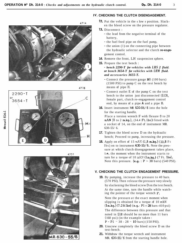
OPERATION No Dh. 314-0 : Checks and adjustments on the hydraulic clutch control. Op. Dh. 314-0 3
IV. CHECKING THE CLUTCH DISENGAGEMENT.
12. Put the vehicle in the a low N position. Slack- en the bleed screw on the pressure regulator.
13. Disconnect : - the lead from the negative terminal of the
battery, - the fuel feed pipe on the fuel pump, - the union (1) on the connecting pipe between
the hydraulic selector and the clutch re-enga- gement control.
14. Remove the front, L.H suspension sphere.
15. Prepare the t e s t bench : - bench 2290-T for vehicles with LHS 2 fluid. or bench 3654-T for vehicles with LHM fluid. and accessor ies 3655-T. - Connect the pressure gauge MI (100 bars)
(1500 PSI) t o pump C on the t e s t bench by means of pipe H.
- Connect outlet E of the pump C on the t e s t bench to the union just disconnected (•˜13), female part, clutch re-engagement control end, by means of a pipe A and a pipe B.
16. Insert instrument MR 630-55/6 into the hole for the start ing handle. P l ace a torsion wrench F with flexure 0 t o 20 mAN (0 to 2 m.kg.1, (14.4 F t . l b s ) f i t ted with a socket of 14, on the end of instrument MR. 630-55/ 6.
17. Tighten the bleed screw D on the hydraulic bench; Proceed to pump, increasing the pressure.
18. Apply on effort of 15 mAN (1,5 m.kg.) (10,8 F t l b s ) on to instrument 630-55/6. Note the pres- sure a t which clutch disengagement takes place, i.e. the moment when the instrument s t a r t s t o turn for a torque of 10 d N (1m.kg.) (7 Ft. Ibs). Note th is pressure. (e.g. : P = 38 bars) (540 PSI).
V. CHECKING THE CLUTCH ENGAGEMENT PRESSURE.
19. By pumping, increase the pressure t o 40 bars. (570 PSI). Then re lease the pressure very slowly by slackening the bleed screw D on the t e s t bench. At the same time, turn the handle while watch- ing the pointer of the torque wrench F.
Note the pressure a t the exact moment when slipping i s obtained for a torque of 10 mAN (1m.kg.) (7 .2f t Ibs) (e.9.: P l - 2 8 bars-410 psi)
The difference between this pressure and that noted in $18 should be no more than 11 bars ( 160 ps i ) (in the example taken : P - P 1 = 38 - 28 = 10 bars) (150 PSI).
20. Unscrew completely the bleed screw D on the test-bench.
21. Withdraw the torque wrench and instrument MR. 630-55/6 from the starting handle hole.

4 OPERATION No Dh. 314-0 : Checks and adjustments on the hydraulic clutch control.
VI. CHECKING THE PRESSURE SUPPLIED BY THE
22. Prepare the test bench. a ) Disconnect the pipe H from the pressure gauge M1
and from the t e s t bench pump. b) Connect the pressure gauge M2 (200 bars) (3000
PSI) to the t e s t bench pump D by means of pipe H.
23. Tighten the bleed screw E on the tes t bench. Start to pump. Increase the pressure in the clutch cylinder to 50 bars4720 psi) , s o causing clutch disengagement.
n 24. Connect the pressure gauge M1 on to the union previously disconnected (•˜13), male part, hydraulic selector outlet, by means of the two pipes A.
25. Connect the lead t o the negative terminal of the battery.
26. Connect the fuel feed pipe to the fuel pump.
27. Start the engine. Adjust the normal idling speed : - 550 to 600 r.p.m. l V e h i c l e s 4 9/ 1968) - 625 to 675 r.p.m. (Vehicles* 9/ 1968)
28. Tighten the bleed screw on the pressure regulator.
29. Engage gear. - The pressure indicated by pressure gauge M1
should be 29 bars min ( 420 ps i ).
IMPORTANT : l o ) During this entire operation, check the pressure
in the clutch cylinder by pressure gauge M2; i t should not drop.
2') Put the gear lever into neutral position and stop the engine.
30. Release the pressure in the clutch cylinder by open- ing bleed screw E on the tes t bench.
31. Slacken the bleed screw on the pressure regulator.
32. Disconnect both the pipe assemblies. Union to pressure gauge MI. Union to tes t bench pump.
33. Connect the union to the pipe assembly hydraulic selector and clutch re-engagement control.
34. F i t the front, LH suspension sphere.
35. Tighten the bleed screw on the pressure regulator.
36. Start the engine. Adjust the accelerated idling : - 875 to 925 r.p.m. (Vehicles 9/ 1968) - 850 to 900 r.p.m. (Vehicles + 9/ 1968)
37. Put the vehicle in the (( normal )) height position.
38. Fi t the rubber plug on to the starting handle passage.

OPERATION No Dm. 314-0 : Checks and adjustments on the clutch control. Op. Dm. 314-0 1
I VEHICLES WITH MECHANICAL
I GEAR SELECTION September I968
I - ADJUSTING T H E CLUTCH CONTROL
1. Check the height of the pedal :
Standard Vehicles : The height should be L = 142 + from the underside of t he pedal p la te (with the rubber pad removed) to the floor panel
PA. Vehicles (improved presentation) : The height should be L = 137 + m.m from the underside of the pedal plate, (wlth the rubber pad in place) to the floor panel.
To obtain th is measurement, unscrew the lock nut (1) and adjust the s top screw (2).
2. Adiust the length of the sheath :
The clearance between the end of the connecting rod (5) and the clutch casing must be J ' = 2,5 to 3 , 5 mm.
To obtain t h i s measurement, move the threaded s leeve (4) by turning the nut (3 ).
3. Adjust the clutch clearance :
Using a rule, measure the clearance (( j ' )) given above.
An a s s i s t an t should depress the clutch pedal by hand up to the point where res is tance i s felt when the thrust face comes into contact with the toggles.
Measure once again the clearance (( j H . The difference (( j-j' )) should be between 1,6 and 2,4 mm.
If it i s not, adjust the screw (6).
4. Check that when the clutch i s disengaged fully, there i s a clearance between the end of the screw (6) and the seal ing sheath of the steering rack.
If there i s not, the screw (6) must be replaced by a new screw : - th ickness of the head = 3 mm - length of the thread = 46,s mm

VEHICLES WITH MANUAL G E A R S E L E C T I O N , ; ~ n ~ d u c e d ,.!nc? Sel,iernher i% ?
Option : P.A./ -

OPERATION No Dm 314-0 : Checks and adjustments on the clutch control. Op. Dm. 314-0 3
I VEHICLES WITH MECHANICAL
I I - ADJUSTING THE CLUTCH CONTROL
(Pedal gear with overlood spring.)
GEAR SELECTION 1-w - September 1968
5. Adjusting the height of the pedal :
a ) Standard Vehicles The height must be : L = 142 2 mm from the under s ide of the pedal plate (rubber pad removed) to the floor panel.
p-r7.c=v . 6 ) P . A vehicles (improved presentation). The height must be : L = 137 +5 mm from the under s ide of
0 the pedal p la te (rubber pad in place) to the floor panel. To obtain t h i s measurement, s lacken the lock nut (5) and adjust the stop screw (6).
6 Adiust the length of the sheath : The clearance between the end of the connecting rod
(1) and the clutch cas ing must be : J = 3 to 4 mm. To obtain this measurement, move the threaded sleeve
(3) by adjusting the nut (4).
.. 7. Adiust the overload spring : a ) Insert a sprag of 9 mm between the end of the
connecting rod (1) and the clutch casing, t o stop the clutoh cable from pulling on the clutoh pedal.
Check that when the clutch pedal i s fully depressed, it i s stopped at iiao. If i t i s not, turn the adjusting screw (7) until the correct position i s obtained.
b) If adjustment by tightening screw (7) i s not possible, move the upper anchoring point for the spring towards the front of the vehicle. (Use tool MR. 630-27 2). Slacken the screw (7) to obtain the adjustment..
c ) If adjustment by slackening screw (7) (L ' = 33 mm max.) i s not possible, move the upper anchoring point for the spring towards the rear of the vehicle by means of tool MR. 630-27/2.
Tighten screw (7) to obtain the adjustment.
d) P l a c e a sprag of 10,2 mm between the end of the connecting rod (1) and the clutch casing. When fully depressed, the clutch pedal should not be stopped a t ii ao. Remove the sprag.
IMPORTANT NOTE : The overload spring must be adjusted and checked with care, s o a s to avoid rapid deterioration of the clutch stop through bringing i t into contact with the toggles of the clutch mechanism, in the ctengagedk) position.

4 OPERATION No Dm. 314-0 : Checks and adjustments on the clutch control.
3332-1 8. Adiust the clutch clearonce.
Using a rule, measure the clearance (( J a given above. An assistant should depress the clutch pedal by hand up to the point where resistance is felt when the thrust face comes into contact with the toggles.
Again measure the clearance (( J' s.
The difference J ' - J should be between 1,6 and 2,4 mm.
If it is not, adjust the screw (1).
Check that when the clutch i s fully disengaged, there i s a clearance between the end of the screw (1) and the sealing sheath of the steering rack.
If there is not, the screw (1) must be replaced by a new screw : - thickness of the head = 3 mm. - length of the thread = 46,5 mm.

TORQUE CONVERTER
OPERATION No. Dbw 320-00 : Characteristics and particular features of the torque conl~erter
Op. Dbw 320-00 1
I DBW. VEHICLES All types
1. DESCRIPTION
- T h e "DS 21" veh ic les (carburettor or e lec t ron ic fuel ~ n j e c t i o n ) may b e opt ional ly f i t ted with a BORG-WARNER
fully automatic gearbox " type 35".
- Pr inc ipa l components of t h e t ransmission :
- A torque converter composed of th ree e lements (impellor, turbine, reactor) permitting a var iab le
multiplication rat io of the torque, from 2 . 3 t o 1.
- An o i l pump (ac t iva ted by t h e conve i te i ~ rnpe l lo r ) supplying oi l under p ressure n e c e s s a r y to t h e
operation of t h e converter and t h e hydraul ic gear change control unit and a l s o for t h e lubricat ion of
t h e ep icyc l ic gear train.
- A hydraul ical ly controlled au tomat ic gear box, including a n ep icyc l ic gear train making i t p o s s i b l e
t o obtain th ree forward gears and one reverse gear.
It. ADVANTAGES OF THE CONVERTER
- T h e converter mult ipl ies the engine torque when s ta r t ing and on acce le ra t ing , a l lowing :
- t h e u s e of only a 3-speed gearbox,
- f l ex ib le dr iving behaviour, even a t low s p e e d s ,
- rapid acce le ra t ion a t low engine s p e e d ,
- i n c r e a s e d "pul l ing power", a d e s i r a b l e qua l i ty when pulling caravcms or for driving with f u l l load.
- T h e converter , couplad with a n e p i c y c l i c gear train gearbox makes t h e following poss ib le :
- t h e el iminat ion of the c l a s s i c a l c u t out c lu tch ,
- t h e damping of n o i s e s and vibrat ions, the eng ine being mechariically Isolated from t h e gearbox.
- T h e conver te r e n s u r e s under a l l c i rcumstances smooth t ransmission o f the power generated by the e n g i n e
without a n y jolting.

2 OPERATION No. Dbw 320-00 : C h a r a c t e r i s t i c s and par t icular features
01 t h e torque converter
Converter - hydraulic coupler. w Brand :
FERODO 250 I (transmission 1680) Licence : BORG WARNER.
It is composed of a leakproof housing filled with oil and containing three bladed wheels :
- Two of t hese a r e mobiie . the impellor and the turbine.
- the third, the reactor, i s fitted cn a free wheel by which i t i s immobilised until the turbine reaches a certain speed when i t f r ee s the reactor.
Until this speed , the assembly operates a s a torque converter achieving a r a t i o of variable multiplication. from 2,3 to 1.
Beyond this speed, i t operates a s a hydmulic
coupler.
IV. PARTICULAR FEATURES
The converter and the gearbox u s e t he same oil. Th i s oi l is of a different quality t o that used for t he crownwheel and pinion and differential assembly which is to be found in a separa te housing.
- Oil type : . . . . . . . . . . . . . . . . . . . . . . . . . . . . . . . . . . . . . . . . . . . . . . . . . . . T O T A L A T F . 3 3
- Total capaci ty of the converter assemblv, qearbox and . . . . . . . . . . . . . . . . . . . . . . . . . . . . . . . . control circuit on filling a t the factory: Approi. 6 Its. ( l o + pts)
. . . . . . . . . . . . . . . . . . . . . . . . . . . . . . . . . - Volume of oil renewed af te r draining; Approx. 2.5 Its (4.4 p t s )
The qeorbox and convertor assembly a r e f i l led through the front dip s t ick tube.
IMPORTANT : Filling must only t a k e p l o r e w i th the engine running and with the selecror lever in position P, .
Tightening torquer :
Screws securing the diaphragm on the crankshaft : . 7 0 m IN (7 mkg. or 50.6 it Ibs) - . . . . . . . . . . . . . . . . . . . . . . . . . . . . . . . . . . . - Screws secur ing t h diaphraqm on the converter : .70 m \N (7 mkq. or 50.6 f t Ibs)

4-SPEED GEARBOX OPERATION No. D. 330-00 : Characteristics and special points on the gearbox Op. D. 330-00 1
DX-DL-DV-DT ALL TYPES VEHICLES DJ + 9/1970
1. CHARACTERISTICS.
1. Gear ratios :
NOTE : T h e s p e e d s a r e given for v e h i c l e s f i t ted with 180-380 XAS, 1 8 0 HR. 380 XAS and 185 HK. 380 XAS t y p e s for which t h e rol l ing circumference i s : 2 ,07 m. (8 l .5 i n )
a ) Vehic les all ~ y p e s (except D.V.) -4 911967
Tooth ra t io Speed
(1 000 engine r.p.m.) km/ h m ,p.li.
3 o w n wheel
a n d pinion Gear Overal l ra t io Gearbox ra t io
i
2
3
4
REV.
b ) Vehic les all types (e-rrept DI / and Dl') b 9'1967
Tooth r a t i o Gearbox ra t io Speed
(1000 engine i.p.m.) km/ h m.p.h.
Zrown whee l Overal l ra t io
and pinion Gear
1
2
3
4
REV.
C ) Vehic les D l ' c-t lo,/ 1968 mtd D V 4 9 ' 1969
Tooth ra t io Gearbox ra t io
Speed Crown whee l I Overai l ra t io I (1000 enqine r.p.rn.) I
Ym ' h m.p.h. Torque 8/ 35 Torque 7 1 34 Torque 8,' 3 5 To! q41e 7,' 34
and pinion DV DT DV DT

2 OPERATION No. D. 330-00 : Character is t ics and s p e c i a l points on the grarbor
e) Vehicles D V and D T 91 1971
Gear
1
2
3
4
REV.
2. O i l capacity of gearbox :
Gear
1
2
3
4
REV'
- Capacity : ..................................................................................... 2 litres (3 112 pts. imp) - Oil : ............................................................................................ TOTAL EP. 80
Tooth ratio
12 - 3 9
- 33
2 9 - 35 - 27
2 3 13 22 - 22 41
GEARBOX (Hydraulic gear selection)
Overall ratio
0,0633(15,78 : 1)
0,1123(8.90 : 1)
0,1705(5.87 : 1 )
0,2416(4.14 : 1)
0,0652(15.29 : 1)
Tooth ratio
12 - 39
- 30 33 - 34 - 28
2 2 13 22 -X - 22 41
Sp.eed (1000 englne [.p.m.)
km/ h m.p.h.
7,9 4.91
13,9 8.64
2 1.2 13.17
3 0 18.64
8.1 5.03
Gearbox ratio
0,3076(3,25 : 1 )
0,5454(1.83 : 1 )
0,8285(1.21 : 1)
1,1739(0.85 : 1)
0,3170(3.15 : 1 )
Crown wheel and pinion
7/ 34
(4.857.1)
Gearbox ratio
0,3076(3.25 : 1)
0,5454(1.83 : 1 )
0,8823(1.13 : 1)
1.2727(0;79 : 1 )
0,3170(3.15 : 1)
Crown wheel and pinion
7/ 34
(4.857:l)
Overall ratio
0,0633(15.78 : 1)
0,1123(8.90 : 1)
0,1817(5.50 : 1)
0,2619(3.84 : 1)
0,0652(15.29 : 1)
Speed (1000 engine [.p.m.)
km/ h m.p.h.
77,9 4.91
13.9 8.64
22,6 14.13
32,5 20.3 1
5,1 5.03

OPERATION No D, 330.00 : Charuc~trr i s t i cs und s p ~ c i a l points on t h e gearbox. Op. D. 330-00 3
GEARBOX (Mechanical gear selection)
DIFFERENTIAL D. 34-1
Left hand s ide k d Righ t hand side

4 OPERATION No D. 330-00 : Characteristics and special points on the gearbox.
F I R S T GEAR
SECOND GEAR
THIRD GEAR
REVERSE
FOURTH GEAR
II. SPECIAL POINTS
1. Speedometer drive :
- Torque of 8/35 : . . . . . . . . . . . . . . . . . . . . . . . . . . . . . . . . . . . . . . . - l o = 0,4761 2 1 - Torque of 7/ 34 : . . . . . . . . . . . . . . . . . . . . . . . . . . . . . . . . . . . . . . . 7 = 0,4375
16
2. Adiustments (Gearbox, all types)
- Distance between thrust race guide screw and clutch ca s ing joint f a c e : . . . 94 to 95 rnrn.
- End-float of 3 rd and 4 th synchro . . . . . . . . . . . . . . . . . . . . . . . . . . . . J = 0,10 rnax. - Distances between 1 s t and 2nd synchro and loose pinions : . . . . . . . . . . equal to within 0,4 rnm.
- Clearance between front bearing and front bearing c a p : . . . . . . . . . . . . . . 0,05 mm. max.
- Adjustment of 4 th gear engagement stroke : . . . . . . . . . . . . . . . . . . . . . . J = 0 , t o 0 ,6 mm.
2a. Special adiustments (hydraulic geur se lecr ion) :
- Clutch re-engagement lock : dis tance between front f ace of clamp and
end of 1 s t - 2 nd s h a f t : . . . . . . . . . . . . . . . . . . . . . . . . . . . . . . . . . . . 1 rnrn approx.
- Release spr ings of control cylinders :
Length under load : 48,8 mm for 24,s f 1'5 kg(511.7to - . . . . . . . . . . . . . . . . . . . . . . . . . . . . . . . . . . . . . . 57.3 Ibs) 31,5 mrn, turns joined
- Adjustment of gear engagement s t rokes (exept for reverse)
Clearance between sl ider and loose pinion : . . . . . . . . . . . . . . . . . . . . . . J = 0,4 to 0,6 mm

OPERATION No D. 3 3 0 - 0 0 : Characteristics and special points on the gearbox Op. D. 330-00 5
3. Tightening torques :
- Dog nut (main shaf t ) ....................................................... 150to 170mAN (15 to 17m.kg) (110to 123 f t lbs) - Bevel. pinion shaft nut .................................................... 200 to 220 mAN (20 to 22 m.kg) (145 to 160 ft lbs) - Screw securing fork or operating dog ................................... 40mAN (4 m.kg) (29 ft lbs) -Draining and filler plug. ................................................... 35 to45 mAN (3,5 to4,5 m.kg) (25 to32 ft lbs)
... - Screw securing clutch lock clamp (hydraulic gear se lec t ion) 20 mAN 2 (2 m.kg) (14 f t lbs)
4. Adiustements on differential and crown wheel and pinion :
- Crown wheel and pinion : Conic distance : etched on upper face of bevel pinion. Matching number : etched on pinion and crown.
- Back - lash ( on outer diameter of crown ) ............................... 0,16 to 0,24 mm - Differential :
..................... Planet gear end-float a t point of min. clearance 0 , l mm max. End-float of sa te l l i t e s ...................................................... 0,3 mm max.
5. Tightening torques (differential ond crown wheel and pinion) :
- Differential shaft : Bush nut (on outer bearing bush ) ........................................ 100 mAN (10 m.kg) (72 ft lbs) Nut (on inner bearing bush ) ............................................... 150 mAN (15 m.kg) (110 ft lbs) Grub screw of nut ( inner bearing bush ) ................................ 115 to 130 d N (2 to 3 m.kg),(83 to 95 f t lbs)
Screws securing drive outlet shaf ts ...................................... 20 to 30 mAN (2 to 3 m.kg) (14 to 22 ft lbs)
,-4 I 6. Modifications ( ,gearbox all types ) 9/ 1969. 2 a3 - - The sliding reverse pinion (wide tooth ) and the 1st - 2nd synchro have been modified. S - C:
2 - The gearbox housing has been modified to enable the new sliding reverse pinion to be fitted.
NOTE : It i s possible to f i t new pinions into an original housing if the gauge 3188- T i s used (thickness 3 mm) to adjust the reverse pinion a t neutral.

OPERATION No Dh. 334-0 : Checking and adjusting the gear change control Op. Dh. 334-0 1
VEHICLES WITH HYDRAULIC GEAR CHANGE
I - CHECKING AND POSITIONING THE HYDRAU- LIC SELECTOR
1. Put the gear selector lever in the first speed position
2. Remove rubber plug from locating hole " a "
3. Insert alignment rod q5 = 3,94mm (2429 T) : it must penetrate approximately 30 mm. to obtain a correct position of the selector. If i t does not, slightly turn the selector lever to en- sure complete insertion of rod.
4. Loosen coupling clamp( 1) . Put the selector lever back to the first speed position. Tighten the clamp.
5. Withdraw the alignment rod ( 2429 T ) and refit rubber plug in locating hole.
II - ADJUSTING THE GEAR CHANGE CONTROL
6. Remove the gearbox cover.
7. Remove the covers of the selector fork shafts for reverse, third and fourth gears.
8. If required, check and adjust the operating dogs by means of fixture 3172 T.
9. Checking the position of the gears :
NOTE : With the cover removed the gearbox i s not in neutral position, the reverse fork shaft i s brought beyond neutral by i ts return spring. To select a gear, i t is essential to bring reverse to neutral usinq a screw driver or gauge : 3183 T hydraulic gear change 4 9/ 1969 3 188 T hydraulic gear change ~c 9/ 1969
a ) Check the position of first gear : Engage first gear, the sliding pinion of first/ second gear in contact with the first gear loose pinion. Measure and note the distance by which the fork shaft projects from the face of the housing. For example : 34,3 mm
b) Check the position of second gear : Engage 2nd gear, the sliding pinion in contact with the 2nd. gear loose pinion Check and note the fork shaft projection For example : 55,3 mm.
c ) Check the position of third gear : Engage 3rd gear, the sliding pinion in contact with the 3rd gear loose pinion Measure and note the fork shaft projection. For example : 1.3 mm
d) Check the position ot fourth gear : Engage 4 th gear, the sLiding pinion in contact with the 4 th gear loose pinion. Again check the fork shaft projection. For example : 23,9mm.

2 OPERATION No Dh. 3 3 4 - 0 : Checking and adjusting the gear change control
10 . Check the position of neutral for reverse :
Determine the end float of the reverse fork shaft when in neutral. Engage 3rd or 4 th. gear. Free the gauge 3183-T (or 3188-T) Push the reverse fork shaft towards the rear of the gearbox and measure, by means of a depth gauge, distance " 4 " between the end of the shaft and the front face of the gear box, for example : "&" = 1,6mm P 11 the shaft forw d s and check distance 'Yl' ' , for example $1" = 2.6 mm. Take the ave- rage of both measurements :
In the example chosen, it will therefor be neces- sary to adjust the shaft to a distance j = 2,lOmm
11. Fit the cover (smear the joint face with CURTYLON paste). Tighten the securing screws.
12. Adjusting the cylinder of reverse gear.:
Screw the cylinder-piston assembly to bring i t into contact with the selector control dog while inserting some " Hyperix " paste into the tapped hole for the cylinder stop screw. Then screw in the cylinder until the shaft protrudes beyond the front face of the gearbox. (for exampleJ= 2,lOmrn dimension previously determined). Smear the cylinder stop screw with CURT-YLON paste). Place a rubber pad into the tapped hole and tigh- ten the screw.
NOTE : It is essential to renew the rubber pads of the qear change control cylinders after each dis- mantling .
13. Adiusting the strokes of the selector fork shafts: NOTE : To engage the different gears, during this 1
cperation, fit a screw 4 7 or better st i l l a threa- ded " T " in the tapped holes of the shafts.
a) Adjust the stroke of first gear : Engage I s t g.ear fully - Make sure that this gear i s fully engaged by checking the shaft projection (i. e. 34,3 mm a s determined in 5 9 line a). Screw in the cylinder-piston assembly for 2nd gear to bring it into contact, while introducing some " Hyperix " paste in the tapped hole recei- ving the screw( 1) , a slight shift of the l s t d n d selector shaft i s definable by touch and indicates that piston and control dog are in contact. Then screw the cylinder a further 1/2 of a turn to ob- tain a clearance of 0,7 to 0,9 mm. between sli- ding sleeve and loose pinion. Smear the cylinder stop screw (1) with CURT-YLON paste. Place a rubber pad in the tapped hole. Tighten the screw. Remove screw C holding the piston in the cylinder.

OPERATION No Dh. 334-0 :Checking and adjust ing the gear change control Op. Dh. 334- 0 3
b) Adjust t he stroke of second geor :
Pul l on the shaft to engage 2nd gear fully. Make su re that gear is fully engaged by checking the shaft projection ( for example 55,3 mm a s determined in 5 9 l ine b ) . Remove screw or threaded T fitted on the end of the shaft .
Bring the cylinder-piston assembly for f i r s t gear in contact with the control dog and operate a s described above.
c )Ad ius t t he stroke of third gear.
Engage 3 rd gear fully. Make su re that the gear is fully engaged by checking t h e shaft posi t ion ( 1 , 3 mm measurement determined in 3 9 l ine c )
Bring the cylinder-piston assembly for fourth gear in contact with the control dog and operate a s indicated above in l ine a (1.3 rnm. measure- ment determinedin •˜ 9, line C).
d )Ad ius t t he stroke of fourth geor.
Engage 4th gear fully. Ensure that the gear i s fully engaged by checking the protusion of the shaft (23,9 mm a s measured i n 5 9 l ine d )
Bring the cylinder-piston assembly for 3 rd gear in contact with the control dog and operate a s described above in l ine a.
14.Fit the front cover over the end of reverse gear shaf t Curtylon and the cover over the end of 3rd/4th gear shaft.
Make sure that the ring s e a l i s in position
15. Adiusting the clutch lock :
With f i r s t gear engaged, ensure that there i s a c learance (a t " J " ) between the clamp (1) and the head of the screw (2) securing the cover of the sha f t ,

4 OPERATION No Dh. 334-0 : Checking and adjusting the gear change control
16. NOTE
Ill. CHECKING A CLUTCH LOCK
2549
9/ 1966 - Use test-bench 2290- T (painted grey ) the accessories bear no markings
9/ 1966 - Use test-bench 3654 -T (painted green) the accessories bear green markings
17. Connect pump outlet ctcn to pressure gauge M2 and to clutch lock feed pipe ((b)). Connect lock outlet ct a )) to pressure gauge M1. F i t fixture MR. 630 - 43/ 20.
18. Operate the pump to build up the pressure to 70 bars ( 1000 psi ) read on gauge M2.
19. The clutch lock control rod being in neutral position-pressure gauges M1 and M2 must give the same reading.
20. Bring the screw B of fixture 630-43/20 in contact with the control rod and screw in by 1+ turns. Release the pump bleed screw ((d D. Pressure given by gauge M2 must drop to zero while remaining unchanged on gauge M1. 2550
Tighten on screw B from 7 to 13 turns. Pressure read on gauge M1 must drop to zero.
Reverse fixture MR 630 - 43/ 20 in order to operate on the other end of clutch lock control rod.
The same readings must be obtained while repeating the operations explained ( 9 9 4 and 5).

OPERATION N o DM 334-0 Checking and adjusting the gear change control (4 and 5-speed gearboxes)
Op. Dm. 334-0 I
I VEHICLES WITH MANUAL GEAR CHANGE
N.B. : This operation applies for both 4 and 5 speed gearboxes
1. ADJUSTING THE STROKE OF FOURTH GEAR
1. Remove the gear box cover
2. Engage fourth gear, the sliding s leeve for 3rd/4th gear in contact with the 4th gear loose pinion, bring screw (2) in contact with the fork shaft and screw in by a turn t o obtain a clearance of 0,4 to 0,6mm between sliding gear and 4th gear loose pinion. Tighten lock nut (1)
3, Fi t gearbox cover. Tighten the securing bolts
II.
111.
CHECKINGTHEGEARCHANGE RELAY LEVER
4. Check the relay lever alignment (4) 5. While changing the gears, the shif t lever
must not touch the gate surround (10)
ADJUSTING THE GEAR CHANGE CONTROL
6. Adiust the control relay lever Relay lever (4) and control lever for fork shaft spindle must be in line. Proceed a s follows to obtain correct position :
a ) Disconnect rod ( 3 ) from lug ( 7 ) on relay lever.
b) After s lackening the securing screws move the lever mounting (8) in i t s stud-holes a s well a s in the stud- holes of the bracket to obtain correct vertical and lateral position.
c) Tighten the mounting securing screws d ) Connect rod (3) t o lever (7)
7. Adjust the movement of the gear shift lever
a ) Gear select ion travel ( travel F.F1) Adjust the control cable length s o that gear shif t lever does not touch surround (10)
To do this
a ) Slacken nut (11) and operate connecting bush (12) t o adjust the cable sheath
b) Tighten nut (11)

2 OPERATION No DM 334-0 : Checking and adjusting the gear change control
(4 and 5-speed gearboxes)
b) Gear shift travel (movement F2-F3)
Adjust the control rod length (1)
s o that gear change lever does
not touch the surround in any
selected position.
To do th is :
a ) Slacken nut (2)
b) Disconnect control rod (1) from
c) Operate ball pin (3)
d ) Connect ball pin (3) t o lug (4)
e ) Tighten nut (2)

5 SPEED GEAR BOX r5PE FATION 1.1 ' 340-CG . Characterls t l ( s unti p i u t i c u l u r feulures of 5 ,,wed g e a r h o i O p . D 340.00 1
I VEHICLES : DJ a l l type. + 99/1979 I . CHARACTERISTICS
1. Gear ratios :
rJO'IA Speeds Jre given for 7:ehicles f i t ted with t y r e s 180 HR 380 XAS or 1 8 5 H R 380 XAS whose mll inq cirixmiererice i.s 2,07 m. I E 1.4 Ins j , under load
a) r// A ! , i \ . j~c , .s 01, 'i I ) / ' t . ' ,hic!r.c
Gears Tooth ra t ios Gearbox ra t ios Crovin wheel and pinion
8 35 r- 6 , 2 2 3 5 4,375 . 1
Speed at 1000 RPM O ,era11 ~ a t l n s
0,07G52 - 14,2'2 0,1177 - 8,45 C 172'3 5 78 0,23562 - 4 244 0,29162 - 3,42 b r ~ 7 ~ 4 7 13,78
Gears
8 , 7 3 4 (5.4 idPi3) i 4 , 6 . ~ 4 (9 MPH) 21 ,433 ( 1 3 3 YPH! 29,175 116 I MPH, 36 2159 ; L A 4 :IiPHl 3,r>O1 l 5 8 W H )
T3rith i a t i o s Gearbex ra t ios Crowc +,heel m d i r ~ i o n Overall ra t ios Speed ,at i 9011 RP?:I
7,861 (4.9 MPH) 13 172 (8.1 M?H! 19,350 (1 1 9 MPH) 25 362 il6,lli YFH 33 725 (2i),8 'J~PIII 8 107 (5 MPH,
2. Gear rat io for speedometer :
. . . - Crowr, whee i and pinion 7 /34 . . . . . . . . . . . . . . . . . . . . . . . 7/16 = 0 , 4 3 7 5 . . . . . . . . . - Crown ?/heel a n d pinion 8 / 3 5 . . . . . . . . . . . . . . . . . . . . . iC)/21 = 0,4761
3. Capac i ty and quai i ty o f oil : . . . . . . . . . . . . . . . . . . . . . . . . . . . . . . . . . . . . . . . . . . . . . . . . . - Capac i ty 2,25 l i t r e s ( 4,4 p te )
. . . . . . . . . . . . . . . . . . . . . . . . . . . . . . . . . . . . . . . . . . . . . . - Oil .... TOTAL EP 8C:
I i . PARTICULAR FEATUqE'S 1.Er1difioot for 3rd o l d 4th gear synchromesh : . . . . . . . . . . . . . . . . J = (j,10 mn. naxi 2. T ighten ing torques on :
. . . . . . . . . . . . . . . . . - s e c ~ r l i i , ~ sciec, for fork or control d a q 40 m \Y ( 4 mkg ) . . . . . . . . . . . . . . . . . . . . . . . . . . - plug i:jr :i:il-.? n~i: drainicg 35-45 m \N (3 ,s to 4 ,5 rriicg) (25 to 32 f t l ' r , ~ )
3. Adjusting c r o w c wheel and p i n i o n and di f ferent ia l
- Crowr, whee l m,ii pinicn: . Conif: ~ ~ S ~ U I I C E . . e a g r a ~ e d l i ~ i en2 face af be.Ji.1 pifiion A n t c h i i ~ g ntiinher : e n j r w e d on crown wkee: a n d pinion
. Bucklash ( ~ r ~ e i t s u r e d a t cu te r end of croviri ;vhzel t e e t h ) O,i6 to U i 2 4 tnrr. - i h f f e i = t : i i !;I : . .Satellire end-float at point of minimum c l ~ n r a n c e 0 ,3 mm ut the 1113si
f ' l ane t end-i lot~t a t point of minixurn c lea rance 0 1 at tiie most
4, T i g h t e n i ~ ~ to:que; lor c~otvn-whee l and pinion and d i f fe rent ia l
- iritfeien+.-i! s h z i t :
Eusl1-n .1 bearincj j u t e r Z C I ~ P . . . . . . . . . . . . . . . . . . . . . . . 100 m \P3 ( 10 mkq) i 72 f t I h s ) . Piui i be,:-:i.,-j ?:;re: ccqz i . . . . . . . . . . . . . . . . . . . . . . . . . . 159 m \PI ( 15 mkrj ; 108 i t I h s ) . h e - 1 ; l,.zkin,; 5: beoricg i n n e r ca3.1 . . . . . . . . . . . . . . . 13 m VJ i 1 mkg ; i '7.2 i t f h j j . Scrsv:s s e ~ u r i ; ~ : ; iroi!n -.:he21 ar.d ditfe:cr.ti;-1 hous ing . . . . . . . 115-131) $7 \ r l i 11.5-12 mi.?; 14-95 i t Ihs , . St:re:iis s e c u r i n g ;~iii~:e o~lriets . a . . , ~ , . ~ ~ . . , , . , . , . 26-3,: ' J j / ? - 3 n k g , 14 4 - 2 2 f t 11-3,

2 OPERATION No D . 340-00 : Character is t ics and particular features of 5 - s p e e d gearbox,
GEARBOX D 33 -130
DIFFERENTIAL D. 3 4- 1

I l l . DIAGRAMS OF GEARS S. 33-2 b
1st G E A R
3rd G E A R
5th G E A R
2nd G E A R
4th G E A R
R E V E R S E G E A R

AUTOMATIC GEARBOX
OPERATION No. Dbw 350-00 : Character is t ics and articular features of the automatic gearbox.
Op. Dbw 350-00 1
I DBW VEHICLES - All types
BORG-WARNER AUTOMATIC TRANSMISSION
BORG-WARNER automatic transmission, type 35, can be fitted a s an option on aDS 21 n carburettor or electronic injection vehicles.
1. GENERAL DESCRIPTION.
This transmission cons is t s of :
1. A three-element torque convertor (impellor, turbine and reactor) forming a variable engine torque multiplication ratio ranging between 2,3 and 1.
2. A gearbox comprising mainly : - a n epicyclic gear train which makes i t possible to obtain three forward gears and one reverse gear. - a hydraulic g e a r se lec tor permitting automatic gear changing.
3. An oil pump, driven by the convertor impellor which feeds the convertor and the hydraulic gear selector a s well a s lubricating the epicyclic gear train.
II. ADVANTAGES.
- The torque convertor s t eps up the engine torque when start ing and accelerating. This permits the u s e of a three-speed gearbox only.
- Connected to an epicyclic gear train, i t enables the c lass ica l clutch mechanism to be eliminated (s ince the pinions should not be engaged, i t i s not necessary to immobilise them when changing gear).
- This assembly ensures smooth transmission of the engine power without jerking. This prolongs t he l i fe of the parts.
- For the driver the advantages are : - extra comfort and l e s s fatigue s i n c e he i s not preoccupied with changing gear and the clutch pedal is eliminated. - smoother driving.
- However, the driver can regulate the automatic mechanism of the gearbox to adapt h is driving to the prevailing conditions. : Depending on how he uses the accelerator, he can vary the amount of time he remains in each gear and s o regulate the acceleration power of his car (within the limits of the engine 's possibi l i t ies) . In certain ca ses , i f the speed of the vehicle permits it , he can even change down by fully depressing the pedal. In addition, by moving the selector lever, he can limit the automatic mechanism to the first two gears, and in certain exceptional ca ses , use f irst gear only.

2 OPERATION NO. Dbw 350-00 : Charac ter i s t i c s and particular features of the automatic gearbox.
111. PRACTICAL OPERATION
1. Gearbox controls
The driver h a s two methods of controlling the operation of the gearbox :
a ) T h e s e l e c t o r l e v e r : This has 6 posit ions : (( P )) - t( R ), - tt N )) - a D ), - tt 2 s - tt 1 n. The posit ions (t D )) and (t 2 n and tt 1 )) correspond to the three different types of forward motion.
b) The acce lera tor : Thi s pedal has two functions : - TO al ter the position of the carburettor butteif l ies (or the strangler-flap on injection models). - To operate the hydraulic selector (which i s connected by a cab le to the butterfly spindles).: The length pf time in each gear increases t h e more the pedal i s depressed and consequently the more rapid i s the accelerat ion of the vehicle ( the engine turns a t higher speeds) . When the pedal i s ful ly depressed this time i s a t a maximum. However, if the speed of the vehicle permits, a lower gear may be engaged. A hard point in the pedal t ravel marks th is extreme position called the ((I\ 'ICK-DOWND position. At the same time i t corresponds to the maximum opening of the butterflies (or the strangler flap).
2. POSITION t( P)) : Porking '
- In th is position, t h e epicyclic gear train is freed from the convertor : the motion of the engine i s not therefore transmitted t o t he wheels.
- The outlet shaf t i s locked by a dog engaging in the outer tee th of the crown wheel of the epicyclic gear train : the front wheels a r e locked mechanically.
- This position i s used for parking and for carrying out adjustments with the engine running. NOTE : It i s poss ib le to operate the starter motor in th is position. IMPORTANT : NEVER SELECT POSITION U P )) WHILE THE VEHICLE IS MOVING.
3. POSITION (i R bj : Reverse.
This position should be se lec ted when the vehicle i s completely stopped and with the engine idling ( the reversing lamps light up automatically),
4. POSITION (( N H : Neutral.
In t h i s position the epicycl ic gear train i s disconnected from the convertor : t heeng ine ' s motion cannot therefore be transmitted to the wheels.
NOTE : It is poss ib le to operate the starter motor in th is posi t ion,

OPERATION NO. Dbw 350-00 : Characteristics and particulur fecrtures of the autornatic geurbon
Op. Dbw 350-00 3
5, POSITION (( B)) : Automatic changing of the three forward gears (drive), This position i s used for the normal runninq of the vehicle :
a ) Acceleration of the vehicle, s t a d r c g start :
- When start ing the firs.t gear i s always used - The succes s ive g e a d are engaged automatically a s the vehicle acce lera tes . The more the pedal i s depressed,
the more appreciable i s this accelerat ion : i t i s a t a maximum in the ((KICK-DOWN D position. However t he gears cannot be changed above a certain speed which corresponds to the speed of maximum power of the engine :
-Changing from 1st . to 2nd. gear : rnax, speed = 38 to 41 mph (60 to 6 5 km/ h) - Changing from 2nd. to 3rd. gear : max. speed = 72 to 76 mph (115 to 120 km/h)
b) Deceleration o f ' the vehicle : When the vehicle slows down the gear i s changed down automatically.
NOTE : In position uD) , the engine n o longer has any decelerat ing effect w.hen 1s t . gear i s engaged.
3 E e C) Forced acceleration, vehicle moving :
If the vehicle i s moving a t a speed of l e s s than 63 to 66 mph (100 to 150 km/h) in 3rd. gear (or l e s s than
31 to 34 mph (50 to 55 km/h) in 2nd. gear) and if the accelerator i s sharply depressed to the ((KICK-DOWN)) position the gear will be changed down automatical ly. This device thus makes i t possible to obtain the maximum accelerat ion necessary on certain occas ions (overtaking, for example).
NOTE : If the vehicle i s travelling a t a speed of l e s s than 31 mph (50 km/h) i t i s possible to change directly from 3rd. t o 1st.
POSITION (( Dl)
Speeds varying with pedal Positions BEFORE ((KICK-DOWN ')
Pedal completely depressed a t (( KICK-DOWN i )
Speed of vehicle on changing gear
1 s t 2nd.
6 t o 28 mph (10 to 45 km/ h)
38 to 41 mph ( 6 0 t o 6 5 k m / h )
max
3rd. 2nd
6 to 34 mph (10 to 55 km/h)
6 3 to 66 m h ( 1 0 0 r o 1 0 5 f m / h l
2nd. I.) 3rd.
1 0 to 53 mph (15 to 8 5 km/ h)
72 to 75 mph ( 1 1 5 t o 1 2 0 k m / h )
mnx
2nd - 1st .
3 to 6 mph (5 t o 10 km/h)
31 to 34 mph (50105.5X, , l 'h i
(chang ing dotun during c tcce lemt ion)

4 O P E R A T I O N No.. Dbw 350-00 : Churn , . t er i s~ ics i l l l l l purticulnr lentures 01 [ h e automutic gear tor
6- POSITION ((2)) : Automatic changing of the first two forward gears. T h i s posi t ion i s used for town traff ic or motoring in mountainous a r e a s . In th i s posi t ion the operation i s iden t ica l t o that of posi t ion ((D)), but only t h e f i rs t two g e a r s a r e used. When t h e second gear i s engaged, t h e s p e e d of t h e veh ic le i s not limited : never e x c e e d t h e maximum engine s p e e d (6000 rpm)
NOTE : In th i s posi t ion t h e eng ine no longer h a s a n y braking e f fec t when 1 s t . gear i s engaged.
N.B : Changing dou n h) movirtg the leuer lrorn position o 1) r to position 4 2 ,> :
In th i s c a s e t h e engagement of t h e 2nd. gear i s not restr ic ted. I t c a n occur a t any s p e e d .
CAUTION : In order to avoid e x ~ e s s i t l e s p e e d s , which are harmful to the engine, netper perjorm this operation at a speed higher than 81 mph (I30 km/ h).
7. POSIT ION (( 1 )) : Locking of the first gear T h i s posi t ion i s used for excep t iona l driving condit ions : t ravel l ing up or down s t e e p gradients (mountainous a r e a s , garage ramps). In th i s posi t ion t h e v e h i c l e normally s t a r t s in 1s t . gear , but t h e l a t t e r remains locked, whatever the s p e e d of t h e veh ic le : never e x c e e d the maximum s p e e d of t h e eng ine (6000 rpm).
NOTE : T h i s posi t ion of the l ever i s t h e only one in which the braking e f f e c t of t h e eng ine i s u s e d in 1s t . gear.
N . B : Chunging (loton h y rnolung the lezler from pos i t tons e I) r or a 2 , t o posz tion 4 1 0 .
In th i s c a s e t h e engagement of f i r s t gear is res t r i c ted t o avoid e x c e s s i v e s p e e d s which a r e harmful to t h e engine: i t can n e v e r s t a k e p l a c e a t a s p e e d . a b o v e t h e appropriate s p e e d limit. T h e la t t e r c a n have two va lues according to the posi t ion of t h e accelerator; pedal : - a l l pos i t ions , excep t a t ((KICK-DOWN)). . . . . . . . . . : maximum s p e e d = 31 - 34 mph (50 - 55 km/h) - pedal fully d e p r e s s e d a t ((KICK-DOWN I) . . . . . . . . ,. : maximum s p e e d = about 50 mph (80 km'h) If th i s operation i s carr ied out a t a higher s p e e d , t h e 2nd gear wil l be engaged : f i rs t gear will not mesh until t h e veh ic le h a s suff icient ly s lowed down and will then remained locked.
8. Starting the engine :
T h e s t a r t i n g motor c a n only be operated, us ing t h e ignition swi tch , when t h e s e l e c t o r l ever i s i n posi t ions (( N )) or (( P )). IMPORTANT : - It i s imposs ib le t o s t a r t the eng ine by towing the vehicle . - Never opera te t h e s t a r t e r motor relay (on the bat tery) hi,/ , I , ~ i l a ~ l ~ r l g hut t h e st,lector /rtlrr i , in ~ ~ o ~ i t i o r r
( N > O r u P * .
9, Towing the vehicle : ,4s a general rule , the front o f the veh ic le should a l ~ u a ~ s he raised for towing.
Exceptionally, however, and over very short distances, t h e veh ic le c a n be towed slowly af te r put t ing t h e s e l e c t - or l ever i n posi t ion (( N ,I (provided that , however, t h e gearbox i s working normally and that the o i l - l eve l s a r e cor rec t ) .

OPERATION No. Dbw 350-00 : Characteristics and particular features of the automatic gearbox
Op. Dbw 350-00 5
IV. CHARACTERISTICS
1. Gears :
Vehicles fitted with 180-380 XAS, 180 HR 380 XAS and 185 HR 380 XAS whose rolling circumference i s 2.07 m (81.4 ins)
1 I Gearbox 1 Crownwheel
ratio I and pinion
Total I Speed a t 1000 rpm
demultiplication in mph
1 1 2 3 REV
2. Lubrication of transmission IMPORTANT : The crownwheel and pinion/differential assembly i s situated in a separate (:using because the lubricating o f t h i s assembly i s of a different type.
9.09 : 1 5.52 : 1 3.80 : 1 7.94 : 1
I
Speed pinion ratio :
2.08 : 1 1.26 : 1 6.62 : 1 1.82 : 1
4 a) Lubrication of the gearbox/convertor assembly :
4 - A pump driven by the impellor of the convertor puts the lubricating oil of the gearbox under pressure. 4 03 This pump feeds the convertor and the selector block a s well a s lubricating the epicyclic gear train. 4
tl - . . . . . . . . . . . . . . . . . . . . . . . . . . . . . . . . . . . . . I Type of oil : This MUST be T O T A L A T F 33
C 1 - Capacity of gearbox/convertor/circuits assembly (when filled a t factory). . . . . . . . 6 L(lOTpts) Approx. 3 - Volume of oi l changed when draining . . . . . . . . . . . . . . . . . . . . . . . . . . . . . . . 2.5 L ($ pts) Approx. - Topping up : through the front dipstick tube . - Reading oil level : This should carried out with the engine laming and the selector lever in position (c Pu :
- engine cold : between lower marks - engine hot : between upper marks.
If necessary, top up the level under the same conditions.
8.492 mph (13.667 km) 14.008 mph (22.544 km) 20.312 mph (32.689 km) 9.725 mph (15.650 km)
8/ 35 (4.375 : 1)
b) Lubrication of crownwheel and pinion/differential housing : - O i l t y p e : . . . . . . . . . . . . . . . . . . . . . . . . . . . . . . . . . . . . . . . . . . . . . . . . . T O T A L E P 8 0 - Capacity : . . . . . . . . . . . . . . . . . . . . . . . . . . . . . . . . . . . . . . . . . . . . . . . . . 1.2 L (2.1 pt) - Topping up : through rear dipstick tube. - Reading o i l leve l : rear dipstick.
A . Drain plug for gearbox/ convertor assembly.
B : Drain plug for crownwheel and pinion/differen- tial assembly.

FRONTBRAKE
b. _ Brake band
Adju
EPICYCLIC GEA
CENTRIFUGAL GOVERNOR-
Valve chest \ CAM
s t a b l e stop
EPICYCLIC GEAR

OPERATION No. Dbw 350.00 : Charc~cteristics and purticulur 'catures of the autona tir gearbox
Op, Dbw 350-00 7
Y, DESCRIPTION OF GEARBOX 0. 35-49
Forward drive v IY
/ I I run gear Rear J'roat
Fret wheel ~ w & e drive
clu tch clutch @* 9-
The gearbox comprises
- A train of ep icycl ic pinions giving three forward gears ar,d one reverse gear. - Two multi-disc c lu tches , each controlled by a hydraulic pi- Lon. - Two brake bands each opemted by a hydraulic servo mechanism. - A free wheel locking the s u n gears s o that 1 s t gear can b e obtained. - A pair of pinions A(rat io = 38/33), si tuated a t the outlet of the epicyclic gear train, returns the movement to
the bevel pinion. - A hydraulic gear se lec tor s i tuated on the lower part of the ca s ing : i t ensures the automatic control of the
c lu tches and the brakes when changing gear. - A centrifugal governor which functions in conjunct' -I w, h the hydraulic selector . - The crownwheel and pinion/ differential assembly in a sepa ra t e casing.
ENGAGEMENT OF VARIOUS PARTS OF- EPICYCLIC TRAIN
I Posi t ion of I Gear se lec tor lever
Front I Rear I Front
clutch brake brake
F r e e
wheel

OPERATION No. Dbw 350-00 : Character is t ics and particular features of t h e automatic gearbox.
VI. DlAGRAMATlC VIEW OF GEAR TRAIN D. 35-49
1 2 3 4 1 s t GEAR
COMPONENTS : Conductors
I 1 6 4 2nd GEAR

OPERATION Noo Dbw 350-00 : Characteristics and particular leatures of the automatic gearbox
1st GEAR (Positions (( 1 D, a2tb, or u D)))
- Rear clutch (1) operating : i t connects the forward movement sun gear (5) and the torque convertor. - When the selector lever i s in position (( 1 n the front bmke (3) immobilizes t h planetary gear holder (4) which
thus becomes a areaction I) element. When the selector lever is in position a 2 )) or aDn, the front brake 13) i s freed : the free w k l (2) immobilizes the planetary gear holder (4) when the engine s tar ts to drive the vehicle (((pulling))). However, when there i s deceleration and the engine tends to have a braking effect on the vehicle, the movement reverses and tbe free wheel allows the planetary gear holder to turn. In this case there is an ((engine brake 1) (decelerating effect on the engine).
- Tho reduction ratio i s : 2.39 : 1
2nd GEAR (Positions (( 2)) or (( D)))
- Rear clutch (1) operating : i t connects the forward movement sun gear ( 5 ) and the torque converter. - The rear brake (6) immobilizes the reverse movement sun gear (7) which thus becomes a ccreaction)) element. - The planetary gear holder (4) turns (( loose h).
- The reduction ratio i s : 1.45 : 1

OPERATION No. Dbw 350-00 : Characteristics and particular features of the automatic gearbox
Fixed
REVERSE

OPERATION NO. Dbw 350-00 : Characteris t ics and particular features o / the automatic gearbox
Op, Dbw 350-00 11
THIRD GEAR (Posit ion (( Do)
- Rear clutch (1) operating, i t connects the forward movement sun gear (5) and the torque convertor. - Front clutch (8) operating, i t joins the two sun gears (5) and (7), thus locking the epicyclic gear train which
turns a s a s ingle unit.
- The reduction ratio i s 1.
REVERSE GEA R (Posit ion (( R)))
- Front clutch (8) operating, i t connects the forward movement sun gear (7) and the torque convertor. - The front brake (3) immobilizes the planetury gear holder (4) . . - The movement of the sun gear (7) i s transmitted to the crownwheel by one s e t of planetary gears only.
Therefore the crownwheel turns in the opposite direction to the engine.
- The reduction ratio i s : 2.09: 1.
NEUTRAL ( Posit ion ((Nu or (( PI))
- The two c lu tches (1) and (8) are not operating, thus there i s no mechanical connection between the engine and the epicycl ic gear train.
- In position ctN )) the brake bands (3) and (6) are released. - In position (( P 1) the front brake band (3) i s engaged, but the clutches are not operating s o there i s no mechanical
connection between the engine and the wheels. - By se l ec t ing position (( P D, a dog which locks the outlet crownwheel of the epicyclic gear train, thus
immobilizing the vehicle, i s mechanically operated.

12 OPERATION No. Dbw 350-00 : Charac ter i s t i c s and particular features 01 the automatic gearbox
VII. PARTICULAR FEATURES
1. Selection lay-out of ranges of operation : It i s this which, in conjunction with the locking mechanism of the hydraulic selector, holds the lever in each of i t s positions.
To change from one position to another, pull the lever backwards, then move it sideways.
However, to go from position "R" (reverse) to position "P", the lever should not be pulled out fully in order to prevent i t striking the shoulder "a".
2. Tightening torquer
- Nut on primary shaft . . . . . . . . . . . . . . . . . . . . . . . . . . . . . . . .150-180 mAN (15-18 mkg, 108-130 f t Ibs) - Speedo wheel . . . . . . . . . . . . . . . . . . . . . . . . . . . . . . . . . . . .200-220 m.AN (20-22 mkq, 144-158 ft Ibs) - Securing bolt of central bearing . . . . . . . . . . . . . . . . . . . . . . . . .20 mhN (2 mkg, 14-44 ft Ibs) - Front casing securing bolts. . . . . . . . . . . . . . . . . . . . . . . . . . . -17 m4N (L7-2 mkg, 12.3-14-44 ft Ibs) - Lower casing securing bolts . . . . . . . . . . . . . . . . . . . . . . . . . . .10 mAN (1 mkg, 7.22 ft Ibs) - Securing bolts for oil pump . . . . . . . . . . . . . . . . . . . . . . . . . . . . I 5 2 0 m ZN (1.5-2 mkg, 10-84-14-44 f t Ibs) - Securing bolts for hydraulic selector. . . . . . . . . . . . . . . . . . . . . .10 mAN (1 mkg, 7.22 ft Ibs) - Bolt for conical pinion retaining plate. . . . . . . . . . . . . . . . . . . . .15 mhN (1.5 mkg, 1a.84 ft Ibs) - Assembly bolts of casings (I$ = 7mm) . . . . . . . . . . . . . . . . . . . . . l l mdN (1.1 mkg, 7.96 ft Ibs) - Assembly bolts of casings (I$ = 9 mm). . . . . . . . . . . . . . . . . . . . .25 mAN (2.5 mkq, 18.08 ft Ibs)
3, Crown wheel and pinion, differentiol and gearbox outlets :
The adjustment of these components i s exactly the same a s for the corresponding components on the standard gearbox.

0 f P U T ) O I W1 D. bw 35440 : Working principles of hydraulic g e c d a g e c o n d . Op. 8. kr 3- 1
a
I
0. bw V-LES ALL TYPIM
BORC-WARNER GEARBOX
HYDRAULIC GEARCHMCE CONTkOL
I - BASIC DIAGRAM.
w , ,
II - DESCRIPTION.
- Gearchanges are controlled by multiple d i sc clutches and brake bands. These components ure '
hydraulically operated, hydraulic power being supplied by means of a pump driven by the en- of the vehicle.
- This hydraulic power i s distributed by a s l ide valve assembly grouped in the selector block.

CONVERTER CLUTCH CLUTCH BRAKE REAR BRAKE FRONT

OPERATION No D. bw 354-00: Aorking principles of hydraulic gearchange control Op. D. bw 354-00 3
The hydraulic control unit consists of :
- The prinrary and secondary regulator s l ide I ~ I - e s :
They control t h e p ressure of t h e o i l suppl ied by t h e pump and permit i t to feed t h e converter and the lubrification circui t .
- The manual l ) operated r-ontrol [alw connected to the gear selector :
This a l lows the dr iver to c h o o s e t h e different g e a r ranges.
T h e s e va lves a r e connected t o t h e acce le ra tor control ; they make i t p o s s i b l e t o control t h aute.mntic cprrrchnqa ae--dr&q ta thP anqine Lnnd~.
- 7'he c~rn/ri/rrKctl r c h . ~ ~ l a / o r / i / / t l r i 011 /hv outlet 01 I ~ P epic).c~lic' goclr ~ r r i i n :
T h i s m a k e s i t poss ib le t o control the hydraul ic uni t according t o the veh ic le s p e e d
This modifies the p ressure in t h e main circui t accordinq to the posi t ion of the a c c e l e r a t6r and the s p e e d of t h e vehicle .
T h e s e direct ly control the front c lu tch and one of the brake bands accordinq t o the posi t ion of the acce le ra tor and the s p e e d of t h e vehicle .
This makes p o s s i b l e p rogress ive gearchanqes from 2nd t o 3rd or from 3rd t o 2nd, depending on v e h i c l e speed .

OPERATION NO. Dbw 354-0 : Checking and adjusting the gear controls Op. Dbw 354-0 1
DBW VEHICLES All types
I. ADJUSTMENT OF BRAKE BANDS
1. Loosen t h e lock-nuts.
2. Tighten t h e s c r e w s (1) and (2) t o 7 mAN (0,7 mkg), then loosen then 3 / 4 of a turn.
3. Hold t h e s c r e w s , and tighten t h e lock-nuts t o 4 5 m A N (4 ,5 mkg).
II. ADJUSTMENT OF KICK-DOWN CABLE
1. Make s u r e that height of t h e accelerator pedal is correct and that t h e but terf l ies of t h e carburettor (or the a i r valve on D.lE vehicles) a r e closed.
2. Pul l the cab le ( 6 ) , then allow i t to return s lowly to i t s position.
3, At th i s point, with the cable under tension but not stretched, t h e ho les for the coupling pin (5 ) in the fork-end (3) of the c a b l e and in t h e lever (4) should be in l ine : the pin ( 5 ) should be "free".
If th i s is not t h e c a s e r e l e a s e t h e lock nut (7 ) and ad jus t t h e endpiece (8) in the appropriate direction.

2 OPERATION No. Dbw 354-0 : Checking and adjusting the gear controls
I l l . ADJUSTING THE SELECTOR
1. Adiust the selector cable :
a ) Remove t h e coupling pin (3).
b) P l a c e t h e se lec tor lever in position "1" and
pull t h e c a b l e us ing the fork end (2) until i t r e a c h e s t h e l a s t notch of t h e locking mechanism.
c) At t h i s point, the ho les for the coupling pin (3) i n the fork-end (2) of the c a b l e and in t h e
lever (4) of t h e s e l e c t o r should be i n l ine : i t
should be poss ib le t o f i t t h e pin (3 ) 'free"
If t h i s i s not the c a s e , turn the ad jus t ing nuts
of t h e s h e a t h (1) endpiece in order to bring th i s
about.
d ) F i t t h e pin (3 ) and a sp l i t pin.
e) Make s u r e tha t the se lec tor lever c a n be moved
to position "P".
2. Check the position of the manual control valve :
a ) Drain the gearbox and remove the lower
inspect ion plate.
b) P u t the lever in position "N" (neutral).
c ) Under the se lec tor block, check t h e position
of t h e 2nd machined face "b" of the va lve (6) in
relat ion t o the bearing "a" of the se lec tor bloc :
The visible section "d" of the face should be
equal on both sides of the bearing.
d ) If not, loosen the fork-end (5) and fit the valve (6) correctly i n place. Re-tighten t h e fork-end.
c) F i t t h e lower inspect ion plate. F i l l t h e
gearbox/ torque converter assembly with the
correct amount of oil .

OPERATION NO. Dbw 354-0 : Checking and adjusting the gear controls
IV. ADJUSTING THE SWITCH FOR THE STARTER MOTOR AND THE REVERSING LIGHTS.
U s e an ohmmeter or a check lamp. 1. P l a c e t he se lec tor l ever in posi t ion "Dm "2"
or "1'
2. Tighten t he swi tch (1) until the current no longer p a s s e s between the two narrowest terminals of the swi tch : - When th i s point h a s been reached, tighten
t he swi tch by f turn. - Tighten the lock nut.
3. Checking the adiustment : a ) P l a c e the se lec tor lever in position 'R"
(reverse) : the current should p a s s between the two widest terminals (reversing l ights illuminated).
b) P l a c e the se lec tor lever in position "P" (parked) or "Nu (neutral) : the current should p a s s between the two narrowest terminals of the swi tch ( s ta r te r solenoid activated).
c) P l a c e the se lec tor lever in position "Dm "2" or "1" : the current should not p a s s between any of the terminals of t he switch.

4 OPERATION Ne. DLw 3546 : Checking md adjusting the gear controls
V. ROAD CHECKS
A) Cbeckine switch on gurbo~. Place the relector lever in the following pmitions : - In positions "P" or "Nu : the.starter motor can be operated. - In positions "R, D, 2 or 1" : the starter motor cannot be operuted - In position "R" : the reversing light* s h w l d illuminate.
6 ) Ch.cking p a r rekc t ian in he d i f h e n t r o w s e4 use. l o / Place the Ievw ia pori t im "Da :
a ) When the accelerator is slightly depressed, the engagement of 1s t - 2nd gears and 2nd - 3rd gears should take place ut low s p d s without m y jolting. The more the acctlemtor is depressed, the higher are the speeds at which tba gear changer should take place. When the pcdal i s completely depresned in the "kick-down" position, these speeds should be :
- 60 - 65 km/h (37 - 40 mph) when the change fmm 1st to 2nd gear occurs. - 115 - 120 km/h (72 - 75 mph) when the change from 2nd to 3rd gear occurs.
b) With the car travelling a t constant speed, check the speed a t which a change-down provoked by using the kick-down device, takes place (accelerator pedal fully depressed.) Depending on the gear, this speed sbould be l ess than :
- 100 - 105 km/ h (62 - 65 mph) when the changa from 3rd to 2nd gear occurs. - 50 - 55 km/h (31 - 33 mph) when the change from 2nd to l s tgear occurs.
c ) With the car travelling a t 80 km/ h (50 mph), release the accelerator pedal and move the selector lever to position "2" : the gearbox should change down automatically to 2nd gear (engine brake)
d) With the car travelling a t 80 km/ h (50 mph), release the accelerator and move the selector lever to position "1" : the gearbox should change down to second gear (engine hk). On continuing to slow down, it should change down a&matically to 1s t gear when the speed drops below 56/55 km/h (31 - 33 mph) (engine brake). Accelerate again : 1st gear should remained locked if the selector l e ~ r is left in position '1'.
2*/ Plqce b v e r in position "2" :
The gearbox should function a s for position "D" ( see 5 1) : the only difference being thut it is limited to gears 1 and 2.
3"/ Place lever in position '1" :
The vehicle should start in 1st. gear, the latter will remain engaged whatever the speed of the vehicle (do not exceed maximum engine speed : 6000 rpm).
4'/ Place lever in position "P" :
Stop the vehicle on a s teep slope and place the selector lever in position "P" : the gearbox should be mechanically locked thus immobilizing the vehicle.
5'/ Place the k v e r in position *RW :
Vehicle stopped, place selector lever in position "R" : the vehicle should start without jolts (no "judder").

OPERATION No D.bw. 354-0 : Checking the oil pressure in the gearchange circuit. Op. D. bw 354-0 5
4z
REMOVAL.
I DBW. VEHICLES - ALL TYPES
VI. CHECKING THE OIL PRESSURE IN THE GEAR CHANGE CIRCUIT
Remove the spare wheel
Disconnect the headlamp control
Remove the spare wheel support bar and radiator ventilation duct assembly.
Remove the plug of the hydraulic circuit (at "a").
Use a 3/ 16" Allen key (3658-T-C) which i s included in the necessary s e t 3658-T)
PRESSURE CHECK
To do this, use the bolt and the union from se t 3658-T.
Connect the union to a pressure gauge graduated from 0 - 16 bars (0 - 230 psi).
IMPORTANT : During all the following operations the wheels of the vehicle should be chocked and the parking brake engaged.
7. Check the pressure with engine idling : - Place the selector lever in position "D" - Let the engine idle. Under these conditions the pressure should be :
3.5- 5 bars (51 - 73 ps i )
8. Check the pressure a t the converter "drag" speed : - Leave the selector lever in position "D" - Depress the main brake. - Accelerate the engine until i t s speed stabilizes.
At this speed, the pressure should be : 12.5 - 15.5 bars (181 - 225 ps i )
IMPORTANT : Do not this operation for more than 10 secondes, in order to avoid over- heating the transmission.
RE-FITTING.
9. F i t the plug of the hydraulic circuit (at "a").
10. F i t the spare wheel support badradiator ventilation duct assembly.
11. Connect and adjust the headlamp control.
12. F i t the spare wheel.

TRANSMISSION
OPERATION No D. 372-00 : Characteris t ics and purticular /earurt.s o/ d r i v e s h a l t s Op. D. 372-00 1
I VEHICLES OF ALL TYPES
PARTlCU LAR FEATURES
1 . Tr i -axe
a ) vehicles-3/197L A sh im of 2.5 mm i s p l a c e d be tween t h e p ro tec t ion p l a t e a n d t h e t r i -axe h o u s i n g
Note : When c a r r y i n g out a r epa i r o n a v e h i c l e p roduced be tween March 1 9 7 0 and March 1971, t h e f i t t i nq of
a s h i m of 2.5 mm be tween t h e b r a k e d i s c a n d t h e protect ion p l a t e i s recommended-61 1971. T h e body of t h e h o u s i n g h a s been e x t e n d e d ( L = 6 8 mm (2.67).
b) S p r e a d 200 o (70.~1 of TOTAL, Mul t i s , b e a r i n g g r e a s e o n ba l l jo in ts a n d t h e t r i- axe (300 q (10 a 02) on v e h i c l e s ~ 6 / 1971)
c) T ~ g h t e n i n q to rques .
- n u t s s e c u r i n q hous inq : - aluminium t r i - a x e . . . . . 8 5 t o 1 1 0 mAN (8.5 to 11 mkg) (61 - 79 f t . lbs)
- s t e e l t r i - a x e . . . . . . . . 1 0 5 t o 135 mAN (10 .5 t o 13.5 mkq) ( 7 6 - 98 i t . I b s )
- nut for t r a c k rod bal l pin . . . . . . . . . . . . . . . . 7 0 m A N ( 7 mkg) (51 f l . I b s )
- n u t s for s w i v e l ba l l p in . . . . . . . . . . . . . . . . . . 1 0 0 mAN (10 mkg) (72 f t . l b s )

2 OPERATION No D. 372 - 00 : Charactercst ics and particular features of driveshafts
- Left hand side - - R ight hand side - Angulac posirion of half rings in relation fo each other not important
I I MARK R I DESCRIPTION COULEUR I MARK R
RH Block Blue w i t h
I I I LH Block Yellow without I
2. Vibration dampers : (on DX, Dj, D X F , D J F W lo / 1968)
- Mounted on driveshafts
- Distance between centre line of grease nipple and outer face of block;
Left hand side 55.5 - 0 ..................................................... 5 mm
.................................................. Right hand side -123 - :mm
L c f t and Right blocks are different
Marking :
................................. R If. Block- with outer ring (welded) marked blue
................................... . . . L. H. Block - no ring .... marked yellow
Tightening torque :
.................................... Screw securing damper half rings 13 miZ N (1.3 m. kg) (9.4 f t ibs)

OPERATION No D. 372-0 : Checking and adjusting the drive:shafts Op. D. 372-0 1
I - ADJUSTING THE CROSS-HEAD END-FLOAT
NOTE : .-!pi1 1967. The cross-head end- float i s adjusted by us ing needle-cup c i rc l ips ( 2)
The s p a r e p a r t s department suppl ies c i rc l ips of seven different t h i c k n e s s e s indicated by c u t s en- graved on t h e curved end p iece ( t o t a l up the num- ber of c u t s )
DX. 372-6f DX. 372-6e DX. 372-6d DX. 372-6c DX. 372-6b DX. 372-6a DX. 372-6
VEHICULES ALL TYPES
T h i c k n e s s 0
- 0 , 0 5 Number of c u t s
6 5 4 3 2 1
without
1. Remove the four p lugs ( 8 ) by means of a punch or a scriber. NOTE : On one s i d e of the double universal housing, both c i rc l ips or iginal ly f i t ted bear t h e mark 3 ( DX 372-66 1 ,55 mm thick )
2. Remove the two other c i rc l ips f i t ted on t h e op- pos i te s i d e of the double universal housing.
Replace them if required by thicker c i rc l ips to obtain a cross-head end-float. J = 0,08 mm maxi.
TAKE CARE The c i rc l ips must b e symmetrical1 y fitted within lo0 i n relation t o dr ive shaf t cen t re l ine, t h e end-pieces ( 2 ) posi t ioned as shown below. T h e circlip must not b e under s t r e s s and c lea rance should be measured with a feeler gauge.
3: F i t t h e four plugs ( 8 ) They must be renewed after e a c h dismantling.
Do not remove them.

SOURCE AND RESERVE OF PRESSURE OPERATION No D. 390-00 : Charac~erist ics and particular features of source and Op. D. 390-00 I
reserve of pressure for the hydraulic circuit.
I. HYDRAULIC CIRCUITS - BASIC DIAGRAMS. VEHICLES ALL TYPES
1. DX/ DY vehicles ( - 12/1967) Power steering
high pressure
t Source of -Three way union -Three way union - Hydraulic gearchange and
I clutch control
Front suspens ion - Front brakes
Pressure distributor
Rear suspens ion - Rear brakes
2. DJ/ D L / D J F / D L F vehiclesf - 1 2 / 1967)
Source of -Three way union - Power steering (optional on DJF and D L F ) high pressure I
f Front suspens ion - Front brakes
Pressure distributor
h e a r suspens ion - Rear brakes
3. D X / D Y / D X F / D Y F vehicles ( - 1 2 , / 1967) Power steering
t Source of L
I Four way union -Hydraulic gearchange and
high pressure I Priority valvr
4 Front brakes
Source of -Three way union - Power steering 1
clutch control -Front suspension
ear suspension R e a r brakes
high pressure k Front suspens ion
Priority a lve
I Rear suspension Rear brakes
Front brakes
Source of - Security valve -Front brakes high pressure
Power s teer ing (optional) - Rear brakes

2 OPERATION No D. 390-00 : Characteristics and particular features of source and reserve of pressure for hydraulic circuit.
6. I.E. vehicles
Source of - Brake accumulator - Front brakes high pressure I
( - Front suspension Priority valve s ear suspension --Rear brakes
Hydraulic gearchange control ( D X . I E Vehic les)
Seven - cylinder H.P. pump. D. 39-6
Pressure regulator and sphere. D. 39-1
Single -cylinder H.P. pump. D. 39-11

OPERATION No D. 390-00 : Characteristics and particular features of source and Op. D. 390-00 3 reserve of pressure for hydraulic circuit.
I I . CHARACTERISTICS.
1. Hydraulic circuit : 4 9 / 1966 red fluid L.H.S. 2 t--t 9 i 1966 green fluid L . H . W.
. . . . . . . . . . . . . . . . . . . . . . . . . . . . . . . . . . . . . . . - Capacity of circuit 6 l i t res (10 , s p ts )
2. Reservoir : - Capacity . . . . . . . . . . . . . . . . . . . . . . . . . . . . . . . . . . . . . . . . . . . . . . 5 ,2 l i t res (9,25 ptsj:
Between mini and maxi. , . . . . . . . . . . . . . . . . . . . . . . . . . . . . . . . . . . . 1 litre (1,75 p t s )
3. Seven cylinder high pressure pump (Vehicles of all types ujith power ass is ted steering) - The pump turns a t half the speed of the engine : - Output : 2 , 8 cc per turn of pump = 840 c c per min for 600 rpm of engine - Sealing for pump body . . . . . . . . . . . . . . . . . . . . . . . . . . . . . . . . . . . . . 150 bars (2130 p s i )
4. Single cylinder high pressure pump (Vehicles with non-ass is ted steering) - This pump i s operated direct ly by the camshaft.
5. Pressure regulator : - For s ingle cylinder H.P. pump (' + 21' 1969)
Marking no groove in Icwer part of plug P re s su re s : - cu t- in . . . . . . . . . . . . . . . . . . . . . . . . . . . . . . . . . . . . . . 100-110 bars (1420-156i)psi)
- cut - out . . . . . . . . . . . . . . . . . . . . . . . . . . . . . . . . . . . . . 130; 140 bars (1850-1990psi)
- For 7 cylinder H.P. pump (* 2 1 1969) and for s inq l e cylinder H.P. pump : Marking : a circular groove in lower part of plug . . . . . . . . . . . . . . . . . . . .
. . . . . . . . . . . . . . . . . . . . . . . . . . . . . . . . . . . . . . . . . Pres su re s : cut in 125 140 bars (1775-1990 ps i ) . . . . . . . . . . . . . . . . . . . . . . . . . . . . . . . . . . . . . . cut - out 150- 175 bars (1850-1990psi)
- Pilot valve pressure regulator (Progressively replacing former ones 4 / 1969) . . . . . . . . . . . . . . . . . . . . . . . . . . . . . . . . . . . . . . . . Pres su re s : cu t in 140- 150 bars (1990-2130 psi) . . . . . . . . . . . . . . . . . . . . . . . . . . . . . . . . . . . . . . - cu t - out 165 175 bars (2280-2490 psi)
6. Main accumulator : NOTE : + 11'1969 on certain vehicles the accumulator Ln machined forged steel has been replaced by an
accumulator in p e s s e d s t ee l . -Opening and closing :
Dv/n;r; /nP+ 3,'197.2 + 30 40 f li bars (569 - 150 ps i ) . . . . . . . . . . . . . . . . . . . . . . . . . . . . . . .
D V / D T , / D P I - 3 ' 1 9 7 3 . . . . . . . . . . . . . . . . . . . . . . . . . . . . . . . . 60 bars (853 + - 150 30 p s i )
P re s su re : a l l types exept DV,/DT/DP. . . . . . . . . . . . . . . . . . . . . . . . 65 bars (925 + -
. . . . . . . . . . . . . . . . . . . . . . . . . . . . . . . . . . . . . . . . - Valve sea l ing a t : 175 bars (2490 ps i )
7. Pressure distributor (+12/ 1967 all types exept Dl ,/ D T )
8. Priority valve (f---F 12 1967 exrept DC'1 D T / DP) . . . . . . . . . . . . . . . . . . . . . . . . . . - - Calibration of s l i de valve return spring 110 130 bars (2560 -1850)
. . . . . . . . . . . . . . . . . . . . . . . . . . . . . . . . . . . . . - Sealing of s l i de valve 175 bars (2490ps i )
. . . . . . . - Valve opening for a pressure between :
9. Security valve ( D l ' 1)7 ' /DP) . . . . . . . . . . . . . . . . . . . . . . . . . . - Calibration of s l i de valve return spring 7 0 - 9 0 bars (995-1280)
. . . . . . . . . . . . . . . . . . . - Calibration of pressure switch + 3 / 197,? 5 5 - 8 5 bars (795-1280psi)
. . . . . . . . . . . . . . . . . . . I- 5 ' 1 9 7 3 75-95 bars (1067-1351 p s i ) . . . . . . . . . . . . . . . . . . . . . . . . . . . . . . . . . . . . . . Sealing of s l i d e valve 175 bars (2490 p s i ) .
.Ilanual gcar changt
Front and rear suspension
4 t o 7 bars 57 to 9 8 p s i
Hydraulic gear change
Front suspens ion
4 t o 7 bars 57 to 98 psi
Rear suspension
25 to 42 bars 360 t o 580 ps i

OPERATION No D. 390-00 : Characteristics and special features of source and reserve of pressure for hydraulic rircuit
Pilot Valve Dressure requlator. D, 39-53
Pressure distributor.
Vehicles wi th hydraulic gear change o. 34;7
Front suspens ion Hiqh pressure Rear suspension
Vehicles wilh manual change D. 39-8
Front suspens ion High pressure Rear suspension
Priority Valve D. 39-10
I Hiqh pressure 1 y Front suspension

OPERATION No D. 390-00 : Characteristics and spec ia l features of source and Op. D. 390.00 5 reserve of pressure for hydraulic circuir.
Ill. PARTICULAR FEATURES,
1. Seven cylinder high pressure pump :
- tension for be l t s . . . . . . . . . . . . . . . . . . . . . . . . . . . . . . . . . 40kg. (88 lhs) . . . . . . . . . . . . - piston push rods : ( lenghs : in s t e p s of 0 , l mm.) 28,8 to 30 ,5 mm.
- clearance between piston crown (TDC) and valve. . . . . . . . . . . . 0 , 5 mm.
- tightening of nut on drive pulley . . . . . . . . . . . . . . . . . . . . . . 40 mAN (4 m.kg) (29 ft. l b s ) - tightening of nuts and screws securing bearing to pump body . . . . 35 mAN ( 3 3 m.kg) (25,3 f t . lbs )
- tightening of securing nuts on gearbox housing . . . . . . . . . . . . . 3 5 - 4 0 mAN ( 3 , s - 4 m. kg)(25,3 to 29f t I b s )
Renew all sea ls after each dismanlling.
2. Single cylinder high pressure pump :
. . . . . . - - clearance between pump body and plug (before tightening) 0,05 t o 0,09 mrn. I u' H - tightening of screws securing plug . . . . . . . . . . . . . . . . . . . . 17 to 19 mAN (1,7 to 1,9 m.kg) m - u (12,3 t o 13 ,7 ft. lbs ) a c
s 3. Pressure regulator :
- shims adjust ing pressure regulutor : th icknesses . . . . . . . . . . . 0,25 and 1 mm.
NOTE : A thickness of I rnm brings ahout a change irr pressure o f . . 1 0 bars (150 psi )
- clearance between cup and cut - in bal l . . . . . . . . . . . . . . . . . . 0,3 to 0,4 mm.
- tightening of nut securing control piston cylinder. . . . . . . . . . . . 30mAN ( 3 rn.kg) (22 ft. l b s )
- tightening of nut supporting plug . . . . . . . . . . . . . . . . . . . . . . 170 to200mAN (17 to20m.kg)
(122 t o 144 ft. lbs )
- Iubricase threads with hydraulic fluid.
. . . . - c u t in chamber : 1 0,30 mrn shim brings about a change in pressure of 3 bars (43 ps i ) approx.
4. Pi lot valve pressure regulator.
- c u t out chamber : 1 0,70 rnrn shim brings about a change in pressure of . . . 7 bars (100 ps i ) approx.
.. adjus t ing shims : thickness . . . . . . . . . . . . . . . . . . . . . . . . . . . . . cut in 0 ,30 and 0,70 mrn . cut o u t . . 0,30 rnm

6 O P E R A T I O N No D. 390-00 : Charac ter i s t i c s and particular features of source and reserve of pressure for hydraulic circust.
5. Priority valve :
. . . . . . . . . . . . . . . . . . . . . . . . . Thickness of adjust ing shims 0 , 9 mm
Tightening of plug screw . . . . . . . . . . . . . . . . . . . . . . . . . . . . 12 mAN (1,2 m.kg) (8,68 ft. lbs )
. . . . . . . . . . . . . . . . . . . . . . . . . . . . . . . . Tightening of plug 1 7 t o 23 mAN (1,7 t o 2,3 rn.kg) (12,3 t o 16,6 ft. lbs )
6. Security valve :
. . . . . . . . . . . . . . . . . . . . . . . . . Thickness of adjust ing shims 2 ,9 - 3 , 8 -4 ,7 mm
7. Pressure distributor :
Plug . . . . . . . . . . . . . . . . . . ... . . . .
Manual gear change
Front and Rear
Long
Hydraulic gear change
Front
Short
Rear
Long

OPERATION No DV 390 -0 : Checking hydraulic components on the vehicle Op. DV 390- 0 1
CHECKING HYDRAULIC COMPONENTS ON THE VEHICLE I VEHICLES DV-DT-DP
In order to carry out these checks, the following must be used: - 2-3 -way unions ( HY 453 - 134 ) - 2 link pipes ( DV 394 - 122 ) - ( ALD ) rubber s e a l s (NN 394 - 87a ) - (green marking for LHM fluid ) - 1 pressure gauge graduated from 0 -200 bars
(0- 3000 p s i ) - 6 plugs (male and female )
24 18
IMPORTANT : It i s essent ia l to carry out the checking operations observing the greatest possible degree of clean- l iness. The components and the areas surrounding connections must be carefully cleaned before dismantling. The operations a r e to be carried out with :
- The vehicle in Low position - The pressure regulator bleed screw open. - Enqine stopped.
unless otherwise instructed.
PREPARATION. 1. Make sure that :
- The H.P. pump bel t s are a t the correct tension - The hydraulic fluid reservoir filter i s clean - The hydraulic fluid i s at the correct
temperature (carry out a preliminary road t e s t if the vehicle i s cold)
2. Remove : - Front left wing - Plate protecting suspension mechanism
3. Put height control lever in low position :
A 4. Loosen the pressure requlator bleed screw.
5. Disconnect : - Rubber overflow return pipe (1) from security
valve - Font brake feed pipe (2) from security valve
6. In the place of front brake feed pipe (2) connect a 3-way union A equipped with a pressure gauge B on to security valve. The union and pressure gauge remain in th is position throughout a l l the various checks.
CHECKS 7. Checking the main accumulator.
a ) Disconnect feed pipes for front suspension ( (a )) and rear suspension (( b )) By means of the plugs, block : - end piece (( c N of 3-way union. - openings ( ( a N and (( b )) on front and rear
suspension feed pipes. b) - Put gear lever in neutral position.
Put on handbrake and tighten pressure regulator bleed screw
c ) - Without switching on ignition, act ivate the the starter.
Observe the pressure gauge needle. It r i s e s steadily, then seems to stabil ize before rising again. Take a reading when the needle comes to rest . This i s the inflation pressure of the main accumulator and must be between :
- 40 ' bars (569 - 10
' 30ps i ) - 150
for vehicles 4 3 / 1973 t 30 .
- 60 bars (853 - 1 5 0 p s ~ )
[or l1~hicle.s k 3,' 1973

2 OPERATION NO DV 390 - 0 : Checking hydraulic components on the vehicle
8. Checking pressure regulator :
Block end-piece ctd n of 3 -way union and openings ( (a )) and ((c )) of front and rear suspension feed pipes.
a ) Cut-out. Start the engine, with the pressure regulator bleed screw tightened and the vehicle in low position.
Observe the pressure gauge needle . When i t ceases to r ise, i t indicates the maximum -~ -
cut-out pressure.
Switch off the engine.
Observe the pressure gauge needle and note the drop in pressure in the next 3 minutes.
If the fall in pressure i s greater than 10 bars ( 150 p s i ) , check again. If the result i s the same, the pressure regulator i s faulty.
Replace i t or repair it .
b) Cut-in Start the engine.
When the cut-out operates, s l ightly open the pressure regulator bleed screw. The pressure gauge needle drops slightly, then r i ses again when the high pressure pump begins to work.
The minimum value shown by the pressure gauge needle corresponds to the cut-in pressure.
9. Checking security valve.
By means of t he plugs, block the end-piece (( dn
of the 3-way union and openings ( ( a )) and (( c )) of front and rear suspension feed pipes. Start the engine.
When cut-out pressure h a s been reached, observe end-piece ( (b) ) of overflow return pipe from security valve.
If there i s a slight amount of seepage, the se- curity valve i s working properly.
If there i s a heavy discharge of fluid, the secu- rity valve must be replaced.

OPERATION NoDV. 3 9 0 - 0 : Checking the hydraulic components on the vehicle Op. DV. 390 - 0 3
10. Checking the slide-valve of the security valve.
By means of plugs block : - the end piece ccc~ of the three way union - a n opening ( ( a )) of the suspension feed pipe
Tighten the pressure regulator bleed-screw
Switch on and act ivate the starter to allow the engine to turn.
Fluid must begin to escape by the free opening (c b )) when pressure r i s e s between 70 and 90 bars ( 995 and 1280 ps i )
11. Checking the brake control valve.
By means of plugs, block : - Both openings ct a )) and ct b )) of the feed
pipes for front and rear suspension.
Connect the brake feed pipe to the end piece ct d )) of the three-way union.
Start the engine. Tighten the pressure regulator bleed screw.
After the cut out wait 10 seconds for the pressure to s tab i l ize then switch off the engine.
Note the pressure drop on the dial gauge in the next three minutes.
If pressure drop exceeds 10 bars ( 150 psi ) check a second time. If the result i s the same the control valve i s faulty.
Repair i t or replace it.

4 OPERATION NO DV. 390-0 : Checking the hydraulic components on the vehicle
12. Checking a brake pressure switch. a ) By means of plugs stop the openings of
the feed pipes for front suspension ( (a )) and rear suspension (( b ~ . Connect the brake control valve feed pipe to end piece (( c )) of the three-way union. Tiqhten the pressure regulator bleed screw.
Start the engine to obtain the cut-in pressure then switch off.
Operate the brake pedal until the pressure warning lamp remains illuminated.
b) At the same time pressure gauge reading must be between : - 55 and 75 bars (783 and 1351 ps i )
for vehicles -+ 3/ 1973 - 75 and 95 bars (1067 and ps i )
for vehicles 3/ 1973 If the lamp does not come on between these readings, change the pressure switch.
13. Checking the front suspension
a ) Stop by means of plugs :
- Opening t( bv of the rear suspension feed
pipe - End-piece tr c )) of the three way union connect the front suspension feed pipe to the security valve. Tighten the bleed screw Put height control lever in normal running position Allow the engine to turn until front of vehicle r i s e s and cut out occurs wait 10 seconds for the pressure t o stabil ize then switch off.
b ) Observe the pressure drop on the dial gauge. If i t exceeds 10 bars ( 150 psi ) within the next three minutes, a new check i s necessary. If need be, check the following components to determine which one i s leaking: - the front suspension cylinders ( o n e or both ) - the front hdght corrector. Find out which component i s faulty by process of elimination.
c ) To check a suspension cylinder, s top i t s feed pipe by means of a plug and check a s descri- bed above. Note the pressure drop on the gauge.
The leakage from the cylinder i s calculated by taking the difference between the total leakage ( noted in paragraph 1 3 b ) when the whole front suspension i s under pressure and the leakage of the cylinder alone. It must not bring about a pressure drop exceeding 10 bars ( 150 p s i ) within three minutes. If i t does , the cylinder i s faulty.

OPERATION No DV. 390-0 : Checking hydraulic components on the veh ic le Op. DV. 390 - 0 5
d ) To check the height corrector block the sus- pension cylinder feed pipes by means of plugs. The leakage observed i s that of the height cor- rector, and should not bring about a drop in pressure of more than 10 bars ( 150 psi ) in three minutes.
14. Checking the rear suspension.
a ) Block by means of plugs - opening ( 2 ) feeding front suspension - end-piece ( 3 ) on 3 -way union, feeding brake control valve. - union feeding rear brake ( 1 ).
Eliminate the power assisted steering by inserting a foil between the sealing plate and flange, thus blocking the feed openings. Disconnect rear suspension feed pipes ( 4 ) and ( 5 ) from power ass is ted steering union ( 6 )
Connect the feed pipes to a 3 -way union A, and block the third opening with a plug.
Tighten the bleed screw.
Put the height control lever in normal running position allow the engine to turn until the front . .
of the vehicle r i ses and cut-out occurs. Wait ten seconds for the pressure to stabilize then stop the engine.
Observe the drop in pressure on the dial gauge. If i t exceeds 10 bars ( 150 psi ) in 3 minutes, checkagain. If the result is the same, find out which component i s faulty by using the following method.
l o ) On vehicles 4 2/ 1967.
Block rear brake feed union ( 7 ).
To check rear right cylinder, block union ( 8 )
To check corrector, block opening ( 9 ) on corrector.
The leakage from rear left cylinder cannot be measured, but must be calculated by taking the difference between the total leakage ( corrector and cylinder ) and the leakage from the corrector alone.

6 OPERATION NO DV. 390-0 : Checking hydraulic components on the vehicle
2' ) On vehicles c-) 3/ 1967.
Block rear brake feed union ( 3 ) To check rear right cylinder, block union ( 2 ) To check rear left cylinder, block union ( 1 ) To check height corrector, block opening ct a ))
15. Checking the power assisted steering.
a ) Block, by means of plugs : - End-piece tt b )) on 3 -way union - Opening cc d )) feeding the front suspension - End piece ctc )r on 3 -way union feeding the
rear suspension.
Connect the feed pipe for the rear suspension and the security valve on to the securi ty valvt
Tighten the pressure regulator bleed- screw ?,
and put the height control lever in normal running position.
Allow the engine to turn until cut-out occurs
then wait 10 seconds for the pressure to s tab i l ize before stopping the engine.
b ) Note the drop in pressure on the dial gauge. If i t exceeds 10 bars ( 150 psi ) in 3 minutes, repeat the check.
c ) If repair i s necessary, find out whether the leak i s in the rotating union on the rack
control
Do this by a process of elimination :
Block the feed to the rack control by inser- ting a foil between the housing and the s ea - ling plate.
Carry out the check again. If there i s a leak i t c an only be due to a faulty rotating union.
16. Simplified check of control valve.
a ) Disconnect the brake rubber return pipe from the hydraulic reservoir.
Attach a transparent plast ic tube to the end of the pipe.
Start the engine and put the height control lever in normal running position.
b ) When the vehicle has reached normal height, depress the brake pedal until fluid appears in the transparent tube.
Release the pedal and observe the fluid level which should remain pratically stable. If there i s a rapid r i s e in the level , the control valve must be replaced.

OPERATION No D. 391 - 0 : Checking a suspension sphere or a brake accumulator Op. D. 391 - 0 1
I VEHICLES A L L TYPES
CHECKING THE INIT IAL PRESSURE O F A SUSPENSION SPHERE OR A BRAKE ACCUMULATOR
4 NOTE : T o carry out this operation make use of t e s t
' bench 2290T for vehicles using synthetic hydraulic 2 a fluid LHS2 (Red marking) and bench 3654T for * 3 vehicles using mineral fluid LHM (green marking) E
23
1. F i t union ( 2 ) on to the sphere by inserting a ring s e a l (marked white ) This union is supplied a s a part of the t e s t bench kit.
2. Connect union ( 2 ) on to t e s t bench pump by means of a pipe (1) (without marking for LHS2. With green marking for LHM)
TAKE CARE : Make use of accessories and gauges corresponding to each hydraulic fluid specification.
3. Read the figure stamped on the sphere plug which indicates the inflation pressure.
4. Tighten the pump bleed screw ((a)). Operate the pump to build up the pressure while observing the gauge : the pressure will not r i s e appreciably a t f i rs t but will then r i s e rapi- dly and remain s teady a t a figure which i s the inflation pressure.
NOTE : At a temperature of 20' C (68OF) the pressure should be : a) Suspension spheres :
- Saloons Front spheres 59 + bars (840 + 30psi)
- 15 - 220
Rear spheres 26 + bars (370 + 3opsi) - 10 - 150
- Safaris Front spheres 59 + bars (840 ' 30psi)
- 15 - 220 Rear spheres + 30 37 + li bars (526 - 1 5 0 p ~ i )
b) Main accumulator : + 71 Vehicles all types ... 65 ' bars (924 220 ps i ) - - (except D V-D T-Dl')
+ 30 DV-DT-DP 4 3/ 1973 :40+~;bars(569 -150psi)
C) Brake accumulator : Vehicles all types 40 2 bars (569 2 30 psi) (Except DV-DT-DP)
5. Allow the pressure to drop by unscrewing the pump bleed screw ( (a) ) remove t e s t pipe ( I ) and union (2)

OPERATION No D 410 -00 : Characteristics and particular features of front axle Op. D 410-00
VEHICLES ALL TYPES
1. CHARACTERISTICS (on vehicles)
1. Caster
Caster angle. . ........................................................................................................... 2. Camber
.. ............................... ..................... Difference between left s i de and right s ide ..... .... Distance between anti-roll bar bearing and suspension control lever bearing :
...................................................................................................... - L.H. s ide , , - R.H. s ide ........................................................................................................
3. Wheel alignment
................................................................................................................. Toe-in
15' MAX.

2 OPERATION No 410 -00 : Characteristics and particular features of front axle.
II. PARTICULAR FEATURES.
PIVOT
Do not clean the pivot assembly by immersion
The pivot bearings can only be replaced by using a special tool.
Tightening Tightening Tightening Tightening
torque torque torque torque
for nut of upper pivot ball on arm: ....... 85 t o 100 m A N 110 m.kq) (72 ft.lbs) for nut of lower pivot ball on arm:....... 100 mAN (10 m.kg) (72 ft.1bs)
t 290 of nut locking pivot bearings : ............ 980 f 39X mAN (100 400 m.kg) (720 -- ftelbs.) for lower ball pin nut on pivot :... ...... .. 390 mAN (40 rn. kg.) (290ft.Ibs)
Because of the high tightening torque, i t is not possible to refit the ball joint on the vehicle without destroying the pivot and linkage.
Select the thickness of the adjusting shim for the lower pivot ball with precision.
The adjusting shim for the upper pivot is sold paired with the bearing assembly and races.
Do not fit the upper ball cup under a press or by blows, to avoid damaging the pivot.

OPERATION No D. 410- 00 : Characteristics and particular features of front axle Op. D. 410 - 00 3
HALF A X L E 1. Removal
The suspension piston rod can only be freed when the pin holes in the rod and the lever are in line. To bring them in line i t i s necessary to press on the arm.
Tighten the screws holding the half-axle to between ............. 70 and 90 mAN (7 to 9 m.kg) (50 to 65 ft.Ibs.)
Anti-roll bar : lateral position i s obtnined by moving the right hand stop to 110 + 0,5mm between the outer face of the boss holding the anti-roll bar knuckle on the right-hand side.
Tighten the anti-roll bar bearings to .............................. ;.. 12 mAN (1,2 m.kg) (8,68 ft.Ibs.)
The bar should be able to turn without an effort greater than : 40 to 60 mAN (4-6 m.kg) (29-43 ft.Ibs.)
End float of the bar ....................................................... 0 , s to 1 mm
e
3 To connect the anti-roll bar to the suspension cylinders, proceed a s indicated in the corresponding operation e OD to obtain a centre distance between the lever ball and the anti-roll bar of 198 mm on the right-hand side and - o 199 mm on the left-hand side. 5
ii 3. Fitting
+ 0 The outer face of the rear joint of the upper arm should be a t 6,25 - o,s mm from the outer face of the bearing inner cup.
The outer face of the front joint of the upper arm should be at 2 , s + 0,25 mm from the outer face of the support bracket.
Tighten the nuts securing the upper and lower arms to : ....... 90 mAN (9 m.kg) (65 ft.Ibs.)
Then loosen by 1/ 12 th of a turn.
Adjust the caster angle using gauge 2321-T. The reading on this gauge should be between 24.75 and 25.25 mm (on the half axle which was removed).

OPERATION No. D. 410-0 : C h e c k i n g and adjust ing the front ax le Op. D. 410-0 1
VEHICLES ALL TYPES
1. ADJUSTING THE CAMBER
1. Check the he igh ts ( s e e the corresponding operation)
2. P u t the vehicle on a f la t , horizontal surface. P u t the height control in t h e normal road position. Start the engine and keep i t running for the whole operation.
3. P u t the tool 2311 T i n posi t ion Note the position indicated by the plumb on t h e s c a l e of the tool.
4. Perform the s a m e operation on the opposi te wheel rim. T h e difference must not exceed 15 graduat ions on the s c a l e .
5. Should this not be the c a s e : Remove the front, lef t wing and the height corrector mudshield. Adjust the s l e e v e (1) to equa l i se the camber between the 2 wheels .
II. ADJUSTING THE ALIGNMENT
1. P u t the vehicle on a f la t horizontal surface. P u t the height control in the normal road posi ti&. Start the engine and keep it running for the whole operation.
2. U s e an ordinary commercial track-gauge. Measure at wheel centre height , the d i s tance between the whee ls rims, a t the rear. Turn the whee ls half a turn and measure a t the front on the points previously marked.
3. T h e r e must be a toe-in of be tween 2 and 4 mm.
If not operate the track-rod s l e e v e ( 2 ) f i rs t ra i s ing the front of the vehicle . Loosen the s l e e v e clamp securing sc rews . Work by fractions of turns ( a quarter of a turn corresponds to variation in the alignment of 1 mm)
4. Check the alignment again. Tighten the clamp sc rews to 1 mkg. (7 ,22 ft . lbs) Turn the s teer ing to full right-lock and lef t lock to ensure that there i s suff icient c lea rance between the clamp sc rews , the front c r o s s member and the radiator fan cowl.
NOTE : Should the vehicle be equipped with direc- directionally controlled long range lamps, a check of th i s device must be carr ied out a s well.

2 OPERATION No D 410-0 : C h e c k s and a d j n s ~ r n r n ~ s on l r o n ~ axle
Ill. CHECKING THE CASTER
1. Case 1 : using luminous projection or level tool : Follow the makers instructions; /hc! c-aslrr should he : 1 ~ 3 0 '
2. Case 2 : using tool 2321-T a ) F ix the two track gauges A and B onto the
arms of the ax le in such a way that the machined dovetail a t !'a" on the gauge B is parallel to the ax i s xx' of the arms, the shoulder (b) towards the rear.
b) Using a caliper square, measure "c" parallel to the ax i s of the arms : to check this , pivot the caliper square, the dimension "c" i s the smal les t of the measurements read from the s l id ing gauge. This measurement should be 25 f 0.25 nrm

REAR AXLE
OPERATION No D . 420-00 :Characteristics and particular features of rear axle Op, D. 420-00 1
1. CHARACTERISTICS
1 . Camber (not adjustable)
VEHICLES OF ALL TYPES
- Difference between L.H. Side and R.H. Side .......................... ... .... . . . . . . ....... . 1mm -Angle ..................................... . ..... . . . .......... . .... . . . . . ....... . . . 0' to 0•‹15
2. Wheel alignment
- Toe-in (not adjustable) ........................................... . . . ........ . . .......... . ........ 0 to 2mm
3. Hub

2 OPERATION No 420 - 00 : Characteristics and particular features of rear axle
4. Wheel arm bearing housing
II. PARTICULAR FEATURES :
1. Hub :
- Length of conical spacer for hub bearing ............................... 72.78 + 0,02mm
- Adjusting shims for hub bearings (25.1 ~ 3 1 . 8 ) . thickness in steps of 0,04mm ........................................ 1,98 to 3,70mm
. Outer face of bearing seal recessed in i t s bore ....................... 4,5mm
- Special bearing grease in housing ........................................ 50grammes
2. Arm :
- Minimum clearance between arm and metal buffer on chassis ...... 0,5mm
3. Tightening torques :
- Hub nut ......................................................................... 100m.AN (lOm.kg) (72 ft.lbs) - Nut for wheel arm pivot
after tightening, slacken by 1 /6 of a turn .............................. 80 to 90mAN (8 to 9m.kg) (57 to 65 ft.lbs) - Screw securing brake back plate ........................................ 25mAN (2.5m.kg) (18 ft.lbs)
- Wheel fixing nuts .............................................................. 80 to 100mAN (8 to l0m.kg) (57 to 72 ft.lbs)

SUSPENSION
OPERATION N o . D. 430-00 : Characteristics and particular features of suspension 0p.D. 430-00 1
1. CHARACTERISTICS.
1 . Spheres a ) Inflation pressure :
Saloon : front = 5 9 + bars (860 + 28 p s i ) - 1 5 - 220
Safari : front = 5 9 + bars (860 + 28 p s i ) - 1 5 - 220
D VEHICLES O F A L L T Y P E S
rear = 26 + b a r s (380 + 28 p s i ) - 1 0 - 150
rear = 3 7 + bars (540 + 28 p s i ) - 10 - 150 b) Securing of dampers :
- V<>hicles produced up to December 1970: The central shaft of the damper is screwed into the body of the sphere.
- Vehic1t.s produced since December 1970: The damper i s sea led in the sphere: t h e s e two components cannot b e separated.
2. Dampers : a ) V(,hir.lca produced up to December 1970 : T h e s e dampers can b e removed and repaired
FRONT DAMPER Saloon and Safari
REAR DAMPER Saloon
REAR DAMPER Safari
Marking (cutting) P / Marking (rear 3 stamped on this face)
1)) Lehicles produced since December 1970 : The damper i s s e a l e d in the sphere and cannot be repaired : if i t i s defect ive, t h e damper-sphere unit must be replaced. The new components a r e interchangeable with the old ones , on condition that two ident ical s p h e r e s a r e f i t ted t o the s a m e axle .
3. Cylinders : a ) Diameter of cy l inders and p i s tons :
- front (a l l types) and rear ( s a l o o n ) . . . . . . . . . . . . . . . . . . . . . . . . . . . . . . . . . . . . 3 5 mm - rear ( s a f a r i ) . . . . . . . . . . . . . . . . . . . . . . . . . . . . . . . . . . . . . . . . . . . . . . . . . . 40 mm
b ) Seal ing check pressure of cyl inders . . . . . . . . . . . . . . . . . . . . . . . . . . . . . . . . . . . 40 b a r s (580 p s i )

2 OPERATION No D. 430-00 : Characteristics and particular features of suspension
4. Tyre pressure : See Op. 0.000
. . . . . . . . . . . . . . . . . . . . . . . . . . . . . . . . . . . . . Tightening torque of wheel nuts : 4 3 -58 ft lbs (6- 8 mkg)
5. Adiusting the heights :
NOTE : The heights are measured between the under-face of the anti-roll bars and the plane on which the wheels are resting.
II - PARTICULAR FEATURES 1. Pre-aiustment of the heights :
At the front, use gauges MR 630-51/3 At the rear, position the two arms s o that there i s a distance of 35 mm between the upper face of the cup and the rubber stop.
Vehicles
D. a l l types
Safari
2. Adiusting of the anti-roll bar Distance between stop clamp and inner face to pivot boss, R.H. end. . . . . . 110 f 0,s mm Clearance between L.H. stop clamp and lower bearing when R.H. s top. . . . clamp i s in contact with R.H. bearing . . . . . . . . . . . . . . . . . . . . . . . . 0,5 to 1 mm Tightening the bearings of the anti-roll bar : remove 0.2 mm of the specified thickness of the shims Tightening torque for anti-roll bar clamp u-bolt nuts . . . . . . . . . . . . . . . 12 mAN (1,2 mkg) 9ft lbs) Force required to turn anti-roll ba r . . . . . . . . . . . . . . . . . . . . . . . 4 to 6 kg (9 to 13 lbs) applied on ball
joint
3. Suspension spheres : . . . . . . . . . . . . . . . . . . . . . . . . Tightening torque for front L.H. spacer 50 mAN (5 mkg) (36 ft lbs)
Tightening torque for screw securing suspension cylinder . . . . . . . . . . . . Hand tight Tightening torque for corresponding lock nuts. . . . . . . . . . . . . . . . . . . . 19 mAN (1,9 mkg) (14 ft lbs) Tightening torque for dampers (torque wrench) +Dec./I970. . 15 to 17 mAN (115 to 1 ,7 mkg) (11 to 12 ft lbs)
Front Height
235 f 3 mm
235 f 3 mm
Rear Height
+ 10 335 rnm
+ 10 350 mm

SUSPENSION OPERATION No D.IE 430-00 : Characteristics and particular features of the suspension Op. D.IE 430-00 1
I D.IE VEHICLES - ALL TYPES
The suspension of the cars equipped with electronic fuel injection system i s similar to that of the other vehicles with the exception of the following points ;
1') Size of tyres :
Front and rear . . . . . . . . . . . . . . . . . . . . . . . . . . 185 HR 380 XAS . . . . . . . . . . . . . . . Inflation p r e s s u r e s front wheel 2 b a r s (29 p s i ) . . . . . . . . . . . . . . . rear wheel 1,8 bars (26 p s i )
2') Suspension Spheres and Dampers :
a) Vehicles produced up to December 1970 The s p h e r e s and dampers a r e modified :
- the dampers cannot be repaired : the central shaf t i s s e a l e d - the dampers a r e f ixed t o the s p h e r e s by threaded r ings
F R O N T \
C R E A R
NOTE : T h e s e dampers a r e dis t inguished by 2 marks a t ( (a)) , diametrically opposed. T h e front dampers a r e dis t inguished from t h e rear o n e s by :
- a n addi t ional washer valve (( c D, of smal le r diameter on the front dampers - a shoulder (i b,) in t h e central h o l e of the rea r damper
b) Vehicles produced since December 1970 T h e dampkrs a r e s e a l e d in t h e s p h e r e s : t h e s e two components cannot b e separated. T h e s e a l e d damper-sphere un i t s a r e interchangeable with t h e old par t s on condition that two iden t ica l
s p h e r e s a r e f i t ted on t h e s a m e axle .
3') Adiusting of heights : NOTE : T h e he igh ts a r e measured between the under-face of the anti-roll b a r s a n d the plane on which
t h e whee ls a r e res t ing : Front height = 235 + 3 mm
+ 1 0 - Rear height = 355 Omm

OPERATION No D. 430-0 : Checking and adjusting the suspension and i t s controls. Op. D 430-0 1
I VEHICLES ALL TYPES
I - PRE-ADJUSTMENT OF THE FRONT HEIGHTS
1. Connect the height control rod ( 2 ) to lever ( 1 ) and to fork end ( 3 ) on the corrector control bar, the manual height control lever being in the low position.
2. Place the manual height control lever in the high position. Make sure that the corrector val- ve is fully open and check this by trying to push i t forwards with a screw driver levering against the wheel arm bracket rib.
NOTE : Never lever against the corrector as this would cut the rubber cup.
3. Put the gauges MR630-51/3 in position. The shorter gauge B in the wheel hub; the longer one A in the bore ((a)) of the steering relay.
By means of two jacks ( one under each lower arm ) raise the arm assembly to bring the shor- ter gauge to a distance t( b)) of 185 mm from gauge A.
Ensure that there is a clearance of about 1 mm between the bottom of the fork on the control lever and the corrector ball-pin; if not, move the control rod on the anti-roll bar (spanner : 1677-T ). Remove gauges MR 650-51/ 3.
I I - PRE-ADJUSTMENT OF THE REAR HEIGHTS
4. Position the two arms so a s to obtain a distan- ce cc c n of 35 mm between the upper edge of the cup for the rubber stop ( 4 ) and the thrust face of the steel stop.
\
screws with flats ).
5. By means of the control rod, put the height cor- rector in the fully open position. Tighten the clamp ( spanner 1677-T for the

2 OPERATION No D. 430-0 : Checking and adjusting the suspension and i ts controls.
1 1 1 - ADJUSTMENT OF THE HEIGHTS
In order to carry out th i s operation, t h e vehicle mus t be i n running order. P l a c e the height control lever in "normal" posi- position.
6. Check the tyre p ressures : See Op. D. 000
7. P l a c e the car on a l i f t or over a pit. Allow the engine to idle. R e l e a s e the parking brake. Do not chock t h e wheels.
8. Adiust the front heights
Slightly loosen the clamp sc rew (1) secur ing t h e height corrector control rod. Operate t h e clamp i n the required direction to obtain a n average height of :
T h i s measure is taken from the unders ide of t h e anti-roll bar to t h e surface on which the whee ls a r e rest ing. T h e height of t h e ca r is increased or decreased a s the clamp i s turned turned ei ther towards the front or the rear. Tighten the clamp sc rew (1) (spanner 1677 (spanner 1677-T).
9. Check the front heights a ) P l a c e a s t raight rod rest ing on the e d g e s of
of the lift or pi t exac t ly below and paral le l to the anti-roll bar. T h e lower part of the rod must be exac t ly l eve l with the surface on which the whee ls a r e rest ing.
b) By taking the front bumper in both h a n d s l i f t the front of the car until t h e weight prevents any further rais ing. L e t go when th i s point i s reached. T h e car lowers then r i s e s and s tab i l i zes . At t h i s moment measure, on both s i d e s of the vehicle , the d i s tance between the under- s i d e of the anti-roll bar and t h e sur face on on which the wheels rest . T h e difference between t h e s e two measurements must not exceed 3 mm. If i t does , operate t h e threaded s l e e v e of the anti-roll bar. Take the average of the two d i s t a n c e s which may be, for example , 236 rnm.

OPERATION No D. 430-0 Checking and adjusting the suspension and i t s controls. Op. D. 430-0 3
d) Lower the car by pressing on the rear bumper. Let go when resistance i s felt. The vehicle rises then lowers and stabilizes.
c) Lower the car by pressing on the front bumpers. Let go when resistance i s felt. The car r ises then lowers and stabilizes Measure on both s ides of the vehicle the dis- tances between the underside of the anti-roll bar and the plane on which the wheels are resting. Take the average of the two measures. For example : 232 mm. Take the average of the figures determined in paragraphs b and c : For instance, in the example chosen :
This average must be between :
232 and 238 mm
If i t is not,repeat the operations described in paragraph 8.
10 - Adiust the rear heights :
Proceed a s for adjusting the front heights (see paragraph 8 ) after having removed the corrector control shield ( inside the boot ).
Operate on the clamp ( 1 )
The height to obtain from the underside of the anti-roll bar to the ground i s :
- D Saloon all types (except l E ) : 335 +. '00 rnm
- D.IE all types :
- D Safari :
11- Check the rear heights
a) Place the straight rod resting on the edges of the lift or pit exactly below and parallel to the anti-roll bar.
b) Remove the rubber plug from the floor
c ) Raise the car by taking the rear bumper in both hands. Let go when the weight prevents any further raising. The vehicle lowers then r ises and stabilizes At this moment measure the distance between the underside of the anti-roll bar and the plane on which the wheels are resting. (Insert the lo- cating rod through the hole ((a)) in the floor, the end resting on the anti-roll bar). Let this distance be,e.g. 347 mm.

4 OPERATION No D. 430-0 : Checking and adjusting the suspension and its controls
Note the distance between the underside of anti-roll bar and the plane on which the wheels stand, for example : 342 mm. Take the average of the figures :
This measurement must l ie between: - 335 and 345 mm
for D vehicles al l types (except IE)
- 355 and 365 mm for D.IE vehicles all types
- 350 and 360 mm for Safari al l types.
e) Refit the rubber plug and the corrector control shield. Check again the front heights and adjust them if necessary. Check the camber of the front wheels. The diffe rence between the two wheels must not exceed 1 mm.
12. Adjusting the manual height control rods.
Place the manual control in normal running posi- tion.
a) At the front check that there i s a clearance ((a)) with the corrector valve in full inlet position (lever ( 1 ) pushed towards the front) a s well a s a clearance (t bn with the corrector valve fully open in the exhaust position, lever ( 1 ) pushed rear-
wards). Clearance measured between the lever ( 5 ) ( 5 ) and the nut. Operate the control rod ( 2 ) i f necessary.
b) At the rear, make sure that there i s a clearance ctc)), with the corrector valve in full inlet posi- tion (lever ( 5 ) pushed forwards) and a clearance ctd)) with the corrector valve fully open in the exhaust position (lever ( 5 ) pushed towards the rear) clearance measured between the lever ( 5 ) and the nut. If necessary, adjust the nuts ( 3 ) and ( 4 ) .
c ) Check the functioning of the manual height con- trol. Ensure in particular that the control levers do not touch the body. If they do, adjust the po- sition of the control bearings.
NOTE : If i t is not possible to adjust the heights by operating the control rods, carry out the pre- adjustment of the heights ( a s explained in paragraphs 1 to 3 of same operation for the front and 4 to 5 for the rear).

OPERATION No D. 430-0 Checking and adjusting the suspension and i t s controls Op. D. 430-0 5
IV - ADJUSTING THE FRONT ANTI-ROLL BAR
13. Adiust the lateral position of the anti-roll bar
a ) Remove the lateral and lower mudshields.
b) Measure the d is tance ( h ) between the stop clamp ( 1 ) and the inner face of the right hand ball pin securing boss. This distance can be measured by placing a straight rod on the boss , holding i t in the hand, while checking the d is tance ( h ) by means of a rule (between the stop clamp and the outer face of straight rod). If necessary, operate the stop in the apro- priate direction to obtain distance ( h ) = 1 l O f 0 , s mm..Tighten the clamp securing screw.
14. Adiust the end float of the anti-roll bar
Push the bar to bring the right hand clamp into contact with the right hand half shell. Posi t ion the left hand clamp to obtain a clearance ctkn = 0 , s to 1 mm between i t and the lower left hand half shell. To do th is , remove the front height corrector.
15. Adiust the half shells on the anti-roll bar
a ) P l ace the half shell on the bar a s shown in the illustration. Holding i t in th is position, measure clearance ( 1 ) using a s e t of fee lers le t j = 1,80 mm. ( for example 1. NOTE : the half she l l s are assembled s o that they grip the bar lightly. Choose amongst the shims sold by the spare parts department those which give a thickness equal to j - 0 ,2
that i s , in the above example :
b) Smear the half she l l s with graphite grease and fit the bearing caps. Insert the two above mentioned shims between cap and bearing.
c) Tighten the R.H. bearing cap nuts t o 12 mAN (1 ,2 mkg - 8 , 7 F t Ibs). Check the leverage re- quired to rotate the anti-roll bar which should turn under a force of 2 to 3 kg (4 1 / 2 t o 6 1 / 2 Ibs) exerted upon the ball-joint. If i t does not, change the shims for some of suitable thickness.
d) Tighten the nuts on L.H. bearing caps to 12 mAN (1 ,2 mkg - 8,7 F t lbs) . Check the levera- ge s o that the anti-roll bar turns a s in ( c ) under a force of 4 to 6 kg ( 9 to 1 3 Ibs ) . If necessary, change the shims a s above.
16. Fit the height corrector
17. F i t the lower mudshield

6 OPERATION No D . 430-0 : Checking and adjusting the suspension and i t s controls
V - ADJUSTING T H E MANUAL HEIGHT CONTROL X . 55
18. Pos i t ion front l inkage rod ( 6 ) correct1 in relat ion t o r e l a y lever ( 9 1.
Determine in t h e rod the corresponding h o l e ((a)) t o ob ta in a clearance j = 7,s + 115 mm - 0
If no adjustment is p o s s i b l e by us ing the h o l e s i n t h e rod ( 6 ) move t h e quadrant ade- q u a t e l y i n i t s s l o t s .
19. P o s i t i o n r e a r l inkage rod ( 14 ) i n e l a t i o n t o r e l a y lever ( 9 )
F i n d ou t which h o l e cca )) will g ive c l e a r a n c e cchu = 8 mrn
If t h i s measure cannot he o b t a i m d with t h e
h o l e s in t h e rod ( 14 ) , s c r e w u p o r unscrew the fork ( 16).
20. F i t t h e connec t ing pin for t h e rods ( 6 ) and ( 1 4 ) t o l e v e r ( 9 ). Turn over the lock a s shown i n c r o s s s e c t i o n A.
21: L u b r i c a t e t h e p ivo t ing p o i n t s and bearings ( 1 5 ) of t h e rod ( 1 4 1 (un iversa l joint a r e a s ) .
22. Adjust t h e l a te ra l posi t ion of the front tors ion rods. The end p i e c e ( 1 ) of t h e rod must b e within 1 mm approximately i n t h e c e n t r e of t h e h o l e s i n t h e arm body. If n e c e s s a r y , move t h e rod af ter loosening clamp ( 1 2 )
23. Adjust the l a te ra l pos i t ion of the rea r tors ion rods end-p iece ( 18 ) must b e para l le l t o the body
m = n + l m m -
Move t h e rod, if n e e d be a f t e r loosen inq c lamp ( 4 )
24. Adjust t h e control l ever
With control lever ( 11 ) i n the low p o s i t i o n , d i s t a n c e
c must b e 10 f i r n m between control lever bal l and
t h e side-member trimming. If no t , s e t t h e lever ( 11 ) t o obtain t h i s measure .
25. Check that nothing prevents t h e front and recrr tors ion rods from being p laced in low or high posi t ion.
26. Check the adjustment of t h e corrector control levers ( 1 ) and ( 1 7 ) .

OPERATION No D. 430-0 : Checking and adjusting the suspension and i t s controls Op. D. 430-0 7
In the low position the suspension spheres must be free.
In the high position the rubber s tops are compressed.
The d is tance between t h e base of rubber stop and thrust face of sheet- metal buffer must be :
d = 6 mm maximum at the front
e = 8 mm maximum at the rear.

STEERING
OPERATION No D . 440-00 : Characteristics and particular features of the steering O p . D . 4 4 0 - 0 0 1
I VEHICLES A L L TYPES
A. STEERING WITH HYDRAULIC RACK CONTROL
Vehicles all types (optional on DV and DT vehicles
1. CHARACTERISTICS . . . . . . . . . . . . . . . . . . . . . . . . . . . . . . . . . . . . . . . . . . . . . . . . . . . - Toe-in 2 to 4 mm
. . . . . . . . . . . . . . . . . . . . . . . . . . . . . . . . . . . . . . . . - Steering reduction rat io 1 / 15 . . . . . . . . . . . . . . . . . . . . . . . . . . . . . . . . . . . . . . . . . . . . . - Steering radius approx. 5.50 m (18 ft)
on . . . . . . . . . . . . . . . . . . . . . . . . . . . . . . . . . . . . . . . . . . . . . . . . - Lock angle 42' . lo . . . . . . . . . . . . . . . . . . . - Number of turns of s teering wheel from centre position 1 1 / 2 turns
I I . PARTICULAR FEATURES
Adjustments on the vehicle :
Lateral position: d is tance between the L.H relay centre line and the centre l ine of the rack pressure plug measured perpendicular to the centre l i ne of t h e v e h i c l e : a = 1 2 2 , 5 ? 2 , 5 m m Adjusting the alignment : toe-in = 2 to 4 mm. Adjusting the straight ahead steering position : th is operation i s carried out on the road. Adjusting the lock angle : 42' Distance between the centre l ine of the ball pin on steering lever and centre l ine of track rod flexible bush : c = 402 mm. ( s e e illustration page 3 ) Tightening torque for nut securing ball pin on s t e e ring lever :
40 mAN ( 4 mkg - 29 f t Ibs) Tightening torque for nut ( 3 ) of steering pinion bearing :
50 mAN ( 5 mkg - 36ft Ibs) Tightening torque for control rod on the rack :
70mAN (7 mkg - 50 ft Ibs) Tighten plug ( 1 ) of plunger ( 2 ) then unscrew by 1 / 6 of a turn using tool MR 630-16/7.
Distance between rubber anti-rattle bush on rack control rod and centre line of pin :
140 ? 5 mm Tightening torque of yoke securing nut :
40 mAN ( 4 mkg - 29 ft Ibs) Tightening torque for nuts securing track rods to yoke :
35 mAN (3 ,5 mkg - 25 ft Ibs) Tightening torque for lock nut on the housing end- piece :
100 mAN ( 10 mkg - 72 ft I b s ) Distance between tyre and mudshield :
10 mm maxi. Distance of the steering rack concert inas in rela- tion to centre l ine of plunger ( 2 )
LH = 56 ? 2.5mm RH = 574 + 2.5 mm
Length of rack control rod 4 7/1967. . . . . 460mm + 7 / 1967. . . . . 464 mm
Diameter of control piston rod : -4 7/1967 . . . . . 21 mm
. . . . . I-- 7/1967 19 mm

OPERATION No D. 440-00 : Characteristics and particular jeatures of the steering
1 1 1 - IMPORTANT POINTS
1. Before doing any work on the hydraulic control of the steering, make sure that the s teer ins track rod ball joints are in good condition.
To do this :
Disconnect the outer track rod ball pins from the pivot levers ( u s e ball pin extractor 1964-T). The ball pins ( o n pivot lever and relay sha f t ) must move freely without any binding or tight point, even a t the limit of their movement.
If a ball pin binds it i s necessary to repIace ei ther the pivot lever or the lower relay lever and track rod assem-
bly or the track rod with ball pins a s appropriate.
2. If the steering shows any sign of leakage
This may be due t o :
1) A leakage definable by sound similar to an e s c a p e of gas . Disconnect the rack feed pipe assembly from the end p iece on steering housing. Close the flange openings with a sheet metal plate, inserting a s e a l plate.
a) If the leak pers is t s , i t comes from the rotating union which must be repaired or renewed.
b) If the leak disappears it cams from the hydraulic rack control which must be repaired or renewed,
2) A leak causing inflation of the rubber dust cover and consequently an external leakage of fluid. This neces-
s i t a t e s overhaul of the steering.
3. If the steering i s hard in operation or when starting to turn the steering wheel to one lock or the other
1) Check that the steering alignment i s correct in the Lateral position and Angulm position
2) Adjust the crossover pressure
4: If the steering ((knocks N the crossover pressure must be adiusted
The knocking may come from any of the followings :
- Excess ive play of the piston and rack control rod coupling pin - Excess ive clearance of the rack plunger guide - A tight spot in the sl ide valves or the dash-pots.
In these c a s e q overhaul of the steering must be carried out.
5. If the steering (( f l icks r in straight line running : ( s e e illustration page 1 )
1) Check the crossover pressure 2) Check the assembly of pluqs ( 6 ) and cups ( 4 )
Remove the battery and i t s tray Disengage the dust cover ( 7 ) from rotating union to gain a c c e s s to the plugs ( 6 ). Release the pressure Remove plugs ( 6 ) do not mix up the parts : each cup ( 4 ) i s paired with i t s plug (6) Disengage the cup and i t s spring (5) Check that there i s no binding in the plug bore, If need be, remove any possible burr in the plug by means of u small scraper.
In the c a s e of light scra tches on the cup, a very light rubbing with abrasive paper No 600 is permitted. Carefully clean the parts. Should the cup ( 4 1 be worn out, renew pluqs and cups assembly. F i t plug and cup assemblies together with springs. Insert a s ea l ( 8 ) . Tighten the plugs moderately to 10 mAN ( lmkg - 7 ft Ib s ) m d adjust the crossover pressure.

OPERATION No D. 440-00 : Characteris t ics and particular features of s teering Op. D. 440-00 3
VEHICLES DV - DT
B. STEERING WITH MECHANICAL RACK CONTROL
I . CHARACTERISTICS
- Wheel a l ignment . . . . . . . . . . . . . . . . . . . . . . . . . . . . . . . . . . . . . . . . . . toe-in 2 t o 4 mm-
- Steering reduction rat io . . . . . . . . . . . . . . . . . . . . . . . . . . . . . . . . . . . . . 1/ 20
- Steering radius . . . . . . . . . . . . . . . . . . . . . . . . . . . . . . . . . . . . . . . . . . Approximately 5.50 m ( 18 f t )
- Angle of lock . . . . . . . . . . . . . . . . . . . . . . . . . . . . . . . . . . . . . . . . . . . . 42' f O: 1 . . . . . . . . . . . . . . . . . . . . . . . . . . . . - Number of turns from centre position 2 turns
I I .
1
PARTICULAR FEATURES
- Adjustments on the vehicle 2 - Repairing
Lcrteral position : dis tance between the L.H relay Length of track rods between cent re l ine o f ball
centre l ine and the cent re l ine of the rack pressure pin and centre line of flexible bush : c = 402 mm
plug measured perpendicular t o the centre l ine of the vehicle :
a = 122.5 f 2.5 mm When the s teer ing wheel spoke i s a t 30' below the horizontal on the L.H s ide , the d is tance between the cent re l ine of the pressure plug and the.outer edge of the f lexible bush should be :
b = 275 mm
Toe-in . . . . . . . . . . . . . . . . . . . . . 2 to 4 mm Lack adjustment . . . . . . . . . . . . . . 42 +:: Tightening torque for screws securing steering le- vers to relay spindle : 25 mAi\ (2 .5 mkg - 18 ft Ibs)
Tightening torque for nut securing lever on track rod ball pin : = 40 mAN (4 mkg - 29- ft I b s )
Tightening torque for nut on rack plunger
=SO mAN ( 5 m k g - 36 ft Ibs)
Then slacken by l j 6 th of a turn. Tightening torque for nut of s teering pinion bea ring : = 50 m \h ( 5 mkg - 36 ft Ibs)
Tightening torque for nut securing centre yoke = 40 m t \ h ( 4 .nkg -29 f t Ibs)
Tightening torque for nuts securing track rods to
centre yoke = 3 5 mAfU (3.5 mkg - 2 5 ft Ibs)

OPERATION No D, 440-0 : Checking and adjusting the steering Op. D. 440 - 0 1
I VEHICLES ALL TYPES
ADJUSTING THE LATERAL STEERING POSITION.
1. Pu t the front of the vehicle on s tands . ( Support 2505 - T ) Disconnect the negative battery terminal.
2. Remove : - the spare wheel - t he front wings - if the battery i s on the left, remove the battery, the tray and i t s support.
3. Slacken the screws securing the bearing caps;, move the steering in i t s bearings s o that distance;
a a , = 122,5 k 2,5 mm
( Distance between the L.H. relay centre line and the centre l ine of the plug for the rack plunger measured perpendicular to the centre l ine of the vehicle ). Tighten the screws securing the bearing caps.
4. Check the position of the steering wheel ; turn the steering wheel until distance :
( b , = 275 mm (D i s t ance between the centre line of the plug for the rack plunger and the outer bush on the L.H. track rod ) In this position, the steering wheel spoke should be a t 30' below the horizontal on the L.H. side. If it i s not, ad jus t the position of the s teer ing wheel.
II. ADJUSTING THE ANGULAR POSITION OF THE STEERING. ( P o w e r a s s i s t ed steering o n l y )
5. When the vehicle has been placed on s tands and the screws securing the bearing caps slackened, fit fixture 1955 - T.
6. Move the steering in i t s bearings t o bring the control pinion (1 ) in contact with the central pin ct a )) of the fixture.
7. Tighten the screws for the bearing caps. Remove the fixture.

2 OPERATION No D. 440 - 0 : Checking and adjusting the steering
I l l . ADJUSTING THE WHEEL ALIGNMENT.
8. Pllt the vehicle in normal running position -" - - - - - - - ~ " . with the engine running.
9. Use a n ordinary commercial track gauge. Measure a t wheel-centre height the distance between the wheel rims a t the rear. Mark the points with chalk. Move the ca r s o a s t o turn the wheels by half a turn and measure a t the front on the points previously marked.
10. There must be a t oe- in of between 2 and 4 mm. If not ad jus t the track-rod s l eeve ( 1 ),first raising the front of the vehicle. Loosen the screws in the clamps of the s l e e v e Work by fract ions of a turn ( 1/4 of a turn corresponds t o a variation in the alignment of 1 mm ). Check the alignment again; tighten the screws on the clamps t o l h A N ( 1 m.kg ) (7.2 f t Ibs ). Turn the steering t o full r ight- lock and left lock t o ensure that there i s sufficient clearance between the clamp screws, the front crossmember and the air intake.
NOTE : T o obtain a su i tab le toe - in adjustment, the track rods must be in good condition.
IMPORTANT : The headlamps must be adjusted after this operation.
IV. ADJUSTING THE STRAIGHT AHEAD STEERING. ( Power assisted steering o n l y )
11. There a r e two possible methods : see the cor- responding operation.
Vu ADJUSTING THE STEERING LOCK.
12. Put the front of the vehicle on s t a n d s . Remove the front right wing.
13. Place the wheels a s for running in a straight line(after the straight ahead steering has been adjusted. )
14. Turn the steering wheel 1; turns exactly to the l e f t if the steering i s power assisted. If it i s not, turn the steering wheel 2 turns. Screw up the s top c a p ( 3 ) until i t contacts the rack,and tighten the locknut ( 2 ). Return the wheels a s for running in a straight line.
15. I f the steering i s power assisted, turn the steering wheel 1: turns exactly t o the right. Screw up the s top c a p and tighten the locknut.
160 If the steering i s not power assisted, turn the steering wheel 2 turns exactly to the right. Slacken the locknut ( 4 ). Unscrew the s t o p screw ( 5 ) until i t contacts the s teer ing housing, then tighten the locknut ( 4 ).
17. Replace the front right wing and lower the c a r t o the ground.

OPERATION No Do 4 4 0 - 0 : Checking and adjusting the steering
NOTE : When the wheels a re a t maximum lock, there must be a clearance between the tyre and the lateral protection sh ie lds for the suspension mechanism. If necessary reduce the lock angle.
VI. ADJUSTMENT OF THE CROSSOVER PRESSURE. (Power assisted steering only)
NOTE : Use t e s t bench 3654 - T and i t s accessor ies 3655 - 5 ( green LHM fluid ) or 2290 - T ( red LHS 2 fluid ). Use pressure gauges calibrated from 0 to 200 bars ( 0 - 3000 ps i )
18. Release the pressure by loosening the bleed screw in the pressure regulator.
19. P l a c e a cloth under the steering pipe assembly flange ( 1 ) R.H. s ide , in order to avoid spil l ing fluid on the brake unit. Remove the hydraulic connecting pipe assembly from the end-piece s ide of the casing.
20. F i t pipe assembly ((A)) to the connecting pipe assembly flange ( 1 ) ( inserting a s e a l plate ). Connect the ends (tab) and t t b ~ of the pipe assembly ((A )) by means of the tubes (( B )) and (( C )) to the two pressure gauges on the t e s t bench.
21. Start up the enqine and tighten the bleed screw on the pressure regulator. Turn the steering from left to right in order to bleed the pipes on the pressure gauges.
22. Posit ion the wheels a s for running in a straight l ine, the straight-ahead steering position having been adjusted.
23. Turn the steering wheel very slowly to the right or l e f t in order to obtain a difference in pressure of about 60 bars (850 ps i ) between the two pres-
I sure gauges. e.a. : - 20 bars and 8 0 bars (290 psi and 1137 psi ) Slowly turn the steering wheel in the opposite direction and note the pressure when the two gauges show the same reading, This pressure should be : 6 5 5 5 bars (920570 p s i )
24. If the pressure does not read 65 f 5 bars (920 Y 70 ps i ) , the pressure distributor must be adjusted. Stop the engine. Remove the battery and i t s sup- port if these are on the L.H. s ide . Withdraw the rubber protector ( 4 ) from the pressure distributor to gain acces s to the adjusting screws ( 2 ) for the s l ide valves. Loosen the locknut ( 3 ) of one of the screws ( 2 )
NOTE : Do not turn theadjust ing screw during the unscrewing of the locknut. If the crossover pressure i s too high, unscrew one of the adjusting screws ( 2 ) or tighten i t if i t i s too low. (Adjust the screw by about 1/ 12 of a turn a t a t ime)
NOTE : Do not re lease the steering wheel until the pressures are stabil ized, otherwise an oscillation may be s e t up a t the steering wheel, which could ruin the pressure gauges.

OPERATION No Dm 445-0 : Adjusting the straight-ahead steering position for vehicles with power assisted steering
ADJUSTING THE STRAIGHT AHEAD STEERING POSITION I VEHICLES ALL TYPES with power assisted steen'ng
NOTE : Before adjusting, check that the tyre pressures are correct.
I. ON THE ROAD
1. Determine the position of the steering wheel for running ii~ a straight line : - Travel on a straight level road. - Attach the clamp of measuring rod MR. 630-51/63
to the L.H. sun visor spindle and stick a piece of adhesive paper on the steering wheel rim at the point of contact with the end of the measuring rod. Mark with a straight line on the adhesive paper the exact point of contact of the end of the measuring rod.
2. Stop the car . 3. Adjust the position of the cam :
- Align the marks made in •˜ 1. - Loosen the securing clamp (3) of the cam and turn
it until the roller (2) i s in the hollowof the cam. - Tighten the clamp to : 4 mAN (0,4 m.kq) (3 FT.LBS.)
Note : The roller must be parallel with the cam and in the centre of it to within 2 mm approximately. The slot (( a )) allows for moving the cam.
4. Check the adjustment by a second road test .
11. IN THE WORKSHOP
5. For this operation, use a light projecting device a s usually used for front and axle checks.
REMARKS : - This process takes into account that each vehicle has i t s own characteristics concerning positioning of axles, toe-in, tyre drift etc. . .
- The vehicle must be in good working order, without excessive play in the front axle and steering.
6. Put the vehicle on a level horizontal surface, with the wheels a s straight a s possible.
VERY IMPORTANT :It i s imperative that the surface be absolutely level and horizontal; otherwise false results will be obtained from the operation.
7. Attach the clamp of measuring rod MR. 630-51/63 to the L.H. sun visor spindle, and stick a piece of adhesive paper on the steering wheel rim at the point of contact with the end of the measuring rod.
8. Put a projector support (( A )) on each of the front wheels. These supports must not be moved again until the end of the operation.
9. Place 2 graduated rulers (( B H 4 meters in front of the vehicle.

2 OPERATION No D. 445-0 : Adjusting the straight-ahead steering position for vehicles with power ass is ted steering.
10. Start the engine to put the circuits under pressure.
11. Put a chock ( a screw driver handle, for example) under the spring rod of the steering centralising cam roller, s o that the roller is no longer in contact with the cam.
12. Put the projector on i t s support on the left-hand wheel. Project the beamon to the ruler, and mark the point of projection (( a N.
13. Repeat for the right hand wheel, marking the point of projection (( a 0.
14. Then make a chalk mark on the tyre, a s shown in the illustration.
15. Put in the path of the wheels, and approximately 2 meters in front of their centre line, 2 units, each made up of 2 metal sheets 400 x 400 x 1 mm placed on top of each other. (put a layer of grease between the plates). Creep forward in 1 s t gear and stop the vehicle when the wheels have completed 1 revolution.
NOTE : Starting and stopping should be as smart as possible. Especially if there i s play in the various front axle and steering bearings.
16. On the right hand side, make a projection on the ruler (which must not have been moved). And mark the point of projection (( b n.
17. Repeat for the left hand side.
18. Various results can be obtained : a ) If the distances (( ab )) are approximate1 y 7 mm
(positioning clearance for straight-ahead steering). and the points cr b )) are outside the points (( a v : the wheels are in the straight-ahead steering posit ion. Mark on the steering wheel rim the position for straight ahead steering.

0 PERATION No D. 445-0 : Adjusting the straight-ahead steering position for vehicles with power assisted steering
Op. D, 445-0
b) If the d is tances (( a b )) a re equal but both points (( b )) are on the left or t he right of both points (( a )) : the vehicle deviated while moving forward. The steering must therefore be corrected by a certain angle which corresponds to a d is tance (( bc )) which i s equal to the average of the two d is tances (( a b n. e.g. : the vehicle has deviated towards the left ,
4180-1 and the d is tance (( ab M on the right hand s ide i s 30 mm. the d is tance (( ab )) on the left hand s ide i s 35 mm. the d is tance (( bc )) should be :
bc = 3 0 + 35 = 32,5mm 2
Turn the steering wheel (alternating from right t o left to take up the play) and bring the point of projection to (( c )).
NOTE : Each division on the ruler in the illustration corresponds to 5 mm.
Reverse the vehicle s o that the wheels make a t l e a s t 1 1/ 2 revolutions, then drive forwards and s top when the wheels a re in the position they were in a t the s ta r t of the 1 s t projection.Check by repeating the operation. If necessary, change the position of the steering wheel s o a s t o sa t i s fy the conditions in paragraph (( a n.
c ) In very rare c a s e s , if the d is tances (( a b )) are equal but the points (( b n are inside both points (( a H, the wheels are in the straight ahead steering position, but their alignment i s faulty (toe-out instead of toe-in), or there i s too much play in the various bearings, or both a r e true. The vehicle must be repaired before adjustment can be made.
NOTE : By means of indication, the distance (( ab ))
( the points (( b )) being outside the points (( a n) should be between 5 and 10 mm for a vehicle with correct toe-in and no play in the various bearings.
19. Adjust the position of the cam a s indicated in •˜ 3.

BRAKES
OPERATION No D. 450 - 00 : Characteristics and particular features of the braking system Op. D. 450 - 00 1
I. CHARACTERISTICS
VEHICLES ALL TYPES EXCEPT DV-DT and DP
Brake accumulator : + 2 t 28
Inflation pressure : ................................................................ 40 , l o bars (569 - 142 p s i ) Sealing of valve : ............................................................. 50 bars (730 ps i )
...................................................................... - Front brake pads : - Parking brake pads : ................................................................... - Rear brake shoes : ..................................................................... - Rear brake drums
Saloon : ............................................................................... Salari ...............................................................................
.................................................... - Calibration of pressure switch : - Sealing of brake control : ............................................................
........................................................... - Sealing of brake pressure : distributor piston
FERODO 623 FERODO 583 FERODO S M
not finned finned 60 to 70 bars (880 to 1020 p s i ) 150 bars (2190 ps i ) 175 bars ( 2555 ps i )
II. BRAKE PRESSURE DISTRIBUTOR PISTON. D . 4 5 - 2

2 OPERATION NO D. 450-00 :
I. CHARACTERISTICS : VEHICLES DV. DT. DP
- Front brake pads : .............................................................. FERODO 623 - Parking brake pads : ............................................................. FERODO 583 - Rear brake shoes : .............................................................. FERODO S M Rear brake drums : ................................ ....,.., .................... not finned. - Calibration of pressure switch ................................................. 55 to 8 5 bars (800 to 1240 ps i ) 4 3 / 7 3
75 to 95 bars (1067 to 1351 ps i )+3/73 - Sealinq of brake control :
........................ From a pressure drop in 1 minute of 140 barf : 20 bars (580 ps i ) maxi
(2040 os i ) pressure drop in 1 minute
II. BRAKE CONTROL D . 4 5 - 1
-r,
Rear suspension
Is, / H.P. \
Rear brakes
Front brakes - -

OPERATION No D. 450-00: Characteristics and particular features. Op. D. 450-00 3of the braking system
VEHICLES ALL TYPES I. PARTICULAR FEATURES .
1. Discs :- Maximum run out : ................................................................................................. 0,15 mm- Diameter : ............................................................................................................... 300 mm- Original thickness : ................................................................................................ 12 ± 0,1 mm- Minimum thickness after grinding (0,5 mm max. each side) : .............................. 11 ± 0.1 mm- Maximum variation of thickness at outer edge :..................................................... 0,015 mm maxi
- Maximum out of flat at outer edge :....................................................................... 0 to 0.025 mm approxi-mately
2. Original thickness of front brake pads : ............................................................. 11,4 mm
3. Diameter of front brake pistons : ......................................................................... 60
- 0.023- 0.036
mm
4. Parking brake :- Clearance between disc and shoe : ...................................................................... 0,l mm- Clearance between caliper and disc : ................................................................... 4 mm- Cable tension : clearance at adjustable : ............................................................. 0,3 to 0,5 mm
cable guide stop.
5. Rear brake drums :- Maximum regrind on diameter : ............................................................................ 2 mm- Original diameter : ................................................................................................. 255 + 0.21
0mm
- Maximum out of round : ......................................................................................... 0,03 mm
6. Rear brake shoes :
- Length
- Width
Front lining : ................................................................................... 175
Rear lining : ................................................................................... 132
Safaris : .......................................................................................... 45
Saloons : .......................................................................................... 35
+ 4- 0+ 4- 0
+ 0- 0.5+ 0- 0.5
mm
mm
mmmm
- Original thickness : ................................................................................................ 5 + 0.3- 0 mm
- Centralizing of shoes; clearance between upper .................................................. 0,25 mm lining and drum lower .................................................. 0,15 mm- Adjust linings to just contact the drum.
7. Vehicles all types except DV, DT and DP :- Brake pressure distributor : AT 60 bars (480 psi ) the distance from the
roller centre line to the rear slide valve centre line should be : ............................... 14 ± 0,25 mm- Stop lamp switch :- When the stop lamps just go out, tighten the adjusting screw by : ........................ 1 turn.- Clearance : .................................................................................................................. 0,4 to 0,6 mm
8. Vehicles DV, DT and DP :- Stop lamp switch :
when the stop lamps just light, unscrew the adjusting screw by : ....................... 2 turns.- Brake pedal gear :
- Rear brakes applied when front brake pressure reaches : .................................. 5 bars ( 70 psi )- Clearance at control knob : ................................................................................... 0,1 à 0,5 mm

4 OPERATION No D. 450-00: Characteristics and particular features of the braking system.
II. TIGHTENING TORQUES.
1. Front brake units :
- Tighten bolts securing units on gearbox outlets to.: ........................ 130 to 140 mΛN ( 13 to 14 mkg )( 94 to 101 ft.lbs )
- Tighten screws securing brake units on cross member to : .............. 40 to 45 mΛN ( 4 to 4,5 mkg.)( 29 to 32.5 ft lbs )
- Tighten screws assembling l/2 housing to : ...................................... 45 to 55 mΛN (4,5 to 5,5 mkg.)( 32,50 to 40 ft.lbs)
- Tighten bleed screw ( manual gear change ) to : ............................... 6 to 7 mΛN ( 0,6 to 0,7 mkg.)( 4,34 to 5,06 ft.lbs )
2. Parking brake :
- Tighten the screws securing the brake calipers to the clutchhousing : ....................................................................... 100 to 110 mΛN ( 10 to 11 mkg.)
( 72 to 79 ft.lbs )
3. Vehicles all types except DV, DT and DP :
- Brake pressure distributor :Tighten guide plug to : ........................................................................ 20 to 25 mΛN ( 2 to 2,5 mkg.)
( 14,4 to 18,l ft.lbs )- Pressure switch :Tighten the union nut to : ................................................................. 6 to 8 mΛN ( 0,6 to 0,8 mkg.)
(4,34 to 5,8 ft.lbs)- Brake pedal gear :Tighten the bolts to : ........................................................................... 20 to 25 mΛN ( 2 to 2,5 mkg.)
( 14,4 to 18,l ft.lbs )- Brake pedal :Tighten nut securing pedal plate to : ................................................. 25 to 30 mΛN ( 2,5 to 3 mkg.)
( 18,1 to 22 ft.lbs )

OPERATION No D. 451 - 0 : Checking and adjusting the braking system components Op. D. 451 -0 1
VEHICLES ALL TYPES
I . ADJUSTING THE FRONT BRAKES
ADJUSTING THE HYDRAULICALLY CONTROLLED BRAKE UNIT
1. Remove
- The spare wheel - The headlamp control cross-bar - The spare wheel crossmember - The air intake
2. Loosen screw (1)
3. If the pads must be replaced, f i t new ones
4. Get a n ass i tan t t o depress the hydraulic brake pedal.
5. Tighten screw (1) to 130 to 140mAN (13 to 14m.kg) (93-6 to 101 ft l b s ) .
6. Release the brake pedal.
7. Replace
- The air intake - The spare wheel crossmember - The headlamp control cross-bar - The spare wheel
II. ADJUSTING THE REAR BRAKES
Centring the brake shoes.
Removal :
8. Rai se the rear of the vehicle on s tands (stand 2505-t) Remove the wing and wheel on the s ide t o be adjusted
9. Bring the shoes into contact with the drum by turning the adjusting cams in the direction shown by the arrows. It must s t i l l be possible to turn the drum by hand
10. Remove the two screws (3) and remove the drum (2)

2 OPERATION NO D. 451 - 0 : Checking and adjusting the braking s y s t e m components
FITTING
11. F i t the gauge 3565 - T (see illustration) Turn the apparatus and note the point a t which
the diameter of the shoes is greatest by means of arm ((A)). Tighten the wing nut to secure the arm in this position.
12. Loosen the locknut (1) on the eccentric bushes Posit ion the eccentric s o that the smallest ((throw)) i s downwards.
13. Adjust the shoes by operating on the cams and the eccentrics together, s o a s to obtain a
clearance between the arm ((A)) and the shoes of:
- 0,15mm a t points M and M1 and - 0,25mm a t points M2 and M3 Measure this clearance with feelers.
14. Tighten the nuts (1) and knock over the lock washer
F i t the drum (2) and tighten the screws (3)
15. F i t the wheel and the wing.
16. Lower the vehicle t o the ground.

OPERATION No. D. 453-0 : Checking and adjusting the brake control 0 p. D. 453-0 1
I VEHICLES ALL TYPES
A. BLEEDING THE BRAKE SYSTEM
s 1 BLEEDING THE FRONT BRAKES.
DO not bleed the brake system under pressure. Th i s prevents the formation of small bubbles in the fluid which could eventual ly produce air pockets i n the system. 1. With the engine stopped, s lacken the pressure
regulator bleed screw. 2. P l a c e the manual height control lever in the
u low* position. (Th i s operation i s not necessary on vehicles produced since December 1967 nor on any DV, DT or DP vehicles).
3. On vehicles fitted with manual gearchange : Disengage the f lexible tube from brake unit bleed screws. Connect t he se bleed screws to the reservoir by means of a flexible tube.
4. On vehicles fitted with hydraulic gearchange : F i t a flexible bleed tube on t o : - the rear bleed screw of the centrifugal regulator
a t ( (a , ) ( t o bleed the front R.H. s ide) ( tube no 1) - the accelerated idling control a t (( b)) ( to bleed
the front L.H. s ide) ( tube no 2) 5. On DX.IE produced since 2/1971 and DX.DY
vehicles produced since 9 / 1971 Remove the flexible piping from the bleed screw of the R.H. brake block. F i t a f lexible bleed pipe on : - the bleed screw of the R.H. brake block ( t o
bleed front R.H.) - the rear bleed screw of the centrifugal governor
a t ( (a , ) ( t o bleed front L.H.)
6. Insert the ends of tubes (1) and (2) in the hydraulic reservoir.
7. Hold the brake pedal depressed. Slacken both front bleed screws ( the fluid under pressure flows out of the brake accumulator).
8. P l a c e the manual height control lever in the e high, position. ( this operatian i s not necessary on vehicles produced since December 1967 nor on any DV or DT vehic les)
9. With the brake pedal depressed, s tar t the engine. Tighten the pressure regulator bleed screw. Allow the fluid to flaw through the flexible tubes until i t i s free from air bubbles, then tighten the bleed screws.
10. Release the brake pedal and remove the flexible tubes (1) and (2) .
11. Check the bleed screws for leakage by depressing fully the brake pedal.
12. Stop the engine.
13. Replace the rubber protecting c a p s or the flexible tubes onto the bleed screws.

2 OPERATION No D. 453-0 : Checking and adjusting the brake control.
II. BLEEDING THE REAR BRAKES
1. Place the vehicle over a pit or on an auto- lift, raise the front wheels of the vehicle.
2. Place the manual height control in the "low
f
' position wait for the vehicle to se t t le down, then place the lever in the "high" position.
4431 3. Connect each bleed screw (1) to a clean recipient using flexible bleed pipes. Loosen the bleed screw (1).
4. Have the brake pedal held down in the depressed position by an ass is tant . Start the engine and let i t idle.
When the liquid flows in the flexible pipes without air bubbles, tighten the bleed screws (1) and remove the pipes.
5. Allow the pedal to return to the raised position.
Place the manual height control lever in the normal "road" position.
Rev the engine to re-establish the pressure in the suspension circuit.
6. Depress the brake pedal completely and check that the bleed screws are not leaking. Place the rubber protecting caps on to the bleed screws.
7. With the engine s t i l l running : Top up the level of fluid in the reservoir of the hydraulic circuit (manual height control lever in the high position)
synthetic fluid LHS 2 9/ 1966 mineral fluid LHM 9/ 1966
8: Place the manual height control lever in the normal "road" position.
Stop the engine.

OPERATION No D. 453 - 0 : Checking and adjust ing the brake control Op. D. 453 - 0 3
I VEHICLES ALL TYPES EXCEPT DV -DT
B. BRAKE PEDAL CONTROL. 1. Adjusting the brake pressure distribution.
NOTE : U s e t e s t bench 2290 - T ( for veh ic les us ing syn the t ic L H S 2 coloured r e d ) or t e s t bench 3654 - T ( [or v e h ~ c l e s using L H M fluid coloured green) . Connect t h e p ressure gauge cal ibrated from 0 to 1 0 0 bars. ( 0 to 1450 psi. )
1. Remove the rear lef t wing. Remove the mudshield protect ing the suspens ion mecha- nism. P l a c e the manual height control lever in the 6 l o w r position.
2. Remove the pipe assembly f ixing lug ( 4 ) Disconnect the upper p ipe ( 1 ) ( towards the brake pedal qear ) from the 4 - way union ( 2 ) and connec t it with a tube to union ((bn on the pump. P luq the opening of union ( 2 ). Remove the pedal panel and t h e pedal.
3. Operate the pump to build up the pressure to approximate1 y 100 bars ( 1450 ps i ). L o o s e n s lowly t h e pump bleed sc rew ( ( c ~
in order t o bring the pressure back t o 60 bars ( 860 psi. ). Measure d i s t a n c e ctml)) using a cal iper square ( rnl = d i s t a n c e between the e d g e of t h e s l i d e - valve and the roller.)
4. R e l e a s e the pressure.
5. Operate t h e pump again to bring the pressure t o 60 bars ( 860 p s i ) Measure t h e new d i s t a n c e ((m2)).
6. a J T a k e the average of t h e two d i s t a n c e s
m3 = m l + m2 2
b ) Measure ct a )) corresponds to t h e d i s t a n c e between t h e c e n t r e l ine of the roller and t h e cen t re l ine of the s l i d e valve and is obtainable by deduct ing from d is tance m3. - The half - diameter of the s l i d e valve :
_,_ 6235 - 3,175 mm
- P l u s the half -diameter of the roller : 1 1 -- 2 - 5 ,5 rnm - That is, on the whole 8,675 mm a = m3 - 8 ,675 mm
c ) If the measure ((a J) i s not e q u a l to 1 4 ? 0 , 2 5 mm operate sc rew ( 3 )
7. R e l e a s e the pressure by looseninq the t e s t bench bleed sc rew ct c )).
8. Ref i t the pedal pane l , the pedal and t h e trimminq.
9. Remove the tube connect ing the pump to the brake pedal qear feed pipe. Remove the s e a l i n g plug from the four way union ( 2 ) and connect pipe ( 1 ) to the union ( 2 ). F i t the pipe assembly fixing lug ( 4 ).

4 OPERATION No D. 453 - 0 : Checking and adjusting the brake control Op. D. 453 - 0
10. F i t the mudshield protect ing the suspens ion mechanism.
11. Start t h e engine and p l a c e the manual height control lever i n (thigh n position.
12. Bleed the brakes ( s e e s a m e operation Chap. A ) fit the rea r lef t wing.
II. CHECKING THE PRESSURE SWITCH.
U s e t e s t bench 2290 - T ( v e h i c l e s with LHS 2. coloured r e d ) or t e s t bench 3 6 5 4 - T ( v e h i c l e s using LHM fluid coloured green). Connect the p ressure gauge graduated from 0 to 100 bars ( 1450 psi . )
Connect the openings ((c )) on the pressure swi tch and ( ( a ) ) on t h e pump, using a tube A.
Connect the green and blue plugs of t h e wires supplied with the t e s t bench to the correspon- ding coloured terminals.
Connect t h e ((crocodile )) c l i p s of t h e s e wi res t o the terminals on a 12 - volts battery. Using t h e yellow wire, connec t terminal ctd)) on the pressure switch to t h e vacan t terminal on the t e s t bench.
T h e warning lamp must illuminate, if i t d o e s not the p ressure swi tch i s faulty.
Tiqhten the bleed sc rew (( b )) and operate the pump in order to build up t h e pressure progres- s ively to 100 bars ( 1450 psi. ).
The lamp must go out between 6 0 and 70 bars ( 860 - 995 psi . ).
Release the pressure by very slowly loosening bleed sc rew c ( b ~ The lamp must light between 70 and 6 0 bars. If not, the pressure swi tch must be renewed.
R e l e a s e t h e pressure by looseninq the bleed screw (( b n. Disconnect the battery. Disconnect the wiring harness and t h e tube A.
NOTE : This operation c a n be carried out on the car.
Ill. ADJUSTING A STOP LAMP SWITCH.
16. Remove the pedal panel. Connect a t e s t lamp between s t o p swi tch and ear th. Operate the ad jus t ing sc rew (( 1 )) until t e s t lamp g o e s out. Tighten the sc rew (( 1 )) by exac t ly one turn and lock the lock nut ((2 )). NOTE : The s c r e w (( 1 )) must be perpendicular and in the c e n t r e of the blade ((3)). If necessary bend the end of the blade,
17. F i t the pedal panel .

OPERATION No D. 453 -0 : Checking and adjusting the brake control Op. D. 453 - 0 5
I VEHICLES DV - D T
C. THE BRAKE CONTROL VALVE.
NOTE : T h e s e veh ic les u s e amineral L.H.M. a
hydraulic fluid. T h e main reservoir is painted green and the components a r e painted or marked in green.
I. CHECKING THE BRAKE CONTROL VALVE,
IMPORTANT NOTE :
Only u s e t e s t bench 3654 - T intended for the mineral LHM fluid ( t h i s bench i s painted green ) and i t s a c c e s s o r i e s 3 6 5 5 - T ( t h e tubes and pres- sure gauges bear a green marking) .
1. Connect t h e bench pump opening cte )) to a brake accumulator feed opening (( sa fa r i type )).
Connect the supply opening of t h i s accumulator t o the 3 - w a y union ( 1 ).
2. Connect the other two out lets of the 3 - w a y union ( 1 ) t o the feed openings ((c )) and ((d )) of the brake control. Connect the control out let opening to the bench reservoir by means of tube ( 2 ), pre- ferably transparent. Connect the front brake feed opening (( b )) to pressure gauge ( M2 ) and the rear b r a k e feed opening ( ( a )) t o p ressure gauge ( M3 ).
3. Tighten the bleed sc rew on the bench and bring the pressure to 100 bars ( 1450 psi . ) On pressure gauge ( M1 )
4. P r e s s on the control and observe the pressure gauges ( M2 ) and ( M3 ). The pressure should r i s e f i rs t on pressure gauge (M2 ) and should be cons tan t ly greater than that on pressure gauge (M3 ) by approximately 5 bars ( 7 3 ps i . ) Stop press ing on the control , the pressure should return to zero.
NOTE : After a cer ta in period of u s e , the pres- s u r e gauges ( M2 ) and ( M3 ) may l o s e their sens i t iv i ty .
It is advisab le to t a k e a s e c o n d reading after interchanging the tubes on pressure gauges (M2 ) and ( M3). Take the average of t h e two

6 OPERATION No D. 453 - 0 : Check ing und adiu 3ting t/lc Orake control
I I . CHECKING THE BRAKE CONTROL VALVE FOR LEAKS.
IMPORTANT NOTE : Only u s e t e s t bench 3654 - T intended f o r mineral LHM fluid i t h i s bench i s painted g r e e n ) and i t s a c c e s s o r i e s 3655 - T ( t h e tubes and pressure gauges bear a green mark ing)
5. Connect bench pump opening eta )) to a brake accumulator ( 1 ) feed opening ( s a f a r i type ). Connect t h e supply opening of the accumulator ( 1 ) to t h e 3 - w a y union ( 2 ) .
6. Connect the other two openings of t h e 3 -w a y union ( 2 ) t o openings ( ( c ) ) and ~ d , ) of the brake control. Block openings ( ( a )) and (( b )) of the control by means of plugs. Connect the ou t le t opening (( e )) of the control , to t h e bench reservoir , by means of a t ransparent tube ( 3 ).
7. Tighten bleed sc rew ( ( f )) on the bench and pump until the p ressure reaches approximately 100 bars ( 1450 psi . ) ( on pressure gauge M2 1
8. P r e s s s e v e r a l times on the control to bleed i t .
Remove tube ( 3 ) .
9. Pump until the p ressure r e a c h e s 140 bars ( 2030 psi . ) ( o n pressure gauge M2 observe th i s pres- s u r e gauge.
After one minute h a s e l a p s e d , the p ressure should s t i l l be 120 bars ( 1 7 4 0 p s i . ) or more.
There should h e no e s c a p e through out let opening c t e ~ or through the overflow return opening.
If there i s , the control must be replaced.
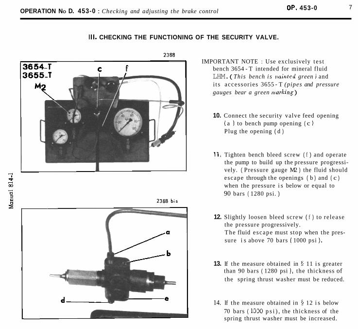
OPERATION NO D. 453-0 : Checking and adjusting the brake control OP. 453-0 7
Ill. CHECKING THE FUNCTIONING OF THE SECURITY VALVE.
IMPORTANT NOTE : Use exclusively t e s t bench 3654 - T intended for mineral fluid LHM. ( This bench i s [~uin ted green ) and i t s accessor ies 3655 - T (pipes and pressure gauges bear a green rmzrking )
10. Connect the security valve feed opening ( a ) to bench pump opening ( c ) Plug the opening ( d )
11, Tighten bench bleed screw ( f ) and operate the pump to build up the pressure progressi- vely. ( Pressure gauge M2 ) the fluid should escape through the openings ( b ) and ( c ) when the pressure i s below or equal to 90 bars ( 1280 psi. )
12. Slightly loosen bleed screw ( f ) to re lease the pressure progressively. The fluid e scape must s top when the pres- sure i s above 70 bars ( 1000 psi ) .
13. If the measure obtained in 5 11 i s greater than 90 bars ( 1280 psi ), the thickness of the spring thrust washer must be reduced.
14. If the measure obtained in 5 12 i s below 70 bars ( 1000 p s i ) , the thickness of the spring thrust washer must be increased.

8 OPERATION No D. 453-0 : Checking and adjusting the brake control.
IV. CHECKING THE SECURITY VALVE PRESSURE SWITCH.
2388 bis
IMPORTANT NOTE : Use exclusively t e s t bench 3654 - T intensed for mineral fluid LHM. ( t h i s bench is painted green) and i t s accesso- r ies 3655 - T (p ipes and pressure gauges bear a green marking )
15. Connect the securi ty valve feed opening ( a ) to bench pump opening ( c ). Seal the three other valve openings ( b, d, e ) by means of plugs.
16. Connect the pressure switch plug to bench terminal ( h ) and the two other bench leads to the terminals of a battery. The bench test lamp must illuminate.
17. Tighten bench bleed screw (3) and operate the pump to build up the pressure progressively (pressure gauge M1) until the tes t lamp goes out. This should occur between : - 55 and 8 5 bars (800 and 1230 psi)
for vehicles 4 3/ 1973 - 75 and 95 bars (1067 to 1351 ps i )
for vehicles + 3/ 1973
18. Build up the pressure to 100 bars (1420 psi) approximately, then slowly loosen the bleed screw in order to release the pressure progre progressive1 y, The tes t lamp must illuminate when the pressure i s between (pressure gauge M1) : - 8 5 and 55 bars (1230 and 800 psi)
for vehicles 4 3/ I973 - 95 and 75 bars (1351 and 1067 psi)
for vehicles + 3/1973 If the measures obtained are beyond these
limits, the pressure switch must be renewed,
V. CHECKING THE SECURITY VALVE FOR LEAKS
19. Connect the securi ty valve feed opening ( a ) to bench pump opening ( c ). Seal the openings ( b, d , e ) by means of plugs. Tighten bench bleed screw ( g ) and build up the pressure to 175 bars ( 24 90 psi ) This pressure i s to be maintained for 1 minute, after this time has e lapsed , there must be no leakage from opening ( f ) if there i s , the secu- rity valve must be renewed,

OPERATION No D. 454 - 0 : Checking and adjusting the parking brake Op. D. 454 - 0 1
I VEHICLES ALL TYPES
1. ADJUSTING THE CLEARANCE BETWEEN CALIPER AND DISC.
NOTE : Access to the L.H. cal iper can be gained from under the vehicle
1. Put the front of vehicle on s tands 2. Loosen the screws (1) and insert a 4mm
shim between caliper and d i sc 3. Tighten the screws (1) to 100-110mAN
(10 to l lmkg. -72 to 79 f t . lbs) 4. Lower the vehicle to the ground.
2. ADJUSTING THE CLEARANCE BETWEEN BRAKE PADS AND DISC.
NOTE : Access to the L.H. cal iper can be gained from under the vehicle.
5.Put the front of vehicle on s t ands 6.With the brake completely off on vehicles
fitted with hydraulic gear change raise the pedal to the maximum and wedge i t with a p iece of wood of about 210mm high. P l a c e between the brake pads and the d isc on each s ide a 0, lmm shim having a surface equivalent t o that of the pads t o prevent them from rocking. Loosen the nuts (4) and (3) (ring spanner 12 sided 16mm A.F. thinned down to 3 mm or spanner 3559-5) Adjust the screws (2) (thin-jawed 14mm O.E. spanner) to bring the brake pads just in contact with the shim Tighten nuts (4) and (3) (ring spanner 12 sided 16mm a/f thinned down to 3mm or spanner 3559-5) Remove the shims Make sure that the wheel turns freely
7.Carry out the same adjustement on the other brake caliper.
8.Remove the wooden wedge from under the pedal on vehicle fitted with hydraulic gear change Lower the vehicle t o the ground

2 OPERATION NO D. 454-0 : Checking and adjusting the parking brake
Ill. ADJUSTING THE SHEATH TENSION
9. On vehicles fitted with mechanical gear change Put the front of vehicle on s tands
9a. On vehicle fitted with hydraulic gear change Remove the front left wing and the mudshield protecting the suspension mechanism. Put front of vehicle on s tands
10. With the brakes released a s indicated in 06 loosen locknut (3) and nut (4) bring the threaded s leeve (2) in contact with the sheath. Screw nut (4) to bring i t to within : 0,3 - 0,5mm from the end of the tube (a). Tighten the locknut (3). Remove the wooden wedge from underneath the pedal and check that the wheels turn freely.
1 1 . On vehicle fitted with mechanical gear change Lower the vehicle to the ground
1 1 a.On vehicle fitted with hydraulic gear change
- Remove the wooden wedge from under- neath the pedal
- Lower the vehicle t o the ground - F i t the mudshield protecting the
suspension mechanism and the front left wing

ELECTRICITY
OPERATION No DX. 510-00 : A s s e m b l y of e lec t r i ca l equipment . Op.DX.510-00 1
DX - DJ Sept . 1965 4 Sept . 1966 I BULB TABLE
Descript ion T y p e of bulb Quanti ty
Headlamp - Dip European P 4 5 t 4 l (ye l low s e l e c t i v e ) 12 V - 4 5 / 4 0 W
Front direct ion ind ica tors
Rear direct ion ind ica tors Stop lamp
BA - 15s - s i n g l e con tac t - 12 V - 15 W ( la rge bulb) On P a l l a s t x h i c l e s : s i n g l e c o n t a c t 12 V - 7 W ( large bulb)
Rear l amps Number p l a t e lamp Spare bu lbs
BA - 1 5 s - s i n g l e con tac t - 4 W P h i l i p s Holland 12.821
Front parking lamps BA 9 s - 1 2 V - 4 W-Tube 1 0 m m diameter
Front interior l amps ( o n I' -1 L LAS) BA 1 5 s - 12 V - 1 5 W ( lorqe bulb)
interior l amps Rear F e s t o o n 12 V - 7 W
P a n e l lamp Brake warning lamp Brake pad wear warning lamp
BA 9 s - 12 V - 2 W- tube 8,8 mm dia . Max. (NORMA 1529)
Charge warning lamp Clock lamp
F l a s h i n g indicator warning lamp Headlamp main beam warning lamp
BA 9 s - 2 4 V - 3 W
F e s t o o n 12 V- 4 W Boot lamp
Q.I. Headlamp (op t ion) Q.I. Bulb - 12 V - 5 5 W (NORMA 112)

ELECTRICITY -
WIRING DIAGRAM

OPERATION No DX. 510-00 : Assembly of electrical equipment. Op. Dm. 510-00 3
MARKING OF PARTS
1. Front right direction indicator.
2. Front right headlamp.
3. Front right QI headlamp.
4. Town horn.
5. Country horns.
6. Front left QI headlamp.
7. Front left headlamp.
8. Front left direction indicator.
9. Front right brake unit.
10. Starter motor.
11. Dynamo.
12. Voltage regulator.
13. Starter motor relay.
14. Battery,
15. SANOR relay for front right QI headlamps.
16. SANOR relay for front left QI headlamps.
17. SANOR relay for country horns.
18. SANOR relay for headlamp flasher.
19. Front left brake unit.
20. Blower for front heating.
21. Windscreen wiper motor.
22. Switch for interior lamps, operated by frontright-hand door.
23. Terminal for accessories.
24. Distributor.
25. Thermal sensor.
26. Ignition coil.
27. Brake pressure switch.
28. Stop lamp switch.
30. Switch for interior lamps, operated by front L.H. door.
31. Switch for front heating.
36. Charge warning lamp.
37. Switch for parking lamps.
38. Electric clock.
39. Switch for interior lumps.
40. Switch for QI headlamps.
41. Switch for lighting and horns.
42. Thermometer.
43. Warning lamp for headlamp main beam.
44. Bulbs lighting instrument panel.
45. Warning lamp for brake pressure switch.
46. Warning lamp for wear on front brake pads.
47. Fuel gauge.
48. Warning lamp for direction indicators.
49. Switch for direction indicators with switch forheadlamp flasher.
50. Rheostat for instrument and clock lighting.
51. Front right interior lamp.
52. Rheostat for fuel (gauge) unit.
53. Front left interior lamp.
54. Boot lamp.
55. Switch for boot lamp.
56. Rear right direction indicator.
57. Lamps for number plate,-rear andstop lamps, R.H.
58. Lamps for number plate,-rear and stop lamps , L.H.
59. Rear left direction indicator.
60. Switch for rear heater. (heating 15º C ( 59º F )
61. Blower for rear heater. (heating 15º C ( 59º F )
62. Switch for fresh air blower.
32. Ignition switch.
33. Cigar lighter.
34. Switch for starter motor relay.
35. Windscreen wiper switch.
63. Fresh air blower.
64. SANOR compressor relay.
65. Compressor for horns.
optional

OPERATION No DX 510-00 : Assembly of electrical equipment. Op. DX. 510-00 5
HarnessWire No
Colourof
ends Wiring schedule
Front 1 Red Starter motor relay (13)Red to starter motor relay switch (34)
Front 2 Green Starter motor relay (13)Black to regulator terminal « BAT » (12)Green to fusebox (29) (Nº 1 and 2 fuses)Black to switch for lighting and horns (41)Black to front right QI headlamp relay (15)Black to front left Ql headlamp relay (16)Black to country horn relay (17)Black to headlamp flasher relay (18)
Dynamo 3 Yellow Dynamo ( 11)Yellow to terminal « EXC » of regulator (12)
Dynamo 4 Brown Dynamo (11)
Brown to regulator earth (12)
Dynamo 5 Red Dynamo (11)Red to terminal « DYN » of regulator (12)
Front 6 Red Terminal « DYN » of regulator (12)Red to charge warning lamp (36)
Front 7 Yellow Fuse box (29) (fuse Nº 1)Green to windscreen wiper switch (35)Black to terminal for accessories (23)Black to windscreen wiper motor (21) (automatic stop)Yellow to cigar lighter (33)
Front 8 Blue Fusebox (29) (fuse No 2)Black to rear junctionRed to stop lamp switch (28)
Black to parking lamp switch (37)Black to clock (38)
Black + Mauve to ignition switch (32)
Front 9 Red Ignition switch (32)Violet to ignition coil (26)
Front 10 Violet Ignition switch (32)Violet to heater switch (31)Violet to fuel gauge (47)
to pressure switch warning lamp (45)to front brake pad wear warning lamp (46)
Violet to charge warning lamp (36)Violet to direction indicator switch (49)Violet to thermometer (42)Violet to switch (60) for rear heating (- 15º C (59º F))
Front 11 Blue Windscreen wiper switch (35)Blue to windscreen wiper motor (21)
Front 12 Red Windscreen wiper switch (35)Red to windscreen wiper motor (21)
Front 13 Blue Direction indicator switch (49)Violet to front R.H. junctionBlue to rear junction
Front 14 White Direction indicator switch (49)Violet to front L.H. junctionWhite to rear junction

OPERATION No DX 510-00 : Assembly of electrical equipment. Op. DX. 510-00 7
HarnessWire No
Colourof
endsSchedule of Wiring
Front
Front
Front
Front
Front
Front
Front
Front
15
16
17
18
19
20
21
22
GreenGreen
BrownBrown
GreyGrey
VioletViolet
BlueBlue
BlueBlue
WhiteYellow
WhiteWhite
Direction indicator switch (49)to direction indicator warning lamp (48)
Front brake pressure switch warning lamp (45)to pressure switch (27) for hydraulic brake unit
Warning lamp (46) for front brake padsto front L.H. harness
Stop lamp switch (28)to rear junction
Thermometer (42)to supply lead (18) for thermal sensor (25)
Switch (41) for lighting and hornsto front L.H. junction
Switch (41) for lighting and hornsto country horn relay (17)
Country horn relay (17)to front L.H. junction
Front 23 YellowYellowYellow
Switch (41) for lighting and hornsto QI headlamp switch (40)to headlamp flasher relay (18)
on PALLAS
Front
Front
Front
Front
Front
Front
Front
Front
Front
Front
24
25
26
27
28
29
30
31
32
33
WhiteYellowYellowBlue
YellowYellowYellow
WhiteMauve
WhiteMauve
MauveBlack
MauveMauveMauve
GreenGreenGreen
MauveMauve
RedMauve
RedBlue
RedRedRed
Headlamp flasher relay (18)to front L.H. junctionto front R.H. junctionto main - beam warning lamp (43)
Switch (40) for QI headlampsto relay (15) for front R.H. QI headlamp (3)to relay (16) for front L.H. QI headlamp (6)
Relay (15) for front R.H. QI headlampto front R.H. junction
Relay (16) for front L.H. QI headlampto front L.H. junction
Relay (18) for headlamp flasherto switch for direction indicators (49)
Earth :to relay (15) for front R.H. QI headlampto relay (16) for front L.H. QI headlampto relay (17) for country horns
Switch (41) for lighting and hornsto front R.H. junctionto front L.H. junction
Switch (41) for lighting and hornsto fuse box (29) (fuse Nº 3)
Fuse box (29) (fuse Nº 3)to rear junctionto rheostat (50) for lighting instrument panelto switch for parking lamps (37)
Rheostat for lighting instrument panel (50)to lamps lighting instrument panel (44)to clock lamp (38)

OPERATION No DX 510-00 : Assembly of electrical equipment. Op. DX. 510-00 9
HarnessWireNo
Colourof
endsSchedule of Wiring
Front
Front
Front
Front
Flying lead
Flying lead
Flying lead
Flying lead
Front R.H.
Front R.H.
Front R.H.
Front R.H.
Front R.H.
Front R.H.
Front L.H.
Front L.H.
Front L.H.
Front L.H.
Front L.H.
Front L.H.
34
35
36
37
38
39
40
42
13
24
26
30
34
42
14
17
20
22
24
27
RedRedRed
GreenRedGreen
BrownBrown
MauveMauve
BrownBrownBrown
Red
YellowYellow
Brown
VioletViolet
YellowYellow
MauveMauve
GreenGreen
RedRed
BrownBrownBrown
VioletViolet
GreyGrey
BlueBlue
WhiteWhite
YellowYellow
MauveMauve
Switch (37) for parking lampsto front R.H. junctionto rear junction
Switch (37) for parking lampsto front L.H. junctionto rear junction
Interior lamp switch (39)to rear junctionto switch on front R.H. door pillar (22)to switch on front L.H. door pillar (30)
Switch (31) for front heatingto heater blower motor (20)
Earth :to switch (34) for starter motor relayto switch (39) for interior lampsto clock (38)
Ignition coil (26)to distributor (25)
Earth :to switch (49) for direction indicators
Earth :to brake pressure switch (27)
Front R.H. junctionto R.H. direction indicator (1)
Front R.H. junctionto front R.H. headlamp (2) (main beam)
Front R.H. junctionto R.H. QI headlamp (3)
Front R.H. junctionto front R.H. headlamp (2) (dipped)
Front R.H. junctionto front R.H. headlamp (2) (sidelamp - parking lamp)
Earth :to front R.H. direction indicator (1)to front R.H. headlamp (2)to R.H. QI headlamp (3)
Front L.H. junctionto front L.H. direction indicator (8)
Front L.H. junctionto harness for front brake pads (9) and (19)
Front L.H. junctionto town horn (4)
Front L.H. junctionto country horns (5)
Front L.H. junctionto front L.H. headlamp (7) (main beam)
Front L.H. junctionto L.H. QI headlamp (6)

OPERATION No DX 510-00 : Assembly of electrical equipment. Op. DX. 510-00 11
HarnessWireNo
Colourof
endsSchedule of Wiring
Front L.H.
Front L.H.
Flying lead
Rear
Rear
Rear
Rear
Rear
Rear
Rear
Rear
Rear
Rear
Flying lead
Flying lead
Horn harness to compressor
-do-
-do -
-do-
30
35
43
8
13
14
18
32
34
35
36
44
45
46
47
48
49
50
51
GreenGreen
RedRed
BrownBrownBrown
BlackBlack
BlueBlue
WhiteBlue
VioletRedRed
MauveMauveMauve
RedGreen
GreenGreen
BrownBrown
YellowYellow
GreyRed
VioletMauve
BlackBlack
BlackBlack
WhiteYellow
WhiteWhite
BrownMauveBrown
Front L.H. junctionto front L.H. headlamp (7) (dipped)
Front L.H. junctionto front L.H. headlamp (7).(sidelamp- parking lamp)
Earth :to front L.H. direction indicator (8)to front L.H. headlamp (7)to L.H. QI headlamp (6)
Rear junctionto front R.H. (51) and L.H. (53) interior lamps
Rear junctionto front R.H. direction indicator (56)
Rear junctionto rear L.H. direction indicator (59)
Rear junctionto rear R.H. stop lamp (57)to rear L.H. stop lamp (58)
Rear junctionto R.H. number plate lamp (57)to L.H. number plate lamp (58)to boot lamp (54)
Rear junctionto rear R.H. parking lamp (or rear lamp) (57)
Rear junctionto rear L.H. parking lamp (or-rear lamp) (58)
Rear junctionto front R.H. (51) and L.H. (53) interior lamps.
Petrol gauge (47)to rheostat for petrol gauge (52)
Switch (60) for rear heating (- 15º C (59º F ))to blower motor (61) for rear heating (- 15º C (59°F))
OPTIONAL FITTINGS :
1) on request a fresh air blower (63) is fitted.jumper lead Vi 10 feeds the switch (62)flying lead Mv 46 feeds the fresh air blower (63)
2) on request an air horn (65) is fitted.regulator (12) terminal « BAT »to junction on horn harness
Junction on horn harnessto « SANOR » relay (64) (terminal 1)
Country horns (5)to « SANOR » relay (64) (terminal 3)
« SANOR » relay (64) (terminal 2)to compressor (65)
Earth :to « SANOR » relay (64) (terminal 4)to compressor (65)

OPERATION No DY. 510-00 : Arrangement of the electrical installation. Op. DY. 510-00 1
DY - DL - DE September 1965 September 1966
BULB TABLE
Description
Headlamp-main/dipped
Front flashersRear flashersStop lamp
Rear lampsNumber plate lampSpare bulbs
Front parking lamps
Front interior lamps on « PALLAS »
Quantity
2
6
6
2
2
Type of bulb
European P.45 E 41 (yellow selective) 12 v 45/40 w.
B.A. - 15 s - single contact 12 v - 15 w ( large bulb)On « Pallas » vehicles-single contact - 12v - 7w (large bulb)
B.A. - 15 s - single contact 12 v - 4 w Philips Hollande 12.821
B.A. 9 s - 12 v - 4 w tube diameter 10 mm
B.A. - 15 s - 12 v - 15 w ( large bulb )
FrontRear
Interior lamps 4 Festoon 12 v - 7 w
Dashboard lampBrake pressure warning lampBrake pad warning lamp
Charge warning lampClock lamp
Flasher warning lampHeadlamp warning lamp
Boot lamp
Optional Q.I. headlamp
4
2
2
1
2
B.A. - 9 s - 12 v - 2 w tube diameter 8,8 maxi (norma 1529)
B.A. - 9 s - 12 v - 1.5 w
B.A. 9 s -24v-3w
Festoon 12 v - 4 w
Q.I. bulb 12 v - 55 w (norma 112)

E L E C T R I C I T Y
Ley to colours
Red R Black N Violet Vi Mauve Mv Green Ve Brown Mr Blue BI White Bc Yellow J Grey Gr
WIRING DIAGRAM

OPERATION N0 DY. 510-00 : Arrangement of the electrical installation. Op. DY. 510-00 b 3
SCHEDULE OF PARTS
1. Front RH direction indicator
2. Front RH headlamp
3. Front RH Q.I. headlamp
4. Town horn
5. Country horns
6. Front LH Q.I. headlamp
7. Front LH headlamp
8. Front LH direction indicator
9. Starter motor
10. Dynamo
11. Voltage regulator
12. Starter motor relay
13. Battery
14. «SANOR» relay for front RH Q.I. headlamp
15. «SANOR» relay for front LH Q.I. headlamp
16. «SANOR» relay for headlamp flasher
17. Front heating blower motor
18. Windscreen wiper motor
19. Front RH door pillar switch
20. Accessory terminal
36. Interior lamp switch
37. Q.I. headlamp switch
38. Lighting and horn switch
39. Thermometer
40. Headlamp warning lamp
41. Dashboard lamp
42. Brake pressure switch warning lamp
43. Fuel gauge
44. Direction indicator warning lamp
45. Switch for direction indicators and headlamp flasher
46. Rheostat for dashboard and clock lamps
47. Front RH interior lamp
48. Rheostat for fuel gauge
49. Front LH interior lamp
50. Boot lamp
51. Boot lamp switch
52. Rear RH direction indicator
53. Rear RH number plate and stop lamps
54. Rear LH number plate and stops lamps
55. Rear LH direction indicator
21. Distributor
22. Thermal sensor
23. Ignition coil
24. Brake pressure switch
25. Stop lamp switch
26. Fuse box
27. Front LH door pillar switch
28. Front heating switch
29. Ignition switch .
30. Cigar lighter
31. Starter motor relay switch
32. Windscreen wiper switch
33. Charge warning lamp
34. Parking lamp switch
35. Electric clock
56. Rear heating switch (15º C)
( - 59º F )
57. Rear heating blower (15º C) ( - 59’F )
58. Fresh air blower switch fittings
59. Fresh air blower
60. «SANOR » relay for air horn
61. Compressor
} optional fittings
NOTE : On DS 19 Pallas vehicles the headlamp flasher relay on the scuttle (in the case of the DS 19)is on the battery with the Q.I. headlamp relay.
On Safaris and ID 19 A, there is no headlamp flasher

OPERATION No DY 510-00 : Arrangement of the electrical installation. Op. DY. 510-00 5
HarnessWireNo
Colourof
endsWiring Schedule
Front
Front
Dynamo
Dynamo
Dynamo
Front
Front
Front
Front
Front
Front
Front
Front
1
2
3
4
5
6
7
8
9
10
11
12
13
RedRed
GreenBlackGreenBlackBlackBlackBlack
YellowYellow
BrownBrown
RedRed
RedRed
YellowGreenBlackBlackYellow
BlueBlackRed
BlackBlack
Black/ mauve
RedViolet
VioletVioletViolet
VioletVioletVioletViolet
BlueBlue
Red
BlueVioletBlue
Starter motor relay ( 12 )To starter motor relay switch ( 31 )
Starter motor relay ( 12 )To « BAT » terminal of voltage regulator ( 11)To fuse box (26) (fuse no 1 and 2)To lighting and horn switch ( 38 )To front RH Q.I. headlamp ( 14 )To front LH Q.1 headlamp ( 15 )To headlamp flasher relay ( 16 )
Dynamo ( 10 )To « EXC » terminal of voltage regulator ( 11 )
Dynamo ( 10 )To earth on voltage regulator ( 11 )
Dynamo ( 10 )To « DYN » terminal on voltage regulator ( 11 )
« DYN » terminal on voltage regulatorTo charge warning lamp ( 35 )
Fuse box ( 26 ) ( fuse nº 1 )To windscreen wiper motor switch ( 32 )To accessory terminal ( 20 )To windscreen wiper motor ( 18 ) (automatic stop)To cigar lighter ( 30 )
Fuse box ( 26 ) ( fuse no 2 )To rear junctionTo stop lamp switch ( 25 )To parking lamp switch ( 34 )To clock ( 35 )To ignition switch ( 29 )
Ignition switch ( 29 )To ignition coil ( 23 )
Ignition switch ( 29 )To heater switch ( 28 )To fuel gauge ( 43 )To brake pressure switch warning lamp ( 42 )To charge warning lamp ( 33 )To direction indicator switch ( 45 )To thermometer ( 39 )To front heater switch ( 56 ) ( cold - 59°F )
Windscreen wiper switch ( 32 )To windscreen wiper motor ( 18 )
Windscreen wiper switch ( 32 )To windscreen wiper motor ( 18 )
Direction indicator switch ( 45 )To front RH junctionTo rear junction

OPERATION No DY 510-00 : Arrangement of the electrical installation. Op. DY. 510-00 7
HarnessWireNo
Colourof
endsWiring Schedule
Front
Front
Front
Front
Front
Front
Front
Front
Front
Front
Front
Front
Front
Front
Front
Front
Front
14
15
16
18
19
20
22
23
24
25
26
27
28
29
30
31
32
WhiteVioletWhite
GreenGreen
BrownBrown
VioletViolet
BlueBlue
BlueBlue
WhiteWhite
YellowYellowYellow
WhiteYellowYellowBlue
YellowYellowYellow
WhiteMauve
WhiteMauve
MauveBlack
MauveMauveMauve
GreenGreenGreen
MauveMauve
RedMauveRedBlue
Direction indicator switch ( 45 )To front LH junctionTo rear junction
Direction indicator switch ( 45 )To direction indicator warning lamp ( 44 )
Brake pressure switch warning lamp ( 42 )To hydraulic brake unit pressure switch ( 24 )
Stop lamp switch ( 25 )To rear junction
Thermometer ( 39 )To feed wire for thermal sensor
Lighting and horn switch ( 38 )To rear junction LH
Lighting and horn switch ( 38 )To rear junction LH
Lighting and horn switch ( 38 )To Q.L headlamp switch ( 37 ) ( Pallas )To headlamp flasher relay ( 16 ) ( terminal 3 )
Headlamp flasher relay ( 16 ) ( terminal 2 )To front LH junctionTo front RH junctionTo headlamp warning lamp ( 40 )
Q.I. headlamp switch ( 37 )To front RH headlamp ( 3 ) relay ( 14 ) ( terminal 3 )To front LH headlamp ( 6 ) relay ( 15) ( terminal 3 )
Front RH Q.I. headlamp relay ( 14 ) ( terminal 2 )To front RH junction
Front LH Q.I. headlamp relay ( 15 ) ( terminal 2 )To front RH junction
Headlamp flasher relay ( 17 ) ( terminal 4 )To direction indicator switch ( 45 j
EarthTo front RH Q.I. headlamp relay ( 14 ) ( terminal 4 )To front LH Q.I. headlamp relay ( 15) ( terminal 4 )
Lighting and horn switch ( 38 )To front RH junctionTo front LH junction
Lighting and horn switchTo fuse box ( 26 ) ( fuse Nº 3 )
Fuse box ( 26 ) ( fuse No 3 )To rear junctionTo rheostat ( 46 ) for dashboard lampTo parking lamp switch ( 34 )

OPERATION No DY 510-00 : Arrangement of the electrical installation. Op. DY. 510-00 9
HarnessWireNo
Colourof
endsWiring Schedule
Front
Front
Front
Front
Front
Flying lead
Flying lead
Flying lead
Flying lead
Front RH
Front RH
Front RH
Front RH
Front RH
Front RH
Front LH
33
34
35
36
37
38
39
40
41
13
24
26
30
34
42
14
RedRedRed
RedRedRed
GreenRedGreen
BrownBrown
MauveMauve
BrownBrownBrown
RedRed
YellowYellow
Brown
VioletViolet
YellowYellow
MauveMauve
GreenGreen
RedRed
BrownBrownBrown
VioletViolet
Rheostat ( 46 ) for dashboard lampTo dashboard lamp ( 41 )To clock lamp ( 35 )
Parking lamp switch ( 34 )To front RH junctionTo rear junction
Parking lamp switch ( 34 )To front LH junctionTo rear junction
Interior lamp switch ( 36 )To rear junctionTo RH door pillar switch ( 19 )To LH door pillar switch ( 27 )
Front heating switch ( 28 )To heating unit motor ( 17 )
EarthTo starter motor relay switch ( 31 )To interior lamp switch ( 36 )To clock ( 35 )
Ignition coil ( 23 )To distributor ( 21 )
EarthTo direction indicator switch ( 45 )
EarthTo brake pressure switch ( 24 )
Front RH junctionTo RH direction indicator ( 1 )
Front RH junctionTo front RH headlamp ( 2 ) main beam
Front RH junctionTo front Q.I. headlamp ( 3 )
Front RH junctionTo front RH headlamp ( 2 ) dipped beam
Front RH junctionTo front RH headlamp ( sidelamp - parking lamp ) ( 2 )
EarthTo front RH direction indicator ( 1 )To front RH headlamp ( 2 )To RH Q.I. headlamp ( 3 )
Front LH junctionTo front LH direction indicator ( 8 )

OPERATION No DY 510-00 : Arrangement of the electrical installation. Op. DY. 510-00 11
HarnessWireNo
Colourof
endsWiring Schedule
Front LH
Front LH
Front LH
Front LH
Front LH
Front LH
Flying lead
Rear
Rear
Rear
Rear
Rear
Rear
Rear
Rear
Rear
Rear
20
22
24
27
30
35
43
8
13
14
18
32
34
35
36
44
45
BlueBlue
WhiteWhite
YellowYellow
MauveMauve
GreenGreen
RedRed
BrownBrownBrown
BlackBlack
BlueBlue
WhiteBlue
VioletRedRed
MauveMauveMauve
RedGreen
GreenGreen
BrownBrown
YellowYellow
GreyRed
Front LH junctionTo town horn ( 4 )
Front LH junctionTo country horns ( 5 )
Front LH junctionTo front LH headlamp ( 7 ) ( main beam )
Front LH junctionTo front LH Q.I. headlamp ( 6 )
Front LH junctionTo front LH headlamp ( 7 ) ( dipped beam )
Front LH junctionTo front LH headlamp ( 7 ) ( side lamp - parking lamp )
EarthTo front LH direction indicator ( 8 )To front LH headlamp ( 7 )To front LH Q.I. headlamp ( 6 )
Rear junctionTo front RH ( 47 ) and front LH ( 48 ) interior lamps
Rear junctionTo rear RH direction indicator ( 52 )
Rear junctionTo rear LH direction indicator ( 55 )
Rear junctionTo rear RH stop lamp ( 53 )To rear LH stop lamp ( 54 )
Rear junctionTo RH number plate lamp ( 53 )To LH number plate lamp ( 54 )To boot lamp ( 50 )
Rear junctionTo rear RH parking lamp ( or rear lamp ) ( 53 )
Rear junctionTo rear LH parking lamp ( or rear lamp ) ( 54 )
Rear junctionTo front RH ( 47 ) and front LH ( 49 ) interior lamps
Fuel gaugeTo fuel gauge ( 48 ) rheostat
Rear heating switch ( 56 ) ( - 59°F )To rear heating blower motor ( 57 ) ( - 59º F )

OPERATION No DY 510-00 : Arrangement of the electrical installation. Op. DY. 510-00 13
HarnessWireNo
Colourof
endsWiring Schedule
Flying lead
Air horn
Air horn
Air horn
Air horn
47
40
49
50
51
VioletMauve
BlackBlack
BlackBlack
YellowWhite
WhiteWhite
MauveBrownBrown
OPTIONAL FITTINGS.
1. On request a fresh air blower ( 59 ) is fitted. A jump leadVi 10 feeds the switch ( 58 ). A flying lead Mv 46 feedsthe blower motor ( 59 )
Voltage regulator ( 11 ) ( terminal « BAT » )To junction on the air horn harness
Junction on the flying feeder leadTo terminal ( 1 ) on « SANOR » relay ( 60 )
Terminal ( 3 ) on « SANOR » relay ( 60 )To country horn ( 5 )
Terminal (2 ) on « SANOR » relay ( 60 )To compressor ( 61 )
Terminal ( 4 ) on « SANOR » relay ( 60 )To compressor ( 61 )To chassis earth

OPERATION N0 DX. 510-00 a: Assembly of electrical equipment. Op. DX. 510-00 a 1(battery on the R.H. side)
DX, DJ, DY, DL September 1967 September 1967
DS 21 AND DS 21 M VEHICLES
MARKING OF PARTS
1. Front right direction indicator
2. Front right headlamp
3. Front right Ql headlamp
4. Town horn
5. Country horns
6. Front left QI headlamp
7. Front left headlamp
8. Front left direction indicator
9. Voltage regulator
10. Front right brake unit
11. Starter motor relay
12. Battery
13. Starter motor
14. Dynamo
15. Front left brake unit
16. Blower for front heating
17. Windscreen wiper motor
18. Terminal for accessories
19. R.H. fuse box
20. « SANOR » relay for headlamp flasher
21. « SANOR » relay for R.H. QI headlamp
22. « SANOR » relay for L.H. QI headlamp
23. Thermal sensor
24. Distributor
25. Brake pressure switch
26. Stop lamp switch
36. Charge warning lamp
37. Switch for parking lamps
38. Electric clock
39. Switch for interior lamps
40. Switch for QI headlamps
41. Switch for lighting and horns
42. Thermometer
43. Warning lamp for headlamp main beam
44. Lamps lighting instrument panel
45. Warning lamp for brake pressure switch
46. Warning lamp for front brake pad wear
47. Fuel gauge
48. Warning lamp for direction indicators
49. Switch for direction indicators with switch for headlamp flasher
50. Rheostat for instrument and clock lighting
51. Fuel gauge unit rheostat
52. Front interior light R.H.
53. Front interior light L.H.
54. Boot lamp
55. Boot lamp switch
56. Rear right direction indicator.
57. Lamp for number plate, rear lamp and stoplamp - R.H
58. Lamp for number plate, rear lamp and stoplamp - L.H
59. Rear left direction indicator.27. Ignition coil
28. L.H. fuse box
29. Switch for interior lamp, operated by front R.H. door
30. Switch for interior lamp, operated by front L.H. door
31. Switch for front heating
32. Ignition switch
33. Cigar lighter
34. Switch for starter motor relay
35. Windscreen wiper switch
60. Switch for rear heating -15ºC ( 59ºF )
61. Blower motor for rear heating -15ºC(59ºF)
62. Switch for fresh air blower motor
63. Fresh air blower
64. « SANOR » compressor horn relay
65. Horn compressor
}}}
optional
optional
optional
NOTE : DS 19 and DS 19 MA VEHICLES
The assembly of the electrical equipment for the DS 19 A and DS 19 MA is slightly different from thatof the DS 21 and DS 2 1 A in that :
1º) There is no front brake pad wear warning lamp.
2º) There is only one country horn.

E L E C T R I C I T Y -
WIRING DIAGRAM
Colour code
Red R Black N Violet V Green Ve Brown Mr Blue B1 White Bc Yellow J Grey Gr Mauve Mv

OPERATION Nº DX 510-00 a : Assembly of electrical equipment. Op. DX. 510-00 a 3(battery on the R.H. side)
HarnessWireNo
Colourof
endsSchedule of Wiring
Front
Front
Front
Front
Front
Front
Front
Front
Front
Front
1
2
3
4
5
6
7
8
9
10
RedRed
GreenBlackYellowWhiteRedBlackBlackBlackBlack
YellowYellow
BrownBrown
RedRedRed
YellowBlackBlackYellowGreen
WhiteBlackRedBlackBlackBlack
RedViolet
VioletVioletVioletVioletViolet
VioletViolet
BlueBlue
Starter motor relay (11)to starter motor switch (34)
Starter motor relay (11)to regulator (9) terminal « BAT »to R.H. fuse box (19) (fuse Nº 2)to R.H. fuse box (19) (fuse Nº 1)to ignition switch (32)to switch (41) for lighting and hornsto headlamp flasher relay (20) (terminal 1)to relay for R.H. QI bulb (21) (terminal 1)to relay for L.H. QI bulb (22) (terminal 1)
Dynamo (14)to regulator (9) (« EXC » terminal)
Dynamo (14)to regulator earth (9)
Dynamo (14)to regulator (9) (« DYN » terminal)to charge warning lamp (36)
R.H. fuse box (19) (fuse Nº 2)to windscreen wiper motor (1’7) (automatic stop)to terminal for accessories (18)to cigar lighter (33)to windscreen wiper switch (35)
R.H. fuse box (19) (fuse Nº 1)to rear junctionto stop lamp switch (26)to ignition switch (32)to switch (37) for parking lampsto clock (38)
Ignition switch (32)to ignition coil (27)
Ignition switch (32)to charge warning lamp (36)to switch (31) for front heatingto thermometer (42)to fuel gauge (47)to front brake pad wear warning lamp (46)to brake pressure switch warning lamp (45)to switch (49) for direction indicatorsto switch (60) for rear heating ( -15º C -59º F)
Windscreen wiper switch (35)to windscreen wiper motor (17)

OPERATION Nº DX 510-00 a : Assembly of electrical equipment. Op. DX. 510-00 a 5(battery on the R.H. side)
HarnessWireNo
Colourof
endsSchedule of Wiring
Front
Front
Front
Front
Front
Front
Front
Front
Front
Front
Front
Front
Front
Front
Front
Front
11
12
13
14
15
16
17
18
19
20
21
22
23
24
25
26
RedRed
BlueVioletBlue
WhiteVioletWhite
GreenGreen
BrownBrown
GreyGrey
VioletViolet
BlueBlue
BlueBlue
WhiteWhite
YellowYellowYellow
WhiteYellowYellowBlue
YellowYellowYellow
WhiteMauve
WhiteMauve
GreenGreenGreen
Windscreen wiper switch (35)to windscreen wiper motor (17)
Switch (49) for direction indicatorsto front R.H. wing junctionto rear junction
Switch (49) for direction indicatorsto front L.H. wing junctionto rear junction
Switch (49) for direction indicatorsto warning lamp (48) for direction indicators
Warning lamp (45) for front brake pressure switchto brake pressure switch (25)
Warning lamp (46) for brake pad wearto front L.H. wing junction
Stop lamp switch (26)to rear junction
Thermometer (42)to feed wire for thermal sensor (23)
Switch (41) for lighting and hornsto front L.H. wing junction
Switch (41) for lighting and hornsto front L.H. wing junction
Switch (41) for lighting and hornsto switch (40) for QI headlampsto headlamp flasher relay (20) (terminal 3)
Headlamp flasher relay (20) terminal 2)to front L.H. wing junctionto front R.H. wing junctionto headlamp warning lamp (43)
Switch (40) for QI headlampsto relay (22) for L.H. QI headlamp (6) (terminal 3)to relay (21) for R.H. QI headlamp (3) (terminal 3)
Relay (21) for R.H. QI headlamp (terminal 2)to front R.H. wing junction
Relay (22) for L,.H. QI headlamp (terminal 2)to front L.H. wing junction
Switch (41) for lighting and hornsto front L.H. wing junctionto front R.H. wing junction

OPERATION Nº DX 510-00 a : Assembly of electrical equipment. Op. DX. 510-00 a 7(battery on the R.H. side)
HarnessWireNo
Colourof
endsSchedule of Wiring
Front
Front
Front
Front
Front
Front
Front
Front
Flying lead
Flying lead
Flying lead
Flying lead
Flying lead.
Front R.H.
Front R.H
27
28
29
30
31
32
33
34
35
36
37
38
39
12
22
MauveYellow
YellowMauveRedBlue
RedRedRed
RedRedRed
GreenRedGreen
MauveBlack
BrownBrown
MauveMauve
MauveMauveMauve
BrownBrownBrownBrown
YellowYellow
Brown
Red
VioletViolet
YellowYellow
Switch (41) for lighting and hornsto L.H. fuse box 28 (fuse Nº 1)
L.H. fuse box (28) (fuse Nº 1)to rear junctionto rheostat (50) for lighting instrument panel and clockto parking lamp switch (37)
Rheostat (50).for lighting instrument panel and clockto lamps lighting instrument panel (44)to clock lamp (38)
Switch for parking lamps (37)to R.H. wing junctionto rear junction
Parking lamp switch (37)to L.H. wing junctionto rear junction
Head lamp flasher relay (20) (terminal 4)to switch (49) for direction indicators
Switch for interior lamp (39)to rear junctionto switch for interior lamp operated by front L.H. door (30)to switch for interior lamp operated by front R.H. door (29)
Switch for front heating (31)to blower motor (16)
Earthto relay (21) for R.H. QI headlamp (terminal 4)to relay (22) for L.H. QI headlamp (terminal 4)
Earthto switch (34) for starter relayto switch (39) for interior lampsto clock (38)
Earthto switch for direction indicators (49)
Earthto brake pressure switch (25)
Ignition coil (27)to distributor (24)
Front junction R.H.to R.H. direction indicator (1)
Front junction R.H.to front R.H. headlamp (2) (main beam)

OPERATION Nº DX 510-00 a : Assembly of electrical equipment. Op. DX. 510-00 a 9(battery on the R.H. side)
HarnessWireNo
Colourof
endsSchedule of Wiring
Front R.H.
Front R.H.
Front R.H.
Front R.H.
Front L.H
Front L.H.
Front L.H.
Front L.H.
Front L.H.
Front L.H.
Front L.H.
Front L.H.
Front L.H.
Flying lead
Rear
Rear
24
26
30
40
13
16
19
20
22
25
26
31
41
16
7
12
MauveMauve
GreenGreen
RedRed
BrownBrownBrownBrown
VioletViolet
GreyGrey
BlueBlue
WhiteWhite
YellowYellow
MauveMauve
GreenGreen
RedRed
Brown
GreyGrey
BlackBlack
BlueBlue
Front R.H. junctionto R.H. QI headlamp (3)
Front R.H. junctionto front R.H. headlamp (2) (dip)
Front R.H. junctionto front R.H. headlamp (2) (parking lamp-side lamp)
Earthto front R.H. direction indicator (1)
to front R.H. headlamp (2)to front R.H. QI headlamp (3)
Front L.H. junctionto front L.H. direction indicator (8)
Front L.H. junctionto harness for front brake pads (10) and (15)
Front L.H. junctionto town horn (4)
Front L.H. junctionto country horns (5)
Front L.H. junctionto front L.H. headlamp (7) (main beam)
Front L.H. junctionto L.H. QI headlamp (6)
Front L.H. junctionto front L.H. headlamp (7) (dip)
Front L.H. junctionto front L.H. headlamp (7) (parking lamp - side lamp)
Earth :to front L.H. direction indicator (8)to front L.H. headlamp (7)to QI headlamp (6)
Front R.H. brake unit (10)to front L.H. brake unit (15)
Rear junctionto front L.H. (53) and R.H. (52) interior lamps
Rear junctionto rear R.H. direction indicator (56)

OPERATION Nº DX 510-00 a : Assembly of electrical equipment. Op. DX. 510-00 a 11(battery on the R.H. side)
HarnessWire
No
Colourof
endsSchedule of Wiring
Rear
Rear
Rear
Rear
Rear
Rear
Rear
Rear
Flying lead
Flying lead
Horn
Harness
to compressor{
13
17
28
30
31
33
42
43
44
45
46
47
48
49
WhiteBlue
VioletRedRed
MauveMauveMauve
RedGreen
GreenGreen
BrownBrown
YellowYellow
GreyRed
VioletMauve
BlackBlack
BlackBlack
WhiteYellow
WhiteWhite
BrownMauveBrown
Rear junctionto rear L.H. direction indicator (59)
Rear junctionto rear R.H. stop lamp (57)to rear L.H. stop lamp (58)
Rear junctionto R.H. number plate lamp (57)to L.H. number plate lamp (58)to boot lamp (54)
Rear junctionto rear R.H. parking lamp (or rear lamp) (57)
Rear junctionto rear L.H. parking lamp (or rear lamp) (58)
Rear junctionto front R.H. (52) and L.H. (53) interior lamps
Fuel gauge (47)to rheostat for fuel gauge (51)
Switch (60) for rear heating ( - 15º C ( - 59º F ))to blower motor (61) for rear heating (- 15º C (- 59º F ))
OPTIONAL FITTINGS :
1) A fresh air blower (63) is fitted by requestA jumper lead Vi 9 feeds switch (62)A flying lead Mv 44 feeds cold air blower (63)
2) A compressor horn (65) is fitted by requestRegulator terminal « BAT » (9)to horn harness junction
Horn harness junctionto « SANOR » relay (64) (terminal 1)
Country horns (5)to « SANOR » relay (64) (terminal 3)
« SANOR » relay (64) (terminal 2)to compressor (65)
Earthto « SANOR » relay (64) (terminal 4)to compressor (65)

OPERATION Nº DV. 510-00 a : Assembly of electrical equipment. Op. DV. 510-00 a 1
DV Sept. 1966 Sept. 1967
BULB TABLE
Description
Main beam / dip
Front direction indicatorsRear direction indicatorsStop lamps
Rear lampsNumber plate lampSpare bulb,:
Front parking lamps
Interior lamp Panel lighting
Brake warning lamp
Charge warning lampClock lighting
Direction indicator warning lampMain beam warning lamp
Boot lamp
QI headlamp (optional)
Quantity
2
6
6
2
1
4
2
2
1
2
Type of bulb
European P 45 t 41 (yellow selective)12V - 45/40W
BA - 155 - single contact 12V - 15W (large bulb)
BA - 15 s-single contact 12V - 4W Philips Holland 12 821
BA 9s - 12V - 4W - tube diameter = 10 mm
BA 15s - 12V - 15W (large bulb)
BA 9s - 12V - 2W -tube diameter = 8,8 mm maxi (NORMA 1529)
BA 9s - 12V - 1,5W
BA 9s - 24V - 3W
Festoon 12V - 4W
QI bulb 12V - 55W (NORMA 112)

E L E C T R I C I T Y
WIRING DIAGRAM
Violet V i Green Ve Brown Mr Blue B I White Bc Yellow J Grey Gr Mauve Mv

OPERATION No DV. 510-00 a: Assembly of electrical equipment. Op. DV. 510-00 a 3
MARKING OF PARTS
1. Front R.H. direction indicator
2. Front R.H. headlamp
3. Front R.H. QI headlamp (optional)
4. 2 nd country horn
5. 1 st country horn
6. Front L.H. QI headlamp (optional)
7. Front L.H. headlamp
8. Front L.H. direction indicator
9. Voltage regulator
10. Starter motor relay
11. Battery
12. Starter motor
13. Dynamo
14. Blower for front heating
15. Pressure switch for security valve (brakes)
16. Windscreen wiper motor
17. Terminal for accessories
18. R.H. side fuse box
19. « SANOR » relay for front R.H. QI headlamp
20. « SANOR » relay for front L.H. QI headlamp
21. Thermal sensor
22. Stop lamp switch
23. Ignition coil
31. Charge warning lamp
32. Switch for parking lamp
33. Electric clock
34. Switch for interior lamp
35. Switch for QI headlamps (optional)
36. Switch for lighting and horns
37. Thermometer
38. Main beam warning lamp
39. Lamps lighting instrument panel
40. Warning lamp for brake pressure switch
41. Fuel gauge
42. Warning lamp for direction indicators
43. Switch for direction indicators
44. Rheostat for lamps lighting instrument paneland for clock
45. Rheostat for fuel gauge unit
46. Interior lamp
47. Boot lamp
48. Switch for boot lamp
49. Rear R.H. direction indicator
50. Number plate lamp, rear lamp and stop lamp,R.H. side
51. Number plate lamp. rear lamp and stop lamp,L.H. side
24. L.H. side fuse box
25. Switch on front R.H. door pillar
26. Switch on front L.H. door pillar
27. Switch for front heating
28. Ignition switch
29. Switch for starter relay
30. Windscreen wiper switch
52. Rear L.H. direction indicator
53. Switch for rear heating(- 15º C) (59º F)
54. Blower for rear heating(- 15º C),(59º F)
55. « SANOR » relay for horn compressor
56. Horn compressor
Optional
Optional

OPERATION Nº DV 510-00 a : Assembly of electrical equipment. Op. DV. 510-00 a 5
HarnessWireNo
Colourof
endsSchedule of Wiring
Front
Front
Dynamo
Dynamo
Dynamo
Front
Front
Front
Front
Front
Front
Front
1
2
3
4
5
6
7
8
9
10
11
12
RedRed
GreenBlackYellowBlackBlackBlackRed
YellowYellow
BrownBrown
RedRed
YellowGreenBlackBlack
GreenBlackRed
BlackBlackBlack
RedViolet
VioletVioletViolet
VioletVioletVioletViolet
BlueBlue
RedRed
BlueVioletBlue
Starter motor relay (10)to switch (29) for starter relay
Starter motor relay (10)to voltage regulator terminal (9) « BAT »to fuse box (18) (fuses N” 1 and 2)to switch (36) for lighting and hornsto relay (19) for front R.H. QI headlampto relay (20) for front L.H. QI headlampto lighting switch (28) (mauve marking)
Dynamo (13)to voltage regulator terminal (9) « EXC »
Dynamo (13)to voltage regulator earth (9)
Dynamoto voltage regulator terminal (9). « DYN »to charge warning lamp (31)
Fuse box (18) (fuse Nº 1)to windscreen wiper switch (30)to windscreen wiper motor (16) (automatic stop)to accessories terminal (17)
Fuse box (18) (fuse Nº 2)to rear junctionto stop lamp switch (22)to parking lamp switch (32)to clock (33)to lighting switch (28)
Lighting switch (28) (red marking)to ignition coil (23)
Lighting switch (28)to switch (27) for front heatingto fuel gauge (41)to warning lamp (40) for brake pressure switchto charge warning lamp (31)to switch for direction indicators (43)to thermometer (37)to switch (53) for rear heating (heating- 15º C)-(59ºF)
Windscreen wiper switch (30)to windscreen wiper motor (16)
Windscreen wiper switch (30)to windscreen wiper motor (16)
Direction indicator switch (43)to front junction R.H.to rear junction

OPERATION Nº DV 510-00 a : Assembly of electrical equipment. Op. DV. 510-00 a 7
HarnessWireNo
Colourof
endsSchedule of Wiring
Front
Front
Front
Front
Front
Front
Front
Front
Front
Front
Front
Flying lead
Front
Front
Front
13
14
15
16
17
18
19
20
21
22
23
24
25
26
27
WhiteVioletWhite
GreenGreen
BrownBrown
VioletViolet
BlueBlue
BlueBlue
WhiteWhite
YellowYellowYellowYellowBlue
YellowYellow
WhiteMauve
WhiteMauve
MauveMauveMauve
GreenGreenGreen
MauveYellow
YellowMauve
RedBlue
Switch (43) for direction indicatorsto front L.H. junctionto rear junction
Switch (43) for direction indicatorsto warning lamp (42) for direction indicators
Warning lamp (40) for brake pressure switchto security valve pressure switch (15)
Stop lamp switch (22)to rear junction
Thermometer (37)to feed wire for thermal sensor (21)
Switch (36) for lighting and hornsto front L.H. junction
Switch (36) for lighting and hornsto front L.H. junction
Switch (36) for lighting and hornsto switch (35) for QI headlampsto front R.H. junctionto front L.H. junctionto main beam warning lamp (38)
Switch (35) for QI headlampsto relay (19) for front R.H. QI headlamp (terminal 3)to relay (20) for front L.H. QI headlamp (terminal 3)
Relay (19) for front R.H. QI headlamp (terminal 2)to front R.H. junction
Relay (20) for front L.H. QI headlamp (terminal 2)to front L.H. junction
Earthto relay (19) for front R.H. QI headlamp (terminal 4)to relay (20) for front L.H. QI headlamp (terminal 2)
Switch (36) for lighting and hornsto front R.H. junctionto front L.H. junction
Switch (36) for lighting and hornsto fuse box (24)
Fuse box (24)to rear junctionto rheostat (44) for instrument panel lightingto switch (32) for parking lamps

OPERATION Nº DV 510-00 a : Assembly of electrical equipment. Op. DV. 510-00 a 9
HarnessWireNo
Colourof
endsSchedule of Wiring
Front
Front
Front
Front
Front
Flying lead
Flying lead
Front R.H.
Front R.H.
Front R.H.
Front R.H.
Front R.H.
Front R.H.
Front L.H.
Front L.H.
Front L.H.
28
29
30
31
32
33
34
12
20
22
25
29
35
13
18
19
RedRedRed
RedRedRed
GreenRedGreen
BrownBrown
MauveMauve
BrownBrownBrown
RedRed
VioletViolet
YellowYellow
MauveMauve
GreenGreen
RedRed
BrownBrownBrownBrown
VioletViolet
BlueBlue
WhiteWhite
Rheostat (44) for instrument panel lightingto lamps (39) lighting instrument panelto clock lamp (33)
Switch (32) for parking lampto front R.H. junctionto rear junction
Switch (32) for parking lampsto front L.H. junctionto rear junction
Switch (34) for interior lampsto rear junctionto switch (25) on front R.H. door pillarto switch (26) on front L.H. door pillar
Switch (27) for front heatingto blower motor (14)
Earthto switch (29) for starter motor relayto switch (34) for interior lampsto clock (33)
Ignition coil (23)to distributor
Front R.H. junctionto R.H. direction indicator (1)
Front R.H. junctionto front R.H. headlamp (2) (main beam)
Front R.H. junctionto R.H. QI headlamp (3)
Front R.H. junctionto front R.H. headlamp (2) (dip)
Front R.H. junctionto front R.H. headlamp (2) (sidelamp - parking lamp)’
Earthto R.H. direction indicator (1)to front R.H. headlampto QI headlamp (3)
Front L.H. junctionto L.H. direction indicator (8)
Front L.H. junctionto first country horn (5)
Front L.H. junctionto second country horn (4)

OPERATION Nº DV 510-00 a : Assembly of electrical equipment. Op. DV. 510-00 a 11
HarnessWireNo
Colourof
endsSchedule of Wiring
Front L.H.
Front L.H.
Front L.H.
Front L.H.
Front L.H.
Rear
Rear
Rear
Rear
Rear
Rear
Rear
Rear
Rear
Rear
Flying lead
20
23
25’
30
36
7
12
13
16
27
29
30
31
37
38
39
YellowYellow
MauveMauve
GreenGreen
RedRed
Brown
BlackBlack
BlueBlue
WhiteBlue
VioletRedRed
MauveMauveMauve
RedGreen
GreenGreen
BrownBrown
YellowYellow
GreyRed
BlackBlack
Front L.H. junctionto front L.H. headlamp (7) (main beam)
Front L.H. junctionto QI headlamp (6)
Front L.H. junctionto front L.H. headlamp (7) (dip)
Front L.H. junctionto front L.H.. headlamp (7) (sidelamp - parking lamp)
Earthto L.H. direction indicator (8)to front L.H. headlamp (7)to QI headlamp (6)
Rear junctionto interior. lamp (46)
Rear junctionto rear R.H. direction indicator (49)
Rear junctionto rear L.H. direction indicator (52)
Rear junctionto rear R.H. stop lamp (50)to rear L.H. stop lamp (51)
Rear junctionto R.H. number plate lamp (50)to L.H. number plate lamp (51)to boot lamp (47)
Rear junctionto rear R.H. parking lamp (or rear lamp) (50)
Rear junctionto rear L.H. parking lamp (or rear lamp ) (51)
Rear junctionto interior lamp (46)
Fuel gauge (41)to rheostat (45) for fuel gauge
Switch (53) for rear heating ( - 15º C ) (59º F )to blower motor (54) for rear heating ( - 15º C ) (59º F )
OPTIONAL FITTINGS :
1) A compressor horn is fitted on request
Voltage regulator (9) (« BAT » terminal)to horn harness junction

OPERATION Nº DV 510-00 a : Assembly of electrical equipment. Op. DV. 510-00 a 13
HarnessWireNº
Colourof
endsSchedule of Wiring
Hornto
compressor
Hornto
compressor
Hornto
compressor
Hornto
compressor
Flying lead
40
41
42
43
44
BlackBlack
WhiteYellow
WhiteWhite
BrownMauveBrown
Violet
MauveMauve
Horn harness junctionto « SANOR » relay (55) (terminal 1)
Second country horn (4)to « SANOR » relay (55) (terminal 3)
« SANOR » relay (55) (terminal 2)to compressor (56)
Earthto « SANOR » relay (55) (terminal 4)to compressor (56)
1) A fresh air blower is fitted on requesta jumper lead Vi (9) feeds switch (57)
Switch (57) for fresh air blowerto fresh air blower (58)

OPERATION No DX. 510-00 b : Arrangement of the electrical installation. Op. DX. 510-00 b 1
DX - DJ - DY - DL Sept. 1967 Dec. 1967
BULB TABLE
Description
Main beam/ dip
Q.I. headlamp
Auxiliary headlamp
Front direction indicators
Rear direction indicators
Quantity
2
2
2
2
Type of bulb.
European P45t 41 (yellow selective ) 12V - 45/40 W.
Q.1. bulb 12V- 55W ( Norma 112)
European P45t 41 (yellow selective) 12V - 45/40 W.( Main beam only )
BA 155 - single contact - 12V - 15W (pear-shaped bulb)MAZDA 1073
BA 155 - single contact - 12V - 15W (large bulb )
Stop lamps 4 On Pallas models : 2 stop lamp bulbs - single contact12V - 7W (large bulb)
Rear lampsNumber plate lightingSpare bulbs
Front parking lamps
Front interior lamps (on Pallas )
6
2
2
BA-15S- single contact - 12V - 4W - Philips Holland 12-821
BA 9S - 12V - 4W - tube diameter 10
BA 155 - 12V - 15W (large bulb)
FrontRear
Interior lamps 4 Festoon 12V - 7W
Instrument panel lightingBrake warning lampBrake pad wear warning lamp
Charge warning lampOil pressure warning lamp
Direction indicator warning lampMain beam warning lamp
Boot lamp
Clock lamp
4
2
2
1
1
BA 95 - 12V - 2W - tube diameter 8,8 maxi (Norma 1529)
BA 95 - 12V - 2W - base diameter 7.
BA 95 - 24V - 3W
Festoon 12V - 4W
BA 95 12V - 1,5W

Colour code
Red R Black N Violet V Green Ve Brown Mr Blue BI White Bc Yellow J Grey Gr Mauve Mv
ELECTRICITY -
WIRING DIAGRAM D. 51-24

OPERATION No DX. 510-00 b: Arrangement of the electrical installation. Op.DX. 510-00 b 3
VEHICLES DS 21 AND DS 21 M
MARKING OF PARTS.
1. Front R.H. direction indicator
2. Front R.H. headlamp
3. Auxiliary headlamp or Q.I. headlamp
4. R.H. country horn
5. L.H. country horn
6. Town horn
7. Auxiliary headlamp or Q.I. headlamp
8. Front L.H. headlamp
9. Front L.H. direction indicator
10. Relay for voltage regulator
11. Front R.H. brake unit
12. Front L.H. brake unit
13. Blower for front heating
14. Fresh air blower (optional)
15. Starter motor relay
16. Battery
17. Starter motor
18. « SANOR » relay for horn compressor ( Optional )
19. Horn compressor (optional )
20. Alternator
21. Thermal sensor
22. Engine oil pressure switch
23. Windscreen wiper motor
24. R.H. fuse box
25. Terminal for accessories
26. « SANOR » relay for headlamp flasher
27. « SANOR » relay for front R.H. auxiliary headlamp
28. « SANOR » relay for front L.H. auxiliary headlamp
29. Distributor
30. Ignition coil
31. Brake pressure switch
32. Stop lamp switch
33. L.H. fuse box
34. Switch on front L.H. door pillar
35. Switch on front L.H. door pillar
36. Switch for fresh air blower (optional )
37. Switch for rear heating ( -15ºC - 59ºF ) ( optional )
38. Switch for front heating
39. Ignition switch
40. Cigar lighter
41. Switch for starter motor relay.
42. Windscreen wiper switch
43. Engine oil pressure warning lamp
44. Charge warning lamp
45. Switch for parking lamps
46. clock
47. Switch for interior lamps
48. Switch for auxiliary or Q.I. headlamps
49. Switch for lighting and horns
50. Thermometer
51. Main beam warning lamp
52. Lamps lighting instrument panel
53. Brake pressure switch warning lamp
54. Front brake pad wear warning lamp
55. Fuel gauge
56. Warning lamp for direction indicators
57. Switch for direction indicators with
switch for headlamp flasher
58. Rheostat for fuel gauge unit.
59. Rheostat for fuel gauge unit
60. R.H. interior lamp
61. Rear heating unit ( - 15°C - 59º F ) ( optional )
62. L.H. interior lamp
63. Boot lamp
64. Switch for boot lamp
65. Rear R.H. direction indicator
66. Rear R.H. number plate lamp, rear lamp andstop lamp
67. Rear L.H. number plate lamp, rear lamp andstop lamp
68. Rear L.H. direction indicator
NOTE : Vehicles DS. 19A and DS. 19MA
The assembly of electrical equipment for the DS. 19A and DS. 19MA is slightly different from thatof the DS. 21 and DS. 21A in that :
1 ) There is no front brake pad wear warning lamp
2 ) There is only one country horn

OPERATION No DX 510-00 b: Arrangement of the electrical installation. Op. DX. 510-00 b 5
HarnessWire No
Colourof
ends Wiring schedule
Front 1 Red Starter relay ( 15 )Red To switch for starter relay ( 41 )
Front 2 Black Starter relay ( 15 ) ( not disconnectible )Black To voltage regulator + terminal ( 20 )Yellow To fuse box R.H. ( 24 ) ( fuse nº2 )White To fuse box R.H. ( 24 ) ( fuse nº1 )Red To ignition switch ( 39 )
Black To switch for lighting and horns ( 49 )Black To headlamp flasher relay ( 26 ) ( terminal 1 )Black To SANOR relay ( 27 ) for R.H. Q.I. headlamp ( terminal 1 )Black To SANOR relay ( 28 ) for L.H. Q.I. headlamp ( terminal 1 )
Front 3 Yellow Alternator ( 20 ) ( terminal « EXC » )Yellow To voltage regulator relay ( 10 ) ( terminal « EXC » )
Front 4 White Alternator ( 20 ) (terminal R )White To voltage regulator relay ( 10 ) ( terminal R )
Front 5 Red Voltage regulator relay ( 10 ) ( terminal L )Red To charge warning lamp ( 44 )
Front 6 Yellow Fuse box R.H. ( 24 ) ( fuse nº 2 )Black To windscreen wiper motor ( 23 ) (automatic stop)Black To terminal for accessories ( 25 )Yellow To cigar lighter ( 40 )Green To windscreen wiper switch ( 42 )
Front 7 White Fuse box R.H. ( 24 ) ( fuse nº 1 )Black To rear junctionRed To stop lamp switch ( 32 )
Black To ignition switch ( 39 )Black To parking lamp switch ( 45 )Black To clock ( 46 )
Front 8 Red Ignition switch ( 39 )Violet To ignition coil ( 30 )
Front 9 Violet Ignition switch ( 39 )Violet To charge warning lamp ( 44 )Violet To engine oil pressure warning lamp ( 43 )Violet To switch for front heating ( 38 )Violet To thermometer ( 50 )Violet To fuel gauge ( 56 )
To front brake pad wear warning lamp ( 54 )To brake pressure switch warning lamp ( 53 )
Violet To direction indicator switch ( 57 )Violet To switch for rear heating ( 37 )Violet To switch for fresh air blower ( 36)Violet To voltage regulator relay ( 10 ) ( terminal « BOB » )

OPERATION No DX 510-00 b: Arrangement of the electrical installation. Op. DX. 510-00 b 7
HarnessWire Nº
Colourof
ends Wiring schedule
Front 10 Blue Switch ( 42 ) for windscreen wiperBlue To windscreen wiper motor ( 23 )
Front 11 Red Switch ( 42 ) for windscreen wiperRed To windscreen wiper motor ( 23 )
Front 12 Blue Switch ( 57 ) for direction indicatorsViolet To front R.H. wing junctionBlue To rear junction
Front 13 White Switch ( 57 ) for direction indicatorsViolet To front L.R. wing junctionWhite To rear junction
Front 14 Green Switch ( 57 ) for direct/on indicatorsGreen To direction indicator warning lamp ( 56 )
Front 15 Brown Brake pressure switch warning lamp ( 53 )Brown To brake pressure switch ( 31 )
Front 16 Grey Front brake pad wear warning lamp ( 54 )Grey To front L.H. wing junction
Front 17 Violet Stop lamp switch ( 32 )Violet To rear junction
Front 18 Blue ThermometerBlue To feed wire for thermal sensor ( 21 )
Front 19 White Engine oil pressure warning lamp ( 43 )White To feed wire for engine oil pressure switch ( 22 )
Front 20 Blue Switch ( 49 ) for lighting and hornsBlue To front L.H. wing junction
Front 21 White Switch ( 49 ) for lighting and hornsWhite To front L.H. wing junction
Front 22 Yellow Switch ( 49 ) for lighting and hornsYellow To switch (48) for auxiliary headlampsYellow To headlamp flasher relay ( 26 ) ( terminal 3 )
Front 23 White Headlamp flasher relay ( 26 ) ( terminal 2 )Yellow To front L.H. wing junctionYellow To front R.H. wing junctionBlue To main beam warning lamp ( 51 )
Front 24 Yellow Switch ( 48 ) for auxiliary headlampsYellow To R.H. auxiliary headlamp relay ( 27 ) ( terminal 3 )Yellow To L.H. auxiliary headlamp relay ( 28 ) ( terminal 3 )

OPERATION No DX 510-00 b: Arrangement of the electrical installation. Op. DX. 510-00 b 9
HarnessWire Nº
Colourof
ends Wiring schedule
Front 25 White R.H. auxiliary headlamp relay ( 27 ) ( terminal 2 )Mauve To front R.H. wing junction
Front 26 White L.H. auxiliary headlamp relay ( 27) ( terminal 2 )Mauve To front L.H. wing junction
Front 27 Green Switch ( 49 ) for lighting and hornsGreen To front R.H. wing junctionGreen To front L.H. wing junction
Front 28 Mauve Switch ( 49 ) for lighting and hornsYellow To L.H. fuse box ( 33 ) ( fuse nº1 )
Front 29 Yellow L.H. fuse box ( 33 ) ( fuse no 1 )Mauve To rear junction
Red To rheostat ( 58 ) for instrument panel and clock lightingBlue To parking lamp switch ( 45 )
Front 30 Red Rheostat ( 56 ) for instrument panel and clock lightingRed To lamps ( 52 ) lighting instrument panelRed To clock lamp ( 46 )
Front 31 Red Switch ( 45 ) for parking lampsRed To front R.H. wing junctionRed To rear junction
Front 32 Green Switch ( 45 ) for parking lampsRed To front L.H. wing junction
Green To rear junction
Front 33 Mauve Headlamp flasher relay ( 26 ) ( terminal 4 )Black To direction indicator switch ( 57 )
Front 34 Brown Switch ( 47 ) for interior lampsBrown To rear junction
To switch ( 34 ) on front L.H. door pillarTo switch ( 35 ) on front R.H. door pillar
Front 35 Mauve Switch ( 38 ) for front heatingMauve To blower motor ( 13 )
Flying lead 36 Mauve Switch ( 36 ) for fresh air blowerMauve To blower motor ( 14 )
Flying lead 36 Red Ignition coil ( 30 )Red To distributor ( 29 )

OPERATION No DX 510-00 b: Arrangement of the electrical installation. Op. DX. 510-00 b 11
HarnessWire Nº
Colourof
ends Wiring schedule
Flying lead 37 Mauve EarthMauve To front R.H. auxiliary headlamp relay ( 27 ) ( terminal 4 )Mauve To front L.H. auxiliary headlamp relay ( 26 ) ( terminal 4 )
Flying lead 38 Brown EarthBrown To switch ( 41 ) for starter motor relayBrown To switch ( 47 ) for interior lampsBrown To clock ( 46 )
Flying lead 39 Yellow EarthYellow To switch ( 5’7 ) for direction indicators
Flying lead 40 Green Starter motor relay ( 15 )Black To horn compressor relay ( 16 ) ( terminal 1 )
Horn to 41 White R.H. country horn ( 4 )Compressor White To link wire
Yellow To « SANOR » relay ( 18 ) ( terminal 3 )
Horn to 42 White « SANOR » relay ( 18 ) ( terminal 3 )Compressor White To compressor ( 19 )
Horn to 43 Brown « SANOR » relay ( 16 ) ( terminal 4 )Compressor Brown To compressor ( 19 )
Brown To earth
Front R.H. 12 Violet Front R.H. junctionBlue To R.H. direction indicator ( 1 )
Front R.H. 23 Yellow Front R.H. junctionYellow To front R.H. headlamp ( 2 ) ( main beam )
Front R.H. 25 Mauve Front R.H. junctionMauve To R.H. auxiliary headlamp ( 3 )
Front R.H. 27 Green Front R.H. junctionGreen To front R.H. headlamp ( 2 ) ( dip )
Front R.H. 31 Red Front R.H. junctionRed To front R.H. headlamp ( 2 ) ( sidelamp - parking lamp )
Front R.H. 44 Brown EarthTo front R.H. direction indicator ( 1 )To front R.H. headlamp ( 2 ) ( sidelamp )To front R.H. headlamp ( 2 ) ( main beam-dip )To auxiliary headlamp ( 3 )
Front L.H. 13 Violet Front L.H. junctionBlue To front L.H. direction indicator ( 9 )

OPERATION No DX 510-00 b: Arrangement of the electrical installation. Op. DX. 510-00 b 13
HarnessWire Nº
Colourof
ends Wiring schedule
Front L.H. 16 Grey Front L.H. junctionGrey To harness for front brake pads ( 11 ) and ( 12 )
Front L.H. 20 Blue Front L.H. junctionBlue To town horn ( 6 )
Front L.H. 21 White Front L.H. junctionWhite To country horns ( 5 ) and ( 4 )
Front L.H. 23 Yellow Front L.H. junctionYellow To front L.H. headlamp ( 8 ) ( main beam )
Front L.H. 26 Mauve Front L.H. junctionMauve To L.H. auxiliary headlamp ( 7 )
Front L.R. 27 Green Front left hand junctionGreen To front L.H. headlamp ( dip ) ( 8 )
Front L.R. 32 Red Front L.H. junctionRed To front L.R. headlamp ( 8 ) ( sidelamp-parking lamp )
Front L.H. 45 Brown EarthBrown To front L.H. direction indicator ( 9 )Brown To front, L.H. headlamp ( 8 ) ( sidelamp )Brown To auxiliary headlamp ( 7 )Brown To front L.H. headlamp ( main beam and dip ) ( 8 )
Flying lead 16 Grey Front R.H. brake unit, ( 12 )Grey To front L.H. brake unit ( 11 )
Rear 7 Black Rear junctionBlack To R.H. ( 60 ) and L.H. ( 62 ) interior lamps
Rear 12 Blue Rear junctionBlue To rear R.H. direction indicator ( 65 )
Rear 13 White Rear junctionBlue To rear L.R. direction indicator ( 68 )
Rear 17 Violet Rear junctionRed To rear R.H. stop lamp ( 66 )Red To rear L.H. stop lamp ( 67 )
Rear 29 Mauve Rear junctionMauve To R.H. number plate lamp ( 66 )Mauve To L.H. number plate lamp ( 67 )
To boot lamp ( 63 )
Rear 31 Red Rear junctionGreen To rear R.H. parking lamp ( or sidelamp ) ( 66 )

OPE RATION No DX 510 - 00b : Arrangement of the electrical installation OP. DX 510-00b 1 5
Rear
R e a r
Rear
Rear
Harness
- Wire NO
Colour of
ends
Green Green
Brown Brown
Yellow Yellow
Grey Red
Schedule of wiring
Rear junction T o rear L.H. parking lamp ( or sidelamp ) ( 67 )
Rear junction T o R.H. ( 60 ) and L.H. ( 62 ) interior lamps
F u e l gauge ( 55 T o fuel gauge rheostat ( 59 )
Switch ( 3 7 ) for rear heat ing ( - 15OC - 5 g • ‹ F ) T o blower motor ( 61 ) for rear heat ing ( - 15O C 5g0 F )
NOTE :
T h e vol tage regulator ( 1 0 ) i s ea r thed by :
1 ) A flying lead ( 48 ) ( coloured brown ) joining upper R.H. securing sc rew on regulator to sc rew ( 1 ) on front R.H. sidemember.
2 ) A flying lead joining rear L.H. secur ing sc rew on battery support t o upper R.H. secur ing s tud on water pump.

OPERATION N0 DV. 510-00 b: Arrangement of the electrical installation. Op. DV. 510-00 b 1
DV September 1967 December 1967
SCHEDULE OF PARTS
1. Front R.H. direction indicator lamp
2. Front R.H. headlamp
3. Front R.H. auxiliary Q.I. headlamp
4. Second country horn
5. First country horn
6. Front L.H. auxiliary Q.I. headlamp
7. Front L.H. Headlamp
8. Front L.H. direction indicator lamp
9. Voltage regulator relay
10. Starter motor relay
11. Battery
12. Starter motor
13. Alternator
14. Front heating blower motor
15. Security valve switch (brakes)
16. Windscreen wiper motor
17. R.H. fuse box
18. Terminal for accessories
19. Front R.H. Q.I. headlamp relay
20. Front L.H. Q.I. headlamp relay
21. Thermal sensor
22. Engine oil pressure switch
23. Distributor
33.
34.
35.
36.
37.
38.
39.
40.
41.
42.
43.
44.
45.
46.
47.
48.
49.
50.
51.
52.
53.
54.
55.
Engine oil pressure warning lamp
Charge warning lamp
Parking lamp switch
Clock
Interior lamp switch
Q.I. headlamp switch
Lighting and horns switch
Water thermometer
Headlamp main beam warning lamp
Dashboard illumination lamp
Brake pressure switch warning lamp
Fuel gauge
Direction indicator warning lamp
Direction indicator commutator
Rheostat for dashboard and clock
Rheostat for fuel gauge unit
Interior lamp
Boot lamp
Boot lamp switch
Rear R.H. direction indicator lamp
R.H. number plate lamp, rear lamp and stop lamp
L.H. number plate lamp, rear lamp and stop lamp
Rear L.H. direction indicator
24. Stoplamp switch
25. Ignition coil
56.
57.
Rear heating switch
Rear heating blower motor} optional
heating -59ºF (15ºC)
26. L.H. fuse box
27. Switch for interior lamp operated by front R.H. door
28. Switch for interior lamp operated by front L.H. door
29. Front heating switch
30. Ignition switch
31. Starter motor relay switch
32. Windscreen wiper motor
58
59
60.
61.
« SANOR » relay for horn compressor
Horn compressor optional
Switch for fresh air blower motor
Fresh air blower motor
}}
optional
optional

E L E C T R I C I T Y -
WIRING DIAGRAM
Colour code White BC Blue B 1 Grey G r Yellow J Brown Mr Mauve Mv Black N Red R Green Ve Violet V i

OPERATION No DV 510-00 b: Arrangement of the electrical installation. Op. DV. 510-00 b 3
HarnessWire Nº
Colourof
ends Wiring schedule.
Front 1 Red Starter relay ( 10 )Red To switch ( 31 ) for starter relay
Front 2 Black Starter relay ( 10 ) ( not disconnectible )Black To voltage regulator + terminal ( 13 )Yellow To R.H. fuse box ( 17) ( fuse box nº2 )White To R.H. fuse box ( 17) ( fuse nº1 )Red To ignition switch ( 30 )
Black To switch for lighting and horns ( 39 )Black To relay ( 19 ) for R.H.. Q.I. headlamp ( terminal 1 )Black To relay ( 20 ) for L.H. Q.I. headlamp ( terminal 1 )
Front 3 Yellow Alternator ( 13 ) ( terminal « EXC » )Yellow To voltage regulator relay ( 9 ) ( terminal « EXC » )
Front 4 White Alternator ( 13 ) ( terminal R )White To voltage regulator relay ( 9 ) ( terminal R)
Front 5 Red Voltage regulator relay ( 9 ) ( terminal L)Red To charge warning lamp ( 34 )
Front 6 Yellow R.H. fuse box ( 17 ) ( fuse nº2 )Black To windscreen wiper motor ( 16 ) ( automatic stop )Black To accessories terminal ( 18 )Green To windscreen wiper switch ( 32 )
Front 7 White R.H. fuse box ( 17 ) ( fuse nº 1 )Black To rear junctionRed To stop lamp switch ( 24 )
Black To ignition switch ( 30 )Black To switch ( 35 ) for parking lampBlack To clock ( 36 )
Front 8 Red Ignition switch ( 30 )Violet To ignition coil ( 25 )
Front 9 Violet Ignition switch ( 30 )Violet To charge warning lamp ( 34 ) and engine oil pressure warning
lamp ( 33 )Violet To front heating switch ( 29 )Violet To thermometer ( 40 )Violet To fuel gauge ( 44 )
To brake pressure switch warning lamp ( 43 )Violet To direction indicator switch ( 46 )Violet To rear heating ( - 59ºF ) switch ( 56 )Violet To fresh air blower motor switch ( 60 )Violet To voltage regulator relay ( 9 ) ( terminal « BOB » )
Front 10 Blue Windscreen wiper switch ( 32 )Blue To windscreen wiper motor ( 16 )
Front 11 Red Windscreen wiper switch ( 32 )Red To windscreen wiper motor ( 16 )
Front 12 Blue Direction indicator switch ( 46 )Violet To front R.H. wing junction

OPERATION Nº DV 510-00 b : Arrangement of the electrical installation. Op. DV. 510-00 b 5
HarnessWireNº
Colourof
endsSchedule of Wiring
Front
Front
Front
Front
Front
Front
Front
Front
Front
Front
Front
Front
Flying lead
Front
Front
Front
Front
13
14
15
16
17
18
19
20
21
22
23
24
25
26
27
28
29
WhiteVioletWhite
GreenGreen
BrownBrown
VioletViolet
BlueBlue
WhiteWhite
BlueBlue
WhiteWhite
YellowYellowYellowYellowBlue
YellowYellowYellow
WhiteMauve
WhiteMauve
MauveMauveMauve
GreenGreenGreen
MauveYellow
YellowMauve
RedBlue
RedRedRed
Switch ( 46 ) for direction indicatorsTo front L.H. wing junctionTo rear junction
Switch ( 46 ) for direction indicatorsTo warning lamp ( 45 ) for direction indicators
Brake pressure switch warning lamp ( 43 )To pressure switch ( 15 ) for security valve
Stop lamp switch ( 24 )To rear junction
Thermometer ( 40 )To feed wire for thermal sensor ( 21 )
Engine oil pressure warning lamp ( 33 )To feed wire for engine oil pressure switch ( 22 )
Switch ( 39 ) for lighting and hornsTo front L.H. wing junction
Switch ( 39 ) for lighting and horns.To front L.H. wing junction
Switch ( 39 ) for lighting and hornsTo switch ( 38 ) for auxiliary headlampsTo front R.H. junctionTo front L.H. junctionTo main beam warning lamp ( 41 )
Switch ( 38 ) for auxiliary headlampsTo front R.H. auxiliary headlamp relay ( 19 ) ( terminal 3 )To front L.H. auxiliary headlamp relay ( 20 ) ( terminal 3 )
Front R.H. auxiliary headlamp relay ( 19 ) ( terminal 2 )To front R.H. junction
Front L.H. auxiliary headlamp relay ( 20 ) (terminal 2 )To front L.H. junction
Earth ( on scuttle panel )To front R.H. auxiliary headlamp relay ( 19 ) ( terminal 4 )To front L.H. auxiliary headlamp relay ( 20 ) ( terminal 4 )
Switch ( 39 ) for lighting and hornsTo front R.H. junctionTo front L.H. junction
Switch ( 39 ) for lighting and hornsTo L.H. fuse box (26 )
L.H. fuse box ( 26 )To rear junctionTo rheostat ( 47 ) for instrument panel lightingTo switch ( 35 ) for parking lamps
Rheostat ( 47 ) for instrument panel lightingTo lamps ( 42 ) lighting instrument panelTo clock lamp ( 36 )

OPERATION Nº DV 510-00 b : Arrangement of the electrical installation. Op. DV. 510-00 b 7
HarnessWireNº
Colourof
endsSchedule of Wiring
Front
Front
Front
Front
Flying lead
Flying lead
Front R.H.
Front R.H.
Front R.H.
Front R.H.
Front R.H.
Front R.H.
Front L.H.
Front L.H.
Front L.H.
Front L.H.
Front L.H.
Front L.H.
Front L.H.
30
31
32
33
34
35
12
21
23
26
30
36
13
19
20
21
24
26
31
RedRedRed
GreenRed
Green
BrownBrown
MauveMauve
BrownBrownBrown
RedRed
VioletBlue
YellowYellow
MauveMauve
GreenGreen
RedRed
BrownBrownBrownBrown
VioletBlue
BlueBlue
WhiteWhite
YellowYellow
MauveMauve
GreenGreen
Red
Switch (35) for parking lamps.To front R.H. junctionTo rear junction
Switch (35) for parking lampsTo front L.H. junctionTo rear junction
Switch (37) for interior lampsTo rear junctionTo switch (27) on front R.H. door pillarTo switch (28) on front L.H. door pillar
Switch (29) for front heatingTo blower motor (14)
EarthTo starter motor relay switch (31)To interior lamp switch (37)To clock (36)
Ignition coil (25)To distributor (23)
Front R.H. junctionTo R.H. direction indicator (1)
Front R.H. junctionTo front R.H. headlamp (2) (main beam
Front R.H. junctionTo auxiliary headlamp (3)
Front R.H. junctionTo front R.H. headlamp (2) (dip)
Front R.H. junctionTo front R.H. headlamp (2) (sidelamp - parking lamp)
EarthTo R.H. direction indicator (1)To front R.H. headlamp (2)To auxiliary headlamp (3)
Front L.H. junctionTo L.H. direction indicator (8)
Front L.H. junctionTo first country horn (5)
Front L.H. junctionTo second country horn (4)
Front L.H. junctionTo front L.H. headlamp ( 7) (main beam)
Front L.H. junctionTo auxiliary headlamp (6)
Front L.H. junctionTo front L.H. headlamp (7) (dip)
Front L.H. junctionTo front L.H. headlamp (7) (sidelamp - parking lamp)

OPERATION Nº DV 510-00 b : Arrangement of the electrical installation. Op. DV. 510-00 b 9
HarnessWireNº
Colourof
endsWiring Schedule
Front L.H.
Rear
Rear
Rear
Rear
Rear
Rear
Rear
Rear
Rear
Rear
Flying lead
CompressorHorn
CompressorHorn
CompressorHorn
CompressorHorn
Flying lead
37
7
12
13
16
28
30
31
32
38
39
40
41
42
43
44
9
45
Brown
BlackBlack
BlueBlue
WhiteBlue
VioletRedRed
MauveMauveMauve
RedGreen
GreenGreen
BrownBrown
YellowYellow
GreyRed
BlackBlack
BlackBlack
WhiteYellow
WhiteWhite
BrownMauveBrown
Violet
MauveMauve
EarthTo L.H. direction indicator ( 8 )To front L.H. headlamp ( 7 )To secondary headlamp ( 6 )
Rear junctionTo interior lamp ( 49 )
Rear junctionTo rear R.H. direction indicator light ( 52 )
Rear junctionTo rear L.H. direction indicator light ( 55 )
Rear junctionTo rear R.H. stoplamp ( 53 )To rear L.H. stoplamp ( 54 )
Rear junctionTo L.R. number plate lamp ( 53 )To R.H. number plate lamp ( 54 )To boot lamp ( 50 )
Rear junctionTo parking .lamp or rear R.H. lamp ( 53 )
Rear junctionTo parking lamp or rear L.H. lamp ( 54 )
Rear junctionInterior lamp ( 49)
Fuel gauge ( 44 )To fuel gauge rheostat ( 48 )
Rear heating ( -59º F ) switch ( 56 )To blower motor ( 57 ) for rear heating ( -59º F )
OPTIONAL FITTINGS1 ) An air horn is fitted if desiredVoltage regulator ( 9 ) ( terminal « BAT » )
To horn harness junction
Horn harness junctionTo relay « SANOR » ( 58 ) ( terminal 1 )
Second road horn (4 )To relay « SANOR » ( 58 ) ( terminal 3 )
Relay « SANOR » ( 58 ) ( terminal 2 )To compressor ( 59 )
EarthTo relay « SANOR » ( 58 ) ( terminal 4 )To compressor ( 59 )
2) A fresh air blower is fitted if desiredA violet jumper lead ( 9 ) feeds switch ( 60 )
Fresh air blower switch ( 60)To fresh air blower ( 61 )
} Option

OPERATION No DX. 510-00c : Arrangement of the electr ical installation. Op. DX. 510-00c 1
DX - DJ - DY - DL - DV
+December 1967 +October 1968
ARRANGEMENT OF THE ELECTRICAL INSTALLATION

Grey Gr Yellow J Brown Mr Mauve Mv Black N Red R Green Ve Violet Vi
ELECTRICITY
WIRING DIAGRAM D. 51-26

OPERATION Nº DX 510-00 c : Arrangement of the electrical installation. Op. DX. 510-00 c 3
The assembly of electrical equipment of the DX 510-00 c differs from that of the DX 510-00 b in that :
1 - The relay ( 27 ) for the RH ( 3 ) and LH ( 7 ) auxiliary headlamps replaces the two relays ( 27 ) and ( 28 ).
The feeds leads Mv 25 for the RH ( 3 ) and LH ( 7 ) auxiliary headlamps replace leads Mv 25 and Mv 26.
2 - The switches ( 34 ) and ( 35 ) on the front RH and LH door pillars have been modified.
- Feed leads Bc 34 replace feed leads 34.
- The two earth leads Mr 48 did not exist before.
3 - Since February 1968 an earth lead 49 has been fitted to the windscreen wiper motor ( 23 ). One end is
fixed to the windscreen wiper motor flange assembly screw, and the other end to the LH securing stud on
the windscreen washer reservoir support.

OPERATION N0 DX. 510-00 d: Arrangement of the electrical installation. Op. DX. 510-00 d 1
DX - DJOctober 1968 January 1969
SCHEDULE OF PARTS
1. Front RH direction indicator
2. Front RH headlamp
3. Auxiliary RH QI headlamp
4. RH country horn
5. LH country horn
6. First country horn
7. Auxiliary LH QI headlamp
8. Front LH headlamp
9. Front LH direction indicator
10. Voltage regulator relay
11. Starter motor relay
12. Battery
13. RH brake unit
14. Starter motor
15. Alternator
16. LH brake unit
17. Front heating blower motor
18. Screen washer pump
19. Windscreen wiper motor
20. Accessories terminal
21. Headlamp relay
22. QI headlamp relay
23. Brake pressure switch
24. Thermal sensor
25. Stoplamp switch
26. Engine oil pressure switch
27. Distributor
28. Ignition coil
29. Fuse box
30. Front RH door switch for interior lamp
31. Front LH door switch for interior lamp
32. Cigar lighter
33. Engine oil pressure warning lamp
34. Charge warning lamp
35. Front heating switch
36. Interior lamps switch
37. Parking lamps switch
38. Clock
39. Starter motor relay switch
40. Switch for lighting and QI headlamps
41. Ignition switch with anti-theft lock
42. Water thermometer
43. Headlamp warning lamp
44. Dashboard lighting switch
45. Brake pressure switch warning lamp
46. Brake pad wear warning lamp
47. Fuel gauge
48. Direction indicator warning lamp
49. Flasher unit
50. Switch for direction indicators, headlamp flasher,and horn
51. Switch for windscreen wipers and screenwasher
52. Rheostat for dashboard lamps and clock
53. RH interior lamp
54. Rheostat for fuel gauge
55. LH interior lamp
56. Boot lamp
57. Boot lamp switch
58. Rear RH direction indicator
59. Number plate lamp, rear and stop lamps, RH
60. Number plate lamp, rear and stop lamps, LH
61. Rear LH direction indicator
OPTIONAL FITTINGS
62. Rear heating switch ( FR-- 59ºF )
63. Rear heating blower motor ( FR - 59º F )
64. Air blower switch
65. Air ‘blower motor
66. Compressor horn relay
67. Horn compressor

White Be Blue BI Grey Gr Yellow J Brown Mr Mauve Mv Black N Red R Green Ve Violet V i
E L E C T R I C I T Y
WIRING DIAGRAM

OPERATION Nº DX 510-00 d : Arrangement of the electrical installation. Op. DX. 510-00 d 3
HarnessWireNº
Colourof
endsWiring schedule
Front
Front
Front
Front
Front
Front
Front
Front
Front
1
2
3
4
5
6
7
8
9
RedRed
BlackBlackGreenRedBlueRed
BlackBlackBlackBlack
YellowYellow
WhiteWhite
RedGrey
Brown
GreenBlack
RedBlackBlackBlackBlackBlackBlackRed
BlueBlack
VioletViol etVioletVioletViol etVioletViolet
BlackVioletViolet
Starter motor relay ( 11 )to starter motor ( 39 ) relay switch
Starter motor relay ( 11) ( non-disconnectible terminal )to « + » terminal of alternator ( 15 )fo fuse box ( 29 ) ( fuse nº 1 )to fuse box ( 29 ) ( fuse nº 2 )to fuse box ( 29 ) ( fuse nº 3 )to ignition switch ( 41 )to lighting switch ( 40 )to headlamp relay ( 21 )to QI headlamp relay ( 22 )to switch ( 50 ) for headlamp flasher and horn
Alternator ( 15 ) ( terminal «EXC» )to voltage regulator relay ( 10 ) ( terminal R )
Alternator ( 15 ) ( terminal R )to voltage regulator relay ( 10 ) ( terminal R )
Voltage regulator relay ( 10 ) ( terminal L )to charge warning lamp ( 34 )to starter motor relay switch ( 39 )
Fuse box ( 29 ) ( fuse nº 1 )to ignition switch ( 41 )
Fuse box ( 29 ) ( fuse nº 2 )to windscreen wiper motor ( 19 )to cigar lighter ( 32 )to accessory terminal ( 20 )to windscreen wiper switch ( 51 )to rear junctionto clock ( 38 )to stop lamp ( 25 ) switch
Fuse box ( 29 ) ( fuse nº 3 )to parking lamp switch ( 37 )
Ignition switch ( 41 )to Voltage regulator relay ( 10 ) ( terminal BOB )to engine oil pressure warning lamp ( 33 )to charge warning lamp ( 34 )to front heating switch ( 35 )to thermometer ( 42 )to fuel gauge ( 47 )to front brake pad wear warning lamp ( 46 )to brake pressure switch warning lamp ( 45 )to flasher unit ( 49 ) « + » terminalto switch ( 62 ) for rear heating ( FR - 59º F )to fresh air blower switch ( 64 )

OPERATION Nº DX 510-00 d : Arrangement of the electrical installation. Op. DX. 510-00 d 5
HarnessWireNº
Colourof
endsWiring schedule
Front
Front
Front
Front
Front
Front
Directionindicator switch
Front
Front
Front
Front
Front
Front
Front
Front
Front
10
11
12
13
14
15
16
17
18
19
20
21
22
23
24
25
WhiteWhite
RedRed
BlueBlue
VioletRed
GreenVioletBlue
YellowVioletWhite
Violet
GreenGreen
BrownBrown
GreyGrey
BlueBlue
RedWhit-
VioletViolet
BlueBlue
WhiteWhite
YellowYellow
Windscreen wiper switch ( 51 )to windscreen wiper motor ( 19 )
Windscreen wiper switch ( 51 )to windscreen wiper motor ( 19 )
Windscreen wiper switch ( 51 )to windscreen wiper. motor ( 19 )
Screen washer switch ( 51 )to screen washer pump ( 18 )
Direction indicator switch ( 50 )to front right wing junctionto rear junction
Direction indicator switch ( 50 )to front LH wing junctionto rear junction
Flasher unit ( 49 )to direction indicator switch ( 50 )
Flasher unit ( 49 )to direction indicator warning lamp ( 48 )
Brake pressure switch warning lamp ( 45 )to brake pressure switch ( 23 )
Front brake Fad Wear warning lamp ( 46 )to front left wing junction
Thermometer ( 42 )to feed wire for thermal sensor ( 24 )
Engine oil pressure warning lamp ( 33 )to feed wire for engine oil pressure switch ( 26 )
Stop lamp switch ( 25 )to rear junction
Horn switch ( 50 )to front left wing junction
Horn switch ( 50 )to front left wing junction
Lighting switch ( 40 )to headlamp relay ( 21 ) ( terminal 3 )

OPERATION Nº DX 510-00 d : Arrangement of the electrical installation. Op. DX. 510-00 d 7
HarnessWireNº
Colourof
endsWiring schedule
Front
Front
Front
Front
Front
Front
Front
Front
Front
Front
Front
Front
Front
26
27
28
29
30
31
32
33
34
35
36
37
38
WhiteYellowYellowBrownBlue
GreenGreenGreen
MauveYellow
YellowMauve
RedBlue
RedRedRed
RedRedRed
GreenRed
Green
RedYellow
WhiteMauveMauve
RedViolet
MauveMauve
BrownBlackWhiteWhite
BrownBrown
Headlamp relay ( 21) ( terminal 2 )to front right wing junctionto front left wing junctionto headlamp flasher switch ( 50 )to headlamp warning lamp ( 43 )
Lighting switch ( 40 )to front right wing junctionto front left wing junction
Lighting switch ( 40 ) to fuse box ( 29 ) ( fuse nº 4)
Fusebox (29) ( fuse nº 4 )to rear junctionto dashboard lighting and clock rheostat ( 52 )to parking light switch ( 37 )
Dashboard lighting and clock rheostat ( 52 )to dashboard lamps ( 44 )to clock lamp ( 38 )
Parking lamp switch ( 37 )to front right wing junctionto rear junction
Parking lamp switch ( 37 )to front left wing junctionto rear junction
QI headlamp switch ( 40 )to QI headlamp relay ( 22 ) ( terminal 3 )
QI headlamp relay ( 22 ) ( terminal 2 )to front left junctionto front right junction
Ignition switch ( 41 )to ignition coil ( 28 )
Front heating switch ( 35 )to heater blower ( 17 )
Rear junctionto interior lamp switch ( 36 )to front left door pillar switch ( 36 )to front right door pillar switch ( 30 )
Joint earthto screen washer pump ( 18 )

OPERATION Nº DX 510-00 d : Arrangement of the electrical installation. Op. DX. 510-00 d 9
HarnessWireNº
Colourof
endsWiring schedule
Front
Flying lead
Flying lead
Flying lead
Air horn
Air horn
Air horn
RH Front
RH Front
RH Front
RH Front
RH Front
RH Front
38
39
40
41
42
43
44
14
26
27
31
34
45
BrownBrownBrownBrown
MauveMauve
MauveMauve
RedRed
GreenBlack
WhiteWhiteYellow
WhiteWhite
BrownBrownBrown
VioletBlue
YellowYellow
GreenGreen
RedRed
MauveMauve
BrownBrownBrownBrownBrown
to windscreen wiper motor ( 19 )to front RH door pillar switch ( 30 )to front LH door pillar switch ( 31 )to interior lamp ( 36 )to clock ( 38 )to headlamp relay ( 21 ) ( terminal 4 )to QI headlamp relay ( 22 ) ( terminal 4 )
Fresh air blower motor ( 64 )to blower motor ( 65 )
Ignition coil ( 28 )to distributor ( 27 )
Starter motor relay ( 11)to horn compressor ( 66 ) ( terminal 1 )
RH road horn ( 4 )to link wireto « Sanor » relay ( 66 ) ( terminal 3 )
« Sanor » relay ( 66 ) ( terminal 2)to compressor ( 67 )
« Sanor » relay ( 66 ) ( terminal 4 )to compressor ( 67 )to earth
Front RH junctionto RH direction indicator ( 1 )
Front RH junctionto RH front headlamp ( 4 ) ( main beam )
Front RH junctionto RH front headlamp ( 2 ) ( dipped beam)
Front RH junctionto RH front headlamp ( 2 ) ( side lamp - parking lamp )
Front RH junctionto RH auxiliary headlamp ( 3 )
Earthto front RH direction indicator ( 1 )to front headlamp ( 2 ) ( side lamp )to front RH headlamp ( 2 ) ( main and dipped beam )to RH auxiliary headlamp ( 3 )

OPERATION Nº DX 510-00 d : Arrangement of the electrical installation. Op. DX. 510-00 d 11
HarnessWireNº
Colourof
endsWiring schedule
LH Front
LH Front
LH Front
LH Front
LH Front
LH Front
LH Front
LH Front
LH Front
Flying lead
Rear
Rear
Rear
Rear
Rear
15
19
23
24
26
27
32
34
46
19
7
14
15
22
29
VioletBlue
GreyGrey
BlueBlue
WhiteWhite
YellowYellow
GreenGreen
RedRed
MauveMauve
BrownBrownBrownBrownBrown
GreyGrey
BlackBlack
BlueBlue
WhiteBlue
VioletRedRed
MauveMauveMauve
Front LH junctionto front LH direction indicator ( 9 )
Front LH junctionto front brake pad harness ( 13 ) and ( 16 )
Front LH junctionto town horn ( 6 )
Front LH junctionto country horn ( 5 ) and ( 4 )
Front LH junctionto front LH headlamp ( 8 ) ( main beam )
Front LH junctionto front LH headlamp ( 8 ) ( dipped beam )
Front LH junctionto front LH headlamp ( 8 ) ( sidelamp - parking lamp )
Front LH junctionto auxiliary LH headlamp ( 7 )
Earthto front LH direction indicator ( 9 )to front LH headlamp ( 8 ) ( sidelamp )to front LH headlamp ( 8 ) ( main and dipped beam )to auxiliary headlamp ( 7 )
Front RH brake unit ( 13 )to front LH brake unit ( 16 )
Rear junctionto RH ( 53 ) and LH ( 58 ) interior lamps
Rear junctionto rear RH direction indicator ( 58 )
Rear junctionto rear LH direction indicator ( 61 )
Rear junctionto rear RH stoplamp ( 59 )to rear LH stoplamp ( 60 )
Rear junctionto RH number plate lamp ( 59 )to LH number plate lamp ( 60 )to boot lamp ( 56 )

OPERATION Nº DX 510-00 d : Arrangement of the electrical installation. Op. DX. 510-00 d 13
HarnessWireNº
Colourof
endsWiring schedule
Rear
Rear
Rear
Rear
Rear
31
32
37
47
48
RedGreen
GreenGreen
BrownBrown
YellowYellow
GreyRed
Rear junctionto rear RH parking lamp ( or tail lamp ) ( 59 )
Rear junctionto rear LH parking lamp ( or tail lamp ) ( 60 )
Rear junctionto RH ( 53 ) and LH ( 55 ) interior lamps
Fuel gauge ( 47 )to fuel gauge rheostat ( 54 )
Rear heating ( FR - 59º F ) switch ( 62 )to blower motor ( 63 ) for rear heating ( FR - 59º F )

OPERATION N0 DY. 510-00 d: Arrangement of the electrical installation. Op. DY. 510-00 d 1( fixed auxiliary headlamps )
DY - DL - DVSeptember 1968 January 1969
PART SCHEDULE
1. Front RH direction indicator
2. Front RH headlamp
3. Auxiliary RH Q.I. Headlamp
4. RH country horn
5. LH country horn
6. First country horn
7. Auxiliary LH Q.I. headlamp
8. Front LH headlamp
9. Front LH direction indicator
10. Voltage regulator relay
11. Starter motor relay
12. Battery
13. Right brake unit
14. Starter motor
15. Alternator
16. Left brake unit
17. Front heating blower motor
18. Screen washer pump
19. Windscreen wiper motor
20. Accessory terminal
21. Auxiliary headlamp relay 22
22. Brake pressure switch
23. Thermal sensor
24. Stop lamp switch
25. Engine oil pressure switch
26. Distributor
27. Ignition coil
28. Fuse box
29. Front RH door pillar switch
30. Front LH door pillar switch
31. Cigar lighter
32. Engine oil pressure warning lamp
33. Charge warning lamp
34. Front heating switch
35. Interior lamp switch
36. Parking lamp switch
37. Clock
38. Starter motor relay switch
39. Lighting switch
40. Ignition switch with anti-theft
41. Water thermometer
42. Headlamp warning lamp
43. Dashboard lamp
44. Brake pressure switch warning lamp
45. Front brake pad wear warning lamp
46. Fuel gauge
47. Direction indicator warning lamp
48. Flasher unit
49. Switch for direction indicators with headlampflasher and horn
50. Switch for windscreen wiper and screenwasher
51. Rheostat for dashboard and clock lamps
52. R.H. interior lamp
53. Rheostat for fuel gauge
54. LH interior lamp
55. Boot lamp
56. Boot lamp switch
57. Rear RH direction indicator
58. Number plate lamp, rear and stop lamp R.H.
59. Number plate lamp, rear and stop lamp R.H.
60. Rear LH direction indicator
OPTIONAL FITTINGS
61. Rear heating switch ( FR - 59ºF )
62. Rear heating blower ( FR - 59º F )
63. Air blower switch
64. Air blower
65. Horn compressor relay
66. Horn compressor

Key to colours
White Bc Blue BI Grey Gr Yellow J Brown Mr Mauve Mv Black N Red R Violet Vi Green Ve
E L E C T R I C I T Y -
WIRING DIAGRAM

OPERATION No DY 510-00 d : Arrangement of the electrical installation. Op. DY. 510-00 d 3(fixed auxiliary headlamps)
HarnessWireNº
Colourof
endsWiring schedule
Front
Front
Front
Front
Front
Front
Front
Front
Front
1
2
3
4
5
6
7
8
9
RedRed
BlackBlackGreenRedBlueRed
BlackBlackBlack
YellowYellow
WhiteWhite
RedGrey
Brown
GreenBlack
RedBlackBlackBlackBlackBlackBlackRed
BlueBlack
VioletVioletVioletVioletVioletVioletViolet
BlackVioletViolet
Starter motor relay ( 11 )To starter motor relay switch ( 38 )
Starter motor relay ( 11 ) ( non-disconnectible terminal )To +ve terminal of alternator ( 15 )To fuse box ( 28 ) ( fuse nº 1 )To fuse box ( 28 ) ( fuse nº 2 )To fuse box ( 28 ) ( fuse nº 3 )To ignition switch ( 40 )To lighting switch ( 39 )To auxiliary headlamp relay ( 21 )To headlamp flasher and horn switch ( 49 )
Alternator ( 15 ) ( terminal « EXC » )To voltage regulator ( 10 ) ( terminal « EXC » )
Alternator ( 15 ) ( terminal R )To voltage regulator ( 10 ) ( terminal « R » )
Voltage regulator relay ( 10 ) ( terminal « L » )To charge warning lamp ( 33 )To starter motor relay switch ( 38 )
Fuse box ( 28 ) ( fuse nº 1 )To ignition switch ( 40 )
Fuse box ( 28 ) ( fuse nº 2 )To wind screw wiper motor ( 19 )To cigar-lighter ( 31 )To accessory terminal ( 20 )To windscreen wiper switch ( 50 )To rear junctionTo clock ( 37 )To stop lamp switch ( 24 )
Fuse box ( 28 ) ( fuse nº 3 )To parking lamp switch ( 36 )
Ignition switch ( 40 )To voltage regulator relay ( 10 ) ( terminal « BOB » )To engine oil pressure warning lamp ( 32 )To charge warning lamp ( 33 )To front heating switch ( 34 )To thermometer ( 41 )To fuel gauge ( 46 )To front brake pad wear warning lamp ( 45 )To brake pressure switch warning lamp ( 44 )To flasher unit ( 48 ) ( +ve terminal )To rear heating switch ( 61 ) ( FR - 59ºF )To fresh air blower switch ( 63 )

OPERATION No DY 510-00 d : Arrangement of the electrical installation. Op. DY. 510-00 d 5(fixed auxiliary headlamps)
HarnessWireNº
Colourof
endsWiring schedule
Front
Front
Front
Front
Front
Front
Direction indica-tor switch
Front
Front
Front
Front
Front
Front
Front
Front
10
11
12
13
14
15
16
17
18
19
20
21
22
23
24
WhiteWhite
RedRed
BlueBlue
VioletRed
GreenVioletBlue
YellowVioletWhite
Violet
GreenGreen
BrownBrown
GreyGrey
BlueBlue
WhiteRed
VioletViolet
BlueBlue
WhiteWhite
Windscreen wiper switch ( 50 )To windscreen wiper motor ( 19 )
Windscreen wiper switch ( 50 )To windscreen wiper motor ( 19 )
Windscreen wiper switch ( 58 )To windscreen wiper motor ( 19 )
Screen washer switch ( 50 )To screen washer pump ( 18 )
Direction indicator switch ( 49 )To front left wing junctionTo rear junction
Direction indicator switch ( 49 )To front right wing junctionTo rear junction
Flasher unit ( 48 ) ( terminal c )To direction indicator switch ( 49 )
Flasher unit ( 48 ) ( terminal R )To direction indicator warning lamp ( 47 )
Brake pressure switch warning lamp ( 44 )Brake pressure switch ( 22 )
Front brake pad wear warning lamp ( 45 )To front left wing junction
Thermometer ( 41 )To feed wire for thermal sensor ( 23 )
Engine oil pressure warning lamp ( 32 )To feed wire for engine oil pressure switch ( 25 )
Stop lamp switch ( 24 )To rear junction
Horn switch ( 49 )To front left wing junction
Horn switch ( 49 )To front left wing junction.

OPERATION No DY 510-00 d : Arrangement of the electrical installation. Op. DY. 510-00 d 7(fixed auxiliary headlamps)
HarnessWireNº
Colourof
endsWiring schedule
Front
Front
Front
Front
Front
Front
Front
Front
Front
Front
Front
25
26
27
28
29
30
31
32
33
34
35
Yellow YellowYellowYellow
WhiteBrownMauveMauveBlue
GreenGreenGreen
MauveYellow
YellowMauveMauveBlue
RedRedRed
RedRedRed
GreenRed
Green
RedViolet
MauveMauve
BrownBlackWhiteWhite
Lighting switch ( 39 )To auxiliary headlamp relay ( 21 ) ( terminal 3 )To front right wing junctionTo front left wing junction
Secondary headlamp relay ( 21) ( terminal 2 )To headlamp flasher ( 49 )To front right wing junctionTo front left wing junctionTo headlamp warning lamp ( 42 )
Lighting switch ( 39 )To front right wing junctionTo front left wing junction
Lighting switch ( 39 )To fusebox ( 28 ) ( fuse nº 4)
Fuse box ( 28 ) ( fuse no 4 )To rear junctionTo dashboard and clock lamp rheostat ( 51 )To parking lamp switch ( 36 )
Dashboard and clock lamp rheostat ( 51 )To dashboard lamp ( 43 )To clock lamp ( 37 )
Parking lamp switch ( 36 )To front right wing junctionTo rear junction
Parking lamp switch ( 36 )To front right wing junctionTo rear junction
Ignition switch ( 40 )To ignition coil ( 27 )
Front heating switch ( 34 )To blower motor ( 17 )
Rear junctionTo interior lamp switch ( 35 )To front RH door pillar switch ( 29 )To front LH door pillar switch ( 30 )

OPERATION No DY 510-00 d : Arrangement of the electrical installation. Op. DY. 510-00 d 9(fixed auxiliary headlamps)
HarnessWireNº
Colourof
endsWiring schedule
Front
Flying- lead
Flying lead
Flying lead
Air Horn
Air Horn
Air Home
RH Front
RH Front
RH Front
RH Front
RH Front
RH Front
36
37
38
39
40
41
42
14
25
26
27
31
43
BrownBrownBrownBrownBrown
Mauve
MauveMauve
RedRed
GreenBlack
WhiteWhiteYellow
WhiteWhite
MauveBrown
VioletBlue
YellowYellow
MauveMauve
GreenGreen
RedRed
BrownBrownBrownBrownBrown
Joint earthTo screen washer pump ( 18 )To windscreen wiper motor ( 19 )To front RH door switch ( 29 )To front LH door switch ( 30 )To clock ( 37 )To auxiliary headlamp relay ( 21 ) ( terminal 4 )
Fresh air blower switch ( 63 )To blower motor ( 64 )
Ignition coil ( 27 )To ignition ( 26 )
Starter motor relay ( 11 )To horn compressor relay ( 65 ) ( terminal 1 )
Road horn RH ( 4 )To link wireTo relay ( 65 ) ( terminal 3 )
Relay ( 65 ) ( terminal 2 )To compressor ( 66 )
Relay ( 65 ) ( terminal 2 )To compressor ( 66 )To earth
RH front junctionTo RH direction indicator ( 1 )
RH front junctionTo front RH headlamp ( 2 ) ( main beam )
RH front junctionTo auxiliary RH headlamp ( 3 )
RH front junctionTo RH front headlamp ( 2 ) ( dipped beam )
RH front junctionTo front RH headlamp ( 2 ) ( sidelamp - parking lamp )
EarthTo RH front direction indicator ( 1 )To RH front headlamp ( 2 ) ( sidelamp )To RH front headlamp ( 2 ) ( main and dipped beam )To auxiliary RH headlamp

OPERATION No DY 510-00 d : Arrangement of the electrical installation. Op. DY. 510-00 d 11(fixed auxiliary headlamps)
HarnessWireNº
Colourof
endsWiring schedule
LH Front
LH Front
LH Front
LH Front
LH Front
LH Front
LH Front
LH Front
LH Front
Flying lead
Rear
Rear
Rear
Rear
Rear
15
19
23
24
25
26
27
32
44
19
7
14
15
22
29
VioletBlue
GreyGrey
BlueBlue
WhiteWhite
YellowYellow
MauveMauve
GreenGreen
RedRed
BrownBrownBrownBrownBrown
GreyGrey
BlackBlack
BlueBlue
WhiteBlue
VioletRedRed
MauveMauveMauve
LH front junctionTo front LH direction indicator ( 9 )
LH front junctionTo front brake pad harness ( 13 ) and ( 16 )
LH front junctionTo main country horn ( 6 )
LH front junctionTo secondary country horns ( 4 ) and ( 5 )
LH front junctionTo front LH headlamp ( 8 ) ( main beam )
LH front junctionTo secondary LH headlamp ( 7 )
LH front junctionTo front LH headlamp ( 8 ) ( dipped beam )
LH front junctionTo front LH headlamp ( 8 ) ( sidelamp - parking lamp )
EarthTo front LH direction indicator ( 9 )To front LH headlamp ( 8 ) ( sidelamp )To front LH headlamp ( 8 ) ( main and dipped beam )To secondary LH headlamp ( 7 )
Front RH brake unit ( 13 )To front LH brake unit ( 16 )
Rear junction:To RH ( 52 ) and LH ( 54 ) interior lamps
Rear junction.To rear RH direction indicator ( 57 )
Rear junctionTo rear LH direction indicator ( 60 )
Rear junctionTo RH rear stop lamp.( 58 )To LH rear stop lamp ( 59 )
Rear junctionTo RH number plate lamp ( 58 )To LH number plate lamp ( 52 )To boot lamp ( 55 )

OPERATION No DY 510-00 d : Arrangement of the electrical installation. Op. DY. 510-00 d 13(fixed auxiliary headlamps)
HarnessWireNº
Colourof
endsWiring schedule
Rear
Rear
Rear
Rear
Rear
31
32
35
45
46
RedGreen
GreenGreen
BrownBrown
YellowYellow
GreyRed
Rear junctionTo rear RH parking ( or tail ) lamp ( 58 )
Rear junctionTo rear LH parking ( or tail ) lamp ( 59 )
Rear junctionTo RH ( 52 ) and LH ( 54 ) interior lamps
Fuel gauge ( 46 )To fuel gauge rheostat ( 53 )
Rear heating switch ( 61 ) ( FR -59ºF )To rear heating blower motor ( 62 ) ( FR -59°F )

OPERATION No DX. 510-00 e : Arrangement of the e lec t r i ca l instal lat ion (Q.I. auxi l iary head lamps)
Op. DX. 510-00 e 1
I DX - DJ
Jan I969 4 Sept I969
ARRANGEMENT OF THE ELECTRICAL INSTALLATION

E L E C T R I C I T Y
Yellow Brown Mauve Black Rad Green Ve Violet Vi
WIRING DIAGRAM

O P E R A T I O N N o DX. 510-00 e : Arrangement of the e lec t r i ca l ins ta l la t ion . Op. DX. 510-00 e 3 (0.1. auxiliary headlamps ).
T h e assembly of e l e c t r i c a l equipement of t h e DX. 510-00 e only differs from that of t h e DX. 510-00 d in that :
There i s a f ly ing lead (N7) feed ing the c igar l ighter (32) , connected t o the terminal for a c c e s s o r i e s (20) ( t h i s lead is heav i ly out l ined in t h e diagram oppos i te ) .
BASIC DIAGRAM
of t h e main a n d QI auxi l i a ry headlamp circui t
( s i n c e Oc tober 1968).
bat tery D. 51-61
3 7 Earth
? / / / / / / / / / / / / / / / / / / / 7 / / / 7 / / / / - / / / / / / / / - / / / / / 7 / / / / / / 7 / / / / / / / - / / / /

OPERATION No DY. 510-00e : Arrangement of the electrical installation. Op. DY. 510-00e 1 ( Fixed auxiliary headlamps ).
BASIC DIAGRAM
of circuit for main andauxiliary fixed headlamps (not Q.I.)
1 ) Vehicles produced belween October 1968 and January 1969
( see diagram DY. 510-00 d ).
-
Earth / / / / / / / / / / / / / / / / / / - I / / / / / / 7 / / / / / / / / / 7 / / / / / 7 / / / / / 7 / / / / / / / - / / / /
2 ) Vehicles produced s i n c e January 1969.
( see diagram DY. 510-1 f ).
A - 1 - Earth 42 7 / / / / / / / / / / / I / / / / / r = / / / / - / / / / - / / / / / / / I - / / / / / / / / / / / / , - / / / / / / / / y / / /

Key to colours
White Bc Blue BI Grey Gr Yellow J Brown Mr Mauve Mv Black N Red R Violet Vi Green Ve
E L E C T R I C I T Y -
WIRING DIAGRAM

OPERATION N o DY. 510-00e : Arrangement of the electrical installation. f Fixed auxiliary headlamps )
Op. DY. 510-00e 3
Since January 1969, v e h i c l e s equipped with f ixed secondary head lamps have been f i t t ed with t h e s a m e c a b l e system as those equipped with s e c o n d a r y Q.1 headlamps.
T h e assembly of e l e c t r i c a l equipment differs from previous models in t h e following w a y s :
lo - Fi t t ing of a flying l e a j ( marked N7 ( black 7 ) ) to f e e d t h e cigar-lighter.
2' - U s e o f a re lay ( 21 ) t o control t h e main head lamps ( 2 and 8 ) i n s t e a d of auxi l iary head lamps ( 3 and 7 ) .
The assembly diagram i s different ( w i r e s heav i ly out l ined in diagram overleaf) .
a ) Affixation of a wire ( marked R ( Red ) 25 ) connec ted by a (( Y ,) union a t t h e swi tch terminal ( 39 ), receiving the wire ( marked J ( yel low ) 25 ).
b) Connect ion of wi res fo r feeding the s e c o n d re lay , u s e d for Q.I. head lamps
- T h e wi res marked N ( b l a c k ) and Mv ( m a u v e ) a r e not used.
NOTE : The wi re marked N ( B l a c k ) i s connec ted t o the pos i t ive terminal of t h e bat tery; i t i s ca re fu l ly
i so la ted to avoid short c i rcu i t s .
- T h e wi res marked B c ( White ) and J ( yellow ) a r e connec ted t o e a c h other ( t h e s e wi res a r e marked Bc ( white ) 25 and J ( y e l l o w ) 25 on the diagram ).

OPERATION Nº DY 510-00 e : Arrangement of the electrical installation. Op. DY. 510-00 e 5(fixed auxiliary headlamps)
The assembly series DY. 510-00e differs from the previous series DY. 510-00d in the following ways corresponding with page 7 of the latter.
HarnessWireNº
Colourof
endsWiring schedule
Front
Front
RH Front
RH Front
LH Front
LH Front
25
26
25
26
25
26
Yellowand Red
Yellow
YellowWhite
Blue
Mauve
Mauve
White
Brown
Yellow
Yellow
Mauve
Mauve
Yellow
Yellow
Mauve
Mauve
Yellow
Yellow
Lighting switch ( 39 )Lighting switch ( 39 )
to main headlamp relay (21 ) ( terminal 3 )
to relay ( 21 )
to headlamp warning lamp ( 42 )
to front right wing junction
to front left wing junction
Main headlamp relay ( 21 ) ( terminal 2 )
to headlamp flasher switch ( 49 )
to front right wing junction
to front left wing junction
RH front junction
to RH auxiliary headlamp ( 3 )
RH front junction
to RH front headlamp ( 2 ) ( main beam )
LH front junction
to LH auxiliary headlamp ( 7 )
LH front junction
to LH front headlamp ( 8 ) ( main beam )

OPERATION No DX. 510-00.f : Arrangement of the electrical installation Op.DX .510 -00 f : 1
I BULB TABLE
Description Quantity
2
Type of bulb
European P 4 5 t 41 (yellow se lec t ive) 12 V- 45 / 40W
QI bulb 12 V - 55 W or
European P 45 t 41 e ell ow se lec t ive) 12 V - 4 5 / 40W (main beam only)
Main beam / d ip
Auxiliary headlamp
Front direction indicators
Rear d i rec t ion indicators
Stop lamp
BA 15 s - 12 V - 15 W ( large bulb)
on l'allas models : BA 15 s- 12 V-7 W ( large bulb)
Rear lamps
Number p la te lighting
Spare bulbs
Front parking lamps BA 9 s - 12 V - 4 W tube diameter 10 mm
Front ipterior lamps (oh Pallas, BA 1 5 s - 12 V - 15 W ( large bulb)
Front and rear interior, lamps Fes toon 12 V - 7 W
Warning lamp cluster
instrument panel lighting
warning lamps
14 V - 3 W - type Wedge- B a s e , tube diameter 10
- -
Lighting of heating controls
(on Pal las)
Lighting of glove compartment
(on Pal lns)
Clock lamp
Boot lamp Fes toon 12 V - 5 W

FUSE TABLE
- Cigar l i gh te r ,
- R e a r h a r n e s s t i n t e r io r l a m p s . - Igni t ion s w i t c h t o :
- s w i t c h for h e a t e d r e a r w indow -t h e a t e d r e a r w indow - F l a s h e r uni t -F s w i t c h for d i r e c t i o n i n d i c a t o r s - f ront a n d r e a r d i r e c t i o n i n d i c a t o r s - T e n s i o n r e g u l a t o r -t a l t e r n a t o r ( f i e ld wind ing c i r c u i t )
I I I
- T e r m i n a l for a c c e s s o r i e s -F l i gh t ing for g l o v e compar tmen t - C l o c k - S t o p l amp s w i t c h -t s t o p l a m p s - Igni t ion s w i t c h t o :
- s w i t c h for h e a t i n g - h e a t i n g - 5' C ( - 41' F) - warn ing l a m p c l u s t e r feed - s w i t c h for w i n d s c r e e n wipe r a n d w i n d s c r e e n w a s h e r -windsc reen wipe r motor - windscreen w a s h e r pump
1 I
- Swi tch for pa rk ing l a m p s t o : 1 I - F r o n t a n d r e a r pa rk ing l a m p s I
b u l b s l i g h t i n g warn ing l amp c l u s t e r I - R h e o s t a t c clock l a m p
- Swi tch for p a r k i n g l a m p s t o : s i d e l a m p s , r e a r l a m p s a n d number p l a t e l ight ing.

OPERATION No DX. 510-00 f : Arrangement of the electrical installation. Op. DX. 510-00 f 3
MARKING OF PARTS
l - Front R.H. direction indicator.
2 - Front R.H. headlamp.
3 - Front R.H. auxiliary headlamp.
4 - R.H. country horn.
5 - L.H. country horn.
6 - First country horn.
7 - Front L.H. auxiliary headlamp.
8 - Front L.H. headlamp.
9 - Front L.H. direction indicator.
10 - Front R.H. brake unit.
11 - Solenoid starter motor.
12 - Alternator.
13 - Coolant temperature thermal switch.
14 - Front L.H. brake unit.
15 - Relay -tension regulator unit.
16 - Starter motor relay.
17 - Heating ( -5º C) (41º F)
18 - Battery.
19 - Switch on front R.H. pillar.
20 - Windscreen washer pump.
21 - Windscreen wiper motor.
22 - Brake pressure switch (DX - DJ - DY)
23 - Stop lamp switch.
24 - Distributor.
25 - Engine oil pressure switch.
26 - Ignition coil.
27 - Fuse box.
28 - Security valve pressure switch (DT - DV),
29 - Switch on front L.H. door pillar.
30 - Terminal for accessories.
31 - Flasher unit.
32 - Starter motor relay switch (DX - DY).
33 - Relay for headlamps.
34 - Rheostat for lamps lighting instrument panel.
35 - Glove compartment lighting (Pallas)
36 - Cigar lighter.
37 - Switch for heated rear window (optional).
38 - Switch for heating.
39 - Clock (except D.V.).
40 - Switch for interior lamps.
41 - Switch for parking lamps.
42 - Lighting for heating control (Pallas)
43 - Lighting switch.
44 - Warning lamp cluster.
45 - Switch for direction indicators.
46 - Switch for windscreen wiper and washer.
47 - Ignition switch.
48 - R.H. lateral interior lamp.
49 - Fuel gauge sender.
50 - Heated rear window (optional).
51 - L.H. lateral interior lamp.
52 - Boot lamp.
53 - Rear R.H. interior lamp (DX - DJ - DY except Pallas).
54 - Rear L.H. interior lamp (DX - DJ - DY except Pallas).
55 - Rear R.H. direction indicator.
56 - Rear R.H. number plate lamp, stop lamp and rear lamp.
57 - Rear L.H. number plate lamp, stop lamp and rear lamp.
58 - Rear L.H. direction indicator.

Colour code White Bc Blue B I Grey Gr Yellow J Brown Mr Mauve Mv B lack N Red R Green Ve Violet V i
E L E C T R I C I T Y
WIRING DIAGRAM

OPERATION No DX 510-00 f : Arrangement of the electrical installation. Op. DX. 510-00 f 5
HarnessWireNº
Colourof
endsSchedule of Wiring
Front
Front
Front
Front
Front
Front
Front
Front
Front
Front
Front
1
2
3
4
5
6
7
8
9
10
11
RedWhite
BlackBlackGreenRedBlueRed
BlackBlackBlack
BrownRed
GreenBlackBlackBlack
RedGreenBlackBlackRed
BlueBlack
BlueViolet
YellowBlackVioletBlack
MauveBlueBlockBlackBlack
RedRed
YellowYellow
Starter motor relay (16)to starter motor switch (32) or (47)
Starter relay (16) (non - disconnectable terminal)to « + » alternator terminal (12)to fuse box (27) (fuse Nº 1)to fuse box (27) (fuse Nº 2)to fuse box (27) (fuse Nº 3)to ignition switch (47)to lighting switch (43)to headlamp relay (33)to switch (45) for direction indicators
Starter switch (32) or (47)to relay-tension regulator unit (15) (terminal L)
Fuse box (27) (fuse Nº 1)to ignition switch (47)to cigar lighter (36)to rear harness junction
Fuse box (27) (fuse Nº 2)to ignition switch (47)to terminal for accessories (30)to clock (39)to stop lamp switch (23)
Fuse box (27) (fuse Nº 3)to switch (41) for parking lamps
Ignition switch (47)to ignition coil (26)
Ignition switch (47)to switch (37) for heated rear window (optional)to relay-tension regulator unit (15) ( terminal « BOB » )to flasher unit (31) (terminal « + » )
Ignition switch (47)to heating switch (38)to windscreen wiper switch (46)to feed lead for warning lamp cluster (44) (yellow housing)to windscreen wiper motor (21) (automatic stop)
Ignition switch (26)to warning lamp cluster (44) (tachometer) (yellow housing)
Relay-tension regulator unit (15) ( terminal « EXC » )to alternator (12) ( terminal « EXC » )

OPERATION No DX 510-00 f : Arrangement of the electrical installation. Op. DX. 510-00 f 7
HarnessWireNº
Colourof
endsSchedule of Wiring
Front
Front
Front
Front
Front
Front
Front
Front
Front
Front
Front
Front
Front
12
13
14
15
16
17
18
19
20
21
22
23
24
WhiteWhite
MauveYellowMauve
YellowBlueRed
GreenMauve
RedRedRed
GreenRed
Green
GreenGreenGreen
YellowYellow
RedMauveMauve
WhiteBlue
YellowYellowBrown
VioletI?ed
WhiteWhite.
BlueBlue
GreenGreenVioletBlue
Alternator (12) (terminal R)to relay -voltage regulator unit (15) (terminal R)
Lighting switch (43)to fusebox (27) (fuse Nº 4)to lighting for heating controls (42)
Fuse box (27) (fuse Nº 4)to switch (41) for parking lampsto rheostat (34) for lamps lighting instrument panelto warning lamp cluster (44) (green housing) (warning lamps)to rear harness
Switch (41) for parking lampsto front R.H. wiring harnessto rear harness
Switch (41) for parking lampsto front L.H. wing harnessto rear harness
Lighting switch (43)to front L.H. junctionto front R.H. wing junction
Lighting switch (43)to headlamp relay (33)
Lighting switch (43)to front L.H. wing junctionto front R.H. wing junction
Headlamp relay (33)to warning lamp cluster (44) (green housing) (main beamto front L.H. wing harness warning lamp)to front R.H. wing harnessto direction indicator switch (45)
Flasher unit (31)to direction indicator switch (45)
Switch for direction indicators (45)to front L.H. wing harness
Switch (45) for direction indicatorsto front L.H. wing harness
Switch (45) for direction indicatorsto warning lamp cluster (44) (white housing) (R.H. indicatorto front R.H. wing harness warning lamp)to rear harness

OPERATION Nº DX 510-00 f : Arrangement of the electrical installation. Op. DX. 510-00 f 9
HarnessWireNº
Colourof
endsSchedule of Wiring
Front
Front
Front
Front
Front
Front
Front
Front
Front
Front
Front
Front
Front
Front
Front
25
26
27
28
29
30
31
32
33
34
35
36
337
38
39
YellowYellowVioletWhite
MauveRed
RedRed
WhiteWhite
BlueBlue
RedGreenRed
MauveMauve
GreyGreyRed
VioletViolet
BrownWhiteWhiteBlack
BrownBrown
Grey
RedBlueBlue
Grey
GreyWhiteWhite
Switch (45) for direction indicatorsto warning lamp cluster (44) (white housing) (L.H. indicator to front L.H. wing harness warning lamp)to rear harness
Windscreen wiper switch (46)to windscreen washer pump (20)
Windscreen wiper switch (46)to windscreen wiper motor (21)
Windscreen wiper switch (46)to windscreen wiper motor (21)
Windscreen wiper switch (46)to windscreen wiper motor (21)
Rheostat (34) for lamps lighting instrument panelto warning lamp cluster lighting (44) (yellow housing)to clock lamp (39)
Switch (38) for heatingto heating -5ºC (-41º F) (17)
Switch (37) for heated rear window (optional)to rear harnessto warning lamp cluster (44) (green housing) (warning lamp for
heated window)Stop lamp switch (23)to rear harness
Rear harness junctionto switch on R.H. door pillar (19)to switch on L.H. door pillar (29)to switch (40) for interior lamps
Warning lamp cluster (44) (white housing) (brake warning lamp)to pressure switch (22) or (28)
Warning lamp cluster (44) (green housing) (charge warning lamp)
to relay -voltage regulator unit (15) ( terminal L )Warning lamp cluster (44) (white housing) ( water temperature
to thermal switch (13) flying lead warning lamp)
Warning lamp cluster (44) (white housing) (brake pad wearto front L.H. wing harness warning lamp)
Warning lamp cluster (44) (white housing) (oil pressure warning to flying lead for oil pressure switch (25) lamp)

OPERATION Nº DX 510-00 f : Arrangement of the electrical installation. Op. DX. 510-00 f 11
HarnessWireNº
Colourof
endsSchedule of Wiring
Front
Flying lead
Flying lead
Flying lead
Flying lead
Flying lead
Front
Front R.H.
Front R.H.
Front R.H.
Front R.H.
Front R.H.
Front R.H.
Front L.H.
40
10
37
39
5
43
41
15
17
19
20
24
42
16
BrownYellow
Red
Blue
White
BlackBlack
YellowBare-galvanized
BrownBrownMauveBrownBrownBrown
RedRed
GreenGreen
MauveMauve
YellowYellow
VioletBlue
BrownBrownBrownBrown
RedRed
Warning lamp cluster (44) (yellow housing) (fuel gauge receiver)to rear harness
Coil (26) ( « RUP » terminal)to distributor (24)
Front harness junction (water temperature warning lamp)to thermal switch (13)
Front harness junction (oil pressure warning lamp)to pressure switch (25)
Terminal for accessories (30)to glove compartment lighting (35) (Pallas)
Earth for glove compartment lighting
Joint earth (secured to flasher unit) (31)to warning lamp cluster earth (44) (yellow housing).to clock earth (39)to earth for windscreen wiper motor (21)to earth for windscreen washer pump (20)to earth for headlamp relay (33)to earth for interior lamp switch (40)to earth for switch on R.H. door pillar (19)to earth for switch on L.H. door pillar (29)
Front harnessto front R.H. headlamp (2) (sidelamp)
Front harnessto front R.H. headlamp (2) (dip)
Front harnessto R.H. auxiliary headlamp (3)
Front harnessto front R.H. headlamp (2) (main beam)
Front harnessto front R.H. direction indicator (1)
Small unit joint earthto front R.H. direction indicator (1)to front R.H. headlamp (2)to R.H. auxiliary headlamp (3)
Front harnessto front L.H. headlamp (8) (sidelamp)

OPERATION Nº DX 510-00 f : Arrangement of the electrical installation. Op. DX. 510-00 f 13
HarnessWireNº
Colourof
endsSchedule of Wiring
Front L.H.
Front L.H.
Front L.H.
Front L;H.
Front L.H.
Front L.H.
Front L.H.
Flying lead
Front L.H.
Rear
Rear
Rear
Rear
Rear
Rear
Rear
17
19
20
22
23
25
38
38
42
4
14
15
16
24
25
32
GreenGreen
MauveMauve
YellowYellow
WhiteWhite
BlueBlue
VioletBlue
GreyGrey
GreyGrey
BrownBrownBrownBrown
BlackBlack
Mauve
RedGreen
GreenGreen
BlueBlue
WhiteBlue
Grey
Front harnessto front L.H. headlamp (8) (dip)
Front harnessto auxiliary L.H. headlamp (7)
Front harnessto front L.H. headlamp (8) (main beam)
Front harnessto horns (4) and (5)
Front harnessto first horn (6)
Front harnessto front L.H. direction indicator (9)
Front harnessto flying lead for brake pads (DX-DJ)
Front L.H. harnessto brake pads (10) and (14)
Small unit joint earthto L.H. auxiliary headlamp (7)to front L.H. headlamp (8)to front L.H. direction indicator (9)
Front harness junctionto interior lamps (48), (51), (53) and (54)
Front harness junctionto boot lamp (52)
Front harness junctionto rear R.H. number plate lamp (56)
Front harness junctionto rear L.H. number plate lamp (57)
Front harness junctionto rear R.H. direction indicator (55)
Front harness junctionto rear L.H. direction indicator (58)
Front harness junctionto heated rear window (50) (optional)

OPERATION Nº DX 510-00 f : Arrangement of the electrical installation. Op. DX. 510-00 f 15
HarnessWireNº
Colourof
endsSchedule of Wiring
Rear
Rear
Rear
Flying lead
Flying lead
33
34
40
44
45
VioletRedRed
BrownBrown
YellowYellow
Front harness junctionto rear R.H. stop lamp (56)to rear L.H. stop lamp (57)
Earth for interior lamps (48), (51), (53) and (54)to front harness junction
Front harness junctionto fuel gauge transmitter (49)
Earth for heated rear window (50)
Earth for R.H. (56) and L.H. (57) number plate lamps

OPERATION No Dm. 510-00 : Arrangement of the electrical installation. Op. Dm. 510-00 1
VEHICLES WITH MANUAL GEARCHANGEDJ, DJ.IE,- DV, DT April 1971
BULB TABLE
NormDESCRIPTION
Headlamp-Dip
Auxiliary headlamps
Front indicatorsRear indicatorsStop lights
Rear side-lightsNumber plate lampSpare bulb
Front side-lights
Quantity
1
2or2
6
6
2
Base
P 45 t 41
P 45 t 41
P 14.5 s
BA l5s/19
BA l5s/19
BA 9s
Type
Yellowselective
Yellow selective
Quartz iodine
P 25/lPear-shaped
bulb
R 19.5
T 8/4
Voltage
12 V
12 V
12 V
12 V
12 v
12 v
Power
45/40 w
45/40 w
55 w
21 w
5 w
4w
French
R 136.15
R 136.15
R 136.16
R 136.12
R 136.13
R 136.33
Intern.
P 25/l
R 19/5
T 8/4
Interior
lights
DJ DV-DT
Pallas
42
2
Festoon
BA 15s
12 v
12 v
7w
15 w
R 136.05
Boot light
On Pallas : lighting- Heating control- Glove box
Clock lamp
Warning lamp clusterHeadlamp check lightSidelight check lightHeated rear window
Warning lamp clusterOther check lights
Dashboard lighting
2
1
3
8
2
Festoon
BA 9s
Wedge base
C 11
T 8/2
ø 10mm
12 v
12 v
14 v
5w
2w
3w
R 136.14
R 136.34
C 11

Yellow Brown Mauve Mv B l a c k Red Green Ve V i o l e t V i

2 OPERATION No Dm 510-00 : Arrangement of the electrical installation
FUSE TABLE
- Cigar lighter - Rear harness + interior lamps. - Ignition switch t o :
- swi tch for hea ted rear window - heated rear window - F l a s h e r unit -m swi tch for direction indicators front and rear direct ion indicators - Tension regulator - al ternator (field winding c i rcu i t )
+ battery
- Terminal for a c c e s s o r i e s + l ighting for g love compartment - Clock - Stop lamp switch + s t o p lamps - Ignition switch t o :
- swi tch for heat ing - heat ing -5' C ( - 4 1 ' F) - warning lamp c l u s t e r feed - switch for windscreen wiper and windscreen washer +windscreen wiper motor +windscreen washer pump
L iqhting swi tch
s i d e lamp terminal (marked Mauve)
1 I
I - Switch for parking lamps t o : - Front and rear s i d e lamps
bu lbs lighting warning lamp c lus te r 1 - Rheostat c c lock lamp
- Switch for parking lamps t o frant and rear s i d e lamps
- Number p la te and boot lighting.

OPERATION No Dm. 510-00: Arrangement of the electrical installation. Op. Dm. 510-00 3
MARKING OF PARTS
1 - Front R.H. direction indicator.
2 - Front R.H. headlamp.
3 - Front R.H. auxiliary headlamp.
4 - R.H. country horn. (DJ)
5 - L.H. country horn.
6 - First country horn.
7 - Front L.H. auxiliary headlamp.
8 - Front L.H. headlamp.
9 - Front L.H. direction indicator.
10 - Front R.H. brake unit.
11 - Solenoid starter motor.
12 - Alternator.
13 - Coolant temperature thermal switch.
14 - Front L.H. brake unit.
15 - Relay-tension regulator unit.
16 - Starter motor relay.
17 - Heating (-5º C) (-41º F)
18 - Battery.
19 - Switch on front R.H. pillar.
20 - Windscreen washer pump.
21 - Windscreen wiper motor.
22 - Brake pressure switch (DX-DJ -DV).
23 - Stop lamp switch.
24 - Distributor.
25 - Engine oil pressure switch.
26 - Ignition coil.
27 - Fuse box.
28 - Security valve pressure switch (DT -DV),
29 - Switch on front L.H. door pillar.
30 - Terminal for accessories.
31 - Flasher unit.
32 - Starter motor relay switch (DX-DY).
33 - Relay for headlamps.
34 - Rheostat for lamps lighting instrument panel.
35 - Glove compartment lighting (Pallas)
36 - Cigar lighter.
37 - Switch for heated rear window (optional).
38 - Switch for heating.
39 - Clock (except D.V.).
40 - Switch for interior lamps.
41 - Switch for parking lamps.
42 - Lighting for heating control (Pallas)
43 - Lighting switch.
44 - Warning lamp cluster.
45 - Switch for direction indicators.
46 - Switch for windscreen wipers and washers
47 - Ignition switch.
48 - R.H. lateral interior lamp.
49 - Fuel gauge sender.
50 - Heated rear window (optional).
51 - L.H. lateral interior lamp.
52 - Boot lamp.
53 - Rear R.H. interior lamp (DJ except Pallas)
54 - Rear L.H. interior lamp (DJ except Pallas)
55- Rear R.H. direction indicator.
56 - Rear R.H. number plate lamp, stop lamp and rear lamp.
57 - Rear L.H. number plate lamp, stop lamp and rear lamp.
58 - Rear L.H. direction indicator.
59 - Horn compressor relay (optional)
60 - Horn compressor (optional)

4 OPERATION No Dm 510-00: Arrangement of the electrical installation. Op. Dm 510-00
HarnessWire No
Colourof
ends Schedule of Wiring
Front 1 White Starter motor switch (47)Red to starter motor lead
Front 2 Black “+ve ” terminal of the battery (18)Black to « + » alternator terminal (12)Green to fuse box (27) (fuse No 1)Red to fuse box (27) (fuse No 2)Blue to fuse box (27) (fuse No 3)Red to ignition switch (47) (connector)
Black to flying lead junction (2) (near 45)Black to lighting switch (43)Black to headlamp relay (33)Black to switch (45) for direction indicators
Front 3 Brown Single lead (near 47)Red to relay-tension regulator unit’(15) (terminal L)
Mauve to warning lamp cluster (44) (green casing) battery charge light
Front 4 Green Fuse box (27) (fuse Nº 1)Black to ignition switch (47) (connector)Black to cigar lighter (36)Black to rear harness junction
Front 5 Red Fuse box (27) (fuse No 2)Green to ignition switch (47) (connector)Black to terminal for accessories (30)Black to clock (39)Red to stop lamp switch (23)
Front 6 Blue Fuse box (27) (fuse No 3)Black to switch (41) for parking lamps
Front 7 Blue Ignition switch (47) (connector)Violet to ignition coil (26)
Front 8 Yellow Ignition switch (47) (connector)Black to switch (37) for heated rear window (optional)Violet to relay-tension regulator unit (15) (terminal « BOB » )Black to flasher unit (31) (terminal (« + » )
Front 9 Mauve Ignition switch (47) (connector)Blue to heating switch (38)Black to windscreen wiper switch (46) (connector)Black to feed lead for warning lamp cluster (44) (yellow housing)Black to windscreen wiper motor (21) (automatic stop)
Front 10 Red Ignition coil (26)Red to warning lamp cluster (44) (tachometer) (yellow housing)
Front 11 Yellow Relay voltage regulator unit (15) (terminal «EXC»)Yellow to alternator (12) (terminal « EXC » )

OPERATION No Dm. 510-00: Arrangement of the electrical installation. Op. Dm. 510-00 5
HarnessWire No
Colourof
ends Schedule of Wiring
Front 12 White Alternator (12) (terminal R)White to relay-voltage regulator unit (15) (terminal R)
Front 13 Mauve Lighting switch (43)Yellow to fusebox (27) (fuse No 4)Mauve to lighting for heating controls (42) (Pallas)
Front 14 Yellow Fuse box (27) (fuse No 4)Blue to switch (41) for parking lampsRed to rheostat (34) for lamps lighting instrument panel
Black to warning lamp cluster (44) (green housing) (warning lamps)Mauve to rear harness
Front 15 Red Switch (41) for parking lampsRed to front R.H. wing harnessRed to rear harness
Front 16 Green Switch (41) for parking lampsRed to front L.H. wing harness
Green to rear harness
Front 17 Green Lighting switch (43)(dipped)Green to front L.H. wing harnessGreen to front R.H. wing harness
Front 18 Yellow Lighting switch (43)Yellow to headlamp relay (33)
Front 19 Red Lighting switch (43) (auxiliary headlamps)Mauve to front L.H. wing harnessMauve to front R.H. wing harness
Front 20 White Headlamp relay (33)Blue to warning lamp cluster (44) (green housing) (main beam
Yellow to front L.H. wing harness warning lamp)Yellow to front R.H. wing harnessBrown to direction indicator switch (45)
Front 21 Violet Flasher unit (31)Red to direction indicator switch (45)
Front 22 White Switch for direction indicators (45)White to front L.H. wing harness
Front 23 Blue Switch (45) for direction indicatorsBlue to front L.H. wing harness
Front 24 Green Switch (45) for direction indicatorsGreen to warning lamp cluster (44) (white housing) (R.H. indicator
warning lamp)Violet to front R.H. wing harnessBlue to rear harness

6 OPERATION No Dm 510-00: Arrangement of the electrical installation. Op. Dm 510.00
HarnessWire No
Colourof
ends Schedule of Wiring
Front 25 Yellow Switch (45) for direction indicatorsYellow to warning lamp cluster (44) (white housing) (L.H. indicator
warning lamp)Violet to front L.H; wing harnessWhite to rear harness
Front 26 Mauve Windscreen wiper switch (46)Red to windscreen washer pump (20)
Front 27 Red Windscreen wiper switch (46) (connector)Red to windscreen wiper motor (21)
Front 28 White Windscreen wiper switch (46) (connector)White to windscreen wiper motor (21)
Front 29 Blue Windscreen wiper switch (46)(connector)Blue to windscreen wiper motor (21)
Front 30 Red Rheostat (34) for lamps lighting instrument panelGreen to warning lamp cluster lighting (44) (yellow housing)Red to clock lamp (39)
Front 31 Mauve Switch (38) for heatingMauve to heating -5º C (-41º F) (17)
Front 32 Grey Switch (37) for heated rear window (optional)Grey to rear harnessRed to warning lamp cluster (44) (green housing) (warning lamp for
heated window)
Front 33 Violet Stop lamp switch (23)Violet to rear harness
Front 34 Brown Rear harness junctionWhite to switch on R.H. door pillar (19)White to switch on L.H. door pillar (29)Black to switch (40) for interior lamps
Front 35 Brown Warning lamp cluster (44) (green housing) (brake warning lamp)Brown to brake pressure switch (DJ) (22) or (28) security valve (DT,DV)
Front 37 Blue Warning lamp cluster (44) (white housing) (water temperaturewarning lamp)
Blue to thermal switch (13) flying lead
Front 38 Grey Warning lamp cluster (44) (white housing) (brake pad wearwarning lamp)
Grey to front L.H. wing harness Front 39 White Warning lamp cluster (44) (white housing) (oil pressure warning
lamp)White to flying lead for oil pressure switch (25)

OPERATION No Dm. 510-00: Arrangement of the electrical installation. Op. Dm. 510-00 7
HarnessWire No
Colourof
ends Schedule of Wiring
Front 40 Brown Warning lamp cluster (44) (yellow housing) (fuel gauge receiver)Yellow to rear harness
Front L 41 Joint earth (securing of indicator light cluster 31)Yellow to warning lamp cluster (44) (yellow housing)
stripped - to clock earth (39)galvanized
Brown to wiper motor earth (21)Brown to washer pump earth (20)Mauve to headlamp relay earth (33)Brown to interior light switch relay earth (40)Brown to RH door switch earth (19 )Brown to LH door switch earth (29)
Flying lead 10 Red Coil (26) (“RUP” terminal) to distributor (24)
Flying lead 37 Blue Front harness (water temperature warning light) to thermal switch (13)
Flying lead 39 White Front harness (oil pressure warning light) to pressure switch (25 )
Flying lead 5 Black Accessories terminal (30)Black to glove box light (35) (Pallas)
Flying lead 43 Glove box light (35) (Pallas) to earth
Front R.H. 15 Red Front harness junctionRed to front R.H. headlamp (2) (sidelight)
Front R.H. 17 Green Front harness junctionGreen to front R.H. headlamp (2) (dip)
Front R.H. 19 Mauve Front harness junctionMauve to R.H. auxiliary lamp (3).
Front R.H. 20 Yellow Front harness junctionYellow to front R.H. headlamp (2) (main beam)
Front R.H. 24 Violet Front harness junctionBlue to front R.H. direction indicator (1)
Front R.H. 42 Brown Small unit joint earthBrown to front R.H. direction indicator II)Brown to front R.H. headlamp (2)Brown to R.H. auxiliary headlamp (3)
Front L.H. 16 Red Front harnessRed to front L.H. headlamp (8) (sidelight)
8 OPERATION No Dm 510-00: Arrangement of the electrical installation.
HarnessWire No
Colourof
ends Schedule of Wiring
Front L.H. 17 Green Front harnessGreen to front L.H. headlamp (8) (dip)
Front L.H. 19 Mauve Front harnessMauve to auxiliary L.H. headlamp (7)
Front L.H. 20 Yellow Front harnessYellow to front L.H. headlamp (8) (main beam)
Front L.H. 22 White Front harnessWhite to left horn (5)White to right horn (4) (DJ)
Front L.H. 23 Blue Front harnessBlue to first horn (6)
Front L.H. 25 Violet Front harnessBlue to front L.H. direction indicator (9)
Front L.H. 38 Grey Front harnessGrey to flying lead for brake pads (DJ)
Flying lead 38 Grey Front L.H. harnessGrey to brake pads (10) and (14) (DJ)
Front L.H. 42 Brown Small unit joint earthBrown to L.H. auxiliary headlamp (7)Brown to front L.H. headlamp (8)Brown to front L.H. direction indicator (9)
Rear 4 Black Front harness junction.Black to interior lamps (48). (51), (53) and (54) (DJ except PA)
Rear 14 Mauve Front harness junctionto boot lamp (52)
Mauve to rear R.H. number plate lamp (56)Mauve to rear L.H. number plate lamp (57)
Rear 15 Red Front harness junctionGreen to rear R.H. sidelight (56)
Rear 16 Green Front harness junctionGreen to rear L.H. sidelight (57)
Rear 24 Blue Front harness junctionBlue to rear R.H. direction indicator (55)
Rear 25 White Front harness junctionBlue to rear L.H. direction indicator (58)
Rear 32 Grey Front harness junctionto heated rear window (50) (optional)

OPERATION No Dm. 510-00: Arrangement of the electrical installation. Op.Dm. 510-00 9
HarnessWire No
Colourof
ends Schedule of Wiring
Rear 33 Violet Front harness junctionRed to rear R.H. stop light (56)Red to rear L.H. stop light (57)
Rear 34 Brown Front harness junctionBrown to each interior light (48), (Sl), and (53), (54) (DJ except PA)
Rear 40 Yellow Front harness junctionYellow to fuel gauge transmitter (49)
Flying lead 44 Earth for heated rear window (50) (screw on R.H. panel)
Flying lead 2 Black Battery (18)Black to compressor relay (59)
Horn harness 22 Yellow Compressor relay (59White to horn wire junction (4)
45 White Compressor relay (59)White to compressor (60)
46 Mauve Compressor relay (59)to compressor (60) and earth (fixing screw)
Flying lead 2 Black Lighting switch(43)Black to front harness junction (near 45)Brown to starter motor switch (47)

OPERATION No. Dm 510-00 a : Arrangement o / the e l e c t r i c a l i n s t a l l a t i o n Ope Dm 510-00 a
I MANUAL GEARCHANGE VEHICLES DV-DT-Dl -Dl . lE -September 1971
F I T T I N G T H E E L E C T R I C A L I N S T A L L A T I O N
New presentation of the "fitting the electrical installation" Operations :
Henceforth these o ~ e r a t i o n s will c o n s i s t of two Darts : - a basic diagram and list of parts replacing the l i s t of wires used
beforehand. - an installation diagram identical to the previous wiring diagram.
A d v a n t a g e s o/ the b a s i c d iagram :
- It clearly indicates the circuits constituting the different functions of the installation.
- I t faci l i tates the location of faults .

2 OPERATION No. D m 510-00 a : A r r a n g e m e n t o/ t he e l e , t r i , ,cd i rc.st ,~ l l r t / i r , r ,
P R E S E N T A T I O N O F T H E D I A G R A M S
1. BASIC DIAGRAM a) Details : T h e d i f fe ren t c i r c u i t s a r e r epresen ted in a funct ional way. Cer ta in p a r t s u s e d in s e v e r a l
c i rcu i t s a r e therefore "exploded" in to s e v e r a l p a r t s p laced on dif ferent l i n e s . b) References : T h r e e k inds of r e fe rences a r e u s e d :
t h r f iqures which refer t o s i n g l e pa r t s (and not t h e wi res ) - the l e t t e r s AD, AG, AR . . . . . . which refer t o the h a r n e s s e s - the other l e t t e r s (Bc, F.Gr, FN.Bl . . .) i n d i c a t e t h e co lour of t h e wire s l e e v e s . NOTE : F o r t h e s e l a s t r e fe rences the re a r e 4 p o s s i b l e c a s e s : - C o l o u r e d s l e e v e o n a w i r e w h o s e c o l o u r i s n o ! u s e d as a re fe rence marker :
reference on d iagrams : B c , B1, Ve , GR . . . . - N o s l e e v e on a w i r e of u l h i r h o n l y the c o l o u r s e r v e s a s a re fe rence marke r :
reference on diagrams : F.Gr , F . V e , F . B c . . . . - C o l o u r e d s l e e v e o n a w i r e w h o s e c o l o u r a l s o s e r v e s a s a re fe rence marke r :
reference on d iagrams : FN-Bl, F .Ve-Bc . . . . - A i r t , 11- irho~rt u r t . / e r e r ~ r t > nrcirl,.c*r : T h i s i s a wire w h o s e pos i t ion canno t g i v e r i s e to a n y confus ion .
- IMPORTANT : T h e re fe rences for t h e p a r t s and h a r n e s s e s a r e arbi t rary : they a r e s e l e c t e d s o l e l y t o enab le the diagrams t o b e used. I n r c ~ r l l i t , / h e c o l o u r s o f t h e e n d p i e c e s a n d w i r e s a re t h e o n l y r e l e r e n c e s u s e d or1 t h e w i r e s m a k i n g u p
/ / I ( , c * l t * c ~ t r i c a l i n s t a l l a t i o n o / he v e h i c l e .
2. INSTALLATION DIAGRAM. T h i s i l l u s t r a t e s the rea l ins ta l l a t ion of the veh ic le . I t i n d i c a t e s t h e lay-out of t h e w i r e s a n d the approx imate position of t h e par ts . T h e method of marking i s iden t i ca l t o tha t u s e d for t h e b a s i c diagram.
3, EXAMPLE OF USE. Problem : T h e head lamps d o not work with t h e l ight ing s w i t c h , but work with t h e headlarnp f l a sher . Use : a) Look for t h e headlamp re fe rences on t h e ins ta l l a t ion diagram and then i n t h e l i s t : re fe rence : ( 2 ) a n d (8) b) Read the posi t ion of t h e head lamps ( 2 ) and (8) i n t h e l i s t :
posi t ion = ( 7 4 ) a n d (73). c) Refer to the b a s i c diagram : mark t h e ve r t i ca l l i n e s (73) and (74) on which t h e l amps (8) a n d (2) a r e
s i tua ted . T h e diagram i n d i c a t e s t h a t the l amps (yel low s l e e v e s ) f3r.n par t of t h e L.H a n d R.H wing h a r n e s s e s . T h e s e wi res a r e connec ted t o t h e re lay (33) (wi re with whi te s l e e v e ) which i s i t se l f con t ro l l ed by the l ight ing s w i t c h (43) (wire with yel low s l e e v e ) . T h e lamps ( 2 ) and ( 8 ) c a n a l s o b e fed d i rec t ly by the head lamp f l a s h e r from t h e s i g n a l l i n g swi tch (45) (wire w i i b brown s l e e v e , posi t ion (56) ). With the headlamp f l a sher working i t i s therefore n e c e s s a r y t o c h e c k t h e r e l a y (33) , the l ight ing swi tch (43) a n d t h e dif ferent connec t ions of t h e c i rcu i t , a g a i n u s i n g t h e i n s t a l l a t i o n diagram.
Key to colours
White B c
Blue 8 1 Grey Gr
Yel low J Brown Mr
Mauve Mv B lock N Red R V i o l e t V I Green V e
BASIC DIAGRAM P. T.O. 4

B A S I C D I A G R A M ( V e h i c l e s DV-- D T - D l Dl.lE s i n c e Sep tember 1971)
I I I I I I I I I I I I I I I I I I I I I I I I I I I I I I I I 1 2 3 4 5 6 7 8 9 1 1 2 3 4 5 6 7 8 9 1 1 2 3 4 5 6 7 8 9 1 1 2 3 4 5
10 20 30
I I I I 1 1 1 1 1 1 1 1 1 1 1 1 1 1 l I I I I I I I I I I I I I I I I I I I I 6 7 8 9 1 1 2 3 4 5 6 7 8 9 1 2 3 4 5 6 7 8 9 1 1 2 3 4 5 6 7 8 9 I I 2 3 4 5 6 7 8
40 50 60 70
L I S T O F P A R T S
N O T E : R e f = reference number of parts on installation and basic diagrams. P o s i t i o n = number of the vertical line on which the part i s situated on the basic diagram. - Ref -
1 2
- Ref - 18 19 20 21 22 23 24 25 26 27 28
29 30 31 32 33 34 35 36
- Ref - 37
38 39
40 41 42
43 44
- Ref - 44
- Ref - 57
Description and Position Description and Position Description and Position Description and Position Key to Symbols used in diagram Description and Position
Rear L .H l i g h t ~ n g u n i t : Stop lamp. . . . . . . . . . . . . .50 Side and t a i l .57 - . . . . . . . Number p l a te .68 - . . . . . . .
Rear L .H d i rec t ion indicator . . . 9 Horn compressor re lay (DVoption) 52 Horn compressor. . . . . . . . . . .52 L i g h t i n g for c igaret te l ighter (except DV) . . . . . . . . . . . . . .60 Swi tch far revers ing lamps 'except DV) . . . . . . . . . . . . . . 18 Ashtray l igh t ing(exceptDv) . . .63 R.H reversing ~amp fexcep tDV) . . 18 L . H reversing ~ o m ~ ( e x c e ~ t D V ) . . 19 Radiator fan relay . . . . . . . . . .43 Radiator fan 1DX,DJ-TT 7/72-1 .45 Thermal sw i tch far radiator fan. . 42
H A R N E S S E S
Front R.H d i rec t ion indicator . .l3 R.H headlamp un i t : Ma in
B e a m . . . . . . . . . . . 74 - D i p . . . . . . . . . . . ..72 - Sidelamp. . . . . . . . . .58
R.H aux i l i a r y headlamp. . . . . 78 2nd. horn . . . . . . . . . . . . . . .54 1 st. horn . . . . . . . . . . . . . . .55
. . . . L .H aux i l i a r y headlamp. 77 L .H headlamp un i t : Main
Beam . . . . . . . . . . . .73 - D ip . . . . . . . . . . . ..71
. . . . . . . . - Sidelamp. .56 Front L.H d i rec t ion i nd i co to r . . 8 R.H brake un i t . . . . . . . . . . .21 Starter . . . . . . . . . . . . . . . . 3 Al te rna tor . . . . . . . . . . . . . .21 Thermal sw i tch far water . . . .25 Temperature sender (option). . 34 L.H brake un i t . . . . . . . . . . .23 Voltage regulator . . . . . . . . .20 Heat ing un i t . . . . . . . . . . . .41
Ba t t e r y . . . . . . . . . . . . . . . . . 1 . . . . . . . . . . R.H door swi tch. 5
Windscreen washer pump.. . . . .47 . . . . . Windscreen wiper motor. "45
. . . . . Hydraul ic s w ~ t c h (DJ) "29 . . . . . . . . Brake lamp swi tch .50
Dis t r ibu to r and spark ing p lugs .39 . . Engine o i l pressure swi tch. .27
Ign i t ion co i l . . . . . . . . . . .37 Fuse box. . . . . . . . .18.28 57 63 Hydrau l i c pressure sw i t ch (DC'.DT). . . . . . . . . . . . . . . .29 L . H door swi tch . . . . . . . . . . . 7
. . . . . . . Accessory terminal. .48 Flasher un i t . . . . . . . . . . . . . .10
. . . . . . . . . . . . Starter sw i tch 3 Headlamp relay . . . . . . . . . . .73 L igh t i ng rheos ta t . . . . . . . . . .65 L igh t i ng for glove compartment .48
. . . . . . . . . . Cigaret te l ighter 14
Rear window heater sw i tch . . . . . . . . . (except DV,DT). .17 . . . . . . . . . Heat ing sw i t ch . .41 . . . . . . . . C lock (except DV) .51 . . . . . . . L i g h t i n g for c l o c k . .62
. . . . . Inter ior l i gh t i ng swi tch. 6 Pork ing lamp rocker sw i t ch . . "57 L i g h t i n g for heoter contro l
. . . . . . . . . . . (except DV) .6 1 . . . L i g h t i n g s w ~ t c h "68.72.76.78
Warning c lus te r :
Warning lamp for :
. . - R.H and L . H ind ica to r . 10.11 . . . . . . . . - Brake pad wear .24
. . . . . . . . . - Stote o f charge 22 Rear heated window. .16 - . . . . .
. . . . . . . . . . . . - Sidelamps .66 Headlamps . . . . . . . . . . . .75
. . . . . . - Hydrau l i c pressure .29 . . . . . . . . . . . . - Engine o i l .27
. . . . . . . - Water temperature .25
Control u n i t (contd) : Plug connection
I Connector - Tachometer . . . . . . . . . . . . 35 . Fuel level. . . . . . . . . . . . . 31 - Dashboard l igh t ing . . . . . . . 65 - Emergency stop warning lamp. 28 - Check button . . . . . . . 26.28.30 Direction indicator/horn switch . 1 1,54
Fuse
Manually operated
Mechanical switch
Thermal switch
Pressure switch
Coi l
switch
Wind screen washer / wiper swi tch . . . . . . . . . . . . . . . . 45 Ant i - the f t swi tch . . . . 3.18,28,36 R.H side inter ior l a m p . . . . . . 5 Petro l gauge t ransmit ter . . . . . 32 I * Resistance
Variable resistance A 7 Condensor
I Diode (Rectif ier)
Rear window heat ing 'option D V - D T ) . . . . . . . . . . 17 L .H s ide inter ior lamp. . . . . . 6 Boot l i g h t ~ n g . . . . . . . . . . . . 9 Rear R.H ~ n t e r i o r lamp (Dl except P.1). . . . . . . . . . . . . 7 Rear L .H ~ n t e r i o r lomp fDJ cxcept P. l) . . . . . . . . . . . . . 8 Rear R.H d i rec t ion i n d ~ c a t o r . . 12 Rear R.H l igh t ing u n ~ t : Stop
lamp . . . . . . . . . . . 49 S ~ d e a n d t a i l . . 59 - . . . .
I Motor
. . . . . . . . . . AG. . . . . . . . . . . L .H w ing AD. . . . . . . . . . . R.H w lng AR. . . . . . . . . . . Rear F.V . . . . . . . . . . Free lead
I + 9 Lighting lamp
Warning lamp
Indicator . Number p l a te . . . . . 67

Manual 814-1 I N S T A L L A T I O N D I A G R A M (1)V - DT - DJ I E vehicles since september 1971)
COLOURCODE Ve = Green
Vi = Violet
B c = White
B1 = Blue
Gr = Grey
J =Yellow
Mr = Brown
Mv = Mauve
N = Black
R = Red

OPERATION No. Dm 510-00 a : Ar rangemen t o / t h ~ e l e c / r r c a l i n s t a l l a t i o n Qp. Dm 510-00 a 3
FUSE T A B L E
I - Cigar l ighter
+ bat tery
I - Rear h a r n e s s interior lamps.
Light ing swi tch s i d e lamp
terminal (marked Mauve)
- Ignition swi tch to : - Reversing lamp swi tch reversing lamps (excep t DV) - Switch for heated rear window hea ted rear window (opt ion DV-DT) - F l a s h e r unit su. i tch for direct ion ind ica tors front and rear direct ion indicators
- Voltage regulator a l ternator ( f ie ld winding c i rcu i t )
v - Terminal for a c c e s s o r i e s l ight ing for g love compartment
- Clock (except DV) - Stop lamp switch s t o p lamps - Ignition switch to :
- Switch for heat ing heat ing - 5OC (-41•‹F) - Warning lamp c lus te r feed C windscreen washer pump
- Switch for windscreen wiper and windscreen washer windscreen wiper motor
1
- Switch for p a r k ~ n g lamps to : - Front and rear parking lamps
1 rn
bulbs l ight ing dashboard
- R h e o s t a t L c lock lamp /c#xcept 1)V)
- Switch for parking lamps to front and rear s ide lamps - Light ing for number p la te and boot - Light ing for hea t ing control ( e x c t ~ p t DL') - Light ing for ash t ray (excep t 1) k ) - Light ing for c igare t te l ighter ( r l c r p ~ I
P.T.O. INSTALLAT ION DIAGRAM

BULB TABLE
Norm Power
45 40 W
I U s e Socke t Vol t a q e F r e n c h
Ye l low I Head lamps -d ip and main
beam
Head lamps t-- Yel low
s e l e c t i v e
H 1 i o d i n e
F ron t i nd ica to r s R e a r ind ica to r s S top l amps - - -
R e v e r s i n p l amps / < , t , f 3 / d 1 I /
R e a r s i d e l a m p s N o p l a t e l i gh t ing Emergency lamp
1 Fron t s i d e l a m p s
I In ter ior 1 D?DT F e s t o o n
I l i gh t ing
B o o t l i gh t ing F e s t o o n - -- --
1,tghting ( I ) I ' - ' - I I J / - A s h t r a y - H e a t i n g control - Glove compar tment - C i g a r e t t e l i gh te r - C l o c k
Earning c lus t e r Warning l amp for headlamp: Warning l amp for s i d e l a m p s H e a t e d r ea r window
R'arning c lus t e r
Other warn ing l amps Wedge b a s e
I D a s h b o a r d l igh t ing

O P E R A T I O N N o D h 510-00 a : Arrangement o / the e l e c t r i c a l i n s t a l l a t i o n Op. D h 510-00 a 1
H Y D R A U L I C GEARCHANGE V E H I C L E S DX-DX.IE-DY I Sep tember 1971
F I T T I N G T H E E L E C T R I C A L I N S T A L L A T I O N
New presentation of the " Fitting the electrical installation" operations :
Henceforth t h e s e opera t ions will c o n s i s t of two p a r t s : - a basic diagram and l i s t of parts replacing the l i s t of w i r e s u s e d
beforehand. - an installation diagram iden t ica l t o t h e previous wiring diagram.
A d v a n t a g e s o/ the b a s i c d iagram :
- It c lea r ly i n d i c a t e s t h e c i r c u i t s const i tut ing t h e different func t ions of the instal la t ion.
- It f ac i l i t a tes t h e loca t ion of faul ts .

P R E S E N T A T I O N O F T H E D I A G R A M S
1. BASIC DIAGRAM a ) Details : T h e di f ferent c i r c u i t s a r e r ep resen ted i n a f u n c t i o n a l way. C e r t a i n p a r t s u s e d i n s e v e r a l c i r c u i t s
a r e therefore " e x p l c d e d " i n t o s e v e r a l p a r t s p l a c e d on d i f f e ren t l i n e s . b) References : T h r e e k inds of r e f e r e n c e s a r e u s e d :
- t he f igu res which r e fe r t o s i n g l e p a r t s ( and no t t he w i r e s )
- t h e l e t t e r s AD, AG, AR . . . . . , which r e fe r t o t h e h a r n e s s e s
- t h e o ther l e t t e r s ( B c , F .Gr , F N , BI. . . ) i n d i c a t e t h e c o l b u r of t h e w i r e s l e e v e s . NOTE : F o r t h e s e l a s t r e f e r e n c e s t h e r e a r e 4 p o s s i b l e cases : - f,~,li,circ:tl . r l c ' t ' ~ ' ~ ' on (1 ~ r . i r r ~c.hosc- t~n lour i s not used us n re/f,rvni.c* nrcirker :
r e fe rence on d i a g r a m s : Bc, BI, Ve, Gr . . . . . . - '40 S / C : V I . P 011 u 1(.irt2 o / ~ ~ . h i c h o n l y the colour sert9es a s a reference rnorker :
r e f e r e n c e on d iag rams : F.Gr, F .Ve , F:Bc.. . . . . - ( . i , lourerl slcr,cle on a tcirts whoat . c~olour c i l , r ~ .serr9es as n r e l e r e n c t ~ rnurkr,r :
r e f e r e n c e o n d iag rams : FN-81, F . V e - S c - II irta r c ithc,ii/ t r rc-/c,rcjnt,t, marker : T h i s i s a wi re w h o s e p o s i t i o n c a n n o t g i v e r i s e t o a n y c o n f u s i o n . IMPORTANT : T h e r e f e r e n c e s for t h e p a r t s and h a r n e s s e s a r e a rb i t r a ry : t h e y a r e s l e c t e d s o l e c y t o
2. INSTALLATION DIAGRAM. T h i s ~ l l u s t r a t e s t h e r e a l i n s t a l l a t i o n o f t h e veh ic l e . I t i n d i c a t e s t h e lay-out of t h e wi re s a n d t h e a p p r o x i m a t e pos i t ion of t h e p a r t s . T h e method of marking i s i d e n t i c a l t o that u s e d for t h e b a s i c d i ag ram.
3. EXAMPLE O F USE Problem : T h e h e a d l a m p s d o no t work with t h e l ight ing s w i t c h , but wcxk wl th t h e head lamp f l a she r . a ) Look for the h e a d l a m p r e f e r e n c e s on the i n s t a l l a t i o n diagram and on t h e l i s t .
r e f e r e n c e : ( 2 ) a n d (8) b) R e a d t h e pos l t lon of t h e h e a d l a m p s ( 2 ) and ( 8 ) in t h e l i s t : p o s i t i o n = ( 7 4 ) a n d (73) . c ) Refe r t o t h e b a s ~ c diagram : maik t h e ve r t i ca l l i n e s (73 ) a n d ( 7 4 ) on w h i c h t h e l amps ( 8 ) a n d (2 ) a r e
s ~ t u a t e d . T h e d iag ram i n d i c a t e s t h a t t h e l amps (ye l low s l e e v e s ) form pa r t of t h e L .H . a n d R.H. wing h a r n e s s e s . T h e s e w i r e s a r e c o n n e c t e d t o t h e r e l a y (33 ) (wi re wi th w h i t e s l e e v e ) w h i c h i s i t s e l f con t ro l l ed by t h e l i gh t lng s w i t c h ( 4 3 ) (wi re wi th ye l low s l e e v e ) . T h e larhps (2 ) a n d (8) c a n a l s o b e f e d d i r e c t l y by t h e headkamp w a s h e r from t h e s i g n a l l i n g s w i t c h ( 4 5 ) (wi re wi th brown s l e e v e , pos i t i on (56). - With t h e h e a d l a m p f l a s h e r working i t i s t he re fo re n e c e s s a r y t o c h e c k a t h e r e l a y (33), t h e l i g h t i n g s w i t c h ( 4 3 ) a n d t h e di f ferent c o n n e c t i o n s of t h e c i r cu i t , a g a i n u s i n g t h e i n s t a l l a t i o n d i ag ram.
ey to colours rn Y e l l o w
Brown
Mouve
Block
R e d
V i o l e t V i
Green V e
BASIC DIAGRAM

B A S I C D I A G R A M ( V e h i c l e s D X - DX.IE - D Y s i n c e september 1971)
I I I I I I I I I I I I I I I I I I I I I I I I I I I I I I I I l l l l 1 1 1 1 1 1 1 1 1 1 1 1 1 1 l I I I I I I I I I I I I I I I I I I I I 1 2 3 4 5 6 7 8 9 1 1 2 3 4 5 6 7 8 9 1 1 2 3 4 5 6 7 8 9 1 1 2 3 4 5 6 7 8 9 I 1 2 3 4 5 6 7 8 9 1 2 3 4 5 6 7 8 9 1 1 2 3 4 5 6 7 8 9 I I 2 3 4 5 6 7 8
10 20
L I S T O F P A R T S
NOTE : Ref = reference number of parts on installation and basic diagrams. Position = number of the vertical line on wh ich the part i s situated on the basic diagram.
Ref Description and Position Ref Description and Position Ref Description and Position Ref Description and Position Ref Key to Symbols used in diagram Description and Position
Front R.H. direction indicator. 13 R.H. headlamp un i t : Main beam.. . . . . . . . . . . . . . . . 74
- D i p . . . . . . . . . . . . 72 - Sidelamp. . . . . . . . . 58
R.H. auxi l iary headlomp. . . . 78 2nd. Horn. . . . . . . . . . . . . . 54 1st. Horn. . . . . . . . . . . . . . 55
. . . . L.H. auxi l iary head lamp 77 L.H. headlamp un i t : Main beam . . . . . . . . . . . . . . . . 73
- D i p . . . . . . . . . . . . 71 - Sidelamp. . . . . . . . . 56
Front, L.H. d i rec t ion indicator 8 . . . . . . . . . R.H. brake unit. 21
Starter . . . . . . . . . . . . . . . 3 Alternator . . . . . . . . . . . . . 21 Thermal swi tch far water . . . 25 Temperature sender (option). . 34 L.H. brake uni t . . . . . . . . . . 23 Voltage regulator . . . . . . . . 20 Starter relay. . . . . . . . . . . . 2
Heat ing un i t . . . . . . . . . . . . 41 Battery . . . . . . . . . . . . . . . 1
. . . . . . . R.H.daor s w i t c h . . 5
. . . . . . . . Cigaret te l ighter 4 . . . . . . Rear window heater
sw i t ch (except DV, D T ) . . . 17
Control un i t (contd) : - Tachometer. . . . . . . . . . . . 35
Fuel level. 31 - . . . . . . . . . . . . - Dashboard l ight ing . . . . . . . 65 - Emergency stop warning lamp 28 - Check button . . . . . . . 26.28.30 Direction indicator/horn switch . 1 1,54 Windscreen washer / wiper switch . . . . . . . . . . . . . . . . 45 Ant i - thef t switch . . . . 3.18,28,36 R.H side inter ior lomp . . . . . . 5 Petrol gauge transmit ter . . . . . 32 Rear window heat ing. . . . . . . 17 L .H side interior lamp. . . . . . 6 B o o t l i g h t ~ n g . . . . . . . . . . . . 9 Rear R.H ~ n t e r i o r lamp . . . . . 7 Rear L.H ~n te r i o r lamp . . . . . 8 Rear R.H direct ion i n d ~ c a t o r . . 12 Rear R.H l ight ing u n ~ t : Stop
l a m p . . . . . . . . . . . 49 S ~ d e and t a i l . 59 - . . . . .
. Number p la te . . . . . 67
Rear L.H l i g h t ~ n g un i t : Stop lamp. . . . . . . . . . . . . .50 Side and ta i l .57 - . . . . . . .
- Number p la te . . . . . . . .68 Rear L.H direct ion indicator . . . 9
. . . . . . Horn compressor relay. . 5 2 Horn compressor. . . . . . . . . . . 5 2 L igh t i ng for cigarette l ighter. . . 6 0
. . . . Switch for reversing lamps 18 Ashtroy l igh t ing . . . . . . . . . . . 6 3 R.H reversing l amp . . . . . . . . . 18 L . H reversing lamp. . . . . . . . . . 19 Radiator fan relov . . . . . . . . . . 4 3 Radiator fan (7/72-1. . . . . . . . 4 5 Thermal switch far radiator fan. . 42
Plug connection
I Connector
Fuse
Manually operated switch
Mechanical switch
Thermal switch
Pressure switch
Coi l
Windscreen washer pump . . . . 47 Windscreen wiper motor . . . . 45 Brake lamp s w ~ t c h . . . . . . . . 50 Distr ibutor and sparking plugs . . . . . . . . . . . . . . . . .39 Engine o i l pressure swi tch . . .27 Igni t ion co i 1. . . . . . . . . . . . .37 Fuse box. . . . . . . . . 18.28.57.63 Hydraul ic pressure switch (DV.DT) . . . . . . . . . . . . . . . 29
. . . . . . . . . L .H. door switch. 7
Heat ing sw i t ch . . . . . . . . . 41 C l o c k . . . . . . . . . . . . . . . 51 L igh t i ng for c l ock . . . . . . . 62 Interior l igh t ing switch. . . . 6 Parking lamp rocker swi tch . 57 L igh t i ng for heater control . 61 L igh t i ng swi tch . . .68.72.76. 78
Warning lamp far : - R.H. and L.H. ind ica tor . 10.11
. . . . . . . . Brake pad wear 24
. . . . . . . . State of charge. 22 . . . . - Rear heated window. 16
- Sidelamps . . . . . . . . . . . 66 - Headlamps. . . . . . . . . . . 75
. . . . . - Hydraul ic pressure 29 . . . . . . . . . . . Engine o i l . 27
. . . . . - Water temperature. 25
I * Resistance
Variable resistance A 7 Condensor
I Diode (Rectif ier)
. . . . . . . . Accessory terminal 48 . . . . . . . . . . . . . Flasher un i t 10
. . . . . . . Starter motor switch. 3 . . . . . . . . . . Headlomp relay. 73
L igh t i ng rheostat . . . . . . . . . 65 H A R N E S S E S I Motor L ight ing for glove
compartment . . . . . . . . . . . . 48 I + 9 Lighting lamp
Warning lamp
Indicator
Front (main) . . . . . . . . . . . . . . . . . . . . L.H wing . . . . . . . . . . R.H w ~ n g . . . . . . . . . . Rear
Free lead . . . . . . . . . .
- AG. AD. AR. F. V -
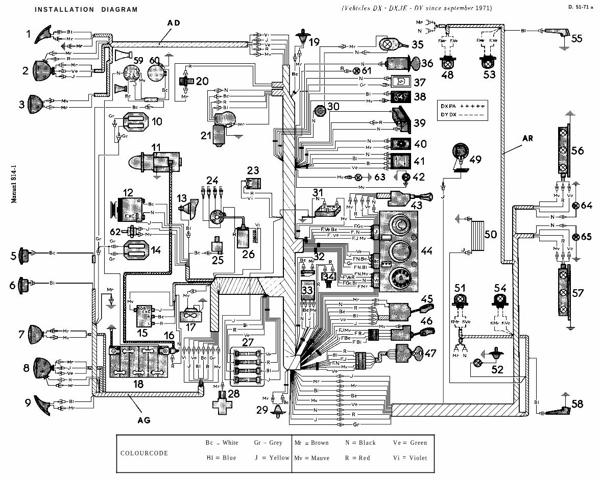
I N S T A L L A T I O N D I A G R A M ('llehicfes DX - DX.IE - DY s ince september 1971) D. 51-71 a
B c = White Gr = Grey
C O L O U R C O D E B1 = B l u e J = Yellow
Mr = Brown N = B l a c k V e = Green
Mv = Mauve R = R e d Vi = Violet

OPERATION No. Dh. 510-00 a : A r r a n g e m ~ n t o/ t h e e l e c t r r c a l i n s t a l l a t i o n Op. Dh. 510-00 a 3
FUSE T A B L E
- Cigaret te lighter - Rear h a r n e s s + interior lamps.
+ bat tery
- Ignttion swi tch to : - Revers ing lamp swi tch - reversing lamps - Switch for heated rear window - hea ted rear window - F l a s h e r unit - swi tch for dlrect lon lnd lca tors - front and rear direction indicators - Voltage regulator - al ternator ( f ie ld wlndlng c i rcu l t )
Light ing s u i t c h s i d e lamp
I t I terminal (marked Mauve)
1 I 1 I
- Terminal for a c c e s s o r i e s - l ight lng for glove compartment - Clock - Stop lamp s w i t c h - s t o p lamps
1 - Ignition swl tch to : - Switch for heat lng -+ heat ing - S'C ( - 4 1 • ‹ F ) - Warning lamp c lus te r feed windscreen washer pump - Switch for windscreen wlper and windscreen washer windscreen wiper motor
= Switch for parking lamps t o : - Front and rear parking lamps -
I
c bulbs lighting dashboard - Rheos ta t
c lock lamp - Switch for parklng lamps to front and rear s ide lamps - Light ing for number p la te and boot - Light ing for heat lnq control - Liqhting for ash t ray - Light ing for c igare t te lighter
P.T.O. INSTALLATION DIAGRAM

4 OPERATION No. Dh. 510-00 a : Ar rangemen / o/ t he e l e c ~ r i c a l i n s t a l l a t i o n
BULB T A B L E
U s e Quan t i ty Socke t V o l t a g e P o w e r
n t e rna F r e n c h
Head lamps - Dip and
main beam
Yel low
S e l e c t i v e
Ye l low S e l e c t i v e
aux i l i a ry H 1 i o d i n e
P 2 5 / 1 P e a r -
s h a p e d
R e a r i n d i c a t o r s S top l amps
R e v e r s i n q l amps
R e a r s i d e l a m p s
No p l a t e l i gh t lng
Emergency l amp
Fron t s i d e l a m p s
Inter ior DX - DY
l igh t ing I ' t r l lu~
F e s t o o n
Boot l i gh t ing F e s t o o n
l , l ~ / l l l f / ~ : - Asht ray - H e a t i n g con t ro l - G l o v e compar tment - C i g a r e t t e l i gh te r - C l o c k
4 urrrrrrg I ~ r a l ( > r :
Warning l amp for head lamps Warning l a m p for s i d e l a m p s H e a t e d r e a r window
U clrning 1 . / 1 ~ . ; ~ v r :
Other warn ing l a m p s
Yedge B a s e
Dashboard l igh t ing
L i g h t i n g for g e a r s e l e c t o r on Dbw
Incorporated in t h e l amp

OPERATION No. Dbw. 510-00 : F i t t m g the e l r c . t r i c a 1 s j s t e r n ( z ~ e h i c l e s f i t ted rci th an nutonlatic
Op. Dbw. 510-00 1
I I
R Front hornerr
DIAGRAM O F THE SYSTEM
K E Y
Existing harness- - ----
DBW. VEHICLES, A L L TYPES
BASIC MACRAM
NOTE . - Dbw v e h ~ c l e s ( i . e w ~ t h BORG-WARNER gearboxes) a re f i t t ed with t h e b a s i c h a r n e s s e s 01 t h e hydraul ic q e a r c h a n q e v e h i c l e s produced sLnce s e p t e m h r r 1971 ( s e e Op. Dh. 510-00 a) and t h e additional harness above.
- In ~ b w v e h i c l e s t h e s ta r te r control i s on t h e ant i- thef t d e v i c e , ins tead of being on t h e gear l ever a s on hydraul ic gearchange veh ic les . REFERENCE NUMBERS O F THE PARTS. T h e re fe rences fo r those p a r t s common to both s y s t e m s a r e iden t ica l to t h o s e indicated in t h e e lec t ron ics diagram Dh. 510-00 a. T h e addi t ional p a r t s a r e a s fol lows : 68. Thermal swi tch for radiator water 66. Fan r e l a y (on battery frame) 69. Switch for reversing lamps and s ta r te r motor s a f e t y 67. Cooler fan d e v i c e (on gearbox\

OPERATION No D.IE - 51 1-00 : Arrangement of the electr ical instal lat ion electronic fuel iniect ion sys tem.
Op. D. IE - 51 1-00
VEHICLES D. I E - ALL TYPES 4 March1970
ARRANGEMENT OF THE ELECTRICAL INSTALLATION OF THE ELECTRONIC FUEL INJECTION SYSTEM
(Vehicles produced up to March 1970)
NOTE : For the arrangement of the general electrical installation : see Op. DX. 510-00 F
DIAGRAM SHOWING THE PRINCIPLES OF THE STARTER CONTROL

WIRING DIAGRAM
Electronic fuel iniection system
Colour Code Blue BI White Bc Grey Gr Yellow J Brown Mr Mauve Mv Black N Red R Green Ve Violet Vi
COMPONENTS 1 Dlstrlbutor 2 Battery 3 General feed relay 4 Pump Relay 5 Impulse Relay 6 Thermal sensor 7 Cold start time delay
/thermal swltch 8 Starter mtr cntrl rela) 9 Cold start Injector 10 Throttle spindle sw. 11 Cyllnder 1 Injector 12 Cyllnder 2 Injector 13 Cyllnder 3 Injector 14 Cyllnder 4 Injector 15 lgnltlon toll 16 Full load swltch 17 Pressure sensor 18 Electr. Control unit 19 Fuel pump A lgnltlon swltch B Starter motor swltch

OPERATION Nº D.IE. 511-00 : Arrangement of the electrical installation Op. D.IE. 511-00 3electronic fuel injection system.
PART SCHEDULE
1. Ignition distributor and triggering contacts
2. Battery
3. General feeder relay
4. Pump relay
5. Impulse relay
6. Thermal sensor
7. Cold start time delay thermal switch
8. Starter motor control relay
9. Cold start injector
10. Throttle-spindle switch
11. Injector Nº 1 cylinder
12. Injector Nº 2 cylinder
13. Injector Nº 3 cylinder
14. Injector Nº 4 cylinder
15. Ignition coil
16. Full-load switch
17. Pressure sensor
18. Electronic control unit
19. Fuel pump
A. Vehicle ignition switch
B. Starter motor switch

OPERATION Nº D.IE. 511-00 : Arrangement of the electrical installation. Op. D.IE. 511-00 5electronic fuel injection system.
HarnessWireNº
Colourof
endsWiring schedule
Electroniccontrol unit
-do-
-do-
-do-
-do-
-do-
-do-
-do-
-do-
-do-
-do-
-do-
-do-
-do-
1
2
3
4
5
6
7
8
9
10
11
12
13
14
BlackBlackBlackBlackYellow
Yellow -brownBrownWhiteMauve
MauveViolet
YellowYellow
WhiteWhite
MauveRedRed
VioletWhiteVioletBlue
Green -greyGrey
Green-brownBrown
Yellow-violetViolet
Yellow-greenYellow
Red-blueBlue
Yellow-whiteYellow
BlueBlue
Starter motor control relay (8) (+ ve battery)to general feeder relay (3) (terminal 30/51)to pump relay (4) (terminal 30/51)to impulse relay (5) (terminal 30/51)to impulse relay (5) (terminal 85)
Electronic control unit (18) (terminal 16)Electronic control unit (18) (terminal 24)
to general feeder relay (3) (terminal 87)to pump relay (4) (terminal 86)
General feeder relay (3) (terminal 86)to ignition coil (15) (+ve terminal) (vehicle ignition switch A)
Pump relay (4) (terminal 85)to electronic control unit (18) (terminal 19)
Pump relay (4) (terminal 87)to fuel pump feed wire (19)
Impulse relay (5) (terminal 86)to starter motor control relay (8)to front cables of vehicle (starter motor switch B)
Electronic control unit (18) (terminal 18)to impulse relay (5) (terminal 87)to cold-start injector (9)to cold start time delay thermal switch (7)
Electronic control unit (18) (terminal 7)to pressure sensor (17) (terminal 7)
Electronic control unit (18) (terminal 8)to pressure sensor (17) (terminal 8)
Electronic control unit (18) (terminal 10)to pressure sensor (17) (terminal 10)
Electronic control unit (18) (terminal 15)to pressure sensor (17) (terminal 15)
Electronic control unit (18) (terminal 2)to full lead switch (16)
Electronic control unit (18) (terminal 9)to throttle spindle switch (10)
Electronic control unit (18) (terminal 20)to throttle spindle switch (10)

OPERATION Nº D.IE. 511-00 : Arrangement of the electrical installation. Op. D.IE. 511-00 7electronic fuel injection system.
HarnessWireNº
Colourof
endsWiring diagram
Electroniccontrol unit
-do-
-do-
-do-
-do-
-do-
-do-
-do-
-do-
-do-
-do-
-do-
Flying lead
15
16
17
18
19
20
21
22
23
24
25
26
27
Yellow-greyGrey
WhiteWhite
GreyGrey
GreenGreen
Yellow-redYellow
RedRed
GreyGrey
Green-whiteWhite
Green-blueBlue
Green-violetViolet
Green-redRed
Yellow-blue
Yellow
Electronic control unit (18) (terminal 14)to throttle spindle switch (10)
Electronic control unit (18) (terminal 17)to throttle spindle switch (10)
Cold-start injector (9)to cold- start time delay thermal switch (7)
Electronic control unit (18) (terminal 23)to thermal sensor (6)
Electronic control unit (18) (terminal 12)to ignition distributor and triggering contacts (1)
Electronic control unit (18) (terminal 21)to ignition distributor and triggering contacts (1)
Electronic control unit (18) (terminal 22)to ignition distributor and triggering contacts (1)
Electronic control unit (18) (terminal 3)to injector (11) cylinder 1
Electronic control unit (18) (terminal 5)to injector (12) cylinder 2
Electronic control unit (18) (terminal 4)to injector (13) cylinder 3
Electronic control unit (18) (terminal 6)to injector (14) cylinder 4
Electronic control unit (18) (terminal 11)to full load switch (16)to injector (11) cylinder 1to injector (12) cylinder 2to injector (13) cylinder 3to injector (14) cylinder 4to general feeder relay (3) (terminal 85)to thermal sensor (6)to earth (on voltage regulator-relay)
Fuel pump (19)to earth on side member

OPERATION No D.IE 51 1-00a : Arrangement of the electr ical instal lat ion Op. D. lE 51 1-00a 1 electronic fuel inie tion sys tem. (Since March 1970)
VEHICLES D. I E - ALL TYPES b March 1970 4 April 1971
ARRANGEMENT OF THE ELECTRICAL INSTALLATION OF THE ELECTRONIC FUEL INJECTION SYSTEM
(Vehicles ~roduced between March 1970 and April 19711
NOTE : For the arrangement of the general electrical installation : see Op. DX. 510-00 F
DIAGRAM SHOWING PRINCIPLES OF STARTER MOTOR CONTROL

WIRING DIAGRAM
Electronic fuel iniection system I
Key t o colours Blue BI White Bc Grey Gr Yellow J Brown Mr Mauve Mv Black N Red R Green Ve Violet Vi
COMPONENTS 1 Dlstrlbutor 2 Battery 3 General feed relay 4 Pump Relay 5 Impulse Relay 6 Thermal sensor 7 Cold start time dela)
/thermal swltch 8 Starter mtr cntrl reli 9 Cold start Injector 10 Throttle spindle sw. 11 Cyllnder 1 Injector 12 Cyllnder 2 Injector 13 Cyllnder 3 Injector 14 Cyllnder 4 Injector 15 lgnltlon toll 16 Full load swltch 17 Pressure sensor 18 Electr. Control unit 19 Fuel pump 20 12-wav union A lgnltlon swltch B Starter motor swltck

OPERATION Nº D.IE. 511-00 a : Arrangement of the electrical installation Op. D.IE. 511-00 a 3electronic fuel injection system.
PART SCHEDULE
1. Ignition distributor and triggering contacts
2. Battery
3. General feeder relay
4. Pump relay
5. Impulse relay
6. Thermal sensor
7. Cold start time delay thermal switch
8. Starter motor control switch
9. Cold start injector
10. Throttle spindle switch
11. Injector cylinder 1
12. Injector cylinder 2
13. Injector cylinder 3
14. Injector cylinder 4
15. Ignition coil
16. Full load switch
17. Pressure sensor
18. Electronic control unit
19. Fuel pump
20. 12-way union
A. Vehicle ignition switch
B. Starter motor switch

OPERATION Nº D.IE. 511-00 a : Arrangement of the electrical installation Op. D.IE. 511-00 a 5electronic fuel injection system (since March 1970)
HarnessWire
Nº
Colour ofends or
self-adhesivenumber
Wiring schedule
Electroniccontrol unit
-do-
-do-
-do-
-do-
-do-
-do-
-do-
-do-
-do-
-do-
-do-
-do-
-do-
-do-
-do-
-do-
1
2
3
4
5
6
7
8
9
10
11
12
13
14
15
16
17
11
22
33
44
55
66
77
88
99
1010
1111
yellow
1212
13
1414
1515
16mauve
1717
Cold start injector (9)to 12-way union (20)
Electronic control unit (18)‘(terminal 2)to full load switch (16)
Electronic control unit (18) (terminal 3)to ,12-way union (20)
Electronic control unit (1.8) (terminal 4)to la-way union (20)
Electronic control unit (18) (terminal 5)to 12-way union (20)
Electronic control unit (18) (terminal 6)to 12-way union (20)
Electronic control unit (18) (terminal 7)to pressure sensor (17) (terminal 7)
Electronic control unit (18) (terminal 8)to pressure sensor (17) (terminal 8)
Electronic control unit (18). (terminal 9)to throttle spindle switch (10)
Electronic control unit (18) (terminal 10)to pressure sensor (17) (terminal 10)
Electronic control unit (18) (terminal 11) earthto 12-way union (20)to full load switch (16)to general feeder relay (3) (terminal 85)
Electronic control unit (18) (terminal 12)to 12-way union (20)
12-way union (20)
Electronic control unit (18) (terminal 14)to throttle spindle switch (10)
Electronic control unit (18) (terminal 15)to pressure sensor (17) (terminal 15)
Electronic control unit (18) (terminal 16)to pump relay (4) (terminal 86)to junction on lead 24
Electronic control unit (18) (terminal 17)to throttle spindle switch (10)

OPERATION Nº D.IE. 511-00 a : Arrangement of the electrical installation Op. D.IE. 511-00 a 7electronic fuel injection system (since March 1970)
HarnessWire
Nº
Colour ofends or
self-adhesivenumber
Wiring schedule
Electroniccontrol unit
-do-
-do-
-do-
-do-
-do-
-do-
-do-
-do-
-do-
-do-
Flying lead
Engine
-do-
-do-
-do-
18
19
20
21
22
23
24
25
26
27
28
29
1
3
4
5
1818
White
19Yellow
2020
2121
2222
2323
24White
BlackBlackBlackBlackYellow
MauveMauve
WhiteWhite
MauveRedRed
1Grey
33
44
55
Electronic control unit (18) (terminal 18)to cold start injector (9)to impulse relay (5) (terminal 87)
Electronic control unit (18) (terminal 19)to pump relay (4) (terminal 85)
Electronic control unit (18) (terminal 20)to throttle spindle switch (10)
Electronic control unit (18) (terminal 21)to 12-way union (20)
Electronic control unit (18) (terminal 22)to 12-way union (20)
Electronic control unit (18) (terminal 23)to 12-way union (20)
Electronic control unit (18) (terminal 24)to general feeder relay (3) (terminal 87)
Starter motor control relay (8) (+ ve battery)to general feeder relay (3) (terminal 30/51)to pump relay (4) (terminal 30/51)to impulse relay (5) (terminal 30/51)to impulse relay (5) (terminal 85)
Ignition coil (15) (+ ve terminal ) (ignition switch A of vehicle)to general feeder relay (3) (terminal 86)
Pump relay (4) (terminal 87)to fuel pump feeder wire (19)
Impulse relay. (5) (terminal 86)to starter motor control relay (8)to vehicle front cables (starter motor switch B)
Fuel pump (19)to earth on R.H. sidemember
12-way union (20)to cold start time delay thermal switch (7)
12-way union (20)to injector (11) cylinder 1
12-way union (20)to injector (13) cylinder 3
12-way union (20)to injector (12) cylinder 2

OPERATION Nº D.IE. 511-00 a : Arrangement of the electrical installation Op. D.IE. 511-00 a 9electronic fuel injection system (since March 1970)
HarnessWire
Nº
Colour ofends or
self-adhesivenumber
Wiring diagram
Engine
-do-
-do-
-do-
-do-
-do-
-do-
6
11
12
13
21
22
23
6 6
11
1212
13Blue
2121
2222
2323
12-way union (20)to injector (14) cylinder 4
12-way union (20)to injector (11) cylinder 1to injector (12) cylinder 2to injector (13) cylinder 3to injector (14) cylinder 4to thermal sensor (6)to earth (on voltage-regulator relay)
12-way union (20)to ignition distributor and triggering contacts (1)
12-way union (20)to cold start time delay thermal switch (7)
12-way union (20)to ignition distributor and triggering contacts (1)
12-way union (20)to ignition distributor and triggering contacts (1)
12-way union (20)to thermal sensor (6)

OPERATION No. DX.IE 511-00 : Arrangement of the electr ical rnsrallation e l e c t r o n ~ c fuel in jec t ion s y s t e m
Op. DX.IE 511-00 1
ARRANGEMENT OF THE ELECTRICAL INSTALLATION
OF THE ELECTRONIC FUEL INJECTION SYSTEM
DX.IE VEHICLES April 1971
( V e h i c l e s DX.IE produced s i n c e A p r i l 1 9 7 1 )
NOTE : For the arrangement of the general electrical installation : see operation DX. 510-00 f
DIAGRAM SHOWING PRINCIPLES OF STARTER MOTOR CONTROL

Manual 814-1
Colour Code Blue BI White Bc Grey Gr Yellow J Brown Mr Mauve Mv Black N Red R Green Ve Violet Vi
COMPONENTS 1 Dlstrlbutor 2 Battery 3 General feed relay 4 Pump Relay 5 Impulse Relay 6 Thermal sensor 7 Cold start time delay
/thermal swltch 8 Starter mtr cntrl rela) 9 Cold start Injector 10 Throttle spindle sw. 11 Cyllnder 1 Injector 12 Cyllnder 2 Injector 13 Cyllnder 3 Injector 14 Cyllnder 4 Injector 15 lgnltlon toll 16 Full load swltch 17 Pressure sensor 18 Electr. Control unit 19 Fuel pump 20 12-way union 21 Alr temp. sensor A lgnltlon swltch B Starter motor swltch

2 OPERATION Nº D.IE. 511-00 : Arrangement of the electrical installationelectronic fuel injection system (Since April 1971).
PART SCHEDULE
1. Ignition distributor and triggering contacts
2. Battery .
3. General feed relay
4. Pump relay
5. Impulse relay
6. Thermal sensor
7. Cold start time delay thermal switch
8. Starter motor control switch
9. Cold start injector
10. Throttle spindle switch
11. Injector cylinder 1
12. Injector cylinder 2
13. Injector cylinder 3
14. Injector cylinder 4
15. Ignition coil
16. Full load switch
17. Pressure sensor
18. Electronic control unit
19. Fuel pump
20. 12-way union
21. Air temperature sensor
A. Vehicle ignition switch
B. Starter motor switch

OPERATION Nº DX.IE. 511-00 : Arrangement of the electrical installation. Op. DX.IE. 511-00 3electronic fuel injection system (since April 1971)
HarnessWire
Nº
Colour ofends or
self-adhesivenumber
Wiring schedule
Electroniccontrol unit
-do-
-do-
-do-
-do-
-do-
-do-
-do-
-do-
-do-
-do-
-do-
-do-
-do-
-do-
-do-
1
2
3
4
5
6
7
8
9
10
11
12
14
15
16
17
11
22
33
44
55
66
77
88
99
1010
1111
yellow
1212
1414
1515
16whitemauve
1717
Electronic control unit (18) (terminal 1)to air temperature sensor (21)
Electronic control unit (18) (terminal 2)to full load switch (16)
Electronic control unit (18) (terminal 3)to 12-way union (20)
Electronic control unit (18) (terminal 4)to 12-way union (20)
Electronic control unit (18) (terminal 5)to 12-way union (20)
Electronic control unit (18) (terminal 6)to 12-way union (20)
Electronic control unit (18) (terminal 7)to pressure sensor (17) (terminal 7)
Electronic control unit (18) (terminal 8)to pressure sensor (17) (terminal 8)
Electronic control unit (18) (terminal 9)to throttle spindle switch (10)
Electronic control unit (18) (terminal 10)to pressure sensor (17) (terminal 10)
Electronic control unit (18) (terminal 11) earthto 12-way union (20)to air temperature sensor (21)to full load switch (16)to general feed relay (3) (terminal 85)
Electronic control unit (18) (terminal 12)to 12-way union (20)
Electronic control unit (18) (terminal 14)to throttle spindle switch (10)
Electronic control unit (18) (terminal 15)to pressure sensor (17) (terminal 15)
Electronic control unit (18) (terminal 16)to general feed relay (3) (terminal 87)to pump relay (4) (terminal 86)to junction on lead 24
Electronic control unit (18) (terminal 17)to throttle spindle switch (10)

4 OPERATION Nº DX.IE. 511-00 : Arrangement of the electrical installation.electronic fuel injection system (since April 1971)
HarnessWire
Nº
Colour ofends or
self-adhesivenumber
Wiring schedule
Electroniccontrol unit
-do-
-do-
-do-
-do-
-do-
-do-
-do-
-do-
-do-
Flying leadEngine
-do-
-do-
-do-
-do-
18
19
20
21
22
23
25
26
27
28
35
29
3
4
5
6
1818
White
19Yellow
2020
2121
2222
2323
BlackBlackBlackBlack Yellow
MauveMauve
WhiteWhite
MauveRedRed
33
44
55
66
Electronic control unit (18) (terminal 18)to cold start injector (9)to impulse relay (5) (terminal 87)to 12-way union (20) lead 13
Electronic control unit (18) (terminal 19)to pump relay (4) (terminal 85)
Electronic control unit (18) (terminal 20)to throttle spindle switch (10)
Electronic control unit (18) (terminal 21)to 12-way union (20)
Electronic control unit (18) (terminal 22)to 12-way union (20)
Electronic control unit (18) (terminal 23)to 12-way union (20)
Starter motor control relay (8) ( + ve battery)to general feed relay (3) (terminal 30/51)to pump relay (4) (terminal 30151)to impulse relay (5) (terminal 30/51)to impulse relay (5) (terminal 85)
Ignition coil (15) ( + ve terminal) (ignition switch A of vehicle)to general feed relay (3) (terminal 86)
Pump relay (4) (terminal 87)to fuel pump feed wire (19)
Impulse relay (5) (terminal 86)to starter motor control relay (8)to vehicle front cables (starter motor switch B)
12-way union (20)to cold start injector (9)
Fuel pump (19)to earth on R.H. sidemember
12-way union (20)to injector (11) cylinder 1
12-way union (20)to injector (12) cylinder 2
12-way union (20)to injector (13) cylinder 3
12-way union (20)to injector (14) cylinder 4

OPERATION Nº DX.IE. 511-00 : Arrangement of the electrical installation. Op. DX.IE. 511-00 5electronic fuel injection system (since April 1971)
HarnessNº ofWire
Colour ofends or
self-adhesivenumber
Schedule of wires
Engine 11
12
18
21
22
23
35
11
1212
13Blue
2121
2222
2323
GreyGrey
12-way union (20)to injector (11), cylinder 1to injector (12), cylinder 2to injector (13), cylinder 3to injector (14), cylinder 4to thermal sensor (6)to earth (on relay voltage regulator)
12-way union (20)to ignition distributor and triggering contacts (1)
12-way union (20)to time delay thermal switch (cold start ) (7)
12-way union (20)to ignition distributor and triggering contacts (1)
12-way union (20)to ignition distributor and triggering contacts (1)
12-way union (20)to thermal sensor (6)
12-way union (20)to time delay thermal switch (7) (cold start)

OPERATION No DJ. lE 51 1-00: Arrangement of the electr ical instal lat ion electronic fuel iniect ion sys tem. (Since 1971)
Op. DJ. I E 51 1-00 1
VEHICLES DJ. IE b April 1971
ARRANGEMENT OF THE ELECTRICAL INSTALLATION OF THE ELECTRONIC FUEL INJ ECTlON SYSTEM
(DJ. I& uehic les produced since April 1971)
NOTE : For the arrangement of the general electr ical instal lat ion : see Op. Dm. 510-00
for vehicles :-4/71 4 9 / 7 1 or Op. Dm. 510.00 a
for vehicles : -9/71
DIAGRAM SHOWING THE PRINCIPLES OF THE STARTER MOTOR CONTROL
The starter motor and impulse re lays a r e no longer fitted
Coil r General
relay

Colour Code Blue BI White Bc Grey Gr Yellow J Brown Mr Mauve Mv Black N Red R Green Ve Violet Vi
COMPONENTS 1 Dlstrlbutor 2 Battery 3 General feed relay 4 Pump Relay 6 Thermal sensor 7 Cold start tlme delay
/thermal swltch 9 Cold start Injector 10 Throttle spindle sw. 11 Cyllnder 1 Injector 12 Cyllnder 2 Injector 13 Cyllnder 3 Injector 14 Cyllnder 4 Injector 15 lgnltlon toll 16 Full load swltch 17 Pressure sensor 18 Electr. Control unit 19 Fuel pump 20 12-way union 21 Alr temp. sensor A lgnltlon swltch B Starter motor swltch

2 OPERATION Nº DJ.IE. 511-00 : Arrangement of the electrical installation of theelectronic system.
PART SCHEDULE
1. Ignition distributor and triggering contacts
2. Battery
3. General feed relay
4. Pump relay
5. Impulse relay
6. Thermal sensor
7. Cold start time delay thermal switch
8. Starter motor control relay
9. Cold start injector
10. Throttle spindle switch
11. Injector Nº 1 cylinder
12. Injector Nº 2 cylinder
13. Injector Nº 3 cylinder
14. Injector Nº 4 cylinder
15. Ignition coil
16. Full load switch
17. Pressure sensor
18. Electronic control unit
19. Fuel pump
20. 12-way union
21. Air temperature sensor
A. Vehicle ignition switch
B. Starter motor switch

OPERATION No. DJ.IE-511-00 : Arrangement of the electrical installation Op. DJ.IE-511-00 3electronic fuel injection system (since April 1971)
HarnessWire
Nº
Colour ofends or
self-adhesivenumber
Wiring schedule
Electroniccontrol unit
-do-
-do-
-do-
-do-
-do-
-do-
-do-
-do-
-do-
-do-
-do-
-do-
-do-
-do-
-do-
-do-
1
2
3
4
5
6
7
8
9
10
11
12
13
14
15
16
17
11
22
33
44
55
66
77
88
99
1010
1111
yellow
1212
13
1414
1515
16whitemauve
1717
Electronic control unit (18) (terminal 1)to air temperature sensor (21)
Electronic control unit (18) (terminal 2)to full load switch (16)
Electronic control unit (18) (terminal 3)to 12-way union (20)
Electronic control unit (18) (terminal 4)to 12-way union (20)
Electronic control unit (18) (terminal 5)to 12-way union (20)
Electronic control unit (18) (terminal 6)to 12-way union (20)
Electronic control unit (18) (terminal 7)to pressure sensor (17) (terminal 7)
Electronic control unit (18) (terminal 8)to pressure sensor (17) (terminal 8)
Electronic control unit (18). (terminal 9)to throttle spindle switch (10)
Electronic control unit (18) (terminal 10)to pressure sensor (17) (terminal 10)
Electronic control unit (18) (terminal 11) earthto 12-way union (20)to air temperature sender (21)to full load switch (16)to general feeder relay (3) (terminal 85)
Electronic control unit (18) (terminal 12)to 12-way union (20)
12-way union (20)to junction on conductor 18
Electronic control unit (18) (terminal 14)to throttle spindle switch (10)
Electronic control unit (18) (terminal 15)to pressure sensor (17) (terminal 15)
Electronic control unit (18) (terminal 16)to general supply relay (3) (terminal 87)to pump relay (4) (terminal 86)to junction on lead 24
Electronic control unit (18) (terminal 17)to throttle spindle switch (10)

OPERATION Nº DJ.IE 511-00 a : Arrangement of the electrical installation Op. DJ.IE 511-00 electronic fuel injection system.
HarnessNºof
Wire
Colour ofends or
self-adhesivenumber
Schedule of wires
Electroniccontrol unit
-do-
-do-
-do-
-do-
-do-
-do-
- do -
- do -
-do-
Flying lead
Engine
-do-
-do-
-do-
18
19
20
21
22
23
25
26
27
35
23
3
4
5
6
1818
white
redred
19yellow
20
2121
22
2323
blackblackblackblackyellow
mauvemauve
whitewhite
33
Electronic control unit (18) (terminal 18)to cold start injectorto shunt with mauve wireto 12-way union (20) wire 13to front wiring harness of vehicle (starter motor switch 3)to flying feed lead for starter motor solenoid
Electronic control unit (18) (terminal 19)to pump relay (4) (terminal 85)
Electronic control unit (18) (terminal 20)to throttle spindle switch (10)
Electronic control unit (18) (terminal 21)to 12-way union (20)
Electronic control unit (18) (terminal 22)to 12-way union (20)
Electronic control unit (18) (terminal 23 Ito 12-way union
Starter motor control relay ( + battery)to general feed relay (3) (terminal 30/51)to pump relay (4) (terminal 30 ‘51)insulated at level of relaysinsulated at level of relays
Ignition coil (15) ( + terminal) (ignition switch A of vehicle)to general feed relay (terminal 86)
Pump relay (4) (terminal 87)to fuel pump feed wire (19)
12-way union (20)to cold start injector (9)
Fuel pump (19)to earth on R.H side member
12-way union (20)to injector (11) cylinder 1
12-way union (20)to Injector (13), cylinder 3
12-way union (20)to injector (12), cylinder 2
12-way union (20)to injector (14) cylinder 4

OPERATION Nº DJ.IE-511-00 a : Arrangement of the electrical installation Op. DJ.IE-511-00 5electronic fuel injection system (since April 1971)
Harness Nº ofWire
Colour ofends or
self-adhesivenumber
Schedule of wires
Engine
-do-
-do-
-do-
-do-
-do-
-do-
-do-
6
11
12
13
21
22
23
35
66
11
1212
13Blue
2121
2222
2323
Grey
12-way union (20)to injector (14) cylinder 4
12-way union (20)to injector (11) cylinder 1to injector (12) cylinder 2to injector (13) cylinder 3to injector (14) cylinder 4to thermal sensor (6)to earth (on relay voltnge regulator)
12-way union (20)to ignition distributor and triggering contacts (1)
12-way union (20)to time delay thermal switch (cold start) (7)
12-way union (20)to ignition distributor and triggering contacts (1)
12-way union (20)to ignition distributor and triggering contacts (1)
12-way union (20)to thermal sensor (6)
12-way union (20)to time delay thermal switch (7) (cold start)

OPERATION No D. 513-00 : Elec t r i ca l i n s t a l l a t i o n lor coo l ins s y s t e m . Op. 0 . 513-00 1
D VEHICLES a l l types
AIR CONDITIONING SYSTEM (COOLING SYSTEM)
FITTING THE ELECTRICAL INSTALLATION
P.T.O. I

BASIC DIAGRAM D. 6 4 - 5 3
INSTALLATION DIAGRAM

T h e e lec t r ica l instal la t ion for the cool ing sys tem c o n s i s t s of th ree extra h a r n e s s e s . The general e lec t r ica l instal la t ion of the vehicle i s iden t ica l t o the s tandard instal la t ion of t h e corresponding type(rirwcuct1 Gc:urc.hc~rrgct (jr 11, tlrctrrlic Gectrc./~c~rc6c cx,hit~lca).
REFERENCE NUMBERS FOR THE PARTS.
The references for those parts common to the general ins ta l l a t ion a r e iden t ica l to those used in t h e ins ta l l a t ion diagram of the corresponding vehicle type (ntecr~unl o r 111 tlrcculic gverrc 11(11rgc r,c.hic,lc*a).
18. Battery 26. Ignition coi l 47. Ignition switch 70. R.H. condensor fan motor 71. L.H. condensor fan motor 72. Fan relay 73. Main relay
74. Main cut -out 75. Electromagnet ic cut. -in for compressor 76. Cut-out on c o n s o l e 77. F a n motor on conso le 78. Thermostat for surrounding a i r 79. General swi tch and rheos ta t for fan
on c o n s o l e (77)
OPERATION.
The cool ing will only operate when the engine i s running : t h e main relay (73) i s only controlled when t h e ignition swi tch (47) i s c l o s e d , addi t ional ly the compressor must be dr iven by the engine.
T h e cooling sys tem i s operated by the rheos ta t swi tch (79) T h i s has 4 positions :
1s t . position : completely non-operational. - 2nd. position : - conso le fan feed ( 7 7 ) 1s t . s p e e d ,
- feed for fans ( 7 0 ) and (71) using relay (72) - feed for cut-in (75) control c ircui t
- 3rd. and 4th. posi t ion : 2nd or 3rd. speed of c o n s o l e a i r fan (77) which makes it p o s s i b l e to ad jus t the cool a i r output.
T h e surrounding air thermostat (78) makes it poss ib le to a d j u s t t h e temperature of t h e cool a ir . As soon a s th i s temperature is reached the thermostat c u t s off the electromagnet ic cut-in (75) feed and the compressor s t o p s . T h e main cut-out (74) (30 amps) protects the instal la t ion a s s e m b l y . It i s fitted on the battery frame.
T h e cut-out (76) (15 amps) protects the c o n s o l e block and the compressor cut-in. This cut-out i s p laced under the lining of the engine r e c e s s near the console.

O P E R A T I O N N o 8. 530-0 : Charnc t e r i~ t i c s and r h c c i s on electrical units Op. 0. 530-0 1
I.- C H A R A C T E RlSTlCS I V E H I C L E S ALL T Y P E S
1 - Batteries
- Battery 200/40 A.H. : C ehic les all type., 4 Oct. 1966 I elricle., ul l l y p e a ~ c i t h o u ~ QI heudlamp.s und uiilholrl heuting - 200 C (680 F )
+ Oct. 1966 4 Sept. 1967 Vehicles all t ypes + Sept . 1967
-- Battery 55 A.H. : : l'allas i l e h i c l e ~ plus all t ypes fitted wilh QI. headlamps and heating - 200 C (680 F ) + Oct. 1966 4 Sept. 1967
- Battery 250/50 A.H.: Vehic les all l ypes (except DV) fitted with aLr cond i~oner
I I Vehicles without QI head- I I Vehicles with QI headlampsl
I Type of vehicle lamps and without heating Vehicles a11 types or heating - 200 C (68' F)* I 20•‹C 168'FI I Pallas vehicles
I Period of use I C I O / 6 6 4 9 / 6 7 1 I-- 1/66 4 5/66
I DUCELLIER dynamo I 7327 A I 7336 A
I PARIS-RHONE dynamo I G. 1 0 C - 3 9 1 G. 1 0 C - 4 4
3. Alternators - Vehic les A. T . 4 .3/1971 : PARIS-RHONE A 13 R 52, or DUCELLIER 7530 A and 7530 B - Lehir l rs A. T . +- 3/1971 : PARIS-RHONE A 13 R 109 and A 13 R 110, or DUCELLIER 7551 A and 7551 B - Pehirles A. T. ( e t c e p f D l / ) fitted r c i th air-ctjnditioner : PARIS-RHONE A 13 R 119, or DUCELLIER 7558 A - - Vehic les A. T. C 5 / 1972 : PARIS-RHONE A 13 R 119, or DUCELLIER 7558 A.
External diameter of pulley
Brand name of regulator and a1 ternat or
68.5 mm
- 2 E:
S
DUCELLIER
60 mm DUCELLIER 601.7 mm PARIS-RHONE
PARIS-RHONE
Brand name of regulator and dynamo
Type of dynamo
Type of corresponding regulator
Type of alternator
Type of corresponding reaulator
AYD 212
DUCELLIER
7327 A
8243 F
PARIS-RHONE
Period of use
7336 A
8346 A
G 10 G - 39
YT 2113
5. Starter motors
- Vehic les DX-DJ-DXF-DJF.
Brand name of starter motor
G 10 C - 46 or G 10 C - 48
YT 2116
Periode of use
Brand name of starter motor
Type of starter motor
PARIS-RHONE DUCELLIER
Type of starter motor
4 12/ 1957
DUCELLIER
6164 A
I-- 12/1967 4 9 / 1969
PARIS-RHONE
D 11 B 116
DUCELLIER
6182 A
D 10 E 52 ( D X ) and D 10 E 55 (I) . / )
PARIS-RHONE
D 11 E 123
6200 A (DX) and 6225 A (DJ)

2 OPERATION No D. 530-0 : Characteristics and checks on electricnl units
II - RE-SKIMMING 1 - Dynamos :
- Vehicles all types (except D X - D J - D X F - D I F )
Brand name of dynamo I DUCELLIER I PARIS-RHONE I
Period of use
Brand name of starter motor
Type of starter motor
Type of dynamo
Minimum diameter after skimmina of commutator
4 9 / 1968
Type of starter motor
+9/68 4 9 / 69
PARIS-RHONE
lo 49
DUCELLIER
6166 A
2 - Starter motors :
Minimum diameter after I 39,s mm 1 31mm 1 43 mm 1 39 5 mm 1 40 mm skimming of commutator
+ 9/ 1969
DUCELLIER
6201 A ( D Y ) 6215 A (DV, DT)
PARIS-RHONE
D 10 B 45
Brand name of starter motor
111 - TESTS ON A TEST BENCH OR ON T H E VEHICLE 1. Dynamos
Dynamo without regulator : yellow wire (( EXC )) joined to red wire (( DYN ,) and black wire to earth.
DUCELLIER PARIS-RHONE
Brand name and type of dynamo
- Vehicles 4 . T. + 3 /1971 : PARIS-RHONE A 13 R 109 and A 13 R 110, or DUCELLIER 7551 A and 7551 B - Ratio of alternator/engine rotation speed :
4 3 1 1971 = 1.53/ 1 I-- 3,' 1971 = 1.75/ 1 - Trials on test-bench without regulator : join terminal ((EXCn to ((+N terminal. - Output when cold at 14 V : 16 A 1650 r.p.m. and 35 A a t 3600 [.p.m. alternator.
Cold starting speed a t 13 V
Output when cold at 13 V
b ) Second case : - Vehicles all types (except L I V ) with air conditioner and vehicles all types I-+ f;/197' - PARIS-RHONE A 13 R 119 or DUCELLIER 7558 A - Ratio of alternator/ engine rotation speed = 1.75/ 1 - Trials on test bench without regulator-join terminal uEXC )) to ((t n terminal - Output when cold at 14 V : 17.5 A at 1750 r.p.m. and 43 A at 3900 r.p.m. alternator.
DUCELLIER 7327 A or
PARIS-RHONE G 10 C 39
2. Alternators : a ) First case :
- Vehicles 4 . r. 4 33 1971 : PARIS-RHONE A 13 R 52, or DUCELLIER 7530 A and 7530 B
1200 rpm
3 ,s A to 1500 rpm 22 A to 2500 rpm
DUCELLIER
7336 A
PARIS-RHONE G 10 C 44 or
G 10 C 48
1950 rpm
11 A to 2200 rpm 29 A to 3000 rpm
1700 rpm
19.5 A to 2200 rprn 33 A to 3000 rpm

O P E R A T I O N No D. 530-0 : Characteris t ics and c h e c k s on electr ical units. Op. D. 530-0 3
3. D' emarreurs :
Brand name of starter motor DUCELLIER
Types of starter motor
Testing on the vehicle
a ) Battery charged, intensi ty absorbed pinion blocked. . . . . . . . . . . . . . . . . . . . . . . . .
b) Starting current. . . . . . . . . . . . . . . . . . . .
c) Starter motor removed, current running l ight . . . . . . . . . . . . . . . . . . . . . .
Test ing on test bench
a ) Maximum power. . . . . . . . . . . . . . . . . . . . - Torque corresponding to this power. . . . . . 10 mAN
7.2 ft Ibs
340 A
6.25 mAN 4.5 ft Ibs
245 A
10 mAn 7.2 ft lbs
340 A
4.5 mAN 3.3 ft lbs
190 A
9.8 mAN 7 ft lbs
300 A . . . . . . - Intensi ty absorbed by th is torque
. . . . . . . . . b) Average torque a t 1000 r.p.m. 13.5 mAN
9.8 ft lbs
8.5 mAN
6.2 ft Ibs
13.5 mAN
9.8 ft l b s 7.5 mAN
5.4 ft lbs
10.5 mAN
7.6 ft lbs
. . . . . . . - Intensity absorbed by th is torque
Brand name of starter motor I PARIS-RHONE I Types of starter motor
Testing on the vehicle
a ) Battery charged, intensity absorber pinion blocked. . . . . . . . . . . . . . . . . . . . . . . . . .
b) Stating current . . . . . . . . . . . . . . . . . . . .
c ) Starting motor removed, current running light . . . . . . . . . . . . . . . . . . . . . .
Testing on test bench
. . . . . . . . . . . . . . . . . . . . 3 ) Maximum power. I ) Maximum power. . . . . . . . . . . . . . . . . . . . .
- Torque corresponding to th is power. . . . . . .
9.5 mAN 13.5 mAN 6.8 ft lbs 9.8 ft Ibs + 250 A
13.5 mAN 9.8 ft l b s
9.5 mAN 10 mAN 6.8 ft lbs 7.2 f t lbs + - Intensity absorbed by this torque . . . . . . . .
3 ) Average torque a t 1000 r.p.m. . . . . . . . . . . .
. . . . . . . . Intensity absorbed by th is torque

4 OPERATION No D. 530-0 : Chnruc t e r i s~ i c s and checks on e!ectrical units. 1
IV - ADJUSTING THE VOLTAGE REGULATORS
1 - Regulator for dynamos : a ) DUCELLIER regulator - 12 vol ts - 8243 F and PARIS-RHONE regulator - 12 vo l t s - YT 2113.
Cut in vol tage - 12 to 13.5 v o l t s (co ld and hot) . Cut out vol tage = a t l e a s t 1 vol t l e s s than t h e cu t in voltage. Return current = 5 A maxi (co ld) .
REGULATION : With t h e dynamo turning at 4000 rpm :
- Adjust t h e vol tage to 12.5 vo l t s , t h e in tens i ty must be between 18 and 22 A. - Adjust t h e vol tage to 14 vol ts , the in tens i ty must be between 18 and 22 A. - Adjust t h e vol tage to 15.5 vo l t s , t h e in tens i ty must be between 0 and 5 A.
b) DUCELLIER regulator - 12 vo l t s - 8346 A and PARIS-RHONE regulator 12 vo l t s - YT 2116.
Cut in vol tage - 12 to 13.6 vo l t s (co ld and hot) Cut out vol tage = a t l e a s t 1 vol t l e s s than t h e cu t in voltage. Return current = 5 A maxi for 1 3 vol ts .
REGULATION : With the dynamo turning a t 4000 rpm. :
- Adjust t h e vol tage to 12.5 vo l t s , t h e in tens i ty must be between 30 and 3 3 A. - Adjust t h e vol tage to 13 vo l t s , t h e in tens i ty mast he between 30 and 3 3 A. - Adjust t h e vol tage t o 13.5 vol ts , t h e in tens i ty must be between 13 and 3 3 A. - Adjust t h e vol tage t o 14 vo l t s , the in tens i ty must be between 5 and 25 A. - Adjust t h e vol tage to 14.5 vo l t s , the in tens i ty must be between 0 and 1 5 A.
2. Regulators for alternators : DUCELLIER regulator - 12 vol ts - 8360 A. PARIS-RHONE regulator - 12 vo l t s - AYD 212 With t h e al ternator turning a t 4000 rprn.
- Adjust t h e in tens i ty to 8 A; t h e vol tage must be between 13.40 and 14.40 vol ts . - Adjust t h e in tens i ty to 20 A; t h e vol tage must be between 13 and 14 volts.
V - CHECKING A PARIS-RHONE ALTERNATOR ( A 13 R 52, A 13 R 109, A 13 R 110, AND A 13 R 119) OR A DUCELLIER ALTERNATOR (7530 A, 7551 A, 7551 B and 7558 A) ON THE VEHICLE.
IMPORTANT REMARKS Certain a c t i o n s mus t b e avoided a t a l l c o s t s b e c a u s e they could destroy t h e alternator
1') I ) o not ullort~ the cdterr~ator to turn r ~ l i ~ h o u t heing connec/et l to the bnltery. 2') Hefore connect ing the alternator, mnX.e sure that the hattcry i s correctl) c , .~~tnerr t~d (n t ,gu t i~ , f : car1hc.d). 3') The hattery nrusl be 14 e l l charged when the alternator output i s checked. 4') no not tc3,t the alternator hy short-rircrciting [he pc~si~iut ' and earth terminals, or the "EYC" t r r r d c~c~rth t t ' r~ t i i t za~ .~ .
ternrinals. 5') 110 not re1:erYe thr 1rr1d.s ronmt~ctc~tl t o t h e rc:gula'tor. 6') C'ei3c.r try to energise un ulrernator : it i s rcr,nrcessar). urrtl ~cuu ld d a m a g ~ the alternator and regulator. 7') U o not connect a condensor either t o t h e ulterntctnr or to the regulator "1;YC" terminnl ,~ . . E 3 ) Do not connect the battery terrnina1.s to a charger rwd nr:ller carry out are or spot wlrf irrg on the car c~hr~s.s is
rcithout l i a ~ ing first disconrrectcd 1)otlr po . s i / i~ ,e urld rlc~gatii~e b u ~ t e r y lrudc.

OPERATION No D . 530-0 : Characteristics and checks on electrical uni ts . Op. D. 530-0 5
Checking the alternator output. The al ternator output must b e measured when the al ternator i s working a t maximum speed.
1. Disconnect t h e negat ive bat tery lead.
2 . Disconnect the exci tat ion lead (yellow end) from the (( EXC )) terminal (1) and the charge lead (black end) from ( ( f )) terminal (2 ) of the al ternator ( insulate the two earth l e a d s )
3. By means of a l ead of a l e a s t 0.12 mm diameter , join t h e (c +N al ternator terminal (2 ) t o the c( EXC )) alternator terminal (1) .
4. Connect a n ammeter in s e r i e s and a rheos ta t i n paral le l t o the charge circuit. - Connect the c(+ )) ammeter terminal t o the c c + ) )
al ternator terminal (2) . - Connect t h e c ( - n ammeter terminal t o t h e discon-
nected charge lead. - Connect the rheostat terminals between the N-))
ammeter terminal and t h e earth.
5. Connect a voltmeter with a jumper l ead t o the charge circuit. - Connect the c ( f )) voltmeter terminal t o the c t + n
al ternator terminal (2). - Connect the ((-)) voltmeter terminal to the ear th.
VI. CI HECKING A VOLTAGE REGULATOR (PARIS-RI
6. Connect the nega t ive bat tery lead.
7. Start the engine and al low it to idle. a ) Let / he alternator turn at 1650 rpnc : T o do th i s
s lowly acce le ra te the engine t o : - 1080 rpm with a PARIS-RHONE A 13 R 52 or
DUCELLIER 7530 A and 7530 B alternator. - 940 rpm with a PARIS-RHONE A 1 3 R 110 and
A 13 R 109, or DUCELLIER 7551 A a n d 7551 B alternator. Adjust the rheostat t o obtain a vol tage of 14 vol ts : t h e output current should be 1 6 amps.
b) Let the alternator turn at 3600 rpm : T o d o t h i s bring t h e engine s p e e d t o : - 2350 rpm with a PARIS-RHONE A 1 3 R 52,
or DUCELLIER 7530 A and 7530 B alternator. - 2060 rpm with a PARIS-RHONE A 13 R 110
or A 1 3 R 1 0 9 al ternator , a n d DUCELLIER 7551 A and 7551 B alternator. Adjust t h e rheos ta t t o keep the vol tage a t 14 vol ts : the output current should b e 3 5 amps. If t h i s i s not the c a s e , the alternator should be overhauled.
8. Stop the engine.
9 . Disconnect the negat ive battery cab le .
10. Disconnect the measuring apparatus and connect the two l e a d s from t h e harness to the al ternator : - lead with black end to ((-k)) terminal (2). - lead with yellow end t o ( ( E X C ) ) terminal (1).
11. Connect the negat ive battery terminal.
12. NOTE : Proceed in the same way for checking the al ternator outputs 4 5 amps (PARIS-RHONE A 1 3 R 119 , or DUCELLIER 7558 A) See chapter 111, 5 2 (page 2 , same operation) where the different va lues of c h e c k s a r e indicated.
r(E AYD 212 or'DUCELLIER 8360 A) ON THE VEHICLE
1. Disconnect the nega t ive battery cab le .
2 Disconnect the charge lead (coloured b lack) from the ( ( + n al ternator terminal (1 ) .
3 Connect a n ammeter in s e r i e s and a rheostat in paral le l to the charge circui t . - Connect the N+ ammeter terminal to the (( t ))
al ternator terminal (1 ) . - Connect the I(- ) , ammeter terminal to the discon-
nected charge lead (coloured black) . - Connect the rheos ta t terminals between the ( ( - 1 )
ammeter terminal and the ear th.

6 OPERATION No D. 530-0 : Characteristics and checks on electrical uni ts .
4. Connect a voltmeter with a jumper l ead t o the exci tat ion circuit.
- Connect the c c f ) ) voltmeter terminal to the c c t n
regulator terminal (2 ) (coloured violet).
- Connect t h e N-)) voltmeter terminal t o t h e ea r th
5. Connect the negat ive bat tery lead. Start the engine and al low it to idle .
Switch off the ignition for a very short time in or- der t o demagnet ize the regulator.
Acce le ra te the engine to about 2600 rpm (4000 rpm of al ternator) .
Adjust the rheos ta t t o r a i s e the current delivered by the al ternator and read the corresponding voltage.
Take various voltage read ings for different amounts of current.
Mark t h e s e measurements on t h e graph. They must be included in t h e shaded a r e a of the graph. If they a re not , the regulator i s faulty and must be repaired.
NOTE : The graph opposi te corresponds to readings. taken a t 20• ‹C (68 'F) . If the ambient temperature i s different, the va lues shown on the graph must be modified.
When the temperature drops, the vol tage r i s e s and when the temperature r i s e s , the voltage drops by a , 1 5 vol ts for a difference of 1 0 • ‹ C (50•‹F) .
IMPORTANT NOTE :
The vol tage readings must be taken while increasing the current. The current must never b e decreased .
6. Stop the engine and disconnect the negat ive battery terminal.
7. Disconnect the measuring appara tus , connect the l e a d s a s u s u a l , and connect the negat ive battery lead.

OPERATION No. D. 530-0 : C l ~ a r a c ~ c r i s ~ i c s and c h e c k s on electr ical uni ts Op. D, 530-0 7
Vlll - ADJUSTING THE CONTROL PINION OF A PARIS-RHONE STARTER MOTOR (Starter motor removed)
1. Remove the rubber plug ( 2 ) of the solenoid.
2 . Disconnect the feed wire ( 6 ) of the inductors from t h e solenoid terminal (5 ) .
3 . Remove the shunt connector between t h e posi t ive terminal(4) of the s ta r te r motor feed terminal, and t h e solenoid (exci tat ion) feed terminal.
4 . Activate the solenoid (3 ) , by connect ing : a ) T h e posi t ive terminal of a battery t o the feed
terminal ( 4 ) of the s ta r te r motor. b) T h e negat ive terminal of a battery to the solenoid
solenoid terminal ( 5 ) (inductor feed) . With the control pinion (1) in a forward posi t ion, measure the d i s t a n c e " b" between the end of the control pinion and t h e s top (8). T h i s distance "6"'
should be between 0.5 and 1 mm. If th i s i s not the c a s e , operate the adjust ing sc rew (7) to bring th i s about.
5. Disconnect the battery from the terminals ( 4 ) and (5) of t h e solenoid. The control pinion ( 1 ) moves back to occupy i t s r e s t position. Measure the d i s tance " a " between the thrust f a c e of the flange of the s ta r te r motor on the engine block and the end of t h e control pinion (1) . T h i s measurement "a" should be 37.5 mm max. If th i s i s not t h e c a s e overhaul the s ta r te r motor.
6. Connect the feed wire ( 6 ) of the inductors to t h e solenoid terminal (5).
7. F i t the rubber plug.(2).

8 OPERATION No D. 530-0 : Character is t ics and checks on electrical
Vlll - ADJUSTING THE CONTROL PINION OF A DUCELLIER STARTER MOTOR (Starter motor removed)
1 Remove the p las t i c plug (2) of the solenoid ( 3 ) .
2 Disconnect t h e feed wire (6) of the inductors from the solenoid terminal.
3. Remove the shunt connector between the posi t ive terminal (4) of the s tar ter motor feed terminal. and the solenoid (exci tat ion) feed terminal.
4 Activate the solenoid (3), by connect ing : a ) The posi t ive terminal of a bat tery to the feed
terminal (4) of the solenoid.
b) The negat ive terminal of a battery t o the solenoid terminal (5) (inductor feed) .
With the control pinion (1) in a forward posi t ion, measure the d i s t a n c e (( b )) between the end of the control pinion (1) and the s top (8). T h ~ s
d ~ s t a n c e a b a should be between 0.5 and I rnm.
If th i s i s not the c a s e operate the adjust ing s c r e w s (7) to bring t h i s about.
5 Disconnect t h e battery from t h e feed wire (4) of the solenoid and the feed wire ( 5 ) of the inductors. The control pinion (1) moves back t o occupy i t s res t position. Measure t h e d i s tance ( ( a ) ) between the thrust f a c e of the f lange of the s tar ter motor on the engine cas ing and the end of t h e control pinion (1). T h i s measurement e a * should be 37.5 max.
If th i s i s not the c a s e overhaul the s ta r te r motor.
6 Connect the feed wire (6) of the inductors to the solenoid terminal (5).
7 F i t the p las t i c plug (2) .

OPERATION No D. 540-0 : Checking and adiusting the headlcmpa unri c.ontrol., Op. D, 540-0 1
VEHICLES ALL TYPES September 1967
MAIN HEADLAMPS WITH SELF - LEVELLING DEVICE D. 54-6
1. Front tors ion control rod.
g. Clamp for tors ion control rod (1). h. Lever with c a b l e hook for tors ion control rod (1). 4, Front a n t i - r o l l bar.
5. Rear a n t i - r o l l bar.
k. Lever with c a b l e hook for control tors ion rod (6).
6. Rear tors ion control rod.
7. Front tors ion control cab le .
8. Rear tors ion control c a b l e .
9. R.H. con t ro l rod.
10. L.H. control rod.
11. R.H. control lever.
12. L.H. control lever.
13. Adjuster s leeve .
14. Integrator.
15. Return spring.
e. Lever for control rod.
16. Control bar.
26. Delay device.

2 O P E R A T I O N N o D. 540-0 : C h e c k i n g and ad jus t ing the heactlamps and controls
P R E - A D J U S T I N G T H E H E A D L A M P C O N T R O L .
IMPORTANT NOTE : E n s u r e that the c a r i s in running order, h e i g h t s correct ly ad jus ted and ty res inf lated t o t h e r ight p ressures .
T h e manual height control lever should be in (( normal )) posi t ion.
1. Position the front control torsion rod on the front anti - roll bar (4).
a) Late ra l posi t ioning : Measure t h e d i s t a n c e (( b b)
(between f a c e (( a )) of c a b l e - hook lever (( h ))
and outer s i d e of R.H. sidemember) T h i s must b e (( b )) = 8,5 t o 10,5 mm. If n e c e s s a r y remove clamp (! g )) on a n t i - ro l l bar (4) af ter loosen ing s c r e w (2) in c l a m p (( g n.
b) Angular posi t ion : Make a n angle of 90' + 5' between c e n t r e l i n e of c a b l e - hook lever (( h ))
and c a b l e ( 7 ) by moving, if n e c e s s a r y , c l a m p (( g I ) on a n t i - r o l l bar.
:) Tighten s c r e w (2 ) holding clamp on a n t i - roll bar (4).
2. Position the rear control torsion rod (6) on the rear anti - rol l bar (5). ( s e e diagram on p a g e 1 for part markings)
a ) Remove pane l protect ing rear corrector control. ( Inside the rear boot
b ) L a t e r a l pos i t ion ing : P l a c e cab le hook lever (( k )) in c e n t r e of hole for p a s s a g e of c a b l e in rear unit.
Without a f fec t ing the functioning, the lever (( k 11 n a y b e of f se t up t o 2 rnrn t o right or left of t h e c e n t r e of t h e hole.

OPERATION No D. 540-0 : Checking and adjusting the headlamps and controls. Op. D. 540-0 3
c ) Angular position : Make a n angle of 90' f 5' between centre l ine of cable - hook lever (k) and cable (8).
3. Adjust control rods (9) and (10) screwed into R.H. (11) and L.H. (12) s o that they protrude ( a ) by 23 2 1 mm. For items (10) and (12) s e e diagram on page 1 of this operation.

4 OPERATION No D. 540-0 : Checking and adjusting the headlamps and controls.
T o obtain t h i s measurement, proceed a s follows . a ) Disconnect control assembly.
b) Pos i t ion lever (( e )) s o that main R.H. head- lamp i s correctly ad jus ted for height. F o r th i s :
Use apparatus of type (( Reglolux )) or (( Reglos- cope )). Ensure that the ca r and appara tus a r e in in alignment. Disconnect de lay dev ice ( 26 ) , t o avoid affect ing movement of controls.
Remove : pin (17) ,
rod (18) ,
of R.H. lever (11).
Compress circui t and run engine a t idling speed during adjustment. Pos i t ion main R.H. headlamp s o tha t the upper limit of dipped beam co inc ides with the l ine on t h e sc reen of t h e appara tus (European code) .
c ) Reconnect lever( e ) to return spr ing (15). Choose the hole in the lever al lowing a measurement (m) n e a r e s t t o 75 + 5 mm.
d ) If n e c e s s a r y a d j u s t control rod (9). After t h i s operation, control rods should protude between 13 and 3 3 mm. ( ( ( a )) )

OPERATION No D. 540-0 : Checking and adjusting the headlamps and controls. Op. D. 540-0 5
e) Posit ion control rod (13).
- Turn curved part ( a ) of t he front rod (13) towards the front R.H. wing.
- Turn curved part (b) of the front rod (13) towards the engine.
- Tighten the adjuster until the upper end ( c ) i s a t the same level a s the sect ion (d) of the front rod.
f ) Adjust thelength of the two cables (7) and (8) using cable- clamps s o that control rod (13) is exactly perpendicular t o centre l ine through fixing point of cable -on integrator (14) and s o that main headlamp i s adjusted to correct height ( s e e Q 4- b).
Adjust the end- float of the control bar (16) th is clearance must be between 1 0 and 12 mm. Before adjusting end - float, ensure that
- L.H. control lever (12) i s correctly fitted in wing. t o d o th is : Check :
- that bearing (19) i s flush with plate (( f n,
- that L.H. spacer (18) i s between the bearing( ' l9) and the control lever (12),
- that bearing (19) retainer pin (17) i s uppermost and that the ends are towards plate (( f )),
- that R.H. control lever (11) i s correctly fitted in wing. For that :
Check :
- that bearing (21) i s flush with plate (( g D,
- that bearing retainer pin (20) i s uppermost, and that the ends are towards plate (( g n.
NOTE : It i s necessary to grease control bar (16) in both bearings (1 9) and (21).
Push control bar well to the right and measure play (( n )) between bearing (21) and R.H. control lever (11) th is must be between 10 and 12 mm.
NOTE : Distance (( n )) can be more easi ly measured using shim MR. 630-51/49.
Insert shim between bearing (21) and R.H. control lever ( 11 ). It should fit exactly.

6 OPERATION No D. 540-0 : Checking and adjusting the headlamps and controls.
I 3 If th is i s not the c a s e , loosen fixing screws (17)
on control bar (16).
'1 Move the bar s ideways, (there a re s lo t s in the bar 4 for th is purpose). Tighten screws (17) and readjust ? the play.
ADJUSTING THE MAIN HEADLAMPS.
6 . Ensure :
- that the upper fixing screw (18) on the closing plate of the front panel i s tight.
- that closing plate and front panel a r e well fixed.
- that the wing i s tightly fitted.
- that the headlamp c a s e (20) i s tightly fitted in the wing.
Check t ightness : - of fixing screws (19), (21) and
(241, - of fixing lug (22), - of t i e -rod ( 23). Tighten until i t
touches both wing and c a s e (20). Then turn screw once more and tighten lock nut.

OPERATION No D. 540-0 : Checking and adjusting the headlamps and controls. Op. D. 540-0 7
- that the wires of the wing harness d o not hinder the movement of the main headlamp.
- that the harness i s held by the rubber collar on the lower part of the wing,
- that the rivets (18) a re tight,
- that the rod (9) does not touch the s ides of the s lo t ( a ) in the headlamp c a s e ,
- that there i s a gap of a t l e a s t 2 mm between the spare wheel and the control rod,
- that the ventilation pipe (19) does not touch the delay device rod (20). There must be a t leas t 2 mm between them.
7. Put the circuit under pressure, and run the engine idling speed during adjustment.
8. Adiustment of main headlamps. U s e apparatus of type (( Regolux )) or (( Regloscope D. Ensure that the car and adjusting apparatus a re in alignment. a ) Loosen, without removing, the two screws (21)
securing the delay device (26) and make sure that during adjustment, the delay device does not restrict the movement of the controls.
b) T o adjust the harness vertically, turn the control rod (9) by knob (23).
c ) T o adjust the harness horizontally, turn knob (22) the upper limit of the dipped beam should coi'ncide with the l ine on the screen (European code) of the apparatus (no tolerance).
d ) If both headlamps a re s e t too low or too high, adjust the lengh of the lengh of the rod (13) by means of i t s s leeve. This should not be moved more than 2 graduations from the centre.
NOTE : After each adjustment, tap the headlamp g l a s s to s tab i l i se i t s position by removing the inspection plate in the headlamp.
9. Adjust the position of the delay device (26). With the thumb and forefinger, hold the two cups (27) level with their retaining rings. The body of the delay device will position itself s o that the s l i de- valve i s in the middle of i t s stroke. Tighten the two screws (21).

8 OPERATION N o D. 540-0 : Checkinn and adjusting the headlamps and controls.
NOTE :
1) The torsion control of the main headlamps may a l s o of controlled by rocking the car . to and fro by leaning on the bumpers.
The dipped beam should remain between l ines ii B )) and (i C )).
2) When driving a t night, make sure that the limit of the dipped beam i s around 80 m and varies by no more than 10 m (more or l e s s ) .
10. Check torsion control of headlamps.
After adjusting the main headlamps, check the working of the headlamp torsion control. For th is :
Place the car on a f lat horizontal surface a t right angles t o a wall or other dull surface. The headlamps should be 6 m( 20 f t ) from the wall.
Put the car in the normal position and run the engine a t idling speed. Switch on the headlamps, dipped and draw a horizontal l ine (( A )) on the wall, corresponding t o the upper limit of the dipped beam of the main headlarnps.
Draw l ines (( B )) and (( C )) a s in diagram opposite.
Put the car in the highest position.
Depress brake pedal hard and, with manual height control lever, let the car down a s slowly a s possible. The front goes down first until the lever i s in the normal position. Then the front and rear go down together a s the lever i s put into the lowest position.
NOTE : If the maneuvre i s too swift, the delay device (26) on the front R.H. wing shows the movement of the headlamps. During th is manauvre , the upper limit of the dipped beam should remain within the limit of l ines (( B ))
and (( C D.
If it does not, check :
- that the front and rear main headlamp controls a re in working order.
- that the control i s not too s t i f f , which makes the limit of the beam move jerkily. In this c a s e ensure that :
- the R.H. ventilation pipe (19) i s not touching the rod of the delay device (20). They must be a t least 2 mrn apart.
- the delay device (26) i s correctly positioned ( s e e •˜ 9).
Find the stiff parts in the working of the torsion control of the main headlamps.
Check that the wires in the electr ical harness in the wing do not obstruct the movement of the main headlamps.

OPERATION No D. 540-0 : Check ing und ndjus t ing the henrllurnps und ( ontro l s . Op. D. 540-0 9
DIRECTIONAL CONTROL OF AUXILIARY HEADLAMPS D. 54.7
1; Cont ro l l ever
2. R e a r con t ro l :od
3. S l e e v e
4. F r o n t con t ro l rod
5. Re turn l ever p la te
6. Re turn l ever
7. S p a c i n g rod
KEY
8. Return spr ing
9. R.H. a d j u s t i n g s l e e v e
10. L.H. a d j u s t i n g s l e e v e
11. R.H. auxi l iary headlamp lever
12. L.H. auxi l iary headlamp lever
13. R .H. control c a b l e
14. L.H. controi c a b l e

1 0 OPERATION No D. 540-0 : Checking and adjusting the headlamps and controls.
ADJUSTING THE DIRECTIONAL CONTROL.
(Auxiliary headlamps )
11. Pos i t ion the rear direct ion control rod (2) in t h e control lever (1 ) ( the curved part of t h e rear rod ( 2 ) should point downwards). P a s s the rear control rod ( 2 ) through the hole in t h e battery support.
Attach rear ( 2 ) and front ( 4 ) rods t o s l e e v e (3) .
Hook front rod ( 4 ) to return lever (6) in the hole (( b )) fur thest from t h e cen t re l ine point t h e curved part (( a )) downwards.
Hook t h e spac ing rod (7) t o return lever (6) in t h e hole (( c )) neares t t o the cen t re line.
Point t h e curved part (( d )) upwards.
F i x the return lever p la te (5) on t o t h e s p a r e wheel support crossmember. ( s ta r washer under nut).
Hook t h e return spring (8) in the hole (( e )) in the f resh a i r intake.

OPERATION No D. 540-0 : Checking and adjusting the headlamps and controls. Op. D. 540-0 11
12. Position return lever (6).
a ) Set the wheels for straight ahead steering.
(Roller in the hole of the cam).
13. Attach the directional control cables.
a ) P a s s the cable and sheath assembly (14) and (18) into the guide (17), orienting it a s in the diagram opposite.
NOTE : The straight ahead position must be correctly adjusted. T o do this , two methods a r e possible : - on the road - in the workshop with optical equipment ( see
corresponding operation).
b ) Turn the adjusting s leeve ( 3 ) until the return lever ( 6 ) i s perpendicular to the spare wheel support crossmember ( 15 ).
c ) Secure the adjusting s leeve (3) by tightening the lock-nut (16).

12 OPERATION No D. 540-0 : Checking and adjusting the headlamps and controls.
b) Attach the R.H. ad jus te r s l e e v e (11) t o the under s i d e of the return lever (6) .
c ) At tach t h e L.H. ad jus te r s l e e v e (12) t o the upper s i d e of t h e return lever (6) .
Keep the s l e e v e s (11) and (12) in p lace with c i rc l ips (16).
d ) Hook L.H. control c a b l e (14) in t h e L.H. ad jus te r s l e e v e (12).
If necessary , unscrew t h e s l e e v e (12) t o fit c a b l e nipple (( a n.
IMPORTANT NOTE :
P l a c e thrust washer ( 1 7 ) between control c a b l e nipple (( a H and the ins ide of ad jus te r s l e e v e (12).
e ) Hook the R.H. control c a b l e in the R.H. ad jus te r s l e e v e ( 1 1 ) in the s a m e way.
NOTE : Grease c a b l e nipple (( a )) and thrust washer .
f ) Hook control c a b l e s t o auxi l iary headlamp levers (18).
Turn t h e auxiliary headlamps (19) a s far a s they wil l go :
- t h e R.H. headlamp t o the right. - t h e L.H. headlamp to t h e left.
P a s s the control c a b l e s through t h e ho les in t h e wing and hook u p t h e c a b l e s by pass ing nipple (( a N and the thrust washer (17) through hole (( b )) in t h e lever (18) s o that c a b l e nipple (( a )) is a g a i n s t t h e washer (17).
NOTE :
Grease the movement of lever (( c )) a s wel l a s c a b l e nipple (( a H and thrust washer (17).

OPERATION No D. 540-0 : Checking and adjusting the headlamps and controls. Op. D. 540-0 13
NOTE :
Turn the steering wheel fully t o the right and make sure that the end of return lever (6) does not touch the radiator ventilation conduit (19).
If it does , move the conduit (19) t o the left until the nearest point of return lever (6) and the conduit (19) a r e a t leas t 2 mm apart.
There are s lo t s a t (( a )) and (( b H t o allow th is movement.

14 OPERATION No D. 540-0 : Checking and adjusting the headlamps and controls.
ADJUSTING THE AUXILIARY HEADLAMPS.
14. Make sure ,
- that the upper fixing screw (15) of the front panel closing plate i s tight,
- that the closing plate and panel a r e tightly fixed to the front unit,
- that the front wing fixing screws are tight.
Check that the headlamp box i s tightly fitted in the wing . Check the t ightness of fixing screws (16 - 18 and 21) and of fixing lug (19) screws.
Tighten s tay (20) until i t touches both wing and box, then tighten one more turn and tighten lock nut.
Check that the directional headlamp (22) turns freely. For th is :
- Loosen nut (24) and tighten screw (23) until there i s no play of the headlamp on i t s pivots.
Then tighten screw (23) one quarter turn.
Adjustment support (26) should r i se slightly from i t s s l ide , s o that the spring (25) exerts a slight pressure.
Check,
- that the conical part (( a )r of screw (27) l ies correctly in the sleeve.
- that the wires of the electr ical harness of the wins do not obstruct maximum rotation of the auxiliary headlamps.

O P E R A T I O N N o D. 540-0 : Checking and adjusting the headlamps and controls. Op. D. 540-0 15
15. Make s u r e that t h e c a r ' s eng ine is running, height ad jus ted , t y p e s correct ly inflated.
Pu t the manual height control lever in the ((
normal N posi t ion.
Pu t the circui t under p ressure and run the eng ine a t idling s p e e d during t h e adjustment .
P l a c e the ca r on a l eve l , horizontal surface.
Set the w h e e l s in t h e s t ra igh t ahead position (see •˜ 12) .
16. Adiustment of auxil iary headlamps.
First method.
U s e appara tus of the (( Reglolux u or (( Regloscope H
type.
Ensure that c a r and appara tus a r e in alignment.
a ) T o a d j u s t t h e unit l a te ra l ly , turn : t h e R.H. ad jus te r s l e e v e t o ad jus t the R.H. d i rec t iona l headlamp, t h e L.H. ad jus te r s l e e v e to ad jus t t h e L.H. direct ional headlamp, unt i l the main beam i s centred on the a p p a r a t u s ' sc reen . Tighten the two ad jus te r s l e e v e lock n u t s (15) .
b) T o ad jus t the headlamps ver t ical ly , turn s c r e w (16) unt i l the main beam i s centred on the appara tus ' sc reen .

16 O P E R A T I O N No D. 540-0 : Checking and adjust ing the headlamps and controls
17. Adiustrnent of auxil iary headlarnps.
Second method.
Use tool 3901-T. This gives p rec i se adjustment and makes the operation eas ie r .
NOTE . The wheels must be s e t exac t ly in the s t raight ahead position.
a ) Check and ad jus t s t raight a h e a d position. ( s e e 5 12 same operation).
b ) Remove : - s p a r e wheel, - inspect ion plates of R.H. and L.H. headlamp
units.
c ) Positioning of tool 390. T.
Set the L.H. part ( ( A )) of the tool right in the R.H. part.
Se t the ends of the gauge in e a c h wing.
P l a c e hook (( a H behind the col lar of the headlamp parabola.
Centre the gauge on e a c h headlamp s o that the guides (( b )) and (( c I) touch the col lar without touching the headlamp g l a s s .
d) Adiustment of headlamp direction.
Slightly r a i s e the gauge 3901 - T in the direction indicated by the arrow. R e - p lace t h e gu ides (( b )) and (( c II aga ins t the parabola col lars . The headlamps must b e pivot.
If they do , turn the s l e e v e s ( 1 ) t o correct.
(Ensure tha t , during th i s operat ion, the hook (( a )I i s a lways behind the parabola col lar) .
NOTE : Check a f t e r tightening the lock nuts ( 2 ) that the adjustment i s s t i l l correct.

O P E R A T I O N No D. 540-0 : Checking and adjusting the headlamps and controls. Op. D. 540-0 17
e) Adiustment of headlamp height.
Run the engine a t idl ing s p e e d , with the manual height control in t h e (( normal )) posi t ion, wai t for the c a r t o become s tab le .
Rota te in turn the ad jus te r sc rew (16) for e a c h headlamp, to bring t h e bubble t o the centre of the sp i r i t levels .
NOTE : T h e appara tus con ta ins two l e v e l s on e a c h s ide .
- one i s for ad jus t ing MARCHAL headlamps (marked MARCHAL on the bar (3).
- the other i s for ad jus t ing CIBIE headlamps, (marked CIBIE on the bar).

18 OPERATION No D. 540-0 : Checking and adjust ing the h e a d l a m p and controls
REPLACING A QUARTZ - IODINE BULB.
PRECAUTIONS.
T h i s operation should only be carr ied out with the headlamp extinguished.
After switching off, i t i s adv isab le t o al low 5 minutes for cooling before handling.
Do not touch the bulb with the f ingers . If t h i s i s done inavertently, c l e a n the bulb careful ly with a l i t t l e soapy water and dry with c l e a n c lo th free from fluff.
REMOVAL.
3557 18. Lif t the bonnet to reach the Q.I. bulb inside the wing.
19. Unhook the bulb retainer spring (1 ) and remove the bulb ( 2 ) h'olding it a t (( b ,).
20. Disconnect the feed wire to t h e Q.I. bulb and the ear th wire.
ASSEMBLY.
21, Connect the feeder wires (v io le t ) t o t h e Q.I. bulb.
22. Hold the Q.I. bulb a t ,( b ,, and posi t ion it in the lamp with the locating dowels i ( a in their s l o t s
R e - hook the spring 1).

1. Front tors ion control rod. g. Clamp for control rod (1) h . Lever with c a b l e hook for control rod (1) 4. Fron t a n t i - ro l l bar.
5 , Rear a n t i - ro l l bar.
6. Rear torsion control rod.
7. Front torsion control c a b l e
8. R e a r tors ion control c a b l e
9. R.H. control rod
OPERATION No DX, 540-0 : CXeckin,: a n d nr l just ing t h e headlamps a n d c o n t r o l s . Op. DX. 540-0 1
11. PRE-ADJUSTING THE HEADLAMP CONTROL.
I . MAIN HEAPLAMPS WITH SELF- LEVELLING DEVICE
10. L.H. control rod 11, R.H. control lever
12. L.H. cont ro l lever.
13. Adjus t ing s l e e v e
14. Integrator.
15. Return spr ing
e. Lever for control bar
16. Control bar
26. Delay d e v i c e
VEHICLES DX. DJ. -4.Sept. 1907
IMPORTANT NOTE : Make s u r e tha t the veh ic le i s in running order, with the heights correct ly a d j u s t e d , a n d the ty res inf lated t o the correct p ressures . P u t t h e manual height control lever in the normal run- ning posi t ion.
1. Posit ion the front torsion control rod on the front
anti - roll bar (4).
a ) La te ra l posi t ioning : Measure the d i s t a n c e (( t ,,
(be tween f a c e (( a ,) of t h e lever with c a b l e hook (( h ,) a n d t h e outer f a c e of the R.H. sic'emember). D i s t a n c e (t b I) must be from 8,5 to 10,s mm, If n e c e s s a r y a d j u s t c lamp (( g n on the a n t i - r o l l bar ( 4 ) a f te r s lackening sc rew ( 2 ) of c lamp (( g 1 ) .

2 OPERATION N o DX. 540-0 : Checking and adjusting the headlumps and controls.
b) Angular positioning : obtain a n angle of 90 + 5' between the centre l ine of the lever with the ca- ble hook cth )) and cable ( 7 ), adjusting clamp (( 9)) on the anti-roll bar if necessary.
2. Positioning the rear torsion control rod (6) on the rear anti - roll bar (5).
a ) Remove the rear height control protection plate.
b) Lateral positioning : put the lever (( k H with the cab le hook in the centre line of the cable aperture in the rear unit.
The lever (( k n can be moved by 2 mm a t the most to the right or the left of the centre line of the aperture without affecting the operation of the component.
c ) Tighten screw (2) of the clamp on the anti- roll bar (4) .
:) Angular positioning : Obtain an angle of 90' + 5' between the centre l ine of lever (k ) with the cable hook and the cable (8) .
3. Provisionally adjust control rods (9) and (10) screwed into the R.H. (11) and L.H. (12) levers s o that they protrude by 18 f 1 mm. For (10) and (12), refer to the diagram on page 1, same operation.

OPERATION No DX. 540-0 : Checking and adjusting the headlamps and controls. Op. DX. 540-0 3
Adjust the length of the return spring (15). Th i s length m must equal = 70 f '8 mm, measured a s shown in the photograph.
To obtain th is d is tance :
a ) Disconnect the control assembly.
b) Posit ion the lever (e) of the headlamp control c ros s - bar s o a s t o bring the headlamp light units approximately parallel t o the edges of the head- lamp bodies on the front wings.
Hook the return spring (15) on the lever, choosing a hole in the lever to give d is tance (( m )) equal t o 70 f lo mm.
0
c) If necessary, re-adjust the control rods ( 9 ) and ( 10 1, pre-adjusted in •˜ 3. After th is operation, the control rods should protrude by between 8 and 28 mm.
d ) Positioning the control rod (13). Turn the hook (( a )) of the front rod of the assembly (13) towards the front R.H. wing.
- Turn the hook (( b )) of the rear rod of the assembly (13) towards the engine.
- Screw the adjusting knob until the front edge of knob (( c )) i s in l ine with the central mark (( d ))
on the front hook.
e) Adjust the length of the two cables (7) and (8) by means of the cable - tightener screws, s o that the control rod (13) i s approximately perpendicular to the centre of the line going through the cab le hooks on the integrator (14) and s o that the R.H. headlamp light units a r e approximately parallel to the edge of the R.H. headlamp body on the front wing.

4 OPERATION No DX. 540-0 : Checking and adjusting the headlamps and controls.
5. Checking the operation of the control bar (16).
NOTE : So that this bar can rotate properly, it i s necessary that : - the bearings (18) l ie against the inside of the
wings correctly, - the rubber joints (17) a r e correctly fitted t o the
bearings (18) on the engine s ide , and l ie against the inside of the wings.
- the end- float of the bar i s well adjusted, - if the bar i s moved to the right, i t returns easi ly
t o the left of the vehicle, and the lever l i e s aga ins t the R.H. bearing correctly.
Adjust the end-float of the bar, the clearance must be from 2 to 4 mm.
a ) Push the bar towards the right until the spring, the bearing (18) and the washer (19) a l l come into contact.
b) Measure the distance between the lever and the bearing on the R.H. s ide , i t must be from 2 to 4 mm.
If i t i s not, s lacken screw (20) securing the control bar (16). Move the bar laterally (by means of the s lo t s in the bar). Tighten screw (20) and check the clearance again.
6. Checking the self-levelling device.
Before adjusting the headlamps themselves, i t i s advisable t o check the operation of the self - levelling device. In order t o do that :
a ) Pu t the vehicle in the highest position b) Remove the L.H. headlamp rim. c) F i t appliance MR. 630-72 / 10 to the headlamp
unit (see photograph). This appliance must be perpendicular and vertical. Check that the two hooking lugs (( a )) are rest ing on the rear part of the headlamp unit.
Adjust indicator (( d )) s o that mark (( c )) i s opposite the level of the liquid in the p las t ic tube.
d ) Proceed a s follows. (during th is operation, the level of the liquid must not move by more than 7 mm).
P r e s s hard on the main brake pedal and, by means of the manual height control lever, lower the vehicle a s slowly a s possible. At f irst , only the front descends, until the height control lever i s in the normal running position, after which both the front and the rear descend more or l e s s simultaneously, until the lever i s in the lowest position.

OPERATION N o DX. 540-0 : Checking and adjust ing the headlamps and controls . Op. DX. 540-0 5
NOTE : If th is is done too quickly, the timing device in the front R.H. wing will slow down the movement of the headlamp.
In th is way, i t i s possible t o check the front and rear headlamp controls. If one or the other i s faulty, the liquid does not remain opposite the mark during the corresponding phase of descent.
If there a r e stiff points in the control, the level will fluctuate rapidly.
e) If the liquid moves by more than 7 mm in the tube, the stiff points hindering the self levelling device, and the positioning of the timing device must be checked ( see •˜ 10, same operation ).
NOTE : If tool No MR 630-72/10 i s not available, proceed a s indicated in D. 540- 0 5 10 page 8.
I l l . ADJUSTING THE HEADLAMPS. 7. Ensure :
- that the upper spring pin (21) i s in tension in the groove of the control rod (9)
- That the spring (22) embeds itself in the screw locating spring t o prevent s l ip
- that the headlamp unit, when disconnected from the control rod, pivots freely. (if not, check the posi- tion of the leads and wiring connectors, which may foul the housing).
- that the points of the lower springs (22) and (25) press on the headlamp unit flange.
- that the lower pivot screws are correctly positioned in the bearing holes.
- that the leads pas s through the hole at the bottom of the headlamp body.
- that the hole a t the top of the headlamp body i s fitted with a rubber plug (if not, the air pressure when travelling fas t may ra ise the headlamp),
- that the plated headlamp rim i s of the type designed for headlamps with self - levelling device.
8. Put the circuits under pressure and leave the engine idling during the adjustment.
9. Adiusting the headlarnps. Use a device such a s (( Reglolux )) or (( Regloscope n. Ensure that the vehicle and the adjusting device a r e on the same plane. a ) Loosen without removing, the 2 screws securing the
delay device (26) on the front wing and make sure that during the adjustment the delay device (26) does not restr ict the movement of the controls.
b) To adjust the unit laterally, turn the lower outer screw (23).
c) T o adjust the unit vertically, u se the control rod (9). d ) If both headlamps a re s e t too high, adjust the
length of the adjuster (13), by means of i t s s leeve. This should not be moved more than 2 graduations from the central graduation.

6 OPERATION No DX. 540-0 : Checking and adjusting the headlamps and controls.
NOTE : - Do not press onthe adjusting screw with a screw-
driver. After each adjustment tap the headlamp g l a s s t o stabil ize i t s position.
- Do not interfere with the adjustment of the screw (24) locked with a hexagonal nut.
10. Adiust the position of the delay device. With the thumb andindex finger hold the two cups ( 27 ) le-
vel with their retaining rings ( 2 8 ). The body of the delay device will position itself s o that the s l ide- valve i s in the middle of i t s stroke.
IV. REPLACING A QUARTZ- IODINE HEADLAMP BULB. PRECAUTIONS :
This operation must only be carried out with the headlamps switched off. After switching off, i t i s adv i sab le t o let the head- lamps cool for 5 minutes before proceeding to handle them.
Do not touch the bulb with the fingers . If this i s done inadvertently, clean the bulb carefully with a l i t t le soapy water and dry with a clean non-fluffy cloth.
REMOVAL
1 1. REMOVE :
- the rim (1) by pulling the c l ip ( a ) , - the headlamp (2) by pulling until the 3 adjusting
screws, (3) , (8), and (9) for the headlamp are completely free from their p las t ic socket.
12. Disconnect the feed wire from the QI bulb, and the earth wire (6).
13. Unhook the spring (5) supporting the bulb. Remove the bulb.
ASSEMBLY.
14. Holding the QI bulb (4) a t (t b n , position it in the projector with the locating dowels (C) in their housings (d).
15. Hook on the spring (3). 16. F i t the feed wire. 17. Put the headlamp unit (2) in position, engaging the
3 adjusting screws (3) , (8) and (9) fully in their plast ic sockets.
18. Engage the centre cl ip of the rim (1) in the slot , and push the rim on.
~,
V. ADJUSTING THE HEADLAMP.
The QI headlamps must be adjusted s o that the centre l ines of the two beams a re parallel to each other, horizontal and parallel to the longitudinal centre l ine of the car. ( u se a beam- set t ing device such a s (( Regloscope H or (( Reglolux )).
19. T o adjust the headlamp unit horizontally, turn screw (3) .
20. To adjust the headlamp unit vertically, turn screw
(8). 21. Screw (9) permits simultaneous adjustment laterally
and vertically.

OPERATION No DY. 540-0 : Adjusting the headlamps. Op. DY. 640-0 1
VEHICLES ALL TYPES EXCEPT DX-DJ -+September 1967
ADJUSTING THE MAIN HEADLAMPS.
IMPORTANT NOTE.
1 ) Make sure that the engine is running, heights adjusted, tyres correctly inflated.
2) Put the manual height control in n normal )) position and run the engine a t idling speed during the adjustment.
) Use apparatus of the (( Reglolux ))or (( Regloscope ))
type.
:) Make sure that the car and apparatus a r e in align- ment.
ADJUSTING AN SEV-MARCHAL HEADLAMP.
1. T o adjust the unit laterally, turn the lower screws ( 2 ) and (3)
2. To adjust the unit vertically, turn the upper screw (4).
ADJUSTING A ClBlE HEADLAMP.
3. T o adjust the unit laterally, turn the lower screw (5).
4. T o adjus t the unit horizontally, turn the upper screw (4).
NOTE : Adjust the height a s precisely a s possible. The upper limit of the dipped beam should coincide with the upper line of the adjustment area on the apparatus.

2 OPERATION N o DY. 540-0 : Adjusting the headlamps.
VEHICLES A L L TYPES September 1967 ADJUSTING T H E MAIN HEADLAMPS AND F I X E D
AUXILIARY HEADLAMPS.
5. Make sure : - that the panel and the panel closing plate a re
tightly fitted, - that the wing i s tightly fitted, - that the headlamp unit support i s tightly fitted
in the wing.
6. IMPORTANT NOTE :
Make su re that the engine i s running height adjusted, tyres correctly inflated.
Put the manual height control lever in (( normal ))
position.
Put the circuit under pressure and run the engine a t idling speed during adjustment.
7. Adiustment of fixed main headlamp (7). Use apparatus of the (( Reglolux )) or (( Regloscope ,)
type.
Make sure that car and apparatus a re in alignment.
Lift the bonnet to reach the adjustment screws inside the wing.
a ) To adjust the unit laterally, turn the lower screw (5).
b) T o adjust the unit vertically, turn the upper screw (8).
The upper limit of the dipped beam should coincide with the line on the screen (( European code ))
(adjustment with no tolerance).
8. Adiustment of fixed auxiliary headlamp (2). Use apparatus of the (( Reglolux )) or (( Regloscope ))
type.
Make sure that car and apparatus a r e in alignment.
Lift the bonnet to reach the adjustment screws inside the wing.
a ) T o adjust the unit laterally turn screw (3) until the main beam i s on the centre point of the sighting - mark of the screen.
b) T o adjust the unit vertically turn screw (1) until the main beam i s on the centre point of the sighting mark of the screen.

OPERATION No D. 560-0 : Checking and adjusting the windscreen wipers. Op. D. 560-0 1
VEHICLES ALL TYPES
POSITION OF ARMS.
1. Loosen s c r e w s ( 1 )
2. Pos i t ion wiper arms on their a x e s as i l lustrated below.
3. Tighten s c r e w s ( 1 ) t o 4 d N (0,4 m. kg) (2,9 FT LBS)

O P E R A T I O N No. D . 640-00 : Charac ter i s t i c s and p a r r l c u l a r po in ts
o / a i r - c o n d ~ r i o ~ ~ i n ~ s y s t e m ( c o o l i n g s yslern) Op. D. 640-00 1
A L L T Y P E S O F V E H I C L E
except DV
C O O L I N G SYSTEM
T h i s a l lows the a i r enter ing t h e p a s s e n g e r compartment t o b e cooled whils t a t t h e s a m e t ime extract ing part of i t s moisture . ( t h i s r e d u c e s mis t ing up)
1. DIAGRAM SHOWING WORKING P R I N C I P L E S OF SYSTEM 0. 64-52
A : . . . . . . B : . . c : . . . .
D : . . . . . .
. Compressor LH condensor
. RH condensor
. Dehydrat ing reservoir
. . . . . . . . . . . . . . E : . Expans ion chamber
. . . . . . . . . . . . . . . F Temperature s e n s o r
. . . . . . . . . . . . . . G : . Evaporator
The compressor A s e n d s t h e coo lan t a long a he rmet ica l ly s e a l e d circuit . I t s u c k s i n t h e fluid a s vcrpour a t low pressure , c o m p r e s s e s i t (producing a r i s e in temperature) and re- c i rcu la tes i t t o the condensers . Condensers B and C a l low t h e fluid t o condense , g iv ing up i t s s to red hea t t o t h e o u t s i d e a i r which c i r c u l a t e s throuqh t h e r ibs . On leav ing t h e condensors , the f luid, now a l iquid a t high p ressure , c r o s s e s the dehydrat ing reservoir. The dehydrating reservoir D s t o r e s the fluid and e x t r a c t s t h e moisture fram i t . The expansion chamber E cont ro l s t h e f low of f luid to t h e evapora to r The temperature sensor F i s s i t u a t e d on the ou t le t p ipe o f t h e evaporator . It con t ro l s t h e expans ion chamber. ensur ing t h a t a l l t h e fluid en te r ing t h e evaporator i s vapor ized and tha t t h e compressor d o e s not s u c k in any f lu id in a l iquid s t a t e which would c a u s e immediate damage . The evaporator G a l l o w s t h e f luid to evapora te . T h e h e a t n e c e s s a r y fo r t h i s evaporat ion i s taken from t h e p a s s e n g e r compartment by m e a n s o f t h e ~ ~ a l l s , t h u s coo l ing t h e p a s s e n g e r compartment. T h e fluid a t low p r e s s u r e is c o n s e q u e n t l y turned in to vapour which i s s u c k e d in by the compressor and t h e c y c l e beg ins aga in .

2 OPERATION No. D. 640-00 : Chclracteristics and particular poinls of ~ l re air conditianing s)stern (cooLinK sys tem)
I I. COMPONENTS
Compressor : . . . . . . . . . . . . . . . . . . . . . . . . . . . . . . . . . . * . . . . . YORKA.206 (MITCHELL 7 039)
Lubricating oil : . . . . . . . . . . . . . . . . . . . . . . . . . . . . . . . . . . . TOTAL " LUNARIA 25" Elec t romagnet ic cut-in : . . . . . . . . . . . . . . . . . . . . . . . . . . ; . . . POLYFLEX - 12 V (5" 5/8) Belt. : . . . . . . . . . . . . . . . . . . . . . . . . . . . . . . . . . . . . . . . . . . . POLYFLEX 11
Pul ley ratio : . . . . . . . . . . . . . . . . . . . . . . . . . - lo* mm = 0.75 drive .pulley - drive pulley 144 rnm
Condenser : . . . . . . . . . . . . . . . . . . . . . . . . . . . . . . . . . . . . . . . . . . . CHAUSSON Dehydrating reservoir : . . . . . . . . . . . . . . . . . . . . . . . . . . . . . . . . MITCHELL Mark IV Evaporator block :,. . . . . . . . . . . . . . . . . . . . . . . . . . . . . . . . . . . . . SOFICA " CAPRI Consold" Coolant : . . . . . . . . . . . . . . . . . . . . . . . . . . . . . . . . . . . . . . . . . . . R. 12 Weight of coolant : . . . . . . . . . . . . . . , . . , . . . 1 kg (2.2 Ibs) F lexib le pipes : . . . . . . . . . . . . . . . . . . . . . . . . . . . . . . , . STRATAFLEX 256
I l l CONTROLS
S r e olperation I). 613-00

OPERATION No. D. 640-0 : Checking and adjusting the air conditioning sys tem (cooling sys tem)
Op. D. 640-0 I
S.O.G.E.V. EQUIPMENT FOR F ILL ING THE COOLING CIRCUIT sold under ref. No. B 01.1 409/2
Replacement Parts : The parts l i s ted below can be obtained directly from the relevant suppliers or v ia the S.O.G.E.V.
Marking Number of Name and address of supplier Description of material
Vacuum pump ref. AG. 1300, spare gaskets , g l a s s cylinder ( level indicator) and operating instructions 7 407 400 S.O.G.E.V.
25, rue de Chony 26 - BOURG-LES-VALENCE Tel : 43-00-83 F RANCE
"G" oil for vacuum pump
Double male union for welding ref : DM. 96
Flexible pipe "Duo tes t robinair" ref : CH. 36 E 1 I
I 5 I 2 L ( 3 t pts)
Flexible pipe "Duo tes t robinair" ref : CH. 72 E 1
Tee pipe R.I.F. ref. T 1.1/4 "Flare"
Double female union ref : P F 1 1 / 4 "Flare" I
RoLESCo 58, avenue P.V Couturier 92 - LEVALLOIS FRANCE
BRANCHET - 2, rue de Savoie 1 69 - SAINT-PRIEST FRANCE Valve B.M.L. 6
Complete adapter for PRESTOGAZ R 12 spray I From refrigeration spec ia l i s t s
Reducer ref.: 64 64 31 (1 /2" - 1 / 4 " ) S.E.R.S.E. G. 1 , c o w s Albert Thomas
Vacuum meter ($ = 80) ref : 6303 Z 3 69 - LYON - 3 FRANCE

I M P O R T A N T MOTE
T h e operating instructions (ref . 7 407 400) supplied with the S.O.G.E.V. vacuum pump must be consulted before
starting up the latter, and for matters concerning i ts maintenance and repair.
T h e incorrect connect ing up of the e i e c t r i c motor, or s ta r t ing the vacuum pump without " G " oi l would bring about
rapid deterioratlorl of t h e components .

OPERATION No D. 640-0 : Checking and adjusting the air conditioning system (cooling sys tem)
Op. D. 640-0 3
1. F ILL ING THE COOLING CIRCUIT using S.O.G.E.V. equipment and a PRESTOGAZ R. 12 spray.
NOTE :
Equipment used in this operation :
a) S.O. G. E. V . equipment - Reference : B. 01 1409/ 2 - Supplier : Etab l i s sements S.O.G.E.V. 2 5 rue d e Chony
26 - BOURG-LES-VALENCE ( T e l : 43-00-83) FRANCE
b) P R E S T O G A Z R. 12 sprays : 1 kg (2.2 lb) s p r a y s so ld by the Replacement P a r t s Dept. under ref : No Z C 9857 108 U
IMPORTANT :
\O 7
m Precautions to be taken during this operation : 0 7 a ) Pro tec t ive goggles MUST be worn.
b) Do not smoke : in the p resence of a flame, R.12 c h a n g e s into a toxic gas .
c ) Never hea t any part of the cooling circui t d) Never s ta r t up the cool ing sys tem with the
two cool ing f a n s disconnected
! 1. Drain the circuit :
NOTES :
- T h i s operation should be carr ied out in a well vent i la ted a rea .
- The cool ing circui t must be drained before a n y repair c a n be carr ied out on it.
a ) Make sure that the t ap (4) marked "VIDE" (empty) and the t a p (6) marked "FREON" a r e c losed .
b) Remove the plug (1) of the compressor suct ion valve, and connect in i t s p l a c e the union ( 2 ) of t h e f lexible pipe (3 )
c ) Dip t h e end of t h e f lexible pipe (5) in to an open receptacle in order to break up the fluid jet and prevent i t turning into vapour. Open the tap (4) marked "VIDE" (empty) Close the tap (4) again when t h e circui t h a s been drained. ( i . e when the g a s jet c e a s e s to make a h i s s i n g no ise )

4 O P E R A T I O N No. D. 640-0 : Checking and adjusting the air-conditioning (cooling system)
2. Check the oil level in the compressor
NOTE : This check can only be carried out after the circuit has been drained. I f this i s not done, dangerous spurts of oil and coolant will result.
a) Remove the oi l f i l l e r plug a t " a" and inser t t h e dipst ick, MR. 630-73/ 1 5 in the hole unt i l i t touches t h e bottom of t h e casing. The o i l l eve l should b e somewhere between the minimum and maximum marks on the dipst ick ( t h e s e correspond to o i l l e v e l s of 22 and 29 mm respect ive1 y)
b) If n e c e s s a r y top up using exc lus ive ly
TOTAL * LIINARIA 250 OIL
c ) Withdraw t h e gauge MR. 630-73/ 1 5 and replace the plug and i t s g a s k e t
3. Empty the circuit :
NOTE : T h i s operat ion c o n s i s t s of emptying t h e circui t as completely a s poss ib le in order t o el iminate ( b y evaporation) a l l t r a c e s of water, which adversely a f fec t s t h e working of t h e cool ing system.
a) Leaving the f lexible pipe (1) of the t a p s connected to the suct ion pipe of the compressor, connect the f lexible pipe ( 2 ) of t h e vacuum pump to the tap ( 3 ) marked "VIDE" (empty)
b) Open t h i s tap (3) and s ta r t the vacuum pump, following t h e S.O.G.E.V. operat ions instruct ions
Operate t h e pump for 45 minutes a t l eas t . C l o s e t h e t a p (3) (marked "VIDE" (empty) and d i sconnec t the pipe ( 2 ) from the tap.
I I up the circuit :
Prepare t h e PRESTOGAZ spray : Unscrew the " Pres to-vanne " union (5) of the tap (4 )
(marked FREON) and connect i t t o the spray : t o d o th i s , s l i d e the coupling dogs of the union (5) right into the neck of the spray, forcing them if necessary . The threaded hole of the "Presto-vanne" should be centred in the va lve of the spray.

OPERATION N D. 640 - 0 : Checking and adjusting the air-conditioning Op. D. 640-0 5
b ) Connec t t h e s p r a y t o t h e c i r cu i t : Screw t h e s p r a y A f i t t ed wi th t h e " P r e s t - v a n n e " un ion , on to t h e t a p (3) marked " F R E O N " ; do not tighten fully, but on ly unt i l t h e e n d of t h e t a p c o m e s i n t o c o n t a c t wi th t h e v a l v e ; do not turn the latter.
c) B l e e d t h e p ipe (1) Open t h e t a p ( 3 ) (marked " F R E O N " ) a n d l o o s e n t h e union ( 2 ) which must be connected to the compressor suction oalue. Screw t h e s p r a y on t o t h e t a p unt i l t h e g a s e s c a p e s through t h e un ion ( 2 ) a n d b l e e d s t h e p i p e ( 1 ) . T i g h t e n t h e union (2 ) .
d ) F i l l t h e c o o l i n g c i r cu i t : With t h e v e h i c l e co ld ( a s c o l d a s p o s s i b l e ) , pos i t i on t h e s p r a y A u p s i d e down a n d hold i t be tween t h e p a l m s of t h e h a n d s (wh ich r a i s e s t h e f lu id temperature su f f i c i en t ly to f i l l t h e c i r cu i t w i th coo lan t in a l iquid s t a t e ) . It i s p o s s i b l e to h e a r t h e f low of t h e f lu id through t h e v a l v e of t h e s p r a y by p l a c i n g o n e ' s e a r a g a i n s t t h e bottom of t h e s p r a y : i t s t o p s when t h e s p r a y c a n i s empty ( s h a k e t h e c a n t o e s t a b l i s h t h i s )
N O T E : In s o m e c a s e s , h e a t i n g t h e s p r a y wi th t h e pa lms may b e in su f f i c i en t . Should t h i s b e the case, top up t h e c i r cu i t with c o o l a n t i n a g a s e o u s s t a t e . T o do t h i s : - Hold t h e s p r a y right w a y u p - T o a d j u s t t h e co ld and maximum ven t i lu t ion :
Vehicles --i 3 / 1972 : pos i t ion t h e k n o b s ( 4 ) (5) ful ly to t h e right.
Vehicles +- 3 / 1 9 7 2 : turn button ( 6 ) fully to t h e right
- Star t t h e e n g i n e a n d a c c e l e r a t e s l i g h t l y unt i l t h e s p r a y c a n i s empty.
- Stop t h e e n g i n e .
e) U n s c r e w t h e s p r a y from t h e t a p (3) a n d remove t h e " P r e s t o - v a n n e " union. D i s c o n n e c t t h e p i p e p i p e ( 1 ) . Sc rew t h e plug (6) in to t h e compresso r s u c t i o n va lve .

Manual 814-1
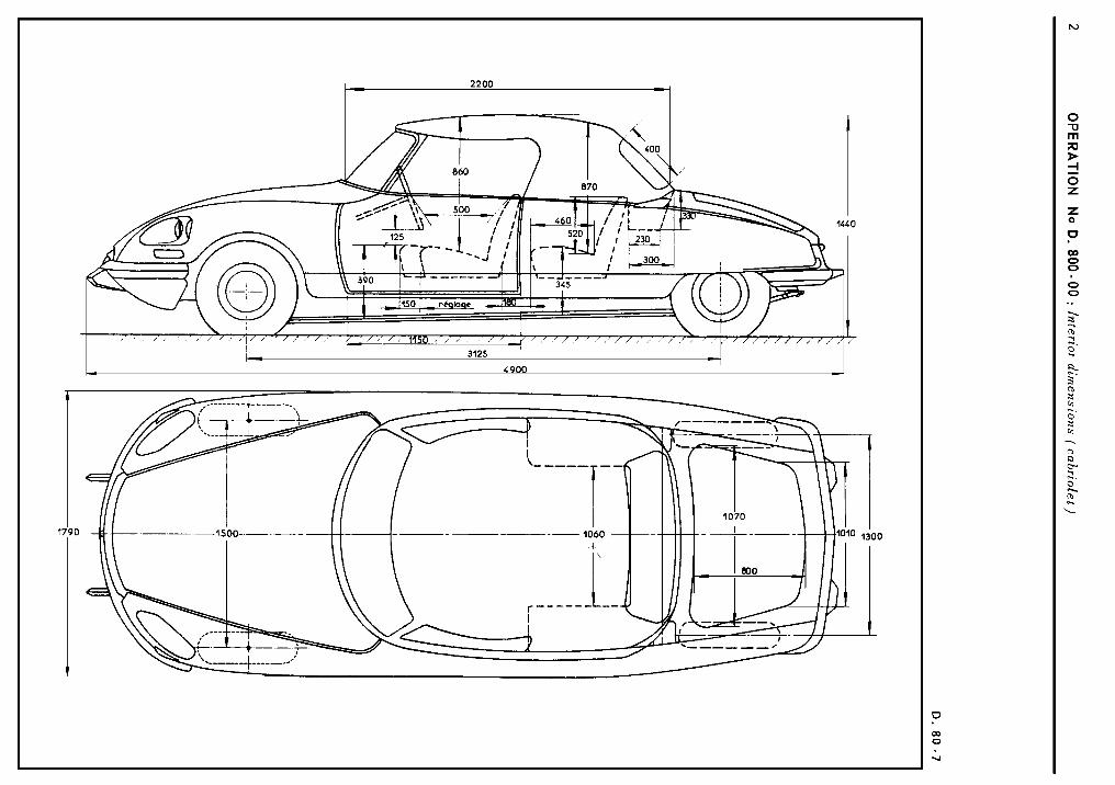

Manual 814-1


Manual 814-1


Manual 814-1

OPERATION No D. 800 - 02 : Adjusting the body panels OP. d. 800 - 02 1
( (a ,) The e d g e s of t h e doors should b e paral le l and within 2 mm.
ADJUSTING THE BONNET, FRONT WINGS AND DOORS.
I ( bn The top of the door should be a t t h e s a m e level a s or s l igh t ly below ( by 1 - 2 mm ) the rear point of the bonnet.
VEHICLES ALL TYPES b ~ e ~ t e r n b e r 1967
, ( c )) T h e (( l ignes d e lumiere )) should b e aligned within 1 mm.
~ ( d )) The door should b e leve l with or s l ight ly below ( by 1 - 2 mm ) t h e rear of the wing.
( ( e )) The rear edge of the wing should be paral le l with the front edge of the door and within 2 mm.
( ( f )) ((gn Within 2 mm ( c o n s t a n t play between wings and bonnet ).
~h )) 580 - 582 mm on veh ic les D of a l l types ( except u Pallas o ) For e Pallas ,) vehic les : s i d e - member trim- ming i s of a different th ickness t h i s must be measured with for example a pin in order to determine t h e bonnet height. C a l l th i s th ickness (( a n. Given that t h e height taken t o the an el i s 587 + 02 mm, the height t o trimming will be 587 + 02 mm - (( a ), -
(( j )) P l a y between windscreen rubber and rear point of bonnet, within 1 - 2 mm.

2 OPERATION No D. 800 - 02 : Adjusting the body panels
ADJUSTING THE BOOT LID, REAR WINGS AND DOORS 8127
( ( a 1 1 Top of front door level with or s l ight ly above (by 1 - 2 mm ) top of rear door .
( ( b ~ P l a y of 2 - 6 mm between wing and bumper.
((c )) T h e wing must b e paral le l with boot lid p ro- f i le .
c(d )) Edge of the door paral le l ( within 2 mm ) to e d g e of t h e wing.
((e)) 500.5 . 504.5 mm on veh ic les a l l types except e Pallas s
On (c Pallas D vehic les the s i d e member trimming is of a different th ickness . T h i s must b e mea- sured for example with a pin in order to deter- mine the wing height. C a l l t h e th ickness (( a ))
Given that t h e height taken t o the panel i s 509 mm, the height measured from t h e trimming will be 509 mm - u a 1).

OPERATION No D. 840 - 0 : A d j u s t i n g t h e doors and l o c k s Op. D. 840 - 0 1
I. ADJUSTING THE REAR DOORS.
ADJUSTING THE DOORS AND LOCKS.
NOTE : For this operation the rear wings should already have been ad jus ted .
VEHICLES ALL TYPES +September 1967
1. The depth to which the la tch i s engaged in t h e the ca tch must be a t l e a s t 4 mrn, with clea- rance between door and body.
To obtain th i s depth,move door supports ( 1 ) longitudinally. If t h i s i s not suf f ic ien t , place s p a c e r s under the ca tch a t ( ( a ) ) .
2. Adjustment of door height : Turn the pivot sc rews s o that the top of the door i s level with the rear doors with the ( ( l igh t liner) a l igned within 1 mm with that on the rear wing.
The rear edge of the door should be parallel with the e d g e of the wing, and within 2 mm. If not move one of the pivots supports ( 1 ).
II. ADJUSTING THE FRONT DOORS.
3 . T h e depth to which the la tch i s engaged in t h e c a t c h must be a t l e a s t 4mm. With c lea rance between door and cen t ra l door pi l lar .
To obtain th i s depth, mzve door supports ( 2 ) longitudinally. If th i s is not sufficient, p lace ad jus t ing shims unde: the ca tch .
4. Adjustment of door height : Turn pivot s c r e w s s o that the t o p of the door i s l eve l with or s l igh t ly below ( 1 - 2 mm) the rear point of the bonnet and level with or s l i - ghtly ahnve ( 1 - 2 mm ) the rear door : the (( l ight l ine 1) (( c ,) should be aiigned with that
on the rear door to within 1 mm. T h e rear edge of the door should be paral le l with the e d g e of the front door and within 2 mm.If not move one of the pivot supports ( 2 ).
I l l . LATERAL ADJUSTMENT OF DOORS.
To avoid any whist l ing t h e front door rnus t be flush with or s l ight ly proud of the rear door ( b y 1 - 2 mm ) T o ad jus t the doors la teral ly , the number of s p a c e r s placed between the cen t re pillar and pivot support ( 1 ) must be modified. I

OPERATION No D. 852-0 : Adjusting the bonnet - (locking and unlocking). Op. D. 852-0 I
ADJUSTING THE BONNET 3 6 5
VEHICLES ALL TYPES 1- 9 / 1 9 6 7
VERY IMPORTANT NOTE :
When the bonnet i s closed, i t cannot be opened if the cables are not connected to the unlocking mechanism.
The mechanism i s not accessible from the outside.
If, by mistake, t h e bonnet r e l e a s e h a s not been connected, proceed a s shown i n sec t ion 2.
ADJUSTMENT OF LOCK.
1. F i t tool (No MR. 6 3 0 - 8 2 / 5 ) in t h e lock aper tu res
Lock it in them.
2. Lower the bonnet. T h e c l o s i n g lugs should fal l in the centre of t h e tool tube.
3. Adjust the lugs ( 1 )
a ) Longitudinally : with s l o t (( b )) by loosening nut (3) .
1 ) Lateral ly : with s l o t (( a )) by loosening sc rews
( 2 ) .
Remove tool (No MR. 630 - 82/ 5)
) Adjust depth to which lugs are engaged :
Tighten (or loosen) the lugs (one turn a l t e r s t h e lengh by 1 mm) by r e l e a s i n g nut (3).
4, Check lock.
5. Tighten s c r e w s and nuts.

2 OPERATION No D. 852-0 : Adjust ing t he bonnet - (In / h e even[ of t h e mechanism being d isconnec ted)
I I - ADJUSTING THE BONNET
(In t h e even t of t h e mechanism being d i sconnec ted)
NOTE :
It is poss ib le t o open a bonnet of which the opening
mechanism h a s become d i sconnec ted :
- either b e c a u s e t h e c a b l e s a r e not connected t o the
bolts
- or b e c a u s e t h e rol lers have s l ipped from the c a b l e s
due to insuff icient tightening of t h e s c r e w s
1. U s e tool MR. 630-66/15
I Inser t the tool a t t h e junction of the bonnet and the
wing, between t h e bonnet and t h e bumper. By
feel ing around, engage t h e end of the tool in
t h e ho le of t h e lock support and push the bolt
unt i l i t r e l e a s e s
2. Repea t the operation for the other s i d e

OPERATION No D. 961-0 : Checking and repairing of a heated rear window Op. D. 9 6 1 - 0 1
CHECKING AND REPAIRING OF A REAR WINDOW HEATING RESISTANCE.
I. CHECKING
Force of the heating resistance :
a ) Saloon : 4 6 / 1972 . . . . . . . . . . . . . . . . . . . . . . . . . . . 7 3 t o 84 Watts unde r 1 3 , 5 + 0 .2 v o l t s . . . . . . . . . . . . . . . . . . . . . . . . . . . 6 / 1972 9 5 t o 110 Wat ts unde r 13 .5 + 0.2 v o l t s
. . . . . . . . . . . . . . . . . . . . . . . . . . . . . . . . . . . . . . . . . . b) Salari :. 85 t o 110 Watts unde r 13.5 2 0.2 v o l t s
T O c h e c k t h e r ea r window h e a t i n g r e s i s t a n c e , m e a s u r e : 1. I the r t h e cu r ren t c i r c u l a t i n g in t h e r e s i s t a n c e , by u s i n g a amphemete r , c o n n e c t e d t o t h e f e e d r e s i s t a n c e wi re .
T h e cu r ren t shou ld b e for : a ) Saloon --cl 6 / 1972. . . . . . . . . . . . . . . . . . . . . . . . . . . .4.8 t o 5.3 a m p s under 1 2 v o l t s
. . . . . . . . . . . . . . . . . . . . . . . . . . 6 / 1972. .6.2 to 7 .2 a m p s under 1 2 v o l t s . . . . . . . . . . . . . . . . . . . . . . . . . . . . . . . . . . . . . . . . . b) Safari : .5.6 t o 7 .2 a m p s under 1 2 v o l t s
2- I the r t h e r e s i s t a n c e , u s i n g a ohmmeter . T h e r e s i s t a n c e s h o u l d b e : a) Saloon 4 6 / 1 9 7 2 . . . . . . . . . . . . . . . . . . . . . . . . . . . .2 .17 t o 2.5 R
. . . . . . . . . . . . . . . . . . . . . . . . . . 6 / 1972. .1.65 to 1.92 R . . . . . . . . . . . . . . . . . . . . . . . . . . . . . . . . . . . . . . . b) Safari :. .1.65 t o 2.14 R - I
2 00 4
4 1 1 . REPAIRS. c 2
N O T E : T h e two undemen t ioned r e p a i r s c a n b e ca r r i ed o u t on a h e a t e d window f i t t ed to t h e veh ic l e .
1. Replacing the terminals.
T i n t h e par t of t h e terminal t o b e s o l d e r e d . Solder i t i n t h e p l a c e p rov ided ( s o l d e r i n g i ron) .
2. Repairing an element.
a ) O b t a i n from t h e R e p l a c e m e n t P a r t s Depar tmen t : - 1 K i t . . . . . . . . . . . . . . . . . . . . . . . . . . . . . . . . . . . . . . . . . .ZC. 9 855 128 U T h i s k i t " S E C U R I G L A C E " c o n t a i n s : - 1 B o t t l e of a b r a s i v e c l e a n i n g powder , - 1 S a c h e t of c o n d u c t i n g e n a m e l , - 1 T u b e of a d h e s i v e - 1 T u b e o f ha rden ing product for t h e a d h e s i v e , - 1 B o t t l e o f m e t a l l i c powder , - 1 R o l l of t h i ck a d h e s i v e t a p e , - 1 Warning l ight for d e t e c t i n g c u t s , - 1 Ro l l of a d h e s i v e for d e t e c t i n g c u t s , - 1 P l a s t i c s p a t u l a , - 1 G l a s s p l a t e , for mix ing t h e p r o d u c t s ,
b) Locat ing the cut :
With r e s i s t a n c e f ed a s normal : - L o c a t e t h e d e f e c t i v e r e s i s t i n g wi re by s t i c k i n g t h e a d h e s i v e d e t e c t i n g t a p e in t h e c e n t r e of t h e r e a r w indow
( o n t h e i n s i d e ) , a n d on a l l t h e r e s i s t a n c e l i n e s s o t h a t t h e t a p e i s pe rpend icu la r t o t h e l a t t e r . T h e w i r e s , w h e n t h e c i r cu i t i s not b roken , wi l l turn t h e the rmopaper b l u e when t h e t empera tu re g e n e r a t e d i s r a i s e d .
- O n t o t h e c u t w i r e , s l i d e t h e t w o po in ted p robes o f t h e suppor t of t h e warninq l igh t , u s e d for d e t e c t i n g c u t s . When t h e lamp l i g h t s u p , t h e po in ted p robes a r e on both s i d e s of t h e b reak in t h e r e s i s t a n c e . B y moving them s l i g h t l y a l o n g t h e wi re , o n e c a n de te rmine t h e e x t e n t o f t h e c u t e x a c t l y .

2 OPERATION No D. 961-0 : Check ing and repairing a hea ted rear window.
c ) Preparing the rear windows:
With the r e s i s t a n c e no longer under voltage :
Clean out the a r e a t reated with the powder, contained in the bot t le marked "Bimspulver" . Sprinkle th i s powder on a smal l p iece of rag and rub. Then wipe c lean with a second p iece of rag.
P l a c e on e a c h s i d e of the res i s tance , a s t r ip of th ick a d h e s i v e tape 25 mm long, marking t h e length of repair t o be carried out. T h e e d g e s of the s t r ip must be per fec t ly s t raight and c lean , s o a s to avoid a cu t during t h e repair.
d ) Repairs :
Fi rs t phrase :
Empty the complete con ten ts of one of the s a c h e t s of conduct ing enamel onto the g l a s s p la te . Mix t h e con ten ts well by using t h e spatula .
Apply the p a s t e thus obtained, on the spo t to be repaired, s o a s to completely fill t h e s p a c e between t h e two s t r i p s o f tape. Only apply the p a s t e to the cut .
L e a v e to dry for about 15 minutes , a t a tmospheric temperature.
Second phrase :
On the g l a s s p la te , prepare a mixture (of about the same s i z e a s a ches tnu t ) containing equa l amounts of t h e a d h e s i v e and U.H.U. hardening product.
T o t h i s p a s t e , add a n equa l amount of the meta l l i c powder, contained i n the bot t le marked " Metallpulver" mix well with the spa tu la .
Apply the p a s t e thus obtained on the conduct ing enamel exceed ing the e d g e s of the depos i t of the l a t t e r , o n both s i d e s , by 10 mm. But with the length s t i l l l imited by the s t r i p s of tape. Use t h e spa tu la to regulate the t h i c k n e s s , us ing t h e tape a s a support.
L e a v e to dry for a n hour and a h a l f , at a tmospheric temperature, before removing t h e s t r i p s of tape. Move them a s i d e parallel t o the s u r f a c e of the rear window, t o avoid removing the film deposi ted.
The drying time c a n be reduced by charging the r e s i s t a n c e for half an hour.
NOTE : Wait 24 to 48 hours before proceedins to c lean the i n s i d e of t h e rear window.
e ) Checking :
Carry out the c h e c k , us ing the adhes ive tape. Proceed a s when locat ing the cut .

LIST OF SPECIAL TOOLS IN VOLUME No 1 OF MANUAL 583
DESCRIPTION
ENGINE
Engine -gearbox a s s e m b l y support Gearbox support Engine support ad jus te r t empla te E l e c t r i c tachometer Graduated c i rcu i t for ad jus tment of au tomat ic
advance F u e l pump pressure control gauge Oil p ressure adapter Pu l ley al ignment measuring rod Bel t t ens ion hook Belt t ens ion lever
CLUTCH
Clutch mechanism control appara tus (D. IE v e h i c l e s ) Hydraul ic t e s t - bench ( L H S 2 F lu id l Hydraul ic t e s t -bench ( L H M Flu id l Tes t- bench accessories ( L H M Flu id l Clutch peda l sp r ing a d j u s t e r
GEARBOX
Tool s e t f o r c h e c k i n g o i l p r e s s u r e o n BW gearbox Adjuster for r e v e r s e - neutral return
Clutch lock control a p p a r a t u s Hydraul ic t e s t - bench ( L H S 2 F lu id l Hydraul ic t e s t - bench ( L H M Flu id l T e s t - bench a c c e s s o r i e s ( L H M Flu id l
PRESSURE SOURCE AND RESERVE
Hydraul ic t e s t - b e n c h ( L H S 2 F lu id l Hydraul ic t e s t - b e n c h ( L H M Flu id l Tes t -bench a c c e s s o r i e s ( L H M Flu id l
FRONT AXLE Wheel camber control appara tus C a s t e r control appara tus
SUSPENSION
Front height a d j u s t e r g a u g e s Hydraul ic t e s t - b e n c h ( L H S 2 F lu id l Hydraul ic t e s t - bench ( L H M Flu id l T e s t - b e n c h a c c e s s o r i e s ( L H M Flu id l
REPAIR METHOD NUMBERS
Old
MR. 3301 - 260 MR. 3725 - 110
MR. 3705
MR. 4208 - 20 MR. 4208
MR. 3301 - 240
MR. 1401 - 3 0
New
MR. 630 - 42/ 13 MR. 630- 51/38
MR. 630-56/ 1
MR. 630-66/11 B MR. 630 - 661' 11
MR. 630 - 55,' 9
MR. 630-27/2
MR. 630 - 431' 20
MR. 630-51/3
R E F . N o s of too l s on s a l e
3658 - T 31 88 - T R e p l a c e s
3 1 8 3 - T + 9/69

LIST OF SPECIAL TOOLS IN VOLUME N V OF MANUAL 583.
DESCRlPTlON
STEERING
Straight a h e a d posi t ion ad jus te r Steering ad jus te r Hydraul ic t e s t - bench ( L H S 2 ) Hydraulic t e s t - bench ( L H M ) Test - b e n c h a c c e s s o r i e s ( L H M ) Straight ahead posi t ion gauge
BRAKES
Stand Centr ing apparatus for rear brake s h o e s Hyfraulic t e s t - bench ( L H S 2 ) Hydraul ic t e s t - bench ( L H M ) T e s t - bench a c c e s s o r i e s ( L HM )
ELECTRICS
End -.float adjustement s p a c e r for headlamp torsion control rod Headlamp beam d i s t a n c e ad jus te r Head lamp torsion control rod adjuster ( -w 9/ 1967) Dipst ick for check ing leve l of o i l in compressor
BODYWORK
Bonnet r e l e a s e tool
Old
REPAIR Method numbers
New
MR. 4541
MR. 4541
MR. 3756- 60
MR. 4531
MR. 4538
MR. 630 - 51/63
MR. 630 -511'63
MR. 630 - 51/49
MR. 630-72/10 MR. 630 - 72,' 15
MR. 630 - 66/ 15
REF Nos
Of too ls on s a l e

SPECIFICATIONS OF TOOLS NOT ON SALE. 1
MR. 630 - 42,' 13
Spl i t pin 0 = 3 F l a t washer 0 = 20 S t d
~ imensions ex. MR. 3301 -260 rom F1 to ground 162 8 ,5 465
/ A ram F 1 to ground 1 18
8 - 4 pleces sheet metal thickness 5 mm
j- Blunted onqles 10 mm
23 290 - 93 - -
35
I
D - 2 angle - pieces 20 x20 x3
1 62
E - 2 angle - pleces 2 0 . 2 0 . 3
0= 20
278 F -2 ~ i e c e s semi -hardened steel
I I
a - l plece sheet metal th = 5 rnm
0= 14 - I 1 12
F1
B
1
- - - - - - - - - - - - - - - - - - - - -
3 a 4 5 " 60 C - 4 pieces semi -hardened steel

2 SPECIFICATIONS OF TOOLS NOT SOLD.
MR. 630 -43/20
ex. MR. 3301 -240
Soldered n u t s
-
\
Sheet metal 2 mm
MR. 630 - 51/3 MR. 630 - 51/38 ex. M R . 1401 -30 ex. MR. 3725- 110
C 4 Shee+ .metd 5
Th. 15/10

SPECIFICATIONS OF TOOLS NOT SOLD 3
MR .630-51/49 ex. MR .3756-60 ex. MR. 4541

4 SPECIFICATIONS OF TOOLS NOT SOLD
MR. 630-56/ 1
1
Semi - hardened steel
MR. 630-66/11
ex. MR. 4208
a l surface 1 2 A / F
MR. 630 -66/ 11 B ex . MR. 4208-20

SPECIFICATIONS OF TOOLS NOT SOLD. 5
MR. 630 72/ 10
ex. MR. 4531 r
v i e w e d ur c -
12 1 1 I Spacer sheet metal 2 mm I
No
1
3 1 Reinforcement Sh-et metal 2 mm.
4 1 1 I ~ h r u s t Sheet metai 2 mm.
Q ~ Y
1
D e s c r i p t ~ o n
T u b e f r a m e 5 . 1Odcvelopped length 12451
7
8
2
1
Col lar
screw 1:=6 5.1. l e n g t h = 3 5

6 SPECIFICATIONS O F TOOLS NOT ON SALE
MR. 630-66/ 15 ex MR. 4538
Extended length - 300
Semi-hardened steel 4 = 5

S P E C I F I C A T I O N S O F TOOLS N O T O N S A L E 7
Lever
r,b ,7 5
20 t
~ ~ o t iron 5x20 I c
Pin to be riveted
Tube 15 . 21
Steel C 35

8 SPECIFICATIONS OF TOOLS NOT ON SALE
Extended length
Moteriol : Mild steel w i r e
0 = 3