
UNIFIED MODELING LANGUAGE
143
1 UNIFIED MODELING LANGUAGE LESSON 1 INTRODUCTION A successful software organization is one that consistently deploys quality software that meets the needs of its users. In this lesson we will discuss the importance of modeling, the four principles of modeling and the object-oriented modeling. Also in this lesson we will have an introduction about the overview of the UML, the three steps to understanding the UML, the software architecture and the software development process. MODEL : A model is a simplification of reality. In other words a model provides the blueprint of a system. Building a model is to better understand the system that is to be developed. Complex systems need modeling because it cannot be comprehended in its entirety. 1.1 PRINCIPLES OF MODELING There are four basic principles of modeling. The include : 1. The choice of what models to create has a profound influence on how a problem is attacked and how a solution is shaped.
-
Upload
khangminh22 -
Category
Documents
-
view
1 -
download
0
Transcript of UNIFIED MODELING LANGUAGE

1
UNIFIED MODELING LANGUAGE
LESSON � 1
INTRODUCTION
A successful software organization is one that consistently deploys quality
software that meets the needs of its users. In this lesson we will discuss the importance
of modeling, the four principles of modeling and the object-oriented modeling. Also in
this lesson we will have an introduction about the overview of the UML, the three steps
to understanding the UML, the software architecture and the software development
process.
MODEL :
A model is a simplification of reality. In other words a model provides the
blueprint of a system. Building a model is to better understand the system that is to be
developed. Complex systems need modeling because it cannot be comprehended in its
entirety.
1.1 PRINCIPLES OF MODELING
There are four basic principles of modeling. The include :
1. The choice of what models to create has a profound influence on how a
problem is attacked and how a solution is shaped.

2
The right models will brilliantly illuminate the most crucial development
problems offering insight that simply could not gain others. For example of a system is
built through the eyes of a database developer, he will likely focus on entity-relationship
models that push behavior into triggers and stored procedures. If the same system is built
through the eyes of structured analyst, he will likely end up with models that are
algorithm-centric, with data flowing from process to process. If the same system is built
through the eyes of an object-oriented developer, he will end up with classes and the
patterns of interaction that direct how those classes work together.
Any of the above approaches might be right for a given application and
development culture. The point is that each view leads to a different kind of system with
different costs and benefits.
2. Every model may be expressed at different levels of precision.
In software models, sometimes a quick and simple executable model of the user
interface might be needed and sometimes complex networking bottlenecks might be
needed. In any case, the best kind of models are those that lets the modeler choose the
degree of detail, depending on who is doing the viewing and why they need to view it.
3. The best models are connected to reality.
It is best to have models that have a clear connection to reality, and where the
connect is weak, to know exactly how those models are divorced from the real world. All
models simplify reality. The trick is to be sure that your simplifications don�t hide any
important details.

3
In structured analysis techniques, there is a basic disconnect between its analysis
model and the system�s design model In object-oriented systems, it is possible to connect
all the nearly independent views of a system into one semantic whole.
4. No single model is sufficient. Every non-trivial system is best approached
through a small set of nearly independent models.
To understand the architecture of a system which uses object oriented approach,
we need several views, namely.,
(a) A Use Case View � Exposing the requirements of the system
(b) A Design View � Capturing the vocabulary of problem space and solution
space
(c) A Process View � modeling the distribution of the system�s processes and
threads
(d) An Implementation View � Addressing the physical realization of the system
(e) A Deployment view � Focusing on system engineering issues.
Together these views represent the blue print of software.
1.2 OBJECT � ORIENTED MODELING
In software the two most common ways to approach a model are
1. Algorithmic Approach
In this approach, the main building block of all software is the procedure or
function. This view leads developers to focus on issues of control and the decomposition

4
of larger algorithms into smaller ones. As requirements change and the system grows,
systems built with an algorithmic focus turn out to be very hard to maintain..
2. Object � Oriented Approach
In this approach, the main building block of all software system is the object or
class. An object is an thing generally drawn from the vocabulary of problem space or the
solution space. A class is a description of a set of common objects.
The Object-Oriented approach to software development is decidedly a part of the
mainstream simply because it has proved to be a value in building systems in all sorts of
problem domains and encompassing all degrees of size and complexity. Object-Oriented
development provides the conceptual foundation for assembling systems out of
components using technology such as Java Beans or COM+.
1.3 INTRODUCTION TO UML
Visualizing, specifying, constructing and documenting Object-Oriented systems is
exactly the purpose of the Unified Modeling Language. The Unified Modeling Language
is a standard language for writing software blueprints.
The UML is a language for
Visualizing :
The UML is more than just a bunch of graphical symbols. Rather behind each
symbol in the UML notation is a well-defined semantics. In this manner, one developer
can write a model in the UML, and another developer, or even another tool can interpret
that model unambiguously.

5
Specifying :
Building models that are precise, unambiguous, and complete. In particular, the
UML addresses the specification of all the important analysis, design, and
implementation decisions that must be made in developing and deploying a software-
intensive system.
Constructing :
In addition to direct mapping the UML is sufficiently expressive and
unambiguous to permit the direct execution of models, the simulation of systems, and the
instrumentation of running systems.
Documenting :
The UML addresses the documentation of a system�s architecture and all of its
details. The documents include.,
Requirements Architecture Design Source Code Project Plans Tests Prototypes Releases
The UML also provides a language for expressing requirements and for tests.
Finally, the UML provides a language for modeling the activities of project planning and
release management.

6
Uses Of UML
The UML is intended primarily for software-intensive systems. It has been used
effectively for such domains as
i) Enterprise Information Systems
ii) Banking and Financial Services
iii) Telecommunications
iv) Transportation
v) Defence / Aerospace
vi) Retail
vii) Medical Electronics
viii) Scientific
ix) Distributed Web-Based Services
1.4 CONCEPTUAL MODEL OF THE UML
To understand the UML, one has to form a conceptual model of the language, and
this requires learning three major elements : (i) The UML�s Basic Building Blocks, (ii)
The Rules that dictate how those Building Blocks may be put together and (iii) Some
Common Mechanisms that apply throughout the UML.

7
Building Blocks Of The UML
The vocabulary of the UML encompasses three kinds of building blocks :
1. Things
2. Relationships
3. Diagrams
Things are the abstractions that are first class citizens in a model; relationships tie
these things together; diagrams group interesting collections of things.
Things :
There are four kinds of things in the UML. They include :
(a) Structural Things :
Structural things are the nouns of UML models. These are mostly static parts of
a model, representing elements that are either conceptual or physical. In all there are
seven kinds of structural things.
(i) A Class : is a description of a set of objects that share the same attributes,
operations, relationships and semantics. Graphically, a class is rendered as a
rectangle usually including its name, attributes and operations.
Window origin size open( ) close( ) move( ) display( )
name of the class attributes of the class operations of the class

8
(ii) An Interface : is a collection of operations that specify a service of a class
or component. An interface therefore describes the externally visible behavior of
that element. Graphically an interface is rendered as a circle together with its
name.
(iii) A Collaboration : defines an interaction and is a society of roles and other
elements that work together to provide some cooperation. Graphically, a
collaboration is rendered as an ellipse with dashed lines, usually including only its
name.
(iv) An Use Case : is a description of set of sequence of actions that a system
performs. A use case is sued to structure the behavioral things in a model.
Graphically, an use case is rendered as an ellipse with solid lines, usually
including only its name.
ISpelling
Chain of responsibility
Place order

9
(v) An Active Class : is a class whose objects own one or more processes or
threads and therefore can initiate control activity. Graphically, an active class is
rendered just like a class, but with heavy lines, usually including its name,
attributes & operation.
(vi) A Component : is a physical and replaceable part of a system that
conforms to and provides the realization of a set of interfaces. Graphically, a
component is rendered as a rectangle with tabs, usually including only its name.
(vii) A Node : is a physical element that exists at runtime and represents a
computational resource, generally having at least some memory and, often
processing capability. Graphically, a node is rendered as a cube, usually
including only its name.
EventManager suspend( ) flush( )
Orderform.java
Server

10
(b) Behavioral Things
Behavioral things are the dynamic parts of UML models. These are the verbs of a
model, representing behavior over time and space. In all there are two primary kinds of
behavioral things. They include :
(i) An interaction : is a behavior that comprises a set of messages exchanged
among a set of objects within a particular context to accomplish a specific
purpose
(ii) A State Machine : is a behavior that specifies the sequence of states an
object or an interaction. Graphically a state is rendered as a rounded rectangle,
usually including its name and its sub states, if any.
(c) Grouping Things
Grouping things are the organizational parts of UML models. There is one
primary grouping thing, namely Packages.
A Package is a general-purpose mechanism for organizing elements into groups.
Structural things, behavioral things and even other grouping things may be placed in a
package. Graphically, a package is rendered as a tabbed folder, usually including only its
name and sometimes its contents.
display Messages
Waiting

11
(d) Annotational Things :
Annotational things are the explanatory parts of UML models. These are
comments. Graphically, a note is rendered as a rectangle with a dog-eared corner,
together with a textual or graphical comment.
Relationships :
There are four kinds of relationships in the UML
(a) Dependency
Is a semantic relationship between two things in which a change to one
thing may affect the semantics of the other. Graphically a dependency is rendered as a
dashed line, possibly directed, and occasionally including a label.
Business Rules
return copy to self
12
0..1 employer
* employee
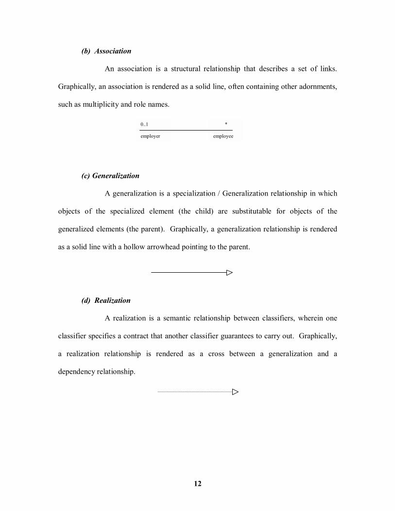
(b) Association
An association is a structural relationship that describes a set of links.
Graphically, an association is rendered as a solid line, often containing other adornments,
such as multiplicity and role names.
(c) Generalization
A generalization is a specialization / Generalization relationship in which
objects of the specialized element (the child) are substitutable for objects of the
generalized elements (the parent). Graphically, a generalization relationship is rendered
as a solid line with a hollow arrowhead pointing to the parent.
(d) Realization
A realization is a semantic relationship between classifiers, wherein one
classifier specifies a contract that another classifier guarantees to carry out. Graphically,
a realization relationship is rendered as a cross between a generalization and a
dependency relationship.
13
Diagrams In The UML
A diagram is the graphical presentation of a set of elements, most often rendered
as a connected graph of vertices and relationships. In UML there are nine diagrams.
1. Class Diagrams
Class Diagrams shows a set of classes, interfaces, and collaborations and
their relationships. Class diagrams are the most common diagrams found in modeling
object � oriented systems.
2. Object Diagrams
An object diagram shows a set of objects and their relationships. Object
diagrams are used to illustrate data structures, the static snapshots of instances of the
things found in class diagram.
3. Component Diagrams
A component diagram shows a set of components and their relationships.
Component diagrams are related to class diagrams in that a component typically maps
one or more classes, interfaces or collaborations.
4. Deployment Diagrams
A deployment diagram shows a set of nodes and their relationships.
Deployment diagrams are related to component diagrams in that a node typically encloses
one or more components.
5. Use Case Diagrams
An use case diagram shows a set of use cases and actors ( a special kind of
class) and their relationships. Use Case diagrams are especially important in organizing
and modeling the behaviors of a system.

14
6. Sequence Diagrams
A sequence diagram is an interaction diagram that emphasizes the time
ordering of messages. A sequence diagram shows a set of objects and the messages sent
and received by those objects.
7. Collaboration Diagrams
A collaboration diagram is an interaction diagram that emphasizes the
structural organization of the objects that send and receive messages. A collaboration
diagram shows a set of objects, links among these objects, and messages sent and
received by those objects.
8. Statechart Diagrams
A statechart diagram shows a state machine, consisting of states,
transitions, events and activities.
9. Activity Diagram
An Activity diagram shows the flow from activity to activity within a
system. Activity diagrams emphasize the flow of control among objects.
1.5 COMMON MECHANISM IN THE UML
A building is made simpler and more harmonious by the conformance to a pattern
of common features. In UML there are four common mechanisms that apply consistently
throughout the language. They are :
1. Specification
The UML�s specifications provide a semantic backplan that contains all
the parts of all the models of a system, each part related to one another in a consistent
fashion.

15
2. Adornments
Most elements in the UML have a unique and direct graphical notation
that provides a visual representation of the most important aspects of the element. Every
element in the UML�s notation starts with a basic symbol, to which can be added a
variety of adornments specific to that symbol.
The above figure shows a class Transaction adorned to indicate that it is an
abstract class with two public operations + execute ( ) , + rollback ( ), one protected
operation # priority ( ) and one private operation � timestamp ( ).
3. Common Divisions
In object-oriented systems modeling, the view often gets divided in atleast
a couple of ways. Graphically, the UML distinguishes an object by using the same
symbol as its class and then simply underlying the objects� name.
Transaction + execute( ) + rollback( ) # priority ( ) - timestamp ( )
Customer name address phone
Jan : Customer
: Customer
Elyse

16
4. Extensibility Mechanism
The UML provides a standard language for writing software blueprints,
but it is not possible for UML to express all possible things of all models across all
domains. The UML�s extensibility mechanisms include :
(a) Stereotypes : extends the vocabulary of the UML, allowing to
create new kinds of building blocks.
(b) Tagged Value : Extend the properties of a UML building block,
allowing to create new information in that element�s specification.
(c) Constraint : extends the semantics of a UML building block,
allowing to add new information in that element�s specification.
In the above diagram <<exception>> is called as the stereotype.
{version = 3.2 author = abc} is known as the tagged value
{Ordered} is termed as the constraint (all additions are done in order)
<< exception >> Overflow
EventQueue {version = 3. 2 author = abc}
add ( ) remove ( ) flush ( )
{ordered}

17
LESSON � 2
BASIC STRUCTURAL MODELING
2.1 CLASSES
Classes are the most important building block of any object-oriented system. A
class is a description of a set of objects that share the same attributes, operations,
relationships and semantics. A class implements one or more interfaces. Well-structured
classes have crisp boundaries and form a part of a balanced distribution of responsibilities
across the system.
Every class must have a name that distinguishes it from other classes. A name is
a textual string. That name alone is known as a simple name; a path name is the class
name prefixed by the name of the package in which that class lives. Graphically, a class
is rendered as a rectangle.
Attributes :
An Attribute is a named property of a class that describes a range of values that
instances of the property may hold. Graphically, attributes are listed in a compartment
path names
attributes
operations
nameShape origin move( ) resize( ) display( )
Temperature Sensor
Wall
Customer
simple names
Business Rules :: FraudAgent
Java::awt::Rectangle

18
just below the class name. Typically, capitalize the first letter of every word in an
attribute name except the first letter.
Operations :
An operation is the implementation of a service that can be requested from any
object of the class to affect behavior. A class may have any number of operations or no
operation at all. Graphically, operations are listed in a compartment just below the class
attributes.
An operation can be specified by stating its signature, covering the name, type
and default value of all parameters. To better organize long lists of attributes and
operations, it can also prefix each group with a descriptive category by using stereotypes.
operations & their signatures
attributes & their data types possibly with a default value
Customer name address phone birthDate
Wall height : Float width : Float thickness : Float isLoadBearing : Boolean = false
attribute
Rectangle add( ) grow( ) move( ) isEmpty( )
TemperatureSensor reset( ) setAlarm(t : Temperature) value( ) : Temperature
operations
19
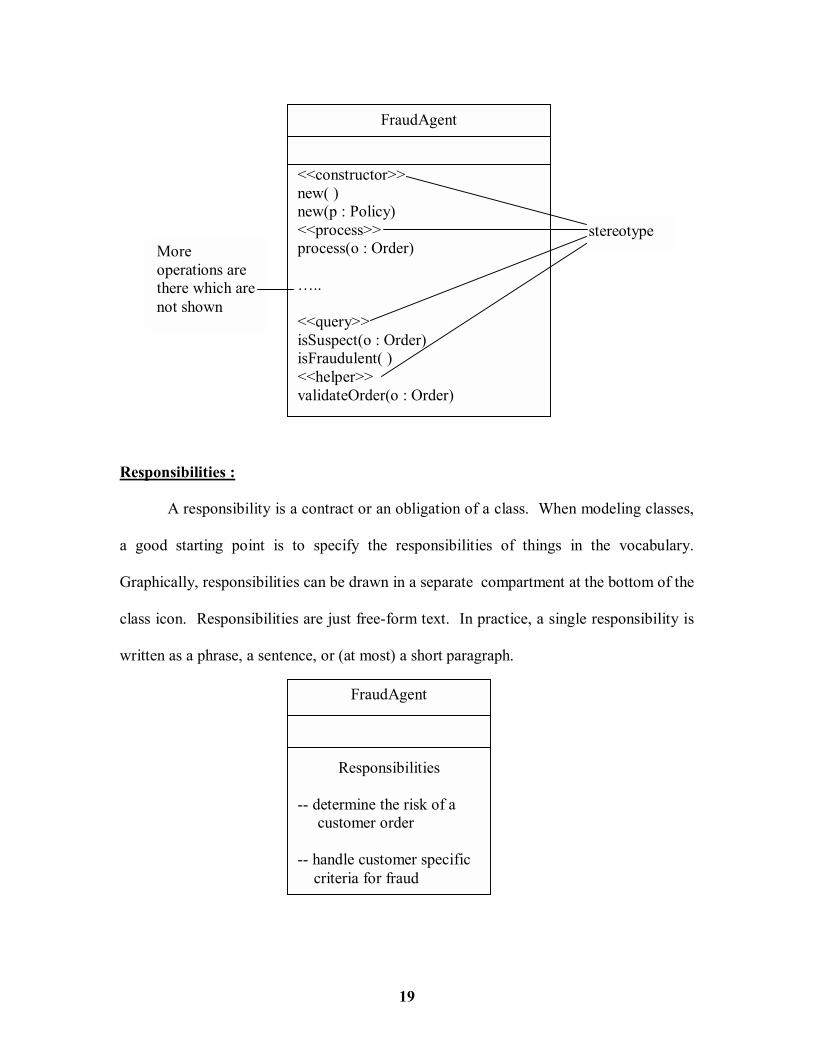
Responsibilities :
A responsibility is a contract or an obligation of a class. When modeling classes,
a good starting point is to specify the responsibilities of things in the vocabulary.
Graphically, responsibilities can be drawn in a separate compartment at the bottom of the
class icon. Responsibilities are just free-form text. In practice, a single responsibility is
written as a phrase, a sentence, or (at most) a short paragraph.
stereotype More operations are there which are not shown
FraudAgent <<constructor>> new( ) new(p : Policy) <<process>> process(o : Order) �.. <<query>> isSuspect(o : Order) isFraudulent( ) <<helper>> validateOrder(o : Order)
FraudAgent
Responsibilities -- determine the risk of a customer order -- handle customer specific criteria for fraud
20
2.2 RELATIONSHIPS
A relationship is a connection among things. In object-oriented modeling, the
three most important relationships are
(a) Dependencies
(b) Generalizations
(c) Associations
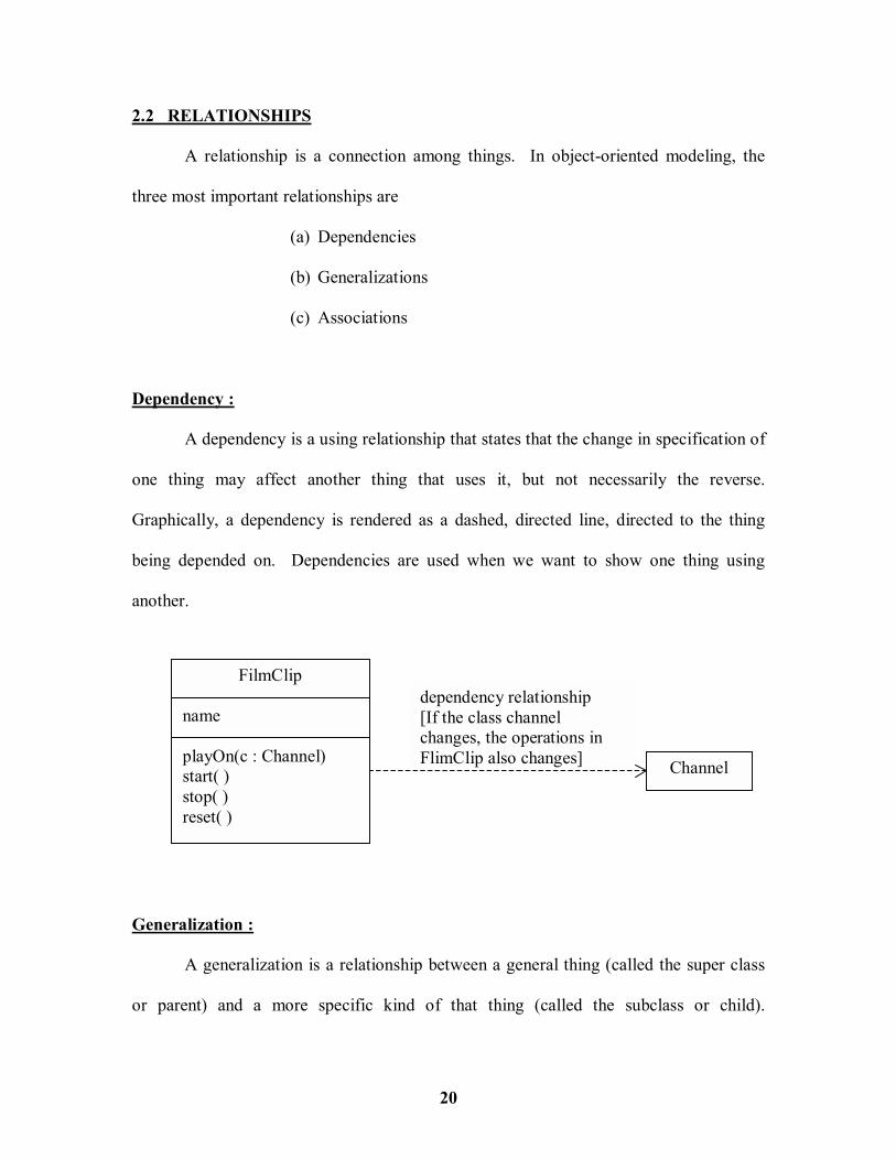
Dependency :
A dependency is a using relationship that states that the change in specification of
one thing may affect another thing that uses it, but not necessarily the reverse.
Graphically, a dependency is rendered as a dashed, directed line, directed to the thing
being depended on. Dependencies are used when we want to show one thing using
another.
Generalization :
A generalization is a relationship between a general thing (called the super class
or parent) and a more specific kind of that thing (called the subclass or child).
dependency relationship [If the class channel changes, the operations in FlimClip also changes]
FilmClip name playOn(c : Channel) start( ) stop( ) reset( )
Channel

21
Graphically, generalization is rendered as a solid directed line with a large open
arrowhead, pointing to the parent.
Generalization is used among classes and interfaces to show inheritance
relationships. A generalization can have a name, although names are rarely needed.
Association :
An association is a structural relationship that specifies that objects of one thing
are connected to objects of another. Graphically, an association is rendered as a solid line
Shape origin move( ) resize( ) display( ) ( )
Rectangle corner : Point
Circle radius : Float
Polygon points : List display( )
Square
base class
Leaf class

22
connecting the same or different classes. Use associations to show structural
relationships. There are four adornments that apply to associations. They include :
Name : An association can have a name to describe the nature of the
relationship.
Role : a role is just the face the class at the near end of the association presents
to the class at the other end of the association.
Multiplicity : Stating how many objects may be connected across an instance of
an association is termed as multiplicity. This multiplicity is written
as an expression that evaluates to a range of values.
1 -- One
0 .. 1 -- Zero to One
0 .. * -- Many
1 .. * -- One or Many
Works for Person Company
name Name�s direction
association
roleemployeremployee
Person Company
*1..* employeremployeePerson Company
multiplicity
Multiplicity

23
Aggregation : Showing relationships between classes of whole and classes of part
may be termed as Aggregation. Aggregation is a special kind of
association and is specified by adorning a plain association with an
open diamond at the whole end.
2.3 Common Mechanisms
Notes : A note that renders a comment has no semantic impact, meaning that its
contents do not alter the meaning of the model to which it is attached. This is why notes
are used to specify things like requirements, observations, reviews, and explanations, in
addition to rendering constraints.
A note may contain any combination of text or graphics. If the implementation
allows it, live URL can be put inside a note, or even link to or embed another document.
In this way UML allows to organize all the artifacts that might be generated or used
during development.
The UML specifies one standard stereotype that applies to notes � requirements.
This stereotype names a common category of notes � those used to state some
responsibility or obligation.
*
1
Company
Department
aggregation whole
part

24
Other Adornments :
Adornment are textual or graphical items that are added to an element�s basic
notation and are used to visualize details from the elements specification. Most
adornments are rendered by placing text near the element of interest or by adding a
graphic symbol to the basic notation. However, sometimes there is a need to adorn an
element with more details than can be accommodated by simple text or graphics. In the
case of such things as classes, components, and nodes, extra compartment can be added
below the usual compartments to provide this information, as shown in the following
figure.
Publish this component In the project repositry After the next design review
See http://www.gameplan.com For an example of this applet
See encrypt.doc for Details about this algorithm
simple text
Embedded URL
Link to document
Transaction addActive( ) rollBack( )
Exceptions emptyTransaction noSuchAction resourceLocked
Client bill.exe report.exe contacts.exe
Named compartment
Anonymous compartment

25
Stereotypes :
The UML provides a language for structural things, behavioral things, grouping
things and notational things. These four basic kinds of things address the overwhelming
majority of the systems needs to the model. However sometimes there is a need to
introduce new things that speak the vocabulary of the domain. In its simplest form, a
stereotype is rendered as a name enclosed by guillemots (for example, <<name>>) and
placed above the name of another element.
As a visual cue, an icon may be defined for the stereotype and render the icon to
the right of the name or use that icon as the basic symbol for the stereotyped item. All
three of these approaches are illustrated in the following figure.
Tagged Values :
Everything in the UL has its own set of properties; classes have names, attributes,
and operations; associations have names and two or more ends; and so on. With
Stereotypes, new things can be added; with tagged values new properties can be added.
Tags can be defined for existing elements or define tags that apply to individual
stereotypes. In simplest form, tagged value is rendered as a string enclosed by brackets
HumiditySensor <<metaclass>> ModelElement
<<exception>> Underflow
Named stereotype Named stereotype with Icon
Stereotyped element as Icon

26
and placed below the name of another element. The following figure explains this
concept.
In the above figure the values within the curl braces ({ }) are termed as tagged
values.
2.4 DIAGRAMS
When modeling something, there is a need to create a simplification of reality so
that the person can better understand the system he/she is developing. Using the UML,
one can build his/her models from basic building blocks, such as classes, interfaces,
collaborations, components, nodes, dependencies, generalizations, and associations.
Diagrams are the means by which he/she views these building blocks. A diagram
is a graphical presentation of a set of elements, most often rendered as a connected graph
of vertices (things) and arcs (relationships).
A system is a collection of subsystems organized to accomplish a purpose and
described by a set of models, possibly from different viewpoints. A subsystem is a
grouping of elements, of which some constitute a specification of the behavior offered by
the other contained elements. A model is a semantically closed abstraction of a system,
meaning that it represents a complete and self-consistent simplification of reality, created
Server {processors = 3}
<<library>>trans.dll
{Server only}

27
in order to better understand the system. A diagram is the graphical presentation of a set
of elements, most often rendered as a connected graph of vertices (things) and arcs
(relationships).
In modeling real systems, no matter what the problem domain, same kinds of
diagrams are created, because they represent common views into common models.
Typically, the static parts of a system are viewed using one of the four following
diagrams.
1. Class diagram
2. Object diagram
3. Component diagram
4. Deployment diagram
To view the dynamic parts of the system, the following five diagrams are used.
1. Use case diagram
2. Sequence diagram
3. Collaboration diagram
4. Statechart diagram
5. Activity diagram
In practice, all the diagrams created will be two-dimensional, meaning that they
are just flat graphs of vertices and arcs that are drawn on a sheet of paper, a whiteboard,
the back of an envelope, or on a computer display. The UML allows to create three-
dimensional diagrams, meaning that they are graphs with depth, allowing to swim

28
through a model. Some virtual reality research groups have already demonstrated this
advanced use of the UML.
2.4.1 STRUCTURAL DIAGRAMS :
The UML�s four structural diagrams exist to visualize, specify, construct, and
document the static aspects of a system. One can imagine of the static aspects of a
system as representing its relatively stable skeleton and scaffolding. Just as the static
aspects of a house encompass the existence and placement of such things as walls, doors,
windows, pipes, wires and vents, so too do the static aspects of a software system
encompass the existence and placement of such things as classes, interfaces,
collaborations, components, and nodes.
Class Diagram :
A class diagram shows a set of classes, interfaces, and collaborations and their
relationships. Class diagrams are the most common diagrams found in modeling object-
oriented systems. Class diagrams are used to illustrate the static design view of a system.
Class diagrams that include active classes are used to address the static process view of a
system.
Object Diagram :
An object diagram shows a set of objects and their relationships. Object diagrams
are used to illustrate data structures, the static snapshots of instances of the things found
in class diagrams. Object diagrams address the static design view or static process view

29
of a system just as do class diagrams, but from the perspective of real or prototypical
cases.
Component Diagram :
A component diagram shows a set of components and their relationships.
Component diagrams are used to illustrate the static implementation view of a system.
Component diagrams are related to class diagrams in that a component typically maps to
one or more classes, interfaces or collaborations.
Deployment Diagram :
A deployment diagram shows a set of nodes and their relationships. Deployment
diagrams are used to illustrate the static deployment view of an architecture. Deployment
diagrams are related to component diagrams in that a node typically encloses one or more
components.
2.4.2 BEHAVIORAL DIAGRAMS
The UML�s five behavioral diagrams are used to visualize, specify, construct and
document the dynamic aspects of a system. The dynamic aspects of the systems are
imagined as representing its changing parts. Just as the dynamic aspects of a house
encompass airflow and traffic through the rooms of a house, so too do the dynamic
aspects of a software system encompass such things as the flow of messages over time
and the physical movement of components across a network.

30
Use Case Diagram :
A use case diagram shows a set of use cases and actors (a special kind of class)
and their relationships. Use case diagrams are used to illustrate the static use case view
of a system. Use case diagrams are especially important in organizing and modeling the
behavior of a system.
Sequence Diagram :
A sequence diagram is an interaction diagram that emphasizes the time ordering
of messages. A sequence diagram shows a set of objects and the messages sent and
received by those objects. The objects are typically named or anonymous instances of
classes, but may also represent instances of other things, such as collaborations,
components and nodes. Sequence diagrams are used to illustrate the dynamic view of a
system.
Collaboration Diagram :
A collaboration diagram is an interaction diagram that emphasizes the structural
organization of the objects that send and receive messages. A collaboration diagram
shows a set of objects, links among those objects and messages sent and received by
those objects. The objects are typically named or anonymous instances of classes, but
may also represent instances of other things, such as collaborations, components, and
notes. Collaboration diagrams are used to illustrate the dynamic view of a system.
Collectively, the sequence diagrams and collaboration diagrams are termed as
Interaction Diagram. All sequence diagrams and collaborations are interaction diagrams,

31
and an interaction diagram is either a sequence diagram or a collaboration diagram. Also
sequence and collaboration diagrams are isomorphic, meaning that conversion from one
to another without loss of information is possible.
Statechart Diagram :
A statechart diagram shows a state machine, consisting of states, transitions,
events and activities. Statechart diagrams are used to illustrate the dynamic view of a
system. They are especially important in modeling the behavior of an interface, class or
collaboration. Statechart diagrams emphasize the event-ordered behavior of an object,
which is especially useful in modeling reactive systems.
Activity Diagram:
An activity diagram shows the flow from activity to activity within a system. An
activity shows a set of activities, the sequential or branching flow from activity to
activity, and objects that act and are acted upon. Activity diagrams are used to illustrate
the dynamic view of a system. Activity diagrams are especially important in modeling
the function of a system. Activity diagrams emphasize the flow of control among
objects.
2.5 CLASS DIAGRAMS
A class diagram is a diagram that shows a set of classes, interfaces, and
collaborations and their relationships. Graphically, a class diagram is a collection of
vertices and arcs. A class diagram is just a special kind of diagram and shares the same

32
common properties as do all other diagrams � a name and graphical content that share a
projection into a model. What distinguishes a class diagram from all other kinds of
diagrams is its particular content. A typical class diagram is shown below.
1..* 1..*
* * {subset}
member 1..* 1 manager
Company
Department name : Name
Office address : Stringvoice : Number
Person name : Name employeId : Integer title : String getPhoto( ) getSoundBite( ) getContactInformation( ) getPersonalRecords( )
Headquarters
ContactInformation address : String
PersonnelRecord taxId employmentHistory salary
ISecurityInformation
Location
33
Class diagrams commonly contain the following things :
! Classes
! Interfaces
! Collaborations
! Dependency, generalization, and association relationships.
Like all other diagrams, class diagrams may contain notes and constraints. Class
diagrams may also contain packages or subsystems, both of which are used to group
elements of the model into larger chunks. Class diagrams are important not only for
visualizing, specifying and documenting structural models, but also for constructing
executable systems through forward and reverse engineering.
2.5.1 COMMON USES :
Class diagrams are used to model the static design view of a system. This view
primarily supports the functional requirements of a system � the services the system
should provide to its end users. When modeling the static design view of a system,
typically class diagrams are used in one of three ways described below :
1. To model the vocabulary of a system
Modeling the vocabulary of a system involves making a decision about
which abstractions are parts of the system under consideration and which
fall outside its boundaries.

34
2. To model simple collaborations
A collaboration is a society of classes, interfaces, and other elements that
work together to provide some cooperative behavior that�s bigger than the
sum of all the elements.
To model a collaboration,
# Identify the mechanism that is to be modeled. A mechanism represents
some function or behavior of the part of the system that results from the
interaction of a society of classes, interfaces, and other things.
# For each mechanism, identify the classes, interfaces, and other
collaborations that participate in this collaboration. Identify the
relationships among these things, as well
# Use scenarios to walk through these things. Along the way, missing parts
will be discovered.
# Be sure to populate these elements with their contents. For classes, start
with getting a good balance of responsibilities. Then, over time, turn these
into concrete attributes and operations.
3. To model a logical database schema
Think of a schema as the blueprint for the conceptual design of a database.
In many domains, there is a need to store persistent information in a
relational database or in an object-oriented database. Schemas are
modeled for these databases using class diagrams.

35
To model a schema,
# Identify those classes in the model whose state must transcend the lifetime
of their applications.
# Create a class diagram that contains these classes and mark them as
persistent (a standard tagged value).
# Expand the structural details of these classes. In general, this means
specifying the details of their attributes and focusing on the associations
and their cardinalities that structure these classes.
# Watch for common patterns that complicate physical database design,
such as cyclic associations, one-to-one associations, and n-ary
associations. Where necessary, create intermediate abstractions to
simplify logical structure.
# Consider also the behavior of these classes by expanding operations that
are important for data access and data integrity.
# Where possible, use tools to help transform logical design into a physical
design.
36
LESSON � 3
ADVANCED STRUCTURAL MODELING -- INTRODUCTION
In this lesson we will be discussing classifiers, special properties of attributes and
operations and different kinds of classes. Also we will look at advanced relationships,
modeling webs of relationships, interfaces, types, roles and realization, packages,
visibility, importing and exporting, instances and objects, modeling object structures and
forward and reverse engineering in terms of object diagrams.
3.1 ADVANCED CLASSES
Classes are indeed the most important building block of any object-oriented
system. However, classes are just one kind of an even more general building block in the
UML � classifiers. A classifier is a mechanism that describes structural and behavioral
features. Classifiers include classes, interfaces, datatypes, signals, components, nodes,
use cases and subsystems. Classifiers have a number of advanced features beyond the
simpler properties of attributes and operations described in the previous section.
The most important kind of classifier in the UML is the class. A class is a
description of a set of objects that share the same attributes, operations, relationships, and
semantics. Classes are not the only kind of classifier. The UML provides a number of
other kinds of classifiers and they include :

37
Class : is a description of a set of objects that share the same attributes,
operations relationships and semantics.
Interface : A collection of operations that are used to specify a service of a
class or a component.
Datatype : A type whose values have no identity, including primitive built-in
types (numbers & strings), as well as enumeration types (Boolean)
Signal : The specification of an asynchronous stimulus communicated
between instances
Component : A physical and replaceable part of a system that conforms to and
provides the realization of a set of interfaces.
Node : A physical element that exists at runtime and often has processing
capability.
Use Case : A description of a set of a sequence of actions.
Subsystem : A grouping of elements of which some constitute a specification of
the behavior offered by the other contained elements.
class Shape
origin move( ) resize( ) display( )
IUnknown
interface datatype
<<type>>Int
{values range from -2**31-1 to +2**31}
signal
<<signal>> OffHook
node
Egb_server
use case
Process loan
component
kernell32.dll
subsystem
<<subsystem>> Customer Service
subsystem

38
Visibility
The visibility of a feature specifies whether it can be used by other classifiers. In
the UML there are three levels of visibility. They include :
1. public : Any outside classifier with visibility to the given classifier can
use the feature; specified by prepending the symbol +
2. protected : Any descendant of the classifier can use the feature; specified by
prepending the symbol #
3. private : Only the classifier itself can use the feature; specified by
prepending the symbol �
When a visibility feature is specified generally the implementation details are
hidden and expose only features that are necessary to carry out the responsibilities of the
abstraction. If a feature is not adorned with a symbol, then it is assumed to be public.
The UML�s visibility property matches the semantics common among most programming
languages, including C++, Java, Ada and Eiffel.
Toolbar # currentSelection : Tool# toolCount : Integer + pickItem(i : Integer) + addTool(t : Tool) # checkOrphans( ) - compact( )

39
Scope
Another important detail that can be specified for a classifier�s attributes and
operations is its owner scope. The owner scope of a feature specifies whether the feature
appears in each instance of the classifier or whether there is just a single instance of the
feature for all instances of the classifier. In the UML, two kinds of owner scope can be
specified.
1. instance : Each instance of the classifier holds its own value for the feature
2. classifier : There is just one value of the feature for all instances of the
classifier
Abstract, Root, Leaf and Polymorphic Elements
In the UML, abstract, root and leaf classes and also polymorphic elements can be
drawn giving differentiation. They are discussed below.
Abstract class : They may not have direct instances. Abstract
classes can be specified by writing its name in
italics
Leaf class : If a class is specified with no further children, then
it is called a leaf class
Root class : If a class is specified with no parents then it is
called a root class
Polymorphic operation : In a hierarchy of classes, if operations are specified
with the same signature at different points in the
hierarchy. In the runtime the operation in the parent

40
is overridden by the child operation. This process is
called polymorphic operation.
Abstract Operation : Icon : : display( ) in the above figure is abstract,
meaning that it is incomplete and requires a child to
supply an implementation operation. Abstract
operation is written in Italics in the UML
Leaf Operation : Icon : : getID( ) is a leaf Operation, meaning that
the operation is not polymorphic and may not be
overridden. {leaf} is also designated.
Icon {root}
origin : Point display( ) getID( ) : Integer {leaf}
RectangularIcon height : Integer width : Integer
ArbitraryIcon edge : LineCollection isInside(p : Point) : Boolean
Button display( )
OkButton{leaf}
display( )

41
Multiplicity
The number of instances a class may have is called its multiplicity. Multiplicity is
a specification of the range of allowable cardinalities an entity may assume.
Multiplicity applies to attributes, as well. Multiplicity of an attribute is specified
by writing a suitable expression in brackets just after the attribute name, as shown in the
above figure.
Attributes
Apart from the usual representation of an attribute, visibility, multiplicity and also
type, initial value and changeability of each attribute can also be specified. The syntax of
an attribute in the UML is
[visibility] name [multiplicity] [: type] [= initial_value] [{property_string}]
The following are legal attribute declarations:
origin name only
+ origin visibility and name
origin : Point name and type
head : *Item name and complex type
name[0..1] : String name, multiplicity and type
origin : Point = (0,0) name, type and initial value
NetworkController 1 ConsolePort[2..*] : Port
ControlRod 3
multiplicity
42
id : Integer {frozen} name and property
There are three defined properties that can be used with attributes.
1. changeability
There are no restrictions on modifying the attribute�s value
2. addOnly
For attributes with a multiplicity greater than one, additional values may
be added. But once created, a value may not be removed or altered
3. frozen
The attribute�s value may not be changed after the object is initialized.
Unless otherwise specified, attributes are always changeable.
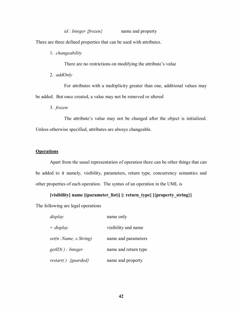
Operations
Apart from the usual representation of operation there can be other things that can
be added to it namely, visibility, parameters, return type, concurrency semantics and
other properties of each operation. The syntax of an operation in the UML is
[visibility] name [(parameter_list)] [: return_type] [{property_string}]
The following are legal operations
display name only
+ display visibility and name
set(n :Name, s:String) name and parameters
getID( ) : Integer name and return type
restart( ) {guarded} name and property

43
Collectively the name of an operation plus its parameter is called the operation�s
signature. In an operation�s signature, zero or more parameters can be provided, each of
which follows the syntax
[direction] name : type [= default_value]
where direction may be
in An input parameter; may not be modified
out An output parameter; may be modified to communicate
information to the caller
inout An input parameter; may be modified
In addition to the leaf property described earlier for operations, there are four
other defined properties that can be used along with operations.
1. isQuery Execution of the operation leaves the state of the system
unchanged
2. sequential Callers must coordinate outside the object so that only one flow is
in the object at a time
3. guarded The semantics and integrity of the object is guaranteed in the
presence of multiple flows.
4. concurrent Multiple flows of control is enabled.
Template Classes
A template is a parameterized element. Template classes are defined as a family
of classes or template function defined by a family of functions. A template includes slot
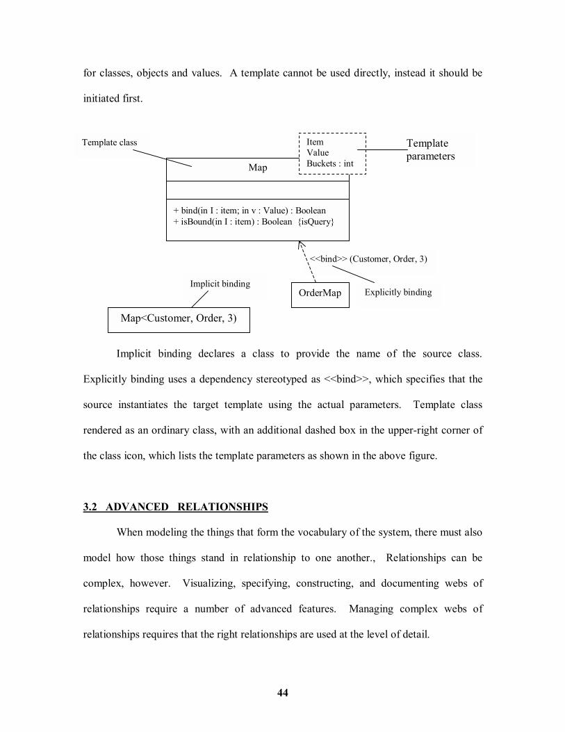
44
for classes, objects and values. A template cannot be used directly, instead it should be
initiated first.
Implicit binding declares a class to provide the name of the source class.
Explicitly binding uses a dependency stereotyped as <<bind>>, which specifies that the
source instantiates the target template using the actual parameters. Template class
rendered as an ordinary class, with an additional dashed box in the upper-right corner of
the class icon, which lists the template parameters as shown in the above figure.
3.2 ADVANCED RELATIONSHIPS
When modeling the things that form the vocabulary of the system, there must also
model how those things stand in relationship to one another., Relationships can be
complex, however. Visualizing, specifying, constructing, and documenting webs of
relationships require a number of advanced features. Managing complex webs of
relationships requires that the right relationships are used at the level of detail.
Template parameters
Implicit binding
Map<Customer, Order, 3)
<<bind>> (Customer, Order, 3)
Map + bind(in I : item; in v : Value) : Boolean + isBound(in I : item) : Boolean {isQuery}
ItemValue Buckets : int
OrderMap Explicitly binding
Template class

45
A relationship is a connection among things. In Object-oriented modeling the
four most important relationships are dependencies, generalizations, associations, and
realizations. Graphically, a relationship is rendered as a path, with different kinds of
lines used to distinguish the different relationships.
3.2.1 Dependency
A dependency is a using relationship specifying that a change in one thing may
affect another thing. Graphically, a dependency is rendered as a dashed line, directed to
the thing that is depended on. There are eight stereotypes that apply to dependency
relationships among classes and objects.
1. bind Specifies that the source instantiates the target using the given actual
parameters
2. derive Specifies that the source may be computed from the target
3. friend Specifies that the source is given special visibility into the target
4. instanceof Specifies that the source object is an instance of the target classifier
5. instantiate Specifies that the source creates instances of the target
6. powertype Specifies that the target is a powertype of the source; a powertype is a
classifier whose objects are all the children of a given parent.
7. refine Specifies that the source is at a finer degree of abstraction than the target
8. use Specifies that the semantics of the source element depends on the
semantics of the public part of the target
There are two stereotypes that apply to dependency relationships among
packages.

46
1. access Specifies that the source package is granted the right to reference the
elements of the target package
2. import A kind of access that specifies that the public contents of the target
package enter the flat namespace of the source, as if they had been
declared in the source
Two other stereotypes apply to dependency relationships among use cases.
1. extend Specifies that the target use case extends the behavior of the source
2. include Specifies that the source use case explicitly incorporates the behavior of
another use case at a location specified by the source.
Three stereotypes apply to dependency relationships among objects.
1. become Specifies that the target is the same object as the source but at a later point
in time and with possibly different values, states or roles.
2. call Specifies that the source operation invokes the target operation
3. copy Specifies that the target object is an exact, but independent, copy of the
source
One Stereotype apply to dependency relationships among state machines
1. send Specifies that the source operation sends the target event
Finally one stereotype apply to dependency relationships among subsystems
1. trace Specifies that the target is an historical ancestor of the source.
3.2.2 Generalization
A generalization is a relationship between the super class or parent and the
subclass or child. The two types of inheritance which generalization support are single

47
inheritance and multiple inheritance. In UML there is one stereotype and four constraints
that are applicable to generalization relationships.
First there is one stereotype
1. Implementation Specifies that the child inherits the implementation of the parent
but does not make public. Violates substitutability
There are four standard constraints that apply to generalization relationships.
1. complete Specifies that all children have been specified in the model and no
children are permitted
2. incomplete Specifies that not all children have been specified in the model and
additional children are permitted
3. disjoint Specifies that objects of the parent may have not more than one of
the children
4. overlapping Specifies that objects of the parent may have more than one of the
children.
3.2.3 Association
An association is a structural relationship, specifying that objects of one thing are
connected to objects of another. Apart from a name, role, multiplicity and aggregation,
advanced association relationship uses navigation, qualification, visibility and
composition.

48
Navigation
Unless otherwise specified, navigation across an association is bi-directional.
Visibility
Unless otherwise noted, the visibility of a role is public. All the three levels of
visibility which is available for class features can be used with the association
relationships�s visibility.
Qualification
Qualifier is rendered as a small rectangle attached to the end of an association,
placing the attributes in the rectangle. The source object, together with the values of the
qualifier�s attributes, yield a target object or a set of objects.
* 1 owner
User Password
Association navigation
*- key
1 + owner
User Password
visibility
WorkDesk JobID : int ReturnedItem
qualifier

49
Composition
Composition is really just a special kind of association and is specified by
adorning a plain association with a filled diamond at the whole end.
The UML defines five constraints that may be applied to association relationships.
They include :
1. implicit Specifies that the relationship is not manifest, but rather conceptual
2. ordered Specifies that the set of objects at one end are in an explicit order
3. changeable links between objects may be added, removed and changed freely
4. addOnly new links may be added from an object
5. frozen a link once added, may not be modified or deleted.
3.2.4 Realization
A realization is a semantic relationship between classifiers in which one classifier
specifies a contract that another classifier guarantees to carry out. When a class or a
component realizes an interface, it means that clients can rely on the class or component
to faithfully carryout the behavior specified by the interface. That means the class or
component implements all the operations of the interface, responds to all its signals, and
1 *
Window
Window
composition
whole
part

50
in all ways follows the protocol established by the interface for clients who use those
operations or send those signals.
Common Modeling Techniques � Modeling Webs of Relationships
Modeling the vocabulary of a complex system requires a balanced distribution of
responsibilities in the system as a whole, with individual abstractions that are tightly
cohesive and with relationships that are expressive, yet loosely coupled. To model these
webs of relationships
# Don�t begin in isolation. Apply use cases and scenarios to drive the discovery of
the relationships among a set of abstractions.
# In general, start by modeling the structural relationships that are present. These
reflect the static view of the system and are therefore fairly tangible.
# Next, identify opportunities for generalization/specialization relationships
# Only after completing the preceeding steps, dependencies can be looked into
<<interface>> RuleAgent
AddRule( ) ChangeRule( ) ExplainAction( )
AccountBussinessRule
Realization of an Interface � Cannonical Form
Realization of a Use Case
Validate User Validation

51
# For each kind of relationship, start with its basic form and apply advanced
features only if it is absolutely necessary
# Remember that it is both undesirable and unnecessary to model all relationships
among a set of abstractions in a single diagram
3.3 INTERFACES, TYPES AND ROLES
Interfaces are used to visualize, specify, construct and document the flow within
the system. Types and roles provide a mechanism to model the static and dynamic
conformance of an abstraction to an interface in a specific context. An interface is a
collection of operations that are used to specify a service of a class or a component.
A type is a stereotype of a class used to specify a domain of objects, together with
the operations applicable to the object. A role is the behavior of an entity participating in
a particular context. Graphically, an interface is rendered as a circle; in its expanded
form, an interface may be rendered as a stereotyped class in order to expose its operations
and other properties.
Names :
Every interface must have a name that distinguishes it from other interfaces. A
name is a textual string. The name alone is known as simple name. A path name is the
interface name prefixed by the name of the package in which that interface lives.
IUnknown Simple Name
Networking : : IRouter
Path Name

52
Operations
An interface is a named collection of operations used to specify a service of a
class or of a component. Unlike classes or types, interfaces do not specify any structure,
nor do they specify any implementation.
Like a class, an interface may have any number of operations. These operations
may be adorned with visibility properties, concurrency properties, stereotypes, tagged
values and constraints. Signals can also be associated with an interface.
Relationships
Like a class an interface may participate in generalization, association,
dependency and realization relationships.
<<interface>>URLStreamHandler
OpenConnection( ) ParseURL( ) SetURL( ) ToExternalForm( )
Java::Util::observable
Tracker id currentPosition setPosition( ) setVelocity( ) expectedPosition( )
<<interface>>Observer
update( )
TargetTracker

53
The above diagram shows the interface with its operations and a realization
relationship which is a cross between generalization and dependency.
Types and Roles
Type is a stereotype of class, and is used to specify a domain of objects, together
with the operations applicable to the objects of that type. A role, names a behavior of an
entity participating in a particular context. In other words a role is the face that an
abstraction presents to the world.
In the above diagram the class Person may have many instances depending upon
the context of it being used. Therefore here the role e of type employee is an instance of
Person. Most component systems, such COM+ and Enterprise Java Beans, provide for
component introspection, meaning that an interface can be queried programmatically to
determine its operation.
Modeling Static and Dynamic Types
Modeling the static nature of an object can be visualized in a class diagram.
However, when modeling things like business objects, which naturally change their roles
throughout a workflow, it�s sometimes useful to explicitly model the dynamic nature of
that object�s type. In these circumstances, an object can gain and lose types during its
life. To model a dynamic type,
role
1..* *e:employee Person Company

54
# Specify the different possible types of that object by rendering each type as a class
stereotyped as type or as interface
# Model all the roles the class of the object may take on at any point in time.
# In an interaction diagram, properly render each instance of the dynamically typed
class. Display the role of the instance in brackets below the object�s name.
# To show the change in role of an object, render the object once for each role it
plays in the interaction, and connect these objects with a message stereotyped as
become.
3.4 PACKAGES
In the UML, the package is a general purpose mechanism for organizing
modeling elements into groups. The elements include classes, interfaces, components,
nodes, diagrams and other elements. Graphically, a package is rendered as a tabbed
folder.
Names
Every package must have a name that distinguishes it from other packages. A
name is a textual string. That name alone is known as a simple name; a path name is the
package name prefixed by the name of the package in which that package lives, if any.
Business Rules
+ OrderForm + TrackingForm- Order
Client

55
Owned Elements
A package may own other elements, including classes, interfaces, components,
nodes, collaborations, use cases, and even other packages. Owning is a composite
relationship, which mean that the element is declared in the package. If the package is
destroyed, the element is destroyed. Every element is uniquely owned by exactly one
package.
Importing and Exporting
Importing grants a one way permission for the elements in one package to access
the elements in another package. In the UML an import relationship is modeled as a
dependency adorned with the stereotype import. By packaging abstractions into
meaningful chunks and then controlling their access by importing, the complexity of
large number of abstractions are controlled. The public parts of a package are called its
exports.
The parts that one package exports are visible only to the contents of those
packages that explicitly import the package.
Graphical Nesting
Textual Nesting
+ OrderForm + TrackingForm - Order
Client + OrderForm
- Order
+ TrackingForm
Client

56
Generalization
Generalization among packages is very much like generalization among classes.
Packages involved in generalization relationship follow the same principle of
substitutability as do classes. A specialized package can be used anywhere a more
general package is used.
exports
<<import>
<<import>
+ OrderForm + TrackingForm - Order
Client
+ OrderRules - GUI :: Window
Policies
+ Window + Form # EventHandler
GUI
+ Database + LoggingService
Server
exports
+ Window + Form # EventHandler
GUI
+ GUI :: Window + Form # GUI :: EventHandler
WindowsGUI
MacGUI

57
3.5 INSTANCES
An instance is a concrete manifestation of an abstraction to which a set of
operations may be applied and which may have a state that stores the effects of the
operation. An Instance does not stand alone. They are almost always tied to an
abstraction. An abstraction denotes the ideal essence of a thing; an instance denotes a
concrete manifestation. The UML provides a graphical representation for instances. An
instance is rendered by underlying its name.
Almost every building block in the UML, most notably classes, components,
nodes and use cases, may be modeled in terms of their essence or in terms of their
instances.
Names
Every instance must have a name that distinguishes it from other instances with
its context. Typically, an object lives within the context of an operation, a component, or
a node. A name is a textual string, such as t and myCustomer that is shown in the
following figure.
t : Transaction myCustomer :Multimedia::AudioStream agent:
:keyCode
Named instances anonymous instance
orphan instance Multiobjcet

58
State of the Instance
An object also has state, which in this sense encompasses all the (usually static)
properties of the object plus the current (usually dynamic) values of each of these
properties.
For example, when making an airline reservation (represented by the object r :
Reservation), the value can be set for one of its attributes (for example, prince = 395.75).
If the reservation changes, perhaps by adding a new leg to the itinerary, then its state
might change (for example, price = 1024.86).
Active Objects
Most often, active objects are used in the context of interaction diagrams that
model multiple flows of control. Each active object represents the root of a flow of
control and may be used to name distinct flows. The following figure shows an active
class.
Common Modeling Techniques -- Modeling Concrete Instances
To model concrete instances
# Identify those instances necessary and sufficient to visualize, specify, construct,
or document the problem to be modeled.
Instance with explicit state
myCustomer Id : SSN = �432� Active = True
Instance with attribute values
c : Phone[WaitingForAnswer]
r : FrameRenderThread

59
# Render these objects in the UML as instances.
# Expose the stereotype, tagged values, and attributes for each instance
# Render these instances and their relationships in an object diagram appropriate to
the kind of the instance
Common Modeling Techniques -- Modeling Prototypical Instances
To model prototypical instances,
# Identify those prototypical instances necessary and sufficient to visualize, specify,
construct, or document the problem
# Render these object in the UML, as instances
# Expose the properties of each instance necessary and sufficient to model the
problem
# Render these instances and their relationships in an interaction diagram or an
activity diagram.
3.6 OBJECT DIAGRAMS
An object diagram is a diagram that shows a set of objects and their relationships
at a point in time. Graphically, an object diagram is a collection of vertices and arcs. An
object diagram is a special kind of diagram and shares the same common properties as all
other diagrams � that is, a name and graphical contents that are a projection into a model.
What distinguishes an object diagram from all other kinds of diagrams is its particular
content.

60
Object diagrams commonly contain objects and links. Like all other diagrams,
object diagrams may contain notes and constraints. Object diagrams may also contain
packages or subsystems, both of which are used to group elements into larger chunks.
Common Modeling Techniques -- Modeling object structures
When object diagrams are used, meaningfully interesting sets of concrete or
prototypical objects are exposed. This is what it means to model an object structure � an
object diagram shows one set of objects in relation to one another at one moment in time.
To model an object structure
# Identify the mechanism to model.
# For each mechanism, identify the classes, interfaces, and other elements that
participate in this collaboration; identify the relationships among these things, as
well.
# Consider one scenario that walks through this mechanism. Freeze that scenario at
a moment in time, and render each object that participates in the mechanism
# Expose the state and attribute values of each such object, as necessary, to
understand the scenario
# Similarly, expose the links among these objects, representing instances of
associations among them.

61
The figure shows a set of objects drawn from the implementation of an
autonomous robot. This figure focuses on some of the objects involved in the mechanism
used by the robot to calculate a model of the world in which it moves. There are many
more objects involved in a running system, but this diagram focuses on only those
abstractions that are directly involved in creating this world view.
To reverse engineer an object diagram,
# Choose the target that is to be reverse engineered.
# Using a tool or simply walking through a scenario, stop execution at a certain
moment in time.
# Identify the set of interesting objects that collaborate in that context and render
them in an object diagram
# As necessary to understand their semantics, identify the links that exist among
these objects.
<<global>>unassigned
r : Robot[moving]
w : World
w : World w : World
w1 : Wall width = 36
w3 : Wallwidth = 96
d8 : Doorwidth = 36
w2 : Wallwidth = 96
: Element

62
LESSON - 4
BASIC BEHAVIORAL MODELING - INTRODUCTION
In this lesson will learn about the links, roles, messages, actions, sequences,
modeling flows of control and creating well-structured algorithms. Also in this lesson we
will discuss about use cases, actors, include, extend, modeling the behavior of an element
and realizing use cases with collaborations. Among the diagrams in the UML, well learn
about usecase diagrams, interaction diagrams and activity diagrams.
4.1 INTERACTIONS
In every interesting system, objects don�t just sit idle. Instead they interact with
one another by passing messages. An interaction is a behavior that comprises a set of
messages exchanged among a set of objects within a context to accomplish a purpose.
Well-structured interactions are like well-structured algorithms � efficient, simple,
adaptable, and understandable.
An interaction is a behavior that comprises a set of messages exchanged among a
set of objects with a context to accomplish a purpose. A message is a specification of a
communication between objects that conveys information with the expectation that
activity will ensue. Graphically, a message is rendered as a directed line and almost
always includes the name of its operation.

63
Context
An interaction may be found in the representation of a component, node or use
case, each of which, in the UML, is really a kind of classifier. In the context of a use
case, an interaction represents a scenario that, in turn, represents one thread through the
action of the use case.
Objects and Roles
The objects that participate in an interaction are either concrete things or
prototypical things. As a concrete thing, an object represents something in the real world.
Links
A link a semantic connection among objects. In general, a link is an instance of
an association. A link specifies a path along which one object can dispatch a message to
another object.
In the above figure, wherever a class has an association to another class, there
may be a link between the instances of the two classes; wherever there is a link between
two objects, one object can send a message to the other object.
The five types of adornments which are attached to the end of the link are
1. association Specifies that the corresponding object is visible by association
2. self Specifies that the corresponding object is visible because it is the
dispatcher of the operation
Assign(development) p : Person : Company

64
3. global Specifies that the corresponding object is visible because it is in an
enclosing scope
4. local Specifies that the corresponding object is visible because it is in a
local scope
5. parameter Specifies that the corresponding object is visible because it is a
parameter
Messages
A message is the specification of a communication among objects that conveys
information. In the UML there are five basic kinds of actions.
1. Call Invokes an operation on an object; an object may send a message to itself,
resulting in the local invocation of an operation
2. Return Returns a value to the caller
3. Send Sends a signal to an object
4. Create Creates an object
5. Destroy Destroys an object; an object may commit suicide by destroying itself.
notify( )
destroy
route
calculateRoute( )setItinerary(i)
<<create>>
c : Client p : PlanningAssistant
: TicketAgent

65
The UML provides a visual distinction among these kinds of messages as shown
in the above figure. The message setItinerary(i) is the Call message, the
calculateRoute( ) is the local invocation of the call message. The message route is the
return message and notify( ) is the send message.
Sequencing
When an object passes a message to another object, the receiving object might in
turn send a message to another object, which might send a message to yet a different
object. This stream of messages forms a sequence.
There are two types of sequences. The are Procedural sequence, which is
rendered using a filled solid arrowhead, and a Flat sequence, which is rendered using a
stick arrowhead, to model the non-procedural progression of control from step to step.
These two sequences are depicted in the following diagram.
2.1 : I = findAt(p)
2 : clickAt(p) 2.2 : putRecentPick(i)
: View c : Controller : Cache
Procedural Sequence
1 : liftHandset( ) 2 : assertCall( )
c : Caller : Telephone : Exchange
Flat Sequence

66
Creation, Modification and Destruction
In some interactions, objects may be created and destroyed. The same is true of
links; the relationships among objects may come and go. To specify if an object or link
enters and/or leaves during an interaction, attach one of the following constraints to the
element.
1. new Specifies that the instance or link is created during execution of the
enclosing interaction
2. destroyed Specifies that the instance or link is destroyed prior to completion of
execution of the enclosing interaction
3. transient Specifies that the instance or link is created during execution of the
enclosing interaction but is destroyed before completion of execution.
To model the flow of control using interactions,
# Set the context for the interaction, whether it is the system as a whole, a class, or
an individual operation
# Set the stage for the interaction by identifying which objects play a role
# If the model emphasizes the structural organization of these objects, identify the
links that connect them.
# In time order, specify the messages that pass from object to object.
# Also to convey the necessary detail of this interaction, adorn each object at every
moment in time with its state and role.

67
4.2 USE CASES
A use case specifies the behavior of a system or a part of a system and is a
description of a set of sequences of actions, including variants, that a system performs to
yield an observable result of value to an actor. Well structured use cases denote essential
system or subsystem behaviors only, and are neither overly general nor too specific.
Names
Every use case must have a name that distinguishes it from other use cases. A
name is a textual string. That name alone is known as a �simple name�. A �path name�
is the use case name prefixed by the name of the package in which that use case lives.
Use Cases & Actors
An actor represents a coherent set of roles that users of use cases play when
interacting with these uses cases. An instance of an actor represents an individual
interacting with the system in a specific way. Although Actors are used in models, they
are not actually part of the system.
commercial customer
Validate User
Sensors :: Calibrate location
Simple name Path name
customer

68
As the above figure indicates, actors are rendered as stick figures. Actors can be
defined as general kinds (such as Customer) and specialize them (such as
CommercialCustomer) using generalization relationships. Actors may be connected to
use cases only by association. An association between an actor and a use case indicates
that the actor and the use communicate with one another, each one possibly sending and
receiving messages.
Use Cases and Collaborations
As the above figure shows, the realization of a use case can be specified explicitly by a
collaboration. Most of the time, though, a given use case is realized by exactly one
collaboration, so there is no need to model this relationship explicitly.
Organizing Use Cases
Use cases can be organized by giving them in packages in the same manner in
which classes are organized. Use cases can also be organized by specifying
generalizations, include and extend relationships among them. Generalization among use
cases means that the child use case inherits the behavior and meaning of the parent use
case.
To model the behavior of an element in the use cases, do the following
Place Order Order Management

69
# Identify the actors that interact with the element. Candidate actors include groups
that require certain behavior to perform their tasks or that are needed directly or
indirectly to perform the element�s functions.
# Organize actors by identifying general and more specialized roles.
# For each actor, consider the primary ways in which that actor interacts with the
element. Consider also interactions that change the state of the element or its
environment or that involve a response to some event.
# Consider also the exceptional ways in which each actor interacts with the element
# Organize these behaviors as use cases, applying include and extend relationships
to factor common behavior and distinguish exceptional behavior.
4.3 USE CASE DIAGRAMS
A use case diagram is a diagram that shows a set of use cases and actors and
relationships such as dependency, generalization and association. Use case diagrams
may also contain packages which are used to group elements of the model into larger
groups.
Common Uses
Use case diagrams are applied to model the static use case view of a system. This
view primarily supports the behavior of a system � the outwardly visible services that the
system provides in the context of its environment. When modeling the static use case
view of a system, use case diagrams are applied in one of two ways.

70
1) To model the context of a system
The above diagram shows the context of a credit card validation system, with an
emphasis on the actors that surround the system. To construct a context of a system, do
the following :
# Identify the actors that surround the system
# Organize actors that are similar to one another in a generalization/specialization
hierarchy
# Where it aids understandability, provide a stereotype for each such actor
# Populate a use case diagram with these actors.
Perform Card Transaction
Process Customer Bill
Reconcile Transaction
Manage Customer Account
Credit Card Validation System
customer
Individual customer
Corporate customer
Retail Institution
Sponsoring Financial Institution

71
2) To model the requirements of a system
Modeling the requirements of a system involves specifying what that systems should
do, independent of how that system should do it. Requirements can be expressed in
various forms, from unstructured text to expressions in a formal language, and everything
in between. Most, if not all of a system�s functional requirements can be expressed as
use cases, and the UML�s use case diagrams are essential for managing these
requirements. To model the requirements of a system, do the following :
# Establish the context of the system by identifying the actors that surround it.
# For each actor, reconsider the behavior that each expects or requires the system to
provide
# Name these common behaviors as use cases.
# Factor common behavior into new use cases that are used by others; factor variant
behavior into new use cases that extend more main line flows.
# Model these use cases, actors, and their relationships in a use case diagram
# Adorn these use cases with notes that assert nonfunctional requirements; attach
some of these to the whole system.

72
The above diagram elides the relationships among the actors and the use cases. It
adds additional use cases that are somewhat invisible to the average customer, yet are
essential behaviors of the system.
Forward and Reverse Engineering
To forward engineer a use case diagram
# For each use case in the diagram, identify its flow of events and its exceptional
flow of events.
# Depending on how deeply the test is chosen, generate a test script for each flow.
Customer
Retail Institution
Sponsoring financial
institution
Perform card transaction
Process customer bill
Reconcile transaction
Manage customer account
Detect card fraud
Report on account balance
Manage network outage
Credit Card Validation System

73
# As necessary, generate test scaffolding to represent each actor that interacts with
the use case.
# Use tools to run these tests each time the element is released to which the use case
diagram applies
To reverse engineer a use case diagram
# Identify each actor that interacts with the system
# Fro each actor, consider the manner in which the actor interacts with the system,
changes the state of the system or its environment, or responds to some event
# Trace the flow of events in the executable system relative to each actor.
# Cluster related flows by declaring a corresponding use case.
# Render these actors and use cases in a use diagram, and establish their
relationships.
4.4 INTERACTION DIAGRAMS
Sequence diagrams and collaboration diagrams � both of which are called
interaction diagrams -- are two of the five diagrams used in the UML for modeling the
dynamic aspects of systems. An interaction diagram shows an interaction, consisting of a
set of objects and their relationships, including the messages that may be dispatched
among them. Interaction diagrams are not only important for modeling the dynamic
aspects of a system, but also for constructing executable system through forward and
reverse engineering.

74
Contents
Interaction diagrams commonly contain Objects, links and messages. What
distinguishes an interaction diagram from all other kinds of diagrams is its particular
context. Like all other diagrams, interaction diagrams may contain notes and constraints.
Sequence Diagrams
A sequence diagram emphasizes the time ordering of messages. Sequence
diagrams have two features that distinguish them from collaboration diagrams. First,
there is the object lifeline. An object lifeline is the vertical dashed line that represents the
existence of an object over a period of time. Most objects that appear in an interaction
diagram will be in existence for the duration of the interaction, so these objects are all
aligned at the tope of the diagram, with their lifelines drawn from top to bottom of the
diagram.
Second there is the focus of control. The focus of control is a tall, thin rectangle
that shows the period of time during which an object is performing an action, either
directly or through a subordinate procedure. The top of the rectangle is aligned with the
start of the action; the bottom is aligned with its completion.
Collaboration Diagrams
A collaboration diagram emphasizes the organization of the objects that
participate in an interaction. Collaboration diagrams have two features that distinguish
them from sequence diagrams. First, there is the path. To indicate how one object is

75
linked to another, and paths are attached as stereotypes to the far end of a line (such as
<local>, indicating that the designated object is local to the sender).
Second, there is the sequence number. To indicate the time order of a message,
the message is preceded with a number (starting with the message numbered 1),
increasing monotonically for each new message in the flow of control. To show nesting,
DEWEY decimal numbering (1 is the first message, 1.1 is the first message nested in
message 1) is used.
When modeling the dynamic aspects of a system, typically interaction diagrams
are used in one of two ways. The include :
1. To model flows of control by time ordering.
Here sequence diagrams are used. Modeling a flow of control by time ordering
emphasizes the passing of messages as they unfold over time, which is a particularly
useful way to visualize dynamic behavior in the context of a use case scenario. To model
a flow of control by time ordering, do the following :
# Set the context for the interaction, whether it is a system, subsystem, operation, or
class or one scenario of a use case or collaboration
# Set the stage for the interaction by identifying which objects play a role in the
interaction
# Set the lifeline for each object.
# Starting with the message that initiates this interaction, lay out each subsequent
message from top to bottom between the lifelines, with each message�s properties
# Adorn each object�s lifeline with its focus of control

76
# Adorn each message with a timing mark and attach suitable time or space
constraints if time or space constraints are to be specified
# Attach pre and postconditions to each message if flow of control is to be specified
more formally.
The above figure shows a sequence diagram that specifies the flow of control
involved in initiating a simple, two-party phone call.
connect(s)
liftReceiver
ring( )
connect(r,s) connect(r)
<<create>>
routeCall(s,n)
{dialing,.executionTime<30 sec}
* dialDigit(d) dialing
setDialTone( )
liftReceiver
s : Caller : Switch r : Caller
c : Conversation

77
2. To model flows of control by organization.
Here collaboration diagrams are used. Modeling a flow of control by
organization emphasizes the structural relationships among the instances in the
interaction, along which messages may be used.
The above diagram shows a collaboration diagram that specifies the flow of control
involved in registering a new student at a school, with an emphasis on the structural
relationships among these objects. To model a flow of control by organization, do the
following :
# Set the context for the interaction, whether it is a system, subsystem, operation, or
class, or one scenario of use case or collaboration
s : Student registered = True
2 : addStudent(s)
{association}{association}
3.2 : add(s) 3.3 : add(s)
3.4 : <<become>>
1 : <<create>> 3 : register( )
<<local>>
3.1 : getSchedule( )
{self}s : Student
registered = False
c1 : Course c2 : Course
r : RegistrarAgent : School

78
# Set the stage for the interaction by identifying which objects play a role in the
interaction.
# Set the initial properties of each of these objects.
# Specify the links among these object along which message may pass
# Starting with the message that initiates this interaction, attach each subsequent
message to the appropriate link, setting its sequence number, as appropriate.
# Adorn each message with a timing mark and attach suitable time or space
constraints if time or space constraints are to be specified
# Attach pre and postconditions to each message if flow of control is to be specified
more formally.
4.5 ACTIVITY DIAGRAMS
Activity diagrams are one of the five diagrams in the UML for modeling the
dynamic aspects of systems. An activity diagram is essentially a flowchart showing flow
of control from activity to activity. Activity diagrams are not only important for
modeling the dynamic aspects of a system, but also for constructing executable systems
through forward and reverse engineering.
An activity diagram shows the flow from activity to activity. An activity is an
ongoing nonatomic execution within a state machine. Activities ultimately result in some
action, which is made up of executable atomic computations that result in change in state
of the system or the return of a value. Actions encompass calling another operation,
sending a signal, creating or destroying an object, or some pure computation, such as
evaluating an expression. Graphically, an activity diagram is a collection of vertices and
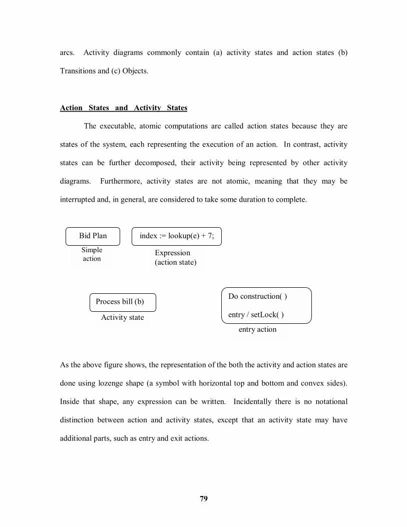
79
arcs. Activity diagrams commonly contain (a) activity states and action states (b)
Transitions and (c) Objects.
Action States and Activity States
The executable, atomic computations are called action states because they are
states of the system, each representing the execution of an action. In contrast, activity
states can be further decomposed, their activity being represented by other activity
diagrams. Furthermore, activity states are not atomic, meaning that they may be
interrupted and, in general, are considered to take some duration to complete.
As the above figure shows, the representation of the both the activity and action states are
done using lozenge shape (a symbol with horizontal top and bottom and convex sides).
Inside that shape, any expression can be written. Incidentally there is no notational
distinction between action and activity states, except that an activity state may have
additional parts, such as entry and exit actions.
entry action Activity state
Expression (action state)
Simple action
Bid Plan index := lookup(e) + 7;
Process bill (b) Do construction( ) entry / setLock( )
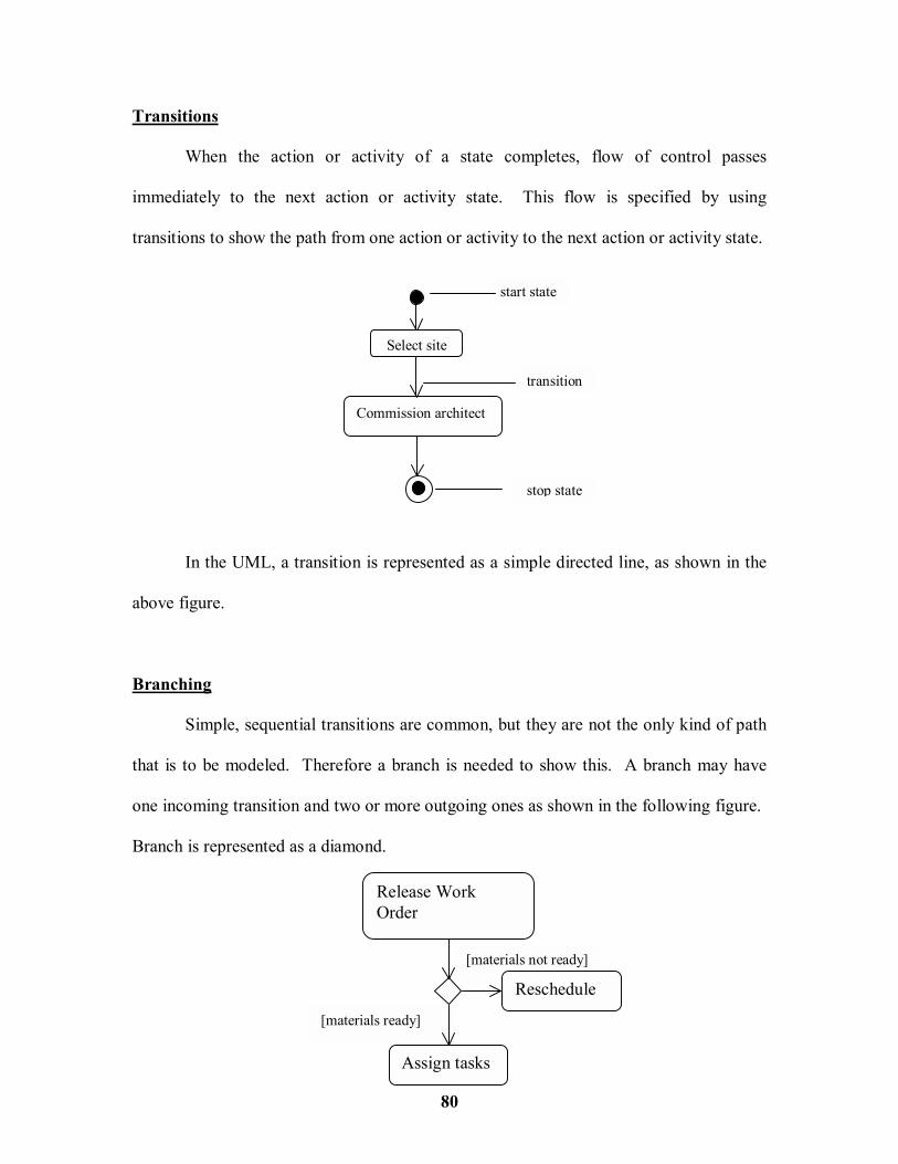
80
Transitions
When the action or activity of a state completes, flow of control passes
immediately to the next action or activity state. This flow is specified by using
transitions to show the path from one action or activity to the next action or activity state.
In the UML, a transition is represented as a simple directed line, as shown in the
above figure.
Branching
Simple, sequential transitions are common, but they are not the only kind of path
that is to be modeled. Therefore a branch is needed to show this. A branch may have
one incoming transition and two or more outgoing ones as shown in the following figure.
Branch is represented as a diamond.
Select site
Commission architect
start state
stop state
transition
[materials ready]
[materials not ready]
Release Work Order
Assign tasks
Reschedule

81
Forking and Joining
A fork represents the splitting of a single flow of control into two or more
concurrent flows of control. A fork may have one incoming transition and two or more
outgoing transitions, each of which represents an independent flow of control. A join
represents the synchronization of two or more concurrent flows of control A join may
have two or more incoming transitions and one outgoing transition.
Prepare for speech
Gesture( )
Decompress
Synch mouth( ) Stream audio( )
Cleanup

82
Swimlanes
To partition the activity states on an activity diagram into groups, UML uses a
term called swimlanes. Visually, each group is divided from its neighbor by a vertical
solid line. Each swimlane has a name unique within its diagram. A swimlane really has
no deep semantics, except that it may represent some real-world entity. There�s a loose
connection between swimlanes and concurrent flows of control Conceptually, the
activities of each swimlane are generally � but not always � considered separate from the
activities of the neighboring swimlanes. This is depicted in the following diagram.
Request product
Process order
Pay bill
Pull materials
Close order
Receive order
Ship Order
Bill Customer
Customer Sales Warehouse

83
Activity diagrams are typically used in two ways when modeling the dynamic
aspects of a system.
1. To model a workflow
In this the focus is on activities as viewed by the actors that collaborate with the
system.
Request return
Get return number
Receive item
Credit account
Restock item
Ship Item
i : Item [returned]
i : Item[available]
Customer Telesales Accounting Warehouse

84
To model a workflow,
# Establish a focus for the workflow/
# Select the business objects that have the high-level responsibilities for parts of the
overall workflow.
# Identify the preconditions of the workflow�s initial state and the post-conditions
of the workflow�s final state
# Beginning at the workflow�s initial state, specify the activities and actions that
take place over time and render them in the activity diagram as either activity
states or action states.
# For complicated actions, or for sets of actions that appear multiple times, collapse
these into activity states, and provide a separate activity diagram that expands on
each.
# Render the transitions that connect these activity and action states.
# If there are important objects that are involved in the workflow, render them in
the activity diagram, as well.
2. To model an operation
In this activity diagrams are used as flowcharts, to model the details of a
computation. In this use of activity diagrams, the modeling of branch, fork, and join
states is particularly important. To model an operation do the following :
# Collect the abstractions that are involved in this operation. This includes the
operation�s parameters, the attributes of the enclosing class, and certain
neighboring classes

85
# Identify the preconditions at the operation�s initial state and the post-
conditions at the operation�s final state.
# Beginning at the operation�s initial state, specify the activities and actions that
take place over time and render them in the activity diagram as either activity
states or actions states
# Use branching as necessary to specify conditional paths and iteration
# Only if this operation is owned by an active class, use forking and joining as
necessary to specify parallel flows of control.
The above diagram shows an activity diagram that specifies the algorithm of the
operation intersection, whose signature includes one parameter and one return value.
x = (l.delta � delta) / (slope � l.slope);
y = (slope * x) + delta;
return Point(x,y)
[slope = l.slope] return Point(0,0)
86
LESSON - 5
ADVANCED BEHAVIORAL MODELING -- INTRODUCTION
In this lesson we will walk through signal events, call events, time events and
change events and modeling a family of signals. We will also learn how to model
exceptions and how we can handle events in active and passive objects. Regarding the
state machines we learn states, transitions, activities, modeling the lifetime of an object
and creating well-structured algorithms. Under the heading Processes and Threads, we
will look into active objects, processes and threads, modeling multiple flows of control,
modeling interprocess communication and building thread-safe abstractions. Under the
heading time and space, we will learn time, duration and location. Also we will discuss
how to model the distribution of objects, objects that migrate and deal with real time and
distributed systems. Finally under the topic Statechart Diagrams, we will see how to
model reactive objects and also the concept of forward and reverse engineering with
respect to statechart diagrams.
5.1 EVENTS AND SIGNALS
In the real world, things happen. Not only do things happen, but lots of things
may happen at the same time, and at the most unexpected times. An event is the
specification of a significant occurrence that has a location in time and space. In the
context of state machines, an event is an occurrence of a stimulus that can trigger a state
transition. A signal is a kind of event that represents the specification of an
asynchronous stimulus communicated between instances.

87
Kinds of Events
Events may be external or internal. External events are those that pass between
the system and its actors. For example, the pushing of a button and an interrupt from a
collision sensor are both examples of external events. Internal events are those that pass
among the objects that live inside the system. An overflow exception is an example of an
internal event.
In the UML, there are four kinds of events that can be modeled. They include
signals, calls, the passing of time and change in state.
Signals
A signal represents a named object that is dispatched (thrown) asynchronously by
one object and then received (caught) by another. Exceptions are supported by most
contemporary programming languages and are the most common kind of internal signal
that will be needed to model.
A signal may be sent as the action of a state transition in a state machine or the
sending of a message in an interaction. The execution of an operation can also send
signals. When modeling a class or an interface, an important part of specifying the
behavior of that element is specifying that its operations can send. In the UML the
modeling of the relationship between an operation and the events that it can send by
using a dependency relationship, stereotyped as send.
<<send>>
MovementAgent position velocity moveTo( )
<<signal>>Collision
force : Float

88
In the UML, as shown from the above figure, signals can be modeled (and
exceptions) as stereotyped classes. A dependency can be used along with the stereotype
as send, to indicate that an operation sends a particular signal.
Call Events
Just as a single event represents the occurrence of a signal, a call event represents
the dispatch of an operation. In both cases the event may trigger a state transition in a
state machine. A call event is an asynchronous event. This means that when an object
invokes an operation on another object that has a state machine, control passes from the
sender to the receiver, the transition is triggered by the event, the operation is completed,
the receiver transitions to a new state, and control returns to the sender.
The above figure shows modeling a call event is indistinguishable from modeling
a signal event. In both cases, the event is shown, along with its parameters, as the trigger
for a state transition.
Time and Change Events
A time event is an event that represents the passage of time. A change event is an
event that represents a change in state or the satisfaction of some condition.
startAutoPilot(normal) Manual Automate

89
In the above figure, a time event is modeled by using the keyword after followed
by some expression that evaluates to a period of time. Such expressions can be simple
(for example, after 2 seconds) or complex (for example after 1 ms since exiting idle).
Unless specified explicitly, the starting time of such an expression is the time since
entering the current state.
In the above figure, also a change event is modeled by using the keyword when
followed by some Boolean expression. Such expressions are sued to mark an absolute
time (such as when time = 11 : 59 pm) or for the continuous test of an expression (for
example, when altitude < 1000).
Sending and Receiving Events
Singal events and call events involve at least two objects : the object that sends
the signal or invokes the operation, and the object to which the event is directed. Because
signals are asynchronous, and because asynchronous calls are themselves signals, the
semantics of events interact with the semantics of active objects and passive objects.
After(2 seconds) / dropConnection( )
when(11 : 49 pm) / selfTest( )
Idle
Active

90
Any instance of any class can send a signal to or invoke an operation of a
receiving object. When an object sends a signal, the sender dispatches the signal and
then continues along its flow of control, not waiting for any return from the receiver.
In the UML, call events that an object may receive is modeled as operations on
the class of the object. In the UML, the named signals that an object may receive is
modeled by naming them in an extra compartment of the class. This is shown in the
following figure.
In most event-driven systems, signal events are hierarchical. By modeling
hierarchies of signals in this manner, polymorphic events can be specified. To model a
family of signals,
$ Consider all the different kinds of signals to which a given set of active objects
may respond.
$ Look for the common kinds of signals and place them in a generalization /
specialization hierarchy using inheritance. Elevate more general ones and lower
more specialized ones.
KeypadManager
Signals pushButton(b : Button) powerUp( ) powerDown( )

91
$ Look for the opportunity for polymorphism in the state machines of these active
objects. Where polymorphism is found, adjust the hierarchy as necessary by
introducing intermediate abstract signals.
An important part of visualizing, specifying and documenting the behavior of a
class or an interface is specifying the exceptions that its operations can raise. In the
UML, exceptions are kinds of signals, which can be modeled as stereotyped classes.
Exceptions may be attached to specific operations. Modeling exceptions is somewhat the
inverse of modeling a general family of signals. To model exceptions,
$ For each class and interface, and for each operation of such elements, consider the
exceptional conditions that may be raised
$ Arrange these exceptions in a hierarchy, elevate general ones, lower specialized
ones, and introduce intermediate exceptions, as necessary
<<signal>>RangingFault
<<signal>>VisionFault
<<signal>>MovementFault
<<signal>> BatteryFault
<<signal>>MotorStall
<<signal>> RobotSignal
<<signal>>H/wFault
<<signal>> Collision
sensor : Integer
Modeling Families of Signals

92
$ For each operation, specify the exceptions that it may raise.
5.2 STATE MACHINES
A state machine is a behavior that specifies the sequences of states an objects goes
through during its lifetime in response to events, together with its responses to those
events. Well-structured state machines are like well-structured algorithms. They are
efficient, simple, adaptable and understandable.
State machines are used to model the behavior of any modeling element,
although, most commonly, that will be a class, a use case or an entire system. State
machines may be visualized in two ways. First, using activity diagrams one can focus on
the activities that take place within the object. Second, using statechart diagrams, one
can focus on the event-ordered behavior of an object, which is especially useful in
modeling reactive systems.
<<exception>>Exception
SetHandler( ) FirstHandler( ) LastHandler( )
<<esception>>Duplicate <<esception>>
Overflow <<esception>>
Underflow Set add( ) remove( )
item
Modeling Exceptions

93
States
A state is a condition or situation during the life of an object during which is
satisfies some condition, performs some activity or waits for some event. An object
remains in a state for a finite amount of time. When an object�s state machine is in a
given state, the object is said to be in that state. For example, an instance of Heater
might be idle or perhaps ShuttingDown.
A state has several parts. They include :
1. Name A textual string that distinguishes the state from other
states, a state may be anonymous, meaning that it has no
name.
2. Entry/exit actions Actions executed on entering and exiting the state,
respectively.
3. Internal transition Transitions that are handled without causing a change in
state
4. Substates The nested structure of a state, involving disjoint
(sequentially active) or concurrent (concurrently active)
substates
5. Deferred events A list of events that are not handled in that state but rather,
are postponed and queued for handling by the object in
another state.
Idle Running keyPress
finished

94
The above figure shows how to represent a state as a rectangle with rounded
corners. There are two special states that may be defined for an object�s state machine.
First, there�s the initial state, which indicates the default starting place for the state
machine or substate. An initial state is represented as a filled black circle. Second
there�s the final state, which indicates that the execution of the state machine or the
enclosing state has been completed. A final state is represented as a filled black circle
surrounded by an unfilled circle.
Transitions
A transition is a relationship between two states indicating that an object in the
first state will perform certain actions and enter the second state when a specified event
occurs and specified conditions are satisfied. On such a change of state, the transition is
said to fire. Until the transition fires, the object is said to be in the source state; after it
fires, it is said to be in the target state. A transition has five parts. They include :
1. Source state The state affected by the transition; if an object is in the
source state, an outgoing transition may fire when the
object receives the trigger event of the transition and if the
guard condition, if any, is satisfied.
2. Event trigger The event whose reception by the object in the source state
makes the transition eligible to fire, providing its guard
condition is satisfied
3. Guard condition A Boolean expression that is evaluated when the transition
is triggered by the reception of the event trigger; if the

95
expression evaluates true, the transition is eligible to fire; if
the expression evaluates false, the transition does not fire
and if there is no other transition that could be triggered by
that same event is lost.
4. Action An executable atomic computation that may directly act on
the object that owns the statemachine, and indirectly on
other objects that are visible to the object
5. Target state The state that is active after the completion of the transition
As the above figure shows, a transition is rendered as a solid directed line from
the source to the target state. A self-transition is a transition whose source and target
states are the same.
An event is the specification of a significant occurrence that has a location in time
and space. In the contest of a state machine, an event is an occurrence of a stimulus that
can trigger a state transition. A guard condition is evaluated just once for each transition
at the time the event occurs, but it may be evaluated again if the transition is retriggered.
contact
targetAt(p) [isThreat] / t.addTarget(p)
noise
after(2 sec) / send c.isAlive
Idle Searching Engaging
Tracking Engaging

96
An action is an executable atomic computation. Actions may include operation
calls (to the object that owns the state machine, as well as to other visible objects), the
creation or destruction of another object, or the sending of a signal to an object.
Advanced States and Transitions
A wide variety of behavior can be modeled using only the basic features of states
and transitions in the UML. Using these features, one will end up with flat state
machines, which means that the behavioral models will consist of nothing more that arcs
(transitions) and vertices (states).
However the UML�s state machines have a number of advanced features that help
to manage complex behavioral models. These features often reduce the number of states
and transitions needed and they codify a number of common and somewhat compels
idioms otherwise encountered using flat state machines.
Entry and Exit Actions
Entry and exit actions may not have arguments or guard conditions. However, the
entry action at the top level of a state machine for a class may have parameters that
represent the arguments that the machine receives when the object is created. The UML
provides a shorthand for Entry and Exit actions. In the symbol for the state, an entry can
be included (marked by the keyword event entry) and an exit action (marked by the
keyword event exit), together with an appropriate action.

97
Internal Transitions
Once inside a state, events are encountered and they are to be handled without
leaving the state. These are called internal transitions, and they are subtly different from
self-transitions. In a self-transition, such as an event triggers the transition, leaving the
state, an action is dispatched, and then the same state is reentered. Internal transitions
may have events with parameters and guard conditions. As such, internal transitions are
essentially interrupts.
Activities
When an object is in a state, it generally sits idle, waiting for an event to occur.
Sometimes, however, an ongoing activity may be modeled. While in a state, the object
does some work that will continue until it is interrupted by an event. Actions are never
interruptible, but sequences of actions are.
entry action exit action internal transition activity deferred event
Tracking entry / setMode(onTrack) exit / setModel(offTrack) newTarget / tracker.acquire( ) do / followTarget selfTest / defer

98
Deferred Events
A deferred event is specified by listing the event with the special action defer. In
the above diagram, selfTest events may happen while in the tracking state, but they are
held until the object is in the Engaging state, at which time it appears as if they just
occurred. The implementation of deferred events requires the presence of an internal
queue of events. If an event happens but is listed as deferred, it is queued. Events are
taken off this queue as soon as the object enters a state that does not defer these events.
Substates
The advanced features of states and transitions solve a number of common state
machine modeling problems. However, there is one more feature of the UML�s state
machines � substates � that does even more to help simplify the modeling of complex
behaviors. A substate is a state that is nested inside another one.
Sequential substates
Substates such as validating and processing are called sequential, or disjoint
substates. Given a set of disjoint substates in the context of an enclosing composite state,
the object is said to be in the composite state and in only one of those substates (or the
final state) at a time. Therefore, sequential substates partition the state space of the
composite state into disjoint states.
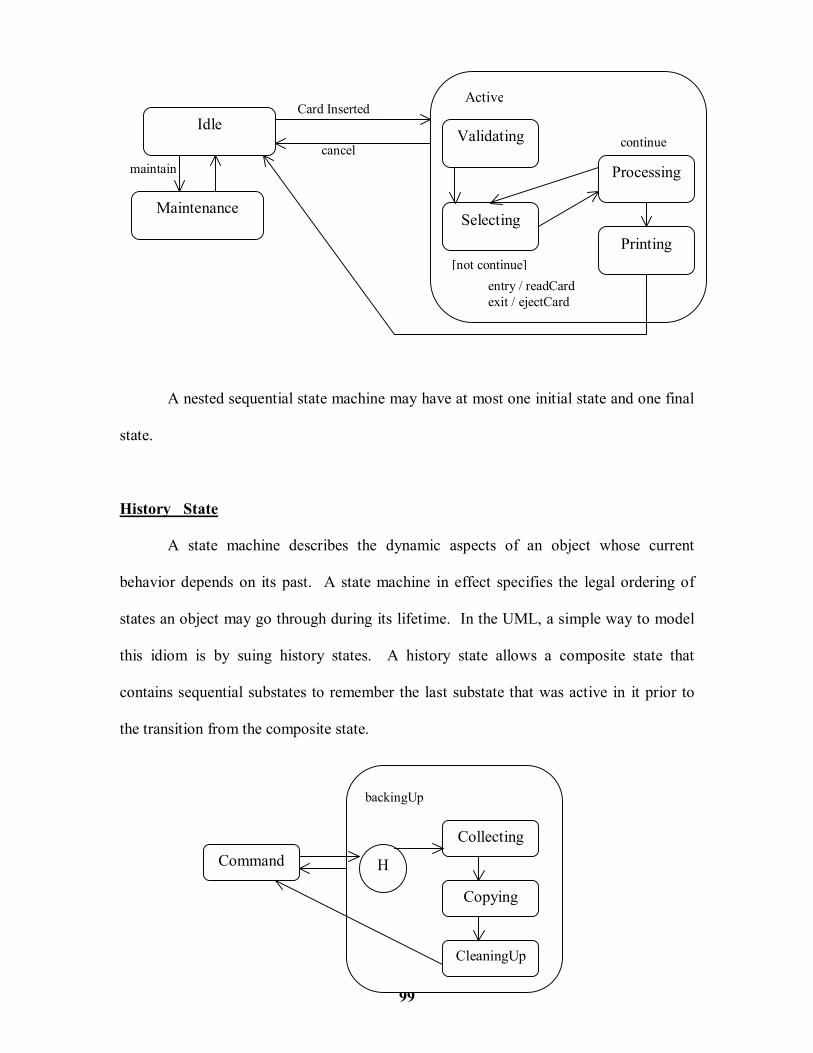
99
A nested sequential state machine may have at most one initial state and one final
state.
History State
A state machine describes the dynamic aspects of an object whose current
behavior depends on its past. A state machine in effect specifies the legal ordering of
states an object may go through during its lifetime. In the UML, a simple way to model
this idiom is by suing history states. A history state allows a composite state that
contains sequential substates to remember the last substate that was active in it prior to
the transition from the composite state.
Command
CleaningUp
Copying
Collecting
H
backingUp
maintain cancel
Card InsertedIdle
Maintenance
Validating
Selecting
Processing
Printing [not continue]
continue
Active
entry / readCard exit / ejectCard

100
As the above figure shows, a shallow history state can be represented as a small
circle containing the symbol H.
Concurrent Substates
Sequential substates are the most common kind of nested state machine often
encountered. In certain modeling situations however, it is necessary to specify
concurrent substates. These substates lets us to specify two or more state machines that
execute in parallel in the context of the enclosing object.
Modeling the Lifetime of an Object
The most common purpose for which state machines is used is to model the
lifetime of an object, especially instances of classes, use cases, and the system as a whole.
Whereas interactions model the behavior of a society of objects working together, a state
[not continue]
[continue] keyPress
Maintenance Testing
Waiting Command
Testing Devices
Self diagnosis
Commanding
Idle

101
machine models the behavior of a single object over its lifetime, such user interfaces,
controllers and devices. To model the life time of an object,
! Set the context for the state machine, whether it is a class, a use case, or the
system as a whole
! Establish the initial and final states for the object. To guide the rest of the mode,
possibly state the pre and post conditions of the initial and final states,
respectively.
! Decide on the events to which this object may respond. If already specified, find
these in the object�s interfaces; if not already specified, then consider which
objects may interact with the object in the context, and then which objects may
possibly dispatch.
alarm(s)
attention
attention clear
after (10 secs) / selfTest
Initializing
Idle
Command
Checking
Waiting Calling
Entry / callCentre(s)entry / set Alarm
exit / clearAlarm
Active
Modeling the Lifetime of an Object

102
The above figure shows the statemachine for the controller in a Home Security
System, which is responsible for monitoring various sensors around the perimeter of the
house. Notice that there is no final state. That, too, is common in embedded systems,
which are intended to run continuously.
5.3 PROCESSES AND THREADS
A process is a heavyweight flow that can execute concurrently with other
processes; a thread is a lightweight flow that can execute concurrently with other threads
within the same process.
In the UML, each independent flow of control is modeled as an active object. An
active object is a process or thread that can initiate control activity. As for every kind of
object, an active object is an instance of a class. In this case, an active object is an
instance of an active class. Also as for every kind of object, although here, message
passing must be extended with certain concurrency semantics, that helps to synchronize
the interactions among independent flows.
A active object is an object that owns a process or thread and can initiate control
activity. An active class is a class whose instances are active objects. A process is a
heavyweight flow that can execute concurrently with other processes. A thread is a
lightweight flow that can execute concurrently with other threads within the same
process.

103
Flow of Control
In a purely sequential system, there is one flow of control. This means that one
thing, and one thing only, can take place at a time. When a sequential program starts,
control is rooted at the beginning of the program and operations are dispatched one after
another. Even if there are concurrent things happening among the actors outside the
system, a sequential program will process only one event at a time, queuing or discarding
any concurrent external events. This process is called Flow of Control.
Concurrency can be achieved in one of three ways : first, by distributing active
objects across multiple nodes; second, by placing active objects on nodes with multiple
processors; and third, by a combination of both methods.
Classes and Events
Active classes are just classes, albeit ones with a very special property. An active
class represents an independent flow of control, whereas a plain class embodies no such
flow. In contrast to active classes, plain classes are implicitly called passive because they
cannot independently initiate control activity.
Active classes share the same properties as all other classes. Active classes may
have instances. Active classes may have attributes and operations. Active classes may
participate in dependency, generalization, and association (including aggregation)
relationships. Active classes may use any of the UML�s extensibility mechanisms,
including stereotypes, tagged values, and constraints. Active classes may be the
realization of interfaces. Active classes may be realized by collaborations, and the
behavior of an active class may be specified by using state machines.

104
All of the UML�s extensibility mechanisms apply to active classes. Most often,
tagged values are used to extend active class properties, such as specifying the scheduling
policy of the active class.
The UML defines two standard stereotypes that apply to active classes.
1. Process Specifies a heavyweight flow that can execute concurrently with
other processes
2. Thread Specifies a lightweight flow that can execute concurrently with
other threads within the same process.
The distinction between a process and a thread arises from the two different ways
of flow of control that may be managed by the operating system of the node on which the
object resides.
Communication
When objects collaborate with one another, they interact by passing messages
from one to the other. In a system with both active and passive objects, there are four
possible combinations of interaction that must be considered.
First, a message may be passed from one passive object to another. Assuming
there is only one flow of control passing through these objects at a time, such an
interaction is nothing more that the simple invocation of an operation.
Second, a message may be passed from one active object to another. When that
happens, there is interprocess communication, and there are two possible styles of
communication. First, one active object might synchronously call an operation of

105
another. That kind of communication has rendezvous semantics, which means that the
caller calls the operation; the caller waits for the receiver to accept the call; the operation
is invoked; a return object(if any) is passed back to the caller; and then the two continue
on their independent paths. For the duration of the call, the two flows of controls are in
lock step. Second, one active object might asynchronously send a signal or call an
operation of another object. That kind of communication has mailbox semantics, which
means that the caller sends the signal or calls the operation and then continues on its
independent way. In the meantime, the receiver accepts the signal or call whenever it is
ready (with intervening events or calls queued) and continues on its way after it is done.
In the UML, a synchronous message is rendered as a full arrow and an
asynchronous message as a half arrow as shown in the above figure.
Third, a message may be passed from an active object to a passive object. A
difficulty arises if more than one active object at a time passes their flow of control
through one passive object. In that situation, synchronization of these two flows are very
carefully modeled.
b : blackBoard
c : blackboardController
: knowledgeSource c2 : startSearch( )c3 : k.evaluate( )
c1 : initialize( )
2 : placePartialSolution( )
1 : hasAHint(k)

106
Fourth, a message may be passed from a passive object an active one. At first
glance, this may seem illegal, but it may be recalled that every flow of control is rooted in
some active object, it may be understood that a passive object passing a message to an
active object has the same semantics as a active object passing a message to an active
object.
Synchronization
Anything more than one flow will interfere with another, corrupting the state of
the object. This is the classical problem of mutual exclusion. A failure to deal with it
properly yields all sorts of race conditions and interference that cause concurrent systems
to fail in mysterious and unrepeatable ways. The key to solving this problem in object-
oriented systems is by treating an object as a critical region. There are three alternatives
to this approach. Each of which involves attaching certain synchronization properties to
the operations defined in a class. In the UML all the three approaches can be modeled.
1. sequential Callers must coordinate outside the object so that only one flow is
in the object at a time. In the presence of multiple flows of control
the semantics and integrity of the object cannot be guaranteed.
2. Guarded The semantics and integrity of the object is guaranteed in the
presence of multiple flows of control by sequential zing all calls to
all the object�s guarded operations. In effect, exactly one operation
at a time can invoked on the object, reducing this to sequential
semantics.
3. Concurrent The semantics and integrity of the object is guaranteed in the

107
presence of multiple flows of control by treating the operation as
atomic.
Some of the programming languages support these constructs directly. Java, for
example has the synchronized property, which is equivalent to the UML�s concurrent
property.
It is possible to model variations of these synchronization primitives by using
constraints. For example, the concurrent property can be modified by allowing multiple
simultaneous readers but only a single writer.
Building a system that encompasses multiple flows of control is hard. In the
UML it can be done by applying class diagrams (to capture their static semantics) and
interaction diagrams (to capture their dynamic semantics) containing active classes and
objects. To model the flows of control using processes and threads,
! Identify the opportunities for concurrent action
! Consider a balanced distribution of responsibilities among these active classes
! Capture these static decisions in class diagrams
! Consider how each group of classes collaborates with one another dynamically
! Pay close attention to communication among active objects
! Pay close attention to asynchronization among these active objects.
Buffer size : Integer add( ) {concurrent} remove( ) {concurrent}

108
Interaction diagrams such as the above are useful in helping to visualize where
two flows of control might cross paths and, therefore, where particular attention should
be paid to the problems of communication and synchronization. Tools are permitted to
offer even more distinct visual cues, such as by coloring each flow in a distinct way.
As part of incorporating multiple flows of control in the system, there must be a
consideration to the mechanisms by which objects that live in separate flows
communicate with one another. The problem of interprocess communication is
compounded by the fact that, in distributed systems, processes may live on separate
nodes. Classically, there are two approaches to interprocess communication : message
passing and remote procedure calls. In the UML, this can still be modeled as
asynchronous or synchronous events, respectively. But because these are no longer
simple in process calls, an adornment is needed to design with further information. To
model interprocess communication,
t : TradingManager
i1 : postValue( )
i2 : postValue( )
m1 : postAlert( )
C1 : postBreakingStroy( )
s2 : postValue()
s1 : postValue( )
s : StockTicker a1 : Analyst s : CNNNewsFeed
m : AlertManager
a2 : Analyst i : IndexWatcher

109
! Model the multiple flows of control
! Consider which of these active objects represent processes and which represent
threads. Distinguish them using the appropriate stereotype.
! Model messaging using asynchronous communication; model remote procedure
calls using synchronous communication
! Informally specify the underlying mechanism for communication by using notes,
or more formally by using collaborations.
The above figure shows a distributed reservation system with processes spread
across four nodes. Modeling with a note, communication is described as building on a
Java Beans messaging Service.
Client r3 : postResults( )
<<process>>h : HotelAgent
{location = hotel server}
<<process>> t : TripPlanner {location = client}
t1 : planTrip( ) r1 : make( )
r1 : make( )
CORBA ORB
<<process>>r : ReservationAgent
{location = reservation server}
<<process>> t : TicketingManager
{location = airline server}
Communicates across Beans messaging services

110
5.4 TIME AND SPCE
The real world is a harsh and unforgiving place. Events may happen at
unpredictable times, yet demand a specific response at a specific time. A system�s
resources may have to be distributed around the world � some of those resources might
even move about � raising issues of latency, synchronization, security, and quality of
service.
Modeling time and space is an essential element of any real time and / or
distributed system. UML�s number of features are used, including timing marks, time
expressions, constraints and tagged values, to visualize, specify, construct and document
these systems. Dealing with real time and distributed systems is hard. Good models
reveal the necessary and sufficient properties of a system�s time and space characteristics.
Time
Real time systems are, by their very name, time-critical systems. Events may
happen at regular or irregular times, the response to an event must happen at predictable
absolute times or at predictable times relative to the event itself.
Especially for complex systems, it is a good idea to write expressions with named
constants instead of writing explicit times. These can be defined by those constants in
one part of the model and then refer to those constants in multiple places. In that way, it
is easier to update the model if the timing requirements of the system change.

111
Location
Distributed systems, by their nature, encompass components that are physically
scattered among the nodes of a system. For many systems, components are fixed in place
at the time they are loaded on the system; in other systems, components may migrate
from node to node.
As the above figure illustrates, the location of an element can be modeled in two
ways in the UML. First, as shown for the KioskServer, physically nest the element
t1 : remove( ) {every 1 ms}
c3 : add(k)
c1 : testKey( ) {every 1 ms}
c2 : testKey( )
{executionTime < 10 ns}
Timing Constraint
c : MIDIController : keyCollection
k : key
b : MIDIEventBuffer t : MIDITransmitter
Time
<<processor>> KioskServer
Deploys
vision.exe log.exe selfTest.exe
: LoadAgent {location = Router}
Location by nesting
Location tagged value

112
(textually or graphically) in a extra compartment in its enclosing node. Second, as shown
for the LoadAgent, use the defined tagged value location to designate the node on which
the class instance resides.
Modeling Timing Constraints
Modeling the absolute time of an event, modeling the relative time between
events, and modeling the time it takes to carry out an action are the three primary time-
critical properties of real time systems for which the timing constraints are used. To
model timing constraints,
! For each event in an interaction, consider whether it must start at some absolute
time. Model that real time property as a timing constraint.
! For each interesting sequence of messages in an interaction, consider whether
there is an associated maximum relative time for that sequence. Model that real
time property as a timing constraint on the sequence.
! For each time critical operation in each class, consider its time complexity.
Model those semantics as timing constraints on the operation.
{b.executionTime < 100 ns}
b : getImage( )a : refresh( )
s : SystemAgent p : ServerPage c : Camera
{getImage.executionTime is proportional to image size}
Modeling Timing Constraint

113
The above diagram, which models the timing constraint shows the left-most
constraint specifies the repeating start time the call event refresh. Similarly, the centre
timing constraint specifies the maximum duration for calls to getImage. Finally the right-
most constraint specifies the time complexity of the call event getImage.
Modeling the Distribution of Objects
Deciding how to distribute the objects in a system is a wicked problem, and not
just because the problems of distributions interact with the problems of concurrency.
Naïve solutions tend to yield profoundly poor performance, and over engineering
solutions aren�t much better. In fact, they are probably worse because they usually end
up being brittle. To model the distribution of objects,
! For each interesting class of objects in the system, consider its locality of
reference.
! Next consider patterns of interaction among related sets of objects. Co-locate sets
of objects that have high degrees of interaction, to reduce the cost of
communication.
! Next consider the distribution of responsibilities across the system.
! Consider also issues of security, volatility, and quality of service, and redistribute
objects as appropriate.
! Render this allocation in one of two ways:
1. By nesting objects in the nodes of a deployment diagram
2. By explicitly indicating the location of the object as a tagged value.

114
5.5 STATECHART DIAGRAMS
Statechart diagrams are one of the five diagrams in the UML for modeling the
dynamic aspects of systems. A statechart diagram shows a state machine. An activity
diagram is a special case of a statechart diagram in which all or most of the states are
activity states and all or most of the transitions are triggered by completion of activities in
the source state. Thus, both activity and statechart diagrams are useful in modeling the
lifetime of an object. However, whereas an activity diagrams shows flow of control from
activity to activity,. A statechart diagrams shows flow of control from state to state.
Statechart diagrams are not only important for modeling the dynamic aspects of a
system, but also for constructing executable systems through forward and reverse
engineering.
A statechart diagram shows a state machine, emphasizing the flow of control from
state to state. A state machine is a behavior that specifies the sequences of states on
object goes through during its lifetime in response to events, together with its responses
to those events. A state is a condition or situation in the life of an object during which it
satisfies some condition, performs some activity, or waits for some event.
o : Order {location = Workstation}
s : Sales {location = Workstation}
a : ObserverAgent{location = Server}
p : Product {location = Server}
p : ProductTable {location = DataWorkstation}
Modeling the Distribution of Objects

115
An event is the specification of a significant occurrence that has a location in time
and space. In the context of state machines, an event is an occurrence of a stimulus that
can trigger a state transition. A transition is a relationship between two states indicating
that an object in the first state will perform certain actions and enter the second state
when a specified event occurs and specified conditions are satisfied. An activity is an
ongoing non-atomic execution within a state machine. An action is an executable atomic
computation that results in a change in a state of the model or the return of a value.
Graphically a statechart diagram is a collection of vertices and arcs.
Statechart diagrams commonly contain Simple states and composite states and
transitions, including events and actions. Like all other diagrams, statechart diagrams
may contain notes and constraints.
Modeling Reactive Objects
The most common purpose for which statechart diagrams are used is to model the
behavior of reactive objects, especially instances of classes, use cases, and the system as
a whole. Whereas interactions model the behavior of a society of objects working
together, a statechart diagram models the behavior of a single object over its lifetime.
Whereas an activity diagram models the flow of control from activity to activity, a
statechart diagram models the flow of control from event to event. To model reactive
objects using statechart diagram,

116
! Choose the context for the state machine, whether it is a class, a use case or the
system as a whole
! Choose the initial and final states for the object. To guide the rest of the node,
possibly state and pre and post conditions of the initial and final states,
respectively.
! Attach actions to these transitions and / or to these states.
! Consider ways to simplify machine by using substates, branches, forks, joins and
history states.
! Check that all states are reachable under some combination of events.
! Check that no state is a dead end from which no combination of event will
transition the object out of that state.
! Trace through the state machine, either manually or by using tools, to check it
against expected sequences of events and their responses.
put(c) [c /= �>�] / token.append(c); return false
Put© [c /= �<�] / return false
put(c) [c /= �;�] / body.append(c); return false
put(c) [c == �;�] / return false
Put(c) [c == �>�]
Put(c) [c == �<�]
Waiting
GettingToken
GettingBody

117
LESSON � 6
ARCHITECTURAL MODELING -- INTRODUCTION
In this chapter we will learn about components, interfaces, realization. We will
model executables and libraries, model tables, files and documents, model an API and
model source codes. Under the topic of Deployment we will learn about nodes and
connections as well as how to model processors and devices, and also to model the
distribution of components. Under the topic Collaborations, we will learn about
collaborations, realizations and interactions. We will also learn about modeling the
realization of a use case, modeling the realization of an operation and modeling a
mechanism. Under Patterns and Frameworks, we will learn about patterns and
frameworks and to model design patterns and to model architectural patterns. Under the
topic Component diagrams we learn how to model source code, executable releases,
physical databases and adaptable systems. Under Deployment diagrams, we model
embedded system, client/server system and a fully distributed system. Finally under
Systems and Models, we learn about systems, subsystems, models and views and will
learn how to model architecture of a system and to model systems of systems.
6.1 COMPONENTS
Components live in the material world of bits and therefore are an important
building block in modeling the physical aspects of a system. A component is a physical
and replaceable part of a system that conforms to and provides the realization of a set of
interfaces. Components are used to model the physical things that may reside on a node,
such as executables, libraries, tables, files and documents.

118
A component typically represents the physical packaging of otherwise logical
elements, such as classes, interfaces, and collaborations. Graphically, a component is
rendered as a rectangle with tabs.
Components and Classes
In many ways, components are like classes; both have names; both may realize a
set of interfaces; both may participate in dependency, generalization and association
relationships; both may be nested; both may have instances; both may be participants in
interactions. However there are some significant differences between components and
classes.
o Classes represent logical abstractions; components represent physical things that
live in the world of bits. In short, components may live on nodes, classes may
not.
o Components represent the physical packaging of otherwise logical components
and are at a different level of abstraction
o Classes may have attributes and operations directly. In general, components only
have operations that are reachable only through their interfaces.
Components and Interfaces
An interface is a collection of operations that are used to specify a service of a
class or a component. The relationship between component and interface is important.
All the most common component-based operating system facilities use interfaces as the
glue that binds components together.

119
Binary Replaceability
The basic intent of every component-based operating system facility is to permit
the assembly of systems from binary replaceable parts. This means that system can be
created out of components and then evolve the system by adding new components and
replacing old ones, without rebuilding the system. A component is a physical and
replaceable part of a system that conforms to and provides the realization of a set of
interfaces.
First, a component is physical. It lives in the world of bits, not concepts.
Second, a component is replaceable. A component is substitutable
Third a component is part of a system. A component rarely stands alone
Fourth a component conforms to and provides the realization of a set of
interfaces.
Kinds of Components
Components can be distinguished by three kinds. They include
First, there are deployment components. These are the components necessary and
sufficient to form an executable system, such as dynamic libraries (DLLs) and
executables (EXEs)
Second, there are work product components. These components are essentially
the residue of the development process, consisting of things such as source code files and
data files from which deployment components are created

120
Third, there are execution components. These components are created as a
consequence of an executing system, such as a COM+ object, which is instantiated from
a DLL.
Standard Elements
All the UML�s extensibility mechanisms apply to components. Most often,
tagged values are used to extend component properties (such as specifying the version of
a development component) and stereotypes to specify new kinds of components (such as
operating system-specific components). The UML defines five standard stereotypes that
apply to components.
executable Specifies a component that may be executed on a node
library Specifies a static or dynamic object library
table Specifies a component that represents a database table
file Specifies a component that represents a document containing
source code or data
document Specifies a component that represents a document
Modeling Executables and Libraries
The most common purpose for which components are used is to model the
deployment components that make the implementation. For trivial systems which has
only one executable, there is no need for component modeling. But for system which is
made up of several executables and associated object libraries, doing component

121
modeling will help to visualize, specify, construct and document the decisions about the
physical system. To model executables and libraries,
o Identify the partitioning of the physical system.
o Model any executables and libraries as components, using the appropriate
standard elements.
o If it�s important to manage the seams in the system, model the significant
interfaces that some components use and others realize.
o As necessary to communicate the intent, model the relationships among these
executables, libraries and interfaces.
The above diagrams shows a set of components drawn from a personal
productivity tool that runs on a single personal computer. This diagram includes one
executable and four libraries, all of which use the UML�s standard elements for
dlog.dll
Animator.exe{version = 5.01}
wrfrme.dll
render.dll
raytrce.dll

122
executables and libraries, respectively. This diagram also presents the dependencies
among these components.
Modeling Tables, Files and Documents
If the implementation include data files, help documents, scripts, log files,
initialization files and installation/removal files, modeling these components is an
important part of controlling the configuration of the system. To model tables, files and
documents,
o Identify the ancillary components that are part of the physical implementation of
the system
o Model these things as components
o As necessary to communicate, model the relationships as well.
dlog.dll
Animator.exe{version = 5.01}
wrfrme.dll
render.dll
raytrce.dll
animator.hlp
animator.ini
shpaes.tbl

123
Modeling an API
An API is essentially an interface that is realized by one or more components. To
model an application programming interface
o Identify the programmatic seams in the system and model each seam as an
interface, collecting the attributes and operations that form this edge.
o Expose only those properties of the interface that are important to visualize in the
given context; otherwise, hid these properties, keeping them in the interface�s
specification for reference, as necessary.
o Model the realization of each API only as it is important to show the
configuration of a specific implementation.
The above figure exposes the APIs of the executable in the previous two figures.
6.2 DEPLOYMENT
Animator.exe{version = 5.01}
IScripts
IRendering
IModelsIApplication

124
Nodes just like components, live in the material world and are an important
building block in modeling the physical aspects of a system. A node is a physical
element that exists at run time and represents a computational resource, generally having
at least some memory and, often, processing capability. Good nodes crisply represent the
vocabulary of the hardware in the solution domain.
The UML provides a graphical representation of node, as canonical notation, and
this notation permits to visualize a node apart from any specific hardware. Using
stereotypes � one of the UML�s extensibility mechanisms � specific kinds of processors
and devices can be represented.
Nodes and Components
In many ways, nodes are a lot like components; both have names; both may
participate in dependency, generalization and association relationships; both may be
nested; both may have instances; both may be participants in interaction. However there
are some significant differences between nodes and components. They include :
o Components are things that participate in the execution of a system; nodes are
things that execute components
o Components represent eh physical packaging of otherwise logical elements; nodes
represent the physical deployment of components.
A set of objects or components that are allocated to a node as a group is called a
distribution unit. Nodes are also class-like in that attributes and operations can be
specified to them.

125
Organizing Nodes
Nodes can be organized by grouping them in packages in the same manner in
which classes and components are organized. Nodes can also be organized by specifying
dependency, generalization and association (including aggregation) relationships among
them.
Modeling Processors and Devices
Modeling the processors and devices that form the topology of a stand-alone,
embedded, client/server or distributed system is the most common use of nodes. To
model processors and devices,
Identify the computational elements of the system�s deployment view and model
each as a node
If these elements represent generic processors and devices, then stereotype them
as such. If they are kinds of processors and devices that part of the vocabulary of the
domain, then specify an appropriate stereotype with an icon for each
As with class modeling, consider the attributes and operations that might apply to
each node.
Modeling the Distribution of Components
When modeling the topology of a system, it is often useful to visualize or specify
the physical distribution of its components across the processors and devices that make
up the system. To model the distribution of components,
o For each significant component in the system, allocate it to a given node

126
o Consider duplicate locations for components.
o Render this allocation in one of three ways
1. Don�t make the allocation visible, but leave it as part of the backplane of the
model
2. Using dependency relationships. Connect each node with the components it
deploys
3. List the components deployed on a node in an additional compartment.
5.3 COLLABORATIONS
In the context of a system�s architecture, a collaboration allows to name a
conceptual chunk that encompasses both static and dynamic aspects. A collaboration
names a society of classes, interfaces, and other elements that work together to provide
some cooperative behavior that�s bigger than the sum of all its parts. Collaborations are
<<10 � T Etherenet>>
<<RS-232>>
s : Server processorSpeed = 300 mHz memory = 128 meg
Deploys dbadmin.exe tktmstr.exe
: kiosk
Deploys User.exe
c : Console
Deploys admin.exe config.exe
: RAID farm

127
used to specify the realization of use cases and operations, and to model the
architecturally significant mechanisms of the system.
Structure
Collaborations have two aspects; a structural part that specifies the classes,
interfaces and other elements that work together to carry out the named collaboration and
a behavioral part that specifies the dynamics of how those elements interact. However,
unlike packages or subsystems, a collaboration does not own any of its structural
elements. Rather, a collaboration simply references or uses the classes, interfaces,
components, nodes and other structural elements that are declared elsewhere.
Behavior
Whereas the structural part of a collaboration is typically rendered using a class
diagram, the behavioral part of a collaboration is typically rendered using an interaction
diagram. An interaction diagram specifies an interaction that represents a behavior
comprised of a set of messages that are exchanged among a set of objects with a context
to accomplish a specific purpose. The behavioral parts of a collaboration must be
consistent with its structural parts. This means that the objects found in a collaboration�s
interactions must be instances of classes found in its structural part.
Organizing Collaborations
The heart of a system�s architecture is found in its collaborations, because the
mechanisms that shape a system represent significant design decisions. All well-

128
structured object-oriented systems are composed of a modestly sized and regular set of
such collaborations, so it�s important to organize the collaborations well. There are two
kinds of relationships concerning collaborations that needs to be considered.
First, there is the relationship between a collaboration and the thing it realizes. A
collaboration may realize either a classifier or an operation, which means that the
collaboration specifies the structural and behavioral realization of that classifier or
operation.
Second, there is the relationship among collaborations. Collaborations may refine
other collaborations, and this relationship is also modeled as refinement.
Modeling the Realization of a Use Case
One of the purpose for which collaborations are used is to model the realization of
a use case. In general every use case should be realized by one or more collaborations.
For the system as a whole, the classifiers involved in a given collaboration that is linked
to a use case will participate in other collaborations. To model the realization of a use
case,
o Identify those structural elements necessary and sufficient to carry out the
semantics of the use case
o Capture the organization of these structural elements in class diagrams.
o Consider the individual scenarios that represent this use case. Each scenario
represents a specific path through the use case.
o Capture the dynamics of these scenarios in interaction diagrams

129
o Organize these structural and behavioral elements as a collaboration that can
connect to the use case via realization.
The above figure shows a set of use cases drawn from a credit card validation
system, including the primary use cases and the subordinate use cases along with a
collaboration.
Modeling the Realization of an Operation
Another purpose for which collaborations are used is to model the realization of
an operation. In many cases, realization is specified of an operation by going straight to
code. To model the implementation of an operation,
o Identify the parameters, return value and other objects visible to the operation
Customer
Generate Bill
Detect Card Fraud
Place Order
Validate transaction
Order Management

130
o If the operation is trivial, represent its implementation directly in code.
o If the operation is algorithmically intensive, model its realization using an activity
diagram
o If the operation is complex or otherwise requires some detailed design work,
represent its implementation as a collaboration.
The above figure shows the active class RenderFrame with three of its operations
exposed. The function progress is simple enough to be implemented directly in code, as
specified in the attached note. However the operation render is much more complicated,
so its implementation is realized by the collaboration Ray trace.
5.4 PATTERNS AND FRAMEWORKS
All well-structured systems are full of patterns. A pattern provides a common
solution to a common problem in a given context. A mechanism is a design pattern that
applies to a society of classes; a framework is typically an architectural pattern that
provides an extensible template for applications within a domain.
RenderFrame setContents render progress
Ray trace
Return(totalPolygons-remaining)/ totalPolygons

131
A pattern is a common solution to a common problem in a given context. A
mechanism is a design pattern that applies to a society of classes. A framework is an
architectural pattern that provides an extensible template for applications within a
domain.
Patterns and Architecture
Patterns are part of the UML simply because patterns are important parts of a
developer�s vocabulary. By making the patterns in the system explicit, the system
becomes far more understandable and easier to evolve and maintain. Patterns help to
visualize, specify, construct and document the artifacts of a software-intensive system.
Forward engineering of a system is possible by selecting an appropriate set of patterns
and applying them to the abstractions specific to the domain.
In practice, there are two kinds of patterns of interest � design patterns and
frameworks � and the UML provides a means of modeling both. When modeling pattern,
it typically stands alone in the context of some larger package, except for dependency
relationships bind them to other parts of the system.
Mechanisms
A mechanism is just another name for a design pattern that applies to a society of
classes. This mechanism show up in two ways, namely, first, a mechanism simply names
a set of abstractions that work together to carry out some common and interesting
behavior. Second, a mechanism names a template for a set of abstractions that work
together to carry out some common and interesting behavior.

132
Frameworks
A framework is an architectural pattern that provides an extensible template for
applications within a domain. A framework is bigger than a mechanism. In fact,
framework can be thought of as a kind of micro-architecture that encompasses a set of
mechanisms that work together to solve a common problem for a common domain.
Modeling Design Patterns
One thing for which patterns are used is to model a design patter. When modeling
the design pattern both the inside and outside views are considered. When viewed from
outside, a design pattern is rendered as a parameterized collaboration. When viewed
from the inside, a design pattern is simply a collaboration and is rendered with its
structural and behavioral parts. To model a design pattern,
o Identify the common solution to the common problem and reify it as a
mechanism.
o Model the mechanism as a collaboration, providing its structural, as well as its
behavioral aspects.
o Identify the elements of the design pattern that must be bound to elements in a
specific context and render them as parameters to the collaboration.

133
The above diagram shows a use of the Command design pattern. This model
shows a binding, in which Application, PasteCommand, OpenCommand, MenuItem and
Document are bound to the design pattern�s parameters.
Modeling Architectural Patterns
The other thing for which patterns are used is to model architectural patterns.
When modeling such a framework, the infrastructure of an entire architecture is modeled
and it can be reused and adapted to some context. To model an architectural pattern,
Harvest the framework from an existing, proven architecture.
Model the framework as a stereotyped package, containing all the elements that
are necessary and sufficient
Expose the slots, tabs, knobs and dials necessary to adapt the framework in the
form of design patterns and collaborations.
Receiver Invoker
Command
Command
Client
Command
Client Command Invoker Receiver
PasteCommand
Application
OpenCommand
MenuItemDocument

134
The above diagram shows a specification of the Blackboard architectural pattern
and uses three use cases.
6.5 COMPONENT DIAGRAMS
Component diagrams are one of the two kinds of diagrams found in modeling the
physical aspects of object-oriented systems. A component diagram shows the
organization and dependencies among a set of components. Component diagrams are not
only important for visualizing, specifying and documenting component-based systems,
but also for constructing executable systems through forward and reverse engineering.
Blackboard
KnowledgeSourceBlackboard Control
Blackboard KnowledgeSource
Apply new knowledge sources
<<framework>> Blackboard

135
Common Properties
A component diagram is just a special kind of diagram and shares the same
common properties as do all other diagrams � a name and graphical contents that are a
projection into a model. What distinguishes a component diagram from all other kinds of
diagrams is its particular context. Component diagrams commonly contain
% Components
% Interfaces
% All the four relationships.
Component diagrams may also contain packages or subsystems, both of which are
used to group elements of the model into larger chunks.
Common Uses
Component diagrams are used to model the static implementation view of a
system. Typically use component diagrams in one of four ways.
1. To model source code
With most contemporary object-oriented programming languages, codes are cut
using integrated development environments that store source code in files. Component
diagrams are used to model the configuration management of these files, which represent
work-product components. To model a system�s source code,
o Either by forward or reverse engineering, identify the set of source code files of
interest and model them as components stereotyped as files
o For larger systems, use packages to show groups of source code files.

136
o Consider exposing a tagged value indicating such information as the version
number of the source code file and other things
o Model the compilation dependencies among these files using dependencies.
Diagrams such as the above can be easily be generated by reverse engineering
from the information held by the development environment�s configuration management
tools.
<<parent>><<parent>>
device.cpp
interp.cpp
irq.h
signal.cpp {version = 4.1}
signal.h{version = 4.1}
signal.h{version = 4.0}
signal.h {version = 3.5}
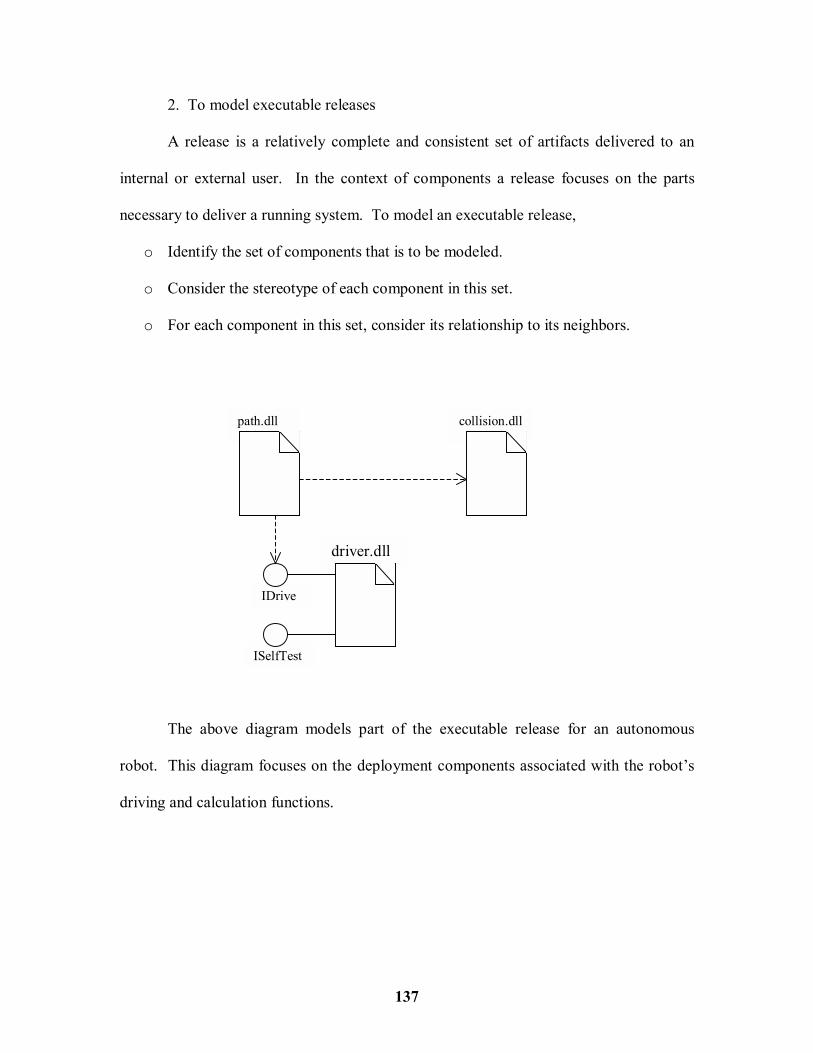
137
2. To model executable releases
A release is a relatively complete and consistent set of artifacts delivered to an
internal or external user. In the context of components a release focuses on the parts
necessary to deliver a running system. To model an executable release,
o Identify the set of components that is to be modeled.
o Consider the stereotype of each component in this set.
o For each component in this set, consider its relationship to its neighbors.
The above diagram models part of the executable release for an autonomous
robot. This diagram focuses on the deployment components associated with the robot�s
driving and calculation functions.
path.dll collision.dll
driver.dll
ISelfTest
IDrive

138
3. To model physical databases
Think of a physical database as the concrete realization of a schema, living in the
world of bits. Schemas, in effect, offer an API to persistent information; the model of a
physical database represents the storage of that information in the tables of a relational
database or the pages of an object-oriented database. To model a physical database,
o Identify the classes in the model that represent logical database schema.
o Select a strategy for mapping these classes to tables.
o To visualize, specify, construct and document the mapping, create a component
diagram that contains components stereotyped as tables.
o Where possible, use tools to help transform logical design into a physical design.
The above diagram shows a set of database tables drawn from an information
system for a school.
4. To model adaptable systems
Some systems are quite static; their components enter the scene, participate in an
execution, and then depart. Other systems are more dynamic, involving mobile agents or
school.db
course department instructor school student

139
components that migrate for purposes of load balancing and failure recovery.
Component diagrams are used in conjunction with some of the UML�s diagrams for
modeling behavior to represent these kinds of systems. To model an adaptable system,
o Consider the physical distribution of the components that may migrate from node
to node.
o If the actions are to be modeled, that cause a component to migrate, create a
corresponding interaction diagram that contains component instances.
The above diagram models the replication of the database from the previous
figure. If the details of each database has to be shown, then they can be represented in
their canonical form � a component stereotyped as a database.
6.6 DEPLOYMENT DIAGRAMS
Deployment diagrams are one of the two kinds of diagrams used in modeling the
physical aspects of an object-oriented system. A deployment diagram shows the
configuration of run time processing nodes and the components that live on them.
The school databaseon Server B replicates the database on Server A
<<copy>>
: school.db {location = Server A}
: school.db {location = Server B}

140
Deployment diagrams are not only important for visualizing, specifying and
documenting embedded, client/server and distributed systems, but also for managing
executable systems through forward and reverse engineering.
Common Properties
A deployment diagram is just a special kind of diagram and shares the same
common properties as all other diagrams � a name and graphical contents that are a
projection into a model. What distinguishes a deployment diagram from all other kinds
of diagrams is its particular content. Deployment diagrams commonly contain
% Nodes
% Dependency and association relationships.
Like all other diagrams, deployment diagrams may contain notes and constraints.
Common Uses
Deployment diagrams are used to model the static deployment view of a system.
This view primarily addresses the distribution, delivery and installation of the parts that
make up the physical system. When modeling the static deployment view of a system,
typically deployment diagrams are used in one of three ways.
1. To model embedded systems
An embedded system is a software-intensive collection of hardware that interfaces
with the physical world. Embedded systems involve software that controls devices such
as motors, actuators, and displays and that, in turn, is controlled by external stimuli such
as sensor input, movement, and temperature changes.

141
2. To model client/server systems
A client/server system is a common architecture focused on making a clear
separation of concerns between the system�s user interface and the system�s persistent
data. Client/server systems are one end of the continuum of distributed systems and
require to make decisions about the network connectivity of clients to servers and about
the physical distribution of the system�s software components across the nodes.
3. To model fully distributed systems
At the other end of the continuum of distributed systems are those that are widely,
if not globally, distributed, typically encompassing multiple levels of servers. Such
systems are often hosts to multiple versions of software components, some of which ma
even migrate from node to node.
6.7 SYSTEMS AND MODELS
The UML is a graphical language for visualizing, specifying, constructing and
documenting the artifacts of a software-intensive system. Well structured systems are
functionally, logically and physically cohesive, formed of loosely coupled subsystems.
Systems and Subsystems
A system is the thing itself that are developed and for which models are build. A
system encompasses all the artifacts that constitute that thing, including all its models and
modeling elements, such as classes, interfaces, components, nodes and their relationships.

142
A subsystem is simply a part of a system, and is used to decompose a complex
system into nearly independent parts. A system at one level of abstraction may be a
subsystem of a system at a higher level of abstraction. A system represents the highest-
level thing in a given context; the subsystems that make up a system provide a complete
and non-overlapping partitioning of the system as a whole.
Models and Views
A model is a simplification of reality, in which reality is defined in the context of
the system being modeled. In short, a model is an abstraction of a system. Think of a
view as a projection into a model. A model is a special kind of package. As a package, a
model owns elements. The models associated with a system or subsystem completely
partition the elements of that system or subsystem, meaning that every element is owned
by exactly one package.
Trace
Specifying relationships among elements such as classes, interfaces, components
and nodes is an important structural part of any model. Specifying the relationships
among elements such as documents, diagrams, and packages that live in different models
is an important part of managing the development artifacts of complex systems, many of
which may exist in multiple versions.

143
Modeling The Architecture of a System
The most common use for which systems and models are applied is to organize
the elements as a system�s architecture. To model the architecture of a system,
Identify the views that will be used to represent the architecture
Specify the context for this system, including the actors that surround it.
As necessary, decompose the system into its elementary subsystems.
system topology distribution delivery installation
system assembly configuration management
performancescalability
throughput
behavior
Vocabulary functionality
Design View
Process View
Implementation View
Deployment View
Use Case View
logical physical