A unified system-level modeling and simulation environment for MPSoC design: MPEG4 decoder case...
6
A Unified System-Level Modeling and Simulation Environment for MPSoC design: MPEG-4 Decoder Case Study Víctor Reyes 1 , Wido Kruijtzer 2 , Tomás Bautista 1 , Ghiath Alkadi 2 , Antonio Núñez 1 1 Institute for Applied Microelectronics, University of Las Palmas GC, Spain 2 Philips Research Laboratories, Eindhoven, The Netherlands [email protected] Abstract New generation Electronic System-Level design tools are the key to overcome the complexity and the increasing design productivity gap in the development of future Multiprocessor Systems-on-Chip. This paper presents a SystemC-based system-level simulation environment, called CASSE, which helps in the modelling and analysis of complex SoCs. CASSE combines application modeling, architecture modeling, mapping and analysis within a unified environment, with the aim to ease and speed up these modeling steps. The main contribution of this tool is to enable this fast modelling and analysis at the very beginning of the design process, helping in the design space exploration phase. CASSE capabilities are disclo- sed in this work by means of a case study where an MPEG-4 decoder application is implemented on an Altera Excalibur platform. 1. Introduction New tools and methodologies that can cope with the increasing design and verification complexity, as well as the tight market constraints, of current System-on-Chip are mandatory. Industry suggests that the new generation of electronic system level (ESL) design tools, which move the system designer towards working at higher abstraction levels, are the key to overcome this complexity [1]. Most of these new generation tools are based on SystemC, the de-facto standard for system level modelling. They are aimed for early software development and performance analysis of a specific system architecture [2][3]. Typically, such tools follow a component-based approach where systems are composed of architectural blocks described using SystemC. Application functionality is added to the architecture by means of embedded software that runs onto processor models, typically Instruction Set Simulators (ISS), or specific HW models that have to be integrated into the system architecture. The drawback of such approach is twofold. First, creating embedded software and specific HW models for a new system instance requires a considerable initial effort that only makes sense if the right HW/SW partition is known beforehand. Second, due to the usage of ISS, simulation speed of the complete system is slowed down to the range of KHz. Such simulation speed is not adequate to explore diverse architectural or mapping options of complex applications within a reasonable amount of time. Although these tools have clear benefits and improvements compared to conventional solutions, due to the tight coupling of functionality and architecture they lack flexibility with respect to design space exploration (DSE) possibilities. DSE is very important at the beginning of the design process, especially for those designs where most of the architectural and mapping decisions still have to be taken. This paper presents a SystemC-based system-level simulation environment, called CASSE, which aims to ease and speed up the modelling and analysis of complex SoCs. The main contribution of this tool is to enable this fast modelling and analysis at the very beginning of the design process, helping in the design space exploration phase. CASSE follows a typical Y-chart methodology where application and architecture are independently modeled and combined in a separate mapping phase, see Figure 1. Quantitative information about the system execution is then obtained by means of simulations. After analysis this information might guide further optimizations in architecture, application and/or mapping structure. The user controls all stages in the design flow by means of textual description files. These description files are read and parsed by the tool during elaboration time in order to create and properly configure the desired system model. The result is an executable model that is executed using the SystemC kernel. More information about this configuration procedure and the internal structure of the tool can be found in [5]. CASSE capabilities are disclosed in this work by means of a case study where an MPEG-4 decoder application is implemented on an Altera Excalibur platform. The rest of the paper is organized as follows. Section 2 covers related work. In Sections 3 and 4 more details about application and architectural modeling are presented. Sections 5 and 6 explain the mapping and analysis capabilities of the tool. The MPEG-4 case study is presented in detail in Section 7. Conclusions are drawn in Section 8. 2. Related work Methodologies that emphasize reusability and standardized SoC design methods to cope with system complexity have resulted in the platform-based design notion and in the orthogonalization of concerns [10]. The Y-chart scheme is a typical example of a methodology that applies orthogonalization of concerns [4]. The Y- chart eases the design space exploration process by 3-9810801-0-6/DATE06 © 2006 EDAA
-
Upload
independent -
Category
Documents
-
view
1 -
download
0
Transcript of A unified system-level modeling and simulation environment for MPSoC design: MPEG4 decoder case...

A Unified System-Level Modeling and Simulation Environment for MPSoC
design: MPEG-4 Decoder Case Study
Víctor Reyes1, Wido Kruijtzer2, Tomás Bautista1, Ghiath Alkadi2, Antonio Núñez1
1Institute for Applied Microelectronics, University of Las Palmas GC, Spain 2Philips Research Laboratories, Eindhoven, The Netherlands
Abstract
New generation Electronic System-Level design tools are the key to overcome the complexity and the increasing design productivity gap in the development of future Multiprocessor Systems-on-Chip. This paper presents a SystemC-based system-level simulation environment, called CASSE, which helps in the modelling and analysis of complex SoCs. CASSE combines application modeling, architecture modeling, mapping and analysis within a unified environment, with the aim to ease and speed up these modeling steps. The main contribution of this tool is to enable this fast modelling and analysis at the very beginning of the design process, helping in the design space exploration phase. CASSE capabilities are disclo-sed in this work by means of a case study where an MPEG-4 decoder application is implemented on an Altera Excalibur platform.
1. Introduction New tools and methodologies that can cope with the
increasing design and verification complexity, as well as the tight market constraints, of current System-on-Chip are mandatory. Industry suggests that the new generation of electronic system level (ESL) design tools, which move the system designer towards working at higher abstraction levels, are the key to overcome this complexity [1]. Most of these new generation tools are based on SystemC, the de-facto standard for system level modelling. They are aimed for early software development and performance analysis of a specific system architecture [2][3].
Typically, such tools follow a component-based approach where systems are composed of architectural blocks described using SystemC. Application functionality is added to the architecture by means of embedded software that runs onto processor models, typically Instruction Set Simulators (ISS), or specific HW models that have to be integrated into the system architecture. The drawback of such approach is twofold. First, creating embedded software and specific HW models for a new system instance requires a considerable initial effort that only makes sense if the right HW/SW partition is known beforehand. Second, due to the usage of ISS, simulation speed of the complete system is slowed down to the range of KHz. Such simulation speed is not adequate to explore diverse architectural or mapping options of complex applications within a reasonable
amount of time. Although these tools have clear benefits and improvements compared to conventional solutions, due to the tight coupling of functionality and architecture they lack flexibility with respect to design space exploration (DSE) possibilities. DSE is very important at the beginning of the design process, especially for those designs where most of the architectural and mapping decisions still have to be taken.
This paper presents a SystemC-based system-level simulation environment, called CASSE, which aims to ease and speed up the modelling and analysis of complex SoCs. The main contribution of this tool is to enable this fast modelling and analysis at the very beginning of the design process, helping in the design space exploration phase. CASSE follows a typical Y-chart methodology where application and architecture are independently modeled and combined in a separate mapping phase, see Figure 1. Quantitative information about the system execution is then obtained by means of simulations. After analysis this information might guide further optimizations in architecture, application and/or mapping structure. The user controls all stages in the design flow by means of textual description files. These description files are read and parsed by the tool during elaboration time in order to create and properly configure the desired system model. The result is an executable model that is executed using the SystemC kernel. More information about this configuration procedure and the internal structure of the tool can be found in [5]. CASSE capabilities are disclosed in this work by means of a case study where an MPEG-4 decoder application is implemented on an Altera Excalibur platform.
The rest of the paper is organized as follows. Section 2 covers related work. In Sections 3 and 4 more details about application and architectural modeling are presented. Sections 5 and 6 explain the mapping and analysis capabilities of the tool. The MPEG-4 case study is presented in detail in Section 7. Conclusions are drawn in Section 8.
2. Related work
Methodologies that emphasize reusability and standardized SoC design methods to cope with system complexity have resulted in the platform-based design notion and in the orthogonalization of concerns [10]. The Y-chart scheme is a typical example of a methodology that applies orthogonalization of concerns [4]. The Y-chart eases the design space exploration process by
3-9810801-0-6/DATE06 © 2006 EDAA

modeling independently functionality and architecture, and later on combining them in a separated mapping phase. CASSE follows a Y-chart methodology where application functionality is separated from architecture, but also communication is separated from computation by means of a task level interface [6]. Similar Y-chart frameworks are Spade [11] and Sesame [12]. Both start with functional simulations of the application that is described in the form of a Kahn Process Network. However, they apply trace-driven architectural simula-tions where the architectural models (annotated with timing and performance figures) are fed with traces obtained during functional simulations. In [13] the Metropolis framework is presented. Metropolis provides a meta-model of computation that offers syntactic and semantics mechanisms to support functionality capture and analysis, as well as architecture description and mapping of functionality to architectural elements. Unlike Metropolis, CASSE uses SystemC (the de-facto industry modeling standard) to support the mapping of functionality into architectural models. Finally, Kogel et al. [14] also propose a SystemC-based simulation framework, which enables the quantitative evaluation of an application-to-architecture mapping by means of an executable performance model. Similar to CASSE, this framework accelerates the exploration of large design space by means of description files where individual timing annotations as well as the mapping are specified. But, unlike CASSE that follows a streaming-wise multiprocessor programming model, this framework uses a general timed Communicating Extended Finite State Machine programming model.
ApplicationModeling
(TTL)
Timingannotation
Mapping
ArchitectureModeling
(PE,SE,NE)
FunctionalSimulations(only app.)
Functional & PerformanceSimulations
(app. + arch.)
TTLtasks
Task-graphdesc. file
Architecturaldesc. file
Externalcomponents
Mappingdesc. file
Tracingdesc. file
Simulationoutput files
Analysis
Refinement
(Executable models)
UTF TF
Fig. 1: CASSE design flow.
3. Application modeling CASSE follows a programming model based on the
Task Transaction Level (TTL) interface [6]. TTL can be used both for developing parallel application models and as a platform interface for integrating hardware and software modules on a platform infrastructure. According to the TTL specification, an application is described as a process network where parallel tasks communicate with
each other by mean of unidirectional channels. A task is an entity that performs computations. Tasks are connected to the channels via ports, and they communicate and synchronize with each other by calling TTL interface primitives on their ports. More information about the TTL implementation in CASSE can be found in [7].
Tasks containing the application functionality are written in C/C++ (i.e. the functionality per task is fixed at compile time). However, the network structure (i.e. port to channel connections) and its configuration (e.g. channel size) are described in a separate text file. An example of the syntax is shown in Figure 2 for a simple producer-consumer application. The tool uses this description file to instantiate and bind together tasks and channels creating an executable model of the network. This architecture-independent executable model can be simulated using CASSE in order to validate the functional correctness of the application. Furthermore, at this stage one can obtain some information about communication and synchronization load for each task/port composing the application.
# Producer-Consumer Task-Graph file #
.CREATE -TASK producer –N_PORT 1 ;
.CREATE -TASK consumer –N_PORT 1 ;
.CREATE -CHANNEL channel1 -SIZE 10 -TIZE 4 ;
.BIND -TASK producer -PORT 0 TO -CHANNEL channel1 -PRODUCER ;
.BIND -TASK consumer -PORT 0 TO -CHANNEL channel1 -CONSUMER ;
Fig. 2: Producer-consumer example.
4. Architectural modeling CASSE provides easy and fast architectural modeling
by describing a system as a modular composition of highly configurable predefined elements (provided by the tool libraries). All elements are connected together in a ‘plug and play’ fashion by means of an inter-component communication protocol and interface called ICCP. Besides these predefined elements the architectural models can be extended with new functionality by means of external components (EC). These external components can be described at any abstraction level using SystemC.
The library of predefined elements is composed of: processing elements (PE), which model generic multitasking computational units, storage elements (SE), which model generic multi-port memory elements, and network elements (NE), which model generic shared bus interconnections including programmable arbiter, address decoder, and optional input buffers. Processing elements include an abstract task scheduler model supporting different arbitration schemes (e.g. priority-based, round-robin, TDMA) and advance features like interruptions and pre-emption. Likewise, ICCP is an abstract communica-tion protocol, which defines a point-to-point interface and a group of communication primitives between two entities named Initiator and Target. ICCP is not a new device level communication protocol, but its aim is to model a generic transaction-level communication protocol that can be parameterized to emulate the timing and basic functionality of standard protocols such as OCP or AXI. Both the ICCP interface and the library of predefined elements have been developed using SystemC and the recently released Transaction Level Modeling Standard library [8].

A separate description file is used in order to specify the architectural composition of the system (i.e. number of elements of each type, number of interfaces per element, and their interconnection), and its configuration (e.g. memory map, memory sizes, communication latencies per interface, task scheduler policy, etcetera). An example of such architectural description file is shown in Figure 3.
PE1 SE1
NE1
NE3
SE2PE2
ICCP LINK
Clock domain 1
Clock domain 2
NE2
PE1 SE1
NE1
NE3
SE2PE2
ICCP LINK
Clock domain 1
Clock domain 2
PE1PE1 SE1SE1
NE1
NE3
SE2PE2
ICCP LINK
Clock domain 1
Clock domain 2
NE2
# architectural file #.CREATE -CLOCK clock1 -PERIOD 1 -UNIT SC_NS ;
.CREATE -CLOCK clock2 -PERIOD 5 -UNIT SC_NS ;
.CREATE -PROCESSIN G PE1 -N_IN IT 1 ;
.CREATE -STORAGE SE1 -N _TARGET 1 ;
.CREATE -NETW ORK NE1 -N_INPUT 1 -N_OUTPUT 2 ;
.CREATE -LINK link1 -W IDTH 32 ;… ..
.BIND -CLOCK clock1 TO -PROCESSING PE1 ;
.B IND -L INK link1 TO -PROC ESSING PE1 -INIT 0 ;
.BIND -L INK link1 TO -NETW ORK NE1 -INPUT 0 ;
… ..CONFIGURE -PROCESSIN G PE1 -IN IT 0 -W IDTH 32 -LAT 1 1 1 0 -CONNID 0 ;
.CONFIGURE -STORAGE SE1 -S IZE 16777216 ;
.CONFIGURE -STORAGE SE1 -TARGET 0 -W IDTH 32 -LAT 1 1 1 ;
.CONFIGURE -NETW ORK NE1 -OUTPU T 0 -RANGE 0x00000000 0x01ffffff ;… .
Fig. 3: Architectural description file example.
5. Application to architecture mapping One of the main advantages of the tool as a unified
environment is the straightforward mapping support of application functionality onto the modeled platform architecture. That is, CASSE supports the direct mapping of TTL tasks and channels onto the modeled architecture with no need for extra source code changes (i.e. original source code of the tasks is executed directly in the architectural model). Timing delays reflecting the computational costs of the functionality can be annotated into the tasks by either automatic methods like described in [15] or have to be annotated manually.
The mapping procedure is performed in three steps. First step is to map TTL tasks onto processing elements. Processing elements are simply placeholders where the functionality is assigned during the mapping phase. Multiple tasks can be mapped into a single PE. Second step is to map channels onto the storage elements. Channels are composed of the channel buffer (CHB) where the channel data (tokens) is stored, and the channel administration tables (CHAT) that are used for the tasks to access the channel buffer and for synchronization purposes. Both CHB and CHATs can be mapped separately in different storage elements, which bring more flexibility in order to analyze different architectural options. Third step of the mapping procedure is the logical to physical communication mapping. That is, each port of each task mapped into a specific PE can be independently configured to access a particular interface in order to carry out their TTL communication and synchronization
primitives. Such flexibility, of course, depends on the number of interfaces available in the processing element, which in turn depends on the kind of component is being modeled.
Another description file is used for the tool in order to control this mapping procedure. The outcome of the mapping stage is an executable model containing the selected application/architecture instance. This executable model is executed using the SystemC kernel in order to validate both the functional correctness and the performance of the system.
6. Tracing, analysis and refinement During simulations relevant information about the
system execution can be gathered and dumped into files for later inspection. CASSE also provides a separate description file that indicates which parts of the system have to be traced and the type of information to record. For instance, the tool allows to the designer to trace and dump all the data transfers carried out by an individual interface in the architecture, as well as its statistics about communication load, latency, etc. Moreover, information regarding the execution of the tasks in a specific PE can be collected during the simulation. For instance, the number of times a task is suspended, total cycles spent in computation, total overhead cycles due to context switching, number of TTL primitives executed in a task’s port, etc.
CASSE allows the system designer to analyze and identify architectural bottlenecks and possible system optimizations at the task level. This analysis guide further iterations where both the application and the architecture models are tuned, or a new mapping is created. One of the main contributions of CASSE is to speed up this procedure by means of the description files that can be easily modified in order to create a new system instance. Since changing the description files does not require recompiling the existing models, extensive parameters sweeps can be perform easily using scripts.
Finally, once the expected requirements are fulfilled the system is ready for implementation. Hardware modules can be progressively refined from more abstract to more accurate (even synthesizable) descriptions in SystemC and verified within the platform model, just by replacing predefined elements of the tool libraries with external components containing the accurate model. Likewise, software modules might be directly taken into an embedded compiler and later integrated again in the system by means of an external component that integrates an Instruction Set Simulator.
7. MPEG-4 decoder case study
This case study is part of the ARTEMI project (ARchiTEctures for Multimedia and Internet), which aims to develop a system for receiving low-quality digital video transmitted over the Digital Audio Broadcasting (DAB) network, using as target technology mixed programmable platforms. A key part of the ARTEMI system is a MPEG-4 decoder, which has to be implemented on the Altera Excalibur FPGA platform [9]. This platform is composed of a million equivalent gates programmable logic device (PLD) and an embedded processor (Excalibur Stripe).
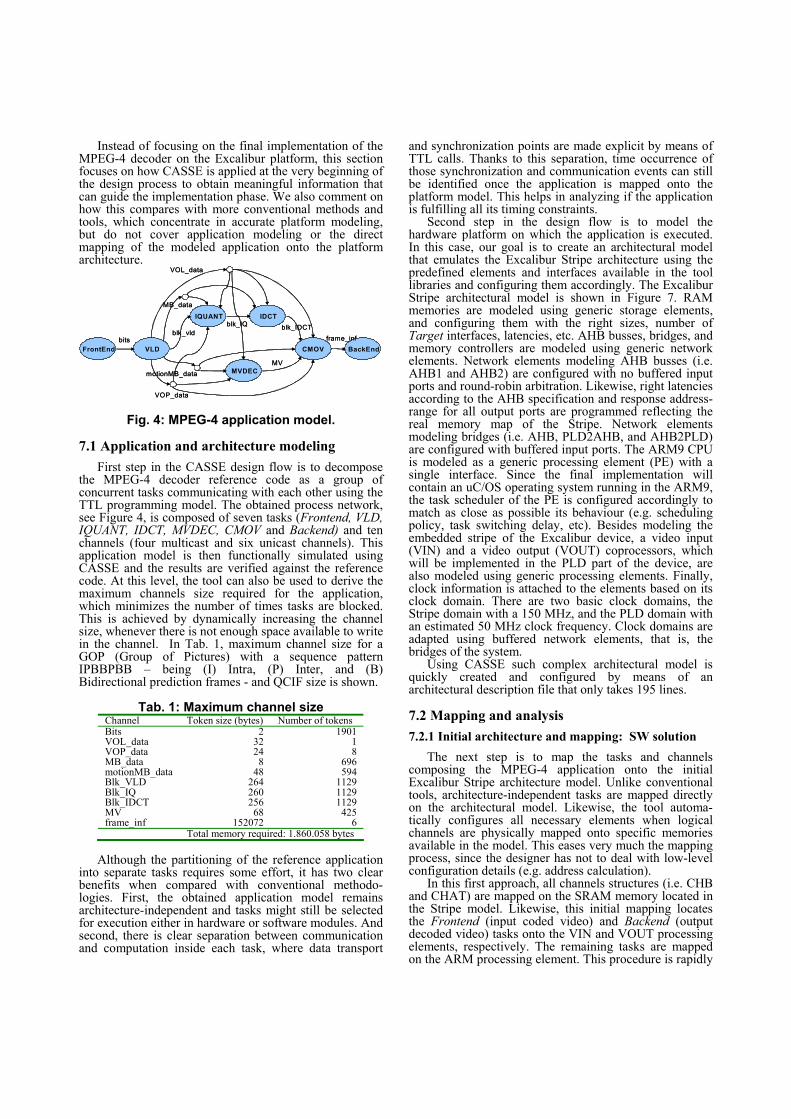
Instead of focusing on the final implementation of the MPEG-4 decoder on the Excalibur platform, this section focuses on how CASSE is applied at the very beginning of the design process to obtain meaningful information that can guide the implementation phase. We also comment on how this compares with more conventional methods and tools, which concentrate in accurate platform modeling, but do not cover application modeling or the direct mapping of the modeled application onto the platform architecture.
FrontEnd VLD
IQUANT
MVDEC
IDCT
CMOV BackEndbits
VOP_data
motionMB_dataMV
VOL_data
MB_data
blk_vldblk_IQ blk_IDCT
frame_infFrontEnd VLD
IQUANT
MVDEC
IDCT
CMOV BackEndbits
VOP_data
motionMB_dataMV
VOL_data
MB_data
blk_vldblk_IQ blk_IDCT
frame_inf
Fig. 4: MPEG-4 application model.
7.1 Application and architecture modeling First step in the CASSE design flow is to decompose
the MPEG-4 decoder reference code as a group of concurrent tasks communicating with each other using the TTL programming model. The obtained process network, see Figure 4, is composed of seven tasks (Frontend, VLD, IQUANT, IDCT, MVDEC, CMOV and Backend) and ten channels (four multicast and six unicast channels). This application model is then functionally simulated using CASSE and the results are verified against the reference code. At this level, the tool can also be used to derive the maximum channels size required for the application, which minimizes the number of times tasks are blocked. This is achieved by dynamically increasing the channel size, whenever there is not enough space available to write in the channel. In Tab. 1, maximum channel size for a GOP (Group of Pictures) with a sequence pattern IPBBPBB – being (I) Intra, (P) Inter, and (B) Bidirectional prediction frames - and QCIF size is shown.
Tab. 1: Maximum channel size
Channel Token size (bytes) Number of tokens Bits 2 1901 VOL_data 32 1 VOP_data 24 8 MB_data 8 696 motionMB_data 48 594 Blk_VLD 264 1129 Blk_IQ 260 1129 Blk_IDCT 256 1129 MV 68 425 frame_inf 152072 6 Total memory required: 1.860.058 bytes
Although the partitioning of the reference application
into separate tasks requires some effort, it has two clear benefits when compared with conventional methodo-logies. First, the obtained application model remains architecture-independent and tasks might still be selected for execution either in hardware or software modules. And second, there is clear separation between communication and computation inside each task, where data transport
and synchronization points are made explicit by means of TTL calls. Thanks to this separation, time occurrence of those synchronization and communication events can still be identified once the application is mapped onto the platform model. This helps in analyzing if the application is fulfilling all its timing constraints.
Second step in the design flow is to model the hardware platform on which the application is executed. In this case, our goal is to create an architectural model that emulates the Excalibur Stripe architecture using the predefined elements and interfaces available in the tool libraries and configuring them accordingly. The Excalibur Stripe architectural model is shown in Figure 7. RAM memories are modeled using generic storage elements, and configuring them with the right sizes, number of Target interfaces, latencies, etc. AHB busses, bridges, and memory controllers are modeled using generic network elements. Network elements modeling AHB busses (i.e. AHB1 and AHB2) are configured with no buffered input ports and round-robin arbitration. Likewise, right latencies according to the AHB specification and response address-range for all output ports are programmed reflecting the real memory map of the Stripe. Network elements modeling bridges (i.e. AHB, PLD2AHB, and AHB2PLD) are configured with buffered input ports. The ARM9 CPU is modeled as a generic processing element (PE) with a single interface. Since the final implementation will contain an uC/OS operating system running in the ARM9, the task scheduler of the PE is configured accordingly to match as close as possible its behaviour (e.g. scheduling policy, task switching delay, etc). Besides modeling the embedded stripe of the Excalibur device, a video input (VIN) and a video output (VOUT) coprocessors, which will be implemented in the PLD part of the device, are also modeled using generic processing elements. Finally, clock information is attached to the elements based on its clock domain. There are two basic clock domains, the Stripe domain with a 150 MHz, and the PLD domain with an estimated 50 MHz clock frequency. Clock domains are adapted using buffered network elements, that is, the bridges of the system.
Using CASSE such complex architectural model is quickly created and configured by means of an architectural description file that only takes 195 lines.
7.2 Mapping and analysis 7.2.1 Initial architecture and mapping: SW solution
The next step is to map the tasks and channels composing the MPEG-4 application onto the initial Excalibur Stripe architecture model. Unlike conventional tools, architecture-independent tasks are mapped directly on the architectural model. Likewise, the tool automa-tically configures all necessary elements when logical channels are physically mapped onto specific memories available in the model. This eases very much the mapping process, since the designer has not to deal with low-level configuration details (e.g. address calculation).
In this first approach, all channels structures (i.e. CHB and CHAT) are mapped on the SRAM memory located in the Stripe model. Likewise, this initial mapping locates the Frontend (input coded video) and Backend (output decoded video) tasks onto the VIN and VOUT processing elements, respectively. The remaining tasks are mapped on the ARM processing element. This procedure is rapidly

described by means of the mapping description file, which only requires 60 lines.
Performance simulations are then carried out. At this point, computation delays were manually annotated in the software tasks running in the ARM PE. In order to be as accurate as possible these computation delays were obtained by analyzing the assembler code of the tasks after compiling with the ADS compiler. Besides providing information about the system performance this simulation can be used to assess functional correctness, that is, to check whether the application is still providing the same results when mapped onto the architectural model. For this example, CASSE took around 90 seconds to simulate one second of the system execution. For a clock reference of 150 MHz the simulation throughput (or simulation speed) reaches approximately 2 Mcycles/s that is three orders of magnitude higher than typical ISS-based simulations.
0
500010000
1500020000
25000
Fron
tend/b
its
VLD/bi
ts
VLD/bl
k_VLD
IQUANT/b
lk_IQ
IQUANT/
blk_V
LD
IDCT/b
lk_ID
CT
IDCT/
blk_IQ
MVDEC/moti
onMB
CMOV/blk_
IDCT
CMOV/frame_
inf
Backe
nd/fr
ame_
inf
Kby
tes/
sc
read write
Fig. 5: SRAM data load per task/port.
0
1000
2000
3000
4000
5000
6000
0 100 200 300 400 500 600 700 800 900 1000
milliseconds
Kby
tes
read write
1 1211Frame # 2 3 4 5 6 7 8 9 10
Fig. 6: SRAM data load vs. time.
For this initial architecture and mapping the system is
able to decode 12 frames within this second of execution. During this simulation, traces are set to measure the data load in the SRAM memory where the channels are mapped. In addition, CASSE allows obtaining those simulation traces every certain period of time within the total execution time. Figure 6 shows the data load in the SRAM memory sampled every 100 milliseconds of execution time and its relationship with the decoded frame. Total data load measured on the SRAM is approximately 50 Mbytes. However, this raw data of 50 Mbytes is not enough to provide information about what is happening in the system and to guide further optimizations. For that reason CASSE allows to tag all transactions happening in the system architecture with an individual identifier. This identifier can be associated to each port of each task running in the system. For instance, the data load produced for the port connected to the channel bits of the task Frontend can be individually observed in the SRAM memory. Figure 5 shows the data
load produced into the SRAM memory in a task/port basis. Analyzing this information, it is observed that the port bits of the Frontend task and the port frame_inf of the Backend task produce two third of the total data load in this memory. Furthermore, it is detected that most of this load is produced during the access to their CHAT information. This means that those tasks are too often blocked waiting for data or room in their channels, and such high load is produced whereas polling the channel status.
7.2.2 First iteration: architectural optimizations
Communication from VIN and VOUT coprocessors to the SRAM memory is too costly in terms of latency and power consumption due to the large path of busses and bridges that the data has to cross. Therefore, one required optimization is to reduce the data load produced by the before mentioned tasks (Frontend and Backend) mapped in these coprocessors. For that purpose, local memories are added to the VIN and VOUT coprocessors and their associated CHATs are mapped into them. Now tasks do not have to use the complex multi-level bus infrastructure of the Stripe to read their channel administration information but they do it locally. Unlike conventional tools, in CASSE such modification simply requires adding and modifying a few lines into both the architectural and mapping description file. After running new simulations the data load into the SRAM memory has been reduced in a 77%, that is, from 50 Mbytes to 11.5 Mbytes.
7.2.3 Second iteration: HW-SW solution
Next iteration is intended to increase the decoding frame rate of the system. Hence, more computational resources, where to execute some of the task running on the ARM, are added to the architectural model. In order to decide which task should be mapped in a separated processing element, the tool derives the percentage of time the ARM is used for each task. That information is shown in the Tab.2.
Tab. 2: ARM computational load per task
Task Cycles % Usage VLD 14.676.715 7,8 IQUANT 28.263.398 15 IDCT 67.551.091 36 MVDEC 245.888 0,13 CMOV 75.907.139 40 Context Switching Overhead 1.104.250 0,6
According to those results, both the CMOV (motion
compensation) and IDCT (inverse discrete cosine transform) tasks are the more computational expensive tasks running on the ARM, respectively. However, since the IDCT is more suitable for a HW implementation, a new processing element executing the IDCT task is added to the architectural model. Channels belonging to the IDCT task are mapped onto the DPRAM memory that has a second port available for direct access from the PLD area. The IDCT processing element and the DPRAM storage element are connected together by a direct ICCP link using this available second port. Source code of the IDCT task is then annotated with new delays taking into account a hardware implementation. We estimate that an IDCT coprocessor might process an 8x8 block in 128 cycles (the previous software IDCT implementation

needed around 1000 cycles in the ARM9). This new architecture and its corresponding mapping are shown in Figure 7.
VLD MVDECIQUANT CMOVSDRAM
SDRAM CTRL
SRAM0 CTRL DPRAM0 CTRL
SRAM0
AHB1
AHB BRIDGE
STR2PLD BRIDGE
PLD2STR BRIDGE
Altera Excalibur stripe model
PLD area model
SDRAM
ARM
SRAM
AHB2
SRAM CTRL DPRAM CTRL
DPRAM
AHB
SDRAM CTRL
STR2PLD PLD2STR
BRIDGE
BRIDGE BRIDGE
PLDBUS VINMEM
VOUTMEM
IDCTMEM
VIN VOUT IDCT COPRO
FrontEnd BackEnd IDCT
blk_IQCHB & P CHATblk_IDCT CHB & C CHATVOL_data CHB & P CHATMB_data CHB & P CHAT
blk_IQC CHATblk_IDCT P CHATVOL_data C CHATMB_data C CHAT
Bits P CHAT
Frame_inf C CHAT
Remaining CHB and CHATs
VLD MVDECIQUANT CMOVSDRAM
SDRAM CTRL
SRAM0 CTRL DPRAM0 CTRL
SRAM0
AHB1
AHB BRIDGE
STR2PLD BRIDGE
PLD2STR BRIDGE
Altera Excalibur stripe model
PLD area model
SDRAM
ARM
SRAM
AHB2
SRAM CTRL DPRAM CTRL
DPRAM
AHB
SDRAM CTRL
STR2PLD PLD2STR
BRIDGE
BRIDGE BRIDGE
PLDBUS VINMEM
VOUTMEM
IDCTMEM
VIN VOUT IDCT COPRO
FrontEnd BackEnd IDCTFrontEnd BackEnd IDCT
blk_IQCHB & P CHATblk_IDCT CHB & C CHATVOL_data CHB & P CHATMB_data CHB & P CHAT
blk_IQC CHATblk_IDCT P CHATVOL_data C CHATMB_data C CHAT
Bits P CHAT
Frame_inf C CHAT
Remaining CHB and CHATs
Fig. 7: Architecture model and mapping.
0
50000
100000
150000
200000
250000
1 10 100tokens
bytes
SRAMDPRAM
Frame rate14 14 15
Fig. 8: Channel size vs. frame rate.
With this new architecture and mapping instance,
performance simulation derives a decoding frame rate of 14 fps. In order to squeeze the possibilities of this new platform model, a brief exploration of the channels size and their relation with memory usage and frame rate is performed. Using CASSE this exploration only requires feeding the tool with different task-graph description files that change the size of the channels. This analysis is shown in Figure 8, where it is observed like increasing channels size to 100 tokens increases the performance in one extra frame, whereas the total memory used for the channels remains within the maximum memory available.
It is important to mention that the results shown in this case study are just brief examples of the tool capabilities since many others architectures and/or mapping might be explored, and much other information can be obtained which can guide further optimizations.
8. Conclusions
This paper shows how a SystemC-based system-level simulation environment, called CASSE, can be applied on the modeling and analysis of a complex system such as an MPEG-4 decoder running on an Altera Excalibur programmable platform. CASSE covers application and architecture modeling, as well as direct mapping and analysis, within a unified simulation environment. This
environment eases and speeds up these modeling steps and helps in the design space exploration phase, at the beginning of the design process.
9. Acknowledgements This work is supported by the Spanish Ministry of Education and Sciences under the ARTEMI project TIC-2003-09687-C02-02. 10. References [1] ITRS Design Working Group, www.itrs.net [2] ConvergenSCTM, www.coware.com [3] Axys MaxSimTM, www.axysdesign.com [4] B. Kienhuis, E. Deprettere, K. Vissers and P. van der Wolf,
“An Approach for Quantitative Analysis of Application-Specific Dataflow Architectures”, in Proc. 11-th Int. Conf. on Application-specific Systems, Architectures and Processors, Zurich, Switzerland, July 14-16 1997
[5] V. Reyes, W. Kruijtzer, T. Bautista, G. Marrero, P. Carballo, “CASSE: A System-Level Modeling and Design-Space Exploration Tool for Multiprocessor Systems-on-Chip”, In Proc. of Euromicro Symposium on Digital System Design, September 2004
[6] P. Van de Wolf, E. De Kock, T. Hendrikson, W. Kruijtzer, G. Essink, “Design and Programming of Embedded Multiprocessors: An Interface-Centric Approach”, In Proceedings of CODES+ISSS’04, September 2004
[7] V. Reyes, W. Kruijtzer, T. Bautista, G. Marrero, A. Nuñez, “A Multicast Inter-Task Communication Protocol for Embedded Multiprocessor Systems”, In Proceedings of CODES+ISSS’05, October 2005
[8] Transaction Level Modelling Standard 1.0, June 2005, http://www.systemc.org
[9] Altera ExcaliburTM, www.altera.com [10] K. Keutzer, S. Malik, A.R. Newton, J.M. Rabaey, A.
Sangiovanni-Vicentelli, “System-level design: Orthogonalization of concerns and platform-based design”, in IEEE Trans. on Computer-Aided Design of Integrated Circuit and Systems, 19(12): 1523-1543, December 2000
[11] P. Lieverse, P. van der Wolf, E.E. Deprettere, K. Vissers, “A methodology for architecture exploration of heterogeneous signal processing systems”, in Proc. of the IEEE Workshop on Signal Processing Systems, SiPs 99, pages 181-190, IEEE Press, 1999
[12] A.D. Pimentel and C. Erbas, “An IDF-based trace transformation method for communication refinement”, in Proc. of the 40th Design Automation Conference, Anaheim, CA, USA, pages 402-407, ACM Press, June 2003
[13] F. Balarin, Y. Watanabe, H. Hsieh, L. Lavagno, C. Passerone, A. Sangiovanni-Vicentelli, “Metropolis: An integrated electronic system design environment”, IEEE Computer, 36(4): 45-52, April 2003
[14] T. Kempf, M. Doerper, R. Leupers, T. Kogel, B. Vanthournout, “A Modular Framework for Spatial and Temporal Task Mapping onto Multi-Processor SoC Platforms”, in Proc. of Design, Automation and Test in Europe, Paris, France, pp. 876-881, 2005
[15] S.V. Gheorghita, S. Stuijk, T. Basten and H. Corporaal, “Automatic Scenario Detection for Improved WCET Estimation”, in Proc. Design Automation Conference, Anaheim, USA, June 2005