
CoERBAT - Border Roads Organisation
12
This Issue • Special Mention : BRO’s contribution in revision of IRC Code P.1 • Segmental construction of bridges in hilly areas P.1-9 • Visit to Sela Tunnel by BRO Officers/Pers P.10 • Compendium of Steel and PSC bridge superstructure P.11 • Monthly lecture on “Peculiarities of runway design and construction at Bagdogra and Barrackpore” P.11 …WE WILL EITHER FIND A WAY OR MAKE ONE… 1 Newsletter Issue-03 CoERBAT Centre of Excellence for Roads, Bridges, Airfields and Tunnels REVISION IN IRC CODE – SILT FACTOR In IRC:5-2015, there is a detailed procedure for determination of maximum scour depth using the universally accepted Lacey’s formula adopted for different terrains in India which had certain shortcomings as far as silt factor for bouldery beds was concerned. Based on extensive study carried out on river scour data pattern by BRO, IRC vide their notification No 40, has revised the silt factor, which will be useful for all departments involved in construction of bridges in bouldery bed due to optimization of scour depth and will save govt exchequer. Indian Highways Issue dated Feb 2022 has also highlighted the important contribution of BRO in this field. SEGMENTAL CONSTRUCTION OF BRIDGES IN HILLY AREAS : AN OVER VIEW Construction of bridges in hilly areas has always been a challenging task for the engineers. Deep gorge, bouldery river bed, high velocity of current, flash floods, limited working space and difficulty in diversion of flow, pose serious problems to the construction agencies in these areas. These factors at times, make it impossible to adopt conventional construction techniques, where formwork is supported on staging from the bed level and demand a high level of ingenuity of the engineers to bridge such gaps. Segmental construction technique, which on the other hand, facilitates construction of longer span bridges, reduces intermediate piers and thus obstruction to flow, and avoid system of erection of staging from river bed level, has been found to be a very effective and economical technique in such situations. Besides least disturbance to the natural flow of water, their appealing aesthetics, speed in construction, reduced efforts in foundation and pier work, make this technique an obvious choice in such situations. Construction of foundations in bouldery river beds, is another tedious problem in hilly areas.
-
Upload
khangminh22 -
Category
Documents
-
view
0 -
download
0
Transcript of CoERBAT - Border Roads Organisation

This Issue
• Special Mention:
BRO’s contribution
in revision of IRC
Code P.1
• Segmental
construction of bridges
in hilly areas P.1-9
• Visit to Sela Tunnel
by BRO Officers/Pers
P.10
• Compendium of Steel
and PSC bridge
superstructure P.11
• Monthly lecture
on “Peculiarities of
runway design and
construction at
Bagdogra and
Barrackpore” P.11
…WE WILL EITHER FIND A WAY OR MAKE ONE… 1
Newsletter
Issue-03 CoERBATCentre of Excellence for Roads, Bridges,
Airfields and Tunnels
REVISION IN IRC CODE – SILT FACTOR
In IRC:5-2015, there is a detailed procedure for determination of
maximum scour depth using the universally accepted Lacey’s formula adopted for
different terrains in India which had certain shortcomings as far as silt factor for
bouldery beds was concerned. Based on extensive study carried out on river scour
data pattern by BRO, IRC vide their notification No 40, has revised the silt factor,
which will be useful for all departments involved in construction of bridges in
bouldery bed due to optimization of scour depth and will save govt exchequer.
Indian Highways Issue dated Feb 2022 has also highlighted the important
contribution of BRO in this field.
SEGMENTAL CONSTRUCTION OF BRIDGES IN HILLY AREAS :
AN OVER VIEW
Construction of bridges in hilly areas has always been a challenging task
for the engineers. Deep gorge, bouldery river bed, high velocity of current, flash
floods, limited working space and difficulty in diversion of flow, pose serious
problems to the construction agencies in these areas. These factors at times, make it
impossible to adopt conventional construction techniques, where formwork is
supported on staging from the bed level and demand a high level of ingenuity of the
engineers to bridge such gaps.
Segmental construction technique, which on the other hand, facilitates
construction of longer span bridges, reduces intermediate piers and thus obstruction
to flow, and avoid system of erection of staging from river bed level, has been
found to be a very effective and economical technique in such situations. Besides
least disturbance to the natural flow of water, their appealing aesthetics, speed in
construction, reduced efforts in foundation and pier work, make this technique an
obvious choice in such situations. Construction of foundations in bouldery river
beds, is another tedious problem in hilly areas.

…WE WILL EITHER FIND A WAY OR MAKE ONE… 2
The slow rate of sinking combined with associated problem of tilt and excessive efforts needed on
dewatering, at times forces the executives to adopt pneumatic sinking. However, this technique also has a
restriction beyond a certain depth. Steel bridges, though offer wide choice to have longer span arrangements
than a PSC construction but space restriction, problem in transportation of heavy fabricated components on
hill roads and proper matching thereof with the case in situ elements remains a major problem. Border
Roads organization, which is primarily engaged in construction of road infrastructure has made many
bridges using segmental construction technique. Because of the space restrictions and transportation
problem, cast-in situ construction has been adopted in segmental construction.
SEGMENTAL CONSTRUCTION TECHNIQUE
Designer has to take into account suitably, the construction technique in detail including stresses
arising during construction and schedule of prestressing of cable at each stage.
Selection of a suitable span arrangement is the first step in design of any bridge project which is
mainly governed by the site conditions. For segmental construction either a continuous span or a cantilever
span having suspended span in between or a hinge is followed due to obvious advantages in design of pre-
stressing system and construction. The connection between pier and the super-structure could either be a
monolithic or otherwise supported on bearings depending upon the soil conditions and seismicity of the area.
Once a suitable span arrangement is decided based on the site conditions and characteristics of soil,
the following steps are followed to evolve the design:
(a) Finalization of the dimensions of box girder depending upon the width of the
carriageway/footpath. Depth at root section however mainly depends upon the span length and is
normally equal to 1/8 of span.
(b) Based on the length of the arm, it is then divided into likely construction units. Length of
each unit is generally kept in the range of 3.0 m to 4.0 m based on the construction convenience and
the gantry parameters.
(c) On finalization of dimensions of the structure, stresses i.e bending, shear and tension, due to
various specified loads is analyzed at each section. Attempt is made to remove the imbalance in the
moment, if any, by suitable re-adjustment.
(d) Finally, the ultimate moments generated at each section due to dead loads and live loads as
per the provisions contained in IRC:18-2020 are calculated. Thereafter, the design of super-structure
is done in such a manner that it can resist the ultimate moments at each section. Suitable cable
profile is accordingly decided based on the pre-stressing system to be used and the concentration of
tensile stresses.
Segmental construction is however a delicate process and needs a fine balance at each stage of
casting. Any imbalance at any stage could lead to severe damages and therefore, a thorough and careful
approach is needed in casting of each segment. On casting of pier head, the process of segmental
construction starts. A proper flow chart of the activities and sequence thereof is drawn for the purpose. In
case of cast-in situ segmental construction, usually the following schedule is adopted.
(a) Construction of one unit each on both side of pier Head
(b) Erection of CLC gantry
(c) Casting of each subsequent cantilever units (including prestressing of cables to be anchored
at that units)

…WE WILL EITHER FIND A WAY OR MAKE ONE… 3
CASE STUDY : A case study of one of such bridges constructed using segmental construction technique
(cast-in-situ) is discussed in subsequent paragraphs.
Salient Features :
(i) Length of bridge : 410.00m (Fig 1)
(ii) Span arrangement : End spans (2x 37 m) & mid spans (3x112m) continuous bridge
(iii) Overall width : 11.05 m (2 lanes with footpath)
(iv) Superstructure : Continuous structure
(v) Deck level : RL 316.500 m
(vi) HFL : RL 303.500 m
(vii) LWL : RL 290.700 m
(viii) Design Discharge : 22000 Cum/ Sec
(ix) Design Velocity : 6.00 m/sec
(x) Silt Factor : 9
(xi) Type of Strata : Soil mixed with boulders/ Hard rock
(xii) Type of foundation
(aa)Abutments : Both sides - Open foundation
(bb)Foundation/Pier :RCC Twin well (circular shape). Distance between wells 5.25m. Outer
dia – 10.5 (Fig-2)
(xiii) Pier : A – shape pier
(xiv) Depth of box – girder : Varies from 2.75m to 6.35m.
SUPERSTRUCTURE
Bridge having total length 410 m, is comprised of 3 spans of 112 m length each and two end spans
of 37 m each on both the sides (Fig 1). On completion of foundation work at A1 and P1, the superstructure
work was planned using cantilever gantry to cast the segments on each side of the pier. All the pier heads
carry pot bearings. Abutment on left side had rocker bearing to cater for the total horizontal force of the
structure and right side abutment provided with sliding bearing. To resist the total horizontal force, mass
concrete filling has also been done with abutment having rocker bearing.
Fig 1 General arrangement drawing

…WE WILL EITHER FIND A WAY OR MAKE ONE… 4
Fig 2 Foundation details
To start the superstructure works, firstly a gantry was fixed to cast the element on the pier head. One element
was first cast on both the sides and then lowered and balanced on the bearing with the help of vertical pre-
stressing. Details of superstructure are as under (Fig3) :-
(i) Height of box at pier head : 6.350 m
(ii) Height of Box at central portion : 2.750 m
(iii) No of cable in one arm : 62 nos
(iv) Pre-stressing system : 12T13
CONSTRUCTION METHODOLOGY
On casting of segment at pier heads (total length 7.80m i.e. 3.90 mtr on each side), the following
methodology was then used to proceed with further work. For this purpose, a steel gantry was designed and
fabricated for cantilever construction. The main trusses of the Gantry were provided with the arrangements
for shuttering of soffit slab, webs and deck.
(i) Gantry consists of two units to facilitate casting of segments on both sides of the pier which
was erected over the segment cast over the pier (Fig 4 & 5).
(ii) Thereafter, soffit shuttering, shuttering for web and deck shuttering fixed to the overhanging
portion of the Gantry on both the sides is carried out. This was fixed to the desired level as per the
design dimension and profile of the super structure (Fig 6 & 7).
(iii) Reinforcement was then tied as per the drawing and profile.
(iv) Concreting of both the units was done simultaneously. Soffit concreting was done first and,
then that of web in stages and finally the deck slab.
(v) Required cables were stressed after the concrete attained the strength of M35. Profile of the
cable which is most important was maintained effectively by cable hangers of 6 mm dia MS rods.
(vi) After stressing the cable, the segment got united with the previous segment.
(vii) The gantry was then released by loosening the back side bolts and front bolts.

…WE WILL EITHER FIND A WAY OR MAKE ONE… 5
Fig 3 Details of superstructure
Fig 4 & 5: Casting of Elements on Pier Head Casting
Fig 6 & 7: Casting of Elements on either side

…WE WILL EITHER FIND A WAY OR MAKE ONE… 6
Fig 8 Completed view of Lohit Bridge
SEGMENTAL CONSTRUCTION ON OTHER BRIDGES
BRO has constructed number of bridges using segmental construction in the past. All were cast-in-
situ, as launching yard arrangement is very difficult in the vicinity of the bridge site in hilly areas. Details of
these bridges are as under:
S/No Bridge
Description
GAD and Completed View of bridges constructed through
Segmental technique
1 Pasighat Bridge
(463.5M) :
Located on Siang
river. Bridge got
delayed badly due
to difficulties in
construction of
well foundation
…WE WILL EITHER FIND A WAY OR MAKE ONE… 7
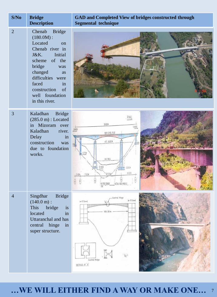
2 Chenab Bridge
(180.0M) :
Located on
Chenab river in
J&K. Initial
scheme of the
bridge was
changed as
difficulties were
faced in
construction of
well foundation
in this river.
3 Kaladhan Bridge
(285.0 m) : Located
in Mizoram over
Kaladhan river.
Delay in
construction was
due to foundation
works.
4 Singdhar Bridge
(140.0 m) :
This bridge is
located in
Uttaranchal and has
central hinge in
super structure.
S/No Bridge
Description
GAD and Completed View of bridges constructed through
Segmental technique

…WE WILL EITHER FIND A WAY OR MAKE ONE… 8
5 Teesta Bridge
(185.0M) :
Located over Teesta
river. Initial proposal
was to make arch
bridge, which was
later on changed to
balanced cantilever,
due to poor strata
available for arch.
6 Bansoi Bridge
(170.0M) :
Located in Sikkim.
7 Rangrang Bridge
(140.0M) :
Located in Sikkim.
S/No Bridge
Description
GAD and Completed View of bridges constructed through
Segmental technique
…WE WILL EITHER FIND A WAY OR MAKE ONE… 9
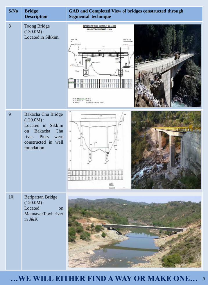
8 Toong Bridge
(130.0M) :
Located in Sikkim.
9 Bakacha Chu Bridge
(120.0M) :
Located in Sikkim
on Bakacha Chu
river. Piers were
constructed in well
foundation
10 Beripattan Bridge
(120.0M) :
Located on
MaunavarTawi river
in J&K
S/No Bridge
Description
GAD and Completed View of bridges constructed through
Segmental technique

…WE WILL EITHER FIND A WAY OR MAKE ONE… 10
SPECIAL CONSIDERATIONS TO BE KEPT IN MIND DURING CONSTRUCTION
Construction of bridge by cantilever/segmental construction is a very delicate exercise and requires a
proper insight on design and construction processes. A very thorough and careful approach is needed to
maintain proper balance while casting of girder on both sides of piers, as any imbalance therein could lead to
severe consequences. Following are some of the issues which need due considerations in such construction:
(a) Casting of first element on the pier head needs a detailed planning and special measures to
facilitate casting of segment and thereafter this segment on bearing (wherever provided). This segment
needs to be properly anchored with the pier cap during construction stage so that any imbalance in the
moment is taken care of.
(b) Movement of gantry over this cast segment is another exercise which needs to be performed
with equal care to ensure proper balances and alignment control.
(c) Pre-stressing of each element require proper care to ensure proper continuity with previous
element and transfer of stresses accordingly.
(d) Last element which is called continuity element needs to be completed after examining stress
transfer mechanism of whole arm and super-structure.
(e) Complete alignment and profile needs regular check at each stage. It is maintained in a manner
that the last continuity element could match with each other properly and facilitate transfer of
stresses in the designed manner. Any mismatch at this stage could lead to severe consequences and
effect serviceability and durability of the structure.
(f) In case of cast-in-situ construction, quality control over the concrete mix is of vital importance.
Events held during last Quarter
A On-site Training on Planning and Construction of Tunnels.
On-site training is being conducted at Sela Tunnel for capacity build-up. As on date, 09 Officers and 13
JEs in four batches have been trained at site.

…WE WILL EITHER FIND A WAY OR MAKE ONE… 11
Following lectures are taken on various aspects of the tunnel project during training :
(a) Introduction to Tunneling
(b) Approaches to Tunnel Design. Four
methods of design as below were covered in
detail :
• Analytical Method
• Empirical Method
• Numerical Method
• Observational Method (NATM)
(c) Tunnel Support System
(d) Case study of Rohtang Tunnel
• Seri Nala Fault zone
• Rock burst at KM 7
• Severe Weather Conditions
(e) Drilling & Blasting Technique
B A Compendium of Drawings of Superstructures of thirteen Steel and seven Prestressed Concrete
bridge has been compiled based on various bridges undertaken by BRO. All designs and drawings have been
proof checked by experts in the field. BRO engineers can use these drawings to start the bridge work on ground
which will save time. The same shall be released during BRO Day on 07 May 2022.
Officers/Pers attending Lecture related to On-site
Training on Planning and Construction of Tunnels
at HQ 42 BRTF
C Peculiarities of Runway Design and Construction at Bagdogra and Barrackpore.
The 4th lecture as part of Monthly Lecture Series on this topic was delivered by Brig S P Singh, CE
(P) Swastik and Col Praveen Padmanabhan, Cdr 755 BRTF on 21 Jan 2022. The following major aspects
were covered:
Brief History on Bagdogra Airport. Bagdogra is a Joint User Airfield (JUA) which serves
people of four Indian states (West Bengal, Sikkim, Assam, Bihar) and three friendly neighbours (Nepal,
Bhutan & Bangladesh). This Airfield was constructed during the Chinese aggression in 1962. On completion
of the work, the runway and other operating surfaces will be able to handle all IAF aircrafts and civil airlines.
In 2019-20, Bagdogra Airport handled 3.2 million passengers, 5000 MT of cargo and was the 18th busiest
airport in India
The last resurfacing was done in 2000.
Brief History on Barrackpore Airport. During WW II, the airfield was used as a reconnaissance
airfield by the USAF Tenth Air Force, which flew unarmed P-38 Lightening aircraft from the station
equipped with several mapping cameras to gather intelligence on Japanese forces in occupied Burma.
Barrackpore was also home to Spitfire Squadrons in the early 1950s. The last Heavy aircraft to land was C-
130J Super Hercules in Jan 2012.
Bagdogra Barrackpore

…WE WILL EITHER FIND A WAY OR MAKE ONE… 12
Nodal Officers for CoERBAT
S K Verma, SE (Civ), Director (RBAT)
Mail Id - [email protected], Mob-8628837063
Lt Col Anil Raj, Joint Director, (RBAT)
Mail Id- [email protected], Mob-9557348703
HQ DGBR, Ring Road, Delhi Cantt, New Delhi-110010,Tele-011-25686861
(a) Important technical details and challenges faced in runway reconstruction and resurfacing works at
airforce station Bagdogra and Barrackpore were discussed by CE (P) Swastik.
(b) Execution of Works. List of broad execution plan with quantities of materials consumed are given in
the following tables :
1 2 3
4 5 6
Fourth issue of newsletter will focus on
“Analysis of Bridge Damages and Rehabilitation”.
Projects are requested to send suitable content related
to the above topic in their respective AsOR, up to a maximum
of 5 pages along with good quality photographs.
S/
No.
Work A/U Qty
Soil
Stabilisation
(250 mm)
10 Sqm 24,442
GSB (150 mm) 10 Sqm 57,860
WMM (75 mm) 10 Sqm 83,939
DLC (150 mm) Cum 39,119
PQC (400 mm) Cum 1,04,316
Resurfacing
Flexible (140
mm)
10 Sqm 23,838
S/
No.
Items Qty (MT)
1 Aggregates of various
sizes
4,91,593
2 GSB Material 2,08,245
3 Cement 59,990
4 Steel various dimension 540
5 Bitumen VG 10 1,428
6 PMB 40 2,135
7 Admixture 313
6
3
2
1
4
5