LATEST RESEARCH IN TUNNEL LIGHTING IN JAPAN
19
( LATEST RESEARCH IN TUNNEL LIGHTING IN JAPAN by Kohei Narisada l. INTRODUCTION The decrease in the driver's visibility, which occurs when a motor car passes from a bright open road in the daytime through a tunnel entrance, depends basically on the following two phenomena - that is, "black out" effect and "black-hole" effect. Lighting for tunnel entrances has to be designed to eliminate at least these two problems in the driver's visual perception. l.l "Black-Out" Effect This is a phenomenon which causes the inside of a tunnel to appear almost black immediately after entry due to insufficient entrance illumination. This makes it almost impossible for the driver to perceive the details inside the tunnel for his safe driving. The phenomenon is the result of the delay in the dark adaptation of the driver due to the sudden abnormal change in the luminance of his visual field. A similar effect can be experienced when a sudden "black-out" occurs in a lighted room at night. 1.2 "Black-Hole" Effect This is a phenomenon which makes the tunnel appear like a black hole while the driver is still on a bright open road approaching a tunnel, as shown in Figure 1. As a result it is almost impossible for the driver to perceive the details of the tunnel necessary for his safe driving. The phenomenon occurs by a kind of negative glare effect due to the extremely high contrast of luminance between the tunnel entrance and the surrounding open scenery. I would like now to introduce some theoretical background of lighting designs employed in tunnel entrance lighting in Japan. Also a new tunnel entrance lighting design procedure will be outlined later in this paper, with some typical examples. II. A SURVEY OF PREVIOUS RESEARCH ON "BLACK-OUT" EFFECT As shown in Figure 2, several researchers such as Reid et al (l), Kabayama (2), de Boer (3), and Schreuder (4), carried out experiments on the lighting conditions to be determined for preventing the "black-out" effect from occurring to the driver immediately after entering a tunnel. The curves show the results of these experiments in a form of the eye-adaptable "quickest decrease of luminance" in the driver's visual field against the time elapsed from the start of this decrease. These three curves are in fairly good agreement in spite of the fact that the experiments had been carried out by different groups of observers under different experimental conditions (5). III. STUDIES OF "BLACK-HOLE" EFFECT 3.1 A Survey of Previous Research Several researchers, for example, Waldram (6), de Boer (3,7), and Schreuder (4) had investi- gated the relationship between the adaptation luminance (La) and the luminance to be provided at the tunnel entrance (Lt) sufficient to prevent the "black-hole" effect from occurring. The results of these investigations are summarized in Table l. A conclusion was already derived from the results - that is, the ratio of Lt over La (Lt/La) obtained by most of the previous studies are fairly consistent and a minimum of 10 to 12% of the adaptation luminance value has to be provided at the tunnel entrance in order to perceive the inside of the tunnel when approaching from a bright open road (4,7). From the results of these studies, the level of luminance required at a given tunnel entrance can be calculated as a function of the adaptation luminance of the driver approaching the tunnel. This, however, presents one 9
-
Upload
khangminh22 -
Category
Documents
-
view
3 -
download
0
Transcript of LATEST RESEARCH IN TUNNEL LIGHTING IN JAPAN

(
LATEST RESEARCH IN TUNNEL LIGHTING IN JAPAN
by Kohei Narisada
l. INTRODUCTION
The decrease in the driver's visibility, which occurs when a motor car passes from a bright open road in the daytime through a tunnel entrance, depends basically on the following two phenomena - that is, "black out" effect and "black-hole" effect. Lighting for tunnel entrances has to be designed to eliminate at least these two problems in the driver's visual perception.
l.l "Black-Out" Effect
This is a phenomenon which causes the inside of a tunnel to appear almost black immediately after entry due to insufficient entrance illumination. This makes it almost impossible for the driver to perceive the details inside the tunnel for his safe driving. The phenomenon is the result of the delay in the dark adaptation of the driver due to the sudden abnormal change in the luminance of his visual field. A similar effect can be experienced when a sudden "black-out" occurs in a lighted room at night.
1.2 "Black-Hole" Effect
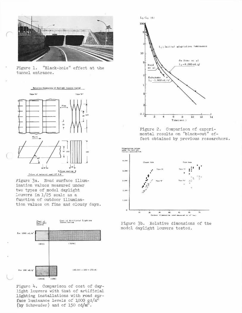
This is a phenomenon which makes the tunnel appear like a black hole while the driver is still on a bright open road approaching a tunnel, as shown in Figure 1. As a result it is almost impossible for the driver to perceive the details of the tunnel necessary for his safe driving. The phenomenon occurs by a kind of negative glare effect due to the extremely high contrast of luminance between the tunnel entrance and the surrounding open scenery.
I would like now to introduce some theoretical background of lighting designs employed in tunnel entrance lighting in Japan. Also a new tunnel entrance lighting design procedure will be outlined later in this paper, with some typical examples.
II. A SURVEY OF PREVIOUS RESEARCH ON "BLACK-OUT" EFFECT
As shown in Figure 2, several researchers such as Reid et al (l), Kabayama (2), de Boer (3), and Schreuder (4), carried out experiments on the lighting conditions to be determined for preventing the "black-out" effect from occurring to the driver immediately after entering a tunnel. The curves show the results of these experiments in a form of the eye-adaptable "quickest decrease of luminance" in the driver's visual field against the time elapsed from the start of this decrease. These three curves are in fairly good agreement in spite of the fact that the experiments had been carried out by different groups of observers under different experimental conditions (5).
III. STUDIES OF "BLACK-HOLE" EFFECT
3.1 A Survey of Previous Research
Several researchers, for example, Waldram (6), de Boer (3,7), and Schreuder (4) had investigated the relationship between the adaptation luminance (La) and the luminance to be provided at the tunnel entrance (Lt) sufficient to prevent the "black-hole" effect from occurring. The results of these investigations are summarized in Table l. A conclusion was already derived from the results - that is, the ratio of Lt over La (Lt/La) obtained by most of the previous studies are fairly consistent and a minimum of 10 to 12% of the adaptation luminance value has to be provided at the tunnel entrance in order to perceive the inside of the tunnel when approaching from a bright open road (4,7). From the results of these studies, the level of luminance required at a given tunnel entrance can be calculated as a function of the adaptation luminance of the driver approaching the tunnel. This, however, presents one
9

10
problem. That is, as the driver approaches the tunnel, and as the tunnel becomes larger and larger in his visual field, the foveal part of his visual field is occupied by the extremely contrasted dark tunnel. Consequently, the state of the driver's adaptation begins to change in a complex manner, and adaptation luminance cannot easily be measured or calculated because the state of adaptation of human eyes :i.s strongly influenced by the luminance projected onto the fovea of the retina which occupies only a visual angle of 1 to 2 degrees (8).
Therefore, in actual application of the relationship between the adaptation luminance and luminance required at the tunnel entrance obtained from the investigations shown in Table 1, the value to be determined as the adaptation luminance of a specific tunnel becomes an important factor in designing the entrance lighting of the tunnel.
In order to solve this problem, a commonly employed assumption is that the driver's eyes remain adapted to the average outdoor luminance (L0 ) up until the driver gets into the tunnel (4). According to this assumption, the luminance level to be given at the tunnel entrance should be 10 to 12% of the outdoor luminance.
3.2 Outdoor Luminance near Tunnel Entrance
According to the measurements already taken in Japan, the average luminance in the driver's visual field when approaching the tunnel reaches:
Near tunnels in flat areas: Near tunnels in mountainous areas:
approx. 6,000 8,000 cd/m2 (*l) approx. 3,000 - 4,000 cd/m2
These values are for the time between 10:00 am to 2:00 pm on a sunny day in summer.
Based on the results of the studies and the assumption cited in the foregoing section, the luminance to be given at the tunnel entrance in a flat area should be approximately 1,000 cd/m2 in the brightest conditions for an outdoor luminance of 8,000 cd/m2. If this value is to be converted into the average horizontal illumination value to be provided on the asphaltconcrete road surface inside the tunnel entrance, it will then correspond with 15,000 to 20,000 lux (*2) when the average luminance factor of 15 to 20 (cd/m2) per lux under artificial lighting with a semi-cut-off light distribution is applied (9).
To furnish this high illumination over a sufficient distance from the tunnel portal, the scale of the lighting installations becomes so large that the construction and maintenance of the installations cause not only economic but also technical difficulties. As a result, daylight louvers having a constant transmission factor of 10 to 12% have recently been installed in several tunnels (10,11).
3.3 Photometric Characteristics of Daylight Louvers
Measurements were taken with several scale models of daylight louvers, as shown in Figure 3a, with an upper cut-off angle of 78 degrees, which is the required angle in Japan that does not permit the direct sunlight to reach the road surface under the louvers. The illumination values were measured and recorded for both outside and under the louvers (12). A part of these measurements is shown in Figure 3b from which the following results were obtained:
a. The transmission factor of daylight louvers on a fine day, including the direct sunlight, is not always constant.
b. Generally, when the outdoor illumination level exceeds about 40,000 lux, the illumination values on the road surface under daylight louvers show a tendency to reach a maximum at about 3,000 to 5,000 lux, resulting in an asphalt-concrete road surface luminance of only 100 to 150 cd/m2.
(*l) l cd/m2 ~ 0.3 fL (*2) l lux ~ 0.09 fc
(
Figure 1. "Black-hole" effect at the tunnel entrance.
-:==-
----~
-~
-
-North ----
Pht1 •- •
_j
23
T
Type •e•
'\Ctou '"' '°"' 1 Colour of toat•ri•I u1ed: SY 6/fi
Figure 3a. Road surface illumination values measured under two types of model daylight louvers in 1/25 scale as a function of outdoor illumina-tion values on fine and cloudy days .
For lO<X> cd/lll'
For 150 cd/ro'
Coit of D11yligb1 Louver
(26•/;)
,100,-) (l,,,.)
Coil ol A.diliaisl Li9btinq In1t11l lat ion
( 1001,)
{26/15) ,I( 100 as 173(<;fj)
Figure 4. Comparison of cost of daylight louvers with that of artificial lighting installations with road surface luminance levels of J..000 ~d/m2
(by Schreuder) and of 150 cd/m.
100
10
5
2
1
s ·
2 -
Li: Initial adaptation luminance
de Boer et al
Li - 8,000cd/m'
O. l0:----2--~4~--'6'----8--~l -O_......Jl2 __ __,14
Time( sec.)
Figure 2. Comparison of experi mental results on "black-out" effect obtained by previous researchers.
u1-,, .. u-.-. , ... , w,.de, tb1 day I J,.rbt J....,.,., . aaa • u,.i I IW1 l
•.ooo . . , .ow •• Type•A·
• I ! : .
J ,000 . Tn>• •8·
l.000
0 --"""T-~-~-....--.--,---..----,-----70
Figure 3b. Relative dimensions of the model daylight louvers tested.

12
It is evident from these findings that the daylight louvers installed at the tunnel entrance cannot give the required luminance of 10 to 12% of outdoor luminance based on the previous research as shown in Table 1 and the previous common assumption.
3.4 Economic Comparison
The main reason for the construction of the daylight louvers for tunnel entrance lighting is its assumed economy compared with artificial lighting installations. It was stated that the cost to obtain a road surface luminance of 1,000 cd/m2 with daylight louvers is only 25% of that with artificial lighting installations, as shown in the upper bar of Figure 4 (4) . The results of our measurements, as stated in the foregoing section, revealed that no daylight louvers can give a road surface luminance of 1,000 cd/m2 in our country. The maximum we could obtain under the bright daylight conditions of summer was 150 cd/m2.
Our recalculation of the cost for artificial lighting installations based on our maximum attainable value of 150 cd/m2 from daylight louvers shows, as in the lower bar of Figure 4, only 15% of the previous calculation already cited, because the cost for daylight louvers in this case remains the same regardless of the road surface luminance. Therefore, the cost of the tunnel entrance lighting with daylight louvers is in reality 70% higher than that with artificial lighting installations. This finding brought back the necessity of studying the possibility of tunnel entrance lighting with artificial lighting installations.
3.5 Experiments on "Black-Hole" Effect on Approaching Driver under Simulated Conditions
To solve the problems related to the adaptation luminance of an approaching driver, experiments were carried out in our laboratory under simulated conditions to obtain the actual relationship between the outdoor luminance (L0 ) and the luminance necessary inside the tunnel (Lt) to prevent the "black-hole" effect, instead of that between the adaptation luminance (La) and Lt (13,14). To make the simulation as close as possible to the actual change in the luminance distribution in the approaching driver's visual field, experimental conditions were chosen carefully to reproduce an actual perspective change in the size of a tunnel entrance in the driver's visual field upon approaching the tunnel.
For this purpose, a special simulator, as shown in Figures 5 and 6, was constructed in our laboratory. In this simulator actual perspective change in the driver's visual field was reproduced by continuously expanding the size of the simulated tunnel entrance, instead of moving the observer. The number of test objects to be perceived was three in random order, and the number of test objects was changed from zero to three in order to give eight different patterns being composed of the three different positions of the objects exposed. Each test object had an apparent square size of 15 cm by 15 cm looked at from a distance of 100 meters. The contrast (C = [Lt -L0 b)/Lt] x 100) of the object luminance (L0 b) against the simulated tunnel luminance (Lt) as the background was 25%. Test objects were exposed on the road surface in the simulated tunnel for a time of 0.5 second. Experimental observations were repeated ten times under one given set of conditions, with eight male observers, having normal vision, aged from 18 to 29 years. The observers were asked to perceive the positions of the objects exposed.
At the start of each observation the visual field, with a uniform luminance of 4,000 cd/m2 was presented (the simulated tunnel also had the same luminance of 4,000 cd/m2). After sufficient pre-adaptation of the observer's eyes to this luminance level, the simulated tunnel entrance with the luminance to be tested (Lt) appeared in the observer's visual field, and the size of the entrance began to expand in accordance with the simulated driving conditions. Then, a given pattern of the test objects appeared in the observer's visual field after a certain re-adaptation time (t) ranging from 2.5 to 6 seconds in five random steps since the appearance of the simulated tunnel entrance. The luminance of the tunnel tested varied from 15.5 to 65.5 cd/m2 in ten random steps. The probabilities of correct perception of the test objects for each given set of conditions were calculated from the observations.
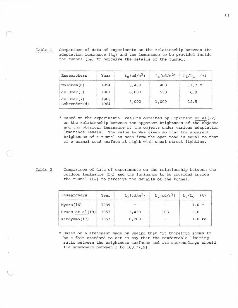
Table 1
Table 2
Comparison of data of experiments on the relationship between the adaptation luminance (Lal and the luminance to be provided inside the tunnel (Lt) to perceive the details of the tunnel.
Researchers Year La (cd/m2 ) Lt (cd/m2 ) Lt/La (%)
i Waldram (6) 1954 3,430 400 11. 7 * I i de Boer (3) 1961 8,000 550 6.9 I
Boer(?) 1963 ! de 8,000 1,000 12.5 Schreuder(4) 1964
* Based on the experimental results obtained by Hopkinson et a1(22) on the relationship between the apparent brightness of the objects and the physical luminance of the objects under various adaptation luminance levels. The value Lt was given so that the apparent brightness of a tunnel as seen from the ·open road is equal to that of a normal road surface at night with usual street lighting.
Comparison of data of experiments on the relationship between the outdoor luminance (L0 ) and the luminance to be provided inside the tunnel (Lt) to perceive the details of the tunnel.
Researchers L0 (cd/m2 ) I
Lt (cd/m2 ) I Lt/Lo (%) Year !
Myers(16) 1939 - - 1.0 * Brass et al(l8) 1957 3,430 103 3.0
Kabayama ( 1 7) 1963 6,200 - 1.0 to
i I I
* Based on a statement made by Sheard that "it therefore seems to be a fair standard to set to say that the comfortable limiting ratio between the brightness surfaces and its surroundings should lie somewhere between 1 to 100."(19).
13
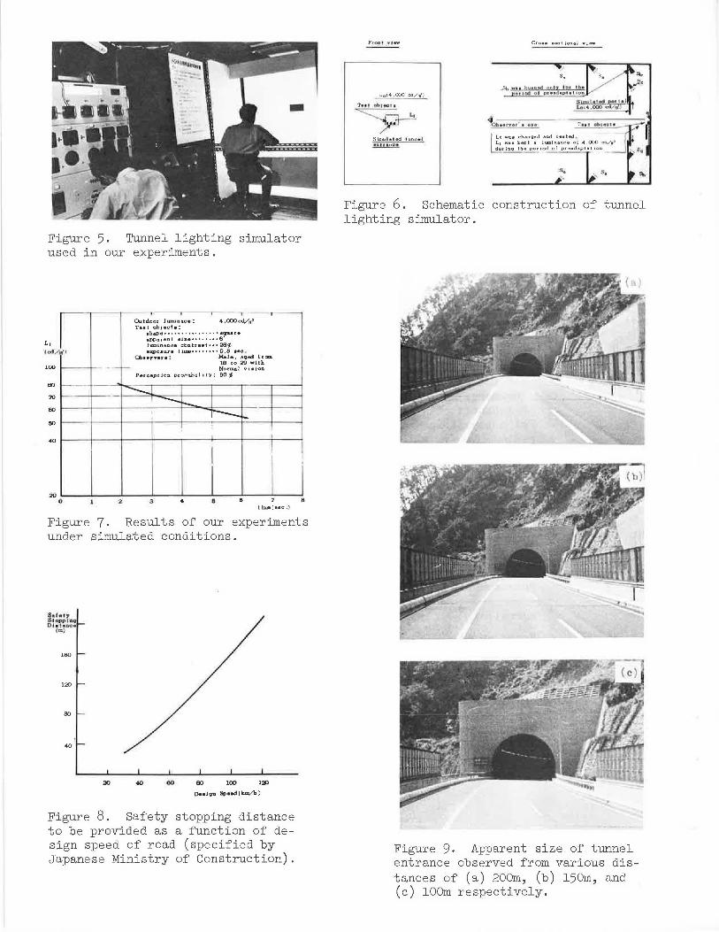
Figure 5. 'I'unnel lighting simulator used in our experiments .
..-----,----,---,------,----,----r--~-~
100 1----t--
80
Outdoor lum.inace: 4,000cd,/nf Ta11t object11:
11haPe • • • • • • • • •• • • • • • • •9"-•r• appa.rent • ize••••••••6 luminance cbntra • t • • • 2S<;(j e:a;po• ure tiIDB••••••••0,5 • ec ,
Cb• erver • : Male, aqed Jrcm 18 to 29 with
-r- Normal vi • ioD Percept ion pro/,.&hi Ii ty: 90 '!,
'.JO 1---- ----t-- - - I --.__ I 60 1----l---+------t-=-~:---t------;--r---...
---- I
80 --1----t---,---t--------:---+--t---
40 1-----1----+---+-----.---4''------t----t------,
I I I 20 OL. _ _. __ ..J2L---3.1.--_.4 __ _.9':--"""'.6;!--~---:8
tlna( • ec,)
Figure 7. Results of our experiments under simulated conditions.
s.h17 Scopph::i D l • l•noe ,m,
160
120
80
40
40 ao 80 100
O. • Jou Speedikm./h)
Figure 8. Safety stopping distance to be provided as a function of design speed of road (specified by Japanese Ministry of Construction).
F, oa,, YI EIW
Si.mul • l ecl 1unn• I •101 • nr•
Cro •• • ect ional vi-
Figure 6. Schematic construction of tunnel lighting simulator.
Figure 9, Apparent size of tunnel entrance observed from various distances of (a) 200m, (b) 150m, and (c) 100m respectively.

(
The final results -of the experiments are shown in Figure T, with the 90% probability curve for the observers below 29 years old, indicating the relationship between the time (t) and luminance (Lt) for a given outdoor luminance of 4,000 cd/m2. The curve was constructed by considering the effect of pre-adaptation time span.
15
It can be applied for the drivers below about 50 years old based on Wolf's research on the glare sensitivity in relation to ages of the observers concerned (15), though the probabilities of correct perception decrease gradually by the advance of age.
Our experiments obtained the following results:
a . The luminance level required at the entrance of a long tunnel (Lt) depends on the time elaps ed since the driver begins to fix his visual attention to the tunnel entrance (t) as shown in Figure I• It decreases from about 2% of a given outdoor luminance for a time of 2.5 seconds to about 1.3% of a given outdoor luminance for a time of 6 seconds. These results differ from the commonly employed assumption that the driver's eyes remain adapted to the average outdoor luminance up until he gets into a tunnel. It can be said, therefore, that the common assumption over-estimates the driver's adaptation luminance near the tunnel, though it is on the safe side. Instead, the adaptation luminance of the driver approaching the tunnel entrance decreases from about 1/6 to 1/10 of that of the common assumption, if we use the results of the experiments given in Tableland our experiments.
b . The change of the apparent size of the tunnel entrance hardly affects the perception of the objects by the drivers under a given outdoor luminance at a distance within 200 meters from the tunnel entrance.
3.6 Comparison with Previous Research under Similar Conditions
Experiments similar to ours had also been carried out by several researchers, for example, Myers (16), Kabayama (lT), and Brass et al. (18), though the results are not yet widely employed for tunnel entrance lighting. Table 2 shows the results of their studies. Brass et al. reported that the luminance level required at the entrance of a long tunnel under a given outdoor luminance is about 3% of the outdoor luminance. This was the value obtained with a short time spent in visual attention to the tunnel entrance. The value agrees well with the results of our experiments when the time spent in visual attention is 2.5 seconds; our value was 3,1%.
Both Sheard's statement (19) quoted by Myers and the results of Kabayama's experiments, as in Table 2, gave this value as about 1% where the observation time could be regarded as infinite, because the observers watched the tunnel entrance over a long time. These results also agree well with our result of 1,31% when the time spent in visual attention is 6 seconds .
IV A NEW DESIGN PROCEDURE FOR A LONG TUNNEL ENTRANCE LIGHTING
In the following sections a new lighting design procedure for a long tunnel, based on the above-mentioned survey of visual problems, will be discussed. The new design procedure I would like to propose here can be divided into three stages as follows:
1) Determination of fundamental design parameters. 2) Determination of the luminance and the length of the stretch to prevent the
"black-hole" effect. 3) Determination of the luminance and the length of the stretch to prevent the
"black-out" effect.
Let me now describe the new design procedure in some detail.
4.l Determination of Fundamental Design Parameters
Fundamental design parameters to be determined here are as follows :
l) Safety stopping distance under a given design speed for the tunnel and the access road . 2) "Fixation distance". 3) Length of the stretch to be lighted to make the driver able to judge the size of the
obstacle on the road surface ahead.
4.l.l Safety stopping distance under a given design speed for the tunnel and the access road.
It is well known that, for safe driving, the driver should be able to perceive and recognize clearly any obstacles on the road surface ahead and its surroundings at a distance sufficient to allow him time to take any necessary action. This known as the "safety stopping distance". The safety stopping distance specified by the japanese Ministry of Construction is given in Figure 8 as a function of the driving speed of the motor car. The figure shows that, if a design speed for any given tunnel and/or access road is known, the corresponding safety stopping distance can be obtained.
4.1.2 "Fixation Distance"
Let me define the point where the driver, approaching the tunnel entrance from an access road, starts fixing his visual attention to the tunnel entrance as the "fixation point", and the distance between the fixation point and the tunnel portal as the "fixation distance" . The adaptation luminance of the driver who has just passed the fixation point begins to decrease gradually, being affected by the dark tunnel entrance to which the driver's visual attention is being fixed. Consequently, as shown in Figures 7 and l2, the luminance values to be provided in the tunnel to make the driver, still on an access road, able to perceive the obstacle in the tunnel ahead decrease gradually as a function of the time elapsed after the driver has passed the fixation point. The fixation distance, therefore, is one of the most important parameters in the design procedure for tunnel entrance lighting.
The fixation distance, however, differs depending on various factors, such as individual driver, driving speed of the car, traffic conditions, road configuration and its surroundings. Considering these factors, an appropriate distance has to be chosen for the fixation distance as the starting point of the lighting design. Although our observations in actual tunnels indicate that the fixation distance is within a range of l50 to 400 meters for normal drivers on normal roads, we have selected a distance of l50 meters as the fixation distance in our design (l3,20). Figure 9 shows the photographs taken at a distance of 200, l50 and l00 meters respectively away from a tunnel portal. It is reasonable to estimate that 150 meters is the minimum distance at which the normal driver begins to fix his visual attention to the tunnel if no car is running ahead of his.
4.l.3 Length of the stretch to be lighted to make the driver able to judge the size of the obstacle on the road surface ahead
Figure 10 illustrates the effect of the length of the lighted stretch to judge the size of the obstacle on the road surface ahead (20). In example (a), a shorter lighted stretch can only give perception of part of the obstacle (about 0.l m high) and cannot give a clear identification of the size to judge whether it is a car or a rock. Example (b) gives perception of a larger portion of the same obstacle (about 0.2 m high), which might enable the driver to recognize the presence of the obstacle but cannot be said truly sufficient to judge its exact size for safe driving. Example (c) gives a perception of about 0.3 m high from the road surface, which is sufficient to clearly distinguish a car from the obstacle.
The length of the stretch to be sufficiently lighted in the background of a car in front (di) and required to give a minimum vertical length to perceive "a" in Figure ll for clear judgment of the size of the obstacle at a safety stopping distance, can be calculated by the

(
Figure 10. In order to make the driver able to judge the size of the obstacle on the road surface ahead, a lower portion of the obstacle with a minimum height of 0.3 meter with its full width has to be perceived against the bright background.
d, ~ -- +-- -d,
d, r--;-ll d
: M,numan he,Qbl ol oh• l11cle lo be pe,cf11ved ,
d , : Le11glh of • t rttlcb to lor11:1 fbft b11ckqr o u.nd
d 1 ; S alet y • l o pp,oq d1 • l11oc e
Figure 11. Geometry of the background for the obstacle for a given minimum height to perceive a.
__ ,, /
3 1,; )_
0,7
L1: Limil Q. IIUICII v11due t o b 11 qi,reo io lbe tunnel
L0 : L11111hu,oce of tbu ouldoor oe,or tb• h.1.D.Del en(r6.llce
9 ( • -c)
Figure 12. Percent luminance values to be provided in the tunnel to prevent the "black-hole" effect (Lt) as a function of the time elasped from the start of the fixation.
:: ; J~~~r::/r~:-T:..!:i ~!~~~/~,:,
Figure 13. values and stretch to effect.
d 1 : Sal • lr Stopplq Dl • luu, • l•l
d1 = ~T!r::d~r.-i:....:.:i =:--:~n:.r d, : d 1-d 1
h • ~ l u •J
..,l,u • ;Y-Spud. ol Iii • ciartlllq.,ti,)
,,.~ ,--,
Determination of luminance the length of the lighted prevent the "black-hole"
ds ! H - b • co l (}
H: HeiQht ol c e il 100 ol th e tll.llnel b : Height o f dr i ver 1 , aye fl : Upper ,:ut-o/1 110,;ile by the front
wi u dow1n1
Figure 14. Determination of the distance between the "adaptation point" and the tunnel portal.
18
a following formula:
h - a
where: h = height of driver's eyes (1.2 m on average) d2 = Safety stopping distance (m) a= Over 0.3 min normal cases.
d1 and d2 have to be maintained as in Figure 11 in all cases where the luminance for the driver at any point on the road is to be determined.
4 . 2 Determination of the Luminance and the Length of the Stretch to Prevent the "Black-Hole" Effect
The "black-hole" effect begins at the fixation point (A) in Figure 13 and disappears at point C. At point C, the driver's visual field is occupied mostly by the tunnel entrance and the ceiling of the car, both of which look dark in his visual field, and give a visual impression of actually entering the tunnel. This point C is defined as the "adaptation point" (4). The distance between point C (adaptation point) and the tunnel portal, as shown in Figure 14, can be calculated by the following formula: d3 = (H - h) cot 8
where: h = height of driver's eyes (1.2 m on average) H = height of tunnel ceiling (m) 8 =uppercut-off angle by the car's front window ( 0 )
(approx. 25° in normal cars).
This value d3 is about 10 meters for a tunnel of usual size. The luminance levels necessary to prevent the "black-hole" effect has to be determined for the driver who has reached point Band C in Figure 13,
For the driver at point B, the distance between the car and the tunnel portal corresponds with the safety stopping distance d2,
For the driver at point C, the distance between the car and the tunnel portal corresponds with the distance between the adaptation point and the tunnel portal d3 .
The luminance Ltl for the driver at point Band the luminance 1t2 for the driver at point C can be derived by calculating the time elapsed from the fixation point A, as shown in Figure 13, using the curve given in Figure 12.
Figure 12 shows the relationship between the percent values of luminance to be provided in the tunnel against the outdoor luminance (Lt/L0 ) based on data given in Figure 7. Because the driver must be able to perceive the object, the luminance values to be provided in the tunnel can be regarded to be in proportion to the initial adaptation luminance (outdoor luminance) under the condition that the adaptation luminance is gradually decreasing.
The length of the stretch to prevent the "black-hole" effect can be determined by adding d1 , the length of the stretch to make the driver able to judge the size of the obstacle as shown in Figure 11, to d4 in Figure 13.
4.3 Determination of the Luminance and the Length of the Stretch to Prevent the "Black-Out" Effect
The "black-out" effect begins at point C and disappears at point D. At point D, the driver begins to perceive the obstacle with the road surface luminance (Lt3) of interior lighting over the full length of the tunnel as in Figure 16. The luminance necessary to prevent the "black-out" effect can be determined -in Figure 16 by using the Kabayama data given in Figure 15, The percent luminance (Lt 2 ) required for the driver at point C in Figure 16 is equal to the percent luminance for the driver at point C in Figure 12 and also corresponds with the

(
(
l
2
0 . l L---'-------'.._____,..____. _ __.. _ ___. 0 2 4 6 B 10 12
Time ( aec .)
Figure 15. Percent luminance values to be provided in the tunnel to prevent the "black-out" effect (Lt) as a function of the time elapsed from the start of the decrease of the field lum4-nance.
Lt,
C D
----' . ',,,, r d, l ', P 2 .
1---------'>---------=-t,..._ I
I
1,
d 5 ! ?l!tAd~t:~!:en point and the tunoel portal (m J
d, ~ V (l ,i-1 2 ) fmJ 3.6
---The ti.nm corre1pond toL1 , l • ec )
The ti.mll correepond lo Lt, I • ec )
Figure 16. Determination of luminance values and the length of the lighted stretch to prevent the "black-out" effect.
19
20
Lt led/.,')
300
100
2
0 so 100 150 200
Ui£tance from the tunnel portal
(Detect iod diat11oce in zoetere)
400 I ' I Outdoor l umina.nce:2,000 to 3,000 cd/nt' D11a lo;p1ed and luted I P• ed: 80 km/ h
300 De• iQD.ed outdoor lumin•aa o: 4 ,000/8 .ooo ad /rn' . : data (or de1 lon.,d 01:i l doo , I umtn .. aci • ol
• .ooo od/J 0 : data iof da,tgoed 01.tldoor l " ml a•nce ol
8.CICX> cd /m'
300 Im)
1
IQ._ - L--- t:::===== 150
"--::: l-----~
100
~ s.1 .,, ,iui:,pino di 1 t,oc e for 80 lml/h (llOm.)
so 0 so 100 190 200 200 300 4!10
(Dt • taoce £ram th• tu.nnel port11I to tbe po1Jt ioo of the te • t object e:apo•-=I Jo meter • )
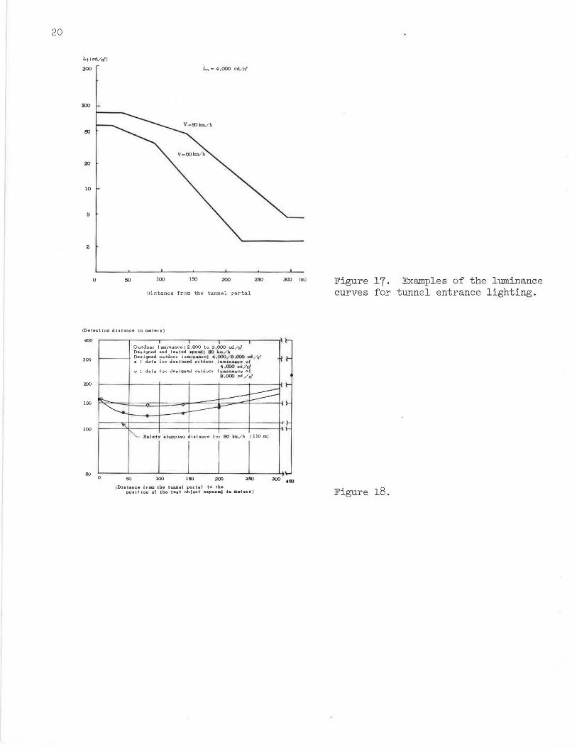
Figure 17. Examples of the luminance curves for tunnel entrance lighting.
Figure 18.

21
(a) Tennozan tunnel (b) Kajiwara tunnel
(c) Senriyama tunnel (d) Kambara tunnel
(e) Satta tunnel (f) Okitsu tunnel
Figure 19(1). Examples of tunnel lighting installations in Japan.

22
(g) Seikenji tunnel (h) Sodeshi tunnel
(i) Nihonzaka tunnel (j) Tsuburano tunnel
(k) Akasa.ka tunnel (1) Chiyoda tunnel
Figure 19(2). Examples of tunnel lighting installations in Japan.
(
Table 3a
Tunnel
Tennozan
Kajiwara
Senrioka
Kambara
Satta
Okitsu
Seikenji
Sodeshi
Nihonzaka
Tsuburano
Akasaka
Chiyoda
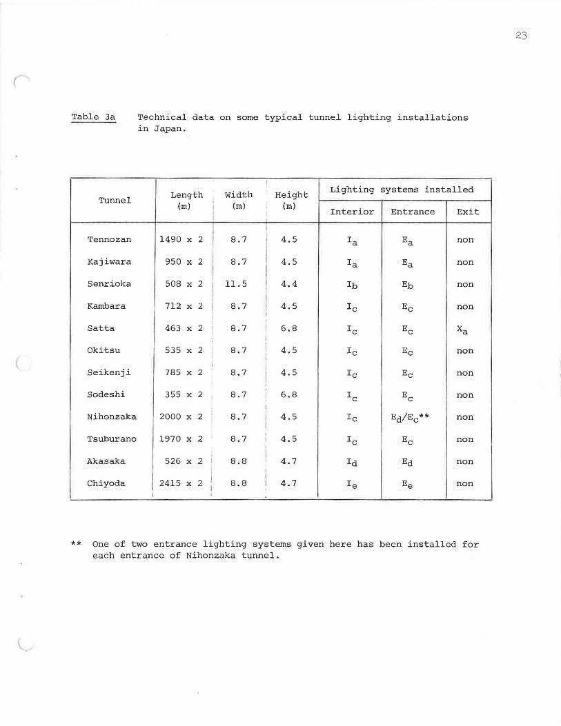
Technical data on some typical tunnel lighting installations in Japan.
!
Length Width Height Lighting systems installed
(m) I (m) (m) Interior Entrance Exit
1490 X 2 I 8.7 4.5 Ia Ea non
950 X 2 I 8.7 4.5 Ia Ea non
508 X I
11.5 4.4 2
l lb Eb non
I 712 X 2 I 8.7 4.5 Ic Ee non I
463 X 2 I 8.7 I 6.8 Ic Ee Xa I I 535 X 2 8.7
l 4.5 Ic Ee I non .
I I I
785 X 2 8.7 I 4.5 Ic Ee non . 355 X 2 ' 8.7 ! 6.8 IC EC non
I
2000 X 2 8.7 [ 4.5 Ic Ea/Ee** non
' 1970 X 2 8.7 I I
4.5 Ic Ee non
526 X 2 j 8.8 I 4.7 Ia Ea non I I
I 2415 X 2 I 8.8 I 4.7 Ie Ee non
I . I
** One of two entrance lighting systems given here has been installed for each entrance of Nihonzaka tunnel.
23

24
Table 3b Technical details of interior lighting as shown in Table 3a.
Mounting of Fittings Lamp employed I
Lighting Lighting :systems ' r Spacing · Size I Level
Position 1 Arrangement I Type I I (m) '(watt) (lux)
I I I I
I a Opposite 4.0 Sodium 60 I 50 a
Ib I b Opposite 4.0 Sodium 60 50 I I I i a Opposite 5.0 Sodium I 60 60 *
C I ' Id a I Staggered 2,5 Sodium
I 60 50
j
I I
I a Opposite 2,5 Fluorescent I 40 50 e
I Fluorescent I If ' a Opposite 2.0 40 50 I
* A higher maintenance factor than that for Ia and Ib was applied.
Table 3c Technical details of entrance lighting as shown in Table 3a.
I ' I
I
Mounting of Fitting Lamps employed Length of
~ighting Lighting entrance
pys tems I ' Level lighting I I Size
I Position I Arrangement Type I (watt) (lux) (m) I L
' 1 140/60
l E a Opposite Sodium 880-50 140
a
Eb b Opposite Sodium i 140/60 880-50 140 I ' I I E a Opposite Sodium l 200/ 1100-60 185
I C 140/60
I Ed First stretch of the entrance lighting system (Ee) was replaced by the daylight louvers with a length of 50 m.
I ' i E a Opposite Sodium I 60 800-50 110
e ' I I
I Ef a Opposite Fluorescent\ 110/ 40 800-50 90 ' I
E a Opposite Fluorescent' 110/40 800-50 100 g I I I
I ' !

(
Table 3d Technical details of exit lighting as shown in Table 3a.
Mounting of Fitting Lamps employed I
Length I Lighting
Lighting I 1 of exit Systems Level
lighting Position Arrangement Type Size I (lux) • (m) (watt) I I
200/60 : I
X a Opposite Sodium 600 ** I BO I a ! ' . I
** Vertical illumination value.
Note: Mounting position of fittings a: Upper edges of side walls. b: Recessed in the ceiling.
25
26
value given in Figure 15 on the vertical axis. The length of the stretch to "black-out" effect (d5 ) can be calculated by the formula shown in Figure 16. shows the examples of luminance curves for tunnel entrance lighting, with L0 cd/m2 and design speeds of 60 and 80 km/h.
prevent the Figure 17
of 4,000
'l'he effect in preventing the "black-hole" effect of the lighting design procedure that I have presented here was confirmed by a series of actual driving tests (21), with the result, as shown in Figure 18, that the distance to detect the test object as used in the foregoing simulated experiments was always longer than the safety stopping distance applied for the design.
Figure 19 gives the actual examples of tunnel lighting installations in Japan, which I hope will give you general impressions of the lighting trends. Tables 3a to 3d give technical data on the tunnel lighting installations as shown in Figure 19.
V. CONCLUSION
The "black-hole" effect and the "black-out" effect that occur near the tunnel entrance in daytime were first analyzed. Although the common assumption on th~ arlapt.A.t.inn l11min11nr.P. of the driver approaching the tunnel entrance requires a very high level of luminance at the tunnel entrance, it has been pointed out in this paper that the use of even daylight louvers is insufficient in giving this high level of luminance based on that assumption. Our experiments have shown that the adaptation luminance of the driver approaching the tunnel entrance on an access road decreases considerably, contrary to the assumption, and that the luminance to be provided in the tunnel is a function of the time elapsed. Also, our calculation reveals that artificial lighting installations are preferable to the daylight louvers from the point of economy. Consequently, a new lighting design procedure for preventing these unfavorable effects was proposed and outlined. Finally, examples of luminance curves for tunnel entrance lighting were given.
In concluding my paper I would like to express a sincere note of thanks to Mr. Fumiki Nakamichi of Japan Highway Public Corporation for his advice on tunnel construction and traffic engineering problems, and to Mr. Kojiro Yoshikawa and Mr. Yoshinori Tanabe of my Lighting Research and Advisory Bureau for their co-operation in our experiments.
REFERENCES
l.
2 .
3,
4.
5.
6. 7.
8.
9.
K. M. Reid and H.J. Chanon, "Daytime Lighting Requirements for Tunnel Entrance," Illuminating Engineering , Vol. 35, March, 1940, pp. 276-279 . H. Kabaywna , "Study on Adaptive Illumination for Sudden Change of Brightness," Journal of the Illuminatin En ineer in Institute of Ja an , Vol. 38, October, 1963, pp . 88- 96 (in Japanese with an English summary) . J.B. de Boer, "Le Probleme de l'eclairage de transition dans les entrees de tunnel," Lux, 1961, pp. 183-189. D. A. Schreuder, The Lighting of Vehicular Traffic Tunnels, Philips Technical Library, Eindhoven, The Netherlands, 1964. K. Narisada and K. Yoshikawa, "Lighting of Tunnel Entrance," National Technical Report , Vol. ll, October, 1965, pp. 342-358 (in Japanese with an English summary) , J.M. Waldram, "The Lighting of Tunnels," Light and Lighting, February, 1956, pp. 51-56. J.B. de Boer, ""Untersuchungen der Sehverhaeltnisse bei Tu.nneleinfahrten," Lichttechnik, 15 Jahrgang, Maerz, 1963, pp. 124-127. P. Moon and D. E. Spencer, "The Specification of Foveal Adaptation," Journal of the Optical Society of America, Vol. 33, August, 1943, pp. 444-456 . Commission Internationale de l'Eclairage, "The International Recommendations for the Lighting of Public Thoroughfares," CIE Publication No. 12 , 1965.

r 10.
11. 12.
13 .
14 .
15,
16.
17.
27
D. van den Bijllaardt, "Coen Tunnel, Amsterdam," International Lighting Review, Vol. 17, No. 6, 1966, pp. 192-196, "Ij-Tunnel, Amsterdam," International Lighting Review, Vol. 20, No. 1, 1969, pp. 18-23. Committee on Tunnel Lighting in the Foundation of Highway Research, Report on Tunnel Entrance Lighting, 1965. The measurements were carried out mainly by H. Yoshida of Tokyo Shibaura Electric _Co., Ltd., Tokyo (in Japanese). K. Yoshikawa, K. Narisada and Y. Tanabe, "Experiment on the Req_uired Luminance of the Tunnel Entrance Lighting," National Technical Report, Vol. 13, No. 1, 1967, pp. 34-50 (in Japanese with an English sunnnary) . H. Nakamichi, K. Narisada and K. Yoshikawa, "Experiment on the Visibility of the Tunnel Entrance Lighting," Journal of the Illuminating Engineerin Institute of Ja an, Vol. 51, October, 1967, pp. 5 -581 in Japanese with an English summary . E, Wolf, "Glare Sensitivity in Relation to Age," Highway Research Board, Bulletin No. 198, 1961, pp. 18-23. R. W. Myers, "Light Transition for High Speed Vehicular Tunnels," Transactions of the Illuminating Engineering Society, June, 1939, pp. 621-626. Technical Comniittee for Tunnel Entrance Visibility Study, "Report on Experimental Investigations on the Light around a Tunnel Entrance and the Visibility within the Tunnel," Journal of the Illuminating Engineering Institute of Japan, Vol. 47, May, 1963, pp. 187-203 (a part of experiments were carried out by H. Kabayama) (in Japanese).
18. J. R. Brass, H. Skootsky and G. A. Trosper, "A New Approach to Highway Tunnel Lighting," Illuminating Engineering , March, 1957, pp. 137-143.
19, C. Sheard, "On the Effects of Quantity and Quality of Illumination upon the Human Eye and Vision," American Journal of Physiological Optics , October, 1924, p. 475.
20 . K. Narisada, K. Yoshikawa and Y. Tanabe, "A Light Technical Solution of Visual Problems at the Entrance of Long Tunnels," National Technical Report, Vol. 14, No. 1, 1968, pp. 10-24 (in Japanese with an English summary).
21 . Committee on Tunnel Lighting in the Foundation of Highway Research, Report on Dynamic Visibility Tests a.t Various Motorway Tunnels, November, 1968 (in Japanese).
22. R. G. Hopkinson, W, R. Stevens and J.M. Waldram, "Brightness and Contrast in Illuminating Engineering", Transactions of Illuminating Engineering Society (London), 6, 1941, pp. 37.