
Construction Programme & Construction Method Statement ...
78
Construction Programme & Construction Method Statement Document Moray East Offshore Wind Farm and Associated Offshore Transmission Infrastructure September 2018 Moray Offshore Windfarm (East) Limited
-
Upload
khangminh22 -
Category
Documents
-
view
4 -
download
0
Transcript of Construction Programme & Construction Method Statement ...

Construction Programme & Construction Method
Statement Document
Moray East Offshore Wind Farm and
Associated Offshore Transmission Infrastructure
September 2018
Moray Offshore Windfarm (East) Limited

Moray Offshore Windfarm (East) Limited Construction Programme & Construction Method Statement
1
Produced by Moray Offshore Wind Farm (East) Limited
Produced by
Document Status Final [version 2]
File Name 8460001-PCA0010-MWE-REP-004
Date 27/09/2018
Review / Approval
Moray East Ecological Clerk of Works Legal Review
Moray East

Moray Offshore Windfarm (East) Limited Construction Programme & Construction Method Statement
2
© Moray Offshore Windfarm (East) Limited 2018
This document contains proprietary information which belongs to Moray Offshore Windfarm (East) Limited and / or affiliated companies and shall be used only for the purpose for which it is supplied. Moray Offshore Windfarm (East) Limited shall have no liability for any loss, damage, injury, claim, expense, cost or other consequence arising as a result of use or reliance upon any information contained in or this document where it is not used the purpose for which it is supplied.

Moray Offshore Windfarm (East) Limited Construction Programme & Construction Method Statement
3
Table of Contents List of Abbreviations ......................................................................................................................................8
Definitions .................................................................................................................................................. 10
Executive Summary .................................................................................................................................... 12
1 Introduction ........................................................................................................................................ 13
1.1 Background ................................................................................................................................. 13
1.2 Objectives of this Document ...................................................................................................... 13
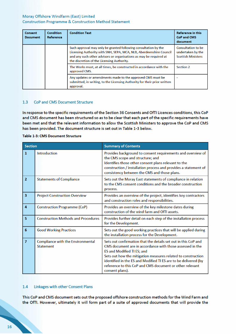
1.3 CoP and CMS Document Structure ............................................................................................ 16
1.4 Linkages with other Consent Plans............................................................................................. 16
2 Statements of Compliance ................................................................................................................. 19
2.1 Introduction ................................................................................................................................ 19
2.2 Statements of Compliance ......................................................................................................... 19
2.3 Health and Safety Management ................................................................................................ 20
2.4 Environmental Management ..................................................................................................... 20
2.5 Equipment and Materials ........................................................................................................... 20
2.6 Construction Personnel – Training and Competence ................................................................. 21
2.7 Construction Vessels .................................................................................................................. 21
2.8 Good Working Practices ............................................................................................................. 21
3 Project Construction Overview .......................................................................................................... 22
3.1 Introduction ................................................................................................................................ 22
3.2 Development Overview .............................................................................................................. 22
3.3 Timing of Construction Works .................................................................................................... 23
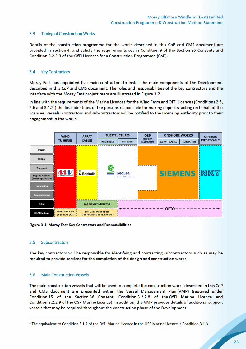
3.4 Key Contractors .......................................................................................................................... 23
3.5 Subcontractors ........................................................................................................................... 23
3.6 Main Construction Vessels ......................................................................................................... 23
3.7 Marine Co-ordination ................................................................................................................. 24
3.8 Construction Ports ...................................................................................................................... 25
3.9 Wind Farm Helicopter Operations ............................................................................................. 25
3.10 Moray East and Key Contractor Roles and Responsibilities ....................................................... 26
3.10.1 Introduction ........................................................................................................................ 26
3.10.2 Moray East - Key Roles and Responsibilities ...................................................................... 26
3.10.3 Key Contractor Roles and Responsibilities ......................................................................... 28
4 Construction Programme (CoP) ......................................................................................................... 29
4.1 Introduction ................................................................................................................................ 29
4.2 Key Milestone Dates ................................................................................................................... 29
4.3 Wind Farm Construction Programme ........................................................................................ 31

Moray Offshore Windfarm (East) Limited Construction Programme & Construction Method Statement
4
4.3.1 Introduction ........................................................................................................................ 31
4.3.2 Commencement of Wind Farm Construction .................................................................... 31
4.3.3 Mobilisation of Plant, Delivery of Materials and Use of Onshore Laydown Areas ............ 31
4.3.4 Timing and Sequencing of Construction Work ................................................................... 32
4.3.5 Contingency Planning ......................................................................................................... 32
4.3.6 Final Commissioning of the Wind Farm .............................................................................. 32
4.4 OfTI Construction Programme.................................................................................................... 33
4.4.1 Introduction ........................................................................................................................ 33
4.4.2 Commencement of OfTI ..................................................................................................... 33
4.4.3 Mobilisation of Plant, Delivery of Materials and use of Onshore Laydown Areas ............. 33
4.4.4 Timing and Sequencing of Construction Work ................................................................... 34
4.4.5 Contingency Planning ......................................................................................................... 34
4.4.6 Final Commissioning of OfTI ............................................................................................... 34
4.5 Compliance with Application and Environmental Statements ................................................... 35
5 Construction Methods and Procedures ............................................................................................. 37
5.1 Introduction ................................................................................................................................ 37
5.2 Pre-Construction – Seabed Preparation ..................................................................................... 37
5.2.1 Boulder Clearance .............................................................................................................. 37
5.2.2 Clearance of Seabed Debris: Pre-lay Grapnel Run ............................................................. 38
5.2.3 UXO Strategy ...................................................................................................................... 39
5.3 WTG and OSP Support Structures (Foundations and Jacket Substructures).............................. 39
5.3.1 Components to be Installed ............................................................................................... 39
5.3.2 Scour Protection ................................................................................................................. 40
5.3.3 Piling Installation Works ..................................................................................................... 40
5.3.4 Jacket Installation Works .................................................................................................... 46
5.3.5 Grouting .............................................................................................................................. 50
5.3.6 Demobilisation of Installation Spread ................................................................................ 51
5.4 Inter-Array and OSP Inter-Connector Cable Installation ............................................................ 51
5.4.1 Inter-Array and OSP Inter-Connector Cable Manufacture and Supply .............................. 51
5.4.2 Cable Layout and Configuration ......................................................................................... 52
5.4.3 Route Engineering .............................................................................................................. 52
5.4.4 Cable Routes Site Survey and Cable Burial Risk Assessment .............................................. 53
5.4.5 Cable Loadout and Transportation ..................................................................................... 53
5.4.6 Preparatory Works and Pre-Lay Survey .............................................................................. 54
5.4.7 Inter-Array and OSP Inter-Connector - Cable Installation .................................................. 54
5.4.8 Cable Burial and Protection ................................................................................................ 57

Moray Offshore Windfarm (East) Limited Construction Programme & Construction Method Statement
5
5.4.9 Termination and Testing .................................................................................................... 59
5.5 WTG Installation ......................................................................................................................... 59
5.5.1 Components to be Installed ............................................................................................... 59
5.5.2 Delivery to Intermediate Delivery Port (IDP) ..................................................................... 59
5.5.3 Pre-Assembly Works ........................................................................................................... 59
5.5.4 Component Load out and Transit ....................................................................................... 60
5.5.5 Pre Installation Checks and Lifts ......................................................................................... 60
5.5.6 Tower Installation ............................................................................................................... 60
5.5.7 Nacelle Installation ............................................................................................................. 61
5.5.8 Blade Installation ................................................................................................................ 61
5.6 OSP Topside Installation ............................................................................................................. 62
5.6.1 General ............................................................................................................................... 62
5.6.2 Delivery to the Construction Site ....................................................................................... 62
5.6.3 Substructure Installation .................................................................................................... 63
5.6.4 Top Side Installation ........................................................................................................... 63
5.6.5 Export Cable Installation .................................................................................................... 63
5.6.6 Inter-Array Cable Installation ............................................................................................. 63
5.6.7 Hook Up and Commissioning ............................................................................................. 63
5.7 Offshore Export Cable Installation ............................................................................................. 63
5.7.1 Offshore Export Cable Supply ............................................................................................. 63
5.7.2 Route Engineering .............................................................................................................. 63
5.7.3 Export Cable Layout ............................................................................................................ 64
5.7.4 Export Cable Route Burial Assessment Survey ................................................................... 64
5.7.5 Third Party Cable Crossing .................................................................................................. 64
5.7.6 HDD installation (landfall connection) ............................................................................... 64
5.7.7 sCable Collection (Loadout) ................................................................................................ 65
5.7.8 Export Cable Installation - Landfall ..................................................................................... 65
5.7.9 Export Cable Installation - Cable Free Lay .......................................................................... 65
5.7.10 Export Cable Installation - Second End Pull-in to OSP ........................................................ 65
5.7.11 Export Cable Installation – Cable Burial ............................................................................. 66
5.7.12 Post Installation Survey ...................................................................................................... 66
5.7.13 Cable Repair Contingency................................................................................................... 66
5.8 Electrical Infrastructure Commissioning .................................................................................... 66
6 Good Working Practices ..................................................................................................................... 69
6.1 Introduction ................................................................................................................................ 69
6.2 Offshore Renewable Industry Good Working Guidance ............................................................ 69
Moray Offshore Windfarm (East) Limited Construction Programme & Construction Method Statement
6
6.3 Construction Management Procedures ..................................................................................... 71
6.4 Environmental Management Measures ..................................................................................... 71
6.5 Project-Specific Good Working Practices ................................................................................... 72
7 Compliance with the Environmental Statement ................................................................................ 76
List of Figures Figure 3-1: Moray East Key Contractors and Responsibilities .................................................................... 23
Figure 3-2: Moray East organisational structure and key roles, and interface with key contractors ........ 26
Figure 4-1: Construction Programme ......................................................................................................... 30
Figure 4-2: Construction Programme as presented within this CoP and CMS document (highlighted in
blue) and how it compares to the indicative construction programme presented within the Moray
East ES 2012 and Moray East Modified TI ES 2014 (highlighted in hatched shading). .............................. 35
Figure 5-1: Boulder plough (left) and typical seabed result (right) ............................................................ 37
Figure 5-2: Typical Grapnel Train ................................................................................................................ 39
Figure 5-3: WTG Jacket 3D View ................................................................................................................. 40
Figure 5-4: OSP Jacket 3D View .................................................................................................................. 40
Figure 5-5: Typical Jack-up vessel for piling operations ............................................................................. 41
Figure 5-6: Arriving at Site- Positioning & Jacking Up ................................................................................ 43
Figure 5-7: Lowering Template ................................................................................................................... 43
Figure 5-8: PSV Pile Delivery ....................................................................................................................... 44
Figure 5-9: Saddle & Hook System for upending piles ............................................................................... 44
Figure 5-10: Stabbing Piles in the Template ............................................................................................... 45
Figure 5-11: Pile Driving .............................................................................................................................. 46
Figure 5-12: Indicative jacket installation vessel - HLV .............................................................................. 47
Figure 5-13: Indicative construction support vessel .................................................................................. 48
Figure 5-14: Sea fastening of Jacket ........................................................................................................... 48
Figure 5-15: Jacket Installation onto pre-installed piles ............................................................................. 50
Figure 5-16: Connection point on jacket for grouting ................................................................................ 51
Figure 5-17: Cable Protection System ........................................................................................................ 52
Figure 5-18: Cable Lay Vessel – Quayside set-up cable load out ............................................................... 53
Figure 5-19: Partitioned carousel with cable loading ................................................................................. 54
Figure 5-20: First end cable pull-in and vessel laying away........................................................................ 55
Figure 5-21: Cable Lay parameters ............................................................................................................. 55
Figure 5-22: Lay vessel second end approach to structure ........................................................................ 56
Figure 5-23: 2nd End pull-in and cable quadrant overboarding .................................................................. 56
Figure 5-24: Cable and Cable Handling quadrant lowered to seabed prior to release .............................. 57
Figure 5-25: Typical cutting and jetting tracked burial tool ....................................................................... 58
Figure 5-26: Typical jet trenching tool ........................................................................................................ 58
Figure 5-27: Fred Olsen Windcarrier Tern Class ......................................................................................... 60
Figure 5-28: Isometric view of OSP Topside ............................................................................................... 62
Moray Offshore Windfarm (East) Limited Construction Programme & Construction Method Statement
7
List of Tables Table 1-1: CoP consent conditions to be discharged by this plan .............................................................. 13
Table 1-2: CMS consent conditions to be discharged by this plan ............................................................. 15
Table 1-3: CMS Document Structure .......................................................................................................... 16
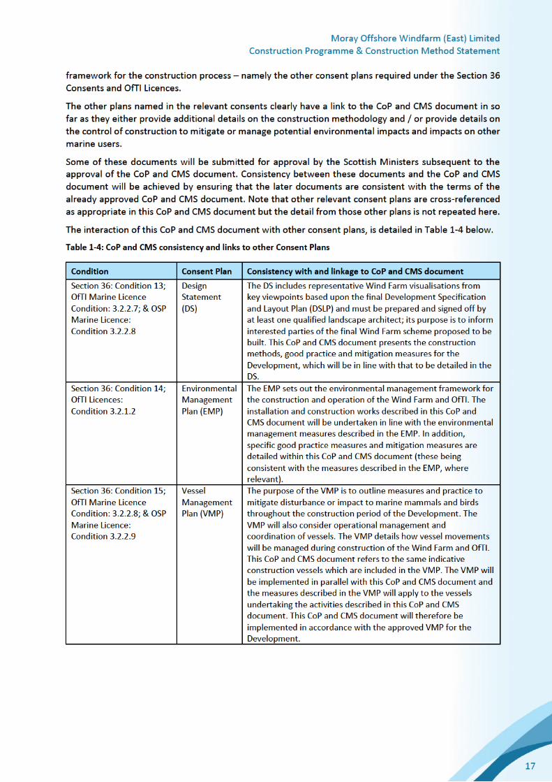
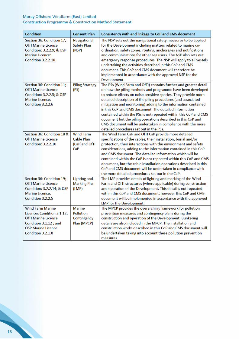
Table 1-4: CoP and CMS consistency and links to other Consent Plans ..................................................... 17
Table 3-1: Key Moray East roles and responsibilities ................................................................................. 27
Table 3-2: Key Moray East contractor roles and responsibilities in relation to construction activities .... 28
Table 4-1: Summary of key milestone dates .............................................................................................. 29
Table 5-1: Summary of WTG and OSP Support Structure Components to be Installed ............................ 39
Table 5-2: Summary of WTG Components to be Installed ......................................................................... 59
Table 5-3: Preliminary Component Origin .................................................................................................. 59
Table 6-1: Offshore Wind Construction Good Working (or Best Practice) Guidance ................................ 70
Table 7-1: Construction-related mitigations relevant to the CoP and CMS document ............................. 76
Moray Offshore Windfarm (East) Limited Construction Programme & Construction Method Statement
8
List of Abbreviations
AC Alternating Current
AHT Anchor Handling Tug
AIS Automatic Identification System
ALARP As Low As Reasonably Practicable
CaP Cable Plan
CDM Construction (Design and Management) Regulations
CMS Construction Method Statement
CSV Construction Supply Vessel
DGPS Differential Global Positioning System
DP Dynamic Positioning
DS Design Statement
DSLP Development Specification and Layout Plan
EMP Environmental Management Plan
ES Environmental Statement
FID Final Investment Decision
FLO Fisheries Liaison Officer
HAZID Hazard Identification
HiPaP High Precision Acoustic Positioning
HLV Heavy Lift Vessel
HV High Voltage
HVAC High Voltage Alternating Current
HVDC High Voltage Direct Current
JNCC Joint Nature Conservation Committee
JUP Self-propelled Jack-up Construction Vessel
LMP Lighting and Marking Plan
MCA Maritime and Coastguard Agency
Moray East Moray Offshore Windfarm (East) Limited
MORL Moray Offshore Renewables Limited
MPCP Marine Pollution Control Plan
NLB National Lighthouse Board
NtA Notice to Airmen
NtM Notices to Mariners
NSP Navigational Safety Plan
OfTI Offshore Transmission Infrastructure
OSP Offshore Substation Platform
OSV Offshore Supply Vessel

Moray Offshore Windfarm (East) Limited Construction Programme & Construction Method Statement
9
PLGR Pre-lay Grapnel Run
PS Piling Strategy
PSV Platform Supply Vessel
ROV Remotely Operated Vehicle
RSPB Royal Society for the Protection of Birds
SCADA Supervisory Control and Data Acquisition
SEPA Scottish Environment Protection Agency
HSE Health, Safety and Environmental
SNH Scottish Natural Heritage
TI Transmission Infrastructure
t Tonne
TJB Transition Joint Bay
UXO Unexploded Ordnance
VMP Vessel Management Plan
WTG Wind Turbine Generator

Moray Offshore Windfarm (East) Limited Construction Programme & Construction Method Statement
10
Definitions
The following definitions have been used throughout this document with respect to the company, the consented wind farms and how these definitions have changed since submission of the Moray East Environmental Statement (ES) in 2012 and the Modified Transmission Infrastructure ES in 2014.
• Moray Offshore Windfarm (East) Limited (formerly known as Moray Offshore Renewables Limited and hereinafter referred to as Moray East) – the legal entity submitting this Construction Programme (CoP) and Construction Method Statement (CMS) document;
• Moray East Offshore Wind Farm - the wind farm to be developed in the Moray East site (also referred as the Wind Farm);
• The Moray East site - the area in which the Moray East Offshore Wind Farm will be located. Section 36 Consents and associated Marine Licences to develop and operate up to three generating stations on the Moray East site were granted in March 2014. At that time the Moray East site was known as the “Eastern Development Area (EDA)” and was made up of three sites known as the Telford, Stevenson and MacColl offshore wind farm sites; The Section 36 Consents and Marine Licences were subsequently varied in March 2018;
• Telford, Stevenson and MacColl wind farms – these names refer to the three consented offshore wind farm sites located within the Moray East site;
• Transmission Infrastructure (TI) - includes both offshore and onshore electricity transmission infrastructure for the consented Telford, Stevenson and MacColl wind farms. Includes connection to the national electricity transmission system near New Deer in Aberdeenshire encompassing AC offshore substation platforms (OSPs), AC OSP interconnector cables, AC export cables offshore to landfall point at Inverboyndie continuing onshore to the AC collector station (onshore substation) and the additional regional Transmission Operator substation near New Deer. A Marine Licence for the offshore TI was granted in September 2014 and a further Marine Licence for two additional distributed offshore substation platforms (OSPs) was granted in September 2017.The onshore TI was awarded Planning Permission in Principle in September 2014 by Aberdeenshire Council and a Planning Permission in Principle under Section 42 in June 2015;
• Offshore Transmission Infrastructure (OfTI) – the offshore elements of the transmission infrastructure, comprising AC OSPs, OSP inter-connector cables and AC export cables offshore to landfall (for the avoidance of doubts some elements of the OfTI will be installed in the Moray East site);
• Moray East ES 2012 – The ES for the Telford, Stevenson and MacColl wind farms and Associated Transmission Infrastructure, submitted August 2012;
• Moray East Modified TI ES 2014 – the ES for the TI works in respect to the Telford, Stevenson and MacColl wind farms, submitted June 2014;
• The Development – the Moray East Offshore Wind Farm and Offshore Transmission Infrastructure (OfTI);
• Design Envelope - the range of design parameters used to inform the assessment of impacts; and
• OfTI Corridor – the export cable route corridor, i.e. the OfTI area as assessed in the Moray East Modified TI ES 2014 excluding the Moray East site.

Moray Offshore Windfarm (East) Limited Construction Programme & Construction Method Statement
11
• Moray East Offshore Wind Farm Consents – are comprised of the following:
Section 36 Consents:
o Section 36 consent for the Telford Offshore Wind Farm (as varied) – consent under section 36 of the Electricity Act 1989 for the construction and operation of the Telford Offshore Wind Farm assigned to Moray East on 19 June 2018.
o Section 36 consent for the Stevenson Offshore Wind Farm (as varied) – consent under section 36 of the Electricity Act 1989 for the construction and operation of the Stevenson Offshore Wind Farm assigned to Moray East on 19 June 2018.
o Section 36 consent for the MacColl Offshore Wind Farm (as varied) – consent under section 36 of the Electricity Act 1989 for the construction and operation of the MacColl Offshore Wind Farm assigned to Moray East on 19 June 2018.
Marine Licences
o Marine Licence for the Telford Offshore Wind Farm (as varied) – Licence Number: 04629/18/1 – consent under the Marine (Scotland) Act 2010 & Marine and Coastal Access Act 2009, Part 4 marine licensing for marine renewables construction works and deposits of substances or objects in the Scottish Marine Area and the United Kingdom Marine Licensing Area transferred to Moray East on 19 July 2018.
o Marine Licence for the Stevenson Offshore Wind Farm (as varied) – Licence Number: 04627/18/1 – consent under the Marine (Scotland) Act 2010 & Marine and Coastal Access Act 2009, Part 4 marine licensing for marine renewables construction works and deposits of substances or objects in the Scottish Marine Area and the United Kingdom Marine Licensing Area transferred to Moray East on 19 July 2018.
o Marine Licence for the MacColl Offshore Wind Farm (as varied) – Licence Number: 04628/18/2 - consent under the Marine (Scotland) Act 2010 & Marine and Coastal Access Act 2009, Part 4 marine licensing for marine renewables construction works and deposits of substances or objects in the Scottish Marine Area and the United Kingdom Marine Licensing Area transferred to Moray East on 19 July 2018.
• OfTI Licences – are comprised of the following:
o Marine Licence for the Offshore Transmission infrastructure – Licence Number 05340/14/0 – consent under the Marine (Scotland) Act 2010 & Marine and Coastal Access Act 2009, Part 4 marine licensing for marine renewables construction works and deposits of substances or objects in the Scottish Marine Area and the United Kingdom Marine Licensing Area (referred to as the “OfTI Marine Licence”).
o Marine Licence for two additional distributed OSPs – Licence Number 06347/17/1 – consent under the Marine (Scotland) Act 2010 & Marine and Coastal Access Act 2009, Part 4 marine licensing for marine renewables construction, operation and maintenance works and the deposit of substances or objects in the Scottish Marine Area and the United Kingdom Marine Licensing Area (referred to as the “OSP Marine Licence”).

Moray Offshore Windfarm (East) Limited Construction Programme & Construction Method Statement
12
Executive Summary
This Construction Programme (CoP) and Construction Method Statement (CMS) document has been prepared to address the specific requirements of the relevant conditions attached to Section 36 Consent and Marine Licences issued to Moray East.
The overall aim of the CoP section of this document is to set out the intended construction programme for the Development (Moray East Offshore Wind Farm and OfTI). This section of the document covers the following information:
• The proposed dates for commencement of construction;
• The proposed details of mobilisation of plant and delivery of materials;
• The proposed dates, durations and sequencing of construction work for all key elements of the Development (highlighting contingency planning for poor weather or other delays); and
• The scheduled date for final commissioning of the Development
The overall aim of the CMS section of this document is to set out construction procedures and good working practices in relation to the installation of the Development assets. The CMS covers, in line with the requirements of Section 36 Consents and Marine Licence conditions, and in line with industry standards and good practice, the following:
• Construction procedures in relation to foundations and substructures, wind turbine generators (WTGs), offshore substation platforms (OSPs) and inter-array, OSP inter-connector and export cables;
• Good working practices to be employed during construction;
• Identification of key contractors and vessels involved in construction;
• The roles and responsibilities of key project personnel and contractors during construction with respect to environmental management; and
The CMS confirms that the construction procedures to be employed align with those considered in the wind farm and OfTI Applications, and that construction-related mitigation measures detailed in the Applications will be applied during installation.
This CoP and CMS document is intended to be referred by personnel involved in the construction of the Development, including Moray East personnel, key contractors and subcontractors. All method statements and work plans produced in relation to the Development by Moray East and its contractors must comply with this CoP and CMS document.


Moray Offshore Windfarm (East) Limited Construction Programme & Construction Method Statement
19
2 Statements of Compliance
2.1 Introduction
The following sections are intended to re-affirm the Moray East commitment to ensuring that the Development is constructed in such a manner as to meet the relevant legislative requirements set out by the Section 36 Consents and OfTI Licences, but also broader legislative requirements; specifically it sets out:
• A number of statements of compliance relating to this CoP and CMS document and the broader requirements of the project consents;
• Matters related to health and safety, and environmental management;
• Matters related to equipment and materials;
• Matters related to construction personnel, including training and competence;
• Matters related to construction vessels; and
• Matters related to good working practices.
Reference is made throughout to other, relevant consent plans required by the project consents and to other sections of this CoP and CMS document where further detail is provided.
2.2 Statements of Compliance
Moray East in undertaking the construction of the project will ensure compliance with this CoP and CMS as approved by the Scottish Ministers (and as updated or amended from time to time).
Where updates or amendments are required to this CoP and CMS document, Moray East will ensure the Scottish Ministers are informed as soon as reasonably practicable and where necessary the CoP and CMS document will be updated or amended.
Moray East in undertaking the construction of the project will ensure compliance with other, relevant consent plans as approved by the Scottish Ministers, as set out in Section 1.4 above.
Moray East in undertaking the construction of the project will ensure compliance with the limits defined by the original application, the project description defined in the Moray East ES 2012, Moray East Modified TI ES 2014 and OSP Marine Licence Application Documents 2017 and the Offshore Consents Variation Application Report 2017 referred to in Annex 1 of the Section 36 Consents (as varied in March 2018) and Part 2 of the OfTI Licences in so far as they apply to this CoP and CMS document (unless otherwise approved in advance by the Scottish Ministers).
Moray East will, in undertaking the construction of the project, require compliance with Moray East Company HSE systems and standards, the relevant HSE legislation and such other relevant legislation and guidance so as to protect the safety of the Moray East construction personnel and other third parties.
Moray East will, in undertaking the construction of the project, ensure compliance with other relevant legislation and require that the necessary licences and permissions are obtained by the key contractors and sub-contractors through condition of contract and by an appropriate auditing process. Moray East will also require all contractors and subcontractors to comply with all relevant maritime safety related legislation regarding vessel certification, manning and safety requirements, and any required survey, certification and inspection arrangements will be discussed and agreed with the relevant MCA Marine Office in advance of works commencing.
It is also a condition of the Wind Farm Marine Licences (condition 3.2.1.2), OfTI Licences (conditions 3.2.2.15) that Moray East must supply Third Party Certification (TPC) or Third Party Verification (TPV) of the works:

Moray Offshore Windfarm (East) Limited Construction Programme & Construction Method Statement
20
The Licensee must, no later than 3 months prior to the Commencement of the Works, provide the Licensing Authority (unless otherwise agreed, in writing, with the Licensing Authority) with TPC or TPV (or suitable alternative as agreed, in writing, with the Licensing Authority) of the basis of design for all [WTG and OSP foundations, jacket, OSP platform structures and met mast structures].
Moray East will provide a TPV in accordance with the Marine Licence conditions as detailed above.
2.3 Health and Safety Management
The Development is a notifiable project for the purposes of the Construction (Design and Management) Regulations 2015 (CDM regulations). Moray East will ensure compliance with the CDM regulations in the design of the project and through the completion of the construction process.
Although these are not environmental regulations, they have a profound influence on how construction is organised and therefore have an influence on environmental performance.
In addition to being the Licensee, under CDM, Moray East is the Client (as defined in the Regulations) and will also fulfil the duties of Principal Designer (as defined in the Regulations), and Principal Contractor (as defined in the regulations). A team (separate from the Client and Principal Designer personnel) supported by organisational governance will deliver the Principal Contractor role (the term Principal Contractor is used throughout the document).
The Principal Contractor shall have a construction phase plan (required by the CDM regulations), reviewed and approved by Moray East as the Client, that sets out the day-to-day arrangements for the management of health and safety during construction.
2.4 Environmental Management
Further information concerning environmental management is set out in the EMP; the construction and installation of the Development described by this CoP and CMS document will be undertaken in line with the procedures and practices set out in the EMP.
2.5 Equipment and Materials
All materials, plant or equipment will require to be audited, either during manufacture or prior to despatch from the suppliers' premises, by a suitably qualified discipline inspector or engineer. Moray East shall be satisfied that any vendor or contractor supplying goods which require traceability has an adequate system of unique identification to satisfy these requirements.
All goods and materials loaded on board construction vessels shall require to be checked against the relevant documentation such as services reports, repair orders, packing list, cargo manifests, purchase orders, material certificates, test reports or material specifications or such other documentation as may be relevant. Inspections will include consideration of quality, quantity, identification numbering, damage in transit and general dimensions (and if such inspections are not or, due to circumstances, cannot be inspected in part or whole this will be noted).
If doubt arises as to the fitness for purpose of any supplied product it shall require to be clearly marked and quarantined until the suspected non-conformance can be resolved.
An appropriate system for the logging, storage, and marking of all equipment and materials will be required on each vessel. The supplier's special instructions and delivery notes will require to be complied during handling, storage and installation with appropriate training or notification of personnel. The correct lifting procedures will require to be followed to ensure safe, efficient handling. These processes will be auditable by Moray East or the Principal Contractor.

Moray Offshore Windfarm (East) Limited Construction Programme & Construction Method Statement
21
2.6 Construction Personnel – Training and Competence
Moray East will require that all personnel engaged in the construction process have adequate experience to perform the activities executed under their responsibility or in their scope.
Moray East will require that all key contractors and sub-contractors have sufficient manpower resources of the required competence to meet the contractual requirements.
Personnel performing specific assigned tasks on the project will be qualified on the basis of appropriate education, training, competence and experience. The Principal Contractor shall make specific checks on particular qualifications in order for people to be allowed to work (e.g. offshore survival), but both Moray East and the Principal Contractor shall audit competency and training on a risk basis.
Moray East will ensure that a project organogram (see Section 3.10 below) is in place and that the roles and responsibilities of all named personnel and appropriate communication details / channels are clear and that clear project management procedures are in place for all aspects of the construction.
Moray East will require that all construction personnel attend inductions including, but not necessarily limited to, matters related to Site Rules, Health and Safety requirements, arrangements for First Aid and Emergency Response, and Environmental Management.
All arrangements concerning environmental competence, training and induction are presented in the EMP.
2.7 Construction Vessels
Moray East will require that all construction vessels meet the required, recognised standards and will comply with the international maritime rules (as adopted by the flag state) and regulations. Where necessary, Moray East will conduct appropriate independent vessel audits on all construction vessels to ensure they meet these standards and are fit for purpose for their prescribed roles.
All construction vessels will comply with the procedures and requirements set out in other relevant consent plans such as the VMP, the NSP, the LMP and the EMP.
2.8 Good Working Practices
Good working practices are set out separately under Section 6 of this CoP and CMS document and in respect of the specific reference made in the consents in this regard.
Moray East will require all possible good working practice is applied by the key contractors and sub-contractors throughout the construction process in seeking to minimise the risks to personnel, other sea users and the environment.

Moray Offshore Windfarm (East) Limited Construction Programme & Construction Method Statement
22
3 Project Construction Overview
3.1 Introduction
This section provides an overview of the Development and construction timing assumptions. It identifies relevant key contractors, briefly describes the main construction vessels, and sets out the main roles and responsibilities in relation to Moray East and the key contractors.
This section also cross-references a number of the other consent plans where further information on these topics will be provided in satisfaction of the consent condition relating to the relevant consent plan (see also Section 1.4 of this CoP and CMS document for relationship with other consent plans).
The specific detail on the construction and installation process is then provided in Section 4 of this CoP and CMS document.
3.2 Development Overview
The Development will consist of the following main components:
• A total generating capacity of 952.5 MW, however the total generation capacity will be constrained by the transmission entry capacity of 900 MW (further details provided within DSLP);
• 100 WTGs of approximately 9.525 MW rated generating capacity (further details provided within the DSLP);
• Jacket substructures each installed on three pin pile foundations driven into the seabed;
• Three AC offshore substation platforms (OSPs) to collect the generated electricity and transform the electricity from 66 kV to 220 kV for transmission to shore;
• A network of buried or (if burial is not possible) mechanically protected, subsea inter-array cables to connect strings of WTGs together and to connect the WTGs to the OSPs;
• Two OSP inter-connector cables that link the OSPs to one another; and
• Three buried or mechanically protected, subsea export cables, each of approximately 60-65 km in length, to transmit the electricity from the three OSPs to the landfall at Inverboyndie and connect to the buried onshore export cables for transmission to the onshore substation and connection to the national electricity transmission system; and
• Minor ancillary works such as the deployment of met buoys (if required) and permanent navigational marks as defined in the LMP.
The location and layout of the Development is fully described within the DSLP.
The construction of the permanent works comprising the Development will be limited to within the Moray East site (combined area of the consented Telford, Stevenson and MacColl Offshore Wind Farms) and OfTI corridor, as shown in the Section 36 Consents and OfTI Licences.
The final layout and more detailed design specification of the Moray East site and OfTI is set out in the Moray East DSLP.
Information on the subsea cabling layout, specification and installation methodologies will be set out in the Wind Farm CaP for inter-array cables and the OfTI CaP for offshore export cables and OSP inter-connector cables.

Moray Offshore Windfarm (East) Limited Construction Programme & Construction Method Statement
24
3.7 Marine Co-ordination
Moray East will obtain competent marine advice and assistance in relation to marine coordination and planning which includes but will not be limited to:
• Provision of marine input into project risk assessments (HAZIDS, etc);
• Assistance in demonstrating that all marine activity hazards have been mitigated to as low as reasonably practicable (ALARP) and taking into account any metocean and ground conditions; and
• Carrying out of audits and assessments of vessels and their operators (company and vessel audits) to check they are fit for purpose for the project.
Moray East recognises that the extent and capability of marine operations co-ordination is critical to the control of the construction process. It will define all the requirements for the safe and effective working of the onshore and offshore construction sites, aiming to ensure the safety and security of all equipment, assets and personnel.
The main topics which will require detailed arrangements to be developed, communicated and audited are as follows;
• Marine Co-ordination Management;
• Weather Forecasting and Met Ocean Data;
• Navigational Marking;
• Vessel Chartering and Marine Support;
• Marine Logistics and Marshalling;
• Personnel Training and Certification;
• Emergency Response and Co-ordination
• Marine Co-ordination Centre; and
• Marine Warranty Survey.
A web based marine management and monitoring tool will be deployed so marine traffic and asset management can be controlled during the offshore works.
Prior to and throughout the Wind Farm construction phase, a marine co-ordination centre will be established to control all offshore works and vessel movements. A marine coordination system will provide access to the following information:
• Chart view of site assets/infrastructure in “as-built” status, including but not limited to marking buoys, cables, substructures, WTGs, etc;
• Vessel work planning;
• Real time vessel tracking including location coordinates and chart view of vessel locations. Vessel tracking data will be recorded, with the functionality to be replayed during the whole construction period. This information will be available through an Automatic Identification System (AIS);
• Vessel crew information; and
• Alerts for guard zones and geofences.
Regarding site data, the marine co-ordination system will provide the following information:
• Site specific wind data which will be measured at the existing offshore met mast;

Moray Offshore Windfarm (East) Limited Construction Programme & Construction Method Statement
25
• Site specific metocean data from wave sensor devices located at the marking buoys;
• A number of bathymetry, geotechnical, geophysical and UXO surveys will have been undertaken by Moray East by the time the construction starts. The GIS data obtained from those surveys shall be integrated in the marine co-ordination system;
• Through the marine co-ordination system it shall be possible to create a weather conditions report for 5 days-look ahead. Key contractors shall have access the weather forecast via an internet portal with unlimited access 24 hours 7 days per week; and
• Regarding construction site management, the marine co-ordination system will provide the following information:
o Vesssel Coordination / Tracking & Recording
o Weather Warnings
o A designated marine co-ordinator for voice communications with the vessels shal be equipped with a Marine VHF & Tetra system. Marine HFH radio and AIS coverage across the offshore construction site will be provided by Moray East as required.
3.8 Construction Ports
The construction ports are still to be confirmed however, the following assumptions have been included in in Section 4 of this CoP and CMS document:
• The piled foundations are subject to finalisation but are expected to be delivered and stored at a port in the Cromarty Firth or in the northeast of Scotland before installation;
• The jacket substructures will be delivered to a a port in the Cromarty Firth, where they will be stored in an onshore laydown area before loadout for installation;
• The WTG components will be delivered to aa port in the east coast of Scotland, where components will be stored in an onshore laydown area for pre-assembly prior to loadout for installation;
• The inter-array and OSP inter-connector cables are expected to be transported directly to site from the manufacturing facility;
• All main elements of the OfTI will be delivered directly to site from the location of fabrication as required;
• Crew transfer to the offshore construction sites will take place from a number of ports within the close vicinity of the Development.
Full details of the constructions ports will be provided in the NSP and VMP.
3.9 Wind Farm Helicopter Operations
Helicopter operations are currently planned for crew transfer from mainland to construction vessels. No helicopter operations are planned to access WTGs or OSPs.
Take-off and landing will be managed from the relevant airport. Helicopters operations on approach to the Development will be managed and coordinated from the MCC.


Moray Offshore Windfarm (East) Limited Construction Programme & Construction Method Statement
31
4.3 Wind Farm Construction Programme
4.3.1 Introduction
The Moray East Wind Farm construction programme is presented in Figure 4-1 above. With reference to Figure 4-1 and in line with the requirements of the Section 36 Consents, the sections below detail the proposed:
• Date of commencement of construction of the wind farm;
• Timings for the mobilisation of plant and delivery of materials, including details of onshore laydown areas (where required);
• Timing and sequencing of construction work for all elements of the wind farm infrastructure;
• Contingency planning for poor weather or other unforeseen delays; and
• Scheduled date for final completion and commissioning of the wind farm.
4.3.2 Commencement of Wind Farm Construction
The Section 36 Consents define the Commencement of the wind farm as:
“the date on which Construction begins on the site of the [Wind Farm] in accordance with this consent.”
The wind farm construction commences with the start of the pre-piling campaign for the WTG substructures in July 2019. The commencement of the construction of the wind farm will therefore be in July 2019.
Following Final Investment Decision (FID) on the Moray East Offshore Wind Farm orders will be placed for components of the Development required early in the process, or those with long lead in times, including the WTGs.
The delivery and stockpiling of materials and onshore fabrication activities to facilitate construction of the wind farm will commence prior to Commencement of the Wind Farm, as shown in the programme in Figure 4-1.
4.3.3 Mobilisation of Plant, Delivery of Materials and Use of Onshore Laydown Areas
The key components of the Wind Farm are:
• Piled foundations;
• Jacket substructures;
• WTGs; and
• Inter-array cabling.
Piles and Jackets
The arrival of the plant required to install the wind farm components will be timed to coincide with the timing of the main installation activities, as set out in Section 4.3.4 below.
The piled foundations and jacket structures will be delivered to the construction port where they will be stored in an onshore laydown area before loadout for installation.
It is currently envisaged that it will take approximately 12 months to fabricate the required number of piles, with fabrication commencing in Quarter 2 2019 and ending in Quarter 2 2020.
It is currently envisaged that it will take approximately 14 months to fabricate the required number of jackets, with fabrication commencing in Quarter 3 2019 and ending in Quarter 4 2020.

Moray Offshore Windfarm (East) Limited Construction Programme & Construction Method Statement
32
WTGs
The WTG components will be delivered to the construction port where components will be stored in an onshore laydown area for pre-assembly prior to loadout for installation.
WTG deliveries from the manufacturing facility to the construction port are scheduled from Quarter 3 2020.
It is envisaged that the WTG nacelles will arrive from the manufacturing facility almost complete and pre-tested, and that WTG pre-assembly will take place at the onshore laydown areas at the construction port. It is assumed that WTGs will be assembled at a rate of approximately 4 days per WTG.
Inter-Array Cables
Deliveries of cables will be phased to match installation requirements. The cables are expected to be transported directly to site from the manufacturing facility.
4.3.4 Timing and Sequencing of Construction Work
The following sections detail the proposed timings and sequencing of construction work for all elements of the Wind Farm and relate to the construction programme provided in Figure 4-1.
Piling of Foundations
Pile installation is planned to take place in a single phase between July 2019 and June 2020. Piling activities have been programmed during the winter months between November 2019 and February 2020 to provide the flexibility required in case delays occur during the summer months.
Jacket Substructure Installation
Jackets will be installed onto the pre-installed piles between the months of August 2020 to December 2020 inclusive.
WTG Installation
It is expected that all piles and jacket foundations will have been installed prior to the WTG installation campaign, providing significant contingency between the installation campaigns. WTG installation is scheduled to be completed over a 9 month period between January 2021 and August 2021. It is likely that WTG installation will proceed at a rate of approximately 2.5 WTGs per week.
WTG commissioning is anticipated to be completed approximately 20 days after installation of each WTG.
Inter-Array Cable Installation
Inter-array cable installation will take place between the end of September 2020 and May 2021. During this time cables will be laid, buried and terminated at WTG and OSP locations. The campaign will include the installation of two OSP inter-connector cables between the three OSP locations.
4.3.5 Contingency Planning
Given the nature and scale of the construction project the potential exists for unforeseen delays, including from events that are outwith Moray East’s control such as periods of unsuitable weather and equipment failure.
Moray East has undertaken weather analysis and assessed programme risks; the construction programme set out in Figure 4-1 has been designed with reasonable contingencies included.
4.3.6 Final Commissioning of the Wind Farm
Annex 3 of the Section 36 Consents defines Final Commissioning of the Wind Farm as:

Moray Offshore Windfarm (East) Limited Construction Programme & Construction Method Statement
33
“the date on which all wind turbine generators forming the [Wind Farm] have supplied electricity on a commercial basis to the National Grid, or such earlier date as the Scottish Ministers deem the [Wind Farm] to be complete.”
It is anticipated that the wind farm will be commissioned over a 10 month period, with first electricity generation scheduled for January 2021 and the full commissioning of the wind farm scheduled for October 2021.
The anticipated date of final commissioning of the wind farm is therefore scheduled to be October 2021.
4.4 OfTI Construction Programme
4.4.1 Introduction
The Moray East Farm construction programme is presented in Figure 4-1. With reference to Figure 4-1 and in line with the requirements of the OfTI Licences, the sections below detail the proposed:
- Date of commencement of the construction of the OfTI assets;
- Timings for the mobilisation of plant and delivery of materials, including details of onshore laydown areas (where required);
- Timing and sequencing of construction work for all elements of the OfTI;
- Contingency planning for poor weather or other unforeseen delays; and
- Scheduled date for final completion and commissioning of the OfTI.
4.4.2 Commencement of OfTI
The OfTI Licences define the Commencement of the OfTI as
“the date on which the first vessel arrives on the Site to begin carrying on the Licensable Marine Activity in connection with the construction of the [OfTI], as described in Part 2 of this licence.”
The first elements of the OfTI to be installed will be the horizontal drilling and installation of ducts at the export cable landfall near Inverboyndie in March 2019, which is when the first vessel will arrive on site to begin carrying out OfTI licensable marine activity.
The Commencement of the OfTI is therefore March 2019.
Following FID on the Moray East Offshore Wind Farm, orders will be placed for components of the OfTI required early in the process, or those with long lead in times, including the export cables and OSPs.
4.4.3 Mobilisation of Plant, Delivery of Materials and use of Onshore Laydown Areas
The key components of the OfTI are:
- Three OSPs;
- Two OSP interconnector cables; and
- Three export cable circuits (and cable protection material (as required)).
The OSP topsides will be installed upon similar specification piled jacket foundations as the WTGs; the installation of the piled foundations and jackets to support the OSPs will fall within the periods of pile and jacket installation described in Section 4.3 above.
The arrival of the plant required to install the OfTI components will be timed to coincide with the timing of installation activities, as set out in Section 4.4.4 below.

Moray Offshore Windfarm (East) Limited Construction Programme & Construction Method Statement
34
All main elements of the OfTI will be delivered directly to site from the location of fabrication as required; no onshore laydown areas will therefore be required for the completion of the OfTI installation process.
OSP Fabrication and Supply
The piles and jackets fabrication and supply for the OSP will be undertaken at the same time as the WTG (please see Section 4.3.3 above).
The OSP topsides are anticipated to be fabricated between October 2018 and August 2020. The supply window for the three OSP topsides is from April 2020 to June 2020 in order to meet the installation campaign as set out in Section 4.4.4 below.
Export Cable Manufacture and Supply
Deliveries of cables will be phased to match installation requirements. The cables will be transported to site directly from the manufacturing facility.
Where required cable protection material will be transported directly to site from source.
4.4.4 Timing and Sequencing of Construction Work
The following sections detail the proposed timings and sequencing of construction for all elements of the OfTI, and relate to the construction programme provided in Figure 4-1.
Installation of Horizontal Ducts
The export cables make landfall to the west of Inverboyndie. Horizontal directional drilling (HDD) and duct installation is required to get the cable ashore. The first offshore vessels will arrive on site to provide support works to the HDD. Offshore installation of horizontal ducts will be completed between March and September 2019.
OSP Installation
The piled foundations and jackets for the OSPs will be installed during the pile and jacket installation campaign as referenced in Section 4.3.4 above. It is expected that OSP topsides will be installed between August 2020 and September 2020 assuming the OSP jackets and topsides are installed as early as possible in order to minimise risk.
Export Cable Installation
Each of the export cable circuits (and any required cable protection material) will be installed in a single length from the landfall site and Inverboyndie and the OSP locations. The installation of the three export cables will be completed between June 2020 and October 2020.
4.4.5 Contingency Planning
Given the nature and scale of the construction project the potential exists for unforeseen delays, including from periods of unsuitable weather and equipment failure which are outwith Moray East control.
Moray East has undertaken weather analysis and assessed programme risks; the construction programme set out in Figure 4-1 has been designed with reasonable contingencies included.
4.4.6 Final Commissioning of OfTI
The OfTI Licences define the final commissioning of the OfTI as
“the date on which all the [OfTI] have been used to supply electricity on a commercial basis to the National Grid, or such earlier date as the Licensing Authority deem the [OfTI] to be fully commissioned.”
First generation is planned for January 2021.

Moray Offshore Windfarm (East) Limited Construction Programme & Construction Method Statement
36
In relation to the OfTI, durations have shortened as only three export cables are being installed rather than the four that were consented. The distributed OSPs require nine pin piles rather than the 32 included for the AC OSPs in terms of the Moray East Modified TI ES 2014. HDD has been selected as the installation methodology at the landfall (see the DSLP for further details) and was included in the Moray East Modified TI ES 2014 assessments. The indicative programme in the Modified TI ES 2014 shows the anticipated duration of the installation of the offshore export cables including a trenched installation of cables at the landfall. Figure 4-1 and Figure 4-2 above show the HDD landfall works as a separate activity in the programme.
The overall construction programme for the Development is significantly shorter than the programme considered within the Moray East ES 2012 and Moray East Modified TI ES 2014: up to five years of construction activities were considered in the Moray East ES 2012 and Moray East Modified TI ES 2014 and less than three years are now assumed for the Development (as shown in Figure 4-1 above).
Below is a summary of the comparison between the assumptions used in the ESs and how they compare with the programme in Figure 4-1 above:
• Offshore export cables: Two offshore export cable installation campaigns (of two cables each), split three years apart, were considered within the Moray East Modified TI ES 2014. The current programme, assumes the installation campaign of the three export cables will be sequential, and therefore only a single camping of around four months is being considered.
• Piling, jackets and OSP topsides installation: The Development programme within Figure 4-1 above assumes a single piling installation and a single jacket installation campaign for the WTGs and OSPs, however piling and jacket installation for the OSPs was assessed separately within the Moray East Modified TI ES 2014 and as part of the OSP installation campaign. The worst case scenario assessed within the Moray East ES 2012 was up to five years of piling (see the Chapter 7.3 Marine Mammals), however the indicative programme within the Project Description Chapter 2.2 (Plate 2.2-3) assumed four years for the combined piling and jacket installation activities. As shown in Figure 4-1 above piling is only expected to take up to one year and the jacket installation around six months.
• Inter-array cables: The Moray East ES 2012 considered that the inter array cables installation could take up to four years, whilst Figure 4-1 above shows that the inter array cables installation is only predicted to take around eight months.
• WTGs installation and commissioning: Eight months are considered within the Development programme in Figure 4-1 above for the WTG installation and commissioning, however almost five years were considered within the Moray East ES 2012.
The ESs also considered different dates for the start of construction. The Moray East ES 2012 considered a start of construction in 2015 and the Moray East Modified TI ES 2014 considered a start of the wind farm construction in 2017 with a start of the OfTI construction in 2018. The current Development programme (Figure 4-1) shows a start of construction activities in 2019. The reason for the delays in the start of construction relate to delays in award of a Contract for Difference for the Development.


Moray Offshore Windfarm (East) Limited Construction Programme & Construction Method Statement
38
For routes with a large number of boulders a towed plough unit will be used to clear the route. The plough has the capacity to clear boulders (up to ~2 m in diameter) for each cable corridor in one pass. The plough is deployed from an anchor handling vessel over a stern roller and therefore does not require a frame for launch and recovery. The plough is towed over the seabed and pushes boulder or debris to either side of the cable route.
The positioning of the plough is maintained by mounted acoustic beacon, and associated vessel high precision acoustic positioning (HiPaP) system, coupled with the vessel differential global positioning system (DGPS). An ROV will be used to support the operations particularly during launch and recovery.
Following deployment of the boulder plough a remotely operated vehicle (ROV) will be used to survey the cleared path and identify any remaining boulders. Where these remaining boulders have the potential to disrupt cable installation a boulder grab will be used to relocate boulders from the cable routes, as described below. Grabbed boulders will be relocated immediately adjacent to the cable routes.
Boulder grab
For the WTG / OSP foundation footprint areas and for routes with fewer boulders, individual boulder removal is more efficient. This method will also be used to clear any remaining boulders following the boulder plough described above. A boulder grab will be positioned over the approximate object location using the vessel dynamic positioning (DP) system. Using a combination of the GPS position and cameras (or acoustic devices depending on the visibility) the operator will locate the target and move the boulder grab into position above it. The boulder grab is then lowered onto the target and the grab is closed. The boulder grab would be lifted up to clear the sea floor, the vessel would move to a safe location off the immediate route or foundation footprint area and the boulder / debris would be lowered to the seabed and released.
Clearance of boulders will be undertaken immediately following completion of plough operations. The duration of clearance activities will be dependent on the number of boulders remaining following plough operations and the number of boulders present in works footprint areas.
Where cleared, boulders will all be relocated within areas of existing high boulder density in close proximity to the WTG / OSP location and having given consideration to potential alternative uses, i.e. scour protection or cable protection.
5.2.2 Clearance of Seabed Debris: Pre-lay Grapnel Run
The removal of out of service cables, fishing nets, wire and other debris which will affect cable installation and burial will be undertaken by clearing the routes with a grapnel train.
A standard offshore anchor handling vessel (commonly a multicat type) will deploy a ‘train’ of grapnel and hooks that will penetrate up to 0.5 m into the seabed to hook surface debris, known as a pre-lay grapnel run (PLGR). The grapnel train is towed over the stern roller of the tow vessel and is equipped with a tension line monitor. During the grapnel run operations the tension is monitored and constant increases in tension indicate that debris or an out of service cable is hooked into the grapnel. Any debris will be recovered to surface or moved to a safe location off the cable route. Any out of service cable which become exposed shall be cut and removed to prevent future snagging risk.
For the inter-array cable activities on the Moray East project a grapnel or hook assembly will be added to the boulder clearance plough, allowing for simultaneous boulder clearance and grapnel clearance from a single pass.
The interval between PLGR and cable lay will be typically not more than 2 weeks before the start of cable lay operations to reduce the chance that debris has been deposited on the route prior to the commencement of cable installation.
Any waste recovered to the surface and taken onshore for disposal will be taken to a suitably licensed facility for disposal/recycling for that waste type. Waste will only be transported by a registered waste carrier.


Moray Offshore Windfarm (East) Limited Construction Programme & Construction Method Statement
43
Figure 5-6: Arriving at Site- Positioning & Jacking Up
Installation and positioning of the piling template
The piling template which is stowed below the vessel is lowered to the seabed by operating the winches and controls (Figure 5-7 below), or if using a deck stowed template, will be lifted off the vessel deck and deployed to the seabed using the vessel crane.
Figure 5-7: Lowering Template
Once deployed to the seabed, the horizontality of the template will be corrected by in-built levelling equipment within the template.
Deployment and positioning of the template will be constantly monitored by ROV and other integrated sensors to ensure position and level are within tolerance.
After all piles have been installed at one location, the template is recovered.

Moray Offshore Windfarm (East) Limited Construction Programme & Construction Method Statement
45
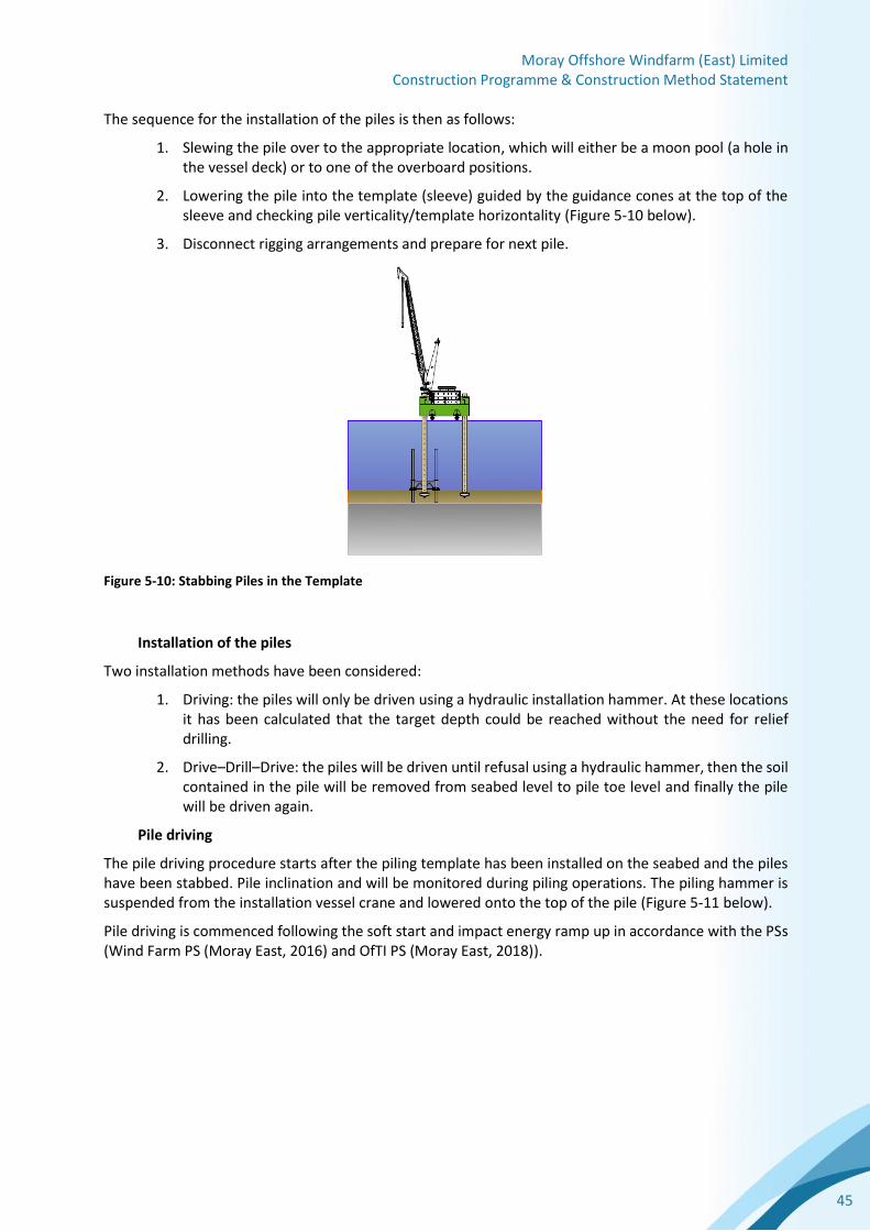
The sequence for the installation of the piles is then as follows:
1. Slewing the pile over to the appropriate location, which will either be a moon pool (a hole in the vessel deck) or to one of the overboard positions.
2. Lowering the pile into the template (sleeve) guided by the guidance cones at the top of the sleeve and checking pile verticality/template horizontality (Figure 5-10 below).
3. Disconnect rigging arrangements and prepare for next pile.
Figure 5-10: Stabbing Piles in the Template
Installation of the piles
Two installation methods have been considered:
1. Driving: the piles will only be driven using a hydraulic installation hammer. At these locations it has been calculated that the target depth could be reached without the need for relief drilling.
2. Drive–Drill–Drive: the piles will be driven until refusal using a hydraulic hammer, then the soil contained in the pile will be removed from seabed level to pile toe level and finally the pile will be driven again.
Pile driving
The pile driving procedure starts after the piling template has been installed on the seabed and the piles have been stabbed. Pile inclination and will be monitored during piling operations. The piling hammer is suspended from the installation vessel crane and lowered onto the top of the pile (Figure 5-11 below).
Pile driving is commenced following the soft start and impact energy ramp up in accordance with the PSs (Wind Farm PS (Moray East, 2016) and OfTI PS (Moray East, 2018)).


Moray Offshore Windfarm (East) Limited Construction Programme & Construction Method Statement
51
Figure 5-16: Connection point on jacket for grouting
The grouting materials will consist of the following:
• BASF Master Flow 9800 High Strength grout or similar alternative;
• Fresh water; and
• Seawater.
For jacket leg / pile interface, there is a primary grout line on top of the jacket (Figure 5-16 above). The grouting equipment located on the vessel will be connected to the primary line with grout hoses running along the gangway from the vessel to the jacket.
Following jacket installation for each pre-pile, grout shall be mixed in proportions and injected to fill the space between the jacket ‘stab-in’ steelwork and the internal pile surface. An ROV shall be used to observe grouting operations and the overflow, to verify the complete filling of the connection. Measures will be put in place to mitigate grout overflow into the sea.
5.3.6 Demobilisation of Installation Spread
After all jackets are completely installed, the HLV and other support vessels will be demobilised.
5.4 Inter-Array and OSP Inter-Connector Cable Installation
5.4.1 Inter-Array and OSP Inter-Connector Cable Manufacture and Supply
The inter-array and OSP inter-connector submarine cables will be designed and manufactured by a European supplier. It is expected two cable conductor cross sections sizes will be required; 240 mm2 and 630 mm2. The supply also includes the two OSP inter-connector cables (630 mm2). The cable design is high voltage alternating current (HVAC) for 66 kV, with aluminium stranded conductors (3 phases) and XLPE insulation. The constructed cable will contain the associated metallic screens, sheaths, bindings and fibre optic elements and is encased by a single layer of helically applied steel armour wires.
As a separate component, a cable protection system will be designed and procured. Its purpose is to protect the cable where it is in the free span zone from the structure exit location and into burial. In this zone the cable is affected by dynamic environmental loads (waves and current). The system protects the cable from these loads and also provides impact protection.

Moray Offshore Windfarm (East) Limited Construction Programme & Construction Method Statement
53
5.4.4 Cable Routes Site Survey and Cable Burial Risk Assessment
In order to support the route engineering and cable burial plan Moray East shall complete a detailed geophysical and geotechnical survey of the preliminary cable routes. The survey shall provide the required soil and seabed condition information to allow the selection and specification of the burial tooling. The survey will also identify debris, wrecks or boulders which pose a hazard to trenching operations, as well as potential unexploded ordinance within the defined cable installation corridors.
A cable burial risk assessment shall be completed and will assess the human (primarily fishing and shipping) and natural hazards to the cables over the life of the Wind Farm. The level of cable protection and depth of lowering is then defined for individual cable routes and soil conditions in a cable burial plan.
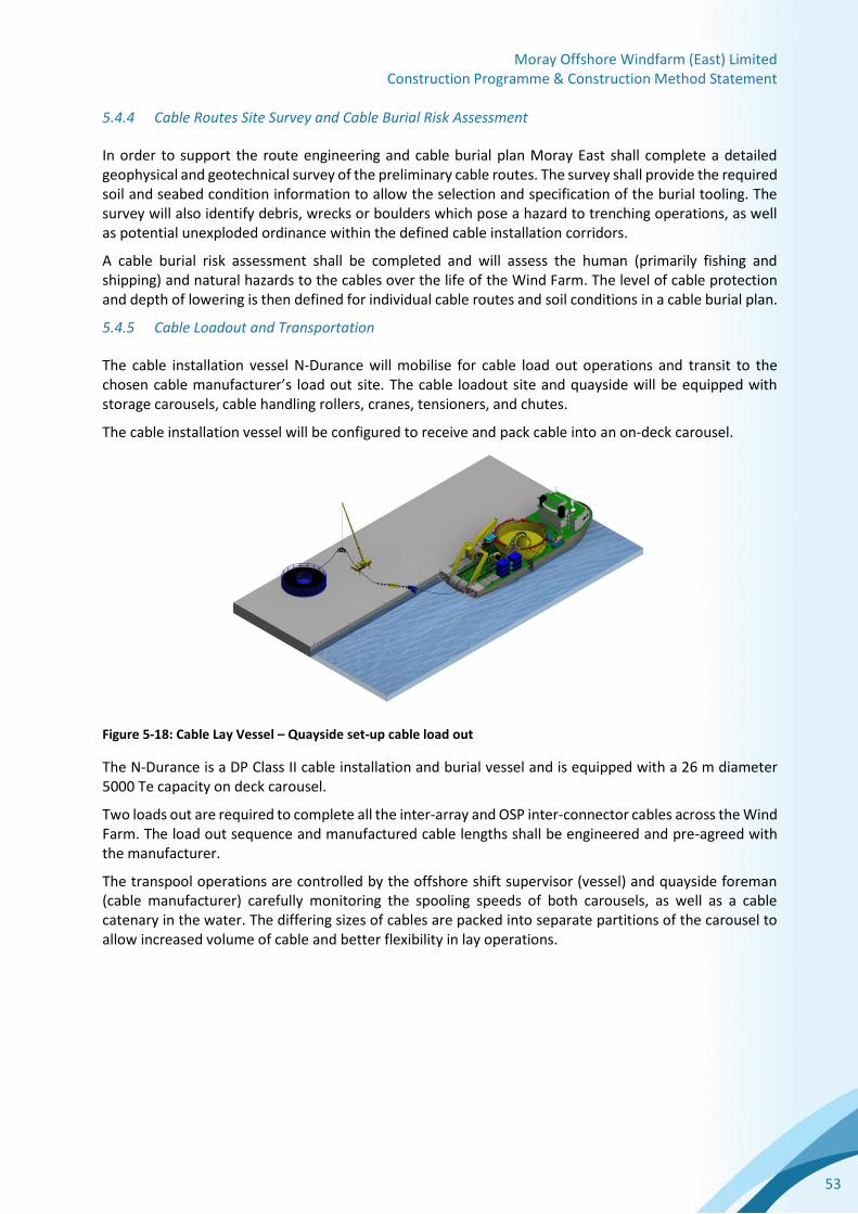
5.4.5 Cable Loadout and Transportation
The cable installation vessel N-Durance will mobilise for cable load out operations and transit to the chosen cable manufacturer’s load out site. The cable loadout site and quayside will be equipped with storage carousels, cable handling rollers, cranes, tensioners, and chutes.
The cable installation vessel will be configured to receive and pack cable into an on-deck carousel.
Figure 5-18: Cable Lay Vessel – Quayside set-up cable load out
The N-Durance is a DP Class II cable installation and burial vessel and is equipped with a 26 m diameter 5000 Te capacity on deck carousel.
Two loads out are required to complete all the inter-array and OSP inter-connector cables across the Wind Farm. The load out sequence and manufactured cable lengths shall be engineered and pre-agreed with the manufacturer.
The transpool operations are controlled by the offshore shift supervisor (vessel) and quayside foreman (cable manufacturer) carefully monitoring the spooling speeds of both carousels, as well as a cable catenary in the water. The differing sizes of cables are packed into separate partitions of the carousel to allow increased volume of cable and better flexibility in lay operations.

Moray Offshore Windfarm (East) Limited Construction Programme & Construction Method Statement
54
Figure 5-19: Partitioned carousel with cable loading
5.4.6 Preparatory Works and Pre-Lay Survey
Prior to cable installation operations an installation support vessel will mobilise and enter the Moray East site. This is a walk-to-work vessel using an actively compensated mobile gangway to allow pull-in and preparation personnel access to the WTGs and OSPs. The preparatory work will include:
• Foundation inspection and pull-in equipment set-up including; winches, rigging and monitoring equipment;
• Installation or checking of messenger lines located in the cable pull-in j-tubes;
• Removal of the subsea and topside J-tube exit covers; and
• A pre-construction survey of each cable route by ROV to identify hazards to cable installation.
5.4.7 Inter-Array and OSP Inter-Connector - Cable Installation
The installation of the inter-array and OSP inter-connector cables will be completed on a string by string basis. The installation support vessel will work ahead of the cable lay vessel and the pull-in teams set-up the pull-in equipment and prepare each structure for cable installation.
5.4.7.1 First End Pull-in
The cable lay vessel will set-up stern to the foundation j-tube exit heading. The pull-in wire messenger line is transferred from the foundation to the cable lay vessel deck and the pull-in winch is brought to deck and connected to the cable, including its associated cable protection system. The cable end is overboarded and pulled into the j-tube. The cable protection system will dock into the j-tube bellmouth and the cable is then pulled up into the foundation cable deck and the overlength required for the final connection is laid out. A ‘hang-off’ clamp is fitted to support the cable in the j-tube. The vessel will move off from the structure and lay cable on the seabed.

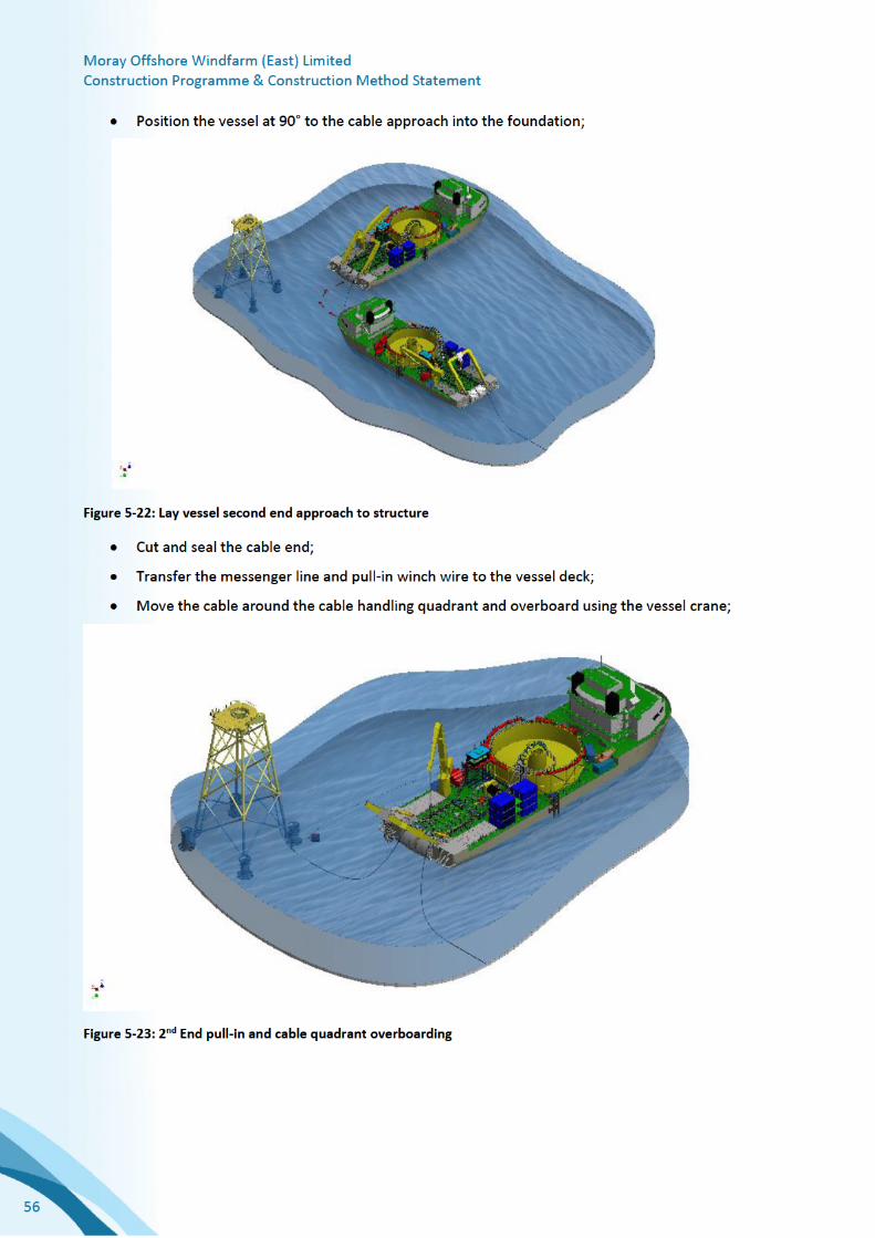


Moray Offshore Windfarm (East) Limited Construction Programme & Construction Method Statement
58
Figure 5-25: Typical cutting and jetting tracked burial tool
A typical jet trenching unit will be employed in the sands, silts and softer clay type soils. These tools use high pressure jet nozzles (jet swords) and large water volumes to liquefy the soil, and allow the cable self-weight to lower the cable into the seabed.
Figure 5-26: Typical jet trenching tool
A combination of the two units can be used along a single route. The jetting trencher can be used for second passes where the cable has not reached the required depth of lowering.
A post burial survey of the cable will be completed by a survey ROV with a mounted cable tracker unit. This survey will provide the achieved depth of lowering and identify if further trenching or cable protection is required (e.g. rock placement or concrete mattresses).
Rock Placement Protection
Where trenching of the cable is not practical, or the seabed soil conditions do not allow the cable to achieve the required level of protection, the installation of rock placement on the cable is required. The
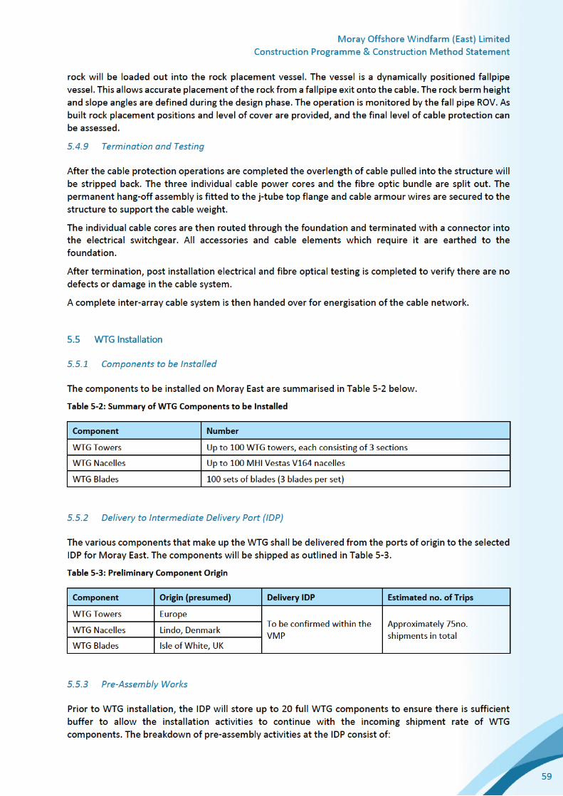


Moray Offshore Windfarm (East) Limited Construction Programme & Construction Method Statement
61
3. The tower will be mechanically connected to the flange of the foundation with bolts and the first step of tensioning performed according to specifications;
4. Once the complete tower is secured, the main crane will reduce the load to 0 t and the nuts connecting the tower and transition piece flange will then be tightened. After all nuts have been tightened the tower installation yoke can be released and returned to the deck of the jack up vessel;
5. Finally all tower / transition piece flange nuts will go through a final tensioning procedure in accordance with the contractor’s specification.
5.5.7 Nacelle Installation
The following process will be repeated for each nacelle installation:
1. The main crane of the jack up vessel will manoeuvre over the first nacelle to be installed. The nacelle will then be connected to the nacelle lifting yoke through the dedicated lifting points within the main frame. A tag line system will be used to control the orientation of the nacelle during lifting;
2. Sea-fastening will be released and the nacelle can be lifted from the jack up vessel deck and manoeuvred over the installed tower using the tag line system and lowered in position;
3. The nacelle will be mechanically connected to the tower flange with bolts and fastened according to the Contractor’s specifications;
4. Once the nacelle is secured, the main crane will reduce the load to 0 t and the lifting yoke can be released and returned to the deck of the jack up vessel.
5.5.8 Blade Installation
The following process will be repeated for each WTG rotor installation:
1. The main crane of the jack up vessel will manoeuvre over the first blade to be installed and secure to the blade. A tag line system will be used to control the orientation of the blade during lifting;
2. The blade will be released from the blade transport system (sea fastening) and then the blade is lifted out of the blade transport system;
3. The blade will be manoeuvred to the correct horizontal position of the hub on the installed nacelle;
4. The blade will be mechanically connected to the hub bearing flange with stud bolts and nuts and then tensioned according to the contractor’s specifications;
5. When the blade is secured the main crane may reduce the load to 0t and the blade lifting tool is released from the blade and manoeuvred to next blade on deck to be installed;
6. The hub will be rotated to the next position via the pre-installed turning gear and locked ready to receive the next blade;
7. The above actions will be repeated for the remaining two (2) blades;
8. When all three (3) blades are installed the blade lifting tool will return to the deck of the jack up vessel.
Upon successful installation of all WTGs from the jack up vessel, the vessel will return to the IDP and repeat the above processes until all WTGs have been installed.


Moray Offshore Windfarm (East) Limited Construction Programme & Construction Method Statement
63
5.6.3 Substructure Installation
Installation of the jacket substructures for the OSPs will be completed as described under Section 5.3 above.
5.6.4 Top Side Installation
The topside platform which includes the transformer and associated switchgear will be assembled as a single unit prior to being loaded onto a barge and transported to the Moray East site. This will ensure that once offshore, the lift of the module onto the substructure will take minimal time. Where possible, all rigging for lifting operations will be in place prior to shipping the module offshore.
Once a sufficient weather window is available, the lift will commence using a heavy lift vessel and the topside is lowered onto the jacket substructure. It is anticipated that the topside module will be secured into position by use of a grouted connection and a stab-in.
5.6.5 Export Cable Installation
Installation of the export cable onto the OSPs will be as described in Section 5.7 below.
5.6.6 Inter-Array Cable Installation
Installation of the array cable onto the OSPs will occur after export cable installation. The installation will be as described in Section 5.4 above.
5.6.7 Hook Up and Commissioning
Pre-energisation commissioning activities take place within the OSP containers such as setting up communication systems with the shore, lighting, fire-fighting system commissioning etc. Once all systems are enabled, the OSP HV electrical systems are commissioned. When complete the OSP is operational and able to provide energisation for the WTGs as required.
5.7 Offshore Export Cable Installation
5.7.1 Offshore Export Cable Supply
The export cable is to be produced at the NKT HV Cables cable factory in Karlskrona, Sweden, and is of a standard HVAC (high-voltage alternating current) design: trefoil aluminium cores, XLPE insulation, associated screening, integral fibre optic cables, bedding and armouring.
5.7.2 Route Engineering
Specialist route engineering techniques will be used to optimise the cable route within the set OfTI Corridor. The engineered route will reduce the risk of complications during the cable installation and maintenance. Important aspects within route engineering are:
The route engineering shall take account of the following:
• Soils and shallow geology to evaluate burial performance or burial risks;
• Seabed topography, sandwaves and potential free span;
• Maintaining clearance from debris, wrecks, and potential UXOs;
• Minimise the level of boulder clearance; and
• Installation limitations and cable approaches to structures.
Moray Offshore Windfarm (East) Limited Construction Programme & Construction Method Statement
64
5.7.3 Export Cable Layout
A total of 3 export cables will be installed to the 3 OSPs. The cables will be designated as ME-OSP1, ME-OSP2 and ME-OSP3. Further details will be provided in the DSLP and OfTI CaP.
The offshore export cables connect to the onshore export cable circuits at transition joint bays (TJBs), located at the landfall area at Boyndie Bay, which will form the 0 (zero) point for the cable lay.
At this shore end 3 HDD ducts are to be constructed well in advance of cable installation, that exit at approximately -10m LAT, approximately 1,100 m offshore. See section 5.9.6.
The route is designed as expediently as possible toward the platforms (see section 5.9.2 below), and along the route at kilometer point (KP) 45 (or 45 kilometers from the TJB) there is one subsea asset, a buried power cable, to be crossed by the Moray East export cables. See section 5.7.5 below.
At the OSPs the cable accompanied with a cable protection system will be pulled into and through a steel j- tube with a bellmouth approximately 2 - 3 m above seabed, with sufficient cable being pulled up onto the platform to allow for it to be connected to the HV switchgear on the OSP. The cable protection system is utilised as an installation aid and protection for the ‘dynamic’ movement of the cable over time.
It is intended that each of the offshore export cables are to be laid in one length with no offshore joints.
5.7.4 Export Cable Route Burial Assessment Survey
As part of the pre-installation works and ahead of the main export cable installation activities, a cable burial assessment has been carried out along the proposed route, to ascertain the likely seabed penetration of future hazards and therefore the cable burial requirement. This is being further informed in 2018 with additional offshore surveys. The surveys and subsequent studies define the target depth the cable is to be buried to protect it in future from all natural and anthropogenic hazards. Further details will be provided within the OfTI CaP.
5.7.5 Third Party Cable Crossing
Three crossings, one per export cable, are to be engineered to protect against contact and sufficiently separate the Moray East export cables from the single Scottish Hydro Electric Transmission cable (known as the SHET cable), an existing high voltage direct current (HVDC) transmission cable between Caithness and Moray.
The sequence of events will be to engineer rock type and quantities, expected to be standard quarried granite / gneiss and install a pre-lay rock berm, followed by post lay rock berm upon completion of cable lay.
In order to install the pre-lay berm, upon arrival infield, a fall pipe rock placement vessel will survey the already installed SHET cable to confirm its location. The vessel will then place 3 berms of rock across the cable at the crossing points of the to be installed Moray East cables.
5.7.6 HDD installation (landfall connection)
A total of 3 ducts of approximately 1,100 m will be installed using HDD, one at a time at the landfall location at Boyndie Bay above Mean High Water Springs.
The proposed HDD works will be undertaken in such a way as to cause minimum disruption to members of the public. The working area will be contained by fencing and access through the works will be restricted for health and safety reasons.
In order to install each duct/pipe, a pilot drill will first originate landward and exiting seaward. The drill hole will then be further opened to reach the diameter required for a duct/pipe of sufficient size to house the export cable. Upon completion of the hole opening, reaming and cleaning, a single length of extruded pipe (fabricated offsite) will be floated into position from offshore and a ‘pullback’ operation will

Moray Offshore Windfarm (East) Limited Construction Programme & Construction Method Statement
65
commence, whereby the drill string is connected to the floated pipe and this is drawn back through the hole to the landward end. Towing tugs and a small jack up or pontoon will be utilised offshore to facilitate this operation.
A dive team will locate the pipe end and proceed to use a dredge pump or similar to create a trench for the pipe to be lowered into. Upon completion, concrete mattresses will be placed on top of the duct to provide ballast. Divers will then use the dredge pump and airlift to provide backfill to the trench.
The onshore end of the duct will be flanged and a bellmouth installed to aid the future pull in of the cable.
5.7.7 sCable Collection (Loadout)
NKT HV Cables’ specialist cable laying vessel the Victoria is scheduled to be utilised for the installation of the export cables.
The Victoria has enhanced dynamic positioning capabilities (DP3) with a 7,000 t upper turntable (cable storage and deployment equipment) capacity and 4,500 t lower turntable capacity.
The cables will be loaded in Karlskrona, Sweden. The anticipated transport of cables is divided in three lots / transports, each lot being each cable from shore to OSP.
The vessel will be moored alongside the factory and a series of cable handling equipment devices will take the cable from the factory, across the quayside and onto the vessel in a controlled manner.
When the cable loading is completed all equipment and cables on the vessel shall be sea fastened and the vessel will sail to the landfall location.
5.7.8 Export Cable Installation - Landfall
Prior to the vessel’s arrival at site, the landfall site will be set up with a pull-in winch to draw the cable through the ducts installed earlier using HDD. The ducts will be inspected and cleaned utilising divers and a small multicat or jack up vessel offshore to assist.
For the installation of each cable, the installation vessel will stand offshore at the seaward end of the duct, ready to deploy the cable into the duct. The duct will have been pre-installed with a wire to aid the collection of the winch wire via a ROV launched off the installation vessel. After which the ROV will monitor as the cable is drawn into and through the duct by the landward winch.
The cable will then be secured to a strong point on the winch base onshore and the vessel will commence the lay the remainder of the cable toward the OSP. Jointing of the offshore export cable to the onshore export cable can then be completed as an onshore construction operation.
5.7.9 Export Cable Installation - Cable Free Lay
Following installation of the cable at the landfall, the installation vessel will then lay the cable to the seabed along the designed route, monitored by a ROV tethered from the vessel. This will be especially important to ensure the cable is accurately laid across the pre-installed rock berm at the crossing point described in Section 5.7.5 above and through boulder fields.
5.7.10 Export Cable Installation - Second End Pull-in to OSP
The preferred method for installation of the final end of the export cable is through the use of a quadrant from the deck of the lay vessel, whereby a ‘bight’ of cable will be supported from deck to seabed during the pull in. The export cable end will be pulled into the OSP using a platform-mounted winch. Cable protection will be attached to the export cable on board the cable laying vessel prior to the pulling operation.
Following cable pulling, the cable will be routed within the OSP structure and connected to its termination point at the HV switchgear. Inspection and testing of each cable will be undertaken prior to its energisation.

Moray Offshore Windfarm (East) Limited Construction Programme & Construction Method Statement
66
5.7.11 Export Cable Installation – Cable Burial
Following cable lay on the seabed, a tracked ROVs will be deployed from a vessel in order to bury the export cables. The ROVs will be configured in cutting or jetting mode depending on seabed conditions. Cutting is used in harder seabed conditions and is performed by chain cutters which are fitted with an array of cutting picks, positioned to efficiently and effectively cut the full width of the cutting boom. A slot trench defined by the cutter will provide protection to the cables in areas of hard clays. Where the seabed conditions are less difficult, such as sands or soft clays, the trenching mode will be water injection jetting from the same trenching ROV.
5.7.12 Post Installation Survey
The final position of the cable will be determined by means of a post installation survey. This will be carried out by a ROV moving along the cable route and recording the horizontal and vertical position of the cable relative to the seabed from the main lay vessel.
5.7.13 Cable Repair Contingency
If, during the cable lay operation, severe weather or a vessel / equipment failure occurs, it may become necessary to abandon the cable as a last resort.
During an abandonment operation the cable ends will be sealed and recovery rigging will be fitted, the location noted and the vessel will then prepare for repair mode.
The installation vessel will then return and collect one end of the cable to deck, the cable will be jointed to a new section and deployed, the second end of this section will be jointed to other side of the cut cable.
The NKT HV cables subsea jointing arrangement consists of bending restrictors on each side of the steel body of the joint itself, within which the individual cable cores and fibre optics will be joined. These bending restrictors will protect the cable for possible over-bending at the joint connections, when the joint is overboarded.
The joint would then be buried by the same method as above, or via a controlled or mass flow excavation tool if the joint body and or lay down radii of the cable ends are too wide or too tight for the standard trenchers.
5.8 Electrical Infrastructure Commissioning
Following completion of the physical installation of the components that make up the OfTI, the OfTI will be commissioned and energised, allowing the Wind Farm to be commissioned and brought into commercial operation.
Commissioning and energisation of electrical infrastructure will involve the following principle activities, each of which is described further below:
• Energisation of the onshore infrastructure associated with the Development;
• Energisation of each of the offshore export cables;
• Commissioning of the OSPs;
• Commissioning of the inter-array cable network; and
• Commissioning of the WTGs.
As the OfTI and Wind Farm utilise equipment operating at voltages up to 220kV, electrical infrastructure commissioning will be undertaken in accordance with high voltage safety rules that will be put in place by Moray East in line with industry practice.

Moray Offshore Windfarm (East) Limited Construction Programme & Construction Method Statement
67
The offshore commissioning works described in this section will be undertaken by personnel who will transfer on a daily basis to the offshore site from a local commissioning port base using crew transfer vessels. An offshore accommodation vessel may be deployed at peak times.
Onshore Infrastructure Energisation
Before the OfTI and Wind Farm can be commissioned, the onshore infrastructure associated with the Development first requires to be connected to and energised from the local onshore transmission network at the connection point near New Deer in Aberdeenshire. This will be completed once the onshore substation forming part of the Transmission Infrastructure has been constructed. The energisation process will be coordinated with National Grid and Scottish Hydro Electric Transmission and, once undertaken, will allow all primary and auxiliary systems at the onshore substation to be commissioned such that they are ready to accommodate connection of the OfTI and the Wind Farm.
Offshore Export Cable Energisation
The first element of the OfTI that will be energised will be the offshore export cables. Each of these will be energised sequentially, together with the associated onshore export cable circuits, once: (i) onshore substation commissioning has been completed as described above; and (ii) the offshore export cables have been physically installed as described in Section 5.7.
OSP Commissioning
Once the associated export cable has been energised, power will be available to each OSP which will allow the following commissioning activities to be undertaken:
• Energisation and commissioning of the primary systems on each OSP, such as high voltage switchgear and grid transformers;
• Energisation and commissioning auxiliary systems on each OSP, such as control and communications equipment required to ensure the OSPs can be operated and monitored remotely; and
• Commissioning and testing of metering equipment.
Once OSP commissioning has been successfully completed, Moray East will be able to energise and commission the inter-array cable network associated with the WTGs as described further below.
Inter-Array Cable Network Commissioning
As described [insert apt reference, e.g. to the DSLP], the inter-array cable network that connects the WTGs to the OSPs will be arranged in a number of circuits or ‘strings’. These will be energised and commissioned individually once the cable installation and testing works described in Section 5.4 above have been completed for each circuit. The main activities involved in inter-array cable network commissioning are as follows:
• Inspection of high voltage equipment and cable terminations along the cable circuit to ensure it is ready to be energised;
• Functional testing of the high voltage switchgear at each WTG location to ensure it is operating correctly;
• Completion of a ‘switching programme’ where each cable and switchgear unit on the circuit is energised; and
• Inspection and monitoring of the energised equipment prior to progressing to the next stage of Wind Farm commissioning.
Once each inter-array cable circuit has been energised, Moray East will be able to progress with energisation of individual WTGs as described further below.
Moray Offshore Windfarm (East) Limited Construction Programme & Construction Method Statement
68
WTG Commissioning
The WTG commissioning activities will be conducted on individual WTG basis once grid power is available at the WTG location. The commissioning process will follow the Contractor’s commissioning manual and will only take place when the following activities have been completed:
• WTG installed;
• WTG Mechanical & Electrical Completion; and
• WTG Energised in accordance with Moray East’sHV Safety Rules.
The energisation of the WTG is a joint activity between Moray East and heir contractor to ensure that the energisation is conducted safely and as efficiently as possible.

Moray Offshore Windfarm (East) Limited Construction Programme & Construction Method Statement
69
6 Good Working Practices
6.1 Introduction
The Section 36 Consents and OfTI Licences include the following requirement relating to this CoP and CMS document (see Table 1-2 above):
The CMS must set out the construction procedures and good working practices for installing the [Development / Works].
Good working practice is not defined by the Moray East Offshore Wind Farm Consents or OfTI Licences. For the purposes of complying with this requirement Moray East have taken the requirement to imply the following:
The reasonable application of methods of working that have been shown to achieve the best outcomes or that reach or exceed relevant legislative standards.
In the context of the construction of the Development this has been taken to apply to those standards, guidance or examples of good practice working that will act to:
• Manage the construction process so as to avoid harm to construction personnel or third parties; and
• Ensure effects on the environment and other users of the marine environment are minimised as far as reasonably practicable (and in line with the commitments made by Moray East or the requirements of the Moray East Offshore Wind Farm Consents and OfTI Licences).
The following sections set out the areas of good working practices that will be applied during the construction process described by this CoP and CMS document. They address the following specific areas:
• Offshore renewable industry good practice guidance;
• Health and safety procedures;
• Construction management procedures;
• Environmental management procedures; and
• Specific good working practice in relation to aspects of the construction process (as set out in Section 4 of this CoP and CMS document) that, for example, act to avoid or reduce environmental impacts or impacts on other users.
Cross reference is made to other relevant consent plans (as described under Section 1.4 of this CoP and CMS document) and to the Moray East Statements of Compliance set out in Section 2.
6.2 Offshore Renewable Industry Good Working Guidance
There are a number of good practice guidance documents that have been produced for or in relation to the offshore renewables industry in recent years. Where relevant, Moray East will require that such good practice is reflected in the detailed method statements produced by the key contractors and sub-contractors.
Industry guidance documents are listed in Table 6-1 below.


Moray Offshore Windfarm (East) Limited Construction Programme & Construction Method Statement
72
• The navigational safety plan (NSP) – setting out matters related to the management of construction vessels to ensure navigational safety;
• The lighting and marking plan (LMP) and the NSP – lighting and marking to mitigate against impacts on other sea users;
• The marine pollution control plan (MPCP) – response to pollution incidents;
• The cable plan (CaP) – cable installation procedures;
• The Commercial Fisheries Mitigation Strategy (CFMS) – sets out the mitigation strategy for commercial fisheries potentially affected by the Development;
• The commercial fisheries liaison officer (FLO) – liaison with the local fishing industry and notification of planned works, vessel movements etc; and
• The archaeological MARP/WSI.
In addition, any matters set out in the ESs in relation to the mitigation and management of construction will be incorporated into the CMS (see Section 7 below).
6.5 Project-Specific Good Working Practices
There are a number of specific good working practices that will be applied to certain aspects of the construction process as set out in this CoP and CMS document and that will seek to minimise the environmental effects arising from the construction. The following sections set out the good working practices related to:
• Drill arising and soil plug disposal;
• Grouting operations;
• Seabed preparation and jack-up usage;
• Cable and scour protection;
• Piling operations;
• Drilling muds;
• Cable installation; and
• Minimising effects on other sea users.
A number of these are also set out in relation to environmental management in the EMP.
Drill arisings and soil plug disposal
Where necessary drill arisings and soil plug material generated during pile installation will be deposited on the seabed adjacent to the foundation location. Volumes generated per pile will be small (estimated maximum of circa 230 m3 for drill arisings and circa 24 m3 for soil plugs per pile; a combined disposal of up to circa 254 m3 per pile). Drilling is not likely to be required for every pile location and in some cases soil plug volumes will also be less.
In the case of soil plug, spoil will be deposited at the seabed in the vicinity of the piles by means of rigid piping or flexible hose and it is possible to control and monitor to some extent the number and location of spoil heaps to manage the impacts at the seabed.
Drill arisings are managed through a reverse circulation drilling system using seawater and deposited to the seabed.

Moray Offshore Windfarm (East) Limited Construction Programme & Construction Method Statement
73
Spoil heaps, if required, can be measured during disposal using Remote Operated vehicle (ROV) sensors or other appropriate methods. The height of the spoil mounds will not exceed 4 m above mean sea bed level (MSBL) at each pile location.
Grout will not be used to control drill spoil as was suggested as an option in the Environmental Statement, the material being left on the seabed for dispersion by the prevailing hydrodynamic forces.
Grouting
Grout will be used to cement the joints between the piles and jacket structures. The volumes of grout required will be minimised as far as possible through design.
Grout loss will be minimised by the monitoring and control of grout volumes being injected into each joint and by the subsea monitoring of grouting operations by use of an ROV.
The high-pressure grouting equipment will be pressure tested onshore prior to being loaded onto the installation vessel to ensure there are no leaks. Once grouting is complete the grouting equipment will be cleaned on the vessel with water in a controlled manner to prevent grout from washing overboard.
Seabed preparation and anchor/jack-up movements
No dredging activities are anticipated prior to foundation installation with seabed preparation limited to that described in Section 5.2 above thereby reducing seabed disturbance and the generation of spoil material and spoil disposal requirements.
Potential boulders at Jacket footprint locations are avoided in the design stage or removed prior to arrival of JUV in the field.
Jack up movements and leg re-positioning will be minimised through the design of installation process so as to avoid unnecessary disturbance to seabed habitats. Similarly, anchor movements will be minimised.
Cable and foundation scour protection
The current foundation design basis is to avoid the use of no scour protection around the foundation structures, thereby reducing impacts on seabed habitats as a result of the placement of scour protection material. It is, however anticipated that a minority of the WTG foundations (< 15%) located in areas of soft soils will require scour protection. In addition, foundations for the OSPs will require scour protection due to the number of cables terminating into these jackets.
The need for cable protection material is not currently anticipated, other than localised and close-fitting cable protection at the cables ends between the J- or I-tubes and the buried sections.
Soft start piling
Soft start piling procedures will be applied at the start of piling operations as part of the marine mammal mitigation protocol. Full details of the piling approach and wider marine mammal mitigation is set out in the Piling Strategy.
Drilling muds
Where relief drilling is required during pile installation, drilling operations will not require the use of oil-based lubricants, but instead will use seawater-based drilling systems with no added chemicals.
Cable Installation
Inter-array cable installation (see Section 5.4) is expected to be completed principally by the use of a water jetting trenching tool. These tools use a high-pressure water jet to fluidise the seabed soils allowing the cable to sink under its own weight to the target burial depth. They rely on the disturbed sediment settling back into the cable trench to create cover/backfill on top of the cable as the trenching tool passes.
To maximise post-trenching cable cover and to minimise the disturbance of sediment away from the trench, site specific trencher settings will be derived based on the soil conditions to ensure disturbed sediment is monitored and managed efficiently throughout operations.

Moray Offshore Windfarm (East) Limited Construction Programme & Construction Method Statement
74
Further details on the cable laying process will be provided for approval in the CaP.
Minimising effects on other sea users
Moray East recognise that the Development represents a major infrastructure construction project in the waters of the Moray Firth that are also used by a variety of other marine users including other commercial shipping, the commercial fishing industry and recreational sailors.
In order to ensure that effects on these other marine users are minimised, standard good working practices will be employed to ensure effective communication to minimise interactions and communicate risks arising from construction works to others in the vicinity of the construction site. A number of these are specific requirements of the consents but also represent good working practice, including:
• The regular issuing of Notice to Mariners (NtMs);
• The issuing of Notice to Airmen (NOTAM) for movements of vessels with structures or equipment above 60 m (e.g. cranes);
• Charting on nautical and aviation charts in line with regulatory requirements (provision of information to the UKHO);
• Lighting of temporary and partially installed structures during construction;
• Establishment of safety zones during construction;
• Use of radio navigation warnings;
• Appointment of a suitably qualified Fisheries Liaison Officer;
• Notification of commencement and completion of the works to local mariners, fishermen’s organisations and HM Coastguard and Buckie Harbour Master by use of NtMs;
• Notification of details of the works through the Kingfisher Fortnightly Bulletin and provision of information to the SeaFish industry on vessel routes, timings and location of the works and relevant operations;
• Provision of details on the location of the Development for inclusion in the Clyde Cruising Club Sailing Directions and Anchorages; and
• Direct engagement and regular communication with other stakeholders such as owners of existing infrastructure in the Moray Firth.
In addition, the project consents contain a number of other conditions which essentially set out good working practice requirements in relation to reducing effects on other marine users, including:
• Burial or otherwise protecting seabed cables;
• Provision and agreement of necessary marking and lighting and buoyage for the Development;
• Employment of measures (through use of the Transportation Audit Sheet) to control debris on the seabed and a process, where necessary, for the reporting of dropped objects and subsequent investigation/recovery;
• Agreed measures for emergency response (through the agreement of an Emergency Response and Co-ordination Plan (ERCoP)).
Further details on Moray East’s approach to these consent requirements will be provided for approval in a number of the other necessary consent plans including the VMP, the NSP (which includes the ERCoP), the LMP, the CaP and the EMP. Moray East, in addition to the good working practices embodied in the consent conditions, is also proposing to engage guard vessels during the period of active construction in order to ensure that third parties do not approach too close to the Development area and the location of construction activities (see also Section 4.6 above).

Moray Offshore Windfarm (East) Limited Construction Programme & Construction Method Statement
75
Moray East will also apply for construction safety zones under the provision of the Energy Act 2004 which will act to provide a clear ‘area to be avoided’ for other marine users; the location of the active safety zones will be provided as part of the NtMs issued.