Short to Medium Span Precast Prestressed Concrete Bridges ...
27
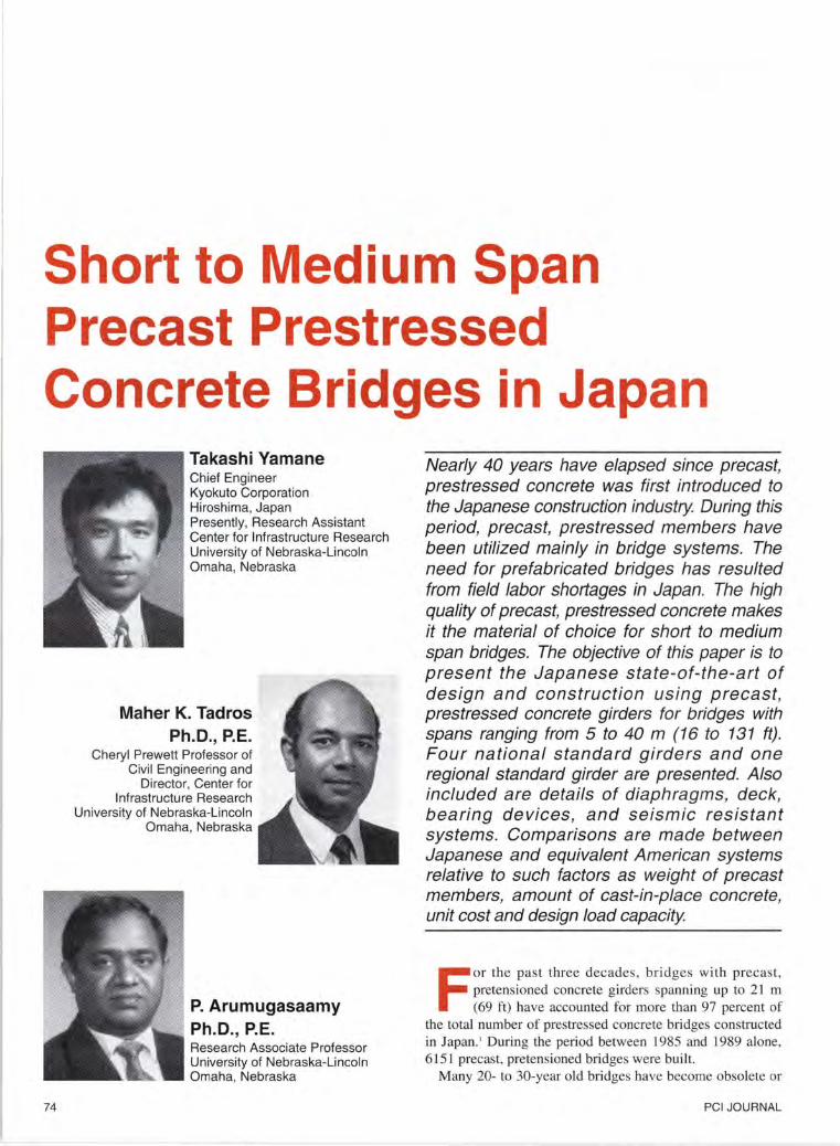
Short to Medium Span Precast Prestressed Concrete Bridges in Japan 74 Takashi Yamane Chief Engineer Kyokuto Corporation Hiroshima, Japan Presently, Research Assistant Center for Infrastructure Research University of Nebraska-Lincoln Omaha, Nebraska Maher K. Tadros Ph.D., P.E. Cheryl Prewett Professor of Civil Engineeri ng and Director, Center for Infrastructure Research University of Nebraska-Lincoln Omaha, Nebraska P. Arumugasaamy Ph.D., P.E. Research Associate Professor University of Nebraska-Lincoln Omaha, Nebraska Nearly 40 years have elapsed since precast, prestressed concrete was first introduced to the Japanese construction industry. During this period, precast, prestressed members have been utilized mainly in bridge systems. The need for prefabricated bridges has resulted from field labor shortages in Japan. The high quality of precast, prestressed concrete makes it the material of choice for short to medium span bridges. The objective of this paper is to present the Japanese state-of-the-art of design and construction using precast , prestressed concrete girders for bridges with spans ranging from 5 to 40 m (16 to 131 ft). Four national standard girders and one regional standard girder are presented. Also included are details of diaphragms, deck, bearing devices , and seismic resistant systems. Comparisons are made between Japanese and equivalent American systems relative to such factors as weight of precast members, amount of cast-in-place concrete, unit cost and design load capacity F or the past three d eca des, bridges with precast, pretensioned concrete girders span ni ng up to 21 m (69 ft) have accounted for more than 97 percent of th e total number of prestressed concrete bridges constructed in Japan.' During th e peri od between 1985 and 1989 alone, 6 151 precast, pretensioned bridges were buil t. Many 20- to 30-year old bridges have become obsolete or PCI JOURNAL
-
Upload
khangminh22 -
Category
Documents
-
view
3 -
download
0
Transcript of Short to Medium Span Precast Prestressed Concrete Bridges ...
Short to Medium Span Precast Prestressed Concrete Bridges in Japan
74
Takashi Yamane Chief Engineer Kyokuto Corporation Hiroshima, Japan Presently, Research Assistant Center for Infrastructure Research University of Nebraska-Lincoln Omaha, Nebraska
Maher K. Tadros Ph.D., P.E.
Cheryl Prewett Professor of Civil Engineering and
Director, Center for Infrastructure Research
University of Nebraska-Lincoln Omaha, Nebraska
P. Arumugasaamy Ph.D., P.E. Research Associate Professor University of Nebraska-Lincoln Omaha, Nebraska
Nearly 40 years have elapsed since precast, prestressed concrete was first introduced to the Japanese construction industry. During this period, precast, prestressed members have been utilized mainly in bridge systems. The need for prefabricated bridges has resulted from field labor shortages in Japan. The high quality of precast, prestressed concrete makes it the material of choice for short to medium span bridges. The objective of this paper is to present the Japanese state-of-the-art of design and construction using precast, prestressed concrete girders for bridges with spans ranging from 5 to 40 m (16 to 131 ft). Four national standard girders and one regional standard girder are presented. Also included are details of diaphragms, deck, bearing devices, and seismic resistant systems. Comparisons are made between Japanese and equivalent American systems relative to such factors as weight of precast members, amount of cast-in-place concrete, unit cost and design load capacity
For the pas t three decades, bridges with precast, pretensioned concrete girders spanning up to 21 m (69 ft) have accounted for more than 97 percent of
the total number of prestressed concrete bridges constructed in Japan.' During the period between 1985 and 1989 alone, 6151 precast, pretensioned bridges were built.
Many 20- to 30-year old bridges have become obsolete or
PCI JOURNAL

10 20 30 40 50 60 70 tnJ (in.)
1000 40 -5 Q.. Cl) ......... 900 "0 E 35 ... Cl) E "0 '-' ·= -5 800 l:)
Q.. 30 ~ ~
700 "0 25 T-girder ·= l:) 600
500 20
400 15
300
Box girder 4 6 8 10 12 14 16 18 20 22
Span (m)
Fig. 1. Span-to-depth relationship for precast, pretensioned concrete girders for short span bridges as used in Japan.
-5 (ft) Q.. 60 70 80 90 100 110 120 130 (in.) ~ ~ 100
"0 ·= 2400 l:)
90 2200
!-girder 80 2000
.........
-5 E 1800 70 Q.. E Cl) '-'
"0 -5 .... 1600 ~
Q..
~ 60 .!::l l:) ...
1400 Cl)
:g 50 l:)
1200 T-girder
1000 box girder 40
fLU 800 30
20 22 24 26 28 30 32 34 36 38 40
Box girder Span (m)
Fig. 2. Span-to-depth relationship for precast, post-tensioned concrete girders for medium span bridges as used in Japan .
unsafe due to the rapid growth of traffic volume and increased use of heavy transportation trucks as a result of the unprecedented economic growth in Japan. Replacement or widening of these bridges, as well as construction
March-April 1994
of new bridges, has demanded careful planning and execution. Cooperation between the precast concrete industry and Japanese transportation authorities has produced highly successful standardized bridge systems . In the fo l-
lowing sections, Japanese design and construction details of typical precast, prestressed concrete bridges are discussed and compared with equivalent American practices.
There are four national and one re-
75

Table 1. Precast, prestressed concrete sections used for short to medium span bridges in Japan.
Typical section
T
I
Pretensioned
solid box girder*
Pretensioned
voided box girder*
Pretensioned
T-girder*
Post-tensioned
T-girder*
Post-tensioned
box girder*
Post-tensioned
I-girder t
* Used with noncomposite bridge deck. t Used with composite bridge deck.
Width mm (in.)
700
(28)
700
(28)
750
(30)
1500
(59)
1000 to 1600
(39 to 63)
650 to 1050
(26 to41)
gional standardized types of precast concrete girders used for highway bridges in Japan. Two types are the pretensioned T -girder and pretensioned box girder. The maximum length of girder that can be moved from a precasting yard to any construction site is limited to 21.7 m (71 ft) by transportation authorities. Because of this constraint, the span length of precast, pretensioned girder bridges is limited to 21.0 m (69 ft). In unusual cases , longer girders have been utilized. In such circumstances, a special permit is obtained from the transportation authority.
Three other types of standardized bridge girders are the precast, posttensioned !-girder, T -girder and box
76
Depth mm (in.)
325 to 400
(13 to 16)
425 to 800
(17 to 32)
800 to 1050
(32 to 41)
1050 to 2150
(4lto85)
800 to 1600
(32 to 63)
1550 to 2450
(61 to 97)
Span range m (ft)
5 to 9
(16to30)
10 to21
(33 to 69)
14 to 21
(46 to 69)
20 to 40
(66 to 131)
24 to 40
(79 to 131)
20 to40
(66 to 131)
Cast-in-place to precast concrete
weight ratio
0.10
0.10
0.25
0.23
0.14
0.60 to 1.20
girder with span capabilities of 20 to 40 m (66 to 131 ft). However, even these girders are precast at the bridge site. Figs. 1 and 2 show the span-todepth relationship of girders. Table 1 lists the various types of precast, prestressed concrete girders used for short to medium span bridges in Japan, whereas Table 2 shows the types used in the United States as reported in PCI literature.2
•3
Of the systems described here, only post-tensioned !-girders are used with structural cast-in-place slabs to produce a composite bridge deck system. In this system, the cross-sectional area ratio of cast-in-place to precast concrete varies between 0.6 and 1.2.
In noncomposite construction, cast-
in-place concrete is used to form diaphragms and to complete narrow strips of slab and shear keys between adjacent girders as shown in Figs. 3 to 6. After the cast-in-place concrete attains its specified strength, transverse post-tensioning is applied to integrate the girders and slabs into a rigid superstructure capable of distributing wheel loads and other forces.
In composite construction, cast-inplace concrete is used for the diaphragms and deck slab (Fig. 7) , similar to 1-girder construction in the United States. However, in Japan the majority of the bridges are noncomposite and transversely post-tensioned.
Table 3 compares the average cost of precast, prestressed concrete elements per unit area of bridge .< The unit cost for short to medium span bridge construction in Japan is three to four times that of bridges in the United States . However, precast concrete costs a comparable percentage of the total bridge cost in both countries . Japanese bridges are more expensive than American bridges due to a variety of reasons, some of which will become apparent in the following discussion. In general, Japanese bridge construction is more complicated and labor rates are higher.
MATERIAL PROPERTIES
Selection of concrete strength and type of prestressing steel is influenced by the type of girder and construction procedure adopted. A concrete compressive strength of 49 MPa (7100 psi) is used for pretensioned girders since a high degree of quality control is maintained at the precasting plant, whereas a lower strength of 39 MPa (5700 psi) is used for post-tensioned girders because these girders are produced at the job site. A compressive strength of 59 MPa (8500 psi) or more is employed for factory -produced post-tensioned box girders.
Most precast concrete bridges built in the United States have a concrete strength in the 34 to 41 MPa (5000 to 6000 psi) range. Several initiatives are underway in the United States to produce bridge girders with a concrete strength as high as 83 MPa (12,000 psi) . Cast-in-place deck
PC! JOURNAL

strength in the United States is generally specified as 24 to 34 MPa (3500 to 5000 psi).
Prestressing steel used for pretensioned girders is either 15.2 or 12.7 mm (0.6 or 0.5 in.) diameter low relaxation strand with an ultimate strength of 1860 MPa (270 ksi) . The choice is influenced by economy and span length. A multi-strand or multi-wire system with fpu of 1620 to 1720 MPa (235 to 250 ksi) is used for post-tensioned girders .
For post-tensioned girders, the standard practice in Japan is to use 12 - 7 mm (0.28 in.) diameter multi-wire systems for girders with span lengths up to 27 m (89 ft) and 12 - 12.4 mm (0.49 in.) multi-strand systems for longer spans . In the United States, 12.7 mm (0.5 in.) diameter strands are used almost exclusively for pretensioned girders, and 15.2 mm (0.6 in.) diameter strands are often employed in post-tensioning applications. Research is underway at several institutions in the United States to develop formulas for development and transfer lengths of 15.2 mm (0.6 in.) diameter strands in pretensioned concrete applications.
DESIGN CONCEPT Flexural design of prestressed con
crete girders is primarily based on the working stress method with the flexural strength checked, similar to the approach taken by the American Association of State Highway and Transportation Officials (AASHTO) Specifications .5 Design for shear and diagonal tension involves both working stress and strength design calculations. The formulas are somewhat similar to those used in the United States. If the section requires shear reinforcement, it may be provided in the form of mild steel reinforcement. Vertical post-tensioning is often used for shear reinforcement of long span girders but seldom used in short span bridges.
LOADS ON BRIDGE GIRDERS
In Japan, similar to American practice, bridge girders are designed for dead and live load, impact or dynamic effect due to live load, wind forces, and
March-April 1994
Table 2. Precast, pretensioned concrete beam sections used for short span bridges in the United States (Ref. 3).
I Cast-in-place
' Width Depth Span range to precast mm mm m concrete
Typical section (in.) (in.) (ft) weight ratio
910 to 2440 250 to 460 up to 9.1 Solid slab
(36 to 96) (10 to 18) (up to 30) 0.0*
II II 910to 1220 380 to 530 7.6 to 15.2
Voided slab (36 to 48) (15 to 2 1) (25 to 50)
0.0*
I I I I 1220 410 to 530 7.6 to 16.8 Multistem
(48) (16 to 21) (25 to 55) 0.0*
' ' Double 1520 to 2440 4 10 to 580 6.1 to 18.3
o.ot stem (60 to 96) (16to23) (20 to 60)
1220 to 1830 610 to 1220 12.2 to 24.4 o.ot Single stem
(48 to 72) (24 to 48) (40 t:J80)
a
D Bo.giTd" 9 10 to 1220 690 to 1070 18.3 to 30.5
(36 to 48) (27 to 42) (60 to 100) 0.0*
T Deck 1220 to 2 130 740 to 1040 18.3 or more o.ot
bulb tee :j: (48 to 84) (29 to4 1) (60 or more)
!-girder :j: 460 to 660 910 to 1370 12.2 to 30.5
0.6 to 1.2 (18 to 26) (36 to 54) (40 to 100)
I AASHTOIPCI 1070 1370to 1830 24.4 to 42.7 0.6 to 1.2
bulb tee+ (42) (54 to 72) (80 to 140)
I Local standard 610to 1520 710 to2740 up to 50.9 0.6 to 1.2
I-girder+ (24 to 60) (28 to 108) (up to 167)
~
* Bridges built without topping concrete or diaphragms. t In some cases, with topping concrete and cast-in-place concrete diaphragms. :j: When post-tensioning is used in combination with pretensioning, these girders may be spliced to reach longer spans up to 76 m (250ft).
other forces . These forces include the effect of thermal movement, shrinkage and creep of concrete, and seismic
loads. As described next, the live loads used in Japan differ significantly from those used in the United States.
77

LIVE LOADS
Two different types of live loads, namely TL and TT loads, are used to determine the live load effect on all highway bridges in Japan.6 TL loadings are designated by the letters TL followed by a number indicating the gross weight in metric tons of the truck.
TL loading consists of two types: "T" represents a truck and "L" represents a distributed load equivalent to the T load. A T-20 truck is shown in Fig. 8a and an L-20 load is shown in Fig. 8b. TL-20 means T-20 or L-20, whichever controls the design . TT designates a truck-trailer loading, as shown in Fig. 9.
For major bridges, TT-43, in combination with TL-20, is used in design. For secondary bridges, only TL-14 is used, whi ch is 70 percent of the weight of TL-20.
L-20 load consists of a uniform load and a transverse line load as shown in Fig. 8b. Uniform load comprises a high intensity load, p, spread over a 5.5 m (18 ft) width and p/2 for theremaining area, where p = 4.9 kN/m2
(102 lbs per sq ft) for spans less than 80 m (262 ft). The transverse concentrated line load consists of 49 kN/m (3400 lbs per ft) in the high intensity loading area, and 24.5 kN/m ( 1700 lbs per ft) over the remaining width.
L-20 loading must be placed in such a way as to produce maximum stress. When TT-43 is used in combination with L-20, L-20 is increased by a K factor which varies with the span length. Different procedures and K factors are used for bridges depending on the owner. Table 4 shows the typical factors used for bridges owned and operated by the Japan Highway Public Corporation.7
In contrast, the United States system requires a 3 m (10 ft) wide uni form lane loading of 93 kN/m (640 lbs per ft) plus a moving point load. The point load used is 80 kN (18,000 lbs) for flexure and 116 kN (26,000 lbs) for shear. These values are to be used when HS-20 truck load is the design loading. For other loading levels, the intensity of the lane loading is adjusted proportionately . Bridges supporting U. S. interstate highways are
78
Table 3 Approximate cost of precast concrete bridges (Ref. 4).
I United States J apa n
I Cost of total I Cost of Cost of
precast concrete Cost of total precast concrete
Type bndge ($/ft ' ) delivered ($/ft ' ) bridge ($/ft ' ) delivered ($/ft') 1-
Short (<60ft) 35 to 50 15 to 20 ( 40 percent) 150 to 200 30 to 55 (25 percent)
Medium (60 to 150ft) 50 to 70 15 to 20 (30 percent) 200 to 250 30 to 55 (20 percent)
Note: I ft= 0.3048 m; I $/ft ' = $ 10.76/m'.
also designed for an alternate military loading of two axles, 1.2 m (4 ft) apart, with each axle weighing 107 kN (24,000 lbs).
Table 5 presents the computed maximum moments and shear forces for a typical bridge with a span length of 20 m (66 ft) for both Japanese and AASHTO loading. In computing moments and shear forces per lane due to Ji ve loads, TL-20 and combined TL-20 and TT -43 were fully imposed on a four-lane roadway bridge, and then the resulting values were divided by four.
It should be noted that in design practice in Japan, the maximum live load effect on a bridge girder is computed using a complex wheel load distribution analysis. As shown in Table 5, the service load moment due to the Japanese loading is 1190 kN-m (878.0 kip-ft) and AASHTO loading is 1240 kN-m (914.0 kip-ft), which are comparable values.
In comparing ultimate moments per Jane due to live load, the live load is multiplied by a factor r= 2.5, whereas in the United States YfiL = 1.3 x 1.67 = 2. 17 is applied before the impact factor is incorporated in the com-
Table 4. Loading factors for live load TT -43 [span s 40 m {1 31 ft)] (Ref. 7) .
Moment and shear force Span (m) Factor K
15 1.08
20 1.1 3
Positive moment 25 I
1.20
30 1.24
40 1.26
10 I
1.57
12
I
1.53
15 1.43
Negative moment 18 1.34
20 1.28
22 1.23
40 1.20
15 I
1.36
Shear force 20 to 30 1.42
40 1.39
Note: I m = 3.28 ft.
putation. The impact factor used in Japan for the bridges under discussion is I = 10/(25 + L) , where L is the span in meters. The impact factor in AASHTO is 50/(125 + L), where Lis in feet. A span of 20 m (66 ft) corresponds to I= 0.22 in Japan and I = 0.26 in the United States. Thus:
Table 5. Comparison of moments and shears due to Japanese and American live loading for a 20 m (66 ft) simple span bridge.
Japan I United States
Live load TL-20 TL-20, TT -43 HS20-44 I HS25-44
Moment due to serv ice load* 11 20kN-m 11 90 kN- m 1240 kN-m 1550 kN-m per Jane: M_, (826 kip-ft) (878 kip-ft) (914 kip-ft) (1143 kip-ft)
Shear force due to service load* 220 kN 270kN 280 kN 340 kN per Jane: Vs (49.5 kips) (60.7 kips) I (63.0 kips) (76.5 kips)
Moment due to ultimate load 3400 kN- m 3640 kN-m I 3400 kN-m 4240kN-m per lane: M
11 (2507 kip-ft) (2684 kip-ft) (2507 kip-ft) (3 127 kip-ft)
Shear force due to ultimate load 680 kN 830kN
I
760 kN 940 kN per Jane: V
11 ( 153 kips) (187 kips) (171 kips) I (211 kips)
* Impact factor is not included.
PCI JOURNAL

20
T
600
640 100
8 14
.... 700
Girder length 17 600
17000
L-A 4 300
Elevation
11200
10000
~ Precast box girder I
Cast-in-place concrete I I
20
·r Transverse post-tensioning
4200
600
Transverse post-tensioning (at diaphragm location)
I
300
Curb (CIP)
13 @ 780 = 10140
A- A B- B
Cross section
640 100
0 00 r----0 V')
§ ~
0
.I 0\
.WJ I
I I 105 [email protected] 105
700
Typical girder cross section
o Prestressing strands • Reinforcement
Bar and strand arrangement
Fig. 3. Precast, pretensioned concrete box girder bridge system for simple short span . Note: 1 m = 3.28 ft ; 1 mm = 0.0394 in.
March-April 1994 79

20 Girder length 17 600 20
~·r~--~-~-~-A---f-)~~~--~-sve-rse~-st--wns-iom-·ng--~·~·
- ---- --- ----l ~------------.
.,.... I I
0 V) 0\
. . ~ < w I· I I lLs r--
l LA I
17 ()()() 00
Elevation
11200
10000
Curb (CIP)
Precast T-girder wearing surface (50-80 mm)
I 10 @ 1 ()()() = 10000
A - A B - B
Cross section
750 750
I. .I Hx
8 C'l
V)
0 0\ V)
...... 0\
f6 C'l
V)V) \00\
~'jj
sJ ~~~~~ ~5 ~t o Prestressing strand · Reinforcement
Typical girder cross section Bar and strand arrangement
Fig. 4. Precast, pretensioned concrete T-girder bridge system for simple short span. Note: 1 m = 3.28 ft ; 1 mm = 0.0394 in .
80 PCI JOURNAL

30
. I -r 500
400 -
600
8 ll"l -
975
20
8 ll"l
Girder length 30 800
15400
~ I I
I
r-B Wearing surface~ rA Transverse post -tensioning
I/'! II I . . . .... . . . . . . . . .. I U' i
LA ! J ~u I 3 900 150 ~50 I
10000 2~ 5000 i Span 30000 I
Elevation
11200
Post-tensioned T-girder
Diaphragm (CIP) I
5 @ 1850 = 9250
A - A I B - B
Cross section
1 500 1500
20
.~ 0 ll"l
8 0 ll"l ll"l ....... ~
0 .......
IN
J..soo ..1 ~
l.soo,.l A-A B - B
Typical girder cross section
Fig. 5. Precast, post-tensioned concrete T-girder bridge system for simple medium span. Note: 1 m = 3.28 ft ; 1 mm = 0.0394 in.
March-April 1994 81

30 Girder length 30 800 .... 15400 I
I
Wearing surface ~ //de Post-tensioning steel
ro rf-B . . . . . . .
j_ I
f- r-~D
~ ll.B r--C 900 3 500 I ~
I 10000 5000
·- Span 30000 I 400
Elevation A - A
0 :g
975 5 @ 1850 = 9250 975
8 - 8 c - c Cross section
1600
20
~ :=1~ 8 t§ 0 0 -It') It')
0 0 - - ·~ tit') 00 -
1000
8 . 8 D-D Typical girder cross section
Fig. 6. Precast, post-tensioned concrete box girder bridge system for simple medium span. Note: 1 m = 3.28 ft ; 1 mm = 0.0394 in.
82 PCI JOURNAL

~ 40 Girder length 30 900 1
15 450 i I
Wearing surface ---. r A r Top slab t B -
--1=~~~~~:::·:···!····!···~···~····~~~~~~~~~~~~-~·· ·!····~· · ·~···~-- ~~~ ......... ..... ... ...... ................. I
550-n 4 900
7 500
450 .....
1\
LA \l_ Transverse post-tensioning
7 500
Span 30000
Elevation
I i
~~-I Precast !-girder
1 700
0 ll"l 00 -
I
Slab (cast-in-place concrete) I
3 @ 2 600 = 7 800
A • A Cross section
700 n_jo 00
1:~-0 ll"l 00 -
=:J~
~ A • A
T~sverse ~st-tensioning
Diaphragm (CIP) 1700
B - B
700 n
~ B • B
Typical girder cross section
Fig. 7. Precast, post-tensioned concrete /-girder bridge system for simple medium span- composite section. Note: 1 m = 3.28 ft ; 1 mm = 0.0394 in.
March-April 1994 83

Length 7 000 (23'-0")
Live load TL-14
Total 137kN
load (30 800 lb)
0.2W 0.8W
1000 4000 2000 (3'-3 h") (13'-1 tn ") (6'-7")
I'" .I. .I. .I c . ~
O.IW 0.4W
O.IW 0.4W c .
~
(a) Standard truck load.
l/2 Span l/2 Span
Line load Uniform load p (kN/m2 )
Live load p Span~80m 80 m ~ Span < 130 m (kN/m)
(Span ~ 262 ft) (262 ft ~ Span < 426ft)
49 4.9 Use linear L-20 interpolation
(3.4 kips/ft) (102 ib/ft2)
(b) Equivalent uniform and concentrated line load (L-20) for moment calculation of simple span.
Fig. 8. Japanese bridge live load: TL-20 loading (Ref. 6) .
84
Span> 130m
(Span > 426 ft)
2.9
(60 lb/ft2
)
TL-20
196kN
(44 100 lb)
PCI JOURNAL

0.14W
1200 (3'-11 ")
0.30W
3 250 (10'-8")
Ocupied length 15 900 (52'-2")
7 800 (25'-7'')
0.28W 0.28W
1550 2 100 (5'-1") (6'-11") ·r ·r ·1
------,
n o.t4w ~ o c--.~9
c-:~Oo .. 0.07W D 0.15W 0.14W I D 0.14W -
a 0.07W 0 0.15W 0.14W I
~--------~--------------~--~---:--~
(a) Japanese live load: TT-43
0.2W
4270 (14'-0")
13 0.1W
a 0.1W
0.4W
H0.2W
B0.2W
(b) U.S. live load: HS20-44
4 270-9 140 (14'-0"- 30'-0")
0.4W
0.2W I
0.2W D
u.s. Japan Live load 1--------+-------1
IT -43 HS20-44
Total load
422kN
(94 900 lb)
320kN
(72000 1b)
F1g. 9. Comparison of Japanese and American bridge live load (Refs. 5 and 6).
March-April 1994 85

Table 6. Strand selection table for precast, pretensioned concrete box girders.
I 7-wire strand
Standard span Girder depth Girder weight I
Number of Diameter Load Type of bridge girder (m) (mm) (kN) strands (mm)
-I---
5 325 27 9 Ordinary 6 325 32 12
girder 7 350 40 13 I 12.7 8 375 so 16
I 9 400 59 17
10 425 58 10 TL-20 I I I 450 66 II loading 12 475 73 II
13 500 82 13 14 525 90 IS
Debonded IS I 550 99 IS 15.2 girder 16 575 110 17
17 600 120 17 18 650 132 17 19 700 148 19 20 750 163 19 21 800 177 19
r----5 275 23 9 6 300 30 9
Ordinary 7 325 37 10 12.7 girder 8 350 46 II
9 375 55 IS 10 400 66 16
11 425 64 10 TL-14 12 450 71 10 loading 13 475 80 I I
14 475 85 13 De bonded
I
IS 500 96 IS girder 16 525 106 IS 15.2
17 575 118 IS 18 600 127 17 19 650 142 17 20 700 !56 17
1 21 750 170 17
Ordinary girder: A girder in which the prestressing strands are bonded to the concrete throughout the span and is arranged in a straight line. Debonded girder: A girder which contains partly debonded strand. Note: I m = 3.28 ft; I mm = 0.0394 in. ; I kN = 225 lbs.
In Japan:
M, = 2.5(1.22)Ms = 3.05M5
In the United States:
Mu = 2.17(1.26)Ms = 2.74M,
Referring to Table 5, the final ultimate moment due to live load in accordance with the Japanese loading is 3640 kN-m (2684 kip-ft) whereas AASHTO HS20-44 load would produce a moment of 3400 kN-m (2507 kip-ft) . This example shows that both practices give comparable results with the service load moment 4 percent larger in the United States and the ulti-
86
mate load moment 7 percent higher in Japan.
Recently , the trend in the United States is toward heavier live loads. Many states, including Nebraska, have adopted an HS-25 truck loading for major bridges, a 12.5 percent increase over HS-20. The draft NCHRP 12-33 Code, which is expected to be finalized by mid-1994, proposes to place the HS-20 truck loading in combination with the un iform portion of the lane live loading. Such a combination has been found to be approximately equivalent to the HS-25 truck loading alone.
The Japanese Ministry of Construe-
tion announced in November 1993 the approval of revised live loading. The new loads would essentially be 25 percent greater than the loads described in thi s paper. The impact of this change on actual bridges has not yet been determined.
SYSTEM SELECTION Each of the precast, prestressed con
crete girders has its own properties and features . Thus, it is imperative for bridge engineers to choose an optimum type of girder which can be designed and constructed economically. Tables 1 and 2 show typical girder
PCI JOURNAL

Table 7. Strand selection table for precast, pretensioned concrete T-girders.
7-wire strand
Standard span Girder depth Girder weight Number of Diameter Load Type of bridge girder (m) (mm) (kN) strands (mm)
-j --- -L-- -- -
14 800 100 13 15 850 Ill 14
Debonded girder 16 900 124 14 TL-20 17 950 136 15 15.2 load ing 18 1000 149 16
19
I
1050 163 13 Draped girder 20 1050 171 15
21 1050 180 17 f- - -
14 750 96 II
15 800 107 II
Debonded girder 16 850 11 9 12 TL- 14 17 900 131 13 15.2 loading 18 950 144 13
19 1000 157 14 f-- --1-- ---
Draped girder 20 1050 171 II
21 1050 180 13
Debonded girder: A girder which contai ns partl y debonded strand. Draped girder: A girder in which the prestressing strands are bonded to the concrete throughout the span and some of the strands are draped. Note: I m = 3.28 ft : I mm = 0.0394 in .; I kN = 225 lbs.
sections popular in Japan and the United States, respectively.
The following observations are noted from these tables: • Cast-in-place concrete is used in all
Japanese bridges, mostly in the form of longitudinal joints . American "all-precast" bridges, such as those using box girders, utilize special grouts in relatively small shear keys.
• In Japan, precast concrete members are limited in length to 21.7 m (71 ft) , which severely restricts the ability to pretension longer girders and limits the use of 1-girder shapes. In the United States, maximum girder length is nearly double that in Japan. Girders as long as 51 m (167ft) have been plant produced and shipped in the states of Minnesota, Pennsylvania and Washington.
• Diaphragms in Japan are usually cast-in-place, while in the United States they may be cast-in-place concrete, structural steel bracing, or occasionally precast concrete.
Pretensioned Girder Bridges
The majority of short span bridges are built with pretensioned T- and box girders. These two types of precast concrete girders are standardized by both the Ministry of Construction and
March-April 1994
the Japan Standards Association. 8·9
They are classified in span increments of 1 m (3 ft) . The procedure in using these girders in short span bridges is high ly standardized. Tables 6 and 7 show examples of such standardized designs.
T-girders are more popular than box girders since they result in structurally and economically efficient bridge systems. Fig . 10 shows an example of prestressing strand arrangement for a 20 m (66 ft) span pretensioned concrete T -girder with draped strands. Strand draping in T-girders is used only for spans of 19 to 21 m (62 to 69 ft). Figs. 11 and 12 show pretensioned T -girders in a precasting plant.
The precast, pretensioned box girder is designed to achieve a low depth-tospan ratio by using more girders for a given bridge width and using more prestressing strands per girder than for a T -girder system. All box girder strands are straight. They are fully bonded for a span range of 5 to 9 m (16 to 30ft) and partially debonded at the ends for a span range of 10 to 21 m (33 to 69 ft). Solid box girders are popular for short spans up to 9 m (30 ft) in length and hollow boxes for longer spans. Fig. 13 is an example of a prestressing arrangement for a 20m (66ft) span box girder with debonded strands.
Since construction of precast, pretensioned box girder bridges does not require any field formwork or falsework, they are popular for bridges which span heavily traveled highways and railways. Figs. 14 and 15 show general views of pretensioned box girders in a precasting plant.
In general , bridges built with Tgirders are approximately 5 percent lighter and more economical than those built with box girders. However, construction work to form T-girder bridges is complicated and the duration of construction after girder erection is longer than that for box girder bridges. Therefore, T-girders are usually employed when there are no site constraints on girder dep th or construction period.
Continuous span bridges are con structed using T-girders by splicing reinforcing bars in the upper flange (slab) of the girders at the interior supports. Box girders are not normally used for continuous span construction.
Post-Tensioned Girder Bridges
Precast , post-tensioned T -girder bridges are also standardized by the Ministry of Construction in Japan. As shown in Fig. 5, the web thickness is tapered for a distance of 0.15L to
87

so
300
,300 Transverse
15.2 mm diameter prestressing strand -~ r
~~14@llo lll t25 =600
3@100 =300
175
13@200 = 2 600
225
Girder length 20 600 I
Standard span 20 000 I I
holes 20@ 500 - 10 000 I
- CV,®mo r-Q) D13 I rrs lol
~ L I '--@)DlO -i"B
24 @ 250 = 6 000 125 I I
Side view of bar and strand arrangement 750
{]) D 10 -+----..
It') It') 00
Q)Dl3
o Prestressing strand D=l5.2mm fpu=l860 MPa (270k)
• Reinforcement
Bar and strand arrangement (typical cross section)
~ It') It') 1----\1:)0'1
~ jj' I====== 0 It')
Section A- A Section B- B
Strand arrangement (typical cross section)
Q)D13 (#4 bar)
G) D10(#3 bar)
3@50 (1) DlO (#3 bar)
fl ~8 ~"CEm
@)010 (#3 bar)
Fig. 10. Bar and strand arrangement of precast, pretensioned concrete T-girder (Ref. 9) . Note: 1 m = 3.28 ft ; 1 mm = 0.0394 in.
88 PCI JOURNAL

Fig. 11 . Pretensioned T-girder; shear reinforcement is epoxy coated. Fig. 12. Completed T-girders in storage.
0.20L from both ends of the girder to enhance shear capacity and to provide post-tensioning anchorage in these regions. Construction of the girder includes placement of bars projecting from the sides of the girders to tie into the cast-in-place concrete deck and diaphragms. Also included are ducts for transverse post-tensioning.
Bundles of 12 - 7 rnm (0.28 in.) di-
350 (1'-2")
ameter multi-wire tendons are used for longitudinal post-tensioning of Tgirders with span ranges of 20 to 27 m (66 to 89 ft). As shown in Fig. 16, about one-half of all tendons are anchored at the top surface of the girder to save steel and to avoid concentration of anchorages .
Bundles of 12 - 12.4 rnm (0.49 in.) diameter multi-strand tendons are used
Standard span 20 000 (65'-7")
for girders with span ranges of 28 m (92 ft) or more. All such tendons are anchored at the end face of the girders as shown in Fig. 17. Fig. 18a shows a typical reinforcing bar detail for Tgirders.
Similar to pretensioned T -girders , post-tensioned T-girders are usually used for bridges with no constraints on superstructure depth or construction
Ci I ..
~-~A - Second debonded r-- First debonded I strand strand I I rr B
71====~1
L.A 2 ()()() (6'-7")
3 500 (11'-6")
L I
Ll.B ~ 15.2 mm (0.6 in.) diameter
prestressing strand
Pretensioning cable profile for precast pretensioned concrete box girder
0 0 0 0
0 Prestressing strand
... First debonded strand 00° 00° Second debonded strand l(oo oo• 000 000 )(
( o•o•o•o•o I ( 000000000 I
Section A· A Section B · B
Fig. 13. Strand arrangement in pretensioned box girder (Ref. 8).
March-April 1994 89

Fig. 14. Reinforcement of box girder. Note: Formation of void using expanded polystyrene, location of diaphragm and position ing of shear reinforcement on a skew angle .
Fig. 15. Completed box girders . Note: Large depth of shear key, size and location of transverse post-tensioning.
time. When continuous span bridges are constructed using T -girders, each span length is generally limited to around 30 m (98 ft). Fig. 19 shows a completed bridge using post-tensioned T-girders.
Precast, post-tensioned !-girders are standardized by the Japan Highway Public Corporation. This girder type is used for composite bridge systems that are very similar to systems used in the United States. Prestressing steel is either 12 - 7 mm (0.28 in.) diameter
Multi-wire anchorage
0
0
0
0
multi-wire tendons or 12 - 12.4 mm (0.49 in.) multi-strand tendons depending on cost and structural detailing considerations.
All tendons are anchored at both ends of the girder. The reinforcing bar and prestressing steel details are shown in Fig. 18b. The web thickness of!girders is increased gradually toward the end of the span and ducts for transverse post-tensioning are provided only in the web at diaphragm locations.
The cost of a bridge built with post-
Multi-wire anchorage
Prestressing cable profile
tensioned !-girders is about the same as that of a bridge built with T-girders. !-girders are used for major highway bridges in Japan. In general, they are versatile and can be used for bridges with various geometric conditions, especially for curved and variable width bridges, since the entire deck slab is cast-in-place.
There are two popular methods used in Japan to build co ntinuous span bridges with post-tensioned !-girders. The first is similar to the method used
~ I I rrB
Up to 10 ducts for 12-7mm (0.28 in.) diameter multi-wire tendons
Cross section A - A Cross section B - B
Fig. 16. Prestressing cable profile for post-tensioned T-girders. Note: Standard span is 20 to 27m (66 to 89ft) .
90 PCI JOURNAL

;:-
Multi-strand anchorage
r-- 12-12.4 mm (0.49 in.) diameter multi-strand tendons
(J
0
0
0
0
0
Prestressing cable profile LlB
Up to 5 ducts for 12-12.4mm (0.49 in.) diameter mul ti-strand tendons
Cross section A - A Cross section B - B
Fig. 17. Prestressing cable profile for post-tensioned T-girders. Note: Standard span is 28 to 40 m (92 to 131 ft).
for the T-girder system described previously. It is accomplished by splicing the reinforcement in the top slab at the interior support of !-girders. The maximum span achieved by this method is about 28 m (92 ft). The seco nd method is used for longer spans. Continuity is achieved by post-tensioning girders and the top slab in the interior support zones only (see Fig. 20).
Precast, post-tensioned box girders are standardized only by regional authorities or by some prestressed concrete companies. The main purpose of the box girder is to build shall ow bridges in the medium span range. Box girders can be 20 to 30 percent shallower than T-girders . This is achieved by employing high strength concrete, e.g., 59 MPa (8500 psi) or higher, using more prestressing steel per girder, and reducing girder spacing. The reinforcing bar arrangement and post-tensioning profile are shown in Fig. 18c.
Similar to the other post-tensioned girders, web thickness increases gradually toward the supports, and ducts are provided in the upper flange and in the web for lateral post-tensioning at diaphragm locations. In general, the weight of each box girder is consider-
March-April 1994
ably heavier than the other systems. Bridges built with box girders are 10 to 30 percent more expensive than those built with 1- or T -girders. Consequently, post-tensioned box girders are often used when a shallow superstructure is required under site specific constraints.
GIRDER SPLICING Girder splicing is a concept in
whic h more than one segment is spliced to produce span lengths greater than the girder segment length. This is used for the above mentioned girder types under some or all of the following conditions: • When the precasting plant and trans
portation limitations do not allow full span segment lengths.
• When the construction yard for post-tensioned concrete girders near the bridge site does not permit one member per span.
• When the construction period is limited. Splicing of segments can be
achieved by full-length post-tensioning or by other methods. 10
· " In the United States, a recent study by Geren and Tadros '2 has resulted in a new se-
ries of 1-girder shapes. The shapes are the first introduced in the United States in "hard" metric units, i.e., with rounded metric dimensions. The proposed girder shapes were optimized for continuous span construction and for uniform safety margin against flexural failure. Their depths vary from 750 to 2400 mm (30 to 94 in.) and the spans range from 15 to 51 m ( 49 to 167 ft) when used unspliced within each span and when the girder spacing is 3 m (10ft). The span capabilities of the new shapes can be extended to 75 m (246 ft) if the post-tensioned , spliced girder concept is used.
COMPARISON OF WEIGHT OF PRECAST GIRDERS IN BRIDGES
Fig. 21 compares the weight of precast concrete girders per unit area of bridge deck, as used both in Japan and the United States. The fig ure shows that the weight of precast girders per unit area of bridge deck in Japan is more than that in the United States, particularly for !-girders. This difference is due to the larger girder web and flange thicknesses generally used in Japan.
91

CIP concrete
• Mild steel reinforcement
0 Ducts for 12-12.4mm (0.49 in.) diameter multi-strand tendons
or 12-7mm (0.28 in.) diameter multi-wire tendons
(a) Typical mild steel reinforcement detail of aT-girder.
CIP concrete
(b) Typical mild steel reinforcement detail of an 1-girder.
CIP concrete
(c) Typical mild steel reinforcement detail of a box girder.
Fig. 18. Reinforcing bar and prestressing steel arrangement for post-tensioned girders.
92 PCI JOURNAL

Fig. 19. Completed bridge using post-tensioned T-girders. Note: Cast-in-place diaphragms and narrow girder spacing.
DECK SLAB AND DIAPHRAGM DETAILS
Unlike the United States, cast-inplace concrete diaphragms are usually required for all types of prec~st multigirder bridges in Japan. As shown in Figs. 4 through 6, pretensioned T-girders and post-tensioned T- and box girders are part of the integral deck system. Cast-in-place concrete is placed between adjacent girders to complete the prestressed concrete deck. On the other hand, a variety of non-cast-in-place concrete diaphragms are used in the United States, such as precast concrete diaphragms connected by welded plates and steel K-bracing.
The Japanese design philosophy is that cast-in-place concrete diaphragms with transverse post-tensioning produce a more durable system and more efficient load distribution among girders. Cast-in-place concrete diaphragms, however, result in complicated and expensive field work. The fabrication system used in the United States is advantageous in reducing field work and in simplifying replacement and widening of bridge superstructures. However, corrosion problems at the connections of these fabricated bridge elements can be considerable and their impact on the service life of the bridge deck should be taken into account.
March-April 1994
Of all diaphragm construction methods used in Japanese precast multigirder bridge systems, the procedure for constructing diaphragms for pretensioned box girder bridges is the easiest and the most economical method as shown in Fig. 22.
The construction process after erecting the girders consists of the following steps:
1. Connect ducts between adjacent girders.
2 . Insert prestressing tendons through girders.
3. Place stay-in-place forms made of galvanized thin steel panels between girders.
4. Pour cast-in-place concrete between the girders.
5. Apply transverse post-tensioning when the specified concrete strength is achieved.
Steps 1 through 4 are done from the top of the girders. These steps can be performed by workers with relatively low skills to make a durable, highly efficient transverse connection system. For 20 m (66 ft) spans , the total amount of post-tensioning is 3300 kN (740 kips) or 165 kN/m (11 kips per ft) . This is a much larger post-tensioning force than is traditionally used in the United States. -
Slabs and diaphragms of pretensioned T -girders and post-tensioned Tand box girders are designed as a pre-
stressed concrete member. The basic spacing of transverse post-tensioning in the slabs of these systems is 500 mm (20 in.). Prestressing steel is placed straight through the slab such that the eccentricity at midspan of the slab is zero or downward, and the eccentricity at negative moment section is upward because of change in slab thickness. Fig. 23 shows an example of transverse post-tensioning for a pretensioned T -girder bridge.
Unlike the United States, all highway bridge decks are covered with a 50 to 80 mm (2 to 3 in.) concrete or asphaltic concrete layer which has the following additional advantages: • Provides a uniform wearing surface
and better riding quality . • Acts as a moisture barrier , and
hence reduces deicing salt effect during the winter season.
• Reduces traffic noise.
BEARING AND SEISMIC RESISTING DETAILS
Since Japan is located in a high seismic risk area, bridges must be designed for seismic resistance. For short to medium span prestressed concrete bridges, rubber pads are used for bearing while steel bars are used as dowels as shown in Figs. 24 and 26. A dowel consists of a steel bar placed within a steel pipe filled with elastic, rust proof material. It is placed in the space between the superstructure elements and embedded in the substructure.
A space between the dowel and pipe is provided at hinge supports to allow for rotation due to live load, and to accommodate construction tolerances. The oval pipe shape at sliding, or "roller," supports allows for movements due to temperature, shrinkage and creep. For simple span bridges, the dowel bars at the hinge supports are designed to transmit horizontal seismic force due to full dead load, and at the roller supports due to onehalf of the dead load effect.
Special measures are used to prevent the superstructure from falling off the substructure due to earthquake motions for bridges on main highways. Many types of seismic resistant systems are available. They include the use of:
93

9 500 9500 .... I
12 7 (0 28 . ) eli - - mm m. ameter
I multi-wire tendons I
} j_
I
l -" . ~ Pier ,~
Section A- A
r- Girder flange
AL l l I -:-::1 ± 1:
l I I 1 I
Girder web __} Plan view
(a) Post-tensioning layout in girder
3 ()()() 3 ()()() 4 500 4 500 3 ()()() 3 000
~~m ~Pier
Section B- B
Section B- B
1 CIP slab between girders .i r Precast girder
J
<
--- -/---- - - --- - ~·. 1--- ---·---------
_jA
RL ~ _jB
-- ----- ---- - -- ~ ~~-- --- - - · - - - - ---
1
Plan view
(b) Post-tensioning layout in CIP slab
Fig. 20. Typical layout of post-tensioning tendons for continuity of !-girder bridges.
94 PCI JOURNAL

20 40 60 80 100 120 (ft)
16.0
Post-tensioned box girder (Japan) ~ / r= 0.14 '\/
14.0 / 280 ,..
___ ,_ ...... .....
12.0 8.. ;;--~ .€ ]~
10.0 oo'--' ... <1)
"' bl) "' -o g ·t::
,-·"' Pretensioned box girder (Japan) r = 0.1
~ -· ~----
.· / , • .....
./ /.~ !-girder (Japan)
240
200
..... .0 o.._ 8.0 -----4~ Slab (U.S.) ,. / .· r=0.6-1.2
160 '- 0
~ ~ ~ ~
6.0 Q} . ..:
~ §
-- r= 0
120
4.0 80 Single stemmed (U.S.) r = 0 !-girder (U.S.)
r= 0.6-1.2 2.0
5 10 15 20 25
Standard span (m)
c u I I I II Pre tensioned Post-tensioned box girder (Japan) box girder (Japan) !-girder (Japan) Voided slab (U.S.)
Fig. 21 . Weight of precast girders per unit area of bridge deck.
• Larger size dowels which can resist a larger portion of horizontal forces.
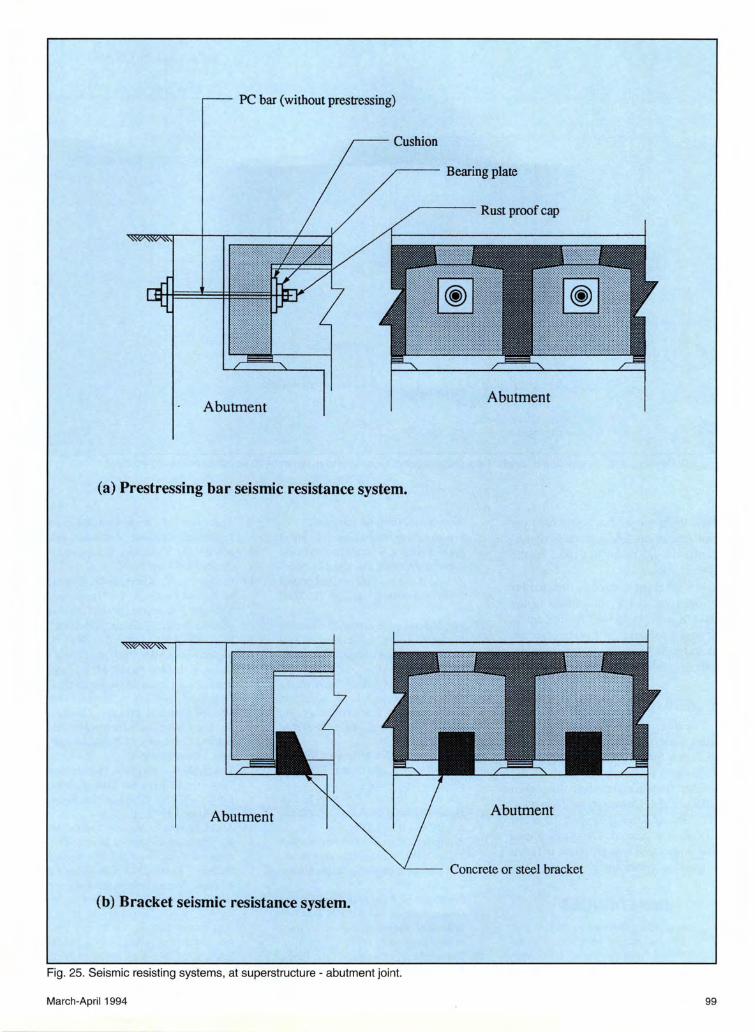
• High strength bars, such as prestressing bars, to tie the abutment back wall to the end diaphragms of the superstructure. This system allows limited movement of the superstructure (see Fig. 25a).
• Reinforced concrete or steel brackets. These brackets are designed to resist horizontal forces due to earthquakes and prevent the movement of girders during an earthquake (see Fig. 25b).
CONCLUDING REMARKS Over 97 percent of the bridges being
built in Japan with span lengths of up to 21 m (69 ft), are made of precast, prestressed concrete girders . Due to
March-April 1994
transportation restrictions, longer girders are not precast in a plant. This necessitates site-cast precast, post-tensioned concrete girder production in the span range of 20 to 40 m (66 to 131 ft) . Much larger girders have traditionally been shipped in the United States, with lengths up to 51 m (167 ft) and weights up to 68 t (75 tons).
Precast, prestressed girders in Japan are either T-or box-shaped. The Tshape is more economical when structural depth and construction time are not restricted . For both shapes , the transverse girder spacing is very small, similar to American butted box systems. However, unlike American practice, cast-in-place concrete is used in relatively large shear keys or longitudinal strips.
Also, all bridge decks are trans-
40
r : CIP/Precast weight ratio
30 35 40
T I Single stemmed (U.S.) !-girder (U.S.)
versely post-tensioned at relatively high levels of prestressing force . Most bridges in Japan do not incorporate cast-in-place structural slabs in composite action with the girders. However, a wearing surface is required on all bridge decks .
Site-cast precast girders ranging from 20 to 40 m (66 to 131 ft) in length are post-tensioned on the ground. They are more closely spaced in the superstructure than the American 1-girder system. Also, they are connected together with large cast-inplace diaphragms and transverse posttensioning.
Short and medium span bridge design and detailing is standardized in Japan. The live load moments, shears and other effects are comparable to those specified by AASHTO. How-
95

~ 1-----0
0 :!JI----Irl r-
350
600
250
.-------- Transverse post-tensioning
Cross section A - A
Standard span 20 000
560
100
Side view B - B
17.8 mm (0.7 in.) diameter strand fpu = 1860 MPa {270 ksi) Pe = 206 kN/strand
(46 kips/strand)
Cast-in-place concrete
Duct 42mm Transverse post-tensioning
Duct 35mm
Detail C
Fig. 22. Example of transverse post-tensioning for pretensioned box girder bridge with span of 20m and TL-20 loading. Note: 1 m = 3.28 ft; 1 mm = 0.0394 in.
96 PCI JOURNAL

300
300
8 '<t"
400
Transverse post-tensioning
19.3 mm (0.76 in.) diameter strand fpu = 1860 MPa (270 ksi) Pe = 245 leN/strand
(55 kips/strand)
Cross section A - A
Standard span 20 000
40@ 500 = 20000
500
Side view B - B
Cast-in-place concrete
Duct 42mm Transverse post-tensioning
Duct 35mm
Detail C
Fig. 23. Example of transverse post-tensioning for pretensioned T-girder bridge with span of 20m and TL-20 loading. Note: 1 m = 3.28 ft; 1 mm = 0.0394 in.
March-April 1994 97

0 ->< ... ~
.~ a 1\
.....J
I 1--
780 (2'-7")
Dowel system
Duct filled with non-shrink, and non-metallic mortar
Oval steel pipe
Steel bar
Longitudinal direction
Steel bar
Mortar
Girder length 20 700 (68')
Standard span 20 000 (66')
Steel pipe (I.D. = 38mm)
Steel bar
Elastic fllling
Steel pipe
End free to move horizontally
End not free to move horizontally
Dowel system
•
Fig. 24. Bearing and seismic dowel details for a pretensioned box girder bridge [span of 20m (66ft) for TL-20 loading].
98 PCI JOURNAL
PC bar (without prestressing)
Cushion
,.---- Bearing plate
_,----- Rust proof cap
Abutment
(a) Prestressing bar seismic resistance system.
Abutment
(b) Bracket seismic resistance system.
Fig. 25. Seismic resisting systems, at superstructure - abutment joint.
March-April 1994
Abutment
Abutment
Concrete or steel bracket
99

Girder length 20 600 (68')
1 ()()() (3'-3") 300 (1'-0") Standard span 20 000 (66')
1· T ..
Spiral bar
Mortar
Bearing pad Dowel system Rust proof material
Duct filled with non-shrink, non-metallic mortar
Fig. 26. Bearing and seismic dowel details for a pretensioned T-girder bridge [span of 20m (66ft) for TL-20 loading].
ever, the amount of concrete used per unit area of the bridge deck is significantly larger than that used in the
United States. Most bridges, except box girder
bridges, are made continuous in the
field by using mild steel reinforcement or post-tensioning. All bridges are required to have seismic connection details as given in the paper.
ACKNOWLEDGMENT The authors wish to express their
appreciation to Kyokuto Corporation of Japan for its financial support of Takashi Yamane's research at the Center for Infrastructure R esearch (CIR) of the University of NebraskaLincoln. Additional support from the CIR is appreciated. D r. Amin Einea and Ms. Deborah Derrick offered valuable suggestions.
REFERENCES 1. Special Issue Devoted to Precast Pre
stressed Concrete Members, Journal of Prestressed Concrete, Japan Prestressed Concrete Engineering Associ-
100
ation, V. 33, 1991. (in Japanese). 2. Precast/Prestressed Concrete Short
Span Bridges, Precast/Prestressed Concrete Institute, Chicago, IT.,, 1985.
3. Bridge Bulletin, Precast/Prestressed Concrete Institute, Chicago, IT., , Winter 1990.
4. The Manual of Prestressed Concrete Bridge Planning, Association of Prestressed Concrete Construction, 1990. (in Japanese).
5. Standard Specifications for Highway Bridges, Fifteenth Edition, American Association of State Highway and Transportation Officials, Inc., Washington, D. C., 1992.
6. Specification for Highway Bridge, Japan Road Association , February 1990. (in Japanese).
7. "Design Criteria," Chapter 2, The Japan Highway Public Corporation, July 1990. (in Japanese).
8. Prestressed Concrete Girders for Slab Bridges, JIS A 5313, Japanese Industrial Standard, Japanese Standards Association, 1991.
9. Prestressed Concrete Girders for Girder Bridges, ITS A 5316, Japanese Industrial Standard, Japanese Standards Association, 1991.
10. Tadros, M. K. , Ficenec, J. A., Einea, A ., and Holdsworth , S ., "A New
Technique to Create Continuity in Prestressed Concrete Members," PCI JOURNAL, V. 38, No. 5, SeptemberOctober 1993, pp. 30-37.
11. Ficenec, J. A., Kneip, S. D. , Tadros, M. K. , and Fischer, L. G., "Prestressed Spliced !-Girders: Tenth Street Viaduct Project, Lincoln, Nebraska," PCI JOURNAL, V. 38 , No. 5 , September-October 1993, pp. 38-48.
12. Geren, K. L., and Tadros, M. K. , "Optimization of Precast/Prestressed Concrete Bridge !-Girders," Precast/Prestressed Concrete Institute, Chicago, IL, and Center for Infrastructure Research, University of Nebraska-Lincoln, December 1992.
13. Tokerud, R., "Precast Prestres sed Concrete Bridges for Low-Volume Roads," PCI JOURNAL, V. 24, No. 4, July-August 1979, pp. 42-56.
14. Abdel-Karim, A. M., and Tadros, M. K. , "State-of-the-Art of Precast/Prestressed Concrete Spliced !-Girder Bridges," Report, PCI Committee on Bridges, Precast/Prestressed Concrete Institute, Chicago, IT.,,
15. Rabbat, B. G ., and Ru ssell , H . G., "Optimized Sections for Precast Prestressed Bridge Girders," PCI JOURNAL, V. 27, No.4, July-August 1982, pp. 88-104.
PCI JOURNAL