Electric Motor Periodic Inspection and Maintenance
16
APTA STANDARDS DEVELOPMENT PROGRAM RECOMMENDED PRACTICE American Public Transportation Association 1300 I Street, NW, Suite 1200 East, Washington, DC 20006 APTA RT-VIM-RP-010-02, Rev. 2 First Published: Sept. 22, 2002 First Revision: July 26, 2004 Second Revision: April 7, 2017 Rail Transit Standards Vehicle Inspection and Maintenance Working Group This document represents a common viewpoint of those parties concerned with its provisions, namely operating/ planning agencies, manufacturers, consultants, engineers and general interest groups. The application of any standards, recommended practices or guidelines contained herein is voluntary. In some cases, federal and/or state regulations govern portions of a transit system’s operations. In those cases, the government regulations take precedence over this standard. The North American Transit Service Association (NATSA) and its parent organization APTA recognize that for certain applications, the standards or practices, as implemented by individual agencies, may be either more or less restrictive than those given in this document. © 2017 NATSA and its parent organization. No part of this publication may be reproduced in any form, in an electronic retrieval system or otherwise, without the prior written permission of NATSA. Electric Motor Periodic Inspection and Maintenance Abstract: This Recommended Practice covers basic procedures for periodic inspection and maintenance of electric motors on rail transit vehicles, with emphasis on maintenance of safety-critical components. Keywords: electric motor, periodic inspection and maintenance Summary: This document establishes a recommended practice for electric motor inspection and maintenance. Rail transit systems should tailor these recommendations to accommodate their specific equipment and mode of operation. Scope and purpose: This Recommended Practice includes essential periodic inspection and maintenance requirements for integral horsepower electric motors utilized on rail transit vehicles. Running maintenance should be developed by the rail transit system based on its service requirements and mileage. Rail transit systems may exceed recommendations given herein. This Recommended Practice is intended for use by rail equipment maintenance organizations.
-
Upload
khangminh22 -
Category
Documents
-
view
2 -
download
0
Transcript of Electric Motor Periodic Inspection and Maintenance
A P T A S T A N D A R D S D E V E L O P M E N T P R O G R A M
RECOMMENDED PRACTICE
American Public Transportation Association
1300 I Street, NW, Suite 1200 East, Washington, DC 20006
APTA RT-VIM-RP-010-02, Rev. 2
First Published: Sept. 22, 2002
First Revision: July 26, 2004
Second Revision: April 7, 2017
Rail Transit Standards Vehicle
Inspection and Maintenance Working
Group
This document represents a common viewpoint of those parties concerned with its provisions, namely operating/ planning agencies, manufacturers, consultants, engineers and general interest groups. The application of any standards, recommended practices or guidelines contained herein is voluntary. In some cases, federal and/or state regulations govern portions of a transit system’s operations. In those cases, the government regulations take precedence over this standard. The North American Transit Service Association (NATSA) and its parent organization APTA recognize that for certain applications, the standards or practices, as implemented by individual agencies, may be either more or less restrictive than those given in this document.
© 2017 NATSA and its parent organization. No part of this publication may be reproduced in any form, in an electronic retrieval system or otherwise, without the prior written permission of NATSA.
Electric Motor Periodic Inspection and Maintenance
Abstract: This Recommended Practice covers basic procedures for periodic inspection and maintenance of
electric motors on rail transit vehicles, with emphasis on maintenance of safety-critical components.
Keywords: electric motor, periodic inspection and maintenance
Summary: This document establishes a recommended practice for electric motor inspection and maintenance.
Rail transit systems should tailor these recommendations to accommodate their specific equipment and mode
of operation.
Scope and purpose: This Recommended Practice includes essential periodic inspection and maintenance
requirements for integral horsepower electric motors utilized on rail transit vehicles. Running maintenance
should be developed by the rail transit system based on its service requirements and mileage. Rail transit
systems may exceed recommendations given herein. This Recommended Practice is intended for use by rail
equipment maintenance organizations.
© 2017 American Public Transportation Association | ii
Table of Contents
Introduction ................................................................................................................................... iv
1. Frequency of conduct ................................................................................................................ 1
2. Requirements and specific tasks .............................................................................................. 1 2.1 Materials ................................................................................................................................................. 1 2.2 Devices and tools .................................................................................................................................... 2 2.3 Safety/personal protective equipment .................................................................................................... 3 2.4 Training requirements ............................................................................................................................ 3 2.5 Inspection and maintenance of DC motors............................................................................................. 3 2.6 Inspection and maintenance of AC motors............................................................................................. 8 2.7 Correction of deficiencies ....................................................................................................................... 9
3. Documentation/maintenance log reports ................................................................................. 9
Related APTA standards ............................................................................................................. 10
References ................................................................................................................................... 10
Definitions .................................................................................................................................... 10
Abbreviations and acronyms ...................................................................................................... 11
Summary of document changes ................................................................................................. 11
Document history ........................................................................................................................ 12
List of Figures and Tables
Figure 1 Minimum Motor Commutator Brush Length in 1∕32 in. Increments ............................................... 2 Figure 2 Ideal Surface .................................................................................................................................. 4 Figure 3 Commutator Problems ................................................................................................................... 4 Figure 4 Motor Stoning Tool ....................................................................................................................... 5 Figure 5 Dial Indicate Commutator ............................................................................................................. 7
© 2017 American Public Transportation Association | iii
Participants
The American Public Transportation Association greatly appreciates the contributions of the Rail Transit
Vehicle Inspection and Maintenance Working Group, which provided the primary effort in the drafting of
this standard.
At the time this standard was completed, the working group included the following members:
Scott Lapps, Chair
Eric Petersen, Vice Chair
Vacant, Secretary
Marwan Al-Mukhtar, Sunlink
Juan Aristizabal, SYTECSA
Dave Barber, Transportation Resources Associates
Chris Barbour, Dellner Couplers
Sherif Bastawros, CH2M
Steve Bethel, Sunlink
Jerry Blackman, Miami-Dade Transit
Donald Bonds, Chicago Transit Authority
Stephen Bonina, Stadler Rail US
John Condrasky, Wabtec Corporation
Richard Curtis, Curtis Engineering Consulting
Henry Davis, SEPTA
Paul Denison, Sound Transit
Robert Doyle, Rdoyle Transit Consulting
Jeff Dunham, BEA Inc.
Phil Eberl, RTD, Denver
Marc Gagne, Transit Design Group
Mike Ghobrial, LTK Engineering Services
Dan Gornstein, Nippon Sharyo
John Green, BEA/Sensorio
Scott Grogan, MTA of Harris County
Terry Hildebrandt, NFTA
Ben Holland, BART
Anthony Jones, Voith Turbo Scharfenberg
John Kesich, Metro-North
Rick Kinding, TriMet
Henry Kolesar, BART
John Kortekaas, Sunlink
Paul Kovacs, Linvale Engineering and Machining
Joseph Krempasky, WMATA
John McEwen, SEPTA
Larry Nye, Port Authority of Allegheny County
Frank Pierson, Interfleet Technology
John Sadorra, SFMTA
Richard Seaton, Transit Design Group
Melissa Shurland, Federal Railroad Administration
James Skaggs, International Electronic Machines
Bill Steinmetz, Port Authority of Allegheny County
Narayana Sundaram, ENSCO
Michele Swayzer, Swayzer Engineering
Tom Tarantino, Dellner Corp.
Brian Turner, Transportation Learning Center
Wilson Wallace, Maryland Transit Administration
Michael Wetherell, NYCT
Evalynn Williams, Dikita Engineering
Daniel Wilson, Miami-Dade Transit
Cliff Woodbury, LTK Engineering Services
Bob Young, Bombardier Transportation
Project consultants
Tim Borchers and Gordon Campbell, Interfleet Technology Inc.
Project team
Charles Joseph, American Public Transportation Association
© 2017 American Public Transportation Association | iv
Introduction This introduction is not a part of APTA RT-RP-VIM-010-02 Rev 2 ‘Recommended Practice for Passenger
Electric Motor Periodic Inspection and Maintenance’.
This Recommended Practice for rail transit vehicles represents a common viewpoint of those parties concerned
with its provisions, namely transit operating/planning agencies, manufacturers, consultants, engineers and
general interest groups. The application of any standards, practices or guidelines contained herein is voluntary.
In some cases, federal and/or state regulations govern portions of a rail transit system’s operations. In those
cases, the government regulations take precedence over this standard. APTA recognizes that for certain
applications, the standards or practices, as implemented by individual rail transit agencies, may be either more
or less restrictive than those given in this document.
This Recommended Practice describes the basic inspection and maintenance requirements for electric motors
found on rail transit vehicles. APTA recommends the use of this Recommended Practice by:
individuals or organizations that maintain electric motors on rail transit vehicles;
individuals or organizations that contract with others for the maintenance of electric motors on rail
transit vehicles; and
individuals or organizations that influence how electric motors are maintained on rail transit vehicles.
APTA RT-VIM-RP-010-02, Rev. 2 Electric Motor Periodic Inspection and Maintenance
© 2017 American Public Transportation Association Page 1 of 12
Electric Motor Periodic Inspection and Maintenance
1. Frequency of conduct Periodic inspection and maintenance tasks on the electric motors should be performed on a regular schedule as
determined by the rail transit system (RTS). The frequency of any task contained within this Recommended
Practice shall comply with all applicable federal, state and local regulations. Maintenance tasks on electric
motors should be performed on a regular schedule to ensure proper operation of the equipment. Further, in the
conduct of a RTS’s periodic inspection and maintenance programs, the frequencies for individual tasks should
be established based on a number of additional factors, including but not limited to the following:
original equipment manufacturer (OEM) recommended intervals
industry experience
operating environment/conditions
historical data
performance requirements
failure analysis
RTS’s testing and experience
reliability-centered maintenance programs
2. Requirements and specific tasks
WARNING: Before working on electrical motors, make sure that the appropriate system circuit
breakers or knife switches are open and properly locked and/or tagged in accordance with the RTS
procedures.
2.1 Materials
The following materials are normally required for electric motor inspection and maintenance:
approved lubricant required by the OEM
reference OEM maintenance manuals for additional appropriate information
RTS or OEM-approved brushes
operation and maintenance manuals for respective property
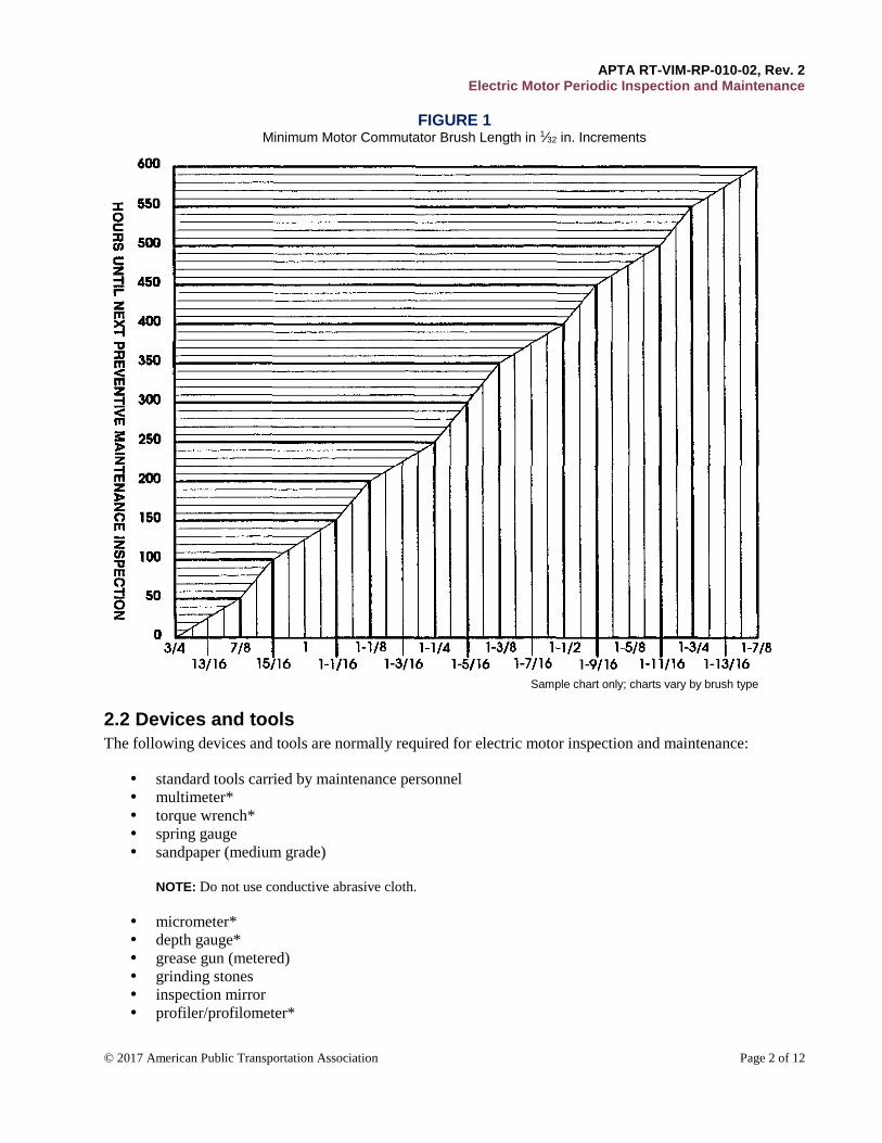
approved brush wear chart for each motor type operation (Figure 1 shows a sample chart)
APTA RT-VIM-RP-010-02, Rev. 2 Electric Motor Periodic Inspection and Maintenance
© 2017 American Public Transportation Association Page 2 of 12
FIGURE 1 Minimum Motor Commutator Brush Length in 1∕32 in. Increments
Sample chart only; charts vary by brush type
2.2 Devices and tools
The following devices and tools are normally required for electric motor inspection and maintenance:
standard tools carried by maintenance personnel
multimeter*
torque wrench*
spring gauge
sandpaper (medium grade)
NOTE: Do not use conductive abrasive cloth.
micrometer*
depth gauge*
grease gun (metered)
grinding stones
inspection mirror
profiler/profilometer*
APTA RT-VIM-RP-010-02, Rev. 2 Electric Motor Periodic Inspection and Maintenance
© 2017 American Public Transportation Association Page 3 of 12
dial indicator*
flashlight
brush holder brush box go/no-go gauge
air hose
megohmmeter (megger) 500 V or 1000 V*
air nozzle, pressure regulated
NOTE: Devices and tools designated with an asterisk (*) require periodic calibration as specified by
the rail transit system’s practices.
2.3 Safety/personal protective equipment
Appropriate personal protective equipment, meeting minimum ANSI standards and as required by the RTS,
shall be worn at all times in the performance of these inspection and maintenance tasks.
2.4 Training requirements
RTS and/or their maintenance contractors should develop and execute training programs that provide
employees with the knowledge and the skills necessary to safely and effectively perform the tasks outlined in
this Recommended Practice. Visual aids are available from various brush manufactures exhibiting commutator
and brush conditions for DC motors. Aids such as these will provide employees with various recognizable
motor conditions.
2.5 Inspection and maintenance of DC motors
The inspection and maintenance checks below are general checks for all DC electrical motors using a supply
voltage up to 1000 VDC. However, these checks should be applied only to those motors that are economically
feasible to repair. These checks are tailored primarily for transit vehicle traction motors.
2.5.1 Visual interior inspection
Visually inspect the following:
a) The field coils wherever visible for overheating or charred conditions. If these conditions are found,
then perform an electrical test as outlined in Section 2.5.4.
b) Field coil connectors wherever visible for discoloration, cracks or looseness of connections. If these
conditions are found, then perform an electrical test as outlined in Section 2.5.4.
c) The security of brush holder to motor. If necessary, secure in accordance with OEM recommendations.
d) The condition of the string band or Teflon band. Epoxy type string band must not indicate signs of
cracking, chipping, flaking appearance or uneven color. Teflon type must indicate a tight fit to V ring
and contact with commutator bars with no peeling or any type of hole that may have been caused by
motor flashover. If any of these conditions exist, then replace the motor.
e) The mounting hardware for looseness. All hardware shall be torqued to OEM specifications.
f) Bearing for lubrication leakage. No leakage is allowed on the interior of the motor.
g) Inspect for signs of flashovers (end of commutator, string/Teflon band and flash arc horns). If flashing
is noted, then dress and clean all areas. Vacuum or blow out inside of motor after dressing flashovers.
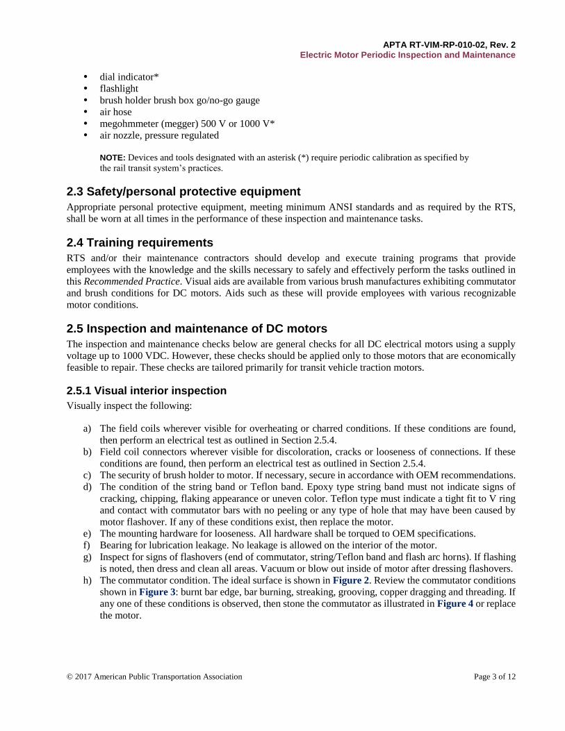
h) The commutator condition. The ideal surface is shown in Figure 2. Review the commutator conditions
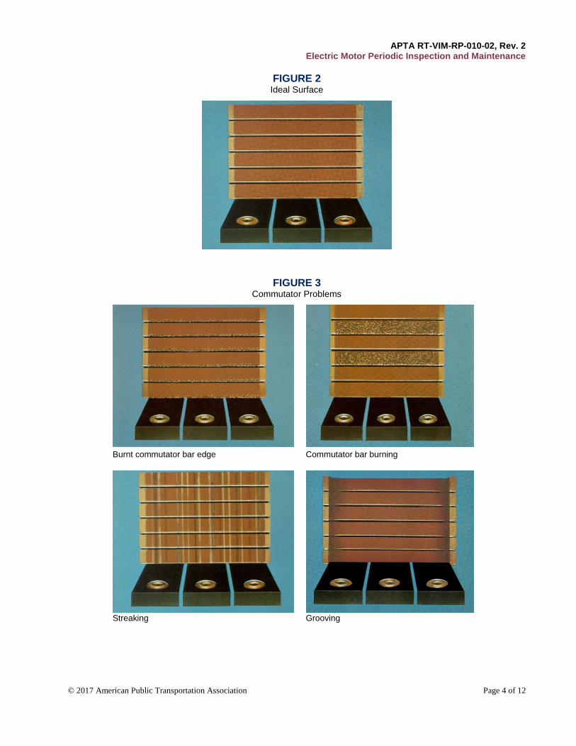
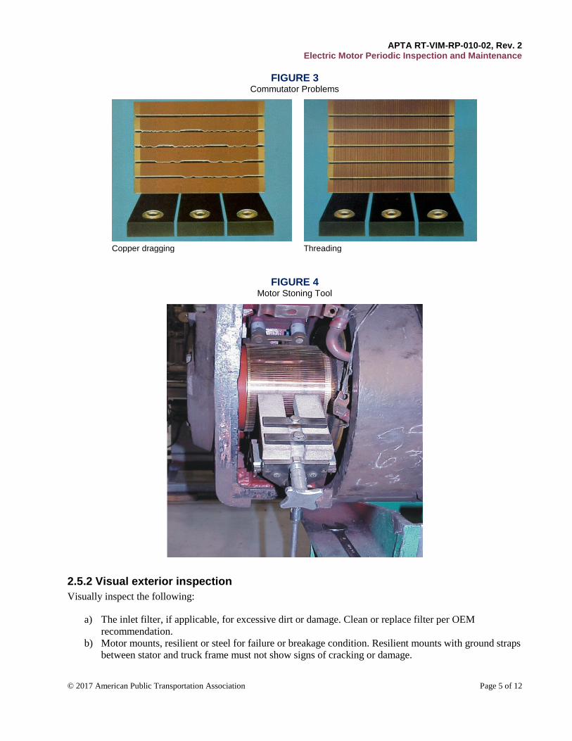
shown in Figure 3: burnt bar edge, bar burning, streaking, grooving, copper dragging and threading. If
any one of these conditions is observed, then stone the commutator as illustrated in Figure 4 or replace
the motor.
APTA RT-VIM-RP-010-02, Rev. 2 Electric Motor Periodic Inspection and Maintenance
© 2017 American Public Transportation Association Page 4 of 12
FIGURE 2 Ideal Surface
FIGURE 3 Commutator Problems
Burnt commutator bar edge Commutator bar burning
Streaking Grooving
APTA RT-VIM-RP-010-02, Rev. 2 Electric Motor Periodic Inspection and Maintenance
© 2017 American Public Transportation Association Page 5 of 12
FIGURE 3 Commutator Problems
Copper dragging Threading
FIGURE 4 Motor Stoning Tool
2.5.2 Visual exterior inspection
Visually inspect the following:
a) The inlet filter, if applicable, for excessive dirt or damage. Clean or replace filter per OEM
recommendation.
b) Motor mounts, resilient or steel for failure or breakage condition. Resilient mounts with ground straps
between stator and truck frame must not show signs of cracking or damage.

APTA RT-VIM-RP-010-02, Rev. 2 Electric Motor Periodic Inspection and Maintenance
© 2017 American Public Transportation Association Page 6 of 12
c) Leads for any overheating at the opening in the lead cleat. If found, determine cause and replace the
lead as required. All loose hardware shall be torqued to OEM specifications.
d) Motor leads shall not chafe or indicate broken insulation. If chafing is found, then reposition the lead.
If broken insulation is found, then replace the motor.
e) Bearing caps or cartridges for overheating and lubricant leakage. If found, then perform corrective
action to determine the cause. Replace the motor as required.
f) All mounting hardware for looseness. If any are found loose, then torque to OEM specification. To
expedite future inspections, apply torque stripes and/or witness marks to the mounting hardware.
g) That all ground straps/cables insulation is in good condition and show no signs of cracking, over heating
or fraying. Replace if required. All loose hardware shall be torqued to OEM specifications.
NOTE: If any motor is found to be vibrating unusually or noisily, identify the problem. If found, then,
repair or replace the motor as required.
2.5.3 Mechanical inspection
a) Inspect brushes for missing, chipping (incidental chips do not require replacement), discoloration,
loose/broken strands and fraying. Replace in kind if these conditions exist.
b) Measure brush lengths per OEM/individual RTS property specifications. Ensure that they will not
exceed condemning limits before the next inspection. Use an approved chart for brush wear limits that
is based on RTS operating limits (see Figure 1). Replace in kind if brushes do not meet the
specifications of the OEM or RTS, or if brushes will not meet service life before next inspection.
NOTE: If brushes are replaced, all brushes on the same motor must be from the same brush
manufacturer’s type and grade.
c) Measure brush holder distance from commutator per OEM specifications. Adjust as required.
NOTE: Nominal distance on many motors is 3∕32 to ⅛ in.
d) Measure brush holder distance from the commutator riser per OEM specifications. Adjust as required.
e) Measure brush holder distance from the arc horn if applicable per OEM specification. Adjust as
required.
f) If a problem is identified, then use a spring gauge to measure spring tension at the top of the brush.
Correct brush pressure is essential for optimum motor operation. Replace spring arm if OEM/RTS
specification is not met.
NOTE: Nominal pressure for rail transit vehicle motors is 6 to 10 lb.
g) Verify that brushes move freely (no binding), but not excessively in the brush box. If binding or
excessive movement is evident, then use the brush holder go/no-go gage to determine the correct
operating limits. Replace the brush holder if no-go specifications fail OEM/RTS specifications. If the
brush holder passes go/no-go inspection, yet the brushes still indicate signs of loose fit, and then
measure the brush dimensions according to OEM specifications. Replace brushes as required.
h) Check for proper shunt dressing. Correct shunt dressing is essential for motor operation. Improper
routing may cause brushes to bind in the brush box, causing the brush to lose contact with the
commutator surface. Check OEM specifications for proper shunt dressing for the motor in question.
i) Check commutator for high mica, low mica or commutator deficiencies.
j) Check flash pins for signs of damage.
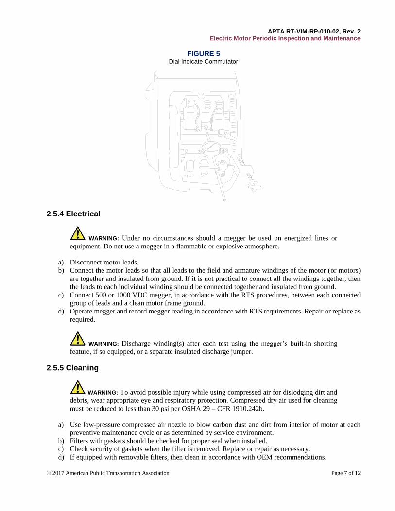
NOTE: Measure commutator total indicated runout (TIR) with use of dial indicator or
profiler/profilometer (see Figure 5 for dial indicator use).
APTA RT-VIM-RP-010-02, Rev. 2 Electric Motor Periodic Inspection and Maintenance
© 2017 American Public Transportation Association Page 7 of 12
FIGURE 5 Dial Indicate Commutator
2.5.4 Electrical
WARNING: Under no circumstances should a megger be used on energized lines or
equipment. Do not use a megger in a flammable or explosive atmosphere.
a) Disconnect motor leads.
b) Connect the motor leads so that all leads to the field and armature windings of the motor (or motors)
are together and insulated from ground. If it is not practical to connect all the windings together, then
the leads to each individual winding should be connected together and insulated from ground.
c) Connect 500 or 1000 VDC megger, in accordance with the RTS procedures, between each connected
group of leads and a clean motor frame ground.
d) Operate megger and record megger reading in accordance with RTS requirements. Repair or replace as
required.
WARNING: Discharge winding(s) after each test using the megger’s built-in shorting
feature, if so equipped, or a separate insulated discharge jumper.
2.5.5 Cleaning
WARNING: To avoid possible injury while using compressed air for dislodging dirt and
debris, wear appropriate eye and respiratory protection. Compressed dry air used for cleaning
must be reduced to less than 30 psi per OSHA 29 – CFR 1910.242b.
a) Use low-pressure compressed air nozzle to blow carbon dust and dirt from interior of motor at each
preventive maintenance cycle or as determined by service environment.
b) Filters with gaskets should be checked for proper seal when installed.
c) Check security of gaskets when the filter is removed. Replace or repair as necessary.
d) If equipped with removable filters, then clean in accordance with OEM recommendations.
APTA RT-VIM-RP-010-02, Rev. 2 Electric Motor Periodic Inspection and Maintenance
© 2017 American Public Transportation Association Page 8 of 12
e) If the filter has deteriorated to be uncleanable, replace with serviceable filter.
f) Clean brush holder insulators and string/Teflon band with dry, clean cloth.
2.5.6 Lubrication
WARNING: Do not over grease.
a) Motor bearing and/or couplings must be serviced as recommended by OEM or RTS requirements.
b) Check for lubrication leakage, internal and external. If found, then determine the cause. Replace the
motor in accordance with RTS requirements.
c) Check motor coupling for proper lubrication by measuring depth if possible. Check OEM or RTS
specifications for proper depth.
2.6 Inspection and maintenance of AC motors
The inspection and maintenance checks in this section are general checks for all AC electrical motors up to
1000 VAC. However, these checks should be applied only to those motors that are economically feasible to
repair. These checks are primarily tailored for transit vehicle traction motors.
2.6.1 Visual interior inspection
Inspect for bearing lubrication leakage if possible. No leakage is allowed on the interior of the motor. If found,
then replace the motor.
2.6.2 Visual exterior inspection
Visually inspect the following:
a) The inlet filter, if applicable, for excessive dirt or damage. Clean or replace filter per OEM
recommendation.
b) Motor mounts, resilient or steel for failure or breakage condition. Resilient mounts with ground straps
between stator and truck frame must not show signs of cracking or damage.
c) Leads for any overheating at the opening in the lead cleat. If found, determine cause and replace the
lead as required. All loose hardware shall be torqued to OEM specifications.
d) Motor leads shall not chafe or indicate broken insulation. If chafing is found, then reposition the lead.
If broken insulation is found, then replace the motor.
e) Inspect for bearing lubrication leakage. If found, then replace the motor.
f) All mounting hardware for looseness. If any are found loose, then torque to OEM specification. To
expedite future inspections, apply torque stripes and/or witness marks to the mounting hardware.
g) That all ground straps/cables insulation is in good condition and show no signs of cracking, over heating
or fraying. Replace if required. All loose hardware shall be torqued to OEM specifications.
NOTE: If any motor is found to be vibrating unusually or noisily, identify the problem. If found,
then, repair or replace the motor as required.
2.6.3 Electrical inspection
a) Conduct a motor insulation test as per RTS or OEM recommendations. Replace the motor if necessary.
APTA RT-VIM-RP-010-02, Rev. 2 Electric Motor Periodic Inspection and Maintenance
© 2017 American Public Transportation Association Page 9 of 12
2.6.4 Cleaning
WARNING: To avoid possible injury while using compressed air for dislodging dirt and
debris, wear appropriate eye and respiratory protection. Compressed dry air used for cleaning
must be reduced to less than 30 psi per OSHA 29 – CFR 1910.242b.
a) Use low-pressure compressed air nozzle to blow dust and dirt from the interior of the motor at each
preventive maintenance cycle or as determined by the service environment.
2.6.5 Lubrication
WARNING: Do not over grease.
a) Motor bearing and/or couplings must be serviced as recommended by the OEM or RTS procedures.
b) Inspect for lubrication leakage, internal and external. If found, then determine the cause. Replace the
motor if required in accordance with RTS requirements.
c) Inspect the motor coupling for proper lubrication by measuring the depth if possible. Check OEM or
RTS specifications for proper depth.
2.7 Correction of deficiencies
Any deficiencies uncovered during the inspections required in Section 2.5 and Section 2.6 should be corrected
and documented in accordance with RTS procedures and OEM recommendations.
3. Documentation/maintenance log reports All maintenance performed on rail transit vehicle motors must be documented. This documentation should be
noted on a unified type of form (electronic or paper) developed by the RTS. It should include the following:
car number
motor serial number
date maintenance performed
location of motor
description of problem
corrective action and part replaced
operational test and inspection
mileage/hours/date since last maintenance activity
serial number of part installed and removed if applicable
signature or identification number of person performing the maintenance activity
APTA RT-VIM-RP-010-02, Rev. 2 Electric Motor Periodic Inspection and Maintenance
© 2017 American Public Transportation Association Page 10 of 12
Related APTA standards APTA PR-E-RP-004-98, “Gap and Creepage Distance” (previously numbered as APTA RP-E-04-98)
APTA PR-E-RP-009-98, “Wire Used on Passenger Equipment” (previously numbered as APTA RP-E-009-98)
References This document should be used in conjunction with the following publications:
Original equipment manufacturers’ (OEM) specifications for electric motor equipment inspection and
maintenance.
Local operating property procedures for electrical motor equipment inspection and maintenance.
Brush Digest, NATIONAL, Union Carbide Corporation, (11th and 13th reprinting).
29 CFR1910.242b, Compressed Air Used for Cleaning
Institute of Electrical and Electronics Engineers:
IEEE 100, The Authoritative Dictionary of IEEE Standards and Terms - Seventh Edition
IEEE Std. 11-2000, IEEE Standard for Rotating Electric Machinery for Rail and Road Vehicles
James G. Biddle Co., “A Stitch in Time: Electrical Insulation Testing for the Practical Man,” Second
Edition, December 1978
James G. Biddle Co., Instruction Manual for the use of “MEGGER” Insulation Testers, Third Edition,
January 1950.
Morganite Carbon Ltd., “Morganite Carbon Brushes and Electrical Machines,” reprint, 1988.
Definitions armature: The part of a machine, whether rotating or stationary, that carries the winding connected to the
external circuit in which the principal electromotive force (EMF) is induced.
NOTE: This term is usually limited to the rotating part of a DC machine and refers to the complete
assembly of the winding with core and commutator.
brush: A conductor serving to provide, at a rotating surface, electrical contact with a part moving relative to
the brush.
brush holder: A structure designed to carry a brush or brushes that enables it to be maintained in contact with
a sliding surface.
cleat: A device used to secure motor cables in place. A cleat typically consists of an assembly of two pieces of
insulating material provided with grooves for holding one or more conductors at a definite spacing from the
surface, wired over and from one another, and with screw holes for fastening in position.
commutator: An assembly of bars of segmental section, insulated from one another and connected to the coils
of an armature winding. The assembly comprises a hollow cylinder on which brushes bear, generally on the
cylindrical surface but sometimes on the radial surface. The arrangement serves to connect each of the sections
of the armature winding in turn with an external circuit connected to the brushes.
integral motor: A motor with an HP rating that is one (1) or greater.
megger/megohmmeter: A precision device designed to test dielectric strength of both motor and cable
insulation.
APTA RT-VIM-RP-010-02, Rev. 2 Electric Motor Periodic Inspection and Maintenance
© 2017 American Public Transportation Association Page 11 of 12
profiler/profilometer: A precision device designed to measure commutator surfaces.
rotor: A rotating part of an electrical machine with a shaft, usually applied to an AC machine.
stator: The fixed part of an electrical machine. A base or other support or suspension elements, if provided, is
not ordinarily considered to be part of the stator.
total indicated run out (TIR): Total deviation from perfectly round condition.
Abbreviations and acronyms AC alternating current
ANSI American National Standards Institute
CFR Code of Federal Regulations
DC direct current
EMF electromotive force
MΩ megohm
NATSA North American Transit Services Association
OEM original equipment manufacturer
OSHA Occupational Safety and Health Administration
psi pounds per square inch
TIR total indicated run out
TM traction motor
V volts
Summary of document changes
Document formatted to the new APTA standard format.
Sections have been renumbered and moved.
Scope of work and summary sections moved to the front page.
Definitions, abbreviations and acronyms moved to the back of the document.
Two new sections added, “Summary of document changes and “Document history”
Some global changes to section headings and numberings resulted when sections dealing with
references and acronyms were moved to the end of the document and other cosmetic changes, such as
capitalization, punctuation, spelling, grammar and general flow of text.
Section 2.2 - Title changed from Tools to Devices and Tools.
Section 2.5.4 – (c) and (d) MG values deleted and left to the RTS to determine acceptable values.
Previous Section 5.6.2 renumbered to 2.6.2 – “Visual Exterior Inspection” Deleted and a new Section
2.6.2 added for ‘Visual exterior inspection’ added.
Previous Section 5.6.3 renumbered to 2.6.3 – “Mechanical Inspection” subsections deleted and
replaced with new subsections.
Previous Section 5.6.4 renumbered to – “Electrical Inspection” – subsections (a) and (b) deleted and a
new subsection (a) added.
Section on Definition – New definition for Integral motor added
Section on Definition – Definition for Slip ring deleted as it is not used in the document.
APTA RT-VIM-RP-010-02, Rev. 2 Electric Motor Periodic Inspection and Maintenance
© 2017 American Public Transportation Association Page 12 of 12
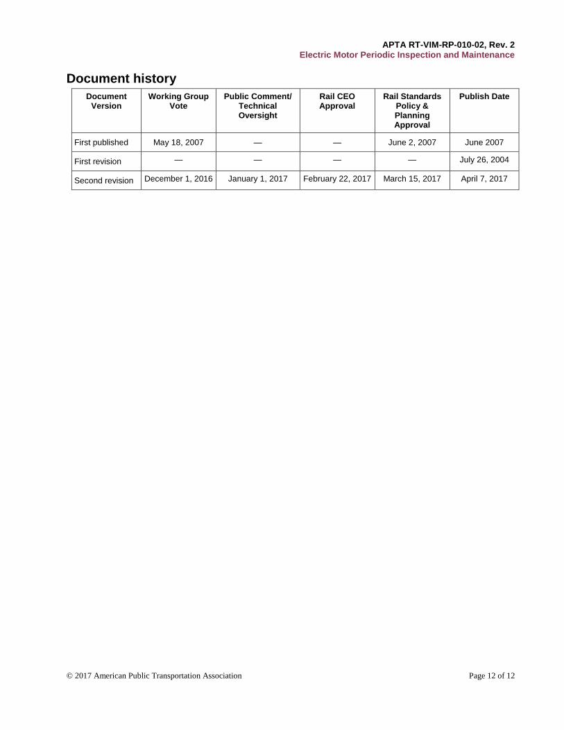
Document history
Document Version
Working Group Vote
Public Comment/ Technical Oversight
Rail CEO Approval
Rail Standards Policy & Planning Approval
Publish Date
First published May 18, 2007 — — June 2, 2007 June 2007
First revision — — — — July 26, 2004
Second revision December 1, 2016 January 1, 2017 February 22, 2017 March 15, 2017 April 7, 2017