INSPECTION AND TESTING REQUIREMENTS
17
INSPECTION AND TESTING REQUIREMENTS IT-7 WATER SUPPLY TABLE OF CONTENTS IT-7.1 Testing of Welds 1 IT-7.2 Pre-backfill inspection 1 IT-7.3 Pressure Test 1 IT-7.4 Water Mains Disinfection Inspection and FAC test 8 IT-7.5 E-coli sampling 9 IT-7.6 Fire Hydrant Visual Inspection 10 IT-7.7 Valve Visual Inspection 10 IT-7.8 Water Meter Inspection 10
-
Upload
khangminh22 -
Category
Documents
-
view
0 -
download
0
Transcript of INSPECTION AND TESTING REQUIREMENTS
INSPECTION AND TESTING REQUIREMENTS
IT-7 WATER SUPPLY
TABLE OF CONTENTS
IT-7.1 Testing of Welds 1
IT-7.2 Pre-backfill inspection 1
IT-7.3 Pressure Test 1
IT-7.4 Water Mains Disinfection Inspection and FAC test 8
IT-7.5 E-coli sampling 9
IT-7.6 Fire Hydrant Visual Inspection 10
IT-7.7 Valve Visual Inspection 10
IT-7.8 Water Meter Inspection 10

1
IT-7.1 Testing of Welds
Refer to IT-5.2.1 Testing of Butt Welds in Polyethylene Pipes and IT-5.2.2 Testing of Electrofusion Weldsin Polyethylene Pipes.
IT-7.2 Pre-backfill inspection
Refer to the following information:
a) IT-1 General Provisions for minimum requirements and applying for inspections/tests
b) IT-1 Appendix A Inspection and Testing Summary for thei) number of inspections requiredii) timing of inspectionsiii) representatives at inspection
c) IS-7.4 Pre-backfill inspection for inspection sheet.
IT-7.3 Pressure Test
In addition to the following sections, refer to
a) IT-1 General Provisions for minimum requirements and applying for inspections/tests
b) IT-1 Appendix A Inspection and Testing Summary for thei) number of inspections requiredii) timing of inspectionsiii) representatives at inspections
c) IS-7.5 Pressure Testing checklist
d) TS-7.1a Constant Pressure Test Method (Flexible Pipes) (available in IDC Toolbox)
e) TS-7.1b Constant Pressure Test Method (Visco-Elastic Pipes) (available in IDC Toolbox)
f) TS-7.1c Pressure Rebound Test Method (Visco-Elastic Pipes) (available in IDC Toolbox)
g) TS-7.1d Visual Test Method (available in IDC Toolbox)
IT-7.3.1 Selecting the Test Method
The method of pressure test depends on the pipe material, combination of materials, pipe pressurerating, pipe diameter and test length. The Engineer shall nominate the appropriate test method at thetime of Development Works Approval or in the contract documents for Council projects. This allows thetesting method to be checked against the designed infrastructure to ensure the correct test method willbe used and any discussions and agreements between parties are made well before testing takes place.

2
The test methods are:
a) Constant Pressure Test Method for Flexible Pipes
b) Constant Pressure Test Method for Visco-Elastic Pipes
c) Pressure Rebound Test Method for Visco-Elastic Pipes
d) Visual Test Method for small diameter pipes, short test lengths or mixed materials
The final decision on whether a visual test may be undertaken is at the discretion of Council. The testmethod shall be selected using Table 1 Pressure Test Selection below:
Table 1: Pressure Test Selection
Test Method Pipe Material Pipe Diameter Length Test Sheet Further Criteria
Test
Met
hods
Constant Pressure TestMethod (FlexiblePipes)
Flexible Pipes(PVC, DI, GRP,Steel)
Any Diameter <1km TS7.1a
Constant Pressure TestMethod (Visco- ElasticPipes)
Visco-ElasticPipes (PE, PP,ABS)
Greater than DN315 <1km TS7.1b
Pressure Rebound TestMethod (Visco-ElasticPipes)
Visco-ElasticPipes (PE, PP,ABS)
DN63 up to DN315 <1km TS7.1c
Visual Test Method PVC DN100 <100m TS7.1d Specific CouncilApproval required.Visual test may beconsidered for theselengths.
DN150 up to DN200 <50mPE80 DN63 <60m
DN125 <50mPE100 DN125 <50m
DN180 up to DN250 <30mMixed Materials Up to DN315 <10m
Notes:
a) PVC = Polyvinyl Chloride Pipe, DI = Ductile Iron Pipe, GRP =Glass Reinforced Plastic Pipe, PE = Polyethylene Pipe, PP =Polypropylene Pipe, ABS = Acrylonitrile Butadiene Styrene Pipe.
b) The above table includes pipe material and diameters that are not in the Approved Materials list. Refer to the ApprovedMaterials section for selection of pipe material and diameters.
c) Where a test length comprises different pressure ratings, a test for each different pressure rated pipe shall be undertaken.d) Where a pipe material is not included in the table or there is any uncertainty regarding the appropriate test to use, please
contact Council for consideration and approval.
Note:
Different pipes act differently under pressure therefore different test methods are required. Flexible pipes flex and move underpressure, therefore a test with constant pressure is appropriate for this type of pipe material. Visco-Elastic pipes are moreelastic and will stretch under pressure and rebound faster to its unpressurised state once the pressure has been removed. ForVisco-Elastic pipes DN63-DN315 a constant pressure test will overstretch the pipe, therefore a rebound test is required. Forlarger >DN315 PE and PP pipes, the pipe is a lot stiffer so a constant pressure test is required. However, the methodology isdifferent to the constant pressure test for flexible pipes.

3
It is important to note that the pressure tests are very sensitive to variations in the test process, weather conditions andpreparation for the test.a) Air - All air must be removed from the length of pipe being tested. Entrapped or entrained air in the pipe will make
the test fail. Air can be compressed and therefore will not allow the tests to pass.b) Average Test Head - The Constant Pressure Test for Flexible Pipes requires the average test head over the length of
the pipe tested. This needs to be calculated accurately prior to the test. Getting this wrong may pass or fail the testincorrectly.
c) Temperature - The Pressure Rebound Test for Visco-Elastic Pipes requires the temperature of the water in the pipe tobe accurately measured, not guessed or estimated. It is not advised to attempt a pressure test in excessive heatwhere any portion of the pipe is exposed (during informal tests pipes may be exposed)
IT-7.3.2 Pressure Test Timing
Table 2: Pressure Test Timing sets out the timing of pressure tests depending on test method and testtype.
Table 2: Pressure Test Timing
Test Method Test Type: Contractor’s Test Test Type: Certifying Test
Test
Met
hod
Constant Pressure TestMethod (Flexible Pipes)
At Contractor’s discretion. Typicallybefore joints, fittings, serviceconnections and valves backfilled. Notethat the tests are sensitive totemperature changes which can occurwhen the mains are not backfilled.
All utilities are installed (including manifolds,meter boxes, end caps and power servicepillars on lot connections) and no furtherpoint loading will be carried out within closeproximity of the watermain andconnections. Within two weeks prior todisinfection.
Constant Pressure TestMethod (Visco- Elastic Pipes)Pressure Rebound TestMethod (Visco-Elastic Pipes)
Visual Test Method All joints, fittings, service connections and valves exposed. Main suitably restrained andbackfilled.
Explanatory Note:Contractor’s Test: Undertaken prior to Council witnessing to ensure the infrastructure has been constructed without defectsand is leak free.Certifying Test: Undertaken with the Engineer to certify and Council as witness.
IT-7.3.3 Test EquipmentTo ensure infrastructure testing is carried out accurately and consistently, Council supply test rigs for useduring testing. The following applies to using test rigs:
a) Rigs will be supplied for both Contractor’s and Certifying tests.
b) For Contractor’s tests, book the rig through the Council’s Representative and collect at Counciloffices.
c) For Certifying tests, book the rig when booking the test. The rig will be supplied to site by theCouncil’s Representative.
d) The test rig consists of a calibrated pressure gauge/data-logger and a certified water meter. Allother equipment shall be supplied by the Contractor.

4
e) The test rig shall only be used for the purpose it has been provided for and shall be returnedimmediately after the test is completed.
f) Where damage or loss of Council equipment occurs as a result of the actions of the Contractorand/or Engineer, the Contractor and/or Engineer shall be responsible for reimbursement to Councilfor all costs incurred, including full replacement if necessary.
g) In instances where the Contractor and/or Engineer wish to use their own measuring devices,approval for this is required from the Council’s Team Leader: Water Services.
IT-7.3.4 Test Procedures
IT-7.3.4.1 Constant Pressure Test Method for Flexible Pipes
The following shall be read in conjunction with NZS4404, C3.5 Constant Pressure Test. The Standard TestPressure (STP) = 25% above the rated pressure of the pipe material.
a) The procedure shall be as follows:i) Undertake all requirements of IS-7.5 Pressure Testing checklist.ii) Prepare test sheet TS7.1a Constant Pressure Test Method (Flexible Pipes) (available in IDC
Toolbox).iii) Pressurize the test length to STP.iv) Maintain the test pressure by adding measured and recorded quantities of make-up water, at
regular intervals over a period in the range of 1 – 12 hours.v) Where pressure measurements are not made at the lowest part of the test length, make an
allowance for the static head from the lowest point of the pipeline and the point ofmeasurement to ensure the STP is not exceeded at the lowest point.
vi) Complete form TS-7.1a – Constant Pressure Test Method (Flexible Pipes) (available in IDCToolbox).
b) The amount of make-up water (Q) to maintain the test pressure shall be as per the followingequation:
Q ≤ 0.14LDH
where:Q = allowable make-up water (L/hr)L = test length (km)D = nominal diameter of the pipe being tested (m)H = average test head over the length of the pipeline being tested (m)
c) The test length shall be accepted where:i) There is no failure of any pipeline component e.g. thrust block, pipe, fitting, jointii) No physical leakage has occurrediii) The amount of make-up water to maintain the test pressure complies with IT 7.3.4.1 b).

5
IT-7.3.4.2 Constant Pressure Test Method for Visco-Elastic Pipes
The following shall be read in conjunction with NZS4404, C3.6 Constant Pressure Test. The Standard TestPressure (STP) = 25% above the rated pressure of the pipe material.
a) The procedure shall be as follows:i) Undertake all requirements of IS-7.5 Pressure Testing checklist.ii) Prepare test sheet TS7.1b Constant Pressure Test Method (Visco-Elastic Pipes) (available in IDC
Toolbox).iii) Pressurize the test length to STP.iv) Shut main off and let pressure settle for 12 hours.v) Re-apply and maintain the test pressure for five hours by pumping a sufficient amount of water
at appropriate intervals e.g. every 15 minutes.vi) Record the water volume, in litres, required to maintain the pressure between Hour 2 and Hour
3 (V1).vii) Record the water volume, in litres, required to maintain the pressure between Hour 4 and Hour
5 (V2).
b) Calculate:
0.55V1 + Q.where:Q = allowable make up volume as per IT 7.3.4.1 b).
c) The test length shall be accepted where:i) There is no failure of any pipeline component e.g. thrust block, pipe, fitting, joint.ii) No physical leakage has occurred.iii) V2 ≤ 0.55V1 + Q.
IT 7.3.4.3 Pressure Rebound Test Method for Visco-Elastic Pipes
This following shall be read in conjunction with NZS4404, C3.7 Pressure Rebound Method for ViscoelasticPressure pipelines. The specified test pressure (STP) = 25% above the rated pressure of the pipematerial.
a) The first phase procedure shall be as follows:i) Undertake all requirements of IS-7.5 Pressure Testing checklist.ii) Prepare test sheet TS7.1b Pressure Rebound Test Method (Visco-Elastic Pipes) (available in IDC
Toolbox).iii) Reduce the pressure to just above atmospheric pressure at the highest point of the test length
and let it stand for one hour, ensuring no air enters the line.iv) Raise the pressure to STP within 10 minutes. Hold this pressure for 30 minutes by pumping
continuously, or for short intervals as required. Do not exceed the specified test pressure.v) During the 30 minute hold time, visually inspect for leaks. Shut off the pressure after this 30
minute period.vi) Allow the pressure to drop for one hour.vii) Measure the pressure after one hour (P60).

6
viii) If P60 ≤ 70% of the STP, the test has failed. Locate and rectify the cause and repeat IT 7.3.4.3a).ix) If P60 >70% of the STP proceed to IT 7.3.4.3b).
b) The second phase procedure (air volume assessment) shall be as follows:i) Within five minutes, reduce the pressure by 10-15% of STP (ΔP).ii) Measure the water volume bled out (ΔV).iii) Calculate the maximum allowable volume using the following equation:
ΔV(max allowable) = 1.2 x V x ΔP((1 / Ew) + (D / e) / ER))
Note: This equation differs from NZS4404.
where:
1.2 = air allowanceV = pipe volume (L)ΔP = measured pressure drop (kPa)Ew = bulk modulus of water (kPa) (see Table 3: Bulk Modulus of Water (Ew))D = pipe internal diameter (m)e = pipe wall thickness (mm)ER = pipe material modulus (kPa) (see Table 4: Pipe Material Modulus (ER))
Table 3: Bulk Modulus of Water (Ew)
Temperature(deg C)
Bulk Modulus(kPa x 103)
5 208010 211015 214020 217025 2210
30 2230
Table 4: Pipe Material Modulus (ER)
Temperature(deg C)
PE80B - E Modulus (kPa x 103) PE100 - E Modulus (kPa x 103)3h 3h
5 680 90010 610 82015 550 75020 510 68025 470 63030 430 600
iv) If ΔV > ΔV (max allowable), the test has failed. Locate and rectify the cause and repeat IT-7.3.4.3a) and IT-7.3.4.3b).
v) If ΔV ≤ ΔV (max allowable), proceed to IT-7.3.4.3c).

7
c) The third phase procedure (main test phase) shall be as follows:i) Record the pressure rise over 30 minutes.ii) If there is a failure, locate and repair leaks.
d) The test length shall be accepted where:i) There is no failure of any pipeline component e.g. thrust block, pipe, fitting, joint.ii) No physical leakage has occurred.iii) The pressure rises or remains the same in the 30 minute time period.
Note: If unsure about the pressure recovery, the length of monitoring time can be extended to 90 minutes. If the pressuredrops by more than 20kPa from the peak during this period, the test fails.
IT-7.3.4.4 Visual Test Method
Requests for Visual Tests will be assessed on a case by case basis.
The following shall be read in conjunction with NZS4404, C3.8 Visual Test For Small Pressure Pipelines.The specified test pressure (STP) = 25% above the rated pressure of the pipe material.
a) The procedure shall be as follows:i) Undertake all pre-test requirements of IS-7.5 Pressure Testing Checklist.ii) Prepare test sheet TS7.1d Visual test method (available in IDC Toolbox).iii) Pressurise the test length to STP.iv) Visually inspect all joints, fittings, service connections and valves for leaks.v) Check gauges as an indicator that no undetected leak has occurred.vi) Repair any leaks and repeat the test.
b) The test length shall be accepted where:i) There is no failure of any pipeline component e.g. thrust block, pipe, fitting, joint.ii) No physical leakage has occurred.iii) There is no pressure loss indicating a leak.
Note: The timing of formal visual pressure tests are different to the formal pressure tests as the joints, fittings, serviceconnections and valves are exposed for inspection.
IT-7.3.5 Post Test Procedure
Once the Certifying pressure test has been completed, reduce pressure to mains pressure, i.e. thepressure in the adjacent Council watermain.
Note: At the conclusion of any pressure test the pipe length shall be depressurised to approximately 500kPa until the pipelength is connected to the Council reticulation. The pipe may be depressurised further for sterilisation but must be broughtback up to approx. 500kPa once the chlorine has been introduced into the line.
The following procedure shall be followed to reduce pressure:

8
a) Open a valve (ideally a 20mm gate valve) at the opposite end of the pipe to the pressure gauge andobserve the gauge to ensure a pressure drop is witnessed. This confirms the entire pipe length hasbeen tested.
b) Open all air venting facilities when draining the pipeline should repairs be required.
c) Depressurise pipelines slowly.
d) Drain all test water to an approved waterway or stormwater network.
IT-7.4 Water Supply Disinfection Inspection and FAC test
Refer to the following information:a) IT-1 General Provisions for minimum requirements and applying for inspections/tests.
b) IT-1 Appendix A Inspection and Testing Summary and TCC/WBoPDC Hygiene Code of Practice forWater Supply Systems for thei) number of inspections requiredii) timing of inspectionsiii) representatives at inspections
c) TS-7.2 Disinfection Mixture (available in IDC Toolbox) for test sheet.
d) TCC/WBoPDC Hygiene Code of Practice for Water Supply Systems Appendix A: Producer StatementWater System: Disinfection
e) CS-9.6 Cleaning and Disinfection of Watermains for further information on keeping water mainunder pressure after cleaning and disinfection
IT-7.4.1 Disinfection Procedure
a) Pipes shall be filled with a (minimum) 15 mg/L free available chlorine (FAC) solution to disinfect. Seetable TS-7.2 Disinfection Mixture (available in IDC Toolbox) for guideline amounts of sodiumhypochlorite to achieve this.
b) The disinfection mixture can be prepared in the following ways:i) Mix a suitable amount of potable water with the required amount of sodium hypochlorite in a
tanker. The water shall be tested for chlorine concentration before use and contain sufficientfree available chlorine (FAC) to produce a uniform concentration of at least 15 mg/l in the pipe.
ii) If pre-mixed chlorinated water is not used, the chlorine solution must be injected at acontinuous rate to ensure a concentration of at least 15 mg/l in the pipe and is in contact withevery part of the pipe system. This can be achieved by pumping in the chlorine solution or byusing a chlorine injector while the pipe is being filled with water.
c) The chlorinated water shall be introduced at the lowest point of the section of pipe to be disinfectedto ensure that no air is trapped. The method of filling shall be such that the chlorine concentration isconsistent when tested and recorded along the length of the pipe.

9
Note: Please note Sodium Hypochlorite is a hazardous substance. Please ensure that the appropriate Health and Safetymeasures are followed by referencing the Materials Safety Data Sheet for the product. Chlorine solutions deteriorate when leftstanding, particularly if containers are dirty, exposed to sunlight or left in a warm place. Concentrated Sodium Hypochloriteshould be used within specified use-by dates, checked for strength before use and should preferably be appropriately dilutedand stored in clearly labelled dark plastic containers.
d) Once filled, the pipeline shall be isolated to prevent any water loss and left to stand for 24 hours.After 24 hours, the FAC is to be tested by Council to confirm that the chlorine residual is greaterthan 5 mg/L.
IT-7.4.2 Draining and Safe Disposal of Super-Chlorinated Water
a) Once the disinfection process has been successfully completed, commence draining the pipe,ensuring that the chlorinated water is disposed of in a safe manner. This can be done by one of thefollowing processes:i) discharging to the nearest sewer (consent to be obtained from the Council‘s Waste Services
Department),ii) dechlorination while draining method (see TS-7.3 Disinfection Mixture de-chlorination calculator
available in IDC Toolbox, for sodium thiosulphate/other de-chlorination chemicals), or byiii) tankering off site for safe disposal.
b) The pipe shall be emptied of the super-chlorinated water and the ingress of any contaminantsprevented. This can be achieved by purging the super-chlorinated water with potable water fromthe Council’s Water Supply. The pipe to be flushed out until the pipe has been purged of all super-chlorinated water (confirmed by FAC measurements at the point of draining. The FAC to be same asFAC of mains water, (typically between 0.4 and 1mg/l).
IT-7.5 E-coli sampling
Refer to the following information:
a) IT-1 General Provisions for minimum requirements and applying for inspections/tests
b) IT-1 Appendix A Inspection and Testing Summary and TCC/WBoPDC Hygiene Code of Practice forWater Supply Systems for thei) number of inspections requiredii) timing of inspectionsiii) representatives at inspections
c) TCC/WBoPDC Hygiene Code of Practice for Water Supply Systems Appendix A: Producer StatementWater System: Disinfection
IT-7.5.1 E. coli Sampling Procedure:
a) Only once sufficient flushing and the typical FAC has been achieved, can E.coli sampling beundertaken. Once sampling has been completed, any sampling flows are to be turned off and thepipe must be kept full of water prior to connection to the live reticulation network.

10
b) Sampling must be undertaken by a suitably trained person using suitably laboratory preparedbacteriological sampling bottles (containing sodium thiosulphate) and submitted for testing inaccordance with an IANZ accredited testing laboratories requirements for E.coli testing. The samplesare to be sent to an IANZ accredited laboratories to perform E.coli tests. If the testing shows thepresence of any E.coli organisms, the disinfection process will need to be repeated.
c) E.coli testing takes approximately 24 hours. Once a pipe has had a successful bacteriological test andthe connection is approved by Council, the pipe must remain charged prior to connection to preventcontamination. The Council Representative will notify the Engineer that the testing has beensuccessful and that the connection can be completed.
IT-7.6 Fire Hydrant Visual Inspection
Refer to the following information:
a) IT-1 General Provisions for minimum requirements and applying for inspections/tests
b) IT-1 Appendix A Inspection and Testing Summary for thei) number of inspections requiredii) timing of inspectionsiii) representatives at inspections
c) IS-7.1 Inspection Sheet – Hydrant for inspection sheet.
IT-7.7 Valve Visual Inspection
Refer to the following information:
a) IT-1 General Provisions for minimum requirements and applying for inspections/tests
b) IT-1 Appendix A Inspection and Testing Summary for thei) number of inspections requiredii) timing of inspectionsiii) representatives at inspections
c) IS-7.2 Inspection Sheet – Valve for inspection sheet.
IT-7.8 Water Meter Inspection
Refer to the following information:
a) IT-1 General Provisions for minimum requirements and applying for inspections/tests
b) IT-1 Appendix A Inspection and Testing Summary for thei) number of inspections requiredii) timing of inspectionsiii) representatives at inspections
c) IS-7.3 Inspection Sheet – Water Connection for inspection sheet.

650mm
Painted with yellow
road marking paint
50mm x 5mm
steel edge
50mm x 5mm
steel edge
100 -
250
Tracer wireTracer wire
INFRASTRUCTURE DEVELOPMENT CODE
................................................................... (CONTRACTOR) ................................................................... (CERTIFYING ENGINEER)
......................................................................................... (COUNCIL REPRESENTATIVE - WITNESS)
Hydrant Number (P)ass / (F)ail
Comments if Fail
DATE: .............................. RC NUMBER: ..................................
DEVELOPMENT NAME & STAGE: ............................................................................................
Check for:
· Spindle height
· Alignment
· Accessibility
· Cap
· Orientation
· Risers
· Paint marking
· Kerb marking
· Cats eyes
· Flush with ground level
INSPECTION SHEET
HYDRANT
IS7.1
IS7.1WATER SUPPLY
VERSION
JUNE 2019
2

INFRASTRUCTURE DEVELOPMENT CODE
VERSION
JUNE 2019
INSPECTION SHEET
VALVE
IS7.2
IS7.2WATER SUPPLY
2
................................................................... (CONTRACTOR) ................................................................... (CERTIFYING ENGINEER)
......................................................................................... (COUNCIL REPRESENTATIVE - WITNESS)
Valve Number
(P)ass / (F)ail
Comments if Fail
DATE: .............................. RC NUMBER: ..................................
DEVELOPMENT NAME & STAGE: ............................................................................................
Check for:
· Valve box orientated correctly
· Tracer wire accessible and not tangled on
spindle (if required)
· Baseblock not sitting on riser pipe
· Lid and surround painted white
· Spindle is accessible (free from debris and not
against riser pipe)
· Kerb marking
· Flush with ground level
Bedding as
specified
Anchor block - for details
see drawing T722
Valve
Flanged adaptor
Dressing set
PE pipe
PVC pipe
Tracer wire
Butt welded
joint
420mm
Painted with white road
marking paint
50mm x 5mm steel edge
50mm x 5mm
steel edge
50
15
0m
m m
in
- 1
00
0m
m

Min. 300mm long x 250mm wide
250mm long x 200mm wide
Moulded meter box with base &
mounting lugs with blue moulded lid
(with " WATER " moulded into top) &
lid secured to surround via stainless
steel flexible coupling
End cap
20mm ID MDPE
pipe Council supply
Flow
Isolating valve
Lid
20mm MDPE pipe user line
Point of supply
Bo
un
da
ry
300mm Approx
1000mm tail
< 185mm
50mm min
35
0m
m H
ig
h
Max height 20mm up
within surround of meter
box for base
INFRASTRUCTURE DEVELOPMENT CODE
INSPECTION SHEET
WATER CONNECTION
IS7.3
IS7.3WATER SUPPLY
VERSION
JUNE 2019
2
................................................................... (CONTRACTOR) ................................................................... (CERTIFYING ENGINEER)
......................................................................................... (COUNCIL REPRESENTATIVE - WITNESS)
Lot Number
(P)ass / (F)ail
Comments if Fail
DATE: .............................. RC NUMBER: ..................................
DEVELOPMENT NAME & STAGE: ............................................................................................
Check for:
· Lid is flush with the surrounding
ground
· Not in a depression
· Manifold is clipped into the base
· The inside of the box is free from
dirt and debris
· Meter number is correct and
services the correct lot

14
IS-7.4 Pre-backfill inspection
Pre-Backfill Inspection checklist
Date:………………………………………………………..Resource Consent/TCC Contract Number:………………………………………..
Development Name and Stage/TCC Contract Name:……………………………………………………………………………………………
Pipe Location and Length: ……………………………………………………………………………………………………………………………………
þ N/A (add comment) Pre-Backfill Inspection
o oAll construction has been completed and inspected by the ConsultingEngineer.
o oThe pipe material pressure rating is in accordance with the DWA drawingsand specifications.
o oThe pipe diameters are in accordance with the DWA drawings andspecifications.
o o Pipe fittings are in accordance with the DWA drawings and specifications.
o oThe pipeline is constructed on the alignment as per the DWA drawings. Note– this will require a measurement to the property boundary.
o o The pipeline is at the correct depth as per the IDC.
o oThe separation between water and the closest service is as per the DWAdrawings and the IDC.
o o The pipeline has been bedded correctly.
o o The pipe jointing has been bedded correctly.
o o Deflections and bend radii are within specification.
CertificationI certify that the above is true and accurate.
…………………………………………….......................................................................................Contractor’s Representative
…………………………………………….......................................................................................Engineer
…………………………………………….......................................................................................Council’s Representative
15
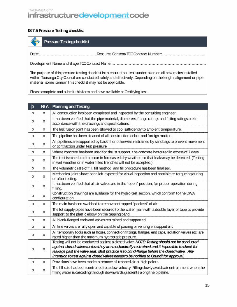
IS-7.5 Pressure Testing checklist
Pressure Testing checklist
Date:………………………………………………………..Resource Consent/TCC Contract Number:………………………………………..
Development Name and Stage/TCC Contract Name:……………………………………………………………………………………………
The purpose of this pressure testing checklist is to ensure that tests undertaken on all new mains installedwithin Tauranga City Council are conducted safely and effectively. Depending on the length, alignment or pipematerial, some items in this checklist may not be applicable.
Please complete and submit this form and have available at Certifying test.
þ N/A Planning and Testingo o All construction has been completed and inspected by the consulting engineer.
o oIt has been verified that the pipe material, diameters, flange ratings and fitting ratings are inaccordance with the drawings and specifications.
o o The last fusion joint has been allowed to cool sufficiently to ambient temperature.
o o The pipeline has been cleaned of all construction debris and foreign matter.
o oAll pipelines are supported by backfill or otherwise restrained by sandbags to prevent movementor contraction under test pressure.
o o Where concrete has been used for thrust support, the concrete has cured in excess of 7 days.
o oThe test is scheduled to occur in forecasted dry weather, so that leaks may be detected. (Testingin wet weather or in water filled trenches will not be accepted.)
o o The volumetric rate of fill, fill method, and fill procedure has been finalised.
o oMechanical joints have been left exposed for visual inspection and possible re-torqueing duringor after testing.
o oIt has been verified that all air valves are in the “open” position, for proper operation duringfilling.
o oConstruction drawings are available for the hydro-test section, which conform to the DWAconfiguration.
o o The main has been swabbed to remove entrapped “pockets” of air.
o oThe lot supply pipes have been secured to the water main with a double layer of tape to providesupport to the plastic elbow on the tapping band.
o o All blank-flanged ends and valves restrained and supported.
o o All line valves are fully open and capable of passing or venting entrapped air.
o oAll temporary tools such as hoses, connection fittings, flanges, end caps, isolation valves etc. arerated higher than the maximum hydrostatic pressure.
o o
Testing will not be conducted against a closed valve. NOTE: Testing should not be conductedagainst closed valves unless they are mechanically restrained and it is possible to check forleakage past the valve seat. Best practice is to blind-flange before the closed valve. Anyintention to test against closed valves needs to be notified to Council for approval.
o o Provisions have been made to remove all trapped air at high points.
o oThe fill rate has been controlled to a slow velocity. Filling slowly avoids air entrainment when thefilling water is cascading through downwards gradients along the pipeline.

16
þ N/A Equipmento o All test equipment has been checked for any obvious faults and its functionality understood.
o oAt least two calibrated pressure gauges or instruments are placed into the test system to be usedas a cross-check for gauge accuracy.
o oThe pressurising pump/water blaster has its own calibrated safety relief valve. NOTE: If thepressurising pump does not have a safety relief valve then it must not be used.
o oThe pressure test rig has been placed in the proper location relative to the pipe being tested andchecked for proper operation without leakage.
o oThe pressurisation pump/water blaster is the correct size. A too small pump will extend the testduration, and a too large pump may inhibit adequate control of the test pressure.
þ N/A Safety
o oAn emergency response plan in the event of a dramatic rupture during hydro-test has beendeveloped and is available on request.
o oA safety meeting to review the safety measures and roles and responsibilities has beenundertaken and is documented.
o o
‘No-go’ areas have been identified to those onsite to ensure unnecessary personnel andequipment stay out of the area during pressurised testing. NOTE: only those trained andqualified persons who are necessary to perform the test should remain in the area where thetest is being undertaken. During testing or de-watering, there are possible un-recognisedhazards that may not have been completely controlled, such as unexpectedly high pressuresfrom internal malfunctions or equipment failures, rupture of the pipe or fusion joint, un-detected flaws. Such situations may develop forces larger than the designed capacities of theanchors. All non-essential persons should be excluded from the test area.
o oAll personnel authorised to participate in the test have been adequately instructed in the testplan, and have been issued the required personal protective equipment.
o o Personnel have been informed of the loading limits on any temporary fittings and supports.
þ N/A Contractor’s Test Resultso o The Contractor’s test has been carried out in accordance to IT-7.3 Pressure Test.
o o The Contractor’s test passed.Please detail below remedial actions undertaken as a result of a failed pre-test.
CertificationI certify that the above is true and accurate.
……………………………………………...................................................................................(Contractor’s Representative)