
INSPECTION AND PREVENTIVE MAINTENANCE (IPM) AND ...
88
INSPECTION AND PREVENTIVE MAINTENANCE (IPM) AND BASIC TROUBLESHOOTING OF SPECIAL CARE BABY UNIT MEDICAL EQUIPMENT This manual will serve as a guide and reference for medical equipment technicians and equipment users to assist them in carrying out inspection and preventive maintenance (IPM) and basic troubleshooting of Special Care Baby Unit medical equipment. It is not intended to provide precise solutions to all kinds of maintenance issues, but rather to provide practical techniques and logical approaches for IPM and for diagnosing abnormalities, as well as potential interventions and remedies to address such issues. “ The goal of preventive maintenance is to improve the performance, lifespan and safety of equipment and property.”
-
Upload
khangminh22 -
Category
Documents
-
view
0 -
download
0
Transcript of INSPECTION AND PREVENTIVE MAINTENANCE (IPM) AND ...

INSPECTION AND PREVENTIVE MAINTENANCE
(IPM) AND BASIC TROUBLESHOOTING OF SPECIAL
CARE BABY UNIT MEDICAL EQUIPMENT
This manual will serve as a guide and reference for medical equipment
technicians and equipment users to assist them in carrying out inspection and
preventive maintenance (IPM) and basic troubleshooting of Special Care Baby
Unit medical equipment. It is not intended to provide precise solutions to all
kinds of maintenance issues, but rather to provide practical techniques and
logical approaches for IPM and for diagnosing abnormalities, as well as
potential interventions and remedies to address such issues.
“The goal of preventive
maintenance is to
improve the
performance, lifespan
and safety of equipment
and property.”
1
Ministry of Health and Sanitation
Sierra Leone
INSPECTION AND PREVENTIVE MAINTENANCE
(IPM) AND BASIC TROUBLESHOOTING OF
SPECIAL CARE BABY UNIT MEDICAL EQUIPMENT
FEBRUARY 2021

2
Contents FOREWORD ................................................................................................................................................... 4
ACRONYMS AND ABBREVIATIONS .............................................................................................................. 5
INTRODUCTION ............................................................................................................................................ 7
ELECTRICAL SAFETY ...................................................................................................................................... 8
Leakage currents ....................................................................................................................................... 8
Classes and types of medical equipment ................................................................................................ 11
Electrical safety tests .............................................................................................................................. 14
COMPARISON OF HEI AND DB9801 SUPPLEMENT 1 RECOMMENDATIONS ............................................ 24
SPHYGMOMANOMETER (Blood Pressure Machine; Digital and Aneroid) ............................................... 27
STETHOSCOPE ............................................................................................................................................. 28
BUBBLE-CPAP (B-CPAP) .............................................................................................................................. 30
GLUCOMETER AND HAEMOGLOBIN METER ............................................................................................. 32
INFANT INCUBATOR ................................................................................................................................... 38
INFANT RADIANT WARMER ....................................................................................................................... 43
RESUSCITATION TABLE WITH WARMER (Infant) ....................................................................................... 46
INFUSION PUMP (Volumetric Pump) ......................................................................................................... 50
OXYGEN CONCENTRATOR MACHINE (Portable Oxygen Generator) ........................................................ 53
PAN WEIGHING SCALE (Digital) ................................................................................................................. 55
PHOTOTHERAPY UNIT/LAMP ..................................................................................................................... 57
PHYSIOLOGIC MONITOR (Bedside Monitor) ............................................................................................. 60
RESUSCITATION BAG .................................................................................................................................. 63
PULSE OXIMETER (SpO2) ............................................................................................................................ 65
SUCTION MACHINE (Vacuum Pump, Electric) ........................................................................................... 68
SYRINGE PUMP ........................................................................................................................................... 72
MAINTENANCE WORK ORDER SYSTEM ..................................................................................................... 75
OPERATION INSTRUCTIONS AND GUIDES ................................................................................................. 75
PHYSIOLOGIC MONITOR (Multi-parameter) ........................................................................................... 75
GLUCOMETER (HemoCue +201) ............................................................................................................. 76
STETHOSCOPE ......................................................................................................................................... 76
BABY WEIGHING SCALE (Digital) ............................................................................................................. 76
PULSE OXIMETER .................................................................................................................................... 77

3
RESUSCITATION TABLE WITH WARMER (Infant) .................................................................................... 77
RADIANT WARMER (Infant) .................................................................................................................... 78
PHOTOTHERAPY LAMP ........................................................................................................................... 78
SYRINGE PUMP ....................................................................................................................................... 78
INFUSION PUMP (500D Volumetric Pump)............................................................................................. 79
B-CPAP .................................................................................................................................................... 79
SUCTION MACHINE (Vacuum Pump, Electric) ........................................................................................ 80
SPHYGMOMANOMETER ......................................................................................................................... 80
OXYGEN GENERATOR MACHINE (OXYGEN CONCENTRATOR UNIT) ....................................................... 80
REFERENCES ................................................................................................................................................ 82
APPENDIX 1. EXAMPLES OF MAINTENANCE FORMS FOR WORK ORDER SYSTEM ..................................... 83
APPENDIX 2. REGISTRATION AND DIRECTORY, IPM AND TROUBLESHOOTING MANUAL FINALIZATION .. 86

4
FOREWORD

5
ACRONYMS AND ABBREVIATIONS A Ampere (unit of electric current)
AA Battery size; indicates height and width: 50.5mm x 14.5mm (called double
“A”, pen-lite or Mignon – French for cute and adorable)
AC Alternating current
Ah Ampere-hour (unit of capacity of battery)
B-CPAP Bubble-continuous positive airway pressure
BP Blood pressure
BT Body temperature
C Celsius (unit of temperature)
DC Direct current
EBME Electrical and Biomedical Engineering (a leading clinical team providing
medical equipment management and support services)
ECG Electrocardiogram; electrocardiograph
ESU Electrosurgical unit
Gm Gram (unit of weight/mass)
Hb Haemoglobin
HR Heart rate
HEI High energy ignition or electronic ignition
Hz Hertz (unit of frequency or cycle per second)
IABP Intra-aortic balloon pump
IC Integrated circuit
ICU Intensive care unit
IEC International Electrotechnical Commission (an international standards
organization that prepares and publishes international standards for all
electrical, electronic and related technologies, collectively termed
“electrotechnology”)
IPC Infection prevention and control
IPM Inspection and preventive maintenance
IR Infrared
IV Intravenous
J Joule (unit of energy)
Kg Kilogram (unit of weight/mass; 1 x 10³ grams)
kPa Kilo Pascal (unit of pressure; 1 x 10³ Pascal)

6
L Active wire/live wire
Lb Pound (unit of weight/mass; 2.24 pounds is equal to 1Kg)
LCD Liquid crystal diode
LoBat Low battery (a symbol indicating battery is close to losing power)
Mega Ω Mega ohm (1 x 10⁶ ohms or 1,000,000 ohms)
µA Micro Ampere (1 x 10⁻⁶ Amperes or 0.000001 Ampere)
µm Micrometre (1 x 10⁻⁶ metres or 0.000001 metre)
MCV Mean cell volume
MCHC Mean cell haemoglobin concentration
mL Millilitre (1 x 10⁻³ litre; 0.001 litre)
MOHS Ministry of Health and Sanitation
N Neutral line
NC Normal condition
NIBP Non-invasive blood pressure
NICU Neonatal intensive care unit
OT Operating theatre
Oz Ounce (unit of weight/mass; one sixteenth of a pound avoirdupois –
approximately 28 grams)
PC Personal computer
PR/HR Pulse rate/heart rate
QC Quality control
RBC Red blood cell (erythrocytes)
RESP Respiration
RR Respiratory rate
R6 Term used to indicate battery size ‘AA’ by IEC 60086; ANSIC 18 calls it
size 15
SCBU Special Care Baby Unit
SELV Safety extra low voltage
SFC Single fault condition
SpO2 Peripheral capillary oxygen saturation
TFT Thin film transistor
VTBI Volume to be infused
WBC White blood cell (leucocytes)

7
INTRODUCTION
The maintenance and management of medical equipment has become an important and essential component of ensuring quality health service delivery in many public health systems in the resource-challenged African continent over the past several years. In recent times, the Sierra Leone Ministry of Health and Sanitation (MOHS) has recognized this concern after many years of neglect. With the support of its health partners, the challenges in the maintenance and management of medical equipment is being given a critical look as a strategy for improving the quality of health care service delivery and optimizing the use of available resources. In general, maintenance in the government health system is viewed as ‘repair and restoration’ work of broken equipment by technicians and artisans. The concept of managed preventive and corrective maintenance is relatively unheard of, leading to much of this medical equipment lying idle due to disrepair and other maintenance management issues. One of these issues is the capacity of the technicians and artisans to carry out basic inspection and preventive maintenance (IPM) and troubleshooting. This Manual provides guidance to these technicians, artisans and equipment users on how to perform basic IPM and troubleshooting, focusing on Special Care Baby Unit (SCBU) equipment, as the SCBUs are one of the priority interventions of the MOHS to improve maternal and child health in the country. The Manual is not a cure-all for maintenance issues, but rather the goal is to promote a culture of maintenance through regular IPM and basic troubleshooting. The Manual also includes instructions for nurses, paediatricians and other users on the safe and correct operation of the equipment, thus reducing the possibility of mishandling and improper operation – one of the major causes of equipment breakdown. Similarly, instructional safety tests and calibration checks are included for technicians to carry out periodically in order to enhance the safety and accuracy of the SCBU equipment. Likewise, the sets of tools and materials needed to carry out the jobs are listed in order to promote the efficiency and effectiveness of the exercise. At the end of the Manual is a discussion of the ‘Maintenance Work Order System’, which includes job request, job order and job report forms. This record-keeping is just as important as the IPM and troubleshooting activities themselves. Throughout the Manual, the blue-coloured letters indicate the recommended procedures for maintenance technicians, while the orange-coloured letters are the instructions for equipment users. The Manual is intended to be applicable to other brands of equipment, not just those currently used in the SCBUs. In all cases, technicians and artisans are advised to use common sense and good judgement when using this Manual.
8
ELECTRICAL SAFETY
Leakage currents
Most safety testing regimes for medical electrical equipment involve the measurement of certain types of "leakage currents" because this can help to verify whether a piece of equipment is electrically safe. This document describes the various leakage currents that are commonly measurable with medical equipment safety testers and discusses their significance. The precise methods of measurement along with applicable safe limits are also discussed.
Causes of leakage currents
If any conductor is raised to a potential above that of earth, some current is bound to flow from that conductor to earth. This is true even of conductors that are well insulated from earth, since there is no such thing as perfect insulation or infinite impedance. The currents that flow from or between conductors that are insulated from earth and from each other are called leakage currents. The amount of current that flows depends on:
a. the voltage on the conductor b. the capacitive reactance between the conductor and earth c. the resistance between the conductor and earth.
Leakage currents are normally small. However, since the amount of current required to produce adverse physiological effects is also small, such currents must be limited to safe values through equipment design. For medical electrical equipment, several different leakage currents are defined according to the paths that the currents take.
Earth leakage current
An earth leakage current is the current that normally flows in the earth conductor of a protectively earthed piece of equipment. In medical electrical equipment, very often, the mains are connected to a transformer with an earthed screen. Most of the earth leakage current finds its way to earth via the impedance of the insulation between the transformer primary and the inter-twining screen, since this is the point at which the insulation impedance is at its lowest (see Figure 1 below).

9
Figure 1. Earth leakage current path
Under normal conditions, a person who is in contact with both the earthed metal enclosure of the equipment and another earthed object would suffer no adverse effects, even if a fairly large earth leakage current were to flow. This is because the impedance to earth from the enclosure is much lower through the protective earth conductor than through the person. However, if the protective earth conductor becomes open-circuited, the situation changes. In this case, a shock hazard exists when the impedance between the transformer primary and the enclosure is of the same order of magnitude as the impedance between the enclosure and earth through the person.
It is a fundamental safety requirement that no hazard should exist in the event of a single fault occurring, such as the earth becoming an open circuit. It is clear that in order for this to be the case in the above example, the impedance between the mains (the transformer primary and so on) and the enclosure needs to be high. When the equipment is in normal condition (NC), this is evidenced by a low earth leakage current. In other words, if the earth leakage current is low, it minimizes the risk of electric shock in the event of a fault.
Enclosure leakage current or touch current
The terms enclosure leakage current and touch current are synonymous, with the former term being used in the bulk of this text. These terms are further discussed in the context of electrical test methods. An enclosure leakage current is defined as the current that flows from an exposed conductive part of the enclosure to earth through a conductor other than the protective earth conductor.
If a protective earth conductor is connected to the enclosure, there is little point in attempting to measure the enclosure leakage current from another protectively earthed point on the enclosure, since any measuring device used would be effectively shorted out by the low resistance of the protective earth. Equally, there is little point in measuring the enclosure leakage current from a protectively earthed point on the enclosure with the protective earth open circuit, since this would give the same reading as the earth leakage current measurement described above. For these reasons, when testing medical electrical equipment, it is usual to measure the enclosure leakage current from points on the enclosure that are not intended to be protectively earthed (see Figure 2). For many pieces of equipment, no such points exist. This is

10
not a problem. A test is included in the test regimens covering the eventuality that such points do not exist to ensure that no hazardous leakage currents flow from them.
Figure 2. Enclosure leakage current path
Patient leakage current
A patient leakage current is the leakage current that flows through a patient who is connected to an applied part or parts. It can either flow from the applied parts via the patient to earth, or from an external source of high potential via the patient and the applied parts to earth. Figures 3a and 3b illustrate these two scenarios.
Figure 3a. Patient leakage current path from equipment

11
Figure 3b. Patient leakage current path to equipment
Patient auxiliary current
A patient auxiliary current is defined as the current that normally flows between areas of the applied part through the patient, but is not intended to produce a physiological effect (see Figure 4).
Figure 4. Patient auxiliary current path
Classes and types of medical equipment
All electrical equipment is categorized into classes according to the method of protection against electric shock that is used. For mains powered electrical equipment, there are usually two levels of protection used: basic and supplementary protection. The supplementary protection is intended to come into play if the basic protection fails.
Class I equipment
Class I equipment has a protective earth. The basic means of protection is the insulation between the live parts and exposed conductive parts such as the metal enclosure. The supplementary protection (i.e., the protective earth) comes into effect in the event of a fault that would have otherwise caused an exposed conductive part to become live. A large fault current
12
flows from the mains to earth via the protective earth conductor, causing a protective device (usually a fuse) in the mains circuit to disconnect the equipment from the supply.
It is important to realize that not all equipment with an earth connection is Class I. The earth conductor may be for functional purposes only, such as screening. In this case, the size of the conductor may not be large enough to safely carry a fault current to earth in the event of a mains short for the length of time necessary for the fuse to disconnect the supply. Class I medical electrical equipment should have fuses at the equipment end of the mains supply lead in both the live and neutral conductors. This ensures that the supplementary protection is operative when the equipment is connected to an incorrectly wired outlet.
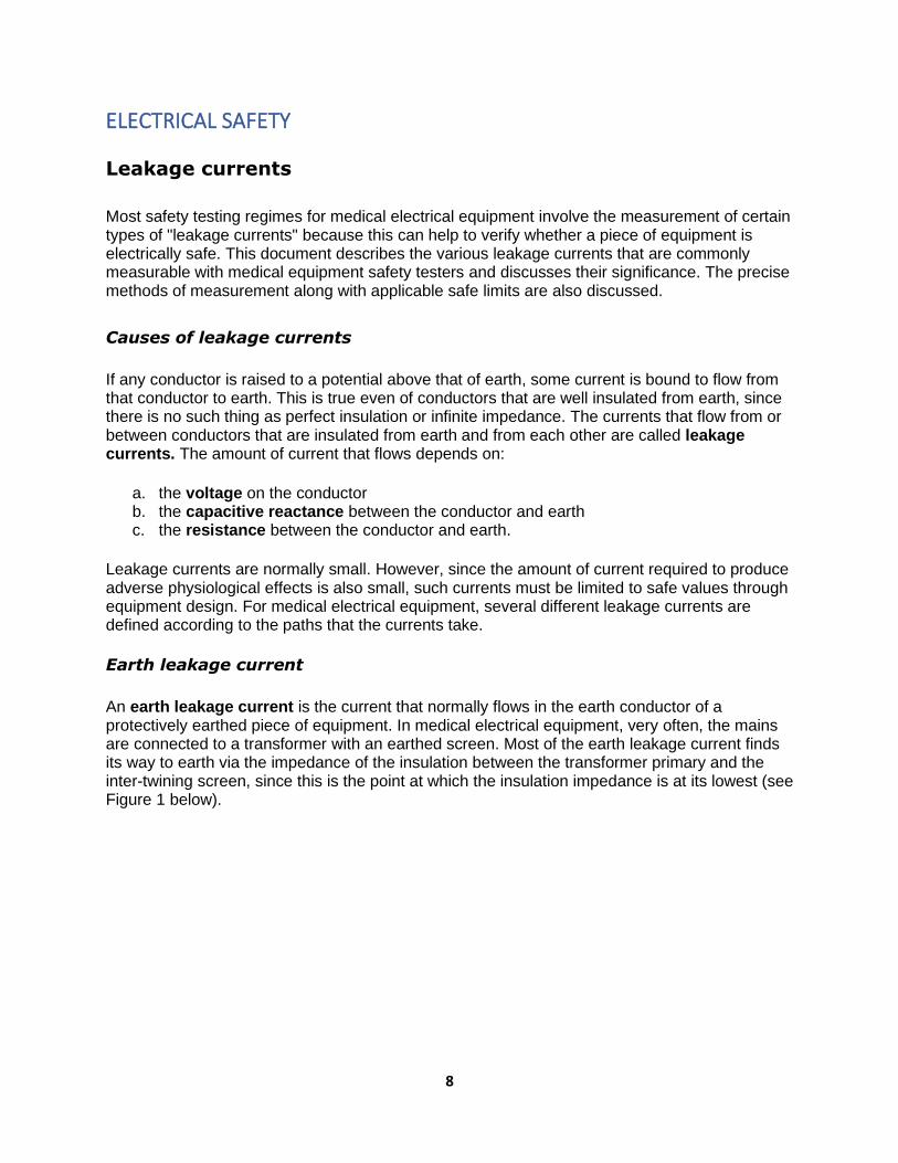
Further confusion can arise due to the use of plastic laminates for finishing equipment. A case that appears to be plastic does not necessarily indicate that the equipment is not Class I. There is no agreed upon symbol in use to indicate that equipment is Class I, and it is not mandatory to state on the equipment itself that it is Class I. If there is any doubt, reference should be made to the equipment manuals.
The symbols in Figure 5 may be seen on medical electrical equipment adjacent to terminals.
Figure 5. Symbols seen on earthed equipment
Class II equipment
In the case of Class II equipment, the method of protection against electric shock is either double insulation or reinforced insulation. In double-insulated equipment, the basic protection is afforded by the first layer of insulation. If the basic protection fails, then supplementary protection is provided by the second layer of insulation, which prevents contact with live parts. In practice, the basic insulation may be afforded by physical separation of live conductors from the equipment enclosure. In effect, the basic insulation material is air, and the enclosure material then forms the supplementary insulation. Reinforced insulation is defined in standards as a single layer of insulation that offers the same degree of protection against electric shock as double insulation.
Class II medical electrical equipment should be fused at the equipment end of the supply lead either in the mains conductor or in both conductors if the equipment has a functional earth.
The symbol for Class II equipment is two concentric squares illustrating double insulation, as shown in Figure 6.

13
Figure 6. Symbol for Class II equipment
Class III equipment
Class III equipment is defined in some equipment standards as that in which protection against electric shock relies on the fact that no voltages higher than safety extra low voltage (SELV) are present. SELV is defined in the relevant standard as a voltage not exceeding 25V AC or 60V DC. In practice, such equipment is either battery-operated or supplied by an SELV transformer.
If battery-operated equipment is capable of being operated when connected to the mains (for example, for battery charging), then it must be safety tested as either Class I or Class II equipment. Similarly, equipment powered by an SELV transformer should be tested in conjunction with the transformer as Class I or Class II equipment, as appropriate.
It is interesting to note that the current International Electrotechnical Commission (IEC) standards relating to the safety of medical electrical equipment do not recognize Class III equipment, since simply limiting voltage is deemed insufficient for ensuring patient safety. Therefore, all medical electrical equipment that is capable of mains connection must be classified as Class I or Class II. Medical electrical equipment having no mains connection is simply referred to as ‘internally powered’.
Equipment types
As described above, the class of equipment defines the method of protection against electric shock. The degree of protection for medical electrical equipment is defined by the type designation. Type designations exist because different pieces of medical electrical equipment have different areas of application and therefore different electrical safety requirements. For example, it would be unnecessary to make a particular piece of medical electrical equipment safe enough for direct cardiac connection if there is no possibility of such a situation arising.
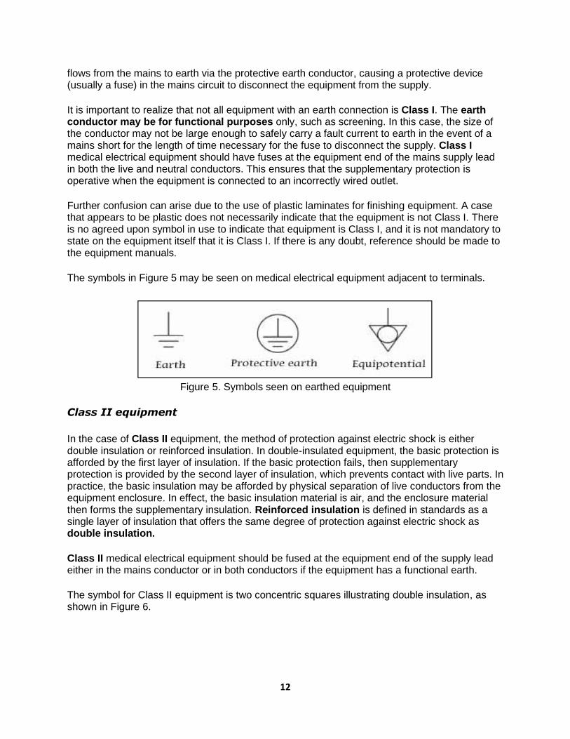
Table 1 shows the symbols and definitions for each type classification of medical electrical equipment.
14
Table 1. Medical electrical equipment types
All medical electrical equipment should be marked by the manufacturer with one of the type symbols above.
Electrical safety tests
The following paragraphs and diagrams describe the electrical safety tests commonly available on medical equipment safety testers. Please note that although HEI 95 and DB9801 are no longer current, they are referred to in this document, since many medical electronics departments have used these as the basis for local acceptance testing and even routine testing protocols. Protocols based on both sets of guidance are also available on many medical equipment safety testers.
Normal condition and single fault conditions
A basic principle behind the philosophy of electrical safety is that no safety hazard should arise in the event of a single abnormal external condition arising or failure of a single means of protection against a hazard. Such conditions are called single fault conditions (SFCs) and include situations such as the interruption of the protective earth conductor or of one supply conductor, the appearance of an external voltage on an applied part, the failure of basic insulation or of temperature limiting devices.
Where a single fault condition is not applied, the equipment is said to be in normal condition (NC). However, it is important to understand that, even in this condition, the performance of certain tests may compromise the means of protection against electric shock. For example, if earth leakage current is measured in normal condition, the impedance of the measuring device in series with the protective earth conductor means that there is no effective supplementary protection against electric shock.
Many electrical safety tests are carried out under various single fault conditions in order to verify that there is no hazard should these conditions occur in practice. It is often the case that single fault conditions represent the worst case scenario and will give the most adverse results. Clearly, during such testing, the safety of the equipment being tested may be compromised. Therefore, personnel conducting electrical safety tests should be aware that the normal means
15
of protection against electric shock are not necessarily operative during testing, and they should exercise due precautions for their own safety and that of others. In particular, no one should touch the equipment under test during the safety testing procedure.
Protective earth continuity
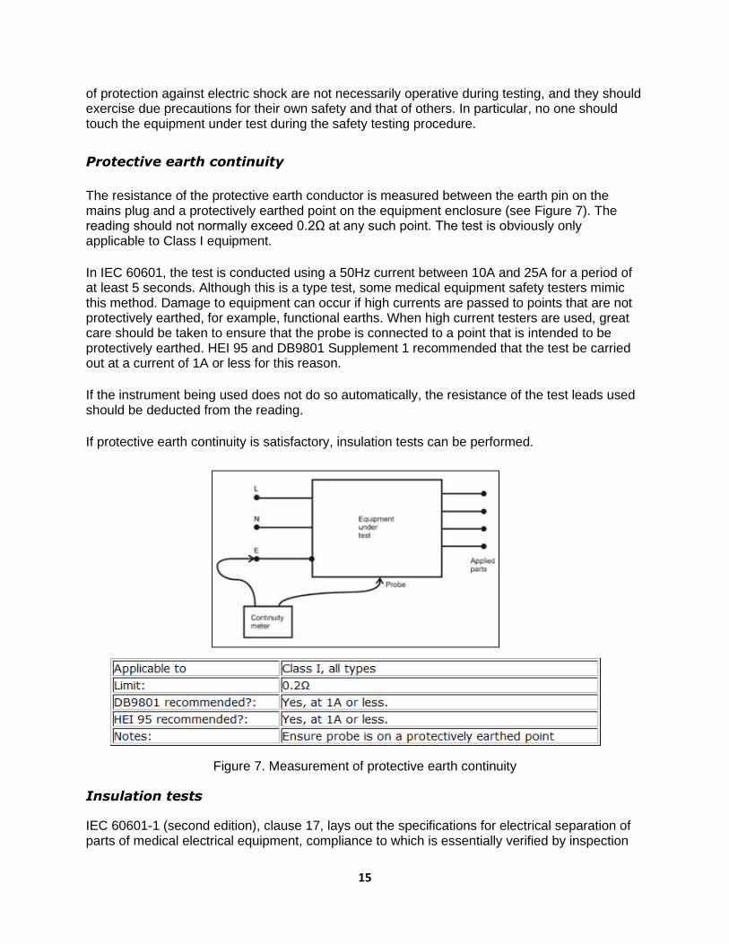
The resistance of the protective earth conductor is measured between the earth pin on the mains plug and a protectively earthed point on the equipment enclosure (see Figure 7). The reading should not normally exceed 0.2Ω at any such point. The test is obviously only applicable to Class I equipment.
In IEC 60601, the test is conducted using a 50Hz current between 10A and 25A for a period of at least 5 seconds. Although this is a type test, some medical equipment safety testers mimic this method. Damage to equipment can occur if high currents are passed to points that are not protectively earthed, for example, functional earths. When high current testers are used, great care should be taken to ensure that the probe is connected to a point that is intended to be protectively earthed. HEI 95 and DB9801 Supplement 1 recommended that the test be carried out at a current of 1A or less for this reason.
If the instrument being used does not do so automatically, the resistance of the test leads used should be deducted from the reading.
If protective earth continuity is satisfactory, insulation tests can be performed.
Figure 7. Measurement of protective earth continuity
Insulation tests
IEC 60601-1 (second edition), clause 17, lays out the specifications for electrical separation of parts of medical electrical equipment, compliance to which is essentially verified by inspection

16
and measurement of leakage currents. Further tests on insulation are detailed under clause 20, "dielectric strength". These tests use AC sources to test equipment that has been pre-conditioned to specified levels of humidity. The tests described in the standard are type tests and are not suitable for use as routine tests.
HEI 95 and DB9801 recommended that, for Class I equipment, the insulation resistance be measured at the mains plug between the live and neutral pins connected together and the earth pin. Whereas HEI 95 recommended using a 500V DC insulation tester, DB9801 recommended the use of 350V DC as the test voltage. In practice, this latter requirement could prove difficult, and a footnote acknowledged that a 500 V DC test voltage would be unlikely to cause any harm. The value obtained should normally be in excess of 50MΩ, but may be less in exceptional circumstances. For example, equipment containing mineral insulated heaters may have an insulation resistance as low as 1MΩ with no fault present. The test should be conducted with all fuses intact and equipment switched on where mechanical on/off switches are present (see Figure 8).
Figure 8. Measurement of insulation resistance for Class I equipment
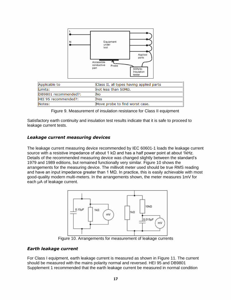
For Class II equipment, HEI 95 further recommended that the insulation resistance be measured between all applied parts connected together and any accessible conductive parts of the equipment. The value should not normally be less than 50MΩ (see Figure 9). DB9801 Supplement 1 recommended that no form of insulation test be applied to Class II equipment.
17
Figure 9. Measurement of insulation resistance for Class II equipment
Satisfactory earth continuity and insulation test results indicate that it is safe to proceed to leakage current tests.
Leakage current measuring devices
The leakage current measuring device recommended by IEC 60601-1 loads the leakage current source with a resistive impedance of about 1 kΩ and has a half power point at about 1kHz. Details of the recommended measuring device was changed slightly between the standard’s 1979 and 1989 editions, but remained functionally very similar. Figure 10 shows the arrangements for the measuring device. The millivolt meter used should be true RMS reading and have an input impedance greater than 1 MΩ. In practice, this is easily achievable with most good-quality modern multi-meters. In the arrangements shown, the meter measures 1mV for each µA of leakage current.
Figure 10. Arrangements for measurement of leakage currents
Earth leakage current
For Class I equipment, earth leakage current is measured as shown in Figure 11. The current should be measured with the mains polarity normal and reversed. HEI 95 and DB9801 Supplement 1 recommended that the earth leakage current be measured in normal condition

18
only. Many safety testers offer the opportunity to perform the test under a single fault condition, neutral conductor open circuit. This arrangement normally gives a higher leakage current reading.
In the 2005 edition of IEC 60601-1, one of the most significant changes with respect to electrical safety was a factor of 10 increase in the allowable earth leakage current to 5mA under normal condition and 10mA under single fault condition. The rationale for this is that the earth leakage current is not in itself hazardous.
In line with local regulations and IEC 60364-7-710 (electrical supplies for medical locations), higher values of earth leakage currents are allowed for permanently installed equipment connected to a dedicated supply circuit.
Figure 11. Measurement of earth leakage current
Enclosure leakage current or touch current
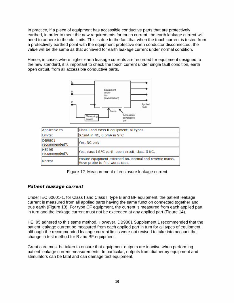
Enclosure leakage current is measured between an exposed part of the equipment that is not intended to be protectively earthed and true earth, as shown in Figure 12. The test is applicable to both Class I and Class II equipment and should be performed with mains polarity both normal and reversed. HEI 95 recommended that the test be performed under the single fault condition protective earth open circuit for Class I equipment and under normal condition for Class II equipment. DB9801 Supplement 1 recommended that the test be carried out under normal condition only for both Class I and Class II equipment. Many safety testers also allow the single fault condition of interruption of live or neutral conductors to be selected. Points on Class I equipment that are likely to not be protectively earthed may include front panel fascia, handle assemblies, etc.
In the new edition of the IEC 60601-1 standard, the term "enclosure leakage current" has been replaced by the term "touch current", bringing it in line with IEC 60950-1 for information technology equipment. However, the limits for touch current are the same as the limits for enclosure leakage current under the second edition of the standard: 0.1mA under normal condition and 0.5mA under single fault condition.
19
In practice, if a piece of equipment has accessible conductive parts that are protectively earthed, in order to meet the new requirements for touch current, the earth leakage current will need to adhere to the old limits. This is due to the fact that when the touch current is tested from a protectively earthed point with the equipment protective earth conductor disconnected, the value will be the same as that achieved for earth leakage current under normal condition.
Hence, in cases where higher earth leakage currents are recorded for equipment designed to the new standard, it is important to check the touch current under single fault condition, earth open circuit, from all accessible conductive parts.
Figure 12. Measurement of enclosure leakage current
Patient leakage current
Under IEC 60601-1, for Class I and Class II type B and BF equipment, the patient leakage current is measured from all applied parts having the same function connected together and true earth (Figure 13). For type CF equipment, the current is measured from each applied part in turn and the leakage current must not be exceeded at any applied part (Figure 14).
HEI 95 adhered to this same method. However, DB9801 Supplement 1 recommended that the patient leakage current be measured from each applied part in turn for all types of equipment, although the recommended leakage current limits were not revised to take into account the change in test method for B and BF equipment.
Great care must be taken to ensure that equipment outputs are inactive when performing patient leakage current measurements. In particular, outputs from diathermy equipment and stimulators can be fatal and can damage test equipment.

20
Figure 13. Measurement of leakage current with applied parts connected together
Figure 14. Measurement of leakage current for each applied part in turn
Patient auxiliary current
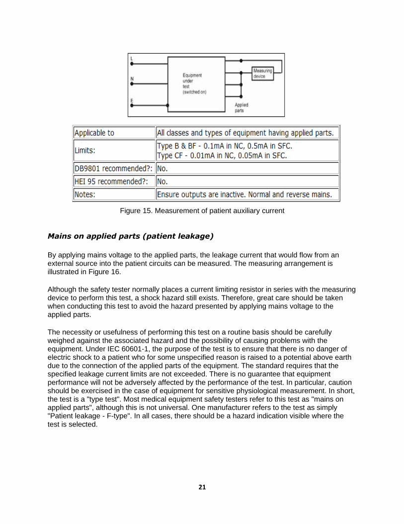
The patient auxiliary current is measured between any single patient connection and all other patient connections of the same module or function connected together. Testing all possible combinations together with all possible single fault conditions yields an exceedingly large amount of data of questionable value.
21
Figure 15. Measurement of patient auxiliary current
Mains on applied parts (patient leakage)
By applying mains voltage to the applied parts, the leakage current that would flow from an external source into the patient circuits can be measured. The measuring arrangement is illustrated in Figure 16.
Although the safety tester normally places a current limiting resistor in series with the measuring device to perform this test, a shock hazard still exists. Therefore, great care should be taken when conducting this test to avoid the hazard presented by applying mains voltage to the applied parts.
The necessity or usefulness of performing this test on a routine basis should be carefully weighed against the associated hazard and the possibility of causing problems with the equipment. Under IEC 60601-1, the purpose of the test is to ensure that there is no danger of electric shock to a patient who for some unspecified reason is raised to a potential above earth due to the connection of the applied parts of the equipment. The standard requires that the specified leakage current limits are not exceeded. There is no guarantee that equipment performance will not be adversely affected by the performance of the test. In particular, caution should be exercised in the case of equipment for sensitive physiological measurement. In short, the test is a "type test". Most medical equipment safety testers refer to this test as "mains on applied parts", although this is not universal. One manufacturer refers to the test as simply "Patient leakage - F-type". In all cases, there should be a hazard indication visible where the test is selected.

22
Figure 16. Mains on applied parts measurement arrangement
Leakage current summary
Table 2 summarizes the leakage current limits (in mA) specified by IEC60601-1 (second edition) for the most commonly performed tests. It is likely that most equipment currently in use in hospitals has been designed to conform to this standard, but the allowable values of earth leakage current have been increased in the third edition of this standard, as discussed above.
The values stated are for DC or AC (r.m.s), although later amendments to the standard include separate limits for the DC element of patient leakage and patient auxiliary currents at one tenth of the values listed below. These have not been included in the table, since, in practice, it is rare for there to be a problem solely with DC leakage that is not evidenced by a problem with combined AC and DC leakage.

23
Table 2. Summary of leakage current limits

24
COMPARISON OF HEI AND DB9801 SUPPLEMENT 1
RECOMMENDATIONS
Table 3. Comparison of standards for different tests
Test HEI 95 DB9801 Supplement 1
Earth continuity Use test current of 1A or less Limit 0.2ohm
Use test current of 1A or less Limit 0.2ohm
Insulation for Class I equipment
Measure between active/live wire and neutral line connected together and earth using 500V DC tester. Limit > 50MΩ. Investigate lower values
Measure between active/live wire and neutral line connected together and earth using 350V DC tester Limit > 20MΩ. Investigate lower values
Insulation for Class II equipment
Measure between applied parts and accessible conductive parts of the equipment. Limit > 50MΩ. Investigate lower values
No recommendation
Earth leakage current
Measure in normal condition Limit < 0.5mA
Measure in normal condition Limit < 0.5mA
Enclosure leakage current
Measure in single fault condition, earth open circuit for Class I, normal condition for Class II Limit < 0.5mA for Class I < 0.1mA for Class II
Measure in normal condition only Limit < 0.1mA
Patient leakage current
Measure from all applied parts connected together for Types B & BF equipment and from each applied part in turn for Type CF Measure under single fault condition, earth open circuit for Class I, normal condition for Class II Limits
• Class I, B & BF < 0.5mA • Class II, B & BF < 0.1mA • Class I, CF < 0.05mA per
electrode • Class II, CF < 0.01mA per
electrode
Measure from each applied part in turn for all types of equipment Measure under normal condition only
• Type B & BF <0.1mA per electrode
• Type CF < 0.01mA per electrode

25
Table 4. Measuring and testing devices
Name of Device Purpose
Safety analysis device of electricity (electrical safety analyser)
Does a general check of the electric safety of medical equipment
Simulator (signal generator) Provides a general check and user education of the monitoring device by generating simulated wave forms
ECG simulator Checks and calibrates ECG machines
Analysis device of blood pressure monitoring equipment
Calibrates the blood pressure monitoring device by adding physical pressure
Analysis device of the defibrillator
Measures the output and energy of defibrillators
Analysis device of the ESU (ESU power meter)
Measures the output and leakage current of the ESU
Analysis device of the infusion pump
Measures the flow quantity and alarm of the infusion pump
Analysis device of the respirator (respirometer)
Checks the working condition of respirators
Simulator of the intra-aortic balloon pump (IABP)
Checks the equipment and educates users
Stroboscope Measures the circular speed (rev/min) and movement of objects like a centrifuge
Tachometer Measures speed
Oxygen analyser Measures oxygen concentration in %
Gas analyser Measures the concentration of different gases used in anaesthesia machines
Pressure gauge Measures positive and vacuum pressure
Temperature gauge Measure temperatures in degrees Celcius and Fahrenheit

26
Integrated circuit (IC) tester Measures ICs
Multi-tester Measures electrical parameters and electronic components
Logic tester Checks the logic sequence
27
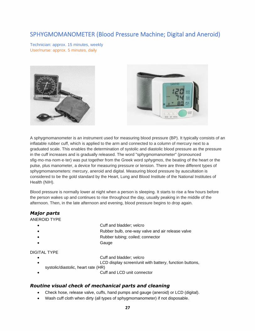
SPHYGMOMANOMETER (Blood Pressure Machine; Digital and Aneroid)
Technician: approx. 15 minutes, weekly
User/nurse: approx. 5 minutes, daily
A sphygmomanometer is an instrument used for measuring blood pressure (BP). It typically consists of an
inflatable rubber cuff, which is applied to the arm and connected to a column of mercury next to a
graduated scale. This enables the determination of systolic and diastolic blood pressure as the pressure
in the cuff increases and is gradually released. The word "sphygmomanometer" (pronounced
sfig·mo·ma·nom·e·ter) was put together from the Greek word sphygmos, the beating of the heart or the
pulse, plus manometer, a device for measuring pressure or tension. There are three different types of
sphygmomanometers: mercury, aneroid and digital. Measuring blood pressure by auscultation is
considered to be the gold standard by the Heart, Lung and Blood Institute of the National Institutes of
Health (NIH).
Blood pressure is normally lower at night when a person is sleeping. It starts to rise a few hours before
the person wakes up and continues to rise throughout the day, usually peaking in the middle of the
afternoon. Then, in the late afternoon and evening, blood pressure begins to drop again.
Major parts
ANEROID TYPE
• Cuff and bladder; velcro
• Rubber bulb, one-way valve and air release valve
• Rubber tubing; coiled; connector
• Gauge
DIGITAL TYPE
• Cuff and bladder; velcro
• LCD display screen/unit with battery, function buttons, systolic/diastolic, heart rate (HR)
• Cuff and LCD unit connector
Routine visual check of mechanical parts and cleaning
• Check hose, release valve, cuffs, hand pumps and gauge (aneroid) or LCD (digital).
• Wash cuff cloth when dirty (all types of sphygmomanometer) if not disposable.

28
• Clean the casing, rubber tubing and main body of the unit.
• Check for leaks in the rubber hose, connectors and bladder.
• Check air release valve control and clean one-way valve.
• Clean battery terminal to remove rust or corrosion. If a digital sphygmomanometer is not in use
for an extended period of time, remove the battery to prevent battery leakage and corrosion.
Functional/operational check
• Operate and check air circuit for leakage. Set the cuff to a dummy and pump the rubber
bulb/switch on the digital unit. Close the air release valve and observe if the gauge reading is
going down, indicating a leak, or in a digital BP machine, if there is prolonged building up of
pressure in the cuff. Replace leaky tubing or bladder, or fix/rectify issue.
• In aneroid type, the pointer should be at 0 at the start. For digital, make sure the battery is strong;
otherwise, the reading display will show ERR or erratic results. Replace the battery with sufficient
voltage/current/power.
• For aneroid and digital, calibrate using an improvised mercury-type sphygmomanometer or use a
known accurate unit for reference by connecting the two cuffs (reference and test unit) to a Y-
connector.
• Adjust/replace inaccurate aneroid gauges.
Parts/materials/consumables needed
• Aneroid manometer
• BP cuffs in both adult and paediatric/infant sizes
• Pressure air release control valve
• Rubber tubes/hoses
• Rubber bulb/hand pump
• Fittings/connectors
• Cleaning cloth
• Disinfectant, soap and water
• Gloves
Tools and equipment needed
• Set of reference units
• Side cutter pliers
• Aneroid gauge
• Long-nose pliers
• Magnifying glass
• Set of screwdrivers
STETHOSCOPE Technician: approx. 5 minutes, weekly

29
User/nurse: approx. 2–5 minutes, daily
Major parts
• Earpiece/ear tips/ear plugs
• Ear tubes
• Binaural headset/spring
• Chest piece, diaphragm, bell, drum, stem
• Flexible tubing, rubber tube
Routine visual check of mechanical parts
• Visually check the physical condition of the major parts, especially the chest piece and ear tubes.
• Clean and disinfect the ear tips/plugs with alcohol/methylated spirit.
• Check the diaphragm for cracks and check audio.
• Clean and replace any worn-out parts.
Functional/operational check
• Insert the earpieces to point in a forward direction into the ear canal.
• Attach the diaphragm. Ensure that the earpieces fit tightly to the headset. • To reduce spring tension in the binaural headset, hold each ear tube at the bend
near the ear tip and gradually pull apart until fully extended. • To increase spring tension in the head set, grasp the headset at the yoke with
one hand where the ear tubes enter the tubing and squeeze until the tubing on one ear tube
touches the other.
stem
30
Parts/materials/consumables needed
• Ethyl alcohol 70%
• Cotton
• Diaphragm
• Rod (thin metal or wood stick)
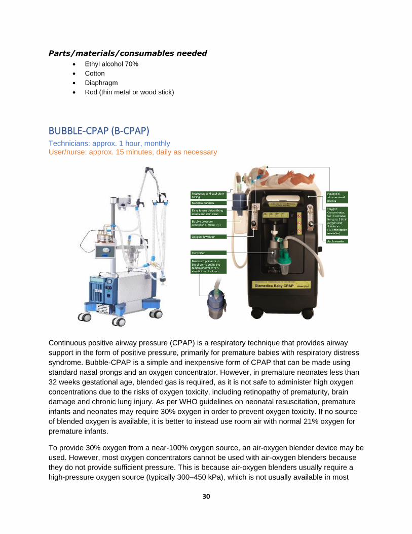
BUBBLE-CPAP (B-CPAP) Technicians: approx. 1 hour, monthly User/nurse: approx. 15 minutes, daily as necessary
Continuous positive airway pressure (CPAP) is a respiratory technique that provides airway
support in the form of positive pressure, primarily for premature babies with respiratory distress
syndrome. Bubble-CPAP is a simple and inexpensive form of CPAP that can be made using
standard nasal prongs and an oxygen concentrator. However, in premature neonates less than
32 weeks gestational age, blended gas is required, as it is not safe to administer high oxygen
concentrations due to the risks of oxygen toxicity, including retinopathy of prematurity, brain
damage and chronic lung injury. As per WHO guidelines on neonatal resuscitation, premature
infants and neonates may require 30% oxygen in order to prevent oxygen toxicity. If no source
of blended oxygen is available, it is better to instead use room air with normal 21% oxygen for
premature infants.
To provide 30% oxygen from a near-100% oxygen source, an air-oxygen blender device may be
used. However, most oxygen concentrators cannot be used with air-oxygen blenders because
they do not provide sufficient pressure. This is because air-oxygen blenders usually require a
high-pressure oxygen source (typically 300–450 kPa), which is not usually available in most
31
African countries. High-pressure oxygen is available from cylinders and piped oxygen systems,
but not from oxygen concentrators (<140 kPa). Alternatively, blended oxygen can be delivered
via some CPAP, anaesthesia and mechanical ventilator devices. In particular, commercially
available oxygen concentrators with an air outlet can be made into a source of blended oxygen
gas in the form of bubble-CPAP, and this approach has been demonstrated in neonatal wards.
For additional information, refer to the WHO Manual on clinical use of oxygen therapy in
children (in preparation) for clinical guidelines and the WHO Technical specifications for medical
devices (https://www.who.int/medical_devices/management_use/mde_tech_spec/en/) for
related equipment.
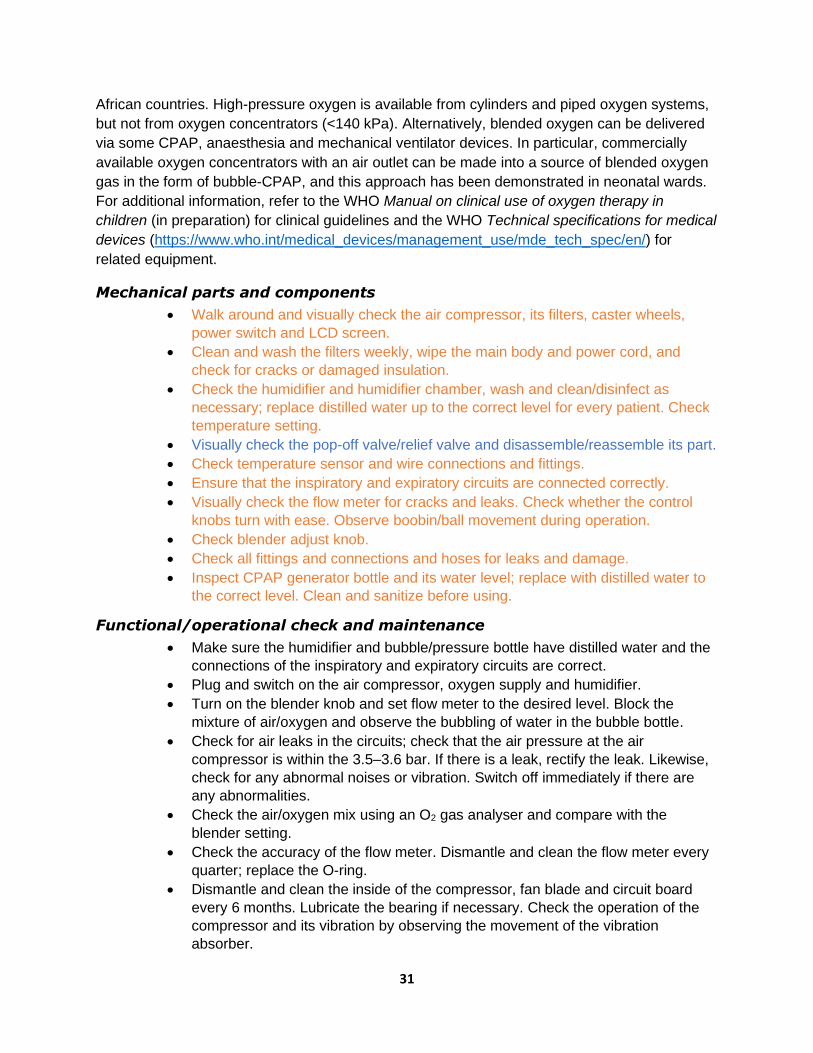
Mechanical parts and components
• Walk around and visually check the air compressor, its filters, caster wheels,
power switch and LCD screen.
• Clean and wash the filters weekly, wipe the main body and power cord, and
check for cracks or damaged insulation.
• Check the humidifier and humidifier chamber, wash and clean/disinfect as
necessary; replace distilled water up to the correct level for every patient. Check
temperature setting.
• Visually check the pop-off valve/relief valve and disassemble/reassemble its part.
• Check temperature sensor and wire connections and fittings.
• Ensure that the inspiratory and expiratory circuits are connected correctly.
• Visually check the flow meter for cracks and leaks. Check whether the control
knobs turn with ease. Observe boobin/ball movement during operation.
• Check blender adjust knob.
• Check all fittings and connections and hoses for leaks and damage.
• Inspect CPAP generator bottle and its water level; replace with distilled water to
the correct level. Clean and sanitize before using.
Functional/operational check and maintenance
• Make sure the humidifier and bubble/pressure bottle have distilled water and the
connections of the inspiratory and expiratory circuits are correct.
• Plug and switch on the air compressor, oxygen supply and humidifier.
• Turn on the blender knob and set flow meter to the desired level. Block the
mixture of air/oxygen and observe the bubbling of water in the bubble bottle.
• Check for air leaks in the circuits; check that the air pressure at the air
compressor is within the 3.5–3.6 bar. If there is a leak, rectify the leak. Likewise,
check for any abnormal noises or vibration. Switch off immediately if there are
any abnormalities.
• Check the air/oxygen mix using an O2 gas analyser and compare with the
blender setting.
• Check the accuracy of the flow meter. Dismantle and clean the flow meter every
quarter; replace the O-ring.
• Dismantle and clean the inside of the compressor, fan blade and circuit board
every 6 months. Lubricate the bearing if necessary. Check the operation of the
compressor and its vibration by observing the movement of the vibration
absorber.

32
Troubleshooting
• If the air compressor is not powering on, the power supply could be faulty. Check
the power cord, socket connection, supply and fuse.
• If the air compressor is on, but no compressor air is coming out, the air outlet
adaptor being used could be interchanged or connected to the wrong air outlet.
Change and replace with the correct one, or move the connection to another
outlet.
• If the humidifier temperature is above normal, the temperature sensor could be
placed in the wrong position. Check temperature sensor placement and position.
• If low medical gas is going to the infant, the oxygen concentrator could be
supplying low O2 pressure or there could be leaks in the system. Check and
rectify the O2 supply; check for hose connections and leaks in the hose, and
replace.
• If the expiratory pressure from the bubble bottle is low, there could be a dirty
pressure regulator in the bubble bottle. Remove the pressure regulator knob
assembly, clean and reassemble.
Parts/materials/consumables needed
• Bacteria and gross particle filters
• Disinfectant, soap and water, distilled/soft water
• Flannel cloth
• O-ring
Tools and test equipment needed
• Oxygen gas analyser
• Sets of screwdrivers and spanners
• Brush
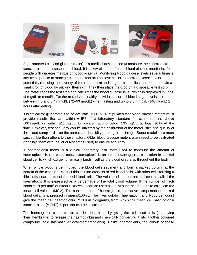
GLUCOMETER AND HAEMOGLOBIN METER HemoCue Glucometer 201+ and Hb 301+
Technician: approx. 0.5 hours, quarterly User/nurse: approx. 0.5 hours, before and after use
33
A glucometer (or blood glucose meter) is a medical device used to measure the approximate
concentration of glucose in the blood. It is a key element of home blood glucose monitoring for
people with diabetes mellitus or hypoglycaemia. Monitoring blood glucose levels several times a
day helps people to manage their condition and achieve closer-to-normal glucose levels –
potentially reducing the severity of both short-term and long-term complications. Users obtain a
small drop of blood by pricking their skin. They then place the drop on a disposable test strip.
The meter reads the test strip and calculates the blood glucose level, which is displayed in units
of mg/dL or mmol/L. For the majority of healthy individuals, normal blood sugar levels are
between 4.0 and 5.4 mmol/L (72–99 mg/dL) when fasting and up to 7.8 mmol/L (140 mg/dL) 2
hours after eating.
It is critical for glucometers to be accurate. ISO 15197 stipulates that blood glucose meters must
provide results that are within ±15% of a laboratory standard for concentrations above
100 mg/dL or within ±15 mg/dL for concentrations below 100 mg/dL at least 95% of the
time. However, test accuracy can be affected by the calibration of the meter, size and quality of
the blood sample, dirt on the meter, and humidity, among other things. Some models are more
susceptible than others to these factors. Older blood glucose meters often need to be calibrated
("coding" them with the lot of test strips used) to ensure accuracy.
A haemoglobin meter is a clinical laboratory instrument used to measure the amount of
haemoglobin in red blood cells. Haemoglobin is an iron-containing protein solution in the red
blood cell to which oxygen chemically binds itself as the blood circulates throughout the body.
When whole blood is centrifuged, the blood cells sediment and form a packed column at the
bottom of the test tube. Most of this column consists of red blood cells, with other cells forming a
thin buffy coat on top of the red blood cells. The volume of the packed red cells is called the
haematocrit. It is expressed as a percentage of the total blood volume. If the number of (red)
blood cells per mm3 of blood is known, it can be used along with the haematocrit to calculate the
mean cell volume (MCV). The concentration of haemoglobin, the active component of the red
blood cells, is expressed in grams/100mL. The haemoglobin, haematocrit and blood cell count
give the mean cell haemoglobin (MCH) in picograms, from which the mean cell haemoglobin
concentration (MCHC) in percent can be calculated.
The haemoglobin concentration can be determined by lysing the red blood cells (destroying
their membrane) to release the haemoglobin and chemically converting it into another coloured
compound (acid haematin or cyanmethemoglobin). Unlike haemoglobin, the colour of these
34
components does not depend on the oxygenation of the blood. Following the reaction, the
concentration of the new component can be determined by calorimetry.
Component checks
Ensure that the following components are available:
• HemoCue Hb 201+ or Hb 301+ analyser
• Main adaptor
• 4 x type AA or R6 batteries, 1.5V
• Vial of HemoCue Hb 201+ or Hb 301+ microcuvettes
• Individually packaged microcuvettes
Functional/operational and mode checks
• START-UP
• SET-UP (Audio signal, time and date)
• MEASUREMENT (capillary blood, venous or arterial blood)
• SET-UP (quality control [QC] test, memory functions, delete results, and printer)
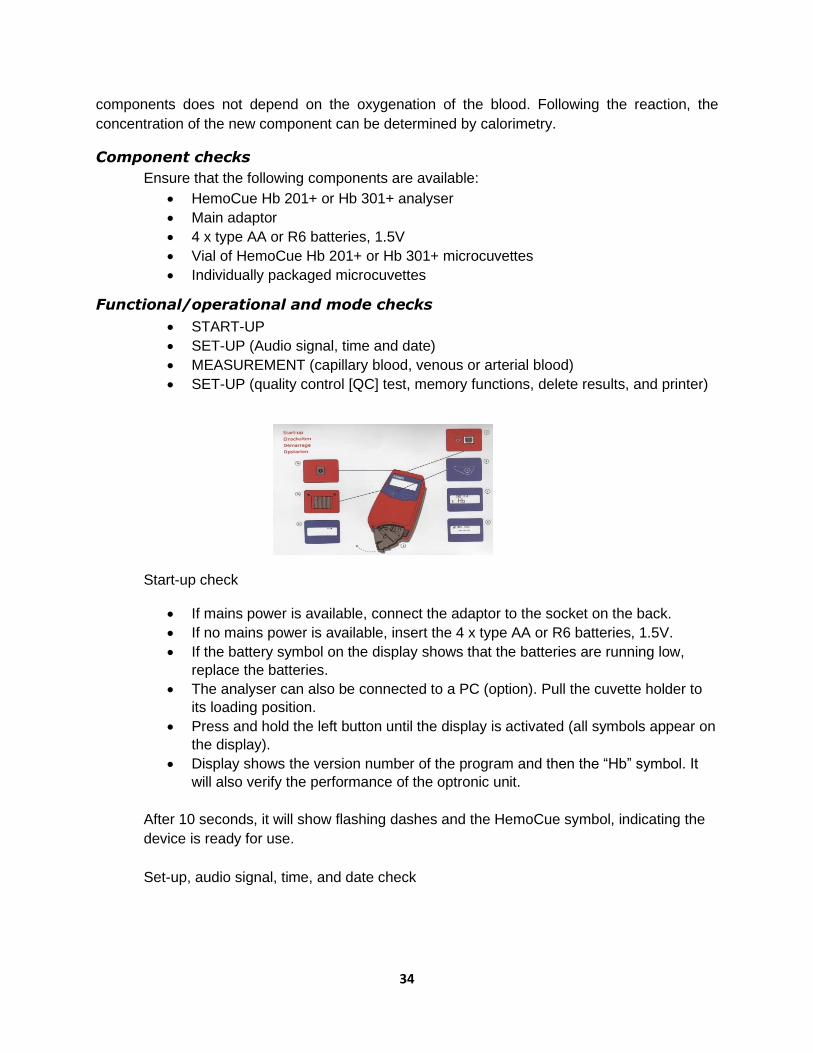
Start-up check
• If mains power is available, connect the adaptor to the socket on the back.
• If no mains power is available, insert the 4 x type AA or R6 batteries, 1.5V.
• If the battery symbol on the display shows that the batteries are running low,
replace the batteries.
• The analyser can also be connected to a PC (option). Pull the cuvette holder to
its loading position.
• Press and hold the left button until the display is activated (all symbols appear on
the display).
• Display shows the version number of the program and then the “Hb” symbol. It
will also verify the performance of the optronic unit.
After 10 seconds, it will show flashing dashes and the HemoCue symbol, indicating the
device is ready for use.
Set-up, audio signal, time, and date check

35
• Press both buttons at the same time.
• The display shows a flashing QC symbol. Use the right button to scroll to the
audio symbol. The signal can be activated or deactivated by pressing the left
button.
• Scroll using the right button to get characters for time, date and year. The hour
figure will be flashing.
• Use the right button to change the hours, minutes, month and year. Use the left
button to change the flashing figure.
• When the settings are complete, hold the right button for 5 seconds. The unit will
move to measuring mode.
Set-up, QC test
• Press both buttons at the same time. The display will show a flashing QC
symbol.
• Select the QC test by pressing the left button.
• The analyser will return to measuring mode and the QC symbol will appear in the
display.
• Fill the microcuvette w/ the control solution and carry out the measurement as in
measuring capillary blood.
• Once the measurement is done, the analyser will automatically return to
measuring mode.
• The QC symbol will disappear from the display.
• To deactivate the QC test, follow steps 1–2 and scroll using the right button until
another activity is shown on the display.
36
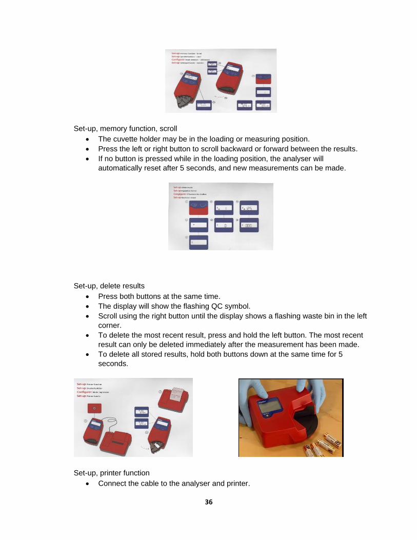
Set-up, memory function, scroll
• The cuvette holder may be in the loading or measuring position.
• Press the left or right button to scroll backward or forward between the results.
• If no button is pressed while in the loading position, the analyser will
automatically reset after 5 seconds, and new measurements can be made.
Set-up, delete results
• Press both buttons at the same time.
• The display will show the flashing QC symbol.
• Scroll using the right button until the display shows a flashing waste bin in the left
corner.
• To delete the most recent result, press and hold the left button. The most recent
result can only be deleted immediately after the measurement has been made.
• To delete all stored results, hold both buttons down at the same time for 5
seconds.
Set-up, printer function
• Connect the cable to the analyser and printer.

37
• Perform the analysis by following the steps for measuring capillary blood.
• When the result is shown on the display, the printer will automatically print the
result, date and time.
Maintenance
• Check that the analyser is turned off. The display should be blank.
• Pull the cuvette holder out to its loading position. Use a pointed object to carefully
depress the small catch positioned in the upper right corner of the cuvette holder.
• While keeping the catch depressed, carefully pull the cuvette holder.
• Clean the cuvette holder with alcohol or mild detergent.
• Push the cleaner swab into the opening of the cuvette holder and pull it out 5–10
times.
• Wait for 15 minutes before using the analyser. Replace the cuvette holder.
Parts/materials/consumables needed
• Battery: 1.5V AA x 4 pcs or R6 battery
• Flannel cloth (non-abrasive material)
• Disinfectant/isopropyl alcohol 70%
• Gloves
• Stick and cotton (swab)
Tools and test equipment needed
• Multi-meter
• Set of screwdrivers
• Brush
• Air blower hand pump
• Flashlight
Caution for storage of strips
• As the reagent strips are affected by heat, humidity and excessive exposure to light, they should be stored in a cool, dark place at a temperature less than 250C.
• Strips should never be frozen/stored in the freezer.
• The bottles contain silica gel to absorb moisture. Do not remove the silica gel.
• The colour of the strip should be checked before using it.
38
INFANT INCUBATOR Technician: approx. 2 hours, quarterly
User/nurse: approx. 30 minutes, before and after use
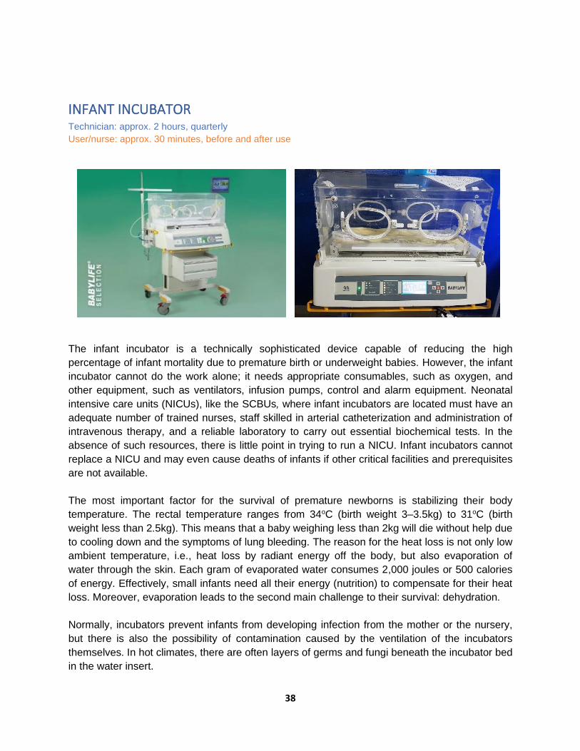
The infant incubator is a technically sophisticated device capable of reducing the high
percentage of infant mortality due to premature birth or underweight babies. However, the infant
incubator cannot do the work alone; it needs appropriate consumables, such as oxygen, and
other equipment, such as ventilators, infusion pumps, control and alarm equipment. Neonatal
intensive care units (NICUs), like the SCBUs, where infant incubators are located must have an
adequate number of trained nurses, staff skilled in arterial catheterization and administration of
intravenous therapy, and a reliable laboratory to carry out essential biochemical tests. In the
absence of such resources, there is little point in trying to run a NICU. Infant incubators cannot
replace a NICU and may even cause deaths of infants if other critical facilities and prerequisites
are not available.
The most important factor for the survival of premature newborns is stabilizing their body
temperature. The rectal temperature ranges from 34oC (birth weight 3–3.5kg) to 31oC (birth
weight less than 2.5kg). This means that a baby weighing less than 2kg will die without help due
to cooling down and the symptoms of lung bleeding. The reason for the heat loss is not only low
ambient temperature, i.e., heat loss by radiant energy off the body, but also evaporation of
water through the skin. Each gram of evaporated water consumes 2,000 joules or 500 calories
of energy. Effectively, small infants need all their energy (nutrition) to compensate for their heat
loss. Moreover, evaporation leads to the second main challenge to their survival: dehydration.
Normally, incubators prevent infants from developing infection from the mother or the nursery,
but there is also the possibility of contamination caused by the ventilation of the incubators
themselves. In hot climates, there are often layers of germs and fungi beneath the incubator bed
in the water insert.

39
Often, newborns are unable to breath alone (e.g., those born in the 28th week of pregnancy)
because their lungs are insufficiently developed. In such cases, an infant respirator should be
available, and a higher oxygen concentration is necessary to compensate for the yet incomplete
lung function. However, it should be mentioned that a high level of oxygen (hyperoxaemia) can
cause eye damage, while too low an oxygen concentration (hypoxaemia) can result in
irreparable brain damage. It is absolutely essential for the oxygen enrichment of the incubator to
be controlled based on the arterially measured oxygen partial pressure in the blood of the baby
(i.e., transcutaneous oxygen measurement).
The major components/parts of an infant incubator are the hood, mattress, access door/panel,
control panel with parameters and alarm displays, trolley, humidity fill pipe, iris entry port,
electrical mains connection, and oxygen input connector.
Major parts
• Canopy with port holes (baby tray for placing the neonate)
• Heat source with fan underneath the baby tray
• Skin probe (for sensing the baby's skin temperature)
• Air probe
• Control panel (displays and control knob)
- Mode selector (selects air or skin mode)
- Heater output display
- Temperature selection key/knob (select the desired skin temperature)
- Temperature display (displays the temperature of baby's skin, the set temperature and air temperature)
- Alarm display for power failure, system failure, skin probe failure, set skin temperature (above or below set temperature) and air flow
• Determine the appropriate temperature for the incubator based on the baby's weight and age.
• Warm the incubator to the desired temperature before placing the baby inside.
Mechanical control and physical integrity
• Conduct a visual check of the power cord, visual and audio alarm controls.
• Check the circuit breaker and ON/OFF switches.
• Check the humidifier vessel and control.
• Check/clean/replace the air filter.
• Conduct a mechanical check of the O2 regulator and control, if any.
• Conduct a physical integrity check; clean, disinfect and sanitize the hood and hand ports, gaskets, mattress and its mechanism and movements, iris doors, doors and air circulation chamber.
• Conduct a mechanical check and clean the cart and casters.
• Conduct a visual inspection of the temperature skin sensor for kinks and cracks.
• Check the cleanliness of the humidifier jars and distilled water level; add and/or replace.
• Clean the fan blades.
• Clean the motherboard/main circuit board.
• Perform a swab test for lab exam every 6 months.

40
Functional/operational check
• Clean the mattress and cover it with a clean sheet.
• Ensure that the incubator's water reservoir is empty; dangerous bacteria may grow in the water and infect the baby. Leaving the reservoir dry will not affect the function of the incubator.
• Ensure that the baby's head is covered with a cap, feet secured with socks and diaper on.
• Place only one baby in each incubator. If the baby is in supine position, place the skin probe on the right hypochondrium. When in prone position, place the probe on the loin area.
• Close the hood as quickly as possible after placing the baby inside, and keep the portholes of the incubator closed at all times to keep the incubator warm. Make sure to place the incubator away from any heat source.
• Work in air mode if the baby is unstable and skin mode/servo mode if the baby is stable. If the incubator is in skin/servo mode, the set temperature should be between 36°C and 37°C. The smaller the baby, the higher the set temperature.
• Check the incubator temperature every hour for the first 8 hours, and then every 3 hours:
- If the temperature of the incubator does not match the set temperature, the incubator may not be functioning properly; adjust the temperature setting until the desired temperature is reached inside the incubator, or use another method to warm the baby.
• Measure the baby’s temperature every hour for the first 8 hours, and then every 3 hours:
- If the baby's temperature is less than 36.5°C or more than 37.5°C, adjust the temperature of the incubator accordingly.
- If the baby's temperature remains less than 36.5°C or more than 37.5°C despite the incubator being kept at the recommended setting, suspect infection.
• Move the baby to the mother as soon as the baby no longer requires special care, frequent procedures and/or treatment. For a stable baby, if the heater output is less than 25% on skin/servo mode or in air mode at 28°C to 30°C and the baby is maintaining the skin temperature, it is time to shift the baby to the mother.
• Place the incubator in a location where there is no direct sunlight or where it is shielded from direct sunlight.
• Always position the incubator in such a way that free air can enter the air inlet.
• When the equipment is in use, all approachable internal and external surfaces should be cleaned daily with soap and water. Spirits or other organic solvents must NOT be used to clean the incubator hood or panel.
• Every 7th day, after moving the baby to another clean incubator, the used equipment should be cleaned thoroughly, first by using a light detergent solution and then by using an antiseptic solution. All detachable assemblies, especially from under the deck area, are to be treated similarly. After drying, the parts should be reassembled and sterilized using a vaporizing agent and/or fumigation. Adding 30mL of 2% glutaraldehyde and 90mL of distilled water to the humidity tank and plugging it for 4 hours will fumigate the incubator. Plug the unit in for half an hour and keep it closed for 4 hours. After this, clean the incubator thoroughly. After fumigation, the incubator should be thoroughly aerated.

41
• The sleeves of the access windows must preferably be changed daily and cleaned. Check and dust the air filter every day.
• Temperature check: Set the unit to “Air Mode” and set the operating temperature; check/compare the temperature reading with a thermometer.
• Audio and visual alarm function check: Set the Hi and Lo temperature limits and breach the set limits; observe the audio and visual alarms.
• Connect the skin probe to a dummy patient and disconnect; observe the audio and visual alarms; compare temperature reading with a thermometer.
• Set the humidity setting and observe the function of the humidity pump.
• Observe the control and indicator panel LEDs based on the operation and functions.
Air circulation achieved by a fan motor
• Air circulation is caused by a fan, which is driven by an electric motor. Fresh air is drawn in by the fan through a bacterial filter.
• The fan also draws incubator air and presses the air through the filter and humidifier into the compartment. Exhaust air is pressed out through small holes in the hood.
• The air circulation caused by a fan, provides nearly uniform temperature, humidity and oxygen concentration, if any, everywhere in the compartment.
Humidity
• Distilled water should be used in order to not pollute the humidifier container. The water level should be between the indicator marks.
• Distilled water also prevents contamination of the infant, as tap water may contain bacteria and other contaminants.
Recommended oxygen concentration (if there is O2 supply)
O2 conc % 25 30 35 40 45
O2 inflow
(LPM)
1.5 3 4.5 6 7.5
Temperature
Birth Weight
(kg)
Recommended
Temp. (˚C)
0.5 35.0 – 36.0
1.0 34.4 – 35.4
1.5 33.5 – 34.5
2.0 33.0 – 34.0
42
3.0 32.0 – 34.0
In addition to the above:
Daily check
• Clean and free from bacteria
• Access door and ports in good status
• Electrical mains cord and plug unbroken
• Cradle tilt is correct and adjustable
• Wheels or casters for wear and damage
Maintenance checklist
• Change air filters: every 3 months
• Temperature calibration: every 3 months
• Clean tip of the humidifier tube: every 1 month
• Preventive check: every 6 months
Alarms and tips on how to address them
• "Power alarm" or “Mains”: This alarm sounds if the mains power fails. Find alternative means of heating if power cannot be fixed.
• "System alarm" or “Tech fault”: This alarm sounds if there is an error in the incubator’s electrical circuit/motherboard.
• "Over temperature alarm": This alarm signals that the temperature inside the incubator is too high: >38°C in manual mode or >39°C in servo mode. The heater power will be automatically disconnected. Check temperature settings and adjust down if set too high. If the setting is normal, the incubator needs troubleshooting and repair.
• "Skin temperature alarm": This alarm operates in servo mode only. It sounds when the patient’s temperature deviates from the set temperature by >1°C in skin mode and >3°C in air mode. Change to manual mode and adjust the temperature setting.
• Check whether water is coming out at the tip of the humidifier tube. If not, clean the tip for a possible blockage. Otherwise, the temperature and humidity alarm will be triggered.
Safety test
Grounding resistance (200Ω)
Insulation resistance (>0.5MΩ)
Leakage current (<500µA)
Parts/materials/consumables needed
HEPA filter Battery: 9V
Distilled water Fuse: 0.5mA
Flannel cloth (non-abrasive material) Gloves
Disinfectant, soap and water
Lubrication oil

43
Tools and test equipment needed
Multi-tester Air blower hand pump
Set of screwdrivers Spirit thermometer
Electrical analyser Brush
Psychrometer
INFANT RADIANT WARMER Technician: approx. 1 hour, quarterly
User/nurse: approx. 15 minutes, before and after use
A radiant warmer is a device that provides heat to the body, helping to maintain the body
temperature of the baby and limiting the metabolic rate. After birth, infants are placed under a
radiant warmer until they can achieve thermoregulation. The heating mechanism consists of
quartz, which produces the desired heat, and a reflective mechanism to divert the heat to the
baby tray. Because warming by infrared (IR) energy is an efficient means of energy transfer,
extreme hyperthermia, skin burns, permanent brain damage, or even death can result. An infant
incubator, on the other hand, usually warms by conducting heat from the warm materials inside
to the object being warmed. It is usually at a lower temperature than the radiant element of a
radiant heater.
Walk around check of mechanical parts and physical integrity
• Bassinet for placing the neonate and mattress
• Radiant heat source
• Skin probe for sensing the baby's skin temperature
• Air probe
• Control panel (displays and control knob)
• Mode selector (selects manual or servo mode)

44
• Heater output control key/knob to increase or decrease the heater output manually, if any
• Heater output display
• Temperature selection key/knob, if any: selects the desired skin temperature
• Temperature display: displays the temperature of the baby's skin, the set temperature and air temperature
• Alarm display for power failure, system failure, skin probe failure, skin temperature high/low and heater failure
• Check overall structure, base, caster wheels and lock, power cords and terminals for cracks and signs of burns.
• Ensure that the unit is placed in a room with a temperature that is 22°C or colder.
• Place the warmer away from air drafts.
• Perform a swab test for lab exam every 6 months.
Functional/operational check
• Clean the mattress and platform, and cover the mattress with a clean sheet.
• Turn on the warmer for at least 20 minutes to pre-warm the linens and mattress.
• Read the temperature on the display. Adjust the heater output to: - High, if the baby’s temperature is below 36ºC - Medium, if the baby’s temperature is between 36ºC and 36.5ºC - Low, if the baby’s temperature is between 36.5ºC and 37.5ºC.
• Once the baby's temperature is between 36.5 ºC and 37.5ºC, switch to servo skin mode.
• If the baby is in the supine position, place the skin probe on the right hypochondrium. When in the prone position, place the probe on the loin area.
• To prevent skin injury, use transparent dressing material and fix the probe on it with an adhesive.
• Ensure that the baby's head is covered with a cap and the feet are secured in socks; keep the diaper on.
• If the baby is <1,000g, use cling film across the panels to prevent undetectable water loss.
• Place only one baby under each radiant warmer.
• Check the temperature of the warmer room every hour and adjust the temperature setting accordingly.
• Record the heater output during each shift (every 6 hours). Any sudden increase in heater output is an early indicator of sickness.
Servo mode
• Set temperature to 36.5ºC. Heater output will adjust automatically to keep the baby at the set temperature. If the baby’s temperature is below the set temperature, the heater output will increase.
• If the baby’s temperature is the same as or higher than the set temperature, the heater output will be zero.
• Look for probe displacement when the unit is in servo mode. Check and ensure proper probe placement every hour.
Manual mode
• Once connected to the mains, the heater output can be regulated using the knob on the front panel. The output is displayed as a % or with bars.
45
• Use maximum (100%) output for rapid warming of the bassinet in the labour room 20 minutes before delivery. Reduce output to 25–75% after 10 minutes depending on the ambient temperature.
• If left on with heater output >80%, an alarm will be activated within 15 or 20 minutes and the heater output will fall to 40%.
• If the alarm is silenced, the heater output will be kept at maximum for another 15 to 20 minutes or as per manufacturer’s recommendations.
• For low birth weight or sick neonates, adjust the heater output depending on the baby’s temperature.
• Never use full (100%) heater output unsupervised.
• Record the baby’s temperature every 2–4 hours.
• Use manual mode only for pre-warming, during resuscitation and during initial stabilization.
Disinfection
• Daily cleaning of front panel; use a damp cloth soaked in mild detergent (soapy water).
• Do not use spirits or other chemicals.
• The bassinet and cot should be disinfected daily using a soap/detergent solution or
disinfectant solution.
Check/test alarms indicating servo radiant warmer problems power
• “Power Alarm”: If the mains power fails, check the fuse located in the mains terminals and the secondary fuse.
• "System Alarm": If there is an error in the electrical/electronic circuits, check/troubleshoot the electrical/electronic circuits.
• “Skin Probe Alarm”: This alarm sounds if the temperature probe sensor is not connected properly or if it is not functioning properly. Connect the probe properly or rectify connections.
• "Skin Temperature Alarm High or Low" (servo mode only): This alarm sounds when the patient’s temperature differs from the set temperature by >0.5ºC. Change to manual mode with maximum output if the baby is having low temperature, and adjust the temperature to try and normalize the baby's temperature. If the baby has a fever, shift to manual mode and set the appropriate heater output.
• “Heater Failure” indicates that the heater is not working. Repair/replace heater or change warmers while the unit is undergoing repair.
Safety test
Grounding resistance (200Ω)
Insulation resistance (>0.5MΩ)
Leakage current (<500µA)
Parts/materials/consumables needed
• Fuse: 0.5mA
• Flannel cloth (non-abrasive material)
• Gloves
• Disinfectant, soap and water
Tools and test equipment needed
• Multi-meter
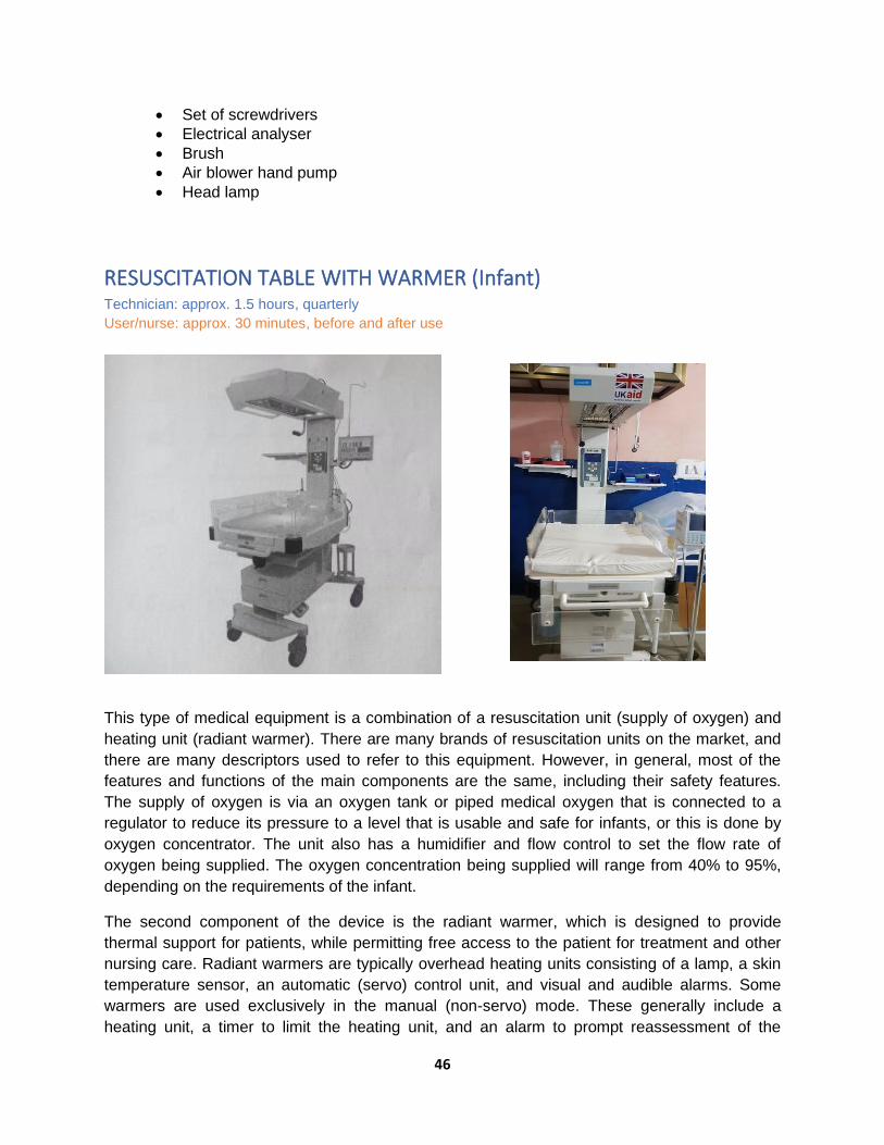
46
• Set of screwdrivers
• Electrical analyser
• Brush
• Air blower hand pump
• Head lamp
RESUSCITATION TABLE WITH WARMER (Infant) Technician: approx. 1.5 hours, quarterly
User/nurse: approx. 30 minutes, before and after use
This type of medical equipment is a combination of a resuscitation unit (supply of oxygen) and
heating unit (radiant warmer). There are many brands of resuscitation units on the market, and
there are many descriptors used to refer to this equipment. However, in general, most of the
features and functions of the main components are the same, including their safety features.
The supply of oxygen is via an oxygen tank or piped medical oxygen that is connected to a
regulator to reduce its pressure to a level that is usable and safe for infants, or this is done by
oxygen concentrator. The unit also has a humidifier and flow control to set the flow rate of
oxygen being supplied. The oxygen concentration being supplied will range from 40% to 95%,
depending on the requirements of the infant.
The second component of the device is the radiant warmer, which is designed to provide
thermal support for patients, while permitting free access to the patient for treatment and other
nursing care. Radiant warmers are typically overhead heating units consisting of a lamp, a skin
temperature sensor, an automatic (servo) control unit, and visual and audible alarms. Some
warmers are used exclusively in the manual (non-servo) mode. These generally include a
heating unit, a timer to limit the heating unit, and an alarm to prompt reassessment of the
47
patient’s status. Most radiant warmers with an automatic mode enable the operator to also
select the manual mode instead.
Typical heating elements are quartz tubes or incandescent lamps, which are broadband energy
sources that generate a significant amount of radiant energy in the far IR wavelength region
(longer than three microns) to avoid damaging patients’ retina and cornea. The radiant output of
the heating unit is also limited to prevent damage to patients’ skin. The integral bassinet unit
provides a total system for continuous thermal support for sick infants and may also act as a
short-term resuscitation platform in the delivery suite or operating room. For mobility, warmers
are mounted on casters, which may be equipped with brakes.
Inappropriate use of radiant warmers can cause patient burns. Any inordinate control settings or
failures observed during inspection that may indicate incorrect use of the warmer should be
discussed with appropriate clinical personnel and/or the maintenance technician. Experts do not
recommend the use of manually operated warmers, except for short, closely monitored periods
because of the increased danger of overheating or underheating the patient.
Other problems include failures within the unit. Mechanical failures of the heater support
mechanisms or the heating source can put the patient in contact with hot surfaces or materials
that have fallen onto the mattress. In addition, fires can result from flammable objects (e.g.,
oxygen hoses, arcing in a laminated plastic canopy, or heat aging of wire insulation). Eliminating
these hazards requires good pre-purchase evaluation and selection of equipment, proper user
training, and periodic inspection and preventive maintenance.
Clean the exterior, including vents and cooling fans. Clean residue or dirt from reflectors, lenses
and heating elements.
Major parts and accessories
• Controller
• Overhead heater
• Bassinet/tray
• Stand base with casters
• Controller
• Humidifier
• Flow meter
• Hose/tubing
Physical and mechanical integrity, cleaning, and visual and walk around check
• Power cord, LCD screen, audio/visual alarm controls/keys, switches, plug terminals, caster wheels
• Infant crib/worktable, instrument trays, examination light and heater hood
• Wipe clean, sanitize and disinfect the body, mattress and other structures according to infection prevention and control (IPC) protocols.
• Check that the oxygen cylinder has a sufficient quantity of oxygen gas.
• Check that the caster wheels are running freely and the brakes are working. Remove stuck debris.

48
• Ensure that the heater guard is secure.
• Check the earthing connection of the unit. Check the continuity of earthing.
Functions and features check
• Plug in and switch on the unit, and set the operating temperature in air mode, mattress mode. Check/compare the temperature reading with a thermometer; any deviation should be no more than ±0.50C.
• Test the skin probe temperature and setting; any deviation should be no more than ±0.50C.
• Test other functions like Apgar and trending.
• Breach temperature set limits in each mode to check the functions of Hi and Lo audio and visual alarms.
• Check heat intensity with temperature gauge/thermometer.
• Check for and measure leakage currents.
• In the off state, inspect, clean and brush off dust in the motherboard and tighten terminal connections.
Operation
• Prepare the unit at least 30 minutes before an infant is to be placed in the bassinet or crib, that is, if the unit has no pre-warming feature.
o Note: Pre-warming allows the unit to be “baby ready” without nuisance alarms.
• If there are any abnormalities or malfunctions, they must be reported to the maintenance department.
• Ensure that the unit is cleaned and sanitized.
• Ensure that it is not exposed to sunlight or heat.
• Ensure it is connected to the appropriate voltage.
• If elevated O2 concentration is desired, attach a regulated oxygen supply to the oxygen inlet.
• If humidification is required, fill the humidity reservoir with sterile water. The water must be changed every day.
• Switch the unit on. The power indicator should light up.
• Set the temperature to the desired temperature. It should take approximately 45 minutes for the unit to reach the desired temperature.
First-line planned preventive maintenance (PPM)
• Make sure that the unit is cleaned and stored in a safe place. Clean the unit with mild detergent. Disinfect according to IPC protocols.
• Turn off the light 30 minutes before attempting to clean the unit, as the heater and lamp could be very hot.
• If the lamp and heater are still hot, do not move the unit, as there is a possibility of damaging them.
• Dry the unit with a clean cloth or paper towel.
Note: Always use gloves when cleaning the unit.
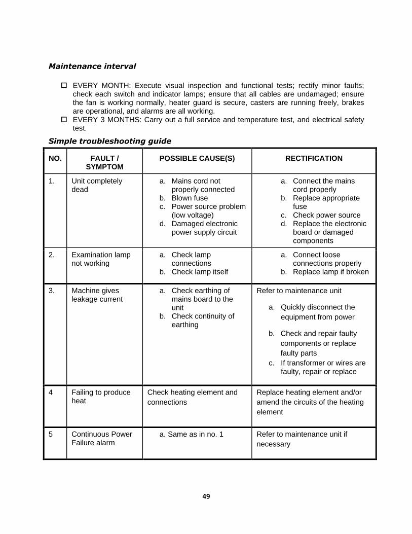
49
Maintenance interval
EVERY MONTH: Execute visual inspection and functional tests; rectify minor faults;
check each switch and indicator lamps; ensure that all cables are undamaged; ensure the fan is working normally, heater guard is secure, casters are running freely, brakes are operational, and alarms are all working.
EVERY 3 MONTHS: Carry out a full service and temperature test, and electrical safety test.
Simple troubleshooting guide
NO. FAULT / SYMPTOM
POSSIBLE CAUSE(S) RECTIFICATION
1. Unit completely dead
a. Mains cord not properly connected
b. Blown fuse c. Power source problem
(low voltage) d. Damaged electronic
power supply circuit
a. Connect the mains cord properly
b. Replace appropriate fuse
c. Check power source d. Replace the electronic
board or damaged components
2. Examination lamp not working
a. Check lamp connections
b. Check lamp itself
a. Connect loose connections properly
b. Replace lamp if broken
3. Machine gives leakage current
a. Check earthing of mains board to the unit
b. Check continuity of earthing
Refer to maintenance unit
a. Quickly disconnect the
equipment from power
b. Check and repair faulty
components or replace
faulty parts
c. If transformer or wires are faulty, repair or replace
4 Failing to produce heat
Check heating element and
connections
Replace heating element and/or
amend the circuits of the heating
element
5 Continuous Power Failure alarm
a. Same as in no. 1 Refer to maintenance unit if
necessary

50
6 Continuous Probe Failure alarm
a. Disconnect probe and check its resistance
b. Check connection of probe
Refer to maintenance unit
Quick troubleshooting interventions
• Alarm bell is blinking and sounding: Temperature limit/setting is breached, or skin probe is detached from the baby. Check temperature settings and adjust; reconnect and reposition skin sensor.
• Unit does not power on: There could be a broken power cord, loose power socket, or blown fuse. Check the power source and power cord, and rectify the issue; check the power fuses in the circuit board and replace.
• No heat is coming from the warmer: The power fuse could be blown, electrical/electronic circuit could be faulty, mechanical switch could be broken, or the heater itself could be faulty/disconnected. Rectify the issue if it is a fuse; pull out the electrical/electronic board and check for damaged components; replace broken switch; check the heater or reconnect electrical wire.
• LED lights are not working: There could be a loose connection, broken or defective lights. Check the switch and connections; replace LED lamps.
Safety test
Grounding resistance (<200Ω)
Insulation resistance (>0.5MΩ)
Leakage current (<500µA)
Parts/materials/consumables needed
Gloves
Fuse: 0.5mA
Flannel cloth (non-abrasive material)
Lubrication oil
Disinfectant, soap and water
Tools and test equipment needed
Multi-tester Air blower hand pump
Set of screwdrivers Spirit thermometer
Electrical analyser Brush
INFUSION PUMP (Volumetric Pump) Technician: approx. 1.0 hour, quarterly
User/nurse: approx. 0.5 hours, before and after use
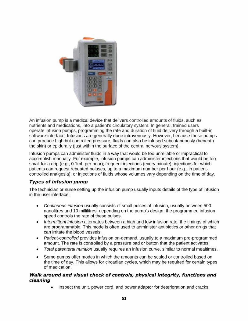
51
An infusion pump is a medical device that delivers controlled amounts of fluids, such as nutrients and medications, into a patient's circulatory system. In general, trained users operate infusion pumps, programming the rate and duration of fluid delivery through a built-in software interface. Infusions are generally done intravenously. However, because these pumps can produce high but controlled pressure, fluids can also be infused subcutaneously (beneath the skin) or epidurally (just within the surface of the central nervous system).
Infusion pumps can administer fluids in a way that would be too unreliable or impractical to accomplish manually. For example, infusion pumps can administer injections that would be too small for a drip (e.g., 0.1mL per hour); frequent injections (every minute); injections for which patients can request repeated boluses, up to a maximum number per hour (e.g., in patient-controlled analgesia); or injections of fluids whose volumes vary depending on the time of day.
Types of infusion pump
The technician or nurse setting up the infusion pump usually inputs details of the type of infusion in the user interface:
• Continuous infusion usually consists of small pulses of infusion, usually between 500 nanolitres and 10 millilitres, depending on the pump's design; the programmed infusion speed controls the rate of these pulses.
• Intermittent infusion alternates between a high and low infusion rate, the timings of which are programmable. This mode is often used to administer antibiotics or other drugs that can irritate the blood vessels.
• Patient-controlled provides infusion on-demand, usually to a maximum pre-programmed amount. The rate is controlled by a pressure pad or button that the patient activates.
• Total parenteral nutrition usually requires an infusion curve, similar to normal mealtimes.
• Some pumps offer modes in which the amounts can be scaled or controlled based on the time of day. This allows for circadian cycles, which may be required for certain types of medication.
Walk around and visual check of controls, physical integrity, functions and cleaning
• Inspect the unit, power cord, and power adaptor for deterioration and cracks.

52
• Check the body, door lock, keypad and LCD screen.
• Check the IV stand holder.
• Inspect the cleanliness of the main body; disinfect and sanitize with a damp cloth and alcohol.
• Open the main door and clean the sensor gently with a swab.
• Plug the unit into the mains or power adaptor and switch on the unit; observe if the battery status light is blinking (charging).
• Check operating functions and settings, i.e., drip rate, flow rate, volume control, bolus, air and occlusion, by manipulating the keypad.
Functional/operational check
• Turn on the unit to operation mode and set up the chamber/infusate. Ensure that there is no air in the line.
• Set the infusion control, e.g., drip rate, flow rate and volume control, and measure the accuracy of drip rate and volume using a hand watch and measuring container with graduation.
• Clean the drip sensors, air detector and occlusion detector with a swab and alcohol, and dry them.
• Open up the unit/dismantle and check the battery pack voltage; replace if necessary; clean the electronic circuit board with a brush; check tightness of terminal connections and fuse holders.
• Check the motor and pulley connections; replace the pulley if it shows sign of deterioration.
• Clean the gears and drives.
• Check whether the alarms are working/functioning by simulating events.
• Ensure that earthing is connected properly.
Troubleshooting
• Power does not turn on when plugged into socket and switched on: External or internal fuse could be blown, power supply connection could be faulty, or power cord could be broken. Check and replace external and internal fuse; check power source, its connection and power cord.
• LCD screen display is completely dark and black when switched on: Electronic board connectors could be loose or broken, or LCD screen could be damaged. Replace and/or reconnect electronic board connectors and tighten; replace LCD or set of connector cables.
• Air bubble or occlusion indicators are on even when there is no air or the line is not blocked: Sensors are dirty. Clean the sensors with a swab and alcohol.
• Inaccurate volume and flow rate, or unit is emitting an abnormal noise: Steeper motor bearing could be dirty or misaligned, or the belt could be loose or worn-out. Replace.
Parts/materials/consumables needed
• Battery: 1.5V lithium-ion x 6 pcs
• Power adaptor: 6V AC/DC
• Flannel cloth (non-abrasive material)
• Disinfectant/isopropyl alcohol 70%
• Gloves
• Stick and cotton (swab)
• PC board connector

53
Tools and test equipment needed
• Multi-meter
• Set of screwdrivers
• Brush
• Air blower hand pump
• Soldering iron and lead
• Hot air blower
• Cable: 2.5mm2
• Allen keys
• Magnifying glass
OXYGEN CONCENTRATOR MACHINE (Portable Oxygen Generator) Technician: approx. 1 hour, quarterly
User/nurse: approx. 15 minutes, daily as necessary
Oxygen concentrator machines draw air in and then remove the nitrogen component from it, leaving only pure oxygen in the portable oxygen tanks for breathing. The principle of Rapid Pressure Swing Adsorption is used, and the nitrogen in the atmosphere gets absorbed by the zeolite present in the machine’s molecular sieve. There is an air compressor provided in the molecular sieve of the oxygen concentrator along with two different cylinders with the zeolite. There is also a reservoir for equalizing the pressure. This technology is both economical and efficient, as it is able to deliver small volumes of oxygen. These portable oxygen generators are used by people with low levels of oxygen in their

54
body, but they are also used in industrial applications. It is important to understand the functioning of an oxygen concentrator in order to ensure it is working properly.
Mechanical control and physical integrity
• Conduct visual and walk around check and clean: power cord, O2 panel indicator for cracks, casing, humidifier, caster wheels.
• Conduct mechanical check of circuit breaker and ON/OFF switch.
• Conduct visual check of flow meter integrity and mechanical check of control.
• Clean/replace gross particle filter.
• Replace second filter, third filter and bacterial filter.
• Clean O2 port(s) and humidifier bottle.
• Run hour check (total running hours and recording), and replace maintenance kits/parts based on the manufacturer’s recommendations.
• Clean and dust interior parts of the unit.
• Clean air compressor fan.
• Check electrical connections.
Functional/operational check
Some issues might arise to cause a medical oxygen concentrator to stop working. These include the following:
• Tube blockage: A blockage in the tube is one of the main reasons for the oxygen concentrator to stop working. Check tube for blockage and remove.
• Weak sieve bed: The molecular sieve bed is one of the most important parts of the oxygen generator. This sieve bed is filled with zeolite, which helps to filter nitrogen from the air. However, if the sieve bed is of poor quality or has other issues, it can become weak and unable to absorb and capture the nitrogen from the oxygen-filled air. Replace the zeolite powder and molecular sieve.
• Bad air compressor: The air compressor helps to increase and decrease the pressure in the machine, which can help the zeolite oxygen sieve to work properly. However, if the compressor is weak and does not work properly, it can affect the entire oxygen concentrator. Replace air compressor.
• Plug and switch on the unit; listen to hear whether the cooling fan is running.
• Check and measure the O2 concentration from the ports using an O2 analyser.
• Disassemble the unit and check/replace the bacterial and second and third filters, or wash and air dry second filter.
• Check alarms (audio and visual alarm activation by powering off and turning O2
off) and other LED indicators.
• Check running hours; replace HEPA filter every after 7,000 hours or as recommended by the manufacturer.
• Measure oxygen flow rate.
Troubleshooting
• Power alarm: Check that the power cord is functioning and connected properly, and check all connections; rectify any issues.
• Low oxygen alarm: There could be a leak in the oxygen accumulator tank, too many patients connected using splitters, dirty gross particle filters, or low compression. Open the unit and check for leaks in the accumulator tank; reduce the number of connected patients to the allowable number and adjust the flow rate of oxygen (flow meter); clean the gross particle filter; check air compressor performance.

55
• Oxygen pressure alarm: The flow meter could be leaking, too many patients connected, or sieve beds deteriorating. Check the flow meter control; check for leaks; check the volume of O2 being administered to the patients; check the running hours of the unit and the life span of the sieve beds.
• All alarms are lit up: This indicates that it is time for a regular maintenance check-up. Check the electronic circuit board, sensors, and carry out IPM protocols.
Safety test
Grounding resistance (<200Ω)
Insulation resistance (>0.5MΩ)
Leakage current (<500µA)
Parts/materials/consumables needed
• Bacteria, gross particle, second and third filters
• Disinfectant, soap and water, distilled/soft water
• Flannel cloth
• Battery: 9V DC
Tools and test equipment needed
• Oxygen gas analyser
• Sets of screwdrivers and spanners
• Brush for air compressor
• Electrical analyser
• Flow meter
PAN WEIGHING SCALE (Digital) Technician: approx. 0.25 hours, quarterly
User/nurse: approx. 6 minutes, daily
A pan weighing scale is a practical device for weighing an infant/baby. Manual scales have a
balanced beam and two pans. When the pans contain exactly the same mass, the beam is in
balance. You can place an object in one pan and place standard weights in the other to find out

56
how much the object weighs. Digital pan weighing scales use a single pan, as the one shown.
This type of scale is highly accurate, fast and stable, and easy to operate.
Main parts
• Pan or baby tray
• Display panel for weight
• Machine body
• Battery holder: 2 x 1.5V DC alkaline or mains adapter if any
Functional/operational check and cleaning
• Put the scale on a firm, even surface. Wipe the weighing pan clean. • Plug in or press the ON button and wait until the display panel registers zero. • Check for and adjust zero error, if any, and select unit of weight (Kg or Lbs). • Place a clean cloth/paper on the pan. • Press the knob to reset the reading to zero; otherwise, you will have to subtract the
weight of the cloth from the total weight when the dummy baby/weight is weighed along with the
sheet.
• Place the dummy baby/weight on the cloth/paper. • Keep the dummy baby/weight in the middle of the weighing pan; hold the remaining
tubes and lines in hand. • When weighing a real baby, detach as many tubes/equipment as possible prior to
weighing. Keep the naked baby on the towel and record the weight (subtract the weight of the cloth if the scale has no facility to be reset to zero).
• Clean the pan with disinfectant/soap and water; use a damp cloth to clean. • Wipe with a spirit swab between babies. • Change the battery pack if the LCD reading is not as accurate as it should be or is
showing signs of malfunction. • Always remove the battery pack during a prolonged period of disuse.
Do
• Put the weighing scale on a flat, stable surface. • If using a pre-weighed splint, subtract the weight from the baby's weight. • Always look for and adjust zero error. • Remove excessive clothing. • Calibrate using a known standard weight daily.
Don't
• Stack or line up other objects on the weighing pan when not in use.
• Pour water on the electronic display.
• Keep the weighing machine in a humid atmosphere.
Troubleshooting
• The unit does not function: The plug, socket, cable or fuse could be blown or the battery pack could be flat/drained. Rectify the issue(s).
• Machine reads ERR or sorry: Too heavy a weight is on the scale. Use appropriate weights to weigh.
• Low battery: The battery is discharged. Connect the power cord to recharge or replace the battery pack.

57
• Machine shows erratic weights: The unit needs calibration. Use standard weights of 100/200 grams or ½kg/1kg every 7 days for calibration.
Parts/materials/consumables needed
Fuses
Flannel cloth (non-abrasive material)
Gloves
Disinfectant, soap and water
Battery or power adaptor
Tools and test equipment needed
Multi-meter
Set of screwdrivers
Brush
Air blower hand pump
Dummy weights
PHOTOTHERAPY UNIT/LAMP Technician: approx. 1.0 hour, quarterly
User/nurse: approx. 15 minutes, monthly
Phototherapy is a treatment with a special type of light (not sunlight) that is sometimes used to
treat newborn jaundice. Phototherapy works by lowering the bilirubin levels in the baby's blood
through a process called photo-oxidation, which enables the bilirubin to dissolve easily in water.
Babies usually need to be under phototherapy lights for around 48 hours or often longer, and
physiological jaundice normally clears by the time the baby is 2 weeks old.
Phototherapy units consist of a light source and a means of allowing the light to radiate the
infant. Devices using overhead lamps can be freestanding on casters, mounted on a ceiling or
wall, or attached to infant radiant warmers or infant incubators. Some units have height and
hood angle adjustments.

58
Medical lamps fall into two categories: those used for therapy and those used for operational
illumination. In either case, a quantity of emitted light energy is delivered as desired. This could
be IR light for the purpose of producing heat in a portion of the patient's body, or ultraviolet light
for the purpose of curing certain types of skin diseases.
Operating lamps produce a broad spectrum, normally called white light, which contains a
relatively full range of light frequencies, although this may be limited by the type of lamp bulb
employed. For instance, a "daylight" lamp has almost all of the IR radiation filtered out and will
have a blue colour. The use of a glass bulb, rather than quartz (as normally found in regular
lamps), screens out and thus eliminates much of the ultraviolet portion of the spectrum. In
general, therapeutic lamps and operating lamps also have a special design in the lamp reflector.
This lamp design is often parabolic, often with the top and bottom sections of the parabola cut
off to provide a more limited band of light and shadow-less illumination.
Walk around check of mechanical parts and physical integrity
Source of light: clean, wipe
• Fluorescent lights (conventional phototherapy)
• Compact fluorescent lights (CFL)
• Light emitting diodes (LED) Other parts
• Fan
• Light meter (hour meter)
• Body, light hood and reflector, frame and base including caster wheels and brakes; ensure cleanliness
• Check power cord for signs of cracks and deterioration; check switch and light meter.
• Use a moist or dry cloth to clean the unplugged unit.
• Ensure the reflectors and bulbs remain dust-free.
Functional/operational check
To ensure delivery of safe and effective phototherapy, switch on the unit and observe the
following:
• Protect the eyes from light using eye patches once the lights are on.
• Keep the baby naked with a small diaper to cover the genitalia.
• Place the baby as close to the light as the manufacturer’s instructions allow. Use white curtains or linen as slings so as to reflect back as much light as possible to the baby; make sure to not cover the top surface of the unit in order to enable air flow to cool the bulbs.
• Monitor the baby’s temperature every 4 hours and weight every 24 hours.
Caution
• Do not use a phototherapy unit under a warmer.
• For babies under 1.5kg, it is preferable to use phototherapy over an incubator.
• After switching on the unit, check that all tubes/bulbs are on.
• Do not place anything on the phototherapy unit, as this can block the air vents/flow.
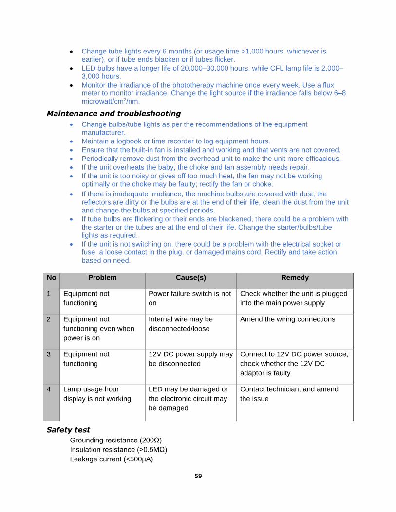
59
• Change tube lights every 6 months (or usage time >1,000 hours, whichever is earlier), or if tube ends blacken or if tubes flicker.
• LED bulbs have a longer life of 20,000–30,000 hours, while CFL lamp life is 2,000–3,000 hours.
• Monitor the irradiance of the phototherapy machine once every week. Use a flux meter to monitor irradiance. Change the light source if the irradiance falls below 6–8 microwatt/cm2/nm.
Maintenance and troubleshooting
• Change bulbs/tube lights as per the recommendations of the equipment manufacturer.
• Maintain a logbook or time recorder to log equipment hours.
• Ensure that the built-in fan is installed and working and that vents are not covered.
• Periodically remove dust from the overhead unit to make the unit more efficacious.
• If the unit overheats the baby, the choke and fan assembly needs repair.
• If the unit is too noisy or gives off too much heat, the fan may not be working optimally or the choke may be faulty; rectify the fan or choke.
• If there is inadequate irradiance, the machine bulbs are covered with dust, the reflectors are dirty or the bulbs are at the end of their life, clean the dust from the unit and change the bulbs at specified periods.
• If tube bulbs are flickering or their ends are blackened, there could be a problem with the starter or the tubes are at the end of their life. Change the starter/bulbs/tube lights as required.
• If the unit is not switching on, there could be a problem with the electrical socket or fuse, a loose contact in the plug, or damaged mains cord. Rectify and take action based on need.
Safety test
Grounding resistance (200Ω)
Insulation resistance (>0.5MΩ)
Leakage current (<500µA)
No Problem Cause(s) Remedy
1 Equipment not
functioning
Power failure switch is not
on
Check whether the unit is plugged
into the main power supply
2 Equipment not
functioning even when
power is on
Internal wire may be
disconnected/loose
Amend the wiring connections
3 Equipment not
functioning
12V DC power supply may
be disconnected
Connect to 12V DC power source;
check whether the 12V DC
adaptor is faulty
4 Lamp usage hour
display is not working
LED may be damaged or
the electronic circuit may
be damaged
Contact technician, and amend
the issue

60
Parts/materials/consumables needed
• Fuses
• Flannel cloth (non-abrasive material)
• Gloves
• Disinfectant, soap and water
• Replacement bulbs/lamps/LED
• Choke, starter and lamp holder
• Fan
Tools and test equipment needed
• Multi-meter
• Set of screwdrivers
• Electrical analyser
• Brush
• Air blower hand pump
• Lumen meter
PHYSIOLOGIC MONITOR (Bedside Monitor) Technician: approx. 1 hour, quarterly User/nurse: approx. 30 minutes, weekly
Multiparameter monitors are designed to measure, record, distribute and display a range of
biometric information needed to understand a patient’s condition (e.g., heart rate, oxygen
saturation [SpO2], blood pressure, temperature) on a single screen. Consequently, high-
capability, multi-function monitors offer a flexible solution for varying critical care needs, and are
typically used in hospitals and clinics to ensure a high level of quality patient care.
There are five standard parameters: electrocardiogram (ECG), respiration (RESP), non-invasive
blood pressure (NIBP), peripheral capillary blood saturation (SpO2), dual temperature (2-TEMP),
and pulse rate/heart rate (PR/HR). 12.1"high resolution colour TFT LCD display. Real-time S-T

61
segment analysis, pace-maker detection. Nurses have traditionally relied on five vital signs to
assess their patients: temperature, pulse, blood pressure, respiratory rate and oxygen
saturation. The monitoring of clinical parameters is primarily intended to detect changes (or
absence of changes) in the clinical status of an individual. For example, the parameter of
oxygen saturation is usually monitored to detect changes in the respiratory capability of an
individual.
Mechanical control and physical integrity
• Conduct a visual check of the power cord and LCD monitor/digital display for cracks.
• Conduct a mechanical check of the circuit breaker and ON/OFF switch.
• Conduct a visual check of patient probes: SpO2, ECG, temperature, NIBP, PR/HR.
• Clean patient cable/cord/probe (disinfection), body and screen display.
• Conduct a mechanical check of the selector switch, probe connectors and terminals.
• Conduct a mechanical check of the earth connection.
• Check that the electrical socket is not burned or loose.
• Check/clean the motherboard/circuit board.
Functional/operational check
• Set the unit and plug to 220V, 50Hz.
• Operate using the battery supply.
• Calibrate; connect patient probes and check the tracings/readings.
• Check the presence of 1mV; calibrate sensitivity, damping, centering and limits.
• Check battery strength status.
• Check the function/parameter selector knob by moving the cursor.
• Adjust the brightness and contrast if necessary.
• Check the audio/visual alarm functions at low and high settings of NIBP, HR, temperature and SpO2.
Safety test
Ground resistance (>200Ω)
Insulation resistance (>0.5MΩ)
Leakage current (<50 µA)
Parts/materials/consumables needed
Mild cleaning agent/disinfectant Fuse: 0.5mA
Soft and water Gloves
Alcohol Thermometer
Cotton cloth materials (non-abrasive)
Lithium-ion battery
Tools and test equipment needed
Multi-tester
Heart simulator
Set of screwdrivers
Electrical analyser
BP machine tester
Brush

62
Air blower hand pump

63
RESUSCITATION BAG Technician: approx. 0.5 hours, monthly
User/nurse: approx. 15 minutes, weekly
Manual resuscitation is a form of artificial respiration that uses a breathing bag (manual
resuscitator) to assist patients with breathing. This technique is usually used when the lungs are
not functioning properly. Some ICU staff members refer to the breathing bag as an Ambu bag,
which stands for Artificial Manual Breathing Unit (ventilation).
Adult Ambu bag, 1,600mL: Self-inflating double-ended silicon bag with mounts, incorporating a
reservoir valve and side feed oxygen inlet, type "L" non-rebreathing valve with a pressure-
limiting device that will open if the inspiratory pressure is more than 60cm of water.
Some Ambu bags are disposable after one use; others are reusable depending on their
manufacturer.
Checking bag & mask
Block patient outlet or mask with the palm of your hand. Squeeze the bag.
• You should feel pressure against your hand.
• Check the opening of the inspiratory valve.
• With higher pressure, you should be able to open the pop-off safety valve.
Procedure
• Choose the appropriate size of bag and mask.
• Position the baby in a sniffing position/slight extension.
• Provide a tight seal.
• Use fingertips to generate enough pressure to move the chest of the baby.
• Observe for any improvement in heart rate, colour and chest rise.
O2 inlet
Air inlet
Body of
the bag
Patient
outlet
Valve
assembly
Safety
valve
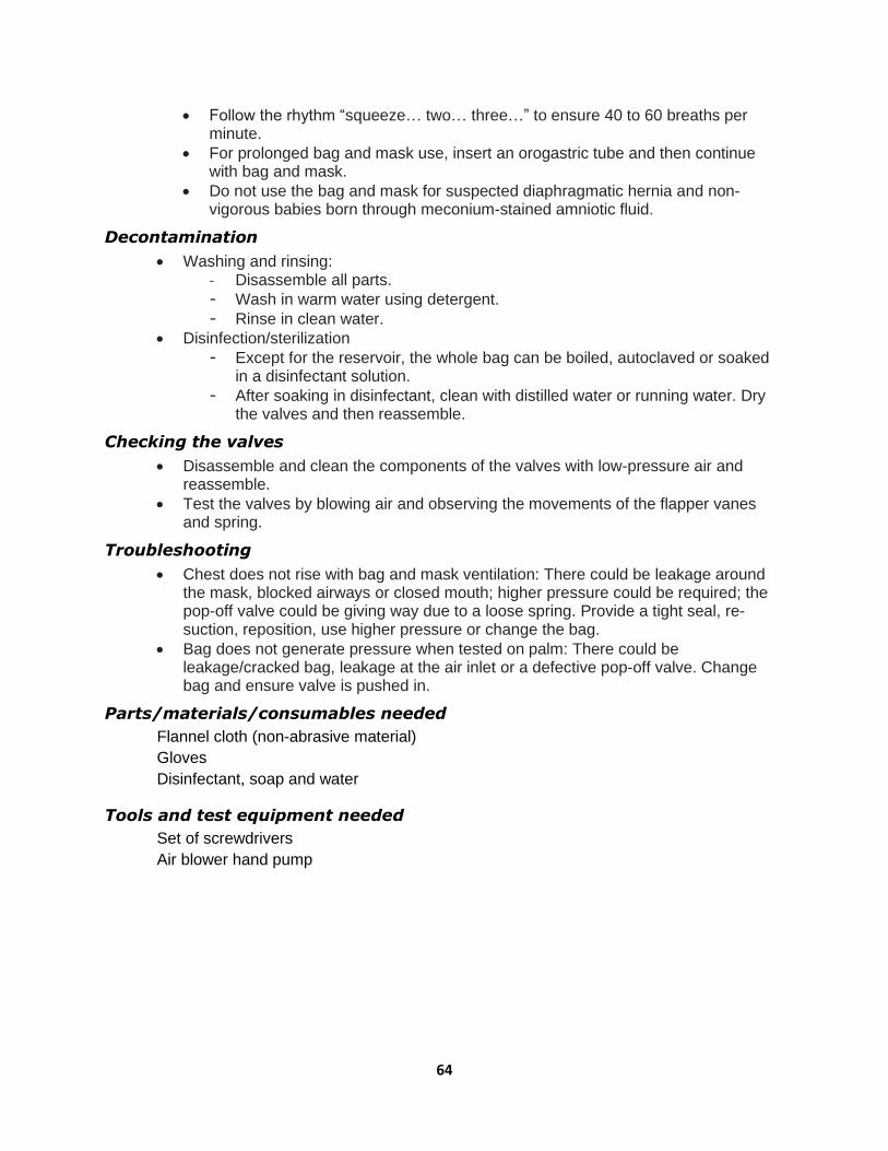
64
• Follow the rhythm “squeeze… two… three…” to ensure 40 to 60 breaths per minute.
• For prolonged bag and mask use, insert an orogastric tube and then continue with bag and mask.
• Do not use the bag and mask for suspected diaphragmatic hernia and non-vigorous babies born through meconium-stained amniotic fluid.
Decontamination
• Washing and rinsing: - Disassemble all parts.
- Wash in warm water using detergent.
- Rinse in clean water.
• Disinfection/sterilization
- Except for the reservoir, the whole bag can be boiled, autoclaved or soaked in a disinfectant solution.
- After soaking in disinfectant, clean with distilled water or running water. Dry the valves and then reassemble.
Checking the valves
• Disassemble and clean the components of the valves with low-pressure air and reassemble.
• Test the valves by blowing air and observing the movements of the flapper vanes and spring.
Troubleshooting
• Chest does not rise with bag and mask ventilation: There could be leakage around the mask, blocked airways or closed mouth; higher pressure could be required; the pop-off valve could be giving way due to a loose spring. Provide a tight seal, re-suction, reposition, use higher pressure or change the bag.
• Bag does not generate pressure when tested on palm: There could be leakage/cracked bag, leakage at the air inlet or a defective pop-off valve. Change bag and ensure valve is pushed in.
Parts/materials/consumables needed
Flannel cloth (non-abrasive material)
Gloves
Disinfectant, soap and water
Tools and test equipment needed
Set of screwdrivers
Air blower hand pump
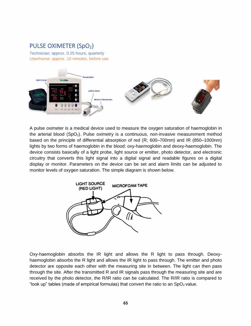
65
PULSE OXIMETER (SpO2) Technician: approx. 0.25 hours, quarterly
User/nurse: approx. 10 minutes, before use
A pulse oximeter is a medical device used to measure the oxygen saturation of haemoglobin in
the arterial blood (SpO2). Pulse oximetry is a continuous, non-invasive measurement method
based on the principle of differential absorption of red (R; 600–700nm) and IR (850–1000nm)
lights by two forms of haemoglobin in the blood: oxy-haemoglobin and deoxy-haemoglobin. The
device consists basically of a light probe, light source or emitter, photo detector, and electronic
circuitry that converts this light signal into a digital signal and readable figures on a digital
display or monitor. Parameters on the device can be set and alarm limits can be adjusted to
monitor levels of oxygen saturation. The simple diagram is shown below.
Oxy-haemoglobin absorbs the IR light and allows the R light to pass through. Deoxy-
haemoglobin absorbs the R light and allows the IR light to pass through. The emitter and photo
detector are opposite each other with the measuring site in between. The light can then pass
through the site. After the transmitted R and IR signals pass through the measuring site and are
received by the photo detector, the R/IR ratio can be calculated. The R/IR ratio is compared to
“look up” tables (made of empirical formulas) that convert the ratio to an SpO2 value.
66
At the measuring site, there are light absorbers that are always present, i.e., skin, tissue,
venous blood, and arterial blood. However, with each heartbeat, there is a large surge of arterial
blood, which momentarily increases arterial blood volume across the measuring site and results
in more light absorption during the surge. If the light signals received by the photo detector are
looked at as a waveform, there should be peaks with each heart beat and troughs between
heartbeats. If the light absorption at the trough (which should include all the constant absorbers)
is subtracted from the light absorption at the peak, then, in theory, the remainder indicates the
absorption characteristics attributed only to the added volume of (arterial) blood.
Since the peaks occur with each heartbeat or pulse, the term pulse oximetry was coined.
Major parts
• Monitor
• Saturation probes
Kinds of probe
• Finger probe for adult or paediatric finger
• Universal “Y” probe for adult or paediatric finger
• Universal “Y” probe for infant hand
• Universal “Y” probe for infant foot
• Ear probe for adult or paediatric ear
• Disposable probe for adult finger or toe
Visual inspection and physical integrity check
• Visually check and inspect the monitor, LCD screen for cracks, power cord, earthing terminal, knobs and controls.
• Check each probe, connector and cable.
• Ensure that the components are clean and dust-free; probes should be cleaned using alcohol and left to dry.
Disinfection
Clean the probe with a spirit swab before every application. Use soap and water to clean the monitor. Do not autoclave or pressure sterilize. Do not use petroleum-based, acetone or other harsh solutions.
Functional/operational check
• Connect the power cable to the electric socket (220V AC, 50 Hz) and turn the monitor on.
• Apply probe to a site that is well perfused. • Ensure that both sides of the probe are directly opposite each other. • Secure the probe in place. Avoid edematous, bruised sites and excessive pressure. • Set high and low alarm limits for saturation (2% above and below desired limits) and
heart rate 100–160/min (for infants). • Set pulse and alarm volumes. • Check the waveform of the perfusion index, if available, for the accuracy of the signal. • Check the correlation between the depicted heart rate on the monitor and the actual
heart rate by auscultation. • Change the site of the probe at least once per shift.

67
Precautions
• Do not allow excess ambient light to shine on the probe. If there is excess light, cover the probe with an opaque material.
• Do not tie the BP cuff proximal to the limb on which the probe is fixed.
• Do not place equipment generating electromagnetic signals in the vicinity.
• Do not run the oximeter on battery alone if back-up power is available.
Maintenance schedule
The pulse oximeter, in general, is extremely user-friendly and requires minimum maintenance.
For better performance, operation and safety, regular routine maintenance is to be performed by the end user. Maintain records on maintenance, repair and required updates to the equipment.
• Look for the standard power supply, as specified in the technical specifications.
• Check the proper connections and functioning of cables and patient accessories.
• Do not use cables, patient accessories or connectors that appear to be damaged.
• Ensure that the battery is fully charged when using battery power. It is preferable to replace the battery every 2 years.
• When low battery is indicated (i.e., LoBat LED glows red), charge the battery immediately.
• Do not expose the device to extreme temperatures, humidity, dust or direct sunlight.
• Make sure that an authorized and fully trained engineer conducts periodic checks and servicing of the equipment once a year to maintain proper functioning and trouble-free operation of the equipment.
Cleaning
• Do not immerse the unit in caustic or abrasive cleaners.
• Unplug the sensor from the equipment before cleaning or disinfecting.
• Clean or disinfect the sensor before attaching it to a new patient.
• Clean the monitor and cables with a dry or damp smooth cloth.
• Do not use rough or sharp instruments to clean the cables and the sensor. Note: Make sure that the equipment is completely off while cleaning any of its
parts.
Storage
When storing the unit, make sure that it is switched off completely and preferably unplug all the cables. If the unit is to be stored for a period of 2 months or longer, notify service personnel to remove the battery prior to storage. Refer to the storage conditions provided in the technical specifications.
Troubleshooting
• Ambient light or excessive light on sensor: Relocate or cover with opaque paper/cloth.
• Check sensor: Motion, low perfusion, or wrong position. Reposition or relocate.
• Interference detected: Erratic signal with electromagnetic waves in the vicinity like TV, mobile phone. Remove interference.
• Low battery: Connect to AC power.
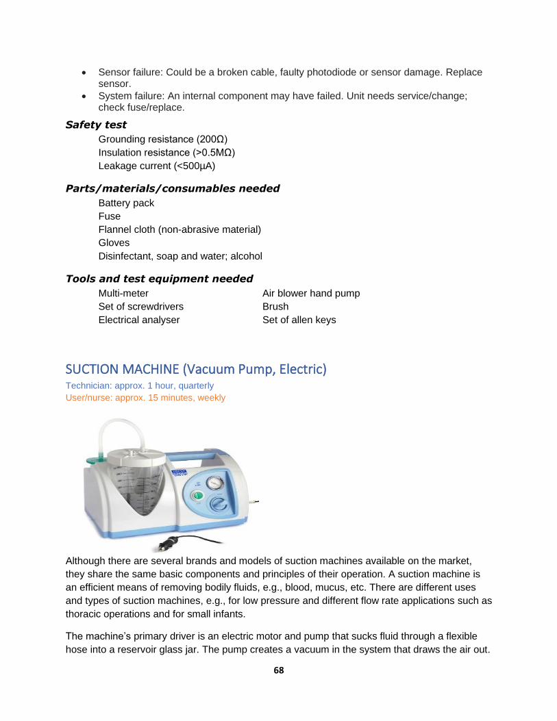
68
• Sensor failure: Could be a broken cable, faulty photodiode or sensor damage. Replace sensor.
• System failure: An internal component may have failed. Unit needs service/change; check fuse/replace.
Safety test
Grounding resistance (200Ω)
Insulation resistance (>0.5MΩ)
Leakage current (<500µA)
Parts/materials/consumables needed
Battery pack
Fuse
Flannel cloth (non-abrasive material)
Gloves
Disinfectant, soap and water; alcohol
Tools and test equipment needed
Multi-meter Air blower hand pump
Set of screwdrivers Brush
Electrical analyser Set of allen keys
SUCTION MACHINE (Vacuum Pump, Electric) Technician: approx. 1 hour, quarterly
User/nurse: approx. 15 minutes, weekly
Although there are several brands and models of suction machines available on the market,
they share the same basic components and principles of their operation. A suction machine is
an efficient means of removing bodily fluids, e.g., blood, mucus, etc. There are different uses
and types of suction machines, e.g., for low pressure and different flow rate applications such as
thoracic operations and for small infants.
The machine’s primary driver is an electric motor and pump that sucks fluid through a flexible
hose into a reservoir glass jar. The pump creates a vacuum in the system that draws the air out.
69
As the vacuum is created, the suction moves fluids from lower pressure to higher pressure. It is
important that there are no leaks in the system, as the vacuum pressure may not be achieved.
There are also manual foot-operated suction machines.
A pressure gauge is installed in the system to guide the operator in adjusting the unit to the
desired vacuum pressure required for a particular case. In some instances, two gauges are
installed in the system. The operator uses a valve to control the vacuum pressure, depending
on the patient’s requirement. As the fluid fills the jar, a float valve rises to stop the fluid from
overflowing and contaminating and damaging the pump. Remember that the pump is designed
to suck air and not fluid. There is also an air filter (bacterial filter) to prevent bacteria and
contaminants from infecting the pump/motor, thereby protecting the technicians and users from
the risk of cross-infection.
When the jar is full, switch off the pump and replace the filled jar with an empty one. In some
designs, there are two jars; as the first jar is nearing its full level, a changeover switch is
activated to divert the flow to the other jar, and the full jar can be replaced with an empty one.
To reduce the possibility of cross-infection, each department (e.g., SCBU, OT, ICU, paediatrics)
should have their own dedicated suction machines. Ideally, each department should be
responsible for their own machines, which should be labelled with the name of the ward or
department to avoid mix-ups.
Routine safety check
Ensure the following:
• Adequate supply of bacterial filters
• Replacement of jar, rubber cover
• Fittings are connected properly, without leaks; spare anti-static hose
• Flexible hose is anti-static
• Float valve is working; spare float valves and “O” rings
• De-foaming agent is in the jar to prevent frothing, e.g., diesel oil
• Spare machine when doing IPM
• Spare plug
When the machine is scheduled for maintenance, testing and general overhaul (approx. every 2
months), thoroughly clean and sterilize the float valve, jar, jar covers, and hoses to protect the
technicians from infection.
Replace air intake and outlet filters every month or as necessary.
Unplug the machine when cleaning. When using, make sure that the machine is not vibrating
abnormally, overheating or making an abnormally loud noise. Report to the maintenance crew if
you observe any of these issues.
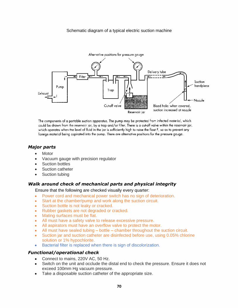
70
Schematic diagram of a typical electric suction machine
Major parts
• Motor
• Vacuum gauge with precision regulator
• Suction bottles
• Suction catheter
• Suction tubing
Walk around check of mechanical parts and physical integrity
Ensure that the following are checked visually every quarter:
• Power cord and mechanical power switch has no sign of deterioration. • Start at the chamber/pump and work along the suction circuit. • Suction bottle is not leaky or cracked. • Rubber gaskets are not degraded or cracked. • Mating surfaces must be flat. • All must have a safety valve to release excessive pressure. • All aspirators must have an overflow valve to protect the motor. • All must have sealed tubing – bottle – chamber throughout the suction circuit. • Suction jar and suction catheter are disinfected before use, using 0.05% chlorine
solution or 1% hypochlorite. • Bacterial filter is replaced when there is sign of discolorization.
Functional/operational check
• Connect to mains, 220V AC, 50 Hz. • Switch on the unit and occlude the distal end to check the pressure. Ensure it does not
exceed 100mm Hg vacuum pressure. • Take a disposable suction catheter of the appropriate size.

71
• Connect it to the suction tubing. • Perform suction gently; if the machine works at this pressure, it means it is okay. • Fill the suction jar up to the point that the float valve rises and closes. • Observe that there is no abnormal noise/sound, vibration or heat produced by the motor. • Switch off the suction machine and discard the suction catheter.
Cleaning & disinfection
• Wash the suction bottle with soap and water. • Change the bottle solution (0.05% chlorine solution or 1% hypochlorite) every use.
Basic troubleshooting guides
PROBLEM ACTION
1. Suction pump motor fails to run after switched on
a. Check the electrical plug and cord, electrical supply 220/240V 50 Hz, 130 watts.
b. Fit plug properly into the wall socket: Is it switched on? c. Repair broken cord. d. Check the fuses: 1.6 Amp, 20mm glass fuse.
2. No suction pressure
despite vacuum pressure
reading on the gauge
a. Check and clean all tubing and tubing connectors. b. Check bottles and fit properly.
c. Check bottle gasket and replace when necessary.
3. Testing for leaks If the motor is running but pressure is weak, or if there is no
vacuum when the vacuum outlet is closed off, the following
steps should be carried out:
a. Check that the vacuum control knob is fully closed by turning in a clockwise direction.
b. The vacuum gauge should now show approximately -80kPa, which will indicate that the pump/motor is fully operational. The vacuum performance can be affected by cracks in jars, caps, connectors and damage to silicone tubing, and cap sealing ring.
c. Examine the parts mentioned above and replace these parts as necessary.
• Replace fuse if blown. • Check cord and amend if deteriorated. • Check earthing if connected properly. • Replace suction jar O-ring/gasket. • Check for leakages in the bottle/tubing. • Check for adequacy of suction pressure. • Change tubing if leaky or broken/brittle.
Safety test
Grounding resistance (200Ω)
Insulation resistance (>0.5MΩ)
Leakage current (<500µA)
Parts/materials/consumables needed
Bacteria filter Catheter tubing/hose
Fuse O-ring/gasket
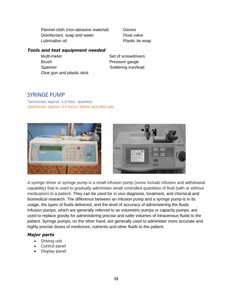
72
Flannel cloth (non-abrasive material) Gloves
Disinfectant, soap and water Float valve
Lubrication oil Plastic tie wrap
Tools and test equipment needed
Multi-meter Set of screwdrivers
Brush Pressure gauge
Spanner Soldering iron/lead
Glue gun and plastic stick
SYRINGE PUMP
Technician: approx. 1.0 hour, quarterly
User/nurse: approx. 0.5 hours, before and after use
A syringe driver or syringe pump is a small infusion pump (some include infusion and withdrawal
capability) that is used to gradually administer small controlled quantities of fluid (with or without
medication) to a patient. They can be used for in vivo diagnosis, treatment, and chemical and
biomedical research. The difference between an infusion pump and a syringe pump is in its
usage, the types of fluids delivered, and the level of accuracy of administering the fluids.
Infusion pumps, which are generally referred to as volumetric pumps or capacity pumps, are
used to replace gravity for administering precise and safer volumes of intravenous fluids to the
patient. Syringe pumps, on the other hand, are generally used to administer more accurate and
highly precise doses of medicines, nutrients and other fluids to the patient.
Major parts
• Driving unit
• Control panel
• Display panel

73
Walk around and visual check of controls, physical integrity, functions and cleaning
• Inspect the unit, power cord, and power adaptor for deterioration and cracks.
• Check the body and mechanical parts, syringe barrel holder, syringe guide, beak, drive unit, lever for clamp, clutch lever, combination clamp, keypad and LCD screen.
• Inspect the cleanliness of the main body, disinfect and sanitize with a damp cloth and alcohol.
• Plug the unit into the mains or power adaptor; switch the unit on and observe if the battery status light is blinking (charging).
• Check the operating functions and settings, i.e., set the flow rate, the volume to be administered, etc.
• Check if the syringe driver will detect an occlusion (a blockage), stop and sound an alarm; check the flow rate and volume control, bolus, air and occlusion by manipulating the keypad.
• Check the displays, i.e., operation mode, running, line power, battery-operated, infusion rate, total volume to be infused (VTBI), pressure, alarm mode, e.g., occlusion, near empty, empty, and other functions.
Functional/operational check
• Press the ON button for 1 second to switch on the syringe pump. All signals on the display unit will glow for a second.
• Connect the power cable to the power slot and fix the infusion pump onto the installation pole.
• Choose the appropriate size and type of syringe as per the need of the patient.
• Set the syringe in the slot in the driving unit. To do this, lift up the syringe holder and place the drug-filled syringe with the inner and the outer cylinders into their corresponding grooves and ensure fixation.
• Set the control parameters, i.e., flow rate and volume; measure the accuracy of rate and volume using a hand watch and measuring container with graduation.
• Before starting the infusion, press the prime button to flush the tubing to remove all air bubbles.
• Now, connect to the patient after ensuring the patency of the IV line.
• Clean the sensors, air detector and occlusion detector with a swab and alcohol and dry them.
• Open up the unit/dismantle and check the battery pack voltage; replace if necessary.
• Clean the electronic circuit board with a brush; check the tightness of terminal connections and fuse holders.
• Check the motor and pulley connections; replace the pulley if it shows sign of deterioration.
• Clean the gears and drives.
• Check whether the alarms are working/functioning by simulating events.
• Ensure the earthing is connected properly.
Maintenance
Cleaning: In the case of spillage, wipe with a soft cloth soaked in lukewarm water.
Disinfection: Disinfect with a cloth dipped in soap and water in the case of blood spilled.
Troubleshooting
• “OUT OF INFU”: Slider has moved inadvertently. Fix syringe again and restart infusion.

74
• “OCCLUSION”: Tube occluded with >60 kPa pressure and unnecessary pushing of fluid into the IV line may cause extravasation (the leaking of intravenously infused fluid and potentially damaging medication into the extravascular tissue around the infusion site).
• “AC FAILURE”: Low internal battery. Connect to AC power.
• “SYRINGE IN USE”: Syringe is removed from holder. Set syringe properly and resume infusion.
• “NEAR EMPTY”: Infusate is almost over-suctioning the compressor. Keep a loaded syringe ready.
Parts/materials/consumables needed
Battery: 1.5V lithium-ion x 6 pcs
Flannel cloth (non-abrasive material)
Disinfectant/isopropyl alcohol 70%
Gloves
Stick and cotton (swab)
Tools and test equipment needed
Multi-tester
Set of screwdrivers
Brush
Air blower hand pump
Soldering iron and lead
Hot air blower
Cable: 2.5mm2

75
MAINTENANCE WORK ORDER SYSTEM
The ‘maintenance work order system’ is a vital cog in the implementation of the IPM and
troubleshooting strategy. It consists of recording and documenting (including scheduling) these
activities as evidence of performance and for future reference as one of the bases for decision-
making.
The work order system requires the use of forms, whether they be digital or the more traditional
paper-based method. Both are usable, depending on the circumstances. For example, in places
where there are limited resources for digitizing procedures, a manual work order system will be
adequate.
The three common forms used are Job Request, which initiates the maintenance activity; Job
Order, which provides the basis for responding to the request for maintenance; and Job Report,
the last stage of maintenance documentation, which narrates the actions taken in an
understandable manner, lists the materials used, and notes any learnings. Examples of these
maintenance forms are shown in Appendix 1.
The scheduling of maintenance activities is inherent to the ‘work order system’ and crucial for
monitoring and supervision. What is written in the three forms provides essential information
regarding not only the equipment itself, but also the technicians’ and artisans’ performance,
capacities, challenges and potential interventions pertaining to these concerns.
The MOHS supports the idea of computerizing the work order system and work scheduling as
part of its plan to better manage, monitor and supervise maintenance operations in order to
make them more efficient and effective. However, the shift from the manual system to a digital
system will require human resources capacity building, input resources such as computer
hardware and software, and Internet provision, especially at the health facility level.
This will necessitate the establishment of a hub office at the MOHS level in charge of the
maintenance and management of medical equipment to make sense of the data that will be
generated at the health facility level.
OPERATION INSTRUCTIONS AND GUIDES
PHYSIOLOGIC MONITOR (Multi-parameter)
• Make sure the unit is connected to the wall socket.
• Press the power button and wait for the LCD screen to light up with the display
parameters.
• Connect the SpO2 probe to the monitor and wait for it to display.

76
• Connect the various probes (ECG, NIBP, SPO2, temperature).
• Set the alarm limits and parameters as required; test if the audio and visual alarms work.
• Connect the two temperature sensors to the patient: one temperature sensor to the
abdomen and the other to the diaphragm.
• Configure to the actual patient (adult or child).
• If the SpO2 reading is maintained at a normal level (>95%) for 24 hours, the baby may be
weaned from b-CPAP or oxygen therapy.
GLUCOMETER (HemoCue +201)
• Make sure the equipment and accessories are available.
• Connect the adaptor to the socket at the back of the equipment if mains power is
available.
• If no electric power is available, insert 4 x AA or R6 size batteries,1.5V each.
• Press and hold the left button until the display is activated (all symbols appear).
• After 10 seconds, it shows flashing dashes and the HemoCue symbol appears,
indicating it is ready for use.
• Pull the cuvette holder to its loading position.
• Place the cuvette with the specimen into the cuvette holder and close; wait for a few
seconds; the result is available in g/dl (grams per decilitre).
• Clean the cuvette holder with alcohol-based sanitizer after each procedure.
To delete results:
• Press both left and right buttons at the same time.
• Once the QC symbol is flashing on the display, scroll with the right button until the
display shows a flashing waste bin in the left corner.
• To delete all stored results, hold both buttons down at the same time for 5 seconds.
STETHOSCOPE
• Check the stethoscope tubes to make sure there are no pinches or holes in them.
• Clean the stethoscope with alcohol and wipe clean.
• Correctly connect the earpiece tips to both ears, making sure they are cleaned of debris
and not blocked.
• Tap the diaphragm to listen to the correct sound. Make sure the stem is connected
snugly to the tubing.
• Always position the diaphragm/chest piece properly to the body parts of the patient.
• Do not overstretch the binaural, as it will be damaged.
BABY WEIGHING SCALE (Digital)
• Place scale on a firm, even surface, then wipe and clean the weighing pan.
• Plug in or press the ON button and wait until the display panel registers zero.
• Check for and adjust zero error, if any, and select unit of weight: Kg or Lb.
• Place a clean paper on the surface of the weighing pan.
• Press the start button to reset the reading to zero.

77
• The baby is now ready to be placed on the weighing scale (remove diaper first).
• Keep the baby in the middle of the weighing pan and record the reading.
• Remove the baby from the scale.
• Clean the pan with disinfectant/soap and water; use a damp cloth to clean.
• Wipe with a spirit swab between babies.
• Change the battery pack if the LCD reading is not accurate or is showing signs of malfunction.
• Always remove the battery pack during prolonged periods of disuse.
• Always keep the scale in a dry place to avoid moisture.
PULSE OXIMETER
• Ensure all accessories are complete in the pulse oximeter; rechargeable type. If battery-operated (disposable type), make sure the batteries are strong/new.
• Connect the power cable to the electric socket (220V AC, 50Hz) or make sure the equipment is charged.
• Switch on the equipment using the power ON button.
• Ensure the IR lights are visible in the clamp/probe.
• Ensure both sides of the probe are directly opposite each other.
• Clean the probe/sensor using an alcohol swab.
• Apply the probe to a finger, earlobe or toe.
• Secure the probe in place. Avoid swollen areas, bruised sites and excessive pressure.
• Set high and low alarm limits for saturation (2% above and below desired limits) and for heart rate/pulse rate 100–160b/min (for infants).
• Wait for a few seconds for the SpO2 and pulse readings to display.
• Change the site of the probe at least every 2 hours.
• Clean the sensor or probe between babies.
• Ensure that the internal batteries of the pulse oximeter are always full.
RESUSCITATION TABLE WITH WARMER (Infant)
• Connect the AC power cord to the wall socket and switch the mains on.
• Switch on the secondary power switch on the back of the equipment.
• Press the menu button to access the select menu code.
• Press the arrow button three times; the digits 01, 02, 03 will appear.
• When the code 03 appears, press the right arrow button to select a new task from the
menu screen; the cursor will move down in the menu.
• Press the key pointing up (arrowhead up) to increase the value of the parameter and the
key pointing down (arrowhead down) to decrease the value of the parameter
(SETTING).
• When the alarm test appears, push the button with the symbol bell and X and
exclamation point (!) symbol. Wait until the alarm test program runs. At the moment
when the TECHN FAULT LED is on, the acoustic alarm sounds and the heating turns
off. The equipment is not ready to be used.
• After 30 seconds, when the menu sub-screen automatically changes back to the main
screen, you can see the title WARN: TECH-FAULT; then press the button. When the
TECH-FAULT LED is off, then the equipment is ready to be used.
• Place the baby on the resuscitation table and attach the monitoring devices as required.
78
• Set the alarm for Apgar and temperature setting to surface.
RADIANT WARMER (Infant)
• Visually check the unit to see if there are any problems with it.
• Check whether the power source is ok: 230V, 50Hz.
• Connect the unit to the power source and switch the machine on.
• Connect the probe in manual mode for temperature monitoring and set the required
temperature.
• Place the baby in the cot, leaving it exposed with a cap, diaper and socks.
• Connect the temperature probe to the chest of the baby and monitor it.
If there is any alarm:
• Check whether the probe has been dislodged from its connection to the baby, or
whether the temperature is higher than required.
Setting of parameters
• The board has five buttons for temperature control.
Manual control button and servo/automatic control button
• Scroll up to increase temperature settings.
• Scroll down to reduce temperature settings.
• An alarm silence button stops the alarm.
• The manual control button also works with the scroll up and
down button to set the temperature high and low.
• When pressed, the servo button is an automatic
temperature sensor, and the temperature can be adjusted.
PHOTOTHERAPY LAMP
• Visually inspect the phototherapy lamp.
• Connect the AC power cord to the wall socket and switch on.
• Turn on the main switch on the back of the phototherapy lamp. There are two power
switches.
• Protect the baby’s eyes from the light using eye patches once the light is on.
• The baby should be placed 45cm from the bed to the lamp and 10cm from the lamp to
the incubator.
• When the light is on, cover the lamp to protect other babies from the light rays.
• The baby should be on IV fluid to prevent dehydration.
• Monitor temperature every 4 hours and weight every 24 hours.
• There are two timers on the back of the phototherapy lamp: the timing of the baby and
the duration of the light.
SYRINGE PUMP
• Conduct a visual inspection; check all accessories, if complete.
• Connect the AC power cord to the wall socket and switch on the syringe pump.

79
• Turn the pump on by pressing the ON/OFF button/key.
• ‘Continue’ will appear: press (YES) to continue or (NO) to start another program.
• If the displayed syringe is ok press (YES); if not, press (NO), and it will ask: change
syringe? Press (YES).
• Select the appropriate syringe and press (YES) to continue; if not available, improvise.
• Select Rate and Time/Volume mode; press (YES) to continue.
• Set the infusion volume as requested from 0–9; press (YES) to continue.
• Set the infusion rate and volume as required by the doctor by inputting the appropriate
numbers 0–9; press (YES) to continue.
• Show drug? Press (YES) or (NO).
• Adjust arm position by pressing << or >>.
• Install the selected syringe properly.
• Prime the tubing by pressing <<.
• Press start /stop to start the infusion process.
INFUSION PUMP (500D Volumetric Pump)
• Fix the pump correctly on the IV stand.
• Connect the pump with the AC power cord or use a 12V DC adaptor to the wall socket, and switch on.
• Pull the door wrench to open the door.
• Release the anti-free flow clamp.
• Install the IV set correctly, making sure the IV set is inserted from top to bottom, through the air sensor, peristaltic pump, pressure sensor and anti-free flow clamp.
• Make sure that there are no bubbles along the IV line.
• Close the door and push the door wrench.
• Turn the power switch on at the back of the volumetric pump.
• The sound means that self-testing is finished, and you can set infusion parameters.
• Press the Menu key when the number blinks, inputting the corresponding parameters one after another and pressing the Menu key again to save the parameter settings.
• Open the flow control valve from the IV line before you start the process.
• Press the Start/Stop key to start infusing; when the infusion is finished, press the Start/Stop key again to end the infusion.
B-CPAP
• Connect the AC power cord to the wall socket.
• Take off the humidifier bottle and bubble bottle.
• Fill with proper distilled water to a level between the top line and the lowest one.
• Position the humidifier bottle and bubble bottle properly by using the lock nut to tighten
the humidifier and bubble bottle in place.
• Connect the inspiratory limb of the circuit to the main gas outlet.
• Connect the expiratory limb of the circuit to the bottle, ensuring that the connectors are
firmly engaged.
• Dial up the level of CPAP required, starting at 7cm water.
• Dial the flow of O2 and air required (which should be the same).
• Check the mix chart to ensure that the setting is giving the required O2 concentration.
80
• Connect the nasal prongs to the child.
• When finished absorbing, turn off the power supply and unplug it from the wall socket.
SUCTION MACHINE (Vacuum Pump, Electric)
• Connect the AC power cord to the wall socket.
• Switch the machine on.
• Connect the hose to the vacuum bottle.
• Connect the output hose to the patient for the extraction of fluid.
• After the process is finished, turn off the machine.
• Remove the fluid bottle and clean it for the next use.
SPHYGMOMANOMETER
Digital type
• Check to make sure that the battery is good and, if so, that the quality of the display is
acceptable when the unit is switched on.
• Use the unit on a patient by placing the cuff on his or her arm properly.
• Start to inflate the cuff by pressing the start button, and the pressure gauge will move up
to 160 to 180mmHg.
• The machine will automatically read the blood pressure of the patient.
• Check the status of the battery regularly.
Aneroid type
• Conduct a visual inspection by checking the cuff, rubber bulb, tubing hose and gauge.
• If everything is in good working order, use the unit on a patient by placing the cuff on the
arm properly.
• Start pumping the rubber bulb; the pressure will build up to 160 to 180 mmHg.
• Start releasing the valve to get the systolic/diastolic pressure with the aid of a
stethoscope.
• The cuff can be cleaned and washed; remove the rubber calf and wash the cloth
materials.
• Roll the cuff up nicely after each use and return it to its case.
OXYGEN GENERATOR MACHINE (OXYGEN CONCENTRATOR
UNIT)
• Carry out routine visual and walkaround checks before using the machine: body,
humidifier, caster wheels, mechanical switches and gross particle filter cleanliness.
• Plug in and switch on the machine after the humidifier bottle has been installed and filled
with the proper quantity and quality of water.
• Switch on the main switch and wait for a few seconds to ensure that the unit is ready
and is already producing a high enough quality of oxygen (± 93% O2). At this point, the
display monitor flashes a green LED indicator instead of a yellow/orange LED indicator.

81
• Set the flow meter to the correct flowrate (2 LPM max for infant) by turning the flow rate
knob counter-clockwise. To reduce or close off the flow, turn the knob clockwise.
• Check to see whether the water in the humidifier bottle is bubbling, indicating oxygen
flow. Also, check the end point of the nasal cannula by feeling it on the skin. If there is no
flow, check for a clog in the system.
• Always observe and monitor the unit for unusual sounds, noises or vibrations, as well as
excessive heat. These are the signs and symptoms of impending technical issues.
• Switch off the machine and check for potential reasons/causes of the issues. Otherwise,
call the maintenance unit for thorough service.

82
REFERENCES Cromwell L, Weibell FJ, Pfeiffer EA. Biomedical instrumentation and measurements. 2nd ed.
New Delhi: Prentice-Hall of India; 1990.
Safety test procedures and protocols for medical equipment and devices. London: EBME
(http://www.ebme.co.uk)
Huys J. Sterilization of medical supplies by steam. Volume I: General theory. Wiesbaden: mhp
Verlag; 2010.
Neonatal Division, AIIMS, New Delhi (designated as the WHO Collaborating Centre for Training
and Research in 1997)
Product manuals
Sahdev SK. Fundamentals of electrical engineering and electronics. New Delhi: Dhanpat Rai &
Company; 2010.
Standard Operating Procedures for management of sick newborns and setting up newborn
services at different level of health facilities. Freetown: Directorate of Reproductive and Child
Health, Ministry of Health and Sanitation; 2019 (https://www.unicef.org/sierraleone/maternal-
neonatal-and-child-health).
Technical specifications for oxygen concentrators. Geneva: World Health Organization; 2015
(https://apps.who.int/iris/bitstream/handle/10665/199326/9789241509886_eng.pdf).
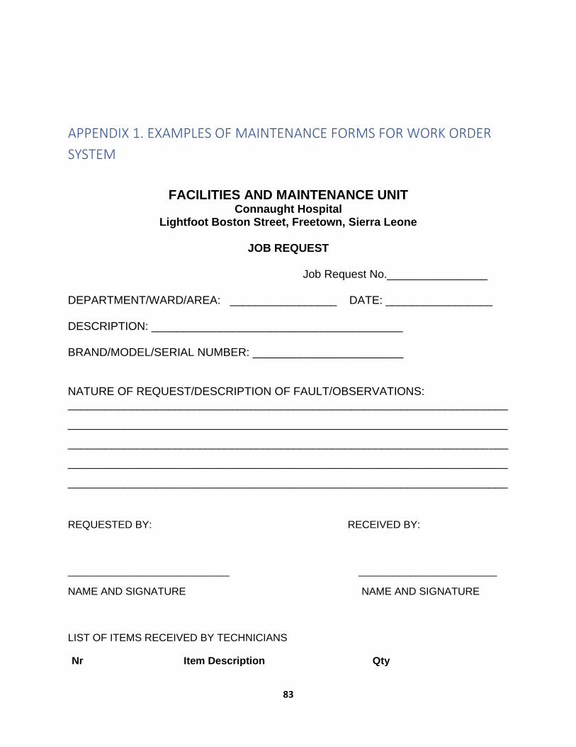
83
APPENDIX 1. EXAMPLES OF MAINTENANCE FORMS FOR WORK ORDER
SYSTEM
FACILITIES AND MAINTENANCE UNIT Connaught Hospital
Lightfoot Boston Street, Freetown, Sierra Leone
JOB REQUEST
Job Request No.________________
DEPARTMENT/WARD/AREA: _________________ DATE: _________________ DESCRIPTION: ________________________________________ BRAND/MODEL/SERIAL NUMBER: ________________________ NATURE OF REQUEST/DESCRIPTION OF FAULT/OBSERVATIONS: ______________________________________________________________________
______________________________________________________________________
______________________________________________________________________
______________________________________________________________________
______________________________________________________________________
REQUESTED BY: RECEIVED BY:
____________________________ ________________________
NAME AND SIGNATURE NAME AND SIGNATURE
LIST OF ITEMS RECEIVED BY TECHNICIANS
Nr Item Description Qty

84
FACILITIES AND MAINTENANCE UNIT Connaught Hospital
Lightfoot Boston Street, Freetown, Sierra Leone
JOB ORDER
Job Request No.________________
DEPARTMENT/WARD/AREA: _________________ DATE: _________________ DESCRIPTION: ________________________________________ BRAND/MODEL/SERIAL NUMBER: ________________________ WORK TO BE DONE: 1.____________________________________________________________________
2.____________________________________________________________________
3.____________________________________________________________________
4.____________________________________________________________________
TOOLS NEEDED: SUPPLIES AND CONSUMABLES:
_____________________ ____________________________ _____________________ ____________________________ _____________________ ____________________________ _____________________ ____________________________
TECHNICIAN/S DATE ASSIGNED: TIME:
1._________________ _________________ ___________
2._________________

85
FACILITIES AND MAINTENANCE UNIT
Connaught Hospital Lightfoot Boston Street, Freetown, Sierra Leone
JOB REPORT
Job Request No.________________
DEPARTMENT/WARD/AREA: _________________ DATE: _________________ DESCRIPTION: ________________________________________ BRAND/MODEL/SERIAL NUMBER: ________________________ WORK TO BE DONE: 1.____________________________________________________________________
2.____________________________________________________________________
3.____________________________________________________________________
4.____________________________________________________________________
LIST OF ITEMS /SPARE PARTS USED AND ESTIMATED COST
Nr Item Description Qty Est. Cost
JOB DONE BY: JOB ACCEPTED BY:
___________________________ ______________________

86
NAME AND SIGNATURE NAME AND SIGNATURE
APPENDIX 2. REGISTRATION AND DIRECTORY, IPM AND
TROUBLESHOOTING MANUAL FINALIZATION
IPM AND TROUBLESHOOTING MANUAL FINALIZATION AND 2021 MAINTENANCE PLANNING
WORKSHOPS, 9–11 DECEMBER 2020, MAKENI
Nr NAME POST HOSPITAL/HF CELLPHONE Nr E-MAIL AD
1. Ola E. Williams MET ODCH 079874089 [email protected]
2. Fatmata Agnes Kamara Dep SCBU in-charge -ditto- 078304373
3. Aminata Gbakie Nurse -ditto- 031252634
4. Umaru Ayoub MET KHMCH 079384581 [email protected]
5. Mariama Sannoh Acting in-charge
SCBU
-ditto- 076755322
6. Margaret Mansaray Nurse -ditto- 077751673
7. Tamba Alie Kpakima MET Koidu Hos 077804139 [email protected]
8. Benjamin Moripeh Asst in-charge; SCBU -ditto- 088605528
9. Medisha H. Mansaray Nurse -ditto- 075308005
10 Amara Kamara MET Jui Hospital 088556510 amaraidriss45@gmail. com
11 Wilfred R. E. Smith MET Port Loko Hos 077284422 wilfredsmith [email protected]
12 Francis J. Lahai Maint. Officer Bonthe Gov Hos 088724383
13 Tamba Kellie MET Kabala Gov Hos 088521405
14 Emmanuel Taylor MET Kambia Gov hos 077532827 [email protected]
15 Mabinty Kabia SCBU in-charge Magburaka Hos 078447799
16 Willie Quinn MET -ditto- 077604945 [email protected]
17 Sulaiman D. Kamara CHO (clinician) Pujehun 076217089 [email protected]
18 Alieu B. Sesay SMET -ditto- 078309756 [email protected]
19 Memunatu Bangura Nurse -ditto- 076663116
20 Prince Abdulai CHO Moyamba 076751550 abdulaiprince@[email protected]
21 Gloria Kambeh SECHN -ditto- 076501209
22 Sahid Dumbuya SMET -ditto- 076307155 [email protected]
23 Suma Amara CHO Bo Gov Hos 079204957 [email protected]
24 Edmond Yarjah SMET -ditto- 076805460 [email protected]
25 Juliana E.M. Conteh SRN in-charge -ditto- 076916648
26 Abu Bakarr Kanu MET Makeni Gov Hos 077670086 [email protected]
27 Messie Alpha Nurse Kenema Gov Hos 079798604
28 Abdul Mansaray MET -ditto- 079028690 [email protected]
29 Gladys Kosia SECHN -ditto- 078828516

87
30 Ibrahim Sesay SMET Connaught Hos 088647727 [email protected]
31 Abdul Turay SMET -ditto- 077483127 [email protected]
32 Sorie iron Sky Turay IT expert KSLP 078633490 [email protected]