Maintenance and Service Guide - HP ProDesk 400 G1 ...
126
Maintenance and Service Guide HP ProDesk 400 G1 Desktop Mini
-
Upload
khangminh22 -
Category
Documents
-
view
0 -
download
0
Transcript of Maintenance and Service Guide - HP ProDesk 400 G1 ...
Maintenance and Service Guide
HP ProDesk 400 G1 Desktop Mini

© Copyright 2015 Hewlett-PackardDevelopment Company, L.P. The informationcontained herein is subject to change withoutnotice.
Intel and Pentium are trademarks of IntelCorporation in the U.S. and other countries.Bluetooth is a trademark owned by itsproprietor and used by Hewlett-PackardCompany under license. Microsoft, Windows,WIndows 7, and Windows 8.1 are U.S.registered trademarks of the Microsoft groupof companies. SD Logo is a trademark of itsproprietor.
The only warranties for HP products andservices are set forth in the express warrantystatements accompanying such products andservices. Nothing herein should be construedas constituting an additional warranty. HP shallnot be liable for technical or editorial errors oromissions contained herein.
This document contains proprietaryinformation that is protected by copyright. Nopart of this document may be photocopied,reproduced, or translated to another languagewithout the prior written consent of Hewlett-Packard Company.
First Edition (February 2015)
Document Part Number: 800859-001
Product notice
This guide describes features that are commonto most models. Some features may not beavailable on your computer.
Not all features are available on all editions ofWindows 8.1. This computer may requireupgraded and/or separately purchasedhardware, drivers, and/or software to take fulladvantage of Windows 8.1 functionality. Seehttp://www.microsoft.com for details.
This computer may require upgraded and/ orseparately purchased hardware and/or a DVDdrive to install the Windows 7 software andtake full advantage of Windows 7 functionality.See http://windows.microsoft.com/en-us/windows7/get-know-windows-7 for details.

Safety warning notice
WARNING! To reduce the possibility of heat-related injuries or of overheating the device, do not placethe device directly on your lap or obstruct the device air vents. Use the device only on a hard, flat surface. Donot allow another hard surface, such as an adjoining optional printer, or a soft surface, such as pillows orrugs or clothing, to block airflow. Also, do not allow the AC adapter to contact the skin or a soft surface, suchas pillows or rugs or clothing, during operation. The device and the AC adapter comply with the user-accessible surface temperature limits defined by the International Standard for Safety of InformationTechnology Equipment (IEC 60950).
iii

iv Safety warning notice

Table of contents
1 Product Features ........................................................................................................................................... 1
Standard Configuration Features .......................................................................................................................... 1
Desktop mini ........................................................................................................................................ 1
Front panel components ....................................................................................................................................... 2
Rear panel components ......................................................................................................................................... 3
Serial Number Location ......................................................................................................................................... 4
2 Illustrated parts catalog ................................................................................................................................ 5
Chassis spare parts ................................................................................................................................................ 5
Computer major components ............................................................................................................. 5
Cables .................................................................................................................................................. 7
Misc parts ............................................................................................................................................. 8
Drives ................................................................................................................................................... 9
3 Routine care, SATA drive guidelines, and disassembly preparation .................................................................. 10
Electrostatic discharge information ................................................................................................................... 10
Generating static ............................................................................................................................... 10
Preventing electrostatic damage to equipment .............................................................................. 11
Personal grounding methods and equipment .................................................................................. 11
Grounding the work area .................................................................................................................. 11
Recommended materials and equipment ........................................................................................ 12
Operating guidelines ........................................................................................................................................... 12
Routine care ......................................................................................................................................................... 13
General cleaning safety precautions ................................................................................................ 13
Cleaning the Computer Case ............................................................................................................. 13
Cleaning the keyboard ...................................................................................................................... 13
Cleaning the monitor ......................................................................................................................... 14
Cleaning the mouse ........................................................................................................................... 14
Service considerations ........................................................................................................................................ 14
Tools and software requirements .................................................................................................... 14
Screws ............................................................................................................................................... 14
Cables and connectors ...................................................................................................................... 14
Hard Drives ........................................................................................................................................ 15
Lithium coin cell battery ................................................................................................................... 15
SATA hard drives .................................................................................................................................................. 15
SATA hard drive cables ........................................................................................................................................ 16
v

SATA data cable ................................................................................................................................. 16
SMART ATA drives ................................................................................................................................................ 16
Cable management .............................................................................................................................................. 16
4 Removal and replacement procedures ........................................................................................................... 17
Preparation for disassembly ............................................................................................................................... 17
Access panel ........................................................................................................................................................ 18
Hard drive ............................................................................................................................................................ 19
Speaker ................................................................................................................................................................ 23
Front bezel ........................................................................................................................................................... 25
Memory ................................................................................................................................................................ 26
SODIMMs ............................................................................................................................................ 26
DDR3-SDRAM SODIMMs .................................................................................................................... 26
Populating SODIMM sockets ............................................................................................................. 27
Replacing SODIMMs ........................................................................................................................... 28
Replacing the battery .......................................................................................................................................... 30
Heat sink .............................................................................................................................................................. 33
Processor ............................................................................................................................................................. 34
Fan ....................................................................................................................................................................... 36
Drive cage ............................................................................................................................................................ 37
WLAN module ...................................................................................................................................................... 39
M.2 solid-state drive ............................................................................................................................................ 41
External antennas (select models only) ............................................................................................................. 43
System board ....................................................................................................................................................... 46
System board callouts ...................................................................................................................... 49
WLAN antennas .................................................................................................................................................... 50
Changing from desktop to tower configuration ................................................................................................. 54
5 Computer Setup (F10) Utility ........................................................................................................................ 55
Computer Setup (F10) Utilities ............................................................................................................................ 55
Using Computer Setup (F10) Utilities ............................................................................................... 56
Computer Setup—File ...................................................................................................................... 57
Computer Setup—Storage ............................................................................................................... 58
Computer Setup—Security ............................................................................................................... 59
Computer Setup—Power .................................................................................................................. 61
Computer Setup—Advanced ............................................................................................................ 62
Recovering the Configuration Settings ............................................................................................................... 63
6 Troubleshooting without diagnostics ............................................................................................................ 64
Safety and comfort .............................................................................................................................................. 64
vi

Before you call for technical support .................................................................................................................. 64
Helpful hints ........................................................................................................................................................ 65
Solving general problems ................................................................................................................................... 66
Solving hard drive problems ............................................................................................................................... 69
Solving display problems .................................................................................................................................... 71
Solving audio problems ....................................................................................................................................... 75
Solving printer problems ..................................................................................................................................... 77
Solving keyboard and mouse problems ............................................................................................................. 78
Solving Hardware Installation Problems ............................................................................................................ 79
Solving Network Problems .................................................................................................................................. 81
Solving memory problems .................................................................................................................................. 84
Solving USB flash drive problems ....................................................................................................................... 85
Solving Internet access problems ....................................................................................................................... 86
Solving software problems ................................................................................................................................. 87
7 POST error messages ................................................................................................................................... 89
POST numeric codes and text messages ............................................................................................................ 89
Interpreting POST diagnostic front panel LEDs and audible codes .................................................................... 93
8 Password security and resetting CMOS .......................................................................................................... 95
Resetting the password jumper .......................................................................................................................... 95
Changing a Setup or Power-On password .......................................................................................................... 96
Deleting a Setup or Power-On password ............................................................................................................ 97
Clearing and resetting the CMOS ......................................................................................................................... 97
9 HP PC Hardware Diagnostics ......................................................................................................................... 99
Why run HP PC Hardware Diagnostics ................................................................................................................. 99
How to access and run HP PC Hardware Diagnostics ......................................................................................... 99
Downloading HP PC Hardware Diagnostics (UEFI) to a USB device .................................................................... 99
10 System backup and recovery .................................................................................................................... 101
Backing up, restoring, and recovering in Windows 8.1 or Windows 8 ............................................................. 101
Creating recovery media and backups ........................................................................................... 101
Restoring and recovering using Windows tools ............................................................................. 101
Using Reset when the system is not responding ......................................................... 102
Recovery using the Windows recovery USB flash drive ............................................... 102
Recovery using Windows operating system media (purchased separately) .............. 103
Backing up, restoring, and recovering in Windows 7 ........................................................................................ 103
Creating recovery media ................................................................................................................. 104
Creating recovery media using HP Recovery Manager (select models only) .............. 104
vii

Creating recovery discs with HP Recovery Disc Creator (select models only) ............ 105
Creating recovery discs .............................................................................. 105
Backing up your information ........................................................................................ 106
System Restore ............................................................................................................................... 106
System Recovery ............................................................................................................................. 107
System Recovery when Windows is responding .......................................................... 107
System Recovery when Windows is not responding ................................................... 108
System Recovery using recovery media (select models only) .................................... 108
Using HP Recovery Disc operating system discs (select models only) ....................... 109
Appendix A Power Cord Set Requirements ...................................................................................................... 111
General Requirements ....................................................................................................................................... 111
Japanese Power Cord Requirements ................................................................................................................ 111
Country-Specific Requirements ........................................................................................................................ 112
Appendix B Statement of Volatility ................................................................................................................ 113
Appendix C Specifications ............................................................................................................................. 115
Index ........................................................................................................................................................... 116
viii
1 Product Features
Standard Configuration FeaturesFeatures may vary depending on the model. For support assistance and to learn more about the hardwareand software installed on your computer model, run the HP Support Assistant utility.
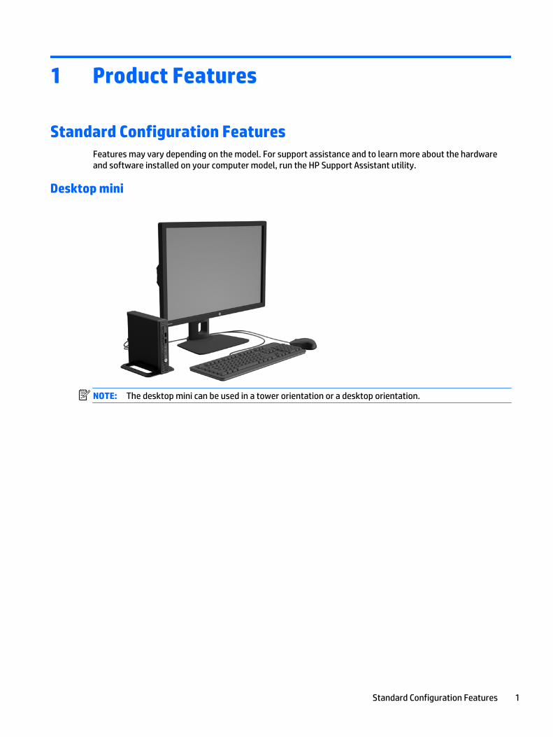
Desktop mini
NOTE: The desktop mini can be used in a tower orientation or a desktop orientation.
Standard Configuration Features 1
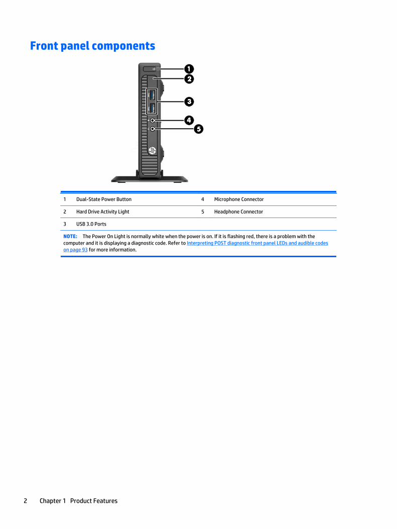
Front panel components
1 Dual-State Power Button 4 Microphone Connector
2 Hard Drive Activity Light 5 Headphone Connector
3 USB 3.0 Ports
NOTE: The Power On Light is normally white when the power is on. If it is flashing red, there is a problem with thecomputer and it is displaying a diagnostic code. Refer to Interpreting POST diagnostic front panel LEDs and audible codeson page 93 for more information.
2 Chapter 1 Product Features
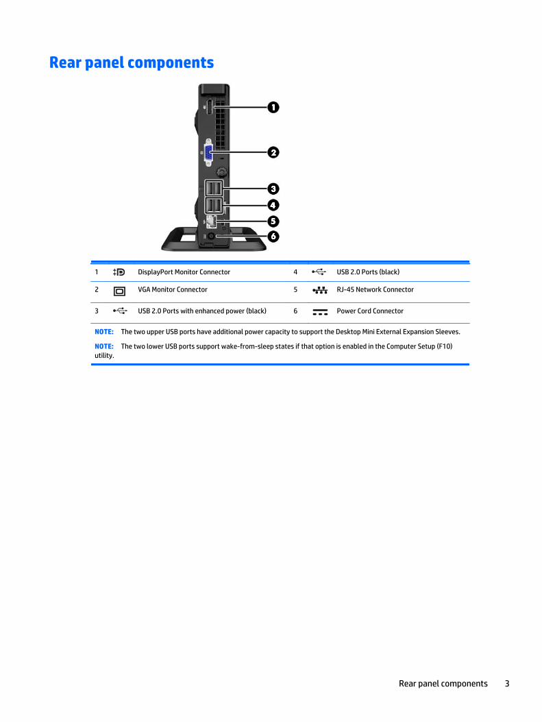
Rear panel components
1 DisplayPort Monitor Connector 4 USB 2.0 Ports (black)
2 VGA Monitor Connector 5 RJ-45 Network Connector
3 USB 2.0 Ports with enhanced power (black) 6 Power Cord Connector
NOTE: The two upper USB ports have additional power capacity to support the Desktop Mini External Expansion Sleeves.
NOTE: The two lower USB ports support wake-from-sleep states if that option is enabled in the Computer Setup (F10)utility.
Rear panel components 3

Serial Number LocationEach computer has a unique serial number and a product ID number that are located on the exterior of thecomputer. Keep these numbers available for use when contacting customer service for assistance.
4 Chapter 1 Product Features
2 Illustrated parts catalog
Chassis spare partsNOTE: HP continually improves and changes product parts. For complete and current information onsupported parts for your computer, go to http://partsurfer.hp.com, select your country or region, and thenfollow the on-screen instructions.
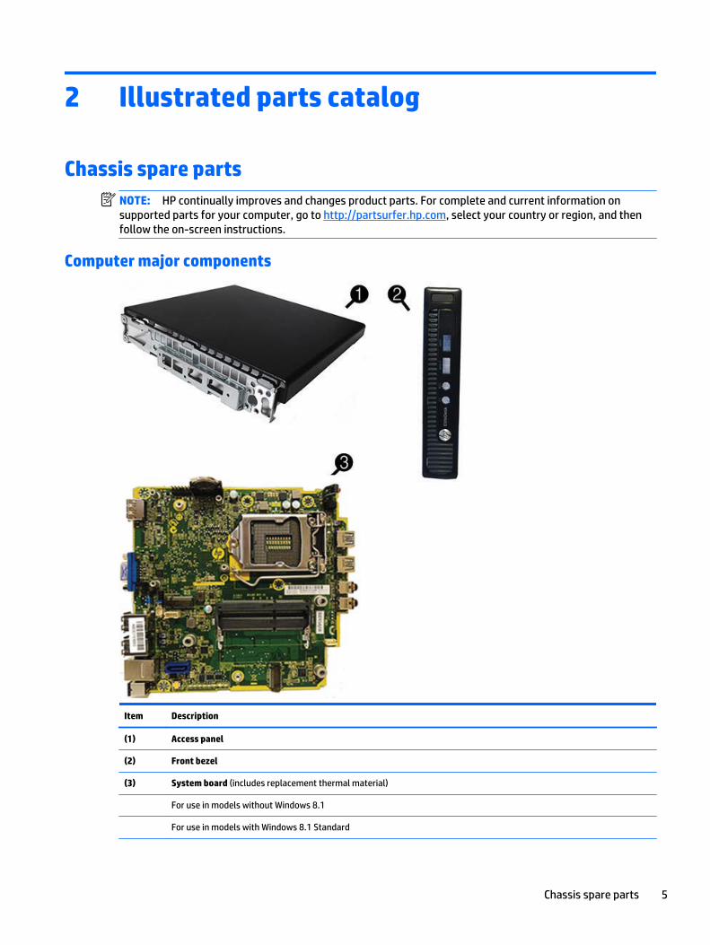
Computer major components
Item Description
(1) Access panel
(2) Front bezel
(3) System board (includes replacement thermal material)
For use in models without Windows 8.1
For use in models with Windows 8.1 Standard
Chassis spare parts 5

Item Description
For use in models with Windows 8.1 Professional
For use in NetClone models
Stand
Power supply, 65W, 89% efficiency
Memory modules (PC3-12800, 1600-MHz)
8-GB
4-GB
Processors (include replacement thermal material)
Intel Core i7 4785T (2.2-GHz, 8-MB L3 cache), 35W
Intel Core i7 4765T (2.0-GHz, 8-MB L3 cache), 35W
Intel Core i5 4590T (2.0-GHz, 6-MB L3 cache), 35W
Intel Core i5 4570T (2.9-GHz, 4-MB L3 cache), 35W
Intel Core i3 4360T (3.2-GHz, 4-MB L3 cache), 35W
Intel Core i3 4350T (3.1-GHz, 4-MB L3 cache), 35W
Intel Core i3 4330T (3.0-GHz, 4-MB L3 cache), 35W
Intel Core i3 4160T (3.1-GHz, 3-MB L3 cache), 35W
Intel Core i3 4150T (3.0-GHz, 3-MB L3 cache), 35W
Intel Core i3 4130T (2.9-GHz, 3-MB L3 cache), 35W
Intel Pentium G3450T (2.9-GHz, 3-MB L3 cache), 35W
Intel Pentium G3440T (2.8-GHz, 3-MB L3 cache), 35W
Intel Pentium G3420T (2.7-GHz, 3-MB L3 cache), 35W
Intel Pentium G3250T (2.8-GHz, 3-MB L3 cache), 35W
Intel Pentium G3240T (2.7-GHz, 3-MB L3 cache), 35W
Intel Pentium G3220T (2.6-GHz, 3-MB L3 cache), 35W
Intel Celeron G1840T (2.5-GHz, 2-MB L3 cache), 54W
Intel Celeron G1820T (2.4-GHz, 2-MB L3 cache), 35W
6 Chapter 2 Illustrated parts catalog

Cables
Item Description
(1) SATA power cable
Wireless antenna cables
Adapter, DisplayPort to HDMI 1.4
Adapter, DisplayPort to VGA
Adapter, DisplayPort to DVI
Adapter, USB to serial
Cable, DisplayPort to HDMI
DisplayPort cable
Grommet, hard drive
Chassis spare parts 7

Misc parts
Item Description
(1) Heat sink
(2) Fan
(3) Speaker
(4) LED cover
* Antenna cover
* HP Ultraslim Keyed Cable Lock
* WLAN modules:
HP WLAN 802.11 a/b/g/n, 2x2 + Bluetooth 4.0
HP WLAN 802.11 a/b/g/n, 2x2
* Mouse
USB, laser
USB, optical
Washable
Wireless
* Keyboards
8 Chapter 2 Illustrated parts catalog

Item Description
USB
Wireless + dongle + mouse
Washable
Smart card
Drives
Description
Hard drives/Solid-state drives:
1 TB, 7200 rpm, hard drive, 2.5-inch, SSHD (hybrid SSD)
500 GB, 7200 rpm hard drive, 2.5-inch
500 GB, SSHD (hybrid SSD), 2.5-inch
500 GB, 7200 rpm hard drive, 2.5-inch, SED
500 GB, 5400 rpm hard drive, 2.5-inch, FIPS
256 GB solid-state drive (SSD)
256 GB solid-state drive (SSD), self-encrypting (SED)
180 GB solid-state drive (SSD), SATA 6.0, OPAL 1.0, MLC
180 GB solid-state drive (SSD), SATA 6.0
128 GB solid-state drive (SSD)
128 GB solid-state drive (SSD), Self-encrypting Drive (SED), OPAL 2.0, SATA 6.0
128 GB solid-state drive (SSD), M.2 2280SS, PCIe
120 GB solid-state drive (SSD), SATA 6.0, OPAL 1.0, MLC
120 GB solid-state drive (SSD), SATA 6.0
Grommet, hard drive
Chassis spare parts 9
3 Routine care, SATA drive guidelines, anddisassembly preparation
This chapter provides general service information for the computer. Adherence to the procedures andprecautions described in this chapter is essential for proper service.
CAUTION: When the computer is plugged into an AC power source, voltage is always applied to the systemboard. You must disconnect the power cord from the power source before opening the computer to preventsystem board or component damage.
Electrostatic discharge informationA sudden discharge of static electricity from your finger or other conductor can destroy static-sensitivedevices or microcircuitry. Often the spark is neither felt nor heard, but damage occurs. An electronic deviceexposed to electrostatic discharge (ESD) may not appear to be affected at all and can work perfectlythroughout a normal cycle. The device may function normally for a while, but it has been degraded in theinternal layers, reducing its life expectancy.
Networks built into many integrated circuits provide some protection, but in many cases, the dischargecontains enough power to alter device parameters or melt silicon junctions.
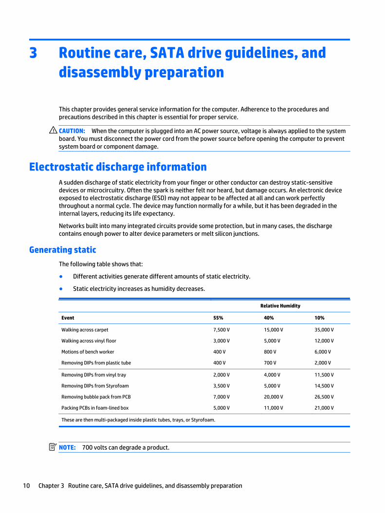
Generating static
The following table shows that:
● Different activities generate different amounts of static electricity.
● Static electricity increases as humidity decreases.
Relative Humidity
Event 55% 40% 10%
Walking across carpet
Walking across vinyl floor
Motions of bench worker
Removing DIPs from plastic tube
7,500 V
3,000 V
400 V
400 V
15,000 V
5,000 V
800 V
700 V
35,000 V
12,000 V
6,000 V
2,000 V
Removing DIPs from vinyl tray
Removing DIPs from Styrofoam
Removing bubble pack from PCB
Packing PCBs in foam-lined box
2,000 V
3,500 V
7,000 V
5,000 V
4,000 V
5,000 V
20,000 V
11,000 V
11,500 V
14,500 V
26,500 V
21,000 V
These are then multi-packaged inside plastic tubes, trays, or Styrofoam.
NOTE: 700 volts can degrade a product.
10 Chapter 3 Routine care, SATA drive guidelines, and disassembly preparation
Preventing electrostatic damage to equipment
Many electronic components are sensitive to ESD. Circuitry design and structure determine the degree ofsensitivity. The following packaging and grounding precautions are necessary to prevent damage to electriccomponents and accessories.
● To avoid hand contact, transport products in static-safe containers such as tubes, bags, or boxes.
● Protect all electrostatic parts and assemblies with conductive or approved containers or packaging.
● Keep electrostatic sensitive parts in their containers until they arrive at static-free stations.
● Place items on a grounded surface before removing them from their container.
● Always be properly grounded when touching a sensitive component or assembly.
● Avoid contact with pins, leads, or circuitry.
● Place reusable electrostatic-sensitive parts from assemblies in protective packaging or conductivefoam.
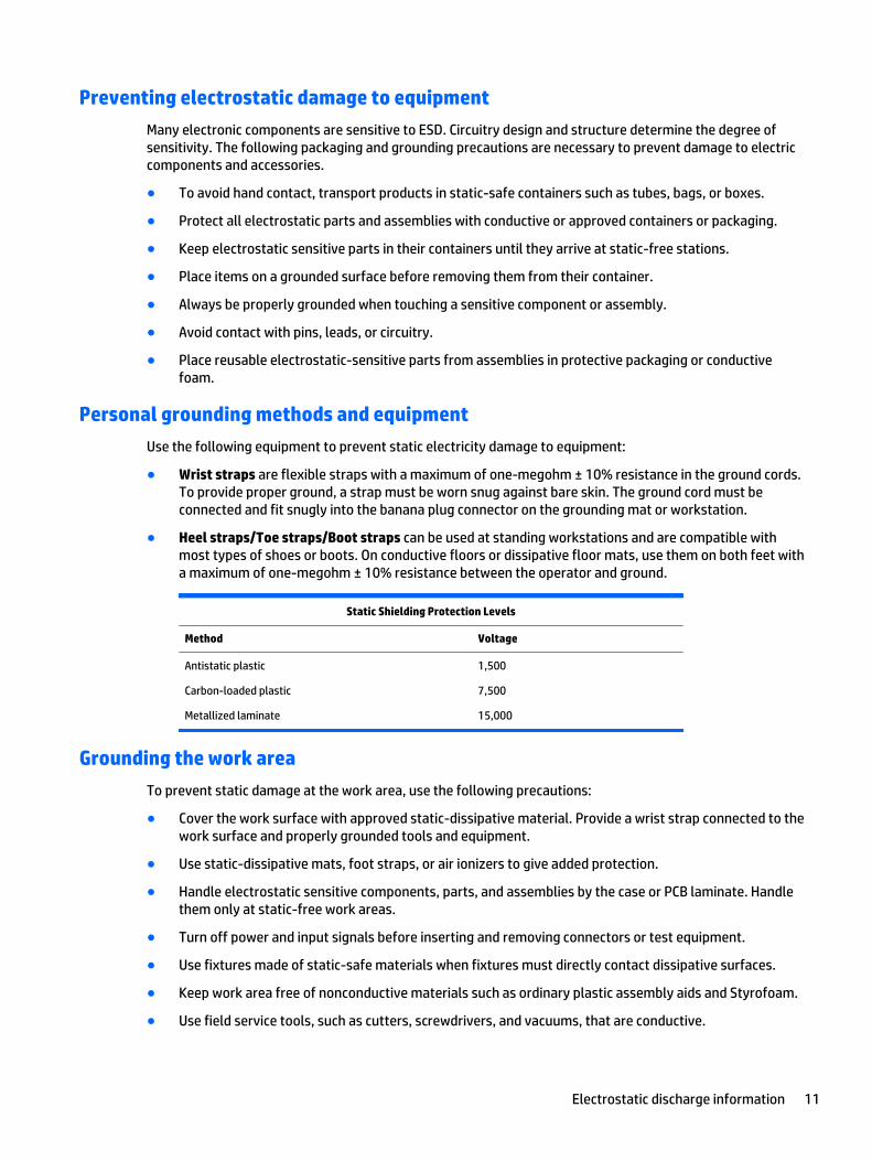
Personal grounding methods and equipment
Use the following equipment to prevent static electricity damage to equipment:
● Wrist straps are flexible straps with a maximum of one-megohm ± 10% resistance in the ground cords.To provide proper ground, a strap must be worn snug against bare skin. The ground cord must beconnected and fit snugly into the banana plug connector on the grounding mat or workstation.
● Heel straps/Toe straps/Boot straps can be used at standing workstations and are compatible withmost types of shoes or boots. On conductive floors or dissipative floor mats, use them on both feet witha maximum of one-megohm ± 10% resistance between the operator and ground.
Static Shielding Protection Levels
Method Voltage
Antistatic plastic
Carbon-loaded plastic
Metallized laminate
1,500
7,500
15,000
Grounding the work area
To prevent static damage at the work area, use the following precautions:
● Cover the work surface with approved static-dissipative material. Provide a wrist strap connected to thework surface and properly grounded tools and equipment.
● Use static-dissipative mats, foot straps, or air ionizers to give added protection.
● Handle electrostatic sensitive components, parts, and assemblies by the case or PCB laminate. Handlethem only at static-free work areas.
● Turn off power and input signals before inserting and removing connectors or test equipment.
● Use fixtures made of static-safe materials when fixtures must directly contact dissipative surfaces.
● Keep work area free of nonconductive materials such as ordinary plastic assembly aids and Styrofoam.
● Use field service tools, such as cutters, screwdrivers, and vacuums, that are conductive.
Electrostatic discharge information 11

Recommended materials and equipment
Materials and equipment that are recommended for use in preventing static electricity include:
● Antistatic tape
● Antistatic smocks, aprons, or sleeve protectors
● Conductive bins and other assembly or soldering aids
● Conductive foam
● Conductive tabletop workstations with ground cord of one-megohm +/- 10% resistance
● Static-dissipative table or floor mats with hard tie to ground
● Field service kits
● Static awareness labels
● Wrist straps and footwear straps providing one-megohm +/- 10% resistance
● Material handling packages
● Conductive plastic bags
● Conductive plastic tubes
● Conductive tote boxes
● Opaque shielding bags
● Transparent metallized shielding bags
● Transparent shielding tubes
Operating guidelinesTo prevent overheating and to help prolong the life of the computer:
● Keep the computer away from excessive moisture, direct sunlight, and extremes of heat and cold.
● Operate the computer on a sturdy, level surface. Leave a 10.2-cm (4-inch) clearance on all vented sidesof the computer and above the monitor to permit the required airflow.
● Never restrict the airflow into the computer by blocking any vents or air intakes. Do not place thekeyboard, with the keyboard feet down, directly against the front of the desktop unit as this alsorestricts airflow.
● Occasionally clean the air vents on all vented sides of the computer. Lint, dust, and other foreign mattercan block the vents and limit the airflow. Be sure to unplug the computer before cleaning the air vents.
● Never operate the computer with the cover or side panel removed.
● Do not stack computers on top of each other or place computers so near each other that they aresubject to each other’s re-circulated or preheated air.
● If the computer is to be operated within a separate enclosure, intake and exhaust ventilation must beprovided on the enclosure, and the same operating guidelines listed above will still apply.
● Keep liquids away from the computer and keyboard.
12 Chapter 3 Routine care, SATA drive guidelines, and disassembly preparation
● Never cover the ventilation slots on the monitor with any type of material.
● Install or enable power management functions of the operating system or other software, includingsleep states.
Routine care
General cleaning safety precautions
1. Never use solvents or flammable solutions to clean the computer.
2. Never immerse any parts in water or cleaning solutions; apply any liquids to a clean cloth and then usethe cloth on the component.
3. Always unplug the computer when cleaning with liquids or damp cloths.
4. Always unplug the computer before cleaning the keyboard, mouse, or air vents.
5. Disconnect the keyboard before cleaning it.
6. Wear safety glasses equipped with side shields when cleaning the keyboard.
Cleaning the Computer Case
Follow all safety precautions in General cleaning safety precautions on page 13 before cleaning thecomputer.
To clean the computer case, follow the procedures described below:
● To remove light stains or dirt, use plain water with a clean, lint-free cloth or swab.
● For stronger stains, use a mild dishwashing liquid diluted with water. Rinse well by wiping it with a clothor swab dampened with clear water.
● For stubborn stains, use isopropyl (rubbing) alcohol. No rinsing is needed as the alcohol will evaporatequickly and not leave a residue.
● After cleaning, always wipe the unit with a clean, lint-free cloth.
● Occasionally clean the air vents on the computer. Lint and other foreign matter can block the vents andlimit the airflow.
Cleaning the keyboard
Follow all safety precautions in General cleaning safety precautions on page 13 before cleaning thekeyboard.
To clean the tops of the keys or the keyboard body, follow the procedures described in Cleaning theComputer Case on page 13.
When cleaning debris from under the keys, review all rules in General cleaning safety precautions on page 13before following these procedures:
CAUTION: Use safety glasses equipped with side shields before attempting to clean debris from under thekeys.
● Visible debris underneath or between the keys may be removed by vacuuming or shaking.
● Canned, pressurized air may be used to clean debris from under the keys. Caution should be used as toomuch air pressure can dislodge lubricants applied under the wide keys.
Routine care 13

● If you remove a key, use a specially designed key puller to prevent damage to the keys. This tool isavailable through many electronic supply outlets.
CAUTION: Never remove a wide leveled key (like the space bar) from the keyboard. If these keys areimproperly removed or installed, the keyboard may not function properly.
● Cleaning under a key may be done with a swab moistened with isopropyl alcohol and squeezed out. Becareful not to wipe away lubricants necessary for proper key functions. Use tweezers to remove anyfibers or dirt in confined areas. Allow the parts to air dry before reassembly.
Cleaning the monitor
● Wipe the monitor screen with a clean cloth moistened with water or with a towelette designed forcleaning monitors. Do not use sprays or aerosols directly on the screen; the liquid may seep into thehousing and damage a component. Never use solvents or flammable liquids on the monitor.
● To clean the monitor body follow the procedures in Cleaning the Computer Case on page 13.
Cleaning the mouse
Before cleaning the mouse, ensure that the power to the computer is turned off.
● Clean the mouse ball by first removing the retaining plate and the ball from the housing. Pull out anydebris from the ball socket and wipe the ball with a clean, dry cloth before reassembly.
● To clean the mouse body, follow the procedures in Cleaning the Computer Case on page 13.
Service considerationsListed below are some of the considerations that you should keep in mind during the disassembly andassembly of the computer.
Tools and software requirements
To service the computer, you need the following:
● Torx T-15 screwdriver
● Torx T-15 screwdriver
● Flat-bladed screwdriver (may sometimes be used in place of the Torx screwdriver)
● Diagnostics software
Screws
The screws used in the computer are not interchangeable. They may have standard or metric threads andmay be of different lengths. If an incorrect screw is used during the reassembly process, it can damage theunit. HP strongly recommends that all screws removed during disassembly be kept with the part that wasremoved, then returned to their proper locations.
CAUTION: As each subassembly is removed from the computer, it should be placed away from the workarea to prevent damage.
Cables and connectors
Apply only the tension required to seat or unseat the cables during insertion or removal from the connector.Handle cables by the connector whenever possible. In all cases, avoid bending or twisting the cables, and
14 Chapter 3 Routine care, SATA drive guidelines, and disassembly preparation

ensure that the cables are routed in such a way that they cannot be caught or snagged by parts beingremoved or replaced.
CAUTION: When servicing this computer, ensure that cables are placed in their proper location during thereassembly process. Improper cable placement can damage the computer.
Hard Drives
Handle hard drives as delicate, precision components, avoiding all physical shock and vibration. This appliesto failed drives as well as replacement spares.
● If a drive must be mailed, place the drive in a bubble-pack mailer or other suitable protective packagingand label the package “Fragile: Handle With Care.”
● Do not remove hard drives from the shipping package for storage. Keep hard drives in their protectivepackaging until they are actually mounted in the computer.
● Avoid dropping drives from any height onto any surface.
● If you are inserting or removing a hard drive, turn off the computer. Do not remove a hard drive whilethe computer is on or in standby mode.
● Before handling a drive, ensure that you are discharged of static electricity. While handling a drive,avoid touching the connector.
● Do not use excessive force when inserting a drive.
● Avoid exposing a hard drive to liquids, temperature extremes, or products that have magnetic fieldssuch as monitors or speakers.
Lithium coin cell battery
The battery that comes with the computer provides power to the real-time clock and has a minimum lifetimeof about three years.
See the appropriate removal and replacement chapter for the chassis you are working on in this guide forinstructions on the replacement procedures.
WARNING! This computer contains a lithium battery. There is a risk of fire and chemical burn if the batteryis handled improperly. Do not disassemble, crush, puncture, short external contacts, dispose in water or fire,or expose it to temperatures higher than 140ºF (60ºC). Do not attempt to recharge the battery.
NOTE: Batteries, battery packs, and accumulators should not be disposed of together with the generalhousehold waste. In order to forward them to recycling or proper disposal, please use the public collectionsystem or return them to HP, their authorized partners, or their agents.
SATA hard drives
Serial ATA Hard Drive Characteristics
Number of pins/conductors in data cable 7/7
Number of pins in power cable 15
Maximum data cable length 39.37 in (100 cm)
Data interface voltage differential 400-700 mV
Drive voltages 3.3 V, 5 V, 12 V
SATA hard drives 15

Jumpers for configuring drive N/A
Data transfer rate 6.0 Gb/s
SATA hard drive cables
SATA data cable
Always use an HP approved SATA 6.0 Gb/s cable as it is fully backwards compatible with the SATA 1.5 Gb/sdrives.
Current HP desktop products ship with SATA 6.0 Gb/s hard drives.
SATA data cables are susceptible to damage if overflexed. Never crease a SATA data cable and never bend ittighter than a 30 mm (1.18 in) radius.
The SATA data cable is a thin, 7-pin cable designed to transmit data for only a single drive.
SMART ATA drivesThe Self Monitoring Analysis and Recording Technology (SMART) ATA drives for the HP Personal Computershave built-in drive failure prediction that warns the user or network administrator of an impending failure orcrash of the hard drive. The SMART drive tracks fault prediction and failure indication parameters such asreallocated sector count, spin retry count, and calibration retry count. If the drive determines that a failure isimminent, it generates a fault alert.
Cable managementAlways follow good cable management practices when working inside the computer.
● Keep cables away from major heat sources like the heat sink.
● Keep cables clear of sliding or moveable parts to prevent them from being cut or crimped when theparts are moved.
● When folding a flat ribbon cable, never fold to a sharp crease. Sharp creases may damage the wires.
● Do not bend any cable sharply. A sharp bend can break the internal wires.
● Never bend a SATA data cable tighter than a 30 mm (1.18 in) radius.
● Never crease a SATA data cable.
16 Chapter 3 Routine care, SATA drive guidelines, and disassembly preparation
4 Removal and replacement procedures
Adherence to the procedures and precautions described in this chapter is essential for proper service. Aftercompleting all necessary removal and replacement procedures, run the Diagnostics utility to verify that allcomponents operate properly.
NOTE: Not all features listed in this guide are available on all computers.
NOTE: HP continually improves and changes product parts. For complete and current information onsupported parts for your computer, go to http://partsurfer.hp.com, select your country or region, and thenfollow the on-screen instructions.
Preparation for disassemblySee Routine care, SATA drive guidelines, and disassembly preparation on page 10 for initial safetyprocedures.
1. Remove/disengage any security devices that prohibit opening the computer.
2. Remove all removable media, such as a USB flash drive, from the computer.
3. Turn off the computer properly through the operating system, then turn off any external devices.
CAUTION: Turn off the computer before disconnecting any cables.
Regardless of the power-on state, voltage is always present on the system board as long as the systemis plugged into an active AC outlet. In some systems the cooling fan is on even when the computer is inthe “Standby,” or “Suspend” modes. The power cord should always be disconnected before servicing aunit.
4. Disconnect the power cord from the power outlet and disconnect any external devices.
5. If the computer is on a stand, remove the computer from the stand.
WARNING! Beware of sharp edges inside the chassis.
Preparation for disassembly 17
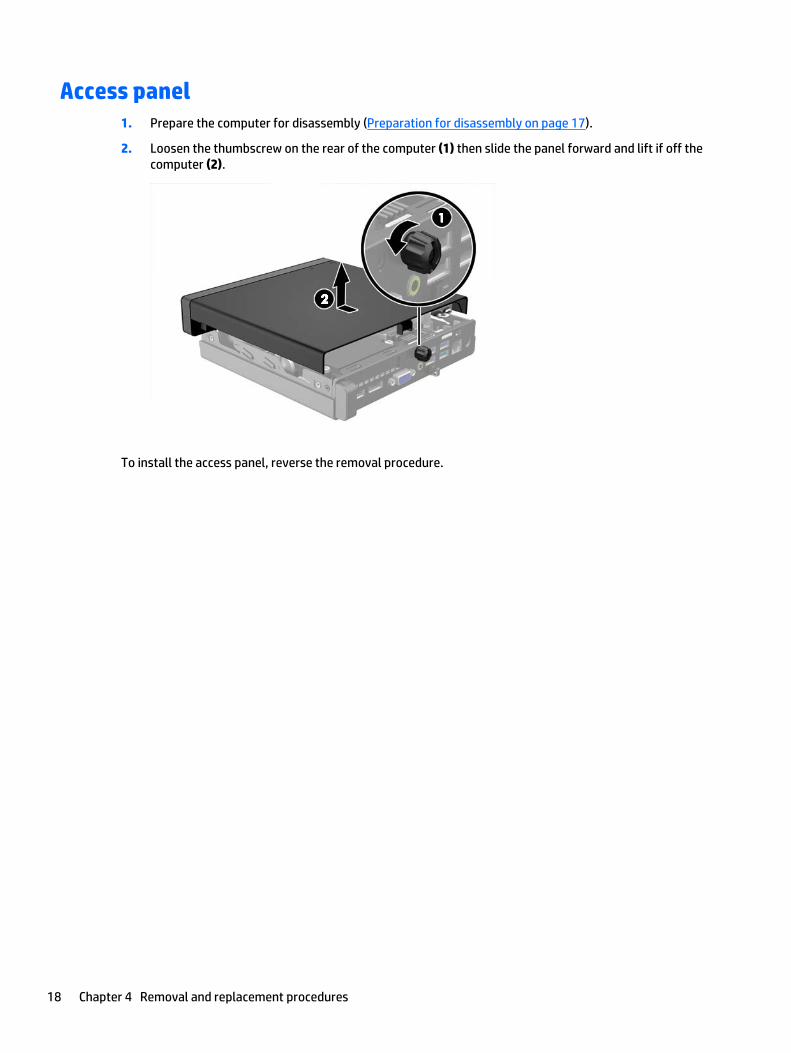
Access panel1. Prepare the computer for disassembly (Preparation for disassembly on page 17).
2. Loosen the thumbscrew on the rear of the computer (1) then slide the panel forward and lift if off thecomputer (2).
To install the access panel, reverse the removal procedure.
18 Chapter 4 Removal and replacement procedures

Hard drive
Description
Hard drives/Solid-state drives
1 TB, 7200 rpm, hard drive, 2.5-inch, SSHD (hybrid SSD)
500 GB, 7200 rpm hard drive, 2.5-inch
500 GB, SSHD (hybrid SSD), 2.5-inch
500 GB, 7200 rpm hard drive, 2.5-inch, SED
500 GB, 5400 rpm hard drive, 2.5-inch, FIPS
256 GB solid-state drive (SSD)
256 GB solid-state drive (SSD), self-encrypting (SED)
180 GB solid-state drive (SSD), SATA 6.0, OPAL 1.0, MLC
180 GB solid-state drive (SSD), SATA 6.0
128 GB solid-state drive (SSD)
128 GB solid-state drive (SSD), Self-encrypting Drive (SED), OPAL 2.0, SATA 6.0
128 GB solid-state drive (SSD), M.2 2280SS, PCIe
120 GB solid-state drive (SSD), SATA 6.0, OPAL 1.0, MLC
120 GB solid-state drive (SSD), SATA 6.0
Grommet, hard drive
NOTE: Before you remove the old hard drive, be sure to back up the data from the old hard drive so thatyou can transfer the data to the new hard drive.
1. Prepare the computer for disassembly (Preparation for disassembly on page 17).
2. Remove the access panel Access panel on page 18.
Hard drive 19
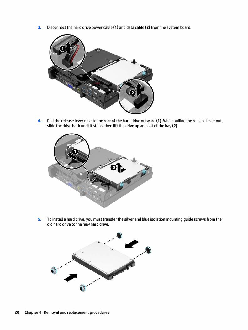
3. Disconnect the hard drive power cable (1) and data cable (2) from the system board.
4. Pull the release lever next to the rear of the hard drive outward (1). While pulling the release lever out,slide the drive back until it stops, then lift the drive up and out of the bay (2).
5. To install a hard drive, you must transfer the silver and blue isolation mounting guide screws from theold hard drive to the new hard drive.
20 Chapter 4 Removal and replacement procedures
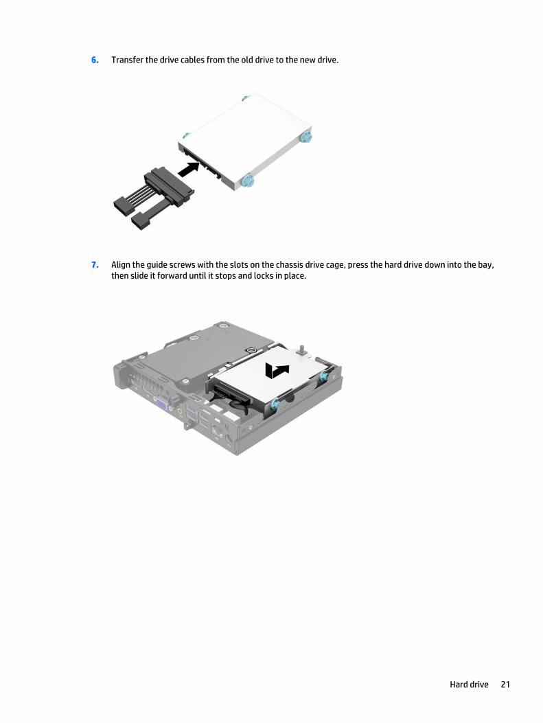
6. Transfer the drive cables from the old drive to the new drive.
7. Align the guide screws with the slots on the chassis drive cage, press the hard drive down into the bay,then slide it forward until it stops and locks in place.
Hard drive 21

8. Connect the hard drive power cable (1) and data cable (2) to the system board.
Reverse this procedure to replace the hard drive.
22 Chapter 4 Removal and replacement procedures
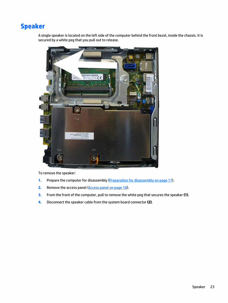
SpeakerA single speaker is located on the left side of the computer behind the front bezel, inside the chassis. It issecured by a white peg that you pull out to release.
To remove the speaker:
1. Prepare the computer for disassembly (Preparation for disassembly on page 17).
2. Remove the access panel (Access panel on page 18).
3. From the front of the computer, pull to remove the white peg that secures the speaker (1).
4. Disconnect the speaker cable from the system board connector (2).
Speaker 23
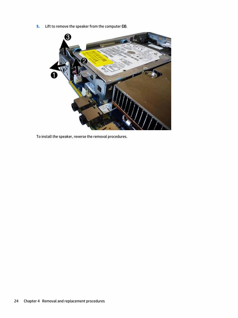
5. Lift to remove the speaker from the computer (3).
To install the speaker, reverse the removal procedures.
24 Chapter 4 Removal and replacement procedures

Front bezelThe front bezel is secured to the access panel by tabs.
1. Prepare the computer for disassembly (Preparation for disassembly on page 17).
2. Remove the access panel (Access panel on page 18).
3. Position the access panel upside-down so you can access the inside of the bezel.
4. Pull down to loose the bottom, interior on the bezel (1).
5. Disengage the tabs on the top, interior of the bezel (2).
6. Remove the bezel from the access panel.
To install the front bezel, reverse the removal procedure.
Front bezel 25
Memory
Description
8-GB, PC3-12800, SODIMM
4-GB, PC3-12800, SODIMM
The computer comes with double data rate 3 synchronous dynamic random access memory (DDR3-SDRAM)small outline dual inline memory modules (SODIMMs).
SODIMMs
The memory sockets on the system board can be populated with up to two industry-standard SODIMMs.These memory sockets are populated with at least one preinstalled SODIMM. To achieve the maximummemory support, you can populate the system board with up to 16-GB of memory.
DDR3-SDRAM SODIMMs
For proper system operation, the SODIMMs must be:
● industry-standard 204-pin
● unbuffered non-ECC PC3-12800 DDR3-1600 MHz-compliant
● 1.5 volt DDR3-SDRAM SODIMMs or 1.35 volt DDR3L-SDRAM SODIMMs
The DDR3-SDRAM SODIMMs must also:
● support CAS latency 11 DDR3 1600 MHz (11-11-11 timing)
● contain the mandatory Joint Electronic Device Engineering Council (JEDEC) specification
In addition, the computer supports:
● 512-Mbit, 1-Gbit, and 2-Gbit non-ECC memory technologies
● single-sided and double-sided SODIMMS
● SODIMMs constructed with x8 and x16 devices; SODIMMs constructed with x4 SDRAM are not supported
NOTE: The system will not operate properly if you install unsupported SODIMMs.
26 Chapter 4 Removal and replacement procedures

Populating SODIMM sockets
There are two SODIMM sockets on the system board, with one socket per channel. The sockets are labeledDIMM1 and DIMM3. The DIMM1 socket operates in memory channel B. The DIMM3 socket operates in memorychannel A.
Item Description System Board Label Socket Color
1 SODIMM1 socket, Channel B DIMM1 Black
2 SODIMM3 socket, Channel A DIMM3 Black
The system will automatically operate in single channel mode, dual channel mode, or flex mode, dependingon how the SODIMMs are installed.
● The system will operate in single channel mode if the SODIMM sockets are populated in one channelonly.
● The system will operate in a higher-performing dual channel mode if the memory capacity of theSODIMM in Channel A is equal to the memory capacity of the SODIMM in Channel B.
● The system will operate in flex mode if the memory capacity of the SODIMM in Channel A is not equal tothe memory capacity of the SODIMM in Channel B. In flex mode, the channel populated with the leastamount of memory describes the total amount of memory assigned to dual channel and the remainderis assigned to single channel. If one channel will have more memory than the other, the larger amountshould be assigned to channel A.
● In any mode, the maximum operational speed is determined by the slowest SODIMM in the system.
Memory 27

Replacing SODIMMs
CAUTION: You must disconnect the power cord and wait approximately 30 seconds for the power to drainbefore adding or removing memory modules. Regardless of the power-on state, voltage is always supplied tothe memory modules as long as the computer is plugged into an active AC outlet. Adding or removingmemory modules while voltage is present may cause irreparable damage to the memory modules or systemboard.
The memory module sockets have gold-plated metal contacts. When upgrading the memory, it is importantto use memory modules with gold-plated metal contacts to prevent corrosion and/or oxidation resultingfrom having incompatible metals in contact with each other.
Static electricity can damage the electronic components of the computer or optional cards. Before beginningthese procedures, ensure that you are discharged of static electricity by briefly touching a grounded metalobject.
When handling a memory module, be careful not to touch any of the contacts. Doing so may damage themodule.
1. Prepare the computer for disassembly (Preparation for disassembly on page 17).
2. Remove the access panel (Access panel on page 18).
3. Remove the hard drive (Hard drive on page 19).
4. To remove a SODIMM, press outward on the two latches on each side of the SODIMM (1) then pull theSODIMM out of the socket (2).
28 Chapter 4 Removal and replacement procedures

5. Slide the new SODIMM into the socket at approximately a 30° angle (1) then press the SODIMM down (2)so that the latches lock it in place.
NOTE: A memory module can be installed in only one way. Match the notch on the module with the tabon the memory socket.
6. Replace the hard drive and connect the power and data cables to the system board.
7. Replace the access panel.
8. If the computer was on a stand, replace the stand.
9. Reconnect the power cord and turn on the computer.
10. Lock any security devices that were disengaged when the computer cover or access panel was removed.
The computer automatically recognizes the additional memory when you turn on the computer.
Memory 29

Replacing the batteryThe battery that comes with the computer provides power to the real-time clock. When replacing the battery,use a battery equivalent to the battery originally installed in the computer. The computer comes with a 3-volt lithium coin cell battery.
WARNING! The computer contains an internal lithium manganese dioxide battery. There is a risk of fire andburns if the battery is not handled properly. To reduce the risk of personal injury:
Do not attempt to recharge the battery.
Do not expose to temperatures higher than 60°C (140ºF).
Do not disassemble, crush, puncture, short external contacts, or dispose of in fire or water.
Replace the battery only with the HP spare designated for this product.
CAUTION: Before replacing the battery, it is important to back up the computer CMOS settings. When thebattery is removed or replaced, the CMOS settings will be cleared.
Static electricity can damage the electronic components of the computer or optional equipment. Beforebeginning these procedures, ensure that you are discharged of static electricity by briefly touching agrounded metal object.
NOTE: The lifetime of the lithium battery can be extended by plugging the computer into a live AC wallsocket. The lithium battery is only used when the computer is NOT connected to AC power.
HP encourages customers to recycle used electronic hardware, HP original print cartridges, and rechargeablebatteries. For more information about recycling programs, go to http://www.hp.com/recycle.
1. Prepare the computer for disassembly (Preparation for disassembly on page 17).
2. Remove the access panel (Access panel on page 18).
3. Locate the battery and battery holder on the system board.
4. Depending on the type of battery holder on the system board, complete the following instructions toreplace the battery.
NOTE: You may need to use a small tool, such as tweezers or needle-nose pliers, to remove andreplace the battery.
Type 1
30 Chapter 4 Removal and replacement procedures
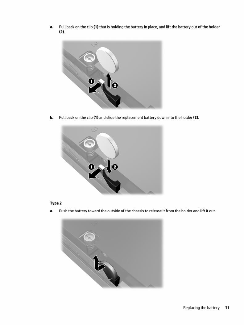
a. Pull back on the clip (1) that is holding the battery in place, and lift the battery out of the holder(2).
b. Pull back on the clip (1) and slide the replacement battery down into the holder (2).
Type 2
a. Push the battery toward the outside of the chassis to release it from the holder and lift it out.
Replacing the battery 31
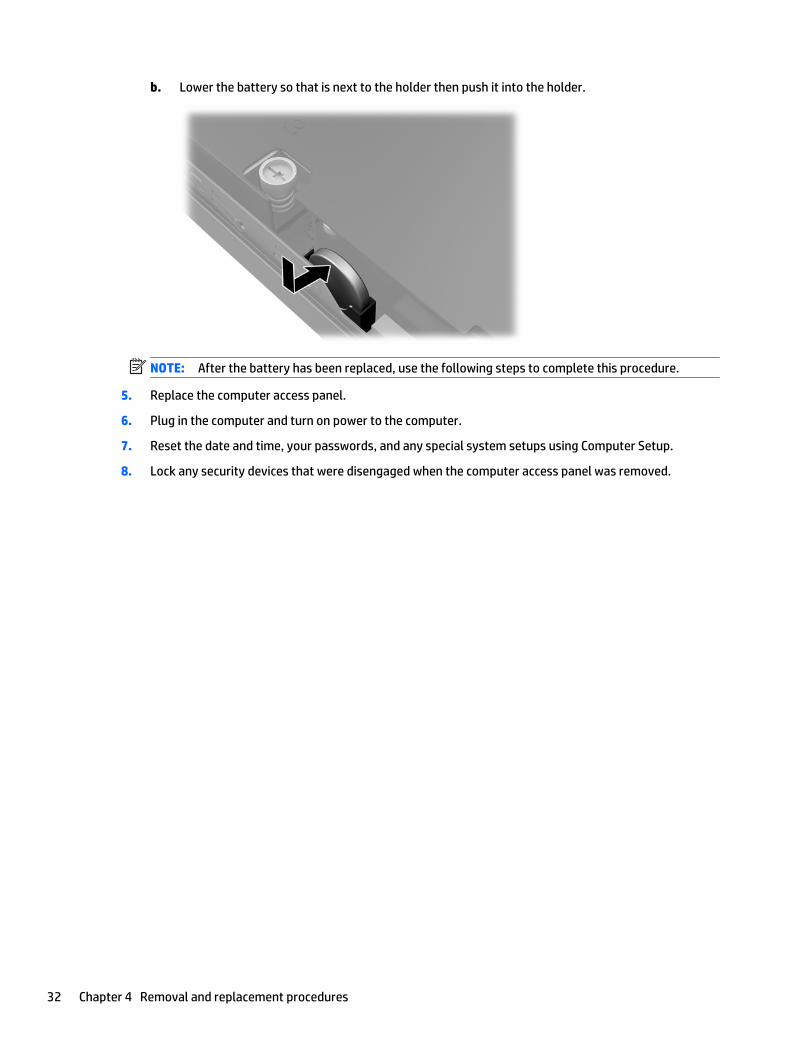
b. Lower the battery so that is next to the holder then push it into the holder.
NOTE: After the battery has been replaced, use the following steps to complete this procedure.
5. Replace the computer access panel.
6. Plug in the computer and turn on power to the computer.
7. Reset the date and time, your passwords, and any special system setups using Computer Setup.
8. Lock any security devices that were disengaged when the computer access panel was removed.
32 Chapter 4 Removal and replacement procedures
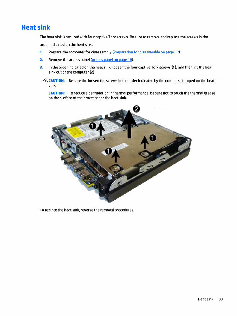
Heat sinkThe heat sink is secured with four captive Torx screws. Be sure to remove and replace the screws in the
order indicated on the heat sink.
1. Prepare the computer for disassembly (Preparation for disassembly on page 17).
2. Remove the access panel (Access panel on page 18).
3. In the order indicated on the heat sink, loosen the four captive Torx screws (1), and then lift the heatsink out of the computer (2).
CAUTION: Be sure the loosen the screws in the order indicated by the numbers stamped on the heatsink.
CAUTION: To reduce a degradation in thermal performance, be sure not to touch the thermal greaseon the surface of the processor or the heat sink.
To replace the heat sink, reverse the removal procedures.
Heat sink 33

Processor
Description
Intel Core i7 4785T (2.2-GHz, 8-MB L3 cache), 35W
Intel Core i7 4765T (2.0-GHz, 8-MB L3 cache), 35W
Intel Core i5 4590T (2.0-GHz, 6-MB L3 cache), 35W
Intel Core i5 4570T (2.9-GHz, 4-MB L3 cache), 35W
Intel Core i3 4360T (3.2-GHz, 4-MB L3 cache), 35W
Intel Core i3 4350T (3.1-GHz, 4-MB L3 cache), 35W
Intel Core i3 4330T (3.0-GHz, 4-MB L3 cache), 35W
Intel Core i3 4160T (3.1-GHz, 3-MB L3 cache), 35W
Intel Core i3 4150T (3.0-GHz, 3-MB L3 cache), 35W
Intel Core i3 4130T (2.9-GHz, 3-MB L3 cache), 35W
Intel Pentium G3450T (2.9-GHz, 3-MB L3 cache), 35W
Intel Pentium G3440T (2.8-GHz, 3-MB L3 cache), 35W
Intel Pentium G3420T (2.7-GHz, 3-MB L3 cache), 35W
Intel Pentium G3250T (2.8-GHz, 3-MB L3 cache), 35W
Intel Pentium G3240T (2.7-GHz, 3-MB L3 cache), 35W
Intel Pentium G3220T (2.6-GHz, 3-MB L3 cache), 35W
Intel Celeron G1840T (2.5-GHz, 2-MB L3 cache), 54W
Intel Celeron G1820T (2.4-GHz, 2-MB L3 cache), 35W
1. Prepare the computer for disassembly (Preparation for disassembly on page 17).
2. Remove the access panel (Access panel on page 18).
3. Remove the heat sink (Heat sink on page 33).
4. Rotate the locking lever to its full open position (1).
5. Raise and rotate the microprocessor retainer to its fully open position (2).(2).
34 Chapter 4 Removal and replacement procedures
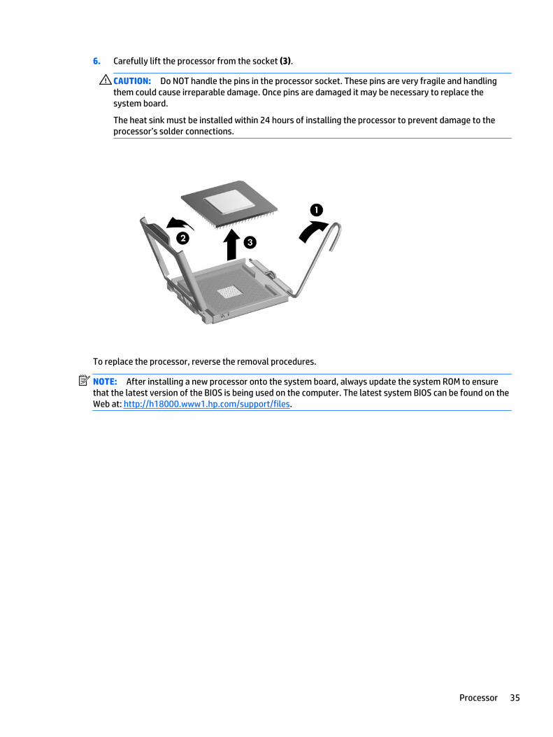
6. Carefully lift the processor from the socket (3).
CAUTION: Do NOT handle the pins in the processor socket. These pins are very fragile and handlingthem could cause irreparable damage. Once pins are damaged it may be necessary to replace thesystem board.
The heat sink must be installed within 24 hours of installing the processor to prevent damage to theprocessor’s solder connections.
To replace the processor, reverse the removal procedures.
NOTE: After installing a new processor onto the system board, always update the system ROM to ensurethat the latest version of the BIOS is being used on the computer. The latest system BIOS can be found on theWeb at: http://h18000.www1.hp.com/support/files.
Processor 35
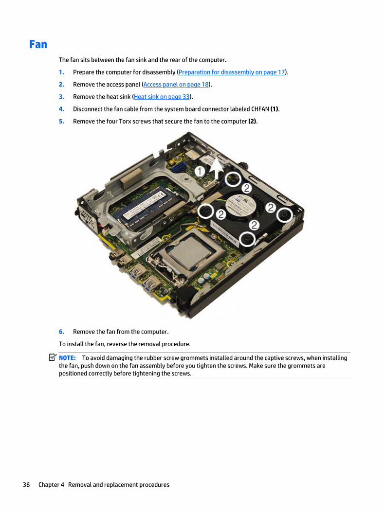
FanThe fan sits between the fan sink and the rear of the computer.
1. Prepare the computer for disassembly (Preparation for disassembly on page 17).
2. Remove the access panel (Access panel on page 18).
3. Remove the heat sink (Heat sink on page 33).
4. Disconnect the fan cable from the system board connector labeled CHFAN (1).
5. Remove the four Torx screws that secure the fan to the computer (2).
6. Remove the fan from the computer.
To install the fan, reverse the removal procedure.
NOTE: To avoid damaging the rubber screw grommets installed around the captive screws, when installingthe fan, push down on the fan assembly before you tighten the screws. Make sure the grommets arepositioned correctly before tightening the screws.
36 Chapter 4 Removal and replacement procedures

Drive cageThe drive cage is located next to the heat sink. The drive cage is secured with three slotted Torx screws.
1. Prepare the computer for disassembly (Preparation for disassembly on page 17).
2. Remove the access panel (Access panel on page 18).
3. Remove the three screws (1) that secure the drive cage to the computer.
Drive cage 37
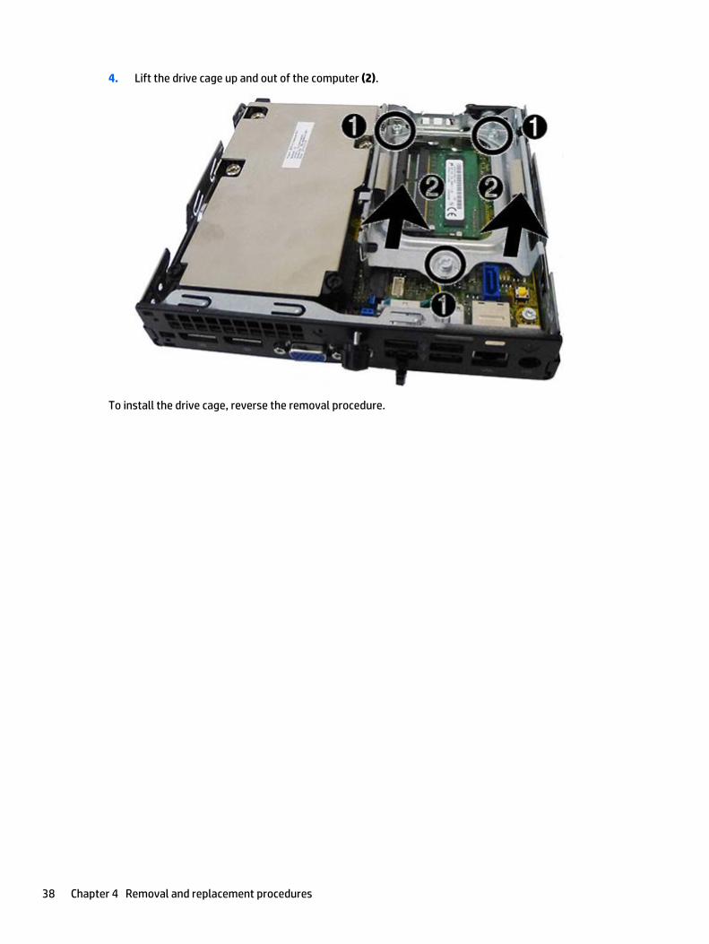
4. Lift the drive cage up and out of the computer (2).
To install the drive cage, reverse the removal procedure.
38 Chapter 4 Removal and replacement procedures
WLAN module
Description
HP WLAN 802.11 a/b/g/n, 2x2 + Bluetooth 4.0
HP WLAN 802.11 a/b/g/n, 2x2
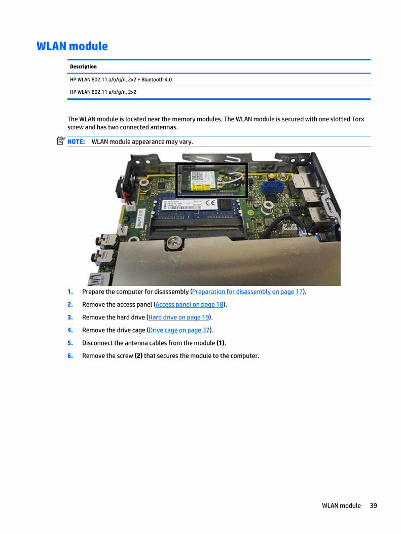
The WLAN module is located near the memory modules. The WLAN module is secured with one slotted Torxscrew and has two connected antennas.
NOTE: WLAN module appearance may vary.
1. Prepare the computer for disassembly (Preparation for disassembly on page 17).
2. Remove the access panel (Access panel on page 18).
3. Remove the hard drive (Hard drive on page 19).
4. Remove the drive cage (Drive cage on page 37).
5. Disconnect the antenna cables from the module (1).
6. Remove the screw (2) that secures the module to the computer.
WLAN module 39
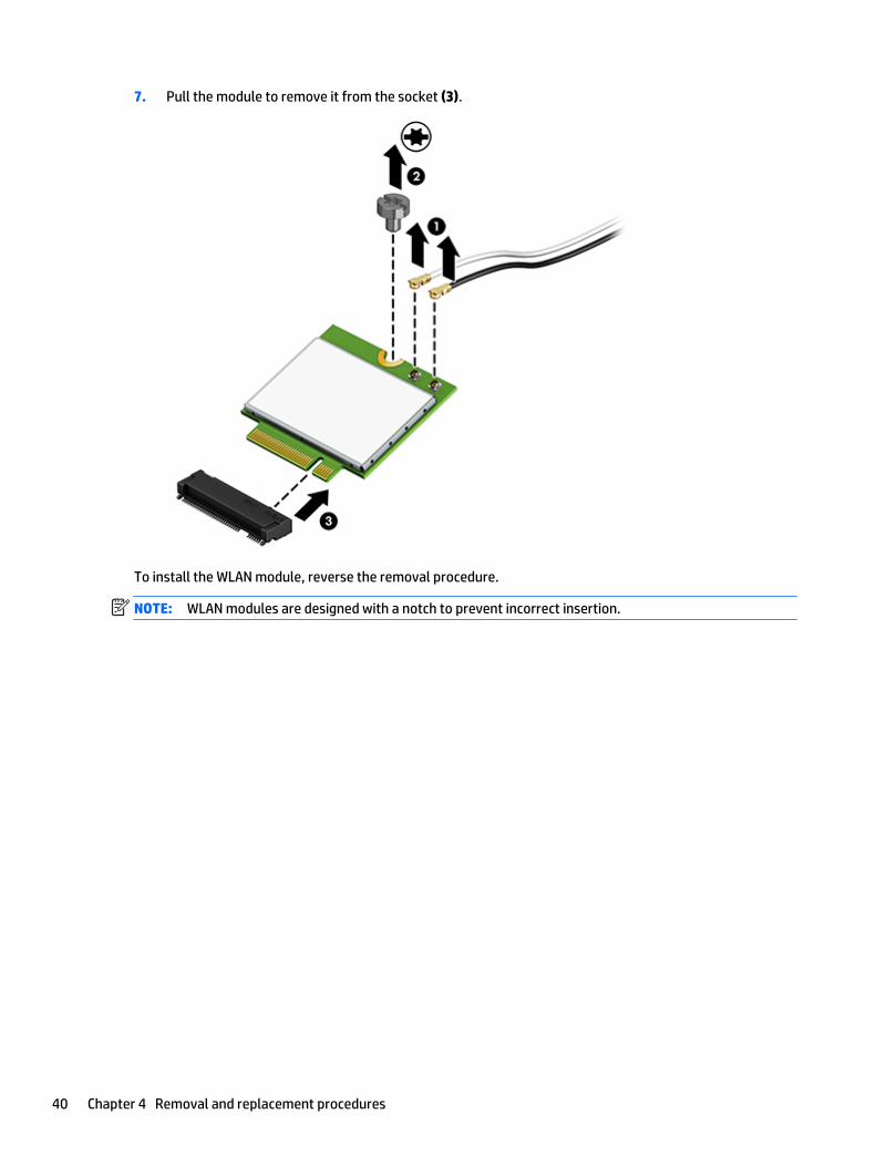
7. Pull the module to remove it from the socket (3).
To install the WLAN module, reverse the removal procedure.
NOTE: WLAN modules are designed with a notch to prevent incorrect insertion.
40 Chapter 4 Removal and replacement procedures
M.2 solid-state drive
Description
128 GB solid-state drive (SSD), M.2
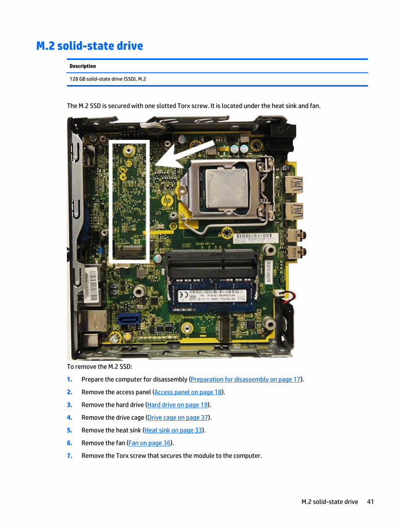
The M.2 SSD is secured with one slotted Torx screw. It is located under the heat sink and fan.
To remove the M.2 SSD:
1. Prepare the computer for disassembly (Preparation for disassembly on page 17).
2. Remove the access panel (Access panel on page 18).
3. Remove the hard drive (Hard drive on page 19).
4. Remove the drive cage (Drive cage on page 37).
5. Remove the heat sink (Heat sink on page 33).
6. Remove the fan (Fan on page 36).
7. Remove the Torx screw that secures the module to the computer.
M.2 solid-state drive 41

8. Lift the module to a 45-degree angle, and then pull it away to remove it from the socket.
To install the M.2 SSD, reverse the removal procedures.
NOTE: M.2 SSDs are designed with a notch to prevent incorrect insertion.
42 Chapter 4 Removal and replacement procedures
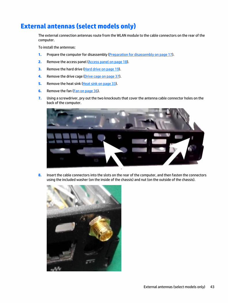
External antennas (select models only)The external connection antennas route from the WLAN module to the cable connectors on the rear of thecomputer.
To install the antennas:
1. Prepare the computer for disassembly (Preparation for disassembly on page 17).
2. Remove the access panel (Access panel on page 18).
3. Remove the hard drive (Hard drive on page 19).
4. Remove the drive cage (Drive cage on page 37).
5. Remove the heat sink (Heat sink on page 33).
6. Remove the fan (Fan on page 36).
7. Using a screwdriver, pry out the two knockouts that cover the antenna cable connector holes on theback of the computer.
8. Insert the cable connectors into the slots on the rear of the computer, and then fasten the connectorsusing the included washer (on the inside of the chassis) and nut (on the outside of the chassis).
External antennas (select models only) 43
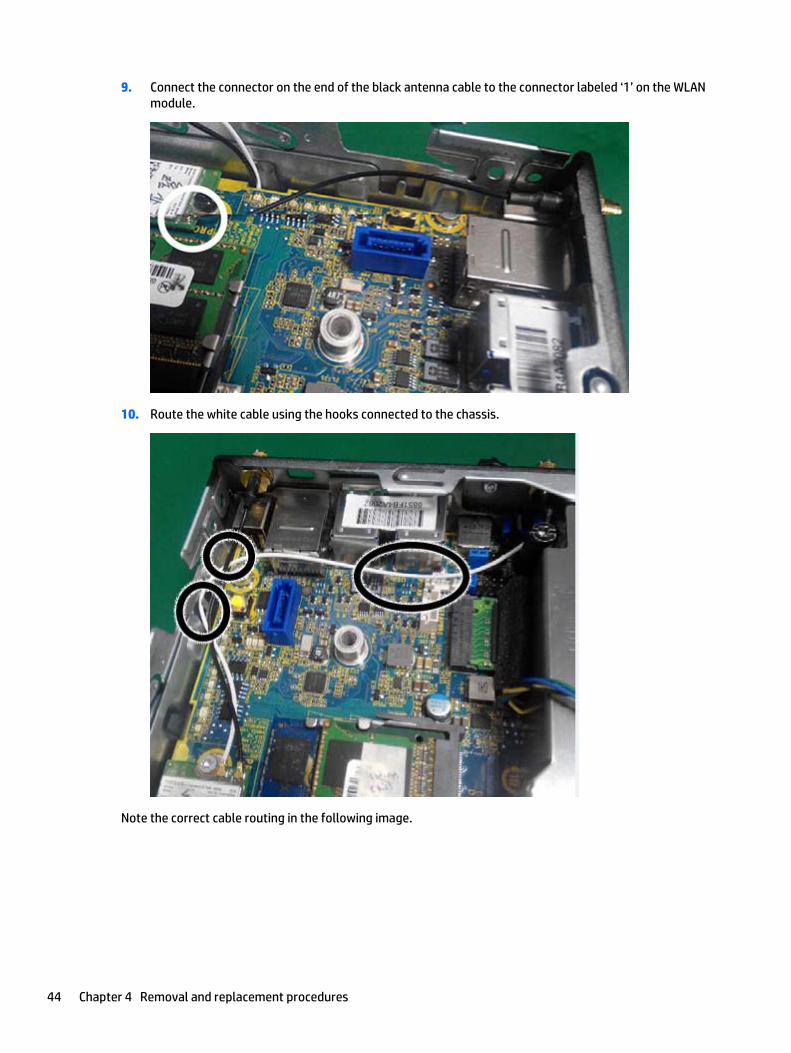
9. Connect the connector on the end of the black antenna cable to the connector labeled ‘1’ on the WLANmodule.
10. Route the white cable using the hooks connected to the chassis.
Note the correct cable routing in the following image.
44 Chapter 4 Removal and replacement procedures
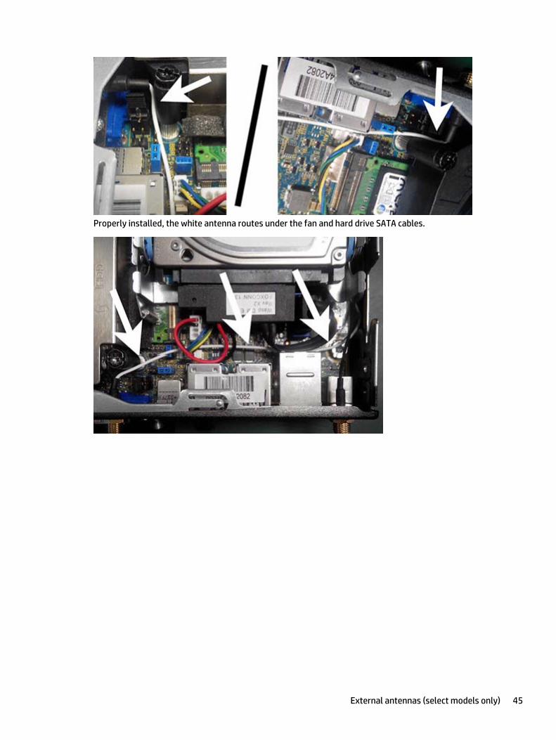
Properly installed, the white antenna routes under the fan and hard drive SATA cables.
External antennas (select models only) 45
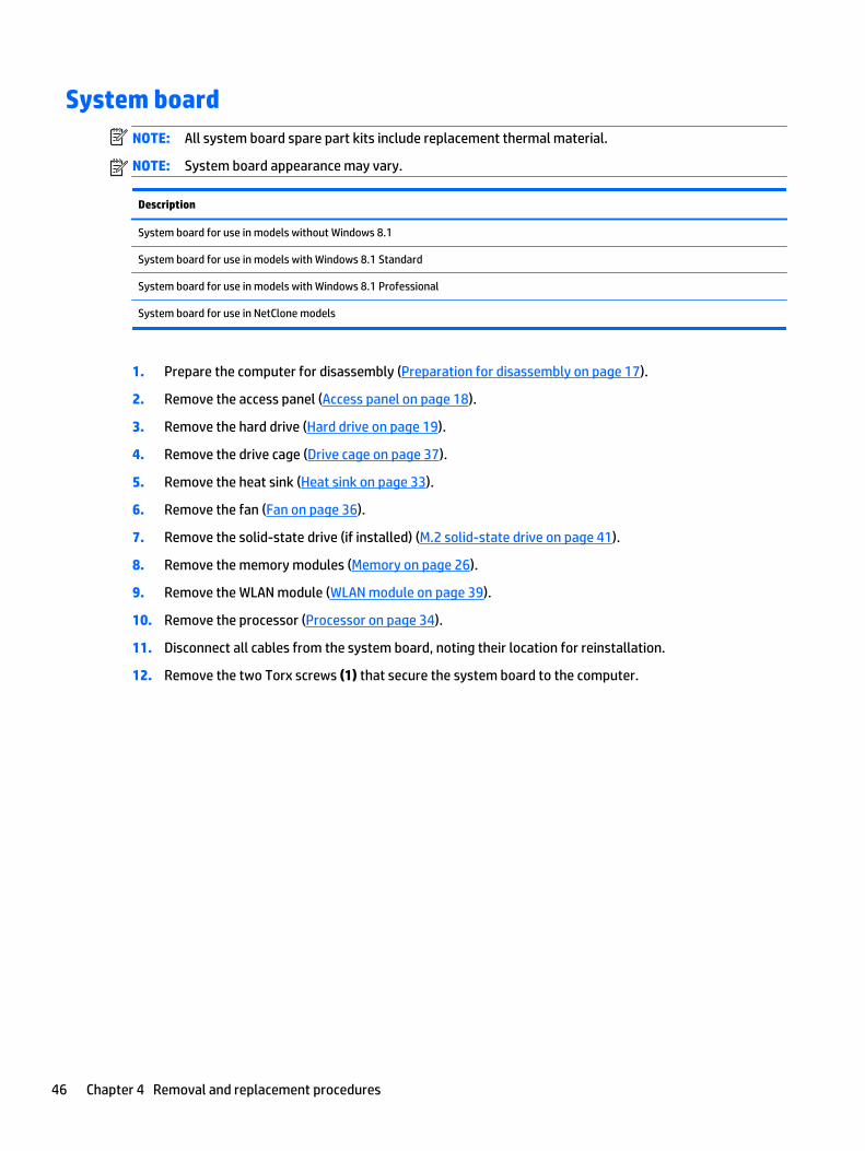
System boardNOTE: All system board spare part kits include replacement thermal material.
NOTE: System board appearance may vary.
Description
System board for use in models without Windows 8.1
System board for use in models with Windows 8.1 Standard
System board for use in models with Windows 8.1 Professional
System board for use in NetClone models
1. Prepare the computer for disassembly (Preparation for disassembly on page 17).
2. Remove the access panel (Access panel on page 18).
3. Remove the hard drive (Hard drive on page 19).
4. Remove the drive cage (Drive cage on page 37).
5. Remove the heat sink (Heat sink on page 33).
6. Remove the fan (Fan on page 36).
7. Remove the solid-state drive (if installed) (M.2 solid-state drive on page 41).
8. Remove the memory modules (Memory on page 26).
9. Remove the WLAN module (WLAN module on page 39).
10. Remove the processor (Processor on page 34).
11. Disconnect all cables from the system board, noting their location for reinstallation.
12. Remove the two Torx screws (1) that secure the system board to the computer.
46 Chapter 4 Removal and replacement procedures
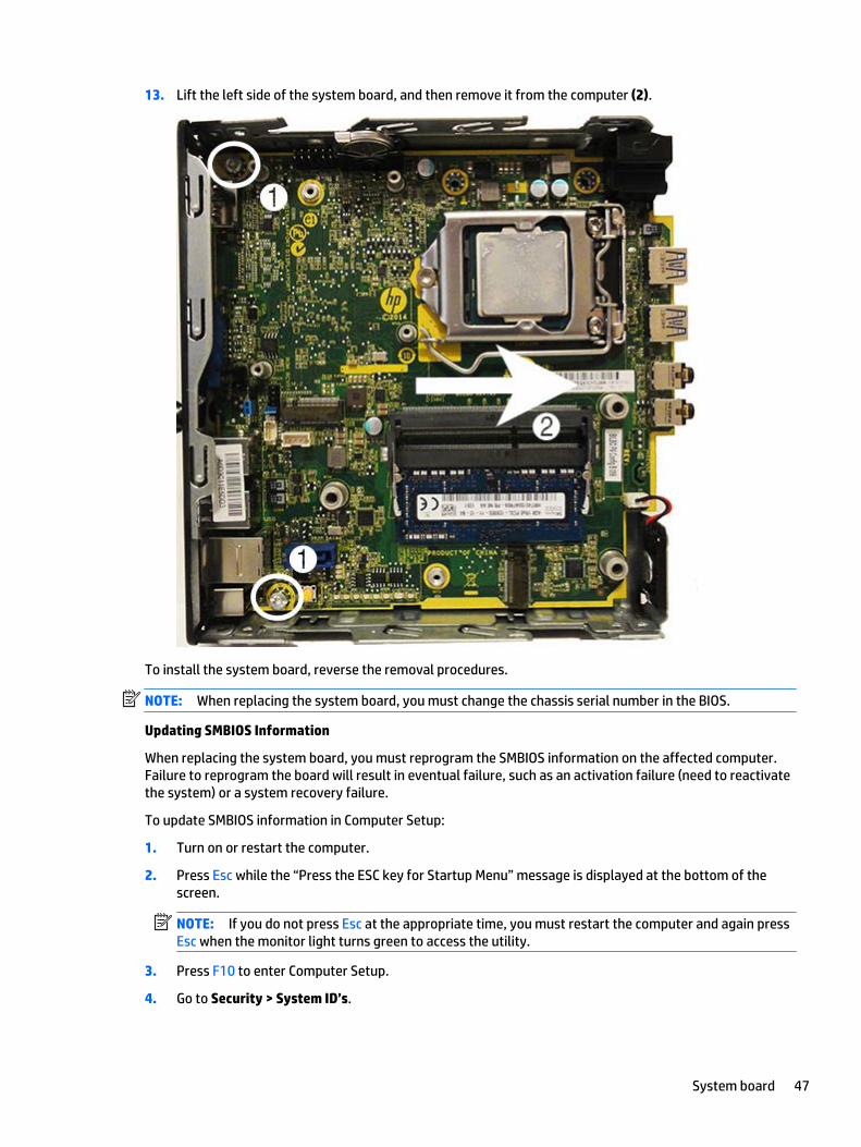
13. Lift the left side of the system board, and then remove it from the computer (2).
To install the system board, reverse the removal procedures.
NOTE: When replacing the system board, you must change the chassis serial number in the BIOS.
Updating SMBIOS Information
When replacing the system board, you must reprogram the SMBIOS information on the affected computer.Failure to reprogram the board will result in eventual failure, such as an activation failure (need to reactivatethe system) or a system recovery failure.
To update SMBIOS information in Computer Setup:
1. Turn on or restart the computer.
2. Press Esc while the “Press the ESC key for Startup Menu” message is displayed at the bottom of thescreen.
NOTE: If you do not press Esc at the appropriate time, you must restart the computer and again pressEsc when the monitor light turns green to access the utility.
3. Press F10 to enter Computer Setup.
4. Go to Security > System ID’s.
System board 47
5. If necessary, press Ctrl+A to initiate edit mode.
6. Edit the fields listed. If the feature byte has data or is not editable, then it was not cleared and cannot beedited.
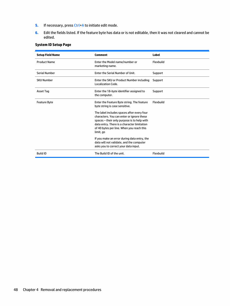
System ID Setup Page
Setup Field Name Comment Label
Product Name Enter the Model name/number ormarketing name.
Flexbuild
Serial Number Enter the Serial Number of Unit. Support
SKU Number Enter the SKU or Product Number includingLocalization Code.
Support
Asset Tag Enter the 18-byte identifier assigned tothe computer.
Support
Feature Byte Enter the Feature Byte string. The featurebyte string is case sensitive.
The label includes spaces after every fourcharacters. You can enter or ignore thesespaces – their only purpose is to help withdata entry. There is a character limitationof 40 bytes per line. When you reach thislimit, go
If you make an error during data entry, thedata will not validate, and the computerasks you to correct your data input.
Flexbuild
Build ID The Build ID of the unit. Flexbuild
48 Chapter 4 Removal and replacement procedures
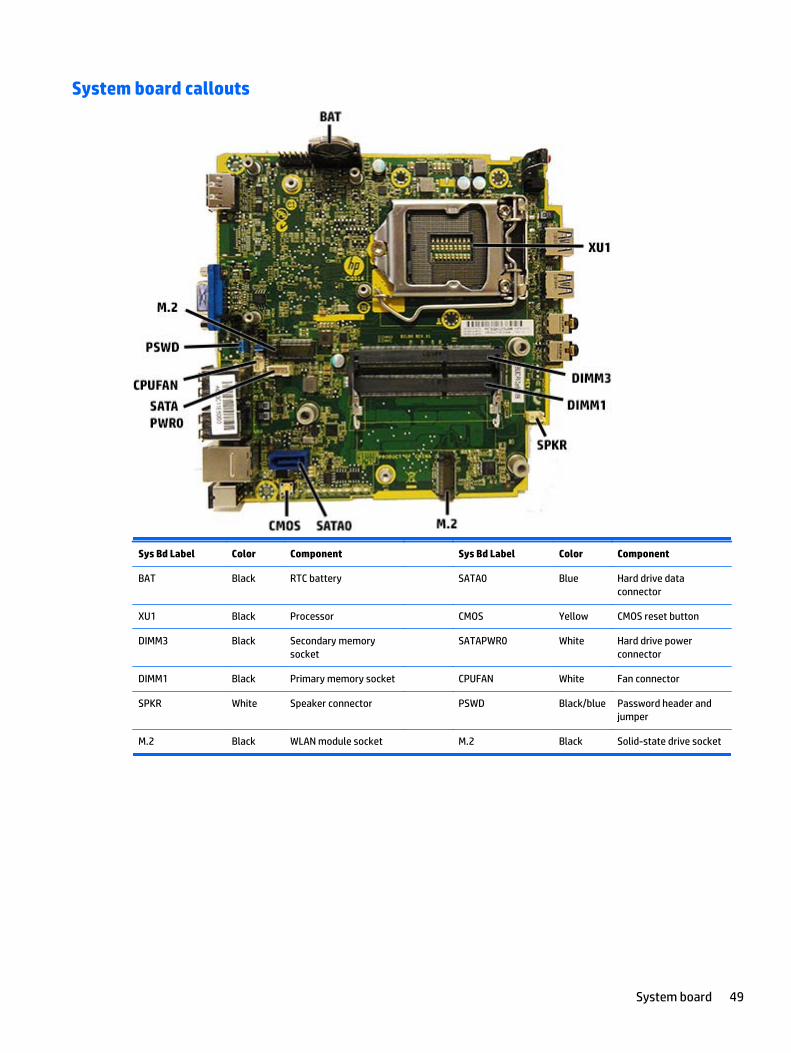
System board callouts
Sys Bd Label Color Component Sys Bd Label Color Component
BAT Black RTC battery SATA0 Blue Hard drive dataconnector
XU1 Black Processor CMOS Yellow CMOS reset button
DIMM3 Black Secondary memorysocket
SATAPWR0 White Hard drive powerconnector
DIMM1 Black Primary memory socket CPUFAN White Fan connector
SPKR White Speaker connector PSWD Black/blue Password header andjumper
M.2 Black WLAN module socket M.2 Black Solid-state drive socket
System board 49
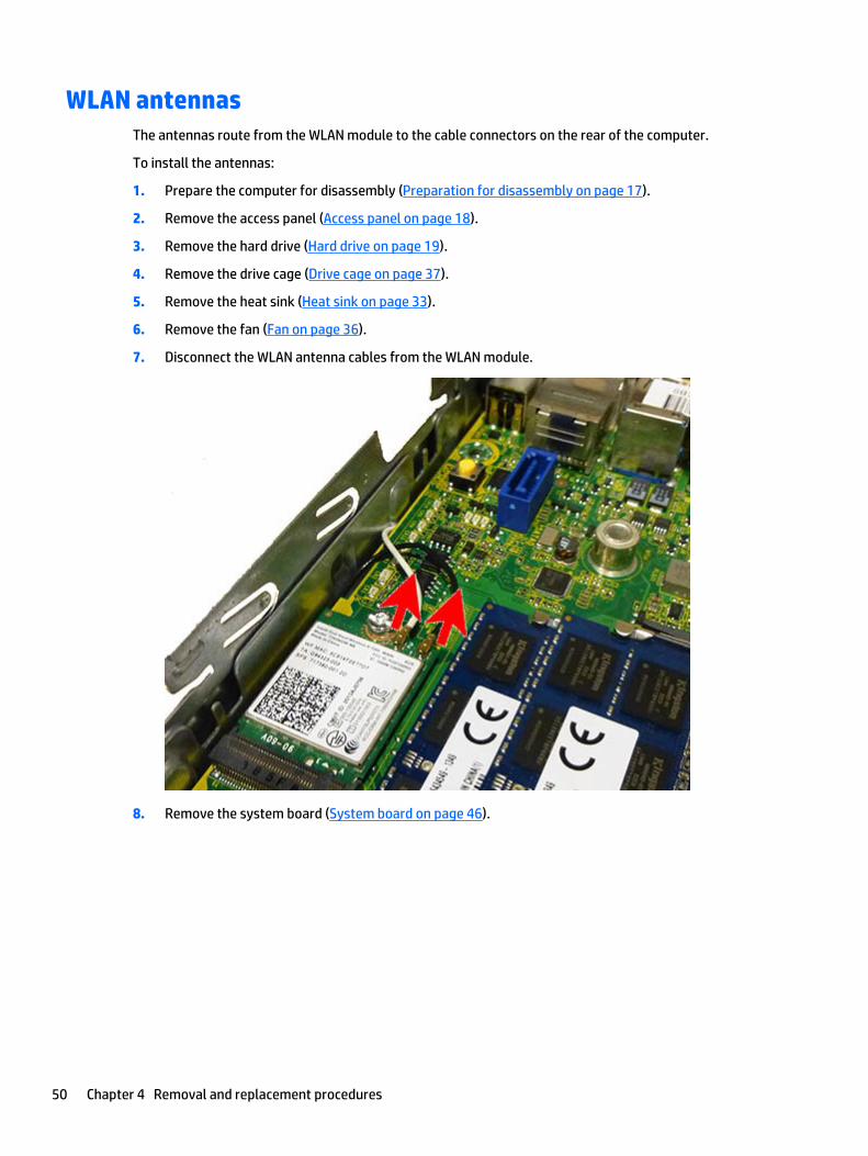
WLAN antennasThe antennas route from the WLAN module to the cable connectors on the rear of the computer.
To install the antennas:
1. Prepare the computer for disassembly (Preparation for disassembly on page 17).
2. Remove the access panel (Access panel on page 18).
3. Remove the hard drive (Hard drive on page 19).
4. Remove the drive cage (Drive cage on page 37).
5. Remove the heat sink (Heat sink on page 33).
6. Remove the fan (Fan on page 36).
7. Disconnect the WLAN antenna cables from the WLAN module.
8. Remove the system board (System board on page 46).
50 Chapter 4 Removal and replacement procedures
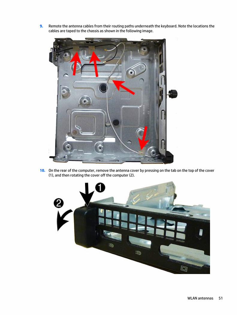
9. Remote the antenna cables from their routing paths underneath the keyboard. Note the locations thecables are taped to the chassis as shown in the following image.
10. On the rear of the computer, remove the antenna cover by pressing on the tab on the top of the cover(1), and then rotating the cover off the computer (2).
WLAN antennas 51
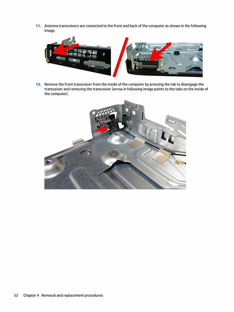
11. Antenna transceivers are connected to the front and back of the computer as shown in the followingimage.
12. Remove the front transceiver from the inside of the computer by pressing the tab to disengage thetransceiver and removing the transceiver (arrow in following image points to the tabs on the inside ofthe computer).
52 Chapter 4 Removal and replacement procedures

13. Remove the rear transceiver from the inside of the computer by pressing the tab to disengage thetransceiver and removing the transceiver (arrow in following image points to the tabs on the inside ofthe computer).
Reverse the removal procedure to install the WLAN antennas and transceivers.
WLAN antennas 53
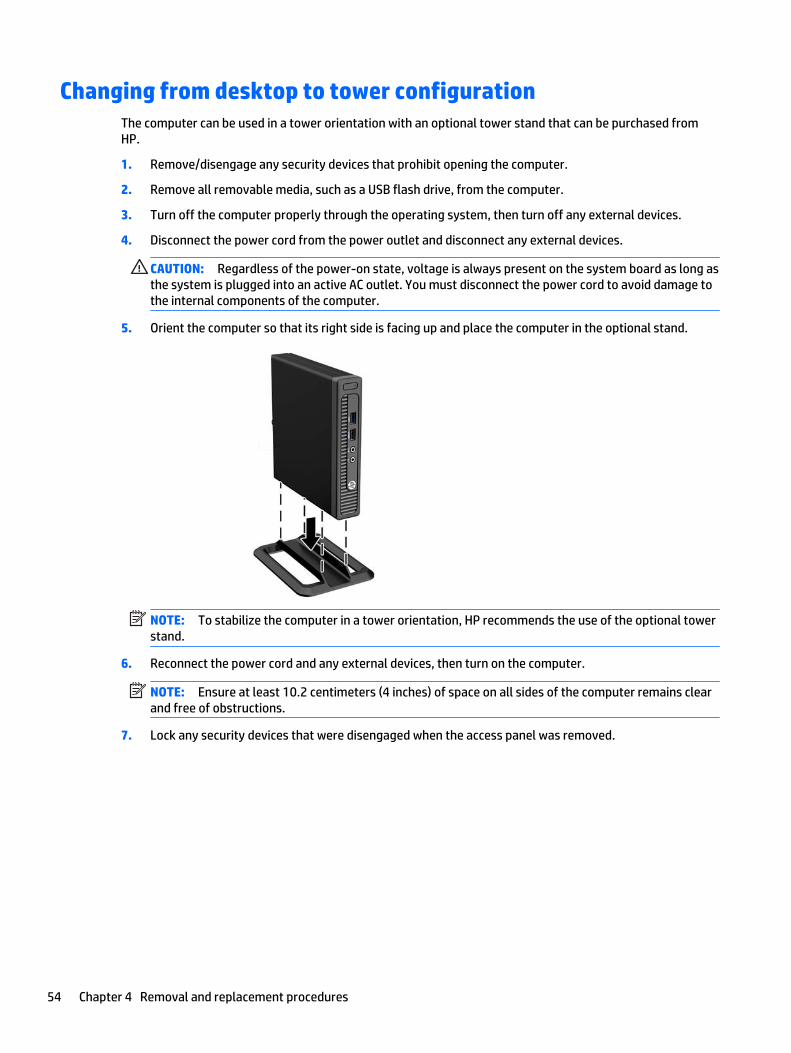
Changing from desktop to tower configurationThe computer can be used in a tower orientation with an optional tower stand that can be purchased fromHP.
1. Remove/disengage any security devices that prohibit opening the computer.
2. Remove all removable media, such as a USB flash drive, from the computer.
3. Turn off the computer properly through the operating system, then turn off any external devices.
4. Disconnect the power cord from the power outlet and disconnect any external devices.
CAUTION: Regardless of the power-on state, voltage is always present on the system board as long asthe system is plugged into an active AC outlet. You must disconnect the power cord to avoid damage tothe internal components of the computer.
5. Orient the computer so that its right side is facing up and place the computer in the optional stand.
NOTE: To stabilize the computer in a tower orientation, HP recommends the use of the optional towerstand.
6. Reconnect the power cord and any external devices, then turn on the computer.
NOTE: Ensure at least 10.2 centimeters (4 inches) of space on all sides of the computer remains clearand free of obstructions.
7. Lock any security devices that were disengaged when the access panel was removed.
54 Chapter 4 Removal and replacement procedures

5 Computer Setup (F10) Utility
Computer Setup (F10) UtilitiesUse Computer Setup (F10) Utility to do the following:
● Change factory default settings.
● Set the system date and time.
● Set, view, change, or verify the system configuration, including settings for processor, graphics,memory, audio, storage, communications, and input devices.
● Modify the boot order of bootable devices such as hard drives, optical drives, or USB flash mediadevices.
● Enable Quick Boot, which is faster than Full Boot but does not run all of the diagnostic tests run during aFull Boot. You can set the system to:
■ always Fast Boot (default);
■ periodically Full Boot (from every 1 to 30 days); or
■ always Full Boot.
● Select Post Messages Enabled or Disabled to change the display status of Power-On Self-Test (POST)messages. Post Messages Disabled suppresses most POST messages, such as memory count, productname, and other non-error text messages. If a POST error occurs, the error is displayed regardless ofthe mode selected. To manually switch to Post Messages Enabled during POST, press any key (exceptF1 through F12).
● Establish an Ownership Tag, the text of which is displayed each time the system is turned on orrestarted.
● Enter the Asset Tag or property identification number assigned by the company to this computer.
● Enable the power-on password prompt during system restarts (warm boots) as well as during power-on.
● Establish a setup password that controls access to the Computer Setup (F10) Utility and the settingsdescribed in this section.
● Secure integrated I/O functionality, including the USB ports, audio, or embedded NIC, so that theycannot be used until they are unsecured.
● Enable or disable removable media boot ability.
● Solve system configuration errors detected but not automatically fixed during the Power-On Self-Test(POST).
● Replicate the system setup by saving system configuration information on a USB device and restoring iton one or more computers.
● Execute self-tests on a specified ATA hard drive (when supported by drive).
● Enable or disable DriveLock security (when supported by drive).
Computer Setup (F10) Utilities 55

Using Computer Setup (F10) Utilities
Computer Setup can be accessed only by turning the computer on or restarting the system. To access theComputer Setup Utilities menu, complete the following steps:
1. Turn on or restart the computer.
2. Repeatedly press F10 when the monitor light turns green to access the utility.
You can also press Esc to a menu that allows you to access different options available at startup,including the Computer Setup utility.
NOTE: If you do not press F10 at the appropriate time, you must restart the computer and againrepeatedly press F10 when the monitor light turns green to access the utility.
NOTE: If the Computer Setup (F10) Utility is set to “fast boot”, use one of the following procedures toaccess Computer Setup:
● Before turning on the computer, press and hold F10. Turn on the computer and continue to holdF10 until the Computer Setup (F10) Utility is displayed.
- or –
● Follow the Windows 8.1 instructions for rebooting the computer into the Computer Setup (F10)Utility.
3. A choice of five headings appears in the Computer Setup Utilities menu: File, Storage, Security, Power,and Advanced.
4. Use the arrow (left and right) keys to select the appropriate heading. Use the arrow (up and down) keysto select the option you want, then press Enter. To return to the Computer Setup Utilities menu, pressEsc.
5. To apply and save changes, select File > Save Changes and Exit.
● If you have made changes that you do not want applied, select Ignore Changes and Exit.
● To reset to factory settings or previously saved default settings (some models), select ApplyDefaults and Exit. This option will restore the original factory system defaults.
NOTE: Not all settings shown in the following sections are available for all models
CAUTION: Do NOT turn the computer power OFF while the BIOS is saving the Computer Setup (F10) changesbecause the CMOS could become corrupted. It is safe to turn off the computer only after exiting the F10Setup screen.
56 Chapter 5 Computer Setup (F10) Utility
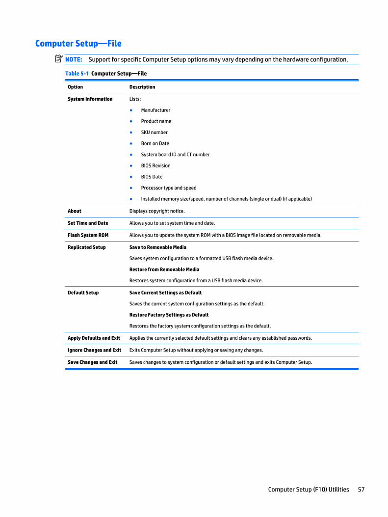
Computer Setup—File
NOTE: Support for specific Computer Setup options may vary depending on the hardware configuration.
Table 5-1 Computer Setup—File
Option Description
System Information Lists:
● Manufacturer
● Product name
● SKU number
● Born on Date
● System board ID and CT number
● BIOS Revision
● BIOS Date
● Processor type and speed
● Installed memory size/speed, number of channels (single or dual) (if applicable)
About Displays copyright notice.
Set Time and Date Allows you to set system time and date.
Flash System ROM Allows you to update the system ROM with a BIOS image file located on removable media.
Replicated Setup Save to Removable Media
Saves system configuration to a formatted USB flash media device.
Restore from Removable Media
Restores system configuration from a USB flash media device.
Default Setup Save Current Settings as Default
Saves the current system configuration settings as the default.
Restore Factory Settings as Default
Restores the factory system configuration settings as the default.
Apply Defaults and Exit Applies the currently selected default settings and clears any established passwords.
Ignore Changes and Exit Exits Computer Setup without applying or saving any changes.
Save Changes and Exit Saves changes to system configuration or default settings and exits Computer Setup.
Computer Setup (F10) Utilities 57
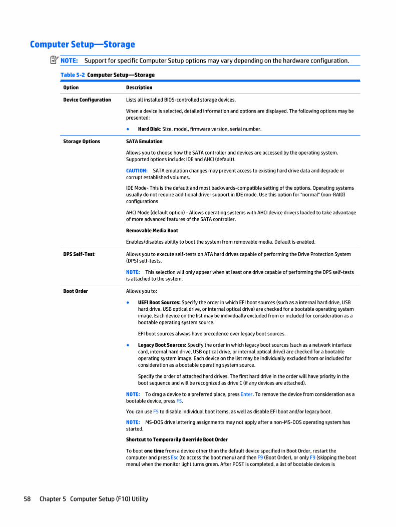
Computer Setup—Storage
NOTE: Support for specific Computer Setup options may vary depending on the hardware configuration.
Table 5-2 Computer Setup—Storage
Option Description
Device Configuration Lists all installed BIOS-controlled storage devices.
When a device is selected, detailed information and options are displayed. The following options may bepresented:
● Hard Disk: Size, model, firmware version, serial number.
Storage Options SATA Emulation
Allows you to choose how the SATA controller and devices are accessed by the operating system.Supported options include: IDE and AHCI (default).
CAUTION: SATA emulation changes may prevent access to existing hard drive data and degrade orcorrupt established volumes.
IDE Mode- This is the default and most backwards-compatible setting of the options. Operating systemsusually do not require additional driver support in IDE mode. Use this option for "normal" (non-RAID)configurations
AHCI Mode (default option) - Allows operating systems with AHCI device drivers loaded to take advantageof more advanced features of the SATA controller.
Removable Media Boot
Enables/disables ability to boot the system from removable media. Default is enabled.
DPS Self-Test Allows you to execute self-tests on ATA hard drives capable of performing the Drive Protection System(DPS) self-tests.
NOTE: This selection will only appear when at least one drive capable of performing the DPS self-testsis attached to the system.
Boot Order Allows you to:
● UEFI Boot Sources: Specify the order in which EFI boot sources (such as a internal hard drive, USBhard drive, USB optical drive, or internal optical drive) are checked for a bootable operating systemimage. Each device on the list may be individually excluded from or included for consideration as abootable operating system source.
EFI boot sources always have precedence over legacy boot sources.
● Legacy Boot Sources: Specify the order in which legacy boot sources (such as a network interfacecard, internal hard drive, USB optical drive, or internal optical drive) are checked for a bootableoperating system image. Each device on the list may be individually excluded from or included forconsideration as a bootable operating system source.
Specify the order of attached hard drives. The first hard drive in the order will have priority in theboot sequence and will be recognized as drive C (if any devices are attached).
NOTE: To drag a device to a preferred place, press Enter. To remove the device from consideration as abootable device, press F5.
You can use F5 to disable individual boot items, as well as disable EFI boot and/or legacy boot.
NOTE: MS-DOS drive lettering assignments may not apply after a non-MS-DOS operating system hasstarted.
Shortcut to Temporarily Override Boot Order
To boot one time from a device other than the default device specified in Boot Order, restart thecomputer and press Esc (to access the boot menu) and then F9 (Boot Order), or only F9 (skipping the bootmenu) when the monitor light turns green. After POST is completed, a list of bootable devices is
58 Chapter 5 Computer Setup (F10) Utility
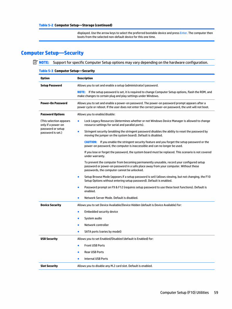
Table 5-2 Computer Setup—Storage (continued)
displayed. Use the arrow keys to select the preferred bootable device and press Enter. The computer thenboots from the selected non-default device for this one time.
Computer Setup—Security
NOTE: Support for specific Computer Setup options may vary depending on the hardware configuration.
Table 5-3 Computer Setup—Security
Option Description
Setup Password Allows you to set and enable a setup (administrator) password.
NOTE: If the setup password is set, it is required to change Computer Setup options, flash the ROM, andmake changes to certain plug and play settings under Windows.
Power-On Password Allows you to set and enable a power-on password. The power-on password prompt appears after apower cycle or reboot. If the user does not enter the correct power-on password, the unit will not boot.
Password Options
(This selection appearsonly if a power-onpassword or setuppassword is set.)
Allows you to enable/disable:
● Lock Legacy Resources (determines whether or not Windows Device Manager is allowed to changeresource settings for serial and parallel ports).
● Stringent security (enabling the stringent password disables the ability to reset the password bymoving the jumper on the system board). Default is disabled.
CAUTION: If you enable the stringent security feature and you forget the setup password or thepower-on password, the computer is inaccessible and can no longer be used.
If you lose or forget the password, the system board must be replaced. This scenario is not coveredunder warranty.
To prevent the computer from becoming permanently unusable, record your configured setuppassword or power-on password in a safe place away from your computer. Without thesepasswords, the computer cannot be unlocked.
● Setup Browse Mode (appears if a setup password is set) (allows viewing, but not changing, the F10Setup Options without entering setup password). Default is enabled.
● Password prompt on F9 & F12 (requires setup password to use these boot functions). Default isenabled.
● Network Server Mode. Default is disabled.
Device Security Allows you to set Device Available/Device Hidden (default is Device Available) for:
● Embedded security device
● System audio
● Network controller
● SATA ports (varies by model)
USB Security Allows you to set Enabled/Disabled (default is Enabled) for:
● Front USB Ports
● Rear USB Ports
● Internal USB Ports
Slot Security Allows you to disable any M.2 card slot. Default is enabled.
Computer Setup (F10) Utilities 59
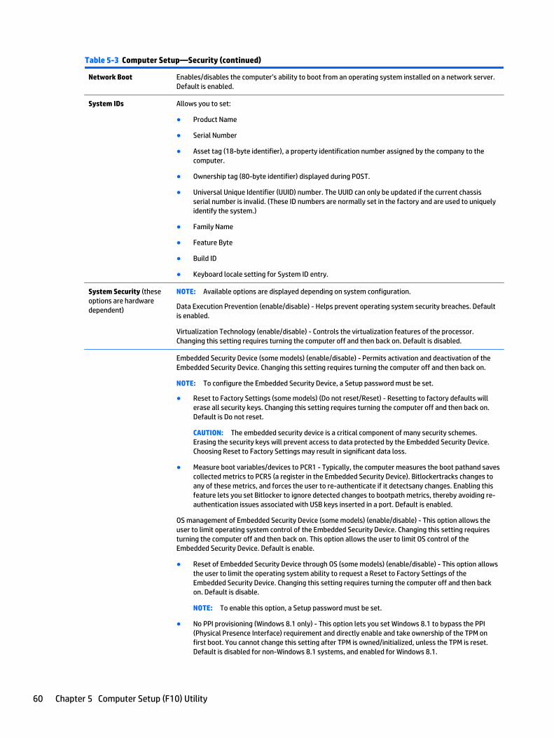
Table 5-3 Computer Setup—Security (continued)
Network Boot Enables/disables the computer’s ability to boot from an operating system installed on a network server.Default is enabled.
System IDs Allows you to set:
● Product Name
● Serial Number
● Asset tag (18-byte identifier), a property identification number assigned by the company to thecomputer.
● Ownership tag (80-byte identifier) displayed during POST.
● Universal Unique Identifier (UUID) number. The UUID can only be updated if the current chassisserial number is invalid. (These ID numbers are normally set in the factory and are used to uniquelyidentify the system.)
● Family Name
● Feature Byte
● Build ID
● Keyboard locale setting for System ID entry.
System Security (theseoptions are hardwaredependent)
NOTE: Available options are displayed depending on system configuration.
Data Execution Prevention (enable/disable) - Helps prevent operating system security breaches. Defaultis enabled.
Virtualization Technology (enable/disable) - Controls the virtualization features of the processor.Changing this setting requires turning the computer off and then back on. Default is disabled.
Embedded Security Device (some models) (enable/disable) - Permits activation and deactivation of theEmbedded Security Device. Changing this setting requires turning the computer off and then back on.
NOTE: To configure the Embedded Security Device, a Setup password must be set.
● Reset to Factory Settings (some models) (Do not reset/Reset) - Resetting to factory defaults willerase all security keys. Changing this setting requires turning the computer off and then back on.Default is Do not reset.
CAUTION: The embedded security device is a critical component of many security schemes.Erasing the security keys will prevent access to data protected by the Embedded Security Device.Choosing Reset to Factory Settings may result in significant data loss.
● Measure boot variables/devices to PCR1 - Typically, the computer measures the boot pathand savescollected metrics to PCR5 (a register in the Embedded Security Device). Bitlockertracks changes toany of these metrics, and forces the user to re-authenticate if it detectsany changes. Enabling thisfeature lets you set Bitlocker to ignore detected changes to bootpath metrics, thereby avoiding re-authentication issues associated with USB keys inserted in a port. Default is enabled.
OS management of Embedded Security Device (some models) (enable/disable) - This option allows theuser to limit operating system control of the Embedded Security Device. Changing this setting requiresturning the computer off and then back on. This option allows the user to limit OS control of theEmbedded Security Device. Default is enable.
● Reset of Embedded Security Device through OS (some models) (enable/disable) - This option allowsthe user to limit the operating system ability to request a Reset to Factory Settings of theEmbedded Security Device. Changing this setting requires turning the computer off and then backon. Default is disable.
NOTE: To enable this option, a Setup password must be set.
● No PPI provisioning (Windows 8.1 only) - This option lets you set Windows 8.1 to bypass the PPI(Physical Presence Interface) requirement and directly enable and take ownership of the TPM onfirst boot. You cannot change this setting after TPM is owned/initialized, unless the TPM is reset.Default is disabled for non-Windows 8.1 systems, and enabled for Windows 8.1.
60 Chapter 5 Computer Setup (F10) Utility
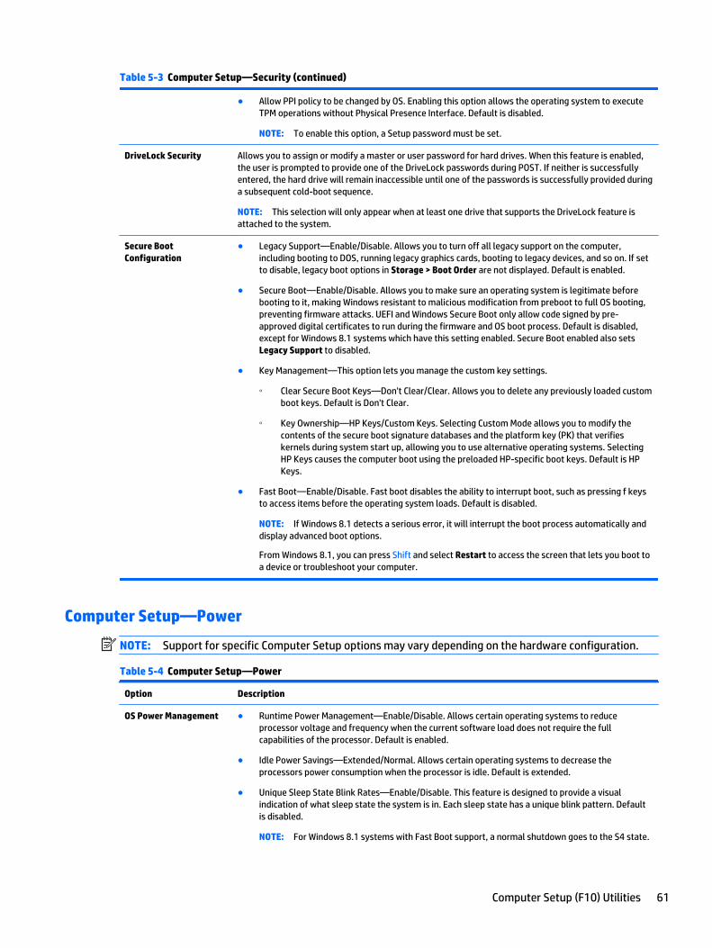
Table 5-3 Computer Setup—Security (continued)
● Allow PPI policy to be changed by OS. Enabling this option allows the operating system to executeTPM operations without Physical Presence Interface. Default is disabled.
NOTE: To enable this option, a Setup password must be set.
DriveLock Security Allows you to assign or modify a master or user password for hard drives. When this feature is enabled,the user is prompted to provide one of the DriveLock passwords during POST. If neither is successfullyentered, the hard drive will remain inaccessible until one of the passwords is successfully provided duringa subsequent cold-boot sequence.
NOTE: This selection will only appear when at least one drive that supports the DriveLock feature isattached to the system.
Secure BootConfiguration
● Legacy Support—Enable/Disable. Allows you to turn off all legacy support on the computer,including booting to DOS, running legacy graphics cards, booting to legacy devices, and so on. If setto disable, legacy boot options in Storage > Boot Order are not displayed. Default is enabled.
● Secure Boot—Enable/Disable. Allows you to make sure an operating system is legitimate beforebooting to it, making Windows resistant to malicious modification from preboot to full OS booting,preventing firmware attacks. UEFI and Windows Secure Boot only allow code signed by pre-approved digital certificates to run during the firmware and OS boot process. Default is disabled,except for Windows 8.1 systems which have this setting enabled. Secure Boot enabled also setsLegacy Support to disabled.
● Key Management—This option lets you manage the custom key settings.
◦ Clear Secure Boot Keys—Don't Clear/Clear. Allows you to delete any previously loaded customboot keys. Default is Don't Clear.
◦ Key Ownership—HP Keys/Custom Keys. Selecting Custom Mode allows you to modify thecontents of the secure boot signature databases and the platform key (PK) that verifieskernels during system start up, allowing you to use alternative operating systems. SelectingHP Keys causes the computer boot using the preloaded HP-specific boot keys. Default is HPKeys.
● Fast Boot—Enable/Disable. Fast boot disables the ability to interrupt boot, such as pressing f keysto access items before the operating system loads. Default is disabled.
NOTE: If Windows 8.1 detects a serious error, it will interrupt the boot process automatically anddisplay advanced boot options.
From Windows 8.1, you can press Shift and select Restart to access the screen that lets you boot toa device or troubleshoot your computer.
Computer Setup—Power
NOTE: Support for specific Computer Setup options may vary depending on the hardware configuration.
Table 5-4 Computer Setup—Power
Option Description
OS Power Management ● Runtime Power Management—Enable/Disable. Allows certain operating systems to reduceprocessor voltage and frequency when the current software load does not require the fullcapabilities of the processor. Default is enabled.
● Idle Power Savings—Extended/Normal. Allows certain operating systems to decrease theprocessors power consumption when the processor is idle. Default is extended.
● Unique Sleep State Blink Rates—Enable/Disable. This feature is designed to provide a visualindication of what sleep state the system is in. Each sleep state has a unique blink pattern. Defaultis disabled.
NOTE: For Windows 8.1 systems with Fast Boot support, a normal shutdown goes to the S4 state.
Computer Setup (F10) Utilities 61
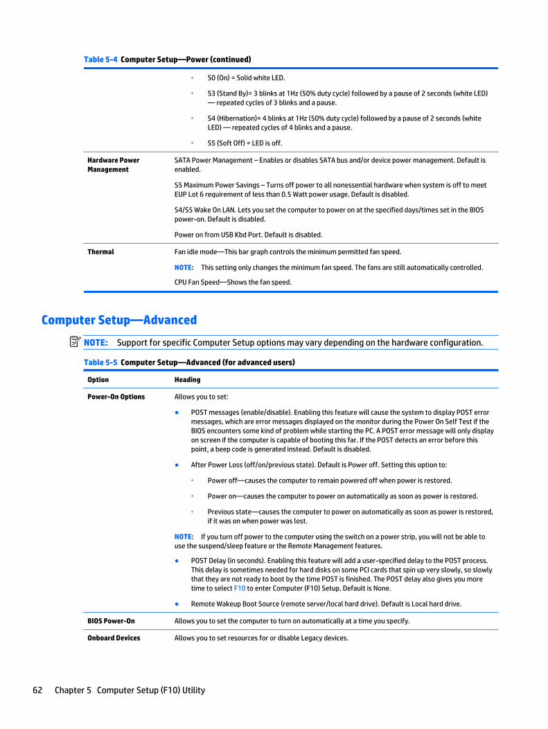
Table 5-4 Computer Setup—Power (continued)
◦ S0 (On) = Solid white LED.
◦ S3 (Stand By)= 3 blinks at 1Hz (50% duty cycle) followed by a pause of 2 seconds (white LED)— repeated cycles of 3 blinks and a pause.
◦ S4 (Hibernation)= 4 blinks at 1Hz (50% duty cycle) followed by a pause of 2 seconds (whiteLED) — repeated cycles of 4 blinks and a pause.
◦ S5 (Soft Off) = LED is off.
Hardware PowerManagement
SATA Power Management – Enables or disables SATA bus and/or device power management. Default isenabled.
S5 Maximum Power Savings – Turns off power to all nonessential hardware when system is off to meetEUP Lot 6 requirement of less than 0.5 Watt power usage. Default is disabled.
S4/S5 Wake On LAN. Lets you set the computer to power on at the specified days/times set in the BIOSpower-on. Default is disabled.
Power on from USB Kbd Port. Default is disabled.
Thermal Fan idle mode—This bar graph controls the minimum permitted fan speed.
NOTE: This setting only changes the minimum fan speed. The fans are still automatically controlled.
CPU Fan Speed—Shows the fan speed.
Computer Setup—Advanced
NOTE: Support for specific Computer Setup options may vary depending on the hardware configuration.
Table 5-5 Computer Setup—Advanced (for advanced users)
Option Heading
Power-On Options Allows you to set:
● POST messages (enable/disable). Enabling this feature will cause the system to display POST errormessages, which are error messages displayed on the monitor during the Power On Self Test if theBIOS encounters some kind of problem while starting the PC. A POST error message will only displayon screen if the computer is capable of booting this far. If the POST detects an error before thispoint, a beep code is generated instead. Default is disabled.
● After Power Loss (off/on/previous state). Default is Power off. Setting this option to:
◦ Power off—causes the computer to remain powered off when power is restored.
◦ Power on—causes the computer to power on automatically as soon as power is restored.
◦ Previous state—causes the computer to power on automatically as soon as power is restored,if it was on when power was lost.
NOTE: If you turn off power to the computer using the switch on a power strip, you will not be able touse the suspend/sleep feature or the Remote Management features.
● POST Delay (in seconds). Enabling this feature will add a user-specified delay to the POST process.This delay is sometimes needed for hard disks on some PCI cards that spin up very slowly, so slowlythat they are not ready to boot by the time POST is finished. The POST delay also gives you moretime to select F10 to enter Computer (F10) Setup. Default is None.
● Remote Wakeup Boot Source (remote server/local hard drive). Default is Local hard drive.
BIOS Power-On Allows you to set the computer to turn on automatically at a time you specify.
Onboard Devices Allows you to set resources for or disable Legacy devices.
62 Chapter 5 Computer Setup (F10) Utility
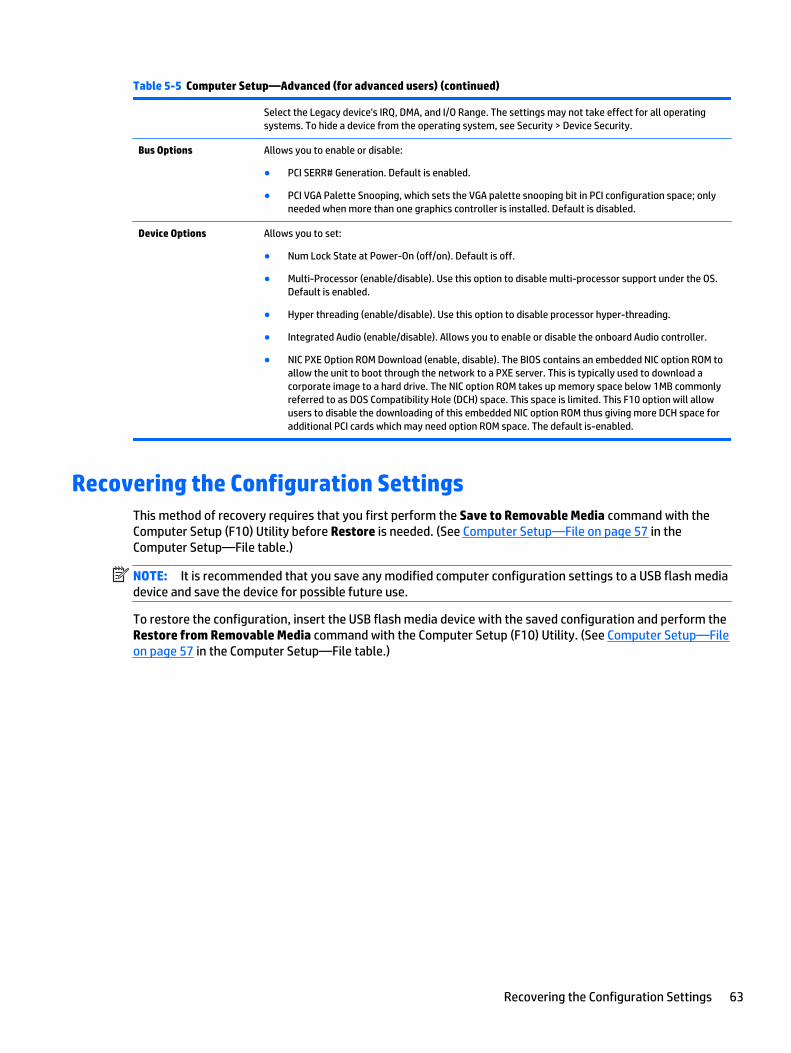
Table 5-5 Computer Setup—Advanced (for advanced users) (continued)
Select the Legacy device's IRQ, DMA, and I/O Range. The settings may not take effect for all operatingsystems. To hide a device from the operating system, see Security > Device Security.
Bus Options Allows you to enable or disable:
● PCI SERR# Generation. Default is enabled.
● PCI VGA Palette Snooping, which sets the VGA palette snooping bit in PCI configuration space; onlyneeded when more than one graphics controller is installed. Default is disabled.
Device Options Allows you to set:
● Num Lock State at Power-On (off/on). Default is off.
● Multi-Processor (enable/disable). Use this option to disable multi-processor support under the OS.Default is enabled.
● Hyper threading (enable/disable). Use this option to disable processor hyper-threading.
● Integrated Audio (enable/disable). Allows you to enable or disable the onboard Audio controller.
● NIC PXE Option ROM Download (enable, disable). The BIOS contains an embedded NIC option ROM toallow the unit to boot through the network to a PXE server. This is typically used to download acorporate image to a hard drive. The NIC option ROM takes up memory space below 1MB commonlyreferred to as DOS Compatibility Hole (DCH) space. This space is limited. This F10 option will allowusers to disable the downloading of this embedded NIC option ROM thus giving more DCH space foradditional PCI cards which may need option ROM space. The default is-enabled.
Recovering the Configuration SettingsThis method of recovery requires that you first perform the Save to Removable Media command with theComputer Setup (F10) Utility before Restore is needed. (See Computer Setup—File on page 57 in theComputer Setup—File table.)
NOTE: It is recommended that you save any modified computer configuration settings to a USB flash mediadevice and save the device for possible future use.
To restore the configuration, insert the USB flash media device with the saved configuration and perform theRestore from Removable Media command with the Computer Setup (F10) Utility. (See Computer Setup—Fileon page 57 in the Computer Setup—File table.)
Recovering the Configuration Settings 63

6 Troubleshooting without diagnostics
This chapter provides information on how to identify and correct minor problems. If you encounter problemswith the computer, refer to the tables in this chapter for probable causes and recommended solutions.
NOTE: For information on specific error messages that may appear on the screen during Power-On Self-Test (POST) at startup, refer to Appendix A, POST error messages on page 89.
Safety and comfortWARNING! Misuse of the computer or failure to establish a safe and comfortable work environment mayresult in discomfort or serious injury. Refer to the Safety & Comfort Guide at http://www.hp.com/ergo formore information on choosing a workspace and creating a safe and comfortable work environment. For moreinformation, refer to the Safety & Regulatory Information guide.
Before you call for technical supportIf you are having problems with the computer, try the appropriate solutions below to try to isolate the exactproblem before calling for technical support.
● Run the HP diagnostic tool.
● Run the hard drive self-test in Computer Setup. Refer to Computer Setup (F10) Utility on page 55 formore information.
● Check the Power LED on the front of the computer to see if it is flashing red. The flashing lights are errorcodes that will help you diagnose the problem. Refer to Appendix A, POST error messages on page 89for more information.
● If the screen is blank, plug the monitor into a different video port on the computer if one is available. Or,replace the monitor with a monitor that you know is functioning properly.
● If you are working on a network, plug another computer with a different cable into the networkconnection. There may be a problem with the network plug or cable.
● If you recently added new hardware, remove the hardware and see if the computer functions properly.
● If you recently installed new software, uninstall the software and see if the computer functionsproperly.
● Boot the computer to the Safe Mode to see if it will boot without all of the drivers loaded. When bootingthe operating system, use “Last Known Configuration.”
● Refer to the comprehensive online technical support at http://www.hp.com/support.
● Refer to Helpful hints on page 65 in this guide.
To assist you in resolving problems online, HP Instant Support Professional Edition provides you with self-solve diagnostics. If you need to contact HP support, use HP Instant Support Professional Edition's onlinechat feature. Access HP Instant Support Professional Edition at: http://www.hp.com/go/ispe.
Access the Business Support Center (BSC) at http://www.hp.com/go/bizsupport for the latest online supportinformation, software and drivers, proactive notification, and worldwide community of peers and HP experts.
64 Chapter 6 Troubleshooting without diagnostics

If it becomes necessary to call for technical assistance, be prepared to do the following to ensure that yourservice call is handled properly:
● Be in front of your computer when you call.
● Write down the computer serial number, product ID number, and monitor serial number before calling.
● Spend time troubleshooting the problem with the service technician.
● Remove any hardware that was recently added to your system.
● Remove any software that was recently installed.
● Restore the system from the Recovery Disc Set that you created or restore the system to its originalfactory condition in System Software Requirement Disks (SSRD).
CAUTION: Restoring the system will erase all data on the hard drive. Be sure to back up all data files beforerunning the restore process.
NOTE: For sales information and warranty upgrades (Care Packs), call your local authorized serviceprovider or dealer.
Helpful hintsIf you encounter problems with the computer, monitor, or software, see the following list of generalsuggestions before taking further action:
● Check that the computer and monitor are plugged into a working electrical outlet.
● Check that the computer is turned on and the white power light is on.
● Check that the monitor is turned on and the green monitor light is on.
● Check the Power LED on the front of the computer to see if it is flashing red. The flashing lights are errorcodes that will help you diagnose the problem. Refer to Appendix A, POST error messages on page 89for more information.
● Turn up the brightness and contrast controls of the monitor if the monitor is dim.
● Press and hold any key. If the system beeps, then the keyboard should be operating correctly.
● Check all cable connections for loose connections or incorrect connections.
● Wake the computer by pressing any key on the keyboard or pressing the power button. If the systemremains in suspend mode, shut down the computer by pressing and holding the power button for atleast four seconds then press the power button again to restart the computer. If the system will notshut down, unplug the power cord, wait a few seconds, then plug it in again. The computer will restart ifit is set to power on automatically as soon as power is restored in Computer Setup. If it does not restart,press the power button to start the computer.
● Reconfigure the computer after installing a non-plug and play expansion board or other option. SeeSolving Hardware Installation Problems on page 79 for instructions.
● Be sure that all the needed device drivers have been installed. For example, if you are using a printer,you need a driver for that model printer.
● Remove all bootable media from the system before turning it on.
● If you have installed an operating system other than the factory-installed operating system, check to besure that it is supported on the system.
Helpful hints 65

CAUTION: When the computer is plugged into an AC power source, there is always voltage applied to thesystem board. You must disconnect the power cord from the power source before opening the computer toprevent system board or component damage.
Solving general problemsYou may be able to easily resolve the general problems described in this section. If a problem persists andyou are unable to resolve it yourself or if you feel uncomfortable about performing the operation, contact anauthorized dealer or reseller.
WARNING! When the computer is plugged into an AC power source, voltage is always applied to the systemboard. To reduce the risk of personal injury from electrical shock and/or hot surfaces, be sure to disconnectthe power cord from the wall outlet and allow the internal system components to cool before touching.
Cannot access the Computer Setup (F10) Utility when booting the computer.
Cause Solution
The Computer Setup (F10) Utility is set to “fast boot” causing theF10 access screen to display too briefly when booting thecomputer.
Before turning on the computer, press and hold F10. Turn on thecomputer and continue to hold F10 until the Computer Setup(F10) Utility is displayed.
- or –
Follow the Windows 8.1 instructions for rebooting the computerinto the Computer Setup (F10) Utility.
Computer appears locked up and will not turn off when the power button is pressed.
Cause Solution
Software control of the power switch is not functional. 1. Press and hold the power button for at least four secondsuntil the computer turns off.
2. Disconnect the power cord from the electrical outlet.
Computer will not respond to keyboard or mouse.
Cause Solution
Computer is in Sleep state. To resume from Sleep state, press the power button.
CAUTION: When attempting to resume from Sleep state, do nothold down the power button for more than four seconds.Otherwise, the computer will shut down and you will lose anyunsaved data.
System has locked up. Restart computer.
Computer date and time display is incorrect.
Cause Solution
RTC (real-time clock) battery may need to be replaced. Reset the date and time under Control Panel (Computer Setupcan also be used to update the RTC date and time). If the problempersists, replace the RTC battery. See the Removal and
66 Chapter 6 Troubleshooting without diagnostics

Computer date and time display is incorrect.
Cause Solution
NOTE: Connecting the computer to a live AC outlet prolongs thelife of the RTC battery.
Replacement section for instructions on installing a new battery,or contact an authorized dealer or reseller for RTC batteryreplacement.
To access Control Panel in Windows 7, select Start, and thenselect Control Panel.
To access Control Panel in Windows 8.1, from the Start screen,type c, and then select Control Panel from the list ofapplications.
Cursor will not move using the arrow keys on the keypad.
Cause Solution
The Num Lock key is turned on. Press the Num Lock key. The Num Lock light must be off if youwant to use the arrow keys on the keypad. You can also disable orenable the Num Lock key in Computer Setup at Advanced >Device Options.
There is no sound or sound volume is too low.
Cause Solution
System volume may be set low or muted. 1. Check the Computer Setup settings to make sure theinternal system speaker is not muted (this setting does notaffect the external speakers).
2. Make sure the external speakers are properly connectedand powered on and that the speakers' volume control is setcorrectly.
3. Use the system volume control available in the operatingsystem to make sure the speakers are not muted or toincrease the volume.
Poor performance.
Cause Solution
Processor is too hot. 1. Make sure airflow to the computer is not blocked. Leave a10.2-cm (4-inch) clearance on all vented sides of thecomputer and above the monitor to permit the requiredairflow.
2. Make sure fans are connected and working properly (somefans only operate when needed).
3. Make sure the processor heat sink is installed properly.
Hard drive is full. Transfer data from the hard drive to create more space on thehard drive.
Low on memory. Add more memory.
Hard drive fragmented. Defragment hard drive.
Solving general problems 67

Poor performance.
Cause Solution
Program previously accessed did not release reserved memoryback to the system.
Restart the computer.
Virus resident on the hard drive. Run virus protection program.
Too many applications running. Windows 7:
1. Close unnecessary applications to free up memory.
2. Add more memory.
3. Some applications run in the background and can be closedby right-clicking on their corresponding icons in the tasktray. To prevent these applications from launching atstartup:
In Windows 7:
a. Go to Start > All Programs > Accessories > Run
b. Type msconfig, and then press Enter.
c. On the Startup tab of the System Configuration Utility,clear applications that you do not want to launchautomatically, and the click OK.
In Windows 8.1:
a. On the Start screen, right-click, and then select the Allapps icon.
b. Under Windows System, click Run.
c. Type msconfig, and then press Enter.
d. On the Startup tab of the System Configuration Utility,clear applications that you do not want to launchautomatically, and the click OK.
Some software applications, especially games, are stressful onthe graphics subsystem.
1. Lower the display resolution for the current application orconsult the documentation that came with the applicationfor suggestions on how to improve performance byadjusting parameters in the application.
2. Add more memory.
3. Upgrade the graphics solution.
Cause unknown. Restart the computer.
Computer powered off automatically and the Power LED flashes Red two times, once every second, followed by a two secondpause, and the computer beeps two times. (Beeps stop after fifth iteration but LEDs continue flashing).
Cause Solution
Processor thermal protection activated:
A fan may be blocked or not turning.
OR
The heat sink is not properly attached to the processor.
1. Ensure that the computer air vents are not blocked and theprocessor cooling fan is running.
2. Open the access panel, press the power button, and see ifthe processor fan (or other system fan) spins. If the fan doesnot spin, make sure the fan cable is plugged onto thesystem board header.
3. If fan a plugged in and not spinning, replace it.
68 Chapter 6 Troubleshooting without diagnostics

Solving hard drive problemsHard drive error occurs.
Cause Solution
Hard disk has bad sectors or has failed. 1. In Windows 7, click Start, click Computer, and right-click ona drive. Select Properties, and then select the Tools tab.Under Error-checking click Check Now.
In Windows 8.1, on the Start screen type e, and then selectFile Explorer from the list of applications. In the leftcolumn, expand Computer, right-click on a drive, selectProperties, and then select the Tools tab. Under Errorchecking click Check.
2. Use a utility to locate and block usage of bad sectors. Ifnecessary, reformat the hard disk.
Disk transaction problem.
Cause Solution
Either the directory structure is bad or there is a problem with afile.
In Windows 7, click Start, expand Computer, and right-click on adrive. Select Properties, and then select the Tools tab. UnderError-checking click Check Now.
In Windows 8.1, on the Start screen type e, and then click FileExplorer from the list of applications. In the left column, expandComputer, right-click on a drive, select Properties, and thenselect the Tools tab. Under Error checking click Check.
Drive not found (identified).
Cause Solution
Cable could be loose. Check cable connections.
The system may not have automatically recognized a newlyinstalled device.
See reconfiguration directions in the Solving HardwareInstallation Problems on page 79 section. If the system stilldoes not recognize the new device, check to see if the device islisted within Computer Setup. If it is listed, the probable cause is adriver problem. If it is not listed, the probable cause is a hardwareproblem.
If this is a newly installed drive, run the Computer Setup utilityand try adding a POST delay under Advanced > Power-OnOptions.
The device is attached to a SATA port that has been hidden inComputer Setup.
Run the Computer Setup utility and ensure Device Available isselected for the device's SATA port in Security > Device Security.
Drive responds slowly immediately after power-up. Run Computer Setup and increase the POST Delay in Advanced >Power-On Options.
Solving hard drive problems 69
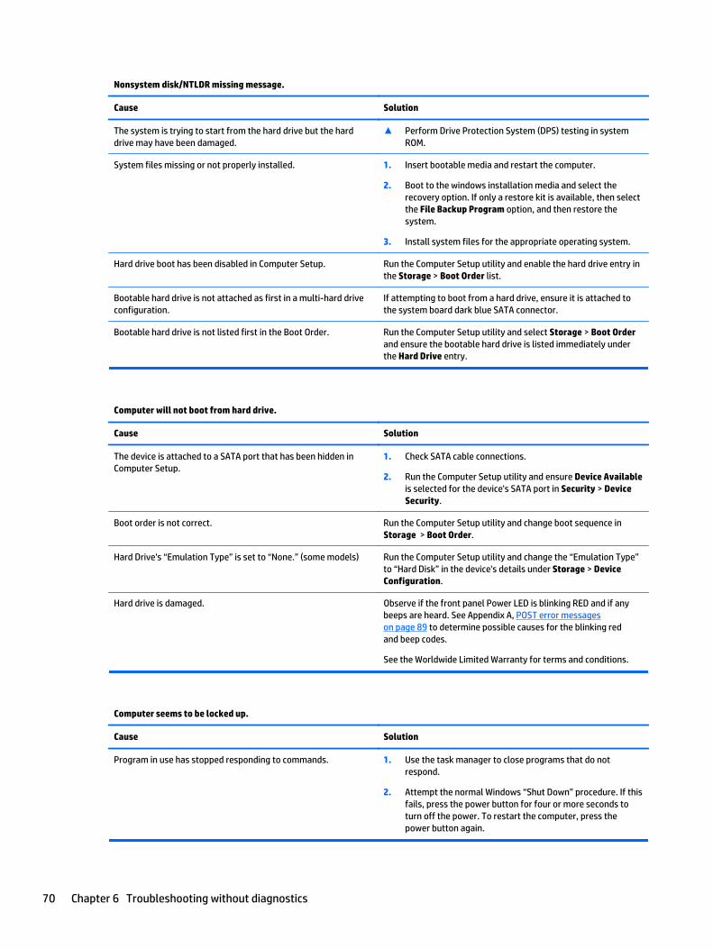
Nonsystem disk/NTLDR missing message.
Cause Solution
The system is trying to start from the hard drive but the harddrive may have been damaged.
▲ Perform Drive Protection System (DPS) testing in systemROM.
System files missing or not properly installed. 1. Insert bootable media and restart the computer.
2. Boot to the windows installation media and select therecovery option. If only a restore kit is available, then selectthe File Backup Program option, and then restore thesystem.
3. Install system files for the appropriate operating system.
Hard drive boot has been disabled in Computer Setup. Run the Computer Setup utility and enable the hard drive entry inthe Storage > Boot Order list.
Bootable hard drive is not attached as first in a multi-hard driveconfiguration.
If attempting to boot from a hard drive, ensure it is attached tothe system board dark blue SATA connector.
Bootable hard drive is not listed first in the Boot Order. Run the Computer Setup utility and select Storage > Boot Orderand ensure the bootable hard drive is listed immediately underthe Hard Drive entry.
Computer will not boot from hard drive.
Cause Solution
The device is attached to a SATA port that has been hidden inComputer Setup.
1. Check SATA cable connections.
2. Run the Computer Setup utility and ensure Device Availableis selected for the device's SATA port in Security > DeviceSecurity.
Boot order is not correct. Run the Computer Setup utility and change boot sequence inStorage > Boot Order.
Hard Drive's “Emulation Type” is set to “None.” (some models) Run the Computer Setup utility and change the “Emulation Type”to “Hard Disk” in the device's details under Storage > DeviceConfiguration.
Hard drive is damaged. Observe if the front panel Power LED is blinking RED and if anybeeps are heard. See Appendix A, POST error messageson page 89 to determine possible causes for the blinking redand beep codes.
See the Worldwide Limited Warranty for terms and conditions.
Computer seems to be locked up.
Cause Solution
Program in use has stopped responding to commands. 1. Use the task manager to close programs that do notrespond.
2. Attempt the normal Windows “Shut Down” procedure. If thisfails, press the power button for four or more seconds toturn off the power. To restart the computer, press thepower button again.
70 Chapter 6 Troubleshooting without diagnostics
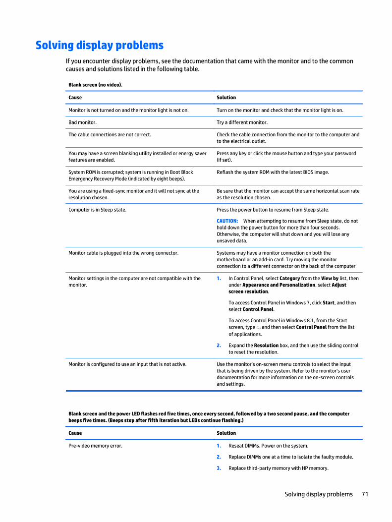
Solving display problemsIf you encounter display problems, see the documentation that came with the monitor and to the commoncauses and solutions listed in the following table.
Blank screen (no video).
Cause Solution
Monitor is not turned on and the monitor light is not on. Turn on the monitor and check that the monitor light is on.
Bad monitor. Try a different monitor.
The cable connections are not correct. Check the cable connection from the monitor to the computer andto the electrical outlet.
You may have a screen blanking utility installed or energy saverfeatures are enabled.
Press any key or click the mouse button and type your password(if set).
System ROM is corrupted; system is running in Boot BlockEmergency Recovery Mode (indicated by eight beeps).
Reflash the system ROM with the latest BIOS image.
You are using a fixed-sync monitor and it will not sync at theresolution chosen.
Be sure that the monitor can accept the same horizontal scan rateas the resolution chosen.
Computer is in Sleep state. Press the power button to resume from Sleep state.
CAUTION: When attempting to resume from Sleep state, do nothold down the power button for more than four seconds.Otherwise, the computer will shut down and you will lose anyunsaved data.
Monitor cable is plugged into the wrong connector. Systems may have a monitor connection on both themotherboard or an add-in card. Try moving the monitorconnection to a different connector on the back of the computer
Monitor settings in the computer are not compatible with themonitor.
1. In Control Panel, select Category from the View by list, thenunder Appearance and Personalization, select Adjustscreen resolution.
To access Control Panel in Windows 7, click Start, and thenselect Control Panel.
To access Control Panel in Windows 8.1, from the Startscreen, type c, and then select Control Panel from the listof applications.
2. Expand the Resolution box, and then use the sliding controlto reset the resolution.
Monitor is configured to use an input that is not active. Use the monitor's on-screen menu controls to select the inputthat is being driven by the system. Refer to the monitor's userdocumentation for more information on the on-screen controlsand settings.
Blank screen and the power LED flashes red five times, once every second, followed by a two second pause, and the computerbeeps five times. (Beeps stop after fifth iteration but LEDs continue flashing.)
Cause Solution
Pre-video memory error. 1. Reseat DIMMs. Power on the system.
2. Replace DIMMs one at a time to isolate the faulty module.
3. Replace third-party memory with HP memory.
Solving display problems 71

Blank screen and the power LED flashes red five times, once every second, followed by a two second pause, and the computerbeeps five times. (Beeps stop after fifth iteration but LEDs continue flashing.)
Cause Solution
4. Replace the system board.
Blank screen and the power LED flashes Red six times, once every second, followed by a two second pause, and the computerbeeps six times. (Beeps stop after fifth iteration but LEDs continue flashing.)
Cause Solution
Pre-video graphics error. Replace the system board.
Blank screen and the power LED flashes red seven times, once every second, followed by a two second pause, and the computerbeeps seven times. (Beeps stop after fifth iteration but LEDs continue flashing.)
Cause Solution
System board failure (ROM detected failure prior to video). Replace the system board.
Monitor does not function properly when used with energy saver features.
Cause Solution
Monitor without energy saver capabilities is being used withenergy saver features enabled.
Disable monitor energy saver feature.
Dim characters.
Cause Solution
The brightness and contrast controls are not set properly. Adjust the monitor brightness and contrast controls.
Cables are not properly connected. Check that the graphics cable is securely connected to thegraphics card (if applicable) or video connector and the monitor.
Blurry video or requested resolution cannot be set.
Cause Solution
Monitor is not capable of displaying requested resolution. Change requested resolution.
The picture is broken up, rolls, jitters, or flashes.
Cause Solution
The monitor connections may be incomplete or the monitor maybe incorrectly adjusted.
1. Be sure the monitor cable is securely connected to thecomputer.
72 Chapter 6 Troubleshooting without diagnostics

The picture is broken up, rolls, jitters, or flashes.
Cause Solution
2. In a two-monitor system or if another monitor is in closeproximity, be sure the monitors are not interfering witheach other’s electromagnetic field by moving them apart.
3. Fluorescent lights or fans may be too close to the monitor.
Monitor needs to be degaussed. Degauss the monitor. Refer to the documentation that came withthe monitor for instructions.
Image is not centered.
Cause Solution
Position may need adjustment. Press the monitor's Menu button to access the OSD menu. SelectImageControl/ Horizontal Position or Vertical Position to adjustthe horizontal or vertical position of the image.
“No Connection, Check Signal Cable” displays on screen.
Cause Solution
Monitor video cable is disconnected. Connect the video cable between the monitor and computer.
CAUTION: Ensure that the computer power is off whileconnecting the video cable.
“Out of Range” displays on screen.
Cause Solution
Video resolution and refresh rate are set higher than what themonitor supports.
Restart the computer and enter Safe Mode. Change the settingsto a supported setting then restart the computer so that the newsettings take effect.
To enter Safe Mode in Windows 7:
1. Restart the computer.
2. Press and hold the F8 key as your computer restarts, beforethe Windows logo appears. If the Windows logo appears,you must restart the computer and try again.
3. On the Advanced Boot Options screen, use the arrow keys tohighlight the safe mode option you want, and then pressEnter.
4. Log on to your computer with a user account that hasadministrator rights.
When your computer is in safe mode, Safe Mode displays inthe corners of your monitor. To exit safe mode, restart yourcomputer and let Windows start normally.
To enter Safe Mode in Windows 8.1:
1. Press the Windows logo + l to open the Settings charm.
Solving display problems 73

“Out of Range” displays on screen.
Cause Solution
2. Select Change PC Settings, select General, and then underAdvanced startup, click Restart now.
3. Select Troubleshoot, select Advanced options, selectStartup Settings, and then click Restart.
4. Use the function keys or number keys to select the safemode option you want.
When your computer is in safe mode, Safe Mode displays inthe corners of your monitor. To exit safe mode, restart yourcomputer and let Windows start normally.
High pitched noise coming from inside a flat panel monitor.
Cause Solution
Brightness and/or contrast settings are too high. Lower brightness and/or contrast settings.
Fuzzy focus; streaking, ghosting, or shadowing effects; horizontal scrolling lines; faint vertical bars; or unable to center thepicture on the screen (flat panel monitors using an analog VGA input connection only).
Cause Solution
Flat panel monitor’s internal digital conversion circuits may beunable to correctly interpret the output synchronization of thegraphics card.
1. Select the monitor’s Auto-Adjustment option in themonitor’s on-screen display menu.
2. Manually synchronize the Clock and Clock Phase on-screendisplay functions. To download a SoftPaq that will assistyou with the synchronization, go to the following Web site,select the appropriate monitor, and download eitherSP32347 or SP32202: http://www.hp.com/support
Certain typed symbols do not appear correct.
Cause Solution
The font you are using does not support that particular symbol. Use the Character Map to locate and select the appropriatesymbol. You can copy the symbol from the Character Map into adocument.
In Windows 7, click Start, select All Programs, selectAccessories, select System Tools, and then select CharacterMap.
In Windows 8.1, on the Start screen, type ch, and then selectCharacter Map from the list of applications.
74 Chapter 6 Troubleshooting without diagnostics
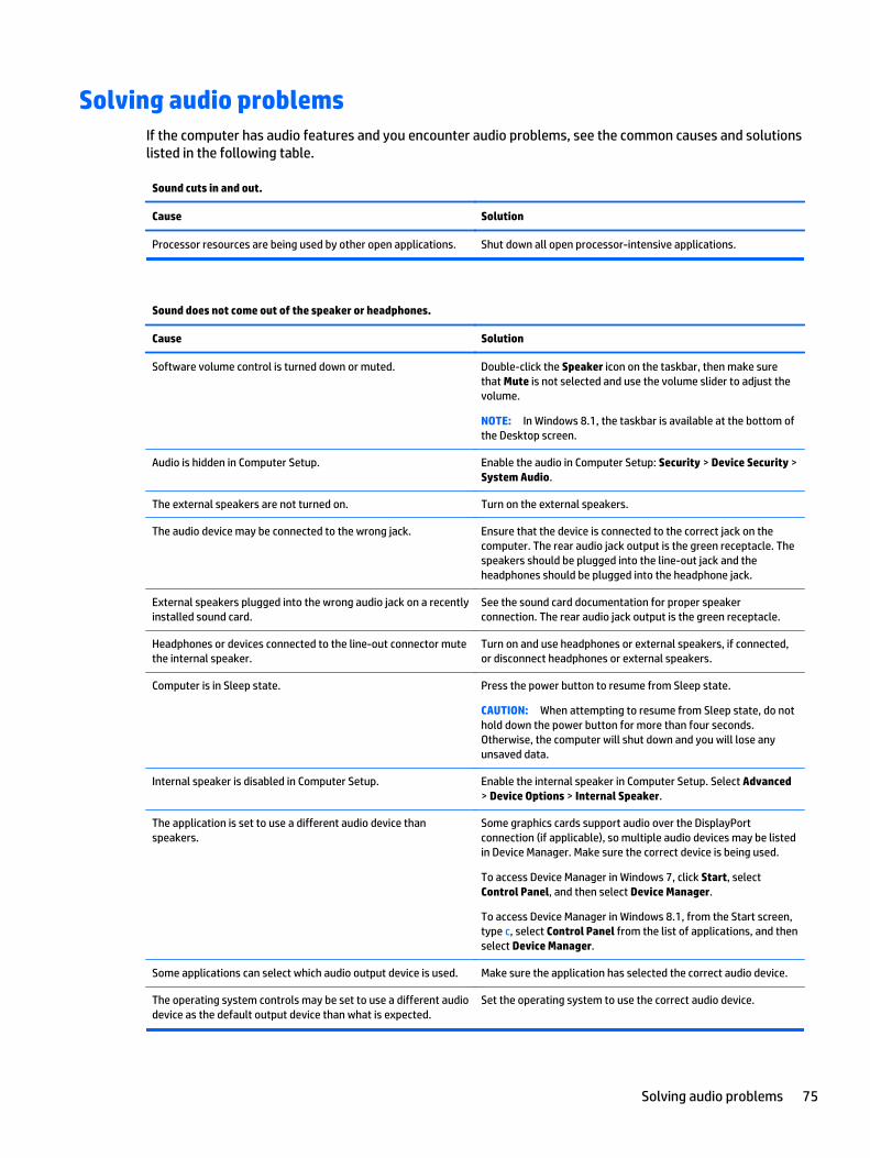
Solving audio problemsIf the computer has audio features and you encounter audio problems, see the common causes and solutionslisted in the following table.
Sound cuts in and out.
Cause Solution
Processor resources are being used by other open applications. Shut down all open processor-intensive applications.
Sound does not come out of the speaker or headphones.
Cause Solution
Software volume control is turned down or muted. Double-click the Speaker icon on the taskbar, then make surethat Mute is not selected and use the volume slider to adjust thevolume.
NOTE: In Windows 8.1, the taskbar is available at the bottom ofthe Desktop screen.
Audio is hidden in Computer Setup. Enable the audio in Computer Setup: Security > Device Security >System Audio.
The external speakers are not turned on. Turn on the external speakers.
The audio device may be connected to the wrong jack. Ensure that the device is connected to the correct jack on thecomputer. The rear audio jack output is the green receptacle. Thespeakers should be plugged into the line-out jack and theheadphones should be plugged into the headphone jack.
External speakers plugged into the wrong audio jack on a recentlyinstalled sound card.
See the sound card documentation for proper speakerconnection. The rear audio jack output is the green receptacle.
Headphones or devices connected to the line-out connector mutethe internal speaker.
Turn on and use headphones or external speakers, if connected,or disconnect headphones or external speakers.
Computer is in Sleep state. Press the power button to resume from Sleep state.
CAUTION: When attempting to resume from Sleep state, do nothold down the power button for more than four seconds.Otherwise, the computer will shut down and you will lose anyunsaved data.
Internal speaker is disabled in Computer Setup. Enable the internal speaker in Computer Setup. Select Advanced> Device Options > Internal Speaker.
The application is set to use a different audio device thanspeakers.
Some graphics cards support audio over the DisplayPortconnection (if applicable), so multiple audio devices may be listedin Device Manager. Make sure the correct device is being used.
To access Device Manager in Windows 7, click Start, selectControl Panel, and then select Device Manager.
To access Device Manager in Windows 8.1, from the Start screen,type c, select Control Panel from the list of applications, and thenselect Device Manager.
Some applications can select which audio output device is used. Make sure the application has selected the correct audio device.
The operating system controls may be set to use a different audiodevice as the default output device than what is expected.
Set the operating system to use the correct audio device.
Solving audio problems 75
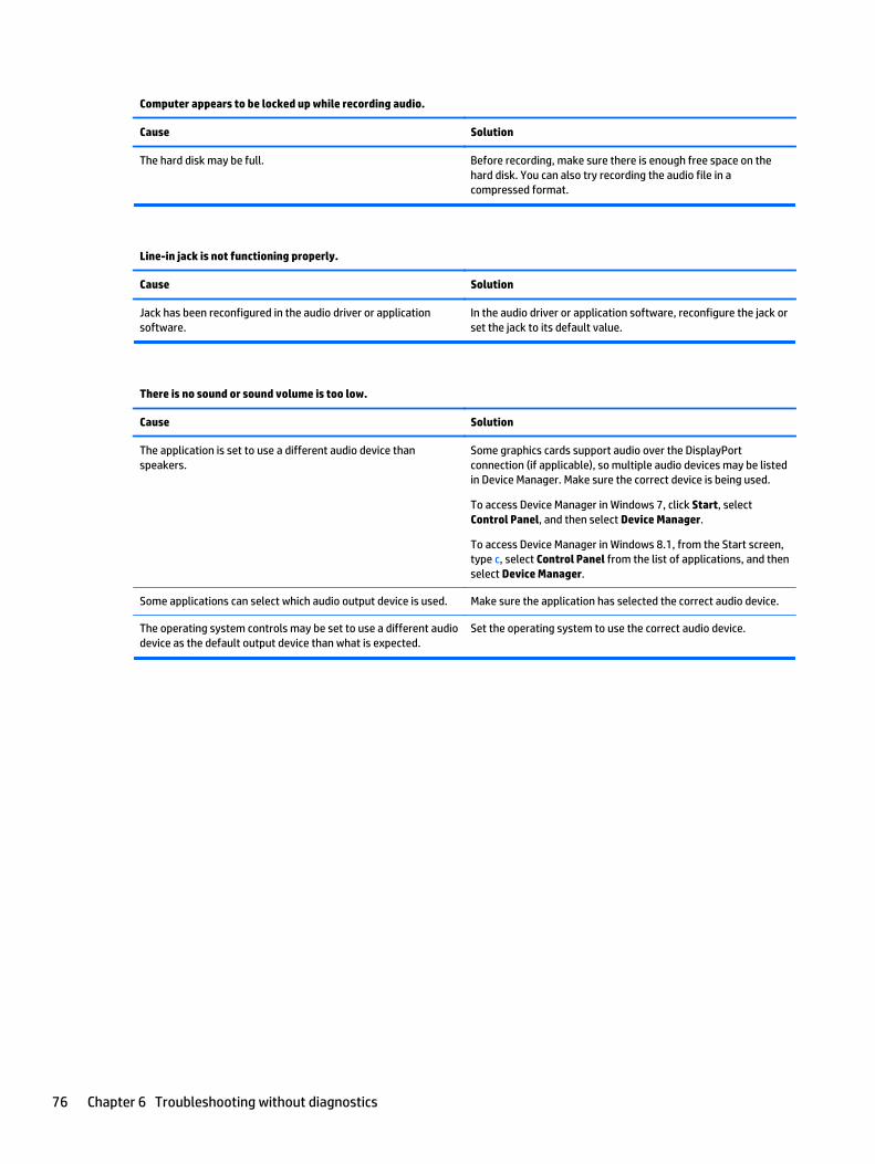
Computer appears to be locked up while recording audio.
Cause Solution
The hard disk may be full. Before recording, make sure there is enough free space on thehard disk. You can also try recording the audio file in acompressed format.
Line-in jack is not functioning properly.
Cause Solution
Jack has been reconfigured in the audio driver or applicationsoftware.
In the audio driver or application software, reconfigure the jack orset the jack to its default value.
There is no sound or sound volume is too low.
Cause Solution
The application is set to use a different audio device thanspeakers.
Some graphics cards support audio over the DisplayPortconnection (if applicable), so multiple audio devices may be listedin Device Manager. Make sure the correct device is being used.
To access Device Manager in Windows 7, click Start, selectControl Panel, and then select Device Manager.
To access Device Manager in Windows 8.1, from the Start screen,type c, select Control Panel from the list of applications, and thenselect Device Manager.
Some applications can select which audio output device is used. Make sure the application has selected the correct audio device.
The operating system controls may be set to use a different audiodevice as the default output device than what is expected.
Set the operating system to use the correct audio device.
76 Chapter 6 Troubleshooting without diagnostics
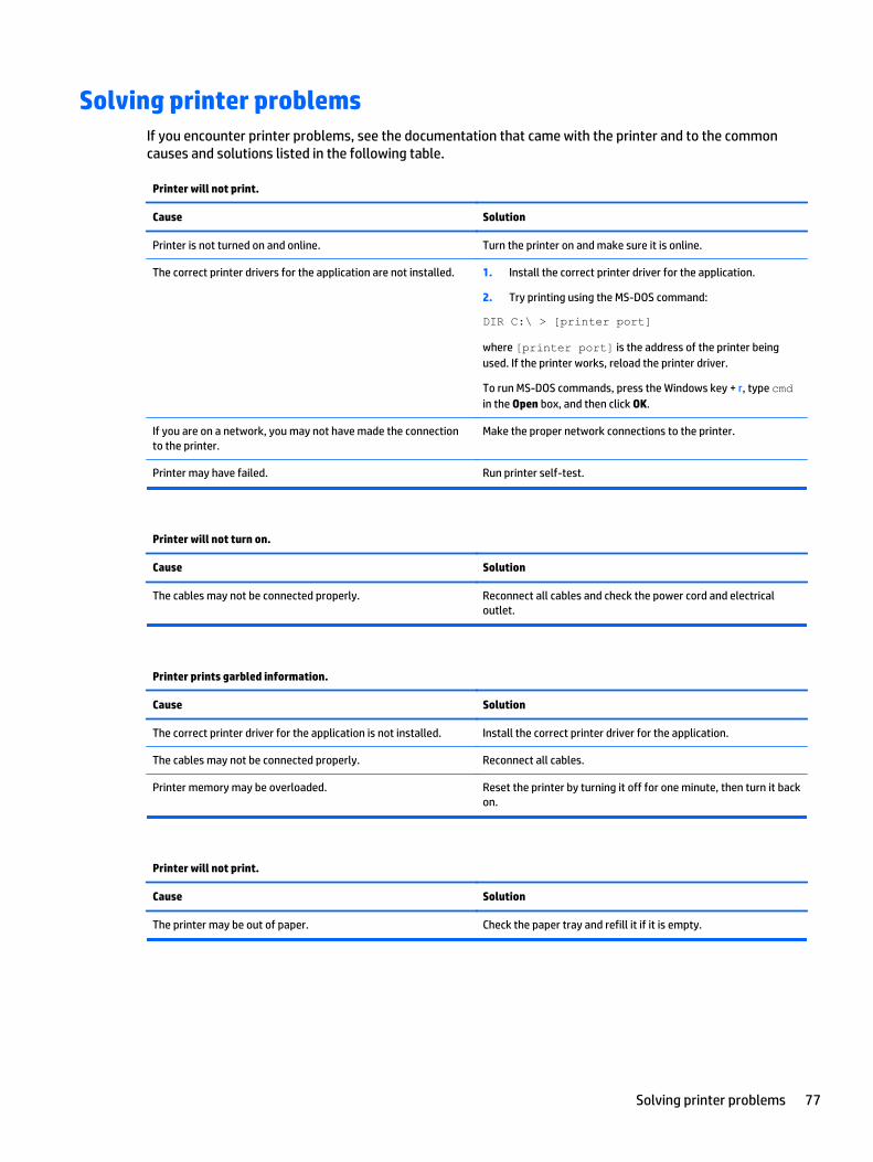
Solving printer problemsIf you encounter printer problems, see the documentation that came with the printer and to the commoncauses and solutions listed in the following table.
Printer will not print.
Cause Solution
Printer is not turned on and online. Turn the printer on and make sure it is online.
The correct printer drivers for the application are not installed. 1. Install the correct printer driver for the application.
2. Try printing using the MS-DOS command:
DIR C:\ > [printer port]
where [printer port] is the address of the printer beingused. If the printer works, reload the printer driver.
To run MS-DOS commands, press the Windows key + r, type cmdin the Open box, and then click OK.
If you are on a network, you may not have made the connectionto the printer.
Make the proper network connections to the printer.
Printer may have failed. Run printer self-test.
Printer will not turn on.
Cause Solution
The cables may not be connected properly. Reconnect all cables and check the power cord and electricaloutlet.
Printer prints garbled information.
Cause Solution
The correct printer driver for the application is not installed. Install the correct printer driver for the application.
The cables may not be connected properly. Reconnect all cables.
Printer memory may be overloaded. Reset the printer by turning it off for one minute, then turn it backon.
Printer will not print.
Cause Solution
The printer may be out of paper. Check the paper tray and refill it if it is empty.
Solving printer problems 77
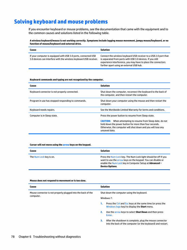
Solving keyboard and mouse problemsIf you encounter keyboard or mouse problems, see the documentation that came with the equipment and tothe common causes and solutions listed in the following table.
A wireless keyboard/mouse is not working correctly. Symptoms include lagging mouse movement, jumpy mouse/keyboard, or nofunction of mouse/keyboard and external drive.
Cause Solution
If your computer is equipped with USB 3.0 ports, connected USB3.0 devices can interfere with the wireless keyboard USB receiver.
Connect the wireless keyboard USB receiver to a USB 2.0 port thatis separated from ports with USB 3.0 devices. If you stillexperience interference, you may have to place the connectorsfarther apart using an external USB hub.
Keyboard commands and typing are not recognized by the computer.
Cause Solution
Keyboard connector is not properly connected. Shut down the computer, reconnect the keyboard to the back ofthe computer, and then restart the computer.
Program in use has stopped responding to commands. Shut down your computer using the mouse and then restart thecomputer.
Keyboard needs repairs. See the Worldwide Limited Warranty for terms and conditions.
Computer is in Sleep state. Press the power button to resume from Sleep state.
CAUTION: When attempting to resume from Sleep date, do nothold down the power button for more than four seconds.Otherwise, the computer will shut down and you will lose anyunsaved data.
Cursor will not move using the arrow keys on the keypad.
Cause Solution
The Num Lock key is on. Press the Num Lock key. The Num Lock light should be off if youwant to use the arrow keys on the keypad. You can disable orenable the Num Lock key in Computer Setup at Advanced >Device Options.
Mouse does not respond to movement or is too slow.
Cause Solution
Mouse connector is not properly plugged into the back of thecomputer.
Shut down the computer using the keyboard.
Windows 7:
1. Press the Ctrl and Esc keys at the same time (or press theWindows logo key) to display the Start menu.
2. Use the arrow keys to select Shut Down and then pressEnter.
3. After the shutdown is complete, plug the mouse connectorinto the back of the computer (or the keyboard) and restart.
78 Chapter 6 Troubleshooting without diagnostics
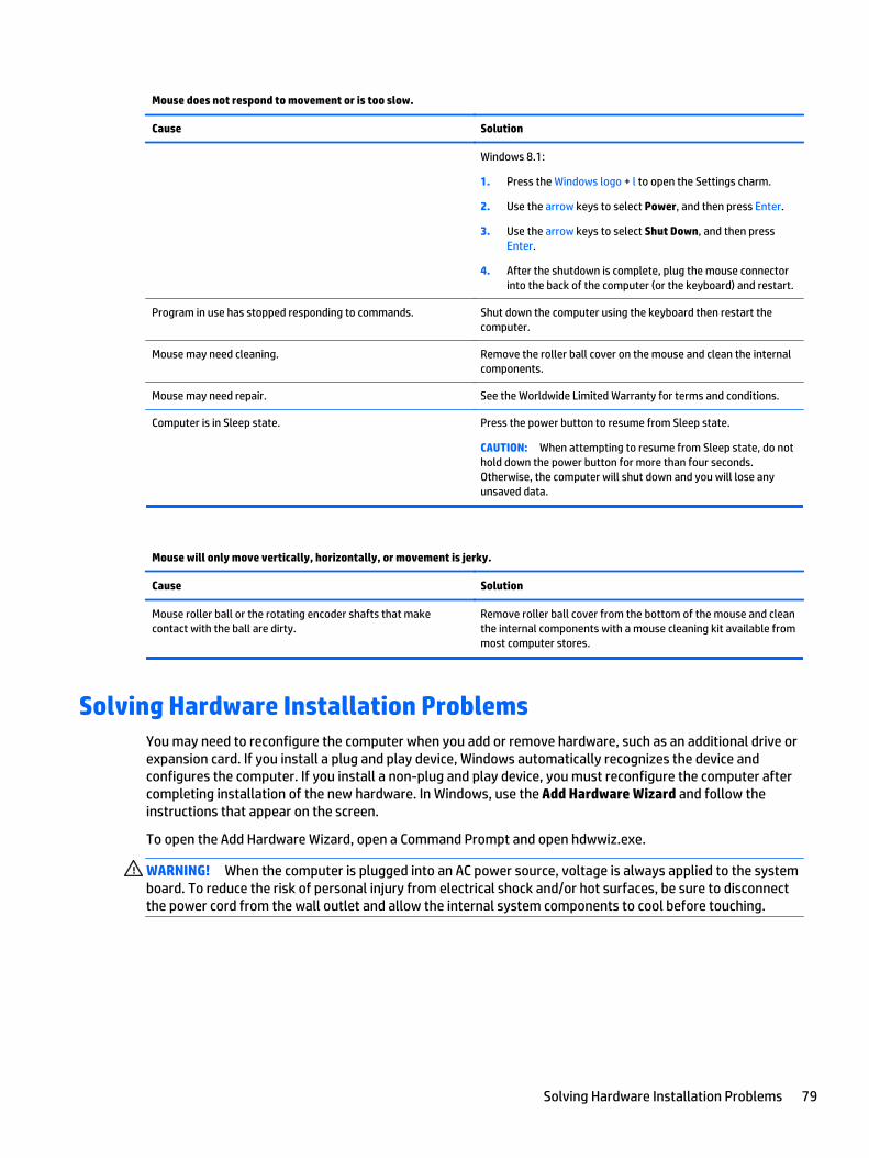
Mouse does not respond to movement or is too slow.
Cause Solution
Windows 8.1:
1. Press the Windows logo + l to open the Settings charm.
2. Use the arrow keys to select Power, and then press Enter.
3. Use the arrow keys to select Shut Down, and then pressEnter.
4. After the shutdown is complete, plug the mouse connectorinto the back of the computer (or the keyboard) and restart.
Program in use has stopped responding to commands. Shut down the computer using the keyboard then restart thecomputer.
Mouse may need cleaning. Remove the roller ball cover on the mouse and clean the internalcomponents.
Mouse may need repair. See the Worldwide Limited Warranty for terms and conditions.
Computer is in Sleep state. Press the power button to resume from Sleep state.
CAUTION: When attempting to resume from Sleep state, do nothold down the power button for more than four seconds.Otherwise, the computer will shut down and you will lose anyunsaved data.
Mouse will only move vertically, horizontally, or movement is jerky.
Cause Solution
Mouse roller ball or the rotating encoder shafts that makecontact with the ball are dirty.
Remove roller ball cover from the bottom of the mouse and cleanthe internal components with a mouse cleaning kit available frommost computer stores.
Solving Hardware Installation ProblemsYou may need to reconfigure the computer when you add or remove hardware, such as an additional drive orexpansion card. If you install a plug and play device, Windows automatically recognizes the device andconfigures the computer. If you install a non-plug and play device, you must reconfigure the computer aftercompleting installation of the new hardware. In Windows, use the Add Hardware Wizard and follow theinstructions that appear on the screen.
To open the Add Hardware Wizard, open a Command Prompt and open hdwwiz.exe.
WARNING! When the computer is plugged into an AC power source, voltage is always applied to the systemboard. To reduce the risk of personal injury from electrical shock and/or hot surfaces, be sure to disconnectthe power cord from the wall outlet and allow the internal system components to cool before touching.
Solving Hardware Installation Problems 79
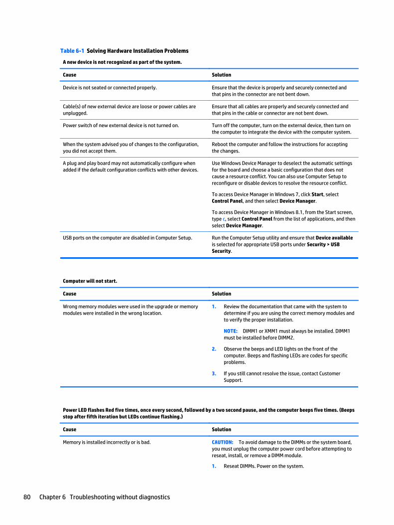
Table 6-1 Solving Hardware Installation Problems
A new device is not recognized as part of the system.
Cause Solution
Device is not seated or connected properly. Ensure that the device is properly and securely connected andthat pins in the connector are not bent down.
Cable(s) of new external device are loose or power cables areunplugged.
Ensure that all cables are properly and securely connected andthat pins in the cable or connector are not bent down.
Power switch of new external device is not turned on. Turn off the computer, turn on the external device, then turn onthe computer to integrate the device with the computer system.
When the system advised you of changes to the configuration,you did not accept them.
Reboot the computer and follow the instructions for acceptingthe changes.
A plug and play board may not automatically configure whenadded if the default configuration conflicts with other devices.
Use Windows Device Manager to deselect the automatic settingsfor the board and choose a basic configuration that does notcause a resource conflict. You can also use Computer Setup toreconfigure or disable devices to resolve the resource conflict.
To access Device Manager in Windows 7, click Start, selectControl Panel, and then select Device Manager.
To access Device Manager in Windows 8.1, from the Start screen,type c, select Control Panel from the list of applications, and thenselect Device Manager.
USB ports on the computer are disabled in Computer Setup. Run the Computer Setup utility and ensure that Device availableis selected for appropriate USB ports under Security > USBSecurity.
Computer will not start.
Cause Solution
Wrong memory modules were used in the upgrade or memorymodules were installed in the wrong location.
1. Review the documentation that came with the system todetermine if you are using the correct memory modules andto verify the proper installation.
NOTE: DIMM1 or XMM1 must always be installed. DIMM1must be installed before DIMM2.
2. Observe the beeps and LED lights on the front of thecomputer. Beeps and flashing LEDs are codes for specificproblems.
3. If you still cannot resolve the issue, contact CustomerSupport.
Power LED flashes Red five times, once every second, followed by a two second pause, and the computer beeps five times. (Beepsstop after fifth iteration but LEDs continue flashing.)
Cause Solution
Memory is installed incorrectly or is bad. CAUTION: To avoid damage to the DIMMs or the system board,you must unplug the computer power cord before attempting toreseat, install, or remove a DIMM module.
1. Reseat DIMMs. Power on the system.
80 Chapter 6 Troubleshooting without diagnostics
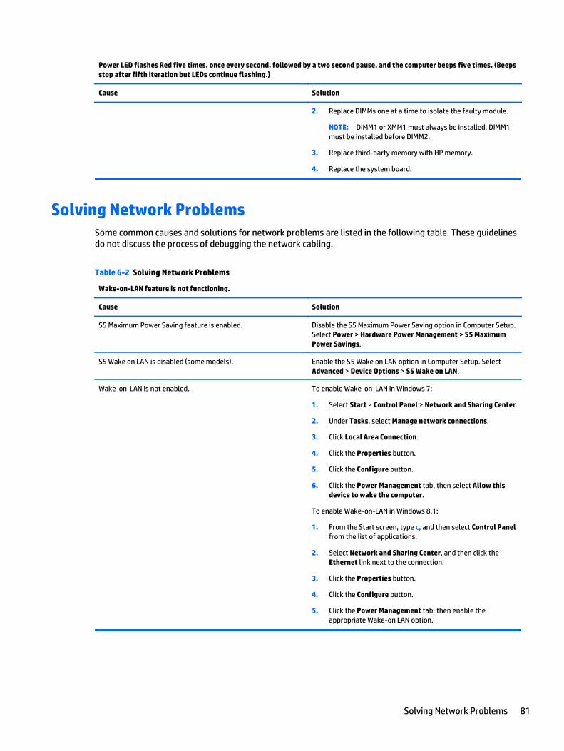
Power LED flashes Red five times, once every second, followed by a two second pause, and the computer beeps five times. (Beepsstop after fifth iteration but LEDs continue flashing.)
Cause Solution
2. Replace DIMMs one at a time to isolate the faulty module.
NOTE: DIMM1 or XMM1 must always be installed. DIMM1must be installed before DIMM2.
3. Replace third-party memory with HP memory.
4. Replace the system board.
Solving Network ProblemsSome common causes and solutions for network problems are listed in the following table. These guidelinesdo not discuss the process of debugging the network cabling.
Table 6-2 Solving Network Problems
Wake-on-LAN feature is not functioning.
Cause Solution
S5 Maximum Power Saving feature is enabled. Disable the S5 Maximum Power Saving option in Computer Setup.Select Power > Hardware Power Management > S5 MaximumPower Savings.
S5 Wake on LAN is disabled (some models). Enable the S5 Wake on LAN option in Computer Setup. SelectAdvanced > Device Options > S5 Wake on LAN.
Wake-on-LAN is not enabled. To enable Wake-on-LAN in Windows 7:
1. Select Start > Control Panel > Network and Sharing Center.
2. Under Tasks, select Manage network connections.
3. Click Local Area Connection.
4. Click the Properties button.
5. Click the Configure button.
6. Click the Power Management tab, then select Allow thisdevice to wake the computer.
To enable Wake-on-LAN in Windows 8.1:
1. From the Start screen, type c, and then select Control Panelfrom the list of applications.
2. Select Network and Sharing Center, and then click theEthernet link next to the connection.
3. Click the Properties button.
4. Click the Configure button.
5. Click the Power Management tab, then enable theappropriate Wake-on LAN option.
Solving Network Problems 81
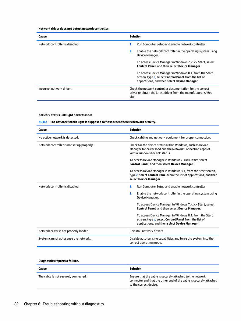
Network driver does not detect network controller.
Cause Solution
Network controller is disabled. 1. Run Computer Setup and enable network controller.
2. Enable the network controller in the operating system usingDevice Manager.
To access Device Manager in Windows 7, click Start, selectControl Panel, and then select Device Manager.
To access Device Manager in Windows 8.1, from the Startscreen, type c, select Control Panel from the list ofapplications, and then select Device Manager.
Incorrect network driver. Check the network controller documentation for the correctdriver or obtain the latest driver from the manufacturer’s Website.
Network status link light never flashes.
NOTE: The network status light is supposed to flash when there is network activity.
Cause Solution
No active network is detected. Check cabling and network equipment for proper connection.
Network controller is not set up properly. Check for the device status within Windows, such as DeviceManager for driver load and the Network Connections appletwithin Windows for link status.
To access Device Manager in Windows 7, click Start, selectControl Panel, and then select Device Manager.
To access Device Manager in Windows 8.1, from the Start screen,type c, select Control Panel from the list of applications, and thenselect Device Manager.
Network controller is disabled. 1. Run Computer Setup and enable network controller.
2. Enable the network controller in the operating system usingDevice Manager.
To access Device Manager in Windows 7, click Start, selectControl Panel, and then select Device Manager.
To access Device Manager in Windows 8.1, from the Startscreen, type c, select Control Panel from the list ofapplications, and then select Device Manager.
Network driver is not properly loaded. Reinstall network drivers.
System cannot autosense the network. Disable auto-sensing capabilities and force the system into thecorrect operating mode.
Diagnostics reports a failure.
Cause Solution
The cable is not securely connected. Ensure that the cable is securely attached to the networkconnector and that the other end of the cable is securely attachedto the correct device.
82 Chapter 6 Troubleshooting without diagnostics

Table 6-2 Solving Network Problems (continued)
Diagnostics reports a failure.
Cause Solution
The cable is attached to the incorrect connector. Ensure that the cable is attached to the correct connector.
There is a problem with the cable or a device at the other end ofthe cable.
Ensure that the cable and device at the other end are operatingcorrectly.
Network controller interrupt is shared with an expansion board. Under the Computer Setup Advanced menu, change the resourcesettings for the board.
The network controller is defective. Contact an authorized service provider.
Diagnostics passes, but the computer does not communicate with the network.
Cause Solution
Network drivers are not loaded, or driver parameters do notmatch current configuration.
Make sure the network drivers are loaded and that the driverparameters match the configuration of the network controller.
Make sure the correct network client and protocol is installed.
The network controller is not configured for this computer. Select the Network and Sharing Center icon in the Control Paneland configure the network controller.
To access Control Panel in Windows 7, click Start, and then selectControl Panel.
To access Control Panel in Windows 8.1, from the Start screen,type c, and then select Control Panel.
Network controller stopped working when an expansion board was added to the computer.
Cause Solution
Network controller interrupt is shared with an expansion board. Under the Computer Setup Advanced menu, change the resourcesettings for the board.
The network controller requires drivers. Verify that the drivers were not accidentally deleted when thedrivers for a new expansion board were installed.
Network controller stops working without apparent cause.
Cause Solution
The files containing the network drivers are corrupted. Reinstall the network drivers using the Recovery Disc Set inWindows 7 or Windows recovery tools in Windows 8.1.
If necessary, download the softpaq from the web (from adifferent computer).
The cable is not securely connected. Ensure that the cable is securely attached to the networkconnector and that the other end of the cable is securely attachedto the correct device.
The network controller is defective. Contact an authorized service provider.
Solving Network Problems 83

Cannot connect to network server when attempting Remote System Installation.
Cause Solution
The network controller is not configured properly. Verify Network Connectivity, that a DHCP Server is present, andthat the Remote System Installation Server contains the NICdrivers for your NIC.
System setup utility reports unprogrammed EEPROM.
Cause Solution
Unprogrammed EEPROM. Contact an authorized service provider.
Solving memory problemsIf you encounter memory problems, some common causes and solutions are listed in the following table.
CAUTION: Power may still be supplied to the DIMMs when the computer is turned off (depending on theManagement Engine (ME) settings). To avoid damage to the DIMMs or the system board, you must unplug thecomputer power cord before attempting to reseat, install, or remove a memory module.
For those systems that support ECC memory, HP does not support mixing ECC and non-ECC memory.Otherwise, the computer will not boot the operating system.
NOTE: The memory count will be affected by configurations with the Management Engine (ME) enabled.The ME uses 8MB of system memory in single channel mode or 16MB of memory in dual-channel mode todownload, decompress, and execute the ME firmware for Out-of-Band (OOB), third-party data storage, andother management functions.
System will not boot or does not function properly after installing additional memory modules.
Cause Solution
A memory module is not installed in the DIMM1 or XMM1 socket. Ensure that a memory module is installed in the DIMM1 or XMM1socket on the system board. This socket must be populated witha memory module.
Memory module is not the correct type or speed grade for thesystem or the new memory module is not seated properly.
Replace module with the correct industry-standard device for thecomputer. On some models, ECC and non-ECC memory modulescannot be mixed.
Out of memory error.
Cause Solution
You have run out of memory to run the application. Check the application documentation to determine the memoryrequirements.
84 Chapter 6 Troubleshooting without diagnostics

Memory count during POST is wrong.
Cause Solution
The memory modules may not be installed correctly. Check that the memory modules have been installed correctlyand that proper modules are used.
Integrated graphics may use system memory. No action required.
Insufficient memory error during operation.
Cause Solution
Too many Terminate and Stay Resident programs (TSRs) areinstalled.
Delete any TSRs that you do not need.
You have run out of memory for the application. Check the memory requirements for the application or add morememory to the computer.
Power LED flashes Red five times, once every second, followed by a two second pause, and the computer beeps five times. (Beepsstop after fifth iteration but LEDs continue flashing.)
Cause Solution
Memory is installed incorrectly or is bad. 1. Reseat DIMMs. Power on the system.
2. Replace DIMMs one at a time to isolate the faulty module.
3. Replace third-party memory with HP memory.
4. Replace the system board.
Solving USB flash drive problemsIf you encounter USB flash drive problems, common causes and solutions are listed in the following table.
USB flash drive is not seen as a drive letter in Windows.
Cause Solution
The drive letter after the last physical drive is not available. Change the default drive letter for the flash drive in Windows.
USB flash drive not found (identified).
Cause Solution
The device is attached to a USB port that has been hidden inComputer Setup.
Run the Computer Setup utility and enable USB ports inSecurity > USB Security.
The device was not properly seated before power-up. Ensure the device is fully inserted into the USB port beforeapplying power to the system
Solving USB flash drive problems 85

System will not boot from USB flash drive.
Cause Solution
Boot order is not correct. Run the Computer Setup utility and change boot sequence inStorage > Boot Order.
Removable Media Boot is disabled in the Computer Setup utility. Run the Computer Setup utility and enable booting to removablemedia in Storage > Storage Options. Ensure USB is enabled inStorage > Boot Order.
The computer boots to DOS after making a bootable flash drive.
Cause Solution
Flash drive is bootable. Install the flash drive only after the operating system boots.
Flash drive is defective. Try a different flash drive.
Solving Internet access problemsIf you encounter Internet access problems, consult your Internet Service Provider (ISP) or refer to thecommon causes and solutions listed in the following table.
Unable to connect to the Internet.
Cause Solution
Internet Service Provider (ISP) account is not set up properly. Verify Internet settings or contact your ISP for assistance.
Web browser is not set up properly. Verify that the Web browser is installed and set up to work withyour ISP.
Cable/DSL modem is not plugged in. Plug in cable/DSL modem. You should see a “power” LED light onthe front of the cable/DSL modem.
Cable/DSL service is not available or has been interrupted due tobad weather.
Try connecting to the Internet at a later time or contact your ISP.(If the cable/DSL service is connected, the “cable” LED light on thefront of the cable/DSL modem will be on.)
The CAT5 UTP cable is disconnected. Connect the CAT5 UTP cable between the cable modem and thecomputers’s RJ-45 connector. (If the connection is good, the “PC”LED light on the front of the cable/DSL modem will be on.)
IP address is not configured properly. Contact your ISP for the correct IP address.
Cookies are corrupted. (A “cookie” is a small piece of informationthat a Web server can store temporarily with the Web browser.This is useful for having the browser remember some specificinformation that the Web server can later retrieve.)
Windows 7:
1. Select Start > Control Panel.
2. Click Internet Options.
3. In the Browsing history section on the General tab, click theDelete button.
4. Select the Cookies check box and click the Delete button.
Windows 8.1:
1. From the Start screen, type c, and then select Control Panelfrom the list of applications.
86 Chapter 6 Troubleshooting without diagnostics

Unable to connect to the Internet.
Cause Solution
2. Click Internet Options.
3. In the Browsing history section on the General tab, click theDelete button.
4. Select the Cookies check box and click the Delete button.
Cannot automatically launch Internet programs.
Cause Solution
You must log on to your ISP before some programs will start. Log on to your ISP and launch the desired program.
Solving software problemsMost software problems occur as a result of the following:
● The application was not installed or configured correctly.
● There is insufficient memory available to run the application.
● There is a conflict between applications.
● Be sure that all the needed device drivers have been installed.
● If you have installed an operating system other than the factory-installed operating system, check to besure it is supported on the system.
If you encounter software problems, see the applicable solutions listed in the following table.
Computer will not continue and the HP logo does not display.
Cause Solution
ROM issue - POST error has occurred. Observe the beeps and LED lights on the front of the computer.See Appendix A, POST error messages on page 89 to determinepossible causes.
See the Worldwide Limited Warranty for terms and conditions.
Computer will not continue after HP logo screen displays.
Cause Solution
System files may be damaged. In Windows 7, use recovery media to scan hard drive for errors, oruse Windows Startup Repair to fix problems that might preventWindows from starting correctly. Windows Startup Repair is oneof the recovery tools in the System Recovery Options menu. Youcan also create a system repair disc that contains the SystemRecovery Options menu. If the problem is severe enough thatStartup Repair doesn't start on its own and you can't access theSystem Recovery Options menu on your computer's hard disk,you can get to the menu and start Startup Repair by using the
Solving software problems 87
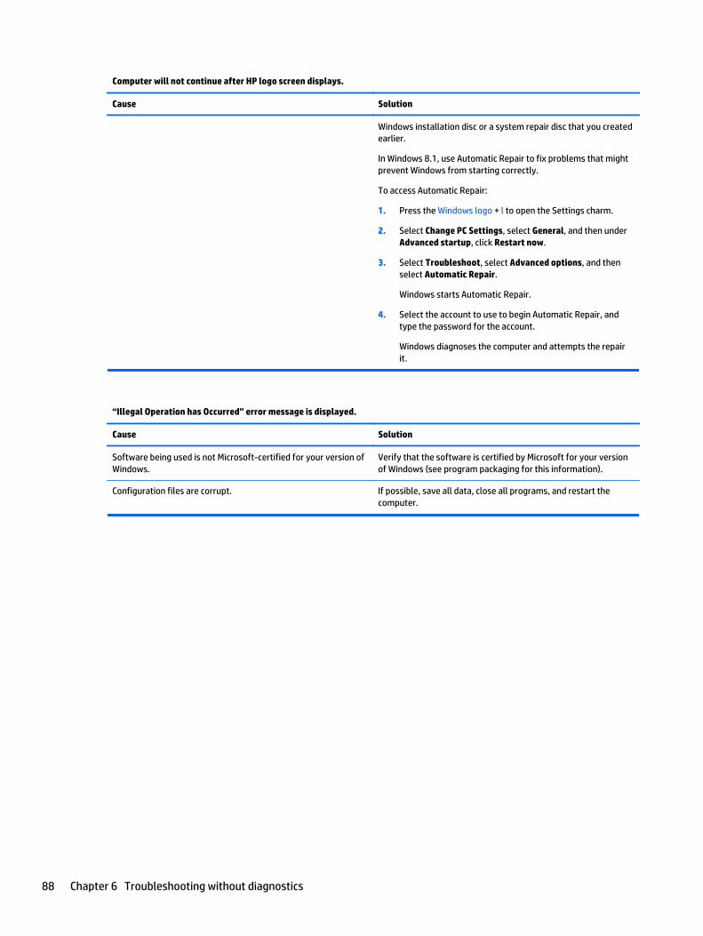
Computer will not continue after HP logo screen displays.
Cause Solution
Windows installation disc or a system repair disc that you createdearlier.
In Windows 8.1, use Automatic Repair to fix problems that mightprevent Windows from starting correctly.
To access Automatic Repair:
1. Press the Windows logo + l to open the Settings charm.
2. Select Change PC Settings, select General, and then underAdvanced startup, click Restart now.
3. Select Troubleshoot, select Advanced options, and thenselect Automatic Repair.
Windows starts Automatic Repair.
4. Select the account to use to begin Automatic Repair, andtype the password for the account.
Windows diagnoses the computer and attempts the repairit.
“Illegal Operation has Occurred” error message is displayed.
Cause Solution
Software being used is not Microsoft-certified for your version ofWindows.
Verify that the software is certified by Microsoft for your versionof Windows (see program packaging for this information).
Configuration files are corrupt. If possible, save all data, close all programs, and restart thecomputer.
88 Chapter 6 Troubleshooting without diagnostics

7 POST error messages
This appendix lists the error codes, error messages, and the various indicator light and audible sequencesthat you may encounter during Power-On Self-Test (POST) or computer restart, the probable source of theproblem, and steps you can take to resolve the error condition.
POST Message Disabled suppresses most system messages during POST, such as memory count and non-error text messages. If a POST error occurs, the screen will display the error message. To manually switch tothe POST Messages Enabled mode during POST, press any key (except F10, F11, or F12). The default mode isPOST Message Disabled.
The speed at which the computer loads the operating system and the extent to which it is tested aredetermined by the POST mode selection.
Quick Boot is a fast startup process that does not run all of the system level tests, such as the memory test.Full Boot runs all of the ROM-based system tests and takes longer to complete.
Full Boot may also be enabled to run every 1 to 30 days on a regularly scheduled basis. To establish theschedule, reconfigure the computer to the Full Boot Every x Days mode, using Computer Setup.
NOTE: For more information on Computer Setup, see Computer Setup (F10) Utility on page 55.
POST numeric codes and text messagesThis section covers those POST errors that have numeric codes associated with them. The section alsoincludes some text messages that may be encountered during POST.
NOTE: The computer will beep once after a POST text message is displayed on the screen.
Control panel message Description Recommended action
101-Option ROM Checksum Error System ROM or expansion board option ROMchecksum.
1. Verify the correct ROM.
2. Flash the ROM if needed.
3. If an expansion board was recently added,remove it to see if the problem remains.
4. Clear CMOS. (See Appendix B, Passwordsecurity and resetting CMOSon page 95.)
5. If the message disappears, there may be aproblem with the expansion card.
6. Replace the system board.
103-System Board Failure DMA or timers. 1. Clear CMOS. (See Appendix B, Passwordsecurity and resetting CMOSon page 95.)
2. Replace the system board.
162-System Options Not Set Configuration incorrect.
RTC (real-time clock) battery may need tobe replaced.
Run Computer Setup and check theconfiguration in Advanced > Onboard Devices.
Reset the date and time under Control Panel. Ifthe problem persists, replace the RTC battery.
POST numeric codes and text messages 89

Control panel message Description Recommended action
See the Removal and Replacement section forinstructions on installing a new battery, orcontact an authorized dealer or reseller for RTCbattery replacement.
163-Time & Date Not Set Invalid time or date in configuration memory.
RTC (real-time clock) battery may need tobe replaced.
Reset the date and time under Control Panel(Computer Setup can also be used). If theproblem persists, replace the RTC battery. Seethe Removal and Replacement section forinstructions on installing a new battery, orcontact an authorized dealer or reseller for RTCbattery replacement.
163-Time & Date Not Set CMOS jumper may not be properly installed. Check for proper placement of the CMOSjumper if applicable.
164-MemorySize Error Memory amount has changed since the lastboot (memory added or removed).
Press the F1 key to save the memory changes.
164-MemorySize Error Memory configuration incorrect. 1. Run Computer Setup or Windows utilities.
2. Make sure the memory module(s) areinstalled properly.
3. If third-party memory has been added,test using HP-only memory.
4. Verify proper memory module type.
201-Memory Error RAM failure. 1. Ensure memory modules are correctlyinstalled.
2. Verify proper memory module type.
3. Remove and replace the identified faultymemory module(s).
4. If the error persists after replacingmemory modules, replace the systemboard.
213-Incompatible Memory Module in MemorySocket(s) X, X, ...
A memory module in memory socket identifiedin the error message is missing critical SPDinformation, or is incompatible with thechipset.
1. Verify proper memory module type.
2. Try another memory socket.
3. Replace DIMM with a module conformingto the SPD standard.
214-DIMM Configuration Warning Populated DIMM Configuration is not optimized. Rearrange the DIMMs so that each channel hasthe same amount of memory.
219-ECC Memory Module Detected ECCModules not supported on this Platform
Recently added memory module(s) support ECCmemory error correction.
1. If additional memory was recently added,remove it to see if the problem remains.
2. Check product documentation formemory support information.
301-Keyboard Error Keyboard failure. 1. Reconnect keyboard with computerturned off.
2. Check connector for bent or missing pins.
3. Ensure that none of the keys aredepressed.
4. Replace keyboard.
90 Chapter 7 POST error messages

Control panel message Description Recommended action
303-Keyboard Controller Error I/O board keyboard controller. 1. Reconnect keyboard with computerturned off.
2. Replace the system board.
304-Keyboard or System Unit Error Keyboard failure. 1. Reconnect the keyboard with computerturned off.
2. Ensure that none of the keys aredepressed.
3. Replace the keyboard.
4. Replace the system board.
501-Display Adapter Failure Graphics display controller. 1. Clear CMOS. (See Appendix B, Passwordsecurity and resetting CMOSon page 95.)
2. Verify monitor is attached and turned on.
510-Flash Screen Image Corrupted Flash Screen image has errors. Reflash the system ROM with the latest BIOSimage.
512-Chassis, Rear Chassis, or Front Chassis Fannot Detected
Fan is not connected or may havemalfunctioned.
1. Reseat fan.
2. Reseat fan cable.
3. Replace fan.
514-CPU or Chassis Fan not Detected Fan is not connected or may havemalfunctioned.
1. Reseat fan.
2. Reseat fan cable.
3. Replace fan.
660-Display cache is detected unreliable Integrated graphics controller display cache isnot working properly and will be disabled.
Replace system board if minimal graphicsdegrading is an issue.
1720-SMART Hard Drive Detects ImminentFailure
Hard drive is about to fail. (Some hard driveshave a hard drive firmware patch that will fix anerroneous error message.)
1. Determine if hard drive is giving correcterror message. Run the Drive ProtectionSystem test under using F2 Diagnosticswhen booting the computer.
2. Apply hard drive firmware patchif applicable. (Available athttp://www.hp.com/support.)
3. Back up contents and replace hard drive.
2212-USB Key Provisioning failure writing todevice
USB device used for USB key provisioning willnot allow BIOS to update provision fileproperly.
1. Try a different USB key device forprovisioning.
2. If the error persists, update to the latestBIOS version and ME firmware version.
3. If the error still persists, replace thesystem board.
2217-ME Firmware Version request failure ME firmware is not properly responding to BIOSquery for version information.
1. Reboot the computer.
2. If the error persists, update to the latestBIOS version and ME firmware version.
3. If the error still persists, replace thesystem board.
2218-ME Firmware Version should be updated ME firmware must be updated to match currentfunctionality contained in the system BIOS.
1. Update to the latest ME firmware version.
POST numeric codes and text messages 91

Control panel message Description Recommended action
2. If the error persists and system BIOS hasbeen recently updated, restore previoussystem BIOS version.
3. If the error still persists, replace thesystem board.
2219-USB Key Provisioning file has invalidheader identifier
Provisioning file contained on the USB key hasbeen corrupted or is not a valid version for thecurrent ME firmware.
1. Recreate the provisioning file using thirdparty management console software.
2. If the error persists and system BIOS hasbeen recently updated, restore previoussystem BIOS version. Otherwise, updatethe ME firmware version.
3. If the error still persists, replace thesystem board.
2220-USB Key Provisioning file has mismatchversion
Provisioning file contained on the USB key isnot a valid version for the current ME firmware.
1. Reboot the computer.
2. If the error persists and system BIOS hasbeen recently updated, restore previoussystem BIOS version. Otherwise, updatethe ME firmware version.
3. If the error still persists, replace thesystem board.
Invalid Electronic Serial Number Electronic serial number is missing. Enter the correct serial number in ComputerSetup.
Network Server Mode Active and No KeyboardAttached
Keyboard failure while Network Server Modeenabled.
1. Reconnect keyboard with computerturned off.
2. Check connector for bent or missing pins.
3. Ensure that none of the keys aredepressed.
4. Replace keyboard.
Parity Check 2 Parity RAM failure. Run Computer Setup and Diagnostic utilities.
92 Chapter 7 POST error messages
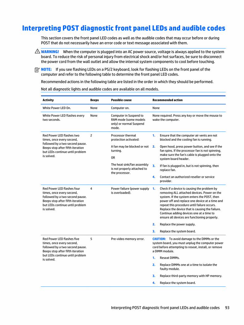
Interpreting POST diagnostic front panel LEDs and audible codesThis section covers the front panel LED codes as well as the audible codes that may occur before or duringPOST that do not necessarily have an error code or text message associated with them.
WARNING! When the computer is plugged into an AC power source, voltage is always applied to the systemboard. To reduce the risk of personal injury from electrical shock and/or hot surfaces, be sure to disconnectthe power cord from the wall outlet and allow the internal system components to cool before touching.
NOTE: If you see flashing LEDs on a PS/2 keyboard, look for flashing LEDs on the front panel of thecomputer and refer to the following table to determine the front panel LED codes.
Recommended actions in the following table are listed in the order in which they should be performed.
Not all diagnostic lights and audible codes are available on all models.
Activity Beeps Possible cause Recommended action
White Power LED On. None Computer on. None
White Power LED flashes everytwo seconds.
None Computer in Suspend toRAM mode (some modelsonly) or normal Suspendmode.
None required. Press any key or move the mouse towake the computer.
Red Power LED flashes twotimes, once every second,followed by a two second pause.Beeps stop after fifth iterationbut LEDs continue until problemis solved.
2 Processor thermalprotection activated:
A fan may be blocked or notturning.
OR
The heat sink/fan assemblyis not properly attached tothe processor.
1. Ensure that the computer air vents are notblocked and the cooling fan is running.
2. Open hood, press power button, and see if thefan spins. If the processor fan is not spinning,make sure the fan's cable is plugged onto thesystem board header.
3. If fan is plugged in, but is not spinning, thenreplace fan.
4. Contact an authorized reseller or serviceprovider.
Red Power LED flashes fourtimes, once every second,followed by a two second pause.Beeps stop after fifth iterationbut LEDs continue until problemis solved.
4 Power failure (power supplyis overloaded).
1. Check if a device is causing the problem byremoving ALL attached devices. Power on thesystem. If the system enters the POST, thenpower off and replace one device at a time andrepeat this procedure until failure occurs.Replace the device that is causing the failure.Continue adding devices one at a time toensure all devices are functioning properly.
2. Replace the power supply.
3. Replace the system board.
Red Power LED flashes fivetimes, once every second,followed by a two second pause.Beeps stop after fifth iterationbut LEDs continue until problemis solved.
5 Pre-video memory error. CAUTION: To avoid damage to the DIMMs or thesystem board, you must unplug the computer powercord before attempting to reseat, install, or removea DIMM module.
1. Reseat DIMMs.
2. Replace DIMMs one at a time to isolate thefaulty module.
3. Replace third-party memory with HP memory.
4. Replace the system board.
Interpreting POST diagnostic front panel LEDs and audible codes 93
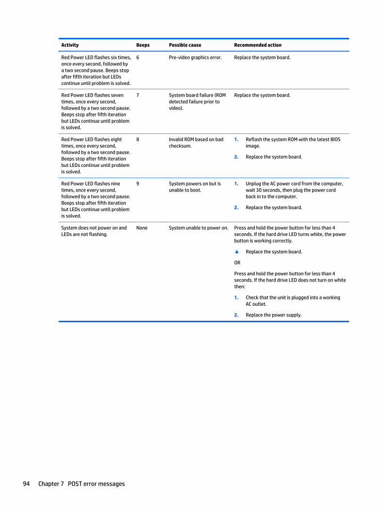
Activity Beeps Possible cause Recommended action
Red Power LED flashes six times,once every second, followed bya two second pause. Beeps stopafter fifth iteration but LEDscontinue until problem is solved.
6 Pre-video graphics error. Replace the system board.
Red Power LED flashes seventimes, once every second,followed by a two second pause.Beeps stop after fifth iterationbut LEDs continue until problemis solved.
7 System board failure (ROMdetected failure prior tovideo).
Replace the system board.
Red Power LED flashes eighttimes, once every second,followed by a two second pause.Beeps stop after fifth iterationbut LEDs continue until problemis solved.
8 Invalid ROM based on badchecksum.
1. Reflash the system ROM with the latest BIOSimage.
2. Replace the system board.
Red Power LED flashes ninetimes, once every second,followed by a two second pause.Beeps stop after fifth iterationbut LEDs continue until problemis solved.
9 System powers on but isunable to boot.
1. Unplug the AC power cord from the computer,wait 30 seconds, then plug the power cordback in to the computer.
2. Replace the system board.
System does not power on andLEDs are not flashing.
None System unable to power on. Press and hold the power button for less than 4seconds. If the hard drive LED turns white, the powerbutton is working correctly.
▲ Replace the system board.
OR
Press and hold the power button for less than 4seconds. If the hard drive LED does not turn on whitethen:
1. Check that the unit is plugged into a workingAC outlet.
2. Replace the power supply.
94 Chapter 7 POST error messages

8 Password security and resetting CMOS
This computer supports security password features, which can be established through the Computer SetupUtilities menu.
This computer supports two security password features that are established through the Computer SetupUtilities menu: setup password and power-on password. When you establish only a setup password, any usercan access all the information on the computer except Computer Setup. When you establish only a power-onpassword, the power-on password is required to access Computer Setup and any other information on thecomputer. When you establish both passwords, only the setup password will give you access to ComputerSetup.
When both passwords are set, the setup password can also be used in place of the power-on password as anoverride to log in to the computer. This is a useful feature for a network administrator.
If you forget the password for the computer, you can clear that password so you can gain access to theinformation on the computer by resetting the password jumper.
CAUTION: Pushing the CMOS button will reset CMOS values to factory defaults. It is important to back upthe computer CMOS settings before resetting them in case they are needed later. Back up is easily donethrough Computer Setup. See Computer Setup (F10) Utility on page 55 for information on backing up theCMOS settings.
Resetting the password jumperCAUTION: If you enable the stringent security feature in Computer Setup and you forget the setuppassword or the power-on password, the computer is inaccessible and can no longer be used.
Enabling the stringent password disables the ability to reset the password by moving the jumper on thesystem board.
If you lose or forget the password, the system board must be replaced. This scenario is not covered underwarranty.
To prevent the computer from becoming permanently unusable, record your configured setup password orpower-on password in a safe place away from your computer. Without these passwords, the computercannot be unlocked.
To disable the power-on or setup password features, or to clear the power-on or setup passwords, completethe following steps:
Resetting the password jumper 95
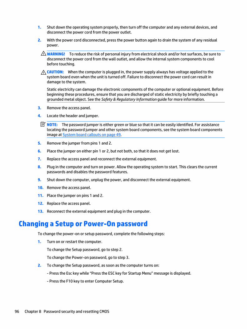
1. Shut down the operating system properly, then turn off the computer and any external devices, anddisconnect the power cord from the power outlet.
2. With the power cord disconnected, press the power button again to drain the system of any residualpower.
WARNING! To reduce the risk of personal injury from electrical shock and/or hot surfaces, be sure todisconnect the power cord from the wall outlet, and allow the internal system components to coolbefore touching.
CAUTION: When the computer is plugged in, the power supply always has voltage applied to thesystem board even when the unit is turned off. Failure to disconnect the power cord can result indamage to the system.
Static electricity can damage the electronic components of the computer or optional equipment. Beforebeginning these procedures, ensure that you are discharged of static electricity by briefly touching agrounded metal object. See the Safety & Regulatory Information guide for more information.
3. Remove the access panel.
4. Locate the header and jumper.
NOTE: The password jumper is either green or blue so that it can be easily identified. For assistancelocating the password jumper and other system board components, see the system board componentsimage at System board callouts on page 49.
5. Remove the jumper from pins 1 and 2.
6. Place the jumper on either pin 1 or 2, but not both, so that it does not get lost.
7. Replace the access panel and reconnect the external equipment.
8. Plug in the computer and turn on power. Allow the operating system to start. This clears the currentpasswords and disables the password features.
9. Shut down the computer, unplug the power, and disconnect the external equipment.
10. Remove the access panel.
11. Place the jumper on pins 1 and 2.
12. Replace the access panel.
13. Reconnect the external equipment and plug in the computer.
Changing a Setup or Power-On passwordTo change the power-on or setup password, complete the following steps:
1. Turn on or restart the computer.
To change the Setup password, go to step 2.
To change the Power-on password, go to step 3.
2. To change the Setup password, as soon as the computer turns on:
- Press the Esc key while “Press the ESC key for Startup Menu” message is displayed.
- Press the F10 key to enter Computer Setup.
96 Chapter 8 Password security and resetting CMOS

3. When the key icon appears, type your current password, a slash (/) or alternate delimiter character,your new password, another slash (/) or alternate delimiter character, and your new password again asshown:
current password/new password/new password
NOTE: Type the new password carefully since the characters do not appear on the screen.
4. Press Enter.
The new password will take effect the next time the computer is restarted.
Deleting a Setup or Power-On passwordTo delete the power-on or setup password, complete the following steps:
1. Turn on or restart the computer.
To delete the Setup password, go to step 2.
To delete the Power-on password, go to step 3.
2. To delete the Setup password, as soon as the computer turns on:
- Press the Esc key while “Press the ESC key for Startup Menu” message is displayed.
- Press the F10 key to enter Computer Setup.
3. When the key icon appears, type your current password, a slash (/) or alternate delimiter character,your new password, another slash (/) or alternate delimiter character, and your new password again asshown:
current password/
4. Press Enter.
Clearing and resetting the CMOSThe computer’s configuration memory (CMOS) stores information about the computer’s configuration.
The CMOS button resets CMOS but does not clear the power-on and setup passwords.
1. Turn off the computer and any external devices, and disconnect the power cord from the power outlet.
2. Disconnect the keyboard, monitor, and any other external equipment connected to the computer.
WARNING! To reduce the risk of personal injury from electrical shock and/or hot surfaces, be sure todisconnect the power cord from the wall outlet, and allow the internal system components to coolbefore touching.
CAUTION: When the computer is plugged in, the power supply always has voltage applied to thesystem board even when the unit is turned off. Failure to disconnect the power cord can result indamage to the system.
Static electricity can damage the electronic components of the computer or optional equipment. Beforebeginning these procedures, ensure that you are discharged of static electricity by briefly touching agrounded metal object. See the Safety & Regulatory Information guide for more information.
3. Remove the access panel.
Deleting a Setup or Power-On password 97

CAUTION: Pushing the CMOS button will reset CMOS values to factory defaults. It is important to backup the computer CMOS settings before resetting them in case they are needed later. Back up is easilydone through Computer Setup. See Computer Setup (F10) Utility on page 55 for information on backingup the CMOS settings.
4. Locate, press, and hold the CMOS button in for five seconds.
NOTE: Make sure you have disconnected the AC power cord from the wall outlet. The CMOS button willnot clear CMOS if the power cord is connected.
NOTE: For assistance locating the CMOS button and other system board components, see the systemboard components image at System board callouts on page 49.
5. Replace the access panel.
6. Reconnect the external devices.
7. Plug in the computer and turn on power.
NOTE: You will receive POST error messages after clearing CMOS and rebooting advising you thatconfiguration changes have occurred. Use Computer Setup to reset any special system setups alongwith the date and time.
For instructions on Computer Setup, see Computer Setup (F10) Utility on page 55.
98 Chapter 8 Password security and resetting CMOS
9 HP PC Hardware Diagnostics
To help troubleshoot and diagnose failures, use the UEFI-based hardware diagnostic solution that HPincludes on all products. This tool can even be used if the computer will not boot to the operating system.
Why run HP PC Hardware DiagnosticsThe HP PC Hardware Diagnostic tools simplify the process of diagnosing hardware issues and expedite thesupport process when issues are found. The tools save time by pinpointing the component that needs to bereplaced.
● Isolate true hardware failures: The diagnostics run outside of the operating system so they effectivelyisolate hardware failures from issues that may be caused by the operating system or other softwarecomponents.
● Failure ID: When a failure is detected that requires hardware replacement, a 24-digit Failure ID isgenerated. This ID can then be provided to the call agent, who will either schedule support or providereplacement parts.
How to access and run HP PC Hardware DiagnosticsYou can run the diagnostics from one of three places, depending on your preference and the health of thecomputer.
1. Turn on the computer and press Esc repeatedly until the BIOS Boot Menu appears.
2. Press F2 or select Diagnostics (F2).
Pressing F2 signals the system to search for the diagnostics in the following locations:
a. A connected USB drive (to download the diagnostics tools to a USB drive, see the instructions inDownloading HP PC Hardware Diagnostics (UEFI) to a USB device on page 99)
b. The hard disk drive
c. A core set of diagnostics in the BIOS (for memory and hard disk drive) that are accessible only ifthe USB or hard disk drive versions are not detected
Downloading HP PC Hardware Diagnostics (UEFI) to a USB deviceNOTE: Instructions for downloading HP PC Hardware Diagnostics (UEFI) are provided in English only.
There are two options to download HP PC Hardward Diagnostics to USB device.
Option 1: HP PC Diagnostics homepage–Provides access to the latest UEFI version
1. Go to http://www.hp.com/go/techcenter/pcdiags.
2. Click the UEFI Dowload link, and then select Run.
Option 2: Support and Drivers pages–Provides downloads for a specific product for earlier and laterversions.
Why run HP PC Hardware Diagnostics 99

1. Go to http://www.hp.com.
2. Point to Support, located at the top of the page, and then click Download Drivers.
3. In the text box, enter the product name, and then click Go.
– or –
Click Find Now to let HP automatically detect your product.
4. Select your computer model, and then select your operating system.
5. In the Diagnostic section, click HP UEFI Support Environment.
6. Click Download, and then select Run.
100 Chapter 9 HP PC Hardware Diagnostics
10 System backup and recovery
Backing up, restoring, and recovering in Windows 8.1 orWindows 8
Your computer includes tools provided by HP and Windows to help you safeguard your informationand retrieve it if you ever need to. These tools will help you return your computer to a proper working stateor even back to the original factory state, all with simple steps.
This section provides information about the following processes:
● Creating recovery media and backups
● Restoring and recovering your system
NOTE: This section describes an overview of backing up, restoring, and recovering options. For more detailsabout the tools provided, see Help and Support. From the Start screen, type help, and then select Help andSupport.
Creating recovery media and backups
Recovery after a system failure is only as good as your most recent backup.
1. After you successfully set up the computer, create recovery media. This step creates a backup of therecovery partition on the computer. The backup can be used to reinstall the original operating system incases where the hard drive is corrupted or has been replaced.
You will use a USB flash drive to create a bootable recovery drive that can be used to troubleshoot acomputer that is unable to start. The USB flash drive can be used to reinstall the original operatingsystem and the programs that were installed at the factory.
NOTE: Any information on the USB flash drive will be erased before the recovery media is created.
● To create the Windows 8.1 recovery media, from the Start screen, type recovery drive, thenclick on Create a recovery drive. Follow the on-screen instructions to continue.
● To create the Windows 8 recovery media, from the Start screen, type recovery drive, andthen click on Settings, then click on Create a recovery drive. Follow the on-screen instructions tocontinue.
2. Use the Windows tools to create system restore points and create backups of personal information. Formore information and steps, see Help and Support. From the Start screen, type help, and then selectHelp and Support.
Restoring and recovering using Windows tools
Windows offers several options for restoring from backup, refreshing the computer, and resetting thecomputer to its original state. For more information and steps, see Help and Support. From the Start screen,type help, and then select Help and Support.
Backing up, restoring, and recovering in Windows 8.1 or Windows 8 101
Using Reset when the system is not responding
NOTE: You may be prompted by User Account Control for your permission or password when you performcertain tasks. To continue a task, select the appropriate option. For information about User Account Control,see Help and Support. From the Start screen, type help, and then select Help and Support.
IMPORTANT: Reset does not provide backups of your information. Before using Reset, back up anypersonal information you wish to retain.
If Windows recovery steps are not working and the system is not responding, use these steps to start Reset:
1. If possible, back up all personal files.
2. If possible, check for the presence of the HP Recovery partition:
● For Windows 8.1, from the Start screen, type pc, and then select This PC.
● For Windows 8, from the Start screen, type c, and then select Computer.
NOTE: If the HP Recovery partition is not listed, or you cannot check for its presence, you must recoverusing the recovery media you created; see Recovery using the Windows recovery USB flash driveon page 102. Or you must use the Windows operating system media and the Driver Recovery media(purchased separately); see Recovery using Windows operating system media (purchased separately)on page 103.
3. If the HP Recovery partition is listed, restart the computer, and then press esc while the HP logo isdisplayed. The computer Startup Menu displays.
4. Press f11 to select the System Recovery option.
5. Choose your keyboard layout.
6. Select Troubleshoot.
7. Select Reset.
8. Follow the on-screen instructions to continue.
Recovery using the Windows recovery USB flash drive
To recover your system using the recovery USB flash drive you previously created:
NOTE: If you did not create a recovery USB flash drive or the one you created does not work, see Recoveryusing Windows operating system media (purchased separately) on page 103.
1. If possible, back up all personal files.
2. Insert the recovery USB flash drive you created into a USB port on your computer.
3. Restart the computer and as soon as you see the HP logo screen, press f9 to display a list of bootdevices. Use the arrow keys to select your USB flash drive from the UEFI Boot Sources list. Press Enterto boot from that device.
4. Choose your keyboard layout.
5. Select Troubleshoot.
6. Select Refresh your PC.
7. Follow the on-screen instructions.
102 Chapter 10 System backup and recovery

Recovery using Windows operating system media (purchased separately)
To order a Windows operating system DVD, contact support. Go to http://www.hp.com/support, select yourcountry or region, and follow the on-screen instructions.
CAUTION: Using Windows operating system media completely erases the hard drive contents andreformats the hard drive. All files that you have created and any software that you have installed on thecomputer are permanently removed. When reformatting is complete, the recovery process helps you restorethe operating system, as well as drivers, software, and utilities.
To initiate recovery using Windows operating system media:
NOTE: This process takes several minutes.
1. If possible, back up all personal files.
2. Restart the computer, and then follow the instructions provided with the Windows operating systemmedia to install the operating system.
3. When prompted, press any keyboard key.
4. Follow the on-screen instructions.
After the repair is completed and the Windows desktop appears:
1. Remove the Windows operating system media, and then insert the Driver Recovery media.
2. Install the Hardware Enabling Drivers first, and then install Recommended Applications.
Backing up, restoring, and recovering in Windows 7Your computer includes tools provided by HP and Windows to help you safeguard your informationand retrieve it if you ever need to. These tools will help you return your computer to a proper working stateor even back to the original factory state, all with simple steps.
This section provides information about the following processes:
● Creating recovery media and backups
● Restoring and recovering your system
NOTE: This section describes an overview of backing up, restoring, and recovering options. For more detailsabout the Windows Backup and Restore tools provided, see Help and Support. To access Help and Support,select Start > Help and Support.
Recovery after a system failure is only as good as your most recent backup.
Backing up, restoring, and recovering in Windows 7 103

1. After you successfully set up the computer, create recovery media. This media can be used to reinstallthe original operating system in cases where the hard drive is corrupted or has been replaced. SeeCreating recovery media on page 104.
2. As you add hardware and software programs, create system restore points. A system restore point is asnapshot of certain hard drive contents saved by Windows System Restore at a specific time. A systemrestore point contains information that Windows uses, such as registry settings. Windows creates asystem restore point for you automatically during a Windows update and during other systemmaintenance (such as a software update, security scanning, or system diagnostics). You can alsomanually create a system restore point at any time. For more information and steps for creatingspecific system restore points, see Help and Support. To access Help and Support, select Start > Helpand Support.
3. As you add photos, video, music, and other personal files, create a backup of your personal information.If files are accidentally deleted from the hard drive and they can no longer be restored from the RecycleBin, or if files become corrupted, you can restore the files that you backed up. In case of system failure,you can use the backup files to restore the contents of your computer. See Backing up your informationon page 106.
NOTE: HP recommends that you print the recovery procedures and save them for later use, in case ofsystem instability.
Creating recovery media
After you successfully set up the computer, create recovery media. The media can be used to reinstall theoriginal operating system in cases where the hard drive is corrupted or has been replaced.
There are two types of recovery media. To determine which steps to follow for your computer:
1. Click the Start button.
2. Click All Programs.
● If Security and Protection is listed, continue with the steps in Creating recovery media using HPRecovery Manager (select models only) on page 104.
● If Productivity and Tools is listed, continue with the steps in Creating recovery discs with HPRecovery Disc Creator (select models only) on page 105.
Creating recovery media using HP Recovery Manager (select models only)
● To create recovery discs, your computer must have a DVD writer. Use DVD+R or DVD-R discs (purchasedseparately). The discs you use will depend on the type of optical drive you are using.
NOTE: DVD+R DL, DVD-R DL, or DVD±RW disc are not supported.
● You have the option of creating a recovery USB flash drive instead, using a high-quality USB drive.
● If you are creating recovery discs, be sure to use high-quality discs. It is normal for the system to rejectdefective discs. You will be prompted to insert a new blank disc to try again.
● The number of discs in the recovery-disc set depends on your computer model (typically 3 to 6 DVDs).The Recovery Media Creation program tells you the specific number of blank discs needed to make theset. If you are using a USB flash drive, the program will tell you the size of the drive required to store allthe data (minimum of 8 GB).
NOTE: The process of creating recovery media is lengthy. You can quit the process at any time. Thenext time you initiate the process, it resumes where it left off.
104 Chapter 10 System backup and recovery

NOTE: Do not use media cards for creating recovery media. The system may not be able to boot up from amedia card and you may not be able to run system recovery.
To create recovery discs:
1. Close all open programs.
2. Click the Start button, click All Programs, click Security and Protection, click Recovery Manager, andthen click HP Recovery Media Creation. If prompted, click Yes to allow the program to continue.
3. Click Create recovery media using blank DVD(s), and then click Next.
4. Follow the on-screen instructions. Label each disc after you make it (for example, Recovery 1, Recovery2), and then store the discs in a secure place.
To create a recovery USB flash drive:
NOTE: You must use a USB flash drive with a capacity of at least 8 GB.
NOTE: Recovery Media Creation formats the USB flash drive, deleting any files on it.
1. Close all open programs.
2. Insert the USB flash drive into a USB port on the computer.
3. Click the Start button, click All Programs, click Security and Protection, click Recovery Manager, andthen click Recovery Media Creation.
4. Click Create recovery media with a USB flash drive, and then click Next.
5. Select the USB flash drive from the list of media. The program will let you know how much storage isrequired to create the recovery drive. If the USB flash drive does not have enough storage capacity, itwill appear grayed out, and you must replace it with a larger USB flash drive. Click Next.
6. Follow the on-screen instructions. When the process is complete, label the USB flash drive and store itin a secure place.
Creating recovery discs with HP Recovery Disc Creator (select models only)
HP Recovery Disc Creator is a software program that offers an alternative way to create recovery discs onselect models. After you successfully set up the computer, you can create recovery discs using HP RecoveryDisc Creator. The recovery discs allow you to reinstall your original operating system as well as select driversand applications if the hard drive becomes corrupted. HP Recovery Disc Creator creates two kinds of recoverydiscs:
● Windows 7 operating system DVD—Installs the operating system without additional drivers orapplications.
● Driver Recovery DVD—Installs specific drivers and applications only, in the same way that the HPSoftware Setup utility installs drivers and applications.
To create recovery discs, your computer must have a DVD writer. Use any of the following types of discs(purchased separately): DVD+R, DVD+R DL, DVD-R, DVD-R DL, or DVD±RW. The discs you use will depend onthe type of optical drive you are using.
Creating recovery discs
NOTE: The Windows 7 operating system DVD can be created only once. The option to create that media willnot be available after you create a Windows DVD.
To create the Windows DVD:
Backing up, restoring, and recovering in Windows 7 105
1. Select Start > All Programs > Productivity and Tools > HP Recovery Disc Creator.
2. Select Windows disk.
3. From the drop-down menu, select the drive for burning the recovery media.
4. Click the Create button to start the burning process. Label the disc after you create it, and store it in asecure place.
After the Windows 7 operating system DVD has been created, create the Driver Recovery DVD:
1. Select Start > All Programs > Productivity and Tools > HP Recovery Disc Creator.
2. Select Driver disk.
3. From the drop-down menu, select the drive for burning the recovery media.
4. Click the Create button to start the burning process. Label the disc after you create it, and store it in asecure place.
Backing up your information
You should create your initial backup immediately after initial system setup. As you add new software anddata files, you should continue to back up your system on a regular basis to maintain a reasonably currentbackup. Your initial and subsequent backups allow you to restore your data and settings if a failure occurs.
You can back up your information to an optional external hard drive, a network drive, or discs.
Note the following when backing up:
● Store personal files in the Documents library, and back it up regularly.
● Back up templates that are stored in their associated directories.
● Save customized settings that appear in a window, toolbar, or menu bar by taking a screen shot of yoursettings. The screen shot can be a time-saver if you have to reset your preferences.
● When backing up to discs, number each disc after removing it from the drive.
NOTE: For detailed instructions on various backup and restore options, perform a search for these topics inHelp and Support. To access Help and Support, select Start > Help and Support.
NOTE: You may be prompted by User Account Control for your permission or password when you performcertain tasks. To continue a task, select the appropriate option. For information about User Account Control,see Help and Support: Select Start > Help and Support.
To create a backup using Windows Backup and Restore:
NOTE: The backup process may take over an hour, depending on file size and the speed of the computer.
1. Select Start > All Programs > Maintenance > Backup and Restore.
2. Follow the on-screen instructions to set up your backup.
System Restore
If you have a problem that might be due to software that you installed on your computer, or if you want torestore the system to a previous state without losing any personal information, use System Restore to returnthe computer to a previous restore point.
NOTE: Always use this System Restore procedure before you use the System Recovery feature.
To start System Restore:
106 Chapter 10 System backup and recovery
1. Close all open programs.
2. Click the Start button, right-click Computer, and then click Properties.
3. Click System protection, System Restore, click Next, and then follow the on-screen instructions.
System Recovery
WARNING! This procedure will delete all user information. To prevent loss of information, be sure to backup all user information so you can restore it after recovery.
System Recovery completely erases and reformats the hard disk drive, deleting all data files that you havecreated, and then reinstalls the operating system, programs, and drivers. However, you must reinstall anysoftware that was not installed on the computer at the factory. This includes software that came on mediaincluded in the computer accessory box, and any software programs you installed after purchase. Anypersonal files must be restored from backups you made.
If you were not able to create system recovery DVDs or USB flash drive, you can order a recovery disc setfrom support. Go to http://www.hp.com/support, select your country or region, and follow the on-screeninstructions.
NOTE: Always use the System Restore procedure before you use the System Recovery program. SeeSystem Restore on page 106.
You must choose one of the following methods to perform a System Recovery:
● Recovery image — Run System Recovery from a recovery image stored on your hard disk drive. Therecovery image is a file that contains a copy of the original factory-shipped software. To perform aSystem Recovery from a recovery image, see System Recovery when Windows is respondingon page 107 or System Recovery when Windows is not responding on page 108.
● Recovery media — Run System Recovery from recovery media that you have created from files storedon your hard disk drive or purchased separately. See System Recovery using recovery media (selectmodels only) on page 108.
System Recovery when Windows is responding
CAUTION: System Recovery deletes all data and programs you created or installed. Before you begin, backup any important data to a CD or DVD or to a USB flash drive.
NOTE: In some cases, you must use recovery media for this procedure. If you have not already created thismedia, follow the instructions in Creating recovery media on page 104.
If the computer is working and Windows 7 is responding, use these steps to perform a System Recovery:
1. Turn off the computer.
2. Disconnect all peripheral devices from the computer except the monitor, keyboard, and mouse.
3. Turn on the computer.
4. When Windows has loaded, click the Start button, and then click All Programs.
● If Security and Protection is listed, continue with step 5.
● If Productivity and Tools is listed, follow the steps in System Recovery when Windows is notresponding on page 108.
5. Click Security and Protection, click Recovery Manager, and then click Recovery Manager. If prompted,click Yes to allow the program to continue.
Backing up, restoring, and recovering in Windows 7 107
6. Under I need help immediately, click System Recovery.
7. Select Yes, and then click Next. Your computer restarts.
8. When the computer restarts, you will see the Recovery Manager welcome screen again. Under I needhelp immediately, click System Recovery. If you are prompted to back up your files, and you have notdone so, select Back up your files first (recommended), and then click Next. Otherwise, select Recoverwithout backing up your files, and then click Next.
9. System Recovery begins. After System Recovery is complete, click Finish to restart the computer.
10. When Windows has loaded, shut down the computer, reconnect all peripheral devices, and then turn thecomputer back on.
System Recovery when Windows is not responding
CAUTION: System Recovery deletes all data and programs you created or installed.
If Windows is not responding, but the computer is working, follow these steps to perform a System Recovery.
1. Turn off the computer. If necessary, press and hold the power button until the computer turns off.
2. Disconnect all peripheral devices from the computer, except the monitor, keyboard, and mouse.
3. Press the power button to turn on the computer.
4. As soon as you see the HP logo screen, repeatedly press the F11 key on your keyboard until theWindows is Loading Files… message appears on the screen.
5. At the HP Recovery Manager screen, follow the on-screen instructions to continue.
6. When Windows has loaded, shut down the computer, reconnect all peripheral devices, and then turn thecomputer back on.
System Recovery using recovery media (select models only)
Use the steps provided in this section if you created recovery media using Creating recovery media using HPRecovery Manager (select models only) on page 104. If you used HP Recovery Disc Creator to create aWindows 7 operating system DVD and a Driver Recovery DVD, use the steps in Using HP Recovery Discoperating system discs (select models only) on page 109.
CAUTION: System Recovery deletes all data and programs you have created or installed. Back up anyimportant data to a CD or DVD or to a USB flash drive.
To perform a System Recovery using recovery media:
1. If you are using a set of DVDs, insert the first recovery disc into the DVD drive tray, and close the tray. Ifyou are using a recovery USB flash drive, insert it into a USB port.
2. Click the Start button, and then click Shut Down.
or
If the computer is not responding, press and hold the power button for approximately 5 seconds or untilthe computer turns off.
3. Disconnect all peripheral devices from the computer except the monitor, keyboard, and mouse.
4. Press the power button to turn on the computer, and press Esc as the computer is powering on todisplay the startup menu.
5. Use the arrow keys to select the boot menu, and press Enter. Use the arrow keys to select the locationwhere the recovery media is inserted (USB or DVD). Press Enter to boot from that device.
108 Chapter 10 System backup and recovery
6. If Recovery Manager asks if you want to run System Recovery from Media or Hard Drive, select Media.On the Welcome screen, under I need help immediately, click Factory Reset.
7. If you are prompted to back up your files, and you have not done so, select Back up your files first(recommended), and then click Next. Otherwise, select Recover without backing up your files, andthen click Next.
8. If you are prompted to insert the next recovery disc, do so.
9. When Recovery Manager is finished, remove the recovery disc or the recovery USB flash drive from thesystem.
10. Click Finish to restart the computer.
Using HP Recovery Disc operating system discs (select models only)
Use the steps provided in this section if you used HP Recovery Disc Creator to create a Windows 7 operatingsystem DVD and a Driver Recovery DVD. If you created recovery media using Creating recovery media usingHP Recovery Manager (select models only) on page 104. use the steps in System Recovery using recoverymedia (select models only) on page 108.
If you cannot use the recovery discs you previously created using the HP Recovery Disc Creator (selectmodels only), you must purchase a Windows 7 operating system DVD to reboot the computer and repair theoperating system.
To order a Windows 7 operating system DVD, contact support. Go to http://www.hp.com/support, select yourcountry or region, and follow the on-screen instructions.
CAUTION: Using a Windows 7 operating system DVD completely erases the hard drive contents andreformats the hard drive. All files that you have created and any software that you have installed on thecomputer are permanently removed. When reformatting is complete, the recovery process helps you restorethe operating system, as well as drivers, software, and utilities.
To initiate recovery using a Windows 7 operating system DVD:
NOTE: This process takes several minutes.
1. If possible, back up all personal files.
2. Restart the computer, and then insert the Windows 7 operating system DVD into the optical drive beforethe Windows operating system loads.
NOTE: If the computer does not boot to the DVD, restart the computer and press Esc as the computeris powering on to see the startup menu. Use the arrow keys to select the boot menu and press Enter.Use the arrow keys to select the location where the recovery DVD is inserted. Press Enter to boot fromthat device.
3. When prompted, press any keyboard key.
4. Follow the on-screen instructions.
5. Click Next.
6. Select Install now.
7. Follow the on-screen instructions.
Backing up, restoring, and recovering in Windows 7 109

After the repair is completed:
1. Eject the Windows 7 operating system DVD and then insert the Driver Recovery DVD.
2. Follow the on-screen instructions to install the Hardware Enabling Drivers first, and then installRecommended Applications.
110 Chapter 10 System backup and recovery
A Power Cord Set Requirements
The power supplies on some computers have external power switches. The voltage select switch feature onthe computer permits it to operate from any line voltage between 100-120 or 220-240 volts AC. Powersupplies on those computers that do not have external power switches are equipped with internal switchesthat sense the incoming voltage and automatically switch to the proper voltage.
The power cord set received with the computer meets the requirements for use in the country where youpurchased the equipment.
Power cord sets for use in other countries must meet the requirements of the country where you use thecomputer.
General RequirementsThe requirements listed below are applicable to all countries:
1. The power cord must be approved by an acceptable accredited agency responsible for evaluation in thecountry where the power cord set will be installed.
2. The power cord set must have a minimum current capacity of 10A (7A Japan only) and a nominalvoltage rating of 125 or 250 volts AC, as required by each country’s power system.
3. The diameter of the wire must be a minimum of 0.75 mm2 or 18AWG, and the length of the cord must bebetween 1.8 m (6 feet) and 3.6 m (12 feet).
The power cord should be routed so that it is not likely to be walked on or pinched by items placed upon it oragainst it. Particular attention should be paid to the plug, electrical outlet, and the point where the cord exitsfrom the product.
WARNING! Do not operate this product with a damaged power cord set. If the power cord set is damaged inany manner, replace it immediately.
Japanese Power Cord RequirementsFor use in Japan, use only the power cord received with this product.
CAUTION: Do not use the power cord received with this product on any other products.
General Requirements 111
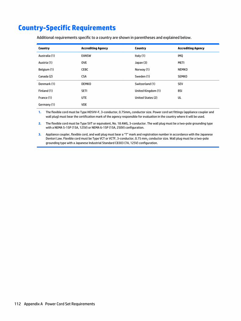
Country-Specific RequirementsAdditional requirements specific to a country are shown in parentheses and explained below.
Country Accrediting Agency Country Accrediting Agency
Australia (1)
Austria (1)
Belgium (1)
Canada (2)
EANSW
OVE
CEBC
CSA
Italy (1)
Japan (3)
Norway (1)
Sweden (1)
IMQ
METI
NEMKO
SEMKO
Denmark (1)
Finland (1)
France (1)
Germany (1)
DEMKO
SETI
UTE
VDE
Switzerland (1)
United Kingdom (1)
United States (2)
SEV
BSI
UL
1. The flexible cord must be Type HO5VV-F, 3-conductor, 0.75mm2 conductor size. Power cord set fittings (appliance coupler andwall plug) must bear the certification mark of the agency responsible for evaluation in the country where it will be used.
2. The flexible cord must be Type SVT or equivalent, No. 18 AWG, 3-conductor. The wall plug must be a two-pole grounding typewith a NEMA 5-15P (15A, 125V) or NEMA 6-15P (15A, 250V) configuration.
3. Appliance coupler, flexible cord, and wall plug must bear a “T” mark and registration number in accordance with the JapaneseDentori Law. Flexible cord must be Type VCT or VCTF, 3-conductor, 0.75 mm2 conductor size. Wall plug must be a two-polegrounding type with a Japanese Industrial Standard C8303 (7A, 125V) configuration.
112 Appendix A Power Cord Set Requirements

B Statement of Volatility
HP confirms that AMD-based business desktop HP EliteDesk 400 G1 systems contain DDR3 volatile memory(memory amount depends on the customer configuration). In addition, the motherboard in the conditionoriginally shipped without subsequent modification or the addition or installation of any applications,features, or functionality, contain the following nonvolatile memory: Real Time Clock battery backed-upconfiguration memory (256 Bytes), DIMM Serial Presence Detect (SPD) configuration data (256 Bytes permodule, 128 Bytes programmable), Serial Peripheral Interface (SPI) ROM for System BIOS (8M Bytes) andSuper I/O’s: masked keyboard ROM (overall 2K Bytes). In addition, these units contain a Trusted PlatformModule (TPM) that contains 16K Bytes of non-volatile memory for user data. The volatile memory will nothold any user data once power has been removed for 30 seconds or longer.
The following procedure shows the steps that should be taken to restore the Non-Volatile memory found inthe Intel-based HP ProDesk 400 G1 systems:
1. Download the latest BIOS (system ROM) from the HP website.
2. Follow the instructions to flash the BIOS that are found on the website.
Flashing the BIOS will reset it back to factory settings.
3. Turn on the system, and while system is powering on, and after the HP splash screen, press the F10 keyto enter BIOS setup screen.
4. Select Security > System Security from the main menu. If the Embedded Security Device Supportoption is set to “Disable”, skip to step 7.
5. To erase all security keys from the TPM:
Under Embedded Security Device in the System Security menu, configure Reset to Factory Settings toReset.
NOTE: Although the TPM security keys will be cleared, data in the non-volatile memory indices maynot be. Data stored in these indices should not contain security sensitive information. If an applicationlocks down and secures the non-volatile indices, these indices cannot be cleared.
6. Press F10 to accept changes.
7. To clear the secure boot key database:
a. Enter the F10 setup utility.
b. Go to the Security menu.
c. Select Secure Boot Configuration.
d. In the Key Management section, select clear Secure boot keys.
e. Use space key to select clear.
f. Press the F10 key to accept changes.
g. From the main menu select File > Save Changes and Exit.
8. If the Ownership Tag or Asset Tag is set, manually clear it under Security > System Ids.
9. Select File > Save Changes and Exit.
113

10. To clear the Setup or Power-On passwords if set, and clear any other settings, power down thecomputer and remove the AC power cord and the computer hood.
11. Locate the green/blue two pin password jumper on header E49 (labeled PSWD) and remove it.
12. Remove the AC power, wait 10 seconds until the unit AC power has drained out, then press the clearCMOS button. This is typically a yellow push button (labeled CMOS).
13. Replace the hood and AC power cord and turn the computer on. The passwords are now cleared and allother user-configurable, non-volatile memory settings are reset to their factory default values.
14. Enter the F10 setup utility.
15. Select File > Default Setup > Restore Factory Settings as Default. This will set the default settingsback to the factory defaults.
16. Select File > Apply Defaults and Exit.
17. Shut down the computer, remove the AC power cord and place the (blue/green) jumper back on headerE49. Replace the computer hood and power cord.
If Computrace is enabled on the computer, see the service provider for instruction to disable the feature.
114 Appendix B Statement of Volatility

C Specifications
Table C-1 Specifications
Dimensions (with stand)
Height
Width
Depth
6.9 in
7.0 in
1.3 in
175 mm
177 mm
34 mm
Approximate Weight 2.9 lb 1.3 kg
Temperature Range
Operating
Nonoperating
50° to 95°F
-22° to 140°F
10° to 35°C
-30° to 60°C
NOTE: Operating temperature is derated 1.0° C per 300 m (1000 ft) to 3000 m (10,000 ft) above sea level; no direct sustainedsunlight. Maximum rate of change is 10° C/Hr. The upper limit may be limited by the type and number of options installed.
Relative Humidity (noncondensing)
Operating
Nonoperating (38.7°C max wet bulb)
10-90%
5-95%
10-90%
5-95%
Maximum Altitude (unpressurized)
Operating
Nonoperating
10,000 ft
30,000 ft
3048 m
9144 m
Power Supply
Operating Voltage Range
Rated Voltage Range1
Rated Line Frequency
Operating Line Frequency
90-264 VAC
100-240 VAC
50-60 Hz
47-63 Hz
Standard efficiency 65W, 87% efficient
DC Output +19.5V
Current Leakage (NFPA 99) < 250 μA
1 This system utilizes an active power factor corrected power supply. This allows the system to pass the CE mark requirements for usein the countries of the European Union. The active power factor corrected power supply also has the added benefit of not requiringan input voltage range select switch.
115

Index
Aaccess panel
illustrated 5removal and replacement 18
antenna cover 8audible codes 93audio problems 75
Bbackup and recovery, Windows 7
103Backup and Restore, Windows 7
106backups
creating Windows 7 104, 106battery
disposal 15removal and replacement 30
battery replacement 30beep codes 93booting options
Full Boot 89Quick Boot 89
Ccable management 16cable pinouts, SATA data 16cautions
AC power 10cables 15electrostatic discharge 10keyboard cleaning 13keyboard keys 14
changing a Power-On password 96changing a Setup password 96cleaning
computer 13mouse 14safety precautions 13
CMOSbacking up 95clearing and resetting 97
computerspecifications 115
computer cleaning 13
Computer Setupaccess problem 66
country power cord setrequirements 112
Customer Support 64
Ddeleting a Power-On password 97deleting a Setup password 97disassembly preparation 17drive cage
removal and replacement 37Driver Recovery DVD,
creating 105using for restore 109
Driver Recovery media, Windows 103
Driver Recovery media, Windows8.1 103
Eelectrostatic discharge (ESD) 10
preventing damage 11error
codes 89, 93messages 89
external antennasremoval and replacement 43
FF10 Setup
access problem 66f11 recovery, Windows 8 101f11 recovery, Windows 8.1 101fan
illustrated 8removal and replacement 36
flash drive problems 85flashing LEDs 93front bezel
illustrated 5removal and replacement 25
front panel componentsProDesk 400 2
Ggeneral problems 66grounding methods 11
Hhard drive
installation 19proper handling 15removal 19removal and replacement 19SATA characteristics 15
hard drive problems 69hard drive recovery
Windows 101Windows 7 107Windows 8.1 101
hard drivessizes 19
hardware installation problems 79heat sink
illustrated 8removal and replacement 33
Help and SupportWindows 7 103
helpful hints 65HP PC Hardware Diagnostics (UEFI)
downloading 99HP Recovery Disc Creator, using
105HP Ultraslim Keyed Cable Lock 8
Iinstalling
battery 30hard drive 19memory 26
Internet access problems 86
Kkeyboard
cleaning 13keyboard problems 78
116 Index

LLED cover
illustrated 8LEDs
blinking PS/2 keyboard 93
Mmemory
installation 26problems 84removal and replacement 28socket population 27specifications 26
memory modulesillustrated 6
monitor problems 71mouse
cleaning 14problems 78
Nnetwork problems 81numeric error codes 89
Ooperating guidelines 12operating system media, Windows
8 103operating system media, Windows
8.1 103overheating, prevention 12
Ppassword
clearing 95power-on 95setup 95
passwords 96, 97POST error messages 89power cord set requirements
country specific 112power supply
illustrated 6operating voltage range 115
Power-On password 96, 97power-on password 95printer problems 77problems
audio 75Computer Setup 66F10 Setup 66
flash drive 85general 66hard drive 69hardware installation 79Internet access 86keyboard 78memory 84monitor 71mouse 78network 81printer 77software 87
processorremoval and replacement 34
processorsillustrated 6
product ID locations 4
Rrear panel components
ProDesk 400 3recovery discs, steps for creating
Windows 7 105recovery discs, using for restore
109recovery media, creating 105recovery media, creating Windows
7 104recovery partition, Windows 8 101recovery partition, Windows 8.1
101recovery USB flash drive, steps for
creating Windows 7 105recovery using Windows 8 operating
system media 103recovery using Windows 8.1
operating system media 103removal and replacement
battery 30drive cage 37external antennas 43fan 36front bezel 18, 25hard drive 19heat sink 33memory 28processor 34solid-state drive 41speaker 23system board 46
WLAN antennas 50WLAN module 39
removingbattery 30hard drive 19
resettingCMOS 95password jumper 95
restoring the hard drive, Windows101
restoring the hard drive, Windows8.1 101
Ssafety and comfort 64safety precautions
cleaning 13SATA
connectors on system board 15data cable pinouts 16hard drive characteristics 15
SATA power cableillustrated 7
screws, correct size 14serial number locations 4service considerations 14Setup password 96, 97setup password 95software
problems 87servicing computer 14
solid-state driveremoval and replacement 41
solid-state drivessizes 19
speakerillustrated 8removal and replacement 23
specificationscomputer 115memory 26
static electricity 10system board
illustrated 5removal and replacement 46SATA connectors 15
System Recovery using Windows 7recovery media 108
System Recovery, Windows 7 107
Index 117

system restore points, creatingWindows 7 104
System Restore, Windows 7 106
Ttemperature control 12tools, servicing 14Torx T15 screwdriver 14tower conversion 54
Vventilation, proper 12
WWake-on-LAN feature 81Windows 7
backing up information 106backup and recovery 103Backup and Restore 106creating backups 104creating recovery media 104creating system restore points
104hard drive recovery 107Help and Support 103steps for creating recovery
discs 105steps for creating recovery
media 104steps for creating recovery USB
flash drive 105System Recovery 107System Recovery using recovery
media 108System Restore 106
Windows 7 operating system discsusing for restore 109
Windows 7 operating system DVDcreating 105using for restore 109
Windows 7 operating system mediacreating 105
Windows 8backup and restore 101Driver Recovery media 103f11 recovery 101hard drive recovery 101operating system DVD 103recovery partition 101restoring the hard drive 101
Windows 8.1backup and restore 101Driver Recovery media 103f11 recovery 101hard drive recovery 101operating system DVD 103recovery partition 101restoring the hard drive 101
wireless antenna cablesillustrated 7
WLAN antennasremoval and replacement 50
WLAN moduleremoval and replacement 39
118 Index