ac arc flash light intensity estimator and mhd based dc arc model
Upload
khangminh22Category
view
1download
0
Processes
Description
TIG (GTAW) Welding
Stick (SMAW) Welding
Arc Welding Power Source
OM-275857B 2017−02
Dynasty 400
208/575 Volt Models W/Auto-Line�
�
�Maxstar 400
File: TIG (GTAW)
CE And Non-CE Models
380/575 Volt Three-PhaseW/Auto-Line� (CE)
For product information,Owner’s Manual translations,
and more, visit
www.MillerWelds.com

DECLARATION OF CONFORMITY
for European Community (CE marked) products.
MILLER Electric Mfg. Co., 1635 Spencer Street, Appleton, WI 54914 U.S.A. declares that theproduct(s) identified in this declaration conform to the essential requirements and provisions ofthe stated Council Directive(s) and Standard(s).
Product/Apparatus Identification:
Product Stock Number
Dynasty 400 907717002
Maxstar 400 907716002
Council Directives:
• 2014/35/EU Low Voltage
• 2014/30/EU Electromagnetic Compatibility
• 2011/65/EU Restriction of the use of certain Hazardous Substances in electrical and electronic equipment
Standards:
• IEC 60974-1: 2012 Arc Welding Equipment – Part 1: Welding Power Sources
• IEC 60974-3: 2013 Arc Welding Equipment – Part 3: Arc Striking and Stabilizing Devices
• IEC 60974-10: 2014 Arc Welding Equipment – Part 10: Electromagnetic Compatibility Requirements
Signatory:
_____________________________________ ___________________________________________
David A. Werba Date of Declaration
MANAGER, PRODUCT DESIGN COMPLIANCE
January 16, 2017
278454A

TABLE OF CONTENTS
SECTION 1 − SAFETY PRECAUTIONS - READ BEFORE USING 1. . . . . . . . . . . . . . . . . . . . . . . . . . . . . . . . .1-1. Symbol Usage 1. . . . . . . . . . . . . . . . . . . . . . . . . . . . . . . . . . . . . . . . . . . . . . . . . . . . . . . . . . . . . . . . . . . . . . .1-2. Arc Welding Hazards 1. . . . . . . . . . . . . . . . . . . . . . . . . . . . . . . . . . . . . . . . . . . . . . . . . . . . . . . . . . . . . . . . .1-3. Additional Symbols For Installation, Operation, And Maintenance 3. . . . . . . . . . . . . . . . . . . . . . . . . . . . .1-4. California Proposition 65 Warnings 4. . . . . . . . . . . . . . . . . . . . . . . . . . . . . . . . . . . . . . . . . . . . . . . . . . . . . .1-5. Principal Safety Standards 4. . . . . . . . . . . . . . . . . . . . . . . . . . . . . . . . . . . . . . . . . . . . . . . . . . . . . . . . . . . . .1-6. EMF Information 4. . . . . . . . . . . . . . . . . . . . . . . . . . . . . . . . . . . . . . . . . . . . . . . . . . . . . . . . . . . . . . . . . . . . .
SECTION 2 − CONSIGNES DE SÉCURITÉ − LIRE AVANT UTILISATION 5. . . . . . . . . . . . . . . . . . . . . . . . . . .2-1. Symboles utilisés 5. . . . . . . . . . . . . . . . . . . . . . . . . . . . . . . . . . . . . . . . . . . . . . . . . . . . . . . . . . . . . . . . . . . . .2-2. Dangers relatifs au soudage à l’arc 5. . . . . . . . . . . . . . . . . . . . . . . . . . . . . . . . . . . . . . . . . . . . . . . . . . . . . .2-3. Dangers supplémentaires en relation avec l’installation, le fonctionnement et la maintenance 7. . . . .2-4. Proposition californienne 65 Avertissements 8. . . . . . . . . . . . . . . . . . . . . . . . . . . . . . . . . . . . . . . . . . . . . .2-5. Principales normes de sécurité 8. . . . . . . . . . . . . . . . . . . . . . . . . . . . . . . . . . . . . . . . . . . . . . . . . . . . . . . . .2-6. Informations relatives aux CEM 8. . . . . . . . . . . . . . . . . . . . . . . . . . . . . . . . . . . . . . . . . . . . . . . . . . . . . . . . .
SECTION 3 − DEFINITIONS 9. . . . . . . . . . . . . . . . . . . . . . . . . . . . . . . . . . . . . . . . . . . . . . . . . . . . . . . . . . . . . . . . . .3-1. Additional Safety Symbols And Definitions 9. . . . . . . . . . . . . . . . . . . . . . . . . . . . . . . . . . . . . . . . . . . . . . . .3-2. Miscellaneous Symbols And Definitions 11. . . . . . . . . . . . . . . . . . . . . . . . . . . . . . . . . . . . . . . . . . . . . . . . . .
SECTION 4 − SPECIFICATIONS 12. . . . . . . . . . . . . . . . . . . . . . . . . . . . . . . . . . . . . . . . . . . . . . . . . . . . . . . . . . . . . .4-1. Serial Number And Rating Label Location 12. . . . . . . . . . . . . . . . . . . . . . . . . . . . . . . . . . . . . . . . . . . . . . . .4-2. Specifications 12. . . . . . . . . . . . . . . . . . . . . . . . . . . . . . . . . . . . . . . . . . . . . . . . . . . . . . . . . . . . . . . . . . . . . . . .4-3. Dimensions, Weights And Base Mounting Hole Layout 13. . . . . . . . . . . . . . . . . . . . . . . . . . . . . . . . . . . . .4-4. Environmental Specifications 14. . . . . . . . . . . . . . . . . . . . . . . . . . . . . . . . . . . . . . . . . . . . . . . . . . . . . . . . . . .4-5. Static Characteristics 15. . . . . . . . . . . . . . . . . . . . . . . . . . . . . . . . . . . . . . . . . . . . . . . . . . . . . . . . . . . . . . . . .4-6. Duty Cycle And Overheating 15. . . . . . . . . . . . . . . . . . . . . . . . . . . . . . . . . . . . . . . . . . . . . . . . . . . . . . . . . . .
SECTION 5 − INSTALLATION 16. . . . . . . . . . . . . . . . . . . . . . . . . . . . . . . . . . . . . . . . . . . . . . . . . . . . . . . . . . . . . . . .5-1. Selecting A Location 16. . . . . . . . . . . . . . . . . . . . . . . . . . . . . . . . . . . . . . . . . . . . . . . . . . . . . . . . . . . . . . . . . .5-2. Weld Output Terminals 16. . . . . . . . . . . . . . . . . . . . . . . . . . . . . . . . . . . . . . . . . . . . . . . . . . . . . . . . . . . . . . . .5-3. Weld Output Terminals And Selecting Cable Sizes* 17. . . . . . . . . . . . . . . . . . . . . . . . . . . . . . . . . . . . . . . .5-4. Remote 14 Receptacle Information 18. . . . . . . . . . . . . . . . . . . . . . . . . . . . . . . . . . . . . . . . . . . . . . . . . . . . . .
5-5. Simple Automation Application (14-Pin Interface) 18. . . . . . . . . . . . . . . . . . . . . . . . . . . . . . . . . . . . . . . . . .5-6. Automation Connection (For 28-Pin Receptacle If Present) 19. . . . . . . . . . . . . . . . . . . . . . . . . . . . . . . . . .5-7. Remote Memory Select Inputs (For 28-Pin Receptacle If Present) 22. . . . . . . . . . . . . . . . . . . . . . . . . . . .5-8. 115 Volts AC Cooler Receptacle, Supplementary Protector CB1, And Power Switch 23. . . . . . . . . . . . .5-9. Gas Connections 23. . . . . . . . . . . . . . . . . . . . . . . . . . . . . . . . . . . . . . . . . . . . . . . . . . . . . . . . . . . . . . . . . . . . .5-10. TIG HF Impulse/ Lift-Arc Connections 24. . . . . . . . . . . . . . . . . . . . . . . . . . . . . . . . . . . . . . . . . . . . . . . . . . .5-11. Cooler Connections 25. . . . . . . . . . . . . . . . . . . . . . . . . . . . . . . . . . . . . . . . . . . . . . . . . . . . . . . . . . . . . . . . . . .5-12. Dynasty Stick Connections 26. . . . . . . . . . . . . . . . . . . . . . . . . . . . . . . . . . . . . . . . . . . . . . . . . . . . . . . . . . . .5-13. Maxstar Stick Connections 26. . . . . . . . . . . . . . . . . . . . . . . . . . . . . . . . . . . . . . . . . . . . . . . . . . . . . . . . . . . . .5-14. Electrical Service Guide 27. . . . . . . . . . . . . . . . . . . . . . . . . . . . . . . . . . . . . . . . . . . . . . . . . . . . . . . . . . . . . . .5-15. Connecting Input Power For 400 Models 29. . . . . . . . . . . . . . . . . . . . . . . . . . . . . . . . . . . . . . . . . . . . . . . . .
SECTION 6 − OPERATION 32. . . . . . . . . . . . . . . . . . . . . . . . . . . . . . . . . . . . . . . . . . . . . . . . . . . . . . . . . . . . . . . . . . .6-1. Software Updates 32. . . . . . . . . . . . . . . . . . . . . . . . . . . . . . . . . . . . . . . . . . . . . . . . . . . . . . . . . . . . . . . . . . . .
6-2. Controls 33. . . . . . . . . . . . . . . . . . . . . . . . . . . . . . . . . . . . . . . . . . . . . . . . . . . . . . . . . . . . . . . . . . . . . . . . . . . .6-3. Accessing Control Panel Menu 34. . . . . . . . . . . . . . . . . . . . . . . . . . . . . . . . . . . . . . . . . . . . . . . . . . . . . . . . .6-4. Lift-Arc And HF TIG Start Procedures 36. . . . . . . . . . . . . . . . . . . . . . . . . . . . . . . . . . . . . . . . . . . . . . . . . . . .6-5. Pulser Control 37. . . . . . . . . . . . . . . . . . . . . . . . . . . . . . . . . . . . . . . . . . . . . . . . . . . . . . . . . . . . . . . . . . . . . . .6-6. Memory (Program Storage Locations 1-9) 38. . . . . . . . . . . . . . . . . . . . . . . . . . . . . . . . . . . . . . . . . . . . . . . .
SECTION 7 − USER FUNCTIONS 39. . . . . . . . . . . . . . . . . . . . . . . . . . . . . . . . . . . . . . . . . . . . . . . . . . . . . . . . . . . . .7-1. Accessing User Setup Menu 39. . . . . . . . . . . . . . . . . . . . . . . . . . . . . . . . . . . . . . . . . . . . . . . . . . . . . . . . . . .

TABLE OF CONTENTS
7-2. AC Independent 40. . . . . . . . . . . . . . . . . . . . . . . . . . . . . . . . . . . . . . . . . . . . . . . . . . . . . . . . . . . . . . . . . . . . . .7-3. General (GEN) Tungsten To Change Programmable TIG Starting Parameters 41. . . . . . . . . . . . . . . . . .7-4. Programmable TIG Start Parameters For Models With 28-Pin Advanced Automation Capabilities 42. .7-5. Output Control And Trigger Functions 44. . . . . . . . . . . . . . . . . . . . . . . . . . . . . . . . . . . . . . . . . . . . . . . . . . . .
SECTION 8 − ADVANCED FUNCTIONS 48. . . . . . . . . . . . . . . . . . . . . . . . . . . . . . . . . . . . . . . . . . . . . . . . . . . . . . .8-1. Accessing Tech Menu For Dynasty/Maxstar Models 48. . . . . . . . . . . . . . . . . . . . . . . . . . . . . . . . . . . . . . . .8-2. Sequencer And Weld Timer For DX Model 50. . . . . . . . . . . . . . . . . . . . . . . . . . . . . . . . . . . . . . . . . . . . . . . .8-3. Lockout Functions 51. . . . . . . . . . . . . . . . . . . . . . . . . . . . . . . . . . . . . . . . . . . . . . . . . . . . . . . . . . . . . . . . . . . .8-4. Lockout Levels Defined 51. . . . . . . . . . . . . . . . . . . . . . . . . . . . . . . . . . . . . . . . . . . . . . . . . . . . . . . . . . . . . . .
SECTION 9 − MAINTENANCE AND TROUBLESHOOTING 52. . . . . . . . . . . . . . . . . . . . . . . . . . . . . . . . . . . . . . .9-2. Blowing Out Inside of Unit 52. . . . . . . . . . . . . . . . . . . . . . . . . . . . . . . . . . . . . . . . . . . . . . . . . . . . . . . . . . . . .9-3. Voltmeter/Ammeter Display Messages 53. . . . . . . . . . . . . . . . . . . . . . . . . . . . . . . . . . . . . . . . . . . . . . . . . . .9-4. Troubleshooting Table 54. . . . . . . . . . . . . . . . . . . . . . . . . . . . . . . . . . . . . . . . . . . . . . . . . . . . . . . . . . . . . . . . .
SECTION 10 − ELECTRICAL DIAGRAM 55. . . . . . . . . . . . . . . . . . . . . . . . . . . . . . . . . . . . . . . . . . . . . . . . . . . . . . .SECTION 11 − HIGH FREQUENCY 57. . . . . . . . . . . . . . . . . . . . . . . . . . . . . . . . . . . . . . . . . . . . . . . . . . . . . . . . . . .
11-1. Welding Processes Requiring High Frequency 57. . . . . . . . . . . . . . . . . . . . . . . . . . . . . . . . . . . . . . . . . . . .11-2. Installation Showing Possible Sources Of HF Interference 57. . . . . . . . . . . . . . . . . . . . . . . . . . . . . . . . . . .11-3. Recommended Installation To Reduce HF Interference 58. . . . . . . . . . . . . . . . . . . . . . . . . . . . . . . . . . . . .
SECTION 12 − SELECTING AND PREPARING A TUNGSTEN FOR DC OR AC WELDING WITH INVERTERMACHINES 59. . . . . . . . . . . . . . . . . . . . . . . . . . . . . . . . . . . . . . . . . . . . . . . . . . . . . . . . . . . . . . . . . . . . . . . . . . . . . . . .
12-1. Selecting Tungsten Electrode (Wear Clean Gloves To Prevent Contamination Of Tungsten) 59. . . . . .12-2. Preparing Tungsten Electrode For DC Electrode Negative (DCEN) Welding
Or AC Welding With Inverter Machines 59. . . . . . . . . . . . . . . . . . . . . . . . . . . . . . . . . . . . . . . . . . . . . . . . . . .WARRANTY
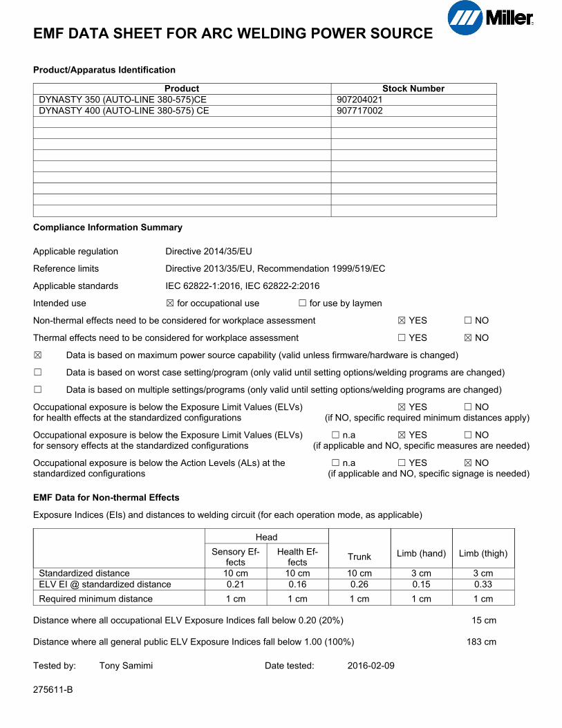
EMF DATA SHEET FOR ARC WELDING POWER SOURCE
Product/Apparatus Identification
Product Stock Number
DYNASTY 350 (AUTO-LINE 380-575)CE 907204021
DYNASTY 400 (AUTO-LINE 380-575) CE 907717002
Compliance Information Summary
Applicable regulation Directive 2014/35/EU
Reference limits Directive 2013/35/EU, Recommendation 1999/519/EC
Applicable standards IEC 62822-1:2016, IEC 62822-2:2016
Intended use � for occupational use � for use by laymen
Non-thermal effects need to be considered for workplace assessment � YES � NO
Thermal effects need to be considered for workplace assessment � YES � NO
� Data is based on maximum power source capability (valid unless firmware/hardware is changed)
� Data is based on worst case setting/program (only valid until setting options/welding programs are changed)
� Data is based on multiple settings/programs (only valid until setting options/welding programs are changed)
Occupational exposure is below the Exposure Limit Values (ELVs) � YES � NOfor health effects at the standardized configurations (if NO, specific required minimum distances apply)
Occupational exposure is below the Exposure Limit Values (ELVs) � n.a � YES � NOfor sensory effects at the standardized configurations (if applicable and NO, specific measures are needed)
Occupational exposure is below the Action Levels (ALs) at the � n.a � YES � NOstandardized configurations (if applicable and NO, specific signage is needed)
EMF Data for Non-thermal Effects
Exposure Indices (EIs) and distances to welding circuit (for each operation mode, as applicable)
Head
Trunk Limb (hand) Limb (thigh)Sensory Effects
Health Effects
Standardized distance 10 cm 10 cm 10 cm 3 cm 3 cm
ELV EI @ standardized distance 0.21 0.16 0.26 0.15 0.33
Required minimum distance 1 cm 1 cm 1 cm 1 cm 1 cm
Distance where all occupational ELV Exposure Indices fall below 0.20 (20%) 15 cm
Distance where all general public ELV Exposure Indices fall below 1.00 (100%) 183 cm
Tested by: Tony Samimi Date tested: 2016-02-09
275611-B
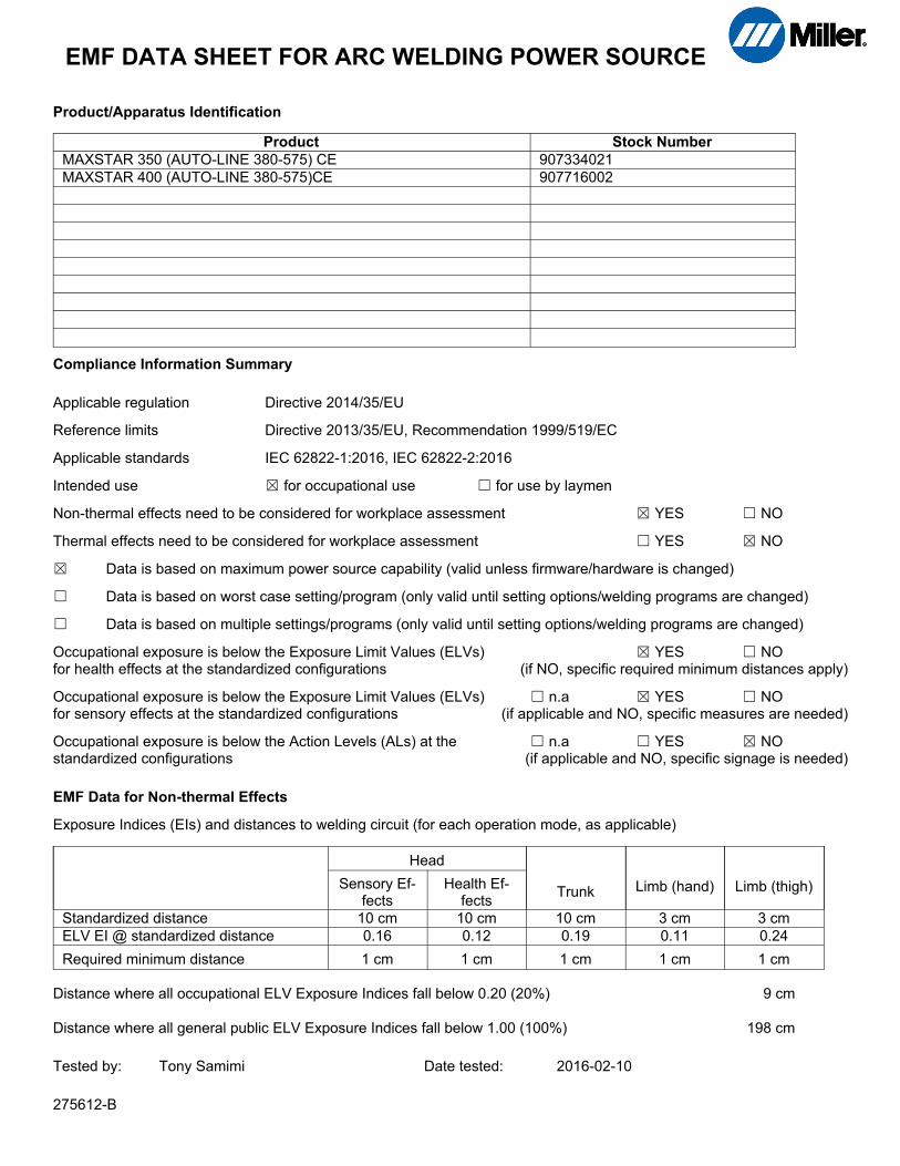
EMF DATA SHEET FOR ARC WELDING POWER SOURCE
Product/Apparatus Identification
Product Stock Number
MAXSTAR 350 (AUTO-LINE 380-575) CE 907334021
MAXSTAR 400 (AUTO-LINE 380-575)CE 907716002
Compliance Information Summary
Applicable regulation Directive 2014/35/EU
Reference limits Directive 2013/35/EU, Recommendation 1999/519/EC
Applicable standards IEC 62822-1:2016, IEC 62822-2:2016
Intended use � for occupational use � for use by laymen
Non-thermal effects need to be considered for workplace assessment � YES � NO
Thermal effects need to be considered for workplace assessment � YES � NO
� Data is based on maximum power source capability (valid unless firmware/hardware is changed)
� Data is based on worst case setting/program (only valid until setting options/welding programs are changed)
� Data is based on multiple settings/programs (only valid until setting options/welding programs are changed)
Occupational exposure is below the Exposure Limit Values (ELVs) � YES � NOfor health effects at the standardized configurations (if NO, specific required minimum distances apply)
Occupational exposure is below the Exposure Limit Values (ELVs) � n.a � YES � NOfor sensory effects at the standardized configurations (if applicable and NO, specific measures are needed)
Occupational exposure is below the Action Levels (ALs) at the � n.a � YES � NOstandardized configurations (if applicable and NO, specific signage is needed)
EMF Data for Non-thermal Effects
Exposure Indices (EIs) and distances to welding circuit (for each operation mode, as applicable)
Head
Trunk Limb (hand) Limb (thigh)Sensory Effects
Health Effects
Standardized distance 10 cm 10 cm 10 cm 3 cm 3 cm
ELV EI @ standardized distance 0.16 0.12 0.19 0.11 0.24
Required minimum distance 1 cm 1 cm 1 cm 1 cm 1 cm
Distance where all occupational ELV Exposure Indices fall below 0.20 (20%) 9 cm
Distance where all general public ELV Exposure Indices fall below 1.00 (100%) 198 cm
Tested by: Tony Samimi Date tested: 2016-02-10
275612-B

OM-275857 Page 1
SECTION 1 − SAFETY PRECAUTIONS - READ BEFORE USINGsom 2015−09
7
Protect yourself and others from injury — read, follow, and save these important safety precautions and operating instructions.
1-1. Symbol Usage
DANGER! − Indicates a hazardous situation which, ifnot avoided, will result in death or serious injury. Thepossible hazards are shown in the adjoining symbolsor explained in the text.
Indicates a hazardous situation which, if not avoided,could result in death or serious injury. The possiblehazards are shown in the adjoining symbols or ex-plained in the text.
NOTICE − Indicates statements not related to personal injury.
� Indicates special instructions.
This group of symbols means Warning! Watch Out! ELECTRICSHOCK, MOVING PARTS, and HOT PARTS hazards. Consult sym-bols and related instructions below for necessary actions to avoid thehazards.
1-2. Arc Welding Hazards
The symbols shown below are used throughout this manualto call attention to and identify possible hazards. When yousee the symbol, watch out, and follow the related instructionsto avoid the hazard. The safety information given below isonly a summary of the more complete safety informationfound in the Safety Standards listed in Section 1-5. Read andfollow all Safety Standards.
Only qualified persons should install, operate, maintain, andrepair this unit.
During operation, keep everybody, especially children, away.
Touching live electrical parts can cause fatal shocksor severe burns. The electrode and work circuit iselectrically live whenever the output is on. The inputpower circuit and machine internal circuits are alsolive when power is on. In semiautomatic or automaticwire welding, the wire, wire reel, drive roll housing,and all metal parts touching the welding wire areelectrically live. Incorrectly installed or improperlygrounded equipment is a hazard.
� Do not touch live electrical parts.
ELECTRIC SHOCK can kill.
� Wear dry, hole-free insulating gloves and body protection.� Insulate yourself from work and ground using dry insulating mats
or covers big enough to prevent any physical contact with the workor ground.
� Do not use AC output in damp areas, if movement is confined, or ifthere is a danger of falling.
� Use AC output ONLY if required for the welding process.� If AC output is required, use remote output control if present on
unit.� Additional safety precautions are required when any of the follow-
ing electrically hazardous conditions are present: in damplocations or while wearing wet clothing; on metal structures suchas floors, gratings, or scaffolds; when in cramped positions suchas sitting, kneeling, or lying; or when there is a high risk of unavoid-able or accidental contact with the workpiece or ground. For theseconditions, use the following equipment in order presented: 1) asemiautomatic DC constant voltage (wire) welder, 2) a DC manual(stick) welder, or 3) an AC welder with reduced open-circuit volt-age. In most situations, use of a DC, constant voltage wire welderis recommended. And, do not work alone!
� Disconnect input power or stop engine before installing orservicing this equipment. Lockout/tagout input power according toOSHA 29 CFR 1910.147 (see Safety Standards).
� Properly install, ground, and operate this equipment according toits Owner’s Manual and national, state, and local codes.
� Always verify the supply ground − check and be sure that inputpower cord ground wire is properly connected to ground terminal indisconnect box or that cord plug is connected to a properlygrounded receptacle outlet.
� When making input connections, attach proper grounding conduc-tor first − double-check connections.
� Keep cords dry, free of oil and grease, and protected from hot metaland sparks.
� Frequently inspect input power cord and ground conductor fordamage or bare wiring – replace immediately if damaged – barewiring can kill.
� Turn off all equipment when not in use.� Do not use worn, damaged, undersized, or repaired cables.� Do not drape cables over your body.� If earth grounding of the workpiece is required, ground it directly
with a separate cable.� Do not touch electrode if you are in contact with the work, ground,
or another electrode from a different machine.� Do not touch electrode holders connected to two welding ma-
chines at the same time since double open-circuit voltage will bepresent.
� Use only well-maintained equipment. Repair or replace damagedparts at once. Maintain unit according to manual.
� Wear a safety harness if working above floor level.� Keep all panels and covers securely in place.� Clamp work cable with good metal-to-metal contact to workpiece
or worktable as near the weld as practical.
� Insulate work clamp when not connected to workpiece to preventcontact with any metal object.
� Do not connect more than one electrode or work cable to anysingle weld output terminal. Disconnect cable for process not inuse.
� Use GFCI protection when operating auxiliary equipment in dampor wet locations.
SIGNIFICANT DC VOLTAGE exists in inverter weld-ing power sources AFTER removal of input power.� Turn Off inverter, disconnect input power, and discharge input
capacitors according to instructions in Maintenance Sectionbefore touching any parts.
HOT PARTS can burn.
� Do not touch hot parts bare handed.� Allow cooling period before working on
equipment.
� To handle hot parts, use proper tools and/or wear heavy, insu-lated welding gloves and clothing to prevent burns.

OM-275857 Page 2
Welding produces fumes and gases. Breathingthese fumes and gases can be hazardous to yourhealth.
FUMES AND GASES can be hazardous.
� Keep your head out of the fumes. Do not breathe the fumes.� If inside, ventilate the area and/or use local forced ventilation at the
arc to remove welding fumes and gases. The recommended wayto determine adequate ventilation is to sample for the compositionand quantity of fumes and gases to which personnel are exposed.
� If ventilation is poor, wear an approved air-supplied respirator.� Read and understand the Safety Data Sheets (SDSs) and the
manufacturer’s instructions for adhesives, coatings, cleaners,consumables, coolants, degreasers, fluxes, and metals.
� Work in a confined space only if it is well ventilated, or whilewearing an air-supplied respirator. Always have a trained watch-person nearby. Welding fumes and gases can displace air andlower the oxygen level causing injury or death. Be sure the breath-ing air is safe.
� Do not weld in locations near degreasing, cleaning, or spraying op-erations. The heat and rays of the arc can react with vapors to formhighly toxic and irritating gases.
� Do not weld on coated metals, such as galvanized, lead, orcadmium plated steel, unless the coating is removed from the weldarea, the area is well ventilated, and while wearing an air-suppliedrespirator. The coatings and any metals containing these elementscan give off toxic fumes if welded.
Arc rays from the welding process produce intensevisible and invisible (ultraviolet and infrared) raysthat can burn eyes and skin. Sparks fly off from theweld.
� Wear an approved welding helmet fitted with a proper shade offilter lenses to protect your face and eyes from arc rays andsparks when welding or watching (see ANSI Z49.1 and Z87.1listed in Safety Standards).
� Wear approved safety glasses with side shields under yourhelmet.
� Use protective screens or barriers to protect others from flash,glare and sparks; warn others not to watch the arc.
� Wear body protection made from durable, flame−resistant mate-rial (leather, heavy cotton, wool). Body protection includesoil-free clothing such as leather gloves, heavy shirt, cufflesstrousers, high shoes, and a cap.
ARC RAYS can burn eyes and skin.
Welding on closed containers, such as tanks,drums, or pipes, can cause them to blow up. Sparkscan fly off from the welding arc. The flying sparks, hotworkpiece, and hot equipment can cause fires and
burns. Accidental contact of electrode to metal objects can causesparks, explosion, overheating, or fire. Check and be sure the area issafe before doing any welding.
WELDING can cause fire or explosion.
� Remove all flammables within 35 ft (10.7 m) of the welding arc. Ifthis is not possible, tightly cover them with approved covers.
� Do not weld where flying sparks can strike flammable material.� Protect yourself and others from flying sparks and hot metal.� Be alert that welding sparks and hot materials from welding can
easily go through small cracks and openings to adjacent areas.� Watch for fire, and keep a fire extinguisher nearby.� Be aware that welding on a ceiling, floor, bulkhead, or partition can
cause fire on the hidden side.� Do not weld on containers that have held combustibles, or on
closed containers such as tanks, drums, or pipes unless they areproperly prepared according to AWS F4.1 and AWS A6.0 (seeSafety Standards).
� Do not weld where the atmosphere can contain flammable dust,gas, or liquid vapors (such as gasoline).
� Connect work cable to the work as close to the welding area aspractical to prevent welding current from traveling long, possiblyunknown paths and causing electric shock, sparks, and firehazards.
� Do not use welder to thaw frozen pipes.
� Remove stick electrode from holder or cut off welding wire atcontact tip when not in use.
� Wear body protection made from durable, flame−resistant material(leather, heavy cotton, wool). Body protection includes oil-freeclothing such as leather gloves, heavy shirt, cuffless trousers, highshoes, and a cap.
� Remove any combustibles, such as a butane lighter or matches,from your person before doing any welding.
� After completion of work, inspect area to ensure it is free of sparks,glowing embers, and flames.
� Use only correct fuses or circuit breakers. Do not oversize or by-pass them.
� Follow requirements in OSHA 1910.252 (a) (2) (iv) and NFPA 51Bfor hot work and have a fire watcher and extinguisher nearby.
� Read and understand the Safety Data Sheets (SDSs) and themanufacturer’s instructions for adhesives, coatings, cleaners,consumables, coolants, degreasers, fluxes, and metals.
FLYING METAL or DIRT can injure eyes.
� Welding, chipping, wire brushing, and grindingcause sparks and flying metal. As welds cool,they can throw off slag.
� Wear approved safety glasses with sideshields even under your welding helmet.
BUILDUP OF GAS can injure or kill.
� Shut off compressed gas supply when not in use.� Always ventilate confined spaces or use
approved air-supplied respirator.
ELECTRIC AND MAGNETIC FIELDS (EMF)can affect Implanted Medical Devices.
� Wearers of Pacemakers and other ImplantedMedical Devices should keep away.
� Implanted Medical Device wearers should consult their doctorand the device manufacturer before going near arc welding, spotwelding, gouging, plasma arc cutting, or induction heatingoperations.
Noise from some processes or equipment candamage hearing.
� Wear approved ear protection if noise lev-el is high.
NOISE can damage hearing.
Compressed gas cylinders contain gas under highpressure. If damaged, a cylinder can explode. Sincegas cylinders are normally part of the weldingprocess, be sure to treat them carefully.
CYLINDERS can explode if damaged.
� Protect compressed gas cylinders from excessive heat, mechani-cal shocks, physical damage, slag, open flames, sparks, and arcs.
� Install cylinders in an upright position by securing to a stationarysupport or cylinder rack to prevent falling or tipping.
� Keep cylinders away from any welding or other electrical circuits.� Never drape a welding torch over a gas cylinder.� Never allow a welding electrode to touch any cylinder.� Never weld on a pressurized cylinder − explosion will result.� Use only correct compressed gas cylinders, regulators, hoses,
and fittings designed for the specific application; maintain themand associated parts in good condition.
� Turn face away from valve outlet when opening cylinder valve. Donot stand in front of or behind the regulator when opening the valve.
� Keep protective cap in place over valve except when cylinder is inuse or connected for use.
� Use the right equipment, correct procedures, and sufficient num-ber of persons to lift and move cylinders.
� Read and follow instructions on compressed gas cylinders,associated equipment, and Compressed Gas Association (CGA)publication P-1 listed in Safety Standards.

OM-275857 Page 3
1-3. Additional Symbols For Installation, Operation, And Maintenance
FIRE OR EXPLOSION hazard.
� Do not install or place unit on, over, or nearcombustible surfaces.
� Do not install unit near flammables.
� Do not overload building wiring − be sure power supply system isproperly sized, rated, and protected to handle this unit.
FALLING EQUIPMENT can injure.
� Use lifting eye to lift unit only, NOT runninggear, gas cylinders, or any other accessories.
� Use equipment of adequate capacity to lift andsupport unit.
� If using lift forks to move unit, be sure forks are long enough toextend beyond opposite side of unit.
� Keep equipment (cables and cords) away from moving vehicleswhen working from an aerial location.
� Follow the guidelines in the Applications Manual for the RevisedNIOSH Lifting Equation (Publication No. 94−110) when manu-ally lifting heavy parts or equipment.
OVERUSE can cause OVERHEATING
� Allow cooling period; follow rated duty cycle.� Reduce current or reduce duty cycle before
starting to weld again.� Do not block or filter airflow to unit.
FLYING SPARKS can injure.
� Wear a face shield to protect eyes and face.� Shape tungsten electrode only on grinder with
proper guards in a safe location wearing properface, hand, and body protection.
� Sparks can cause fires — keep flammables away.
STATIC (ESD) can damage PC boards.
� Put on grounded wrist strap BEFORE handlingboards or parts.
� Use proper static-proof bags and boxes tostore, move, or ship PC boards.
MOVING PARTS can injure.
� Keep away from moving parts.� Keep away from pinch points such as drive
rolls.
WELDING WIRE can injure.
� Do not press gun trigger until instructed to doso.
� Do not point gun toward any part of the body,other people, or any metal when threadingwelding wire.
BATTERY EXPLOSION can injure.
� Do not use welder to charge batteries or jumpstart vehicles unless it has a battery chargingfeature designed for this purpose.
MOVING PARTS can injure.
� Keep away from moving parts such as fans.� Keep all doors, panels, covers, and guards
closed and securely in place.
� Have only qualified persons remove doors, panels, covers, orguards for maintenance and troubleshooting as necessary.
� Reinstall doors, panels, covers, or guards when maintenance isfinished and before reconnecting input power.
READ INSTRUCTIONS.
� Read and follow all labels and the Owner’sManual carefully before installing, operating, orservicing unit. Read the safety information atthe beginning of the manual and in eachsection.
� Use only genuine replacement parts from the manufacturer.
� Perform installation, maintenance, and service according to theOwner’s Manuals, industry standards, and national, state, andlocal codes.
H.F. RADIATION can cause interference.
� High-frequency (H.F.) can interfere with radionavigation, safety services, computers, andcommunications equipment.
� Have only qualified persons familiar withelectronic equipment perform this installation.
� The user is responsible for having a qualified electrician prompt-ly correct any interference problem resulting from the installa-tion.
� If notified by the FCC about interference, stop using theequipment at once.
� Have the installation regularly checked and maintained.
� Keep high-frequency source doors and panels tightly shut, keepspark gaps at correct setting, and use grounding and shielding tominimize the possibility of interference.
ARC WELDING can cause interference.
� Electromagnetic energy can interfere withsensitive electronic equipment such ascomputers and computer-driven equipmentsuch as robots.
� Be sure all equipment in the welding area iselectromagnetically compatible.
� To reduce possible interference, keep weld cables as short aspossible, close together, and down low, such as on the floor.
� Locate welding operation 100 meters from any sensitive elec-tronic equipment.
� Be sure this welding machine is installed and groundedaccording to this manual.
� If interference still occurs, the user must take extra measuressuch as moving the welding machine, using shielded cables,using line filters, or shielding the work area.

OM-275857 Page 4
1-4. California Proposition 65 Warnings
Welding or cutting equipment produces fumes or gaseswhich contain chemicals known to the State of California tocause birth defects and, in some cases, cancer. (CaliforniaHealth & Safety Code Section 25249.5 et seq.)
This product contains chemicals, including lead, known tothe state of California to cause cancer, birth defects, or otherreproductive harm. Wash hands after use.
1-5. Principal Safety Standards
Safety in Welding, Cutting, and Allied Processes, ANSI Standard Z49.1,is available as a free download from the American Welding Society athttp://www.aws.org or purchased from Global Engineering Documents(phone: 1-877-413-5184, website: www.global.ihs.com).
Safe Practices for the Preparation of Containers and Piping for Weldingand Cutting, American Welding Society Standard AWS F4.1, from Glob-al Engineering Documents (phone: 1-877-413-5184, website:www.global.ihs.com).
Safe Practices for Welding and Cutting Containers that have Held Com-bustibles, American Welding Society Standard AWS A6.0, from GlobalEngineering Documents (phone: 1-877-413-5184,website: www.global.ihs.com).
National Electrical Code, NFPA Standard 70, from National Fire Protec-tion Association, Quincy, MA 02269 (phone: 1-800-344-3555, website:www.nfpa.org and www. sparky.org).
Safe Handling of Compressed Gases in Cylinders, CGA Pamphlet P-1,from Compressed Gas Association, 14501 George Carter Way, Suite103, Chantilly, VA 20151 (phone: 703-788-2700, website:www.cga-net.com).
Safety in Welding, Cutting, and Allied Processes, CSA StandardW117.2, from Canadian Standards Association, Standards Sales, 5060Spectrum Way, Suite 100, Mississauga, Ontario, Canada L4W 5NS(phone: 800-463-6727, website: www.csagroup.org).Safe Practice For Occupational And Educational Eye And Face Protec-tion, ANSI Standard Z87.1, from American National Standards Institute,25 West 43rd Street, New York, NY 10036 (phone: 212-642-4900, web-site: www.ansi.org).Standard for Fire Prevention During Welding, Cutting, and Other HotWork, NFPA Standard 51B, from National Fire Protection Association,Quincy, MA 02269 (phone: 1-800-344-3555, website: www.nfpa.org).OSHA, Occupational Safety and Health Standards for General Indus-try, Title 29, Code of Federal Regulations (CFR), Part 1910, Subpart Q,and Part 1926, Subpart J, from U.S. Government Printing Office, Super-intendent of Documents, P.O. Box 371954, Pittsburgh, PA 15250-7954(phone: 1-866-512-1800) (there are 10 OSHA Regional Offices—phone for Region 5, Chicago, is 312-353-2220, website:www.osha.gov).Applications Manual for the Revised NIOSH Lifting Equation, The Na-tional Institute for Occupational Safety and Health (NIOSH), 1600Clifton Rd, Atlanta, GA 30329-4027 (phone: 1-800-232-4636, website:www.cdc.gov/NIOSH).
1-6. EMF Information
Electric current flowing through any conductor causes localized electricand magnetic fields (EMF). The current from arc welding (and allied pro-cesses including spot welding, gouging, plasma arc cutting, andinduction heating operations) creates an EMF field around the weldingcircuit. EMF fields can interfere with some medical implants, e.g. pace-makers. Protective measures for persons wearing medical implantshave to be taken. For example, restrict access for passers−by or con-duct individual risk assessment for welders. All welders should use thefollowing procedures in order to minimize exposure to EMF fields fromthe welding circuit:
1. Keep cables close together by twisting or taping them, or using acable cover.
2. Do not place your body between welding cables. Arrange cablesto one side and away from the operator.
3. Do not coil or drape cables around your body.
4. Keep head and trunk as far away from the equipment in thewelding circuit as possible.
5. Connect work clamp to workpiece as close to the weld aspossible.
6. Do not work next to, sit or lean on the welding power source.
7. Do not weld whilst carrying the welding power source or wirefeeder.
About Implanted Medical Devices:
Implanted Medical Device wearers should consult their doctor and thedevice manufacturer before performing or going near arc welding, spotwelding, gouging, plasma arc cutting, or induction heating operations.If cleared by your doctor, then following the above procedures is recom-mended.

OM-275857 Page 5
SECTION 2 − CONSIGNES DE SÉCURITÉ − LIRE AVANT UTILISATIONfre_som_2015−09
7
Pour écarter les risques de blessure pour vous−même et pour autrui — lire, appliquer et ranger en lieu sûr ces consignes relativesaux précautions de sécurité et au mode opératoire.
2-1. Symboles utilisés
DANGER! − Indique une situation dangereuse qui si onl’évite pas peut donner la mort ou des blessures graves.Les dangers possibles sont montrés par les symbolesjoints ou sont expliqués dans le texte.
Indique une situation dangereuse qui si on l’évite paspeut donner la mort ou des blessures graves. Les dan-gers possibles sont montrés par les symboles joints ousont expliqués dans le texte.
AVIS − Indique des déclarations pas en relation avec des blessurespersonnelles.
� Indique des instructions spécifiques.
Ce groupe de symboles veut dire Avertissement! Attention! DANGERDE CHOC ELECTRIQUE, PIECES EN MOUVEMENT, et PIECESCHAUDES. Consulter les symboles et les instructions ci-dessous yafférant pour les actions nécessaires afin d’éviter le danger.
2-2. Dangers relatifs au soudage à l’arc
Les symboles représentés ci-dessous sont utilisés dans ce ma-nuel pour attirer l’attention et identifier les dangers possibles. Enprésence de l’un de ces symboles, prendre garde et suivre lesinstructions afférentes pour éviter tout risque. Les instructionsen matière de sécurité indiquées ci-dessous ne constituentqu’un sommaire des instructions de sécurité plus complètesfournies dans les normes de sécurité énumérées dans la Sec-tion 2-5. Lire et observer toutes les normes de sécurité.
Seul un personnel qualifié est autorisé à installer, faire fonc-tionner, entretenir et réparer cet appareil.
Pendant le fonctionnement, maintenir à distance toutes lespersonnes, notamment les enfants de l’appareil.
Le contact d’organes électriques sous tension peutprovoquer des accidents mortels ou des brûluresgraves. Le circuit de l’électrode et de la pièce est soustension lorsque le courant est délivré à la sortie. Lecircuit d’alimentation et les circuits internes de lamachine sont également sous tension lorsque l’alimen-tation est sur Marche. Dans le mode de soudage avecdu fil, le fil, le dérouleur, le bloc de commande durouleau et toutes les parties métalliques en contactavec le fil sont sous tension électrique. Un équipementinstallé ou mis à la terre de manière incorrecte ouimpropre constitue un danger.
UNE DÉCHARGE ÉLECTRIQUE peutentraîner la mort.
� Ne pas toucher aux pièces électriques sous tension.� Porter des gants isolants et des vêtements de protection secs et
sans trous.� S’isoler de la pièce à couper et du sol en utilisant des housses ou
des tapis assez grands afin d’éviter tout contact physique avec lapièce à couper ou le sol.
� Ne pas se servir de source électrique à courant électrique dans leszones humides, dans les endroits confinés ou là où on risque detomber.
� Se servir d’une source électrique à courant électrique UNIQUE-MENT si le procédé de soudage le demande.
� Si l’utilisation d’une source électrique à courant électrique s’avèrenécessaire, se servir de la fonction de télécommande si l’appareilen est équipé.
� D’autres consignes de sécurité sont nécessaires dans les condi-tions suivantes : risques électriques dans un environnementhumide ou si l’on porte des vêtements mouillés ; sur des structuresmétalliques telles que sols, grilles ou échafaudages ; en positioncoincée comme assise, à genoux ou couchée ; ou s’il y a un risqueélevé de contact inévitable ou accidentel avec la pièce à souder oule sol. Dans ces conditions, utiliser les équipements suivants,dans l’ordre indiqué : 1) un poste à souder DC à tension constante(à fil), 2) un poste à souder DC manuel (électrode) ou 3) un poste àsouder AC à tension à vide réduite. Dans la plupart des situations,l’utilisation d’un poste à souder DC à fil à tension constante est re-commandée. En outre, ne pas travailler seul !
� Couper l’alimentation ou arrêter le moteur avant de procéder à l’in-stallation, à la réparation ou à l’entretien de l’appareil. Déverrouillerl’alimentation selon la norme OSHA 29 CFR 1910.147 (voir nor-mes de sécurité).
� Installez, mettez à la terre et utilisez correctement cet équipementconformément à son Manuel d’Utilisation et aux réglementationsnationales, gouvernementales et locales.
� Toujours vérifier la terre du cordon d’alimentation. Vérifier ets’assurer que le fil de terre du cordon d’alimentation est bienraccordé à la borne de terre du sectionneur ou que la fiche ducordon est raccordée à une prise correctement mise à la terre.
� En effectuant les raccordements d’entrée, fixer d’abord le conduc-teur de mise à la terre approprié et contre-vérifier les connexions.
� Les câbles doivent être exempts d’humidité, d’huile et de graisse;protégez−les contre les étincelles et les pièces métalliqueschaudes.
� Vérifier fréquemment le cordon d’alimentation et le conducteur demise à la terre afin de s’assurer qu’il n’est pas altéré ou dénudé −,le remplacer immédiatement s’il l’est −. Un fil dénudé peut entraî-ner la mort.
� L’équipement doit être hors tension lorsqu’il n’est pas utilisé.� Ne pas utiliser des câbles usés, endommagés, de grosseur insuffi-
sante ou mal épissés.� Ne pas enrouler les câbles autour du corps.� Si la pièce soudée doit être mise à la terre, le faire directement
avec un câble distinct.� Ne pas toucher l’électrode quand on est en contact avec la pièce,
la terre ou une électrode provenant d’une autre machine.� Ne pas toucher des porte électrodes connectés à deux machines
en même temps à cause de la présence d’une tension à vide dou-blée.
� N’utiliser qu’un matériel en bon état. Réparer ou remplacer sur-le-champ les pièces endommagées. Entretenir l’appareil conformé-ment à ce manuel.
� Porter un harnais de sécurité si l’on doit travailler au-dessus du sol.� S’assurer que tous les panneaux et couvercles sont correctement
en place.� Fixer le câble de retour de façon à obtenir un bon contact métal-
métal avec la pièce à souder ou la table de travail, le plus près pos-sible de la soudure.
� Isoler la pince de masse quand pas mis à la pièce pour éviter lecontact avec tout objet métallique.
� Ne pas raccorder plus d’une électrode ou plus d’un câble demasse à une même borne de sortie de soudage. Débrancher lecâble pour le procédé non utilisé.
� Utiliser une protection différentielle lors de l’utilisation d’un équi-pement auxiliaire dans des endroits humides ou mouillés.
Il reste une TENSION DC NON NÉGLIGEABLE dansles sources de soudage onduleur UNE FOISl’alimentation coupée.� Arrêter les convertisseurs, débrancher le courant électrique et
décharger les condensateurs d’alimentation selon les instructionsindiquées dans la partie Entretien avant de toucher les pièces.
OM-275857 Page 6
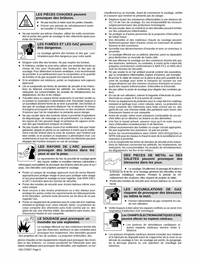
LES PIÈCES CHAUDES peuventprovoquer des brûlures.� Ne pas toucher à mains nues les parties chaudes.� Prévoir une période de refroidissement avant
de travailler à l’équipement.
� Ne pas toucher aux pièces chaudes, utiliser les outils recomman-dés et porter des gants de soudage et des vêtements épais pouréviter les brûlures.
LES FUMÉES ET LES GAZ peuventêtre dangereux.
Le soudage génère des fumées et des gaz. Leurinhalation peut être dangereux pour votre santé.
� Eloigner votre tête des fumées. Ne pas respirer les fumées.� À l’intérieur, ventiler la zone et/ou utiliser une ventilation forcée au
niveau de l’arc pour l’évacuation des fumées et des gaz desoudage. Pour déterminer la bonne ventilation, il est recommandéde procéder à un prélèvement pour la composition et la quantitéde fumées et de gaz auxquels est exposé le personnel.
� Si la ventilation est médiocre, porter un respirateur anti-vapeursapprouvé.
� Lire et comprendre les fiches de données de sécurité et les instruc-tions du fabricant concernant les adhésifs, les revêtements, lesnettoyants, les consommables, les produits de refroidissement, lesdégraisseurs, les flux et les métaux.
� Travailler dans un espace fermé seulement s’il est bien ventilé ouen portant un respirateur à alimentation d’air. Demander toujours àun surveillant dûment formé de se tenir à proximité. Des fumées etdes gaz de soudage peuvent déplacer l’air et abaisser le niveaud’oxygène provoquant des blessures ou des accidents mortels.S’assurer que l’air de respiration ne présente aucun danger.
� Ne pas souder dans des endroits situés à proximité d’opérationsde dégraissage, de nettoyage ou de pulvérisation. La chaleur etles rayons de l’arc peuvent réagir en présence de vapeurs et for-mer des gaz hautement toxiques et irritants.
� Ne pas souder des métaux munis d’un revêtement, tels que l’aciergalvanisé, plaqué en plomb ou au cadmium à moins que le revête-ment n’ait été enlevé dans la zone de soudure, que l’endroit soitbien ventilé, et en portant un respirateur à alimentation d’air. Lesrevêtements et tous les métaux renfermant ces éléments peuventdégager des fumées toxiques en cas de soudage.
LES RAYONS DE L’ARC peuventprovoquer des brûlures dans lesyeux et sur la peau.Le rayonnement de l’arc du procédé de soudage génèredes rayons visibles et invisibles intenses (ultraviolets e
infrarouges) susceptibles de provoquer des brûlures dans les yeux et sur lapeau. Des étincelles sont projetées pendant le soudage.
� Porter un casque de soudage approuvé muni de verres filtrantsapproprié pour protéger visage et yeux pour protéger votre visageet vos yeux pendant le soudage ou pour regarder (voir ANSI Z49.1et Z87.1 énuméré dans les normes de sécurité).
� Porter des lunettes de sécurité avec écrans latéraux même sousvotre casque.
� Avoir recours à des écrans protecteurs ou à des rideaux pourprotéger les autres contre les rayonnements les éblouissementset les étincelles ; prévenir toute personne sur les lieux de ne pasregarder l’arc.
� Porter un équipement de protection pour le corps fait d’un matériaurésistant et ignifuge (cuir, coton robuste, laine). La protection ducorps comporte des vêtements sans huile comme par ex. desgants de cuir, une chemise solide, des pantalons sans revers, deschaussures hautes et une casquette.
LE SOUDAGE peut provoquer unincendie ou une explosion.Le soudage effectué sur des conteneurs fermés telsque des réservoirs, tambours ou des conduites peutprovoquer leur éclatement. Des étincelles peuvent
être projetées de l’arc de soudure. La projection d’étincelles, des
pièces chaudes et des équipements chauds peut provoquer des incen-dies et des brûlures. Le contact accidentel de l’électrode avec desobjets métalliques peut provoquer des étincelles, une explosion, un sur-
chauffement ou un incendie. Avant de commencer le soudage, vérifieret s’assurer que l’endroit ne présente pas de danger.� Déplacer toutes les substances inflammables à une distance de
10,7 m de l’arc de soudage. En cas d’impossibilité les recouvrirsoigneusement avec des protections homologués.
� Ne pas souder dans un endroit là où des étincelles peuvent tombersur des substances inflammables.
� Se protéger et d’autres personnes de la projection d’étincelles etde métal chaud.
� Des étincelles et des matériaux chauds du soudage peuventfacilement passer dans d’autres zones en traversant de petitesfissures et des ouvertures.
� Surveiller tout déclenchement d’incendie et tenir un extincteur àproximité.
� Le soudage effectué sur un plafond, plancher, paroi ou séparationpeut déclencher un incendie de l’autre côté.
� Ne pas effectuer le soudage sur des conteneurs fermés tels quedes réservoirs, tambours, ou conduites, à moins qu’ils n’aient étépréparés correctement conformément à AWS F4.1 et AWS A6.0(voir les Normes de Sécurité).
� Ne pas souder là où l’air ambiant pourrait contenir des poussières,gaz ou émanations inflammables (vapeur d’essence, par exemple).
� Brancher le câble de masse sur la pièce le plus près possible de lazone de soudage pour éviter le transport du courant sur unelongue distance par des chemins inconnus éventuels en provo-quant des risques d’électrocution, d’étincelles et d’incendie.
� Ne pas utiliser le poste de soudage pour dégeler des conduites ge-lées.
� En cas de non utilisation, enlever la baguette d’électrode du porte-électrode ou couper le fil à la pointe de contact.
� Porter un équipement de protection pour le corps fait d’un matériaurésistant et ignifuge (cuir, coton robuste, laine). La protection ducorps comporte des vêtements sans huile comme par ex. desgants de cuir, une chemise solide, des pantalons sans revers, deschaussures hautes et une casquette.
� Avant de souder, retirer toute substance combustible de vos po-ches telles qu’un allumeur au butane ou des allumettes.
� Une fois le travail achevé, assurez−vous qu’il ne reste aucunetrace d’étincelles incandescentes ni de flammes.
� Utiliser exclusivement des fusibles ou coupe−circuits appropriés.Ne pas augmenter leur puissance; ne pas les ponter.
� Suivre les recommandations dans OSHA 1910.252(a)(2)(iv) etNFPA 51B pour les travaux à chaud et avoir de la surveillance et unextincteur à proximité.
� Lire et comprendre les fiches de données de sécurité et les instruc-tions du fabricant concernant les adhésifs, les revêtements, lesnettoyants, les consommables, les produits de refroidissement,les dégraisseurs, les flux et les métaux.
DES PIECES DE METAL ou DESSALETES peuvent provoquer desblessures dans les yeux.
� Le soudage, l’écaillement, le passage de la pièce àla brosse en fil de fer, et le meulage génèrent des étincelles et desparticules métalliques volantes. Pendant la période de ref-roidissement des soudures, elles risquent de projeter du laitier.
� Porter des lunettes de sécurité avec écrans latéraux ou un écranfacial.
LES ACCUMULATIONS DE GAZrisquent de provoquer des blessuresou même la mort.� Fermer l’alimentation du gaz comprimé en cas
de non utilisation.
� Veiller toujours à bien aérer les espaces confinés ou se servir d’unrespirateur d’adduction d’air homologué.
Les CHAMPS ÉLECTROMAGNÉTIQUES (CEM)peuvent affecter les implants médicaux.
� Les porteurs de stimulateurs cardiaques etautres implants médicaux doivent rester àdistance.
� Les porteurs d’implants médicaux doivent consulter leur médecinet le fabricant du dispositif avant de s’approcher de la zone où sedéroule du soudage à l’arc, du soudage par points, du gougeage,de la découpe plasma ou une opération de chauffage parinduction.
OM-275857 Page 7
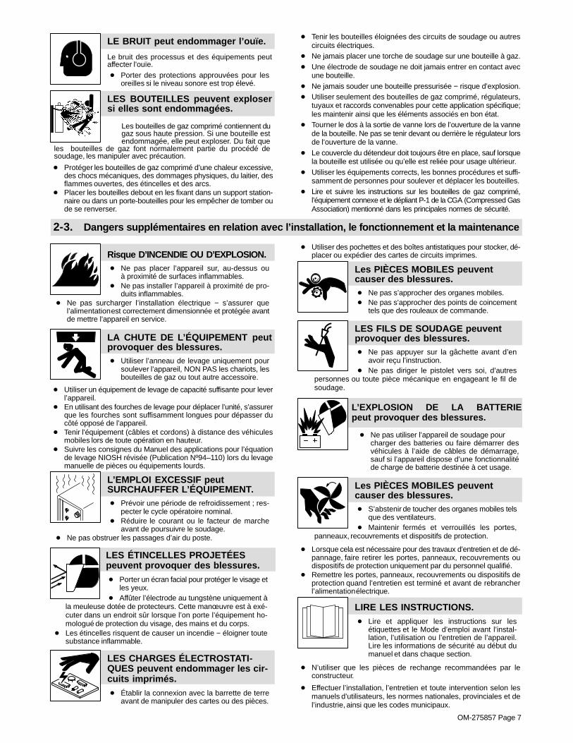
LE BRUIT peut endommager l’ouïe.
Le bruit des processus et des équipements peutaffecter l’ouïe.� Porter des protections approuvées pour les
oreilles si le niveau sonore est trop élevé.
Les bouteilles de gaz comprimé contiennent dugaz sous haute pression. Si une bouteille estendommagée, elle peut exploser. Du fait que
les bouteilles de gaz font normalement partie du procédé desoudage, les manipuler avec précaution.
LES BOUTEILLES peuvent explosersi elles sont endommagées.
� Protéger les bouteilles de gaz comprimé d’une chaleur excessive,des chocs mécaniques, des dommages physiques, du laitier, desflammes ouvertes, des étincelles et des arcs.
� Placer les bouteilles debout en les fixant dans un support station-naire ou dans un porte-bouteilles pour les empêcher de tomber oude se renverser.
� Tenir les bouteilles éloignées des circuits de soudage ou autrescircuits électriques.
� Ne jamais placer une torche de soudage sur une bouteille à gaz.� Une électrode de soudage ne doit jamais entrer en contact avec
une bouteille.� Ne jamais souder une bouteille pressurisée − risque d’explosion.� Utiliser seulement des bouteilles de gaz comprimé, régulateurs,
tuyaux et raccords convenables pour cette application spécifique;les maintenir ainsi que les éléments associés en bon état.
� Tourner le dos à la sortie de vanne lors de l’ouverture de la vannede la bouteille. Ne pas se tenir devant ou derrière le régulateur lorsde l’ouverture de la vanne.
� Le couvercle du détendeur doit toujours être en place, sauf lorsquela bouteille est utilisée ou qu’elle est reliée pour usage ultérieur.
� Utiliser les équipements corrects, les bonnes procédures et suffi-samment de personnes pour soulever et déplacer les bouteilles.
� Lire et suivre les instructions sur les bouteilles de gaz comprimé,l’équipement connexe et le dépliant P-1 de la CGA (Compressed GasAssociation) mentionné dans les principales normes de sécurité.
2-3. Dangers supplémentaires en relation avec l’installation, le fonctionnement et la maintenance
Risque D’INCENDIE OU D’EXPLOSION.� Ne pas placer l’appareil sur, au-dessus ou
à proximité de surfaces inflammables.� Ne pas installer l’appareil à proximité de pro-
duits inflammables.� Ne pas surcharger l’installation électrique − s’assurer que
l’alimentation est correctement dimensionnée et protégée avantde mettre l’appareil en service.
LA CHUTE DE L’ÉQUIPEMENT peutprovoquer des blessures.� Utiliser l’anneau de levage uniquement pour
soulever l’appareil, NON PAS les chariots, lesbouteilles de gaz ou tout autre accessoire.
� Utiliser un équipement de levage de capacité suffisante pour leverl’appareil.
� En utilisant des fourches de levage pour déplacer l’unité, s’assurerque les fourches sont suffisamment longues pour dépasser ducôté opposé de l’appareil.
� Tenir l’équipement (câbles et cordons) à distance des véhiculesmobiles lors de toute opération en hauteur.
� Suivre les consignes du Manuel des applications pour l’équationde levage NIOSH révisée (Publication Nº94–110) lors du levagemanuelle de pièces ou équipements lourds.
L’EMPLOI EXCESSIF peutSURCHAUFFER L’ÉQUIPEMENT.� Prévoir une période de refroidissement ; res-
pecter le cycle opératoire nominal.� Réduire le courant ou le facteur de marche
avant de poursuivre le soudage.� Ne pas obstruer les passages d’air du poste.
LES ÉTINCELLES PROJETÉESpeuvent provoquer des blessures.� Porter un écran facial pour protéger le visage et
les yeux.� Affûter l’électrode au tungstène uniquement à
la meuleuse dotée de protecteurs. Cette manœuvre est à exé-cuter dans un endroit sûr lorsque l’on porte l’équipement ho-mologué de protection du visage, des mains et du corps.
� Les étincelles risquent de causer un incendie − éloigner toutesubstance inflammable.
LES CHARGES ÉLECTROSTATI-QUES peuvent endommager les cir-cuits imprimés.� Établir la connexion avec la barrette de terre
avant de manipuler des cartes ou des pièces.
� Utiliser des pochettes et des boîtes antistatiques pour stocker, dé-placer ou expédier des cartes de circuits imprimes.
Les PIÈCES MOBILES peuventcauser des blessures.� Ne pas s’approcher des organes mobiles.� Ne pas s’approcher des points de coincement
tels que des rouleaux de commande.
LES FILS DE SOUDAGE peuventprovoquer des blessures.� Ne pas appuyer sur la gâchette avant d’en
avoir reçu l’instruction.� Ne pas diriger le pistolet vers soi, d’autres
personnes ou toute pièce mécanique en engageant le fil desoudage.
L’EXPLOSION DE LA BATTERIEpeut provoquer des blessures.
� Ne pas utiliser l’appareil de soudage pour charger des batteries ou faire démarrer desvéhicules à l’aide de câbles de démarrage,sauf si l’appareil dispose d’une fonctionnalitéde charge de batterie destinée à cet usage.
Les PIÈCES MOBILES peuventcauser des blessures.� S’abstenir de toucher des organes mobiles tels
que des ventilateurs.� Maintenir fermés et verrouillés les portes,
panneaux, recouvrements et dispositifs de protection.
� Lorsque cela est nécessaire pour des travaux d’entretien et de dé-pannage, faire retirer les portes, panneaux, recouvrements oudispositifs de protection uniquement par du personnel qualifié.
� Remettre les portes, panneaux, recouvrements ou dispositifs deprotection quand l’entretien est terminé et avant de rebrancherl’alimentation électrique.
LIRE LES INSTRUCTIONS.� Lire et appliquer les instructions sur les
étiquettes et le Mode d’emploi avant l’instal-lation, l’utilisation ou l’entretien de l’appareil.Lire les informations de sécurité au début dumanuel et dans chaque section.
� N’utiliser que les pièces de rechange recommandées par leconstructeur.
� Effectuer l’installation, l’entretien et toute intervention selon lesmanuels d’utilisateurs, les normes nationales, provinciales et del’industrie, ainsi que les codes municipaux.

OM-275857 Page 8
LE RAYONNEMENT HAUTEFRÉQUENCE (H.F.) risque deprovoquer des interférences.
� Le rayonnement haute fréquence (H.F.) peut provoquer des interférences avec les équi-
pements de radio−navigation et de communication, les servicesde sécurité et les ordinateurs.
� Demander seulement à des personnes qualifiées familiarisées avecdes équipements électroniques de faire fonctionner l’installation.
� L’utilisateur est tenu de faire corriger rapidement par un électricienqualifié les interférences résultant de l’installation.
� Si le FCC signale des interférences, arrêter immédiatement l’appareil.
� Effectuer régulièrement le contrôle et l’entretien de l’installation.
� Maintenir soigneusement fermés les portes et les panneaux dessources de haute fréquence, maintenir les éclateurs à une distan-ce correcte et utiliser une terre et un blindage pour réduire lesinterférences éventuelles.
LE SOUDAGE À L’ARC risque deprovoquer des interférences.� L’énergie électromagnétique risque de
provoquer des interférences pour l’équipementélectronique sensible tel que les ordinateurs etl’équipement commandé par ordinateur tel queles robots.
� Veiller à ce que tout l’équipement de la zone de soudage soit com-patible électromagnétiquement.
� Pour réduire la possibilité d’interférence, maintenir les câbles desoudage aussi courts que possible, les grouper, et les poser aussibas que possible (ex. par terre).
� Veiller à souder à une distance de 100 mètres de tout équipementélectronique sensible.
� Veiller à ce que ce poste de soudage soit posé et mis à la terreconformément à ce mode d’emploi.
� En cas d’interférences après avoir pris les mesures précédentes,il incombe à l’utilisateur de prendre des mesures supplémentairestelles que le déplacement du poste, l’utilisation de câbles blindés,l’utilisation de filtres de ligne ou la pose de protecteurs dans la zonede travail.
2-4. Proposition californienne 65 Avertissements
Les équipements de soudage et de coupage produisent desfumées et des gaz qui contiennent des produits chimiquesdont l’État de Californie reconnaît qu’ils provoquent des mal-formations congénitales et, dans certains cas, des cancers.(Code de santé et de sécurité de Californie, chapitre 25249.5et suivants)
Ce produit contient des produits chimiques, notamment duplomb, dont l’État de Californie reconnaît qu’ils provoquentdes cancers, des malformations congénitales ou d’autresproblèmes de procréation. Se laver les mains aprèsutilisation.
2-5. Principales normes de sécurité
Safety in Welding, Cutting, and Allied Processes, ANSI Standard Z49.1,is available as a free download from the American Welding Society athttp://www.aws.org or purchased from Global Engineering Documents(phone: 1-877-413-5184, website: www.global.ihs.com).Safe Practices for the Preparation of Containers and Piping for Weldingand Cutting, American Welding Society Standard AWS F4.1, from Glob-al Engineering Documents (phone: 1-877-413-5184, website:www.global.ihs.com).Safe Practices for Welding and Cutting Containers that have Held Com-bustibles, American Welding Society Standard AWS A6.0, from GlobalEngineering Documents (phone: 1-877-413-5184,website: www.global.ihs.com).National Electrical Code, NFPA Standard 70, from National Fire Protec-tion Association, Quincy, MA 02269 (phone: 1-800-344-3555, website:www.nfpa.org and www. sparky.org).Safe Handling of Compressed Gases in Cylinders, CGA Pamphlet P-1,from Compressed Gas Association, 14501 George Carter Way, Suite103, Chantilly, VA 20151 (phone: 703-788-2700, website:www.cga-net.com).Safety in Welding, Cutting, and Allied Processes, CSA StandardW117.2, from Canadian Standards Association, Standards Sales, 5060
Spectrum Way, Suite 100, Mississauga, Ontario, Canada L4W 5NS(phone: 800-463-6727, website: www.csagroup.org).Safe Practice For Occupational And Educational Eye And Face Protec-tion, ANSI Standard Z87.1, from American National Standards Institute,25 West 43rd Street, New York, NY 10036 (phone: 212-642-4900, web-site: www.ansi.org).Standard for Fire Prevention During Welding, Cutting, and Other HotWork, NFPA Standard 51B, from National Fire Protection Association,Quincy, MA 02269 (phone: 1-800-344-3555, website: www.nfpa.org).OSHA, Occupational Safety and Health Standards for General Indus-try, Title 29, Code of Federal Regulations (CFR), Part 1910, Subpart Q,and Part 1926, Subpart J, from U.S. Government Printing Office, Super-intendent of Documents, P.O. Box 371954, Pittsburgh, PA 15250-7954(phone: 1-866-512-1800) (there are 10 OSHA Regional Offices—phone for Region 5, Chicago, is 312-353-2220, website:www.osha.gov).Applications Manual for the Revised NIOSH Lifting Equation, The Na-tional Institute for Occupational Safety and Health (NIOSH), 1600Clifton Rd, Atlanta, GA 30329-4027 (phone: 1-800-232-4636, website:www.cdc.gov/NIOSH).
2-6. Informations relatives aux CEM
Le courant électrique qui traverse tout conducteur génère des champsélectromagnétiques (CEM) à certains endroits. Le courant issu d’unsoudage à l’arc (et de procédés connexes, y compris le soudage parpoints, le gougeage, le découpage plasma et les opérations dechauffage par induction) crée un champ électromagnétique (CEM)autour du circuit de soudage. Les champs électromagnétiques produitspeuvent causer interférence à certains implants médicaux, p. ex. lesstimulateurs cardiaques. Des mesures de protection pour les porteursd’implants médicaux doivent être prises: Limiter par exemple tout accèsaux passants ou procéder à une évaluation des risques individuels pourles soudeurs. Tous les soudeurs doivent appliquer les procéduressuivantes pour minimiser l’exposition aux CEM provenant du circuit desoudage:
1. Rassembler les câbles en les torsadant ou en les attachant avecdu ruban adhésif ou avec une housse.
2. Ne pas se tenir au milieu des câbles de soudage. Disposer les
câbles d’un côté et à distance de l’opérateur.3. Ne pas courber et ne pas entourer les câbles autour de votre
corps.4. Maintenir la tête et le torse aussi loin que possible du matériel du
circuit de soudage.5. Connecter la pince sur la pièce aussi près que possible de la
soudure.6. Ne pas travailler à proximité d’une source de soudage, ni
s’asseoir ou se pencher dessus.7. Ne pas souder tout en portant la source de soudage ou le
dévidoir.En ce qui concerne les implants médicaux :Les porteurs d’implants doivent d’abord consulter leur médecin avantde s’approcher des opérations de soudage à l’arc, de soudage parpoints, de gougeage, du coupage plasma ou de chauffage par induc-tion. Si le médecin approuve, il est recommandé de suivre lesprocédures précédentes.

� A complete Parts List is available at www.MillerWelds.com
OM-275857 Page 9
SECTION 3 − DEFINITIONS
3-1. Additional Safety Symbols And Definitions� Some symbols are found only on CE products.
Warning! Watch Out! There are possible hazards as shown by the symbols.
Safe1 2012−05
Wear dry insulating gloves. Do not touch electrode with bare hand. Do not wear wet or damaged gloves.
Safe2 2012−05
Protect yourself from electric shock by insulating yourself from work and ground.
Safe3 2012−05
Disconnect input plug or power before working on machine.
Safe5 2012−05
Keep your head out of the fumes.
Safe6 2012−05
Use forced ventilation or local exhaust to remove the fumes.
Safe8 2012−05
Use ventilating fan to remove fumes.
Safe10 2012−05
Keep flammables away from welding. Do not weld near flammables.
Safe12 2012−05
Welding sparks can cause fires. Have a fire extinguisher nearby, and have a watchperson ready to use it.
Safe14 2012−05
Do not weld on drums or any closed containers.
Safe16 2012−05
Do not remove or paint over (cover) the label.
Safe20 2012−05

� A complete Parts List is available at www.MillerWelds.com
OM-275857 Page 10
Do not discard product (where applicable) with general waste.
Reuse or recycle Waste Electrical and Electronic Equipment (WEEE) by disposing at a designated collectionfacility.
Contact your local recycling office or your local distributor for further information.Safe37 2012−05
Environmental Protection Use Period (China)
Safe123 2016−06
Disconnect input plug or power before working on machine.
Safe30 2012−05
When power is applied failed parts can explode or cause other parts to explode.
Safe26 2012−05
Always wear long sleeves and button your collar when servicing unit.
Safe28 2012−05
After taking proper precautions as shown, connect power to unit.
Safe29 2012−05
Do not use one handle to lift or support unit.
Safe31 2012−05
=< 60° Always lift and support unit using both handles. Keep angle of liftingdevice less than 60 degrees.
Use a proper cart to move unit.
Safe44 2012−05
>60s
V
V
V
Hazardous voltage remains on input capacitors after power is turnedoff. Do not touch fully charged capacitors. Always wait 60 secondsafter power is turned off before working on unit, OR check input ca-pacitor voltage, and be sure it is near 0 before touching any parts.
Safe42 2012−05
Become trained and read the instructions before working on themachine or welding.
Safe40 2012−05
Wear hat and safety glasses. Use ear protection and button shirtcollar. Use welding helmet with correct shade of filter. Wear completebody protection.
Safe38 2012−05

� A complete Parts List is available at www.MillerWelds.com
OM-275857 Page 11
3-2. Miscellaneous Symbols And Definitions� Some symbols are found only on CE products.
A Amperage
Output
Gas Tungsten ArcWelding (GTAW)
Shielded MetalArc Welding
(SMAW)
V Volts
Input
3 Phase StaticFrequency
Converter-Transformer-Rectifier
Output
SupplementaryProtector
Remote
Lift-Arc (GTAW)
Protective Earth(Ground)
Postflow Timer
Preflow Timer
S Seconds
On
Off
Positive
Negative
AlternatingCurrent
Gas Input
Gas Output
I2Rated Welding
Current
X Duty Cycle
Direct Current
Line Connection
U2ConventionalLoad Voltage
U1 Primary Voltage
IP Degree OfProtection
I1maxRated MaximumSupply Current
I1eff
MaximumEffective Supply
Current
U0Rated No LoadVoltage (OCV)
Polarity Control
Initial Amperage
Increase/Decrease Of
Quantity
Remote Standard
Remote 2T Hold
Gas/DIG Control
Percent
Hz Hertz
Recall FromMemory
Arc Force (DIG)
Impulse Starting(GTAW)
Final Slope
Final Amperage
Pulse PercentOn Time
Initial Slope
AC WaveshapeControl
Pulser
EP Amperage
Pulse Frequency
Work
Electrode
EN Amperage
Process
Unit may be usedin environmentswith increased
hazard of electricshock
Sequence
BackgroundAmperage
f AC Frequency
Water (Coolant)Input
Water (Coolant)Output
Circulating UnitWith Coolant
Pump

� A complete Parts List is available at www.MillerWelds.com
OM-275857 Page 12
SECTION 4 − SPECIFICATIONS
4-1. Serial Number And Rating Label LocationThe serial number and rating information for the power source is located on the front of the machine. Use the rating labels to determine input powerrequirements and/or rated output. For future reference, write serial number in space provided on back cover of this manual.
4-2. Specifications
� Do not use information in unit specifications tables to determine electrical service requirements. See Sections 5-14 and 5-15 for information onconnecting input power.
� This equipment will deliver rated output at an ambient air temperature up to 104�F ( 40�C).
A. Dynasty 400 Models
� Do not use information in unit specifications table to determine electrical service requirements. See Section 5-14 A for information on connectinginput power.
Welding AmperageRange
Max Open CircuitVoltage (Uo)
Low Open-CircuitVoltage (Uo)
Rated Peak StrikingVoltage (Up)
IP Rating
3-400* 75♦ 10-15*** 14KV** 23
*Welding range for Stick process is 5-400 amperes. For TIG, the amperage range is tungsten diameter dependent (see Section 7-1).
** Arc starting device is designed for manual guided operations.
*** Low open-circuit voltage while in TIG Lift Arc�, or while in Stick with low open-circuit voltage selected.
♦ Normal open-circuit voltage (75) is present while in Stick with normal open_circuit voltage selected.
InputPower
Rated Welding
Output
Amperes Input at Rated Load Output 50/60 Hz
208 V 230 V 380 V 400 V 460 V 575 V KVA KW
ThreePhase
250 A @ 30 Volts,100% Duty Cycle 28 25 15 14 13 10 10.3 9.8
300 A @ 32 Volts,60% Duty Cycle
36 33 19 19 16 13 13.1 12.5
400 @ 36 Volts,20% Duty Cycle
55 49 29 28 24 19 19.4 18.6
SinglePhase
200 A @ 28 Volts,100% Duty Cycle
40 36 − 20 17 13 8.2 7.5
250 A @ 30 Volts,60% Duty Cycle
52 47 − 26 22 17 10.9 9.9
300 A @ 32 Volts,20% Duty Cycle
67 60 − 33 28 22 13.9 12.7
� This unit is equipped with Auto-Line. Auto-Line is an internal inverter power source circuit that automatically links the power source to anyprimary input voltage from 190 to 625 volts, single-or-three-phase, 50 or 60 hertz. It also adjusts for voltage spikes within the entire range.

� A complete Parts List is available at www.MillerWelds.com
OM-275857 Page 13
B. Maxstar 400 Models
� Do not use information in unit specifications table to determine electrical service requirements. See Section 5-14B for information on connectinginput power.
Welding AmperageRange
Max Open CircuitVoltage (Uo)
Low Open-CircuitVoltage (Uo)
Rated Peak StrikingVoltage (Up)
IP Rating
3-400* 75♦ 10-15*** 14KV** 23
*Welding range for Stick process is 5-400 amperes. For TIG, the amperage range is tungsten diameter dependent (see Section 7-1).
** Arc starting device is designed for manual guided operations.
*** Low open-circuit voltage while in TIG Lift Arc�, or while in Stick with low open-circuit voltage selected.
♦ Normal open-circuit voltage (75) is present while in Stick with normal open_circuit voltage selected.
Input PowerRated Welding
Output
Amperes Input at Rated Load Output 50/60 Hz
208 V 230 V 380 V 400 V 460 V 575 V KVA KW
Three Phase
250 A @ 30 Volts,100% Duty Cycle 26 23 14 13 12 9 9.4 9.1
300 A @ 32 Volts,60% Duty Cycle
33 30 18 17 15 12 12 11.6
400 @ 36 Volts,20% Duty Cycle
50 45 27 25 22 17 18.1 17.3
Single Phase
200 A @ 28 Volts,100% Duty Cycle
37 33 − 18 18 12 7.4 6.9
250 A @ 30 Volts,60% Duty Cycle
48 43 − 24 20 16 10.0 9.2
300 A @ 32 Volts,20% Duty Cycle
62 55 − 30 28 20 12.8 11.8
� This unit is equipped with Auto-Line�. Auto-Line is an internal inverter power source circuit that automatically links the power source to anyprimary input voltage from 190 to 625 volts, single-or-three-phase, 50 or 60 hertz. Also adjusts for voltage spikes within the entire range.
4-3. Dimensions, Weights And Base Mounting Hole Layout
� Overall dimensions (A, B, and C) include lifting eye, handles, hardware, etc.
A. Welding Power Source
B
A
C
803 914-A
CD
FG
E
Dimensions
A 24.75 in (629 mm)
B 13.75 in. (349 mm)
C 22 in. (559 mm)
D 20.5 in. (521 mm)
E 1 in. (25 mm)
F 11.75 in. (298 mm)
G0.5 in. Dia. (13 mm Dia.)
4 Holes
Weight
134 lb (60.8 kg)

� A complete Parts List is available at www.MillerWelds.com
OM-275857 Page 14
B. Welding Power Source With Cart And Cooler
B
A
C
804 642-C
Dimensions
A 43.125 in. (1095 mm)
B 23.125 in. (587 mm)
C 43.75 in. (1111 mm)
Weight
250.5 lb (113.6 Kg)
4-4. Environmental SpecificationsA. IP Rating (All Models)
IP Rating
IP23
This equipment is designed for outdoor use. It may be stored, but is not intended to be used for welding outside during precipitation unlesssheltered.
IP23 2014−06
B. Temperature Specifications
Operating Temperature Range* Storage/Transportation Temperature Range
14 to 104 °F (-10 to 40°C)
*Output is derated at temperatures above 104°F (40°C).−4 to 131 °F (−20 to 55°C)
Temp_2016- 07
C. Information On Electromagnetic Compatibility (EMC)
! This Class A equipment is not intended for use in residential locations where the electrical power is provided by the public low−voltage supply system. There can be potential difficulties in ensuring electromagnetic compatibility in those locations, due to con-ducted as well as radiated disturbances.
This equipment complies with IEC61000-3-11 and IEC 61000−3−12 and can be connected to public low-voltage systems provided that the publiclow-voltage system impedance Zmax at the point of common coupling is less than 42.7m� (or the short−circuit power Ssc is greater than 3,746,329
VA). It is the responsibility of the installer or user of the equipment to ensure, by consultation with the distribution network operator if necessary,that the system impedance complies with the impedance restrictions. ce-emc 1 2014-07
� A complete Parts List is available at www.MillerWelds.com
OM-275857 Page 15
D. China EEP Hazardous Substance Information
������������ ����
China EEP Hazardous Substance Information
�� �Component Name(����)(if applicable)
��
Hazardous Substance
�
Pb�Hg
�
Cd���
Cr6���
PBB���
PBDE
������Brass and Copper Parts X O O O O O
�� �Coupling Devices X O O O O O
! �Switching Devices O O X O O O
"#�"#��Cable and CableAccessories
X O O O O O
�$Batteries X O O O O O
%�&'*��SJ/T 11364��,-..This table is prepared in accordance with China SJ/T 11364.
O:�2���5���78�9:����85��GB/T26572�,����>[email protected] that the concentration of the Hazardous Substance in all homogeneous materials of the part is below the relevant threshold of ChinaGB/T 26572.
X:�2���AC5����DE8�9:�����F��GB/T26572�,����>.Indicates that the concentration of the Hazardous Substance in at least one homogeneous material of the part is above the relevant threshold ofChina GB/T 26572.
�������HIK�L�'*��SJ/Z11388��,N,.
The EFUP value of this EEP is defined in accordance with China SJ/Z 11388. EEP_2016−06
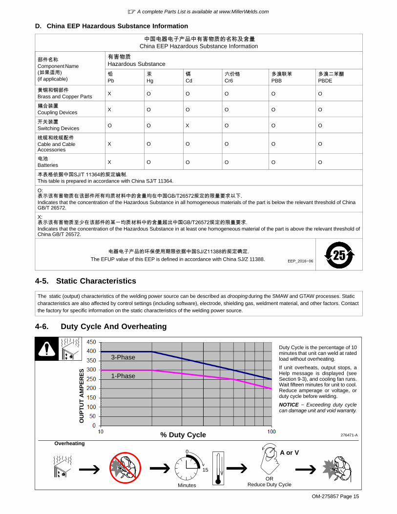
4-5. Static Characteristics
The static (output) characteristics of the welding power source can be described as drooping during the SMAW and GTAW processes. Staticcharacteristics are also affected by control settings (including software), electrode, shielding gas, weldment material, and other factors. Contactthe factory for specific information on the static characteristics of the welding power source.
4-6. Duty Cycle And Overheating
Duty Cycle is the percentage of 10minutes that unit can weld at ratedload without overheating.
If unit overheats, output stops, aHelp message is displayed (seeSection 9-3), and cooling fan runs.Wait fifteen minutes for unit to cool.Reduce amperage or voltage, orduty cycle before welding.
NOTICE − Exceeding duty cyclecan damage unit and void warranty.
Overheating
0
15
A or V
ORReduce Duty CycleMinutes
276471-A
3-Phase
1-Phase
% Duty Cycle
OU
PT
UT
AM
PE
RE
S
� A complete Parts List is available at www.MillerWelds.com
OM-275857 Page 16
SECTION 5 − INSTALLATION
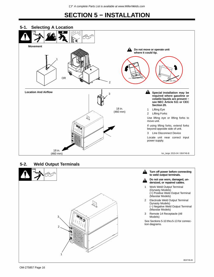
! Special installation may berequired where gasoline orvolatile liquids are present −see NEC Article 511 or CECSection 20.
1 Lifting Eye2 Lifting Forks
Use lifting eye or lifting forks tomove unit.
If using lifting forks, extend forksbeyond opposite side of unit.
3 Line Disconnect Device
Locate unit near correct inputpower supply.
5-1. Selecting A Location
3
18 in.(460 mm)
18 in.(460 mm)
OR
1
2
Movement
Location And Airflow
loc_large 2015-04 / 804746-B
! Do not move or operate unitwhere it could tip.
5-2. Weld Output Terminals
804746-B
! Turn off power before connectingto weld output terminals.
! Do not use worn, damaged, un-dersized, or repaired cables.
1 Work Weld Output Terminal(Dynasty Models)(+) Positive Weld Output Terminal(Maxstar Models)
2 Electrode Weld Output TerminalDynasty Models)(−) Negative Weld Output Terminal(Maxstar Models)
3 Remote 14 Receptacle (AllModels)
See Sections 5-10 thru 5-13 for connec-tion diagrams.
2
1
3

� A complete Parts List is available at www.MillerWelds.com
OM-275857 Page 17
5-3. Weld Output Terminals And Selecting Cable Sizes*NOTICE − The Total Cable Length in Weld Circuit (see table below) is the combined length of both weld cables. For example, if the power source is 100ft (30 m) from the workpiece, the total cable length in the weld circuit is 200 ft (2 cables x 100 ft). Use the 200 ft (60 m) column to determine cable size.
Weld Cable Size** and Total Cable (Copper) Length in Weld Circuit Not Exceeding
100 ft (30 m) or Less**** 150 ft(45 m)
200 ft(60 m)
Welding Amperes***10 − 60% Duty Cycle
AWG (mm2)
60 − 100% Duty Cycle
AWG (mm2)
10 − 100% Duty Cycle
AWG (mm2)
100 4 (20) 4 (20) 4 (20) 3 (30)
150 3 (30) 3 (30) 2 (35) 1 (50)
200 3 (30) 2 (35) 1 (50) 1/0 (60)
250 2 (35) 1 (50) 1/0 (60) 2/0 (70)
300 1 (50) 1/0 (60) 2/0 (70) 3/0 (95)
350 1/0 (60) 2/0 (70) 3/0 (95) 4/0 (120)
400 1/0 (60) 2/0 (70) 3/0 (95) 4/0 (120)
500 2/0 (70) 3/0 (95) 4/0 (120) 2x2/0 (2x70)
* This chart is a general guideline and may not suit all applications. If cable overheats, use next size larger cable.
**Weld cable size (AWG) is based on either a 4 volts or less drop or a current density of at least 300 circular mils per ampere.( ) = mm2 for metric use
*** Select weld cable size for pulsing application at peak amperage value.
****For distances longer than 100 ft (30 m) and up to 200 ft (60 m), use direct current (DC) output only. For distances longer than those shownin this guide, call a factory applications rep. at 920-735-4505 (Miller) or 1-800-332-3281 (Hobart).
Ref. S-0007-L 2015−02 (TIG)
Notes
Work like a Pro!
Pros weld and cut
safely. Read the
safety rules at
the beginning
of this manual.

� A complete Parts List is available at www.MillerWelds.com
OM-275857 Page 18
5-4. Remote 14 Receptacle Information
804746-B / 218 716-A
A JB K I
C L N H
D M GE F
Socket Socket Information
15 VOLTS DC
OUTPUTCONTACTOR
A Contactor control +15 volts DC, referenced to G.
B Contact closure to A completes 15 volts DCcontactor control circuit and enables output.
REMOTEOUTPUT
CONTROL
C Output to remote control; +10 volts DC output toremote control.
D Remote control circuit common.
E 0 to +10 volts DC input command signal fromremote control.*Reconfigurable as input for Output Enable (WeldStop) − used to remotely stop the weld outside thenormal welding cycle. Connection to the D socketmust be maintained at all times. If the connectionis broken, output stops, and Auto Stop is dis-played.
OutputSignals
F Current feedback; +1 volt DC per 100 amperes.
H Voltage feedback; +1 volt DC per 10 volts output.
I* Valid arc indication closed to socket G with validarc. Electrical specifications: open collector tran-sistor (see Section 5-5 for connection example).
J*
**
Arc length control lockout closed to socket G dur-ing Initial and Final Amperage and Slope, and dur-ing the background time of a <=10 Hz pulse wave-form. Electrical specifications: open collector tran-sistor (see Section 5-5 for connection example).
Touch Sense Detection closed to Socket G, withModbus’s Touch Sense enabled and machine nottriggered for weld output.
COMMON G Return for all output signals: F, H, I, J and A.
CHASSIS K Chassis
SerialCommunicationBus
L** Modbus Common (RS485 Common)
M** Modbus D1 (RS485 B+)
N** Modbus D0 (RS485 A-)
� If a remote hand control like the RHC-14 is connected to the Remote 14 receptacle, some current value above min. must be set on the remotecontrol before the Panel or Remote contactor is turned on. Failure to do so will cause current to be controlled by the panel control, and the remotehand control will not function.*Available with optional Automation Expansion memory card.**Available with optional Modbus Expansion memory card. Modbus serial communication provides access to all front panel parameters andmachine functionality. See Owner’s Manual 265415 for a list of Modbus registers. Modbus expansion also includes functionality of Automation,Hot Wire, and Hot Start Adjust expansions.
Sockets G and K are electrically isloated from each other.
5-5. Simple Automation Application (14-Pin Interface)
R
CR1
+
−
CR1 To User EquipmentCoil resistance plusRshould be chosen tolimit current to 75 mA
User supplied powerup to 27 volts DCpeak
Pin I, J: Collector
Pin G: Emitter
� This application requires the pur-chase of the automation expansionmodule, Miller Part No. 301151.

� A complete Parts List is available at www.MillerWelds.com
OM-275857 Page 19
5-6. Automation Connection (For 28-Pin Receptacle If Present)A. Basic Automation ModeUse this mode when only the basic functions of the automation board are required. These functions include Start/Stop, Valid Arc Indication, Gas Con-trol, High Frequency Arc Start Disable, and Remote Memory Select. The welding power source functions as a standard unit. Automation 2 mode shouldbe used when an externally controlled pulse waveform is needed, or if the welder’s amperage is affected by noise injected into the cabling betweenthe remote equipment and the welder.
804746-B / 218716-A
1
4
9
15
21
2628
25
20
14
8
3 2
7 6 5
13 12 11 10
19 18 17 16
24 23 22
27
PinSignal Direction Pin Information For 28-Pin Receptacle RC28
1 Input Start/Stop = Maintained connection to pin 8 starts the weld cycle. Opening connection stops weld cycle. For moment-ary closure operation, set unit to 2T, A momentary closure greater than 100 ms, but less than 3/4 of a second starts andstops weld output.
3 Input Gas Control = This input is used to control the gas flow outside the settings of the preflow and/or postflow set on themachine. Connection to pin 8 turns on gas.
4 Output Valid Arc Indication = Paired with Pin 9. This output is used to signal external fixtures that the machine has detected avalid arc. Pin is closed to pin 9 when the output is on and there is less than 65 load volts. Electrical specifications: Opencollector transistor maximum values 27 volts DC peak @ 75mA. (See Section 5-5 for typical application).
5 Output Scaled Actual Welding Voltage = +1 volt DC per 10 volts of output w/reference to pin 11.
6 Output Scaled Actual Welding Amperage = +1 volt DC per 100 amperes of output w/reference to pin 11.
7 Output +15volts DC with respect to pin 11 (Pin A of 14 pin)
8 Output Reference PIN = This pin is the signal reference for pins 1,2,3,10,15,16
9 Output Valid Arc Indication Reference = Paired with Pin 4. Connect to user’s external voltage supply common. (See Section5-5 for typical application).
10 Input Memory Select = Used to select between memory numbers. Used in conjunction with pin 15 and 16. (See Sections 5-7and 6-6.)
11 Output Amperage Control Reference = for pins 5,6,7,17 and 18. (Pin D of 14 pin)
12 Output Welders Chassis = Earth ground. Connected only if common potentials are needed between user equipment and thewelder.
13 Output Arc Length Control Lockout = Paired with Pin 14. Used to send signal to an automatic voltage control to ignore thevoltage during certain situations. Pin is closed to pin 14 when weld cycle is in Initial Amperage, Initial Slope, Final Slope,Final Amperage, and Pulsed Background time. Electrical specifications: Open collector transistor maximum values 27volts DC peak @ 75mA. (See Section 5-5 for typical application)
14 Output Arc Length Control Lockout Reference = Paired with Pin 13. Connect to user’s external voltage supply common (SeeSection 4-17 for typical application).
15 Input Memory Select = Used to select between memory numbers. Used in conjunction with pin 10 and 16. (See Sections 5-7and 6-6.)
16 Input Memory Select = Used to select between memory numbers. Used in conjunction with pin 10 and 15. (See Sections 5-7and 6-6.)
17 Input Amperage Control = 0 to +10 volts DC with respect to pin 11. The 10 volts represents the amperage value set on ma-chines meter. (Pin E of 14 pin)
Continued on next page

� A complete Parts List is available at www.MillerWelds.com
OM-275857 Page 20
Continued from previous page Section A.
18 Output +10 volts DC with respect to pin 11 for use with an external potentiometer to vary the signal into pin 17 (Pin C of 14 pin)
19 Input High Frequency Arc Start Disable = Disables the arc starter from being activated when connected to pin 8.
23 Output Final Slope Sequence Indication = Paired with Pin 24. Pin is closed to pin 24 when in Final Slope. Electrical specifica-tions: Open collector transistor maximum values 27 volts DC peak @ 75mA. (See Section 5-5 for typical application).
24 Output Final Slope Sequence Indication Reference = Paired with pin 23. Connect to user’s external voltage supply common.(See Section 5-5 for typical application).
All other pins not used.
B. Welder Controlled Automation Mode (Pin 20 Connected To Pin 8) Automation 1Use this mode when only the basic functions of the automation board are required, or if the welder needs to control the initial and final weld timers. Thesefunctions include Start/Stop, Valid Arc Indication, Gas Control, High Frequency Arc Start Disable, Remote Memory Select, and Emergency weld stop.The welding power source functions as a standard unit. Automation 2 mode should be used when an externally controlled pulse waveform is needed, orif the welder’s amperage is affected by noise injected into the cabling between the remote equipment and the welder.
804746-B / 218716-A
1
4
9
15
21
2628
25
20
14
8
3 2
7 6 5
13 12 11 10
19 18 17 16
24 23 22
27
PinSignal Direction Pin Information For 28-Pin Receptacle RC28
1 Input Start/Stop = Maintained connection to pin 8 starts the weld cycle. Opening connection stops weld cycle. For momentaryclosure operation, set unit to 2T. A momentary closure greater than 100 ms, but less than 3/4 of a second starts andstops weld output.
2 Input Emergency Weld Stop = Used to remotely stop the weld outside the normal welding cycle (i.e. light curtains or externalE-Stop). Connection to pin 8 must be maintained at all times. If the connection is broken, output stops, Postflow begins,and AUTO STOP will be displayed on the meters.
3 Input Gas Control = This input is used to control the gas flow outside the settings of the preflow and/or postflow set on themachine. Connection to pin 8 turns on gas.
4 Output Valid Arc Indication = Paired with Pin 9. This output is used to signal external fixtures that the machine has detected avalid arc. Pin is closed to pin 9 when the output is on and there is less than 65 load volts. Electrical specifications: Opencollector transistor maximum values 27 volts DC peak @ 75mA. (See Section 5-5 for typical application).
5 Output Scaled Actual Welding Voltage = +1 volt DC per 10 volts of output w/reference to pin 11.
6 Output Scaled Actual Welding Amperage = +1 volt DC per 100 amperes of output w/reference to pin 11.
7 Output +15 volts DC with respect to pin 11 (Pin A of 14 pin)
8 Output Reference PIN= This pin is the signal reference for pins 1,2,3,10,15,16
9 Output Valid Arc Indication Reference = Paired with Pin 4. Connect to user’s external voltage supply common. (See Section5-5 for typical application).
10 Input Memory Select = Used to select between memory numbers. Used in conjunction with pins 15 and 16. (See Sections 5-7and 6-6.)
11 Output Amperage Control Reference = for pins 5,6,7,17 and 18. (Pin D of 14 pin)
12 Output Welders Chassis = Earth ground. Connected only if common potentials are needed between user equipment and thewelder.
13 Output Arc Length Control Lockout = Paired with Pin 14. Used to send signal to an automatic voltage control to ignore thevoltage during certain situations. Pin is closed to pin 14 when the weld cycle is in Initial Amperage, Initial Slope, FinalSlope, Final Amperage, and Pulsed Background time. Electrical specifications: Open collector transistor maximum val-ues 27volts DC peak @ 75mA. (See Section 5-5 for typical application)
Continued on next page

� A complete Parts List is available at www.MillerWelds.com
OM-275857 Page 21
Continued from previous page Section B.
14 Output Arc Length Control Lockout Reference = Paired with Pin 13. Connect to user’s external voltage supply common (SeeSection 5-5 for typical application).
15 Input Memory Select = Used to select between memory numbers. Used in conjunction with pin 10 and 16. (See Sections 5-7and 6-6.)
16 Input Memory Select = Used to select between memory numbers. Used in conjunction with pin 10 and 15. (See Sections 5-7and 6-6.)
17 Input Amperage Control = 0 to +10 volts DC with respect to pin 11. The 10 volts represents the amperage value set on ma-chines meter. (Pin E of 14 pin)
18 Output +10 volts DC with respect to pin 11 for use with an external potentiometer to vary the signal into pin 17 (Pin C of 14 pin)
19 Input High Frequency Arc Start Disable = Disables the arc starter from being activated when connected to pin 8.
20 Input Welder Control Select = Connect to pin 8 to activate this mode.
23 Output Final Slope Sequence Indication = Paired with Pin 24. Pin is closed to pin 24 when in Final Slope. Electrical specifica-tions: Open collector transistor maximum values 27 volts DC peak @ 75mA. (See Section 5-5 for typical application).
24 Output Final Slope Sequence Indication Reference = Paired with pin 23. Connect to user’s external voltage supply common.(See Section 5-5 for typical application).
All other pins not used.
C. User Controlled Automation Mode (Pin 25 Connected To Pin 8) Automation 2This mode includes all the basic functions of the automation board, plus gives the welder the option to control the pulse or AC waveforms, or to minimizethe noise that can be injected into the welder from the control and cables. These functions include Start/Stop, Valid Arc Indication, Gas Control, HighFrequency Arc Start Disable, and Emergency weld stop.
804746-B / 218 16-A
1
4
9
15
21
2628
25
20
14
8
3 2
7 6 5
13 12 11 10
19 18 17 16
24 23 22
27
PinSignal Direction Pin Information For 28-Pin Receptacle RC28
1 Input Start/Stop = Maintained connection to pin 8 starts the weld cycle. Opening connection stops weld cycle. For momentaryclosure operation, set unit to 2T. A momentary closure greater than 100 ms, but less than 3/4 of a second starts andstops weld output.
2 Input Emergency Weld Stop = Used to remotely stop the weld outside the normal welding cycle (i.e. light curtains or externalE-Stop). Connection to pin 8 must be maintained at all times. If the connection is broken, output stops, Postflow begins,and AUTO STOP will be displayed on the meters.
3 Input Gas Control = This input is used to control the gas flow outside the settings of the preflow and/or postflow set on themachine. Connection to pin 8 turns on gas.
4 Output Valid Arc Indication = Paired with Pin 9. This output is used to signal external fixtures that the machine has detected avalid arc. Pin is closed to pin 9 when the output is on and there is less than 65 load volts. Electrical specifications: Opencollector transistor maximum values 27 volts DC peak @ 75mA. (See Section 5-5 for typical application).
5 Output Scaled Actual Welding Voltage = +1 volt DC per 10 volts of output w/reference to pin 11.
6 Output Scaled Actual Welding Amperage = +1 volt DC per 100 amperes of output w/reference to pin 11.
7 Output +15 volts DC with respect to pin 11 (Pin A of 14 pin)
8 Output Reference PIN = This pin is the signal reference for pins 1,2,3,10,15,16
9 Output Valid Arc Indication Reference = Paired with Pin 4. Connect to user’s external voltage supply common. (See Section5-5 for typical application).
Continued on next page
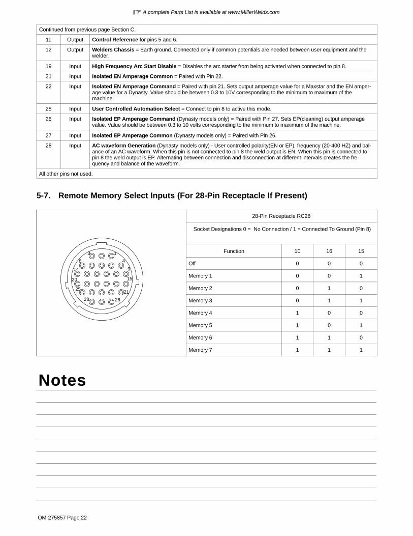
� A complete Parts List is available at www.MillerWelds.com
OM-275857 Page 22
Continued from previous page Section C.
11 Output Control Reference for pins 5 and 6.
12 Output Welders Chassis = Earth ground. Connected only if common potentials are needed between user equipment and thewelder.
19 Input High Frequency Arc Start Disable = Disables the arc starter from being activated when connected to pin 8.
21 Input Isolated EN Amperage Common = Paired with Pin 22.
22 Input Isolated EN Amperage Command = Paired with pin 21. Sets output amperage value for a Maxstar and the EN amper-age value for a Dynasty. Value should be between 0.3 to 10V corresponding to the minimum to maximum of themachine.
25 Input User Controlled Automation Select = Connect to pin 8 to active this mode.
26 Input Isolated EP Amperage Command (Dynasty models only) = Paired with Pin 27. Sets EP(cleaning) output amperagevalue. Value should be between 0.3 to 10 volts corresponding to the minimum to maximum of the machine.
27 Input Isolated EP Amperage Common (Dynasty models only) = Paired with Pin 26.
28 Input AC waveform Generation (Dynasty models only) - User controlled polarity(EN or EP), frequency (20-400 HZ) and bal-ance of an AC waveform. When this pin is not connected to pin 8 the weld output is EN. When this pin is connected topin 8 the weld output is EP. Alternating between connection and disconnection at different intervals creates the fre-quency and balance of the waveform.
All other pins not used.
5-7. Remote Memory Select Inputs (For 28-Pin Receptacle If Present)
1
4
9
15
21
2628
25
20
14
8
3
28-Pin Receptacle RC28
Socket Designations 0 = No Connection / 1 = Connected To Ground (Pin 8)
Function 10 16 15
Off 0 0 0
Memory 1 0 0 1
Memory 2 0 1 0
Memory 3 0 1 1
Memory 4 1 0 0
Memory 5 1 0 1
Memory 6 1 1 0
Memory 7 1 1 1
Notes

� A complete Parts List is available at www.MillerWelds.com
OM-275857 Page 23
5-8. 115 Volts AC Cooler Receptacle, Supplementary Protector CB1, And Power Switch
805593-A
1 AC Cooler Receptacle
Receptacle RC2 supplies 115 V 10A of single-phase power.
� RC2 is a designated use re-ceptacle intended only for sup-plying AC power to a Miller-ap-proved cooler.
2 Supplementary Protector CB1
CB1 protects cooler receptaclefrom overload. If circuit breakeropens, the receptacle does notwork. Press button to resetprotector.
3 Power On/Off Switch
1
2
3
5-9. Gas Connections
805593-A
1 Gas Fitting
Fittings have 5/8-18 right-handthreads.
2 Cylinder Valve
Open valve slightly so gas flowblows dirt from valve. Close valve.
3 Regulator/Flowmeter
4 Flow Adjust
Typical flow rate is 15 cfh (cubic feetper hour).
Connect customer supplied gashose between regulator/flowmeterand gas fitting on rear of unit.
Tools Needed:
11/16, 1-1/8 in.
3 241

� A complete Parts List is available at www.MillerWelds.com
OM-275857 Page 24
5-10. TIG HF Impulse/ Lift-Arc Connections
805594-A
! Turn off power beforemaking connections.
1 Electrode Weld OutputTerminal
Connect TIG torch to electrodeweld output terminal.
2 Gas Out Connection
Connect torch gas hose to gasout fitting.
3 Work Weld Output Terminal
Connect work lead to work weldoutput terminal.
4 Remote 14 Receptacle
If desired, connect remote con-trol to Remote 14 receptacle(see Section 5-4).
5 Gas In Connection
Connect gas hose from gas sup-ply to gas in fitting (see Section5-9).
Tools Needed:
11/16 in. (21 mm for CE units)
2 3
5
4
1
Notes
Work like a Pro!
Pros weld and cut
safely. Read the
safety rules at
the beginning
of this manual.

� A complete Parts List is available at www.MillerWelds.com
OM-275857 Page 25
5-11. Cooler Connections
Cart and cooler are optional equip-ment.
1 AC Cooler Receptacle RC2
� RC2 is a designated use re-ceptacle intended only for sup-plying AC power to a Miller-ap-proved cooler.
2 115 VAC Cord
Provides 115 vac to power cooler.
3 Electrode Weld OutputTerminal (−Weld OutputTerminal On Maxstar Models)
Connect TIG torch to electrodeweld output terminal.
4 Gas Out Connection
Connect TIG torch gas hose to gasout fitting.
5 Work Weld Output Terminal(+Weld Output Terminal OnMaxstar Models)
Connect work lead to work weldoutput terminal.
6 Water-Out (To Torch)Connection
Connect torch water-in (blue) hoseto welding power source water-outconnection.
7 Water-In (From Torch)Connection
Connect torch water-out (red) hoseto welding power source water-inconnection.
Low Conductivity Coolant No. 043 810**;Distilled Or Deionized WaterOK Above 32° F (0° C)
GTAW Or WhereHF* Is UsedApplication
*HF: High Frequency Current
**Coolant 043 810, a 50/50 solution, protect to -37° F (-38°C) and resist algae growth.
Coolant
3
4
5
6
7
805595-A
3-1/2Gal
2
Tools Needed:
11/16 in. (21 mm for CE units)
NOTICE − Use of any coolant other than those listed in the table voids the warrantyon any parts that come in contact with the coolant (pump, radiator, etc.).
1

� A complete Parts List is available at www.MillerWelds.com
OM-275857 Page 26
5-12. Dynasty Stick Connections
805596-A
! Turn off power before makingconnections.
� Connections shown are forDynasty models.
1 Work Weld Output Terminal
Connect work lead to work weld outputterminal.
2 Electrode Weld Output Terminal
Connect electrode holder to electrodeweld output terminal.
3 Remote 14 Receptacle
If desired, connect remote control to Re-mote 14 receptacle (see Section 5-4).
2
1
3
5-13. Maxstar Stick Connections
803916-C
! Turn off power before makingconnections.
� Connections shown are forMaxstar models.
1 + Weld Output Terminal
Connect electrode lead to positive (+)weld output terminal.
2 − Weld Output Terminal
Connect work lead to negative (−) weldoutput terminal.
3 Remote 14 Receptacle
If desired, connect remote control to Re-mote 14 receptacle (see Section 5-4).
2
1
3

� A complete Parts List is available at www.MillerWelds.com
OM-275857 Page 27
5-14. Electrical Service Guide Elec Serv 2017−01
A. Dynasty 400 Models
Failure to follow these electrical service guide recommendations could create an electric shock or fire hazard. These recommenda-tions are for a dedicated circuit sized for the rated output and duty cycle of the welding power source.
In dedicated circuit installations, the National Electrical Code (NEC) allows the receptacle or conductor rating to be less than the ratingof the circuit protection device. All components of the circuit must be physically compatible. See NEC articles 210.21, 630.11, and630.12.
CE-marked equipment shall only be used on a supply network that is a three-phase, four-wire system with an earthed neutral.
� Actual input voltage should not be 10% less than minimum (5% for 380 volt CE models) and/or 10% more than maximum input voltages listedin table. If actual input voltage is outside this range, output may not be be available.
NOTICE − INCORRECT INPUT POWER can damage this welding power source. Phase to ground voltage shall not exceed +10% of rated inputvoltage.
Three-Phase
Input Voltage (V) 208 230 380 400 460 575
Rated Maximum Supply Current I1max (A) 55 49 29 28 24 19
Maximum Effective Supply Current I1eff (A) 28 25 15 14 13 10
Max Recommended Standard Fuse Rating In Amperes1
Time-Delay Fuses2 60 60 35 35 30 20
Normal Operating Fuses3 80 70 45 40 35 30
Min Input Conductor Size In AWG (mm2) 4 10 (6) 10 (6) 14 (2.5) 14 (2.5) 14 (2.5) 14 (2.5)
Max Recommended Input Conductor Length In Feet (Meters) 56 (17) 70 (21) 77 (23) 83 (25) 111 (34) 175 (53)
Min Grounding Conductor Size In AWG (mm2) 4 10 (6) 10 (6) 14 (2.5) 14 (2.5) 14 (2.5) 14 (2.5)
Reference: 2017 National Electrical Code (NEC) (including article 630)1 If a circuit breaker is used in place of a fuse, choose a circuit breaker with time-current curves comparable to the recommended fuse.2 “Time-Delay” fuses are UL class “RK5” . See UL 248.3 “Normal Operating” (general purpose - no intentional delay) fuses are UL class “K5” (up to and including 60 amps), and UL class “H” ( 65 amps and
above).4 Conductor data in this section specifies conductor size (excluding flexible cord or cable) between the panelboard and the equipment per NEC Table
310.15(B)(16) and is based on allowable ampacities of insulated copper conductors having a temperature rating of 167°F (75°C) with not more thanthree single current−carrying conductors in a raceway. If a flexible cord or cable is used, minimum conductor size may increase. See NEC Table400.5(A) for flexible cord and cable requirements.
Failure to follow these electrical service guide recommendations could create an electric shock or fire hazard. These recommenda-tions are for a dedicated circuit sized for the rated output and duty cycle of the welding power source.
In dedicated circuit installations, the National Electrical Code (NEC) allows the receptacle or conductor rating to be less than the ratingof the circuit protection device. All components of the circuit must be physically compatible. See NEC articles 210.21, 630.11, and630.12.
Single-Phase
Input Voltage (V) 208 230 400 460 575
Rated Maximum Supply Current I1max (A) 67 60 33 28 22
Maximum Effective Supply Current I1eff (A) 40 36 20 17 13
Max Recommended Standard Fuse Rating In Amperes1
Time-Delay Fuses2 80 70 40 35 25
Normal Operating Fuses3 100 90 50 40 35
Min Input Conductor Size In AWG (mm2) 4 8 (10) 8 (10) 12 (4) 12 (4) 14 (2.5)
Max Recommended Input Conductor Length In Feet (Meters) 63 (19) 78 (24) 96 (29) 129 (39) 132 (40)
Min Grounding Conductor Size In AWG (mm2) 4 8 (10) 8 (10) 12 (4) 12 (4) 14 (2.5)
Reference: 2017 National Electrical Code (NEC) (including article 630)1 If a circuit breaker is used in place of a fuse, choose a circuit breaker with time-current curves comparable to the recommended fuse.2 “Time-Delay” fuses are UL class “RK5” . See UL 248.3 “Normal Operating” (general purpose - no intentional delay) fuses are UL class “K5” (up to and including 60 amps), and UL class “H” ( 65 amps and
above).4 Conductor data in this section specifies conductor size (excluding flexible cord or cable) between the panelboard and the equipment per NEC Table
310.15(B)(16) and is based on allowable ampacities of insulated copper conductors having a temperature rating of 167°F (75°C) with not more thanthree single current−carrying conductors in a raceway. If a flexible cord or cable is used, minimum conductor size may increase. See NEC Table400.5(A) for flexible cord and cable requirements.

� A complete Parts List is available at www.MillerWelds.com
OM-275857 Page 28
B. Maxstar 400 Models
Failure to follow these electrical service guide recommendations could create an electric shock or fire hazard. These recommenda-tions are for a dedicated circuit sized for the rated output and duty cycle of the welding power source.
In dedicated circuit installations, the National Electrical Code (NEC) allows the receptacle or conductor rating to be less than the ratingof the circuit protection device. All components of the circuit must be physically compatible. See NEC articles 210.21, 630.11, and630.12.
CE-marked equipment shall only be used on a supply network that is a three-phase, four-wire system with an earthed neutral.
� Actual input voltage should not be 10% less than minimum (5% for 380 volt CE models) and/or 10% more than maximum input voltages listedin table. If actual input voltage is outside this range, output may not be be available.
NOTICE − INCORRECT INPUT POWER can damage this welding power source. Phase to ground voltage shall not exceed +10% of rated inputvoltage.
Three-Phase
Input Voltage (V) 208 230 380 400 460 575
Rated Maximum Supply Current I1max (A) 50 45 27 25 22 17
Maximum Effective Supply Current I1eff (A) 26 23 14 13 12 9
Max Recommended Standard Fuse Rating In Amperes1
Time-Delay Fuses2 60 50 30 30 25 20
Normal Operating Fuses3 80 70 40 35 35 25
Min Input Conductor Size In AWG (mm2) 4 10 (6) 10 (6) 14 (2.5) 14 (2.5) 14 (2.5) 14 (2.5)
Max Recommended Input Conductor Length In Feet (Meters) 62 (19) 76 (23) 81 (25) 92 (28) 121 (37) 196 (60)
Min Grounding Conductor Size In AWG (mm2) 4 10 (6) 10 (6) 14 (2.5) 14 (2.5) 14 (2.5) 14 (2.5)
Reference: 2017 National Electrical Code (NEC) (including article 630)
1 If a circuit breaker is used in place of a fuse, choose a circuit breaker with time-current curves comparable to the recommended fuse.2 “Time-Delay” fuses are UL class “RK5” . See UL 248.3 “Normal Operating” (general purpose - no intentional delay) fuses are UL class “K5” (up to and including 60 amps), and UL class “H” ( 65 amps and
above).4 Conductor data in this section specifies conductor size (excluding flexible cord or cable) between the panelboard and the equipment per NEC Table
310.15(B)(16) and is based on allowable ampacities of insulated copper conductors having a temperature rating of 167°F (75°C) with not more thanthree single current−carrying conductors in a raceway. If a flexible cord or cable is used, minimum conductor size may increase. See NEC Table400.5(A) for flexible cord and cable requirements.
Failure to follow these electrical service guide recommendations could create an electric shock or fire hazard. These recommenda-tions are for a dedicated circuit sized for the rated output and duty cycle of the welding power source.
In dedicated circuit installations, the National Electrical Code (NEC) allows the receptacle or conductor rating to be less than the ratingof the circuit protection device. All components of the circuit must be physically compatible. See NEC articles 210.21, 630.11, and630.12.
Single-Phase
Input Voltage (V) 208 230 400 460 575
Rated Maximum Supply Current I1max (A) 62 55 30 26 20
Maximum Effective Supply Current I1eff (A) 37 33 18 18 12
Max Recommended Standard Fuse Rating In Amperes1
Time-Delay Fuses2 70 60 35 30 25
Normal Operating Fuses3 90 80 45 40 30
Min Input Conductor Size In AWG (mm2) 4 8 (10) 8 (10) 12 (4) 12 (4) 14 (2.5)
Max Recommended Input Conductor Length In Feet (Meters) 68 (21) 85 (26) 106 (32) 139 (42) 145 (44)
Min Grounding Conductor Size In AWG (mm2) 4 8 (10) 8 (10) 12 (4) 12 (4) 14 (2.5)
Reference: 2017 National Electrical Code (NEC) (including article 630)
1 If a circuit breaker is used in place of a fuse, choose a circuit breaker with time-current curves comparable to the recommended fuse.2 “Time-Delay” fuses are UL class “RK5” . See UL 248.3 “Normal Operating” (general purpose - no intentional delay) fuses are UL class “K5” (up to and including 60 amps), and UL class “H” ( 65 amps and
above).4 Conductor data in this section specifies conductor size (excluding flexible cord or cable) between the panelboard and the equipment per NEC Table
310.15(B)(16) and is based on allowable ampacities of insulated copper conductors having a temperature rating of 167°F (75°C) with not more thanthree single current−carrying conductors in a raceway. If a flexible cord or cable is used, minimum conductor size may increase. See NEC Table400.5(A) for flexible cord and cable requirements.

� A complete Parts List is available at www.MillerWelds.com
OM-275857 Page 29
5-15. Connecting Input Power For 400 Models
L1
2
1
L2
L3
3
4
5
6
7
A. Connecting Three-Phase Input Power
Tools Needed:
Ref. Input 2 2012−05 / Ref. 804746-B
! Installation must meet all Nationaland Local Codes − have only quali-fied persons make this installation.
! Disconnect and lockout/tagout in-put power before connecting inputconductors from unit. Follow es-tablished procedures regardingthe installation and removal oflockout/tagout devices.
! Always connect green or green/yellow conductor to supplygrounding terminal first, and neverto a line terminal.
� The Auto-Line circuitry in this unit au-tomatically adapts the power sourceto the primary voltage being applied.Check input voltage available at site.This unit can be connected to any in-put power between 208 and 575 VACwithout removing cover to relink thepower source.
See rating label on unit and check inputvoltage available at site.
For Three-Phase Operation
1 Input Power Cord.
2 Disconnect Device (switch shown inthe OFF position)
3 Green Or Green/Yellow GroundingConductor
4 Disconnect Device GroundingTerminal
5 Input Conductors (L1, L2 And L3)
6 Disconnect Device Line Terminals
Connect green or green/yellow groundingconductor to disconnect device groundingterminal first.
Connect input conductors L1, L2, and L3to disconnect device line terminals.
7 Over-Current Protection
Select type and size of over-currentprotection using Section 5-14 (fused dis-connect switch shown).
Close and secure door on disconnectdevice. Follow established lockout/tagoutprocedures to put unit in service.
= GND/PE Earth Ground
3
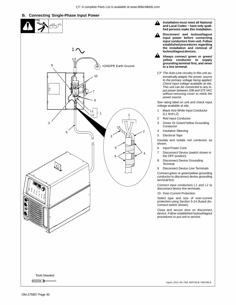
� A complete Parts List is available at www.MillerWelds.com
OM-275857 Page 30
B. Connecting Single-Phase Input Power
! Installation must meet all Nationaland Local Codes − have only quali-fied persons make this installation.
! Disconnect and lockout/tagoutinput power before connectinginput conductors from unit. Followestablished procedures regardingthe installation and removal oflockout/tagout devices.
! Always connect green or green/yellow conductor to supplygrounding terminal first, and neverto a line terminal.
� The Auto-Line circuitry in this unit au-tomatically adapts the power sourceto the primary voltage being applied.Check input voltage available at site.This unit can be connected to any in-put power between 208 and 575 VACwithout removing cover to relink thepower source.
See rating label on unit and check inputvoltage available at site.
1 Black And White Input Conductor(L1 And L2)
2 Red Input Conductor
3 Green Or Green/Yellow GroundingConductor
4 Insulation Sleeving
5 Electrical Tape
Insulate and isolate red conductor asshown.6 Input Power Cord.
7 Disconnect Device (switch shown inthe OFF position)
8 Disconnect Device GroundingTerminal
9 Disconnect Device Line Terminals
Connect green or green/yellow groundingconductor to disconnect device groundingterminal first.
Connect input conductors L1 and L2 todisconnect device line terminals.
10 Over-Current Protection
Select type and size of over-currentprotection using Section 5-14 (fused dis-connect switch shown).
Close and secure door on disconnectdevice. Follow established lockout/tagoutprocedures to put unit in service.
1
6
54
2
7
6
L1L2
1
=GND/PE Earth Ground
3
3
1
8
9
10
Tools Needed:
Input1 2012−05 / Ref. 804746-B / 803766-A

� A complete Parts List is available at www.MillerWelds.com
OM-275857 Page 31
Notes
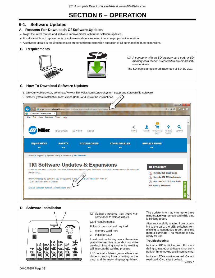
� A complete Parts List is available at www.MillerWelds.com
OM-275857 Page 32
SECTION 6 − OPERATION6-1. Software UpdatesA. Reasons For Downloads Of Software Updates• To get the latest feature and software improvements with future software updates.
• For all circuit board replacements, a software update is required to ensure proper unit operation.
• A software update is required to ensure proper software expansion operation of all purchased feature expansions.
B. Requirements
� A computer with an SD memory card port, or SDmemory card reader is required to download soft-ware updates.
The SD logo is a registered trademark of SD-3C LLC.
C. How To Download Software Updates
2
1. On your web browser, go to http://www.millerwelds.com/support/system-setup-and-software/tig-software.
2. Select System Installation Instructions (PDF) and follow the instructions. 1
D. Software Installation
273670-A
� Software updates may reset ma-chine back to default values.
Card Requirements:
Full size memory card required.
1 Memory Card Port
2 Indicator LED
Insert card containing new software intoport while machine is on, (but not whilewelding). Inserting card while weldingwill interrupt the welding process.
LED indicator blinks green when ma-chine is reading from or writing to thecard, and the meter displays go blank.
The update time may vary up to threeminutes. Do Not remove card while LEDis blinking green.
After successfully reading from or writ-ing to the card, the LED switches fromblinking to continuous green, and themeters illuminate. The machine is nowready for use.
Troubleshooting:
Indicator LED is blinking red: Error up-dating software, or software is not com-patible. Try removing and inserting card.
Indicator LED is continuous red: Cannotread card. Card might be bad.
1 2

� A complete Parts List is available at www.MillerWelds.com
OM-275857 Page 33
273670-A / Ref. 803901-A
1
2
5
12
86 7
� For all front panel switch pad controls:press switch pad to turn on light and en-able normal function.
� Green on nameplate indicates a TIGfunction, Gray indicates a normal Stickfunction.
1 Encoder ControlUse Encoder control in conjunction with ap-plicable front panel function switch pads tochange values for that function.2 Memory Card Port And IndicatorPort is used to add features to the machine,and update software. Indicator is lit while cardis being accessed.
3 Ammeter And Parameter Display
Shows actual amperage while welding andpreset amperage while idle. It also shows pa-rameter selection options when in any menu.
4 Voltmeter And Selected ParameterDisplay
Shows actual rectified average voltage whenvoltage is present at the weld output termi-nals. It also show parameter descriptionswhen in any menu.
5 Polarity Control (Dynasty Only)
6 Process Controls
7 Output Controls
8 Pulser Controls
9 Sequencer Controls
10 Gas/DIG Controls
11 AC Waveshape (Dynasty Only)
12 Amperage And Spot Time Control
13 Memory
See Section 6-6.
14 Memory Display
Displays active memory.
15 Power Switch
Use switch to turn unit On/Off.
Rear Panel
9 10
13
6-2. Controls
14
15
� Polarity and AC Waveshape controls areavailable on Dynasty Models only.
11
3
4

� A complete Parts List is available at www.MillerWelds.com
OM-275857 Page 34
6-3. Accessing Control Panel Menu
273670-A
1 Amperage Button
2 Parameter Display
3 Setting Display
4 Encoder Control
Rotate Encoder to adjust paramet-er setting.
Amperage Control
Controls the welding amperageoutput. Limits the maximum outputof a remote amperage device.
12 3 4
Polarity Selection (Dynasty Only)
Select output type AC or DC. With DC selected, the electrode will be negative (DCEN) for TIG, andpositive (DCEP) for Stick.
Process Selection
TIG HF Impulse is a non-contact arc starting method for AC and DC TIG welding (see Section 6-4).
TIG Lift-Arc Is a contact arc starting method for AC and DC TIG welding (see Section 6-4).
Stick − Select AC or DC Stick (SMAW) welding.
Trigger Mode Selection (See Section 7-5 for additional trigger function options).
[RMT] [STD]
Typical setting for a remote foot or hand control. RMT STD requires a maintained contact closure toenable weld output. Amperage can be controlled with a remote potentiometer, or it can be set at thecontrol panel.
[RMT] 2T [HOLD]
Remote control required. Allows the operator to weld without holding the trigger closed. To start theweld, operator presses and releases trigger. To stop the weld, the operator again presses and re-leases the trigger. In this mode, only the output contactor is controlled by the remote control. Amper-age must be set on the control panel. (see Section 7-5).
[OUT] [ON]
Output on. (Stick and TIG Lift Only)
! Weld output terminals are energized at all times when displays read [OUT] [ON].
No remote control or trigger required. Amperage can be controlled at the control panel or with a remotepotentiometer. Blue output on LED illuminates to indicate output is on.
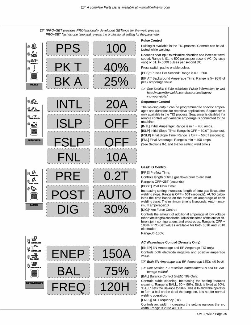
� A complete Parts List is available at www.MillerWelds.com
OM-275857 Page 35
OFF
20A
10A OFF
0.2T
AUTO
ISLP
INTL
FNLFSLP
PRE
POST
100PPS
25%BK A 40%PK T
Pulse Control
Pulsing is available in the TIG process. Controls can be ad-justed while welding.
Reduces heat input to minimize distortion and increase travelspeed. Range is 01. to 500 pulses per second AC (Dynastyonly) or 01. to 5000 pulses per second DC.
Press switch pad to enable pulser.
[PPS]* Pulses Per Second: Range is 0.1− 500.
[BK A]* Background Amperage Time: Range is 5− 95% ofpeak amperage value.
� See Section 6-5 for additional Pulser information, or visithttp:/www.millerwelds.com/resources/improv-ing-your-skills/
Sequencer Control
The welding output can be programmed to specific amper-ages and durations for repetitive applications. Sequencer isonly available in the TIG process. Sequencer is disabled if aremote control with variable amperage is connected to themachine.[INTL] Initial Amperage: Range is min − 400 amps.[ISLP] Initial Slope Time: Range is OFF − 50.0T (seconds).[FSLP] Final Slope Time: Range is OFF − 50.0T (seconds).[FNL] Final Amperage: Range is min − 400 amps.(See Sections 8-1 and 8-2 for setting weld time.)
Gas/DIG Control
[PRE] Preflow Time:Controls length of time gas flows prior to arc start.Range is OFF−25T (seconds).[POST] Post Flow Time:Increasing setting increases length of time gas flows afterwelding stops. Range is OFF − 50T (seconds). AUTO calcu-lates the time based on the maximum amperage of eachwelding cycle. The minimum time is 8 seconds. Auto = max-imum amperage/10.[DIG]* Arc Force Control:Controls the amount of additional amperage at low voltage(short arc length) conditions. Adjust the force of the arc for dif-ferent joint configurations and electrodes. Range is OFF −100%. PRO-Set values available for both 6010 and 7018electrodesRange, 0−100%
AC Waveshape Control (Dynasty Only)
[ENEP] EN Amperage and EP Amperage TIG only:Controls both electrode negative and positive amperagevalue.
� Both EN Amperage and EP Amperage LEDs will be lit.
� See Section 7-1 to select Independent EN and EP Am-perage control.
[BAL] Balance Control (%EN) TIG Only:Controls oxide cleaning. Increasing the setting reducescleaning. Range is BALL, 50 − 99%. Stick is fixed at 50%.“BALL” sets the Balance to 30%. This is to allow the operatorto form a ball on the tip of the tungsten. It is not for normalwelding operation.[FREQ] AC Frequency (Hz):Controls arc width. Increasing the setting narrows the arcwidth. Range is 20 to 400 Hz.
30%DIG
75%120H
BALFREQ
� *PRO−SET provides PROfessionally developed SETtings for the weld process.PRO−SET flashes one time and reveals the professional setting for the parameter.
150AENEP

� A complete Parts List is available at www.MillerWelds.com
OM-275857 Page 36
6-4. Lift-Arc And HF TIG Start Procedures
Lift-Arc Start
When Lift-Arc� button light is On,start arc as follows:
1 TIG Electrode
2 Workpiece
Touch tungsten electrode to work-piece at weld start point, enable out-put and shielding gas with torch trig-ger, foot control, or hand control. Holdelectrode to workpiece for 1-2 sec-onds, and slowly lift electrode. Arc isformed when electrode is lifted.
Normal open-circuit voltage is notpresent before tungsten electrodetouches workpiece; only a low sens-ing voltage is present between elec-trode and workpiece. The solid-stateoutput contactor does not energizeuntil after electrode is touching work-piece. This allows a properly pre-pared electrode (see Section 12-2) totouch workpiece without overheating,sticking, or getting contaminated.
Application:
Lift-Arc is used for the DCEN or ACGTAW process when HF Start meth-od is not permitted, or to replace thescratch method.
HF Start
When HF Start button light is On, startarc as follows:
High frequency turns on to start arcwhen output is enabled. High fre-quency turns off when arc is started,and turns on whenever arc is brokento help restart arc.
Application:
HF start is used for the DCEN GTAW,or the AC GTAW process when anon-contact arc starting method isrequired.
1
1 − 2Seconds“Touch”
Do NOT Strike Like A Match!
2Lift-Arc Start Method

� A complete Parts List is available at www.MillerWelds.com
OM-275857 Page 37
6-5. Pulser Control
1
3
2
Peak Amp
Bkg Amp
Peak 50%/Background 50%Balanced 50%
80%More Time At Peak
Amperage
20%More Time At Background
Amperage
Pulsed Output WaveformsPercent (%) Peak TimeControl Setting
PPS
4
1 Pulser Control
Pulsing is available while using the TIG pro-cess. Controls can be adjusted while weld-ing.
Press switch pad to enable pulser.
ON - When lit, this LED indicates the pulseris on.
Press switch pad until desired parameterLED is lit.
To turn Pulser off, press and release switchpad until the On LED turns off.
2 Encoder Control (Set Value)
3 Ammeter (Displays Value)
PPS - Pulse frequency or pulses per sec-ond, is the number of pulse cycles per sec-ond. Pulse frequency helps reduce heat in-put, part warpage, and helps weld bead cos-metics. The higher the PPS setting, thesmoother the ripple effect, the narrower theweld bead, and the more cooling you get. Bysetting PPS on the lower end, the pulse isslower, and the weld bead wider. This slowpulsing helps agitate the weld puddle to helprelease gas trapped in the weldment, andhelp reduce porosity (very useful in alumi-num welding). Some beginners use a slowerpulse rate (2-4 pps) to help them with theirtiming on adding filler material. An experi-
enced welder may have the PPS settingmuch higher, depending on their personalpreferences, and on what they are trying toaccomplish.
PEAK t - (PEAK t) is the percentage of timein each cycle, spent at peak amperage(main amperage). Peak amperage is setwith the Amperage control (see Section6-2). If one pulse per second is being used,and peak time is set at 50%, one-half secondis spent at peak amperage, and the other50%, or one-half second, is spent at thebackground amperage. Increasing peaktime increases time spent at peak amper-age, which increases heat input into the part.A good starting point for peak time is about50-60%. To find a good ratio, you will have toexperiment a bit, but the idea is to decreaseheat input into the part, and increase thecosmetics of the weld.
BKGND A - (Background amps) is set as apercentage of the peak amps setting. If peakamps is set at 200, and background amps at50%, your background amps is 100 ampswhen the machine pulses on the back-ground side of the cycle. The lower back-ground amperage helps reduce heat input.Increasing or decreasing background ampsincreases or decreases the overall averageamperage, which helps determine how fluid
your puddle is on the background side of thepulse cycle. Overall, you want your puddleto shrink to about one-half the size, but stillremain fluid. To start with, set backgroundamps at about 20-30% for stainless/carbonsteel, or at about 35-50% for aluminum al-loys.
4 Pulsed Output Waveforms
Example shows affect changing the PeakTime control has on the pulsed output wave-form.
Application:
Pulsing refers to the alternating raising andlowering of the weld output at a specific rate.The raised portions of the weld output arecontrolled in width, height, and frequency,forming pulses of weld output. These pulsesand the lower amperage level between them(called the background amperage) alter-nately heat and cool the molten weld puddle.The combined effect gives the operator bet-ter control of penetration, bead width,crowning, undercutting, and heat input.Controls can be adjusted while welding.
Pulsing can also be used for filler materialaddition technique training.
� Function is enabled when LED is lit.

� A complete Parts List is available at www.MillerWelds.com
OM-275857 Page 38
6-6. Memory (Program Storage Locations 1-9)
1 Memory (Program Storage1-9) Switch Pad
2 Polarity Switch Pad (DynastyOnly)
3 Process Switch Pad
To create, change, or recall awelding parameters program,proceed as follows:
First, press Memory switch pad untilthe desired program storage loca-tion (1-9) is displayed.
Second, press Polarity switch paduntil the desired polarity, AC or DC,LED is lit
Third, press Process switch pad un-til desired process, TIG HF Impulse,TIG Lift Arc, or Stick, LED is lit.
The program at the chosen location,for the desired polarity and process,is now the active program.
Fourth, change or set all desired pa-rameters.
Memory Locations
1−9
AC
DC
TIG (HF or Lift)
TIG (HF or Lift)
Stick
Stick
For Dynasty Models, each memory location (1 thru 9) can store parametersfor both polarities (AC and DC), and each polarity can store parameters forboth process (TIG and Stick) for a total of 36 programs.
And
And
And
2
3
2nd 3rd
1st
� Polarity And AC Waveshape Controls Are Available On Dynasty Models Only.
Memory Locations
1−9
DC
TIG (HF or Lift)
Stick
For Maxstar Models, each memory location (1 thru 9) can store parametersfor both process (TIG and Stick) for a total of 18 programs.
And
1
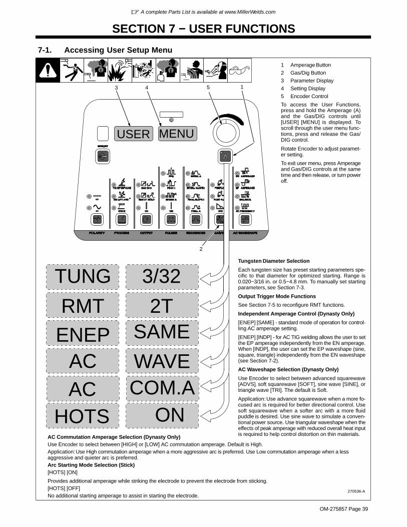
� A complete Parts List is available at www.MillerWelds.com
OM-275857 Page 39
SECTION 7 − USER FUNCTIONS
7-1. Accessing User Setup Menu
270536-A
MENU
1 Amperage Button
2 Gas/Dig Button
3 Parameter Display
4 Setting Display
5 Encoder Control
To access the User Functions,press and hold the Amperage (A)and the Gas/DIG controls until[USER] [MENU] is displayed. Toscroll through the user menu func-tions, press and release the Gas/DIG control.
Rotate Encoder to adjust paramet-er setting.
To exit user menu, press Amperageand Gas/DIG controls at the sametime and then release, or turn poweroff.
3 5
Tungsten Diameter Selection
Each tungsten size has preset starting parameters spe-cific to that diameter for optimized starting. Range is0.020−3/16 in. or 0.5−4.8 mm. To manually set startingparameters, see Section 7-3.
Output Trigger Mode Functions
See Section 7-5 to reconfigure RMT functions.
Independent Amperage Control (Dynasty Only)
[ENEP] [SAME] - standard mode of operation for control-ling AC amperage setting.
[ENEP] [INDP] - for AC TIG welding allows the user to setthe EP amperage independently from the EN amperage.When [INDP], the user can set the EP waveshape (sine,square, triangle) independently from the EN waveshape(see Section 7-2).
AC Waveshape Selection (Dynasty Only)
Use Encoder to select between advanced squarewave[ADVS], soft squarewave [SOFT], sine wave [SINE], ortriangle wave [TRI]. The default is Soft.
Application: Use advance squarewave when a more fo-cused arc is required for better directional control. Usesoft squarewave when a softer arc with a more fluidpuddle is desired. Use sine wave to simulate a conven-tional power source. Use triangular waveshape when theeffects of peak amperage with reduced overall heat inputis required to help control distortion on thin materials.
USER
2T
3/32TUNG
RMT
WAVEAC
ONHOTS
2
SAMEENEP
14
AC COM.A
AC Commutation Amperage Selection (Dynasty Only)Use Encoder to select between [HIGH] or [LOW] AC commutation amperage. Default is High.Application: Use High commutation amperage when a more aggressive arc is preferred. Use Low commutation amperage when a lessaggressive and quieter arc is preferred.Arc Starting Mode Selection (Stick)[HOTS] [ON]
Provides additional amperage while striking the electrode to prevent the electrode from sticking.[HOTS] [OFF]No additional starting amperage to assist in starting the electrode.

� A complete Parts List is available at www.MillerWelds.com
OM-275857 Page 40
7-2. AC Independent
� AC Independent Expansion is available onDX models with SD expansion card and onCE models with feature enable through the user menu (see Section 7-1).
A. AC Independent Amperage
1
2
31 AC Waveshape Control
Press switch pad until desired function is selected.
2 Encoder Control (Set Value)
3 Ammeter (Displays Value)
4 Voltmeter (Parameter Selection)
EN Amperage [EN] - Use with AC TIG only to se-lect electrode negative amperage value.
EP Amperage [EP] - Use with AC TIG only to selectelectrode positive amperage value.
5 Amperage Button
Average Amperage Control - Setting EN Amper-age, EP Amperage, Balance, and Frequency val-ues creates an average amperage. The operatorcan change the average amperage value whilemaintaining the same EN amperage to EP amper-age ratio at the existing balance and frequency. Tochange the average amperage value, press theAmperage switch pad and rotate the Encoder con-trol. The changing average value is displayed onthe ammeter. Example: If EN Amperage is 150, EPAmperage is 100, Balance is 75%, and Frequencyis 120, the average amperage is 138 amps. If youpress the Amperage switch pad and rotate the En-coder control until 69 amps is displayed, the EN am-perage is now 75 and EP amperage is now 50. Thebalance remains 75%, and the frequency is still120, and the 1.5 to 1 EN amperage to EP amperageratio is maintained.
5
4
150 A150 A
ENEP
B. AC Independent Waveshape
� See Section 7-1 for additional informationon Accessing User Setup Menu. The[ACEN], [ACEP] option replaces the [AC]option.
1 Amperage (A) Button
2 Gas/DIG Control
3 Parameter Display
Press Gas/DIG switch pad until [ACEN] is dis-played. Press the A switch pad to toggle be-tween [ACEN] and [ACEP].
4 Setting Display5 Encoder Control
Use Encoder to select between advancedsquarewave [ADVS], soft squarewave[SOFT], sine wave [SINE], or triangle wave[TRI]. The default is [SOFT].
SOFT
SOFT
ACEN
ACEP
MENU
3 5
USER
2
14

� A complete Parts List is available at www.MillerWelds.com
OM-275857 Page 41
7-3. General (GEN) Tungsten To Change Programmable TIG Starting Parameters
1 Encoder Control
2 Parameter Display
3 Amperage Button
Once inside the machine set upmenu, tungsten parameter valuescan be manually changed by press-ing the Amperage switch pad tostep through each adjustable para-meter. Rotate encoder to changethe value.
1
2
Current (A)
Start Time
Start Slope Time
Preset Amperage Minimum
Start A
mperage
Available Parameter Settings
3
Parameter• Start Output Polarity (POL)• Start Amperage (STRT)• Start Time (TIME)• Start Slope (SSLP)• Preset Minimum
Amperage (PMIN)
Default AC
• EP (Electrode Positive)
• 30 A
• 140 ms
• 10 ms
• 10 A
Default DC
• EN (Electrode Negative)
• 60 A
• 30 ms
• 50 ms
• 5 A
Range
• EP / EN
• 5−200 A
• 0−250 ms
• 0−250 ms
• 1 (DC) 2 (AC) −25 A
GENTUNG

� A complete Parts List is available at www.MillerWelds.com
OM-275857 Page 42
7-4. Programmable TIG Start Parameters For Models With 28-Pin Advanced AutomationCapabilities
A. OFF/ON (Start Amperage And Time) For Models W/28-Pin Advanced Automation Capabilities
2
STAT OFF
3
Off is the default setting. Use Encoder con-trol to select On. When On is selected, theAmperage switch pad LED turns on.
Dynasty models have a separate set ofparameters for AC and DC.
The AC and DC parameters are selectedremotely through pin 28 of the 28-pin auto-mation receptacle where EP (electrodepositive = AC, and EN (electrode negative)= DC1 Amperage Button2 Encoder Control3 Amps Meter
Preset Advanced Automation TIG StartParametersDefault values for Advanced AutomationTIG Start Amperage and Start Time are asfollows: AC Start Amperage = 50A, ACStart Time = 30ms. DC Start Amperage =30A and DC Start Time = 30ms.If it is necessary or desired to change theAdvanced Automation TIG Start Amperageand Start Time values from the default val-ues, press the amperage switch pad to stepthrough each adjustable parameter (seeSections B and C).
1
Current (A)
Start Time
Start A
mperage
B. Changing Programmable TIG Start Amperage For Models With 28-Pin Advanced AutomationCapabilities
1 Amperage Button
2 Encoder Control
3 Amps Meter
To adjust TIG Start Amperage proceed asfollows:Press Amperage switch pad until the cur-rent start amperage is displayed. The cur-rent Start Amperage is displayed on the
amps meter, and can be adjusted by rotat-ing the Encoder control.
To change Start Time, proceed to SectionC.
1
2
STRT 30A
3
Current (A)
StartAmperage

� A complete Parts List is available at www.MillerWelds.com
OM-275857 Page 43
C. Changing Programmable Start Time For Models With Advanced Automation Capabilities
1 Amperage Button
2 Encoder Control
3 Amps Meter
To adjust Programmable Start Time pro-ceed as follows:Press Amperage switch pad until the cur-rent start time is displayed. The current
Start Time is displayed in milliseconds onthe amps meter, and can be adjusted by ro-tating the Encoder control.
3
2
TIME 30m1
Current (A)
StartTime
Notes
Work like a Pro!
Pros weld and cut
safely. Read the
safety rules at
the beginning
of this manual.

� A complete Parts List is available at www.MillerWelds.com
OM-275857 Page 44
7-5. Output Control And Trigger Functions
A. Remote (Standard), 2T, And 4TE Torch Trigger Operation
Current (A)
Preflow
Initial Amps
Initial Slope Final Slope
Postflow
Main Amps
Final Amps
R RP & H
Maintained Switch Foot Or FingerRemote ControlP&H = Push trigger and hold
R = Release trigger.
� When a foot or finger remote current control is connected to the welding power source, initial amps, initialslope, final slope and final amps are controlled by the remote control, not by the welding power source.
P&R P&R
P&R = Push trigger and release.
� If torch trigger is held more than 3 seconds, operation reverts to RMT STD (Remote Standard) mode.
P/R P/R P/R P/R
P/R = Push and release trigger.
*Pushing and releasing trigger during final slope will break the arc and start postflow.
� For first torch trigger push & release, if trigger is held more than 3 seconds, trigger cycle ends.
� When a remote switch is connected to the welding power source, use the remote switch to control the weldcycle. Amperage is controlled by the welding power source.
Application:
Use 4T Momentary trigger method when the functions of a remote current control are desired, but only a remoteon/off control is available.
*P/R
Time
Standard
Remote 2T
Remote 4TE

� A complete Parts List is available at www.MillerWelds.com
OM-275857 Page 45
B. 3T Specific Trigger Method
1 3T (Specific Trigger Operation)
Sequencer is required to reconfigure for 3T.
3T requires a specific type of remote con-trol with two independent momentary-contact switches. One will be designatedinitial switch, and it must be connected be-tween Remote 14 receptacle pins A and B.The second will be designated as the finalswitch, and it must be connected betweenRemote 14 receptacle pins D and E.
2 Encoder Control
To select 3T, rotate Encoder control.
Definitions
Initial slope rate is the rate of amperagechange determined by the initial amperage,initial slope time, and main amperage.
Final slope rate is the rate of amperagechange determined by the main amperage, fi-nal slope time, and final amperage.
OperationPress and release initial switch within 3/4second to start shielding gas flow. To stop thepreflow sequence before preflow timeelapses (25 seconds), press and release fi-nal switch. The preflow timer will reset andthe weld sequence can be started again.
� If an initial switch closure is not madeagain before preflow time ends, gas flowstops, the timer resets, and an initialswitch press and release is necessary tostart the weld sequence again.
Press initial switch to start arc at initial amps.Holding switch will change amperage at initialslope rate (release switch to weld at desiredamperage level).When main amperage level is reached, initialswitch can be released.Press and hold the final switch to decreaseamperage at final slope rate (release switchto weld at desired amperage level).When final amperage has been reached, thearc extinguishes and shielding gas flows forthe time set on the Postflow control.
Application
With the use of two remote switches insteadof potentiometers, 3T gives the operator theability to infinitely increase, decrease, orpause and hold amperage within the rangedetermined by the initial, main, and final am-perages.
Current (A)
Remote Trigger Operation
**
**
**
*
A B C D EPreflow Initial Amps/Initial Slope Main Amps Final Slope /Final Amps Postflow
* Arc can be extinguished at any time by pressing and releasing both initial and final switches, or by lifting the torch and breaking the arc.

� A complete Parts List is available at www.MillerWelds.com
OM-275857 Page 46
C. 4T, 4Tm, And 4TL Specific Trigger Method
4T And 4Tm Application:
Use 4T or 4Tm (modified) triggermethod when the functions of a re-mote current control are desired,but only a remote on/off control isavailable.
4T* allows the operator to togglebetween weld current and finalcurrent.
� When a remote switch is con-nected to the welding powersource, use the remote switchto control the weld cycle. Am-perage is controlled by thewelding power source.
4TL Application:
The ability to change current levelswithout either initial slope or finalslope, gives the operator the oppor-tunity to adjust filler metal withoutbreaking the arc.
4TL (mini logic) allows the operatorto toggle between initial slope ormain amps and initial amps. FinalAmperage is not available. Finalslope always slopes to minimumamperage and ends the cycle.
� When a remote switch is con-nected to the welding powersource, use the remote switchto control the weld cycle. Am-perage is controlled by thewelding power source.
Current (A)
Preflow
Initial Amps
Initial SlopeFinal Slope
Postflow
P/H R P/H R*P/R
Main Amps
Final Amps
4T And 4Tm Torch Trigger Operation
*P/R
P/H = Push and hold trigger; R = Release trigger
*4T only: P/R = Push trigger and release in less than 0.75 second
Preflow
Initial Amps
Initial Slope
Final Slope
Postflow
Main Amps
4TL Torch Trigger Operation
* * * *
* *
* *
P/H R P/R P/R P/R P/R P/R P/H
P/H = Push and hold trigger; R = Release trigger; P/R = Push trigger and release in less than 0.75 seconds
* * = Arc can be extinguished at final slope rate at any time by pushing and holding trigger
Current (A)

� A complete Parts List is available at www.MillerWelds.com
OM-275857 Page 47
D. On Trigger Operation
Voltage (V)
Current (A)
Current (A)
Touch StickLift Stick
Touch Current
Initial Amperage Initial Slope
Main Amperage
Touch TungstenLift TungstenSlightly
Lift Tungsten
Electrode Electrode
ON
2 Sec
Stick
Lift
*Final Slope
*Final Amperage
*Becomes active with Spot Time enabled.
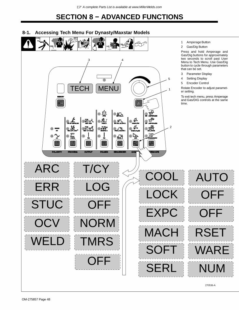
� A complete Parts List is available at www.MillerWelds.com
OM-275857 Page 48
SECTION 8 − ADVANCED FUNCTIONS
AUTOCOOL
8-1. Accessing Tech Menu For Dynasty/Maxstar Models
270536-A
T/CYARC
NORMOCV
OFFSTUC
RSETMACH
WARESOFT
1 Amperage Button
2 Gas/Dig Button
Press and hold Amperage andGas/Dig buttons for approximatelytwo seconds to scroll past UserMenu to Tech Menu. Use Gas/Digbutton to cycle through parametersthat can be set.
3 Parameter Display
4 Setting Display
5 Encoder Control
Rotate Encoder to adjust paramet-er setting.
To exit tech menu, press Amperageand Gas/DIG controls at the sametime.
TMRSWELD
OFFLOCK
OFFEXPC
OFF
LOGERR
NUMSERL
MENUTECH 1
5
2
3 4

� A complete Parts List is available at www.MillerWelds.com
OM-275857 Page 49
[ARC] [T/CY] Arc Timer: Monitors hours, minutes, and cycles of valid arc on. To view these different elements, rotate Encoder. To reset,rotate encoder until [RESET] [YES] is displayed. Press Menu button to display [RESET] [Done]. Displays turn to [000] [000].
[STUC] Stick Stuck: Detects if the electrode is stuck or shorted to the workpiece. Turns weld output off to aid in freeing the electrode. Toturn on, rotate Encoder. Not recommended for air carbon arc or large diameter electrodes.
[MACH] [RESET] Machine Reset:: Resets all machine values back to factory defaults. To reset, rotate Encoder to [RESET] [YES]. Thenpress Amperage button. [RESET] [DONE] will be displayed when the reset is complete and factory defaults have been restored.
[LOCK]: Limits user control and adjustability of machine. See Section 8-3 For instructions and operation.
[WELD] [TMRS] Weld Timers: [ON] enable and [OFF] disable the feature. See Section 8-2 for information on setting weld timers. WeldTimers work with or without Sequencer feature.
[SOFT] [WARE] Software Number: Software number and revision will be displayed.
[OCV] Open Circuit Voltage: Allows user to select between Normal (NORM) and Low open circuit voltage. Low reduces open circuit voltageto between 8 and 12 volts. To select, rotate Encoder.
[EXPC] External Pulse Control Commands: Turn on when it is desired to control machine from an external source. When command ison, a command voltage of 0− 10 volts DC equals off − 400 amps.
[ERR] [LOG] Error Log: Use to view last eight logged error events. Each event may list multiple Error Codes. See Section 9-4.
[SERL] [NUM] Serial Number: If serial number displayed does not match serial number of machine, see Section 9-4.
[COOL] Cooler Auxiliary Power (Optional): Selects between [OFF] and [AUTO]. [OFF] disables the power supply to the receptacle. [AU-TO] provides power to the receptacle when the TIG process is active.
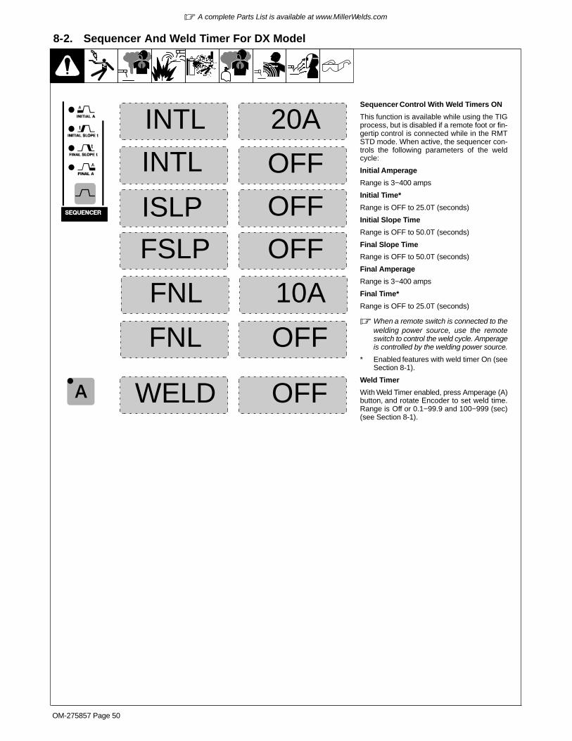
� A complete Parts List is available at www.MillerWelds.com
OM-275857 Page 50
8-2. Sequencer And Weld Timer For DX Model
OFF
20A
OFFISLP
INTL
INTL
Sequencer Control With Weld Timers ON
This function is available while using the TIGprocess, but is disabled if a remote foot or fin-gertip control is connected while in the RMTSTD mode. When active, the sequencer con-trols the following parameters of the weldcycle:
Initial Amperage
Range is 3−400 amps
Initial Time*
Range is OFF to 25.0T (seconds)
Initial Slope Time
Range is OFF to 50.0T (seconds)
Final Slope Time
Range is OFF to 50.0T (seconds)
Final Amperage
Range is 3−400 amps
Final Time*
Range is OFF to 25.0T (seconds)
� When a remote switch is connected to thewelding power source, use the remoteswitch to control the weld cycle. Amperageis controlled by the welding power source.
* Enabled features with weld timer On (seeSection 8-1).
Weld Timer
With Weld Timer enabled, press Amperage (A)button, and rotate Encoder to set weld time.Range is Off or 0.1−99.9 and 100−999 (sec)(see Section 8-1).
OFF
10A
FSLP
FNL
OFFFNL
OFFWELD

� A complete Parts List is available at www.MillerWelds.com
OM-275857 Page 51
8-3. Lockout FunctionsSee Section 8-1 for information on how toaccess Lockout Functions.
There are four (1−4) different lockoutlevels. Each successive level allows theoperator more flexibility.
� Before activating lockout levels, besure that all procedures and para-meters are established. Parameteradjustment is limited while lockoutlevels are active.
To turn On lockout feature, proceed asfollows:
1 Encoder Control
2 Amperage Button
Press Amperage (A) control to togglebetween the lock off and code off dis-plays. Toggle control until [CODE] [OFF]is displayed
Rotate Encoder to select a lockout codenumber. Select a number between 1 and999. The number will appear on the am-perage, right, display.
� Remember (write down) this codenumber, as you will need this numberto turn this feature off, or makechanges to your settings.
Toggle Amperage control until [LOCK] isdisplayed. You may now select a lockoutlevel. See table below for the degree ofadjustability associated with each locklevel. Exit Advanced Functions accord-ing to Section 8-1.
To turn Off lockout feature, proceed asfollows:
Toggle Amperage control until Code isdisplayed.Use Encoder control to enter the samecode number that was used to turn on thelockout feature.Press the Amperage control. The amper-age meter display will turn to [OFF]. Lock-out is now off. Exit Advanced Functionsaccording to Section 8-1.
LOCK
CODEOFF
1
2
8-4. Lockout Levels Defined
Minimum Adjustability Degree Of Adjustability Maximum Adjustability
Lock Level 1 Lock Level 2 Lock Level 3 Lock Level 4
Adjustable Locked Adjustable Locked Adjustable Locked Adjustable Locked
Panel Amps Panel Amps Panel Amps +/- 10% Remote Amps
(min−panel)
Panel Amps +/- 10%
Polarity (Dyn Only) Polarity (Dyn Only) Polarity (Dyn Only) Polarity (Dyn Only)
Process Process Process Process
Output Output Output Output
Pulser Pulser Pulser (on/off only) Pulser (on/off only)
Sequencer Sequencer Sequencer Sequencer
Gas/DIG Gas/DIG Gas/DIG Gas/DIG
Waveshape Waveshape Waveshape Waveshape

� A complete Parts List is available at www.MillerWelds.com
OM-275857 Page 52
SECTION 9 − MAINTENANCE AND TROUBLESHOOTING
9-1. Routine Maintenance
! Disconnect power before maintaining.
� = Check � = Change � = Clean Δ = Repair = Replace* To be done by Factory Authorized Service Agent
Every3Months
� Weld Terminals� Labels � Gas Hoses
Every3Months
�Δ Cables And Cords
Every6Months
�:Durning heavy service, clean monthly.
9-2. Blowing Out Inside of Unit
804746-B
! Do not remove case whenblowing out inside of unit.
To blow out unit, direct airflowthrough front and back louvers asshown.
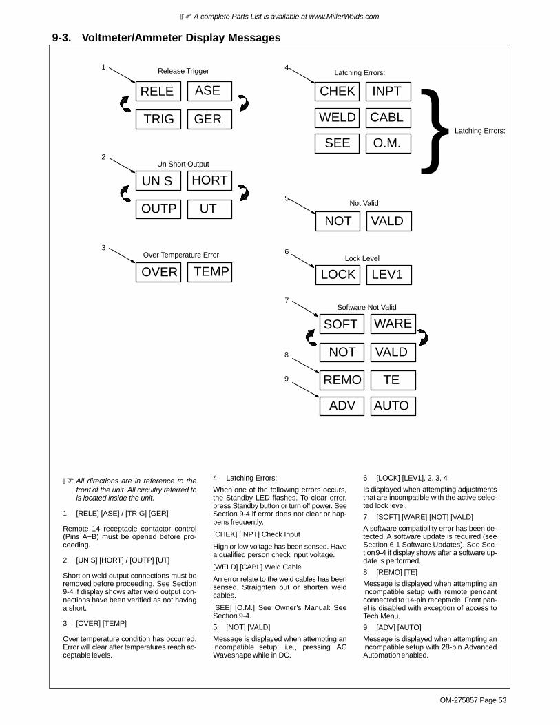
� A complete Parts List is available at www.MillerWelds.com
OM-275857 Page 53
9-3. Voltmeter/Ammeter Display Messages
� All directions are in reference to thefront of the unit. All circuitry referred tois located inside the unit.
1 [RELE] [ASE] / [TRIG] [GER]
Remote 14 receptacle contactor control(Pins A−B) must be opened before pro-ceeding.
2 [UN S] [HORT] / [OUTP] [UT]
Short on weld output connections must beremoved before proceeding. See Section9-4 if display shows after weld output con-nections have been verified as not havinga short.
3 [OVER] [TEMP]
Over temperature condition has occurred.Error will clear after temperatures reach ac-ceptable levels.
4 Latching Errors:
When one of the following errors occurs,the Standby LED flashes. To clear error,press Standby button or turn off power. SeeSection 9-4 if error does not clear or hap-pens frequently.
[CHEK] [INPT] Check Input
High or low voltage has been sensed. Havea qualified person check input voltage.
[WELD] [CABL] Weld Cable
An error relate to the weld cables has beensensed. Straighten out or shorten weldcables.
[SEE] [O.M.] See Owner’s Manual: SeeSection 9-4.
5 [NOT] [VALD]
Message is displayed when attempting anincompatible setup; i.e., pressing ACWaveshape while in DC.
6 [LOCK] [LEV1], 2, 3, 4
Is displayed when attempting adjustmentsthat are incompatible with the active selec-ted lock level.
7 [SOFT] [WARE] [NOT] [VALD]
A software compatibility error has been de-tected. A software update is required (seeSection 6-1 Software Updates). See Sec-tion 9-4 if display shows after a software up-date is performed.
8 [REMO] [TE]
Message is displayed when attempting anincompatible setup with remote pendantconnected to 14-pin receptacle. Front pan-el is disabled with exception of access toTech Menu.
9 [ADV] [AUTO]
Message is displayed when attempting anincompatible setup with 28-pin AdvancedAutomation enabled.
1
2
3
4
6
5
RELE ASE
TRIG GER
UN S HORT
OUTP UT
TEMP
Release Trigger
Un Short Output
Over Temperature Error
Latching Errors:
CHEK INPT
WELD CABL
SEE O.M. } Latching Errors:
NOT VALD
Not Valid
LOCK LEV1Lock Level
SOFT WARE
NOT VALD
Software Not Valid7
REMO TE
ADV AUTO
OVER
8
9
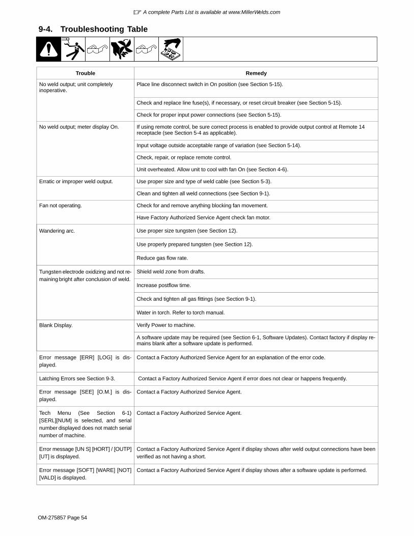
� A complete Parts List is available at www.MillerWelds.com
OM-275857 Page 54
9-4. Troubleshooting Table
Trouble Remedy
No weld output; unit completelyinoperative.
Place line disconnect switch in On position (see Section 5-15).
Check and replace line fuse(s), if necessary, or reset circuit breaker (see Section 5-15).
Check for proper input power connections (see Section 5-15).
No weld output; meter display On. If using remote control, be sure correct process is enabled to provide output control at Remote 14receptacle (see Section 5-4 as applicable).
Input voltage outside acceptable range of variation (see Section 5-14).
Check, repair, or replace remote control.
Unit overheated. Allow unit to cool with fan On (see Section 4-6).
Erratic or improper weld output. Use proper size and type of weld cable (see Section 5-3).
Clean and tighten all weld connections (see Section 9-1).
Fan not operating. Check for and remove anything blocking fan movement.
Have Factory Authorized Service Agent check fan motor.
Wandering arc. Use proper size tungsten (see Section 12).
Use properly prepared tungsten (see Section 12).
Reduce gas flow rate.
Tungsten electrode oxidizing and not re-maining bright after conclusion of weld.
Shield weld zone from drafts.
Increase postflow time.
Check and tighten all gas fittings (see Section 9-1).
Water in torch. Refer to torch manual.
Blank Display. Verify Power to machine.
A software update may be required (see Section 6-1, Software Updates). Contact factory if display re-mains blank after a software update is performed.
Error message [ERR] [LOG] is dis-played.
Contact a Factory Authorized Service Agent for an explanation of the error code.
Latching Errors see Section 9-3. Contact a Factory Authorized Service Agent if error does not clear or happens frequently.
Error message [SEE] [O.M.] is dis-played.
Contact a Factory Authorized Service Agent.
Tech Menu (See Section 6-1)[SERL][NUM] is selected, and serialnumber displayed does not match serialnumber of machine.
Contact a Factory Authorized Service Agent.
Error message [UN S] [HORT] / [OUTP][UT] is displayed.
Contact a Factory Authorized Service Agent if display shows after weld output connections have beenverified as not having a short.
Error message [SOFT] [WARE] [NOT][VALD] is displayed.
Contact a Factory Authorized Service Agent if display shows after a software update is performed.
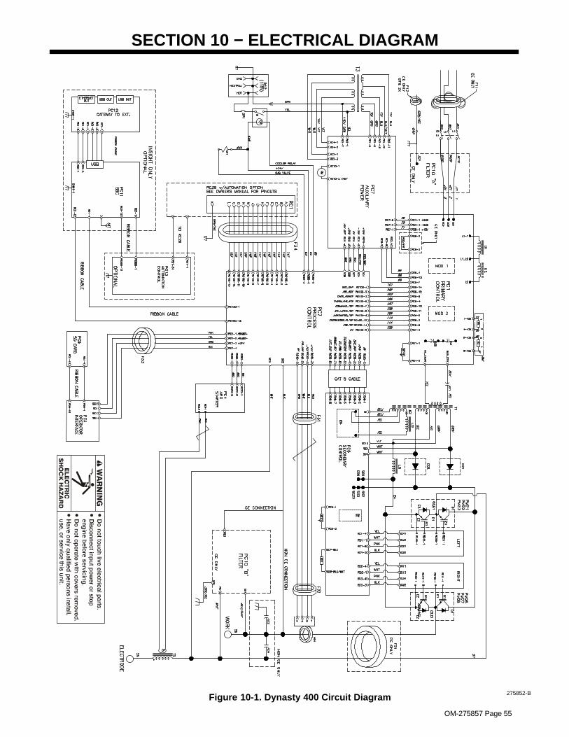
OM-275857 Page 55
SECTION 10 − ELECTRICAL DIAGRAM
Figure 10-1. Dynasty 400 Circuit Diagram 275852-B

OM-275857 Page 56
Figure 10-2. Maxstar 400 Circuit Diagram275851-B
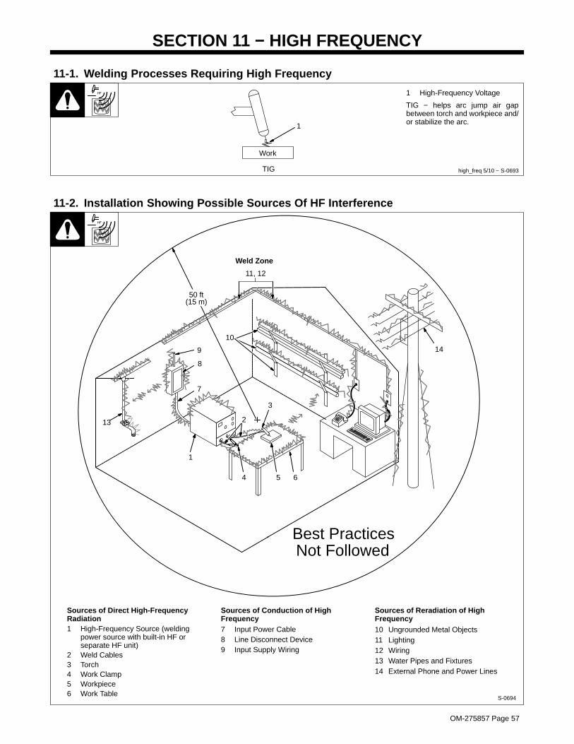
OM-275857 Page 57
SECTION 11 − HIGH FREQUENCY
11-1. Welding Processes Requiring High Frequency
high_freq 5/10 − S-0693
1 High-Frequency Voltage
TIG − helps arc jump air gapbetween torch and workpiece and/or stabilize the arc.1
TIG
Work
11-2. Installation Showing Possible Sources Of HF Interference
50 ft(15 m)
S-0694
Sources of Direct High-FrequencyRadiation1 High-Frequency Source (welding
power source with built-in HF orseparate HF unit)
2 Weld Cables3 Torch4 Work Clamp5 Workpiece6 Work Table
Sources of Conduction of HighFrequency7 Input Power Cable8 Line Disconnect Device9 Input Supply Wiring
Sources of Reradiation of HighFrequency10 Ungrounded Metal Objects11 Lighting12 Wiring13 Water Pipes and Fixtures14 External Phone and Power Lines
Weld Zone
13
9
8
7
1
2
4 5 6
3
10
11, 12
14
Best PracticesNot Followed

OM-275857 Page 58
11-3. Recommended Installation To Reduce HF Interference
1 High-Frequency Source (weldingpower source with built-in HF orseparate HF unit)
Ground metal machine case (clean paintfrom around hole in case, and use casescrew), work output terminal, line discon-nect device, input supply, and worktable.2 Center Point of Welding ZoneMidpoint between high-frequency sourceand welding torch.3 Welding ZoneA circle 50 ft (15 m) from center point in alldirections.4 Weld Output CablesKeep cables short and close together.
5 Conduit Joint Bonding and Grounding
Electrically join (bond) all conduit sectionsusing copper straps or braided wire.Ground conduit every 50 ft (15 m).
6 Water Pipes and Fixtures
Ground water pipes every 50 ft (15 m).
7 External Power or Telephone Lines
Locate high-frequency source at least 50 ft(15 m) away from power and phone lines.
8 Grounding Rod
Consult the National Electrical Code forspecifications.
Metal Building Requirements
9 Metal Building Panel BondingMethods
Bolt or weld building panels together, installcopper straps or braided wire acrossseams, and ground frame.
10 Windows and Doorways
Cover all windows and doorways withgrounded copper screen of not more than1/4 in (6.4 mm) mesh.
11 Overhead Door Track
Ground the track.
Ref. 0695 / Ref. 0695
1
2
3 50 ft(15 m)
Weld Zone
4
7
50 ft(15 m)
8
5
8
6
Groundworkpiece ifrequired bycodes.
Ground all metal ob-jects and all wiring inwelding zone using#12 AWG wire.
NonmetalBuilding
9
11
10
Metal Building
88
Best Practices Followed
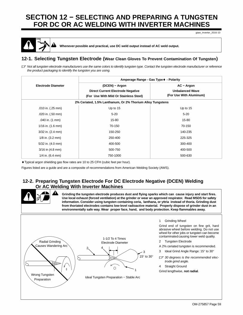
OM-275857 Page 59
SECTION 12 − SELECTING AND PREPARING A TUNGSTENFOR DC OR AC WELDING WITH INVERTER MACHINES
gtaw_Inverter_2016-10
Whenever possible and practical, use DC weld output instead of AC weld output.
12-1. Selecting Tungsten Electrode (Wear Clean Gloves To Prevent Contamination Of Tungsten)
� Not all tungsten electrode manufacturers use the same colors to identify tungsten type. Contact the tungsten electrode manufacturer or referencethe product packaging to identify the tungsten you are using.
Amperage Range - Gas Type♦ - Polarity
Electrode Diameter (DCEN) − Argon
Direct Current Electrode Negative
(For Use With Mild Or Stainless Steel)
AC − Argon
Unbalanced Wave(For Use With Aluminum)
2% Ceriated, 1.5% Lanthanum, Or 2% Thorium Alloy Tungstens
.010 in. (.25 mm) Up to 15 Up to 15
.020 in. (.50 mm) 5-20 5-20
.040 in. (1 mm) 15-80 15-80
1/16 in. (1.6 mm) 70-150 70-150
3/32 in. (2.4 mm) 150-250 140-235
1/8 in. (3.2 mm) 250-400 225-325
5/32 in. (4.0 mm) 400-500 300-400
3/16 in (4.8 mm) 500-750 400-500
1/4 in. (6.4 mm) 750-1000 500-630
♦Typical argon shielding gas flow rates are 10 to 25 CFH (cubic feet per hour).
Figures listed are a guide and are a composite of recommendations from American Welding Society (AWS).
12-2. Preparing Tungsten Electrode For DC Electrode Negative (DCEN) WeldingOr AC Welding With Inverter Machines
Grinding the tungsten electrode produces dust and flying sparks which can cause injury and start fires.Use local exhaust (forced ventilation) at the grinder or wear an approved respirator. Read MSDS for safetyinformation. Consider using tungsten containing ceria, lanthana, or yttria instead of thoria. Grinding dustfrom thoriated electrodes contains low-level radioactive material. Properly dispose of grinder dust in anenvironmentally safe way. Wear proper face, hand, and body protection. Keep flammables away.
Ideal Tungsten Preparation − Stable Arc
1 Grinding Wheel
Grind end of tungsten on fine grit, hardabrasive wheel before welding. Do not usewheel for other jobs or tungsten can becomecontaminated causing lower weld quality.
2 Tungsten Electrode
A 2% ceriated tungsten is recommended.
3 Ideal Grind Angle Range: 15° to 30°
� 30 degrees is the recommended elec-trode grind angle.
4 Straight Ground
Grind lengthwise, not radial.1
3
Causes Wandering Arc2
Wrong Tungsten
Radial Grinding
Preparation
15° to 30°
4
1-1/2 To 4 TimesElectrode Diameter

Notes
Effective January 1, 2017(Equipment with a serial number preface of MH or newer)This limited warranty supersedes all previous Miller warranties and is exclusive with no other
guarantees or warranties expressed or implied.LIMITED WARRANTY − Subject to the terms and conditions below,Miller Electric Mfg. Co., Appleton, Wisconsin, warrants to its originalretail purchaser that new Miller equipment sold after the effective date ofthis limited warranty is free of defects in material and workmanship atthe time it is shipped by Miller. THIS WARRANTY IS EXPRESSLY INLIEU OF ALL OTHER WARRANTIES, EXPRESS OR IMPLIED,INCLUDING THE WARRANTIES OF MERCHANTABILITY ANDFITNESS.
Within the warranty periods listed below, Miller will repair or replace anywarranted parts or components that fail due to such defects in materialor workmanship. Miller must be notified in writing within thirty (30) daysof such defect or failure, at which time Miller will provide instructions onthe warranty claim procedures to be followed. If notification is submittedas an online warranty claim, the claim must include a detaileddescription of the fault and the troubleshooting steps taken to identifyfailed components and the cause of their failure.
Miller shall honor warranty claims on warranted equipment listed belowin the event of such a failure within the warranty time periods. Allwarranty time periods start on the delivery date of the equipment to theoriginal end-user purchaser, and not to exceed twelve months after theequipment is shipped to a North American distributor or eighteenmonths after the equipment is shipped to an International distributor.1. 5 Years Parts — 3 Years Labor
* Original Main Power Rectifiers Only to Include SCRs,Diodes, and Discrete Rectifier Modules
2. 3 Years — Parts and Labor* Auto-Darkening Helmet Lenses (Except Classic
Series) (No Labor)* Engine Driven Welder/Generators
(NOTE: Engines are Warranted Separately by theEngine Manufacturer.)
* Inverter Power Sources (Unless Otherwise Stated)* Plasma Arc Cutting Power Sources* Process Controllers* Semi-Automatic and Automatic Wire Feeders* Transformer/Rectifier Power Sources
3. 2 Years — Parts and Labor* Auto-Darkening Helmet Lenses − Classic Series Only
(No Labor)* Fume Extractors − Capture 5, Filtair 400 and Industrial
Collector Series4. 1 Year — Parts and Labor Unless Specified
* AugmentedArc and LiveArc Welding Systems* Automatic Motion Devices* Bernard BTB Air-Cooled MIG Guns (No Labor)* CoolBelt and CoolBand Blower Unit (No Labor)* Desiccant Air Dryer System* External Monitoring Equipment and Sensors* Field Options
(NOTE: Field options are covered for the remainingwarranty period of the product they are installed in,or for a minimum of one year — whichever isgreater.)
* RFCS Foot Controls (Except RFCS-RJ45)* Fume Extractors − Filtair 130, MWX and SWX Series* HF Units* ICE/XT Plasma Cutting Torches (No Labor)* Induction Heating Power Sources, Coolers
(NOTE: Digital Recorders are WarrantedSeparately by the Manufacturer.)
* Load Banks* Motor-Driven Guns (except Spoolmate Spoolguns)* PAPR Blower Unit (No Labor)* Positioners and Controllers* Racks* Running Gear/Trailers* Spot Welders* Subarc Wire Drive Assemblies* TIG Torches (No Labor)* Tregaskiss Guns (No Labor)* Water Cooling Systems* Wireless Remote Foot/Hand Controls and Receivers* Work Stations/Weld Tables (No Labor)
5. 6 Months — Parts* Batteries
6. 90 Days — Parts* Accessory (Kits)* Canvas Covers* Induction Heating Coils and Blankets, Cables, and
Non-Electronic Controls* M-Guns* MIG Guns, Subarc (SAW) Torches, and External
Cladding Heads* Remote Controls and RFCS-RJ45* Replacement Parts (No labor)* Spoolmate Spoolguns
Miller’s True Blue® Limited Warranty shall not apply to:
1. Consumable components; such as contact tips,cutting nozzles, contactors, brushes, relays, workstation table tops and welding curtains, or parts thatfail due to normal wear. (Exception: brushes andrelays are covered on all engine-driven products.)
2. Items furnished by Miller, but manufactured by others,such as engines or trade accessories. These items arecovered by the manufacturer’s warranty, if any.
3. Equipment that has been modified by any party other thanMiller, or equipment that has been improperly installed,improperly operated or misused based upon industrystandards, or equipment which has not had reasonableand necessary maintenance, or equipment which hasbeen used for operation outside of the specifications forthe equipment.
MILLER PRODUCTS ARE INTENDED FOR PURCHASE ANDUSE BY COMMERCIAL/INDUSTRIAL USERS AND PERSONSTRAINED AND EXPERIENCED IN THE USE ANDMAINTENANCE OF WELDING EQUIPMENT.In the event of a warranty claim covered by this warranty, theexclusive remedies shall be, at Miller’s option: (1) repair; or (2)replacement; or, where authorized in writing by Miller in appropriatecases, (3) the reasonable cost of repair or replacement at anauthorized Miller service station; or (4) payment of or credit for thepurchase price (less reasonable depreciation based upon actualuse) upon return of the goods at customer’s risk and expense.Miller’s option of repair or replacement will be F.O.B., Factory atAppleton, Wisconsin, or F.O.B. at a Miller authorized service facilityas determined by Miller. Therefore no compensation orreimbursement for transportation costs of any kind will be allowed.TO THE EXTENT PERMITTED BY LAW, THE REMEDIESPROVIDED HEREIN ARE THE SOLE AND EXCLUSIVEREMEDIES. IN NO EVENT SHALL MILLER BE LIABLE FORDIRECT, INDIRECT, SPECIAL, INCIDENTAL ORCONSEQUENTIAL DAMAGES (INCLUDING LOSS OF PROFIT),WHETHER BASED ON CONTRACT, TORT OR ANY OTHERLEGAL THEORY.ANY EXPRESS WARRANTY NOT PROVIDED HEREIN AND ANYIMPLIED WARRANTY, GUARANTY OR REPRESENTATION ASTO PERFORMANCE, AND ANY REMEDY FOR BREACH OFCONTRACT TORT OR ANY OTHER LEGAL THEORY WHICH,BUT FOR THIS PROVISION, MIGHT ARISE BY IMPLICATION,OPERATION OF LAW, CUSTOM OF TRADE OR COURSE OFDEALING, INCLUDING ANY IMPLIED WARRANTY OFMERCHANTABILITY OR FITNESS FOR PARTICULARPURPOSE, WITH RESPECT TO ANY AND ALL EQUIPMENTFURNISHED BY MILLER IS EXCLUDED AND DISCLAIMED BYMILLER.Some states in the U.S.A. do not allow limitations of how long animplied warranty lasts, or the exclusion of incidental, indirect,special or consequential damages, so the above limitation orexclusion may not apply to you. This warranty provides specificlegal rights, and other rights may be available, but may vary fromstate to state.In Canada, legislation in some provinces provides for certainadditional warranties or remedies other than as stated herein, andto the extent that they may not be waived, the limitations andexclusions set out above may not apply. This Limited Warrantyprovides specific legal rights, and other rights may be available, butmay vary from province to province.
Warranty Questions?
Call1-800-4-A-MILLERfor your localMiller distributor.
miller_warr 2017-01
Your distributor also givesyou ...
ServiceYou always get the fast,reliable response youneed. Most replacementparts can be in yourhands in 24 hours.
SupportNeed fast answers to thetough welding questions?Contact your distributor.The expertise of thedistributor and Miller isthere to help you, everystep of the way.

ORIGINAL INSTRUCTIONS − PRINTED IN USA © 2017 Miller Electric Mfg. Co. 2017−01
Miller Electric Mfg. Co.An Illinois Tool Works Company1635 West Spencer StreetAppleton, WI 54914 USA
International Headquarters−USAUSA Phone: 920-735-4505 Auto-AttendedUSA & Canada FAX: 920-735-4134International FAX: 920-735-4125
For International Locations Visitwww.MillerWelds.com
Model Name Serial/Style Number
Purchase Date (Date which equipment was delivered to original customer.)
Distributor
Address
City
State Zip
Please complete and retain with your personal records.
Always provide Model Name and Serial/Style Number.
Contact a DISTRIBUTOR or SERVICE AGENCY near you.
Welding Supplies and Consumables
Options and Accessories
Personal Safety Equipment
Service and Repair
Replacement Parts
Training (Schools, Videos, Books)
Technical Manuals (Servicing Informationand Parts)
Circuit Diagrams
Welding Process Handbooks
Contact the Delivering Carrier to:
For Service
Owner’s Record
File a claim for loss or damage duringshipment.
For assistance in filing or settling claims, contactyour distributor and/or equipment manufacturer’sTransportation Department.
Contact your Distributor for:
To locate a Distributor or Service Agency visitwww.millerwelds.com or call 1-800-4-A-Miller
Copyright © 2022 FDOKUMEN