Airmux-400 - CREZER
510
Airmux-400 Broadband Wireless Multiplexer Version 2.8.40CA INSTALLATION AND OPERATION MANUAL
-
Upload
khangminh22 -
Category
Documents
-
view
2 -
download
0
Transcript of Airmux-400 - CREZER

Airmux-400 Broadband Wireless Multiplexer
Version 2.8.40CA
INSTA
LLATIO
N A
ND
O
PER
ATIO
N M
AN
UA
L

Airmux-400 Broadband Wireless Multiplexer
Version 2.8.40CA
Installation and Operation Manual
Notice
This manual contains information that is proprietary to RAD Data Communications Ltd. ("RAD"). No part of this publication may be reproduced in any form whatsoever without prior written approval by RAD Data Communications.
Right, title and interest, all information, copyrights, patents, know-how, trade secrets and other intellectual property or other proprietary rights relating to this manual and to the Airmux-400 and any software components contained therein are proprietary products of RAD protected under international copyright law and shall be and remain solely with RAD.
The Airmux-400 product name is owned by RAD. No right, license, or interest to such trademark is granted hereunder, and you agree that no such right, license, or interest shall be asserted by you with respect to such trademark. The RAD name, logo, logotype, and the terms EtherAccess, TDMoIP and TDMoIP Driven, and the product names Optimux and IPmux, are registered trademarks of RAD Data Communications Ltd. All other trademarks are the property of their respective holders.
You shall not copy, reverse compile or reverse assemble all or any portion of the Manual or the Airmux-400. You are prohibited from, and shall not, directly or indirectly, develop, market, distribute, license, or sell any product that supports substantially similar functionality as the Airmux-400, based on or derived in any way from the Airmux-400. Your undertaking in this paragraph shall survive the termination of this Agreement.
This Agreement is effective upon your opening of the Airmux-400 package and shall continue until terminated. RAD may terminate this Agreement upon the breach by you of any term hereof. Upon such termination by RAD, you agree to return to RAD the Airmux-400 and all copies and portions thereof.
For further information contact RAD at the address below or contact your local distributor.
International Headquarters RAD Data Communications Ltd.
24 Raoul Wallenberg Street Tel Aviv 69719, Israel Tel: 972-3-6458181 Fax: 972-3-6498250, 6474436 E-mail: [email protected]
North America Headquarters RAD Data Communications Inc.
900 Corporate Drive Mahwah, NJ 07430, USA Tel: (201) 5291100, Toll free: 1-800-4447234 Fax: (201) 5295777 E-mail: [email protected]
© 1988–2015 RAD Data Communications Ltd. Publication No. 581-200-02/15
Front Matter Installation and Operation Manual
ii Airmux-400
Limited Warranty
RAD warrants to DISTRIBUTOR that the hardware in the Airmux-400 to be delivered hereunder shall be free of defects in material and workmanship under normal use and service for a period of twelve (12) months following the date of shipment to DISTRIBUTOR.
If, during the warranty period, any component part of the equipment becomes defective by reason of material or workmanship, and DISTRIBUTOR immediately notifies RAD of such defect, RAD shall have the option to choose the appropriate corrective action: a) supply a replacement part, or b) request return of equipment to its plant for repair, or c) perform necessary repair at the equipment's location. In the event that RAD requests the return of equipment, each party shall pay one-way shipping costs.
RAD shall be released from all obligations under its warranty in the event that the equipment has been subjected to misuse, neglect, accident or improper installation, or if repairs or modifications were made by persons other than RAD's own authorized service personnel, unless such repairs by others were made with the written consent of RAD.
The above warranty is in lieu of all other warranties, expressed or implied. There are no warranties which extend beyond the face hereof, including, but not limited to, warranties of merchantability and fitness for a particular purpose, and in no event shall RAD be liable for consequential damages.
RAD shall not be liable to any person for any special or indirect damages, including, but not limited to, lost profits from any cause whatsoever arising from or in any way connected with the manufacture, sale, handling, repair, maintenance or use of the Airmux-400, and in no event shall RAD's liability exceed the purchase price of the Airmux-400.
DISTRIBUTOR shall be responsible to its customers for any and all warranties which it makes relating to Airmux-400 and for ensuring that replacements and other adjustments required in connection with the said warranties are satisfactory.
Software components in the Airmux-400 are provided "as is" and without warranty of any kind. RAD disclaims all warranties including the implied warranties of merchantability and fitness for a particular purpose. RAD shall not be liable for any loss of use, interruption of business or indirect, special, incidental or consequential damages of any kind. In spite of the above RAD shall do its best to provide error-free software products and shall offer free Software updates during the warranty period under this Agreement.
RAD's cumulative liability to you or any other party for any loss or damages resulting from any claims, demands, or actions arising out of or relating to this Agreement and the Airmux-400 shall not exceed the sum paid to RAD for the purchase of the Airmux-400. In no event shall RAD be liable for any indirect, incidental, consequential, special, or exemplary damages or lost profits, even if RAD has been advised of the possibility of such damages.
This Agreement shall be construed and governed in accordance with the laws of the State of Israel.
Product Disposal
To facilitate the reuse, recycling and other forms of recovery of waste equipment in protecting the environment, the owner of this RAD product is required to refrain from disposing of this product as unsorted municipal waste at the end of its life cycle. Upon termination of the unit’s use, customers should provide for its collection for reuse, recycling or other form of environmentally conscientious disposal.

Installation and Operation Manual Front Matter
Airmux-400 iii
General Safety Instructions
The following instructions serve as a general guide for the safe installation and operation of telecommunications products. Additional instructions, if applicable, are included inside the manual.
Safety Symbols
This symbol may appear on the equipment or in the text. It indicates potential safety hazards regarding product operation or maintenance to operator or service personnel.
Danger of electric shock! Avoid any contact with the marked surface while the product is energized or connected to outdoor telecommunication lines.
Protective ground: the marked lug or terminal should be connected to the building protective ground bus.
Some products may be equipped with a laser diode. In such cases, a label with the laser class and other warnings as applicable will be attached near the optical transmitter. The laser warning symbol may be also attached.
Please observe the following precautions:
• Before turning on the equipment, make sure that the fiber optic cable is intact and is connected to the transmitter.
• Do not attempt to adjust the laser drive current.
• Do not use broken or unterminated fiber-optic cables/connectors or look straight at the laser beam.
• The use of optical devices with the equipment will increase eye hazard.
• Use of controls, adjustments or performing procedures other than those specified herein, may result in hazardous radiation exposure.
ATTENTION: The laser beam may be invisible!
In some cases, the users may insert their own SFP laser transceivers into the product. Users are alerted that RAD cannot be held responsible for any damage that may result if non-compliant transceivers are used. In particular, users are warned to use only agency approved products that comply with the local laser safety regulations for Class 1 laser products.
Always observe standard safety precautions during installation, operation and maintenance of this product. Only qualified and authorized service personnel should carry out adjustment, maintenance or repairs to this product. No installation, adjustment, maintenance or repairs should be performed by either the operator or the user.
Warning
Warning
Front Matter Installation and Operation Manual
iv Airmux-400
Handling Energized Products
General Safety Practices
Do not touch or tamper with the power supply when the power cord is connected. Line voltages may be present inside certain products even when the power switch (if installed) is in the OFF position or a fuse is blown. For DC-powered products, although the voltages levels are usually not hazardous, energy hazards may still exist.
Before working on equipment connected to power lines or telecommunication lines, remove jewelry or any other metallic object that may come into contact with energized parts.
Unless otherwise specified, all products are intended to be grounded during normal use. Grounding is provided by connecting the mains plug to a wall socket with a protective ground terminal. If a ground lug is provided on the product, it should be connected to the protective ground at all times, by a wire with a diameter of 18 AWG or wider. Rack-mounted equipment should be mounted only in grounded racks and cabinets.
Always make the ground connection first and disconnect it last. Do not connect telecommunication cables to ungrounded equipment. Make sure that all other cables are disconnected before disconnecting the ground.
Some products may have panels secured by thumbscrews with a slotted head. These panels may cover hazardous circuits or parts, such as power supplies. These thumbscrews should therefore always be tightened securely with a screwdriver after both initial installation and subsequent access to the panels.
Connecting AC Mains
Make sure that the electrical installation complies with local codes.
Always connect the AC plug to a wall socket with a protective ground.
The maximum permissible current capability of the branch distribution circuit that supplies power to the product is 16A (20A for USA and Canada). The circuit breaker in the building installation should have high breaking capacity and must operate at short-circuit current exceeding 35A (40A for USA and Canada).
Always connect the power cord first to the equipment and then to the wall socket. If a power switch is provided in the equipment, set it to the OFF position. If the power cord cannot be readily disconnected in case of emergency, make sure that a readily accessible circuit breaker or emergency switch is installed in the building installation.
In cases when the power distribution system is IT type, the switch must disconnect both poles simultaneously.
Connecting DC Power
Unless otherwise specified in the manual, the DC input to the equipment is floating in reference to the ground. Any single pole can be externally grounded.
Due to the high current capability of DC power systems, care should be taken when connecting the DC supply to avoid short-circuits and fire hazards.
Make sure that the DC power supply is electrically isolated from any AC source and that the installation complies with the local codes.

Installation and Operation Manual Front Matter
Airmux-400 v
The maximum permissible current capability of the branch distribution circuit that supplies power to the product is 16A (20A for USA and Canada). The circuit breaker in the building installation should have high breaking capacity and must operate at short-circuit current exceeding 35A (40A for USA and Canada).
Before connecting the DC supply wires, ensure that power is removed from the DC circuit. Locate the circuit breaker of the panel board that services the equipment and switch it to the OFF position. When connecting the DC supply wires, first connect the ground wire to the corresponding terminal, then the positive pole and last the negative pole. Switch the circuit breaker back to the ON position.
A readily accessible disconnect device that is suitably rated and approved should be incorporated in the building installation.
If the DC power supply is floating, the switch must disconnect both poles simultaneously.
Connecting Data and Telecommunications Cables
Data and telecommunication interfaces are classified according to their safety status.
The following table lists the status of several standard interfaces. If the status of a given port differs from the standard one, a notice will be given in the manual.
Ports Safety Status
V.11, V.28, V.35, V.36, RS-530, X.21, 10BaseT, 100BaseT, 1000BaseT, Unbalanced E1, E2, E3, STM, DS-2, DS-3, S-Interface ISDN, Analog voice E&M
SELV Safety Extra Low Voltage:
Ports which do not present a safety hazard. Usually up to 30 VAC or 60 VDC.
xDSL (without feeding voltage), Balanced E1, T1, Sub E1/T1, POE
TNV-1 Telecommunication Network Voltage-1:
Ports whose normal operating voltage is within the limits of SELV, on which overvoltages from telecommunications networks are possible.
FXS (Foreign Exchange Subscriber) TNV-2 Telecommunication Network Voltage-2:
Ports whose normal operating voltage exceeds the limits of SELV (usually up to 120 VDC or telephone ringing voltages), on which overvoltages from telecommunication networks are not possible. These ports are not permitted to be directly connected to external telephone and data lines.
FXO (Foreign Exchange Office), xDSL (with feeding voltage), U-Interface ISDN
TNV-3 Telecommunication Network Voltage-3:
Ports whose normal operating voltage exceeds the limits of SELV (usually up to 120 VDC or telephone ringing voltages), on which overvoltages from telecommunication networks are possible.
Always connect a given port to a port of the same safety status. If in doubt, seek the assistance of a qualified safety engineer.
Always make sure that the equipment is grounded before connecting telecommunication cables. Do not disconnect the ground connection before disconnecting all telecommunications cables.
Some SELV and non-SELV circuits use the same connectors. Use caution when connecting cables. Extra caution should be exercised during thunderstorms.

Front Matter Installation and Operation Manual
vi Airmux-400
When using shielded or coaxial cables, verify that there is a good ground connection at both ends. The grounding and bonding of the ground connections should comply with the local codes.
The telecommunication wiring in the building may be damaged or present a fire hazard in case of contact between exposed external wires and the AC power lines. In order to reduce the risk, there are restrictions on the diameter of wires in the telecom cables, between the equipment and the mating connectors.
To reduce the risk of fire, use only No. 26 AWG or larger telecommunication line cords.
Pour réduire les risques s’incendie, utiliser seulement des conducteurs de télécommunications 26 AWG ou de section supérieure.
Some ports are suitable for connection to intra-building or non-exposed wiring or cabling only. In such cases, a notice will be given in the installation instructions.
Do not attempt to tamper with any carrier-provided equipment or connection hardware.
Electromagnetic Compatibility (EMC)
The equipment is designed and approved to comply with the electromagnetic regulations of major regulatory bodies. The following instructions may enhance the performance of the equipment and will provide better protection against excessive emission and better immunity against disturbances.
A good ground connection is essential. When installing the equipment in a rack, make sure to remove all traces of paint from the mounting points. Use suitable lock-washers and torque. If an external grounding lug is provided, connect it to the ground bus using braided wire as short as possible.
The equipment is designed to comply with EMC requirements when connecting it with unshielded twisted pair (UTP) cables with the exception of 1000BaseT ports that must always use shielded twisted pair cables of good quality (CAT 5E or higher). However, the use of shielded wires is always recommended, especially for high-rate data. In some cases, when unshielded wires are used, ferrite cores should be installed on certain cables. In such cases, special instructions are provided in the manual.
Disconnect all wires which are not in permanent use, such as cables used for one-time configuration.
The compliance of the equipment with the regulations for conducted emission on the data lines is dependent on the cable quality. The emission is tested for UTP with 80 dB longitudinal conversion loss (LCL).
Unless otherwise specified or described in the manual, TNV-1 and TNV-3 ports provide secondary protection against surges on the data lines. Primary protectors should be provided in the building installation.
The equipment is designed to provide adequate protection against electro-static discharge (ESD). However, it is good working practice to use caution when connecting cables terminated with plastic connectors (without a grounded metal hood, such as flat cables) to sensitive data lines. Before connecting such cables, discharge yourself by touching ground or wear an ESD preventive wrist strap.
Caution
Attention

Installation and Operation Manual Front Matter
Airmux-400 vii
FCC-15 User Information
This equipment has been tested and found to comply with the limits of the Class A digital device, pursuant to Part 15 of the FCC rules. These limits are designed to provide reasonable protection against harmful interference when the equipment is operated in a commercial environment. This equipment generates, uses and can radiate radio frequency energy and, if not installed and used in accordance with the Installation and Operation manual, may cause harmful interference to the radio communications. Operation of this equipment in a residential area is likely to cause harmful interference in which case the user will be required to correct the interference at his own expense.
Canadian Emission Requirements
This Class A digital apparatus meets all the requirements of the Canadian Interference-Causing Equipment Regulation.
Cet appareil numérique de la classe A respecte toutes les exigences du Règlement sur le matériel brouilleur du Canada.
Warning per EN 55022 (CISPR-22)
This is a class A product. In a domestic environment, this product may cause radio interference, in which case the user will be required to take adequate measures.
Cet appareil est un appareil de Classe A. Dans un environnement résidentiel, cet appareil peut provoquer des brouillages radioélectriques. Dans ces cas, il peut être demandé à l’utilisateur de prendre les mesures appropriées.
Das vorliegende Gerät fällt unter die Funkstörgrenzwertklasse A. In Wohngebieten können beim Betrieb dieses Gerätes Rundfunkströrungen auftreten, für deren Behebung der Benutzer verantwortlich ist.
Warning
Avertissement
Achtung

Front Matter Installation and Operation Manual
viii Airmux-400
Fra
nça
is
Mise au rebut du produit
Afin de faciliter la réutilisation, le recyclage ainsi que d'autres formes de récupération d'équipement mis au rebut dans le cadre de la protection de l'environnement, il est demandé au propriétaire de ce produit RAD de ne pas mettre ce dernier au rebut en tant que déchet municipal non trié, une fois que le produit est arrivé en fin de cycle de vie. Le client devrait proposer des solutions de réutilisation, de recyclage ou toute autre forme de mise au rebut de cette unité dans un esprit de protection de l'environnement, lorsqu'il aura fini de l'utiliser.
Instructions générales de sécurité
Les instructions suivantes servent de guide général d'installation et d'opération sécurisées des produits de télécommunications. Des instructions supplémentaires sont éventuellement indiquées dans le manuel.
Symboles de sécurité
Ce symbole peut apparaitre sur l'équipement ou dans le texte. Il indique des risques potentiels de sécurité pour l'opérateur ou le personnel de service, quant à l'opération du produit ou à sa maintenance.
Danger de choc électrique ! Evitez tout contact avec la surface marquée tant que le produit est sous tension ou connecté à des lignes externes de télécommunications.
Mise à la terre de protection : la cosse ou la borne marquée devrait être connectée à la prise de terre de protection du bâtiment.
Avertissement

Installation and Operation Manual Front Matter
Airmux-400 ix
Fra
nça
is
Certains produits peuvent être équipés d'une diode laser. Dans de tels cas, une étiquette indiquant la classe laser ainsi que d'autres avertissements, le cas échéant, sera jointe près du transmetteur optique. Le symbole d'avertissement laser peut aussi être joint.
Veuillez observer les précautions suivantes :
• Avant la mise en marche de l'équipement, assurez-vous que le câble de fibre optique est intact et qu'il est connecté au transmetteur.
• Ne tentez pas d'ajuster le courant de la commande laser.
• N'utilisez pas des câbles ou connecteurs de fibre optique cassés ou sans terminaison et n'observez pas directement un rayon laser.
• L'usage de périphériques optiques avec l'équipement augmentera le risque pour les yeux.
• L'usage de contrôles, ajustages ou procédures autres que celles spécifiées ici pourrait résulter en une dangereuse exposition aux radiations.
ATTENTION : Le rayon laser peut être invisible !
Les utilisateurs pourront, dans certains cas, insérer leurs propres émetteurs-récepteurs Laser SFP dans le produit. Les utilisateurs sont avertis que RAD ne pourra pas être tenue responsable de tout dommage pouvant résulter de l'utilisation d'émetteurs-récepteurs non conformes. Plus particulièrement, les utilisateurs sont avertis de n'utiliser que des produits approuvés par l'agence et conformes à la réglementation locale de sécurité laser pour les produits laser de classe 1.
Respectez toujours les précautions standards de sécurité durant l'installation, l'opération et la maintenance de ce produit. Seul le personnel de service qualifié et autorisé devrait effectuer l'ajustage, la maintenance ou les réparations de ce produit. Aucune opération d'installation, d'ajustage, de maintenance ou de réparation ne devrait être effectuée par l'opérateur ou l'utilisateur.
Manipuler des produits sous tension
Règles générales de sécurité
Ne pas toucher ou altérer l'alimentation en courant lorsque le câble d'alimentation est branché. Des tensions de lignes peuvent être présentes dans certains produits, même lorsque le commutateur (s'il est installé) est en position OFF ou si le fusible est rompu. Pour les produits alimentés par CC, les niveaux de tension ne sont généralement pas dangereux mais des risques de courant peuvent toujours exister.
Avant de travailler sur un équipement connecté aux lignes de tension ou de télécommunications, retirez vos bijoux ou tout autre objet métallique pouvant venir en contact avec les pièces sous tension.
Sauf s'il en est autrement indiqué, tous les produits sont destinés à être mis à la terre durant l'usage normal. La mise à la terre est fournie par la connexion de la fiche principale à une prise murale équipée d'une borne protectrice de mise à la terre. Si une cosse de mise à la terre est fournie avec le produit, elle devrait être connectée à tout moment à une mise à la terre de protection par un conducteur de diamètre 18 AWG ou plus. L'équipement monté en châssis ne devrait être monté que sur des châssis et dans des armoires mises à la terre.
Branchez toujours la mise à la terre en premier et débranchez-la en dernier. Ne branchez pas des câbles de télécommunications à un équipement qui n'est pas mis à la terre. Assurez-vous que tous les autres câbles sont débranchés avant de déconnecter la mise à la terre.
Avertissement

Front Matter Installation and Operation Manual
x Airmux-400
Fra
nça
is
Connexion au courant du secteur
Assurez-vous que l'installation électrique est conforme à la réglementation locale.
Branchez toujours la fiche de secteur à une prise murale équipée d'une borne protectrice de mise à la terre.
La capacité maximale permissible en courant du circuit de distribution de la connexion alimentant le produit est de 16A (20A aux Etats-Unis et Canada). Le coupe-circuit dans l'installation du bâtiment devrait avoir une capacité élevée de rupture et devrait fonctionner sur courant de court-circuit dépassant 35A (40A aux Etats-Unis et Canada).
Branchez toujours le câble d'alimentation en premier à l'équipement puis à la prise murale. Si un commutateur est fourni avec l'équipement, fixez-le en position OFF. Si le câble d'alimentation ne peut pas être facilement débranché en cas d'urgence, assurez-vous qu'un coupe-circuit ou un disjoncteur d'urgence facilement accessible est installé dans l'installation du bâtiment.
Le disjoncteur devrait déconnecter simultanément les deux pôles si le système de distribution de courant est de type IT.
Connexion d'alimentation CC
Sauf s'il en est autrement spécifié dans le manuel, l'entrée CC de l'équipement est flottante par rapport à la mise à la terre. Tout pôle doit être mis à la terre en externe.
A cause de la capacité de courant des systèmes à alimentation CC, des précautions devraient être prises lors de la connexion de l'alimentation CC pour éviter des courts-circuits et des risques d'incendie.
Assurez-vous que l'alimentation CC est isolée de toute source de courant CA (secteur) et que l'installation est conforme à la réglementation locale.
La capacité maximale permissible en courant du circuit de distribution de la connexion alimentant le produit est de 16A (20A aux Etats-Unis et Canada). Le coupe-circuit dans l'installation du bâtiment devrait avoir une capacité élevée de rupture et devrait fonctionner sur courant de court-circuit dépassant 35A (40A aux Etats-Unis et Canada).
Avant la connexion des câbles d'alimentation en courant CC, assurez-vous que le circuit CC n'est pas sous tension. Localisez le coupe-circuit dans le tableau desservant l'équipement et fixez-le en position OFF. Lors de la connexion de câbles d'alimentation CC, connectez d'abord le conducteur de mise à la terre à la borne correspondante, puis le pôle positif et en dernier, le pôle négatif. Remettez le coupe-circuit en position ON.
Un disjoncteur facilement accessible, adapté et approuvé devrait être intégré à l'installation du bâtiment.
Le disjoncteur devrait déconnecter simultanément les deux pôles si l'alimentation en courant CC est flottante.

Airmux-400 DoC.doc 03/13
DECLARATION OF CONFORMITY
Manufacturer's Name:
RAD Data Communications Ltd.
Manufacturer's Address:
24 Raoul Wallenberg St. Tel Aviv 6971920 Israel
Declares that the products: Product Names: Fixed Radio systems
Airmux-400/aaa/F24E/bbb, Airmux-400/aaa/F3XE/bbb, Airmux-400/aaa/F54E/bbb, Airmux-400/aaa/F58E/bbb (aaa,bbb - model characteristics suffixes) in the following frequency bands respectively: 2.400-2483.5 GHz, 3.410-3.700 GHz, 5.470-5.725 GHz, 5.725-5.875 GHz
Product Options All Conform to the following standard(s) or other normative document(s) as applicable: Radio EN 300 328
V1.7.1 Electromagnetic compatibility and radio spectrum Matters (ERM); Wideband transmission systems; Data transmission equipment operating in the 2.4 ISM band and using wide band modulation techniques; Harmonized EN covering the essential requirements of article 3.2 of the R&TTE Directive.
EN 302 326-2 Fixed Radio Systems; Multipoin Equipment and Antennas; Part 2, Harmonized EN covering the essential requirements of article 3.2 of the R&TTE Directive for Digital Multipoint Radio Equipment.
EN 301 893 V1.5.1
Electromagnetic compatibility and Radio spectrum Matters (ERM); Wideband transmission systems; Data transmission equipment operating in the 2.4 GHz ISM band and using wide band modulation techniques; Harmonized EN covering essential requirements under article 3.2 of the R&TTE Directive.
EN 302 502 V1.2.1
Broadnand Radio Access Networks (BRAN); 5.8GHz fixed broadband data transmitting systems; harmonized EN covering the essential requirements of Article 3.2 of the R&TTE Directive.
EMC EN 301 489-1 V1.8.1
Electromagnetic compatibility and radio spectrum Matters (ERM); ElectroMagnetic Compatibility (EMC) standard for radio equipment and services; Part 1: Common technical requirements.
EN 301 489-4 V1.4.1
Electromagnetic compatibility and radio spectrum Matters (ERM); ElectroMagnetic Compatibility (EMC) standard for radio equipment and services; Part 4: Specific conditions for fixed radio links and ancillary equipment and services.
EN 61000-3-2:2006 Electromagnetic compatibility (EMC) - Part 3-2: Limits - Limits for harmonic current emissions (equipment input current ≤ 16A per phase)
EN 61000-3-3:2008 Electromagnetic compatibility (EMC) - Part 3-3: Limits - Limitation of voltage changes, voltage fluctuations and flicker in public low-voltage supply systems, for equipment with rated current ≤ 16A per phase and not subject to conditional connection.
Safety EN 60950-1:2006 + A11:2009,A1:2010 A12:2011
Information technology equipment – Safety – Part 1: General requirements.
EN 60950-22:2006 Information technology equipment – Safety, Part 22, Equipment to be installed outdoors.
PAGE 1 OF 2

Airmux-400 DoC.doc 03/13
Supplementary Information: The products herewith comply with the requirements of the EMC Directive 2004/108/EC, the Low Voltage Directive 2006/95/EC, the R&TTE Directive 99/5/EC and the ROHS Directive 2011/65/EU. The products were tested in typical configurations.
Airmux-400/F24E systems are classified as Class 1 subclass 22 equipment with no restrictions on their use. Airmux-400/F54E systems are classified as Class 1 subclass 54 equipment with no restrictions on their use.
The frequency bands that are used by Airmux-400/F3XE and Airmux-400/F58E systems and their characteristics are not fully harmonized within the EU. Potential restrictions on their use may be applicable in one or more EU member states. Tel Aviv, 04 March 2013
Nathaniel Shomroni
Homologation Team Leader
European Contact: RAD Data Communications GmbH Otto-Hahn-Str. 28-30, 85521 Ottobrunn-Riemerling, Germany
PAGE 2 OF 2

Airmux‐400 User Manual Release 2.8.40 vi
Contents at a GlancePart 1: Basic Installation
Chapter 1: About this User ManualChapter 2: IntroductionChapter 3: Site SurveyChapter 4: Hardware InstallationChapter 5: Getting Started with the Airmux ManagerChapter 6: Installing the LinkChapter 7: The Airmux Manager: Main WindowChapter 8: Configuring the LinkChapter 9: Site ConfigurationChapter 10: Monitoring and Diagnostics
Part 2: Site SynchronizationChapter 11: Hub Site SynchronizationChapter 12: Serial Hub Site SynchronizationChapter 13: Hub Site Synchronization over EthernetChapter 14: Using the RAD GSU
Part 3: Advanced InstallationChapter 15: Monitored Hot Standby Installation ProcedureChapter 16: The RAD Ethernet RingChapter 17: VLAN Functionality with Airmux‐400Chapter 18: Software UpgradeChapter 19: False Radar Mitigation FacilitiesChapter 20: FCC/IC DFS ConsiderationsChapter 21: Quality of ServiceChapter 22: Capacity UpgradeChapter 23: Changing the Factory Default BandChapter 24: Quick Install Mode
Part 4: Field Installation TopicsChapter 25: Pre‐loading an ODU with an IP AddressChapter 26: Link Budget CalculatorChapter 27: Spectrum ViewChapter 28: Using the Web Interface
Part 5: Product ReferenceAppendix A: Technical SpecificationsAppendix B: Wiring SpecificationsAppendix C: Small Form‐factor Pluggable TransceiverAppendix D: MIB ReferenceAppendix E: External Alarms SpecificationAppendix F: Setting Antenna ParametersAppendix G: RF Exposure

Airmux‐400 User Manual Release 2.8.40 vii
Appendix H: Regional Notice: French Canadian
Index

Airmux‐400 User Manual Release 2.8.40 viii
Table of ContentsNotice ..................................................................................................................................................iRAD Headquarters and Operations ....................................................................................................iiRegulatory Compliance ..................................................................................................................... iii
Part 1: Basic InstallationChapter 1: About this User Manual
Manual Structure ...................................................................................................................... 1‐1Terminology .............................................................................................................................. 1‐2
Chapter 2: IntroductionWelcome to Airmux‐400!.......................................................................................................... 2‐1What’s new in Release 2.8.40 ................................................................................................... 2‐1Supported Frequencies Summary ............................................................................................. 2‐2Key Features of Airmux‐400...................................................................................................... 2‐3Components of a Airmux‐400 Link............................................................................................ 2‐6
Chapter 3: Site SurveyPlanning the Link Site ................................................................................................................ 3‐1The Site Survey.......................................................................................................................... 3‐1Stage 1: Preliminary Survey....................................................................................................... 3‐2Stage 2: Physical Survey ............................................................................................................ 3‐3Stage 3: RF Survey ..................................................................................................................... 3‐4RF Planning for Dense Installations and Collocated Sites ......................................................... 3‐4
Chapter 4: Hardware InstallationWhat’s in the box ...................................................................................................................... 4‐2Tools required for installation................................................................................................. 4‐11Safety Practices ....................................................................................................................... 4‐12Before Field Installing ODUs.................................................................................................... 4‐13Hardware Installation Workflow for a Airmux‐400 Link ......................................................... 4‐14Connecting and Aligning ODUs / Antennas............................................................................. 4‐36
Chapter 5: Getting Started with the Airmux ManagerInstalling the Airmux Manager Application............................................................................... 5‐1Getting Started with the Airmux Manager................................................................................ 5‐2The Airmux Manager log‐on Concept ....................................................................................... 5‐3Log‐on Errors and Cautions ....................................................................................................... 5‐7First steps ................................................................................................................................ 5‐10Using Airmux Manager Spectrum View .................................................................................. 5‐11
Chapter 6: Installing the LinkOverview ................................................................................................................................... 6‐1Installation................................................................................................................................. 6‐3
Chapter 7: The Airmux Manager: Main WindowThe Main Window of the Airmux Manager............................................................................... 7‐1The Airmux Manager Tool bar .................................................................................................. 7‐2Main Menu Functionality .......................................................................................................... 7‐2Elements of the Airmux Manager Main Window...................................................................... 7‐5
Chapter 8: Configuring the LinkOverview ................................................................................................................................... 8‐1Configuration ............................................................................................................................ 8‐3

Airmux‐400 User Manual Release 2.8.40 ix
Chapter 9: Site ConfigurationConfiguring the Site................................................................................................................... 9‐1Viewing System Details ............................................................................................................. 9‐3Viewing Air Interface Details..................................................................................................... 9‐4Changing the Transmit Power ................................................................................................... 9‐4Hub Site Sync............................................................................................................................. 9‐6IP Address, VLAN and Protocol ................................................................................................. 9‐7Displaying the Inventory ......................................................................................................... 9‐12Security Features..................................................................................................................... 9‐13Setting the Date and Time....................................................................................................... 9‐19Ethernet Properties................................................................................................................. 9‐23TDM MHS Status ..................................................................................................................... 9‐38Setting External Alarm Inputs ................................................................................................. 9‐39Resetting ................................................................................................................................. 9‐40IDU Detection.......................................................................................................................... 9‐42Backup/Restore of ODU Software Files................................................................................... 9‐42Muting the alignment tone buzzer ......................................................................................... 9‐44Configuration with Telnet ....................................................................................................... 9‐44
Chapter 10: Monitoring and DiagnosticsRetrieving Link Information (Get Diagnostics) ........................................................................ 10‐1Link Compatibility.................................................................................................................... 10‐3TDM Loopbacks ....................................................................................................................... 10‐4Reinstalling and Realigning a Link ........................................................................................... 10‐9The Link Budget Calculator...................................................................................................... 10‐9Throughput Checking .............................................................................................................. 10‐9Performance Monitoring....................................................................................................... 10‐10Events, Alarms and Traps ...................................................................................................... 10‐16Reverting Alert Messages...................................................................................................... 10‐22Other Advanced Preferences ................................................................................................ 10‐23Remote Power Fail Indication ............................................................................................... 10‐23Troubleshooting .................................................................................................................... 10‐24Replacing an ODU.................................................................................................................. 10‐25Restoring Factory Setup ........................................................................................................ 10‐25Online Help............................................................................................................................ 10‐25Customer Support ................................................................................................................. 10‐26
Part 2: Site SynchronizationChapter 11: Hub Site Synchronization
What is Hub Site Synchronization (HSS).................................................................................. 11‐1RAD HSS................................................................................................................................... 11‐1HSS Concepts: Radio Frame Pattern (RFP) .............................................................................. 11‐3HSS Status LED on the IDU‐E and IDU ..................................................................................... 11‐7HSS Error Notification ............................................................................................................. 11‐8
Chapter 12: Serial Hub Site SynchronizationRAD Serial HSS......................................................................................................................... 12‐1Hardware Installation.............................................................................................................. 12‐1ODU/HSS Unit Connection Pinout........................................................................................... 12‐5Link Configuration and HSS ..................................................................................................... 12‐6Site Configuration and SHSS.................................................................................................... 12‐9
Chapter 13: Hub Site Synchronization over EthernetRAD Ethernet HSS.................................................................................................................... 13‐1

Airmux‐400 User Manual Release 2.8.40 x
Installing Collocated HSSoE ODUs........................................................................................... 13‐2Link Configuration and HSSoE ................................................................................................. 13‐3Site Configuration and HSSoE................................................................................................ 13‐10Mixing HSSoE and SHSS enabled ODUs................................................................................. 13‐11
Chapter 14: Using the RAD GSUWhat is it for............................................................................................................................ 14‐1GSU Functionality.................................................................................................................... 14‐1Typical GSU Scenarios ............................................................................................................. 14‐1GSU Redundancy..................................................................................................................... 14‐3GSU Kit Contents ..................................................................................................................... 14‐4GSU Installation....................................................................................................................... 14‐5GSU Monitoring and Diagnostics .......................................................................................... 14‐15GSU Telnet Support............................................................................................................... 14‐15Software Upgrade for GSUs .................................................................................................. 14‐16
Part 3: Advanced InstallationChapter 15: Monitored Hot Standby Installation Procedure
What is a RAD Monitored Hot Standby................................................................................... 15‐1What RAD MHS provides......................................................................................................... 15‐2Purpose of this Chapter........................................................................................................... 15‐3Who Should Read this ............................................................................................................. 15‐3RAD MHS Kit Contents ............................................................................................................ 15‐3Installing a RAD MHS............................................................................................................... 15‐3Maintaining a RAD MHS Link................................................................................................... 15‐9Switching Logic ...................................................................................................................... 15‐11
Chapter 16: The RAD Ethernet RingScope....................................................................................................................................... 16‐1What is an Ethernet Ring......................................................................................................... 16‐1RAD Ethernet Ring................................................................................................................... 16‐2Ethernet Ring Topologies Supported by RAD.......................................................................... 16‐4Protection Switching ............................................................................................................... 16‐6Hardware Considerations........................................................................................................ 16‐6Special Case: 1 + 1 Ethernet Redundancy ............................................................................... 16‐7Using Airmux Manager to Set up a Ring.................................................................................. 16‐8
Chapter 17: VLAN Functionality with Airmux‐400VLAN Tagging ‐ Overview ........................................................................................................ 17‐1VLAN Availability ..................................................................................................................... 17‐6VLAN Configuration Using the Airmux Manager..................................................................... 17‐7
Chapter 18: Software UpgradeWhat is the Software Upgrade Utility? ................................................................................... 18‐1Upgrading an Installed Link..................................................................................................... 18‐1Software Upgrade for GSUs .................................................................................................... 18‐5
Chapter 19: False Radar Mitigation FacilitiesWho needs it ........................................................................................................................... 19‐1DFS and False Radar Mitigation .............................................................................................. 19‐1FCC/IC 5.4/5.3 GHz Links: Background.................................................................................... 19‐2Configuring False Radar Mitigation......................................................................................... 19‐5FCC/IC Requirements .............................................................................................................. 19‐6
Chapter 20: FCC/IC DFS ConsiderationsFCC 5.4GHz Device Registration .............................................................................................. 20‐1Registering the Device............................................................................................................. 20‐1

Airmux‐400 User Manual Release 2.8.40 xi
TDWR Table............................................................................................................................. 20‐5
Chapter 21: Quality of ServiceAvailability ............................................................................................................................... 21‐1QoS ‐ Overview........................................................................................................................ 21‐1Setting up QoS......................................................................................................................... 21‐2Disabling QoS .......................................................................................................................... 21‐5
Chapter 22: Capacity UpgradeWhat is Capacity Upgrade ....................................................................................................... 22‐1Applicability............................................................................................................................. 22‐1Data Gathering ........................................................................................................................ 22‐1Acquisition............................................................................................................................... 22‐2Application .............................................................................................................................. 22‐2
Chapter 23: Changing the Factory Default BandWhy this is Needed ................................................................................................................. 23‐1Required Equipment ............................................................................................................... 23‐1The procedure......................................................................................................................... 23‐1Changing Band for DFS............................................................................................................ 23‐5Special Products or Features: Entering a License Key ............................................................. 23‐5Provisions for Licensed 3.X and 2.5 GHz Bands....................................................................... 23‐7
Chapter 24: Quick Install ModeWhy this is Needed ................................................................................................................. 24‐1Enabling Quick Install .............................................................................................................. 24‐1Using Quick Install ................................................................................................................... 24‐2
Part 4: Field Installation TopicsChapter 25: Pre‐loading an ODU with an IP Address
Why this is Needed ................................................................................................................. 25‐1Required Equipment ............................................................................................................... 25‐1The procedure......................................................................................................................... 25‐2Tip: How to Recover a Forgotten ODU IP Address .................................................................. 25‐8
Chapter 26: Link Budget CalculatorOverview ................................................................................................................................. 26‐1Calculations ............................................................................................................................. 26‐2About the Fresnel Zone........................................................................................................... 26‐3 Running the Link Budget Calculator ...................................................................................... 26‐5
Chapter 27: Spectrum ViewWhat is Spectrum View? ......................................................................................................... 27‐1Running Spectrum View.......................................................................................................... 27‐1Understanding the Spectrum View Display............................................................................. 27‐5
Chapter 28: Using the Web InterfaceWhat is it For ........................................................................................................................... 28‐1Who Needs it........................................................................................................................... 28‐1How it Works........................................................................................................................... 28‐1What it Provides...................................................................................................................... 28‐2Prerequisites ........................................................................................................................... 28‐2Special Considerations Working with the WI.......................................................................... 28‐2Scope of this Chapter .............................................................................................................. 28‐4Logging on ............................................................................................................................... 28‐4Using the Configuration Wizard .............................................................................................. 28‐6Site Configuration.................................................................................................................. 28‐13

Airmux‐400 User Manual Release 2.8.40 xii
Part 5: Product ReferenceAppendix A: Technical Specifications
Scope of these Specifications.................................................................................................... A‐1ODU........................................................................................................................................... A‐1IDU.............................................................................................................................................A‐8IDU‐E .......................................................................................................................................A‐10Airmux‐IDUH/2ETH (Aggregation Unit)...................................................................................A‐12GbE PoE Device ‐ Indoor, AC ...................................................................................................A‐13PoE Device ‐ Outdoor, DC........................................................................................................A‐14GSU..........................................................................................................................................A‐15Lightning Protector..................................................................................................................A‐16Fast Ethernet CAT‐5e cable repeater ......................................................................................A‐17Antenna Characteristics ..........................................................................................................A‐18
Appendix B: Wiring SpecificationsODU‐IDU Cable.......................................................................................................................... B‐1ODU/HSS Unit Connection Pinout............................................................................................. B‐1 User Port Connectors ............................................................................................................... B‐2DC Power Terminals .................................................................................................................. B‐5Unbalanced Mode for E1 Interface ........................................................................................... B‐5
Appendix C: Small Form‐factor Pluggable TransceiverIDU‐E SFP Support ..................................................................................................................... C‐1
Appendix D: MIB ReferenceIntroduction ..............................................................................................................................D‐1Interface API..............................................................................................................................D‐2Private MIB Structure................................................................................................................D‐2MIB Parameters ........................................................................................................................D‐4
Appendix E: External Alarms SpecificationExternal Alarms Specification.................................................................................................... E‐1
Appendix F: Setting Antenna ParametersAntenna Issues .......................................................................................................................... F‐1About Single and Dual Antennas............................................................................................... F‐1Considerations for Changing Antenna Parameters ................................................................... F‐4
Appendix G: RF ExposureAppendix H: Regional Notice: French Canadian
Procédures de sécurité..............................................................................................................H‐1Installation sur pylône et mur ...................................................................................................H‐3
Index

Airmux‐400 User Manual Release 2.8.40 xiii
List of FiguresFIGURE 4‐1 STANDARD ODU FORM FACTORS ‐ ALL SERIES OTHER THAN A AND B ...........................4‐2FIGURE 4‐2 SMALL FORM FACTOR ODU: A AND B SERIES ONLY .................................................... 4‐3FIGURE 4‐3 IDU‐ FRONT VIEW ................................................................................................ 4‐4FIGURE 4‐4 IDU‐E PACKAGE CONTENTS ‐ THE IDU‐E, ETHERNET ONLY.......................................... 4‐4FIGURE 4‐5 IDU‐E PACKAGE CONTENTS ‐ THE IDU‐E, 16 E1/T1 PORTS ........................................ 4‐4FIGURE 4‐6 IDU‐E PACKAGE CONTENTS ‐ THE MOUNTING KIT AND DC POWER PLUGS ...................... 4‐5FIGURE 4‐7 GBE POE DEVICE .................................................................................................. 4‐5FIGURE 4‐8 RUGGEDIZED DC‐POE DEVICE ................................................................................ 4‐5FIGURE 4‐9 AIRMUX‐IDUH/2ETH FRONT PANEL ....................................................................... 4‐6FIGURE 4‐10 DC THREE PIN POWER PLUG ................................................................................. 4‐6FIGURE 4‐11 AIRMUX‐IDUH/2ETH FRONT VIEW ‐ SINGLE CONFIGURATION.................................... 4‐7FIGURE 4‐12 AIRMUX‐IDUH/2ETH FRONT VIEW ‐ DOUBLE CONFIGURATION .................................. 4‐7FIGURE 4‐13 ODU WITH INTEGRATED FLAT PANEL ANTENNA ....................................................... 4‐8FIGURE 4‐14 EXTERNAL ANTENNAS FOR USE WITH AIRMUX‐400 .................................................. 4‐8FIGURE 4‐15 HSS INTERCONNECTION UNIT ............................................................................... 4‐9FIGURE 4‐16 GENERAL GSU CONFIGURATION.......................................................................... 4‐10FIGURE 4‐17 RAD LIGHTNING PROTECTOR.............................................................................. 4‐10FIGURE 4‐18 USING AN ETHERNET REPEATER WITH LIGHTNING PROTECTORS ................................. 4‐11FIGURE 4‐19 STANDARD FORM FACTOR STANDARD MOUNTING KIT ............................................. 4‐15FIGURE 4‐20 LARGE CLAMP.................................................................................................. 4‐15FIGURE 4‐21 SMALL CLAMP.................................................................................................. 4‐15FIGURE 4‐22 ARM............................................................................................................... 4‐15FIGURE 4‐23 ATTACHING THE MOUNTING KIT TO THE POLE ........................................................ 4‐16FIGURE 4‐24 MOUNTING KIT IN PLACE ON THE POLE ................................................................. 4‐16FIGURE 4‐25 MOUNTED CONNECTORIZED ODU....................................................................... 4‐17FIGURE 4‐26 MOUNTED ODU: INTEGRATED ANTENNA.............................................................. 4‐17FIGURE 4‐27 ODU: GROUNDING LUG .................................................................................... 4‐17FIGURE 4‐28 SMALL FORM FACTOR ODU ‐ REAR, METAL TIE...................................................... 4‐18FIGURE 4‐29 MOUNTING ADAPTER ........................................................................................ 4‐18FIGURE 4‐30 SECURING THE MOUNTING ADAPTER .................................................................... 4‐19FIGURE 4‐31 ATTACHING A STANDARD MOUNTING KIT ..............................................................4‐19FIGURE 4‐32 AIRMUX‐IDUH/2ETH FRONT PANEL ................................................................... 4‐20FIGURE 4‐33 AIRMUX‐IDUH/2ETH POWER CONNECTORS, GROUNDING LUG AND POWER PLUG....... 4‐21FIGURE 4‐34 AIRMUX‐IDUH/2ETH FRONT PANEL ................................................................... 4‐21FIGURE 4‐35 IDU: REAR PANEL............................................................................................. 4‐22FIGURE 4‐36 IDU POWER CONNECTOR, GROUNDING LUG AND POWER PLUG................................. 4‐22FIGURE 4‐37 IDU‐E PACKAGE CONTENTS ‐ THE IDU‐E, 16 E1/T1 PORTS .................................... 4‐23FIGURE 4‐38 IDU‐E FRONT PANEL ......................................................................................... 4‐23FIGURE 4‐39 IDU‐E FRONT PANEL LEDS................................................................................ 4‐24FIGURE 4‐40 IDU FRONT PANEL LEDS ................................................................................... 4‐24FIGURE 4‐41 FLAT PANEL ANTENNA MOUNTING KIT ADAPTER...................................................... 4‐26FIGURE 4‐42 FLAT PANEL ANTENNA ‐ REAR WITH MOUNTING KIT ADAPTER ................................... 4‐27FIGURE 4‐43 FLAT PANEL ANTENNA ‐ MOUNTED ...................................................................... 4‐27FIGURE 4‐44 POLE CLAMPS FOR EXTERNAL ANTENNAS ............................................................... 4‐28FIGURE 4‐45 RAD LIGHTNING PROTECTION KIT ....................................................................... 4‐29FIGURE 4‐46 BASIC USE OF LIGHTNING PROTECTORS ................................................................. 4‐30

Airmux‐400 User Manual Release 2.8.40 xiv
FIGURE 4‐47 EXPOSING THE TACK SIDE OF THE SEALING TAPE......................................................4‐32FIGURE 4‐48 START AND END POINTS FOR PROTECTIVE‐TAPING THE UNIT ..................................... 4‐33FIGURE 4‐49 PROTECTING THE UNIT JOINTS WITH VINYL TAPE ..................................................... 4‐33FIGURE 4‐50 MOUNTED AND STRAPPED TO THE POLE................................................................ 4‐34FIGURE 4‐51 SING AN ETHERNET REPEATER WITH LIGHTNING PROTECTORS.................................... 4‐35FIGURE 4‐52 BEEP SEQUENCE FOR ANTENNA ALIGNMENT .......................................................... 4‐37FIGURE 5‐1 LAN PORTS ON THE FRONT PANEL OF THE IDU‐E....................................................... 5‐2FIGURE 5‐2 PINGING AN UNINSTALLED AND UNCONFIGURED LINK .................................................. 5‐3FIGURE 5‐3 FIRST TIME LOG‐ON WINDOW ................................................................................. 5‐3FIGURE 5‐4 LOG ON WINDOW EXPOSING THE USER TYPES............................................................. 5‐4FIGURE 5‐5 UNSUPPORTED DEVICE MESSAGE ............................................................................. 5‐7FIGURE 5‐6 UNREACHABLE DEVICE MESSAGE.............................................................................. 5‐7FIGURE 5‐7 INVALID PASSWORD MESSAGE ................................................................................. 5‐8FIGURE 5‐8 LOGGING ON TO AN OVER‐THE‐AIR SITE .................................................................... 5‐8FIGURE 5‐9 OPENING AIRMUX MANAGER WINDOW PRIOR TO INSTALLATION ‐ USING IDU‐E S ........ 5‐10FIGURE 5‐10 SPECTRUM VIEW ‐ OPENING DISPLAY ON AN UNINSTALLED LINK ............................... 5‐12FIGURE 6‐1 LINK INSTALLATION WIZARD ................................................................................... 6‐3FIGURE 6‐2 INSTALLATION WIZARD, SYSTEM DIALOG BOX ............................................................ 6‐4FIGURE 6‐3 INSTALLATION WIZARD, SYSTEM DIALOG BOX FILLED OUT ............................................ 6‐5FIGURE 6‐4 CHANGE LINK PASSWORD DIALOG BOX .....................................................................6‐6FIGURE 6‐5 LOST OR FORGOTTEN LINK PASSWORD RECOVERY....................................................... 6‐6FIGURE 6‐6 CHANNEL SETTINGS ‐ AUTOMATIC CHANNEL SELECTION .............................................. 6‐7FIGURE 6‐7 CHOOSING PREFERRED CHANNELS ............................................................................ 6‐8FIGURE 6‐8 CHANNEL SETTINGS ‐ SHOWING AVAILABLE INSTALLATION RATES...................................6‐8FIGURE 6‐9 CHANNEL SETTINGS ‐ SHOWING AVAILABLE CHANNEL BANDWIDTHS.............................. 6‐9FIGURE 6‐10 TRANSMISSION POWER AND ANTENNA PARAMETERS.............................................. 6‐10FIGURE 6‐11 ANTENNA CONFIGURATION DIALOG......................................................................6‐11FIGURE 6‐12 ANTENNA TYPE CHANGE WARNING ......................................................................6‐12FIGURE 6‐13 ANTENNA PARAMETERS CHANGE WARNING ...........................................................6‐13FIGURE 6‐14 TX POWER LIMITS............................................................................................. 6‐13FIGURE 6‐15 ANTENNAS CONFIGURED FOR TWO DUAL AND TX POWER 5 DBM ............................. 6‐14FIGURE 6‐16 HSS SETTINGS ................................................................................................. 6‐15FIGURE 6‐17 SERVICES AND RATES ‐ AIRMUX‐400 100M ONLY ................................................. 6‐16FIGURE 6‐18 SERVICES AND RATES FOR AIRMUX‐400 COLLOCATED AS A CLIENT ............................ 6‐17FIGURE 6‐19 SERVICES AND RATES ‐ AIRMUX‐400 100M MASTER, AIRMUX‐400 CLIENTS ............. 6‐19FIGURE 6‐20 TDM TYPE SELECTION ....................................................................................... 6‐20FIGURE 6‐21 TDM SERVICE PORT SELECTION ...........................................................................6‐20FIGURE 6‐22 TDM SERVICE PORT SELECTION ‐ SEVEN SERVICES SELECTED ..................................... 6‐21FIGURE 6‐23 SERVICES AND RATES ‐ SERVICES CHOSEN..............................................................6‐22FIGURE 6‐24 SERVICES AND RATES DIALOG: AVAILABLE RATES .................................................... 6‐23FIGURE 6‐25 CHOOSING HOT STANDBY MODE ........................................................................ 6‐24FIGURE 6‐26 TDM JITTER BUFFER CONFIGURATION .................................................................6‐25FIGURE 6‐27 TDM JITTER BUFFER CONFIGURATION ‐ TBFR EVALUATION BAR ..............................6‐26FIGURE 6‐28 SERVICES AND TDM DELAY SET ‐ LINK READY FOR EVALUATION.................................6‐26FIGURE 6‐29 TDM E1 PARAMETERS CONFIGURATION (1) ......................................................... 6‐27FIGURE 6‐30 TDM PARAMETERS CONFIGURATION (2)..............................................................6‐28FIGURE 6‐31 TDM PARAMETERS...........................................................................................6‐29FIGURE 6‐32 UNBALANCED E1 ADAPTER CABLE (Y SPLITTER)......................................................6‐30FIGURE 6‐33 TDM T1 PARAMETERS CONFIGURATION .............................................................. 6‐30FIGURE 6‐34 INSTALLATION WIZARD EXIT SUMMARY ................................................................ 6‐31

Airmux‐400 User Manual Release 2.8.40 xv
FIGURE 6‐35 MAIN WINDOW OF THE MANAGER AFTER INSTALLATION WITH LOADED TRUNKS .......... 6‐32FIGURE 6‐36 INSTALLATION WITH ASYMMETRIC CAPACITY ALLOCATION ‐ NO HSS .......................... 6‐33FIGURE 6‐37 INSTALLATION WITH ASYMMETRIC CAPACITY ALLOCATION ‐ HSS ENABLED................... 6‐34FIGURE 6‐38 USING GBE IDU‐ES. 200 MBPS IN BOTH DIRECTIONS. ........................................... 6‐35FIGURE 7‐1 MAIN WINDOW, WIRELESS LINK IS ACTIVE................................................................ 7‐1FIGURE 8‐1 LINK CONFIGURATION WIZARD ............................................................................... 8‐3FIGURE 8‐2 CONFIGURATION WIZARD, SYSTEM DIALOG BOX......................................................... 8‐4FIGURE 8‐3 CHANNEL SETTINGS DIALOG BOX ‐ AUTOMATIC CHANNEL SELECTION............................. 8‐5FIGURE 8‐4 SEARCHING FOR THE BEST OPERATING CHANNEL ......................................................... 8‐6FIGURE 8‐5 CHANNEL SETTINGS WITHOUT AUTOMATIC CHANNEL SELECTION.................................... 8‐7FIGURE 8‐6 CHANNEL FREQUENCY OPTIONS ............................................................................... 8‐8FIGURE 8‐7 CHOOSING AN “OTHER” OPERATING CHANNEL FREQUENCY ......................................... 8‐9FIGURE 8‐8 TRANSMISSION POWER AND ANTENNA PARAMETERS................................................ 8‐10FIGURE 8‐9 ANTENNA CONFIGURATION DIALOG WITH OPENED TYPE SELECTION ............................. 8‐11FIGURE 8‐10 HSS SETTINGS ................................................................................................. 8‐13FIGURE 8‐11 SERVICES AND RATES DIALOG.............................................................................. 8‐14FIGURE 8‐12 TDM PARAMETERS CONFIGURATION ................................................................... 8‐15FIGURE 8‐13 CONFIGURATION WIZARD EXIT SUMMARY ............................................................ 8‐16FIGURE 8‐14 MAIN WINDOW OF THE MANAGER AFTER CONFIGURATION....................................... 8‐17FIGURE 9‐1 CONFIGURATION DIALOG BOX ................................................................................ 9‐2FIGURE 9‐2 CHANGING THE ANTENNA TYPE AND TRANSMIT POWER.............................................. 9‐5FIGURE 9‐3 HSS STATUS: HSS DISABLED .................................................................................. 9‐6FIGURE 9‐4 MANAGEMENT ADDRESSES ‐ SITE CONFIGURATION DIALOG BOX................................... 9‐8FIGURE 9‐5 CONFIGURING MANAGEMENT TRAFFIC VLAN SETTINGS............................................. 9‐10FIGURE 9‐6 SUPPORTED PROTOCOLS ...................................................................................... 9‐11FIGURE 9‐7 INVENTORY WINDOW .......................................................................................... 9‐13FIGURE 9‐8 AVAILABLE SECURITY FEATURES ............................................................................. 9‐14FIGURE 9‐9 CHANGING THE COMMUNITY STRINGS/PASSWORDS ................................................. 9‐16FIGURE 9‐10 ALTERNATIVE COMMUNITY DIALOG BOX............................................................... 9‐17FIGURE 9‐11 DATE AND TIME CONFIGURATION........................................................................ 9‐21FIGURE 9‐12 CHANGE DATE AND TIME................................................................................... 9‐22FIGURE 9‐13 DATE AND TIME CONFIGURED FROM AN NTP SERVER............................................. 9‐22FIGURE 9‐14 BRIDGE, VLAN AND MIR CONFIGURATION USING AN IDU‐E................................... 9‐24FIGURE 9‐15 BRIDGE, VLAN AND MIR CONFIGURATION USING A POE DEVICE ............................. 9‐25FIGURE 9‐16 GBE LAN PORT WITH CRC ERROR WARNING AND CRC COUNT TOOL‐TIP................... 9‐27FIGURE 9‐17 ODU VLAN CONFIGURATION ............................................................................ 9‐28FIGURE 9‐18 VLAN TAG SETTINGS......................................................................................... 9‐30FIGURE 9‐19 ETHERNET CONFIGURATION ‐ SITE CONFIGURATION DIALOG BOX .............................. 9‐36FIGURE 9‐20 ETHERNET MIR ‐ THROUGHPUT SELECTION ........................................................... 9‐37FIGURE 9‐21 AIR INTERFACE DETAILS ...................................................................................... 9‐37FIGURE 9‐22 TDM MHS STATUS .......................................................................................... 9‐39FIGURE 9‐23 EXTERNAL ALARMS CONFIGURATION.................................................................... 9‐40FIGURE 9‐24 SITE CONFIGURATION ‐ RESET TO FACTORY DEFAULTS ............................................. 9‐41FIGURE 9‐25 ALIGNMENT TONE BUZZER STATES........................................................................ 9‐44FIGURE 9‐26 TELNET SESSION LOG ON .................................................................................... 9‐45FIGURE 10‐1 GET DIAGNOSTICS DIALOG BOX .......................................................................... 10‐2FIGURE 10‐2 LOOPBACK CONFIGURATION BOX ......................................................................... 10‐4FIGURE 10‐3 LOOPBACK CONFIGURATION BOX WITH ONE SITE A PORT SELECTED ........................... 10‐4FIGURE 10‐4 LOOPBACK OPTIONS .......................................................................................... 10‐5FIGURE 10‐5 LOOPBACK DEFINED........................................................................................... 10‐5
Airmux‐400 User Manual Release 2.8.40 xvi
FIGURE 10‐6 SITE A PORT 2 SET TO LOOPBACK......................................................................... 10‐6FIGURE 10‐7 LOCAL LINE LOOPBACK ...................................................................................... 10‐7FIGURE 10‐8 REMOTE REVERSE LOOPBACK.............................................................................. 10‐7FIGURE 10‐9 REMOTE LINE LOOPBACK ................................................................................... 10‐8FIGURE 10‐10 LOCAL REVERSE LOOPBACK............................................................................... 10‐8FIGURE 10‐11 PREFERENCES DIALOG BOX.............................................................................. 10‐11FIGURE 10‐12 BASIC PERFORMANCE MONITORING REPORT..................................................... 10‐12FIGURE 10‐13 TYPICAL PERFORMANCE MONITORING REPORT BASED ON 15 MINUTE INTERVALS .... 10‐12FIGURE 10‐14 PERFORMANCE MONITORING REPORT SHOWING THE EFFECT OF A RESET ............... 10‐13FIGURE 10‐15 THRESHOLD CONFIGURATION DIALOG BOX......................................................... 10‐15FIGURE 10‐16 EVENTS LOG DISPLAY .................................................................................... 10‐17FIGURE 10‐17 PREFERENCES DIALOG BOX ‐ EVENT TAB............................................................10‐20FIGURE 10‐18 ACTIVE ALARMS SUMMARY ............................................................................ 10‐21FIGURE 10‐19 RECENT EVENTS ‐ UP TO LAST 256 EVENTS AT SITE A......................................... 10‐22FIGURE 10‐20 ADVANCED PREFERENCES............................................................................... 10‐23FIGURE 11‐1 INTERFERENCE CAUSED BY COLLOCATED UNITS ....................................................... 11‐2FIGURE 11‐2 COLLOCATED UNITS USING HUB SITE SYNCHRONIZATION (1) .................................... 11‐2FIGURE 11‐3 COLLOCATED UNITS USING HUB SITE SYNCHRONIZATION (2) .................................... 11‐2FIGURE 11‐4 RADIO FRAME PATTERN..................................................................................... 11‐4FIGURE 11‐5 AIRMUX‐400 100M HSM AND HSC.................................................................. 11‐5FIGURE 11‐6 AIRMUX‐400 100M HSM AND HSC ‐ EXTREME ASYMMETRIC ALLOCATION .............. 11‐6FIGURE 11‐7 ODU BEEP FOR HSS ERROR ............................................................................... 11‐8FIGURE 12‐1 HSS INTERCONNECTION UNIT ............................................................................. 12‐2FIGURE 12‐2 HSS WIRING SCHEMATIC ................................................................................... 12‐3FIGURE 12‐3 HSS SYNC SIGNAL PATH WITH ODU 1 AS HSS MASTER .......................................... 12‐3FIGURE 12‐4 CASCADING TWO HSS UNITS .............................................................................. 12‐4FIGURE 12‐5 CASCADING THREE HSS UNITS ............................................................................ 12‐4FIGURE 12‐6 HSS SETTINGS: LEFT ‐ CLIENT, RIGHT ‐ MASTER ..................................................... 12‐6FIGURE 12‐7 HUB SITE CONFIGURATION DIALOG ...................................................................... 12‐8FIGURE 12‐8 SITE CONFIGURATION: SHSS ‐ TOP ‐ CLIENT, BOTTOM ‐ MASTER.............................. 12‐9FIGURE 13‐1 HSS SETTINGS WINDOW.................................................................................... 13‐4FIGURE 13‐2 HSS CONFIGURATION WINDOW .......................................................................... 13‐5FIGURE 13‐3 HSS CONFIGURATION DOMAIN NAME, VLAN ID AND DISCOVERY ............................ 13‐6FIGURE 13‐4 SITE CONFIGURATION: HSSOE ‐ TOP ‐ CLIENT, BOTTOM ‐ MASTER ......................... 13‐11FIGURE 14‐1 GSU SCENARIO ‐ INDEPENDENT DISTRIBUTED SITES ................................................ 14‐2FIGURE 14‐2 GSU SCENARIO ‐ COMMUNICATING DISTRIBUTED SITES........................................... 14‐2FIGURE 14‐3 PHASE SHIFTED TRANSMISSION ‐ PHASE SHIFT IS 1/2 THE RFD ................................. 14‐3FIGURE 14‐4 MAKE THE GSUS THE FIRST TWO COLLOCATED UNITS.............................................. 14‐4FIGURE 14‐5 GENERAL GSU CONFIGURATION.......................................................................... 14‐5FIGURE 14‐6 GSU MAIN WIDOW AT STARTUP ......................................................................... 14‐6FIGURE 14‐7 SITE CONFIGURATION: SYSTEM ........................................................................... 14‐7FIGURE 14‐8 SITE CONFIGURATION: GPS SYNC UNIT................................................................ 14‐8FIGURE 14‐9 SITE CONFIGURATION: MANAGEMENT................................................................ 14‐10FIGURE 14‐10 SITE CONFIGURATION: INVENTORY................................................................... 14‐11FIGURE 14‐11 SITE CONFIGURATION: SECURITY ..................................................................... 14‐12FIGURE 14‐12 SETTING THE DATE AND TIME FOR TRAP REPORTING ............................................ 14‐13FIGURE 14‐13 SITE CONFIGURATION: OPERATIONS................................................................. 14‐14FIGURE 14‐14 SITE CONFIGURATION: OPERATIONS................................................................. 14‐15FIGURE 15‐1 RAD MONITORED HOT STANDBY........................................................................ 15‐1FIGURE 15‐2 RAD Y‐CONNECTION PATCH PANEL..................................................................... 15‐3
Airmux‐400 User Manual Release 2.8.40 xvii
FIGURE 15‐3 HOW TO CONNECT THE IDUS TO THE PATCH PANEL ............................................... 15‐4FIGURE 15‐4 SERVICES CONFIGURATION PANEL: HOT STANDBY MODE SELECTION .......................... 15‐5FIGURE 15‐5 THE PRIMARY LINK UNDER NORMAL OPERATION ..................................................... 15‐6FIGURE 15‐6 THE SECONDARY LINK UNDER NORMAL OPERATION ................................................. 15‐7FIGURE 15‐7 PRIMARY LINK A FEW SECONDS BEFORE REGULAR NO‐LINK DISPLAY ........................... 15‐8FIGURE 15‐8 SECONDARY LINK OPERATING AS THE HOT STANDBY LINK ........................................ 15‐9FIGURE 15‐9 PRIMARY LINK AFTER THE SWITCH OVER TO SECONDARY LINK.................................. 15‐11FIGURE 15‐10 SECONDARY LINK OPERATING AFTER THE SWITCH OVER TO SECONDARY .................. 15‐12FIGURE 15‐11 PRIMARY LINK OPERATING AFTER THE SWITCH BACK FROM SECONDARY .................. 15‐13FIGURE 15‐12 SECONDARY LINK OPERATING AFTER THE SWITCH BACK TO PRIMARY ...................... 15‐14FIGURE 16‐1 RING PROTECTION MECHANISM .......................................................................... 16‐2FIGURE 16‐2 NODE WITH IDU AND POE DEVICE ...................................................................... 16‐7FIGURE 16‐3 1+1 ETHERNET ................................................................................................ 16‐7FIGURE 16‐4 USING IDU‐E OR IDU WITH POES FOR THE RPL ................................................... 16‐8FIGURE 16‐5 SERVICES WINDOW WITH RING SELECTED ..............................................................16‐8FIGURE 16‐6 RING OPTIONS .................................................................................................16‐9FIGURE 16‐7 CONFIGURING RING LAN VIDS...........................................................................16‐9FIGURE 16‐8 CONFIGURING RPL VIDS .................................................................................16‐10FIGURE 17‐1 TWO NETWORK USING THE SAME LINK WITH TAGGING ............................................ 17‐2FIGURE 17‐2 SEPARATING CLIENT DATA STREAMS USING DOUBLE TAGGING ................................... 17‐2FIGURE 17‐3 VLAN TAG SETTINGS......................................................................................... 17‐8FIGURE 17‐4 VLAN: INGRESS MODES..................................................................................... 17‐9FIGURE 17‐5 VLAN: INGRESS MODE ‐ SETTING VLAN ID AND PRIORITY ...................................... 17‐9FIGURE 17‐6 VLAN: EGRESS MODES...................................................................................... 17‐9FIGURE 17‐7 UNTAGGING SELECTED VIDS............................................................................. 17‐10FIGURE 17‐8 PROVIDER PARAMETERS ................................................................................... 17‐10FIGURE 18‐1 SOFTWARE UPGRADE UTILITY ‐ MAIN WINDOW..................................................... 18‐2FIGURE 18‐2 ADD SITE OPTIONS ............................................................................................ 18‐2FIGURE 18‐3 ADDING A SINGLE SITE FOR UPGRADE ................................................................... 18‐3FIGURE 18‐4 SOFTWARE UPGRADE SITE OPTIONS ..................................................................... 18‐4FIGURE 18‐5 SOFTWARE UPGRADE IN PROGRESS ‐ NOTE THE STOP BUTTON .................................. 18‐5FIGURE 18‐6 SOFTWARE UPGRADE COMPLETED SUCCESSFULLY.................................................... 18‐5FIGURE 19‐1 CHANNEL SELECT DIALOG BOX ‐ ACS PERMANENTLY ENABLED .................................. 19‐3FIGURE 19‐2 FALSE RADAR MITIGATION .................................................................................19‐5FIGURE 21‐1 SERVICES WINDOW WITH QOS SELECTED .............................................................. 21‐2FIGURE 21‐2 ETHERNET QOS CONFIGURATION ‐ MODE SELECTION ............................................. 21‐3FIGURE 21‐3 TOP: VLAN ALLOCATION. BOTTOM: DIFFSERV ALLOCATION ..................................... 21‐4FIGURE 21‐4 MIR CHOICE ‐ PER QUEUE.................................................................................. 21‐5FIGURE 23‐1 BECOMING INSTALLER ....................................................................................... 23‐2FIGURE 23‐2 OPENING MANAGER WINDOW PRIOR TO BAND CHANGE (DEFAULT CIRCLED) ............... 23‐3FIGURE 23‐3 CHANGE BAND DIALOG......................................................................................23‐3FIGURE 23‐4 A DIFFERENT BAND SELECTED ..............................................................................23‐4FIGURE 23‐5 CHANGE BAND CONFIRMATION ...........................................................................23‐4FIGURE 23‐6 MAIN WINDOW AFTER BAND CHANGE ‐ NEW BAND CIRCLED .................................... 23‐5FIGURE 23‐7 USING THE OPERATIONS WINDOW TO ENTER A LICENSE KEY ..................................... 23‐6FIGURE 24‐1 PREFERENCES: QUICK INSTALL............................................................................. 24‐2FIGURE 24‐2 NEW INSTALL MODE BUTTON FOR QUICK INSTALL MODE ........................................ 24‐2FIGURE 24‐3 CHANGE TO INSTALLATION MODE CAUTIONARY MESSAGE ........................................ 24‐3FIGURE 24‐4 SERVICE MODE BUTTON TO RESUME LINK SERVICE TRAFFIC ......................................24‐3FIGURE 24‐5 RESUMPTION OF SERVICES CAUTIONARY MESSAGE .................................................. 24‐3

Airmux‐400 User Manual Release 2.8.40 xviii
FIGURE 25‐1 LOG ON WINDOW FOR LOCAL CONNECTION.......................................................... 25‐2FIGURE 25‐2 OPENING AIRMUX MANAGER WINDOW PRIOR TO INSTALLATION............................... 25‐3FIGURE 25‐3 CONFIGURATION DIALOG BOX ............................................................................ 25‐4FIGURE 25‐4 MANAGEMENT ADDRESSES ‐ SITE CONFIGURATION DIALOG BOX............................... 25‐5FIGURE 25‐5 ODU WITH IP ADDRESSING CONFIGURED ............................................................. 25‐6FIGURE 25‐6 CONFIRMATION OF IP ADDRESS CHANGE ..............................................................25‐6FIGURE 25‐7 MAIN WINDOW AFTER IP ADDRESS CHANGE.........................................................25‐7FIGURE 25‐8 EXISTING IP ADDRESS DISPLAYED AFTER LOG‐ON WITH LOCAL CONNECTION ................ 25‐8FIGURE 26‐1 FRESNEL ZONE.................................................................................................. 26‐4FIGURE 26‐2 ACCESSING THE LINK BUDGET CALCULATOR........................................................... 26‐5FIGURE 26‐3 LINK BUDGET WINDOW ..................................................................................... 26‐6FIGURE 26‐4 BAND SELECTOR ............................................................................................... 26‐7FIGURE 26‐5 AIRMUX‐400 SERIES SELECTOR............................................................................ 26‐7FIGURE 26‐6 AIRMUX‐400 CHANNEL BANDWIDTH SELECTOR ..................................................... 26‐8FIGURE 26‐7 RFP SELECTOR ................................................................................................. 26‐8FIGURE 26‐8 RFP SELECTION GUIDE ...................................................................................... 26‐8FIGURE 26‐9 RATE SELECTOR ................................................................................................ 26‐9FIGURE 26‐10 CALCULATION OF DISTANCE FROM SITE COORDINATES......................................... 26‐10FIGURE 26‐11 CLIMACTIC C FACTORS................................................................................... 26‐11FIGURE 26‐12 CLIMACTIC C FACTOR DESCRIPTION.................................................................. 26‐11FIGURE 26‐13 WORLD MAP SHOWING C FACTOR CONTOURS ................................................... 26‐12FIGURE 26‐14 LBC ‐ RESULTS SECTION................................................................................. 26‐12FIGURE 27‐1 STARTING THE ANALYSIS..................................................................................... 27‐2FIGURE 27‐2 SITE A (MANAGING SITE) DONE ........................................................................... 27‐3FIGURE 27‐3 SITE B (OVER‐ THE‐AIR SITE) DONE, SHOWING CURRENT CHANNEL............................. 27‐4FIGURE 27‐4 AIRMUX‐400 SPECTRUM VIEW ‐ ANNOTATED DISPLAY............................................ 27‐5FIGURE 27‐5 SELECTING AN AREA OF INTEREST TO ZOOM WITH THE RIGHT MOUSE BUTTON DOWN ... 27‐6FIGURE 27‐6 REQUESTED SECTION ZOOMED ............................................................................ 27‐7FIGURE 27‐7 SPECTRUM VIEW SYSTEM MENU ......................................................................... 27‐7FIGURE 27‐8 EFFECT OF SETTING SHOW MAX.......................................................................... 27‐8FIGURE 27‐9 EFFECT OF SETTING SHOW AVERAGE .................................................................... 27‐8FIGURE 27‐10 FURTHER VIEWING OPTIONS.............................................................................. 27‐9FIGURE 27‐11 ANTENNA A SELECTED ..................................................................................... 27‐9FIGURE 28‐1 WEB INTERFACE ‐ A TYPICAL WIZARD WINDOW ..................................................... 28‐3FIGURE 28‐2 WEB INTERFACE ‐ LOG ON.................................................................................. 28‐4FIGURE 28‐3 WEB INTERFACE ‐ MAIN WINDOW....................................................................... 28‐5FIGURE 28‐4 WEB INTERFACE ‐ MAIN WINDOW, INSTALLATION MODE ........................................ 28‐5FIGURE 28‐5 WEB INTERFACE ‐ CONFIGURATION SYSTEM WINDOW............................................. 28‐6FIGURE 28‐6 WEB INTERFACE ‐ CONFIGURATION CHANNEL SETTINGS...........................................28‐7FIGURE 28‐7 WEB INTERFACE ‐ INSTALLATION CHANNEL SETTINGS ..............................................28‐7FIGURE 28‐8 WEB INTERFACE ‐ ANTENNA SETTINGS.................................................................. 28‐9FIGURE 28‐9 WEB INTERFACE ‐ CHANNEL BANDWIDTH SETTINGS ..............................................28‐10FIGURE 28‐10 WEB INTERFACE ‐ CONFIGURATION COMPLETED.................................................28‐13FIGURE 28‐11 WEB INTERFACE ‐ SITE CONFIGURATION BUTTON MENU...................................... 28‐13FIGURE 28‐12 WEB INTERFACE ‐ SITE CONFIGURATION ACTION BUTTONS................................... 28‐14FIGURE 28‐13 WEB INTERFACE ‐ SITE CONFIGURATION SYSTEM WINDOW.................................. 28‐14FIGURE 28‐14 WEB INTERFACE ‐ SITE CONFIGURATION RECENT EVENTS LIST .............................. 28‐15FIGURE 28‐15 WEB INTERFACE ‐ SITE CONFIGURATION AIR INTERFACE...................................... 28‐16FIGURE 28‐16 WEB INTERFACE ‐ SITE CONFIGURATION, ANTENNA DETAILS ................................ 28‐17FIGURE 28‐17 WEB INTERFACE ‐ SITE CONFIGURATION, INVENTORY.......................................... 28‐18

Airmux‐400 User Manual Release 2.8.40 xix
FIGURE 28‐18 WEB INTERFACE ‐ SITE CONFIGURATION, MANAGEMENT .................................... 28‐19FIGURE 28‐19 WEB INTERFACE ‐ SITE CONFIGURATION, ETHERNET PORTS CONFIGURATION........... 28‐20FIGURE 28‐20 WEB INTERFACE ‐ SITE CONFIG., ETHERNET PORTS CONFIGURATION, DETAIL........... 28‐20FIGURE 28‐21 WEB INTERFACE ‐ SITE CONFIG., ETHERNET PORTS CONFIGURATION, GBE.............. 28‐20FIGURE 28‐22 MONITOR PANEL FOR AIRMUX‐400 100M LINK: ETHERNET ONLY, GBE SUPPORT... 28‐21FIGURE B‐1 EXAMPLE FOR CONNECTING THE ALARM CONNECTOR .................................................. B‐4FIGURE B‐2 UNBALANCED E1 ADAPTER CABLE (Y SPLITTER).......................................................... B‐5FIGURE B‐3 UNBALANCED E1 ADAPTER CABLE (Y SPLITTER) ‐ SCHEMATIC ....................................... B‐6FIGURE D‐1 TOP LEVEL SECTIONS OF THE PRIVATE MIB...............................................................D‐3FIGURE D‐2 PRODUCT MIB FOR AIRMUX‐400...........................................................................D‐3FIGURE H‐1 GRANDE CLAME....................................................................................................H‐3FIGURE H‐2 PETITE CLAME ......................................................................................................H‐3FIGURE H‐3 BRAS ..................................................................................................................H‐3FIGURE H‐4 MONTAGE SUR UN PYLÔNE ....................................................................................H‐4FIGURE H‐5 MONTAGE SUR UN MUR........................................................................................H‐5

Airmux‐400 User Manual Release 2.8.40 xx
List of TablesTABLE 1‐1 USER MANUAL ‐ GENERAL LAYOUT .......................................................................... 1‐1TABLE 2‐1 FREQUENCIES FOR AIRMUX‐400 FAMILIES (OTHER THAN 6.4 GHZ)............................... 2‐2TABLE 4‐1 BILL OF MATERIALS: STANDARD MOUNTING KIT........................................................ 4‐15TABLE 4‐2 MOUNTING ADAPTER KIT FOR SMALL FORM FACTOR ODUS ........................................ 4‐18TABLE 4‐3 AIRMUX‐IDUH/2ETH LED INDICATORS ................................................................. 4‐22TABLE 4‐4 COMPONENTS OF AN IDU‐E FRONT PANEL .............................................................. 4‐23TABLE 4‐5 IDU‐E FRONT PANEL LEDS .................................................................................. 4‐24TABLE 4‐6 IDU‐E AND IDU FRONT PANEL LEDS FOR HSS........................................................ 4‐25TABLE 4‐7 LPU KIT CONTENTS ............................................................................................. 4‐29TABLE 5‐1 PC REQUIREMENTS FOR THE AIRMUX MANAGER APPLICATION ..................................... 5‐1TABLE 5‐2 USER TYPES, DEFAULT PASSWORDS AND FUNCTION...................................................... 5‐5TABLE 5‐3 DEFAULT AND ILLUSTRATIVE SETTINGS ...................................................................... 5‐9TABLE 6‐1 LINK INSTALLATION WIZARD.................................................................................... 6‐2TABLE 7‐1 AIRMUX MANAGER TOOLBAR................................................................................. 7‐2TABLE 7‐2 AIRMUX MANAGER MAIN MENU FUNCTIONALITY ........................................................ 7‐3TABLE 7‐3 STATUS BAR INDICATORS......................................................................................... 7‐8TABLE 8‐1 LINK CONFIGURATION WIZARD................................................................................ 8‐2TABLE 9‐1 SITE CONFIGURATION TABS ..................................................................................... 9‐2TABLE 9‐2 SITE CONFIGURATION MENU BUTTONS ...................................................................... 9‐3TABLE 9‐3 ODU MODE CONFIGURATION FOR COMMON SCENARIOS............................................ 9‐26TABLE 9‐4 TELNET ‐ DISPLAY COMMANDS .............................................................................. 9‐45TABLE 9‐5 TELNET ‐ SET IMMEDIATE COMMANDS .................................................................... 9‐46TABLE 9‐6 TELNET ‐ SET COMMANDS REQUIRING RESET ............................................................ 9‐47TABLE 10‐1 GET DIAGNOSTICS DATA AND DESCRIPTION ........................................................... 10‐2TABLE 10‐2 LINK COMPATIBILITY TRAP MESSAGES................................................................... 10‐3TABLE 10‐3 EXPLANATION OF PERFORMANCE DATA................................................................ 10‐13TABLE 10‐4 ACTION OF THE TOOLBAR BUTTONS .................................................................... 10‐15TABLE 10‐5 AIRMUX MANAGER TRAP MESSAGES.................................................................. 10‐18TABLE 10‐6 ACTIVE ALARMS COMMAND BUTTONS................................................................. 10‐21TABLE 10‐7 LED FAULT INDICATORS.................................................................................... 10‐24TABLE 10‐8 SYSTEM TROUBLESHOOTING.............................................................................. 10‐24TABLE 11‐1 RADIO FRAME PATTERN TABLE ‐ AIRMUX‐5000 BS................................................ 11‐4TABLE 11‐2 RADIO FRAME PATTERN TABLE ‐ AIRMUX‐400 ...................................................... 11‐4TABLE 11‐3 LEGEND FOR RADIO FRAME PATTERN TABLES......................................................... 11‐4TABLE 11‐4 ASYMMETRIC ALLOCATION WITH COLLOCATED LINKS ‐ SCENARIOS............................. 11‐7TABLE 11‐5 IDU‐E AND IDU FRONT PANEL LEDS FOR HSS...................................................... 11‐7TABLE 12‐1 EXTERNAL PULSE STATUS.................................................................................... 12‐7TABLE 13‐1 LINK SETTINGS TO DEMONSTRATE HSSOE.............................................................. 13‐3TABLE 16‐1 TOPOLOGIES SUPPORTED BY RAD ETHERNET RING.................................................. 16‐4TABLE 17‐1 PORT SETTINGS ‐ INGRESS DIRECTION.................................................................... 17‐4TABLE 17‐2 PORT SETTINGS ‐ EGRESS DIRECTION..................................................................... 17‐4TABLE 20‐1 LATITUDE AND LONGITUDE LOCATIONS OF TDWRS ................................................. 20‐5TABLE 21‐1 DEFAULT PRIORITIES AN D ALLOCATION BY VLAN ID AND DIFFSERV ........................... 21‐1TABLE 22‐1 AIRMUX‐400 LC ODU CAPACITY UPGRADE LINK LIST............................................. 22‐1TABLE 23‐1 FCC/IC COMPLIANCE BY ANTENNA AND TRANSMISSION POWER ................................ 23‐8TABLE 23‐2 HIGHER TRANSMISSION POWER LIMITS ................................................................. 23‐9

Airmux‐400 User Manual Release 2.8.40 xxi
TABLE 23‐3 AVAILABILITY FOR FCC/IC AND UNIVERSAL 3.X GHZ ............................................ 23‐10TABLE 23‐4 BAND SPLIT FOR ETSI 3.4‐3.7GHZ.................................................................... 23‐10TABLE 27‐1 SPECTRUM VIEW ‐ SITE A................................................................................. 27‐10TABLE 27‐2 SPECTRUM VIEW ‐ SITE B ................................................................................. 27‐11TABLE B‐1 ODU‐IDU RJ‐45 CONNECTOR PINOUT ....................................................................B‐1TABLE B‐2 ODU/HSS UNIT CONNECTION PINOUT ....................................................................B‐1TABLE B‐3 FAST ETHERNET CONNECTOR PINOUT .......................................................................B‐2TABLE B‐4 TRUNK PORTS ‐ E1/T1 RJ45PINOUT .......................................................................B‐2TABLE B‐5 HOT STANDBY RJ‐11 PORT PINOUT.........................................................................B‐2TABLE B‐6 IDU ALARM CONNECTOR (DRY‐CONTACT) ................................................................B‐3TABLE B‐7 TERMINAL BLOCK 3‐PIN ‐48VDC ............................................................................B‐5TABLE B‐8 TERMINAL BLOCK 2‐PIN ‐48VDC ............................................................................B‐5TABLE B‐9 E1 Y SPLITTER PINOUT FOR UNBALANCED MODE .......................................................B‐6TABLE D‐1 SUPPORTED RFC 1213 VARIABLES ..........................................................................D‐5TABLE D‐2 PRIVATE MIB PARAMETERS....................................................................................D‐6TABLE D‐3 MIB TRAPS .......................................................................................................D‐36TABLE E‐1 IDU‐E AND IDU ‐ OUTPUT ALARMS DESCRIPTION...................................................... E‐1TABLE E‐2 IDU‐E ‐ INPUT ALARMS DESCRIPTION....................................................................... E‐2TABLE F‐1 MIMO ‐ DIVERSITY SETTINGS.................................................................................. F‐3TABLE F‐2 AIRMUX‐400 AIR RATES......................................................................................... F‐3TABLE G‐1 SAFETY DISTANCES FOR AIRMUX‐400 FCC AND IC PRODUCTS .....................................G‐1TABLE G‐2 SAFETY DISTANCES FOR AIRMUX‐400 ETSI PRODUCTS ...............................................G‐1


USER MANUAL
Part 1: Basic Installation
Release 2.8.40

Airmux‐400 User Manual Release 2.8.40 1‐1
Chapter 1:
About this User Manual
Manual StructureThis User Manual is divided into five functionally distinct sections reflecting the activities required to set up a Airmux‐400 link. The division is shown in the following table:
Typographical Convention
Where a term is defined or introduced for the first time, it is shown in Boldface.
Viewing and Printing
This manual is optimized for viewing online as a PDF file. To this end it uses an 11 point Tahoma typeface for main text. Tables for most part, use 7 or 8 point fonts. Here are a few pointers for hard‐copy printing:
• The text and table typefaces used are large enough to print the manual at two pages per sheet
Table 1‐1: User Manual ‐ General layout
Section General Content Purpose
1Basic Installation and Configuration
Core information to physically install a link: Site preparation and hardware Installation
2 Site SynchronizationIntra‐site with Hub Site Synchronization, inter‐site with the GPS Synchronization Unit
3Advanced Installation Topics
Software upgrade, VLAN, QoS, Radar Mitigation, Dynamic Frequency Selection (Radar avoidance), Capacity upgrade
4Field Installation Topics
Link Budget Calculator, Spectrum View, Web interface
5 Product Reference Technical specifications, wiring tables, MIB reference

Airmux‐400 User Manual Release 2.8.40 1‐2
Notifications
• For good legibility, use a commercial grade laser printer. A color printer is of course best, however a monochrome printer set to use gray‐scale gives acceptable results
• Better quality ink jet printers also give good output
Notifications
Notifications consist of Warnings, Cautions and Notes.
Occasionally we use a Note as a Tip:
Terminology• Universal bands refer to RAD Universal bands.
• 3.X or 3.X GHz refers to the frequency range 3.3 – 3.8GHz
• BRS refers to the 2.5 GHz band subject to the FCC BRS regulations
• A 3.X ODU is an ODU pre configured to operate in the 3.X GHz licensed bands
• A 3.X Link in a Airmux‐400 link using a pair of 3.X ODUs
Warning
A Warning is a notification of risk of danger to persons operating near the equipment
Caution
A Caution is a notification of risk of damage to equipment or of service degradation
Note
The purpose of a Note is to• Draw your attention to something that may not be obvious or counter‐
intuitive
• Emphasize a special feature or peculiarity of the Airmux‐400
• Offer an external reference for additional information
• Add a caveat that would not qualify as a full Caution or Warning (see below)
• Provide additional background to what follows
• Offer a recommendation
• Highlight an indication of something to watch out for
• Advise you if an action has “side effects” i.e. it may disturb something else that would be best left undisturbed
• Remind you of something that should be kept in mind
Tip
This is about a useful short‐cut or method not otherwise obvious.

Airmux‐400 User Manual Release 2.8.40 1‐3
Terminology
• High Resolution Bands ‐ Channel minimum step is 250 KHz. applies to 3.475 ‐ 3.650 GHz IC, 3.4 ‐3.7 GHz ETSI and the 3.3 ‐ 3.8 GHz Universal band.
• Low Resolution Bands ‐ Channel minimum step is 1 MHz. Applies to FCC regulations in the 3.650 ‐ 3.675 GHz band.
• In the field, a link typically has a local or headquarters site. Typically, a service provider is the local or headquarters site. The service recipient is the remote site.
Where the link is completely internal to a corporation, the choice of the local and remote is just a matter of convenience.
A link then, consists of two sites.
• In Broadband Wireless terminology, the local and remote sites are sometimes referred to as “near” and “far”, “HQ” and “remote” and so on.
The site which is closer to the network core (often the local site) will be referred to as site A, and the opposite side of the link, usually closer to the end user, as site B.
This choice is application‐neutral and will be used throughout the manual both to describe the sites and their names as in the examples.
• The link is configured and managed using a PC, the managing computer connected to site A. (The precise requirements for the managing computer are set out on page 4‐1).
We will occasionally need to distinguish between the site to which the managing computer is connected, and the second site, when they are not necessarily A or B. The former will be called the managing site and the latter, the over‐the‐air site. Which is which, is always determined by the location of the managing computer.
• Airmux‐400 supports three connection methods for the managing computer:
• Local ‐ a direct peer to peer connection between the Ethernet ports on the managing computer and the IDU or PoE device. Local connection is always read‐write.
• Network ‐ the managing computer and the site A IDU or PoE device belong to a LAN and communicate through a router or switch
• Over‐the‐air ‐ the managing computer connects to site B via the air interface
• The managing computer may be connected to the link through an IDU or a PoE device. In what follows, where ever we refer to an IDU it includes PoE devices unless stated oth‐erwise. Typically, if we need to refer to an IDU as such, we will use a model name such as IDU‐E.
• The terms uplink and downlink, originate from the field of Satellite communications. In a backhaul or ISP context, uplink is from the user to the network and downlink is from the network to the user.

Airmux‐400 User Manual Release 2.8.40 2‐1
Chapter 2:
Introduction
Welcome to Airmux‐400!Airmux‐400 is a portfolio of carrier‐class wireless broadband radios in the sub‐6 GHz range. These radios offer unmatched performance and robustness.
The Airmux‐400 portfolio consists of four product series:
• Airmux‐400 LC ‐ Series supporting either of:
• 25 and 50 Mbps aggregate net throughput with up to 4 E1s/T1s and Ethernet
• 10 Mbps aggregate net throughput with up to 2 E1/T1s and Ethernet
• Airmux‐400 L ‐ Series supporting 50 Mbps aggregated net throughput and Up to 8 E1/T1
• Airmux‐400 100M ‐ Series supporting 200 Mbps aggregate net throughput and up to 16 E1s/T1s
• Airmux‐400 10M ‐ Series supporting 20 Mbps aggregate net throughput and up to 3 E1s or 4 T1s
What’s new in Release 2.8.40LA 2.8.40 release is available as a software upgrade for eligible products as set out in the Compatibility section of the 2.8.40 Release Note.
Release 2.8.40 is intended to meet new regulatory requirements as follows:
• Update 5.x GHz ETSI certification to comply with the EN 301 893 V1.7.1 standard
• Support the new unlicensed 5.1 GHz (5.15‐5.25 GHz) FCC band
In addition, the Airmux‐400 LC series now supports 100Mbps throughput. Existing units
can be capacity-upgraded with a license key.

Airmux‐400 User Manual Release 2.8.40 2‐2
Supported Frequencies Summary
Supported Frequencies SummaryTable 2‐1: Frequencies for Airmux‐400 families (Other than 6.4 GHz)
Airmux‐400 Series
Frequency bandsChannel Bandwidth (MHz)
Capacity (Mbps) TDMs
A‐Series5.x GHz and 2.x GHz FCC, 5.x GHz ETSI, Universal, WPC
5/10/20
25, aggregate net throughput
4
10, aggregate net throughput
2
C‐Series
• 3.4 ETSI, 3.5 ETSI, 3.6 ETSI (*)
• 3.5 IC, Universal, 3.6 FCC/ICa
• 5.0 GHz per Japanese regula‐tions
5/10/20b100, aggregate net throughput
16 E1/T1
• 5.8 GHz FCC/IC• 5.9 GHz Universal• 5.7 GHz Universal• 5.8 GHz MII China• 5.8 GHz WPC India• 5.4 GHz FCC (20 MHz)• 5.4 GHz IC• 5.4 GHz Universal• 5.4 ETSI• 5.3 GHz IC• 5.3 GHz FCC (20MHz)• 5.3 GHz Universal• 4.9 GHz Universal• 4.9 GHz FCC/IC
• 4.9 GHz per Japanese regula‐tions
• 4.8 GHz Universal• 4.8 GHz per Argentina Regulations
5/10/20/40b200, aggregate net throughput
16 E1/T1
B ‐ Series
4.9 GHz FCC, multi frequency 5.x GHz
5/10/20
50, aggregate net throughput
8 E1/T1
5.8 GHz FCC/IC, multi frequency 5.x GHz
5.4 GHz ETSI, multi frequency 5.x GHz
5.4 GHz Universal, multi frequency 5.x GHz
6.0 GHz Universal
5.8 GHz WPC
2.4 GHz ETSI5/10/20/40
2.4 GHz Universal

Airmux‐400 User Manual Release 2.8.40 2‐3
Key Features of Airmux‐400
Key Features of Airmux‐400» E1/T1 + Ethernet in one Solution
Airmux‐400 systems deliver carrier‐class native E1/T1 + Ethernet in a single platform, making them ideal for a range of backhaul and access applications. Up to 16 E1/T1 services are supported, depending on model.
» GbE support
GbE support is available for Ethernet services only using a GbE PoE device or IDU‐E without TDM ports.
» High Capacity
The Airmux‐400 system provides a high‐capacity link of up to 200 Mbps net aggregate throughput
» Superior Spectral Efficiency
Built on advanced MIMO and OFDM technologies, the Airmux‐400 system provides a high‐capacity link at channel bandwidths of 5, 10 and 20 MHz. These channel bandwidths supports high robustness of the air interface under interference and harsh conditions.
B ‐ Series
4.9 GHz per Japanese regulations10/20
50, aggregate net throughput
8 E1/T15.0 GHz per Japanese regulations
X ‐ Series• 3.4 ETSI, 3.5 ETSI, 3.6 ETSI
• 3.5 IC, Universal, 3.6 FCC/ICc5/10/20
20, aggregate net throughput
3 E1/4 T1
a. Supports restricted mode onlyb. For Japanese regulations, see the Japanese Regulation table in Appendix A. Each CBW has pre‐determined frequency alloca‐
tions.
c. Supports restricted mode only
Note
• Table 1‐1 applies both to integrated and connectorized ODUs.
• The B Series product include small form factor integrated models, con‐nectorized for alternative use with external antennas
• (*) ETSI uses a split band as follows.
• 3.403 ‐ 3.490 GHz up to 16 dBm
• 3.470 ‐ 3.610 GHz up to 23 dBm
• 3.590 ‐ 3.710 GHz up to 25 dBm
See also page 21‐9.
Table 2‐1: Frequencies for Airmux‐400 families (Other than 6.4 GHz) (Continued)
Airmux‐400 Series
Frequency bandsChannel Bandwidth (MHz)
Capacity (Mbps) TDMs

Airmux‐400 User Manual Release 2.8.40 2‐4
Key Features of Airmux‐400
» Multi‐band Products
Every Airmux‐400 Multi‐band radio supports multiple frequency bands. The Airmux‐400 Multi‐band products support the regulations of FCC, IC Canada, ETSI and WPC India. DFS is supported where required by regulation.
» Telco grade
Extremely robust performance under harsh weather conditions
» Operates in nLOS/NLOS and dense environments
» Advanced Air Interface
The Airmux‐400 system provides an advanced air‐interface based on MIMO, antenna diversity and OFDM technologies, resulting in an exceptionally robust air interface and high frequency band granularity.
Using the following technologies, the Airmux‐400 air interface is designed to ensure nonstop, high quality transmission, even under interference and harsh conditions:
• Automatic Adaptive Rate (AAR) is a mechanism that dynamically adapts the air inter‐face rate by changing both the signal modulation and coding.
• Automatic Channel Selection (ACS) chooses the best channel by monitoring the avail‐able radio channels and dynamically selecting a channel which is best suited for trans‐mission at any given time.
• Automatic Repeat Request (ARQ) is a mechanism for error control during data trans‐mission. When the receiver detects an error in the received information, it automati‐cally requests the transmitter to re‐send the information. This process is repeated until the transmission is error free or the error continues beyond a predetermined number of maximum transmissions. Airmux‐400's ARQ mechanism is optimized for time‐critical traffic.
• Forward Error Correction (FEC) with very low overhead and algorithms specifically designed for the varying conditions of license‐exempt frequency bands, ensuring fast, robust and error‐free communications.
» High transmission (Tx) power
The Airmux‐400 system supports high Tx power, compliant with radio regulations. High Tx power increases the system's availability and range, and enables the high performance with smaller antennas, thus reducing the total cost of the solution (lower CAPEX), installation and tower rent costs (lower OPEX).
The 5 GHz bands support a maximum Tx power of 25 dBm whereas the 2.4 GHz band supports a maximum Tx power of 26 dBm.
» Superior range performance ‐ up to 120 Km/75 miles
The Airmux‐400 system supports high capacity at superior ranges. The Link Budget Calculator (Chapter 20) is used to determine the capacity and range according to the choice of product, antenna, type of service and environmental conditions.
Note
Maximum allowable Tx power may be limited by local regulations.

Airmux‐400 User Manual Release 2.8.40 2‐5
Key Features of Airmux‐400
» HSS Interoperability between Airmux‐400 and other RAD radio products
In addition to the legacy Serial HSS, Airmux‐400 now supports Ethernet HSS, requiring nothing more than Ethernet connectivity between collocated ODUs. Ethernet HSS support is model dependent.
» Monitored Hot Standby (1+1):
The RAD Monitored Hot Standby (MHS) protects up to sixteen E1/T1 services with Airmux‐400. It is designed to provide high reliability high‐capacity Point‐to‐Point Links. The RAD MHS is ‐
• Designed to provide redundancy and high reliability for carrier class operators
• Optimized for high capacity links operating in license‐free bands
• A comprehensive solution providing protection against both equipment failure and loss of air interface, by simple connectivity between a primary link and a secondary link
• Able to use a different band for maximum protection to the air interface
The main features of the RAD MHS are –
• Cut‐over from the primary to the secondary link completely automatic
• Cut‐over time no more than 50 ms
• Automatic restore to primary link as soon as it becomes available
A major benefit of RAD MHS is that is can underpin an affordable Service Level Agree‐ment structure.
MHS supports TDM services; Ethernet services are carried by both links indepen‐dently.
» Spectrum View
Spectrum View displays a visual representation of spectrum availability during the link installation. It is an RF survey tool supporting the link installation prior to service acti‐vation.
Use Spectrum View to assist you to choose the operating channel.
» Diversity
Airmux‐400 links using dual‐pole antennas may be configured to transmit the same data through both radios. This feature provides added data transmission integrity under harsh conditions.
» Simple installation and management
Airmux‐400 systems are extremely simple to install and maintain. They are typically up and running in less than an hour.
The Airmux Manager application has full local and remote management capabilities. The user‐friendly SNMP based management tool provides full end‐to‐end configuration, event logging, and performance monitoring capabilities.
» Enhanced Security
The security features of Airmux‐400 include:
• Airmux‐400 AES 128‐bit integrated advanced encryption support provides enhanced air interface security for carriers and private networks. It ensures user data protection with one of the most sophisticated commercially available combined encryption and

Airmux‐400 User Manual Release 2.8.40 2‐6
Components of a Airmux‐400 Link
authentication techniques, CCM/AES. This technique combines message authentica‐tion (preventing anti‐spoofing and replay protection) with commercial encryption, and complies with the IEEE 802.11i (phase iii) recommendations.
CCM/AES uses a symmetric 128‐bit encryption key (EK), and a nonce, and pro‐vides both message encryption and authenticating signature. The nonce enables the receiver to remember already received genuine messages and reject all replayed messages.
• Initial encryption and authentication is based on a user‐defined master key (Link Password). While standard Wireless LAN encrypts only the Ethernet Payload, the AES encrypts both the source and destination MAC addresses.
• In addition to normal log on access, Read or Write Community access is available at log on
• Link Lock is a part of the Airmux‐400 security concept. It is designed to discourage physical theft of units and “piggybacking” using an otherwise identical ODU to steal bandwidth or information. It locks a pair of synchronized ODUs for mutually exclusive communication.
• Supports SNMPv3
» SFP support in the IDU‐E and Airmux‐IDUH/2ETH
Standard SFP modules are used, enabling any type of Ethernet physical connectivity including various fiber connections. E3/T3 or E1/T1 over Ethernet SFPs can be used as well.
» Separate management and traffic VLAN support
» Ethernet Ring Topology
» QoS Support (Airmux‐400 100M based links)
QoS enables Operator and Service Providers to offer delay‐sensitive services such as VoIP, IP‐TV, time critical applications and online games.
» Web based Management
Manage and control a RAD link using a Web browser (MS Internet Explorer, Mozilla Firefox, Google Chrome) or from a smartphone.
Components of a Airmux‐400 Link
Major Components
A link consists of a pair of hardware‐identical sites. The major element of each site is the ODU radio transceiver. The ODU actually contains two radios, which may be connected to a dual pole integrated or external antenna. The ODU itself is connected to a PoE device or an IDU that provides power and L2 ethernet data transport. The PoE or IDU provides an Ethernet LAN connection to user equipment (typically a switch).

Airmux‐400 User Manual Release 2.8.40 2‐7
Accessories
Accessories
RAD provides a variety of accessories to support the Airmux‐400 system:
• PoE devices ‐ Both Gigabit and 100 Mbps
• HSS unit ‐ Collocation unit for intra‐site synchronization
• Airmux‐IDUH/2ETH Aggregation unit for a collocated hub site instead of multiple PoE devices
• GSU for inter‐site synchronization
• Antennas
• AC Power Adaptors
• ODU and antenna mounting kits
• Lightning protector for use with all RAD outdoor products
• Ethernet repeater ‐ enables you to extend non‐GbE PoE ‐ ODU cables beyond the 100m limit
• CAT 5e cables of various lengths specifically for use with RAD radios and PoE devices
• Grounding cables
Link Management ToolsAirmux Manager
The Airmux Manager is an SNMP‐based management application which manages a complete link over a single IP address. It can also manage each side of the link separately.
The intuitive, easy‐to‐use Airmux Manager has a conventional graphical Microsoft Windows interface, and can be run locally and remotely.
The Airmux Manager provides:
• Installation Wizard
• Frequency band selection
• On‐line monitoring of air interface quality allowing the administrator to monitor the service and status of each link
• On‐line monitoring of equipment alarms
• Local and remote loopback testing
• Configuration Wizard and site settings
• Integrated software upgrade utility
• Spectrum View utility
• QoS management
• VLAN management
• On‐line user manual and help files
• Link Budget Calculator for calculating the expected performance of the Airmux‐400 wireless link and the possible service configurations for a specific link range.

Airmux‐400 User Manual Release 2.8.40 2‐8
Documentation supplied with Airmux‐400
The Airmux Manager can easily be integrated with any SNMPv1 and SNMPv3 based NMS system.
The Web Interface enables you to carry out basic link management functions using a Web
browser. It is an easy way to rapidly configure and setup a link.
It may be used to ‐
• Establish a link on a minimal basis for Ethernet only
• Check link parameters and make basic changes
• View the link Inventory
• Inspect the Recent Events logs
Full details are supplied in Chapter 26.
Documentation supplied with Airmux‐400
The technical documentation supplied with a Airmux‐400, is located on the product CD. It includes the following items:
• A Quick Installation Guide for experienced installers (also hardcopy)
• A full User Manual ‐ the document which you are reading
• A Help file accessible from the Airmux Manager
• Link Budget Calculator

Airmux‐400 User Manual Release 2.8.40 3‐1
Chapter 3:
Site Survey
Planning the Link Site
Overview
Link site planning consists of a set of surveys, which must be carried out before any equipment is brought to the site. If for some reason, the outcome of any of these surveys is negative, site re‐location will need to be considered.
A Site Survey consists of three stages:
1. Preliminary survey ‐ The proposed link is analyzed in the office using a topographic map.
2. Physical survey ‐ The locations of the indoor and outdoor equipment are determined on‐site.
3. Radio Frequency (RF) survey ‐ It is recommended that the installation area be scanned with a spectrum analyzer, to identify RF interference so as to determine a clear channel for
radio installation (on‐site).
The Site Survey
Introduction
RAD wireless links must be planned before installation. The designated installation site must
be appraised to determine that the wireless system is able to operate efficiently and provide connectivity without signal degradation.
Airmux‐400 offers a wide operating frequency range. A free frequency channel must be determined within the operating range, for optimum performance.

Airmux‐400 User Manual Release 2.8.40 3‐2
Recommended Equipment
Recommended EquipmentStage 1: Preliminary Survey• Topological map of the area
• Urban map of the area
• Compass
Stage 2: Physical Survey• 100 meter tape measure
• Ohmmeter, to check ground connection
• Binoculars
• Map
• Digital camera
• Paper, pencil, and a clipboard
• GPS device (optional)
• Compass (optional)
Stage 3: RF Survey• Spectrum Analyzer with Max Hold function and screen capture facility that can store
multiple images, for documentation purposes
• RF accessories (connectors and cables)
• Communication devices (for example, cellular phones, or a set of walkie‐talkies)
Stage 1: Preliminary SurveyA preliminary survey is necessary before visiting potential installation sites. As much detail as possible should be obtained about the two designated ODU installation sites and the area between them.
To perform a preliminary survey:
1. Mark the two designated installation sites on a topographic map of the area.
2. Measure the distance between the sites; check that it is within the specified range of the equipment.
3. On the urban map, check for developed areas situated between the two installation sites. Pay attention to these areas when performing the physical site survey; there may be tall buildings, RF towers, or transmitters, which could cause interference to the link.
4. Check the area between the two sites for obstructions such as:
• High ground ‐ hills or mountains
• Lakes or large bodies of water. Water has a reflection effect on RF signals like a building. This type of reflection causes the received amplitude to be reduced. As a rule of thumb, the presence of a large body of water between the link sites may double the required antenna height.

Airmux‐400 User Manual Release 2.8.40 3‐3
Stage 2: Physical Survey
5. Determine and record the compass bearings between both ODUs, relative to north.
6. If there are obstructions between the two sites, calculate the Fresnel Zone (see Chapter 26 for details).
7. If the site chosen does not meet requirements, consider alternative sites.
8. Use the Link Budget Calculator (on the CD supplied with the equipment or using the Airmux Manager) to determine the expected performance.
Stage 2: Physical SurveyThe physical site survey reviews the environment of the proposed installation location, to ensure that the link sites are suitable for the wireless network. The results of the physical site survey should be recorded.
To perform a physical survey:
1. From the compass readings taken in the preliminary survey, find the azimuth (hori‐zontal position) that the ODU should face towards the second ODU.
2. Using binoculars, locate any obstructions such as tall trees, high buildings, hills or mountains. Look for other RF towers between the two sites. Mark the locations of the obstructions on the map.
3. Determine the location for the ODU (having regard for existing rooftop installations and tower space). It should be above any obstructions, considering the Fresnel zone (see Chapter 26).
4. If you need to install the ODU on a tower, make sure that the tower is far away from
overhead electric power lines.
5. Determine a location for the indoor equipment; it should be as close as possible to the ODU. At an existing site, there is probably an equipment room with cable‐routing channels.
6. Measure and record the path length of the cable from the ODU position to the indoor equipment room.
7. Determine the ground and lightning connection points of the installation. The ODU and IDU must both be grounded.
Note
It is advisable to go on a clear day, so you can more easily see any obstructions between the two sites.
Note
The IDU ‐ ODU cable length limit is 100m, in accordance with 10/100BaseT interface.
Airmux‐400 User Manual Release 2.8.40 3‐4
Additional Outdoor Site Requirements
8. Using the Ohmmeter, measure and record the resistance of the required installation to the grounding point. The resistance must be less than 1O ohm.
9. Review the results of the physical site survey. Decide if the site is suitable for the wireless network installation.
• If the site is suitable, continue with stage 3, the RF survey
• If the site is not suitable, survey another site
Additional Outdoor Site Requirements
The ambient outdoor operating temperature should be ‐35 to 60C (‐31 to 140F).
Additional Indoor Site Requirements
The following requirements guarantee proper operation of the system:
• For IDU‐E units, allow at least 90 cm (36 “) of front clearance for operating and mainte‐nance accessibility. Allow at least 10 cm (4 “) clearance at the rear of the unit for signal lines and interface cables
• The ambient operating temperature should be 0 to 50°C (32 to 122 °F) at a humidity of up to 90%, non condensing
Stage 3: RF SurveyThe RF survey examines the wireless environment of the installation site, to determine whether there are available channels within the radio operating frequency band. An RF survey is performed using a spectrum analyzer.
It is advisable to familiarize yourself with the spectrum analyzer before going out on site, specifically the Max Hold and Marker functions.
You should perform the RF survey at both proposed link sites.
The survey should be carried out during a busy time of day, to best judge the worst‐case radio interference. Allow 2‐4 hours duration for a good RF survey.
RF Planning for Dense Installations and Collocated SitesInterference may arise from
Note
It is possible to install the link and use the Airmux Manager to find a clear channel. Each frequency channel can be evaluated in turn. Achievement of a clear channel is indicated by the marker in the Quality bar on the Channel Setting window (see Figure 6‐6) moving into the green area.

Airmux‐400 User Manual Release 2.8.40 3‐5
RF Planning for Dense Installations and Collocated Sites
• Self interference from collocated RAD radios
• Other collocated radio devices installed on the same site.
To avoid or minimize interference, follow these recommendations:
• For collocated RAD units, use an HSS unit to synchronize between them. Select a differ‐ent operating channels for each collocated RAD unit.
• If one or more collocated units are not RAD units, ensure that there is a physical separa‐tion of at least three meters between a RAD unit and any other collocated radio on the site.
• Use the largest possible frequency gap between these units.
• Choose the best frequency channel (as clear as possible form interference). You may have to use the Change Band facility available for all Airmux‐400 products.
• To select a frequency channel, move the link to Installation Mode (using Site configura‐tion) and start the Installation wizard. In the Channel Settings window, use the quality bar at the bottom to help you choose a better channel (clearer of interference).
• Use the Spectrum View tool to find the best working channel (Tools | Spectrum View).
• Decreasing the Tx Power of a link will reduce collocation interference (Site Configura‐tion | Air Interface).
Note
Use the Link Budget Calculator to determine the minimum Tx Power required to maintain link stability.

Airmux‐400 User Manual Release 2.8.40 4‐1
Chapter 4:
Hardware Installation This chapter sets out the requirements and procedures for the hardware installation and alignment of a Airmux‐400 link in accordance with the prior planning as set out in Chapter 3. It is intended to guide qualified field technicians.
This chapter covers the following topics:
• Unpacking and checking supplied equipment:
• ODUs
• IDUs
• PoE devices
• Airmux‐IDUH/2ETH aggregation unit
• Antennas
• Accessories
• Tools required for installation
• Safety practices
• Mounting an ODU
• Connecting an ODU
• Grounding and lightning protection for an ODU
• Network connection
• Powering up
Note
The material in this chapter is generic to all RAD radio link products unless stated otherwise.
Warning
Outdoor units and antennas should be installed ONLY by experienced installation professionals who are familiar with local building and safety codes and, wherever applicable, are licensed by the appropriate government regulatory authorities. Failure to do so may expose the end user or the service provider to legal and financial liabilities. RAD and its re‐sellers or distributors are not liable for injury, damage or violation of regulations associated with the installation of outdoor units or antennas.

Airmux‐400 User Manual Release 2.8.40 4‐2
What’s in the box
• Establishing a radio link
What’s in the box
Unpacking and Checking
For each of the items below, do the following:
1. Remove the equipment from the box.
2. Check that everything listed on the included Bill of Materials or Pro‐forma Invoice is present.
3. If any item is missing, contact Customer Service. You will be advised whether to return the package for replacement, or whether the missing item can be supplied separately.
4. Do not dispose of the packaging until the unit is installed and operational.
ODU Radios
A Airmux‐400 ODU package includes the following items:
• One ODU ‐ see the next figure for front and rear view
Figure 4‐1: Standard ODU Form Factors ‐ All series other than A and B
Front Rear
Connectorized
Integrated
Antenna

Airmux‐400 User Manual Release 2.8.40 4‐3
ODU Radios
Figure 4‐2: Small form factor ODU: A and B series only
• An ODU mounting kit
• A CD containing ‐
• The Airmux Manager
• Quick Start Guide
• User Manual ‐ the document you are reading
• Link Budget Calculator
• A self‐adhesive label showing the MAC address and the alternative Community string.
You should keep this label in a safe place
• Cable glands (to be used with the ODU‐IDU cable)
• Quick Start Guide leaflet
Further to Figure 4‐2 above:
• Integrated Antenna ODU
This ODU has an integrated 370mm (1.2ft) flat panel antenna. The ODU contains both the radio and the antenna as a single unit housed in a weatherproof (IP67) case.
• Connectorized ODU
This ODU has 2xN‐type connectors for connecting an external antenna
• Embedded (Connectorized) ODU
The Embedded ODU has two N‐type connectors for an external antenna and a built‐in low gain antenna.
• The small form factor ODU package
It also contains a special mounting kit adapter and two metal ties.
Front RearConnectorized
Integrated
Antenna

Airmux‐400 User Manual Release 2.8.40 4‐4
IDU Package Contents
IDU Package Contents• IDU
• AC/DC Converter
• IDU wall‐mounting drilling template
• Self adhesive label showing the IDU LED operation
Figure 4‐3: IDU‐ front view
IDU: Rear panel
IDU‐E Package Contents
The IDU‐E package contains:
• IDU‐E ‐ see Figure 4‐4 below.
• 19” rack mounting kit ‐ see Figure 4‐6 below
• Two DC power plugs for power cables ‐ see Figure 4‐6 below
Figure 4‐4: IDU‐E Package contents ‐ the IDU‐E, Ethernet only
Figure 4‐5: IDU‐E Package contents ‐ the IDU‐E, 16 E1/T1 ports

Airmux‐400 User Manual Release 2.8.40 4‐5
Power over Ethernet (PoE) Devices
Figure 4‐6: IDU‐E Package contents ‐ the mounting kit and DC power plugs
Power over Ethernet (PoE) Devices
RAD’s Gigabit Power over Ethernet (GbE PoE) device provides data and power to Airmux‐400 outdoor units. The PoE device is available with a variety of AC cables with different plug types.
This is the recommended PoE device for use with all RAD radios.
The unit comes with a VAC cable. The cable length and plug are region dependent.
Figure 4‐7: GbE PoE device
The Outdoor (Ruggedized) DC PoE Device may be used for all RAD radios. It will not support Gigabit performance. Two models are available using power input of 20 to 60 VDC or 10 to 30 VDC. The unit may be installed in a vehicle using respectively 24VDC or 12VDC power circuits.
Figure 4‐8: Ruggedized DC‐PoE Device

Airmux‐400 User Manual Release 2.8.40 4‐6
Airmux‐IDUH/2ETH aggregation unit
Airmux‐IDUH/2ETH aggregation unit
The Airmux‐IDUH/2ETH provides aggregation for multiple RAD ODUs at a hub site. It supports all RAD ODUs. It features ‐
• Six PoE ports (PoE legacy mode / RAD PoE)
• Up to 25W per PoE port
• 2 LAN Interfaces 10/100/1000 Mbps; auto‐negotiation
• SFP Interfaces: 2 x SFP ports of 1000 Mbps (standard MSA)
It is 19” rack mounted, 1U and half width. Power feeding is 44VDC ‐ 56VDC, Dual redundant inputs through standard IDU‐E type adapters.
Figure 4‐9: Airmux‐IDUH/2ETH front panel
The Airmux‐IDUH/2ETH package contains:
• One Airmux‐IDUH/2ETH
• One short mounting ear
• One long mounting ear
• One dual connector to join two units mounted side by side
• Two DC power plugs for power cables ‐ see Figure 4‐10 below
Figure 4‐10: DC three pin power plug
The power connectors are 3 pin in line female, with polarities (left to right) minus, ground, plus. If required, an AC/DC power adapter should be ordered separately, depending on your region.
The Airmux‐IDUH/2ETH may be installed in single or double configurations:

Airmux‐400 User Manual Release 2.8.40 4‐7
Antennas
Figure 4‐11: Airmux‐IDUH/2ETH front view ‐ single configuration
Figure 4‐12: Airmux‐IDUH/2ETH front view ‐ double configuration
Antennas
An antenna is the radiating and receiving element from which the radio signal, in the form of RF power, is radiated to its surroundings and vice versa. The antenna gain and transmitting power may be limited by country regulations.
The Airmux‐400 may be operated with an integrated antenna that is part of the ODU unit, or with external antennas connected to the ODU via N‐type connectors. All cables and connections must be connected correctly to reduce RF losses. The required antenna impedance is 50.
The 5.x GHz Integrated Antenna ODU is provided with 370 mm (1.2ft) flat panel antenna, with
a gain of 23dBi (5.x GHz) / 19dBi (4.9 GHz) and 8° beam width. The 2.x GHz Integrated Antenna ODU is provided with 370 mm (1.2ft) flat panel antenna, with a gain of 16dBi and 16° beam width. The radio and the antenna are housed in a weatherproof case as a single unit.

Airmux‐400 User Manual Release 2.8.40 4‐8
External Antennas
Figure 4‐13: ODU with integrated Flat Panel antenna
External Antennas
External antennas are available for the Airmux‐400 radios, varying in operating frequencies, form factor, size and gain, dual or single polarization.
The Flat Panel antenna shown below can be used either as an integrated or external antenna.
Figure 4‐14: External Antennas for use with Airmux‐400
Antenna Kits
External antennas are available for the Airmux‐400 radios, varying in operating frequencies, form factor, size and gain.
See the RAD products catalog for a more detailed offering of external antennas. External
A typical antenna kit contains ‐
• An antenna
• Two RF cables 1.2 m (4’) long
• Mounting kit

Airmux‐400 User Manual Release 2.8.40 4‐9
Accessories
AccessoriesHub Site Synchronization (HSS) Unit
The HSS unit synchronizes collocated ODUs to prevent self interference. It is particularly useful at a multi‐sector base station employing several ODUs.
A single HSS unit supports up to ten collocated ODUs. In addition to each unit being connected to its PoE device, the collocated unit has an additional cable that is connected to the HSS Unit. The HSS Unit is a compact, weatherproof (IP67) connector box that is installed on the same mast as the ODUs. All collocated units connect to this box using an HSS cable. Cables in prepared lengths are available for purchase.
The HSS unit is supplied with ten protective covers; any port not in use must be closed with a protective cover.
Figure 4‐15: HSS Interconnection Unit
See Chapter 11 and Chapter 12 for further details about the use of HSS.
Airmux GSU
The GPS‐based synchronization unit (GSU) is designed to handle inter‐site interferences under large‐scale deployment scenarios.
The Airmux GSU is an outdoor unit consisting of GPS antenna and a PoE device.
The Airmux GSU is connected to the HSS Unit using a standard HSS cable. It synchronizes the transmission timing of multiple Hub‐Sites to the same clock source thus eliminating self interference (see Chapter 14).

Airmux‐400 User Manual Release 2.8.40 4‐10
Accessories
Figure 4‐16: General GSU configuration
Lightning Protector Unit (LPU)
The use of lightning protection is dependent on regulatory and end user requirements. The Airmux‐400 ODU is designed with surge limiting circuits to minimize the risk of damage due to lightning strikes. It is designed for use with RAD products.
Figure 4‐17: RAD Lightning Protector
The lightning protector incorporates high‐power gas discharge tube and current transistor protection in a single protector unit. Technical specifications are shown in Appendix A.
Ethernet cable Repeater
The RAD Ethernet repeater enables you to extend the PoE to ODU cable beyond the 100m limit (but no more than 200m). The unit looks physically like the lightning protection device in Figure 4‐17. Its use is very simple as shown in the following schematic:

Airmux‐400 User Manual Release 2.8.40 4‐11
Tools required for installation
Figure 4‐18: Using an Ethernet repeater with lightning protectors
Tools required for installationThe following is a list of the equipment and materials required to install Airmux‐400 hardware.
Tools and Materials• Crimping tool for RJ‐45 (if the ODU‐PoE cable is without connectors)
• Spanner/wrench 13 mm (½”)
• Drill (for wall mounting only)
• Cable ties
• Sealing material
• Waterproofing tape such as Scotch 23 Tape ¾” wide, from 3M to ensure IP‐67 compliant protection against water and dust
Note
The Ethernet repeater cannot be used with GbE IDU‐ODU cables.

Airmux‐400 User Manual Release 2.8.40 4‐12
Cables and connectors
Cables and connectors• ODU grounding cable 10 AWG
• ODU‐PoE cable (outdoor class, CAT‐5e, 4 twisted pairs, 24AWG):
• Up to 100 m. for 100BaseT connection.
• For a 1000BaseT connection (HBS only) use an ODU‐PoE cable no longer than 75m.
• External CAT‐5e cable diameter should be between 7‐9 mm to ensure waterproof sealing.
Safety Practices
Preventing Overexposure to RF Energy
To protect against overexposure to RF energy, install the ODUs so as to provide and maintain minimal separation distances from all persons.
When the system is operational, avoid standing directly in front of the antenna. Strong RF fields are present when the transmitter is on. The ODU must not be deployed in a location where it is possible for people to stand or walk inadvertently in front of the antenna.
Grounding
All RAD products should be grounded during operation. In addition:
• All ODUs should be earthed by a wire with diameter of at least 10 AWG.
Airmux‐400 ODUs must be properly grounded to protect against lightning. It is the user's responsibility to install the equipment in accordance with Section 810 of the National Electric Code, ANSI/NFPA No.70‐1984 or Section 54 of the Canadian Electrical Code. These codes describe correct installation procedures for grounding the outdoor unit, mast, lead‐in wire and discharge unit. It also lays down the size of grounding conductors and connection requirements for grounding electrodes. Airmux‐400 ODUs must be grounded to a Protective Earth in accordance with the Local Electrical Regulations.
• The earth lug on any IDU should be connected to the protective earth at all times, by a wire with a diameter of 18 AWG or wider. Rack‐mounted equipment should be mounted only in earthed racks and cabinets.
Further, you should ‐
• Always make the ground connection first and disconnect it last
• Never connect telecommunication cables to ungrounded equipment
Note
For 1000BaseT, you should use RAD supplied ODU‐PoE cables, which guarantees 1Gb performance. RAD cannot guarantee 1Gb performance if you use third party cables.

Airmux‐400 User Manual Release 2.8.40 4‐13
Protection against Lightning
• Ensure that all other cables are disconnected before disconnecting the ground
Protection against Lightning
The use of lightning protection is dependent on regulatory and end user requirements. All of RAD outdoor units are designed with surge limiting circuits to minimize the risk of damage due to lightning strikes. RAD recommends the use of additional lightning protector devices to protect the equipment from nearby lightning strikes.
General• It is recommended that installation of the outdoor unit be contracted to a professional
installer.
• Before working on equipment connected to power lines or telecommunication lines, you should remove jewelry or any other metallic object that may come into contact with energized parts.
• Use extreme care when installing antennas near power lines.
• Use extreme care when working at heights.
• When using an AC power source for RAD devices, always use the AC power adapter sup‐plied by RAD.
• Use the right tools!
• Do not mount an ODU upside down or horizontally. Doing this may void you product warranty.
Internal ESD Protection circuits
RAD equipment is designed to meet the ETSI/FCC/Aus/NZ/CSA EMC and Safety requirements. To fulfill these requirements, the system's Telecom lines at the ODU/PoE are Transformer‐isolated and include internal ESD (Electro‐Static‐Discharge) Protection circuits.
Before Field Installing ODUsPrior to installing ODUs in the field, you might like to consider pre‐loading them with their intended IP addresses. In a large dispersed network this would be done in the warehouse ahead of deployment. To do this, see Chapter 25 for details.
Airmux‐400 User Manual Release 2.8.40 4‐14
Hardware Installation Workflow for a Airmux‐400 Link
Hardware Installation Workflow for a Airmux‐400 Link
Installing a LinkSite Survey
The Site Survey is carried out as described in Site Survey. Recall that the Site Survey has three main steps:
• Stage 1: Preliminary Survey
• Stage 2: Physical Survey
• Stage 3: RF Survey
Site preparation
Site Preparation includes ‐
• Obtaining any necessary legal and statutory permits for installation of radio equipment
• Clearing physical obstructions as far as possible
• Erecting a mast or tower if required. A mast‐sited ODU typically uses a pole attached to the mast.
• Installing a pole on a building wall if required
• Constructing a weather‐proof cabinet to house a PoE device or other IDU if it is not to be housed indoors
• Ensuring availability of power, typically standard local AC power
• Ensuring that there is a LAN cable in place from the user’s switch to the PoE/IDU loca‐tion

Airmux‐400 User Manual Release 2.8.40 4‐15
Installing a Link
Mounting a Standard Form Factor ODU
Use a mounting kit to mount the ODU on a pole as shown in the following figures:
Figure 4‐19: Standard form factor Standard Mounting kit
Figure 4‐20: Large Clamp Figure 4‐21: Small Clamp Figure 4‐22: Arm
Table 4‐1: Bill of Materials: Standard mounting kit
Item No.
DescriptionQuantity
1 Large Clamp (see Figure 4‐20) 1
2 Small Clamp (see Figure 4‐21) 1
3 Arm (see Figure 4‐22) 1
4 Screw hex head M8x40 4
5 Screw hex head M8x70 2
6 Washer flat M8 4

Airmux‐400 User Manual Release 2.8.40 4‐16
Installing a Link
Figure 4‐23: Attaching the mounting kit to the pole
Figure 4‐24: Mounting kit in place on the pole
7 Washer spring M8 3
8 M8 Nuts 2
Table 4‐1: Bill of Materials: Standard mounting kit (Continued)
Item No.
DescriptionQuantity
p
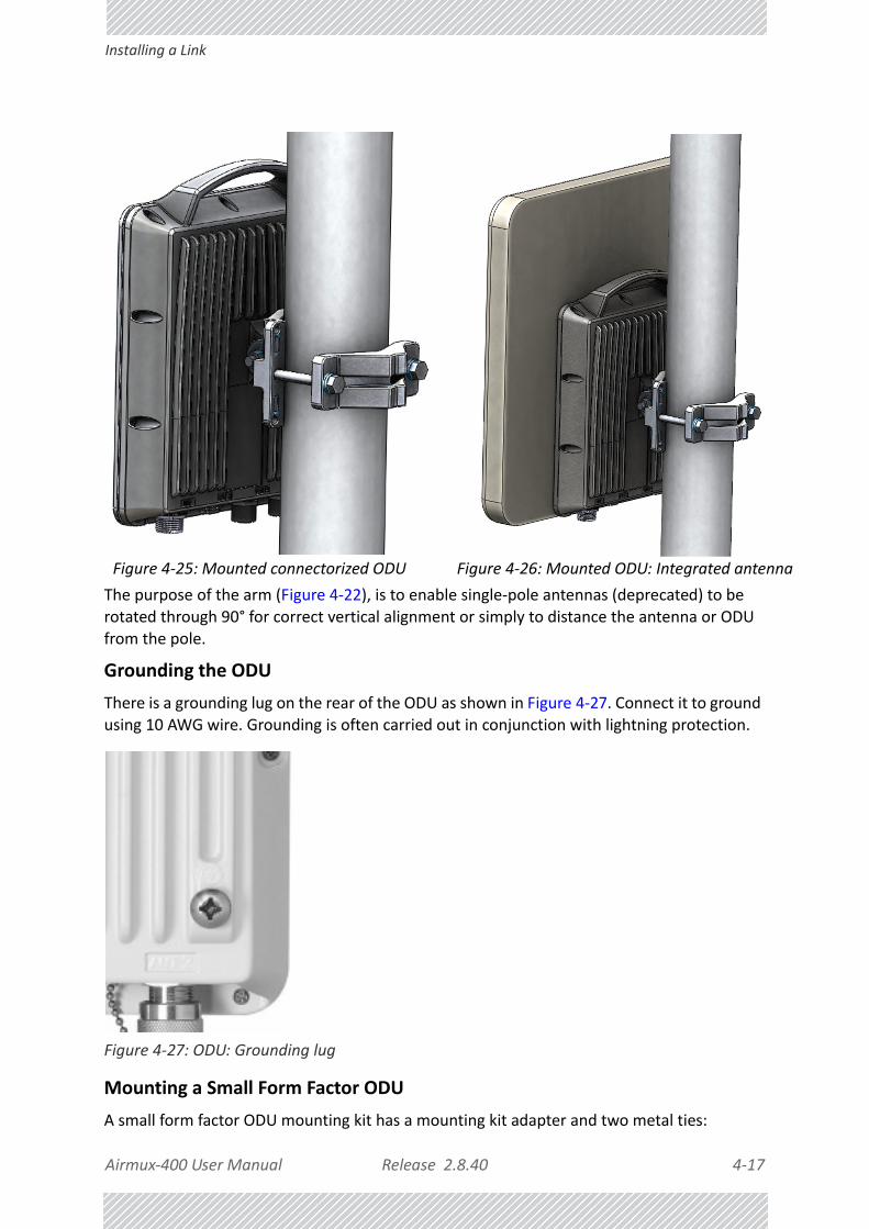
Airmux‐400 User Manual Release 2.8.40 4‐17
Installing a Link
The purpose of the arm (Figure 4‐22), is to enable single‐pole antennas (deprecated) to be rotated through 90° for correct vertical alignment or simply to distance the antenna or ODU from the pole.
Grounding the ODU
There is a grounding lug on the rear of the ODU as shown in Figure 4‐27. Connect it to ground using 10 AWG wire. Grounding is often carried out in conjunction with lightning protection.
Figure 4‐27: ODU: Grounding lug
Mounting a Small Form Factor ODU
A small form factor ODU mounting kit has a mounting kit adapter and two metal ties:
Figure 4‐25: Mounted connectorized ODU Figure 4‐26: Mounted ODU: Integrated antenna

Airmux‐400 User Manual Release 2.8.40 4‐18
Installing a Link
Figure 4‐28: Small form factor ODU ‐ Rear, metal tie
The mounting ties are threaded through the mounting slots provided and the unit mounted on a pole.
U
Figure 4‐29: Mounting adapter
The mounting adapter is used with the standard mounting kit shown in Figure 4‐19. It is not included in the ODU package and must be ordered separately.
To mount a small form factor ODU using a mounting kit:
1. Referring to Figure 4‐30 below: Secure the adapter (3) to the rear of the ODU (2) using the two screws provided (4). Use a Phillips screwdriver set to a torque of 2.0 NM.
Table 4‐2: Mounting adapter kit for small form factor ODUs
Item No.
Description Quantity
1 Metal ties 2
2 Mounting adapter 1
3Screw M5x10, CSK, Phillips, stainless steel
2

Airmux‐400 User Manual Release 2.8.40 4‐19
Installing a Link
Figure 4‐30: Securing the mounting adapter
2. Referring to Figure 4‐31 below: Attach the ODU mounting kit (1) to the mounting adapter ear (4) and proceed as above, for a standard ODU.
Figure 4‐31: Attaching a standard mounting kit
Installing a PoE device
The PoE device (Figure 4‐7) is a very simple piece of equipment. It has a recessed three pin AC power plug, a matching power cable, a LAN‐In port (from a switch), a LAN‐Out port (to the
ODU) and a power LED, green under normal operation. It is typically strapped into a network equipment rack using plastic ties. It may also sit free on a tray or table‐top.
Note
• When mounting an ODU on a pole or wall, ensure that the unit is ori‐ented so that the cable connectors are at the bottom.
• Do not mount an ODU horizontally
• For an ODU with an integrated antenna: Do not tighten the ODU to its mounting bracket until the antenna alignment process is complete.
• Ensure that there are no direct obstructions in front of the ODU or interference from man‐made obstacles.

Airmux‐400 User Manual Release 2.8.40 4‐20
The Airmux‐IDUH/2ETH: An Alternative to PoE Devices
Connecting the ODU to the PoE device
Connect the ODU to the LAN‐Out port only. It will not work on the LAN‐In port.
Connecting the PoE Device to a Network
Connect the PoE to network equipment such as a switch from the LAN‐In port. Connecting network equipment to the LAN‐Out port may damage it.
Powering up the ODU from a Poe Device
Connecting the ODU port labelled IDU to a powered up PoE is sufficient. If you have not already closed and weather‐sealed the ODU IDU port, then inside it you can see an amber colored power LED which turn green when the ODU is configured. (See Chapter 6.)
The Airmux‐IDUH/2ETH: An Alternative to PoE DevicesUsing an Airmux‐IDUH/2ETH instead of several PoE devices
The Airmux‐IDUH/2ETH is an aggregation switch with the functionality of six PoE devices. It is ideal for use at a site having several collocated ODUs. It also affords the connectivity required to use Ethernet HSS for collocation (see Chapter 13).
Figure 4‐32: Airmux‐IDUH/2ETH front panel
Installing an Airmux‐IDUH/2ETH
The Airmux‐IDUH/2ETH can sit on a table top, but is best installed in a rack using the supplied ears as in Figure 4‐11 and Figure 4‐12.
Connecting the ODU to an Airmux‐IDUH/2ETH
Connect the ODU IDU port to any of the six PoE ports of the Airmux‐IDUH/2ETH.
Connecting the Airmux‐IDUH/2ETH device to a network
The Airmux‐IDUH/2ETH has two LAN ports, either of which may be used for network connection.
Grounding and Powering Up the Airmux‐IDUH/2ETH
The Airmux‐IDUH/2ETH has redundant power connection circuits. An enlarged view of the power connectors is shown in below:
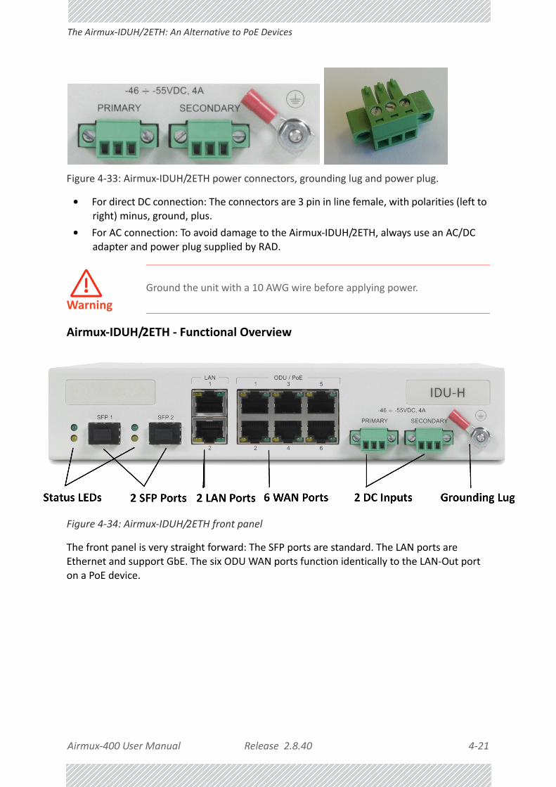
Airmux‐400 User Manual Release 2.8.40 4‐21
The Airmux‐IDUH/2ETH: An Alternative to PoE Devices
Figure 4‐33: Airmux‐IDUH/2ETH power connectors, grounding lug and power plug.
• For direct DC connection: The connectors are 3 pin in line female, with polarities (left to right) minus, ground, plus.
• For AC connection: To avoid damage to the Airmux‐IDUH/2ETH, always use an AC/DC adapter and power plug supplied by RAD.
Airmux‐IDUH/2ETH ‐ Functional Overview
Figure 4‐34: Airmux‐IDUH/2ETH front panel
The front panel is very straight forward: The SFP ports are standard. The LAN ports are Ethernet and support GbE. The six ODU WAN ports function identically to the LAN‐Out port on a PoE device.
Warning
Ground the unit with a 10 AWG wire before applying power.

Airmux‐400 User Manual Release 2.8.40 4‐22
Installing an IDU
The Airmux‐IDUH/2ETH LEDs
Installing an IDU
The IDU can be wall mounted, placed on a desktop or take up one half of a 1U rack slot. The unit looks deceptively like a simple domestic router: It is not. It must be properly grounded, cabled to the ODU and connected to power using the supplied AC/DC adapter.
.
Figure 4‐35: IDU: Rear panel
Although the three pin power plug is physically similar to that of the other IDUs, the power requirements are quite different:
Figure 4‐36: IDU power connector, grounding lug and power plug
• For direct DC connection: The connector is a 3 pin in line female, with polarities (left to right) minus, ground, plus.
• For AC connection: To avoid damage to the Airmux‐IDUH/2ETH, always use an AC/DC adapter and power plug supplied by RAD.
Table 4‐3: Airmux‐IDUH/2ETH LED Indicators
Port Green Yellow
WAN (2xRJ45 LEDs) Link / Activity Duplex or Port’s PoE status (configurable)
LAN (2xRJ45 LEDs) Link / Activity Duplex
SFP (2 panel mounted LEDs) Link / Activity Duplex

Airmux‐400 User Manual Release 2.8.40 4‐23
Mounting an IDU‐E
IDU LEDs
The IDU LEDs share the same functionality as the corresponding IDU‐E LEDs. They are described in the next section.
Mounting an IDU‐E
Figure 4‐37: IDU‐E Package contents ‐ the IDU‐E, 16 E1/T1 ports
IDU‐Es are all rack mountable, as shown in Figure 4‐38. A front panel keyed schematic of a rack mounted IDU‐E is shown in the figure below.
Figure 4‐38: IDU‐E front panel
Further description of the keyed items in Figure 4‐38 is shown in Table 4‐4 below:
Table 4‐4: Components of an IDU‐E front panel
Key Label Remarks
A Indicator LEDs See Figure 4‐39.
B ODU Port RJ‐45 connector, see Table B‐1.
C LAN RJ45Ports Ethernet, RJ‐45 connector, see Table B‐3.
D LAN SFP Port and Status LEDs See Appendix C.
E Alarm Ports Standard DB25 female connector, see Table B‐7.
F Label indent Place for adhesive identification labels.

Airmux‐400 User Manual Release 2.8.40 4‐24
Mounting an IDU‐E
The Indicator LEDs (Item A in Table 4‐4 above) are shown in more detail below:
Figure 4‐39: IDU‐E Front Panel LEDs
The IDU Front Panel LEDS look like this and are functionally the same as the IDU‐E LEDs.
Figure 4‐40: IDU Front Panel LEDs
The purpose of the LEDs is shown in Table 4‐5 below:
GPrimary 3 pin Power Connector Standard 3 pins in line power connector, see
Table B‐8.H
Secondary 3 pin Power Connector
I Grounding Lug Use the lug supplied.
J Rack mounting holes
KDetachable Rack mounting brackets
L 0, 4, 8 or 16 E1/T1 Ports See Table B‐4.
M Standby Port Hot Standby ready: HSB cable socket, see Table B‐5.
Table 4‐5: IDU‐E Front Panel LEDs
Name Color Function
IDU
Green
Blinking Green
Red
Blinking Orange
IDU operational
During power‐up only
Failure
During power‐up; continues if ODU fails to load IDU firmware.
Also, when using an IDU‐E to replace a PoE device in which case all other LEDs off.
ODUGreen
Red
ODU‐to‐IDU communication link is operating
ODU‐to‐IDU communication link is disrupted
Table 4‐4: Components of an IDU‐E front panel (Continued)
Key Label Remarks

Airmux‐400 User Manual Release 2.8.40 4‐25
Mounting an IDU‐E
AIR I/F
Green
Orange
Red
Wireless link is synchronized
During installation mode; also signals software mismatch on some identical ODUs
Wireless link lost synchronization
SVC
Green
Orange
Blinking Orange
Red
Off
E1 or T1 line is synchronized
Alarm detected at the opposite site interface; Normal or LOSS
Local or remote loopback
Alarm detected at this site interface
Ethernet only IDU or E1/T1 not configured
HSS See supplementary Table 4‐6 following.
STBY
Hot Standby Mode ‐ for use with Trunks only
Link State
Green
Blinking Green
Red
Orange
Off
Primary
Secondary
Primary
Secondary
Off
Active
Not active
Not active
Active
HSM not activated
Hot Standby Mode ‐ For use with Ethernet only in a 1+1 Ring application)
Link State
Green
Blinking Green
Red
Orange
Off
Hardware ready
Table 4‐6: IDU‐E and IDU Front Panel LEDs for HSS
Color Function
Green This ODU is HSS master, generating signal, and HSS Sync is OK
Blinking Green
This ODU is a HSS client and in Sync
RedHSS not operational due to improper signal detection. This ODU is not transmitting
Table 4‐5: IDU‐E Front Panel LEDs (Continued)
Name Color Function

Airmux‐400 User Manual Release 2.8.40 4‐26
Mounting External Antennas
To rack‐mount an IDU‐E (The keys refer to Figure 4‐38):
1. Attach the rack mounting brackets (K) to the IDU.
2. Bolt the IDU into an empty slot in the rack, ensuring that it sits securely.
3. Ground the IDU to the rack using grounding lug I. The IDU should be left permanently grounded.
Mounting External AntennasMounting a Flat Panel External Antenna
Typically, a flat panel antenna such as that shown in Figure 4‐14 is used. It has four bolts for a mounting kit adapter.
Figure 4‐41: Flat panel antenna mounting kit adapter
Orange
HSS is operational. One of the following conditions apply:• This ODU is a master that is generating signals and detecting signals• This ODU is a master that is generating signals but detected improper sig‐
nals• This ODU is a client “Continue Tx” but is not detecting signals• This ODU is a client “Disable Tx” and is detecting signals from multiple
sources
All orange cases transmit.
OffHSS is not activatedDisconnection between ODU and IDU
Note
Instead of using the rack mounting brackets, the IDU may be rail mounted using the four screw holes on each of its sides.
Table 4‐6: IDU‐E and IDU Front Panel LEDs for HSS (Continued)
Color Function

Airmux‐400 User Manual Release 2.8.40 4‐27
Mounting External Antennas
It is mounted on a pole in exactly the same manner as the ODU itself using the adapter shown in Figure 4‐41. The left hand view in shows the knurled surface adjacent to the mounting kit ear. The right hand view shows the recess for the mounting kit holding nut.
Figure 4‐42: Flat Panel antenna ‐ rear with mounting kit adapter
Figure 4‐43: Flat Panel antenna ‐ mounted
Other Antenna Types
Many of the antennas of the types shown in Figure 4‐14 use the standard mounting kit of Figure 4‐19. Some third party antennas use pole clamps, similar to those shown below:

Airmux‐400 User Manual Release 2.8.40 4‐28
Mounting the Lightning Protection Devices
Figure 4‐44: Pole clamps for external antennas
Grounding an External Antenna
External antennas should be individually grounded using a suitable Grounding Kit such as an Andrew Type 223158‐2 (http://www.commscope.com).
Mounting the Lightning Protection Devices
The use of lightning protection is dependent on regulatory and end user requirements. The Airmux‐400 ODU is designed with surge limiting circuits to minimize the risk of damage due to lightning strikes. RAD recommends the use of additional lightning protector devices to protect the equipment from nearby lightning strikes.
In what follows, ODU may be any type of RAD outdoor radio unit and IDU may be any type of RAD IDU used with such products (PoEs, Airmux‐IDUH/2ETH, IDU‐E etc.)
Warning
Do not stand in front of a live antenna.

Airmux‐400 User Manual Release 2.8.40 4‐29
Mounting the Lightning Protection Devices
Figure 4‐45: RAD Lightning Protection Kit
Table 4‐7: LPU Kit contents
Item Quantity View/Remarks
LPU (shown wrapped)
1
U wall clamp 1
RJ‐45 connectors (shown wrapped)
2

Airmux‐400 User Manual Release 2.8.40 4‐30
Mounting the Lightning Protection Devices
For any type of IDU‐ODU connection, lightning protection units (LPUs) are installed in pairs, as shown in the next figure:
Figure 4‐46: Basic use of lightning protectors
0.5m CAT‐5e cable
1
Metal tie 1
Quick Installation Guide
1 Pamphlet
Table 4‐7: LPU Kit contents (Continued)
Item Quantity View/Remarks

Airmux‐400 User Manual Release 2.8.40 4‐31
Mounting the Lightning Protection Devices
To install a LPU on a pole adjacent to an ODU (HBS or HSU):
1. Mount one LPU on the ODU pole, as close as possible to the ODU.
2. Ground the LPU to the pole using the grounding lug.
3. Connect the 0.5 meter CAT‐5e cable to the IDU port of the ODU.
4. Connect the other end of the cable to the top of the LPU.
5. Tighten the top cable LPU gland cap.
6. Connect the main ODU‐IDU cable from the IDU to the bottom end of the LPU.
7. Tighten the bottom cable LPU gland cap.
8. Run the main ODU‐IDU cable towards the IDU location.
9. Insulate both LPU connections. See the next section, Additional Consideration for Waterproofing below.
To install a LPU on a wall adjacent to an IDU (PoE or Airmux‐IDUH/2ETH):
1. Use the supplied wall clamp to mount the second LPU as close as possible to the indoor access point to the IDU.
2. Ground the LPU to an earth strip using the grounding lug.
3. Remove the top cable LPU gland cap together with the rubber sealing tube.
4. Thread the IDU cable from the upper LPU, through the removed cap from the previous step.
5. Plug it in to the top of the LPU.
6. Screw down and tighten the LPU cap.

Airmux‐400 User Manual Release 2.8.40 4‐32
Mounting the Lightning Protection Devices
7. Connect the 0.5 m CAT‐5e cable to the Bottom of the LPU.
8. Connect the other end (via the indoor access point) to the IDU.
9. Insulate both LPU connections. See the next section, Additional Consideration for Waterproofing below.
Additional Consideration for WaterproofingLightning Protectors and Ethernet Repeaters
If these units are installed at locations heavily exposed to heavy dust, rain or corrosive moisture (for example, close to the sea), you should protect them further as in the following procedure. In the remainder of this section, “unit” refers to either a Lightning Protection Unit or a Repeater.
To seal a unit against excessive dust and moisture:
1. Obtain a high quality sealing material such as Scotch 23 Tape ¾” wide, from 3M to ensure IP‐67 compliant protection against water and dust.
2. Cut two pieces each 25 cm long, of Scotch 23 splicing tape. Remove the plastic cover to expose the tacky side of the sealing tape as shown in Figure 4‐47.
Figure 4‐47: Exposing the tack side of the sealing tape
3. After connecting the short CAT‐5 IDU/ODU cable (provided in the box) from the ODU to the unit, tighten the cable gland cap firmly and use the insulation tape scotch 23 to fully cover both of the cable glands.
4. Connect the tape with tacky side up on the cable gland cap and the CAT‐5 cable. Start at Start Point at the bottom of the cable gland as shown in Figure 4‐48. Finish at End Point of the CAT‐5 cable, 2.5cm after the end of the shrink tubing. Stretch the tape and apply half‐overlapped to form gap‐free joint.

Airmux‐400 User Manual Release 2.8.40 4‐33
Mounting the Lightning Protection Devices
Figure 4‐48: Start and End points for protective‐taping the unit
5. Wrap two layers of any scotch vinyl plastic electrical type (e.g Scotch Super 88 Vinyl
Plastic Tape from 3M) to protect the joints as shown in Figure 4‐49. Ensure that the bottom of the cable gland and the end of the CAT‐5 cable are covered with the sealing splicing tape and with vinyl plastic tape.
Figure 4‐49: Protecting the unit joints with vinyl tape
6. Mount the unit on the pole using the mounting ring as shown in Figure 4‐50. Ground the unit using the GND screw. For lightning protection, repeat the same procedure to install the second unit connected to the IDU.

Airmux‐400 User Manual Release 2.8.40 4‐34
Mounting the Lightning Protection Devices
Figure 4‐50: Mounted and strapped to the pole
External Ports for CAT‐5e Cables
All external ODU ports should be water sealed. Use the same materials and method as for the
LPU cable glands.

Airmux‐400 User Manual Release 2.8.40 4‐35
Mounting the Ethernet Repeater
Mounting the Ethernet Repeater
The RAD Ethernet repeater enables you to extend the PoE to ODU cable beyond the 100m limit (but no more than 200m). The unit looks physically like the lightning protection device in Figure 4‐17. It’s use is very simple as shown in the following schematic:
Figure 4‐51: sing an Ethernet repeater with lightning protectors
Connecting an ODU to an IDU
The ODU‐IDU cable conducts all the user traffic between the IDU and the ODU, and also provides power to the ODU. The maximum length of the ODU‐IDU cable is 100m (328ft) in accordance with 10/100BaseT standards.
The ODU‐IDU cable is supplied pre‐assembled with RJ‐45 connectors, at the length specified when ordering, or as a cable drum with spare connectors. If the ODU‐IDU cable was not ordered, use an outdoor class, CAT 5e 24AWG shielded cable. See Appendix B for Wiring Specifications.
To connect the ODU to the IDU, route the cable from the ODU to the IDU, secure the cable along its path and connect the cable to the ODU RJ‐45 connector on the IDU (see item B in Figure 4‐38 above).
Note
The Ethernet repeater cannot be used with GbE IDU‐ODU cables.

Airmux‐400 User Manual Release 2.8.40 4‐36
Connecting User Equipment
Connecting User Equipment
To connect user equipment to an IDU:
1. Connect user switch/router or any other compatible device to one of the IDU panel RJ‐45 ports designated LAN. (For an IDU‐E, see item C in Figure 4‐38 above. For an Airmux‐IDUH/2ETH see Figure 4‐9 above.)
2. Connect user E1/T1 traffic to the IDU panel RJ‐45 ports designated TRUNKS. (For an IDU‐E, see labeled item L in Figure 4‐38 above.)
3. IDU‐E and Airmux‐IDUH/2ETH only: To use the SFP Port(s) (see Figure 4‐38 and Figure 4‐9 above), insert an SFP plug‐in module into the port and connect the user switch/router or any other compatible device to the SFP plug‐in module.
Refer to Appendix B for connector pinouts.
For TDM Users
You may use SFP units configured for TDM with the Airmux‐IDUH/2ETH. Be aware however, than the TDM performance will be limited to TDM over Ethernet. If you require native mode TDM performance, you should use an IDU or an IDU‐E.
Connecting and Aligning ODUs / AntennasYou perform antenna alignment using the ODU's buzzer.
To speed up the installation time, alignment of a Airmux‐400 system should be performed by two teams simultaneously, at site A and at site B.
To align ODUs with integrated antennas or external dual‐pole antennas:
1. For external dual‐pole antennas: Using a coax cable with N‐Type connectors, connect the vertical polarization connector of the antenna to the ANT 1 connector of the ODU.
2. For external dual‐pole antennas: Using a coax cable with N‐Type connectors, connect the horizontal polarization connector of the antenna to the ANT 2 connector of the ODU.
3. Ensure that power is connected to the IDUs at both sites.
4. Ensure normal operation of the IDUs by the LED indications on the front panel.
Provided that site A detects the signal from site B, the ODU starts beeping 20 sec‐onds after power up, and continues beeping until the ODUs are aligned, and the installation is complete.
Note
Do not connect two LAN ports to the same network, or flooding may occur.

Airmux‐400 User Manual Release 2.8.40 4‐37
Connecting and Aligning ODUs / Antennas
In the following steps, “antenna” refers both to an external antenna and an inte‐grated antenna.
5. Direct the antenna of site B in the direction of site A. This is simplified if a previous site survey has been completed and azimuths are known.
6. Make a horizontal sweep of 180 degrees with the site A antenna so that the strongest signal from site B can be detected.
7. Slowly turn the site A antenna back towards the position of site B, listening to the tone until the best signal is reached. See the following figure for audible signal variations.
Figure 4‐52: Beep Sequence for antenna alignment
8. Secure the site A antenna to the pole/wall.
9. Repeat steps 4 to 8 for site B.
Warning
When aligning the antennas, do not stand in front of a live antenna.
Note
• Three beeps and a pause is 'best signal so far'
• Two beeps and a pause is 'signal quality increased'
• One beep and pause is 'no change in signal'
• Long beep and short pause is 'signal quality decreased'
• One beep and a long pause is 'no air link'
• Any other signal does not relate to antenna alignment

Airmux‐400 User Manual Release 2.8.40 5‐1
Chapter 5:
Getting Started with the Airmux Manager
Installing the Airmux Manager Application
Minimum System Requirements
The Airmux Manager application is distributed on a CD. Operating system specific PC resources required by the application are set out in Table 5‐1 below:
Requirements common to all systems are:
• Hard disk: 1 GB free space
• Network: 10/100BaseT NIC
• Graphics: 1024x768 screen resolution with 16 bit color
• Microsoft Explorer version 5.01 or later
Installing the Software
Any PC running the Airmux Manager application can be used to configure a Airmux‐400 link.
To install the Airmux Manager program:
1. Insert the CD‐ROM into your CD‐ROM drive.
Table 5‐1: PC Requirements for the Airmux Manager Application
Windows Version
XP ProVista/7
32 bit 64 bit
Memory 512 Mb 1 Gb 2 Gb
Processor P IV P IV Dual Core

Airmux‐400 User Manual Release 2.8.40 5‐2
Getting Started with the Airmux Manager
The installation starts automatically.
2. Follow the on‐screen instructions of the installation wizard to complete setup of the Airmux Manager program in the desired location.
Getting Started with the Airmux Manager If your links are within easy reach, you can configure them using the procedure described below. If however, your links are to be geographically scattered, it may be convenient to pre‐load each ODU with its network address prior to physical installation. The procedure is quite straight forward, and set out in Chapter 25.
To start the Airmux Manager:
1. Connect the managing computer to one of the two LAN ports as shown in Figure 5‐1 below:
Figure 5‐1: LAN ports on the front panel of the IDU‐E
If you are not using a direct connection as above, ensure that you have IDU to man‐aging computer connectivity (e.g. through a LAN).
2. Check that you have connectivity to the ODU. You can do this by opening up a command line session (Start|Run and then type, cmd). At the command prompt, type
ping 10.0.0.120
You should see something like this:
Note
Each ODU requires a static IP address, since part of the link definition is the IP address pair of both ODUs. Network Managers should ensure that these addresses are outside of the automatic allocation ranges used by their network DHCP server.
Note
• For IDU users: The LAN ports are located on the rear panel on the unit.
• From release 2.6 and higher, LAN ports support GbE (10/100/1000 Mbps)

Airmux‐400 User Manual Release 2.8.40 5‐3
The Airmux Manager log‐on Concept
Figure 5‐2: Pinging an uninstalled and unconfigured link
Any other response from ping means that the ODU is not responding. Check your Ethernet connection and that both the IDU and ODU are switched on and then try again. If you do not succeed, seek assistance from RAD Customer Support.
3. Dismiss the command line session.
4. Double‐click the Airmux Manager icon on the desktop, or click Start|Programs|Airmux Manager|Airmux Manager.
The Log‐on dialog box appears.
Figure 5‐3: First time log‐on window
The Airmux Manager log‐on ConceptAirmux‐400 supports SNMPv1 and SNMPv3 either separately or together. The log‐on procedure differs slightly between operation under SNMPv1 and SNMPv3. In what follows below, we assume that SNMPv1 is in use. In Table 5‐2 below, we show the difference between SNMPv1 and SNMPv3 at log‐on time.
The Airmux Manager provides three levels of access in one of two entry modes. To see them, click Options and Settings at any time in the Log on window (Figure 5‐3 above). You are offered an extended log‐on window:
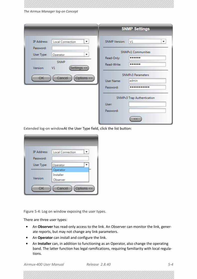
Airmux‐400 User Manual Release 2.8.40 5‐4
The Airmux Manager log‐on Concept
Extended log‐on windowAt the User Type field, click the list button:
Figure 5‐4: Log on window exposing the user types.
There are three user types:
• An Observer has read‐only access to the link. An Observer can monitor the link, gener‐ate reports, but may not change any link parameters.
• An Operator can install and configure the link.
• An Installer can, in addition to functioning as an Operator, also change the operating band. The latter function has legal ramifications, requiring familiarity with local regula‐tions.

Airmux‐400 User Manual Release 2.8.40 5‐5
The Airmux Manager log‐on Concept
If you are using Trap Authentication, enter the User and Password. Leaving these fields blank or incorrect, will not prevent you from logging on. You will not be able to see trap messages directed to the trap message address associated with a defined user. The allocation and association of a trap address with a user is described in Chapter 9, IP Address, VLAN and Protocol.
The following table summarizes these options:
The Network Manager should change the default passwords as soon as possible, particularly if SNMPv3 is to be used.
Continuing the log‐on procedure:
5. Type an IP address for the ODU (if you connect through a LAN), or click Local Connection (if you are connected directly to the IDU port).
Table 5‐2: User types, default passwords and function
User TypeDefault Password
Function
SNMPv1 SNMPv3
CommunityCommunity String
PasswordDefault Value
Observer admin Monitoring Read‐Only public Read‐Only public
Operator adminInstallation, configuration
Read‐Write netman Read‐Write netman
Installer wirelessOperator plus set‐band
Read‐Write netman Read‐Write netman

Airmux‐400 User Manual Release 2.8.40 5‐6
The Airmux Manager log‐on Concept
6. If your User Type is not Operator, then choose it now.
7. Enter the password.
8. If you are a user with Read‐Write permission, click Options to enter the Community options if required
9. For initial log on:
• Leave the default Community passwords, netman for read‐write, and public for read‐only
• If Community values were previously defined, enter them under Community in the Read‐Only or Read‐Write boxes
• If you are a user with read‐only permission, then you may only log on as Observer
The Airmux Manager main window is displayed (see Figure 5‐9).
Warning
• The Local Connection method uses broadcast packets to “discover” the attached ODU
• If you log on using Local Connection, but your physical connection is not local (i.e. anything other than a direct connection between the managing computer and the IDU), then any configuration you carry out may affect other links in the network. Do not do this!
• Do not carry out this procedure using a multi homed managing com‐puter also connected to a network. It will flood the network with broadcast packets. Further, it will throw any other links on the network into Installation or Inactive mode.
• In any event, as a precaution, default log‐on over Local Connection is read‐only mode. Check the Read/Write enable box to carry out instal‐lation procedures.
• Network log on (IP address to the ODU) is recommended.
• If you log on via an over‐the‐air IP address, you will receive a warning. If you reset the site to which you are connected to factory settings, you can lock yourself out of the link.
Note
• The default IP address for the ODU is 10.0.0.120. The subnet mask is 255.0.0.0.
• The actual IP address is defined during link configuration (see IP Address, VLAN and Protocol on page 9‐7. See also, Chapter 25).

Airmux‐400 User Manual Release 2.8.40 5‐7
Log‐on Errors and Cautions
Log‐on Errors and Cautions
Unsupported Device
Attempting to connect to an unsupported device on an otherwise valid IP address (for example, a LAN printer) will result in the following error message:
Figure 5‐5: Unsupported device message
Incorrect IP Address or Invalid Read/Write Community Strings
If the IP address chosen is invalid, the community strings are incorrect or the link is unreachable, the following error message will be displayed:
Figure 5‐6: Unreachable device message
To deal with lost or forgotten Community Strings:
1. Send an email request for to RAD Customer Support for an alternative key. Your email must include the ODU serial number shown on the adhesive sticker on rear of one of your ODUs.
2. The reply will contain an alternative key, which functions as a temporary master Community String. Copy/paste the supplied alternative key to both the Read‐Only and Read‐Write fields in the log‐on window (Figure ). This gets you to the Airmux Manager main window.

Airmux‐400 User Manual Release 2.8.40 5‐8
Incorrect Password
3. Use the procedure on page 9‐14 to enter new Community Strings.
Incorrect Password
If you type an incorrect password in the Login window, the following message will be displayed:
Figure 5‐7: Invalid password message
Logging in to the Over‐the‐Air Site
You can log on to the over‐the‐air site of an established link (Site B in our example). However, you will be first offered the following caution:
Figure 5‐8: Logging on to an over‐the‐air site
Changing the Log‐On Password
To change the log on password:
1. Log on to a valid IP address.
2. From the Tools menu, select Change Password.
Note
If you upgraded from an 8.x .xx release of the Airmux Manager, you will notice that it is no longer possible to work in “Offline mode”. You can only enter the Manager when it is connected to a valid RAD device.

Airmux‐400 User Manual Release 2.8.40 5‐9
Default Airmux‐400 Settings
The Change Password dialog box appears.
3. Enter the current password, and the new password.
4. Click OK to confirm.
Default Airmux‐400 Settings
The default settings of the Airmux‐400 configuration parameters are listed in the second column of Table 5‐3 below. The third column shows the values we use in this manual for illustrative purposes.
Note
A valid log‐on password must contain at least five characters excluding SPACE, TAB, and any of “>#@|*?;.”
Table 5‐3: Default and Illustrative Settings
Parameter Default Value Illustrative Value
Factory default bandProduct dependent
5.820GHz
ODU IP Address 10.0.0.120 10.104.2.2 and 4
Subnet Mask 255.0.0.0 255.255.0.0
Default Gateway 0.0.0.0 10.104.10.21
Trap destination 0.0.0.0 0.0.0.0
Airmux Manager log‐on passwords
Observer admin
Operator admin
Installer wireless
Link ID Link EBG_20561334
Link Name Name TPSF_BTT
Site 1 Site A
Site 2 Site B
Location (per site) Location A B
Name (per site) Name Here There
Contact (per site) Person John Mary
Link Password wireless‐bridge
Rate Adaptive

Airmux‐400 User Manual Release 2.8.40 5‐10
First steps
First stepsAt this point the main window of the Airmux Manager should be displayed:
Figure 5‐9: Opening Airmux Manager window prior to installation ‐ Using IDU‐E s
A detailed field by field description of the contents of the Airmux Manager main window may be found in Chapter 7.
Ethernet Configuration Auto Detect
Radio Link Failure Actions No action
Bridge or Hub mode Hub Mode, Aging time = 300 sec
Protocol SNMPv1 SNMPv1 (may be v1, v3 or both)
Community valuesRead‐write – netman
Read‐only – public
Note
The Dynamic Tx Ratio bar only appears for model Airmux‐400 100M
Table 5‐3: Default and Illustrative Settings (Continued)
Parameter Default Value Illustrative Value

Airmux‐400 User Manual Release 2.8.40 5‐11
Using Airmux Manager Spectrum View
The procedure required to make the link functional has three phases:
1. Link Installation ‐ which we will detail below.
Installation actually gets the link operational by setting the link parameters. It uses a fixed channel at the lowest possible modulation, BPSK at 6.5Mbps and will work under the harsh interference condition.
2. Link Configuration ‐ described in Chapter 8.
Configuration provides much the same functionality as Installation, but for a running link. A fallback to Installation mode is provided for situations which cannot be handled without resetting the link, such as antenna realignment and IDU or ODU replacement.
The Link Installation and Configuration phases are both carried out using Wizards, which “walk you through” the processes. The Wizards are visually quite similar and will be described in detail below.
3. Site Configuration ‐ described in Chapter 9.
Site specific configuration for each side of the link is available at any time ‐ under a running link or under the restricted Installation mode.
Site Configuration consists of a set of panels, which may be invoked individually in any order, as needed.
Using Airmux Manager Spectrum ViewPrior to running the Installation Wizard (Chapter 6), consider running the Airmux Manager Spectrum View utility.
The Airmux Manager Spectrum View utility is an RF survey tool designed to support the link installation prior to full link service activation. The tool provides comprehensive and clear information enabling easier, faster and better quality installations.
Note
During the installation procedure, the definition of link‐wide parameters is automatically applied to both sides of the link.
Caution
• The ODUs as supplied by RAD are set up with a factory default band. If for some reason the default band needs to be changed, it should be done before link Installation. The procedure is set out in Chapter 23.
• Use of an incorrect band may be in violation of local regulations.
Note
An installed and configured link can be returned to installation mode for re‐installation and configuration from last settings or from factory settings.• Reversion to installation mode requires a complete break in the link
service
• Configuration mode may vary the service throughput and quality, but without a service break
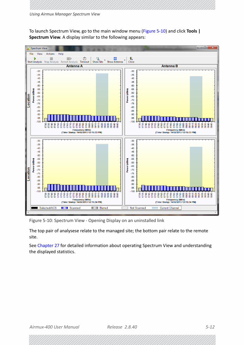
Airmux‐400 User Manual Release 2.8.40 5‐12
Using Airmux Manager Spectrum View
To launch Spectrum View, go to the main window menu (Figure 5‐10) and click Tools | Spectrum View. A display similar to the following appears:
Figure 5‐10: Spectrum View ‐ Opening Display on an uninstalled link
The top pair of analysese relate to the managed site; the bottom pair relate to the remote site.
See Chapter 27 for detailed information about operating Spectrum View and understanding the displayed statistics.

Airmux‐400 User Manual Release 2.8.40 6‐1
Chapter 6:
Installing the Link
OverviewThe installation is carried out using the Installation wizard. Its operation is detailed in the following pages in a tutorial style.
For the purpose of explanation, we will set up a example link with the following characteristics:
• Channel selection: Automatic
• Antennas: Dual at both sites
• Services: Ethernet + 7xE1 on ports 1, 2, 3, 8, 10, 11, 14. It is unlikely that you would use a non‐contiguous set of ports ‐ but this shows that if required, it can be done.
The Installation wizard has 8 main steps as shown in Table 6‐1 below.
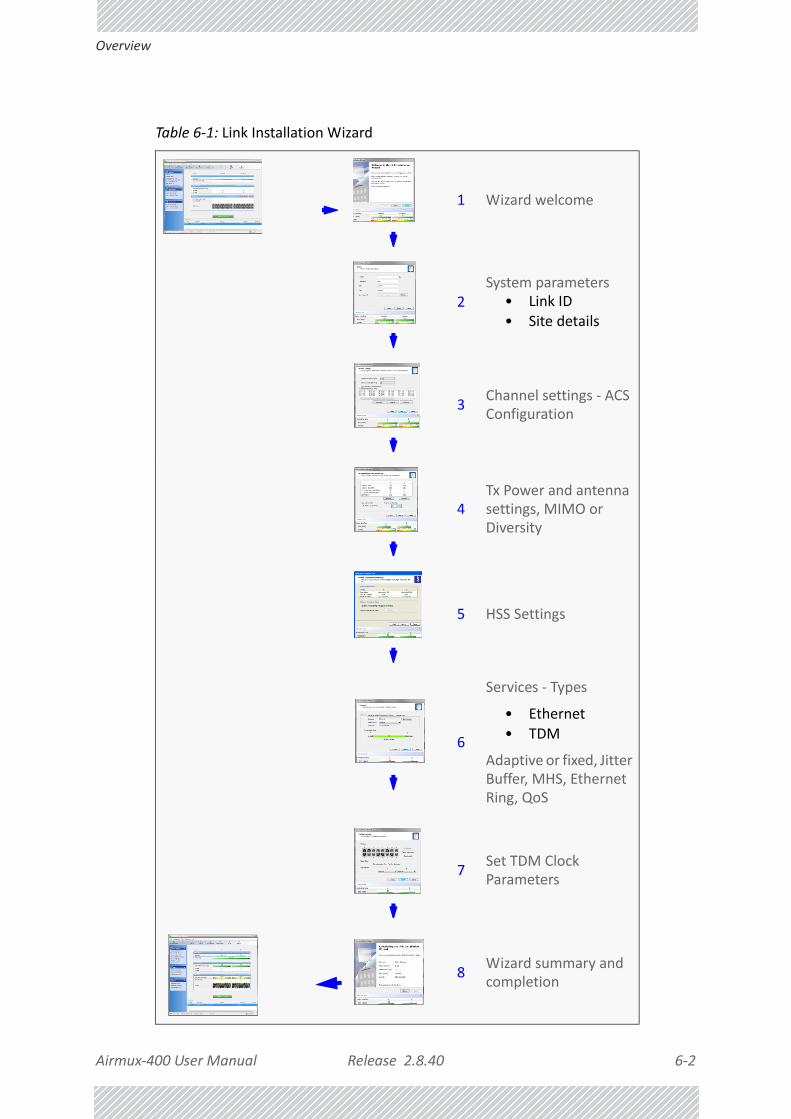
Airmux‐400 User Manual Release 2.8.40 6‐2
Overview
Table 6‐1: Link Installation Wizard
1 Wizard welcome
2System parameters
• Link ID• Site details
3Channel settings ‐ ACS Configuration
4Tx Power and antenna settings, MIMO or Diversity
5 HSS Settings
6
Services ‐ Types
• Ethernet• TDM
Adaptive or fixed, Jitter Buffer, MHS, Ethernet Ring, QoS
7Set TDM Clock Parameters
8Wizard summary and completion

Airmux‐400 User Manual Release 2.8.40 6‐3
Installation
Installation
Step 1, Start the Wizard
In the tool bar of the Airmux Manager main window, click the Link Installation button. The Link Installation button is only accessible if the antennas are properly aligned. If this box is “grayed out”, you should align the antennas as set out in Chapter 4.
The Installation Wizard opens:
Figure 6‐1: Link Installation Wizard
The bottom data area reproduces the corresponding data from the main window ‐ which the above panel obscures. See Chapter 7 for a field by field description of this data area.
Click Next to proceed with the installation procedure.
Step 2, System Parameters
The system dialog box opens:

Airmux‐400 User Manual Release 2.8.40 6‐4
Installation
Figure 6‐2: Installation Wizard, System dialog box
To complete Installation Step 2:
1. Enter a Link ID. The Link ID must be identical for both ODUs in the link, otherwise they will not communicate. The Link ID must include at least eight alphanumeric characters. Up to 24 characters are allowed. You should use a Link ID composed of both alphabetic and numeric characters.
2. Enter a Link Name for the link identification. The default name is “Link”. You should change it.
3. Enter names for Site 1 and Site 2. The default names are both “Location”. You should change them. Throughout this manual, we use A for Site 1 and B for Site 2.
4. Optionally enter a new Link Password.
Note
If the Link Password is incorrect a link is established but configuration cannot be performed and no services are available. A new link password may be obtained from RAD Customer Support or use the alternative password supplied with the product. The link password is peculiar to the link itself and should not be confused with the Airmux Manager log on password.

Airmux‐400 User Manual Release 2.8.40 6‐5
Installation
Here is our completed System panel:
Figure 6‐3: Installation Wizard, System dialog box filled out
5. Click Next.
The default link with a rate of 6.5 Mbps is evaluated.
The Channel Setting dialog box appears. Proceed to Channel Settings, below.
Changing the Link Password
The default password is wireless‐bridge. Optionally, you can change the link password as explained here.
To change the link password:
1. Click the Change button in the System dialog box.
The Change Link Password dialog box opens.
Note
Use the Hide characters check box for maximum security

Airmux‐400 User Manual Release 2.8.40 6‐6
Installation
Figure 6‐4: Change Link Password dialog box
2. Enter the current link password (The default link password for a new ODU is wireless‐bridge).
If you have forgotten the Link Password, click the Forgotten Link Password button. The following window is displayed:
Figure 6‐5: Lost or forgotten Link Password recovery
Follow the instructions to use the Alternative Link Password, and click OK to finish. You are returned to the window in Figure 6‐4 above. Continue with the next step.
3. Enter a new password.
4. Retype the new password in the Confirm field.
5. Click OK.
6. Click Yes when asked if you want to change the link password.

Airmux‐400 User Manual Release 2.8.40 6‐7
Installation
7. Click OK at the Password changed success message.
Step 3, Channel Settings
Airmux‐400 systems have a feature called Automatic Channel Selection (ACS). In the event of sync‐loss, ACS chooses the first available channel in a list of monitored channels nominated in the Channel settings window of Figure 6‐6 below. A channel switch takes place sufficiently fast as to ensure no loss of service.
Figure 6‐6: Channel Settings ‐ Automatic Channel Selection
The default frequency for the product is shown.
Of the selected channels, you may choose a set of preferred channels which will be used by ACS with highest priority. To use this feature, click the Preferred button:
Note
• A link password must contain at least eight but no more than 16 char‐acters excluding SPACE, TAB, and any of “>#@|*?;.”
• Restoring Factory Defaults returns the Link Password to wireless‐bridge.
• If the link is inactive, then the link password may also be changed from the Site Configuration dialogs. See page 9‐14.

Airmux‐400 User Manual Release 2.8.40 6‐8
Installation
Figure 6‐7: Choosing preferred channels
Typically, you would based your preferred channels on based on a spectrum analysis. (You may acquire a spectrum analysis using the Spectrum View tool,Chapter 27.
Check the preferred channels and then OK. The other channels will be used by ACS, but only if the preferred channels become to noisy.
To select channels to be used by the link:
1. Select the installation frequency from the Installation Channel box.
Figure 6‐8: Channel Settings ‐ Showing available installation rates

Airmux‐400 User Manual Release 2.8.40 6‐9
Installation
2. Choose the required Channel Bandwidth.
Figure 6‐9: Channel Settings ‐ Showing available Channel Bandwidths
3. Click the check box if Automatic Channel Selection is required.
4. The Available Channels List contains all of the allowable channels for the link. Check the channels that can be automatically selected.
Selecting a new channel causes the system quality to change. The Quality bar pro‐vides an indication of the link quality from No serv(ice) (red) to Ethernet + TDM (green) as shown in the bottom of Figure 6‐8 above.
5. Click Next.
Step 4, Tx Power and Antenna Settings
The Tx Power and Antenna Parameters dialog is displayed.

Airmux‐400 User Manual Release 2.8.40 6‐10
Installation
.
Figure 6‐10: Transmission Power and Antenna Parameters
The choice of Tx Power, antenna gain and cable loss (between the radio and the antenna) determines the EIRP and is affected by such considerations as radio limitations and regulatory
restrictions.
Before proceeding to antenna installation details, the background information in Appendix F, Setting Antenna Parameters should be considered.
These parameters are controlled as follows:
To set Tx Power and configure antennas:
1. Click the Configure buttons in turn to configure the antennas on both sides of the link. Each one offers a dialog like this:

Airmux‐400 User Manual Release 2.8.40 6‐11
Installation
Figure 6‐11: Antenna configuration dialog
2. Choose the antenna type and required transmission (Tx) power for the first site and click OK. You will receive the following warning:

Airmux‐400 User Manual Release 2.8.40 6‐12
Installation
Figure 6‐12: Antenna type change warning
3. Repeat the process for the second site.
4. At the same time you can set the Antenna Gain and Cable Loss.
The Tx Power (per radio) indicates the power of each radio inside the ODU and is used for Link Budget Calculations. The Tx Power (System) shows the total transmis‐sion power of the ODU and is used to calculate the EIRP according to regulations.
If you choose to set the Antenna Gain and Cable Loss, you will receive the following warning message:
Note
For Airmux‐400 L Links:These ODUs may be switched between the SFF embedded antenna and external antennas. To this end, the Antenna Connection Type radio buttons are always enabled:
Use the Integrated radio button to enable the embedded antenna.
Observe that the SFF embedded antenna functions as a dual antenna and cannot be changed.
Note
To see the relationship between Tx Power (radio) and Tx Power (system),
note that so that if you double the power
in milliWatts (for two radios) then dBm will increase by .
dBm 10 milliWatt10log=
10 2 310log

Airmux‐400 User Manual Release 2.8.40 6‐13
Installation
Figure 6‐13: Antenna parameters change warning
If inequality (*) above is violated, then the following warning window is displayed:
Figure 6‐14: Tx Power Limits
The precise relationship between the items in inequality (*) and the window of Figure 6‐11 is as follows:
• Required Tx Power (per radio) will be adjusted down to the lesser of the value entered and maxAvailableTxPower
• Tx Power (system) is maxAvailableTxPower + 3 (for 2 radios)
• Max EIRP is maxRegEIRP.
Note
• The Max EIRP level will be automatically set according to the selected band and regulation.
• The EIRP level is the sum of the System Tx Power and the Antenna Gain minus the Cable Loss.

Airmux‐400 User Manual Release 2.8.40 6‐14
Installation
• EIRP is maxAvailableTx Power + Antenna Gain ‐ Cable Loss
The table in Figure 6‐14 only shows rates where the maximum Tx Power is the limita‐tion, rather than regulations. When you close the window of Figure 6‐14, the change you requested will not be honored, and you will need to try again.
Figure 6‐15: Antennas configured for two dual and Tx power 5 dBm
5. Choose Dual Antenna mode if appropriate. The green Antenna Configuration diagram indicates the active state. For dual antennas in Diversity mode it looks like this:
There are intermediate modes available for dual antennas opposite a single antenna as set out on Figure 6‐10 above.
If you make a change you will see a warning similar to this:
Note
Since our demonstration link is entirely indoors, we have reduced Tx Power to 5 dBm to obtain a realistic RSS. Although this is much too low for field use, the method is general.

Airmux‐400 User Manual Release 2.8.40 6‐15
Installation
A similarly worded warning applies to a s switch from MIMO to Diversity mode
6. When you are finished with Tx Power configuration, Click Next.
Step 5, Hub Site Synchronization Settings
Figure 6‐16: HSS Settings
The Synchronization Status dialog box displays the current status of each side of the link. See the Hub Site Synchronization section for instructions about installing and configuring collocated links. If you do not require HSS, click Next.

Airmux‐400 User Manual Release 2.8.40 6‐16
Installation
Step 6, Services
The Services dialog appears:
Figure 6‐17: Services and Rates ‐ Airmux‐400 100M only

Airmux‐400 User Manual Release 2.8.40 6‐17
Installation
Figure 6‐18: Services and Rates for Airmux‐400 collocated as a client
For a collocated link proceed to TDM Services selection.
Otherwise, you can use the green slider to allocate asymmetric Ethernet capacity by changing the Transmission Ratio between the sites.
For example: Suppose that during congestion, you might want to use 70% for the downlink and 30% for the uplink. Your choice would typically be based on your experienced traffic load during periods of congestion.
For a collocated link you will see a display like this:

Airmux‐400 User Manual Release 2.8.40 6‐18
Installation
If you choose a Transmission Ratio outside the two tick marks, you run the risk of disabling collocated links operating on a lower channel bandwidth:
Whatever the case, if you change the Transmission Ratio on a collocated link, you will be offered the following warning:
The conditions under this may occur are detailed below.
Otherwise, click Yes to continue.
Limitations on the use of Asymmetric Allocation
For non collocated links, capacity allocation between uplink and downlink traffic is determined automatically according to actual Ethernet traffic and air interface conditions. Your manual allocation using this feature “cuts in” during congestion.
Asymmetric Allocation and Collocation
The use of Asymmetric Allocation is limited where the link is collocated. You may only change the HSM (master) from symmetric to asymmetries allocation. If you do this, the affects on collocated clients are as follows:
• Releases prior to 2.4 ‐ Link down
• Release 2.4 and later (Airmux‐400 100M series) ‐ TDM services stopped, link set to transmission ratio of master
• Release 2.4 and later (Airmux‐400 100M series) ‐ Asymmetric Allocation slider visible but cannot be changed
Caution
If you have active collocated links, or if you are uncertain of whether collocated links provide TDM services do not use this option now. You can do it at a less disruptive time using the Link Configuration (Chapter 8).
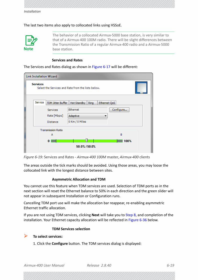
Airmux‐400 User Manual Release 2.8.40 6‐19
Installation
The last two items also apply to collocated links using HSSoE.
Services and Rates
The Services and Rates dialog as shown in Figure 6‐17 will be different:
Figure 6‐19: Services and Rates ‐ Airmux‐400 100M master, Airmux‐400 clients
The areas outside the tick marks should be avoided. Using those areas, you may loose the collocated link with the longest distance between sites.
Asymmetric Allocation and TDM
You cannot use this feature when TDM services are used. Selection of TDM ports as in the next section will reset the Ethernet balance to 50% in each direction and the green slider will not appear in subsequent Installation or Configuration runs.
Cancelling TDM port use will make the allocation bar reappear, re‐enabling asymmetric Ethernet traffic allocation.
If you are not using TDM services, clicking Next will take you to Step 8, and completion of the installation. Your Ethernet capacity allocation will be reflected in Figure 6‐36 below.
TDM Services selection
To select services:
1. Click the Configure button. The TDM services dialog is displayed:
Note
The behavior of a collocated Airmux‐5000 base station, is very similar to that of a Airmux‐400 100M radio. There will be slight differences between the Transmission Ratio of a regular Airmux‐400 radio and a Airmux‐5000 base station.

Airmux‐400 User Manual Release 2.8.40 6‐20
Installation
Figure 6‐20: TDM Type selection
2. Using the TDM Type radio buttons, choose E1 or T1. You are now able to select the
required service ports:
Figure 6‐21: TDM service port selection

Airmux‐400 User Manual Release 2.8.40 6‐21
Installation
3. Use the spin button to choose consecutive service ports, the Select Maximum button to choose all available ports or click on individual ports to choose them.
Figure 6‐22: TDM Service port selection ‐ seven services selected
4. Click OK. You are returned to the Services and rates dialog of Figure 6‐24. It is
updated to reflect your choice.
Note
• Ethernet is always selected.
• The maximum available services will be reduced in accordance with actual air interface capacity.

Airmux‐400 User Manual Release 2.8.40 6‐22
Installation
Figure 6‐23: Services and Rates ‐ Services chosen
Modulation Rate Selection
You may choose a specific modulation rate or use Adaptive.
Note
The selected ports will be enabled for both sides of the link. You cannot for example, use ports 1, 3, 5, 7 on one side and 2, 4, 6, 8 on the other.

Airmux‐400 User Manual Release 2.8.40 6‐23
Installation
Figure 6‐24: Services and Rates dialog: Available rates
To choose a modulation rate:
1. Choose Adaptive or one of the available rates.
2. Click Evaluate to continue or click the TDM Jitter Buffer tab to set the TDM Jitter Buffer (see next section).
The service is activated as show below:
You are returned to the Services and rates dialog of Figure 6‐23.
Setting Monitored Hot Standby Mode
If you are not using Hot Standby Mode, you may skip this section.
To install and use the Hot Standby feature, see Chapter 15. The following procedure can be used to switch links between primary and secondary or to disable the mode.
To set the Hot Standby Mode:
1. Click the Hot Standby tab. The following dialog appears:

Airmux‐400 User Manual Release 2.8.40 6‐24
Installation
Figure 6‐25: Choosing Hot Standby Mode
2. Click the radio button to make this link primary or secondary.
Ethernet Ring
To install and use the Ethernet Ring feature, see Chapter 16.
Ethernet QoS
To install and use the Ethernet QoS feature, see Chapter 21.
Setting the TDM Jitter Buffer
To set the TDM Jitter Buffer size:
1. Click the TDM Jitter Buffer tab. The following dialog is displayed:

Airmux‐400 User Manual Release 2.8.40 6‐25
Installation
Figure 6‐26: TDM Jitter Buffer Configuration
Note
• The receiver jitter buffer for each site can be enlarged, thereby increasing system resistance to interference (the larger the jitter buffer, the longer the interference period that the system will overcome without TDM errors).
• You can also decrease the jitter buffer to decrease the system delay.
• The jitter buffer can be configured between 2.0 and 16.0 ms.
• After setting the new value you must evaluate the expected quality. During the evaluation the TBFR (TDM Block Failure Ratio) bar is displayed. You select either Next, which per‐forms the change or Back to cancel the change. Notice that the Jitter Buffer is configured per site.

Airmux‐400 User Manual Release 2.8.40 6‐26
Installation
Figure 6‐27: TDM Jitter Buffer Configuration ‐ TBFR evaluation bar
2. After setting the jitter buffer size, if grayed out, the Evaluate button is enabled while both Back and Next are disabled as shown in the next figure:
Figure 6‐28: Services and TDM delay set ‐ link ready for evaluation
3. You may make any further changes to the Service Configuration or the Jitter buffer. When you are satisfied, click the Evaluate.
The optimum transmission rate for the selected services is evaluated.

Airmux‐400 User Manual Release 2.8.40 6‐27
Using E1 TDM Ports
Following a short delay for processing, Back and Next are enabled.
4. Click Next to continue.
Step 7, TDM Clock Configuration
Using E1 TDM Ports
The following dialog is displayed:
Figure 6‐29: TDM E1 Parameters Configuration (1)
Note
The transmission rates used by Airmux‐400 are shown in Table F‐2.

Airmux‐400 User Manual Release 2.8.40 6‐28
Using E1 TDM Ports
To configure TDM clock parameters:
1. For any individual port, click it. For the same parameters for all ports, click the Select Maximum tag.
2. Right click any port. The following drop down list is displayed:
Figure 6‐30: TDM Parameters Configuration (2)
3. Click the required parameter. Their meanings are as follows:
Note
• Select Maximum will select the maximum number of services that were configured for the air interface for configuration
• Deselect All unconditionally deselects all of the services for configura‐tion
• Without selecting anything, right‐clicking any port will cause the appearance of the drop down list of Figure 6‐30 below
Note
Please keep in mind that what follows is per port.
mmmp

Airmux‐400 User Manual Release 2.8.40 6‐29
Using E1 TDM Ports
Figure 6‐31: TDM Parameters
Transparent/Transparent
The clock at Site A regenerates the clock from Site B and vice versa.
Loop time/Recover
The Site A port receive‐clock is used as the transmit‐clock for that port on both sides of the link.
Recover/Loop time
The Site B port receive‐clock is used as the transmit‐clock for that port on both sides of the link.
Internal/Recover
The Site A port uses its internal oscillator to generate its transmit clock while
the Site B port regenerates the clock received at the Site A port.
Recover/Internal
The Site B port uses its internal oscillator to generate its transmit clock while the Site A port regenerates the clock received at the Site B port.
Mousing‐over any port causes a pop‐up help balloon:
4. You may configure the E1 ports to unbalanced mode (75 ohm). You should configure both sides of the link as balanced or unbalanced.
Figure 6‐32 shows an adapter cable for connecting devices with balanced E1 inter‐face to the user equipment with unbalanced E1 interface. The Y splitter cable

Airmux‐400 User Manual Release 2.8.40 6‐30
Using T1 TDM Ports
includes one RJ‐45 balanced connector (left) and two unbalances BNC coaxial con‐nectors (right).
Figure 6‐32: Unbalanced E1 adapter cable (Y Splitter)
See Appendix B for further technical details.
5. Click Finish to complete the wizard.
Using T1 TDM Ports
If you are using T1 (or international equivalents), the Clock Configuration is a little different:
Figure 6‐33: TDM T1 Parameters Configuration
Here you should also chose the Line Code and Impedance. Some regulatory areas (such as Japan) require a 110 Ohm line impedance.

Airmux‐400 User Manual Release 2.8.40 6‐31
Using T1 TDM Ports
Step 8, Installation Summary and Exit
Figure 6‐34: Installation Wizard Exit Summary
Click Done to return to the main window.
The main window now reflects the installation:

Airmux‐400 User Manual Release 2.8.40 6‐32
Using T1 TDM Ports
Figure 6‐35: Main window of the Manager after installation with loaded trunks
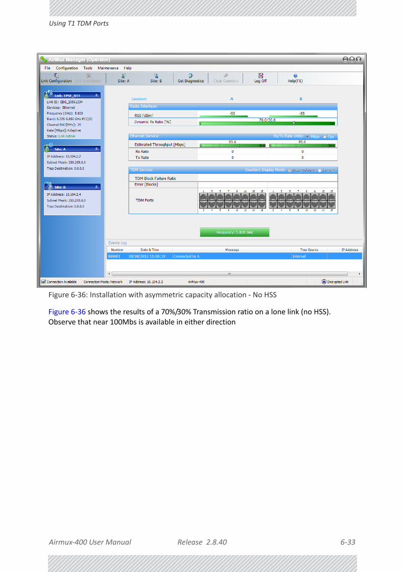
Airmux‐400 User Manual Release 2.8.40 6‐33
Using T1 TDM Ports
Figure 6‐36: Installation with asymmetric capacity allocation ‐ No HSS
Figure 6‐36 shows the results of a 70%/30% Transmission ratio on a lone link (no HSS). Observe that near 100Mbs is available in either direction

Airmux‐400 User Manual Release 2.8.40 6‐34
Using T1 TDM Ports
Figure 6‐37: Installation with asymmetric capacity allocation ‐ HSS enabled
Figure 6‐37 shows the results of a 70%/30% Transmission ratio on a lone link with HSS. The allocation is “hard”.
Our final example uses the same pair of ODUs with a pair of IDU‐Es supporting GbE:

Airmux‐400 User Manual Release 2.8.40 6‐35
Using T1 TDM Ports
Figure 6‐38: Using GbE IDU‐Es. 200 Mbps in both directions.
To verify the installation:
• Verify that the Received Signal Strength (RSS) is according to expected results as determined by the Link Budget Calculator.
Caution
Installation mode, as described above, may be re‐entered using Site:A or Site:B and Installation Mode in the Site Configuration dialog. Some Installation mode functionality may cause a break in, or degrade link service.If you can accomplish link changes without affecting the service, always prefer to use Configuration mode, described in Chapter 8.

Airmux‐400 User Manual Release 2.8.40 7‐1
Chapter 7:
The Airmux Manager: Main Window
The Main Window of the Airmux ManagerEnsure that the Airmux Manager is running.
The main window should look similar to that in Figure 7‐1:
Figure 7‐1: Main window, Wireless Link is Active

Airmux‐400 User Manual Release 2.8.40 7‐2
The Airmux Manager Tool bar
The main window of the Airmux Manager contains a large amount of information about the link. Before proceeding to details of link configuration we set out the meaning of each item in the main window.
The Airmux Manager Tool barIn configuration mode, the Airmux Manager toolbar contains the following buttons:
In Installation mode, Link Configuration is grayed out and Link Installation is open.
The button functions are set out in Table 7‐1:
Main Menu FunctionalityThe main menu contains the following items:
Table 7‐1: Airmux Manager Toolbar
Item Description
Link Configuration
Changes configuration parameters of an operating wireless link; assigns text files for storing alarms, statistics and configuration data. This button is disabled until a link installation has been completed
Link InstallationPerforms preliminary configuration of the system. This button is disabled after the link is installed
Installation Mode Enter Quick Insllation mode. See Chapter 24.
Site: <Site 1 name>Opens the Site configuration dialog for Site 1. Same as Configuration | 1 Configure <Site 1 name>
Site: <Site 2 name>Opens the Site configuration dialog for Site 2. Same as Configuration | 2 Configure <Site 2 name>
Get Diagnostics Obtain system information
Clear CountersClears TDM error blocks counters. Disabled for Ethernet‐only link
Log off Closes the current session and logs off Airmux Manager
Exit Exits Airmux Manager
Help Opens Help on the use of contextual online help

Airmux‐400 User Manual Release 2.8.40 7‐3
Main Menu Functionality
The Airmux Manager menu functionality is displayed in Table 7‐2.
Table 7‐2: Airmux Manager main menu functionality
Menu levelFunction Reference
Top +1 +2
File
Log OffReturn to log‐on dialog. Same as Log Off button
ExitExit the Airmux Manager. Same as Exit button
Configura‐tion
Link Configuration
Run the Configuration Wizard. Not available in Installation Mode
This chapter
1 Configure <Site 1 name>
Opens the Site configuration dialog for Site 1. Has a path to return to Installation Mode
Chapter 9
2 Configure <Site 2 name>
Opens the Site configuration dialog for Site 2. Has a path to return to Installation Mode
Link Installation
Runs the Installation Wizard. Not available in Configuration Mode
Chapter 6

Airmux‐400 User Manual Release 2.8.40 7‐4
Main Menu Functionality
Tools
Performance Monitoring Report
On screen and printable
Chapter 10Active Alarms
1 <Site 1 name>Shows active alarms for <Site 1 name>
2 <Site 2 name>Shows active alarms for <Site 1 name>
Recent EventsDisplays recent events by site
Software Upgrade
Upgrade ODU firmware Chapter 18
Spectrum View Monitor and evaluate spectrum availability
Chapter 27
Change Band (Installer only)
Change the link band Chapter 23
Events LogClear Events Clear local events log
Chapter 10Save to File Save events log file
Preferences Local preferences dialog
Mainte‐nance
Clear counters Clear TDM counters
Loopbacks Set TDM loopbacks Chapter 10
Estimate Eth. Throughput
Estimate Ethernet throughput by transmitting full size frames over the air for 30 sec
Chapter 10
Reset1 <Site 1 name> Reset <Site 1 name> ODU
2 <Site 2 name> Reset <Site 2 name> ODU
Help
Airmux Manager Help
View help on online help
Link Budget Calculator
Calculator opened in default browser
Chapter 26
Get Diagnostics Information
Obtain system information Chapter 10
About Airmux Manager
Manager build and system information
Table 7‐2: Airmux Manager main menu functionality (Continued)
Menu levelFunction Reference
Top +1 +2

Airmux‐400 User Manual Release 2.8.40 7‐5
Elements of the Airmux Manager Main Window
Elements of the Airmux Manager Main Window
Link details pane
The Link details pane on the left is split into three sections, which are largely self explanatory. The top section summarizes information about the link:
For Link status possibilities and color codes, see Table 10‐2.
The two lower left panels show basic link site details:
The three fields for each site are user definable. See page 9‐7.
The Monitor pane
The monitor pane, is the main source of real time information about link performance at both link sites. It includes the following panes (top to bottom):
Received Signal Strength
Radio Interface, Received Signal Strength (RSS) in dBm and Transmission Ratio:

Airmux‐400 User Manual Release 2.8.40 7‐6
The Monitor pane
Under normal operating conditions the RSS for both sites should be balanced with occasional fluctuations of 1‐2 dBM. The main causes of consistent imbalance are as follows:
• A consistent RSS imbalance may be caused by different TX Power settings at each site. There is no warning indicator but it may be easily corrected using Site Configuration | Tx Power & Ant or by rerunning the Configuration wizard.
• A yellow warning triangle will be displayed for an RSS difference of more than 8 dBm between the two polarizations on the same site (the RSS display is the combination of both polarizations on this site)
Notice the mouse‐over tool‐tip explaining the problem.
• A red warning triangle indicates an RSS difference of more than 16 dBm between the two polarizations on the same site
Again, notice the mouse‐over tool‐tip explaining the problem.
The latter two cases are usually the result of a physical problem at the indicated site. Probable causes are:
• Interference
• Antenna polarity problem
• ODU malfunction
Note
The Dynamic Tx Ratio bar only appears for model Airmux‐400 100M

Airmux‐400 User Manual Release 2.8.40 7‐7
The Monitor pane
Ethernet Service
• Estimated Ethernet Throughput: The numbers are the current calculated throughputs at each site. The colored bars (with numbers) indicate the maximum possible throughput having regard for air conditions.
• Rx and Tx Rates: The Rx and Tx rates are the receive and transmit rates on the LAN side of each ODU, not the air side. For a balanced link, the Rx and Tx rates at the LAN side of Site A will match the Tx and Rx rates at the LAN side of Site B respectively. In all cases, The LAN side Rx rate shown will be the same as the air side Tx rate for each individual ODU.
• Actual Ethernet traffic received and transmitted rates per site, is in Mbps of Fps, select‐able in the panel title bar.
TDM Services (IDU‐E and IDU)
• The title bar enables you to switch between Accumulative and Current view.
• Immediately below the title bar is displayed the TDM Block Failure Ratio. It is zeroed by the Clear Counters button in the tool bar.
• Error block count is shown immediately above the active TDM channels display.
• The color of the TDM ports reflects their current status:
• Green ‐ Operational
• Red ‐ Error: LOS for loss of signal and AIS for Alarm Indication Signal
• Yellow ‐ Loopback
• Gray ‐ Inactive
Frequency box
The Frequency box shows the link frequency. The color of the box indicates the status as follows:
• Green is an active link
• Red is an inactive link
• Magenta indicates an authentication or compatibility problem
• Brown indicates severe compatibility problem

Airmux‐400 User Manual Release 2.8.40 7‐8
Events Log
Events Log
The Events Log, stores alarms generated from both sides of the link and is detailed in Chapter 10.
The little triangular arrow‐head on the right of the Message header indicates the order of messages. Default as shown, is from oldest to newest. Click it to change the order.
Status Bar
The Status bar, displays the following icons:
Table 7‐3: Status bar indicators
Icon or Label Purpose
Connectivity Shows if Airmux Manager is communicating with the ODU.
Connection available
Connection mode to the ODU• Over‐the‐Air connection ‐ using the IP address of the
remote unit.• Local connection ‐ direct connection to the IDU without
using an IP address.• Network connection ‐ through a LAN
ODU unreachable
IP Address Log on IP address
Encryption indicator
Normally encrypted link
Link password validation failed. The link is encrypted with default keys.
Service and configuration are unavailable. Change the link password.
Link Lock
Link Lock enabled
Link Lock encrypted
Link Lock mismatch
Ethernet Ring Member

Airmux‐400 User Manual Release 2.8.40 7‐9
Status Bar
DFS in use
Rescue Alarm In the event of an active alarm, opens alarms dialog
Table 7‐3: Status bar indicators (Continued)
Icon or Label Purpose

Airmux‐400 User Manual Release 2.8.40 8‐1
Chapter 8:
Configuring the Link
OverviewThis chapter describes the link configuration procedure, which is performed after the installation of both sides of the Airmux‐400 link, as set out in Chapter 6.
Link configuration uses a Link Configuration wizard to redefine the configuration parameters and fine‐tune an operational link. Both sides of the link are configured simultaneously.
Link configuration allows you to configure link parameters, which do not lead to sync‐loss or require a reset. Some may change service performance, in respect of which, warnings are displayed.
For ease of use, the Link Configuration wizard follows the same pattern as Link Installation. You should therefore be familiar with the content of Chapter 6.
The following parameters are configured using the Link Configuration Wizard:
• System parameters
• Channel settings
• Transmission power and antenna settings
• Service parameters
The Configuration Wizard has seven steps as shown in Table 8‐1 below.
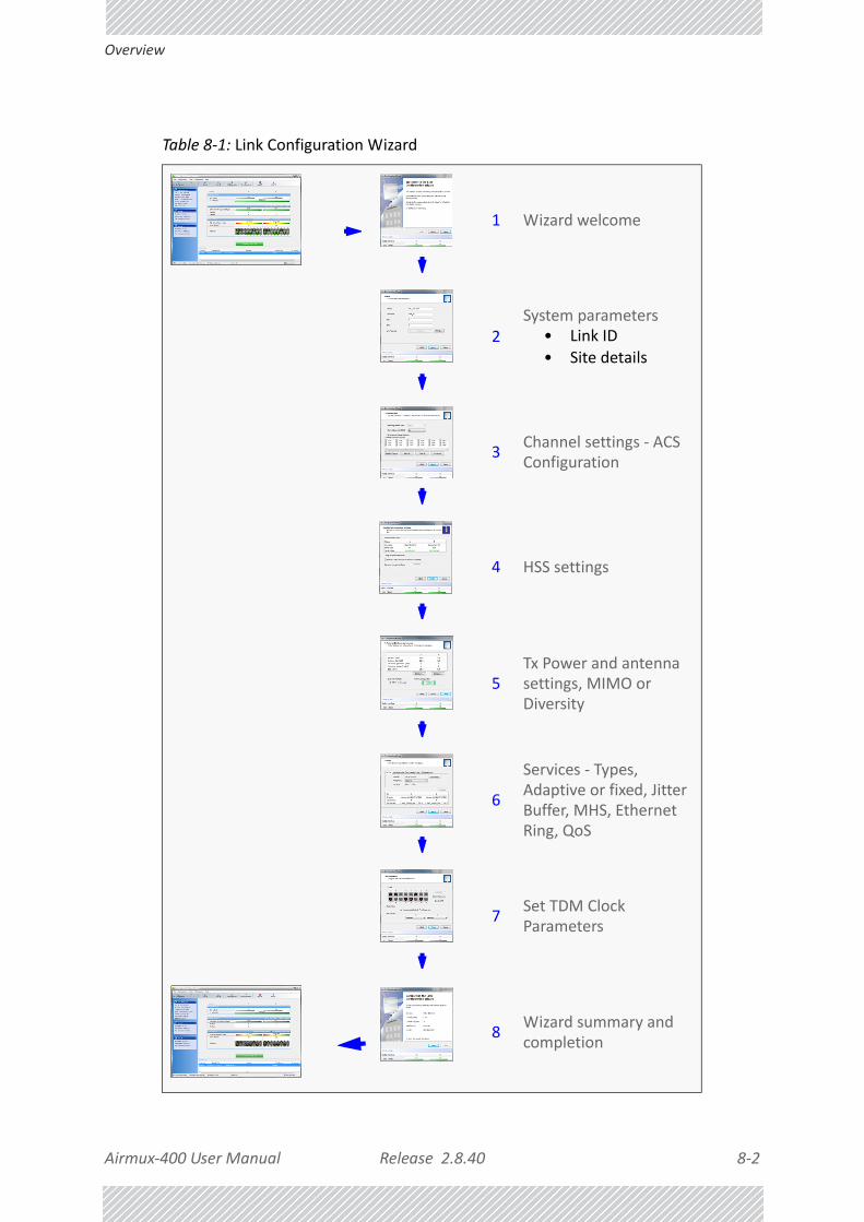
Airmux‐400 User Manual Release 2.8.40 8‐2
Overview
Table 8‐1: Link Configuration Wizard
1 Wizard welcome
2System parameters
• Link ID• Site details
3Channel settings ‐ ACS Configuration
4 HSS settings
5Tx Power and antenna settings, MIMO or Diversity
6
Services ‐ Types, Adaptive or fixed, Jitter Buffer, MHS, Ethernet Ring, QoS
7Set TDM Clock Parameters
8Wizard summary and completion

Airmux‐400 User Manual Release 2.8.40 8‐3
Configuration
ConfigurationSince configuration functionality is included in the installation, we will briefly review the main steps and for most part offer references to the corresponding installation step.
Step 1, Start the Wizard
In the tool bar of the Airmux Manager main window, click the Link Configuration button. The Link Configuration button is only accessible on a fully installed link as set out in Chapter 6.
The Configuration Wizard opens:
Figure 8‐1: Link Configuration Wizard
Click Next to proceed with the configuration procedure.
Step 2, System Parameters
The System dialog box opens:

Airmux‐400 User Manual Release 2.8.40 8‐4
Configuration
Figure 8‐2: Configuration Wizard, System dialog box
The System attributes may be edited and the Link Password may be changed exactly as in the corresponding Link Installation step on page 6‐5.
Click Next to continue.
Step 3, Channel Settings
Configuring the Channel Settings follows the same pattern as the Installation procedure:

Airmux‐400 User Manual Release 2.8.40 8‐5
Configuration
Figure 8‐3: Channel Settings dialog box ‐ Automatic Channel Selection
Notice that the operating channel is grayed out. If you use the Reselect Channel button, to change it, you will be asked for confirmation:
If you accept, then the system will search for the best operating channel:

Airmux‐400 User Manual Release 2.8.40 8‐6
Configuration
Figure 8‐4: Searching for the best operating channel
The link will return to the status of Figure 8‐3 above with a possible change to the operating channel.
You may choose a channel subset and set preferred channels as for Link Installation as shown on page 6‐16.
If you work without automatic channel selection, the Channel Settings window looks like this:
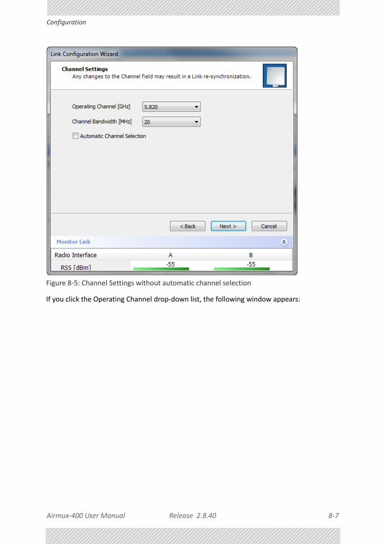
Airmux‐400 User Manual Release 2.8.40 8‐7
Configuration
Figure 8‐5: Channel Settings without automatic channel selection
If you click the Operating Channel drop‐down list, the following window appears:

Airmux‐400 User Manual Release 2.8.40 8‐8
Configuration
Figure 8‐6: Channel frequency options
Selecting one of the frequencies presented returns you to the status of Figure 8‐5 with the appropriate change. If you choose Other..., the following window opens:

Airmux‐400 User Manual Release 2.8.40 8‐9
Configuration
Figure 8‐7: Choosing an “Other” Operating Channel frequency
The right hand drop‐down list (showing the current Operating Channel) allows you to fine‐tune the frequency in increments of ±5MHz within a range of the operating band, which in this example is 5.725 ‐ 5.850 GHz.
The Channel Bandwidth may also be changed. The available choices are 5, 10, 20 and 40MHz depending on model and regulation (see Appendix A).
For the purposes of this illustration, we choose adaptive channel selection and operating channel frequency 5.820 GHz.
When you have completed making your choice, click Next to continue.
Step 4, Tx Power and Antenna Settings
The Tx Power and Antenna Settings window is similar to that for Installation:

Airmux‐400 User Manual Release 2.8.40 8‐10
Configuration
Figure 8‐8: Transmission Power and Antenna Parameters
As in Installation mode, you need to consider three items:
• Number of antennas at each Link site (1 or 2)
• Tx Power setting for each one
• MIMO or Diversity mode
Changing Number of Antennas and Tx Power
TX Power, Antenna Gain and Cable Loss
If you chose to configure either antenna, you are presented with the following window:
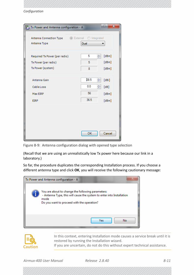
Airmux‐400 User Manual Release 2.8.40 8‐11
Configuration
Figure 8‐9: Antenna configuration dialog with opened type selection
(Recall that we are using an unrealistically low Tx power here because our link in a laboratory.)
So far, the procedure duplicates the corresponding Installation process. If you choose a different antenna type and click OK, you will receive the following cautionary message:
Caution
In this context, entering Installation mode causes a service break until it is restored by running the Installation wizard. If you are uncertain, do not do this without expert technical assistance.

Airmux‐400 User Manual Release 2.8.40 8‐12
Configuration
You may also change the Required Tx Power, Antenna Gain and Cable Loss. The procedure is the same as for the corresponding Installation, Step 4: Tx Power and Antenna Settings.
Switching Between Single and Dual Antennas
Single/Dual Antenna mode selection works precisely the same way as shown for Installation, Step 4.
Switching Between MIMO and Diversity Modes
A similarly worded warning applies to a s switch from Diversity to MIMO mode.
The considerations are otherwise no different from those set out in the corresponding Installation step.
When you have completed making your choice, proceed to the Services window.
Note
For Airmux‐400 L Links:These ODUs may be switched between the SFF embedded antenna and external antennas. To this end, the Antenna Connection Type radio buttons are always enabled:
Use the Integrated radio button to enable the embedded antenna.
Observe that the SFF embedded antenna functions as a dual antenna and cannot be changed.

Airmux‐400 User Manual Release 2.8.40 8‐13
Configuration
Step 5, Hub Site Synchronization Settings
Figure 8‐10: HSS Settings
The Synchronization Status dialog box displays the current status of each side of the link. See Hub Site Synchronization for instructions about installing and configuring collocated links. If you do not require HSS, click Next.
Step 6, Services
Here is the services dialog:
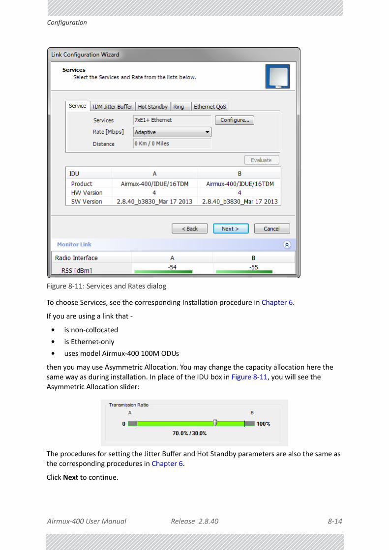
Airmux‐400 User Manual Release 2.8.40 8‐14
Configuration
Figure 8‐11: Services and Rates dialog
To choose Services, see the corresponding Installation procedure in Chapter 6.
If you are using a link that ‐
• is non‐collocated
• is Ethernet‐only
• uses model Airmux‐400 100M ODUs
then you may use Asymmetric Allocation. You may change the capacity allocation here the same way as during installation. In place of the IDU box in Figure 8‐11, you will see the Asymmetric Allocation slider:
The procedures for setting the Jitter Buffer and Hot Standby parameters are also the same as the corresponding procedures in Chapter 6.
Click Next to continue.

Airmux‐400 User Manual Release 2.8.40 8‐15
Configuration
Step 7, TDM Clock Configuration
The following dialog is displayed:
.
Figure 8‐12: TDM Parameters Configuration
To configure the TDM Parameters, see the corresponding procedure in Chapter 6.

Airmux‐400 User Manual Release 2.8.40 8‐16
Configuration
Step 8, Configuration Summary and Exit
Figure 8‐13: Configuration Wizard Exit Summary
Click Done to return to the main window.
The main window now reflects the configuration:

Airmux‐400 User Manual Release 2.8.40 8‐17
Configuration
Figure 8‐14: Main window of the manager after configuration

Airmux‐400 User Manual Release 2.8.40 9‐1
Chapter 9:
Site ConfigurationThe Site Configuration dialog panels are used to configure parameters, which may differ between both sides of the link.
The parameters configured using the Site Configuration dialog panels include (among others):
• System settings
• Air interface ‐ Transmit (Tx) power and antenna
• Hub Site Synchronization status
• Network management including VLAN
• Inventory ‐ link hardware and software model details
• Security settings
• Date and time
• Ethernet service settings
• TDM Hot Standby status
• External alarms settings
• Operations ‐ Revert to factory settings
The Operations dialog offers a “doorway” to jump into installation mode.
The Site Configuration dialog has its own main menu with the following extra functionality:
• Backup ODU software
• Restore ODU software or configuration from a backup file
• Refresh the current panel
• Enable/disable the site ODU buzzer
• Jump back into installation mode keeping current configuration settings
Configuring the Site
Editing the Configuration Parameters by Site
You can edit the configuration parameters for each site individually. The following functions are available from the left side of the dialog box.

Airmux‐400 User Manual Release 2.8.40 9‐2
Editing the Configuration Parameters by Site
Figure 9‐1: Configuration Dialog Box
Functions on the left of the dialog box:
Table 9‐1: Site Configuration tabs
Tab Purpose
System Edit the contact person and location details. View the system details
Air Interface Change the Tx Power, cable loss, antenna type and settings.
View HSS settings
Management Configure the IP address, Subnet Mask, Default Gateway, Trap Destination and VLAN
Inventory View the hardware and software inventory (product identification, versions, MAC address and serial number)
Security Change the Community Values and the Link Password. Set Link Lock.

Airmux‐400 User Manual Release 2.8.40 9‐3
Viewing System Details
Functions at the top of the dialog box:
To edit the Configuration Parameters:
1. Click the required site button on the main tool bar of the Airmux Manager
OR
Click Configuration from the main menu and choose a site to configure.
The Configuration dialog box opens (see Figure 9‐1 above).
2. Choose the appropriate item in the left hand list to open a dialog box.
3. Click Apply to save changes.
In subsequent instructions, we will simply say “Choose a site to configure” on the understanding that the foregoing procedure is implied.
Viewing System DetailsThis is the first window displayed ‐ as depicted above. You can edit the contact details and site names.
Date and Time Set the date and time of the link from an NTP servers or from the managing computer
Advanced Choose Hub or Bridge ODU mode, IDU aging time, set the Ethernet ports configuration, set max. information rate, TDM MHS status, set the external alarm inputs, restore factory settings, set IDU detection mode.
Table 9‐2: Site Configuration menu buttons
Menu Button Purpose
Backup Save the current ODU software to a file
Restore Restore an ODU’s software or configuration from a backup file created by the backup facility
Refresh Refresh current panel with latest values
Installation Mode Return to Installation Mode for the entire link.
Selecting the Mute check box before clicking the Install Mode button mutes the Beeper.
Buzzer Mutes the alignment tone in installation mode. Reactivate the beeper during alignment.
Table 9‐1: Site Configuration tabs (Continued)
Tab Purpose
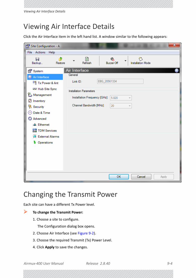
Airmux‐400 User Manual Release 2.8.40 9‐4
Viewing Air Interface Details
Viewing Air Interface DetailsClick the Air Interface item in the left hand list. A window similar to the following appears:
Changing the Transmit PowerEach site can have a different Tx Power level.
To change the Transmit Power:
1. Choose a site to configure.
The Configuration dialog box opens.
2. Choose Air Interface (see Figure 9‐2).
3. Choose the required Transmit (Tx) Power Level.
4. Click Apply to save the changes.

Airmux‐400 User Manual Release 2.8.40 9‐5
Changing the Transmit Power
Figure 9‐2: Changing the Antenna Type and Transmit Power
The Antenna Connection type reflects the installed ODU. In our example, we are using an external antenna on a Airmux‐400 100M ODU, so the first two fields are set and grayed out as shown. If you have a connectorized Airmux‐400 LC model, you will be able to switch between external and integrated antennas.
The antenna type (Dual, Single) may only be changed if you access the ODU by Local Connection.
For detailed explanation about the relationship between the Tx power, antenna gain and cable loss parameters, see Installation, Step 4..
Caution
Changing the Tx Power will affect service quality. The same considerations apply here as were noted in the Installation procedure, Step 4.

Airmux‐400 User Manual Release 2.8.40 9‐6
Hub Site Sync
Hub Site SyncHere you can view the HSS status. For our example, HSS is disabled and the status is as follows:
Figure 9‐3: HSS Status: HSS disabled
If we enable HSS and set Site A as HSM, the window looks like this:

Airmux‐400 User Manual Release 2.8.40 9‐7
IP Address, VLAN and Protocol
For further details about HSS, see Chapter 11.
IP Address, VLAN and Protocol
Configuring the ODU Address
Each site must be configured separately. For an over‐the air configuration, first configure site B then site A so as to avoid lockout. See Chapter 25 for detailed instructions about the best way to do this on‐site.
See Chapter 17 for further details about VLAN Functionality for Airmux‐400.
To define the Management Addresses:
1. Choose a site to configure. The Configuration dialog box opens:

Airmux‐400 User Manual Release 2.8.40 9‐8
Configuring the ODU Address
Figure 9‐4: Management Addresses ‐ Site Configuration dialog box
2. Choose Management.
3. Enter the IP address of the ODU in the IP Address field.
4. Enter the Subnet Mask.
5. Enter the Default Gateway.
Note
If performing configuration from the Airmux Manager, the IP address is that entered from the Login window.

Airmux‐400 User Manual Release 2.8.40 9‐9
Configuring IP Addresses for Trap Destinations
Configuring IP Addresses for Trap Destinations
To enter a Trap Destination:
1. In the Trap Destination table, double click a line to be edited. The following entry win‐dow is displayed:
2. Enter the Trap Destination IP Address and Port. It could be the IP address of the managing computer. The events log will be stored at the addresses chosen.
3. For Security model you may choose between SNMPv1 or SNMPv3. The choice is site dependent. If you choose SNMPv1, you may only enter an IP address and port number. For SNMPv3, you should supply a user name and password:
4. Click OK to save your choice. Here is the result:

Airmux‐400 User Manual Release 2.8.40 9‐10
Configuring VLAN for Management
At any time, click Apply to save accumulated Management changes.
Configuring VLAN for Management
VLAN Management enables separation of user traffic from management traffic whenever such separation is required. It is recommended that both sides of the link be configured with different VLAN IDs for management traffic. (This reduces your chances of accidentally locking yourself out of the link.)
To enable VLAN management:
1. Click Configuration from the main menu.
2. Choose a site to configure. If you are configuring both sites, choose site B first to avoid locking yourself out.
3. Choose Management.
4. Open the VLAN tab.
Figure 9‐5: Configuring management traffic VLAN Settings
5. Check the Enabled box.
Tip
VLAN IDs are used by RAD products in three separate contexts: Management VLAN, Traffic VLAN and Ethernet Ring. It is recommended that you use different VLAN IDs for each context.

Airmux‐400 User Manual Release 2.8.40 9‐11
Lost or forgotten VLAN ID
6. Enter a VLAN ID. Its value should be between 1 and 4094.
After entering the VLAN ID, only packets with the specified VLAN ID are processed for management purposes by the ODU. This includes all the protocols supported by the ODU (ICMP, SNMP, TELNET and NTP). The VLAN priority is used for the traffic sent from the ODU to the managing computer. Using VLAN for management traffic affects all types of management connections (local, network and over the air).
7. Enter a Priority number between 0 and 7.
8. Change the VLAN ID and Priority of the managing computer NIC to be the same as those of steps 6 and 7 respectively.
9. Click Apply or OK.
Lost or forgotten VLAN ID
If the VLAN ID is forgotten or there is no VLAN traffic connected to the ODU, then reset the relevant ODU.
During the first two minutes of connection, the ODU uses management packets both with and without VLAN. You may use this period to reconfigure the VLAN ID and priority.
Supported Protocols
Supported protocols are shown in Figure 9‐6.
Figure 9‐6: Supported Protocols
SNMP support is permanently enabled. You may choose between SNMPv1, SNMPv3 or both. If you choose SNMPv3, you will be offered the following cautionary message:
Caution
Changing this parameter causes the Airmux Manager to immediately disconnect. To avoid inconvenience, you should verify the change by setting the VLAN only to one ODU, and only after verifying proper management operation, change the other ODU VLAN setting.

Airmux‐400 User Manual Release 2.8.40 9‐12
Displaying the Inventory
For a link managed in a network, direct access to an ODU using Telnet is considered to be a security breach. Telnet access may be enabled or disabled by clicking the Protocol tab and enabling/disabling Telnet access using the Telnet check‐box. Similar considerations apply to access via the Web Interface.
• For further details about Telnet access see page 9‐44.
• For further details see Chapter 28.
Telnet and Web Interface access modes when available, are site specific. If for example, site A is the operator site and site B the client site, you may wish to disable these protocols for site B but leave them enabled for site A.
Displaying the Inventory To view the inventory data
1. Choose a site from the main menu.
The Configuration dialog box opens.
2. Choose Inventory.
Note
If either access mode poses a general security risk, you must disable them for each site separately.

Airmux‐400 User Manual Release 2.8.40 9‐13
Security Features
Figure 9‐7: Inventory window
Security FeaturesThe Security dialog enables you to change the Link Password and the SNMP Community strings and use the Link Lock feature:

Airmux‐400 User Manual Release 2.8.40 9‐14
Changing the Link Password
Figure 9‐8: Available security features
Changing the Link Password
This item is only available when the link is down. Otherwise, it works the same way as the corresponding item in Chapter 6.
Airmux Manager Community Strings
The ODU communicates with the Airmux Manager using the SNMPv1 or SNMPv3 protocol. The SNMPv1 protocol defines three types of communities:
• Read‐Only for retrieving information from the ODU
• Read‐Write to configure and control the ODU
• Trap used by the ODU to issue traps.
The Community string must be entered at log on. You must know the password and the correct Community string to gain access to the system. You may have read‐only privileges. It is

Airmux‐400 User Manual Release 2.8.40 9‐15
Airmux Manager Community Strings
not possible to manage the ODU if the read‐write or the read Community values are forgotten. A new Community value may be obtained from RAD Customer Support for the purpose of setting new Community. You must also have available the serial number or the MAC address of the ODU.
The read‐write Community strings and read‐only Community strings have a minimum of five alphanumeric characters. (bru1 and bru4097 are not permitted). Changing the trap Community is optional and is done by clicking the check box.
Editing SNMPv1 Community Strings
The Community change dialog box is available from the Configuration | Security tab. Both read‐write and read‐only communities must be defined.
On logging on for the first time, use the following as the current Community:
• For Read‐Write Community, use netman.
• For Read‐Only Community, use public.
• For Trap Community, use public
To change a Community string:
1. Type the current read‐write Community (default is netman).
2. Choose the communities to be changed by clicking the check box.
3. Type the new Community string and re‐type to confirm. A community string must contain at least five and no more than 32 characters excluding SPACE, TAB, and any of “>#@|*?;."
4. Click OK to save.
Editing SNMPv3 Passwords
To commence the process, you must enter the current Read‐Write Community password as shown in the first field of Figure 9‐9 below. Change the Read‐Write an d Read‐Only passwords as indicated. A password must be between 8 and 31 characters long. The same character restrictions for the SNMPv1 community strings also apply here.

Airmux‐400 User Manual Release 2.8.40 9‐16
Airmux Manager Community Strings
Figure 9‐9: Changing the Community Strings/Passwords
Forgotten SNMPv1 Community string
If the read‐write Community string is unknown, an alternative Community key can be used. The alternative Community key is unique per ODU and can be used only to change the Community strings. The alternative Community key is supplied with the product, and should be kept in a safe place.
If both the read‐write Community and the alternative Community key are unavailable, then an alternative Community key can be obtained from RAD Customer Support using the ODU serial number or MAC address. The serial number is located on the product label. The serial number and the MAC address are displayed in the Site Configuration inventory tab.
When you have the alternative Community key, click the Forgot Community button and enter the Alternative Community key (Figure 9‐10). Then change the read‐write Community string.

Airmux‐400 User Manual Release 2.8.40 9‐17
Link Lock Security Feature
Figure 9‐10: Alternative Community Dialog box
Link Lock Security Feature
Link Lock is a part of RAD’s security concept intended to meet a form of abuse encountered in the field. It is designed to prevent the situation where a remote ODU can be stolen and used as a “pirate” link to steal services or information. The Link Lock feature actually locks the local ODU to be synchronized ONLY to specific remote ODU. It is a site oriented feature.
The lock can only be set from a live link. It is based on MAC authentication and is site oriented and activated on a per ODU basis. For example, if you lock the Site B ODU to the Site A ODU, you must still lock the Site A ODU to the Site B ODU to ensure complete two way locking.
Link Lock can only be removed when the link is unsynchronized. In such a case, an alarm is raised by the Airmux Manager.
To enable Link Lock:
1. Click Site A on the main tool bar.
2. Choose the Security tab. The following window is displayed:
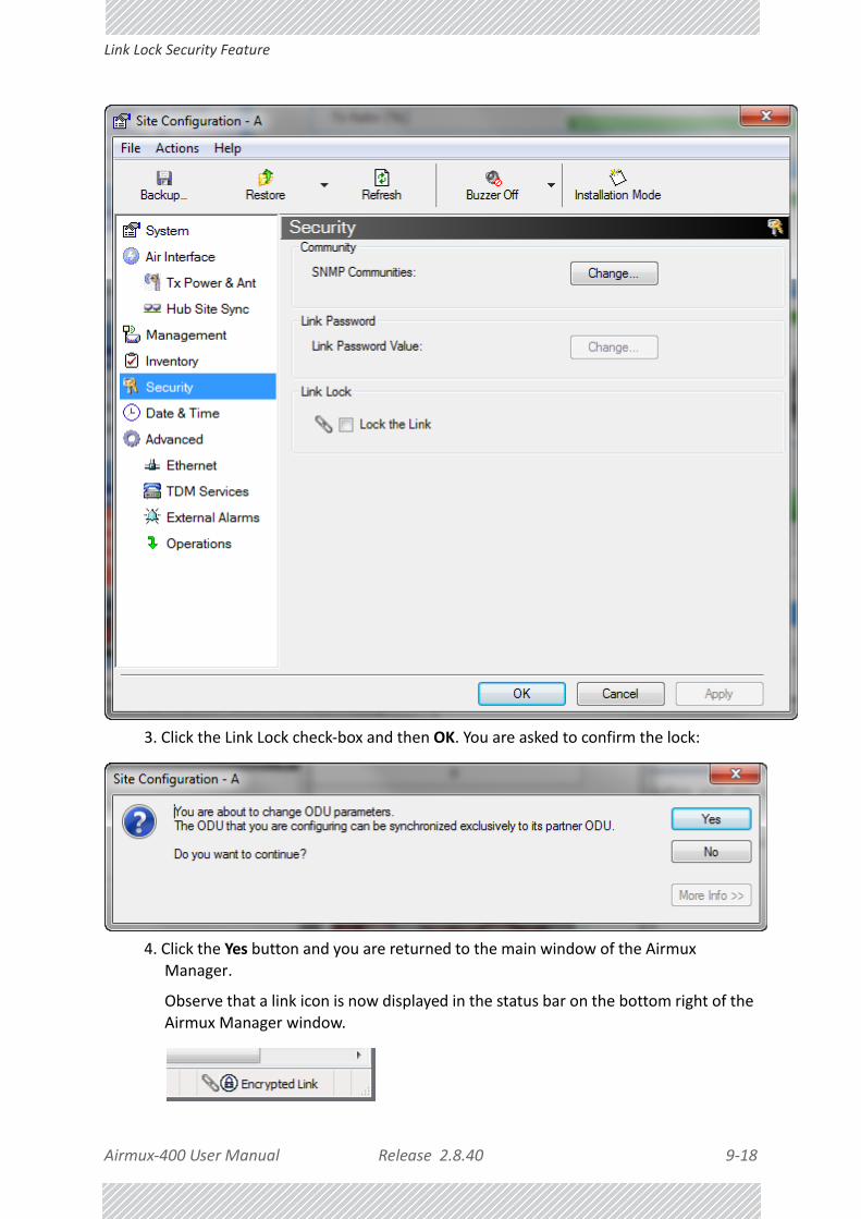
Airmux‐400 User Manual Release 2.8.40 9‐18
Link Lock Security Feature
3. Click the Link Lock check‐box and then OK. You are asked to confirm the lock:
4. Click the Yes button and you are returned to the main window of the Airmux Manager.
Observe that a link icon is now displayed in the status bar on the bottom right of the Airmux Manager window.

Airmux‐400 User Manual Release 2.8.40 9‐19
Setting the Date and Time
The link to the remote unit is now locked and the Security screen will look like this:
The Link Lock check‐box is now unavailable.
5. If required, repeat the procedure for Site B.
Setting the Date and TimeThe ODU maintains a date and time. The date and time should be synchronized with any Network Time Protocol (NTP) version 3 compatible server.
Note
To revert the Link Lock status to unlocked, power down each ODU in turn. Use the above procedure to uncheck the Link Lock status box for the live ODU.A simple ODU reset at either end will restore the link to its previous locked or unlocked state.

Airmux‐400 User Manual Release 2.8.40 9‐20
Setting the Date and Time
During power‐up the ODU attempts to configure the initial date and time using an NTP Server. If the server IP address is not configured or is not reachable, a default time is set.
When configuring the NTP Server IP address, you should also configure the offset from the Universal Coordinated Time (UTC). If there is no server available, you can either set the date and time, or you can set it to use the date and time from the managing computer. Note that manual setting is not recommended since it will be overridden by a reset, power up, or synchronization with an NTP Server.
To set the date and time:
1. Determine the IP address of the NTP server to be used.
2. Test it for connectivity using the command (Windows XP or later), for example:
w32tm /stripchart /computer:216.218.192.202
You should get a continuous response of times, each a few seconds apart.
3. Choose a site to configure.
The Configuration dialog box opens.
4. Choose Date & Time:
Note
The NTP uses UDP port 123. If a firewall is configured between the ODU and the NTP Server this port must be opened.It can take up to 8 minutes for the NTP to synchronize the ODU date and time.

Airmux‐400 User Manual Release 2.8.40 9‐21
Setting the Date and Time
Figure 9‐11: Date and Time Configuration
5. If entering an IP address for the NTP Server, click Clear, and then enter the new address.
6. Set your site Offset value in minutes ahead or behind GMT1.
7. To manually set the date and time, click Change and edit the new values.
1. Greenwich Mean Time

Airmux‐400 User Manual Release 2.8.40 9‐22
Setting the Date and Time
Figure 9‐12: Change Date and Time
If you used an NTP Server, you will see a window like this:
Figure 9‐13: Date and Time configured from an NTP Server
8. Click OK to return to the Configuration dialog.

Airmux‐400 User Manual Release 2.8.40 9‐23
Ethernet Properties
Ethernet Properties
ODU Mode• Hub Mode ‐ In Hub mode the ODU transparently forwards all packets over the wireless
link.
• Bridge Mode ‐ In Bridge mode the ODU performs both learning and aging, forwarding only relevant packets over the wireless link. The aging time of the ODU is fixed at 300 seconds.
Airmux‐400 100M ODUs at hardware revision 9 or higher (see Displaying the Inventory) work in Hub mode only. Bridging is only available when using an IDU‐E/IDU/Airmux‐IDUH/2ETH and it is performed by the IDU. The bridge capability is not configurable, being built in to the IDU.
Other Airmux‐400 models control the choice of Hub or Bridging mode.
Configuring the Bridge
Bridge configuration is required in various network topologies, such as protection (Ethernet 1+1) and ring applications.
Note
Changing these modes requires system reset.

Airmux‐400 User Manual Release 2.8.40 9‐24
ODU Mode
Figure 9‐14: Bridge, VLAN and MIR Configuration using an IDU‐E

Airmux‐400 User Manual Release 2.8.40 9‐25
ODU Mode
Figure 9‐15: Bridge, VLAN and MIR Configuration using a PoE device
IDU Aging time
This parameter controls the IDU aging time.
The aging time parameter controls the time after which each MAC address is dropped from the MAC address learning table.
The default value is 300 seconds.
Note
In Figure 9‐14 and 9‐15, the ODU supports GbE and may operate at up to 1000 Mbps. The latest IDU‐E models (hardware versions 6 and later) and the new GbE PoE will support up to 1000 Mbps at their LAN ports. A suitable SFP module will also support GbE.
Note
• Any change to these parameters is effective immediately.
• Each side of the link can be configured separately, with different aging times.

Airmux‐400 User Manual Release 2.8.40 9‐26
Configuring Ethernet Ports Mode
The following table shows the appropriate configuration for several common scenarios. Both link sites must be configured with the same parameter:
Configuring Ethernet Ports Mode
The ODU Ethernet port mode is configurable for line speed (10/100/1000BaseT) and duplex mode (half or full duplex).
An Auto Detect feature is provided, whereby the line speed and duplex mode are detected automatically using auto‐negotiation. Use manual configuration when attached external equipment does not support auto‐negotiation. The default setting is Auto Detect.
To configure the Ethernet Mode:
1. From the Configuration menu, choose the site to configure.
The Site Configuration dialog box opens.
2. Click Advanced | Ethernet.
3. In the Ethernet Ports Configuration pane, use the drop‐down menu to choose the required mode.
4. Click Apply to save the changes.
The Mode and Radio Link Failure Action options vary somewhat with IDU or PoE type. For a GbE PoE device they are respectively, as follows:
Table 9‐3: ODU mode configuration for common scenarios
ScenarioODU Mode
IDU Aging Time
Standard (default) Configuration for Ethernet Applications
Bridge
300 sec
Rapid network topology changes where fast aging is required
Hub 1 sec
Caution
You should not reconfigure the port that is used for the managing computer connection, since a wrong configuration can cause a management disconnection or Ethernet services interruption.
Note
It is possible to close the Ethernet service by disconnecting the Ethernet port.If you close the port, you may subsequently be unable to access the device. If this should occur, a workaround is as follows:• Connect to the system from the remote site
• Connect via other Ethernet port (of the IDU)
• Power down the equipment and connect immediately after power up (the fastest way is to enter install mode)

Airmux‐400 User Manual Release 2.8.40 9‐27
Port Connections
Port Connections
For IDU‐E based links the Port Connections window enables you to control communication between the two LAN ports and the SFP:
The port combinations shown may be Connected or Disconnected. For IDUs, you will only see LAN1‐LAN2.
CRC Error Detection for GbE Ports
The CRC error count for GbE LAN ports may be seen as mouse‐over tool‐tips:
Figure 9‐16: GbE LAN Port with CRC error warning and CRC count tool‐tip
The occurrence of CRC errors on a port is indicated by the yellow triangular caution sign; to see the CRC error count, mouse over the caution sign.
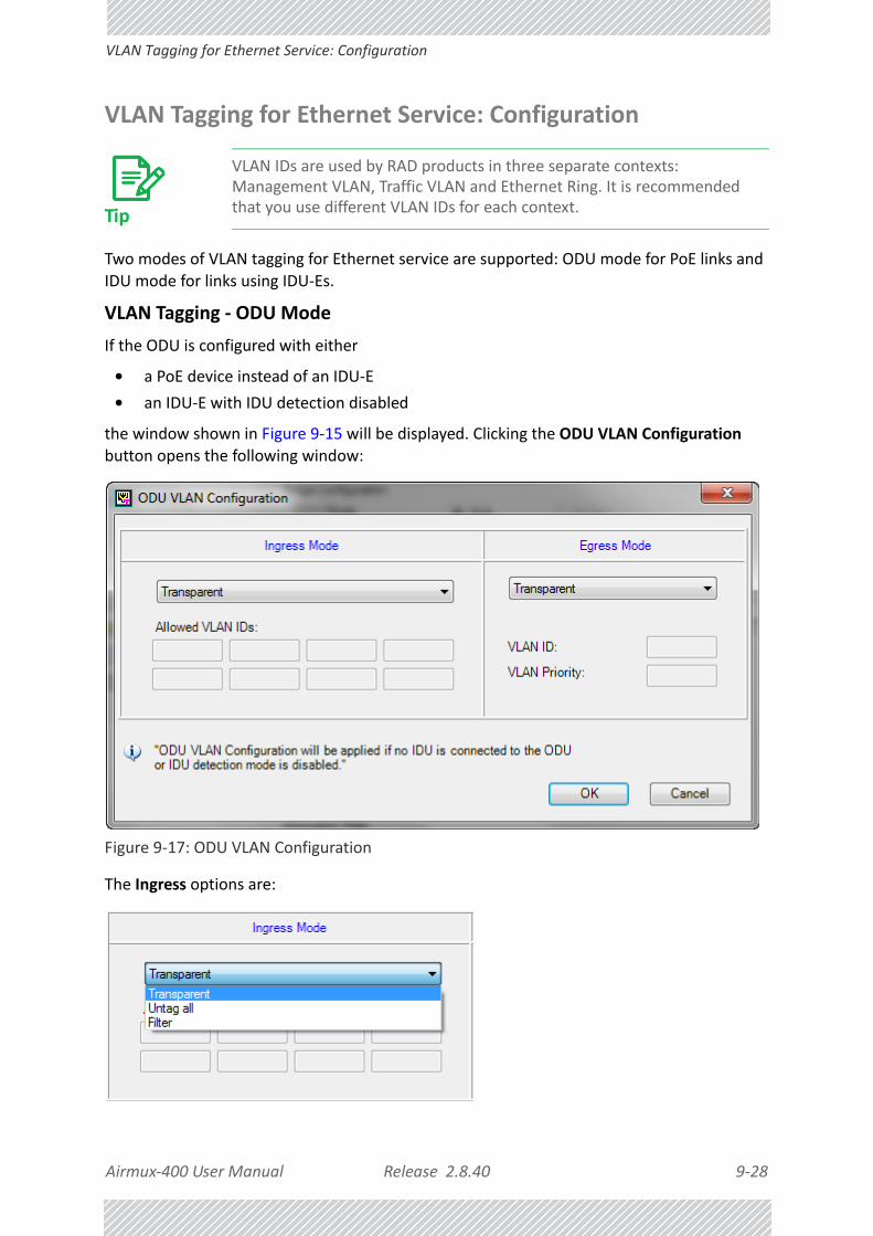
Airmux‐400 User Manual Release 2.8.40 9‐28
VLAN Tagging for Ethernet Service: Configuration
VLAN Tagging for Ethernet Service: Configuration
Two modes of VLAN tagging for Ethernet service are supported: ODU mode for PoE links and IDU mode for links using IDU‐Es.
VLAN Tagging ‐ ODU Mode
If the ODU is configured with either
• a PoE device instead of an IDU‐E
• an IDU‐E with IDU detection disabled
the window shown in Figure 9‐15 will be displayed. Clicking the ODU VLAN Configuration button opens the following window:
Figure 9‐17: ODU VLAN Configuration
The Ingress options are:
Tip
VLAN IDs are used by RAD products in three separate contexts: Management VLAN, Traffic VLAN and Ethernet Ring. It is recommended that you use different VLAN IDs for each context.

Airmux‐400 User Manual Release 2.8.40 9‐29
VLAN Tagging for Ethernet Service: Configuration
Transparent mode passes through all frames transparently. Untag all removes tagging from all frames. Filter mode passes through packets with VLAN IDS listed in the table. Untagged packets are also filtered. They are blocked by the ODU.
The table of Allowed VLAN IDs is enable when you select the Filter option. You may enter up to eight VLAN IDs.
The Egress options are:
Transparent mode passes frames without tagging. Both Tag mode Provider Tagging each requires that you assign a VLAN ID and VLAN Priority:
The VLAN ID must be in the range 2 to 4094 and the VLAN Priority is an integer between 0 and 7.
When you are done, remember to click OK (Figure 9‐17).
VLAN Tagging ‐ IDU Mode
To set up IDU mode VLAN tagging for Ethernet Service, click the VLAN Configuration... button in Figure 9‐14. The following window is displayed:
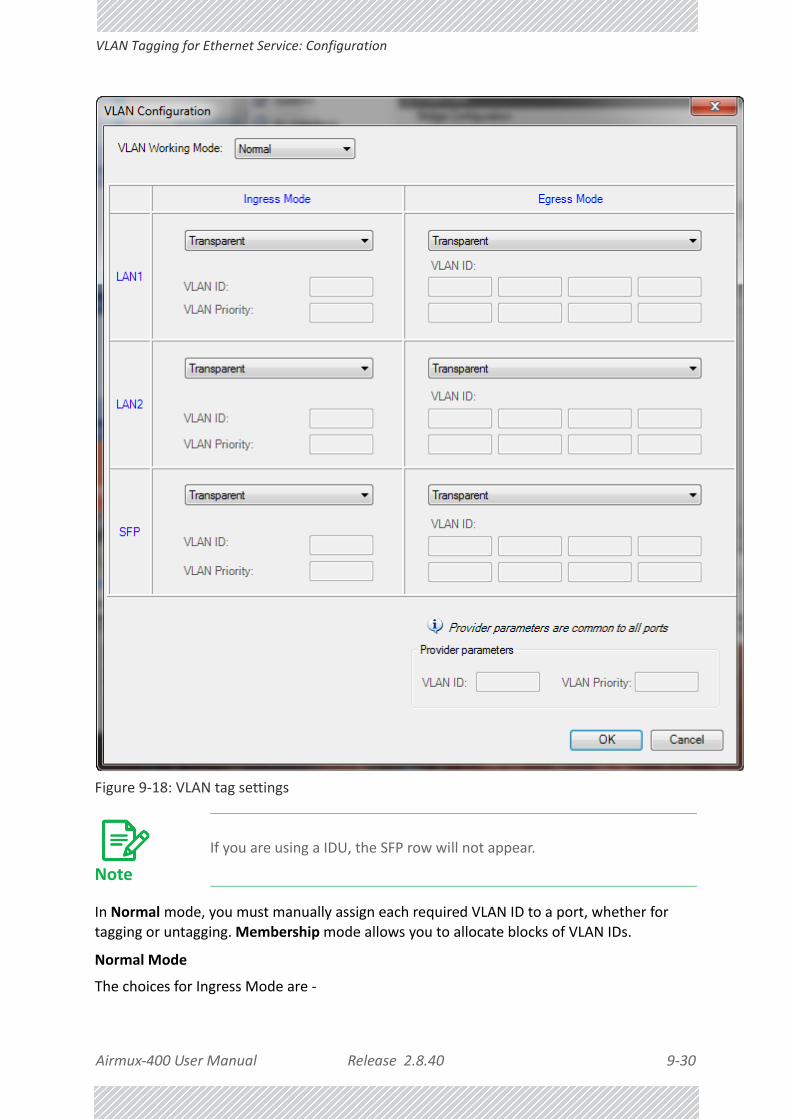
Airmux‐400 User Manual Release 2.8.40 9‐30
VLAN Tagging for Ethernet Service: Configuration
Figure 9‐18: VLAN tag settings
In Normal mode, you must manually assign each required VLAN ID to a port, whether for tagging or untagging. Membership mode allows you to allocate blocks of VLAN IDs.
Normal Mode
The choices for Ingress Mode are ‐
Note
If you are using a IDU, the SFP row will not appear.

Airmux‐400 User Manual Release 2.8.40 9‐31
VLAN Tagging for Ethernet Service: Configuration
and for Egress Mode are ‐
Membership mode
In Membership Mode you may assign VLAN IDs in blocks to the ports. The next three figures shows the work flow.

Airmux‐400 User Manual Release 2.8.40 9‐32
VLAN Tagging for Ethernet Service: Configuration
To configure VLAN using Membership mode:
1. Add a range of VLAN IDs or a single line item.

Airmux‐400 User Manual Release 2.8.40 9‐33
VLAN Tagging for Ethernet Service: Configuration
2. Assign participating ports to each VLAN ID.
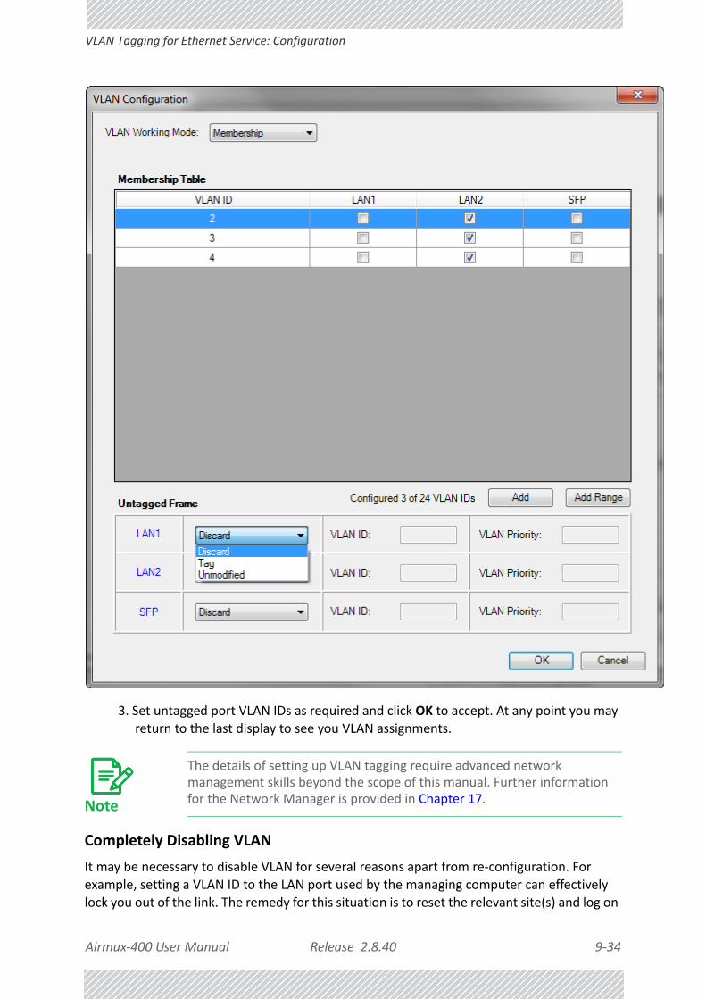
Airmux‐400 User Manual Release 2.8.40 9‐34
VLAN Tagging for Ethernet Service: Configuration
3. Set untagged port VLAN IDs as required and click OK to accept. At any point you may return to the last display to see you VLAN assignments.
Completely Disabling VLAN
It may be necessary to disable VLAN for several reasons apart from re‐configuration. For example, setting a VLAN ID to the LAN port used by the managing computer can effectively lock you out of the link. The remedy for this situation is to reset the relevant site(s) and log on
Note
The details of setting up VLAN tagging require advanced network management skills beyond the scope of this manual. Further information for the Network Manager is provided in Chapter 17.

Airmux‐400 User Manual Release 2.8.40 9‐35
Setting the Maximum Information Rate (MIR)
again. You have “two minutes of grace” before the VLAN settings take hold. During this period, you should navigate to Site Configuration | Ethernet and then click the Disable VLAN button. Any VLAN settings for the site will be lost.
Setting the Maximum Information Rate (MIR)What is the MIR
The maximum Ethernet throughput of the link (MIR) can be limited. The default setting is Best Effort (see Figure 9‐14 above), where the highest information rate available for the link conditions and settings is used.
What is it for
The MIR setting limits the throughput for Ethernet service. It does not affect the capacity of TDM services.
If the Link Budget Calculator or air conditions limit the capacity to X Mbps, and suppose that you use Y (< X) Mbps for TDM services, then you are left with X ‐ Y=Z Mbps for Ethernet.
Suppose for example, that Z = 20 Mbps.
As a Service Provider, you can decide to sell a package based on 10Mbps and charge $P1 for it, or 15 Mbps for $P2 > $P1.
The MIR setting allows you do this.
The default value is “best effort” (shown as “Unlimited”) which will give Z above.
To limit the Ethernet information rate:
1. From the Configuration menu, choose the site to reconfigure.
2. Click Advanced | Ethernet
The Configuration dialog box opens.
Note
The minimum value is 256 Mbps.The maximum value will be the minimum between Z above and ‐• 25/10 Mbps for Airmux‐400 LC (Model dependent)
• 50 Mbps for Airmux‐400 L
• 20 Mbps for Airmux‐400 10M
• 200 Mbps for Airmux‐400 100M
The MIR setting is independent per direction.

Airmux‐400 User Manual Release 2.8.40 9‐36
Setting the Maximum Information Rate (MIR)
Figure 9‐19: Ethernet Configuration ‐ Site Configuration dialog box
3. In the Information Rate pane, use the drop‐down menu to choose the MIR.

Airmux‐400 User Manual Release 2.8.40 9‐37
Setting the sync‐loss Threshold
Figure 9‐20: Ethernet MIR ‐ Throughput selection
4. Choose Other to define the throughput with 1 Kbps resolution
5. Choose Best Effort for the highest information rate possible for the link conditions and settings
6. Click Apply to save the changes.
Figure 9‐21: Air interface details
Setting the sync‐loss Threshold
You may change the sync‐loss threshold by clicking the sync‐loss Threshold button:
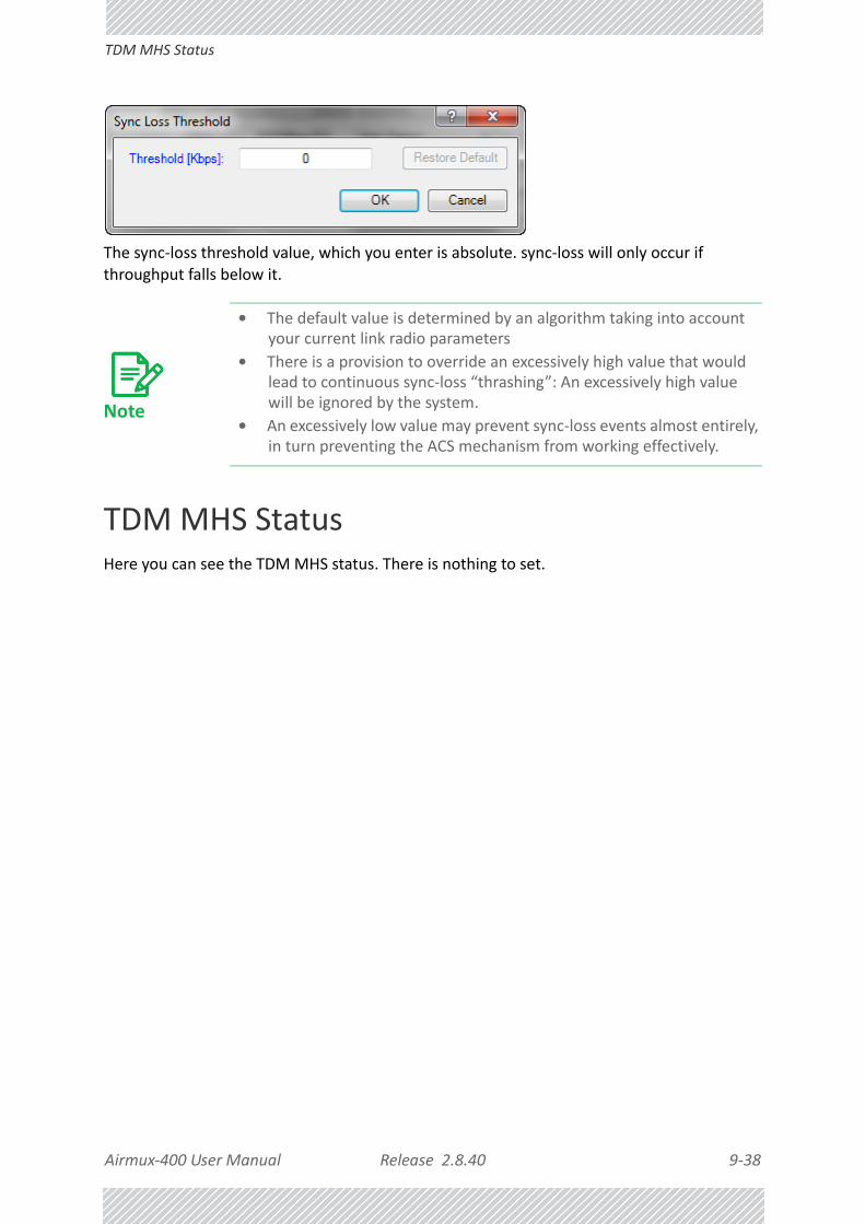
Airmux‐400 User Manual Release 2.8.40 9‐38
TDM MHS Status
The sync‐loss threshold value, which you enter is absolute. sync‐loss will only occur if throughput falls below it.
TDM MHS StatusHere you can see the TDM MHS status. There is nothing to set.
Note
• The default value is determined by an algorithm taking into account your current link radio parameters
• There is a provision to override an excessively high value that would lead to continuous sync‐loss “thrashing”: An excessively high value will be ignored by the system.
• An excessively low value may prevent sync‐loss events almost entirely, in turn preventing the ACS mechanism from working effectively.

Airmux‐400 User Manual Release 2.8.40 9‐39
Setting External Alarm Inputs
Figure 9‐22: TDM MHS status
Setting External Alarm InputsThe IDU‐E and the IDU have four external alarm inputs and four external alarm outputs in the form of dry‐contact relays. The Alarm interface is located on the front panel of the IDU‐E and is a 25‐pin D‐type female connector. See Appendix B, for wiring specifications and pinout. You may enable or disable each of the alarms and configure the alarm description text appearing in the alarm trap message. The ODU sends the alarm within less than a second from actual alarm trigger.
To set the external alarm inputs:
1. Choose External Alarms from the Site Configuration window.

Airmux‐400 User Manual Release 2.8.40 9‐40
Resetting
Figure 9‐23: External Alarms Configuration
2. Choose an alarm and set its mode to Enabled or Disabled
3. Enter a description of the alarms in the text field.
4. Click Apply to save.
5. Click OK to exit from the dialog.
ResettingYou may reset the link, preserving the current configuration, or reset to factory defaults.
Caution
Resetting the link causes service disconnection.To maintain the connection between the managing computer and the link, first reset Site B.

Airmux‐400 User Manual Release 2.8.40 9‐41
Resetting
To reset the link preserving current configuration:
1. From Maintenance on the main window, reset the remote unit.
2. From Maintenance on the main window, reset the local unit.
To reset to Factory Defaults
1. Choose either of the sites to be reset. The Configuration dialog box opens.
2. Choose Operations in the Configuration dialog box.
Figure 9‐24: Site Configuration ‐ Reset to factory defaults
3. Click the Restore Defaults button.
A message box asking if you want to restore factory default settings appears.

Airmux‐400 User Manual Release 2.8.40 9‐42
IDU Detection
4. Click the check box if you want to keep the current IP address settings.
5. Click Yes to continue.
After a few moments the site will be reset and you will need to log on to it to re‐install the link.
IDU DetectionAn ODU always tries to detect the IDU to which it is connected. IDU Detection is effected by
an IDU responding to special ODU packets.
If a PoE device is in use, the detection packets spread to the containing network and may cause flooding. In such a case, the IDU Detection feature, (Figure 9‐24), should be disabled.
To disable IDU Detection Mode, just toggle the check box in Figure 9‐24.
Backup/Restore of ODU Software Files
Backup ODU Software to a File
Airmux Manager allows you to backup the ODU software of both units of a link to the managing computer as binary files. Each site is backed up in a separate file. The default backup file name is constructed from the ODU IP address and the date as in the following example:
Backup of Site A as used in our examples:
10.104.2.2_1.12.2009.backup
If you perform more than one backup on a given date you will need to change the file name to something like this:

Airmux‐400 User Manual Release 2.8.40 9‐43
Restoring ODU Software or Configuration
10.104.2.2_1.12.2009_00.backup
10.104.2.2_1.12.2009_01.backup
...
To backup the ODU software a file:
1. Choose a site to back up. The Site Configuration dialog box opens.
2. Click Backup.
3. In the Save As dialog box, indicate in which folder and under what name configuration file is to be saved, and click Save.
Restoring ODU Software or Configuration
Backup files can be uploaded from the managing computer. You may choose a full software restore or configuration‐only restore. You may restore a backup file to another ODU subject to the following provisions:
• The backup was performed with Airmux Manager, release 2.8.20 or higher
• The source and target ODUs have the same
• Product ID
• Hardware version
• Capacity
You can check Product ID, Hardware version and Capacity from the Inventory display for the source ODU.
To restore from a backup file:
1. Choose a site to restore (from a previous backup).
The Site Configuration dialog box opens.
2. Click Restore. You are offered the choice of a Full or Configuration Restore as shown:
3. Click the required Restore type. You are then offered a standard Open File dialog box.
4. From the Open File dialog box, navigate to your backup storage area and choose file to upload. Click OK.

Airmux‐400 User Manual Release 2.8.40 9‐44
Muting the alignment tone buzzer
Muting the alignment tone buzzerThe ODU alignment tone becomes audible as soon as power is supplied, and continues until the ODUs are aligned and the link established.
It is possible to mute the tone during regular operation of the link. It must be enabled when performing the alignment procedure.
To mute the alignment tone buzzer:
1. Choose a site. The Configuration dialog box opens.
2. In the Configuration dialog box, click the Buzzer button.
Figure 9‐25: Alignment tone buzzer states
3. Click Off. The tone is disabled.
To restore the alignment tone buzzer:
1. Choose a site. The Configuration dialog box opens.
2. Click On to have the buzzer beep continuously or Auto to have the buzzer beep only in install mode.
Configuration with TelnetA Telnet terminal can be used to configure and monitor the Airmux‐400.
To start a Telnet session, use telnet <ODU_IP>.
For example, if you run Telnet as follows,
telnet 10.104.2.2
you will be asked for a user name and password.
The Telnet log on user name is the password that you used to enter the Airmux Manager (for example, the default: admin). The Telnet password is the corresponding Community string (default: netman).

Airmux‐400 User Manual Release 2.8.40 9‐45
Configuration with Telnet
Figure 9‐26: Telnet session log on
A Read‐Only Community string allows display only whereas a Read‐Write Community string allows display and set commands.
Supported Telnet commands are shown in Table 9‐6. Note that some of the commands are model‐specific. For example, TDM commands will not apply to Ethernet only and PoE based links.
Table 9‐4: Telnet ‐ Display commands
Command Explanation
display inventory
Displays ODU product name, Name, Location, hardware and software revisions, uptime, MAC address, IDU product name, IDU software and hardware revisions
display management Displays IP, Subnet, Gateway, Traps table
display linkDisplays State, Link ID, Channel BW, RSS, TSL, Frequency/ACS, DFS, Rate/ARA, Distance
display ethernetDisplays Bridge Mode, Aging time, Port table (State, Status and action)
display ethernet_errors Display FCS errors for ODU/IDU Rx, IDU LAN1/LAN2
display tdmDisplays Clock Mode, Master Clock Mode, Current Clock, Quality, TDM table (Line status, Error Blocks)
display ntp Displays Time, Server and Offset
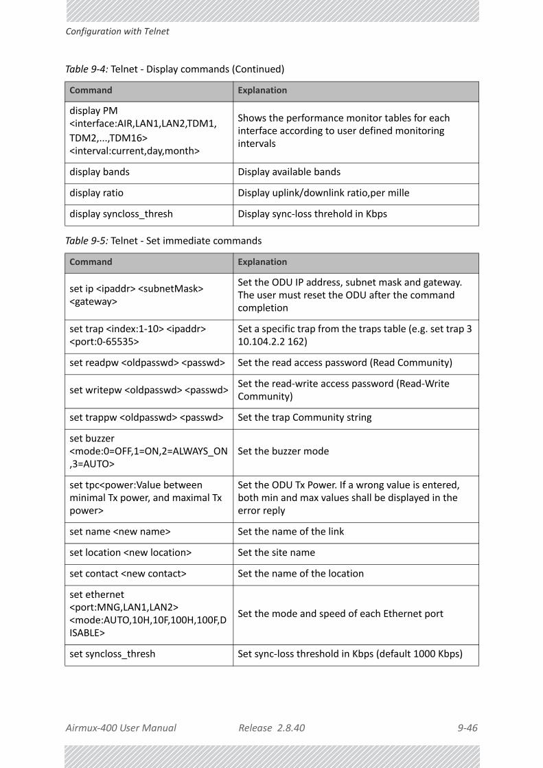
Airmux‐400 User Manual Release 2.8.40 9‐46
Configuration with Telnet
display PM <interface:AIR,LAN1,LAN2,TDM1,
TDM2,...,TDM16> <interval:current,day,month>
Shows the performance monitor tables for each interface according to user defined monitoring intervals
display bands Display available bands
display ratio Display uplink/downlink ratio,per mille
display syncloss_thresh Display sync‐loss threhold in Kbps
Table 9‐5: Telnet ‐ Set immediate commands
Command Explanation
set ip <ipaddr> <subnetMask> <gateway>
Set the ODU IP address, subnet mask and gateway. The user must reset the ODU after the command completion
set trap <index:1‐10> <ipaddr> <port:0‐65535>
Set a specific trap from the traps table (e.g. set trap 3 10.104.2.2 162)
set readpw <oldpasswd> <passwd> Set the read access password (Read Community)
set writepw <oldpasswd> <passwd>Set the read‐write access password (Read‐Write Community)
set trappw <oldpasswd> <passwd> Set the trap Community string
set buzzer <mode:0=OFF,1=ON,2=ALWAYS_ON,3=AUTO>
Set the buzzer mode
set tpc<power:Value between minimal Tx power, and maximal Tx power>
Set the ODU Tx Power. If a wrong value is entered, both min and max values shall be displayed in the error reply
set name <new name> Set the name of the link
set location <new location> Set the site name
set contact <new contact> Set the name of the location
set ethernet <port:MNG,LAN1,LAN2> <mode:AUTO,10H,10F,100H,100F,DISABLE>
Set the mode and speed of each Ethernet port
set syncloss_thresh Set sync‐loss threshold in Kbps (default 1000 Kbps)
Table 9‐4: Telnet ‐ Display commands (Continued)
Command Explanation

Airmux‐400 User Manual Release 2.8.40 9‐47
Configuration with Telnet
resync
Resyncs the ODUs. The user is warned that the command will drop service for a few seconds. The air interface is reset but not lost. The Telnet session is maintained. (Watch the IDU LEDs.)
reboot
Resets both the IDU and the ODU. The user is warned that the command will reset the ODU. A new Telnet session to the ODU may be opened after the reset is complete. (Watch the IDU LEDs.)
help Displays the available commands
Table 9‐6: Telnet ‐ Set commands requiring reset
Command Explanation
set <ssid> Set Link ID
set rate <index:1‐7,adaptive>Set the rat. Index is to the table as appears in the Config Wizard
set bridge <mode:0=Bridging OFF,1= Bridging ON >
Set the ODU bridge mode (0 – off, 1 – on)
set ratio <1‐1000> set uplink/downlink ratio, per mille
set dual_tx_mode (mode: 1=MIMO, 2=Diversity)
Set dual antenna mode to MIMO or Diversity
set preferred frequencies clear Clear preferred frequencies. Requires a resync.
set preferred frequencies add <freq>
Add a preferred frequency in MHz. Requires a resync.
Table 9‐5: Telnet ‐ Set immediate commands (Continued)
Command Explanation

Airmux‐400 User Manual Release 2.8.40 10‐1
Chapter 10:
Monitoring and Diagnostics The Airmux Manager application enables you to monitor the link, as well as perform diagnostic operations such as loopback tests.
This chapter covers:
• Retrieving link information
• Link compatibility issues
• TDM port loopbacks
• Reinstalling and realigning a link
• Link Budget Calculator
• Performance monitoring
• Throughput checking
• Events, alarms and Traps
• Reverting alert messages
• Remote power fail indication
• Troubleshooting
• Replacing an ODU
• Restoring to factory setup
• Online help
• Obtaining support
Retrieving Link Information (Get Diagnostics)The Get Diagnostics feature collects and writes all link and Manager information (from both sites) into a text file. The file information can be used for diagnostics and should be sent to RAD Customer Support to speed up assistance.

Airmux‐400 User Manual Release 2.8.40 10‐2
Retrieving Link Information (Get Diagnostics)
The following table lists link and system information that can be monitored.
To get diagnostics
1. From the Help menu, choose Get Diagnostics Information.
Figure 10‐1: Get Diagnostics Dialog Box
2. Select or deselect the data options. If the file is to be sent to RAD Customer Support leave all options checked.
3. Click File Path to specify the folder in which you want to save the file and then click Start to save the information.
Table 10‐1: Get Diagnostics Data and Description
Data Description
System Data General information about the system
Link Information Information about the link properties
Events Log• List of system events including those from other
sites if this site is defined as the trap destination• Last 256 events from both sites
Site Configuration Data about the site parameters
Active Alarms List of active alarms
Performance Network performance data over defined time periods
Monitor Detailed event data record
Spectrum View Data from last Spectrum View run

Airmux‐400 User Manual Release 2.8.40 10‐3
Link Compatibility
The file is saved in the specified folder as Diagnostics Information.txt
Link CompatibilityLink Compatibility indicates the version compatibility using software traps. As new hardware or software is added to existing networks compatibility issues may arise. An incompatibility issue is indicated to the user by a change of color of the Link Status box on the Main Menu window. Trap messages (can be viewed in the Events Log) indicate the problems or limitations and suggest upgrades when appropriate.
The following Link Status messages are given:
fullCompatibility ‐ different software versions were detected that are fully compatible. The message indicates that an upgrade is available.
restrictedCompatibility ‐ different software versions were detected that operate correctly. However, new features are not supported.
softwareUpgradeRequired ‐ different software versions were detected allowing limited operation. The message is, that a software upgrade is required.
versionsIncompatibility ‐ different software versions were detected that are incompatible. You need to perform local upgrades.
Table 10‐2: Link Compatibility Trap Messages
Link StateLink State text
Link Status Color
Site Description
fullCompatibility Active GreenSoftware Upgrade Available
restrictedCompatibility
Active ‐ Software Version mismatch
Magenta (Same as authentication error)
Software Upgrade Recommended
softwareUpgradeRequired
Active – Software Upgrade Required
Brown (Major)
Software Upgrade Required
versionsIncompatibility
Not Active ‐ Software Upgrade Required
Red
Local Software Upgrade Required

Airmux‐400 User Manual Release 2.8.40 10‐4
TDM Loopbacks
TDM LoopbacksInternal and external loopbacks on both sites of a link are used to test the TDM connections
To activate a loopback:
1. From the Maintenance menu, choose Loopbacks... or right‐click the TDM display in the main window.
The Loopbacks dialog box appears:
Figure 10‐2: Loopback configuration box
2. From the active ports, click those required for loopback activation. The selected port icons change color to light blue as in the following example:
Figure 10‐3: Loopback configuration box with one Site A port selected
3. Click configure to choose a loopback mode:

Airmux‐400 User Manual Release 2.8.40 10‐5
TDM Loopbacks
Figure 10‐4: Loopback options
4. Click the required loopback mode.
Figure 10‐5: Loopback defined
5. Click OK to activate the selected loopback(s).
This activates selected loopback(s). The corresponding service port icon changes color and appearance to indicate an active loopback.

Airmux‐400 User Manual Release 2.8.40 10‐6
Local Line Loopback
Figure 10‐6: Site A port 2 set to loopback
To deactivate a loopback:
• Return to the situation of Figure 10‐4 and click None.
When a loopback is deactivated, the corresponding icon in Figure 10‐6 reverts to its previous state (like the right side of the figure).
Local Line Loopback
A Local line loopback can be set to test the local E1/T1 port and its connection to local side user equipment. In this mode, data coming from the local user equipment is looped back to it. This loopback is initiated from a managing computer connected to the local unit.

Airmux‐400 User Manual Release 2.8.40 10‐7
Remote Reverse Loopback
Figure 10‐7: Local Line Loopback
Remote Reverse Loopback
A remote reverse loopback can be set to test connection between the local and remote units and between the local E1/T1 port and its connection to the local user equipment. In this mode, data coming from the local user equipment is looped back at the remote side. This loopback is initiated from a managing computer connected to the local unit.
Figure 10‐8: Remote Reverse Loopback
Remote Line Loopback
The remote unit can be set to a line loopback to test the remote E1/T1 port and its connection to the remote side user equipment. In this mode, data coming from the remote

Airmux‐400 User Manual Release 2.8.40 10‐8
Local Internal Loopback
user equipment is looped back to it locally. This loopback is initiated by the managing computer connected to the local unit.
Figure 10‐9: Remote Line Loopback
Local Internal Loopback
The local unit can be set to close a remote loopback to test connection between the local and remote units and between the remote E1/T1 port and its connection to the remote user equipment. In this mode, data coming from the remote user equipment is looped back to it locally. This loopback is initiated by the managing computer connected to the local unit.
Figure 10‐10: Local Reverse Loopback

Airmux‐400 User Manual Release 2.8.40 10‐9
Reinstalling and Realigning a Link
Reinstalling and Realigning a LinkIt may be necessary to reinstall the link if the ODUs need to be realigned.
To reinstall the link:
1. Choose a site.
The Configuration dialog box opens.
2. In the Configuration dialog box, click the Install Mode button.
A message box asking if you want to enter install mode appears.
3. Click Yes to continue.
The system enters Install mode and the alignment tone becomes audible.
4. Realign the ODUs and start the Installation wizard (see Chapter 6).
The Link Budget CalculatorThe Link Budget Calculator is part of the Airmux Manager software and is found in the Help menu. This useful utility enables you to calculate the expected performance of the wireless link and the possible configurations for a specific link range including antenna size, cable loss and climate conditions. For full details, see Chapter 26.
Throughput CheckingIn this mode, Airmux‐400 estimates Ethernet throughput by filling frames over the air to maximum for 30 seconds. This mode should not influence service.
To use Throughput Checking:
1. At the main menu, click Maintenance | Estimated Eth. Throughput. A confirmation message appears:
Note
Activating Install Mode causes both sites to go into install mode, causing disruption in service for approximately fifteen seconds.

Airmux‐400 User Manual Release 2.8.40 10‐10
Performance Monitoring
2. Click Yes to continue. The Ethernet services area changes appearance and the estimated throughput is displayed:
At the end of 30 seconds, the display reverts to normal.
Performance MonitoringAirmux‐400 Performance Monitoring constantly monitors traffic over the radio link and collects statistics data for the air interface, TDM and Ethernet ports. It does so continuously, even when the Airmux Manager is not connected.
Two types of logs are recorded:
• Monitor Log that records statistics on traffic rate and radio signal strength.
• Events Log that records when the rates fall above or below a predefined threshold. See page 10‐16 below.
Both the statistics Monitor log and events log can be saved as text files.
The Monitor Log
The Monitor Log records performance statistics for predefined intervals. You can save the monitor log to a text file, as well as display the information in an on‐screen report.
Saving the Monitor Log
You can save the recorded Monitor Log statistics to a text file.
To save the monitor log:
1. From the Tools menu, choose Preferences.
The Preferences dialog box appears:

Airmux‐400 User Manual Release 2.8.40 10‐11
The Monitor Log
Figure 10‐11: Preferences dialog box
2. Click the Monitor Tab.
3. Select the file to save.
4. Click the check box to open the file for saving.
5. Click the button and in the Select File dialog box indicate in which folder and under what name the monitor log file is to be saved.
6. Set the time interval for adding data to the file.
7. Click OK to save the file.
Viewing Performance Reports
The Performance Monitor Report displays performance views of each of the interfaces.
To obtain performance monitoring reports:
1. From the main menu, choose Tools | Performance Monitoring Report ...
You are presented with the following window:

Airmux‐400 User Manual Release 2.8.40 10‐12
The Monitor Log
Figure 10‐12: Basic Performance Monitoring Report
2. Choose a report type from the left panel and click the Get Data toolbar button. For example, if you choose Site A, Air and Current, you will be offered a report looking
like this:
Figure 10‐13: Typical Performance Monitoring Report based on 15 minute intervals
Notice the Min RSL value of ‐100 on the fourth line. It Indicates that during the inter‐val 12:30 to 12:45, there was a link sync‐loss. The next figure shows the effect of a
reset between 14:15 and 14:30.

Airmux‐400 User Manual Release 2.8.40 10‐13
The Monitor Log
Figure 10‐14: Performance Monitoring Report showing the effect of a Reset
The prior data is invalidated as shown by the red crosses in the left hand column. Further, Min and Max RSL for the invalidated period is set to zero.
3. Click the Selection Pane icon to toggle the side panel on or off.
The other reports look similar. Here is a detailed description of the reports and their fields:
Several performance data occurrences are collected for each of the interfaces (ES, SES, and UAS), as well as specific data per Interface type (e.g., Tx and Rx bytes for Ethernet). For the Air Interface, user defined thresholds data are collected. Refer to Table 10‐3 and Table 10‐4 below.
Data is collected and selectively displayed based on three time intervals as selected by the Interval radio buttons:
• Current (t=0)
• 15 minutes Intervals
• Daily
Table 10‐3: Explanation of performance data
Data type Reported Value Explanation
Generic PM Data
UAS – Unavailable Seconds
Seconds in which the interface was out of service.
Raw ES – Raw Errored Seconds
The number of seconds in which there was at least one error block. Note that the notion of an error block is different per interface.
SES – Severe Errored Seconds
The number of seconds in which the service quality was low (the quality is different per type of interface and determined by the BBER threshold per interface).
BBE – Background Block Error
The number of errored blocks in an interval.
Integrity
A flag indicating that the data was valid. Note that the Performance Monitoring data is not valid if not all the values were stored (e.g., due to clock changes within the interval or power up reset).

Airmux‐400 User Manual Release 2.8.40 10‐14
The Monitor Log
Additional Air Interface PM Data
Max RSLThe maximum of the receive signal level (measured in dBm).
Min RSLThe minimum of the receive signal level (measured in dBm).
Max TSLThe maximum of the transmit signal level (measured in dBm).
Min TSLThe minimum of the transmit signal level (measured in dBm).
RSL Threshold 1The number of seconds in which the Receive Signal Level (RSL) was below the specified threshold.
RSL Threshold 2The number of seconds in which the RSL was below the specified threshold.
TSL ThresholdThe number of seconds in which the Transmit Signal Level (TSL) was above the specified threshold.
BBER ThresholdThe number of seconds in which the Background Block Error Ratio (BBER) exceeded the specified threshold.
Additional Ethernet Interface PM Data
Received BytesThe number of Megabytes received at the specified port within the interval
Transmitted BytesThe number of Megabytes transmitted at the specified port within the interval.
Throughput threshold
Seconds count when throughput fell below the threshold
Traffic thresholdSeconds count when actual traffic exceeded the threshold
TDM interface Active secondsThe number of seconds that the configured TDM services are active
Table 10‐3: Explanation of performance data
Data type Reported Value Explanation

Airmux‐400 User Manual Release 2.8.40 10‐15
The Monitor Log
Performance Monitoring Report Toolbar
You can use the toolbar to perform the actions described in the following table:
Setting Air Interface Thresholds
Use the Thresholds button on the Monitoring Performance Report toolbar to set the Air Interface Thresholds:
Figure 10‐15: Threshold configuration dialog box
RSL Thresholds
Two RSL Thresholds can be defined. They are used as an indicator of problems in the radio channel. You can check the RSS from the Link Budget Calculator results during installation. Values of ‐5dB and ‐8dB from the current RSS are typical.
TSL Threshold
Table 10‐4: Action of the toolbar buttons
Command Button Action
Get Data Gather current performance monitoring data.
Save Save current performance monitoring data to a file
Clear Clear current performance monitoring data
Thresholds Set Thresholds
Selection Pane Toggle on/off left panel
Close Closes the Performance Monitoring window
Airmux‐400 User Manual Release 2.8.40 10‐16
Events, Alarms and Traps
A counter is maintained, of the number of second intervals during which Tx power exceeds this threshold.
BBER Threshold
The Background Block Error Ratio is measured as a percentage. The threshold can be set from 0.1% up to 50%.
For links with Ethernet only service, 8% threshold is recommended. If there are no problems during the interval, then for that threshold, the recommended BBER value should be 0. Since the system provides a lossless Ethernet service, there is throughput degradation in case of interference. The degradation is proportional to the BBER.
Ethernet Thresholds ‐ Capacity
This is used as a basis for checking adherence to a Service Level Agreement. It is the number of seconds count that the link capacity falls bellow the threshold.
Ethernet Thresholds ‐ Traffic
The number of seconds count that received traffic exceeded this threshold. It can be used to measure traffic peaks.
Events, Alarms and Traps
The Events Log
The Events Log records system failures, loss of synchronization, loss of signal, compatibility problems and other fault conditions and events.
Alarms (traps) are displayed in the Events Log in the lower panel of the main window. The Events Log may be saved as a text file.
The Events Log includes the following fields:
» Sequential number (ID)
» Date and time stamp
» Message
» Trap source
» IP address of the ODU that initiated alarm.
For complete information about traps and alarms see Appendix E.
The events are displayed in the Events Log in the lower right‐hand panel of the Airmux Manager main window:
Note
The foregoing event types include events from all links for which this managing computer has been defined as the traps address. Only events from RAD equipment will be shown.

Airmux‐400 User Manual Release 2.8.40 10‐17
The Events Log
Figure 10‐16: Events Log Display
To save the Events Log:
1. From the Tools menu, choose Preferences.
The Preferences dialog box appears
2. Click the Events Tab.
3. Select the file to save.
4. Click the check box to open the file for saving.
Click the button and in the Select File dialog box indicate in which folder and under what name the Events Log file is to be saved, and click OK.
Note
To store the Events Log, first define the IP address, subnet mask, default gateway and trap destination address of the managing computer (see Chapter 9 for details).

Airmux‐400 User Manual Release 2.8.40 10‐18
Airmux Manager Traps
Airmux Manager Traps
The Airmux Manager application issues traps to indicate various events, displayed in the Events Log.
Table 10‐5: Airmux Manager Trap Messages
Trap Message Severity Remarks
Cannot bind to trap service port. Port 162 already in use by ProcessName (pid: ProcessId)
Warning Airmux Manager will not catch any traps from the ODU, some other application has grabbed this port. For further detail see this web site.
Device unreachable! Error Check connectivity to ODU
Connected to <site_name> Information
<site_name> Site will be reset. Information
Restore Factory Default Settings in process on Site <site_name>
Information
Factory Settings: The process was not finished due to connection issues.
Warning Factory setting failed due to connectivity problem to ODU
Reset: The process was not finished due to connection issues.
Warning Factory setting failed due to connectivity problem to target ‐ ODU will not be reset
Cannot Write to Monitor file. There is not enough space on the disk.
Warning Free some space on disk on the managing computer and retry
Windows Error: <error_ID>. Cannot Write to Monitor file.
Warning Operating System error on the managing computer
TDM Counters were cleared for both sides Information
Identical IP addresses at <local_site_name> and <remote_site_name>
Warning Set up a different IP to each site
The Product is not identified at the <local_site_name> site.
Warning Airmux Manager is incompatible with the ODU software version
The Product is not identified at the <remote_site_name> site.
Warning

Airmux‐400 User Manual Release 2.8.40 10‐19
Setting the Events Preferences
Setting the Events Preferences
You can define a color for the messages to be displayed in the Event Log window, according to the severity of the event. The severity is predefined.
To set the Message color:
1. From the Tools menu, choose Preferences.
The Preferences dialog box appears.
2. Click the Events Tab:
The Product is not identified at both sites. Warning
Product Not Identified! Warning
The Manager identified a newer ODU release at the <remote_site_name> site.
Warning ODU release is newer than Airmux Manager release. Wizards are not available. Airmux Manager will be used just for monitoring. Upgrade the Airmux Manager. (You will get this message as a pop up)
The Manager identified a newer ODU release at both sites.
Warning
The Manager identified a newer ODU release at the <local_site_name> site.
Warning
Newer Version identified at the <local_site_name> site.
Warning ODU release is newer than Airmux Manager release. Wizards are not available. Airmux Manager will be used just for monitoring. Upgrade the Airmux Manager.
Newer Version identified at the <remote_site_name> site.
Warning
Newer Version Identified! Warning
Different IDU Detection Mode at <Site1 Name> and <Site2 Name>
Warning IDU detection mode set differently at the two sites
Table 10‐5: Airmux Manager Trap Messages (Continued)
Trap Message Severity Remarks

Airmux‐400 User Manual Release 2.8.40 10‐20
Saving the Events Log
Figure 10‐17: Preferences dialog box ‐ Event tab
3. Select the event type and click on the button.
A color chart opens.
4. Select the required color.
5. Repeat for each of the event types.
To set the message background color:
• Click Background Color to change the text background.
To reset the message colors:
• Click Reset Settings to return to the default color settings.
Saving the Events Log
You can save recorded events in an Events Log text file. New alarms are automatically added to the text file, as they enter the Events Log.
SNMPv3 Trap Authentication
The SNMPv3 User and Password are relevant if you are using SNMPv3. In this, case trap messages are keyed to the user name and password and not visible to anyone else. The preferences entered here, relate to trap messages sent to the specified user if specified or to

Airmux‐400 User Manual Release 2.8.40 10‐21
Active Alarms
all trap messages, otherwise. For associating a user with a trap address, see Configuring IP Addresses for Trap Destinations.
Active Alarms
Upon setting a trap destination, applicable events are reported as active alarms to the user. The active alarms are saved and can be viewed in the Active Alarms window.
To view summary of saved alarms:
1. From the Tools menu, choose Active Alarm Summary.
2. Choose either of the sites offered.
The Active Alarms Summary window opens:
Figure 10‐18: Active Alarms Summary
The active alarms display does not update itself until the Refresh button is used.
The following table provides an explanation of the command buttons.
Viewing Recent Events
Each ODU stores the last 256 events:
Table 10‐6: Active Alarms command buttons
Command Action
Save Saves the alarms in CSV or text format for further analysis
Refresh Shows the active alarms at the moment of refresh
Site Selects site for the active alarms
Close Closes the active alarm window

Airmux‐400 User Manual Release 2.8.40 10‐22
Reverting Alert Messages
To view the last 256 events:
1. Click Tools | Recent Events ... A window like the following is displayed:
Figure 10‐19: Recent Events ‐ Up to last 256 events at Site A
2. Use the Site button to choose Site B
3. Use the Save button to store the events in a tab‐delimited list.
Reverting Alert MessagesMany alert messages in the Airmux Manager have an option of the form “Do not show this message again”. These alert messages can be reverted to their default state (shown) by choosing the Advanced tab from the Preferences dialog:

Airmux‐400 User Manual Release 2.8.40 10‐23
Other Advanced Preferences
Figure 10‐20: Advanced Preferences
Just click the Restore Defaults button, followed by OK.
Other Advanced Preferences
Setting SNMP Parameters
Use these choices to set the SNMP monitoring interval and time‐out. These are only significant if you are using an SNMP based network management system.
Remote Power Fail IndicationRemote power fail indication indicates to one side that the other side has suffered a power failure. The failed site sends a final trap indication about the power loss just before powering off.
A “Dying‐Gasp” circuit identifies the power failure at a minimum interval of 20 milliseconds before the ODU or IDU powers off. During that interval a message notifying the power failure is sent to opposite site. External alarm output number 4 indicates power failure at the opposite site.

Airmux‐400 User Manual Release 2.8.40 10‐24
Troubleshooting
TroubleshootingUse the following table to troubleshoot LED fault indications:
Use the following table to troubleshoot faults in the system:.
Table 10‐7: LED fault indicators
LED Status Remedy
PWR Off Check that power is connected to the IDU
IDU Red Check that the IDU/ODU cable is properly wired and connected.
ODU Red Check that the IDU/ODU cable is properly wired and connected.
AIR I/F
Orange Complete the installation procedure from the Airmux Manager
RedCheck the antenna alignment. Check that the radio configuration of both site A and site B units are the same (Channel and Link ID).
SVC
Orange
Red
Off
Alarm detected at the Site B interface or Local or Remote loopback
Alarm detected at the Site A interface
Ethernet only IDU or E1/T1 not configured
HSS
Red
Orange
HSS not operational due to improper signal detection. This ODU is not transmitting
HSS is operational. One of the following conditions apply:• This ODU is a master that is generating signals and detecting
signals• This ODU is a master that is generating signals but detected
improper signals• This ODU is a client “Continue Tx” but is not detecting signals• This ODU is a client “Disable Tx” and is detecting signals from
multiple sources
All orange cases transmit.
STBYRed
Orange
MHS mode Primary, Link state not active
MHS mode Secondary, Link state active
Table 10‐8: System Troubleshooting
Symptom Remedy
No powerEnsure that power is connected to the IDU
Ensure that the ODU cable is properly wired and connected
No signal
Complete the installation procedure from the Airmux Manager
Check the antenna alignment. Check that the radio configuration of both site A and site B units is the same (channel settings and Link ID)

Airmux‐400 User Manual Release 2.8.40 10‐25
Replacing an ODU
Replacing an ODUPrior to any action ensure that both ODUs have the same software version. You can see this on the inventory panels for each site.
For Site A, click Site A | Inventory and note the ODU software version. Repeat this for Site B using Site B | Inventory.
If either ODU has an old software version, perform a software upgrade. It is important to configure the new ODU identically to the old ODU to avoid configuration mismatches, which will disrupt the link.
An ODU may be reconfigured in several ways.
• Use the backup configuration
If a backup of the configuration is available, restore that configuration using Site A| Restore. Recall that backup files are linked to a MAC address. This won’t work for an identical replacement ODU.
• Manual configuration
The new ODU can be configured manually according to the link configuration. Remember to use the same settings for Link ID, channels, link password, IP addresses, and names.
Restoring Factory Setup To restore factory setup:
• Use Site Configuration A or B, and then Operations | Restore Defaults. Always restore the over‐the‐air site (B) first.
Online HelpOnline help can be accessed from the Help menu on the main window of the Airmux Manager.
Weak signal received
Check the antenna alignment, reconfigure the link
Check the alignment tone sounds the Best Signal sequence
Table 10‐8: System Troubleshooting (Continued)
Symptom Remedy

Airmux‐400 User Manual Release 2.8.40 10‐26
Customer Support
Customer SupportCustomer support for this product can be obtained from the local VAR, Integrator or distributor from whom it was purchased.
For further information, please contact the RAD distributor nearest to you or one of RAD's offices worldwide .

USER MANUAL
Part 2: Site Synchronization
Release 2.8.40
Airmux‐400 User Manual Release 2.8.40 11‐1
Chapter 11:
Hub Site Synchronization
What is Hub Site Synchronization (HSS)When several radios are collocated at a common hub site, interference may occur from one unit to another. RAD ODUs support the collocation of more than two units at a central site. Like any other RF deployment, the wireless operation is highly dependent on factors such as available frequencies, the physical spacing between radios, other third party interfering radios, and whether other RAD radios are installed.
RAD HSSThe RAD HSS method uses carries pulses sent to each ODU, which synchronize their transmission with each other. The pulse synchronization ensures that transmission occurs at the same time for all collocated units. This also results in all of the hub site units receiving data at the same time, eliminating the possibility of interference that could result if some units transmit while other units at the same location receive.
Figure 11‐1 illustrates interference caused by non‐synchronized collocated units.
Note
HSS does not eliminate the need for careful RF planning to ensure the design will work as planned. See Chapter 3 for information on installation site survey.

Airmux‐400 User Manual Release 2.8.40 11‐2
RAD HSS
Figure 11‐1: Interference caused by collocated units
Adding HSS removes interference as shown in the next two figures:
Figure 11‐2: Collocated units using Hub Site Synchronization (1)
Figure 11‐3: Collocated units using Hub Site Synchronization (2)
The units are connected to each other with HSS cables and HSS Distribution Units.
One of the radios in the site is defined as HSS Master and generates synchronization pulses.
The other collocated radios in the site ‐ the HSS Clients, are connected to the HSS Master and synchronize their transmission to the pulses. An HSS Client can be configured to work in one of two modes:

Airmux‐400 User Manual Release 2.8.40 11‐3
HSS Concepts: Radio Frame Pattern (RFP)
• HSS Client‐Continue Transmission (HSC‐CT): If the unit loses synchronization with the HSS Master, the link remains active. However, without synchronization pulses, it is pos‐sible that this unit will cause interference.
• HSS Client‐Disable Transmission (HSC‐DT): If the unit loses synchronization with the HSS Master, the link is dropped until the synchronization pulses resume. This setting prevents the unit from causing interference.
The remote ODUs that are not located at the hub site, are called Independent Units (INU).
RAD offers two types of HSS:
» Serial HSS
The RAD Serial Hub Site Synchronization (SHSS) method uses a cable connected from the master ODU to all collocated ODUs; this cable carries pulses sent to each ODU, which synchronize their transmission with each other. SHSS is covered in Chapter 12.
» Ethernet HSS
The Ethernet HSS (HSSoE) method requires Layer 2 Ethernet connectivity between collocated ODUs. It has two requirements:
• Collocated ODUs providing Ethernet services only, should be connected to an Air‐mux‐IDUH/2ETH instead of regular PoE devices. Other simple switches may work with degraded performance. They are not recommended and problems arising from their use will not be eligible for any kind of support.
• Collocated ODUs providing E1/T1 services should use an IDU‐E or IDU and then be connected to an Airmux‐IDUH/2ETH functioning as a switch. One of the LAN ports on the IDU‐E or IDU is connected to any of the six Airmux‐IDUH/2ETH PoE ports or the two LAN ports. (This is possible because the IDU‐E or IDU LAN cable only uses four pins for data; the power pins are not used so there is no risk of damage to them.) In this way, up to eight such ODUs may be collocated.
HSS Concepts: Radio Frame Pattern (RFP)A Radio Frame Pattern (RFP) is the cycle duration of transmit and receive of the air‐frame.
Without HSS
When selecting TDM or Ethernet services, the system automatically and transparently chooses the optimal RFP. When TDM and Ethernet services are configured, the RFP is optimized for TDM.
Note
You may only use one Airmux‐IDUH/2ETH. That is, they may not be cascaded.
Caution
If you are using an IDU‐E0 (GbE) it must be connected to the Airmux‐IDUH/2ETH LAN port only. Connecting it to the P0E ports will damage the unit and in any event, it will not work.

Airmux‐400 User Manual Release 2.8.40 11‐4
RFP and HSS
RFP and HSS
When HSS is used, the RFP for the collocated radios must be selected manually.
Airmux‐400 uses the Time Division Duplex (TDD) mechanism.
Under HSS, TDD enables synchronization of transmission for the collocated units as shown in Figure 11‐4:
Figure 11‐4: Radio Frame Pattern
Two RFP types (labelled B and E) are available. Under HSS the RFP must be configured by the user depending on the type of the radio products, services and channel bandwidth in accordance with Table 11‐2.
The table describe the efficiency of the air interface according to the RFP type, services and channel bandwidth. The tables may also be viewed in the Airmux Manager and in the Link Budget Calculator. The efficiency of the air interface will vary according to the product used.
Table 11‐1: Radio Frame Pattern Table ‐ Airmux‐5000 BS
RFP 5/10/20/40 MHz
TDM Ethernet
E N/A Best fit
Table 11‐2: Radio Frame Pattern Table ‐ Airmux‐400
RFP 40 MHz 20 MHz 10 MHz 5 MHz
TDM Ethernet TDM Ethernet TDM Ethernet TDM Ethernet
B Available Available Available Available Available Available Best fit Best fit
E Best fit Best fit Best fit Best fit Best fit Best fit Available Available
Table 11‐3: Legend for Radio Frame Pattern Tables
Item Description
Best fit Optimal RFP choice for TDM and Ethernet services
Available Available RFP for TDM and Ethernet services, but not optima
N/A Service unavailable

Airmux‐400 User Manual Release 2.8.40 11‐5
RFP: General Radio Frame Pattern
Select the RFP that gives you the Best Fit or Available for required system services and select the channel bandwidth accordingly.
RFP: General Radio Frame Pattern
When setting the RPF, the following considerations should be borne in mind:
• Selection of the RFP influences the capacity, latency and TDM quality
• RFP influences capacity and latency. Jitter buffer configuration can be used to set the TDM quality (see the User Manual, Chapter 6, TDM Services selection)
• Using the Link Budget Calculator, you can see the affect of the RFP on the Ethernet throughput.
RFP: Airmux‐400 Considerations• The performance of Airmux‐400 radios that operate with RFPs B or E can be seen in the
Link Budget Calculator.
• For Airmux‐400 100M series: If the HSS Master works in asymmetric Tx/Rx ratio, then all other collocated Airmux‐400 units must operate in the same Tx/Rx ratio. In this case the ratio will be fixed and not automatic‐adaptive.
• Installation/Configuration considerations: If you are using Airmux‐400 100M master and
Airmux‐400 clients, the Services and Rates dialog will look like this:
Figure 11‐5: Airmux‐400 100M HSM and HSC
Note
The RFP must be the same for each link within the collocated system.

Airmux‐400 User Manual Release 2.8.40 11‐6
RFP: Airmux‐400 Considerations
• The circled areas should not be used. Using those areas, you may loose the collocated link with the longest distance between sites. If you do move the slider into a circled area, you will receive a popup warning:
Figure 11‐6: Airmux‐400 100M HSM and HSC ‐ Extreme asymmetric allocation
By restricting one direction into the restricted area, the more distant sites may not even be able to sustain the link much less send or receive data.
• Asymmetric Allocation and Collocation: If the link is collocated, the use of Asymmetric Allocation is limited.
The effective available range for Asymmetric Allocation (between the two circled tick in Figure 11‐5) is primarily determined by three factors:
• The RFP in use (B or E)
• Channel Bandwidth
• Link distance
• Whenever Asymmetric Allocation is available, it is static for all traffic conditions

Airmux‐400 User Manual Release 2.8.40 11‐7
RFP: Airmux‐5000 Base Station Considerations
• Possible scenarios are shown in Table 11‐4. (References to Airmux‐400 100M apply to Airmux‐400 L)
RFP: Airmux‐5000 Base Station Considerations
Recall that for collocation purposes, a Airmux‐5000 Base Station behaves like a Airmux‐400 100M unit. Where one or more Base Stations are collocated with Airmux‐400 unit, it is recommended that the Airmux‐400 be used at the HSM. You can only use RFP E when collocating mixed product types.
HSS Status LED on the IDU‐E and IDUThe IDU‐E and IDU have a front panel HSS status LED:
Table 11‐4: Asymmetric Allocation with Collocated Links ‐ Scenarios
Scenario: If you try to... Result Remarks
Change master to asymmetric allocation
• Releases prior to 2.4 ‐ Link down
• Release 2.4 and later (Airmux‐400 100M and Airmux‐400 10Mseries) ‐ TDM services stopped, link set to transmission
Release 2.4 and later (Airmux‐400 100M and Airmux‐400 10Mseries) ‐ Asymmetric Allocation slider visible but cannot be changed
Change client to asymmetric Asymmetric Allocation slider not displayed
You cannot do this!
Table 11‐5: IDU‐E and IDU Front Panel LEDs for HSS
Color Function
Green This ODU is HSS master, generating signal, and HSS Sync is OK
Blinking Green
This ODU is a HSS client and in Sync
RedHSS not operational due to improper signal detection. This ODU is not transmitting

Airmux‐400 User Manual Release 2.8.40 11‐8
HSS Error Notification
HSS Error NotificationIn the event of an HSS installation fault, the ODU will sound a beep pattern according to the following chart, also printed on the ODU product label:
Figure 11‐7: ODU beep for HSS Error
For this purpose, ODU buzzer must be set to Auto or On.
Orange
HSS is operational. One of the following conditions apply:• This ODU is a master that is generating signals and detecting signals• This ODU is a master that is generating signals but detected improper sig‐
nals• This ODU is a client “Continue Tx” but is not detecting signals• This ODU is a client “Disable Tx” and is detecting signals from multiple
sources
All orange cases transmit.
Off
HSS is not activated
HSS is not supported (Airmux‐200 only)
Disconnection between ODU and IDU
Table 11‐5: IDU‐E and IDU Front Panel LEDs for HSS (Continued)
Color Function

Airmux‐400 User Manual Release 2.8.40 12‐1
Chapter 12:
Serial Hub Site Synchronization
RAD Serial HSSThe RAD Serial Hub Site Synchronization (SHSS) method uses a CAT 5e cable connected from the master ODU to all collocated ODUs; this cable carries pulses sent to each ODU, which synchronize their transmission with each other.
Since the SHSS unit is still shown in the RAD Catalog as an “HSS unit”, in the remainder of this chapter we will continue with this convention on the clear understanding that we are dealing only with SHSS.
Hardware Installation
Connecting an HSS Unit
A single HSS unit supports up to ten collocated ODUs. In addition to each unit being connected to its IDU or PoE device, the collocated unit has an additional cable that is connected to the HSS Unit. The HSS Unit is a compact, weatherproof (IP67) connector box that is installed on the same mast as the ODUs. All collocated units connect to this box using CAT‐5e cable. Cables in prepared lengths are available for purchase.
The HSS unit is supplied with ten protective covers; any port not in use must be closed with a protective cover.

Airmux‐400 User Manual Release 2.8.40 12‐2
Connecting an HSS Unit
Figure 12‐1: HSS Interconnection Unit
To connect an ODU to an HSS unit:
1. Unscrew the protective cover from the port marked SYNC 1.
2. Connect the RJ‐45 connector from one end of the prepared CAT‐5e cable to SYNC 1.
3. Connect the other end of the CAT‐5e cable to the ODU connector labeled SYNC.
4. Tighten the protective seal that is on the prepared cable over the RJ‐45 connector.
5. Repeat for all ODUs that are to be collocated at the hub site. The next ODU to be connected is inserted in SYNC 1, SYNC 2, followed by SYNC 3 and so on.
Note
• For a single HSS unit, ensure that the collocated units are connected in sequence from SYNC 1. If an ODU is removed from the hub site, then all remaining ODUs must be reconnected to maintain the connectivity.
• You may cascade (daisy‐chain) two or more HSS Units with an HSS cable. The method is described in detail below.
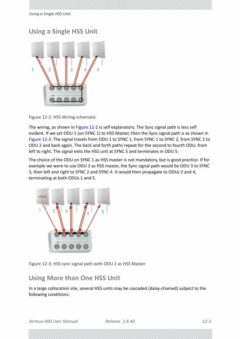
Airmux‐400 User Manual Release 2.8.40 12‐3
Using a Single HSS Unit
Using a Single HSS Unit
Figure 12‐2: HSS Wiring schematic
The wiring, as shown in Figure 12‐2 is self explanatory. The Sync signal path is less self evident. If we set ODU 1 (on SYNC 1) to HSS Master, then the Sync signal path is as shown in Figure 12‐3. The signal travels from ODU 1 to SYNC 1, from SYNC 1 to SYNC 2, from SYNC 2 to ODU 2 and back again. The back and forth paths repeat for the second to fourth ODU, from left to right. The signal exits the HSS unit at SYNC 5 and terminates in ODU 5.
The choice of the ODU on SYNC 1 as HSS master is not mandatory, but is good practice. If for example we were to use ODU 3 as HSS master, the Sync signal path would be ODU 3 to SYNC
3, then left and right to SYNC 2 and SYNC 4. It would then propagate to ODUs 2 and 4, terminating at both ODUs 1 and 5.
Figure 12‐3: HSS sync signal path with ODU 1 as HSS Master
Using More than One HSS Unit
In a large collocation site, several HSS units may be cascaded (daisy‐chained) subject to the following conditions:

Airmux‐400 User Manual Release 2.8.40 12‐4
Using More than One HSS Unit
Condition 1: Cabling Sequence
1. Up to nine ODUs may be connected to the first HSS unit using HSS ports SYNC 1, SYNC 2, SYNC 3,... up to SYNC 9 in order without leaving empty ports.
2. The next available SYNC port of the first HSS unit should be connected to SYNC 10 of the second HSS unit as shown in Figure 12‐4. In the illustration, the next available port on the first HSS unit is SYNC 6.
3. The second HSS unit may be filled out with up to nine more ODUs in reverse order. That is, connect SYNC 9, SYNC 8, SYNC 7... as shown in Figure 12‐4.
Figure 12‐4: Cascading two HSS units
4. To add a a further HSS unit: Connect the next available SYNC port from the second HSS unit in descending order (SYNC 5 in Figure 12‐4) to SYNC 1 of the third HSS unit.
5. ODUs are connected to the third HSS unit from SYNC 2 as shown in Figure 12‐5, in ascending order:
Figure 12‐5: Cascading three HSS units

Airmux‐400 User Manual Release 2.8.40 12‐5
ODU/HSS Unit Connection Pinout
6. If further ODUs are required, observe the convention that additional even numbered units are populated in descending order from SYNC 9 and odd numbered HSS units are populated in ascending order from SYNC 2.
Condition 2: Total HSS Cable Length
The total path of the HSS sync pulse must not exceed 300m. This applies no matter how many HSS units are used. To illustrate the method for calculating the sync pulse path length we show three examples. For our purpose, let:
Lmn denote the length of the ODU‐HSS unit cable at SYNC n on HSS unit m
Hm be the length of the cable joining HSS unit m to HSS unit m+1
One HSS unit with five collocated ODUs
Two cascaded HSS units as shown in Figure 12‐4
Three cascaded HSS units as shown in Figure 12‐5
ODU/HSS Unit Connection PinoutSee Table B‐2.
Note
If an ODU is disconnected from an HSS unit, then all remaining ODUs must be moved up or down to maintain the connectivity.
PathLength L11 2 L12 2 L13+ 2 L14 L15++ +=
PathLength L11 2 L12 2 L13 2 L14+2
+L15
+H1 2 L29 2+ L28 2+ L27 L26+
++ +
=
PathLength L11 2 L12 2 L13 2 L14+2
+L15
+H1 2 L29 2+ L28 2+ L27 2 L 26+
H2 2 L32 2 L33 2 L34 L35+++
++ + +
+
=

Airmux‐400 User Manual Release 2.8.40 12‐6
Link Configuration and HSS
Link Configuration and HSSThe Hub Site Synchronization Settings dialog box appears in both the Link Installation and Configuration Wizards.
Figure 12‐6: HSS Settings: Left ‐ client, Right ‐ master
The Synchronization Status dialog box displays the current status of each side of the link.
• Operation: Type of unit
• Hub Sync Master (HSM)
• Hub Sync Client ‐ Disable Transmission (HSC‐DT)
• Hub Sync Client ‐ Continue Transmission (HSC‐CT)
• Independent Unit
• Synchronization:
• N/A‐ for Master or Independent Units
• Synchronized ‐ for Hub Site Clients
• Not Synchronized ‐ for Hub Site Clients
Note
Continue Transmission is intended to work if there is no HSM pulse. If a wrong HSM pulse is detected, a Airmux‐200 will resync, adapting to the HSM RFP and continue whereas Airmux‐400 may stop.

Airmux‐400 User Manual Release 2.8.40 12‐7
Link Configuration and HSS
• External Pulses:
To configure the Operational States of the Hub Site unit
1. Click the Enabled check box
2. Click the Configure button
The Hub Site Configuration dialog box with the current status of the ODUs is dis‐played.
3. Select the type of unit configuration from the drop‐down list.
4. Select the appropriate RFP radio button. Some RFP options may be disabled depending on the bandwidth previously selected.
Table 12‐1: External Pulse Status
HSS Sync Status MeaningColor code
Generating ODU is HSM and generates the sync pulse
GreenDetected ODU is HSC and detects the sync pulse
Not detected ODU is independent
Generating and detected HSM, but other HSM present
OrangeGenerating and Improperly Detected
Airmux‐400 ODU is HSM, but detects a HSM signal that is not RFP E
Not detected HSC but no HSM present
Improperly detectedHSC but HSM pulse doesn’t fit the HSC as configured. ODU stops transmitting.
Red
Note
Take care to avoid incorrect configuration of bandwidth, RFP or to set multiple Hub Sync Masters, as system interference can occur. Airmux Manager provides error messages and tool tips if the system is configured with mismatches.

Airmux‐400 User Manual Release 2.8.40 12‐8
Link Configuration and HSS
Figure 12‐7: Hub Site Configuration dialog

Airmux‐400 User Manual Release 2.8.40 12‐9
Site Configuration and SHSS
Site Configuration and SHSSFor units that support SHSS, the Hub Site Sync option appears in the Air Interface section and displays the current HSS status of the unit.
Figure 12‐8: Site Configuration: SHSS ‐ Top ‐ client, Bottom ‐ master

Airmux‐400 User Manual Release 2.8.40 13‐1
Chapter 13:
Hub Site Synchronization over Ethernet
RAD Ethernet HSS
Ethernet HSS Requirements
The RAD Ethernet Hub Site Synchronization (HSSoE) method provides intra‐site synchronization without the need for external cables or an HSS unit. Sync signals are exchanged between collocated radios over the regular Ethernet connection.
The Ethernet HSS (HSSoE) method requires Layer 2 Ethernet connectivity between collocated ODUs. It has two requirements:
• Collocated ODUs providing Ethernet services only, should be connected to an Air‐mux‐IDUH/2ETH instead of regular PoE devices. Other simple switches may work with
degraded performance. They are not recommended and problems arising from their use will not be eligible for any kind of support.
• Collocated ODUs providing E1/T1 services should use an IDU‐E or IDU and then be connected to an Airmux‐IDUH/2ETH functioning as a switch. One of the LAN ports on the IDU‐E or IDU is connected to any of the six Airmux‐IDUH/2ETH PoE ports or the two LAN ports. (This is possible because the IDU‐E or IDU LAN cable only uses four pins for data; the power pins are not used so there is no risk of damage to them.) In this way, up to eight such ODUs may be collocated.
Note
You may only use one Airmux‐IDUH/2ETH. That is, they may not be cascaded.
Caution
If you are using an IDU‐E0 (GbE) it must be connected to the Airmux‐IDUH/2ETH LAN port only. Connecting it to the P0E ports will damage the unit and in any event, it will not work.

Airmux‐400 User Manual Release 2.8.40 13‐2
HSSoE Concepts
HSSoE ConceptsSync Frames
Sync frames are exchanged between collocated ODUs using Layer‐2 broadcasting.
Domain
To prevent network flooding, each group of collocated ODUs is configured with an internal “domain name”. The default name must be changed to prevent sync frames being received over the LAN by another ODU, which could be then mistakenly configured as a client of an HSM at the wrong location.
Discovery
Discovery by the HSM and HSCs is provided using the following choice of filters:
Using discovery at the HSM, you can select only those HSCs in the HSM’s domain; when configuring a new HSC you may use discovery to pick the correct HSM.
VLAN
VLAN is used to separate sync frames from traffic so as to give sync frames highest priority. If you have collocated ODUs running close to full capacity, failure to do so, would result in excessive jitter and dropped traffic frames.
By default, the VLAN ID 1997 and priority 7 are reserved for HSS. You may change the VLAN ID but not the priority.
Installing Collocated HSSoE ODUs
Ethernet Services Only
Use an Airmux‐IDUH/2ETH for the collocated ODUs instead of separate PoE devices. The Airmux‐IDUH/2ETH has two LAN ports, one of which will be connected to a switch.
Ethernet and TDM Services
To attain Layer 2 connectivity for up to two such ODUs, you should connect one of the two the IDU‐E (or IDU) LAN ports to the Airmux‐IDUH/2ETH LAN ports. You may use the second
Caution
VLAN Tagging should not use the VLAN ID used by HSSoE and vice versa.

Airmux‐400 User Manual Release 2.8.40 13‐3
Link Configuration and HSSoE
IDU‐E (or IDU) LAN port to connect to a switch. As pointed out earlier, you may only collocate two ODUs in this way.
Link Configuration and HSSoEThe Hub Site Synchronization Settings dialog box appears in both the Link Installation and Configuration Wizards. To illustrate HSSoE configuration, we will use two Airmux‐400 100M links set up as in Table 13‐1:
We illustrate the HSSoE configuration procedure from the Configuration wizard.
To configure an HSSoE Master:
1. Log on to the A1 site of Link 1.
2. Open the Configuration Wizard and proceed (by repeatedly clicking Next) to the Hub Site Synchronization Settings window.
Table 13‐1: Link settings to demonstrate HSSoE
ParameterLink Name
Link 1 Link 2
Operating band (by ACS) 5.745 GHz 5.825 GHz
Site Name A1 B1 A2 B2
Link ID EBG_205613341 EBG_205613342
Rate Adaptive
Ethernet Configuration Auto Detect
Service Ethernet Only
CBW 20 MHz
ODU IP Address 10.104.3.2 10.104.3.4 10.103.3.2 10.103.3.4
Subnet Mask 255.255.0.0
Default Gateway 10.104.10.21 10.103.10.21
Trap destination 0.0.0.0
HSSoE Domain Name EHSS
Required HSSoE Status HSM INUHSC (Continue Tx)
INU
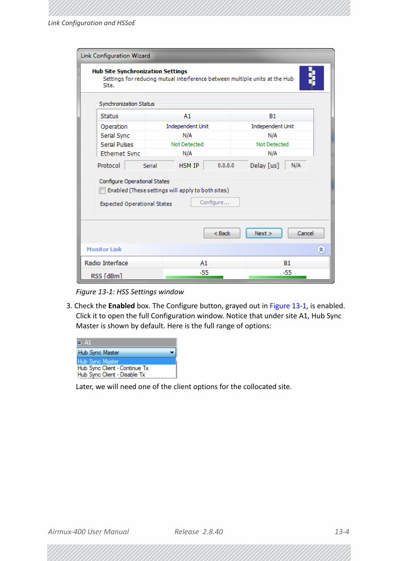
Airmux‐400 User Manual Release 2.8.40 13‐4
Link Configuration and HSSoE
Figure 13‐1: HSS Settings window
3. Check the Enabled box. The Configure button, grayed out in Figure 13‐1, is enabled. Click it to open the full Configuration window. Notice that under site A1, Hub Sync Master is shown by default. Here is the full range of options:
Later, we will need one of the client options for the collocated site.

Airmux‐400 User Manual Release 2.8.40 13‐5
Link Configuration and HSSoE
Figure 13‐2: HSS Configuration window
4. Choose the Ethernet protocol:
5. The bottom part of the window looks like this:

Airmux‐400 User Manual Release 2.8.40 13‐6
Link Configuration and HSSoE
Figure 13‐3: HSS Configuration Domain name, VLAN ID and Discovery
6. The default Domain name is (not surprisingly) Default. We will changed it to EHSS.
7. Choose a VLAN ID for the domain. Do not use this VLAN ID for traffic or management VLAN. The VLAN priority is set to 7 (maximum possible). For our example, we will leave the default VLAN ID as is.
8. Click the Start Discovery button. Here is an extract of the Discovery display:
It shows other HSMs (of either type) on the same subnet and any other collocatable ODUs configured or not.
9. At this point you can click OK to exit the HSS window and continue with regular configuration. Here is the HSS window display after configuration:

Airmux‐400 User Manual Release 2.8.40 13‐7
Link Configuration and HSSoE
10. The Details button offers a list of configured HSSoE client. It is empty for now, so click Next to continue.
To configure an HSSoE Client:
1. Start the Configuration Wizard as for the HSS Master and get to this point:

Airmux‐400 User Manual Release 2.8.40 13‐8
Link Configuration and HSSoE
2. Check the Enabled check box, click Configure and in the following display choose an HSS client:

Airmux‐400 User Manual Release 2.8.40 13‐9
Link Configuration and HSSoE
3. Click OK to continue the Configuration wizard in the usual way.
If for some reason, the discovery process (which occurs anyway) does not pick up a domain, or you are installing a replacement unit and you do not know the domain, use the Start Discovery button to obtain a list of responding HSMs. You should be able to identify the correct HSM (from its IP address) and note the domain name for entry in the previous window.

Airmux‐400 User Manual Release 2.8.40 13‐10
Site Configuration and HSSoE
Site Configuration and HSSoEFor units that support HSSoE, the Hub Site Sync option appears in the Air Interface section and displays the current HSS status of the unit.

Airmux‐400 User Manual Release 2.8.40 13‐11
Mixing HSSoE and SHSS enabled ODUs
Figure 13‐4: Site Configuration: HSSoE ‐ Top ‐ client, Bottom ‐ master
The Details button in the (bottom) HSM window offers a list of collocated clients.
Mixing HSSoE and SHSS enabled ODUsODUs using both HSS styles may be collocated as follows:
To collocate HSSoE and SHSS ODUs:
1. Ensure that the HSSoE master also supports SHSS. (It will have a Sync port.)
2. Connect the HSSoE Sync port of the HSSoE master to the first port of the HSS unit.
3. Configure the HSSoE master to support both Serial and Ethernet HSS as shown:
4. Ensure that all other collocated ODUs are configured as clients as described above (HSSoE) and in Chapter 12 (SHSS).

Airmux‐400 User Manual Release 2.8.40 14‐1
Chapter 14:
Using the RAD GSU
What is it forThe GPS‐based synchronization unit (GSU) is designed to handle inter‐site interferences under large‐scale deployment scenarios.
The GSU is an outdoor unit consisting of a small size enclosure, a GPS antenna and a PoE device.
The GSU is connected to the HSS Unit using a standard HSS cable. It synchronizes the transmission timing of multiple Hub‐Sites to the same clock source thus eliminating mutual interference.
GSU FunctionalityThe GSU receives a synchronization signal from the GPS once per second. It distributes a RAD
proprietary synchronization signal to all other ODU units using the RS422 protocol and the standard HSS mechanism, where the GSU acts as an HSM unit.
When the GSU doesn’t receive a synchronization signal from the GPS for 30 seconds, it moves automatically to Self‐Generation mode and acts as a regular HSM unit, until the GPS recovers.
Typical GSU Scenarios
Independent Distributed Sites
In the scenario of Figure 14‐1, we have multiple independent collocated sites, which may interfere with each other. To meet this situation, we coordinate all of them using the GSU as shown.
The GSU functions like “wide area HSS unit”, ensuring that all participating radios at the locations marked GSU each transmit and receive at the same time.

Airmux‐400 User Manual Release 2.8.40 14‐2
Multiple Distributed Sites with Communication
Figure 14‐1: GSU Scenario ‐ Independent distributed sites
Multiple Distributed Sites with Communication
What happens if, in Figure 14‐1, the GSU towers themselves have radios communicating as shown in Figure 14‐2?
Consider GSU 1 and GSU 2: Both collocated towers transmit and receive simultaneously. However, the radios communicating at GSU 1 and GSU 2 must transmit and receive in turn according to the scheme in marked “Normal Phase” in Figure 14‐3. This is an impossible situation, if all the links must send and receive together. It is further complicated by adding a third and further sites as shown.
Figure 14‐2: GSU Scenario ‐ Communicating distributed sites

Airmux‐400 User Manual Release 2.8.40 14‐3
Cascaded Sites using Shifted Phase Transmission
Cascaded Sites using Shifted Phase Transmission
The solution offered here is not a “universal cure”. The following conditions are necessary, but in any specific case may not be sufficient:
• The GSU sites (marked 1, and 3 above) are sufficiently far apart as to ensure that there is no mutual interference between communicating sites (1‐2 and 2‐3 above)
• There should be no interference between non‐communicating sites (1 and 3 above).
To see how it works, we use Figure 14‐2. The GSU towers are numbered and marked for cascading, 1‐2 and 2‐3. There should not be a link between 1 and 3.
The GSU can synchronize the TDD timing of several sites enabling the cascading of consecutive links without mutual interference.
To use cascading, the TDD timing of the even‐ordered links (GSU 2 above) must be “shifted” (Shifted Phase) and odd‐ordered links (GSU 1 and GSU 3 above) must be “unshifted” (Normal Phase). The phase shift is half of the Radio Frame Duration (RFD) from the chosen RFP. The scheme is shown in Figure 14‐3.
Since the GSU is always HSS master (HSM), at each GSU location, the GSU can “force” the synchronization of its collocated radios. By half RFD shifting, alternate collocated sites can talk to each other.
Figure 14‐3: Phase shifted transmission ‐ phase shift is 1/2 the RFD
Choice of normal or shifted phase is configurable per GSU using the Airmux Manager.
GSU RedundancyThe GSU is designed to support redundancy, improving the robustness of a GSU based topology.
In redundancy mode, two GSUs are installed at the same HSS site. One of them self‐configures to generate HSS sync signals. We will call it the Primary unit. The other one, the Secondary unit remains dormant merely polling the first GSU. If the Primary GSU fails, then the Secondary GSU becomes active immediately. If the Primary unit becomes active again, it remains dormant, reversing the original roles. The choice of the Primary GSU is random and of no significance.

Airmux‐400 User Manual Release 2.8.40 14‐4
GSU Kit Contents
If the Primary GSU fails, and then the Secondary GSU also fails to receive sync signals from its GPS, then it moves to self‐generation HSM mode like an ordinary HSM ODU until its GPS recovers.
Figure 14‐4: Make the GSUs the first two collocated units
Redundancy switching is completely transparent to the GSU‐managed links.
GSU Kit ContentsThe GSU package includes:
• 1 x GSU
• 1 x Mounting Kit
• 1 x GPS Antenna
• 1 x GPS Antenna Mounting Kit
• 1 x RF Cable, 1.5m
• CD

Airmux‐400 User Manual Release 2.8.40 14‐5
GSU Installation
GSU Installation
Overview
Figure 14‐5: General GSU configuration
It may be configured using the regular Airmux Manager or Telnet.
Preparing the GSU for Use
Log on to the unit using Local Connection or IP address 10.0.0.120 to change its IP address from the default (10.0.0.120). In the example screen captures below, we use 10.104.20.1 with Subnet Mask 255.255.0.0 and Gateway 10.104.10.21.
Mounting the GSU
Mount the GSU and antenna. Ensure that its ODU port connected to its PoE device and the HSS cable is connected to the HSS unit as shown. The external LAN port of the PoE device is connected to the managing computer. If you are accessing the GSU through a network it is

Airmux‐400 User Manual Release 2.8.40 14‐6
Configuring the GSU
essential that you use the IP pre‐loading method. The default IP address may be inaccessible and you may not use the Local Connection method over a network.
Configuring the GSUGetting Started
To configure the GSU, you log on to it, exactly as in Chapter 5.
The GSU Main Window
Here is the main window for GSU configuration:
Figure 14‐6: GSU Main widow at startup
The top five items in the GSU Monitor panel are taken from a satellite. The transmission Phase may be Normal as shown or Shifted. It purpose, together with the Tx Ratio bar, will be explained below.
The Status Box
Under normal operating conditions, it will be green as shown, indicating that it is synchronized with a satellite.
If satellite synchronization is lost, then the GSU will function as an independent HSM and the status box will change color:

Airmux‐400 User Manual Release 2.8.40 14‐7
Configuring the GSU
The Main Menu
The main menu is a subset of the main menu applicable to the Airmux‐400. Notice that there are no Installation or Configuration wizards. Such configuration as is necessary is carried out using a modified version of the standard Site Configuration.
Similarly, the Tool bar is a subset of that applicable to the Airmux‐400.
Using Site Configuration for the GSU
Site Configuration: System
Here is the opening window for Site Configuration:
Figure 14‐7: Site Configuration: System
Site Configuration: GPS Sync Unit
This window is the main GSU configuration tool:

Airmux‐400 User Manual Release 2.8.40 14‐8
Configuring the GSU
Figure 14‐8: Site Configuration: GPS Sync Unit
1. Setting the RFP for HSS
The GSU is automatically configured as HSS Master (HSM).
If the hub site consists only of Airmux‐200 units, then any suitable RFP may be chosen. If there are one or more Airmux‐400 units, you must use RFP B or E.
Note
Ensure that no other collocated ODU is configured as HSM.

Airmux‐400 User Manual Release 2.8.40 14‐9
Configuring the GSU
The permitted RFPs are also dependent on channel bandwidth and are color coded as fol‐lows:
There is a further restriction: If there are two distributed sites transmitting to each other, they must both use the same RFP. This requirement, together with use of shifted transmis‐sion phase (item 3 below), ensures that communicating distributed sites to not interfere with each other by transmitting simultaneously.
Two GSU managed sites transmitting with shifted transmission phase and using the same RFP, transmit one half a RFD apart (see Figure 14‐3 above).
2. Setting the Tx Transmission Ratio
Since the GSU is always HSM, it must be able to cater for hub site Airmux‐400 100M based links. (See the Airmux‐400 User Manual, Chapter 5). If you use asymmetric allocation, shifted transmission phase becomes unavailable and you cannot “cascade” links as described in step 1.
3. Choosing the Transmission Phase
Chose the Transmission Phase in accordance with considerations in step 1 above. If you choose Shifted Phase then the Asymmetric Ratio selector is disabled.
You May use RFP/Channel Bandwidth combinations with this color
For these collocated radios
Airmux‐200 only
Airmux‐400 only
Airmux‐200 and Airmux‐400 together
None ‐ unavailable

Airmux‐400 User Manual Release 2.8.40 14‐10
Configuring the GSU
Site Configuration: Management
Figure 14‐9: Site Configuration: Management
Here you set the GSU IP address, subnet mask and gateway. You also set trap addresses here. It is identical to the corresponding panel for Airmux‐400.

Airmux‐400 User Manual Release 2.8.40 14‐11
Configuring the GSU
Site Configuration: Inventory
Figure 14‐10: Site Configuration: Inventory
Site Configuration: Security
You can only change the SNMP Community strings:

Airmux‐400 User Manual Release 2.8.40 14‐12
Configuring the GSU
Figure 14‐11: Site Configuration: Security
Site Configuration: Date and Time
ODU Recent events, alarms and traps are time‐stamped from the time method chosen here (NTP, managing computer, ODU default).

Airmux‐400 User Manual Release 2.8.40 14‐13
Configuring the GSU
Figure 14‐12: Setting the date and time for trap reporting
Site Configuration: Operations
The only available action here is Restore System Defaults:

Airmux‐400 User Manual Release 2.8.40 14‐14
Configuring the GSU
Figure 14‐13: Site Configuration: Operations

Airmux‐400 User Manual Release 2.8.40 14‐15
GSU Preferences
GSU Preferences
The Preferences window adds a new tab for the GSU:
Figure 14‐14: Site Configuration: Operations
You may chose the units for latitude/longitude coordinates.
GSU Monitoring and DiagnosticsThe monitoring and diagnostic reports are similar to those of Airmux‐200.
GSU Telnet SupportTo configure the GSU with Telnet, start a Telnet session, using
telnet <GSU_ipaddr>.
For example, if you run Telnet as follows,
telnet 10.104.20.1
you will be asked for a user name and password. You must log on with administrator privilege under user name, admin and password netman.
The available commands are the same as for Airmux‐200 with the addition of four additional display commands and three additional set commands.

Airmux‐400 User Manual Release 2.8.40 14‐16
Software Upgrade for GSUs
The additional display commands are
display rfp
The rpf value displayed is an index from 2 to 6, 2 for A, 3 for B and so on.
display ratio
display tx_phase
display gpsinfo
The last one, display gpsinfo, is the most interesting:
[email protected]‐> display gpsinfo
Current GPS time 102941.000
Current GPS latitude 51.500000
Current GPS N\S Indicator N
Current GPS longitude 0.000000
Current GPS E\W Indicator E
Current GPS number of satellites 09
Current GPS altitude 84.0
Command "display gpsinfo" finished OK.
The three additional set commands are
set rfp <index> (2‐6)
set ratio <ratio>
set tx_phase <mode:1=normal,2=shifted>
Software Upgrade for GSUsAll GSUs in a distributed site can be updated simultaneously. Use an IP list as described in
Chapter 18.

USER MANUAL
Part 3: Advanced Installation
Release 2.8.40
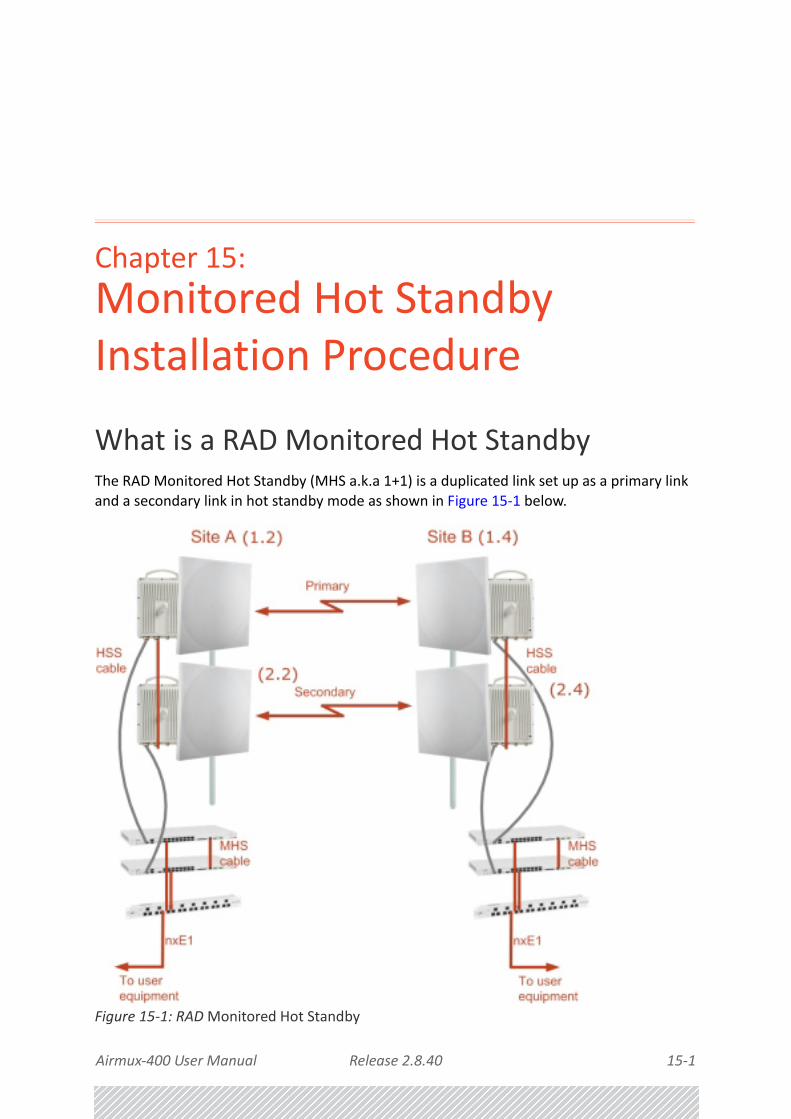
Airmux‐400 User Manual Release 2.8.40 15‐1
Chapter 15:
Monitored Hot Standby Installation Procedure
What is a RAD Monitored Hot StandbyThe RAD Monitored Hot Standby (MHS a.k.a 1+1) is a duplicated link set up as a primary link and a secondary link in hot standby mode as shown in Figure 15‐1 below.
Figure 15‐1: RAD Monitored Hot Standby

Airmux‐400 User Manual Release 2.8.40 15‐2
What RAD MHS provides
RAD MHS provides redundancy and backup to TDM services. It is designed to provide high reliability high‐capacity Point‐to‐Point links. The RAD MHS is ‐
• Designed to provide redundancy and high reliability for carrier class operators
• Optimized for high capacity links operating in license‐free bands
• A comprehensive solution providing protection against both equipment failure and loss of air interface, by simple connectivity between a primary link and a secondary link
The main service redundancy features of the RAD MHS are –
• TDM service cut‐over from the primary to the secondary link is completely automatic
• TDM service cut‐over time no more than 50 ms
• Automatic restore to primary link as soon as it becomes available
• Support for up to sixteen TDM channels for Airmux‐400
MHS is supported between two Airmux‐400 links using IDU‐Es. In what follows, ODU refers to a Airmux‐400 radio and IDU refers to an IDU‐E.
What RAD MHS provides
Equipment Protection
Equipment protection is provided for the electrically‐active network elements, ODU and IDU.
The primary IDU and the secondary IDU are connected by a cable to monitor failure and to control protection switching. Switching time is less than 50ms.
Air‐Interface Protection
Air‐Interface protection is unique to RAD and is optimized for wireless links operating in license‐free bands.
The primary link and the secondary link use different frequency channels. If the air‐interface of the primary link is disturbed and cannot carry the required TDM service, then the system automatically switches to the secondary link.
In addition, improved robustness and frequency planning flexibility is achieved, as the primary and secondary air interfaces can operate in the same frequency band or in different frequency bands.
Automatic Channel Selection (ACS) can be configured for each link to add additional robustness.
The primary and secondary links are synchronized using Hub Site Synchronization (HSS).
It is recommended that both sites be installed with HSS cables. If HSS fails at one site, it can be operated from the other site by remote configuration.

Airmux‐400 User Manual Release 2.8.40 15‐3
Purpose of this Chapter
Purpose of this ChapterThis chapter is an installation and maintenance guide for RAD MHS. It applies to all RAD radio products able to support the Monitored Hot Standby operational mode.
Who Should Read thisThis chapter is intended for persons responsible for the installation and maintenance of RAD MHS. To use it you need to know how to ‐
• Install a Airmux‐400 radio link
• Use the Airmux Manager software
RAD MHS Kit Contents• One Y‐Connection Patch Panel
• One MHS cable
Figure 15‐2: RAD Y‐Connection Patch Panel
Installing a RAD MHS
Figure 15‐1 above is a schematic of a RAD MHS. Figure 15‐3 shows how to connect the IDUs to the Patch Panel.
Note
The following procedure is substantially generic to all RAD radio products. What you see on your running Airmux Manager may differ in some details from the screen captures used to illustrate this chapter.

Airmux‐400 User Manual Release 2.8.40 15‐4
Installing a RAD MHS
Figure 15‐3: How to connect the IDUs to the Patch Panel
In what follows, it will be assumed that –
1. We will depart from our usual Site A / Site B conventions. Sites A and B on the primary link will be Sites 1.2 and 1.4 respectively. The corresponding sites on the secondary link will be Sites 2.2 and 2.4. The site names reflect their IP addresses. This is a useful convention and is reflected in the screen captures below.
2. The link will be managed from Site 1.2; Site 1.4 may be a remote site.
3. The links intended as the primary and secondary will be referred to their respective names, Primary Link and Secondary Link as shown in Figure 15‐1 above, despite their hav‐ing yet to be installed.
To install a Hot Standby Link:
1. Set up Primary Link in the usual way. Ensure that it is fully operational in accordance with the relevant instructions in Part 1 of the .
2. Connect user equipment to Site 1.4.
3. At Site 1.2, disconnect the TDM cables from the external equipment or disconnect external equipment from the Hot Standby Patch Panel.
4. The HSS cable (connecting the ODUs) should be connected at Site 1.2. The ODU belonging to the primary link should be configured as HSM, whereas the ODU belonging to the secondary link should be configured as HSC‐CT.
Note
• With Airmux‐400 links you can protect up to 16 TDM ports. To protect more than eight TDM ports use two Patch Panels at each site.
• Ethernet services are carried independently by primary and secondary links. Each link carries different Ethernet traffic. MHS does not protect Ethernet traffic.
Note
Do not proceed unless this condition is fully met!

Airmux‐400 User Manual Release 2.8.40 15‐5
Installing a RAD MHS
5. Establish Secondary Link in the usual way, with HSS enabled. The two link frequencies should be at least 5MHz apart.
6. Connect the MHS cables at Sites A and B as shown in Figure 15‐1 and Figure 15‐3 above.
7. Run the Configuration Wizard for Primary Link. Activate TDM services in the usual way. Navigate to the Hot Standby tab, in the Services Configuration panel:
Figure 15‐4: Services Configuration Panel: Hot Standby mode selection
Check the Primary button to configure Primary Link as the primary link.
8. Complete the Wizard, and then move to Secondary Link.
9. Repeat step 7 for Secondary Link. For the Services Hot Standby tab, this time, check the Secondary button.
10. Complete the Wizard.
11. At Site 1.2, reconnect the Hot Standby Patch panel to the external equipment.
From this point on, we will simply refer to primary and secondary link (no capitalized names).
At the end of the process, the Airmux Manager main windows should look like this:
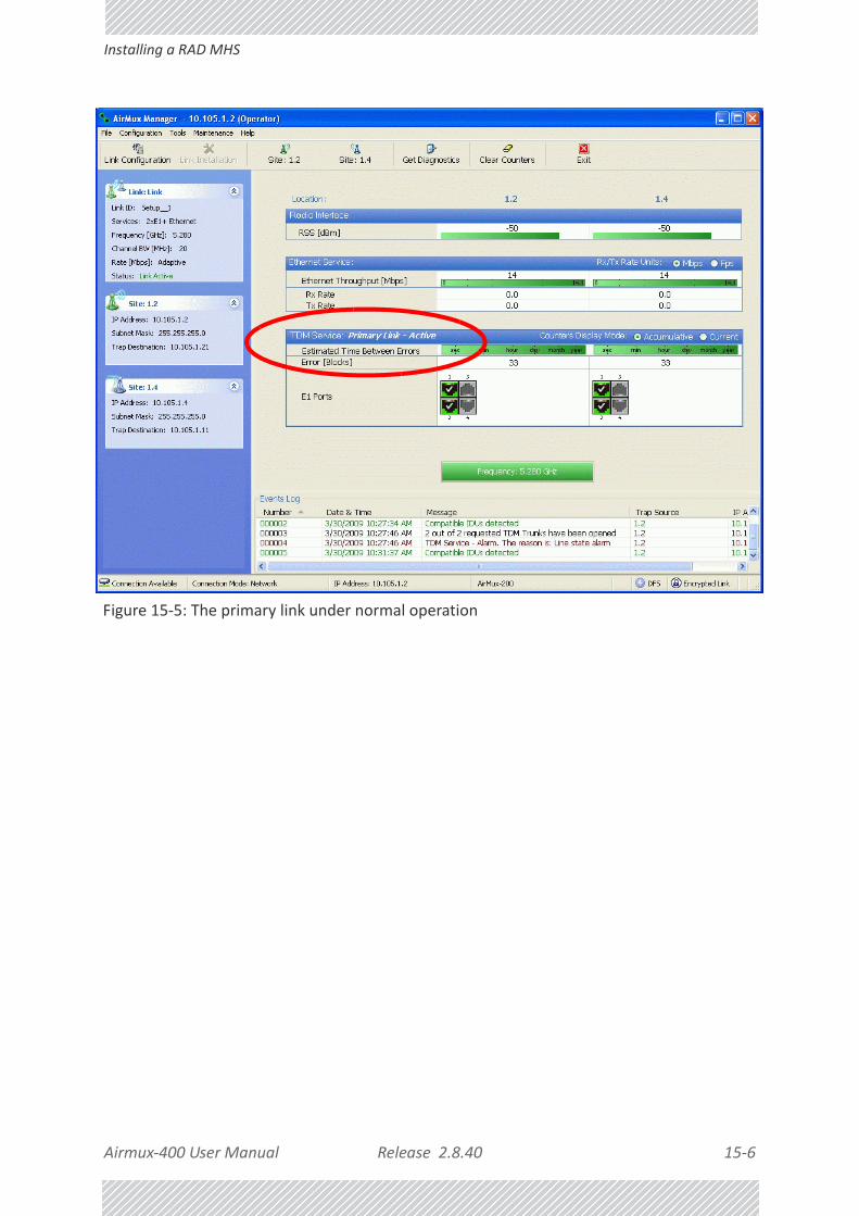
Airmux‐400 User Manual Release 2.8.40 15‐6
Installing a RAD MHS
Figure 15‐5: The primary link under normal operation

Airmux‐400 User Manual Release 2.8.40 15‐7
Installing a RAD MHS
Figure 15‐6: The secondary link under normal operation
To see what happens following a cut‐over from the primary link to the secondary link, you need to have running two copies of the Airmux Manager – one logged into the primary link, and one logged into the secondary link.
Here then, is the situation after a cut‐over to the secondary link:
For the primary link, the following window will appear for a few seconds:

Airmux‐400 User Manual Release 2.8.40 15‐8
Installing a RAD MHS
Figure 15‐7: Primary link a few seconds before regular No‐Link display
It will then revert to the standard No‐Link‐available window.
On the secondary link Manager window, you will see a window like this:

Airmux‐400 User Manual Release 2.8.40 15‐9
Maintaining a RAD MHS Link
Figure 15‐8: Secondary Link operating as the Hot Standby link
Notice that the active link notice is highlighted in red, so that there is no mistaking which link is operational.
Maintaining a RAD MHS Link
IDU Replacement
There are two situations, which must be treated differently.
Situation 1:
To replace either of the IDUs at Site 1.4 or the IDU at Site 2.2, nothing special is required. Simply disconnect the IDU to be replaced – and replace it with a new one. Replacing a secondary link IDU obviously has no effect on the TDM service. Disconnecting the Site 1.4 primary IDU activates Hot Standby. After the Site 1.4 primary IDU is replaced, the Link will detect the change and switch back to the primary link.
If you replaced the Site 2.2 IDU, remember to reconnect the MHS cable.
Situation 2:
Replacing the Site 1.2 IDU is different, and requires several steps.

Airmux‐400 User Manual Release 2.8.40 15‐10
ODU Replacement
To replace the Site 1.2 primary link IDU:
1. Power off the Site 1.2 IDU. This activates the secondary link using Hot Standby.
2. Run the Configuration manager on the secondary link, and in the Hot Standby panel of Figure 15‐4 above, check the Disabled button.
3. Replace the Site 1.2 IDU without connecting it to the ODU (to prevent transmission by the primary link with the undefined IDU).
4. Reconnect the MHS cable between the IDUs at Site 1.2.
5. Again, run the Configuration Wizard on the secondary link, and in the panel of Figure 15‐4 above, check the Secondary button to re‐enable the link as secondary.
6. Connect the new Site 1.2 IDU to its ODU.
The Hot Standby will automatically revert to the primary link within 50ms.
ODU Replacement
Both the primary and secondary replacement ODUs require pre‐configuration prior to insertion into the link. The items to be preconfigured are
• HSS mode
• Link ID
• Frequency
• Hot Standby mode – using the new Services panel in Figure 15‐4 above
• IP address (optional)
To preconfigure an ODU:
1. Attach the new ODU to an IDU or a PoE device.
2. Run the Airmux Manager and use Hot Standby tab of Figure 15‐4 above to configure the new ODU to Primary or Secondary mode as required.
3. Ensure that it is set to the proper HSS mode in accordance with Figure 15‐4 above. Enter the required Link ID and frequency.
To replace an ODU for primary or secondary link, at either site:
• Install the preconfigured ODU. (Since the other link is working normally, nothing need be done with it. If the secondary ODU was replaced, TDM service remains as is on the primary link. If the primary ODU was replaced, then the TDM service will shift back to the primary link.)
Note
Pre‐configuration must be carried out before the new ODU is connected to its IDU. If you try to do it “live” against its IDU, it will cause spurious transmissions and a service break.

Airmux‐400 User Manual Release 2.8.40 15‐11
Switching Logic
Switching Logic
Switching from Primary Link to Secondary Link
Switching from primary link to secondary link will occur following:
• Loss of the primary air interface due to sync‐loss
• Loss of the primary air interface due to failure of the receiver to acquire expected E1/T1 data during a period of 24ms
• The Primary equipment (either ODU or IDU, local or remote) is powered off
Following the switch from the primary to the secondary link, the primary and secondary link Manager main windows should look like this:
Figure 15‐9: Primary link after the switch over to secondary link
After a few seconds the display moves to No‐Link display, with TDM ports grayed out.

Airmux‐400 User Manual Release 2.8.40 15‐12
Switching back from the Secondary to the Primary Link
Figure 15‐10: Secondary link operating after the switch over to secondary
After a few moments the TDM icons become green.
Switching back from the Secondary to the Primary Link
Switching back from the secondary link to the primary link will occur after the primary link has become and remains fully functional for a continuous period of at least one second. Following reversion from the secondary link to the primary link, the Manager main windows should look like this:

Airmux‐400 User Manual Release 2.8.40 15‐13
Switching back from the Secondary to the Primary Link
Figure 15‐11: Primary link operating after the switch back from secondary

Airmux‐400 User Manual Release 2.8.40 15‐14
System Operation description
Figure 15‐12: Secondary Link operating after the switch back to Primary
System Operation description
Normal operation
• TDM services are carried by the primary link
• The secondary link (equipment and air interface) is operating but not carrying user traffic
• TDM ports on the secondary IDUs are tri‐state
Switching to backup
• Switching to secondary will occur in the following cases:• Loss of the primary air interface due to sync-loss• Loss of the primary air interface due to failure of the receiver to acquire expected
TDM data during a period of 24ms• Primary equipment power off (either ODU or IDU, local or remote)
• The switching result would be:• TDM ports on the primary IDUs turn to tri-state • TDM ports on the secondary IDUs become active
Backup operation • TDM services are carried by the secondary link
Switching back to primary
• Switching back to primary will occur as soon as the Primary link is fully functional for 1 second

Airmux‐400 User Manual Release 2.8.40 16‐1
Chapter 16:
The RAD Ethernet Ring
ScopeThe description of RAD Ethernet Ring in this Chapter is completely generic: Both Airmux‐200 and Airmux‐400 links may participate in an Ethernet ring.
What is an Ethernet RingAn Ethernet ring consists of several nodes connected by hops (links). Loops are not allowed with Ethernet; therefore one hop is a Ring Protection Link (RPL) which “blocks” Ethernet traffic. In the event of failure in the ring, the Ring Protection Link unblocks and Ethernet traffic in the ring is restored.
Some terminology:• Normal State – all member links are functional except the RPL which is blocked.
• Blocked ‐ the air‐link is up but Ethernet traffic is not transmitted across the link. The Ethernet service panel for the RPL in the Airmux Manager is labeled Idle
• Unblocked ‐ Ethernet traffic is transmitted across the RPL. The Ethernet service panel for the RPL in the Airmux Manager is labeled Active
• Protection State – a member link is broken and the RPL passes Ethernet traffic
• Ring Protection Link ‐ as described above
• Ring Link ‐ any member link controlled by the RPL
• Independent Link ‐ not subject to ring protection
Caution
VLAN IDs are used by RAD products in three separate contexts: Management VLAN, Traffic VLAN and Ethernet Ring. It is recommended that you use different VLAN IDs for each context.

Airmux‐400 User Manual Release 2.8.40 16‐2
RAD Ethernet Ring
• Ring Protection Message (RPM) ‐ control message used to monitor and control the ring.
RAD Ethernet RingThe following figure describes the RPL behavior during a ring failure and recovery cycle.
Figure 16‐1: Ring Protection mechanism
Note
RPM messages are broadcast, so it is essential (to prevent flooding) to associate the RPL and member Ring LInks with a VLAN ID. This requires in turn, that equipment used in the ring either supports VLAN or can transparently pass through VLAN tagged packets.
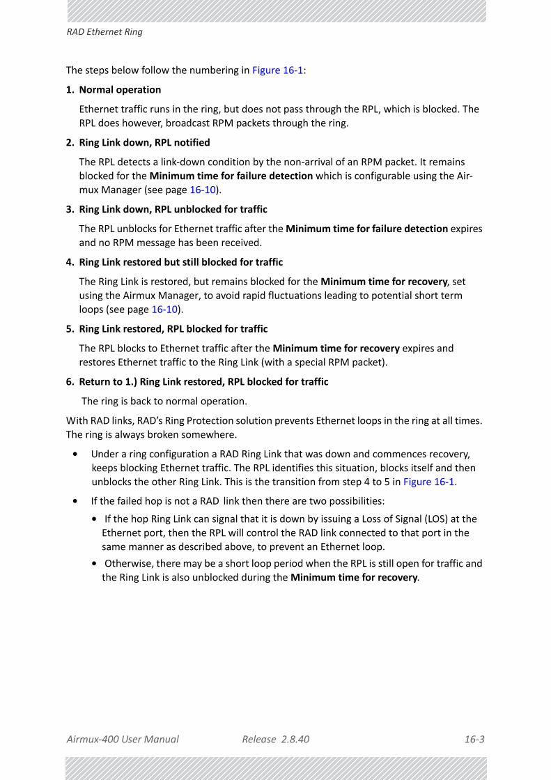
Airmux‐400 User Manual Release 2.8.40 16‐3
RAD Ethernet Ring
The steps below follow the numbering in Figure 16‐1:
1. Normal operation
Ethernet traffic runs in the ring, but does not pass through the RPL, which is blocked. The RPL does however, broadcast RPM packets through the ring.
2. Ring Link down, RPL notified
The RPL detects a link‐down condition by the non‐arrival of an RPM packet. It remains blocked for the Minimum time for failure detection which is configurable using the Air‐mux Manager (see page 16‐10).
3. Ring Link down, RPL unblocked for traffic
The RPL unblocks for Ethernet traffic after the Minimum time for failure detection expires and no RPM message has been received.
4. Ring Link restored but still blocked for traffic
The Ring Link is restored, but remains blocked for the Minimum time for recovery, set using the Airmux Manager, to avoid rapid fluctuations leading to potential short term loops (see page 16‐10).
5. Ring Link restored, RPL blocked for traffic
The RPL blocks to Ethernet traffic after the Minimum time for recovery expires and restores Ethernet traffic to the Ring Link (with a special RPM packet).
6. Return to 1.) Ring Link restored, RPL blocked for traffic
The ring is back to normal operation.
With RAD links, RAD’s Ring Protection solution prevents Ethernet loops in the ring at all times. The ring is always broken somewhere.
• Under a ring configuration a RAD Ring Link that was down and commences recovery, keeps blocking Ethernet traffic. The RPL identifies this situation, blocks itself and then unblocks the other Ring Link. This is the transition from step 4 to 5 in Figure 16‐1.
• If the failed hop is not a RAD link then there are two possibilities:• If the hop Ring Link can signal that it is down by issuing a Loss of Signal (LOS) at the Ethernet port, then the RPL will control the RAD link connected to that port in the same manner as described above, to prevent an Ethernet loop.
• Otherwise, there may be a short loop period when the RPL is still open for traffic and the Ring Link is also unblocked during the Minimum time for recovery.

Airmux‐400 User Manual Release 2.8.40 16‐4
Ethernet Ring Topologies Supported by RAD
Ethernet Ring Topologies Supported by RADThe following ring topologies are supported:
Table 16‐1: Topologies supported by RAD Ethernet Ring
Stand‐alone ring
The ring is not connected to other rings
Single‐homed ring
One of the nodes is connected to another network / ring:
Dual‐homed ring
Two adjacent nodes are connected through a non‐RAD link (e.g. micro wave or fiber):
Note:• The network has to be layer 2 and support VLANs• The ring control broadcasts RPM packets. Hence it
is recommended to prevent these packets from propagating into the network

Airmux‐400 User Manual Release 2.8.40 16‐5
Ethernet Ring Topologies Supported by RAD
Mixed ring
Some of the hops are connected through non‐RAD links:
Repeater sites
Some of the hops are connected through RAD links with PoE devices, not supporting ring functionality:
Table 16‐1: Topologies supported by RAD Ethernet Ring (Continued)

Airmux‐400 User Manual Release 2.8.40 16‐6
Protection Switching
Protection SwitchingProtection switching occurs upon failure in the ring.
The Ethernet service restoration time depends on the number of hops in the ring. With four hops the Ethernet service is restored in less than 50 ms.
In single and dual homed topologies the service restoration may take longer due to the aging time of the external switches. Switches that are immediately aware of routing changes reduce the restoration time.
Hardware ConsiderationsEthernet Ring Protection is supported by the IDU‐E, IDU and PoE.
A typical Ring Protection Link consists of an IDU‐E or IDU, a PoE and two ODUs as shown in Figure 16‐2. Hence one end of the RPL and of ring controlled links, as shown in Figure 16‐2 has to be an IDU. It is recommended to have an IDU at each node to have the flexibility to change the RPL.
A ring node is built from two ODUs from adjacent links. The ODUs can be connected to either an IDU or to a PoE device as in Figure 16‐2. Port names in the IDU are shown.
Shared ring
RAD rings with shared hops.
Note:• A RAD link hop can be a part of up to 4 rings• The RPL cannot be a shared link• The two RPLs should use different Minimum Time
for Activation values to prevent duplicate action causing a loop
Table 16‐1: Topologies supported by RAD Ethernet Ring (Continued)

Airmux‐400 User Manual Release 2.8.40 16‐7
Special Case: 1 + 1 Ethernet Redundancy
Figure 16‐2: Node with IDU and PoE device
The switching function is carried out by the IDU‐Es and IDUs, both of which provide Layer 2 support (see Chapter 17).
Special Case: 1 + 1 Ethernet RedundancyThe same device may be used to provide economic 1 +1 redundancy for a single link.
A 1+1 Ethernet is a ring with two nodes. One of the links is RPL.
The equipment in a 1+1 Ethernet installation is as follows:
Figure 16‐3: 1+1 Ethernet
Note
Connect the switch at the site only to one IDU.

Airmux‐400 User Manual Release 2.8.40 16‐8
Using Airmux Manager to Set up a Ring
Figure 16‐4: Using IDU‐E or IDU with PoEs for the RPL
Notice that link content drops from four PoEs plus two switches to two PoEs and two IDU‐Es or IDUs.
Using Airmux Manager to Set up a RingCreating a Ring using Airmux Manager requires two stages:
7. Set up each participating link separately, in the usual way
8. For each link, run the Configuration wizard to define it as RPL or a Ring Link
Here then, is step 2 in more detail:
To integrate a link into an Ethernet Ring:
1. Using either the Installation or Configuration wizards, navigate to the Services win‐dow and chose the Ring tab.
Figure 16‐5: Services window with Ring selected
Note
• The Ring uses a VLAN ID for the RPL. It is used to manage the Ring and nothing else; it is completely separate from the management and traf‐fic VLANs referred to elsewhere
• A regular Ring Link may be a member of up to four rings and each of their RPL VLAN IDs must be configured

Airmux‐400 User Manual Release 2.8.40 16‐9
Using Airmux Manager to Set up a Ring
2. Click Configure. The Ring definition window is displayed. The default is Independent Link and is used when the link is not part of any Ring.
Figure 16‐6: Ring Options
3. To configure the link as a regular Rink link, click Rink Link (Non‐ RPL) and enter the ring LAN VIDs (at least one) to which it belongs and click OK:
Figure 16‐7: Configuring Ring LAN VIDs
4. To configure the link as RPL, click Ring Protection Link (RPL) and enter its Ring VID.

Airmux‐400 User Manual Release 2.8.40 16‐10
Using Airmux Manager to Set up a Ring
Figure 16‐8: Configuring RPL VIDs
5. Enter the minimum times for failure detection and recovery.
For dual‐homed configurations, where part of the ring goes through the core, if a core segment fails, the core should be allowed to recover before the RPL enters Pro‐tection State. Otherwise, it could happen that both the core and the RAD ring will switch in parallel. You should therefore, configure a Minimum time for failure detec‐tion high enough to take this possibility into account.
The Minimum time for recovery is a delay switch to prevent rapid “on‐off” fluctua‐tions. It functions like a delay switch use to protect electrical devices from rapid “on‐off” power fluctuations, which in this context, may lead to potential short term loops.
6. Click OK to accept your settings.
The RPL will be clearly indicated in the Airmux Manager. In the Link status area on the top left, you will see an Ethernet (Blocked) notice:
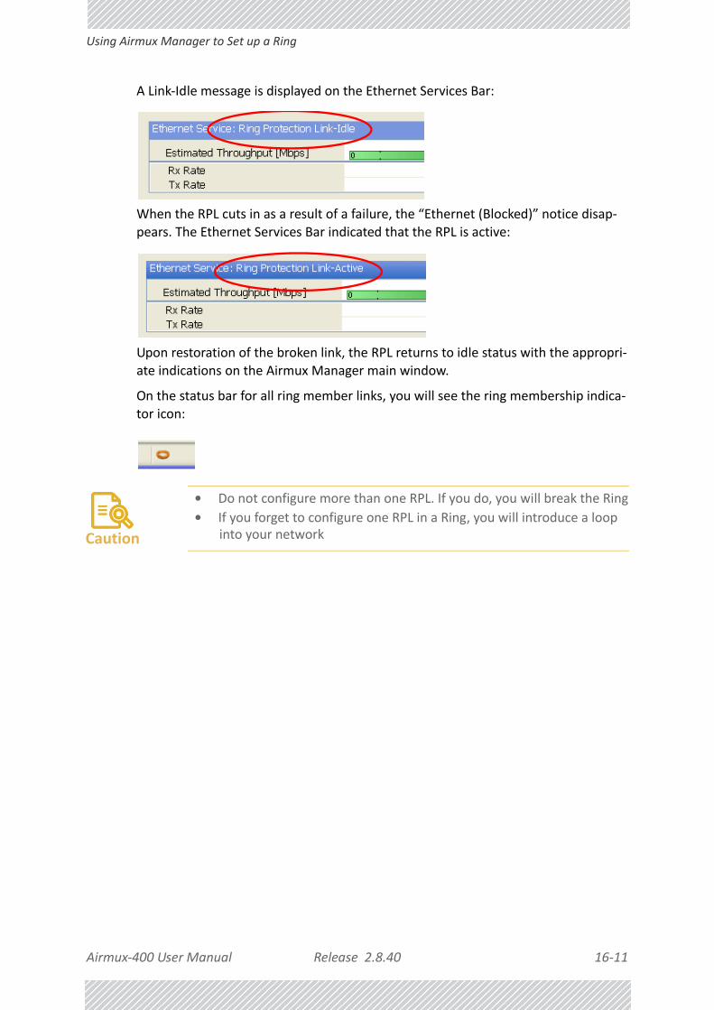
Airmux‐400 User Manual Release 2.8.40 16‐11
Using Airmux Manager to Set up a Ring
A Link‐Idle message is displayed on the Ethernet Services Bar:
When the RPL cuts in as a result of a failure, the “Ethernet (Blocked)” notice disap‐pears. The Ethernet Services Bar indicated that the RPL is active:
Upon restoration of the broken link, the RPL returns to idle status with the appropri‐ate indications on the Airmux Manager main window.
On the status bar for all ring member links, you will see the ring membership indica‐tor icon:
Caution
• Do not configure more than one RPL. If you do, you will break the Ring
• If you forget to configure one RPL in a Ring, you will introduce a loop into your network

Airmux‐400 User Manual Release 2.8.40 17‐1
Chapter 17:
VLAN Functionality with Airmux‐400
VLAN Tagging ‐ Overview
VLAN Terminology
Both the technical literature and the Airmux Manager use the terms VLAN ID and VID interchangeably to denote a VLAN identification number.
VLAN Background Information on the Web
The standards defining VLAN Tagging are IEEE_802.1Q and extensions.
For general background about VLAN see http://en.wikipedia.org/wiki/Virtual_LAN.
Background information about Double Tagging also known as QinQ may be found here: http://en.wikipedia.org/wiki/802.1QinQ.
VLAN Tagging
VLAN tagging enables multiple bridged networks to transparently share the same physical network link without leakage of information between networks:

Airmux‐400 User Manual Release 2.8.40 17‐2
QinQ (Double Tagging) for Service Providers
Figure 17‐1: Two network using the same link with tagging
IEEE 802.1Q is used as the encapsulation protocol to implement this mechanism over Ethernet networks.
QinQ (Double Tagging) for Service Providers
QinQ is useful for Service Providers, allowing them to use VLANs internally in their “transport network” while mixing Ethernet traffic from clients that are already VLAN‐tagged.
Figure 17‐2: Separating client data streams using double tagging
The outer tag (representing the Provider VLAN) comes first, followed by the inner tag. In QinQ the EtherType = 0x9100. VLAN tags may be stacked three or more deep.
When using this type of “Provider Tagging” you should keep the following in mind:
• Under Provider Tagging, the system double‐tags egress frames towards the Provider’s network. The system adds a tag with a VLAN ID and EtherType = 0x9100 to all frames, as configured by the service provider (Provider VLAN ID).
• The system always adds to each frame, tags with VLAN ID and EtherType = 0x9100. Therefore,
• For a frame without a tag – the system will add a tag with VLAN ID and EtherType = 0x9100 so the frame will have one tag
Airmux‐400 User Manual Release 2.8.40 17‐3
VLAN Untagging
• For a frame with a VLAN tag – the system will add a tag with VLAN ID and EtherType = 0x9100 so the frame will be double‐tagged
• For a frame with a VLAN tag and a provider tag – the system will add a tag with VLAN ID and EtherType = 0x9100 so the frame will be triple‐tagged and so on
VLAN Untagging
VLAN Untagging means the removal of a VLAN or a Provider tag.
Port Functionality
The VLAN functionality is supported by all LAN and SFP ports in the IDU.
Each port can be configured how to handle Ethernet frames at the ingress direction (where frames enter the IDU) and at the egress direction (where frame exit the IDU).
The configuration is independent at each port.

Airmux‐400 User Manual Release 2.8.40 17‐4
Port Functionality
Ingress Direction
Egress Direction
Table 17‐1: Port settings ‐ Ingress direction
Transparent The port ‘does nothing’ with regard to VLANs ‐ inbound frames are left untouched.
Tag
Frames entering the port without VLAN or QinQ tagging are tagged with VLAN ID and
Prioritya, which are preconfigured by the user. Frames which are already tagged at ingress are not modified.
a. Priority Code Point (PCP) which refers to the IEEE 802.1p priority. It indicates the frame priority level from 0 (lowest) to 7 (highest), which can be used to prioritize different classes of traffic (voice, video, data, etc).
Table 17‐2: Port settings ‐ Egress direction
Transparent The port ‘does nothing’ with regard to VLANs ‐ outbound frames are left untouched.
Untag all
All frames are untagged.

Airmux‐400 User Manual Release 2.8.40 17‐5
Port Functionality
Untag selected VIDs
Untags only frames tagged with one of the user defined VIDs. You can define up to eight VIDs per port. Other frames are not modified.
Filtered VLAN IDs at egress
This setting allows for mutual filtering of multiple ingress tags not relevant at the egress end:
Table 17‐2: Port settings ‐ Egress direction (Continued)

Airmux‐400 User Manual Release 2.8.40 17‐6
VLAN Availability
VLAN AvailabilityVLAN is available for links using either Airmux‐200 or Airmux‐400 radios. VLAN support requires the use of IDU‐Es or IDUs for Airmux‐200. For Airmux‐400 you may also use a PoE device and configure ODU VLAN. See Chapter 9.
Provider tagging
With Provider tagging, the system double‐tags egress frames towards the provider’s network. All frames are tagged QinQ with a VLAN ID, which is configured by the service provider (Provider VLAN ID).
With this setting, ingress frames which are not tagged with the configured Provider VLAN ID are blocked (filtered).
Note: Each port can be configured independently to a tagging mode. However, only a single Provider VLAN ID can be defined per IDU.
Provider tagging without filter
This setting functions like Provider tagging. However, all ingress frames are passed through.
Table 17‐2: Port settings ‐ Egress direction (Continued)

Airmux‐400 User Manual Release 2.8.40 17‐7
VLAN Configuration Using the Airmux Manager
VLAN Configuration Using the Airmux Manager
Management Traffic and Ethernet Service Separation
You can define a VLAN ID for management traffic separation. You should configure the system to prevent conflicts as detailed below.
When configured for the default operational mode, a “Provider port” will handle ingress traffic as follows:
• Filters frames that are not tagged with the Provider VLAN ID
• Removes the Provider double tag
Therefore, if a port is configured for management traffic separation by VLAN and as ‘Provider port’, then the received management frames must be double tagged as follows:
• The outer tag has to be the Provider’s tag (so the frame is not filtered)
• The internal tag has to be management VLAN ID
To avoid mix‐ups, best practice is to:
• Separate the management and data ports
• Define only a data port with Provider function
All IDU‐E and IDU models have two LAN ports so you can easily separate management and Ethernet service.
VLAN Tagging for Ethernet Service: Configuration
VLAN Configuration is carried out per site. It is up to you to ensure consistency between the link sites. The discussion below is based on Site A however, it also applies to Site B.
See also VLAN Tagging for Ethernet Service: Configuration.
To set up VLAN tagging for Ethernet service, enter Site Configuration for Site A, choose the Ethernet tab and click the VLAN Configuration... button (Figure 9‐14). The following window is displayed:
Tip
VLAN IDs are used by RAD products in three separate contexts: Management VLAN, Traffic VLAN and Ethernet Ring. It is recommended that you use different VLAN IDs for each context.
Disclaimer
If you are not a VLAN expert, please be aware that incorrect VLAN configuration may cause havoc on your network. The facilities described below are offered as a service to enable you to get best value from your Airmux‐400 links and are provided “as is”. Under no circumstances does RAD accept responsibility for network system or financial damages arising from incorrect use of these VLAN facilities.

Airmux‐400 User Manual Release 2.8.40 17‐8
VLAN Tagging for Ethernet Service: Configuration
Figure 17‐3: VLAN tag settings
Normal and Membership modes are different ways of entering VLAN settings and are described in detail in “VLAN Tagging for Ethernet Service: Configuration” on page 28. What follows below is a short summary.
The choices for Ingress Mode are ‐
Note
If you are using a IDU, the SFP row will not appear.

Airmux‐400 User Manual Release 2.8.40 17‐9
VLAN Tagging for Ethernet Service: Configuration
Figure 17‐4: VLAN: Ingress modes
The two choices correspond respectively to the two rows of Table 17‐1. Choosing Tag causes the VLAN ID and VLAN Priority fields to become available:
Figure 17‐5: VLAN: Ingress mode ‐ setting VLAN ID and Priority
The choices for Egress Mode are ‐
Figure 17‐6: VLAN: Egress modes
The five non‐transparent choices correspond respectively to the five rows of Table 17‐2 in the order, row 1, 2, 4, 5, 3.
The first two choices, Transparent and Untag all require no further action.
Untag selected VIDs causes the eight VLAN ID fields to become available:
Note
Throughout this chapter, all VLAN IDs must be between 2 and 4094, inclusive. All VLAN priorities must be between 0 and 6, inclusive. The values entered are range‐checked. If for example, you enter a VLAN ID of 4095, then 4094 will be reflected back.

Airmux‐400 User Manual Release 2.8.40 17‐10
VLAN Tagging for Ethernet Service: Configuration
Figure 17‐7: Untagging selected VIDs
You may nominate up to eight VIDs for untagging; beyond simple range checking, there is no other validation.
Both Provider tagging and Provider tagging without filter enable the Provider parameters fields:
Figure 17‐8: Provider parameters
There is of course only one Provider VLAN ID. It is most likely yours, as the Provider!
Filtered VLAN IDs enables you to filter and block only frames tagged with one of the user defined VIDs. You can define up to eight VIDs per port. Other frames are not modified and are forwarded transparently.
When you are finished, remember to click OK (Figure 17‐3) to save your entries.

Airmux‐400 User Manual Release 2.8.40 18‐1
Chapter 18:
Software Upgrade
What is the Software Upgrade Utility?The Airmux Manager provides a Software Upgrade Utility (SWU) to upgrade the software (firmware) of installed ODUs in a network. The update files may be located anywhere accessible by the operator.
The SWU provides for:
• Prior backup of the current files prior to upgrade
• Upgrade from a list
• Delayed upgrade
• Various ODU reset options
The default location of the software files is in the installation area, and can be used to restore factory defaults.
Upgrading an Installed Link To upgrade software for a link:
1. In the Airmux Manager main menu, click Tools | Software Upgrade ... The following detached window appears
Note
The following procedure is generic to all RAD point to point radio and GSU products.

Airmux‐400 User Manual Release 2.8.40 18‐2
Upgrading an Installed Link
Figure 18‐1: Software Upgrade Utility ‐ Main window
The default sites shown in the Software Upgrade list panel belong to the currently link. The list may be empty if you are running the Airmux Manager “offline”.
2. Click Add Site to add additional sites for upgrade.
Figure 18‐2: Add site options
Click Add Single Site for one site only:
Warning
What follows about adding sites manually or from a list file, assumes that all sites to be upgraded are of the same type ‐ either Airmux‐200 or Airmux‐400. but not both. This will not work with a mixed list.

Airmux‐400 User Manual Release 2.8.40 18‐3
Upgrading an Installed Link
Figure 18‐3: Adding a single site for upgrade
Enter the IP address of the site, the Community strings (Default: public and netman, respectively) and then click OK. The site will appear in the Software Upgrade list box.
The list can be cleared using the Clear All button.
As an alternative to adding sites one at a time, you can add sites from a prepared list using the Add from File option in Figure 18‐2. The list has the following format:
<IP address>,<Read‐Only community>,<Read‐Write community>
Here is the example we will use:
10.104.2.2,public,netman
10.104.2.4,public,netman
10.104.3.2,public,netman
10.104.3.4,public,netman
10.103.3.2,public,netman
10.103.3.4,public,netman
3. Having created an update list, click Clear all to remove the sites.
4. Use Add from File to load your list.
5. click Upgrade Package to chose the relevant files. The default files are located in the SWU subdirectory in the Airmux Manager installation area. The default filename for Airmux‐400 is SWU_2k.swu. You may have to find them elsewhere, depending on your system.
6. Here is our example:
Note
You can only include one type of ODU in a list. That is, you need separate list for Airmux‐400, Airmux‐5000, Airmux‐200 and GSU products.

Airmux‐400 User Manual Release 2.8.40 18‐4
Upgrading an Installed Link
7. You make limited changes to the list by right‐clicking any line:
Figure 18‐4: Software Upgrade site options
8. To back up your existing system, check Backup device software check‐box. Then click
the button for a standard file dialog. The default location is the My Documents directory on the managing computer or the last backup directory you used.
9. In addition to the previous step, you may opt to perform a delayed upgrade. Check the Delayed Upgrade box, and enter the date and time for the delayed upgrade.
10. The radio buttons on the right determines how your sites should be reset. Bear in mind that on the one hand, a reset involves a service interruption, but on the other hand, the software upgrade will not become effective until after the reset is carried out.
11. Returning to our two‐site example, click Start Upgrade to commence the process. For an immediate upgrade you will be able to observe the upgrade progress from the green progress bars:
Note
The backup here is the same as that in page 9‐42, and serves the same purpose. It provides a fallback if the upgrade proves problematic.
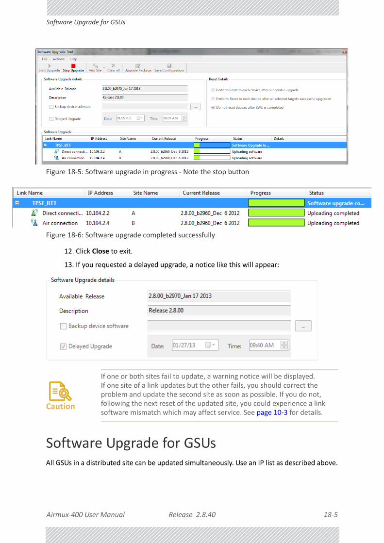
Airmux‐400 User Manual Release 2.8.40 18‐5
Software Upgrade for GSUs
Figure 18‐5: Software upgrade in progress ‐ Note the stop button
Figure 18‐6: Software upgrade completed successfully
12. Click Close to exit.
13. If you requested a delayed upgrade, a notice like this will appear:
Software Upgrade for GSUsAll GSUs in a distributed site can be updated simultaneously. Use an IP list as described above.
Caution
If one or both sites fail to update, a warning notice will be displayed.If one site of a link updates but the other fails, you should correct the problem and update the second site as soon as possible. If you do not, following the next reset of the updated site, you could experience a link software mismatch which may affect service. See page 10‐3 for details.

Airmux‐400 User Manual Release 2.8.40 19‐1
Chapter 19:
False Radar Mitigation Facilities
Who needs itIf you are using DFS frequency bands 5.3/5.4 GHz ETSI and 5.4/5.8GHz FCC you should use this facility.
DFS and False Radar Mitigation
About DFS
Under DFS frequency bands, it must be ensured that radio links do not interfere with certain radar systems in the 5 GHz band. If radar is detected, the radio link should move
automatically to a frequency that does not interfere with the detected radar.
What is False Radar Mitigation
False Radar Mitigation capability is an advanced method to reduce or eliminate false radar detection and DFS triggering (“False positives”).
False radar detection can be caused by other radios transmissions or external interference that can be interpreted as true radar.
This option is active only in DFS frequency bands, 5.3/5.4 GHz FCC for Site A only and 5.4/5.8GHz ETSI, bote sides of the link.
In what follows false radar means any source of radar‐like signals which are not real radar.
False Radar Mitigation has two components:
1. Reduction of false positive radar detection by reduction of the probability of detecting any kind of false radars, while allowing the system to detect real radar signals.

Airmux‐400 User Manual Release 2.8.40 19‐2
FCC/IC 5.4/5.3 GHz Links: Background Chapter 19
2. Elimination of detection of specific false radar types by blocking detection of false radars of a specific type. There are three types of radars:
• Fixed: False radars with fixed pulse width having fixed repetition frequency
• Variable: False radars with variable pulse width having variable repetition frequency
• Staggered: False radars with variable repetition frequency within a burst period (Applies to 5.4 GHz ETSI only)
FCC/IC 5.4/5.3 GHz Links: BackgroundThe FCC/IC regulation for 5.4/5.3 GHz allows unlicensed wireless data equipment, provided that it does not interrupt radar services. If radar activity is detected, the equipment must automatically change frequency channel. This feature is termed Dynamic Frequency Selection (DFS). According to the standard, a channel with active radar is prohibited from use for 30 minutes. Before using a channel for transmission, the radio equipment must probe it for radar signals for a period of 60 seconds.
RAD radio products support DFS as well as ACS.
An immediate consequence of the FCC/IC regulation for 5.4/5.3 GHz is that the method of link installation is slightly different.
First, ACS cannot be disabled:
Note
The FCC/IC regulations for 5.4 GHz band requires the frequency range 5600 – 5650 MHz to be banned from use. The FCC regulation for 5.4 GHz band requires that within 35 km radius from any (Terminal Doppler Weather Radars) TDWR location the frequency range 5570 – 5680 MHz shall be banned from use.Follow the instructions in the last section of this chapter.

Airmux‐400 User Manual Release 2.8.40 19‐3
FCC/IC 5.4/5.3 GHz Links: Background Chapter 19
Figure 19‐1: Channel Select dialog box ‐ ACS permanently enabled
Second: The Tx Power window in the Installation/Configuration wizard is preset in compliance with the relevant regulation, be it FCC/IC or ETSI. Tx Power per radio is set to ‐1 dBm so that an ODU with two radios has a system Tx Power as shown, of dBm, reflecting the
requirement to add 3 dBm to double radio Tx Power. The only items you can change are Antenna Gain and Cable Loss.
1– 3+

Airmux‐400 User Manual Release 2.8.40 19‐4
FCC/IC 5.4/5.3 GHz Links: Background Chapter 19
After completing Installation/Configuration, go to the Site:Location|Air Interface windows for each site in turn.
One side will show as Master and one as Slave. The choice is internal, purely for the purpose of establishing the link and under FCC/IC regulations, choosing the site to carry out radar detection.
The ODUs are either supplied from the factory ready for use at 5.4 GHz or 5.3 GHz FCC/IC or alternatively, they can be set up for these bands using the Airmux Manager.

Airmux‐400 User Manual Release 2.8.40 19‐5
Configuring False Radar Mitigation Chapter 19
Configuring False Radar MitigationThe configuration method for the managed ODU (ETSI and FCC/IC) is the same. ETSI regulations require that the over‐the‐air site also be separately configured in the same way.
We will demonstrate the method for Site A for a link using the 5.4 GHz FCC/IC band:
To configure False Radar Mitigation:
1. Log on to the Master ODU as Installer.
2. Enter the Configuration window and open the Advanced tab.
Figure 19‐2: False Radar Mitigation
3. The DFS Frequency Status Table at the bottom of Figure 19‐2 shows the time, type and frequency of the last radars detected. This table should be used to select the best option(s) to reduce or eliminate false radar detection without completely blocking out real radar detection.
4. Check the mitigation features to be used.
Airmux‐400 User Manual Release 2.8.40 19‐6
FCC/IC Requirements Chapter 19
5. When you are satisfied with your configuration parameters, click OK to save them and dismiss the Configuration window.
FCC/IC RequirementsThe FCC requires that devices installed within 35 km of any Terminal Doppler Weather Radars (TDWR) location should be registered in the voluntary WISPA sponsored database.For convenience, we supply guidelines about the way this is done in False Radar Mitigation Facilities.

Airmux‐400 User Manual Release 2.8.40 20‐1
Chapter 20:
FCC/IC DFS Considerations
FCC 5.4GHz Device RegistrationThe FCC requires that devices installed within 35 km of any TDWR location should be registered in the voluntary WISPA sponsored database.
The FCC has published a TDWR Location Information table that lists the exact location of all TDWR towers (see Table 20‐1 at the end of the chapter).
1. When installing a 5.4 GHz device define your exact location (latitude and longitude)
2. Use the TDWR Location Information table to determine if the distance between the device and any TDWR tower is less than 35 km.
3. If the distance is less than 35 km then register the device in the voluntary WISPA sponsored database (following section)
4. Disable the frequencies between 5570 – 5680 MHz from the available channels list.
5. The frequency range between 5.600 to 5.650 GHz is not included in the available channels list.
Registering the Device To register a device:
1. Enter the website http://www.spectrumbridge.com/udia/home.aspx and follow the instructions.
At your first entry into the site, you will be required to register as a user:

Airmux‐400 User Manual Release 2.8.40 20‐2
Registering the Device
2. Click the User Registration button to enter the registration page.

Airmux‐400 User Manual Release 2.8.40 20‐3
Registering the Device
3. Fill in the registration page and click Register.
4. To complete device registration enter the Register Device tab as shown:

Airmux‐400 User Manual Release 2.8.40 20‐4
Registering the Device
You are offered this:
5. Fill in the required information in the preceding web page and click the Register Device button.

Airmux‐400 User Manual Release 2.8.40 20‐5
TDWR Table
TDWR TableThe following table contains the latitude and longitude locations of Terminal Doppler Weather Radars (TDWR). Use this table to determine if the Master or Client device installed is within 35 km radius of a TDWR location. If one of the installed devices is within 35 km radius of any TDWR location then disable all frequencies between 5570 – 5680 MHz from the available channels list.
Table 20‐1: Latitude and longitude locations of TDWRs
STATE CITY LONGITUDE LATITUDE FREQUENCY TERRAIN ELEVATION (MSL) [ft]
ANTENNA HEIGHT ABOVE
TERRAIN [ft]
AZ PHOENIX W 112 09 46 N 33 25 14 5610 MHz 1024 64
CO DENVER W 104 31 35 N 39 43 39 5615 MHz 5643 64
FL FT LAUDERDALE W 080 20 39 N 26 08 36 5645 MHz 7 113
FL MIAMI W 080 29 28 N 25 45 27 5605 MHz 10 113
FL ORLANDO W 081 19 33 N 28 20 37 5640 MHz 72 97
FL TAMPA W 082 31 04 N 27 51 35 5620 MHz 14 80
FL WEST PALM BEACH W 080 16 23 N 26 41 17 5615 MHz 20 113
GA ATLANTA W 084 15 44 N 33 38 48 5615 MHz 962 113
IL MCCOOK W 087 51 31 N 41 47 50 5615 MHz 646 97
IL CRESTWOOD W 087 43 47 N 41 39 05 5645 MHz 663 113
IN INDIANAPOLIS W 086 26 08 N 39 38 14 5605 MHz 751 97
KS WICHITA W 097 26 13 N 37 30 26 5603 MHz 1270 80
KY COVINGTON CINCINNATI W 084 34 48 N 38 53 53 5610 MHz 942 97
KY LOUISVILLE W 085 36 38 N 38 02 45 5646 MHz 617 113
LA NEW ORLEANS W 090 24 11 N 30 01 18 5645 MHz 2 97
MA BOSTON W 070 56 01 N 42 09 30 5610 MHz 151 113
MD BRANDYWINE W 076 50 42 N 38 41 43 5635 MHz 233 113
MD BENFIELD W 076 37 48 N 39 05 23 5645 MHz 184 113
MD CLINTON W 076 57 43 N 38 45 32 5615 MHz 249 97
MI DETROIT W 083 30 54 N 42 06 40 5615 MHz 656 113
MN MINNEAPOLIS W 092 55 58 N 44 52 17 5610 MHz 1040 80
MO KANSAS CITY W 094 44 31 N 39 29 55 5605 MHz 1040 64
MO SAINT LOUIS W 090 29 21 N 38 48 20 5610 MHz 551 97
MS DESOTO COUNTY W 089 59 33 N 34 53 45 5610 MHz 371 113
NC CHARLOTTE W 080 53 06 N 35 20 14 5608 MHz 757 113
NC RALEIGH DURHAM W 078 41 50 N 36 00 07 5647 MHz 400 113
NJ WOODBRIDGE W 074 16 13 N 40 35 37 5620 MHz 19 113
NJ PENNSAUKEN W 075 04 12 N 39 56 57 5610 MHz 39 113
NV LAS VEGAS W 115 00 26 N 36 08 37 5645 MHz 1995 64

Airmux‐400 User Manual Release 2.8.40 20‐6
TDWR Table
NY FLOYD BENNETT FIELD W 073 52 49 N 40 35 20 5647 MHz 8 97
OH DAYTON W 084 07 23 N 40 01 19 5640 MHz 922 97
OH CLEVELAND W 082 00 28 N 41 17 23 5645 MHz 817 113
OH COLUMBUS W 082 42 55 N 40 00 20 5605 MHz 1037 113
OK AERO. CTR TDWR #1 W 097 37 31 N 35 24 19 5610 MHz 1285 80
OK AERO. CTR TDWR #2 W 097 37 43 N 35 23 34 5620 MHz 1293 97
OK TULSA W 095 49 34 N 36 04 14 5605 MHz 712 113
OK OKLAHOMA CITY W 097 30 36 N 35 16 34 5603 MHz 1195 64
PA HANOVER W 080 29 10 N 40 30 05 5615 MHz 1266 113
PR SAN JUAN W 066 10 46 N 18 28 26 5610 MHz 59 113
TN NASHVILLE W 086 39 42 N 35 58 47 5605 MHz 722 97
TX HOUSTON INTERCONTL W 095 34 01 N 30 03 54 5605 MHz 154 97
TX PEARLAND W 095 14 30 N 29 30 59 5645 MHz 36 80
TX DALLAS LOVE FIELD W 096 58 06 N 32 55 33 5608 MHz 541 80
TX LEWISVILLE DFW W 096 55 05 N 33 03 53 5640 MHz 554 31
UT SALT LAKE CITY W 111 55 47 N 40 58 02 5610 MHz 4219 80
VA LEESBURG W 077 31 46 N 39 05 02 5605 MHz 361 113
WI MILWAUKEE W 088 02 47 N 42 49 10 5603 MHz 820 113
Table 20‐1: Latitude and longitude locations of TDWRs (Continued)
STATE CITY LONGITUDE LATITUDE FREQUENCY TERRAIN ELEVATION (MSL) [ft]
ANTENNA HEIGHT ABOVE
TERRAIN [ft]

Airmux‐400 User Manual Release 2.8.40 21‐1
Chapter 21:
Quality of Service
AvailabilityThe Quality of Service (QoS) feature is available for links using Airmux‐400 100M radios. If you already have this model, you can access the feature by carrying out a Software Upgrade to the 2.8.40 release.
To use the facility you must be familiar with the use of VLAN (802.1p) or Diffserv.
QoS ‐ OverviewQoS is a technique for prioritization of network traffic packets during congestion.
Airmux‐400 100M links support two classification criteria, VLAN based or Diffserv based. You may choose which of them to use.
Table 21‐1: Default priorities an d allocation by VLAN ID and Diffserv
Quality queuePriority REDAT
%Diffserv VLAN
Real time 48‐63 6‐7 15
Near real time (responsive applications)
32‐47 4‐5 20
Controlled load 16‐31 2‐3 25
Best effort 0‐15 0‐1 40
Note
For REDAT (Remaining Ethernet Data ‐ Ethernet throughput) measurement. See page 10‐9. REDAT measures remaining Ethernet throughput after reduction of bandwidth used by TDM channels. Use the Link Budget Calculator to see how much remaining bandwidth is available for Ethernet.

Airmux‐400 User Manual Release 2.8.40 21‐2
Setting up QoS
Based upon the classification criterion chosen, received packets will be mapped into one of four quality groups: Real time, Near real time, Controlled load and Best effort.
You may partition the total link capacity across the four Quality queues. The default weights as percentages are shown in Table 21‐1.
Further, you may also limit the maximum information rate (MIR) for each queue per site.
Setting up QoSYou may set up QoS from either the Installation or Configuration wizards. Before doing so, set up for VLAN (Chapter 17) or Diffserv, depending on which you intend to use.
To define QoS settings for a link:
1. Using either the Installation or Configuration wizards, navigate to the Services win‐dow and choose the QoS tab.
Figure 21‐1: Services window with QoS selected
Although QoS is a link‐oriented feature, each site may have its own separate parame‐ters.
2. Click the Configure button for a site.

Airmux‐400 User Manual Release 2.8.40 21‐3
Setting up QoS
Figure 21‐2: Ethernet QoS Configuration ‐ Mode selection
3. Choose the required mode ‐ 802.1p (VLAN) or Diffserv.

Airmux‐400 User Manual Release 2.8.40 21‐4
Setting up QoS
Figure 21‐3: Top: VLAN allocation. Bottom: Diffserv allocation
4. The entry fields in both cases are self evident. Upon clicking OK,
• If you over‐book the Weight column, the last entered field will be reduced so that the total is 100%.
• No weight field may be left zero. If you do, you will not be able to proceed until it is set to something:
This reflects the implementation policy under which no checked queue may be completely starved. If you really do not want to use a queue under congestion, uncheck it.
• If you are under‐booked, you will receive this notice:
• In any event, you may automatically apply the same settings to both link sites:

Airmux‐400 User Manual Release 2.8.40 21‐5
Disabling QoS
5. Priorities: You are completely responsible for the completeness and consistency of your VLAN or Diffserv priorities.
6. Choose a Maximum Information Rate for each queue:
Figure 21‐4: MIR choice ‐ per queue
If you previously used Site | Ethernet | Maximum Information Rate (Chapter 9) to globally limit the site, then your choice in Figure 21‐4 will also be limited.l
7. Click OK on the exit dialog to accept the settings. If you did not use these settings for the opposite site, you should configure it now.
8. Complete the wizard in the usual way.
Disabling QoSIn the dialog of Figure 21‐2, choose the Disabled mode. The two sites may be enabled or disabled independently.

Airmux‐400 User Manual Release 2.8.40 22‐1
Chapter 22:
Capacity Upgrade
What is Capacity UpgradeA Airmux‐400 LC series ODU may have its capacity increased by application of an upgrade license key. The Capacity Upgrade process consists of three steps:
• Data Gathering ‐ preparation of a list of Airmux‐400 LC ODUs for upgrade by serial num‐ber
• Acquisition ‐ purchasing the Capacity Upgrade keys
• Application ‐ activating the Capacity Upgrade using the Airmux Manager
ApplicabilityYou may only upgrade a Airmux‐400 LC unit from 10 Mbps to 25 Mbps.
Data GatheringFor each relevant link, prepare a table similar to Table 22‐1:
Columns 1 is for your own convenience. Column 2 provides a precise connection between ODU identification and its serial number. Later you will copy/paste the Capacity Upgrade key into column 4 as a permanent convenient record.
To get the required link information:
1. Log on to the link.
Table 22‐1: Airmux‐400 LC ODU Capacity Upgrade Link List
ODU Name
(1)
ODU MAC Address
(2)
ODU Serial Number
(3)
Capacity Upgrade Key
(4)
Site A 00xxyy41b205 PFC580E500000123
Site B 00xxyy41b20e PFC580E500000124

Airmux‐400 User Manual Release 2.8.40 22‐2
Acquisition
2. Run the Get Diagnostics utility from the main button menu.
3. Load the generated Diagnostics Information.txt file into a plain text editor (like Notepad)
4. Search for the text string Inventory. You should see something like this:
Inventory
ODU
Product <Some product ID String>
HW Version 6
SW Version 2.8.00_b2970_Jan 17 2013
MAC Address <Your MAC address>
Serial Number PFC580E500000123
...
5. Copy the MAC Address to column 2 of the table (most likely for Site A).
6. Copy the string following the Serial Number to column 3 of the table.
7. Repeat the process to get the ODU serial number for Site B.
8. If you have several links, aggregate the Link Lists into one list (consider using a spreadsheet for the purpose).
AcquisitionSend the supplier of your equipment a Purchase Order for your Capacity Upgrade List (Use the aggregated version of Table 22‐1). Ensure that you include a current email address for receipt of the key list. Upon completion of the order, you will receive an email with an attached list consisting of serial numbers and a licence key per serial number. The licence keys are quite long and it is important that you receive them in electronic format for subsequent copy/pasting.
Application
Carrying out the Capacity Upgrade
Each ODU must be upgraded individually. The process is very unforgiving of errors, so you should carefully carry out the following steps. It is assumed that you have Table 22‐1 in a sortable format such as a spread sheet.

Airmux‐400 User Manual Release 2.8.40 22‐3
Carrying out the Capacity Upgrade
To prepare for application of the Capacity Upgrade keys:
1. Sort Table 22‐1 by serial number.
2. Make a working copy of the Capacity Upgrade keys attachment file. Keep the original in a safe place.
3. Load the working copy into a spread sheet program and ensure that it is sorted by serial number.
4. Ensure that your table and the sorted list match line for line ‐ if not check carefully for errors of missed units.
5. Copy/paste the key column into column 4 of your own table.
6. For each link, log on as Installer. (For isolated “spare” ODUs, you may log on using Local Connection.)
7. Open each Site in turn.
8. Open the Inventory page to check which line item in your table matches it.
9. Copy the Capacity Upgrade key to the clipboard
10. Open the the Operations page:

Airmux‐400 User Manual Release 2.8.40 22‐4
Completing the Capacity Upgrade
11. Paste the key to the License Key field. The Activate button is enabled.
12. Click the Activate button. You will receive a confirmatory message if the activation succeeded or an error message if not. In the latter case, you will need to be in contact with your equipment supplier to solve the problem.
Completing the Capacity Upgrade
To make the upgrade effective, each upgraded ODU must be reset.
Persistency of the Capacity Upgrade
The upgrade is persistent across an ODU reset. If however, you restore a capacity upgraded ODU to factory defaults, you will need to apply the Capacity Upgrade to it again. This further underlines the importance of saving the license keys attachment file in a safe place and maintaining a record like Table 22‐1.
Airmux‐400 User Manual Release 2.8.40 23‐1
Chapter 23:
Changing the Factory Default Band
Why this is NeededAll ODUs supplied by RAD come with preconfigured with a factory default product‐dependent band according to the ODU part number.
For ODUs supporting Multi‐band, it may be changed using the procedure in this chapter. The procedure is generic, applying to all ODUs with the Multi‐band feature.
Required EquipmentThe minimal equipment required to change an ODU default band is:
• Laptop computer (managing computer) satisfying the requirements of Table 5‐1.
• An installed copy of the Airmux Manager
• A PoE device
• An Ethernet LAN cable
• An IDU‐ODU cable
The procedure
Caution
• If for some reason the default band needs to be changed, it should be done before link installation.
• Use of an incorrect band may be in violation of local regulations.
Note
The following procedure is generic to all relevant RAD radio products. What you see on your running Airmux Manager may differ in some details from the screen captures used to illustrate this chapter.

Airmux‐400 User Manual Release 2.8.40 23‐2
The procedure
To change the factory default band:
1. Using the IDU‐ODU cable, connect the PoE device to the ODU, ensuring that the cable is plugged into the PoE port marked P‐LAN‐OUT.
2. Connect the Poe device to AC power.
3. Using a LAN cable, connect the LAN‐IN port of the PoE device to the Ethernet port of the managing computer. The ODU will commence beeping at about once per second, indicating correct operation.
4. Launch the Airmux Manager.
5. Log on as Installer.
Figure 23‐1: Becoming Installer
6. Enter the default password, wireless. After a few moments, the Airmux Manager
main window appears:

Airmux‐400 User Manual Release 2.8.40 23‐3
The procedure
Figure 23‐2: Opening Manager window prior to band change (default circled)
7. Click Tools | Change Band. The following window appears:
Figure 23‐3: Change Band dialog

Airmux‐400 User Manual Release 2.8.40 23‐4
The procedure
8. Click the band required:
Figure 23‐4: A different band selected
9. The Change Band warning is displayed. Click Yes to continue.
Figure 23‐5: Change Band confirmation
Note
The bands appearing in Figure 23‐3 are product dependent. To see which bands are available for your product, check your product Inventory (see Figure 9‐7) and then consult RAD Customer Support.

Airmux‐400 User Manual Release 2.8.40 23‐5
Changing Band for DFS
The change, which may take some time, is carried out. The result is reflected in the Airmux Manager main window:
Figure 23‐6: Main Window after band change ‐ new band circled
Changing Band for DFSChanging to a DFS band is similar to the foregoing procedure. The link in established in Active mode for the new band and set to Installation mode. See Chapter 19.
Special Products or Features: Entering a License KeyIf you go to the Operations window as Installer (Figure 23‐7), you will see a provision for entering a license key. Should you ever require such a key, the procedure is as follows:
Note
If you carry out this operation on a link, the band is effective on both sites and you are placed in installation mode.
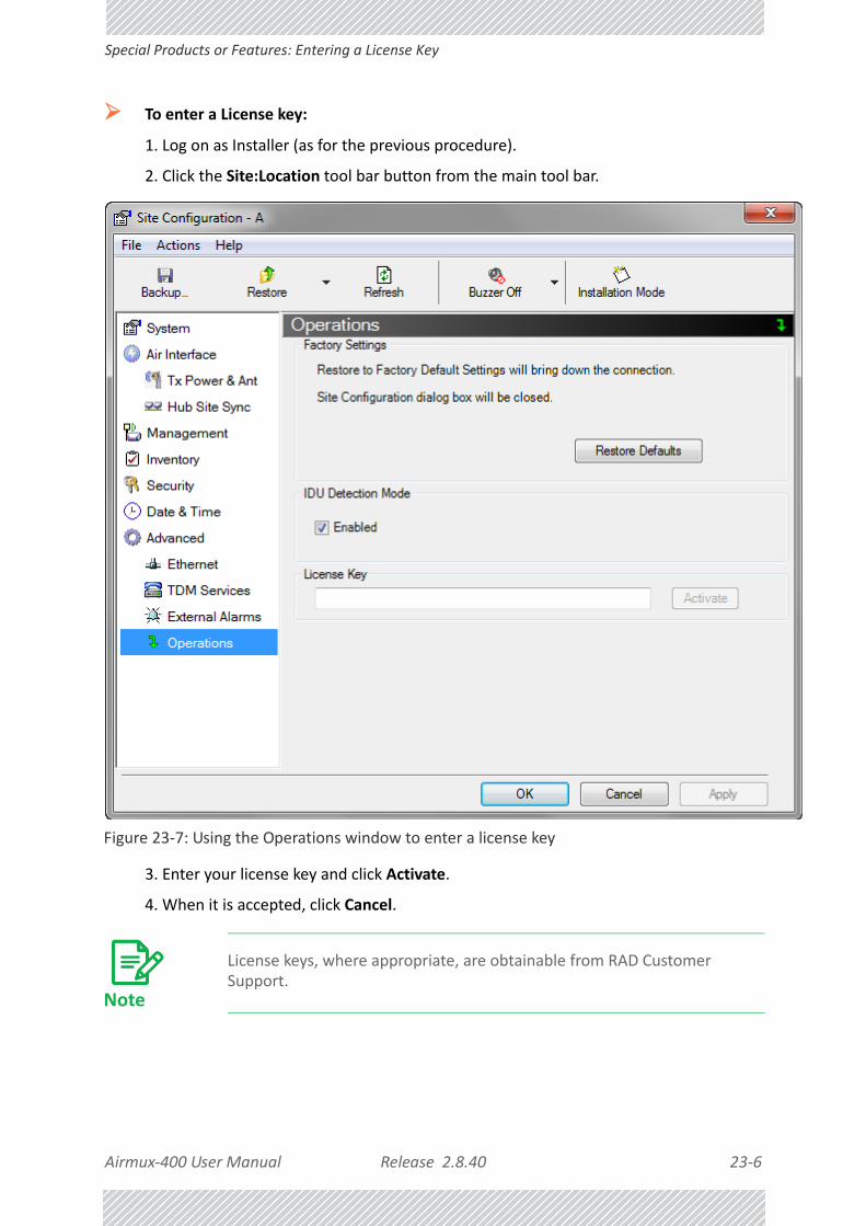
Airmux‐400 User Manual Release 2.8.40 23‐6
Special Products or Features: Entering a License Key
To enter a License key:
1. Log on as Installer (as for the previous procedure).
2. Click the Site:Location tool bar button from the main tool bar.
Figure 23‐7: Using the Operations window to enter a license key
3. Enter your license key and click Activate.
4. When it is accepted, click Cancel.
Note
License keys, where appropriate, are obtainable from RAD Customer Support.
Airmux‐400 User Manual Release 2.8.40 23‐7
Provisions for Licensed 3.X and 2.5 GHz Bands
Provisions for Licensed 3.X and 2.5 GHz Bands
Overview3.X Bands
The new Airmux‐400 100M and Airmux‐400 10M series add additional bands in the 3.X GHz range to those in Release 2.5.00. The new supported bands fall into two categories: The first category consists of those falling under the ubiquitous FCC, IC or ETSI regulation. The second category is referred to as RAD Universal bands. These bands are known to be regulated but the numerous combinations of regulation and location preclude specific support.
Release 2.8.40 supports the band 3.3‐3.8 GHz as follows:
• FCC part 90 subpart Z and IC RSS‐197 supporting 3.650‐3.700 GHz
• 3.650 ‐3.675 GHz in Restricted mode
• Hardware ready for the Unrestricted Mode band operating in all 50 MHz of the 3.650‐3.700 GHz band
• IC RSS‐192 supporting 3.475 – 3.650 GHz
• ETSI 3.4 ‐3.7 GHz split into three sub‐bands, 3.650‐3.675 GHz, 3.475‐3.650 GHz and 3.590‐3.710 GHz
• RAD Universal 3.300‐3.800 GHz.
Integrated and connectorized products are available. All of them are multiple band with the default band being 3.650‐3.675 GHz other than the ETSI 3.4 ‐ 3.7 GHz models.
The new products may be operated under 5, 10 and 20 MHz channel bandwidths and are broadly compatible with the full feature set of Airmux‐400.
To meet regulatory requirements, a somewhat different procedure is required to set up links using these bands.
2.5GHz Bands for BRS/EBS
The rationale for these bands and relevant details are described in Chapter 25. The installation method ids the same as for other licenced FCC bands as described below.
Terminology Recap• Universal bands refer to RAD Universal bands as described above
• 3.X or 3.X GHz refers to the frequency range 3.300 – 3.800GHz
• A 3.X ODU is an ODU pre configured to operate in the 3.X GHz licensed bands
• A 3.X Link in a Airmux‐400 link using a pair of 3.X ODUs
• High Resolution Bands ‐ Channel minimum step is 250 KHz. Applies to 3.475 ‐ 3.650 GHz IC RSS‐192, 3.4 ‐3.7 GHz ETSI and the 3.3 ‐ 3.8 GHz Universal band.
• Low Resolution Bands ‐ Channel minimum step is 1 MHz. Applies to FCC regulations in the 3.650‐3.675 GHz band.
• Inactive Mode ‐ An ODU is powered up, in communication with a managing computer but not transmitting. It is required where regulation does not permit the use of RAD’s

Airmux‐400 User Manual Release 2.8.40 23‐8
Regulatory Considerations for 3.650‐3.675 GHz FCC/IC part 90 sub part Z
default Installation Mode frequency and channel bandwidth. The ODU may transmit using the licensed or registered band, channel bandwidth and permitted Tx power.
• Regular Mode ‐ The usual default Installation Mode
Regulatory Considerations for 3.650‐3.675 GHz FCC/IC part 90 sub part ZRestricted Mode
The band is supported in accordance with 3.650‐3.675 FCC/IC part 90 subpart Z:
RAD Data Communications Ltd. conforms to FCC DA 07‐4605 (November 14, 2007) FCC‐certified with FCC‐ID: Q3KRW2030 and supporting the following equipment requirements:
“Restricted contention protocols can prevent interference only with other devices incorpo‐rating the same or similar protocols. Equipment using a restricted protocol can operate only on the lower 25 megahertz (3650‐3675 MHz)."
Transmission power options
Table 23‐1shows the extent of compliance by Airmux‐400 100M products to FCC/IC power limits, having regards to antenna type and transmission power options.
Table 23‐1: FCC/IC compliance by antenna and transmission power
Measured
Frequency Power
AntennaNominal CBW
Low Center Frequency Channel [MHz]
High Center Frequency Channel [MHz]
Max Conducted Tx Power per Pole [dBm]
Total Conducted Max Tx Power [dBm]
Max EIRP [dBm]
21dBi INT
5 MHz 3653 3672 11.14 14.14 35.14
10 MHz 3655 3670 14.46 17.46 38.46
20 MHz 3660 3665 17.36 20.36 41.36
21dBi EXT (22dBi‐1dB feeder)
5 MHz 3653 3672 11.14 14.14 35.14
10 MHz 3655 3670 14.46 17.46 38.46
20 MHz 3660 3665 17.36 20.36 41.36
24dBi EXT (25 ‐1dB feeder loss)
5 MHz 3653 3672 8.65 11.65 35.65
10 MHz 3655 3670 11.36 14.36 38.36
20 MHz 3660 3665 13.73 16.73 40.73

Airmux‐400 User Manual Release 2.8.40 23‐9
Regulatory Considerations for 3.650‐3.675 GHz FCC/IC part 90 sub part Z
Higher Transmission Power Options and Restrictions:
Table 23‐2 defines the maximum transmission power and EIRP limits for the specified frequency and channel bandwidths.
It specifies the power limits to be used by the operator when assigning center frequencies.
Table 23‐2: Higher Transmission Power Limits
Nominal
CBW
Low Center Frequency
Channel [MHz]
High Center Frequency
Channel [MHz]
Max Conducted Tx Power per Pole [dBm]
Total Conducted
Max Tx Power [dBm]
Max EIRP
[dBm]
5 MHz 3653 3672 15.60 18.60 35.60
10 MHz3655 3670 18.69 21.69 38.69
3656 3669 22.00 25.00 38.50
20 MHz3660 3665 21.18 24.18 41.18
3661 3664 22.60 25.60 39.10

Airmux‐400 User Manual Release 2.8.40 23‐10
Band Splitting for ETSI 3.4 ‐ 3.7GHz
Availability Summary for FCC/IC and Universal 3.X GHz
Band Splitting for ETSI 3.4 ‐ 3.7GHz
The ETSI 3.4 ‐ 3.7GHz band is split into three sub‐bands reflecting the different Max Tx Power allowed in each one. The details are shown in below:
Table 23‐3: Availability for FCC/IC and Universal 3.X GHz
Products seriesOccupied Band
GHzRegulation Mode
Channel Bandwidth MHz
Max Tx Power dBm
Frequency Step
KHz
Airmux‐400 100M
3.650‐3.675
FCC/IC Regular
5, 10, 20
25
1000
3.475‐3.650
IC
Inactive 2503.300‐3.800
Universal Unlimited
Airmux‐400 10M
3.650‐3.675
FCC/IC Regular
5
25
1000
3.475‐3.650
IC
Inactive 2503.300‐3.800
Universal Unlimited
Table 23‐4: Band split for ETSI 3.4‐3.7GHz
Products seriesOccupied Sub‐Band GHz
Center Frequency GHz
ModeChannel Bandwidth MHz
Max Tx Power dBm
Frequency Step KHz
Airmux‐400 100M
3.403‐3.490
3.413‐3.480
Inactive 5, 10, 20
16
2503.470‐3.610
3.480‐3.600
23(†)
3.590‐3.710
3.600‐3.700
25(‡)
Airmux‐400 10M
3.403‐3.490
3.413‐3.480
Inactive 5
16
2503.470‐3.610
3.480‐3.600
23(†)
3.590‐3.710
3.600‐3.700
25(‡)

Airmux‐400 User Manual Release 2.8.40 23‐11
Using he Airmux Manager to set up a 3.X or BRS Link
Using he Airmux Manager to set up a 3.X or BRS LinkInactive and Active Mode
Low Resolution Band 3.X ODUs may be installed and configured in the usual way.
What follows applies to High Resolution Band ODUs.
To ensure compliance with the relevant license, 3.X ODUs for IC, ETSI and Universal must be configured from an inactive mode where the ODU is powered up, in communication with a managing computer but not transmitting.
Setting up a link is a two stage procedure:
1. Activate the ODUs by individually by configuring the band, frequency and channel band‐width for the license
2. Complete link configuration in the usual way
To set up a 3.X or BRS ODU:
1. Log on to it as Installer (Operator sufficient for ETSI) and set the IP address as shown in Chapter 25.
2. Navigate to Site:Location|Air Interface and enter the Link ID for the ODU.
3. Click OK to dismiss the Site Configuration window. Answer Yes to the following popup message:
4. For ETSI models, skip to step 7 below. For all others, navigate to Tools|Change Band. The following window is displayed:
Note
(†) The 3.480 GHz frequency is overlapped, occurring in two different bands as shown. If you wish to use the 3.480 GHz frequency, you should set Max TX Power to 16 dBm.(‡) The 3.600 GHz frequency is overlapped, occurring in two different bands as shown. If you wish to use the 3.600 GHz frequency, you should set Max TX Power to 23 dBm.

Airmux‐400 User Manual Release 2.8.40 23‐12
Using he Airmux Manager to set up a 3.X or BRS Link
5. Choose the required band. For illustration, we will choose the IC band.
6. Click OK to continue and accept the notification message which appears:
After a few seconds, the ODU goes into inactive mode:

Airmux‐400 User Manual Release 2.8.40 23‐13
Using he Airmux Manager to set up a 3.X or BRS Link
7. Activate the ODU by navigating to Site:Location|Air Interface:
8. Choose a frequency from the drop down list:

Airmux‐400 User Manual Release 2.8.40 23‐14
Using he Airmux Manager to set up a 3.X or BRS Link
9. Enter Installation Mode and confirm your choice:
10. After a few moments of processing, you may click OK to dismiss the Site Configuration window. The ODU is now in normal Installation Mode:

Airmux‐400 User Manual Release 2.8.40 23‐15
Using he Airmux Manager to set up a 3.X or BRS Link
11. Repeat the above procedure for the second ODU in the link, ensuring that the Link ID is entered correctly and the same band is chosen.
12. From this point, you may install both ODUs in the field according to the procedures in this User Manual.

Airmux‐400 User Manual Release 2.8.40 24‐1
Chapter 24:
Quick Install Mode
Why this is NeededIt may be required to temporarily suspend service traffic over a link without losing the link connection. The simplest way to do this is to place the link in Installation mode but without changing any configured parameters. Quick Install Mode is a “one click” method for doing this. The method is completely generic, working identically for both Airmux‐200 and Airmux‐400 products.
Enabling Quick InstallBy default, this feature is disabled.
To enable Quick Install mode:
1. Log on to the Airmux Manager, navigate to Tools | Preferences and click the
Advanced tab:

Airmux‐400 User Manual Release 2.8.40 24‐2
Using Quick Install
Figure 24‐1: Preferences: Quick Install
2. Check the Enable Quick Install box and then OK. A new button is added to the main window toolbar:
Figure 24‐2: New Install Mode button for Quick Install mode
Quick Install mode may be disabled by unchecking the Enable Quick Install box.
Using Quick Install To suspend service traffic and enter Installation mode:
1. Click the Install mode button. You are offered a confirmatory message:

Airmux‐400 User Manual Release 2.8.40 24‐3
Using Quick Install
Figure 24‐3: Change to Installation Mode cautionary message
2. Click Yes to continue. The link goes into Installation mode. The main window looks the same as if you had entered Installation mode in the usual way through one of the Site windows with the exception of the toolbar:
Figure 24‐4: Service Mode button to resume link service traffic
3. When you are ready to resume normal service traffic, click the Service Mode button. The following cautionary message is displayed:
Figure 24‐5: Resumption of services cautionary message

Airmux‐400 User Manual Release 2.8.40 24‐4
Using Quick Install
4. Click Yes to continue. The link will resume normal services with your last set configuration parameters provides that you did not change link parameters in a a way leading to sync‐loss.
Note
It is also possible to change parameters in a way leading to service degradation. For example mis‐configuring the number of antennas or transmission parameters at one side of the link may allow service to resume, but in a degraded fashion.You may only enter Quick Install mode from a configured link. If you set both sites back to factory settings and chose Quick Install, you will not be able to continue:

USER MANUAL
Part 4: Field Installation Topics
Release 2.8.40

Airmux‐400 User Manual Release 2.8.40 25‐1
Chapter 25:
Pre‐loading an ODU with an IP Address
Why this is NeededAll ODUs supplied by RAD come preconfigured with an IP address of 10.0.0.120. For use in a network, the ODUs must be configured with suitable static IP addresses. The method for doing this under office conditions is set out in Chapter 6.
There are two situations under which ODUs may need to be pre‐loaded with an IP address prior to installation to a link:
• Changing an individual ODU in the field
• Preparing a large number of ODUs in a warehouse prior to deployment in the field, according to a network installation plan.
This chapter explains how do this.
Required EquipmentThe minimal equipment required to pre‐load an ODU with an IP address is:
• Laptop computer (managing computer) satisfying the requirements of Table 5‐1
• An installed copy of the Airmux Manager
• A PoE device
• An Ethernet LAN cable
• An IDU‐ODU cable
• If you have connectorized ODUs, two N‐type RF terminators
Caution
Do not carry out this procedure using a multi homed managing computer also connected to a network. It will flood the network with broadcast packets. Further, it will throw any other links on the network into Installation mode.

Airmux‐400 User Manual Release 2.8.40 25‐2
The procedure
The procedure
To Preolad an ODU with an IP address:
1. Using the IDU‐ODU cable, connect the PoE device to the ODU, ensuring that the cable is plugged into the PoE port marked P‐LAN‐OUT.
2. For connectorized ODUs, screw the RF terminators into the two antenna ports.
3. Connect the Poe device to AC power.
4. Using a LAN cable, connect the LAN‐IN port of the PoE device to the Ethernet port of the managing computer. The ODU will commence beeping at about once per second, indicating correct operation.
5. Launch the Airmux Manager.
6. At the log on window, choose Local Connection.
Figure 25‐1: Log on Window for Local Connection
7. Enter the default password, admin. After a few moments, the Airmux Manager main window appears:
Note
The following procedure is generic to all RAD radio products. What you see on your running Airmux Manager may differ in some details from the screen captures used to illustrate this chapter.
Warning
A powered up ODU emits RF radiation from the antenna port (or connected antenna). When working with a powered up connectorized ODU, always use RF terminators.For an ODU with an integrated antenna, ensure that the antenna is always directed away from other people.

Airmux‐400 User Manual Release 2.8.40 25‐3
The procedure
Figure 25‐2: Opening Airmux Manager window prior to installation
8. Click the un‐grayed Site:Location button. The following dialog window appears:

Airmux‐400 User Manual Release 2.8.40 25‐4
The procedure
Figure 25‐3: Configuration Dialog Box
9. Click the Management item in the left hand panel. The following window is presented:

Airmux‐400 User Manual Release 2.8.40 25‐5
The procedure
Figure 25‐4: Management Addresses ‐ Site Configuration dialog box
10. Enter the IP Address, Subnet Mask and Default Gateway as requested. For example, the ODU used here is to be configured as follows:

Airmux‐400 User Manual Release 2.8.40 25‐6
The procedure
Figure 25‐5: ODU with IP Addressing configured
11. CLick OK. You are asked to confirm the change:
Figure 25‐6: Confirmation of IP Address change
12. Click Yes to accept the change. After about half a minute the changes will be registered in the ODU. On the left hand panel of the main window, you will see the new IP configuration for the ODU.

Airmux‐400 User Manual Release 2.8.40 25‐7
The procedure
Figure 25‐7: Main Window after IP Address change
13. Click Cancel to leave the open Management dialog. You may now exit the Airmux Manager, or connect to another ODU. If you choose to connect to another ODU, after about a minute, the main window of the Airmux Manager will revert to that shown in Figure 25‐2 above. In any event, power down the changed ODU; your changes will take effect when you power it up again.
Note
Some additional things you may want to do now:• Go to Site Installation | Air Interface. You can enter a Link ID and
change the Installation Frequency and Channel Bandwidth.
• If you log on as Installer, you can change the default band (Chapter 23).
Note
Don’t forget to remove the RF terminators from a connectorized ODU after powering it down.

Airmux‐400 User Manual Release 2.8.40 25‐8
Tip: How to Recover a Forgotten ODU IP Address
Tip: How to Recover a Forgotten ODU IP AddressIf you have an ODU with lost or forgotten IP address, use the above procedure to log on to it using Local Connection. The IP address will appear in the left hand status area:
Figure 25‐8: Existing IP address displayed after log‐on with Local Connection

Airmux‐400 User Manual Release 2.8.40 26‐1
Chapter 26:
Link Budget Calculator
OverviewThe Link Budget Calculator is a utility for calculating the expected performance of the Airmux‐400 wireless link and the possible configurations for a specific link range.
The utility allows you to calculate the expected RSS of the link, and find the type of services and their effective throughput as a function of the link range and deployment conditions.
User Input
You are required to enter or choose the following parameters. Depending on the product, some of the parameters have a default value that cannot be changed.
• Band, which determines frequency and regulation
• Channel Bandwidth
• Tx Power (maximum Tx power per modulation is validated)
• Antenna Type (cannot be changed for ODU with integrated antenna)
• Antenna Gain per site (cannot be changed for integrated antenna)
• Cable Loss per site (cannot be changed for integrated antenna)
• Required Fade Margin
• Rate (and Adaptive check box)
• Service Type
• Required Range
Link Budget Calculator Internal Data
For each product (or Regulation and Band) the calculator stores the following data required for link budget calculations:
• Maximum Transmit power (per modulation)
• Receiver Sensitivity (per modulation) for Ethernet service and for TDM services at vari‐ous BER

Airmux‐400 User Manual Release 2.8.40 26‐2
Calculations
• Maximum linear input power (used to calculate minimum distance)
• Antenna gain and cable loss for ODU with integrated antenna
• Available Channel Bandwidths
Calculations
EIRP
Expected RSS and Fade Margin
where:
Site A is the transmitting site
Site B is the receiving site
PathLoss is calculated according to the free space model,
where Sensitivity is dependent on air‐rate.
Min and Max Range
MinRange is the shortest range for which per air‐rate.
MaxRange (with Adaptive checked) is the largest range for which
, at the highest air‐rate for which this relationship is true. In a
link with adaptive rate this will be the actual behavior.
MaxRange (for a given air‐rate) is the largest range for which
.
Service
The Ethernet and configured TDM trunks throughput is calculated according to internal product algorithms.
EIRP TxPower AntennaGainSiteA CableLossSiteA–+=
ExpectedRSS EIRP PathLoss AntennaGainSiteB CableLossSiteB–+–=
PathLoss 32.45 20 frequencyMHz 20 RequiredRangeKm 10
log+10
log+=
ExpectedFadeM inarg ExpectedRSS Sensitivity–=
ExpectedRSS MaxInputPower
ExpectedRSS Sensitivity
ExpectedRSS Sensitivity RequiredFadeM inarg+
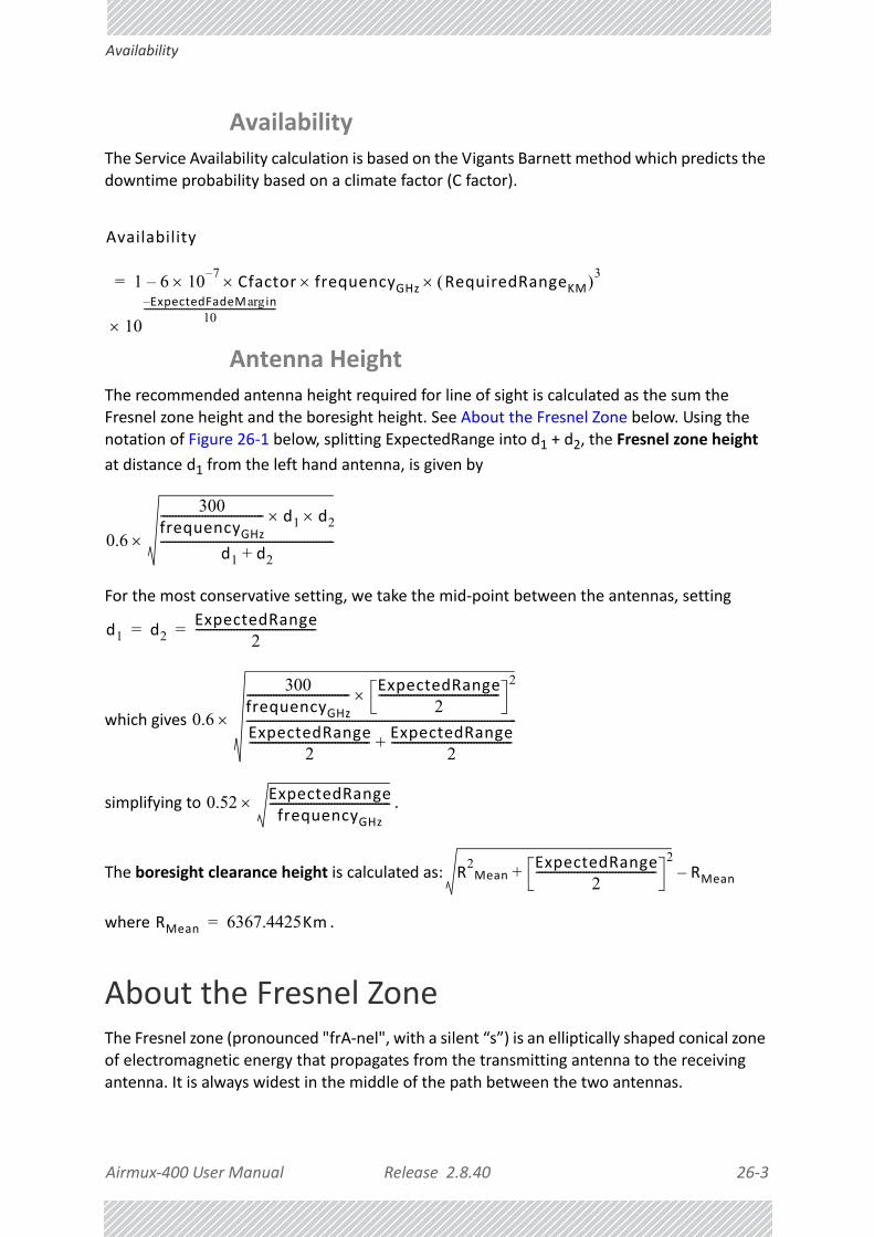
Airmux‐400 User Manual Release 2.8.40 26‐3
Availability
Availability
The Service Availability calculation is based on the Vigants Barnett method which predicts the downtime probability based on a climate factor (C factor).
Antenna Height
The recommended antenna height required for line of sight is calculated as the sum the Fresnel zone height and the boresight height. See About the Fresnel Zone below. Using the notation of Figure 26‐1 below, splitting ExpectedRange into d1 + d2, the Fresnel zone height
at distance d1 from the left hand antenna, is given by
For the most conservative setting, we take the mid‐point between the antennas, setting
which gives
simplifying to .
The boresight clearance height is calculated as:
where .
About the Fresnel ZoneThe Fresnel zone (pronounced "frA‐nel", with a silent “s”) is an elliptically shaped conical zone of electromagnetic energy that propagates from the transmitting antenna to the receiving antenna. It is always widest in the middle of the path between the two antennas.
Availability
1 6– 107– Cfactor frequencyGHz RequiredRangeKM 3
10
ExpectedFadeM inarg–10
------------------------------------------------------------
=
0.6
300frequencyGHz----------------------------------- d1 d2
d1 d2+-----------------------------------------------------------
d1 d2ExpectedRange
2-----------------------------------------= =
0.6
300frequencyGHz----------------------------------- ExpectedRange
2-----------------------------------------
2
ExpectedRange2
----------------------------------------- ExpectedRange2
-----------------------------------------+--------------------------------------------------------------------------------------------
0.52 ExpectedRangefrequencyGHz
-----------------------------------------
R2Mean
ExpectedRange2
-----------------------------------------2
+ RMean–
RMean 6367.4425Km=

Airmux‐400 User Manual Release 2.8.40 26‐4
About the Fresnel Zone
Figure 26‐1: Fresnel zone
Fresnel loss is the path loss occurring from multi‐path reflections from reflective surfaces such as water, and intervening obstacles such as buildings or mountain peaks within the Fresnel zone.
Radio links should be designed to accommodate obstructions and atmospheric conditions, weather conditions, large bodies of water, and other reflectors and absorbers of electromagnetic energy.
The Fresnel zone provides us with a way to calculate the amount of clearance that a wireless wave needs from an obstacle to ensure that the obstacle does not attenuate the signal.
There are infinitely many Fresnel zones located coaxially around the center of the direct wave. The outer boundary of the first Fresnel zone is defined as the combined path length of all paths, which are half wavelength (1/2 ) of the frequency transmitted longer than the direct path. If the total path distance is one wavelength (1 ) longer than the direct path, then the outer boundary is said to be two Fresnel zones. Odd number Fresnel zones reinforce the direct wave path signal; even number Fresnel zones cancel the direct wave path signal.
The amount of the Fresnel zone clearance is determined by the wavelength of the signal, the path length, and the distance to the obstacle. For reliability, point‐to‐point links are designed to have at least 60% of the first Fresnel zone clear to avoid significant attenuation.
The concept of the Fresnel zone is shown in Figure 26‐1 above. The top of the obstruction does not extend far into the Fresnel zone, leaving 60% of the Fresnel zone clear; therefore, the signal is not significantly attenuated.
For more about Fresnel zone, see http://en.wikipedia.org/wiki/Fresnel_zone.

Airmux‐400 User Manual Release 2.8.40 26‐5
Running the Link Budget Calculator
Running the Link Budget CalculatorThe Link Budget Calculator is supplied on the Airmux Manager CD. It may be run stand‐alone from the CD, from the Airmux Manager application or from the Windows Start Menu.
To run the Link Budget Calculator from the CD:
1. Insert the Airmux Manager CD into the drive on the managing computer. In the win‐dow which opens, click the Link Budget Calculator option.
2. If the CD autorun application does not start by itself, then point your browser to
Z:\RAD\Setup\DATA\Link Budget Calculator.htm
where Z should be replaced with your own CD drive name.
To run the Link Budget Calculator from the Windows Start Menu:
• Choose Start | Programs | Airmux Manager.
To run the Link Budget Calculator from the Airmux Manager:
• Choose Help | Link Budget Calculator from the main menu of the Airmux Manager as in the following figure:
Figure 26‐2: Accessing the Link Budget Calculator
To run the Link Budget Calculator from the Windows Start Menu:
• Click Start | Programs | Airmux Manager | Link Budget Calculator.
However invoked, your browser displays the following page:

Airmux‐400 User Manual Release 2.8.40 26‐6
Running the Link Budget Calculator
Figure 26‐3: Link Budget window
To use the Link Budget Calculator for Airmux‐400:
1. Choose a band from the drop‐down list.
Note
• Microsoft Internet Explorer users may see a warning message like this:
• Click the yellow bar and follow the instructions to allow blocked con‐tent.

Airmux‐400 User Manual Release 2.8.40 26‐7
Running the Link Budget Calculator
Figure 26‐4: Band selector
2. Chose the relevant Airmux‐400 series.
Figure 26‐5: Airmux‐400 series selector
3. Choose the Channel Bandwidth.

Airmux‐400 User Manual Release 2.8.40 26‐8
Running the Link Budget Calculator
Figure 26‐6: Airmux‐400 Channel Bandwidth selector
4. For a collocated link choose the RFP. Use the Help button to the right of the RFP selection box for help:
Figure 26‐7: RFP Selector
Figure 26‐8: RFP Selection Guide

Airmux‐400 User Manual Release 2.8.40 26‐9
Running the Link Budget Calculator
5. Enter the radio details. Note that Rate is chosen from a drop‐down list:
Figure 26‐9: Rate selector
The Rate shown, defines the air‐interface rate in Mbps. The system operates in TDD mode and has the overhead of the air‐interface protoco.l Thus, the Ethernet actual throughput is provided by the Ethernet Rate.
The Fade margin is the minimum required for line‐o‐ sight (LOS) conditions. For degraded link conditions, a larger Fade margin should be used.
The EIRP is given in dBm and Watts.
6. If the required range between the two link sites is known, you may enter it directly. Alternatively, you may enter the latitude and longitude of each site in the link, in which case the distance between them will be calculated and displayed.
Note
For collocation with:• Airmux‐400 products, you may only use RFP B or E.
• Airmux‐200 products, you may only use RFP E.
Note
If you choose Adaptive Rate, then the Rate list is unavailable as is the Climate factor list. Both of these quantities are calculated.
Note
For a given air‐rate, Ethernet throughput will decrease with increasing range due to propagation delay.

Airmux‐400 User Manual Release 2.8.40 26‐10
Running the Link Budget Calculator
Figure 26‐10: Calculation of distance from site coordinates
For example, enter:
Site A: 41.1°N lat 74.2°W Long
Site B: 40.8°N lat 74.0°W Long
7. Click Set. The distance and link budget is calculated.
8. Located to the right of the green Coordinates button is a drop‐down list of Climactic C Factor values. It is only available if you choose a non‐adaptive rate.

Airmux‐400 User Manual Release 2.8.40 26‐11
Running the Link Budget Calculator
Figure 26‐11: Climactic C Factors
The C factor does not affect the foregoing range calculation. It only affects the Avail‐ability calculation for a link with non‐adaptive rate.
For help about what these C factor values mean, click the ? button to the right of the list in Figure 26‐11.
Figure 26‐12: Climactic C Factor description
In Figure 26‐13 we display a map of the world showing C Factor contours:

Airmux‐400 User Manual Release 2.8.40 26‐12
Running the Link Budget Calculator
Figure 26‐13: World map showing C Factor contours
9. At any time, click Calculate to recalculate the required performance estimate.
Figure 26‐14: LBC ‐ Results section
The Expected Performance parameters are calculated and displayed:
• Expected RSS ‐ the expected RSS that the Airmux Manager shows when the Airmux‐400 ODUs are optimally aligned
Note
Placing the cursor in any other calculated field will also update the calculated results.

Airmux‐400 User Manual Release 2.8.40 26‐13
Running the Link Budget Calculator
• Services Type ‐ max number of T1 or E1 trunks if “Max Trunks” is selected
• Ethernet Rate ‐ maximum throughput available for the chosen parameter combination
• Antenna height for LOS – the minimum antenna height required for line‐of‐sight opera‐tion. It is the sum of the height required for boresight clearance due to the earth’s cur‐vature plus the height required to clear the Fresnel zone
If the expected performance is not suitable for your application, try different parameters and repeat the calculation.

Airmux‐400 User Manual Release 2.8.40 27‐1
Chapter 27:
Spectrum View
What is Spectrum View?The Airmux Manager Spectrum View utility is an RF survey tool designed to support the link installation prior to full link service activation. The tool provides comprehensive and clear spectral measurement information enabling easier, faster and better quality installations.
You can view real‐time spectrum information, save the spectral information and view retrieved spectral information from historic spectrum scans.
RAD’s spectrum measurement and estimation algorithms are designed to show accurate information accommodating variations in frequency, temperature and interference power and at the same time overcoming anomalies that tend to occur in high interference environments.
Running Spectrum ViewTo launch Spectrum View, go to the Airmux Manager main window menu and click Tools | Spectrum View.

Airmux‐400 User Manual Release 2.8.40 27‐2
Running Spectrum View
Figure 27‐1: Starting the analysis
To obtain a spectrum analysis:
1. Use the Timeout button to set the maximum time for the analysis. The default is 120 seconds.
2. Click Start Analysis. Since the anlysis will drop the link for its duration as set in 1, you are asked for confirmation:

Airmux‐400 User Manual Release 2.8.40 27‐3
Running Spectrum View
3. Click Yes. After a few moments, the first results for the managing site appear:
Figure 27‐2: Site A (managing site) done
The over‐the‐air site takes a little longer:

Airmux‐400 User Manual Release 2.8.40 27‐4
Running Spectrum View
Figure 27‐3: Site B (over‐ the‐air site) done, showing current channel
The analysis complete when the Start Analysis button reverts to green. It never runs for longer than the timeout value and you may stop it any time by clicking the red Stop Analysis button.
The results for the over‐the‐air site are displayed after the link is re‐established regardless of whether the analysis completes by itself or was stopped.
Note
If you are using a high resolution licensed band, the Stop Analysis button works differently: It will halt the analysis of the managed site (Site A), but it will not halt analysis of the over‐the‐air site (Site B).You should therefore ensure that the timeout value is not too high.

Airmux‐400 User Manual Release 2.8.40 27‐5
Understanding the Spectrum View Display
Understanding the Spectrum View Display
Information Displayed
Figure 27‐4 shows an annotated display taken from a live link.
Figure 27‐4: Airmux‐400 Spectrum View ‐ annotated display
From Figure 27‐4 above, you can see that the Spectrum View provides clear information including:
• Spectral measurement for each of the 4 receivers that make a Airmux‐400 link (two sites x two antennas per site)
• Spectral power measurements in 5MHz channel granularity
• Current, average and maximum power per channel
• Indication of
• channels free from radars
• channels with radars detected
• barred channels (for DFS bands)
• Indication of scanned and un‐scanned channels

Airmux‐400 User Manual Release 2.8.40 27‐6
Changing the Display
• Indication of channels selected for ACS
• Notation of the current operational channel of the Airmux‐400 link
• Time stamp of the last spectrum scan
• Further, it supports zoom capability, selective view of antennas and sites constituting the link and selectable detail level
Changing the Display
Moving the mouse anywhere over one the display areas changes it to a cross hair. The mouse may then be used to select an area for zooming, or to enable a right‐click System menu.
Selecting a rectangle and clicking will zoom the channels below it to full panel width:
Figure 27‐5: Selecting an area of interest to zoom with the right mouse button down

Airmux‐400 User Manual Release 2.8.40 27‐7
Changing the Display
Figure 27‐6: Requested section zoomed
The zoom can be reversed using the System menu obtained by right‐clicking any of the Spectrum View display panels. It also offers display variations such as maximum, average and current power per channel.
Figure 27‐7: Spectrum View System menu
Here are two examples:
If you click Show Max, each panel will show the peak values recorded during the analysis:

Airmux‐400 User Manual Release 2.8.40 27‐8
Restricting the Panels to be Displayed
Figure 27‐8: Effect of setting Show Max
If you click Show Average, each panel will show the average values recorded during the analysis:
Figure 27‐9: Effect of setting Show Average
Restricting the Panels to be Displayed
Click View for further viewing options:

Airmux‐400 User Manual Release 2.8.40 27‐9
Saving a Spectrum Analysis
Figure 27‐10: Further viewing options
If for example you want Antenna A only, the resulting display will look like this:
Figure 27‐11: Antenna A selected
Saving a Spectrum Analysis
Your analysis can be saved in a CSV (comma separated values) text file. Use the Files | Save menu item in the usual way.

Airmux‐400 User Manual Release 2.8.40 27‐10
Saving a Spectrum Analysis
The Spectrum View information is logged as part of the Diagnostics Information to improve link and system diagnostics and remote support. It can be retrieved from the Airmux Manager menu using Help |Get Diagnostic Information.The Spectrum View values in dBm, are noise‐floor (NF) relative.
Here is an extract from a saved Spectrum View, imported to MS Excel:
Table 27‐1: Spectrum View ‐ Site A
Spectrum View ‐ Site: A
Frequency Is ScannedLast Scan Timestamp
Last NF‐AntennaA
Last NF‐AntennaB
Average NF‐AntennaA
Average NF‐AntennaB
Max NF‐AntennaA
Max NF‐AntennaB
5735 TRUE 20/02/2013 12:57 ‐89 ‐91 ‐90 ‐92 ‐89 ‐91
5740 TRUE 20/02/2013 12:57 ‐89 ‐92 ‐91 ‐93 ‐89 ‐92
5745 TRUE 20/02/2013 12:57 ‐90 ‐92 ‐91 ‐93 ‐90 ‐92
5750 TRUE 20/02/2013 12:57 ‐90 ‐92 ‐91 ‐93 ‐90 ‐92
5755 TRUE 20/02/2013 12:57 ‐90 ‐92 ‐91 ‐93 ‐90 ‐92
5760 TRUE 20/02/2013 12:57 ‐90 ‐92 ‐91 ‐93 ‐90 ‐92
....
5815 TRUE 20/02/2013 12:57 ‐92 ‐94 ‐92 ‐95 ‐91 ‐94
5820 TRUE 20/02/2013 12:57 ‐92 ‐94 ‐93 ‐95 ‐92 ‐94
5825 TRUE 20/02/2013 12:57 ‐92 ‐94 ‐93 ‐95 ‐92 ‐94
5830 TRUE 20/02/2013 12:57 ‐92 ‐95 ‐93 ‐95 ‐92 ‐95
5835 TRUE 20/02/2013 12:57 ‐92 ‐95 ‐93 ‐95 ‐92 ‐95
5840 TRUE 20/02/2013 12:57 ‐92 ‐95 ‐93 ‐95 ‐92 ‐95
Rx Power ‐ AntennaA: ‐54
Rx Power ‐ AntennaB: ‐58

Airmux‐400 User Manual Release 2.8.40 27‐11
Management Integration
Management Integration
Spectrum view information is supported in RAD’s MIB and can be used by external Network Management applications.
Table 27‐2: Spectrum View ‐ Site B
Spectrum View ‐ Site: B
Frequency Is ScannedLast Scan Timestamp
Last NF‐AntennaA
Last NF‐AntennaB
Average NF‐AntennaA
Average NF‐AntennaB
Max NF‐AntennaA
Max NF‐AntennaB
5735 TRUE 20/02/2013 12:57 ‐90 ‐91 ‐91 ‐92 ‐90 ‐91
5740 TRUE 20/02/2013 12:57 ‐90 ‐91 ‐91 ‐92 ‐90 ‐91
5745 TRUE 20/02/2013 12:57 ‐90 ‐91 ‐91 ‐92 ‐90 ‐91
5750 TRUE 20/02/2013 12:57 ‐90 ‐92 ‐91 ‐93 ‐90 ‐92
5755 TRUE 20/02/2013 12:57 ‐90 ‐92 ‐91 ‐93 ‐90 ‐92
5760 TRUE 20/02/2013 12:57 ‐90 ‐92 ‐91 ‐93 ‐90 ‐92
5765 TRUE 20/02/2013 12:57 ‐91 ‐92 ‐92 ‐93 ‐91 ‐92
...
5810 TRUE 20/02/2013 12:57 ‐92 ‐94 ‐93 ‐94 ‐92 ‐93
5815 TRUE 20/02/2013 12:57 ‐92 ‐94 ‐93 ‐95 ‐92 ‐94
5820 TRUE 20/02/2013 12:57 ‐92 ‐94 ‐93 ‐95 ‐92 ‐94
5825 TRUE 20/02/2013 12:57 ‐92 ‐94 ‐93 ‐95 ‐92 ‐94
5830 TRUE 20/02/2013 12:57 ‐92 ‐94 ‐93 ‐95 ‐92 ‐94
5835 TRUE 20/02/2013 12:57 ‐92 ‐94 ‐93 ‐95 ‐92 ‐94
5840 TRUE 20/02/2013 12:57 ‐92 ‐95 ‐93 ‐95 ‐92 ‐95
Rx Power ‐ AntennaA: ‐55
Rx Power ‐ AntennaB: ‐58
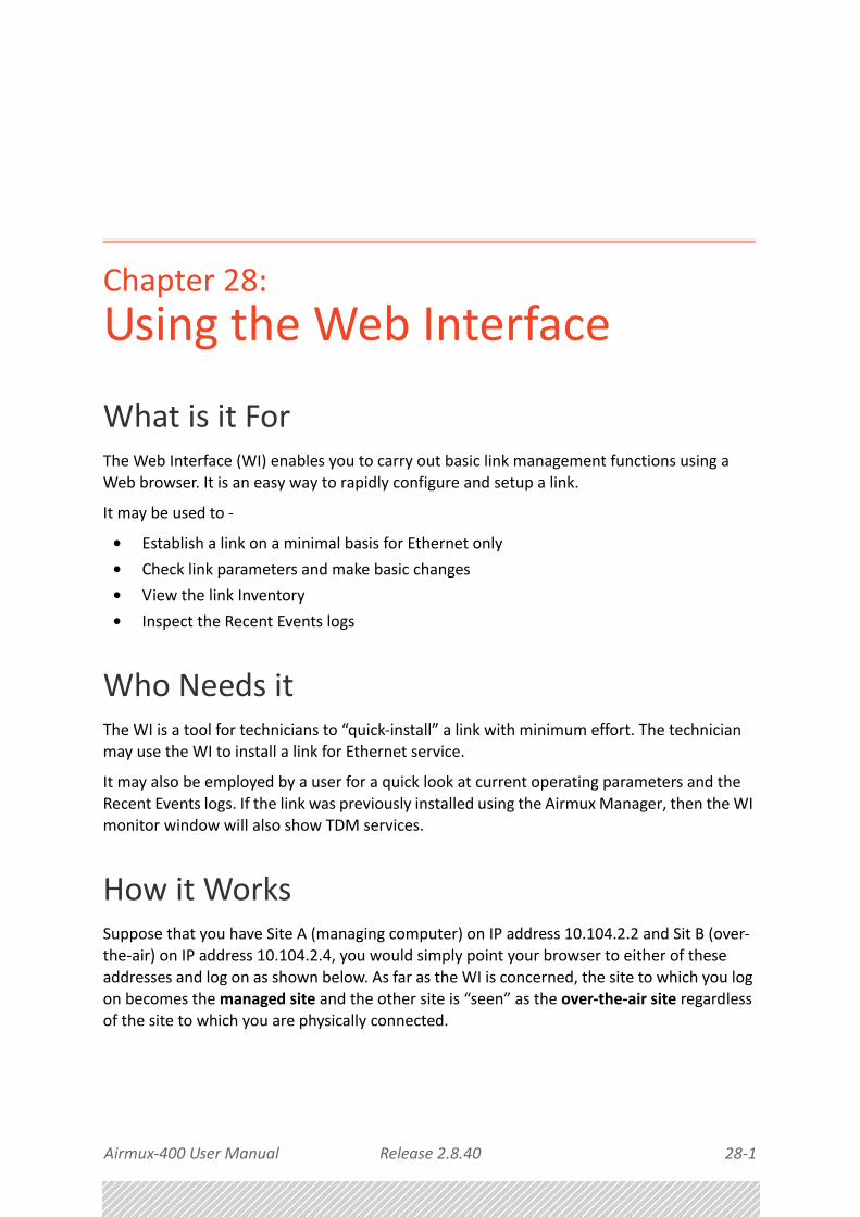
Airmux‐400 User Manual Release 2.8.40 28‐1
Chapter 28:
Using the Web Interface
What is it ForThe Web Interface (WI) enables you to carry out basic link management functions using a Web browser. It is an easy way to rapidly configure and setup a link.
It may be used to ‐
• Establish a link on a minimal basis for Ethernet only
• Check link parameters and make basic changes
• View the link Inventory
• Inspect the Recent Events logs
Who Needs itThe WI is a tool for technicians to “quick‐install” a link with minimum effort. The technician
may use the WI to install a link for Ethernet service.
It may also be employed by a user for a quick look at current operating parameters and the Recent Events logs. If the link was previously installed using the Airmux Manager, then the WI monitor window will also show TDM services.
How it WorksSuppose that you have Site A (managing computer) on IP address 10.104.2.2 and Sit B (over‐the‐air) on IP address 10.104.2.4, you would simply point your browser to either of these addresses and log on as shown below. As far as the WI is concerned, the site to which you log on becomes the managed site and the other site is “seen” as the over‐the‐air site regardless of the site to which you are physically connected.

Airmux‐400 User Manual Release 2.8.40 28‐2
What it Provides
What it ProvidesThe WI provides an Installation/Configuration wizard as well as site configuration dialogs.
Prerequisites
Hardware
You need a regular LAN connection between a managing computer and one of the link ODUs. The WI is available for Airmux‐400 100M and Airmux‐400 L ODUs at release level 2.6.00 or later.
Software
Your computer should have at least version 6 of MS Internet Explorer. The Web interface also works with other browsers such as Mozilla Firefox version 3 and later.
Technical Background
You should be familiar with the concepts underlying the Airmux Manager and preferably with the Manager itself.
Special Considerations Working with the WI
Advanced Configurations
For setup configurations using features such as HSS, TDM service, VLAN and QoS, you will need to use the Airmux Manager.
More on how WI WorksUser Interface Considerations
Most standard Windows based Wizards have Next, Back and Cancel buttons on each Wizard window. Typically a Wizard does not commit your input until you complete it. You can always “back out” from the Wizard, abandoning your input by using the standard Cancel button. The Web Interface Wizard works differently:

Airmux‐400 User Manual Release 2.8.40 28‐3
Some Working Tips
Figure 28‐1: Web interface ‐ A typical Wizard window
Suppose that the Wizard window illustrated in Figure 28‐1 is your current window. Then ‐
• It you use Save & Next, it first commits the data on the current window before moving to the next one.
• If you return to the previous window with the Previous button, it does not commit the current window
• If you exit the Wizard using the Monitor button, the current window is not committed, but prior commits are not undone.
Major implications of these differences will be pointed in Caution messages below.
Operational Effects
Several WI functions cause temporary sync‐loss. Typically, changing the number of antennas falls into this category. These cases will be pointed out in Warning messages.
Some Working TipsYou can:
» Log on to a ODU on the default IP address of 10.0.0.120/8, set the Link ID and IP address instead of using the Airmux Manager as in Chapter 25. Unlike the latter method, you need to reset the ODU to see the change in the Web Interface.
» Change the operating Band of an ODU instead of using the Airmux Manager as in Chapter 23. If you do, always change the band of the physical over‐the‐air site first, so that you do not lock yourself out of the link.
» Install/configure a link to work with Ethernet only.
» Look at Recent Events for either site
» Drop back to Installation mode without losing installed TDM services
You cannot:» Change default Tx power

Airmux‐400 User Manual Release 2.8.40 28‐4
Scope of this Chapter
» Configure MIMO/Diversity
» Manage TDM services
» Manage HSS
» Manage other features such as GSU, MHS, Ethernet Ring, VLAN, QoS
» Perform Software upgrade
Be very careful:» Using this tool if your link is providing customer service which may not be interrupted
with sync‐losses
Never:» Leave your browser unattended while in Installation mode ‐ and then forget to return!
Scope of this ChapterThe remainder of this chapter is divided into three sections: Logging on, Link Configuration and Installation and Site Configuration.
Logging onTo use the Web interface, simply point your browser to the IP address of the site to which you are connected.
Figure 28‐2: Web interface ‐ Log on
The User Name and Password are respectively, admin and netman as used for Telnet access. You must click the Log In button to effect entry to the WI.

Airmux‐400 User Manual Release 2.8.40 28‐5
The Main Window
The Main Window
Figure 28‐3: Web interface ‐ Main window
The main window shows a subset of the link operating parameters. The A and B buttons open Site Configuration for Site A and Site B respectively. The Configure button opens a Configuration Wizard.
Getting in to Installation Mode
Under certain circumstance you may be better off working in Installation mode, particularly if you want to change the Operating Band or Operating Channel.To this end, click the managed site button (A here), Air Interface and then Installation Mode. Figure 28‐3 changes:
Figure 28‐4: Web interface ‐ Main window, Installation Mode
Note
For the purposes of illustration, we are using a link with 16 E1 ports configured. The reason for doing this will become apparent below.

Airmux‐400 User Manual Release 2.8.40 28‐6
Using the Configuration Wizard
Using the Configuration Wizard To configure a link using the Configure Wizard:
1. Start the Wizard by clicking the Configure button. The System page is displayed:
Figure 28‐5: Web interface ‐ Configuration System window
The similarity to the corresponding Airmux Manager Configuration Wizard panel is quite intentional. The fields have the expected meanings. The Refresh button will revert your changes to the previous values provide you have not used the Save & Next button.
2. The second Wizard panel configures the Operating Channel settings:
Caution
• Under Install Mode, these four fields may take a default values which you should change
• Commits are carried out as soon as you click Save & Next
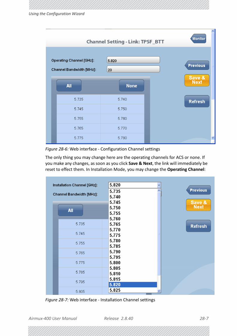
Airmux‐400 User Manual Release 2.8.40 28‐7
Using the Configuration Wizard
Figure 28‐6: Web interface ‐ Configuration Channel settings
The only thing you may change here are the operating channels for ACS or none. If you make any changes, as soon as you click Save & Next, the link will immediately be reset to effect them. In Installation Mode, you may change the Operating Channel:
Figure 28‐7: Web interface ‐ Installation Channel settings

Airmux‐400 User Manual Release 2.8.40 28‐8
Using the Configuration Wizard
You may select additional channels for ACS or none by using the All or None buttons or alternatively, manually selecting channels by clicking them. Suppose that you choose these:
You will receive the following advisory notice:
3. The next wizard panel displays antenna types and Tx power:
Warning
Changing Operating Channels (for ACS) in either Configuration or Installation mode is applied immediately upon clicking Save and Next, and is accompanied by a short sync‐loss.

Airmux‐400 User Manual Release 2.8.40 28‐9
Using the Configuration Wizard
Figure 28‐8: Web interface ‐ Antenna settings
The only fields that you can change here are the antenna types. (Required Tx power may become available for modification in a future release.)
4. Suppose that you change the Site A antenna type to single:
You are asked for confirmation. Click OK:

Airmux‐400 User Manual Release 2.8.40 28‐10
Using the Configuration Wizard
5. Accept the next browser‐initiated confirmation:
The WI displays the following advisory message:
The next page ‐ Change Bandwidth, is displayed:
Figure 28‐9: Web interface ‐ Channel Bandwidth settings
6. For this example, leave the Bandwidth as is, and click Save & Next. Here is the result:
Warning
This operation leaves the link in Installation mode, where it remains until completion of the Wizard. The link then reverts to normal Active mode.

Airmux‐400 User Manual Release 2.8.40 28‐11
Using the Configuration Wizard
The most obvious indication that something has changed is the reduced number of available E1 channels (from 16 to 10) reflecting the drop in link capacity due to the antenna change. Less obvious is the Estimated ethernet Throughput, which has dropped from 17.5Mbps to 4.9Mbps on both sides of the link.
7. For the purpose of illustration we revert the link to dual antennas at bot sites and run through the Configure Wizard again. Get to the last panel, Change Bandwidth:
8. Change the Channel Bandwidth to 40Mhz. (It is supported by the link regulation in use.) Click Save & Next. The following advisory message is displayed:
After a few moments you are shown the main window:

Airmux‐400 User Manual Release 2.8.40 28‐12
Using the Configuration Wizard
Here then, is the final result:
Warning
Changing the Channel bandwidth drops the link into Installation mode, and it remains so after completing the Wizard.
Warning
You are in Installation mode! The link is up, but services are stopped. You must “walk” through the Install Wizard again, changing nothing. This will revert the link to Active mode with all services enabled. If you do not do this, you will have to re‐configure your services in the usual way, using the Airmux Manager.
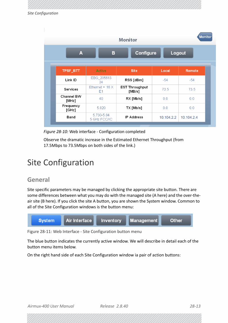
Airmux‐400 User Manual Release 2.8.40 28‐13
Site Configuration
Figure 28‐10: Web interface ‐ Configuration completed
Observe the dramatic increase in the Estimated Ethernet Throughput (from 17.5Mbps to 73.5Mbps on both sides of the link.)
Site Configuration
General
Site specific parameters may be managed by clicking the appropriate site button. There are some differences between what you may do with the managed site (A here) and the over‐the‐
air site (B here). If you click the site A button, you are shown the System window. Common to all of the Site Configuration windows is the button menu:
Figure 28‐11: Web Interface ‐ Site Configuration button menu
The blue button indicates the currently active window. We will describe in detail each of the button menu items below.
On the right hand side of each Site Configuration window ia pair of action buttons:

Airmux‐400 User Manual Release 2.8.40 28‐14
System
Figure 28‐12: Web Interface ‐ Site Configuration action buttons
Save commits the current window. If you made changes but prefer to revert them to their original values, use the Refresh button.
System
Figure 28‐13: Web Interface ‐ Site Configuration System window
In this window, the Name, Contact and Location fields may be changed. Location is the site name (A). if you click Recent Events, the site A ODU Recent Events list is displayed:
Note
Refresh will revert to the last saved values or the original values if Save was not used. If you changed anything outside the WI with the Airmux Manager or any other network management tool, Refresh with update the WI.

Airmux‐400 User Manual Release 2.8.40 28‐15
System
Figure 28‐14: Web Interface ‐ Site Configuration Recent Events list
From here, you are returned to the WI main window (Monitor button).
If you open the Site Configuration window for site B (over‐the‐air), the Recent Events button is missing. To sse the Recent Events list for site B, you must log on to site B. You may do it by simply opening up another browser window or tab, concurrently with the site A tab.

Airmux‐400 User Manual Release 2.8.40 28‐16
Air Interface
Air Interface
Figure 28‐15: Web Interface ‐ Site Configuration Air Interface
The only editable field is the Buzzer state. The three buttons at the bottom are fully functional and should be used with care:
Installation Mode
This button places the link in Installation mode: Services are stopped.
Change Band
Change Band should be used with care. It is not available on the Air Interface window of the
over‐the‐air site (B). Again, you must create a separate session to use it on B.
To change Band for a Link:
1. Log On to the over‐the‐air site (B).

Airmux‐400 User Manual Release 2.8.40 28‐17
Air Interface
2. Chose the required band and save. You will lose contact with site B.
3. Repeat the process for site A. The link will re‐sync using the newly chosen band in Installation mode.
4. Re‐install the link.
Antenna & Tx Power
The Antenna and Tx Power window is for information only.
Figure 28‐16: Web Interface ‐ Site Configuration, Antenna details

Airmux‐400 User Manual Release 2.8.40 28‐18
Inventory
Inventory
The Inventory display is for information only, and has separate panels for the ODU and IDU:
Figure 28‐17: Web Interface ‐ Site Configuration, Inventory
Management
The Management window may be used to change the site IP Address, Subnet Mask and Default Gateway. In addition, you may define Trap Destinations.
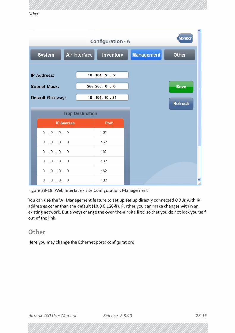
Airmux‐400 User Manual Release 2.8.40 28‐19
Other
Figure 28‐18: Web Interface ‐ Site Configuration, Management
You can use the WI Management feature to set up set up directly connected ODUs with IP addresses other than the default (10.0.0.120/8). Further you can make changes within an existing network. But always change the over‐the‐air site first, so that you do not lock yourself out of the link.
Other
Here you may change the Ethernet ports configuration:

Airmux‐400 User Manual Release 2.8.40 28‐20
Other
Figure 28‐19: Web Interface ‐ Site Configuration, Ethernet ports configuration
You may change the mode for LAN 1 and LAN 2 only:
Figure 28‐20: Web Interface ‐ Site Config., Ethernet ports configuration, detail
Here is the corresponding situation for a link using GbE support:
Figure 28‐21: Web Interface ‐ Site Config., Ethernet ports configuration, GbE

Airmux‐400 User Manual Release 2.8.40 28‐21
Other
Notice that under GbE support, the ODU port mode is also configurable. Here is the Monitor panel for the GbE link:
Figure 28‐22: Monitor panel for Airmux‐400 100M link: Ethernet only, GbE support
Note the 200 Mbps aggregate throughput in both directions.

USER MANUAL
Part 5: Product Reference
Release 2.8.40

Airmux‐400 User Manual Release 2.8.40 A‐1
Appendix A:
Technical Specifications
Scope of these SpecificationsThis appendix contains technical specifications for the major link components appearing in this User Manual. They are correct at the date of publication, but are intended for general background only. The latest authoritative and most up to date technical specifications are available as Data Sheets obtainable from RAD Customer Service.
In any event, RAD reserves the right to change these specifications without notice.
ODU
Capacity (Net Aggregate or FD)
Configuration
SeriesMax
Throughput (Mbps)
Services Notes
Airmux‐400 LC10
Ethernet Only Separate groups, not selectable
25 4 E1/T1
Airmux‐400 L 50 8 E1/T1 SFF embedded antenna
Airmux‐400 100M 200 16 E1/T1
Airmux‐400 10M 20 3 E1 or 4 T1
Architecture
ODU: Outdoor Unit with Integrated Antenna or Connectorized for External Antenna
IDU: Indoor Unit for service interfaces or PoE device for Ethernet only
ODU to IDU/PoE Interface Outdoor CAT 5e cable; Maximum cable length: 100 m

Airmux‐400 User Manual Release 2.8.40 A‐2
ODU
Radio
Range Up to 120 km / 75 miles
Radio Modulation 2x2 MIMO‐OFDM (BPSK/QPSK/16QAM/64QAM)
Adaptive Modulation & Coding Supported
Automatic Channel Selection Supported
Diversity Supported
Spectrum View Supported
Duplex Technology TDD
Error Correction FEC k = 1/2, 2/3, 3/4, 5/6
Max Tx Power 25 dBm
Duplex Technology TDD
Ethernet Connection 10/100/1000BaseT
Supported Indoor UnitsIDU‐E, IDU, Airmux‐IDUH/2ETH, PoE devices (specified below)
QoS
Packet classification to 4 queues according to 802.1p and Diffserv, Dynamic scheduling according to air interface changes
VLAN Supported
Ethernet Ring Protection Supported including Ethernet 1+1
Hub Site Synchronization (HSS) Supported
Monitored Hot Standby (MHS) 1+1 with Airmux‐400 link or Airmux‐200 link
Rate – Dual Antenna [Mbps] @ 20MHz CBW
13 26 39 52 78 104 117 130
Rate – Single Antenna [Mbps] @ 20MHz CBW
6.5 13 19.5 26 39 52 58.5 65
Modulation BPSK QPSK 16QAM 64QAM
FEC [k=] 1/2 1/2 3/4 1/2 3/4 2/3 3/4 5/6
Max Tx Power [dBm] for 4.8 – 6 GHz
25 24 21 19 18
Max Tx Power [dBm] for 4.9 – 5.1 GHz under Japanese Regulations
23 23 23 23 21 19 18 18
Max Tx Power [dBm] for 2.4 GHz 26 25 24 24 21 20
Max Tx Power [dBm] for 2.5 GHz (BRS)
See Table 25‐3
Sensitivity (dBm) @BER <10e‐11@ 20MHz CBW
‐88 ‐86 ‐83 ‐81 ‐77 ‐72 ‐70 ‐67
Encryption AES 128

Airmux‐400 User Manual Release 2.8.40 A‐3
ODU
Supported Bands
The bands shown below are supported by RAD products. Both the bands and related Channel Bandwidths are product dependent.
Band
(GHz)Regulation
Occupied Frequency Range
(GHz)
CBW (MHz)
DFS? Compliance (Notes)
2.3 Universal
2.3045‐2.4745 5
No N/A (Supported CBW product dependent)2.302‐2.477 10
2.297‐2.482 20
2.287‐2.492 40
2.4 FCC/IC
2.4095‐2.4645 5
NoFCC 47CFR, Part 15, Subpart C and IC RSS‐210
2.407‐2.467 10
2.402‐2.472 20
2.392‐2.482 40
3.4 ETSI
3.4105‐3.4825 5
NoETSI EN 302 326‐2 (Nominally, 3.5 GHz ETSI)
3.408‐3.485 10
3.403‐3.490 20
3.5 ETSI
3.4775‐3.6025 5
3.475‐3.605 10
3.470‐3.610 20
3.6 ETSI
3.5975‐3.7025 5
3.595‐3.705 10
3.590‐3.710 20
3.5
IC
3.4755‐3.6495 5
No IC RSS‐1923.473‐3.652 10
3.468‐3.657 20
Universal
3.2975‐3.8025 5
No N/A3.295‐3.805 10
3.290‐3.810 20
FCC/IC
3.6505‐3.6745 5
NoFCC Part 90 Subpart Z and IC RSS‐197 (Restricted)
3.650‐3.675 10
3.650‐3.675 20
4.4 Universal
4.3975‐5.0025 5
No N/A4.395‐5.005 10
4.390‐5.010 20
4.8 Universal
4.8075‐4.9025 5
No N/A4.805‐4.905 10
4.800‐4.910 20
4.790‐4.920 40

Airmux‐400 User Manual Release 2.8.40 A‐4
ODU
4.9
FCC/IC
4.9425‐4.9875 5
NoFCC 47CFR, Part 90, Subpart Y and IC RSS‐111
4.940‐4.990 10
4.940‐4.990 20
Universal
4.8975‐5.0025 5
No N/A4.895‐5.005 10
4.890‐5.010 20
4.880‐5.020 40
4.9Japanese Regulations ‐ see Japanese Regulations table below
5.0
5.0 Universal
4.9975‐5.1525 5
No N/A4.995‐5.155 10
4.990‐5.160 20
4.980‐5.170 40
5.1
ETSI5.150 ‐ 5.350 10
Yes ETSI EN 301 893 v1.7.15.150 ‐ 5.350 20
FCC 5.150 ‐ 5.250
5
NoFCC 47CFR, Part 15, Subpart E UNII New Rules
10
20
40
Universal
5.1475‐5.3375 5
No N/A5.145‐5.340 10
5.140‐5.345 20
5.130‐5.355 40
5.2 FCC/IC
5.2525‐5.3475 5
YesFCC 47CFR, Part 15, Subpart E and IC RSS‐210
5.255‐5.345 10
5.255‐5.345 20
5.255‐5.345 40
Band
(GHz)Regulation
Occupied Frequency Range
(GHz)
CBW (MHz)
DFS? Compliance (Notes)
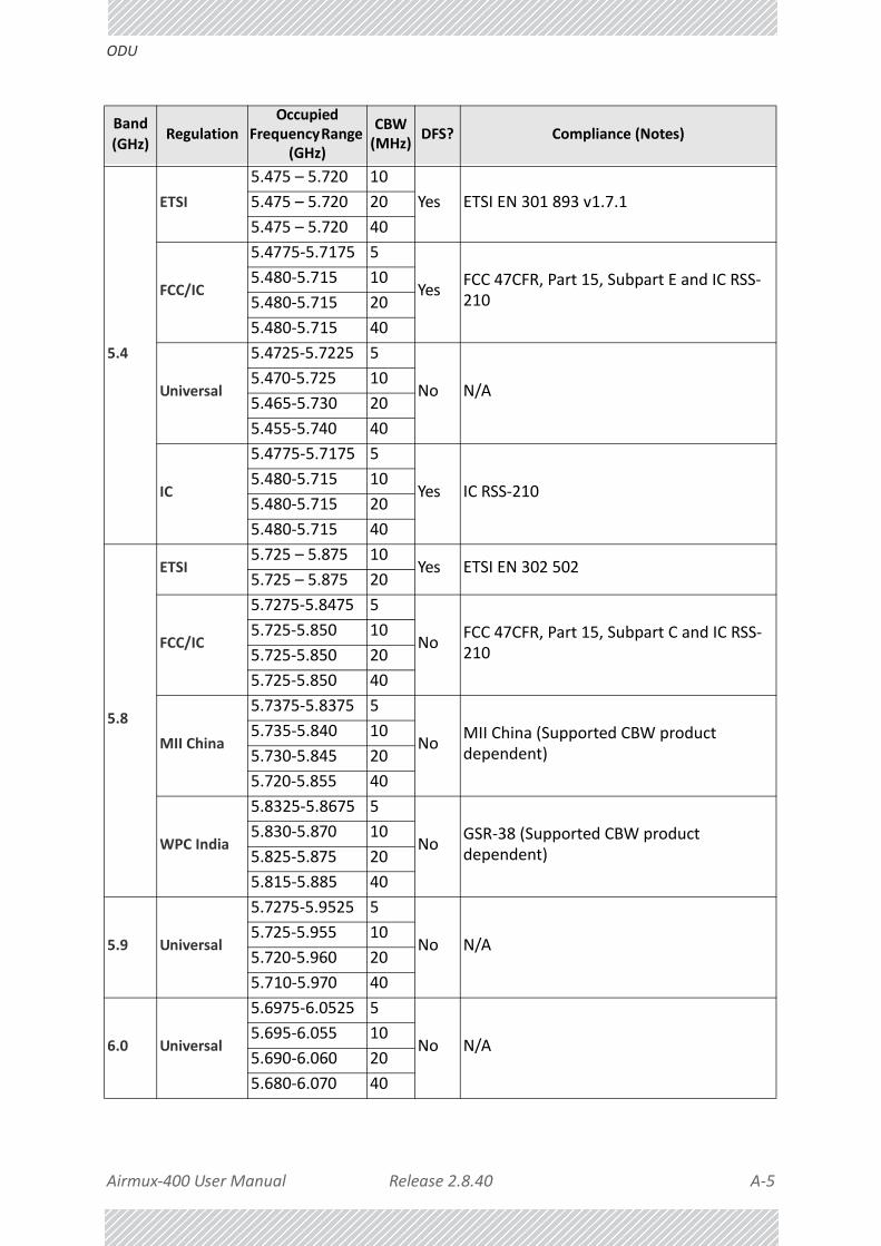
Airmux‐400 User Manual Release 2.8.40 A‐5
ODU
5.4
ETSI
5.475 – 5.720 10
Yes ETSI EN 301 893 v1.7.15.475 – 5.720 20
5.475 – 5.720 40
FCC/IC
5.4775‐5.7175 5
YesFCC 47CFR, Part 15, Subpart E and IC RSS‐210
5.480‐5.715 10
5.480‐5.715 20
5.480‐5.715 40
Universal
5.4725‐5.7225 5
No N/A5.470‐5.725 10
5.465‐5.730 20
5.455‐5.740 40
IC
5.4775‐5.7175 5
Yes IC RSS‐2105.480‐5.715 10
5.480‐5.715 20
5.480‐5.715 40
5.8
ETSI5.725 – 5.875 10
Yes ETSI EN 302 5025.725 – 5.875 20
FCC/IC
5.7275‐5.8475 5
NoFCC 47CFR, Part 15, Subpart C and IC RSS‐210
5.725‐5.850 10
5.725‐5.850 20
5.725‐5.850 40
MII China
5.7375‐5.8375 5
NoMII China (Supported CBW product dependent)
5.735‐5.840 10
5.730‐5.845 20
5.720‐5.855 40
WPC India
5.8325‐5.8675 5
NoGSR‐38 (Supported CBW product dependent)
5.830‐5.870 10
5.825‐5.875 20
5.815‐5.885 40
5.9 Universal
5.7275‐5.9525 5
No N/A5.725‐5.955 10
5.720‐5.960 20
5.710‐5.970 40
6.0 Universal
5.6975‐6.0525 5
No N/A5.695‐6.055 10
5.690‐6.060 20
5.680‐6.070 40
Band
(GHz)Regulation
Occupied Frequency Range
(GHz)
CBW (MHz)
DFS? Compliance (Notes)

Airmux‐400 User Manual Release 2.8.40 A‐6
ODU
The following Max Tx Power limitations apply to all products supporting the 3.5GHz ETSI band:
6.4
ETSI 5.928‐6.4005/10/20
No Low temperature, to ‐35°C
Universal
5.895‐6.4050 10No N/A
5.890‐6.410 20
5.725‐6.4005/10/20/40
No N/A Low temperature, to ‐55°C
Occupied Sub‐Band
GHz
Center Frequency
GHzMode
Channel Bandwidth
MHz
Max Tx Power
dBm
Frequency Step
KHz
3.403‐3.490 3.413‐3.480
Inactive 5, 10, 20
17
2503.470‐3.610 3.480‐3.600 23(†)
3.590‐3.710 3.600‐3.700 25(‡)
Note
(†) The 3.480 GHz frequency is overlapped, occurring in two different bands as shown. If you wish to use the 3.480 GHz frequency, you should set Max TX Power to 17 dBm.(‡) The 3.600 GHz frequency is overlapped, occurring in two different bands as shown. If you wish to use the 3.600 GHz frequency, you should set Max TX Power to 23 dBm.
Japanese Regulations
Frequency sub‐band (GHz)
Channel Bandwidth (MHz)
Frequency Allocation (MHz) Regulation
4.9
104915, 4920, 4925, 4935, 4940, 4945
MIC Notification 88, Appendix 47, Article 2 Paragraph 1, radio standard 19‐5/6/7/8/9/10
20 4920, 4940, 4960, 4980
40 4930, 4970
5.010 5035, 5045, 5055
20 5040, 5060, 5080
Band
(GHz)Regulation
Occupied Frequency Range
(GHz)
CBW (MHz)
DFS? Compliance (Notes)

Airmux‐400 User Manual Release 2.8.40 A‐7
ODU
Management
Environmental
Mechanical
Power
Safety
Japanese Regulations
Frequency sub‐band (GHz)
Channel Bandwidth (MHz)
Frequency Allocation (MHz) Regulation
4.9
104915, 4920, 4925, 4935, 4940, 4945
MIC Notification 88, Appendix 47, Article 2 Paragraph 1, radio standard 19‐5/6/7/8/9/10
20 4920, 4940, 4960, 4980
40 4930, 4970
5.010 5035, 5045, 5055
20 5040, 5060, 5080
Management Application (per link)
Airmux Manager
Web based manager for Airmux‐400 L and Airmux‐400 100M series.
Protocol SNMP and Telnet
NMS RAD NMS
Operating Temperatures ODU: ‐35°C to +60°C / ‐31°F to +140°F
Humidity100% condensing, IP67 (totally protected against dust and against immersion up to 1m)
Storage ‐40° to 85°C / ‐40°F to 185°F
ODU with Integrated Antenna37.1/14.84(W) x 37.1/14.84(H) x 9.00/3.6(D) cm/in; 4.2 kg / 9.2 lbs including Mounting Kit
ODU Connectorized (including SFF antenna ODUs in Airmux‐400 L series)
18.0/7.2(W) x 27.0/10.8(H) x 5.5/2.2(D) cm/in; 3 kg / 6.6 lbs including Mounting Kit
Power FeedingDual feeding, ‐20 to ‐60 VDC (AC/DC converter is available)
Power Consumption ‐ alone 25W
Power Consumption with IDU See IDU specifications, this Appendix
FCC/IC (cTUVus)UL 60950‐1, UL 60950‐22, CAN/CSA C22.2 60950‐1, CAN/CSA C22.2 60950‐22
ETSI/IEC EN/IEC 60950‐1, EN/IEC 60950‐22
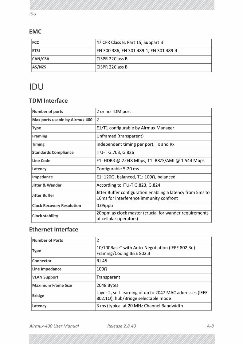
Airmux‐400 User Manual Release 2.8.40 A‐8
IDU
EMC
IDU
TDM Interface
Ethernet Interface
FCC 47 CFR Class B, Part 15, Subpart B
ETSI EN 300 386, EN 301 489‐1, EN 301 489‐4
CAN/CSA CISPR 22Class B
AS/NZS CISPR 22Class B
Number of ports 2 or no TDM port
Max ports usable by Airmux‐400 2
Type E1/T1 configurable by Airmux Manager
Framing Unframed (transparent)
Timing Independent timing per port, Tx and Rx
Standards Compliance ITU‐T G.703, G.826
Line Code E1: HDB3 @ 2.048 Mbps, T1: B8ZS/AMI @ 1.544 Mbps
Latency Configurable 5‐20 ms
Impedance E1: 120Ω, balanced, T1: 100Ω, balanced
Jitter & Wander According to ITU‐T G.823, G.824
Jitter BufferJitter Buffer configuration enabling a latency from 5ms to 16ms for interference immunity confront
Clock Recovery Resolution 0.05ppb
Clock stability20ppm as clock master (crucial for wander requirements of cellular operators)
Number of Ports 2
Type10/100BaseT with Auto‐Negotiation (IEEE 802.3u). Framing/Coding IEEE 802.3
Connector RJ‐45
Line Impedance 100Ω
VLAN Support Transparent
Maximum Frame Size 2048 Bytes
BridgeLayer 2, self‐learning of up to 2047 MAC addresses (IEEE 802.1Q), hub/Bridge selectable mode
Latency 3 ms (typical at 20 MHz Channel Bandwidth

Airmux‐400 User Manual Release 2.8.40 A‐9
IDU
Dry Contact Alarms
ODU Interface
Mechanical
Power
Environmental
Safety
EMC
Dry Contact Alarms4 Inputs + 4 Outputs; Configurable by the Airmux Manager
Connector RJ‐45
Cable Outdoor CAT‐5e cable; Maximum cable length: 100 m
Style Half 19” wall mounted or desktop
Dimensions 22cm(W) x 17cm(D) x 4.4cm(H)
Weight 0.5 kg/1.1 lbs
Power Consumption
With Airmux‐400 ODU < 35W
Alone < 5W
Power Feeding Options 110 – 240 VAC*; ‐20 to ‐60 VDC
Operating Temperatures 0°C ‐ 50°C / 32°F ‐ 122°F
Humidity 90% non‐condensing
Storage -20° to 70°C / --4°F to 158°F Humidity 95%
TUV UL 60950‐1, CAN/CSA C22.2 60950‐1
EN/IEC 60950‐1
FCC 47 CFR Class B, Part 15, Subpart B
ETSI EN 300 386, EN 301 489‐4
CAN/CSA‐CEI/IEC CISPR 22 Class B
AS/NZS CISPR 22:2006 Class B

Airmux‐400 User Manual Release 2.8.40 A‐10
IDU‐E
IDU‐E
TDM Interface
Ethernet ports
Dry Contact Alarms
Number of ports 16, 8, 4 ports or no TDM ports.
Max ports usable by Airmux‐400 16 (model dependent)
Type E1/T1 configurable by Airmux Manager
Framing Unframed (transparent)
Timing Independent timing per port, Tx and Rx
Connector RJ‐45
Standards Compliance ITU‐T G.703, G.826
Line Code E1: HDB3 @ 2.048 Mbps, T1: B8ZS/AMI @ 1.544 Mbps
Latency Configurable 5‐20 ms (default 8 ms)
Impedance E1: 120Ω, balanced, T1: 100Ω, balanced
Jitter & Wander According to ITU‐T G.823, G.824
Jitter BufferJitter Buffer configuration enabling a latency from 5ms to 16ms for interference immunity confront
Clock Recovery Resolution 0.05ppb
Clock stability20ppm as clock master (crucial for wander requirements of cellular operators)
Monitored Hot Standby Supported
Number of Ports 2
Type10/100/1000BaseT with Auto‐Negotiation (IEEE 802.3u). Framing/Coding IEEE 802.3
Connector RJ‐45
Line Impedance 100Ω
SFP Interface 1 port, Type: Fast Ethernet
VLAN Support Transparent
Maximum Frame Size 2048 Bytes
BridgeLayer 2, self‐learning of up to 2047 MAC addresses (IEEE 802.1Q), hub/Bridge selectable mode
Latency 3 ms
Dry Contact Alarms4 Inputs + 4 Outputs; Configurable by the Airmux Manager

Airmux‐400 User Manual Release 2.8.40 A‐11
IDU‐E
ODU Interface
Mechanical
Power
Environmental
Safety
EMC
Connector RJ‐45
Cable Outdoor CAT‐5e cable; Maximum cable length: 100 m
Style 1U 19” Rack mounted
Dimensions 43.6cm(W) x 21cm(D) x 4.4cm(H)
Weight 1.5 kg/3.3 lbs
Power Consumption
With Airmux‐400 ODU <35W
Alone <10W
Power Feeding Options Dual feeding, ‐20 to ‐60VDC, AC Power Adapters available
Operating Temperatures 0°C ‐ 50°C / 32°F ‐ 122°F
Humidity 90% non‐condensing
Storage -20° to 70°C / --4°F to 158°F Humidity 95%
TUV UL 60950‐1, CAN/CSA C22.2 60950‐1
EN/IEC 60950‐1
FCC CFR47 Class B, Part 15, Subpart B
ETSI EN 300 386, EN 301 489‐4, EN 301 489‐1
CAN/CSA‐CEI/IEC CISPR 22 Class B
AS/NZS CISPR 22:2006 Class B

Airmux‐400 User Manual Release 2.8.40 A‐12
Airmux‐IDUH/2ETH (Aggregation Unit)
Airmux‐IDUH/2ETH (Aggregation Unit)
Ethernet Interface
Mechanical
Power
Environmental
Safety
PoE Interfaces6 x legacy mode PoE ports(10/100/1000Mbps), up to 25W per port
Ethernet Ports2 x RJ‐45 PHY ports of 10/100/1000 Mbps Based‐T Ethernet
LAN Interface Framing/Coding IEEE 802.3/U
LAN Interface Line Impedance 100Ω
LAN Interface Ethernet Mode Auto‐negotiation 10/100/1000
SFP Interfaces 2 x SFP ports of 1000 Mbps (standard MSA)
MAC Address Entries Up to 1K MAC Address entries
Maximal Frame Size 2048 bytes
Ethernet Latency 3 ms
Dimensions 1U 19” Rack mounted, half width
Weight 0.8Kg
Internal Power Consumption < 15W @ Maximal Power feeding
Power Feeding44VDC ‐ 56VDC, Dual redundant inputs. 3 pin female DC connector
Grounding Front panel grounding lug
Protection
‐ DC input Line & Reverse Polarity protection
‐ PoE Ports over/under Current & over/under Voltage protections
Operating Temperatures ‐40°C to 55°C / ‐40°F to 131°F
Humidity 90% non‐condensing
Storage ‐40° to 70°C / ‐40°F to 158°F Humidity 95%
TUV UL60950‐1, CAN/CSA‐C22.2 No. 60950‐1
ETSI/IEC EN/IEC 60950‐1

Airmux‐400 User Manual Release 2.8.40 A‐13
GbE PoE Device ‐ Indoor, AC
EMC
GbE PoE Device ‐ Indoor, AC
Electrical
Interfaces
Mechanical
FCC 47CFR Part 15, Subpart B, Class B
ETSI EN 300 386; 301 489‐4; 301 489‐1
CAN/CSA‐ AS/NZS CISPR 22 Class B
AC Input Voltage 100 ‐ 240 VAC nominal, 90 ‐ 264 VAC max range
Input Frequency 47 ‐ 63 Hz
Input Current2.0 A (rms) 115 VAC at Max. load
1.2 A (rms) 230 VAC at Max. load
Max. In‐rush Current30A for 115VAC at Max. load
60A for 230VAC at Max. load
Standby Power 0.5W (Max) at 240Vac
DC Output Voltage 56 VDC
Protection
• Short circuit protection• Auto recovery• Over voltage protection
Indication Green led for normal operation
PoE output RJ‐45 connector
PoE to ODU InterfaceOutdoor CAT 5e; Maximum cable length: 75m for 1000BaseT or 100m for 10/100BaseT.
Ethernet input RJ‐45 connector
AC input on device Standard socket IEC320 C14 type
AC cable Variety of AC plugs available (see below)
Ethernet / ODU RAD RJ‐45 connector
Ethernet LAN interface typeRJ-45, 10/100/1000BaseT Interface (Line Impedance -100)
Case Plastic
Dimensions 16cm(W) x 6.3cm(D) x 3.33cm(H)
Weight 250g

Airmux‐400 User Manual Release 2.8.40 A‐14
PoE Device ‐ Outdoor, DC
Environmental
Safety
EMC
PoE Device ‐ Outdoor, DC
Electrical
Interfaces
Mechanical
Operating Temperatures 0°C to 40°C/32°F to 104°F
Humidity 90% non‐condensing
ULCSA 60950‐1, C22.2 No. 60950‐1
ETSI/IEC IEC/EN 60950‐1
ESD 61000-4‐2
RS 61000-4‐3
EFT 61000-4‐4
Surge 61000-4‐5
CS 61000-4‐6
DIPS 61000-4‐11
EMIFCC part 15 class B, CISPR Pub 22 class B, AS/NZS CISPR 22 class B
Input voltage range ‐20 to ‐60 VDC (single input)
Output voltage 48VDC / 0.6A
Power Consumption 0.5W (not including radio)
ProtectionsDifferential ‐ 15KW
Common – 3KW
Ethernet LAN interface type RJ‐45, 10/100BaseT Interface (Line Impedance ‐100W)
DC input 2 pins connector
ODU (PoE Port) RJ‐45
Enclosure All weather cases
Dimensions 24.5cm(H) x 13.5cm(W) x 4.0cm(D)
Weight 1.0kg/2.2lbs

Airmux‐400 User Manual Release 2.8.40 A‐15
GSU
Environmental
Safety
EMC
GSU
Configuration
Mechanical
Power
Environmental
Operating Temperatures ‐35° C to 60° C / ‐31° F to 140° F
Humidity Up to 100% non‐condensing
StandardsIEC 60721‐3‐4 Class 4M5
IP67
FCC/IEC/ CAN/CSA Designed to meet 60950‐1, 60950‐22
ETSI Designed to meet EN 300 386; EN 301 489‐1
FCC Designed to meet 47CFR Part 15, Subpart B, Class B
CAN/CSA Designed to meet ICES‐003 Class B
AS/NZS Designed to meet CISPR 22 class B
Architecture
Outdoor Synchronization Unit; including External GPS Antenna and RF cable. (PoE device should be ordered separately)
GSU to PoE Interface Outdoor CAT‐5e cable; maximum cable length: 100 m
Dimensions 21(w) x 17(h) x 7(d) cm
Weight 1.2 kg / 2.65 lbs
Power Feeding Power provided by PoE device
Max Power Dissipation <10Watt
Operating Temperature Range‐40°C to 60°C / ‐40°F to 140°F (Up to 70°C/158°F for limited time or under forced convection)
HumidityUp to 100% non‐condensing, IP67 (totally protected against dust and against immersion up to 1m)

Airmux‐400 User Manual Release 2.8.40 A‐16
Lightning Protector
Safety
EMC
Lightning Protector
Electrical
Nominal discharge currents
Impulse Discharge Current
FCC/IC (cTUVus)UL 60950‐1, UL 60950‐22, CAN/CSA C22.2 60950‐1, CAN/CSA C22.2 60950‐22
ETSI EN/IEC 60950‐1, EN/IEC 60950‐22
FCC CFR47 Class B, Part15, Subpart B
ETSI EN 300 386, EN 301 489‐1, EN 301 489‐4
CAN/CSA‐CEI/IEC CISPR 22‐04 Class B
AS/NZS CISPR 22‐2004 Class B
Compatible Interfaces 10/100/1000BaseT
Data Rates Up to 1000Mbps
Nominal Operational Voltage 48 VDC
Maximum Operational Voltage 60 VDC ‐ 650 mA
Maximum Continuous current 1 A
Impedance 90 to 110 Ohm
Connection type RJ45 CAT 5e STP (shielded)
Pin-out 8 wires + shielding
Pins Protected All pins protected
Response time <5 microseconds (with ODU)
Line to Line 500 A @ 8/20μs
Line to Ground 2000 A @ 8/20μs
20000 A, 8/20 μs 1 operation minimum
10000 A, 8/20 μs > 10 operations
2000 A, 10/350 μs 1 operation
200 A, 10/1000 μs > 300 operations
200 A, 10/700 μs > 500 operations

Airmux‐400 User Manual Release 2.8.40 A‐17
Fast Ethernet CAT‐5e cable repeater
Impulse Spark‐over
Mechanical
Environmental
Fast Ethernet CAT‐5e cable repeater
Electrical
Mechanical
DC Spark-over ±20 % @ 100 V/s 150 V
100 V/μs 350 V
1000 V/μs 500 V
Capacitance < 2 pF
DC Holdover Voltage 80V
Enclosure Metal
Connection to bonding Network Screw
Dimensions 150mm
Weight 220 gram (0.22Kg)
Operating temperature ‐40°C to 60°C
Storage temperature ‐50°C to 70°C
Enclosure rating IP67
Humidity 100% non condensing
Compatible Interfaces 100BaseT
Data Rates Up to 1000Mbps
Nominal Operational Voltage 48 VDC
Maximum Operational Voltage 60 VDC ‐ 650 mA
Current consumption 0.5 A
Impedance 90 to 110 Ohm
Connection type RJ45 CAT 5e STP (shielded)
Pin-out 8 wires + shielding
Enclosure Metal
Connection to bonding Network Screw

Airmux‐400 User Manual Release 2.8.40 A‐18
Antenna Characteristics
Environmental
Safety
EMC
Antenna CharacteristicsAn antenna is the radiating and receiving element from which the radio signal, in the form of RF power, is radiated to its surroundings and vice versa. The transmission range is a function of the antenna gain and transmitting power. These factors are limited by country regulations.
The Airmux‐400 may be operated with an integrated antenna attached to the ODU unit, or with an external antenna wired to the ODU via N‐type connectors. All cables and connections must be connected correctly to reduce losses. The required antenna impedance is 50Ω.
Dimensions 150mm
Weight 220 gram (0.22Kg)
Operating temperature ‐40°C to 60°C
Storage temperature ‐50°C to 70°C
Enclosure rating IP67
Humidity 100% non condensing
TUVUL 60950‐1, UL 60950‐22, CAN/CSA C22.2 60950‐1, CAN/CSA C22.2 60950‐22
ETSI/IEC EN/IEC 60950‐1, EN/IEC 60950‐22
FCC CFR47 Class B, Part 15, Subpart B
ETSI EN 300 386, EN 301 489‐4, EN 301 489‐1
CAN/CSA‐AS/NZS CISPR 22 Class B

Airmux‐400 User Manual Release 2.8.40 B‐1
Appendix B:
Wiring Specifications
ODU‐IDU CableThe ODU‐IDU cable is shielded/outdoor class CAT 5e, 4 twisted‐pair 24 AWG terminated with RJ‐45 connectors on both ends.
The following table shows the connector pinout:
ODU/HSS Unit Connection Pinout
Table B‐1: ODU-IDU RJ-45 Connector Pinout
Function Color IDU ODU
Ethernet (RxN) White/Green 1 1
Ethernet (RxT) Green 2 2
Ethernet (TxT) White/Orange 3 3
Ethernet (TxN) Orange 6 6
Power (+) Blue 4 4
Power (+) White/Blue 5 5
Power () White/Brown 7 7
Power () Brown 8 8
Table B‐2: ODU/HSS Unit Connection Pinout
ColorODU
RJ‐45
HSS UNIT
RJ‐45
White/Green 1 1
GreenNot connected
White/Orange
Orange 6 6
Blue 4 4

Airmux‐400 User Manual Release 2.8.40 B‐2
User Port Connectors
User Port Connectors
LAN Port
The LAN 10/100BaseT interface terminates in an 8‐pin RJ‐45 connector, wired in accordance to Table B‐3.
Trunk Ports ‐ E1/T1 RJ45 Connector
The E1/T1 interfaces terminate in 8‐pin RJ‐45 connectors, as shown in Table B‐4 below:
Hot Standby Port RJ‐11
White/Blue 5 5
White/Brown 7 7
Brown 8 8
Table B‐3: Fast Ethernet Connector Pinout
Function Signal Pin
Transmit Data (positive) TD (+) 1
Transmit Data (negative) TD (–) 2
Receive Data (positive) RD (+) 3
Receive Data (negative) RD (–) 6
Table B‐4: Trunk Ports - E1/T1 RJ45Pinout
Function Signal Pin
Transmit Data Tip TxTip 1
Transmit Data Ring TxRing 2
Receive Data Tip RxTip 4
Receive Data Ring RxRing 5
Table B‐5: Hot Standby RJ-11 Port Pinout
SignalPin Side A
Pin Side B
HSB out 1 2
HSB in 2 1
Table B‐2: ODU/HSS Unit Connection Pinout (Continued)
ColorODU
RJ‐45
HSS UNIT
RJ‐45

Airmux‐400 User Manual Release 2.8.40 B‐3
IDU (all models) Alarm Connector
IDU (all models) Alarm Connector
The IDU Alarm interface is a 25 pin D type female connector. Its pinout is listed in Table B‐6.
The figure below, shows how to connect external input and output alarms.
Ground 3 3
Ground 4 4
Table B‐6: IDU Alarm Connector (Dry-Contact)
I/O Description Pin
Input 1 Positive 14
Input 1 Negative 15
Input 2 Positive 16
Input 2 Negative 17
Input 3 Positive 18
Input 3 Negative 19
Input 4 Positive 20
Input 4 Negative 21
Output 1 Normally Open 1
Output 1 Common 2
Output 1 Normally Closed 3
Output 2 Normally Open 4
Output 2 Common 5
Output 2 Normally Closed 6
Output 3 Normally Open 7
Output 3 Common 8
Output 3 Normally Closed 9
Output 4 Normally Open 10
Output 4 Common 11
Output 4 Normally Closed 12
Note
• Use an external current limit resistor to limit the current at the output relays to 1 Amp. Such resistor is not required if the equipment con‐nected to the IDU supports current limiting to 1 Amp.
• The voltage of the input alarm must be within the range of ‐10 to ‐50 VDC.
Table B‐5: Hot Standby RJ-11 Port Pinout (Continued)
SignalPin
Side A
Pin
Side B
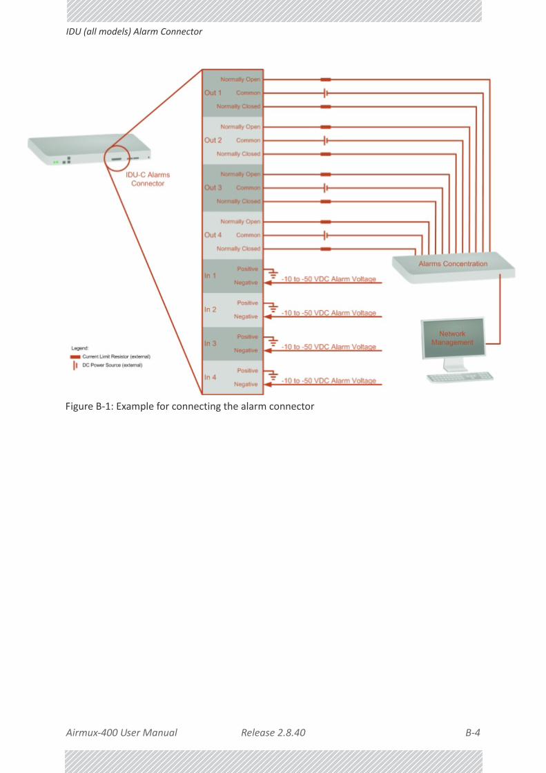
Airmux‐400 User Manual Release 2.8.40 B‐4
IDU (all models) Alarm Connector
Figure B‐1: Example for connecting the alarm connector

Airmux‐400 User Manual Release 2.8.40 B‐5
DC Power Terminals
DC Power Terminals
IDU‐E & E
DC PoE
Unbalanced Mode for E1 InterfaceYou may configure the E1 interface to unbalanced mode (75 ohm) using the Airmux Manager.
Figure B‐2 shows an adapter cable for connecting devices with balanced E1 interface to the user equipment with unbalanced E1 interface. The Y splitter cable includes one RJ‐45 balanced connector (left) and two unbalances BNC coaxial connectors (right).
Figure B‐2: Unbalanced E1 adapter cable (Y Splitter)
Figure B‐3 provides a schematic:
Table B‐7: Terminal Block 3-pin -48VDC
Function Pin
+ Right
Chassis Center
– Left
Table B‐8: Terminal Block 2-pin -48VDC
Function Pin
+ Right
– Left

Airmux‐400 User Manual Release 2.8.40 B‐6
Unbalanced Mode for E1 Interface
Figure B‐3: Unbalanced E1 adapter cable (Y Splitter) ‐ schematic
Table B‐9: E1 Y Splitter Pinout for Unbalanced Mode
BNC Connector Color Code RJ‐45 Connector Pin
2 (NGND)Red
1, 4, 7, 8
1 (Center) 2
2 (NGND)Green
1, 4, 7, 8
1 (Center) 5
Note
The Y‐splitter cable cannot be used as a balanced to unbalanced converter. The cable merely provides a physical interface conversion without any impedance matching. Some devices automatically detect cable insertion and change the impedance internally

Airmux‐400 User Manual Release 2.8.40 C‐1
Appendix C:
Small Form‐factor Pluggable Transceiver
IDU‐E SFP SupportThe Small Form‐factor Pluggable (SFP) transceiver, is a compact, hot‐pluggable transceiver used in communications applications.
The SFP transceiver technology allows almost any protocol converter implementation with seamless integration to a standard Ethernet switch.
The IDU‐E supports SFP transceivers to provide and support several network applications.
Any standard Fast Ethernet (FE) SFP transceiver can be plugged into the IDU‐E. These SFPs support various Ethernet interfaces. For example a fibre optic interface can be used to support long fibre distances.
In addition, System on SFP transceivers can be used, supporting a protocol converter
concept. The main application for such SFP transceivers is TDM over Ethernet providing E1/T1 or E3/T3 over full duplex Ethernet Remote Bridge
The following table provides a few SFP types that can be used with the IDU‐E:
SFP Type Interface Description
100baseT/1000baseT 100BaseT,1000BaseT IEEE 802.3, UTP CAT 5
100baseFX/1000baseFX Multimode fiber‐optic (MMF) link spans up to 2km long
100baseLX/1000baseLX Single‐mode fiber optic (SMF) links pans up to 10km
100baseBX/1000baseBX SMF single‐strand link spans up to 10 km or 40 km
E1/T1/FE E1/T1 with 100 M
E3/T3/FE E3/T3 with 100 M
E1/T1/GBE E1/T1 with 1000 M
E3/T3/GBE E3/T3 with 1000 M

Airmux‐400 User Manual Release 2.8.40 D‐1
Appendix D:
MIB Reference
Introduction
About the MIB
The RAD MIB is a set of APIs that enables external applications to control RAD equipment.
The MIB is divided into public and a private API groups:
• Public: RFC‐1213 (MIB II) variables, RFC‐1214 (MIB II) System and Interfaces sections
• Private: Controlled by RAD and supplements the public group.
This appendix describes the public and private MIB used by RAD.
Terminology
The following terms are used in this appendix.
In addition, the MIB uses internally, the older notions of Local site and Remote site where this manual would use site A and site B.
To avoid burdening the reader, this appendix will follow the MIB usage.
Term Meaning
MIB Management Information Base
API Application Programming Interface
SNMP Simple Network Management Protocol

Airmux‐400 User Manual Release 2.8.40 D‐2
Interface API
Interface API
Control Method
The Airmux Manager application provides all the means to configure and monitor a Airmux‐400 link, communicating with the SNMP agent in each ODU. Each SNMP agent contains data on each of the IDUs and ODUs in the link. Both agents communicate with each other over the air using a proprietary protocol.
To control and configure the device using the MIB, you should adhere to the following rules:
• The connection for control and configuration is to the local site, over any SNMP/UDP/IP network.
• All Parameters should be consistent between both of the ODUs. Note that inconsistency of air parameters can break the air connection. To correct air parameters inconsistency you must reconfigure each of the ODUs.
• Common practice is to configure the remote site first and then to configure the local site.
• For some of the configuration parameters additional action must be taken before the new value is loaded. Please refer to the operation in the parameters description.
• Some of the MIB parameters values are product dependent. It is strongly recommend using the Airmux Manager Application for changing these values. Setting wrong values may cause indeterminate results.
Community String
To control a link, all SNMP requests should go to the local site IP address.
See Table 5‐2 for default Community strings.
Private MIB StructureThe sections in the private RAD MIB and its location in the MIB tree are shown in Figure D‐1 below:
Note
Each ODU has a single MAC address and a single IP address.

Airmux‐400 User Manual Release 2.8.40 D‐3
Private MIB Structure
Figure D‐1: Top Level Sections of the private MIB
The products MIB section contains the definition of the Object IDs for the two form factors of the ODU, Integrated Antenna and Connectorized (referred in the MIB as external antenna)and GSU:
Figure D‐2: Product MIB for Airmux‐400
The ODU MIB contains the sections: Admin, Service, Ethernet, Bridge, Air, PerfMon and Agent.
The IDU MIB contains the sections: Admin, Service, Ethernet, Bridge and TDM.
The GpsSynchronizerFamily MIB defines the GSU.
The general MIB include a single generic parameter that is used by all traps as a trap description parameter.

Airmux‐400 User Manual Release 2.8.40 D‐4
MIB Parameters
MIB ParametersThe following section describes all of the MIB parameters. The MIB parameters follow the following naming convention:
<radwllMil><Section 1>...<Section n><Parameter Name>
For each of the configuration and control parameters (parameters with read‐write access), the “Description” column describes when the new value is effective. It is recommended that you perform the appropriate action to make the values affective immediately after any change. Where a change is required on both sides of the link, it is recommended that you change both sides of the link first and then perform the action.
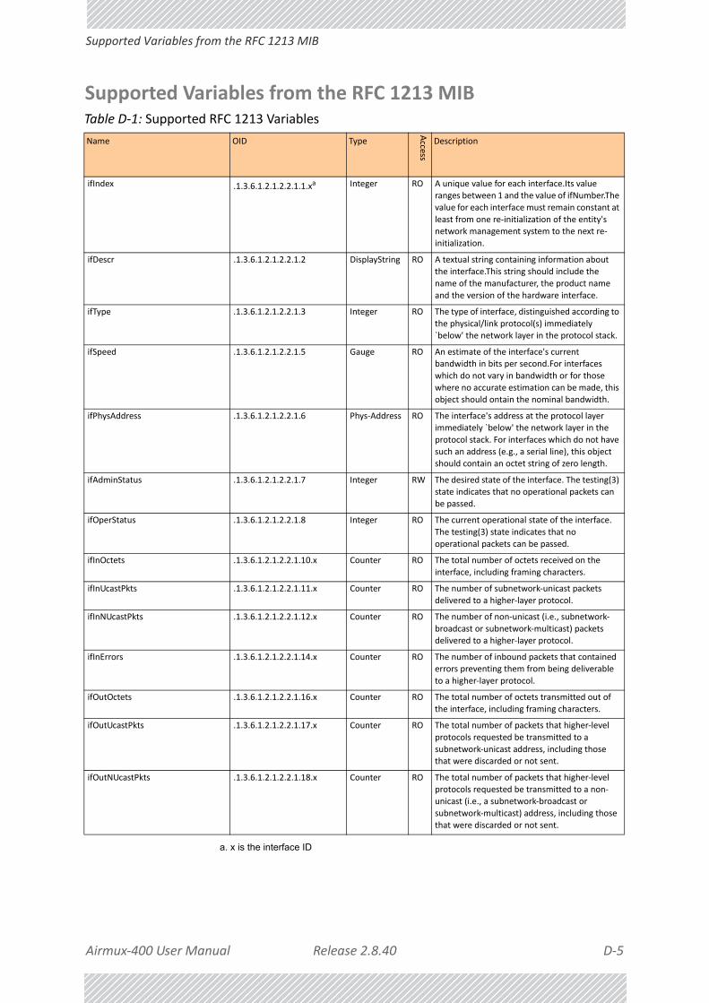
Airmux‐400 User Manual Release 2.8.40 D‐5
Supported Variables from the RFC 1213 MIB
Supported Variables from the RFC 1213 MIBTable D‐1: Supported RFC 1213 Variables
Name OID Type
Access
Description
ifIndex .1.3.6.1.2.1.2.2.1.1.xa
a. x is the interface ID
Integer RO A unique value for each interface.Its value ranges between 1 and the value of ifNumber.The
value for each interface must remain constant at
least from one re‐initialization of the entity's network management system to the next re‐
initialization.
ifDescr .1.3.6.1.2.1.2.2.1.2 DisplayString RO A textual string containing information about the interface.This string should include the
name of the manufacturer, the product name
and the version of the hardware interface.
ifType .1.3.6.1.2.1.2.2.1.3 Integer RO The type of interface, distinguished according to
the physical/link protocol(s) immediately `below' the network layer in the protocol stack.
ifSpeed .1.3.6.1.2.1.2.2.1.5 Gauge RO An estimate of the interface's current bandwidth in bits per second.For interfaces
which do not vary in bandwidth or for those
where no accurate estimation can be made, this object should ontain the nominal bandwidth.
ifPhysAddress .1.3.6.1.2.1.2.2.1.6 Phys‐Address RO The interface's address at the protocol layer immediately `below' the network layer in the
protocol stack. For interfaces which do not have
such an address (e.g., a serial line), this object should contain an octet string of zero length.
ifAdminStatus .1.3.6.1.2.1.2.2.1.7 Integer RW The desired state of the interface. The testing(3) state indicates that no operational packets can
be passed.
ifOperStatus .1.3.6.1.2.1.2.2.1.8 Integer RO The current operational state of the interface.
The testing(3) state indicates that no
operational packets can be passed.
ifInOctets .1.3.6.1.2.1.2.2.1.10.x Counter RO The total number of octets received on the
interface, including framing characters.
ifInUcastPkts .1.3.6.1.2.1.2.2.1.11.x Counter RO The number of subnetwork‐unicast packets
delivered to a higher‐layer protocol.
ifInNUcastPkts .1.3.6.1.2.1.2.2.1.12.x Counter RO The number of non‐unicast (i.e., subnetwork‐
broadcast or subnetwork‐multicast) packets delivered to a higher‐layer protocol.
ifInErrors .1.3.6.1.2.1.2.2.1.14.x Counter RO The number of inbound packets that contained errors preventing them from being deliverable
to a higher‐layer protocol.
ifOutOctets .1.3.6.1.2.1.2.2.1.16.x Counter RO The total number of octets transmitted out of
the interface, including framing characters.
ifOutUcastPkts .1.3.6.1.2.1.2.2.1.17.x Counter RO The total number of packets that higher‐level
protocols requested be transmitted to a
subnetwork‐unicast address, including those that were discarded or not sent.
ifOutNUcastPkts .1.3.6.1.2.1.2.2.1.18.x Counter RO The total number of packets that higher‐level protocols requested be transmitted to a non‐
unicast (i.e., a subnetwork‐broadcast or
subnetwork‐multicast) address, including those that were discarded or not sent.

Airmux‐400 User Manual Release 2.8.40 D‐6
MIB Parameters
MIB ParametersTable D‐2: Private MIB Parameters (Sheet 1 of 30)
Name OID Type
Access
Description
radwllMilOduAdmProductType 1.3.6.1.4.1.4458.1000.1.1.1 DisplayString RO ODU configuration description.
radwllMilOduAdmHwRev 1.3.6.1.4.1.4458.1000.1.1.2 DisplayString RO ODU Hardware Version.
radwllMilOduAdmSwRev 1.3.6.1.4.1.4458.1000.1.1.3 DisplayString RO ODU Software Version.
radwllMilOduAdmLinkName 1.3.6.1.4.1.4458.1000.1.1.4 DisplayString RW Link Name. A change is effective immediately.
radwllMilOduAdmResetCmd 1.3.6.1.4.1.4458.1000.1.1.5 Integer RW Reset Command. A set command with a value
of 3 will cause a device reset. HBS only: A set
command with a value of 4 will cause a device reset for the entire sector. The read value is
always 0.
radwllMilOduAdmAddres 1.3.6.1.4.1.4458.1000.1.1.6 IPAddress RW ODU IP address. A change is effective after reset.
The parameter is kept for backward
compatibility. Using the alternative parameter: radwllMilOduAdmIpParamsCnfg is
recommended.
radwllMilOduAdmMask 1.3.6.1.4.1.4458.1000.1.1.7 IPAddress RW ODU Subnet Mask. A change is effective after
reset. The parameter is kept for backward
compatibility. Using the alternative parameter: radwllMilOduAdmIpParamsCnfg is
recommended.
radwllMilOduAdmGateway 1.3.6.1.4.1.4458.1000.1.1.8 IPAddress RW ODU default gateway. A change is effective after
reset. The parameter is kept for backward
compatibility. Using the alternative parameter: radwllMilOduAdmIpParamsCnfg is
recommended.
radwllMilOduAdmBroadcast 1.3.6.1.4.1.4458.1000.1.1.1
0
Integer RW This parameter is reserved for the Manager
application provided with the product.
radwllMilOduAdmHostsTable N/A Trap destinations table. Each trap destination is
defined by an IP address and a UDP port. Up to
10 addresses can be configured.
radwllMilOduAdmHostsEntry N/A Trap destinations table entry. INDEX {
radwllMilOduAdmHostsIndex }
radwllMilOduAdmHostsIndex RO Trap destinations table index.
radwllMilOduAdmHostsIp 1.3.6.1.4.1.4458.1000.1.1.12.1.2
IPAddress RW Trap destination IP address. A change is effective immediately.
radwllMilOduAdmHostsPort 1.3.6.1.4.1.4458.1000.1.1.12.1.3
Integer RW UDP port of the trap destination. A change is effective immediately.
radwllMilOduBuzzerAdminState 1.3.6.1.4.1.4458.1000.1.1.13
Integer RW This parameter controls the activation of the buzzer while the unit is in install mode. A
change is effective immediately. The valid values
are: disabled (0) enabledAuto (1) enabledConstantly(2) advancedAuto (3).
radwllMilOduProductId 1.3.6.1.4.1.4458.1000.1.1.14
DisplayString RO This parameter is reserved for the Manager application provided with the product.
radwllMilOduReadCommunity 1.3.6.1.4.1.4458.1000.1.1.15
DisplayString RW Read Community String. This parameter always returns ***** when retrieving its value. It is
used by the Manager application to change the
Read Community String. The SNMP agent accepts only encrypted values.
radwllMilOduReadWriteCommunity 1.3.6.1.4.1.4458.1000.1.1.16
DisplayString RW Read/Write Community String. This parameter always returns ***** when retrieving its value.
It is used by the Manager application to change
the Read/Write Community String. The SNMP agent accepts only encrypted values.
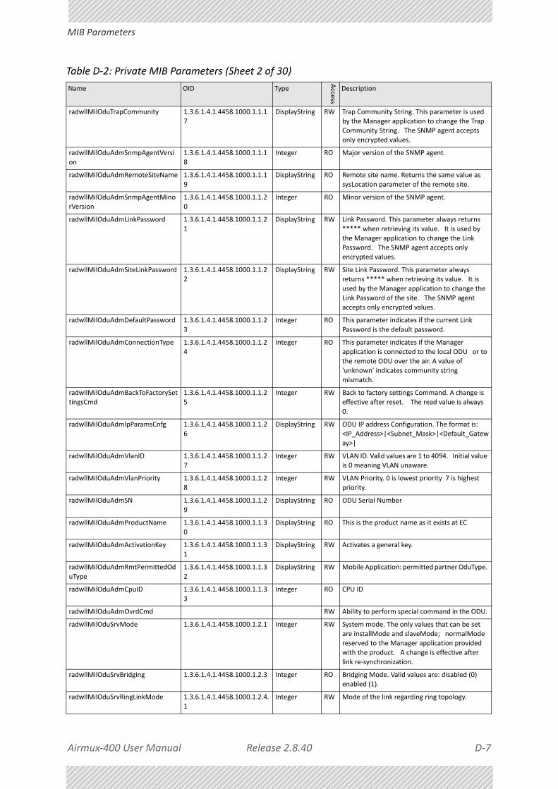
Airmux‐400 User Manual Release 2.8.40 D‐7
MIB Parameters
radwllMilOduTrapCommunity 1.3.6.1.4.1.4458.1000.1.1.1
7
DisplayString RW Trap Community String. This parameter is used
by the Manager application to change the Trap Community String. The SNMP agent accepts
only encrypted values.
radwllMilOduAdmSnmpAgentVersi
on
1.3.6.1.4.1.4458.1000.1.1.1
8
Integer RO Major version of the SNMP agent.
radwllMilOduAdmRemoteSiteName 1.3.6.1.4.1.4458.1000.1.1.1
9
DisplayString RO Remote site name. Returns the same value as
sysLocation parameter of the remote site.
radwllMilOduAdmSnmpAgentMino
rVersion
1.3.6.1.4.1.4458.1000.1.1.2
0
Integer RO Minor version of the SNMP agent.
radwllMilOduAdmLinkPassword 1.3.6.1.4.1.4458.1000.1.1.2
1
DisplayString RW Link Password. This parameter always returns
***** when retrieving its value. It is used by
the Manager application to change the Link Password. The SNMP agent accepts only
encrypted values.
radwllMilOduAdmSiteLinkPassword 1.3.6.1.4.1.4458.1000.1.1.2
2
DisplayString RW Site Link Password. This parameter always
returns ***** when retrieving its value. It is
used by the Manager application to change the Link Password of the site. The SNMP agent
accepts only encrypted values.
radwllMilOduAdmDefaultPassword 1.3.6.1.4.1.4458.1000.1.1.2
3
Integer RO This parameter indicates if the current Link
Password is the default password.
radwllMilOduAdmConnectionType 1.3.6.1.4.1.4458.1000.1.1.2
4
Integer RO This parameter indicates if the Manager
application is connected to the local ODU or to
the remote ODU over the air. A value of 'unknown' indicates community string
mismatch.
radwllMilOduAdmBackToFactorySet
tingsCmd
1.3.6.1.4.1.4458.1000.1.1.2
5
Integer RW Back to factory settings Command. A change is
effective after reset. The read value is always
0.
radwllMilOduAdmIpParamsCnfg 1.3.6.1.4.1.4458.1000.1.1.2
6
DisplayString RW ODU IP address Configuration. The format is:
<IP_Address>|<Subnet_Mask>|<Default_Gateway>|
radwllMilOduAdmVlanID 1.3.6.1.4.1.4458.1000.1.1.2
7
Integer RW VLAN ID. Valid values are 1 to 4094. Initial value
is 0 meaning VLAN unaware.
radwllMilOduAdmVlanPriority 1.3.6.1.4.1.4458.1000.1.1.2
8
Integer RW VLAN Priority. 0 is lowest priority 7 is highest
priority.
radwllMilOduAdmSN 1.3.6.1.4.1.4458.1000.1.1.2
9
DisplayString RO ODU Serial Number
radwllMilOduAdmProductName 1.3.6.1.4.1.4458.1000.1.1.3
0
DisplayString RO This is the product name as it exists at EC
radwllMilOduAdmActivationKey 1.3.6.1.4.1.4458.1000.1.1.3
1
DisplayString RW Activates a general key.
radwllMilOduAdmRmtPermittedOd
uType
1.3.6.1.4.1.4458.1000.1.1.3
2
DisplayString RW Mobile Application: permitted partner OduType.
radwllMilOduAdmCpuID 1.3.6.1.4.1.4458.1000.1.1.3
3
Integer RO CPU ID
radwllMilOduAdmOvrdCmd RW Ability to perform special command in the ODU.
radwllMilOduSrvMode 1.3.6.1.4.1.4458.1000.1.2.1 Integer RW System mode. The only values that can be set
are installMode and slaveMode; normalMode
reserved to the Manager application provided with the product. A change is effective after
link re‐synchronization.
radwllMilOduSrvBridging 1.3.6.1.4.1.4458.1000.1.2.3 Integer RO Bridging Mode. Valid values are: disabled (0)
enabled (1).
radwllMilOduSrvRingLinkMode 1.3.6.1.4.1.4458.1000.1.2.4.
1
Integer RW Mode of the link regarding ring topology.
Table D‐2: Private MIB Parameters (Sheet 2 of 30)
Name OID Type
Access
Description

Airmux‐400 User Manual Release 2.8.40 D‐8
MIB Parameters
radwllMilOduSrvRingTopologySupp
orted
1.3.6.1.4.1.4458.1000.1.2.4.
2
Integer RO Ring Topology options are: supported not
supported
radwllMilOduSrvRingVlanIdTable N/A Ring VLAN IDs table.
radwllMilOduSrvRingVlanIdEntry N/A VLAN ID of the internal ring messages. Valid
values are 1 to 4094. Initial value is 0 meaning
VLAN unaware. INDEX { radwllMilOduSrvRingVlanIdIndex }
radwllMilOduSrvRingVlanIdIndex 1.3.6.1.4.1.4458.1000.1.2.4.3.1.1
Integer RO Index of VLAN ID of the internal ring messages.
radwllMilOduSrvRingVlanId 1.3.6.1.4.1.4458.1000.1.2.4.3.1.2
Integer RW VLAN ID of the internal ring messages. Valid values are 1 to 4094. Initial value is 0 meaning
VLAN unaware.
radwllMilOduSrvRingEthStatus 1.3.6.1.4.1.4458.1000.1.2.4.
4
Integer RO Represents the Ethernet service blocking state
of a Rings link
radwllMilOduSrvRingMaxAllowedTi
meFromLastRpm
1.3.6.1.4.1.4458.1000.1.2.4.
5
Integer RW Defines the minimal time (in ms) required for
determination of ring failure.
radwllMilOduSrvRingWTR 1.3.6.1.4.1.4458.1000.1.2.4.
6
Integer RW Defines the minimal time (in ms) required for
ring recovery.
radwllMilOduSrvQoSMode 1.3.6.1.4.1.4458.1000.1.2.5.
1
Integer RW Mode of QoS feature.
radwllMilOduSrvQoSConfTable N/A QoS configuration table.
radwllMilOduSrvQoSConfEntry N/A QoS configuration table. INDEX { radwllMilOduSrvQoSConfIndex }
radwllMilOduSrvQoSConfIndex 1.3.6.1.4.1.4458.1000.1.2.5.2.1.1
Integer RO Index of QoS Configuration.
radwllMilOduSrvConfVlanQGroups 1.3.6.1.4.1.4458.1000.1.2.5.2.1.2
Integer RO Frames classification according to VLAN Priority IDs.
radwllMilOduSrvConfDiffservQGroups
1.3.6.1.4.1.4458.1000.1.2.5.2.1.3
Integer RO Frames classification according to Diffserv.
radwllMilOduSrvConfQueMir 1.3.6.1.4.1.4458.1000.1.2.5.2.1.4
Integer RW Desired Private MIR.
radwllMilOduSrvConfQueWeight 1.3.6.1.4.1.4458.1000.1.2.5.
2.1.5
Integer RW QoS queueu's weights in percent.
radwllMilOduSrvQoSVlanQGroupsS
etStr
1.3.6.1.4.1.4458.1000.1.2.5.
3
DisplayString RW Frames classification according to VLAN IDs
string for set.
radwllMilOduSrvQoSDiffservQGrou
psSetStr
1.3.6.1.4.1.4458.1000.1.2.5.
4
DisplayString RW Frames classification according to Diffserv IDs
string for set.
radwllMilOduSrvQoSMaxRTQuePer
cent
1.3.6.1.4.1.4458.1000.1.2.5.
5
Integer RO Maximal percent for RT & NRT queues.
radwllMilOduSrvVlanSupport 1.3.6.1.4.1.4458.1000.1.2.6.
1
Integer RO ODU Ethernet port VLAN support and
configuration availability indication. 1 ‐ ODU VLAN Functionality Not Supported 2 ‐ ODU
VLAN Functionality Supported 3 ‐ ODU VLAN
Functionality Supported and Available
radwllMilOduSrvVlanIngressMode 1.3.6.1.4.1.4458.1000.1.2.6.
2
Integer RW ODU Ethernet port ingress VLAN mode.
radwllMilOduSrvVlanEgressMode 1.3.6.1.4.1.4458.1000.1.2.6.
3
Integer RW ODU Ethernet port egress VLAN mode.
radwllMilOduSrvEgressTag 1.3.6.1.4.1.4458.1000.1.2.6.
4
Integer RW ODU ethernet port egress VLAN tag. Right
most digit is Vlan priority (0‐7) other digits compose Vlan Id (2‐4094)
radwllMilOduSrvEgressProviderTag 1.3.6.1.4.1.4458.1000.1.2.6.5
Integer RW ODU ethernet port egress Provider VLAN tag. Right most digit is Vlan priority (0‐7) other
digits compose Vlan Id (2‐4094)
radwllMilOduSrvVlanIngressAllowe
dVIDs
1.3.6.1.4.1.4458.1000.1.2.6.
6
DisplayString RW ODU ethernet port VLAN IDs that will not be
filtered on ingress. w|w|w|w|w|w|w|w| (
where w = {0‐4094} and w != 1 )
Table D‐2: Private MIB Parameters (Sheet 3 of 30)
Name OID Type
Access
Description

Airmux‐400 User Manual Release 2.8.40 D‐9
MIB Parameters
radwllMilOduSrvVlanDisable 1.3.6.1.4.1.4458.1000.1.2.6.
7
Integer RW Disable VLAN functionality. The following values
can be set: 3 ‐ Disable ODU & IDU VLAN Configurations.
radwllMilOduServiceVlanProviderListTPIDstr
RO Holds the possible Provider TPIDs.
radwllMilOduEthernetRemainingRate
1.3.6.1.4.1.4458.1000.1.3.1 Integer RO Current Ethernet bandwidth in bps.
radwllMilOduEthernetIfTable N/A ODU Ethernet Interface table.
radwllMilOduEthernetIfEntry N/A ODU Ethernet Interface table entry. INDEX {
radwllMilOduEthernetIfIndex }
radwllMilOduEthernetIfIndex 1.3.6.1.4.1.4458.1000.1.3.2.
1.1
Integer RO ODU Ethernet Interface Index.
radwllMilOduEthernetIfAddress 1.3.6.1.4.1.4458.1000.1.3.2.
1.5
DisplayString RO ODU MAC address.
radwllMilOduEthernetIfAdminStatu
s
1.3.6.1.4.1.4458.1000.1.3.2.
1.6
Integer RW Required state of the interface.
radwllMilOduEthernetIfOperStatus 1.3.6.1.4.1.4458.1000.1.3.2.
1.7
Integer RO Current operational state of the interface.
radwllMilOduEthernetIfFailAction 1.3.6.1.4.1.4458.1000.1.3.2.
1.8
Integer RW Failure action of the interface.
radwllMilOduEthernetNumOfPorts 1.3.6.1.4.1.4458.1000.1.3.3 Integer RO Number of ODU network interfaces.
radwllMilOduEthernetGbeSupporte
d
1.3.6.1.4.1.4458.1000.1.3.4 Integer RO Supported Giga bit Ethernet in ODU.
radwllMilOduBridgeBasePortTable N/A ODU Bridge Ports table.
radwllMilOduBridgeBasePortEntry N/A ODU Bridge Ports table entry. INDEX { radwllMilOduBridgeBasePortIndex }
radwllMilOduBridgeBasePortIndex RO ODU Bridge Port Number.
radwllMilOduBridgeBaseIfIndex RO IfIndex corresponding to ODU Bridge port.
radwllMilOduBridgeTpMode 1.3.6.1.4.1.4458.1000.1.4.4.
101
Integer RW ODU bridge mode. A change is effective after
reset. Valid values: hubMode (0) bridgeMode
(1).
radwllMilOduBridgeTpPortTable N/A ODU Transparent Bridge Ports table.
radwllMilOduBridgeTpPortEntry N/A ODU Transparent Bridge Ports table entry. INDEX { radwllMilOduBridgeTpPortIndex }
radwllMilOduBridgeTpPortIndex RO ODU Transparent Bridge Port Number.
radwllMilOduBridgeTpPortInFrames 1.3.6.1.4.1.4458.1000.1.4.4.
3.1.3
Counter RO Number of frames received by this port.
radwllMilOduBridgeTpPortOutFram
es
1.3.6.1.4.1.4458.1000.1.4.4.
3.1.4
Counter RO Number of frames transmitted by this port.
radwllMilOduBridgeTpPortInBytes 1.3.6.1.4.1.4458.1000.1.4.4.
3.1.101
Counter RO Number of bytes received by this port.
radwllMilOduBridgeTpPortOutBytes 1.3.6.1.4.1.4458.1000.1.4.4.
3.1.102
Counter RO Number of bytes transmitted by this port.
radwllMilOduBridgeConfigMode 1.3.6.1.4.1.4458.1000.1.4.4.
102
Integer RO ODU bridge configuration mode
radwllMilOduAirFreq 1.3.6.1.4.1.4458.1000.1.5.1 Integer RW Installation Center Frequency. Valid values are
product dependent. A change is effective after link re‐synchronization.
radwllMilOduAirDesiredRate 1.3.6.1.4.1.4458.1000.1.5.2 Integer RW Deprecated parameter actual behavior is read‐only. Required Air Rate. For Channel
Bandwidth of 20 10 5 MHz divide the value by
1 2 4 respectively.
radwllMilOduAirSSID 1.3.6.1.4.1.4458.1000.1.5.3 DisplayString RW Reserved for the Manager application provided
with the product. The Sector ID in Point‐To‐Multi‐Point systems.
Table D‐2: Private MIB Parameters (Sheet 4 of 30)
Name OID Type
Access
Description

Airmux‐400 User Manual Release 2.8.40 D‐10
MIB Parameters
radwllMilOduAirTxPower 1.3.6.1.4.1.4458.1000.1.5.4 Integer RW Required Transmit power in dBm . This is a
nominal value while the actual transmit power includes additional attenuation. The min and
max values are product specific. A change is
effective immediately.
radwllMilOduAirSesState 1.3.6.1.4.1.4458.1000.1.5.5 Integer RO Current Link State. The value is active (3) during
normal operation.
radwllMilOduAirMstrSlv 1.3.6.1.4.1.4458.1000.1.5.6 Integer RO This parameter indicates if the device was
automatically selected into the radio link master or slave. The value is undefined if there is no
link. The value is relevant only for point to
point systems.
radwllMilOduAirResync 1.3.6.1.4.1.4458.1000.1.5.8 Integer RW Setting this parameter to 1 will cause the link to
restart the synchronization process.
radwllMilOduAirRxPower 1.3.6.1.4.1.4458.1000.1.5.9.
1
Integer RO Received Signal Strength in dBm. Relevant only
for point to point systems.
radwllMilOduAirTotalFrames 1.3.6.1.4.1.4458.1000.1.5.9.
2
Counter RO Total number of radio frames.
radwllMilOduAirBadFrames 1.3.6.1.4.1.4458.1000.1.5.9.
3
Counter RO Total number of received radio frames with CRC
error. The value is relevant only for point to point systems .
radwllMilOduAirCurrentRate 1.3.6.1.4.1.4458.1000.1.5.9.4
Integer RO Deprecated parameter. Actual rate of the air interface in Mbps. For Channel Bandwidth of
20 10 5 MHz divide the value by 1 2 4
respectively.
radwllMilOduAirCurrentRateIdx 1.3.6.1.4.1.4458.1000.1.5.9.
5
Integer RO Index of current air rate.
radwllMilOduAirTxPower36 1.3.6.1.4.1.4458.1000.1.5.1
0
Integer RW Deprecated parameter. Actual behavior is read‐
only.
radwllMilOduAirTxPower48 1.3.6.1.4.1.4458.1000.1.5.1
1
Integer RW Deprecated parameter. Actual behavior is read‐
only.
radwllMilOduAirCurrentTxPower 1.3.6.1.4.1.4458.1000.1.5.1
2
Integer RO Current Transmit Power in dBm. This is a
nominal value while the actual transmit power
includes additional attenuation.
radwllMilOduAirMinFrequency 1.3.6.1.4.1.4458.1000.1.5.1
3
Integer RO Minimum center frequency in MHz.
radwllMilOduAirMaxFrequency 1.3.6.1.4.1.4458.1000.1.5.1
4
Integer RO Maximum center frequency in MHz.
radwllMilOduAirFreqResolution 1.3.6.1.4.1.4458.1000.1.5.1
5
Integer RO Center Frequency resolution. Measured in
MHz if value < 100 otherwise in KHz.
radwllMilOduAirCurrentFreq 1.3.6.1.4.1.4458.1000.1.5.1
6
Integer RO Current Center Frequency. Measured in MHz if
center frequency resolution value < 100 otherwise in KHz.
radwllMilOduAirNumberOfChannels
1.3.6.1.4.1.4458.1000.1.5.17
Integer RO Number of channels that can be used.
radwllMilOduAirChannelsTable N/A Table of channels used by automatic channels selection (ACS).
radwllMilOduAirChannelsEntry N/A ACS channels table entry. INDEX { radwllMilOduAirChannelsIndex }
radwllMilOduAirChannelsIndex 1.3.6.1.4.1.4458.1000.1.5.18.1.1
Integer RO Channel Index.
radwllMilOduAirChannelsFrequency
1.3.6.1.4.1.4458.1000.1.5.18.1.2
Integer RO Channel frequency in MHz.
Table D‐2: Private MIB Parameters (Sheet 5 of 30)
Name OID Type
Access
Description

Airmux‐400 User Manual Release 2.8.40 D‐11
MIB Parameters
radwllMilOduAirChannelsOperState 1.3.6.1.4.1.4458.1000.1.5.1
8.1.3
Integer RW Channel state. Can be set by the user.
Automatic Channel Selection uses channels that are AirChannelsOperState enabled and
AirChannelsAvail enabled. A change is
effective after link re‐synchronization. Valid values: disabled (0) enabled (1). Rewriteable
only in Point‐To‐Point products.
radwllMilOduAirChannelsAvail 1.3.6.1.4.1.4458.1000.1.5.1
8.1.4
Integer RO Channel state. Product specific and cannot be
changed by the user. Automatic Channel
Selection uses channels that are AirChannelsOperState enabled and
AirChannelsAvail enabled. Valid values:
disabled (0) enabled (1).
radwllMilOduAirChannelsDefaultFr
eq
1.3.6.1.4.1.4458.1000.1.5.1
8.1.5
Integer RO Default channel's availability for all CBWs. The
valid values are: forbidden (0) available (1).
radwllMilOduAirDfsState 1.3.6.1.4.1.4458.1000.1.5.1
9
Integer RO Radar detection state. Valid values: disabled (0)
enabled (1).
radwllMilOduAirAutoChannelSelect
ionState
1.3.6.1.4.1.4458.1000.1.5.2
0
Integer RO Deprecated parameter. Indicating Automatic
Channel Selection availability at current channel bandwidth. Valid values: disabled (0) enabled
(1).
radwllMilOduAirEnableTxPower 1.3.6.1.4.1.4458.1000.1.5.2
1
Integer RO Indicating Transmit power configuration
enabled or disabled.
radwllMilOduAirMinTxPower 1.3.6.1.4.1.4458.1000.1.5.2
2
Integer RO Minimum Transmit power in dBm.
radwllMilOduAirMaxTxPowerTable N/A Table of Maximum transmit power per air rate
in dBm.
radwllMilOduAirMaxTxPowerEntry N/A Maximum Transmit power table entry. INDEX {
radwllMilOduAirMaxTxPowerIndex }
radwllMilOduAirMaxTxPowerIndex 1.3.6.1.4.1.4458.1000.1.5.2
3.1.1
Integer RO Air interface rate index.
radwllMilOduAirMaxTxPower 1.3.6.1.4.1.4458.1000.1.5.2
3.1.2
Integer RO Maximum Transmit power in dBm.
radwllMilOduAirChannelBandwidth 1.3.6.1.4.1.4458.1000.1.5.24
Integer RW Channel bandwidth in KHz. A change is effective after reset.
radwllMilOduAirChannelBWTable N/A Channel Bandwidths table.
radwllMilOduAirChannelBWEntry N/A Channel Bandwidth table entry. INDEX {
radwllMilOduAirChannelBWIndex }
radwllMilOduAirChannelBWIndex 1.3.6.1.4.1.4458.1000.1.5.2
5.1.1
Integer RO Channel Bandwidth index.
radwllMilOduAirChannelBWAvail 1.3.6.1.4.1.4458.1000.1.5.2
5.1.2
Integer RO Channel Bandwidth availability product
specific. Options are: Not supported supported with manual channel selection supported with
Automatic Channel Selection.
radwllMilOduAirChannelsAdminSta
te
1.3.6.1.4.1.4458.1000.1.5.2
5.1.3
DisplayString RO Channels' availability per CBW.
radwllMilOduAirChannelBWHSSATD
DConflictPerCBW
1.3.6.1.4.1.4458.1000.1.5.2
5.1.4
Integer RO Indication for possible Link drop per CBW due to
conflict between HSS and ATDD.
radwllMilOduAirChannelBWMinRat
ioForSupporting
1.3.6.1.4.1.4458.1000.1.5.2
5.1.5
Integer RO Minimal TX ratio that may be used by the HSM
and still enable proper operation of the
aforementioned CBW.
radwllMilOduAirChannelBWMaxRat
ioForSupporting
1.3.6.1.4.1.4458.1000.1.5.2
5.1.6
Integer RO Maximal TX ratio that may be used by the HSM
and still enable proper operation of the aforementioned CBW.
radwllMilOduAirRFD 1.3.6.1.4.1.4458.1000.1.5.26
Integer RO Current radio frame duration in microseconds.
radwllMilOduAirRatesTable N/A Air Rate indexes table for current channel bandwidth.
Table D‐2: Private MIB Parameters (Sheet 6 of 30)
Name OID Type
Access
Description

Airmux‐400 User Manual Release 2.8.40 D‐12
MIB Parameters
radwllMilOduAirRatesEntry N/A Air Rate indexes table entry. INDEX {
radwllMilOduAirRatesIndex }
radwllMilOduAirRatesIndex 1.3.6.1.4.1.4458.1000.1.5.2
7.1.1
Integer RO Air Rate index.
radwllMilOduAirRatesAvail 1.3.6.1.4.1.4458.1000.1.5.2
7.1.2
Integer RO Air Rate availability depending on air interface
conditions.
radwllMilOduAirDesiredRateIdx 1.3.6.1.4.1.4458.1000.1.5.2
8
Integer RW Required Air Rate index. 0 reserved for Adaptive
Rate. A change is effective immediately after Set operation to the master side while the link
is up.
radwllMilOduAirLinkDistance 1.3.6.1.4.1.4458.1000.1.5.2
9
Integer RO Link distance in meters. A value of ‐1 indicates
an illegal value and is also used when a link is
not established.
radwllMilOduAirLinkWorkingMode 1.3.6.1.4.1.4458.1000.1.5.3
0
Integer RO Link working mode as a result of comparing
versions of both sides of the link. Possible modes are: Unknown ‐ no link Normal ‐ versions
on both sides are identical with full
compatibility with restricted compatibility or versions on both sides are different with
software upgrade or versions incompatibility.
radwllMilOduAirMajorLinkIfVersion 1.3.6.1.4.1.4458.1000.1.5.3
1
Integer RO Major link interface version
radwllMilOduAirMinorLinkIfVersion 1.3.6.1.4.1.4458.1000.1.5.3
2
Integer RO Minor link interface version
radwllMilOduAirHssDesiredOpState 1.3.6.1.4.1.4458.1000.1.5.4
0.1
Integer RW Required Hub Site Synchronization operating
state.
radwllMilOduAirHssCurrentOpState 1.3.6.1.4.1.4458.1000.1.5.4
0.2
Integer RO Current Hub Site Synchronization operating
state.
radwllMilOduAirHssSyncStatus 1.3.6.1.4.1.4458.1000.1.5.4
0.3
Integer RO Hub Site Synchronization sync status.
radwllMilOduAirHssExtPulseStatus 1.3.6.1.4.1.4458.1000.1.5.4
0.4
Integer RO Hub Site Synchronization external pulse
detection status. In GSS mode: if generating
then 1PSP is auto generated by the GSS Unit. if
generatingAndDetecting then 1PSP is generated by GPS satellites signal.
radwllMilOduAirHssExtPulseType 1.3.6.1.4.1.4458.1000.1.5.40.5
Integer RO Hub Site Synchronization external pulse type.
radwllMilOduAirHssDesiredExtPulseType
1.3.6.1.4.1.4458.1000.1.5.40.6
Integer RW Hub Site Synchronization required external pulse type. Valid values for read write:
{typeA(2) typeB(3) typeC(4) typeD(5) typeE(6)
typeF(7)}. Valid value for read only: {notApplicable(1)}.
radwllMilOduAirHssRfpTable N/A ODU Radio Frame Patterns (RFP) Table.
radwllMilOduAirHssRfpEntry N/A ODU RFP Table entry. INDEX {
radwllMilOduAirHssRfpIndex }
radwllMilOduAirHssRfpIndex 1.3.6.1.4.1.4458.1000.1.5.4
0.7.1.1
Integer RO ODU RFP Table index. The index represent the
Radio Frame Pattern: typeA(2) typeB(3) typeC(4) typeD(5) typeE(6).
radwllMilOduAirHssRfpEthChannelBW5MHz
1.3.6.1.4.1.4458.1000.1.5.40.7.1.2
Integer RO Represents the compatibility of Ethernet service under Channel BW of 5MHz in the specific
Radio Frame Pattern.
radwllMilOduAirHssRfpTdmChannel
BW5MHz
1.3.6.1.4.1.4458.1000.1.5.4
0.7.1.3
Integer RO Represents the compatibility of TDM service
under Channel BW of 5MHz in the specific
Radio Frame Pattern.
radwllMilOduAirHssRfpEthChannel
BW10MHz
1.3.6.1.4.1.4458.1000.1.5.4
0.7.1.4
Integer RO Represents the compatibility of Ethernet service
under Channel BW of 10MHz in the specific Radio Frame Pattern.
Table D‐2: Private MIB Parameters (Sheet 7 of 30)
Name OID Type
Access
Description
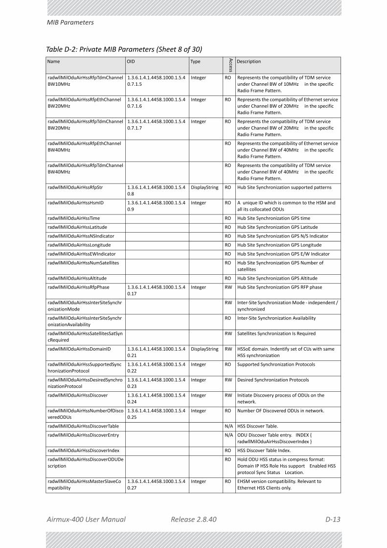
Airmux‐400 User Manual Release 2.8.40 D‐13
MIB Parameters
radwllMilOduAirHssRfpTdmChannel
BW10MHz
1.3.6.1.4.1.4458.1000.1.5.4
0.7.1.5
Integer RO Represents the compatibility of TDM service
under Channel BW of 10MHz in the specific Radio Frame Pattern.
radwllMilOduAirHssRfpEthChannelBW20MHz
1.3.6.1.4.1.4458.1000.1.5.40.7.1.6
Integer RO Represents the compatibility of Ethernet service under Channel BW of 20MHz in the specific
Radio Frame Pattern.
radwllMilOduAirHssRfpTdmChannel
BW20MHz
1.3.6.1.4.1.4458.1000.1.5.4
0.7.1.7
Integer RO Represents the compatibility of TDM service
under Channel BW of 20MHz in the specific
Radio Frame Pattern.
radwllMilOduAirHssRfpEthChannel
BW40MHz
RO Represents the compatibility of Ethernet service
under Channel BW of 40MHz in the specific Radio Frame Pattern.
radwllMilOduAirHssRfpTdmChannelBW40MHz
RO Represents the compatibility of TDM service under Channel BW of 40MHz in the specific
Radio Frame Pattern.
radwllMilOduAirHssRfpStr 1.3.6.1.4.1.4458.1000.1.5.4
0.8
DisplayString RO Hub Site Synchronization supported patterns
radwllMilOduAirHssHsmID 1.3.6.1.4.1.4458.1000.1.5.4
0.9
Integer RO A unique ID which is common to the HSM and
all its collocated ODUs
radwllMilOduAirHssTime RO Hub Site Synchronization GPS time
radwllMilOduAirHssLatitude RO Hub Site Synchronization GPS Latitude
radwllMilOduAirHssNSIndicator RO Hub Site Synchronization GPS N/S Indicator
radwllMilOduAirHssLongitude RO Hub Site Synchronization GPS Longitude
radwllMilOduAirHssEWIndicator RO Hub Site Synchronization GPS E/W Indicator
radwllMilOduAirHssNumSatellites RO Hub Site Synchronization GPS Number of
satellites
radwllMilOduAirHssAltitude RO Hub Site Synchronization GPS Altitude
radwllMilOduAirHssRfpPhase 1.3.6.1.4.1.4458.1000.1.5.4
0.17
Integer RW Hub Site Synchronization GPS RFP phase
radwllMilOduAirHssInterSiteSynchr
onizationMode
RW Inter‐Site Synchronization Mode ‐ independent /
synchronized
radwllMilOduAirHssInterSiteSynchronizationAvailability
RO Inter‐Site Synchronization Availability
radwllMilOduAirHssSatellitesSatSyncRequired
RW Satellites Synchronization Is Required
radwllMilOduAirHssDomainID 1.3.6.1.4.1.4458.1000.1.5.40.21
DisplayString RW HSSoE domain. Indentify set of CUs with same HSS synchronization
radwllMilOduAirHssSupportedSynchronizationProtocol
1.3.6.1.4.1.4458.1000.1.5.40.22
Integer RO Supported Synchronization Protocols
radwllMilOduAirHssDesiredSynchronizationProtocol
1.3.6.1.4.1.4458.1000.1.5.40.23
Integer RW Desired Synchronization Protocols
radwllMilOduAirHssDiscover 1.3.6.1.4.1.4458.1000.1.5.40.24
Integer RW Initiate Discovery process of ODUs on the network.
radwllMilOduAirHssNumberOfDiscoveredODUs
1.3.6.1.4.1.4458.1000.1.5.40.25
Integer RO Number OF Discovered ODUs in network.
radwllMilOduAirHssDiscoverTable N/A HSS Discover Table.
radwllMilOduAirHssDiscoverEntry N/A ODU Discover Table entry. INDEX {
radwllMilOduAirHssDiscoverIndex }
radwllMilOduAirHssDiscoverIndex RO HSS Discover Table Index.
radwllMilOduAirHssDiscoverODUDe
scription
RO Hold ODU HSS status in compress format:
Domain IP HSS Role Hss support Enabled HSS
protocol Sync Status Location.
radwllMilOduAirHssMasterSlaveCo
mpatibility
1.3.6.1.4.1.4458.1000.1.5.4
0.27
Integer RO EHSM version compatibility. Relevant to
Ethernet HSS Clients only.
Table D‐2: Private MIB Parameters (Sheet 8 of 30)
Name OID Type
Access
Description

Airmux‐400 User Manual Release 2.8.40 D‐14
MIB Parameters
radwllMilOduAirHssNumberOfAsso
ciatedCU
1.3.6.1.4.1.4458.1000.1.5.4
0.28
Integer RO Number of associated Ethernet HSS Clients.
Relevant to Ethernet HSS Masters only
radwllMilOduAirHssAssociatedCUTa
ble
N/A Associated Ethernet HSS Clients Table. Releant
for Ethernet HSS Masters only.
radwllMilOduAirHssAssociatedCUTa
bleEntry
N/A Associated Ethernet HSS Clients Table Entry.
Releant for Ethernet HSS Masters only. INDEX { radwllMilOduAirHssAssociatedCUIndex }
radwllMilOduAirHssAssociatedCUIndex
1.3.6.1.4.1.4458.1000.1.5.40.29.1.1
Integer RO Associated Ethernet HSS Clients Table Index. Releant for Ethernet HSS Masters only.
radwllMilOduAirHssAssociatedCUDescription
1.3.6.1.4.1.4458.1000.1.5.40.29.1.2
DisplayString RO Holds Associated Ethernet HSS Clients Description in compress format: IP Delay
Compatibility Ethernet Speed Ethernet Rx rate
radwllMilOduAirHssSyncStatusEth 1.3.6.1.4.1.4458.1000.1.5.4
0.30
Integer RO Ethernet HSS Client Synchronization Level
radwllMilOduAirHssEthVLANTag 1.3.6.1.4.1.4458.1000.1.5.4
0.31
Integer RW Ethernet HSS VLan Tag: The least significate
decimal digit is the VLan Priority(0‐6) and the
rest of the digits represents VLan ID (2‐4094)
radwllMilOduAirHssHSMIPAddress 1.3.6.1.4.1.4458.1000.1.5.4
0.32
IPAddress RO HSMs IP address. Relevant for HSC synchronized
over Ethernet.
radwllMilOduAirHssDelayToHSM 1.3.6.1.4.1.4458.1000.1.5.4
0.33
Integer RO Delay in microseconds to HSM. Relevant for HSC
synchronized over Ethernet.
radwllMilOduAirHssSyncAcquisition
Seconds
RW Accumulated quantity of seconds in clock
acquisition while connected to current HSM
radwllMilOduAirLockRemote 1.3.6.1.4.1.4458.1000.1.5.4
1
Integer RW This parameter enables locking the link with a
specific ODU. The following values can be set: Unlock (default) ‐ The ODU is not locked on a
specific remote ODU. Unlock can only be
performed when the link is not connected. Lock ‐ The ODU is locked on a specific remote
ODU. Lock can only be performed when the link
is active.
radwllMilOduAirAntennaGain 1.3.6.1.4.1.4458.1000.1.5.4
2
Integer RW Current Antenna Gain in 0.1 dBi resolution. User
defined value for external antenna. Legal
range: MinAntennaGain<AntennaGain<MaxAntennaG
ain.
radwllMilOduAirFeederLoss 1.3.6.1.4.1.4458.1000.1.5.4
3
Integer RW Current Feeder Loss in 0.1 dBm resolution. User
defined value for external antenna.
radwllMilOduAirMaxAntennaGain 1.3.6.1.4.1.4458.1000.1.5.4
4
Integer RO Maximum allowed Antenna Gain in 0.1 dBi
resolution.
radwllMilOduAirMinAntennaGain 1.3.6.1.4.1.4458.1000.1.5.4
5
Integer RO Minimum allowed Antenna Gain in 0.1 dBi
resolution.
radwllMilOduAirMaxEIRP 1.3.6.1.4.1.4458.1000.1.5.4
6
Integer RO Maximum EIRP value as defined by regulation in
0.1 dBm resolution.
radwllMilOduAirAntennaGainConfig
Support
1.3.6.1.4.1.4458.1000.1.5.4
7
Integer RO Antenna Gain Configurability options are
product specific: supported not supported.
radwllMilOduAirAntennaType 1.3.6.1.4.1.4458.1000.1.5.4
8
Integer RW External Antenna Type: single‐pole or dual‐pole.
radwllMilOduAirRssBalance 1.3.6.1.4.1.4458.1000.1.5.4
9
Integer RO RSS balance. Relation between RSS in radio 1
and RSS in radio 2. ‐2 : Radio 2 RSS is much
stronger than Radio 1 RSS. ‐1 : Radio 2 RSS is stronger than Radio 1 RSS. ‐0 : Radio 2 RSS is
equal to Radio 1 RSS. 1 : Radio 1 RSS is stronger
than Radio 2 RSS. 2 : Radio 1 RSS is much stronger than Radio 2 RSS.
radwllMilOduAirTotalTxPower 1.3.6.1.4.1.4458.1000.1.5.50
Integer RO Total Transmit Power in dBm. This is a nominal value While the actual transmit power includes
additional attenuation.
Table D‐2: Private MIB Parameters (Sheet 9 of 30)
Name OID Type
Access
Description

Airmux‐400 User Manual Release 2.8.40 D‐15
MIB Parameters
radwllMilOduAirInstallFreqAndCBW 1.3.6.1.4.1.4458.1000.1.5.5
1
DisplayString RW Installation frequency Channel BW. Relevant in
point to point systems.
radwllMilOduAirDFStype 1.3.6.1.4.1.4458.1000.1.5.5
2
Integer RO DFS regulation type.
radwllMilOduAirComboSubBandTab
le
N/A ODU Multi‐band Sub Bands Table.
radwllMilOduAirComboSubBandEnt
ry
N/A ODU Multi‐band Sub Bands Table entry. INDEX
{ radwllMilOduAirComboSubBandIndex }
radwllMilOduAirComboSubBandInd
ex
1.3.6.1.4.1.4458.1000.1.5.5
3.1.1.1
Integer RO ODU Multi‐band sub bands table index.
radwllMilOduAirComboSubBandId 1.3.6.1.4.1.4458.1000.1.5.5
3.1.1.2
DisplayString RO Represents the Multi‐band sub band ID.
radwllMilOduAirComboSubBandDe
scription
1.3.6.1.4.1.4458.1000.1.5.5
3.1.1.3
DisplayString RO Multi‐band sub band description.
radwllMilOduAirComboSubBandIns
tallFreq
1.3.6.1.4.1.4458.1000.1.5.5
3.1.1.4
Integer RO Represents the Multi‐band sub band installation
frequency in KHz.
radwllMilOduAirComboSubBandAd
minState
1.3.6.1.4.1.4458.1000.1.5.5
3.1.1.5
Integer RO Represents the Multi‐band sub band
administrative state.
radwllMilOduAirComboSubBandIns
tallationAllowed
1.3.6.1.4.1.4458.1000.1.5.5
3.1.1.6
Integer RO Reflects if the Multi‐band sub band allowes
installtion.
radwllMilOduAirComboFrequencyB
andId
1.3.6.1.4.1.4458.1000.1.5.5
3.1.1.7
Integer RO Reflects the frequency band Id.
radwllMilOduAirComboSubBandCh
annelBW5AdminState
RO Reflects the CBW 5MHz admin state vector.
radwllMilOduAirComboSubBandCh
annelBW10AdminState
RO Reflects the CBW 10MHz admin state vector.
radwllMilOduAirComboSubBandCh
annelBW20AdminState
RO Reflects the CBW 20MHz admin state vector.
radwllMilOduAirComboSubBandCh
annelBW40AdminState
RO Reflects the CBW 40MHz admin state vector.
radwllMilOduAirComboSubBandAll
owableChannels
RO Reflects the allowable channels vector.
radwllMilOduAirComboSubBandCh
annelBWAvail
RO Reflects the available CBWs vector.
radwllMilOduAirComboSubBandCh
annelBandwidth
RO Reflects the sub‐band default channel
bandwidth.
radwllMilOduAirComboSubBandMi
nFreq
RO Reflects the sub‐band default minimal
frequency.
radwllMilOduAirComboSubBandMa
xFreq
RO Reflects the sub‐band default maximal
frequency.
radwllMilOduAirComboSubBandFre
quencyResolution
RO Reflects the sub‐band frequency resolution.
radwllMilOduAirComboSubBandDef
aultChannelList
RO Reflects the default channel list vector.
radwllMilOduAirComboSubBandDfs
State
RO Reflects the sub‐band DFS state.
radwllMilOduAirComboNumberOfS
ubBands
1.3.6.1.4.1.4458.1000.1.5.5
3.2
Integer RO Represents the number of Multi‐band sub
bands.
radwllMilOduAirComboSwitchSubB
and
1.3.6.1.4.1.4458.1000.1.5.5
3.3
DisplayString RW Switch sub band operation with a given sub
band ID. The get operation retrieves the
current sub band ID.
radwllMilOduAirComboCurrentSub
BandDesc
1.3.6.1.4.1.4458.1000.1.5.5
3.4
DisplayString RO Current Sub Band description.
radwllMilOduAirInternalMaxRate 1.3.6.1.4.1.4458.1000.1.5.5
4
Integer RO Max Ethernet throughput of the site (in Kpbs).
Table D‐2: Private MIB Parameters (Sheet 10 of 30)
Name OID Type
Access
Description

Airmux‐400 User Manual Release 2.8.40 D‐16
MIB Parameters
radwllMilOduAirCapacityDirection 1.3.6.1.4.1.4458.1000.1.5.5
5
Integer RW Capacity direction of the site.
radwllMilOduAirSpectrumAnalysisO
perState
1.3.6.1.4.1.4458.1000.1.5.5
6.1
Integer RW Spectrum Analysis operation state. The
configurable values are Spectrum Analysis Stop Start and Restart. Not Supported value
indicates that the feature is not supported on
the device. Not Supported is not a configurable state.
radwllMilOduAirRxPowerAntennaA 1.3.6.1.4.1.4458.1000.1.5.56.2
Integer RO Received Signal Strength in dBm of Antenna A.
radwllMilOduAirRxPowerAntennaB 1.3.6.1.4.1.4458.1000.1.5.56.3
Integer RO Received Signal Strength in dBm of Antenna B.
radwllMilOduAirNumberOfSpectrumChannels
1.3.6.1.4.1.4458.1000.1.5.56.4
Integer RO Represents the number of Spectrum Channels.
radwllMilOduAirSpectrumChannelTable
N/A ODU Spectrum Analysis Channel Table.
radwllMilOduAirSpectrumChannelTableEntry
N/A ODU Spectrum Analysis Channel Table entry. INDEX { radwllMilOduAirSpectrumChannelIndex
}
radwllMilOduAirSpectrumChannelI
ndex
1.3.6.1.4.1.4458.1000.1.5.5
6.5.1.1
Integer RO ODU Spectrum Channel index.
radwllMilOduAirSpectrumChannelF
requency
1.3.6.1.4.1.4458.1000.1.5.5
6.5.1.2
Integer RO ODU Spectrum Channel frequency in MHz.
radwllMilOduAirSpectrumChannelS
canned
1.3.6.1.4.1.4458.1000.1.5.5
6.5.1.3
Integer RO An indication of the vaildity of the channel's
data. If the channel was scanned the data is
valid, else not.
radwllMilOduAirSpectrumChannelS
canningTimestamp
1.3.6.1.4.1.4458.1000.1.5.5
6.5.1.4
TimeTicks RO Channel last scan timestamp in hundredths of a
second since device up time. If the channel was not scanned than the return value will be 0.
radwllMilOduAirSpectrumChannelLastNFAntennaA
1.3.6.1.4.1.4458.1000.1.5.56.5.1.5
Integer RO Normalized Noise Floor value in dBm ‐ of Antenna A ‐ (including 2 neighbor frequencies).
radwllMilOduAirSpectrumChannelLastNFAntennaB
1.3.6.1.4.1.4458.1000.1.5.56.5.1.6
Integer RO Normalized Noise Floor value in dBm ‐ of Antenna B ‐ (including 2 neighbor frequencies).
radwllMilOduAirSpectrumChannelA
verageNFAntennaA
1.3.6.1.4.1.4458.1000.1.5.5
6.5.1.7
Integer RO Average normalized Noise Floor value in dBm ‐
of Antenna A ‐ over all dwells.
radwllMilOduAirSpectrumChannelA
verageNFAntennaB
1.3.6.1.4.1.4458.1000.1.5.5
6.5.1.8
Integer RO Average normalized Noise Floor value in dBm ‐
of Antenna B ‐ over all dwells.
radwllMilOduAirSpectrumChannel
MaxNFAntennaA
1.3.6.1.4.1.4458.1000.1.5.5
6.5.1.9
Integer RO Max normalized Noise Floor value in dBm ‐ of
Antenna A ‐ over all dwells.
radwllMilOduAirSpectrumChannel
MaxNFAntennaB
1.3.6.1.4.1.4458.1000.1.5.5
6.5.1.10
Integer RO Max normalized Noise Floor value in dBm ‐ of
Antenna B ‐ over all dwells.
radwllMilOduAirSpectrumChannelC
ACPerformed
1.3.6.1.4.1.4458.1000.1.5.5
6.5.1.11
Integer RO Was CAC performed on the channel.
radwllMilOduAirSpectrumChannelL
astCACTimestamp
1.3.6.1.4.1.4458.1000.1.5.5
6.5.1.12
TimeTicks RO Last CAC performed timestamp in hundredths
of a second since device up time. If no CAC has performed on the channel the return value will
be 0.
radwllMilOduAirSpectrumChannelR
adarDetected
1.3.6.1.4.1.4458.1000.1.5.5
6.5.1.13
Integer RO Was Radar detected on the channel.
radwllMilOduAirSpectrumChannelR
adarDetectionTimestamp
1.3.6.1.4.1.4458.1000.1.5.5
6.5.1.14
TimeTicks RO Last Radar Detection timestamp in hundredths
of a second since device up time. If no Radar
has detected on the channel the return value will be 0.
radwllMilOduAirSpectrumChannelAvailable
1.3.6.1.4.1.4458.1000.1.5.56.5.1.15
Integer RO Is the channel available for use.
radwllMilOduAirSpectrumChannelMaxBeaconRss
1.3.6.1.4.1.4458.1000.1.5.56.5.1.16
Integer RO The max RSS value of a received beacon on the specific channel in dBm.
Table D‐2: Private MIB Parameters (Sheet 11 of 30)
Name OID Type
Access
Description

Airmux‐400 User Manual Release 2.8.40 D‐17
MIB Parameters
radwllMilOduAirSpectrumChannelC
ompressed
1.3.6.1.4.1.4458.1000.1.5.5
6.5.1.17
OctetString RO Compress all the Spectrum data per channel
into one variable. Frequency (4 bytes) Scanned (1 byte) Timestamp (4 bytes) Last NF
Antenna A (1 byte) Last NF Antenna B (1 byte)
Avg NF Antenna A (1 byte) Avg NF Antenna B (1 byte) Max NF Antenna A (1 byte) Max NF
Antenna B (1 byte) CAC Performed (1 byte)
Last CAC Timestamp (4 bytes) Radar Detected (1 byte) Radar Detected Timestamp (4 bytes)
Channel Available (1 byte) Max Beacon RSS (1
byte).
radwllMilOduAirChipMinMaxFreq RO The minimum and maximum frequencies in
MHz which the chip supports.
radwllMilOduAirSpectrumAnalysisTi
meout
1.3.6.1.4.1.4458.1000.1.5.5
6.7
Integer RW Spectrum analysis timeout in seconds.
radwllMilOduAirAntConfAndRatesS
tatus
1.3.6.1.4.1.4458.1000.1.5.5
7
Integer RO Description: Antenna configuration and Rates
status (1 = Single antenna with single data stream 2 = Dual antenna with single data
stream 3 = Dual antenna with dual data
stream).
radwllMilOduAirDualAntTxMode 1.3.6.1.4.1.4458.1000.1.5.5
8
Integer RW Description: Transmission type when using Dual
radios (MIMO or AdvancedDiversity using one stream of data).
radwllMilOduAirTxOperationMode 1.3.6.1.4.1.4458.1000.1.5.59
Integer RW This parameter controls the Operation mode of frames sent over the air. The Operation mode
is either normal (1) for regular transmission
where frame size is determined by the traffic or throughput test (2) when the user requests an
actual over the air throughput estimation using
full frames. The latter lasts no more than a predetermined interval (default 30 sec).
radwllMilOduAirDesiredNetMasterTxRatio
1.3.6.1.4.1.4458.1000.1.5.60.1
Integer RW This parameter is reserved to the element manager provided with the product.
radwllMilOduAirCurrentNetMaster
TxRatio
1.3.6.1.4.1.4458.1000.1.5.6
0.2
Integer RO Represents the actual Net Master Tx RAtio.
radwllMilOduAirMinUsableMasterT
xRatio
1.3.6.1.4.1.4458.1000.1.5.6
0.3
Integer RO Represents the minimal value the user can
configure for Desired net mAster Tx Ratio.
radwllMilOduAirMaxUsableMasterT
xRatio
1.3.6.1.4.1.4458.1000.1.5.6
0.4
Integer RO Represents the maximal value the user can
configure for Desired net mAster Tx Ratio.
radwllMilOduAirAccumulatedUAS 1.3.6.1.4.1.4458.1000.1.5.6
1
Integer RO Accumulates the Unavailable seconds of the Air
Interface. Relevant for point to point systems.
radwllMilOduAirDistStr 1.3.6.1.4.1.4458.1000.1.5.6
2
DisplayString RO Possibilities of the link according to RFP and
CBW
radwllMilOduAirChannelsDefaultFr
eqStr
RO A string representing the channels available.
Each character represents one frequency when '1' means its available and '0' means its not.
radwllMilOduAirAntConnectionType
1.3.6.1.4.1.4458.1000.1.5.64
Integer RW Antenna connection type (External(1) Integrated(2) Embedded_External(3)
Embedded_Integrated(4) ).
radwllMilOduAirAllowableChannels
Str
RW A string representing the allowable channels.
Each character represents one channel when '1'
means its available and '0' means its not.
radwllMilOduAirDfsAlgorithmTypeS
tate
RW Bitmap for state of Radar Algorithm Type. Filters
by bit's position: 0 = Zero PW 1 = Fixed 2 = Variable 3 = Staggered 4 = Long.
radwllMilOduAirDfsLastDetectedTbl N/A Last detected radars table.
radwllMilOduAirDfsLastDetectedEn
try
N/A ODU Multi‐band Sub Bands Table entry. INDEX
{ radwllMilOduAirDfsLastDetectedIndex }
Table D‐2: Private MIB Parameters (Sheet 12 of 30)
Name OID Type
Access
Description

Airmux‐400 User Manual Release 2.8.40 D‐18
MIB Parameters
radwllMilOduAirDfsLastDetectedInd
ex
RO Dfs Last Detected Radars Table Index.
radwllMilOduAirDfsLastDetectedTi
me
RO Dfs time of the last detected radar.
radwllMilOduAirDfsLastDetectedAlg
orithmType
RO Dfs type of the last detected radar.
radwllMilOduAirDfsLastDetectedFre
quency
RO Dfs frequency of the last detected radar.
radwllMilOduAirPreferredChannels
Str
1.3.6.1.4.1.4458.1000.1.5.6
7
DisplayString RW A string representing the preferred channels.
Each character represents one channel when '1' means its preferred and '0' means its not.
radwllMilOduAirSyncLossThreshold 1.3.6.1.4.1.4458.1000.1.5.68
Integer RW When the current throughput is below this threshold (in Kbps) sync loss will occur.
radwllMilOduAirGeoLocation RW Geographic device location in format: latitude longitude.
radwllMilOduAirAggregateCapacity 1.3.6.1.4.1.4458.1000.1.5.70
Integer RO Aggregate Capacity of the ODU in Mbps.
radwllMilOduPerfMonCurrTable N/A This table defines/keeps the counters of the current 15 min interval.
radwllMilOduPerfMonCurrEntry N/A This is an entry in the Current Interval Table. INDEX {ifIndex }
radwllMilOduPerfMonCurrUAS 1.3.6.1.4.1.4458.1000.1.6.1.1.1
Gauge RO The current number of Unavailable Seconds starting from the present 15 minutes period.
radwllMilOduPerfMonCurrES 1.3.6.1.4.1.4458.1000.1.6.1.1.2
Gauge RO Current number of Errored Seconds starting from the present 15 minutes period.
radwllMilOduPerfMonCurrSES 1.3.6.1.4.1.4458.1000.1.6.1.1.3
Gauge RO Current number of Severely Errored Seconds starting from the present 15 minutes period.
radwllMilOduPerfMonCurrBBE 1.3.6.1.4.1.4458.1000.1.6.1.1.4
Gauge RO Current number of Background Block Errors starting from the present 15 minutes period.
radwllMilOduPerfMonCurrIntegrity 1.3.6.1.4.1.4458.1000.1.6.1.1.5
Integer RO Indicates the integrity of the entry.
radwllMilOduPerfMonCurrCompres
sed
RO Holds a compressed string of all data per
interface. Compressed Air Interface Structure (size in brackets): UAS (4) ES (4) SES (4) BBE
(4) Integrity (1) MinRSL (1) MaxRSL (1)
RSLThresh1Exceeded (4) RSLThresh2Exceeded (4) MinTSL (1) MaxTSL (1) TSLThresh1Exceed
(4) BBERThresh1Exceed (4) RxMBytes (4)
TxMBytes (4) EthCapacityThreshUnder (4) HighTrafficThreshExceed (4) Compressed
Etherent ODU interface (size in brackets): UAS
(4) ES (4) SES (4) BBE (4) Integrity (1) RxMBytes (4) TxMBytes (4)
EthCapacityThreshUnder (4)
HighTrafficThreshExceed (4) ActiveSeconds (4)
radwllMilOduPerfMonIntervalTable N/A This table defines/keeps the counters of the last
day (in resolution of 15 min intervals).
radwllMilOduPerfMonIntervalEntry N/A This is an entry in the Interval Table. INDEX
{ifIndex radwllMilOduPerfMonIntervalIdx }
radwllMilOduPerfMonIntervalIdx RO This table is indexed per interval number. Each
interval is of 15 minutes and the oldest is 96.
radwllMilOduPerfMonIntervalUAS RO The current number of Unavailable Seconds per
interval.
radwllMilOduPerfMonIntervalES RO Current number of Errored Seconds per interval.
radwllMilOduPerfMonIntervalSES RO Current number of Severely Errored Seconds per
interval.
Table D‐2: Private MIB Parameters (Sheet 13 of 30)
Name OID Type
Access
Description
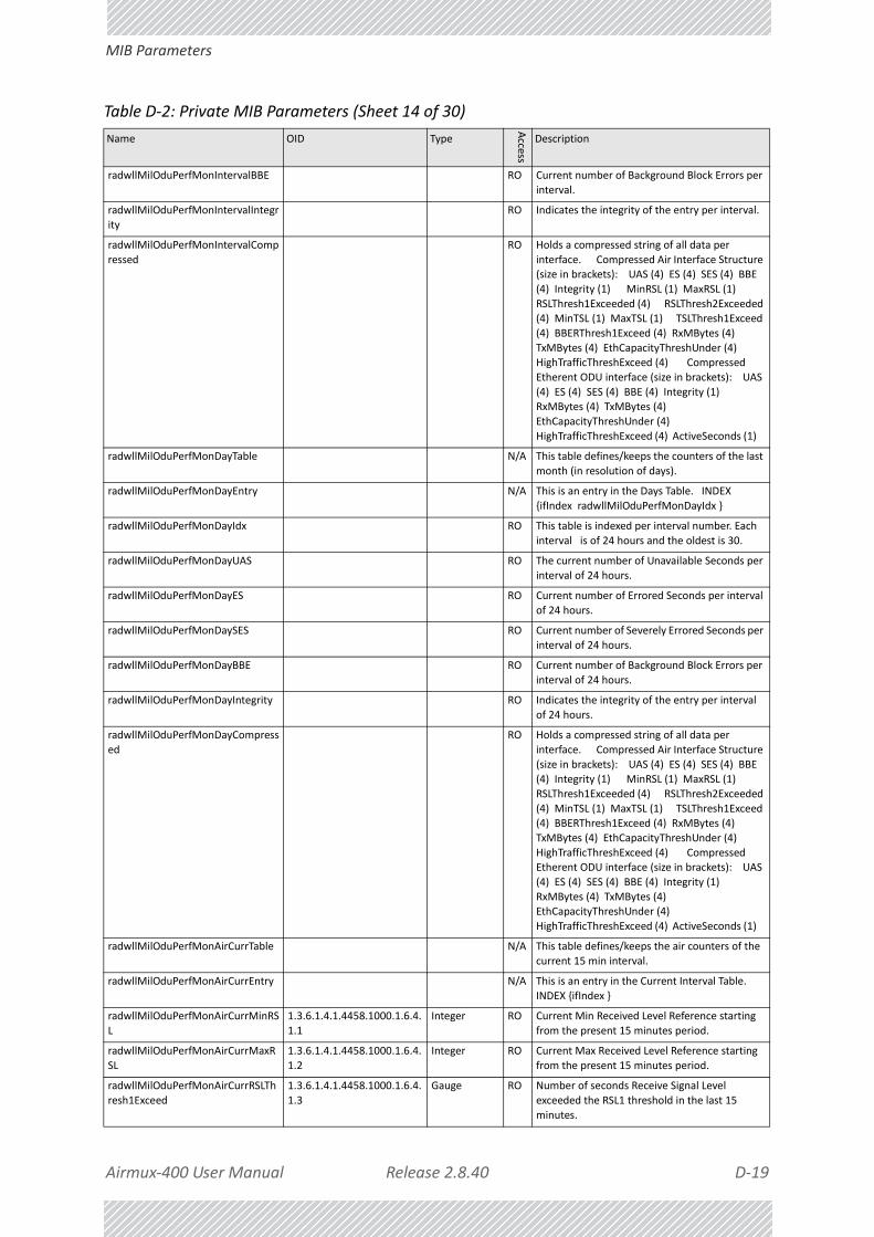
Airmux‐400 User Manual Release 2.8.40 D‐19
MIB Parameters
radwllMilOduPerfMonIntervalBBE RO Current number of Background Block Errors per
interval.
radwllMilOduPerfMonIntervalIntegr
ity
RO Indicates the integrity of the entry per interval.
radwllMilOduPerfMonIntervalComp
ressed
RO Holds a compressed string of all data per
interface. Compressed Air Interface Structure (size in brackets): UAS (4) ES (4) SES (4) BBE
(4) Integrity (1) MinRSL (1) MaxRSL (1)
RSLThresh1Exceeded (4) RSLThresh2Exceeded (4) MinTSL (1) MaxTSL (1) TSLThresh1Exceed
(4) BBERThresh1Exceed (4) RxMBytes (4)
TxMBytes (4) EthCapacityThreshUnder (4) HighTrafficThreshExceed (4) Compressed
Etherent ODU interface (size in brackets): UAS
(4) ES (4) SES (4) BBE (4) Integrity (1) RxMBytes (4) TxMBytes (4)
EthCapacityThreshUnder (4)
HighTrafficThreshExceed (4) ActiveSeconds (1)
radwllMilOduPerfMonDayTable N/A This table defines/keeps the counters of the last
month (in resolution of days).
radwllMilOduPerfMonDayEntry N/A This is an entry in the Days Table. INDEX
{ifIndex radwllMilOduPerfMonDayIdx }
radwllMilOduPerfMonDayIdx RO This table is indexed per interval number. Each
interval is of 24 hours and the oldest is 30.
radwllMilOduPerfMonDayUAS RO The current number of Unavailable Seconds per
interval of 24 hours.
radwllMilOduPerfMonDayES RO Current number of Errored Seconds per interval
of 24 hours.
radwllMilOduPerfMonDaySES RO Current number of Severely Errored Seconds per
interval of 24 hours.
radwllMilOduPerfMonDayBBE RO Current number of Background Block Errors per
interval of 24 hours.
radwllMilOduPerfMonDayIntegrity RO Indicates the integrity of the entry per interval
of 24 hours.
radwllMilOduPerfMonDayCompress
ed
RO Holds a compressed string of all data per
interface. Compressed Air Interface Structure
(size in brackets): UAS (4) ES (4) SES (4) BBE (4) Integrity (1) MinRSL (1) MaxRSL (1)
RSLThresh1Exceeded (4) RSLThresh2Exceeded
(4) MinTSL (1) MaxTSL (1) TSLThresh1Exceed (4) BBERThresh1Exceed (4) RxMBytes (4)
TxMBytes (4) EthCapacityThreshUnder (4)
HighTrafficThreshExceed (4) Compressed Etherent ODU interface (size in brackets): UAS
(4) ES (4) SES (4) BBE (4) Integrity (1)
RxMBytes (4) TxMBytes (4) EthCapacityThreshUnder (4)
HighTrafficThreshExceed (4) ActiveSeconds (1)
radwllMilOduPerfMonAirCurrTable N/A This table defines/keeps the air counters of the
current 15 min interval.
radwllMilOduPerfMonAirCurrEntry N/A This is an entry in the Current Interval Table.
INDEX {ifIndex }
radwllMilOduPerfMonAirCurrMinRS
L
1.3.6.1.4.1.4458.1000.1.6.4.
1.1
Integer RO Current Min Received Level Reference starting
from the present 15 minutes period.
radwllMilOduPerfMonAirCurrMaxR
SL
1.3.6.1.4.1.4458.1000.1.6.4.
1.2
Integer RO Current Max Received Level Reference starting
from the present 15 minutes period.
radwllMilOduPerfMonAirCurrRSLTh
resh1Exceed
1.3.6.1.4.1.4458.1000.1.6.4.
1.3
Gauge RO Number of seconds Receive Signal Level
exceeded the RSL1 threshold in the last 15
minutes.
Table D‐2: Private MIB Parameters (Sheet 14 of 30)
Name OID Type
Access
Description

Airmux‐400 User Manual Release 2.8.40 D‐20
MIB Parameters
radwllMilOduPerfMonAirCurrRSLTh
resh2Exceed
1.3.6.1.4.1.4458.1000.1.6.4.
1.4
Gauge RO Number of seconds Receive Signal Level
exceeded the RSL2 threshold in the last 15 minutes.
radwllMilOduPerfMonAirCurrMinTSL
1.3.6.1.4.1.4458.1000.1.6.4.1.5
Integer RO Current Min Transmit Signal Level starting from the present 15 minutes period.
radwllMilOduPerfMonAirCurrMaxTSL
1.3.6.1.4.1.4458.1000.1.6.4.1.6
Integer RO Current Max Transmit Signal Level starting from the present 15 minutes period.
radwllMilOduPerfMonAirCurrTSLThresh1Exceed
1.3.6.1.4.1.4458.1000.1.6.4.1.7
Gauge RO Number of seconds Transmit Signal Level exceeded the TSL1 threshold in the last 15
minutes.
radwllMilOduPerfMonAirCurrBBERT
hresh1Exceed
1.3.6.1.4.1.4458.1000.1.6.4.
1.8
Gauge RO Number of seconds Background Block Error
Ratio exceeded the BBER1 threshold in the last
15 minutes.
radwllMilOduPerfMonAirIntervalTa
ble
N/A This table defines/keeps the air counters of the
last day (in resolution of 15 min intervals).
radwllMilOduPerfMonAirIntervalEn
try
N/A This is an entry in the Interval Table. INDEX
{ifIndex radwllMilOduPerfMonAirIntervalIdx }
radwllMilOduPerfMonAirIntervalIdx RO This table is indexed per interval number. Each
interval is of 15 minutes and the oldest is 96.
radwllMilOduPerfMonAirIntervalMi
nRSL
RO Current Min Received Level Reference per
interval.
radwllMilOduPerfMonAirIntervalM
axRSL
RO Current Max Received Level Reference per
interval.
radwllMilOduPerfMonAirIntervalRS
LThresh1Exceed
RO Number of seconds Receive Signal Level
exceeded the RSL1 threshold per interval.
radwllMilOduPerfMonAirIntervalRS
LThresh2Exceed
Number of seconds Receive Signal Level
exceeded the RSL2 threshold ACCESS read‐only per interval.
radwllMilOduPerfMonAirIntervalMinTSL
RO Current Min Transmit Signal Level per interval.
radwllMilOduPerfMonAirIntervalMaxTSL
RO Current Max Transmit Signal Level per interval.
radwllMilOduPerfMonAirIntervalTS
LThresh1Exceed
RO Number of seconds Transmit Signal Level
exceeded the TSL1 threshold per interval.
radwllMilOduPerfMonAirIntervalBB
ERThresh1Exceed
RO Number of seconds Background Block Error
Ratio exceeded the BBER1 threshold per interval.
radwllMilOduPerfMonAirDayTable N/A This table defines/keeps the air counters of the last month (in resolution of days).
radwllMilOduPerfMonAirDayEntry N/A This is an entry in the Days Table. INDEX {ifIndex radwllMilOduPerfMonAirDayIdx }
radwllMilOduPerfMonAirDayIdx RO This table is indexed per Day number. Each Day is of 15 minutes and the oldest is 96.
radwllMilOduPerfMonAirDayMinRSL
RO Current Min Received Level Reference per Day.
radwllMilOduPerfMonAirDayMaxRSL
RO Current Max Received Level Reference per Day.
radwllMilOduPerfMonAirDayRSLThresh1Exceed
RO Number of seconds Receive Signal Level exceeded the RSL1 threshold per Day.
radwllMilOduPerfMonAirDayRSLThresh2Exceed
RO Number of seconds Receive Signal Level exceeded the RSL2 threshold per Day.
radwllMilOduPerfMonAirDayMinTSL
RO Current Min Transmit Signal Level per Day.
radwllMilOduPerfMonAirDayMaxTSL
RO Current Max Transmit Signal Level per Day.
Table D‐2: Private MIB Parameters (Sheet 15 of 30)
Name OID Type
Access
Description

Airmux‐400 User Manual Release 2.8.40 D‐21
MIB Parameters
radwllMilOduPerfMonAirDayTSLThr
esh1Exceed
RO Number of seconds Transmit Signal Level
exceeded the TSL1 threshold per Day.
radwllMilOduPerfMonAirDayBBERT
hresh1Exceed
RO Number of seconds Background Block Error
Ratio exceeded the BBER1 threshold per Day.
radwllMilOduPerfMonEthCurrTable N/A This table defines/keeps the ethernet counters
of the current 15 min interval.
radwllMilOduPerfMonEthCurrEntry N/A This is an entry in the Current Interval Table.
INDEX {ifIndex }
radwllMilOduPerfMonEthCurrRxMB
ytes
1.3.6.1.4.1.4458.1000.1.6.7.
1.1
Gauge RO Current RX Mega Bytes starting from the
present 15 minutes period.
radwllMilOduPerfMonEthCurrTxMB
ytes
1.3.6.1.4.1.4458.1000.1.6.7.
1.2
Gauge RO Current Transmit Mega Bytes starting from the
present 15 minutes period.
radwllMilOduPerfMonEthCurrEthCa
pacityThreshUnder
1.3.6.1.4.1.4458.1000.1.6.7.
1.3
Gauge RO The number of times throughput was below
threshold in the present 15 minutes period. Relevant for point to point systems.
radwllMilOduPerfMonEthCurrHighTrafficThreshExceed
1.3.6.1.4.1.4458.1000.1.6.7.1.4
Gauge RO The number of times actual traffic was above threshold in the present 15 minutes period.
radwllMilOduPerfMonEthCurrActiveSeconds
1.3.6.1.4.1.4458.1000.1.6.7.1.5
Gauge RO The number of seconds in which RPL Ethernet swervice was not blocked in the present 15
minutes period.
radwllMilOduPerfMonEthIntervalTa
ble
N/A This table defines/keeps the ethernet counters
of the last day (in resolution of 15 min intervals).
radwllMilOduPerfMonEthIntervalEn
try
N/A This is an entry in the Interval Table. INDEX
{ifIndex radwllMilOduPerfMonEthIntervalIdx }
radwllMilOduPerfMonEthIntervalId
x
RO This table is indexed per interval number. Each
interval is of 15 minutes and the oldest is 96.
radwllMilOduPerfMonEthIntervalRx
MBytes
RO Current RX Mega Bytes per interval.
radwllMilOduPerfMonEthIntervalTx
MBytes
RO Current Transmit Mega Bytes per interval.
radwllMilOduPerfMonEthIntervalEt
hCapacityThreshUnder
RO The number of times throughput was below
threshold in the each interval. Relevant for
point to point systems.
radwllMilOduPerfMonEthIntervalHi
ghTrafficThreshExceed
RO The number of times actual traffic was above
threshold in the each interval.
radwllMilOduPerfMonEthIntervalAc
tiveSeconds
RO The number of seconds in which RPL Ethernet
service was not blocked in the each interval.
radwllMilOduPerfMonEthDayTable N/A This table defines/keeps the ethernet counters
of the last month (in resolution of days).
radwllMilOduPerfMonEthDayEntry N/A This is an entry in the Days Table. INDEX
{ifIndex radwllMilOduPerfMonEthDayIdx }
radwllMilOduPerfMonEthDayIdx RO This table is indexed per Day number. Each
interval is of 15 minutes and the oldest is 96.
radwllMilOduPerfMonEthDayRxMB
ytes
RO Current RX Mega Bytes per day.
radwllMilOduPerfMonEthDayTxMB
ytes
RO Current Transmit Mega Bytes per day.
radwllMilOduPerfMonEthDayEthCa
pacityThreshUnder
RO The number of times throughput was below
threshold each day. Relevant for point to point
systems.
radwllMilOduPerfMonEthDayHighTr
afficThreshExceed
RO The number of times actual traffic was above
threshold each day.
radwllMilOduPerfMonEthDayActive
Seconds
RO The number of seconds in which RPL Ethernet
service was not blocked each day.
radwllMilOduPerfMonTdmCurrTabl
e
N/A This table defines/keeps the TDM counters of
the current 15 min interval.
Table D‐2: Private MIB Parameters (Sheet 16 of 30)
Name OID Type
Access
Description

Airmux‐400 User Manual Release 2.8.40 D‐22
MIB Parameters
radwllMilOduPerfMonTdmCurrEntr
y
N/A This is an entry in the Current Interval Table.
INDEX {ifIndex }
radwllMilOduPerfMonTdmCurrActiv
eSeconds
1.3.6.1.4.1.4458.1000.1.6.1
0.1.1
Gauge RO Parameter indicating whether the TDM service
was active. Under TDM backup link the parameter indicates whether the backup link
was active.
radwllMilOduPerfMonTdmIntervalT
able
N/A This table defines/keeps the TDM counters of
the last day (in resolution of 15 min intervals).
radwllMilOduPerfMonTdmIntervalE
ntry
N/A This is an entry in the Interval Table. INDEX
{ifIndex radwllMilOduPerfMonTdmIntervalIdx }
radwllMilOduPerfMonTdmIntervalI
dx
RO This table is indexed per interval number. Each
interval is of 15 minutes and the oldest is 96.
radwllMilOduPerfMonTdmIntervalA
ctiveSeconds
RO Parameter indicating whether the TDM service
was active. Under TDM backup link the
parameter indicates whether the backup link was active.
radwllMilOduPerfMonTdmDayTable N/A This table defines/keeps the TDM counters of the last month (in resolution of days).
radwllMilOduPerfMonTdmDayEntry N/A This is an entry in the Days Table. INDEX {ifIndex radwllMilOduPerfMonTdmDayIdx }
radwllMilOduPerfMonTdmDayIdx RO This table is indexed per Day number. Each interval is of 15 minutes and the oldest is 96.
radwllMilOduPerfMonTdmDayActiveSeconds
RO Parameter indicating whether the TDM service was active. Under TDM backup link the
parameter indicates whether the backup link
was active.
radwllMilOduPerfMonTxThresh1 1.3.6.1.4.1.4458.1000.1.6.2
0
Integer RW When the Transmit power exceeds this
threshold a performance monitoring TSL1 counter is incremented.
radwllMilOduPerfMonRxThresh1 1.3.6.1.4.1.4458.1000.1.6.21
Integer RW When the RX power exceeds this threshold a performance monitoring RSL1 counter is
incremented.
radwllMilOduPerfMonRxThresh2 1.3.6.1.4.1.4458.1000.1.6.2
2
Integer RW When the RX power exceeds this threshold a
performance monitoring RSL2 counter is
incremented.
radwllMilOduPerfMonBBERThresh1 1.3.6.1.4.1.4458.1000.1.6.2
3
Integer RW When the BBER exceeds this threshold a
performance monitoring BBER counter is
incremented. The units are 1/10 of a percent.
radwllMilOduPerfMonEthCapacityT
hreshKbps
1.3.6.1.4.1.4458.1000.1.6.2
4
Integer RW When the current throughput is below this
threshold the corresponding counter is incremented
radwllMilOduPerfMonHighTrafficThreshKbps
1.3.6.1.4.1.4458.1000.1.6.25
Integer RW When the current traffic is above this threshold then corresponding counter is incremented.
radwllMilOduAgnGenAddTrapExt 1.3.6.1.4.1.4458.1000.1.7.1.1
Integer RW If 'yes' is chosen the ifIndex Unit Severity Time_T and Alarm Id from the
radwllMilOduAgnCurrAlarmTable will be bind
to the end of each private trap.
radwllMilOduAgnGenSetMode 1.3.6.1.4.1.4458.1000.1.7.1.
2
Integer RW This parameter is reserved to the element
manager provided with the product.
radwllMilOduAgnGenLocalConnecti
onMode
RW Local Connection (Broadcast) Configuration
Mode. Options are: 1 ‐ SNMP Read‐Write 2 ‐ SNMP Read‐Only.
radwllMilOduAgnNTPCfgTimeServerIP
1.3.6.1.4.1.4458.1000.1.7.2.1
IPAddress RW IP address of the server from which the current time is loaded.
radwllMilOduAgnNTPCfgTimeOffsetFromUTC
1.3.6.1.4.1.4458.1000.1.7.2.2
Integer RW Offset from Coordinated Universal Time (minutes). Possible values: ‐1440..1440.
Table D‐2: Private MIB Parameters (Sheet 17 of 30)
Name OID Type
Access
Description

Airmux‐400 User Manual Release 2.8.40 D‐23
MIB Parameters
radwllMilOduAgnRealTimeAndDate 1.3.6.1.4.1.4458.1000.1.7.2.
3
OctetString RW This parameter specifies the real time and date
Format 'YYYY‐MM‐DD HH:MM:SS' (Hexadecimal). A date‐time specification:
field octets contents range ‐‐‐‐‐ ‐‐
‐‐‐‐ ‐‐‐‐‐‐‐‐ ‐‐‐‐‐ 1 1‐2 year 0..65536 2 3 month 1..12
3 4 day 1..31 4 5 hour
0..23 5 6 minutes 0..59 6 7 seconds 0..60 (use 60
for leap‐second) 7 8 deci‐seconds
0..9 For example Tuesday May 26 1992 at 1:30:15 PM EDT would be displayed as:
07 c8 05 1a 0d 1e 0f 00 ( 1992 ‐5 ‐26
13:30:15 )
radwllMilOduAgnCurrAlarmLastCha
nge
1.3.6.1.4.1.4458.1000.1.7.3.
1
Integer RO This counter is initialized to 0 after a device
reset and is incremented upon each change in the radwllMilOduAgnCurrAlarmTable (either an
addition or removal of an entry).
radwllMilOduAgnCurrAlarmTable N/A This table includes the currently active alarms.
When a RAISED trap is sent an alarm entry
is added to the table. When a CLEAR trap is sent the entry is removed.
radwllMilOduAgnCurrAlarmEntry N/A Entry containing the details of a currently RAISED trap. INDEX {
radwllMilOduAgnCurrAlarmCounter }
radwllMilOduAgnCurrAlarmCounter 1.3.6.1.4.1.4458.1000.1.7.3.
2.1.1
Integer RO A running counter of active alarms. The counter
is incremented for every new RAISED trap. It is
cleared after a device reset.
radwllMilOduAgnCurrAlarmSeverity 1.3.6.1.4.1.4458.1000.1.7.3.
2.1.2
Integer RO Current Alarm severity.
radwllMilOduAgnCurrAlarmId 1.3.6.1.4.1.4458.1000.1.7.3.
2.1.3
Integer RO Unique Alarm Identifier (combines alarm type
and interface). The same AlarmId is used for RAISED and CLEARED alarms.
radwllMilOduAgnCurrAlarmIfIndex 1.3.6.1.4.1.4458.1000.1.7.3.
2.1.4
Integer RO Interface Index where the alarm occurred.
Alarms that are not associated with a specific interface will have the following value: 65535.
radwllMilOduAgnCurrAlarmUnit 1.3.6.1.4.1.4458.1000.1.7.3.2.1.5
Integer RO Unit associated with the alarm.
radwllMilOduAgnCurrAlarmTrapID 1.3.6.1.4.1.4458.1000.1.7.3.2.1.6
Integer RO ID of the raised trap that was sent when this alarm was raised.
radwllMilOduAgnCurrAlarmTimeT 1.3.6.1.4.1.4458.1000.1.7.3.2.1.7
Integer RO Timestamp of this alarm. This number is in seconds from Midnight January 1st 1970.
radwllMilOduAgnCurrAlarmText 1.3.6.1.4.1.4458.1000.1.7.3.2.1.8
DisplayString RO Alarm display text (same as the text in the sent trap).
radwllMilOduAgnLastEventsNumber
1.3.6.1.4.1.4458.1000.1.7.4.1
Integer RO This counter indicates the size of the radwllMilOduAgnLastEventsTable
radwllMilOduAgnLastEventsTable N/A This table includes the last events. When a trap is sent an event entry is added to the table.
radwllMilOduAgnLastEventsEntry N/A Entry containing the details of last traps. INDEX { radwllMilOduAgnLastEventsIndex }
radwllMilOduAgnLastEventsIndex 1.3.6.1.4.1.4458.1000.1.7.4.2.1.1
Integer RO The index of the table
radwllMilOduAgnLastEventsSeverity 1.3.6.1.4.1.4458.1000.1.7.4.2.1.2
Integer RO Current Trap severity.
radwllMilOduAgnLastEventsIfIndex 1.3.6.1.4.1.4458.1000.1.7.4.2.1.3
Integer RO Interface Index where the event occurred. Traps that are not associated with a specific
interface will have the following value: 65535.
radwllMilOduAgnLastEventsTimeT 1.3.6.1.4.1.4458.1000.1.7.4.
2.1.4
Integer RO Timestamp of this trap. This number is in
seconds from Midnight January 1st 1970.
Table D‐2: Private MIB Parameters (Sheet 18 of 30)
Name OID Type
Access
Description

Airmux‐400 User Manual Release 2.8.40 D‐24
MIB Parameters
radwllMilOduAgnLastEventsText 1.3.6.1.4.1.4458.1000.1.7.4.
2.1.5
DisplayString RO Trap display text (same as the text in the sent
trap).
radwllMilIduAdmProductType 1.3.6.1.4.1.4458.1000.2.1.1 DisplayString RO IDU configuration description.
radwllMilIduAdmHwRev 1.3.6.1.4.1.4458.1000.2.1.2 DisplayString RO IDU Hardware Revision.
radwllMilIduAdmSwRev 1.3.6.1.4.1.4458.1000.2.1.3 DisplayString RO IDU Software Revision.
radwllMilOduAdmNumOfExternalAl
armIn
1.3.6.1.4.1.4458.1000.2.1.4 Integer RO Indicates the number of currently available
External Alarm Inputs.
radwllMilOduAdmExternAlarmInTa
ble
N/A This is the External Alarm Inputs table.
radwllMilOduAdmExternAlarmInEnt
ry
N/A Entry containing the elements of a single
External Alarm Input. INDEX { radwllMilOduAdmExternAlarmInIndex}
radwllMilOduAdmExternAlarmInIndex
1.3.6.1.4.1.4458.1000.2.1.5.1.1
Integer RO This value indicates the index of the External Alarm Input entry.
radwllMilOduAdmExternAlarmInText
1.3.6.1.4.1.4458.1000.2.1.5.1.2
DisplayString RW This field describes the External Alarm Input. It is an optional string of no more than 64
characters which will be used in the event
being sent as a result of a change in the status of the External Alarm Input. DEFVAL {Alarm
Description}
radwllMilOduAdmExternAlarmInAd
minState
1.3.6.1.4.1.4458.1000.2.1.5.
1.3
Integer RW This value indicates if this External Alarm Input
is enabled or disabled.
radwllMilOduAdmExternAlarmInSta
tus
1.3.6.1.4.1.4458.1000.2.1.5.
1.4
Integer RO This value indicates the current status of the
External Alarm Input.
radwllMilIduAdmSN 1.3.6.1.4.1.4458.1000.2.1.6 DisplayString RO IDU Serial Number
radwllMilIduAdmIduDetectionMode
1.3.6.1.4.1.4458.1000.2.1.7 Integer RW The parameter defines whether to send Ethernet frames to detect an IDU. The valid
writable values are: userDisabled (3)
userEnabled (4). A change requires a reset and is effective after reset.
radwllMilIduAdmMountedTrunks 1.3.6.1.4.1.4458.1000.2.1.8 Integer RO Number of mounted trunks in the IDU
radwllMilIduAdmLicensedTrunks 1.3.6.1.4.1.4458.1000.2.1.9 Integer RO Number of Licensed Trunks in the IDU
radwllMilIduAdmVlanSupported 1.3.6.1.4.1.4458.1000.2.1.10
Integer RO Identifies if the local IDU supports VLAN tag/untag
radwllMilIduAdmVlanEgressMode 1.3.6.1.4.1.4458.1000.2.1.11
DisplayString RW VLAN tag/untag egress values
radwllMilIduAdmVlanIngressMode 1.3.6.1.4.1.4458.1000.2.1.12
DisplayString RW VLAN tag/untag ingress values
radwllMilIduAdmVlanDefaultPortVIDs
1.3.6.1.4.1.4458.1000.2.1.13
DisplayString RW VLAN tag/untag default VLAN ids for each port ‐ Right most digit is Vlan priority (0‐6) other digits
compose Vlan Id (1‐4094)
radwllMilIduAdmVlanLan1Untagge
dVIDs
1.3.6.1.4.1.4458.1000.2.1.1
4
DisplayString RW VLAN untagged VIDs for LAN1 port
radwllMilIduAdmVlanLan2Untagge
dVIDs
1.3.6.1.4.1.4458.1000.2.1.1
5
DisplayString RW VLAN untagged VIDs for LAN2 port
radwllMilIduAdmVlanSfpUntaggedV
IDs
1.3.6.1.4.1.4458.1000.2.1.1
6
DisplayString RW VLAN untagged VIDs for Sfp port
radwllMilIduAdmVlanLan1FilteredV
IDs
1.3.6.1.4.1.4458.1000.2.1.1
7
DisplayString RW VLAN filtered VIDs for LAN1 port
radwllMilIduAdmVlanLan2FilteredV
IDs
1.3.6.1.4.1.4458.1000.2.1.1
8
DisplayString RW VLAN filtered VIDs for LAN2 port
radwllMilIduAdmVlanSfpFilteredVI
Ds
1.3.6.1.4.1.4458.1000.2.1.1
9
DisplayString RW VLAN filtered VIDs for Sfp port
Table D‐2: Private MIB Parameters (Sheet 19 of 30)
Name OID Type
Access
Description

Airmux‐400 User Manual Release 2.8.40 D‐25
MIB Parameters
radwllMilIduAdmPortsConnection 1.3.6.1.4.1.4458.1000.2.1.2
0
Integer RW IDU ports connection bitmap. bit 0 ‐ LAN1‐
LAN2 bit 1 ‐ SFP‐LAN1 bit 2 ‐ SFP‐LAN2 bit values: 0 ‐ ports are disconnected. 1 ‐ ports
are connected.
radwllMilIduAdmVlanMode 1.3.6.1.4.1.4458.1000.2.1.2
1
Integer RW Local IDU Vlan Mode.
radwllMilIduAdmVlanMembershipV
IDs
1.3.6.1.4.1.4458.1000.2.1.2
2
OctetString RW VLAN Membership VLAN IDs list.
radwllMilIduAdmVlanMembershipP
ortsCode
1.3.6.1.4.1.4458.1000.2.1.2
3
OctetString RW VLAN Membership ports code. Each value
represent the relation (bitmap) Between the
suitable VID to the IDU ports. bit 0 ‐ LAN1 bit 1 ‐ LAN2 bit 2 ‐ SFP bit value 0 ‐ not member
of appropriate VID bit value 1 ‐ member of
appropriate VID
radwllMilIduAdmVlanMembership
UntaggedHandle
1.3.6.1.4.1.4458.1000.2.1.2
4
DisplayString RW VLAN Membership Untagged frames handling.
The 3 values representing LAN1 LAN2 and SFP accordingly. For each port the optional values
are: 1 ‐ Discard 2 ‐ Tag 3 ‐ Leave Unmodified
radwllMilIduAdmVlanMembershipT
agUntagged
1.3.6.1.4.1.4458.1000.2.1.2
5
DisplayString RW VLAN Membership Untagged frames tagging.
The 3 values representing LAN1 LAN2 and SFP
accordingly. The value on each port entry represent the tagging value which is built of:
VLAN ID & VLAN Priority.
radwllMilIduSrvDesiredTrunks 1.3.6.1.4.1.4458.1000.2.2.2 Integer RW Required trunks bitmap. Note that the number
of possible trunks that can be configured may
vary based on the IDU hardware configuration the selected air interface rate and the range of
the installation. The provided Manager
application enables the user to select only available configurations. A change is effective
immediately if applied to a master unit and the
link is in service mode.
radwllMilIduSrvServices 1.3.6.1.4.1.4458.1000.2.2.4 ObjectID RO This parameter is reserved to the Manager
application provided with the product.
radwllMilIduSrvActiveTrunks 1.3.6.1.4.1.4458.1000.2.2.6 Integer RO A bitmap describing the currently open TDM
trunks.
radwllMilIduSrvAvailableTrunks 1.3.6.1.4.1.4458.1000.2.2.8 Integer RO A bitmap describing the number of TDM trunks
that can be opened in the current configuration.
The values take into account the IDU hardware configuration the air rate and the installation
range.
radwllMilIduSrvPossibleServicesTab
le
N/A IDU Possible Services table.
radwllMilIduSrvPossibleServicesEnt
ry
N/A IDU Services table entry. INDEX {
radwllMilIduSrvPossibleServicesIndex }
radwllMilIduSrvPossibleServicesInd
ex
1.3.6.1.4.1.4458.1000.2.2.1
0.1.1
Integer RO Table index Rate index of the air interface.
radwllMilIduSrvPossibleTdmService
s
1.3.6.1.4.1.4458.1000.2.2.1
0.1.2
Integer RO Deprecated parameter. A bitmap describing the
TDM trunks that can be opened in the
corresponding Air Rate.
radwllMilIduSrvPossibleEthServices 1.3.6.1.4.1.4458.1000.2.2.1
0.1.3
Integer RO Deprecated parameter. This parameter
describes if the Ethernet Service can be opened in the corresponding Air Rate. The valid values
are: disabled (0) enabled (1).
radwllMilIduSrvRemainingRate 1.3.6.1.4.1.4458.1000.2.2.1
0.1.4
Integer RO Current Ethernet bandwidth in bps per air rate.
radwllMilIduSrvTrunkCost 1.3.6.1.4.1.4458.1000.2.2.1
0.1.5
Integer RO Cost of the TDM Service in bps.
radwllMilIduSrvAvailServicesTable N/A ODU Possible TDM Services table.
Table D‐2: Private MIB Parameters (Sheet 20 of 30)
Name OID Type
Access
Description

Airmux‐400 User Manual Release 2.8.40 D‐26
MIB Parameters
radwllMilIduSrvAvailServicesEntry N/A ODU TDM Services table entry. INDEX {
radwllMilIduSrvAvailServicesIndex }
radwllMilIduSrvAvailServicesIndex 1.3.6.1.4.1.4458.1000.2.2.1
1.1.1
Integer RO Table index. The index is the bit mask of the
TDM service.
radwllMilIduSrvAvailServicesState 1.3.6.1.4.1.4458.1000.2.2.1
1.1.2
Integer RO Represents the TDM service availability.
radwllMilIduSrvAvailServicesMinRa
teIdx
1.3.6.1.4.1.4458.1000.2.2.1
1.1.3
Integer RO Minimum rate index of the air interface which
make the service possible.
radwllMilIduSrvAvailServicesMaxRa
teIdx
1.3.6.1.4.1.4458.1000.2.2.1
1.1.4
Integer RO Maximum rate index of the air interface which
make the service possible.
radwllMilIduSrvAvailServicesReason 1.3.6.1.4.1.4458.1000.2.2.1
1.1.5
Integer RO Information about the TDM Service availability.
‐ Not Applicable if the service is available. The reasons for TDM Service unavailability: ‐ The
available throughput isn't sufficient for Service
demands; ‐ The IDU HW doesn't support the service; ‐ A Link Password mismatch was
detected; ‐ The external pulse type detected is
improper for TDM services; ‐ A Software versions mismatch was detected. ‐ A‐Symetric
TDD Mode Is Obligated.
radwllMilIduSrvEthActive 1.3.6.1.4.1.4458.1000.2.2.1
2
Integer RO Represents the Ethernet service activation state.
radwllMilIduSrvEthAvailable 1.3.6.1.4.1.4458.1000.2.2.1
3
Integer RO Represents the Ethernet service availability
state.
radwllMilIduSrvEthThroughput 1.3.6.1.4.1.4458.1000.2.2.1
4
Gauge RO Current available Ethernet service throughput in
bps.
radwllMilIduSrvEthMaxInfoRate 1.3.6.1.4.1.4458.1000.2.2.1
5
Integer RW Holds the maximum bandwidth (kbps) to be
allocated for Ethernet service. Value of zero
means that Ethernet service works as best effort. The maximum value is product specific.
Refer to the user manual.
radwllMilIduSrvAvailableTrunksT1 1.3.6.1.4.1.4458.1000.2.2.1
6
Integer RO A bitmap describing the TDM trunks that can be
opened under T1 configuration. The values
take into account the IDU hardware
configuration the air rate and the installation range.
radwllMilIduEthernetIfTable N/A IDU Ethernet Interface table.
radwllMilIduEthernetIfEntry N/A IDU Ethernet Interface table entry. INDEX {
radwllMilIduEthernetIfIndex }
radwllMilIduEthernetIfIndex RO If Index corresponding to this Interface.
radwllMilIduEthernetIfAddress 1.3.6.1.4.1.4458.1000.2.3.1.
1.5
DisplayString RO IDU MAC address.
radwllMilIduEthernetNumOfLanPor
ts
1.3.6.1.4.1.4458.1000.2.3.3 Integer RO Number of LAN interfaces in the IDU.
radwllMilIduEthernetNumOfSfpPor
ts
1.3.6.1.4.1.4458.1000.2.3.4 Integer RO The number of SFP interfaces in the IDU.
radwllMilIduEthernetSfpProperties 1.3.6.1.4.1.4458.1000.2.3.5 DisplayString RO SFP venfor properties : Vendor Name PN and
Revision.
radwllMilIduEthernetGbeSupported 1.3.6.1.4.1.4458.1000.2.3.6 Integer RO Supported Giga bit Ethernet in IDU.
radwllMilIduEthernetOduInErrors 1.3.6.1.4.1.4458.1000.2.3.7 Counter RO The number of inbound packets that contained errors preventing them from being deliverable
to a higher‐layer protocol.
radwllMilIduBridgeTpAging 1.3.6.1.4.1.4458.1000.2.4.4.
2
Integer RW Timeout in seconds for aging. Note that for this
parameter to be effective the ODU must be
configured to HUB mode. A change is effective immediately.
Table D‐2: Private MIB Parameters (Sheet 21 of 30)
Name OID Type
Access
Description

Airmux‐400 User Manual Release 2.8.40 D‐27
MIB Parameters
radwllMilIduTdmTxClockAvailStates 1.3.6.1.4.1.4458.1000.2.6.1.
1
Integer RO Available states of the TDM Transmit Clock
Control each input status is represented by a bit. When the state is available the bit value is
1. When the state is unavailable the bit value
is 0. The available states are: bit 2 = Transparent bit 3 = Local Loop Timed bit 4 =
Remote Loop Timed bit 5 = Local Internal bit 6
= Remote Internal
radwllMilIduTdmTxClockDesiredStat
e
1.3.6.1.4.1.4458.1000.2.6.1.
2
Integer RW Required state of the TDM Transmit Clock
Control. A change is effective after re‐activation of the TDM service.
radwllMilIduTdmTxClockActualState 1.3.6.1.4.1.4458.1000.2.6.1.3
Integer RO Actual state of the TDM Transmit Clock Control.
radwllMilIduTdmMasterClockAvailOptions
1.3.6.1.4.1.4458.1000.2.6.2.1
Integer RO Available options of the TDM Master Clock Control each input status is represented by a
bit. When the option is available the bit value
is 1. When the option is unavailable the bit value is 0. The available options are: bit 2 =
Automatic bit 3 = Trunk #1 bit 4 = Trunk #2 bit
5 = Trunk #3 bit 6 = Trunk #4 When no options are available the returned value is: 1
radwllMilIduTdmMasterClockDesired
1.3.6.1.4.1.4458.1000.2.6.2.2
Integer RW Required TDM Master Clock. A change is effective after re‐activation of the TDM service.
radwllMilIduTdmMasterClockActual 1.3.6.1.4.1.4458.1000.2.6.2.3
Integer RO Actual Trunk used for TDM Master Clock.
radwllMilIduTdmConfigTable N/A IDU TDM Links Configuration table.
radwllMilIduTdmConfigEntry N/A IDU TDM Links Configuration table entry.
INDEX { radwllMilIduTdmConfigIndex }
radwllMilIduTdmConfigIndex RO Table index.
radwllMilIduTdmIfIndex RO Link index in the interface table.
radwllMilIduTdmLineCoding 1.3.6.1.4.1.4458.1000.2.6.6.1.6
Integer RW This parameter applies to T1 trunks only. The parameter controls the line coding. Setting the
value to each of the indices applies to all. A
change is effective after the next open of the
TDM service.
radwllMilIduTdmLoopbackConfig 1.3.6.1.4.1.4458.1000.2.6.6.
1.9
Integer RW Loop back configuration table. Each of the
trunks can be set Normal Line loop back or Reverse line loop back. A change is effective
immediately.
radwllMilIduTdmLineStatus 1.3.6.1.4.1.4458.1000.2.6.6.
1.10
Integer RO Line status.
radwllMilIduTdmCurrentTable N/A IDU TDM Links Statistics table.
radwllMilIduTdmCurrentEntry N/A IDU TDM Links Statistics table entry. INDEX { radwllMilIduTdmCurrentIndex }
radwllMilIduTdmCurrentIndex RO Table index (Same as radwllMilIduTdmLineIndex).
radwllMilIduTdmCurrentBlocks 1.3.6.1.4.1.4458.1000.2.6.7.1.101
Counter RO Number of correct blocks transmitted to the line.
radwllMilIduTdmCurrentDrops 1.3.6.1.4.1.4458.1000.2.6.7.1.102
Counter RO Number of error blocks transmitted to the line.
radwllMilIduTdmCurrentTxClock 1.3.6.1.4.1.4458.1000.2.6.7.1.103
Integer RW TDM Transmit Clock. A change is effective after re‐activation of the TDM service.
radwllMilIduTdmCurrentBlocksHigh 1.3.6.1.4.1.4458.1000.2.6.7.1.104
Counter RO High part of the 64 bits counter Current Blocks
radwllMilIduTdmRemoteQual 1.3.6.1.4.1.4458.1000.2.6.8 Integer RO Estimated average interval between error second events. The valid values are 1‐2^31
where a value of ‐1 is used to indicate an
undefined state.
Table D‐2: Private MIB Parameters (Sheet 22 of 30)
Name OID Type
Access
Description
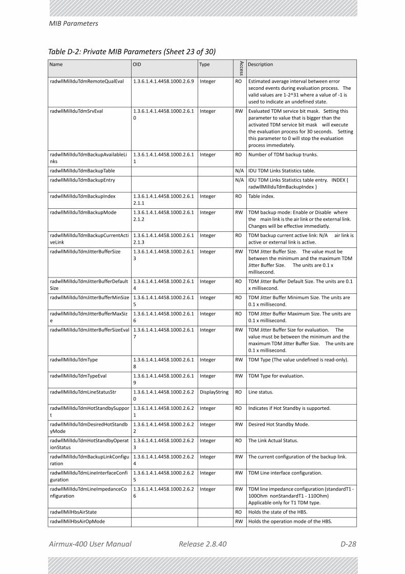
Airmux‐400 User Manual Release 2.8.40 D‐28
MIB Parameters
radwllMilIduTdmRemoteQualEval 1.3.6.1.4.1.4458.1000.2.6.9 Integer RO Estimated average interval between error
second events during evaluation process. The valid values are 1‐2^31 where a value of ‐1 is
used to indicate an undefined state.
radwllMilIduTdmSrvEval 1.3.6.1.4.1.4458.1000.2.6.1
0
Integer RW Evaluated TDM service bit mask. Setting this
parameter to value that is bigger than the
activated TDM service bit mask will execute the evaluation process for 30 seconds. Setting
this parameter to 0 will stop the evaluation
process immediately.
radwllMilIduTdmBackupAvailableLi
nks
1.3.6.1.4.1.4458.1000.2.6.1
1
Integer RO Number of TDM backup trunks.
radwllMilIduTdmBackupTable N/A IDU TDM Links Statistics table.
radwllMilIduTdmBackupEntry N/A IDU TDM Links Statistics table entry. INDEX {
radwllMilIduTdmBackupIndex }
radwllMilIduTdmBackupIndex 1.3.6.1.4.1.4458.1000.2.6.1
2.1.1
Integer RO Table index.
radwllMilIduTdmBackupMode 1.3.6.1.4.1.4458.1000.2.6.1
2.1.2
Integer RW TDM backup mode: Enable or Disable where
the main link is the air link or the external link.
Changes will be effective immediatly.
radwllMilIduTdmBackupCurrentActi
veLink
1.3.6.1.4.1.4458.1000.2.6.1
2.1.3
Integer RO TDM backup current active link: N/A air link is
active or external link is active.
radwllMilIduTdmJitterBufferSize 1.3.6.1.4.1.4458.1000.2.6.1
3
Integer RW TDM Jitter Buffer Size. The value must be
between the minimum and the maximum TDM Jitter Buffer Size. The units are 0.1 x
millisecond.
radwllMilIduTdmJitterBufferDefault
Size
1.3.6.1.4.1.4458.1000.2.6.1
4
Integer RO TDM Jitter Buffer Default Size. The units are 0.1
x millisecond.
radwllMilIduTdmJitterBufferMinSize 1.3.6.1.4.1.4458.1000.2.6.1
5
Integer RO TDM Jitter Buffer Minimum Size. The units are
0.1 x millisecond.
radwllMilIduTdmJitterBufferMaxSiz
e
1.3.6.1.4.1.4458.1000.2.6.1
6
Integer RO TDM Jitter Buffer Maximum Size. The units are
0.1 x millisecond.
radwllMilIduTdmJitterBufferSizeEval 1.3.6.1.4.1.4458.1000.2.6.1
7
Integer RW TDM Jitter Buffer Size for evaluation. The
value must be between the minimum and the
maximum TDM Jitter Buffer Size. The units are
0.1 x millisecond.
radwllMilIduTdmType 1.3.6.1.4.1.4458.1000.2.6.1
8
Integer RW TDM Type (The value undefined is read‐only).
radwllMilIduTdmTypeEval 1.3.6.1.4.1.4458.1000.2.6.1
9
Integer RW TDM Type for evaluation.
radwllMilIduTdmLineStatusStr 1.3.6.1.4.1.4458.1000.2.6.2
0
DisplayString RO Line status.
radwllMilIduTdmHotStandbySuppor
t
1.3.6.1.4.1.4458.1000.2.6.2
1
Integer RO Indicates if Hot Standby is supported.
radwllMilIduTdmDesiredHotStandb
yMode
1.3.6.1.4.1.4458.1000.2.6.2
2
Integer RW Desired Hot Standby Mode.
radwllMilIduTdmHotStandbyOperat
ionStatus
1.3.6.1.4.1.4458.1000.2.6.2
3
Integer RO The Link Actual Status.
radwllMilIduTdmBackupLinkConfigu
ration
1.3.6.1.4.1.4458.1000.2.6.2
4
Integer RW The current configuration of the backup link.
radwllMilIduTdmLineInterfaceConfi
guration
1.3.6.1.4.1.4458.1000.2.6.2
5
Integer RW TDM Line interface configuration.
radwllMilIduTdmLineImpedanceCo
nfiguration
1.3.6.1.4.1.4458.1000.2.6.2
6
Integer RW TDM line impedance configuration (standardT1 ‐
100Ohm nonStandardT1 ‐ 110Ohm) Applicable only for T1 TDM type.
radwllMilHbsAirState RO Holds the state of the HBS.
radwllMilHbsAirOpMode RW Holds the operation mode of the HBS.
Table D‐2: Private MIB Parameters (Sheet 23 of 30)
Name OID Type
Access
Description

Airmux‐400 User Manual Release 2.8.40 D‐29
MIB Parameters
radwllMilHbsAirAvailTimeSlots RO This parameter holds the number of available
time slots (not in use) in the air interface.
radwllMilHbsAirSectorCbwSupport
edStr
RO Represents the channel bandwidth which is
supported by the HBS and all connected HSUs.
radwllMilHbsAirCompressedMon RO Holds HBS monitor data in compressed format:
HBS Traffic Monitor In Bytes(4) Out Bytes(4) In Frames(4) Out Frames(4) HBS State (1) HBS
Freq (4) Number of Links (2) EC Change
Counter (4) Current Ratio (2) Total Air Frames (4) HBS Rx Rate in Kbps (4) HBS Tx Rate in Kbps
(4) HBS Rx Rate in Fps (4) HBS Tx Rate in Fps
(4) HBS Set Mode (1).
radwllMilHbsAirConfChanges RO 16 characters that represent 16 HSUs. Each
time a configuration is been changed increment the relevant character.
radwllMilHbsAirConfTable N/A Holds the table for all registered HSUs in the sector (16 entries).
radwllMilHbsAirConfEntry N/A HSUs configuration table entry. INDEX { radwllMilHbsAirConfIndex }
radwllMilHbsAirConfIndex RO HSUs configuration table index.
radwllMilHbsAirConfUpMir RW Uplink MIR towards specific HSU in units of
kbps.
radwllMilHbsAirConfDownMir RW Downlink MIR towards specific HSU in units of
kbps.
radwllMilHbsAirConfHsuName RW HSU name.
radwllMilHbsAirConfHsuLocation RW HSU location.
radwllMilHbsAirConfDualAntTxMode
RW Spatial multiplexing: MIMO (1) or Diversity (2)
radwllMilHbsAirConfNumOfTs RW Number of time slot which are allocated to specific HSU.
radwllMilHbsAirConfGeoLocation RW Geographic device location in format: latitude longitude.
radwllMilHbsAirConfHsuType RW HSU type (1 = Fixed 2 = Stationary 3 = Mobile)
radwllMilHbsAirConfHsuLevel RW HSU level (1 .. 4)
radwllMilHbsAirConfDesiredRateIndex
RW The rate index of both sides of the link to this HSU.
radwllMilHbsAirConfMacAddress RO HSU MAC Address.
radwllMilHbsAirConfNumOfTsUp RW Number of UL time slot which are allocated to
specific HSU.
radwllMilHbsAirLinkNumOfLinks RO Number of links in the links table.
radwllMilHbsAirLinkTable N/A Holds the table for all links in the sector.
radwllMilHbsAirLinkEntry N/A Link table entry. INDEX { radwllMilHbsAirLinkIndex }
radwllMilHbsAirLinkIndex RO HSUs configuration table index.
radwllMilHbsAirLinkHsuId RO HSU ID of specific link (if registered).
Unregistered links have ‐1.
radwllMilHbsAirLinkState RO Holds the state of specific link.
radwllMilHbsAirLinkWorkingMode RO Indicates the sub‐state within the version
compatibility.
radwllMilHbsAirLinkSessionId RO Holds the Session ID of the link.
radwllMilHbsAirLinkHbsEstTput RO Holds the Estimated throughput from the HBS to the HSU.
radwllMilHbsAirLinkHsuEstTput RO Holds the Estimated throughput from the HSU to the HBS.
radwllMilHbsAirLinkRange RO Holds the range of specific link.
Table D‐2: Private MIB Parameters (Sheet 24 of 30)
Name OID Type
Access
Description

Airmux‐400 User Manual Release 2.8.40 D‐30
MIB Parameters
radwllMilHbsAirLinkHbsRss RO Holds the RSS of specific link (HBS side).
radwllMilHbsAirLinkHbsRssBal RO Holds the RSS Balance of specific link (HBS side).
‐2 : Radio 2 RSS is much stronger than Radio 1
RSS. ‐1 : Radio 2 RSS is stronger than Radio 1 RSS. ‐0 : Radio 2 RSS is equal to Radio 1 RSS. 1
: Radio 1 RSS is stronger than Radio 2 RSS. 2 :
Radio 1 RSS is much stronger than Radio 2 RSS.
radwllMilHbsAirLinkHsuRss RO Holds the RSS of specific link (HSU side).
radwllMilHbsAirLinkHsuRssBal RO Holds the RSS Balance of specific link (HSU side).
‐2 : Radio 2 RSS is much stronger than Radio 1
RSS. ‐1 : Radio 2 RSS is stronger than Radio 1 RSS. ‐0 : Radio 2 RSS is equal to Radio 1 RSS. 1
: Radio 1 RSS is stronger than Radio 2 RSS. 2 :
Radio 1 RSS is much stronger than Radio 2 RSS.
radwllMilHbsAirLinkHsuSerial RO Holds the serial number for specific HSU.
radwllMilHbsAirLinkTxOperMode RO Holds the TX operation mode.
radwllMilHbsAirHsuInBytes RO Number of frames received in the HSU Lan port.
radwllMilHbsAirHsuOutBytes RO Number of frames transmitted from the HSU
Lan port.
radwllMilHbsAirHsuInFrames RO Number of bytes received in the HSU Lan port.
radwllMilHbsAirHsuOutFrames RO Number of bytes transmitted from the HSU Lan
port.
radwllMilHbsAirHsuMacAddress RO HSU MAC Address.
radwllMilHbsAirMaxTputDown RO Max Throughput Downlink.
radwllMilHbsAirMaxTputUp RO Max Throughput Uplink.
radwllMilHbsAirLinkCompressedMo
n
RO Holds all the link information in compressed
binary (Bytes/octets). Fields included (size in
bytes): Link State(1) Link Working Mode(1) Session Id(4) HBS Est.
Tput(4) HSU Est. Tput(4) HBS Rss(1)
HBS Rss Balance(1) HSU Rss(1) HSU Rss Balance(1) Tx Operation Mode(1)
HSU In Bytes(4) HSU Out Bytes(4)
HSU In Frames(4) HSU Out Frames(4)
HSU ID (1 bytes) HSU Rx Rate In Kbps (4) HSU Tx Rate In Kbps (4) HSU Rx Rate In Fps (4) HSU
Tx Rate In Fps (4) Peak throughput in the DL
direction (4) Peak throughput in the UL direction (4).
radwllMilHbsAirLinkCompressedStatic
RO Holds all the configuration data of this link in compressed format. Helps the NMS to get info
regarding new Unregistered links. Fields
Included: SessionID (4 bytes) HSU IP address (4 bytes) HSU Name (32 bytes) HSU Location
(32 bytes) HSU Serial number (16 bytes) HSU
MAC Address (12 bytes) Air Link Range Max Throughput Down (4 bytes) Max Throughput
Up. (4 bytes) Cpacity Limit (4 bytes) HSU
Antenna type (1 byte) Aggregate Capacity (4 bytes)
radwllMilHbsAirCpeCapacityLimit RO Capacity Limit in Kilo bit per second.
radwllMilHbsAirLinkAntennaType RO HSU External Antenna Type: single‐pole or dual‐
pole.
radwllMilHbsAirHsuRxRateInKbps RO HSU Rx Rate in Kbps.
radwllMilHbsAirHsuTxRateInKbps RO HSU Tx Rate in Kbps.
radwllMilHbsAirHsuRxRateInFps RO HSU Tx Rate in Fps.
radwllMilHbsAirHsuTxRateInFps RO HSU Tx Rate in Fps.
radwllMilHbsAirLinkPeakTputDown RO Peak throughput in the DL direction (kbps).
Table D‐2: Private MIB Parameters (Sheet 25 of 30)
Name OID Type
Access
Description

Airmux‐400 User Manual Release 2.8.40 D‐31
MIB Parameters
radwllMilHbsAirLinkPeakTputUp RO Peak throughput in the UL direction (kbps).
radwllMilHbsAirLinkUtilDownSecRe
lMill
RO The average time percentage (in thousandths)
out of the BTS DL capability that was used for
transmitting data to the SU.
radwllMilHbsAirLinkUtilUpSecRelMi
ll
RO The average time percentage (in thousandths)
out of the BTS UL capability that was used for receiving data from the SU.
radwllMilHbsAirLinkUtilDownAllocRelMill
RO The time percentage (in thousandths) relative to the SU DL allocation that was used for
transmitting data to the SU.
radwllMilHbsAirLinkUtilUpAllocRel
Mill
RO The time percentage (in thousandths) relative
to the SU UL allocation that was used for
receiving data from the SU.
radwllMilHbsAirLinkUtilDownTraffic
Kbps
RO Average data throughput (Exported in Kbps)
transmitted in the DL towards the SU during the last second.
radwllMilHbsAirLinkUtilUpTrafficKbps
RO Average data throughput (Exported in Kbps) received in the UL from the SU during the last
second.
radwllMilHbsAirLinkUtilCompresse
dMon
RO One string that holds the 6 Utilization per link
values: DownSecRel (2 bytes) UpSecRel
(2 bytes) DownAllocRel (4 bytes) UpAllocRel (4 bytes) DownTraffic (4 bytes) UpTraffic (4
bytes).
radwllMilHbsAirComboSwitchSecto
rFreqBandId
RW Switch Frequency band for the whole sector.
radwllMilHbsAirGeoAzimuth RW Geographic sector azimuth in degrees * 10.
radwllMilHbsAirGeoBeamwidth RW Geographic sector beamwidth in degrees * 10.
radwllMilHbsAirMaxDistanceMeter
sMobility
RW Maximum distance in meters. Used by Mobility
links only.
radwllMilHbsAirComboSwitchSecto
rFreqBandIdStr
RW Switch Frequency band for the whole sector
overriding some of the Combo parameters.
radwllMilHbsAirTimeSlotAllocation
Bitmap
RW Time Slots Allocation Bitmap for the entire
sector (Hex Value).
radwllMilHbsAirAvailTimeSlotsUp RO This parameter holds the number of available
UL time slots (not in use) in the air interface.
radwllMilHbsAirDownUtilMill RO Sector Air Interface utilization in the Downlink
direction (thousandths). Average time
percentage out of the entire BTS DL capability that was used for transmitting data to all the
SUs.
radwllMilHbsAirUpUtilMill RO Sector Air Interface utilization in the Uplink
direction (thousandths). The average number
of timeslots that were used in the UL (by all the links) out of the entire number of timeslots.
radwllMilHbsAirDownTrafficKbps RO Average data throughput (expressed in Kbps) transmitted in the DL towards all the SUs
during the last second.
radwllMilHbsAirUpTrafficKbps RO Average data throughput (expressed in Kbps)
received in the UL from all the SUs during the
last second.
radwllMilHbsAirCompressedMonSe
c
RO One string that holds the 4 Utilization per Sector
values: DownUtil (2 bytes) UpUtil (2 bytes) DownTraffic (4 bytes) UpTraffic (4 bytes).
radwllMilHbsBridgeAgingTime RW Timeout in seconds for aging.
radwllMilHbsBridgeVlanTable N/A Holds the bridge Vlan operations towards all the
registered HSUs.
Table D‐2: Private MIB Parameters (Sheet 26 of 30)
Name OID Type
Access
Description

Airmux‐400 User Manual Release 2.8.40 D‐32
MIB Parameters
radwllMilHbsBridgeVlanEntry N/A HBS bridge Vlan table entry. INDEX {
radwllMilHbsBridgeVlanIndex }
radwllMilHbsBridgeVlanIndex RO HBS bridge Vlan table index.
radwllMilHbsBridgeVlanIngress RW HBS bridge Vlan ingress.
radwllMilHbsBridgeVlanEgress RW HBS bridge Vlan egress.
radwllMilHbsBridgeVlanFilterIn RW HBS bridge Vlan filter in.
radwllMilHbsBridgeVlanFilterOut RW HBS bridge Vlan filter out.
radwllMilHbsBridgeVlanDoubleTag RW HBS bridge Vlan double tag.
radwllMilHbsBridgeVlanDefaultId RW HBS bridge Vlan default id.
radwllMilHbsBridgeMembershipTab
le
N/A Holds the bridge membership relations for all
the registered HSUs.
radwllMilHbsBridgeMembershipEnt
ry
N/A HBS bridge membership table entry. INDEX {
radwllMilHbsBridgeMembershipIndex }
radwllMilHbsBridgeMembershipInd
ex
RO HBS bridge membership table index.
radwllMilHbsBridgeMembershipSta
te
RW HBS bridge membership state bitmap. Each bit
represents Blocked/Opened relation
(membership) between two HSUs. Blocked=0 (bit) Opened=1 (bit). This object holds the
relation to 32 HSUs.
radwllMilHbsBridgeMembershipSta
te2nd
RW HBS bridge membership state bitmap. Each bit
represents Blocked/Opened relation
(membership) between HSU and LAN/Stack port of the HBS. Blocked=0 (bit) Opened=1 (bit).
Only 2 bits are used.
radwllMilHbsBridgeFloodOverloadP
rotect
RW Flood overload protection 1‐ Enabled 2‐
Disabled.
radwllMilHbsServiceCommandStr RW Ability to perform special command in the HBS.
Format (string): Operation Index Session
Param1 Param2 ....| ParamN The index and SessionID can be uniting to one parameter. On
registered HSU it is HSU‐ID and on Unregistered
it is Session‐ID.
radwllMilHbsServiceVlanTable N/A Holds the Vlan operations towards all the
registered HSUs.
radwllMilHbsServiceVlanEntry N/A HBS service Vlan table entry. INDEX {
radwllMilHbsServiceVlanIndex }
radwllMilHbsServiceVlanIndex RO HBS service Vlan table index.
radwllMilOduServiceVlanTblTag RW The VID to be used when adding TAG or adding Provider
radwllMilOduServiceVlanTblPri RW The Vlan priority 0‐7 to be used when adding TAG or adding Provider
radwllMilOduServiceVlanTblMajorMode
RW The Vlan major mode
radwllMilOduServiceVlanTblEgressMode
RW The Vlan mode in the Egress direction
radwllMilOduServiceVlanTblIngressMode
RW The Vlan mode in the Ingress direction
radwllMilOduServiceVlanTblEgressFilter1
RW VLAN Filter1 VID
radwllMilOduServiceVlanTblEgressFilter2
RW VLAN Filter2 VID
radwllMilOduServiceVlanTblEgressFilter3
RW VLAN Filter3 VID
radwllMilOduServiceVlanTblEgressFilter4
RW VLAN Filter4 VID
Table D‐2: Private MIB Parameters (Sheet 27 of 30)
Name OID Type
Access
Description

Airmux‐400 User Manual Release 2.8.40 D‐33
MIB Parameters
radwllMilOduServiceVlanTblUntagFi
lteredBitmap
RW Represents (in bitmap) if to Untag a frame after
it is filtered (Egress direction) [4 bits represent 4 filters].
radwllMilOduServiceVlanTblProviderTPID
RW Holds the Provider TPID that is used in all provider operations.
radwllMilHbsServiceQoSMode RW Quality of Service mode.
radwllMilHbsServiceQoSVlanQGrou
psStr
RW Frame classification according to VLAN priority
(all 4 groups separated by comma).
radwllMilHbsServiceQoSDiffservQG
roupsStr
RW Frame classification according to Diffserv (all 4
groups separated by comma).
radwllMilHbsServiceQoSMaxRtQue
Pct
RO Maximal percent for RT and NRT queues.
radwllMilHbsServiceQoSTable N/A Holds the QoS operations towards all the
registered HSUs.
radwllMilHbsServiceQoSEntry N/A HBS service QoS table entry. INDEX {
radwllMilHbsServiceQoSIndex }
radwllMilHbsServiceQoSIndex RO HBS service QoS table index.
radwllMilHbsServiceQoSConfAdmin
State
RW QoS administrative state. The valid values are:
enabled (1) disabled (2).
radwllMilHbsServiceQoSConfUpQu
eMir
RW Private MIR for each QoS group of the Uplink
direction (4 values separated by comma).
radwllMilHbsServiceQoSConfUpQu
eWeight
RW Weight in percent for each QoS group of the
Uplink direction (4 values separated by comma).
radwllMilHbsServiceQoSConfDown
QueMir
RW Private MIR for each QoS group of the Downlink
direction (4 values separated by comma).
radwllMilHbsServiceQoSConfDown
QueWeight
RW Weight in percent for each QoS group of the
Downlink direction (4 values separated by
comma).
radwllMilHbsServiceMobilitySuppor
ted
RO Mobility Support (1 = Not supported 2 =
Supported)
radwllMilHbsServiceMaxNumOfHS
Us
RO Holds the maximum number of registered HSUs
in the HBS.
radwllMilHbsPerfMonThreshTable N/A Holds the performance monitor thresholds
towards all the registered HSUs.
radwllMilHbsPerfMonThreshEntry N/A HBS performance monitor threshold table entry.
INDEX { radwllMilHbsPerfMonThreshIndex }
radwllMilHbsPerfMonThreshIndex RO HBS performance monitor threshold table
index.
radwllMilHbsPerfMonTxThresh1 RW HBS performance monitor transmit power
threshold.
radwllMilHbsPerfMonRxThresh1 RW HBS performance monitor receive power
threshold 1.
radwllMilHbsPerfMonRxThresh2 RW HBS performance monitor receive power
threshold 2.
radwllMilHbsPerfMonBBERThresh1 RW HBS performance monitor BBER threshold.
radwllMilHbsPerfMonEstThroughputThreshKbps
RW HBS performance monitor estimated throughput Threshold.
radwllMilHbsPerfMonHighTrafficThreshKbps
RW HBS performance monitor high traffic threshold.
radwllMilHbsPerfMonAirGenCurrTable
N/A This table defines/keeps the ethernet counters of the current 15 min interval.
radwllMilHbsPerfMonAirGenCurrEntry
N/A This is an entry in the Current Interval Table. INDEX {ifIndex }
Table D‐2: Private MIB Parameters (Sheet 28 of 30)
Name OID Type
Access
Description

Airmux‐400 User Manual Release 2.8.40 D‐34
MIB Parameters
radwllMilHbsPerfMonAirGenCurrRx
MBytes
RO Current RX Mega Bytes starting from the
present 15 minutes period. (Represents the LAN traffic RX direction toward the HSU)
radwllMilHbsPerfMonAirGenCurrTxMBytes
RO Current Transmit Mega Bytes starting from the present 15 minutes period. (Represents the
LAN traffic TX direction from the HSU)
radwllMilHbsPerfMonAirGenCurrEt
hCapacityThreshUnder
RO The number of times throughput was below
threshold in the present 15 minutes period.
Relevant for point to point systems.
radwllMilHbsPerfMonAirGenCurrHi
ghTrafficThreshExceed
RO The number of times actual traffic was above
threshold in the present 15 minutes period.
radwllMilHbsPerfMonAirGenCurrAc
tiveSeconds
RO The number of seconds in which RPL Ethernet
swervice was not blocked in the present 15 minutes period.
radwllMilHbsPerfMonAirGenIntervalTable
N/A This table defines/keeps the ethernet counters of the last day (in resolution of 15 min intervals).
radwllMilHbsPerfMonAirGenIntervalEntry
N/A This is an entry in the Interval Table. INDEX {ifIndex radwllMilHbsPerfMonAirGenIntervalIdx
}
radwllMilHbsPerfMonAirGenInterva
lIdx
RO This table is indexed per interval number. Each
interval is of 15 minutes and the oldest is 96.
radwllMilHbsPerfMonAirGenInterva
lRxMBytes
RO Current RX Mega Bytes per interval.
(Represents the LAN traffic RX direction toward
the HSU).
radwllMilHbsPerfMonAirGenInterva
lTxMBytes
RO Current Transmit Mega Bytes per interval.
(Represents the LAN traffic TX direction from the HSU)
radwllMilHbsPerfMonAirGenIntervalEthCapacityThreshUnder
RO The number of times throughput was below threshold in the each interval. Relevant for
point to point systems.
radwllMilHbsPerfMonAirGenInterva
lHighTrafficThreshExceed
RO The number of times actual traffic was above
threshold in the each interval.
radwllMilHbsPerfMonAirGenInterva
lActiveSeconds
RO The number of seconds in which RPL Ethernet
service was not blocked in the each interval.
radwllMilHbsPerfMonAirGenDayTable
N/A This table defines/keeps the ethernet counters of the last month (in resolution of days).
radwllMilHbsPerfMonAirGenDayEntry
N/A This is an entry in the Days Table. INDEX {ifIndex radwllMilHbsPerfMonAirGenDayIdx }
radwllMilHbsPerfMonAirGenDayIdx RO This table is indexed per Day number. Each interval is of 15 minutes and the oldest is 96.
radwllMilHbsPerfMonAirGenDayRxMBytes
RO Current RX Mega Bytes per day. (Represents the LAN traffic RX direction toward the HSU)
radwllMilHbsPerfMonAirGenDayTxMBytes
RO Current Transmit Mega Bytes per day. (Represents the LAN traffic TX direction from
the HSU)
radwllMilHbsPerfMonAirGenDayEth
CapacityThreshUnder
RO The number of times throughput was below
threshold each day. Relevant for point to point
systems.
radwllMilHbsPerfMonAirGenDayHig
hTrafficThreshExceed
RO The number of times actual traffic was above
threshold each day.
radwllMilHbsPerfMonAirGenDayAc
tiveSeconds
RO The number of seconds in which RPL Ethernet
service was not blocked each day.
radwllMilHsuAirState RO Holds the state of the HSU.
radwllMilHsuAirLinkState RO Holds the state of the HSU link.
radwllMilHsuAirHsuId RO Holds the HSU ID as sent by the HBS.
radwllMilHsuAirLocalDeregister RW Performs Local HSU Deregistration when ‐ only
when the link is off.
Table D‐2: Private MIB Parameters (Sheet 29 of 30)
Name OID Type
Access
Description

Airmux‐400 User Manual Release 2.8.40 D‐35
MIB Traps
MIB TrapsGeneral
Each ODU can be configured with up to 10 different trap destinations. When the link is operational, each ODU sends traps originating from both Site A and Site B.
radwllMilHsuAirRemoteCompresse
dMon
RO Holds all the configuration data of The HBS in
compressed format. Fields Included: Rss (1 byte) Rss Balance (1 byte) Est. Tput (4
bytes) In Bytes of the whole sector (4 bytes)
Out Bytes of the whole sector (4 bytes) In Frames of the whole sector (4 bytes) Out
Frames of the whole sector (4 bytes) Max
Throughput DownLink (4 bytes) Max Throughput UpLink (4 bytes) Rx Rate In Kbps of
the whole sector (4 bytes) Tx Rate In Kbps of
the whole sector (4 bytes) Rx Rate In Fps of the whole sector (4 bytes) Tx Rate In Fps of the
whole sector (4 bytes) Peak Throughput in the
DL direction in Kbps (4 bytes) Peak Throughput in the UL direction in Kbps(4 bytes)
radwllMilHsuAirRemoteCompressedStatic
RO Holds all the configuration data of the HBS in a compressed format. Helps the NMS to get info
regarding new Unregistered links. Fields
Included: Location (32 bytes) IP address (8 bytes in hexa) Subnet mask (8 bytes in hexa)
HBS Antenna type (1 byte) HBS Agent Version
(4 bytes)
radwllMilHsuAirRssThreshSync RW HSUs will be sychnornized immediately if RSS is
better than threshold.
radwllMilHsuServiceCommandStr RW Ability to perform special command in the HSU.
Format (string): Operation Param1 Param2 ....| ParamN.
radwllMilHsuServiceHsuType RW HSU type (1 = Fixed 2 = Stationary 3 = Mobile)
radwllMilHsuServiceHsuLevel RW HSU level (1 .. 4)
radwllMilHsuEthernetPoESupporte
d
RO Indicated if this HSU has special port for PoE
devices.
radwllMilHsuEthernetPoETemperat
ure
RO Holds the temperature (Celsius) of the POE
component.
radwllMilHsuEthernetPoEEquConsu
mption
RO Holds the consumption of the connected
equipment (milliampere).
radwllMilHsuEthernetPoEEquVoltage
RO Holds the voltage of the connected equipment (Volt).
radwllMilGeneralTrapDescription 1.3.6.1.4.1.4458.1000.100.1 DisplayString RO Trap's Description. Used for Trap parameters.
radwllMilGeneralTrapSeverity 1.3.6.1.4.1.4458.1000.100.2 Integer RO Trap's Severity. Used for Trap parameters.
radwllMilGeneralCookie 1.3.6.1.4.1.4458.1000.100.3 DisplayString RW Reserved for the Manager application provided
with the product used for saving user
preferences affecting ODU operation.
radwllMilGeneralEcChangesCounter 1.3.6.1.4.1.4458.1000.100.4 Integer RO This counter is initialized to 0 after a device
reset and is incremented upon each element constant write operation via SNMP or Telnet.
radwllMilGeneralTelnetSupport 1.3.6.1.4.1.4458.1000.100.5 Integer RW Enable/Disable Telnet protocol.
radwllMilGeneralWISupport 1.3.6.1.4.1.4458.1000.100.6 Integer RW Enable/Disable Web Interface protocol.
Mandatory Disabled ‐ No option to enable the feature. Mandatory Enabled ‐ No option to
disable the feature.
Table D‐2: Private MIB Parameters (Sheet 30 of 30)
Name OID Type
Access
Description

Airmux‐400 User Manual Release 2.8.40 D‐36
MIB Traps
The source IP address of the trap is the sending ODU. The trap originator can be identified by the trap Community string or by the trap description text.
Each trap contains a trap description and additional relevant information such as alarm severity, interface index, time stamp and additional parameters.
Trap Parameters
Table D‐3: MIB Traps (Sheet 1 of 16)
Name ID Severity Description
trunkStateChanged 1 normal Indicates a change in the state of one of the TDM trunks. Raised by both sides of the link. Contains 3 parameters: 1 ‐ Description: TDM Interface %n ‐ %x 2 ‐ %n: Is the trunk number 3 ‐ %x: Is the alarm type and can be one of the following: Normal AIS LOS Loopback
linkUp 2 normal Indicates that the radio link is up. Contains a single parameter which is its description: 1 ‐ Description: Radio Link ‐ Sync on channel %n GHz. %n Is the channel frequency in GHz.
linkDown 3 critical Indicates that the radio link is down. Contains a single parameter which is its description: 1 ‐ Description: Radio Link ‐ Out of Sync. The reason is: %s. %s Is the reason.
detectIDU 4 normal Indicates that the IDU was detected. Raised by both sides of the link. Contains a single parameter which is its description: 1 ‐ Description: IDU of Type %s was Detected. %s Is the type of the IDU.
disconnectIDU 5 major Indicates that the IDU was disconnected. Raised by both sides of the link. Contains a single parameter which is its description: 1 ‐ Description: IDU Disconnected.
mismatchIDU 6 major Indicates a mismatch between the IDUs. Raised by the master only. Contains a single parameter which is its description: 1 ‐ Description: IDUs Mismatch: One Side is %s and the Other is %s. %s Is the type of the IDU.

Airmux‐400 User Manual Release 2.8.40 D‐37
MIB Traps
openedServices 7 normal Indicates that services were opened. Raised by the master only. Contains 3 parameters: 1 ‐ Description: %n2 out of %n1 Requested TDM Trunks have been Opened 2 ‐ %n1: Is the requested number of TDM truncks 3 ‐ %n2: Is the actual number of TDM trunks that were opened
closedServices 8 normal Indicates that services were closed. Raised by the master only. Contains a single parameter which is its description: 1 ‐ Description: TDM Service has been closed. The reason is: %s. %s Is the reason.
incompatibleODUs 9 critical Indicates that the ODUs are incompatible. Contains a single parameter which is its description: 1 ‐ Description: Incompatible ODUs.
incompatibleIDUs 10 major Indicates that the IDUs are incompatible. Contains a single parameter which is its description: 1 ‐ Description: Incompatible IDUs.
incompatibleOduIdu 11 major Indicates that the ODU and IDU are incompatible. Contains a single parameter which is its description: 1 ‐ Description: The IDU could not be loaded. The reason is: %s. %s Is the incompatibility type.
probingChannel 12 normal Indicates that the ODU is monitoring radar activity. Contains a single parameter which is its description: 1 ‐ Description: Monitoring for radar activity on channel %n GHz. %n is the channel frequency in GHz.
radarDetected 13 normal Indicates that radar activity was detected. Contains a single parameter which is its description: 1 ‐ Description: Radar activity was detected in %s on channel %n GHz. %s Is the site name. %n Is the channel frequency in GHz.
Table D‐3: MIB Traps (Sheet 2 of 16)
Name ID Severity Description
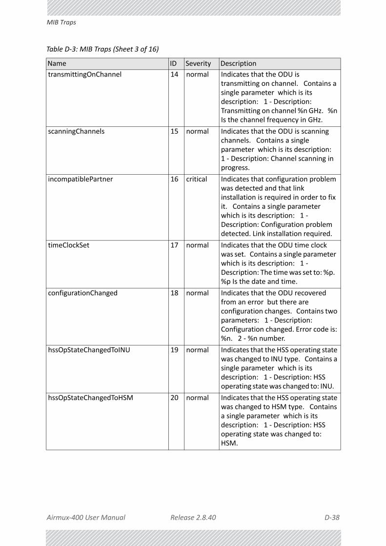
Airmux‐400 User Manual Release 2.8.40 D‐38
MIB Traps
transmittingOnChannel 14 normal Indicates that the ODU is transmitting on channel. Contains a single parameter which is its description: 1 ‐ Description: Transmitting on channel %n GHz. %n Is the channel frequency in GHz.
scanningChannels 15 normal Indicates that the ODU is scanning channels. Contains a single parameter which is its description: 1 ‐ Description: Channel scanning in progress.
incompatiblePartner 16 critical Indicates that configuration problem was detected and that link installation is required in order to fix it. Contains a single parameter which is its description: 1 ‐ Description: Configuration problem detected. Link installation required.
timeClockSet 17 normal Indicates that the ODU time clock was set. Contains a single parameter which is its description: 1 ‐ Description: The time was set to: %p. %p Is the date and time.
configurationChanged 18 normal Indicates that the ODU recovered from an error but there are configuration changes. Contains two parameters: 1 ‐ Description: Configuration changed. Error code is: %n. 2 ‐ %n number.
hssOpStateChangedToINU 19 normal Indicates that the HSS operating state was changed to INU type. Contains a single parameter which is its description: 1 ‐ Description: HSS operating state was changed to: INU.
hssOpStateChangedToHSM 20 normal Indicates that the HSS operating state was changed to HSM type. Contains a single parameter which is its description: 1 ‐ Description: HSS operating state was changed to: HSM.
Table D‐3: MIB Traps (Sheet 3 of 16)
Name ID Severity Description

Airmux‐400 User Manual Release 2.8.40 D‐39
MIB Traps
hssOpStateChangedToHSC 21 normal Indicates that the HSS operating state was changed to HSC type. Contains a single parameter which is its description: 1 ‐ Description: HSS operating state was changed to: HSC_DT/HSC_CT.
vlanModeActive 22 normal Indicates to non‐VLAN PC that after 2 minutes the system will support only VLAN tag on management interface. Contains a single parameter which is its description: 1 ‐ Description: VLAN Mode is active. Non‐VLAN traffic will be blocked in 2 minutes.
spectrumAnalysis 23 normal Indicates that the ODU is in Spectrum Analysis mode. Contains a single parameter which is its description: 1 ‐ Description: Spectrum analysis in progress.
hbsHsuDeregisteredOffline 24 normal Indicates that a HSU was deregistered offline (out of link)
hbsHsuDeregisteredSuccessfully 25 normal Indicates that a HSU was deregistered successfully
hbsHsuRegisteredSuccessfully 26 normal Indicates that a HSU was registered successfully
hbsHsuRegistrationFailed 27 normal Indicates that registration has failed
hbsHsuViolatedState 28 normal Indicates (on the HBS side) that a HSU is is violated state
hsuViolatedState 29 normal Indicates (on the HSU side) that the HSU is is violated state
hbsUnregisteredSynchronizedHsu 30 normal Indicates an unregistered HSU has been synchronized.
hbsUnregisteredUnsynchronizedHsu 31 normal Indicates an unregistered HSU lost synchronization.
cableQuality 32 normal 1Gbps rate is not supported due to bad line quality.
httpAuthentication 33 normal HTTP Authentication Failure.
telnetAuthentication 34 normal Telnet Authentication Failure.
tdmServiceAlarm 100 major Indicates that TDM Service is in alarm state. Contains a single parameter which is its description: 1 ‐ Description: TDM Service ‐ Alarm.
Table D‐3: MIB Traps (Sheet 4 of 16)
Name ID Severity Description

Airmux‐400 User Manual Release 2.8.40 D‐40
MIB Traps
ethServiceClosed 101 major Indicates that Ethernet Service is closed. Contains a single parameter which is its description: 1 ‐ Description: Ethernet Service is closed.
ethServiceNotPermitted 102 major Indicates that Ethernet Service is not permitted. Contains a single parameter which is its description: 1 ‐ Description: A valid IDU could not be detected at %s. Please check your configuration. %s ‐ Is the Local Site name or Remote Site name or both sides of the Link.
encryptionAlarm 103 major Indicates an encryption key mismatch. Contains a single parameter which is its description: 1 ‐ Description: Encryption Status ‐ Failed. No Services are available.
changeLinkPasswordAlarm 104 major Indicates that a failure has occurred while attempting to change the Link Password. Contains a single parameter which is its description: 1 ‐ Description: Failed to change the Link Password at/on: %s. %s ‐ Is the Local Site name or Remote Site name or both sides of the Link.
externalAlarmInPort1Alarm 105 major The trap is sent every time an alarm occurs in the External Alarm Input of port #1. Contains a single parameter which is its description: 1 ‐ Description: External Alarm 1 ‐ <User Text> ‐ Alarm.
externalAlarmInPort2Alarm 106 major The trap is sent every time an alarm occurs in the External Alarm Input of port #2. Contains a single parameter which is its description: 1 ‐ Description: External Alarm 2 ‐ <User Text> ‐ Alarm.
bitFailedAlarm 107 major The trap is sent if there is no way to recover from the situation.Contains two parameters: 1 ‐ Description: ODU power up built in test failed. Error code is: %n 2 ‐ %n number
Table D‐3: MIB Traps (Sheet 5 of 16)
Name ID Severity Description

Airmux‐400 User Manual Release 2.8.40 D‐41
MIB Traps
wrongConfigurationLoadedAlarm 108 major The trap is sent if there is a way to recover from the situation.Contains two parameters: 1 ‐ Description: Wrong configuration loaded. Error code is: %n 2 ‐ %n number
lanPort1DisconnectedAlarm 109 major Indicates the LAN port 1 status changed to disconnected.Contains a single parameter which is its description: 1 ‐ Description: LAN port 1 status changed to disconnected.
lanPort2DisconnectedAlarm 110 major Indicates the LAN port 2 status changed to disconnected.Contains a single parameter which is its description: 1 ‐ Description: LAN port 2 status changed to disconnected.
mngPortDisconnectedAlarm 111 major Indicates the management port status changed to disconnected.Contains a single parameter which is its description: 1 ‐ Description: Management port status changed to disconnected.
externalAlarmInPort3Alarm 112 major The trap is sent every time an alarm occurs in the External Alarm Input of port #3. Contains a single parameter which is its description: 1 ‐ Description: External Alarm 3 ‐ <User Text> ‐ Alarm.
externalAlarmInPort4Alarm 113 major The trap is sent every time an alarm occurs in the External Alarm Input of port #4. Contains a single parameter which is its description: 1 ‐ Description: External Alarm 4 ‐ <User Text> ‐ Alarm.
swVersionsMismatchFullCompatibilityAlarm
114 warning The trap is sent if SW versions mismatch with full link functionality. Contains a single parameter which is its description: 1 ‐ Description: Software versions mismatch ‐ full link functionality
Table D‐3: MIB Traps (Sheet 6 of 16)
Name ID Severity Description

Airmux‐400 User Manual Release 2.8.40 D‐42
MIB Traps
swVersionsMismatchRestrictedCompatibilityAlarm
115 minor The trap is sent if SW versions mismatch with restricted link functionality. Contains a single parameter which is its description: 1 ‐ Description: Software versions mismatch ‐ restricted link functionality
swVersionsMismatchSoftwareUpgradeRequired
116 major The trap is sent if SW versions mismatch and SW upgrade is required. Contains a single parameter which is its description: 1 ‐ Description: Software versions mismatch ‐ Software upgrade required
swVersionsIncompatible 117 critical The trap is sent if SW versions are incompatible. Contains a single parameter which is its description: 1 ‐ Description: SW Versions incompatible
hssMultipleSourcesDetectedAlarm 118 major Indicates that multiple sync pulse sources were detected. Contains a single parameter which is its description: 1 ‐ Description: HSS multiple sync sources were detected.
hssSyncToProperSourceStoppedAlarm
119 major Indicates that synchronization to a proper sync pulse source was stopped. Contains a single parameter which is its description: 1 ‐ Description: HSS sync pulse ‐ Down. The reason is: %s. %s ‐ Is the reason for the sync down.
hssSyncPulseDetectedAlarm 120 major Indicates that HSS additional sync pulse was detected. Contains a single parameter which is its description: 1 ‐ Description: HSS additional sync pulse was detected.
tdmBackupAlarm 121 major Indicates that the TDM backup link was activated. Contains a single parameter which is its description: 1 ‐ Description: TDM backup alarm ‐ backup link was activated.
Table D‐3: MIB Traps (Sheet 7 of 16)
Name ID Severity Description

Airmux‐400 User Manual Release 2.8.40 D‐43
MIB Traps
linkLockUnauthorizedRemoteODU 122 major Indicates that the remote ODU is unauthorized. Contains a single parameter which is its description: 1 ‐ Description: Unauthorized remote ODU connection rejected.
linkLockUnauthorizedODU 123 major Indicates that the ODU is unauthorized. Contains a single parameter which is its description: 1 ‐ Description: Unauthorized ODU connection rejected.
hotStandbyAlarm 124 major Indicates that the hot standby secondary link was activated. Contains a single parameter which is its description: 1 ‐ Description: Secondary Link Is Active.
sfpInsertion 126 normal Indicates that a device was inserted to SFP Port
sfpPort1DisconnectedAlarm 127 major Indicates the SFP port 1 status changed to disconnected.Contains a single parameter which is its description: 1 ‐ Description: SFP port 1 status changed to disconnected.
ringRplStateActiveAlarm 128 major RPL state changed to Active.
desiredRatioCanNotBeAppliedAlarm 129 normal Indicates Desired UL/DL RAtio Can Not Be Applied.
cbwMismatch 130 major Indicates that a Channel Bandwidth mismatch was detected.Contains two parameters: 1 ‐ Description: Channel Bandwidth Mismatch: one side is %n0 MHz and the other is %n1 MHz. %n0 is the local Channel Bandwidth value in MHz. %n1 is the remoet Channel Bandwidth value in MHz.
gpsNotSynchronized 131 major Indicates that the GPS is not synchronized with satellites. Pulses are self generated.
pdTooHighDueCbwLimitations 132 major Indicates that link cannot be established because link range is too large for channel bandwidth.
hbsEncryptionAlarm 133 major Indicates an encryption key mismatch. Contains a single parameter which is its description including the HSU's name
Table D‐3: MIB Traps (Sheet 8 of 16)
Name ID Severity Description

Airmux‐400 User Manual Release 2.8.40 D‐44
MIB Traps
hbsEhServiceClosedToHsu 134 major Indicates an encryption key mismatch. Contains a single parameter which is its description including the HSU's name
hbsUnsynchronizedHsuAlarm 135 warning Indicates a registered HSU lost synchronization.
hbsInactiveHbsAlarm 136 major Indicates HBS is InActive.
incompatibleHsu 137 critical Indicates that the HSU is not compatible to HBS. Contains a single parameter which is its description: 1 ‐ Description: Incompatible ODUs.
hsuUnsupportedBeacon 138 warning Indicates an unsupported beacon has arrived at HSU
lanPortDisconnectedAlarm 139 major Indicates the LAN port status changed to disconnected.Contains a single parameter, which is its description:1 ‐ Description: LAN port status changed to disconnected.
poePortDisconnectedAlarm 140 major Indicates the POE port status changed to disconnected.Contains a single parameter, which is its description:1 ‐ Description: POE port status changed to disconnected.
poePowerConsumptionAlarm 141 major Indicates the POE Power Consumption is above allowed maximum.Contains a single parameter, which is its description:1 ‐ Description: POE consumption above allowed maximum. port closed.
hobupFaultyStateAlarm 149 major This Alarm will indicate that the Hot Backup module is in faulty state.1 ‐ Description: Hot Backup fault detected: %s unit.%s ‐ Primary Or Secondary Unit
Table D‐3: MIB Traps (Sheet 9 of 16)
Name ID Severity Description

Airmux‐400 User Manual Release 2.8.40 D‐45
MIB Traps
gpsOverCurrentAlarm 150 major Indicates the GPS Antenna current consumption is above allowed maximum.Contains a single parameter, which is its description:1 ‐ Description: GPS Antenna current consumption above allowed maximum. GPS closed.
gpsCommunicationFailiureAlarm 151 major Indicates the GPS data isn't received.Contains a single parameter, which is its description:1 ‐ Description: GPS Communication failiure.
temperatureThresholdAlarm 152 major Indicates the board temperature is above allowed maximum.Contains a single parameter, which is its description:1 ‐ Description: GPS Antenna current consumption above allowed maximum. GPS closed.
localRouterDiscoveryStatus 153 major This Alarm will indicate that we have no connection with Track side router.1 ‐ Description: MacLearningUpdate detected disconnection with Track side router %s%s ‐ Default gateway IP
TrackRouterDiscoveryStatus 154 major This Alarm will indicate that we have no connection with Track side router.1 ‐ Description: MacLearningUpdate detected disconnection with Track side router %s%s ‐ Default gateway IP
btsTargetUnreachable 156 major This Alarm will indicate that we have no connection with Bts desired target.1 ‐ Description: TNC detected disconnection with the BTS target %s %s ‐ Default gateway IP
tdmServiceClear 200 major Indicates that TDM Service fault is cleared. Contains a single parameter which is its description: 1 ‐ Description: TDM Service ‐ Normal.
Table D‐3: MIB Traps (Sheet 10 of 16)
Name ID Severity Description

Airmux‐400 User Manual Release 2.8.40 D‐46
MIB Traps
ethServiceOpened 201 normal Indicates that Ethernet Service has been opened. Contains a single parameter which is its description: 1 ‐ Description: Ethernet Service has been opened.
encryptionClear 203 normal Indicates that encryption is OK. Contains a single parameter which is its description: 1 ‐ Description: Encryption Status ‐ Normal.
changeLinkPasswordClear 204 normal Indicates that the Link Password was changed successfully. Contains a single parameter which is its description: 1 ‐ Description: Link Password has been changed at/on: %s. %s ‐ Is the Local Site name or Remote Site name or both sides of the Link.
externalAlarmInPort1Clear 205 normal This Trap is sent every time an External Alarm Input fault of port # 1 is cleared. Contains a single parameter which is its description: 1 ‐ Description: External Alarm 1 ‐ <User Text> ‐ Alarm Cleared.
externalAlarmInPort2Clear 206 normal This Trap is sent every time an External Alarm Input fault of port # 2 is cleared. Contains a single parameter which is its description: 1 ‐ Description: External Alarm 2 ‐ <User Text> ‐ Alarm Cleared.
lanPort1Clear 209 normal Indicates the LAN port 1 status changed to connected. Contains two parameters: 1 ‐ Description: LAN port 1 status changed to connected ‐ %s 2 ‐ %s Is the Eth. mode (speed & duplex)
lanPort2Clear 210 normal Indicates the LAN port 2 status changed to connected. Contains two parameters: 1 ‐ Description: LAN port 2 status changed to connected ‐ %s. 2 ‐ %s Is the Eth. mode (speed & duplex).
Table D‐3: MIB Traps (Sheet 11 of 16)
Name ID Severity Description

Airmux‐400 User Manual Release 2.8.40 D‐47
MIB Traps
mngPortClear 211 normal Indicates the management port status changed to connected. Contains two parameters: 1 ‐ Description: Management port status changed to connected ‐ %s 2 ‐ %s Is the Eth. mode (speed & duplex)
externalAlarmInPort3Clear 212 normal This Trap is sent every time an External Alarm Input fault of port # 3 is cleared. Contains a single parameter which is its description: 1 ‐ Description: External Alarm 3 ‐ <User Text> ‐ Alarm Cleared.
externalAlarmInPort4Clear 213 normal This Trap is sent every time an External Alarm Input fault of port # 4 is cleared. Contains a single parameter which is its description: 1 ‐ Description: External Alarm 4 ‐ <User Text> ‐ Alarm Cleared.
swVersionsMatchFullCompatibilityClear
214 normal The trap is sent if SW versions match. Contains a single parameter which is its description: 1 ‐ Description: Software Versions compatible
swVersionsMatchRestrictedCompatibilityClear
215 normal The trap is sent if SW versions match and link functionality is not restricted. Contains a single parameter which is its description: 1 ‐ Description: Software Versions compatible
swVersionsMatchSoftwareUpgradeRequiredClear
216 normal The trap is sent if SW versions match and SW upgrade is successful. Contains a single parameter which is its description: 1 ‐ Description: Software Versions compatible
swVersionsCompatibleClear 217 normal The trap is sent if SW versions compatible Contains a single parameter which is its description: 1 ‐ Description: Software Versions compatible
hssMultipleSourcesDisappearedClear 218 normal Indicates that multiple sync pulse sources disappeared. Contains a single parameter which is its description: 1 ‐ Description: HSS multiple sync pulse sources disappeared.
Table D‐3: MIB Traps (Sheet 12 of 16)
Name ID Severity Description

Airmux‐400 User Manual Release 2.8.40 D‐48
MIB Traps
hssSyncToProperSourceAchievedClear
219 normal Indicates that synchronization to a proper Sync source was achieved. Contains a single parameter which is its description: 1 ‐ Description: HSS sync pulse ‐ Up.
hssSyncPulseDisappearedClear 220 normal Indicates that HSS additional sync pulse disappeared. Contains a single parameter which is its description: 1 ‐ Description: HSS additional sync pulse was disappeared.
tdmBackupClear 221 normal Indicates that the TDM main link was activated. Contains a single parameter which is its description: 1 ‐ Description: TDM main link was activated.
linkLockAuthorizedRemoteODU 222 normal Indicates that the remote ODU is authorized. Contains a single parameter which is its description: 1 ‐ Description: Authorized remote ODU connection accepted.
linkLockAuthorizedODU 223 normal Indicates that the ODU is authorized. Contains a single parameter which is its description: 1 ‐ Description: Authorized ODU connection permitted.
linkAuthenticationDisabled 224 normal Indicates that the Link Lock is disabled. Contains a single parameter which is its description: 1 ‐ Description: Link Authentication has been disabled.
hotStandbyClear 225 normal Indicates that the Primary Link Was Activated. Contains a single parameter which is its description: 1 ‐ Description: Primary Link Is Active.
sfpExtraction 226 normal Indicates that a device was extracted from SFP Port
sfpPort1Clear 227 normal Indicates the SFP port 1 status changed to connected. Contains two parameters: 1 ‐ Description: SFP port 1 status changed to connected ‐ %s 2 ‐ %s Is the Eth. mode (speed & duplex)
Table D‐3: MIB Traps (Sheet 13 of 16)
Name ID Severity Description

Airmux‐400 User Manual Release 2.8.40 D‐49
MIB Traps
compatibleIdus 228 normal Indicates that the ODU has identified compatible Idus on both sides of the link.
desiredRatioCanNotBeAppliedClear 229 normal Indicates Current UL/DL Ratio Is Equal To Desired Ratio.
cbwMatch 230 normal Indicates that a Channel Bandwidth match was detected. Contains a single parameter which is its description: 1 ‐ Channel Bandwidth value in MHz.
switchCbwAndChannel 231 normal Indicates that the system is switching Channel Bandwidth and channel frequency. Contains two parameters: 1 ‐ Switching to Channel Bandwith %n0 MHz and to channel %n1 GHz.
ringRplStateIdle 232 normal RPL state changed to Idle.
ringEthServiceStatus 233 normal Indicates Ethernet service's state ‐ blocked \ unblocked. Contains a single parameter: 1 ‐ Description: Ethernet's state (blocked \ unblocked)
ringFirstRpmReceived 234 normal Ring application: in non‐RPL link indicates first from a specific RPL was received. Contains a single parameter: 1 ‐ Description: RPM's VLAN ID
ringEthernetSrviceUnblockedTO 235 normal Ring application: in non‐RPL link Ethernet service is unblocked due to RPM timeout.
gpsSynchronized 236 normal Indicates that the GPS is synchronized with satellites.
hbsEncryptionClear 237 normal Indicates that encryption is OK. Contains a single parameter which is its description including the HSU's name
hbsEhServiceOpenedToHsu 238 normal Indicates that encryption is OK. Contains a single parameter which is its description including the HSU's name
hbsSynchronizedHsuAlarm 239 normal Indicates a registered HSU is synchronized.
hbsActiveHbs 240 normal Indicates when HBS has been activated.
Table D‐3: MIB Traps (Sheet 14 of 16)
Name ID Severity Description

Airmux‐400 User Manual Release 2.8.40 D‐50
MIB Traps
switchCBW 241 normal Switching Channel Bandwidth.
changeRatio 242 normal HBS Tx ratio has changed.
lanPortClear 243 normal Indicates the LAN port status changed to connected.Contains two parameters:1 ‐ Description: LAN port status changed to connected ‐ %s2 ‐ %s Is the Eth. mode (speed & duplex)
poePortClear 244 normal Indicates the POE port status changed to connected.Contains two parameters:1 ‐ Description: POE port status changed to connected ‐ %s2 ‐ %s Is the Eth. mode (speed & duplex)
poePowerConsumptionClear 245 normal Indicates the POE power consumption is valid.Contains two parameters:1 ‐ Description: POE consumption within limits. port is opened.2 ‐ %s Is the Eth. mode (speed & duplex)
incompatibleHbsHsu 246 normal Incompatible HBS/HSU software versions ‐ no service.
mobilityLinkOff 247 normal Mobility ‐ Link cannot be established due to:1 ‐ The HBS does not support Mobility2 ‐ Lack of resources in the HBS for HSU level
enterLocalConnection 248 normal Entering Local Connection (Broadcast) Mode.
hobupActiveStateFaultyClear 249 normal This clear alarm will indicate that the Hot Backup unit is in active state.Contains a single parameter, which is its description:1 ‐ Description: Hot Backup %s unit activated.%s ‐ Primary Or Secondary Unit
Table D‐3: MIB Traps (Sheet 15 of 16)
Name ID Severity Description
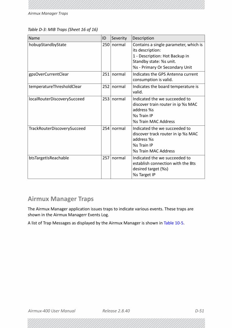
Airmux‐400 User Manual Release 2.8.40 D‐51
Airmux Manager Traps
Airmux Manager Traps
The Airmux Manager application issues traps to indicate various events. These traps are shown in the Airmux Managerr Events Log.
A list of Trap Messages as displayed by the Airmux Manager is shown in Table 10‐5.
hobupStandbyState 250 normal Contains a single parameter, which is its description:1 ‐ Description: Hot Backup in Standby state: %s unit.%s ‐ Primary Or Secondary Unit
gpsOverCurrentClear 251 normal Indicates the GPS Antenna current consumption is valid.
temperatureThresholdClear 252 normal Indicates the board temperature is valid.
localRouterDiscoverySucceed 253 normal Indicated the we succeeded to discover train router in ip %s MAC address %s
%s Train IP%s Train MAC Address
TrackRouterDiscoverySucceed 254 normal Indicated the we succeeded to discover track router in ip %s MAC address %s%s Train IP%s Train MAC Address
btsTargetIsReachable 257 normal Indicated the we succeeded to establish connection with the Bts desired target (%s)%s Target IP
Table D‐3: MIB Traps (Sheet 16 of 16)
Name ID Severity Description

Airmux‐400 User Manual Release 2.8.40 E‐1
Appendix E:
External Alarms Specification
External Alarms SpecificationThe IDU‐E and IDU support external input and output alarms through a standard DB25 pin female connector (see page B‐3 for pinout details).
Input alarms
The input alarms are raised by events from external equipment, such as a fire warning, door open or air conditioner failure. They are user defined.
Output alarms
Output alarms are generated through dry contact relays to indicate various system events such as sync‐loss or disconnection. An alarm is raised if at least one of the conditions in one of the tables below, is met.
IDU‐E and IDU Alarms
Table E‐1: IDU‐E and IDU - Output Alarms Description
Alarm Description Alarm On Conditions Alarm Off Condition
Output 1Air interface Alarm
• Link is down• Link in installation
mode• Link authentication
problem
Link is up or equipment alarm is ON
Output 2Equipment Alarm
• Built in Test (BIT) error• No connection to the
ODU
Both ODU and IDU are in operational state

Airmux‐400 User Manual Release 2.8.40 E‐2
IDU‐E and IDU Alarms
Output 3Service Alarm at Site B
N/A Permanently off
Output 4Power Failure at Site B
Link Loss due to Power Failure at Site B
Link is up or down without power failure indication within the last two seconds
Table E‐2: IDU‐E - Input Alarms Description
Alarm DescriptionAlarm On Conditions
Alarm Off Condition
Input 1User Defined External Alarm
Voltage in range ‐10 to ‐50VDC
Voltage > 0VDCInput 2
Input 3
Input 4
Table E‐1: IDU‐E and IDU - Output Alarms Description (Continued)
Alarm Description Alarm On Conditions Alarm Off Condition

Airmux‐400 User Manual Release 2.8.40 F‐1
Appendix F:
Setting Antenna Parameters
Antenna IssuesThe choice of Tx Power, antenna gain and cable loss (between the radio and the antenna) determines the EIRP and is affected by such considerations as radio limitations and regulatory restrictions.
Before proceeding to antenna installation details, the following background information should be considered:
About Single and Dual AntennasEach Airmux‐400 ODU has two radio transceivers (radios). The radios make use of algorithms that utilize both MIMO and Diversity resulting in enhanced capacity, range and link availability. The number of antennas (i.e. radios) used is determined by user configuration and by automatic system decisions, explained below.
Dual Antennas at the Both Link Sites
When using dual antennas at both sites (single dual‐pole antenna or two single‐pole antennas) you can choose between MIMO Mode and Diversity Mode.
MIMO Mode
Under this mode, the system doubles the link capacity. At the same time, it keeps the same rate and modulation per radio as was used with single antenna, thus increasing capacity, range and availability.
For example with a dual antenna Airmux‐400 can transmit at modulation of 64QAM and FEC of 5/6 and get an air rate of 130 Mbps, compared to 65 Mbps with single antenna.
To work in this mode, each antenna port must be connected to an antenna, the RSS level in both receivers should be balanced and a minimal separation between the antennas must be maintained. (For example, by using dual polarization antennas a cross polarization separation is attained).

Airmux‐400 User Manual Release 2.8.40 F‐2
Single Antennas at Both Sites
Upon selecting Antenna Type as Dual, Airmux‐400 automatically selects this mode and doubles the air rates.
Airmux Manager indicates a case of unbalanced RSS between the two antennas.
Diversity Mode
Diversity Mode uses two antennas to improve the quality and reliability of the link. Often, there is not a clear line‐of‐sight (LOS) between transmitter and receiver. Instead the signal is reflected along multiple paths before finally being received.
Each such “bounce” can introduce phase shifts, time delays, attenuations, and even distortions that can destructively interfere with one another at the aperture of the receiving antenna. Antenna diversity is especially effective at mitigating these multi‐path situations.
This is because multiple antennas afford a receiver several recordings of the same signal. Each antenna will be exposed to a different interference environment. Thus, if one antenna is undergoing a deep fade, it is likely that another has a sufficient signal. Collectively such a system can provide a robust link.
Antenna diversity requires antenna separation which is possible by using a dual‐polarization antenna or by two spatially separated antennas.
Use Diversity instead of MIMO in the following situations:
• When the system cannot operate in MIMO Mode
• When one of the receivers has high interference compared to the second receiver (i.e. the system is “unbalanced”)
• When you achieve higher capacity in Diversity Mode than in MIMO Mode
• When high robustness is of importance and the capacity of Diversity Mode is sufficient (up to 25 Mbps full duplex)
Single Antennas at Both Sites
By selecting a single antenna at both sites, the ODUs operate with a single radio that is connected to the ANT 1 connector. The second radio is automatically shut down.
Single at One Site, Dual Antennas at the Other
In this mode one of the sites uses the ODU with a single antenna while the other site uses the ODU with a dual antenna.
The advantages in this mode in comparison to using a single antenna in both sites are doubled total Tx Power and additional polarization and/or space diversity (depending on the polarization of installed antennas).
The air rates used in this mode are same as when using single antennas in both sites.

Airmux‐400 User Manual Release 2.8.40 F‐3
Single at One Site, Dual Antennas at the Other
Table F‐1 summarizes the situation:
The rates used by Airmux‐400 are shown in Table F‐2 below:
Table F‐1: MIMO ‐ Diversity settings
Number of Antennas Mode
Max Full Duplex CapacitySite A Site B
2 2MIMO 50 Mbps
Diversity 25 Mbps
2 1 25 Mbps
1 2 25 Mbps
1 1 25 Mbps
Table F‐2: Airmux‐400 Air rates
Antenna Modulation FEC
Air‐Rate [Mbps]
20 MHz CBW
40 MHz CBW
Single BPSK 1/2 6.5 13.5
Single QPSK 1/2 13 27
Single QPSK 3/4 19.5 40.5
Single 16QAM 1/2 26 54
Single 16QAM 3/4 39 81
Single 64QAM 2/3 52 108
Single 64QAM 3/4 58.5 121.5
Single 64QAM 5/6 65 135
Dual BPSK 1/2 13 27
Dual QPSK 1/2 26 54
Dual QPSK 3/4 39 81
Dual 16QAM 1/2 52 108
Dual 16QAM 3/4 78 162
Dual 64QAM 2/3 104 216
Dual 64QAM 3/4 117 243
Dual 64QAM 5/6 130 270

Airmux‐400 User Manual Release 2.8.40 F‐4
Considerations for Changing Antenna Parameters
Considerations for Changing Antenna ParametersLet:
max Available Tx Power denote the maximum Tx Power practically available from an ODU. (It appears as Tx Power per Radio.)
maxRegEIRP denote the maximum EIRP available by regulation. It will be determined by three factors:
• per band/regulation
• per channel bandwidth
• antenna gain
maxRegTxPower denote the maximum regulatory Tx Power for the equipment, also having regard the above three points.
Then, the following relationship must be satisfied:
... (*)
The Tx Power (per radio) indicates the power of each radio inside the ODU and is used for Link Budget Calculations. The Tx Power (System) shows the total transmission power of the ODU and is used to calculate the EIRP according to regulations.
The inequality (*) above is always satisfied by the system in accordance with the relevant regulation.
The precise relationship between the items in inequality (*) is as follows:
• Required Tx Power (per radio) will be adjusted down to the lesser of the value entered and maxAvailableTxPower
• Tx Power (system) is maxAvailableTxPower + 3 (for 2 radios)
• Max EIRP is maxRegEIRP.
Notes
• To see the relationship between Tx Power (radio) and Tx Power (sys‐
tem), note that so that if you double
the power in milliWatts (for two radios) then dBm will increase by
.
• The Max EIRP level will be automatically set according to the selected band and regulation.
• The EIRP level is the sum of the System Tx Power and the Antenna Gain minus the Cable Loss.
• The Max EIRP level will be automatically set according to the selected band and regulation.
• The EIRP level is the sum of the System Tx Power and the Antenna Gain minus the Cable Loss.
maxAvailableTxPower min maxRegEIRPAntennaGain CableLoss maxRegTxPower+–
()
dBm 10 milliWatt10log=
10 2 310log

Airmux‐400 User Manual Release 2.8.40 F‐5
Considerations for Changing Antenna Parameters
• EIRP is maxAvailableTx Power + Antenna Gain ‐ Cable Loss
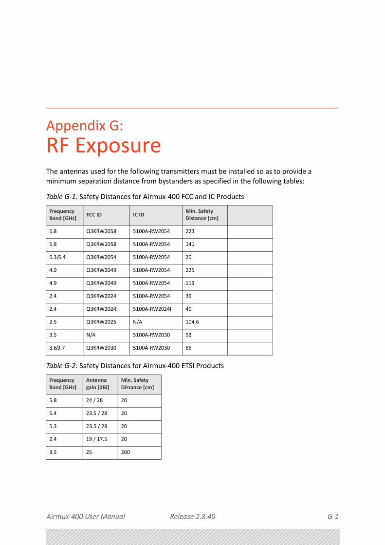
Airmux‐400 User Manual Release 2.8.40 G‐1
Appendix G:
RF ExposureThe antennas used for the following transmitters must be installed so as to provide a minimum separation distance from bystanders as specified in the following tables:
Table G‐1: Safety Distances for Airmux‐400 FCC and IC Products
Frequency Band [GHz]
FCC ID IC IDMin. Safety Distance [cm]
5.8 Q3KRW2058 5100A‐RW2054 223
5.8 Q3KRW2058 5100A‐RW2054 141
5.3/5.4 Q3KRW2054 5100A‐RW2054 20
4.9 Q3KRW2049 5100A‐RW2054 225
4.9 Q3KRW2049 5100A‐RW2054 113
2.4 Q3KRW2024 5100A‐RW2054 39
2.4 Q3KRW2024I 5100A‐RW2024I 40
2.5 Q3KRW2025 N/A 104.6
3.5 N/A 5100A‐RW2030 92
3.6/3.7 Q3KRW2030 5100A‐RW2030 86
Table G‐2: Safety Distances for Airmux‐400 ETSI Products
Frequency Band [GHz]
Antenna gain [dBi]
Min. Safety Distance [cm]
5.8 24 / 28 20
5.4 23.5 / 28 20
5.3 23.5 / 28 20
2.4 19 / 17.5 20
3.5 25 200

Airmux‐400 User Manual Release 2.8.40 H‐1
Appendix H:
Regional Notice: French Canadian
Procédures de sécurité
Généralités
Avant de manipuler du matériel connecté à des lignes électriques ou de télécommunications, il est conseillé de se défaire de bijoux ou de tout autre objet métallique qui pourrait entrer en contact avec les éléments sous tension.
Mise à la terre
Tous les produits RAD doivent être mis à la terre pendant l'usage courant. La mise à la terre est assurée en reliant la fiche d'alimentation à une prise de courant avec une protection de
terre. En outre:
• La cosse de masse sur l'IDU‐E doit être constamment connectée à la protection de terre, par un câble de diamètre de 18 AWG ou plus. Le matériel monté sur rack doit être installé seulement sur des racks ou armoires reliés à la terre
• Une ODU doit mise à la terre par un câble de diamètre de 10 AWG ou plus
• Il ne doit pas y avoir de fusibles ou d'interrupteurs sur la connection à la terre
De plus:
• Il faut toujours connecter la terre en premier et la déconnecter en dernier
• Il ne faut jamais connecter les câbles de télécommunication à du matériel non à la terre
• Il faut s'assurer que tous les autres câbles sont déconnectés avant de déconnecter la terre

Airmux‐400 User Manual Release 2.8.40 H‐2
Protection contre la foudre
Protection contre la foudre
L'utilisation de dispositifs de protection contre la foudre dépend des exigences réglementaires et de l'utilisateur final. Toutes les unités extérieures RAD sont conçues avec des circuits de limitation de surtension afin de minimiser les risques de dommages dus à la foudre. RAD conseille l'utilisation d'un dispositif de parafoudre supplémentaire afin de protéger le matériel de coups de foudre proches.
Matériel supplémentaire requis
L'équipement requis pour l'installation du matériel est le suivant:
• Pince à sertir RJ‐45 (si un câble pré‐assemblé ODU/IDU n'est pas utilisé)
• Perceuse (pour le montage sur mur seulement)
• Câbles de terre IDU et ODU
• Clef 13 mm (½)• Câble ODU ‐ IDU si non commandé (type extérieur, CAT 5e, 4 paires torsadées, 24 AWG)
• Colliers de serrage
• Ordinateur portable avec Windows 2000 ou Windows XP.
Précautions de sécurité pendant le montage de ODU
Avant de connecter un câble à l'ODU, la borne protectrice de masse (visse) de l'ODU doit être connectée à un conducteur externe protecteur ou à un pylône relié à la terre. Il ne doit pas y avoir de fusibles ou d'interrupteurs sur la connection à la terre.
Seulement un personnel qualifié utilisant l'équipement de sécurité approprié doit pouvoir monter sur le pylône d'antenne. De même, l'installation ou le démontage de ODU ou de pylônes doit être effectuée seulement par des professionnels ayant suivi une formation.
Pour monter l'ODU:
1. Vérifier que les supports de fixation de l'ODU sont correctement mis à la terre.
2. Monter l'unité ODU sur le pylône ou sur le mur; se référer à la Installation sur pylône et mur au dessous.
3. Connecter la câble de terre au point de châssis sur l'ODU.
4. Relier le câble ODU‐IDU au connecteur ODU RJ‐45.
5. Visser les presses‐étoupe de câbles pour assurer le scellement hermétique des unités ODU.
6. Attacher le câble au pylône ou aux supports en utilisant des colliers classés UV.
7. Répéter la procédure sur le site distant.
Prudence
Ne pas se placer en face d'une ODU sous tension.

Airmux‐400 User Manual Release 2.8.40 H‐3
Connecter la terre à IDU‐E
Connecter la terre à IDU‐E
Connecter un câble de terre de 18 AWG à la borne de masse de l'appareil. L'appareil doit être constamment connecté à la terre.
Installation sur pylône et murL' ODU ou l'O‐PoE peuvent être montés sur un pylône ou un mur.
Contenu du kit de montage ODU
Le kit de montage ODU comprend les pièces suivantes:
• une grande clame (voir Figure H‐1)
• une petite clame (voir Figure H‐2)
• un bras (voir Figure H‐3)
• quatre visses hex tête M8x40
• deux visses hex tête M8x70
• quatre rondelles plates M8
• trois rondelles élastiques M8
• deux écrous M8.
Prudence
• Les appareils sont prévus pour être installés par un personnel de ser‐vice.
• Les appareils doivent être connectés à une prise de courant avec une protection de terre.
• Le courant CC du IDU‐E doit être fourni par l'intermédiaire d'un dis‐joncteur bipolaire et le diamètre du câble doit être de 14 mm avec un conduit de 16 mm.
Figure H‐1: grande clame Figure H‐2: petite clame Figure H‐3: bras

Airmux‐400 User Manual Release 2.8.40 H‐4
Montage sur un pylône
Montage sur un pylône
Figure H‐4: Montage sur un pylône

Airmux‐400 User Manual Release 2.8.40 H‐5
Montage sur un mur
Montage sur un mur
Figure H‐5: Montage sur un mur

Airmux‐400 User Manual Release 2.8.40 H‐6
Montage d'une antenne externe
Montage d'une antenne externe
L'antenne externe optionnelle peut être montée sur un pylône.
Contenu du kit de montage d'une antenne externe
Le kit de montage d'une antenne externe comprend les pièces suivantes
• Douze rondelles plates
• Huit rondelles élastiques
• Huit écrous hex
• Quatre boulons
• Un support en U
• Un support à pivotement
• Deux courroies de fixation en métal
Pour installer une antenne externe sur un pylône:
1. Attacher le support en U à l'arrière de l'antenne en utilisant quatre rondelles plates, quatre rondelles élastiques et quatre écrous hex.
2. Attacher le support à pivotement au support en U en utilisant huit rondelles plates, quatre rondelles élastiques, quatre écrous hex et quatre boulons.
3. Passer les deux courroies de fixation par les fentes verticales dans le support à pivotement.
4. Attacher l'antenne au pylône en utilisant les deux courroies de fixation .
Ajuster l'inclinaison nécessaire en utilisant l'échelle angulaire et serrer tous les boulons et écrous à la position requise.

Airmux‐400 User Manual Release 2.8.40 Index 1
Index
Numerics2.5GHz bands for, BRS/EBS 23‐73.X, bands 23‐7
Aaccessories 2‐8active alarms 10‐21Air Interface Thresholds, setting 10‐15alert messages, reverting 10‐22antenna
changing number of, Tx Power 8‐10connecting and aligning ODUs with 4‐36considerations for changing parameters
F‐4dual at the HBS and an HSU F‐1external, mounting 4‐26issues F‐1setting parameters F‐1single and dual F‐1single at both sites F‐2single at one site, dual at the other F‐2switching between MIMO and Diversity
modes 8‐12switching between single and dual 8‐12Tx Power, gain and cable loss 8‐10
asymmetric allocationand Collocation 6‐18and TDM 6‐19limitations of 6‐18
availabilityLink Budget 26‐3QoS 21‐1, 22‐1VLAN 17‐6
Bbackup, ODU software to a file 9‐42bands
3.X 23‐7changing factory default 23‐1changing for DFS 23‐5changing, higher Tx Power options and
restrictions 23‐9
inactive and active mode 23‐11provisions for licensed 3.X and 2.5 GHz
bands 23‐7regulatory, for 3.650‐3.675 GHz FCC/IC
part 90 sub part Z 23‐8restricted mode 23‐8Special Products or Features‐ entering a
License Key 23‐5splitting for ETSI 3.4 ‐ 3.7GHz 23‐10summary for FCC/IC and Universal 3.X
GHz 23‐10Tx Power options 23‐8
Bridge, configuring 9‐23BRS/EBS
2.5GHz bands for 23‐7
CCapacity Upgrade 22‐1
Persistency 22‐4changing
Link Password 6‐5, 9‐14Log‐On Password 5‐8Tx Power 9‐4
Community Strings 9‐14, D‐2forgotten 9‐16invalid 5‐7
configuration, with Telnet 9‐44configuring
Ethernet Ports Mode 9‐26
Index

Airmux‐400 User Manual Release2.8.40 Index 2
GSU 14‐6Link 8‐1ODU Address 9‐7Site 9‐1the Bridge 9‐23VLAN Settings 9‐10
CRC Error Detection for LAN Ports 9‐27Customer Support 10‐26
DDate and Time, setting 9‐19DC PoE B‐5DC Power Terminals B‐5default settings
ODU 5‐11DFS
changing bands 23‐5
EEquipment Protection, MHS 15‐2Ethernet
Properties 9‐23QoS 6‐24Ring 6‐24, 16‐1, 16‐2Ring, described 16‐1service 7‐7supported Ring Topologies 16‐4
Ethernet Ports Mode, configuring 9‐26events
also alarms and traps 10‐16log 7‐8, 10‐16log, saving 10‐20
Events Preferences, setting 10‐19External Alarm Inputs, setting 9‐39External Alarms Specification E‐1
FFCC/IC 5.4/5.3 GHz Links
Background 19‐2
Ggrounding 4‐12GSU
cascaded sites using Shifted Phase Transmission 14‐3
configuring 14‐6described 14‐1
functionality 14‐1independent distributed sites 14‐1installation 14‐5kit contents 14‐4Manager, main window 14‐6monitoring and diagnostics 14‐15mounting 14‐5multiple distributed sites with
communication 14‐2Overview 14‐5preferences 14‐15preparing for use 14‐5redundancy 14‐3Site Configuration 14‐7
Date and Time 14‐12GPS Sync Unit 14‐7inventory 14‐11Management 14‐10Operations 14‐13Security 14‐11System 14‐7
Software Upgrade for GSUs 14‐16, 18‐5status box 14‐6Telnet support 14‐15using 14‐1
HHSS
and link configuration 11‐7, 13‐3and RFP 11‐4and Site Configuration 12‐9, 13‐10cabling sequence 12‐4connecting an HSS unit 12‐1described 11‐1, 12‐1, 13‐1error notification 12‐5hardware installation 11‐3, 12‐1Radio Frame Pattern (RFP) with 11‐3status LED, IDUs 11‐7to ODU unit connection pinout 11‐3, 12‐
5, B‐1total cable length 12‐5unit with five collocated ODUs 12‐5using a single unit 12‐3using more than one HSS Unit 12‐3

Airmux‐400 User Manual Release2.8.40 Index 3
Hub Site Synchronization ‐ see HSS
IIDU
(all models) alarm connector B‐3aging time 9‐25connecting the ODU 4‐35detection 9‐42HSS status LED 11‐7replacement, MHS 15‐9to ODU cable B‐1
IDU‐EInstallation 4‐22
incorrect IP Address 5‐7incorrect password 5‐8Interface
logging on 28‐4Internal ESD Protection circuits 4‐13Invalid Read/Write Community Strings 5‐7inventory, displaying 9‐12
LLAN Port B‐2LBC
antenna, height 26‐3calculations 26‐2EIRP 26‐2Expected RSS and Fade Margin 26‐2Fresnel Zone 26‐3internal data 26‐1Min and Max Range 26‐2Overview 26‐1running 26‐5Service 26‐2User Input 26‐1
linkcompatibility 10‐3configuration and HSS 11‐7, 13‐3configuring 8‐1installation 6‐1reinstalling and realigning 10‐9Site Configuration 9‐1
Link Budget Calculator, see LBCLink Budget, availability 26‐3Link Lock Security Feature 9‐17Link Password, changing 6‐5, 9‐14log
events 10‐16
events, saving 10‐20monitor 10‐10monitor, saving 10‐10
logging onerrors and cautions 5‐7to the Over‐the‐Air Site 5‐8to the Web Interface 28‐4
Log‐On Password, changing 5‐8loopback
local internal 10‐8local line 10‐6remote line 10‐7remote reverse 10‐7TDM 10‐4
lost or forgotten VLAN ID 9‐11
MManager 2‐7
installing application 5‐1log‐on concept 5‐3main window 7‐1, 7‐1, 7‐5
frequency box 7‐7link details pane 7‐5main menu functionality 7‐2monitor pane 7‐5Received Signal Strength (RSS) 7‐5status bar 7‐8
setting up an Ethernet Ring 16‐8toolbar 7‐2traps 10‐18
MHSAir‐Interface Protection 15‐2described 15‐1, 15‐9Equipment Protection 15‐2Hot Standby Port RJ‐11 B‐2IDU replacement 15‐9installation procedure 15‐1installing 15‐3kit contents 15‐3mode, setting 6‐23ODU replacement 15‐10status, TDM 9‐38switching back from the Secondary to the
Primary Link 15‐12switching from Primary Link to Secondary
Link 15‐11switching logic 15‐11system operation description 15‐14

Airmux‐400 User Manual Release2.8.40 Index 4
MIBcontrol method D‐2Interface API D‐2parameters D‐6Reference D‐1, D‐1Structure, private D‐2Supported Variables from the RFC 1213
MIB D‐5Trap Parameters D‐36traps D‐35
MIRdescribed 9‐35setting 9‐35
Modulation Rate Selection 6‐22monitor
log 10‐10log, saving 10‐10
Monitoring and Diagnostics 10‐1mounting
external antenna 4‐26GSU 14‐5lighting protection unit 4‐28
NNetwork Management System 2‐8Normal Mode 9‐30
OODU A‐1
address, configuring 9‐7backup software to a file 9‐42connecting to the IDU 4‐35default settings 5‐11mode 9‐23muting the alignment tone buzzer 9‐44pre‐loading with an IP Address 25‐1replacement for MHS 15‐10replacing 10‐25restore software from a file 9‐42to HSS unit connection pinout 11‐3, 12‐5,
B‐1to IDU cable B‐1
Online Help 10‐25
Ppassword incorrect 5‐8Performance Monitoring 10‐10Performance Monitoring, Report toolbar 10‐
15PoE
DC B‐5using 4‐36
Port Connections 9‐27Power Over Ethernet Devices ‐ see PoEPreventing overexposure to RF energy 4‐12protection
mounting unit 4‐28Protection against Lightning 4‐13protocols, enable/disable 9‐11
QQoS
availability 21‐1, 22‐1disabling 21‐5Ethernet 6‐24Setting up 21‐2
Quality of Service, see QoSQuick Install Mode 24‐1Quick Install Mode, enable 24‐1
RRemote Power Fail Indication 10‐23restore
ODU, factory setup 10‐25ODU, software or configuration 9‐43
restore, ODU software from a file 9‐42retrieve link information (Get Diagnostics) 10‐1RF Exposure G‐1RFP
and HSS 11‐4General Radio Frame Pattern 11‐5
RingEthernet 6‐24, 16‐1, 16‐2
described 16‐1hardware considerations 16‐6protection switching 16‐6setting up with the Manager 16‐8Special Case ‐ “1 + 1 Ethernet
Redundancy” 16‐7Topologies, supported, Ethernet 16‐4
SSafety Practices 4‐12Sectrum View
main window 27‐5
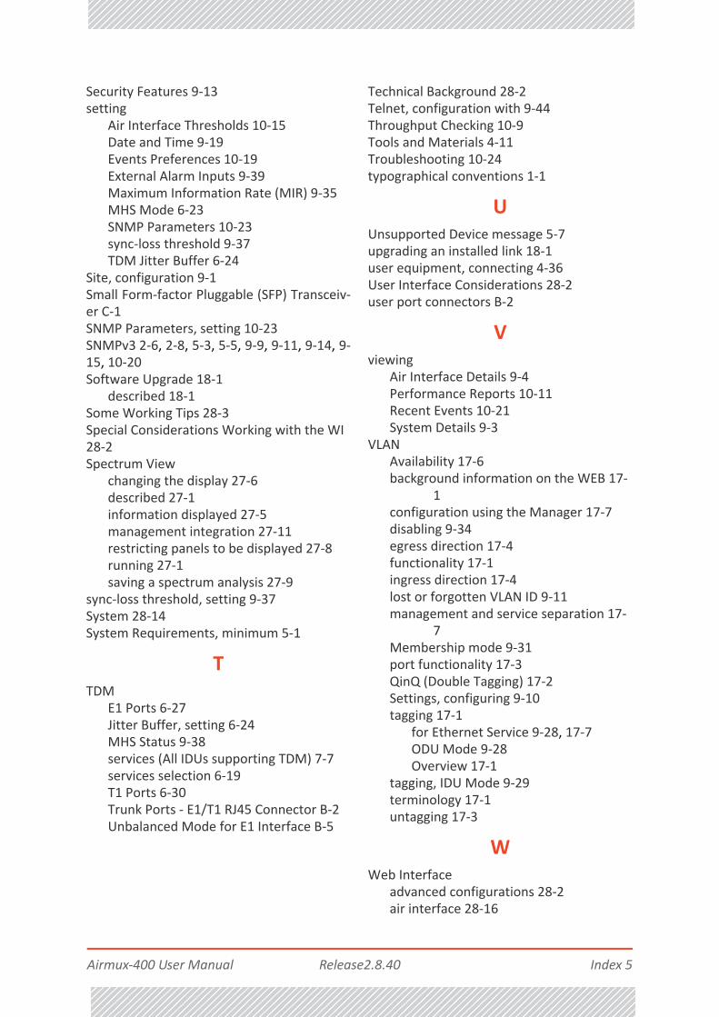
Airmux‐400 User Manual Release2.8.40 Index 5
Security Features 9‐13setting
Air Interface Thresholds 10‐15Date and Time 9‐19Events Preferences 10‐19External Alarm Inputs 9‐39Maximum Information Rate (MIR) 9‐35MHS Mode 6‐23SNMP Parameters 10‐23sync‐loss threshold 9‐37TDM Jitter Buffer 6‐24
Site, configuration 9‐1Small Form‐factor Pluggable (SFP) Transceiv‐er C‐1SNMP Parameters, setting 10‐23SNMPv3 2‐6, 2‐8, 5‐3, 5‐5, 9‐9, 9‐11, 9‐14, 9‐15, 10‐20Software Upgrade 18‐1
described 18‐1Some Working Tips 28‐3Special Considerations Working with the WI 28‐2Spectrum View
changing the display 27‐6described 27‐1information displayed 27‐5management integration 27‐11restricting panels to be displayed 27‐8running 27‐1saving a spectrum analysis 27‐9
sync‐loss threshold, setting 9‐37System 28‐14System Requirements, minimum 5‐1
TTDM
E1 Ports 6‐27Jitter Buffer, setting 6‐24MHS Status 9‐38services (All IDUs supporting TDM) 7‐7services selection 6‐19T1 Ports 6‐30Trunk Ports ‐ E1/T1 RJ45 Connector B‐2Unbalanced Mode for E1 Interface B‐5
Technical Background 28‐2Telnet, configuration with 9‐44Throughput Checking 10‐9Tools and Materials 4‐11Troubleshooting 10‐24typographical conventions 1‐1
UUnsupported Device message 5‐7upgrading an installed link 18‐1user equipment, connecting 4‐36User Interface Considerations 28‐2user port connectors B‐2
Vviewing
Air Interface Details 9‐4Performance Reports 10‐11Recent Events 10‐21System Details 9‐3
VLANAvailability 17‐6background information on the WEB 17‐
1configuration using the Manager 17‐7disabling 9‐34egress direction 17‐4functionality 17‐1ingress direction 17‐4lost or forgotten VLAN ID 9‐11management and service separation 17‐
7Membership mode 9‐31port functionality 17‐3QinQ (Double Tagging) 17‐2Settings, configuring 9‐10tagging 17‐1
for Ethernet Service 9‐28, 17‐7ODU Mode 9‐28Overview 17‐1
tagging, IDU Mode 9‐29terminology 17‐1untagging 17‐3
WWeb Interface
advanced configurations 28‐2air interface 28‐16
Airmux‐400 User Manual Release2.8.40 Index 6
antenna & Tx Power 28‐17change band 28‐16described 28‐2getting in to installation mode 28‐5installation mode 28‐16inventory 28‐18management 28‐18operational effects 28‐3prerequisites 28‐2site configuration 28‐13using the configuration wizard 28‐6


Publication No. 581-200-02/15
Order this publication by Catalog No. 803822
International Headquarters 24 Raoul Wallenberg Street
Tel Aviv 69719, Israel
Tel. 972-3-6458181
Fax 972-3-6498250, 6474436
E-mail [email protected]
North America Headquarters 900 Corporate Drive
Mahwah, NJ 07430, USA
Tel. 201-5291100 Toll free 1-800-4447234
Fax 201-5295777
E-mail [email protected]
www.rad.com