EPP-400 - ESAB
80
EPP-400 Plasma Power Source Instruction Manual (EN) 0558006924 08/2010
-
Upload
khangminh22 -
Category
Documents
-
view
3 -
download
0
Transcript of EPP-400 - ESAB

EPP-400Plasma Power Source
Instruction Manual (EN)
0558006924 08/2010

This equipment will perform in conformity with the description thereof contained in this manual and accompa-nying labels and/or inserts when installed, operated, maintained and repaired in accordance with the instruc-tions provided. This equipment must be checked periodically. Malfunctioning or poorly maintained equipment should not be used. Parts that are broken, missing, worn, distorted or contaminated should be replaced imme-diately. Should such repair or replacement become necessary, the manufacturer recommends that a telephone or written request for service advice be made to the Authorized Distributor from whom it was purchased.
This equipment or any of its parts should not be altered without the prior written approval of the manufacturer. The user of this equipment shall have the sole responsibility for any malfunction which results from improper use, faulty maintenance, damage, improper repair or alteration by anyone other than the manufacturer or a ser-vice facility designated by the manufacturer.
BE surE thIs INforMatIoN rEachEs thE opErator.You caN gEt Extra copIEs through Your supplIEr.
these INstructIoNs are for experienced operators. If you are not fully familiar with the principles of operation and safe practices for arc welding and cutting equipment, we urge you to read our booklet, “precautions and safe practices for arc Welding, cutting, and gouging,” form 52-529. Do Not permit untrained persons to install, operate, or maintain this equipment. Do Not attempt to install or operate this equipment until you have read and fully understand these instructions. If you do not fully understand these instructions, contact your supplier for further information. Be sure to read the safety precautions be-fore installing or operating this equipment.
cautIoN
usEr rEspoNsIBIlItY
rEaD aND uNDErstaND thE INstructIoN MaNual BEforE INstallINg or opEratINg.
protEct YoursElf aND othErs!

taBlE of coNtENts
section / title page
1.0 Safety Precautions . . . . . . . . . . . . . . . . . . . . . . . . . . . . . . . . . . . . . . . . . . . . . . . . . . . . . . . . . . . . . . . . . . . . . . . . . . . . . . . . . . . .5
2.0 Description . . . . . . . . . . . . . . . . . . . . . . . . . . . . . . . . . . . . . . . . . . . . . . . . . . . . . . . . . . . . . . . . . . . . . . . . . . . . . . . . . . . . . . . . . . .7 2.1 Introduction . . . . . . . . . . . . . . . . . . . . . . . . . . . . . . . . . . . . . . . . . . . . . . . . . . . . . . . . . . . . . . . . . . . . . . . . . . . . . . . . . . . . . .7 2.2 General Specifications . . . . . . . . . . . . . . . . . . . . . . . . . . . . . . . . . . . . . . . . . . . . . . . . . . . . . . . . . . . . . . . . . . . . . . . . . . . .7 2.3 Dimensions and Weight. . . . . . . . . . . . . . . . . . . . . . . . . . . . . . . . . . . . . . . . . . . . . . . . . . . . . . . . . . . . . . . . . . . . . . . . . . .8
3.0 Installation. . . . . . . . . . . . . . . . . . . . . . . . . . . . . . . . . . . . . . . . . . . . . . . . . . . . . . . . . . . . . . . . . . . . . . . . . . . . . . . . . . . . . . . . . . . .9 3.1 General. . . . . . . . . . . . . . . . . . . . . . . . . . . . . . . . . . . . . . . . . . . . . . . . . . . . . . . . . . . . . . . . . . . . . . . . . . . . . . . . . . . . . . . . . . .9 3.2 Unpacking . . . . . . . . . . . . . . . . . . . . . . . . . . . . . . . . . . . . . . . . . . . . . . . . . . . . . . . . . . . . . . . . . . . . . . . . . . . . . . . . . . . . . . .9 3.3 Placement. . . . . . . . . . . . . . . . . . . . . . . . . . . . . . . . . . . . . . . . . . . . . . . . . . . . . . . . . . . . . . . . . . . . . . . . . . . . . . . . . . . . . . . .9 3.4 Input Power Connection . . . . . . . . . . . . . . . . . . . . . . . . . . . . . . . . . . . . . . . . . . . . . . . . . . . . . . . . . . . . . . . . . . . . . . . . .10 3.5 Output Connection . . . . . . . . . . . . . . . . . . . . . . . . . . . . . . . . . . . . . . . . . . . . . . . . . . . . . . . . . . . . . . . . . . . . . . . . . . . . . .12 3.6 Parallel Installation. . . . . . . . . . . . . . . . . . . . . . . . . . . . . . . . . . . . . . . . . . . . . . . . . . . . . . . . . . . . . . . . . . . . . . . . . . . . . . .13 3.7 Interface Cables . . . . . . . . . . . . . . . . . . . . . . . . . . . . . . . . . . . . . . . . . . . . . . . . . . . . . . . . . . . . . . . . . . . . . . . . . . . . . . . . .16
4.0 Operation . . . . . . . . . . . . . . . . . . . . . . . . . . . . . . . . . . . . . . . . . . . . . . . . . . . . . . . . . . . . . . . . . . . . . . . . . . . . . . . . . . . . . . . . . . .19 4.1 Block Diagram Circuit Description . . . . . . . . . . . . . . . . . . . . . . . . . . . . . . . . . . . . . . . . . . . . . . . . . . . . . . . . . . . . . . . .19 4.2 Control Panel . . . . . . . . . . . . . . . . . . . . . . . . . . . . . . . . . . . . . . . . . . . . . . . . . . . . . . . . . . . . . . . . . . . . . . . . . . . . . . . . . . . 22 4.3 Sequence of Operation . . . . . . . . . . . . . . . . . . . . . . . . . . . . . . . . . . . . . . . . . . . . . . . . . . . . . . . . . . . . . . . . . . . . . . . . . 26 4.4 Arc Initiation Settings . . . . . . . . . . . . . . . . . . . . . . . . . . . . . . . . . . . . . . . . . . . . . . . . . . . . . . . . . . . . . . . . . . . . . . . . . . . .27 4.5 EPP-400 V-I Curves. . . . . . . . . . . . . . . . . . . . . . . . . . . . . . . . . . . . . . . . . . . . . . . . . . . . . . . . . . . . . . . . . . . . . . . . . . . . . . 30
5.0 Maintenance. . . . . . . . . . . . . . . . . . . . . . . . . . . . . . . . . . . . . . . . . . . . . . . . . . . . . . . . . . . . . . . . . . . . . . . . . . . . . . . . . . . . . . . . .33 5.1 General. . . . . . . . . . . . . . . . . . . . . . . . . . . . . . . . . . . . . . . . . . . . . . . . . . . . . . . . . . . . . . . . . . . . . . . . . . . . . . . . . . . . . . . . . .33 5.2 Cleaning . . . . . . . . . . . . . . . . . . . . . . . . . . . . . . . . . . . . . . . . . . . . . . . . . . . . . . . . . . . . . . . . . . . . . . . . . . . . . . . . . . . . . . . .33 5.3 Lubrication . . . . . . . . . . . . . . . . . . . . . . . . . . . . . . . . . . . . . . . . . . . . . . . . . . . . . . . . . . . . . . . . . . . . . . . . . . . . . . . . . . . . . 34
6.0 Troubleshooting . . . . . . . . . . . . . . . . . . . . . . . . . . . . . . . . . . . . . . . . . . . . . . . . . . . . . . . . . . . . . . . . . . . . . . . . . . . . . . . . . . . . .35 6.1 General. . . . . . . . . . . . . . . . . . . . . . . . . . . . . . . . . . . . . . . . . . . . . . . . . . . . . . . . . . . . . . . . . . . . . . . . . . . . . . . . . . . . . . . . . .35 6.2 Fault Indicators . . . . . . . . . . . . . . . . . . . . . . . . . . . . . . . . . . . . . . . . . . . . . . . . . . . . . . . . . . . . . . . . . . . . . . . . . . . . . . . . . .35 6.3 Fault Isolation . . . . . . . . . . . . . . . . . . . . . . . . . . . . . . . . . . . . . . . . . . . . . . . . . . . . . . . . . . . . . . . . . . . . . . . . . . . . . . . . . . 38 6.4 Testing and Replacing Components . . . . . . . . . . . . . . . . . . . . . . . . . . . . . . . . . . . . . . . . . . . . . . . . . . . . . . . . . . . . . 46 6.5 Control Circuit Interface Using J1 and J6 Connectors . . . . . . . . . . . . . . . . . . . . . . . . . . . . . . . . . . . . . . . . . . . . . .52 6.6 Auxiliary Main Contactor (K3) and Solid State Contactor Circuits . . . . . . . . . . . . . . . . . . . . . . . . . . . . . . . . . . 54 6.7 Main Contactor (K1A, K1B and K1C) Activation Circuit . . . . . . . . . . . . . . . . . . . . . . . . . . . . . . . . . . . . . . . . . . . . . .55 6.8 Arc Current Detector Circuits . . . . . . . . . . . . . . . . . . . . . . . . . . . . . . . . . . . . . . . . . . . . . . . . . . . . . . . . . . . . . . . . . . . . 56 6.9 Current Control Pot and Remote Vref . . . . . . . . . . . . . . . . . . . . . . . . . . . . . . . . . . . . . . . . . . . . . . . . . . . . . . . . . . . . 57 6.10 Pilot Arc HI / LO and Cut / Mark Circuits . . . . . . . . . . . . . . . . . . . . . . . . . . . . . . . . . . . . . . . . . . . . . . . . . . . . . . . . . 58
7.0 Replacement Parts . . . . . . . . . . . . . . . . . . . . . . . . . . . . . . . . . . . . . . . . . . . . . . . . . . . . . . . . . . . . . . . . . . . . . . . . . . . . . . . . . . .597.1 General . . . . . . . . . . . . . . . . . . . . . . . . . . . . . . . . . . . . . . . . . . . . . . . . . . . . . . . . . . . . . . . . . . . . . . . . . . . . . . . . . . . . . . . . . .597.2 Ordering . . . . . . . . . . . . . . . . . . . . . . . . . . . . . . . . . . . . . . . . . . . . . . . . . . . . . . . . . . . . . . . . . . . . . . . . . . . . . . . . . . . . . . . .59

4

5
sEctIoN 1 safEtY prEcautIoNs
1.0 safety precautionsUsers of ESAB welding and plasma cutting equipment have the ultimate responsibility for ensuring that anyone who works on or near the equipment observes all the relevant safety precautions. Safety precautions must meet the requirements that apply to this type of welding or plasma cutting equipment. The following recommendations should be observed in addition to the standard regulations that apply to the workplace.
All work must be carried out by trained personnel well acquainted with the operation of the welding or plasma cutting equipment. Incorrect operation of the equipment may lead to hazardous situations which can result in injury to the operator and damage to the equipment.
1. Anyone who uses welding or plasma cutting equipment must be familiar with: - its operation - location of emergency stops - its function - relevant safety precautions - welding and / or plasma cutting
2. The operator must ensure that: - no unauthorized person stationed within the working area of the equipment when it is started up. - no one is unprotected when the arc is struck.
3. The workplace must: - be suitable for the purpose - be free from drafts
4. Personal safety equipment: - Always wear recommended personal safety equipment, such as safety glasses, flame proof clothing, safety gloves. - Do not wear loose fitting items, such as scarves, bracelets, rings, etc., which could become trapped or cause burns.
5. General precautions: - Make sure the return cable is connected securely. - Work on high voltage equipment may only be carried out by a qualified electrician. - Appropriate fire extinquishing equipment must be clearly marked and close at hand. - Lubrication and maintenance must not be carried out on the equipment during operation.
The Ip code indicates the enclosure class, i.e. the degree of protection against penetration by solid objects or water. Protection is provided against touch with a finger, penetration of solid objects greater than 12mm and against spraying water up to 60 degrees from vertical. Equipment marked Ip23s may be stored, but is not in-tended to be used outside during precipitation unless sheltered.
Enclosure class
MaximumTilt Allowed
15°
cautIoNIf equipment is placed on a surface that slopes more than 15°, toppling over may oc-cur. personal injury and / or significant dam-age to equipment is possible.

6
sEctIoN 1 safEtY prEcautIoNs
WElDINg aND plasMa cuttINg caN BE INJurIous to YoursElf aND othErs. taKE prEcautIoNs WhEN WElDINg or cuttINg. asK for Your EMploYEr’s safEtY practIcEs WhIch shoulD BE BasED oN MaNufacturErs’ haZarD Data.
ElEctrIc shocK - Can kill. - Install and earth (ground) the welding or plasma cutting unit in accordance with applicable standards. - Do not touch live electrical parts or electrodes with bare skin, wet gloves or wet clothing. - Insulate yourself from earth and the workpiece. - Ensure your working stance is safe.
fuMEs aND gasEs - Can be dangerous to health. - Keep your head out of the fumes. - Use ventilation, extraction at the arc, or both, to take fumes and gases away from your breathing zone and the general area.
arc raYs - Can injure eyes and burn skin. - Protect your eyes and body. Use the correct welding / plasma cutting screen and filter lens and wear protective clothing. - Protect bystanders with suitable screens or curtains.
fIrE haZarD - Sparks (spatter) can cause fire. Make sure therefore that there are no inflammable materials nearby.
NoIsE - Excessive noise can damage hearing. - Protect your ears. Use earmuffs or other hearing protection. - Warn bystanders of the risk.
MalfuNctIoN - Call for expert assistance in the event of malfunction.
rEaD aND uNDErstaND thE INstructIoN MaNual BEforE INstallINg or opEratINg.
protEct YoursElf aND othErs!
WarNINg
this product is solely intended for plasma cutting. any other use may result in personal injury and / or equipment damage.cautIoN
cautIoNto avoid personal injury and/or equipment damage, lift using method and attachment points shown here.

7
sEctIoN 2 DEscrIptIoN
2.1 Introduction
The EPP power source is designed for marking and high speed plasma mechanized cutting applications. It can be used with other ESAB products such as the PT-15, Pt-19XLS, PT-600 and PT-36 torches along with the Smart Flow II, a computerized gas regulation and switching system.
• 12 to 400 amperes for marking• 50 to 400 amperes cutting current range• Forced air cooled • Solid state DC power• Input voltage protection• Local or remote front panel control• Thermal switch protection for main transformer and power semiconductor components• Top lifting rings or base forklift clearance for transport• Parallel supplemental power source capabilities to extend current output range.
EPP-400 400V, 50 / 60Hz CE
EPP-400 460V, 60Hz
EPP-400 575V, 60Hz
Part Number 0558006470 0558006471 0558006472
Output (100 % duty cycle)
Voltage 200 VDC
Current range DC (marking) 12A to 400A
Current range DC (cutting) 50A to 400A
Power 120 KW
* Open Circuit Voltage (OCV) 423 VDC 427 VDC 427 VDC
Input
Voltage (3-phase) 400 V 460 V 575 V
Current (3- phase) 138A RMS 120A RMS 96A RMS
Frequency 50/60 HZ 60 Hz 60 Hz
KVA 95.6 KVA 95.6 KVA 95.6 KVA
Power 87 KW 87 KW 87 KW
Power Factor 91.0 % 91.0% 91.0%
Input Fuse Rec. 200A 150A 125A
2.2 general specifications
* Open circuit voltage is reduced to 360V in the marking mode for 460V and 575V, 60Hz models and to 310V for 400V, 50Hz model.
8
sEctIoN 2 DEscrIptIoN
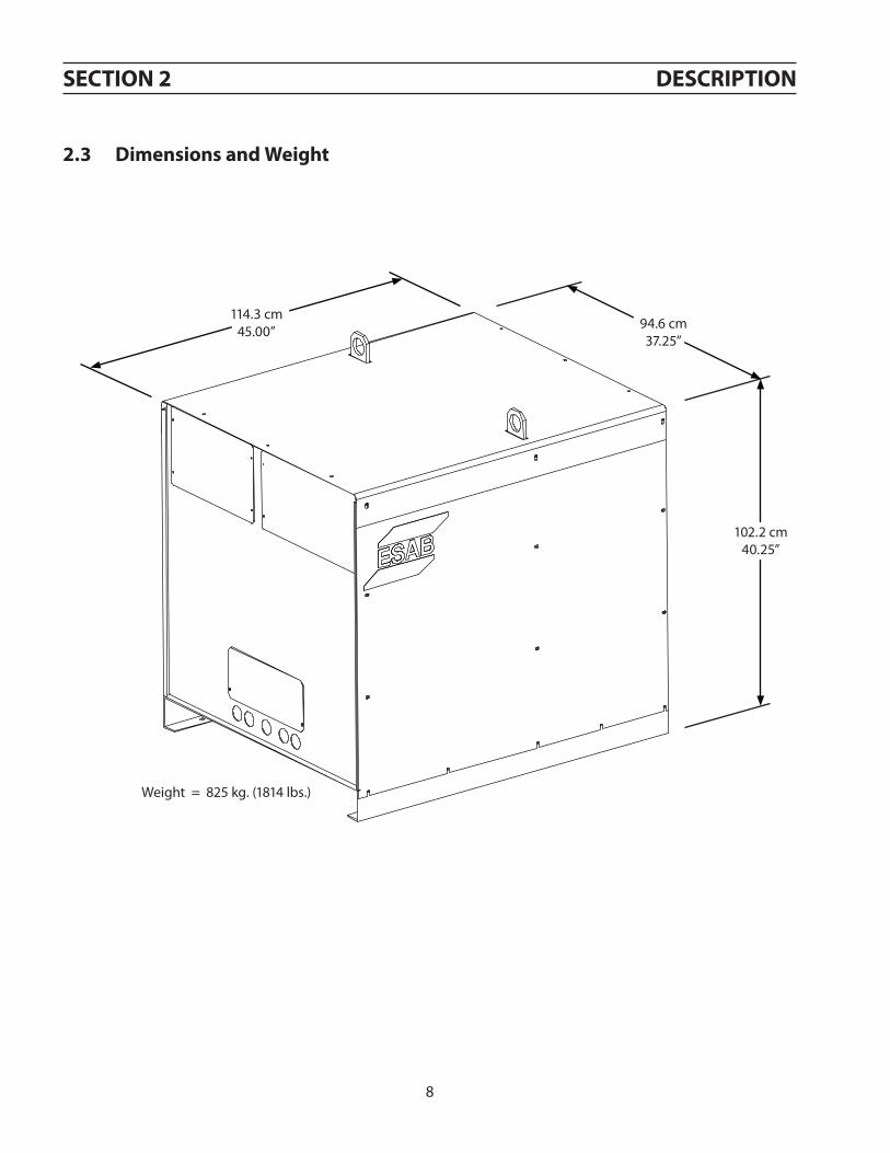
2.3 Dimensions and Weight
114.3 cm45.00” 94.6 cm
37.25”
102.2 cm40.25”
Weight = 825 kg. (1814 lbs.)

9
sEctIoN 3 INstallatIoN
3.1 general
faIlurE to folloW INstructIoNs coulD lEaD to DEath, IN-JurY or DaMagED propErtY. folloW thEsE INstructIoNs to prEvENt INJurY or propErtY DaMagE. You Must coMplY WIth local, statE aND NatIoNal ElEctrIcal aND safEtY coDEs.
WarNINg
3.2 unpacking
using one lifting eye will damage sheet metal and frame. use both lifting eyes when transporting with overhead method.cautIoN
• Inspect for transit damage immediately upon receipt.• Remove all components from shipping container and check for loose parts in container.• Inspect louvers for air obstructions.
3.3 placement
Note: Use both lifting eyes when transporting from overhead.
• A minimum of 1 M (3 ft.) clearance on front and back for cooling air flow.• Plan for top panel and side panels having to be removed for maintenance, cleaning and inspection. • Locate the EPP-400 relatively close to a properly fused electrical power supply.• Keep area beneath power source clear for cooling air flow.• Environment should be relatively free of dust, fumes and excessive heat. These factors will affect cool-
ing efficiency.
conductive dust and dirt inside power source may cause arc flash-over.Equipment damage may occur. Electrical shorting may occur if dust is allowed to build-up inside power source. see maintenance section.
cautIoN
cautIoN

10
sEctIoN 3 INstallatIoN
3.4 Input power connection
ElEctrIc shocK caN KIll!provIDE MaxIMuM protEctIoN agaINst ElEctrIcal shocK.BEforE aNY coNNEctIoNs arE MaDE INsIDE thE MachINE, opEN thE lINE Wall DIscoNNEct sWItch to turN poWEr off.
WarNINg
3.4.1 primary power
EPP-400 is a 3-phase unit. Input power must be provided from a line (wall) disconnect switch that contains fuses or circuit breakers in accordance to local or state regulations.
Dedicated power line may be necessary.Epp-400 is equipped with line voltage compensation but to avoid impaired performance due to an overloaded circuit, a dedicated power line may be required.
NotIcE
Input current =(V arc) x (I arc) x 0.688
(V line)
Recommended input conductor and line fuse sizes:
* Sizes per National Electrical Code for a 90° C (194˚ F) rated copper conductors @ 40° C (104˚ F) ambient. Not more than three conductors in raceway or cable. Local codes should be followed if they specify sizes other than those listed above.
To estimate the input current for a wide range of output conditions, use the formula below.
Input at rated load Input and ground conductor* cu/
mm2 (aWg)
time delay fuse size
(amperes)volts amperes
400 138 95 (4/0) 200
460 120 95 (3/0) 150
575 96 50 (1/0) 125
Rated load is output of 400A at 200V

11
• Customer supplied• May consist either of heavy rubber covered copper conductors (three power and one ground) or run
in solid or flexible conduit.• Sized according to the chart.
3.4.2 Input conductors
Input conductors must be terminated with ring terminals.Input conductors must be terminated with ring terminals sized for 12.7 mm (0.50”) hardware before being attached to the Epp-400.
NotIcE
1. Remove left side panel of the EPP-4002. Thread cables through the access opening in the rear panel.3. Secure cables with a strain relief or conduit coupling (not sup-
plied) at the access opening.4. Connect the ground lead to the stud on the chassis base.5. Connect the power lead ring terminals to the primary termi-
nals with supplied bolts, washers and nuts.6. Connect the input conductors to the line (wall) disconnect.
3.4.3 Input connection procedure
1
3
2
1 = primary terminals
2 = chassis ground
3 = power Input cable access opening (rear panel)
sEctIoN 3 INstallatIoN

12
ElEctrIc shocK caN KIll!rINg tErMINals Must havE clEaraNcE BEtWEEN sIDE paNEl aND MaIN traNsforMEr. clEaraNcE Must BE suffIcIENt to prEvENt possIBlE arcINg. MaKE surE caBlEs Do Not INtEr-fErE WIth coolINg faN rotatIoN.
IMpropEr grouNDINg caN rEsult IN DEath or INJurY.chassIs Must BE coNNEctED to aN approvED ElEctrIcal grouND. BE surE grouND lEaD Is Not coNNEctED to aNY prI-MarY tErMINal.
ElEctrIc shocK caN KIll! DaNgErous voltagE aND currENt!aNY tIME WorKINg arouND a plasMa poWEr sourcE WIth cov-Ers rEMovED:
• DIscoNNEct poWEr sourcE at thE lINE (Wall) DIscoNNEct.
• havE a QualIfIED pErsoN chEcK thE output Bus Bars (posI-tIvE aND NEgatIvE) WIth a voltMEtEr.
3.5 output connections
WarNINg
WarNINg
WarNINg
3.5.1 output cables (customer supplied)
Choose plasma cutting output cables (customer supplied) on the basis of one 4/0 AWG, 600 volt insulated cop-per cable for each 400 amps of output current.
Note: Do not use 100 volt insulated welding cable.
sEctIoN 3 INstallatIoN

13
sEctIoN 3 INstallatIoN
3.5.2 output connection procedure
Access Panel
1. Remove access panel on the lower front of the power source.2. Thread output cables through the openings at the bottom of the front panel or at the bottom of the power source im-
mediately behind the front panel.3. Connect cables to designated terminals mounted inside the power source using UL listed pressure wire connectors.4. Replace panel removed during the first step.
Two EPP-400 power sources may be connected together in parallel to extend the output current range.
3.6 parallel Installation
cautIoN
parallel power source minimum output current exceeds recommend-ed amounts when cutting below 100a.use only one power source for cutting below 100a.We recommend disconnecting the negative lead from the supple-mental power source when changing to currents below 100a. this lead should be safely terminated to protect against electric shock.

14
sEctIoN 3 INstallatIoN
Note: Primary power source has the electrode (-) conductor jumpered. The supplemental power source has the
work (+) jumpered.
1. Connect the negative (-) output cables to the arc starter box (high frequency generator).2. Connect the positive (+) output cables to the workpiece.3. Connect the positive (+) and negative (-) conductors between the power sources.4. Connect the pilot arc cable to the pilot arc terminal in the primary power source. The pilot arc connection in the supple-
mental power source is not used. The pilot arc circuit is not run in parallel.5. Set the Pilot Arc HIGH / LOW switch on the supplemental power source to “LOW”.6. Set the Pilot Arc HIGH / LOW switch on the primary power source to “HIGH”.7. If a remote 0.00 to +10.00 VDC current reference signal is used to set the output current, feed the same signal into both
power sources. Connect J1-G (positive 0.00 to 10.00 VDC) of both power sources together and connect J1-P (negative) of both power sources together. With both power sources operating, the output current can be predicted using the following formula: [output current (amps)] = [reference voltage] x [100]
Connections for parallel installation of two EPP-400 power sources with both power sources in operation.
3.6.1 connections for two Epp-400’s in parallel
S u p p l e m e n t a l Power Source
Primary PowerSource
work(+)
electrode(-)
pilot arc
2 - 4/0 600Vpositive leads to workpiece
1 - 14 AWG 600Vlead to pilot arc con-nection in arc starter
box (h.f. generator)
2 - 4/0 600Vnegative leads
in arc starter box (h.f. generator)
EPP-400 EPP-400
work(+)
electrode(-)
15
sEctIoN 3 INstallatIoN
ElEctrIc shocK caN KIll!
ExposED ElEctrIcal coNDuctors caN BE haZarDous!
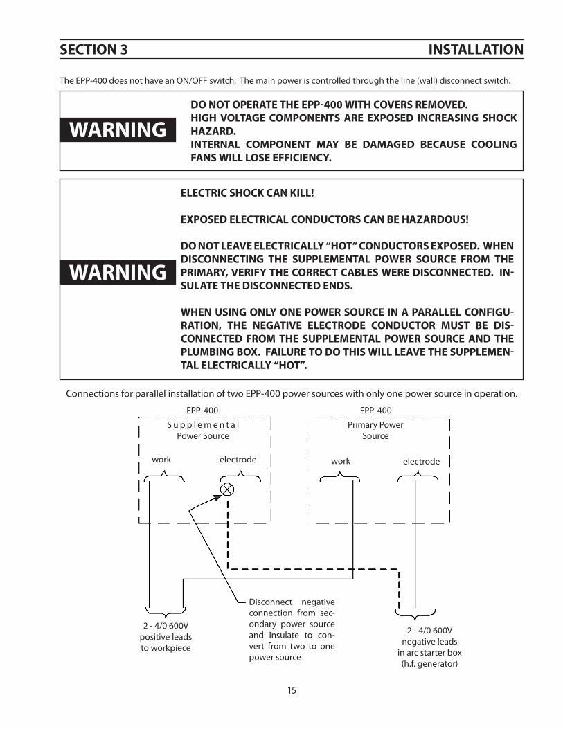
Do Not lEavE ElEctrIcallY “hot“ coNDuctors ExposED. WhEN DIscoNNEctINg thE supplEMENtal poWEr sourcE froM thE prIMarY, vErIfY thE corrEct caBlEs WErE DIscoNNEctED. IN-sulatE thE DIscoNNEctED ENDs.
WhEN usINg oNlY oNE poWEr sourcE IN a parallEl coNfIgu-ratIoN, thE NEgatIvE ElEctroDE coNDuctor Must BE DIs-coNNEctED froM thE supplEMENtal poWEr sourcE aND thE pluMBINg Box. faIlurE to Do thIs WIll lEavE thE supplEMEN-tal ElEctrIcallY “hot”.
WarNINg
Do Not opEratE thE Epp-400 WIth covErs rEMovED.hIgh voltagE coMpoNENts arE ExposED INcrEasINg shocK haZarD.INtErNal coMpoNENt MaY BE DaMagED BEcausE coolINg faNs WIll losE EffIcIENcY.
WarNINg
The EPP-400 does not have an ON/OFF switch. The main power is controlled through the line (wall) disconnect switch.
Connections for parallel installation of two EPP-400 power sources with only one power source in operation.
S u p p l e m e n t a l Power Source
Primary PowerSource
work work electrodeelectrode
2 - 4/0 600Vpositive leads to workpiece
2 - 4/0 600Vnegative leads
in arc starter box (h.f. generator)
Disconnect negative connection from sec-ondary power source and insulate to con-vert from two to one power source
EPP-400 EPP-400

16
sEctIoN 3 INstallatIoN
3.7 Interface cables
CNC Interface (24 Pin)
3.6.2 Marking with two parallel Epp-400’s
Water Cooler Interface (8 Pin)
Two EPP-400’s, connected in parallel, and can be used for marking down to 24A and cutting from 100A up to 800A. Two simple modifications can be made to the Supplemental Power Source in order to permit marking down to 12A. The modi-fications are necessary only if marking down to 12A is required.
fIElD chaNgEs to pErMIt MarKINg DoWN to 12a:
1. CHANGES TO THE PRIMARY POWER SOURCE: None
2. CHANGES TO THE SUPPLEMENTAL POWER SOURCE: A. Unplug the WHT wire from the coil of K12 B. Remove the ORN jumper from TB7-11 and connect both ends of the jumper on TB7-12.
opEratIoN of tWo parallEl Epp-400’s:
1. Provide Contactor On/Off, Cut/Mark, & Pilot Arc Hi/Lo signals to both Primary & Supplemental units for both cutting & marking. When marking, both power sources are powered up, but the Mark Signal disables the output of the Supple-mental Power Source if it has been modified for marking down to 12A. If the Supplemental Power Source has not been modified, it will provide the same output current as the Primary Power Source.
2. Feed the same VREF signal into both the Primary & Supplemental units for both cutting & marking. For installations with a modified Secondary Power Source, the output current transfer function for marking is that of the Primary Power Source: IOUT = 50 x VREF. For cutting, it is the sum of the Primary & Supplemental Power Sources: IOUT = 100 x VREF. For installations with an unmodified Secondary Power Source, the output current transfer function for both cutting and marking is IOUT = 100 x VREF.

17
sEctIoN 3 INstallatIoN
3.7.1 cNc Interface cables with Mating power source connector and unterminated cNc Interface
3.7.2 cNc Interface cables with Mating power source connectors at Both Ends
GRN/YEL
RED #4
GRN/YEL
RED #4

18
sEctIoN 3 INstallatIoN
3.7.3 Water cooler Interface cables with Mating power source connectors at Both Ends

19
sEctIoN 4 opEratIoN
4.1 Block Diagram circuit Description
Left
PW
M /
Gat
e D
rive
Boar
d
Gal
vani
c
Isol
ator
PWM
Gat
e D
rive
Gal
vani
cIs
olat
or
PWM
Gat
e D
rive
(Mas
ter)
(Sla
ve)
Righ
t PW
M /
Gat
e D
rive
Boar
d
2
H
Sync
Sig
nal
For A
ltern
ate
Switc
hing
3 Ph
ase
Inpu
t
T1 M
ain
Tran
sfor
mer
-300
V-37
5V
DC
Bus
Bus
Rect
ifier
s30
0U12
0’s
Cap.
Bank
Cont
rol C
ircui
t
Feed
back
For
Fas
t Inn
er S
ervo
s
Erro
r Am
plifi
ers
Gal
vani
c
Is
olat
or0.
0 - 1
0.0V
DC
Vre
fIo
ut =
(Vre
f) x
(50)
CNC
Com
mon
(Flo
atin
g)S
T“T
” Com
mon
Con
nect
ed to
Ear
th G
roun
ded
Wor
k Th
roug
h th
e “+
” Out
put
Feed
back
for C
onst
ant
Curr
ent S
ervo
Twis
ted
Pair
Left
IGBT
Mod
ules
See
Not
e
Righ
tIG
BT M
odul
es
T
Left
Hal
lSe
nsor
Righ
t Hal
lSe
nsor
L1
Bloc
king
Dio
des
Bloc
king
Dio
des
L2
Free
Whe
elin
gD
iode
s - S
ee N
ote
T
T1T1
Cont
act o
n Pi
lot
Arc
Con
tact
or425V
Pea
k25
0V P
eak
Boos
t Sta
rtin
gCi
rcui
tBi
ased
Snu
bber
R (b
oost
)
R (s
nub) Pi
lot A
rcCi
rcui
t Prec
isio
nSh
untEL
ECTR
OD
E
NO
ZZLE
WO
RK
EPP-
400
BLO
CK D
IAG
RAM
See
Not
e
See
Not
e
Not
eBo
th th
e IG
BT’s
and
Free
Whe
elin
g D
iode
s ar
e co
ntai
ned
in th
e sa
me
mod
ule.
20P. K. Higgins: Current_Ripple_ESP-600C; RMS CURRENT RIPPLE Chart 17
EPP-600 10/20KHz Output RMS Ripple Current Versus Output Voltage
0.0
1.0
2.0
3.0
4.0
5.0
6.0
7.0
8.0
9.0
0 50 100 150 200 250 300 350
Output Voltage (Volts)
RM
S R
ippl
e C
urre
nt (A
mpe
res)
Choppers Synchronized and Switchng in Unison (10KHz Ripple)
Choppers Synchronized and Switching Alternately (20KHz Ripple)
sEctIoN 4 opEratIoN
4.1 Block Diagram circuit Description (con’t.)
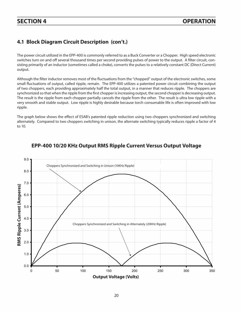
The power circuit utilized in the EPP-400 is commonly referred to as a Buck Converter or a Chopper. High speed electronic switches turn on and off several thousand times per second providing pulses of power to the output. A filter circuit, con-sisting primarily of an inductor (sometimes called a choke), converts the pulses to a relatively constant DC (Direct Current) output.
Although the filter inductor removes most of the fluctuations from the “chopped” output of the electronic switches, some small fluctuations of output, called ripple, remain. The EPP-400 utilizes a patented power circuit combining the output of two choppers, each providing approximately half the total output, in a manner that reduces ripple. The choppers are synchronized so that when the ripple from the first chopper is increasing output, the second chopper is decreasing output. The result is the ripple from each chopper partially cancels the ripple from the other. The result is ultra low ripple with a very smooth and stable output. Low ripple is highly desirable because torch consumable life is often improved with low ripple.
The graph below shows the effect of ESAB’s patented ripple reduction using two choppers synchronized and switching alternately. Compared to two choppers switching in unison, the alternate switching typically reduces ripple a factor of 4 to 10.
Epp-400 10/20 Khz output rMs ripple current versus output voltage
rMs
ripp
le c
urre
nt (a
mpe
res)
output voltage (volts)
Choppers Synchronized and Switching in Unison (10KHz Ripple)
Choppers Synchronized and Switching in Alternately (20KHz Ripple)

21
The Control Circuit contains regulating servos for both choppers. It also contains a third servo that monitors the total output current signal fed back from the Precision Shunt. This third servo adjusts the two chopper servos to maintain an accurately controlled output current commanded by the Vref signal.
The Vref circuitry is galvanically isolated from the rest of the power source. The isolation prevents problems that can arise from “ground” loops.
Each chopper, the Left Master, and the Right Slave, contain their own PWM / Gate Drive PC Boards mounted next to the IGBT’s. This circuitry provides the on / off PWM (Pulse Width Modulation) signals to drive the IGBT’s. The Left (Master) PWM provides a synchronized clock signal to its own Gate Drive circuitry as well as to the Right (Slave) Gate Drive circuitry. It is through this synchronized signal that the IGBT’s from the two sides switch alternately reducing output ripple.
The EPP-400 contains a Boost Supply for providing approximately 425V DC for arc starting. After the cutting arc is estab-lished, the Boost Supply is turned off with a contact on the Pilot Arc Contactor (K4).
A Biased Snubber reduces the voltage transients created during cutting arc termination. It also reduces the transient volt-ages from a parallel power source thus preventing damage to the power source.
The Pilot Arc Circuit consists of the necessary components for establishing a pilot arc. This circuit disengages when the cutting or marking arc is established.
* The Bus voltage for the 400V, 50Hz model is approximately 320V DC.
sEctIoN 4 opEratIoN
The EPP-400 Block Diagram (after Subsection 6.4.4) shows the main functional elements of the power source. T1, the Main Transformer, provides isolation from the primary power line as well as the proper voltage for the *375V DC Bus. The Bus Rectifiers convert the three phase output of T1 to the *375V bus voltage. A capacitor bank provides filtering and energy storage that supplies power to the high speed electronic switches. The switches are IGBT’s (Insulated Gate Bipolar Transis-tors). The *375V bus provides power for both the Left (Master) Chopper and the Right (Slave) Chopper.
Each chopper contains IGBT’s, Free Wheeling Diodes, a Hall Sensor, a Filter Inductor, and Blocking Diodes. The IGBT’s are the electronic switches that, in the EPP-400, turn on and off 10,000 times per second. They provide the pulses of power filtered by the inductor. The Free Wheeling Diodes provide the path for current to flow when the IGBT’s are off. The Hall Sensor is a current transducer that monitors the output current and provides the feedback signal for the control circuit.
The Blocking Diodes provide two functions. First, they prevent the 425V DC from the Boost Starting Circuit from feeding back to the IGBT’s and the *375V Bus. Second, they provide isolation of the two choppers from one another. This permits independent operation of each chopper without the other chopper functioning.
4.1 Block Diagram circuit Description (con’t.)

22
sEctIoN 4 opEratIoN
4.2 control panel
A - Main Power
Indicator illuminates when input power is applied to the power source.
B - Contactor On
Indicator illuminates when the main contactor is energized.
C - Over Temp
Indicator illuminates when power source has overheated.
D - Fault
Indicator illuminates when there are abnormalities in the cutting process or when the input line voltage falls outside of the required nominal value by ±10%.
E - Power Reset Fault
Indicator illuminates when a serious fault is detected. Input power must be disconnected for at least 5 seconds and then reapplied.
F - Current Dial (Potentiometer)
EPP-400 dial shown. EPP-400 has a range of 12 to 400 A. Used only in panel mode.
c
B
D
E
K
JI h f
g
a
l

23
sEctIoN 4 opEratIoN
G - Panel Remote Switch
Controls the location of current control. • Place in the PANEL position for control using the current potentiometer.• Place in REMOTE position for control from an external signal (CNC).
c
B
D
E
K
JI h f
g
a
H and L - Remote Connections
H - 24 pin plug for connecting the power source to CNC (remote control)
L - 8 pin plug for connecting the power source to the water cooler
I - Pilot Arc HIGH / LOW Switch
Used to select amount of pilot arc current desired. As a general rule, for 100 amperes and below, a setting of LOW is used. This can vary depending on gas, material and torch used. High/Low settings are specified in cutting data included in the torch manual. When the EPP-400 is set to marking mode, this switch must be in the low position.
4.2 control panel (con’t.)
l

24
sEctIoN 4 opEratIoN
J - Meters
Displays voltage and amperage when cutting. The ammeter can be activated when not cutting to view an estimation of the cutting current before cutting begins.
K - Actual/Preset Switch
The ACTUAL AMPS / PRESET AMPS spring return toggle switch, S42, defaults to the ACTUAL (UP) position. In the ACTUAL position, the OUTPUT AMMETER displays the output cutting current.
In the PRESET (DOWN) position, the OUTPUT AMMETER displays an estimate of the output cutting current by monitoring the 0.00 to 10.00 VDC cutting or marking current reference signal (Vref ). The reference signal comes from the CURRENT PO-TENTIOMETER with the PANEL/REMOTE switch in the PANEL (UP) position and from a remote reference signal (J1-J / J1-L(+)) with the PANEL/REMOTE switch in the REMOTE (DOWN) position. The value displayed on the OUTPUT AMMETER will be the value of Vref (volts) times 50. For example, a reference signal of 5.00V will result in a preset reading of 250 Amps on the meter.
The switch may be changed to and from the ACTUAL and PRESET positions at any time without affecting the cutting process.
DaNgErous voltagEs aND currENt!ElEctrIc shocK caN KIll!BEforE opEratIoN, ENsurE INstallatIoN aND grouNDINg pro-cEDurEs havE BEEN folloWED. Do Not opEratE thIs EQuIp-MENt WIth covErs rEMovED.
WarNINg
4.2 control panel (con’t.)

25
sEctIoN 4 opEratIoN
4.2.1 Modes of operation: cutting and Marking Mode
1. The EPP-400 operates in the Cutting Mode through a single continuously adjustable output current range from 50A through 400A using either the Current Potentiometer, on the front panel, or a remote current reference signal fed into connector, J1.
When using a remote signal, 50A corresponds to a current reference signal of 1.00VDC, and 400A corresponds to a signal of 8.00VDC. For signals over 8.00V, the power source internally limits the output current to a typical value of 420A.
The EPP-400 defaults to the Cutting Mode of operation unless the command signal from a remote control for Marking Mode is supplied.
2. The power source is placed in Marking Mode with an external isolated relay or switch contact connecting J1-R (115VAC) to J1-M. See Schematic Diagram included inside back cover. This contact closure must be made before (50mS or lon-ger) issuing a Start or Contactor On command.
In the Marking Mode, the output current is adjusted through a single continuously adjustable range from 12A through 400A using either the Current Potentiometer, on the front panel, or a remote current reference signal fed into connec-tor, J1.
When using a remote signal, 12A corresponds to a current reference signal of 0.24VDC, and 400A corresponds to a signal of 8.00VDC. For signals over 8.00V, the power source internally limits the output current to a typical value of 420A.
In the Marking Mode, the Boost Supply, used for arc starting in the Cutting Mode, is de-activated. The resulting Open Circuit Voltage is approximately 360V at nominal input line voltage*. Additionally, K12 closes connecting R60 through R67 into the output circuit. These resistors help stabilize the output for the low marking currents. The power source is capable of its full 400A 100% duty output in the marking mode.
12 Amp output is provided by resistors R60-R67. The factory set Minimum Starting Current (SW2) is 3 Amps. The de-fault settings of Switch Two (SW2) on the Control PC Board mounted behind the access cover on the upper right of the front panel is positions 5, 6, 7 and 8 are off (down).
* Approximately 310V for the 400V model.

26
sEctIoN 4 opEratIoN
1. Apply power by closing the line (wall) switch. (The EPP-400 does not have an on / off switch). The main power light will illuminate and the fault light will flash and then go out.
2. Select the Panel / Remote setting.
3. Set pilot arc High / Low switch. If pilot arc High / Low is selected from a remote control, the switch must be in the Low position. (Refer to cutting data in the torch manual.)
4. If using panel mode, view preset amps with the ACTUAL / PRESET AMPS switch. Adjust current until the approximate desired value is shown on the ammeter. If using the remote mode, placing the actual Amps / Preset Amps switch in the Preset Amps posi-tion provides the initial output current commanded by the remote control.
5. Begin plasma cutting operation. This may include manually setting up other options, depending on the total plasma package.
6. If using panel mode, after cutting has begun, adjust current to desired amount.
7. If cutting or marking fails to initiate, check for fault light. If a fault light illuminates, refer to troubleshooting section.
Note: The fault light flashes when the contactor is first turned on signifying the DC
Bus powered up normally.
4.3 sequence of operationSECTION 4 Operation
ESP 400C Plasma Power SourceESP 400C Plasma Power SourceESP 400C Plasma Power SourceESP 400C Plasma Power Source4-4
BeginCutting
ACTUAL AMPS
PRESET AMPS
HIGH
LOW
PILOTARC
PANEL
REMOTE
Apply Power
4.3 Sequence of Operation
1. Apply power by closing the line (wall) switch.(The ESP-400C does not have an on/offswitch). The main power light will illuminateand the fault light will flash and then go out.
2. Select the Panel/Remote setting.
3. Set pilot arc High/Low switch. (Refer to cuttingdata in the torch manual.)
4. If using panel mode, view preset amps with theACTUAL/PRESET AMPS switch. Adjust currentuntil the approximate desired value is shown onthe ammeter.
5. Begin plasma cutting operation. This mayinclude manually setting up other options,depending on the total plasma package.
6. If using panel mode, after cutting has begun,adjust current to desired amount.
7. Check for fault light. If a fault light illuminates,refer to troubleshooting section.
Note: The fault light flashes when the contactor isNote: The fault light flashes when the contactor isNote: The fault light flashes when the contactor isNote: The fault light flashes when the contactor isfirst turned on signifying the DC Bus powered upfirst turned on signifying the DC Bus powered upfirst turned on signifying the DC Bus powered upfirst turned on signifying the DC Bus powered upnormally.normally.normally.normally.
4.4 Arc Initiation SettingsThe time to achieve full current can be adjusted tosuit your particular system. This feature uses 50%of the cutting current to start, dwell and thengradually (less than a second) achieve full current.The ESP-400C is factory shipped with this featureenabled. The default settings are:
Minimum Start Current 40A
Start Current 50% of cut current
Timing to achieve full current 800 msec
Dwell Time 50 msec

27
sEctIoN 4 opEratIoN
4.4 arc Initiation settings
The time to achieve full current can be adjusted for a soft start. This feature uses a reduced current to start and then gradu-ally ramps up to full current. The EPP-400 is factory shipped with soft start enabled. The default settings are:
Minimum Start Current . . . . . . . . . . . . . 3AStart Current . . . . . . . . . . . . . . . . . . . . . . . 50% of cut currentTiming to achieve full current . . . . . . . 800 msecDwell Time . . . . . . . . . . . . . . . . . . . . . . . . . 50 msec
These timing functions can be disabled or adjusted to suit individual system requirements.
Start Current Wave Form With Soft Start OFF
Cut Current1OUT = 50 VREF
Approx. 2 msec time to full current
DC
Out
put C
urre
nt
Time
Start Current Wave Form With Soft Start ON
Cut Current1OUT = 50 VREF
Start Current
Time to full current
800 msecDwellTime
DC
Out
put C
urre
nt
Time
ElEctrIc shocK caN KIll!shut off poWEr at thE lINE (Wall) DIscoNNEct BEforE rE-MovINg aNY covErs or MaKINg aNY aDJustMENts to thE poWEr sourcE.
WarNINg

28
4.4.1 Enable/Disable arc Initiation conditions
sEctIoN 4 opEratIoN
1. Remove access panel on the upper-right corner of the front panel. Be sure to replace this panel after adjustments have been made.
2. Locate SW1 and PCB1 and push both rocker switches down to disable. To enable push both switches up. (If one switch is up and the other is down, arc initiation time is considered on.)
4.4.2 adjusting arc Initiation Dwell timer
Dwell Time is controlled by selections of positions 1 through 4 of SW2 on PCB1. When a switch is pushed on, its value is added to the minimum dwell time of 10 msec.
Switch #1 = 10 msec dwell timeSwitch #2 = 20 msec dwell timeSwitch #3 = 40 msec dwell timeSwitch #4 = 80 msec dwell timeThe default setting is with switch #3 on. 40 msec + 10 msec (minimum) = 50 msec
4.4.3 adjusting the Minimum start current
Minimum Start Current is controlled by selection of positions 5 through 8 of SW2. When a switch is pushed on, its value is added to the factory set minimum value of 3A.
Switch #5 = 25A min. start currentSwitch #6 = 12A min. start currentSwitch #7 = 6A min. start currentSwitch #8 = 3A min. start currentDefault setting is with 5, 6, 7 and 8 off (down) 0A + 0A + 0A + 3A = 3A
Factory default settings shown
Factory default setting shown.
1 2 3 4 5 6 7 8
SW2
SW1
on
off
12345678
SW2
on
off
38
4.4.1 Enable/Disable Arc Initiation Conditions
sECtIon 4 opErAtIon
1. Removeaccesspanelontheupper-rightcornerofthefrontpanel.Besuretoreplacethispanelafteradjustmentshavebeenmade.
2. LocateSW1andPCB1andpushbothrockerswitchesdowntodisable.Toenablepushbothswitchesup.(Ifoneswitchisupandtheotherisdown,arcinitiationtimeisconsideredon.)
4.4.2 Adjusting Arc Initiation Dwell timer
DwellTimeiscontrolledbyselectionsofpositions1through4ofSW2onPCB1.Whenaswitchispushedon,itsvalueisaddedtotheminimumdwelltimeof10msec.
Switch#1=10msecdwelltimeSwitch#2=20msecdwelltimeSwitch#3=40msecdwelltimeSwitch#4=80msecdwelltimeThedefaultsettingiswithswitch#3on.40msec+10msec(minimum)=50msec
4.4.3 Adjusting the Minimum start Current
MinimumStartCurrentiscontrolledbyselectionofpositions5through8ofSW2.Whenaswitchispushedon,itsvalueisaddedtothefactorysetminimumvalueof3A.
Switch#5=25Amin.startcurrentSwitch#6=12Amin.startcurrentSwitch#7=6Amin.startcurrentSwitch#8=3Amin.startcurrentDefaultsettingiswith5,6,7and8off(down)0A+0A+0A+3A=3A
Factorydefaultsettingsshown
Factorydefaultsettingshown.
1 2 3 4 5 6 7 8
SW2
SW1
on
off
12345678
SW2
on
off
SW2
1 2 3 4 5 6 7 8

29
sEctIoN 4 opEratIoN
4.4.4 arc Initiation controls
38
UP-Slope TimerStart Current Potentiometer
4.4.5 start current and up-slope timer
Start CurrentSet using potentiometer located above and to the left of center of PCB1. Factory default setting of 7 results in a starting current that is 50% of the cutting current..
Up-Slope TimerThree position switch located next to the start current poten-tiometer. Time is from start current (after dwell ends) to full current. Factory default = 800 msec. Left position = 250 msec Center position = 800 msecRight Position = 1200 msec
90%
80%
70%
60%
50%
40%
30%
20%
10%
0%0 1 2 3 4 5 6 7 8 9 10
Perc
enta
ge (%
) of C
uttin
g Cu
rren
t
Start Current Pot Setting
Starting Current (%) and Pot Setting Relationship
MAX
SW1
SW2

30
PK
H: V
I_Curves_370V
_Bus.xls; E
PP
-400 (460&575V
) VI C
urves
EPP-400 V
-I CU
RV
ES FO
R 460V
& 575V
INPU
TS
0
100
200
300
400
0100
200300
400500
OU
TPUT C
UR
REN
T (Am
peres)
OUTPUT VOLTAGE (Volts)
427V O
pen C
ircuit (460V
& 575V
Inpu
ts)
INTERNAL CURRENT LIMIT
VREF = 8.000
VREF = 6.000
VREF = 4.000
VREF = 2.000
VREF = 1.000 MIN CUT CURRENT RATING Ou
tput of B
oost/Start C
ircuit
Max O
utpu
t Voltage
@ N
omin
al Line
IOU
T = (50) x (VR
EF )
MIN MARK CURRENT RATINGVREF = 0.240
DATA PLATEM
AX RATING
sEctIoN 4 opEratIoN
4.5.1 Epp-400 v-I curves for 460v and 575v, 60hz InputsOutput Voltage (Volts)
Output Current (Am
peres)
427V Open Circuit (460V &
575V Inputs)
Output of Boost / Start Circuit
IOU
T = (50) x (V
REF )
Max. O
utput Voltage @
Nom
inal Line
Internal Current Limit
V REF = 8.000V
V REF = 6.000V
Min. Cutting Current
V REF = 0.240V Min. Marking Current
V REF = 2.000V
V REF = 4.000V
V REF = 1.000VD
ATA PLATE
MA
X RATING

31
PK
H: V
I_Curves_370V
_Bus.xls; E
PP
-400 (400V) V
I Curves
EPP-400 V
-I CU
RV
ES FO
R 400V
INPU
T
0
100
200
300
400
0100
200300
400500
OU
TPUT C
UR
REN
T (Am
peres)
OUTPUT VOLTAGE (Volts)
423V O
pen C
ircuit (400V
Inpu
t)
INTERNAL CURRENT LIMIT
VREF = 8.000
VREF = 6.000
VREF = 4.000
VREF = 2.000
VREF = 1.000 MIN CUT CURRENT RATING Ou
tput of B
oost/Start C
ircuit
Max O
utpu
t Voltage
@ N
omin
al Line
IOU
T = (50) x (VR
EF )
MIN MARK CURRENT RATINGVREF = 0.240DATA PLATEM
AX RATING
sEctIoN 4 opEratIoN
4.5.2 Epp-400 v-I curves for 400v, 50/60hz InputsOutput Voltage (Volts)
Output Current (Am
peres)
423V Open Circuit (400V Inputs)
Output of Boost / Start Circuit
IOU
T = (50) x (V
REF )
Max. O
utput Voltage @
Nom
inal Line
Internal Current Limit
V REF = 8.000V
V REF = 6.000V
Min. Cutting Current
V REF = 0.240V Min. Marking Current
V REF = 2.000V
V REF = 4.000V
V REF = 1.000V
DATA
PLATEM
AX RATIN
G

32
sEctIoN 4 opEratIoN

33
section 5 maintenance
5.1 General
electric shock can kill!shut off power at the line (wall) disconnect before at-temptinG any maintenance.
warninG
warninGeye hazard when usinG compressed air to clean.
• Wear approved eye protection with side shields when cleaning thepowersource.
• Useonlylowpressureair.
caution maintenance on this equipment should only be performed by trained personnel.
5.2 cleaning
Regularlyscheduledcleaningofthepowersourceisrequiredtohelpkeeptheunitrunningtroublefree.Thefrequencyofcleaningdependsonenvironmentanduse.
1. Turnpoweroffatwalldisconnect.2. Removesidepanels.3. Uselowpressurecompresseddryair,removedustfromallairpassagesandcomponents.Payparticularattentionto
heatsinksinthefrontoftheunit.Dustinsulates,reducingheatdissipation.Besuretoweareyeprotection.

34
section 5 maintenance
air restrictions may cause epp-400 to over heat.thermal switches may be activated causing interruption of func-tion. do not use air filters on this unit. keep air passages clear of dust and other obstructions.
warninG
caution
5.3 lubrication
• Someunitsareequippedwithoiltubesonthefans. Thesefansshouldbeoiledafter1yearofser-vice.
• AllotherEPP-400shavefanmotorsthatarepermanently lubricatedandrequirenoregularmainte-nance.
electric shock hazard!be sure to replace any covers removed durinG cleaninG before turninG power back on.

35
section 6 troubleshootinG
6.1 General
electric shock can kill!do not permit untrained persons to inspect or repair this equipment. electrical work must be performed by an expe-rienced electrician.
warninG
stop work immediately if power source does not work properly.have only trained personnel investigate the cause.use only recommended replacement parts.
caution
6.2 fault indicators
FaultindicatorsarefoundonthefrontpanelUsedwiththeLEDsonPCB1(locatedbehindthecoverwiththeEPPlabel)problemscanbediagnosed.
note:It is normal for momentary light-ing(flashing)ofthefaultindicatorandLED3whena“contactoron”signalisappliedatthebeginning
ofeachcutstart.
FaultIndicatorusedwith:LED3-BusRippleLED4-HighBusLED5-LowBusLED7-ArcVoltageSaturationLED8-ArcVoltageCutoff
PowerResetFaultIndicatorusedwith:LED6-RightOvercurrentLED9-LeftOvercurrentLED10-LeftIGBTUnsaturatedLED11-RightIGBTUnsaturatedLED12-Left-12VBiasSupplyLED13-Right-12VBiasSupply
PCB1 Located behindthispanel.
Front Panel FaultIndicators

36
section 6 troubleshootinG
FaultIndicator(FrontPanel)
Illuminateswhenthereareabnormalities inthecuttingprocessorwhenthe inputvoltagefalls±10%outsidethenormalvalue.Momentary illumination isnormal. Ifcontinuouslylit,checkLEDs3,4,5,7,and8onPCB1forfurtherdiagnosis.
38
38
LED3–(amber)BusRippleFault-Momentarilyilluminatesatthebeginningofeachcut.Continuouslylitduringsingle-phasingorimbalancedline-to-linevoltagesofthethreephaseinputline(ExcessiveRipple).PowerSourceisshutdown.
LED4–(amber)HighBusFault–Illuminateswheninputlinevoltageistoohighforproperoperation (approximately20%abovenominal linevoltage rating).Powersourceisshutdown.
LED5–(amber)LowBusFault–Illuminateswheninputlinevoltage is approximately 20% below nominal line voltagerating.PowerSourceisshutdown.
LED7–(amber)ArcVoltageSaturationFault–Illuminateswhenthecuttingarcvoltageistoohighandcuttingcurrentdropsbelowpreset level.LEDwillextinguishaftervoltagedecreasesandcurrentrises.
LED8–(amber)ArcVoltageCutoffFault–Illuminateswhenarcvoltageincreasesoverthepresetvalue.PSisshutdown.
37
section 6 troubleshootinG
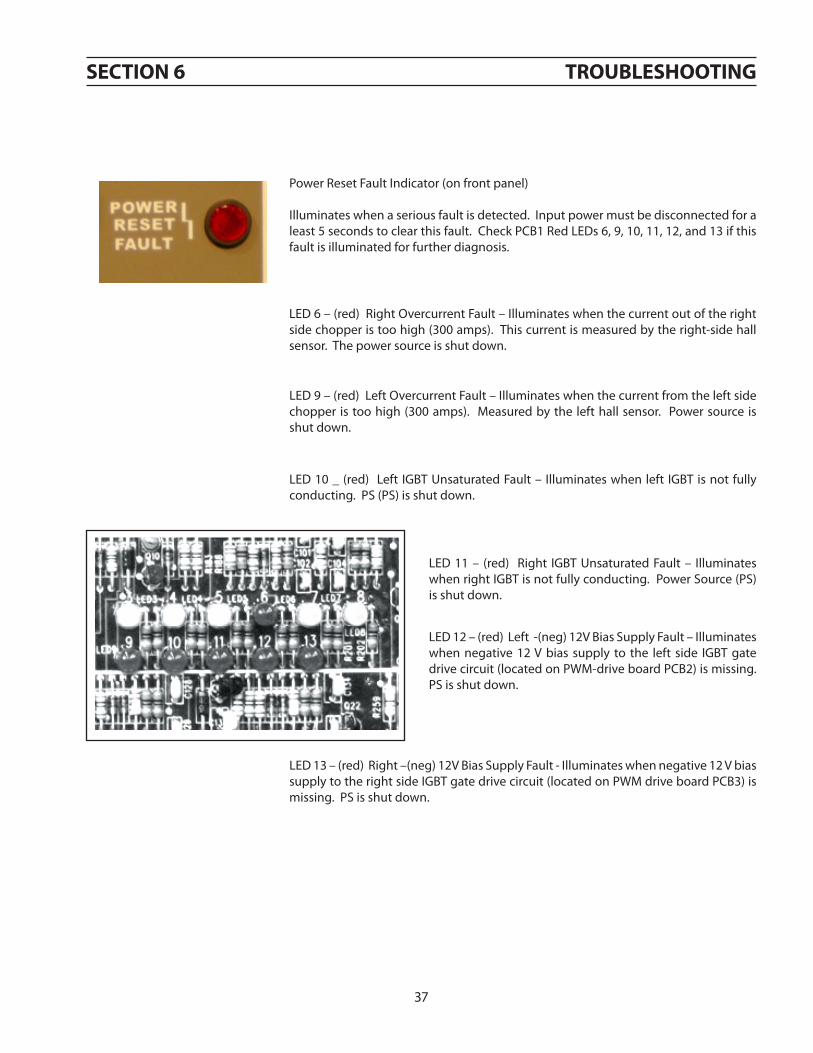
PowerResetFaultIndicator(onfrontpanel)
Illuminateswhenaseriousfaultisdetected.Inputpowermustbedisconnectedforaleast5secondstoclearthisfault.CheckPCB1RedLEDs6,9,10,11,12,and13ifthisfaultisilluminatedforfurtherdiagnosis.
LED6–(red)RightOvercurrentFault–Illuminateswhenthecurrentoutoftherightsidechopperistoohigh(300amps).Thiscurrentismeasuredbytheright-sidehallsensor.Thepowersourceisshutdown.
38
LED9–(red)LeftOvercurrentFault–Illuminateswhenthecurrentfromtheleftsidechopper istoohigh(300amps). Measuredbythelefthallsensor. Powersource isshutdown.
LED10_(red) Left IGBTUnsaturatedFault– Illuminateswhenleft IGBTisnotfullyconducting.PS(PS)isshutdown.
LED11– (red) Right IGBTUnsaturatedFault– IlluminateswhenrightIGBTisnotfullyconducting.PowerSource(PS)isshutdown.
LED12–(red)Left-(neg)12VBiasSupplyFault–Illuminateswhen negative 12V bias supply to the left side IGBT gatedrivecircuit(locatedonPWM-driveboardPCB2)ismissing.PSisshutdown.
LED13–(red)Right–(neg)12VBiasSupplyFault-Illuminateswhennegative12VbiassupplytotherightsideIGBTgatedrivecircuit(locatedonPWMdriveboardPCB3)ismissing.PSisshutdown.

38
section 6 troubleshootinG
6.3 fault isolation
Manyofthemostcommonproblemsarelistedbysymptom.
6.3.1 Fansnotworking6.3.2 Powernoton6.3.3 FaultLightIllumination6.3.4 Torchwon’tfire6.3.5 FussesBlownF1andF26.3.6 Intermittent,InterruptedorPartialOperation
6.3.1 fans not working
problem possible cause action
All4fansdonotrunThisisnormalwhennotcutting.Fans run only when “Contactor On”signalisreceived.
None
1,2or3fansdonotrun.Broken or disconnected wire in fanmotorcircuit. Repairwire.
Faultyfan(s) Replacefans
6.3.2 power not on or low voltage
problem possible cause action
Powersourceinoperable:Mainpowerlampisoff.
Missing3-phaseinputvoltage Restore all 3 phases of input voltage to within±10%ofnominalline.
Missing1of3-phaseinputvoltage Restore all 3 phases of input voltage to within±10%ofnominalline.
Lowopencircuitvoltage
FuseF3blown ReplaceF3
PilotarcContactor(K4)faulty ReplaceK4
FaultyControlPCB1 ReplaceControlPCB1(P/N0558038287)

39
problem possible cause action
Faultlightilluminatesattheendofcutbutgoesoffatthestartofthenext.
Normalconditioncausedwhenter-minatingthearcbyrunningthetorchofftheworkorthearcbeingattachedtoapartthatfallsaway.
Reprogramcuttingprocesstoensurearcisterminatedonlybyremovingthe“ContactorOn”signal.
LED3–(amber)BusRipple
Imbalanceof3-phaseinputpower Maintainphasevoltageimbalanceoflessthan5%.
Momentary loss of one phase ofinputpower
Restoreandmaintaininputpowerwithin±10%nominal
FaultycontrolPCB1 ReplacePCB1P/N0558038287
LED4–(amber)HighBus
Oneormorephasesofinputvoltageexceednominallinevoltagebymorethan15%.
Restoreandmaintainlinevoltagewithin±10%
FaultycontrolPCB1 ReplacePCB1P/N0558038287
Oneormoreshorteddioderectifiers(D25-D28)onthe“ElectrodePlate” Replaceshorteddioderectifiers
LED5–(amber)LowBus
One or more phases of input volt-agearelowerthannominalbymorethan15%.
Restoreandmaintainwithin±10%ofnominal
BlownF1andF2fuses SeeF1andF2inBlownFusesSection
OvertempLightcomeson. SeeovertempinFaultLightSection
Imbalanced3-phaseinputpower
Maintainphasevoltageimbalanceoflessthan5%
Momentary loss of one phase ofinputpower
Restoreandmaintainwithin±10%ofnominal
FaultyMainContactor(K1) ReplaceK1
FAULTYControlPCB1 ReplacePCB1P/N0558038287
section 6 troubleshootinG
6.3.3 fault light illumination

40
section 6 troubleshootinG
problem possible cause action
LED 6 – (red) Right Over Cur-rent
note:Ifoperationat275Aorlessispossible,thentheLEFTsideis
notworking.
Cuttingatover275Awithafaultyleftside(leftsideoutput=0) Seefaultyleftorrightside
Rightcurrenttransducerconnector looseorunplugged.PCBloose. Secureconnections
Loose or unplugged connector at rightPWM/DrivePrintedcircuitboard. Secureconnection
P2atleftofPWM/DrivePCBlooseorun-plugged. Secureconnection
CheckvoltagebetweenP7-6andP7-7.Avoltage in either polarity of greater than0.01Vindicatesafaultyrightcurrenttrans-ducer(TD2).
Replace right current transducer(TD2)
FaultyPCB1 ReplacePCB1P/N0558038287
FaultyrightPWM/DrivePCB Replace right PWM / Drive PCB P/N0558038308
LED9–(red)LeftOverCurrent
note:Ifoperationat275Aorlessis
possible,thentheRightsideisnotworking.
Cuttingatover275Awithafaultyrightside(rightsideoutput=0) Seefaultyrightside
Leftcurrenttransducerconnectorlooseorunplugged.PCBloose. Secureconnections
LooseorunpluggedconnectoratleftPWM/DrivePrintedcircuitboard. Secureconnection
P2 at right of PWM / Drive PCB loose orunplugged. Secureconnection
CheckvoltagebetweenP7-2andP7-3.Avoltage in either polarity of greater than0.01Vindicatesafaultyleftcurrenttrans-ducer(TD1).
Replaceleftcurrenttransducer(TD1)
FaultyPCB1 ReplacePCB1P/N0558038287
FaultyleftPWM/DrivePCB Replace left PWM / Drive PCB P/N0558038308
never attempt to power-up or operate the power source with any Gate / emitter iGbt plug disconnected from it’s pwm / Gate drive board. attempting to operate the power source with any open (un-plugged) iGbt Gate / emitter connector may damage the iGbt and the plasma cutting torch.
caution

41
section 6 troubleshootinG
problem possible cause action
VeryhighOutputcurrentac-companiedbyeitheraleftorrightovercurrent(LED6)
ShortedIGBT ReplacetheIGBTs
Currentpotsettoohigh Lowerthecurrentsetting
FaultyleftPWM/DrivePCB ReplaceleftPWM/DrivePCB
Highremotecurrentsignal Decreaseremotecurrentsignal
FaultyPCB1 ReplacePCB1P/N0558038287
LED10-(red)LeftIGBTUn-saturated
BlackwireconnectingIGBT(Q2)collectortoP3oftheleftPWM/DrivePCB(PCB2)isdisconnected. Secureconnector
ShortedFreewheelingDiode(s) Replacefreewheelingdiode(s)
LooseorunpluggedP1connectorattheleftPWM/DrivePCB SecureP1
LooseorunpluggedP10connectoratPCB1 SecureP10
FaultyPCB1 ReplacePCB1P/N0558038287
FaultyleftPWM/DrivePCB ReplacePCB2P/N0558038308
LED 11 - (red) Right IGBTUnsaturated
BlackwireconnectingIGBT(Q5)collectortoP3oftherightPWM/DrivePCB(PCB3)isdisconnected. Secureconnector
ShortedFreewheelingDiode(s) Replacefreewheelingdiode(s)
LooseorunpluggedP1connectorattheleftPWM/DrivePCB SecureP1
LooseorunpluggedP10connectoratPCB1 SecureP11
FaultyPCB1 ReplacePCB1P/N0558038287
FaultyrightPWM/DrivePCB ReplacePCB3P/N0558038308

42
section 6 troubleshootinG
problem possible cause action
LED12–(red)Left–12VMissing
LooseorunpluggedP1connectorattheleftPWM/DrivePCB SecureP1connector
Loose or unplugged P10 connectoratPCB1 SecureP10connector
FaultyleftPWM/DrivePCB Replace left PWM / Drive PCB P/N0558038308
LED12–(red)Right–12VMissing
LooseorunpluggedP1connectorattherightPWM/DrivePCB SecureP1connector
Loose or unplugged P11 connectoratPCB1 SecureP11connector
FaultyrightPWM/DrivePCB Replace right PWM / Drive PCB P/N0558038308
VeryhighOutputcurrentaccompa-niedbyeitheraleftorrightovercur-rent(LED9orLED6respectively)
ShortedIGBT ReplacetheIGBTs
Currentpotsettoohigh Lowerthecurrentsetting
FaultyleftPWM/DrivePCB Replace left PWM / Drive PCB P/N0558038308
Highremotecurrentsignal Decreaseremotecurrentsignal
FaultyPCB1 ReplacePCB1P/N0558038287
OverTempLampilluminates
Oneormorefansinoperable Repairorreplacefan(s)
Brokenwireorunpluggedconnectoratthermalswitch.
Repair broken wires and unplugged con-nector
Obstructiontoairflowcloserthan3feet(1m)torearofpowersource.
Allow3ft.(1m)minimumbetweentherearofthepowersourceandanyobjectthatmayrestrictairflow.
Excessive dirt restricting cooling airflow
Clean out excessive dirt, especially in theextrusionsfortheIGBTsandfreewheelingdiodes,thePOS,NEGandElectrodePlates,the main transformer (T1) and the filterinductors(L1andL2).
ObstructedairintakeCheckandclearanyobstructionsfromthebottom, front, and top rear of the PowerSource.

43
section 6 troubleshootinG
6.3.4 torch will not fire
problem possible cause action
MainArcTransfers to theworkwithashort“pop”,placingonlyasmalldimpleinthework.
Remote control removes the startsignal when the main arc transfers tothework.
Panel/Remoteswitchin“Remote”withnoremotecontrolofthecurrent
Place Panel/Remote switch in “Panel”position
Remote current control present butsignalmissing.
CheckforcurrentreferencesignalatTB1-4(+)andTB1-5(-).SeeSignalvs.OutputCurrentCurvethissection.
Currentpotsettoolow. Increasecurrentpotsetting.
Start current pot, located behind thecover for the control PCB is set toolow.
Increasethestartcurrentpostsettingto“7”.
Arcdoesnotstart.Thereisnoarcatthetorch.OpencircuitvoltageisOK.
Openconnectionbetweenthepowersourcepositiveoutputandthework. Repairconnection
FuseF6inthePilotarccircuitisblown. ReplaceF6
FuseF7inthepilotarccircuitisblown. ReplaceF7
PilotarcHigh/Lowswitchisinthe”LOW”position when using consumables for100Aorhigher(Refertoprocessdataincludedintorchmanuals)
Change Pilot arc to “High” position.(Refertoprocessdataincludedintorchmanuals)
Pilotarccontactor(K4)faulty. ReplaceK4
FaultyPCB1 ReplacePCB1P/N0558038287

44
problem possible cause action
FusesF1andF2blown.
Processcontroller ignitespilotarctoosoon after providing the “ContactorOn”signal
Process controller must allow at least300MS to lapse between the applica-tion of the“Contactor On” signal andtheignitionofthepilotarc.Fixprocesscontrollerlogicandreplacediodes.
Faultynegative(Electrode)outputcableshortingtoearthground. Repaircable
Shortedfreewheelingdiode. Replace shorted freewheeling diodeandF1-F2
One or more shorted diode rectifiers(D13-D18)on“POSPlate”.
Replacealldioderectifiersonthe“POSPlate”.
One or more shorted diode rectifiers(D7-D12)on“NEGPlate”.
Replacealldioderectifiersonthe“NEGPlate”.
section 6 troubleshootinG
6.3.5 fuses f1 and f2 blown
problem possible cause action
WorksOKat275Aor less-Overcurrent right side when cuttingover275A.LED6oncontrolboardilluminated.
LooseorunpluggedconnectoratleftPWM/DrivePCB(PCB2) Secureconnector
FaultyleftPWM/DrivePCB Replace right PWM / Drive PCB P/N0558038308
CheckvoltagebetweenP5-1andP5-2attheleftPWM/DrivePCB(PCB2).Shouldbe20VAC.BetweenP5-1andP5-3shouldbe40VAC.Ifnotthecontroltransformer(T5)isfaulty.
ReplacecontroltransformerT5
6.3.6 intermittent, interrupted or partial operation
never attempt to power-up or operate the power source with any Gate / emitter iGbt plug disconnected from it’s pwm / Gate drive board. attempting to operate the power source with any open (un-plugged) iGbt Gate / emitter connector may damage the iGbt and the plasma cutting torch.
caution
WorksOKat275Aor less-Overcurrent left side when cuttingover275A.LED9oncontrolboardilluminated.
LooseorunpluggedconnectoratRightPWM/DrivePCB(PCB3) Secureconnector
FaultyRightPWM/DrivePCB Replace right PWM / Drive PCB P/N0558038308
CheckvoltagebetweenP5-1andP5-2attherightPWM/DrivePCB(PCB3).Shouldbe20VAC.BetweenP5-1andP5-3shouldbe40VAC.Ifnotthecontroltransformer(T7)isfaulty.
ReplacecontroltransformerT7

45
section 6 troubleshootinG
problem possible cause action
Power Supply turns off prema-turelyinthemiddleofthecut.
“ContactorOn”signalisremovedfromunit. PowersourceisOK.Troubleshootpro-cesscontroller.
Momentarylossofprimaryinputpower. Restore and maintain input voltagewithin±10%ofnominal.
Faulty condition, indicated by illuminationofthefaultlamp.
RemovecontrolPCB(PCB1)accesspaneltodeterminethefaultcausingtheshut-down.Refertofaultlightilluminationsection.
Faultycondition,indicatedbytheilluminationofthepowerresetfaultlamp.
RemovecontrolPCB(PCB1)accesspaneltodeterminethefaultcausingtheshut-down.Refertofaultlightilluminationsection.
Currentsettingtoolow. Increasecurrentsetting
Remotecurrentsignalremovedduringcut. Fixremotecurrentsignal
problem possible cause action
Output current is unstable anddrifts above or below the set-ting.
PlacethePANEL/REMOTEswitchinthe“PANEL”position.Adjustcurrentcontrolpot.Ifcurrentno longerdrifts, theremotecurrentcontrolsignalisfaulty.
FixtheremotecurrentcontrolsignaltooperatethePANEL/REMOTEswitchinthe“PANEL”position.
Select“PANEL”onthePANEL/REMOTEswitchandadjustthecurrentcontrolpot.Thecur-rentstilldrifts,measurethecurrentreferencesignalatTB1-4(+)andTB1-5(-).Ifthesignaldrifts,thecurrentcontrolpotisfaulty.Ifthesignaldoesnotdrift,theControlPCB(PCB1)isfaulty.
Replacethecurrentcontrolpot.
Replace the control PCB (PCB1) P/N0558038287

46
section 6 troubleshootinG
6.4 testing and replacing components
• ReplaceaPCboardonlywhenaproblemisisolatedtothatboard.• AlwaysdisconnectpowerbeforeremovingorinstallingaPCboard.• Donotgrasporpullonboardcomponents.• Alwaysplacearemovedboardonastaticfreesurface.• IfaPCboardisfoundtobeaproblem,checkwithyourESABdistribu-
torforareplacement.Providethedistributorwiththepartnumberoftheboardaswellastheserialnumberofthepowersource.
• Donotattempttorepairtheboardyourself.Warrantywillbevoidedifrepairedbythecustomeroranunauthorizedrepairshop.
notice
power semiconductor components
Categoriesofpowersemiconductorsinclude;
• PowerRectifiers• ModulescontainingthefreewheelingdiodesandIGBTs

47
section 6 troubleshootinG
6.4.1 power rectifiers
PowerRectifiers–Proceduretoaccessbehindthefrontpanel
1. Removetopcoverandsidepanels2. Locateanddisconnectpluginrearofammeter(at-
tachedtoneredandoneblackwire)3. Removepilotarcswitch4. Disconnectvoltmeter5. DisconnectorangeandyellowwiresfromrelayK4.6. Removetwoboltsholdingtheleftsideofthefront
paneltothebase.7. Removethreeboltsholdingacrossthecenterbase
ofthefrontpanel. Theseareaccessedfromunder-neath.
8. Removeoneoftheboltsholdingtherightsideofthefrontpaneltothebase.Loosenthesecondbolt.Ofthesetwobolts,removetheboltontheleftandloosentheboldontheright.
9. Swing the front panel out to gain access to powerrectifiercomponents.
PowerRectifierslocatedbehindthefrontpanel.
troubleshooting procedures –negative plate
1. VisuallyinspectfusesF8andF9.Replaceiftheyshowsignsofbeingblownormelted. Inspectdiodes. If rupturedorburned,replacealldiodesontheNEGPlate.IfdiodesappeartobeOK,proceedtonextstep.
LocationofNeg.Plate
LocationoffusesF8andF9

48
section 6 troubleshootinG
1. CheckohmsbetweenNEGPlateandBR“A”Bus.Areadingof2ohmsorlessindicatesoneormoreshorteddiodes.ReplaceallDiodesonNEGPlate.
2. IffusesF8and/orF9wereopeninthefirststep,maketwomoreohmmeterreadings.
A.MeasureresistancebetweentheNEGPlateandBR“B”bus.
B.MeasurebetweenNEGPlateandBR“C”bus.
If resistance is 2 ohms or less in either case, replace all thediodesontheNEGPlate.
POSPlateElectrodePlate
DiodeRectifierNEGPlate
LocationofPos.Plate
LocationoffusesF8andF9
troubleshooting pos plate
1. CheckohmsbetweenPOSPlateandBR“A”Bus.Areadingof2ohmsorlessindicatesoneormoreshorteddiodes.ReplaceallDiodesonPOSPlate.
2. IffusesF8and/orF9wereopeninthefirststep,maketwomoreohmmeterreadings.
A.MeasureresistancebetweenthePOSPlateandBR“B”bus.
B.MeasurebetweenPOSPlateandBR“C”bus.
If resistance is 2 ohms or less in either case, replace all thediodesonthePOSPlate.
D27,28D25,26
CathodeLeads
Bus
1. Visuallyinspectforrupturedorburneddiodes.Replaceonlythosedamaged.
2. CheckresistancebetweenElectrodePlateandtheparallelpigtails(cathodeleads)ofD25andD26.Ifreadingis2ohmsorless,disconnectleadsfrombusandcheckeachdiode.Replaceonlyshorteddiodes.
Repeat procedure for D27 and D28. Replace only shorteddiodes.

49
section 6 troubleshootinG
6.4.2 iGbt / freewheeling diode (fwd) replacement
the emitter and the gate of each affected iGbt must be jum-pered together to prevent electrostatic damage. each power source is supplied with six jumper plugs that mate to the iGbt Gate / emitter plug.
caution
electrostatic discharge hazardelectrostatic discharge may damage these components.
• Damageisaccumulativeandmayonlyappearasshortenedcompo-nentlifeandnotasacatastrophicfailure.
• WearaprotectivegroundstrapwhenhandlingtopreventdamagetoPCBcomponents.
• Alwaysplaceapcboardinastatic-freebagwhennotinstalled.
caution
the module gate plugs must be plugged into the pwm/Gate drive pc board whenever the power source is in operation. failure to plug them in will result in damage to the module and possible damage to the torch.
caution
removal:A. Insurethatinputpowerisremovedbytwoactionssuchasadisconnectswitchandremovaloffuses.Tagandlockany
disconnectswitchtopreventaccidentalactivation.B. Removethetoppaneltogainaccesstothemoduleslocatedinthetoprearofthepowersource.C. Cleanthecompartmentcontainingthemoduleswithdry,oil-freecompressedair.D. UnplugthegatedriveleadsconnectingtheIGBTGatestothePWM/GateDrivePCBoard.Inordertopreventdamage
totheIGBT,installjumperplugsintotheIGBTGateDriveConnector.SeeCautionbelow.Jumperplugsaresuppliedwitheachpowersource.
E. RemovethecopperbussplatesandbarsconnectedtotheIGBT’s.SavetheM6hardwareconnectingthebusstructuretothemoduleterminals.Youmayneedtore-usethehardware.Longerhardwarecandamagethemodulebycontact-ingthecircuitrydirectlybelowtheterminals.
F. RemovetheM6hardwaremountingthemodulestotheheatsink.Savethehardwarebecauseyoumayneedtore-useit.HardwaretooshortcanstripthethreadsintheAluminumheatsink.Hardwaretoolongcanhitthebottomoftheholescausingthemodulestohaveinsufficientthermalcontacttotheheatsink.Hardwaretoolongortooshortcancausemoduledamageduetooverheating.

50
threeleads
section 6 troubleshootinG
replacement:A. Thoroughlycleananythermalcompoundfromtheheatsinkandthemodules.Anyforeignmaterialtrappedbetween
themoduleandheatsink,otherthananappropriatethermalinterface,cancausemoduledamageduetooverheat-ing.
B. Inspectthethermal(interface)pad,P/N951833,fordamage.Acreaseordeformitycanpreventthemodulefromseat-ingproperly,impedingtheheattransferfromthemoduletotheheatsink.Theresultcanbemoduledamageduetooverheating.
Ifathermalpadisnotavailable,aheatsinkcompoundsuchasDowCorning®340HeatSinkCompoundmaybeused.It’sagoodideatomountallparalleledmoduleslocatedonthesameheatsinkusingthesamethermalinterface.Differentinterfacescancausethemodulestooperateatdifferenttemperaturesresultinginun-equalcurrentsharing.Theimbal-ancecanshortenmodulelife.
C. Placeathermalpad,andanIGBTmoduleontheheatsink.Carefullyaligntheholesinthethermalpadwiththeheat-sinkandmoduleholes.Ifheatsinkcompoundisusedinplaceofathermalpad,applyathincoatofeventhicknesstothemetalbottomofthemodule.Athicknessof0.002”–0.003”(0.050mm–0.075mm)isoptimum.Toomuchcom-poundimpedesheattransferfromthemoduletotheheatsinkresultinginshortmodulelifeduetooverheating.
D. InsertthefourM6mountingbolts,butdonottighten.Leavethemlooseafewturns.Becertainthatthethreadsfromthemountingboltsdonotbendtheedgesofthethermalpadclearanceholes.Abentthermalpadcanpreventthemodulefromseatingproperly,impedingtheheattransferfromthemoduletotheheatsink.Theresultcanbemoduledamageduetooverheating.
E. Partiallytightenthefourmountingboltsalittlemorethanfingertightintheorder:A-B-C-D.Seefigurebelow.F. Fullytighten,inthesameorderabove,toatorqueof35–44in-lbs(4.0–5.0N-M).Seefigurebelow.G. Installthebusplatesandbusbars.Becarefulthatthesheetsofinsulationseparatingthebusplatesarestillintheir
originalpositions.It’sagoodideatotightenthemountinghardwareonlyaftergettingitallstarted.TorquetheM6moduleterminalhardwareto35–44in-lbs(4.0–5.0N-M).
H. Removethejumperplugsfromthemodulegateleadplugs,andplugintotheappropriateplugsfromthePWM/GateDrivePCBoard.SeeCautionbelow.
I. Replacethetoppanel.
the module gate plugs must be plugged into the pwm/Gate drive pc board whenever the power source is in operation. failure to plug them in will result in damage to the module and possible damage to the torch.
caution
Four-PointMountingType Partialtightening-a➜b➜c➜d Fullytightening- a➜b➜c➜d
a
d
c
b
1 2 36 (red)
7 (wht)
key plugposition 1 (red)
1-IBGTCollector,FreeWheelingDiode(FWD)Anode
2-IGBTEmitter
3-FWDCathode
6-IGBTGate
7-IGBTEmitter

51
6.4.3 power shunt installation
instability or oscillation in cutting current can be caused by im-proper dressing of shunt pick-up leads.
poor torch consumable life will be the result.caution
Terminals paralleltobusbars
Therearetwocablesthatattachtotheshuntpick-uppoints:
atwoconductorcabledrivestheammeterathreeconductorwhichprovidesthecurrentfeedbacksignaltoPCB1(controlPCB).
Dressingofthe2conductorcableisnotcritical.
Thefollowingisthedressingprocedureforthe3conductorcable.
• Thebreakoutpointshouldbephysicallyatthemiddleoftheshunt.Thebreakoutpointistheplacewheretheconductorsexitfromtheouterinsulationjacket.
• Theblackandclearinsulatedwiresmustbekeptnexttotheshuntandunderthecableties.• Thewireterminalsfortheblackandclearinsulatedwiresshouldbeorientedinparallelwithbusbars
asshown.
section 6 troubleshootinG
clearinsulation
twoleadsthreeleads
• It is important to have the barrels of the blackand clear insulated wires, from the three leadcable,bepointinginoppositedirections.
• Thethirdwireattachestothebusbarontheleftwiththeshuntmountinghardware.Orientationofthiswireisnotcritical.

52
section 6 troubleshootinG
6.5 control circuit interface using J1 and J6 connectors
InterfacetotheEPP-400controlcircuitryismadewithconnectorsJ1andJ6onthefrontpanel.J1has24conductors,andJ6has8.
J1-PandJ1-Gprovideaccess tothegalvanically isolatedtransistoroutputsignal indicatingan“ArcOn”condition. SeeSubsection6.8,ArcCurrentDetectorCircuits. J1-LandJ1-JaretheinputsfortheremoteVoltageReferenceSignalthatcommandstheEPP-400outputcurrentSubsection6.9,CurrentControlPot&RemoteVref.J1-RandJ1-Zsupply115VACforremotecontrols.SeeSubsection6.6,AuxiliaryMainContactor(K3)&SolidStateContactorCircuitsandSubsection6.10,PilotArcHi/lo&Cut/markCircuits.
J1-EandJ1-Farethe inputconnectionsfortheEmergencyStopfunction. ForEmergencyStoptooperate,theJumperbetweenTB8-18andTB8-19mustberemoved.
J1-SistheinputtoK8thatparallelsS1switchcontact.When115VACfromJ1-RisfedintoJ1-S,K8activatesplacingthePilotArcinHigh.
J6Cut/Markselection:ThepowersourcedefaultstoCuttingmodewhenthereisnosignalfedintoJ1-C.When115VACfromJ1-RisfedintoJ1-C,K11isactivatedplacingtheEPP-400intheMarkingmode.Formoredetailsconcerningtheopera-tionofK11andtheCut/Markmodes,refertoSubsection6.10,PilotArcHI/LO&Cut/MarkCircuits.
J6connectstothewatercooler.J6-AandJ6-Bare115VAChotandneutralrespectively.This115VACactivatesthecontactorforthepump.J6-CandJ6-Dconnecttotheflowswitch.Theflowswitchisclosedwhencoolantisflowing.J6-EandJ6-Hconnecttothecoolantlevelswitch.Theswitchisclosedwhenthecoolantreservoircontainssufficientcoolantanditisopenwhenthereservoirislow.
6.4.4 procedure for verifying calibration of digital meters.
Voltmeter
1. Connectadigitalmeterknowntobecalibratedtothepositiveandnegativeoutputbusbars.2. Compare the power source voltmeter reading to the calibrated meter reading. Readings should match within
±0.75%.
Ammeter
1. Externaltothepowersource,connectaprecisionshuntinserieswiththeworklead(s).Thebestshuntisonewithavalueof100micro-ohms(50mV/500Aor100mV/1000A)andacalibratedtoleranceof0.25%.
2. Useacalibrated4½digitmetertomeasuretheoutputoftheshunt.Theamperageindicatedwiththeexternalshuntandmetershouldmatchpowersourceammetertowithin0.75%.

53
section 6 troubleshootinG

54
section 6 troubleshootinG
K3,activatedbysupplyingaContactorSignal,initiatesandcontrolstheoperationofK2(StartingContactor)andK4(PilotArc Contactor). K3 iscalled the Auxiliary Main Contactor because itmust be activated before the Main Contactor (K1)power-upsequencecanoccur.TheContactorSignalissuppliedthrougharemotecontactconnecting115VACfromJ1-RtoJ1-M.IfK6-2isclosed(nofault)andtheEmergencyStoploopisclosed,K3willactivate.TheclosingofK3-3activatesK2,theStartingContactor,andK4,thePilotArcContactor,providedthepowersourceisnotoverheated.SeeSubsection6.7,MainContactor(K1A,K1BandK1C)ActivationCircuitformoreinformationontheoperationofK2.K4isturnedoffwhentheCurrentDetectorsensesarccurrentandopensthecontactconnectingP2-5toP2-6ontheControlPCBoard.
InadditiontooperatingK3,theContactorSignalalsoactivatestheSolidStateContactor.TheSolidStateContactorisalogicandinterlockcircuitpermittingtheIGBT’stoconductwhenevertheremoteContactorSignalispresent.The115VACContactorSignalisfedtoTB1-9,TB7-8,andresistorsR45andR45A.Theseresistorsreducethe115Vtoapproximately16VACfedintotheControlPCBoardatP6-1andP6-2.TheControlPCBoardsendsasignaltoboththeLeftandRightPWM/GateDrivePCBoardsmounteddirectlyontheIGBT’s.IlluminationofLED3onbothofthePWM/GateDrivePCBoardsisindicationthattheSolidStateContactorisfunctioning.
6.6 auxiliary main contactor (k3) and solid state contactor circuits
J1-R J1-Z
J1-D
J1-F
J1-E
J1-M
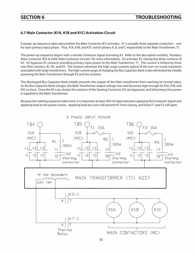
55
section 6 troubleshootinG
6.7 main contactor (k1a, k1b and k1c) activation circuit
Apower-upsequencetakesplacebeforetheMainContactor(K1)activates.K1isactuallythreeseparatecontactors–oneforeachprimaryinputphase.Thus,K1A,K1B,andK1CswitchphasesA,B,andCrespectivelytotheMainTransformer,T1.
Thepower-upsequencebeginswitharemoteContactorSignalactivatingK3.Refertothedescriptionentitled,“AuxiliaryMainContactor(K3)&SolidStateContactorCircuits”formoreinformation.K3activatesK2closingthethreecontactsofK2.K2bypassesK1contactsprovidingprimaryinputpowertotheMainTransformer,T1.ThiscurrentislimitedbythreeoneOhmresistors,R1,R2,andR3.Theresistorseliminatethehighsurgecurrentstypicaloftheturn-oninrushtransientsassociatedwithlargetransformers.ThehighcurrentsurgeofchargingtheBusCapacitorBankisalsoeliminatedbyinitiallypoweringtheMainTransformerthroughK2andtheresistors.
ThedischargedBusCapacitorBankinitiallypreventstheoutputoftheMaintransformerfromreachingitsnormalvalue.AstheBusCapacitorBankcharges,theMainTransformeroutputvoltagerisesandbecomeshighenoughforK1A,K1B,andK1Ctoclose.OncetheK1’sareclosed,thecontactsoftheStartingContactor,K2,arebypassed,andfullprimarylinepowerissuppliedtotheMainTransformer.
Becausethestartingsequencetakestime,itisimportantatleast300mSlapsebetweenapplyingtheContactorSignalandapplyingloadtothepowersource.ApplyingloadtoosoonwillpreventK1fromclosing,andfusesF1andF2willopen.

56
section 6 troubleshootinG
6.8 arc current detector circuits
TherearethreeArcCurrentDetectorcircuitsintheEPP-400.OneisusedinternallytocontrolthePilotArcContactor,K4.Theothertwoareavailableforremoteuse.
AgalvanicallyisolatedtransistorCurrentDetectorOutputisaccessibleatJ1-G(-)andJ1-P(+).J1isthe24conductorcon-nectorontheEPP-400frontpanel.ThetransistorisbestsuitedforswitchingsmallrelaysorlowcurrentlogicsignalslikethoseutilizedbyPLC’s(ProgrammableLogicControllers).Thetransistorcanwithstandamaximumpeakvoltageof150V.Itcanswitchamaximumof50mA.ThetransistorturnsonwheneverthearccurrentthroughtheWorkLeadexceeds5A.Pilotarcsnotestablishingmainarcswillnotturnonthetransistor.
AsecondcurrentdetectoroutputisavailableatTB8-3andTB8-4.Thisoutputissuppliedbyanisolatedrelaycontactratedfor150V,3Amperes.ThiscontactisclosedwhentheprimaryinputpowertotheEPP-400isoff.Itopenswheneverprimarypowerissuppliedtothepowersource,anditcloseswhenmainarccurrentisestablished.Likethetransistoroutput,therelaycontactcloseswheneverthearccurrentthroughtheWorkLeadexceeds3A.Pilotarcsnotestablishingmainarcswillnotclosethecontact.
J6-DJ6-EJ1-GJ1-P

57
section 6 troubleshootinG
6.9 current control pot and remote vref
AReferenceVoltage,Vref,isusedtocommandtheoutputcurrentoftheEPP-400.VrefisaDCvoltagethatcancomefromeithertheCurrentControlPotentiometeronthefrontpanelorfromaremotesource.Inthe“Panel”position,S2,thePanel/RemoteswitchselectstheCurrentControlPotentiometer.Inthe“Remote”position,thePanel/RemoteswitchselectstheVreffedintoJ1-L(+)andJ1-J(-).TheEPP-400OutputCurrent,I(out),willfollowVrefwiththefollowingrelationship:I(out)=(50)x(Vref)
TheControlPCBoardcontainstwoinputsforVref:HighSpeed;andNormal.WhenthenegativeoftheVrefsignalisfedintotheHighSpeedinput(P8-3),theEPP-400willrespondtoachangeinVrefwithin10mS.WhenthenegativeoftheVrefsignalisfedintotheLowSpeedinput(P8-1),theEPP-400willrespondtoachangeinVrefwithin50mS.Theslowerresponseofthe“Normal”inputhelpsfilterelectricalnoisesometimesencounteredinindustrialenvironments.
EPP-400: (50)

58
section 6 troubleshootinG
6.10 pilot arc hi / lo and cut / mark circuits
Aremotecontactconnecting115VACfromJ1-FtoJ1-LplacesthePilotArcinHighbyoperatingK8.Note,thatforthisfunc-tiontooperate,thePilotArcHi/Loswitchonthefrontpanelmustbeinthe“LO”position.
TheEPP-400isplacedintheMarkingmodewhenaremotecontactconnecting115VACfromJ1-RtoJ1-CoperatesK11.IntheMarkingmode,anormallyclosedcontactonK11opensturningoffK10.WhenK10turnsoff,theBoostsupplyisdiscon-nectedloweringthenormalCuttingMode425VDCOpenCircuitVoltageto360V*DCforMarking.Anormallyopencon-tactonK11activatesK12.K12connectstheI(min)resistorsnecessaryforstabilizingthelowcurrentsrequiredformarking.IntheCuttingmode,theminimumstableoutputcurrentis50A,andinthemarkingmode,it’s12A.
*310Vfor400V,50/60Hzmodel
J1-Z J1-S J1-CJ1-D
J1-RJ6-A
J6-B

59
section 7 replacement parts
7.1 General
Alwaysprovidetheserialnumberoftheunitonwhichthepartswillbeused.Theserialnumberisstampedontheunitserialnumberplate.
Toensureproperoperation,itisrecommendedthatonlygenuineESABpartsandproductsbeusedwiththisequipment.Theuseofnon-ESABpartsmayvoidyourwarranty.
ReplacementpartsmaybeorderedfromyourESABDistributor.
Besuretoindicateanyspecialshippinginstructionswhenorderingreplacementparts.
RefertotheCommunicationsGuidelocatedonthebackpageofthismanualforalistofcustomerservicephonenumbers.
7.2 ordering
Billofmaterialitemsthathaveblankpartnumbersareprovidedforcustomerinformationonly.Hardwareitemsshouldbeavailablethroughlocalsources.
note
7.0 replacement parts
NOTE:Schematicson279.4mmx431.8mm
(11”x17”)paperareincludedinsidethebackcoverofthismanual.

60
section 7 replacement parts

61
section 7 replacement parts

62
section 7 replacement parts

63
section 7 replacement parts

64
section 7 replacement parts

65
section 7 replacement parts
EPP-400Only-2Places
EPP-400Only-2Places

66
section 7 replacement parts

67
section 7 replacement parts
49

68
section 7 replacement parts

69
section 7 replacement parts
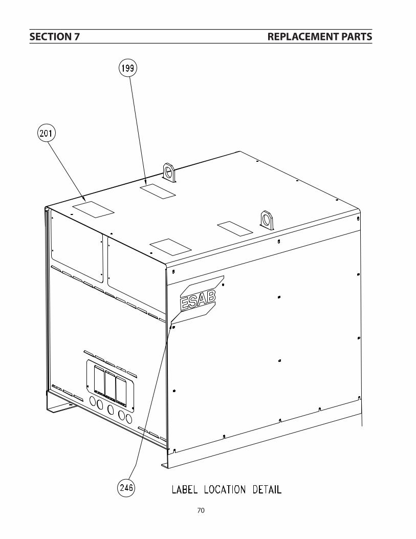
70
section 7 replacement parts

71
section 7 replacement parts
35751Y35752Y
0558006169

72
section 7 replacement parts
17280215 R10-11 RESISTOR1.5KOHMS100WR28-31
951198 L3 FERRITECORE

73
section 7 replacement parts

74
section 7 replacement parts
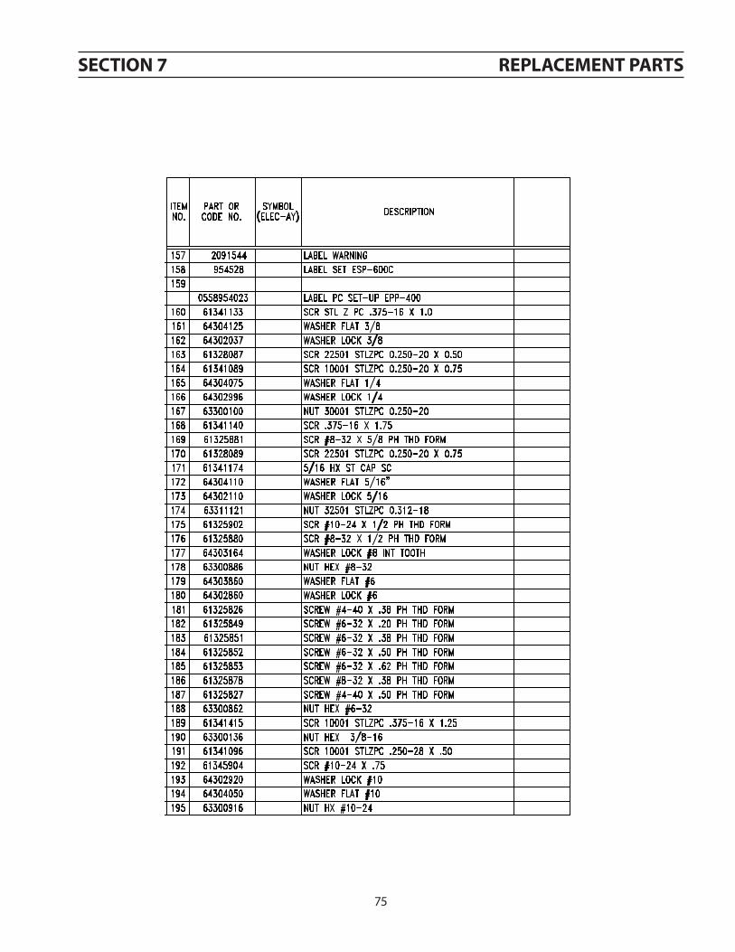
75
section 7 replacement parts

76
section 7 replacement parts
0558954035

77
section 7 replacement parts
4600610 3.62W

notes

revision history
1. Originalrelease-11/2006.2. Revision08/2010-UpdatedwithnewDOCform.
europeaustriaESABGes.m.b.HVienna-LiesingTel:+4318882511Fax:+431888251185
belGiumS.A.ESABN.V.BrusselsTel:+3227451100Fax:+3227451128
the czech republicESABVAMBERKs.r.o.PragueTel:+420281940885Fax:+420281940120
denmarkAktieselskabetESABCopenhagen-ValbyTel:+4536300111Fax:+4536304003
finlandESABOyHelsinkiTel:+3589547761Fax:+35895477771
franceESABFranceS.A.CergyPontoiseTel:+33130755500Fax:+33130755524
GermanyESABGmbHSolingenTel:+492122980Fax:+49212298218
Great britainESABGroup(UK)LtdWalthamCrossTel:+441992768515Fax:+441992715803
ESABAutomationLtdAndoverTel:+441264332233Fax:+441264332074
hunGaryESABKftBudapestTel:+3612044182Fax:+3612044186
italyESABSaldaturaS.p.A.Mesero(Mi)Tel:+3902979681Fax:+390297289181
the netherlandsESABNederlandB.V.UtrechtTel:+31302485377Fax:+31302485260
norwayASESABLarvikTel:+4733121000Fax:+4733115203
polandESABSp.zo.o.KatowiceTel:+48323511100Fax:+48323511120
portuGalESABLdaLisbonTel:+3518310960Fax:+35118591277
slovakiaESABSIovakias.r.o.BratislavaTel:+421744882426Fax:+421744888741
spainESABIbéricaS.A.AlcaládeHenares(MADRID)Tel:+34918783600Fax:+34918023461
swedenESABSverigeABGothenburgTel:+4631509500Fax:+4631509222
ESABInternationalABGothenburgTel:+4631509000Fax:+4631509360
switzerlandESABAGDietikonTel:+4117412525Fax:+4117403055
north and south americaarGentinaCONARCOBuenosAiresTel:+541147534039Fax:+541147536313
brazilESABS.A.Contagem-MGTel:+553121914333Fax:+553121914440
canadaESABGroupCanadaInc.Missisauga,OntarioTel:+19056700220Fax:+19056704879
mexicoESABMexicoS.A.MonterreyTel:+5283505959Fax:+5283507554
usaESABWeldingandCuttingProductsFlorence,SCTel:+18436694411Fax:+18436645748
asia/pacificchinaShanghaiESABA/PShanghaiTel:+862153089922Fax:+862165666622
indiaESABIndiaLtdCalcuttaTel:+91334784517Fax:+91334681880
indonesiaP.T.ESABindoPratamaJakartaTel:+62214600188Fax:+62214612929
JapanESABJapanTokyoTel:+81352967371Fax:+81352968080
malaysiaESAB(Malaysia)SndBhdShahAlamSelangorTel:+60355113615Fax:+60355123552
sinGaporeESABAsia/PacificPteLtdSingaporeTel:+6568614322Fax:+6568613195
south koreaESABSeAHCorporationKyungnamTel:+82552698170Fax:+82552898864
united arab emiratesESABMiddleEastFZEDubaiTel:+97148872111Fax:+97148872263
representative officesbulGariaESABRepresentativeOfficeSofiaTel/Fax:+35929744288
eGyptESABEgyptDokki-CairoTel:+2023909669Fax:+2023933213
romaniaESABRepresentativeOfficeBucharestTel/Fax:+4013223674
russia-cisESABRepresentativeOfficeMoscowTel:+70959379820Fax:+70959379580
ESABRepresentativeOfficeStPetersburgTel:+78123254362Fax:+78123256685
distributorsFor addresses and phone num-bers to our distributors in othercountries, please visit our homepage
www.esab.com
esab abse-695 81 laxÅswedenphone: +46 584 81 000www.esab.com
esab subsidiaries and representative offices