ARC 400 - National Welding
14
ARC 400 DC Inverter Manual UNI FLAME AUTOLIFT
-
Upload
khangminh22 -
Category
Documents
-
view
4 -
download
0
Transcript of ARC 400 - National Welding
ARC 400DC Inverter Manual
UNI FLAME AUTOLIFT
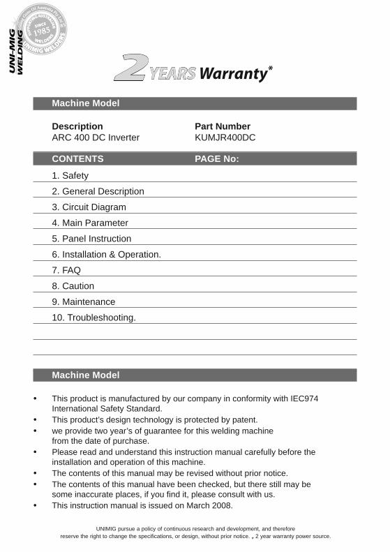
Machine Model
Description Part Number ARC 400 DC Inverter KUMJR400DC
CONTENTS PAGE No:
1. Safety
2. General Description
3. Circuit Diagram
4. Main Parameter
5. Panel Instruction
6. Installation & Operation.
7. FAQ
8. Caution
9. Maintenance
10. Troubleshooting.
Machine Model • This product is manufactured by our company in conformity with IEC974
International Safety Standard. • This product’s design technology is protected by patent.• we provide two year’s of guarantee for this welding machine
from the date of purchase.• Please read and understand this instruction manual carefully before the
installation and operation of this machine.• The contents of this manual may be revised without prior notice.• The contents of this manual have been checked, but there still may be
some inaccurate places, if you find it, please consult with us.• This instruction manual is issued on March 2008.
UN
IFLA
ME
AUTO
LIFT
UNIMIG pursue a policy of continuous research and development, and therefore reserve the right to change the specifications, or design, without prior notice. * 2 year warranty power source.
YEARS Warranty*2
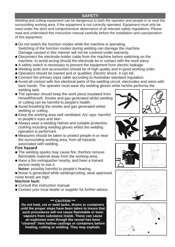
• Do not switch the function modes while the machine is operating. Switching of the function modes during welding can damage the machine. Damage caused in this manner will not be covered under warranty.
• Disconnect the electrode-holder cable from the machine before switching on the machine, to avoid arcing should the electrode be in contact with the work piece.
• A safety switch is necessary to prevent the equipment from electric leakage.• Welding tools and accessories should be of high quality and in good working order. • Operators should be trained and or qualified. Electric shock: It can kill. • Connect the primary input cable according to Australian standard regulation.• Avoid all contact with live electrical parts of the welding circuit, electrodes and wires with
bare hands. The operator must wear dry welding gloves while he/she performs the welding task.
• The operator should keep the work piece insulated from himself/herself. Smoke and gas generated whilst welding or cutting can be harmful to people’s health.
• Avoid breathing the smoke and gas generated whilst welding or cutting.
• Keep the working area well ventilated. Arc rays: harmful to people’s eyes and skin.
• Always wear a welding helmet and suitable protective clothing including welding gloves whilst the welding operation is performed.
• Measures should be taken to protect people in or near the surrounding working area, from all hazards associated with welding.
Fire hazard• The welding sparks may cause fire, therfore remove
flammable material away from the working area.• Have a fire extinguisher nearby, and have a trained
person ready to use it.Noise: possibly harmful to people’s hearing.
• Noise is generated while welding/cutting, wear approved ear protection if noise levels are high. Machine fault:• Consult this instruction manual.• Contact your local dealer or supplier for further advice.
SAFETYWelding and cutting equipment can be dangerous to both the operator and people in or near the surrounding working area, if the equipment is not correctly operated. Equipment must only be used under the strict and comprehensive observance of all relevant safety regulations. Please read and understand this instruction manual carefully before the installation and use/operation of this equipment.
*** CAUTION ***Do not heat, cut or weld tanks, drums or containers until the proper steps have been taken to insure that such procedures will not cause flammable or toxic vapours from substance inside. These can cause
an explosion even though the vessel has been “cleaned”.Vent hollow castings or containers before
heating, cutting or welding. They may explode.
UN
IFLA
ME
AUTO
LIFT
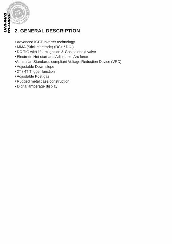
• Advanced IGBT inverter technology• MMA (Stick electrode) (DC+ / DC-) • DC TIG with lift arc ignition & Gas solenoid valve• Electrode Hot start and Adjustable Arc force•Australian Standards compliant Voltage Reduction Device (VRD)• Adjustable Down slope• 2T / 4T Trigger function• Adjustable Post gas• Rugged metal case construction• Digital amperage display
2. GENERAL DESCRIPTION
UN
IFLA
ME
AUTO
LIFT
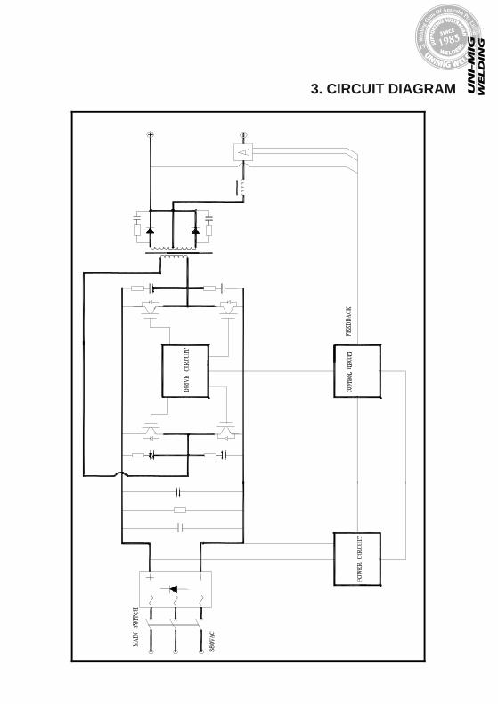
3. CIRCUIT DIAGRAM
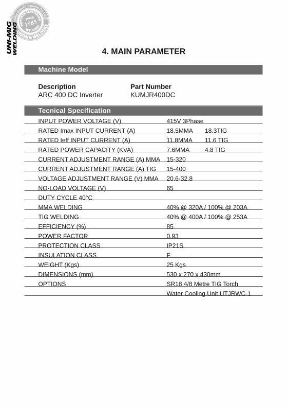
Machine Model
Description Part Number ARC 400 DC Inverter KUMJR400DC
Tecnical SpecificationINPUT POWER VOLTAGE (V) 415V 3PhaseRATED Imax INPUT CURRENT (A) 18.5MMA 18.3TIGRATED Ieff INPUT CURRENT (A) 11.8MMA 11.6 TIGRATED POWER CAPACITY (KVA) 7.6MMA 4.8 TIGCURRENT ADJUSTMENT RANGE (A) MMA 15-320CURRENT ADJUSTMENT RANGE (A) TIG 15-400VOLTAGE ADJUSTMENT RANGE (V) MMA 20.6-32.8
NO-LOAD VOLTAGE (V) 65 DUTY CYCLE 40°C
MMA WELDING 40% @ 320A / 100% @ 203ATIG WELDING 40% @ 400A / 100% @ 253AEFFICIENCY (%) 85POWER FACTOR 0.93
PROTECTION CLASS IP21SINSULATION CLASS FWEIGHT (Kgs) 25 KgsDIMENSIONS (mm) 530 x 270 x 430mmOPTIONS SR18 4/8 Metre TIG Torch
Water Cooling Unit UTJRWC-1
UN
IFLA
ME
AUTO
LIFT
4. MAIN PARAMETER
UN
IFLA
ME
AUTO
LIFT
Uo<
24V
1
2
4
56
7
11 12
10
1315
1614
9
38
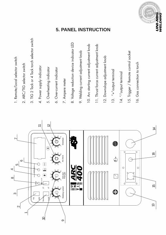
1. R
emot
e/Lo
cal s
elec
tor s
witc
h
2. A
RC/T
IG s
elec
tor s
witc
h
3. T
IG 2
Tac
k or
4 T
ack
torc
h se
lect
or s
witc
h
4. P
ower
sup
ply
indi
cato
r
5. O
verh
eatin
g in
dica
tor
6. O
ver-c
urre
nt in
dica
tor
7. A
mpe
re m
eter
8. V
olta
ge re
duct
ion
devi
ce in
dica
tor L
ED
9. W
eldi
ng c
urre
nt a
djus
tmen
t kno
b
10. A
rc s
tarti
ng c
urre
nt a
djus
tmen
t kno
b
11. T
hrus
t for
ce c
urre
nt a
djus
tmen
t kno
b
12. D
owns
lope
adj
ustm
ent k
nob
13.
“+”o
utpu
t ter
min
al
14. “
-”ou
tput
term
inal
15. T
rigge
r / R
emot
e co
ntro
l soc
ket
16. G
as c
onne
ctio
n to
torc
h
5. PANEL INSTRUCTION

13
. Na
me
pla
te
14
.3
-ph
ase
po
we
r su
pp
ly in
pu
t jun
ctio
n b
ox
15
. Inp
ut s
witc
h
16
. Fa
n n
et
17
. Ea
rth c
ab
le
UN
IFLA
ME
AUTO
LIFT
5.2 BACK PANEL INSTRUCTIONS
UN
IFLA
ME
AUTO
LIFT
6. INSTALLATION & OPERATIONNote:
• Please install the machine strictly according to the following steps.• Before connecting machine to main supply, ensure mains supply is switched off.
After machine has been connected to mains supply, mains supply and machine can be switched on.
• The protection class of this machine is IP21S, therefore avoid using it in rain.
Input cable connectionA. Connect the machine to 415V 3 Phase, ensure that the machine is fitted with a plug
that is equal to or larger than the Ieff.B. The input cable should be connected well with the corresponding power supply
connection plug or socket, to avoid oxidation.6.2.1 Arc welding installationA. Choose arc function from the Arc/Tig selector switch number 2 on front panel
diagram.B. Set the welding current in relation to the electrode and material to be welded
using the welding current adjustment knob number 9C. Connect ground cable to negative (-) receptacle number 14 and to work piece.
Connect the Electrode holding cable to positive (+) number 13 or according the welding rod manufacturer’s specifications, as some electrodes require a DC negative connection and some are DC positive connection. If the inappropriate polarity is used, the welding arc will not be stable and there will be a lot of spatter. In case reverse polarity electrodes are used, connect the ground cable to socket (13) positive polarity (+).
D. Start welding considering that you can adjust the Hot Start (10) to improve your arc striking, at the start of the welding. The current is increased to the limit set for 0.3 seconds. You could also adjust the Arc Force (11) to improve the arc stability during the drop transfer period. The current is increased to the set percentage over the main current during the drop transfer.
E. Please note the machine has Antisticking function, which operates automatically after 0.2 seconds of short circuit between the electrode and the work piece.The function stops the machine from suppling power to the electrode and work piece.
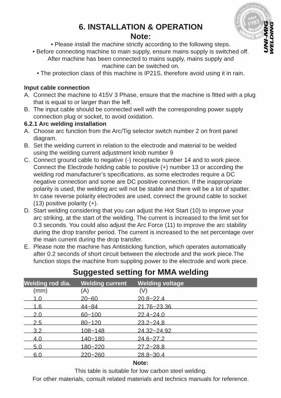
Suggested setting for MMA weldingWelding rod dia. Welding current Welding voltage
(mm) (A) (V)1.0 20~60 20.8~22.41.6 44~84 21.76~23.362.0 60~100 22.4~24.02.5 80~120 23.2~24.83.2 108~148 24.32~24.924.0 140~180 24.6~27.25.0 180~220 27.2~28.86.0 220~260 28.8~30.4
Note: This table is suitable for low carbon steel welding.
For other materials, consult related materials and technics manuals for reference.
UN
IFLA
ME
AUTO
LIFT
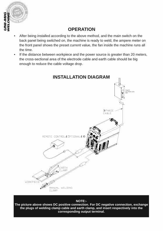
NOTE:-The picture above shows DC positive connection. For DC negative connection, exchange
the plugs of welding clamp cable and earth clamp, and insert respectively into the corresponding output terminal.
OPERATION• After being installed according to the above method, and the main switch on the
back panel being switched on, the machine is ready to weld, the ampere meter on the front panel shows the preset current value, the fan inside the machine runs all the time.
• If the distance between workpiece and the power source is greater than 20 meters, the cross-sectional area of the electrode cable and earth cable should be big enough to reduce the cable voltage drop.
INSTALLATION DIAGRAM

A. Select the Tig function from the Arc/Tig selector switch number 2 on front panel diagram.
B. Adjust the welding current, considering the size of the tungsten electrode and the thickness of the metal to be welded using the Welding Current Adjustment Knob number 9 on front panel diagram.
C. Set the down slope using the Downslope Adjustment Knob number 12 on the front panel diagram.
D. Connect the ground cable to positive socket (+) number 13 and to work piece. E. Connect Tig torch to negative socket (-) number 14 on front of power source. F. Connect the torch switch plug to receptacle number 15 on front of machine G. Connect the gas hose on torch to the gas connector number 16 on the front of the
power source.H. If the Tig torch is water cooled, connect the tubes of the water hoses of the torch to
the water-cooling unit.I. Connect the gas inlet hose to the gas connector at the back of the machine and to
the gas regulator, connect the gas regulator to the gas cylinder.J. Open the gas and adjust the gas flow rate to approximately 5-8 litres per minute.K. Touch the work piece with the ceramic part of the torch and push the trigger switch.L. By a twist of the wrist rotate the torch until you touch the base metal with the
tungsten electrode.M. Return to the original position by an opposite rotation movement and continue
welding.N. To stop welding release the torch switch.O. 2T and 4T Tig function selector switch number 3 on front panel diagram allows you
to select between 2 times and 4 times working. 2 times working is when you press the trigger switch to weld and release the trigger switch to stop welding. The 4 times working is when you first press the trigger switch to start welding then release the trigger but the welding continues, you have the press the trigger and release again to stop the welding.
P. Remote control function allows you connect and use manual potentiometer for remote control adjustment of welding amps or a foot control adjustment
Q. Down slope adjustment: Approaching the end of the weld time the welding current can be reduced gradually until it stops, this prevents craters and pin holes and is referred to as “down slope”. This dial is for the adjustment and setting of the down slope time. Adjustment is 0-10sec.
R. Post gas: This dial provides an after flow of gas when the welding arc is extinguished. Post flow gas prevents contamination of the molten pool and tungsten electrode during cool down period. Adjustment time 0-10sec.
UN
IFLA
ME
AUTO
LIFT
TIG INSTALLATION

UN
IFLA
ME
AUTO
LIFT
Remote controlOptional Foot remote control is available
Over-current If the over-current LED turns on in the welding process, it shows that machine has developed a faulty or accidental interference has occured. Restart the machine. If this fault cannot be eliminated, turn off the machine and contact the maintenance personnel of our company.Overheating If the overheating LED turns on in the Welding process, it shows that the duty cycle of the machine has been exceeded. It is unnecessary to turn off the machine, Wait for the overheating LED to go off, and then welding can be continued.
UN
IFLA
ME
AUTO
LIFT
CAUTION1. Working Environment.
The environment in which this welding equipment is installed must be free of grinding dust, corrosive chemicals, flammable gas or materials etc, and at no more than maximum of 80% humidity.
When using the machine outdoors protect the machine from direct sun light, rain water and snow etc; the temperature of working environment should be maintained within -10°C to +40°C.
Keep this equipment 30cm distant from the wall for ventilation.
Ensure the working environment is well ventilated.
Good Ventilation
Ventilation
This equipment is small-sized, compact in structure, and of excellent performance in amperage output. The fan is used to dissipate heat generated by this equipment during the welding operation.
Important:
Maintain good ventilation of the louvers of this equipment. The minimum distance between this equipment and any other objects in or near the working area should be 30 cm. Good ventilation is of critical importance for the normal performance and service life of this equipment.
Thermal Overload protection.
Should the machine be used to an excessive level, or in high temperature environment, poorly ventilated area or if the fan malfunctions the Thermal Over load Switch will be activated and the machine will cease to operate. Under this circumstance, leave the machine switched on to keep the built-in fan working to bring down the temperature inside the equipment. The machine will be ready for use again when the internal temperature reaches safe level.
Over-Voltage Supply
Regarding the power supply voltage range of the machine, please refer to “Main parameter” table. This equipment is of automatic voltage compensation, which enables the maintaining of the voltage range within the given range. In case that the voltage of input power supply amperage exceeds the stipulated value, it is possible to cause damage to the components of this equipment. Please ensure your primary power supply is correct.
MAINTENANCE
TROUBLESHOOTING
Caution: Only qualified technicians are authorized to undertake the repair of this welding
equipment. For your safety and to avoid Electrical Shock, please observe all safety notes and precautions detailed in this manual.
WARRANTY• 2 Years from date of purchase.
• Welding Guns of Australia Pty Ltd warranties all goods as specified by the manufacturer of those goods. This Warranty does not cover freight or goods that have
been interfered with. All goods in question must be repaired by an authorised repair agent as appointed by this company. Warranty does not cover abuse, mis-use, accident, theft,
general wear and tear. New product will not be supplied until Welding Guns of Australia Pty Ltd has inspected product returned for warranty
and agree’s to replace product. Product will only be replaced if repair is impossible. If in doubt please ring.
WARNING: Exposure to extremely dusty, damp, or corrosive air is damaging to the welding
machine. In order to prevent any possible failure or fault of this welding equipment, clean the dust at regular intervals with clean and dry compressed air
of required pressure.Please note that: lack of maintenance can result in the cancellation of the
guarantee; the guarantee of this welding equipment will be void if the machine has been modified, attempt to take apart the machine or open the factory-made
sealing of the machine without the consent of an authorized representative of the manufacturer.
WELDING GUNS OF AUSTRALIA Pty Ltd
WWW.UNIMIG.COM.AU
Disclaimer:While the information is provided in good faith, Welding Guns Of Australia does not warrant the accuracy of information
provided nor assume any legal responsibility for it or for any damage which may result from reliance on or use of it or from any negligence of Welding Guns Of Australia or other person/s with respect to it.
For further information please call Welding Guns of Australia Pty Ltd.112 Christina Rd, Villawood NSW 2163 - PO Box 3033 Lansvale NSW 2166
UNIMIG pursue a policy of continuous research and development, and therefore reserve the right to change the specifications, or design, without prior notice. * 2 year warranty power source.