AD. 400 151 - Defense Technical Information Center
960
UNCLASSIFIED AD. 400 151 A4,(MED, SERVICES TECHNICAL INFORMATION AGENCY ARLING)N HALL STATION. ARLINGTON 12, VIRGINIA U[TNCLASSIFIED
-
Upload
khangminh22 -
Category
Documents
-
view
1 -
download
0
Transcript of AD. 400 151 - Defense Technical Information Center

UNCLASSIFIED
AD. 400 151
A4,(MED, SERVICES TECHNICAL INFORMATION AGENCYARLING)N HALL STATION.ARLINGTON 12, VIRGINIA
U[TNCLASSIFIED

NOTICE: When government or other drawings, speci-fications or other data are used for any purposeother than in connection with a definitely relatedgovernment procurement ope;'ation, the U. S.Government thereby incurs no responsibility, nor any
obligation whatsoever; and the fact that; the Govern-ment may have fornaated, furnished, or in any way
supplied the said drawings, specifications, or other
data is not to be regarded by implication or other-wise As in any maner licensing the holder or any
other person or corporation, or conveying any rightsor permission to manufacture, use or sell anypatented invention that may in any way be relatedthereto.

DEPA RTMENT OF THE A RMYCORPS OF ENGINEERS
C (BAUM, F.A. et al T- 1488 a--q
C PHfTS OF AN EXPLOSION
411APR 16

PHYSICS OF AN EXPWSION
T-1488 (a-q)
b7
F. A. Baum, K. P. Stanyukovich and B. I. Shekhter
Source
Russiaon BookA FIZmTGIZ, MOSCOW (1959)
Translated for
U.S. Army EngineerResearch and Development LaboratoriesInformation Resources BranchTechnical Informtion Section
by
Research Information Service122 Fast 55th StreetNew York 22, New York
I
I

CONTENTS
Page
Preface 1
CHAPTER 1. General Characteristics of Explosives 4
CHAPTER 2. Sensitivity of Explosives to External Influences 22
CHAPTER 3. Thermochemistry of Explosives 115
CHAPTER 4. Reactions of Explosive Breakdown 156
CHAPTER 5, Elements of Gas Dynamics 208
CHAPTER 6. Elementary Theory of Shock Waves 262
CHAPTER 7. Theory of Detonation Waves 298
CHAPTER 8. Excitation and Propagation of Detonations 339
CHAPTER 9. Initial Parameters of a Shock Wave at an Interface 375
CHAPTER 10. Cmbustion of Explosives 413
CHAPTER 11. Brisans of Explosives 496
CHAPTER 12. Cumlation 546
CHAPTER 13. Explosion in Air 657
CHAPTER 14. Explosions in Dense Media 790
CHAPTER 15. Sympathetic Detonation 896
SUPPLM',". Toward the Theory of Cumulation of Gases 937
(III

Pref'ace T.No. 1488 a.
EF-plosives wbicla are capable of achievinig a considerable amout of
work after extremely short periods of time are eff~ectively on *of the
most powerful sources of energy at the present time~.
In munitions, explosives are employed for different kinds of fire-
armss, for amnunition and blasting media, for missiles and deatz'twtive
purposes. Under the conditions of modern warfare, a.iloaives play an
extremely important role and are used in colossal quantities. axplosives
are also widely used for domestic purposes in con~itructlonal and mining
wor~k; for breaki~ng through canals, for blasting -holes and drilling wellsa,
for clearing groui9., ate. Lxplosive methods for hydraul~ic work are now
successful1ly used for the solubion of' problgms connecteud wi tn the grandiose
construcotion plans of Commnism±~. Thefore, conridaration o~f the pbysial.
problems-of' explosion and taie pheromena accapany~r.g it are of great
interest.
In this book an attempt is made to fill the i~xlortant gap in the
literat",e concerning the physics of an explosion and til-a ;)rocesses
occurring in the environment under the action of an explc sion.
The only detailed books on the theory of explosions at thai p.raent
day are stila. the textbooks by K.K. SNITXO on "Toz'±ya vzryuobatykh
veshchtstv" (Theory of'. explosives) (Part 1, 10,.4, and Part 11, 1936) and
also by N.,A. SOKOLOV 'tKuro teorii 1WV (Course on the theory of oxplosives).
During t}-_ period of more t"an twenty yearus inoe thesie books were
published, the study of explosions has developed rapidly due to the work
of a number of Russian and foreign scientistu. Many assumaptions made in

SNITIO ta and SOKOLUOV's bookts are nlow out of~ date. A number of iportant
problems -which have only besn widely stcicC or solvod in recent years
are either not discussed at all in tWhose books or are quite inadequaately
treated in them.
Today, the physics of an explosion, making extensive use asf the
rmethods o: gas dynamics, theoretical and axerimeftil j&Wz~wk* j~yuL1aD.
chemistry, etc., is capable of describing s iaytica.14.a.:numbr of
complicated phenomena which wera formarly on3,y treated qusli tIu17 -at
the very bost. This has led to it being oonverted Into -a (quits ama
and rigJid sine_ embracing a w~ide .circle of aztrasmelr :Iprtz M
cmplicated theoretical and apoplied probiem. InU csas oU=O it
became necessary tomk rtoigenera ime mte
investigations on the physics of qneiu~ j2L& ame oreaima~ dLS-
conneated and contradictory.
The content and distribution of the mater~alt th pmeusat book
gives fundamentally a contemporary ipresetation (on the #ZL~m (or zzexplosion. Because the book dhould Jrnt on-9e~ the evil~D af present-
day knowleago attained on :a number of problems but tho'cid afl.,og Untbai
further develo~ment in perspective, the au4 thors thoi&t It Maesawa to
explain briefly, with respect to obj~ectives or rinma etgtsa
some problems whioh in 'zbeir opinion ;can becomo (of real alua An~ mmdwn
science and technology. It can be assumed that in such a Cor~ =h Usremmt
book will be useful not only to iucientific workers .but walzo to stbudent-
phyzic- sts and engineers specializing in tb~interestiaa lbri=a (of
science.
The authors, having considered in detai Une V1ysa cal phenOTacL I

oom~rdn~g diALrI a ei?]us~l (do nut dieel at all herain ith the problas
(Of atiC expib-OnIOa, aLS they7 i-btre that its specifc peculiarities should
b e snc 'aad in datail In a special noaagraL )Hzwer, S=3 of the laws
Smmti~g ths propaugattoa of Inpact urvea Am various mei an also be
used IU the analysis of the affect o4, an at=ani eraloscam. Causiersble
attentio Is paiA U this honk to the applIel pmatia= of gas dpas of
asztnag flows, uthwt i~ch it Is iwaposaihls to sta4 the pmblins
arisiqfg In the 1hsics of am expbason.
Mao athors would like to draw the atteto of the raesto the
fact that tbis Is the firt attnt Uin dana mgp
an the PVaIC3ato a axpUdna andtozqety= esana=bro
errrs *Lh'mhope the raidr u122 report to us.
'Maptr I, UI, ZV, 7, VI, WII, MOE, I wure uritton by F.A., Bit;
Capt~wn = ant ZIT by X.P. SI' MC, W; aptwrs M, 1H and XV by
2.1. S~n Captr LI at fl wre written JOintUy by at~e anj
87byBMat MEMandithe lm a~x-as r-ttcn b7 .
The autbors tttb to expcess their ratItud. -0 N.A. 0AO M
t.S. SMOAx'S amd 0.1. -W=nV=r for their va Luse omments ten they
the nzacit

Ce~er~i Cactz-t, c: o~f isves
§ 1. The pheno-enon of an e2nlosion.
An explosion in the wide sensa of the word is a process of rapid
pbysical and chemical t-aforation of a system into mechanical orkA,
accompanied by a change of its potential energy. The work accomplished
during an exlosion Is due to the rapid expansion of gases or vapours
indeperdently of whether they already exist or are formed at the time of
the explosion.
The most essential sign of an explosion is the rapid jump in pressure
in the medium surrounding the place of the explosion. This is the direct
reason for the wide-spread effect of an explosion.
Mxplosions can be produced by various physical or chemical phenomena.
The following examples can be given of explosions due to physical
causes:
1. The "ex,-losion" of a steam boiler or bomb containing compressed
gas. In the first case the phe-nenon is produced by the rapid change of
superheated water into a vapour state and in the second case by the
increase in pzsare of the gas in the bomb. In both cases the explosion
arises as a result of overcoming the resistance of the walls of the con-
taiLur, and its destruztive effect depends on the pressure of the steam or
gas in the container.
2. EqxIcsions caused by powerA.ual ap- bsucharges, for example,
lig4htUing or the passage of a hiK voltage electric current through thin

metallic thr. ds.
In the Qase of poweorefl discharges, the c'ifference in potential
levels off in a tiae interval of the order 10 - 6 _ 1O- 7 see, thatnks to
which a colossal energy density is attained in the discharge zone and
extremely high temperatures (of the order of tens of thousands of degrees)
arise, which in their tun leads to a large increase in pressure of the
air at the" point of discharge and the spread of an intense disturbance
through the surrounding medium.
The explosions of wires under the ection of electric energy are
caused by the sudden change of the metal into a vapour state; the
temperature in this case reaches magnitudes of the order of 20,0000.
Explosions based on such physical phenomena have an extremely Limited
application and are chiefly the subjects of speciallsed soientific
researches.
We will only consider explosions produced by the processes of
chemical t4-ansformations of explosives.
Explosives are comparatively unstable systems in the thermodynamical
sense, which under the influence of external actions are capable of
extremely rapid exothermic transformations, accompanied by the formation
of very heated gases or vapoura.
The gaseous explosion products due to the exceptionally high rate of
the chemical reaction practically occupy the volume of the explosive itlif
at the first instant and, as a rule, they are in a greatly compressed
state, because the pressure at the pJace of the explosion inoreapeAs sharply..
From what has been said it follows that the ability of chemical
systems to explosive --ansformations is determined by the three following

factors: the exothericity of the profess, the high rate of its propa-
gation and the presence of gaseous (vapour) reaction products,. These
properties can be exhibited in explosives to varying degrees; it is only
their totality which gives the character of an explosion to the phenomenon.
Lst us conoider the meaning of each of these factors.
ExothermicitV of a reaction. The evolution of heat is the first
necessary condition without which the occurrence of an explosive process
is generally I.iipossible. If the reaction were not accmpanied by heat
evolution, th a its sponta:eus development and, consequently, the self-
propagation of the explosion would be excluded. It is evident that
suhstancos requiring a constant supply of external energy for thei"
decomrosition cannot possess explosive properties.
' . count of the thermal energy of the reaction, heating of the
gaseou,, p"ou , leads to temperatures of several thousand degrees and to
their .ouseq% Ont expansion. The higher the heat of reaction and the rste
'f its pro, gation, then the greater is the destructive power of the
explosion.
rie heat of reaction is a criterion of the efficiency of the explosive
and is its most important ch'Lrateristic.
Fo' moder. .4losives which find the widest application in practice,
the heat of the -)sive transformation fluctuates within the limits of
900 to 1800 kcal/g.
High rate of the proogs. The most characteristic feature of an
explosion, which distinguishes it sharply from norral c:cmical reactions,
is the high r te of the process. The change to the fitial explosion
products occurs within hundred-thousandths or even millionths of a second.

The hIgh r"ate of enaray evolution defines the advantage of explosives
over orde uis. Nevertheless as regard the total enery -,-ntent
referred- to an equal cquantlt.y by weoight, even we most energy-rich
explosives do not exceed noral fuel systems, but on explosion they attain
an incomparably higher volune concentration or energy density.
This can be seen, for example, from the data given in Table 1.
Table 1.
Tha, heats of explosion ard calorific values
of some ex-losives and fuel xrxtures.
Heat of explosionor calorifia value
Explosive or fuel referred to . kgexplosive or fuel
_____________________ mizture, kcal
Pyroxyli(13.3 X) 1040 . .litrogl .. rine' .1...... .1..85:: xt ;.' of Lonz(.e rand orjgen 2330'ixto- of oabon and oxygen f 2130'lixture of hydroges ad orgon 3230
The combustion of ordinary fuels proceeds comparatively slowly which
leads to a considerable expansion of the reaction products during the pro-
cess and to an essential dispersal of the energy evolved by means of heat
conductivity and radiation. For thaae reasons only a relatively low energy
density by volbe in the combustion products is attained in a given case.
Explosive processes, on the other hand, proceed so quiclay that it
can be considered that all the energy is practically evolved into the
space occupied by the explosive itself, which leads to the high energy
(7

concentrations which are not attained under tha~ u 1'n of the normal
course of chen'-i al %-eactions.
Particularly high ener,,, densities are attained durine, the explosion
of tl'e condansed (solid. or liquid) explosives which are striczly the only
ones used in practice. This is explained by the fact that these explo-'-ves
posse.,s a significantly smaller specific volume than the gaseous fuel
mixctures (bee Table 2).
Table-2
Volume density of enermr of some enplosives and fuel mixctures
Volume density ofenergy, referred
Name of explosive or fuel mixture to 1. 1. oxplOSiveor fuel mxture,
.Pyroxylin (13.3% X) . ........... 1350Nitroglycerine.. .. .. .. .. ..... 2380Miitur.; of carbon nd oiyes 4,)
,mixture of benzene vapoura and oxygen. 4,4Mixture of hydrogen and oxy'gen 1,7
The numbers given for fuels (carbon, benzene) are calculated on the
assumption that the combustion of these substances Is completely achieved
in the initial volume occupied by the corresponding mixture.
From the given data it is evident that the energy density 'by volume
attainablo during the explosion of standard explosives exceeds the energy
de~nsity for normal fuels by a factor of hundreds or even thousands-. This
is responsible for the greater power of the explosion and the destrucotive
abi I ty.
it must be noted that an unsatisfactory method of estimating the power

of an explosion is accepted by a number of authors as a graphic indication
of the value of the rate of the process under explosive conditions. For a
quantitative estimate of the power of an explosion the following relation-
ship is used
MQI MQID~(1.1)
where B is the power of the explosion, M is the weight of the
explosive charge, c is the tipe (in sac) of propagation of the
explosion through the explosive charge, Q is the heat of explosion in
kcal/kg, I is the mechanical equivalent o heat, D is the linear
rate of propagation of the explosion and I is the length of the charge.
According to this formula, for a given finite value of Q , the
power of the explosion B should increase without bound as the time t
decreases, so that as T-.O,#-eo.
Formula (1.1) is unsatisfactory because in it the criterion of the
power of the explosion i.e. the work capable of producing products of
explosion in unit time, is mistakenly taken to be a magnitude proportional
to the rate D of the propagration of the explosion through the charge,
or the rate of evolution of energy during the expoosive decomposition
react....n.
We note that the power referred to unit volume of ex-ploicn products
under the conditions of their free dischargo into space should be pro-
portional to pq3 where p is the density of the explosion products
and q is the rate of their discharge into space.
The rapid coixi°ae of the processes of explosive transformation can be
judged on the basis of data concerning the linear rate of propagation of

the explosion through the explosive charge. The maximum rate D of the
propagation of the explosion for the modern explosives used in practice
fluctuatcs between the limits 2000 to 9000 M/sec.
G.fo r ration. The high pressmres arising during the explosion and
the destructive eioet caused by them could not be achieved if the chemical
reaction were not accompanied by the formation of a sufficiently large
quantity of gaseous products. These products, found at the moment of
oxplosion in an extremely compressed state, are the physical agents which
on expansion cause the extremely rapid change of the potential energy of
the explosive into mechanical work or the lk7ne'e,.- c energy of moving gases.
The volume of gaseous explosion products (calculated under normal
physical conditions) of some explosive5 is given in Table 3.
Table 3
The vol.uuo of exolosion _roducts.
Volume of gaseous Ox-ame of explosie plosaiooduotA in 1.
for 1 k for 1 1.I explos vec explosivi
Pyroxylin (13.3 N) ....... 765 995
Picric acid ...... ............ 715 1145TrIty1 ................. .... 740 1180Nitroglyoerine . ......... 690 1105
Thus, for 1 I., of normal explosives about 1000 1. of gaseous products
are formed, which are under very high pressure at the moment of explosion.
The maximum pressure during the explosion of condensed explosives
attains hundreds of thousands atmospheres. Evidently, such pressures

camot bo realisod under the conditions of flow of normal chemical
reactions.
Durin& the explosion of gaseous systems an increase in volme des
not usuaLy occur and in some cases the explosive transformation is even
accompanied by a decrease in volume.
An example of such a reaction is the explosion of detonating gas
2H.- -O 2 --- 2H 2O +2.57,8 kca.
as a result of which a decrease in voluae by one third occurs. However,
this decr'-aso in volume is compensated by the exothermicity and high rate
of the process, due to which the pressure during explosion does, neverthe-
less, roach a magoitude of the order of 10 atm.
The value of the gas formation factor can be established by a series
of reactions during which gaseous products are not formed. The simplest
reaction of this type is the well-known thermite reaction
2AI + FeO, = AJ,0- + 2Fe + 198 kcsx,.
which occurs, a- a rule, without explosion in spite of the fact that the
thermal effect of the reaction is sufficient for the heating of the end
products (7e, A12 0 3 ) to 3C000 , at which they are in a liquid state. Under
the ignition oondittions of large quantities of a thermite mixture
phenomena ,ometimes occur which are rominLscent in their character of a
normal explosion. Analysis of suca explosions leads to the conclusion that
they are mainly duo to secondary phenonena connected with the heating and
e.cpansion of the surrounding air and also the air included in the porous
mass of the thermite mixture. Moreover aL± extremely rapid combustion of
the pulverized powder-foming aluminium can also partially occur due to
/1

the orygexi in the air. in this case one off the reaction producte
A1203 - will be found partially in the vapour state.
In contrast to thormita and other similar mixtures we also have a
number off subutances vhioh possess all the characteristic properties of
ecpJlos±veD, in spite )ff the fasct that during their decowposition they fomu
products whi oh are found .in a solid state under normal conditions.
A. typical examnple off such substances is silver acetylida which readily
explodes according to the following scheme-.
AgZ 2 -2 Ag +2C +87 koAl..
It is evident that silver should behave as a moznoatomli- gas under
'the temperature conditions of the reaction.
Thus, on the basis of the qualitative laws established by us, it can
be concluded that only the sinmultaneous combination of the three basis
factors - exothermicity, high process rate and gas fforzation - can
6'uar"-tee that the phenomenon possesses the joint properties giving it the
character of a normal. explosion.
§2. Classifi rtion of exnlosive Piocesses.
Dopending oz the conditions of initiation of the chemical reaction,
the character off the explosive and some other factors, the processes of
explos-ive transforution can be propagated at a varying rate and tan
possess ecsential qualitative differences.
Ao regards the character and rate of triair propagation, all the
exmpo.sive processes Inown to us are divided into the following basic types:
co~b.~tonexnosior~and dotollation.

of "._ - ocd coparatively slotwIy and at a
zata uCl,. :o.:'-, frctions of a cent metre to
several n trs cr second. Tho cozbustion rate varies essentially with
'ha cxte'rrl rr-szure arid increases noticeably 6ith increase of the latter.
'n tno open air this process pzocdz :-eatvely sluggi shly and is
not a ;:.anJIeI by any siS-,fficznt sound effect.
In a confined space the process proceeds much more eziergetically and
is characterised by a more or loss rapid increase in pressuze and by the
ac:_izy oz the gaseous combustion products to roduce the ener~r needed to
... .. ccon ., ...... -.. . . - -. i .. f
off pow;ders.
In coparison with cozibustion, explosion is a cu-.-Itatively different
form of propagation of the process.
The distingicsh.g qualities of an mlosion are: a rapid jump in
prossure at the site of explosion aind a c .aeing rate of propagation of
the process mcasuarable in thousands of zetres per second and depending
comparatively little on external conditions. The action of an explosion
is charactorised by sharp impact of gases on the s-rounding zedium causing
crushing and severe defo.vation, of objects at comparatively small dis-
tances f'-om the place of explosion.
D31on.tion is an explosion propagated at a constant rate which is
the ma.zu= possible for the given explosive and the given conditions and
which exceeds the speed of sound in the given substance. Detonation does
not difffer from an ezplosion in the character and nature of the phenomena
but it represents its stationary form.
Best Availab!e Copy/3

:,.,n ate uader g±ven COViad fO:~O' C-Jh 0oC1o0iVC
~'~C. .~.4 A1~..~e by a coia;.nt *whi'h is ore of its most iraportamt
~~ ~Uadcr tho detonation conditions the maai detruive
cfoct c,.:* an ez '* ion ii attainod.
_po ooe; a3 of' axploaion and detornation diffor essen-tially from
thi -)rocez.~es of' conbuction with respect io tho A1iaracter of' their propa-
'aio: oobu~tion transits. to the mass of the explosive by means of
t.couducatlvity, diffusion and radiation, whilst cxplosion aild
Cetonatioa aze 'propagated by means of the compression of the substance by
a zhoO ave
soare: dztailcd Wharacteristics of the various for-as of' explosive
Wza3o:-z-t on will be 3-van in the folJlowirtg ohaers.
6 . 1ntificn+n of exlosives
-oa n iai:,ozous r.aLbar of' explosiva.- ara 1cnowt which 'differ widely
bothQ with rcz;-?ct to oo;;poaition and to theGir p.yaico-ohezical and
oxploo~iva prop-otioz. Bcauzo of' this, it is necessary to classify them
oy_0;,:atioaly, for co-vcvonionc3 of investigation.
;,11 axplosives can be divided into two basic groups.- oxplosiva
chenical co~ourndo and explo ;ive zixturao.
oorory Oro rolatively unstable chenical systems
c--bl o' rz Ad exother.-ic transforzation:s under the action of' external
ar, a result of' which there oooua's comiplete rupture or the
intano~eclarbonds and the subsequent recombination of' the free e m
(or ions) into tber'_a d mCally stable products.

-~ ~ .oxyr-,-conta-* inn
o:~...c c~z 'c of. oartial or co=I)Iete intramolecular combustion.
Th:, Zec~~ a"it C n-j:bzz of~ e=:;)".-I-ve endothermic compounds
not cont .L- o-.cyz.ai aahIch ure explo-on conditions decornpo~e into
~hc~r bic o:n~tz. n G~p~eo~ histype Of com-p =4 -'s lead azide
&a.c ccmpozoes on exnlosion into free nitroCgen and DThad with an
evolution of energy ocju;:C" to tWhe heat of-for~ation of this azide from the
elemarxtz.
Such compounds, as a rule, possess quite an unstable mol~ecul~ar
st'Cruct-ara and hi-. sensitivity to extaxrnal actions, which greatly liits
As ani e.-;=~ of Particulaly unstabla co : we can quote
tho halogen and uJptcomounds of nitrocen, such as: XCl 3 , :"Mi 2 ,
E" ,A which rcadily o~cploda --- a raL<t of negligible machanical -Influences.
The a'o~i~yOf erplosive Compoun-ds, according to VL PT HOFF is
&~to t-hcir contalning molecul~es possessing special so-called exploso-
phozic ato= rui~ whi4ch include;
C 0 aroup, pi-;is ic-nt in acotyler-a deriv.at'~~
N X vz va in halogan cozmpounds of ritro ,en,
N = N -Loup:, :In azldes, diazo compouncdl, tetrazoles,
N=C group, in salts of' fuz'.nic acid or fulJminates,
= 0 group, Inl nitrates and nitro compounds,.
O C group, iA'n pa-zaXIdes and ozonides,
o Cl group,, in c-hiorates and perchiorates.
E.-rlosive mixturac arz, systems containinZ. at least two compohents
unconncted with one another chemically. Usually one of the components, of

~o r.~~.ro a -a t srca hc is relatively oxygen-rich, and the second
co:~ ~ "ahr hand, is a co~abustibla substance which e~tho3r
co::ita-- z o~:~ o- cornta-=s it in a quantity :nsu i.eient
L:liv ici.zare ekth;er .0 I.n~d so- o~r hetezo:7eneous
Ga,-,ou m i.tur3.z have no practical. application in oxplosive tech-
nogoy due to tho Low emerM- density obtained during their explosion.
Gaseous mixtures are, howaver, of' great scientific interest. Their
v~t~aL.onhas led to vital1 results in the study of the propagation
.;.ocesze3 of az expjosion and also in the mechanism ani kinetics of
ex~.oz~.veroacti.ons.
~L~t~ ~~caare darngerous as regards explosions. are
±'rec'uontly encountarad rznder di?~etpractiaal conditions. Thus, in
co~-:~r~e Z.:o-~ro'~,h.-3i a n-ixcture of' methane and air is often. foxmed.
£eccz-b:,Lstible co.nsof liquid explosives are usually substances
Vtich 1.,z wi.-th a large tLz-z. of.fct, suchi as benzene tolaane, zono-
r11tro ks.L~-~ '~c~zers fr,,nG nitric acid ad tetranitromathazne
S-4qic'-id mixures are qui.te powarAu. explosives but in Practice
thzy a::c z.,-:cly us3ed boc-Use of' their h-,Ia sensitivity and unsuitabilityv
S).ae:;- io .uro are very numerous and find a wi~de application,
boh n 'vi ad ~iit~yspers.Depending on the chemical nature
of' the zing,- azont in. their composition, these mixtures can be divided
into apzo-;rlate zub-sroi.?s the most important of which are the ranm nium.-
Best Availabla-CQr~y

nitrate xc loiLves or ammonites. The basic component of these substances
i z a.our i~i i .trwo A 4N 3 tho content of which varies from '0 to 95% in
the diffazont compositions. As combustible component, use is made of the
va'-iouo .itro-arozatic explosive compounds (Trotyl, dinitrobenzene, etc.)
wlich contaia insuffLcient g-gen to form the products of complete
cozmbustion.
.- tho oimplest ammonites the combustible components are such
substancas as coal, sawdust and various resins. Examples of ammonites are
asphaltite (95. LT 4 N03 , 5% asphalt) and Amatol (80% NH4 NO3 , 20% Trotyl).
subvUL ... s for basic i' w..-t...- .
Dy=za tez, oloeless powders and explosive alloys occupy the csz
place among explosive systems. The basic explosive omponent of dynamites
is nitroglycerine. To the dynamite group belong.
a) nitrogelatin of composition: 93% nitroglycerine and 7%
coilo:qlin;
b) o;latin-dynamites; 62-63% nitroglycerine, 27-25% potassum
nitrate, 2-3% collo.ylia and 8. absorber;
o) powdor-.'orning dynamites or grisoutine compositionat 29-30%
tro~lyecorne, 0.8-1.0% collodion cotton, 69.5 - 68.5. ammonium nitrate,
up to 0.8% soda or chalk.
.ie ox2ooless powders are systems which have cellulose nitrates as
Cie bazic e.qiposive component. Some types of smokeless powders contain,
moroover, nitroglycerine or other explosives as well.
Exlosive substances and explosive systems can be divided into four
Groups with respect to the basic fields of their application;
1) initiating explosives,
2) high explosives,
3) missile explosives or powders,
4) pyrotechnical compositions.
Tnit~nitirnq explosives. Those are employed as initiators CC explosivi
proces;es to stimulate detonation of the basic explosives, for example, to
stimulate detonation in shells, mines, aerial bombs, blasting media, etc.
The distinguishing properties of initiating explosives are:
a) the ability to explode in the form of detonation under the
influence of insignificant external thermal or mechanical actions;
b) their explosive transformation is characterized by the fact that
the period of increase in its rate up to a maxim=m is very small, 4
incomparably less than in explosives of other types. In some initiating
substances as, for example, in lead azide, the period of acceleration of
the process is practically absent, i.e. the process immediately changes
into the detonating form independently of the dimensions of the charge.
Thanks to this it requires only an extremely small charge of initiator
to stimulate explosion of high explosives.
Initiating explosives are used pre-eminently in the fo-m of capsule-
dotonate6 (c-d). Some initiating explosives are used in compositions
destined for equipping capsule-igniters (c-i).
The mRft important representatives of this group of explosive .;
1. The salts of heavy metals of fulminic acid or the so-called
f'lminates. Of these mercury fulminate Hg(ONC) 2 is the most important.
2. Salts of hydrazoic acid or azides. The most widely used is lead
azide, PbN6.

Tho initiating explosives also include some organic azides, for
ex-i'Ple, cyanuri ctriazide, 03N3 N33 )3 .
3. Salts of heaN-- metals of styphnic acid. Their most important
representatives are lead styphnate or trinitroresorcinate
C. (d2 Pb. H2 0.
4. Oarbides of heavy metals or acetylides, for example, silver
acetylide A92 02 .
. nitiating mixtures employed as detonating or igniting compo-
sitions (the latter consist mairyv of mercury fulminate, potassium
chlorate and antimony tr.sulphide) are used in c-i and C-d.
The initiating explosives of practical interest also include tetra-
zone C2H8 ON1 0 , which is a derivative of an usaturated nitrogen-hydrogen
compound N4; 4 , and some nitro-ar=matio diazo-oompounds, for example,
diazodinitrophenol.
Docause of their ability to detonate directly under the influence of
external actions, initiating explosives are sometimes called primary
explosives.
High e%-losives are employed as explosive charges for various munition
and blasting purposes. In contrast to Initiating explosives, they possess
considerably gre ter stability. Their detonation is produced under the
in'luance of relatively large external actions, usually with the help of
initiating eiosives. Because of this, in contrast to the initiating
exlosives, #1ey are sometimes called secondary explosives. Their basic
fom of exp /osive transformation is also detonation, but during the
stimulatiol7 of an explosion the period of rate increase of the process up0
to a maxirm is considerably longer for high explosives than for initiating
/q

The most important reproesentatives of explosive compounds of~ this
group are.
1. Nitrates or esters off nitric acid. The most important off them
aro rniiro -JIycerine (glyceryltrinitrate) C3H5 (0N0 2 )3 , FEWN (pentaerythrito2.
tetranitrate) C(0H200 2 )4 , cellulose nitrates e~g. C2,jH2909(ONO 2) 1 -
2. Nitro-compounds. O±f the huge number of these compounds, the most
widely usod are uitro-compounds of the aromatic series, mainly trinitro-
derivatives. Among them are:
Trotyl (trinitrotoluene) 06%(N0 2)3C%,
picric said (trinitop9henol) C6H2 (N02.)30H,
Tetryl (trin:Ltrophenylt.etbylzitramine) CAU (N02), < O
Of the non-aromatic nitro-compounds,,not. must be made of:
He,~gen (trimethylenstrinitramine) C31~6 N06,
nitroguanidine HNl = C<NW0 2
tetranitromethane C (N02 )4-
The most important representatives of the explosive mixtures belonging
to thia group are ammonites, dynamites and also some alloys, for example
the alloys of Trotyl with Hexaoen, etc.
INissile explosives or -powders.
Powders are mainly used for missile purposes. Their basic form of
explosive transformation is rapid combustion.
They are divided into two groups;
a) powders of mechanical mixbuwes and

b) powders of nitrocellulose or smokeless powders.
An example of the first sub-group is smoky powder, consisting of 75%
potassium nitrate, 15% wood charcoal and 10% sulphur.
Nitrocellulose powders, depending on the nature of the solvent, can
be used for gelatinisation of their basic component, nitroceflulose, and
are divided into several groupss
a) powders in a volatile solvent or pyroxylin powders containing up
to 98% of-pyroxylin, bydrox-ether solvent, diphenylimine and moisture;
b) powders in a low-volatility solvent or ballistites, in which
nitroglycerine, nitrodiglycol and such like substances serve as solvent of
pyroxylin. Ballistites are prepared from the so-called soluble pyroxylin
and contain up to 40% nitroglycerine, in which this form of Mroxylin is
dissolved, and up to 151 of other additives.
c) Powders in a mixed solvent or cordites are prepared from the so-
called insoluble pyroxylin; they contain up to 60% nitroglycerine and as
an additional solvent up to 1.5% acetone and some other additives.
d) Powders in a non-volatile solvent, in which such explosives asTrotyl, dinitrotoluene etc. are used to prevent pyroxylin gelatinising.
As regards the categories of explosives, reference should also be
nade to vyrotechnIo compositions, which under known conditions are capable
of detonation and possess a comparatively high sensitivity to external
actions. Pyrotechnic compositions, as a rule, are mechanical mixtures of
inorganic oxidizers with organic and metallic fuels and cementing additives.
The basic form of the explosive transformation of these mixtures is
combustion.

Chaper 11
SENSITIVITY OF EXPLOSIVES TO EXTERNAL INFLUENCES
4. Initial or initiating impulse.
Explosives, depending on the composition, possess greater or smaller
ability to withstand external influences without undergoing explosion
i.e. spontaneously developing chemical transformation.
The smaller the influence necessary to stimulate explosive trans-
formation in a substance, then the greater is its sensitivity.
A charaoteristic corresponding to this sensitivity o. cxqplo i¢vas
to external influences is the magnitude of the 1iitial or initiating
impulse which is required to excite explosion in them under Ziven
conditions.
Various forms of energy can be used as the Initial impulse:
mechani(Al, thermal and electrical energy, the energy of radiation and
also the energy of another initiating explosive.
The quantity of energy necessary to stimulate explosion even for one
and the same explosive in a given state is not a strictly constant
magnitude and can fluctuate appreciably depending on the form of the
initial impulse and the character of the trazemission of the influence to
the explosive.
Thus, for exmple, under the conditions of rapid heating of the
explosive achieved at high temperatures, initiation of the explosion can
be attained at considerably less expenditure of energy than under tae
T-No. 1488b

conditions of slow heating achieved at lower tomperatures.
During the slow compression of some explosives possessing relatively
low sensitivity, an explosion cannot be produced even in the case when
the quantity of work done during the compression is large and extremely
high pressures are attained, whilst under conditions of sudden shock the
initiation of an explosion in corresponding explosives can be produced for
considerably les expenditure of energy. According to BRIDGMAN's data,
Trotyl under conditions of static compression does not explode even at
pressures of the order of 50,000 atm. or higher.
Moreover, the form and magnitude of the initial impulse affects
essentially the che~eter and development of the explosive processes.
Thus, for example, under the action of a heat pulse combustion of an
explosive is obtained under oertain conditions only, uhilst under the
influence of an impact and particulatly that of the explosion of an
initiating explosive it. detonation im pre-ea±nently attained.
Zn order to produce initiation of an explosion, it is primarily
necessary that the initial impulse be applied to the explosive charge
under conditions under which sufficiently high concentrations of energy
will be attained even if only in a localised zone of the system.
Particularly high concentrations of energy naturally arise during the
stimulation of an explosion by means of initiating explosives, which have
been extremely widely used in explosives technology because they possess
this proparty.
There is no rigid equivalenoe between the various forms of initial
impulse with respect to the results of their action on one and the same

explosive. Thus, for example, lead azide is more sensitive to machanical
influences than to a thermal impulse, whilst the picture is the reverse
for lead styphnate.
A ohlorine-hydrogen mixture (012 + H2 ) is passive to a heat pulse,
but easily explodes under the action of light rays, which excite an
intensive photo-hemical chain reaction in the gas.
The selectivity of explosives towards their response to an external
impulse in determined by the combined manifestation of those of their
chemical and physical properties which can influence essentially the
conditions of consumption of energy by the substances and the stimulatior
in them of a chemical reaction by some initiating impulse.
5. Sensitivity of exlosivas io heat Wlses.
A measure of the sensitivity of an explosive to a heat pulse is
usually given by the explosion temperature established for quite definite
experimental conditions.
The explosion temperature is the temperature to which a given quantity
of explosive should be heated to obtain its ignition, during which the
chemical transformation of the substanaeis aocompanied by a greater or
lesser sound effect.
To secure explosion it is necessary to increase the heat supply
specified by the oovrse of the chemical reaction so that it exceeds the
heat losses due to conductivity and radiation of heat.
Explosion occurs at the moment when the rate of the process reaches
some critical value corresponding to explosive conditions.

Thus, on heating an explosive the explosion temperature is always
preceded by a period of acceleration of the chemical reaction. The
interval of time between the commencement of heating and the moment of :
explosion of the explosive is caflled the induction period or the ignition
time lag.
For explosive substances the connection between the ignition time
lag and the explosion temperature is expressed by the lawi which was first
obtained by N.N. S34WOV:
Ce
where -t is the ignition time lag in jM, E is the activation energy
of the explosive appropriate for an explosive reaction in cal/mole, *R is
the gas constant equal to 1.986 ga/ola C is a constant dependent
on the composition of the explosive; T
is the explosion or ignition temperature
in degrees Kelvin.
From this expression it is evident
that on decrease of the activation
_______________energy E and on increase of the ig-
nition temperature T , the ignition
time lag f' decreases rapidly. The
Fi-y.1. Variation of variation (5.1) can be convenientlyignition time lag withtemperature. presented in the logarithmic foxm
Int I n C + E

From this expression it follows that between in c. and T there exists
a linear dependency (Fig. 1), which has been confirmed experimentally for
the majority of the explosives investigated.
The slope of the straight line on this graph equals . . Thus, on
the basis of experimental data concerning explosion temperatures it is
p ossiblt to determine ! which is an important charaoteristio for
explosives.
The explosion temperature of an explosive is not a strictly constant
magnitude, but varies essentially with the experimental conditions: the
quantity of tested explosive, its degree of pulverisation, the methods of
testing and other factors determining the conditions of heat supply and
auto-aoceleration of the reaction. Because of this, in order to obtain
comparable results the tests must be carried out under strictly defined,
standard conditions.
In determining explosion temperatures of condensed explosives, the
following two methods are most widely used$
1) A given quantity of explosive at a certain initial temperature
is heated at constant rate. In this way the temperature is determined at
which ignition occurs. The explosion temperature thus obtained depends
mainly on the initial temperature of the explosive and becomes higher as
the rate of heating increases. This method is in wide-spread use for
practical tests on explosives.
2) The second method consists of establishing the relationqhip
between the change in ignition time lag and the temperature; experimental
results are usually expressed in the form of a graph (Fig. 2). This
method which permits the response of an explosive to a heat pulse to be
(71

characterized more precisely and com-
pletely is used pre-eminently in research
and much more rarely for routine tests on
explosives.
For every explosive, under corres-
ponding experimental conditions, there
exists a temperature below which ignition
generally does not occur however long the Fig. Variation ofignition delay with
explosive is heated. This is explained as temperature.
follows.
The process of thermal decomposition of an explosive can be divided
into three periods: the indubtion period connected with the formation of
the initial centres of reaction, the period of auto-aoceleration of the j
reaction and the period of its extinguishment.
At sufficiently high heating temperatures the induction period is
suallj as a result of auto-aoceleration of the reaction its rate can
attain a critical value v ,, , corresponding to the commencement of
ignition in the presence of a sufficient quantity of as yet undecomposed
material.
If, however, the heating temperature of the explosive is below a
certain limit and the reaotion rate increases too slowly as a result, then
the initial explosive is depleted sooner then the critical value of the
reaction rate v is attained. In this case because of the unfavour-
able relationship between the external heat supply and the heat losses,
auto-aoceleration of the reaction can indeed not occur. From this it can
be concluded that the explosion temperature up to a known limit should
,Q7

depend on the quantity of explosive undergoing heating, that is, it
should decrease somewhat on increase in the quantity of explosive.
According to PATRY's investigations for 1 g. merciy fulminate the
explosion temperature equals 1280; for 10 g. it, is 1150c; the ignition
time lag exceeded 7 hours.
The minimum explosion temperatures for some explosives are given in
Table 4 (weight of explosive - 0.05 g.).
Table 4.
Exilosion tmperatures of some explosives
Name of SPlosiv . time la,
-~ f~t .780
* Tr~nitzotoluen .......... . .. 275 423T2rlnitrophenol ......... . . .... 275 143Triaitioxylene ............ . ... 300 240Trinitiorpsoroinol .... ........ . 245 31Triniztiophlorglucine ....... . ..... 200 18~rnirpkey~i . . .. . 87 85Tezt71:. . . . .. ........ . ... 180 40'trintrophenalo~by2niiramia± 160 25
The minimum explosion temperatures of explosives are of interest
mainly from the point of view of problems connected with safety techniques.
At the same time, however, it must be remembered that on increasing the
mass of the heated explosive the minimum explosion temperature can be
considerably lower than in laboratory experiments due to the changed
conditions of heat supply.
Of the physical properties of explosives the most essential quantity
for processes of thermal initiation is their volatility.
I<
The conditions of ignition and the explosion temperature depend to a
large extent on the ratio of the rate of the chemical reaction to the rate
of the vaporization (sublimation) of the explosive. The value of this
factor for explosive processes was first established by BELYAEV.
If the quantity of explosive is small and it possesses high volatility,
then the substance can be completely consumed in the heating process. by
means of sublimation or vaporization sooner than the necessary conditions
for the vigorous auto-acoeleration of the reaction are attained.
Thus, for trinitroaniline and trinitrophenylenediamine each taken in
a quantity of 0.05 g, it was not possible to detect ignition even at
o~araturas oxooedirig ;G0o. CA n.. an to,~
ignition was attained under the following conditions& for trinitroaniline
at 1 - 2.8 sea, t - 50000; for trinitrophenylenediamine at r - 11.2
sees t 52000.
On decreasing the temperature below 50000 for trinitrophenylene-
diamine. ignition could nit be attained because of the decrease in the
reaction rate and the value prevailing for the volatility factor at these
temperatures.
It is evident that at higher pressures the volatility of the
explosive will decrease noticeably and at sufficiently high pressures will
be almost completely eliminated.
In some cases during the practical application of explosives, the
initiation of the explosion is achieved by extremely brief heat pulses
(for example, during the transmission of an explosion from a capsule-
igniter to a capsule-detonator), during which the ignition time lag does
not exceed thousandths or even ten-thousandths of a second.

The conditions of ignition and the explosion temperature depend to a
large extent on the ratio o-' 'ie rate of the chiemical reaction to the rate
of the vaporization (sublimation) of the explosive. The value of this
factor for explosive processes was first established by BELYAEV.
If the quantity of explosive is small and it possesses high volatility,
then the substance can be completely consumed in the heating process 'by
means of sublimation or vaporization sooner than the necessary conditions
for the vigorous auto-acceleration of the reaction are attained.
Thus, for trinitroaniline and trinitrophenylenediamine each taken in
a quantity of 0.05 g, it was not possible to detect i[n-tion even at
temperatures exceeding 60000. On increasing the quantity to 0&1 e,
ignition was attained under the following conditions: for trinitroaniline
at 1 2.8 see, 9 50000; for trinitrophenylenediamine at r 11.2
seo, 5 52000.
On decreasing the temperature below 500C for trinitrophenylen.-
diamine, ignition could not be attained because of the decrease in the
reaction rate and the value prevailing for the volatilty factor at these
temperatures.
It is evident that at higher pressures the volatility of the
explosive will decrease noticeably and at sufficiently high pressures wil
be almost completely eliminated.
In some oases during the practical application of explosives, the
initiation of the explosion is achieved by extremely brief heat pulses
(for example, during the transmission of an explosion from a capsule-
igniter to a capsule-detonator), during which the ignition time lag does
not exceed thousandths or even ten-thousandths of a second.

4
5700C which is of the same order of magnitude as the temperature given
above for this explosive.
Nevertheless it must be nuted that, g-nerally speaking, extreme care
must be taken in using such methods of extrapolation for the following
reasons:
a) the possibility cannot be excluded that a change can ocour in the
very character of the chemical decomposition of the explosive on transfer
from lewer temperatures to higher temperatures;
b) under standard conditions of testing explosives for sensitivity
to a heat surge we identify the ignition temperature of the explocive with
the temperature of its heat source whiah -or very small ignition delays
( r 04 sea) cannot be considered
correct (the aotual temperature to which
the explosive is heated will, of course,
be noticeably lower).
d To determine the explosion temper-
- & atures of explosives, devices of various -
construotion are employed. Most frequently,
b tests are carried out with the apparatus
presented sohematioally in Fig.3.
It consista of a metallic cylindrical
bath, a, filled with Wood's alloy. Heating
is achieved by means of an electric our-
Fig, Apparatus for rent with the help of a nichrome coil. Thedetermining explosiontemperature, temperature of the bath is regulated by
means of rheostats. To deorease heat
'3/

transfer and for convenience of working, the bath is surrounded by a brass
jacket, b, leaving an ai- clearoace betveen the bath and the Jacket.
The top of the bath is covered by an iron lid, a, with orifices;
through the central orifice passes a thermometer embedded in the alloy and
protected from the effects of the explosion by a metal case; the other
orifices are ased for the passage into the bath of special cartridge cases
containing explosive, d. The charge is normally 0.05 g.
The determinations are carried out according to one of the following
methods.
1. A cartridge charged with explosive and plugged with a stopper,
is introduced into the bath previously heated to 1000. Immediately after
the insertion of the cartridge the bath temperature is increased uniformly
at the rate of 200 per minute and the temperature is noted at which
! ignition occurs.
2. The bath is heated to a definite temperature close to the
expected explosion temperature; the charged cartridge is embedded in the
alloy to a determined depth and the time elapsing until ignition occurs
is recorded. By means of a series of experiments it is possible to
establish within an accuracy of 50 the least temperature below which
.ignition does not occur when the test is continued for a definite period
of time (5 min. or 5 sec).
This temperature is also taken to be nominally the explosion
temperature of the explosive.
3. In some cases the test on the explosive is carried out in sealed
glass ampoules which makes it possible to change the explosive during the
period of test. A special glass apparatus (illustrated in Fig. 4) was
31~

proposed by KOSTEVITCH for this purpose.
Explosion temperature data for the
most important exolosives are given in ,
Table 5 (delay time 5 min).
To determine the explosion temper-
atures of explosives for very small
ignition delayg, B014DLN and YOFFE employed b
the method of rapid adiabatic compression
of air over the explosive. In this case
the minimum degree of compression of the
gas was determined at which explosion Fig. KOSTEVITCH's apparatusfor explosion temperature
occurred for a given quantity of explosive. determination;tl, t2 - thermometers,
From the results of these experi- a -,bath,b - ampoule loaded with
ments the corresponding temperatures were explosive.
calculated using the well-known relation-
ship
where v0 is the initial volume of gas, 61 is the final volume of
Table5
Th egolosion temerature of some explosives
Eixplosionl ExLplosion1NYme of explosive temperature, Name of explosive temperature,
MIrcur fulminate. . . 175-180 Tetryl ........ . ... 190-200Lead.azid. ...... ... 31&--330 Iexogeno.. . .... 225-235Silver azide .... ..... 310-320 -p .. ......... ..... 210-220Lea d styphnat,. . . 270-280 Xylyi ............ 315--30'Pyroxylin . . .... 185-195 Amatol ....... 220Nitroglyoerine .... 200-205 'Smokeless gunpowder. 180-200Totz1 ........ ... 300-310 Smoky gunpowd~r . . 290-4310
Piqj p, ag ......... 295-310

gas undcr the conditions of its compression, 7 is the adiabatic index,
To and T, ara the initial and final temperaturea in 0 K. The dta
obaind aro g.von in able 6.
Mabl, 6.
C , I.!ioL ExplosionExplosive I doy, Itomppa eur o,
Microsio. -_____
Sitroglyoarin3 . . . 50 450-480....... .-. 460-500
Led azide . *. . 10 570-600Tetrazeno .. . 5 400-450
§ 6. Impact sensitivity of explosives.
Tests on the impact sensitivity of explosives are carried out by
means of drop-hammer machines.
The basis of the test is to determine the energy of the impact
necessary to obtain either explos-
dions alone or failures alone or a
definite proportion of the two.
P ~ In testing initiating explosives
possessing particularly high impact
sensitivity, an arc drop-hammer
Smachine is usually used (Fig. 5).
It consists of *n iron base, a,
with a steel anvil, a graduated
measuring arc, b and a load, p,Fi_.. Arc drop-hammermachine, attached to the end of the rotating
-L

arm, c. The load is maintained at a cortain height by a hinged supporting
arm, d, which can travel along the arc and is attached to it by a clamp.
On the anvil there is a guide bloek, e, for a steel striking pin, k, with
a flat.
A definite quantity of explosive (usually 0.02 g) is compressed under
pressure (500 or 1000 kg/cm 2 ) into the brass cap of a capsule of a pistol
cartridge and covered with foil (Fig. 6). The capsule is installed by
-ans of a special centreing bracket at the centre of the anvil under the
flat of the striking pin. I
The sensitivity of the initiating explosives to impact is taken to be
charecterised by the upper and lower limits of sensitivity i.e. the
minimum drop height H of the load
at which 100% explosions are
obtained for a definite number of ---- '.
tests (usually not less than ton) U ~~'
and the maximum drop height of the .
load at which 100% failures are ob-
tained for the same number of tests. Fi.. Capsule.
The upper limit of sensitivity ,Hoo defines the condition of "no-
failure" of the capsule and the lower limit Ho the condition for
handling it without danger.
Whilst testing initiating substances or products from them, the
upper and lower limits are sometimes supplemented by the construction of
a complete curve of sensitivity, the general charr ter of which is showrA
in Fig. 7.
In testing the less sensitive high explosives a vertical impact

machine is usually used (Fig. 8). It
consists of two vertical and strictly
parallel guides, a, between which a
load, b, can move freely. The woight
% explosionsCO of the load is chosen according to the
sensitivity of the explosives being
investigated. The load is fitted with
)I " A . a small head, o, which is fixed between
the grips of a release clamp, d. The
latter slides along a special guide
Fie, 7. Curve of impact and together with the load can besensitivity of initiatingexplosives, fixed at any required height. Below,
on the fixed base, there is a massive steel anvil, e, on which are placed
the devices containing the explosive to be investigated.
Today, plunger devices are widely used (Fig. 9). The plunger
device consists of an anvil and face, for which standard steel roller
bearings are used ( d 1 !0 m, h - 10 mm), guide sleeve and a base.
In working with this device the quantity of explosive used is 0.05 g.
To obtaim the required results on impact sensitivity in testing
explosives it is necessary, above all, to maintain identical experimental
conditions. Special attention should-be given to the quality of the
plunger devices; the clearances between the face, the anvil and the
sleeve should be completely determined.
The drop height of the load in tests should not exceed the limit at
which residual deformation arises in the elements of the system; other-

wise the e;,porimental conditions become
indeterminate.
The sensitivity of high eyploaivas
to impact is most fraqueantly characterised
by one of the following methods:
0 0 1. The deternination of the percentage
of expl~osions obtained on dropping the
weight from a definite height. The standard
tes*- conditions axes the weight of the
load P =l0 kg and its dop height H-
d25 cm(or P -2 kgand H - 50 cm).
I The results of the determinations for some
a explosives ara given in Table 7.
2. The determination of the critical
I earay of' impact (Ks = PH) ,corres-
ponding to 50f. probability of explosion~
URBA1\TSKIY, WlLL~ER, TAYLOR', etc.) adhere
to the opinion that in estimating the
necessary to subtract from the total impact
Fiz 8. Vertical drop-hammer machine.
Fig, 9 Plunger device

enera that part which is consumed by the rebound of the load and in this
Table 7.
I-,pact .n itivity of high exolosives
The tests were carried out with smples of high-purity explosives ( P
10 kg, H =26 cm).
Number of Number of
No.me of explosive n I Nue of explosive OxDlosions100 tests li 100 tests
Trotyl .. ........ 4-8 Styphnio aci . . 64Trinitrophenol . . 8 exogen ....... .... 75-80Triaitroxylyt .100 2 1 1. ......... 10Trinitrocresol! ... 34 iAatol 80/20 . . . 16-18Trotryl ........ 45-55
connection recommend as a characteristic of the sensitivity of an
explosive the magnitude
K50 =P (H - H) = P1(1a) (6.1)
where Ho is the rebound height of the load and a '
Rebound of the load occurs due to the elasticity of the material of
the weight, the plunger devices, the anvil, etc.
In determining the impact sensitivity of an explosive it is not
possible to guarantee the strict maintenance of identical experimental
conditions, since in repeated tests explosions and failures are distributed
5 80/20 signifies that the composition of amatol is 801. ammonium nitrateand 20% trotyl,

statistically according .to the law of errors. The perimental errors
decrease appreciably with increase in the number of ir,.-
Research has shown that if a sufficiently large nuzbor of tests is
carried out at each height, then the sensitivity curve constructed
directly on the basis of experimental data coincides almost completely
with the distribution curve calculated on the basis of.probability laws.
Accepting the magnitude K o , according to formula (6.1), as the
criterion for the sansitivity of an explosive, some investigators
(RURAOUR, TAYLOR, .YILL, etc.) assumed that this part of the energy during
impact is completely, or almost completely, consumed in the 'explosive
contained in the plunger device. However it is not difficult to prove
that the magnitude K0 does not represent the proportion of energy
which is responsible for the excitation of an explosion.
The total energy balance on droppiag the load into an uncharged Idevice can be represented in the following way to a sufficient approxi-
mation:
where K PH is the energy acquired by the load at the mo.ent of
impact, K. is the irreversible loss of energy in the impact machine
system, K2 is the energy of elastic deformation of the plunger devices
and the metallic elements of the machine.
The energy of the elastic deformation of metal K2 is consumed in
the rebound of the load, i.e.
X2 PH.
On testing the explosive in a standard case the height of the load
39q

rebound can be quite larg'e.
According to our experiments, when a load of 10 kg is dropped from
various heights onto an uncharged plunger device the magnitude Hc
changes as sho=n in Table 8.
Table 8.
Drop height and load rebound
15 7.0 0.4720 0.5 0,4725 12.0 0,4830 1,.5 0.835 18.0 5 05140 26, 0.5245 2U, 015350 26.8 0.5460 32,0 0.53
From these data it is cvidaat that the ratio Ha/H for a given
construction of machine and plua-r device has an average vaue 0.5 and on
increase in the drop height of the load it increases somewhat. Rcwever at
sufficiently large values of H the magnitude Ho begins to decrease
appreciably which is connected wlith the additional irreversible energy
consumption in the plastic defor;ation of the metal.
Thus it is possible to conclude that in the absence of an explosive
the energy losses in the system amount on an average to about 50 of the
total inrpact energy.
Uhen the load drops on a device charged with explosive, the total

energy balance i11 be
i,'hera K( is the Lreverible enor ,y loss in the iLpact machine system;
T(2 is the energy of elastic deformation; K' is the eneray absorbed
by the explosive.
Experiment shows that for devices charged with explosives the load
rebound height HO differs only insignificantly from Ho the rebound
height in the absence of explosive. Thus, for standard tet conditions
( P = 10kg and H 25 am), (HO-H ) amounts in all to only,
1.5 - 2.0 am.
This fact implies that a negligible part only of the impact kinetio
energy is absorbed by the explosive itself. The p aiqant portion of
the energy, just as in the absence of explooive, is used up in the load
rebound and the irreversible losses in the impact machine system. Under
standard test conditions the thbclmess of the explosive layer in the com-
presscd state is of the order of 0.1 m, because KI should be only
insi&gnificantly less than K,
Thus, it =ust be concluded that Kso=P(H - Ho) does not
represent the portion of the energy whichSis disstpated in the explosive
itself ard should be of the same order as K,
BecauS of this, A50 as a cuantitative measure of sensitivity is an
extremaly norninal magniltude and can only serve as a characteristic for
comparing explosives under given test conditions. On changing the
coastruction and the characteristics of the impact machine and plunger
devices the relationship between K and K and consequently the
'I'

magnitudo 1(50 will essentially ahange, which is the fundamental reason
for the absence of prcper agreement between the data on the senstvity of
eaplosives derived by various authors.
The energy Ka absorbed on impact in the explosive itself cannot be
ietermined exactly and therefore cannot be used directly as a criterion
of the sensitivity c.e the explosive.
The critical conditions under which it is possible to initiate an
explosion will depend not only on the total quantity of energy absorbed
by the substance during impact but also on the maximum stresses, arising
in the explosive, under the influence of which movement of the particles,
plastic deformation, flow of explosive through the clearances and other
phenomena leading to its heating occur. On increasing these stresses the
temperature of the foci of heating will incree.se and the probability of
explosion, as a rule, increases oven in the case when the energy of fabsorption of the explosive does not increase.
The stresses arising in an eplosive upon impact in a drop-hammer
machine can easily be determined from data on the energy of elastic
deformation ld.
In the calculations it is possible to neglect the elastic deformation
of the main impact machine and load, because the compression in them will
be considerably less than in the cylinders since the stresses in them are
spread over an incomparably larger area
According to the theory of elasticity it is sufficiently accurate to
take
2 Kred =6.2)
4/2-i

where .olf.x is tho niaximi stres arising in tho metal of the
cylinders, I is the height of the cylinders, s is their cross-
sectional area, Ered is the reduced modulus of elasticity of the
rollers-explosive system.
The magnitude red is only a little less than the modulus of
compression of the metal of the rollers, since the thickness of the
explosive layer (0.1 mm), taking part in the el. ic deformation, amounts
to only 1/20 of the total height of the rollers ( i = 20 m).
The enory of elastic deformation of the metal is consumed in the
load rebound i.e.
4Brodmax f~ mmVF.P~ (6.3)
where a=)/
The exprassion (6.3) can serve as an astimate of the iadmumstresses arising on impact in an ew.p!osiva, since OMA. in the metal
of the cylinders and in the e=losive should be equal.
On using the usual plunder devices and standard test conditions
( P = 10 kg, H - 25 cm) for high explosives, a. attains 15,000
k /cU2 . Om is a magnitude which determines to a known extent the
state of the e:slosive (the degree of its deformation and the compression
of the air enclosed in it) which should be taken into account in estimating
the possible regions of local heating of the explosive and the probability
of explosion occurring in it.
The expression (6.3) shows that the experimental results on the
impact sensitivity of an explosive should to some extent depend on the

load robovzd heint and the elastic properties of the cylinder netal.
a nt-l investiations confizm this:
1) It is known, for exampIe, that tho use of copper cylinders
requires a somewhat greater impact energy to obtain explosion than the
use of steel cylinders. The modulus of elasticity of copper, B 106 k,/= 2 and for steel, E - 2 x 10⁶ kg/an2 . Therefore for copper
cylinders at a given load drop height, the rebound height is somewhat less
than for steel cylinders.
2) I the presence of a rubber layer between the plunger device and
the base of the impact machine, the load rebound height increases
noticeably, and to obtain a given porcentage of explosions it is necessary
to consume correspondingly larger amounts of impact energy, which at first
glance would appear to contradict the suposition expressed above con -
cerning the possible affect of the magnitude au on the probability
of an explosion occurring on impact. This contradiction, however, is
only apparent, since the rubber layer is responsible for a considerable
decrease in E because of the relatively small value for the modulus of
elasticity of rubber'.
3) Nume. ous investiations show that on increasing the weight of
the dropping load somewhat rore energy is required to initiate explosion
than is necessary in the case of impact w±th a lighter load from the same
height, which is evident from the data of WELLER and WDSTSELB G given
in Table 9.
44

Table 9.
The va.,,,io of the critco'ctenerm
K0 ( i) with the -,oight of the load (kg)0L1
4
*Weight of loadExplosive 0
0.?5 5 105
T ......... 7.32 6.90 7.55 7.04 8.06?etryl .... .......... 6.A4 6.W 7.10 7.42 7.49Trotyl ... ........... 9.31 9.52 9,70 9.69 10.32'Xylyl. ......... 5.16 5.15 5.77 6.93 7.07Trinitrokeaityleane . . . 5.77 5.89 5,97 7.21 7,29
The reason for the decrease in tho critical impact energy on using a
lighter load is explained, in the osin.ion of some investigators, by the
fact that due to the higher impact velocity there arises a higher surface 4
pressure for a somewhat smaller total coprossion of the explosive.
A clearer physical explanation of this phenomenon can be given
starting from the following considerations.
According to SiIRBOVE the magnitude of the elastic defoxmation
occurring in the system under the influence of an impact is determined
mainly by the kinetic energy of the impact, whilst the extent of the via-
cous deformations depends basically on the impulse acquired by the system.
If the impact kinetic enerey remains constant, then the character of
the change in impulse depending on the velocity of the dropping load ii-
determined by the ratin 1 C
since - m u-0 C - const and I = my.
From this it follows that with increase in the drop vi locity of the

loa) te ipuleandcon c(uen.1 th exoatof heviscous defor.-iations,
00:ropo-digl, .uinq ,on ic:-eao n heload rebound. The latter
as follows from. exprassion (.)
7. The sensitivity of explosives to Pnc tur'ina and friction.
Sensitivity to puncturing is d efined only for initiating compounds or
mixtures intended for use in punctur-
ing capsule-igniters and capulie-
detonat~rs.
To test the sensitivity of an
I / explosive! to puncturing M~ULTOVSKIY' a
-I electz-icq.impaot machine is usually
I, S.uoad; its construation is illustrated
in Fig. 10.
4 M~e pear-shaped load 1. in main-
tained at a given height by means of
Lan elactromagnet 2. The explosive to
be tested is pressed under a definite
pressure into a cartridge case, the
top is covered with tinfoil and in
kig,j.. RDUMTOVS] 1Y's electric this form it is placed in a specialimapact machine. 1 - load;2 - 'electromagnet; 3 - stand; mounting covered by a lid S. Through4 - aleeve; 5 - mounting withcapsule and pin, the opening in the lid exactly in the
middle of the capsule is passed a

stoeel pin of standard ditmonsions. The j ettionIng of the load onto the
pin ia caused by discorncting the circuit of the clctro-zazet. In this
case the sensitivity is said to be charactarizod by the upper and lower
limits.
Friction as a forr, of initial impulse is rarely used in practice,
only in the special abrasive compositions which find extremely limited
application today. The sensitivity of an explosive to friction is mainly
of interest from the point evio of' affoty .eclnigues in the production A
and application of explosives.
-disting methods ffor the determination of sensitivity to friction
are not distinguished by great accuracy and cannot form the basis for
the rigid quantitative characterication of .xplosives with respect to
their sensitivity to this impulse.
The following methods of testing for sensitivity to friction are
well- o :
1. Test on a friction pendulum (Fig.
11). The pendulum 1 with the help of
the arc 2 can be fixed at a given
height. As the perndulum falls the
removable shoe of its corresponding
weight pases over a face vith a
groove 3 filled with explosive,- in
so doing the convex surface of the
shoe strongly grinds against the
explosive. In the tests the
minimum drop height of the pendulum FiR.1. Friction pendulum.
f7

and the number of oscillations to the commencement of ignition are
determined.
In this method it is difficult to regulate eoctly the clearance
be.tweon the surface of the shoe and the groove which has an effect on
the magnitude of the frictional force; for the method used the friction
is essentially combined with the impact.
2. The testing of explosives for sliding friction is carried out
in an apparatus illustrated schematically in Fig. 12.
In this apparatus the explosive undergoes friction between two
plates 1, 2. The lower friction surface, on which is placed the explosive,
is immovable. The upper friction plate rotates at a given speed. With
the help of the load 3 it is possible to regulate the frictional force.
In this method of testing, the sensitivity of an explosive to
friction is usually characterized by the force of compression of the
explosive between the plates at which, for a given rotational speed,
explosion occurs. In this case the time from the commencement of the
test to the moment of eplosion is determined.
3. BOWDUBN and GURTON in investigating the sensitivity of solid
explosives to friction used the apparatus shown in Fig. 1. In this
apparatus the thin lyer of explosive (about 25 mg) is pressed by means
of a loading- screw onto the steel plate 2. The sliding plate is caused
to move by the impact of the load 3, which is a pendulum falling at a
given speod; in this case the explosive undergoes a rapid movement.
The results of some tests according to this method are given in Table 10.

<33
//:
Fi,1.Apparatus for the Fir-713. Apparatus for thecieterminatign of the sensitivity determnination o- the sensitivityof an initiating explosive to of solid explosives to friction.friction.
The sensitivity oft a-nosi'res to friction
according to- BOI-Mr.Z and GURTON.
'oeie XOp h~qh.4re~unc ' ol,ZpaieLoad, k95. D km osiou.~
1006 70 0Load azidt....... . 1600 70 10
p r64 70 10..... 64 60 . 0 .
Load styphnate............6 60 so8j.64 -45 .. 60
- , -64. 4V 0N orcury I'ub~nnt 0 4 5.0 1
..... ... 64 . . 2.5 .0

-~ ~ ~ ~~n H-~~-. oxorcn.. possess a
V~~~~.'',y to 1C1p - i.'
Th: effuc:t of -additives on th.a srnsi -L'iy. of e:c1sv~to friction~.
Nazxe of' additive Pon of Led -zdadiive, 3dt~d yi.__________I 1H____ 40. 60 mj~ cz)
:C addt~v 0 1 0S41vor broie.... .. .. .. ..... 434 0.S-vor ioeade. .. .... ....... 0 100 8B3'rLuthjte:..,............1114S 10 0Lead Ziance 114100 100
In the presenceofO an extreely qu~l cantity of c:.xshed glass,
.E~ey.?lo3ives td~r te s~z ccnations 133"P cxp Io sicn s. The
.Se4sivit- of th cors0n pl ~tatn :~o:ivoz to friction in
the pl-asence of g-~etn additives (witit malting Point > 5C00 0 C) also
increazo ossantially, as is evident f'ro= Table 11.
BO ._-_ e hiUs co-v:orkers showed t.t tho_-e ir;s a :.o ;"'Z2le aff:ect
on., the o t.~t ol explosives to frition, all oerconc~t-foas being
ho~d~ae to the therxal condr-otivilwY of the sliding body (slide:.)
_-s- to the expQlosive.
.. i~~~.-0-olshed'glass disc is covered with a t'hin tilz of nitro-.
!Ycea"i;no and is rotated at a constant speed. Tho load on tha sli1dar is,

gradually increased until explosion
occurs. The expe^ mental results
are presented in Fig. 14.
The minmum friction force in M ,ow
grans is given on the ordinate axis .8 ,
on the left; on the right is given
the minimum load necessary tor 2oo
explosion to occur. The abscissa low 00
axis gives the thermal conductivity.
The different curves correspond to A s C DThermal conductivity, oa1om.soo.deg
diffnrent rates of rotation of the
disc. Fie.1 . The variation of thefriction force necessary for the
For constantan, the coef- initiation of explosion in nitro-glycerine versus the thermal
fLicient of thermal conductivity conductivity of.the sliding bodywith respect to the e-cplosive.
k = 0.05 (A), for steel k- 0.1 (B),
for nickel k = 0.16 (0) and for tungsten k - 0.35 (D).
From the diagram it is evident that if the sliding contact is a bad
heat conductor (for example, constantan), then explosions occur much more
readily than in the case of a good heat conductor (for example, tungsten).
8. The sensitivity of exnlesIves to vibration during, firing.
During firing from artillery guns the possibility is not excluded of
the premature action of the amaunition which in some way or other is
connected with the stresses arising in the explosive charges at the moment
of firing due to the forces of inertia.

The maximum stresses X arising in an explosive charge can
readily be estimated from the folloing assumptions:
a) the possibility of linear movement of the explosive charge during
firing is excluded due to its close pro:rLdmty to the base of the 3hell.
0 its mass
are completely uniform, as a resLIt of which the stresses at any point of
a given cross-section should be the same.
The maximum force acting on the base of the shell equals
whera R is the semi-bore diameter of the shell, P.. is the maximum
pressure of the powder gases.
The maxmum acceleration acquired by the shell is, correspondingly:
where Q is tae weight of the shell, g is the acceleration of the force
of gravity.
The explosive charge, on acquiring this acceleration at any cross-
section x , will develop at this section the inertia force:
where o, is the weight of the part of the explosive charge corres-
ponding to the section x
The maximum inertia force is attained in the bottom laye:. i.e. when
wo equals half the weight of the explosive charge o . The force per
"imit ared of cross-section of the explosive charge, or the maximum stress,
therefore equals

x -p (.AX J
wb aro is the radius of the explosive charge at the cross-section
under greatest stress.
The expression for X. can, also be represented in the folloiwing
XMiX PO Q
whaere H- is the length of the charge, S is the cross-sactionaJ. area of
the shell$ p is the density of the explosive.
It io not difficult to note that formula (8.2) can oasily bo
to thu fQm (8.1).
It is accepted that to secure safe conditions during firing 1.t is
nocaosary that )~does not excoeed some liiting value X,,
dependent, on the sensitivity of the given explosive) at which the possi-
Aility of its ignition or explosion is copletely excluded. The reaults i
Sdeterminatlons of X carried out under given erimental conditions
7xcertain explos~v"- are given in Table 12.
Table 12.
The clritical stresses for certain enclo, ives.
Name of explosive ;.,kC
Trotyl . . . .. .. . ... . 1800frtyl-Hexogqra lloy (50/50) -- 1400Tetryl. .. .. ... ........ 850PF1'TJ with 536 phlagmatizntor .. . 750Aaatol (00/201. . .. .... .... 1400

It follows, however, that it must be stressed that X, cannot be
considered as some constant criterion for a Piven explosive, since in
real ammunition ignition of the explosive c, occur at essentially
different values of X depending on the physical properties of the
charge and. other test conditions (construction of the object, the presence
of spaces, sharp edges in the body, defects in the equipment, etc).
As has already been said in § 4, even under conditions where
extremely high stresses (of the order of 104 kg/cm2 and higher) are
achieved, the ignition of the explosive does not occur, if the possibility
is eliminated of the displacement and rapid flow of the explosive, leading
to the development of regions of intense local heating.
The structure of the explosive charge has a large effect on the
explosion hazard during firing. Some defeats in the charge are especially !harmful, such as external blisters, air bubbles, cracks and macro-
crystalline impurities, which under certain conditions can be centres of
dangerous heating.
Whilst using pressed explosive charges it is necessary that the
pressure of the compression exceeds the stresses which can arise in the
explosive at the moment of firing. If this does aot apply, the possibility
is not excluded of the appearance of intensive displacements of the
explosive particles and other forms of deformation of the charge, which is
especially dangerous in the presence of spaces or sharp edges in the given
section of the chamber of the shell.
Insufficient density of the explosive charge can in certain cases
lead to a disturbance of the "no-failure" action of the shell (mine) due
to strong consolidation of the charge at the moment of firing and the

formation in this connection of a space between the explosive charge and
the fuse.
Safe conditions during firing depend not only on the combined effect
of the factors given above, but also on the character of the acceleration
of the shell, i.e. on the interval of time during whi,. 'ossure in
the bore attains a value P.. . The smaller this interval of time, the
more dynamic is the load experienced by the explosive charge and the less
will be its deformation for a given stress.
The results of the relevant investigations give no reason to doubt
the fact tlat the mechanism of excitation of explosion during firing is
directly connected with the thermal ignition of the explosive and the
conditions of its initiation approx.ate to the con.i'i,:: c.'. - :
and friction.
S9.. The sensitivity of explosives to the
action of initiatina substances.
As initiators of explosive processes, initiating substances are used
mainly to produce detonation of high explosives.
The sensitivity of explosives to detonation during the action of an
initiator or, as is usually said in this case,their susceptibility to
detonation, is usually characterized by the magnitude of the limiting
initiating charge.
The limiting initiating charge is called the minimum charge of the
initiating explosive responsible for the detonation of a definite quantity
of the high explosive being investigated. It is usual to judge the

excitation of detonation by the character of the rupture of a lead disc
by means of the explosive. The higher the limiting initiating charge,
then tho less is the susceptibility to detonation of ths high explosive
under consideration.
The stimulating (initiating) ability of various initiating substances
with respect to the same high explosive is not identical. The higher the
rate of detonation of the initiating substance and the less the period of
acceleration of the explosion i.e. the period of increase in the rate of
the process up to a maximum, then the greater is its initiating ability.
Lead aside and mercury fulminate possess almost the same rate of
detonation; however, the section in which the detnaZ.o1 prc.
is considerably shorter for lead azide than for mercury fulminate.
Because of this the initiating ability of lead azide is considerably
greater than that of mercury Culminate, especially under the conditions of
action of small-sized capsule-detonators. For a relatively large-sized
initiator, the initiating abilities of lead aside and mercury fulminate
are approximately the same.
The magnitude of the limiting initiating charge is determined not
only by the properties of the explosive initiator and the susceptibility
to detonation of the high explosive being tested, but also by a number of
other factors connected with the choice of casing, the conditions of
installation of the initiator, etc.; these are considered in detail in
special courses on the means of initiation. From this, however, it is
clear that to obtain comparable results tests of explosives for suscept-
ibility to detonation should be carried out under strictly standardized
conditions.

The test method is as follows.
0.5 or 1.0 g of the explosive to be
investigated is compressed under a
pressure of about 1000 kg/cm2 into a
normal capsule cartridge, then the
appropriate %Aght (see below) of
initiating substance is passed into
the cartridge, the small cup is secured
and the capsule charge is pressed under
a pressure of 500 kg,/= 2 . The capsule Fie, 15. Container for ex-ploding the capsule.
having been charged in this way is
exploded in a special container over a 5 mm lead plate, as is shown in
Fig. 15.
The initiation of the explosion of the capsule 1 is carried out by
meano of a fuse 2. The detonation is considered complete if the orifice
in the lead plate 3 is greater or equal to the diameter of the capsule.
Some data on limiting initiating charges are given in Table 13.
The initiating ability of an initiator depends to a marked extent
on the surface to be initiated. With increase in the latter, the
initiating ability of the initiator increases to a known limit. Thed
optimum conditions of initiation are attained when - =1 ,where d,
is the diameter of the initiator and D is the diameter of the
initiatable charge..

Table 13.
Limiting initiating charges, _.
fasted explosive
Initiating charge Tttr7l P~erio acid Trotyl
Mercury fulina t... 0,29 0.30 0.36.Lead azds . 0.025 0.025 0.09
SUMOVs data on limiting initiating charges rofor-.sd to unit
initiatable surface are given for some explosives in Table 14.
Table 14.
?'pted expiceive, g/ca2 P1TN T61,272 'Trotyl
Limiting initiatingI
oharge, a= 2 0.70 0.82 0.90
§ 10. Initiation of explosion during impact and friction.
':ae initiation process of an explosion under the action of impact
(or other forms of mechanical impulse) is an extremely complicated
phenoL enon which has not yet been -investigated completely in all its
details.
According to BERTHELOT, the action of an external impulse,
-S5

independently of the form of the applied energy, reduces in the end to a
rapid thermal change and to a rise in temperature even if only In a
narrowly localised region of the explosive system.
The direct reason responsible for the beginning of explosive
decomposition of the molecules is the increase in temperature in the
Axplosive above its self-ignition point.
If, however, it were assumed, as some investigators did assume, that
the heat absorbed during impact is propagated uniformly because of the
small size of the volume occupied by the whole w.hight of explosive, then
the heating temperature would clearly be insufficient for the '"
of an §.tvo :'tcion. On the asswm.tion that the entir --o% j
(corresponding to 50% probability of exposi .s cc. 2..i :"
by heating the explosive, TAYLOR and YUILL on the basis of to..-r expori-
merits with mercury fulminate estimated that the temperature increase of
the explosive does not exceed 200 which is clearly insufficient for the
ignition of this explosive. Similar estimates, carried out for piori
acid, show that for this mechanism the rise in temperature reaches 33000.
It is evident that under impact conditions, the duration of the impact
being measured only in tea-thousandths of a second, self-ignition of the
picric acid at this temperature cannot be guaranteed.
The temperatures calculated in this way are clearly over-estimated,
since the energy actually absorbed by the explosive, as has already been
explained earlier, is considerably less than the so-called critical impact
energ.
Thus we see that on the baris of only a single overall thermal effect
of impact it is not possible to explain the process creating explosion.

TAYLOR and YUILL expressed views against the thermal mechanism of
initiating an explosion, in supposing that during impact direct acti-
vation of the molecules without an intermediate thermal stage can occur.
These investigators' ideas concerning the mechanism of explosion
initiation during impact for the case of solid crystalline explosives
were developed in the tribochemical hypothesis proposed by them. The
mechanism of the process, according to this hypothesis, as as follows.
Under the influence.of impact on the surface and edges of the
separate crystals there arise normal and tangential stresses, as a result
of which extremely strong friction arises between the mutually dis-placed
molecules are formed in a considerably ireater quantity than would follow
from Maxwell's distribution law.
Thus, according to this hypothesis, the main reason for explosion
initiation under the action of impact is the tribochemical reaction
arising on the friction surfaces of explosive crystals.
It must also be said that the phenomena arising in an explosive
under the action of an impact are not of course limited to friction alone
but bear a considerably more complicated character (crushing of crystals,
plastic flow of the substance, compressidn of air bubbles, etc).
Above, it has already been noted that one of the parameters defining
the qtate of the explosion at the moment of impact is the stress arising
in it, 0 ,.Z . However, in reality the stress is not distributed
uniformly through the explosive and because its physical structure is
disordered (internal cavities, irregular shape, disordered arrangement of
the crystals, etc), there can arise in separate localised sections "peaks"

of increased stresses, which will under given conditions be the foci of
regions of maximum local heating. It is evident that these foci or "hot
spots" should at the same time be the most likely centres of explosion
initiation.
In this case, initiation of explosion will be attained only when the
temperature of the "hot spot" is sufficient for the ignition of the
explosive with an ignition time lag not exceeding the duration of the
impact. The hypothesis concerning the possibility of explosion ocuurring
during impact due to the .direct influence of regions of localised heating
was first expressed by CHAZTON, whilst BELYAEV was the first to prove
experimentally the ability of an explosive to be initi3ated thu.r.ly "ndeI
the influence of extremely brief ( , - l0 " sea) heating of local
regions.
To obtaiLL thij kind of local heating in small volumes of the order
of a few oubic microns BELYAZV used thin platinum wires (a--- 2-5
passing through the explosive, which were heated by the current of a ,
condenser discharge. This method seemed suitable in that with its help
it is possible to obtain extremely high energy concentrations for a
negligible total consumption of energy. The heating period of the micro-
volumes of explosive in this case was not more than 10-3 - 10-4 sec.
BELYAEV's experiments showed that at atmospheric pressure a highly-
sensitive explosive such as nitrogen trichloride, detonates only during
the localised heating of a small volume to temperatures of the order of
several thousands of degrees, but for nitroglycerine detonation does not
occur even under the experimental conditions under which a unique
"explosion" of the wire occurs accompanied by an increase in its

temperature to 20,000° .
However, under these test conditions the temperatures of the regions
of local heating of given explosives in reality exceeded onJ.y slightly
their temperatures of vaporization since the energy supplied would have
been absorbed by the vaporization process.
In this connection additional investigations were carried out under
a pressure of one hundred atmospheres. The increase in pressure leads to
an increase in the boiling point and consequently should lead simultaneously
to an increase in the maximum temperature of the regions of localised
heating and thus cause the develom-ezt - f a c*,-. , :'... C-1
explosive.
The results of these experiments are as follows.
1. Under a pressure of 100 atm. nitrogen trichloride detonates
during a considerably shorter (about 10-15 times) heat pulse than at
atmospheric pressure. The minimum energy necessary for exciting its
detonation, under given test conditions, amounted to 9.6 x 10⁻⁷ cal. This
energy can produce heating of the wire by at most about 1700.
2. Nitroglycerine under atmospheric pressure which does not de-
flagrate even under very powerful heat pulses attaining 10- 3 cal energy
deflagrated under the pressure of 100 atm with an impulse of the order
of 10- 3 cal, but its explosion was not achieved consistently. Approximate
calculation shows that for the critical impact conditions under which
nitroglycerine explodes, a pressure of over 10,000 atm. develops in the
layer in which the regions of locallsed heating arise.
3. In volatile explosives localised heating itself cannot produce
an explosion on its own. It is necessary to combine the localised heating

with a relatively high pressure, which condition is fulfilled during a
sufficiently strong impact of the explosive.
The possibility of the thermal initiation of "hot spots" during
impact was directly proved by tudying the sensitivity of liquid
explosives, and plastic and molten solid explosives by BOWDEN, YOFF, and
their co-workers.
They showed that the impact sensitivity of explosives increases
noticeably when there are small bubbles of air or another gas present in
them. Thus, for exmmple, the impact energy for nitroglycerine, containing
air bubbles of radius 5 x 10- 3 cm, necessary to obtain 100% explosions
equals 400 gem; in the absence of bubbles in the nitroglycerine an impact
energy of the order of 105 - 106 gam was necessary to secure regular
explosions. The initiation of the explosive in the first case occurs due
to the adiabatic compression of the gas present in the bubble. The
temperature increases rapidly. In the second case, explosion is evidently
produced by the viscous heating of the liquid during the rapid discharge
from the clearance between the impacting surfaces. It was seen that the
quantity of gas capable of sensitizing the explosive (increasing itz
sensitivity) is very sall, of the order of 3 x 10" 0 g and that the
quantity of heat evolved during compression of the air in one bubble
amounts to only 10-7 cal. The minimum degree of compression of the gas
necessary to excite explosion amounted to P2/P,,'20.
With increase in the initial pressure of the gaseous occlusions, the
sensitivity of the nitroglycerine decreases correspondingly because of
the decrease in the degree of compression of the gas. The experiments
were carried out in a closed vessel where p, could change from 1 to

100 atm.
In experiments on t-o initiation of explosion of liquid and solid
explosives by friction it was established by the cited authors that the
conditions of explosion ':, determined by the regions of local heating
arising in the explosive ; 2 sliding 1)f the bodies. The maximum
temperature of heating is limited by tho melting point of the corresponding
body.
Experiments carried out with metals and melts of different m"..
points showed that large loads and sliding rates cannot of themselves
produce an explosion of nitroglycerine provided that the local temperature 4does not attain 480 - 50000.
BRIDCMAN also drew similar conclusions concerning the role of themal
effects for the initiation of an explosion under the influence of powerful
mochanical deformations of the explosive. Two types of tests were carried
out by him with different explosives. In the first test, the explosive 4underwent a hydrostatic pressure of 50,000 kg/c 2 , imposed so that it
produced a powerful deformation of the tested object under the combined
action of high pressure and shear (of the order of 60 radians).
In the second test, the explosive was subjected to a pressure of
1000,00 kg/ 2 , but at a comparatively small shearing deformation. On
the basis of his experiments BRIDGMA drew the general conclusion that
shearing by itself, unless it is acompanied by high temperature, cannot
produce detonation.
For the majority of secondary explosives friction between the crystals
or between the crystals and the metal surface itself cannot be the reason
for the initiation of explosion, since rapid decomposition of the explosive

occurs at temperatures exceeding its melting point. During this time the
maximum inorease in temperature under thest Aitions cannot exceed the
melting point of this explosive.
BOWDEN and his co-workers, however, showed that in the friction pro-
cess sufficiently intense foci of heating can be f .med, necessary for
securing the explosion of these explosives when sufficiently high-melting
additives have been introduced into their composition. -
In contrast to secondary explosives, initiating explosives even in
the pure state are exploded more or less readily under conditions of
friction, since their explosion on heating always occurs in the solid
state. VThese authors by means of photo-recording have established for the
majority of explosives both during impact and during friction that an
explosion begins as a relatively slow combustion, the velocity of which
increases to several hundred m/seo and then changes quickly to detonation
with a velocity of the order of 2000 m/ sc.
In initiating explosives of the PbN6 type explosion always arises as
a detonating type.
BOWDEN and YOFFE arrive at the general onclusion that the initiation
of the majority of liquid, plastic and solid explosives by impact and
friction is always conneoted with regions of localised heating occurring
in the explosive as "hot spots" of finite dimensions ( ro - 10 - - 10 5 cm),
which fulfil the role of the initial centres of thermal ignition. The
"hot spots" can form as a consequence of one of the following causes:
a) the adiabatic compression of small quantities of gases or vapours
included in cavities present in the exnlosive or arising in it at the

moment.
b) the friction of the solid parts - tre- _- -t io. "
of ". tirj additives and
c) the viscous heating during rapid discharge of the explosive L(at
sufficiently high impact energies).
It is impossible, of course, to agree with somn investigators (GAMER
and others) in whose opinion detonation of explosives can arise as a
result of the activation of separate isolated molecules. During the decom-
position of these activated molecules, the energy of the reaction is
quickly dissipated by heat conductivity, thanks to which the necessary -
conditions are not created for the acceleration of the process.
In research carried out with TRILL& and OKE, MURAOUR showed that the
impact of high-velocity eleotrons or a -particles does not produce an
explosion even of such highly-sensitive explosives as nit-ogen. iodide,
silver aoetylide or lead azide; at the same time there occurs in them the
decomposition of separate isolated molecules, or even of a group of mixed
molecules, expressed, for example, in the blackening of lead aside or
silver acetylide.
RIDEAL and ROBINSON estimated2 1
the temperature and time neoessary
for the decomposition of thehot
spotsfor various explosives,4
determined experimentally theF Plunger device for the
period of time from the moment of determination of the interval oftime from impact to explosion.
impact to that of explosion and
showed after this time the "hot spots" succeed in reacting completely.
66

The test was carried out on the following explosives: nitrogen
iodide, PETN, hex.ogen and Tetryl. The load of explosive 2 is placed in a
plunger device (Fig. 16) between two rller bearings 1. The sleovo 3 of
the device was provided with two transverse ducts 4 for the discharge of
the gaseous products of explosion. A third duct was drilled perpendicular
to one of thes:e two ducts nearer to the lower layer of explosive.
During the passage of ionised explosion products through this duct,
electric circuits were closed which made it possible to fix the moment of
explosion. The moment of impact in its turn was determined by an electric
circuit closed through the contact of the load with the upper roller. The
corresponding time intervals were determined by means of an oscillograph.
The least time recorded by the apparatus amounted to 20 micro sec ....- The
mean results of the determination are given below (Table 15).
Table 15.
The mean interval from the moment of impact to exvlosion
(p -4kg, H 59cm)
Name of exploaive uiorosoo Name of explosive Isiorosea
Nitrogen iodide 202eoam(00gPEN(50agY 230 flHeoe 25Mg9 1
PMT1 (25 240 Tetryl 50 mg 350PTN (10Ms. 230 Tstryl 35mg 320
On decrease in the impact energy, the time necessary for explosion
increases somewhat. Thus, for P - 4 kg and H - 34 cm it was shown
that for PETN (25 mg) r - 390 mioro seo, for Hexogen (25 mg) 'r

450 micro see. The addition of quartz (18%) to PETN decreases the time
necessary for explosion to 80 micro see.
In the absence of explosive from the plunger device at P = 4 kg
and H - 59 cm the duration of impact (the interval of time irom the
moment of impact to the moment of load rebound) was shown to equal 460
micro see. Using this method, the authors also determined the rate of the
radial outflow of the explosive during impact which was equal to 15 m/sec
for Hexagen at P - 1.5 kg and H - 75 co
Under somewhat different test conditions carried out by BOWDEN and
GURTON the duration of impact did not exceed 300 micro see and the delay
time for PETN and Hexogen fluctuated between the limits of 60 and 150
micro see.
These authors' data concerning delay times seem to us to be more
exact, since in them the moment when the explosion begins was determined
directly by the displacement given on the photo-recorder, whilst in
RIDEAL and ROBEMSON's experiments the delay time includes the additional
time necessary for the propagation of the flame through the weight of
explosive until it reaches the electrodes.
RIDEAL and R0BERTSON carried out a theoretical calculation of the
critical temperature at which the substance at a"hot spot" succeeds.in
reacting completely during a given interval of time T . For this, they
estimated the heat losses outside the hot shot" and the reaction heats
and kinetic characteristics of the corresponding explosives were taken to
be such that they were establishedO durIng their slow thermal decomposition.
Let a be the radius of the "hot spot", 9 the density of the
explosive, c its heat capacity, 0 the increase in temperature at any

point at a distance r (outside the "hot spot") attainable in the interval
of tirae c due to heat conductivity.
It is assumed that the focus of heating at the initial moment has the
same temperature at all points, which exceeds the temperature of the
surrounding medium by 0 o . Then the heat given out by the "hot spot"
to the surrounding medium after time T equals
Q1 f 41?$epc dr, (010
where 8 is defined by Fourier's basic law of heat transfer which for
the given case (spherical symmetry) is written in the following form:
be. k rte- 2 00
k is the coefficlent of thermal conductivity).
The boundary conditions here are
e-0 at 0 for r>a,0=e at 't0 for r<a,
which permits the equation to be solved and the temperature at any point
to be estimated in an explicit manner. If the temperature of the "hot
spot" is nearly the same an the reaction temperature and the time c is
very small, then the heat evolved by the "hot spot" after this time as a
result of the reaction equals
Q2= iwaspqtAe-fi (1.2
where q is the reaction heat referred to unit mass, Ae - '/* is the
quantity of substance reacted per sec per unit volume (the rate of the
C4

chemical reaction).
The critical temperature of the "hot spot" can be determined from the
condition of thermal equilibrium, i.e. that
Q, = Q1.
The coefficient of thermal conductivity, heat capacity and density
for all the explosives in the calculations were taken to be, respectively,
2.4 x 10⁻⁴, 0.3 and 1.3 in CGS units. The time I was assumed to be as
follows:
for "hot spots" vith radiu 10" cm t -- 1 ' sa
10- C 100- 96.0,
N Mfl h I 10' - n 10"' sea,
is 1. . 0- an C l0 O a iioo.
In Table 16 the critical temperatures are given of the "hot spots"
calculated for these conditions.
Table 16.
The critical temperatures si , c of "hot spots" for some explosives.
Same of explosive a-10-8
oi aalO- ' - a-105
(Is aslO-do.
PETH ......... 350 440 560 730Heooen ... .... 3w 485 620 820Cyolotetranethylene-tetranitramine . . . 405 500 625 80,5
Ethylsnedinitrazine. 400 590 930 1775Tetryl ....... .... 425 570 815 1250Ethylenediaminadinitrate 600 835 1255 2225AmoniuM nitrate 590 825 1230 2180

In the opinion of the cited authors, the estimated critical
temperaturos agree satisfactorily with the impact sensitivity of these
explosives.
The period of decomposition of the explosive at the "hot spots" was
determined by the authors from the following kinetic relationships:
R
mc dT - (m - x) qAe RT -(T--T 0 ); I (10. )dx = (m - x) ,As -If dt,
4
where m ,ap is the mass of the "hot spot", x is the quantity
of explosive decomposed after time r at the "hot spot".
The heat given to the surrounding medim is determined from the
second term on the right-hand side of the first equation. The time -c
can be calculated by the method of numerical integration, if the initial
conditions are known.
The results of the calculation give values of t, equal to 4400C
and 4850C for PETN and Hexgen respectively at a _ 10-4 cm and reaction
time T = 106 sec. From this it is clear that the explosive at the
"hot spots" can react completely after intervals of time which are
considerably shorter than the impact time.
BOWDEN and YOFFE established by various methods that the minimum
temperatures necessary to excite the explosion of nitro-glycerine, Hexogen
and PETN, both under conditions of friction and impact and for the rapid
adiabatic compression of air, are of the order 430 - 3000; this agrees
,well with the calculated values of t. given above. One of the possible

reasons for the occurrence of "hot spots" under impact is the heating
during viscous flow of the explosive. This flow can take place due to
the formation in the impact zone of -nall volumes of liquid explosive
flowing through the spaces between the solid particles.
For the quantitative estimate of the temperatures in such processes,
we consider the flow of a liquid through a capillary of constant cross-
section. Neglecting the heat losses due to thermal conductivity and liquid
compression, the increase in temperature a can be determined 1.pproxi-
mately, as according to POISEUILLE's law for laminar flow with constant
viscosity it equals
(10.4)
where I is the length of the capillary, a is its radius, v is the
average rate of flow, I is the mechanical equivalent of heat, Tj is
the viscosity, p is the density of the explosive and c is its heat
capacity.
Taking I - 0.1 cm, n - 0.3 CGS units,, v 103 cm/sec
(according to experiment), a - 10"4 =, P - 1.3 g/= 3 and c -
0.3 cal/g deg, we obtain e = 147000.
To obtain for the conditions given Above a flow rate equal to 103
cm/seo, a,. should be of the order of 10,000 kg/cm 2 which is frequently
the case under the explosion conditions of high explosives at impact.
The case considered of the capillary flow of an explosive, as has
already been shown, is not of course the solitary reason for the occurrence
of an explosion on impact. Even for one and the same explosive the
conditions and the probability of the formation of"hot spots"can be

essentially different depending on tho possible character of the
deformation of the explosive on impact. Thus, for example, it is possible
to consider that on testing an explosive in standard devices with no
clearances between the sleeve and the .ollers, a decisive role in the
formation of "hot spots" will be played by the processes of internal local
deformations (micro displacements, adiabatic compression of the gas
bubbles, capillary flow etc.), passing under the action of the appropriate
pressures into a closed volume of the same explosive. On the other hand,
if as a result of impact the explosive charge is capable of deformation
and if under the influence of the pressures arising during impact it
penetrates into some of the spaces, then the processes of plastic and
viscous flow of the explosive and the effects of friction of the particles
will have a definite significance together with the air spaces in the
initiation of explosion.
From what has been described it is possible to conclude that
independently of the character of the deformation of the explosive and
the conditions of formation of active oentres, the initiation of an ex-
plosion for all forms of mechanical impulse occurs as a result of the
local processes of thermal ignition of the explosive.
An understanding of the mechanism of explosion initiation is of
essential importance in the oorrect solution of many practical problems
connected with accident prevention whilst using explosives.
11. The dependence of the sensitivity of exolosives on various factors.
The sensitivity of the same explosive can change greatly, depending

on the action of various physical factors. The basic factors of a
physical kind, showing an effect on
[77Z2 I-Tetrazene the sensitivity of explosives to-Mercury
____ eexternal actions, are:
1) temperature, 2) heat capacitytoo
and thermal conductivity of the sub-
o -,-stance, 3) volatility, 4) state of
aggregation, 5) structure, 6) den-
"' ' ' sity of the substance, 7) magnitude
of the crystals.
Fie.17. The variation of the The effect of the enumeratedimpact sensitivity of tetra-zene and mercury fulminate factors is shown on the sensitivitywith initial temperature.
to a varying degree depending on the
character of the initiating impulse applied to excite explosion. We will
consider the effect of each of these factors separately.
On increasing the temperature the sensitivity of explosives increases
sharply and at temperatures approaching explosion temperatures they ex-
plode from even a weak impulse. The variation of the impact sensitivity
with temperature is represented in Fig. 17 for mercury fulminate and
tetrasene from the data by TAYLOR and YUILL.
For a considerable decrease in the tempu ture, the sensitivity of
an explosive decreases. Thus, on cooling mercury fulminate to the
temperature of liquid air, it often gives failure on ignition. The effect
of a severe cooling on the sensitivity of explosives is illustrated by the
data of Table 17.

Table 17.
The effect of initial temnerature
on the limiting initiating charge.
Least qu tItyV o0 MBWouX "Iufai. n8ooBM 7 t
hae~~~~ ....osr xit Z~si'g.
t-200
C f -110-C
Hitropolaii .. .. .... 0.25 1,0
Pyro lin ....... 0.25 2.0 1Pierao aid ........ . 0,25 2.0.f f.±1tom i
Heat capacity and thermal conductivity have an effect mainly on the
sensitivity of explosives to a heat pulse. On increasing the heat
capacity it is necessary to expend a greater quantity of heat in order to
heat the substance to temperatures at which its ignition is Rohieved. A
sinilar effect is shown by thermal conductivity; the smaller the latter
becomes, the higher are the local temperatures which can be attained during
heating of the substance; high thermal conductivity responsible for the
rapid dispersal of heat through the body, on the other hand, impedes the
formation or development of foci of ignition.
A noticeable effect of the quoted factors was established during the
investigation of the processes of ignition and cobustion of some mixtures
containing metallic alloys (Fe - Si, Si - Al).
In tests on impact sensitivity, heat capacity =md thermal conductivity
show less effect, because in zbis case the decisive factor in initiation is
-

the formation of the local processes connected with the occurrence of "hot
spotslt. The time necessary for the formation 6f these foci and the devel-
opment of reactions in them is so small ( 10- 5 sec) that thermal
conductivity cannot show any noticeable effect on the general character
of the phenomenon.
A large effect on the conditions and development of the processes of
thermal initiation of explosives is shown by their volatility. BELYAEV
established that the conditions of ignition of volatile substances are
determined to a considerable extent by the relationship between the rate
of the chemical reaction and the rate of their vaporization.
If the explosion temperature of an explosive is higher than its
boiling point, then, as BELYANV. showed, ignition of the substance oan
occur only in th- vapours (either in a mixture of vapour and air or with
the products of the thermal decomposition of the explosive).
If the explosion temperature is lower than the boiling point of the
explosive, as, for example, for Hexogen ( Ibl = 34000, lip
2300 C), then the decisive role in the process of spontaneous ignition will
evidently be played by the reactions occurring in the condensed phase and
in the intermediate decomposition products.
In BELYAEV' s opinion, the character of the explosion is defined by
the relationship between the boiling point and the explosion temperature.
If the boiling point is higher than the explosion temperature, then the
explosion should have a detonating charaoterj for the reverse relationship
of these temperatures the explosion should occur as a more or less rapid
combustion. This point oi view, however, is contradicted by many
experimental data.

Noticing the fallibility of BELYAEV's criterion, AMDREEV quite
corre&+Iy points out the following circumstances which are guides in the
de6..-nation and estimate of thw character of the explosion.
During thermal initiation of the explosion, ignition of the explosive
first occurs, followed by a more or less brief period of its violent
combustion. If the combustion is unstable, then the explosion can be
completed in the detonating form, as occurs in nitro-glycerine. A criterion
of the instability of the process is the excess of gas supply (due to the
reaction) over gas exhaust. In this case a rapid auto-acceleration occurs
of the combustion which under favourable conditions (sufficient weight eta)
changes in the end to detonation.
During a study of ignition processes ANDREEV found that for some
explosives (Trotyl, pioric acid, )loi) during rapid heating explosion
does not occur but there is a flameless decomposition if the temperature
of heating is higher than a certain limit. In ANDREEV's opinion, this
phenomenon is explained by the hypothesis that on rapid heating of the
substance until the boiling point is attained tho concentration of decom-
position products of the condensed phases, which play an essential role in
the processes of spontaneous ignition, is small. The vapours of the
explosive which possess a considerably higher temperature of spontaneous
ignition than the boiling point decompose without an explosion; however,
if the heating temperature exceeds the temperature of spontaneous ignition
of the vapours, then explosion occurs. A known confirmation of this
explanation is the fact that, for example, Tetryl does not have an upper
limit. The boiling point of Tetryl (31000) is considerably higher than
its explosion temperature (19500) because its spontaneous ignition occurs
77

before it vaporizes.
Volatility which plays an essential role in the processes of thermal
initiation of an explosion can, however, have practically no effect on the
impact sensitivity of explosives and less so on their tendency to deton-
ation under the influence of an initiator, because the heatings and
initiation of explosion in these cases are achieved under conditions of
very high pressures at which vaporization is completely or almost entirely
suppressed.
The dependence of the sensitivity of explosives on the state of
a~gregation has quite a general character; during the change of the
substance from the solid ste to the liquid state, its sensitivity, as a
rule, increases which explains the higher temperature and the greater
content of internal energy in the substance in the liquid state, the
excess corresponding to the latent heat of fusion. Under the conditions
of thermal initiation, the quoted variation is determined by the fact that
in the liquid state the substance possesses a greater vapour pressure and
therefore ignites more readily.
Thus, for example, it has been established that in the liquid state
nitro-glycerine is noticeably more sensitive than solid frozen nitro-
glycerine, provided this does not contain spaces in the .orm of liquid
nitro-glycerine drops.
However, in some oases the possibility is not excluded of increasing
the sensitivity on transfer of the substance from the liquid state to the
solid due to the formation of crystalline modifications of lower stability.
An example of such a transfer is the labile form of solid nitro-glycerine
characterized by increased sensitivity to exteral influences.
75

As regards the effects of structure,, density and the maanitude of the
.2tls, it must be shown first of all that these factors have an effect
mailn.y and most markedly on the susceptibility of explosives to detonation
and to a lesser degree show an influence on their impact sensitivity.
This is explained by the fact that the limiting initiating charge,
which is a measure of the susceptibility of explosives to detonation,
should as an initiator- o explosion not only cause the detonating process
but also its subsequent propagation through the charge. This indicates
mainly thaa within the limits of the charge under test a normal rate of
detonation should be attained.
The readiness with which an explosive reaction is stiulkrted depends
mainly on the structure of the substance whil s the conditions of transfer
of the stimul~ting process to normal detonation and its subsequent steaj.y
propagation through the charge depend essentially on the physical
properties of the explosive charge by means of which this process is
propagated.
In determining impact sensitivity on an impact machine the mechanical
impulse is transmitted to an extremely thin layer of explosive, the isolated
localised volumes of which serve as aetres for the excitation of an
intense chemical reaction, which, generally speaking, could lead either to
the development of normal detonation or to the extinguishment of the
explosion.
However, the layer of explosive in the given case is so small that
the physical properties which influence essentially the character of the
propagation of the process through the-charge cnot be of great significanoe
under the conaitions being considered.

In F.. 18 two possible types of developnent of the process are
illustrated for the effect of an
initiating impulej.
D, Curve I gives the development of
normal detonation; Curve II the
I i extinguished explosion. The length la
I is the thbcikess of the layer of explosive
-- av-- IBnt in the plunger device, the length 11 is
the portion after which the explosion dies
away sharply.
P I Change in From the diagram it is evident that,explosion rate in thecharge of initiating within the 14aits of the charge in theexplosive.
device, the rate of the process oannot
attain one of its limiting values.
The statement made concerning the preferential influence of the
physical factors given above on the tendency of explosives to detonation
is confirmed experimentally.
Data on the influence of the physical structure are especially
significant in this respect. We will demonstrate this by the following
examples.
a) An explosive in a gelatineous state has a very much worse
susceptibility to detonation than the same explosive in a non-gelatineous
state, which is easily established by a comparison of pyroxylin and pyro-
xylin powders.
Pyroxylin powders, as is well-know, differ from pure pyroVlin in
their structure and content of "additives" (residual solvent, stabilizer,

moisture). Pyroxylin powders, as a rule, possess a very high impact
sensitivity, yielding little in this respect to pure pyroxylin, which to
a considerable extent could be referred to the effect of the "additives"
mentioned above.
Thus,, the pyroxylin powder for rifles under standard test conditions
gives 80% explosions, i.e. it is more sensitive than Hexogen, in spite of
the fact that it contains about 3.5% inert additives.
At the saye time pyroqlin powder, in contrast to pyroxylin itself,
possesses an extremely low susceptibility to detonation. It does not
detonate in capsule-detonator No. 8. We note that pure pyroxylin in the
compressed state detonates readily in a capsule with 0.3 g of nercury
fumnte.
j.) In the compressed state explosives possess a considerably greater
tendencyv to detonation than in the molten state, even for the same density
(Trotyl, pioric acid, etc.).
o) Molten mnixt~ures of some nitro-ompounds, for exmple, a moltenI
eutectic comprising 95% Trotyl and 5% zylyl, possess considerably greater
susceptibility to detonation than either of these explosives separately.
With respect to its impact sensitivity this melt does not differ
noticeably from Trotyl.
The molten eutectic of Trotyl and 3xylyl differs from molten Trotyl
in possessing a considerably finer crystalline structure. This leads to a
considerable increase in the initiation zone of the number of active
centres, the reaction rate and the evolution of enery during the develop-
ment of a normal detonating process.
LEYT1MLN succeeded under special cooling conditions in obtaining the

same eutectic melt with a considerably coarser orystalliua structure, which
did not possess ary advantage over molten Trotyl with regard to suscepti-
bility to detonation.
LEY7W's investigations also showed that many explosives (Trotyl,
-Vlyl, Hexogen, etc.), obtained in the finely divided state by precipitating
them from solution, possess a great4! increased susceptibility to
detonation in comparison to the sama explosives with a normal quantity of
crystals.
The effect of the degree of dispersion of the orystals of explosives
on the susceptibility to detonation is characterized by the following data
in Table 18, according to LTAN.
The information encountered in the literature concerning the effect
of crystal size on the impact sensitivity of explosives is extremely
contradictory. Analysis of the data available shows all the same that
crystal size influences mainly initiating explosives which possess high
sensitivity to mechanical actions.
It was noted that coarse crystals of some asides sometimes explode
on lightly touching, fracture of the dystal, etc., which, in the opinion
of some investigators, is explained, strictly, not by the dimensions of
the crystals but by the alterations in the crystal structure due to the
conditions of orystallsaton.
In the places where such alterations occur, the energy of the crystal
lattice can be considerably greater than normal.
Whilst testing a large number of aromatic nitroompounds, LTMAN did
not succeed in a single case in detecting a noticeable change in their
impact sensitivity on transfer from normal crystals to finely divided

Table- 18
The effect of the degree of digversion of crystals
on the tendeng to detonation.
Miimim . harge of lead aside, gfor partoles - ne by
Name of exploslve passig thro'h o btaidya sieve .a{.t h g eipitation
2500 holezoa 2 n. S solution
rimitroxylene ... 0.34 0.08
Trinitrobenzene. . . . 0.19 0.08
Trinitrotoluene . . . . 0.10 0.04
particles, the dimensions of which varied within the limits of 1 to 4 1.
It is accepted that with inorease in the density of an explosive,
its sensitivity decreases. This factor actually shows a marked effect
on the susceptibility of the explosive to detonation and has an especially
marked influence in thfs respect on the behaviour of aulonites, ohloratites
and certain other explosives. On increase in the density of the latter
,.above a kow limit their susceptibility to detonation decreases sharply.
The effect qf the density of explosives on the susceptibility to
detonation can be illustrated by the following data (Table 19).
At the same time it was established that the density of charges shows
essentially less effect on their Impact sensitivity than on their
susceptibility to detonation.

Table 19.
Jhe eLfeet of d tZ of a cheddite charge
on the susceptibility to detonation.
Dehity, j/.a3 o.eW OA8 1,20 1,30 I139 1,46
Xinimu inm 1atim6 O&ia ofaer=uly fuiax3ate, g ....... 0.3 0.3 0.75 1.5 2.0 3,0
Some initiating explosives (mercury friminate, diazodinitrophenol,
trinitrotriaidobenzene, *et.) on increase in density above a oertain
limit under practical conditions of application (capsule-detonators) lose
the ability to detonate under the influence of a heat pulse; the decom-
position of these substanoes under pressing acquires the charaoter of a
more or less rapid combustion. This phenomenon known by the name "dead
pressing" was quite thoroughly investigated by AVANESOV and FJOKTISTOVA
and also by ANDREEV. During thermal initiation of explosion of the majority
of explosives, detonation in always preceded by a period of violent
combustion. The change from combustion to a detonating form of explosion
is achieved under definite critical conditions in the sense of pressure
and auto-acooeleration of the reaction.
It was established by the above mentioned investigators that the
phenomenon of "dead pressing" does not characterize any special state of
the substance in which it loses its detonating ability, but it means that

Tabl.e 19.
The effeat-of density of-a cheddite charge
on hesueetiiltyto-dtonation,
Density, &/*&3 0,66 0.88 1,20 1.30 1,39 1,46
XMiu initiating charge ofnaroury Wu..inate, g.......0.3 0.3 0.75 1,4 2.0 3,0
Someo initiating explosives (mer'cury ftiltinate, diazodinitrophenol,
trinitrotriasidobnzene, etc.) on increase in density above a oertain
limit under practical conditions of application (capsule-detonators) lose
the ability to detonate under the influence of a heat pulse; the decom-
position of these sub stances under pressing acquires the character of a
more or less rapid combustion. This phenomenon known by the tame "dead
pressing" was quite thoroughly investigated by .LVANZSOV and M3KTISTOVA
and also by ANDREEW. During therm~al initiation of explosion of the majority
of explosives, detonation is always preceded by a period of violent
combustion. The change from combustion to a detonating form of explosion
is achieved under definite critical conditions in the sense of pressure
and auto-accoeleration of the reaction.
It was established by the above mentioned investigators that the
phenomenon of "dead pressing" does not characterize any special state of
the substance in whi±ch it loses its detonating Ability, but it means that

the acceleration of combustion proceeds slowly because the change from
combustion to detonation cannot be achieved %ithin the limits of a small
charge.
The slowing-up of the acceleration process of combustion in its turn
is determined by the decrease in the porosity of the charge at increased
densities. According to the data of AVAN1SOV and FEOXTISTOVA in any
"pressed" charge it is possible to produce a change from combustion to
detonation, if the strength of the case and the degree of hermetic sealing
of the charge are increased correspondingly.
The sensitiviiy of explosives can change s. rly on the introduction
of irt additives into the charge. The influenco of the latter is felt
mainly on the sensitivity of explosives to mechanical actions. Different
linds of additives do not show the same effect on the sensitivity of
explosives; in some cases the sensitivity increases and in others
decreases.
Additives capable of increasing the sensitivity of explosives are
* called sensitizers and additives which decrease the sensitivity of
explosives are called ghlenatizers.
Good sensitizers, as a rule, are substances which possess great hard-
ness, sharp edges and high melting-point, as, for exrample, powdored glass,
sand, particles of certain metals, eta. They provide concentrations of
impact energy on the sharp edges, they are foci of intense friction and
they lead to the formation in the charge of numerous oentres of local
heating capable of causing explosion in it. RIDEAL and ROBERTSON's
experiments showed that in the presence of sensitizers the period of time
c from the moment of impact to explosion is sharply curtailed; thus

for pure P3TN = 240 micro see; but in the presence of 18. quartz
it is only 80 micro see.
COPP and UBBELOHDE on the basis of their experiments with various high
explosives note that if the hardness of the added substances is more than 4
on the Mohs scale, then the sensitivity of explosives increases with
increase in the percentage concentration of the additives.
BOWDEN and GUIRON, on the other hand, consider that the melting point
of the additive particles, not their hardness, gives the decisive effect
on the sensitivity of explosives to mechanical actions. The results of the
coi'respon-ing teeta oarr.ed out by z : : o: ..- 'e &ivon in
Table 20.
The effect of additives on the sensitivity of PETE
to imDact and ftietion.
-"eaueny of
friction Impact
Pure PEN 1,8 141 0 2Silver nitrate ......... 2-3 212 0 2Potassium acetate ... ....... 1-1.5 324 0 0Potapsum dichromate . I . 2-3 398 0 0Silver bromide. ........... 2-3 434 50 6Lead chloride ............. 2-3 501 60 27Borax .................. 3-4 560 100 30Biscuthite (B02o). .... . 2-2.5 685 100 42Glass . ..... I.. . 7 800 100 100Rook malt ..... ........... 2-2,5 804 s0 0Copper glance2X.......... -- 2.7 flo0 100 s0oa1lt............... 3 1339 100 43

2
Analogous results were obtained for Hexogen.
On the basis of analysis of the experimental data, the authors
arrived at the following conclusions.
1. Sensitizing properties only occur in additives (independently of
their hardness) the melting points of which are higher than the critical
temperature necessary to excite explosion of the given explosive at the
"hot spots".
For such sensitizers with respect to PETN and Hexogen, only additives
with melting points higher than 430-45000 are used.
2. Hard particles of additives increase the sensitivity of explosives
to a greater degree than soft particles under conditions such that their
melting point is higher than the cor.esponding critical value fZWr The
given explosive.
IFrom Table 20 It in evident that of all the substances tested, glass
possessing the greatest hardness was also the beat sensitizer under the
test conditions of PETN for impact sensitivity.
The best phlegnatizing properties are possessed by such substances
as, for example, paraffin, wax, vaseline, camphor, etc. By covering the
crystal surfaces by a soft elastic film they permit a more uniform
distribution of stresses in the charge and a decrease in the friction
between the separate particles which leads to an essential restriction of
the surface reactions and of the probability of "hot spots" occurring.
The character of the influence of inert additives on the sensitivity
depends to a considerable extent on the relationship between the physical-
mechanical properties (particularly, the hardness) of the explosive itself
and these additives. Thus FROLOV and BAU's experiments showed that talc,

Table 21
The-effect of talc on tha impact senvitility at' Trotyl and Hexogen.
Talc content, epoin
%%Trotyl Hexogen
14 842.58 80
5.0 8 3610.0 24 1220.0 52 840.0 68 850.0 74 4
whicoh iSa a phlea-aizer with respect to Nexogen, is at the same time
quite an active sensitizer with respect to Trotyl (Table 21).I
We note that tale occupies acentral place on the hardnessIscale between Trotyl and Hexogen. O
HOLEVO shows that the effect
of inert additions is determined
not only by their physical proper'-
ties but depends essentially onFi, HOLEVO's plunger
the conditions of deformation of device.
the charge on impact. He confirms this by the following experiments. The
impact sensitivity of explosives is determined both in normal devices and
in HiOLEVO's device Illustrated in Fig. 19. In devices of this
construction, the charge on Impact can be squezed more or less easily into

the groove whilst in normal devices it can only flow partially into the
clearance between the oylindcra and the sleeve.
Test results showed that in certain ";;es whilst using standard
devices the addition of paraffin leads to a noticeable Increase in the
sensitivity of explosives, whilst aluminium powder and aluinum oxide
possessing extremely high hardness or silica bebAve like phlegmatizcerse
Thus, for example, a mixture of Hexogen and alum"Mim powder, in a 1:1
proportion, for an impact energy of 3 kgm. gives some failures in standard
devices, whilst in HOLEVO's devices under the same conditions it gives 100%
explosions, i.e. it is even more sensitive than pue Zoxogen. ';ca .h
addition of 10% paraffin to this mixture for the same Impact energy in
standard devices, 80% explosions were obtained and~ in- HOLMIsd~ie 0
explosions.
HOLE70 notioes that in 'hU presence of paraffin the sensitivity
increases only when the charge without, paraffin-deforms slightly and doesj
not extrude into the clearance of a standard device; in the presence of
paraffin this form of deformation does not increase noticeably.
The sensitizing actions of hard additives, in HOLZVO's opinion,
clearly only appear when conditions are favourable for the rapid flow
(extrusion) of the onarge in the device. In this case in the charge, as
a rule, more favourable conditions are caused for the creation of local
volumes of high temperature.
In conclusion it must be noted that, of course, it is not possible
to consider the process of extrusion of the explosive into the clearance
or the groove ag the only reason for the occurrence of an explosion on
impact, which by the way is confirmed by the results of HOLEVO's own

experiments. Thus, in testing a number of high explosives, including such
highly sensitive ones as nitro-glycerine, Tetryl and Hexogen, in devices
with a groove it was not possible to obtain explosions, In normal devices
these explosives secured a high percentage of explosions for considerably
lower energy of impact.
The reasons for the different sensitivity of explosive compounds have
not yet been investigated sufficiently fully. It is sometimes attempted
to explain these differences by the effect of thermo-ohemical factors,;
thus, it is supposed that with decrease in the heat of formation of an
explosive its sensitivity should increase.
This law does actually hold within known limits. The majority of
highly sensitive initiating explosives are endathermio compo_nds, whil st
less sensitive high explosives in a majority of oases are exothermLo
compounds.
However, numerous examples of deviation from the given rmle can be
quoted even for explosives which are close to one another in their
chemical nature. Thus, for example, the more endothermic azides of lead
and mercury are less sensitive to impact than the azides of silver and
strontium.
A marked lack of correspondence between heat of formation and
sensitivity also occurs in many nitro-ompounds of the aromatic series,
which is evident, for example, from Table 22. Trinitrophloroglucinol
which according to its heat of formation should be an extremely stable
compound is characterized by particularly high impact sensitivity, in
comparison to the remaining explosives in this table.
qI

Table 22.
Impact sensitivity of some high explosives.
( P = lOkand 1-1 25 am)
Heat of I
Name of explosive oati %on explos1ons
a--trinitrotoluo . ..... 13.0 8
trinitroaniline ...... 19,5 0
trinitrophenol ...... 49.6 18trizLtroresorcinol ..... 117.3 64trinitrophloroglucinol . . . 159.6 100
Thus, it must be concluded that the heat of formation itself oannot
in any way be a criterion for the comparative estimate of the sensitivity
of explosive compounds.
BERHTILOT supposed that on increase in the heat of explosive decom-
position or the potential energy of the system the sensitivity of explosives
increases. In practice a number of oases do aotually occur where this rule
is confirmed (Table 23).
Table 23
Th' variation of impact sensitivity with heat of explosion.
3eat of " hpaotName of .eplouiv xplosion senitivity
k~i K$0jrS.m/O&2
Nitroglyoerie ....... ....... 1485 0.16
PETK ..... I..... . 1403 0.80HexOgen .......... .... 1390 1.30Tetryl ........... 1095 1.60Picrio ai . 1030 2.0Trotyl..................1010 3,5

Howover, on detailed consideration of the question it appears that
the given rule does not hold within wider limits. Thus, the heat of
explosion of Hexgen is more than three times that of mercury fulminate
but the latter is of very considerably greater sensitivity. We find
similar contradictions in comparing a whole series of other explosives.
The majority of the most widely used explosive compounds (Trotyl,
picric acid, Hexogen ard othrrs) are in general thermodynamically unstable
and possess relatively high stability under normal conditions, which can
be explained to a certain extent by the kinetic conditions of their
decomposition at high temperatures. The most fundamental kinetic
characteristic of a substance is its energy of activation E.
We will turn our attention to high values of E and unusually large
values of the magnitude L for a number of explosives which decompose
according to the monomolecular lawj
dx dx=(a- x),
where k =Z - I is the rate constant of the chemical reaction
(Table 2,,.).
Table 24.
Kinetic constants of certain explosives.
EXploaive kcal/oleg Z
Nitroglyoerine (1250l5C* 0) 45 000 23.5P.roxylu (155-175) . . . 56000 24.0Tetryl 1liquid) ...... 60000 27.5Picric acid .... 58000 22.5Trotyl ........... .53000 Ig.O

SEMMOV shows that high values of E make explosives stable at low
temperatures whilst unusually large values of the pre-exponential factor Z
makes their violent decomposition possible at higher temperatures.
The activation energy of an explosive is usually detarmined from the
conditions of their thermal decomposition or on the basis of the data
concerning the variation between the exp2 sion temperature and the
ignition time lag. Starting from this, some investigators consider that
the sensitivity of explosives to a heat pulse should be determined above
all by their activation energies. However, analysis of the data available,
presented in Table 25, does not confirm this hypothesis. The aotivation
energy was determined on the basis of data oonoerning explosion tamper-
atures. Weight of explosive is 0.1 g.
Table 25.
Activatlion energies and exolosion temDeratu ep
of some explosives (aooording to BAM').
Sensitivity toDgP SI eat pulse
kgplosaiy 1 a / PUB
Lead aside . ........... . .... 26000 330 16Silver aside ..... ........... 23400 210 21Brium azia. .... ........... 18500 257 18Strontium aside .... .......... 11 500 230 9Trotyl ..... .............. 27800 340 13Trinltroaniline .... ......... 28 000 460 12Trinitrophenol ............ 26000 340 13Trlnltrophlorogluci ol 2......27 000 200 17Teiryl ..... .............. . 3 100 100 22Trinitropheny nitrainse..... ..... 41 000 05 24

The series of explosives given in the table is characterized by
quite similar values, of E' but they differ essentially with respect to
explosion temperatures. Trinitrophenylnitramine possesses the highest
value of activation energy whilst it is one of the most seAsitive solid
explosives towards a heat pulse.
The absence of a regular law between explosion temperature and
activation energy of explosives is explained above all by the fact that
the latter is nota constant magnitude but changes essentially f r one and
the same explosive depending on the temperature and character of the
chemical reaction.4
Thus, according to ANDRM's investigations, for calcium axide E
changes within the limits of 20,000 cal/mole at 700 C and 34,000 cal/mole
at 13500. He showed that the reaction products of CaN6 at lower temper-
atures consist of calcium hydrazide and at higher temperatures of the
nitride; under explosion conditions deomapositior, ocours with the 4
separation of free metal.
At temperatures up to 10000 trinitrtriazdobnzene is decomposed
according to the equation
C, (N,), (NO,), --+ C, (NO), +3NI
i.e. the reaction leads to the formation of hexanitrobenzene, which is
itself an explosive compound; at higher temperatures complete deco o>-
sition of the benzene nucleus can occur.
The energy characteristics considered by us so far - heats of
formatio:i and explosion, activation enery - are magnitudes
characterizing the overall properties of the molecules of the explosive
q

compounds. They do not characterize directly the energ level of the
separate intermolecular bonds or the atomic complexes which can have a.
decisive effect on the strength of the whole elementary structure.
The different bonds occurring in molecules are not of equal value
either with respect to their own strength or with respect to their effect
Thus, for example, in Tetryl the least stable bond is that whiohCi,
connects the carbon atom in the nucleus with the complex -NNO,
However the separation of this coplex during the time of reaction does
not produce destruction of the basic benzene nucleus, Just as the
separation of the NO2 group in pyMoqlin still does not zean the destructionof the basic carbon chain of the molecule.
All the same, the structure of the molecule uan be radically destroyed
as soon as the bond between the basic carbon atoms in some part of the
benzene nucleus or the carbon skeleton 6f the molecule in broken. This
scission will occur at the place of the weakest bond.
Therefore, in estimating the sensitivity of explosives it is
necessary to consider the peouliarities of their molecular structure and
the bonds upon which the stability of the molecule as a whole depends.
The question of the connection between the sensitivity of explosives
and their structure is dealt with in only a few research works, in
particular, the work carried out by BAUM and BAGAL in 1945-1947.
The nature of this connection has been very olearly established for
inorganic asides.
The results of X-ray and electron examinations showed that many

inorgani.c azides possess an ionic crystal lattice, because the chemical
bond between the nitrogen and the corresponding metals in them, as a rule.
is heteropolar.
Because of this it is possible to cozaider that the stability of the
elementary structure and consequently the stability of these azides should~i
to a considerable extent depend on the energy U of the crystal lattice,
determined by the force of electrostatic attraction between the corres-
ponding ions (N " and It). The greater the energy of the crystal lattice,
then the more stable is the given azide and the smaller its sensitivity
should be under the conditions of detonating decomposition. The results
of our experiments on the determination of impact sensitivity oonfirm this
hypothesis (Table 26).
Table 26
Imact sensitivity of certain azides.
Teat oonditions Upper limIt
_ _rity of_ of , ensitivty
of load, of fae, ' p~o8±ofl
PbNe ........ 99,4 1,52 1,55 225 100CdN. ............ 99,7 1.52 155 195 100CaNe . . . .. . . . . . . . . 99.2 1,52 1.40 119 100BaN . . .. . .. . . . . ODA9. 1.52 1.35 65 100
NgN ........ . .1.... .8 1.52 1.50 235 100CuN0 . . . . . . . . 9.4 1.52 1.40 125 100AgNe ........ 98.5 1.52 1,35 80 100

The azides given here possess a more or less clearly expressed
heteropolar itructure. Estimates made using BORN's cycle showed that in
a number of azides of divalent metals, compared with PbN6 , the lattice
energy for CdN6 is 57 kcal less, for Ca 6 it is 138 kcal les. and for
BaN6 it is 150 koal less; for a number of azides of monovalent metals,
compared with HgN3 , the lattice energy for CuN3 is 24 koal less, and for
AgN3 it is 66 koal less. As would be expected, the sensitivity of the
correspoading asides increases in the same order.
Gold aside Au(N 3") 3 ise of great theoretical interest. The formation
of the ion Au4" requires the separation of two electrons from the stable
closed shell ,O , which is connected with great expenditure of energy
and makes the ionic structure of gold aside unfavourable from the energy'
point of view. This circumstance leads to the formation of an extremely
unstable covalent bond Au-N, which corresponds to the probable structure
-Au--N= N = N.
Because of this, gold aside should be a barely-stable and very
sensitive explosive. Thus, its explosion temperature equals 730 for a
delay time of 2 sea; it explodes under ver7 insignificant mechanical
actions, CuN6 behaves similarly.
BOWDE in his researches reached agreement with the hypotheses
developed by us concerning the sensitivity of asides.
12. The thermal decomosition of explosiveg.
It was established earlier that the mechanism of explosion Initiation
under thb influence of a heat pulse, impact and friction is connected with

the processes of thermal decomposition of axplosives. These processes
also play an extremely important role in phenomena connected with thu
chemical stability of explosives.
The decomposition processes of explosives obey the general laws of
chemical kinetics and according to them their flow rate depends very
greatly on temperature.
In certain cases, using the laws of chemical kinetics, it is possible
to calculate more or less accurately the time during which, for a given
temperature and reaction rate constant, a definite portion of the
explosive decomlposes.
The basic law of chemical kinetics is the law of mass action,
according to which the reaction rate at a given moment is proportional to
the product of the concentrations of tho reactants at that moment of time.
For monomolecular reactions when only one form of moleoule undergoes
transformation and the stoichiometric coefficient in the reaction equation
equals unity, i.e. for reactions of the type AB -+ A + B, the law of
mass action gives
-v (a x),
where o is the rate of the chemical reaction; a is the initial
concentration of the substance; x is the quantity of the substance
decomposed at a given moment of time I and k is the reaction rato
constant showing what part of the substance reacts per unit time.
Integrating equation (12.1), we obtain
I- = k dt,
0 0

whence
At o~a~x~eAS.(12.2)
Graphically, this variation in expressed in the form of a curve (Fig,, 20).
From (12.2) and the diagram it follows that the concentration and,
consequently, the reaction rate ereases continuously with time.
The charateristic of thermal stability of the substance is usually
taken to be the time -r during. whiob a definite portion of the substance
reacts. It is evident that
In 100
ubere v is expressed -as a percentage.
SMPZMflIKVs ROBEMN and other investigatore estab~lshed that this
law, in particular,, in obtained with stable cellulose nitrates in the first -
716
I1 3 1 4 £ fi 7 8 ft IMOD
FZJ!, 2. The variation of reaction rate with time.
period of their heating in a stream of carbon dio~dde carrying the products
of decomposition. The magnitude of the constant depends on the ocnoen-

tration of nitrogen in the cellulose nitrate. The variation of the
reaction rate constant (in
relative units) with the concen-
tration of nitrogen in the cellulose I
nitrates aocording to LDMO iS
shown in Fig. 21. Prom the diagram - -
it follows that the larger the a01 I I
concentration of nitrogen in the Gaanrit of nitrogen, %
cellulose nitrate, then the higher
in its decomposition rate at the Fix. 21. The variation of thereaction rate constant with the
given temperature. nitrogen concentration in cellulosenitrates.
The thermal decomposition of
some explosives under given conditions possesses an auto-catalytio
character utich is more or less clearly expressed. Auto-catalytic
decomposition at high temperatures is charaateristic of cellulose nitrates.
Thermal decomposition of liquid Trotyl (at temperatures of the order of
30000 and above) and some other explosives (for example, Tetryl, amonium
nitrate) is also accompanied by auto-catalytic phenomena.
The role of autocatalysts, accelerating ,the processes of explosive
decomposition, is assumed mainly by the intermediate reaction products, in
particular, some radicals and oxides of nitrogen recovered during the
course of the reaction. Thus, during the theral decomposition of cellulose
nitrates, about 40% of all the oxides of nitrogen produced separate in the
form of NO2 . It oxidizes the cellulose nitrate and is reduced to NO. If
the decomposition occurs in the presence of the oxygen in the air, then NO
is again oxidized to NO2 , etc.

The role of positive catalysts of the reaction can also be fulfilled
by certain additions to the explosive, for example,. traces of free acids,
fine particles of metals (11t, i, Ag, Fe, etc.) and oxides of metala
(FO2 03 , A12 03 , Y402, etc.) and, in some cases, traces of moisture.
It is characteristic of auto-catalytic reactions that the increase in
rate is progressive as the decomposition products accumulate up to a
definite limit (maximum) after which the rate begins to decrease, uhiah in
connected with a considerable decrease in the concentration of the initial
substances. A very al rate is characteristio of the initial stage of
the auto-catalytic reactions. In this stage (induction period) an
accumulation of the active intermediate product occurs.
The kinetic equations for auto-catalytic reactions are in gener4
quite complicated. For an auto-catalytic homogeneous reation of the first
order tne kinetic equation has the form
dx
-where x is the concentration of the catalysing product.
Integration of eis equation gives
In as, (12.4)
which corresponds to a curve with a maximum at
a2
It is not always possible to describe the charaoter of the thermal.
decomposition . explosives by a kinetic equation of one type. In
particular, according to ANDREEV's investigations, confirmed by BAUMX'
/o

d t, e tho-rl accor. _'c:o - of C; -dos,- of cc-Ic'la and1 bari=drin
the ato-accclez'ation of t:o r~o'Vion c o1 to the zo-cal'_Lsa topo-
chonical t:-.7pa of czv-o;> ntc2 rzcts~cn -.:nos f th:m the centres
o± : r~:..-- = n h .:z2l 'n.r o
deco=:ositi-*on of~ su Ibtase strictl. obeys th ;o.wLjua law.
Vhen teimitia3. namber of nucici io constant, tho rate of the topo-
cbemical r-cto
2x o = -s (12.5)
i.e. tho concentration or the decoozing- su:--t~nco S.Lznld be pooto.
to tha cfoe of the tizme i
The exprasoion (12.5) requiras a linear relationship betwaen log x.
(or loi- p , wh e p is the pressua of the decomposition products)
and log t* The results obtained by BAUM for t',he period of auto-
acceleration of the decomposition reaction of Ba16 (Fig. 22) show that
t!his condition holds only up to a
knon limit. Later there accurs: a
clearly expressed
growth of log p,~,
*This is easily orplai:n if
it is supposed that new initI...10
centres of reaction form and ~z.p
which :,-,, ~ore likely than that the 0 Oj t26 ay, 44 iog -
n.-L-r o'f nitial centres remain ~i
c:.. .. ad .. the whole course of tbi Zi t22. Dc con-o:;tion of
barium azido at 1550C.
Best Available Copy

reaction.
The period of auto-aocieration of the thermal decomposition of some
explosives, according to SMNNOV, proceeds according to a chain mechanism
thanks to the regeneration during the reaction of active intermediate
products of decomposition. It was shown that the processes of ignition
and combustion of many gaseous systems do indeed proceed according to this
-- mechanism (see Chapter X).
In the opinion of some investigators, the development of chain
~reactions can also occur, during the thermal decomposition-of condensed
explosives. Thus ,ccurding to APIN, the pre-ezplosion rate increase of
the thermal decomposition of lead aside proceeds acor~ding to a chain
meclianima. The rate of the process Is expressed by the relation
Whilstco
uhere T is the temperature and E is the activation exergy.
G~RAY and YOM~ on the basis of the results of their experiments ame
to the conclusion that the thermal dsoompositiinn of methylnitrate and
ethylnitrate, preceding their i~gn±ion and explosion, occurs according to
a thermal-chain mechanism and proceeds in the vapour phase. In the given
case the acoeJ.dration of th1e a-eactioa is t";ially onneotod ithse-
heating, due to the formation of rapidly b. -anchin .i during the course
of the reaction (see Chapter X).
Acoxding to PHILLIPS, the first stage in the decomposition of
alkylnitrates is connected with the formation of a free radical and of
nitrogen peroxide and is assumed to occur according to the following

mechanism:
RCH 2ONO2 - RCH 2O + NO2,RCHO +RCHONO, - RCH20H- RCHONO2 ,
RCHONO2 -- RCHO + NO 2-.
Later oxidizing-reducing reactions follow between these products with the
formation of such gases as NO, GO, etc.
Temperature has an exceptionally large influence on the rate of
chemical reactions. Because change in temperature has a comparativev7
mall effect on concotration, then in the chemical kinetic equation
v== kCC 2 ... (where Ci, C2.... are the corresponding con.-
,3antrations) -we v ;e'. f temperature on reaction rate practically reduces
to its effect on the rate con,,1tant k .
For an approximate estimate of the effect of temperature on rction
rate in a comparatively small temperature range, it is possible to use
the temperature rate coefficient k,+0/k# , giving the maguitude
of the rate constant on inoreasing the temperature by 100.
Experimental data show that on increasing the temperature by i00 t
reaction rate for typical explosives increases 2-4 times. This means that
on increasing the temperature by 1000 the rates of the chemical reactions
increase by 210 - 410 times. The data given above ",azz to be true for
temperatures approaching the explosion temporature.
Accoring to ROBEWSON, the decomposition rate of nitroglycerine (on
heating iz in a stream of carbon dioxide) changes with increase in
temperature as given in Table 27 (the average value of the temperature
coefficient is 4.0).
(6 i

Table 27.
The decomwositLon-of nitroglycedne at various temerature s.
Quatity of 7mmpor.lure ooefra nitrogen evolved fio. ";t ofTemperature, in Mg reaction rate
(after 15 mn) *(by S0 tepp)
90 0.010 -100 0.044 4,4110 0.20 4.5120 0.74 3.7130 .,72 3.7135 4.87 3,6
For the same temperatures the decomposition rate of various explosives
is different. Thus, the decomposition rate or nitroglycerine is approxi-
mately 10 times higher than that of pyroxylin, but the decomposition rate
of Trotyl in its turn is many times less than the decomposition rate of
pyroxylin
A series of data charaoterising the thermal stability of some
explosives is given in Tables 28-30.
The variation of reaction rate with temperature is determined from
ARRHENIUSI-s equation
k=Ze- (12.6)
According to ARt IUS, by no means all the molecules can take part
in the reaction, but only the active molecules with energy exceeding some
magnitude E characteristic for the given reaction. The magnitude E
is known as the energy of activation. The factor e - 14 1 characterizes
the relative number of active mole.ules.

For bimolecular reactions the magnitude Z is proportional to the
number of collisions per second. For monomolecular reactions Z is a
constant proportional to the probability of decomposition of the molecules.
It must be noted that the factor Z
is a constant magnitude only to a
first approximation. In fact the Ik
magnitude Z does vary slightly
with temperature.
The estimation of the values
E and Z are carried out
analytically or graphically based
on the investigations of reaction 2. The variation of thereaction rate constant with
rates at various temperatures. temperature.
The graphical connection between In k and the reciprocal of the
temperature is expressed by a straight line (Fig. 23). The tangent of the
angle betwen this line and the abscissa axis is determined by the magnitude
£, and the intercept on the ordinate axis gives in Z . By this
means the values E and Z may be determined for many reactions of the
thermal decomposition of explosives following a monomoleoular law..
For the determination of the activation energy £ , as has already
been stated, data are frequently used concerning the ignition time lags,
starting from the relationship
!n n Inc-+
Using this method BAUM found that the decomposition process of azides
at temperatures corresponding to explosion conditions is characterized by

two extremely different stages cf development which have a definite
temperature boundary. For each of these stages, as can be seen from Fig.
24, the variation between in - and - has a linear character. If we
start from the lower straight lines which determine the decomposition
process at higher temperatures, then for the activation energy E of
the corresponding azides we obtain the following values:
Formula of azide. PbN, AgN, UaN, SrN1
E, Cal/ol.e ....... . ... 200 23400 18500 10500
i&30-4Ztro rnge,0-230-0 310-320 270
If we start from the upper straight lines corresponding to lower
temperatures, then we find that the activation energy of PbN6 eSualB
51,000 cal/mole and that of SrN6 equals 33,500 cal/mole. Aocording to
S2.
Ffg. 2 The variation of the ignition time lag with temperature forsome azides.

APIN's data, the activation energy of lead azide equals 50,000 - 55,000
cal/mole which agrees with the results given above.
The variation of activation energy with temperature occurs not only
for azidfs but also for-other explosives, which is, of course, explained
by the change in character of the course of the deom.osition reaction with
temperature. Thus, it has been established by SAPOZHNIKOV that the
composition of the decomposition products of pyrolin changes with change
in the temperature of the reaction. The change in the kinetic constants
for nitroglycerine and pyroqlin is given in Table 28 from the data of
ROGINSKI and other authors.
Table 28.
The kinetic constants of nitrosivcerine and rroxylin,
Substance Temperature !ztlvatior : log z___________________ r ang, "0 elal
lfitroglyosrlzo .............. 00-125 42 600 18.0125-150 45000 23.5160-100 48000
,.pyroxylin (13' nitrogen) ...... .00-135 44000 21.0litto ..... 140-155 48 000 -
155-175 000 24.0
The values of E and log Z for some explosives, obtained whilst
investigating the kLnetics of slow thermal decomposition, are given in
Table 29.
In recent years ROBERTSON investigated the thermal decomposition of
a number of high explosives at temperatures close to the explosion

Table 29.
Kinetic constants for some exPlosives
Name of explosive c 918e ogz
Trotyl .f......... 53000 J 19,0Piqiri acid .... I 58 000 22.5
•-Mercury fulminate .. 25400 11.0
temperatures and established the nature of the decomposition and kinetic
constants for them (Table 30).
Table 30.
Decomostion rate constanto for some erplosives
i Reaction rate.Nane of explog±ve Temperature constant k
P N . . . . . ... . . . 193-222 i.0 I9.",A7 IOO/RT
Ethylenediamino ...... .... 230--57 1013'1e°4/RT
Ammonium nitrate ....... .. 243-. I lO3.8e-,-4030,TEthylenedinitraine .... 184-254 10 12.8 0- 3
0 I/RT
Tetryl . . ... ..... - /RT
Knodiug the reaction rate constant, it is possible to calouLLate the
tire during which a definite portion of the substanca decomposes at a
given temperature. As an example we will oonsider the decomposition period
of i1. nitroglycerine at a temperature of 9000. Using the data of Table 28,
.,/0

we find that
42600
k = 1O'e 803.1,9" -2.38. 10- see-10.01 0.01
,3 .= 48. .2 105 sa 5 days:
COP? and UBBJOHDE used this method for estimating the temperature of
short-lived localised foci of explosion ("hot spots"), arising under
conditions of impact and friction, extrapolating the calculation beyond.
the temperature limits at which the kinetic characteristios .( E and z )
of the corresponding explosives bad been determined.
Some results of the calculations for PETN showing the portion a of
decomposed explosive for various intervals of time and various temperatures
are given in Table 31.Table 30L.
The thermal decomosition of PETN
T aPortion of dooomposedPFN()
*0,2 -3 Sao 1 5.10
- 4 Age Sao
227 0.0003 0.0001 0327 0.47 0.27 0.006127 - 1.0 -1.0 0.82477 , 1,0 ,-1.0 ,--1.0
Because the centres of heating continue to exist for 10-4 to 10-3 see,
then in order to complete the reaction in them temperatures of the order
430 - 48000 are necessary, which agrees well with the values found
experimentally by BOWDEN and GURTON. We note, however, that such extra-
///

polations, especially for very high temperatures, are not sufficiently
reliable.
In kinetic calculations it can also be taken into account that for a
number of explosives thermal decomposition is only one of the component
elements of the oomplicated process of decompo. .tion. Thus, under the
conditions of storage of powders and cellulose nitrates, the process of
hydrolytic decompobition must be considered to no less an extent than the
process of purely thermal de~omposition.
1i
tI

Biblio!=aphy.
1. N.A. Sokolov, Teoriya vzryvchatykh veshchestv (Theory of explosives),
Oborongiz (1938).
2. K.K. Androev, Termicheskoye razlozheniye i goreniye vzryvchatykh
vashohestv (Thermal decomposition and combustion of explosives),
Gosonergoizdat (1957).
3. N.N. Semenov, Chemical Kinetics and Chain Reactions, Oxford
University Press, (1935).
4. A.F. Belyaev, Sbornik statey po teorii vzryvchatykh veshohestv
(Symposium on the theory of explosives) Oboro4iz (1940).
5. X. Patry, Goreniye i detomwtsiya vzryvohatykh veaanhestv (Combustion
and detonation of explosives), Oborongiz (1938).
6. F.A. Baum, Trubohobye porekha (Smoky powders), Oborongiz (1940).
7. P.W. Bridgman, The Physics of High Pressures, New York, Macmillan
Co. (1931), London, Bell & Sons (1931).
8. E.K. Rideal and A.J.B. Robertson, Proc. Roy. Soo. A 195, 135 (194)
9. A.F. Belyaev, Dokl. Akad. Nauk gi, No. 3, (1939).
10. K.K. Andreev, Dokl. Akad. Nauk 44, No. 1, (1944).
11. J.B. Chariton and S.B. Ratner, Dokl. Akad. Nauk 41, 293 (1943).
12. F.P. Bowden and A.D. Yoffe, The Initiation and Growth of Explosion
in Liquids and Solids. Cambridge University Press (1952).
13. K.K. Andreev, Dol1. Akad. Nauk U, 29 (1946).
14. A.J.B. Robertson, Trans. Faraday Soc., 44, 977 (1948).
15. A.F. Belyaev and A.E. Belyaeva, Dokl. Akad. Nauk 56, 491 (1947).
"3

16. W.DE. Garner an~d J. lMaggs, Pzoo. Roy. Soo. A 172, 229 (1939).
17. G.K. XJlimenko, Metody isrytaniya pox'okhov (Mfsthods of testing
powders), Oborongiz (1941).

Chapter III T No. 1488c.
TherMoohemitrv of explosive
13. Generfa data,
In appraising explosives as sources of energy it is first necessary
to know the quantity of energy evolved by unit mass in the process of
transformation, the volume and composition of the transformation products
and their temperature. The hydrodynamio theory of detonation and the 4
combustion theory, too, cannot be developed without a knowledge of these
characteristics.
Plosion processes are ohemioal processes.
From elementary thezmodynnons it follows that the'change in internal
energy of the system
AE-q-A, (3
where q is the heat evolved or absorbed by the system, A La.±b w
done by the system.
It is proved in hydrodynamics that
A=f pdv. ,, 0(13.2)
Thus it is possible to establish the conneotio: ;ween the thermal
effect of the reaction and the change in internal , .-.-& or heat content .
from basic principles. The thermal effect is the name usually given to
the quantity of heat evolved or absorbed during a reaction. This quantity
of heat uwally re'ers to 1 g rel or 1 kg of the substance.

In chemistry it is usually aocepted that the thermal effects of exo-
thermic reactions are positive and of endothermic are negative. On the
other hand, in using a sign system in thermodynamios, positive values are
assumed for the absorbed heat q and negative values for evolved heat.
To reconcile the two sign systems it is approprinte to denote the thermal
effects by another letter, for example Q . It is obvious that QC -q.
For processes occurring at constant volume, A=0 and
Here Q. is the thermal effect at constant volume.
If the process ocaurs at constant pressure, then
Q - (AE+p u) - A, (13.4)
where QP is the thermal effect at constant pressure.
Thus, the thermal effect at constant volume equals the decrease in
internal energy of the system and the thermal effect at constant pressure
equals the decrease in heat content of the system.
The difference between the thermal effents at constant volume and
constant pressure follows from expressions (13.3) and (13.4) and equals
Q._ Q, =PA
In the theory of explosives the following therma effects must be
considered: the heat of formation, the heat of combustion of the sub-
stances and the heat of explosion.
The heat of formation is the thermal effect obtained during the
formation of one gram-mole of a given compound from free elements under
standard conditions. Standard conditions are taken to be a temperature
/4
of 250 C and pressure of I ate of all the substances taking part in the
reaction and the states of aggregation in which they are normally found
under these conditions.
The heat of combustion of a substance is the quantity of heat evolved
during the combustion of the substance in an oxygen atmosphere.
e- t'of exelosion is the quantity of heat which is evolved during
the explosion of one grap-mole of explosive; for the purposes of comparison
of various explosives with one another, this magnitude usually refers to
I kg of explosive.
Equation (13.5) establishes in a general form the nonnection between
the thermal effects at constant volume and at constant pro aor. . - l
reaoting substances are ideal gases and if the temperature up to and after
the reaction remain the same (its intermediate changes have no significae),
then equation (13.) can be written in the following ways
QQp + P (via - Qp +p~ (v A A)
where v is the volume of one gram-molecule and n2 and nf are the
number of moles at the end and the beginning of the process; nA-.S=n.
If the thermal effect refers to the temperature 2300 (29801) and is-
estimated in large calories, then RT -= 0.592 and
Q, = Q, + 0.592 An kca2.
This important practical relationship remains true when solid or
liquid substances take part In the reaction. In this case it is possible
to neglect the change in volute due to the change in the number of moles
I am =760 mr. Hg.

of these substances in comparison with the change in volume of the gaseous
components of the system, i.e. 4n is the change in the number of moles
of the gaseous components of the reaction.
Thus, for the combustion reaction of the substance in oNygen
Ca11~oNd a+( 0,O aCO, + b HO ± N,+Q.
If the substance CaHbO.Nd is a solid and the water formed after
the reaction is liquid, then
and
Q QP+O0.592(42- 4) ~
The thermal effect depends on the temperature at which the reaction
takes place, The variation of the thermal effect with temperature can be
estimated using the arguments given above.
We will consider, as an example, the monomoleoular decomposition
reaction occurring at constant volume according to the equation
MN=M--N.
For-two different initial temperatures T, and T2 the thermal
effects of the reaction equal Ql and Q . According to
(13.3) Q,,--AE , where AE= EW+ EN -EN .
Differentiating (13.3) with respect to 7 for o =cons( and
taking into account that .(I0) (O)E ,c , where 0" is the beat
capacity at constant volume, we obtain:
dr " )~tQ0 f //R

Integrating the equation obtained, we find that
7' d (23.6)
If the process occurs at p yconst , then, according to (13,4) E
must be replaced by i and the heat capacity at constant volume is
replaced by the heat capacity at conrtant pressure (c.) , then
Q' -Ql'- f4c, dT.2; (13.7)
These fo-uulaa can be generalised for any reactions if A4 is
taken to mean the algebraic sum of the heat capacities which is determined
by giving a minus sign to the heat capacity of the substances taking part
in the reaction and a positive sign to the products of the reaction. If
the average values of the heat capacities in the temperture interval
T2 - T1. are used, then the formulae take the form
Q9'- QTI- .( - - TI)!:
and .Qj, = Q 7"- Ap (7 2- T,.
It is usually understood that Q, and Q' denote the
thermal effects at the standard temperature 2,00.
14. The calculation of thermal effects.
The basis of thermoohemsary is Hess's lawz the thermal effect of a
reactioii does not depend on its course but only on the initial and final
/19

states. This law was stated and proved experimentally by W.N. Hess in
1840. The law follows directly from elementary principles of thermo-
dynamics.
The application of Hess's law requires chat the reactions take place
under identical conditions (at P - consf or p -const) ).
Hessts law on the independence of the thermal effect-from the path of
the reaction permits the thermal effects of some reactions to be calculated
from the thermal effects of other reactions which are more accessible by
direct measurements or from data given in thermodynsmio tables.
For example, it is required to determine the heat of fortion of an
explosive CaHbO.Ng knowing its heat of combustion in oxygen
/ b o\ h d
CG.bO.Nd +(a + A- ), aCO,+' IHO +-N 2..
In order to calculate the heat of formation we consider three states
of our systems the elements, the explosive and oxygen, and the oombustion
products. We will denote the thermal effects on transfer from one state
to another by Q,2, Q. and Q,, £
aC, bH (a + N,Q,,,Q13V CaHONd+( +~ 0.aCO,, I Ho, T, Na.,
According to Hess's law
QI, - Q12 + Q2,
Q13 , the heat of formation of the combustion products from the elements,
is determined from thermochemical tables as the sum of the heats of

formation of (aCO 2,+4HPO) . Qn , if needed, is taken from the
tableg or calculated according to the methods considered below. Q12. ,
the heat of formation, is eatimated thus:
Q1a Q13 Qa,.
The heat of explosive transformation is calculated from the known
heat of formati6n and the reaction of explosive transformation as the
difference between the heat of formation of the explosion products from
the elements and the heat of formation of" the explosive.
For the calculation it is necessary to use consistent quantities, i.e.
Q, or Q9, , converting them where necess=, according to the
exproesion
Q,- Qp+AnRT
In thermodynamic tables the magnitudes of Al-- Q, are tsually
given. For the heat of explosion the final result is converted to Q.
This is explained by the fact that under practical conditions the trans-
formation is accompanied by a sharp increase in pressure and relatively
small change in volume, since the free expansion of the products formed
during explosion and combustion is prevented by the casings (gun barrel,
manometric bomb, calorftetrio bomb). In the case of detonation the
formation of explosion products proceeds at such a rate that in practice
the explosion products are formed in a volume almost the same as the volume
of the explosive charge, even in the case when the charge is not installed
in a casing.
The heat of explosive transformation, which is one of the basic
characteristics of an explosive, can be determined directly by experimental
/2!

means (calorimetric measurements, the accuracy of which today is within
o.1%).
In addition, the heat of explosion can also be calculated theoret-
cally if the composition of the explosion products is known, which,
strictly speaking, is defined not only by the properties of the explosive- -
but also by the characteristics of the charge and the given conditions.
This problem will be considered in detail in the next ohapter.
Calculation must be used when it is impossible to determine the heat
of explosion experimentally or when it is required to make a preliminary
theoretical estimate of an explosive or explosive system which has not yet
been synthesised.
The basic difficulty in the calculations is the absence of reliable
data on the heats of formation of explosives. However, this difficulty
can also be avoided, sinoe modern thermochemistry gives the means of
calculating these data if the molecular structure of the substance is
known.
Gomparisou of the heats of formation or beats of dissociation of
various compounds reveals that it is possible to attribute a definite
energy to every bond, which remains more or less constant for any compound.
The sum of these bond energies is approximately equal to the energy of
formations of molecules of compounds made from free atoms.
In Table 32 the average values of the bond energies are given,
obtained by YA.K. SYRKIN as a result of comparing the experimental thermo-
dynamic data for a large number and variety of compounds.
1,2

Table 32.
The ener.rv of r. oovalent bond
Bond_- koal
H-H ........ .. 106,2 0C-H ........... 85.56 C/ (eaters) 327C-C ......... .. 62.77 \0CC=C ......... ... 101,16 C-N ........ .... 3,5C¢-C (acetylene) • . 128,15 C=N.......... 840-H .... ..... .. 110 N-N ......... ...... 270-0 ....... 35 NN ......... ...... 800=0 .... .... 117 N=N ......... ..... 170C-O(alcoholn Sa ethars) 75 N-H (NHS) 83.3C=0(adehyda)", . IS0 N-0 ....... ... .61C-O(ketonaa) . . 156 N O ............. 108C-0 (CH-it). . , 144 0i ~~~c.o (ic. 14 +Ne/ 169<E<186
(HCOOH) ."' ......\OH$4 C-O-NO2 (nitrate' @), - 312
ceO I C-NO, (nitro-O (other si~Ld), 3 60 ~ 2 cood)•I.40
\OH N-NO,.:. ....... .. .231
All thesc values refer to standard temperature and apply only to
covalent bonds which usually exist in organic compounds. With their help,
it is easy to determine not only the heats of formation of" organic
compounds from free atoms but also the heat of formation from elements to
the standard state (from solid graphite, gaseous H2, N2, 02 etc.), the
beat of combustion and the heat of the chemical reactions. The heats of
formation are calculated for the gaseous state.
It should be mentioned, however, that the additivity of the bond
energies does not always hold. This is stipulated by the structure of
the substance. Because of this the heats of formation obtained by Pumming
the bond energies sometimes differ from those established experimentally.

Thus, for example, the energy of formation of a branched hydrocarbon is
somewhat bieh, .-an that of the oorresponc.ng normal hydrocarbon.
The isomeric effect, i.e. the increase in energy with branching, holds
not only for hydrocarbons but also for compounds of other classes (alcohols,
ethers, ketones, etc . Thus, the heat content Ai during transfer from
normal pentane to tetramethylmethane decreases by approximately 5 koal,
since the heat of formation of tetramethylmethane is 5 keal/mole greater
than that of normal pentane.
We will evaluate, as an example, the heat of formation of PETN and
Hexogen, using the data given in Table 32.
1. Pentaerythritol tetranitrate (PETN)
CHONOQ
C 2NOH 2C----CHONO9
cH2ONOQ
The heat of formation of this explosive from the atoms equals
Q±f.jr' 4:.62.77 + 8: 85.56 + 4x.312 =2183.6 koal/mole.
To determine the heats of formation from the elements it is necessary to
determine the heat of sublimation of 5 carbon atoms (-125 kcal/g atom),
the heat of dissociation of two nitrogen molecules, six oxygen molecules
and four hydrogen molecules. Using the data of Table 32, we find that:
for 5C heat of sublimation eQuals 51x125 =625 kcal,fore 4 H, heat of dissooiation equals 4 %102,6 = 410.4 kca,for 2H2 2.z170 =340 koal.fori. 602 .. . . 6:117 = 702 :kcoal',
q = 2077.4 koal,.

The heat of formation of PETN from the elements equals;
Q, = Qfr - I q = 2183.6 - 2077.4 = 106.2 ,kca1/moio.
If, however, analogously to tetramethy1methane it is taken into account
that the correction for the isomeric effect equals 5 kcal, then finally
we obtain Q, - II kcal/mole. According to experimental data the heat
of formation of PETN equals 122.4 kcal/mole.
2. Hexogen
'H, C!
\N1
NO,
The heat of formation from the atoms equals
Qror"u 6 x 85.56+6 x 53.5 + 3,x 231 = 1527.4 k/aol.,
_,q-3.x125+3x170-3 117-4-3z102.6-'1543.8 ki..
The beat of formation from the elements
Q,-Qz o,- q =1527.5 - 1543.8 = - 16.4 kc,/mola
The experimental value of the heat of formation of Hexogen equals
Q= -20.9 kcal/noi,.
The divergence between the calculated and experimental data is srane-
what changed if the heats of vaporization and condensation of these

explosives are taken into account.
More courate values ifor the heats of formation can be calculated
from the eatimatd heat of combustion. The later is calculated (at
constant pressure) by XHARASCH' s method, developed by KASATKIN, PLANOVSXIY
and KUL 'BAKH.
By considering any organic compound such as a hydrocarbon, in which- -. ..
some of the hydrogen atoms are replaced by other atoms and groups of
atoms, and by considering the heat of combustion as a funotion of the
number of electrons moving during combustion from the carbon and hydrogen
atoms to the oxygen atozms, KHARASCH derived the relationship
QOO~b= 26,05 (4A +B -+p) -.I- k (4.)
for liquid organic compounds, where 26.05 koal/ole electron is the heat
of scission of the bonds C-0 and G-H and of the subsequent formation of
002 and H20; 4A - B is the number of removable electrons for normal
paraffins ( A and .B are the numbers of carbon and hydrogen atoms in
the molecule); p is the number of migrated electrons in a molecule of
the substance (the migrated electrons are the electrons of the hydrogen
and carbon atoms linked with the oxygen); ki, is the number of the
same subatituents in the molecule and At is the corresponding
correction factor for the given substituent, taking into account the change
in the electron structur inn... paraffins due to the polarization of
the bonds caused by the introduction of the substituent.
The sign of A. is determined by the direction of the migration
of electrons on introducing the substituent. It is negative for the
transfer of electrons from the carbon atoms (corresponding to a decrease
/2~(

in energy of the molecule) and positive for movement in the reverse
direction.
Equation (14.1) holds on the assumption that the action of the
substituent newly introduced into the molecule does not vary with the
presence of other substituents, i.e. if the mutual effect of the atoms in
the molecule is neglected. This assumption, however, does not lead to a
large error in the estimate of the heat of combustion, since the importance
of the term EkA is comparatively small.The values of the heat correction factors are given in Table 33.
Table 33
Heat correction factora
Type of grouping, aubstituemta and bonds kcAl
Xetone group in aliphatic (aromatic) compottds A/-- CO - AI;
orimary aromatic aminoa iIr NI i. ; ieoondry aliphatic
alcohols; nitramIne group- N-NO'2 . . . . . . . . . . . . . . .Wond between aromatic radicals; othyleno bond in the closedcycle; chlorine in aromatic compounds........... -6,5Bond botwoon ar-omatic radicals 'ed hydroxyl grup Ar Of;
tertiary aliphatic alcohols, .. . . . . ,5Bond between aromatic and aliphatic 'radioals Ar - Al bond,
between aromatic amine and aromati (aliphatic) radicalAr-N-Ar. ........
Secondary aliphatic amines At - NIl -I At; trtry......aromat o ;amines (Ar), N;' aliphati6 and aromatic, ethersAI-O-Ai. ........... ............. ...... 19.5
Prfimary aliphaiio axines Al - N l; ; pruary aliphatic,lochols, secondary aromatic amin ;s (At),.Nil I 13
Aliphatic esers. ..' .. ......... ........ 6.5Nitrogroup in aliphatic and aromatic oompounds
Al..- NO. 2 . . . . . . . . . . . . . . . . . . . . . . .. . . . . . . - 13Tertiary aliphatic &amnes .(AI..N . ".. . .. . . . . .... 26
/23

As an example, we will calculate the heat of combustion of Trotyl
C6H,(NO2),CH,: A = 7. B-5, p-0 , correction factors: A.,=-35
(bond Ar-Al ) and A2 -13 (ArNO 2).
Qomb 26.05 (4 x 7 +5 ) + (- 3 ,5 - 3 x 13) = 81 7.5 kwa/m2o1,
which approximates to the experimental data (817.1 kcal/mole).
For all thermochemical calculations it is important to know the
thermal effects of as large a number of elementary reactions as possible.
The heats of such reactions are given in thermochemical ta'bles. In these
tables, data is given on the thermal effects at constant pressure referred
to standard temperature. All the substances taking part in the reaction
are assumed to be in the states in which they usually exist under standard
conditions.
For some substances the heats of formation are also given in a
physical state in which they cannot exist under standard conditions. Thus,
for example, the heats of formation of water are given for the liquid and
gaseous states, whilst water at a temperature of 2500 is a liquid with
vapour pressure 23.&= Hg. Therefore, the given heat of formation of
gaseous water implies only that so much heat would be evolved in the gaseous
state under given conditions.
More complete thermochemical tables of the heats of formation can be
found in hand-books of physico-chemical constants.
The tables presented here (Tables 34 and 35) give only the heats of
formation of the more important compounds ana explosives.
Numerical values of the heats of explosion of the various explosives
are often taken to be completely definite and unchangeable characteristics

Table 34
H~eats of fozmation (Q,,) f'or standard states.
"eal, 01, State o
formtion aggregation
H 0 GasI . -51.8 1
.02 .. .. .. ..... . . ...... 008 .. .. .... ..... ...... 33.030, -8.5C (graphjte)' . '............0 Solid:
*0 Gasi*N . 85.0 :S rhombico . ..... 04olidH-10 . .. .... . .. ... . .57.801 Gas
H2 .. .. .. .. .. 68.31S Liquid,, 44.87 Gas
HCN........ . .- 32.9N ...- .... 11.04N269. .. .. ... ..... .....- 19.65NO. .. .. .... ........- 21.60NO2 . . . . . . . . . . . . . . . . . - 7.96
K1.0 I. - 3.1HNOq3,, .. . . . . . . . . . . . .. . . . . . 41.5 LiquiLdKNO82 . . . . . . . . . . . . . . . . . . . . 118.1 SolidNa N 02 . . . . . . . . . . . . . . . . . 111.7NHAN03 .. .. .............. 87.41<1..................93.2NaCI 8. . . . . .. . . . . . . . . . . . . M.6 31
03.0 1NH§1, C 4 . . . . . . . . . . . . . . . 70.2
Ali .. . . . . . . . . . 303.3Fe* .... .... 265.7P
Sb,,q . I . .. .. .. .. . .38,2 JIX J).. .. .... ..... ..... 145.8 A1EA. ... ... ... .. 26,393 Ga.
co C . . . . . . . . . . . . . . . . . 94.0)33CH- methane.............17.87 IC, 1 dethani...............20.193C2IHS propane .. .. .. .. . ...... 24.75C4 Hj0 Vutano .. .. .. . .. ... 29.73C,Hic pintaxe............34.73CaHi4 hixane .. .. .. ... ...... 40.03C7H-11 heptane. .. .. . .. . ..... 45.4 31CAS~ octane.............52.7 11C2HA ethylene -..... .. .. . -12.56C2172 acetylene .. .. . .. . ....- 7.15PCa1-I berzen . .. .. . .. . ....- 11.12 SolidC1-1, tolueqe.. .. ... . .....- 1.93
CH3RO anthyl alcohol , .57.03 -C Hl-Oi ethyl alcohol. 66.35

Ta~ble 35
Heats of formnation of the more impnortant exploaivee (Q,
Name of explosive ChIiu Molecula
Hlydrazoic aoid , H ~N 43 -64.4Lead azida PbR. 291.3 -107.0Meroury hlninato. . . Hg (ON C)2 284.6 - 65.4leadtrinitroresorcinata. . Cam (NO2) 02Pb - HO 468.1 199.8
Cyanurictri azide . . . 3N12 - 222.0Tririitrotriaiidobeaseno C6 (NO 2)a (.N3) 336 - 272Guaziidine nitrate ... HNC (NHI)g M0N04 122 87.5
Nitroguanidine HNC(NJI0 104 -18.98
01oldinitrate . . . . 02)12,4.Glyoorine trinitrate. . CH, ONO2 a 227 83.71trythritol tetranitrato CA '-, ONO 302 114Pentserythritol
Mfainitol haxanitrat.. CM (ONO,) 6 4S2 105.1a - lllnitrobonefe. &M L 4 NO,), 168 5.71 3,arjfliitrobenzone Cams (NO,) 213 2,32, -Trinitrochicro-
banzons .. . . . ..... Cal (NOt), CI 247.5 -11.1
2,4_;pinitr*otoluene . CaHa (N02)2 CH, 182 15.32, 4, 6-'riatrotolusne
(T1.otyl) .. .. . . .... Cams(NOt)a CH3I 227 13.5
21on 1 6-f±Mro.4 (N 1- (CH, 1 241 10,2flinitrophonol......... . )"M 18 .53'Trinitrohono1 CH(O) OH 229 50.6Trinitroor:ol. . CH NO,), tO) CHI, 243 52.7
(styphnio aid) . Cam (NO)8 (OH)2 245 102,1Trinitroanimfnls C4}1 (NO:)& 0CM 243 3515Trinitrop~eaylaethyl. ,CA 8
Tatranitroanilins Cam (NO) NH2 - 21,5'I, 5-Dii-roriaphthalene CarlaHe(No, 218 -7.11,3-IDiaitronap11thalons. TO We 0- 8.41,3,1-'riitroaph1thaBae [C 10H (NO?), 263 6.9Heoxanitrodiphenylamine a CH2 (01O,)a] NH 430 - 12,3Nitrate of trinitrophnl
g.ycol ether Ca NO ,, 0C. ONO 318 61.4Ammonium piorato . .: g ( OH 4 ON 246 g0Potassium picrate am,. ,(N),OK 267 113
Tatranitromethans CcjNo, 198 532 k,0/I
itr 1.48X N 571 i
1235 % N 641I11,97% N 664
111% N69
130

Table 36
Heats of explosive transformation of exp.osives
I ll. Dnvity ofNuame of exploaive (car i har
Glyooldinitrite . .. .. 1580 1.5dlycerinotrxnitrite . . . . ...... 1485 1.6.rythritol tetranitrate ........... 1114 -: .... .... ... Pentaorythritol tetranitrate . .. .. . .. l1100 1.5 4
Hexogen .. *.. 1390 -Mannitol hanitrate ............. 1365 1.56Tetryl . . . . . . . . . . . . . . . . . . . 1000 1,56Trinitrophonol ............... 1030 1,45I? otyl . . . . . . . . . . . . . . . . . . . 1010 1.52Dinitrobenono . .............. 870 1.45M4ercury fulminate . 414 -Lead aside . .. .. .... .. .. .. .. 367Ammonium nitrate ...... .. . 344 -Smoky powder ...... . ....... 665 1.20Oxyliquits (abaorbers. peat, wood, meal,2roal, moss) .... . 7. .......... 1800-000 -1.0
Ammonium plorate ............... 865 -Hirogelatin .............. 1500 1,45Pyroxy'lin (13-14 X) ........... 1040 1.30
Table 37
Heats of explosivo transfo ation of ammonites
Mixture composition Quantitative
ompoition, al/kg% _water, steam
Ammouium nitrate . . . . . . . . . ... 100 344Ammonium nitrate + coal .... ..... 93,0 + 7.0 365Ammonium nitrate . diaitrobenseno . . 3.0 + 17.0 980Ammonium nitrate + dinitrotoluene . 85.0 + 15.0 970Ammonium nitrate + dlnitronaphthalene, . 87.6+ + 12,5 945Ammonium nitrate * trotyl ... ........ 79,0 + 21.0 1010Ammonium iutrate + trinitroxylene . . 82. 0 - 18,0 990

of each explosIve. This is completely untrue since the relationf~hip
between the reaction products of an explosive transformation depends only
to a certain extent on the characteristics of the explosive charge but
mainly on the cooling conditions. Because of this the thermal effect of
the reaction also changes.
Therefore the heat of explosion of a given explosive is not a constant
magnitude and varies within certain limits. The calcilated values of the
heats of explosive transformation for a number of explosives are given in
Table 36, compiled from various sources. Table 37 presents the heats of
explosive transformation calculated by K.K. SNITK0 for a number of
ammonium-nitrate type explosives. The compositions given are calculated
for the cmplete combustion of the components.
From the data in the tables it follows that in the most widely used
explosives the heat of explosive transformation varies frma 1000 to 1500
kcal4g.
15. The exnerimental determnation of thar al effects.
The experimental determination of thermal effects (heats of combustion
and explosive transformition) is carried out by means of a calorimetric
apparatus, which consists basically of a calorimetric bomb. The calori-
metric bomb (Fig. 25) of the normal calorimetric apparatus consists of a
container made of nickel chrome steel (stainless and acid proof) with a
capacity of about 300 cm3. A massive lid is fitted to.the container
covering the bomb. Lead packing is used for the necesimry hermetic
sealing.

Norma). bombs are uced at comparatively low pressures (100-200 atm..);
to car;-- out exprionts at p~rasxo
of 3-4 tWhoustad atinosphoras, bombs of
__spe cial construction are used.
The second part of the cal.orimetric
apparatus is the calorimeter itself,
\~~; which consists of a small nickel-plated2
brass calorimetric tank and a copper
13 protective calorimetric dish.
iii;LIn the small tank there is agiven
s "jj I /quantity of water, which is carefully
stirred by a propellor mixer, which
guarantoes an even temperature. Mhe
temperature of the water in the small
tank is measured by meana of an accurateBeckmL.. thermometer. The small tank is
TriiL. 25. Calorimetric bomb; installed in the protective isothermalI - container, 2 -lid;3,4 - contact; 5 -crucible. or adiabatic jacket and covered on the
top with the lid.
The protecting vessel is a do1.uble-walled cylinder vith a double bo~ttom.
The walls of the vessel (external and internal) are polished which decreases
the absorption by the vessel of radiation energy. Mreover, the space
between the walls is filled with water. Because of the fact that the mass
of water is significant and the walls are polished, the temperature of the
vessel is practically unchanged during the experiment. A general view of a
/33

calorimetric aparatus writh an isothermal jacket is given in Fig. 26.
T.o dote ri~ the q"1Aait~Ay 02 heat evvo.oie dur:L'--.o or
cxpJloaive tran orma~tion, a few o'e .- ^ o2 oreauly diicd s'Lbetano are
taken. This weighed portion is put in a platinum or quartz crucible, fitted
inside the bomb. To deteimine the heat of combustion, oxygen is introduced
Kf. Calorimetric auiparatus: 1I calorimetric bomb, 2 -.smallcalorimetric tank, 3-mixer, 4 -thermometer, 5 -±sothermal calori-metric jacket.
into the bomb at a pressure of 25 atm, and to determine the heat of
explosive transformation nitrogen is introduced or a vacuum, is created at
a few millimetras of mercury. lgnition of the substance is caused by an
iron wire carrying an electric current.
The heat evolved in the bomb dux-ig comeoustion or erx'Iosion is given
to the water, the change in temperature of which is measured on the

thorrnometer. The quantity of heat evolved in the bomb is consumed in
heating the water and the calorimeter, i.e.
Q C T) = (-) - T),
where 1W is the thermal capacity of the given water and W0 is the
thermal capacity of the apparatus ("water value" or water equivalent): Tf
is the final and T, the initial temperature of the calorimeter; V is
determined directly by weighing the water; WO is a constant for the
given apparatus.
The water equivalent of the calorimeter is usually determined by
burning in the bomb a standard chemically pure substance, the heat of
combustion of which is known; than only the value Wo is uninown in the
expression (15.1) and this is readily determined from the experimental
data. By this method of determining the water equivalent the effeots of
various factors are automatically considered; the work of the mixer, the
effect of heat loss from the protruding parts of the apparatus, errors due
to the change of the heat capacity of water with temperature.
As standard substaaces uue is usually made of chemically pure benzoio
or salicylic acid, naphthalene, camphor and others.
Apart from W and We it is also necessary to know the temperature
difference (T71-T) in order to determine Q . Ti is taken directly
fr-oz experiment. As regards 7j , due to the heat radiation into the
surrounding medium the m=immum value on the thermometer is less than the
maximum possible value of Tf (in the case when radiation is absent) by
some magnitude AT . AT , known as the radiation factor, is cal-
13 3

culJated from experimental data.
1+ should be mentioned that although by the method described it is
possible to dotormine the heat of combustion in oxygen of all combus le
substances, it is possible to determine the heat of explosive transfor-
mation in a nitrogen atmosphere or vacuum only for explosives which are
readily ignitible by means of an incandescent wire. This refers to such
explosives as pyroxlin, gunpowder, nitroglycerine, etc. The heat of
explosion of nitroaromatic explosives is determined by calculation or
experimentally in special calorimetric apparatuses with bombs of capacity
up to 30 litres. The initiation of explosive transformation is achieved
in this case by means of an electrodetonator.
16. The final ten -t'oe of an explosion.
The final temperature of an explozion means the maximum temperature
to which the reaction products of the explosive become heated.
Up to the present, the direct experimental determination of the final
temperature of an explosion has been very difficult. The difficulties of
measurement are due to the facts that the interval of time during which
the maximum temperature is attained is extremely small and that when the
maximum is attained the temperature of the explosion products begins to
fall rapidly.
The usual methods of measuring comparatively low temperatures in which
the measuring appliance is placed in contact with the hot body cannot be
used for measuring high temperatures. At temperatures above 2000cK only
optical methods are suitable in practice.

hoe L-pos-zib±ity of measz' r t.o flnn ,o l oI rn -,
~~y ~ ~~ ~ Ls a-,2~ :3 Z6VU _- 22
of the o:xolosion. To determire " o t CA''u of ' oonp,.uu"
pyrometry is used, since the explosion is ulwaysi accompanied by a fla;h oi!
light.
This type of experiment has been carried out repeatedly by numorous
investigators (MU OUR, PATRY, WOOD). :owover these peivioto did not
give positive results. The negative result of these experiments is
explained as being due to the luminescence which is in fact produced by
secondary phenomena.
Thus, ,TUOUR and his co-workers osta'liahed that a considerable
quantity of the light during an exilosion i due to the luminescence f
the surro'dlng atmosphere caus-.d by the :assage o. a shook wave th. ouh
it. In this case both the continuous and the lint spectim of th
substances entering into the compositioz.,f the suro ,ndinj atr are a a
produced.
In 1945 ALEITSEV, BLYAV, SO2OLT ivnd STWPANO1V dovelor., more
complete method for the spectroscopio dotrmzation of the Uminescence
temperature of the explosion of explohv . Below, the M;thod used by ose
authors and the results obtained by thom ar clsoribod b j tly.
To eliminate the luminescence produc:ed by a chocu Ve in the atmols-
phere and to obtain approximately %he co:.ditions asur. durina the
calculations (see below), explosion is produced in ar aqueous film. Xt
seems that the luminescence is centred inside the t' Bt-tubo in which th,
explosive was located before explosion. Moreover. th ouri'aco brightnous
of the liminescence was quite uniform. I 3ontirl u speotrum was obtained.
/3 7

KL this allowed the authors to suppose that under the test conditions
lunineascnco of the incandescent products of explosion was obtained in the
iaitial apace of the charge and a photograph permitted the 3=d-muz
temperature to be Judged, since as this decreases the brightness decreases
rapidly.
To detoraine the temperature a method was chosen in which the relative
distribution of energy in the spectr. is measured at various wave lengths.
For ex-plosives it has been established that during explosion they
emit a continuous spectrum, i.e. the explosion products are heat emitters.
The distribution of energy in a spectrum of a gray body of constant
absorptive power a is determined from the relationship
I(X, T)dA=aX-'C,e T dX, (16.1)
where 1(%, 7) is the spectral light intensity, I is the wave
length, C, and C2 are constants: C- 2nc2h = 3.74xlO s Q2 ex 0seo,he
C2 - v = 1.432 cm. deg ( c is the velocity of light, h .s
Planck's constant and k is Boltzmann's constant), T is the tempera-
ture.
Taking logarithms, we obtain
In I+5 In X+const- C,-Tr 1 16.2)
Denoting the left-hand side of (16.2) by f(X, T) , we obtain:
Cif( 'r)--- r'(16.3)
i.e. for a gray body there exists a linear relationship between f(X, T)

and t In the co-ordinates f(RX, )) the relationship (16.3)
will be represented by a straight line with thb tangent of the anqlo of
slope def'ining the temperature of the
investigated source of light;
f.,T) ta -C
1 IC Experiment confirms that the connection1.5
between f(X, T) and .T for the
luminescence of an explosion is indeed
linear. For the construction of the
1 . £ graph of f (k, f) versus ,he
spectrograms obtained vare examined with
FT. 27. Datermination of a miorophotometer. Values of intensitythe final temperature of anexplosion for glycoldinitrate. were obtained by means of a calibratedfilament lamp with a tungsten filament at a filament temperature of 2526b
through a graded clearing agent. The exposure time was 10-3 sea.
The results of the treatment of one of the photographs are given in
Fig. 27 for glycoldinitrate.
It was established first of all that the form of the light density
curves for the plates used for an exposure of 10-3 sec or less does not
depend on the exposure.
The temperature determined in this way is the colour temperature. For
bodies the emission of which is not selective (black or gray bodies), this
coincides with the actual temperature of the body. For the majority of
metals and their oxides which display some selectivity of emission, the
colour temperature is somewhat higher than the actual temperature and

temperature of the luminescence with increase in the density of the
explosive powders. The extremely high temperatures obtained at small
charge densities should be regarded as due to the luminescence of the
bubbles of air compressed by the explosion to very high pressures.
PATERSON exploded charges of alternate layers of table salt and a
very dense plastic explosive in water. It was shown that the explosive
with almost completely expelled air emits only a little light during
detonation but from the layer of salt intense light is emitted during the
passage of the shook wave (luminescence of compressed air bubbles).
H41ING showed that during the explosion of charges of explosive powders
the luminescence changes depending on the nature of the gas filling the
spaces between the granules.
The data of Table 38 show that the final temperature of explosion of
liquid explosives, for which the test oonditions exclude the l=inescence
temperature of the surrounding medium and the bubbles of gas, is oonsider-
ably lower than the calculated value. The latter is determined on the
assumption that the course of the explosion process is adiabetic.
Foz the calculation it is assurd that all the energy of the
explosion is thermal energy, whilst the theoretical considerations developed
by LAIWAU and STANYUKOVITCH show that for condensed explosives part of the
pressure should not depend on the temperature but should be determined by
the elastic resisting forces. From this it follows that the greater the
initial density of the explosive charge, then the greater should be the
portion of the energy of the explosion jonverted into energy of elastic
deformation. Consequently, the higher the charge density of the given
explosive, then the lower should be the temperature of the detonation
differs from it by some tens of degrees.
The'average values of the temperature, each 'obtained from several
photographs, are given in Table 38.
Table 38
The final temperature of ex~1osion of some linuid exnlosives
EpiDensit 7' -. 7KExplosive- _____ aa [(GXp*) (Cale.)
1ehynitrats .. .. .. .......... 1,21 3050 4560Olycerin. trimitate .. . . . ....... 160 3150 4,520G1yooldinitrate. .. .. .... .. . . .... 150 3160 4700
The authors reckon that the temperatures are determined within an
accuracy of ±1000. Accuracy of the-method used in determining the final
temperature of the explosion would be necessary in a more detailed
investigatiLon to establish the degree of correspondence between the
radiation of explosion products and the radiation of an absolutely black
body.IAttempts to use this method to determine the temperature of an
explosion of explosive powders were unsuccessful. Thus, for PEWN for a
charge density of 0.9 g/cm3 the temperature was equal to 66500K, i.e.
considerably greater than the calculated value. Inoreasing the charge
density to 1.1 &lcm3 decreased the temperature to 5750 0K. For still greater
densities (1.60 &/cm3) the brightness of the flash decreased so that the
spe ct-rograms obtained on specially sensitive plates were unsuitable for
treatment. These experiments undoubtedly show the rapid decrease in
/',

products behind the front of the detonation wave, other conditions
remaining the same. Also in calculating the final temperature of the
explosion, only the variation of the thermal capacity with temperature is
taken into account, and not its variation with pressure, since the latter
has been only slightly inventigated. It is possible that for the pressures
and densities which are characteristic for detonation it is more correct to
consider, as did ALENTSEV, SOBOLEV and BELYAEV, that the thermal capacity
of the detonation products equals the thermal capacity of the solid body
or of the liquid.
Assuming that the detonation products behave similarly to a solid
body, we will estimate the final temperature of explosion of glycoldi-
nitrate, the heat of explosion of which equals Q, 1380 kcal/g -=
240 koal/mole.For solid bodies the thermal capacity at constant volume c, tends
to a definite limit at high temperatures
c=3nR = 5.96 n i;fdog.
where n is the number of atoms in the molecule.
Using this rule, we find the heat capacity of the explosion products
of glycoldinitrate C2H 4N20 which forms, during the explosion, products
consisting of 14 gram-atoms per gram-molecule of explosive.
The thermal capacity of the explosion products equals
,--5.96 z 14rn 83.44
The temperature of the explosion products is determined from the following
relationships240z1G00 8-- -"-- TO --- -298 31800 K,
cO 83.44

where To is the initial temperature of the explosive. From the
experiment T = 31600 K is obtained, i.e. the calculated temperature is
very close to that determined experimentally.
It is not yet possible to make more penetrating deductions, based on
the correspondence obtained between the experimental and calculated data,
since the experimental material accumulated on this problem is still
insufficient. However, there is no doubt that the method developed by
ALENTSEV, SOBOLEV and others of determining experimentally the final
temperature of explosion of liquid explosives definitely merits attention.
The problem of determining the final temperature of explosion of explosive
powders remains open.
In spite 6f the known achievements in the field of determining
experimentally the final temperature of an explosion, due to the complexity
of the method, it is usual to calculate it from the thermal capacity of
the explosion produots or from their internal energy.
The basis of the calculation is the supposition that an explosion is
an adiabatic process, occurring at constant volume, and that the energy oZ
chemical transformation evolved in the explosion process is consumed only
by heating the products of the transformation. It in also assumed that the
thermal capacity of the explosion products depends only on the temperature
but does not vary with the pressure (dlnsity) of the explosion products.
For the processes of rapid combustion (for example, powders in munitions),
the consumption of heat by heating of the barrel and by the work of
expanding the combustion products is known to occur. This too is not taken
into account in the calculation, as this would involve a much more compli-
cated calculation.
/4/s

To calculate the temperatumr of the explosion Products it is necessary
to know the laws of change in the thermal capacity of these products with
temperature or the change in the internal energies of the explosion pro-
ducts. Today the theory of this process has been developed satisfactorily.
Below, a short summary is given for practical caJloulations.
The conteraporary theory of beat capacities io based on the quantum
theory and inf the analysis of molecular and atomic spectra., Analysis of
these spectra gives the necessary data for determining the thermodynamic
functions of the-various-substances and their thermal capacities. We recall
that the thermal capacity
c (dqmdE +dA) (64
is the n-syn given to the quantity of heat necessary to heat unit quantity
of the substance (one mole) by 10 (molar thermal capacity). The beat
capacity and the magnitude of q depends on the conditions of the proaeed.
The heat capacity at constant volume (c,) differs frm the heat
capacity at constant pressure (co) IfX± the process bocus at v' const,
then dA=0 and
d U
If' the process occurs at p const ,then dA -p du and
For the difference in heat capacities we obtain
(+.5

F o r i d e a l g a s e s m d p( f~ )
i.* e..
For real gases the difference somewhat exceeds. R .This, however,
cannot be taken into account in praotical calculations.
For liquid and solid bodies formula (16-.5) is, ipually replaced by
empirical formulae. The quantity of heat necessary for heating a body
from temperature T1 to temperature r, , corresponding to the
equation (1,..4), ie determ~ined from the expression
71
q- f CdT.
If an average value is taken for the heat capacity over a smll
temperature range, we obtain:
q c( T2 -j
where c is the average heat capacity over the interval T, -T,
The correct relationship between the real and the average heat
capacity for c.. and ct i a:
f c dT=7(TI- T1).
According to quantum theory, the heat capac:.ty of gases consists of
three terms corresponding to the translational, rotational and vibrational
degrees of freedom:

C4 = Ctr,.+ C ro. C vib. (16.6)
The kinetic theory of gases gives the energy of translation of one mole of
monatomic gas by the following relationship-
Etr.. A RT,
whence
For polyatomic molecules, kinetic theory gives;
Sm +2 kCp m+2c,=R, = R =- =-,
where m is the number of degrees of freedom equal respectively to 3, 5
and 6 for mon.-, diL- and tri-atomia molecules. Only monatonio gases conform
strictly to kinetic theory up to mvery high temperatures.
-The rotational degrees of freedom arise at very low temperatures,
whilst for every degree of freedom the energ must equal -yRT , which
given for diatomic or polyatomic linear molecules
C1.R (two degrees of freedom of rotation);
for other polyatomic molecules
3,,j-y,. (three degrees of freedom of rotation).
The stimulation of vibrational degrees of free4om depends on the
temperature and conforms to the conditions of quantum theory. The thermal
capacity obtained due to vibrational movement is defined for gases
according to the DEBYE-EINSTEIN formula

where (67
w ~ 4.788 x 10⁻¹¹ w is the so-called charateristic temperature,
Sis the frequency of the vibrations, m is the number of degrees of
freedom.
in this formula the parameter 4) (the frequency of the natural
vibrations) is determined depending on the properties of the substance.
Usually the value of the characteristic temperature I for vari~ous bodies
is given in tAbles-.
in calculating the final temperature of an explosion for solid
explosion products it is possible to take the heat capacity c, - 3Rn
The heat capacity of solid bodies tends
to this limiting value ith increase inC.. Ci
temperature (Fig. 28).
The number m for gases is founmd
from the following considerations. Each
of the n atoms of the molecule in
___________________the free state possesses three trans-
lational degrees of freedom, These 3n
Fig. 28. The variation of the degrees of freedom are maintained in theheat capacity uf a solid bodywith temperature. molecule. Three of them must be for

translational motion and 2 (linear molecules) or 3 (non-linear molocuJles)
for rotational motion.
The number of vibrational dog as of freedom
m=3a-5 (linear molecules) and
m=3a-6 (non-linear molecules).
Finally, for gases we have
4TR+ ) for linear molecules and
c SR + Cz (-)for non-linear polyatomic, moleculesa.
For symetrically construoted molecules two (or more) frequencies co
can coincide.* The vibrations corresponding to them are known as doubly,
three times, etc., degenerate. In the sum, of the expressions for CE
they occur with the factors 2, 3, etc. The magnitudes Cr (01T) are
calculated from the corresponding data presented in band-books of phyuico-
chemical quantities.
The magnitudes 0=-c.W for gases encountered in explosion products
and derived by optical means are given in Table 39. The degrees of
degeneracy of the corresponding frequencies are given in brack.ets.
The data of Table 39 are used to calculate heat capacity, For
eumple, the heat capacity of INH3 (non-linear molecule) varies with the
tempeature according to the following law. Of the six frequencies one in
doubly and another three times degenerate. Tu,
C4-3R+C'N )+2CR (-r)+3Cv(47 2 ).

Characteristic temneratul'es of some gases
Diatomio Xonatolc ,gases gasem
H2 6130 CO, 954(2) 1920 3360CI, 801 NiO 842(2) 1840 319002 2224 H'O 2280 5150 5360N 3350 SO, 750 1650 1950H1 2938 NH8 1360 2330 (2) 4470 (3)NO 2705 C-1 1870(3) 2180 (3) 2170(2)Co 3085 43203
The heat capacity of 00 is exprrssed by the relationship
At T 3085 K 0/T" = * This corresponds in the tables of the 1instions CE (6/T) to a value of Cz- 1.828 o 1.83 and C,m- R
+ 1.43 - 6.80 eal/mol, degree.
At very high temperatures, apart from tha termB -
is necessary to take into aocount the energy of electronic excitation.
Today, tables have been set up containing the heat capacities of various
gases taking into aocount all the calculated faoi,rz. For praotia.
calculations it is convenient to express the results by an analytical
relationship. Usually it in given in the form of a power series
(C - ao + 4 T + a " +-..) With accurately estimated coefficients.
In practice, estimates of the final temperatures of an explosion
frequently maka use of KAST's binomial formulae for the mean molecular
heat capacities in the temperature range from 00 to tee.

For diatomic gases c, -4.8+4.5x10' .
For steam = 4.0-+21.5 x10-'t.
For carbon dioxide 1c- 9.8 + 5.8 x 10-t.
For tetratomic gases c, = 10.0 +4.6 z 10't.
For pentatomic gases c. = 12.0 +4.5x10't.
A coparison of the results of the determination of the mean heat
capacities according to KAST's formulas and according to internal energies
shows that decreased values of the heat capacities are obtained according
to EAST's formulae and consequently increased values for the final
temperature of explosion.
The final temperature of an explosion can also be estimated if the
internal energy of the explosion products is known.
If the process occurs at constant volume, then on the assumption that
all the heat of reaction is consumed in heating the explosion products it
is possible to wrte .
Q= is the heat of explosion referred to 000; nj is the number
of gram-moles of the I.th product of the explosion;AEt is the
change in internal energy of the I-th product of the explosion in
the temperature range 0'- 1 *.
The values of AE, for some gases and A1203 are given in Table 40.
Let us determine as an example the final temperature of the explosion
of PETN, for which the approximate reaction of explosive transformation
can be written as:
CHO,1N, -= SCO -- 2CO + 4HO + 2N,

Table 40.
Internal energies of explosion products (kcal/mole).
I, CI CO CO, HI H,0(9) IIO(L) 0, NI NO CH, NH A
100 0.50 0.73 0.49 0,61 10.84 0,51 0.50 0,51 0,71 0.68 2,0500 2.61 4.6 2,50 3,28 13.51 2.75 2,57 2,69 4.78 4.08 12,11000 5 58 9.87 5,13 7,24 17,47 5.93 5,50 6,76 12.48 9.81 27,51200 6.85 12.23 6.25 9.06 19.23 7.26 6.75 7,06 16,10 12,47 34,31400 !.15 14,64 7,41 10,85 20,08 8.62 8.03 8.38 19,94 16.28 41.51800 9.46 17,11 8.61 12.78 23.01 10,00 9.33 9,72 23,94 18,22 49.11800 10.80 19,62 9.84 14,77 25,00 11,41 10.65 11,08 28.06 21.25 57,02000 12.14 22.14 11.11 16.81 27,04 12.84 1198 12,44 32,30 24,37 65.32200 13.50 24.70 12.40 1889 23.12 14.28 13,33 13,82 36.62 27655 09.82400 14.87 27.27 13.72 21,03 31.2615,76 14,69 iL,21 41.01 30,80 108,42600 16.25 29.86 15.06 23.19 33.42 17.26 16.06 16,60 45.45 34,09 117.02800 17.63 32.47 16,42 25.38 35.61 18.77 17,43 18,00 49.95 37.43 12.,63000 19.01 35.09 17.79 27,57 37.0 20.28 18.81 19,40 54.49 40.80 134.23200 20.41 37.74 19,10 29.79 40.02 21.84 20.20 20.81 69.03 44,77 142,83400 21.80 40.39 20.60 32,06 42.29 23.39 21,59 2'2,22 63.63 47,60 161.43600 23.29 43.05 22.01 34,33 44.61 24.97 22.99 23.65 68,23 51.03 160,03800 24.61 45.72 23.46 36.61 48,84 26.56 24.38 25,07 72.86 54.49 168,64000 26,01 48,40 24.88 38.90 49.13 28,15 26.79 26.50 77,51 67.97 177,24200 27.43 1.10 28.34 41.19 61.42 29,76 27,20 27.94 82.17 61.464400 28.84 83.80 27.80 43.49 63.72 31.88 28,61 29.39 86.87 64,954000 30.28 5661 29.27 45,81 56,04 33.00 30.03 JU,84 91.58 68.464800 31.68 59.24 30.15 48.14 58.37 34.83 31.46 32.30 86.29 71.9856000 33.10 61,97 32.22 60.48 60,71 3826 32.87 33,76 100.91 75.51
The heat of explosion Q, .) =489 keal/mole.
Let the temperature of explosion f0 - 400000. Then
~nAEg ==496.90 ,kca,
which is greater than Q, (i) by 7.9 kcal.
Now let the final temperature of explosion t - 38000C, which gives
EnjAE,1 = 471.26 kcal, which is less than the heat of explosion by
13.74. Supposing that in a small temperature range (2000) the internal
energy changes linearly with temperature, we find that on changing the
temperature by one degree the internal energy of the explosion products is

changed by
496.90- 471.26 = 0.1282 kwa/degree.200
The final temperature of explosion equals
79t 400 .9 = 3939oC _4210 oK.
Sometimes it is neceasary to change the final temperature of explosion
in various mixed explosives.
The final temperature of an explosion is determined by the expression
Q-- ", = QI-Qt
where Q; is the heat of formation of the' explosion products, Q2 is
the heat of formation of the components of the explosive mixture.
Analysing the given formula, it can be established that the final
tempe 'ature of explosion increases with increase in the heat of formation
of the explosion products and with decrease in the heat of formation of
the explosive components for a decrease or comparatively small increase in
the heat capacity of the explosion products. The final temperature of an
explosion can also be increased by. the introduction of easily oxidized
substances which give a greater quantity of heat durin, the consumption of
a similar (or less) amount of oxygen dutring their own oxidatiun, than during
the oxidation of carbon or hydrogen. Of the additions to explosive
compositions which are useful for increasing the final temperature of the
explosion, mention can be made of aluminium and magnesium in a finely
divided state.
The effectiveness of the introduction into amnoniter of aluminium and
magnesium to increase their final temperature of explosion is confirmed by

the following data for the heats of combustion;
Reaction Thermaal effecot of the reaction
2A + 1.5O02 =A12 031 393.3 kcal or 3,85 koaa/g,3mg +1.5 02 =3MgO. 437.4 kcoalt or 3.61 koel/fg'1,5C±+1.5 0~, I5CO2, 141.5 koa3. or 2.24 koa4/g,3H, + 1.5 0,--3H20 173.4 kwa or 3,21 kwa/g.
The ratio of the thermal effect of the reaction to the heat capacity of
its products is highest for A23and YgO which bears witness to the
increase in the final temperature of explosion on the introduction of tlx.se
metals into the composition of the explosive system.4
The introduction of ali-nium and magnesium unconditionally increases
the power and efficiency of the explosive (brisance). However, it was
shown experimentally that the introduction of these substances into high
explosives, in spite of the increase in the total heat of explosive trans-
formation, decreases the r~ate of detonation. This circumstance permits
the assumption that the oxidation reaction of al=nium and magnesium is
secondary with respect to the process of the detonating transformation of
the explosive. The latter statement means that the introduction of these
additives should not inqxease directly the temperature in the front of the
detonation wave.
The formation of the oxides A1.203 and MgO can proceed as a result of
the inter-reaot!.on of these metals with the products of the explosive
transformation of the explosive and probably also on account of their
oxidation by the oxygen in the air. In any case the reaction is favourable
from the energy viewpoi t which is demonstrated by the increased brisance

of an explosive, especially pf ammonites, containing aluminium and Magnesium.
In many cases it is necessary to lower the final temperature of
explosion or combustion, which is especially important for powders. We
also encounter such a necessity when carrying out blasting in shafts which
are dangerous as regards gas and dust. For the explosives used in such
shafts the final temperature of the products of their exlosive transfor-
mation should not exceed definite values.
Decrease in the final temperature of explosion is achieved by using
exactly opposite measures to those used for increasing this temperature,
i.e. by decreasing the heat of formation of the explosion products,
increasing their heat capacity and increasing the heat of formation of the
explosive itself. In practice this is attained by upsetting the oxygen
balance, and by introducing spacial additives which increase the overall
heat capacity of the explosion products. For this purpose, an increase of
the ratio of the number of H atoms to the nuber of C atoms in the
elementary composition of the explosive is recommended, since the heat
capacity of O0 and C02 calculated for 1 g at high temperatures is consid-
erably less than the heat capacity of I g of steam.
In safety explosives, the additives used to decrease the final
temperature of the explosion are chlorides, sulphates, bicarbonates etc;
in powders they are hydrocarbons, resins, nitro compounds of the aromatic
series, etc.

BIBLIOGRAPHY
1. A.i. Brodskiy, Fizicheskaya chimiya (Physical Chemistry).
Goskhimizdat (1948).
2. K.K. Snitko, Izv. Artilleriyskoy akademii 30, 118 (1940).
3. L. Pauling, "The Nature of the Chemical Bond", 0xford Univ.
Press, (1940).
4. Ya. K. Syrkin and M.E. Dyatkina, 1himi( heskaya svyAz' i stroyeniye
molekul (The chemical bond and structure of molecules), Go.kimizdat
(1947).
See also "Structure of Molecules", Butterworths (1950) by the same
authors.
5. I.A. Kablukov, Goakhimtekhizdat (1934).
6. S. Paterson, Nature 167, 479 (1951).
5,S-5-

.Cap ter IV
REACTIONS OF .EPLOSIVE BREAKDOWN
17. gneral data. T.No. 1488d
To estimate the possible destructive effect of an explosion, it is
necessary to know the specific Vblume of the products of the explosive
transformation, the detonation pressure and the heat of explosion, as has
already been mentioned. These characteristics in their turn are determined
by the composition of the explosion products, i.e. by the reactions of the
explosive transformation of the substance.
The composition of the explosion products in also important in order
to judge the safety of various plouives in use for underground work, so
that the explosion products are harmless to the human body.
The reaotions of explosive transformations can be established
theoretically and from the data on the composition of the cooled products
of the explosion. The accurate determination of the composition of
explosion products and of the heat of axplosion is an extremely complex
problem. This is explained by the following reasons.
1. The composition of the cooled explosion products determined from
the result of chemioal analysis depends essentially on the external
conditions (surrounding medium, cool.n time) and can dif.Cer from the
14t4 COmpositiCO of Uhe explosion produats whiah corresponds to the
m&dmum toyperature and pressure of the explosion.
A very grea influence on the fiMal composition of the explosion
products is exerted by their cooling time, during which so-called

secondary reactions occur between the explosion products. The course of
these reactions is determined by the laws of chemical equilibrium.
2. The character of explosive reactions changes noticeably depending
on the means of init.ating the explosion (heating, impact, initiation by a
detonator, etc.), the density of the explosive charge, the temperature and
external pressure at which the reaction occurs.
According to MUMAOUR's data, during ignition under a very high
pressure a number of secondary explosives lose their brisanoe and ability
to undergo a normal detonation, which is attested by a change in the
character and rate of the reaction. RYABININ also shows that at a pressure
of 45,000 kg/cm2 and a temperature of 2350 the breakdown rate of barium
azide in 58 times loss than its breakdown rate at atmospheric pressure and
the same temperature.
The factors given and especially the method of exciting reaction
predetermines to a considerable extent the character of the process which
can occur as detonation, rapid combustion or slow decomposition. It is
evident that in all those cases the composition of the breakdown products
can be different.
For eximple, ammonium nitrate can decompose according to the following
basic equations depending on the conditions of initiation of the reaotionz
1) NH4NO+NH +HNO - 41.3 keel (on careful heating to a
temperature somewhat higher than the melting-point).
2) NH4NOs NRO+2HO + 10.2 koal (on heating to 260-28500);
3) NH4NO- N, + 0,502 + 2H,O 30.7 kcal (explosion, excited
by a capsule-detonator);
4) NH 4NO =0.7N, + 0.5NO- + 2HO + 29.5 koal (on rapid

heating to 400-5000C).
The processes of slow deoomposition of organic explosives is usually
accompanied by the formation of a copious quantity of oxides of nitrogen
and a nmnbe.- of liquid and solid organic compounds.
During rapid combustion of explosives and powders under relatively.
high pressures quite a profound decomposition of the molecules of the
substance occurs and the breakdown products Oonsist mainly of such simple
substances as 002, CO, R20, 12 and N2.
Under the conditions of detonation the quantitative and qualitative
composition of the transformation products differs noticeably from the
o=position of the combustion products of the same explosive. This iz
explained by the fact that duriog detonation higher pressures ies under
the Influence of wbiab, aooording to the LE MLATLI2R prnciple, a dis-
turban*e occurs in the balance between the reaction prodUt. so that the
volume of the system decreases, ie., so that processes of association of
the molecules and partial formation of free carbon (2C0 -COj + C) tend
to develop. With increase in the chatgo density (which is equivalent to
an increase in the detonation pressure) these processes are of course more
strongly developed, since the detonation products become richer in 002 and
o with a corresponding decrease in the quantity of CO. This is wen
confirmed by the experimental data given in Table 41.
18. Theoretical calculation of the oomnositicn of
the produots of An e xlosive transformation
The character of the explosion products is determined above all by
the stoichiometrio composition of the explosive.

The gR22kr detonatlQn Mrducts
for vanvinf initigl cha~ge ftnaltIe8.
Ooapoaitio :atof Tatryl Piaria aid
cot . . . . . . . . . . . . . .59 3.02 7,88 4,49CO . 10.85 18.83 10.18 17.60C . . .80 0.30 6,80 0.80HM .. .. . 6.91 3.03 4.6D 4.02H1 . . . . ... .. .. 1.84 3.64 1.08 1.70N .... 7.82 7.73 6.81 5.02
~T4i 2.. . . . . .6 0.20 0.40 1.20
apsoic~ ,la ofsuits, .. 780 860 800 780
The majority of explosives are organic compounds with molecules
containing pre..ininentV~ such elements an 0, X, 0 and N. Because of this
the moot characteristic products of an explosive transformation ane 002
N20, 00, R2# N2, NO, 02 an C. Apart from thlese prodncts, during an
explosion ON,4,, 02N2 and other products am be formed in insignificant,
quantities.
At the moment of explosion a nmber of reactions between these
substances can occur which, depending on the elementaxy composition of the
explosive, can determine the final composition of the explosion products.
The following reactions have a decisive significance in the composition
of explosion products

2C+0 2 -i..2C0+2x26A4 kul~,
N2+3H,=±2NH,+2x.1I.O ko*L2C0 =± C0 2 +FC + 41.2 koa4,
2H2 + 0,1 2iaO + 2 x57.8 k0al.CQ+H 20 Z=COv+I1 2+J0.4 kcal.
2N0 ; Na+Oa 2 122 1-6 ko&L
The NO formation reaction. in endothermic and acquires noticeable
development only at very high temperatures, so that ini the majority of
cases it is of secondary Importance only.
The following reactions have a slight influence a the composition of
explosion products:
CO+l-I,=±KaO+C+31.4 ko&4aNg+3H, =± 2411,+2' 11.0 kG4,
C&N 2C+ Ng +68.5 koa,2HCN,--,2C+N,+Ha+2.3.7 kni.
During cooling of the explosion products secondary reactions can
develop connected mainly with the formation of methass
C+ 2H2GHj + 17.9' k~CO +31a WZ CH-4+H 20+49.3 kna,
2CO+2H2=Z±CH 4+C0 1 +59.1 kwa.
At the moment of explosion methane in formed only in negligible
quantities which in confirmed by the results of spcial experiments. The
explosions of explosive charges in these experiments were carried out
under conditions where "freezsing" of the initial composition of the.
explosion produots is attained by rapidly cooling them by means of exte.rnal-

work. For this purpose charges installed in tough thick-walled lead or
steel appliances or in special lead bombs were exploded in an evacuated
bomb. Under those conditions among the explosion products of picr1ic acid
there was detected not less than 0.2% CH4 , whilst according to the data of
SAPRf and VIEILLE the quantity of methane in slowly cooled explosion pro-
ducts amounts to about 5%. I
The composition of the explosion products can be calculated theor-
etically, starting from the general laws of chemical thermodynamicz. Here
the following assumptions are made.
1. At the temperatures and excessively high pressures occurring
during explosion, the reactions proceed so quickl y that in spite of the
extremely short duration of the phencaenon, a chemiewi equ-tl'im',1, i
established between the explosion products. IThe results of calculations on detonation velocities for gaseous
mixtures assuming an equilibrium state between'the reacting components
indirectly confirm the validity of this assumption. From Table 42 it it
evident that the detonation velocities of gaseous mixtures calculated in
this way for all oases are in considerably better agreement with experi-
mental data than those calculations based on a quantitative reaction.
2. Explosion is an adiabatic process during which the external
energy is expended only by the heating-up of the products.
Moreover, it is supposed that the explosive process occurring in a
detonation form is isochorio i.e. it is completed within the volume of
the explosive charge itself.
3. It is also often assteed that the equation of state of ideal
gases and the thermodynamic consequences arising from it are also

Table 42
Calculated and exverirnental valvuen-for the
dotoivition veloaitiAs- of Ptac~oup mixtuires. M600,o
Compoition of b0aze n sd on:'gagoGuB mitr quantitative eqilibriuma
2H-i +01.. ... ....... 3278 2806 281022--±0,+N,........2712 2378 24072H1-, t 3... 2104 2053 205521,-i, ± 0, + N. .. . ...... 27 1W5 18222H,-' -0 0. 2630 2302 231422--0'+ 36,: . . . 2092 1925 17022M1,- - 01 '02 . .. .. ..... 825 1735 - 112H:: -+ 01+- - , .. .. ...... 3650 M35 3273
72H, +02-+4H, ...... 3769 ~ 3627 3527
applic@able to the conditions of an explosion which is aactrized by
In theoretical calculations the principal difficulty is not In the
actual application of the equations of state corresponding to explosive
conditions; it is due to the rather aiwimrd equations obtained which can
only be solved numerically.
Applied to the processes of rapid combustion which are characterizsed
by comparatively 1ev pressures, the equations of state of Ideal gases (or
the approximate van der Wal. equation) leads to completely satisfactory
results.
The course of the -cemnical react is %Wd the conditions oft ecili-
brum As Is known, all spontaneously occurring processes tend to increase
the entropy AS>O) or decrease the free energy (AF <0) .The

ma~gnitude dF or the ma-minum work A serve as a measure of the chemi cal
affinity and define the course- of the chemical roactions.
For the general case of the reaction
uare, v, is the ni~ber of gram-molecules of type L1 , ae.
The ma1-4itu work is defined by the expression
A == -AF = RT (In K, - A In c),
(is 0)
where K. In the equilibrium constant which according to the law Of Mass
action equas
A In C vilnc., v.1In c.. ~ v, In vs In ei
The equation (18.2) is the equation of the chemical isotherm.
c, . c,,, c., are the initial. conoentrations of the reactants;
Cs,, CL,., cCu are the equilibriu concentr'ations of the
reactants,
Whilst Cj 4 , where ni in the nmber of mols of the given
Component, V is the total volume of the system;
Thus
A In c In -~-.--

Replacing the concentrations by the partial pressures Pt with the
help of the equation of state of ideal gases, where
p v-21 RT-CIRT,
we obtain
A =- RT(In K,- npo), (e3
where Pa is the pressure at which the gases take part in the reaction
and p are the eqilibriiu pressures.
The values I(. and K. do not coincide; in the general case
Kp--K.(,?T)A. (18.4)
In a number of oases it is more expedient to express the concentrations
in the form of mole fractions
where a is the total number of moles in a gaseous mixture.
Since piNip where p is the total pressure of the gaseous
mixture
KNv - KvpA- K, P((RT1
At Av- (for example, for the reaction 2N0 ;t N2 + 02)
Equation (18.2) shows that A can be taken to have any values
depending on such arbitrary parameters as the initial and final concen-
trations or the partial pressures. Therefore, for a comparative estimate
of the forces of chemical affinity the concept of normal chemical affinity
is used. The magnitude of the normal chemical affinity is usually its

value at unit concentrations and partial pressures of all the reacting
components, whilst it refers to standard temperature.
The equilibrium constants vary with change in temperature. The
dependence of X. and b on temperature is given by the isoohorio and
isobaric equations respectivelys
7f R"R~(18.6)
d in Kp Al QP
where AE and At are the changes in internal energy and enthalpy of
the system, Q, and Q. are the thermal effects of the reaction at
constant volume and pressure.
The relationships (18.2), (18.6), (18.7) and the deductions derived
from them are fulfilled strictly only for those systems the gaseous
components of which satisfy the laws of ideal gases.
For non-ideal systems in which the equation of state pv nRT in
not applicable, the derived relationships are not completely true. In
particular, Kp ceases to be a function of temperuture alone and varies
also with pressure. This fact must be borne in mind when considering
reactions which occur during detonation.
The application of the laws of equilibrium to the compressed products
of detonation is largely possible if the basis of the estimate of the
derived thermodynamic functions is taken to be the equation of state
corresponding to the pressure of the explosion. The expression for the
thermodywmic potential in the general form is

P
(D - (DO +T In p+JPv - Lj]dp. (88
For ideal gases the integral on the right equals zero and formula
(18.8) leads directly to the relationship (18.2).
For non-ideal gases this integral represents the correction for the
deviation from the ideal state and can be calculated from the given
equation of state p f(p, T).
However, the solution Of'the problem is simplified considerably, if
in the thermodynamic relationships describing the eqZ Ibzi= o: 1±;1oal
gases, the partial pressures are replaced by the :.-called activities.
The activity is defined by two conditions 1) the thermodynamic
equations for maxim= work and the equilibrim of ideal gases hold also
for non-Ideal gases, if the pressures are replaced by activities, 2) the
activity coincides with the pressure if the latter is so wa" that the
gas becomes ideal.
From this definition it follows that in the gaseous mixture for each
of its components
0 =0?+RlTnfj. (18.9)
Oonsequently, in a system not satisfying the laws of ideal gases the
constant will not be given by In K, =A In p,. but will be given by
In K, A In , ; the real equilibrium constant depending on
temperature alone will be not K, but
11K ,/(18.1.

The equation (18.9) can be used directly for equilibrium caiculations
only in .
simply. Taking into account chat V. )T.=V (molar volume) and-
differentiating the expression (18.9) we obtain
ord In= dp.
Integration of the right-hand side of the expression (18.11) can be
carried out if the equation of state is given. For the detonation products
it is possible, for example, to use the equation of state proposed by
LANDAU and STANYUOVICH
p -A -B (p) p T.
For practical calculations it is convenient to introduce the activity
coefficient y expressing the deviation of the gases from the ideal
state. In this case
f== Tp(
We note that this expression does not depend on any approximations
and represents simply the definition of the activity coefficient.
Corresponding to the definition of partial pressure the relationships
are obtained for partial activity
where T is the activity coefficient of the given component in the
mixture; pi= Nip is its partial pressure equal to the molar fraction
/" ?

multiplied by the total pressure p of the mixture.
Now 1t is possible to represent tho eqilibr co:.: tant Kr of
formula (1.8.110) --rt",n foxm:
JnKrt-A~nf-=AlnPj+Aln Tj
or
(ia.l )
The problem of changing from K, to Kr reduces to finding the
activity coefficients 7, since according to the definition K,
coincides formally with K, estimated by the usual method for ideal
gases.
The magnitudes 7 can be considered ithin a satisfactory degree
of aoouracy to be identical for all gases and vapours at the same reduced
Tpressure m==p/p. and temperature c -7- where p. and 7 ax
the critical pressure and temperature.
It was shown above that the variations of K, and Kp with
temperature are given by equations (18.6) and (18.7).
Integration of equation (18.7) gives
In Qf T±const, (18.16)
where Q, = Q, (T).
According to KIRCHOFF's equation
Q Qo- f Ac, dT.0
(18.17)

According to NERNST the constant of integration const= Al , where Aj
is the difference betreen the cherioal conota.nts of tho ::cng ga..es.
They can be deto rrinocl from tho va.pcur oq=ztion for the cooled raactior
products according to the following relationship
So - CO4575(1.8
where S0 is the entropy at T-0 and co0 c, for the low temper-
atures at which vibrational frequencies are not invoked, but rotational
frequencies do occur.
Introducing expression (18.17) into formula (17.16) and integrating,
we obtain
LosI Q0S+ d7' f,&c,AT+,1I.'K + 57 4575 710 0(18.19)
For the solution of equation (18.19) A] is usually established
experimentally and the heat capacity is expressed by equations of the type
C= a + br + cT 2 -... which leads to approximate formulae which are
not sufficiently accurate especially at high temperatures.
Spectroscopy and theoretical physics make it possible, however, to
estimate thermodynamic uanotions including equilibrium constants to an
accuracy far exceeding the average accuracy of the usual methods used in
chemical thermodynamics.
Such calculations can be carried out today for various reactions up
to extremely high temperatures. They are based on modern methods of quantua
statistics, and recently have found increasingly wide application in
theoretical calculations connected with the determination of the state of

combustion and detonation produacts and also of shock-wave parameters
taking into account, the processes of disq'ociation and iordsat.on of air
some r~aotions are givan in "Sooo '.'> \"-:" and VON ELBS's data).
Reaction equations of explosive breakdown. During the study of
explosive reactions for convenience all1 explosives are divided into three
groups depending on the proportions of oxygen and combustible elements in,
a molecule of the explosive compoutd (or in explosive compositions):s
1) explosives wi4th positive oxygen balance, i.e. with a quantity of
oxygen sufficient for complete oxidation of the combustible elements;
2) explosives with naeative oxygen balance but with a quantity of
oxygen sufficient for complete vaporiza~tion;
3)explosives with a quantity of oxygen insufficient for complete
vaporization, i.e. with an essentially negative oxygen balanoe.
First arog-o or explosives The condition cbaracteriuing orgmAoi
explosives of the general formnula C.H6iO,,Na belonging to the first
group is
2a +-Y . c.(18.20)
A typical representative of this group is nitroglycerine. Hers we
refer to explosive mixtures computed for complete omxbustion.
For a mixture of organic explosives of the type
C.HboONd +xCjHbl0ojNdj.CS.1
where the first substance has insufficient oxygen and the second has excess
oxygen, the value of x is easilyr detereined from the condition
1 70:

' '-+N-'-ON t-: Ps -O4OCO
liiIIliiil IION:9 10 A + O
+++.I 4
oHI~ OH+O3 _9 cocw
O1I~'~P-17 1 1 1 lei I I I I I
0o = iJL,loo;=-- 40
INq Xg 51
10 0&
-.1HTiHHl

2 ±- c x (c-2a-4) (25.2
Por the =ost froquently usoC ' o' o .. . ..
ammonium nitrate
C.HbOON +xNH,NO,
the vals of z for which completeness of combustion of the mixture is
secured is determined by the expression
x=2a+v--c.
The results of experimental inv6stigations showed that the course of
the reactions of expl ,& re breakdown of this group corresponds approzi.
mately with the principle of the maxidmum evolution of heat, i, the cooled
explosion products consist basically of the products of complete combustion.
According to this the equation for the explosive breakdown of nitro-
glyosrizis can be written in the following form:
CjH6o (ONO,)$ --- CO, + 2,5H20 + 0,2,0, + 1.5N2 + Q. ,
However, at the moment of explosion, in spite of the extremely high
pressure, due to the high temparatube, partial dissociation of the products
of complete oxidation (002, H20) and the formation of some endothezaic
compounds (NO, 02 N2 etc.) can occur.
For amonites, the final temperature of explosion does not usually
exceed 30000K and these processes are not noticeably developed. For
explosives with a final temperature of explosion of more than 4000°K (for
example, for nitroglycerine, nitrogelatin, etc.) these processes acquire a
considerable influence.

For example, for nitrogelatin consisting of 92% nitroglycerine and
8% colloxylin, undor conditions of %olonion fo?' hitc!. "freezinp" o the
corresponiing to the following reca"ioa rquation:
C14,H 22,,0 30,3NI 2,- 13.09CO 2 -f-0.98CO + 11.13H 20 +0.21Hg + 0,03CH, +0.70NO + 0.1502 + 6,0N2.
From this reaction, by the way, it is evident that E20 undergoes dis-
sociation to a considerably less extent than 002.
In the general case during the theoretical caloulation of the
composition of explosion products the possibility should be considered (f
the following reactions occurring
2C0 -2CO + 02,
2H,0 2H2 + 02,N2 + 0 2NO.
Then the reaction of explosive breakdown in the general fom can be
expressed by the equation
CaHbOONd xCO2 + yCO + zO2 + uHO + wuHI +fNO + inN,.
To determinine the unknown quantities we set up the following equationss
x + y a,2x + y + 2z + +f=c,
U +W = -PW
f+2m=d.
Moreover, for the equilibrium constants of the given reactions it is
/23

possible to write:,
Y"z
Kpo' P W2 - Pr
where p is the total pressure of the system; n is the aum of all
the gaseous molecules.
The number n in the given case is determined by the relationship
n -x+Y++zW+ M -(a+ .+d)+(z-m).
For more exact calculations the values of KI, should be replaced by
values of Kt .
The pressure p starting from the given equation of state oan be
expressed as a function of the volume v (or density p ) and
temperature, p-f(p, T) . The pressure is given .by the oonditions of
explosion. Because it is assumed that the explosion takes place in the
volume of the charge itself, then p p 0, Where P0 is the initial
density of the charge. If we start from the equation of ideal gases, then
_
Thus, to solve the problem we have a system of seven equations from
which it is possible to determine uniquely all the unknowns knowing the
temperature 7 and the corresponding values of X, or Kr . If T
/7'?,

is unknown, then taking values of T the problem is solved by the method
of successive approximation.
The solution of this system is "athor co.plicatcd and requires ra
time even in the case starting from fundamental relationships for an ideal
gas.
However, studying the equilibrium conditions of corresponding
reactions, we reach the conclusion that the formation of nitric oxide NO
and the dissociation of H20 under explosion conditions can be neglected in
the majority of cases, which does not reflect in any wy essentially on
the final results during the determination of the thermal effect and
specific volume of the gaseous products of explosion. In this ease the
solution of the problem is considarably pliZ ,,
The formation reaction of nitrio oxide NO occurs at very high
temperatures and does not depend on pressure since it proceeds without
change of volumeI I
NO Ng +O,s +214
Let a and b be the initial concentrations of nitrogen and oxygen,,
z in the concentration of NO in the equilibrium mixture. Then the
equilibrium constants are expressed by the relationship
Kv - Ko. Ir "
a~)(h -)
For air a - 0.792 and b - 0.208.
The variation of the equilibrium constants with temperature is shown
in Fig. 29. The data referring to temperatures above 38000K were obtained

by extrapolation.
Calculations show that for corresponding temperatures and relation-
ships between nitrogen and oxygen in the explosion products the quantity
of nitric oxide formed is not large and does not exceed 1-3% of the total
volume of gases at 40000 N.
The equilibrium of the formation and dissociation reactions of water
vapour was investigated in detail for different temperatures including
very high temperatures. Let the reaction
2H2 + O V 2H20
occur at constant pressure and temperature. Let us express the equilibrium
constamt of this reaction by the degree of dissociation. If there was
410'
2000 2,500 YWO 4aV 456t Wk M50 T,W1
Piz.2 The variation of K , th temperature for the reaction
N2 + 09 2N0.
/ 2

initially one mole of umter vapour and its degree of diss6eiation is a
at the given temperature, then in the equilibrit, mix'uxe n, 0 (1-)
m oles, a -t* O -'o ',.4 11o - :T o -
Tho total n'zibe, of "ao .ea ix ,ze eibu r ' to
then
i(1+ 7 2( s(I - a)~2--a
(1.8.23)
Using expression (18.23), it is possible to calculate c for any p
and T , if K)0 is known.
The variation of K. with temperature is determined by means of
(18.16). In using the exact quantum formulae for heat capacity, it hasthe form 3+
logK111O 113943 6,24. ,,, 8SXI0-' T - 0,474 XIO-'T 7* ..
P4+f-ik17To-------- 6X4.575(18.24.)
For the rapid determination of K,"-° it is convenient to use Fig. 30,
'based on fundamental data due to LEWIS and VON ELBE, supplemented by other
authors.
Calculations show that even at a temperature of 4D000 K and pressure
of 10,000 atm. the degree of dissociation of U20 amounts in all to only
4.00% and consequently there is a good reason for neglecting it in
(77

10$ rcalculations of explosive reactions.
The variations of the degree of
dissociation of water (.ia percent-
ages) with temperature and pressure
goo /are given in Table 44.
The equilibrium of the formation/A and dissociation reactions of carbon
, -/0 dioxide
2CO + O02 2CO2
has also been studied thoroughly at
Fg. 3. Variation of Kp various temperatures and pressures.with temperature for thereaction 2H2+0, _ 2=2H20 The equilibrium constant expressed
by a has the form
K°°0- pas-- (2 + a) ( -a ) " (18. 25)
Table 4
Degree of dissociation of wmter (in ercelntage5) at
different temperatures and Pressures,
p (atm)
1 10 11w 100W W0 1,, OW,,.0 3,0000 0
2000 ON58 000 0.121 0.0300 0.0328 0.02391 0.02281 0,02Cd06 1 80CJ 0,01252400 2,90 1,N40 0,62, I 0,20 0.169 0.134 0.117 0.100 ,,.0 0.06328 0,60 4,440 2,070 0.060 0.562 0.445 0,389 0,363 0,309 0,20720O 23,00 11:000 6.130 2.3 390.300 1.100 0,062 0.873 O.7t 0,613
0600 47,30 21.400 10.020 4.730 2.760 2.190 115 1,740 1.20 1.0028 O 4U0 18,/ WO 8 6t0 ,070 4o010 3.500 3.190 2:780 1,8/0.4400 100,00 69.500 32:1,00 1.000 8,180 6:950 0,080 0.520 4.900 3.204800 100.00 1O0.O0 0,000 23,200 13.510 10.130 9,800 8,030 7.460 5.0008200 100.00 100.00 65.00 30,600 17,900 14,100 12.400 1.200 9,8W0 6.890

The variation of Kv with temperat-re is shown in Fig. 31.
The data referring to temperatures above 38000 Y were obtained by
extrapolation.
MT
M _- - - 7I
Mg . 31. Variation of K9 with temperature for the reaction
2C0 + 02 4- 2C02,
Calculations show that at temperatuxes of tie arder of 40000 the
dissociation of carbon dioxide becomes noticeable even at very high
pressures (Table 45); for exact calculations it should be taken into
Thus, neglecting the formation of nitrio oxide and the dissociation
of water vapour for the reasons described, to determine the composition of
the explosion products, the system of equations
/70

x-y a,
2x+y+2z= -b
.cK o Os y'z P"
can be written, uEailot n=N + z , hera N=a+ b +~ d
(p0. T) is determined from the given equation of state.
Table 45Degree of diasociation or nO (in percentages) Tbe4i
for 'different temperatures and pressures.
P (tz)
1 000 0.0353 6.1 36 27,26010000 0.0164 2.d56 12.68030000 0.0113 1.975 8,76050000 0.0096 1.665 7.400
100000 0.0076 1.330 5.910
The equation o^ state p (v-a) - RT can be used for application
to combustion processes, in this case p.- - , where a is the
co-volume. For explosive-processes occurring in a detonating form, the
corresponding equations of state have such a complicated form that in their
turn they lead to rather cumbersome expressions for the equilibrium constants.
Moreover, it must be noted that the equation of state due to LANDAU
and STANYUMOTICH and others (for example, JONES) in the majority of cases
leads to somewhat excessive values of the detonation velocity.
i~o.1

To avoid these complications it is expedient to proceed in the
following way. The quantity p. , , ch in the given case a s t
average pressure of the explosion pro&ucts, on Rinstantaneous" detonation
can be expressed quite simply. in terms of the detonation velocity (see
Chapter ViI)
The detonation velocity can be determined experimentally easily and
with great accuracy and is known for the majority of explosives.
In this case the expression for the constant takes the 'ollowing form:
1 y"-zpoD2
(18.26)
The solution of this system reduces to the solution of equations of
the third degree.
As an example we will calculate the composition of the explosion
products of a stoichiometric mixtures of heptans and tetranitromethane
xC (NO2)4 + CH 16.
Using expression (18.22), we find that x 3.50 which corresponds
to the following proportion of components: tetranitromethane 87.8% and
heptane 12.2%.
Let us now depict the reaction of explosive breakdown in the following
form (for I kg of mixture):
C1I,ISH0.2O036,CNI ,00 - xCO2 +yCO + O2 + uH20 + 0N 2 + Q1.
From experiments it is known that for this mixture the detonation

velocity D =7380 m/sIoo and the deiAty 00 1.40 g/cm3.
0 nseouently,
-U 1A.40 -lo 97400 kg/oi 3 ;
N-=a +A..+ .=32.18;
it M1I8 + z.
A temperature 7T 42000K is asumed for Vaich K -6 *To
determine the unknowns we set urp the following equations:
2x +y + u+ 2z36.36,4 895,
y'rx9740O6
Solving the system with respect to x ,we obtain
X3 aly2 + ay~ a,= 0,
where
c" 2 =-Me -2A-u; e +4
To solve this equation we introduce a new var-lab1e by that
then our equation can be reduced to the form

x/I - 1.3x' + 10.0 = 0.
Applying COARAN's formula to find the roots of tY- equation, we
obtain
x'--2.18 and, consequently, x==10.02; y=-3.11.; z- '1.55.
Thus, at 7 C2C 0 K we will have a reaction equation:
.10.02CO.,+3,11CO + 11l1O1-10C F+ 1.550 2+8.95N 2 +Q,,
We will check the validity of the selected temperature. The heat of
foraation of the explosion products equals 1965.4 kcalg. The heat of
formation of the mixture equals 22.4 kcal/cg. The heat of explosion equals
1743 koalpcg. For this heat of explosion, an estimate of the final
temperature of explosion gives 7' 475001.
The temperature obtained differs essentially from the selected
temperatura so that it is necessary to repeat the calculation. Now we
will assume 7 = 40 0°K at which K °°O - 9.60. For the solution of
this problem we will have the following system:
x+y- 13.13,I - 11.10,
2x + y u + 2z = 36.36.aW = =8.95,
9.6= y.97400
which leads to the equation
x- 2 x' + 120 0.
Solviag this equation, we determine
x+4.80 + 38.3 -8,00..V 5.13, z = 20.
For this composition of explosion products Q. - 1528 kcal/kg; T
45500K which is close to the selected tenperaturo.
Thus the reaction equation of explosive breakdown of the mixture can
be taken to be
,3O2-36,017.08.00 C-2 +- 5.13 CO. + I ./C +
Second grou, of exrlosives. It is not possible to draw an exact
line between the second and third group of explosives. One and the same
explosive depending on the conditions can detonate either with the
formation only of gaseous products or with the partial separation of free
carbon. On increase of the charge density (which is equivalent to an
increase in the detonation pressure), other conditions remaining the same,
the probability of the formation of free carbon increases.
The form of explosive decomposition also exerts a strong influence on
the character of the explosion products. Thus nitrocellulose powders under
normal conditions of application belong to the second group; during
detonation they separate outea certain quantity of free carbon, i.e. they
behave under these conditions similarly to explosives of the third group.
As the oxygen content in a molecule of explosive (or molecules of

mixture) decreases, then the reaction
2C0 = CO, +_ C,
acquires a greater significance and the probability of carbon separation
increases.
However, there exist a number of explosives with pioportions of
oxygen and combustible elemants in the molecule such that they definitely
belong to the second group under any conditions. Typical representatives
of such explosives are ETN and Hexogen in which only gaseous products are
always formed during their explosive decomposition.
For explosives if the type .CHbOiNd the characteristic criterion
which shows that they belong to the second group is
a+- >c> a.+2> (.8.27)
This criterion is not satisfied, for example, by the majority of the
..-nitro-derivatives of the aromatic series, including Trotyl, xylyl etc.
Picr-ic acid and Tetryl,for which this condition is fulfilled, detonate at
large densities with separation of a noticeable quantity of free carbon.
On the basis of analysis of experimental data, MALLARD and LE
CHATELIER proposed 4n approximate rule for the .determination of the
composition of explosion products applicable to explosives with a negative
oxygen balance. Here they started with the following hypothesis. At the
moment of explosion only products of direct oxidation are formed, namely,
the oxygen first oxidizes the carbon to CO and its remaining portion is
divided equally between H2 and 00 as a result of which 002 and H20 are
partially formed. According to this law the approximate equation of

wh-ich on the wh:2ole reflects quite closely the actual composition of the
explosive products of PETN. However, for a number of other explosives the
application of this rule leads to a considerable discrepancy between the
results of theoretical calculation and the composition of explosion products
established experimentally. The discrepancy is explained above all by the
fact that the principle itself of equal distribution of oxygen between 00
and H2 , accepted by these scientists, is not substantiated and is based on
the rule of greatest evolution of heat, according to which both the
reactions
2C0 -- 02 2- 2C0 2 -- x68.i kcal,
2H, +OQ,- 2H,0 + 2x68,3 k4
(for liquid water) are, for example, equally probable.
it is evident, howdver, that for the same pressures and temperatures
dissociation of 002 is developed to a considerably greater degree than
dissociation of H20, so that the reaction of H2 0 formation will prevail
over the reaction of CO2 formation.
On the basis of these arguments and the analysis of results of rigid
calcul-tions on the equilibrium states between explosion produotos
BRIIULEY and VILSON developed a rule for the approximate determination of
an explosion reaction by considering it possible to neglect completely the
dissociation of water vapour.
For explosives satisfying the condition a + 7 c> a , the

approximate eua=ion of exp.cive decomposition has the form
, I
(2a- -) CO+ -2N.
Applied to Sexogen and FITN this rule gives
CHCONG -- 3H20 + 3CO + 3N 2 ,C (C-I.ONO),~ 3C0 + 2C0 + 4-l 3 + Ms.
For a comparative estimate of the approximate method data are given
in Table 46 of the composition of the explosion products of PETN obtained
experimentally under conditions of extromely rapid coollng and also based
on the theoretical calculation of equilibrium states.
Table 46
The comoosition of the explosion roducts of PETN
in moleg per Rr-m-nolec'nle of exlosive,
Composition 'dopo eit±r,
products co.position equiiium experimental
Idata data
C0 2 .3.... 3 (.) 3.1 2.9CO .......... 2(1.5) 1.9 2,1H20 . ..... - (3.5) P.5 3.5
N 2(2. . . . . . (.0) '2 1.8
From Table 46 it is evident that the approximate equation in the
given case is in satisfactory agreement with the experimental results and
theoretical calculation (in brackets the data are given which were obtained

acc-=:7Ung -.o MtALLARD and M CHATELIEBRs mcthod).
The ba;qc exploion produots of e:cplosives of the second group are
CO~, H,, 2 a N2 . "'o-eovor, for explosives close to the first
i fi"'car c"untities 0o 02 a NO can bo found in the excplosion
p',,oducto, iceti these, the reaction of explosive transformation can
be exprzased by the equation
CHbONjj =xCO, +y CO + zH 2 +u HiO +d -Na.
Th relationship between CO, 002, H2 0 and H2 can evidently be
datei=Ined from the vmter gas equilibrium:
CO t-HO ZZ CO. -i-,.
To find the unknotrns the following equations can be set ups
x +y -a,2x+y+u =o, ,
z +o =4."" "
Theequilibrim reaction of water. gas proceeds without change in
volume, therefore FC K K.
Given the final temperature of explosion T, , we find K, from
the graph (Fia. 32). This graph is based on specific data for Kw up to
T = 38000K and extrapolated for higher temperatures. The solution of
the syaton reduces to the solution of a quadratic equation.
Having determind the values of x, y, z and .u , the decomposition
n quation of the given ex.loaive is set up and the corresponding temperature
T2 is calculkted from the composition of the explosion pr~iucts. If

i ,i
ii n. oe
,- .--- .. . -
:K 4 L ii1L.-" • - . 1:: i ..
Co + H120 C02-Fii
the difference a'-.-~i not largc,, then the composition of products
obtained is tak 'en to be the des'rad composition. If this difference is
large, then a new tempertture is taken, U3Ily LR4L an h
calculation is repeated.
For the initial choice of th, toapezaturs T, it ia convenient to
dotormite this starting from the appro:4"'e reaction eotion of the
given explosive. We will explair, the method of calculation by means of a
prduts0 I- e io en i
concrete example. We wLl det rine the composition of the explosion
The apprs mate equation for the explosive reaction of this explosive
is
CH 0ON, -- 3HO +- 3CO + 3NS- Q,.

Dotermining the final temperature of explosion from this, we find
that P T 37000 K.
1Ci t o a Tte T' .S00 ° I( , for ,:hich
Now we write the eq;ation for the explosive decompoution of Hezoeen in
the forz
-CHONa -o xCO2-yCO+u H2O +zH +3N 2 +Q,,.
To find the unknowns, we have
x+y=3.2x+y+L=G,
at+z=3,-v 8.3.
Solving this system ith respect to x , we find that
(3-2 x) 2 10.3
or9.3x2 + 6 -9 =0,
whence x 0.76; y = 2.24; u - 2.24; z 0.76.
Thus, for ' 38000 K the composition of the explocioz products will
beCgHoON, e 0,76 CO +' 2,24O+2,24 H0 + 0,76 H +3, 2.
Let us verify the validity of the selected temperature
'Feat of formation of explosion produots Ql,s - 260.4 kcalHeat of format.ion or oxogen . . . .Q,2 = 20.0. koal
Heat of explosion ................ Q - 281,3 kcal/mole.
Determining the temperature of explosion, we obtain
/qO

T= 37W K,
which is close to the given temperature. Thus, the reaction described
can be taken an the equation of explosive decomposition ,of Hexogen.
Starting from this reaction, we also determine
Q,222 127o _ko.2AgaV 0 =- . 910 I/kg.
Third Mroug of eznlogives. This includes organicexplosives with
essentially negative oygen balanbe, the explosion products of which can
contain free carbon. The decisive criterion for an explosive to belong to
the third group is
(18.28)
As has alread been alted, it is not possible to draw an exact line
between the second and third groups.
The criterion (18.28) should be accepted only in tbe case when the
explosives satisfying it can detonate under appropriate test conditions
with the forzation of free carbon. These conditions, as will be shown
below, can be determined b7 theoretical oalcilation.
Under any conditions, the third group includes only those explosives,
where the oxygen in a molecule does not suffte even to oxidize this
carbon into 00 (a> o) . A typical representitive of these explouivos
ii Trotyl.
Explosion products of the third group, as investigators have shown,
consist mainly of 00, H20, 0, N2 and insignificant quantities of 002 and
H2. If the latter are neglected, then the approximate reaction equation
/.qI

for this group, according to BRINKM~ and WILSON, in a general form will
be:
CaHbO.Nd -~.H 2 - c-4CO+
(ac+ ')c+4AN. (18,29)
(18.29)
in the opinion of theme investigators, equation (18.29) characterizes
sufficiently accurately the compoition of the detonation products for
high-density eipilouives and in the majority of oases gives vary cloe
agreement with theoretical data.
Oorresponding to the expression (18.29) the reactions of explosive
decomposition of picria adid and Trotyl should'be written in the following
ways
CgH3 (NO,)$ OH -- 1.5H20 +5.5C 0.5C +1,5N2.CgH1 (NO2)3 CHS --- 2.5H20 + 3.5C0 + 3.5C + 1.5Ng.
It is interesting to compare these data with the results of specific
calculations carried out by BRINK= I and WILSON.
In calculating the equilibrium state for the explosion products of
frotyl, they started from the following possible reactions:
H1Q+cO ~CO2 +H,1, 2N0 +2H,=Z2H20 +Na,.I2C0 =~±C0 2 +C. 3H2I +C q ± CH4 + HsO
2H,+ 0, = 2HO, 3H,+ N2 2 2N H1.
Comparative data for Trotyl are given in Table 4? (in moles per 1 kg
explosive).

As we see, the agreement is satisfactory on the whole. From the table
it also follows that in calculations of the composition of explosio n pro-
ducts for this group the formation reactions of NH3, CH4, NO and 02col
be neglected unconditionally. In this approxi~mation the reactions
determining the composition of the explosion products are
.CO + H20 = CO8 + H,,2CC COR+C,
The-latter reaction, the so-called gas generation reaction, is
heterogeneous.
Table 4
Thgegmvoition of exglosion products of Trotyl in moles
IAooordiW to According to,'Detonation hb aproximate equilibrim.prOU~ W-aIlon (1.8.29, data
H20 0Co..........0 1,0CO . . 15.77 11.64HO0.. .. .. .... 11.12 1U.06
N2 .. ... 6.67 *8.6000
ON0 0.04CH-..........0 0NJIS1 . . . . . . . . . 0 0.04C .. .. .. ...... 15.77 17.32
With increase in temperature, the equilibrium of this reaction is
displaced to the left. The high pressures characteristic of detonation
processes permit the forzation of solid carbon. !%±eh of these factors
predominates can be established in each concrete case from calculation.
The variation of the equilibrium constazts of gas generation with
M'3

temperature is determined from the form=la
*lo8Kv 7. .- 2.46731oT-
0.0010824T O,116 10- T -.-2,772.
(18.30)
To determine K, it is oonvenient to use Table 48, based on the
rslationship (18.30).
Table 48
The values of 'K. for the reaction 2CO Z CO, + C41,2 kcal.
T' K . K KP
1000 54I6 3000 1462200
200 146 400 3171"2500 34 4 18836000
We will write the equation of explosive deoomposition for explosives
of the third group in the general form:
C.HbOONd -- xCO+yCO+aH2O-+z Ha +vC+ N,.
To determine the unknowns, we set up the following equations:
x+Y+v=a,b
, x+y-u =c,
It
It ±8 evident that in the given oase
,/6/

na + - d
The magnitude of is determined in just the same way as for the
first group.
After appropriate substitutions the last equation takes the form
KP =(lB. 31)
Our system can be reduced to an equation of the third degree of
general form
Ax'+Bx'+Cx+DO0.
The next step in the calculation is identical to that for the first
and seoond groups. '4
For explosives not satisfying the condition a> c it is not
possible to predetermine earlier whether free carbon will separate out on
detonation or not.
To obtain an answer to this question, we proceed in the following
way. First of all, the calculation is carried out as for the second group
assuming complete vaporization. Having obtained values for x, Y; Z and
u. , the temperature of explosion is then calculated and its corresponding
value for Kpo' found.
The value of K. found is compared with
=Pe D 2
" p = = 8 . " n x ,
for the given conditions of density of the explosive charge. If k4 >.K,
then it is easily seen that solid carbon is'separated out (for ,Kp to

become equal to K1 , the value of y should decrease and the value
of x increase which is connected with the disturbance of the equil tbrium
towards the side of separation of free carbon). If K/P< Kp , then
for the given conditions solid carbon should not be separated and the
composition of the explosion products found can be considered to be the
real composition. The average detonation pressure p , as will be shown
in hapter VII, equals
p--PO(- )Q.- 10''I 2
where x 3 is the isentropic coefficient and Q, is the heat of
explosion of unit mass of explosive.
Then the limiting density POrn of the explosive, at which the
reaction begins to occur with separation of solid carbon, can be estab-
lished from the equality condition JK=K, ; whence
where QU is the heat of explosion referred to unit mass of explosive.
From this
KnXPoi iyZ( -Q;10 , M ,eo2/.....
In conclusion we will consider two concrete examples.
Example 1. It is required to' calculate the composition of the
explosion products of Trotyl at
po=l. 5 0 glc&3 (D=6500 m/'a').
Starting from the approximate reaction equation, we are given a

temporatuur o o x explosion T = 3000' at whi ch Ko =. 7.4 and .V
_L..16 x 10
To fd the u , wot u, ,
x+y +v=7,2x-+y+u =6,
z+ I= 2,5,2- 7,4,
fe D y2 807,50 ys=D~~y d -O , --1 ,46xlO; " 183,8.
Solving this system of equations, we find:
y= 5,4; x=0.16; u=0,38; z=2.12
and
• 1,44.
Let us prove the validity of the selected temperature.
Raat of formation of explosion products .5 = 179.6 kca.
Reat of formation of one noe of Tot Q. 2 - + 13 kcal-
'Hea. of.exploaiax ... ............ Q, 166.6 koA/cole.
Determining the temperature of explosion, we obtain . 1,21500 C
or T,= 24230K , which diverges considerably from the selected
temperature. We repeat the calculation, taking T = 27000 K'
At this temperature, K. = 7.0 and K. - 6,3 x 10³.
Solving the system of equations, we find that:
y--4,70; x-0,52; u=0,78; .z1,72and
v 1,78.
= . • "q"7

For this composition of explosion productsQ1,= 193.86 koal; Q0= 180.86 "kca1/aola,
whance foi- t:e tem poratura of explocioc we obtain
T, - 2673° K.
This temperature is very close to the selected temperature. Thus,
the temperature of explosion can be taken to equal 27000 K and the reaction
equation of explosive decomposition of Trotyl at PO = 1.50 g/cm3 will
have the following form:
CH, (NO,)a CH, ==0.52 CO + 4.70 CO 0.78 H - +1.72 H, + 1.78 C-+ i. 5 Na.
_Exmle 2. It is required to determine the limiting density of
picric acid, at which (or above which) detonation will be accompanied by
the separation of free carbon.
At first we will carr through the calculation for the composition of
the explosion products on the assumption of complete vaporization
C0H 2 (NO) OH- -O - x COg {y CO +u H 20 + z H -+ 1,5N 2.
We will take a temperature of explosion • T - 29000 K at which K,
- 7.20. To find the unknowns we write down the following equationss
x6y=6.2v+y+ u 7.
z+y= l,5
a 7,20,
The solution of the problem reduces to the solution of a quadratic
equation
/98

6.2x 2 + 10.6x - 6 -0.
F'rom tM.s we datorzine
x=0.45, y=5,55, u=0,55and z 0,95.
Let us verify the validity of the selected temperature.
Seat of forzatiou of' exp2ouaon produota, QIJ - 221,76 koal
"eat of formation of Picrio 4cid" Q + 46.8 koal
Reat of evpozion . . ................ Qu 174,96 koi
PMo1 thIs t =2648C or T=292 VK.
This temperature is close to the selected temporature. Thus the
rzaction c uation of explosive decompositioa of picrio acid will have the
formCHg (NO2 ) OH 0.45 CO2- 5.55 CO -0.95 H2+0.55 HO ' 1.5 N2.
At T 29000 the equilbriui constant of gas generation 1K' -
5.63 x 10⁵.
Taking x -3 , according to formula (18.32) we determine the
limiting density of pioric acid at which (or above which) its detonation
will be accompanied with separation of free carbon:
, 11xn. 10' S.63x102x0.459x 108
Po 1-'y (i-- 1) Q 5.52x2x 00x427XgFA1 - 112 .. o42/ '.
or
P0 x"-- 1,10 g/.3.
/99

19. -Tht°hod for the p-eriren, l investigation
An investigation of explosion products really means the dezermination
of their composition and vol-awa. For this purpose a given quantity of
explosive is exploded in a special bomb. Then the explosion products
cooled down to room tcmporature undergo chemical analysis.
Wilst investigating the combustion products of powders, burning is
usually carried out in a calorimetric bomb which makes it possible to com-
bine this irvestigation with the determination of the heat of explosive
decomposition.
Explosion of high explosives is most frequently accomplished in the
bomb shown in Fig. 33 or in special calorimetric bombs. The internal
volume of the bomb for explosions is 20 1; the thickness of the walls is
12 c; the bomb is designed for the explosion of up to 200 g of high
explosive. In it up to 1 kg of powder can be bwned. The bomb is covered
with a massive lid. To guarantee .erzetio sealing between the lid and the
bomb, an annular lead strip is fitted.
The explosive charge is installed in the bomb on a wire support.
Explosion is carried out by means of an electrodetonator with non-insulated
leads in order to eliminate the effect of a combustible insulation on the
composition of the explosion products.
Directly before the explosion the air is evacuated from the bomb
until the vacuum is of the order of a few m of mercury. For this purpose
the bomb possesses a valve which also serves as the exit for the gases
after explosion.

Fig. 3 Bomb for explosions.
The explosion products are cooled and the gases are passed into a
gasometer to determine their volume. The volume of the gases can be
determined to satisfactory accuracy by means of a mercury manometer which
communicates with the interval volwue of the bomb.
The volume of gases ref'erred to a temperature O0 and a pressure
760 mm Hg is calculated according to the formula
V -p-w)x273M= 7 r '(19.1)
where t, is the volume of dry gases referred to standard conditions (in
litres), v is the internal volume of the bomb, p, is the pressure
of the cooled gases (in mm Hg), . is the pressure of saturated water
vapour at room temperature, T is the temperature of the cooled gases
(room temperature), a is the weight of the explosive to be exploded,

M. is the weight of explosive to which the volume vio refers.-
The q%3antitative oompoention of -a-c
determined by the usual methods of gas analy.sis. For- this purpoze - aauiple
of gas is taken from the bomb. The analysis is based on the successive
quantitative alsorption of the separate gases by different absorbents.
The following are used as absorbents:
for C02, an aqueous, solution of caustic potash,
for 02, an Alkaline solution of pyrogallol [l,2,3O6H3 (C'H), I
for 00, an emmniacal solution of cuprous chloride (CM201 2 ),
for NO, a saturated solution of ferrous sulphate (PeSO4 ),
for NH3, a dilute sulphuric or hydrochloric acid,
for N2, H2 and CH4, sufficiently good absorbents are not available.
The determination of H2 and OH4 is usuilly carried out In the following
way. After absorption of the enumerated gases, the remaining'portion of
the gas is mixed with a measured quantity of oxygen and is burned in an
explosive pipette by means of an electric spark. After this tie total
increase In volume Av is determined, which occurs as the result of
the reaotionst
2H +Oa--P2HO, (a
CHi + 202 -~C0 2 + 21S0.(
The quantity of H2 and OH4 is estimated on the basis of the following
arg~ents. From reaction (a) it is evident that during the burning of two
moles of R2 the volume of gas is decreased by three moles; if there were
originallyv z volume of R2 in the mixture, then the decrease in

volume duo to thQir combuation thc" !- be
From reaction (b) it follows that during the ourrnig of Q~a uoio o" QA4
the volume is decreased by two moles; if there were y volumes of CH4
in the mixture, then the decrease in volume due to their combustion will
bebe Ava = 2y.
The total decrease in volume after burning will be
3(19,2)
where Av is determined by direct measurement; -y equals the volume of
002 formed.
Thus, the only unknown is x. *
The quantity of N2 is determined either as the difference between the
volume of mixture taken for analysis and the sum of the volumes of all of
its determined constituent components, or directly by measurement of the
remainder after burning and absorption of the 02 and 02.
The exact quantity of H20 formed can be determined only by conducting
the test in a bomb with two valves, an inlet and an outlet. For this
purpose the gases are passed from the bomb to the gasometer through
previously weighed tubes filled with calcium chloride. After this a stream
of carefully dried air .s passed through the inlet valve into the bomb.
The quantity of water formed during the explosi.on is determined by the
increase in weight of t1s absorption tubes.
If there is a solid residue in the explosion products, then it can.be

collected and analysed by the usual nothods of analytical chemistry,
In the c f".-ora there i , n solid ra:-dus in :.s o.-ioonro-
between the uraight of the exploded expcosOre and the total wo'6aT of all
the dry gases.
Calculation, according to the results of gas analysis, of the number,
of moles- of separate components is achieved by means of the formula
n cit,0(19.3)
where Cj" is the percentage volume of the given gas, v. is the volume
of all the dry gas (in litres), ro Is the molar volume equal to 22.41 1
at OC.
The number of moles of H20 is determined from the formula
~sM
where s. is the quantity of H20 found (in grams), a* in the weight of
exploded explosive.
On the basis of the analytical data the reaction equation of explosive
decomposition is readily determined. We will explain this by means of the
following example..
On exploding 50 g of a cellulose nitrate containing 13.1% nitrogen
in a bomb, 33.76 1 of dry gases were obtained ( p, - 760 mmHg and t'
OOC). hey contains /
CO- 21,70/; CO - 48,75%; CH, -O,59%:H2-13,26/ aid N2 -1,5,70/ 0 .
The molecular composition of the cellulose nitrate is 02429.509. (O I0 .5

Hand
M= 1120.5g.
The volume of gaseous explosion products of a mole of cellulose
nitrate
o. 33.76 x 1120.5 - 756.5 1. 1503
.Number of moles of
7,56..5 x 21.7002 100 x 22.41 7
their weight equals 7.33 x 44 = 322.5 g.
The number of moles of
00 - 756.5 x 4.8.25 1 16.46;
100 x 22.41
their weight equals 16.46 x 28 = 461.0 g.
The number of moles of
OH4 M 256.5 x 0.59 0.20;
100 x 2.. 4
their weight equals 0.2 z 16 - 3.2 g.
The number of moles of
H2 256.5 x .6 .....
100 x 22.41
their weight equals 4.48 x 2 - 9.0 g.
The number of moles of
M2 =756.5 x 15.70 =5.30;100 x 22.41
their weight equals 5.3 x 28 - 148 g.

The total weight of gases equals 944.2 g.
There are solid substances in th :losion products of Co1fli3usa
nitrate, therefore the difference between the weight of a mole of cellulose
nitrate and the weight of gaseous products could be taken as the quantity
of water formed during the explosion; its wr jht will equal 1120.5 -
944.2 = 176.3 g or 9.8 moles.
As a result of these calculations, the reaotion equation of explosive
transformation of cellulose nitrate will have the form
Cg4Hga,6O0,6 (0N0 2)0,.5
7,33 CO2 + 16,46 CO + 0,2 C-I 4 + 4,48 H2 + 5,3 N2 + 9,8H20.
6o4

BibliOgrAP1vr.
1. Ya.M. Pauslhkin, Khimicheskiy soctav i svoystva reaktivnykh topliv
(Chemical compositioni and properties of jet fuels), Izv. Lkcad.
Naukc, U.S.S.R. (1958). English translation shortly to be published
by Pergamon Press.
2. R.N. Wimpress, Internal Ballistics of~ Solid-Fuel Rockets. McGraw-
Hill (1950).
3. R.H. Cole, Underwater Explosions. Princeton Univ. Press (1948).
4. B. Lewis and 0. von Elbe, Combustion, Flames and Explosions of
Gases. Cambridge University Press (1938).
5. J. Corner, Theory of the Interior Ballistics of Guns.' John Wiley
& Sons (1950).' New York.
6. R.V. Vritske, A.?. Iapustinskiy et al., Tarmicheskia konstanty
vzryvchatykh veshohestv, (Thermal constants of explosives), lad.
Akad. Nauk, U.S.S.R. (1949).

Chapter V
ELEMENTS OF .1AS DYNAMICS .T-No. 1488e.
5 20. Equations of vas dynamics.
The basic equations of gas dynamics are derived from the law- of
conservation of mass, of momentum and of energ,
In all the following arguments whilst considering the motion -of a
gas (fluid) we assume that the moving medium fills the space, i.e. any
small volume of it contains an extremely large number of molccules.
When speaking of an infinitesimally small volume of the medium we
assume that it in nevertheless quite large in comparison with the length
of the mean free path of the molecules in this medium. Therefore, when
considering the transfer of some particle of the medium, we should
remember that in this ease it is a question of the motion of some fixed
volume containing a large number of molecules 'ouz which is extremely small
in comparison with the volume occupied by the whole medium.
Also, in determining the parameters of motion of the medium, we will
neglect completely the processes of dissipation of ..y which can arise
in the medium due to internal friction (viscosity) and "he heat exchange
between the separate elements of the medium under the action of thermal
conductivity. Such motion is known as the motion of an ideal fluid.
The absence of heat exchange between separate elements of the fluid
(and also between the fluid and the external medium) signifies that the
motion occurs adiabatically.

The motion of the medium (gas, fluid) can be stulited by two methods
- the LAGRANGE method and the EULER method.
The first method reduces to the determination of the parameters of
state (density, pressure, temperature or entropy) and of motion (velocity
and co-ordinates) of every fixed particle of the medium at any given moment
of time.
The second method, on the other hand, reduces to the determination for
every given point in the space of the variation of cited parameters with
time; in other words, all the parameters of the medium are considered as
functions of the co-ordinates and time, i.e. as functior. of tho .
arguments S, Y, and t , the so-called Euler variables.
Below, we will give the result of the basic equations of gas
dynamics in Euler's form, which are more convenient for the study and
solution of the problems conneated with the gas-dynamics of an explosion.
We will consider first the law of conservation of mass. At a time to
let us. consider an infinitely small volume of liquid No which at
time t changes into the volume '6 . Since during the motion of a
fluid, the quantity of a substance should remain unchanged, then
Spo~o t p const, (20.1)
where p0 and p are the densities of the fluid at times to and t
respectively.
Taking the total derivative of (20.1) with respect to time we obtain
.. d p or-
The magnitude T expresses the rate of the corresponding

volumetric expansion of the fluid in the-neighbourhood of the given point
and equals the divergence of the velocity at this point; consequently, we
will have
~+PdIvV=Q.
From vector analysis it is known that
Consequently, in .arteuian co-ordinates, we have
(20.2)
This expression is the equation of continuity in Euler's variables.
We 'will turn~ now to the result of the equation characterizing the law
of conservation of momentum. Foz' this purpose, we will isolate some
volume in the medium, assuming that the medium is not acted upon by
external forces. LUt p be the pressure in the medium, then the total
force acting on the whole surface Iof the isolated volume due to the
medium surrounding it equsal
- dj.
Transforming this integral into a volume integral according to the
Ostrogradskiy-Gauss method, we have
p f ga v
From this it is evident that in each element of volume dv a force
grad-p-d. acts, whilst a force J;r ad p. acts on unit volume of the

medium.
We can equate this force to the product of the mass p of unit
volume of the medium and the acceleration LV ie.
dv I
dv +-gradp=O.
(20.3)The derivative Wdv i the acceleration of a gie atceof
the medium movi ng in space and not the acceleration at a given stationary
point in space. To determine the acceleration of a particle at a given
fixed point In spac. we eprems the derivative -~according to the
formula of vector analysis
(20.4)
The first torm of the right-hand sdde of this equation defines the
acceleration at a given point in spa @6 for constant : v M and 4 , and
the second term is the acceleration due to the change in velocity (for a
given moment in time) on transfer from the given point in space to a point
separated from it by a distance dr' traversed by the parbicle in time
di
Using (20.3) we can nov represent equation (20.4) in the following
forms
09 r 0 rdp 0
Equation (20.3) in the required equation for the motion of the fluid,
also known as the Wulr equation.

We will now derive the equation characterizing the law of conservation
of energy. It has already been stated earlier that we will consider only
adiabatic motion of the medium. For adiabatic motion the entropy of each
particle of the fluid remains constant.
Denoting the entropy relative to unit mass of the medium by S
we can express the condition of adiabatic motion of the medium in the form
d$ 0as
(20.6)Here, as has already been'mentioned, the complute derivative of entropy
with respect to time signifiesthe change in entropy of the given particle
moving in space.
Because
dS OS c~as~ O S Is" "== b'F X -&-= - + vgrld S,
where c'x are the co-ordinates of a particle at a given point in space
( , - 1,2,3), then the condition of adiabatic motion in Euler form can
be written in the form
T-+vgradS=O. (20.7)
If at some initial moment the entropy for all the particles of the
medium were identical, then due to the adiabatic process they remain
constant during the further motion of the medium. In this case the
condition of adiabatic motion takes the form
S=So=const, (20.8)

This motion is known ae i"entrop-1.
Combining the basic equations derived by us with the equation of
state of the form*pp(;T)
or the equation of state
~ ~* (20.9)
we obtain the closed system of equations
~+divpv=O,
dT (vV) v+-Lgradp==O,
7,-+vgradS=O,P =P (P; A)
(20.10)
determining for given initial and boundary conditions the parameters
V. p, P and S (or T ) characterizinig the motion and state of theA
fluid (gas) as functions of r and t.
We will now transform the equations of gas dynamics from the veotor
form to the co-ordinate form in whioh they are more convenient for4
solution and study.
In the orthogonal system of co-ordinates the basic equations of gas
dynamics take the form:

6P bp at + at + PO V b
_ T+aiu _..+V J a v /a du ", I ~ w a
OV- OVe-- 6V- + , OP .'
w._ u am + ,. 0 a-•~ ~ ~ w -a-T .. +.r,. -z .---i----a ,
as as as as 0
p p (p; S . . . .
(20.11)
where u, v and w, sipifY the projections of the velocity V' on
the x,.. and .4 axes.
In the oases when the parameters determining the motion and state of
the medium depend on the time, i.e. when in a given region of space these
parameters change with time, the notion of the medium is said to be
unsteady. On the other hand, in the oases when the parameters of the
moving mediu at every given point in space remain unchanged with tine,
the motion in said to be stea It is evident that all the partial
derivatives with respect to time in our equations beoome zero and the
system of equations (20.11) are oonsiderably simplified.
1Jilsot studying later the, phenomena connected with the detonation of
explosives and the effect of an explosion, we will be oonoerned mainly
with the unsteady motion of a gas.
In many cases of motion of the media their density can be considered
to be unchangeable, ioe. constant throughout the whole volume of the fluid
during the whole time of motion.' It is said that this motion is that of
an inoompressaible fluid. In this case the general equations of gas
dynamics are greatly simplified. In fact, if p const, , then'S =S 0 .
/,

conSt, and all the partial derivatives of the density become zero. We
arrive at a dystem of four equations Ath four unknowns ( u, V, w ,
p, ), of which three equations, the uer equations of motion, remain
unchanged and the equation of continuity takes the form
-u -- V- +-6- -r.- -. = ,div vp=O.
(20,12)
As wil be shown below (Chapter XIV), whilst solving a number of problems
connected with the effect of an explosion in dense media (water, earth,
rock etc.) already at relatively small distances from the source of the
explosion, the compressibility of the surrounding media can be praotioally
neglected and the differential. equations for an incompressible fluid used.
We will now introduce the concept of the so-called streamlines.
These are the lines, ti tangents of which indicate the direction of the
velocity vector at the point of contact at a given moment in time; they
are determined by the system of differential equations
dx d : do
For steady motion of the fluid the streamlines remain unchanged with
respect to time and noinoide with the trajectories of particles of the
fluid. For unsteady motion this coincidence does of course not occur.;
the tangents to the streamlines give the direction of the velocity of
various particles of the medium at successive points in space at a
definite moment In time, whilat the tangents to the trajectories give the
direction of the velocity of definite particles at sucoess ve moments in
time.
zfds.

§21. B erroulli I'a equation.
The equ~ations of ga a dynamics, as has already been said, are
appreciably simplfied in the case of the steady flow of a fluid (gas).
equality
(VIV) v + I grad p =0. (11
We tram form this equation, using the well-known thermodynamic relation-
shup
idi=TS~dP(21.2)
where in1 the best content of the medium.
in the case of adiabatic motion for evry particle (along every
streamline) 4S and
di -dp.(1)
It is also known from vector analysis that
grad .4)
wehere q-V'i-Y+ u"+ is the absolute value of the flow velocity.
Taking into account equalities (2.1.3) and (21.4) we can now rewrite
equation (21.1) in the form
The vector [V pot i s i perpendicular to the velocity 6
therefore its projection on the direction perpenic~lular to the streamline
equals zero at every point of it, From this it follows that

q2T = const.
Equation (21.6) is known as Bernoulli's equation.
We note that the value of theconstant differs generally speaking
for different streamlines. In the case of luentropic flow the values of
the constant are identical for all the streamlines and Bernoulli s
equation takes the form+ i== 4=const,
where i4: is the heat content of the medium in the state of flow.
22. One-dimensional Isentro ic motion of a cas.
The theory of one-dimensional unsteady motion of a compressible
medium, is mainly of ±iportanoe for the explanation of the physical laws
of unsteady motion in general, and in particular it permits the solution
of a number of concrete problems connected with the definition of the
parameters of motion and the state of the detonation products.
In the case of one-dimensional otion the basic equations of gas
dynamio can be represented in the form
ba aul-
(22.1)
For isentropio prboesese
, = Apo. (22.2)
From (22.2) it follows that because
...-. Z

where e is the velooity of sound, then
!Pl- aa In p di(22.3)
and
C =(An)f ' '
From this we-find that
2dlnp =-.- dInc.;
(22.4)
Substituting from (22.4) the value of dlnp in the first equation of
the system (22.1) and multiplying it term-by-te by ;c we arrive at the
expression
aa- Oc , -I ¢ O
.. ... :"(22..5)
Analogously, using (22.3) and (22.4), the second equation of system (22.1)
can be written in the for
,, +U -- 2 o 0.
(22.6)
Having multiplied (22.5) by 2 and adding or subtracting it from
the derived equation (22.6), w obtain
n- .I C Ox
(22.7)
Taking into account that
2-I. -==jfcdinp.
it in possible to represent our system of equations also in the form of
Y 2rI "'..

the relationship
-U:±! cdlnp)+(ud-c). ~(U=Lfcd In p) . (28
From equations (22.8) and (22.7) it is evident that the given state' of the
medium defined by the magnitudes --f cdIn P or 2-U C i
propagted at a velocity u + c in the positive direction of the ;
awde with the notion of the medium and the state defined by the magnitudes
U-fordinp2or in propagated at a ve.Looity U',- c
against the motion of the medium. In these ciroumstances the propagation
of a disturbance at a velocity up to the, speed of sound will occur both in
a positive anW in a negative direction along.the d -.axis; at a gas
velooity above the speed of sound distuancr~es will depend on the course
and their propagation wil occur only in a positive direction along the
x -axi~s (here w will &aume that the origin of the co-ordinates maves
together with the souroe of the disturbance). Waves of one direction
encountering waves of another direction in1 interact with them, and,
consequently, the propagation of waves in opposing directions will not be
Independent.
Equations in the form (22.7) are specially suitable for investi-
gation. In the case when the index of isentropy -n-=3: which, as willbe shown below (see § 41), hold. for the greatly compressed detonation
products of condensed explosives, the systex of equation. (22.7) takes
the very simple foZU
00~ au~ a)Cn=
(22.9)

and if we denote -U+ C-a , u-C.P then
The solution of system, (22.9) is
x =(is+ C) t+i-i(is+ C),X =(U-c) t+ Es(u-c),J
(22.11)
where Piu C) and F2(u - c) are two arbitrary functions of
Y-±C and u-c' respectively.
'The solution of (22.11) which is the general solution of the
differential equations in the case n '3 can be written onveniently
in the fozu
(22.12)
Analysing equation (22.9) and its solution (22.12), it is possible to
conclude that the given states defined by the magnitudes ,u +0 em a and
u-C-p are propagated in the medium for n - 3 independently of
one another. This is also shown by the fact that the magnitudes a andI
-are d6fined in equations (22.9) for given initial and boundary
conditions quite independently.
Spe cial solutions. We have established above that waves exi~st in
two opposing directions, which in the general case (h-.3) interact
with one another. At p=A' thyaedsrbdby the relationships
w~~ -n-
u+ n-2 -const, (22. 14a)
2
equations (22.13) are satis+fied identically.
Having determined from (22.J.4a) that
at n-1 Ou
it is possible to reduce equation (2%.6) to the form
(22.15)
Analogously, having determined from (22.14b) that
6C n-I ju
equation (22.6) oan take the form
au au 0.
~-+ (a + C) *(2.6
The solution of the system of equations (22.15) and (22.16) its
x ==(U z C) t+ Fa) (22.17)
where P (u) in an arbitrary funotion.
It must be remembered that u and a. are oonnected directly by the
relationships (22.14a) and (22.14b). In the general pass when the iden-
tropio equation has the form p () ,these relationships'*reduce
tM.
U±L jcdn P const.
The solutions given above for the system

x (U+C)t+F 1 (u), U-- 2 cnt
x=(U-~t+F(-U'U+ 2C.=const,
are known as special solutions and describe the particular case of wave
propagation in only one direction. Theae waves are known as simle iraves.
We will study these waves in more detail using the method of character-
istios.
§ 23. Charateristics of the eaualigns of P-as-dy'nsasis.
In a stationary madium small disturbances are propagated in all1
directions at the velocity of sound. In the most genera case, when the
medium moves and the velocity of the motion depends on x, yi, z and. t
the velocity of propagation of small1 disturbances will be composed of the
local velocity of the motion of the medium and the local velocity of sound
at every point in space. In this case the velocity of the disturbance
will be defined by the three different equations
dx _
dy
dz __+ 2C
(23.1)
where dx, dy dz are the projections of the velocity D of
propagation of the front of the disturbance on the corresponding co-
ordinate axea and 17" C.. !% re the direction cosinera noi'ral toW the
surface of the front.

The solution of the system of equations (23.1) for given initial
conditions of motion defines some hyper-surf-aoo
(X'y, z, t) (23.2)
which is the surface of the front of the disturbance. These surfaces are
called characteristic surfacel or characteristics.
Disturbances can be propagated in the form of compression waves or
rarefaction waves. Compression waves describe the motion of the medium
when during motion of any element of the medium the pressure in it
increases. On the other hand, when the pressure decreases during the
motion of any element of the medium, we are concerned with rarefaction
waves.
In the oase of one-dimensional unsteady motion of a gas the equation
(2.23) takes the form f(x, 1)= 0 and the characteristics will be
dxrepresented by lines in the plane x, t , the elope of which -< at
ary point, equals the looal velocity of propagation of sound relative to a
fixed system of co-ordirates.
Depending on whether the disturbances are propagated in the positive
or negative direation of x we will have two families of oharacteristiost
whioh we will call C+ and C.. characteristics for which
(Wd) + J~ di)-UC
For simple waves, it is Seen from (22.13) that these oharacteristics
correspond to the relationships&n
u+ =iT c =--const
2U -- nZ --- Cflst,
2.23

They are called Riem ias invarit,,nts and are the characteristics of the
basic system of equations (22.13) in the u, c plane; in this system
u and o are taken to be independent variables and x and t. are
dependent variables. These characteristics are represented as parallel
lines in the uC S plane.
Apart from the characteristics considered by us, there is also a
family of characteristics expressing the properties of ehtropic disturb-
ances. For adiabatic flow S-const for any particle, therefore they
are transferred together with the substance, i.e. the velocity of their
propagation
dxIn the case of n 3 d =-const , and the fronts of the disturb-
ances will be propagated according to the laws
(23.3)
where x, and x2, are constants and u + c = a = const; u - c =-const,
i.e. these characteristics in the x, t plane will be represented by
straight lines.
Differentiating equations (22.17) for a simple wave, we will have
dx = (u is c) dt + ft-zt c' (u) + " (a)] du.
At the same time along the characteristics C+ and C. we have
dx = (u - c) dt.
Comparing both equations we come to the conclusion that along the
characteristicst-+- to' (u) + F' (u) du = 0.
The expression in square brackets cannot be identically equal to zero,

therefore d=- 0 and u = const.
Thus, we reach the conclusion that along each characteristic of the
corresponding family C+ or C- the velocity remains constant and
consequently the other parameters too.
This indicates that any state in the medium will move at a constant
velocity, a-j-c or . T-c. inherent to this state.
From this property of simple waves it follows directly that the C+
characteristics (for waves propagating to the right) or the C- oharac-
teristics (for waves propagating to the left) are represented respectively
by families of straight lines in the x. I planes.
For the purpose of a more graphic explanation of the properties ,of
simple waves, we will consider the following two cases.
A tube closed at one end (on the right), contains gas which is con-
fined by means of a piston on the left.
During the movement of the piston a simple rarefaction wave arises.
In Fig. 34 a family of C+.
characteristics is represented
for this wave as divergent
straight lines fomed on the
curve x -- x(I) describing the
Motion motion of the piston. To theOf
pstof, right of the characteristic x cot
there spreads a region of quies-Pg,-. Family of characteristicsfor the simple rarefaction wave cent gas in which all thearising during the outward motion of
a piston from a tube. characteristics are parasel to
one another.
The divergence of the characteristics in this %ave is explained as
follows. As a result of the initial acceleration of the piston in the
initial elementary portion of its path, the first rarefaction wave arises
which wij.. move relative to the piston from left to right with a velocity
u-co, , since the front of the disturbance moves through the quiescent
gas with the velocity of sound oD and the disturbed gas moves after the
piston. The next wave of the disturbance which runs from the piston during
its further aoceleration cannot therefore reach the front of the first
elementary disturbance, and so on. Because of this, the slope of the C+
characteristics to the ordinate axis will decrease in proportion to the
acceleration of the piston, i.e. these lines will diverge.
The. section AIA, on this figure corresponding to some definite
moment in time represents the region of gas embraced by the rarefaction
wave up to the given moment in time; it is evident that as time increases,
the region of disturbance will expand.
In Fig. 35 a similar sketch is given for the simple compression wave
formed during the acceleration of the motion of a piston into a tube.
During every elementary acceleration separate compression waves leave the
piston, the velocity of propagation of which is defined by the slope of
the C+ -characteristics to the ordinate axis. The slope of these lines
to the ordinate increases gradually. This is explained by the fact that
every following elementary wave will be propagated through a gas which has
been compressed to a greater extent by the proeding wave, so that the
amplitude of the wave will increase continually. The convergent cluster
of characteristics in Fig. 35, which should finally intersect, points to
a tendency to form a shook wave. However the intersection of the

characteristics from the physical viewpoint is absurd; since the velocity
along any characteristic remains const it, as has already been explained,
we will have a many-valued function
u(x, i). at the point of inter- I
Motionsection. This point can be inter- of
preted as the place where the shock Quescent.region,
wave o riginates.
We will consider below the
problem of the conditions under
which shock waves occur (§ 28). Fig. 25. Family of characteristicsfor a simple compression wave arising
Earlier ,w have proved that during forward motion of a pistoninto a tube.
in a simple wave throughout the
whole region of movement during the whole time the Riemann invariants
remain constant; they are denoted (for isentropic motion) by
1+ 2 24=+ j-j-c--ont; . = -- -
The Riemann invariants themselves are characteristics in the u, o plane.
Along each of the C;. and C- characteristics the values of I or
._ , respectively, remains constant. Small disturbances of the 4+
magnitude are propagated only along the C+ characteristics, and the
disturbances of L along the C. characteristics. In the waves running
to the right L is constant over the whole range of motion and in the
waves running to the Jeft 4 is constant. From what has been described
the property mentioned above for simple waves follows as a particular case,
that is, the linearity of one of the families of C characteristics.
This is easily proved. Let the wave be propagated to the right. In this

case along each of the C characteristics the magnitude of 4 remains
constant. Moreover, the magnitude of I_ is also constant on th.
characteristics and for simple waves it is constant over the whole range,
of motion of the gas. But from the constancpy of the two magnitudes 4
and.--- on any C4. characteristic it follows that u = const, and
c const on this characteristic which leads directly to the conclusion
regarding the linearity of these characteristics.
It is also easily proved that if the region / of any type of flow
is bounded by a region i/ of stationary flow- (p const, p const, uconstl),.
then region / is a simple wave. In fact in region I/ I, and ,.
are constant and the C,, and C. characteristics are linear. The
boundary between the two regions is one of the C characteristics
illustrated in Fig. 36 as a thicker line, i.e. the C. lines do not go
from one region into another. The C. characteristics do go from one
region to another and take from
region II to region I the oons-
s , tant magnitude I. whioh remains
constant over the whole 'region of
-. -tn-r this flow representing a simple wave.
- " It follows from what has been
said that the simple wave always
borders on the region of quiescent
Fig 3. Motion of wave (1) stationary flow, but the velocity ofbordering onto a region ofstationary flow (a) propagation of this wave front can be
represented as the velocity of the
displacement of the boundary between the two regions which represents some

slight discontinuity.
Indeed, because the motion on both sidon from this boundnry is
described by different equations, then this boundary rapresents the
discontinuity of some derived magnitudes, which (the derivatives) coincide
with same characteristic.
In the case when F(u) =0 in equation (22.7) we will have
+=-C, U+ 2C=p. 4
(23.4)
In the given ease the motion of the medium will be a similarity flow
(automodel') as W and e are functions of only one independent variable
z ma * Here we are dealing with a particular case of the class of
similarity flows. In the general case z -A . In the problem
considered al .
In similarity flow the distribution of all parameters depends only on
x and t in the form of their ratio T possessing the dimension of
velocity, i.e. these distributions at different moments in time will be
similar to one another. If lengths are measured in units increasing in
proportion to , then the picture of the motion will not generally
change. This is the most characteristic property of a similarity flow.
The simplest example of this motion is the motion of a gas in a
cylindrical tube closed at one end by a piston which immediately begins to
move out of the tube at a constant velocity. In this case all the
characteristics on the x, t plane will originate from one point.
These waves are therefore given the name centered. In Fig. 37 the

centering of a rarefaction wave is
shown, the characteriatics of iihich
are represented by a cluster of
divergent straight lines.
In the case of isentropic one-
dimensionol motions and also of Notion
isentropio motions with an axial,
(cylindrical) and central (spheri-
cal) symetry all the parameters of Fi._37. Centering of a rare-faction wave.
the medium depend oxi one space co-
ordinate ai4d it is not difficult to prove that the equations of gas
dynamics take, the form
77 p Tr
. +uAr+p '-+N2'---O,
p - Ap",(23.5)
where N 0 for one-dimensional motion, N = I for motion with a
cylindrical symmetry and N-2 for motion with a spherical symmetry.
For motions with axial or central symmetry the characteristios in
r, I co-ordinates will not be straight lines.
In fact, applying to system (23.5) the transformations carried out in
22 we obtain the equations
... 2 \
a u:L-2 ) (; L C n- 0. ec
(23.6)
Thus, the characteristics are determined as before by the equations

dr
but they -re no longvr lines on .:hc. t values0±' u of u 2 -t c arefl-i
iae.',tained constant, i±o. they arc not n 0%'n -o- e ,lt.r the (x;)
plane or the (u; c) plane. Only at large distances from-the centre or
from the axis of symmetry does the magnitude - become quite mall
and the characteristics will approach the characteristics for one-
dimensional motion.
24. Steady isentronic flow.
For a steady one-dimensional flow, Bernoulli's equation holds
i +: Y to const, ( 4 1
whence
During the discharge of a gas into a vacuum when 'p-O and t. 0
we have
Um~z1/24(24.2)
But for isentropic processes according to (21.3)
dl - -LPc2dIlnp d 2 cdc,
whenoe
Taking into account (24.2) we find that
n(24.4)

where. co is the velocity of sound in the quiescent medium.
To determine the critical velocity of discharge o.? the gas Ucr WS
will consider a stream moving in a nozzle which first contracts uniformly
and then expands (LAval nozzle). We will consider the motion of the gasi
to be uniform across the cross-section of the nozzle and the velocity to
be in a direction along the axis of the cross-section.
The linear dimensions of the vessel will be considered to be very
large in comparison with the diameter of the tube. Therefore the velocity
of the gas in the vessel can be taken to be zero and all the parameters of
state of the gas to be constant.
The consumption of gas per second across the cross-section of the
nozzle-equals &I p u& where s is the area of the cross-section of
the nozzle; this magnitude should evidently remain constant along the-
whole nozzle, i.e..
g-pusmconst..(45
The minm= density of the stream I -pu will be attained at the
narrowest cross-section. From this it follows that-
dj-udp+pda=O.. (24.6),
On the other hand, it follows from Bernoull1i's equation that
!PL-di--udu.!! (24.7)
Having determined pfrom this and substituting its value in (24.6) we
find that Isa 4p Cdp
whence U :L Cir,

which points to the attainment at the minimum nozzle cross-section of
the sonic disoharge regime. This section is known as the critical section
and the value ucr= C. is also known as the critical value.
For ,pAp" Bernoulli's equation can be represented in the
form
S+ t ==o c onst,+ W 4_ c t (24.8)
and for the critical section it takes the form
Cor, cCr C I1hence it follows that
So r const.
(24.9)
From the relationships (24.8) and (24.9) it is possible to obtain the
epression
(24.10)
which will also hold for three-dimensional flows of gas, if u is re-
placed by the complete velocity v .
§ 25. Unilateral outflow of a formerly guiescent gas,
Some portion of a tube is filled with gas confined at both sides by
baffle plates. Outside this portion there is a vacuum. We will denote
the distance between the baffle plates by .1. We will take the origin

of the co-ordinates to be at the right-hand baffle (Fig. 38). The area of
the tube cross-section is constant and is assumed to equal unity.
At time t 0 we remove the baffle at ,x - 0. Then an unsteady
outflow of gas begins into the vacuum, and simultaneously a rarefaction
wave arises directed towards the left, i.e. we are concerned here with a
simple rarefaction wave. The boundaries of the wave at any time are: on
the right, the front of the gases flowing into the vacuum which is dis-
placed to the right; on the left, the front of the rarefaction wave. It
is evident that the wave will be described by a particular solution of the
.............- 2.e 4 WVc- 'n OZO Z
Gas propagating through undisturbed gas.
' a' Here it must be noted that thefront of the gas flowing to the right
F1&. 3. Derivation of therules ror the unilateral out- into t1a vacuum cannot be consideredflow of gas into a vacuum.
as a wave, since here the gas
particles which themselves move do not lead to a motion of any medium. The
distribution of velocity and gas density on both sides of the removed
baffle plate are described by one and the same equations.
To solve the problem set we should use the equations
2- coc~nSt. (25.2)
For determining the unknown F(u) and the const we use the following
boundary conditions. For a quiescent gas u =0 and c . .
Consequently

0 - 2 + -u-const,
whence const 2
and the second equation takes the final form'
(2.3U,= n- (C.- C). (25,3)
The limiting velooity during outflow into a vacuum will evidently be
determined by the relationship
2(25. 4)
"i.e.
mass (Stemr .- '- =55
whiah follow .directly f a omparison of apressions (25.4) and (24.4).
At n < 3 this ratio will always be gearer than unity. Thus, for
example, for air I (n T) the velocity of the unsteady outflow is
approximately 2.2 times greater than the velocity of a steady motion.
This in explained by the fact that for an unsteady flow one paa-t of
the gas wan have an energ oonsiderably greater, and another part eonid-
erably less, than the average energy of the gas, whilst in the case of
steady flow the energy of all particles taking part in the motion is the
saMe. In the process of motion in unsteady flows, as will be shown belov,
a continuous redistribution of energy oours throughout the mass of the
moving stream.
We will now prove thAt -F(u) in (23.1) should be identically equal
to zero, since the motion of the gas initially at jvO, was determined
;23<

at the section x=O
In fact, for 'F(u)- 0 equation (25.1) takes the form
(25.6)o
whence at t=, x=0, u-c---, i.e. u and c are indeterminate,
which corresponds exactly to the conditions of our problem. Indeed, at
the initial moment when the baffle plate is taken away, u and c do
not have definite values, since the velocity u increases in steps from
zero to its limiting value u.. ,-- c , and the density, pressure
and velocity of sound decrease in steps to zero from their initial values.
Thus the solution finally takes the form
1 (c. - ).
(23.7)
The gas motion being considered is a similarity flow because all the
parameters characterizing it are functions of +
We will now define .the law of motion of the rarefaction wave front.
This front over the whole region of the wave at any moment in time is
bounded by undisturbed gas; therefore on the front u 0 and c C. ,
consequently, for it equation (25.7) givesX
(25.8)
i.e. the rarefaction wave front actually moves from right to left relative
to the stationary observer at Uh1 valooity or sound. The relationship
x -c.d is the characteristic of our equations.

nt. Distribution of u and c during unilateral outflow of gas.
Having detemined u, and c from (23.7) we find that
f-----1 n-T+iT t w ---i-. ±. 'j
(25.9)
Equations (25.9) give the distribution of u and c ore the whole range
of the disturbanoe with respect to time. It 1. evident from these
equations that at any time the distribution'of u. and c is oharacter-
ised by etraight lines. From equations (25.9) it follows that at the
section xn= 0
22 + -:i¢" -). C.=
(25.9.)
i.e. the critical discharge re me is established: Tt is evident that tho
state, at which u= C , is not tranferred through the gas, since the
velocity of the transfer of this state 25.) sth.Be7 O nx

On the rarefaction wave front u =0 , c , c . On the front of2
the out-flowing gases u u ,0 . At n 1.4 (diatomic
gas) equations (25.9) give
(25.11)
The graphs of distribution of u and c (Fig. 39) correspond to
this case. -The left and right arrows indicate, respectively, the direction
of motion of the wave front and the front of the moving particles of gas.
§ 26. The general solution for one-dimensional
igentroDio motions of as.
We have considered above two classes of gas motion: 1) po=const
and ' const which oorresponds to stationary flow and 2) when over the
whole region covered by the disturbance one of the Riemazin invariants (4+
or 1.,) is constant, which is a oharaotezistio property of simple waves.
Here we will oonsider the general case of a motion when neither j+ or
, is constant in the region of the disturbance; only one cross-section
in the region of disturbance on the. x t plane corresponds to the pair
or values 1- , ' .
To derive the general solutions of one-dimensional isentropio motion
we use the equations
da- r l U du a 61 .I x.
(26.1)
.2 3

The independent variables here are x and ' . We will now change
to new ±.dependent variables -u- and i , considering x and i as
dependent variables. For this purpose we establish the partial derivatives
of the system of differential equations in the Jacobian form (functional
determinants).
The Jacobian is the determinant
' 0 (xi. YO dy yt OIx2~ ~ j7~ty ) - - - .VYi 8Y
The sob0., J,2 Ox
As a result the system (26.1) takes the form
( , x) (t, a) (,1) 0+U0 + 7x
0(x) - +) - (,,x)
To change to the independent variables '(a, we now multiply these
equations by assming that this Jacobian does not become
zero anywhere vwithin the range of the dosired solutions. It is known that
during the miltiplioation or division of Jacobians described symbolloally
it is possible to consider them as ordinary fractions. As a result of the
transfo~mation we obtain
. +(ua (t,U) + a (1, )=1) (U, 1) 0Q(,) + , I) =0
(1, ) + u ) *+ja .a) ..(26.2)
Multiplying out the Jacobians, we will have

Ox dibt ¢aO
ax at ____
iy-U-w+ C2 Y 0.
(26.3)
To transfozu this system into a system of linear di±lerential
equations we will carry out the so-called Legendre transformation; intro-
ducing a new function *(u.t) by means of the relationship
(26.4)
Then the equations take the form
ta + ll at
The first equation gives
(26.6)
Using (26.6), we convert the second equation to the form
(26.7)
Thus as a result of the given transformations we have derived a single
linear (with respect to 4i ) differential equation from a system of
non-linear equations.
Equation (26.4) now correspondingly takes the form
- - "(26.8)
Integrating equation (26.7) for appropriate initial and boundary conditions
we determine 4 ; then according to formulae (26.6) and (26.8) we

determine t. and x respectively and therefore the remaining parameters
of the motion under consideration.
For an ideal gas c== (- )1 and the basic equation (26.7) takes
the form
(26.9)
This equation can be integrated in tie general form for the condition3+2N
3-1=2N, T= -- FN 0, 1, 2P 3, .I + 2A-
This condition is satisfied, in particular, by a diatomic gas (I W. N 2)
and the ompressed detonation products of condensed explosives (1'. 3, N 0).
Using N instead of T we rewrite (26.9) in the form
2 YU I -o- -(26.10)
We will denote the function satisfying this solution for a given value of
N by * Then for the function 4o (at N - 0) wewill have
o0.(26.11)
We now introduce a new variable w V2. For this
aw I '0 o0o OW 0+0
and equation (26.11) takes the form
(26.12)
This is the well-known wave equation, the general solution of Wioh is

+0 - (W U) f2 ( U),(26.13)
where f1 and f2 are arbitrary fP-,ctions.
Converting again from w to we will have
+0=/ (: + U) +/ ( - ).(26.14)
It is possible to show that if the funotion 4'v is known, then the
lunotion + is obtained by simple differentiation. Indeed,
differentiating equation (26.10) with repeot to 4 we obtain
2 2JV +___ 6 (O!N al~('N\_
(26.15)-
We now introduce Instead of' u the variable
*= U f12N + a*
in this case (26.10) gives the equation
"I - Ti 4W~) + T(6G1-) -1di) (71y) 01a
coinciding with eqaation (26.15) for the funotion + u)Y (b
replacing N by N+ )
2 (N+I)+ lt ( N+,) + ( +,)-i(N+a) =0.
From this it follows that
+ i )~~i * (26.16)
Having differentiated 1N times the funotion ,o0 we obtain a general
solution of equation (26.11)
(26.1?)

The functions f, and f2 in the definition of . should be
written in the general form. WA recall that N= 0 for j,, T s-
forming from V to c we find that2
Y2"i2N- - )1l--(2N I 1) c-j - c
and equation (26.17) takes the fc .mN 2= c+,) +f,(-CU).
The expressions standing as arguments in the arbitrary functions, as we
already know, are F.,mann lnvariants whioh are constant on the character-
istios.
As would be expected, the general solution of the two equations (26.3)
in partial derivatives of the first order depends on the two arbitrary
functions.
In the oas '"-O, -3 and
For this
"Tr2 + U;¢ ') +; /9 -) 4 (0+M ,+2 U§T 0.
(26.18)
and aooordzng to (26.8)
7 "V'.tf(c,+)+f,'(c-u)-~~)f~-)
(26.19)
We write the relationship (26.18) in the foan
ct =/ (+ ) +/(C-). (26.20)
Substituting successively f and f' from (26.20) in (26.19), we
.2.4/

obtain
x=(ut+c) t-2f'(u+c)=(u~c) t+F(a+cSx ---(u -c) t + 2/f (c -u) (u -c) t - F' (t - c),
.(26.21)
i.e. we arrive at the general solutions, already known to us, for the case
To find the general solution of the gas-dynamic equations, we trans-
formed from the independent variables x and t to the independent
variables !u and U, , by dividing the system (26.1) by the Jacobian
r) (-, i)==-o,T"
assuming that A 0 0. For simple waves this method of solution does
not apply, since for them 'd and I (or a and o ) are definite
functions which are mutually dependent on one another and therefore the
given Jacobian becomes identically zero.
In § 23 it was established that the simple wave Is always bounded
either by a quiescent region or by a region of stationary flow. Therefore
the motion described by the general solution (26.17) cannot border
directly onto these regions and is separated from them by the intermediate
region of the simple wave. The boundary between the simple wave and the
wave described by the general solution is always a characteristic by
necessity since it is simultaneously the boundary between the regions of
two different analytioal solutions.
To solve the various concrete problems the necessity arises for
determi ing the value' of * on this limiting characteristic.
The conditions for oombining 9. simple wave with the wave described by
the general solution can be fulfilled by substituting the expressions

(26.6) and (26.8) for x: and t in the equation for the simple wave
x (U__. c) t 4-fu).
In this case we obtain
_f(U 0.(26.22)
Since for a simple wave and consequently on the limiting characteristic
. . d C .+dl
then da=-C-cd np -- '---.;- --±j-u'
whence +f (u) - O,
f f (u) d, (26.23)
which also determines the required boundary value for * . In the
particular case when I(u)- 0 (centered waves) im=sconsL . Since
the funotion 0 itself is given correct to a constant, then without
deorea6ng the generality it is possible to 'assume 0 on the
boundary characteriatio.
The region characterized by the general solution can also be joined
on the left ank on the right with regions oharacterized by general
solutions or, on the one side, with a region described by a partioular
solution and on the other side by a region described by a general solution.
There can also be the case when there are regions of particular solutions
on both sides of the region of general solution. The simple wave should
always be joined on one side either to a quiescent region or to a region
of fixed motion. On the other side there can be either a region of a com-
plex wave or of a stationary wave.
The region of disturbance described by the general solutions can also
2'IS>

be bounded on the one side by a wall which leads to reflection and
frequently to a complicated interreaction of the various waves.
The region of the general solution in a number of cases can be bounded
on one or both sides by regions of disturbance pousessing different
entropy, i.e. separated from them by the so-called particular or contact
discontinuity.
The general solutions obtained, if the initial or boundary conditions
are known, make it possible to solve a number of important concrete
problems connected with the determination of zhe motion during reflection
of the rarefaction wave from the wall, during bilateral outflow of'gas
from the tube, the interaction of the rarefaction wave with shook waves,
etc.
5 27. Reflection of a centered rarefaction wave from a wall.
In § 25 we considered the motion of a rarefaction wave arising during
the sudden removal of the right-hand baffle plate from the pipe. The
solutions found by us for this case hold only up to time t 1 , ise.
until the rarefaction wave reaches the left wall at a distanoe I from
the origin of the co-ordinates. It is evident that
(27.1)
After this, reflection occurs of the wave which will be propagated through
the already disturbed gas and therefore will be described by general
solutions of the basic gas-dynamic equations.
In Fig. 40 the characteristios for the reflection process of a wave

are illustrated.
In regions I and ' 11
the gas is stationary; in region 3, 5 CF
it moves from left to right at a
constant velocity; 2 is the,'
region of the incident rarefaction C.-
wave with straight-line C-.
characteristics. Region 5 is that of
a reflected wave with straight-line C,.
charoatoriastics. Raglon 4 is a region
of intermakion or mutual penetration !F..R . Reflection of acentered rarefaction wave from
of two rartfaotion waves in which the the wall.
stmdght-itne characteristics become
distorted, For this region a solution of the gas-dynamic equations ought
also to be found. This solution is completely deterained by the boundary
conditions. The first condition is that on the wall (ab) at Ax--l, and
a I >A7 the velocity of the gds is identically equal to zero.
Substituting theme conditions in relationship (26.4)
we will have
(27.2)
The second condition is easily found by considering the boundary joining
the reflected wave to the incident simple wav*. This boundary is the
section ao of the C. characteristics arising at the wall at time 'tl'
Therefore on it we should have

u +-2c cost.
On the wall (at point a) u O and const2--- 1 c... On this
boundary, as was proved above, we should have ' =0 . Thus, the
second condition gives
2-i (cf-c), +=0.
(27.3)
Starting from these two boundary conditions the arbitrary functions P.
and F2. can be easily determined.
Expressing c in terms of i , we obtain for the characteristic
at the join,,.= VF(2-+-T [VT." - TI,
In this ease the arbitrary functions will depend Qo.the. argumerts:
F. PV[T(2ff+1)1.: F,=P2 [V.(2N+1 C2VT-VY...
It is possible to prove that i F2rn 0 and the function always satisfying
theme conditions Is
(27.4)
where
Detailed consideration cC this problem can be found in STANYUKOVICH's
book "Neustanovivshlyesya dviiheniya sploshnoy sredy" (Unsteady motion of'
a uniform medium).
We will now introduce some .important results of calculations, obtained
from the exaot solutions derived above.

The total impulse "acting on the wall is determined from the
relationship
(27.5)
where M, and Ex. are the total mass and energy of gas in the state
of rest,
t=yo-N+3Z(2M+ 1)!
The value of ' for various values of 'n and N are given below:
N 0 1 2 00
a 0.865 0.839 0,825 0.796
We can see that the value of depends little_on_ beo.v.alue of n
The determination of the parameters in the refleoted wave at n 3
presents a problem of geat interest to us.
Taking into acoount that in the case under consideration F2. 0
equation (26.17) gives
+ = P',[V'+,].
Also on the wall (x - -1) u m ; from the relationship x - ut--
we have -I - F (}/W ) . After integrating between the limits
4 to I we obtain
Thus, funotion * will have the form
(27.6)

Also it is possible to determine the pressure pj at the wall
after the advent of the rarefaction wave. For this purpose, starting
from (27.6) we determine that
Because c .p , thenC p I~
which at n 3 leads to the following relationship:
(27.7)
i.e. the.pressure p, at the wall usually deorases as the inverse
third power of I, . For other values of n very much more oumbvrsome
relationships are obtained for. p,
We will now estimate the pressure P2 at the points (on the line)
of the join of the reflected wave to the incident wave. On the basis of
(27.3), the following relationship holds on this line
22.8i -- -c"T ( 78)
The equation of this line which is a C. characteristic can be found
from the condition*dx
Substituting here the values of u and .c from (25.9) we find that
dx 4 3-n xSTfl+A"l+I'T.(27.9)
Integrating (27.9) and taldng into account that the integral line should
pass through the point . -- / at =- we find that

-Y- - L !"(27.10)
For a travelling rarefaction wave
= (- C) t. (27.11)
From (25.7), (27.10) and (27.11) it follows that
n+1_ I (o,~ n-I)--- _/ .(27.12)
This expression determines the time of the encounter of the reflected wave
with the incident wave. , C ... C ....
ve find that
4A
(27.13)
In the case of n 3
. P. . ,(27.14)
i.e. the pressure in the reflected wave does not depend on the co-ordinates
but only on the time, which is an important fact that simplifies all
calculations in the solution of a number of concrete problems connected
with the mtion of detonation products of condensed explosives (reflection
of a detonation wave from a wall, etc.).
It is interesting to determine the pressure p2 at the section x - 0
i.e. at time '-j, , when the reflected wave reaches the origin of the
co-ordinates. For this moment on the basis of (25.10) we obtain

S 2
and
t2l±2
Whence it follows that
' (41+ '" (27.15)
whJjich for n =3 gives P
Below, the values of P (for It- ) are given for various i" ,PI
obtained as a result of exact solutions.
2 I.00 X 0,23 0,
These data show that in the reflected wave the pressure and consequently
the velooty of sound a, varies little with. the 3o-ordinatee for any
values of n
Fig, 41. Distribution of aand 6in a gas during reflection of acentered rarefaction wave from a wall.

The distribution of u and c in the gas for the case under
consideration is given in Fig. 41.
In the case n = 3 , as has already been said, p and c' are
only functions of time and do not vary at. all with x
The solution for a reflected wave in the gE iral case (n .3) is
extremely complicated and unsuitable for a nimber of transformations. 1y
considering the slight variation of pressure with x , STANYUOVICH
obtained a simple approximate solution for the reflected wave which
guaranteed good accuracy. For this purpose the pressure acting on the
wall in the refleoted wave is expressed approximatoly as 4 ̂ unc ';.on of
time by .the relationship
'". ... c11 c I7 '
• (27.16)
where h, and 7" are constants.
Omitting the corresponding deductions, we will only state that these
constants are determined by comparing the results of the exact and
approximate solutions according to the formulae
LI/ n-1 ,
." 4 1 1.
(27.17)

Below, the values of k, and given for various n
n 3 --7 g
I 1.80 1, 5 1
' -7- -0,28 -0.83 -0S
For a comparison of the accuracy of the results we will carry out an
estimate of the impulses acting on the wall during the outflow of gas into
a vacuum in an infiitely long tubes
I- p ,L- h+
(27.18)
Also, taking into account the well-known thermodynamic relationship
40L== which in the given case gives pal=-E, (n 1I) (where E.
is the total energy of the gas and :/ its initial volume, because tho
cross-sectional area of the tube is umity) and writing c,. in the form
,I .. (27.19)
where M. in the total mass of gas, we reduce equation (27.18) to the
form
k - I -

and carrying out calculations for various n , we find values for
n 3 %1
61 0,866 0,850. .J 0,839
which are very close to the corresponding values of 5 obtained as a
result of exact solutions.
The application of this
approximate method facilitates the
solution of a number of complicated
problems of an applied character.
In conclusion we note that the
problem of the interaction of two
identical centered rarefaction waves
emerging simultaneously (at 1- 0 Z J.- Interaction of twoidentical centered rarefaction
from the points x - 0 and x -2 waves, emerging simultaneouslyand progressing towards one
and propagating towards one another another.
is evidently equiialent to the problem considered above of the reflection
of a rarefaction wave from a wall at distance . from the open end of a
tube (Pig. 42).
5 28. Bilateral outflow of eas from a eylindr-ioal jssul
into a Plne,
The preceding problem is generalised as follows.
At the moment i=0" the gas begins to flow out of the right-hand

end of a cylindrical vessel of length I into a tube of the same
diameter. Within some interval. of'time .(o K 'C < i.e. after the
first rarefaction wave reaches the left-hand side of the vessel, outflow
of gas begins from the left-hand side. During the-interval of time
O< t , the whole process reduces to the propagation'of a simple
wave moving to the left from the right-hand side.
11e91,11 Region ofOf ro Interaotionvmi lhoof rareofaction/
siaple.. waves Region
0of prop..on.
of aimplO 1%ayi(1)j
Z.I_ 0
-. Interaction of rarefaotion waves during the bilateral outflowof gas into a tube occurring non-simultaneous]y.
At the moment t.- , the propagation of the second rarefaotion wave
begins frcn the left-hand end to the right. Let t--i be the moment of
encounter of these waves, while it is evident that 'C <iC <.
During the interval of time C I<, , we have an undisturbed
medium between the fronts of the approaching waves, i.e. we will be con-
cerned only with the motion of simple waves.
At time i' , as a result of t..e interaction of waves I and 11
a new complicated wave arises which will be described by the general
solution, since its left and right fronts will propagate through the
'S:

disturbed gas. The general picture of the phAnomena under consideration
is given schematically in Fig. 43 with the help of C characteristics.
The problem of bilateral outflow of gas into a tube was first solved
by STANYUKOVIGH. The results of the corresponding calculations are given
below.
The masses M , the impulses I and the energies E of the gas
flows to right and left are determined from the following relationships:
-RI (R + DI2+I J
M2 I (2R + I)' R 3-'~ 1(R +1)I2 2
A+ 1
For A--3 we have
(2R 4-() (2R)I-(W-+ ) PR + 3) 2 (R +lI-) (R)2} R"
f,T [" I+ 1 (P + )> R + > (2R)l
At n-38 we will1 have
" ---T- "-)(a,)
or substituting ,- =1W(n- 1) g. where r, is the speoific enerj7 of
the gas', we obtain
The energins are calculated from the formula
OR7 + I)[ -7r+
which at n- 3 gives
4, (28.4)
The indices 1 and 2 refer to the right and left f:lows, respectively.
529.- Conditions for the orignation of shook waves
In I23 it was shown that during the propagation of a simple
compression Wave a shook wave arises Which is characterized by an
Infinitely steep front.
In fact1, let noM. disturbance Of arbitrarY amplitude be given which
runs, for example, in the Positive direction of the x axis.o we shall
fidthe velocity Of Propagation Of aMY given state Of the miedium. Let us'
recall that for simple waves all the parameters of state (p, .P,c0) are
tonneoted with the velocity a by a single-valued functionial Variation.
Jt soMe tMe 11 at the point X1 let Usaggsmethe Values U=W'
c - The"e values should satisfy the solutions obtained i.e.
x~=(ii)4+Fi~).(29.1)
'We Will now determine at what point x, the values of and '; are
the same at some time t2>t>h, It isa evident that the point xg
should satisfy the equation
(29.2)
From (28.1) and (28.2) we find thatJI-xI
(29.3)

From this it follows that the velocity of motion of the given state of the'
medium is u+Ca.. Any two states, characterized- by dAi:L on valrzzs of
u and c will be propagated at constant but dif:Crent velocities.
Because of this, the disturbance cannot be propagated unchanged; points
characterizing the parameters of state of the medii. for which u + 0 is
greater, for example, the wave crests, i.e.
the places wihere the density is a maximum,
will move more rapidly than other points
Of ~for which the vuIass of u-f- o r
considerably less. This Is evidently
explained physicallyv by the fact that it
a more compressed gas the velocity of
sound is greater; a more compressed gas
also possesses a greater mass velocity, in
igL. Deformation of the sae direction as the propagation Ofa wave of finit, amplitude.
sound.
As a result of such a propagation of the disturbance, the wave will
be deformed, The regions of comression (wave creste) will be displaced
forward, the regions of rarefaction, on the other hand, inl lag behind the
general average flow of the gas - the wave crets will become steeper and
steeper until finally its front becomes vertical (oment of formation of
shookr v~ae- The- inte 'zactin of thS. charatWeistics, ahown in Fig35
also reflects thin phenomonon.
If, however, the pressures are calculated at later moments of tine,
then many-valued ft2ntions are obtained, according to which one and the
sama Point x' can have simultaneously three different values of pressure
and density, which is absurd from the physical viewpoint.
The charaoter of the deformation of a sinusoidal wave of finite
amplitude, derived from the obtained solutions, is shown schematically in
Fig. 44.
The reason for such results being obtained with no physical meaning
is because the original differential equations in gas-dynamics which we
used onlyt .... .n.il diaontinuities occur (Fig. 35). In fact, the
occurrence of jumps and of surfaces of discontinuities (prosestiure, density,
temperature) indicates a change in entropy of the system and in de-_ving
the solutions we neglected thermal conductivity, i.e. we assumed constant
entropy.
When the temperature gradient ( increases without limit in the
motion of a wave, then even for a low coefficient of thermal conductiviti,
X the flow of enery ).-j , transferable by thermal conductivity,
should also increase without bound. From this it is evident that for the
processes connected with the origination of large temperature gradients it
is surely necessary to take into account the thermal conductivity of the
medum.
The occurrence of discontinuities thus leads to an increase in
entropy, i.e. to a dissipation of energy and consequently implies a power-
ful damping of the wave.

Bibliogra=h.
1. L.D. Landau and E.M. Lifshitz.' Mekbaniki oplosbnykh sred (Fluid.
Mechanics). Translation published by Pazgamon Press (1959).
2. L.I. Sedov, Metody podobiya i raznernooti v mekhanike (Similarity
and dimensional methods in mechanics). Gostekhizdat (1957).
3. I.P. Stanyukovioh. Neustanovivshiyesaa dvizheniya sploshnoy sredy
(Unsteady flow of a continuous medium). Gostelchizdat (2953).
4. Ya.. B. Zel'dovioh.. Teoriya udarnykb voln ± vvedeniye v gazodinamiIQ'
(Theory of shook waves and introduction to gas dynamios). lid. Akad.
Nauk' USSR (1946).
5. N. Ye. Roobin, I.A. Kibell and N.V. Roze. Teoreticbeskaya. gidrome-
kha-nika (Theortical hyctromeohanios). Gootekhizdat (1948).
6. G.1. Abrazno,.oh. Prikladiya gazovaya dillemika (Applied gas
dynamics5). Qostekbizdat (1953).
'7. R. Oouz'ant and L.O. Friedricks. Superconic flow and shook waves.
Intersoience Publishers, New York (3.948).
9. I.d. B. Zeltdovich and.A.S. Nompanyets. Teoriya. detanstsii (Theory
of detonation). Gostekhizdat (1955).
9. G. Birkhoff. Hydz'odynadm. Princeton Univ. Press (1950).
10. K.P. Stanyukovioh. Teoriya, neuetanovivehikhoya dviuheniy (Theory of
unsteady flow). lad. Byuronovoy tekhnikL., lXosoow (194).

CHAPTER VI
ELEMENTARY THEORY OF SHOOK WAVES
30. Basic Relations
Shook waves play a very important part in the propagation of doton-
ation waves; they are of major interest in relation to the mechanical
effects of explosions. The theory of shock waves was founded in tha
second half of the 19th century by RANKINE and others; RANKINE'S. work,
in which he made ailowance for thermal conduction, was the earliest,
in which the basic differential equations were derived. This system of
equations has, so far, been solved only for the special case of a steady-
state planar stepwise density change. The basic relationships for
steady shock waves.may be derived directly from the conservation laws.I
The following is a deduction of the basic equations.
First of all I consider the general conditions at the front of a
general shock wave, which need not be moving uniformly. The front Im
the surface at which there are discontinuities in the parameters for the
state and motion of the medium; the basic laws for this front in
general are found by considering the behavior of an element of the sur-
face during an i:idefinitely small interval. I employ a rectangular
coordinate system 'hat moves with the element, the xjxxis being normal
to the surface (Fig. 45). The speed of the wave is then the epeed at
which the element moves along the.,.''axis.
The laws nf conservation (of mass, momentum, and energy) apply to
the surface; the law of conservation of mass implies that any flux of
matter must be continuous across the element. That flux, referred ho

unit area, is Pu,, in which -p' is density and u. is the component of the
flow velocity along the x axis. Let subscripts I and 2 respectively
denote the unperturbed and perturbed sides; then-the law of conserv-
ation of mass, as applied to the front, is
(30,1)
The law of conservation of momen-
tum is used as follows. The con-
- dition for continuity in the:X''
component of the momentum flux is
PI+ Pa +P (30,2)Fig.45.Dedctio oftheThe conditions for continuity in
relationships at the surface te.iadacmoet r
of discontinuity.(3,a
Pa~iWa~a~~a'a. (30,3b)The condition for continuity in the energy flux1IA
______I____ ____i_________+ (30.4)
Y-U!,+V! + Wk. Y3 ak' + vt u, (30,5)
in which q'and qare the total velocities and -ImE+pu' is the enth-
alpy. Then (30,1) gives (30,4) the form
I :'+ itq22(30,6)
To these six equations we ddd ihe equation of state
P (P.(30,7)
which is assumed to be known.
The above equatioiib definei the conditions at the front completely;
we may use them to find the parameters for the state and motion of the
perturbed medium in terms of the parameters for the unperturbed medium.
There is no flow of the medium thvough the surface if ul uu1 =O
(30,2) implies that pis=*p2. The density, and the tangential compon-
ents b'and w, mayr undergo any changes across the surface, The dis-
continuity is called tangential if, the values on the two sides are

unequal for one (or both) of the tangential components; the density may
or may not change across the front. The discontinuity is called
special if u, =2 and wiw 2 but pi 0pi
A flow of matter through the front must imply that
(30,8)
then (30,3a), (30,3b),,and (30,1) imply that
r', v; W1 m,,. (30,9)
(the tangential velocity components are continuous across the surface).
The pressure, density, and other thermodynamic parameters then have
discontinuities at the front; the above system of equations becomes
p a.+,= P,-P, ,a±=P, (30,10)
The flow is normal to the front, and we have a straight shock wave, if
.'ui-#u O' but ,u1 -g' and wj-w 2-O ; the wave is spatially
oblique if a 00 and w, O .0, The wave is called simply
oblique if one of the tangential velocity components is zero. The above
relLtions are applicable to a front of any shape.
The front (surface of discontinuity) moves at a speed .D along the
normal to the surface. It is always possible to choose a coordinate
system such that the motion of the surface occurs along that normal;
that system is called fixed, to distinguish it from the system in which
our element of the front is at rest. The velocities uo and rugo in
the fixed system are
ujo u +D, uo=u+D. (30,11)
so (30,10), with v1=vg=w=jw 2==O. , becomes
p, (uo- D) p2 (uo- D), p, + p, (U1 o - D)l ' p2 + p2 (ago.- D)',
t (30,12)
Now I turn to the basic properties of shock waves, which are con-
sidered in relation to a plane straight shock wave.
31. Plane Straight Shock Wave
Consider a density step propagating from left to right at a speed ;D

in a cylinder of unit cross-section. Figure 46 indicates the para-
meters, of whiL 41 l0 0 This motion ul is superimposed on the motion
of the front, so the effective speed
A of the step in the medium is D.-ulD
0.P at A'A. Uand the flow speed behind the front is
A U2-Ul. kConsider a coordinate system
moving in the opposite sense at aFig. 46. Motion of a
speed D; the entire medium mus1...._._-plane shock wave.
assigned a velocity -D (one from right
to left), which leaves the front AB in a fixed position. The conserv-
ation laws then give us the relationships we need.
The medium to the right of A8 moves to the left with a speed D-u 1 ;
the medium compressed by the wave moves to left and right at speeds
,D--u and D-u 2 respectively. In one second a mass of gas that initi-
ally took up a volume 'D-u1 acquires a volume D,--u,; its right bound-
ary CD moves Up to AB, while its left boundary AB moves to CDk. The
masses in these two volumes are the same, so
p, (D- u) p D- ). (31,1)
which is simply the law of conservation of matter. NEWTON's second law
is is "F- .,'(31,2)
in which FPis force, :t is time, and Mu is change of momentum. Here the
force is produced by the pressure difference P2-"P, ; the time is taken
to be unity, so the law of conservation of momentum becomes
p2-p = p (D- u1 ) (ua -u. (31,3)The internal energy of unit mass of the medium is :E; the kinetic energy
of unit mass is T . The motion of the medium requires an intake of
work equal to ( pgua-plu. ) in unit time, which, referred to unit mass,

be comes
(D -a rI)
The work done by the pressure goes to change the internal and kinetic
energies; the energy-balance equation is
jfL~u~(E. EI) + (~ ~)(14
This may be transformed by putting (31,1) in the form
D-uj S (31,5)
in whichv-ip is the specific volume. We multiply both sides by
VIv 2* to get that
and so
Subtracting al- from both aides, we have
whence V-i
Further, (31,.3) gives us that v 1 ~,(16
Ma Ii U u- 14
Comparison of the last two expressions shows that
U2 . U4(31-,?)V
The speed of the wave is then readily found as
D --. U~l f A1,8)
Then (31,6) and (31,8) enable us to put the energy equation as
ia.)[2 PiU::pla (u +s) T. U2U
which gives us that
~E,.E ei~(.i~iJa),(31 ,9)
This is called HUGONIOT's equation; it is used to relate the parameters
of the medium on the two sides of the front.
For an ideal gas, and for'any medium that obeys the polytropic law

pO = constant, we have that
Ec T=.P =--T 1 (31,10)
EX -- RI E1 -62 P~IVII-= '- 1'
Simple manipulations give us that
L2 k2 -1 71 P2 kg-p 1 .A1..l P hi-I '
which becowe
e._ (+I)p,-(h-)p ., j (k.+ 1) p 1-+(k- 1) (11p, (h+I) pA.-(k-1)P, t ' i (k+1)P1 +(h-1)P 1 '(1,
if k,==kg=k (if the change is not too large). These equation
express the shook adiabatic or HUGONIOT's adiabatic; this adiabatic
represents the law of conservation of energy and is applicable to shock
waves in polytropic media (it is analogous to the ordinary adiabatic).
Properties of shock waves. The above relations are
u1 - u =, U (PaI)F(VI -%121FD-- D v Vo I p- (1,2
p=f(p, T).
This is a system of four equations in five unknowns; we can determine
four of the parameters if the fifth is given. Table 49 gives the ara-
meters for-shock waves in air for various values of .AI. it is con-
venient for future use to express the basic parameters "u2, PA , and i1
as functions of c1, the velocity of sound in the unperturbed medium.
We put u-=Of u2 =u ., and use the equation of state for ideal gases
to transform (31,3) to
, P ,= (Pa r _ 2-P, )= pI D. (31,13)
....q ..,....

Table 49
Parameters of Shook Waves in Air
Initial state:
p1ml atm', p 1 ,293?q10'./OmJ, T1=-2730 K, el-333 rn/wec.'
2 1.23 335 1.63 175 368 4525 1.76 482 2,84 452 439 6088 2,26 618 3M3 627 407 875
10 2.58 705 3,88 725 528 978'20 4,12 1126 4.81 1095 661 136930 5,57 1522 5.38 1364 763 167640 6.95 18398 5.76 1594 847 .1930
50 8.28 2260 6,04 1793 920 2150
60 9.83 2660 6:30 1978 984 235080 11,76 3210 6.70 2300 1080 2705
100 14.15 386 7,06 2590 1180 . 30203Wa 31,6 8830 9.48 4590 1700 5160400 38,5 10520 10..'8 5330 1860 5900500 44.8 12200 11.15 5980 1930 6570600 50A4 13760 11.91 6570 2100 7140700 55.6 15100 1 2,58 7130 2200 7730800 60.6 16F40 13.2 7620 .2300 8260900 55.2 1710 13.8 8100 2380 8730,
1000 70.0 19100 14.3 8560 2400 92101300 81.6 22330 15.9 9800 2640 104501600 92.7 25310 17.3 10850 2800 1155012000 106,2 29900 18,8 12210 2990 129002500 120,4 32860 20.8 13700 3160 14350'3000 134,4 36700 22.3 15050 3340 15750!
Here we'insert the P2, of (31,5) and the T2 of (0 1,10), with '-k-1 ks6k'
to got finally that
2 D( (31,14
(here c1 ~, ) The uof (31,14) is inserted in (31,13) to glve
us that
Pg.pI'-pPW (1 0 D2
Further, (31,5) gives us that
Thehe equations give us the basic relationships for sound waves; if

P2 -* Pl and r2 -, v,
D=v, . 1--dp
Here -u-0 (the medium is at rest), and (31,9) 'becomes.dE==-p dv,
which is the usual adiabatic law ;po = constant for an ideal gas. The
previous relationships imply that
D> cc and u7O, with u<D', for a
shock wave; the medium is5 displaced.
in the direction of notion of the front,
". 4 ) 'but at a lower speed. The shock adia-
I batic plays a very important part in
Fig. 47. Hugonio't curve the theory of shock waves; the rela-
(shock-wave adiabatic). tion may be represented as a .p-:'
diagram (Fig. 47), which provides a
simple and convenient means of examining the behavior of shock waves.
Through .A (which represents the state of the unperturbed medium) and B
(which represents the state behind the front) we draw a straight line,
for whichR 1 - PI
in which a is as shown. This shows that a defines D and w" completely.
Any point above A on the curve corresponds to a shock wave, because
D>O and 'u>O; whereas below :A'we have that (p2-pi) <0 and
(VI-v)<'O" , so D>0 and u<0,. This means that the medium is dis-
placed in a sense opposed to that in which the perturbation propagates;
that is, we have. a wave of rarefaction. Now p2-.pI and V2 "'-l
.....at the limit for a weak shock wave, so
which means that the shook adiabatic becomes an ordinary one; the two
have a common tangent at.A.

The entropy increases as we pass from 'A to B along the shock-wave
curve; for an ideal gas
dQ =pdvj-HcdT, i (31,17)
so • - d d c f,.
which gives us that dS-dInz-+,d1n T.
The integral is
S- So In v +c. I T=in Wza 7,). (31,18)
We replhce 'T by .p and v. to get that
1 P409
and so
(31,19)
Now o-p vI for the unperturbed m-dium, and ' 'pgv" for the per-mo:a, n p'4 o th prturbed medium; inserting the '02 of (31,11), we have that
That is, the larger p2. the greater the entropy increase. It can be .
shown that is the condition for a shock wave in any
medium.
To the above relations we may add one for the temperature at the
front for an ideal gas. Here pv"-RT, so
2 P P,
7- P1 P1 P1 N -+-82
in which the prime denotes the parameters of the medium for the shock
wave. Shock compression causes the temperature to increase with the
pressure more rapidly than for normal adiabatic compression; the
reason, as we shall see, is that the density at the front remains finite
at 10-12 times its initial value even when 2 " "* A normal adiabatic
process obeys the laws

so T Oc,'2c p - ; pp P T "
k-I
and T (PI!
T' ! " , , z k, +-I .F± I + ''P (31,22)
S(2- Pi P2 A k2 Ip2
in which subscript a denotes parameters for normal adiabatic compression;
(31,21) and (31,22), with kl~k2=k., become
n_.- , (k + 1) p, + (k - )p (31,23)T 1 t +I)p A +(k- 1)pt'
T Pi(A +1) P, +(k-1P2 (31,24).
Equations (31,14), (31,15), (31,21), (31,23), and (31,24) take'
particularly simple forms if P2 . :
2D .01 .5)
Pa=Rt+L , (31.26).k I -
(31.27)
-1 (31.29)
Equation (31,27) shows that the density does tend to a definite limit,
which is dependent on k. Table 50 gives values computed for air by
Burkhardt on the basis of revised values for the specific heats (with
allowance for dissociation and ionizatian in the shock wave); for
example, T2 300000 K and -- 9.5 for -- 3000 . Figures 48 and
49 comapare these results with those given by classical' formulas based on
the assumption of constancy in the specific heats. These results 'show
that D and ,p vary little with ,k if the gas is ideal. Further, the
classical methods give the T2 for a given to (= ' ) too large if the

Table 50
Parameters of Shock Waves Producing Dissociation and
Ioniza tic xi
Inm.tial satet of~iirl ~ I ati, 71 -273* K, p, 1,293 -10-fl/1111 3
1 26 0. 160 9 3870 4350266 22.0 6000 10 4320 4800
384 26.0 7000 11 5220 57501040 48.0 13100 11 8600 94701620 75.0 20500 10 10680 118602Q90 114.0 31200 9.5 14500 16200
heat capacity is assumed to be a linear function of temperature; for
example, Tacomes out 20% larger than BIIRKHARDT's value for a nf of 3000.
I 234 5 678.9V' 2 3 45 67,6917' 23 4 S 6 78910' 2 5
*I 23468h0 3*83~4352/~2 3M I I I X/41
Fig. ~ ~ ~ ~ ~ ~ -- 2 287a-oo h sedo ho av otesedo
soun asa fuctin ofthepresurerati fo an dea2gaand0 foOar
The relly lage disrepances occr in .EL , tOug;doito
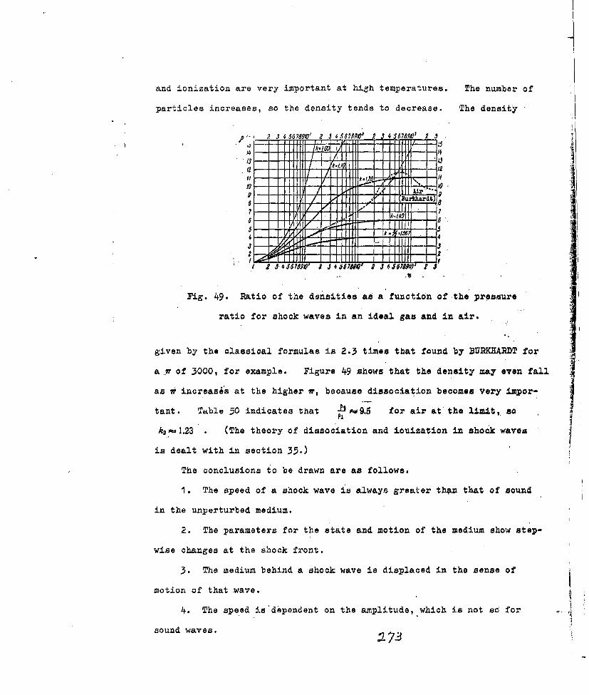
and ionization are very important at high temperatures. The number of
particles increases, so the density tends to decrease. The density
,2 3 56 8 ' 2 3 S 70 e 3 56 78,M' 2 JI II V II . I 1
T -I
2--* L L
2-
I2 J,*4 66 8 9*P 2 8 0
.4 7
Fig. 49. Ratio of the densities as a function of the pressure
ratio for shock waves in an ideal gas and in air.
given by the classical formulas is 2.3 times that found by BURKHARDT for
a .tr of 3000, for example. Figure 49 shows that the density may even fall
as ii inoreases at the higher i, because dissociation becomes very impor-
tant. Table 50 indicates tkhat -fr9.5 for air at the limit, sO
ka, 1.23' . (The theory of dissociation and ionization in shook waves
is dealt with in section 35.)
The conclusions to be drawn are as follows.
'1. The Bpeed of a shock wave is always greater thin that of sound
in the unperturbed medium.
2. The parameters for the state and motion of the medium show step-
wise changes at the shook front.
3. The medium behind a shock wave is displaced in the sense of
motion of that wave.
4. The speed is dependent on the amplitude, which is not so for ..
sound waves. :7

5. The entropy increases (dS 2>0) when a shock wave is formed.
6. A shock wave propagates as a single step in de 9ity; it is not
oscillatory.
So far we have considered a shock wave as representing discontin-
uities in pressure, density, and temperature (Fig. 50); we have con-
sidored the parameters on either side of the front, but we have not
08 IA
• - 4 1 Iii. g" ." ressure in an xaea 11"Ig. ). ressure in a real
shock wave. shock wave.
examined the structure of the front itself. The viscosity and thermalF
conductivity prevent the gradients from being indefinitely large" the
front itself takes somewhat the form shown in Fig. 51, and there is a
verynarrow transition zone between the planes A and B. This zone con-
tains only a very small amount of matter, and its thickness remains
'constant, so we were justified in neglecting the processes in this one
in the above treatment. The shock adiabatic uniquely defines the final
state behind the front, but it tells us nothing about the changes in the
frontal zone. These changes cannot be considered unless we introduce
the viscosity and thermal conductivity, which have no effect on the
relation of the final state io the initial state. For example, the
equation
DP2-P1
was derived from the laws of conservation for mass and momentum; it is

correct except when vi6cosity effects are present (as at the front), for
these alter the equation of conservation for the momentum.
A study of the differential equations as corrected for the viscosity
and thermal conductivity reveals that the width d of the front is of the
order of the mean free path for the initial state. ZEL'DOVICH has
shown from the kinetic theory of gases that
in which I is the mean free path; TAYLOR has assumed that the ratio of
the kinematic viscosity to the thermal diffusivity is one, in which
case d for air isd=4xlO ,,
(AP in atm). These expressions show that d is of the order of 4' for
strong shook waves (Ap > pl)
Finally, equations based on the assumption of continuity describe
the behavior correctly only if the parameters change relativelylittle
withiA-a mean free path. This means that the results they give rep-
resent only a first approximation. A more detailed examination
involves a study of the behavior of the various internal degrees of
freedom of the gas.
The specific heat for very rapid changes (as in shock waves) may
be appreciably less than that for slow changes. A gas molecule carries
energy of rotation, vibration, and forward motion; all those increase
with the temperature, and additional degrees of freedom associated with
excited electronic states become significant at high temperatures.
The various degrees of freedom do not take up energy equally readily;
the forward motion and rotation do so almost instantaneously, but. the
vibrations respond relatively slowly. For example, the time needed'to
reach vibrational equilibrium is about .160 sec for 'C. One result of
-:2. 7

this is that the velocity of sound increases with frequency; this is
equivalent to a reduction in the specific heat, which itself implies.an
increase in A, because cl- kp . The slow response of the internal
p degrees of freedom affects the structure of
the front, because the compression is very
I rapid. Dissociation is also a process that
Fig. 52.... Structure of takes an appreciabli time. Zel'.dovich
a strong shock wave in states that a strong shook wave starts with
a gas showing slow res- a discontinuity, which has a width of the
ponse in its degrees of order of the mean free path and which shows-
freedom. no appreciable excitation of the. internal
degrees of freedom. Following this there is
a fairly gradual rise over a length of the order of Di (in which % is
the excitation time); Fig. 52 shows the structure. A detailed quanti-
tative study confirms this; the front consists of two parts, one having
very large gradients over a distance of a few times the mean free path,
and the other (a few win wide) having comparatively small gradients.
T8pler photographs confirm these theoretical deductions.
32. Oblique Shock Wave
This type may arise when a flow whose speed is constant strikes an
inclined plane (Fig. 53). At the junction ,k of the two planes there
'
Fig. 53. Formation of an oblique Fig. 5h. Supersonic flow
plane shock wave; S is the front. around a wedge; two shock
waves.
c27/~'

arises an oblique shock wave; the flow is turned abruptly through the
angle 0 bet,-een the planes, whereupon it continues with a fixed speed
This occurs if 0 is less than some lirait. Again, a flow around a
wedge (Fig. 54) produces two shock waves; this type may be derived by
combining two flows, one for each
side of the wedge. Let us con-
sider first a plane oblique shook
2, wave, in which the inciden't flow
makes an angle with the front
(Fig. 55). Let q1t and iq2 be the
Fig. 55. Rotation of the flow speeds of the flow on the two
after passage through an sides, and let a, and ul. be the
oblique shock front. projections of those speeds on an
1) Front; 2) flow axis parallel to the front. The
direction. equations for the laws of con-
servation then become
2UP , + Flu P2+ ag"VV
Here (30,8) and (30,9) imply that vl=v2 and w 1 = w=O (two-dimensional
case). The direction of the flow is altered, because vo vg. but
,u2<Uk, as (32,1) shows directly:
U P <:Let o be the angle between the front and the flow direction behind
the front (Fig. 55); then
U1 q, sin p, vr1= qcos y, (32,2)u-- -7-sin w: , ,= T>COs w,
in which q is the resultant of u, and v,,, and is the same for u 2. and
z' From (32,2) we have that
-77

but v=v 2 so
V2 = p, tano)ltan (32,3)
which means that co<q, The ang:le turned through by the flow is
0=9-co ,so (32,3) may be put asP1el (32,4)
whereupon (32,1)-(32,3) give us that.
P~-PP~U~(1 -P,9, sin'~ i-) (32,5)
The energy equation for a polytropic medium gives us that
L . (k + 1) P.+(0-)Pt (32,6)
Then the .L of (32,5) gives us that
We may find a relation between.j- and "-, by combining (32,), (32,5),
and (32,7), which give us that
= + sin: T. (32,8).+I
and this may be transformed to
This gives us .- f () , so p'. and um ray be found. That is, we have a
complete solution for the parameters of the flow behind the fiont if pt,
p,, a,-, and are given.
I A necessary condition for a shock
wave to arise as in Fig. 53 is ui > el t
that is, the normal component of the
speed must be supersonic, not merelyFig. 56. Shook wave de-
# the speed itself. Then q,> c, in
tached from vertex of cone. every case, because v,>O It can be
1) Front. shown that there is a limit Ot such
that for "O>QO the shock wave becomes
7 '

detached (Fig. 56); the shock wave becomes straight on the axis of
symmetry. Further (purely adiabatic) compression occurs in the region
00'; the pressure at 0' is given by
12 C P= --12 , P= (32, 1)
"which !and p" are the enthalpy and pressure at 0'. Now
so we have that
P2~+) (32,11)
The u2., p., and p2 appearing here are given by the formulas for straight
fronts (vua.O) - (32,1) and (32,6) give us that
P' 2' P A ) + - -) P,(3 2112)
P24 U, (k - 1,P + (,- +1)p, ( 1- ) p,-" - 2 ,-, (• , 2
Pa- ' (k+1)pa+(k1)Pij 2p1u1- (k-i);1and so
PI [0 -+1) 24,, (32,13)
P S ___2 k ____,
If uj =MCI,,-p2 =pj and
A; 1 k- 1)-'_+I + 2
If U!:>>Cj.
R9-( +i1 (k -p 2 + 1+ ~ (k- I P (32,14)
At the limit, when h,'I, in the first case; in thePa PiPg,
second, -== .. That is, the pressure increases only slightly withinPa
the adiabatic zone if the shock wave is sufficiently strong. The angle
.G is given by (32,9), which we put in the form
t +- 1 - (A + 1) qla sing Y
Then, because. j
,(32,15)
7qY

we have that
V 2M (Mt, (32,16)
For simplicity, we put cot 0 q, and tan (py , with k 7/5 , which
gives us that.yl @,+ 5) & y2- ( 1-) + (6,8 4.-5) y + 5,a 07o'
(32,17)
This shows that y2.': i/( P-I ) for any k when 0.0, so
sin -° q,
which is so for sound waves. This y is always positive, because the
physically significant range in 9 is
o<<:.
Equatio n (32",16) becomes, ,when P>> 1_
It-- 1 -(32,18)and so
(k-(' -1(32,19)
The solution is physically meaningful if . ' 4'-1 , so
Y P (32,20)The relation of to y for a given angle .0=1 is
-I h+3 (32,21)
in which ,. 'i Figure 5? shows ! f(j)- for a>o, in which
j I This shows that there are two
.LI , .. f v e ,.-erv A >R.
______the actual process usually
. . corresponds to the smaller
* I value of y (the weaker shock
-I ,wave); the third value of Y
for .o, is negative and
Fig. 57. The relation pf()f
has no physical significance.

The limit 0 defines the smallest - that can occur for a
o\, ) oC!
given 0,. The two positive roots of (32,16) coincide when =?o
The flow conditions alter when 0>0o.and o>o; the shock wave
becomes detached. We can find 0o-/(Po ) from (32,21) and, by equating
the derivative to zero, we can find the condition for minimal P:
0 [4 ~. F~+l01L o WOj,1 A Q=0
The results for oblique shock waves are best presented by means of
graphs based on shock polars, which relate the parameters of the medium
behind ~he front to q1 and cl.. Here we need the components of q, and
C, along the x and y axes, the x axis being the direction of the inci-
dent flow. Figure 55 shows thatr, ---qj, u, -O, u2=-usiny -vcosT,}
U2y - V2 Sin - U C .• (32,23)
We eliminate 9, v2 , and v, from these equations to get the equation for
the shook polar as
U2M qU2),+ (q, (224i4 (qq -- au) -;F-2 )
This is shown-in graph form in Fig. 58. This polar enables us to con-
struct the oblique front (the
line OB) as follows. The direo-
A tion of .qj. is given by tan :0-
--. (Fig. 58 corresponds
.u. ql, j; from O we draw a
Fig. 58. The shook polar in straight line at an angle 8 to
the u-,2 'u,2 plane. the horizontal axis to meet the
curve at A and B. This result
means that two modes of flow are, in principle, possible for the givenf0,
c., and q., as we have seen previously. The usual mode is that corres-
ponding to B; vector OB defines q2. The line of the front, which lies

at an angle 9 to qr, (i.e., to 0Bo), is normal to the line Joining B'O to
B, because the 'rector ( q?2 -ql is normal to the front. It is also
clear that 0 <9 (this has also been demonstrated above). Now A cannot
exceed the limit Do for a given ol an'd 'qi this limit corresponds to
the tangent OT. Now eo, increases with ,JLand tends to the limit
si1o=: (32,25)
when A --. o A normal front (straight shook wave) corresponds to
the 1pcint where the polar cuts the U2U axis; then
This polar gives us directly only relations between the velocities;
the pressure behind the front is given by (32,7) and (32,8), and the.
density by (32,6).
33. Acoustic Theory of Shock Waves
If -Lp~ (weak shock wave), there is very little change in ant-P
ropy, so we may consider the wave as being almost P'. simple compression
wave havirng a discontiruity at its front (the entropy is then constant).
Let the wave transfer the gas from the state ( pL, vj, ul ) to the state
P2, V2, U2 )~it is readily shown that the quantities for the final
state after a weak shock wave differ from those for a simple wave only as.
regards terms of' order higher than the second. -To this end we put the
equations for shock waves in the form,
pa -pt i (42 u) ( - l),(33,1)
-v. ,rv Pt+P A -- __ 1)
and so, for (U2 -~u)< ,wehv
02 - Ck- I (U2 -_U1 )
k+ I (3.3,2)
Further, we expand 'D D-ul in powers of 'U2 - U1 . to get

Substitution for ( u2 - u, ) from the previous 'expansion gives us that
D' = tu --7 el + V (U2 + 02 .-_.. (33,4)
That is, the speed of the shock wave is, to a first approximation,
simply the mean of the speeds for small perturbations on the two sides:
D =1 ("1 + + +.-lCO). (33,5)
If the initial state ( ul, c, ) for a simple wave is a steady flow, we
have that2
(33,6)
Then (33, 2), with A- - (.eL k.Sa(.., -. ( gives us that
2k .
A c= , + 3 -)u).
UaC iC1+- (UUi)
We expand( P2-PI ) in terms of ( u2 -u ) to get that
,Pa Pii(u ) + L-ii ps(Ua-" u)2 . . (33,8)
and so, if -e1 , the para~meters of the two waves are the same upPI
to quantities of the second order. This means that our future cal-
culations for weak shock waves may be based on the approximate formulas
Ap =Pic, (2 - UO) ( 33,9 )
A~ -P1 (U2- ui.CII
The error resulting from the use of these formulas is very small
even when -p is somewhat greater than one; for example, if 'k-1,4'
and. -L-1.5 , the exact formulas give us that
OLj
-- = 1,51
while the approximate ones give us that
Su 0.70; c - 0,14;01 0 i
Do- = 1. ,

This enables u's to use the acoustic approximation for waves of ,.P
somewhat greater than one in certain theoretical treatments (in partic-
ular, for the reflection of a detonation wave from a wall; see section
58).
34. Energy Dissipation in-Shock Waves
The motion is isentropic if the state of the medium changes slowly
during an adiabatic process. The thermodynamic criterion here is that
p. the rate of approach to equilibrium
should be substantially in excess of
the rate of any external perturbation.
The rate of approach to equilibrium is
correlated with the speed of elastic
vibrations in the medium; compressionFig. 59. Shock adiabatic
by a piston or a blow on a surface isand isentropic line.
isentropic if the speed of the piston
or striker is less than the speed of
sound, for example.
The entropy is increased by the passage of a shock wave; physic-
ally, this means that the organized energy of the flow is in part con-
verted to unorganized thermal energy. The kinetic energy decreases,
and the internal energy increases, as we see from
12- 1= U_ (2 Vo. ) (34,1)
E, --Eo = (p, po) (vo - v), (34,2)
in which subscripts 0 and 2 denote the states before and at the front.
The irreversible loss of energy is defined by
*Ea-E=+ (P2 +PO)O-V2)-jf vdp. (34,3)V.
whereas the energy in state 2. after an isentropic copression is
V.E>Eo~fpdv
i@0

The expanoion from state 2 to state I is isentropic (Fig. 59), so
E-Ei f dp. (34,5)
Then (34,3)-(34,5) give usthe irreversible loss'as
I=EL-- o.---- (Vo- V2) -f- adp. (34,6)
This energy goes to produce the incroased teaperature found when the
expansion is complete, so (34,6) gives us that temperature. For
example, for an ideal gas we have that
and so
p dp r--d J'VL
which implies that for P,-=Po (which means that viOvo ) we have that
AE~cAT P2±O(~..~~) DV~- 0 V1 (34,7)
in which vi is given byp. f0 --,
PO
The temperature after the passage of the shock wave is then given
by (34,7).
35. Shock .ayes in Air: Allowance for Dissociation
and Ionization
A'strong shock wave produces a pronounced temperature rise; the
number of particles tends to increase, on account of dissociation and
ionization. The change in the number of particles alters the forms
taken by the equation of state and by the shock adiabatic; the effects
are reflected to varying extents in all parameters. These factors are
exceptionally important in a nuclear explosion; the shock wave produces
partial dissociation and ionization out to great distances from the
center. Radiation plays an importantpart in energy transfer also, at
least for rather shorter distances. The law of mass action applies to
ionization and dissociation; the equilibrium constants for these

processes enable us to determine the composition and hence the number
of particles. Devel, *_ents in spectroscopy and theoretical physics
have provide! us.with feans of computing thermodynamic functions with
an accuracy far exceedint that of methods normally used in chemical
thermodynamics. These calculations can be extended to the very high-
est temperatures for a variety of reactions; they are bosed on quantum
statistics, and can be applied with 'advantage to ahock waves.
Statistical method for thermodynamic functions. The total energy
of a gas molecule-ic made up of the energy of forward motion Ef, the
energy of rotation Er, the energy of vibration R., and the energy of
electronic excitation E . Consider one mole of the substande, which
contains N particles, of which N0 , NI, N2.. .... are respectively in the
energy states E0, El, Ea. ....... ; then the Boltzmann.distribution imp-
lies that
N A
in whichg is the statistical weight of the i-th state (the number of
differing quantum states having the energy ej) and z is the sum over
states:
z g~e"' . (35, 2)
The summation is performed for all possible states from 1;..0, (the
lowest level) to "i-oo; this z. is an important parameter that appears
in all later calculations.
This sum is calculated on the assumptions a) that the molecule
behaves as a rigid rotor (that interaction between rotation and vib-
ration is negligible); b) that 4uantization of the rotational ene .gy
can be neglected, because many vibrational states are already excLted
at room temperature; and c) that the vibrations are harmonic. Then
the energy may be represented as the sum of the energies corresponding
to the various degrees of freedom, while the statistical sum becomes the

product of the corresponding factora:
Lf +Er +Ev + Ee, (35,3)
Zr Z., . C. (35,4)
The degrees of freedom for the forward 4otion are three, so
f V (3515
while for diatomic and linear polyatomio molecules
Er =kT (35,6)
Er U-k7 for nonlinear molecules).
The statistical sum for an atom consists of two factors (one for
the forward motion, one for the electronic energy). Statistical mech-
-anics gives us for tha forward motion that
in which m is the mass of the particle, whose momentum is p, h is
Planck's constant, and V is the volume of the system. Th sum for the
electronic .jtates is
Ze gg e(35.8)
in which v,, is frequency;
o g - =g "'lg e - -- =e i . (35,9)
The absolute E. are unknown; all that can be meamured are the differ-
ences A E, - 0 , which are found direct from spactro-scopic measure-
ments. For the purpose of oalculating 'z- we take HE as 0, which is
equivalent to reckoning the energy frora that level; then z.' is
replaced by
4~ ~~e kg0~ge kTg~e(35,10)
Comparison of (35,9) with (35,10) shows that
It is usual to find that even A i is very large, in'which case
9g7

exp( -' ) becomes appreciable only at very hiah temperatures; then
the second and subsequent terz in (35,10) can be neglected, so
z, g - .2 +1, (35,12)
in which J is the internal quantum number of the ground state.
We consider a system consisting of particles of one kind only, so
the choice of zero state is unimportant; so does not appear in the
calculations. Several typos of particles may be present in a chemical
reaction, and each has its own e#., in which c.se the energies must be
referred to a zero common to all particles. Here iz muat appear in
the statistical sum, not z. . Then the total sum over states for an
atom is
ZA 2 4e T~z~ M?*(35,13)
We do ncknow t0 for the various molecules, but As0 is'rea4 ily'
found for reacting molecules; the sum of these differences is the heat
yield of the reaction at absolute zero per particle. For one mole,
AsoN=AE 0 = -Qo (35,4)
so (35,13) becomes
'Z= e - 20 (35,15)
Statistical sum for a diaton.c iholocule. Here (35,?) gives z1 ,-m
being the mass of the molecule; the internal degrees of freedom intro-
duce their own factors, that for the rotation boinLg
Z' "-=.h"r- (35,16)
in which I is the moment ox inertia about an axis normal to the line
joining the nuclei and S is the symmetry number) on the assumption that
many rotational states are excited at room temperature. The number of
degrees of rotational freedom is two for a diatomic or linear polyatomic
molecule; the total number of degrees of freedom for a molecule con-
sisting of n atoms is 3., so a linear molecule has 3n-6. vibrational

degrees of freedom, while a nonlinear one has 3n-6. The zv of (35,2)
requires the quantum-mechanical exprer 'on for the energy of a harmonic
oscillator
V. (35,17) 1
in which n is the'vibrational quantum number (D toco), wis the proper
frequency of the oscillations, and /zs/R. is the zero-point energy. This
last is commonly included in the total zero-point energy to, which is,
in effect, a change in the level from which the energy is reckoned. Then
The g,, for a solid is one for solids, diatomic molecules, and most poly-
atomic molecules, so (35,1?a) gives us that
,- I e- k - --
RI-0
The so, is as for an atom, so the"over-all statistical sum is
t Z,, ZV. Z e- .-- (35,19)
T)hermodynamic functions. One gram-molecule of gas oontains N
particles; then the number in any given energy state is
AlN, ge . (35,20)The internal energy at temperature T is
andI, Ij It
z -- goge 'If gae-kTI =+ . ge'1. (35,22)
Butdg -
91 ege g
- 2 An *n d-r* (35,23)
From (35,21) and (35,23) we have thatdz hiT: D2 d InZ
'E=-N.T2. RT-.:-, (35,24)naTh
in which z. is the over-all statistical sum. That is, once .z is known
we can use (35,24) to find the total internal energy as a function of
temperature, and hence the thermal capacity. Thermodynamicb gives us
that
"447
- ' -(35,26)
in which F is the free energy; (35,24) and (35,26) give us that
Rdlnz (35,27)and so
F-RTInz. (35,28)This gives us a thermodynamic interpretation of the statistical s-am.
Equilibrium constant. The composition must be known before the
energy, density, and so on can be calculated. The composition is gov-
erned by the equilibrium constants for dissociation and ionization; the
values of these constants for very high temperatures may be expressed in
terms of statistical sums to a very high order of accuracy. Ther=-
dynamics gives as the free energy as
F=F-RTInv. (35,29)
so (35,28) gives us that
FO=--RTIn.." (35,30)
All energies must be reckoned from absolute zero when ,z is calculated
(they must include the chemical energy the substance possesses when it
is cooled to absolute zero.). This means that .Z and F do not have fixed
values; we can assign numerical values to them by specifying an indivi-
dual zero of energy, which may be taken as the energy of the substance
at absolute zero. Then (35,30) gives us that
FO .- RTIn..g + E
or
F O - R T In-Z. (35,31)
The equilibrium constants are now readily found in terms of statistical
.9-

sums, for
A - RT In K,
in which K0 is the equilibrium constant in terms of the concentrations
of the reactants. This may be put in the form
In l <.Z (35,32)
The ( P--E.) of (35,31) gives us tnat
in K, = AIne + Q+3n 35,)T'
in which AESog=Q Ou is the heat of reaction at absolute zero. Trans-
ferring from concentrations to partial pressures, we have
in which nj is the namber of moles of a given species in the equilibrium
mixture; then
In vAEr +_P
That is, K can be expressed in terms of - and z for any
species in the reaction, the rule being the same as for the expression
in terms of the concentrations or partial pressures in the law of mass
action. In the general case of a reaction
VL +VL+,... VM+ + .+ + Q. iInK- In AI V ZIV,...t QV
/I--IR, LI ' Zt 11 i
or
K K~VAe RT.'a ",,. ... (35,35)
which gives us that
,,It ' - -- K - (35,36)
K . Z 1 • • '
,,I Is (35,37)
Ellurgy. There is no special diffi'culty in calculating the total
energy once we have established the statistical sums and the numbers of

the various species. Consider 'I mole of gas, which consists of
N0=6.02X10²³. particles at normal temperature. Lot N be the number
of particles for the equilibrium.state at temperature .T, where in general
N-N.+N±+N"++N., (35,38)
in which N,,is the number of undissociated molecules, N, is the number
of atoms produced by dissociation, Na. is the number of positive ions
(from atoms), and N is the number of free electrons. We neglect mole-
cular ions, 'because the ionization energy of a molecule is much higher
than the dissociation energy; almost all the molecules are dissociated
at temperatures at which ionization becomes appreciable.
Equation (35,3) gives us the total energy as the sumET=RTV( f)
.+ . . . .Bd+L) ..
;VN din'' d" MN (nza M+ d nI \. . . ,0., .+=B,)+. dTo (35,39)
+ MV; Qd + ..... .- I.
The dissociation energy Ej is calculated on the assumption that the
molecules are diatomic and of one kind; the composition becomes more
troublesome to calculate if the gas consists of more than one compound
(as for air). Again, the above formulas become much simpler if the gas
consists of atoms and ions only.
These results are applied to shock waves by means of the equation
E, - Eo y (, + poj (v, - v) = Poo ( + PO V -.-
The equation of state for the unperturbed gas, per mole,'is
po"Vo0 I R. / (35,40)
while that for the gas behind the front is
piy, A r T , (35,41)
in which k. is Boltzmannts constant. The ±1- of (35,40) and (35,41)VC
gives us thatEl -O po (I +' I Tp
Here E0 if the unperturbed gas consists of diatomic molecules
at normal temperatures; in general, the gas may consist of any particles
and may be heated to a high temperature, in which case the initial

energy is
(34,43)
This E,, with (35,42), gives us that
2 P T P,) - E • (35,44)
This equation may be used to compile curves of El as a function of
T for various Ai~c-- ; the point where the curve of (35,44) for a given
PA meets the curve of (35,39) defines uniquely the temperature T'
behind the front. This .T' is inserted into (35,41) to get par, which
enables us to find u.,D , and c for the wave.
Some results on the composition of air at high temperatures are
given below; Table 50 gives results for shook waves in air, with allow-
ance for ionization and dissociation.
Composition of air at high temperatures. The mixture consists of
molecules, atoms, and ions of oxygen and nitrogen, and aiso free elect-
rons; compounds such as NO, N20., and NO 2 may be present. I shall con-
sider only NO, because this has the largest energy of dissociation.
One mole of air at room temperature consists of 6, ( 602x1023 )
molecules; let there be N1 molecules of oxygen and N of nitrogen, withN1 L-21.2N 21.2 ' = 0.269.
Let A be number of neutral atoms divided by No, At being the same
for positive ions, for electrons, and MAfor other species. Sub-
script I applies to oxygen, subscript 2 to nitrogen, and subscript 12
to nitric oxide. The equations for the equilibria are
1. Dissociation
1. , -. C,. M,, . (35,45a)
2'. Ionization
• 4 , - (3.5,4b)
'2q3

The initial number of molecules is known, so
Mi; + -+4(A,+ At +MAll 2),
+ t+ 1 2 ,O=Aj'I-j+ (35,4.50)
These eight equations define the eight unknowns. The equilibrium con-
stants' c1 (2 .L ) .p (-~)are readily found; we put z~. as33 5
(2KkmiI) 2 v (2ft~lmJ)' vNJV,' (PO (35,46)I-IN T0Jz'N0 p P
whereupon the cl- become .
WG.C= 5M. +s 5 -ist Tu - ~ +W2oz.c 2 M (&
+24,.A + "(2
we C2+-TW. 1-WST AZ.. .+(5, )
I- CS + A I,- .-- .. ,
04 ' ~=6 PO)'N (3,47)It is assuE C +n .1 Tha th masTo o'fthe io, + stesmsa
of ~ ~ ~ ~ ~ ~ 1 thPaetaoa1 a stems fa lctoo stevlm
2ft~ I-O

(35,45a) give us that
ed C,
We eliminate the number of molecules from the two penultimate
equations to get that
+~ A1 +A 1 +AA-2 fA-; A 2 AA-~~~-+4 ++~C~ - s + C6 +*
Substitution for A2 gives us Ai, which is
r
generl0ybm+ SL 7a,~ c
It is gnrlypermissible to neglect the effect of the NO on A,; then
II IIorn
for jil is; the for ~2P0 P0ratio of the number of part-
icles to the number at OO'-

all factors containing ca may be omitted. The A, for high temperatures
(complete dissociation) is
A,
a 1
This gives Al as a function of.0', whereupon all other quantities, and
hence N also, can be calculated as functions of 0, with T .88 parameter.
We calculate O as a function of temperature for a given N, to get the
numbers of all other species.
Figures 60 and .61 gives results from these rather tedious calcula-
tions for the composition of air for .14 of I and 20 for the tempera-
E-0 .ola2JnoIs a o4.dg
- uazo cures
7~i
AL AV
Fig 62. Internal enerey of one rig. 63. Specific therrr~al cap-
gram-molecule of air at constant acity of nitrogen at 'constant
deyisity. *vo-lume.
ture range 2000 to 30 0000K. We see that N increases fairly rapidly and

also that dissociation and ionization are appreciably dependent on the
density. The total energy per mole is
if RT1 (MA1+M2 +M 1'2 +A 1 +A 1 +20)
+ RTI (Mi + M2 + M1)+,RT'.(M, d 1nz" ,M+Ma dInz, HM,+Mj2-ArInzv,~.+,R7! (A,-f In Xe. A, A/v -- nx, __ _ nz
+A n z,, + At d I'V., A)- . (35,49)
+ A + A, + At,++A- + A'.
in which %.I and ., apply to the corresponding elementary reactions.
Figure 62 gives Burkhardt's results for air for various , Fig. 63
gives the thermal capacity derived from these results, since c,.
Bibliography
1.- Ya. B. ZFL'DOVICH. Theory of Shock Waves: an Introduction to Gas
Dynamics [in Russian). Izd. AN SSSR, 1946.
2. L. D. LANDAU and E.'1. LIVSHITS. Meohanics of Continuous Media
[in Russian]. Gostekhizdat, 1953.
3. R. COURANT and K. 0. FRIEDRICES. Supersonic Flow and Shock.Waves
[Russian translation]. IL, 1950.
4. K. P. STANYUKOVICH. Transient-State Motion of a Continuous Medium
[in Russian]. Gostekhizdat, 1955.
5. W. Y. M. RANKINE. Trans. Roy. Boo. Land., 160, 277 (1870).
6. H. HUGONIOT. Journal do l'cole polytechnique, 58 (1889).
7. R BECKER. Z. Phys., 8, 321-362 (1922).
8. 2. H. COLE. Underwater Explosions [Russian translation]. IL, 1950.
'Alf1

T-1488g
CHAPTER VII
THEORY OF DETONATION WAVES
36. General Features and Basi. Relationships
Explosion 'procosses vary widely i rate and type in accordance with
the initiation conditions, nature of the explosive, and so on. All
such processes may be divided into two essentially distinct groups,
namely those of burning and those of explosion proper. Burning has a
rate dependent on external factors (expecially the proaoure), worcaa
the rate of an explosion process is almost independent of such factors.
Theoretical studies show that a strict quantitative distinction can be
drawn; the rate of burning is always less than the speed of sound in
the unreacted material, whereas the rate of explosion is always greater
than that speed. The laws of thermal conduction are decisive in burn-
ing; those of shook waves, in explosions. Burning can pass over sud-
denly to explosion under certain critical conditions; detonation, the
iimiting form of explosion, occurs x. r suitable circumstances, and
here the rate is constant at the maximum rate po.sible for the given
explosive. That is, detonation is a special s; srate form of,
explosion; the detonation rate is a very importaxit ' : r.-kcteristic of
any explosive. We may say that explosion represents a transient process,
which either goes over to detonation or dies away. This transient
state is usually Yound around the site of init-,- cn. 1xplosion in the
wide sense covers the detonation (steady-state). transifnt-state forms,
which have no essential difference in mechanism of propaga tion.

The fullest study has been made on detonation processes, which are
exceptionally important for detonators and high explosives; most of the
theoretical work relates to gas mixtures, which form the simplest explo-
sion systems. This work has given rise to a rigorous-mathematical
treatment of detonation waves| the main features of that treatment are
applicable also to liquid and solid explosives. Detonation in gases
was discovered in 1881 independently by BERTHELOT and by LE CHATELIER in
the course of work on the propagation of flames in tubes. It was very
soon discovered that the rate of propagation of a detonation wave under
fixed conditions.soon becomes constantl values of 3500-4000 m/sec were
recorded for certain gas mixtures, which speeds are, very much in excess
of the speed of sound in those mixtures at ordinary temperatures and
pressuresd
The hydrodynamic theory of detonation made a major sontribution to
our understanding of detonation processes; it gave a satisfactory means
of calculating all the parameters (speed, pressure, etc.) of a detonation
wave. One of the founders of this theory was the Russian physicist
MIKHEL'SON, who put forward the basic concepts in 1889; othermajor
advances were made by CHAPMAN (1899), JOUGET (1905), and KRUSSAR (1907).'
Recent leading Russian workers in this field, who have applied the theory
to condensed explosives especiaily, are LANDAU, ZELIDOVICH, GRIB,
STANYUKOVICH, and NEYMAN. The cause of detonation is that a shook wave
propagates through the substance; if the amplitude of the wave is suf-
ficient, there arises behind the front a very violent chemical reaction,
which serves to maintain the wave parameters at a steady level. The rate
of detonation can then be calculated as the rate of propagation of a
shock wave.
The motion of an ordinary shock wave is composed of the propagation

of a pressure step and of the displacement of tho mediu- A detonation
wave is more complicated in structure, because the mot.un of the shock
u*~fl wave is associated %ith motions of the
Produoia Reaotion nt reaction zone and of the ultimate pro-ions mixture_
* ducts. The steady state mnay be con-
D- -sidered merely in terms of the initial
Fig. 64. Derivation of state and of the final productsi the
the basic relationships reaction zone need not be considered.
for a detonation wave. This zone remains fixed in a coordinatea
system tkat moves in the sense opposed
to the motion of the wave (Fig. 64). Symbols to be used are D, theI
detonation riate, which equals the speed at which the reaction zone moves;
.49the speed Of the products, behind the- front; :pl I ,, and 7r, para-motors for the state behind the reaction zone; 9~ p' and 7; j the same
for the region in front; Ej., the specifio energy in the rear zone.; E0 1
the specific energy of the initial mat'eriall andQ, the specifiocenorgy
release in the reaction.
The basic equations for soock waves apply also to detonation, ones;
P * we have that
D v I-PPa='v Vc '(36,2)
But'D.= constant here, so
[<3the latter equation gives a
*straight line in the variables
I, - .P.andU
Fi. 5.HUONOTcuvefo aThe origin A may be taken at
detonation wave. -
(pq, VO):p which lies on this

line; the line is known as the MIKHEL'SON line. HUIGONIOT's equation
becomes
(.36,4)
in which the first term on the right is the change in internal energy
resulting from the compression. Figure 6 5 shows the Hugoniot curve for
a detonation wave; it lies above the corresponding curve for a shock
wave on account of the energy acquired from the reaction.
The only significant part of the curve is CB, because here D>O
and 'u>O.1 , as (36,1) and (36,2) show; part DE:has D'>0 and ,u<,
and it corresponds to burning, whose characteristic feature is that the
products move in a sense opposed to that of the burning zone. ,.t tBD
does not correspond to any real steady process, because here (p-pe) 0
and -(.f-a <0,, which imply imaginary values for, D aMd u.
Prom'A we draw a line at an angle .a, which meets the HUGONIOT
detonation curve at two points; here we have the condition
which implies that a given D can correspond to two distinct states of
the decomposed material at the front, which ib physically absurd.
CEAPMAN and JOUGET have demonstrated in different ways that any detona-
tion corresponds to the unique state of the products specified by the
point M (the point at which the MIKHEL'SON line touches the HUGONIOT
adiabatic). Here tan a, and hence D,, are minimal; Dn-Df.t The
following is a proof that the state corresponding to M is one in which
i . equal to the speed of propagation for a perturbation in the pro-
ducts (relative to a fixed observer), i.e. that
D=a+c, (36,5)
and that dS-O, (i.e., Sam oonstant) on the HUGONIOT curve. Now
301

(36,5) implies that
D-.1f PZ PI PO
soPiP,
V-JI VI (.36,6)
The proof that 'D=u+i at MWis given from the first l~aw of thermo-
dynaicstTdSmdE+pdv.
The two sides are divided by p~v , to make all quantities dimensionless.
Let = and -j=.;then
T
-OdS==ds+vcdpi,Further, (36,4) in the same difnenaionleas terms ±s
and so.. .
We substitute for Ids in the transformed thermodynamic law, in conjunc-
tion with the substitutions 4pt-d(l-jk) 'tand d(%+I)*-d(r- ).
to get that
* __ dSu= (I - p)d(n.- 1) (wit ) d (I
The two sides are divided by (IiA) 2 to get that
PO S i*±[Ip OW (36,7)
Again, (,36,6) in terms of ff and A is
~ (36,6a)
In which
A.
But
so comparison with (36,7) gives us that
Further, ,Po' 2

so r :dS=(1--o) + (it-_d= da ,- .(36,7a)
Now S' "I'constant for a steady-state detonation, so
L o 0. (36,8)
This is possible only if dat.-. , because the factor before the differ-
ential is always positive; but ds,0O< at the point where aj'has its
minimum, which is the point where the MIKHEL'SON line touches the
HUGONIOT'adiabatic. Clearly, "'a, does not have a maximum at any point
on the branch corresponding to detonation.
Point M~is also the point at which the Hugoniot adiabatic touches
the ordinary adiabatic, which is the line of constant entropy ((dS-O)j;
ABAis a common tangent to both adiabatics, so
which is a direct consequence of our assumption that :D-4+0.'
Another important feature is as follows. Expression (36,7a) shows
that "dSCO' for points on the HUGONIOT curve on both sides of M,,beoause
!&1>0.1 and the associated factor is always positive. This means that
the entropy increases at the detonation front for any state in the pro-
ducts corresponding.to a point other than 44F
ZEL'DOVICH has given a more rigorous physical demonstration that'M-
must correspond to a steady-state detonation and that any other state
for the products gives rise to an unstable process; his demonstration
is based on a study of the conditions for the reaction at the front.
37. Effects of Reaction Kinetics on the Formation
and Behavior of a Detonation Wave
The reactions in a detonation wave are not instantaneous; the
reaction time is governed byL ,the mean number of collisions needed to
perform one act of reaction. Since J!,'000, the width of the front
3e3

in a detonation wave is very much greater than that in a shock wave;
the gradients are much smaller, so effects from viscosity and thermal
conduction are negligible. The role of heat conduction in transmitting
the detonation is small, because the temperature gradients are low. - The
material is compressed so rapidly that its composition does not have
time to change; the compression -Initiates the reaction, which produces
heat; this results in subsequent expansion of the hot products. The
pressure at the front is affected, by this.
The speed of the detonation wave is not dependent on:Q. being given
by (36,2)i which is a consequence of the equations for the conservation
of matter- and momentum. The viscous forces are negligible for the tran-
sition zone of a detonation wave (but not of a shock wave), so (36,2) is
directly applicable to any state in which only part of the total Q has
-been released (or none at all, i.e. to the initial state). The process
cannot be steady unless the parts of the reaction zone move at the same
speed; any other situation would cause the detonation wave to become
'" deformed',as it moves, so the process
would not be steady. The condition ;D.=
C ''constant can occur only if all the para-
I \ meters of. the state vary in accordance
L with the MIKHEL'SON line'
Formation of Figure 66 illustrates the formation of
a steady detonation such a wave. The explosive is com-
waves pressed by a shock wave, whose speed is
,, to the state Q in which the reaction
starts; the material is gradually converted to final products, and the
transition from state .Cto the final state:'prooeeds along the line 4d

I(the expansion consequent upon the heating keeps the'speed constant).
The speed is constant, but p. and v are variable; statei lies on the
HUGONIOT adiabatic for the products, being the special point at which
dS.O' and .Do= .+c, '(the point for the steady state). Figure-67
illustrates the behavior of thG pressure
and density behind the front; here
pointM corresponds to point. Won the
HUGONIOT curve.
Consider now a detonation initiatedby a shock wave having a speed D, > D:
and which compresses the material to
S"state C1 ; the above argument shows
that the reaction must then take the
Fig. 67. Distribution ofCourse oorreasponding to the line AC,
a) pressure and b) densityand the final state corresponds toin a detonationwave.point Bof Fig, 66. This detonation
wave cannot be stable, for a wave of rarefaction occurs in the products, jand the head of this wave moves with the speed of sound for the products,
namely 'U + C. This wave will not arise, and the products will not
expand, only if we bring up behind the detonation wave a piston moving
with a speed.u (the speed of the products behind the front), which is
impossible.
We have seen above that S increases to both sides of point A-4on the
HUGONIOT curve. Now I shall show that u-cu>q for the upper part of
the curve (for v<'," and p p>), the converse being true for the lower
part (for .-h'c and p<p?-). All parameters corresponding to point M.
are here denoted by subscript 1.

The first inequality is put as
which implies that
dv -V(37,1)
We-put HUGONXOT's equation in the form
which gives the increment
dE (v - v)dp__(p + o___ (371,2)
in which
* dE TdS-p dJ
so simple manipulations give us that
VO-V =V 7V(37,3)
Now dS> 0 and i'dv< 0 s < 0; then
i2e. dS
dp p-Pa
which demonstrates that '-->..
Again, for the lower branch
d 4
dv>0,0V->0
Now I turn to the, stability or otherwise of the state represented
by 9,; here u+,o>'D , so the head of thi, rarefaction wave catches up
with the detonation wave; the pressure at the front falls. The state
at the front can be altered only by moving along the HUGONIOT curve for
the products, because the reaction is already completed; the motion
along this curve will continue until the pressure fal~ls to p'(that for
point.M), at which point ~Dwhich corresponds to stability.
An initial state with *D>Di (point.B)-can arise when an explosive
is ignited by a detonator havi-ig a higher A; the normal speed D, is

attained only at a certain distance from the detonator, and so there is
an initial transient zone. The above discussion is strictly correct
only if the detonator and charge are identical in density and compressi-
bility, because the speed of a shook wave changes discontinuously at
the interface between two media that differ in either of these parameters
(see chapter IX). The line of equal speeds, AC,, meets the HUGONIOT
adiabatic at a pointL on the lower branch, but this point is inaccessible
for physical reasons. The parameters of a wave of speed D could corres-
pond to L only if the material were first compressed to state C, by a
shook wave; then the state of the products immediately after the
reaction would correspond toff, but the further transition to.D along
,.AC41 is not possible, because this would require energy in-excess of Q
(ZEL'DOVICH first directed attention to this point.) Further, should L,
be reached for a given.Diby any means, the detonation wave would then be
unstable, because ,U+ D-i at this point. This means that an elastic
wave in the products will always lag behind the detonation wave, which
makes it impossible for energy released behind the front to be trans-
mitted to the front; the detonation wave then soon becomes an ordinary A
shock wave in an inert medium (one that dies away).
The mechanisms of the reactions initiated by the compression are
such as to indicate that a stable state of detonation can exist only for
the single state of the products that corresponds to point M, Thermo-
dynamic arguments lead to the same conclusion; s must increase as heat
is released in the reaction and becomes maximal on the MIKHEL'SON line
at point M; which defines the parameters at. he front for the- instant
when the reaction has gone to completion.
This statement is demonstrated as follows. The thermodynamic

jrelation
T dS - dE + p dv
may be modified by inserting the.dE found from (36,4):
2TdS- (o - v)dp + (p --p)dv. (37,4)
The expression for the MIKHEL'SON line gives us thattJ.J
(V. ) V) (P po),and so•
dS
Now 0 at the point of maximum S.on that line, so
PI
(P -Po) D2 dp o.
whence DI P dp
,0 VO - VI V
which corresponds to the point Mat which AC'touches the Hugoniot adia-
batic; this demonstrates the above statement, because
ap~p (vO - v) + (P - PO)
--"=( - v,)'= == dv v0- - <0
when
P , Pd a j , .
38. Calculation of Detonation-Wave Parameters for Gas
Mixtures
A detonation is described by p," , and .D, which are
given by
'EI --,go + "-- (VO --'vJ + Q', (38,1)P ( POD-- V V ') - VI(38,2)
=(Vo -- , ) _;,- P__o (3 8,3 )
p,-po / dp kI_
--V1 - d - -i. ' (38,4)

p=f(S, T). (38,5)
The last is the equation of state, whose form is dependent on the nature
of.the explosive material (gas, solid, or liquid). WO may use pvk=
constant for gas mixtures, whereupon RUGONIOT'a equation becomes
*ll POV'O P'+PO2P (e- V) + (38,6)
in which 'ko' (for the initial mixture) usually differa somewhat from k.
(for the products). We elimtinate p, q.nd v", and put k-k , to get a
relation for D 3 , &ives as that
0. p~ . , +l POVI Po A AI, (38,7)
This, with (38,2), gives us that
We eliminate'v, from the energy equation to get thatT,'(' . -2 , - -)~cT I)j.OD'-FA(k I'r- 2('-i)0c,T, -2(k' - ).QW =0,
and so
in which c' is the speed of sound in the initial mixture; if D I is
known, p-.! and Vj: are then readily found, for
PoD _
C'= '(
<'--% = ,--- "\ .-- , I t.(38, I0) ;
The equation of state for ideal gases gives us that
T1 PitI~ k1P 2 + cs)'* V . _L, . (38,11)
These expressions show that all the parameters of interest are dependent
on 7r' (but not explicitly), because 'k is dependent on the temperature at
the detonation front. This-feature makes the final solutions rather
cumbrous.

However, the expressions (and the calculations) beco - much sinpler
if we calculate k on the basis of the reaction te-iperature T and neglect
Po relative to p, Rusults for typic ccL z - P0
has very little effect on the result iZ , :xceeds 10 atma, whiich, Is
always so for detonations in .the usual gas mixtures; then (38,7) becomes
t-7 = k-=T (38,12)
and the energy equation gives us that
--2(k-)pQ. (38,13)
which, inserted in (38,2) with po. neglected, gives us that
D = Y (A' Q.'. (38,1,4)
The equation of state gives us that
. , =P, V, _ ,P , ,
We substitute for p, and from (38,13) and (38,12) to get that
T, =rT ,, ,)
We use (38,10) and (38,14) by neglecting co as being small relative
to Di, which gives us that
Q Q* (38,16)
The'Q appearing here must be referred to unit mass of the products; iD
2and u,'are usually expressed in m/sec and p. in kg/cm , so Q must be
expressed in mechanical units. Then Q,. 427gQ m2/sac2 (in which g is
the acceleration due to gravity and Q is the heat of reaction in
kcl/kg). But
and (38,15) gives us T , so (38,14) may be put as
(38,17)
or, since
xO.848 x9.81.
(in which M'is the mean molecular weight of the products), we have

that/ T.- L' (8,.8)
Then 17) Sh ., 3 . ,' ! '::C ee.d3 th speeO d Of: , z;:: :, o
'preased Products by a faQ,;C: - i.,: .o..
molecules per unit nas;5 of the products, other things being equal. The
factor cannot exceed two for gas mixtures.
(31,15) and (38,10) enable us to calculate the ratio of pressures
for shock and detbnation waves having the same speed 0; for the shock
wave
and for the detonation one
p (Oso
P' - P,) ior p ,2pi.
Further, (31,16) and (38,10) give us that v'-2vj-v0.
These results again show that the products expand, which is the
reason for the fall in pressui-e behind the reaction zone to about half
the pressure pioduced in the initial mixture by the shock wave. Table
51 gives JOUGET's calculated results for detonation fronts in certain
Table 51
Parameters of Detonation Waves in Gas Mixtures
Mixture 7 , -K Pi.a
- 60 1.88 17.5 !Ai30 "819CH, + 20 4080 1.90 1"/.4 • 2220 257C.., +- 50s 5570 1.84 54 , .5 UJ0 )
(2H2 +- 02) -t- 502: 2G0 1.79 14.4 16V0 1700
gas mixtu-res; JOUGET used here some not very precise results for the
.3/

thermal capacities as functions "' T, but the calculated D. are in very
good agreement with the measu, . ones. LEBWIS and FRIAU, have performed
si;.ilar calculationa for c-x;.oscn ,rax"o" ' oorri..v- -i-O;'
t;ey maae allowance for the dizssociation occurring aZ T . '12. e 52
gives their results, wvich show that The aided' az afcts D. substant-
ially; nitrogen and oxygen reduce D, whereas hydrogen incre-aes it
Table 52
Detonation Speeds for Explosion Mixture Containing Othur Gases
.Axture' " "G~ale.. "s
i..+ 0 ~ 18.0 S.2 z9~,,- 05+ 0) 17.4 3200. 1,4''. -O. - 41-12 j I .97 : 7&''
C2 ;' 2+ O)- "z N= 7 3ai;7 .,-:' 24'u7
(2' '+-,)' 15 Ar 17 . 2 ' i7 150
greatly, although it reduces 7' . These observa-cions are in agreement
,.-h the theory, which shows that1D is du;dt on the r:sean molecular
weight as well as on T,. ydrogen and heliumx fall below H 0 in mole-
cular we'ight, so they increase D to a certain extent.
An example of this effect is found for szoichiometric methane-oxygen
mixtures:CH, -+-20 -I-{N 2a=CO2 + 2HO +-bN +- 191. : ,~
Here T, - 22000K Q) in which Vc,, is given by figures listed in
chapter III asc,= 86.88 cal
.C ,86. 88 + I JR 86.88 + 11 x 1.966 108.74 cal
Then
't
and (38,15) gives r. as
Ti k T-'T Tr =24400 K.
3/?-

Also 44-+ 2 K18 8X 28 7 611
so (38,18) gives us that
D =gzr83 X 2440 70oi__ M i, 1Pr
. po 1,17x 10- . &/cz3: p,. 2.10 x10- 3
.,/'2c Qk )-764 0.,o
pi -p, = puD 15.7 ka 2 .
39. Effect of the Density on the Detonation Rate
The above calculations- are based on the equation of state for an
ideal gas; this describes correctly the behavior of a gas aixture in its
initial state at atmospheric 'pressure, becauae the density is doubled (at
moat) in the detonation wave, while the prossure at the front does not
greatly exceed 10 atm. In this case, though, the initial density has no
effect on D, a:, and Tj.; experiment shows that this is so for gas mix-
tures whose initial pressures are relatively low. For. example, D for
explosion mixture inoreases only from 2821 to 2872 m/seo when the initial
pressure is raised from 760 to 1500 mm Hg. However, CLAPEYRON's
equation is not applicable to gases of high initial pressure; the initial
density starts to affectD substantially. For example, LE CHATELIER's
resul.ts show that 0 increases from 1000 to 1600 m/see for acetylene mix-
tures when the initial pressure is raised from 5 atm to 30 atm.
If we use ABEL's equation of state,
p(V-)- ) , (39,1)
in which a is the covolume, on the assumptions that M.Ls independent of
and that a m constant (as for ideal gases), then HV"),- 0. Thermo-
dynamics gives us that
"./ d3 ' + ()
.3/.3

but
C,- ) 1 (39,,!)
so
dE=C.dT+I T(o#)-pJdv.(
Now 0 for an ideal gas, so
(39,4)It is readily seen that ABEL's equation gives the same result, for its
derivative gives us that
so ( 2) Z= 0.This means that Hugoniot's equation here takes the form applicable to an
ideal gas:
Eo TO)(- "- +2(PPo)( o d
Then (38,12) becomes
-(I B h . (3•9,5) .
and
L VO.JV2h-1QF.2k1Q (39,6)
in which PO is the mass (kg) per liter; (38,15) and (38,16) remain
unchangea.
This shows that ABEL's equation, if used with' = constant, implies
that 0! increases with. although r. and uremain unchanged. This
effect of the density is actually observed, as Fig. 68 shows for explo-f L I sion mixture for a = 0.75 cm3/g;
. the experimental points fit the
. - curve well, and D increases from
0 +3000 to 44,00 m/sec when po"Sa 4/ a, 4Y-' 45, A.oad
Fig. 68. Relatioh of D to den- increases from 0.1 to 0.5 g/cm 3 .
sity for explosion mixture.- TAFFAVELLE and D'AUTRICHE,
followed by SCHMIDT, have attempted
311

to apply the above equations to condensed explosives; the principal diff-
iculty here is that a is not known for the products at the very hig'i
pressures produced by such explosives. They attempted to obviate this
difficulty by deducing a from the measured D by means of (39,5) and (39,6);
theory gives us for an ideal R~is thcat D
o 'Dp 1 /p
so for a practical explosiveD
(39,7)
whih gve usa i ,r;.isknown and 0?'A is calculated. In this way
SCHMIDT found a for various explosives; I.n particular, a for TEN
decreases from 0.79 to 0.44 liters per kg when p Inoreases.from 0.5 t~o0
1.6 kg/liter. Similar results were obtained for trotyl, picric acid,
and tetryl. Table 53 gives detonation-wave parameters SORMIDT o~lau-
lated in this way.
Table 53
Parameters of Detonation Waves in Trotyl (SCEMIDT)
1.0 f1.23 4700 OA8 O1W00 SZ.51.29 1.53 6000 0.52 67600 35301,48 1.70 600 , 0.48 84000 35.502.59 1.M 6900 0,45 96500 3W3
The results are essentially in conflict with the assumptions made in
deriving them; the formulas are applicable only if a is constant. A
condensed explosive has 0 a*s (39,5) and (39i6) are not appli-
cable.
The above method also gives the incorrect result that u is indepen-
dent of i. and. D., which is, physically speaking, absurd. All the same,
the 'D~oaloulated in this way are often in agreement with experiment; this
In not really surprising, because. the ar*e t'eund from the mneasured bfor

explosives of similar compositions.
40O. Theory of Detonation for Condensed Explosives
LANDAU and STANYUKOVICB have shown that the main features of the'
hydrodynamic theory apply to condensed explosives; they have deduced
the parameters of the detonation front from the equation of state for the
highly compressed products. The argument is as follows. The initial
density is hig her (greater than that of water), so the pressure at 'the
front becomes very high (often in excess of 10 atm), and the dernsity of
the compressed products is substantially in excess of the initial density.
These features indicate that the ideal-gas equation and VAN DER WAAS's
equation are not applicable, becauve they both neglect the forces of
reusion between particles, which forces are very important.
LANDAU andBTANYUflCVICH's general deductions are as follows (detailed
results are not giveni). A suitable general equation of state is
W +AV)(40,1)
The forces of repulsion azdtattraction between molecules are represented
resp*Otively as -~'2
The-theory 6f solids indicatie thatin >;sand that ,M>U so, V(di)'40
* when the distancesr' between mole-
cules are large; the attraction
is initially dominant as v,
decreases, so ID(v)-,O. Th
repulsion exactly balanpes the
attraction at a critical distance
Fig. 69., Relation of inter- :0;te Do .adtesse
action energy to separation is in equilibrium. Repulsion pre-
Figure 69 indicates the relation
for~~~~~ moeue.dmne6fr~ ad~~).

betwee ''r and the interaction energy U for two molecules; this and (40,2)
imply that the attraction can be neglected in relation to the highly
heated products, so the equation of state becomesp mA-"- -f(i)T,. (40,3)
in which A is a constant. BOPN's lattice theory gives P -Av-"for
the elastic component of the pressure, but this is not applicable for
the very small separations considered here; a power-law representation
of the repulsion is only a mathematically convenient approximation,
The term in (p)P' represents the ratio of the total volume to the
inherent volume of the molecules; p.RT when v is large, andineet.lueo.h mlcls gn wh, , itlre n
cD(P)-*O , so ( as 'V-+oo. The molecules become deformed at
very high pressures, so it is not possible to put f(6); in tha form
in which a is a constant. If acc. to a certain degree of
approximation, then f(v) " in which B is a slowly varying function
of v:; B.= constant for high pressures and B-*.. as v: -w .. Then the
final form for the equation of state is
p= ~ V+t (40,4)
Statistical physics gives us the free energy of a solid (or liquid)
as .F /, ,.) + RL 7, in ,
(40,5)
in which .Fj(qbj is the temperature-independent part of F,.L is the mean
number of degrees of freedom for a molecule, ke'is BOLTZMAIN's constant,
and :w. is the mean vibrational frequency of the atoms (allowance being
made for the rotational and vibrational degrees of freedom). But
so
.p,,_ F, (z)_RZ . Av-_. (40,6)
Then
3,/7

and so B
1I; can be shown that (40,6) corresponds to the isentropic equation
p =M (S) V (40,7)
in which M(S) is a function of the. entropy whose form is governed by the
conditions at the detonation front. This equation, with the conditions
for contact between the MIKHEL'SON line and the shock adiabatic, gives
us that
BIif, we Aegle~t p.o relative to p.; then Bis related to 'A by,
and (40o,7) may be put as
(40,9)
This A' is given by
% which is a consequence of (40O,7) and the basic relationships for detona-
tion waves.
Th~e Biaf (40,8) is inserted in (40,10) to give
in whichI
That is, k; may be found if a' and P' are known. The medium resembles a
solid body in its behavior when the pressure is very high, and then 0 2,
RLbecause *,R. At low pressures, =1, because Cy-j-- for an
ideal gas; .increases wit-h 'a-and P3. Of course, the state of the
highly compressed products is not-exactly that-of a solid; it approaches
more closely that of a liquid at the high temperatures involved, so
10 )>RL.', and P may be somewhat greater than ~. Values of P near 2.2
are typical of standard high explosives.
349

We may deduce a from the relation of D to A~ 'which is linear on a
log-log plot for p=S g/Orn3; -then
and ais almost constant; the range is 0.70-O.75 for most high explo-
sives at reasonably high densities, so we may reasonably use an average
value for a.
The A and' n of,(40,4) are to be found from the formula for the
temperature 7, at the front, which is deduced from the equations of
energy and imontropy as '(kH , ATDI k..........(40,12)
in which sQ, is the heat produced at the front and
if
(since 'Qm~,and also hmn ;then the limit D!, at which j.4T-2O,
is 'given by
D'L,2 Q.(40,13)
Now ki rises gradually to the limit d as increases, so (W,12) implies
A40f that T1 falls from.: 2k
in which T2 is the reaction
temperature, to the initial
temperature of the explosive
* as the density increases (the
W latter limit is unattainable
Sin practice). The reason
Fig. 70. Temperature rise at the frti ali sflos
gront in a detonation wave as a funa- The elastic forces between
tion of density. of explosive for Q,.= and within molecules become
1 kc~l/g and 41= 30. more important as the density

increases, so the energy released by the reaction is in part used up in
overcoming these forces (of repulsion); less is available for the energy
of thermal motion, and so TIi falls. Figure 70 illustrates this.
The limit to k., namely ti, is given by (40,4) and (40,7), which
become the same for -T-Q, for .M(S) = constant aM and so
p-=Av-,,= Mv "'' C-A-,)], (40,14)
whence
'('u is the limiting k' ). This gives us.D1 , and hence, by extrapolation
of the relation of ln D to In po. (see Fig. 86, section 44), we get the
limit to poi, which is given by
'P, n--
and.
n:+1P.r Po n
Then (40,14) gives us that
A - -jzg D '2 l-n (40 16
The k and #I corresponding to any given po' and Q; are calculated from
the above formulas; Table 54 gives the final results for the case
Q... I kc~l/g, which corresponds to n = 3.6 and a limiting po of •
2.25 g/cM3n; these give t = 2.2. It has also been assumed that a
increases linearly from zero at .po=0 to 1/6 at po0-2-25 then
PO
Table 54
Detonation-Wave Parameters
* ,/om5
0 0.1 0.2M 0.32 1050 0.7a LO ,0 1.2 1.70 2.25
a 0 0.01 0.16 0,23 0.45 0.70 0.76 0,76 0.76 0.76DA O.o 2180 2500 2800 2950 S300 4300 5W30 6500 8000 10000
A 1.25, 1.30 1.62 1.78 2,22 2,80 3.05 3.21 3.40 3.60m 1.25 1.29 1,35 1,38 1,42 1,50 1.75 1,0 2.10 2.40[ 1,00 1,10 1.24 1,33 1,42 1,80 1.88 1,66 1.84 2.22
,3 ' ....

The above expressions give us thatIQk+1
A"k+ I \n-n (in- I)Q
k rn-i ± O '-'1 112' 2k (40,17)
But D-.v,,p,_ ., so (40,17) gives
D2. 2 -1, (k " A p+(_n/1) \,,-,,2/1 ,.-- (M --fT- -1) 0n - +(m -:.Q 4 ,8
which defines Q in terms of Po and Q; in cgs units it becomes
= .b,(po)Pc-+b 0o) - 10'0bp '"+bQ' , (40,19)10in which A'= 1.16 x 10¹⁰ We may put (40,4) in the form
p ,= Ap" + .p7 1.16N 10.1p6,8+B pT, (40,+0)p~a d M (40,20),
in which M" is the mean molecular weight and
Table 55 gives b:, b , and a, as well as other paraseters, a3 fur.;i£ons of
•p' for Q, m I kcal/g and M -"30; the mean ;L- for the products is 6, n and
Table 55
Parameters for the Equation of State and for
the Detonation Frox%(Q. = 1 kcl/g)
0, AT.*
.1 ' i
0 2180 0 0 910 400 6,0 5000 1.0 1.12 30 1.250.1 2500 0.17 0.28 1040 487 7.0 4,,0 1,0 1.37 30 1.300,25 2800 o.o 0.2 1020 480 7, wk 1. 1.64 29 I1.0.32 2950 0.52 1.00 1060 466 8.0 4200 2.4 lA, 17.5 1.420.50 3300 0.73 1./0 1030 453 8.5 3850 3.10 2.05 15,0 1.520,76 4300 1,02 3.60 1130 435 0.0 3500 6.00 1.05 14.0 1,781.00 5350 1.50 7.00 1330 416 0.6 31.50 7.27 4J,0 10.0 2.101.25 6500 1.65 12.50 1640 381 10,0 2750 8.0 6.S 9.7 2.451.70 8000 2.20 24.80 1800 265 11,0 1750 8.1 7.8 7.7 2.932.25 10000 2.o7 49.50 2200 0 12.0 0 8,7 10.0. 7.0 3.60
-A being as above.
The properties of the products gradually approach those of an ideal
gas as the expansion proceeds; (40,9) canno be used to discuss this

transition, for it represents the behavior accuirately only for very high
pressures. Instead, we use the energy equation,
AI +A Q, (40,21)in which subsoript :L!denotes the initial state (that at the front) and
subscript hY some intermediate state,:AQ being the residual heat in that
state (the state in which the mixture becomen effeotively an ideal gas).3
Any subsequent expansion obeys the law
SPv7-=P3 v'.==const, (40,22)
in which
and
A~am~-~r.(40,23)
Now (40,9) is the isentropic equation for the first stage of expan-
(40,24)
The energy equation Is
2 rA+ 41(40,25)
Comparison of (40,21) with (40,25) gives us
which, when the pks ,- of (40,23) -z inserted, becomes
I 4Q ==AQI - h2 (4o,26)That is, we riplace.
(an equation of isentropy with '4' variable) by (40,9) and (40,22), which
are matched to efisure that the'law of conservation of energy is obeyed.
It is very convenient here to introduce t~ie kO, defined by
This is an approximation, and (40,26) shows that this Iko. corresponds to
Q-~ 05; then we use a single formilla pMp' for the entire range of
the expansion. Table 55 shown that :~3" 'f or p, f1.55 to 1.63 (the

usual range for high explosives). This means that we may use a-mean
value k of 3 in approximate calculations on detonation-front parameters
and on the expansion of the products; precise calculations require the
k, of Table 54, of course. The basic relations for detonation waves
then become
* poV' PoD1 • " a
k +1 4S Pj k+I + 4 (40,27).U= D.- D: - .
(here and henceforth, by k is meant k, ).
ZEL'DOVICH and XOP'ANEYETS have given a more riggious treatment
based on the above assumptions; their results are
D'-Q Sn•- L
(40,49)
is the ratio of the temperature component of the pressure to the elastic
component, a- (in which c,,' is the specific heat associated'withowl
the vibrational motion, which is converted to forward motion or rotation
as the expansion proceeds), ntis as above, and B'is a constant dependent
on the nature of the explosive. The relation of D to ;po.- for TE gives
' 0.473 and 4.8; :nis 2.8 to 3.0, which is almost exactly
LANDAU and STANYUKOVICH's value. Calculations from (40,19) and (40,2Q)
also give similar results. The D~for a condensed explosive may be cal-
culated approximately from
Da==D 1 Vff .(40,30)
in which subscript 1 relates to some standard explosive (say, trotyl)
whose D.?is known accurately as a function of po;. This gives D*in terms
of;'Q for a given density; the tosults are in agreement with experiment.

~imple. Determine Dl for hexogene for p.0 1.6; Q, 1360 kco.l/kg.
The D., for trotyl for this density is 7000 rn/sea (Qi 1000 koza/kg), do
(40,30) gi-vesD 2 70/6860za.
MeasuremeL..s give 0 for hexogene at 1.6 g/cm 3 as 8200 n/sec.
The following is a simple meLaod of deduciLag k, which was described
by POKROVSXIY'and STANYUKOVICH. The perpendicular to the axis of a
long charge makes .A certain angle 9with the direction of maximum density
for the fluxes of energy and momentum; we may assume that
in which jis the speed of the produc ts along the axis behind the front
and-w is thie speed of t he products escaping from the surface of the
charge along the normal to the axis. Now
This means that we have onl.y to measure q9;; various methods are available.
For example, a curved charge may be detonated on an aluminium plate, in
which case the damage is most pronounced along an arc of radius 'r. that-
lies near the center of curvature. .A simple geometrical construction
shows that
D0KU0CIAYEV has made many measurements of this kind, which have given 'A,
of 2.85 to 3.0 for .i3.between 2.5 and 11 cm;..R' appears not to affect 9!~
at all, so we may say that the direction of escape is established very
close to the charge, where the density is high and so A: is effectively J
constant.
BAUM and SCKAORTgR have used an entirely different method to test

the compression law for condensed explosives. Here use was made of thie
kine mdtic parameters of the shbok waves set up in certain mediia iny order
*to test the law for pressures up to 2 X 10⁵ kg/l,. 2_5 : very Co.-
venient for this purpose, because the reg'ion in the shock wave becomes
opaque; the mlotion of the wave can be recorded photographically.
If the charge is in contact with the water, we must have that P.
and us0 =y;' when the detonation wave reaches the interface (here p.~ is
the pressure in the gas, p' is the initial pressurq of the shock wave in
the water, is the speed of the interface, and !U'1 is the initial flow
speed behind the shock frofit in the water). The compressibility of
water is very muo12 larger than that of the highly compressed products,
so a rarefaction wave appears in the latter; then
(p,is density), which, with-the equation of isentropy :'p=Apkl, gives us
that4
D 2
Then-.. ... . .
is Y(R.-p)(z-~)(40,32)
in which and i), are the specific volumes of water in the unperturbed
state and at the front respectively. But, &,*4 ads (40,32) may be
put an . . .
(40,33)
Tie relation of 'p to io for water is given for a wide range 9f
pressures by
2 Pw = A(40,34)
COLE gives A =304+7 kg/cm. and 'z:= 7.15 for fresh water on the basis of
BRIDGMAN's results for the compressibility as a function of-temperature;

(40,33) and (40,34) give us that
.(1--')', P -= - -- __)~E (40,35).
The shock wave has a s&eedi Ut
PR. V-Pow I P (40,36)SCHACHTER has measured the initial'speeds of shook waves produced in
water by trotyl and by retarded hexogene; the speeds were measured in the
direction of propagation of the detonation wave in the charge (Table 56).
Table 56
Initial Parameters of Shock Waves in Water
Explosive O I D1, 2 '
g/cm3 m/sec m/see kg/cm M/sec
Trotyl 1.61 7000 5560 129 000 2300
Hexogene 1.60 8000 6100 166 000 2665
Here ) is experimental, while p, and a,' are from (40,35) and (40,36).
Equation (40,27) enables us. to put (40,31) a
, UD2, kU+D .jL (40,37)
The only unknown ia k, which is the quantity required. The results
given by the parameters of Table 56 are satisfactory if n is taken as
3.17 for retarded hexogene and as 3.20 for trotyl; that is, these two
very different explosives have almost the same equation of isentropy,
which is
c... .. (40,38)
in which A. (= 3.2) is close to the value of 3 assumed previously.
In 1958 COOK criticized the hydrodynamic theory on the ground that
thermal conduction' is not negligible for a detonation wave; he con-
sidered that a heat f.ux can move at a speed substantially in excess of

the speed of a normal detonation wave. The consequence of this is that
he rejects the parameter distributions for the reaction zone implied by9,
the ZEL'DOVICH-DORING theory (section 3?). As confirmation of this he
quotes his experiments on the spread of the emi.aaion region in tetrani-
tromethane before the normal detonation conditions have become estab-
lished (speed in excess of 30 km/sec). There is, however, no Justi-
fication for equating the spread of the emission to the speed of the heat
flux; 'other effects may be responsible. In particular, COOK's
tetranitromethane charge was detonated from both sides simultaneously by
symmetrically placed charges isolated by layers of lucite. There is
always a delay before the detonation becomes normal under these condi-
tions; a weak wave is generated initially, which releases only part of
ihe chemical energy. This wave does not produce a strong emission.
Two such waves interact to increase the parameters (especially the temp-
erature) very substantially; the reaction proceeds much more rapidly
in the reflected waves. This means that the delay before the emission
becomes strong will vary from one part of the charge to another; it
will be least in the plane in which the waves meet. This means that,
under suitable conditions, the phase velocity of the emission can be
indefinitely large; it has no relation to the rate of spread of heat.
The hydrodynamic theory has received an important confirmation in
the recently published work of ZEL'DOVICH, TSUKERMAN, and RIVIN, in
which short X-ray pulses were used to measure the density distribution.
COOK's criticism of the hydrodynamic thaory . not convincing; his
deductions are based on an incorrect interpretation of his results.
41. Limiting.Conditiuns of Stability
Any gas mixture will detonate stably only within certain limits of
concentration. Table 57 collects limits as given by various workers.
3i 7

ITable 57
Concentration Limits for Detonation at Room
Temperature and ' t"mos-her" :
'Ni UbX4e500KL ___
1 -:" ......... 20 . 0 1457 350H, -- air 18.2 .89 1500 2100
COS-+O, ( moit..) . 38 90 - . 1473C2H4 ± air .... 5.5 11.5 1675. 1801C2 H4- + 02 .... .. 8.. 5-3.6 92-93 1607 2423CAs + 0- ......... . . 3.2 37 1587 2210CH F1 to+ 0 ..... .. 2.9 31,.' 1695 2188
(0H,),O ± O. ... ...... 2.7 40 1593 4323
These limits apply for tubes 10-20 cm in diameter under laboratory con-
ditions; they are aomehat wider for larger tubes. KOGARKO and
ZEL'DOVICH have found that H in air has limits of 15 and 63.5% H2 for22
a tube 305 mm in diameter, for example. The lower limit is a result of
the 'fall in D and of the relative rise in the importance of heat loss.
If the above relationships apply to the entire reaction zone, then I'Viannot be less than would correspond to point M on the Hugoniot curve
no matter how low the reaction rate may be. Two conditions basic to
those relations must be complied with, namely a) there must be no loss
of heat by conduction to the cold tube and no friction at the wall of
the tube; b) the tube must be absolutely rigid. Then the front remains
straight, and all parameters are functions only of a coordinate whose
axis is that of the wave. These conditions do not apply to real tubes,
of course; the reaction cannot persist at all unless the rato of pro-
duction of heat exceeds the rate of loss, and, in the limit,'1 = -! 1,
in which Q. is the energy used by the wave and Q is the chemical energy.
The balance between production and loss moves unfavorably as the reaction
rate falls; n decreases. wlth the result that 0 D' does the oame
The energy balance as defined by HUGONIOT's, equation is altered if .9 <1;

the wave propagates as though the chemical energy had been reduced by
the amount of the heat loss.
ZEL'DOVICH and LEYPUNSKIY have shown.that the ignition conditi; ; &t
a detonation front are essentially the same as thecse for ignition oy
rapid adiabatic compression. They ignited the explosive mix~ure by
means of a bullet from a special small-caliber rifle; a shock wave
having the speed of the bullet was formed at the tip. Speeds of
1700-2000 m/sec were sufficient to ignite 2H + 02 + 5Ar, although the
gas was compressed for no more than 10 sec.
VENDLAND has calculated the temperature at the front of a shock wave
moving in a limiting nixture with a speed equal to the limiting stable D;
he finds it to be close to the ignition temperature as measured by adia-
batic compression. Of course, the excitation mechanism for a condensed
explosive is rather more complicated, for the temperature change in the
compressed layer is comparatively small.
The above results show why 1 is reduced when the tube is of 4mall
diameter; much heat-is lost to the wall. ZEL'DOVICH has considered
the theory of the limits and P as affected by heat loss and friction;
the detailed treatment is given in ZEL'DOVICH and Kompaneyets's book
"Theory of Detonation".
Similar effects, which may retard or suppress the detonation, can
occur if the tube or casing ruptures during the process; this occurs
mainly for condensed explosives, which produce very high pressures.
The products then escape from the sides; the resulting rarefaction wave
ente rs the reaction zone Pnd may cause the pressure at the front to fall
very greatly. The precise effect is dependent on the ratio of the,
width of the reaction zone to the tlamel;er nd of thewcharge. Lt
.3i
beteratontmadle '~b h tm eddfo h aet

propagate back to the axis of the charge (a distance da/2.); then
1 2= ' (41,1)
in which ;-is the speed of that wave (the speed of sound in the pzoducts).
If :>ua , the wave reaches the.zone before the reaction ia complete, in
which case the pressure at the front will fall below that oorrespond-ing
to point .M'on the HUGONIOT curve; the products start to expand rapidly
before the reaction is complete,3.. 4
r~. ~ so not all of the energy is uti-
lized and D is reduced. Fidgure
71 illustrates the general beha-
vior of the rarefaction wave.
Fig. 71. Detonation in an Here Dis a function of
open cylindrical charge. 1) t/ . in which L is the effec-
Detonation direction; 2) rare- tive length of the reaction zone.
faction wave; 3) region unaf- The 0 corresponding to point M is
fected; 4) rarefaction front; then the maximum speed; the mini-
5) front of escaping products; mum diameter of charge d. that can
6) explosive; 7) zone of ensure this speed is 'given by
products. Ior d.='F- as
d. (41,2)
because c,-- (see section 42). This applies to a charge of unlimited
length.
CQOOK and othera havo drawn the same oo aluwiun from the effects of
particle size onD and on the radius of curvature of the detonation
front. This enables us to Ovaluate the reaction rate if dm is known.
Figure 72 illustrates the situation in a charge of this diameter; the
hatched area represents the zone that remains unaffected by the rare-
faction wave during the reaction. The central zone of the detonation
33 e'

wave moves with a speed Q,
whereas parts nearer the ede
lower spends. The result is
Fig. 72. Detonation in a charge a curved detonation front of
of diameter d.-; 8) profile of the shape shown in Fig. ?2.
wave front; other notation as The radius of curvature R is
for Fig. 71. roughly equal to I if-d, lies
between d and Ad (the criti-
cal diameter); the speed of any given point on the-front varies as the
sine of the angle between the axis of the charge and the tangent at that
point. The process is steady, so the front moves withut change of
shape.
BELYAEV has recorded the motion of suoh fronats and has demonstrated
that the central part does move appreciably faster than the edge. COO
has made systematic studies for various explosives; he finds that the
front is spherical and that 0.5 4 Amax/ 3_ 4 3.5 for all the explosives
he examined (apart from NH 4 NO3)
:istarts to fall if d is reduced below ,o and reaches a limit D € at
dv. This represents a lim:t to the stable state; below it, no shock
wave can excite a self-sustaining reaction leading to a stable detonation
Wava. If A and hence the prccsurc of the shock- wave, falls below this
limit, the explosion wave dies away, The- critical shock-wave parameters
are characteristic of the explosive. Other things being equal, the
higher the reaction rate, the lower dm and €, the casing had an effect
here, because it restricts or prevents the escape of the pr.oducts.
KHARITON formulated the stability criterion in the form c<c%, ; he
33/

considered that no steady detonation was possible for I>12 - The
measured d-5 agree closely with those given by (41,2), which tends to con-
firm this view. If we assume that D is a function of 1, /! = being
maximal for .9.= 1, we can establish a relation beitween D and d for the
range de<d<dm for charges of constant density and particle size.
We assume that Qx,, the energy taken up by the front, is proportional to
the total energy of reaction, when m. SO QM
But D ocQand7. = , so _( 3
d, being the diameter and Dn the maximum D. Now I increases as
decreases, on account of energy losses and reduced temperatures; 7. can
be deduced from kinetic considerations. Here I. = tD, and r=W in
which v.. (the reaction rate) is proportional to oxp(-'R/'.. These
relations imply that
p.-m - (41,4)
in which T7 is the temperature corresponding to.Q, .T,. being the same
for . Then (41,3) and (41,4) imply that
'Do ~ E -- "e TX (4,5
We need 7'.(d.) in order to calculate D,'as a function of d,; this
presents some difficulty. However, D,(d,) is known from experiment, ao
we can find 7(d ); in this way we can find the temperature corres-
ponding to the condition of limiting stability. In this connection, we
may take the , of (41,5) to represent the mean temperature in the reaction
zone.
JONES and EYRING have dealt with the theory of detonation for
charges with d <dm; the two treatments, although rather different, give
almost preciaely the same form for d--If , in which a is the
width of the reaction zone. JONES's theory is based on representing the

charge as a material issuing from a nozzle (in a moving system of coordi-
nates). Hydrody-namic relationships a e deduced for the expanding pro-
dvcts (the PRANDTL-NEYER problem). EYRING's theory differs from JONPS'ls
in the assumption that the wave front would be flat but becomes curved
as a result of lateral escape of products. The relation of curvature to
speed is deduced. Both theories deal with charges with and without
cases; the case, if thin, is assumed to start moving before the reaction
.is complete, so its effects are determined by its inertia. On the other
hand, the shock wave is taken t6 be responsible for the ekpansion if the
case in very heavy; here lateral escape of products is mainly a result
of the compressibility of the material.
The two theories often give good agreement with oxperiment;* their
main disadvantage is their assumption that the reaction zone is of con-
stant width when d <4. KHARITON has claimed that any system in which
an exothermic reaction is possible can be detonated uider suitable-con-
ditions, no matter what the reaction rate; the 6lower the reaction, the
greater d. This definition of capacity to detonate is not sufficiently
precise, because it neglects the critical conditions associated with
initiation at the detonation front. In fact, if :Q is small, and if the
j oorresponding to that 'Q'is less than the critical speed D (the speed
needed to initiate the reaction), then no d however great-can give rise
to a steady detonation wave. (I. Ya. PETROVSKIY first directed atten-
tion to this point.) This means that we can assume that a system can
be detonated only if it can give an exothermic reaction such that D can
exceed .
The above arguments as to the limits are dealt with in detail in
chapter VIII, whio4 presents experimental results.
3;.3
42. Parameters of the Products behind the Front
The detonation wave is always associated with a rarefaction wave,
which appears as soon as the reaction is complete; the reason is that
the products move with a speed u in the detonation direction immediately.
behind the reaction zone, where they are under high pressure. The pro-
ducts come to rest, and the pressure falls, if the charge is contained in
an indefinitely strong tube closed at the starting end. It is readily
demonstrated that the law of conservation of energy is violated if the
rarefaction wave is neglected. The entropy at the detonation front
remains constant, and behind the front we have an isentropic expansion,4
so the effect can be described in terms of .the first two equations of gai
dynamics. All parameters depend only on.x and'V(ses section Ra) if .the
wave is'plane; the equations then become
* du 6U, 20 adw + F'-+ -k T r .0.(42,1)
2 dec 2 :. c Cu' 0 d-.)
and these give us that
6 ~ (±c-u~.~( i2. o-.(42,3)
if
.-- k=T+Cflt.*I (42,4)
(4.2,3) is satisfied exactly, so the initial system of equations can be
put as 6(42,5)
which enables us to put the solution as
(I.- X (uC) t4 p u) (42,6)
This describes propagation in one direction only (a feature character-
istic of detonation waves); the positive Eign is taken if the propagation
is from left to right in the direct ion of .4-increasing, and 'vice versa.
*33y
Then the parameters are given by the solutions
9 t 2c cos . (27
Let us suppose that the detonation starts" at the closed and of the
tube '(X-Oy at time .~ and propagates from left to right; the plus
sign is then used in (42,?). The position f ort=0. is defined as
x*='O, so P(w)-O*, and
x=Qs~~t. .(42,8)
For a strong detonation wave, -. . . .
Then the constant in (42,4) is ..
co~st'~~r.(42,9)
Thus the-v.arefaction wave is described by
R o- (42,10)
The tube is closed at X.=O' so these equations apply only forV-X for
whichu is not zero, all parameters remain constant back as far as
X=4O, from the point at which urO
The products from condensed explosives, which give strong detonation
waves, have ',4-3 ;then (42,10) takes the very simple form
so - 0-+ = -4 (42,12)
At the front, 'L D , U1 ~D, and q .4 D ;when, U-91x DI D
T(4.13)Then (42,12) implies that .-U and oa."vary linearly in thc 'range
IL 0 and c-:7 for
C 0 Figure 73 shows 1and -d'as functions of
-,2 time; the point of. transition from
f4. expansion to rest lies half-way between
Fig. 73. Variations in W the detonation front and the point of
and c.behind a plane wave initiation.
with .k=3.33

so for the point at which 'u ,-8 2 8
P. 'A, P ~Pi 'P0. (42,14)
That is, the pressure follows a power law, while the density varies
linearly. Figure 74 shows
this. All parameters are
functions of +only, so the
wave gradually becomes broaderI
but does not change in shape
'64(a sell-rmodeling proce"').
_______________'Table 58 gives results for
various values of k; theFi.g. 74. Variation in e: and 0'
pressure ratio clearly isbehind a plane wave with A 663:.
little'affected by k4
Simlarly, a spherical
charge detonated at the center gives a wave whose parameters are functions
Table 58 of il. only; ZELIDOVICHI has
Density and Pressure in the Zone given the detailed argument,
of Rest as Functions of 'is of which only the main
k _ Puresults are presented here.
ao0 0 M, 0.67 Figure 75 shows the' para-1,66 0.88 0.511.40 0.4 0.46 meters fo0r k.3' Here c is120 0.X 0.42
* 1.0 * 0.889- 0.369somewhat less than-D2 o
the point at which " Umn". A characteristic feature of sphericail-waves in
that the pressure falls very sharply behind the front; the pressure and
density at the front and at the center are as for the corresponding
points on a plane wave.
-3,34

The first result of a detonation in a closed space is a pressure p O
(the same at all points), the density being still
:P0. This pressure is given b.L -- Q ,45
(ka~ (42,15)
j~ ( The pressure at the detonation front is
Fig r ai Pe2( )-ai
ation ofP so P!.P~ 2. The increased pressure at the front
and u. behind a is balanced by reduced pressures elsaewhere, because'
sphercal dto- ~ mO.6a~ . The maximum pressure would be a4
* ntio wae. if the reaction was simultaneous at all points;
that is, the local. effect of a sijsultanebus explo-
sion would be less than that of a normal detonation, although the total
effect, being governed by the e nergy release, would be the same.
The above results show that a detonation causes substantial changes Iin the energy content and other parameters of the products; we shall
,Bee (in chapter X111) that this feature occurs also for the processes of
escape from the surface of the charge.
Bibliography
1. K."P. Stanyukovich. Transient-State Motion of a Continuous Medium
.[fin Russian], Goatekhizdat, 1955.
2. Ya. B. Zel'dovich and A. S. Kompaneysts. Theory of Detona.tion
[in Russian!** Gostekhizdat, 1955.
.3. R. Courant and K. 0. Friedrichs. Supersonio Flow and Shook Waves
[Russian translation], IL, 1950.
4~. R. Cole. Underwater Explosions [Russian translation]. IL, 1950.
5. Ya. B. Zel'~ovich. Theory of Shock Waves: an Introduction to Gas
Dynamics [in Russian], Izd. Akad. Dlauk SSSR, 1946.
6. V. A. Yikhel'son. CollecLed Works Lin Russianj, vol. I.. Izd.
Novgy Agronoin, 1930.
7. Ya. B. Zelldovich. Theory of Combustion and Detonation in uases
[in Russian], Izd. Akad. Nauk SSSR, 1944.
8. Ya. B. Zel'dovich. Zh. iksper. Teoret. Fiz., 10, 542 (1940).
9. G. N. Abramovith and L. A. Vulis. Dokl. Akad. Nauk SSSR, J5, 111
(1947).
10. Ya. B. Zel'dovich and I. Ya. Shlyapintokh. Dokl. Akad. Nauk SSSR,
, 871 (1949).
11. V. Ro.ing and Yu.Khariton, Dokl. Akad. Nauk LSSSR, i, 360 (1939).
12. A. F. Belyaev. Dokl. Akad. Nauk SSSR, 18, 267 (1938).
13. A. Ya. Apin. Dokl. Akad. Bauk SSSR, i, 285 (1945).
14. L. D. Landau and K. P. Stanyukovich. Dokl. Akad. ahauk SSSR, 46,
399 (1945).
15. E. Jougot. Meohanique des Explosifs. Doin at FRls, Paris, 1917.
16. B. Lewig-and G. Ebe. Combustion, Flame, and Explosion in Gases
[Russian translation]. IL, 1948.
17. Collection of Articles on the Theory of Explosives [in Russian3,
Oborongiz, 1940.
18. M. A. Cook. The Science of High Explosives, Now York, 1957.
335

T-1488h
CHAPTER VIII
EXCITATION AND PROPAGATION OF DETONATIONS/
43. Excitation
Thermal or mechanical shock, or the direct action of a detonator,
is the usual means of initiating an explosion. The initiation con-
ditions are dependent on the method used, on the type of explosive, and
on the parameters of the charge. Heating or local ignition almost
always produce a period during which the material burns at an increasing
rate; Athe duration of this phase is dependent on the density and dia-
meter of the charge, the initial temperature, the external pressure, the
strength of the casing, and so on. The process'may develop rapidly or
not at all (in the latter case, the charge merely burns). Some deto-
nators detonate almost instantaneously no matter what the conditions.
Section 6 deals with initiation by impact; the typical features
are as follows. The hot spots produced by the blow are the active cen-
ters; the reaction in these spots goes to completion long before the
blow is over, and so it propagates irto the material with the spied
characteristic of explosions. These conditions are very different
from those of thermal initiation; all transient effects are -restricted
to a thin layer of material deformed by the blow and last only a hun-
drod microseconds or so. The subsequent propagation is dependent on
the extent of the process in the'primary layer; a powerful blow causes
the charge to detonate, whereas a light one may cause a local spark
that dies away.
_33'?

Initiation by a detonator was discovered by NOBEL in 1864; he
observed that nitroglycerine or dynamite was readily caused to explode//
completely by means of a small charge of aercury fulniinate. Sub-
sequent research revealed detonators even better than mercury fulmin-
ate; these are principally certain inorganic azides, and, in partic-
ular, lead azide, which has largely displaced mercury fulminate. High
explosives with little tendency to detonate are nowadays commonly deto-
nated by means of more sensitive explosives (TEN, hexogene, tetryl),
which themselves are initiated by a detonator.
Much experimental work has been done on detonators, but the initi-
ation mechanism was long neglected; major studies have been made only
since the war, in particular by BELYA.V, KHARITON, PETROVSIY, and
SUEETER in the USSR. The mechanism is now considered to be as follows.
The detonator is in close contact with the charge, as in Fig. 76.
A shock wave starts to propagate
through the charge when the detonator
explodes; for simplicity, we assume
• -- .that the density and compressibility
of the two materials are the same,
which means that the speed of the wave
.Fig. 76. Development of does not alter as it passes through the
an explosion in a charge. interface. lo detonation can arise
direutly via the impact mechanism if
the initial speed of the shock wave is below the speed of sound; for
example, consider an attempt tr datonate a charge of trotyl of density
1.60 g/cm3 by means of ammotol 90/10. If the latter is used in a dia-
meter close to the critical diameter, the detonation speed will be about
1600 m/sec, which is too low to excite an explosion directly in trotyl,
39d

A
because the speed of sound for trotyl of that dennity is (according to
REMPEL') about 1900 m/sec; for po = 1.665 (a monocrystal of TNT), the
speed is 2700-2800 m/seo.
Of course, the hot products from the detonator may ignite the
charge, and the burning may go over to detonation under favorable con-
ditions.
The following cases are possible if the speed of the initiating
wave is greater than CC but close to D .
I. The shock wave cannot produce a self-sustaining reaction; it
rapidly dies away, much as it would in an inert substance. The charge
does not detonate, but it may be scattered. This corresponds to curve
I of Fig. 76.
II. The wave ignites the charge, and the burning passes over into
a detonation.
The detonation may also be initiated directly by the shook mechan-
ism; the shook wave travels at a relatively low speed in the first part
of the charge. The explosion is then delayed by some microseconds.
Such conditions are close to the critical ones, and, in practice, the
process is liable to die out.
The first necessary condition is then that the initiating wave
should have a speed in excess of some limit; this is readily ensured
if the detonator explodes .ith sufficient speed, as is usually the case.
The second necessary condition is that the energy release should be
sufficient to maintain the pressure at the front. The proportion of
the energy so used has already been calculated (section 41) as a func-
tion of I./I., (Fig. 71). The speed D., of the rarefaction wave in an
open charge is almost constant; D.,r !2, so L/, determines the. e
reaction rate, other things being equal.' An increase in rate reduces
3d f/l

I and so increases the proportion of the energy that is used at the
front.
The , for the steady state is dependent on the diameters of charge
and casing. The initial width of the wave is very much dependent on
the parameters of the detonator; the area of contact increases with
the diameter of the detonator, and this has the effect of increasing the
effective depth of the reaction zone. The detonator is most effective,
other things being equal, when its diameter is the same as that of the
main charge. An increase in length for a given'diameter also tends to
increase I., because the layer of products will tend to prevent " he
rarefaction wave from entering the reaction zone. However, not all of
the products move along the line of propagation of the detonation, and
the limiting effect is attained when the length is about twice the dia-
meter (for open charges). That is, the effective depth is propor-
tional to the active length of the detonator, I., other things being
equal. The duration of the action also increases with I., and this
prevents an early fall in the parameters of the initiating wave.,
The following factors favor detonation in a charge of a given
density.
1. Smaller crystal size. The less the size, the more numerous
the active centers, and the more rapidly the reaction goes to comple-
tion. The result can be a substantial increase in the ease of deto-
nation, as LEITMAN has observed (section 9).
2. Detonator buried in charge. The rarefaction wave is largely
suppressed, and the area of action is increased.
3. Increased charge diameter and the presence of a casing. These
restrict the effects of rarefaction waves.
If I,./Z is small in the initiation layer, on account of a low
e3 1

reaction rate, the process at first propagates with a reduced speed.
Autocatalysis may then raise the rate to the normal detonation speed
(case 2 of Fig. 76), as is often observed.
If the detonation rate of a detonator of optimal length is much in
excess of that rate for the main charge, the speed of the wave in the
first part of the charge (several om) may be in excess of the normal
rate (curve 3 of Fig. 76).
The above discussion shows that the detonation region is always
preceded by a region of transient conditions; the length of the latter
region is dependent on many features of the charge and detonator. The
normal rate can be attained almost at once if conditions are favorable,
especially if the detonator produces a powerful pulse. Unfavorable
conditions may cause the process to die out, especially so after the
speed of the initiating weve has fallen below a certain limit (curva 4
of Fig. 76). This becomes more likely as the density increases, other
things being equal, because o increases, and with it LDe; SHEXJTER finds
that an increase from 1.4 to 1.6 g/cm3 for retarded hexogene causes a
rise from 2300 to 2600 m/sec in' D. (RMPL' gives eo as about -.000
3m/sec for 1.6 g/cm .) Moreover, the proportion of air spaces decreases,
which means that less hot
spots are produced by the ini-
tiating wave. Experiments in
fact show that charges are
less readily detonated at the
higher densities, the effects
Fig. 77. uharge for measuring I being most pronounced for
1) charge; 2) electrical detona-ammonites.
tor; 3) brass plate; 4) steelThe curve for a decaying
plate.explosion has two part'. In

the first, the speed falls slowly to. D; this corresponds to a criti-
cal length 1," In the second, the reaction is no longer excited, so
the speed falls very rapidly; the length corresponding to this part is
only 5-10 mm. It is found that I %C increases with the initiating capa-
city of the detonator and also with the sensitivity of the charge.
These properties are used in the Artillery academy test for detonators,
in which I is used as the criterion. A charge of low susceptibility
(e.g., TNT mixed with DNT, or ammonium-nitrate
mixtures of high density) is used, the length I
of the charge being such that ,. 1 . The charge
is used as shown in Fig. 77; the explosion leaves
a clear impression on the plate (Fig. 78). Fig-
ure 79 shows 1, as a function of height of doto-
nator for tetryl (d = 24.5 mm, = 1.6 glcm3 ;
after PETROVSX1Y). The limit is reached when
the height is 50 am, which is about 2'dFig. 78. Imp-
Figures 80 and 81 illustrate the effects ofressionas on
detonator diameter at constant weight (20 ; tet-brass plates.
ryl detonators). Clearly, 1. increases with d,
although A becomes less than optimcl; this shows that d is the more
Z0,mm i
; 0 "',80 ----- - --- ----- - 8
75------------70-----70 ----------- I
I ItI I I
.. .. I~ I IS304 0'50' 7 20 3 6 R 3
Fig. 79. Relation of Ic to Fig. 80. Relation of 1.
height of detonator. to detonator diameter.

important factor, 1. being a linear function of 4e/d. As one would
expect, 71 L.icreases greatly when the detonator is enclosed in the
1, Mtn charge.
. 44. Propagation of Detonation Processes
- I B4RTHILOT and others =ade detailed
70 .L . - -studies for gas mixtures in 1881-1890,
I I I followed !ater by DIXON and others.
,4 I ,The principal work in the USSR has
.Oa /.4 f5 8. 2a 2 Ua been done by SHCROJ-IN, ZL'DOvICH, and
Fig. 31. Relation of I SOKOLIK. The results are as follqws.
to d:/I'; the top line is 1. D varies from 1000 to 3500
for a detonator enclosed m/sec, which speeds are rather higher jin the charge. than the speed of sound at ordinary
pressures and temperatures.
2. D is not appreciably dependent on the position of the tube
(vertical or horizontal), on the material and thickness of the wall, and
on the diameter (provided that this exceeds a certain limit).
3. . is not dependent on the initiation conditions (open or closed
end of tube, spark or flame initiation, etc.), which affect only the
length of the transition region.
4. L'Dvaries little with the initial temperature (Table 59), which
Table 59 affects only the ignition con-
Effect of Initial Temperature on ditions. The slight fall at
Detonation Rate the high temperature is caused
2HH.+O, CH,+3o. by the reduction in density
7. 0'D -Di .see (the tests were done at atmo-
10° 2821 2M 1 . spheric pressure).1000 2790 2538
5. D.generally increases

with Po (pressure), slowly at low pressures and more rapidly at high
ones.
6. D'is dependent on the composition; every pair of gases has a
best ratio (the one giving the highest D.; Fig. 82).
Dilution with either com-
Z :1: ponent results ultimately in a27-21- mixture that will not give a
2-;'24W ' stable detonation wave; for
22002100 A example, one limit for hydrogen-2000 -
900- -V- air mixtures lies at 18.5% hydro-
gen. This limit corresponds to
Fig. 82.,D for aoetyleno- 'D The lower limit for
oxygen mixtures as a func- ordinary combustion, for com-
tion of composition. parison, is 4.1% hydrogen.
rimilarly, the upper concent-
ration limit for detonation lies well below the upper limit for' ignition.
Inert gases also affect D, but the effects are-very much dependent
on the nature of the diluent. For example, excess of hydrogen (which
remains unused) within certain limits actually increases D , although
the temperature of the explosion is reduced (Table 60). The increase
Table 60 is associated with the
Effects of Diluting Explosion Mix- decrease in the mean mole-
ture with Hydrogen oular weight in this case;
(38,18) shows that.D' is
Te, -K Dinversely proportional to the
2 "Hs35 289(2H.'+02)2H2 3314 3273 density of the products, so(Hs . 04. 4H= 2976 327(2H, 0) 611 2650 3532 helium added to 2H2 + 02 also
increases 'D, whereas an equal

molar proportion of argon reduces D (Table 61), although both gases
Table 61 affect the temperature id,..
Effects of Helium and Argon on D*- tically.
for Explozion Mixture The theory shows that D
for a condensed explosive is
r__..____primarily iependent on Q,
2H,+ 3583 :810 other things being equal, al-(2fl. +r M: 3e 3265 3130(2H2 -1 M: +e 3097 3160(2H2-'0)+ 3Ar 3265 39 though the physical parameters(2M. --+ 01) +- 5Ar 3097 L 0"'
of the charge are important.
The major factors here are the diameter, density, phase state, crystal
size (for solids), and casing Cif any). S ,. of th ,e determine whother
a deto..tion . cc-- .: "
*, , , certain conditions. .:a.y stud.es avebeen made of the effects of charge dia-
meter d; BELYAEV and BOBOLEV in the1 m. USSR, and UOOK abroad, have made the
Fig. 83. Relation of D most systematic investigations. It is
to'diameter of charge. found that D increases with a. up to
some limit 4 , which varies from one
explosive to another. Figure 83 shows the general form of the relation.
Published results indicate that d, is about 30 mm for dynamite and
cast TNT, or 10 mm for TNT pressed to a Po of 1.60 g/cm30 Hexogone
with a P0. of 1.0 6/cm3 has a:.d of only 3-4 mm, whereas cast 50/50
ammotol has a d,. of about 120 mm. No steady-state detonation is poss-m
ible unless > ; the process simply dies away after a certain dis-
tance. Thisad corresponds to the D, for the given conditions.
BELYAEV has measured d for ammonites, and BOBOLZV for other explosives;
d and d- are found to be functions of density, grain size, and casing
34/7

conditions even for a given explosive.
S";-T. xi-- ... aJJ |I rticular, .d.. ia very sensitive to
,_•_• osition, as'Fig. 84 shows for anmo-
't1 (aiuoniu nr, t rat rxcd w ith TT;JLJ.LI I ,,... -1A , .o-. |1i7Li
T ,after BELYAEV). Here the density
varied only from 0.8 35'to 0.85 6/cm3 ;to _ I l I ",O In 7 X 40 H 10 V . the powders were sieved to give a maxi-
mum grain size of 0.4 mm before use.
Fig. 84. Relation of~ on- Clearly, d, rises very sharply above
tica. diameter to composi- the 80/20 composition, although D falls
tion for ammotcrl. only from 1300 to 1100 /sec, betwoon
compositions 80/20 and 97/3. (The d
for the pure nitrate of density 0.?-O.8 g/cm3 is 80-100 ram, and,,D is
Table 62
Critical Diameters for Charges
'31Explosive p, g/cm Crystal size, mm 4. 4 .
TNT .. .. .. 0.85 0.2 -0.07 11.2
Pioric acid .. 0.95 0.75-0.1 9.2
Solid nitroglycerine 1.00 0.24 2.0
Hexogene .. .. 1.00 0.15-0.025 1.2
Ta 1.00 0.1 -0.025 0.9
1100 m/sec.) Table 62 gives BOBOLEV's results for some explosives;
these relate to charges in thin-walled glass tubes.
some explosives, especially ones very readily detonated, have very
small .d.; for example, :d = 0.05 mm for a stoiohiometric mixture of
tetranitroethane with :nitrobenzene (HOLBINDER's value), while BOWDEN
gives a d! of about 20 ji for lead e zide of nearly maximal density; here
3 1

400 . The corresponding D for the last case are 2000 and 5500
m/sec. The azide merely decompose. slowly if d - d . The dc fo '
I, /I yiclhon~ogenecu..
1000i i',";," I I L L -maller thza those forcompositions containing
F to A; d 2r '54 0 on accoun" of
Fig. 85. Relation of D to charge dia- differe~nces in the
meter; effects of grain size. reaotin rates. The
for typical high explo-
sives are 2200-3000 m/sec.
The limits J and d. increase with the grain size and ten. to
diverge, on account of change in the width of the reaction zone. This
trend is common to homogeneous and mixed explosives. Figure 85 (after
BOBOLEV) gives some results. Curve 3 relates to picric acid (p=
0.95 g/cm3 , grains of sizes 0.1 to 0.75 mm), while curve 4 relates to
the same material but of rather smaller grain size. The effects may
be summarized as follows. For picric acid:
Grain size, mm MM, mm P rn po g/cm 3
0.1-0.75 9.0 17.0 0.95
Small 5.5 11.0 0.95
and for trotyl (curves 1 and 2);
Grain size, mm d, Irm An , mm P0. g/cm3
0.2 -0.07 11.0 30.0 1 0.850.05-0.01 5.5 .9.0 j 0.85

The grain size does not affect the D' for a given.; 9; it affects
only the rate of approach to that limit. Further, it does not affect
Dc.
These rules apply also to mixtur%, b 4t e ad dm are usually =uch
larger than for homogeneous explosives. For example, BELYALV's results
show that even very fine-grained dynamon (12% peat and 88% NH4NO3 ) gives
a ) that is very mu,.h dependent on d,'whern the latter is 80 mm. This
shows that many practical charges have'd ' .; .
Some observations by FRIEDERICHS for TEN are relevant here. Fine-
ly powdered TEN was pressed (3000 kg/cm 2 ), and the product was broken
up into pieces 4-5 mm in size, which were packed into a copper tube
315 mm in diameter to a mean density of 0.753 s/cm . Here D was
7924 m/sec, whereas the normal D. for that density is only 4740 m/sec.
Trotyl and other less sensitive explosives do nQt give anomalous '
under these conditions. It is clajimed that here tne detonation pro-
pagates with the rate characteristic of the individual pieces,'not as a
continuous front, but this leaves the question open, for TEN and hexo-
gene show the effect, whereas explosives such as trotyl do not. BOBOLEV
has solved the problem by applying XHRITON's stability criteria. The
pieces detonatb independently if their size exceeds d.; then the deto-
nation is transmitted from piece to piece at a rate characteridtic of
the density of the pieces. The pieces cannot detonate in this way if
their size is less than d-, so a continuous front is formed, and the
normal D is found. Now 4 mm is less than .q for trotyl, so t,is gives
no anomalous D. We would expect anomalous D for certain detonators
whose do is less than their grain size, and FRIEDRICHS has actually
observed this for lead azide and mercury fulminate at medium densities.
For example, D is 4423 m/sec for lead azide of Pa 1.60 g/cm3 , which is

almost thA I) for 3.25 g/cm3 (4500 m/soc).
The casing affects D because it restricts to lateral rarefaction
waves and so favors complete use of Q in the detonation. This would
indicate that tho casing should have a more marllukd efecct for an
explosive that reacts slowly; in fact, it has often been observed that
explosives based on ammonium nitrate give much higher DWhen they are
enclosed in strong casings. The casing has little effect for a deto-
nator. In general, the effect on D'is appreciable for a high explosive
Table 63 only if d and p are small,
Effects of Casing on D for Tro- as Table 63 shows. Similar
tyl of Density 1.59 g/cm3 results have been obtained
for pressed trotyl, picric
_________ acid, and zo on. ZZLYDV,
-1 3 I5b,- 700 BOBC"LV, and otherk have found20 10 1 17:;075 14.5 6I ,
i. 2.. 1.). that the strength of theSW 50 670'o
casing is without effect on
D if d > .dm; 2) that no casing and no size of detonating pulse has any-appreciable effect on the q?, for a diven n ; and 3) that d, and d for
a cased charge are much less than those for an open one, the effect
being the greater the higher the inertial resistance of the oasing.
This last illustrates the moat important aspect of the oa. Ag, although
the strength is also important for low explosives. The casing acts in
Table 64 =uch the same way
Critical Diameters for Ammotol as an increase in
Mixture •dc' MR
for example, that% trotyl.. t i' wat . or no cae
1,) - the stable D for22 72 4 118 5 1 88/12 ammotol as6 N4 8 213 07 14 300 100 40 100 charges 5 mm in
35-1

diameter enclosed in water is 1650 m/sec, whereas this'Dis obtained
with open charge6 only when d4 is 16-17 mm. Table 64 gives some of
BELYAEV's.results; in every instance the water shell had a thickness
3of 2d, to 3d, p, being 0.8-0.85 g/cm . Further, B ZYA2V found that
ammonium nitrate would detonate stably at a :d of only 7 m when the
charge was enclosed in a steel tube of wall thickness 2 cm; hereiD:was
1500 M/sec.
Only Q, and 0 affect D if 4 > d ; all other factors affect only
the transient state. The increase in D with P, is at first rapid, but
Table 65 the rise con-
Relation of D to Charge Density inues u%) to
,_ _the maximum 'p0:
P a ci &id Tatryl ? E b C.Zi~de- I attainable.
01 .7 20 0 .2 /0 P00 &/3 ql.,,Sdr'Dc/"i I Table, 65 given07 41 0.2 3040 1.03 5615 1.06 Q664 Tbe6 ie
0.97 4963 0.69 4444 1,22 6357 1.18 3322 I '1.32 6190 0.96 S87 1.37 970 2,56 4478 FRIEDRICHS's1.41 6510 1.22 6291 1.50 7418 3.51 47451.62 7200 1.42 7373. 1:62 I 7.13 3.96 123resu ts, which1.70 7483 1.68 7740 1.73 8350 4.05 5276
agree with
other findings. SHEKHTER has measured j) for trotyl and hexogene (the
latter retarded by 5% paraffin
- 4 wax); Table 66 and Fig. 86
give these results, which fit
the relation
0.p~ (4 14,1)
in which "B = 5060 and &= 0.67
for trotyl. while r- 5720 and
,a = 0.71 for retarded hexogene.
. .. ao #This relation applies to many
Fig. 86. Relation of D to p' other explosives over a wide
range in 'Do -, is close to
3

0.7. This is an indirect proof of the isentropic expansion of the
Thls 66 products from con-
Pelation of D to Density for Trotyl and densed explosives
Retarded Eexogene at high pressures
' -. -, ____3 . (=A-); thisTr otyl i.c ,., I
___'_ ___°_i o.typ. tpo' law wasP, a/cm D, a/ioc j .&/OrnM3
.0 N21 6660 used in deducing
.:, 6315 *15 ?,25 --he equation ofI,.i 6-1L', 73151.50 6610 1,45 74701.55 6735 1,0 6,10 state. The expo-1.60 6960 1.55 78201.61 7000 L,60 7905neti oetO:
nent is close to
ifX.. :. Of
.. u/8... (44,1) is 0.7.J000
2. 10 The above relation between D and
220C - " -applies for any J > d for homogeneous
2- iI explosives; mixtures of two components
240c /j- _L 11 give D. that increase with p' only up to
29X 4 i>some liit, beyond whcothereis a
210 4rapid fall and ultimately a failure toC.7 Re tOS W o detonate. DAUTRIHE has demonstrated
rig. 87. Relation of D 2i o hdio(i.8) n
to P for cheddite. UR3AASIY and others have done the
zamo for exploivea baod on N4X.O .
The yoint o: maximum D movem to hi-h1,ar ,p rD d inoreases, and the D
The effect is usually dimcussed in the specialist literature as
one specific to mixtures, but we shall see that it is actually one that
appears only when -a. 4 d, (the above results are for charges of this3
3 5-3

type). BOBOLEV and others have found that ,d' and dc decrease rapidly
and become more ne-iIv- e-u-n a Inceaes UU snlows B..LYIa~
ir AM FT - results for prassed trotylj in which
- i.J------ curve 1 is for grains of size 0.2-0.,? mm
and curve 2 is for grains of size
24'N 0.01-0.05 mm. clearly, 41 is reduced
ZL - t a third when increases from 0.85
48 W U 2 A3L4 f$ .4 to 1.5 g/cm3; the 'd* for cast trotyl of
Fi.88. Relation ofd large grain size and for liquid tz'otyl
to ~o or resed ~~oyl. ~ =1.46, tom-:eriture 1001C) c-re both
is directly related to the lower sensitivity o: these materials.
The fall in Dwhen d: .4 2 is at first slow, but the drop to
becomes very rapid as d.is approached; this is especially character-
istio of high explosives at the higher densities. This makes it diffi-
cult to measure D. accurately by varying d, and many of the.D -given in
the literature are undoubtedly too high. On the other hand,, a decaying
explosion may be produced by suitable means in a charge, whereupon a
photographic recording will give an accurate reading of the speed at
which the detonation terminates. This speed may be taken as' D"; a
charge of varying diameter is convenient for this purpose. .Di
increases somewhat with po, on account of the increase in :cQ. the
increase is ispeoially pronounced near the maximum *pand . app-
roaches . The latter increase is not auaociated with change inmax
. - .. . L ..' " . Lg VA~jJ.LUM.LV(;5~ t
maximum density; the cause is that the mechanism of the init iat~ion at
the front is altered.. The hot spots are the most important when ,
is small, on account of the numerous pores and points of friction,

whereas the medium becomes more nearly homogeneous as the maximum po,
i approachcd. Hr. the ten'erat4i-e i-jv puiduced b! the shock wave
is important; the adiabatic compressibility of an explosive is low
(comparable with that of water), so the temperature needed to initiate
and complete the reaction in a short time is attainable only from a
shock wave much stronger than that needed for low p@.
For example, if we take the compression zone for hexogene to be
-610 cm wide, which implies that the zone is acted on by the wave for
about 10- 10 sea, we find that the temperature must be 1000-11000K.
Rough calculations show that this temperature can be produced in a
mUnooryetal only by a wave whose D exceeds 6000 m/aec. -
BELYALV has observed a difforent -ala t..o L-weon d, and p fo .
mixtures containing N 4N 3 ; increases with p,, expecially for high
Figure 89 gives results for 80/20 amotol and for dynamon (88%
o NO3 and 12% peat). Here d,,
I0 becomes ?0 mm even when po is only-1 1.2-g/cm3 (curve 1); the rise 'is very
3 p ronounced. On the other hand, ammo-
. tel 80/20 (curve 2" Sho.para--
[ [ t:, ,:,:/ ),..tle effect from P4. Fig-
AW, ure 90 shows the effect observed for
Fig. 89. Relation of d mixtures containing more TNT (50/50
to p,[ for ammotol" and mixture, components passed through a
dynamon. Ne. 16 aieve). The behavior up to
oonsisting largely of NH4NO3, whereas it becomes an for TNT and other
homogeneous explosives at higher densities.
The shape of the curves in Fig. 87 can now be explained. Clearly,

it is easy to ensure that 4, > dforo2
homogeneous oxplo~ivaa at aldniis
-- - --so D -is found, to increase with Po The
- -- -same should be found for d sufficiently
- -large for mixtures; if it is not, and
4'the curve has a poak insteae, this means
that 4 .>d,. only for the lower densities,
Fig.90. Reltio of4~* as Fig. 91 shows schematically. -Hers.D
to 9 or~05Oincreases witbh r until .P, is reecoed, at
s~mto.which point d*. a dj then conditions
become less favorable, and a'. some 2oint
D c6,n increase no further. Thereafter there is a fall until thp point
11) is r'eached; here d. 4 d and a
4---------------charge of any higher density cannot
I I. be detonated.
j This shows that the relation of
OPA'C to p0 musat be as for a homogeneous.
Fig. 91. Relation of, A explsv rvddta d >4; -rig.-
and d, to diameter of ex- 92 (after PETROVSCIY) demonstrates
perinentn2, cba?'ge C1. Iz f 1or. *iwmotol 90/10 (unezuwt
(schmati)..charges; components passed through a
No. 38 sieve). Ulearly, there is
no tendency for .Dto fall as p~increases if 4is 40 mm.
Effects of other components. Combustible organic and inorganic

. compounds affec.'.D, the effects
is reduced appreciably by 5%
400paraffin Wax (from 7900 c
*. SO ,/,f for pure hexogene at '1.50 g/cmn
Fig. 92. 1ela~tion of D to p for to 7640 rn/oo for the retarded
ammotol 90/10. material at the same density). tOn the other hand, -5% " of
42 is reue ppeibyy5/
beeswax or paraffin wax increases the D for mercury fulminate som ewat.
The reasons are as follows. The Mfor the products from mercury ful-
minate is very lares; the par-skffin reduues M and increases the volume
Table 67 of the products,
Effects of Other Components oi. D for Trotyl so D increases,
-although the energy
", A/" sorelease is somewhat
S , + 0 NCI .. ... 1.86 6010 lower. On the75% ' ,+25% BaSO, ... 2.02 654085% .+ l5%aSO, .B.3.. 1.82 669074% -. + 26% Al . . . . .. 1.0 6530 . 'r h , t ..
-.. ... -....... effect in the case
of hexogene is largely one of reduction in Q.
AS a rule, an inert diluent tends to reduce D, though not as much
as one might expect from the reduction in Q, as Table 67 shows. Large
amounts of CaI and BaSO 4 have little effect on D; these diluents act
m-!- as ma - - ------ -the
through the mixLure. Even aluminium has this effect on. trotyl, although
it increases Q by up to 40%; the effect is very much the same as that
of BaSO 4. The reason is that the aluminium reacts slowly, and most of
35-7

the reaction occurs in the zone affected by the rarefaction wave, so
the extra energy is not available to the detonation front.
Two detonation rates. It has long been known that liquid nitrates
(nitroglycerol, nitroglycol, methyl nitrate) can detonate at t,!o very
different rates. The higher one, which corresponds to Q, usually occurs
when d: is large and the initiating pulse is strong; here Dis 6000-8000
m/sec. The lower D,(about 1500 m/see) occurs when d is small, but it
can occur when d is large if the initiating pulse is weak. Again, a
narrow tube connected to a wide One at first gives the, high Z when
the wave enters it, but the speed suddenly drops to the low D after a
certain distance. Recent work has shown that this effect is not con-
fined to liquids; it can occur also for solids if,;d is close tod €.
BOSOLEV has observed the low D for powdered nitroglycerine and icric
acid uader these conditions, while LAJRENC has found that the small D
increases a pa decreases (the large D increases with pa). RATNER has
demonstrated that the effects are not associated with modifications or
isomeric foras of the compou'nd.
TSIBUL'SK;Y has found that two distinct Values of D can occur for
Laxosives based on nitroglycerol, the strength of the initiating pul.se
being tle decisiv6 factor. The high 'D is 6000-8000 m/see, and the low
one up to 3000 m/sec Fach .,If these D.,has been measured as a function
ofld.; each has its own'.. The same effect has been observed for D5
dynamite for ; ) 20 mm, vnd for DIS dynamite for d- 18 mm. The high
Didoes not occur for small,- d no mattar how strong the detonator.
Miss -W j 5R k toe wlT' nc .-.lete decomposition (with a
reduced Q), as analysis of the products has "e:wn.
45. Initiation and Reaction Mechanisms for the iitonation Front
The relationships demonstrated above are very much dependent on

the reaction conditions at the front. 4a very difficult to examine
the kinetics of the reactions, and little is known at present. The'
ignition conditions in a detonation wave in a gas are very much as for
ignition by adiabatic compression; the reactio- is produced directly
bj the sharp rise in temperature. The pressure at the front in a liquid
explosive is usually somewhat over 105atm, the temperature being
900-1000*K. This is sufficient (see section 10) to cause the reaction
to go to completion in the compressed zone even when no air bubbles are
present; the time needed for complete reaction in typical high explo-
sives is 10-6 to 10-7 sec. - I
The conditions at the frodt im a solid are not essentially differ-
ant from those produced by mechanical shock, apart from the much greater
rate of deformation; the stresses are extremely high, and intensely
heated spots appear, which act as reaction centers. The number of
these centers is much larger than that produced by an ordinary blow.
A solid (pressed) material is more readily detonated than the same mat-
erial in the liquid state; the difference in the critical diameters is
a result of the higher temperatures and more numerous reaction centers
in the solid.
The reaction conditions in a detonation wave are very much depen-
dent on'the composition and physical properties of the explosive.
KHARITON considers that the mechanisms may be divided into impact, bal-
listic, and mixed types. A mechanism is of impact type if the material
is compressed and heated before the reaction occurs; in this case the
material is homogeneous, and the reaction occurs throughout the volume
of the material in the reaction zone. This mechanism is character-
istic of gases and of bubble-free liquids; the reaction time1' 'may be
deduced as follows. The shock wave brings the material almost

Iinstantly to the state represented by'p, and 7T, and so
• =(l 7' )=+ 0' +5,1)
in which w is the reaction rate. This formula is not generally app-
licable, on account of lack of data on the kinetic characteristics of
the explosive for detonation conditions.
The ballistic mechanism is one in which the products are formed by
the burning of individual particles; the reaction occurs only in the
surface layers of the burning particles. The combustion process
resembles that of gunpowder grains confined in a closed space and so
is also called explosive burning.. This is the basic mechanism
homogeneous solid explosives; the gaseous products from, the activeI
centers engulf theograins, which burn rapidly at thee high temperatures
and pressures. The number of active centers increases an the grain
size.decreases, while the mean burning time for a particle decreases,
so the reaction zone becomes narrower; the result is that d. and de
decrease.
Consider the sijplest case (a monomolecular reaction); here the
rate u: is given as a function of .T by
11 14 -1in which 'Z is 10 to 10 sec If the reaction were isothermal,then
but the high reaction rate makes the prboess adiabatic. The resulting
increase in temperature raises the reaction rate, and so on. The
theory of explosions for gases (section 51) shows that, under adiabatic
conditions,
I R er
in which 7,; is a temperature close to the reaction temperature. Now I-
3 o3

dm is related to P by
dm, ',Do
and so we have that
DR72. W--'., - e (45,5)
in which D applies for the density used.
A rise in density raises the detonation pressure, which intensi-
fies the local heating; moreover, an increase in density, resulting
from increased forming pressure is associated with a reduction in par-
ticle size. This size affects d. and 'd. more noticeably at the lower
densities, though.
The reaction time for explosive burning is simply the time for a
single particle to burn, whi'ch is
"="V" .(4 ,6)
in which 21. is the diameter of a grain and :a, is the linear burning
rate. Thend (45,7)
This relation may be used to fin d If _ kno,:n a 4n tl.... of
pressure for relativoly high pressures.
The-mixed mechanism occurs when the reaction involves two or more
substances not in molecular contact; it is characteristic of hetero-
geneous systems, especially solid ones. KHARITON considers that the
reaction here occurs only at the interfaces, but it is difficult to
suppose that the original components react directly, the more so since
they are solid. The most likely sequence for explosives of dynamon
type is as follows.
1. The nitrate decomposes to produce oxidizing agents; the pri-
mary reaction here appears to be
2NH 4NO8 - 4H2O + N2 + 2NO + 29.2.,

2. The other components, or their decomposition products, react
with the N04 most of the heat is produced in this stage, and this heat
serves to accelerate the reactions.
It is essential to mix the components thoroughly in order to ensure
that the reactions occur rapidly and completely. Failure to do this
may retard the reaotiona, especially those in stage 2, which in practice
means incomplete combustion (the products contain oxides of nitrogen in
large amounts).
Theu4, of an ammonite increases rapidly with , which implies
that the reaction rate falls as p. increases. The rate-limiting step
is the decomposition of NE NO (The effect is even more pronounced4,3
for pure ammonium nitrate.) BOBOLEV's obbervations ondi. for ammotols
containing much TNT may be explained as follows. The rate of deoom-
position of the NE NO 'remains high while 1-p and are low, so the
4 3 arelow soth
reaction sequence is basically as above; but the reaction with the TNT
becomes the primary step at higher densities, the second step being
decomposition of the S NO3 (in part caused by the first step) and•4 3
reaction between decomposition products. The entire prooess requires
a special study, especially as regards the decomposition kinetics of
anmonium nitrate at high pressures.
All of the above schemes for detonation processes fall within the
framework of the hydrodynamic theory, because it is assumed that the
initiation and propagation of the reaction are directly associated with
the passage of a shock wave.. APIN Las taken a very different view on
this; he considers that the detonation in a condensed explosive pro-
pagates by a jet-breakdown mechanism. The layers ahead of the reaction
zone are assumed to be broken down and ignited by.the reaction products,
the process being assisted by pores in solids and by bubbles in liquids.

The detonation rate is then the speed of the reaction products in the
material.
This mechanism would appear not to be characteristic of detona-
tions, for a detonation is readily transmitted through a layer of metal,
water, etc.; no ignition by hot gases is possible here, and the shock-
wave mechanism must be operative. One may presume that the same app-
lies when there is no layer of metal, the more so because the strength
(i.e., the initiating capacity) will be greater in the absence of the
barrier. All the same, APIN'a mechanism may apply to a charge con-
misting of fairly large pieces of explosive; but here we do not find
the usual relation of D. to A.
It may be tnat APIN's mechanism corresponds to burning at compara-
tively low rates; '.he flame penetrates through the gaps, the burning
front ceases to be straight, and the process is not truly steady.
Unstable burning of this type may pass over into detonation under 4er-
tain conditions.
46. Methods of Measuring Rates of Explosion Processes
Methods for this purpose are now fairly well developed; the
various types of apparatus may be divided into two groups. The first
group covers various types of chronograph and oscillograph (instruments
for measuring short times). A chrono-
0 - graph records the time taken for the
/ process to pass between fixed points,
which gives the 'mean speed oetween the
points. The second group covers various
types of optical recorder. If the pro-Fig. 93. D'AUTRICHE's
cess does not of itself emit light, usemethod of measuring a
is made of the effects on the lightdetonation rate..
from an accessory source.
:3 3
Optical methods have certain advantages; in particular, there is
no lag in the recording, and there are. no transducers to introduce
errors. The recording is continuous, so the instantaneous speed can
be measured. On the other hand, recent pulse oscilloscopes can measure
speeds over distances of only a millimeter or two, which is very diffi-
cult to do photographically.
No special equipment is needed in the chronograph method; Fig. 93
illustrated D'AUTRICHE's system, in which the speed is compared with a
known and constant speed of detonation, which acts. as the time source.
The charge is made up as a cylinder 30-40 cm long contained in a metal
tube. The detonating fuse (about I m long) is inserted at two fixed
points a and b, which are 10-20 cm apart. Sometimes the ends are
fitted with detonator capsules. The middle is fixed to a thin lead or
brass plate. A:line K'is marked exactly at the center. The charge
is fired'with a detonator and ignites the fuse; the detonations from
the two ends meet at a point i1 somewhat to the right of :K,. This
point KI. is readily visible on the plate.
Let ,D' be the detonation rate of the fuse, and let the time ;"
for the detonation to reach /; along the path aXl from a be
in which 'L)is the length of the fuse and h is the distance KXX. Let
D be the detonation rate for the charge; then the time til for the
detonation to reach:KRj along the path ahbC, is
But ,so,- -
whence
2A. ( .4 6,)
The errors are governed by the variation in Q' and by uncertainty inih
3"?,

and ;. The maximum relative error in .1A is given by
dInD=dInl+dlnD' ±dint.The derivative is
dD . d dD' dh)
.D' is known to'1.5-2%; I (commonly 200 mm) is measurable to 1 mm
(greater accuracy is not possible, as the explosive may penetrate into
the recesses). Then .... 0Sdt I ^:.%
The A for a given Z is dependent on DID; h ',,/2 if they are equal,
so 1.= 200 mm and 'h = 100 mm. The measurement of h is not very accu-
rate, because the marks are not very clear and the center of the fuse
may not be located exactly. The probable error is 4/ah a 2%, and so
the maximum error is.dD (2± + 0.5 + 2=)= 4.5%/.:
This result is in agreement with experiment, which indicates that
the average error is about 1% and the maximum about 5%. This sub-
stantial range of error has sometimes been overlooked, as in FRIEDRICHS's
measurements on the variations in D.
The above method is simple and convenient; moreover, it is
directly applicable to charges as actually used, which is often noteso
for other methods. The main disadvantage is that the error is rela-
tively high, particularly in view of the fact that only a mean speed
over a fair length (some 30 cm) is obtained.
A pulse oscilloscope can be used for the same purpose, which pro-
vides a very precise time measurement (error only 10-8 to 10-7 Sac).
• "ht: simplest form of detector is provided, by two leads inserted in the
charge and connected to a charged capacitor. The detonation wave acts
as a conductor and so produces at the first detector a pulse that serves

to trigger the beam; the second detector deflects the beam. The trace
on the acreen is
V phiotographed, together
~. with the time marks.
5 (Figure 94 shows the
circuit, and Fig. 95Fig. 94. Pulse-oscilloscope system for shows a typical rea-
measuring D: 1) and 2) detectors; 3) ult.) Then D'is
charge; 4) detonator; 6) to trigger; dedu~ced from the
7Y t defecton 3atem fd: an cj7)~~~~lnt todfetoIyte; 4ad ~ ~1 on the trace
capacitors. corresponding to
given time markat
in which it. in the distance between the detectors and It'-wM, is tie time
taken for the wave to pass between them, M~being a scale- factor for the
trace.
The error can be diminished by using a spiral time-base, which
enables one to measure f
-. . very precisely even when .L
- ~ is only 10-20 mm.
. 1.* ~Optical methods have
*.~ .~ ~ i{ I Ibeen used extensively in
studies on processes that
accompany detonations.
The path traversed isFig. 95. Oncillogram of a detonation'
recorded as a function ofprocess.
time is recorded on a filmn;.
the film may move, or the image may be swept over it by a mirror.'

Electron-optical converters may be used. Moving-film systems are
divided into drum and disc types; in Lhe first, the film is held on
A 'the outside or inside of a
I ' rotating drum (Fig, 96), or
] l ' i on a rotating disc in the
-4---, second type.
r The lens 2 forms an
Fig. 96. Drum recorder. image on the drum 3, whose
speed is measured. Let us
assume that the detonation front acts as a luminous point; if the drum
were not rotating, the image would trace out the line A'B as the front
passes along AB. If the drum turns with a surface speed -u, the image
traces out a curve A'8'', which will be a straight line if . is con-
stant. Then the speed:D at a distance Z from the start is
D W. (46,2)
The projection of the corresponding part of the curve on the Oj axis
is A'B"'-; from Fig. 96,
in which P is the magnification (usually P 1). The distance moved
through by the film (speed v) in the time t corresponding to 1 is
Then dt, and 41 are inserted in (46,2); P and 6 are constants, so
D=1t1CP:1 v 2frn,(46,3)
in which i'is the angle as made by the tangent at IA', r is the radius.
of the drum, and n is the angular speed; the slope is found by dividing
? by :x if D. is constant.
The front is not a point, so the line is broad; the tangent cannot
be drawn very Avamotly. The error can be minimizzeby re-striatng the
width of the luminous spot with a slit, which may be inside or outside
3/7

the recorder, e.g., at the surface of the charge, but in that case it
is damaged by the explosion and must be replaced frequently. More-
over, it reduces the light-gathering power of the objective very much.
An internal slit is placed directly above the surface of the drum; it
has none of the disadvantages of the other slit. On the other hand,
is 0.05 to 0.25 for most such recorders, which is a major disadvantage,
because a charge 100 m long produces a trace 5-25 m long; no very
exact measurements of, change in D can be made.
Moving-film systems have the disadvantage that the linear speed is
low; the film on the outside of a drum cannot be driven at more than
100 m/sec, on account of breakage under centrifugal forces. Speeds of
200 m/sec are attainable with the film inside the drum, but then the
drum must be very carefully balanced, the system must be evacuated, and
so on. Higher apeeds are not accessible, because the emulsion starts
to flow under the centrifugal forces.
The maximum relative error is given by (46,3) as
idD do .... dw 2
The factor that contributes most to the error is 0; the error is mini-
mal if. D/v a 1., but this is very difficult to ensure for drums. For
example, 1 1 135 if Di= 7000 r/eec and iv a 200 m/sec; this id not
usable, because it demands
charges of length I m or
mor3. This shows that drum
recorders are best used with
Fig. 97. Optical system of a mirror slow processes, e.g. burning.
recorder: 1) charge; 2) and 4) Reasonable values of
lenses; 3) slit; 5). rotating are 0.25 to 0.5, so Dp/v. = I
plane mirror; 6) films., implies that vc is to be

2000-3000 r/sec. These speeds are attainable with a mirror system
working into a fixed film. The principal units are the optical system,
the synchronizing unit, and the sweep device. The optical system (Fig.
97) consists of two lenses having a common focal plane, which provides
a large radius of sweep and high image intensity if lenses of long
focal length are used. Moreover, the charge can then be placed well
away from the front lens. The full aperture of the first lens isused
only if all the light entering it passes to the second lens and thence
to mirror.
A slit placed in the common focal plane of the two lenses restricts
the width of the image. The mirror is front-surface silvered and is
made of thick glass or metal,
* r in order to prevent #stor-
7 tion at high speeds. The
9 synchronizing unit (Fig. 98)
is used to start the deto-
nation when the mirror is in
Fig. 98. Mirror synchronizing unit: a specified position. The
1) and 2) transformers; 3) rheostat; cap-
4) rectifier; 5) capacitor; 6) dis- acitor 5; the gap 6
breaks down when the mirrorcharge gap; 7) synchronizing disc;.
8) mirror; 9) detonator; 10) re- is in the required position,
slistor, and the current from the
capacitor runs to ground
via the synchronizer disc 7 and detonator 9. Disc 7 is rigidly coupled
to the mirror 8, The axis of the mirror is parallel to the charge.
The voltage (3-5 kV) at the capacitor is adlustad by mArn nf h o -
stat in the primary circuit of the transformer.

The angular speed of the mirror must be measured in order to
determine the linear £apeed of the sweep; the measurement should be
made to 0.5% or better. This 8peed v ia rolat', tc dy,/dt (Fiid. 99)
I A /by ,v=(OJRv2caR.., because .4i=2-; then
/ (.46, ) gives us that
aa~/ 0 in Which tan 9, is the slope of the tan-
gent and '44 /P is a constant of the
instrunen: t, which may be denoted by C
- Then
Fig. 99. Reflection of a IFor, example, we may have'R as 1.5 mn,
ray from a rotating planeSas 1/2 or 1/3, and n as 6000 rpm, in
mirror.which ease a,= 1890 n/sec; this is
very much larger than the maximum--speed available from'a drum recorder.
Moreovez, 0 is comparatively large, so the error of measurement is much
lessa; instantaneous speeds can be measured, and changes occurring in.
distances of 1-3 cm are detectable. A charge only 100.mm long is quite
sufficient.
The maximum error is determined
as for drumnrecorders; the result for
a steady process comes out-as ±0.8%,
and for a process of variable speed as
±2.5%. Figure 100 shows a recording
for a hexogene charge; the rate is
clearly constant.
The rotating-mirror system has
Fig. 100. Detonation of other advantages, because it eaableil
a hexogene charge. one to combine a variety of methods,
S7e,

e.g. for effects that do not produce light (for example, the flight of
fragments and -" motion of shock waves 4.7 transparent media). The
,4 .TOPLER effect is used,
'--, as a-own in Fig. 101.
.* a Any perturbation in an
Fig. 101. Recording by means of trans- optically homogeneous
mitted light: 1) source; 2) spherical medium causes a change
mirror; 3) lens; 4) knife-edge; 5) in the refractive index.
film; 6) object. The light from the
mourco 1 forms a real
image at the lens 3 after reflection at the mirror 2 if there is no
perturbation; the result is a uniformly illuminated circle on the film
5. A perturbation 6 in the ,4 plane deflects the rays; the knife-
edge 4 is placed in the image plane in order to reveal this perturb-
ation. This edge blocks out the rays and prevents them from reaching
the film, which results in an image of the perturbation. (The lens-
holder has the same effect if the deviation is very great.)
The perturbation may not cause the deflected rays to be cut off;
instead, it may render the medium opaque. The result is then 6L shadow
of the perturbation. This image may be restricted by a slit as in the
method above, and the mirror may be rotated, in which case the film
records the position of the perturbation as a function of time.
The light may be provided
- .... ..... by an exploding wire; SOBOLEV
• / ".has made a detailed study of this.
Fig. 102. Optical system with The light may be collected by a
rotating mirror. high-aperturelens instead of by
a spherical mirror. Pigure 102
37/.
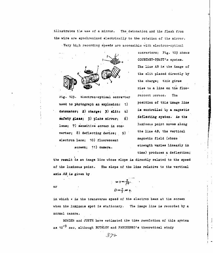
illustrates tie use of a mirror. The detonation and the flash from
the wire are synchronized electrically to t-he rotation of the mirror.
Very hi ;h recording speeds are accessible with electron-optical
converters; Fig. 103 shows
4 COURTNEY-P ATT'.s system.
8 The line AB is the image of
the slit placed directly by
the charge; this gives
Irise to a line on the fluo-
Fig. 103. Klectron-optioal converter reacent acroon. The
position of thisimage lineused to photograph an explosion: 1)
detOnatOi; 2) chargel 3) ulitl 4) is controlled by a magnetio
safety glass; p) plane mirror; 6) deflecting system. As the
lens; 7) sensitive screen in c- luminous point moves along
the line AB, the verticalverter; 8) deflecting device; 9)
electron lens; 10) fluorescent magnetic field (whose
screen; ii) camera. strength varies linearly in
time) produces a deflection;
the result is an image line whose slope is directly related to the speed
of the luminous point. The slope of the line relative to the vertical
axis AB is given by.
or D
in which v is the transverse speed of the electron beam at the screen
when the luminous spot is stationary. The image line is recorded by a
normal camera.
BOWDEN and JOFFE have estimated the time resolution of this system
as 0 9 ,a h SLOV and FANCHEO's theoretical study

indicates that a resolution of 104 see shiould be accessible.
A majnr advantage of the system is that it needs no synchronizing
unit or special detonator. Electron-optical converters may be Used to
record fast procezaes generally; rates up to 10 frames per second are
accessible, although the total number of frames is not large. SIMONOV
and KUTUKOV have been able to record 6-10 frames each with an ~exposure
of 0.05 to 0.5 1lsec by means of a special pulse-sl'aping circuit.
Bibliog~raphy
1. Yu. B. Khiariton, t"Detonati on oapacity of an explosive";
A. F. Belyaev, "Effects of physical-factors on the stability of
detonations in explosives based on ammonium nitrate"; Ya. 1. Leytman,
"Effects of grain size on the sensitivity of high explosives to
initiating pulses". Voprosy..teorii vzryvchatykh veshchestv
- - [Theory of Explosives], No . 1, issue 1. Izd. Akad. lqauk SSSR, 194i7.
2. V. K. Bobolev. "lPhysics of explosions". Experimental Studies on
the Physics of Explosions, Collection No...2. Izd. Akad. Nauk
SSSR, 1953..
3. Collection of Papars on the Theory of Explosives. Oborongis, 1940O.
4. Wl. Jost. "Excplosion and Combustion Processes in Gases" [Russian
translation], IL, 1953.
5. M. Patri, Burning and Detonation of Explosives .Oborongiz, 1938.
6. A.. F. Belyaev and A. E. Belyaeva. Doki. Akad. Nauk .SSSR ,
295 (1945).
7. V. X, Bobylev, Dokl. Akad. Nauk SUSR 5, ?89 (1947).
8. A. Ya. Apin and V. X. Bobylev. Zh. Fiz. Khim. 20, 1367 (194L6).
9. Idem., Dokl. Akad. Nauk SSSR5, 241 (1947).
10. S. B. Ratner and Yu. B. Khariton. Dbkl. Akad. Nauk SSSR 41, 307
(1943).
3 7

11. R~. Kh. Kurbangalina, Zh. Fiz. Khim. 22,. 49 (1948).
12. H. Eyring and Ii. E. Powell, Chemn. R~ev. 1,5 69 (19149).
14. J. S. Courtney-Pratt, Research 2, 287 (194+9).
15. Collection of Papers on High-Speed Cinematography in Science and
Technology. IL, 1955.
.3 7 I

T .-
CHAPTER IX
INITIAL PARAMETERS OF A SHOCK WAVE AT M. !'I2~7
40?. Reflection of a.Shock Wave at a 10igid Planec Wall.
The pressure exerted by a shock wave on a barrier ca.n bc ~ir
abl.y in excess of the pressure at the front, on account of the re-flec-
tion." The folloain,, is IZI.AYLOVI.
I;. treattriant of' the refla-ci-io of a planrv
zOD t isteady-state zho'ck wavo by a r4I I id
' -barrier. The state of the ~;~at t'lhe
/ ' wall ahead of the incident wave isz 3poci-
- N Lied'.by po, po., and = 0; th ezt a to
behinrd the incident front, by pi. p,
rig. 104. Reflection of and u~;and tbtat zchind the rcoflccted
a shock wave by a rigid Lfc. , by p2, p2, ."~d U = 0 (the wall i_
plane wall: 4) paths of f i;: . Figur,. .m-ows the situation
gas particles; 5) inci- in (1, x) coordi.,I rn which the various
dent front; 6) reflec- zoncG are denote. . j , 1, and 2
ted front. The reflectoCI wave 6 .tcary _4Z
the incident w&';vo is. 2ic~~ a St_.:-
nation region (u = 0) between the reflected wa-:,..j txc 1-1w> t1,
meana that the gas must-acquire a speed ul equal ii-, -I. a tonno-
zite i'. aian to Iu, so the condition for the wall to ... fixed z
.U1 -u 2 =0.
3 Best Available COPY

The basic relations for shock waves give us that
in which v =1/i ; then
P; -go P2 1 P(O i S P) (47,3)
HUQONIOT's equations for the two waves determne:p/po. and p2./IP1. for a
polytropic gas:i(+~i+k1pPa (k-+I) pa+ (k -1)po A
L, (k +1) p+ (A -1)pi (47,4)P1 (At-1)p2+(k+1)p.'
Le t .pi;/po * i and pdp ;'C then (4f7,3), with Ipo/p, and C,2
inserted, becomes
and so -
ta r-IA I= hD (1+7o6)If pit >> P
and so 'Pg ,p if A,= 1.4; further, (.47,6) gives us the ratio of the
excess pressures as
___O 2 _1p+k+ (47,7)
Pf (. - PO)~ pa. iPo (-)i+kIP
APO 2 (PL 'PD).
which is the result found in acoustics.
We may put (47,6) in~ the form.
P, = P, 'k-)P1+'t+1PO-(47,8)
The incident pressure is Pt, so the second term oi± the z'i ht in
(47,8) represents the pressure resulting from the motion of the medium
behind the incident front. Here (47,2) and (1:7,4) give us that
APo AT 2u[+pi 16k P 179
PLPO I+7 +(g,9

This (pj: -pa) is substituted into (47,8) to give
P PQ (PI PO) +ik± + 1 + 2(+1; (1:+ WVI + I3 P ,. (47,10)
The speed Do1 of the reflected wave is.
A V, v +ss, (47 11)
This, with (47,2), (47,4), and (47,6), givesus that
while (47,4), with the Pe of (47,6), gives us that
which means that p./p, .5 fok. = 1.4 if -pI>' pa and that pq./pO 21;
this shown that the density is very much increased by the' reflection..
Figure 105 gives results for an ideal gas for various ;k,l the
2N *JJ 3 WWV I
a) -K-
Fig. 105. Relation of a) the pressure ratio, W) the density
ratio, and a)the temperature ratio for the reflected wave to
the pressure ratio for the incident wave.
results apply to air for w?<140. The.-parameters of the reflected wave
should be taken as-initial ones L. the wave is not steady.
The problem becomes much more troublesome if any attempt is made
3;77

to allow for the variation in the specific heat with temperature.
The problem in also more complicated if ,pq (the angle betwoen the
incident front and the wall) is not zero. I shall consider the problem
-for an ideal gas only. The
waves are'as shown in Fig. 106;
* $ " the parameters in region 0 (in
front of the wave) are denoted
Fig. 106. Oblique incidence of a by subscript zero, and so on.
shook wave on a rigid wall: 4) in- A moving coordinate system is
aident front; 5) reflected front. used; the intersection
between the wall and the wave
is taken as being at rest. The velocity of the gas is denoted by q
Fig. 107. Reflection of an obliquely incident shook wave at a
rigit wall.
(Fig. 107); then
sin To (47,14)
The components normal and parallel t6 the front are respectively
D, and D1'/tan 10,; q changes in magnitude and directidn as the front is
traversed, but the parallel component is not affected, because all
forces are normal to the front. The normal component fails to
-a.ui:), because the medium behind the front moves with a speed u,.

Then
q~ V (47,15).PL .
The angle betwien qo- arnd .q is 0; the flow near the wall must be
parallel to the wall, so q2 must be turned through an angle 'Vin the
reverse.sense. This applies if the reflected front passes through 0;
in general, 9, ;dg, Further, q2. is defined by the fact that the corn-
ponent parallel to th~a front remains unchanged (Fig. 10?):
I. qCos 2+C (47,16)
Here *~is given by
or '~
But.
MR T T (47,17)
HUGONIOT's equations relate p and v for adjacent'regions:
vt 14 . Ij)plj(k-)PO (47,18).1 (k - 1) P,+(R+ 1)p
The qj. , pi and !p for adjacent regions are related by
'Va (PI PS) -q2 ('ii - qd.
which define the q. A further condition is that
qo X 2= Op(47, 21)
which implies that q~o is parallel to qj We can put (47,20)
3 79_
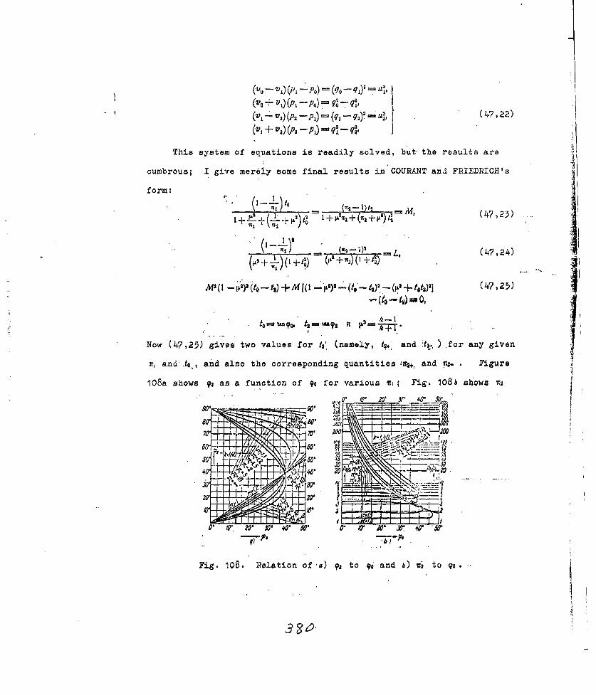
V.- 'V1 (A1 - PO) -(q0 - =X it,
(vo + v,) (p - p,,)= q -q
This system of equations is readily solved, but the results are
cumbrous; I give mereiy some final results in COURANT and FRIEDFJCH's
form:_________1
+ +(4+7,23).
MS ( 2 to i) +M ( Oo' W.(P +tot)'](47,25)
N~ow (47,25) gives two values f or t2' (namely, ig4' and :t2-, ).for any given
7ti and Jo,, and also the corresponding quantities :us+ and 1*.. Figure
108a shows ~,as a function of qo for various i Fig. 108 b s1iows 7 a
44
10
40- 20 ~ X 0~hI-
Fig. 108. Relation of a) ~ato qp6 and b) x- to go .

as a -function of o for ,jveral ,. The difference between -2., and
• increases as % and ir, decrease; 7C2+ becomes much larger than the
r2 for 90:= 0. This implies that t2- is the more probable value, which
corr.esponds to t..
The lower bianches of the curves of Fig. 108a imply that 92y0<.
if .90 is small; .s. at first falls as g0 increases, but regains the
initial level when = 9. A notable point here is that 9o is inde-
pendent of it.; o, = T2 when qo = o*, This go* is given by (47,25), 7
with t = 't1: i(- + t 0
or
so
This means that 39014' for air. Again, (47,24), with t0. t ,
shows that w. regains its initial value when -90<?o
(ICI- P) = (-,.- 1)2
The solution is
(2p' -I) pI--
or (3 -
(k - I) +(k +1)
Further, % becomes somewhat larger when o > p; this is true,
however, for 1.4 for wi < 7.02 (fairly weak waves). This fp*; is
almost the limiting angle for regular reflection if i. is large, so
such a wave cannot give a Tc2. greater than that for Oo0.
The regular reflection described by the above rel.tion6 is not
possible for all go but only for 9o4 om , in which yo, is dependent on
It,; the limit can be found from the condition that (47,25) must have a
real, root 4 fo given td and n, Now M="O if i, 1, and (47,25)
38/

gives us that 12' to o 'im = 90, which io so for sound xavuO. Then
oo< 900 -," ,>I (>O).
Figure 109 shows gon as a
XOL function of the pressure ratio
01-:, - for the incident wave.
0 Irregular (MACH) reflection
.occurs for f,>y ; the'a 47 P50 0 . 04 0 20
Fig. 109. Relation of Tom to pres- speed of the reflected wave is
greate'r than that of the inci-sure ratio for incident wave:
1) no regular reflection; 2) dent wave, because the forner
travels through Las heated byregular reflection poesibla.
the latter [the reflected wave
is not appreciably retarded by the flow behind the incidont froi, whWz i
- *yp is large, since Fig. 107 ahows
S" that the component of the flow
speed behind that front par;llul
to the r lectee, front is
U 1os( o + 92):. Th~asunp
that the refle ted wave meetsFig. 110. Irregular reflection
the incident wave at some dis-of a shook wave from a rigid
tance from the surface; thewall: 1) reflected wave; 2)
result is a new wave (the head orincident wave; 3) head wave;
MACH wave). 'There is albc a4) contact discontinuity.
contact dizcontinuity, .>ieh
separates regions differing in densit" and temperature but identicJ in
pressure and flow speed (Fig. 110). STANYUKOVICH and COUR1AINT havo
made detailed studies of this t.ype of reflection.
Thu principal feature of interest here is the ratio p"./p1 , which
3g2-

varies with 9D. although . j is constant; for goOp..,= (3k - 1) p, - (k - 1) Po
pz (k-1)P+(k-f1)po
This r at Zirst decreases as go increases in regular reflection, but
it reGains its initial value when, q g 9om , and, if i is. small, then
somewhat exceeds the initial value. No such increase occurs in -dCH
reflection; 14. for the head wave approaches one as .o tends to 900,
because the wave slides along the surface instead of being ;reflected.
These various forms of reflection must be considered in order to
estimate the loads that may act on the wall and also to determine the
pressure at the front from experimental measurements of the force. A
single shock wave can appear to give a variety of pressures at equal
distances from the source, because the disposition of the instrumonts
affects the result. Allowance must be mado for !helangle of incidence
at tha mounting of the instrument; the calculation becomes very
troublesome if allowance must be made for flow around anobstacle tom-...
parable in size with the depth of the wave.
48. Initial parameters of Shock Waves Produced by Efflux of
Detonation Products
A shock wave is generated when the products from a detonation
escape into any medium; the products themselves ray contain a shock
wave or a rarefaction wave. These shock waves may be examined if
their initial parameters are known.
A shock wave is generated when the detonation wave reaches the
interface between the charge and the medium; the parameters of this
wave are determined by those of the detonation. and by the mechanical
characteristics of the medium. The effect on the products is depen-
dent on the pressure difference at the interface; if p; e Px (in which
pi is the pressure at the detonation front and pA is the pressure at
3,93

the interface), a reflected shock wave will occur in the products. A
rarefaction wave arides in the converse case.
There is no general analytic relation for the compressibility and
density of an arbitrary medium, and so there is no generpl means of
deducing which type of wave will arise in the products; but it is often
possible to make the deduction for particular cases. For example, a
reflected shock wave will occur if the medium is much more dense than
the products (at the front); a rarefaction wave will occur if the
reverse is the case. A reflected wave occurs if the products strike Imetals, while a rarefaction wave occurs if the products from a con-
densed explosive enter air, water, etc. A special study is needed if
the two densitieV are similar.
The parameters of a wave generated at an interface may be derived
from the laws for waves in the products and from the laws for shock waves
in a medium in contact with a charge. Additional conditions imposed
here are that the pressure and velocity must be continuous across the
interface. Consider a
2 plane detonation wave inci-
~pi" -
Pi mt. ace dent nornally on an inter-
' -, ' ¢ face; th ere are, two cases,
0) b) namely P,, pi. and. p0 > p.'
Fig.111. Determination of the ini- Figure Ill zhows the pres-
tial parameters of a shock wave sures a) not long before
(p, 4 p 1) Rarefaction wave; the wave (p0 , pi) strikes
2) interface; 5) shock wave. the interface and b) shortly
afterwards. The condition
at the interface is
ax U i + U , ( 4 US )I

in which l'x is the speed of the interface and ul. is the changeo in the
speed of.the products in the rarefaction wave. The latter is
P1.U, rdpf, '2)
in which p. is density and c is the speed of sound (for the proauc:ts).
The relation of pressure to density for the products is
pp-k = a, (48,5)
in which k = 5 for high explosives of po. greater than one, and a is a
constant.
Then, for a strong detonation wave,
, D , kD } i
k+t poD' (48,4)
We may find ujl fromk- i k-I i
We insert p and c in (48,2) to get thatkP 2 " •k~ 2k
U1 Ph'C i ;P 2kdp=( -~ jjI_ P
Sut kpa,./ . = .c and Coi. k k w 1), so
k-iUI- - ~ I(48,5)or
u, ((48,6)
The ur- of (48,5) and the uj'. of (48,4) are inserted in (48,1) to give
us that { IU.---- k +I --- 8 i k48,7)
Now the speed u' of the medium behind the shock wave is
Un which 'S,, n 5 ,f t8)
in which 'v4v', and . are the specific volumes of the rn~dium on the two
sides of the shock wave and Pa is the pressure in the medium ahead of
the shock wave. Equations (48,7)and (48,8) define the initial para-
meters of the rave completely if the equation of state is known.
If the products escape into a vacuum, p,==0 , so
Ul "Umax ~y D.Then um,1! = if k'- 3, so the efflux speed cannot exceed D. Of
course, this result does not correspond to e:xperience; in fact, the
leading section of the products escapes with a speed of almost 2D into
a vacuum, and with a speed in excess of D even into air, although (48,7)
implies that u, Dj. if p, > 0. The reason for this discrepancy is
2that k. cannot be taken as 3 if ps, is less than 20-30 thousand kg/cm
We ohall so# below that the initial p, is of the order of Pi i$'the
medium is dense (water, soil, etc.), so (48,7) then describes correctly
the behavior of the products in those media.
If we assume that the detonation is instantaneous, (48,1), with
ul 0, gives us that
-o U1 T ( -
in which cjI is the speed of sound in the products; then
* 2 ' 2 .r Ai (48,9
in which ' is the pressure in the products. But C. Dk/2(k + 1)]6
soI Tk- -)(4 ,0
For a vacuum, pd.'= 0,so
which, with 'k'= 3, gives us that
u.iD / '=.6 1D.
This is substantially below the,*.,, found for actual detonations.

Now I consider the case po, > Pj-; Fig.112 shows the pressure imme-
diat.ely before
P and immediately
2 after the wave
Si' 'reaches the inter-
2 face. Here
there is a ref-Fig. 112. Determination of the initial para-
letted shook wavemeters of a shock wave .(p > ) 1) inter-
in the productsface; 2) detonation wave; 3) reflected
(because p. > pj.)shock wave; 4) shook wave.
and a shook wave
in the medium. The condition at the interface is
UM- -il, (8, 11)
in -which tm. is as shown and =u . is the speed of the products behind the
reflected shock wave; the latter is given by"'=U (" -,)( - ) ( 48,112)
in which , 4 is the specific volum., of the products at the front' of the
detonation wave and is the same for the reflected wave. Then
(48,3) transforms HUGONIOT's equation to
'--- - (,-.,+-)' (48,13)
in which i.
We transform (48.12) to
in which we insert the'v/'vi, of (48,13) to get that
Then (48,4) gives u's thatD
3~2

.' (+) ItC+ p
We subsTitute -for' u, and u1. 'from (48,11) to get that
T___+ ____ (48,14)
Wurtber, behind the shook wave in the external medium
!=im' =.(P. p (vo--vow), (I,5
in which Pot is the pressure (usually atmospheric),ahead of the shock
wave; : Vo and yvi are the specific volumes of the medium ahead of and.
behind that wave. But 'P~=,so p, may be neglected, in which case(48,15) becomesI
u =PO=/, (.o 0 ma be (edw6
Equations (48,14) and (48,15) ser'Ie to define the initial para-
meters if the law of compression is known. Approximate solutions for
ortain media are given below,
Absolutely rigid wall. Here m8 u .0; then (48,14) is solved foras
s5i-4: i + 74 +--kT
4 (48,1'?)
This ,varies little with A, being 2.60 for the limiting'oase if.= 1,
2.42 forlhin 1.4, 2.39 for k z 3, and 2.28 for 'k-+coo (the root n.e
for anyk is physically meaningless). The 1p. ='vj./v. are given by
(48,13) as, (n @2.60) P.-x=2 6 0 ; '
It,= 1.4 (it= 2.42) ' 1,85;
Pi.i =8 A- o 2.28) -i LI 1,C-5.
Then (48,13), with the ,'cof (48,17) gives us that
S" .... .k2+2A ...... .. (4P j I O-+ (k - 1) .1+ k+1

The initial speed of the reflected wave is
D"--V (i Pi+U*
This may be put as
We insert the o~e'of (48,13) and use the relations
to get that.
Then P,,/Di -0-31 for .A I and n' 2.60, -0.78 un t~a3 2.39,
and -1i.28 for A-+~oo ; that in, Dais very much dependent on k., but it
is not very much dependent on-if, if A taken a fixed value close to 3,
as the following values .for .=3 show:
-1.5065
tr2.4 07
This fact enables us to measure !k .in terms of the speed of a shook wave
reflected from a dense medium.
This measurement is one of some importance, because we have as yet
no accurate ;~ethod of measuring the pressures produced iLn detonations
and in the reflection of detonation waves. Kinematic measurements can
be made accurately, and these give us k.', whioh enables us to calculate
the parameters of a' detonation wave with reasonable precision.
There is a small rise in the entropy of the products when the
wave is reflected, which is caused by the small pressure change in the

reflected wave. We have that before reflection
~S- np vk+const;
and after reflection
S, In ",V + colSt.
The entropy change is then
AS=S,-j nIPi. Vi
This t?) is given by (48,17) and (48,18) as
5*+ 1+ Y17i%+2k+ I [ 9k2 +k-1Y1m2+2k+1 14k L ki +2k+ I+ (k +1)J17k2T2§+ 11
A-3
Thus AS is negligible, 3o we can perform the calculation for the ref-
lected wave as for a set of sound waves. Here the RIEMAKN solution
gives us that
du =±=- d In P. (48,20)The isentropie law gives us that
2
du =i= dc.,
The integral is
k-1
'or
2(C C
At the wall
so
k-I 3k-jC0 ,+ U 0k -
kM
~s--

We substitute for CO and ci in the last expression to get2A.
j 2k- (48,21)
The acoustic theory gives us that
..... F . A. (48"22
P i 2 .37; PO 33; c. Dj;
D, 3T 0.75.,
These results are very close to the exact ones.
The theory enables us to determine the initial conditions at the
contact between two colliding bodies (even liquid or solid ones);
STANYUKOVIC! explains this by saying that the formulation of the cIn
servation laws for the instant of collision is not dependent on tha
phase states of the bodies, Moreover, no forces have yet arisen
within the bodies when contact has just been made; the contact gives
rise to shock waves.
Let subscript i and a denote tho parameters before impact, primes
and subscripts 1 and 2 denoting parameters after the impact. Con-
sider a coordinate system in which the second medium is at rest; then
the interaction is one between the first medium and an initially
motionless barrier. The relative speed of collision is
fij -t~r U&' (48,23)
in which Ua, is positive if the two media move in opposite senses and
negative if they move in the same sense (the condit'ion for collision is
then ui,.>U ). The speed of the 'interface, is u'; then
and
R =Pi -A'. (48,25)

The speeds of the media behind the shook waves originating from the
point of contact are givei. y_________(___- .1 , -- 14-p)( - )
'.' if the s eed of col
in which p, is the initial pressure; pif the speed of col-
lision is high, so
U, ~vp'{-IV. '. =u L-1/p' yl-4 (48,26)
Let
4 .v =% '2
and
Then
' )a.Linp (48,2)
or
a! a
.the ratio of speeds being
- .--. (48,28)1+V PC '
This last defines the speed of the interface; the other initial
parameters are readily found in terms of u', ,i, and aq. For example,
(48,27) defines the initial pressure at impact, while the speeds of
the waves are .
D,' -V
The p' of (48,27) then gives us thatD--. D.2 =- (48,29)
The equations of state ('or of compressibility) are needed in order to
find a and a2.

Equations (48,27)'and (48,28) enable us to relatetail to p':
"I ~ Pa H' ._ "
V . (48,:3o)
A general relation between 'density and pressure for liquids and solids
(not porous) 'is
-(48,31)
in which A(S) is a function of the entropy; n may be taken as constant
over a wide range of pressures. The change in ,S c.onsequent' upon impact
can be neglected if the speed of impact does noG exceed a few km/eec;
then (48,31) is the equation of isentropy for a solid or liquid. JMethods are available for measuring 'hand A; n = 4 for some metals,
which agrees with JENSEN's re~ult, We can oalulAte 4 from TATE, s
adiabatic equation of state for liquids and solids:
I /V" n p +A (S)] (4 8,32)
which has the integral'
p --A(S) 48,33)
But
I(3V) I
so (48,32) may be put as
p=--A. . (48,34)
Then p= Po, P.=6'Po' and c'= cq. give us that
po; A.But
SPO)
and so
--o [(o) .48,3 5)
If we neglect Po , which is here permissible, and compare this with
39F3

4+8,30), we have that
Table 68 gives calculated and experimental A for metals, for which
Table 68
Calculated and Measured Values of A for Metals
,ta l A e oa,2 A c kg/cm
2 A -
Iron .... ....... 4.5 X.10 1 5.0 X 10⁵ 1.11Copper ... ........ 2.35z105 2,5 X 10⁵ 1.08.DI~&ralual . ... 2.04 z103 2.03z 101 1.00
i, - 4; the agreement is satisfactory, which confirms that (48,31)
deaoriboa the behavior of a solid ac0urately. This equatiai Sivw U .
that
p,. . , ./(P (-77+ i (48,36)
which is the final step in the solution. Table 69 gi.ves 'some results,
Table 69
Parameters of Shock Waves Produced by Duralumin
Striking Steel
I/, .3/ .6 I " U, /.ea
1000 2.5 x1 O 0.180 0.106 5753000 OG 0.38 0.253 17808000 5X10⁵ 0.555 0.1166 542013500 107 0.624 0542 8300
5: 400 5 X10⁷ 0.748 0.693 20200
for which purpose the values adopted were .u,, = 0, P, = 7.8 g/cm3,= 4.5 x 10⁵ kg/cm2 , h. = 2.73 g/cm3 , and &A = 2.04 x 1O' kg/cm2 .
6The calculations are not very precise for p' 1 10 kg/cm, because

the change in S cannot be neglected. The law of compressibility has
not been tested experimentally for these ve high pressures;
We have made measurements of the A of ,,31). Plates of various
thicknesses were fitted with cylindrical charges (height equal to 5-6
diameters) standing on end. The wave reaching the plate was then
almost plane. The other side of the plate was in contact with water
in a transparent vessel; the wave in the plate gave rise to one in the
water, which was recorded. The initial speed of the water wave gave
.' for the interface with the water and hence the pressure. (These
two parameters may be varied by using several different explosives.)
The hydrodynamic theory then gives us the pressure and density for the
wave in the metal, which may be treated as a liquid, because the stress
produced by the explosion in wcll in xoessa of tba yiold point.
The equation is
in which U.. relates to the interface, u. the initial speed behind the
wave in the metal, and ul to the change in that speed as a result of the
reflection. The treatment of section 47 shows that
"o, = V(P' -Pc) (v - vw),, (4+8,38)
in which voo and ow are specific volumes for the water ahead of and
behind the shock wave. Now
Uj YPO- (Vu---V7., (48,39)
in which pi relates to the incident wave in the metal and the i..,are
specific volumes for the metal. Also,
U,~= dp (48,40)
If we use (48,31) for the law of compression, we can put (48,40) as
+1 (48,41)
* i ~ L 7~3V

Here p. and ul. are known, because water is used; the,unknowns in
(48,37) and (48,41) are then A, a, and pL. Experiment ;an give us uj,
whereupon we have
pi -'pxoujDj, (48,42)
in which D. is the speed of the shock wave, which is close to that of
sound even if ps > 10 kg/cm2 . There is no means of measuring D! at
a point; it can be measured only over a distance of several mra.
(The values can be used without introducing great error, in view of the
above.) Then (48,31) and (48,42) enable us to put (48,36) as
Then the ul of (48,41) and the 'uj of (48,42) give us from (48,37)
~Ithat ,.
p0Di+n-1 17+ - , (4,44)
The unknowns are as before; calculations show that pi varies very
little with n if n'>3, so we were able to put n as 4, and then to
determine pi. and A for given p. and D. We found that A remained
nearly constant for :n, = 4 for a fairly wide range of plate thicknesses
(i.e., for a wide range in pit).
This work was done in 1955; later in the year, there appeared a
paper on the same topic by 4ALSH and HRISTIAN, who measured D. for a
metal with a free surface, and also ud: for that surface. Their assump-
tion was that u. would be twice u ,, because
(48,45)
-ul t. (48,46)
.3al

In fact, ,/jui varies from 0.96 to 1.03 for Zn, from 0.98 to 1.02
for Al. end fio-u 0.98 to 1.01 for ca for pressuree up to 1:50 kbar
2(445 000 kg/cm2); this introduces an error of -1% in the v,,. Then
(48,42) and (48,46) give Pi, which, with
v, D- u (48,47)
.gives V .v D:
WALSH and CHRISTIAN'a results for A1 agree closely with ours;
Table 68 gives the conLtants, and Table 70 gives the results. Their
Table 70
Compressibility of Aluminium as a Function of Pressure
' ,1339 218 . 258.6 288,7 323. I 347.0 SQ11r• !I0Vl 0,834 0.817
_ 0.880 0,830 .0.813 0.801 0.788 077" Own resuts
results for Cu do not agree so well with ours, because their copper had
a specific gravity of 8.903, whereas ours had ont of 8.5.
ALI'TSHULER and others in 1958 published some very important
results on dynamic compressibility for metals at pressures up to 5 x 1 6
kg/cm 2 . Their method was to meazure tha kinematic parameters of the
waves excited in a target. In onc case they measured the mean speed
of the shook wave and the speed of the free surface, which latter was
taken as twice the speed of the metal behind the front. This was
6 2shown to be so for pressures up to 3.5 x 10 kg/cm
COOK denies that this relation is applicable; without good reason,
he assumes that the measurements give the sum of the speed of the free
surface and the speed of the body as a whole (instead of the first alone).
3~J

This would be so if the body were absolutely incompreseible, in which
caie tne acceleration would be indefinitely great. Such conditions do
not occur, of course.
AL'TSHULER et a. produced these very higrh pressures by allowin&
a body that had beer ..'.-;$ lerated slowly to strike a target at rest; if
the striker and tar-et are made of the same material, the speed of the
interface should he
in which 'u is the initial speed of the striker. This u and D' (the
speed of the shock wave) must be measured in order to deduce the com-
pressibility.
They found that D' is linearly related to a' if the latter is in
the range I to 5.17 ka/sec:
in which Co and X are empirical constants, whach take the values 3.80
and.1.58 respectively for iron if the speeds are expressed in km/sec.
This functional relation defines the dynamic adiabatic
Co 2'~u)~ (.48,48)
AL'TSHULER et al consider that this is applicable for P' between 3 x 10
and 5 x 10⁶ kg/cm2 for iron. They found that this linear relation is
applicable to all the metals whose -C' and X are listed below (but not
for ,n); the adiabatics are of the form of (48,48).
These generallaws
o" kz/40 ' g1023 become much simpler if
CU 3,O 1.46 8.93 p'/A 44 1; we may expandZn :. ,.20 1.45 7.1,t..o 5 7.14 1!%V(l + p.'/A) in series form
2,65 .1.48 8.64Au " 3.15' 1.47 10.30PI) 2.230 1.27 1 1.813i 2.00. 1.34 O.O and take only the first
term, which gives us

(I + p'/.,A). Then (48,36) gives us that aj = Pll(.nA; + p') and a2
p'/('n + p:'); these are insorted in (48,30) to give us that
+ (a (48,49)
If now we neglect pl on the right, we get
V p, A,
which is a linear relation of.P, to u.,. If now ul is substantially
less than the speeds of sound in the metal (ca and ci), we can put
(48,27) and (48,28) as
P==' +'4.-I ", (48,51)
= Pic', (48,52)
.UTho xpxoaea ionsare correct only if the
yield stress is exceeded
by a considerable margin,
* _as for lead and some
alloys;, other metals
require a correction for
the yield stress, which
reduces u and increases
p'. (T!-iz toiic is
considered in chapter
1 XII.) A body that
deforms in -coordaice
with HOOKE'e, law can be
Fig. 113. Apparatus for measuring the used in nmeanurerients of
displacement of the free end of a rodcompressibility if we
and the speed of a wave in the rod.have some aeans of
3 t g

recording the displacement of th material in a thin rod. HO14xINSO.
first used rods in order to measure the pres~iure as a function of time;
DAVIS dcscribed an electrical fora of Hopkinson's method in 1948. Rods
of HOPKIiNSON4's original design have been used at the Institute of
Chemical Physics in order t. measure the parameters of strong shock
waves (see section 87). BAUM and STETSOVSKIY have improved the method
by using a new technique for recording the motion of the end and. the
passage of the wave in the specimen (Fig. 113).
The two rotating-mirror recorders (type SFR-2M) were made at the
Institute; the lens 2 and the recorder 1 produce photomicrographa
(x 20) of the motion of the end of the rod 7, which lies normal to the
A
1000
750100
0 5 2 /6 29 14 -IeeoC
Fig. 114. a) Motion of the end of a rod after reflection of a
compression wbave; b) propagation of compression and tension
waves in the rod; c) shape of stress wave.
plane of the figure. The second recorder 6 rec ;.s the progress of
the wave excited in the specimen. The two recorders are synchronized
with the light aource 5 and with the explosion. The lenses 3 and

mirror 4. serve to direct the light to the recorder.
The pressure p, in-a compression wave approaching the froo end
is given byI 11X
in which 1po is density, co i-% the speed of sound in the rod, and dx/dt
is the speed of the free end. Experiment gives us X fO from
which we find p..= i.e. the form of the stress wave.
Figure 114~a shows the motion of the end of a rod of plexiglas
200 mm long as excited by 200 mg of lead azide placed'at the oti~r end.
-. . Figure 114b shows the waves
propagating in the rod, and
Fig. 114e shows the stress
Ax0 .. Wave* The recordings &.how
that the tensile stresses
resulting from the reflection
at the free end are. respon-
sible for breakinG t~he rod.
___________________The free end starts to move
when the compression wave
arrives; the rod~ breaka when£0? £02 4XtO £04
the tensilo stress exceedsFig. 115. Coipressibility of
the ultimate strength of theplexiglas for dynamic loads.'
mat erial.'
The ultimate strength of plexiglas for dynamtic loads IS 1250-1350
2 2kg/cm (the value for static loads is Only 650 kg/Gm ).The maximum
speed'of the material behind the shock wave is
u ~()u

so the law of compressibility can be deduced from the measured D and
.,, for which we have the basic laws
D u(4,)
P
p-poum..D- (48,55)
Figure 115 shows the result; the compressibility is linear up to.
2000 kg/cm2 , which justifies our assumption that plexiglas obeys HOOXE's
law, at least up to that limit.
49. Initial Parameters of Shock Waves in Media
Escape of detonation products into air. We have seen above that
(48,?) canngt be applied to the shock wave and products when the latter 4escape into the air; LANDAU and STANYUKOVICH have proposed to incor-
porate a correction for the variation in k in order to perform the cal-
culation. We do not know k(p) in analytic form, so they used two
isentropic laws in order to describe the process:
' T(49,1)
in which subscript k refers to the detonation front, subscript k relates
to the point where the two laws overlap, and .Y is 1.2 to 1.4.
HUGONIOT's equation can be used to find and v,k:
2(VO v!) +(49g,2)in which AQ is tbe residual heat and Q, is the heat of explosion. It
is found that :itp is small relative to p. vt , so (49,2) can be put as
.. =- __ 2 . . ..
But_.,_= Io k 1
pD2so
(49,4)
Now 'AQ, is thermal energy,. so AQ= the products behave as an
ideal gas for p ,< Pk, so
,V. = - -1, =7- ( 4 9, 5 )

We have two equations
P-v-=(T- )AQ AQ' X
for Pk and vk.; y can be found only if the composition of the products
is known, but we may. assume that i7,.1.3 for the usual high explosives.
The velocity of escape isUj, -th tj., (49,6)
in which 'u is the chanje in the speed of the products resulting from
the rarefaction wave ; here
'We divide the region of integration into two parts to got
PIC
in which c is the speed of sound and ck = k (, Then
Now
'-1
D ki)
_,,,.__ 7-'1
so substitution gives us that
Further, p., ='Ojif the products escape into a vacuum, so
_- . .\,, - 2o ( 4 9 ,9 )A+1. k-1 'Pi.
The products produce a shock wave iZ they escape into the air, and
this reduces the escape speed. Initially, the speed of escapo coin-
cides with.a", the speed of the air behind the shock-wave front, which

we may take as strong. Thern we have that
D + ' p I "11 (49,10)
2 (49,11)
in which T ire 7 for air (1.2 for strong shock waves) and pA is the
density of the air in front of the wave.
Equations (49,8) and (49,11) suffice - determine th, initial
parameters. Table 71 gives results for typical high explosives; the
Table 71
Initial Parameters of Shook Waves in Air
Be
Trotyl. . . . 1.60 7000 1000 285 ;50 570 6450 7100Hezogene ,.. 1.60 8200 1300 310 1500 760 7450 8200 II 900TEN ... 1.60 8400 1400 3450 1,800 810 7700 8450 12400
last column is for escape into a vacuum, and here u. is much larger
than D, (u. - .D' for escape into air). Experiment shows that these
calculated values are somewhat too low, expecially for escape into
vacuum. Moreover, the , (and the other parameters) for air are some-
what dependent on the density of the charge, as Table 72 shows for
Table 72
Speeds of Shock Waves in Air Near Charges
Mesn opeed, N/8P.. g1m 3' A A/30
Trotyl .... .......... 1,30 6025 6670 4650 4620*. ..... .. ..... 1,35 6200 6740 5670 4720
.. . ... .. . 1,45 6450 6820 5880 -. . . . 1.60 7000 7,500 6600 5460
Hazogons . ........ 1.40 7350 8000 - -
1.60 8000 8600 6900 6400

.herges 23 mm in diameter..
If we take the speed in the first section as D', we get u.,, for
trotyl of density 1.60 g/cm3 as 2D,'/(y, + 1) 6800 m/sec, so p,,
2640 kg/cm , which are somewhat higher than the calculated values.
Hexogene having a detonation rate of 8000 n/sec gives pc, = 840 kg/cm2
and u,, 7850 m/sec. The discrepancy can be reduced if we use the
two laws
pv= - const , pvf=const.
It is usual in calculations on the total effect of an explosive
charge to assume that the detonation is instantaneous, We can dvalu-
ate the initial parameters of the shock wave in air for this case, for
u* 0 and (48,7) becomes
. ,=f.. . j.* , ,*'a., - al<,,a.P1 .IM 3
or 2o, 2cI+ °, <, iT1,U- - (Poj T (49,13)
in which the barred quantities apply to an instantaneous detonation,
the others in subscript Al being for the point of overlap:
Pi 'P I -= D,.
HUGONIOT's-equation for this detonation is
Pjt 0 PR,14I
so, if we neglect the secbnd term as being small relative to the first,
we have that
That is, the residual heat at this point is not dependent on the nature
of the detonation. The parameters for this point of overlap are given, by
Pi,.'r)g .V,) r ,vy (T -1) AQ, cg==V P~

Table 73 gives results for instantaneous detonations. Exp nt
Table 73
Initial Parameters of Shock Waves Produced in Air by
instantaneous Detonations
' "
rty .... 1,60 00 1250 230 4100 4500 7750flex .... 1,60 130 1300 30 4700 5150 • 8700
.. 1,60 140 l6O 330 4900 5400 9000
• tshows that the initial parameters of actual shock waves in air are
higher than the ones calculated for instantaneous detonation; this
feature must be allowed for in any calculation on the local effects,
but it is less important in relation to the general effects, for the
actual and calculated parameters become very similar at fairly small
distances from the source.
Shock wave in water. An underwater explosion from a charge whose
density exceeds 1,g/cm3,has a rarefaction wave in the products, but
here there is no need to consider the change in ., for there is no very
large change in.p or p. This means that we can use (48,7) and (48,8),
so
D +2kr, -I+ if (119,14)
uZ = (pO -po) (V.o- v ). i (49,15)
The relation of p. to p for water for p. > 5000 kg/cm is
P(49,16)
in which A and n are empirical constants. Then (49,15) may be trans-
formed by neglecting po., because po p , and by replacing the specific

volumes by the densities:
Piio V Q Po po (49, 1?)
in which p, is the density ahead of the shock wave and p is the
density in the shock-wave front. Formula (49,16) gives us that
This ratio of the p is inserted in (49,17) to give that
(49,18)
which, with (49,14), solves the problem. A graphical treatment is
convenient; experiment gives the.A
256 and n for the range 0.03 to 0.2
2 W - n q / c 2 a s2.0
~~A:39410 vC./C'o , ti=:,8,A. 34. e.WOO. 8
p.- 940 1 ]1 (49,19)
2.. (49,20)(1.3940
4751/10 8022W0 25W0 X 3/00 .NX
AM AM 20---- MV,3WFigure 116 illustrates the graphi-
cal treatment for the exp)losives ofFig. 116. Initial para-
Table 71. The curves for the rare-meters of shock waves in
faction wave and for the shook wavewater: 1) trotyl, p6; =
3 rin the water have been constructed1.61 g/cm ; 2) retarded
e from (49,14) and (49,17); these curveshexogene, po = 1.60 glom;
meet at a point that defines u. and ps,3) rarefaction wave in
and so D' is given byproducts; 4) shock wave
in water.
zfr 7

This.D.t is found from the ratio of the p and the no as given by
(49,2o) and (49,18) to be
D' = P-"'B'( -n)(49,21) *
Further, (49,16) gives uis . . and DL from the kiown p .
The temperature chanL. across the front in the water cannot be
calculated exactly, because we lack reliable values for the thermal
capacity of water at very high pressures; there is no information on
the division of the internal energy between the thermal and elastic
forms. We may, though, use the shock adiabatic
in order to determine the increase in the internal energy
A E - Eo
during the compression; Table 74 gives results found in this way by
means of (49,19). The initial pressure and speed are less than for
Table 74.
Initial Parameters of Shock Waves in Water
Trotyl . ..... 1.60 f;I' [ 2185 1360 136 000 87.2 .70T.. . ...... 7U20 2726 196 000 83. 800
the charge itself; moreover, po/p. andD,/Y' tend to decrease as D ,
and 'pi' increase, which is a result of an increase in the compressibility
at high pressures.
CHALLE has given comparable results for certain other liquids; he
measured the density ratio by means of microsecond radiographs of waves
generated by charges of TEN. His poo/poo are: water, 1.75; ethanol,
2.05; acetone, 2.15; ethyl ether, 2.45. The first as close to our

value.
The parameters of the wave generated by an instantaneous deto-
nation are given by
it, ~-f[ (49,22)
+ (49,23)
in which subscript i denotes the initial values for the products; D'
is given by ("L9,21). and Pow by (49,19). Table 75 gives some cal-
culeted results, which are substantially less than the actual values
Table 75
Initial Parameters of Shock Waves Produced in Water by
Instantaneous Detonations
P., a P .kgl o%2 /80 000', aoo
'rotyl • 1,60 43000 1050 4000 1,37TIN. . 1,69 62000 13W 4500 1.43
(our results agree quite well with ones calculated by the KI=WOOD-
BETHE method). The accuracy of any such calculation is governed by
the error in the relation of pressure to density, which is derived
from measurements of the speeds of shock waves near explosions in
water. Better methods of measurement are needed here, because
results for isothermal compression (BRIDGMAN and others) nannot be
used; water solidifies (seven forms of ice are know.' when it is com-
pressed slowly at very high pressures.
Shock waves in metals. The density of a metal or alloy is
usually greater than that of the products from a detonation, while

the compressibilities usually stand in the reverse relation; this
means that a metal tends to produce a reflected shock wave. The
equaticnb for the initial parametner are
f +- (.9,24)
U~i, [, ~=P(VCDo a 0 P (49,25)
These enable us to find the parameters if p(r)) is known for high pres-
sures. We have seen above that the relation of p to p for a metal is
p= A[( )-_ i (49,26)
so (49;25) becomes
up_7 P-j1 P.0Ux~ - _ (49,27)
Equations (49,24) and (49,27) give uz che initial parameters of the
shock waves in the metal if A and n are known.
Table 76 gives these initial parameters for certain metals exposed
to the detonation waves from typical exiloaives; >p/, > 1, and it
increases with A, although it decreases as Pi increases. It is always
substantially less than for reflection from an absolutely rigid wall
'(here p0/pl = 2.4). Further, p increases by 10-25% when the shock
wave is strong; as one would expect, duralumin is found to be the most
compressible, and steel the least.
The method described in section 48 for examining the stress wave
is not applicable to the tail of the wave if the rod fractures; that
method has been improved by BAUM and 3TETSOVSKIY as follows.
A narrow scratch is made on one of the side faces of the rod;
passage of repeatedly reflected waves past this point i6 recorded As
before, which enables one to use stress waves of any amplitude.

This method has
been applied to
S"plexiglas to yield
ON~~ C I the *e=4c~curve,
" in which e is
§ relative elongation
________ _ ___ and a is tensile
13 -- _ _ _ , stress. The e
M - for an 1explosion>
" wave is the ratio .
Sof th diaplacemeht
o .of the line, to the
to length of the sec-.j
NI, C tion acted on by
the wave. It is
j } '' '.found that plexi-
H glas, although
-n usually ,considered
as plastic, in fact
obey& HOOKE's law
aup to the pointof
rupture for explo-
sion conditions;
it behaves as an ideally elastic body, and YOUNG's modulus E is!6 x 10
4
kg/cm2 . For comparison, the given by;: (E/,p) is 6.05 x 10⁴ kg/cm
2
Lill

Bibliograrhy
1. L. I. Sedov. The Methods of Similitude and Dimnrion-s in
Mechanics. Gostekbizdat, 195?.
2. Ya. B. ZAI'dovich. Theory of Shock Waves: .cn in~troductionL to
Gas Dynamics. Izd. Akad. Nauk SSSR, 1946.
3. Y. B. Zel'dovich and A. S. Kompaneyets. Theory of Detonation.
Gostekhizdat, 1955.
4. R. Courant and K. 0. Friedrichs. Supersonic Flow and Shock Waves
[Russian translation]. IL, 1950.
5. L. D..Landau and E. M. Livahits. Mechanics of Continuous Media.
Goatekhizdat, 1953.
.6. L. D..Landau and K. P. Stanyukovichk Dokl. Akad. Nauk S9SR 4?,
No. 4 (1945).
7. Idem. Dnki. Akad. Nauk SSSR 4, No. 4 (1945).r
8. Ya. t. Zel'dovich and K. P. Starnyukovich. Dnkl. Akad. Nauk SSSR
S591 (1947).
9 K.P. Stanyukovich. Transient-State Motion of a Continuous
Medium. Gostekhizdat, 1955.
10. J. M. Walsh and R. H. Christian, Phys. Rev. 97, No. 6 (1955).
11. P. W. Bridgman. Physics of Hig~h Pressure [Russian translation].
IL, 194-8.
12. L. V. Altshuler, K. K. Krupnikov, B. N. Ledenev, V. 1. Zhukov,
and M. 1. Brazhnik. Zh. Dcsper. Teoret. Piz. 34, No. 4 (1959).

T.No.1488
Chapter X.
WOMBUSTION OF EXLWS.V$.
'50, Basic Characgteristics of ExcplosLive CombustionPr e.
Under definite conditions most explosives aae capable of 'udceging
stable combustion without transition-'to detonation. For powders rapid
burning is the basic type of explosive transformation.
The results of theoretical and experimental studies show that the bazic
processes which are characteristic of combustion rather than detonation are
included in the following.
1. During cambust:Lon energy enters the initial substance by heat
conduction, diffusion of gaseous products, an d irradiation. Drinir detonation
the energy and subsequant initiation of explosive reaction are provided for by
the propagation of explosive prea6surb waves.
2. The rate of diseuination of combustion pr.4.. is far ind away
less th=n '&a rate of detonation proc, sses. The rate of coi~s~ncannot
exceed the speed of sound in the startir , .. arial, anxd is us.aally considerably
less than this. This is a result of z~e co~paratively slo. te of heat trans-
fer and diffusion. It will be recalled that the rate Of datUL.tion processes
alwa exceeds the speed of Bound in the origiaL ;bstance, .. quantly by a
considerable margin.
3. The oombu~t~on products formed directly at the fron-. ..; -- i: Ia"me movie
in a direction opposite that of the fLame front, whereas the; .. sita occurs
during detonation. Consequently the pressure of combustion du;.-- in tae
flame zone is considerably less than at the-, fxrrt of a destonati41 Wavo.
4. The rate and character of the chemical proces ses c... .:rinZ du;in' the
combastLon of explosives depend to a considerable extent on tr.. ax"na pressure.
z11.3
For example, combustion of pyroxylin and of some other esters of nitric acid
at relatively low pressures (up to 30 - 50 ataos.) usually leads to the form-
ation of nitrogen oxides and formaldehyde. This does not occur at higher
pressures - of the order of hundreds or thousands of atmospheres. At very
low pressures (close to the combustion unit) the combustion of many gaseous
mixtures goes via a chain nechsaism whereas at sufficiently high pressuros
reactions going via a thermal mechanim become important.
The combustion of many liquid or solid expl~sives proceeds either in the
gas phase, or simultane6usly in the gas and condensed phases. The change to
the 3nal combustion products usually goes through a series of intermediate
reactions.
It is characteristic of detonation in explosives that the chemical processes
occur in both condensed and gaseous phases at very high pressures. Under these
conditions behaviour of gases iS virtually the same as that of liquids.
Investigation -of the combustion of explosive systems had begun even in the
second half of the last century. Gaseous mixtures were mainly concerned, The
most important work on the combustion of gaseous mixtures during this period was
carried out bF allior and Le Chutelier, Diakson, and Micheoon. Their
investigations played an important role in the subsequent development of the
theory of combustion of gaseous mixtures. The process of ignition and s read
of the flame were studied for a long time in isolation from the chemical
kinetics, and this led to some of the principal errors of the formal theories
of combustion (Croy, Grimshaw, Letan, and others).
Considerable progress has been achieved in the development of the theory
of combustion of gaseous and condensed explosives in the last ton years. This
is a result of progress in the field of chemical kinetics, and in particular
the theory of chain reactions uhich has been developed in the main by Hinshel-
%ood and Semenov and their schools. The thermal and chain thpmriA of pato-

igniton of gaseous mixtures, originated by Semaenov, have served as a starting
point for the theoretical work of Soviet scientists (Zeltdovich, Frwnc-
Kamenetskii, Todes) on combustion.
Important results have also been achieved recently in the study of
combustLoki p 05esi in condensed phases aind in the study-of the coaditions
for transition from combustion to detonation. The most valuable studies in
these fields have been carried out by Belyaev, Andreev, and Zoll dovion.
Oombustion of gsseous qxe2lyiv syatems. Gaseous explosive systema are
chiefly mixtures of combustible gases or vapours with oxygen or air. A
gaseous ziixttue can be Ignited either by heating the mixture or by localised)
ignition (electric spark, etc.).
In the first case the chemica1 zeoaotion proceeds simultaneously throu !L-
out the volume of the vessel containing thie gas; in the seconld case a "LaIe
arises at the ignition point and spreads through the initial material. The
:Meme appears as a thin zone, which separates the unreacted starting niateri.v1
fzom the final reaction products, and in vhich chemical energy is converted
into heat. flossei1na on of the flame may occur by de-:onation or by normal
combustion. The term "normal combustion" signifiez the process by which
ignition of each layer of the gaseous mixture proceeds by thermal conductive.
heating from the previous layer, or by diffCusion of active intermediate
reactive products into the starting mixture.
*Termal- Ed chaIn ignition, Ignition and subsequent buniiaZ of gaseous
mixtures can occur only in those cases in %tich the, chemical reaction proccads
in conditions of progressive auto acc al oration. The eriti-... condition for
ignition is therefore determined by the conditions for tr&,zsforn.tioix from
stationary to non-stationary reaction.
If at some value of the texperature and pressure stationary heatin~v
becomes impossible and the temperature of the reaction Ldxtur.', ~Izanz to
increase to an importat extent in a non-stationary mazner, the jphenonernoz

is designated thermal ignition. At bufficiently low prenaureb heat evoh'ut-'.
by the -reactton is compensated for by heat loss to the Iu~unc s tao
pressure is increased heat evolution in the vessel is inoaras'.. T..iO o Wdo'
to an increase in the gas temperatu~re and consequently to an incroazaa in
thermal radiation. However, the rate of reaction and of heat evo.uttion also
increase as a result of the rise in temperatutre.
Since the reaction rate (oxotharmic) increases exponenati ally with
temperature whereas the heat loss increases more or less linoarly with
temperature, a ofltLnuousl7 autocoatalytic reaction occurs as thie result o.*6
disturbance of the thermal equilibrium, and'this leads to explosion (ignition).
Vae limiting conditions for ignition depend notably on the dimensions of tha
vessel when a thermal reaction mechanism is involved. An increase in the size
of the vessel leads to some decrease in the limiting ignition pressure because
the relative size of the heat loss is decreased. Thermal combustion can bo
observed in any exothermic reaction, the rate of whicah increases sufficiently
rapidly ud.th, increasing temperature.,
If the concentration of active interaeidiate products begins to rise to an
important extent in a nori-stationAry n~.ner 4- so~c vo2.ue of the extornal
parameters, then the phenomenon is termed chain or difisidn i~mition. Chain
or diffusion combustion is possible only in autooatalytic roactiona.
Ignition by a chain mechanism is principally encounterad at compratively
low pressures. Most cases of igLuition at atmospheric or hi,'er pressures are
of the thermal tyvpe. These are the reactions of most praotical ixoportonce.

-51. The Theory of Thermal and Chain IgnitLon of Gans
The basic ideas of autoignition were discussed by van't Hoff, according
to whom the condition for an autoaccelerating reaction was t .at the ho%
input should exceed the heat loss. A quantitative theory of auto%dtioi
was'first formulated by Semenov. The essence of this theory is tLiat, under
q ~' certain conditions (tem~perature, presaural
etc.) the heat of reaction becomes larger
than the heat loss, and, as a reoult of this,
the mixture becomes salf-hcatinL and the
. ,reaction autoaccolerating, so that an
Fig. 117. Relation between explosion ensues.the heat input q4, and theheat loss q2' at different Let the gas mixture consist of moleculespressures.
A and B' whth react together bimoleculorly:
A +B.= AB.. In this case the rate of reaction is described by the equation
/ whare a and B are concentrations. Tha quantity of heat liberated per
second as a result of the reaction will be
EF
~UT, (51,2)
where q is the heat liberated by each elcnentary act of the reaction, n and
(1-mn) are parameters itich characterise the composition of the mixture, p is
the total pressure of the mixture, and D - qZ..
Thus the heat$ q-, evolved by the reaction increases rc,.pidly with temprature,
and at a give temperature it is proportional to the second ,.or of the prosure
of the mixture*.
In Fig.17 are shown curves which give the relation betwuan q, aMd -tc
temperature at different temperatures. The greater the pressure the hiLher
lies thn Curve.

To a first approximation the heat ' Z'3 per second, q,l can be a.o-wrd
to be proportional, to the difference Lw.,aien the gas temperaturo "Li that o2
the surrounding medium
(T -TO),(51,3)
where T in the temperature of the gas, T0 is ie temperature of tho zur-ouzdin
medium, and a is the coefficient of heat outflow.
The graphical representation of the relation between q and T is a str&4t
line. At low pressure, when the quantiV of heat evolved is defined by curve 1j
the gas will initially heat up as a result of reaction because q, > q2. The
rate of reaction vi41 in.crease until the temperaturo of the ,as ro-Lches T1 .
At this point q, qga. and after this acceleration of the roactioa oa"*.
At higher pressures the heat :olution curve 3 lies completely above t.e
heat loss line, , > q2; consequently the reaction rate rises continuously.
leading to an explosion.
Curve 2 corresponds to a boundary case between "quiet reaction" and
explosion. It only touches .the heat loss line. A small change in eithe'
direction of the pressure or tUmperature T. would lead to an explosion or to
a quiet reaction.
Evidently the pressure p correspondinZ to this case would be tbh, minimum
pressure for self-irtiton at the given temperature T.
This pressure can be defined in terms of the conditiona for the curve and
the straight to touch. Two conditions must be fulfilled at the point of contact
q W= C(- 0 )5 (5,4)4.#q dq2 I'
dT dT
The temperature Tg can be determined from equation (51.4).
The solution, which we shall omit here, shows that -'2 is only a few
degrees hi~her than T0 . Hence we may use the second equation of (51,4)
on its own, putting 'T= T0., to draw conclusions about the conditions for

thermal explosion. This equation gives
,. .... .... Dpl. (I -- n
RTR
Putting C, we have Ci Ce.
orIn 2o+ InC
Wheaoe finallyIn A B,6
Where A
and' 4RB=-InC=2In D,(-,)E'
It is easy to show that the l1miting condition for self-igition, L
expressed by equation (51,6), remains correct in the case when the reaction
is not bimolecular but goes via a more complex rule..
, ~~~W= Z (A)m (B) e'- Zpr,+Zn.(1 - ) Ze"II .
E
and B- Inm+1 DnKf(I -n
Thus the logarithm of the ratio of the minimum pressure to the absolute
temperature of autoiLmition should depend linearly on I/ro. Tis rule was
checked and confirmed by Zagulin and a number of other .,o:cera for a large
number of gaseous mixtures.
SemenovIs theory of thermal explosions, uhich is the.'basis for all later
work in this field, was Constructed from the assumption that the temperature
may be assumed to be uniform throughout the vessel. This supposition is not
in accord with the experimental data; ignition always .occurs in a localised
volume at a maximnum temperature, and the fl.ame then spreads through the gas.
£711

A later development of the theory of thermal ignition was Frank-
Kamenetskii's o-cnlled stationary the.ry of thermal explosion, in wlich
the distribution of temperatures in the gaseous reaction mixture is taken
into account.
The stationary theory of thermal explosions starts from the discussion
of the statonary equation of hoat conduction for a syste with a continuous
distribution of energy sourcess
(5.,7)
where A is the Laplace operator. ,iq' is the volime rate of heat evolution, and
is the thermal oonductivlty coefficient.
If the rate *C reac'tion Is related to the temperature by the Arrheniun
relationship, then
'q,=Qze7'. (5,8)
The equation (51,7) cm now be Put into. the fo 1where Q is the heat effect of the reaction.
The problem reduces to the integration of the equation (51,9) with the
boundary conditionst at the walls of the vessel, = To
According to this theory ignition of the gas should occur when a
stationary distribution of temperature becomes impossible.
Without ping into a detailed discussion of the mathematical conclusions,
we shall look only at the end results of the theory in the form of a criteria
hiotch permit the limiting conditions of thermal ignition of the reacting gas
to be established.
According to Frank-Kamenetakii this condition can be put in the form of
a critical value of the dimensionless parameter
)8 =. .

where To is the temperature of the .Valls of the reaction vessel, Q is the jheat effect of the reaction, B is the energy of activation, R is the gas
constant, r is. the radius of the vessel, and Ze =W -is the rate
of reaction at a composition of the reaction mixture corresponding to the
maximum rate of reaction.
The parameterA describes the aggregated properties of the system
(the rate and heat effect of the reaction, thermal conductivity, size of
the vessel). The critical condition for igation has the forms
" = Const== ,."(5., .)
If the corresponding parameter (which, when substituted into equation
(51,10), characterisea the experimental conditions) gives a value of A8 less
than the crtical, then a stationar7 distribution of -4nperatures should be
established; in the pposite case an explosion should ensue.
The critical value of 8 depends on the geometric shape of the vessel.
For a plane-parallel vessel '8, - 0,88: ; for a spherical vessel q, 332
and for a erlindrical vessel with length L and diameter d
8,,.=2,00+0,843d

Table 77 The theory permits the position ofDecomposition of Azomethane ignition limits to be calculated for
(after Rice)(CH2 N2 = CHl4 +N, " reactions of known kinetics. The
p, aXHg Toale K o) 4 , "K calculated results show excellent agree-
191 619 614 ment with the experimental data in a102 629 62055 638 63131 647 643 number of reactions. Examples are shown18 656 659
in Tables 77 - 79.Decomposition of Methyl Nitrate
'(after Apin and Khariton) ' r Kmeetsk~i showed that2CHlONO, CHOM + CHO + 2NO, ignition had a therMal character if at
p. Da Hg 7ca3=aK rb, -K ,.the ignition limit a exceeded the critical
103 531 520 value. If gnlition octuated at'8 less107 538 62133 553 534
9 578 687, than the oritical value, then ignition of4 590 597
Table 79 the gas had a chain character.Decomposition of Nitrous Oxide t t(after Zeltdovich and lakovlav) j te stationar thorY Of thermal .
2N0-2N+O .. auto-gnition only the distributLon of2N26 .2N +0p,, .as, iz lcalc( Tob&, "K temperature in the vessel is discussed.
I '- Tha -han of this distribution with time590 IIIQ 1100330 1 175 1105 is not taken into account. Todes, like170 1255 1285
- - - . Semenov, considered that the temperatare
was uniform throughout the reaction
mixture. He discusied the relation between this temperature and time.
Non-sgationag! theory of theMal exnlosion. Starting from the assumption
mentioned above, we shall discuss the heat balance of the whole vessel. The
quantity of heat evolved by the chemical reaction in the total volume of the
vessel in unit time is equal to.
where W'is the volume of the vessel.
The quantitV of heat lost from the walls of the vessel in the same time
will beI; (51(,-13),

i&ere -a is the coefficient of heat transfer, and S is the surface of the
walls of the vessel. The difference between these quantities of heat, used
in heating the gas, is, in umit time
dT (5,14)
bbere c is the heat capacity of the gaseous mixture, p is its density (number
of moles per mit volme), and t is the time.
Comparing thes equatLons, we obtain tho heat balance equation
IT( (51.15)
Putting 7 - To_ 0,. then
e-=e -W''/,
It was shown earlier that <-, 7. close to the auto-ignition limit.
Consequently, putting o in the form of a geometric progression and
omittng all terms of order greater than onep we obtain
'_ (51.16)
Transforming to dtmensionless temperature
(51,17)Rro
we get the equaton (51,15) in the form
W1c RT, cfi
with the initial condition that =O0 at i .
All the terms in equation (51,18) have the dimensions of reciprocal time.
To wnvert this to the dLmensionless form it is necessary to introduce a
unitary scale of time. Equation (51,18) contains two parametors which could
serve as such a scale:
\c: RT p /
and :a =( ° p '

On this basis one can conclude that equation (51,18) should have tho form
where T can be either of the parameters 1. or Tr2-
Thus the relation beteea the dimensionless temperature and the dimension-
less parameter, 21 , the value of vibich is determined by the form of the
temperatre-time curve. A sudden change in the course of the curve should
occur at a definite critical value or the parameter L , i.e., the critical
condition for ignition ill bet
L'= const. (51,21)
This result was f1rat obtained by Todes. If one takes from the theory
of thermal conduotion the value
=- Nu
where Nu -- the Nusselt criterion - is a constant value depending on the
geometric form of the vessel, d is the characteristic linear dimension of
the vessel, and 4 is the thermal conductivity coefficient, it is not difficult
to ascertain that, idth a precision of a constant factor, the parameter .L
coincides with the parameter . introduced in the stationary theory. Thus
both theories lead to a single form for the critical condition for auto-ignition.
Let us determine the physical meaning of the parameters T, and t.. Let us
write equation (5,118) in the formt
dE 0 (51,22)
On the right hand side the first term is proportional to the amount of
heat evolved in the reaction, whereas the second term is proportional to the
amount of heat lost from the walls, At temperatures and pressures consider-
ably above the limiting values, the first term will be much larger than the
second. In these conditions heat loss can be neglected and a thermal
explosion may be considered to be adiabatic. In this case the relation

between temperature and time ehould have the form
:0 ~(51; 2!"'
i.e., tho tazo to reach some vh Vli-* of will bo . I .
Consequently the induction period, i.e., the time during Uhic 0 t/ho -
ignition occurs, is proportional to the parameter tz. in adiabatic thermal
explosions. An analytical solution shows that the proportionality constant
is unity.
The parameter c, is therefore termed the adiabatic induction period.
From equation (51,19) it follows that the adiabatic induction period
~ = c" 7 ,(_91024)where
%&er (51,25)
(T,,, = + TG is the maximum explosion temperature) is calculated on the
assumption that the heat capacity is constant.
The relation between the induction period and the self-isuition
temperature (51,24) evidently has a more general value, and as has been noted
.(see Chapter I), it is found in experiments on most explosive sstems studied
both in the gas and in the condensed phase. Equation (51,25) establishes the
theoretical relation between the pro-exponential factor B in equation (51,24)
and the nature and basic kinetic characteristios of the gaseous mixture.
According to the theory developed above explosions principally arise in
heated systems. However, many case. are known in Whiih a slow reaction can,
in certain conditions, become autoaccelerating, not as a result of heating,
but as a result of the 'accumulation of catalytically active intermediate
reaction products in the system. This occurs in conditions favouring the
origin and branching of chains. In this case heating is the result of the
explosion, not its cause.

The active intermediate products react with tho starting materials and
transform them into the end products of the reaction. These proecsses
require a comparatively small activation energy, (especially when the active
puoducts) are free radicals or atoms) and t-. therefore go at a great speed.
The initial fbrmation of the active centres from the stable starting materials
requires a .gh activation energy and hence cannot proceed at a high speed.
For an active centre reaction to proceed sufficiently fact it is necessary
that the active centres should be regenerated during the reaction, i.e., the
reaction of the active products with the starting materials should produce
non active Intermediate products as well as stable terminal reaction products.
Reactions in which regeneration of the active intermediate products
occurs, are called chaln reactions. Each active molecule (atom, radical)
Lich is onsumed during the reaction causes a prolongation of the chain in
subsequent reaction steps.
In the last decade great progress has been made in the study of the
kinetics and development of chain reactions, largely as a result of the work
of odenstein, Hinshelwood, and the Soviet school under Semenov, who have
particularly developed the important bases of the chain-theory of explosion
for gaseous mixtures.
The chain theory of climical reactions was first introduced to explain
unusually large quantua yields (the number of reacted molecules arising from
the absorption of one !1-2t quantum) in photochemical reactions - in certain
cases the quantum yield reached 10 molecules per quantum.
As an example of a chain reaction the interaction between chlorine and
hydrogen may be taken. According to Nernst this goes in the following way:
C1z+hv=Cl +C1,
CI1 H2 = HCI +H,
H-+C12,=HC1 +-C1+45 J1-+4 , o.

In this case a quantum of light causes the dissociation of a molecule
of chlorine into chemically active atoms. In subsequent steps these ato:
react with the starting materials to form new active centres (chlartna and
Other. examples of reactions with chain mehaniams are the reacti;e
between hydrogen and oxygen and between carbon monoxide and o/gean The
initial active oantres in the for.mer reaction are hydroxV free radicals.
H. 0, -2OH.
The process then proceeds further by the following scheme:
1) OH + H2 = HO H,
2) H+-O OH+O,
3) 1 O+H2=OH+H *to.
In this process a single OH radical, may times regenerated, is capable
of forming a large number of water molecules. The three intermediate products
of reaction - OH, Hs and 0 - are active ceatres and chain earriQrs.
Loss of one of the active centreas, by a reaction vbich does not lead to
regeneration, prevents tie formation of many watear molecules: such a process
is called chain temination. In the case given the chain may be terminated
as a result, for example, of the following reactions:
OH+QH=H. ±C,,
H+H';H2,
0 + 0 = 02.
Chain ruptare can also occur at the surface of the vessel walls either
by reaction of the active centres with the material a f the walls, or by
simple absorption.
On the other hand, reactions (2) and (3) lead to an increase in the
number of active centres; vouch processes are termed reactions with chain
br.nchi . If tha rate of increase of active centres caused by chain

branching reactions exceeds the rate of their loss by chain teraninatiou
reactions, then continuous autoacecleration occu.s.3 and f£no'lly tho systE
explodez. In the opposite case ignition of the gwi baaomaz impossible.
Li of. -,O Adin. The occurrence of upp'.r and lower ig'nition Jimito
may be explaiza" in conditions in aich chain reactions proceed. Unper and
lower ignition limits have bean estalcolished for mixturas of hydrogen, carbon
monox-ide, methane, and some othar gases, A,4th ozrgen at sub-atmospheric
pressures. A typical diagr; of the ignition limits for
is given in Fig. 118.
The lower ignition toperature is characterised by the fact that for
every tanperature there is some minimum pressure, p , below which it is
impossible for ignition of the gas to occur. ITnea the pressure on the
lower limit curve is lowered the auto-ignition teperatre rises. However,
in a certain taeperature range ignition is impossible if the pressure
exceeds some critical value, p, • Thus the region in which explosive
reaction occurs is shaped like a peninsula and this phenomenon is termed
peninsular ignition.
Ignition limits may be determined in -tho following manner:
Let a gaseous mixture in a vessel be heated to the temperature and
pressure required to exceed the pressure, pg , corresponding to the upper
limit. In these conditions a slow reaction will occur. A gradual
pumping out of the mixture initially leads to a further decrease in the
rate of reaction, but then at definite pressure, Pi, explosion occurs,
indicated by a bright flash. The reaction retains its explosive character
until some very low pressure, m*, is reached vhon the mixture again ceases
to iznite. As the temperature decreases the upper and lower limits
approach one another and finally their ends coincide.

The existence of an upper Jimit caa se-vo
- ----~-~ as an undouboad demonstration of tha chain
. mochWIZZI of th eaction. In thu givez
L i~~~~ ~~itj oa a decrazo ii'. prLr e~ to an
Ignition temperature CT i21craase ini the rate of chaia bran&hing
Fia.ll8 RegLon of ignition reactions in comparison with the rate offor a stoicrometric mixtureof hydroCgea and o.gan at homogeneous chain temination. Consequently,low presaures.
below a certain critical pressure the process
accelerates so much that an explosion onsues.
This could not occur by a thormal mechanism.
According to Lewis nd Alba, the existenco
of a lower limit for the hydcgen-oxygen
explosive mixture is explained by the loss of active centres on the walls
* eterogesous termination). At a suf i'ciently low pressure the part played
by chain termination at the walls increases to sich an extent that a further
decrease in the reaction praeure finally causes the reaction to lose its
explosive charactor. Stdios by aIbandyan and Lis co-workers showed that
the princ,.pal hetarogenous chain texaination prooaz a in the, i.j. Qa. reaction
is the loss of atomic hydroZea at the surface. Thig was explained by the
fact that, because of its endothermicitV, the slowest of the basic stepa In
the reaction is
Consequently the concentration of atomic hydrogen in thu reaction zone
is considerably higher than the concentrations of tho rcmaining active contres.
Study of the kinetics of chemical reactions above the upper ignition
limit showed that, when the pressure was increased, the r aeacton vas
again transformed to an explosion, and this is lirked Ath the eiisteace
of a third Ignition limit. The curve of this limit is characterised by

the fact that, starting from a particular pressure, an increase in pressu-c
leads to a s] --croase in the auto-i Iiti-l tampcrature.
relation between the guition ts~porature w~ -20~
aid the pressu~re has the generd~ formi ~ ~ z+sho'va in Fig. 1.19.
UV 540 MU768 711 A?/ TW
AFrr-Kaiaenot,skii's calculations Fih=i2$ i1g n the ~Wotmeaur of-- a stoichicotalrio
showed that the itpitioa of a hydrogen mixture oZ methane and oxygonwith pressure.
oxF.-en~ aixure in the region of the
third limit had a taermal character.
It should be noted that, unlike aufto-igition, an upper limit does not
exist for electric-5park initiated explosions*
Catalytic effect of imnpritee (adcditiyves). The largo effects of additives
iLn a gas on the conditions and rates of chain reactions is explained by thep
catalyttic effects of the additives. Additives which appear to be positive
catalysts are substances capale of iving rise to active centres of
initiating chains, or of hindering the diffusion of active centres to the
walls of the vessel. Negative catalysts on the other hand usuall.y cause
chain rupture by reactlng with the active centres.
For example, small quantities of iodine or the other halogens irongly
repress the oxcidation of hydrogen in an explosive mixture by introducing tbo
followin& processes:
H!I = HI±I
The reaction between carbon monoxide and o.,Wgan in tho presence of traces
of water vapour and hydrogen serves as an example of positive catalysis. TWO
trpes of reaction have been established for this mixture. One of these

occurs within an ignition peninsula at temperatures between 450 aad 7000 .
The upper iguition limit corresponds to pressures from 70 =,m to atrno.heric"
pressure. Water vapour does not affect the posi.Lton of the upper linmIt
and heace does not tzce part in thd mechanism of this reaction.
According to Lewis and Alba the active cantrcs in tiis reaction are
the C03 radioal and the ozone molecule. However, this should lead to ;ns
almost complete suppression of the process at a sufficiently high temperature
becaueje of th thermal instability of CO and 03 It is know,_ from oxeriments
that awell dried mixture of CO and oxygen will not react even up to 7000 at
pressures of the order of atmospheric (i.e. above the u pper limit). Above
7000 only a slow he'roaanow. reaction is observed. hus the bomogenous
(taking place in the body of the vessel) type of reAction discussed above is
practically impossible outside the limits of the igition peninsula.
In the conditions described above the process in a moist mixture is
strongly accelerated, but the.mechaniam is cheaged considerably. According
to Semenov and Zell dovich, it can be described by the following scheme:
H + - 01O +O,
OH- +I CO CO., -'+ H.CO + O=CO,
0 +- I12=O' - ,
OH+ H= &O%0- H.
On the basis of a spectrographic study Kondrat' cv concluded that the
limiting step in the combustion of CO in the presence o: moisture is the
processI •" I '',. - '.., T I I,
Stationary and non-stationary chain ree-ctions. Depending upon the con-
ditions, a chain reaction occurs in a stationary 'r in a noa-;tatlonary :o=.
We shall discuss the simplest case in u.ich only a single active intermediate
takes part in the reaction. Let us call the concentration of the active

occurs withini an ignition peninsula at temperatures between 450 and'7000
The upper iiion limit correaponds to pressures from 70 Mm to atmospheric
pressure. Water vapour does not aff'ect the pos.rtion of the upper limit
and hence does not take part in the mechanitn of this reaction.
According to Louis and Alba the active centres in this reaction are
the C0 radical and the ozone molecule. However, this should lead to a
almost complete suppression of the process at a sufficiently$ high temperature
because of the thermal inatabilicy of CO3 and 04-.. It is knowafrom expL)rim~eatoc0that a well dried .mixture of CO and o3q'gen will, not react even up to 700 at
prSu*-f-hOdrb ~~rc(i.e. above ah upper limit). Above
7000 only a slow heterogenous reaction is observed. Thus the homogenous
(taking place in the-body of the vessel) type of repction discussed'above is
practioally impossible outside the limits of the ignition peninsula.
Inthe conditions described above the process in a moist mixture is
stzongly accelerated. but. the mechanism is changed considerably. ,According
to Sesuenoy and Zell'dovich, it can be described -by the following scheme:
H + 02 OH + 0,OH +CO =C02 +H-,
co + =c02 ,
0 + HaOH+ H.
On the basis of a spectrographic study'Kondrat' ev concluded that the
limiting step in the combustion of CO in the presenoe of moisture is the
processOH +CO=C0 2+ H.
Stationarv -and non-stationary chain reactions. Depending upon the con-
ditions) a.chain reaction occurs in a stationary or in a noa-stationary form.
We shall discuss the simplest case in idiich only a single active intermediate
takes part in the reaction. Let us call the concentration of the active

product x. The change of this parameter with time is governed by the
kinetic equation:* = n + fx -gx,(51,20_)
uhere no, is the rate of chain initiation, .is the rate constant Por chain
branching processes, and g is the rate constant for chain terminating processes.
Under chain initiation are included the primary processes of intermediate
product formation from the starting L aterials; under chain br z=;h~na, those
rsactions in uhich one molecule of active intermediate reacts With starting
material to give tuo or more active centres; and under chain tormination,
processes by which active cntres are destroyed.
The solution of equation (51,26) has a diffe:'ent ch.ractsr, depending on
the ratio between the parameters f and g. Mhen .g > we shall havo a
stationary regime. In this case the concentration of the active prnduot, x,
Vill, with time, approach a stationary value:
X n7 (5-,27)
Nhen this value ha's been reached the concentration of the active product
will remain constant, and the reaction will go at a constant rate
(v1,28
there A is the rate constant for chain transfer.
BY chain transfer is meant the process by which one molecule (atom,
radical) of intermediate product reacts with starting material to give the
final reaction product; the alive intermediate is regenerated.
The rate of chain transfer is not included in equation (51,26) because
ui.i reacT.on coos not 'alter the quantity of active intermediate. It is
formed as fast as it is consumed. However, the rate of chain transfer
mult~plied by the concentration of active intermediate does determine the
/3-3

rate of the overall process for the convorsion of sartincr materials into
Aia reaction products.
The parameters' n0~ f, and g depend on the concentration o.*L the starting
materials and Phainge slowly an the reaction proz-resses. Consecraently,
accordi.ng to equati (51,27), the parameter x changes. 11.cnica it should'not
really be called stationary oonoentratioa of tha intermediate, but a quasi-
stationary one. However, the initial change -in the parametor *x, (i.eo. until
it reaches its quasi-Itatonary valvue) occurs in a short time during vfhich the
concentration of the starting material does not undergo a notable change.
It is knoma from the theory of vchain reactions that
g and
Ahkere a is the probability' of ohuin Mru~ep : is the probabilit/ of chain
branching,. and A, Is the average time between tiz successive reactionsain ~a
chain.
By carring out the respective substitutions, and by considering that
the rate of reaction
we c an put equation (51,28) in the .form
we.= -- I~ nT%tere J
The parameter y is termed the chain length and is the avorage, number of
el.ementary reactions or links in the chain arising from a single active
contre in unit time.
with /> g a non,-stationary reaction is obviously obtained. In thisdxcase Te >0.

Putting f-g- : we get the equation (51,26) in the following form;
w T ( Y (51,30)
Integration of this equation gives
or (I. .) ---- )? (no
or times greater thm the ooncentratibn of active product and the
reaction rate will increase exponentially with time, i±.e. at a rate proportiorAL
to elt . The initial period, wheA the active product concentration and
reaction' kate are small, is the induction or chain origin period. Its
length is of the order of
If we change the reaction conditions in such a way that the parameters
g and f change, then at g==, a s.arp change in the character of the reaction
wilW occur - a transition from a stationary to a non-stationary system. Thus
the criterion that g.f is the oond.tion for chain auto-ignitiod.
We have discussed the case in which only one active intermediate product
takes part in the reaction.. When several intermediate prdduots take part in
the reaction the reaction can become much more complex, but the principal of
the diagram dqes not change.
It follows frcm the theories discussed that auto-acceleration and ignition
of a gas mixture, in fhich a chain reaction is taking place, can occur, not as
a consequence of self-heating) but as a result of rapid chain branching. It
is necessary to bear in mind that the increased rate of a chain reaction may
in Its turn lead to heating of the mixture, thus providing the -rereauisite
for an auto-accelerating reaction. This is because all the parameters of a
chain reaction - the probability and rate of chain branching, the number of
active centres, the rate of the .chain. reaction - depend extremely strongly
on the teaperature.

, '-' -l-i--'l:- -7 -! " -- r-1-7 ---' .. ,, ..
-0 -'-' ' 1 .. ..
AV I I I II IOi
o"-"lL!'
1254 678/0,1 121M 615 7 O 71277457bflOLQ80M/828MOS8Volume par ont of the contet of combustible
gas ±n limiting mixture.Fig.laO. Relation between the ignition concentration iLmits and the initial
temperature.
Combuation of a gaseous mixture is not poasibla at any parcuntae
composition. When the composition is chaged bondaries will be reached
outside ibhich it is not possible to cause a diffused flame to arise even with
a very powerful spark. These boundaries are called concentration limits.
The lower limit arises from a deficiency of oxygen in a mixture with an excess
of the combustible component.
Concentration limits depend on the experimental conditions. With
increasing power of the initiating impulse, of thea initial temperature or
pressure of the gaseous mixture the concentration limits are pushed farther
apart.
The relation between the concentration limits and the initial temperatures
for mixtures of carbon monoxide (curve ,I) and hydrogen (curve 2) with air are
shown in Fig.120.
It is evident from the figure that as the initial temperature is decreased
the upper and lower limits approach one another, and it is evident that they
will col:.ide at seime particular temperatare. This will evident..y correspond
to the mixture most likely to ignite in the conditions given.

The ahange in concentration limits with pressure is described by the
curve shown in Fig. 121.
It is evident from the curve that the concentration limits are narrowed
as the pressure is decreased, ,ad on roaching sopa3 minimum pressure, po the
mixt:, becomes completely uauble to bura. 2 , 3rezaure, p,, crr.ds to
th most favourable ratio of components in the
hiIExplosive mixture. The explosion ra-o at a given tair-perzp-
ture is delimited by the curve aeb.
,The concentration limits also depend on ;&are
1CC%4 the gas is ignited. When the gas is iLgited from
Fig.121. Relation below, i.e., whea the flame spreads upwards, thebetween i/±t.on con-caetration limits and concentration limits are always ,:dtr than whea thethe pressure.
flame spreads doawards. This is explained by the
fact that the flame cannot move downwards Vien its rate of diffusion is slower
than the rate of convection of the hot combustion products. Such a ratio of
rates is established close to the concentration limits, From the po W, of
view of safety techniques it is natural to consider as the index the possibility
of ignition within the concentr&'ion limits with a spread of the flame from the
bottom upwards.
Concentration limits for mixtures of various zases and vapours with are
are cited in Table 80 (data from Lewis and A2ba).
The ancentration limits cited in Table 80 were determined at atmospheric
pressure and room temperature With upward spread of the flaae in tubes uith a
diameter of 10 cm. or more.
uoncentratlon Limits are deternined not only by tae concentration of
components in the gaseous mixture but also by the diameter of the tube.
Expansion of the concentration limits is observed in tubas with eiiameters of
up to 5 cm. The same mixture will burn in a wide tube ut not in tubes vhosa
diameters are smaller than a critical value. Tnis phenomenon was dLzccvered

by Davy in 1816 and was the 'basis for the construction of the miner's safty
lamp,, in -iich a copper gauze i Jmall holes prevent. zproad of te fL.e
from the interior of the lrnp into the atmosphere of the mine.
Conoatraton iLaits for mixtures of gases and vapcurs wi-uz air.
Ponoentration limits,5Substanoe %mml
;lower i ppor
Hydrogen .. I 4.00 74.'20.Ca 6bon. onqxide.. .. ...... CO 12,50 74,20
Carbon dioulphide ..... ........ CS. 1.25 50,00iiydrogei .ulphide .... ......... HS 4.30 -155A omoaia ....... ............. NI1', 15.50 27.00.iiothaae ........... .. . C 1-14 5.00 15.004hane ...... .............. C,Ht 3.22 12.4 5Ethyleno ................ .. CJH4 2.75 28.60Acetylene .. .. .. .. .. .... . C 1- 2,50 80,00%'W o.:ol ......... ..... CH 40 , 6.72 36.50
-1 . I. . . .. . I . , C. IJO 3,28 18.95:'..thyl ethor . ..... ; . .. C4 I O 1.3 36.50
" .ohyl ethyl ethO ... ....... CJLHO 2.(00 I0.10A•o"or,o ................ . . ". C "1 2.5 2,.,'Benzene ...... .............. 1.41 I ;7zTolueno ..... .............. C I' 1.27 6.75Xylone ....... 1........Cyjir l,0 7.00fLhloroeth ao......... "..... C,4H1CNl 6.20 15,UO
The origin of concentration limits is heat los to the surrounding space
by heat conduction through the illrs of the tube and heat loss by irradiation.
Nhen a flame is spreading through a narrow tube the limit of dissemination
is connected u.ith heat onduction at the walls. The concentration limits
beyond Aiich spread of a flame is ir ,.iible in a vess2. of any diameter. is
caused in its turn by radiative heat loss.
Zel'dovich developed the theory of the limits of flawa spread.
5~~~ipp..ofGaQes.
Study of the processes of combustion in gaseous mixtures have been based
vrineir~~~~~~~ai~~~U a2t ~ ...-. .--. ~ WI .Lw]le may
be carried out directly or by shadow or Schlieren methods which are based on
differences in density between the non-combusted mixture and the products of
combustion.- Direct photography is possible uhen the luminescent intensity of
the flame is sufficiently great.

The combustton of gaseous nixtures may occur in very diffo"'ent ways
according to the experimental conditions. W 1: Tmbustion of the mixture
occurs at constant pressure, the flriao is observed to sprad uniformly at a
constant rate. Tis type of combustc--i c ua be brouat about by iaiting
the gaseous mixture at the open cnd of a tube; in tAris case a continuous
equalisation to atmospheric of the pressure at the flaze front occurs. This
condition (p = const) is observed in the cone of a bunsen burner flame, in
which spread of combustion also occars at a cons'rant >t.
A uniform rate of flame diffusion can also be brouht about by the soap
bubble method (Stevens' method). A spherical flame front is formed by spark
ignition of the gas in a soap bubble. As the flame front diffuses the
diameter of the bubble increases as a result of the diffusion of "mbustion
produots. Because the resistance of a soap film is very small, the expansion
of gases ani the whole diffusion process goes at an almost constant pressure.
The rate of diffusion of the flame in space is a combination of the rate of
diffu aion of the reaction zone relative to the gas and the movement of the
expanding gases.
o ,f
S -I I6 ,A5 :1 1
042 44 46 08a ?7 0.Square of the zolefraotion of CO
Fig.122. Relation between the rate of flame diffusion (a)', or the rate ofcombustion (b) and the composition of a gaseous mixture.
The experimental results of various authors showed that the rate of
combustion of gaseous mixtures depended strongly on -the concentration of
the components. Examples of this are shomn in Fig. 122 and 123.

To give the cur~ves a more syr-metricaJ. fo;=, thcbL;O:'-sa in Figr. .122
is g~vn in tcrn.s of the scj-,,re of the nolo:fraction of CO 1-2t1c
Theac. data &->zy to -i zixtures of~ CO &zd 02,; tsle ni 4 xof 1-' H0
is C.;y3. The x rs .rtes of co~.n a'- CO cand CH., lia in the con-
centration roEion cl.ose to a atoic-i 'cntetric ra-"-.
The effect of ern]aJ. concentrations of water on the combution of a
stoichiometxc mixture of CO and 0: is i :aoun in FnLZ. 124, frorm %,fich it
can be seen C aat nou1iiblo -es :P watz., t edto a very share;
increase in the rate of flaex diffusion. 'This iz in. a rcmant ith the
cataly-dc role of water vapour. Water vapour appears to have no affect on
the rate of combustion of a math&:ae mixture. 0 r
%he rate of difftsion of a flame depenfds 1i5mark 36 ly on the tube disneter. The cora'ec-
pending data for a mixture o; meth=ne and air 4,,
are shown in Fig. 125. ooi
The greatest valuea rneasurad corrzs.onJ
to a tube diameter of al~most 100 cmi. FromC,4
the shape of the curve a rn, id cessation of (~
the rate of growth would not be expected oa
further increasing the tube diejeter. ThiS a6 /~1
phenomenon can be explained Ir. the fact that aw
the tube diaeter is increased the 12ezne front
is distorted by convection curronts. As a U 2 14 4ati aof .01".
result the combustion surface is onsidorably ~ g 2.2eLto t~e
increasecl and this is a continuous cause for concentratd-on ceipositionof a gaseoas mixture.
an increase :..n fleme velocity.

As a result of working up expdrimental data Coward ard Hartwcll showed
that if the tube diameter is ereater than a citicza value, then the veLocu .y
of the l-ame (defined as the volume of gas burned in uait time at s surface
of the front) remains unchanged as the tube diameter changos.
The expurimental results cited have a simple theorotioal explanatio.
The basic is.mof combustion in a moving gas were established by Michelson
in his work "The normal velocity of combustion in explosive gaseous mixtures".
According to thiz law, if the norm,]. to the surface of the flse~m front is at
an angle '9 to the direction of difVasion, th3n toe rate of cdi ffuion of - o
flame increases in inverse proportion to cos . If the rate of diffusion
of the flat front of the llame relative to the non-moving gas in a direction
perpendicular to its surface is w,, then the velocity u of the flame in the
direction of its diffusion will be
WV- 8 (52*1)
The relation (52,1) iJ. known as the cosine law. w is known as the
normal or fundamental rate of diffusion of the flame.
The area rate gLves a more general formulation. It is used for the
curved fLame front as well as planar ones. It follows from this rule that,
for any size of flame front surface, the rate of diffusion increases as the
ratio of-surfacenof the flame front to its projection on a plane perpendicular
to the direction of diftusion.
Let a flame diffuse in a tube of cross-sectIcnal a at a velocity v.
The vlume of the mixture being burat in unit time will be:
V/

00
-- F
0 0,Z02 04 005 408 4/0 012 014Holar rraction of wator vapour
Fig.124. Effect of w~ater vapour concenration on the rate of flame diffusion.
-;9 12
4-.
Tubo dianeter,ou.
Fig.125. Relation between the rate of If.axe diffusion and~ tube diameter* (methane and air mixture).
On the other hand, at each point on the surface the flame front is diffusing
in a direction normal to this f==nt at a ftm'a' amentfl vclocity j If the
surfaca of any sort of curved flame front is deoignated S,, then the volume
of the mixture being burned in unit time Is described by.
Hence V s
which is the equation for the area rule. (22

In cartain cases of planar falme f:'o~jts we shall. have
a =SCoS Y
is not autocatalyti c then the cause of flasme dilf.6 ion can onl~y ba tra'
of heat from the combustion products to the unburned mixture. This type
of flame diffusion is termed thermal.
A model of the die tril:%r.ion c,. temperatiuze in a gaseous mixtue caused
by heat of reaction and thermal conductivity is shown azhatcally a 1%e~.126.
-According to th1rs scheao, chemical reaction (the conabustion m.ono) begins
ow .y at. a temperature T, cose to the tm,)eratua'e . ~of ccabustion of tz~c
gaseous mnixture. In the zone limited by the temparaturei T. and -T, (-4h
initial2 tEmperatire of the startintg. raterials) reaction n~occods Eo lowy
ththeat evolution con- be nonlected. In this case the idth of this (tie
heating zone) can be deterwined, atarind from the differential equation for
thermal coziduction. For the one 6~zninlcase this has the form
cdi d-T (2,5
ubiere c is the volume heat capacity and n is the coofficient of thendal
conductivity..
The solution of equation (52,3 has
the form
Caabution T To+Ne,
Het '1 Starting ~ iera a in the rate of flame diffusion..
Ind. N is a constant determined by the
FiC.126. Temperatuiro distribu- bou2ndary conlditions, a~d [t is the ratiotion in a burninggaseous mixtuire. of the thermal conductivity, to the voliz-.
heat capacity end, is called the coefficient of' teaperava.re conducotivitr
4L7W3

,here p is the mean density of the gas in W tmperatur r-z-o .
Because at .-- _oo T-=T o., and at x=O T=TL, , th-az. N=T0 -T. ;.-
(52,4) may be changed into the fora
N " -T 0-7=To T. - e (52,6)
Lquation (52,6) makes it possible to Judge. the order of the width of
the layer in uhich heating is ±mpoe, tmt. This equation was first obtained
by ichelson.
If as a scale for the width k of the zone we take the distance in which
(52, 7)
Substituting in (52,6) the corresponding constants for a tenomerature of
about 5000, we find: L - 0.06 cm. for a mixture of methane and air (u
5 cm/sec.) and L = 0,0003 cm. for the explosive mixture 2H2+0 2 (4= 1000 M/seeC).
In both oases the width of the heating zone is many times greater than
the free path of a molecule. As a demonstration it is sufficient to substitute
into (52,7) the molecular kinetic expression for coefficient of thermai
conductivity
where 4 is the longth of the free path of the zolecule and ' is the meian
velocity of thermal motion of a molecule.
The parameter c' is of the order of the valovity of sound in the gas, cJ ;
both these parameters are proportional to 1.
Thus* according to the order of parameters
L, x - ' X ' (52,8)
For our examples 'c'>u.

Using the corresponding ratio of the kinetic "AzorZ of gases it Is easy
to establish in a general forn the connection between 'he rate of Zame
difiusion Lnd the speed of sound in the gaseous mixture.
As has been show the width of the heating zone is given by the relation
The width of the combustion zone Lr, i.e. the zone in which an intense
chemical reaction is occurring (see Fig.126) will be
Le - it (52,9)
when r is the time of a chemical reaction.
It is evident that Lr cannot be longer than L . In fact the combustion
zone is always smaller than the heating zone. To observe its size it is
necessary to conclude that L, and L are proportional:
L,. =DL, . (52210)
where the coefficient 4 < I'and depends on the reaction kinetics and the
temperatures To and Tc
By simult;Aneous solution of the equations (52,9) and (52,10) we obtain
an earession for the rate of flame diffusionz
-(52,11)
if A is the length of the free path and T is the average number of
collisions necessary Ibr an elementary act of the chemical reaction, then
the tme for the chemical reaction is.
(52,12)
uhere c' is the rate of motion of the molecules and Xy is the means of intro-
ducing the molecular thermal'component by means of which it reacts.
Replacing . y its value from equation (52,12) and the Lefficient of
temperature conductivity by its molecular kinetic expression, we get the
formula (52,11) in the form
zi 4i

,%hero c is the speed of sound in the combustion zone, and j is a 4imcnsion-
less factor smaller than unity
A very important conclusion follows from formula (52,13): the rate of
flame diffusion during combustion is always many times smaller than the
speed of sound. This is because the rate of enery transfer in a gas by
thermial conductivity is small compared to the rate of diffusion of elastic
vibrations.
The Ze.'dovich and P -Kamemetski theory of eombustion. These authors
constructed their theory starting fom calculations on the relation between
the rate of chemical reactions and the temperature and the concentration of
reacting substances.
7he concentration of reactants at the flame front will change as a result
of the chemical reaction and of diffusion. To calculate the rate of diffusion
in thermal dissemination of a flame, it is necessary -to find the connection
between the temperature and the concentration of reactants in the flame zone.
This conneotion can be defined by a simultaneous discussion of the equations
for thermal conductivity and diffusion applied to stationary diffusion of a
flame.
With the assumption that the coefficients of thermal conductivity and
diffusion are independent of tempjarature these equations take the form
P'T d7' Q -
S +- , 0 (52,14)
(thermal condctivitv equation). Here Qf()-a'F() is the
volume rate of heat evolution, f (n )Ze-'I is the rate of chepocal
reaction, and *M is the coefficient of temperature conductivity.,

I I(diffusion equation) where 0 'is the diffuision coefficien~t and n is thie
conacentra~tion of reactants. The boundary conditiona for these equations
ar:atx=+oo, T-=Tr and an O, and at x-OO, T-TO a n 1
From the kinetic theory of Cases it is known that, if the molecular
of the reactants and products are closely similar, the coefflient of
temperature conductivity is close in value to the coafficient of diffu1.sion.
If the di-fference between these parameters is neglected equcra 52~
and (52,15) are the same. A simple transformation makes this clear. For
this, we intmoduce Into 'equation (52,14) the identity
0 , .(52,16)j
Then equation (52,14) takes the form
- ~ ~ j-~f~)Zc(52#17)
The boundary conditions are: at x Poo , O .Tr T,; at x 9==+ 8 #
0-0.It equation (52,15) is multiplied by --i it taik.s the -form
C2% c dx PC '~l~EJ(r(52,1S)
Intro ducing the new transformation. X n into equation (52,18) we obtainC
dl dx PC (52,19)
With D=A~ t*4 if' identical with (52,17).
The boiDunry conditions for equation (52,19) are: at x =-ooci
X~;at X==00o' 0.Assuming that c- Const., we get Q=T. -To and the b4oundary
conditions if equation (52,19) coincide exactly with those of equation (52,17)
and consequently
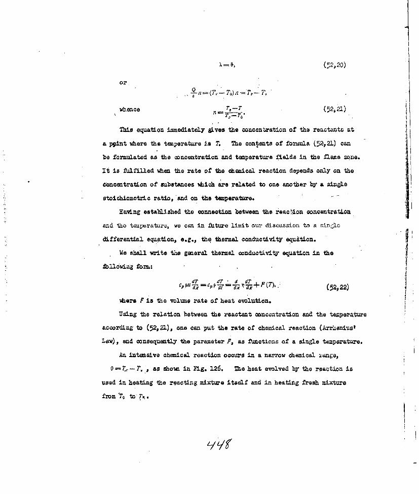
or,
Tbi eqatin imedatey gvesthecon en tration of the ractants0 at
appiflt %here the temperature is T. The contents of formula (52,21) can
be fomltda h ocnrto nd twperature fields in the flame zone.It Ifuflewhntertofthe ceiaratondpdsonly onth
ftaenratonofsubtacesAhchare rltdto one aohrby asingle
stoichiomatric ratio, adon the temperature.
Having established the connection between the reac-1on concentration
a-nd the temeratu~re, we can in fuiture limit our discussion to a sin~ie
diff'erential equiation, e.g., thq thermal conductivity equation.
We shall write the general thermal condutivity equation in, the
foliag form:
C dT CPPdT 'd dT +F()7x' 71- -dl TX/(T) (52p22)
ihere F is the volume rate of heat evolution.
Using the relation between the reactant conocntration and the temperatur'e
aacording to (52,21), one can put the rate of chemical reaction (Arr~ieniust
Law), and consequently the parameter F, as functions of a single temperature.
An intensive chemical reaction occurs In a narrow chemical i-ane
0 =7., - 7'. ,as showa in Fig. 126. The heat evolved by the reaction is
used in heating the reacting mixtiue Itself and in heating fresh mixture
frz To to T..

The term O~PP d 7 PI1 is the expendit~re at ~
in.-raising -die temperature of tho rf.;actio u-x-xra.
The term a - 11 is the loss ;,I' %eat by or. n; ~tVi~.
Because the temperatu~re interval in wbich the reactiUon goeui is r,6r';i
(VI< T - T,,) 'we can justifiably neglect the uge of heat in hoatitg tLo
reacting mixture in thea reaction zonf; equation (52,22) then takes. tho form
d2T F () 0.(52,23)
The'thermal conductivity in the reaction zone can be counted as
~:ac*tically constant.
The solution of this aquation has the form
dr (52s24)
If we neglect the use of heat in beating the r6acting mnixture itself.,
then all the heat of reaction is dissipated by thermal conductivi-ty.
Equating this heat loss from the reaction zone ith the tote-1 heat
evolved in the fl.ame in 'unit time, we have
dT
'n,--uQ (52,25)
where Q is the vol'ume calodific capacity of thr, =Li4ture, and 'up is the
mass velocity of the flame.
Comparing equations (52,24) and (52,25) wt. ?ovas the final equation
for the flama velocity; _____
U.!,1 7 f F(T)dT. (52,26)
Cadovnikov compared the rates of combustion of explosive mixtures ofl
carbon monoxi~de and air diluted with combustion products. The dilute
mixture was heated beforehand so that the temperature of combustion would
not differ from that of an undiluted mixture. This experimient confi--aed
with satisfactory precision the relation obtained from the theory, -upQ -const.

The parameter F(T) in equa'ton (52,26) can be oxreised in t-Le 'sf-
F (T) = Qr" - '' , (.5227)
where n is the relative conceatzation of t e rxac.t 3 s.d rn is the order.
of the reaction.
If in (52,27) n isi expressed in tcrms of the temperaturo as in (5221)
and e-am is resolved into a series of degree - , and we take
into account only first order terms (tbis is jugrdiiable because the reaction
rate is only large enough with T close to Tt), thea we obtain
/F(T)\, Q -r , r ! ,,
ldLdLng some Awther omplications and taking account of the fact that
at the lower integration limit the reaction rate becomes negligibly small,
we get after integration of (52,26)
/1j 2iI/ .,2rnI (52,28)
Whtre 01 (T TO), is the coefficient of thermal
conductivity at tiperature TrP I ris the characteristic time of the reaction
at temperature T, -ad the initial concentration of reaction products
(reciprocal of the maximum rate of reaction).
Since the rate of reaction is
* (df),, ......nrZe'., .
uhere no is the concentration of reactants in g/cm3 , then
; en , (52,29)
In deducing the above result we started from the, condition that the
rate of re:;.ctlon at thd initial' tenperature .T was negligibly small. When
this condition is not observed a stationary diffusion of the flame would

become quite impo&5ible, because at any point the mixture would have
reacted before the D' a front arrived. The above condit-'onz, vQiCa
arise fro the Arrhenus law, can Ie quantitatively fonulated thuz.
8k)(T.o--O)
Substituting values of ( and -r in equation (52,28) end taking into
account that Co(7TT) T Q (waen c = conast.), we obtain the
corresponding equationa for the rate of flae difx~usion:
2 oz, ( 7; (. 5 2 , 1 P
for first order reactions, and fbr second. ordr roactions
POQ(r-T 0y L
Belyaev i a experiments on the combustion of mathyl nitrate end nitro-
glycl (in the vapour phase) confirn the results of this theory well.
"ihe important relation between the ;aaie valocit and the temperature
according to (52,30) and (52,31) is connected with ArrhealUa law of chemical
reaction rates, ihbih states that, to a first approx imation
O-Mfi'r", ".(52,.3)
Consequently there should be a linear relation between Ig . and -
The results of working up the data of Passauer and Sadovnikov (on CO/air
mixtures) are shown in Fie. 127. They are in complete agreement with this
requiremat of the. theory.
TL'e relation between the rate of flame diffusion and the pressure With
other conditions constant is deterained by the characteristic relation of
the chaaical reaction rate and the pressure.
....

Because 1 r 7
then, according to (52,26) ;j~w
MF±R.l27 on. t 08 c-'-;P14 -P (52,33) the, rate ofc siondthe taprtne.
wqhere 117 is the rate of the chmaica. reaction, p, is tho prcesure Qf the
.-aseous mixcbira, and mn is o~ rder of t.'e chemical reaction.
Thus, for a uniinolecu3.ar reaction PU wher~.as for aIbimolecular reaction P- 1P
Because the density of a gaseous mixture is proporilonal to the pressure$
we got for a linear rate of combustion
U (252,.34)
ohich requires that u should be indepondit, of prassure for a biriolecular
reacti on, and that L U~ for a -xinolecular reaction.
Tlbbelohda and Kellikerts observation that the rate of 1141 me diffusiou iin mixtures of different Inflammable gases (petrol, bonsene, 1 thaaie) was
related to the pressure at orders betweea p-'- and pb , corresponded to
chetuical combustion reactions of oirder Lbetween first and second.
53,. Combustio 00' Oa~sed- gxosiv-:5.
When explosion of a high eVlosive or detonator is broufght about by
a thermal impulse the formatioi. of a detonation wave Is always preceded
by a more or less prolonged period of accelerating oombustion. Transition
from combustlon into the detonation type of explosion only occurs in
favourable conditions even in the cease of non-stationary processes.
The combustion of detonators is usually very unstable and is easily
transformed into detonation. On the other hand combustion of powders
procods in a vory atlible manner and tranuition to donation appours to be
possible only under special circumstazoes ver.1-h ; L; 1*c,

High e>@losives occupy an intermediate position between detonators and
powders in their ability to undergo normnal combustion.
Tha- combustion of high exlosivas and dotorators hao been studied
insufficieatly. It has bcoa inve~gatod principally at low "d.' contan=
prossures, close to atuospheric. It hac beea estit-ished thcat most of
the e>2.osives studied ci undergo stable omluastion at a cntaunt rate in
th L'; ned conditions, and the rate waa dceden of tho length of the
charge.
AndreeV observed that combustion of the exoloaives under discussion
usualy occurred idth very- weak luminescence in a gas -layer uhich lay close
to the surface of the condeased phaae. Then what he called the combustion
flame was a result of the combustion of hot reaction products in contact
with the air.
The following factors can have a considerable effect on the character
and rate of diffusion of the combustion processes: the properties of the
explosive, the pressure, the initial temperature, the density of the charge,
the diameter of the charge., the thickness and the kind of casing.
The possibility of a process and the rate of t diffusion are deter-
mined first and foremost by the kinotics of the chemical reaction, i.e.,
by the rate of heat evolution and the rate of heat t ,anamisslon from the
reaction mne into the starting material. The coz.ditLon of heat trans-
mission uith a given reaction kinetics deponds on the thermal conductivity
of the explosive.
That lead azide only undergoes a detonation tuma of akolosion, no
matter vha-t the conditions, can be ecplained by kinetic factors. The high
rate of the chclical reaction in the conversion aa a result of exceptioaally
rapid acceleration leads to diffusion processes by heat transmission be!mo

OQt~aonritif: i rate 0 .chi"2 axo 1-a i:
experimental .condit:Lons ise small, t '.o 106a G f~~ _-'a cjo
of hea't c~i.'iLo to -Uia sui z.e ~ :ot ~ta
asn~ce of heat, tiie px-ocess wcvuld ~a ~ do~o
Howevar, if tho tliermaJ. conductivity of the exlosiv, -'s hiv 'hc
the heat of reaction ma patrzte iatoth =_ocd :3ust"Yica tIo a '_a
do',tb, and consequ±ently the t=-peratuxa 'ka thon:v&-sion zo.-ia would 'V-
insufficient to stimulate an iat= se chemical raact ancapabl.e of sustaina~ing
a sl-diffusing, process.U
The speciflo pecliarity of the oombustion of high ezpJlosivdi and
detonators is the possibility of physico-chemical processes occurritne
simul4taneousl.y in the condensed and gaseous phases. In a very volatile
substance combustion may occur exceptionally in the gas phase when its
bopiling or subl.imation teiperature is lower than the temperature, at Va±ch
the chemical reaction proceeds at a, notable rate in the condensed phase.
In this case the general character of the combustion will ba deter'-
mined by two~ factors - the process of evaporation of the condensed phase
end the conditions of development of the chemicaL reaction in the vapour;
heat fromn the flame ~e will pass totho ondenased phase through a layer
of hot, but not yet reacted, e~xosive vapour just us in gaseous ixitares.
Thin type of combu.stion is characteristic for low Wio616ng liquid explosives.
The combustLons of met:yl nitrate z.nd mitroglycol at czparatively low
pressures are typical exampl.es.
For non-volatile end poorly v"latile substances, dep)ezding on its
mechanisz, the chemical reaction may occur either only In the m-n&-e'sed
phase, or simultaneously in the condensed, smoke-gas, and gas phaaes.
In the first. case reaction leads almost directl.y to final combustion
pxoducts,, but in t~he second case combustion is a very complex process izi
uhir4h _ne-e~a r~c~loi ara of de±'.Lite importance. This tyipeo

roaction is the moot frequent in practice. Typic. -, th
combustion of pyro>'lin and
PrasaurQ has the most iaport~zt effect on the r-te of cm'uLicn
of exqlosives. As a rule the rate of combustion increases with pr ?sWu-
and at a sufficiently high pressure burnint bc.zeo unstable and diar.Lea
into detanati on.
2%,aercur fulminate is the most satisfactorily studied of detonators.
Patri, uho studied the combustion of non-pressed uercur"7 fulminate in th
open air, established that the process diffused at a rate 9f saeirl tC.Is
of metres per second, that it was unstable and chan.%ed into a detor.Qtin.
This is explained mainly by the easy diffusion of hot reaction prod~cta
into the pores o. the substence, thus continuously iac-easing the
combustion surface.
A qatenatia investigation by Eelyaev showed that mtrcury fut.,
• i4b had been pressed into tabloe (d = 4 mm; A 7 an) a'c a pressure 6.A
about 2D00 Krg/aj without cases, was ablec co =dar&o stationary combuat~on
at atmospharlc pressure at a rate of oly moa on/seo. Analoyuj
data were obtained for same other deta .rto S.1a-v' results are
cited in Table 81. TA BLE 81
.Rate of combustion of some detongting explosives at atospheric pressure.
NDensity 3 Linear velocityName of explosive g/cm CM/see.
Mercury fulminate 3.80 1.55
Trinitrotriaidobensene 1.70 0.65
Diazodinitrophenol 1.45 2-15
Potassium picrate 1.83 1.50
Lead styphnate exploded -
Lead styphnate talc(WO/60) -- 14.50

It was concluded, from observations on the combustion of detonators
at various pressures below atmospheric, that the rate of combustion over a
wide range changes almost linearly with pressure.
ua a +bp. (53,1)
This circumstance is evidence of the important part played by
combustion in the gas phase. If the rate of reaction in the gas phase
depends on the number of oollisions, thin the rate of combustion should
rise linearly Ath the pressure.
Resulta of experimuts Ath mercury fulminate and trinitrotriaidobenene
are gven in Table 82.
Nero.ry fulainate Trinitrotrlasidobonsme
g i. .iac p. sn g .ef
760 1.53 760 0 63603 1.30 425 0.44406 1,92 375 OAS3175 0,67 115 0.1610 0.48 40 0.15
ZAWLr k. hflega batwn Ie rate of , , ,,tree.._..
It 1i am from these data that when the preeure Is dcoreased lo
about a nta the rate of combuston of mercury fulminate Is. &m--weed
to about a tird. With a pressure of 2OO m. or leas the rate of
combustion to praotioally lndopmdmt of pressuae., similar pattern
is observed for trinittotriaidobeneeo.
On the basis o heuo and other observations Bely ae -. that
reactions In the oondmnse phae plaed an importt part In the
calmbuton of detonators and espeoilly of nerourcr fAumiate. 7he
intermefiate products of mercury fulminate fonmed " the result of
priay reeUone react eve at comparatively 1ow temperatures i & the
gas pkaneI thes reactions have a deteiminin. 4 ,flownetk "e rate of
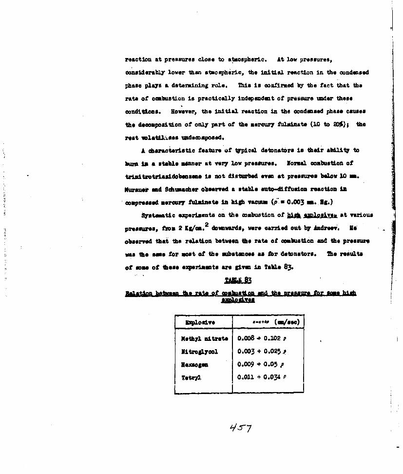
reactlon at preasures 0c0e to atmospheric. At low pressures,
oonsiderably lower than atmospheric, the initial reaction in the condensed
phase plays a determining role. This in confirmed by the fact that the
rate of canbustion ins practically independent of pressure under these
conditions. However, the initial reaction in the condensed phase causes
the decomposition of only part of the mercur7 Ablmiziate (10 to 2D%); the
rest wlatikss undeconposedo
A daracteristic feature of tupical detonators in their abilitr to
bum in a stable menner at very loy pressures. Normal combustion of
tral4ottrimsdobensmen is not d&sturbed even at pressures below 10 m.
Murauew and Schuacher observed a stable auto-diftfusion reaotion a
Scompressed mercury Alinate In hbith ,aCom (pS 0.003 M. 96.)
Systematic experiments on the combustion of h j~JJyjb at various
2presmsuess fom 2 Ka/em. downwardsp were arried out by Andrew. ge
obsorved that the relation. between the rate of combustion and the pressure
was the ease for most of the substsnoes as for detonators. The results
of mne of these experiments are given in Table 83.
EUB hqdVok the rate qt goah .gaon end the nassUln for -maj bla
Explosive a-4+60 (om/sea)
Kethyl nitrate 0.008 + 0.102 p
Nitroslycol 0.003 + 0.025.R
Iesso em 0.009 + 0.05 p
Tetry2 00011 + 0.034 F

In all *.as* experiment@ ambustion of the explosive was carried
out ina glas tube ( I Pw4-6 m) whiahws placed under the bell of a
yarnm pmp.
On thte beau~ of these data it can be oncaluded high explosives
camiderably more slowly Shan detonators. The parameter 'b in considerably
larger hbr the latter than for the former. Thus, according to Belyaev,
a -0.4 and b a 1.1 Jhr aeraazy fulminate. ?Us seems that the
acceleration of combustion under the Influence of procss proceeds com-
Aidorably more slowly in high explosives them In detonators, because the
former ane capable of uderiping stable combustion (in the absence of
factors caning increased acceleration) at relatively hiab pressurs.
In mat cases wha the pressure is domeased below am*s inli vlu
norMal cMbustin of explosives becomes, impossible and Soe prooesm oeases.
The limiting presmuire depands principally on the pbyio-6ial
pMropete Of the exloMiVe and the 2*Meauif Of the Chalcal reactio In
Soe comibustion ams According to Andreovs date hi proeses
2%O-=0 m. Rg. hr nitroglyco, ft em. Ng, hbr hakoogmef. sanet 400 mjg.
Jbr pyroxylin 90.11 d loss Uma 24 -. 3g. for nitelyoorine.
Ike cocorraso. o a lover pressure limit for osudased explosives Is
aydmmose hr the especially Important role of reactions in the g%3 phase
in the owmbuftion of these mubstances. On decreasing the pressure the
reaction rate ad the rate of heat evolution in the gem phase decrease
correspondingly, but the rate of heat loss in the condensed yhase is
practicloly indepandmat of the pressure ad remains omstant. At a
doeflaite@ poessiW tisa~ Ban tMo 40teMAenme of 4 thiimoa1M
epq.Jiz mum and cesatilon. 0i we reacuaon.

If In the aettanims of ccabuston, of an explosive under specifiled
conditions, a reaction occurring in the condensed phase becomes at P.sJor
isiportano., then the 2osibility of stable, combustion on decreasing the
pressure aracin. A enul value at thi% limiting pressure can Indicate
that a condensed phas, reaction is contsolling the selt-dittuuian process
in the cantions given. Mhe independence at the rate of combutiAn at
meraaz todainate and pressure at P < 1W0 ma. Hg, and Its ability to
burn In hiab vacum ae in agreement with 1ya~v'a Ida" an the oorn-
bastion ot this substance in tho condilU ama discussed.
Saim ha" established, for a tholo series of solid explosive mixtures
that their relative ability to udergo stable oombustorn at low pressure.
end stuicity em.pawabLe conditions depends on the ratio bgtveen the solid
anid Caseous reactiom prodaotse If the reaction products at the combustion
temperatre are completely7 solid or liquid, that the raea of cocbustion is
completely independent of pressure. Systems ioh am capable of this
the rate of combustion. of suah mixtares takes a particularly simple talus
of toe reaeon ooatrolling heat tranamsul. ad whici occurs In the solid
phase, *ore"s Ike cooeffiient- b,dependa c9 the condittons for a process
occurrin in the gas pha&""
2ke results of Andreev's studes ohm"e that ombustion of condensed
exp"losve at hi" paess a es a in different wqs depe-ding on Soe
physica state of the explosive. saploldvos am be divided into three,
&MIMR Ahp Moomomaa4 ^IC 64 4 .d-* J&.. - .
(powdered end pressed ezlosiv*),, and liquid ezplosive systems.

Besides the nitrocellulose powders, blasting gelatine gelatins-
dyamite and some other explosives are representative of the first
class of explosives. The ability of these explosives to undergo stable
conbustion at high pressures is expressed most strongly. Thus, blasting
gelatins does not lose it. ability to burn normally in a closed sysaen
even at pressures of 1200 Xg/ 2 .
Typical repreentativos of the second group are the high explosive
powders. According to Andreev's data, the limit of stable combustion
2for t4n and hekmogen In a pressure oa about 25 Kg/n , and for tactyl
and piefe acid a pressure of about 65 Kg/rn 2 .
However, these explosives in a compressed otate are able to burn
stably in a o;.osed tube at considerably hiAer pressures; for example,
ten, at a denatt-v of JAS ,/c2 bwh noznally even at 210 IK/on 2
Cast 4qlosives behave in this manner %hm PAtOIently compressed.
Thes tacts cm be explaved thus, In powdered explosives at iig
pressures the burning gases cm eosparLtivly easAly enter the pores
between particles of explosive and IAIte then. Consequently the suracee
of ombustion inoreases mbarply aid a stationary process bacomes impossible.
the porosity of the explosive Is decreased b" Increasing its density and
this makes mre difflault the entr of the flame deep into the substance.
The ehracter of the combustion of liquid explosives in relation to
the pressure Is somewhat different fioa that of kld explosives. iken
nitroglyoerine Is ipited at atmospheric pressure it ,does not bum but
lashe. When ignited in a sealed tube it deteates at a pressure of
about 45 /ri 2
aecorng to Andreev's data, relatively unimfr comnbustion of nitr-
glycerine only occurs at pressures below 20 KRer . At hbiher pressures
the ahnar ntf+J- *ee hiti- ~w"WiseraP~y. rue suZ'zace of tiie

liquid is disturbed and the whole pYOoBess"occurs an a series of
oinsecut.,s flash es. Theoretical and experimental investigations
have shown thtit the disturbance of stable combustion in liquid and
solid explosives is a result of an increase in the ombustion surface.
In the present cas this occurs by boiling of the surface layer of
liquid (Zelldoviah) or by disturbance of its gamodynamic stability
(Landen) owi~ng to the turbulence of the surface. Increased viscositir
prevents the'eppearence of these, phenomena.
On the basis of the results discussed, it is possible to conclude
that the £ sturbance of stable coabustion in condensed explosives
depends not only on tie acceleration of the process as a direct result
of the rising pressure (+Ais acceleration Is =all) but also on the
cause qicih, at a certain pressure, produoes a disturbence of the timse
fzont and of the combustion LIIrtace.
For simost all the explosives stuisied the linear rate of ombustion
Is deeweased as the density (of the explossve) increases. This Is shown
for eample in Aadreev's data cited in Table 84.
Mate of afebalUm, /#ata
T~t~~1(tiF. 1A. at the tab@ 24 o)0,68s i Set but0,74 5.41OA8 4A81.04 4.461.07 4.27
lekaeea (a-164 di. of the tube 6.3 no)
0,95 3.191.05 2.191.16 1.49

The effect of denaLtiy on the rate of combustion is evidence of
the importance of changes in porositY of the substance. Density
affects not only the rate of combustion but also whether it can
occur at all.
The data in Table 84 show that the combustion of tetryl and
heksogen ceases if te density is reduced below a certain level.
Andreev explained this as a result of an increased rate of heat loss
in the condensed phase caied by the ease with which the molten
substance could penetrate between the particles of explosive. T The
limiting density depends on the experimental conditions (tube diameter,
crystal aso). The density limit for stable combustion is somewhat
reduced by an increase in tube dismeter and in the state of div'sion
of the explosive.-
Pyroxylin, which has a oelluloeo-like structure, behaves quite
differently from tetryl and hekeogen. It bures energetically enough
even at poured density, but it shows an upper density limit above which
combustLon does not diffuse (Table 85).
WMALOR tonb*wesn the rate 01 eMabtion 9 on i~n 'In- I kno d.40"
DOWLty,WCon Wet at omutatoa,a0/u
0.24 37.50.30 31.10.67 M 1Wigbla~ue

A satisfactory explanation for this peculiar phenomena has rnot
yet been found.
For condensed explosives, just as for gaseous mixtures, there is
a critical diameter below which comustion will not spread in the
conditions of the experiment. Critical diameters at atmospheric
pressure are ahown in Table 86.
OZ~tpal dameteirs for sa~ hLU ezolosI33a
£xploa orv
Cast TNT 1.59- 32.0Cast Tetryl 1.60 5.7Hekbogen 1.0 6.o '
PYVO.Vlin No.1 0.6 5.5litroglyool -2.0
the critical dl. meter for en explosive in not constant. It changes
considerably, varying with the density of the explosive,, the material
mnd 1hickness of the casing, and certain other factors.
The critical diameter depends on the hea% loss. Howevers the
conditions of heat output can differ considerably depending on whiether
the reaction occurs only in the gas phase or In lboth gas and condensed
phases. In the latter case the combustion process would be accompanied
by considerable heating of the condensed phase and the heat loss wuld
Increase sharply.
The limiting diameter also depends on the rate of combustion.
The greater the rate of combustion the smaller will be the heat outflow
and the critical diameter in otherwise Identical conditions. TNT bias
its maximim limiting diameter at its lowest rate of combuotion (-1 n/in).

For vnlatile substances, in Qhch the reaction occurs monpleteLy in the
gaseous phase, the surface layer only of the condensed phase is heated
to the boiling point and the heat loss consequent upon heat conduction
in the condensed phase will be small. For this reason the limiting
diameter of a nitroglycol charge is small even at low rates of
combustion (- 2 /mn.).
The rate of combustion of explosives is increased relatively
slightly by an increase in the initial temperature. The rate of
combustion of a series of explosives studied by Andreev was not more
than doubled by increasing the initial temperature by 100° The
results of some experiments are ci-ed in Table 87.TA&L 87
Effect of toerature on the rate of combus~ton of ezlosiveas at -atmospheric Pressure
L Exerimental Temperature ooeff.Explsiveconditions. of combustion rate
Nitroglyeol Liquid 1.52
Gelignite- 1.82Tetrl 0. ; = o9 V/03 l.ej
He icoge ,, . 9 /M 3 1. 0.9
Nitroglycerine powdercontaining 28% nitro- = 1.6 &/CM3 2.9
glycerine.
Similar results were obtained by Belyaev in experiments on the
combustion of mercury fulminate. On changing the temperature from 16
to 1050 C the rate of combustion of mercury fulminate increased 1.52 times.
The data obtained permit one to conclude that the regligible acceleration
of combustion with increasing temperature is a phenomenon which is general
for higb explosives and for detonators. tl q

A study of the combustion of TN~T and nitroglycr'- temperatures
close to the flash temiperatures showed that in these conditions the
acchleration of the process does not become large, as can be seen from
the data cited in Tables 88 and 89.
TIL88
Ef4fect of temperatuire on hert fmutonofnitrojky~col A&
I ni tia' Linetr rate oftesterature, n
Frozm Table 68 it is seen that when the initlal temperature was
increased from 20 to 180?, i.e., almost to the flash temperhture, the
rate of combustion of nitroglycol increases approxi-nately twice.
On the basisa of his observations Ba2.yaev concluded that at atznos-
pheric pressure a. temperature of 1850 is limitLnL for niormal3 combustion
of nitroglyool in parallel layers.
Effegt gt i.n4.gJ tiieau.o e rate of gM_.Mpon q;f lTTa
~~(Iital a .0: rate of h
temperaure, cobu tion Remarks
112 1
21M) i ,62:.ks 2 ) Combustion with
pulsation20 -.7 ditto
ditto

The combustion of TNT, which is initially even, becomes pulsating
at temperatures of abouL 23D - 2500 and is accompanied by spitting of
the hot melt. This ib ze cause of the more rapid rate of growth of
combustion under these ounditions.
As ill be zhom below, it follows from the theory of Combuation
of condensed explosives that one would expect a linear relation between
the logarithm of the rate of combustion and the reciprocal of the
absolute temperature for condensed explosives (and also for gaseous
systm s).
The results from Andreev t a and Belyaev's experimental data show that
this requirement of the theory (in a stationary process) is in fact
fulfilled and has a general character.
The ep-Zalldgich thor= of thA caMabujatn of cgidensPd eoxlogives.
It is necessary to start from physical promises and the basic laws
established in the theory of thermal d&ffusion of flames in gas to discuss
the combustion processes in general and the combustion of condensed
explosives in particular. However, it is also necessary to take into
account those specific peculiarities which Pre linked with the mechanism
of their combuation.
A number of authors (Letan, Shveikert, Yamaga, Kraw and Grimahaw,
and others) have constructed theories of combustion on the premise that
the chemical reaction proceeds only in the condensed phase. They started
from the erroneous supposition that activation of the molecules and the
transfer of energy in the combustion process occurs by bombardment of the
surface layer of the explosive by the gaseous reaction products.
In 1938 Belyaev put forward a new theory of combustion for condnsed
explosives in -which the basic role in energy transfer was played b.
thermal conductivity, and the kinetics of the chemical reaction were

taken into account. It differed from the theories discussed in that
it assumed that the combustion of axplosives took plac.. in the gas phase,
not the condensed phase.
According to Belyaev the energy at the surface of a volatile
explosive would bA used in evaporating the substance. According to
Belyaev's calculation the probability of a molecule of nitroglycol at
2000 having sufficient energy to evaporate is 109 times as great as the
possibility of it having sufficient energy for activation.
In fact the probabilities of these processes are respectively:
e-p F ' e-, -F
where X is the heat of evaporation and E is the energy of activation.
For nitroglyol X = 14500 cal/mole and E 3500 cal/mole.
Thus the rate of evaporation should considerably exce( I the rate of
combustLon and combustion can occur only in the gaseous phase. The heat
set free in combustion would be used in heating the gases and in
evaporating a new portion of-t acondensed phase. An increase in the
rate of combustion and, consequently, an increase in the passage of heat
to the condensed phase should lead to an automatic increase in the rate
of evaporation, ad this, by absorbing the energy from the combustion
zone, would prevent reaction occurring in the condensed phase. Because
of evaporation the surface of the explosive would be constantly changing,
but te temperature of te surface of the condensed phase would remain at
a constent value equal to the boiling point.
The explosi-e vapour should not ignite at once; some time should
Aanse %bile the gas is heated and the re':ction spreads; consequently,
combustion of the vapour would occur at some distance from the condensed
phase, aid between the combustion region and the condensed phase there
would be a zone of gas awalting combustion. 1lj-auv .... riad '%Q
4'7

ex.stence of s-uch a zone (dark, non,-luinoun)
experimentally in the case of nitrolycol. .1
Thus we are led to the general diagram of . . -n
combustion of explosives showA in Fig. 1 Fli.. 128." Temperature
diiftributicn in a bur ingexplosive,
Here / in the reion of the conden.ed zone, /I is the reic-n of Las
awaiting combustLon, and III is the region of hot reaction products. The
curve T0- T, - Zr shows the temperature disatribution. T,, is the initial
temperature of the explosive, T'k is the temperature at which the vapour
pressure of the explosive is equal to the external pressure, i.e. for
liquids, the boiling point, and T, is the temperature of combustion.
It is clear than, when a stationary combustion system is established, 4
the quantity of substance evaporating from 1 2m. of surface in 1 sec.
should be equal to the amount of substance burning in 1 cm. 2 in 1 see;
in other vords, the mass rate of combustion should equal the mass rate of
evaporation of the condenced phase.
Zelclovich showed that the theory of combustion of gaseous mixtures
developed by Frenk-Kamenetskii and himself could, with some modification,
be applied to some cases of interest to us. On going from the combustion
of gaseous mixtures to the combustion of explosive vapours it is only
necessary to take into account the energ used in evaporating the condensed
phase. According to Zellclovich, the mass rate of diffusion (if combustion in
explosive vapours is defined by the following expression:
PU' (T, TO) +n 1) 1W (Tr) g Isea 3, (53,2)
where ,, is the coefficient of thermal conductivity of the vapour at the
combustion temperature, T; Is the combustion temperature, To is tho inial

temperature, 1T, is the rate of reaction at temperature T,., L is the
activation eniergy, Q, irs the heat of reaction minuis the heat of evaporation,
end ma is the order of the reaction.
In the particular case when the reaction is unimolecular, equation (5_-,,2)
cen be put in the follo&Ang form:
!4J e7 -T
where p is the vapour density at temperature T,.
From equati'on (53 ,2) it follows that the relation between the rate of
combustion arnd the pressure is, in. this case, of the sae form as for
gaseous aixtures: -P
Since, according to the experimental study, the rate of combustion of
nitroglycol depends linearly on the pressure, rn 2, i.e., the reaction
w~hich determines the rate of combustion of this substance is bimolecular.
The direct application of equation (53,2) to the calculation of rates
of combustion is very diffi cult because the values of m, E and T, &are
unknown for most explosives. However, if equation gives the correct
connection between the basic kinetic constants and the rate of combustion,
than the reverse problem can be solved - from the rate of combustion and
its dependence on pressure the kinetic constants can be calculitted. Belyaev
carried out this type of calculation for nitroglycol; the calculated
activation energy E --3L,000 cal/mole obtained by Apiri from experiments on
the thermal decomposition of nitroglycol. According to Belyaev, this
confirms the correctness of his theory.
According to Belyaev combustion in the gas phase is only possible if
the pressure does not exceed a certain critical value. As the pressure
increases so does the boiling point, and consequently the temperature of
the surface layer of the condensed Phase. As a result, the "tail' of' the

curve Tk - T, will reach further inside the substance. This increase in
temperature mq be very considerable. For nitroglyol t k is 1900 C at
atmospheric pressure and 400°C at 100 atmospheres. At the same time the
relation between the rate of evaporation and the rate of combustion changes
considerably. At a sufficiently high pressure the heat liberated in the
reaction %ould be only partly used in evaporation and combustion would occur
in the condensed phase. However, in Belyaev's opinion such a combustion
regime would not be stable and should change over to detonation almost
instantaneously because of the direct bombardment of the unreacted molecules
of the condensed phase by the gaseous products.of explosive decomposition.
It will be recalled that in the normal process of diffusion of combustion
it is thought that the transfer of energy from the reaction zone to the
starting material is by thermal conductiity.
Belyaev considered that the combustion mechanism described above was
characteristic for most condensed explosives. If the boiling point is
lower than the temperature at which intensive reaction occurs, and the heat
of vaporisation is considerably less than the energy of activation, then
combustion %Lll occur in tho ge. phase. If the boiling point is considerably
higher than the temperature at thich intense decomposition begins, end the
heat of vaporisation is close t the energy of activation, then decomposition
ill occur in the condensed phase. However, as a result of the initial
reaction only vaporisation of the original substance end formation of hot
products occurs. The fUrther reaction of these products in the gas phase
totally determines the rate of combustion.
The toiling points and the heat of vaporisation of some explosives are
given in Table 90 (fter Belyaev).
/7e)
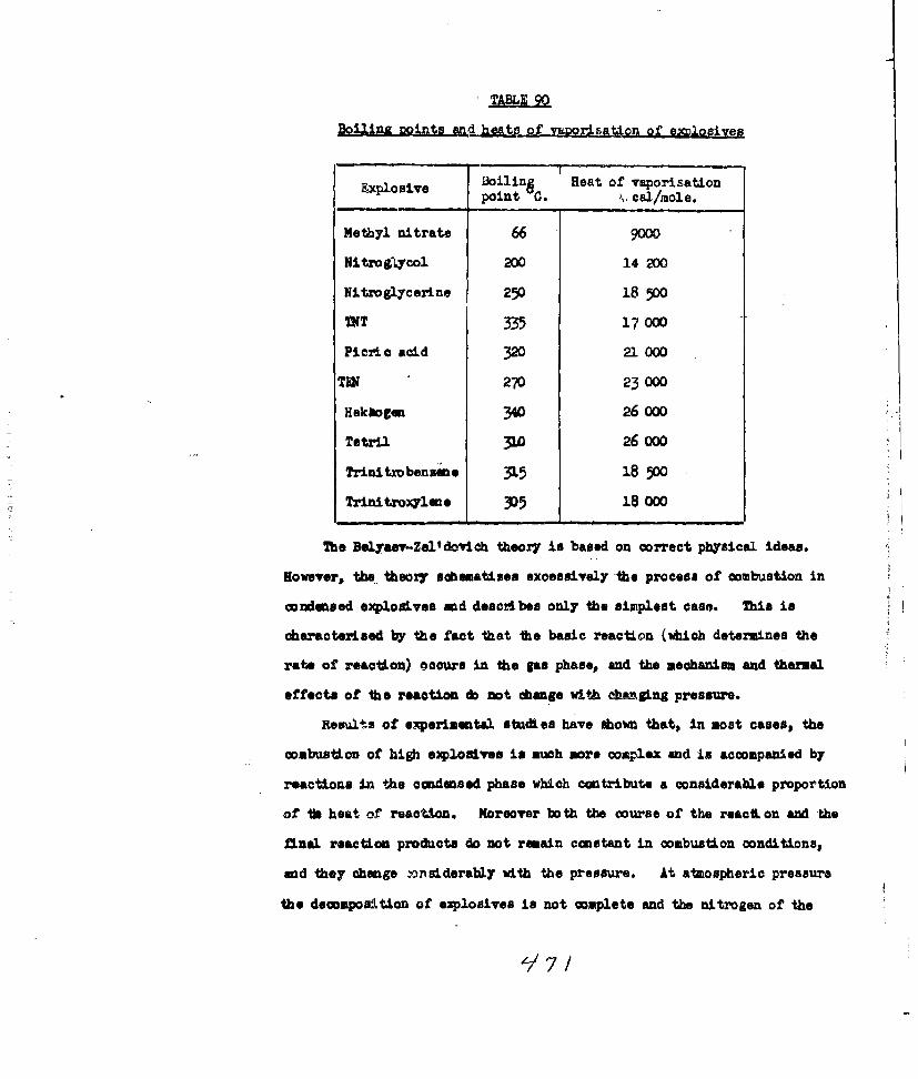
Dolling points Mgd heatg of vyrsation of enJlogives
Exposie oling Heat of vraporisationpoint 0.Cal/mole.
Methyl nitrate 66 9000
NitroLyco1 200 14 200
Nitroglycerine 250 18 500
IT335 17 000
Picric acid 32X 21 000
TM270 23 000
Hekbogen 340 26 000
Tetril ~ .0 26 000
Trinitrobenie 31 18 500
Trinitroylie 305 18 000
The Belyaev-Zeltdovich theory is based on correct physical ideas.
Howvr, the, theory scheumatises excessively -the process of combustion in
condenased explosives and desci.bes only the simplest case. This is
characterised by the fact that The basic reaction (which determines the
rate of reaction) occurs in the gas phase, and the mechanism and thermal
effects of the reaction cb not change with ah&sn*%Sng pressure.
Reslts of experimmntal. studies have shown that, in most cases,, the
combustion of high explosives is much more complex and in accompanied by
reactions ij2 the condensed phase which contribute a considerable proportion
of b~ heat of reaction. Moreover bo th the course of the react on and the
final reaction products do not remain constant in combustion conditions
ad they change -3nsiderably with the pressure. At atmospheric pressure
the decomposition of explosives is not complete and the nitrogen or the

explosive separates as nitric oxide, whereas at hiiLur pressures (of tlhe
order of tens of atiospheres) no nitric oxide is observed.
54. 006IN0OF EQD
Normal combustion of high eplosives and detonators is possible only
under well-defined conditions, whereas for projectile oxplosives .(powders)
thiL type of explosive conversion is typical. The characteristic stable
oombustion of powders results from their ability to burn in parallel
concentric layers even at high temperatures - 5000 - 6000 Kg/cm 2 in
extreme cases.
The following three phases are normally distinguished in the combustion
of explosives:
(1) iguition or localised origin of a self-diffusing reaction;
(2) inflammation or spread of the original process in the surface
of the oubstance,;
(3) proper combustion or diffusion of the reaction in the bulk of
the substance.
Such a division of the process into three phases is in general
conditional because they do not differ from one another in principlo.
However, it must be remembered that these processes occur at different
rates in the conditions for the practical use cf powders.
Ignition is the initial denomposition of the powder. This usually
occurs as a result of local heating. It is the first stage of ignition.
The rate of inflammation of a powder depends on the nature of the
powder, the state of its surface, end especially strongly on the pressure.
The smokiness of a powder dependp in the first place on its ability to burn.
The rate of ignition under otherwise equal conditions increases with
increasing specific surface of the powder. According to this principle
a powder with a rough porous surface as a rule ignites more easily than

a powder with a smooth surface.
The rate of ignition increases considerably with increasing pressure.
This is because the increased pressure hinders the removal of' the hot
gaseous combustion pro ducts from the surface of the powder. Analogous
data was also obtained for gelatinous nitroglycerine. According to the
data of Levkovich and Arab the rate of combustion of nitrocell.ulose
powders in the open air fluctuates within the limits 20-40 a/sec. %bhen
large quantities- of powder are burned the rate of spread of the flame
over the surface may reach several metres per second. W~hen powders are
burned in air the rate of spread over the surface is considerably greater
tha the rate of combustion. If a vertically suspended powder charge is
ignited at its upper mid, then in a certain time
the surface of combustion of the! charge will
take the shape of a right-angled cone (Fig.129)
because of the difference between the rates of ()ignition and combustion. The ratio between
these rates can be defined in terms of the
vertical angle of the ocne I
wheire ui in the rate of cembuastion and u2 Fig.129. Combustionof a powder charge in air,
is the rate of ignitlon."
When a charge is bu'ned in an inert atmosphere
tese two rates are equal and consequently. a
cater is formed instead of a cone (Fig. 1l30).
Hec~tis-clear that the great rate of qom-
bus~oninopen air is connected with the:
Fig.13D. comnbustionlo f a powder charge in combustion of reaction products due to oxygenan atmo sphere of an~inert gas. in the air.
147 3

Combustion of a powder proceeds at a deflnite rate normal to the
surface. Equilibrium spread of the process is achieved thanks to the
high densiV and uniform physical structure of the powder elements.
Other things being equal, the rate of combustion depends on the
calorificity of the powder, the initial temperature of the powder elements,
and the external pressure.
The rate of combustion increases with increaslng calorificity.
Consequently, for example, the rate of combustion of pyrox~lin powder
increases with increasing nitrogen content.
According to Murauer's investigations, at sufficiently high pressures
the rate of combustion of nitrocellulose powders changes in an exponential
manner with changes in the temperature. This is because there is a
linear relationship between the logarithm of the linear rate of combustion
mod the tmperatarQ.
1gti=A+BT. (54,2)
As the density of a powder decreases so its rate of ombustion also
falls. According to W.-li's data, the time for camplete ceubustion of
standard cylindrical charies of moke powder varies with increasing deAsity
of the charge as fbllows (Table 91).
Charge density, i/A 3 1.670 1.83 •1.900 1.92D 1.946
Time for combusU/on, sec. 0.00274 0.00392 0.01073 0.03W2 0.05269
It follows from these data that a 17% increase in charge density led
to the rate of combustion being lowered by a factor of more than 19.
This relationship is explained as followas vhen the density is
increased, the porosity of the powder is decreased, and thus the passage
of hot reaction products into the bod of the substance in binfed.
471

The rate of combustion increases with increasing inO.Idal temperature
of the powder, but the effect of this factor in the case given is not
large. According to Andreev' a data, the ratio between the rates of
combustion at 1000a and 0 0 for a 28% nitroglycerine powder was 2.9.
11e effegt gf orasre,. The relation between the rate of combustion of
powders and the pressure p ham been the subject of many investigal on.
According to Wel, the relation "~(P). in satisfied by the equation
Ht = Ap' (5403)
where A and v depend on the nature of the powder.
For maokyr powders Weil put v equal to 0.5. According to Zabudskoa,
a 0.93 for pyroqlin powders.
Bausaamd Leykavich showed that v was not constant for a particular
powder. It chaed considerably with the pressi.re. Thus for ivition
of pipe powder in a manometric bombs 0.117# whereas at alaospheric
pressure 0 ~.505.
Miaplm,, from a treatment of other authors* data, conaidered that v
for moky powder changes with increasing pressure as shown in the table.
Many authors believe that a simpler relatiori
oa be used for the rate of conbustdon of n1ii____ _____
cellulose w-wderst
u ==Ap. (5494) 0410
nxis is a seial case of (54#3) with -v 1. 300.40
m ~erimonts establismhed that the relation (54,4) was
satisfactorily observed only at high pressures (about 1000 atom' and above).
For lover pressures (from 5 to 250 atc) ivtaid&4v 0.7. Thus
it can be soon that v1Is not constant for nitrocllulose powdors either.
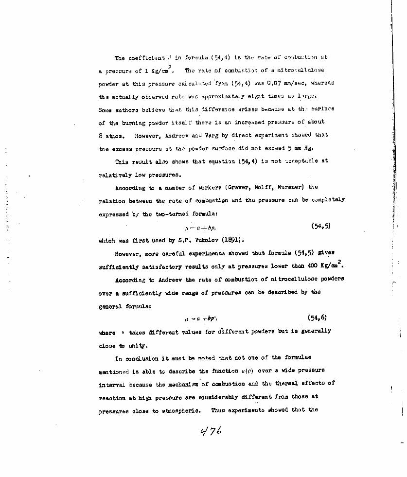
The coeffteient .1 in fornula (54,4) is tht- rate of cY!ibu:;ti.tn at
& pressure of 1 Kg/cm . The rate of conbu Lion of a nitro.:elu1o3e
powder at this pressure calcu1' tud frm)p (54,4) was 0.07 rm/sec, whereas
the actually observed rate was approxLn:ateiy ei~at timts as l'rge.
Some authors believe that this difference arises becuse at th:. surfare
of the burning powder itse'l.f thera is an increased pre:3oure of about
8 atmos. However, Andreev and Varg by direct experiment showed that
toe excess pressure at the powder surface did not exceed 5 mm Hg.
This result al~o shows that equation (54,4) is not -.cceptable at
relatively low pressures.
According to a number of workers (Graver, Wolff, Murauer) the
relation between the rate of combustion and the pressure can be completely
expressed by the two-termed fonAula:
a bp, (54,5)
Which was first used by S.P. Vukolov (1891).
flowever, more careful experiments showed that formula (54,5) gives
2sufficiently satisfactory results only at pressures lower than 400 Kg/a
.
According to Andreev the rate of combustion of nitrocellulose powders
over a sufficientl4 wide range of pressures can be described by the
general formula:
a - (54,6)
where v takes different values for different powders but is generally
close to unitv.
In conclusion it must be noted that not one of the formulae
mentioned is able to describe the fAnction up) over a wide pressure
interval because the mechanism of combustion and the thermal effects of
reaction at high pressure are considerably different from those at
pressures close to atmospheric. Thus experiments showed that the
L/7

tfermal effect of burning a nitrocellulose powder at pressures below
240 Kg/cm was only about 53 o , heat of combustion of tV-. powder
at P ' 70 K&/c 2.1
The sensitivity of different powders to pressure is not omi!form.
Thus smoky powders burn about ten time as fast as pyroxylin gunpowders
at atmospheric pressure, shereas the reverse is observed at hig& pressures
2(2500 Kg/cm2): the rate of combustion of pyrolin powders is considerably
greater than +*hAt of smoky powders.
By stuidying the combustion of various powders at pressures close to
atmospheric, Baum established that as a rule the sensitivity of powders
to pressure increased with increasing -uantity of gaseous reaction
products. In the absence of gaseous reaction products the rate of
combustion is .ndependent of the external pressure.
Mechinism of ombuson of nitrocellulose Dowderi. The mechanism of
combustLon of nitrocellulose powders remained almost unstudi6d until
recently. This was a serious obstacle to the development of a complete
theory of their combuStton. Zel'dovich attempted to construct such a
theory based on Belyaev' a general ideas on the mechanism of combustion
of condensed explosives, uhich have been discussed above.
The basic characteristLc of this theory is the assumption that
combustLon of the powder is preceded by its vaporisation.
Combustion thus proceeds in the gas phase. If this is so it
appears that the basic principles of the theory of combustion of gaseous
mixtures can be applied to the combustion of powders. The chief
difference between the combustion of powders and condensed explosives
is that evaporation of the condensed phase is changed into gasification,
which, according to Zeltdo- ch, is either weakly endothermic or weakly
exothermio.
4-/77

According to ZeI'dovich the basic scheme for the combustion of nitro-
liulose powders takes the following form. %boan heat is applied to the
,adeased phase the temnperatu&re in the surface phase (powder, gas) in raised
to some temperature T, at which gasificatinn ntf the heated layer of powder
begins. The gaseous products are heated to the temperature at which chemnical
reaction begins by heat flow fromn the combu-tion zone. This leads to the
final products of pcwder combustion. Tj is practically independent of the
initial temperature and pressure. .T; has a tendency to rise as the rate of
combustion increases but, because the rate of decomposition is exponentially
related to the temperature, the expenditure of heat on gasification in
increased and T,, remains constant.
The greater the rate of combustion the thinner the heated layer of
powder, but because 20, Tr, r, remain constant, the temperature distribution
gentle. because a thicker layer of substance is bested with a longer time
interval.* With increase in pressure the rate of combustion increases but
the thickness of the heated layer should decrease. This theoretical result
was confirmed experimentally by Ariatove arnd Leipunskii.
The basic principal conclusions of the Zelldovinb theory qualitatively
reflect the regularities observed during the combustion of a powder, but the
theor does not give quanti tative agreement with experimental results. This
is explained by the admitted aimplifications of the complex mechanism of
powder combustion.
Lefkovich and Arsh showed from the analysis of experimental results
that combustion of a powder is a considerably more complex process than
allowed for in the Zelldovich scheme. According to these authors combustion
3f a powder occurs In the condensed phase as wll as in the gas phase. About
50% of the heat evolution occurs fivm reaction in the condensed phase, and it

2
follows that it must play an important part in the process of powder
combustion. The intermedizite oxidiution-reducti)n proce ses, in which
oxides of nitrogei take part (No,No 2 ) is very important in the combustion
of the powder. The rates of oddtinn-reduction processes depend warkedly
on tne pressure. This explains the obaervation that combustion of nitro-
cellulose powders at low pressures is generally accompanied by considerable
formation of nitric oxide.
Subsequent investlgations supported some of the ideas of Levkovich and
Arsh and led to further considerable definition of the mechanism of
combustion of powders.
Rice and Genelle developed a quantitative theory for the combustion of
nitTocellulose powders. They considered that the process took place in
three stages: an exothermic reaction in the condensed phase, an intermediate
reaction in the gas phase leading to the formation of nitric oxide, and
reactions between nitric oxide and the products of incomplete combustion.
The basic correlations in the theory of Rice and Genelle were obtained using
the same assumptions and the same methods as were first used by Frank-
Kamenetakii and Zelldovich.
The special points of the Rice-G-wnelle theory are as follows. At very
low pressures reaction in the condensed phase plays the decisive part in
the dissemination of combustion. The rate of the reaction in the condensed
phase is depenident on the tamperature, but independont of the pressure. At
higher pressures (up to a few atmospheres) the predominant place in the
combustion process is gained by a bimolecular reaction which occurs in a
second phase, for example the reaction between nitric oxide and carbon
monoxide. The peculiarity of these reactions is that they have small
activation energies and consequently their rates have little dependence
on teaperature, but depend strongly on pressure. The reactions of the
q77

third phase (inflammation) occur only at pressures of 20 atreos. and above.
The heat evolved in this zone is transferred into the adjoining intermediate
reaction zone by thermal conductivity, and from the latter into the con-
doned phase. This leada to hlcreased heating of its surface layers and
to a corresponding increase in the rate of combustion. At high pressures
the reactions in the third zone have a decisive influence on the rate of
combustion.
The results of the Zel'dovich theory make it possible to define the
basic parameters which characterise the ability of an explosive to ignite
(the inflammability of an explosive).
If the surface of a powder (an explosive charge) is subjected to a
heat source of a sufficiently high teperature, then the critic: temperature
at the surface of the explosive (the temperature at which ignition becomes
possible) will not be reached immediately, but after some time t. The
time - . depends on the ratio between t3 s rate of input of energy from
heat transport and the rate of heat loss from the surfaLe into the bulk of
the materLal-o Wh the cr itical temperature its) La rerichz'i ' , the
surface of the explosive, the temperature distribution in the adjoining
layers is set up according to the Michelsou law, and this dtemines the
thickness of the heated layer. The amount of heat in the heated layer
at the moment of ignition (i.e. at the moment when Ta is reacted at the
surface) can be determined from the equation
Q=fC,,, (T - TO) dx= ,(Tk- TO),Q!

From this relation it follows that thea so-celled flash temperature
(deteradned under defined standard con~ditions) cannot serve as a criterion
of the inflammability of an explosive. his question is di scussed in some-
what greater detail in Chapter XV.
55. THE TBAZSITION FROM COMBUSTON 1M DIIDNATION
The meghaniju -of the transition from combustion to detonation in P-mseoR
mixftures. The conditions for transition from combustion to detonation are
most simply established by a discussion of non-stationar processes of flame
propagation in gaseous mixtures.
The equilibrium propagation of a flame at a constant rate occurs only
wh~en a gaseous mixture ia ignited at the open end of a tube. On combustion
in a closed tube the flame in propagated at a constantly increasing rate.
The reason for this atoaccelarating process is the progressive compression
of the gaseous mixture.in front of the flame front. This was confirmed
experimentally by Kirkby and Viler.
Thanks to the. continuous increase in pressure (and, consequently, the
increase In density and temperature) the reaction goes faster in each
successive lay'er of gas and is finished in shorter time intervals. The
increased pressure in front of the flame front is a consequence of the
origin of a compression wave in th. gae. The compression wave is formed
as a result of expansion of the combustion products. The flame drives the
gas before it like a piston. Each successive compression wave is propagated
in a denser medium and catches up with its predecessor. As a result'of the
superposition of these elementary waves a sufficiently sharp pressure.
transition, characteristic of a shoc wave, is progressively formed. The
mechanism of formation of a shook wave from these elementary compression
impulses was aboirai schematically in Fig. 35.The curves 01) describe the movement of a flame in time in the co-
ordinates t, x. This curve starts from separate points (eleusAetary compression

waves) the rate of' propagation of vhich equals ii C- and the greater thlis
is, the greater the velocity of the flame. This leads to the intersection
of these characteristic curves and the formatio~n of' a sufficiently intense
shock wave (see § 23).
The intensity of the shock wave increuses with the propaguti.on of the
flame, and the rate of movement of' the gas increazes with it. Thus the
rate of propagation of' a flame in a r~latively motionless mixture will be
U III i 11*a, (55,1)
where it, is the velocity of the flame in a relatively inoving.-gas and u2
the veloctity of the gas compressed by the shock wave.
The origin of compression waves in the initial gaseous mixture hits been
demonstrated by instantaneous photographs, taken by Tepler's method. One
such photograph, taken ahile heating a mixtuire of CH 4 + 2 0, is shown In
Fig. 131. Here the sharp lines of' the compression waves preceding the
flame front are clearly seen.
An even more convincing demonstration of the formation Of shock waves
during the combustion of' gaseous mixtures is the autoignition of the gas at
a more or loes considerable distance in frint of the flame front.
Fig.131. Origin of compression waves ina a burning gaseous mixture(H4+20)

Thus the mechanisi of transition o' combustion into detonation coaies
to the following.
ColOustion caus;es movdment of the gas and the formation of shock waves
of compression precedint the flame front. Consequently, propagation of
thu flame occurs in a compressed and moving gas. As the acceleratiun of
the flame increases so does the amplitude of the shocek wave, which causes
acceleration of the flame, and so on. Detonation occurs when the intensity
of the shock wave reaches some critical va'.ue, at which ignition of the gas
,,d constancy of the regime at the wave front are assured as a result of
the energy of reaction.
Under normal combustion conditions the velocity of a flame in a
relatively motionless gas does not exceed 10 metre/sec. even in a very
rapidly burning mixture. However, the transition from combustion to
detonation is accompanied by acceleration of the flame. The rate of
combustion passes through an intermediate value of the order of hundreds
of metres per second. The movement of
the flame at a velocity considerably
greater than that for propagation by
thermal conduction and considerably-------
less than that for propagation by a
detonation mechanism is easilyFig.132. Hugoni's curve
explained from the condition of the
processes proceeding in the moving gas.
This velocity intermediate between detonation and slow combustion
corresponds to the region BC on Hugo n a curve. This region does not
correspond to any material result (Fig. 132).
The point M corresponds to a process of stationary detonation. The
point F corresponds to a process of slow stationary combustion, if the
flame is propagated through a gas with the parameters of state pt, tco

If one starts from the ideas on non-stationary flame propagation
expressed above, th-an it is possible within the limits of hydrodynanic
theory to construct a regime with any flame velocity; in particular with
a velocity between slow combustion and detonation. Zel'dovich was the
first to carry out a theoretical study
of non-stationary combustion processes.Flame i ,
ShockWe shall discuss the process of flamewv Wfl frontTT- propagation in a long tube of constant
,nitia7 cross-section with igni.on of the gasfl' mixture
0 / I/ A at he closed end. In agreement with
the mechanism of combustion established
Fig.. 133, Distribution of above we obtain the distribution ofpressure in a burning gas
pressure in the gas, shown in Fig. 133
some intermediate time after ignition.
The vlume limited by the sections 0-1 is occupied by the reaction
products, and the Volume i-l by the compressed moving gas; the volume
to the right of /I contains the undisturbed mixture. With the passage of
time the pressure, velocity, mad other parameters of the zone 1-11 increase,
nd they in their turn cause acceleration of the flame.. However, as the
velocity of the flame increases the difference between its velocity and that
of the shock wave decreases and eventually they coincide at a velocity equal
to the velooity of detonation. Let the parameters of state of the initial
8 / undisturbed mixture be Po, Vo, u0 =O;
A,~.u, ~the parameter of the shock wave beingpropagated in unreacted gas p:, P,.
Fig.134. Distribution of D, and u, • and those of the productsparameters in a burning gas.
of combustion- P,, v2, Di and U2 (Fig.l1
Let us write down for this case the corresponding relations which arise from

the lavs of conservation. For the decomposition surfacot II we obt-2in
the knmici relationships:
Ps ,o 2 D31 D)
where co is the velocoity of sound in the initial gas.
For the combustion zone (separation suxfaces I-I1) in which the.
heat of reaction Q is liberated, the corrsponding equation take the form.
P-Pf t NJ,( *w.-'( +')
where _________
The equations cited satisfy the lxiunda:7 conditions. In the caa~e
when Q -0 and I the equation has the general form for a shock wave.
In the detonation case we have
and I= =0 , i *e. we obtain the knowun relation for a procas which in being
propagated In a moving gas. This ari sea from the hydrodynamic theory of
detonation.
If ignition of the gas started at the closed end of the tube, theii
Ug 0.(5507)
Thus in the oases of interest to us we have six equations with sevom
iinktioifs pl. , ul Up Dip ps, pV2 , find D2. By fixing one of these parameters
(for example the velooiil7 of the rlame which can be easily determined
experimentally) the values of all the roeining parameters in the combustion
zone can be calculated. The conditions of non-stationa?7 ombustion, and

ite transition to detonatio~n can be more clearly established by graphical
interpretation of' the equations obtained fFiv- 35
riirve I Is the adiabatic Hhlgoni for the
shook wave; curve /I the Hugoni for the t
final products of' reaction. The transition
from curve /to curve IIcorrearonds to the
evolution of' the heat of reaction.
Lot the gas in front of' the flame front ___be compressed to a state corresponding to the Fig.1345. The transition
from non-stationary com-point Bi.as a result of' the combustion process. bustion into detonation.
At this state of the starting materiel the fi:mie front acquires a point
velocity corresponding to the state of the reaction products at /),on the
adiabatic curve I/. D)1. lies above the point Di
If the pressure of' the compressed mixture in froant of the flame front
remained at this leel, then the point I) would correspond to stationary
propagation of the combustion process in the cinditions given.
On fu~rther propagation of' the process, the amplitude of' the shock wave
increases and this corresponds to a movement of the point B3 up the adiabatic
curve /. It is plain that the point Vi will also move along the ascending
bk'andi of' curve 1/. until it coincided with the point M, and consequently
the rate of combustion will increase accordingly.
Finally, *hen the pressure at. the front of' the shock wave reach.s a
critical Value Pop, at which its velocity becomes equal to the velocity of'
detonation, then autoipition of the compressed gas occurs and the state
of' the reaction products is represented by the point M. Only in this way
does the propagatibri of' the shock wave and of'the reaction zone following
it become stationary* During this predetonation period flame propagation
In the relatively compressed moving gas in determined by the laws of heat
transf'ir. With respect to the undisturbed mand non-moving gas mixture

HftactioD POr2.a Undisturbed propagation of the flame will. t.:,sessfprodutsJ gasga
_______________> _ combined "sahock-heat" mechanismn of energyF~m. front raating
TeOCOIty In transfer.gar
Fig.11 6. Distortion of the According to K.I. Shboelkin the layer
of compressed gas lying along the side is deceilerated and its movement in
the centre of the tube is correspondingly r.ccelerated; in this way turbulence
of the gas arises. The distribution of velocities across the tube is not in
equilibriu and this leads to a reorganisation of the profile of the flame
front (Fig. 136) and an increaso in the combustion process. The quantity of
substance consumed in unit time is increased uniformly. The increased rate
of comustion in its turn leads to an increase in the velocity of the moving
gas end so on.
The condition for tri~nsition from combustion to detonation as a result
of autoacceleration, of the fLmeo can be settled by photographing the process
by a shadow (schieren) method on a moving film. One such photograph is
shown In Fig. 137. The transition to detonation occurred at point C in front
of the flame front. At this moment the flae. front was at point D.
The mgksnLm of jq transition from combustion to detonation for: nondensed
z~jsjni doem not differ in principle from the mechanism for gaseous
mixtures. However,, this transition occurs under considerably di fferent
conditions. The origin of a shook wave sand the movement of the substance
in front of the Ilame front are practically excluded in the combustion of
a condensed e~rqlouiv#e; the formation of a shook wave occurs behind the
flame front in the burning gaseous reaction products. A characteristic of
the cobustion of condensed explosives is the sharp increase in vol'uie in
the flame none taioh results from the transformation of the explosive into
gasous products.
if these gases do not escape fast wough the pressure in the reaction
son* wilU increase continuously, and the rate of combustion will increase.

When the rate of combustion reaches a uritica1 Talue. atable combustion
becomnes impossible and the trans~ormation to detonation occurs.
Wqve Deonatior
Fig. 137. Transformation of combustion ofa gaseous mixture into deflonation.
Disturbance of stationary comnbustion can also occur as a result of
distortion of the flme front which results in an increase of the combustion
surface.'
Belyaev formulated the conditions for stable combustion of condensed
explosives in a general form. Accordinig to Belyaev combustion can only be
stable when the ;as production (from the reaction) and the gas loss are in
equilibrium. If the rite of gas production in greater than the rate o? gas
loss, then the process will accelerate. The disturbance of the gas balance
in the most important cause of the transition from ombustion intl detonation.
Th. critical rate of stable combustion can be determined from the equilibrivm
condition :ror 1he rates of gas formation and gas louses
U1 M lis
whaere Ui In the rate of gas production wich is squal4 to the rate of a-
bustion in r/m2see., and ' us, is the rate of gap loop.
Acoording to Belyaorr' a approxdim ate calculation the critical FaLU of
onmmhiston at at-om-pheric precnc uriaAk aoual explosives ics 0~ t~e 'order of
7 - 8 g/am 2see* If ul > 7-8 g/m= too, the combustion will. be non-.
stationary no matter what the initial pressure, and combustion will accelerate.

For most expl.osives the normal rate of combustion is considerably lower
than t;W 2ulated critical rate. .. vertheless, disturbance of statLonary
combustion of those exploeives is possible in certain conditions, in the
first place when the fl.me front is distorted.
The vork o.. Andreev has developed further the ideas outlined above.
Andreev discussed in detail the relation between gas production and gas loss
with various laws of combustion.
In Fig. 138 the lines describing gas loss as a function of pressure are
designated us; the curves of gas formation are marked ug,
Vj b)
VOV
Fig. 138. Relation between gas production, gas loss, and pressureidth various laws of coabstion.
When p - p,, i.e. when the pressure at the flame front is equal to the
external pressure, the gas loss is zero. With increase in the pressure P.
the gas loss increases as shown on the curve, and then, beginning at a
pressure about twice as large as the external pressure, the gas loss increases
in proportion with the pressure i.e.
idhere the coefficient of proportionality
K~ 2k 2,11 2,f .?TM Mk . I 1 ." I.013 . 06 22.110 T'
2U2 is te rate of gas loss, g/cM see.; le is the index of polytropy;
a is the cross-sectional opening for gas loss, a; ! s the molecuiar
weight of the gases; and T, is the temperature of the gases.

For diatonic gases
2 1 k~ o.W8 5
The form of the gas formation curve it determined by the character of
th -elto bewe the rate of pr~zS-4r. MT I~ I
assume that- A .- BpI .
We shall discuss three cases v<l, v- nd I.
StationaW combustion is possible and stable if the gas formation and
gas loss curves intersect and the tngent of the angle of inclination
touches the gas formation eurve Is- than the tangent of the angle of
inclination of gas loss line at the point of intersection.
We shall first dscusas graph q (Fig. 138) %bere these concitions are
fulfilled (v < ) . Let combustion start at pressure Po at this pressure
gas loss is zero. The pressure at the flame front will rise until a
pressure p, Is reached, at which the gas loss and the gas formation are
equal. From the graph it is seen that, with K < the intersection of
the gas formation and gas loses curves always permits stable combustion.
With v > I (graph a) for curve 11 stable combustion is generally
Impossible; it is easily show that combustion is stable for curve I. If
the pressure is less than iTa"and- untable at greater pressures.
If v- I (graph b), two cases are possible. If coefficient .q is
less than K (the tangent of the angle of inclination of the gas loss curve),
then stable combustion is possible (line I. If B is greater than K
(line II.) then gas formation is greater than gas loss at aWy value of p,
the presmre at the front will inerease ontinuously and the process will
finish as a detonation. Hence for the ocabWstioe law
A + BA +ep
it is not the rate but the pareter B-t.-tvbIcbImsrttcal, i.e. the

derivative of the rate with respect to the pressure. Thus, with the
usual V rear dependence of the rate of combusti-n on the pressure, the
o)nditLon for stable ombustn ta equivalent t- the requi-.mAnt thht the
accoleratibn of combstion (u.)soudntexedte val~ue K., With AI28
(CO; 2 F = 27 °K, =o 485 and :=l, we get A: = 7.5 Kg/ca9
Andreev's investiati ,is showed tn.t the acceleration of combustin in
all the high explosives he studied was less than critical value even at
teneratures close to the Qah point, and hence their ombusti:fn was
necassarily st&ble.
In fact this is qnly possible in those cnses in vich other additilal
possibilities of accelerating combustion are absent, e.g. in particular if the
explosive retains the ability to burn in parallel layers at higber pressuras
as, for example, in charactristic of nitrocellulose powders.
In the case of pyroxylin and other porous substances, cmbusti.n can
penetrate through the pores into the bulk of the substance under known
conditions; the combustlon surface increases rapidly and the gas forwation
is above the limit at whic combustion is stable.
Landan showed that in the combustion of liquid explosives disturbance
of the stability of ¢om~stL)n was produced by perturbation of the flame
front by turbulence of the liquid. The flame fwnt remained stable only
if the mass rate of combustion did not exceed same limit defined by tne
equation
i. 4a[4., gp a,%, (55,8)
where a. is the nrface tension of the liquid at its boiling point, p is
the density of the gaskous combustion products, 8. is the density of the
liquid, and g is the accelerating force of gravity.
Since most organic explosives are liquid at their autoignition temperatures
one can apply Landan's criterion to them.

Andreev noted t4jat the parwmeters on the right hand side of
equation (55,8) changed very little for differenit explo.;ives. Consequently
U., is an approxLnately constant parameter at a given pressure, being
approximately equal to 0.25 g/er'2 sec at itinorpheric pressure.
In Table 92 are cited approximate values for the rate of coiambt-tion
of s:-ae explosives at the spark temperature. They were obtained by
Andreev by extrapolation I'r-m ri.ult: !7A?'i .t m'lich l.wer tw,p.:rat - s.
e Rate of e atosi.n at
Lxolosive Rate .plseca Ch.,racter of sparksparxc tem:).. L/CM 'Sec
Nitroglycerine - 0.5 ) Sharp sound, sample broke
Nitromannitol | 0.7 into small pieces.
Nitroglycol 0.096 )T1W 0.120 Weak sound, sample
Heksogen 0.084 , remained unbroken.
TNT 0.040
It is seen from the table that, apart from the first two explosives,
even at the. spark teaperature the rate of combuotion is considerably less
than the limiting value. These data agree with the character of the spark
of the corresponding explosive and with the fact that disturbance of
stable combustion at the usual beginning temperatures is observed at
pressures considerably higher than atnospherie.
From this account the following conclusions can be drawn:
1. The basic principle for the transition froin combustioa to detonatiop
is disturbance of the gas balance. This occurs if the rate or acceleration
of combustion exceeds some critical value.

'I 2. For most explosives which are capable
of combustion the parameters a and are
consider~bly less than the critical values.
3. Disturbance of stable comburtion of
explosives in actual conditions is most frequently
connected with curvature of the fl&'ne front and
considerable increase in the combustion surface
as a result of either combustion inside the
substance (porous exploeives) or perturbation
of the flamd front (liquid eAplosives).
Hith pressures facilitate the occurrence of
these phenomena.
4. Growth of pressure at the flame front
ith a compensating gar .os is t c cause of the
Fig.139. Transition from formation of a shock; wav ( -" icr .ze inCoj.bustion to detonationwith mercury fulminate. amplitude during cumbustion) in the reaction zoneA. Ignition point.CD.. Detonation. Subsequent transition tW detonation is siwilar to
that in gaseous mixtures but it occurs at much higher critical pressures at
the fv)nt of the shock wave.
5. These processes are accelerated by c Detonaition
enclosing the explosive charge in a casing.
A photograph of the transition fros ml
ombustion to detonation in mercury fulminate Combuotion
is shown in Fig. 139. Normal detonation
starts at point C where the flame front Fig.140. Diagram of transitionfrom combustion to detonation
coincides with the front of the pressure in mercury fulminate.
wave. In Fig. 140 a graphical interpretation of this photograph is given
in terms of the coordinates 1)and 1.

It is seen from Fig. 140 that the origin of a detonation type of
decomposition is connected with a sharply increased (di-continuous) rate
of prmpagation of the process.
'4q

_ibliopap y
1. L. N. litrin. Pkqsica of Combustion and Explosion,Moscow University Press, 1957.
2. T. M. Paushdin. Oheuical Constitution and Properties ofReactivp Fuels. U.S.S.R. Aaademy of Sciences Press, 1958.
3. K.K. Andreev. Thermal Decomposition and Combustion of Explosives.
Gosenergoisdat, 1957.
4. 1.1f. Semenov. Chain Reactions. Ooskhimtekhisdat, 1934.
5. A.F. BElyaev. Meohanimn of Combustion of Explosives.Doeteral thesis. Moscow, 1946.
6. ua.s. zel'dovioh. Theory of the ombustion and Detonation of Gases.
U.S.S.R. Acadwm of Scences Pres 1944.
7. M. Patri. Cobustion and Detonation of Explosives, Oborongiz, 1938.
8. D.A. Frank-KAmenotakii. Diffusion and Heat Transfer in ChemicalKinetics. U.S.S.R. Acadmy of Sciences Press, l1947.
9. V. lost. Combustion and plosion in Games.Foreign Lit. Publishing Seuse, 1953.
10. I. Lewis and 0. Albe. Combustion Flames, and Exploson in Uses.Foreign Lit. Publishing Hloue, 1;48.
n. L.A. Vulise The Thermal Regime of Combustion. Gosenerg~iidat, 1954.
12. A.F. BWysy and A.I.KI"otkev. Psics of Eplosions. CollectedVol.1 of the Scientific Studies in Exlosion Ptsics.U.S.S.R. Acadomy of Sciences Press, 1952.
A.F. BIaev and L.D. Icmkova. The Combustion of nitroglyerin,nitroglyosl, and methy1 nitrate at high pressures; P.P. Pskhil,Mechanism of the combustion of smokeless powders Z.. Aristoea and0.1. Leipunakii, The heating of powders before ignition. Physics ofExplosions. Collected Tol. UX of the Scientific Studies In f.laioonPfsioso U.S.S.R. AcadeWe of Sciences Press, 1952.
13. Liquid and jelid Rocket Fuels. Collseted Translation.Foreign Lit. Publishing House, 1959.

T -No, 1488 k
CHaPTR 171
BISAICE OF EXLOIVES
) 56.: Methods of Estimatiing Brisance Theoretically.
Brisance - thia -is the ability of explosives to effect local destructive
action, which Is the result of the sudden shook of -the detonation products
throurgh the material surround.n the explosive.
The brisance effect of' explosives only a_ pears at oloce distances from the
site of the explosion, where the pressure and .*nor -density of the explosion
products in still. sufficiently great. On movina away from the site of the explozionl
the mechanical effects are sharply roduoed as a consequence of the steep drop in
pressure, velocity and other parameters of the expl1osion producots. Actually, it
±'ollows from theor that in the ease 0±f gpheial symetry the prurr; in tho
explosion products is reduced inversely proportionally to RD,: Where R. is the
distance from the explosion source. This follows from the fact that the highly
compressed detonation products expand according to the lea~ PVJ' = conat, Ythere
k=3i and v.-R 3.
The maxdirun brisance effeact is mvAifested as a result of direct contact of
the explosive with an obstacle diaposed. perpenaicularly Ix the direction of prop2V.-
gation of the detonation wave.
Zie fraguentation effect of aia.aunition, teanziour pirigeffect of
the detonation products and other formis of local destrvaotionj, for ar~b~ c'
erlplained by the phenomenon of the brisance effect of explosivec,
Bxrisance., together with work oapability: is one of "the m~ost jixportmcnt
characteristics of an expolosive, on which is beased their relative evaluatLiol, ad.
their choice -for one or other tasks (fra-mentationp' blast;nrj media, etc).

hebriclanco0 pronPertiez of e-,Ilo~ivcs are not' do terdncd Coreel 1001 =Lidonticaldly by th-ose paroaeters on which their wo~rk oryability dtependz-. Zio work
Eocci fic volwfnc lo and th--o o-peoific heat; C of th-e uaseousz 3xplosion :?roduacts.
The work capability and fu'.aoity effect of anecplosive ircreases with Tincreaso
of a1 nd vo. * o de-tonation velocity D~and the detonation pressure . ; areO
thie deterrininC C actorz of brisanoc.
1 o1,, -,d arsoo 83/2 0 ress -proxi~mately eqaal vwor 1C aiite2
The brisance of trotyl zi5-ificaitly exceeds the brisiance of =snzotolp whI'ich i's
expJlained by its higZher detonation velocity.
Variation af the charge density has a slight effect on h1e queatities ,
and. VD. and Consequently also on the work capability of the oxplosivo, 'but on thie
other hand exerts a considerable in Mluenoe on its bris ace. This is e 1 ailo by
thio fact that p and D dependI stroinZly on the initial density of the expilosive.
Z~erinents fbir evaluating brisanoe theoretically have been carried out by
razierous investigators (BIX1EL' ,BPXXER,'KAST eta,), which, however , were based
on inadequately accurate physical Ooundz. Az a consequeiice of this, tha fornvClae
Proposed by thcrn for a claantitlative charateriatic of brisance could find no
practical app)lication.
BiM , assui-ing a definite velocity for the proceos, sugg~ested that
'brioanoc coula be evaluated by thc ;qiantiloy 1LID 2i-c e-'ol-frte1-el
energy of the detonatioli products. HeI asumed the initial vel.ocit.y, of the lattersf9r tohis, to be equal to the detonation velit I fteec~ojv.I a
"'tblshe( by tileOny W'd by experiinents; however" that in fact the initial naci-
niis, velocityJ of dis-persion of thei explosion products for the majority of hirh
exploozivr- is higher than their detonation velocity. M~reover, it' 6hould be
41qi

borne in siind that different czfractions ao not 13sse- itlontacaj volcooitJo.*
On. cIctonation.. a cornsiderable rodistribution of' volooiti -,occuros Of the 4£_zcouz
eynozo - rdut Iiorn to her rzs. Only a relatively small por'-ion o'
1-10 mass 0of _,:15 '?oFoeszCos a highi velocity ; the - raalter Iportion of tho r~iusn of
Cas pozessez relatively lowt vcloitics (zee para. 30).
RML conciderad it morc accurate to characterize lorieanco by thec quonti- ;
/mD, i. e. the rnoxientmii of' the 5aaseou- expl~osion :)oductz. A~Z=.L~Int;, as a result
of Uds; the some errors az BII~IC 4 it aid not, iovievor taoe ito account the
Ilct that on enoountarinZr mi obstacle, the .nrrulse of the c.z:losio-a considerobly
inoreases as a result of' ref'leotion,
*HESS and KAST assumec t!,at brismrnce should. be darnotcrizedl boy the ove
o' the exclosive. 1M SS, thecrefore . VjJithoUt tsOIdine in'o accounIt thle jnii- C Cto-_
* sity of' the explosive, related the power to unit rtei~ht of' explosive. "A-T, on.-
the other hanx4 aosi~ied a 1=arra importvane to tho dansity,' end suLEc.ztod tiat
brisance sho-uld be evaluated "by Uhe power per unit valume of explosive.
XAST souZZeated that thec polroz' should. be cha-racterized by thc axpress ion
B =I-M-.O)
where A... is the mcXililm, Work d,0n10 by theexloin ro.ts.,i tie time
over Which it takes place =.d Pa is thie denzityj of' the expl'osive.
AocoordinC to KaST,. c is inveroely proportional to tho detcnatLcn velocity,
and theo workc done, A ,is proportional to the ":Dower" F. jz, %.rslt
f'ollovin& formula was proposed by them for estinating tlie bricanoce of'an
explosivea
BO -,FDpO._
IC.K.MITKO;' a-ssun~l-ty tie absence of' strict proportionality A,,Xren
o.,uaJ. to the potential enerar of' the explsvq)aa',adez zui
'that 'r-, -where /-is the charge length, suggested thatit was raore accurate

to evaluate power by the rolat ionspilp
B U=~ cal/l.se
He assigned thia quantity to the energy stress, as a rezult of the ez-plo ion.
The values of B calculated according to forcula (56.5) for certain explosivos,
are presented in Table 95.
Table 95
Energy Stresses. of Cortain i;losivoa
NameDn y Linear di- Heat of Dtonation PowerNa~ o Eploiv ,5m manziona of exolo;;ion, velocity, ikoa/l. Soo
S charge ",,M kcalAJ'/1i e
Ammotol 80/20 -.. 0 0.018 1010 5500 7- . 10
Oxyliquite 1.00 0.100 2000 5000 100,106
Totyl 1.52 0.108 1010 6600 95. 10
Tetzyl 1.55 0.1M 1090 7500 1±7 .t
1.55 0.108 1.400 7800 156 .10
Formulas (56.2) and (56.3) have found. some application for the quantitative
estimation of brisance of explosives and in general gives satisfatory agreement
with that found in practise, Thus, in accordance with the data from Table 95 the
brisance should increase with sucessive transition from ammotol to PRTN, which
is in. fact verified by axcpriment.& results.
Neverthelesa, Poullae (56.2) anad (56.5) are, to a considerable otent, of
an arbitrary nature. This is explained first of all by thae fact that L1 the
formulae mentioned the time .' , during which the explosion products do work, is
assume& to be proportional to or equal to the time of traverse of the detonation
twa-gh the charge, which is not trze. Thus, for example, under conditions of
sicu taneous. double-Anded. initiation of an explosive charge, its detonation time
decreasesi by a factor of two. It i. obvious, however, that this circumstance
cannot., in itself, involve either an increase in, the power or tha brisance offact

of the explosive.
Thar du~ration oA' thu work done by'. the explosion prooducts is not dtO2iinedL
uniquoly by the detonation velocity, but it dopends also on the natuzre of the
obstacle an~d on cortain othler factors and it doos. not give an aoaxate quaxti
tative. detexminatiola.
From. -vfrat has b=-n augr-,asted. above, it f1olloyrz timt Forxril2o (563.2) and
(56.3) cannot b-- proposed as tA4 bazis of any c .valati-ons as-sociated. with a
quantitati~o ava.:iuet.on of the local baris,)lncleet of an expJloz 1.on.
BC-a, RUDIME-C and SCU%.: TP, in order to interpret the concept of bri-
sanc, prooceedod from ooczrte hydrodynewio rapresentations. of the process of
detonation. F'or ti U, BZE WM ww SI= asotuz d that brizw'-Q of ani o:Z.0lOL.N
should be characterized .- ~y a rapid. chaamo in prossurc at the detonation nvave
front, which, ams is wall-ciown, is determined, by the exrozioni
APp.~puD. (53.4)
RUDIMMB1RO, proceding from the raepresentatio=, acaarate in- principlo,
that on &ncouiterinj the obstacle, aa a conseqluence of the mcv.ment of the dat6-
nation producta to tho wall, they vrill be&c~ ard theo pressure will be
1xiroased, suggested that brisenco- could. be oharaocr;isad by the sula of the
quantities,
Pizp P + P1112)s s
oa22ed. by imd the inipulsive force. plug - i5 the momentum of -che detonation. pro-
ducts in the region of the detonation. wave.
F'or a strong detonation wave
and,
uthence
PiMjj. 1,A

which for -A,= 3 givesPip ,
The o xprc-Lio.-cj sc bir RITL-M 2: -,, nu~ zu shcicnt4!y a ~
actual nrozur,:. *0ri y the Vwal2. Qt t-= sluc. 02CC' 4 ~ h .~ t~
r,;.tion wava, is "I2-Ierxi±ned by tho cor.ditionia of rofb. e-ot-.on I'rcra t.ea Yn-2 and
i. easily ateoz;-.1eC, by thoortLcal. calcu±a1,i.n (sc~~.C
67. ~ ~ ~ ~ ~ R Th nu :.z~t~j eOotiona Of thcj
The1 theoretical oalculatioll of the ir-Ls rosultin.3 from. ref1octior, 0o6
a detonation wauve: f a u'all has been given by ZEIDOVIC-i and TiKV II
Let us considler this problemn.
Suppose that a plane detonation wwvc is. ita~ t~al-z.Cm
end of an expqlosive charge (at the orizin. ol' coorainat .ez.) . Th.- length of the-
o-hare is, I i a non-da foiiiblc wall is situatad &!t theD rihtand ed for X
(Fig* 141).
The gas dynamio e'ations. for unifoin. is~titropiaO flow have the form.
Tie can write (5i. 1) for the, casez ;hc A~ : z
otuc + (4 :tC) UX (357.2)
The sollution of (57.2.), Lia acordonce with r=;.25 v±.L '0
x= -(i+c) I1+ F, 1 + -c),
whore F, and Fj, -&re arbitraz~y -ftuitions.
)?or the ref'lecoted vlave the solution -. f~to CO t X I
As a result of this.,, u 0. c- D.;; it followsa froma this. t.ha.t

cons-*jueniz, Dorivatio--- c2 the 'o.-
iation~h-iP foz' tho r10 Th rezuJltinjfroa Imfloct-ionI of a cL0tonation Wave
3z:ram a non-defoimabJlc wall.The. finotion F2 is acterxnina& from tho
conditions that at the wall~ for, x / 0*-
0~ for wy vaue of T~he
Azsninz that for t.7 - C=Dj we
ob tain
I= +P2(0-c 1 .ie. P, -21
Conseque: .tj
X (a C) t+ 21. (57.7)
Pr=m equations (57.5) and (57.7) via detexin. ui and C:
The latter rolationsahip oales us to establish e azily the. lwt of yariation of the
prressure acting on the wall Yrith razpact to time.
Pi-me 1-2.Fall in pressure act-ing on the valj as a. result o'
rei'leotion o:O a detonation viave.
2
From the isentropy ecuation; p-=Ap3 it follows that

since for . k = 3 ., c-p , thon
(5'7.10)
Suabstitutig in eqtuation (57.10) the valuc of c 2-om (57.8) sa& asaainng tht
Cj D we, obtain
27 Pi\ DI)
Equation (57.11) givoa the law of vaxration o prosa'x-e at the wall. Tia
relationship ia prozonted Zraphio.iy in 1ilurn 1 Tho total impulse as a
result of reflection of the detonation wave from the %vall ioa
where §. is the cross-sectional area of the explosive ohac¢.
Sincepi.= T- pa D1
,
then we have f inally8 8
I2ySpID T7nD, (67.L5)
where m= SpO is the mass of the ohp o.
It can be soon from Pig, 14.2 that tIO _zoazure at the vtaLI. falls exedcUngly
rapidly. It follows from this tlat thc ii,.ipa.e, dependin g on tha local aution
of the explosion(depioted on th- ya~h by the hutchea aroa), ia nza -te to the
21obstacle essentially a-ter sa oxtrc-moly short interval of tiLm a . eqf.al to
Dthe '.transit time 'of the rare-ati6n .ave through the charge. - is the velocity
of the rarefaction wave.
In the case when D- ---8000 m/aoc and tl 20 cm, t, 6 5 .0 5 see.
After this time the pressure falls to the valu, p1 . ps., w"ich is still
quite. 2age and usually exceeds the elasti. limit of deformation of the respec-
tive matarials.

It 10nozz~yt takc fuito 'OC~OcU.L.. c:ltiU tw.-
explosioOfl cTct lul~cr corlditio'-Is Of aL7_zct con-tuct ofZ thto O'cz-Lge with t2ho 6o -
stacle is not entirciy d ont. or, tbh Jrcm xc of cazco, 0 onij
upon a oeta in partr of. it, oz. ;-vio cf v1hih t'Uhe Drosan:r o .cs
not I'a.J. beo"oI aL crtainl Critical L;iit, crni on the. itr-ucture cxnd
lloraover, L.in th oe w oltin ne a ak no oon tho aotA.
maxilmum pressure oriZ~ina-,inr~ at. t.e boun&.oxy oi2 soTaration, o-' tho cle ; w ce.Li c.
result of the reflection, vtrh-ioh daocnda considorLably on th olationzhip botwacra
the density and comprssibility of tho doetonatioi, p-roduatz end. of tha , I-- zia
itsel.f. lylethods of calculation of these preszu;:zz wrc conisidxered in dotaii in
Chapter IX.
Hiowever', in a nunfber of cseLs for _oea ostination of' the Q*risonoa
eltf.'ot oP chx.-,es, it in- sufiir~ o citho' toaio prezzuro of. tlae cyx-
plosive and t119 specioi ixlzul=s azs a. ramalt of reflection of thea detonation ?,-o-
ducts from an absolutoJly non-doeform-.i. wa].. Bot1 e*.se ratitios ox a sil
derived by theoretical calculation.
it follows from =xraion (57.-') t'=; the 2aciio, iple eanldin-
(to a first approximation) oi. the loac..-is Once off at Of theW W.IploSiVO, oo
not ox-y on the detonation, vclocity c theo density of te cosvbut alzo oz.
ther waijht and. geometrical paromietors of tho olaar e.
It also flva]. w from exreasion (57.15m that the po c for wpren
inateJly the seame condlitions, zhould- increaze 1lnearly irtth icrease in- duto^ i1on
velooity. Hence it follovis that heimncu2.se of a ohaxre of LL Livon -.oiv .ay
be considerably inores.ed az a. result of azi. inorcaso in density of the o~
since D -Ap n , then the following rlationahip should oonacquantly be aioo

Ejuirtion, (55'.i5) dsuim ie~ ~inhi eveniuz .a]
lon~th, wiolh -icz. not, in I'act,s orcvc"1. T:-di, Is zl i by tha fa~ct t1 -Iat :ILI
practice it -La not ZiJeto roali.ieu :-.o~ ~ocionirn otiox o-. t.'-.
detonation produc.i~ and tvhe complte exluzilon of' tuheir, siowieyz ~±X even
or a closed iar-ge Ii a zuf icicrntly ot-onQj cnveloj.:e
However, relationship (57.13) "an be u. not orly ~'rthe o &i~~o.
Casa blt. also for the t:Z,-atez.nsiona2 C=O. Yor thiz. it,.3e cso to -ub-
Fiur V. D.' parsioii of the M"4;czs 01, the _Z;ivd rD;.tJio1n Of
c etonation produacts from the, cnds the. oh=:; in plawc of' the total rzz 4Df
oIf a~ eylindxioa c1haxgc. tha charZ, hie c be alenlc.d ih
~~Z_ 'W.5" Z~. ozi oi" the 5 tivo poricion. o--'
devalq=.ont i.n -bhc \Io :% of cL Il az- BlXV - y th20~~z.tilon of a
mcnant the. porti.cln o'f a t-i'c2.c~v'io 'c~on .cz ~o~c
iaporscd :L- a C 4i.xnao.-o.. V,--,;' a. givon L
motor, the aotive masa of'th o.hagecoa orly ut_ limt, a~
limiting mass of the zo.tive por-tion oz' the chea-ge c"n bc; oaculated in the
ifollowling inomner.
Suppose- that initiation of a cyJlindL;ioal chcxga toicos I)lacQ iii an . bta-
section dividing the charge into two parts. ( a and b') as shown inL-1 1-5
17'om the theory of ,simnltan~oua' diapersion of the. datonatx1ioi- prodL Otz
it is lezwn thait in this ca"e, f'or the detonationi 1xoducta dispzs:Uin in
opposite directions, the f'olloing relationzhi-,p ac~z valid
nil ±5 PO PO

where tni czAi ini ::z:- t:-. t-rZ~ o lo.-,; cad to z'iZht :.-speoy--voly.
If the char:,c initi.tica ic, a;V' :h- c",d then /O of t:a_ total
maza of the chaa7- is ejocted to the zida in ~ihthe utonztoQn. is p,72opazgatod
(to the rig~ht). Eowiiver, as a concquaoe -oi the s~Tfltancaas .. flight of th.,e
datoiation, produots from the side. surfacc, the active mass o'6 the oer-ger is
reducied.
If a ja, the velocity of -.ho w~'oticn wavcr pro~aed from the lecoraa
surface towards the axcis of tho charge, c.%d itG ro&4iuz is r , thon tho limitinZ
length of the active portion of the ch=7c- la is dataxvina from the condition
ecid the activa mass vz=1 oooupy a volum* of ix corc vwith a b=asa radiun of r -and
a height 'Il i. :.
where m~ is the limTiting active iiass o f the, chargo.
Assumiag -Wrat V' -t2 , whidch is sufficiently closo for jmracticeJ. appl±-
cation,' and. relatiLng the active inaza to the unit o' aurface of origin of th*
charge, we obtain
='S r PO(57.18)
It is. 6bvious from (57..'i~ (57._-.6) that the lmt.gvalue of the
active mass for a given dioter olf charge; La attaziod feor a cha lonath or
I = . 11enco, it felloys that the increase in apacific iLmulso as a resultof an increase in the charge length zsheuld only take plc u o a om imlt
By increasing the charge length above it. optL=u value L 2..ti
4 I -I -no increaze of impulse should. be. 6bservuc. (i.144).
if the charge length I <L~r ,then the activ* raze. of the charge is
detoiminod by the volume of~ a -"-uncatad cone, the height o f vinich iz eq,.ua to

The xnaoz c;. t;,, '-z; aoz:ic::o -1t.2c
tha follo v-nc
tha &iar,,o, and oorzo :uo..ty 2,l-h lzfc:z.~~o tlr_ .10
Flg.ura 144 Aot-zv,, ~tion of ~iopon n M.tiv poztion- of W.
1>!Dxz fo pnczo for <ur
LAO orc~~~ ro~ate ,'z otair.. 02 ~ in*. 1iUzO mu.e o.u~
The most rclaojm inztuorit 'or dot, ninZ; ipulgos at tho aurf aco of
,detonating, chan.L-cs is tche -ba11iotic p3n&~ulJx2a.
In order to dotoxinin* th~i i4pls~ mot-c !to .cd "- ; . .Q a gufaoa
507

o~f a choixge. The plate, az -I. rc:;uat of . C)toa .- , 0o the cha x-jo, Th
momentum acquired by it to tho pe2nduu... :Th-o~ it-p.zc e .trg r i z iz
determined by the angle of doeflection o2 Zhe 1zui. norc that t. .oca
dulumn complotaly accura t,-ho Y44o] of th A' ~ ie "t11 1iz:)- Z> th
result off the enplosion:- pronz.tu±'c e z ctOn f t~--L. ~ :x% c. ow oo
the, contrary £.the- ca e ;C, c~ zdcm traJoc-
tories and they only parti.ally ztri-Lco v-* oux,~ ~r.v d2 thea-
duluni is shaun in Iii14 .L order to mzruro ixlcz uder conditions oA-
direct contc t between. the chaxrge and the pendufltu, the "ibob"I 1. hiz ronoveo-:01
anvils 2.
We shall derive the calcuiated ;.ovmulo. for datox' ixg theI iaLvlsa with
respect to the measured angle of def'lection. o:2 the penduluna.
iap~ra 1486. Ballisti: Pond~u]Lu
We introduce the following zy-h*io~ m is the inazz of' t.' plato ro-!at,;
&-t the 1pendulum, v' is the velocity of the 2121-to, AR is tlhe ra 2zIus of iinpaocz o.;"
the plat,,, coo is the angular velocity of the ponLdulura, I(is the omitolf
inertia, of the plate, L is the distance from, tho axis of, susjpens.Lin -.o the
contre of gravity off the plate, and-" s the ax ,Zi o ' d~etno' theoenb.~m

On the baais of the La'vz of Ccnscrvation o Lomatun and Energy we have
-VI? - (ink 2+ K) + o. (s.±.)
I (K + gIR) w- g(M L + , (1 - cos a), (58.2)
Solving simulltwootusly the.co twro oquo.~ionz1 and asustituting - cosa. -2 slnl-
we obtain
whenoe
,'J = V(/s1±m,,gL (,,m "K) . (58.5S)
Neglecting in equation (58.5) PnRl anLd. ni in comparison with K and M respectively,
we obtain
2 sinA ____
V=- (58.4)
The period of all. oscillations of a phyzioal pondulum is
T =2n fk (e-sDetermining f A rcma this expression w'i substituting in (58.4) we have
or
/11 - -.V - ,,Sl.. (s8.v)
vwhere the quantity TL = C is the pendulum constant (Q lg is the weight of
the pendulum ).
By carrying out the experiment under conditions. o', direct contact between
the oharge and the pendu.lum, R-= L. . In order to dot ormine the pendulum constant
it is neocessary to Imow the period of osoillation. T.and the static morment QL ol
the pendulum, which is easily detormiiicc by experiment.
The first systematic, atudies in determining imytalsoa resulting from an

explosion and the estdolishmant of the relatiu!iZp botvreen pecific irnyle
end th c n sreeior of co-... er w o aC crushers wvere caried out byr .A.SAD0VS13KE:
and P.P.PO-EM~ . Me relationship between inxpulse, vzcio~t anC oemetricoJ. jcxa-
meters of the ohoartc can be Yx~itte'i 'by rmenn of .io
Where k iz a coefficient,' dependinG on tl-o ponwer of thei e.,ijlotiivo, P is the
charge wveight, 0) is the base area of the ohar~r;e in contaiot iith the pendulwit
and -2is th-e surface area of the oharc.
Aosumine that the momenntum of thc erxlosicr pro( ucts is pro-ortioneJ. to
theo velooity of, motion, Wh-i in its itrn Is proportiona~l to Cthe dctonation
velocity. P, the authors derived f'ormulao (5o. 8) in d"11 follow-in,~ form
Where .l -is the ohar~e imss.
Table 94 Dresento experi~iontal. data sbhvw.ng the effect of' detonation
velocity wa~s achieved by varyinej the dlensity of chargez of t. and phler,
matisod hexogen.: The weight of the charges Y=a 50&. and the diameter vras-4Oxan
Tabl e X~
Relationship be-tWeen spccitio i=.ulsa axid detona-tion velocity
Tro tyl Pleoiitizod haxogexiCharge density"* Wor 3
,k&;SeO/Cm2 DIP. w/sec k& I cc/= 2 D., /soeO
L-2 0,512 64001.2 -0.625 3660
1La0 0.295 6025 0.536 6870L 135 0.205 C1200 0. V3 - 70601.4-0 0.303 G520 0.355 75501.45 0.311 644.0 -
3,50 0,320 6W4
It jan be seen frm . 1 347 that frg nchgehracteristics
fo5&Wvnchre hr

(constant veiZht and diaeter) the relationsip between imru1 se and detonation
velocity for two essentially different explosivos (trotil and phlegmatized
hexoren ), as also required by theory, in expressed by one and the -same linear
relatlonship. This relationship; obviouslyj should be of ag eneral nature.
Wiare 147. Relationship between specific impulse ;nd detonation
veloity.
0'80
vim
6dI -#44~ d78 Z202 Z'I Z# a 4V/...
It can also be seen from Table 94 that with inoreaa of density of the
two tyl from L 30 &/cm to L 50 dam. and for l2_epntized hexogen from 1, 20 gcm
to 140 &/cma, the speofic impulse in both cases is inoreased by 12 14 ..
3xpressior, (57.14) 1 which results from theory, requires a linear
relationship between log fand log ,p, , which is well borne out by results of
experiment (Pig 148).
With inoroase in charge diameter for constant heiht# the specific imzpulzes
as also would be expected, increases; which for example can be seen from the
data obtained 'y V'MOVa3I for totyl, andpresented in FiS.149.
'Ell

Vigure 148. Relationship betw/een aixre A.L. Relationship beTeen
impulse and cage density speoific irapulse ci charge
1 - Trot-1, charge wei~it 22. 8z, diameter(height of charge CO= )
2 - Phlegratized hexogcn, charge
weight 22.8g, 3 - Phlenatized
hexogen; charge weight 35. 8s.
,g Sao/o2
4,52
- - I I I
4'40 44 49 4e 4M 4
The increase of impulse in the given case is explained by the substantijl
increase of the active portion of the charge with increase of its diameter.,
On - be asis 6f theory and from Pig. 149 it can be concluded that for a
sufficiently large diameter of the charge the na=ximu inorease wvill still have
no noticeable effect on the speOifiD impulse.
In Table 95 are presented values of impulses established experimentally
ana oalculatea according to formula (57.15) for trotyl charges, based on data
coneerning the active portion of the charge. A- can be seen from the table;
the calculated values are found to be in satisfactory agreement with the experi-
mental values.

Table 03
Calculatjed and~ ex-erit'entlJ. vJu Of specific, impulmez
C1=8 C.. no.=
2
_________ ________________ (cporimort) (cacalatca)
80 20.0 L.40 6320 0.162 0.178
80 23.5 L.40 6520 0.217 0.208
80 3L.4 L 4-0 63520 0,,305 0. 2 30
80 40.0 L.4-0 6320 0,378 0.:360
70 20.0 1.50 6640 0.205 0.200
70 23.5 1.50 6640 .266 0. 25-1
70 51.4 L.50 6640 0350,J
463 40.0 1.50 6025 0. 2va 0,;I72
61 . 40.0 L.60 6025 0.516 0.505
67 400 1.30 6025 0.53 0.5104
An ezcamaple of the ceaculation of i. is alhown below.- Swuppose that for a
cha~rge of 1t'otyl of heieht H -~ 80 rm vand diameoei d = 20 r o .3anDing 6025 n~/seo.
Since ->2.25, ,,then tho limitiiag activa rnasa of the charge is
2
Since
then
8.-2.2. 10-, 1,3, 10' 6,025. 1 027.-3 -981-106 -0,315 kC- seC/j= 2
3

By enclosing the chorge in a case, propagation of 'die lateral rarefaction
waves in the detonating charge is liaidted'to a Zreater or lesser extent w.,ich
leads to a corresponding inorease of specific irtnulse at it: end. 1711 increase
of density and tiol1ess of the cas;", the imulse is noticeably increased.:
Some data illustrating the effect of those factors on the specific in)ulse are
presentod in Table 96.
It should be noted that the presence of a ease leadz to aconsiderable
increase in brisanoe.
Table 96
Effect of a case on the specific Lmpulse.
Chargb characteristics- ' Lk e/c 2
Steel Steel Alu1 initExplosive H, . DonsiVy, -case' case, case, No case
M rom,1=5 thickness thilciess thickness
Tft ty I 0 25.5 L350 0.523 0.380 -
Trotyl 50 23.5 1.50 3856 0.430 - '
Troylv 60 23.5 . 30 0,878 0.475 - 0.217
21klezMa;B'. -
tize'd hexac 60 23.5 130 0.830 - O.,760 0,370
59. Metods of Deto Tang E:.cermental-.y tho
Brisanoc of Explosiven.
1e most simp~le methods for deternining the characteristics of brisznoo
are tests- based on the ooxipression of lead cylinders and copper cru hors.
The test proposed by HESS in 1876" based on 'de coxnreasion of lead cy-
linders' is constructed in the folloving nmer (ric. 150). A cyliader 'a',* =ado
of refined lead' with a height o fH= 60mn and a diameter .d, 4.0s,, is p1aced on a
/

massive steel slab A . Above the cylider is placed a. steel plate b vrith a
diameter of 4I..5=-. and thialoes Im, on which is placed .tlo explosivo charge
.(c) wvith a weight of 50g. and a diameter of 4C=(m into w1iich 2it e. a- o.8 o
datonator (d), As a result of explosion of the charge, the lead cylinder ia
ompressed and acquires a characteristic mshroom shape (10i,.o151).
Figure 150. 0 base& on the IViMEre 151. CoressOd lead. cyinder.
ompression of lead cylinders.
AI
The reduotion in height of the cylinder serves as, a measure of the bxrLsanoe
AH=Ho-H,
where H ia the height of the cylinder after the explosion.
By exylodinj trotyl charges with a density- of p0> 1.3 &/= 3 , and other
oharges.with similar brisanoo yroperties,. the lead cylinder L destroyed. In order
to: avoid this, a steel plate with a thikmess. of 20m. is usodj or ohargos
weighing only 25g. are exploded.
Tha resulta preae.4te& in Table 97 were obtained, in thia instrument of
standar& construction for oertain, explosives with a density of 1.2 &/=3 arA
using a TAT-8 capsule detonator.
For amicr.taes and similar explosiv. mixtures, the oazesaion depends to
a considerable extent on the degree of grinling and quality of mixing of the
components. This is explained. by the effect of those factors on. the datonation

velocoity and on the limiting diameter of these, explosive systems.
\fith in-cac -- chaz.-ge &.asity(for the same ,aight), the comprozzion of
lead col%mns increases linearly. Thus, Fi.,(rl 52. Releaionazhio betvcz
for l-epatize-L hexogen, by iioznce.inZ cCi'; o1 "oa' oy'L
its density from 1.2 to 1.5 &/Cma the and 011a -nruity trotyl).
compression was increased, from 17.2
to 21.2= (steel gasket with a thilcknes
of 50=m). The relationship between om- I
pression and charge density is shovwn i n2
Fig.12 for trotyl.
A tooa st' based. on the corn--L .544 4
pression of copper cushers was, propose,&
by AST in 1895. A n instrument for dze-eL
mining brIsanoo by this test(brisanco M0t0) in ho;z n in .
A hollow steel cylinder , rith a ground-iia piston C of eight 680g.
is fixed on a steel base a .0n the piston there is a. steel cover plate d. with
Figure 153. frisance meter. a thickness of 20= and a weight of 320g,
covered for protection from the direct action
of the explosion products by two lead washers
with a thicInoss of 4m. Below the piston is a
copper crusher i, usually with dimensions of
C 7 x 10.5mu. The test explosiv ohazre, with a
diameter of 22xm and fitted. with a capsule-
detonator, is place& on the lead wash-ers. rW a
result of explosion of the charge, the piston
receives a dynamio shook and compresses the
crusher; the compression serves as a charactcr-
iatia of the obrisance.

The weight of the test charge Ymas prviously ohosen ocual to 10g. However,
subsequent investigations have est&bliahe& t0h.LL the results, up to a lawn lI.it,
depend on the height of -ce charge. The 1,mitin , heiht of the chorge for a dia-
juetor of 21mm aro-uitz to aoout 7O.;,; oxpy.,t
with this height of the ohar-La. I "w. L, IU rou;. a of ep oriex'a'-.tc ,'Or
Certad.n explosives.
Table 98
Compression of Copper crushers.
Compression. ofName of explosive
crusher, mm.
NUinating jelly 4.8(Blasting gelatine)
Nitroglycerin 4.6
Tetryl 4-.2
y elinite 4.1
Trotyl 5.6
Dinitrobenzone 2.1
Pyroxylin 3.0
Ammotol 50/50 2.5
Ammotol 70/50 1.6
6%rl, Dynamite 3.9
Comparing the tests carried out on compression of lead cylinders and
oopper crushers, MEYE arrived at the conclusion that they give generally con-
sistent, results, and the average acouraoy of both methods is approximately the
same (about 5 - 4%,)
One disadvantage of the test by compression of copper crushers is its
small "resolution capability", since the compression of the copper crusher is
relatively little ohanged by variation of oharge density and height. Moreover,

the results oV this test, i. its standard. form, are not rcprescntative in
many cases. Thus for example, for a number of explosives the limniting diameter
of which is considerably grcater than 21m (o=aonites, mixtures of trotyl with
dinitronaphthalene etc), brisance indices. are obtaiod. which are clearly too loa.
HYDE and 71111, on. the basis of the results of their investigations, came
to the conclusion that the method of estimating the brisance of explosivas,by
direct comparison of the magnituda of compression of copper cruahers, is not
sufficiently accrate, sinw in the process of compreasion, .th cross-sectional
area of the crusher is increased. and its resistanco to deformation increases.
Im order to establish the relationship between the resistance of the
crusher and the mat.nitude of the compression they comprese& simultaneously by
explosion sao cruahers, thei. number, ii ' "'he j o craho'tih
the oompression of each of them wi oqual to . In ths case the ofot of
orose-seotion of the crusher can be naolooted. and the n - crushers compressod by
:Lm may be taken as a measure of the brisance.
The data obtained by IE for certain explosives is presented in Table 99.
Table 99
Brisance of various explosives(according to ME)
Derzity, Charze ChargeName of explosive e/czm weight, height,g. an,
Dinitrobenzene 1.50 41 8. 6.2
Trotyl 1.59 Z 8 10,1
Piorio aoi& 1.68 46 8 12.2
Totryl 1.66 45 8 14.0
R.ETN 1.69 46 8 1 17.0
Notes: The charges were placed i a, case of galvanised tin with atio~aoss of 0.3am. The detonator was a No.& capsule-datonator
and 10g. of compressed pi\rio acid.

,BELYAYEV also occupied hiisolif with the study of tho daprncdnce of the
resistance of the crusher on its conmprezzion. I-- orde- to oitaia. an experiWental
relationship he subjectecl the see crusher to repeate& compressuon by explosions
of standard. charges p'epad. from t~ o awna ex-l oziva.
The question of the relationship btwocr, comnpression of the crusher and
the impulse from the explosion was first i-vestiatc& by P.P. VO-7a= anda
M.A. SADOVSKII. By establishing the operating concUtions o.' P_ lead orusher under
the action of an explosion, the anthors rof"Lrre& to proa"oca. 'rorm tihe assunption
that the resistance off the crusher is prouortioal to its cross-seotional area
after deformation. By equating the volumes of the crusher before and. after
deformation we have
v4ere H0 i the original height of the crushar, AH its compression, R,, is the
initial resistance of the crusher, proporional to its area of crlss-saoction,
and. w, is the volume of the crusher.
he equation for the work done in corxpression of the. crusher has the
following formR A.. " AH /I
: ° - -- R '(59.2)
where ) is the impulso of the explosion, acting on the base of the cruhor,
AI L s the mass set into motion after a time of explosion t. The mass M oorroponds
to that layer of metal whichp after a time T. will be trbmorsad. by the deafor-
mation wave. In order to establish the quatity Al, P0C M SAD OV I carried
out 'the following experiment. The stool plate mad the explosive carge vcro
placed. coaxially at different distanoes I from the lead crusher (Wig.Z54.).
p7.

1. Compression of a lead By detonating charges of explo-
orusher by impact of a plate. sire, a kzinctic energy wa5 iv1prted
to the plate, depending on the ri-
th ' e. orp;;wozsion of the crusher
oocurred by the action of impact of
the plate. S"; : :5oriiwnts were
oa-iea out by V U.OVLI, the results
of which are presenteL in Table L00.
It can be seen from the table
that o.ozpresaion of the crusher is
independent of whether or not the
plate is in contact vith the orushcr.
This Lidioates that after the time of
aotion of the explosion, only the transmitting plate is. set into motion. Hence it
Collows that in equation (59.2) M should be equated to the mass of the plate.
Equation (59.2) establishes the relationship between compression of the crusher
and the impulse.
Table 100
Compression of crushers by impact.
Charge Plate Compresion (mm) of lead. crusher,e0s a Au'loti.on of .
Explosive 8
Arn otol 80/20 50 1.2 .10 41 i l - 16.0 160 -
Trotyl 0 1.3 10 41 22.5 25.0 25.0 - 25.0
Trotyl 50 1.5 16 41 20.0 - 20.0 20.0 -
By carrying out par'llel measuremento of impulser. and compression of
v-

crushers, MUMHIL and SADOVSLIi calculated, o. the bazi5 c2 equation (59. 2), the
resistance of the c.usher for a variety of cazcs. 1t wa established as a result
of thi& that I? v rios withiL extremely vrid lindt (romn 100 to 2.000 kz/c 2
rupidly increasing with inoroaze of the initial velocity of tho pa-.o. T-" S iz
mainly explainc& by the considerable increase .,- " - ' ..... .... ;j_
lead which spills to the sides as a rez-lt of rapid. defornmtiouz4
The initial velocity of the plate ¢ :, ba dct -e:nic& easily. A.z ordin to
data by VERBOVSKII , by explodina a charge of 'o .. r h a ight of 5 30 at a
density of . 1.80 g/a5; the specific impulse I'= 0.285 2z.seo/on .
Mhe velocity acquired by tho plate writh a diazcter of 4Q= and a height of
.10am (weight of plate- 97.3g) wi.L be, in. tha ZLven case
v= L 12.56. 0,285. 0,81 -362 m/sac,M - 97.310-2
where q is the area of the plate in ontact with the explosive charge and
M is the mass of the plate.
The initial velocity Qf the plate also charaoteriaos, to s a extent the
initial velocity of deforration of the lea.
Direct application of equation (59.2.) for calculating impulses by data
obtainod from compression of lead crushers (or .olution of the reverse roblm)
presents difficulty, since the resistance of the crusher varies sharply with
change of initial velocity of' the plate and it, does not afWorL an. acc rato
determination, Uoreovor, the mass Min. this equation is equate -to the masa of
the plate, which is true only up to a definite liit. If the deformation wave
after the time of action of the explosion pressure on the plate has tize to
traverse a path greater than the height of the plate, then, the mass M is
indetenrinate. In this case there will be no conformance betwcen' caapression of
the crusher, caused. by the plate beiug projected, by the explcsion products, and
compression under conditions of direct cortact of the plate with the lea& crukaier.

This phenomenon can be obsorved. In exporin;nt- crts h oa & of powcr-tXi 0x1,'o-
sives -rlth incxeazed. density oani :articularly inf the preoence o a t>x r -
mission plate.
I O1L and. SADOVSnI havc 'ho 'i •q clu-tion (50.2) z:Lvc Co-,..toly
sisfactory a3r'oement vrtti. rosultz o;' ozcr.=cnt .)Y W Uz data obta-n. ci -'a.
tests with copresaaon of coppar cruzhars. l. ordez' to r-coruilih totbi teat, the
initial velocity of the oving pa.La of' the b3"acc roter are conirlrably
less than the velocity of the plate used. in. ctat id... e& out or coarij siion of
lea& cylinders, which is dependent on. the considaraDly Zoatcr weight oC the
mobile' parts (1.25 kg) and the lower r anituda of the total impulse acting on
the piston of the brisanco meter.
Moreover, for copper orushers n toghening is observad. Aooording to data
by the above-montioned authors, the 1uorical value of tao resitanc, Ro c=a
be assui4d wth sufficient accuraoy to be equal to the oritical ;oint of copper
(3500 ka/cm2 ), and the mass M is the maza of the maving parts of the brisance
meter. Having used. equation (59.2), the poasibility is tkAw presented of
detezmning the value of the 1'np2se aoting on, the crusher according to data
conoerning its compression. For c4lculations, it shoild be based on the
mental results of brisance established by =.El. an& = or L-YAYEV's methods.
It* was established above that vith staadadisod equi.aont conditions
(constant plate dimensions) compression of ioar cylinders varies linearly witi
charge densityAl!
W-=k 1p.
On. the other hand, the relationship botween the specifio impulse and the
charge density (for constant mass of charge) is. determined by the relationahip
where n<1, wd for trotyl nl 0.70.

It follows from equations. (59.3) and (5S.4) that
= ' (50.5)i-la I. -
i.e. that vrith inorease in density of the oha.Mgp, the comprezion of load
cyli nors shoul& ±ncroase somewhat more strongly than the spccifio iqpulso
which is verifio& by experimental data. Fi-g.'.35 dpicts the relationshi
between o &Lio cci .roszion fv j' yl chaes with a vreight of'
50g. it can be seen from the graph that the ccaprL ... " ncresoa vt impulse
more steeply than according to a linear law.
Fipure 155. Relationship between co.,,resaion of leaA qjlinders and
apocifc impulse, for trotyl.
IzL additionl to the methods described, th brisox/Oa ofexplcoives is oft-oa
assessed according to the re-sults of practical. tasts of jra itnJ4- q.u~p~'r
Wx0losives(misaiaes, mis, wrhareby the intensity and nature of fxmjmoentatiou
of the oasing of the amrition serves vs criterion of brisanco.
F'or these tests: the muitionz are Usual-Ly e7'ploda& in a aoured pit,
5A3

and the ca'sin' £1- a erlrc-t co'!Dcl~ "--l L,-4--CI Ou :UIt r~fnt I
accordir,- to wci~ht. M~Anoamn ia caz-ricd out ir- cach graup ol number
of' fraouentz .3nd by ±ividin., by tho total veight of all fra~nerit3 collectod in,
kiloram~s, a rr~or f fiura area2, a, ..... The value
of these nuinberz and thoir Sum.
A a + a 2,
give the wl'hols ipicture concerning tao natureo and intw-nsity ot fragmentation~ of
the casing. The greater the numbecr A, the greator the brisance. oZ the explosive.
F'or this, however) it is necessa2.7 to acsume that fra,-Pentation of the casins
dependz not only on the explosive dhaxge, but to an oven greater extent on. the
weight of tho cazing-an3.I ILLhoo ncc a icc2. -(oao of t.he
inevitable vaxiationo in tho.e o t'entv .O.±b.~~t L.n bri-
saais axtrcnily a;oieo
Moeoover, the ;zothocl -for e~or ctaigbse c anot be a'd"'itted.
to. be accurate, since tobriseaw efc:.L t of an e :l)oaivo . ara-~ is detelr!Ind
not only by the intensity of fragrnetation o.-' theo cwin.g, but ,Llso by the hineatio
eneray acquired, by the fragcnts as a result of the explosion. As, a consequence
of this, saiditioal tests of nunitions oxe ecametIxies coaxrio& out by oxploddang
them in a. circle Of.tarZots(Secto;L-z).
Thia L~ethci consists inL the following: around. the device to bc- oxplcld
arer disposed& a nut-ber of wooden peuials to dlefinite spocifications, in concontric
circles wi±th radii equal to j 0, 20,, 50, 40,,' 50 and, 60 metraz. After ta devicesa
have been. exploded, the, number of fraZjnonts. arc eerid.ih have penetra.ted
the panels and the number olf fraonets embadd in themi.
The brisance of the explosive is azscd to be greater, the grecater the
radius of strike of the frgaonts. 11et notz that the resuits of he, tesat in a
circle of taraets charaotericz tL-o a groater cnxtcnrt the fragaentatiLon effect of

thio arxinitioa alocti',r, tha D lora sanc offou 01' its C--ofzive oh.;DzC
sinlce in a nUJiber c)'-' ca, &f0- j. 1i -.
f'iciently strorC oas l' c 3ra liz ox'~io2ranoobia~ :1
as a ccnseciuonce of' tlco mrorc scvoro v'aott. f h ai~iqafort
be less thani for a ]os3 brisaat oc.:2.o-Avc.
A more = 'iaqcl -t ~ of' 14:10 i o ''arc.tto
eif'octs of' chazgea cu- 'be carri.Ad out onwi ai of datu OCo~ncer,-t1
impulse, aa'ujnZ as a r6;xult of' an e jlozion. on tho latcro:l ma-f.ace of' the case,
since the preaominant riass of' f''a3 1 f'oPed az a rcoult of' zhattexinc C1.
iust te cylindr'ical ,,ortion of' Lhe o of' tao ~a. ""on. Mhe iiaU- veooity
of thefrl nc.t for W)poxi.mateo.y th"o rmmo enioz is datrlZ e.-
mined by the specific lateral in~e
§80. Czaculation of' -Lc M:,,u"Lzesaoin on toLat-cro2 azr;;'0'co
ofk -iJ- Ch.arzo 0.
* The question of' lis.tributicj:n of' uL; -lonz *Yli >tr - UrTaoe of'
a cha.rge was investiL~atwed by BjI2anc.SVCI
In order to e2.ucidate- the me-th-od of' calculat.-ion 'vw -,*.L,- coxisidez' tL-o
proble=6c
Problem I . Suposo that a 0deto;nation bo niitJi heeto x 0
of' a ylincaricaJ. chai'goc )1acca in an infiite02Y stron~ trs' opon a bo-Lh ens.
The length of thie ohar~a is I . Mhe Oross-zectional area of t:, Oklaa'e
s= I....Az a result of this; a rarel'acti on wava or:L,7inatos z!-2 tweoasjy
Ivith the detonjation wave in thje section x = 0 Both these wavwes a[; is el
knoV~n - are d&'aeribed by tho ecjuatioylz
x ~D (0214 + C

whenceD 1) j + D
We shall call thic rarefaction wave the P.'treIsaction wlave.:
The pressure in ti-his '-,:avc coxi be determined fron the relationshieO
wherePOD2
Sstitting in equatilon (60.4~) tho value of' ci from (60.4) arA. thie value ol;
Cfrom (60. 2) -vie obtain
At tie imnteant ±'ov~ tho n&;io 1cor ;es n the
a 1 ; ,"'ond raz-ceaction Ivv erZrat.. o in~oft-, this %wave is doter-
rj±ned by tho oaneral solution oif tie asz cl.wnic ecqations
x -(i --- c ~-+ F, (is + c),
The arbitrai-y ±fulutionc -F, '*=a 1%,M~ -o ri determi.ned rom the oonaition,
that, for.x=U1,J DV- 1. A a resultop taia;
S= (!D -) '~ -i- F2 (uis
and hence
For the second wave, consequently.,, we have
and

The pi'ecoiuie in it i S clct~crrind 1)- t.o rel a i mlira
P- /C Ix x-:
T~ ~ 2 (30.9)Mi;wave :L3 :ro.)Asmtcd tlirough t?,e _rz of varij2 clnot ni fot
moves according to t-,c Ism-,
3 2: (Co.aLo)'Atich iz detca'mircei 1froyat omition of zi_,tnous nol-ation of ecuton
(60.3.) a (60.7). Hice,' it i.- obov-iot that both 1,arcfaction waveS Meet in
tIho Section x* at thea i.zlat of tilme
'410 specifio impjulse in the arbitray seolon 0 <~ I of -UiJe lat~ral
surface of the charge %vill be
i£ fpidt+f p~dt,
(60.12)vwlere D , a~ nd p. axe daemvinud from eqaationz (60.5) and. (80. 9).
On iLnte~vratinZ., we obtain
3-2a~41~t- a' { + W) +2(I -~)1.1TO (-2 ) = 2.j
" 1 r11 3 2 (1 I-a
whellre a- all '0 P Rj ;- 1 O the cmenifin :Ln onls ;thlVe end~sutrface of the oharrro. Hence; - mus
I-'[I + 6,, ( + In 2- +
+ 6a(1 -) (2a - 1)]r 3-n
Oarr~n~outthecalulaion for different sections of the latoral murface ofA
the charge, we obtain

a ~ i =O. 1u-i,
-- _ i 0.44"~
On1 analysinrr thlcse res,11ts via can ar-'ivc at t1,1 conolUL;iorn that tha xd.n
nMIl .se is altaid in teseotioi x -0. 7 1, , i. c. at tho - 1acc w'helra ap~row.-
mately the t-to roa.%oation xvavasL- et
Problem 11. St; pose thaat dcto.aticn is niaedint the iaddle sectionl
of a cylindrical chage'1acod in Lz irxi-nitely zta-on_, t.i:Cb vith- oOn Ondo.;
Let un consider tho ixmpulres vthiolh 411 act on unit latcural Lur3ace of the ~Itba.at dif'±erent dis-tancec from tie detonaio -.oint "aUz~ 1rbe al, ouvat
to the case vhan thcre is a Wall in thUavdl section, so thaat at the wall
The detonation wava v.,thin Jthce ij orve o -6 time x DI -'z ohaoa-
teznI.ed by thc, equationz
C - 0-- - (30.V.
(30. 15J
'Il shl o ll this wavo tha firrst .we.o i"Or this wave
1.7ithin the tirme interv al Ot (zoo )ara 2
'?o shall call this tvavo the sccon,. ywave. vor t_%is Ijavo; s is ~el~~w
P2

At the instant of time i=- (-, is the dcistanoe frcni the wall to the
end of the oharge) Clow of the detonation p-oduots oo Menoes in the seotion
* x =~LA *The rarefaotion wave originating sa a result of this, as shown above,
is descr'bobp the equation
U+C - D- . (60.19)
whenoe
V . D x _ D (8 0 .2 0 )
We sall allthis wave the thirL wao For this wave
The wave will move aoding to the law
The weak dlisoontinuity in the detonation wave 'will be moving acooz dng to the,
X~T. (60.25)3 V-
At. the instant of time ' y - and in the seotion x==- I the
rwetaotion wave x= meet the weak discontinuity dividing the detonation wave
Into two different regime&* This. is establishe& fron simultaneou, consideration
ot equations (60.22) arA (80.25). A new Zort uwe ori.ginatess which is a
Riemam wave '(p it oost) * This wave it. describe&~ by- the eqjations t
- ' . .. -,U+C~const udu-= (60,24)
At the ooxdugate point of this wave with the weak disoontinuity we have :l"'' : " .,. D : ' " D ]*"tu-O ,¢,- riO+j,= e, sb¢
whence.
. " .'."" . .•. . .. :v
and oonsequentl ,.
,RD I + 1-- 1 ' D l(60.28)

..4
The right hand front, will mae according. to the law
o-t, (60.27)
and the le't-hand frort will ve aooording to the law
3 DIT. o(60.28)
For ths wave we have
27 T DI-I(60.29)
m the eaetion. x = 0 1 at the I ant of time ,reflection of the
raef'ation we~ fraa the waln takes plae" which -is deaoib4L by the equations
( + c)t ,'(U +C), x =(U- c) t+ F(. C), (60.0)
Te fum, on F,, is daermined b. the exzeeoa
as & oonsequuenc of whioh we am write that
whence
,s-c=D D- e~aIh a admInlar mannear, by substituting X*by%- xn1 byI:Z-u, we obtain for the
left-han end.(of the charge)u+c= -j . . (x+o.s)
For the wave reneoted from the wl, epati (60.2) apa (6o.33) &ive
We shall call this wave the fifth wave It Moves acording to the law
whioh is established. from a opariaom oC equations (6.3) an& (60.25) . For
this wave we have.
. l.(60.\6)

Let us now consider the region L 0 <x < - , For the arbitrar c
in, thjs region, the pressure impulae is caloauate& according to thc formala
to t. to0l., fpdt+fpdt+f p, +tf pdt (60.37)'S, 1, 1. t
where_312 -2m, 31+2xD,- D, Z,5,, -D-. (60.58)
I. the region . . .the imlse is. d.tex.ina. by the .o.r.ala
• *,-9, to
,J f p, at + f padt + f pdt +f p5 dt, (0.59)
where31-.2x' t, +x
to=l -- "- 6 . 0
Carrying o the alou.l&ton, whioh we ahal cuLt here;, we obtain finaly
'-' " ~ ~ -4 In ++' 34- ... 0o2
which gives,1.'r
a=-O I a=-10,
~T1-0.944,
1 d=0.6410.
-ipreston (80.39) gives. .
a,=l 1= 0,254e. ••
On arjalys the results obtlai , we see that the impulse begins to
fal in the direction frcm the wall to the and of the charge, and. that in1tially
the talI is slow and then beomes more rapid.
For a given mass of ezplosave, thbe presence of the wall may ireaze the
Ampulse by a factor of two (since the w&l is equivalaent to twice the mass of
explqsIve).•

Figure .1.56 shows. the distribution of specific imp ses, along the surface,
of a charge, obtedne& for various methods of initiation. Curve I dopicts
1 !W, for the oase of, detonation froi the wall. Curve 2 corresponds 'o the
case considered in Problei I * ff2e*, the implse is coz~vortod. for convenience of
o~arison for the double& mans ( the truet v.alue of isin less by a. factor of
two). Curve a~. a late&. to the *ae of detonatiai proceeding fraL the open ond
of the charge to the waLn. The total impulBs (1). acting on the entire lateral
surface of the charge Is.
f= (650.42)
where RO -is the radius of the charge. If we. asua. that 2M~O I .,than the
Pigure 156. Distribution of imp~ulses corresponding calculations &ive,;
along the lateral surf ace of a. or the cases of detonation proceeding
chage.fmantho wall, 1-.0,7641, 0 or
* instantaneous detonation in the42
pr.0esence of a wall I -O,17iol, for
0.2cdetonation of the charge in an, open
41 V2 al 04 45 0 47 48 a9Ot meDn twrs h ml
The latter caso is equivalent to double-a 14ad~ initiation of the charle,
since the collision of the twfo contrary waves-.is equivalent to a. reflection of
the travelling detonation wave from the wall. Thin. method of initiation is thus
the least ad±antageous of all those considered.
S61 . Dotermina.1t.on of the'Velocity of the Fragments
soatterad. from the Lateral Surf'ace of a Charge.
Under conditions af nczrnmi charge detonation,, part, of the totaa onor_7

is found in the form of kinetic energy of the detonation products. After can-
pletion of the process, the r~tio of the kixietic: energy Em to the toatal energy
Eo is equal to 0=---O.102
STANXUKOM IM ahowo& that if the charge im enclose& in a tube,, olose& at
both ends, then even after double reflection of the detonation wave from the
vwal.,, the parsmeters of the detonation products difer by 2% less from the
parameters of the products of an instantaneous detonation.
hen the explosive cliane is enclose& in. a case. the mas. of which is
greater thi tho mass of the explosive charge, then In order to Oalculato the
velocity- of the fragments it is necessary to use the hypothesis of instantaneous
detonation, since re..leotion of the waves oocurz several times prior to the case
being significantly stretched and before the fragments, formd. as a conseqaoneono
ofi this, cconnce. to fly apart.
The expansion velocity of the case u ,in the case of complete closure of
the ends. of the charge, if energy losses are neglected (expended on deformation
of the casing), can be determined from the oneray equation
where aM is the mass of the case, n is. the mass of the exp~losive,' .is the
kinetic energy of the explosion products, and. 'Qi.s the heat of wxplosive
transformation of unit mass of explosive. For, > , >> I i,., and it can
be asswned that
a1J~aY M(61. 2)
Since the velocity of the detonation wave, on, the average, is equal to D=4yQ.
it can be assume& vith sufficient accuracy that
3-33

Uiior cxamnol, for L =4,5 an. :D =7000 w/sea, -ed. uU1.165 m/z.rn
In the case of a thick casing (.- I) , the cnergy axpor-Icd. on de1 f or-
mation of the ca:owig becomes considerable, which must be takon into accYnt Li
relations]ip (61.1) ;: in the contrazy case, the difference uttocon tXe .... a"a
and measured velocities of the fragmcnts will be substahtial.
1e shall. now consider how the difference in velocities of the coasing or of
the fragments may he observed., if the coasin is, oonsidd1ed as wvhole for the
entire, time and if it be assume& that it previously consisted of fabricated
fraGnent-clements. This problem was solvcd by BArni and STZT=YXOVICH.
Law of Conservation of Momentum, we can write
M d , d. -i du d dr du
whore s ia the&'mrurent"area of the lateral surfaoe of the c4±ndzioal =:izg.
It is obvious that
whoro so is tho initial area of the latoral surface of tho oylindr. Since
for the initial stage of axpanaionz of the detonation products
PV = P(101)", Const, '(Z6
then for . oonat
=zwhere p is. the initial pressure of the explosion products for instantneous
detonation.
Subatituting the values of a and p in equation (61.4) we obtain
IT". 1po ropo,'*.. is the mass of the explosive charge ) o-
du2 DIm I(.,
77==T39r

On intQratinIL, we arrive at the I'cllowving exproscien for th,. vo).ocit-' of-
forr.o
(GL. 10)i. a. as v should expect, we hiave ar'rived at expression (531. 3).
In the secona casos s - so ra -therefore ixiteeration of ec~atioxi (1 a
leadz to the follovrinL: re=-1t
w~hich for r- oo given
Zhu a the ratio of the valcoitioz is
Tbhis isgifican~t diff'erence in tho velocities is ezcplainod by theo -.'ct
that the man part of the velocity of the oasinC or of the fabricated fraL-,ent-
elomantci obtain at rel~atively szmallI values of A.,r r - to, , inoo the
pressure falls inversely pOroportionaily to "a, (p.3 prg const),
The relationships obtaincd above for thie main part of ch azsinkr, o0t
prefabricated fra sient-elementz also hold good feor Oatonaticn of cxplosivezs in-
a lonZ oy24.nder,' open at the end.s. ?or' a long oharCe ,the oenl N o2 whic
is aeveral times greater than its dinmP4-w%' the- ele-nltzi C X~
som.,ewhat reriote from the endLs of the ohargao' are able to riove to a consejc'al
cUstanc before the axi~al rarefaction wave :Ls able to penetrate Linto t,;he
dqpets of the c]1erje.
Lot us conoider another limitdnz case" when the Jaegho h yid
th04'7l 3lnda

qocia cn&~ z s uaa in comar=it:on Vath I':- diameter or is closje t*,o .ho
lla~-'.. otVlou-. that es- a ro~sult U.. "0u; be.Qore the, cnazin r .,rL~~
:z'v~to a .nicant distozice, the w)essure has aarca~y Thlonz saz 1y;
in orJ~.r to calculate the velocity toreforo, the follo-winZ. ecLatiJon con b
U!, ed
Mu 1, C6..4
V'*hrto I.1;; the i-ul~se;~
-the c Uant!AY A -In c~iozen as a tunction. of the cros-scati-on of tubc MIbead
is the-i lemgtli ofteo=e
Attewall (or in -Uhe contre of ho chearLc) A1 -I oCr A 1/2 ).
Since
u =16 1n
Pei, eyuip~lep ii thu, oaue oi' detonation prooeadin, 1from the wall.) :or
4W -g- -g y7 m6., for D 75Oo n'/sCO, eiVCs U: 270 nse
n 1tho ease of a lone- tmbe for L' ano-L o
D ?~CO /zoo j4VOO u~ = 14 /zoe.
Ths hun c inlen_,th of the tube l~eads to a chaxZc in veloci4ty of
aIctrof 1.7 A+}!n
2101' remailiz to consider the _rfnexral case, i. e.. to emplair.o vib
CX.20of len-~th oa? thew tube, the velcity. of. tc frajnants is o.a,c. AL,
We Sall~.J ajmly tho bwothosio of _.nstantalnmou dotolltion- riw
rir-

fravintfcr -o c from thec nstddlo nortio:n of tz
z'~rthc cont~ra of thcarzo in atin (~s
21 Jo r.zz~t: thc cnr c.
Azt~zthA thLc in in too rz staz-c (up to ax-rival of the ran'e-
f>eticon iz itshtee into "'4~cn-' in ordorc tQ c$32cu1CXC J,"-
\7C aja-Y 2oxnxila(o
D7{ III[ (7o)4]
Sa -1i a U=-1 aatz ive at tha
can be 27resentoed in th.e ione: cl2e JZiw
it iszufiont for our A)rAzo to a:erraw is£tcrJa byth
2rcom ocyaationu (Ga. 19) and 6. 0 we haXve
I cLs] to lrio a te conolucion; that the ILmitin_, volocity o t
1 1m dX. ID 2 2M
I. . t Creonsto ilhe velocity ctermincd above.
63 7

t -11fc' O v
Pli
--n Li:or -0,ri U-r onea~r c~f ~av ~ ~ t
~~ v~
-. x.I ' 2 ax:-% anit .ae, ";c - L-'Zatc a:: uO a C
-a ~ of t.-- cf=:.zi is actericdnc& by i-he exmx'ezion
reztl Of (ro\%is from
II
Y* = ,l! 2 Y mf
2"" tta iLJ..'c a:-iVinI at t~entr I.t22 s:rI~ac 0~cecn,
+(GL2S)
Best Avilable Copy

Id MT I I+
L n / 0
1-+T+00 7 11
f, .- " - 0 tc4 . i* - P* cc c,- .. t* Of.~
fo n --
~.z *'~ ti~ ~ rap*~ ez, J. ap-aches to its
c' -'t-4 - i--'- 21 Sto.
Of 4-- %Xal-
'--y
. zof :3 jt-.L'-a -a-s Nworkod out "by .P. SUNM1OVIOH
1zc-z:.iCca "u:i ior of a boy ,occtcd by t'ho d~~j-j"!
*53f 7

2-- -t.2 ~
7 to.. (.-z
(i + C'
1 *..t- 5. 6 ~' Of. -h 1 101' -
ioz
~~i~~~~'2 Vj ~ ~ i OsA-. -O,' a ~ ~ i~ a v~ v
*.., ~ 0. -Q*C 1 CZ.0 .
Be0st Availal

.,- I. - =
+ a), x (a C) t + C)
SP itf ec..
G'. 7
- . P - J
dit S- I .,
0.c
Tt 7
Best Available Co

o r(+22r, I
'.' ... 1dx X-1
0
x==DtL, + j=D T,2- 13
0- 1
L J'v.z'ch ivc lavfC 0h .0'o~~ 0 ocv. .
D -2D ril _, 10 0
L +r

J ....... *.
- .~ ~~ ~~ +.. .,' ,' ,J * *~
I-- .A .)
m
-m% -: of. C.c. I
It D
* Yff *'

For large values of expanding the expression in powers of t I we obtain
for t.-i.oo -F I- +- I -D --- ''
It is obvious that for Mm0 th impulse of the projected bod I m0,416 mm' D
for M-*oo oIi a d , ,or consequently
Ij nO, * which' as we establighed earlier, oorresponds to the total momenm
of the detonation proucts as a result of their dispersion.
We can see that for large values of M ' the absolute term is absent
from the relationship between '.V, andn1 4 in order to determine the relationihip
between Iand ~,,'S" it is neoensary to expand .X1 with respect tojn up to terms
containing 'Ij *
On oaxying out the caloulation for U and I we obtain ' for t--0o0
In oonolusions" we shall show that if the detonation prouets are dispersed. in
all directions (detonation of an open charge) then the relitionsiprwmii6h..woe
have derived will hold 'ooc ±f b? the Vantir "mass of charge"' m we understand
the mass of its active portion m,..'
Table 101
Comparison of experimetal and calculated velocities
of plates; projected by the explosion of explosive
ohargoes
M ', A -. isr e .e o ,#b i s e o ! 1
22.8 0 6880 8.80 2.04 2440 2870 91. 622.8 1.40 7M,5 S. 80 3.98 250 2790 90.522.8 1.50 7690 6.82 .87 2700 2460 9. 522.8 1.60 8000 6.79 398 2830 5060 90.,1348 1.40 715 8, 91 . 8 2060 2170 96.5

The results of the experimental investigations verify the theo%-y vAkioh
-ias been developed quite well; as oan be seen from Table 101,' in which cora-
Darisons are mnade~ of the experiments], and calculated (calculated according to-
Velationship (62L i5) ) velocities of' plates in. the case of a charge of pler.-
natized hexogenw' The charge was installed in a thick steel tube.

T-No t .1488,
65, General Introduction
The cumulative effect is a substantial increase in the locil effect of an
explosion. This efieot is obtained by using oharges having a recosa at one end -
the ct'lative recess. If such'a charge be initiated from the opposite end, then
the brisance effect in the direction of the axis of the recess turns out to be
considerably greater than that resulting from normal charges. It has been estab-
lished experimentally that if the surface of-the cumlative recess be covered by
& thin metallic casing, then the araour-pieroing action of a cumulative charge
is inoreasa& many times (Table 102).
Table 102
Effect on amour of normal and comilative charges.
Oharge oharaoteristics. Obstacle Nature of deformation-. _ _of obstacle.
Solid. cylindrical;height Armour plate, Indentation1 80mra, diameter 65mn thicknesa 200=n
Ditto, rith conical re- "rater"# with depthoess, without casing -Ditto- 22r
Ditto, recess has steeloasdng, thickness 2ram -Ditto- Throug-puncture
The increased local effect of charges with recesses has been known for
more than 100 years. Fvn.ver, for & long time no proper attention was paid to
this phenoonnon and cumulative charges were not used in militar and nmane' f
technolov.
The first systematic investigations of the phenomenon of cu=mlation were
The generally accepted, name for this phanamenon is charge shaping, end the
effect is known as-the shape&-oharge effect

carried out during 1923 - 1926 by SU~kiAREVMZII who established. the relationship
betweeni tbe armoui'-pieroing acotion of cumul~ative charges (without. casing) an& the
sh~ape of the recess an~d a number of other factors.
Cumulative oharges. attvined wide Ivaotical aplication onl.y during the
period of the Second World War. These charges ware used in uuiuniton Lnd in
8in3.ttion agents designed for cobatting tAwks and. forticatices.
Onlyv during the years of the Second World War mwe seriou.. esperimentaL
an& theoratio3. investigations of o.wrelation initiated. The most ottanding
work, in t~da field. Is attributed to Soviet Scientists, (PCMVII LAVREMZ#HV,
The otutural hydro dynamic theory of ouslitm based on 4aurate Phyb-
sioal ideas, wma workedL out in 1940. by LLVREMT'V wAd Amly also by the
Amnericsa scientists, Taylorpsn& sohelbeiger et al,
On the basis of milItary experiments It am be cenaluded that omilative
muitions; ame effective agents ot attackc against armnoured. targets an&d enginleering
structures* They have also found wide apication in tecibnology* especial.ly fOr
extzotIcn of petralaum.
The atu~ of tis problan must nsoessarily coenoe with a stu4y of the
Maa.ative effeo in a. pwe fcrmu, iL.f in the absence of & "4 mes2oeniing ,&U
the surface of the recess.
With the use of normal charge& (not having recesses) we are oonoene& 032-
_trodiots arid shook waves. The chracteristic feature of saoha motion in thet
rapid. decrease of the basic ga parameters (pressure, velocity, density) W1-
maiy as, a cosequence of the energy distribution of- the aeglosica with res-
pact to the mation of the detonation products an& of the shook waves in a
ciontinuouslV incrosading spherical volume.

On. the oontravr, as. a result of the motion of the coverget stream of
detonation prod,.,. or of the shock waves, q6 tnsiderable increase of the pars-
meters of the mediuzm occurs. The specific featuxre of such motion is the shazl.
1ncroase in the enerZy density of the gas,. w.hcLh in its turn leadi to a oon-
siderable increase in t _j lool destructive effect of the explosion. Similar
motions are attaine& an a result of the explosion of speoiallshaped, dharges -
am-lative charges.
Thus,, the owmLmatIve.Teffeot =ocists in the fact that it is associated with
a oonsiderable oompresaion of the detonation produots, an inrease in their
pressur, and. also with a oonsderale increase in energy desity of the dis-
pering detonAtion produots, as ell as in the shook waves. criginating an a
Msult of the explosion
A sphseriqapomverent shook or detonation wave servea as a classical em-
ample of owulationo Prespures of azoud a million atmospheres may originate at
the centre of convergenoe of such a wave. hiA fAm of omulaticon' in partioular,
can be realized by the use of hemiqphericall-shaped charga with uimltaneous
initiation of explosion over the entire outside surfaoe. Hoever, the entire
oumulative effect in the given case will be oentred inside a osvity - in the
zone adjacent to the oentre of the sphere. This form is, p rely radial auoulation,
whioh may find an extremely limited praotica application. Nevertheless, it
is of great soientifio interest, since an a result of its anaidration, certain
fctuzes are vewiraed which apply generally for the oumlative effect -a a
whole-.
The most important praotioal significance is that of directional axial
awulation. This form of orulation can be achieved by exploding charges having
a recess of me shape or another (hemiaherioal, oonioal paraboloidal, hyper-
boloidailpeto). Axil cumulation is dependent On Can ression, of the detonation
I Yi

prodluots and their acceleration along the axis of the recess. This fonn of
cumulation, in contrast from radial cumulation, is always associated with the
formation and directional motion of the so-called cum.ative jet.
64. Dispersion of Fxplosion Produats, fran the Inoline&
Surface of a Charge.
In order to kmtermine the conditions fo= the formation of a cnmulative jet
as a result of axial directional cumulation, it is necessary to consider first of
all the fundamental laws of disoharge of the detonation products from a hollow
cumulative recess, mhich in its. turn leads to a review of the problem oonoorning
the Plow of detonation produots fran an inclined planes ie. "it leads to the
study of detonation of a linear charge in the cam when the detonation wave
a pyroachea. the surfaoe of the charge at a certain angle.
In analyzing the diagram of the dispersion of the surface layer of the
oharge as a result of an inclined detonation wave, it can be proved that the
main portion of the energy of this layer is radiated within quite a small angle,
the bisector of which makes an angle '7 with the normal tomthe surface of the
oharge, depending on a (Fig. 57), where c,.is the angle between the detonation
wave front and the surface of the charge. On the average, more than 70A of the
energy of the surface layer is radiated within an angle of ±0. s 1. 15 for
i a - ;? - for CL-4
We recall, that in calculating the dispersion' of the detonation products,
restlting from PR M - MME's solution, we are correct in speaking onlv of
the dispersion of the surface layer of explosive. Dispersion of the deeper
layers will not conform with the law quoted; with increase of .thiokness of the
charge, the thickness of the surface layer to which this solution applies., is
1-74'

~ Diapera~ on of detonation xe1,awe.asepren,
pzroamots from an inoline&l plane*. shows that the warface layer of a cum-
lative olurge carries the main portion
of th. energy expenae on destrotion
of the obstacle.
We shall analys In detail. the
detonatton of an extenaed lixtsar charge.
Mie exerimt. of XMOVMI and
DOUQ!A!7 ar in omplete %pemnt
.,,with tbeOy Ua have shown that the
uazb=u effect on an obstacle are
GMrted IW the detwation proaots
madgan aqezi of 7 14U0 with the normal to the wrwae of te charge. Since
the main portion Of the energ Of A 1linear Oharg is concenrated wtI I 1
Aa*gl;" then it in possible to oonxtm~ot geomerically the fronts of, the disper-;
sing detonation pmwata of wmob a ohwargo given by aW.eqaation; I,*. a charge
having the form of aIO ax'bitrazy 4ry.. Conversely it is posgible to deterin
the ecpation of- the linear oharge *1ich produces at a given distance a given
Arfa for the front of the detonation products.
Creat interest in presented by a linear charge having a Viw'..shWp
(Fr. M~IIt Aud A a.hra. bei&a x.* nn n 'P 4+ia o~a".1- e~lrle It th
point 0; then the following takes place: the front of the detonation pro&wta,
proo'seding from the Liao OA .ftboAh an .Aagl T'. and the front proceeding from
t"e Line AB twrogh the saMe angle, .Meet along the line OA ; as a result of
this, OA'm 1+ I. 5Slzlar2yj we obti elieO frAad 1 0 In,
4 Uz heU=O! fo5A ad O;=1

finaly; the line of anoounter WSE for OA and =,. It is obvious that the
point 0O. ham the ooor~inates Z=0 Detonatonx Of ILI";
x= Aacos(45-7) =--(1+sin2 ); sh pea o haget
y - OA-M cos 2T,
If this charge be plaoel on a
metallic plate, then msinu defor-
maton of the metal will be observe A 8
Jst along te line A'i0'D a t. - "
It is obvious that by meaasring the
angles 0A0 A0' am the coordinates - - - "
of the point 0% the angle 1. oa be 0U
datelmineL with a high degee of
4 ~ als_--he - =*D B sin ,- is the Mach angle
in the given problem).
Supose that the max.uam action of -the detonation pra&ats is moving with
a velooli1v U. .. Than," as a remt of the detonation of the linear charge; the
surfaoe of propagation of the maxima, will have a reo i*,Uar ghape.' ie ;.t is
an envelope aggregate of the indi±viual waves; than its angle of incliman to
the mArfane of the Arge Will al&o W the Mah Wnle.
Itahm'I Abe noted that herseg is not the velooci of the partiolea; but
the velocity of motion of the maxim= itself, Which is several times less than
the Vsloodt7 of the o± A.., . .zl,. ome oo-,' With te one-.imenional
dispersion of a& ga issing from a flask; when te ve.,l.v of mtion L, is
"Obut the inwaanm velocity' of the parialea is
Uia3 -1 - '-1
+oI

It is obvious that the very clear in8. sharp zone of acthon. of the maxi~mn
(pa") -. gives the possibility of focussing the stresa of detonation products.
This is possible as a result of the following conditions.' The detonation pro
duots; p oe'sding from the differenit points; of the detonating surface should 41oni-
-vrg siutaeouly at the foal point4: oonsequientlyal the front of the oonvar-
gent wave of the aletonation products ihoulil be, spherical; and the angle betw.een
the tangent to the surface of the charge azA the direction at the focus in Oon-;
stant, We as"Il derive the equation for such a w"ml1a+ting surfaces First of
all 'we shall consider the plane problem and we shallI derive the equation of the
F6=lating" carve; giving a convergent circular waves To shell arrange that the
origin of the coordinates in at the focus of thbis ourve Suppose that a detonation,
be inltiated at a certain point 0 (3'ig.,L59). 2%=;. from the principle of tsztc .
Olunis (Fman.t' s Principle) we have
.~.+ L - 2 = const.U U
Hence, for the length of the arm OA Z~we 5. Polarogaphio spiral.
we obtain the e~resuion,
~.OA ~ d.=(OF -AF)~=~r~) N N
4(64.1).
iuhere -u is the velocity of notion, of0
the ma~znm of action.
Dferentiating- &ezion. (64. 1) with respect to 'P8 we obtain
dr d?___
Solving equation ("42); we fn
r=roel -"2

We have obtair ed the eqzuation of a polarographio Spiral.
By forming the surfaoe of rota.on(axls of rotation OF).; we obtain the
cumulating uface, giving a. convergent spherical wvave. An is w el-known; a
polazographio spiral satisfies the condition that : the angle between the
tangent at any point A an the radiusa.veotor is a oonstant value.-
It in obvious from the cona trution that ths angle is equal to 90°--
an that 90 -- 1806 - (a+ ), S w e a , a the angle or 4IPPu" o the.
tagent.
' a-90°+(f.
S~zie n (900 - Cc) cog r~g
r
thenor
, re = -T; "7 = - T,
but;," we have estaM~shel '
2a=m the basio relationship for a reotilinear oharge also holds goodl
In the case being oonaideref. ' Mhe polax% Vnj c -spiral is the Only cur Vhich
as a result of foussing the detonation produtgi sisuzltaneously possesskesthe Proper y Of tautochrOm m M the properV of dieoting fro eve'7 ea.
mOnt of its surface to the focus hae detonation products with preoisel
identical parameters throgh the ve1 same aZ4l.i ILperiments wit' detonating
cord gve gao agreement wit theory. F= ,atna ting cord

D = ,7=-"14 o,
The maxim= defomation of the plate on which rests the spiral made of
detonating fuse, occurs at the theoretical focus of the spiral to an accuracy.
of a few percent.
The "volume" charge, formed by rotating the polarographio spiral round the
axis OF and. which givea a cbnvergent wave from the detonation products is of
great interest from the principle point of view, since muoh a dharge with
aufficiently large dimensions wil create extremely high pressures at its foc,
which may attain a million atmospheres. The initial average pressure of the
detonation products is equal to ±00,000 atm.
The surface formed by rotation of the polarographio rral will be the
ounmul§tive" surface of the charge garanteeing simultaneous focusaing of the
detonation products only in the caa mxen the detonator is located close to the
point 0. If the layer of explosive between the detonator and, the cumulative
surface(at the point O) is of mifficient thidkzess, then the shape of the
cumulative surface already considered will not possess the specified properties,
since it will no longer satisfy sdymaltaneously tautochr nism and. discharge of
the detonation products through the specified angle to the aurfaoe of thd charge
(for a specified angle between the detonation front and the surfaoe).By cutting
Out ".A, portion of the charge, formed by rotation of the polarographia spiral
(for example tbrough the Plane W), we obtain an actua cumulative charge which
is capable of xaaeranteeing an extremely high pressure in the zone of convergence
of the elementary jets, However, the amour-pieroing capability of a oharge like
this will be sma l; this is explained by the fact as a result of its detonation
the normal cumulative axial Jet action dds not develope. This problem will be
ccnsidered below in more detail.
The theory of an open cumulative chexge , guaranteeing directional axial

cumulation, presents considerably greater d±ifficulty then the theory of a
closed charge, since the stream of detonation products will possess not central
(point) symmtry, but axial symmetry, which increases the number of independent
variables of the problem by one. However, the laws established above enable a
number of useful qualitative conclusions to be drwm relative to the nature and
process of formation of a cntzlative jet and. to carry out oertain approimAte
calculations of its parameters.
Process of Formation of a Ounlative Jet. It was established above that
the main portion of the =ogr of the detonation prOducts, adjaoent to the
Wmud~ary- of the exploded charge, is radiated within a small angle, the bisector
of wbich 4rmS:Sn angle T. with the M uaoe of the charge. Hence it follorms that
for discharge throgh the sufaoe of the a31lative recesa, the detomtion pro-
duots wi deviate from their initial trajectory, so that the maxinmm effect
will, be in the direction alost perpendicular to this surfaoe.Abnozmal refraction
of the detonation producta oca and a shock wave front is created ahead of
them. As a reaLflt of this motion of elementary jets, a streaw of detonation
1W§. Po~mation of a (Iwlative Jet. products wil be formed, converging
along the axia of the cumulative
recess aaui possessing increased
density and velocity in relation to
the detonation produots, which are
dispersed in other directions. The
process of formation of a cuulative
jet is shovm diagramatioa3ll in
Fig.S0.
Individual elementary jets will
move normal to the surfae Of the
5S3!

recess only in the vicinity of the recess itself. As a result of the further
motion7 the Jets are straightened in accordance with the general laws of gas
dynamics. At a certain distance frcn the base of the recess, maimum cpression
of the omulative jet -akes place. This distance F also detemines the point
of location of the so-called riznulative focus. At a distance exceeding the focal
distance, the cumuative jet rapidly degenerates as a consequenoe of the
radial flight of the detonation products, which are ccmpresse& to a high pressure.
It is knoyrn that the cumulative effect is manifested( qute clearly only in
the im nediate vicinity of the ahaage. WAth increesing distance from the charge,
the cumulative effect i. shaxply reduced and then dies out completely. It can be
concluded from this -that the action of a cumulative chrge is conditioned prinoi-
pally by the shook of the detonation produots(cumulative jet), which, at close
distanoes, from the explosion focus , possess a considerably higher density than
the density of the air in the shock wave moving ahead. of tham, Even for normal
discharge of detonation products# as we established in hapter IX, the air deD-
sity at the shook front is approximately 20 - 50 times less than the density of
the stream of detonation products. The difference in the densities of the air
and tho cumulative stream is even more considerable.
Thus, we arrive at the conclusion thai by studying the phenomenon of auM-
lation, it is necessary to pay particular attention to the consideration of thil
motion of the explosion products, and.. eapecially to that portion of them
wich, in particular, forms the cumulative jet . Problems associated with motion
of the shock wave are of secondry importance in tJ given case.
Results of experiment have shown that the maximum velocity of the mnula-
tive jet (the velocity of its leading .portion) for high explosive charges
amounts to 12 - 15 I/sec. The focal distance depends first and foremost on
the shape of the recess the less the curvature of the cumulating surfaoev

the less is the refraction undergone by the explosion proczots in discharging
through this surface and the less is the corresponding fb"d distance.
In principle, the recess can be assigned such a shape that the cumuative
focus will be located at a distance exceeding the zone of direct action of the
explosion products.
In this particular cases the aumilative effect will be chiefly dependent
on the convergence of the shock waves. However, the aotion of similar ouiAI-
tive charges wil be considerably inferior to the action of a normal oumnlalve
charge.
The focal distance for a given shape of recess varies In relation to
the detonation velooity of the explosive charge.' We shall aualyse this situatton
by the example of a charge with a heAispherical recess* If the detonation wave
arrives simul~taneously at the entire surface of the hemisphere' iaen the cu=-
lative focus will be found only a little beyond the centra of the hemi- hem
sphere. Me no*ooinidenoe of the focus with the centre of the hemisphere is
explained by the fact that for axial unalaation the elementary jets are strai±
tened, according to its proximity to the axis of the charge. he samultaneous
arrival of the shock front at the entire surface of the recess' obviously;- is
possible only for an infinitely large detonation veloci'y. Bence it follows
that the lower the detonation velooity of the explosive charge, the greater is
the corresponding foc&l distance. Mhis ciraumstace is one of the reasons
for the considerable decrease in the o u=lative effect as a result of detonating
oumlative charges of lo-brisance explosives (ammonitess, eta).
For a given shape of recess and given proerties of the explosive oharge,
the focal distance can be varied by introauocng inside the charge peially
selected "lenses" of an inert material, or of another exlosive. These "lenses"
54"4-7

enable the aetonation process to be direoted.. Is ensuring in pariax lar
si-0ltaneous arrival of the detonation wave at the surface of the recess.
Figure 161 shows charges with "lenses". In case a , rozaatio of the time of
FLgre 16. Ou1ative charges; with arrivul of the detonation wave at the
lenses. surface of the recess is ensure& by
chanalm the irection of the deto-
nation f rout ; I n case 6, the 1lia is
of an explosive with a lower ietonution
Inordter. to e'ui~ e h =!U. . .. * J..!I.
ence of he shape *xA dimension of
the recess on the destructive action
of a owmulative aharge ai a Lso in ozde to cmpute the nera.'. ma of t e
oultm:LVe Jst*" t is As"ne82 rst Ofa o'.U to establish ifth part of the
explosive aharge;- In pariuar,' form, the emulative je. we shanl can it the
*acive prtion ofthe mulati. Charge".
65., Active Portion of a O=alative oharge.
In order to assess the active portion of a =wamltive charge, we shall
use the wYrtem of instantaneous detonation, In this Case the rarefaction waves
proceed frOM all sides of the charge with unifor velooitiy Whioh peiwits the
shape .to be deteadine& eLmpy of the surface of the tm Convergent rarefaton
waves, oOMIAng from aV tm mu-faces, in ths cae when these surfaoe ae
specLfied (3g, 182).
" et the equation for the UZae of resvOt'tUoa 1 be
y, -A (XI).

The e- "ation for surface of revolution-2 j!&tL169 A tive portion Of
is a ouo.ative oharge.
y, = (x). (65. 2)
We shall write the unl=wn equation
in the form y--=f W. (65.5 2 )X\
It is obvious from the onotrution
that
y=y ,-z.
.1.iminatig z, ftom equation (61. 4)'' we arrive at the relations .p
.y-y 1 -x-x4.
T , = ) &a A -y,
and.
y 2 =f (xa) and X2,
then relationship (65. 5) assumes the form
(65.6)
This eqaation ieter ines the unkmown surface of enoounter of the tw
rarefaction waves. It is obvious that the line y -=I (x) ahoulA be equal to ihe
A[part=& of the Lines 9, f,(x,) an y2=f1(x2).. It is =t difficult in
principle to find, the equation of this llne.' However$ sine Anside the reuess
the stream of detonation procaots is Aspersed mre alov2y than from the' exter..
hal face, a relatively large portion of the detonation products will issue
from the external facs Therefore the line y'M (x) is displaoed. olose to
the line 1/- f2(x 2) .
If the distance from. -the rear srfaoe of the charge (Pig.2162) to the

point 0 is not less than the distance from it to the apex of the recess(not
less than r ), then 4Ie line of encounter of -the rarefaction waves will be
approximately the line of separation of the bulk of the explosion pro&Iots, .
dispersing in different directions. It.is obvious that the volume of the active
/crtion of the charge v. # of the portion moving in the direoion of the oim-
lative reosass' is determined. - if the displacement of the line y J- f(x)- j is not
taken into account bacanse of the somewhat different ooditions of flow of the
detonation produts from the external and, internal surfaces - by the integralr+b +
V,=uf yldi-tif yd
An a result of this
y=yl; dx~dx+dy-dy,.
which follows from equation (6M.5).
It is neoessary to know
thendx1 dy
andF
C 0
which gives
- fyrdy. (es.)
It remals to finAi yi as a funotion of y,., ich is not iifficult. since
y. =;(xz ) and, Y2-(x).
On the other hand.,
whioh gives
I(65.9)0

In the pi-rbicular case when
Y2 = ro C const
(cylindrical charge), equation (65.6) assumes the form
F. Active portion of a y+-,cy)--x ro
cylindrical caumlative charge. and the volume of the active portion is
detennined by the formula
V" IWO,(65.10)3
since in equation (65.9) the expression
under the integral sign is equal to zero,
_- -- -- i.e., the active portion depends only an
I the calibre of the charge. As a result of
this, it is asmmed that the radius of the
base of the recess is equal to the semi-diameter of the charge. From this., one
must drmv the conclusion that the active portion of the charge is reduced by
varying the diameter of the base of the recess. Consequently, in order to obtain
a large active portion in a charge of given diameter, it is essential that the
diameter of the base of the recess be made as large as possible.
For an example we shall consider a cylindrical charge with a hemispherical
end section and a recess of arbitrary shape (Fig16). The height of the charge
is equal to 2ro +h . The volume of this charge is equal to
3 12 YIdY(ea)S + / I *
The ratio
r.f 6.2
hro e r
where
y/dy

Por a conical recess
tf -- , = j reh, .vo= - 7ro--i ro k, (66.1.4?)
0*r
1-ence it is obvious that for actual chbarea (A 2r0)
i.e. the mass of the active portion of the charge will comprise ±3, of the mass
co£ the whole charge. The charge shown in Pig.1.S5 haa the mdini possible volume,
for wIhioh the whole of it is used. for calculating the aotive portion 4 '
The active portion of a flat(non-oumulative o .ge) is detezmined as before
by the relationship .t
The mlnlzwm volume of a sinlar charge is
gJ,=wr- w (0..
Threfore A= 5, which can be obtained. diretly fr fo ~l (65.4) by
VVA
sabstituting = 0 in t. similarly, a cylinical non-ounded chage will have
VV.
STANXUXOVIOII, having like~wie investigated the propagation of rarefaction
waves for detonation products dispersing under actual conditions, showed .thatthe relatonshisderive& above for the active portion of any charge, are a li-
cable, for instantaneus detonation, with an acuracy of for calUlating the
active portion in the ca e of anlatual 1ou at sein t ndn f
On analysing the results obttind, we can arrive at the following conolu-
sions. The minimum height of ahare for which its active portion attains its
limituing h value i equal, fora yiner i o I no2ro+ , hchg, for actual
cthmulative charges with a oonic.l recess without casing, ozearar approxi-
mately to n diameters. By redacing the length oa the ate, the weight o the

active portion is reduced more slowly than the weight of the whole cha.rgo. This
pennits char~ges with a height of H < H 3. to be used. in c~mulative munitions,
without noticeably reducing the cumulative effect.
it follows f'rom equation (65.±0), that with increasing diameter of the
base of the cumulative recess,, the cumuative effect should incoam oconsiderably,
since the mass- qf the active portion is, proportional to the cube of the calibre.
We sh&1l study now the effect of a casing aaidofC a lining for a cumulative
charge on the size of the active portion. We shall consider the following one-
dimensional problem. : Suppose that in an infinite non-deformabla tube two bodies
of mas A and.Mg move in opposite directions under the. action of an expanding
gas(detonation products)* The mass MI is moving to the right and.-M, is, moving to
the left. It is required to-detexmine the velocities( u, end u2*) or motion Of the
muss and also the mess of the detonation produaots moving to right and to left
(in, and Mw)~ Ch ollaiing relationshps are obvious,:
U-1; m=m]+m,; m1 t+ (85. 18)
Assuming that the velocity of the gas is distributed linaza' with respect
to its =mes m, and in2, then from the Law of conservation of Momentum we
obtain.
Mju,.M2uMu$% . (s.9
The Lam Of Olonaeivation of Energy gavas
- 1 1+ --y- -6 n1Q -- '" (65.20)
where , is the velocity of' sound. in the detonation produots(for the, case of
instantaneous detonation). It is further obvious,that since
then jU: (85.2±)
Solving simultaneously equations (65.3.9), (6.5.20) and (65.21), and. takinag into
acout that Mn MI + M2 We Obtain

.-1
I, M -M, (65.22)
t, 2 2m (T_+ 2Mp) (M + M,2 + m) -
X Fm --(m2MI) + 6M2 (MI + M +.M)] +( ( A.1))
_ 2m (m + 2M,), (MI + M, + m)Cj) -(m+ 2,)I[m (m.+2 2') -6M, (M, ", + ,n)] + (,, + M' ,')<
-(m+ -) + 6M,.(. I + M, + m)] (65.24)
We now datenmne the unilateral inplse
In tba particular oase when M= 0,
m2 f2uj u2M +m] 65'Since for MR 0
+ C) i 11(mn + 4W (m +MI)then
,, , (m + 2M,)'=- 4 "(+M,) V(m+M-)( ,+4 (65.2)
for IM, + i0 1. ;for M, --co ,01 e These results are obvious,4,2
since as a result of reflection from an absolut*2y sol.& Wal (M, -too)
ItlIAxlse is. doubled.
If. M-=M2=M, ,then
.. (M.2o)
UL,-U2-C ' ___CVm+3M
If M-+O, TO I, =j for + v+0 whioh is
quite natua-Uy so, since for M M .th pressure at t.he wll .,ll

act for an infinitely long time.
This same scheme can be used. with a high degree of accuracy for studying
the disintegration of the- active portion of a cumlative charge; a. sauming that
m is the mass of the explosive enclosed between the casina a the lining units#
and that M, and. Mg are the masses of those units,' The distance boetwoen the
caning and, lining units is chosen with respect to the shortest straight line.'
S68, Cumlation w.4 th Attallic Lining of the Recess.
In the presence of a mnetal.lio lining; as already noteal. a very sharp
intensifioation of the ouculativa effect is observed. at the surfaoe of the reoes.
Notwithstaning this oiroumtanooe the same p~ysical. peculiarities are maintained.
in this case vhich are characteriatia of aU e ,PloSiOA Of & oumlative charge
without lining of the recess. H~owever; the picture of the phenomenon under dis.
oussion as a remazt of this is oonsiaembly altwa&J
It has been astnbliahoa az a rosult of nied.outalJ and5 theoretical. iniw2-
tigationa that the intensification of the cumulative effect in the presence of
a lining is associated with the extremely powerful A unique redstri~bution of
enercr between the explosion products and. the material of .the metallic l.iing,
and the conversion of part of the metal into a cumlative jet, Mle main part of
the ener~~' of the active portion of a. cumulative charge is 0 Punpet over" into
the metal of the .1ining so that a thin layer is concentrated in it; which really
forms the cumulative jet. As a consequence of this, a consi4ez'ab3y greater
enerV' densityv is attaned in the Jet th0a bY the exPlosion of a charge without
lining of the recess. Tfe "a~d~am" s.quaeing',a determined. byo the ratio of the
diameter of the recess to the diameter of the Jset 1for A Charge Without :lininais equal to 4 _' 5.+ For a charge with a metallic recess l~n~te 3 qer~

is considorably greater.% since the diameter of the cumulative jet is equak to
The nature of the cumulative jet anc the mechanism of its formation has
been suocessf Ily establishea by methods of Inst aeous X-ray tcchniques;
spark photography eto in comprehensive exerimental invstigations.. The method
of instantaneous X-ray hotosrapby is particlar2r fruitfu1 for invest:-..xatng
the phenomenon of cumulation in the presence of a metallio lining'
The process has been studieL in the nost e til on charges with hemi-
spherical and conical recess linings. To m up these Investigations it was
establishe that a metallic 1±In gUnier- the action of the explosion proauctes
is squeese, as a reslt of which its section are Ia.snel togethear. with the
formation of a fine metallic. j t ihih possesses a high veloo .1'.,
The overall pioture of the prooess of deformation of the metallic 1in
an the formation of & aw latite jet is shom in the two series of X-ray photo.;
zraphs (Figs,164 & 165). They fi the process of aqueezing of the linIng an,
the motion of the jet with respect to tine. On processins the experimental d&t.
it was proved that the maxim= veloci1 Of radja deformaLon of a steel .oe
with a wan thickness of 1 mm, depending an the Vrpe of ezposive ohargae
amounts to 1000 , 2500 W/seo. As a result of such ftpil conreqaion, the lining
is transformed into a compact monolithic mass - a pestle (Fig. 186) , giving rise
initially to the formation and subsequent development of the actulative jet
As a result of the compression of each section of the li'nUn, its thiz1Iess is
inoreased , but the energ is mainly concentrated in its outer layer.: The jet is
formed exclusiveay on account of the stream of metal adjacent to the inner
surfaoe of the l ?nIng; dioh appears as a conseqaence of the raPid collision
of its sections at the inst t of salamming togather.

F.i&ure 164 Formation of a cuma+tive jet by conression of a
hemispherical linin.; a - oharge prior to eqplosion;
b - charge 6 mseo after explosion; o afte-r 8 usec
4.1 after 12 aeo; a - after 24 mao ,
D I *
Datonator
Zxplcoma
-- war
wi
C)

ZI&re 165. Formation of a owmalative jet by compv-ssion of a oonioaJ
lining - prior to explosion., b - oharge 6 m~eo -after
explosioz; o ;; After 12 mseo' 41 - after 3.5 seo,.
eaftr 7mse,, f-after 24 msec6,
Flo

J1The mass of metal transfomied into the cumulative jet, amounts on the average
to 6 13% of the mass of the Ls ng Figure 16 Pestle,
Confirmation of the fact that the cuma-
lative jet is assooiate with the'steam ,
of met, , in addition to the results
given; is affordea by -the followig data.'
If a layer of copper"- with a. thionesas of
G. 05i; be deposited, on the inside surface
of a steel cone by means of galvsizisi
then no trace of ocpper can be found at all
in the pestle.' If howevr the layer of
copper Is depositie on the outer marface of the oone; then sreaks of copper
oxide are discovered in the pestle. On inspection of the pestles a narrow
channel can be found along Its axis*' the presence of whiloh is an inaucation
that the inner layers of metal have a sharp increase in velocit in relation to
the outer layers. The results of metalloaraphio examinations of pestles in
sections at &bfferent i.astanes from the axis also afford information concerning
the na ure of the deformation of a metallc 14Ji-ng &Arng the process of its
oorepsion.
The orientation and strething of the struotoral constitu nts can easily
be seen in all the microstruotae photographs (Fig.267), in the axial direction.
The orientation and stretching are increased according to the extent of
the proximitV of the respective layers to the axis.
The formation and motion of a cuzlative jet can be divided into two
stages. The pl 7,sical and mechanical charactariatios of the metal of tihe lining
have a considerable inlfence on these stages.'

First Stante. The first stage characterizes the foration of the jot
in the process of compression of the lining. Th~rng this period, the pestle
ace.thejetooprise & single structare( see Pigs. 164 & 165); however, their
motion is accomplished with different velocities
Piw.re 167, Miorophotopraphs of thin sections of the pestle (brass)
1, 7
/7
* ~ - = :

The pestle m~oves relatively slowly(with a velocity of 500 - 100 n/see).
The jet' on the other hand; has an cteuey high velocity off forward motion.,
However: thLs velocity Is different in different parts alonZ the jet; the
leadinC portion of the. jet has the maxinum velocity, and the velocity of the
tail seotion is close to the velocity of the pest"e Depending on the shape
anal nature of the lining metal.' the properties of tha explosive charge and.
other factors, the velocity of the leading portion of the jet ma vary within
wide iimits. For an aluminium, linina of hyperbolic shape, the velocity of the
leading portion attains, for exazrpleq dbproxi2atelyv 1.000 Z/seo.
Paure I88 Motion of a~ cunlative jet Weore auA after piercing
aruour plate.
Some data on the velocity of the leading part of a a3-ulative jet are
presented in Table 105.
The CumgIative olarges are preparea, in all cages, from a mixtare of trotyl
and hexogen (D =~ 7600 nl'seo).
The velocity ZrAdients along di cUMlative Jet were established. by direct
experiment, namely ly means of mirrr scanning USIng a Methoa of st-b-step

"chopping" of aifferents sections of the jet with obstacles - different
±bi-Uokness (Fig.168). Mhis method was first developed and i"' in 1946 by BAU
and S== Sabsequently it attained wide application for investigating the
process of cumulation.
T-ble 105
Dependence of the velocity of the leading portion of a
cu-1lative jet on certain factors.
Charge Nature of Parameters Velocity of Velocity of
dimensions, liSning of recess leading lealinge-. Shape of poZrtic:- of portion of
' ' ." !recess . jet; /seo Jet,' /sec.
50 70 Steel I Hem- 28 500 6050
50 70 1 Conical 27.2 60 6500 7650
50 70 1 " 27,2 55 7500 8500
50 70 1 " 27.2 27 7400 9000
50 70 " 1 ypczrola 27.2 - 9500 -
42 85 " 4 57.2 - 7150 10700
*) Data for charges with an ajuminium mj--gd thickness 1 z=
Second S_te. Drzin a certain interval of time after compression of
the lining.' the Jet, because of the presence of velocity pradientsq Zreaks away
from the pestle(ng.169). It oan be assumea that the MadMEm effective action
of a ounulative charge is achieved in the case when the jet is severed, subse-
quent to the supply of metal toit fr= the pestle being disoontiured, which
prior to a definite instant of time. represents a unique reseroirmaintaining
the supP-.Ly for the Jet. his may take Place up to the time when the inertial

forces'i under the action of w~hich the flow ot metal takles place's will no longer
*be in equilibriumn with the cohesive foroes bsetween the metallic paticles.
From this point of view;' a high plasticity of the material is a decisive factor.
Fiur 69 Breakaway of' the Je'v- from the pestle.
This faor is of particularly important s±pifioanoe for the normal. process of
comzpression of the lining. In the process of deformations no frabi~gbla breakdown
of the lining should occurs' since if the oontraxy is the cases, the transfer
coefficient of metal into the jet is sharply reduced, and, its axroux-piez'oing
action is oorretpozaingly reduced. Pigure 170 shoam linings in -arious stages
of deformation; prepared from low-oarbon and tempered ate"la
Pim~re 1'7. Compression. of linings of (s) soft and (b) tepered. steel
Aib
a) b)

It can be seen from the fiolre, that compression of the first three specimens
is not accompanied by b rittle fraotare (Pisure 170 A ); the lining made from
texapered steel is shatterec as a result of contression (Pi& 170 b ).
It is obvious tiat tao con.itAono for ,rcLz of ito jot ;rom the pestle
are deermined by the velocity graaient ana the l sicc-eohanical characteri.
tics of the metal from which the Uining is made, and upon Ybich depends the maxi-
Ama elongation of the jet.: On the lasis of what has been stated; it may be o
oluded that the most affective action of a -m3lative jet my be eaitred obly
by a definite combination of the hysioo-meohanioal properties of the Ining
metaL.' For this; it shoula be borne in mind 'hat the properties of a metal unde
conditions of rapid deformation my differ considarably frm its properties
defined for normal deformation velooties For xamplo c ast L=4' mich is
brittle under normal oondittonss behaves as a meal with a relatively 'igh plan-
tic±i as a result of the eXPlosion of a ounilative charge.
As a result of investigations oarried out by WM and MZAV; the
following was establshed.
Te conditions of :formation of a ouullative Jet are determined by the
micrestrrauore of the 1ni metal an the ability of its s'utiatral contituents
towaxas plastio deformation.
Sowever, the plastioitV of a metal under compression conditions; brought
about by the action of an exqlosion, is not daeaermine solely by its normal
characteristios. Mie relationghip between the ability of the '.0+al towards
rapid compression and the tvpe of orystal lattice should be mentioned. .e best
ooUjression is observe& with linings of metal with a cubic latt ice (Al; pe; u);
the woros' compression is oUsermd with metals having a hexagonal lattice(C CcOS
MZ). The best Armour piercing effect is attainea for linings of copper a :ir'
71/

By catching a cunailative jet in certain loose media folowed by metallo-
Crap Mo snnlysist i hai been established that in the process of foration of
Zure 171. Photo-scan of the motion of a jet; melting of the netal does
the leading p6rtion of a. c=u- not occur . However' the te uperate
ltive Jet. of the jet mWy exceed1 0 0 100000.
Motion of the jet in aicr is
a ocompanied by oonsiaerable oxidation
of the Meal" which is associated
with the elavated temeratre of
of the surfaoe layers lbeoause of
air friction. As a result of this"
intense luminesoenoc of the aamlua;-
tive jet is observea; espeoially. in
the ase vien the lining is made
from &Walumin or 51mln.iu i 2-2±W
permits the notIon of the Jet to be
YhOtOgraPh8A in its own light; withthe a±& of PhOto-SOan, 1ra to dateznne from the Photoersaho the velooitr of
Its m~n ,'n A tYPioai photo-soan of the moio of a jet is shown. Sa- rrigre,~L
A cumulative jot maintains its Monolithic Pr,*.sPQrty only in the first stagesof its MQtoio Before long, Under tle influeTe of the vlocitr gradientgs, its
CUspersion into particles takes plance The in~tal stage of aestruotion of a jetis shown P-P, T172 , which is a photograph obtained by an exposure of about
:0"e sec-. Ois exposure was achievad by means of an eleO ootical shtter;
based on the Kerr effeo,. The equipment for the eleotro.ioptical shatter was
devise, by .A.IVAN0V. hW formAtion of a "neck" can be clerly dstingashea in

theoL!Awtograph, alona 7vhich breakip of the jet. takes plaoe into individual
particles.
1'ioize 17. Saki-otograph of a dispersing cnaaative jet(45 miseo
after oomenoement of the explosion).,
The se of fths w~tIhO' a ml wi.th mlo~seooniA X-rAy potograPI1
enables a complete picture to be reoona'raoted of the explosion of a cw~tv
oharge in the presencoe of a metallio owkilative recess (Fig.,175).
ZPZ~q 17& &Eposion of a atwlati&e oharge ( ±a~ramatio)
77

The physical concepts developed alove concerning the phenomenon of au-
lation in the presence of a. lining have served as the basis for an ana.Vtical
interpretation of this phenomenon. For this# the classical theory of convergeiit
jets has been used to advantage.
G.I.POOv [I first used this theory to desorile the process of cumulation
in the presence of a conical lining' The assumption is made in the theory that.
as a result of compression of the lining; the elastic and viscous foroes oan be
neglected in comparison with the inertial forces; under the action of whioh cc4
pression of the lining takes place. The Justification for this assumption is sub-
stantiate. in the work of 14A.LAVRENT'IV, creator of the hydro8ynamio th*ory
of cumulation. X'rom consideration of this case; the metal of the linizg,' on o-
pression; may be likened to an ideal incompressible liqui
Zn order to arrive at the results of this theory, it is necessary to con-;
sider the fznaamental aspeots of the theory of convergent jets.
87. Elements of the Theory of Convergent Jets.
We shall now consider the lams of motion of an incompressible liquid; a a
result of the convergence of two identical plane jets (:6 e. we shall considw a
two-dimensional problem).
PiZ-Rae 174 Collision of Jets.' It is well-known; that as a result of the
convergence of two identical jets(identical
in velooii and delivery) thogh a certain
Ut u, angle -(2a) ; two Jets are again formed,the li uid in Igch moves to opposite sides,
in the dl'ec.-.ion of "he bisetor of the
angle of onver"ence(Fig.174)., As a result

of this; as follows from the Law of Conservation of Mass, Moment= and Enerr,
the velooities of the diverging Jets are equal to eawl other.witi respect to
magnibde, but opposite in sign an equal tc the velooities of the original
converging Jets. Te masses of I4Lxid moving in the diverging Jets are different,
In the Jet# in which the direotion of motion of the liquicl ooinoides with the
projection onto the x.:- axis of the direoWton of motion of the initial jets"
the mass of liquid is greater than in the jet oppositely direoted., Te shall
now prove the validity of these statments.'
It is obvious that the problem being oczidere. is analagous to the
problem of divergent je. oolliing tbrngh an angle, a with an ideal solid
surfacei ooinoiding with the plane xOz.,
Suppose the supply of liquid per second in the inaotig Jet be m0 m' lot
the velooitV of the liquid in the j t be u0. .' Denoting the jets divering to
right an. left#' PWI =37~.; 1W inm,, mi, 'U1, U'g (sup-plies and velocities),
we arri - on the basis of the Laws of Conservation of Mass, Momaentm and Energy'
at the fb13.OWing relationships
m juj M2U, = -m U0 cos, a.(7.2)
Henoe it follows that
(67.6)#1 1 2 S C0 2'.
It is asamed here that the original Jet flows from right to left and
from above to below.

Since the density of the liquid remains unclhaged, then the masses can bo
substituted by the cross-section of the jet ; as a result of this,
1 - - cos' a
where bo, 8, and 82 are the cross-sectional dimensions of the origins& and diver-
gent jets . (mp -PUI , where. p is the density of the liquid).
Suppose now that the point of Figure 175. Collisiom of jet(point
itersection of the jet with the plane of intersection of the jet vzitho
xOz is moving along the+: x. - axis :i the the plane is. moving along the plane)
positive direotion(to the right)with a
certain velocity w, -then the velocity
of the jet, diverinZ to tho right
(Jet I) and to the left (Jet I), will A "
be W
Here, and in ibture us < 0. In this
case, in the system of coordinates in which the point of intersection is statioaxy,
the ramlting velocity wo and the direction (angle P ) of motion of the original.
jet are determined fArom the relationship (Fig.175)
W mul+WZ-2uOwc os a, (78sin - i z (67.9)
In this syntm of coordinates , the motion of the plane stream is observed,
having a finite thicmess through the front and intersecting the plane x4z
through a certain angle 7 180°-.(a*& P).
If the velocity of the liquid, ivo an& the angle p between the direction of
motion and the front of the stream, moving towards, the plane "xOz , and also the
angle a, are given, then it. is always possible to transfer to the system of

coordinates in which the point of intersection of the plane vwith the front of
the liquid remains stationary.
It is of interest to considcr three oaaes of motion of the liquid.
1. Let the angle ~ (direction of motion of the liquid. perendaLlar
to its front).
Then,
Hence we obtain
W ! o + cosa
Taking into uccount relationship (67.7), we find.WA O - +-Cos a WO W2 Uo -ca (.s
sin a tg CO os
or | -Cosa
W2 w= Os Wo tg (67.12)
2. Let the angle P -1 -a (direction of motion of the liquid perpen-
ditular to the x,- axis).
Then
Henoe,
w =u 0 cosv, w 0=- 0s in , W=a-U 0 (O+cos,)
=- +COs, a .o (6".1)tan
O - Cos a M (67.1)
5. Let w2 m O , which corresponds to the plane of the retarded jet II.
Then, from the conditions of (67.7), (67.8).and. (67.9) we obtain
-UO W, go~ - 0 /2 (1 ~-cos a) -uO sin2 (67.16)
W7 -- .17)sina
sin P,= - sin - cos '(e7.i)
(6798

w heiio ewhence.
(67.19)
Analysis of these simple relationships show,that on interseotion ith
the stream of the, plane xOz, redistribution of the mass and energy ofthe original
stream takes place, between the two streams formed. Aa. a. result of this, jet I,
moving to 'the right, has small mass but large eanergy, and. jet 1, on the contrary,
has a large mass but small energy.
x or given velocity. wo. and angles AL, and 9 , , w , wi and.W2 are deter-
mined in the general case from .the relationships
" WO si-
S sinsin a
W2W in P-sin (a+p)sinsC
The length of each jet, obviously, is equal to the length of the original
jet. This follows from the fact that in the stationary system of coordinates the
velocities, and.consequently the lengths of all the jets are identical* The mass
to energy ratio of these streams, as shova by relationships (67.5), (67.6). and
(67.20), are deterv±nod by the formulae
Hence it follows, that for a <--
When 0= 2 and x E O' (Fig.176), the entire energy transfers to jet I
and, consequently, the energy density in it, in canrparisan with that originally,
increases considerably. Since the. energy density calculated per unit mass is -

than
2
For -'-> n-a , the liquid in jet II will move to the right; for
7C-- a it wll move to the left; consequently, the energy density in jet I
Fipur, 176 ollision of jets.Oase of is reduoed in comparison with the
formation of a single jet after value a determined by relationship
collision ( ).(67.25).
When the lenbth of the original
jet in the statioary system of co-
o rdinateB, or the length of the
stream front in a system of coordi-
A nates in which the point of inter-
/0 . section of the jet and the plane xOz,
z is statto,=ry, is small, its leading
portion will not be d.esoribed by the
relationships given above,' since the
liquid in this portion will have a non-stationary motion s being subject to c. more
complex law. The oonsideration of the effect of two non-identiosa jets oolliding
throug a certain angle is somewhat more complex than for identioal jets."We shaUl
not study this problem, since the primary interest in the phenomenon of oumnlation
has already been presented. in the problem being considered.
Collision of jets, taking into account the compressibility of the medium,
can be studied forrelatively slow plane motion&. The basic equations for this
can be oritten in the same foxm as for an incompressible medium. This is essenti-
ally, that for supersonic jets as a result uf impact and divergence of the jet,in
the plane .iz', one or several oblique compression discontinuities are formed.
This leads to an inorease in the entropy of the medium, and consequently, as a
7-?
rouLt of its excpansion to its. Initial(atmospheric) pressure, it leaP - so to
the ±aot that its dernsity 411l be l~ess. than the original, for the gas but the
temperature will be higher. As a result of expansion of the liquid jets, phe-
nomena may take place whichl are similar to the phenomenon of cavitation, i.e-
disruption of the jet may ccur.
68. Elements of the Theory of Cunlation in Presenot of
a M(etallic Lininig.
The theory of the ounla tive effect in the presence of a metallic lining
has been most fully developed ;Cor charges with a conically shaped recess.
II.A.IAVRJ~T'EV hs. considered in detail the following problem s the
secti±ons of a conical. lining with constant wall thickness instantaneously
acquire a velocity which is nor7nal to that forming it.* The o= mt3fion velocity
is constant alon~g the 'oone SwAai Mhi4 statement of the problem can be
boiled down to a consideration of the poblem of collision of jets for an
ax-syxetrical: steady -. stream of an ideal liquid. Pigure 177 shlows a cross-
section of such a stream, obtained by approximation methods.
Rip-Uwe .77. Convergence of jets (steady stream of an ideal liquid).
C-- original jet, A and B.- diverging Jets.
n-
c

At the origIn of the coordinates, the velocity of the stream is equal
to zero. Po r- - the stream i q- cylindrical jet with radius r, and
velocity - F u. or x -c-Y the strea . is a cylindrical jet with radius r0 and
velocity un. The sections at the borders of the "'shroua" have the general
asymtote
Y-x ,+(a,88.1)
whereupon
r.2)
Prom the coltition that at the free surface of the "shroud" the stream
velocity is equal to .uo i the supply of :Lquid into the "sahrud" is eqaal to
ac (42 + r) uo - 2,y WO, (6E. 5)
where 8 is the thickness of the 'shroud".
Renoe it is not difficult to find an approximate expression for the
thickness of the "shroud" 8 in terms of the Coordinatel y an. the radid of the
Jets r and r,:
Polmula (8.4) is acurate for P-+o,
In order to caloulate the parameters of a cumlative jet" we shall con-
sider the motion of the liquid as a result of collision of the jets in the
system of coordinates moving uniformly to the right with a velocity
In the new system of coordinates t, y ' the conical shroud C will have
a velocity wo, orthogonal for X-* 00 to the asymptotio cone A, which is formed, and
which corresponds tO the case of oospredsion being oonsidered(the sections of
the cone have a velocity normal to he genertrx )As a result of this.

the velocity of the cumulative jet is
I -+t COS. cc
ani the velocity of the shroud
Wa Wo ]-oa(68.7)
It is not difficult to see that relationships (8.6) and (68.7) are
identical with the oorresponding relationships for the Jet velocities; obtained
by considering the plane pro'blem, ( _'T .) . As a result of this ,and arising
from the theory of collision of plane Jets, the length of the cumalative jet is
equal to the length of the cone Senaratrix, and the radius of tho j t ro const.
In actual cumulative chargesi the velocity of compression of the lining is
not constant since the impulse imparted to the lining by explosion of the charge.,
is also not constant along the line of its formations which leads to the appear-
anoe of veloci-W gradients along the cumzlative jet and to its disruption, More-
over, as a result of compression of the sections of the lining and the formation
from them of the corresponding seotions of the jet' there ocars a change in the
angle a.
LAVRW'YEV calculated the parameters of the oujlativ Jet for charges
with a conically shaped recess and close to conical; taldmn into account these
factors;
We shall now derive the solution of this problem for the particular case
.of a conical reoess with constant lining thiokness.
We consider the mtion of an element of the cone having the aboissa X at
a specified instant of time I (Fig.178).
In this case
, .X.== L. (68.8)

We denote
a = 2.8y = 8x Oa. (8
In addition, ass"mn a Lnehar law for the distribution if im ulse along
the oone seiieratrix,ve obtain for the vel~oii;7 of compressioi to of the lining
*w =WO ( -kx). (88.10)
The length of the normal betreen the element A of the lining- and the
coas is equal toq
Mhe element under consiclaration,' wi.th aboissa x at the instant of time
tj > f forms an element or the jet at-the point with aboissa xo, equal to
xO-_X+y~cSa.- (.11) E'iure 1'?8 Motion of the elements of
it is 6bvious that a oonical l±nin&;
ti~z 2 1-. (68.1u)
In virtue of the non-,
constant veloci1tr wv, after a
time !j- 1 , the element is A
turned at an angle, A1a., so that
w dx J"
HezioeD assuming that
Y~a+Aa(88.14)
oin4 using rolationships (68.,8) a (".0O); we obatain for the v"10oo±1V of the
element of the jet,
w1~w(1 kx -a-- (68.15)
21e angle
1--kx(8.)
In acoordanoe with forsuia, (88.4), we have for the radius of the jet
2by -~+00 Ax+o-A (88.17)a

which, after simple transformations gives
Vhx(ian- sin W), (68. 2.)
where x is distanoc from the leading portion of the jet.
In the proposed theory; the relationship has not loeen established for the
volooity of compression of a cumiative U'.nin as a f uation of the perameters
of the explosive charge. Without ti-is relationship,' it is impossible to determ-io
iuerically the value of the basic parameters of the o unlativo jet., In addition$
in LAVMNT'XVs theoryp, the strengt characoeristios of the metal of the linings"
which in a ramber of oases may have an effeot on the owition o.- formation of
the oumulative Jet.
We shall discuss the method for determining theoretically the parameters
of a ounilative jet, taking into acoount the mass and energy of the active
portion of a cum.lative charge. This "ehod has been developed by BAIM and
STAMTMVICH; who have also considered the problem of the lindtinS conditions
of formation of a cumlative jet as a function of the strength characteristics
of the lining metal.
We shall consider first of all the notion of the casing as a whole
(the motion of the centre of Zraviy of the casing) as a result of the action
on it of the dispersing detonation produts;; without taking into account its.
conpreasion. This problem is easily solved on the basis of the general theory
of a lodyp roJected by the detonation prodluots.
The equation of Oonservation of Energy for one-dimensional;' un2-diirectional
discharge of the detonation pro .cts in a. ynothetioal instantaneous detonation
with synchronous projection of any body of mass M-as a result of total expan-
sion of the explosion Prodouts; con be vitten down in the form
2 + pdx d(68,19)0

Here um is -the l iting velocity of the projectie, s is the cross-seotonal
area of the body, m is the mass of the explosion produots.
F pression (68.19) is easily obtained; if it be assumed that the energy
remaining in the detonation prosets is equal to
I-~f U2 dm,0
vjhere dm'= sp dx.
As the theory of one-dimensiontl discharge of the detonation products
shows; for total expansion of the explosion pro dots ' e. 'Kh p p, Shere
P, is the amoospherio pressure,
X m-9 7-, p i (68.20)
Therefore;
2p2 f 8~xm4 (68.21)0 0
hence; talcing into acou~nt that for an ±sezit=Mp 4 Mex of .1. 3 D2 Pt 1 Q,
we obtain fx equation (M 19)
Mic is the li ting velocity of the projectile and of the explosion products
at the. boundary with the projeotile.
Disersion of the explosion products, as we know; does not occur one-ri~enion~ly, but, by introducing the concept of mass of the active portion
of the charge m m., (see para. 6),' it oan be assumed that the explosion pro-
duots move along the axis of the charge. Consequently. in formzlae (W.3.9) to
(68.22); it shoull be understood that m is the ative mass; m, .of the charge.
sB±otl.7Y spea.kng; relaionship (8.19), and consequent3y also (68..22) are vaid
for.the case of instantaneous deton'.tion,
f-f

Sinoe the detonator is inrcrtd in the portion of the charge opposite
from that in vhich is located the cumuative recess, the energy density for an
actual detonation. calculated per unit mass of the active portion of the charge,
is greater than Qv. We shall dente this energy density ly
where > 1. As a result of this;' relationship (6822) as= -mea the form
73' (M824)
We shall calculate the value of P
The energy density at the detonation wave front for j== 3 -is ecual to
sinceD p 4Ui= , Pi' 4 -PIm 3o,
than
We now calculate the energy density Qo for that portion of the charge
in whioh u 0 (prior to dispersion). It is obvious that in this 0ase
P 2
8 D. 2
since for p4=., 827P and Pk-9 8
It can be assumed with sufficient cegree of accuracy that
Q-= -L(Q,+ Q.) _4Q.2 -9(8.~28)
There is no point in calculating the distritution of energy of the
active portion of the charge more accurately, althou; knowing its configu-
ration, this is easily done.'
It is well-known from the theory of one-dimensional dispersions that
a mass comprising 4/9 ths of the entire charge mass oes in the diretion of

.1dispersion of the active portion of the charge; the energy of which comrises
16/27ths of the entire energy of the charge,; and in the opposite direction
there goes 5/9ths of the mass "and ll/27ths of the eneror. 0onseeuentay; in the
first asae the energy. demsity will exceed the average 'y a factor of 4/, On
the bsis of our calculationsp we shall take ._ hence we finally
oltain the relationship
arn I ~ 0,41
DV M +)T 1 (68.29),a
The oentze of gravity of the lining wl move with this velocit;
without takng into account its ooressone For va atal detonation, the
average density of the explosion produots of the active portion of the chare
,p' is areater than the original density Po of the cumlative charge.: The
value of p* MY be assUM, with Sffitient practical acauracy, to be equal tot 4to
. +\P0) C6.ao)lA~tionship (M8 50) can be used for oalculatiza tile active mass %.: For a
steel conical Iining of a 7-an missile; thickness 2= for hld . 1.58 ;, we
obtain
M:= 130 g m, -%'-6-p 0 45 g.
For 1) a 7600 U/sec (Mixture of "rotyl-hexozen), a. i l' 50 /sec.
W'e shall now consider the motion of the casing simultaneously vith its
coMPression. In order to calculate the basic laws. observed as a result of
this$' we shall consider the follOWing scheme,
Sup&pose that detonation takes place instantaneously. A plane plate of
mass ! oves under the action of the expanding detonation produot, moh that

its lower portion slides along the axis of symmetry (Vi. 179). It is obvious;
that in the scheme of instantaneons detonation ; the velocitV of the plate will
be normal to its surface, ie. * This velocity corresponds to the
maxlwm velocity of "slamsing" of the lining. Howeveri the different points of
the plate(!ining) .wi aotual3.r have a different valocity of motion relative
to the axis of symetry.
This is explained by the faot that +e distance to the as of synmetry
for different elements of the lining will be differentl, since azr body does not
acuire its limiting velocity instantaneously, but over the path of its mot.on.'
oreover" the angle of inollination Pimfae 179 N otion of a plane plate
of the lining to the axis of under, the action of detonation
sy-etry till be changed (in- prod"ots.
oreased) uring the process of
its compression. herefore. the
average velociy of ccmpression
of the lining will be_
- 041D (86.1)
The ooeffioient i takes into acoount the unoomplete utilisation of the
energy of the active portion of the oharge and the error in the average
increase of the angle of inclination of the lining to the axis as a result of
its compression. We shall consider this problem in more detail bel=; and we
shall calculate the coefficient .,
Assuming in the oase being considered that the direction of motion of the
lining is perpendicular to its Senerator S(=.) , we obtain final!!y, in
the scheme for an ideal liquia an approximate relationship determining the

velocitr of motion of the jetO41D I, 2
As we shall see belowo n= 0.67 (for the exmple being considered);
therefore w, 7500 m/seo, Ywhich is close to the experimentally established
value.
It follows from the theory that with reduotion of the ang3e of flare of
the cone, the velocity of the jet should be increase. This oorresponds with
experimental data (Table i05).
It follows also from equation (88.32)" that by observing geometrical
similarity in relation to the shape of the charge and of the recess, constancy
of the ratio _- and approximately equal conditions( quality of the exlosive"
linirg material)' the velooity of the cumulative jet should be independent of
the diam ter of the harge and of the recess; rtich in fact is observed in
experiment (Table 104).
Table 104
Effect of M on the velocity of the leading portion
of a cumulative jet.
(Shape of recess - conical." angle of flare 350)
Diameter of Veloc!-t7-f leadingLining material charzesm2 portion of jet"
____________ X1/seo
Steel 22 7400
" 30 750
42 7400
Daralumin 22 8800
"5 0 8500
42 8600

If tie thiokness of the lining 6 is not too small (if the opposite is
the, case tho usual jet is not formed), then with rec.ction of 6 the velocity
of the et should increase up to a certain limit;" which is confirmed by the
data of Table 105.
Table 105 2Effect of thickn~ess of lining on the velocity' of the
leading portion of a cumAlative jet
(Charge dimensions : .= ;. d = 42)
Lining material ickness of Velooity of leading1inin,;z portion of je. M/seo
Steel 2 67W
" 8 6050
1 4 5250
Draluidn 1 8600
B'2 7800
"I 5 '7500
" 4 7150
te shall consider qualitatively the effect of the oompressibility of
the metal of the lining and its struotural resistance on tho oompression pro-
cess and on the formation of the cumlative jet.
Since the height and thick,' of a layer of the active portion of a
charge decrease from the axds to the base of the recess; then the velocity of
Compression also falls for the peripheral portions of the lining as compared ith
the inner Portions. Since only the PressaUe'devoloped as a result of oollisioh
of the orresponding portions of the lining; falls to a value P .- to
Ji,: it

a certain linit: wdue, the proccss cf jet fCozmaon VaLshes. Az Tr: re
of th5 S plim corresponds to the internal pressure; proportional to the cohesive
forces.
As a consequence of the non-constancy of the velocity of corpression of
tie different sections of the linng.. a velocity distribution olqo fruIces its
appearance along the cumalative je'b; so that the leading portion of the jet
attains a velooity\greater than that of the rear portion. ' The substantial velocity
gradients lead to stretching of the jet and its breakdown into a number of
separate parts, *
We shall now undertake oertain oonsidcrations related to the description
of the phenomenon. The maxdimim pressure resulting from the impact of two identi-
eel bodies is; as is well-knom; independent of the angle of i2maact' and is
desoribed by the relationship
4 1-uP
vore, pa and pm are the density of the body prior to impact and at hs shook
front(compression wave) rewultnIg from their inpaot, Uo' is the impact velooitay.
Relationship (68. 3) is a particular case of the more general relation.
ahip(see para. 75).
Applying the law of comressiilijq,
p. can be elirdnated from equations (M 33) and (68.54) and ,=(pa, u) ,oan be
determined.
Since' as we have alreagy shown, u has a different v ',.te for every

section of the lining, then the value of p. u" vrill also varj.
If we' assume that the active mazs of L. .... plosive, arriving at each
element of the lirdng, depends approximately on the distance r of a given ele-
mant fran the axis of symmetry, then
where r, is the radius of the base of the cumulative recess, mo: is an element
of mans& of the active portion of the charge at the axis of symmetry, b <I.
Then, approximately2PITF "inr M a r r
= -72-.= =I.- b .p V , m, (68.e
Here pm,, , u,,., MOA Ur are the pressure and velocity at. the axis and at a
distance r from it. Hence it follows that in fact, a radius rx- t can alvaya
be found for any charge, for which pm=pl, . The material of the lining elements
for r>r.gh, having been compressed, i4. not always Sive rise to a cumulative
jet.
It is obvious that the limiting velocities of compression should be less
than thr armour-piercing velocity of the jet.
The conditions of formation oC a cumulative jet have a substantial influence
on the laws governing its motion and the effect on an obstacle. We note uhat for
a value of the angle a. apnproaching + the cumulative jet will not alwalrn be
formed, since the velocity of compression , proportional to co. a, is smale ar"
the compressive pressure is less than pli=' In view of the fact that the pre'aure,
developed by the shoo of the detonation wave aroun. the liring,
p ,=pj(l + 1.4 sin~a)(8.7
increases with increase of the angle a , the lining should split up into a number
of fragmnents. These fragments, dispersed with an angl. a4 2 , will move
directly with a velocity

f
I -b-L =0.41ltm, U If,,Ji 1 -b'-- 0o.41D sin a
t ! result of this, only fra. 7nents proceeding from the contral portion
of the.lining will have a substantial velocity.
'We shall determine approximately the optimum thickness of the cumulative
lining, and we shall carry out the calculation for a cone. Let the length of
the Jet be equal to I- loP , where is the extension coefficient of the jet
under armour-piereing conditions.
The mass. of the jet is
where -is the mean radius of the jet.
In accordance with forraula (67.5), the. mass of the lining ia
M1 0P = 2 g t° 2sins sins' (884
Here R, is. the base radius of the cone, h is the height of the cone (h- Z I cos a,
where , is the Oons geheratrix, approximately equal to the initial length of the
jet to).
From equation (68.40) we obtainV2
Bearing in mind that the maximum effective length of the jet, for which A
maximum armour-piercing is achieved, is
,t .. extension for which the jet still retains its non.ic
nature), and solving equetion (68.41) relative to. % the optimum thickness of
S.- lining can be determined nprroximately
op e,,ro (68.42)~'g 2R,2 cos a sin'~2
If We azwime,on the basis of experiment, that for a steel lining

and, r-- O,80mm (ro ohmiges little with change of 6), then for the
case ,re are considering (R = 30rm, 2a = 550 we obtain" 2.20mm, which
is close to the experimentally established value(2 - 2.5rm).
i conclusion we shall establish the liiting ratio of the mass of the
lining to the mass of the active portion of a cumulative charge, for which jet
foramtion ceases,
ilor this, we shall assume (see equation (68.53) that the limiting
pressure at which jet fenration ceases is
If u , .and the value of 'pa/Pa corresponding to it are knoym for a
given material, then au. can be determined.
For values of yo <u, - as we have already shown, further flow of metal
and formation of a cumulative jet ceases.
Using exoression (68.51) and taking into aocout the coe:Xicient 71
we obtain IM \L / O"41D t1 141D I
( M cat, be determined by experiment. In experiments carried out by BIAM-a,.iu 3with a 56mM charge of aMmotol 00/10 of density 1.2 &/aa (D = 3400 m/sec) zad
with a copper conical li'iing (dbase = 45 mm ; angle of flare of cone 2a 370,
"B 3nmy, M 429g.), jet formation was completely absent. As a result of this,
MM 4.57 and UO. 420 nv'aeo. Using formula (68.43), We obtain
-~' /0,000 1&J2.
Knowing the value of ) oan be detenalned wid also the
liniting thicaIess of the lining for a oxtLuative charge prepared from any
explosive.
For a oharge of trotyl/hex7gon mixture, 0.21, and the limitingMo U '7

thickncss of the copper cone 3,,. = 16. 0 17. 0 =6
We note finaly that the value of p_. , established for the given
material under conditions of compression of the lning, Samoul. be considerably
less than the value of pl,. s which is characteristic for this same material
under amrour-piercing conditions' of the cumulative jet. This is explained by
the fact that the strength characteristics of materials are not constant, but
depend substantially on the nature of application of the stress to the obstacle
and on the conditions; of its daformation.
For oxasple, for a steel lining, the limiting velocity of the limulat v
Jet wtL crit as a result of its action on a steel obstacles, is equal to 2000 W/seo,
which corresponds to the value pu.,, 4.8 - 10 k € 2 For, w1, the
aox~ur-iercing characteristioc& practically cease. the large value of pu, in
the given case is explained by the instability of the cmulative jet and its
continuous breakdown in the process of Armour piercing.
69. The Effect of the Non-uniformity of Comression of the
Lining on th Distribution of Vealocities in a 0 asuatve
Jet.
From the theory of the active portion of a cunlative charge, it is
possible to establish the nature of the lining compression and distribution of
velocities along the cuolative jet, which is of =o iderable interest.
In view of the fact that tho ra)tio. is not constant for the indivi-
dal elements of the lining; but is reduced from the vertex to the base of the
cumlative recess, the velocity of compression of the individual elements of
the lining will also be chanzej in accordance with expression (68. 5i). As a
result of this it should 'e taken into account that the angle of slope m f

Uie indivtdial elements of the lining to the axis of the charse will also be
changed during the process of their compression. Te net effect of these factors
(non-constancy of u and a) will have its effect on the no: inifor~t *stri'jution
of velocities wji alonz the ouirlativc jeT., The ma,±audes o) the active portions
of indiviaal elements of the lining mq be determined geometrically (FiglSO).
Por this, it is suff'icient to know the shape of the linin and of the charge, and
also the weight of the lining and the weight if the charge casin.
Since we are considering the action of the explosion proaucts from the
active portion on the lining, then the process of their expansion may be assumed
to be one-aimensional, as before In this case, the following relationship will
be valid for an instantaneous detonation system:
d. d . du
where M, is the mass of the i-th linin,& riement, u, is its velocit, S is its
aras' n is the path length of the i-.th element to the axis of syzmetry.
Pipure.!1 CoMnression of the conical lining of a cumlative charZe.
Since the mass of the •.-th element of the active portion of the ohage
is equal to *rmn=SLp., and
-e L
where
D-47

then
SL) ( L ,)1
Henoe
Integrating expression (69.4) for the conditions that u =0 for n = 0,
we arrive at the relationship
SinceL m,0 m (69.6
where m0 and L0 are the mass and. lenath of the element of the aotve portion
lying im eiately next to the axis of the charge; then
The function 7(+ can easily be deter'mined geometrically for any given
shape of recess. Zie mass of agy element of lining is also koo; in the
most general case
Assuming that the angle through which aro element of the lining approaches
the axis of the charge is not changed (this anti is equal to 900 - z.), we can
easily determine the "slam" velocity of an arbitrary element of the lining.
Actually,
flj (69.8e)
and therefore equation (C9.7) can be wriLLen i. the form
"'2 L )1] (69.9)

In the case of a conical recess with a lining of constant thickness
For this
V.- Psin ao
Where 8 is the thickn~ess of the lining, Do is the density of the explosivai,
p, is the density of the lining metal; RO is the base radius of the one.
Now eclu.at".On (69.5) assumes th form
y r E W Sp S in a 0 I X ., .
Ap ' -RO li 7$L1
(69. 10)
The value of w1i, as before, is determined by the expression
For the actual example presented above (Ro sc 50 zwi s 2 mmpx ao 1 70501 ,
PO a~ gom~, Pi 7* .8 &/om 3 and D a 7600 n4/seo); ha~ving used equations
(69.10) and, (69.11), wis dateruine the C 'oiigvazues for u1 and the
velocitr distribution Wii in the o.~ilktive jet. The results of the-calculation
are preseated in FiS. 181 (curve 1).
Piioure 181. Velocityr distribution along a cumulative jet,
0 .1. 02 a3 .4 05 a .6 07 0 a9 1,T7

It oan be seen from the figure that the maximum velocity gradients in
the cunmletive jet arise on account of the lining elements lying towards the
apex and base of the recess. This should have as its consequence the rapid
breakaway of the jet from the pestle Pigure 182 Compression of a conical
and the intense dispersion of the lining,, taking into account
leading portion of the jet. What the non-instantaneity of
has been said is found to be in detonation of the charge.
accordance with the results of
experimental investigations.
In aotual charges, detonation
does not take place instantaneomly;
therefore we should take into account
the time &awing which the detonation
wave traverses the distance from the
vertex to the base of the oone. After this time the vertex of the lining
travels a certain path x0, as a consequence of whicoh the angle of slope of the
lining is changea (Fig.18). Biwe for the vertex of the lining
U ]I I d x
where
MOri o S ina
then
dx I'Tin (a9,
(LO + X),
Here T is the time ftring which the datonation wave travels the path from the
vertex to the base of the cone. It is obvious that

I COo a0
D
f- i (L x)dx
(() - (XO) (89.14)
(for A <I this solution in qLte aourate); then
We determine x0 from expressions (69.14) ana1(91)
NnowJng -,t .it is easy to de dne 1, tho nglof slope of the Mng
to the axLs of the obarge t the instant of termination of the detonation"
xe sl-- o-----cos a0-gn sine cr c, , (69.18)xo sin 4 8916
where s, ii the increment of the angle.
In solving the neutralized problem it oa lie assumed that the avermge
value of the angle is
In solving Lh6 problem by elements, it can be assumed with suffioient accuracy
that--.-.
Therefore,' in formulae, (69.10) and (69.1.1), in oalcuating u, an Y,
the angle ao should be replaoed by the anglei= O'o + .
Por the example oonsi.ered above" 1 (xo) s C6 M Y hene
- 1x°=, '0 0.3 and.Aa -,6 °.
Pr the solution. of Uie neutralised problem(for calculatin; w1 .,), the
error in the angle gives the ooeffioient

ao.2-T
tan (0+(9.)
In our case 2o a 17030' and ., '7 0. 76.
In order to find the velocity distribution along the jet, it is neoessazy;
having been givi1 " to calulate the value of Aai according to relationship
In our example
he nature of the velocity distrilution by oalculating the change in
,vAle is shown in Fig.181 (curve 2). Por - a 0.5, w a 7200 Wseo; 'which is
very close to the maxdmum velc d.ty of the oumzlative Jetaestalishecl for a.
similar charge by experiment.
We shall now calculate the ooeffioient 11 applicable to formula. (f842).
the volume of the active portion of the charge v,=J-sin'e0;i ; he liziting
volume, in which the explosion products from the active portion of the charge
expand in the process of ooupression of the lining is V " P, (See
Pi 180) ; taking into aooount that
so that P " C, where C is the mean velooito of sound in the explosion prouots,
we obtain
va COs 20
V.-I--f-c- oa, (89.23 )
v,+ v is the limiting volume oocupied. by the explosion products 'from the
active portion of the charge at thi ond of copression of the lining.
The ratio of the energy remaining at this iistant in the explosion pro-
ducts tv their initial energy is

Sos? coO= l) + Cos o) (69. 22)
The kinetic energy acquired by the lining is
/', =E - =E [ - EosJ-COS~a __________
l cos I + cos2 (O ,
where 2 is a coefficient whioh takes into account the incomplete utilization
of enersr in determining w-- according to equation (68. 52).
For the exaniple being oonsidercd, Y1 2: 0. 93.: Since; as we have established I
above; consideration of the error in the mean variation of the angle a gives
l, 0.70 for this case; then by determining Wi qpoord4ng to formul;a (68.52)
0.95 • 0. 7 0. 67.'
Since the velocity in the o xaativo jet is inoroased from thi front to
the rear elements and then- falls again tc ards the end of the jet; redistri-
bution of velqoities will tako place; namely; the leading portion of -the jet
as a result of this will be accelerated j and the idcle portion will be retrded.
Te diameter of the jet,' as a resulta of this, In creases somevwat.
In order to describe the final velooity distribution da the Jet and to
determine its diameter, we make use of the Laws of Conservation.
Let us consider the simple case. Suppose that the velocity of the jet at
the interval O<I<T -increases linearly from zero to = (for x =l--() ,
and at the interval 1<x<1 it falls linearly to zero (for x--
ire shall superimpose the origin of the coordinate at the end of the Jet. Over
a certain time; a new regime is established; for which the velocity of the
leading portion of the jet is eqal to T. e velocity distribution will be
linear (from 2)1 , o zero for x=C). Me length of the jet is equal to I

and the ratio of the mean areas of cross-seotion t he Jet px&r- to redist±-
bution and after distribution will be equal to ---
We sholl now prove this.' Prior to redistitution of the velocities
M 1 =SLP! s T I1n=M +M2=SLP.
Newtrang the velocity in the jet; we obtain
E2 ZwmOVI
2- 2
sJ),mx t--- ..
E2 6
o W2
he-is the density of the jet"! s, Is the area of cross seotion (veaoess)
tnds the length of the ieth.
After redistribution of vaooities
m s2P (I-I)E= .. 2
2a
which proves our hypotheulo.
It follows from these relationships that
or-
The time after vihich redinatbittion ocura can bea estimated from the
relationship
Cc
where. Co is the velocity of soundl In the jet material,! The path of the compression
and rar~faction, waves in both directions is taken Into acount by those
relationships,

Towards the end r' nompression of the lining, the length of the jet is
(69.26)
where 7,o--4.
Actually, the initial velocity distribution in a owimlative jet is not
linear (see Fig.181). Consequently., a precise solution of the problem is more
complex. However, the jet can always be divided into several intervals and it
can be assumed that in each one of them the velocity distribution is linear.
70. Theory of the Armour-peroing Aotioi of a Cumulative Jet.
The theory of the armour-piercing action of a cumuilative jet was first
developed by LAV1X -T'YD,:. It originated from the hypothesis that as a result
of the impact of the jet with armour plate, hiGh pressures are developed, at
which the strength resistance of the metal mW be disregarded, and the armour
plate may be considered as an ideal rmzrpressible liquid. In aooord8Inoe with
this, IAVR3MTEfV considered the following problem in detail.
Suppose that the jet is in the shape of a cylinder with radius , ; the
velocity of all its elements is identical and equal to- wt * In addition, let us
assume that the jet penetrates into a cylinder with radius rt,, coaxial with
the jet. In this setting the problem is equivalent to the problem we have con-
sidered of the collision of two Jets; by changing the signs of the jet veloci-
ties, the mode of formation of the jet as a result of compression of the lining
reiuces to the mode of operation of the jet as a result c4 its penetration into
a medium with the same density.
In this case, Fig.177 may be considered as the mode of penetration of a
jet A into an obstacle B if w& assume that the obstacle B (pestle) forx--o
has xero velocity. Hence the relationship follows for the penetration velocity.
of the Jet (armour-piercing velooity)s
2 (70.1.)
62

It follows from relationship (70.1) that as a result of penetration of the jet
to a depth L, a portion of the jet, also equal, to L, i expendod, i.e. the rnzd-
rmim depth of a nour penetration is equal to the length of thQ cumulative jet.
-If the jet and the armour plate have different densities, then the pene-
tration velocity is determined by the formula
U - WJ
I/ z ap (70.2)
and the depth of penetration by the formula
L 1l (7..
where Pi and p2. are the densities of the jet metal and of the amour plate,
and iia the length of the jet, equal to the , igth of the generatrix of the oone.
LAVRI T' YEV showed that the original scheme proposed by him is valid, it
the pressure resulting from collision of. the jet with the amour plate exoeeds
5 2 32 • 0 k0 gcM , i.e. if W, >Wo0 t 1 • ±0 rnsec.
Results of verification have shova-i that velocities and depths of penetration
calculated by LAVRENT'YIEV are diffeaxit from the experimental values in a number
of oases.
The principal reason for the variance between theory and experiment is
In neglecting the compressibility of rhbtals'at high pressures and, in particular,
the structural resistance of obstacle material.
The structural resistance of metals, as is well-knvin, increases in general
with increase of dynamic loading and, as we shall show below, under definite
conditions it becomes commensurate with the pressure generated by the cumulative
jet.
In this case, the depth of armour, penetration should depend not only on
the length of the jet and the ratio:.of the densities of the metals, but also on
the velocity of the Jet and the structural characteristics of the armour plat
6I

The structural resistance p., of metals, under conditions of dynamic
stresses acting on +aem, cannuot be determined with sufficient accuracy theoreti-
cally, in view of the absence of reliable data concerning th variation of the
parameters of the crystal lattice of metals at high pressures.
The value of pa+ may be established, hoaever, on the basis of experimental
data for the limiting velocity of a cumulative jet zdYit , at which the avmour-
piercing action ceases.
It is obvious that for this velocity, the pressure of the jet will be
balanced by the total resistive forces of the obstacle, which is compounded from
the inertial force ' p, and the structural resistance
However, since in the vioinity of the limit of penetrability the velocity
of motion of the metal of the obstacle is negligibly small, the .quantity
Pin can be quite reasonably neglected, and the value of p ,t can be determined
from the theoretiol relationship between the pressure and the velocity Of the
Ounvilative jet.
Table i06
Critical Velocity of armour-piercing
Obstacle material. Brinell Material of cumulative Critical velo-hardness jet c ity of jot,
in/see
Duralumin 1 Duraluml 2900
Steel 1Duralumin . 500
Steel 125 Steel 2050
Tempered steel R 50 Steel 2200
Results, of determination of' wIOr.t for certain metals, as obtained byFARI1 and SIFaiER, are presented in Table 106.
With the object of determining W1 ait for any material, the limiting

thicoincss of ax our penetration was established accurately at 3 - 5 m, and
the exit v eloci+iy of a cxmulattvc jet at thia thiclaisa wa measured photo-
graplically. Figure 185. Velocity distribution
Figure 168 shows a photo~raph along a cumulative jet.
or which the motion of the rear
portion of a cmumltative jet is
recorded.
It follows from Table J.06 that
WO 0 t depends on the relationship --
betWeen the dcnsitios of the metals of
the jet and of the obstacle aid their
physico-mecha;iaal characteristics.
fMs, it may be concluded that not the whole of the jet poasesses
axnour-piercing capabilities, but only a certain portion of it, wAhich ve shall
call the effective longth of the jet, I.,,
The quantity Iot is determined by the ^ature of the velocity distribution
along the cumulative jet, as Fig.±85 shows diagrammatically.
N-aturally, in order to determine 1.w , it is noceesa-r to consider the
jot at the instant of its maximum extension, ut which it atill retains its mono-
lithic oharacter. It is obvious, that in this state it will possess maximum
armour-piercing capabilities. The value of t.tt can be calculated if we know
the law of motion of the cumulative jet.
The theory of the arour-piercing action of a jet, tak1in into account
the compressibility of the metals of the jet and of the obstacle and. also its
structural oharacteristics, has been developed by 1AA}e and STXPUKOVICTl.
6/2

71. Motion of a Cumulative. Jet.
We shall consider first of all the motion of a cumulative jet in air. It
is obvious that at relatively smal distances from the charge(up to several
metres), which are also of practical interests' the air resistance can be negleote&
and we oan consider the motion of the jet as in a Vacuum. Furthermozre, it is
obvious that the internal pressre in different portions of the jet is close
to atmospheric and, the a pessure gradient Is small in oomparison with the
velocity gradJient (-V to .It own be assumed thia~t 0 -.
In this case, in order to describe the' motion of the jet, Euler's equation
for .nov-station=7 , one-dmensial motion of liquids *an be used s
70o!r 0 tin the given csa" i, the general solution of equation
(71 .1 ) is written in the forn
X. x-0ut+ F (. (71.2)Knowing the law of distribution of ,the velocity u with respect to the
coordinate x.4 at any fl--Ate instant of time, for example for t -- 0, it is easy to
determine the arbitrary function #(u)' (origin of the time reading and of the
coordinate are entirely arbitrary# since in equation (71.1) t argd X appear
under the differential sign),
Suppose tat for f -0, u= (x) or x'-() , where 9(u); is a given
function of the velocity; then it is obvious thatS - (a) = ),.
The isogonal motion is inertial; every partivle of the jet has a constant
velocity, determined by the initial oonditions, and Jrd1pan&ent of time. Hence,
it follows thAt

U M. X,),(71.4)
where tto describes the velocity distribution as a function of the Lasgrangian
coordinatbe Ao . Th val~ue of -z defines- the position of a particle, at, the
instant of time, !, - 0.
At any arbitrary instant of time --> 0 ,the position of A, paxticle..
is determidned by the expression
X-X. +U0 (Xo) t.' 71
Suppose that for t .0 the langth of a certain part of the jet is10 N,( 1, 0 XI., U
Then, for t >0 the length of this part of the jet is detezxnined by the
expression
I(1, 2) "o (1, 2) -+ Ia,, o (XI, 0)- 1, 0 (XI, A) t. (18
We shall consider two possible oases of motion of-the jet. In the first
oas we shall assume that the velocity depends linew ly on the =xordinate#
i.e. for t-0,
where uo is the velocity of the leading portion of the jet, a-is- a diensionless
ooeffioient which depends on the velocity gradient and which can be determnined.
by experiment from data concerning the velocity distribution along the jet,
to' is the initial effective length of the jet.
For XuZ 1,
where Uiffl WI 0ri*
Hence it follows, that
LIQ,
uL \ 191 ~(71.8

From ez ession (71.8) we obtain
UO
X O
Using expessions (71.5 ) and (7..8), we obtain the relationship
U
X U -- O V > ).
Heance, we debamina U=uX U ):
+ OO _ o$ + "- (71.10)Z
U°-"uL t " ±io
'the position of everr particle of the jet for I'>0 is determined by the
relationship
X X( Uw0 ).'X.] (.
The effeotive length of the jet is determined by the relationship
..= 0 + (U6- =,(71.12)
In the seoond case we assume that at t = 0, the velooity distribution
along the Jet is determined by the la w
u1 14~ + L71.±s&ippose that fo' x= o, , u . Then
"- u=-'I -- C' +1-,
lift
vhioh finally d4tenninese.
U + +3.X \
whereupon the parameter a should be determined by experiment. It is easy to
deterine the value of x for 1>0. from equation (73.14) :
X = D Uotl -/ao(73.15
The total effeotivo length of the jet as a result of this is detexui2ne4
as before, bV relationship (71,12).
During the process of motion, the jet, having extenaedi" loses its =no-
lithic nature in the course of a certain time t" , We shall determine tuI
In this oase, when the velocity along the jet varies according to a
linear laws, the relative extension of the jet can be expressed dreotly by the
relationship Diagam of rue stresses.:
If the process of extension of
the jet is limitae only by the region
of elastic dformations. then in
order to determine t., we am U
the well-nown relationshipV, -7
where a, is the temsporary resistance
of the metals' a is the relative extension, and E .is the mo~lus of elasticity.
Howevers" deformation of the jet is accomplishei after the limits of the
elastic region, in view of ftich Hookts Law cannot be used in the given case
for calculating the relative extension of the maetg, For this we must use fixed
exPerimental relationships which establish the connection Jetween te breaking
loaA and the rel&tive. extension of the respective metal., In order to Obtain

these irelatiohipas diagrams of tru.o stresses (gZ.184) may IDe used, whiho
inlude the region of plastic dformation as well as the elastic region, for
ut2c"h the law of in:crease of ten~sion is ohazracterized by .he eq ation
" oo0 A (it-).
Sus t-tting this equation 1by the approximate equation
a = Do + const, (71,17)
where D in the a-bezeth idbailus' 3hiowig the quantity 4k~ and neglecting elastic
deformation, the relative extension can datermined approximately from the
diagram
D 1 - (M21.8)
mhere S,, is the resistance of the metal at brealwp.
We find from relationships (71.18) and (72.18S) that
, = t Sek-o.U0 - D,. (7l. 19)
&last±tinUg the value found for ', in expresaion (7. 12), we find;
finally' the relationship for the limting effective length of jet
(71. 20)
It i not posiole" meanhile, to usp this formula direotly for mo .oAl
calclations, since the existing values of S, and D are valia o)ly at normal
temperatures and small deformation velocities of metals., By =reasing the
tenerature and, velooiL of deformation, these values are changed. 2e values
of k and D at the tezveratures and enormwus deformation velooities wioh are
attMined "by the motion of a awlative jet are not knoWA at presen+
Eguaation (71.20) ; bowevers, leads us to the conclusion that in order to
increase 'lef and oonsequently also the armour.pieroing effect; it is

necessary to ensure such a combination of the physioo-meohanioal properties
of the lining metal, at which the ratio S - 0 attains the grec-st
possible value.
On1 the boasis of data with respect to the armuzr-penetrability of am-lative,
charges and from XF~ra~y photographs of -1-1lative jets; it may be assumed that
for a lining *ae of mild steel
i. e., '4. fai aiunts approxi~mately to 31o where 10 is about the length of the
Senerati'±X of the bumulative. recess.
§ 72. Physical Principles of the Theory of the Ar~ur-pieroing
Aotiox of a Oumilative ;at
In Oonstixoting the tosozy of the axmou-piercung action of a ainmlative
jet; it is not possible to trooee4 Without clear id6Aa concerning the
mechanism of destruction of the armour plate.
Itisclfi~t+n wtl~l rlli-r analysiss, whether we are
dealing in a given case with large-aole destruotion of the material of the
&rnur plate; or with some other rhenomwwe.
Moementary calculation; g~neraly. speakicng, indUoate that even close to the
limit of penetrailiitr, the energy of a oun13ative jet is suffioLent to cause
meitin g of the metal of the axacur plate.'
We shall determine the limiting velocityr of the Jet; for which omplete
fusion of steel aan still be achieved; assming that the Mlng and consequently
also the Jta Consist of the sawe metal.
The k.c.netio energy of unit mass of the jet is
(72.2)
2/

The energr required for melting unit mass of the obstacle is
S ==. . (72.2)
For steel at normal pressures; q a 0.5 kca3/g.
Comaring equations (72.1) and (72.2); we obtain for the oasev are
discussing, U.. = 1600 iq/sec.'
The actual value of ul, should be somewhat greater, since at th6-high
pressures (around 106 kkg/ 2 ) " experienced by the metal at the instant of impsact,
the melting point and the specific heat of the metal will be considerably higher
than at orzmal pressure; 1. e. uU. will approximate to the value of uar *
which for normal steel is equal to 2050 /sec.
However; it is difficult to assume that under Impaci conditions of a ouMU-
lative jet, having-& aration of a few millionths of a seoond" total excitation
of all the deErees of freedom can occur; which deter -ne the conditions of
flsion of the metal of the obstaole.
We are also led to this same conclusion by the experimental faot that the
depth of penetration for metals with very similar nature(with praotioally identi-
cal values of q and eqaal densitr); depend. sigificantly on their strength
CharaceristicsG
For exapL,, for steel with a hardness HII 125, uazi 2000 n/seo,' bt
for tempered ste;:2. with Re = 50; uot 2 2200 =/sec.
Still more si~nifioant are the data concerning the effect of the strength
of the respective metals on the depth of penetration These data have been
obtained by LAUM and SItALYAROV.'
The results of their experimental deterztnations are presented in Table 107.
The experiments were carried out with charges of trotyl-hexogen 50/50.
with a d iameter of 42 n and a height of 84 am; the oumlative recess was"

hbiperoio in shape wii~i a l±rinn of ,e2uzninium alloy of thickness 2
Table 107
Eelsationship between armour-piercing action of a jet
and the hardness of the armour'.
Material of obstacle Brinell1 Depth of penetration,hardness n
steel 100 21
steel 350 s
Aluminium alloy so02
Almiium. alloy 200 258
On the basis of w~hat has been said; it may be conaluded that the meta of
the arrour plate during the process of action of the cumulative jet# is evidently
in.& peculiar cqiasi-liquic state; the franition conditions for which depend
xmbstantial.1y on its s'irength characteristics.
In fuibarej we shall use the qtat~ pt as a primary strength character-
istic of the mtalj ich is ea~sily derived by experimental Catersm.nation,
The following physical factors raould fezi tha basis of atoture of a
ncre precise theory of the crnmur-pieroing effect*' a shom, by the tesults of
experiments which have boon carried out
L At high pressures,' arising as a result of the interaction of a owrlative
jet rith an obstaole; it,'is neoisoary to take into account -the ooressiblity
of the Ineta3., vhioh bomes considerable.
2.' The strength Ciaracteristics of the metal o? the obstaole have a6 ocnfi-
.lerable influence on the depth of penetratior.i Desamuction of the armour plate
is associated with the overcoming of the StrUctural forces i h ea n

its transition to a quasiliquid state.
5. Taking into account Je circumstance mentioned; the velocity of penitration
can be computed as the velocity of metion of 'he boundary of separation betyoen
the metal of the jet and the metal of the armour plate.
4, The depth of penetration for aWroximate3y equal conditions is determined
by the effective length of the oumnl&tive jet ?.I,. p for which its velocity
becomes equal to u, t 9 Penetration ceases on the jet attaining this velocity.
S75.% Velooit of Penetration and the Pressure as a Result
of Imaot of the Jet with an Obstacle.
As a result of the collision of the Jet with an obstaole a shook wave
originates in the obstacle as well as in the Jet In order to determinc the
pressure developed on penetration of the obstacle IV the jet and the velocity
of penetration;' the well-knonm rela'onships of the theory of ahook waves can
be used a
UU-Vp0 ('.-' V1. . C1 I ~-V,,.51
where a is the velocoity of a oorrespondinE element of the jet ' u. is the
velocity of motion of'the boundary of separation of the 4m ,ei p
piercing veIooi ), , "is the pressure at the boundary of separation of the
media at the instant of Impao ; i,o 0 w are the specific volumes of the im-
paotina body (the jet), intialy and at the instant of i 'paot, V2,0 ; ', are
the specific volumes of the bo4y subjected to the impact (the obstacle).
We shall suppose that . v b(o 0 -- a ,. After a few transformationm;
relationship (75.1) leads to the following for~laea vioh dtermin o and u.
Yx PI ,7
.
MA /.1.

U
+ If a pl
a2 P1,
where P.0 nd 2, o are the initial densittes of the impacting body and of the
bvody sufferina impact.
In contrast from formula (70.2),; established. by LAV W'TV" equations
(7,%.2) and (7. 5) take into account the effect of the comressiility I () of
the impacting bodies on the armour-piercong parameters.
It follows from formila (73.1) that in the case when the jet and the
obstacle consist of one and the same metal (a , , Pt Pt,, 0), the velociiv
of penetration j. = 4-.
In this pazrtilar oases forulae (73. 3) and (70.2) lead to an identisal
result. It was shown in Chapter IX that at pressures of arouna 105 k/m 2 and
higher$' the relationship betvreen p and p in established by the law
Exresn by a and. using equation (73* 4), we find
P . 1 A '(75,5)
$Pubstituting the relationship obtained for a in equation (7,.2), we obtain
P - ---- ----
The 0eloity of mtion of the boundary of separation u. calculatnd
accoring to formla (7.), corresponds to a medium, the strength of which is

not taken into account (waters- leadi etc).
Under actasl conditionz of amour-piercing, it is necessary to tcke into
accoant the structural resistance of the armour plate metal P~t ,as a conse-
quenoe of which the actual velociir of motion of the boundary of separation,'
equal to the penetration velocity; will be less than u, .. We shall dewte t s
velocity by U.
The quantity u,,n oan be aetern~.ned by the forula
Here p., is interpreted as the initial "internal" pressure in the metal
of the armour plate.
Transforming relationshiU (73.7), the following relationsh p can be =iten
&own for u0, 0
,//,1 Pt%
21
* JOr p , cgi > p' , relationship (75.8) asfoirs to rela.tional~il (75. 3)
anr. if the Jet and the obsaole consist of one and the same metal, then ,- U.
AM the velooitjes u of 0unAlatdlve Jets which we usuall r enoulnter in poractice,
the value Of P,2 0__h <

o r p ---Pa t , u x .o', w h ich i s a t t ai n e d f o r u = u oti j t . T h e
results obtained oorrespona to actual conditions of anour-piercing by
cumulative charges.
Knowing the value of u,,i~t. by experiment for the appropriate metals,
it in easy to caloulate values of pat for them For this pu pose relationship
(75.6) is used, which, after substituting u- =u . an ,p,pi in it, assumes
the form
Pst2' POUrit
+ + fh ot )n +==, 0 er04Lit
The calculation of Nt in oonvenientay oc~aried out by a graphioal method.
For this purose different values are assigned to p. and the corresponding
values of u are oaloulated, Mhe results of the calovlations are presented In
the torm 'of graphs of Ip, p '(u) p which can be used to determine pa aocordinZ
to the values of uri, found exerimentally.
The relationship between the pressure p and the V elocitv u of a __-
lative jet is presented in Table 108 and in Figure 185.
Pm 1 Relationship between velooit and pressure as a result of
the interaction of a cumulative jet with different obstacles.
ffO0 Dural on Dural0000D
P~.Olha
' eSt l on hual76 00 V ' nd Dural oit zt qa2-70 V
Steil an steel
1*..
at

It can be seen from Vig,185 that for ateel with hardness He = 125*
p 4t = .8 - 105 kg'om2 p and for duralumin with a hardness HI/ = 1-15
-P 2. 8 . 105 kd/= 2 .
We note that P t for steel amounts to about 20 - 2ela of the mad~lum
(initial) pressure, which originates in the o1stacle at the instant of its
collision with the leading portion of the oumulative jet.
The calculation of the penetration veloci? u.,'; is carried out in
the following manner. Using the graph (ti185), the corresponding value of
pA is found for a jet velocit y and then Oandi = are deteniaed aoording
to formala (74). The values fcm4 for these c eistieo are substituted in
relationshbip (7,%.8).
Table 108
Relationship between the pressure and velooiMV for
penetration of a cuulative Jet.
i.,' o A! ,; V/380 r/aseo, kg/2 (aaalumin jet through (&tralumin jet through (steel jet
f-mlumin obstacle) steel obstacle) thrushsteel ob..
stacle)
I - 1 250 9005102 30 2520 1640 970
I 0 5200 2270 15804* 10 4000 2870 17605 . 105 4670 5590 21206 105 5510 5870 24507 10 5 5950 4550 27858 105 6520 4775 30709 10 5 7060 5180 55501 106 7570 5580 5650
1.2 -108 8540 6340 4110L 4 .106 9450 7040 46401.6 .106 10250. 7660 51101.8 .106 11100 8290 5550
2 o 106 11850 8890 5980

The results of a few caloulations which have been oarried out, and
applicable to obstacles, and cumulative jots of steel and &uralumin4 are
presented in Table 109. where the relationship between u,,o and the jet
velocity u is gLiven.
Table 109
Relationship between penetation velocity and Jet velocity.
Jet material - IuarlumIn Jet material - Steel
Axw" plate material - Steel Anmour plate material - Sttel
WSOC N ., /Vso , %/sea
50o 0 2050 0
4000 610 6000 940
5000 1060 00 1540
6000 1470 5000. 2080
7000 1890 5500 260
8000 2260 6500 2770
2660 7000
In Table 110 the values of the average pynreration velocities are
compared, whioh have been established erxpermentany an& oaloulated according
to LAVNT'IXE-v a forrmla and according to formula (7. 8),,for the initial
stages of ar ur-pieroing (thiociess of arnour 22 - 50 ram). The average velo-
city - (U.1 ) of the element of a. jet expended in the process of armour penetration
was chosen for the claculations.

Table ±10
Experimental atd calculated armour-piercing velocities
Average "-aThickness of Obstacle Jet velocity B B ---
obstacle, material material of element Y exPri- B Byo. ojeta ment. Formula Lavrentlyev's
m/sec. (73.8) Formzla
0. Steel Steel 6300 0.43 0.44 0.50
20 Duralu- Duralu- .8000 0.4z 0.44 0.50min. Min
50 Duralu- Steel 7100 .0,57 0.60 0.65min
It caa be seen from the Table that the results of theoretical calculation
by formula (75.8) and those by experiment are in complete agreement.
The results, calculated by LAVRENT'YEV's fornula lead in all cases(even
for the initial stages of penetration) to a .igher value for the penetration
velocity. Naturally, for greater depths of penetration, this discrepancy will
be markedly increased.
74. Determination of the Depth of Penetration
We shall consider the problem of motion of the boundary of the medium
(penetrability) in general form. The penetration velocity -of the jet is
dx F lUM, U I+ =7 0p
2' O
2 Ploy (74.1)
where a isa f %otion or x and .
Transforming the right hand side of equation (74.1), we obtain
dx pio h
( 1 + / a P ,0 92 ( 7 4 .2 )where u0 ..is the initial velocity of the leading portion of' the jet.

Introducing the notation
1 V 1 , e Po P.,, 0 2 e (74.3)
we can write equation (74.2) in the formdX
d uo' = 0 (74.4)
where io is the effective length o the jet for t-O.
Solving this differential equation for the initial conditions'x -0,,
-t=O, u=u0 and f(0,0) -1,! we find& x-F(t). . Knowing that at the end.
of penetration . 14t it can be determined that x, L,, by. simultaneous
Uori
solution of the equations xtP(t,) and /(xI , t') ..- , where L is the
depth of penetration an4 r, is the time to the end of penetration.*
Figure 186. Linear distribution of The solution of this problem leads
velocities along a to a cimbersome expression, from which
mis"lative jet. the value of L oan be ditermined by the
method of sucaessive approximation or
by tables.
However, the depth of penetration
cli be determined more simply. For this,
- 4 we require the velocity in the jet to be
neutralized, so that the Law of Consex-
vation of Mftergy for the jet is f'ufilled.
2or a linear volocity distribution in the jet, which follows from simple geometri-
cal considerations(Fig.186), we can virite
ac-u 1.0o - Xuo - o"
UO rit t
or,
,,= ,,°- (, - (,,+ -,.,..,).to (74.5)
(4 is the length of the jet at the instant of arival at the armour plate);
the energy of the jet is
to 2 I t -I (O1Se= o~ @ =lc f 2,d X =-*p f' r1 ,+ X (uo-uo )]dX.-
0 0
- Cit -5 - +, j U0 C) (74 6)
and from equations (74.5) and (74.6) we can obtain that
PA I1+ -- + U2__
- 3 (74.7)
where u- isthe neutralized velocity of the jet.
In order to calculate the depth of penetration, we obtain the equation
U0, 0 = -- =" .. ,
Integrating this expression, we have
L
where L is the depth of penetration, t, is the time to the intant of completion
of the penetration. It is obvious that
ti= 7+L ,(74.9)U
whenoe L1o + L2 .o
For Pt-* 0.
/- ,7 /=2 P1, O
LI P,7o V I, -'z (74.=)
If the ocompressibility coeffioient of the metals '.of. which consist the
jet and the obstacle are identical (i= -=a2), then we arrive at LAVPRM IYLV's
foxmula
L7, 7 (74)
72,

From thi relatiots hips: which have been obtained, it oan be concluded that
the armour-piercing capability of a oumulativ, jet, for approximately equal con-
ditions, is proportional to the length of the gencratrix of the lining..Therefore,
for equal heights, a lining of hyperbolic shape is more advantageous than a. coni-,
cal lining. The use of a lining -with a generatrix in the form of the branch of a
logarithmic spiral is irrational, since it forms not a normal jet but a spherical
bullet.
In order to aohicye the maximum armour-piercing effect (L - Lmnx) it is
essential that the quantity ,o be chosen in such a manner that uring the time
of the entire subsequent process of penetration of the jet into the armour plate,
the jet should maintain its continuity.
The optimum Value for T,4, +R, (10 is the initial length of the jet;
R, is the focal distance) is equal to the optimum distance of the charge from
the armour plate, at which the cumulative jet has the maximum penetration capa-
bility.
Consequently, in the case specified, the concept of "focal distance" has
a completely different physical signiricance than for a cumulative charge with-
out lining.
For approximately equal conditions, the focal distance will be greater for
the charge having a cumulative lining of metal which has a greater capability of
being stretched vrithout breaking down.
For modern cumulative charges with a conical recess and iron lining,
where 14 Ls approximately equal to the length of the generatrix of the cone.

'75. Determination of the Diameter of the Hole
An accurate deterunation of the diameter of the hole is extee3,y
complex.' However; an approximate relationship for calculating the diameter
of the hole can be obtained as a result of the following considerations.r
It may be assumed that after the impact of the leading portion of the
jet with the surface of the obstaclej transient high pressures p, are
formed C which we oalculated above). These pressures are relieved ver
rspidly as a consequence of which ra.ial motion of the material of the
obstacle takes place under the action of the inertial forces. Bearing in mind
that the lateral shock wave is almost cylndrioals tha following relationship
oan be written down
AV 11 ,, 1(75.1)
where pl. is the lateral pressure' p, is the pressure in the axial direotionj
r0 is the mean radius of the jet and -, is the current radius of t.e hole.
Asm=ins that the radial motion of the metal oeases Ywen- prPa
we oan find the radius of the hole from equation (75.1)
(Ph) = r~ Pa)S(75.2)
At the instant of completion of penetraton' i. e. when p = ,
R.ro . In the example given, the maximum, value for p 2*0 a 106 ka/cm2 ,
p., 5. 0. 1085 ]c/om2 . The mean radius of the.jet; - ; is de termined. by
the formularo /r 2 R b cos a i
ubstituting the values 2R = 80 .'Ow 2 mn, Q for our 55ot0l
case and assuming that the Maxim G oeffioient of extension for present;-4ey
steel casings .5 we find .78 3=61

Using equation (75.2), we find the maximam diameter of the hole
d,. 2R., n 24 m, which is in good agreement with experiment.
When the charge is exploded under such conditions that the process of
normal jet formation is disrupted and its effective extension is not achieved
(for exarple, if the charge is plaoea immediate3,y on the armour plate), then
the diameter of the hole may be oonsiderably increased p which is, in fact,
observed in practice, NatArallyj the depth of penetration as a remilt of this
is reanoed.(sinoe the length of the jet I< I.d
76. Effect of apid Spin on the Stab' 141t of a. Ouzlative
Jet arA on its Arxurpieroin Action.
It is woell-known that the a.mour-piercing action of a spinnzim Oma-
lative aimunition is less than that of non-spinning aamnition. With increase
of angular velooilr of a amxalative charge, the negative effect of VlIA
motion is intensified. Systematic investigations of the effect of spin
on tho cumaulative effect, as a function of the diameter and shape of the
recess, the angular velooit of the charge and the distance from it to the
obstacles have been carried out by.BAU. Certain experiments in this direction
wwe also oarried out under the leadership of LOR, TYEV.
The Bffec of Oalrediametner of the base of the recess) of a Margo
an the Armuz%.pieroiW &Tact jqth~ ki.or investigatinag the effect
of this fac-tor, charges of troty3l-hexogen 80/50 zixture were used in steel
casings with a conical recess. Te cumulative oavities(linings) were of steel.
.Te experiments were carried out at spin velocities of 20,000 to 50,000
rpm Te charges were exploded at the focal distance from the armour plate.
Me results of these experiments are presented in Table l11.
3 o

It is obvious from the table that with inorease of* calibre t the
,.arge the negative influence of rotation is intensified, and - a large
extent for charges with a deep oonic.a recess. his is explainod by the faot
that in view of the Law of Conservation of Momentu; the elements of the jet
will have an angular velocity deterineil by the mment of the mmnm of
the uorresponding lining element relative to its instantaneous ads of
spih s a result of "sla2 dng". The mwdwin angular vlocoity of the jet
is determined by the expression
jet R. (76.1)
wvhere wo is the angular velocity of the calrge, RO.is the base radius of the
cone, R. is the base radius of the cone(pestle) after its total compression.
Table 111
Eff.ct of, spin, on the armour-piercing aoon
of mumlative charges.Pr Depth of pena-
Parameters or cone trationm. Reduction
Diameter Diameter Wall thick- Without ' = 20,000 armour-of of base of . nass of spin r.p)MU piercingcharge ,sMn reoes, nn lining efeot,
52 2 1 L 0 45 # 5 87 + 4 20
55 44 .7 + 1 57 + 2 26
78 66 1 2.0 12 t 90+ 5 52
32 26 2 2.0 74± + 4. 51
78 6 1 2 12.0 12 05±+5 82±+2 80
Here . refers to the pestle ank not to the jet since at the instant
of formation, the pestle and Jet comprise a single bod and.oonseet,,
63/

they have iclentical angular velocity.
It f ollows from (76.1) that with iLncrease in calibre of the charzes-
the angular velocity of the Jet increases oonsiderably, vhich, as wea shall
show below, has a nega-'.ve influence on its stabili.ty.
Effect of ofl o the Gone on A~ur--Percir et.a
Result of Spim With the object of invost igating the effect of this factor,-
tests were carriec. out Yrith 76-nrm c.nmlati'v- charges, having conical re-
oesses and an angle of flare of 6 0 ' 5iO 270* The results of these tests
are presenited in Table I12
On the basis of the data. in Table 112;- we can draw the followina con-
oluaions.
1. A high cone with a stationary exp losion guarantees greater axnmouz'-
piercina effect than a low cone. This is explained for the n=st part by the
fact that with a high oonej a greater length and greater velooiiv of the
oumuliative jet is ttained.
2.- The negative effect of spin.' for approxdimate)ly equal condUtionsa- is
intensified with aecrease in the angle of flare of the cone. This is explained
by the fact that a long jet, because of twisting under spin conditions; i. .
less stable.

Table 112
Effect of the flare angle of the cone on the armour-piercing
action of spinning curulative charges
Parameters of Penetration effect,
Shape of db X, -- Without n = 20"000 Rea&ction ofrecess d , spin rp. armur-ipercing
effeo by spin,,
Cone 27 56 2 0 205 + 5 82 + 2 80
Cone 55 56 3.2 160 ± 5 SO + 8 46
Cone 60' 56 2.0 130 + 90 + 5 52
Hyperbola - 56 2.0 160 + 5 85 5 47
The effect of spin velocity on tho armuxpieroing effect is shown in
Table 315.
Table 115
Effeot of spin velocity on the axwo-piercing effect
of cumilative charges
Parameters Depth of penetration, meof recess 43 oi X! -
Diameter Shape ofof reocss~O ~Fcharge, , .. .
76 Cone 56 2 205 120 15 98 82
.76 Hyperbola 56 2 160 150 150 j.100 '85
In Table 114; data are presented characterizing the effect of spin as
a fuotion of the distan~e of the charge from the armour plate. 76-Me charges

with corical recesses were tested.
It can be seen from the table, that by exploding charges with a conical
recess (h/db,,.. = 1 ) under stationary con itions" the ouimlative jet
possesses a quite stable arour-piercing efficiency at distances betwveen
charge and armour plate equal to twice the calibre. However, the negative
influence of spin on armour-piercing capability of a cumulative jet oormenoes
to be effective even at very short dis-anoes between the charge and the armour
plate' which testifies to the rapid disruption and brealc1bwn of the jet under
spin conditions.
Table 114
Relationship between armour-piercing action (depth of
penbtration; -t. ) and the distance between charges and
armour plate.
Distance between chargeand armour plate,
Spin velocity 10 40 76 152
Without spin 100 132 - 120
20,000 r.P." 70 90 70 40
In storing the question of structure and the reasons for disruption
of a cumulative Jet as a result of spin, it is particularly interesting from
the point of view of principles, to determine the behaviour and. operating
regime at relatively far distances from the point of explosion of the charge.
at vhich are observed quite distinct symptoms of disruption of the jet, even
as a result of normal stationary explosion.

§77. Concerning the Stability of a Cumulative Jet
Ii~gre 187. Effect of a 76-Cmm cumu- Mhe results of investigations
lative charge on a slalb Permit the conclusion to be dawn that
(distance between charge the most inportant initial forms of
and slab 4.5 mm ). disruption of the Jet appear to be
in the following
I. In the breakdown of' the =ono-
lithic nature of the let unae r thp
o o 0 action of velocity gradients, as a0 0
U0 D0consequence of which &,sintcegration i
0 of the Jet takes place into a large,
0 or small n=er of elements. As a re-
suit of large zradients inton. a i-
integration of the jet mry occur, and,
Ss a consequence of thisa it is con-
verted into a stream of finely divided metallio particles.
The fall in armour-pieroing capability with distance in the gi case
is a consequenre of the rec~otion in density and radial divergence of the jet
because of the resistance of the air. Pigure 187 shows the zone of lethality
(holes and indentations) W' 20-= armour plate of a 78-x= cumulative charge
at a distance of 4.5 m, from the site of explosion (this zone is elliptical
in shape with semi-axes a = 18 cm and "6 = 58 cm).
2. In the expansion of the Jet and its subsequent radial disintegration
under the action of the enery of elastic comnLression; accumulated in the
jet &nIng the period of its formation. A similar type of disruption is
distinctly observed with jets from lead; which has a large volume compress0:llity.

The nature of the jet formed by a lead lining is shown in Figure 188.
Fire 188. Lead cumulative jet
a - charge prior to explosion. b) - formation of lead cumu-
lative jet. 12 microsec after explosion.
ab)
tead
. Zn the twisting of the jet as a oonsequence of aqymetry of the
explosive impulse or of the cumulative crater, which leads to deviation of
the indivicual elements of the j-t from their normal trajectory and to a
reduction in the armour-pieroing efficiency (Figure 189). This form of insta-
bility for the appropriate conditions(in the case of a relatively large
twisting of the jet and its destruction) may lead to the formation of two or
more perforations in the armour plate.
Figure 189. Destruction of stability of a cumulative jet
636

Under actual conditions of usage of cumulative charges, the possibility
should not be exoluded of the simultancous appearance of all the factors which
we have erAumerated.
Under conditions of stationary explosion; disruption of the jot is only
sufficiently noticcable at relatively large distances from the site of the
explosion. However, as a result of repid spin of the charge,* the Jet" under
Figure 190. Effect of a spinning cumulative igure 191. Effect of non-
charge on an obstacle sp..nnming cumalativc
(n 20,000 r.).m) charge on an obstacle.
the action of oentrifugal forces may even undergo more profound disruption
at once," associated with the increase in the extent of tuisting of the jet
and with the radial dispersion of its individual -1Lements. The phenomena
nentioned at i a.;. Le re2-a'.iy close to the charjge, should lead t) an
increase in the adiameter of the hole, to brealcup of the jet vit
simultaneous reduction of the depth of penetration. and at larger distances
to practical21.Y total elimination of the armour-piercing effect

'irnire 192. Action of' a non-spinning Mhe c'onsiderations mentioned are
ounix1ative charge on an fo-,n-L to be in coy.plete a~coment wiith
obstacle. the resultr of experiment Thus, for
exa~ple, Iftiure 190 ahowvs the effect
of a cuinulative je~t on on obsta.cle
under conditions of explosion of a
charge havin a spin velbcitj of
20O00 rpO r In thei given case, as A
cox.'scqJence of tho disruptionl of the
jetl several) indentations -mere formed in the armour plate,' vihioh weret spread
over a relatively large area. The results of th-e actiLon on rcrmur plate of a
similar choar~e as a result of stationarty explosion an& identical distance from
the obstacle are show~n in Figuire 19L.
A steel screen -mith a thieocmess of 29 was placed in the path of the
Oxmi.~ative Jot from a 76-m charge at a distance of 3,5 = from the coharj;e.
Mhe nature of the demae to the screen as a result of stationary explosion is
shown Fig.192j and the same ith spin is shown in na. 3.9
On the basis of the aata, )resonted;' it can be conoludo-d tihat the ob)surved
differences in disturbance of the stability of the Jet as a r ecult of qpint
~a Un~or conlit 0Ofls of stationway explosion are only of a quantitativ.
nature. Disruption of -the Jet; observed jrith stationary explosion at rela-
tively large distances from the ahargep- occurs at considerably smaller, dis-
tanoes N-ri th spin.
Mhe ceformations of a curJlative charge as a result of possible
asynmetrles of the expnlosive imnulse and of the lining were inves,.,Fatee.
theoreticlly by IM~EIN. From the results obtained by Mim, it follows ta

even with slight aqinetry of the cumul.ative lining or of the explosive
izqmlse, displacement of the centre of formation. of the jet takes place
WI.l.ire 19~ Effect on an olostacle of relative to the primary axis of
a spinning aux=lAtive the charge. In conneol:Lon wuith this,
charge. and& also as a consequ.ence of the
change with respect to time of the
direction of the initial velocities
of the jet elements$ toisting of
. .. .. . .. Mthe jet oactwe.
Aocording to IAVRqV, this
Vpe of disruption of a ouin~LLative
jet is more freq~zently erxmmutered.
in practice Lnd is the primary
reason for the negative infInenoe
of spin on the Armour-iercing pro-
perties of aimlative cairges, As a
rewilt of this he proceeds to the following considerations.
AsiuuetrY Of the explosive inPUlse9 , to sowe degree or other; almost
alwWXv 000=8 in sLcbzal charges as a consequaenc~e of the deviation of the
axis of the recess from the axis of the lining,, incorrect positioning of the
detonator3 and a miuer of other reasons. However.- under conditions of station-
arY explosion, the initial twisting of the jet will-be reduce& as & consequ.ence
Of two stabi.isirng factors ; the effect of the air medium arA the stresses in
the jet# which ori~±nate because Of its extension; as a 'emsilt of which the
Jet will be straightened. out.

Confining ourselvas to an analysis of. the second factor, the jet can
be considered, to a fi .'- approrximation; as a jet w-i oh is under a tension
p0 as a result of plastic flow. The frequency of oscillation of a string,
and consequently also the jet, is determined by the well-41aioy forrula
(77.31)
where .1-is the lenrths D is tho tension and p is the density.
If we assuno tnat p = 4 - 103 kG/cm2 and I = 5 am(the element of the
jet with the most clearly defined antinode), then we obtain; in accordance
with formlal (77. i), that the time required for the antinode to die out is
t0<5, 10'- se ,
i.e. with a velocity of the rear portion of the jet wi = 4 - 103 q/seo, the
antinode will be wiped out ihen the element of Jet being cons, dered traverses
apath a = 2 cj.
Ms.-, on te free-flight path of the rear portion of the jet to the
armour plate* the stabilisinZ factor undcer consideration rcy considerably
reduce the Y.rplitude of the jet. LAVRT'YEV notes that for the asymnetries
existinZ in actual chjrges and for anglar velocities of the linina of
5000 - 150000 r.p.m. 1 the centrifagal forces are found to be greater thu
the'stabilising forces from the tension of the Jet.
As a result of the motion of a spinning jet, its antinode will increase
the rear portion of the jet will not strike the hole pierced by its leading
portion; the energy of the rear portion wil be expended on piercing a second
hole.
In conclusion,we note that the factor we have considered cannot be recog..
nised as the sole casue of the negative influence of spin on the cwm1ative
effect, Side by side with teistinZ of the jet a and a no less important form

of disru,)tion(az inlionted by nwimerousophatographs) is disintegration of the
jet into discrete particles.
A siule calculation shorts that under the action of the centrifugal
forces J ' and during the process of motion of the spinning Jet, quite con-
siderable dispersion of it Tasy occur radially
In fact$ the mvaxdmu centrifugal forces originating in the Jetp can be
determined by the formula
2= 2/L =2
p = PrW =PW (77. 2)
where ro is the initial diametor of the cunulative jet, po is the initial
density of the jet.
The centrifugal forcess ori&.nating, in a jet as a result of firing a
76-rm cumlative nissile from a 15-calibre gun, calculated by the formula
given are approximately equal to 1800 kF/cm .
Under the action of the centrifugal forces, divergence of the jet should
occur, which is a Dnction of time. The acceleration acquired by particles of
the jet is determined by the expression
d2r
where r is the radius of the Jet' I is the time and, co is the angular
velocity of the jet.
On integrating this differential equation we obtain
r l + _-).
Knowing the value of 0o = 300 r.pm., the ratio r can easily be oalcu-ro
lated for ary instant of tik1u.
Mhe total time of motion of the elements of the jet in air (over a path
of O .) and of penetration into armour plate to 50 mp, amounts approximately

to I t = * 10- 5 sec for the case ,m are considering.
The results of the calculation show that at this instant$ the diameter
of the jet is increased by 2U/J and its lethality area by 5elo. The average
density of the jet is corTespondingly reduced by 50C This result is foundt
to be in accordTance with the reduction in penetrability (by 52), wVich was
laid down in our expe-iments on spin.
S78. Super High-speed Cumulation
It is of great interest in experimental physics to obtain gaseous and
metallic Jets which are movina with velocities of around several tens of kilo-
metres per second. In addition to the use of powerful electrical charges,
leading to similar velocities of motion in plasaas, it was shown by the work
of I.V. XWDHAMOV et als, that cumulation mehods can be used for obtainina
such high velocities.
By analyzing the basic relationship of the theory of cumulation
Wa
it is easy to satisfy oneself that the velocit of a cumulative jet increases
with decrease of the angle a. Hence it follows that if the velocity of r.l.m"
io of the elements of the lining is sufficiently large( which can be achieved
by the correct choice of explosive, lining metal and other parameters of a
cumulative chrge),' ihen for suffiiciently smail values of a. an extremely high
velocity can be achieved, in principle' for a cumulative jet, Such velocities
can be attained,'" in. particular. under conditions of achievement of cylinarical
cunmilatiom
It has beer h ra in a series of works by American scientists that by
usin& cylindrical tbes made of light metals as linings, the lateral surface

of which is enclosed in a quite thick lay of explosive, a velocity of around
several tans of kilometres per second c-' . enatred in the leading portion of
2LMgre 194. A Shaped (Cumu lative) charge. the cumulative jet. The maxirm
1 - Detonator* 2 - Heavy velocity of the cumnlative jet,
lens, 5 - Explosive charge, equal to 90 i/seo, was attained
4 - Cunulative lining, by using tubes of beryllium" -the
specific gravity of vhich is 3.5.
I A shaped(omalative) Orge is
ahown? diagraimiatioall.y in Fig.3194.
I As a consequenoe of the non-
simultaneous arrival of the deto-.3
n ation1 wave at the aifferent ele-
ments of the lining; its implosion ,
shbck, in spite Of the cylinarical
shape of the lining, Will still
ocr all over at a certain angle,
which will increase according to
the extent of advancement of the detonation wave along the be. By regulating
the time of arrival of the detonation wave at the various elements of the bbe
in some way or other, the angle £ oan te altered within certain limits, and
thereby a given velocity distribution in the cumlative jet can 'be assured,
for the mxium Possible velocity of its leacing portior.
The parameters -of a cumulative etj' in the case of cylindrical shaping,
can be easiqy cal.culated., pixst of all:I -a L-~~jn 4-1- +'i r~ 44 4 h
, " i".h iL v-e twae 1he . 7 shall give the solution
for the Plane wave case, obtained by BAUM and STAMUKVICH.

We shall eq.loy for the calclation the szcheme for which the detonation wave,
curved by the "lens". begins to excite the active portion of the charge at a
distance Ya from the metallic lirng (Piz 195). The front of the detonation
wave, comencing at the point yo , reaches tho point xr in a time
t '; (78.2)
Me motion of a given element of the lining co menoes exactly at this instant
of time. We shall asTuie that evezy element of the lininZ is moving alon& the
Y - axis, so that the law of notion of an element of lining is determined by
the expression
M dly A
vJhere M s~h is the mass of a given element of lining " s is its area;
h is the thiokness and 8 is the donli3y of the lirniG material. Hence;
dly p
(78.4)Integrating equation (78.4) with resPect to timewe find that the velociV' of
motion of the given element of lininq is
.dy I(iM'Iva fp d (78.5)I,
vdhere 1=1(t) is th ipulse. (ment=) transmitted to a given element of
lining and oaloulated per unit area of the element.

Firre 195. Derivation of the relationahips for a cumulative oharge
with a cylindrical lining.
A FT
The pressure acting on the given element of lining oan be determined
opproximately by the relationship
P(78.P)
W.icre the quantities Po and t depend on the coordinate ro of the given
lining element. It may be assumed for h±s that the ±mulse iparted by a
given element of explosive to a given element of lining is constant and is
independent of. xo. : The nomentw4'vhlCh the detonation produots develope in
a given direction (witbout connecting masses)' having a, mass m ,' is determined,
as we kxsw, by the exression
I= .(78.7)
As a result of this, half the mass of the eplosion products moves to one side,
and half to the other side.: The total mamentum is equal to zero, since the
forces acting as a result of the explosion are internal forces. On reflection
from an absolutely solid wall
It th :: lo.3ie i , enIx. .n a methyl case, and the mass of the wall of the
case corresponding to the mass of a given element of explosive is. M,

and the mass of an element of liing is M, then we can calaalate- the
oriresponding zoment=~ developed as a result of detonation #aM of the
connecting misses of lining and wall vdda~h are projeoted.,
The respective relationships Lre presentei. in par. !.
In the particular case Yhen M, -0, the forma&l in oonsd derab2.y
(m+ 2M1)II 1 1 0 (78..9)
If _gM I M - th=v
(78.3.0)
The latter case is simple for osiwlation; we asal also use i+,*
In the general -case'; w shall. uupose that
In particular; in detexuia from equations (78. 9) or (78. 10). Since
M=~s8. then m'esjpo __Alnd'. wher" PO is thbe dans4IVr of the
explosive.,
W1rom relatonshipj (78. 8) we find,
CO
The value of po for nom3. reflection is determined.by the relatjrnzhip
644
where , - wes
~16poDs 7,

'As &-result of ul±&Ung of the detonailon wave
It car~ be assumd in the general case that
w~here P_ is the angle bsetween tha fron~t of the de tonat±on wave and the lixing.,
Zxpresson (78.17) oan be oonveoient2.y written in the form
AP-PAf1 + -fCOq',j. (78.1a8)
2=0; Biwa cogp= And to. =7 _We h&Ve
64yol + 274
Using relationabips (76.'?); (71L.11) and (7s.219) we obtain
'120 4pbHD2 s spoD 64YI + 274 wi2Dt)827~~( '+~(820).
whence it follows that
Dt,=V+y,2- 321 H 64yoz+ 274' 7.1
Z~"in the .pproimte law for the fall of preamme with tine& at the
Uownd=7 of the explosion produota ani the UmirSn, "e know all tie constants
(Pot' to# 11). n part4.culari if 'xo - 0, yo= I.: -M2.u0, M'-oci,. then'I)2 And Dt, =0 which follOWB frOxa the theoz7 of reflection of a detonation
Wa6Ve.' Since
PM
Wihere %&CZn, t~ f it sirez mo ),p then; on u~sing eqpjation
I.QQ.we T'1V"d

Since
dy _ po , o- _po I, ,> 2
Iegatnemion (78. 22 wi sm the fresett i;w ic h a fmto~.,p"
Y= Po (to- t,)t+t,- (to - I),--- 7- j., (78.25)
64' + 78P,4-j+ A
Ano n ;Ix) iaeato iet, ~ n th then.a auho
16 pH (1- ,)
a given element of Miins reaches the plane of smetry.
It is Obvious that
( die)(78.28)
Te velootA ic woh the given element of uning wil have as a result of this is,"~0=(-).
Since the velocity of the jet is W1 na for small angles (ancn it isprecisely these -m angl.es 7toh we are interested for ob.tainin bigh
velocities) then ..\o / . 0 (y;xo)(DY n[ OX)\
expresson 1.78.25);.we fin& that

t t, + Ay zt V2Ay (to - ti) + A'/, (v,9)
27 t hwhere A F I
and having writtxequc~ationi (78. 28) in the form
2
\ ozo j (78. 0)
we fIA that
'2Sdt0 dt1 1 (a'1t "LTdxoJ
4 tQ -o ~ ) d1- 2(t -t,) d-ir,.
dx0 1 64
"ty L o- 64y' + 27H 3'It is ob0vous tha.b for t=0 arnia x=0, the dspersing mass as &result
of this however is equal to zero., In this case; both the cypostely-looated
parts of the lining are in oontat t and the process of jet formation; in
general, is not oomenoed.1 With Increase of tima, the angle a and the Ods-
persinZ mass Inoreases, but the velooitr of the Jet. falls: As , result of
this' for appreoiable masses passing, into the jet, enormous velocities
of around 100 k4/seo can be attatne8.
......... 6" ,W, 6.ejuu ions for ma2l angles; which correspon. to
sa' values of, xo , re

Ao 7 Y 1H di d1 -o d i 37 H--O- -%-Oy- =o -:n- ooto~fi ~~ W' xo dl.' d DyO 64yo
Wo 4 Po T :2 (7&54)
D = 27 h TfiJ -0_ o ,qHe.
-2Dyo I3o Ay 37 1H ' (76*.W)
£0 --. --1+ 3
t 4 H PO zi D
It is obvious that the madzm velocities of moton of the jet *ioh
is fonne win occur for smal values of xc.., Te m)d-3- velooity win be
for xo-0.. The ener~r of a given element of the jet is almost equal to the
eargy of motion of a given eloement of lining; this energ, increases with
time; and for j-. o attaims its - value, For t -oo
The enerjy of a given element of the jet is
Where FV is the velooit' of the given element of the jet,,'
Since the mass of WW given jet element is

vwhere, mi is tI'e mass of the givren elemen~t of irdxZP- we have
-. i4D lPp,1 H i-27-.27 A4'V 64 YO, ('78.41)
This energy is independent of the qutj ,xAo
The momentum of a given element of the jet in
rnu1 27. 27A'I'y 3 (I +- 7.2
The momentu Increaaes according to the evteuct of Increase of x0.,
Since almost the wmaxIni velooiiV of msotioni of the lining, Wo ., i
atta±n for relatvely aal intervals of time, elapsed from the ooirmenoe-
ment of mstion; there ir, no neoessii~y to withdraw the lining frob the plan.;
or in an actual cee from the axis of synmetr to a greater distance.' It is
sufficient to take Zor tlis.dintanoo a imlue around (2 y'3 o
The difference. between the wd-onmetioal case and the chosen plane
will be Ji&2i fioantv
A similar elementax7 theory'cian be developed for linings with an arbi-
tiary curxo-Meaz' shape. The general expressions retdai their form for this,
It should aso 'be taken into account that as a result of integrating
exprssion. (78.5),' for
ioes V' vill be a given function of xg.
Svidgent3l it is PrOfitable to choose a casing.' nevertheless,, with a
rectilinear shape$ bu~t somewhat sloping towards the axi~s of symnetrzr on the
side 0o7osite from the ~m'
AUU1 UU 1Ww pmass on 0- et tonfUwProbsUre and temperature

resulting from the im aot of a cumulative jet wit a solic. obstacle.
As a recult of the collision of two Cuulative jets; ha.ving velocities
of arouncl 100 lz/ctextrceel high pressures and very onsaider'able tmera-
tures should originatei *Lich considerably exceed those resulting from the
collision of normal cumulative jets.
In order to explain which Fi~eI A Shaped charge;
equation of state usit be used in 3. - detonator1 2 -heavy
the givea case for doscribing the lens, 3 - explosive charge,
collision, process, we first of all. 4 -oulative liing.
make a rough extimate of the
pressures. originating as a resalt
0 Cthi a.
The problem concerning the -
collision Of two cumulative jets is 2
equivalent to the problem of' UTxra~t2
vith an absolutely rig~id. obstacle.
As ae=Ultof impact with the ob-I
stacle, a shook wave originates in
the cwumultive jet,. wh~ich proceeds - -
from the wall, the initial pressure
in-which, a we kniow, is det ermined by the relationship
- 0
Where Uo and Po are the velocity ana aeniby of the cumulative jet~, p, 'and P.:are. the .Pressure and density -at the shobkk front which bas been formed.
va-Lue of~ 4is determined by the equation of state of the given material..

If, ithin the range of high pressures which are of interest to us, we
assume the equation of state for the material of the ju;t to be of the form
p -Ap" , , then the limiting density p.. wcll. be determined by the relationship
P.. fl+lP.
As & result of this,
2 -l2 (..
Equation (78.45) gives the maximum pressure p. , which originates as a result
of the impact. At veryj high pressures (around 0a kgl/cm2 ), any medium is trans-
formed into an electron gas, and for this the equation of state p-Apn
actually holds good, so that n (a for a monatomic gas) and relationship
(78.45) assumes the form4 aAW:-- poU. (78.46)
For uo =00 k;/sec, p 1.5 / (beryllium), we obtain from relationship
(78.46) that P. = ±.5 l e08 kg/cm, which confirms the validity of the esti-
mate of the pressure which we have ma'e, and which-givcs the basis for consi-
dering the material of the jet as a degenerate electron gas.,
It is well-known from statistical physics that the equation of state for
this gas isI I
hI (~i.,(78.47)
where g is the statistical weight of the particles, N is the number of particles
in one mole, m, is the mass of an electron, h is Planak's constant, equal to
6.558 . 10"27 erg.seo, V is the molar volume of the substance at the pressure .p.
For the case being considered, g 2,, N ZN, , where N, is Avogadro's anumber
ad. 2 the number of electrons in an atom of the given metal (for beryllium Z - 4),
V , ........ iz he atca.'. XL" " . t ' ''
the pressure a (for beryllium j .- 9g/mole). Thus, for beryllium,
P--T~ h ( ' 4N,.
We shall now calculate the temperature originating during the process of ir-
pact of a cumulative jet with an obstacle.
The first, extremely rough estimate of the temperature can be r-srried
out for the follow.ng considerations. The Intern.l enerr of the medium at the
shook front is
f-T (78.49)
For a degenerate electron gas, since n = , we have
(78.50)
We now transcribe equation (78.50) in the fc: .,ia!
E. C7 -4PL.(78.51.)It is well-known that at high temperatures, the atomic spocifio heat of solids
caltends to 6 -cai.e If, in the given ocase, we asome that
C9.= 6 ratm.aeg for the material of the Jet, then
3 .9.1,35. 1011-.34,.10 - 6= 2.6- s. 1.1.10,"°K. (78.52)
We must admit, however, that this temperature is clearly excessive, since the
specific heat of substanoos existing in an elootron gas state is an increasing
fuotion of temperature.
In aooordanoe with this, and with the object of obtaining a more preoise
estimate of the tewmerature which is of interest to us, we shall proceed from
the formula for the specific heat of a degenerate electron gas
1 (78.55)
where
6s1'A

For the case we are considering here, relationship (7853) assumes the
form .2. ) ( -) mek2. 470
Substituting in this expression the numerical values of the corTaponding
quantities, we obtain
c, - 2,87T deg. "
We now transform equation (78.51), and, we obtain
i , 3 , .35. 101' ,
cT 2,87T - 1.35. O - 1.35.10,
whenceT=3,25 • 10 OK.
We have determined this temperature on the assumption that the material of the
jet behaves, under impact conditions, as & degenerate electron gas.
We shall now verify the validity of this assumption.
As we know, the oriterion for strong doagenaatica is 0 1, bhere
IN' (7.5)Substituting the numerical values for thi respective quantities in
uquation (78.54), we obtain
0.=4.73.10-67',( .)
whence it is obvious that at temperatures of around 10 5 - "tO i c, 0 <
i.e. the material of the jet at the instant of Impact can, in fact, be con-
aidered as a degenerate electron gas.
Thus, the second. variant, which leads, to a shock temperature of around
500,O00OK for uO- 100 bs/seo, is. evidently quite accurate.
It follows. from this that at shook velocities of a-",d 7eve: m
cuu nlative Jet will ros.e not only . a,-io'u-y.Croing action, but

Laso a powerful annouxr-burning capability.
At impact velocities of t1he jet of arounad 100 lmVsec, 4 he appearance of
not only normal radiation may be expected, but also harder radiation.

T-1488mCIHAPME X111
ELOSION N AIR
79.o Fundamental physical effects originating as a result
of an explosion.
In the overwhelming majority of cases explosions are created with the
objective of a specific effect on the medium surrounding the source of the ex*
(plosion.
Let us analyse in more detail the effect of an explosion in air.
Explosive charges may have various shapes. It is difficult to describe
the effect of charges with a ocalex shape' however" with the exception of the
region in the immediate vicinity of the charge it is always possible, for pVAC-
tical applioations to reduce the effect of the explosion of a similar charge
with sufficient accuracy to the effect of a sphericali cylindrical or plane
(one-dimensional) charge.
The effect of the explosion in the i.nediate vicinity of the charge Dust
always be considered separately.
It is known from experiment that the explosion of a charge, not differ-
ing Freatly in one dimension with respect to all the dimensions, at distances
ar6und. the average dimension of the charge is equivalent t,' the effect of the
explosion of a spherical charge or the same weight. In t- .ase when the
measurements of the charre in one dimension oonsiderably exceed .tO gize in the4
other two dimensions,' the effect of the explosion a .t distance around the mean
value of the smaller dimensions is equivalent to the explosioni or a cylindri-
na! c--rge Of thl owme weight' but at a distance of several of the larger
uwju sizes it Is equivalent to the explosion of a spherioal charge of thesame weight.

As a result of this, in the regions distant from the charge end
around the sraller dimension the effect of the explosion is equivalent to
the explosion of a oharge of somewhat less mass than the mass of the oharge
originating in. a tbe (plane explosion).
Let us investigate the fundamental physical effects ordginting from
an explosion. If the explosion were to occur in a vacuum (for example, at
the surface of the moon), then the products of the explosion, having a fin-
its pressure (as a consequence of the faot that -heat Hai befti liberatea
in a finite volume) begin to expand unimpeded, being subject to the law of
non-steady motion.- As a result of thisat any givon instant of time the dis-
tribution of pressure; denaity and. velocity of the expanding explosion pro-
ducts at different distances from the origin of the exlosion will be dif-
ferent The pressure and density will be minima in the outer regions and
maxima in the inner regions of the exlosion produqts but the velocoity of
the gas,* on the contrary, will be a max,=im in the outer regions and a mini-
mum in 10he inner regions. In the case of a spherical charge, the velocity at
the oentre of the explosion will obviously be equal to zero; in the case of
the explosion of an arbitrary charge a number of points of zero velooitV
are similarly always found in the inner regions*
Expansion of the explosion products in an infinite "eMtry" space will
proceed unrestrictedly,
For an analytioal description of the expanding explosion produots.we
shall introauce the concept of "explosioi field". By the explosion field we
shall imply the region of spaoe, at each point of which all the parameters
........ t., e a. luwiu i p oo's (pressure, density, temperature, velj,-
ui~r eto) can be UM que4j delned. The explosion field will be transient
since at all Points all parameters Wil be changing with respect to time,

It is essertial to note here also that the maximum velocity of dis-
persion of the explosion products ill corresPond to the velocity of propa-
gation of the boundary of the explosion proriots, whereupon for dispersion
of the explosion products in vacuo the density and pressure at the boundazj
of the explosion prodmots will be equal to zero.
This maximum velooity u=.i , of outflow of gases depends on the shape
of the exploding oharge, on the inherent course of the explosion pzooia's
itself' and also on the energy of explosive transformation Q, Between U.,
and the energy of explosion in Uie oase of'a spherical charge$ when the
explosion products are e gas, there exists a simple relationship
,z --- , (79.1)
vhere ik is the mean adiabatic index of the expansion process.
For typioal explosives
By the .ypothesis of instantaneous detonation
*umQz' (79.2)
which, for typioal explosives gives
= 9000m/ied.
In the case of an explosion ftrom condensed explosives, when the ex-
plosion products are not an ideal gas in t ie initial state, those sirnle
forAaae are changed into somewhat more complex ones, But the values of
the maximum velooities of outflow remain praotically invariable (of.Chap.IX);
thus, for a real detonation a. =.2-000. m/,sep' ; for an instantanant s
.stonation . 0 .1-_000 wn/mo.
Por the detonation of 'the: most powerfil explosives (for example,
hexogen) the maxnum velocities of outflow amount to 18'00 r/ 168.

In the case of an explosion in any other medium, the process of dis-
persion of the explosion products will take plaoe somewhat iffexrantl. than
for dispersion in vacuo.
Zvo reginmes of dispersions' different in principle, may arise. As a rei
sult of dispersion the explosion products at the boundary of tho charge
begin to interact ivith the medium suTounding the oharge. In the case of a.
very dense medium the line of demarcation between charge and medium begIns
to move slowly from the centre of the charge. If the explosion process
occurred by detonation, then the detonation pI'oduots, moving behind the front
of the detonation wave will move more rapidly than the line of demarcation,
ands" on striking it; will be compressed. The pressure of the detonoat±n pro-
duets at the demarcation line will increase in the first instants of ti re
after oonolusion of the detonation ; only after the lapse of some tme does
the pressure of the detoation products commence to fall. If the medium is
not very dense& then the line of demaroation between the detonation prodcts
and the medium vell move more rapidly than the detonation products, and at
the very beginning of the expansion process the pressure in the explosion
products rill fall.
In the first case considered with repooet to the detonation products,
a shook wave comes from within the line of doaruation, being the 'onsequenoe
of the impaot of the detonation products with the medium; on reaching the
centre the shook wave is "transformed" into a rarefaction wsave, and then
everywhere within the explosion products the pressure begins to fall. In the
second case with respect to the explosion products a rarefaction wave issues;
a shook wave propagates through the medium, imanediately setting it in mtion.
Z!s, the study o.' 1~e dispersion of the explosion products in any
medium is considerably oomplicated in comparison with the sthay of dispersion

in vacuo and, speaking of the explosion field in the first case, it is neces-
sary to determine the parameters not only of tho detonation products but also
of the medium set into motion.
However, even without developing the theory of dispersion of the explo-
sion products it is possible to evaluate distances at which the effect of the
explosion products vrill be practically no longer feltj and also to estimate
the distances at which t1s shock wave will act, propagated in the medium
surrounding the source of the explosion. First and foremost it is obvious
that as a result of an explosion in an infinite medium the explosion prodacts
over a certain time after conmenoement of dispersion occupy a certain finrte
volune v., corresponding to the residual pressure of the explosion produots,
and equal to the pressure of the surrounding medium 'p,
If the average initial pressure of the explosion produots
(in this case the isentropy index for the explosion products k.-)
and the residual pressure
f'or.
then the finite volume is easy to determine from the follovrIng considerationa:
for typical explosives, up to a pressure pk 2000 d/c "2 the explosion
products, as is well-known, expanc according to the law
where ok is the volume corresponding to the pressure ph.Por P <Pk we shall assume that expansion proceeds according to the law
where 'T- 1.2 ,.
y lindng these two laws for _ 2000 kg/cm2 we shall derive accor-
dingly the equation of state of the explosion products and the eqation of

conservation of energy (see Chap.VII)
I I
' 'o \P./ PI
Here'vo is the initial volume of the explosion products. Sine for typical
explosives po'= 1,6 /oa D -7000 m/ moo', then
~i0000OOO ke/ons; p-pIl ka/oa2 rM-~.whenoo
*10SCIO' 200OCI-3.7. 220=8O;
for
o 5.2000 - 1600.
Thus, tho explosion products of tnioal explosives expand by approxi-
mately 800-600 times. In the case of a spherical explosion, the limiting
radius of the volume ocupied by the explosion products will be 10 times
greater than the initial radius of the charge. In the case of a cylindrical
charge this ratio will be equal to approximately 30. Thus, it can be con-
firmed that the effect of the explosion products are confined to extremely
small distances. To this it sould be addedathat as a consequence of the
instability of the process of expansion of the explosion proucts they will
attain a finite boundary by means of a number of damping oscillations near
this boundary; at first, the explosion products, having expanded, occupy the
maximum oolume, in excess of the limiting (by 307-40%') sa that their
:zverage pressure will be less than pA; then, the external pressure cor-
presses them to a pressure somewhat greater than p, and so on. However,
presslon processes, after which tho process praotioally dies away.
We note now that in reality the dividing boundary between the explosion
products and the madium , being initial3,y clearly expressed, over a tUie

become everywhere more and more diffuse, since behind the shock wave front
the pressure vrill be turbulent; a turbulent region is created in neighbour-
ing dividing boundaries, whiohp on intensifying will erase the dividing
bound&aXy. 'Diffusion" of the explosion products in the medium" however, takes
place quite slowly and only after conletion of the dispersion process does
total intermixing of the explosion products take place with the medium, For
the first stage of dispersion, we are therefore justified in speaking of the
initial dividing boundary. Knowing the finite volume, the energr (E- can be
determined which is "bound up" in the explosion products
~Bco= a~(79.7)
Since the initial explosion energy (Ei) is determined by tho relationship
Ei -pOVOQ MQ. (79.8)
wh ere in is the q~asw or explosiv Ie.' then'the enocr transitted to the medium
(in the shock wave) will be
Pa.
whence la E~ 0 linQ(990 -1) Qi7
Taking for typioal explosives Q - I kcal/. '&30 P.' 1,6. oa",
we find that for 1 7 ; for 0.91• -0* 97 ; for .T= ; ~ -. 91
The overwhelming portion of tlhe explosion enerr is transmitted to -the
medium surrounding the region of the explosion; of coursej in consequenoce of
the increase in entropy and a corresponding reduction of free enerX/ in te
than results from calculationr As we showed above, part of the e:ploso,, ro_
duots 1will, prior to establishing a state of ecqilibrium, Move towards the
centre ad will carry about '/a of the explosion energy. Consequently, about
&3.

*byro-tirds of thu e)-mloziou ,nergy is tramitted in the prinm.ry shock wave.
.,:oroovor, tho surface layer of' c~r)oonives in a. iumber of oasooo "bur.-s" vithl in1-
cmpl.3te-I reloaso of aaer~y and thorof orc not all the cnor,;y,,6 is, released, but
oi-dy oboiu 0,9-0,8,BEl which further rocXuoes the encrjy transrnittcd. ini the
soc;waVO.
In the case whon the explosion proaiuctz are reprcsented by an ideal gaz,
the limiti.n, volume is oalculated accorli.-;g to the fcnyula
whereupon hO0 P
The energy transmitted in -the shoeck wave is
The enar -,y transriission coefficient for the shock wo-vo will be
In the ease when Q I kca/,5 : po 1n.6 glom3 1 '0 1.. wM have
LIn the case when T= - 0.86.
Thus, the calculations carrnea out for a ron-ideeol and for an ideal gaz
arc -in practical agreement.
Let us pass on to thc approximate evaluation of the rongo o-f oboervable
effect Of the shock wrave for an explosion in air. As a. result of the ipact of
the detonntion products on the air ,the initial pressure at the shook front
~u kg,j. , O)ut U-rUU a ; jwu : s&LIS I-WapIdV wI-th tftme1.
iswl-ko.th-L 'lie ve--Xcity of prc'psAr';Jr.. o,. a, shock mxat (D,
xend the velocity of outf:low of gas behind the wave, rront (L'.iare connected. by

the rclat-ionshid?S 2D. / _ca\2D, ,,
vhere cA is thc vlocity of sound in quiescent air. As a result 0of propa-
ation of the shock wave, a regine is raiy establishea, for Vnich the
velocity of outflow of the gas in the wave is almost linearly increased from
the boundar of oeparation to the shock front. Assu ing that for expansion dfr
the explosion products the velocitj of the wave front is times greater
than the velocity of the boun(dry of separation, vie find the distance passed
through by the shock front, which will be less than the actual;' i e. somemhat
less than the actual dimensions of thc region occupied by the shock wave,
since the velocity of the shock front exceeds the velocity of the boundary of
separation by a factor of more than This rcilced distance, obviously,
will also be a factor of Gr eater han the Cdztemce traversed by t.cboundaryofs 1±1'beeparation. Z length of thie shock wave wall be - -
-i times less than this distance. Conze ently, for a sphcrica! e-x-o..
sion, the volum-eu a'occupied by the -hock wave vill be defined, for v
by the relationship
whence, by expandina in series and nelectin.g cerm of tuhe 2nd and 3rd order
we obtain
7 7The intrinsic enerZ of thie air enclosed in this vou~, by coarLz,-
e-. -"~~~~ OOlo ... rZ,' ' -
, %"' .. z.o".th te oxpJIocionr'ler~y trclit-lttCl in dokwvc be.gct&
'ince t1e ePlosion nrr per uit voluO is equal to 427 . . , .
Best Available Copy

w-Uic~ e~cr~r of' h air in thie enti - nlump, (for do 1)is Gqowl to
500. 5 500. I0 . 2..
Thusthe ratio of tho enorVr of thc air to the ex.loosion ener v is
cqual to5' 00 ' •
The avor %Z kir .resoure in the shook wave (assuming al the enorr to
be turbulent )will heP', < (T--) PoQ 50 'kao.A'
Thus, for a spherical explosion at cstances frora the oentre of the ex- pplosion around PO-12r the average pressure in the shook wave will be
arr-A '0 ,: Beyond this the pressure begins to fall a!proximately in-
versely proportional to t-e sc1are of the cistanoe ( whih, at a
di stane, of 2& ro _7i'e s p,, I. j
'urther out the fall in pressure will be less intensive, and the shook
wave itself will no longer be strong. Terefore, if the destxuction is detor-
minea by the pressure of the shook wave, then a distance of 225-50_% oan be
reearded as the limit of strong effect on the melium surroundiug the source
of the explosion. The impulse of the shook wave (spocific inmulse) varies
approximately as 7I '- since the duration of effect of the shook wave ia 2)ro-
portional to i.,o
If the density-and potential of the explosive be taken into account.
then it can be said that the distance of finite effect of the shock wave, if
the destruotion is determined by the pressure; is proportional to MQ ;
-fOr L,,s:iu'sive demol;-.t-on 4-h,, fs'tarce 1t. proporhion '
For a exr-.L~. :)ion ~JLI
at a clistance of about 3n-40 ro p.1, 8.0 kgloa2

Thc law of fall of pressure up to. p k 1O.k/ca . ll be p ,.r - - ,
02s, the pressurc of 71.0 k/i :2 w ill be attained, at a distance of
around 150 r@. The distance of finite action of the shock Iwav vith respect
to nrsuei rprinJ 6V Q and with respect to !XrpuJlse toMQ.
In the case of a one-dimensional explosion
iv,. 02 .% 15O o.
At a distance of arouid 1000 ro the average pressure ps-. 150 k_/cm. , furUther
out t1ae fall in pressure; up to a pressure of about :30. "g'.." , ill take place
according, to tle law p,.,*r-• . Later$' the pressure will fall more slowly
- .. The distance of finite effect of the exp.io-Lon rrith respect to
pressure is proportional to MQ,' The .impulse of the shook wave in the one-
dimensional case, as we shall see below' even for r -o o remains finite.
In practice, because of ener r losses, accumulating with time (mainly,
as a conseraence of increase of entropy), the effect of the shock wave,
especially in the one-dimensional case, vill be manifested at distances con-
siderably less than those calculated.
Let us consider the principal special features of the effect of an ex-
plosion in an unconfined liquid(in water). E>ansion. of the e.plosi6n.pro-
ducts in water will take place more slowly than in air, in consequence of
the greater resistance of water to compression. However, the overall clen-
sions -of the cavity filled by the exmplosion pjoducts will not exceed the
dimensions calculated for the explosion in air if the intrinsic pressuie of
the water is close to atmospheric.
For an explosion at some depth; for example at a depth of 100 .,. where
P p iOP'the overall volume occupied by the explosion proucts is,,' ,60vo..
Oviously, tho initial pressure of the medium exerts a noticeable influence
on the ma~itu&d of v. . Por a deep explosion the gaseous cavity(bubble)
Best A

-till gradually float to the surface because of the marked f'dfference of
pressure acting on various parts of t. Hoever, rate of asoont of the
bubble is considerably less than the velocity of the processes brought about
by the explosion ; the ixplosion itself and its visible consequences are
already conilcted at the instant of e.eraence at the surfaoe of the bubble.
he field o:1 the shook wave created wrill differ shaa-y from te field of
an air shook wave. The cause of this eifferenoe is obvious : in the first
place the initial pressure at the shook front, vhich in air for the most
powerful explosives does not exceed' 1500-.2000 kg/cm2 , for typical explo-
sives in water will be around 15', 000 ke/m 2 ; uecondly, in consequence of
the small (relative to air) compression of the water, its temerature will
only be increased slightly ; as a result of this the increase in entropy also
will be small and, consequently, the energy carried in the shock wave will be
"usefly exipended in movement of the wave (in mechanioal vork, and not In '
heat).
Someahat less energy will be transmitted in the shock wave of deep ex-
plosions than for explosions in air. hus, for exazclef for an explosion at
a depth of 100 m Ip= Op,.), 90 of the explosion' energy is transmitted in
*th shook wave (for. Ir ), whereas for an explosion in air (for ?)
97%* of the explosion energy is transmitted in the shock wave. This differ-
ence is small. Consequently, the overall effect of the shock wave in water
will be somewhat more powerful thoin the effect of the shook wave Jn air.
In the initial stare of epansiojthe detonation products the pressure in
the shook wave will, in the case of a spherioal and cylindrical explosion,
- -..~. ... rir p:,-y to thn 1A11 ;?- - -' ; -,, ? . , ....... ..... .. . . . .
-- ld ih, the second case according to the law p- r-' In the case of a one-
dimensional explosion the drop in pressure initially will be ver slow
(up to r20ro ). Later, the pressure will drop aecordirng to the lawp- -r-'

In atta.Lning an average pressure in the explosion products of around
k00o kuron 2 the dr'op in pressurwe is retarded.
These data relate to0 thie average pressures in an shook wave. Thec
pressure at the shobk front will fall, in the case of a spoherical explosion,
also acoording to the law pJ~r~ for a cylindrical explosion according to
tie law- pi-r-1 and for a ono-dimensional explosion aodordin 1:o -the lawr
'pk-. v-' The shapo of the shook wave in water will differ strongly fromt thespe ofr an air shock wave, in that the shock wav6 being considerd ±lbe
even in. the first instant4 of" tim6 afer-it formation, characterized by a
very uhazp drop in pressure, density and velocity behind the shook front.
It can be said that the minadmum densitZy of ener~r in the shook wave ni"l be
localized within a very narrow zono.*
The change of density at the front of a powerful shook wave it water
may be considerable, as for example, at a pressure of around 100,000 CF./CM2
the density of water attains a value of L. 5 /c
The lim~iting~ distances at which a significant effeot from an expl.)osion
is manifested are of approximatvely the sama nzagnitude as thiose for an explo-
Sion in air.
The powertul destructive effect of an explosion is manifested in the
spyace occupied by the exoplosion productq. Zie effect of a water shock vwave
in volumnes larger than tho volume occupied by the detonation productbs is
~d> insif~f anUt., despite the .rgo magntude of the initial pressures,
since the pressuLre drops extremely rapidly.The effect of an explosion in 'Unlest2'±oiad earth affect$ voluz'np rrsl
-64L utie Vo.=we of expansion- of the elOSnr d- Uf 1 t os-pheric preaure ; the effect of tho explosiLon near te free surface , as iWel-know, is accorpanied by the appeoaane of 0, crater, the radius of

whieh R -- (mQ)' as a result oif this, burstin8 of the ground occurs at
a distance in excess of one -two orders of the dimension of the crater.
The shock wvave which is formed as a result ofO this in the earth, is
not rmich different, --ith respect to its properties, from thie shock Ngave prope.
gated in water.
Thle effect of an explosion in an unrestricted metalic(crystalline)
medium is manifested in volumes considerabl.y less than the overall volume of
the detonation products, and the volume is define&d by the magnitude of the,
pressure, yet s.il producing noticeable plastic deformations of the mete".
If we assume that this pressure for steel is roughly p>l.O;01OO k&/cm2 $we
arrive at a voliume which only exceeds the initial volume of the eXplosive by
a factor of two or 2.ess Por an explosion nesar the free surface of the metal.
or N-ith-in a, thin metallic casing,. part of the metal will becnxshed and the
effect of the explosion wrill be acoonnanied by a fragmentation effect.
$ 8O.. One-dimensionaldispersion of Detonation Products.
The study of the dispersion of the deto6nation ,roducts in the sinr>le
one-dimnensional, case present -considerable interest and assists in the exple.
nation of the fundamental laws of dispersion of the detonation products
resulting from explosion of a spherical .chare, and Which will be discussed
b elowz.
The detonation wave, as wie already kniow, Tay be deterined f rom the
special solution of the basic ecluatiorms of gas dynamics. Since one can
always assum-e that the detonation of any cyjlndrical cag siiitdi
an arbitrary cross section .0= x at an instanit 6f tivie t-'b, ' then for the
wave, Prr -acated to 'the' rigo L the 6qua1kion
X=(a+C) t+F (U)
wVill hold good,. rhereupon in the gi ven case
Best Available Copy

9¢
F(u)= 0 and u - - const.
For waves propagating to the left: tho equations
x =(U - C).t,
u + 2 -- eorist.
will hold good.
Sinoe at the front of the detonation wave
D kDk + rI+
then for the "right-hand" wave
and for the "lTeft-hand" wave
U+ 2, D
For future calculatios it Is advantageous to introduce the dimensionless
quantities
-; = w , - a , T2 , = ,
where I is the lenath of the charge.
Finally, we shall write the equation for the rIght-halid detonation wave in
the form
- rn-I-a. 2a- I (ov + a, w.< (80.3.
.. ; 0a - d. w 0.
Por the left-hand detonation wave we have' 2a_1
-mw-a, w -(80.2)~k-I-
Let us investigate wehat happens to the wave propagated to .the right at
the instant when this wave reaches tihe boundary of the charge ald the
~ .7/

detonation products commence to disperse. We shall study the dispersion of
the detoiation product& in a vaouu".
SDisperion of the Detonation Products in a Vaouur. The characteristic
special feature of this dispersion is that the velocity of motion of the
particlcs at the front of the dispersing detonation products radually attwis
its maxm valueID) defined as we kno-- -
by the special solution
2 (ci - ck-1
D _ kDfe,', c=O, .Uj---- CL~k' -
The density or the local velocity of sound proportional to it on the
contrary, reduces in stages to zero. The distribution of velocitj and density
in the detonation products can be found only in the case when we apply the
general solutions of the gas-dynamic equations. Mis becomes clear from the
followin. When the Lctonation wave reaches the boundary of the charge. two
waves oriinate one of these may be interpreted as a rarefaction wave
issuing from vwithin the boundary of the charge, and the other wave is proqpa-
gated into space. Mhus, a Rieman solution is no longer a.plioable here,
since it holds good. only for a wave travellinrg in one direction with con-
stant parameters at the ront, and the rarefaction wave travelsfdram within the
oharge, the parameters of which are varying at the front(gradually decreasing).
The general solution nust satis~j boundary conditions, in particular the
condition of coupling the new solution with the old special solution.
If the dispersion of the detonation products takes place in a vacuum,
then for a complete desoription of this process the same tyo aa- yAmi-
ciratons will suffice, which we have used up till now . If the dispersion
takes place in a medium of specified density, then ahead of the front of the
de nationi products shock wave with variable amplitude is created, as a

consequence of which the entropy at its front will be continuously chainog,
and a complete solution of tho problem can only be obtaine& from the three
gas-dynox-ic equations.
-hc all limit ourselves for tho present to dispersion of the deton-
ation products in a vacuum. The new solutions about vfnich we have just
spoken, vill hold good up to the time when the front of the rarefaction wive dos
not reach the point of first ordcr discontinuity ot the special solution for
the detonation wave. As a result of this, Another solution arises. It is not
difficult to see that it will again be a special solutic.-, since behind the
point of first order discontinuity the density, or the local velooit- of
sound, remain constant, but the velocity of motion of the particles is simi-
larly equal to zero.
Cofisequently, tae wave travelling from within the charge vill possess
constant parameters at its front, i.e.properties by which the Riemann wave is
precisely characterised. This special solution gives the relationship betveen
the velocity and. the local velocij of sound no longer as a function of
but by a more complex function of x and t
A similar analysis can also bc carried out for the left-hand end of the
charge. As a result, we arrive at t.e fact that the two individual rarefaction
waves, ono of which travels from the ri,ht-hand end 'b the left, and the
other from the left-hand end to the right, impact.
Tnen at the instant of impact a fifth solution will arise, which wil not
be singular and which can be found only from the general integral of the
Cas-dynamic equations. This general inteZral can be found arising from the
two boundazry conditions of its conjugate with the right- and left-hand
individual waves. As a result, we shall have five solutions conjugate between
themselves at four points. As we shall further see,' it is easy to satisfy%
i '73.

our:selvcs of t!e l act that the waves defined by te ext"eme and mean
5encre- solutions will be propa,ZaCCl in tho course of imo at intervals
incrcasingf proportionally .,with time, but -t.e mean individual solutions in
tic case of k- 3 -ill contilnUC at intervals, MintlifLg constatn an
finite values. On account of this, for t-oo the masses foun& withi°
these intervals vill tend towards zero, and we can exclude them from fur-
ther considerations.
In the general case when k<3, the mass of gas found vithin, the
intervals, &efined by the mearn individual solutions, also tends towards
zero for t-oo.
TMs, thc cortplete solution consists of seven separate solutions.
Wc shall find all the solutions mentioned. above in the case of 3, which
corresonS n the average with the expandine detonation products of tyjpi-.
cal explosives.
Now, let +he detonation of a charge be initiated in a certain plane
passing throug the origin of coordinates. We srall aerote the length of
the right-hand portion of the charge of explosive by I and. the left-hal&
porttio by 12. • Then the detonation wave travelling to the right can be
described by the folloirin;a equations
-+a = = T -,= -
W =---O ,, a = -T.T-- 1 1
At the instant of time T, = , +the detonation wave reaches the ri ht-
hand end of the charee, after which dispersion of the detonation products
conmaences. It can be proved from the general solutions that the dispersion
proOess ie ll be characterized by these equations
1 + a,(

w, a,= E-k (P,
oIu:'tion (S3O.41a) is obvio; equation (8O.4b~vic find results frorm the
gc.icrol solutiorn of' thc ,-,s- agijwrdn cquoatiox
F2 ( - c) = X,[1- (w1 -a
*.-i ce for i- al vrc 61;tain o(:c-_tion .04)
Tha raref.hction wvavce, crc, c . '-,y the-i risorsion, rzcceadinp .6ro 1'Qh to
1-eft, at the inzta-it of tinc c21k .x :, r3-a-t.x E1,-ncounters
tho poiint of' vi-7ak dizcor-inU-uit-y, wiih is c.ste2lished fromt thec zimultianeous sol-
ution of cc uati n 3.4b a~ eq~uation (30.3) vA i f16or tho point of weakc diz-
Cantinuaity (f or w= 0 to:;c-z th-.e 1orM
As a re sult of this a new rolutioi is- crea-,ted.. This solution vil !=.vc the-
*w+ 2=-. (80.5)
TheC solutionl for W2 -a 2 'is- -etim~d.
A sird.lsar -icture will be, preran~cd Ifor the left-hanid end of' t-ie c"-
In order to .describe the correspondUing eq.uaiolls it iai only necessary to sub-
Stitute ;-I by 1%2A=T, w+a by w-a, P w-a . y-(w+a) ancl. -by-E
At the insta,:t of 4C~ie %=T~(X - X2), the ri. ;ht -and left-hand rarcaauton
wiaves meet, wrhich is established Trom sirmltaneous solution of equations (8.0.5)
ald (80.6),an).the walas-ous ecuations set dowin for the left-hand end. As. a
result of this a new solutionq %All again be created:
m.I -.vw .ite dovn all th~e solutions fo the ight ad left ends. of the charge

w.-l-a.~ , +1 -a. +
w2 +aa==
Let us consider hovt the enor;y, mcnce-tun and rnasscs oif the detonation pro-
ducts will be distributed, dispor.zinAi in opposite dirctions, 'at a suT.U*iciently
I arg 0 intm.rva.L o.j' tie (T- so)' P or this vie cant, as alr-eady ine-t-1 .iouo& sbove,
r=ZJudc'. fr'om our considuratio;i the rnasscs o'f gas detcaminod by the indiviuafl
solutions.
To thiz end Yvie shall consider the relat-ionship
16 4r1. !-I J-p is t ,a3, (80.6)
Fo a0) lo =M, is tkve mazs ofL thc ex. rzc roducta di-porsing to theright,-for a / ,Ij / is the monr-tu oi this :1 .--s, m-1,1 "or m-2 ~ii h
onr~o,!y oif hia mass.
JLvaluating the into';rsai. for the right rad :left ends ofth , v
havo
A4 2 - (4, + 5)2), E1 = 16.2 ( 16XI+ 11)2).
M.=- (5k, + 4.), H 2 = 'D' (I)I X+ 16X,),
4MD
The ~ RL0 intOlfs of xnlos"Ive M ps~ crosa-seotionc-Z area of" the
4.76

Tegalno.it of theo imnoulsos(momanta) I'S obvious, since only in~ternsmi.
forcca act in thc (Ictoxiation zroooss. '"le ratios Of masses wnd energyw are dleter-
mined by the 2ormulae
M, 41, + 51, El 161, + 111,A4,_ T1 + 412 , m, +_ 1'(.
, 5 E2 Y11
;ieneOO, it is Obvious that for en end positio.n of C~ie detloi7ator in' the side of
the chargso less mass is involved than in teconatraary position, but this mass
ca.rries witli it the greater eocrgy.
It cozn thur, be saia, that in t.4e detonation n0rocess_ redistriboution of
enrytakes Place w-id this rodiatribution can be controlled by ocanging tho
location o' thc detonator, fhich groees wvell Yrith' e,-perimenatsJ data. T'rie distri-
bution oe density and, velocity of the detonation products Cor diffevent cases is'
shown in Firuz-es 1(5 - 201.
When the cletonation is initiated at o-no end of the charge, the mraoitude
of the wave As considerably reducied :there remain only the rarefaction Yfave
proceeding from tUhe open end, which is descrfoed by aquations (80.4a) and (80.4 ~),
and the raxnfaetion Yrave prceairn'j from the end wihere detonation rfz iitiated.
It should be noted that this wviev is described b'r the same equ.,tions as the
detonation wtave, i.e. by equat-lons C80.5); As~ a result of thia, the mczcr-rm velo-
ditv of discharge olf the dotonatiorn products at the side cpposita froi-m the direc-
tio11 Of detonation is determined _rocm the oxoression
k-1 k-i
vnioih. for r~ 0 74ve cf-s .- -
YXL Lbsu caewn detonation is i'nitiated in the ra:*ddle oe the choa-;e, it
cs.n -,e assua~cd that it is initiated, from. the solid -wall, wid as a result of this
the rdcrentuxa received by the out2Jloivin., det-onatior. prodlues is. equal. to the
6.77

i~ro~re a on thoc wall (Occ gOlater -,a.
Diczpersion -of cJtorultion -preruct5 for a centi-Flly 100ca-tefl
detonzator C 1,-129 ll vm V-JO n/sec).
$cm
950, - ----
-C w U
V-O~cw
97

Di yersion o' 6aton~cat:Ln -ounus f'or an a~&d-looatod
di.,tarator (1- or. Dm -OunM e
0 Rem
W~grb
22.5IAV-----
----- ----- -

iOyur
ig- 4 cm, L *-8000 1/e)
b
bw-
b w -

jjne200 1'oqtion of detonrttion products (ahof oerticies
cm,4- 6 D -9 nw sc)
-i.-4 -3-2 - f 2 3 0 58b789 x~l
24~01 MO tin Of detonation proclucto (Path of partialea
9,2CM) 8911 0
lb
/I I

This i:mnulse is detexmro,'d from relationship (80.9), If the 41locity of
djtonation id expressea via. the energy of decomposition oV the explosive (),
then
D i'= 2 ( - 1) Q - 16Q
EL;d the impulse. is detemiexid by the rela.tionship
where .-. MQ, MA -T is the mass of the detonation products disch'r-ginZ in
this cUirection and E, =MQ,
Ano.lysis of th& wave system formed as a result of dispersion of the
detoriation products in those oses when the isentropy index k <3 , presents
considerable .aalytioal diffibulty. Hoever, here the problem can be solve&-.
for the ease eehen k 2e+•
In tLis case
M1 , ,. C"+ 1)] (n+2)"+" dg +
Ad,= Ad 2 -) (2 ' - 1)11 +(o.ia)
ni
E, E [ (k, +2 ( +a) (n + 2+2) X
E F. - ED,
:,are
n ( n " T + --,I ( ,n t , )
;F+ 2 (n-+ ) (n+,.+ 4)1'
= 'F. .L~ nI(a± 1)(a+2)6-0
In the limiting case when. -k I. for any. position of the dotorator. i.,ti-
cal m.sses are. disintegrated to left and to right carrying identical o:ont ol
n The i anituae of the impulse zs a result of this is determi od by th

expreos (sion~
We shall deduce tho values of and. f for an end-located detonator,
i.e. when X2 0, for different values of' k. (Table 115)
Table 115
Ratio of mass and energy of the dispersing detonation
products for different values of tho isentropy index.
(one-dimensional dispersion)
2 C2
M ;4 297 49 1
E, 18 21.81 8
Per k k3 I YHH/A1 0592 VE,
for k 1 0.565V347.
We ,ee that the impulse is oonsiderably reduced by a reduotip,- of k
Arom 3 to 1 The redistribution of mass end ener& as a result of this is
also reduced, and for'k - 1 the effect of redistribution tends to zero.
Analysis of the process of discharge of tho detonation produocs pre-
sents oonsiderable interest in the case when detonation talces place instan-
taneously, i.e. when explosion of an explc Ave takes place in a constant
volume, The initial stage of dischargo s uuaterizea by a wave in one
-.. ._. . is obviously, by tho special solution of the
basic equations of gas-dynamics ; for examPle, for te detonation products
diAcharging to the right
93I

__ (80.l4A )U--C T, tS=y-C C .
At the front of tho rarefaction wave, the velocity of the pas is -aqual
to zero, the velocity of sound is equal to the initial velocity of sound,
tho arbitrary function of the special solution" obviously, can be equated
to zero, assuming that the discharge process is initiated at the iintant of
time t-0. in the section x-O,.
The initial parameters of the detonation products are determined by
the relationships
- = pODI-- (80.1-)
It should be noted that the pressure of the products of an "instantaneous"
detonation are less by a factor of two than the pressure at the front of thet
detonation wave. At tle instant of time It- - the rarefaction wa"
proceeding from tho right and left end of the charge oonverges at the centre
of the oharge, after which a reflected wave is formed Miloh, in the case of
k 3, is described by. thao ecations.
a-c= 7 , 4+ =(0.6
1his result ensues from the condition that for 1=-- in the section-07
i X--T. u -=0 and c-Ej, , as a consequence of which the arbitrary
function F, (u+ c) in the equation X=- (u+C)t-J-F,(u+c) is equal to
The magnitude of the impulse acting on the wall located at -he midcle
of the charge, is determined, for an arbitilaxy value of k D by the foriula
I=V2(2n) ME (2n+1)1 (oc.a\_ n1(n+ 1)122( "1+1)
where k 2 -n-
For k l,n-- o ' the impulse is determined by the formula
-Y 7.....18

Values of impulse for different isen-ropy indices are presented in
Table 116.
In comparing the magnitude of the impulses for a normal and for an -
instantaneous detonation, we arrive at the conclusion that for 3> k> I
tic inpulse for ean instantaneous detonation is considerabl* in exoess of the
impulse for a normal detonation. For k - I the impulses for both cases are
the samo.
Now let us analyse the results obtained. The principal special feature
of a non-stationary disoharpe of gas is the redistribution of the energy
density with respect to the mass of discharging Zas.
A small portion of the mass has a velocity considerably in excess of
the "mean velocity" oorresponding to the initial energy density; the main
portion of the mass moves with velocities less than the "mean velocity".
Zale 116
Values of impulse for different values or the isentropy index
Cone-dimensional dispersion; instantaneous detonation)
0 24MEY 57y-r
S!nce a=-U(M), it is clear that the momentum(impulse) will be less
than for stationay motion of this same mass of gas. M with the same store
of energy £.

SAtually)r
I=--udM, E= = udM, (809)0 0
where u=(u(M) .
Let us find the ,.woniti.. for I,I if E :is given.
We subatitute the expressAion
0= 1+XE =fs (+ L)dM,
where X is a oonan factor (Legenare faotor).,
Difern'tiatiri the expressionu + -wi'th respeot to u ad equating the
result to zero; we have.. I + lu = 0 , vhenoe u -W nst,
Tlhs, ( attain a maxim- for a given enery if the velocity of th&as
is inepenient or A! 6 e.. in the case of stationary. gas f.% As a result of
this; since for flow in vacuo E= -T- "' ani 1 I -- we have
I = O,0 71 V --- (8. 20)
(the total mommum is 2I/= Th)'.
We sall deote the cone .oients in "Z* expressaions deterining the
mWetum*, in the cases of noxral ani instantaneous detonation, b 4, " 2
we shall dnote the ooeffiolent indioatLg the ratio of these :menta. to the
momntum for stationary flow Iy 80 . - r0 The caloulated dataare presentel in Table 117.
Table 11?
Ratio of the *wmta for instantaneous and normal
detonation to the mmentim for stationary flow
(one-ai, ial dispersion)
n k
0 3 0.592 0.612 0.837 0,8651 5/3 0.585 0,592 0.823 0,8392 7/5 0.675 0.585 0.810 0.8253 9/7 0.606 0.580 0.800 " 0.818
1 0.5M5 OM 0.795 0,795

As already mentaoneM above, the laws governing 'aisoharge of the
detonation produots in a vacuum give true results in the case of Zischarge
iv air only In the vioinity of the charge, i e. at those distances for which
the mass of air set into motion by the detonation products is less than the
awa of explosim I the on-,dimensional ws0 this dis+=oe consieraaly
exoeeds the length of the charge.
98L Dimparsion o Detonation Prokwts for an Inclined Seotionj
Let us consaidr the extremely interesting oase of tho flow of detona -
tion prolots from the surfaoe of an explosive charge towards which the
detonstioa wave aouvorges through a certain angle a (Pig. 202).-
ipture 202 Approach of detonation wave towards the suzfaoe
of & charg at an angle.
Y
~i
0
, y
Zn orier to detezinie the para ews of the detonation o=o41ts d L 3er-
sing from the mauraoe lyers close to the ohswge ezt solutions of the g -
Aymemio equatios can be used. However, Iefore an lysing these releivty
oon'e*x solu~tons we shll cosideAr an 8APZoximate solution of the problc ;
with a view to e~lining the physion of the phenomenon, tho resulta of Which
re a n the average, quite accurate?
We sheall assume that on the av erag4±spersion of the clatonation po-
ducts takes place with respeol to the ioxmal to the surface of the chargo,
:6 e. in the direction of mai -- pressure gradient. Aotoall.; as we shall
see from the exact solution; dispersion takes place within a certain angle,
the 'bisector of stich almost coincides with the normal to the surfacoe of the
charge.
It can Ue seen from Pig. 205 that the resultant velocity is
viere uj is the velocity of motion of the detonation products 'behind the.2
'front of the de tonation wavo k - i j. the velocity of dispersion of the
detonation products in yaaao with rempeot to the normal and a is the angle
between ths front of the detonation wave and the surface of the charge.
Tanaformins zelationshdp (81.1) ama. thaig into aocount that
D L- - O~MA C c= k- v* a rive at the relationship
1 (81.2)
wI2Iah; for k 3 gives
qk=.V1O+6CoS.
For C1 -00 q D arA for a- q-j/ .
The angle of roa tno the velocity vector PO (Fig. 205 ~obviously,
can lie detezmine4 from the relationship
2 Cisin -qk--sina a
V* k 2k n

FiAnce 20S Dispersal of detonation uproduts
from the surface of the charge
Detonation- Surfoe offront oharge
0 1'• A
Let us daterm1i1e the l~idta of variation of the atle of rotation go
as a fuz~tion of the variation of the aSsle a..
IPr a =O to- Po=OJ
a2 o (81, 4)
which; for k~ 3 gives sin go 1= whoe o = 730 * Tis correqnonU
to a deviation of the flow from the norml by .1i 7o. W~e note that' the exaot
s01ution gives.. for the mean velocity voctor, an angle of deviattion. from the
normnal equal to 12-140., , dapndng upon the polytropio indez.
Actually, an we alrear knows as a result of dispersion of the detonap-
tion products the pressure falls rapidly sAnd the Sass as a result of expan-
sion becoms ideal$ and the index of polytrapy approadimates to the-value
k=-.
_OD g
h ' 3 O;, for P-o, SD = 00 - i3e. the
d evati on of the flow from the ormal in obtaned eq"ah to 100.

4
The true values of q, and 0 lie between those given for k 3 ana
7
Let us tun to the derivation of e Preoise solution%
In the polar arstem of oo-ozitnates, for w oh the point of interseotdn
of the detonation wave with the asurfacoe of the charge is statiozar the
following equations are -lid
U L.+a du 7"+"L " = 0
. a (81.5)
whore r is the raaius vector, 1s the polar agles u. is the radial velocity
OoPaj~nntt v is the tangential velocity Gooponent, p is the density san
p is the pressure of the ga.
It is obvious that for the assumtions made" all the pa.t.rsw close
to the line of interseotions' depend slight3 on r.
Mien, for the oon lition such that b , "-' , , an' v depand on y on ,
the eq utions tak the xofm (Pranat - Mayer solution) :
du I dp + V (ox)
72-4 + Ldo v± -0, P p- -=Q . (18
Xrnohio azig the velocity of soun. and carxying out certain transformations
we obtain
W -0) (6 1 7 )dv dInp.
AdLtiPlYina the last expression termwiseby 0 ama oomparins it with the
Previous expressions we arrive at the result that v c .

We shall find that the solution of our actual problem results from
this condition.
In order to determine the maxi=u velooity qk oi flow of the dotona.
tion proauots in a vacunm and the depeudenoe of the flow velocity q on the
angle 0 we are justified in using Bewnu11i's equation for stead.y flovi (for
the assau~tion we have madethat In the vicinity of the confines of the
charge all the paamtera are praotioally independent of r )
whom in the given case is the same for all stream lines.
Sin"e .q =4 ,* 2 + U2 . ' where v=c ad the irltial flow velooity q,
and the initial veloaity of sound c, are glivn then from Beraculli s equation
it is euV~ to Ceteznzue jtha Inazinm vel.ocity q,, which the gas acquires
floving In vaouod; azd also the dependence of the veloty on, the anigle 10
Since da
then! d u'. .k-' "N. U2
e~oe 1.% (o1.1"0)
U~ Clos I ln(we Shall read off the anales from the line where. u = in a oounter.;lock-
wise direotion). In Fi& 202 thi line is OC . lrther frm equation (81.10)
end (81.3a) it follows that
+
The local Uach angle is determined by the equation
-I . .+ V-T ( .-L)
U 6k 1 kT

Let us determine the region of existence of a solution for the case under-
consideration. In Fig. 202 this region is bounded by the lines OC and OA ; above
the line OA we have &- region of constant velocity. The value of the angle r.
defining the region of existence of a solution; can be found fra formula (8. 15)
ta MUM=V, ---- I]/- (l
It can be seen from Pig 204, that in the obosen movrng mystem of coordinates,
having a velocity of --- , we have
Ci77 - am~iu.
kD
Substituting " k- we obtain
imam
Hlnoe it further follows that
Figare 204 R^la 4ti ip between velocities (d-ispersion from
an inUlonoa section)
In the region T all the parameters are functions only of the angle a.
The line 00 gives the limit of dispersion.
Obviously, for 9 , c = c,, whereupon using formulae (l,12) and

(81.5) we obtMin
U i cs c k,7Cos 1=1+ 0,
v C=c, cosec/ ¢--+iT sin / -T .
Lot us dctermixe t., values of the paxwacters in the usual (non-mobile)
system of coordinates. The angle botl:reen the radius-vootor and the Lnitial con-
fines of the chaxre is
We deterndne the total dispersion velocity. Xnain-. the angle of flight and
taling into account the ±nitiai velocity k we derive the vector sum.
ie obtain
(ai.20)
The an;l3e bet-meen" the confines of tho oharge and the velocity vector
is determined by. the formula,
-V
vrhcro u is the projection of the velocity onto the radius-vector aid v is the
pr-jection of the velocity onto the perpendicular to the radius-vector.
The formimlae obtained establish the denendence of the velocity and density
of the dispersing detonation products upon the a-le of' fligi ht and upon the angle
of impact. Analysis of the ;olution shorts thant the mximum de"sity - of the im-
pulse is proportional to pq , whore q=Y - ' the ma-irmm energy is pro-
portions. to pq2 and the maxinmm power is prlo,")txional to pq3 , th-ey - aut to
practically one and the same angle vrith the normal to the surface of the charge.
This angle depends 6n a and !-
With increase of k and a this angle is dcreoased.

'2 -trc N5 Dispcroion o2 detoaiation 'i~ 20 Diapar~ion of' doctoi.-
products froi- an inclined ation produicts 23ora0
section (k-3, T~) iiil~Jso o(k 3,
Bouadrf of obasrge
In the case of' k-3 f'or r.'= 4.50 it amont,; to 80; V'OX a COO0 tho nicis eo~aal
to 140, which i's in good a~oenent with1- aoxorirnentoa dato... Pi~z. 208 208 show,
the distribution of' the quantities proportionaZ to pq 2= = p and q 'or
k 3 and k.~ and f'or a 450 and. a 900.
4y.i

Fiz* 207. Dispersion of detonation products from an inclined sectiolx
SB-,dary of charge
Pi Igure 20. Dispersion of detonation products from an i.-wlined section
/

The case of disprsion of the detonA tion products from the lateral
surface of an explosive charg6 is of interest for more detailed oonsideration,
i.e. when the angle a 2
In this case 7!,y
v=cisr1/' c t, mos f -t-coseJL k I
V= -sin D o+1 *+ 1
sin
An approximate, but very graphical solution of this same problem is
also possible '(See 1....) based on the assumption that after the detonation
wave has passed throuah a given section of the charge, dispersion of the
surface layers under the action of the internal pressure takes plaoe perpen-
dicularly to the surface of the charge. in the system of coordinates moving
together with the wave front. Then, in a non-moAile system of coor'e".ates,
it is obvious that dispersion of the detonation products will take place through
an angle 0 to the surface of the charge, such that this angle is obtained from
the ralationship.g k-
"-' - (81.22)2
UL 22D
where Uo 2 --- is the velocity in a direction normal to the
Dsurface of the charge, and u.--. is the velocity in a direction along
the surface of the charse. The tuOtal velocity of dispersion, obviously, is
determined by the relation-hip

For typical explosives, asswiing k w we obtain from (81. 22) and. t8L 25)
that .= 180 an& " 0.8 D.
The laws as indicated are particularly clearly manifestod for the
detonation of any extended charge of explosive or for a detonating fus
If we wish to obtain, for example, the front of the dispersing deto-
nation products as a plane surface, then it is necessary for this purpose
to take an extended charge or a length of detonating cord in the form of an
angle., suon that the magnitude of tis angle P. obviously, is determined by ..
the relationship 1800 - 24 - Q (Fig. 209).
Pi ure 209. Charge shape for obtaining a plaze dispersion fz ont
for the detonation products.
In concluding the investigation of the processes taking place as a
result of dispersion of the detonation products in vacuo it should be noted
that the use of the isentropy equation p'v .= const p where k = 50 as we -.ow
holds good only for pressures of p > 2000 kz/m 2; for pressures of p < 2000
kg/om2 the isentropy equation p v ='oonst nst be usea, where 7 - 5 to --.4 .5
However, the leading portion of the detonation produots, for 1whioh the isen-
tropy equation pu = constaholds good, has extremely small Mass, namely
its mass amounts to not more than 57* of the total mass of the detonation Rro-
ductsi which does not necessitate separate consideration of its effect.
§ 92. Dispersion of Detonation Produlots in Air.
Let us pass on to a stuay of the dispersion of detonation products in
air. In order to sinrplif the i%'%"le. w. *lt_ _-- ', ,
nation is uot~n~u~ n. ~~l cozisic' G_-.".L *
tion products and of the shook wave as if in a t~be.
Let, at an instant of time t = 0 in the section x = 0 ; a discharge of
detonation products be initiated ; as a result or the shook of the detonation
products on the air in it, a stationary shock wave is formed; the initial para-
meters of Which are
This shock wave will be propagated to the rightsand to the left thrugh
the charge a rarefaction wave will proceea,such tha-'the- rarefaction wave! at
a time interval c1 r < x< (ux - c,) t will be described by the well-aowa
relationships
At tie time interv%.3 (u, - c,) t < x < uzt a stationary wave passes
through the detonation products
U==aw, P p, p ---P = C-- ' (82.,)
The initial paramuters of the shook wave and of .ho detonation products
at the boundary of separation are deterOmined from the equation
__ I__ p,~, 29c(82.4)
which; for5 1
T~T, ,= /c P ..6 S cm , D 8000 nSeo
givesi - 4880 zq/seo, . 128,'000 kom 2 s Pm = 20 kg/m2
The reflected rarefaction rave
U x + 21

overtakes the staucoflrl razerwotio wave at
*C I
whereupon n nlew wave originat
a +c3mx+-r, Mc~ua, rn (82.7)
which will be a compression waver (In the osse of a sperical explosion# ax.-
a result of the &Lnp4er.±Oc there in formel not a simple ammresuion wave but
a shook wave which pamss * oia the explosion proawos)* Tis mmovyression
wave overtakes the bc'md=z' of separation at
after which there orIginates in -the Oxy a mew wave, within the none of the
shook wave, which ovartakes this ftont of the ohm*k wave atb
D t, + Dal
(*diah Oorresponis to 2 0 25a').
axis wave winl be a. s~vi e t
u-c-&8 --0 , =Qs~~t+'~i~(82.10)
so that an arbitrz7 fwncton can be foundknowing tha law of Motion of the
'bcun az of separation. However,' we shall not carzy cut the"i OCePleX Calcu.
lAtiona s~zoe they are of no pat practical value
NrOW let us consider the problem of the initial phase of action. of the
shook, wave created by an actual detonation.
-. An aourate solution to this problem isnnot roabihi. hOWcV_ n p~e
'uis. esription of the properties of this wave ca %e jvem in the case
when the iLsentz equation for the ltonatios rm'ouctu takes the form
p mAp ~ 8.1
or
P (82.212)
and On t he asauaytiu that within the region Of thO SW: ~LWAYS the d=nuiy In
P"(ft.18)
S-41

Behind the shook fronts' acoordng to the tent of the pressure ohanm ,
the air dentalt ohanges (it is reduoe), but we shall not take this into
acoAunt in the approximate analysis.
On these assu;mtions the problem is solved analytically.
We shel present only the final reults, amitting the rather unrelay
derivations.
'Mie laws of variation of the shook wave pa'sarae n the proeus of
its propagation are determined by 'the relaa hp
S' T' -' VO (82.2b )
(u. u. toa the Initim, va1ooi1r or motion of the tounlaz7 of sspabstion)
as 3 (82.26)
Mie law of notion of the shook front is determinei.1 by thereatonsp
Me pressure at the bouiazy of epa- rtion is equal o
0 __ ,065v. (82.28)
For D a 8S= Wseo
,,=97OL, (ea9is)
if the pressure is measrea in kV.. Resaults. of the calculations are
presented in Tole 11.n
1466

Table .18.
shook vwv pArNqeterm in air~ (*-dmensioma Charge)
!,7 0,89 7801,73 163 0,84 ."•6802,65 2,38 0,80 6204,12 8 0,76 W08,18 4,32 0,74 S305,80 4,79 0,73 510
.120 69,0 10o 240
The solution found Is app24able In prqotio. up to ftme for which the
sqaaion 'p -Aps, is valid for the etonation pro&ts, proximat.ely It mill
Im effeotive up to a distance of about ten times the charge length.
3n the Case of Instantaneous detonation the reflected wave of the rare-
faction wave overtakes the shook front at a dismt e of about 22. .
At this same distanoe the pressur in the shook wave for an actual &to.
netim is appozdate.y the same as in the case of an instantaneous detonation,
and the maxim= drop In pressure in the shook wave in both useswi± take
place according to ome and the same law. We have alrea shown that the law
woerai *bs drop in pbsure may b represented &W 'ae.b fomula
Por this Case m write down the Law of Omnsernvtion of Monenta.
since Mm, a (pax 4-1 -pot). then, 'by intoducing Almmesionlesa Coordinates
and neglecting the iantir,' ':-- relative to unit, we Can arrive at the
equation
+ 7.2

Here b'a in the dimeSnsionl1ess 8istenoe at vhioh thx .,fleoted
wave, or more preotely the oompt anion wave (27,oetr .ibtUxwazr
of separation,
Izvtogati on of this equationa for the initial omOidtionsX-Xv, tu:6t 1, U.". !Or- I- V iv
gives the a;pproximat law of variation of the shook wave parameters fbr Its
maiapropagatioci
The law of variation of wolooilar with listAune bia the form
A 4 1a I (aZL)
41 y' '+ I PaD'h-I
I... this value of 1 datezvalns te Unimia exansion of thes detontion.
At weater distancea from te point of explosio te ypzwiw t &Ife
Shook front will Ue greater than at the bOUndazy of spartion* uStioh in the
cotmre of times leais to omiderable i"AoUraoies in uuing e"aation (8&.17).
Considerable interest in presented Vy examination, of the Limting
Phase of prapagation of the shook wave at ligtanoes *Wer the &Ohag in/
an'boW prove to.be quite smLI. By neglootipg this ch&USe the problem
can. be considered aanaooustioal apoiain
. % Lfxiting 81oOUStLoal Phase Of the PrceSs.
WiLthin the I 1ia for A sufflci'U7l 2078e intervl of time after the
begiin~zg of the process (for, tjo -in an intIPnit. tzbe)s the explonion pro-
.duc'b will aO=letely oomxp a finite .Velum; siwae the final. pzeaste should
be P.'
Thi volmes for the detonation _vodtaots of ondansed explosives is
4letezawe bw te reationship

whore Pkt is -the pressure at the conjugate point.
The ressurc of' the air set inte motion within the zone of the shook wave
should, also be close to Pa for large vaaues of t ( but not identically eg3uAl
to PI' ) in aln re~.±ons, since the shook wave for these conditions degenerates
into a sound wave which should be roersented by a aomressian wave,
This sound wave should carry the entire detezminate onergy 'T S muc
in determined from the followine considerations.
The detonation products, within theliinit,,have an ener&y Of
_v ~ T prr (85.S
Thuss the energy given. up to tme. a=osphere will be
This energy, for a sufficiently large value ofO t ,in also propagated by a very
extensive, but of waall intensity, ompression wave.
For a plane sound wave, the wnplitude. of' whiph -is not sitZymallp foir
,b p-'- pa as is woll-known, the singular solution of the basic system
of equations is valid'
* .- (U+C)i+P(a+C). 854
am= -(C - C.).
If the quantity 0 - ) in the wave depoAn mnotocnically uIpU4o D -90SUM
that ot,±)> 0.,, then in the course of' time the quantity- !fe becomes a linear
funztion of ~,whatever the value of' F (u + c). was.
Actually, O(~c*t+ OP~c -t 0 +'pe)
for X Whic givl
Xm1s 1_0_onut -

We shall issu ne also that for t< 00,1
(:x z-(u+c)t+const.
whereupon this exprossion, for convenience in future use, wifl be written in
the form
x - +u +c) (t + to).. (85.6)
Then, from the secood rolationship of (85.4) and (85.6) we' obtain
, : (- -- +.to .... ) K (85.7)
The velocity of the :: ::: front of the not infinitely weak sound wave is deter-
mined by the oq~uation
dx f+% T+I XkD& -- TI =---, - -4 T" C" T T +T_ -1 (85.8) J
Intejrating (85.8) we arrive at the relationship dfinin the law of motion of
the shook front :,., x--xo+c,(t+tG)-jA Vf' t, (83.9)
where the constant of integration A is dee'ined from the condition that at a
6ertadn time , the known coordinate of the wave 'X0 (or the velocity 5.) is.=X -t Y 7+- TV -- to:
From (85.7) and (85.8), (85.9) we obtain for the wave front
I, *' I 2 A -S1- - 1- A NA - v,-. . (8s. 0)D. = c + 2ifFTW
The, total energy of the sound compression wave can be determinea by the
formula
- - T dx, (83.= )p.
where Pr is the pressure at the wave front.
Since A; Ap < p.,'" then the expression following the integral sign can be
represented, nocurate to terms of the' second order, in the form

tAp + hp & APC P. a'
but to the same approximation u c,, therefore
Pu', (A)'c
From th irst equation of (83.7) (expaning into series and discarding
terms of the second order ) v obta.U
4=- L +QC5' +( ~IX M- 'p(85.12)for
for . =Ap, x.=-xo+c .(t+t.)+AYt+4- b
therefore P;j -
Eam A, LAp L)'\ A~CI S- A
Obvioua3, the excess mass of air M contained within the vmve iS determined by
the expression -- .-
A'p r 3 -7 A I*' M 7. Ap dx(+,), +- .(+I ') JLet us now determine the momentum I of the air in this wave :
' " ''. IP i
padv==p./ udx+jf. (,d,pa 0 0
henceAlp +'. 4 . A -""0 - .'+- C1)
3(y+ C. y -I
If we express S. an& I via M , substituting , by.Dl0 10
I ---- I + - + 1
for too
e,"n it L, e= " t i I. * soo .. (sa.
The fall in energy with increase in 'time is associated with tha faot that as aa

result of the propagation of a non-infinitely weak sound wave, a portion of
the energ is irreversibly transformed into thermal enerj, which "get stuW
behind the wave passing through the giv'en volum of air. This effect can ~also
be studied :we know thatin deterining 3C ;* 10 and No the inaccuracies
assooated with negleoting chauge of entop does not affect terns of the
se ond order proportional -to .(p) 0 which# after Integraton beome
terms of the first order.
The inaouracy associated with negleoting entropy only affects *airma of
the third orders whioh after integration become terms of the seoo oxen
It Is obvious that behind the wave for p p., the condition V <,v
shoul d be attainqdp which gives F> 0.,' D8 where F and F. are the opeolfic,
volume and velocit of sound behind the wave# so '.at the quantitieu AF- - v,and Ac ..c-c,. "Al3, be proportoa 'to the quantity (Ap"-,,
Let us find these relaonehipa. Since the volume denaiM of the enera'
behind the =v is oonstantj A (s). 0# ibm g is the internal enerv'
Annsity, oalculated per unit mams; hee Ape + P. Ac=O'. Since As -TIAS7--P.AI
we' arrive at the relationship
AV +P.V.) aAS,)
where .1is the enthalpy of the ar
In order to determine the Ya3,"e of AS --ith rop~ot to the rapid changeof pressure at the wavI front, we have the we.-known relationship
T. AS . . (eas9herefore
V. (At0 (85, 20)In the case of an Ideal gA
and (8., 20) .assumes the form

Sinoe for constant pressue v- ,then
-- :p,.. (8. 22)
In order to sat&sft the Law of Oonservation of kergy, i.e. in order
that the sum of the total energies of the air masses contained In the Wave,
and behind the wave uholi be oontaztp it must be assumed that behind the
wave the pressure oA ,ip..,
Obviou .ya the differenceP, - P. - Apt ..- l '
a more aoourate calculation givesI( I) As
( (y + 1))1
For t..0o
10 VYT 1) MOEO 8.)
sinoe the nomentum of the air is equa to the pres"se splase acting on
the wall for t - Co (a a result of oompletiou of the ga ftsoharge proc ss),
then this Impulse to a teunad by *ae tormau
0 C Me,, 0 =(y -1). 8(.24)
Obously', the value of BI is the sm of the eerV of the S 1 givn up
to the atmosere a" the awr Ed U thie -. ia. mass of a , =
Ed -= () -, v, ) pa
susttuin!,froms(88 and assumd-zg that
and k -"7i we arrive at the fo_ 'aa
Io-(T 1 ) o "
iimnoe, after transformationwe have
-3 ).28)
ihere X j is the mas of eplouiveo k. - f foz W'pioAl e.zpl-nivex.
Cocarig the Magnitude of the imiuls 1 with the iaIul resulting

from discharge of the deton~ation products in -,acuo ( 1j") we find that
VQ --3.Comparing the mass of air in the shook wave with the mass of the detonation
prodlucts, we have
Q ~- 1) Q 0
In the proosan of expansion of the gas; the Instant comes Twhe- -' p.,:
but u > U at the boundaz7y of separation and the expansion of the gas is pro-
longed up to a value u < p. when the valooit~ '. of the boundary of .separation
between the gas and the air becomes equal to zero After this,, reverse motion
of the gas comenoes it is oompressed to a value p> pa.. then It agai n
expandAs, and so on* until the condition P P' is establishe9A everywhere.
Damping oscillations of the Wa oo2.ui are set up. Obviou~ys it is sufficient
to consider the first expansion -a onressions after which the process practi-
oaLIV o...sp as & remait of which it Is fouM that 'p < psa t the wall &uing
a certain. interval of time. ms V the magniids of the iwpulse also undergoes
fluobiations arand. the value 0.-
2he case which we have considered of the l.imiting shock wave gives an
aprozation for the value* PA' "above; and this signifies that for adancamait
of the shook wave# the pressure at the wall,, being less than pi&Wvroachas
the value P& j after the first expansion$, the Process of compreauion of the
gAs wil have the largest amplibAde, ocneuponding to a weak shook wave. In the
process of the first expansion the shock wave is ralativelr strong.
Compression of the gAm, takes place am a oiaen of the fact that the
pressure behind the shook wave,, es we have showi' is greater than it was
originall '> P.)
Mie laws which we have considered for the limitiMg Phase of. the shook
wave are adeq~ataly understood from the pbyminel point of vimw

Let us nlow try to analyse approMimate3ly the basio laws assooiatec4 with
+Ae pulsations of' the gas, and to estimate the limits of its ma42mn expansio.
"Promn the theory of nou-stationary motion; it is'kam that the "non-
atationary " imp~ulse is, on the whole# only 20% less than the oorepondLng
"stationary' impulse ; this differenoe can Seam as &. ohaaOterLs+:o redisri-
buition of energy'. It may be thought that the difference between the interma
energy of the gas for' t -+oc, x =x0 . M&A for' xx.2 Ih*ee -x. is the
Maknam expansion9 ' will be of the same order'.
MWe energy for' X_-X., is
The eergy for x -aZmML is
The difference in energy in
or
A E, (832E)
'heft P1 is the presgure -for x XA
Simse P ~< Pt then. denoting p.pw AP We arrive at the expxessien
kA p P
.Lh~8~we se 'that -A , 7
Thus, the value of the minirum pressure is 0. 5 p., aM AWL 1
anid Oonsecl1ently the maZgnibide of the Impulse is wot very oonsidera le
MWOO, the essential 00~nclusion can be drawn that the MOMentUM of the
shook wave for t -] c0 tends towards a oCMlete3ly finite limit. This momentam
exceeds the moment=m of the detonationpoutwihte hudpsesaresult of discharge in vaco. mile -~n.e*o irn~nu sepand~tef

that 'the mass of air set into motion exoeds the mass of the detonationpi0-
Mote by a faotor of ten.
§ 84, Theory of a Point Explosion.
Similarity. solution for a strong shook wave
The convergent strong wave.
A point explosion is the uiplest ase of the action of a shook waves,
for which it is assumed that the mess of the detonation proots are infinitely
mall. ( it tends to seo a but the quantity of energy liberated by the oharge
is finite.
Obviously, such a statement of the problem boils down to the discussion
of the effect of only one shook wave.
At distances close to the source of the explosionj this s wave will
be stron& Tireforei in order to sti y its properties, the intrinsio ener z of
the air set into motion can alleys be negleote4 iL e. the value of the atmos-
pherio pressure D. in comparison with the pressure at the shook front,
As already shown in 1944 by SrUDb and AU=V/=, the stWcr of a point
explosion is considerably more simple than the stay of an aotual explosion,,
and the rebults obtained from it may also be applied to suOt the oase of an
actial explosio.
An a result of a point explosion, the mnion ot t the a i fe so& wa v
t ulose distances from the explosi~on oign fnVI-1_ t, similarity solutio4
since it is independent of any of the 1 near initial parameters oharaoterising
the explosion.
By "similarity solution' notion we should understand moti:)n such that the
spatial distribution of any value is decreased similarly with itself in time.
In order to sttra a point explosion, the basic system of differential
equations

WU Lu +P lor
JL Pz (84.1)p? p
7
----+, U -= 0
is transformed into a system of oonmon differential equationss since all the
paramneters haranterising the motion of the air in the shook wave oan be
expressed by the relationshps:
,=,"(z),~ p= ".(z),,~ j p e(a-I +"'o (z),, (84.2)
wtier z'- r It' is an independent funotnf L, a and as are oo6stants.
In order tod obtain the ur om differential equation" we Qml introuoo
the obvas ov - ,. 2M .nSq~ation (84 1) w=. "MM s ftr
II-77-- + 2k.-a-..- + -Jr - -- .(" a)
From the second equa"t or (84, ) it follows that
IL u ---,, - - 7-r -r -
Substitatina Tae expression on we r.ght hand side'in the last equation
of (8.) we obtain
.M A, T + ,%.Or rI C 846 4)
± U 7 , .W W -,T w obtain the equ;ations
X-x + xx' + y'- X2 +2y+ y 01,
'Yx+x ' + (T-1)['- (N+ 1)x + 2 (x- 1) 0.
'71p

Kare, for exap~le,SOx
ix
We shall now derive the so2ution of this syutemon apwnmin that
;X =X(Z), y =y(), P t , . (z), (84.8)
where
Then
x--adx. dx
Equation (84.5) now takes the form
dx (x-a, + 1) + dy +y F + (2y x) d In z -0,' dy-Z-(x-,) +.(T - )d. +, n z, x ,(T- ) +T +-I -2} =O,.
"L(x- a,) + dx + (N+ 1) x+azj dInz-:-0,
hence we find Ut
dinydinz (a-x) d, 1)
dx [N(T- 1)- T- + IJx--2(at- x)2,- yyJ2 (a,- 1)-+ at +- I (N +- 1)x] - x (I1- x) (a,--X)" (847)
-Inr =In (x - aJ)+J a+(N-l)x dn
We have one differential equation of the firt order in te to.e ofi
the derivative. • Its solution will be F (x; 'y; c,) =0 i e .et_..ns
by the uadrature
Fa(x; y; z; cl; c2) 0,
adil is determined by the. quadrature
As a result we obtain a solution dependent upon six constants three
obtained by integration (c., c ana ") A" three . nroduoed the solution
. a2; ) " at the same time the constant ,V can be introduced. sine the

equations arc unaltered by substituting t + T for t
Relationship (84.2) follows aiitomaticolly from relationships (84.4) w.
(84.5), so that
Since at the front of a strong shook wave conditions are achieved, such that2
Pi, Y+ Ip2. 2,
Uii11F I
Pa T- 1
(where D is the velocity of the shook -1ront, and the suffix " " refers to para-
meters at the shock front), and also
1d r zir--' aT
. .. .. .. . i
thenD (84.8)
It is easy to see that at the iront of the wave z=.- oonst, since the distance
travelled by the wave front, in the case of similarity solution motion, varies
proportionally as ta", which follows from definition of similarity solution
motion itself, i.e. it is independent of. z
It follows fran these conditions that
+2 j .
"j +Y + 87r4.9)
Obviously, 7 q (zj) conat ; the parameter a1 is equal to 0, since at
the front of a strong. shoo-k wave in an ideal gas
Po 7- 1 co n st.
ThMc point Ll'i the ooordinates
a, ( +( 1) a',,

lies on a cur e, whi:oh .is the solution of the equations for a strong shock wave
Pr'om a point explosion. As a resul+ of t' , equation (84,7) takes the form
dinydr In z d
t [N(y-I)+( 7 + 1)x-2 = ' i(.)(at - x), - Ty
Y [2(a-l)+ I(N+ 1)x]-xll-x)(at-) I
-In. n (xa,) +(,v + 1)f xXt dIn. IJ.
In order that the solution should be determinate, it is neoessay to know
the constant a,. The constant .. without limiting the generality of the solution,
can be assumed equal to zero, on the assumption that the explosion takes place
at time t : 0. In the given oase , a4 is dotormined from energr considerations.
We write down the exressiou for the total energy of the shook wave at any
instant of time (as 1 ng as the wave is a strong one)
i .E=, U I---_rm], dr. (84..U)
Vere A,= 2 forN = 0 'A, .for N= I ;-A- 4 Y ror N = 2. Expreasion (84.11)
reduces to the form
2.= A f/ (hjlY Z' 0~~i ) dz e (61-1)+41 (N+ ')+No,8.~
Since the total energy is constant, then the -'itegial -o-IUd be independent
of t and therefore
2. (a, -. 1)+ a, (N+ 1) + a, 0 ,
;a,(N +3) + a22. (84.13)
.:n the case under consideration .j==0 a.2
a, = N+3' s.:,
onsequently, for a plane wave aj--. for a cylindrical wave a, , and for
2a spherical wave -a,
Thus, eyqation (,84.2) azaumm~s thO 100=1

+-3 N+1II I. __ X g (,- ) z 2 r 3.5"P :- ('-)zYP --- zN YPr - +' " (,1 ,
Tbaj, at the wave front/
and. the velocity of the wave front iU
D -- N+1.(84.17)
Tis result was first obtained by LANDAU in 194"
It was shown by SYEDOV that the solution of the first equation of
(84.7) for the oonditions of (84.14) oan. be written 1; a simple ans2.y-Mma
formY-1 X at-x
It oan be easily seen that this solution satisfies the in±t~a oon-
ditiops of equation (84.9), i. e the conditions at the wave *onto
ftm the qu admares we determine thot
_ -)a-+i + a(- LX a1- 2 )l-T =cy 1(), 84.19)
22
)<a[ +(-2)+;.i + (x). (84. 20)
We deterciins further that
- 'I-)Xl~I ., Lr(T-2)taI+l a,-)+- 8421)
_T- 1 - - -,, c, y(( 4+, ~ ~ ~ ~~~~[ +- at (I -Y -+ I'"' -+ - 7+ .. T'"L-1 'Cod- +- W (84.22)
-7//

Here
a1(y- 2)+ ,- 2 a,(1 -2)+ 1 +a,
b==2a[l + 2)a
Vrom ewuatt o (84w 20) and (" 422) we detemine the teMperatur
RT -~ (T -1) c07' -"T i Clct'~ XllO X
X< (a, x)(V - X+nt[x +, ((y - 2)
BITuati=n (84. 20) - 8.23) give the distribution of the primary parameters
of the sho0k .wave behind the shook front ana the values of the parameters at
the shook front as a fuotion of tines or the path taken by the shook wave.
Let us analyse the solutions thus found. At the oente of Rs point
expl.osion for
U-O, pMO, p-mconst-, T-00o,
The quantitr -L_ is determined from eqation (8422)Pi Pi
Pi 21 1 2aIy + 3 =:4aj+ )]24
Let us consider the i mitng osse ; for 1 =1 0 -for anw value of N*
Table 19 gives the values of .for various values of N and I
Table. 119
Dependence of 'Von the Isentrnpy Indetl
1 I 9/7 7/5J 51:3 2 }N-0 0,5 0,45 0,39 0,36 0 0,18N== 1 0,5 0,42 0,36 0,32 0 0,16N-2 0,5 0,39 0,34 0,30 0 0,15
'(N- o 12 we have respectiv

0==2)T - 6=n an d 6
Let us evaluate "the iategral i expression (84.12); using formsla (8414)
we obtain
e. A0 25)
It fo'lows from equation (84.18) that
and from equations(84,.19) and 84.20) we ob n
where: qs i mnd 4, the values of the runotion. 91 wW 1P2 Zor x x, z -zt.
*j I ,. o
E== A PO I, - d a,
zf we enote
,d Z--.-.
Men
E -L-A p;a. Atpi Zj+ 27r~~)
We shall traatform this expresaion. i.,oe.
2 a
then
' Z Y, = 42 ( 2,0)
Which gives,
E 7+'-At Y+' peN+i(T+1 Pi2.! =a 2A

If we denote1+ 2+\-2a, / -
then we =,Ave at the txpression
_L10 +1 (4.29)
Here r+1 represents the volume .i oocupied by the shook wave.
If we designate P 1- wheref is the volume ener density at the shook
front, then
E = to,, ,,. (19 Wo)
Sioe 2 oan be represented in the form 3 a 1K mhere 'E; is theE
mean volume ener denuity, then o- denotes the ratio of the mean
energy density to the energy density at the shook front.
The value of will be neoessary for our further oalcaataW g, Biuo
24~
then T+
2 '..--. I E(N+ I)(Y+) l,
A62 2ap (E4 1)
wdich-.tez.mnes the value of Pi by the re.lationship
y- E' (r (+ 1) 1'4 ,, A ca l J
if we desgnate,
2 1-) _- B.
then,
The results of oalcuation for a sphe* cal and 0y1drjoal shook wave
are Presented in Figures 210 and 211

FiMure 210 Distribution of parameters FiMre 211 Distribution of parameters
at the front of a spheri- at the front of a oylindri-
cal similaritV solution oal s ilaritj solution
shook wave, shook wave.
N-2 N-I
VANI
Let us pass on to the determination of the implse for a strng
sit1AW.Ity Solution shook wave. ObviousLy, tsa iause acting on unit asrfaoe
perpendicular to the wave velooitr at a distance r' frog the oenwe of ths
explosion is determined by the foxzula
1=3 p)dt=B ft--!=3-dt. (e.M)
Me is the time &Uing Ihioh the wava front travels a
distance r, Henoe it is clear that in the one--imeni-nal caue N a 0 for a
pl ane wave
for a oylindroal wave(.. ----
and for a spherioal wave (N 2) -
-/

Thus, the impulse proves to be finite only for a spherical wave for
co - .But this is underanaable, sinoe in idealising the problem we
assume that the external oountez-pressure is equal to zero.
Aotlallv, if the external counter-pressure is taken into account, then
for a plane and a cylindrical wave the impulse actig on unit strf ae w
always have a finite value at aw distance.
We aS13 Present a few calculations carried out for a mre real case -
a strong spherical, similarit solution wave (N = 2 al air densit
Sv 770 9/=3) On eVAluating the integral in (84.28) we obtainL
or T to ,.e. for a heated air shook wave (ewluation of this
integral is carried out umwerdcall.y' uince the integral is insolvable in the
general form).
Buice, lusing forXmla (8420) ire obtain
_L2%
9 P,-Iiub' ch,, for 7 " - giv.'+e s - .-
3rther taking eationg (4. ) (4.52) we obtain
2 2~P 5EI Z.
.(in the O..S. system).
MOese fon.lae are valid only up to a definte distance (up to a
pressure at the wave front of about 10 - 20 k /oz ).
Further on the density at the wave front is receed, the vwave readjusts
to become a siinariIV solution wave. As a result of this "he intrinsic
.. ..,i

energy of the asir set in motion by"the shook wave commences to play W.
sinifioant r;le. Thins factor also disrupts the siallarity solution behaviour
of the motion, since the flow of energy is not subject to the law of siadmIlariiV.
AssuminS that
E~in~~4r~P0Q
(m is the mass anrd r, the radius of the charge ) we arrive at the conclusion
that by taking into account the intrinsic energy of the air in the vicini±ty of
the point of explosion' the energy balance (eq.ztion ( 29) will be detemnad
by the relationship
24r'4p 4urQ±4xU p,
(the scond tem 'of -the right-hand portion Of the oea~t 1o e.ows for the
intrinsic enerjV, of the air set into motion). After transamation we obtmn
AP=3(TZI2OQ (ro)', 2 '
where
Nealecting 'P. in comparison with Ap, sinwe the wave is a strong one; and
after substItating th'e values Poi = 3.6 8 /oAb Q *1000 kca~kg and., L25
we obtain
Apr5OO (). (8458)
This formala is valid for distances at which the wave is still strons.
Consequently; a pressure of 25 1;&G is attained for -ii,[ O4, i'. aiprozx-
mately at the same distances as for an actual explosior.
The theozy of a strong point explosion which we have considered is
valid only in the region in which the pressure ahead of the shook front can
be neglected in comparison with the pressure 'at the shook front i. e, at
relatively small distanoes from th centre of the explosion.
At the same time, for. the explosion in air of a spherical charge of

the usual explosives, the basic relationships at the shook front as a
function of the characteristics of the charge and of the distance can only
be established approximately at present. The impulse of the shook wave is
determined by a more or less aoourate o oulation.-Nowever, this is inadequate
for estimating the radius of the destructive effect of a normal or an atomio
explosion. It is essential to know the characteristics of the explosion
field (pressure' velocity head, impulse eto) in the region where'' in the
bydrodynamic sense, the wave is no longer strong, but is still capable of
oausing characteristio destruction,
Me development of machine calculating techniques nowadays permits
similar problems to be solved relatively simply. Mhss the problem of a
POWerftl explQaion In an InXindt@ LtMhr Of COnstant da~ty has beon -
solved Iy im:e- cal integration with the aid of electronic computers. Me
results of the solution are presented in a report by Broud in the form of
graphs and oolle .ve tablar data for the eairioal fozm lae. Me problem
has been solved for three oases : a point explosions an isothermal spheres
the density of the pa inside of which is'equal to the gas density outside,
the sphere; and an isobarlo sphere, the inside temperatre of which is equal
to the gas temperature outside the sphere. The initial pressures in the iso-
thermal spheres are 2000 and 121 ata. respeotivoly.
Mhe initial pressure of the medium outside the sphere and in the
medium surrounding the point source were taken as equal to one atmosphere.
A similar calculation has also been carried out by D. Y O,. X
I.L.MMUMA p Z.p.yiASOV and R.K AZOXOy in the Mathematioal zitstib of
the AoadeW of Soiences USSR for a somewhat mre extended range of pressure
at the shook front than in Br.ud' a paper.
'e shall give the primary results of the njierioal solution to the

problem as stated. As priary variAbles we take the di nensionless distance
and the dimensionless time.
where r is the distance from the explosion oentre, is a quantity propor-
tionaJ to the explosion energy converted zto the shook wave (aynami length).'
t is the time and ca in the velocity of sound in the gas ahead of the shook
front; t in determined by the relationship
Pa4-, / '(84.39)
where S is the energy imparted to the gas by the explosion, p, is the atnos-
phoio pressure (the pressure ahead of the s front); p is the density of
the gas behind the shook fronts, in the velocoity of the gas behind the
shook fronto Sint in the specii internal energy of the gas in the shook
wave; 7 is the adiabatio index of the gas; asummed to be constant in the
problim6 to be solved, ri is the distance from the explosion oente to the
shook fronut -"- is the specific kIdatio enerar of the gas in the shoo: wve
The second tezm of the right hand portion of relationship (8 5)
gives the initial internal enevgy of the gas,
The dapendence of the ovez-pressure at the shook front on
: is ( ! i - 1 i22. Tue continuous ourves give the
dependence of &pu(Xi)' for a point.explosion, and the peoked cuzves depiot
the dependence of the overpressuro at the shook front on M' for the case
of isothcitAl spheres with an initial overpreahure of 2000 t and, 1320 at.
The d0t-dash urves depict 'the solution for an Isobario sphere.

Figure 212 *Dependence of overpres sure at the shook front ondimensi~onless distance.
/0000 r:t
7000-70.
3000Q24 - - 0,.
400- 4- 004
300-J
200-\ 2- aoz
For a point explosion vithin the range Pi > 10 atm, the results of theg
numerioal solution Are wall-d~escribed by the empirical fox=1a
For wesak shook waves
APim 0.1371 -5 +. 0.419 Xi -2 0. 269 A. 0. 0±9 atm, '8.A
0.1 < AP < 10 or 0.28 <A,< 2.8
If' the energy vranafoied into the shook wave is expressed in units of
WT equivalent and the distance ri in metres, then relationship (84.40)

and (.41) can be written thus
Api. = 6.0 ! eq. 1 atm (8 2)
andA, . V5 + ,.4 5 45 +. 5.85i . 0,019 m, 4 )
=- .i. 5.8
where q,,,, is the WT equvlent of the explosion with respect to the shook
wave(for the Case of an explosion in an uncorfined infinite atmosphere).
It follows frow Fig. 212 that the solution for isothermal spheres
prao'ioally oorresponds with the solution for a point explosion oonmenciag at
r > 2r'o; ie. when the mass of gas set into motion by the shook wave
exceeds the original mass of gas in the isothermal sphere by a factor of 10
or more*
The dependence of the maximnm velooitr head Q, -p~ul ip s the
density of the gas at the shook front and u, is its velocily) on the
dimensionless distance Xi is shown in Fig 21 (for a point exlosion).
F__ue 21. DependenQe of maximm velocity head on diensionless distance.
101loo oY -._Of
700 U0~a7.
300 003400 -4 1a04
003
/00 t 00170 07 - .00750: 051- 040
30- 03- 00
10 ,,07005 ./ . s.
.. xl
,/ 4

02
:0- - a N
7T - I
dTit T---.-
.4..
~ CC

The dependence or uj' on Ii within the range -An> O.1 atm. is wefl-dascribed the emporoal fo3Iula
U. 0,0 36 (.664)
The change in pressure beoirA the shook front. at different relative dst4lnoes
is ahorn in. ig. 214. Me peaked lines show the change in penuB5ra as a
funotion of the coordinates and the nwnbers beside the peaks of the curves
show the time after expl.osion in the dimensionless units -
Zie dimensionless distam e in related to the aistane,r, up to the
shook frnt by the relationahip
or --
Th envelope dmran ugh the vertices of +he brokenj/urves gLves
the dependence of the pressue at the shook fo t on the dimoensonleas
diatanoe R0
Pg. 21- shows the dapendance of the time of aotLon of the ooqpression
and rarefaction Phsaee (curves . and 2 respectively) of the shook WavO on
diSt=noUUn dimensionless units)*
Ilgr Dependenoe of tin. of action of the GoUVOGGIhOU and
rarefaction phases of the shook wave din dimensionless
distance.
2
Aj
0 _ , , . .
-7o

For shook waves fron normal explosivess aooordizr, to Sadovel±di' the time of
action of the compression phase is equal to
whreq n heweight of the charge. But' .. 1 yLB, t.Z -P qq =4a 7 10 *where 3 is the energy of explosive charge ;the
specific energr is asswaed to be equal to 1000 kcal/g a 4, 27. -10' kgmjIg(T).,
After substitution we obtain
Comparison of datt wvith respect to time of aotion of the shook wave saous +,hat
the +Ime of action of the compression phase for a point explosion# just as for
aL "OrMml explosions in described by the sawe laws; 16 ft the time of aot:LoA is
proportional to h
The time of action of the rarefaction phase is praatically in&endnt*
of distano.
and
Fig, 2186 shows the change of presetie witL time at different distances,
oharacterisig the Overpressure at the shook front (,,c is the tim of action of
the cOMPression phase, 'where 0 <

Pikure 21 C hange of pressure with time for shook waves of aeifferent
intensity (at difrerent aistan~es from the explosion~ oentrae
The rlatonship -,A(L) t an 'ne expressed brthe eewpiriopl foiuala
if Apj< I Atm then z.~ -T + At..
For shook waves with I atuo <Ap44 a tn
A vez7 similar relationship is also established for the velooiir hea"
,where for waves with Apt <p stm, b a 0.,75 + 4%.2Apt..
It should be noted that in the region -ghere the atmospherio pressure
can be negleoted in ocrzpaz'soa with the preissure Wt, the shook front, uzmeriosa
ol11tion gives results PraOtiOA223r identical with the avalytical Solution of
the problem for a strong point exploaion; according to 51=fQV an4-M 1~q-C'
M'iS holds 8w-' for the region vhare ).g< 0.2.
7LXI

What has been said is verified in 111g. 217, where the continuous
curves show the variation of the gas parameters beb2.nd a, similarity solution
i~ypa of shook front, and the pecked curves show the sae for a point explo-
sions taki~ng into account the aounter-pressure (for two time intervals).
For the nerical solution of the problem of a point explosion it h"s
been assumed that the gas set into motion is ideal.. This is valid if
APj. < 10 at, a applied to air*
Since the mas of air comressed by the shook imve up to a pressure of
-Ap > 10 atm amounts 1D only !% of the mass -of air oompressed by the wave
up to Av > :1 atm.; then the solzktion is valid with sufficient accuracy for
air in the region where APj< 10 atm, In the region wihere Ap.>" 10 att.';;
it is necessary to take into acount the nonm-ideali1tr of sir*' No account is
taken in the solution of the transfer of explosion eneror by radiation; whioh
for verY powerfdl explosions may be of considerable magnitdee Also* ±onisaton
and dissociation processes are not taken into accounts' but these are uaignifi-
cant only in the region close to the explosion focas.
Up to now we have considered the divargent shook wares *Aaih are formed
by expansion of the detonation pxvoluot.. Now we shallI consider a strong
spherical shock wave travelling towards the centre of symetry, and we shall
assume that the medium in wioh -the wave io propagated obeys t.he equation
of polytropy
Wv-colat 4(. ~
The theory of this motion has been developed by La=~4. and OLUM~XKVrCg
in 194. In order to study the properties of a shook wave converging from
Infiniir towards a centre of synmetry, the results of the theory. of' a point
exPlosion rian be used; ainee the motion of the, unmilar WaVue will be that Ofa Similari'ty solution.
73,

Pii~~re 1?. DistriutiLon of gas parameters behind a shock fiont
(similarity anid non-iiarity± solution) for tum
tL=o in~tervals.
1.0
- - - -- - - - -
4 ~ 01 aA
'73

The equations and the initial conditions At the wave front are the same
as in the problem of a strong shock wave divergent from the centre of symetry.
Our problem has been stated up to now as being equivalent to the problem
of a strong shoak wave diverging froam the centre of symmetry. However, the region
of existence of a solution in the latter case isl defined as 0 , , dinoe
for the given t = to ., r varios from r z rd to r a 0 . In th case of
the divergent wave the parameter a, is determined from the Lmv of Conservati,
of Energy and can be found from the relationship 'a= R2 3-
In the problem being cohsidered, when the motion of the wave is also that
of a similarity solution but the wave moves towards the centre from infinity,
the r6Zion of existence of a solution is determined as 1z< cc. The value
of the parmaoter at cannot yet be determined from the Law of Conservation of
Energy, since the total energy o the similar wave is infinite. It shoul. be
determined as a result of other considerati ons. z4 should also be other than in
the case of the divergent wave.
In order to simplify future calculations, the convergent wave can be con-
sidered, as a divergent vave by replacing t with -t and a with -u, i.e. as
if the motion of the wave were reversed.
First of all we shall see if a solution exists within the range z < co
for this - oe < t<0. Since the velocity behind the shock front should fWal
(or, in mny case- it shoula not incree.3c), then by uorimidering the process for =Wy
fixed instant of time t = t, the conclusion can be dram that X - u falls
behind the front and for .r-, , x=; ; thus u: remains finite. Consequently,
!.x, should be determined within the range 0<X , and the value of the
dinsinderivative is =X< 0 (for a divergent wave l > 0 ). Substi-
tuting -a equation (84.10).the value of'.' and '* at the point ((-.A,.).) we 'hall

have diny" Il
dI.jz I dx +_ ,I + " 1), ..dX (w - [4a,7 +zNl+4ai-3(y+IN(.
Hence it follows that if
a (47-- -- 4)--3 (T 3)>O, (84.47)
then din,d-"I < O.
The condition of (84.47) determines a certain finite value for the parai-
meter a,. By taking into consideration the inequality (84.47) the unknIown
solution actually exists. The value of the derivative should change monotonically,
since change of its sign would be evidence of the fact that A is a multiple
function of ,z- or that -u is a multiple fiunction of" , or ., , and the latter is
excluded by jhysical considerations. Consequently, it is nqcessary that in
equations (84.46) or (84.10) the numerators and denomLators of the fractions
should vanish aLimultanecisly.We require that the expressiona
(a,-x)'-Ty i. y[2(a-I)+(N+I)TxJ -x(-x)( 1 +x);
should vanish simxItaneously ; then
-. al(N+PI-T+2(1-a) +
fall 1 V + 1) - +2(1 -a,)),-- 8a,(I -a,* + 21N 1(84.48)
- (a -:0'
The .roots of
2IN '
Ir[a1y(N± 1)- 7 +2(1-a)j-8Nyi( -4 1)2TN
and
x~a
do not satisfy the unknown solltion, since by this. the values of al, are
obtained less than the limiting value, which follows fra equation (84.47).
For xta, y=O the wave is divergent. In this case the inequality (84.47)
is not maintained and - .n- .

If the solution of equation (84. 10) is written in the formIF (x, y, a,)-j-€
( c,' is the integration constant), then it is required that the line (84.48)
passes through the points 'x, , and. X,. Y' • Hence it follows that sinoe
-x, and ,,, y . are in essenoe functions of [ax, then we can write
whence
which also determines. unambiguously the value of a,,.. Equation (84.10) has no
vua rti*.e solution which will satisfy the oonditions posed, and therefore the
valuo of a, ist be determined numerically. However, an approximate value of 'a,
can be found by supposing that the exressions
..a,-x?.-.ry, .y[2'(a,-lD +'t(,N+ )xl-x(I-x)(ah-.v)
and [N(-)+t+1[.
vanish simultaneously. Hence
2 . -. (at -x)l
all N(T -1) + T + I'- -(- a, rN(7 - ) -+ 1 -
-2(N- )-T( -1)(N - 1) .0.
We note .also that the radicand expression in (84.48) should be greater
than zero, otherwise the roots of x will be ima_-Inary. The 'ther appr~d=ate
value for a., detei ined from the conditions of inequality of the roots of x
and x , should also satisfy the conditions of the problem. We shall determine
this value. let the radicand expression in (84.48) be equal to zero; then
.2 ( at) - +f + ajf (N-I-- 1) Y j8N'ra( l -a.).-
Hence
tali(N+ I) 211+8yN -- 2a t {(j .- -)[ -f [N -I 1] - 2] --}4 ' + (2 - 7 )' = O. "(8 4. 50)

One of the values of a, agrees approximately with the value deterined by
formula (84.49) ; the otheri close to zeros does not satisfy the conditions
of the problem.'
In order to solve equation (84 10) it is essential to know the value of
a, . As shown ly analysis, q, is determine& almost exaotly by relationship
(8 50), based on our oal.oulationau
Let us see what values are assumed by a, for various values of N and .
Analysis and calculation show respectively that for a," 1 for
N = Op 11 2 ; for 7-oo (inoompressible liclia) aF n I for N = 0 p a, t 2
forN uland , =- fov w. 2.i For a pherioa.l shook wave (N 2)i oorn-
sideration of wdich presents the greatest interest; the values of a, for
I - and ?'= have been coaloulated, as a result of which at was found
to be equal to 0.717 and .0. 638 respectively.
In order to ooletely explain the properties of the hwnome.n,' the
solution rzust be analysed in the vicinity of the point - - 0, which corres-
ponds to an infinite distance from the centrs for ri > 0 and to any finite
distance fro the oentre for r" - 0,0 . . when the wave has 'eached the oente,For ~s dx
For this , ', - and equation (8.0) in
the vicinity of the point. r 0, y-' 0 asenmes the form
dx x dz z
T-kse esf.uio are obtained if terms of the second and higher orders are
negleoted in equaticn (84.10), ie. tfe terms xk and. vx,.
It follows naturally rom these relationships that y'.-xg and z~-L.
The seond equation of (84.10) in this case assues the form
-In Q=]n v-In a , N+ 1. const. (84.52)
We obtain (84.52) after substituting the value o'l xas a fnotion of. in

the second equation of (84.10), from the relationship
dz z
Henoe0, F conat, u - = oonst , p m oon'lst, since
Jn o =In a, +(N+ cl) nst, p =py2TPJ U,--. tt.a1z XV r
We note that the velocity u is negative evexywhere after substitution of
t by -i and of u by -a.
The limiting values of density, velocity and pressure may be found ony
by a numerical method. At the front
Pjt (a- oi
i, e.,,
P, --ra-, b
U-f 0. - , (84.54)
where
2(la
For. a spherical wave, the value - of the parameter: b' and of the
limiting density p l.., oan be gven in a table.
~ b F imPi
0 2.727/6 0,8 2.01 3 1,l I.4 A00. 3,31
The results of oalculations describing the nature of Propagation of a.
spherical convergent detonation wave for . - 3 are shown in Figs. 218 .. 220

'ie 218. Distributton of pF, ::.eters behind the front of a spherical
oonve8unt detonation wave.
Nj
The considerations developed here oorerning the properties of a strong
convergent wave can be applied successfully to the study of convergent
detonation waves. The entropy at the front of the similarity solution wave
inoreases, the pressure also increasess being subject to the law which we have
established for convergent shock waves.
The distribution of parameters behind the front of a detonation wave
will be somewhat different from the case of a shook wave.
As a result of ur "vestiationspthe conclusion may be drawn that the
pbessure at the front of a hook wave converging towards the centre of sym-
metry increases approximately inversely proportionally with the distance from
the centre (p +). Therefore, for convergent shook waves, and even reso
for detonation waves, the pressure in regions close to the centre of syr~etry
may attain enormousm magnitudes ( of the order of millions of k4VOm2 ).
77

igure 23 .. Variation of ress=r6 behind the front of a convergent
detonation wave at different instants of time.
#,bara
2. Z N-2;,Z.Oo ... ' t-6I°,oi.o"
Pi~'e 220. Variation of ve.looity behind the front of a sphezioal
oonvergent wave at different instants of time.
26W
fox7 r-ow
o '," *"°2 .
H73t:

For oylindrical waves, p -; thus, the pressure along the axis of
symmetry may also be considerab- a.
Conformance to the laws as stated enables one to draw the conclusion
that in convergent waves the energy will be concentrated everywhere in
smaller and smaller volumes according to the degree of convergence, i e. the
energy density will increase. These considerations have an i4ortant signifi-
canoe for the basis and establishment of the special features of the ]Rroess
of umlation and of certain similar prooesses..
§8. A Spherical 7aplosion.
2e st&Oy of the one-dimensional dispersion of detonation pro&d6ts
and the resulting shook waves has enabled & munber of laws of motion to be
established, which we shall apply here.
We now pass on to the stuOy of the dispersion of the explosion products
from a spherical charge in air. The explosion of a long cylindrical charge
can be studied by similar methods and we shall not ftel-I separately on this.
We shall present only the principal results at the end of this section for
determining the pressures and impulses resulting, from the explosion of a
cylindrioal chara%
We shall ive here a few approximate analytioal results for a spherical
.ohar, and we shall now show that the explosion field resulting fro a real
detonation of a spherical charge can always be substituted by the e plosion
field of a spherical charge, assuming that it was detonated instantaneously
Just as in the case of a one-dimensional detonation.
Actually, we shall consider the first phase of dispersion of theexplosion products for a real spherical detonation. It is obvious, first of
all, that the pressure in the explosion produots will fall nore rapidly than
73

in the shook wave, since the isentropy index for the explosion products is
considerably greater than for airs' and this also leads to a rapid fall of
pressure in the explosion products as a result of their expansion. 1ovri in
the case of a one-dimensional explosion after several interactions of the
reflected rarefaction wave, a compression wave originated which travelled
in the opposite direction from the gas flow. As a result of explosion of a
spherical charge, a similar compression wave is formed
immediately after impact of the explosion prodaots on the air, i. e. immedi-
ately after generation of the shook wave.; Azrther, this compression wave
travelling contrary to the gas flow from the explosion products end passing
throug~h a region of sharply-falling pressure may become a shook wave. Somehow
or other ,,his conpression .wave(or shook wave) begins to mooth out the pressure
in the explosion products. Te shook wave will travel' experienoing ever7-
where less and less impact pressure on the part of the explosion products
At a distance of about 10;6 theexplostion drodots will be almost stationa:
and they will give up practically all their energy to the air (to the shook
wave )P' since the interactions between the wave itself will smooth out the
prfsure gradients in the explosion prosets.
The same picture will be presented also for the kvpothesis of an inatn-
taneous detonation,
Ln the oo--msi.oa uase, the smoothing out of the field of a real
detonatton and its approximation to the ease of an Instantaueous detonation
takes place at a distance of about 20r 0, which corresponds to 20 initial
volumes of explosive. Por a spherical explosion this will correspond to
approxdmately Zr i.e. it may be supposed that smoothing out of the field
in the case of a real detonation takes place after the rarefaction wave,
whih is formed by the comenoement of dispersion at the surface of the

explosive' arrives at the centre of the charge, s"reflected"from it and
then reaches the boundary of separation betven the explosion products and.
the shock wave, which actually occurs at a dilsatce of about 5 ; 4 o ,,
considerably oloser than for the complete expansion of the explosion prodots.
-We have shown above that about 9C of the energy of the explosion pro-
dots is transferred to the air. However, the enexgy of the air moving forward
(from the oentre of the explosion) is, as measurements show, less than this
value and it amounts to 60 - 7C of the total explosion energy. This is ex-
plained by the fact that the prooess of expansion of the explosion prouota
is nn-stationary and the boundary of separation between the explosion pro-
ducts and the shook wa-e causes oscillations about the equlibrium position
(when a pressure of p=p). is established in the explosion produ ts). About
20 ;. 2 , of the explosion energy is involved in these osoiJllator ;movemnetS.
Therefore, from tie boundary of separation between the explosion prod ats
and the air not ony one wave radiates, but a series of ex emeLy rapidly
damping shook waves( apparently it is still essentially a second pulsation,
since the wave originating from a third pulsation wil be so weak that it wil
be praotically similar to an ordinary sound wave). Therefore in the 4ftst..
shock wave traveling forward, not 0 of the total explosion energy is trans-
formed, but 25 - 20$ less, i.e. th shook wave will oontain 65 - 70A of the
total explosion energy.
LeL us, establish how the average pressure in the shook wave, the pressure
at the shook front and in the explosion prodots will %y at different dis-tanoes from the souroe of the explosion.
In order to stdy the pressure profile of a spherical explosion wo shall
use a hypothetical instantaneous detonation., as we agreed above.: At a distanoe
of r> (5 - 4)r o 'this pressure profile conforms with the pressure profile

for a real detonation.
We note that for a real detonation , at the instant of formation of
the shook wave the initial pressure at the shook front is greater than in the
case of an instantaneous detonation$ but the rate of fall of pressure with
distance is greater for a real detonation; which leads to equalisation of
pressure for both oases at distances of (3 - )r 0 approximately.
lose to the site of the explosion the mass of air engulfed by the
shock wave isM. + - ,( - O I-4( I_ . 8,I
4(8,)
M.no it folo% that
where r1 is the distance from the cenre of the explosion to the boundary iof separation and r2 is the distance from the centre of the explosion 0o
the shook front. The Law of Conservation of Momentum can be written in the
formd, 8 (P, - P., (85.5)
where s = 4nr2 is the Vurface area of the boundary of separation and .
is its velocity.
Since
tin the vicinity OX the site of the explosion
where P -,nd ci is the average pressure and average
velocity of sound in the explo6i.on products for instantaneous &1tonaton
then relationship (85. 5) (negleoting the quantity p which is small in

conparison. with p,,) assumres the form
d .1 2 .- a,)' -- )........
since ---- (p is the density of the explosive oharge). Henoe,
2 boa- - "t " + , .U1 (8.5)
Further, substituting
dul dul Mr'" by u,- and - by ud-1 =l3u,
we arrive at the relationship
U1 du -4 2 U1 a,
U, dUl
The solution of this equation for the condition that for r a r then u--= u.x
does not present difficulty. Here i. is the initial velooitv with whioh the
products of the instantaneous detonation escape into the air. The value of U
is determined from the relationship
2 Po(--" =
T U - =85. 7)
If we write the general solution of equation (85.6) in the form
d~ (8'3.8)
where
i -S-(T-T1)' P. i
then it follows from this soJ.ton that t1e velocity and pre-ssure falls
rapidly witi ai stanoes' approxdnately acording to the law
U1=:(X) .- r

These relationships are valid only at the very beginning of the motion. Later
the explosion products no longer obey the law of isentvppy p A":., since
the pressure falls considerably below 1000 - 500 kg/cAO As a result of this it
is necessary to use the equation for genera i'sentropy p = Aip # whre
to Z for the detonation products).
However, inotead of canbininm the two solutions evaluating the integral
2of the momentum in the txvn zones, the approximate relationship ... -+ C(j-C .
should not 'be used(Which is satisfied accurately only for one-dimensional motion)
but it mast be assumed that since the density falls as r - 'jen the pressure
fals as i "3 ', vriere "t, 3 S up to r 2r and. then T"; Equation (85.5)
then assumes the form ... .
di dr rop~ 4r.
*(4r is the initial pressure at the botundary el sepaw i~~an hi n~~ij~
6 -ives +3 (T+I)
•a a -+o) (85.10)
i1enoe for initial condit~ons as specified above
where the constant of integratio..
Finally vr obtain
- _ 1)-'
which at small dist&oos rives u and at rela..ively Isxge distances gives.
U, ~ r 2 r,2
We note once s,:;ain that vwr are dete-Innining here the law o1' motion of the
* boundsry of separation.
We shall now pass on to establishing some of the laws of motion of the

shock front. or this mr poso we shall oonsidcr the total energy balance for
the propa.gatod shook wave. We shall itroduce the eonicept of a.verage "broking"
pressure eb'. AmimvAnng that all the energy pf the shook wave at any instant of
time is potential energy (the Air {n the shok wimve is "braked"), this pressure
Pb con be detormincd from the relationship
... . ...( I(85.13 )
whore 2 is tho energy of tho sfhook-vwa, r2 is the distance of its loading
edge from the explosion centre, end ri is the distance from the explosion centre
to the boundaxy of separation. Obviously, the energy of the shock wave is com-
pouadezL from the eaergjy transferred to it by the detonation products ( El )
and the intrinsic initial energ: of the air (E 2 ). Those energies are determined
from the relationships .
Ej (85.14)
where '4! is averag~e -Preouro in thoe eplosion products,Ej- $.t-'~4Q
where E;j ib the energy of th,- explosive ollre (Q is the specific energy of
the explosive) .
4 w. ") P&(85.15)
iihence -
or ( . . -,
(I=(r-)I)-"EL "/ r-r1)r 1)poQ-. 1 41,- --P, 4 (, 1) .(8, +
This relationship is valid mntil total expansion of the detonation products has
taken place, i.e. up to r$ = ar o = (10 - 12) r0 . After this the energy of the
shook wave will be determined approximately by the relationship ..
+± P (85.17). .... 1~
'2 /3

which follows from the "oondition that
p / J' r 9 (T-I). T- 1 )1
The explosion products will no longer give up ener-y, and the portion of the air
behind the tail end of the shook f-ont wrill be braked, possessing the initial
energy density for, p = p .Frcm equations (85.13) and (85.17) we have.I * 4 *... -
P 6 P --( T -) _ - -"b (. )
for rj>'; ro ioro.
For fmtu-e calculations it is now necessary for us to kaov. the value of
r2 for r 1 = ; vr shall assume meanwhile that r2 =.', ro . We shall estab-
lish the relationship bet een the potential and kinotio energies in the shook
wave.
jidnce the pressure in the explosion products falls more rapidly than i.
the shock wave, then the rarefaction wave whioh follows at the rear a with",
the shook wave compels it to asame such a shape that the pressure and velocity
,in the leading portion of the shock wave becomes groater than at the rear.
Assuming to a firot approximation that the pressure (and density) and velonity
in the shock vave are determined linearly along the r - Axis for any fixed in-
stant of time, we find that-.
2, , 0rl -r) I ../
where Es.k is the kinetic enerZy .in the shock wave ; deftaes tho average
pressure (not the ,braking pressure) of the shook wave, pl.; ia the pressure
at the shook front. Sice
E. ;I .4==4z .
O I
' )
then the average value or ,pU': is (for a linear distribution of P'. and
u with respect to r ). Therefre I
; .Pj, 4 ,,( - )E,,/ k

I
Substitutinrk the value found for E in (85.19) and comparing the expression
obtained with (85.15) we obtain
where Pi and uj:! are the density and velocity at the shock front. ;Por a strong
shock wave (up to r, ,. lOr0) we shall have the followirg relationships
2 D2 11 ID,
therei'ore . - .
P6=11A2yl (85.21)
inca D. dt - then from relationships (85.21) and (85.16), neglecting p a
compacrison with p.b , we obtain
iovrinZ the laav of motion of the tail edge of the shock front (the boundary of
seporation betveen the oxplosion pr oucts and the shook vxve ) and solving
equation (85.22.) for the condition that r 2 = r 0 for t =: 0 , the lawr of motion
of its leading ed e can be determined. AssuminZ, on the basis of (85.12) that
41 " .
we find that
On the basis of equatio. (85.22) it o-. be assuied for an approxi. ate estimation
that
3PA ro-.|
whence we find that6S
ior r, =Or 0 we have, on the basis of equation (85.25)
t, ro108 "
-3 .
717

or since
u0, =4000 /soo = 4-105 cz;/seo,
then t r. seoa, so that for a typical explosive (Q =.1 koal/g and
po.= 3.8 &/m ) we obtain r 2 r 1 ,0 .1 Ths, we have arrived at the wall-
roIown experimental fact by vezy rough calculations that the lent of the
shook wave to the instant of cessation of motion of the explosion yroduots,
i. e. to the instant of its so-called breakaay from the explosion products, is
appro ately equal to l or. Aotally, it is evident that this value my vary
frpm 10r 0 to 15r 0By lenth of the shook wave we understand the quantity ' w r ; r We
shall now deter ine the pressure at the shook front at the instant of breakaway
from the explosion products. For this purpose we shall rrite the relationship
(85.22) in the for=
Pb P (Pi- P.) = 1)- L ,)j
Ths relationshi-? also defines the prassure at the shook front for r'I 1Cr .
i~e.a for r2 < 20r 0 - 25r 0 .
An aproximate relationship between r1 and '2 can be found. from
(85-.3) and (85.24) b eliinating t' and nsleoting the quantity r.o
(~L (2)T U,)T~, ~ ~ ~ W-s 1) Q. -- £,.Po
or
(LT8 - Tl •-2ro -- ol . \ =, t
For r 1 = 1r rc = 20r , we determine from (85.24) that
-. - 4 kglo MO his means that at .those distances the wave is alreadyweak. For the assumption made above$ the rate of fall of pressure should be
7 ~d

retarded. T- " in fact actually occurs.
2he v-,ocity of rotion of the tail and of tha shock front becomes
approxmately equal to the velocLty of sound C, and the velocity of thecnt
leading edge of the shock front is equal to ci + on , therefore ther2
length of the .sh .. k wave as a result of its further moton is changed only
slight2y and propot onal to n r 2 *ro
The relationship for determining tbus assumes the form
Pb P"(85.28)
Biwasaice
2 9
where a 10 - 15 . Later the relationship between pb and p is altereo4
Aolly'k, since
Pb P- -+ 8
then apprOXI'mately Pb i -
Apa 'iP,=2_- j
Pe Q(85.27~)
wh'nere I -a' -. . Zf at the start of mgtion for a strong wave
r0 M(8a. 96)
where U is the mass of the explosive charge, then we now have
4 Ms.l
A 2:M. (85.29)
Relationship (85.27) shows that the rate of fall of pressure is eb.ally
retared for r 2 > O

Let us express the pressure in terms of the shook wave velocity. Since
_2p D _ c )
then
• " (a5,o)
According as how the spherical shook wave is propagated, a rarefaction
originates behind the wave, and the pressure becomes less than atmospherio;
the pressure variations in the wave are observed to be of the tpe of pressure
variations in a normal sound wave.
Consequently, within the limit at a distance of about 50 - 40r0 approxi-
mately) the average energy denaiiV I L 'he shook wave w1ll be determined, as
before# by the relationship
The expression for this ener in tems of Api is ndified and takes
the form
In the limit
ro C85. 2)*1 (M32
that is ,
The development here of the general considerations may be made considerably
more precise, but we have limited ourselves here only to the basic physical
picture of shook wave propagation. Below we shall examine the question of
the impulses aoting as a result of a spherical explosion, and we shall see
that this problem is solved qu i* accurately on the basis of the element, x
relationships.
In aoOr"-e 'ei-h the theory of detonation,. for an impulse flux
7S~~

passing through unit area at a distance equal to the radius of the ha ge is
16 YkB
n0
where E = 11 Q is the total explosion anerlr.
It is well-kown from meohanlos that for a given enerEyj the m~nentum
or impulse flux inoreases proportionally wi'.h the square root of the mass set
into motion. 0onsequentlys the flux of an inpulse passing through unit area at
a distance r from the oharge. since air is set into moton, is d&ezilned
by the relationship
16 V'(+ 1
L27 4*
wbe is the m -s---o iLnto motio.oaSisZNMQM #Vhere b is tdtOatovlo±r;thn
For this it is assumed that the available (free) eneswr is conservea,
sin e on the averae the loss of free Gaergv boy the irreversible prooess of
shook front formation are almost e,,o'ly conmensated by the Intinsio ener r
of the air set into motion 1-y the shook wave.
Sines at distances of r < 3.0 - 15ro
Al -~~ip. (r), Al='= ,pr.,
then, '
1 + ' 1 Po \ /o'Pt-
and here the quantity c oan always be neglected. as small compared with
unity (- T)o._ herefore at these distances
P0 r
At distances greater' than I0 - 15r o a a. r.-o the shook'caves as we have already
7355

shovm "brekes away" from the explosion products (strictly speak. ng the
explosion products break awV from the shook wave) ; as a result of this
P - (r - _3 4 -p = 4p,cor (3)'.
Therefore+ A +3aa r \
and relationship (85. 56) takes the form
MD = = . . (ssa)
I I +% P.'
Within the limit, for large values -of 40 - 50, we obtain
r
i MD 3, L~ MDV~~3. klO *) = (.7 1/277i2rPO 0 PO
Assuming~ that for- typioal explosives D u7200 n/Beoa PQ M. &/om 5 0
a n 12,' then
andi~ relationlahips (65.367)-, (85.58). and. (85.39) in the O.G.S. system aaszme
the form
1 0.85 14 1 + 0- or.
7100!:,.!(8& 40)
ror r
in the M.K.S. astem we shall have
\2
8 .5 F1 +/7 + 1ooro (85,41).
Ma
.5 27

As. result of reflection of the shook wave and of the explosion products
from aanY obstacle, the pressures and impulses increase. In this case, the
values for the impulses and average pressures should be multiplied by the
quantity ci,, where for a very extensive obstacle c., = 2.
We shall now derive the basic laws of propagation of cylinarical waves.
"In the vicinity " of the shargep up to r (50 5- 0)r
MQ 2 M V 1%_ (85.42)
where 1 is the length of the cylinder on which the.,mass of the explosive
M fits.
... At distances lying within the interval (50 - 150)r
MQ .},2 -
fl-r )/" i+2L. aL
where 50.
At distances of around 200r, and greater
M,,
PP
Finally, we note that the relationships detersirng the impulses are
verified oxperimentelly, not only with respeot t_ ornder of m.Lt4ae, out
also in numerical coefficients with an accuracy of about 5 - lo.
We note also that on the basis of comParlison of the pressures and
5rpulses, since I '-i '(t is the time over which the shock wave acts) forfor ra spherical wj.ve /r < 50o- r and for r > 50or - -o, for a cylindrical
wave with r<100r. and with r">1Or,Q. CA

At present, no accurate theory of spherical and cylindrical explo-
sions exists, although the construction of a similar theory is possible
thanks to the development of gas-dynamio methods.
Concerning the Relationship between the Impulses
for transmitted and incident shock waves.
The relationships obtained for the impulses resulting from an explosion
are related to the case when the shook wsve is reflected normally from an
obstacle. However, under actual conditions of the effeot of an explosioni
the shook wave may fall on an obstaole, in particular on a measuring instrument
(impulsometer), through various angles. Obviously. the impulse felt by the
obstacle may, depending on the angle of impact of the shook wavej be OQn-
siderably different frm the Impule resulting from normal refleotion of a
wave from the obstacle.
A knowledge of the relationship between the disoeruable impulse an
the angle of impaot of the shock wave is important for an accurate estimation
of the efficiency of action of an explosion on the basis of ihat has been
shown, with various p sitions of the measurina instrmentwith respect to
the shock front.
It is very difficult to carry out an accurate measurement of the
impulse of a shook wave moving towards an obstacle at an angle 9 (the
angle between the normal to the o be .aoe and the d 4ection of yxopa"Otiu
of the shook wave (Fig 221).

_____ 2 Approach o? a hook wave to an obztacle, at an angle.
.. . ,
t h e
An account is given below of a method for solving approzmatel. the
prob ,em . as propowed by BALT and STTANUUOVICH, 'W shall introduce the
follow rng symbols
IN is the specific impulso for , nornxlly reflected shook wave
from the obstacle ( 0).
j, is the specific irLpaxue for the tr,.",tted shook wave
(GlancinZ yarallel. with the obstacle 2)~
, is tho speoific . ,ilb1o for tho shook wave moving towards
the obitacle at an anZgle 9.
In deterdnirig 4 we shal assume approxdmately that &,e +otal inpuase
of the shock wave is oompounded from thi 1raou. .. %f' +f-1 satc
and the im)ulse 12 of -iac mass of ai:' flow pu, moving V ith a velocity .
It is essent. .. bear in xirind that
11 = 1., sin ?(5
and Cicos" f. (So )
RolaiWn ,hiJ'&, and (85.46) az.e obtainfrod thc folloirig
considerations. It is obvious that
j ,- f Ap dt,
so that the time of action of the shock wave as a result of its front moving
parallel with the obstacle should be proportional to the length of the shook
wave , and in the case of its approaching the obstacle at an angle 9- it
is proportional to the projection of 9 on the horizontal axis, i.e. it is
proportional to sin 4 (See ig. 221). By the length of the shock wave, we
understand here the distance frora the shock frcont to the rear liait (i. c. to
the place where the pressure in the wave I -comes equal to atmospheric).
Since the normal projection of the velocity u is proportional to os 9
and the mass filow1 acting on unit area of +:ho obsol",c .s al-o 2roio C
to cos 9 1 then the nornafl conoonont of the im-ulse if Oroportior.al t co 2- 9
* which leads to relationship (85.4W).
We arrive finally at the relationship
S 4y(cos2 + sin (.47)
where =-.
The quantity P can be reDres.ented in the form
fAp di
02f PO dt
Me introduction of the factor 2 ir.-o thae deno inator takes nto account that
for a normal reflection of the flow from the obstacle, the momentum is doubled.
Since
f fptAp~ fpi tt~0 0
I;-here Ap- and pu are the average values of Ap and pul at an interval of the
length of the shook wavoe then "
Wc shall assume that the volocity depends approximately linear3ly upon the

distance, i.e. that e .: 1 (t).
As a result of this the follovdr i relationships will be validp r (t), p = a+2j(t),
- _- P d -
where p,,, p, arc the values of P ' P , an .at the shock front.Hore It
follows thatp i (a + 3 )p
AssuminZ that p,- (a+3)p, Ap, we obtain
• . V - 2p u'.
The relationships for the shock front give
2 \1 D2.
Vor a strong vrave - , vfnich gives p=1. for k But if it 4
be taken into account that for strong shook vaves, as a consequence of the
development of dissociation and ionisation processes, - ,then
we obtain A=A and p=I4 T6
Relationihip (85.48) holds good up to a pressure of Ap, Z'pj L, for
smaller bressures it is essential to take into account the region behind the
shook wave, where Ap <p &. For PI I we have ----- 4 V.Oih gives 4-.
PPfor k=-7 . For' <I the wave form is approximately s~nusoida2l As a result
CO Pa
of this f Apdt-+o , and fPU2dt>O, , since in the reGion of Ap>;O
A(U = rzo (pU2)_ (p Ap) U2 'Idj, waim. fh APgi <0
-Z2) (pu)2. - 2 A16142 > 0.
As a result of this o*' 0
hus, with reduction of pressure at the shock fronts the value of
increases initially and then it falls a:;ain for . <<p
We note that, depending upon the form of distribution of the parameters

behxi th ~oC thrat to.- vof p, p ~ vzy
VWe con Ntrite, th .for a"~ IVGiven di:trbut~io" .po
(3.5. .69)
whrj Qa~ecsonte ,f of~ tho distribution.
For a z ar~y outiO". frvfo xmpe .I'~or a ,.ave .71-dch
is not vezyj StrorZ Ap a.d uz aeper4 lixely on r. ,aud P Pe corzst2 the,-
=..etc. For ajV cistriLbui n of' the prc;.eters be-hind the shook fronts a
Vzalue of' ,,c=-arys be f'oun& f'or every real casce, and .hie is a slto
to the orblclm set.
Mie rnagidu of' the impulse, deterrned by foz:U1a (85.47); has a
weakly expressed zmaxi~im. Actually, assun~.rg that
T,~ = "Co -2 cos y sin p 0
vie f'ind thac the arn ;le c==Qyoarcsin--
86. Ef' 'ect of' Intrinsic Velocity of' P'orxard 11otion
of' the Charge on the xplosion 2,f 'iiency
Lodern military teehnolo Zt is asnoc.ated as a = la wita the use of'
roving explosive s-ou-ce-,' tWich pos~sas :i rxany cases a, lazg.a intxinsic;
f'orvrexd velocity (aroun& 5000 r/sec aad re cw ,enzurate wi-!h thae average
velocity of' disersion of' the aatoneltion rro&d.cts.
At these velocities the enerjy of>- the moving, explosive source incraa.sOZ
conziaee'bly(lqy a f'actor of' t,;*o o~r more) r-elative to its static Z2Tvi
in its trz. leads to a mor-e or less cOnsidorable change of' the:o.~so
Znelawof'opa~ation of' an e xplosion as a res It of' _,f
4. "Oving ezolosive !:harg-e has be-en s!.u~ca.d by pOKIVIU n i.cl
uso by :AMaM u1dVCL
22". pric J results of' tho investigation- are presented balor :. s

obvious that if the explosive source is inving, then even for instantaneous
detonation of the chargoe. the explosion field nill not be one-dimensional;the parameters of "ic er:plosion vill be chanred dependent on the angle
betiveen the a-c=ified diroctin and the velocily vector of motion of the
charge. The maxium explosion effect will be in the direction of motion of
the e:plosion source. All the relationships presented below are given for
this oase.
We shall consider first of all the effect of explosion of a spherical
charge in a vacuum.
The basic forzulae defining the ratio of the fluxes (fallinga on unit
area) of the mass, impulse and energy of the moving explosion source (m, i, C)
to these same parameters for a stationary explosion source (no, lo, so)'
have the fo'm
t7o
iv7'ere. uo is the intrinsic velocity of motion of 11-he chargoe, Ois the average
deduced velocity of soiind in the detonation products (c, O.46, Where.D. is
the detonation velocity).
Tho values of, MO =4 ad are given in Table 120 for cdfYreen±.
values of 4o,C7-5-,
757 ,2

Table 120
a.tio o.2 fluxes of mass, mmentum ana energy of a moving explosion
source to the same parameters for t.he case of a stationaxy
explosion source.
N~ 2/ '13 4/5
1. -1/3 532 7/5
1. 16/9 25/9 4 49/910
W~27 125/7 W82
For explosivesa of the hexogen type (D 8000 Jr/seoil ci 3700 nD/seo)
for UO 50O0 Iaee, 2,5 j T, 5 7. For UO 3000 /See
~ ; .L 32,.. 6.0.
We shall shoN7 that for a cylindrical charge) the Maxitum value of the local
effect of thie explosion is found to be weaker t:hen "oer a spherical Charge.
AS a result Of tun ex-plosion in air.. tho initial pressure at ,:he Igront
Of the shook wave created, for a znovin,7 charZ~o, relati;ve to 'the pressure for
a stationary explosion source is. eitermiincod 1-, tho relationship
where p.~ is the initial pressure of the s;ockc vzave un "4i . -or th cnvi
explosion source, p,,, is the initial- pressure of the shook iva-e in air for
a stationary explosion scUreep.
PM, I4 %D2 ,where Pa is the density of' he abient air *Tackz P
7200 s/e, 6800 for. a-30 /ewe obtain
2~ -20,
i. es the initial pressure of the shook wave is increased apod~eyb

factor of twto.
We shall denot; to initial velocity of the air behind the ihock fro t
from a stationary explosion by ., and Vor a moving oharge by. u . The ratio
of-these velocities is defined by the formula
Por uo = 5000 w/see and D-= 7200 M/sec 6 .2
The air retards the flow of the &tonation products. It can be sbovza
from the Law of Conservation of YomentuM that the velocity of motion of the
oentre of gravity of the explosion products relative to distance will vary
accordiang to the law
+ P4(,,4
Lv*ere po is the initial density of the ezplosive, Par is the density of
the air he]-hAd the shock front at a dirtanoc r from the centre of the ex-
plosions Uris the velocity of motion of th,. centre of gravity of the explo-
sion products for the moving ohar~e at a distance r = uo is the initial
velocity of motion of the charge.
For r IOro (par
Per r~5r 0 (ro) go
At greater dirnt 3 We obtain thLu foraula
Lo 00)(86.5)For
r=20r
i. e. the intrinsic velocity of motion under real conditions becomes equal
to several humdreds'of metres per second.
The ratio of the energy of the air in the shook wave to the total
.74/

explosion energy for the moving oharge is determined by tle expression
2 P
where' ca is the velocity of sound ahead of the shook front,'Q.is the poten-
tial energy of the, explosive, E, is the ener r of the air in the shook
wave, E' is the total explosion energy. For 427. 108
T ,c 5.Z0 zj/seo and, r~4.0 r
1.3.
Thus* it can be assumed that the equalisine process of -.he energ/ of
the air is main.y ,ompleted for r > 4r 0 , and we arrive at a practically
tunaform distribution of parameters in the shock wave relative to the oentre
of mass. Consequently; at large distances from the point of explosion (around
40 ; 50 " and more) ' in order to detoemro the shock wave parameters wo
coci use the limiting formlae2 II,
r
Comparing these expressions %vti' the corresponding ex2pressions for a staxo=j
explosion, we oan write
tlin U
p.., (SC, )
For .=Q(Uo= 000 /see ) 1.4 andPat .
Since th dependence of I- ,nd p.. on energy is the sane, then the radii
of the destructive effects, estimated either with, respect to impulse or
pressure' wil increase trop ortiotll-oy yt . qtaho i ty.
2and the area will increase proportionally with the quantity i +---,
VliOh, for u,0 =' 5000 /sec gives a two-fold increase in area and for

uo = 5000 !ysOc the increase in area is practically four-fold, Mis will
occur at r'elatively larfe dista=ce ,h all the enery is 1r.ore or less
uniformly distributed throughout the entire volurne ocquxpied by the shock
wavew,
The followina oonclusions can be r-aina from. an analy,3iz of the relation-
ships we have presented.
In the case the explosion of a spherical charge at hih initial velo-
cities (u :3000 q/see), tha niaxdmn increase of e=, losion effect in the
imidiate vicinity of the charge exceeds by 5 - 10 times the effect of a
stationary charge, However, the effect of the explosions as a result oi' this,
(in the case of a low altitude explosion) will be;" for the most partp, of a
local nature (formation of a crater in the ground, eto). Por a cylindrical
charge, the maxinua increase of the loc l effects of the explosion is found
to be weaker than for a spherical charge4
At distances greater tha. 4 r0 the excess impulse and pressure for a
moving explosion source will be less siL±.fioant (for uo = 5000 n/Seo it is
about 25 - , which corresponds to an increase in the area of effect by
a faoor of 1. - 2 ).
87. Some Rcsults of :3.perimontJ.a lnvest .gation ofthe Destrctive 3 ects of an Explosion.
-.,.,.-.Lvu eii ' ct ' E. osLon1 dete-Uineed by the total work
., ' I1.; pr ot i rnf.i.. . a differor a-%nner and at 4±ffer-.
orn 'stanoes f-rom the source of t1he ex o0ion depending upon the properties
of tho explosive, the cha:ge ieizht and the tmture of the medium in ve'ich the
explosion takes place.
The work caPability(effioiancy) of an explosive, and the destructive
. 7 "3
Cifect o2 the C,-loi1-i Da;-3ociated -with it 'or @,.-ro:IxatoJly tho son, conditions
ccincrooacod with iia-oaso oi thec pote~itiell ezler.-y of the e ,.olo ive en .rilth
i-norease of tho Smocilfic volume of the 3z)seoua pxCo~o roducts.
For r -fl rn-oerti es or the explosive and the ohexge wh, the range
oif officio.icy o- orntjon o2 the oxplos-io0:2 alo d)eonhe to a vicll-Im.rn extexit
on the -cometrical shape of the c~eand. on th1- ncthod of it's initiation.
The work done by the expl.osion produats con easily be detenmined theoreti-
caal fran the assumption oconcer:ning th- ise-tronpic -law or their eyxoansioz..
In this oose we can write
whence, bearinrg in mi-nd that
weo obtain
nRT1 I 7\
Relating the work X to 1 gof exrclosive and. asuring that: 'Pk const,
Ai
-;here, T , P v and P, are respectivaly the ternoera.+ uro, specific volume xid
pressure o-L' tiie -aseous prmoducts at tho instaitA o explo siorn, wd T1, vi,
ad Pk' arc the vauez of the Same paramneters duaring, the process of~ a-oansion
of the explosiona products.
The cjv~ntity F=4 nRT, is the so-called "power"1 of the explosive,
where n-, is the numnber of moles of gosous exnlosioln products foimed as a
rcesult ,' the explosion of iIc,,- of e=plosive.
It is obvious that the qluoatity F, ha~s the dimelisioiis of aanery-

R POv
Vtere po is the atlospheric pressure, vo is the specific volume of one mole of
gas at fP. If Po is expressed in atmospheres and' vo in litres, then f.Fwill
be expressed in . "atm
lor unrestricted expansion of the explosion products in the atmosphere
pi-=po, TI--- TO, v, = vo
A = Am.. - IQ., (87.5)
whev'e 1, is the mechanical equivolent of he.t.
The quantity iQv' is the potential energy of the explosive; it Iis usually taken to be a measure of the efficiency of an explosive.
Relationship (87.3) is obtained on the assumption that the explosioa pro-
ducts consist entirely of gases. If, however, there are also solid and liquid
substances in addition to the gases, then 'A', <'IQ,. In this case, in order
to detexmine theoreticaly the vklue o' A., , the heat oxohange between t1B
gaseous and condensed explosion rroduots dxarinI; the process of their dispersion 3
must be particularly takos, into account, since their rate of cooling differs
sifyificontly. Such a calculation presents considerable di.f'.culties.
For an acplosion in a closed volume (for example in a steel or lead bofo)
or in dense medium (e.g. water , earth),. the exohmiawe of heat between the ex-
plosion products may be quite co.pletc. In the latter case, the velocity of
motion of the bounda:y of separation botween the exp2losion products n"d. the
medium is relatively small, which ensures adequate duration of contact end
interaction betWeen the gaseous and condensed explosioi products and a more
corplete conversion of the potential energy of' thc explosive into mec-henical
work of the explosion.

A- a result of i:hb e:qcosion in, air of e%plosive chsrgca, breh:awray of
the shock wave ff-om the front of the detoiation products may, in a number of
cases, occur earlier than t'he exchange of heat bot .von the condei;sed and
gaseous particulates is comrpletes, which Yrill have as its consecquen~ce on
11iodequately complete conversion o the explosion energy.into a shook wae.e.
Iovievor, the possibility must not bo excluded as a result of this, of partial
oxidation of solid combustible particles because of the oxygen in the air
(for example, solid carbon formed by the explosion of trotyl).
If the explosive is represented by a heterogeneous system (oxyliq~uite,
a mixture of explosive with polered metals etc.), then the explosive effect
nma, be noticeably reduced depending on the conditions of the experiment cad on
the relationship betwteen the sizes of the solid particles oomprising the ex-
plosive system and the diameter of the charge itself.
It is woll-known that the time of occurrence and the zone width of the
ehendcal reaction at the front of a. detonation wave increases accordign to the
extent of reduction of the del-ree of dispcrsivity of these particles. Conse-
quently, as a .m+ n. .... . coarse particles of an
explosive system and the accomplisnelit of the e.-plosion Li air, the chemical
reaction, because of the rapid dispersion of the reactinZ substeanoes, is ,uible
to be totaily completed within the zone of effective action of the explosion
.ro.t.. Thm , aS VAperiMent slvs, leads to an Aiadequately complete utili-
sation of the energy of the explosive system. If, however, the dismter of the
charge is increases,"then the exiint of completion of the reaction iicreases
and. for a definite ratiQ of dcho e( where d is the diameter of the
charge A d P is the mean dreer of the particles) a suficiiently com-
:)les conversion of ener r of chemical reaction into an explosion wave (up to 70%)
may be acieved in principle. This is confirmed by results of experiinent.

By exploding similar heterogeneous explosives Aystams in a closed volume
(lead bomb) or in dense media (water, earth), a fully completed reaction and
efficient utilization of the explosive energy is achieved, Just as one would
expect, even under conditions for which quite small charges are used.
The energy losses may be dependent not only on an incomlete reaction
between the components of the explosive system, but also on the partial
scatering . and incompleteness of reaction partioularly of the surface layers
of the tiplosive oharge, which also appears as a shook wave of weakened inten-
sity. A similar phenomenon is observed in using non-homogeneous as well as
homogeneous explosives.
Pwaure 222 . Lead Bomb.
It follows from Xharitonts principle that the energy losses increase
for proaely egual conditions with increase of the limiting diameter of.
the charge.
Acording to Aata *ay =3:lo z, for charges of mmAtol 40/60 with a
weight of 25 k&. the losses may attain 58A but for a weight of 500 kg. the
losses are i% . For charges of 'UAthe limiting diameter of which is small,
the energy losses are very insignificant. With increase of charge weight the

the energy losses are reduced. The chiarge casing also exerts a similar
influence. However, in the latter case the conversion of energy into the
shook wave is also reduoedj, since part of the potential energy of the explo-
sive charge is converted into kinetic energy of the fraanents. For small
filling coefficients the fragments receive up to 79 of the explosion energy.
In order to evaluate practically the efficiency of an explosive under
laboratory conditions, the so-called lead bomb expansion test is usually used.
It consists in the! following. A 10 gm batch of explosive is detonated by
means of a detonator c.. in a cylindrical channel in a massive lead block
(Wig. 222a), made of pure lea. As a result of the explosion, the channel of
the bomb is dilated (Fig. 222b) and the increase of its volume serves as a
characteristic of the efficiency of the explosive.
The diameter and height of the bomb are 20 cma; the diameter of the bomb
channel is 2.5 cm, with a depth of 12.5 om, and has a vulume of 61 - 62 CA
The bomb weighs about 70 k&
In order to analyse the results of ,. perimentc one must take into con-
sideration 1) the deviation of the bomb temperature from 15°0 j for which a
diagram can be used to determine this correction (Pig. 223) ;
.inare 323 Temperatare correction (per cent) for lead bombs.
12-
t
2) the capsule effect i.e. dilation of the bomb channel due to the explosion
of the detonator cap itself ; ) absence Of strict proportionality between the
efficiency of the explosive and the dilation 0 tho bomb c uel, as
.hp bob alla

consequence of the reduction of the thickness and resistance of the w1e.ls.
of the bomb, -due to the large dilation.
The results of this experiment for various high explosives are pre-
sented in Table 121.
Table 121
Lead Bomb channel dilation test.
Name of explosive Dilation of lead 14mb,Mi.
Trotyl (WT) 285
Piorio aoid 50
Tetzyl 540
Hexogen 480
M (Tetra-erythritol 500nitrate)
Ammatol 80/20 580
Dynamite 80p 520
Another method which enables the effioiency of an 6xplosive to be
deterined is the method of testing by means of a ballistic pendulum-mortar.
(Pig, 224)., This pendulum consists of a freely suspended r,rtar inside which
is placed a charge (about 1o S.) of the test explosive. The explosion chamber
is .losed by a projectile B. As a result of the explosion the missile is
ejected and the pendulum is defleoted backwards by the powerful recoil. The
angle of deflection of the pendUlum serves as a measure of the effioiency
of the explosive.,
Aotually, the total work done by the explosion products is
A A2,

where A, is the work expended in raising tho pendulum by a height h....
oorrespondixg to an angle of deflection of;. A2.- is the work exp2aded on
imparting a velocity u to the projectile.
Obviously,
A-=QA=Q(1-cosa), A3 V-,
where Q and q are the weights of the pendulum and projeotile respectively,
I is the length of the pendulum (from the axis of the pivot to the oentre of
gravity).
The value of v can be easily calculated from the equilibrium conditions
for the momenta of te pendulum and of the projectile, is e.
Qu- qvi.
Zie velocity of owing of the pendulum , 'u , is determined by the relationship
Q1 (I.- Cos a)= U"
Tus, the effioienoy of the explosive is determined by the relationshipA-QI(I-cosa)( 1+! (87.
where -a in the weight of the explosive expressed in gram.
Piure 224 Ballisti. 0 pendulum mortar.
Te experimental results show that the efficienoy of an explosive, and
consequently the destroative effeot of the explosion," is practically indeper-
dent of the denaist of the explosive charge, whioh is in acoordance with theory.

Effect of the Explosion P~roducts and of the Shoc Wave. As a consequence
of the high detonation pressure attained for moceitr explosives of around
2 - 2.5 x 10⁵ kg/om2 , the explosion is always accompanied by the impact of
the detonation prodlcts through the medium in which the explosion has taken
place, and by the formation later of the shook wave.
The initial parameters of the shock waves originating as a result of
an explosion vary within wide lLmits, depending on the nature of the medium.
Thus, for example, in metals (irons steel, copper) which have low comressi-
bility the initial pressure Po of the shock wave resulting from thu explosion
of typical high explosives, amounts to 1.8 - 1.8 p p, is the detonation
pressure ),in soils po0wp,, for an explosion in water p.6 0.f6 - 0.7p, and
in air, which has a very strong oompressibility and a low density pao0. as a
rule does not exceed 1300 - I.OO kg/= 2 .
In dense media (metals; concrete, earth ) all the parameters of the
shook wavei according to the extent of the distance from the explosion
sources, fall considerably more abruptly than in air. This is explained by the
considerable losses of energy of tho explosion products and of the shook wave,
and also by transferrence to deforming the medium. As a consequence of this,
the zone of effective action in such media ia considerably less than for an
explosion in air.
Resulting from a study of the effect of aA. e-plosion in air the
observed destructive effects my be assumed to be divided into three groups :
1) strong,. charaoterised by destruction of stone and brilavorks
2) medium, accompanied by destnotion of walls and wooden structures,
) weak, by which glass windowsfor example, are broker
Effect of an ExPlosion in Dense edia. Firings of explosives in dense
"77/

media, IncluLrig earth, are usually accompanied by Istruction sad ejection
of the medium. This effect is known under the name of the fugacity effect of
explosives.
A measure of the fugaoity effect is furnished by the volume of the crater
formed in the ground by the explosion of I kZ. of explosive. The crater volume
depends on the weight and properties of the explosive charge, on the properties
of the m edium dam fged, and on the positioning of the charge relative to the
medium.
A considerable influence is exerted on the fugacity effect of explosives
by the extent to which the charge is sunk in the medium. ThUs, for example,
trotyl at the surface of normal soil gives, on explosion, a crater of about
0.15 m5/k,, but with a charge sunk to a depth of 0.4 m, the crater volume in
the same soil is I m5/kg.
In order to calculate the weight'c of a charge intended to blast out
rock, BM , ~'s well-known fornila is used
c k W (0.4 + o.6n), (87. s)where 'W is the length of the line of least resistance (LLR), i.e. the
distance from the oentre of the charge to the rock surface, k is a constant
depending on the properties of the rook and of the explosive, "n is the
ejection factor' equal to .- * Here' ru is the radius of the crater
... t te rock'-M--L level.
Tie coefficient k6 for explosives of medium power can be, according to
G.I.-PGKCVS, determined by the formula
k,= 0,80 + 0.08.5N,
where A' is the yield category of the rock. N varies from 1 to 16 (with
respect to the EV & R scale, 1944).

A ty pical blasting crater is shown in Fig. 225. The apparent ol -ter
cp I H. resulting from fall of part of the rook and crambling of -. ,e crater
rim proves to be less than is shown in Fig. 2258 i.e. less than W+Rk..
It is assumed that
2r,- W
G.I.POKR0Vo"Ii, on the basis of a number of assumptions, established that it is
more correct to use the following relationship in calculating the crater sze:
"7
28000
where 7 is the volumetric weight of the earth in k/mJ.
Accordir to data by P0KROV31a3I, the relationship is true for explo-
sions of charge weights up to 1600 tons.
25. Crater formed by ejection of rook as a result of an explosion.
if~ur , re
Zonee of zoe 1
Ioospression
Te volume of material ejected by optin-am sinking of charges in earth
amounts to I - 1. 5 .m6/I of explosive.
Three zones can be clearly distinuished as a result of an explosion in
the ground : these are the zones of comression, crshing Eald shook.
The zone of conpression is formed as a result of earth being ejected
by the detonation products followed by extr'emely intense packing The zone

of crushing, situated behind the sphere of compression, is characterised
by destruction of continuity between the earth particles, partial crushing
=nd the formation of fissures. Within the shock s hre the ground structure
is partially destroyed.
The radius of each of these zones is
In this relationship the proprtinality coeffioient depends on the nature
of the explosive and oftho mediui. Muss for normal soils, the radius of the
sphere ot cowpression is approximately equal to
.o.T ~o.451.
Buildings found within the zone of crushing suffer considerable damage
in the majority of oases.
It is well-known from experience in the Second World War that the
zones of destruction of terrestrial buildings by explosion of aerial bombs
can be determined by the empiricul fo ula
(87.7)
where ' 0. 5 for brick struotures, 0 = 0. 2 for concrete walls and roofs.
The weight of the charge is taken in kilograms.
In orcrl~ t-_ _eermllne the raaiu of c c o ruotion as alfuiotion of the
wall thiclmess L of the building' we use the formla
which is found to be in satisfactory agreement with experiment..
For distances at which splittingof brick walls is observed, it is
assumed that k.., = 0.4 , for the formation of cracks in brick walls and
ceilings k, = 0. and for the destruction of light elements of. buildings
(destruction of wall partitions, bracing, doors., window frames etc) ki = 5
CL .- 1). Destruction of the latter tYPe is observed for aerial bombs with

a calibre of 1000 kg at distances of around 60m
Accorling to data by M.A.SADOVSKII, the radii of the zones of des-
tractive effect are determined, over a very wide range of charge weights, by
the general relationship
R kc,
where 'n varies from 3,/Z to 2/3.
On the basis of results from experimental data processing, it can be
concluded that tho zone of severe destruction from the effects of large
calibre aerial bombs (FAB-1000 and 3AB-200O) amounts to about 50 - 55 equiva-
lent charge radii. Hene, it fnllows that this destruction is chiefly depen-
dent on the effect of the air shock wave. The zone of direct effect of the
detonation products, as shown above, does not exceed 10 - 12 charge radii.
It is of Interest to estimate the approximateA for Y/nich destroction of
obstacles is dependent on the impulse ( dynanio effect ) or the pressure
(according to SADOVSI -' the "static" effect ).
The 4ysimio effect is observed when the ratio T< 1, but the static
effect, on the contrary, is observed when the ratio -W-> , where iis
the time of action of the shock mve on the obstacle, is the relaxation
period of the obstacle (for elastic systems 0 - T , d.e. the period of natural
oscillation of the system).
Acoording to data by SADOVSII. the periods of natural uouiiiation of
the most conmon elements of building structures, rad also the values of the
"static" (F times) and the drnamio (I times) destructive loading, have the
values given in Table 122.
According to OISOV and SADOVSI, the iulsive effect of a shock
wave is observed for + < 0.25.
?7 S

Table 122
Period& of natural oscillation, of structural elements,
and destructive loading stresses.
J Ferro- Ceilings Light
brictur bricks i all, wooden titions
0.25m beams
tt loain 0.01 0.015 O.CU5 0.5 0.07 0.04 - 0.02
Static loadingj
k-,/c' 0. 25 O015 -0 O. . 0.16 0.05 005 -0.10
I=,ulsiveloading,
1, k 220 190
The "static" type of effect of a shock wave is observed for ->I 0 O Conse-
quently, for those structural elements such. as walls, the, i=,ulsive effect
;iill be observed for c <0.002 .sec and the "stati6" effect for r> 0.1 see,
for glass structures the impulsive effect will be for 0 0005 sec and the
"static" effect for c > - 0.2 sec.
Con.aring, for a charge of given wei*.4t, the time of action of the
shook waves calculated for eaimple by SADOVSKII's experimental formula
with the period of oscillation of the structure. it can be. Juaed +..at -r
the action of such a. loading (dynamic or "static" ) it v~ill be destroyed.
An analysis, carried out by &ADOVSKIT, shows that severe destruction is
determined by the impulse of the shock wave, even for heavy "blockbusters".
Mhe law of propagation of shock waves has been studied by maisy investi-
gators. The most reliable experimental investisations il this sphere within

the Soviet Union have been carried out by SADOVSKII, TSEXHANSII, OLISOV
and VLASOV.
In order to determine experimentally such parameters of shook waves
in air as pressure and i rulse, as a result of which the destructive effect
of an explosion is chiefly determined, extensive use has been made of
various mechanical instruments.
Instruments for measuring impulses should possess natural oscillation
periods exceeding by an order or more the time of action of the shock wave.
If the contrary is the case; the instruments will only measure an undefined
portion of the impulse.
Instruments for measuring pressure" on the contrary,' should have a
period of oscillation considerably less than the time of action of the ovor-
pressure.
The accuracy of measurement of impulse or pressure is determined by
the design of the instrument and by its working principle. he modern equip-
ment, devised by G.S.TS ' ANIX , is adequate for-maaing shook wave
impulses over a wide range of values.
Diaphragm pressure gauges (Fig. 228) have been mridely used for studying
the explosion field. According to the flexure of the diaphragm of this instrau-
ment, some idea is given of the magnitude oi th . impulse or pressure of the
shook wave. Lead diaphragms are usri to masure i-mpulsa, -whih have a low
natural frequency. The frequency can be increased by using rigid aluminium
diaphra&=6 However. as pointed out by MEMKANSaIE, in either of these cases
the periods of the diaphrams are found to be conmnensurate with the time of
action of the explosion. Consequently, daphrag pressure gauge instruments
cannot be used for accurate quantitative measurements.
27 7
Figure 226. Diaphragm pressure gauge instrument.
Reliable quantitative data concerning the maximum pressures of a strong
air shook wave are obtained on the basis of measurements made of the shook
wave velocities$ which are easily measured to a high degree of accuracy The
pressure of a shook wave is deternined thus by the formula
Numerous measureaents of shock wave velocities have been oarried out
by A.S.ZAVRIYEV using var .ous types of modern measuring ind recording equip-
ment. The results obtained for charges of VH(trotrl-hexoge.x) 50/60 weighing
15 Z. are shovm in Fig. 227. The overpressure as a function of the distance
r from the charge centre is given on to scales. Tho author estimates the
maximum error in measurement of the overpressure to be 5 - T76.
By usin- small charges of explosive, data on the propagation of a shock
wave can ve obtained as a function oV the distance from the site of the explo-
sion, by using mirror scanning with an intensity gate(see para.46). For explo-
sives which have small chemical losses when detonated, the relationships

ID T- (rIWr) and Ap =2 (rlro) obtained , ill be applicoble with accuracy to
a charge of la-.ge weight, since for these explosive charges geometrio scaling
is quite justified. Photographic mthods cen be used to gre.t advantage for
establishing the relationship D f(r) close to the explosive olrge. Calout-
lation of the pressure at the shock front, even for % very powerful sheokwave,
with respect to the known velocity does not c=so any spociAl dfficultiea.
Figure 227. Dependence of velocity and overpressure at the shock front
on distance from the centre of the eplosion.
p, jr.¢' t
2400 _ -2.4
2000 4-0 2.0'
60
t200 '2
i 'D4200 .i
5 4 p
0 0 400 80 IX "20 W O 26, M
0 15 30 45 60 75 rr
Ballistic pendulums are widely employed for measuring impulses. Numeraus
measurements have been carried out by SADVS3!i by means of these instruments.
The so-called ball indicators have also been used for measuring the pres-
sures of air shock waves (Fig.228). The pressure of the shook wave is estimated.
by the diameter of an impression on a copper or aluminium plate. The imression
is formed as a result of steel sphere a attached to a piston and freely movable
in the body of the instrument, being forced into the plate. The period of the

instrument for use with copper plates and a light pizton is appro;±notely
0.2 mse, which defines the possibility of usage of the irnstrument for ma-asuring
pressure only Lit quite considerable distances from the explosion focus. TUis
same instrument, but with the weight of the piston pn4 the hardne.3s of the plate
seleoted accordingly, can be used for meaz-urig impulses.
It should be borne in mind, however, that since the resistance of the
plate material depends on the rate of deformation and upon the energy of the
piston, then the calibration of the instruments should be carried out under
condition% snalogous with the effect of the shock wave, and this presents con-
siderable difficulties.
Figure 228. Ball indicator.
A number of measurements of shock wave pressures have bees carried out by
SADO-V=I by means of a piezzoeletric manometer desi-ned by .j-E%
The pressure-absorbing elements in this istrment are quartz plates.
B, mconz of a delaY oi..Lt it waz possible to record the piezzo-curreat an
a Schleiffer. oscillograph. The accuracy of meassurement guaraontecd by the instru-
ment amounts to + 6%.
For determining very large pressures (in "-coesos of 10,030 kg/cm 2 ) , ua
also for plotting the relationship between pressure md tima, 1.A.Saaovskii
and A.I.Korotkov used Hopkinson's measuring rod, suitably :.p:-oved. This instru-
ment, called a mechanical. pressure recorder, operatec5 in the follo'awing manner.
-7

Suppose the shocc wave encounters the end of the steel rod; if the presszre
of the wave does not exceed the elastic limits of the rod, then the tension rt
its end, at any instant of time, will be equal to the pressure of the wave. A
longitudinal compression wave will be propagated through the rod, practically
undamped and having an approximately constant velocity equal to the velocity of
sound c n the rod material.
On reaching the opposite end of the rod, the wave is reflected and now
moves back as a tension wave. If the rod is cut into two pieces such that the
point of sectioning is in good contact, then, as a result of the passage of the
compression wave the sections of the rod will. be pressed together vrith a force
eqal to ps , where s is the oross,-sectional area of the rod and p is the
magnitude of the pressure in the wave. On arrival of the tensile wave at the
point of sectioning, contact is broken and a' piece of the bar of length I flies
off, carrying a certain momentum ecual to
mv f spdt.0
The upper mimit of integration is e - , since the wave follows the pathCO
I twice.
By using pieces of rod of different lengtha 1, , 12 , Is etc., the
average pressure can be measured in the different zections by the curve p-(t)
according to the momentum of the piece of rod measured by some method or other.
The advantages of such an instrument axe obvious. .Amongst its disadvantages
are the necessity for carrying out a large number of experiments to construct
the curve D [(t) , and the low ccuracy in deteimining small pressures ("tail"
of the curve).
The results of measurements of pressure for a shock wave in air reflected
f rom a calibrated rod, obtained by A.I. 1OKOV* are presented in Fig.229.

kjaure 229. Relationship between pressure as a result of reflection
of . r ok wave from the face of a steel rod and
distance from the explosion centre.
I0r45,,k&/c=2
8
4
2
0 5 10 15 i 25 JOrc
The average pressures over a time 5.1O" sec are plotted on the graph
and not the actual maximum pressures on reflection. According to data by xOiROrvthe difference between the actual and the average maxim= pressures over e time
of 5 • 10- 8 sec is about ±0 - 15;%. The preosue at different distances was
measured by instruments differing somerinat ir 3onstruotion. As a consequenoe of
this the earves~ ie '2OQ do not .- Charges Of a 50150 mixture trotyl-
hexogen with a weight of 15 g. vwere exploded. The values of the pressure close
to the charge verify the validity of the calculation of the initial parameters
of shook waves in air, as presented in Chapter IX . It should be taken into
account, however, that as a result of the reflection of very intense shuck Nvav,
the pressure on reflection exceeds the pressure at the shock front by at least
a factor vf a.

For measuring the pressure at the shock front and its variation ith
time at a fixed point in space, the best method is to use piezzo detectors
together with cathode ray oscillographic recording of the piezzo-ourrents.
The double-piston impulsoneter by TSIASai (Fig. 250) is quite WiL04
used as an inztmnent for measuring shock wave impulses. The piston of the
instrument consists of hvo parts : a, lower and an upper part. Into the receps
formed by the lower portion of the piston and the upper portion of the gasipg
a stop collar is inserted. Under the action of the shock wave the pistx0
Fi ure 250. Double piston irmulsometer : moes doinwards. Passirmg
1, 2 - Pistons ; 3- Crusher gauge; through a path length the
4.- Stop collar . upper piston, on enoour.te4-4n
the stop oollar is arrdsteo,
but the lower piston ocg!-
tinues to move and Oefqnra a
conical crusher Zauge.
The inulse is determiried by
means of special oalibr tion
S"tables, according to t 1e paj
tude of deformation of the
crusher gauge. Calibrato !s
accomplished by dropping a piston of predetervi-ned weight onto the cruslher
gauge. By simultaneous measurement of the impulse, with several impulsometers a
having different clearances x : the curve of YWx) can be plotted and P(:)
can be determined by means of it, i. e. the charge of pressure actinz on the
JLLu.someter vith time.
Actually, the velocity of the piston is
?1x

whence d
The iz:jUlse
//I ,
and
d ,.pd p
Substituting the values c-f dt and v in expression (87. 10) we obtain
dl I(87.3.3)
At the sie time,
t f .dx.(87.12)
Thus, for every path lenath.' with respect to a ]aioim dependence of I1(X)
thie pressure, and tje corrcspondinz timte can be found, io, the function p(t)
can be determined
-By plotting g~raphi-,ally the funoCion 1(x) (Fg.2 L) ha pressure can
be found for anqy point with respct to tho angle of slope of the tangent at
the given point to the azcaL x.
Fi~ue. 251. Relationship betveen Pime22 Subsidiary graph for
the imqulse recorded by tie establishing the dependezice
impulsoineter and the path of pressure an timne#
of thea upper piston.
i C
46 A
dx d

In order to dctcrmine t.e time t, corrsi- Uing to a given pressure, -
a graph is plotted ,2i2. 232) in iw-ich th-c sect" n- AC is hypoiletical$ since
for the e=crfcrir.-ents carried out the variation of x oes not comence at zero.
However, the error introduced by this circoumstance does not exceed 5 - 7
he double-piston impulsometer only measures the positive phase of the
impulse. At the instant vwhen the external pressure becomes less than the
pressure inside the instnent, disengagement of the piston occurs if the
clearahce x is sufficiently large.
The depeadenoe of the impulse on the path'x of the upper piston has
the form shovin in Fie.25,, accordine to TSEMLTSIaI for charges of trotyl
vwita a weight of 8 kg. The dependence of the pressire and also of the time of
action of the shock w ave on distance is shown in Fie. 234 for the same Oharges.
It can be seen P'rom FiL 23 that the positive phase of the inpulse is
integrated coLletely at a path x of the piston equal to 5 - 6 =6 The ms4-
tde of the impulse determined experimentally, as Sadovski showed$ ooze5-
ponds to .the value calculated by the theoretical fornula
R ~(87. 15)
where, for explosives of tho trotjl and anmatol type, A = 52 - 56, and for
flegmatized hexoZen A - 75.
Figure 23. Dependence of inulse as igre 254 Dependence of maximum
recorded by , impulsometer on pressure at the shock front
thc path of. the upper piston. and its time of action.on distance.v"'kg. soc
200 -1 440
sao 20 3 H 1, 46 o 7 litS . II0
0"m -- V

The time of acton of a shock wave agrees with that calculated by
SADO I' experimento formula
For relatively close distaroces ftorn the explosion source (I <(15 -20) ro)
the formua
&ives a more satisfactory agreement with experiment for determining impulses,
which is also found to be in coplete agreement with theory (see para.85).
By processing the numnerous experimental data obtained by the various
investigators, and the data from his ovn experiments, 1A. SADOVS1FZ est4b-
lished the following empirical fornulae for calculating ove;preszures at the
shock fronts
Ap=O.g 5 -- 3.9-;i+ l ( Tro rtyl ),
AP 1 .09 I+ 4.5 1+15.0 q (
(for a mixture of trotyl with hexogen in the proportion 50/50). The foxnnlae
are used for lare-scale concentrated charees (sphere, oylinder,vrth height
equal to the diameter, cube etc. ), exploded at the earth' s surface. For this
0,1 < 10 (for trotyl q>100 k).
ST0IM and BLA]=EY plotted a similar relationship for charges of
pentolite (a mixture of trotyl with T.E.N in the proportion 50/5o )
8.63 295.1 7823,&P= -+--+~ - atm, (87.3.6)
w'therer
9eq

.i is the s oecifioe'°is tho density of_ tjiue e--mlosive charge p P sth p.iiezc~M1._q.
ravit Of v atCr e-Z'd. '0' is %hc volu o of chari
Ly introcUcnh2 tl-.i; a'A 1nt Z S I 'or a fo .troyl-oxoZaen
which rcsen.,bles pentolito :La its charcoterist-cs will have the form
10.9 450 15000Alp = -.4- + -- - kL/om2 (87. 1 )
SadovsCii noted that the ratio of the coefficients in this fornmla to
tho coefficients of relationship (85.15) are subject to the followinZ rLe :
10,9 .26-
h2 1.53
/ _.1,5000 __ .0 ---_
-7 -ks -= 1.92
The reason for the difference between the relationships Ap j(r) established
by SADOVSICI! and STON- , in the opinion of Sadovskiis consists in the fact
that STOIE exploded the charges at a relatively high altitude, which elimi-
nated the effect of reflection from the surface of the ground on the over-
pressure.
Thus, an explosion on the ground, with respect to overpressure at the
shock front, is equivalent to a Qharre of twice the mass exploded at such a
distance from the surfaue of the earth that reflection has practically no influ-
once on the profile of the shook wave. (In the region where measurements were
carried out, it is a sphericol and nota hemispherical shook wave, as occurs
as a result of explosion on the ground). The formula established by
M.A.SADOVS]I is in good agreement with the numerous experimental data of
various authqrs.
The shape of the charge exerts a certain influence on the efficien4y

of an exolosion, mainly in the case when it takes place in the air and has
attack against ,,,ound t;-,zotz as its objective.
It has been established that as a result of the explosion of large-scale
charges of cylindrical shape (or close to cylindrical) for a sufficiently
large value of l ad if the charges are eisposed normally to (or close to
normal) the surface of the ground, thcn the zone of intense and average destac-
tion is increased somewhat in the direction perpendicular t- the lateral surface
of the charge.
This effect may be intensified i the charge at thbe irP'7t ^f' ' -'losion
I s located at a certain distance from the ground and if a method of initiwtton
is used which will ensure radial propagation of the detonation from -the axis
of symmetry of tie charge.
Me o )timum height of explosion of a charge is selected from conditions
which preclude the possibility of formation in the ground of any sinifioant
crater. In this case, the so-called "dead" space does not arise in the voinity
of thoc erplosion focus, and sporeading of the explosion products parallel to
the surface of the ground is suitably ensured.
The positive effect of the factors discussed is ex plained by the fact
that by suitable choice of the shape of the charge and of methods of its ±itia-
tion, the formation of a quite sharply defined cylindrical shock wave is
achieved as a result of the explosion. The brealcaway of such a wave from the
front of the detonation products, as is well-known, occurs at an appreciably
larger distance from th6 explosion centre than for. A spherical explosion, and
as a result of this a more even fall of the shock wave parameters is ensured
c4ring the process of its propagation.

.4
The results of comparable experiments vith cylindrical and spherical
charges whow that at identical distances the pressure of the air shock wave In
the case of the cylindricL charge is greater than for the explosion of a
spherical charge. Less difference is observed in the inulses, which should
explain the lesser depth and consequently also the lesser time of action of
the wave in the case of explosion of a cylindrical charge.
A supplementary factor , intensifying the directional effect of an explo-
sion in the case considered, is the sudden confinement of the axial disporsion
of the detonation products from the ends of the charge and, consequentlys a
corresponding increase of the effective., active part of the charge.
Signifioant effects , resulting from the use of all the possibil.ties
mentioned, mVy be attained only in the case of exposed charges or oharges
enclosed in an envelope with a high filling coefficient. With a relatively
small filling coefficient rapid eqaalisation of the energr in the explosion
products occurs, as a result of iich the shock wave very soon acquires a
shape close to spherical.
. ...... ..

T-No. 1488 n
CI!MXTER XIV
EXPLOSIONS IN DENSE 12DIA
§ 88. Propagation of Shock Waves in Dense Ki.cdia
The study of shock waves propagating in dense media (metal, concrete,
water) presents a difficult but extremely inmortant problem in the ldheory of
an explosion.
The solution of this problem is clearly linked with the question of the
equation of state of any arbitrary body at high pressures.
If "the equation of state and the isentropy equation of the body is
known, it is possible to establish the fundamental layrs of propagLatoi of
shock waves in that body for the one-dimensional case. In fact, the pertur-
bations which are propagated in a body as a result of an explosion Vill not,
of courses be one-dimensional.
The most interesting case is the study of the propagation in the body
of rphoric-a. and cylindrical raves. floevr -r, ,, si4 , of one-dimensional
motions is the first essential - which ccz-wri utas "-o an understanding of
the processes taking place.
Let us consider some supplementary co-wicrations relative to the ec.:za-
tions of state of dense media at ligh pressures. It .. shown earlier (see
Chapter VII) that the equations of state of solids : liquids can be repre-
sented, in a quite general forms by the expression
p =,D (v) ±1 (V) T. (81
In solving hydrodynamic problems, we shall be interosted not only in
tho equation of state itself, but in the isentropy ec .,1c o which deins
. equation of energy in a system of hydrodynamouic C :ionL. Ccz!cjuently,
S7 90

having been given the isentropy oquation, it is of groat interest to deter-
mino the corresponding equation of states which may also be cormared with the
equation of state (83.1) given in statistical physics. Por this, the equation
of isentropy should be in a form convenient for hydrodynamic application.
We shall give the isentropy equation in the form
p A (S) F (v), (88.2)
whore A (S) is s function of the entropy S. We shall derive the equation of
state corresponding to theentropy (88.2) in the form
By using the well-kown th-iexmoaynamic expression
FOS V Varl,,
we find the isentropy equiation
~~~~~~~~~p ---- (v(t) +- N(S)y"d-,.(8.p~(''r)NsfJt (88.4)
Comparing this expression with (88. 2), we obtain1dv1 -aN( - A (S), /e-J / =~)
where a is a constant,
Integrating the latter equation, we have
where ko is the constant of integration.
WVe now recall +ta in equation (88.1), T(v) characterises the elastic
force of repulsion acting between the molecules of the mediua ; Tf(v) gives
the "lermal" component of the pressure. We shall neolcot -Lhr Corocs of attc,:-.
tion acting between the molecules of the medium, since, at pressures greater
than the internal pressure of the medium, the repulsive forces consiIerably

exceed the attractive forces.
The interna enorry of the medium can be written in the form
Since
thendE c,, dl' - (1) dv.
(88.7)
Integratina equation (88.7) ve have-
E - EO c(T - TO)- D Ddv. (88.8)
On the other hand, from (88. 6) and (88.1i) we obtain
dS~= cd In T +f (v) dv, (89
vwtich, after integrationp givesV
S -So c.1n !f fdv, 8.0
-o lo dv'Whence
A1SS=cI - . - (88. 12)TO k, -c~l f 4Pdf
For a slightly-onrpressible inedium
-E v0AT-+1.v8.5
where 2 O
and
AS== c, -V) d c, + (88.1v k)
since =() c. P (v)v
P~v) =A. (v-k - v-j') A A(pk PO(.15
Zq7-

thien
((8.10k()= io + P k 1t -
and the isentropy equation takes the formp = A (S) (p - po). d..)
As experiments show, for example those carried out by S II zTM in
stadying the propagation of shock waves in water, and JEEISE1P s calculations
(choosing A (S in the correct manner), at pressures exceeding 50,000 kg/cm2
k may be assumed equal to 5 (or somewhat greater). As a result of this, the
thermal component of the pressure is relatively small in ma nitude compared
with the magitude of the other pressures.
In other words' f(v) <<
Thus it becomes obvious that the change of entropy in solids and liri2iCz
as a result of a compressive shock wave is very insignificant.
Let us determine the parameters of a shock wave propagating in a dense
medium*
The enerpy equation (neglecting the qicntities EO and P.) gives
E (V (88.18)
Comparing it with expressions (88.8) and (88.1), we obtain the Hugoneot
adiabatic equationuV
c,T- / bdv=A(v 0-v')=c, p 7 - fEdv. 8.)
In the case whenF(v) = A. (vA -0k
relationship (88.19) can be written in the form
(VO-V)= A-k,_- [o+Aov(+-T+v;')- (88.20)
-AQ -J-Aov V-- 3 1 o)

Hence, for a strong wave (p-+c> )
vo - o - A~-! -0
2 VA Ok(88. 21)
hich defins the quantites -~- or O ° In the case when ko-- 0, we arrive
at the equation
fp~+ k-I( p )k+Po - po= . (88.22)
For k- 3 . for example, we have
whence
P-2.3.PQ
Since the enerL7 inoreasos slowly for a largo increase of pressure, then
the shock wave is replaced by a normal. comprezs-.3n wave, aszuming constsat
entropy, since in this case the value of the ratio of the densities -=
even for water, wvill correspond to a pressure of around several millions of
kg/cm2 (and greater for metals).
Orly at ultra-hit] pressures wil the Vedium acquire gaseous properties
and the entropy commence to increase shaX1ly, however, as a result of this the
gas will not be ideal, but decneratcd.
The criterion for a strong shock WAve can novr be established.
In the case of propagation of a shock wave in the act sphere (in any
rarefied medium) the density. of thic medium at the shock iront aproaches its
liniting value for a ratio of the pressure at the shock front to the initial
pressure of about 30 - 50. In the case of propagation in a dense medium. at
±nsmense pressures(around 100,000 kg/cm2 ) the shock wave is identified vrith
an acoustic wave.
It is obvious that th e pressure at the shock front is not a criterion

of the fact that we have either a strong or a wvealk wave. The quantity
w- nay be such a criterion, where u, is the flow velocity at the
shock front, c is the local velocity of sound. For Ma.< I the wave xn4 be
assumed weak, and for MN> 1, it nma be assumed strong For a shook wave
propagating in a rarefied medium
,K (j7-p 0 ) (Vs0 -) (88. 23)M. kpv
whioh, for a strong wave, gives'
for k=. A=-9.
For a lonritudinal wave, assud.±ng that
vo (k+l)p+(k-I)p, (83.24-)V (- 1)p+(k+ )p (
we find
-/ 2(p-p)O
for
+, k (k -1
2M,--- I.
For example, for k- 7 , the value M,--I-- is attained for -= 3,•Ph
For a detonation wave M, =- , .e. .M. is always less than unily.
Ve shall further use the fact that as a result o' separation of the
detonation wave from the solid wall, the entropy at the separated shook front
increases very insigoificontly, and consequently the problera is considered
as an acoustic approximation. This is also obvious from Vdat has bemi said
above, since the quantity U (Mach number) for a detoration wave is alway.s
less than unity.
For a dense medlium where the isentropy equation (38. 17) holds good,

C;= ) -kA'-'- P _-_L__
therefore
(83. 25)
whence, even for a medium having a finite value of ' v, at tho shock front
M.4<Vk(k - )
which, for k=3 gives M.<0.52 , ip . M, is always considerably less than
unity and the shock wave in this medium can always be considered as an acoustic
anproxinatior
Vave Propagation in a Dense Medium F For a travelling shook wave
the Riemann solution of tha basic gas-ynanic equations can to used, witten
for one-dimensional motion
S+uOp oiTt+ -+p 0. .(83.28)
This solution has the form
x = (it + C) t + ,F (U), it 2 -- c -C) 8 .x=Q~ct± ~ !::s~-1 -(C-C). (88. 27)
In certain cases longitucinal waves uqV also originate in the meaiu=6
In particular, these waves (t.1o-direotional wtaves) ori.ginate in the dispersi-
detonation products as a result of their interaction with the recUtiu ,
These waves, as is "-.ell-1aiown, may be describod by the general solutions
of the gas-dynem:c equations (see Chater V).
Yor an isentropy index of k = 3 a the general solution, as we alrea~y
kaow, hnz the form
x = (u + c) t ±F, (,t + c),S=(- )t+,(-c). I' (3. 2a)

!E"quat ions (38. 26) ana (& v) are based on these solitijors) v.4ich nee
nv~lflr' cofloideX'.
Sul."2o that at '1 2oi X --0 afndl r:'e t-0 a liner cha=-o' of
dxplosive of lenZgt a detonates fromi left to right. \Yc sb.l consider tIo
izrportant practical cas:os
1) the left hand er,,d of the charge is o.,en and thore is no ton~i-g;
2) t-he entire -recess Is ZI nzolicaly pro-aga d to both sides) va',ioi.2
reduces t-ho problen to one of &9tonation at the wals.
Me wave system originating under these conc!itionz is sbo-.;,n in Fics. 25
and 256,
At the beginning of the prooess the first two cases may be considered
as simul taneou .
The travellincs detonation wave in the case of isentropio law of expan-
sion of the detonation produats
p = A (3 .29)
will be descr.ibed by the equatioxm
At time I-D the detonation wave rt tho point,; x =a reaches the
boundor', of se aration of the tvo ;eOia. As a result of tis, the follovrdng
wave system originates.
In 'he detonation prod&cts there arise ',ither t.wo rfxe.,. ,in waves
Vfor flow in air, water, etc), or a compression wave and a rarefaction vrave,
separated by ,-veelc Ctsont:oduts ill a
lizhtly oaarpl-essive "oo-hr:. The ^irst wave Zs conjugate with the wave in
(303tion ( 3) 12 uations
-s+-c) t, +u )(a

1h.r255. Sy ;Wri of~ ;vies in a a.cnsc z oolt a 'n in the actonation
jroducts '(left-.hand end of' chargte ur.6n).
Fialre 236. System of waves in a denise medium(symxetrialJ Vroblem).
*'0 L9
. t1/1

Zhis ensues f -nm +h- - 1 a . . . ,i t - a
F, (it +c) 0
antd
F 2 (u - c) D a- (a- a) .
The second wave is located xnore to tho riht of t1he initial position
of the boundary of separation
x-(u+c)t, x=(u-c)t+F2(u-c), (. m ))
which is separated on the right by the -articularly strong cdisontinxuily from
the arbitrary medium, so that F2(u c) in equation (88. 52) v4ll be defined
below from the coadition of coinciden at th-e boundary of separation of the
detonation products andl the medium.
S.Mila. ., but more complex relationships hold for an arbitrary value2n +3
of k,=-2n-+ ,
The travelling shook wave which originates in the arbitrary meditun i4
described by the equations of (88.27)
- _ 2k-i_ ( '-c), C=67 )t+ p(,) (88.33)
(here the bar over' u and c denotes that t-hese quantities refer to the given
arbitrary medium),
It is obvious that to the left and right of the boundary of separation
-- ax=p -- at, -(as.
From these conditions we shall dete.,xine the law of motion of the
boundary of separation, and also the qiuantities F, and Fg,.
7'or the detonation products we hav.e
3; ~p =' ApI = Bcs,(8 ..
For the arbitrary medium, for wthich the isentropy equation (88. 17) is
valid, since p C F , we have

T^' - .r
Holice, at thc boun&U-1 of separation
2k 2k
(71C)3=c0i CO k-I,
whereB-
It follows from equations (88 36), (88. 32) 'and (88. *5) that
x di-
whenoe
2k 2k+ - -k -. I8 .) k-C 0 (38.57)
Ile have obtained the differential equgations defining tho law of motion
of the boundary of sepi.xation of the two nedia.
It is obvious that the initi!J oonditionz are as before,
so that-T -- D -10 + -C-o.
P(D -"o) = (Co+- -[t o) -Co , (8. it 3
vlhich detorxines the initial value of uo , the velocity of the bounlary of
separatior.
',ie detenm-ine the initial value of the pressure f%:m the formula
p _ p(Co\K. (D--uo)8
where
Pi- - and C D
are the values of p and c at the detonation wave front, po is the initial
density of the explosive.

..... ' uw de-ewriinej ror VIC boundnlry of sePlC,'ation
x = x (), u ---it (t).
For jthQ captonction proauotz it con be cclaulated that
where tho suffi7 refers to the wave (rarofaction or compression) passine, throuch
the detonation produots from the boundary of separatioi. n qUantities x2 Wand
t2, are variables and also F2 is a function of (ur-c) , ~vhic.h defaines F2 in
equation (88. 52).
The determination of F2 u-0) leads to the result
(38.C.
For the arbitrarny medium -vie can evaluatet = ,(U), x = X, (u).
These functions define F,(u) in the equation (88,27). As a result we have
7-,=u+ 1 , . (88.40)
It now remains to-'determine the law of motion of the shock front origi-
natin in the arbitrary medium.
In the approxiation (acoustic) considered, we have, taking into account
equation (88.52),
dx 1 " k+I - k-
wthere uo is the velocity of the medit. oheal of the shock front, usually equal
to zero and, x is a ooordinate of the shock front.
From equations (88. 40) and (88.41) yre ha.ve
2 - . x-xj k-1 (88.42)
which gives
D. --- ±-= -- ,
*8 dt 2 2 - t e&F
&lving this'equation we dete±'-rine
d) Cbx; t) = ,
i. e- the law of niotion of the shock front.
.Zo I

IU, U/,u u = L I. £ LL lUCic eIar! C thuf ohare being open 'tor or" tne
detonation products in a vacuum or in air) 1te solution found will be valia,
in practice, for any value of t . In the case of detonation at the wall, Ue
rarefaction wave (88. 51) formed at time t7 7 at the point x = a (for
k =3 for the detonataion products), passes through the point of weak discon-
tinuity in the detonation wave itself, since '.n this case the solution of
equation (88. 27) is d temined only by the interval - a T he value of3 a3a is determined from the condition that at the 'point of weak discon-
DtinUity 'u O and c = "
x 1)For T 4
- a new wavw, (Riemann wave) originates, prooeeding towards
the wall and defined. by the e, ationa (see Chapter V)
x-aw--(-c)t-A4); U+C=-~ (8.45
.is wave overtakes the point of weak discontinuity between the waves
(88. 35) and (88. .2), after which the wave again foxmed, propagating in both
directions, overtakes the boundary of separation between the two media and
ehanges the parameters of the shock waves
Further, for i - (resultin from equation (88.5), if one assuraes
that at the wall u 0 ando - -T) for. x,-O ), bre.akaway of the wave (88.45;
occurs, which leads to the formation of. new waves as a result of the encoun-
ters of the various points of weak and strong disoontinuities.
Let us consider an actual case. We shall assume that k =S3; for the
arbitrary medium ; then the basic formula (88. 57) has the form
,B( ~ +.i)3~cS,(88.43-)
whereupon u c - c,
Assuming that =D , we can dater'mine x0 u0 at the instant of
impact of the detonation wave with the second medium.

Equation (838. 67) can be solved analytically. Since
X _-. it + [(l+ co) CollJ, (38.47)
then., difforentiating equation (88.4-7) vrith respect to t and then integrating
we obtain
- [-r + co), - const,[(-u + CQo C, JT
vhoh gives
Fomaae(8.4) nd(88.4-8) give tesolution of th rbe nparametrical
forsBy elmn u, from these etioisto the law of imtion of the boun.
dary of separation oan be found.
If the first scheme be considered i. e. flow to the left in vaouo* then
for t-,cc u-+.O In the vicinity of 'ho point 1= e ave
-rC tan. (88.49)t= ' € to (a C" -- C e v . "
and
x=,=o , .] T +o !+
where Colo.
Hence., since x0 = cot, we obtain
-Iarc flt '
Toto( - ",'x .' , W 11 ( 0 8 ..al )

It follovs from (38. 51) that for +CO xn* tends owards aosi-
tive constant, and this indicates that the bowudary of separation is moved
to the ultimate distance
We shall now solve the problem for the case when - is small. It follows
from (88.4-6) that : is also small ; equation (88.46) thus givesX.1
dx
On integrating this expression, we find that
x 4 12-q , + 3 J - a 2i1 cJ (88. 63)
Evsluajung for q3 = 0.1. and C gives
u0 2 PoX. 1\-- =-=0.22, -[1.12, -106
(this corresponds approximately with the case of pr6pagatica of the wave in
alitminium).
Similar calculations by a precise formula for the case T3 1 1.0;
D (corrsponding approximately with the case of propagation of the
shook wave in water) leads to the results
0.4, Po xam_ 2.5.61 a
The working formulae are (88. 47) and (88.48) and (88. 55) is for a:pro:.-
mate solutions. By using them we can detex-n=no "b" and --- , after hiclh
we can determine co and Po. from the usual fornulae.
"Cavitation!' o) a Dense N,edium at the ree Surface. hen any dense
medium, the expansion of vi4ich is described by the equation
p = A (p'- o), (8. v_
is moving in such a manner that its leading portions have a higher velocityr
and pressuze t.Mn the tail ends$ then as a result of its expansion, phenoz.ena

rvzjuw1tjL~ uavi-Lio * ar pss~ble, i. e. fissuring of the medium' macy occur.
Since thec diff~erent parts of' the medium, as a result of wqpansion, are
maying witk different velocities, then intense stxetohing of the medium
occurs. In tic case of a liquid this leads to disintegartion. into a number
of separate droplets. In the case of a solid (metallic) 'sodys' cav.tation can
develope only as a result of a quite large velocity gradient.
Let us consider first off aJl cavitation in any liquid. It follows from
(88. 27)' that we can expect,, with a large degree of certaintr, the following~e
distribution of velocities in the medium and of the velocity of sound in
the shock waves' approchi=j the free surface of the liicd
X-4U~vF~,U-C-_Ce, for k=.,,
where u is the velocity of the medium, c is the local velocity of sound in
the medium, c. is the velocity of sound in the undisturbed mediums a is a
constant determining the stretching by the shook wave.
The qualitative solution of the problem of cavitation is of prime in-
terest to uas.
The rarafaction wave, oe-in.ating Am a result of the shook wave reaching
the free surface of the liquid, as follows from equations (88 28) and (a88, 40),
is characterised by the relationships
where !1 is a coordinate of the f,-ce surface ;.'r is the time of arrival of
the shook wave at the free surface.
Mhe front of the rarefaction wave, as derived fromj equations (88. 55)and (8e. 56) , will move according' to the lawy
The coordinate x= x -Or lvhich C t~~j eoindfo
relationship (88. 56)

(x-a (88.5 )
As a result of this
2 1 +(88.59)
Solving this equation we find
x = - (t-,0 + 20, V ,C(88.60)
the law of motion of the front'beginrnnZ cavitation. The velocity of the
cavitation front is equal to
For futre calculations we shall transfer to Lagrangrian coordinates,dx
for which we shall suppose that u -Ld- and we shall determine the relaton-
ship between x and xo ((xq. is the Lanaang coordinate).
For the initial shook wave
dx x-a C,dx x-, c,(88. 62)
Inteirating (88. 62) we find
- -- ct+A1/7.In order to deteine the constant A we shall assure that x x0 for the
instant of time c., oorresponding to the arrival of, the shook wave at the
free surface. ThenA.YTT +,
whence
x= -ct + C. -(o-a)/.. (-.6O)
Similarly# for the rarefaction wave vie have
x I 'x a x-a- =¥ -- - +T= "

InteLvation Lives
Thc constant A, is aeter ninca from the conaition
rich given( I (,ac,, i" a+a ; X-I= [(i, a +C.
-1XQ Ix.a+ C'1I x a -,(' x--a+4-t L-x--A, Y"
Hence,
A = VX,2 - 1, + 2(xo -) a , )
and
t_.(t_,+ Vt- V(k'O-I)txO+1+2(C, -a)l. :
x ; .:(8. 6..)
At the line defined by equation (88. 30), particles of the mediura
acquire the maxium possible velocity, u P for which c ca s. p . .
Furthers every particle flies a',ar-; with this velocitys independently of one-
another, since cavitation of the medium occura.
We slall detenmine' this w.anw possible velocity. -ron equations (38. 60)
and (88.,- 4) we find that
A 4dt (t-,) =(xo -).o + I + 2 (c., - a)]. (8 5
Exqa-ession (88. 65) gives the relationship btveen xo Lmd i along the line at
which cavitation occurs. Form (88. 61) we find
=,-._ + 3v I-a
Substituting the, relationship for t obtained in (33. 65), vie find thc
relationship bet,,een xo -and u:
. (oa.6 )(x )[(.+ )+2(.Ta]4,2 T+ . - t7_ -
Let us carry out a fe.-r calcujlationo . If' cn± *tic ~~' i~
thoi f'2Iei surf'ac3, u~ui and c~Ci a~t the shock froni, u-C=_C
ana 2c -- c. -C~- -whence
On flying a.part, the first particl.e attainsa a velocity of'
UMI'l -c. 2u 1.
Lot us establish thu region or e~astenoe of the solution which we have
found. It is obvious that for
.u=o and Cc 1 CS)
x = a + cit.
M±s expression. gives the larr of m~otion of the rear of the aooi front,-
Piur Wava system at the frece surf~oo of a liquid.
Trajectory 0fprto.
t.

MhC VeCOOX7 L motaon of the head of the shock front is
D x U + U + x_.
whence x a+ +.tA Vt,
whereupon the constant A is determined from the condition such that for
t=. j x I. Finally, we obtain the law of motion of 'he shook front in
the form
x=a+-et+(I- (cs--.
Fit. 237 gives a schem'atiu picture of the motion of all the wVave frnts:
the sfock front and the rarefaction vave following bl-ind it * the fret' of
the rarefaction wave after reflection from the free surface, the line of move-
ment of the cavitation front, and also the traectory of the liquid particles.
In a metals cavitation can be initiated considerably later than he
attainment of zero pressure, since considerable cohesive forces will act in
it between the particles, thus opposing the tensile stresses.
Fissuring commences when -the tensile stresses, dwich originate as a
result of the velocilr gradient, exceed the cohesive forces.
§ 89. Propagation of a Sph rical Shock Wave in Water.
The problem of propagation of a shook wave in water is solved more
simply if it be assumed that detonation of the charge is instantaneous. In*
-this case one can assume approxdmztely that for the rarefaction vave travelling
through the detonation products, the relationship
Till be valid.
It can be assumed to an. even reater di.gee of accuracy that for water

the followin relationhip in valid between the velocity of the particles
of the medium and the local velocity of sound (c)~(60.2)
The accuracy of this relationship increases with respect to increase in
distance from the centre of symmetry.
Substituting erpressions (89.1) and (89.2) in the equations of motion
and in the continuity eqmation vre obtain
a+ 2 _ kI 0 }dc + 2 k+1 a 2 (_ c) c
....1 C ,. -
(for the detonation products).
and
a.(n+l 2 -)
- I -I C -0,
(for the shock wave in water).
Integrating the continuity equation and neglecting the Eler equation,which for cylindrical awn: spherical waves is not copatible withhe con d uu-ty
ecuation (but nhich implies an insiriifice-.t error in the Law of Conservation
of lomentum), we shall, by taking the isentropy equation for the deo.,
products of condensed explosives in the form
p=A@" (k=3), (8, 5)
.rnd for water, the isentropy equation in the form
-$ -3p=A( -p.). (n =3), (98
arrive at the following solutions (waves) vrith respect to both sides of the
boundary of separation

C=', ,r~@ - 1) 1 ,+C=C, (M 7 )
(for the detonation products)
and
C + (89.8)
(for yrater).
Te arbitrary function 0 is deter'dined from the condition that
t-O and r -r 0 As a result of this (89.7) is transcribed in the form
¢ I• \r 0 r0
C1 4 L it-r. ro -(
If necessw.y, more acourate solutions can be used
= 7,~ ~ (T i. +F+
where
+=u-c=c1 -2cand
,r IIn +2-J+a[2
where u + C =2C- C, . In this casey equation (89.10), takcing into
account +.e condi .on that for 1 0 S and r ro. , will have the form
= W 0.1 '( 1)+2C P= I + -)+
+ (f _-)

xore to the r.gnt or wne rarerao~ton vrave described by eqvtations (8U.9)
or (89.12) should ba found the wave reilected from the boundary of separation.
The solutions of equations (89.10) and (89.=L) are found from the equations
2rll -= 0,-T r + -- =O (89.1)
in which it is assumed that either 8=u-C=Ci -2c and. a== const,
or a=u+C=--2c-c& and P= Po conat.
In accordance with a hypothesis by A.A.BUITGAKOV and N.I.MOLYAKOV the
wave, rdflected from the boundary of separation, on be approximated to a
stationary wave, i.e. it can be described by the equations2
u2 CI A, 2uC k (19. )
2±+ -- F 2' (89.F2
In the case When k 3 these equations assume the form
B (89,.5)u2 +cz=A, 2uB=7F,
Whence B~jA~, P / -. 8.8
.In order to detezmine the arbitrary funct.3on 0 in (89.8) or in (89.11), it is
necessary to know the law of motion of the boundary of separation.
Calculations show that the velocity of motion of the boundary of separ-
ation of a spherical wave falls more rapidly than in the case of a plane wave,
just as one would expect.
In the case of detonation of Saseous mixtures the, Initial pressures at
the shock front will be mall, and a liquid can be assumed to be incompressible.
As a result of the detonation of condensed explosives , in the case of a spheri-
cal explosion, the pressure in the explosion products at the shock front falls
off considerably at a distance of about 2r0 , and a-a result of Purther devel2c:-r
ment of the process a liquid may also be asaumed to be incompressible.

It i ~te. a ~ i- zh. zii t px~puv;Lb--tion .we are oonsidaering
(acoustic) for a compressible liquid, ve. are justified, in the case of a spheri-
cal wave, in using the relationshipdr .. .ID,=-J T + + )(8..)
For n 3 , using the relationship c= C-n , we obtain
For an arbitrary value of n
D, + n+l s- - - __I-AA+a (n -) 4 Us-
(89.19)
In order to determine the law of motion of the shook front, it is necessary
to evaluate the arbitrary function D * The law of motion of the shook front of
a spherical shuck wave will be differentiated from the law of motion of the
shock front of a plane wave in that the velocity of the shook front will decrease
more rapidly with distance; therefore for equal time intervals, the length of
a spherical sho'.ak wave will be less than the length of a plane shook wave.
It can be assumed approximately that, beginning at small distances from
the point of explosion (for r =. r, > 2ro ), the law of motion of the front of a
spherical shock wave is determined by the relationship
D. c, H + 1i. =a+2±~ CA +4. L (89.20)dt44 r r
where 4. ror ,i is determined by the vrell-known acoustio relationship
U r1 (89.21)
and ui is the value of the velocity u, for r---r,
It is obvious from (89.20) that at a distance of around (8 - 12)rL the
velocity of the s,ok !ront becomes prsctically equal to the initial velocity
of sound, sit :,e , is of the order of magnitude equal to c. , which follows
inmediately f.:om experimental data.

that thlo dependenoe of the pressure at Ilie shook front on distance can be
expressed by the formnla
(P8 -p.)(?.V, = _.P.. P pa .
.. .. '(92r2 pa p (89.22)
Apo
Henco, at small distances from the explosion point, where a liquid. is still
compressible
or
+ (89. 25)
At large distances, where a liquid is practically inoomressible, or,
more precisely its compressibility is subject to a linear law,
,1p =ttxp,-'A, (8. 24.)
the pressure kil depend on the diotancc4
Ap f (89.25)i. e. the acoustic formula will be valicL
Completely analagous conclusions can be drawn also for a cylindrical
explosion.
The study of the process of expansion in a liquid of the products o,
an actual detonation is more complex. However, just as for propagatnjn i.n
air, the explosion £A.dl at small distances from the point of explosion
(about (3--.9 ro) approximates to the explosion field for the case of

Mhe solution of the problem of expansion of the sphere of detonation
products, assuming that the process of expansion e a certain distoace
r k 2r0 . vrill be equivalent to the process of expansion of an ideal gas
in an incompressible medium. Here and henceforth we note thhit, in accordance
with VLASOV, for the detonation products
-, (89)26
approximately* where k.-, A* = A =_O
For a spherical wvave in an incompressible mediums the basic hydro-
dynamic ecuations have the form
+" U Ad" + p _L.. 0 . 2,-, 0.- -± u-a + - -o, - (89. 27)
and lead to the f-ollowing general solution
ur2 f (1); ~ZAW. df f,P, rdt 2r8428
where /(I) and "(t) are arbitzrary functions of time. so that it may be
assumed with a high degree of accuracy that p(t) =p& .. As a result of this,
the law of motion of the boundary of separation can be written in the form
so that, at the boundary of separationdf = d u -4 -2tr-- = - -r -+ u2r 2 + r --2u r.W-~r W d dt 2 dr
and therefore equation (89. 29) assumes the form
dg2,f p,,du2
3 I22 I 2p.r Pa r3a-k' par" (80. ,5)
Its solution, for the condition +hat, u -u for t= r, ,has the form
L12 (1 3 (k 1) p j
2 T- (//\ .+ 2P.
+

1'h - +4-- A4 u,,.,,-i ua be- deterrane±
from relationship (89.51), assumi4ng that u='O:
Neletinz t-he first term of the left hand side of the equation, wichia
is small in comparison with p, and r , and in the right hand side p ,
and p.ti which are small in comparison wirth Pt we arrive at the expression
Applying relationship (89. 26) and assuming that r1, 2r0 , we obtain finally
\ P0 D 2 / r0 \9 ,,Dl17 8 ( k- Ip--1)p 1 TiI7-2- (89.-p) ,
For pa = 1.6 &/= 5 , D= 7000 n/seo, k = 1.4, we find, for typical condensed
exlosives, 500 ,or 500 • 8 = 4000, whih gives $-i16.
Thus, the liniting distance differs but slightly from the distance
attained by the detonation prochots in air. With increase of the depth at which
the explosion takes place in water, the external oounterpressure increases
and therefore the limiting volume of the detonation products is decreased
in the ratio (- ) , where pf. is the counterpressure at a depth Az ,
The expansion of the detonation products (gaseous bubble) takes place
with gradually increasing velocity. Towards the end of the expansion, the
pressure of the gas falls below the hydrostatic prezsure. As a consequence of
this the gas bubble begins to contract zith gradually inureasing velocity.
Comression of the bubble will take place until tho increase of pressure
inside the bubble is no longer compensated by the inertia of the convergent
flow of water. Towards the end of the compression, the pressure inside thl
bubble becomes greater than the hydrostatic pressure.
Uhus, the gaseous bubble will pulsate. \ith favou:cable conditions
(absenco o~f t2he effect of bunaary suirfaces) up to ten'or mnore pusat ions of
the gaseous bubble will take place. The process of pulsation of the bubble
vrill go on with its simultaneous emergence at the free surface.
Pulsation and emergence of the gaseous bubble can be clearly seon on
the scries of oine-framespobtaine8 with U&ih-peed oine-fi. (a. 258).
The variation of the radius of the buU,)le, according to, 0010 ,for
the explosion of a 250 g. cha~bge of tetryJ. at a depth of 91.5 m. ia shown in
a-'& 239 as a function of time.
It should be pointed out that 't4se *of the solutions in eciation
(89. 28) for -a shock wave propagating mven in a ver slightly oonrpressible
'medium has no physical sigaificancej since the velocity of propagation of
sound in such a medium is always finite and not infinitel large, whichlyI
follows formally from these solutions. 1toreover, it follows from the- solution
of equation (89. 28) that the velocity in the shook wavep- more correctly in the
compression wave, falls from the boundary of separation to the saIke front,
although actually the pressure at the front is higher. However' if one assumes
that P (1) -P, , then 9 (1) can be determined from the condition for
terminal. velocity of the wlave
917

of a charge of tetryl. h e figures below the frames denote
time intervals after detonation in ridlseconds.
E u..i ,.a0 5,7 ,5 15,4
448 46, 142 58 0,
We note that the equation for an incomi.ressi..e liquid describes
relatively satisfactorily only the law of motion of the boundary -of separation,
Consequently, in order to describe tho aooustio stage of propagation of thio
wave the acoustic equations should be used$ takIdr into accoiunt the non-
linear terms, i. e. to assume that in the travelling wave the relations1iit
u==fV':-pdvi fC dp.
is satisfied, and which can be written in the form
u~c--~(39.3":hereup-on
U ~(39.037)

M6 vv , iusrsed by zae water behind t"10 ahock front can be
determined by relationships sidlax" to th1ose which we used in peara. &5.
In conclusion, let us consider the case of a point explosion in watcr.
Mhe equation of state for the water can be %Titten in the foxmip =A (S) (p"- p'&'). (e..38)
and th-ie power index can Fiqura 23.. Dependence of racius of
be chosen quite arbitrarily cepseous 'bubble on time
corresponding to the lesser interval after aetonation.
value A. If we accept +he
approxdination that 20
p= A (S )p' -.---)then it is easyto finsolutions for the case of a 0
0 .40
point e.xlosion. Mese sol- Time,aso
utions become partioularly
sir ple for n--- 7. Actually, by usi- the basic solutions for similarity-
solution 4e n'otion
- dinyd Inz ta =-;3--'"j7 - t - 1)
.dx .[N(n-1)+n+iTx--2
_ ~(at -x), - yY 'a - + XI ) -(, -1
In E.+dIn (x -4-- (IV+I).V dlIn z =O
and seeking the solution in the form
2 a _ _ _ _2 a ( a - 1 ) a)n +-1i- Y ' y i ' ( n + 1 ) , 8 .
w'e arrive at the follovinf result
2o, r 4Vnn 11, -=n+) ' c- ~ "[043

A.. -.. 4.~ &1.,. . ~~AAML4 L I.uii ahQu.CL be fil-LO..Cea
IN (n-- 1) -- tn 11A xJ=2
ienoe~we see that since
a, 2 n R1+1N-f-3 ~(89.45)
For N-2 we obtaia n -7.. As- a.result of this
The, law of motion of the shock front is expressed by the relationship
D= T rT (89.47)
The dependence of the pressure on distance is Oexpessed by the relationship
p _ r-3.(89.48)
The respective constants can be deteimined from the eaergy equation.
With this we conclude the short discussion of the basic lamm of the most
important types of non-stationary motion in liquids. We note only that after
passage of the shook front through the surface of a liquid cavitation =aences,
which leads to the ejection of atoxaed liquid, into the atmosphere.
§ 90. Some Problems concened vrith the Theory of
an Explosion in a Liquid.
In order to interpret some of the experimental data relating to the
study of shock wave propagation in liquids and the interaction of a compressed.
liquid with various obstacles, it is of great interest to consider theoretically
E. number of ideas relevant to this range of problems.
Flirst of all we shall consider the question of limiting comipression of
a liquid. Suppose that in a volume athere is an explosive and izn a volume v~
there is any liquid (Fig.24O)s Tht; vmlls or the vessel containing this liquid

and al.so the- enno~vP- ur she-11 i to Lbi: aLuJ.iuly sld. Yoing the
calorific value and density 0±f the expl osive, an-a also the ddnsity of thu li-
quid end its equation of state, we find tle limiting volu:-ne %v.'hich this liquid
occupies. 4fto detonWo;ion of the explosive-, razulting fran its compression by
the datonatioii :proaucta.
Suppose the equatioa~ of state of th.- explosion produots- has the form
p A(90.1)
and the equation of state of the liquid has the form-
p~A~p$~p~)(90.2)
(where P. is the initial. density of the liquid) (we shr 1 neglect changes of
entropy, which is permissible for pressures up to 2M0,000 Ikg/an). Then the
following relationships are obvious for the limiting state of equilibrim of
the explosion products and of the liquid
Ap;- (90.3)
Where xj defines the position of the bcundexy of separation of the explosiml
produots aad the liquid in the equilibrium state, p pnd pa re the densities
of the explosion products and of the liquid in this state, p is the equil~i-
brium pressure Pj Is the initial average pressure of the explosion products,
r OD'
P i (k+ 1) (90.4)
where Po Is the initial density of the exp9losive, and. D is the. detonation
velocity.

Fm 2440. O',CMrAiAY1~w &Mf' q ~~A ,
I-ab
Since the initial effective velocity of sounla in the liluid is
'V; = = ac., (90.5)
where Ca is the normal initial velocity of sound in the liquid (the coef-
ficient a is a correction which takes into account the inaoCUracy of the
equation of state (0.2) for small pressures), then relationship (90.5) can be
written in the form'1 ( + _k 7 (90.6)
2d' (k+ 1) -440
Hence, it"i:l possible to determine that
X o D =f (90.7)
For a specified explosive and liquid
If we designate
2" (k + 1) pc
then it can be shown in the general case that
Calculations, for a typical explosive and water shmT that for i1 I , the
density of the water is inoreased by no more than 50%. It is well-know that
the initial density at the shock front in water can be greater.
The next problem which must be solved in o.,der to analyse the prooesses
involved in shock wave propagation in vater, is the problem concerning reflection
of a shock vwarve from a non-deformable wall (iPig.241).
4g -2- L-

i~ge 241. Reflection of a s2' ck wave We shall conduct the discuszion
in wzter frm non- for h
defonnable wall,plane wrave impacting at right
h angles tVo the wall. We shall
ave also, as above, neglect the
chmVce of entropy on reflection.
It is well-kn m that even as a result of reflection of an air shock wave the
entropy does not increase very strongly; on reflection of a. detonation wave it
is inoreased but little. This is associated rith the fact that for the deto-
nation wave the Mafch numberM."i < I
C1
For the liquid , in the impacting wave -< I (up to pressures not exceeding
1 0 k/om2 ), therefore the change of entropy can, in fact, be neglected.
If the reflection be considered as an acoustical apnroxirtion, as we
IAve decided to so do, thn for the wave proceeding from left to right the
Riemann invariant is conserved up to and after reflection, which, in tne case
of the equation of state (90.2) is vritten in the following manner
2 2 (90.9)U±~-y C~r ~ C 1- refl.
At the instant of reflection at te wall
U'j 0f = 0 and C c+ n-Lis.(9.)
Since Li the impacting shook waved which propasates as a restlt of expansion of
the explosion products,
= + 2u,(9
then
C re 2c - oa, (90.1:2)
hence it follows bhatArof -,,n -c (9O.1.3)
The pressure and velocity of sound are connected by the relationship
( 2 2' n \p-p =B ce,-_c ),(0 4
therefore 2 F n. "
prof,~ -p. +Be' a = L2 kP-PL+ BC -B11~ n
Let p-P AP , then2n 2n
te refl Pr '-a -Bc a-+2 (p-p),whence
~Pu' 2AP,(0.5
whioh is valid for a weak wave.
In the case of a strong wave, neglecting the qantities p, and ,
we have 2n
Proi' 1 P ' (90.18)
Mhe result depends strongly cn the povfe? inadex n in equation (90.14), oMso-
quently it is not precise. For n 3 , , and for n-o A,' =-4p.
The true value of it for pressures in the range i to i0akg/cm2 lies betivec
5 and 8. A difference in pressures of a factor of two is obtained.
It can be assumed tLat by measuring the ratio between the "incident" and
the "reflected" pressures, we can determine the value of n, hcowever these s e
measurements are unfortunately oharacterized by low accuracy.
We shall consicxan now the problem of projection of . solid body by a
compressed liquid (Lagrange's problem i n interns ballistios, where the
projection of a solid body by a compressed gas is considered). Suppose we hav
a tube, filled with a compressed liquid (Fig.242.); the cross sectional area of
the tube is equal to unity. In front of the liquid there is a body of mass, N.
The density of the liquid is pi , the pressure is pi, the mass of the iquid
m /pi W We shall. choose initially a coordinate of the liquid -, projectile
boundary and vie shall assume that motion is initiated at time I = 0 a The
motion is determined by the equationxs

x (a- Ic) t+ F (C),
U 2-(c-C). (90.17) (oo.i,)
Bign~ve 2 2. rojeotion of a body by a coraressed liqid.
In accordance with the Law of± Conservation of Momentum, the folloning relation-
ship will hold good at the surface of the bodyM u M u d Adi dii-dF --- u T£= P,(90.18)
assuming te c q ation o1 state to be in the form
p = A (pl -- 'PS) = c (- c'),&(o,0
whore C=TpB (n -=3), :
we shall transcribe equation (90,18) in th-e form
M d- m4 A = B (0 - c). (90.20)
Since
then, from (90.20) we obtain
da M ( dc (90,21)
On integrating this equation we have
t ---- I -- +--c-, + ' C V', 2. +const;
3cB o c[ 2I (C -4:2+CYa+ + Majd'
B 0~c -C8 Me [2 2
+C-a+-" twa c~2 + 2ca J __
= ' In C -+0. a + +CC. + 2 2, 3Ba [2 C I + CC. + C2 + 2 tasc-f+2cJ

whence eW [\ cx~aC, +ll +CCA C2
2 -CL +const. (90.22)
Since for t=O x- O, u--O, ci , then
2+ca + C.
- / c. C 2 + Cj\
6C,- c, c, + CAc ( C,
Ca (2 IX ) wrt -2. c±tr 2~c
nowi..g that I=7(c) and x-x(c) w deter.ne F(c)x(c) - (u -c)(c),
The raxefaotion wave in the liquid will be determined by the relationabip
x-X(O()-s-c)(t-(c)), i+c=cL. (90.25)
The law of motion of the pro~ootile is described by relationships (9U.235) and
VU. 24), wh-re c' is -ntro +ed as a paraeter.,
At time t -,c , t±~- front of tne -a-'evaction we reaohea the
wall located at the section x I~and gives rise to a. now reflected rare-
faction weve.
This wave will be characterised by the equations
x - x -(U -c) (x- Q(tc)t+F(u+ c). (90.28)
We determine the arbitr function F(u -4- c). in the following =er. In the
sectionce x. t hu 0 for any value of iv Therefore
since
(I + (0 ( )t (u+).(.
then
t~t.+V .an. F(o+c)=-l+(O+c)(I +-04 )i

or
'(o +tC) - [21 + + (a (+ C) T
Noia Ye must bear in m:Lid, that=. t(c) =-t(o +-c), x =x (c) - (o 4c).
Since re have the xurther relationship, u C =--C , in order to determine
"(c) and "(c), then__________( a+C--2a
U+C-C and fC) -. )-2 22 U+C
Ttum, for u c 0 'we have
F (u + c) = 121 + (a + c) 7 (u + c) + x ( + c)] (90.27)
andx = (it + c) t - 21- X- (u + c) (90.28)
Finally, we write equations for the reflected wave in the form
X - (U-C) (t-t, }(90.29)x - + 2z= (, 0 (-/), +9o. -
where t = t(u +o) , x - x(u4+c) , whereupon .
.d.ng, end subtracting equation (90.29) we obtain
(90.50)For u>O , in fact, x=-I , Vdhich is proof of the validity of the deter-
mination of. F(u + c). T e v. ve reflected frAn the wll YrIl. be propagated to
the right according to the lawdx-d =i + . (90.5.)
Fro the second equation of (90.29) d e obto-i
dx (02)w ba.dx = d(- + -d(u +c) +ds a -1-) (t-) +
+( rd-(u c d (u ce), 9.d (u + d (90.52)
ComParing (90.51) and (90.52) we find
t=7k + repet', (0.33)where the derivatives are taken with respect to (U + C',.

x -f(it + )[T-' 4- (i + c)7e - X"[ d (t, + c). (90.64)
Equations (90.56) and (90.54-) determine the front of the reflected rarefaction
vave in parametrical form.
Solving equations (90.23),(90.24), (90.3a) and (90.54) simultaneously
ve determine the time t and the coordinate x when the reflected wave reaohes
the projectile.
The proble can be further condidered as a, normal thezmoddynaic approxi-
mation, assuming that thepressure is independent'of the distance, but is dapen-.
dent only on the time. With other conditions
p = A (pl - p.I),
where
PX=Px (9o.5)
( is the density at time 7 for x= , i.e. near the projectile).
Consequently,
du du A(3 (0: M,, t A (p X- ,.(o
.-.enoe,
A A' (9o.57)
This, solution is significant whilst p > P. For p = p,
(90.38)
S Ap 32, ..- + '- 2xI( i)' (90.39)
Later, the motion of the body will be inertial if the external resistance is
not takc , into account. Since expansion of the liquid can take place only for
values of p > P , then the limiting velocity which may be acquired by the
J.iquid. as a result of free expansion in vacuo canno=t excceod the vilue

U~MAX C i CA
or in the more general case
n (90.40)
Thusa, equation (90.39)'is valid only in the case when U'L <Uma, , whioh
is Afti.lled. After u attains the value u. , further expansion is quite im-
possible and motion wli take place inertially.
In the wave reflacted from the projectile
X Xproj Xilm U UproJi ti
as a. result of this
(90.46)
Obviously, the condition should also be fulfflned. that
PXrnI.
However, because of the fact that for 1 the density at different values
of x, is di±'fezrptj this condition is not precisely fulfilled. Therefore it is
essential to dateriine precisely from the condition of equaticon (90. 41). The
difference in the deteri±nations of p v.11 be. a measuro of the accuracy of
the "thexmody'naiio" aplroxdanation.
24 System at~ waveos In a liquid. created by a projectile.
reflected wavee
The s~ystem of waves created by the proijectile. is shown in Figi 24-5.

§ 1.La_-ran~e' s P-:oblen for ithe system
Gaz - Llc-.uid - Projecti.o.
i ct u,, ccnzir&2-.- 1-:-, nore ~tn:r:i-roblci. Su oe that;4 in a td e,
,cm. of cross cecti.)n S -I -U anc:)1.V( clex--C of n'ass Mn iL
c w \iz in contact vith a )rojctllc oe :-.zz 10 (Fi.2,14).
Fite2-.Projection o- a zolid body by G'aZ - i..d zyztem.
"Titiall,: wec shall .> coord.nat e &tt I~he bounary of~ soparation of the
explosive cna Ith liquid. Z1 cetoniation, which~ 3.paxL ~'4 to be instan-
ti~neouzp occurs at time t-\O
The system o: waves or. S5.natina f'rom this is shom-L in F-~ -.
Fi-7re'25 Systom of v 0-x oLirz.t-4!;~ in a Iaz %,I(! a 1iquia
the i oo~no oi oy
0c, 4%
X-4'

. .-o.Leotc ) passing throu.h tac explosion products
is dascribed by the eouatiOnsX=(I-C)t, U=Ci-C (92.1)
,ithin the interval of time C t < x < (sUX - CO) t, ' -'
A ztationay vravc yill be nro,,,%atcd to thc ":L:It
u~u , A=Tp p (qL 2)
-rit hin the interval of tie (U, - C,) t.< x uxt , herupon u., anda,
are de exdncd from tie eouation
;tere P, and c, are the intia - density and vc ict of sound in '-he licuid,
for, which th e uation of state is defined by (90.19). A stationary shook
wave will pass throuch tne li±uid
P=P& -P." ,
Mc shock wave wi. reach the 2rojaotilo -.t tire t, The velocity of the
shock wave is
D + +2 '
since
t;." C, -Cal
then
Ds r cs =am a+e and t ,ver (9o.5)
Asa result of reflection of the shook wave from the projectile, a

j.eiuc~ hua UUI wave OQrAti(oes \L 1 .o(eos uo C t left. The wvave is
ciharactevised by th3ecun..
X =-- -c)i ±i+I' (is-c),+'=u.+. (91. 6).
n+c=W1 +C.,
'.there (D (u-c) is tho sne as in 1-e previous problem (of. § 90). Here and
henceforth, for the parameters characterisin3g tholiquid, we shall put a
line above, except for the velocity an& tha pressure p
At time t2 + fite rarefaction wave passinZ throujh the exllosion
products is reflected from the wall and a wave is originated. wvhida is
described by the equation
C = x+2tu (91.7)
At ttMe .hL in the section
the simple wave
orisinates.
The rarefaction wave (91. 6) rving in tro liquid, at time 4 21- in the
section
-,21 UC., (91.0)
reaches the boundary of separation, and the wave
oriinates, whercupon F(u.+c) oan be found from the obvious conditions
that at the boundary of separation "he velocity and pressure to left and
right are equal, and s a result of this
x.u = - -.. (O .12)

Hovrovear. t'io foynm n-1 'v_ 't ni ct uLp.x(o Y.P.TA.NJX0V101i
"on-stabilisingry 1Dtion in Coitinuous 2Iedia" , § z03)o ac finl solution
vill also be e:xtrvcxely Coo.lex, since in the ncvwy-orignain- y,, vos
a(u-c) and f(u+ c). ohould be taken into a.ccount.
It is of considerable interest to consider the lrting phase of the
notion. We know that inxref? -cted wavoo the pressure depends slightly on the
coordinate x and falls rapidl- writh tim. It can be assumed that hUis same
law will be valid in the wave (91.6) and in all succeeding waves.
First of all it is necessary to elucidate the law of distribution of
,velocity inside the liquid. In the limiting states' for t-*oo
C # and p - pa
as a result of this
u x(t) + 9 () (9..1)
and
U=11.0-const.
are possible. We shall establih whici of these yvo laws is val.
The maxizan flow', velocity of the prodb.cts from an instantaneous
detonation in vacuo is
The liquid will have this same velooity for thc condition that its mass,
and the mass of the 'projectile tend to zero. On tiLo other hmd, as a result of
disintezration of the compressed liquid, its maxi=mm velocity is
i~o~i~ea-C..(92416)
Obviously, if um...> UMAX ioe. if
then the liaid will meve vith constant velocity, since the detonation
3

prOCLUOta. Dehjind V'rll -z1Peed UP"T thc li Mid.
Az a J-tftEc fi. .al = ;as of the liquid and of the projectile, it
is necossary, for conotant velocity, to obtain an inequality for the
velocity of Mf~ion of the boundary of separation 'between the explosion
produ'cts and the licjui&
UMMnIZ> CA.9.8
In tie contrary case when
11M M16 Cal (1.9
the velocity in the leading,- portion of the liquid will be 1preater, Idinan at
the boundary of separation and the regime of notion of the liquid (9l.13)
is established, for iiich u x. The '.ave (91. 9), propagatingr in' the e xplosion
products, is characteristio in that the pressure i it is greater to theo
ri~ht than to the left (this is a oom~ression wave). The compression wave
npvinZ through the liquitd w'ill "ldrag away" the particles of licuid to the
left, reducing their velocilqy, whereupon this process vrill be propagated from
left to right, which leads~ to 9. velocity1 distributi.on defined by relationship
(9 1). If -In> j~+ Ml , the "rc2mraing" process of the liqu.id Vill begin
aeain, which leads to the law doeribed by equiation (91). If m < p + Ml
then the flow is defined by eqaation (11)
Let us exlain how either the conditiaa _ > Feo or the stronqer
condition C i > -ca (91.20) can be attained.
The equation of state of the explosion products has- the form
p -, oP3)91.21)
the equation of state of the li~gid is
For the explosion products we writeP == Boc (93.25)

p-L fd,. Bi liq--u)i(d.l
At the boundary of separation bctveen the explosion products and the lilid.
In the case L = M -4 0 , the pressure in an infinitely thin layer of
liquid Nvill beP. ==
POD,
8-C91. 25)
Therefore
B ( - ) .
whence
B0 s80 +
The oonditon that Ci>ja.-- gives (Ci-+ .)> -Bo c+c. whence
or
Sinae for trotyl
Y -S f 10-8; 4.5 0 Owl- 0~ie3
and. for water
c-- .5 .I05 c /secj
then we obt'n
-/ _ 4V _ .1 20 .1 2. ( 9L 2 3
Consequently, the inequality (91. 20) for infinitely small masses of liquid
t,7 '

--+ ..."- "' - -+ ati aine6.
f=r final meases of liduid ana proJ-cilo not exceeding cortai.L- values.
Let us pass on to finding the limiting velocities oJ n.tion of the
liquid and of the projectile for the most general law of distribution of
velocity in the liquid, when
u =xf(t) + (1)and
P = 7,29)
w*.ere o f const.
For tho detonation products, as usual, we take
U X+ O P = 3( 0)
The Law of Conservation of Mass for the explosion produots and for the
liquid will respectively have the form
II f rPdx=-- ax, (t); ~f f d/ auU 0
-dx ff dx a ,,0 - U) =a(X,- X+)f(t). (9.. 32)
Here u0 and x,, are the velocity and position of the boundarj of separation
betmeen the explosion products and the liquid, Uo and x0 , are the velooiiV
and position of the projectile.
As a result of this, tho relationahip
is fulfilled I whencef., Y p() '_ y ) (t)
-- (,"1) - t=7) (91. 5)'
Since for 1-o 00 .11 -1 x.n u1 a-C thc1±±t,
(tus= for the ex r- tft)).Z=.sj for the exnlonin rma ,,

x t(92==9-)T,
Il - (9".- )
For the liqaid
7 -x(. 3)
V .= f(t) + I. [ -- Ii Mt) I it. + f () [x -- UzA . (93.37)
Vie now write the Law of Conservation of nera.
1n( 2 1 2 M.20 U
The last term in the right hand portion takes into acouOnt the kinetic
enerFr of the projectile; the left hand portion determines the initial
eneer~v of the explosive charge. We shall neglect the potential energy. Since
P-Pl. pd-$then the integral fpd-Ljd x
for t-* o;
4f ° f "°x +,,/'f P12 Cx f x2 dx= u- 'a ,
utfpg2 xV f [f(t) (x - at) + Ud x
ut "ugt
- k 2- [L I( U,+u.u,)+ U (U. + U,) + (-2 "
If we introduce 0- (t)t, t then the latter relationship assumes the form
1 f-..
"- .1 w - " ) +X,=
=i { ((u oz)+3 -e) [Guo+u+(1 D, -).,H.
s eioner,.........y balance is

m 'U(-- ) 6 -6
Qug
+3u, (I --0)[a(UO+U.)+(1 O)U +---. (91. 59)
Since it follows from (91. 52) that
f (t) X0 -ZX
then it can be assumed' within the limit, that f(0 or that 0 1 and
M. =-- +U o + UOU +1)+-M..Q + L UO -(9L 40)
As a result of th;ss for the liqd and also for the explosion prouots
U
If for all masses of li~a a0d u0 =., conast (which corresponds to
the case 0-0 ), then
(1, ~+ M) 4M 6 2 - (93.4-2)
Relationships (1.4,0) and (91.42) are dteminate. From (91#42) we deterine
the limiting velocity Nddch the projectile aoquires
f 2mQ
In the other liiting case .(91.40), it is first necessary to find the relation-
ship between u, and uo and then.to determdne the velooit uy ; it is
obvious that
X- 40 - (9,4)
where po is the initial density of the explosive and p, is the density of
the liquid. Tus,
As a result of this,' relationship (91.40) assumes the form.

- + + -. -+- 1-, (91.46)
whence
+]+
or
u~= 14.c~~)iif2mQVi-+ I( + + 0 + M)+M(I+ ' (91-7)
For uO u," 0 relationship (9L 47) transforms into relationship (91. 63).
We note that the law P -1 , where. a const, ts fulfilled only for k -3lowevm if i
Howeve) i + I then this law is satisfactorily fulfille& also for
other values of k.
It is of interest to calculate the momentum of the -explosion products,
of the-liquid and of the projectile. Tho total momentum is determined from the
relationship
uUot
ifpudx+ f.padx+Mfuo. (910.8)
Obviouesly,
0 + u+ tI=-- ] xdx+!- I xf M)+ u.(0-f(t) t)] dx +Muo
o--+ [U2 (I+# ,.-, 0- , + MO,or
= + f+- ++ , -+,,+ (; -+) + ,°.(91.49).
0 -, then
If a=1, than
2 -L (u., +.°) + Mu, .,.)
which gives,' after substitution of u,= --
'6+w 9

I-,o -r-( = U--O+ j (91.52)
Substituting here the value of uO, from (91. 47) , re finally arrive' at the
relationship2mQ ()43
S n xlarly, for the oase 6 0 (when o, 0) also), we have
The relationships dcrivod here give a quite accurate result for deternningng
both the velocities and moment'. w of the system explosion products - liqui4 -
projeotile. However, for convenience of calculation it is more convenient to
introduce ho. detontion velocity D =4VQ in 2aoa o-1 .Q" J P
in plaoe oe w; tlhen roltionship (91.o47) wo=szxn, the f9u
"0 * P, mL- = X.. ... .D) 4
If the velocity of the total mass of liguid is uLafoami, then
Let us examine the essential diffference betwTeen these two relationships.
For A - 0 both expressions (91.55) and (91.56) are, of course, in agreement.
For i-.oo (91.55) and (91.56) give respectively
UO 0-- -- , - -- -o .
If P, P O and rn 1- M,, we obtain respectively
In tis case the ratio of the velocities of the rojectile is equal to

- 1.2 o £I. L) 8OUL V/sec, then the diff crence wrount -to
0.2 8000 n/aeo = 400 jsco. It is quite sii io-ant. However, for4
S+ M>2m, for exwnple for 1i + M 3m , it does not exceed 100 n/sec and it
can be neZ1ected.
Since for the relationshisi3 as statedj when n P 2 ( + M) , the veloc.ty
of ejection of the liquid mclof tUc projectile does not exceed 2000 /seo,
and the limiting velocity of ejection of liquid compressed by a detona'.on
pressure around 2600 - 3000 m/soc' then relationship (9L 55), in which the
distribution of velocity with respeot to the coorcdiate is taken into aocotunt,
is more reliable.
For " +A4< .- , it my be assuvied that in tho liquid te voeocit, is
ever 11hero constant =nd eqal to uo; then relationz ip (0.l. 56) should be used.
1Howaver 1 the difference vrill not be. too consiclerablo in oalculations,
assa have sho.u
§ 92. PropaGation of Waves in Solid.
The theory of propaZation or weak wave.s, lonziudinal and nsvcr.;e,
in solids has been quite failly dovoloped. 1U1oreovor the nImMO. us ezncnt.
d o-ncernin_ the behaviour of solids for relatively small 0ynamio and static
stresses are accurate.
The stuciy of the behavour of solids for the largo stresses which a-rise
as a result of exniosions has been ianitiated only raat'70Jy recently, and in
this sphere our da, both theoretical and practical, ae still very inadequate.
;70 shall endeavour to develope here and investiZate =re deeply certain
well-kown results of the theory of propagat.on of strong (non-linear) w~ren
in solids originating as a rem.u.t of l:-go, rapicy fiuo ating cplos ve or

other --tresses.
In contrast from a liquidi which, after the relief of Wn praoctiaJ:y
attainable strezs, returns to tho initial Eitate such that oinly the tempcraturoe
of the final state Wn., diff er somovihat from -cm tc~xatur ofth initial sa
:;olids possess a so-called residual defonniation; in additiUon, the very crystal-
lin stru~cture of the oolia, may be changed or iWy even disappear at sufficiently
hirgh pressures. As a result of this, the residual deformation resulting from
tension is usu~Lly greater than that from compression.
Even as a resul~t of the propagation of wreak wraves tha effect of resicna
deformation may be considcrable. Sherefore the the<ry of propagation of wavea
in zolidii has its difficultlies cornTored with the theoory' of propapation of waves
in liq~uid~s however' in ms aos tie low conr. siar~bilq of Colia f6aoilitatCs
solution of the problem.
It is Well-Imoym that as a result of the action of any force app),lied to
a solid, for exaple' a metal, a travelling dleformation wave (itress wave)
origfinates in it, aepe&inZ upon the maS2±tude of this force calculated per
unit of surface, iLe. dependingS on the applied pressure, the warvIe ill have
a different intensity.
As a result of the refleetion of waves from -the free surface of the bec~y
or by relieving the stres, new waves originate - stress relieving wave s.
I~uvadys, 'in order to' solve come 'of thej principal thieoretical and techini-cal probloms presented byl the necessiLty of investigating -h ~zs~no h
action Of very high pressures on metals or other solids when strong waves
origin-ate within these solids, ann. when thi eqJu&tion rela-Ung CiwmnatUon and
s~tress does not Obey Hook' s Law. The dependence of the density of the boay onj
the pesrordeformation as a result Q^ -C~srs ol by HoI a

for pressures(dfoIn-nations) which are not verv la-'te. PV ny'- 4-"reE of
ond huncheds of tLiousands of atmospheres Hook' s Law is quite applicable. For
a nnfoer of solids te slope of the curve o ac) i decreased in a certain
region as a result of compressior.' For pressures of the order of millions of
atmospheres a solid body actually becomes quai-liquid and even gaseous, and
in t1is region of pressure p - p" , here . n is the index of polytrop y;
rithin tho lirit this index, for still greater pressures, tends to a value of
5 (Fig. 246). If the laws of propagation of weak deformation have been
well investigated within the limits of applicability of Hook' a Law, then the
laws of propagation of strong waves of stress and stress reliefs when the body
is in a plastic state and it is necessary to take into consideration the com-
pressibility of the material of which the body consists$ have been stulied in
insufficient detai. and reliability.
As a result of the detonation of high explosives near the surface of any
solid obstacle pressures are developed which are capable of severely deforming
a certain vnlume of +he material of which the 'obstacle is composed. As a result
of this, a powerftl compression wave passes throuh the material of the obstacle
in the initial stage (a loading stress wave). Since the pressure of the explosion
.roducts falls rapidly with time, a rarefaotion wave passes through the material
of the obstacle (relief wave).
Figure 240. Dependence of Index of Polytropy on pressure. for a solid
and a gas (system).
0 .0 I 2 3 ' # ? 0lg%

'F -.. .. Lod- Z an
relief of .. tcriol of tL obstacle.
The basic ecuations, t,2.Ln- into account .-the change in density of the
rr-aterial of tqe obstacle, have Uh3 followin, wll-cnovna form in Lagranae
coordinates
7-+1 0, . U--, (9+.0)
where s is the velocity, p is tao pressure and v, is the specific volumio
11f Podxo=f Pdx, (92.2)0 0
where h is the mass of tic obstacle materiaa (Lrone coorainates);
po and P are the initial and transient density oC the material, 'xo, and x are
the Lagranre and transient coordinates, mid t is the time.
The pressure and specific Volume should be connected by the relation-
ship (equation of state)
p=p(v); (02.35)
for this, it is. assumed that the entropy is alyres constant, since in solids
and liuids for pressures around 106 k,/c, 2 the entropy ahmnges but little
in practices even in shook waves.
It is usual to introduce into the taeory of elasticity and plasticity
the tension
in Plae Of P, )and for v the deformation
VV Po
Plus, ecqUations (92.1i) aad (92.,2) ass~e the forml
da __ au I ~ aW ri o at'
41/

(02, 7)
F'irst of all we shall fiua Lhe particulax- solutions of those ooquations.
Assur inr thct u = u (p) or tnat u = u (a) , Ve arrive at fLc £ollo-:,mt'r relation-
ships aefir.ig The iyn icular solutions=,I= V (92.8)
or
do t + F (a),du 1 df,. (92.9)
If the relationship bet'een p and v or c and . be Civen aaro.-
matoly by the expression
-p A (v -- (92.10)
or
0.- 00- =B (o - 8 })- ,, (V2.11)
w~cre k, A, po, oo, so ad B --ae constants, then it is easy to find the
general solutions of thc basic equations. - .ese solutions have thle rst
Sirmolo foni if k- where n -I, 0, 1,2 ... oo Per tho
purgose of obtaining a practical solution to -he series ox problems, it is
sufficient to choose n=-- , thon k - (for pres zures up to 10,000 k.om2
in the case of metals, and
p-p==A(v-), -=B(o-o), (92.12)
iich aivas Hook' s Law'. For n = 0., k - 3 and
p- po = A(v -- ', 1- 5= ( - o-,( ,l)
Ymioh establishes tho relationshin. between ti tensions and the aefo3xnatio--
at hidh(up to l06 ke/cm2 ) pressureo, acting on metallic or t"rock" obstacles.
W'e shall fid first of all tho general solutions for an aporozimtJ' 'c
of the ecluation of state (92.10). Sice

ap 6PeV Ak ~2 c
the~, y evcZin t~ d ndnte, jnecd"l aiables in eqution(2.)
ywc a27r±VC atth ci,:aiOflZ
ahA 0 di O (92. 15)Ot' (V- "I au j .3 Ou
-on'. in~rocC the II~CV vclocity 0:? SOInd
k-iifV-0 2
~icc v. p, c , nd.w~are teinitial Values Of~ v, p, c *and. ca). a
result, thc caations ill (92.1i5) cassUMe3 thc '0='.
k+I
Oh k-I _)nk-IO 0 I
w;hera' pi is the initia! dcesi tY.
Hence,' by el rr. a.Kz ie~iea 3h euetfl 8.termirdifl t
( alt1rO~ k+I1 1 O1\2 +L' I -iw. (92. 13),
Z,,, solutio, k± hsev~ini h aewc 2n+3 for n=-l '1 0
1,2.... nizz, as is ei-o (see pasra.25)
.. er k- inz the ef ective enthalpye F, ana F2 - are aexitrary f'uncticncs.
XnmovinLg that t t(i*; u) I=to; u) v e de t nnine h =Ihz(w; u)
fromn (92.17), whidch also solves the prob1on Of~ findin- the senorzl so:u-'io.-:
Best Available Copy

of the system (92.1).
In thjo case vfi'en n=-, k=-I
t=,F, (w + u) +F2(-u),
1Z= picji F, (c + u) - F( -- u)J, (92. 20)
vmiercupon
V-I 0,-a
Henoe._It is easy to find
w, - ,P1 (h + pc t) +±'[2 (h - p0 t, !.
U - )(h+ pjCtt)- t)(2 - pIClt), D 92 22,
where (D, ind 0 2 are nem1 arbitrary functions.
In the case when n=0, k.3
t -- F1 + ) + .
-hww-eupor
Vi a--V3p 1 r)~ -4i a),2
Similar special end general solutions can also b4 foun in t!e case when the
basic equations are expressed in Suler coordinates.
We shall show first of all that the transition from ono set of coordi-
nawes to another can easi3,7 be carried out,, Iowng that u - O hen c
by the well-lainm e",ression u-- u (t, h) A it is easy to find on inteci'atinZ
tuhat x=x(t,h) and to determine
u - a (t, , =(t, x). )
Zqaation (92.1), in uler coordinaten, will have the fonrm
ou + u L. I
0W ax pdx '
.In ± . " (02, 2%01 O 0* '
A'?

di+ J7 - 7 a-
__- +' J-(a- O (02. 27)
A-- a rosult oif this tha-j- ia solution will be
du1/-dpdv,
Iwholre Cis thc valocity of sound, or
-f __(02.29)
whe reupon
Mhe Scaeral solutions have thec fonrm of eq~uation (9J2. 19) thus,
x= t- t A-(92.50)
where
[q' (Y (2n + 1) 7 + u) + F, (VT2(2t +1 1i'-) (92,51l)
The relationsohip be twen, x a;nd h.. con again Lt. roL-u-d itzom -L:th rel" ationahip
u*~ -~)by inte~rating i t for the specift od ini tioJ cz" 'ons
Conoernina Ccrt~i2n ]otions of ~traas a regult of Stress Loadin
wid 3tross 1Rolinvinn Suppose that aolJumn of iaterial be e~pozed to a
t ; Z as a recult of. this a sitalo wave passen througfi it, described by
the. oPecial solution of the lbasic equ&tions. P'irst of all ;,, shall assume b:.:Lt
the extm'noidtn of the0 COIL=i ±S unlirmited, twhex we tshall cmlz{&,.rov 6:1 01-. 0
tccolivin andI vre shal. study, tho- reflection of the siinrile wave f1romn ito encl.

~2 ~o~imKIv ave 'opas f ror..? mo r±it ~ c~ , ~ , ~ ~ v ,. the o!.
d.dp RP' 'p
~'r~ f'or h -0 (XO =0) *i 1 .vT 02 f 2 axjI C 1. Ali o f th o f Orc C e fP t
o-- t vi(p, e dce:~c F (p) - -9(P) dv hr v=vp
Z~uti-e solution t%,I31es tho f'orm
For thc cc-,uation o:C stwa
dp -k V _ Z-(k+,) JC+1P O)-- d Av) =kA' (92. 34)
-uanth solution of' (^2, 53) cmm be vrttn in ai
2 k-1j
k+1 (91"1035)
Sic fo Pp~ P u 0 . wvhare p, is the initial gressu-re in tho material,
thenk-1
2 2k
Le-t us consieler thLc case of' %applicat on of' an explosive3 slress, i. C. we.,
shall asmwne that a atr os(pressure) in sonliecl mnmentl~arily to thei imerial
It is xlkze f= thieory and rom exerilnents tha-t wa am ~d~
wSa hi::h i~oToo of' &ouracoy, thr't
mhere B = const, r =const , which gives
B,- * (2.3
C?(PY===qI.

H.-nce, til eo. ution of thc riven problem for veny hiS-i prezzures in thc mediua,
wherc < 0, fl have tic form
I (P-P()-92 )
Since at the boun&d-a-pfor u > 0 p - , then
dx 2 kA" - (0---tU - • kA - - (P. P). (9PO))
Hence,
2k 2k dt- - ¢onst,x= _ k A-fpo (P.-Po)( 5
and t.c constant is determined from tlhc condition that for x -0 t t
i. c. motion cormences at t - v4.en
BP-P-- (92. 42)
It iG obvious that initially x i'ncreaze , then for the condition that
u =O, L.e. for the condition -Uiat P = .,
Bor --g Po Pa -Po
orI
and the value of x %egins to decrease. For t t
r.'ik-I k-
22ce hal r now calculate the iipulse which is i-, ar'ted to the medium; obviously
this impulse is determined by the relationship

For t t1
sI
(r - 1) cr- [1 i(2..6A &o.inite relationrhip exists betieen x., and
For largZe initial. pressures the ve-lue of Po is univnportaz~t, therefore
1-L k-. )f k-i
Wk (Pi
B 'P P
,Pi
-(92.47)
Hero we shall assne that the tuanvuity (k-I P -u 0 * In the
contrary case the dependence oP x on t wi±ll be logari-LImio.
Further, the quantity hcan. be nerJlected, and so finally
----- V -kA -) k- B
rience, ~max 2k -ijB(k1-
-I .I -, P (02.4.3)
is 0. vie arrive at the ftmdwan~al conclusioni that the nr-nituade of the o:;..ez
sion is proportional to the rknjntade of t-he nmaxd~nx= impilse of' the coxrprcssion.
If the stress loadingS wave pansina through the bodyv is reflected from a
More ri&id obstacle, then the reflected wave proceeds to the left and,~j on
reach~tng the end w~here the load Was previously applied, 'it is reflected from
x,,, = _,,I/ kA -- --S - 1

this eii. If th-crc ifs nro "Lo-a,, then cavitation plienor.-Lena iray be 6observed
in the riaterial,: as a. consequei-ce pf thec tensile strosses arisin-, as a result
of th1is, If t,--1 load -till remains, then these phenomena vill be vreakenec. or
Vwill not-be obsorved .. all.
Az a result of the action of an explosive loadinc-, sh-attering of thc
rmateri:-l should be obse.-vcd in the process of its coriprossion; it can be
assumed trn.t t-ho g'reater tLac iipulse loaedig the stronger are these shatteriLng
effccts. A nartial "out nevertheless stron reflection of the co-r-)ression wrave
%,.ill -Izo occur jfrom the ou-1.ai-ry o- destruction
Zie rarefactiLon vr..fonzed on arr'ival. of thze reflected corir.ressioa
wave at the open enw,.. xill co"-tribLute to the ejection of shattered particles
o&WI the dc.2±,. if the load, be rerOwa.~o':y t.,ethi ejection vwill not be
intnse Onrspia reo'ov: 1 of the l.oad., on the contar; ho':ol of the shat-
tcrca cs mV. be scoured of fragments o.^ the ..
Z-usp asz a revalt .)f an e-losion iLn air, dcz ,ite thle fact thn!t t~he
i-m-ulse is less than for an ex-plosion Yrith an aqueous "ra.rt, the ov,.erall1 deptha
of the depression in the niedium may be lar~ger than for an explosion in water.
§ 9Z. Elements of the Theory of an Erplosion
in the Ground.
Zhe stady of the propargation of the e:xpl)osi-on proe ects andt of1 +te hoci
%Move in t-he ZroUnd. is an irortanvt thecoretical -and practical problem. The
conditions of porop)agation of the explosion products in the grownd, desite,
the Iact that from a densit-y point. of Vie\7 earth. differs but, little from water
or any other liquidi, differs sh-arcPly from the Propagation of explo =-on pOro-
c Lets in liui3. mediae This is associated %with tho porosit (discreteness) of

Actusl, as a resualt of cresoilo tho earthL adhesaion of the
inpa.2&~ rt-Icc tke 21ace at first, wich. Lirn~,, 4,e 'lzuJc densiy,
s~thcn lat c:7tzi2.~c ~.::
of' viich Cthe "L ound~ is co. :osc3c . is~ *A oth. consiacr-
althca in gr7ourir sa1;=atvcd '.rith w~ater ,the co~pression, as a conse mence
o. narticle adhesion may be considerabl.y greater than the nornaal adiabatic
coxrpressioru
Also, Just as for an explosion in a liquiid, the zone of sigificant
adiabatic co-,mression of the ground. is extremely small,. and. for an explosion
in an unconfined. redium it does not exceed 8 -. 10 tinies the initial. volur-ne
of' the explosive as a consequence of the ra-pid drop in pressure of the explo-
Sion -.oducts
Co.-Lresszion of the grou-nad, occ=-.:xr as a result of eliminamtion of its
porosity, takes place- even at relatively small -pressures, of -the order or
huna.-cas of atmnospheres (for ty.-pical soils) ad consequent~r involves acniderably larger zone, of thie order of several hundreds of meth
inttial volume of explosive.
Mhuss at distlances of t.7o- three charge radii (talcixng the explosive
charg-e as a sphere), 1where the adiabatic compression of the ground is nes)4.-
giblc, u.-. to a distance of, 7 .8 charge radii a stron change of density %ill
be observed after the passage of the shock wrave. The chsnj.e of density 'will
be irreversible vfaereaz. in a liquid medium after relieving the pressure,
the densi-ty of the medium assumes' its initial value ,It' is precisely these
circuzL-tances, associated ith cozipression of the ground, 'which also make the
problem Of propagation Of the explosion products in the ground different
Best Available Copy
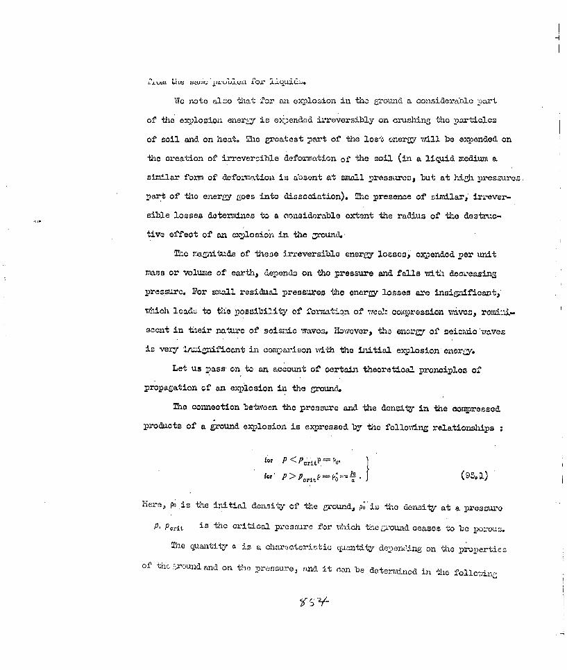
4. .VJJI41 W IUU j/LUU"IJ;L .Lx liquiLC-J.
Vic note a.Tho -liat 2cr an oxplo~don in tho Zrowad a consideretblc -part
of theC explosion ener~y is or~endod irreversibly on crushingf the particlas
of soil and~ on hee.. The greatest pt-rt of the lost enerr/ will be exponded on
the creation of irreversible defoxination of the soil (in a liquid mediumn a
sirilar forn of deformation is absent at small pressures, but at h-.gh- pres-mres.
part of thio energyrigoes into dissociation). Mco presence of oimilar.* irrever-
sible losses determi~nes to a considerable extent the radius of the deztruc-
tiva effect of an explosiona in the -.;ound.
Mhe maailh.ade of thes3e irreversible energy losses, expended per unit
mass or voume of earth, depends on the pressure and falls with decieasins
pressuro. For sreJal residu~al pressures the ener~r losses are insigniffiosntj,
whI'ich lca&s to Vie poszibility of formation of wea!,- co.Tmj,.ressiln waves, rorin-
scent in tieir n~atuxre of seisnIc waves. Howvever, the enorar of sei=-ic waaves-
is vexyj Iainiicant in conry.)rison writh the iitial exylosion energy.
Let us pass on to an account of certain theoretical pronoi-ples of
Propa~rtioxi cf an explosion in the Uround.
Mhe connection between the pressure ana the density in the compressed
products of a ground explosion is expressed by tio folloyring relationships
fo P <Pc..r. tP 0
for' P>Pcr Po (9,l
Iierep Po is the initial deiisity of the grounld, P;'ir th0 density at a pressure
PA Perit is th-c critoc02 presburc for hich theL::ound cases to be porouz.
The quatity a is a. characotcristic qaantit-y dcen-r0ing on the properties
Of tlc.naround emd on tle prsur nd it can be deterri&nod in the folodr,c'

Yfl~1~' T " *~-. - ~'~r 0 j "und in the~ natural s'tate be
pO acd Ic-ovmi to us ; let tie donsity (avozr-Te) of the soil particles be Pi
.ion the auxilia rj quontity a .is detentiincd by the'obvious ex)ression
for the condition that we do not assume adiabatic corpression of the soil
particles. In taking into account adiabatic compression an. inwoaucoinZ the
coefficient of compression 4 -w , we arive at the relationshipPO
for detoz'm-iwn the value of ao PO
e process ol' 'hock, wave propagation (coaprovsoion wave) in the Lrouvn
as a result of expexision ofO the detonation products my be represented as a
process of propagation of the zone of compression of the woun; behind the
sh O A rn the .&Inv~u o & d.A4nUiOf c'Ite C~ ~i oil vii]. 1t of a puraly
acibatio nature. The c.one of enitwopy behind the shock front o= be neilecte
for the reason that in eay dense medium the thermal component in the equation
of state for that medium is small in cozmparison ;vIth te "elastico" component
of the pressure.
Tho parameters of the front of the Vropa~ating shock wave are deter-
mined by the well-mova relationships
u2 V O- a. (ac
( for. P> P.)
Here D a is the velocity of the shook front, u, is the particle velocity
behind the shock front, p. is the pressure at the wave front, va is the sznecific
volume at the wave front and Po, vo are the initial pressure wid s:ecific
volmc~h.o -t, ' L2t~ ao - o veon wr ite these relationshi suo:d~ Ztc uo~i , ... .

in the form
whence it follows thatPP, - Po =-a (54
Neglecting the adiabatia compression of the psatioles of eawrth In oc.-
parison with the oanpressio a for eliminating its porosity, a theory can be
postulated oonoe.-ning the propagation of shock waves in the groud, 17e shallJ
consider the propagation of a shook wave in an infLite nodium.
For this purpose we must integrate the basic hydrodynamic equations
g+vau'+. +JP, up" + Put +- "- =" 0,,
for both the expanding explosion products and the medium in wlhich they are
propagating.
At the boundary of separation between the explosion products. and the
medium, the following boundary conditions obviously apply in the first phase
of propagation of the explosion products
P2 PI,(5.~P'Pdr }( 6
where P2 is the pressure in the explosion products, p, is the pressure in
the ground, .u, is the velocity in the explosion products and u- is the velo-
city in the ground.
At the shook front, i,&ich in the vicinity of the explosion source may
be assumed to be strong and therefore po can be neglected in comparison with
the pressure, p, , the follwing conditions vwill be attained
P. = PD', (1-- ), u --(.1 - )O , D 2 =- . (95.7)
As a result of the expansion of the detonation products and since the

procesa. ox compression of the grouan aszocia.tion zilth the el.Wination of its
porosity is practically iLwevorsilo, tho -pozitioa Ly ultimoctoly be reached-
vrKhcn at the bon dary of separation betx;een thw detontion Products and the
ground, the pressure is quite siall aznd aurthzr motion of the ground will be
inertial; as a result of this, the limiting conditions of equation .(93.6) will
fi" illy be fornaally achieved, but they will no longer be taken into conaideration.
In consequence of. the fct that the nasa of earth set into motion behind
the shock front very rapidly begina to ezoeed the ras of the explosion pro-
dhcts, the following simplified concept of the e:p.anzjzsion of the detonation pro-ducts can be appied. First of all, it cen be asssaed that the detonation took
plaoe. "tantaneouz.Ly and con.;oquantly ueo=sn consider the ezzzasion off the gas,
as if at rest prior to .:-encemnt off oz'.nio,. and, occupy=ig a volnie equalj
to the initial volt=no of the explosive, -1d scccildy it c:-. be azzuzod-L hat at
the boundary of separation bettleen t:-he t;.. odcta wad r-ound, thA
condition
is ful~fillcd for the detonation proCucts, where p is the initial deens. ty
of the explosive, r0 . is the radius of the explosive charge, r -is the present
distance of the boundary of separation. Relationship (V5.8) folloa's from the
Law off Conservation of 11ass° Since exc-Ansion of the explosion products is isen-
tropis, we obtain from this relatio±ahip for the pressure at the boundary of
separation
Pr =_ /-, r ro8
P expl Dwhere Pj 8 is the initial pressure off the detonation products and D is
the velocity of the detonation wave.
If ve suppose further that the ground, after elimination of its porosity,

is incompressible, we are able to integrate imdiately the system of equations
in (93.5). The solution vill have the ",orm
ur -- (1),
p-9 P( -Po r 2r 4 J
The general solution of (95.10) depends on the two arbitrary ..unctions
1(t) and .~(1) ; these arbitra-y functionb can be detenrined from the con-
dition at the boundary of separation (95.6) and at the shock front (93.7).
Sincer at the bounday of separation, then by tranafo-' ingSrc ut he-ou-.
the solution (95.±0) and taking into consideration that --r2?, 1 r r- 2-2,
we have=r; + -1;= ru Lr+- 2 .
PO2 dr 2
Substituting the value of the pressure at the boundary of separation £firzcj
(95.9), we finally arrive at the following equation detezrmining the law of motion
of the boundary of separation
dut U1 2p. ( 0 ro+ 2 rodr - r- por r..
Thois equation could be integrated if we Iowi the form of the arbitrar-j ; mction
9= 9 (t) ; hweaver, it can be confirmed in advanoe that sinoe the process of
compression of the ground, associated ith the elimination of its porosity, is
irreversible, then over a period of time or with increase of the distance tra-
versed by the boundary of separation, this function decreases and, within the
limit ( for r-oQ ) tends to zero.
We can rite the solution of equation (93.12) in the form
2 - r 3A 2 r3
a2 A _____ Pi (2. _ r y(t)r2 dr;r 3 3 (k-1) P *, r 3p -r4
the constant A is. determined from the condition that r = re, u == ui
(Ii is the initial velocity of motion of the ground).

Analysis of this solution shcws that mith a sufficiently rapid decrease
o2 the iAnction e(1) , the velocity U of the boundary of separation tend to
zero onily for r--co .
The mure precise Dolutiun to tae problem vatft tne simultaneous application
of both boundary conditions, which enables a ccmpatiblu determination of the
functions )(t) and f(1) to be given, is of no insigj.iicance , since at large
distances rozn tne explosicn point, as we nave shown, a considerable portim of
the explosion energy is irreversibly expended on heating up and deforming par-
ticles of earth, and the basic equation - namely, the equation definLnL, the LM7
of Gonservation of 2omentum - ceases to be valid, since we. have not taken into
accowit te eappropriato cd ssipative foroes in it. J,
We shall cont;Wea the solution of the problcm -rIt the as=2tionz made
ELOcVO, anct 'we sigoIj c4texmaie trie lov V 'ia2o-u cmZ of~ Ue arjok~ fruat. Vor t~lis
purpose, first of all assuming simply that 9(e) W O we shall determine t1i e
form of the arbitraay ifunctin f(f).
-'ne assukotion tha t 0(0) - i, t quite valid, since this arbitrary
function is small in comparison Yzith the pressure in the vioinity of the xpVlo-
sion source, and it decreases sharply with increasing distance.dr
Since u - d- then3f1(t)dt==drs.(9±)
From equation (95.15) wre have, for 9(t) 0
u2 = U2 + 2 p, fr Sk) (005' rs 3( -Wp
Hence we detennine
where .
r= Y7 3 f f(t)dt,

~.f~r J~L.tr iLA Ma.±' jj -Uiv1z 0 theeuation,gives =0e rorma Of the
-Fnotion WQ
We now determine the pressure and velocity in the shook waxvo zone propa-
gating in the ground.
P f
Since at the shook front
ps ,P (95.JI)
and, in addition,
dR
then•, on the basis ot quatiou (95.16) we have, for'
R f (d9?
The non-corrspondenoe in the form of the two equations is explained by
the fact that we have neglected P(0-
These solutiom also determine the law of motion of the shook front. The
solution of either, one of these equations oan be carried out nuericall-y.
Before dealing with the analysis of the reSults obtained, we shLl con-
eider the effect of-the dissipative forces leading to the irreversible energy
losses. We shall assume that the magnitude of the irreversible lost energy per
unit me-as of the material of which the ground is conposed is proportional to the
energy density at a given point of the medium, i.e. we shall assume that
--- -- - ,(95.20)
where s is the energy density per unit mass. of ground, and -t is the propor-
tionuli y ooeffioient. H(re , we can vwit. the Law of Conservation of Energy in
the form
E= Eo- f 4irr2podr, (95.2±)
0h

Whereupon
E
dE €dr
which ives
-ko- (95o22)
Here E primarily determines the enerMF of motion of the medium, since
for an adiabatic process the intensal energy of the slightly-conpressible
uround can be neglected.
It is obvious that for a Siven law of energy loss, the kinetic energr of
will decrease vith increase of mass of the moving ound.
For the ultimate solution of the problem concerning motion of the ground
we shall effect one further simplification, which however hardly affeotg the.
accuracy of the result obtained, namely, we shall =rite the expression for the
velocity of the boundary of separation in the form
U1=~ A,,
whereA0 - 2 p,
3. --1) P*o"*(9 . 2 )
i. e. we shall neLect the quantity in expression (9.15).
It is easy to convince c aeself of the fact that as a result of this the
arbitrary function of time f(t) can be vritten as
If(t) =Btw,whance
!(93.2s)

vhereI
B - r u1-6.
It is not difficult to see from 'his that the law of motion of the
boundary of separation vwill be detorrx.nea by the relationship,.- 2
where the constant is determined from the condition that t=-, for ,r ro.
The law of motion of the shook front is determined by the relationship
= 7-a-t5 +onst. (95.2e)
Here the constant is determined from the condition that " for R ro .
Usin' equation (92.25) we find
S+rOi -95%27)
On the other hand,
f 2ldR F1t- I
whence
R Ntl F-i-const, (10., 28)
"Ne obtain relationship (o0. 27) from the formula deternining the velocit-
of the medium and equation (02, 28) from the fornala determining the pressure;
the lack of agreement between these two formulae, as we assumed above.' is
insignificant, which enables us to assume that 9tt) - 0.
We shall now calculate the oirow.qstances such that the conrpression wave
will be propagated with the velocity of sound(in the given medium ) at
considerable distances. The velocity of propagation of the coi-ression wave
can be vwItten in tho form
D. -; + , d-R- (9. 2)
vhere
U, =B-

at , aU UXate tha-n ize corresponcting expression in formla (95. 5),
",%hero we did not take into account the elastic properties of the mediun
Thus, tho law of motion of the front of the coworession wave vill be
expressed approximately by the relationship
It is essential to note that t+%e length of the shook wave or the congpressio
wave increases considerably with distance at large dist-ces from the site of
the explosion. By length of the wave is understood tie interval between the
wave front and tho I undarof separation beteen the wave and the explosion
prodwts. The wave length
W7e now note that the motion of the shock wave has a similarity solution
nature, as a result of the approdxnmation we have mad&; - e law of motion U2
he wave front in the vicinity of the explosion souroo oorreponds in accu-
racy to the law of motion of the front of a strona air shook wave from a point
ex2losion source, the theory of whioh was, in due courses developed by
L.I. SY=DOV and X.P.STANKOVICH.
The relationships found by us for the velocity and pressure may be
finally presented in the follovIng manner
1 4 2p B _ B B' (e1. P2)
r2 PO
These relationships can easily be intt.-preted physically. Actuall.y,
nelecting adiabatic conpression of the ground, having already lost its
porosity, it can be assumed that e2_. the enerar of the explosion is eroeneed.
oi iapartina to the ground kinetic energy and on its irreversible defon-ation.
KeClectina for the present the ene.'gy losses on irreversible deformation,

1 L lb vwsy LA wi.-I) ' u, Zo lJowin6 onco ±I b ULa).c basea on lo Law of
Conservation of Energ:
4 :u
vehere .... rpOR3 is the mass of the ground.
Hance, it is obvious that the average velocity of motion of the ground
is detertined by the relationship
4W ,poR'(98. 4)
which corresponds to formula (98.25).
We now come to the determination of the omentm of the ground moving
behind the shock front. For this purpose we find first of all the relationship
between the energzs mass and momentum of the ground.
Since for any given instant of time the velocity of motion of the
ground behind the shook front is determined by the expression u-
and the ener r can be found by means of the integral
BB0
hen the momentum
o Bo 4 orp -dr =Bo" 4p(R--r) (93.56)
V,
oc nnbe represented in he form
Ia ~ {2~c R1)' (93.7)
In tbc case of 'a stationexy process, the momentum is determined by
the relationship
Wve denote the ratio of the momentum for non-stationry flow to the
rcenibn for stationry jlow by 0, then
?769

Since, R=ca(r-ro) +c. (I--)'+ r (a, + I) ,
r B0 t7,
where
then
+ (95.40)[-(o+.ctJ -~/t __..v - .+-- cw 9
Tis ratio is decreased acoording to inareace of distance from the
point Ofell~o
Relationship (93. 7) ocan only be used for the condition of completoly
total c xanzion of the detonation prodnots,Aen the residual anercy of the
e:xlosion produots is small in comr-pason with the initial encrgy, and this
will correspond to distances greater than 8 - 10 initial charge radii. For
smaller distances, the energy trwisferred to the moving ground is detenined
by tie relationship
EiE4o (1--j@-l 3(I : 934
As a result of this, the momnntoum of the detonation products is
I12M E0
where me is the mass of the explosive char-e,
0 M 1x (Q is the energy per unit mass of explosive).
The .total momentum of the ground snd of the detonation products is
ectla2 to

2=~ E /~AFf1 + )2Q l-r2M (LO)L
The quaniUty ., characterising the non-stationary nature of the notion of
tho detonation products, can be assumed to be equal to 0.80 - 0.85, in
accordance with e results of trhe theory of non-stationary motion of a gas.
Zie total i;omentum arriving at 1 cm2 , at a distance r from the site
of tho explosion, is determined by..the .forua
I4Sri + 47r L (9a.44)
In order to determine the flow of momentum passing through 1 cn of the
surface of a sphere of radius r. the following procedure can be carried out:
since the momentum for a given energr is proportional to the square root of
the mass set into motion' thn the quantity I deter ed b the
re2ationshi.p
Itere the coefficient ", assuming non-stationary motion and depending on
the velocity distribution in the medium, can be tacen as equal to
E -o,
for distannes of r>(5-8)r
In order to defino formila (95.44) more accurately, which determines
both the Momentum of the medium for a given instant of tirae and also the
iow of momentum through any given surface. it is necessa rj to tace into
account tho irreversible enernv l. _ Wrw t-h--is, i.t -. in 4o.4
that by the quaxtity of energy one should understand the total energy of the

z f azivun instant, or ti.me or for a given distanoe:
v,!.ere AE is the irreversible enermp losses.
Assmning in equation (95. 22) that E EO ve arrive at the
folaovdi.g relatiomships
'{2ME, (r0 S~k +T fif/( I
4.-t-r \-Lro (
In these relationships, the quantity , *which oharacterises the extent of
the enargy lossess is indcten, iate. If we suppose very rou&bhy that 7T
we arrive at the fol2owi:n results
________ eypa(9.3.49)
It is knNw from experirnents treat at relatively large distances from
the site ot the oxplosion, exceeainS (8 - 10)',r , the impulse aotinZ on any
obstacle at a distance r from the site of the exploson. ' is dster'mned by'
the relationship M3
(95. 51)
Since'at these same Listances
.22
'~hoe , .2 F, t" hon 1eltionshi p (93.48) assume +mh. fo
--- - - -,o7_/r~ r K r/VE: i T7 = (93.53)

uonvornanoe or the experimenta nd theoretical formulae in the sense
of dcpendence 3f the quantity i* on diotance will occur for wdncl
is equal to the value which we have taken. However, there will be no agree-
ment of -he dependence of the quantity i on M..p as. a result of this.
This non-conformance should be related bo the not entirely accurate
determination of the impulses, and also to the fact that as a result of the
reflection of the material from the obstacle j because of lateral spreading,
oomplementary lateral eompressions of the medium, may take place, which involve
the a.2pearcace of the destruction wave around the obstacle. Mis vill reduce
the maZnitude of the impulse more considerably for large charges than for small
charges. As a consequence of ths, the experimental dependence of i* on. M
will be more feeble than vwill Ite theoretical depeadence.
Let us pass on to a few numerical determinationz of the momontum 6f
the medium behind the shooik front. Neglecting the lateral compression of the
ground near the obstacle, it is ecsy to see that the inmulsive loading ac-ing
on this obstacle will be equal to double the momentm of the medium behind.
the shook front.
On the basis of' Lhc well-ko.vn results of the theory of an explosion,
formula (93. 5) can be used to determine t2he impulse at distances greater than
8 1 10 charge radii.
WIe now write this for;mula in thc form
Sub ti uatin - in it 6 _A , po "-.-Q'c= I
" ei eh;vc, for'' we Qav,. f 'or,.4 .18 . .lr erz/ I .in te GGS cystem of units,

!ir 16..A0,m a (o 10=0M).
Uj) to now vie havo aswned that the ' hlo region bet:een the boundar- of
soaration rld the shook f'ront is occupied by in g efroui-La, however, as a
conse.ucnoc of the fact that the pressre inside thle growund falls with
increasina distance, retardation of the rear portions of the moving ground
should be observed, dow' to its complete cessation, i. e. sooner or later
breakaway of the shook wave from the detonation products should take place.
In thc ground +his phenomenon shoulc. be somewhat more characteristio then in
.'r. Indec, -the zone 'whtrc. the rowund is retarded vill akn.areatly be trans-
mitted with variable velocity and the wave length in tie gtrund will not be
constrnt. In the li "tinz oase, just a; in :iAr,. asswuing that the wave length
is constant and neglecting tho irreversible enera- losses, we arrive at the
following relationship
:';here A-= cons% ain ' into account th losses as before, we on a ite tit.e
'elationship in the form
vfnera consto
Ole divergence bet, een the ex'oLimtmta o,. theoreticaul rel,;t.osh
oce01Mn'- mainly for the depndence of the im2J.sc on the charge weight,
We note that in deriving the relationship deton~ining the omoentuj5 of
the grouna, wo do not tako into account the internal pressure, Actally, at I

C$I.siances grea'ter t~an LU to. 'nO Internal pressure plays w ftui'ther tart.
In concluision wre shall attex~pt to cdctern-d-ne the ra:dius of tho sO-oallc( L
itself is deformeda by the passage through it of the shook front. Me average
energy. density depends on disrtoe in the follo; rng nwcaer
- Mqx~1 Q "0ai2
vhore uo02 : t is the critical velocity of motion of the ground as a result
or 7htich deformation takes place.
Knowi~nZ the limiting energy density Fa , at which noticeable deformation
of the ground ceases, we arrive at the following relation.:ir
w#ere rum is the limiting radius of destruction.
AssutinZ for typical soils that e. i07 er, Vs = 2,6
2 &/crQ. 4 * era/s we obtain _t. .15.r0
An ener~r density of g = 107 era/g corresponds approximately +o a
pressure of 20 k&/cm2 .
Actually, as a result of the density variation from the value pa to'
the value ' the pressure intensity p i acoomplishes an amount of vrk
Ax = ,X,2. --j (X,60' 4ex e
X1 Xi-l_ PP 1
xi and x2 are the radii of the elementary spheres contailning a mass of earth
equal to unitJ. Since 4nxs- thon
C1he

Assuming that - 2 , we arrive at the relationshipPa
which, for =2 .gives ±-itand for p. = 20 10 bar , 107 er&/z
We note that the theory of explosion in the ground still regires further
development.
Some experimental data obtained by the Artilleiy Acade;W verify the
validity of the assumption that starting at some quite small distance from tI
centre of the charge (about 2 to 5:ro), j we are Justified in neglectinZ the
compressibility of the soil particles in the ease when the porosit- of the
ground has already been eliminated.
It has been established that the initial pressure at the shock front in
the ground , resulting from detonation of a charge of hexogen attains a value
of 2 • 105 kg/cm2 , as a result of which the rapid change cf density is equal
to 1.45, and the density of the gromund (oloy) is thus shown to bo equal to
2.1 g/cm5 . The density of the ground is taken as equal to 2. a/c 5 .
It follow.s from this that for r - ro, the increase in density occurs
mainly on account of the elimination of porosity. The initial velocity of
motion of the ground behind the wave front has been sho:l to be ecual to 1726
4/seo.
Using relationship (95. 4)'
al e ao d ou ,
and also the relationship for the detonation produeots for k 3

3 P 1
wre arrive at the equation'
For
a - 0.7, , D.-800 1)/seO , P. 2.1 6 50 0 . = ,
we obtain. i, u 1900 n/sec, which is close to the experimental value Liven above,
S94. a'plosion w±th Blowout.
Explopion in an infinite . 1edLum. Aftor co pletion of the process of
detonation .)f an eplosive charge, whon the detonation .-tave reaches the
boundary of separation betveen the explosive and the medium, notion of the
medium commencesn td2:r the action of the expanding detonation products. As a
result of -his 4 shook wave originates in the mediu=
As a result of an explosion in tough metals the pressure at the shook
front is greater than the pressure at the front of the detonation wave. For
less rueZed materials and, for excrple, as a result of an explosion in water,
the pressure at the shook front is less than at the front of the detonation-
Waveo
Wo shall not consider here the law relating to t"e propagation of a
shok wave and we shall not take into account the riultple wave processes
in the medium as a result of reflected waves, but we shall occupy ourselves
With the overall picture of an explosion.
As a result of the explosion of a mass of explosive in an infinite
L mert i ute volume V, , occupied by the expandiug explosion products

is proportional to the mass In of exnlcj Vn' n" A , A. .
of the mediuni. Expansion of tie dotonation lproducts proceeds from an iaitial
pressure of
Pi= k 1) POQ, (41
(where k is the index of polytopy for the explosion products. pO is the
density of the explosive charge and Q is the specific enerry of the explosive)
up to the fiiul pressure p 1 , determined by the properties of the medium. In
the initial stage of expansion ( for p. p p p, ) it proceeds according to
the law p, V- 1 r- °' j then for p,-< p- p. the expansion proceeds accor-
ding to the law p-,V- 2-3k, where k-- is the isentropy index.
For 9ieaJ explosivesk=3 .Pk-14-12 ,=. l0 k&/j p.,3.051C&/,Ma2.
For expansion in air or in w,er, where there is practically no viscous force
to be overoroe aid practically no expenditure of energY on deformation of the
medium, and its rarefaction . .1p where pa is the back-pressure of the
medium. If Pa 1 k/crm2 , then
V. A Vo, (04.2)
whore V0 is the initial volume of the explosive, A 4 00o. For eQasion of
the detonation :)roducts in a solid medium p. >pa. For mmteriels vith a
different hardness the value of p& can van, from 1 kV'crn2 to 1000 kq/cm2 , As
a result of this, the corresponding value of V. is decreased in relation to
that determined from equation (94.2) by a factor of 10k or I0OA* .In the
general foms, we can vr-itc that
whera k1 i l the effective value of k , depending on the properties of tho
nedim. ~For exzmple, for typical soils

V- L-50 V0.
Me volume of the zone of destiotion Vii of the ground and of aW medium
considerably exceeds the volume whichl can be occupied by the detonation pro-
ducts' (see Fig. 247), but it is always proportional to Vw , i.e.
VA1 - a-const. (06.4)-V --= - CN[
Experiment shows that for different media., including soils and rocks,
I <a< 10 , whereupon the lesser value corresponds to the toughest metal mad
the larger value corresponds to the toughest ground.
Thus, it can be verified that Rmre 247. Zone of
=. (94.5) destruotion of
Me mass of the deformed ground M -pva j medium.
(p is the density of the ground) can be
expressed via the rass of the explosive thusM c ,PA aAm, = Aim.. (04.6) V
90 PThe quantities 'd and .7 are found from experiment.
For pliable media the value of. k* is closer to k, .than for more rigid media.
For the latter the value of k* is closer to k; for soils and slightly durable
metals P.<Pk , therefore P*-kL, for hard metals k>k* > , and for
the toughest metals k* --1 /
Explosion in a Finite Medium T The most interest is presented by
Y!'e study of an erplosive charge inserted to a certain derth h, from t.e
o.arth's surf aca,' which we shall assume 'Lo be horizontal. A- a result of this
.hc, force of gravity should be taken into account.
7c ahall calculate the ener y which is exp ended in overcoming the for-ce
of gravity by the explosion of a charge at a depth h0 , in the case when the

crtcr formed a.COte ' thc oxr2.osion is 2 '' j2
Frrc2,1-n. -For thc caculation RfJo 'see Fig, 248). '7e shall O-Ctcuaata
of bl-."Owut. the '%ravitatlonal" cncr[Zr for the caso
when there is ejection of soil at t~
menft of m.ass of the ecrth in bolteedb
oones w~ith bas r3adili R + dR; R, th en
2w 2o t,-2 rw is
... c L~t2 'n_.i M p' tjR2 Co.
AZ. .3)M c elcxnont o" mass boumnded by thei zootions (h + dlz; h) is
dM,=z2ph2dhi~iCos F(x )T o r t~z ener~y ncozjx~r %'r the ejecot.tor, of A--, clcnwent of nmaos dM at the
zurf ace AA', is determ-nined by the equ.ation
whore~ g is theo accel-ration dJue to gravity.-
Thua, integrating within the lir~dts from ho to 0 and from 0 to q)o, Via find
E WA'Sh To -MgJIO(4~0 12 - 4
In the region boutided by thec conro vrith base radiiA (,R + dR, R)
dE- pg h04siwpy ~=,' dgd.d~g -y-COT- - &M.(04.12)
1:6 it 'be assumed that the explosion energy is propagated isotropiosally
(-.1hieh) or course, iz xiot --ltogether so), then in this region the explosion
r~ncerzywhc acts is
dE. =Q dm. = m.Q sin dy B. sin cp d)
\czeE. i;3 the1 total explosion energy. Meo e:,-lesion energy propagating
-L-0~'th cono !7111 'be
2

hs dE, Xpgh40
Obviously, if the enray losses in breaking up the grund are not taken into
aoount, ejection will occur for the condition that dE.> dE, , whence it
follows that
Thus, for a given depth h0
IC~I
Cos. PCos O '(- (m
Mhe mairam possible depth is determined from this relationship for go u
ho AOM ItF9(94.17)
By meana of equation (94.17) we vite equaion (94.16) in the form
Cosec 4P >
Relationships (94. 16) and (94.17) give the optimum values for h, and the
angle of flare of the 'cone .o.. If the irreversible losses be taken into
account, then the values of' h0 'and $o irill be less than those determined by
these relationships.
We shall na calculate the residual 'velocity aa; with which part of the
gromd will be ejected from the crater at an angle * from the norr;o. -We shall
calculate the iaximnw velocity of ejection below, but for the present we shall
onlly assume that the particles of earth aoqire the velocity quite rapidly, but
in the process of its ejection, part of the .velocity is expended on overcondmgn
the force of gravity.
It is obvious that, from the Law of Oonservation of Rneryy, we can ."ite

a,22-d.4 + dE/ - dEo,
whence
[±E . d~ l / 3 E .4COSB ghol/; [dM dM v Ph3 29b9
or -/ % r[,, \ ;
40
Wor , uo= , f .£z r~ ,, 0 1
If o-horn, j then for = * .'Om O.- e relations~
ForU', an r F 0
,. ."z;', - ~~ao -. a.,) = -,,/-tT-' g.,
the refaZtionshih
# :pgh, (I + toan,) (94. 22)
B ~U.(-cO~y) (94.20)Y
r(. 4 ) .+cos h
For a Ainlte vnjlue of , * the vaJlue of . &t~s±s a maxiau n ?e Oanl
easilyr Iin from (94.21), 1hat
As a re.',oult of thlo
-.* ., 0.1; C°s'° (' "0 .8
On The bais of the relationships introuoe&, the paaeeters can b0 evaluate
for the orater formea by the explosion n the _ biseqjent ejot-ionof" 1n.'t'.ri~1.
B" "g,"M, ' Itgh",(I Cosrpo (94 22
T.-C If 2,os p

blowout and explosionq
Mc initiJ nhana of the cratur should be conioal, which is perfeot ly
ai:.tuval ut -i ui iuu cu of -u iodium takes place more or less aion the radUi
R, I lowo-vri, near tho s'arface of' the crater a rarecoto Crclaxa'tion) V wire
ori-inates, which leads to the fact that at the surface itself they be
Fi irc ,19. Volume of collapsed oomplementarily destroyed ana a certain
rook. mass of the medium rjy be eJecte4.
(Fi. 249). As a result of thiso the
A * radius of the orator is somevhat in-
oreased (from' R.ot. to, ) and the chao
of the crater is ritered. It is not vc ,'
simplo to take this effect accurately
into account, and we shall not consider
this here. All the relationships intro-
&uced above are of s±gnifioanoe if h . h- < R,,m , where R,,m is the m :rx.TUa
radius of the zone of collapse, tading into account the effect of the free
surface.
From this condition and from equation (94.6) :it follows that
3E / 3Vr,,\ "3Mm\
where Vm and M,,m are the volume and mass of the zone of collapse. Sin6e
Alm, A, -! = A,Q (94, 21)
,.,here A, A (see equation (94 6)); a is a oof'ficjent ch,-.x:2 ;o.'
ising the increase in the zone of collapse, then equaticn, (9M. 24) coan b
written in the fo..n
± gl

z vw-a lvau Qw; ~ fThe explosive charge.
hence it follovs that the greater the calorific value of the exwplosive Q,
the noreso is the inequality (94. 25) fulfilled as a result of the Zruater force
of jgizu-41 --. i the absence or a gravitational force, the inequalitr (94. 25) is
never fWLxeil 1 e
We shall now consider the various possibilities of formation of a crater
as a result ot an explosion
. If no>Rcm , then for ho > 1/k the crater is not formed, but a
so-called camouflet is obtained.
2. If ho < Rm , then for ho > hon partial bulging of the surface will
be observem in the vioinity of the epioentre C above the site of the explosion),
3. If ho < , for ho < hm we shal have the case considered above,
when a crater is formed.
With decrease of h the profile of the orator will be altered (the angle
90 will be increased).
The first t-, cases are of no interest at present and we shall next ooMpy
ourselves with a =re detailed anysis of the third Case.
Nvow let h0o ho <R,,. T he angle of flare of the crater cone is deter-
mined from relationship (94.15)
Cos 0o-~2) .a e ,l of wh .h <T 1 . m' he radius of t he crater
3E 2
RO ho. ta O to1
2-io specified relationships will be valid only for the condition that
, CO4 26)

~f ~w. -i14j wne is de+,exwi --d Irrom
V- relationshipCOS p o C o - (94. 26)
If ihe C and the crater radius willbe,
RDmoh To 1/ (94o27)
Mhe lw-iting condition (94. 26) leads to t his relationships
POS T 0"
Thus, if Ro- ?,,, , then on integration tho angle . is changed from 0 toD jand for Ro > ,.,, from O't v ou,, The relatd onships presented above oom.-pletely define tho orator w iich is ,formed as a result of' the explosion of an
explosive charge of mass m.* at a. depth ho :I
If Ro,%R.R, , then oo-9o,.is calculated from relationship (94,25); if
Ro>Rm , then cos. To Cos- ,". is calculated from relationship (9 28).
Then we can oaoulate
q-0 'an.~ and m CP4 aT
A criterion of this ane.,' as a result of formation of a crater; will be
the d1ensionless ' ,ntitV-
'COSy 0o A (94.2
If t,> I, then %12--q'c , and we shall be concerned with the case when
Ro < R,,, as a result of which the toroe of gravir paisys 'the principal r~he;
if . < I ; then q.0,"<% and we shall be conoerned with the case when
?o >, R,p ," as a result of which the radius of collapse of the medium plays the
principal Ale.
If there is no gravitational field, then we shall always be..m'nerned

.it the seaona3 en _c 5 ba t au a resul.t of us-n1Z
very hih calorific value explosives. Only in the case of a very pliable
medium, when the quantity Ai L-s large, ahal we be oncerned with the first
case for hidhcr values of Q. As a result of the presence of a strong gravitational
filU we may be concerned with both cases , depending on the value of g, Q and
the quantity A,, whiah characterises the medium.
We shall now determine the ultimate relationship between the mass of the
medium ejected from the orator by the ex-plosiona the mass of the explosive, its
oalorific value (or explosion onerZy); the initial depth of the explosion centre
and we shall examine the optinzm deptu for which the ejected mass proves to be
a maximum for th two oases 1,> Iand <1,q
Por n. 1 we have
where
for -os2 CPO.
M,~3 == 3 Ph"
It is obvious that the mass of the ejected material has a mimdum for a
definite depth hop and this mindmum will ocu for
To ( = '= -44hom
Sthe inequality < 1 3. iteE------y< i is satisfied for this).
Substituting the value we have found for 'ho=Wo in equations (94.25),
(94. 28) and (945i); we arrive accordinely at the expressions:

For , < 1 we have
M P4 S. .f Co 0--A
,iftere I >cos po >. h "
For cos po h
M PR -, bi
It is obvious that' just as in the previous oaseithe mass of ejeoted material
for a def nite depth hh s ,.&. maxmm value,- Ths maxim 'will occur for
*For' this
As we can see, depending on whether the criterion t is greater or less
than unitya different optium aigles of the cone are obtained.
For 1>,I y-_70°; for -q,< 1 -yo *5' .-
We dhU now relate the purely theoretical results which we have obtained with
the basic experimental data.
It is well-known that for a certain depth of insertion of the charge
CvAich is not always optimum in the sense of obtaiing the maxium ejected
mass) 'the crater radius is.,~4 ,..%= (94 .3§
where .;L. is an experimentally determined coefficient.
Assuming that Ro. -, Ro " we con write equation (94.36) in the fo:m,
=M ,94 57).
It is further obvious that
g-.

AA 4- A-
C,omparing evuations (9,.24) and (94. 58), we find, that
A,(=4.59)
On the other bandA, - ;A (-'
and therefore
4 ';A - IF(94.4-0)
These relationships establish the relationahip betreen the empirical parameters
a, A, A, and .
" Since the quantir A is quite well Ianownp is determined by experient,.'
then we oan find -41 from equation (M4,59), and from elaation (94.40) we can
find the extremely important ooeffioient a ; We note that a
We now determie the momenbm of the material ejected as a result of the
explosion, Pirst of all we determine the so-called total (scalar) momentn (V,),
It is obvious that__
dJ,=ad= a= dM. i 8T dT sin ,, (T4)S3 cosy
ntenoes integrating ivitbin the limits of variation of the ange.e from 0 to ~
(asMdinz0 that w we find
h,=2 v:Ep/;. [-.y i. ] I/WM-E., (94.,42)
where
Iiu ah e t& (o e sn.4.43)
It is useful here to introdue instead of the total explosion energy Eo,

Athl a vertex angle of 2ge
From equation (94.13) we find
and am a result of this equation (94w42) assumes the form
= 0 V'2ME , (94.. 45)
vhere
VTTcsi f -+ o YPo=60 ° ( 9 .3
For .example, for go0 oI ; a. 0 for go 0 0.95
We now determine the projeo tion of the momentum I on the' z axis
perpendicular to the surface of the earth. It is obvious that
* (94.47) -
dia a..cos/dM sin ? dy., 3 cos f
Hence,
.2 1/i VrpOES Y-= (1.0
where
tao (94.49)
Further.' substituting E, by E,, , we find that
J. 0, 50o)
where
21f'T cos yo
2For' exampl e, for go= 0 , -- I = 60 P 0, Wo can vrite that
o- V 90 wherreui)ou 'Whe ooeffLuien6 9 ks a measure of the velooity
distribution dnecrin,6 upon the quantity of the mass of ejected material through
different angles. If there were not this distribution, then 0 -1 and

4o= V2MF -
Now we can finally write down that
IOI~;J,~j iCO CO=OI2AE.Cos ~=Ol (G*4. 52)
Hovrevers' for practical calculations it is rore convenient to ttuse
reiationships (94.42) and (94.48).
Fron +hese ralationshipa4 for example, it follows tiat for @o =600 ,
In tih general 'orm, ":¢ithout t3retr rdn. i % t. l'r o'- 4,tstrib-itioi of velool-
ties Yjthi re csct to mass, WO oOn write
O . 0 .. .
vilere a-a[M(.)J~a( ) is the law of distribution of velocities ,Tith
res.,)z-t to ;S,/
he theoretical relationships which we have obtained above may be made
morei precise b-, additionally taJdhn into acoXnt t1he enerur vhih, as reult
of propaeation of the shook wave's is expended on heating up and on irreversible
deformation of the medium, These energy losses at a large depth of insertion of
the charge may be considerable, and should be determined experimentally.
S95, Impact-'of Meteorites against a Solid Surface.
It is well-known that as a result of the impact of solid bodies with
velocities in excess of several kilometres oer second , a. phenomenon closely
resembling the appearanoe of an explosion has been observed.
ror an iToact velocity of greater than a - 4 kq/seos the crystalline
structure of the meteorite an. a oertain volume of the medium with maioh tho
mteoite collides is destroyeds and an explosion occurs in the ,01 'sense of
the wora.'

as a result of impact at velocities greater than a fewv kLlometre-s per second.
Explosion of a Meteorite in an Infinite Mediun. We shall consider
first of all the "explosion of a meteorite" in an infinite medium. It is ob-
vious that the problem may be posed in the following manner. Suppose that in
a certain volwne, equal to the volume of the meteorite, enery E -2--..
.be liberated instantaneouslye he mass m , inside of which "vapourisation"
of the medium will occur' is obviously determined by the relationship
Moest+m~~T MMu A q2& - q.
vhere 11 < I is the ener " efficiency factor
2 -T
whcr3 sk and q is the eneray density required for "vapourisation" of the
mate).jal of the medium and of the medium and u* a nd " sarc the limitinm veloci-
ties recuired to "vaporise" unit mass of material of the meteorite and of the
medium.
If uo > uk U k then it is possible to make a distinction between the
quantities ek and a for the impaotin body and for the body receiving the impact.
Then equation (95.1) assumes the form
A + MA,- 1 -- . g .)ilk
Since the value of ; is close to the eneray density Q liberated by the explo-
sion of condensed explosives, and since experimental relationships are well-
3=nown for the effect of explosions at the surface and inside different bodies,
which rqlate. the mass of the charge of explosive (m.), its specifio enerey (Q)t
the radius, depth and shape of the crater in different media, then it is more
a-vantxgcous to vrite Q in place of 6,u and ' in relatonhips (95.1) and (95. 5).
Actually, for typical explosives Q- I. - 15 koa/g ; and for

va.,- zf Z .1 LC 3 k i ror' ionaluminium and ranite
respectively. Consequently, we can vr t doan that
.,Q , (05..)
Hence it follows that
00 - (95. 5).
After expansion of the gas up to an energy dsnsity value equal to Q, the ultimate
ac:ansion stage ay be likened to the expansion of the explosion pro' ots from
.an explosive, but somewhat more dense than the normal explosive.
Actually, the density of rockt is about 3 81=3p the densi.ty of iron is
about 8 Z/cm and the density of a standard explosive is L 6aox .
Thus,' the volumetric energy density in the case being considered w1l. be
several times greater than in the case of explosion of normal explosives.
Te shall now put the problem somewhat more preoisely.
As a result of an impact and an explosion. a shoock wave is formed whtich
will be propagated through the medium, Since at the shook front part of the
energy will be expended on "destruction" of the medium, then it is necessary to
take into account this energy loss in writing down the Law of Conservation of
ZnerXr for this shoock front.
For a strong wave these conditions will have the form:
E .(V"- V,)-, (95.6)
,2 =P, (v0- v,), (.7
Ths the relationship E If(p,; VO) depends on the equation of state of
the medium and in a certain sense on the initial impact velocity, since at
different pressures the equation of state may be approximated different'y.

FDrom equa-iuw .* aaa D3.7"J. wo liavu
(59)
By eA. L. these relationships one should uderstand the enerr going into one
or other of disturbance and destfaction of the crystalline lattice. Obviously,
this process of destructi6n of the crystal lattice will continue until at the
sh ck front
U2+(95.ao)
Fora equations (95.9 ) ana(95. O) it follows that the process of destruotion
of thc latticc -. 1 takc placc f'cg2 >, (95.11)
By introcluoing 14; =1 we can define more precisely the condition uo>u u ;
which is formulated above. Sine from equation (95.11) it follows that u Z ,
and that 2uO " then u, 2u. or
2 u k (95.12)
In the first instant of time after impacts when the regime of motion and"
"flov" has not yet been established, "vapourisation' will take place fpr the
condition that u1.*,. then after.an intibval of time r- regime is uite
rapidly established when "vapourisation" will take place for the condition that
uo > 2Uk.
Wo shall define more preoisely once more what is understood by se * For
vapourisation *8- € - for fusion k=ek , for simplo "disintegration"
(dispersion) of the medium 1A, '' In the first two cases , the expenditures
of energy in the expansion processs going into latent heat of vaporisation and
fusion , are restored Again to the medium in the process of expansion$ except
for a small portion of the medium which has already expanded as a result of
discharge from the dense medium(from the crater) into the atosphere or into
an empty space. However, these losses can' in general, be ne leoted, all the
*tlg

11 .I h' A p cAnu A irlr +hm A A 4 1 ~ ~~~ *' WiL". UU ~vI L iruatr
than in the case of .ijle dispersion of thc'mediu=' Finally,* the energy ex-
penditure * -,kvrill be irreversible. It can be asstumed." as was done above,
that a*= Q approximately, for different media. Consequently; it is always
possible to introduocpjust as in the case of an atomic explosion$ the totyl
(VT) equivalent. vich arises from the Law of Conservation of .Energyr i.e.
the kinetic enera :E0) of the impacting body, taking into account lsses
(allowina for efficiency) n-nn be qc-ate. to +e enerw- of an Cxplosive kTul
flav .r.Z z- , . avlu ewumL-np -Lnat 'm*.Q- ,q a
It can be assumed for simplicity that the process of detonation in a
dense medium ia instantaneous. The process of "destraotion we shall arbi-
trarily call the process of "vaporisation".
As a result of a detonation, the enerr density at the front of the
detonation wave is
where
is the potential energy ;t thus,
Ui 2Q. C5 5
For an instantaneoua detonation, the mean energy density is
In the second case,when ed= Q, the problem is reduced to the comparison of Q,
tae effect of the impact with the effect of an explosion with a cJarge mass of
2m. and. a calorific value of R_ by the hypothesis of instantaneous detonation.2
In the first case, the problem is reduced approximately to the case or real
detonation of an explosive charge with a mass m. and oalorific value Q.

we und rstand, by a case of real detonation the case when the preazure at
ite front of the detonation wave is trdce as big as the average pressure aund
the enrr-, donsity at the front is u',=-2Q..
Both cases are sufficiently emivalent to one another, vhich follows
faom ex losion theory.
The first case breaks dovn to a more simple analysis and we shall now
discuss it farther.
Now, the equivalent mass of an explosive charge m. ',,aving a calorific
value Q will be detcwmined, for fu'rc caeulaiC*IL % y Yc~a' ... .
E.1osion of a Mreteorite in a Finite Mediuum. First of all we shall
determine the maximm depth of the depression - crater, formed by the invact
of a meteorite with the surface of any me iun This depth is determined by
Figure 250. Oalculation the depth of penetration and by the radius of
of crater depth. the vaporised mass 6f the medium It is necessary
to further take into account that after tho pro-
ess of vaporisation ceases , disintearation of
the medium will simply take place at the front
of the dying shock wave and part of this disinte-
grated medium may be ejected outwards. which
further increases the depth of the crater ; however, this additional depth
will be less than the depth of the vaporised zone.
T"us, the total orator depth (Fig. 250) is
= , + (95.17),Iere
nMo n ris ) CosZ, A! h er, t i s 1o y
In thieso relationships, m, is the mass of the meteorito, ~ sits velocity,
09

c. aa the rasistance factor, S is the surface of impact of the meteorite
Mad p is its density, z is the an-gle betaeen the direction of the velocity of
of the meteorite and the normal to the surface of impact, and r, is the radius
of the collapsed zone - "vaporised" zone. Since
M0um. -T--0.
U.2
(here and in Pfubn' wo o th6 rLafty ,,o' "-j -=, 4Va .... hO- Q th
ener y density required for destruction of lattice binding or of the finely
divided rook), then2M^
I --- ------ cos z In .Z---f- -/2 -o~ •a •u~
CxSP Uk V 81PQ K ~ 9
Sin c o S ' then we can wriLte that
where " is the shape factor of the meteorite ; for a sphere, for exanipLe,
S* Now, equation (95.19) is conveniently presented in the form
.. hvere
I +Cos Z- in4.
The mass of the medium ejected from the orater(asumina that the shape
of the crater is conicaL), is determined by tho relationship
A4 T Potn2Po ;o, (95. 21)
Now we shall determine the normal projection of the impulse of the explosion
* (95.22)
Since
E.= 7E0 , M;= M

tnen
- -p) (95.25)
For
71-- <, os TO A-i
For TI, 1;
4 )F )- I jmu
e7 shall evaluate the dimensionless i .tities A, il, ed I, entering into those
relationships. As we have shown above) the quantity i is slightly less than
Uni ty YE2- V/ "l uO
1 3 1 + -cs CO Infor + u1 0 J1
for = ,"=u1 ; if z=iQ,, c.-2, &-In. = p=, 8 v shall have
. ,+ (I fn.
Lot uoe3U'..,72O. , e = + ,.
The quantity jT~ H ~ 15 for 'u~eu- C onsequently, the
range of variation of n is not very signifioant6 Since, 1 < I, 'Az>] , then theiA
secod term, into which 1-1 enters, does not play a large rAli it is small in
comparison with the first term ; however, this quantity 3 .is always easy to
find 'if th shape of the impaoting body is known.
We ell now evaluate the essential cuantity, A S Since
4A= A, ( k v '
then, ".ing experimental data for , it is easy to oalculate q and the
quantitya

u-,li, Lul L .ve ti v. o A,0A, p und a *~ for
diferent meaia, for P Ic ,/ 2 , A- 1000, k*
P A A
Sand 2 - 8 100 10' 7 10
clay 515 0 1L7 # 106 8. 102
Granite 4 10 1.6 .04.Alurdnium 26 10 0 . 6
iron 8 5 4 .0 S
Ma velooity of disinteration of the blasted medium is determined by the
r'elationship (see 94, rel'atioaship (94b 19))3E(,.,o,8 , e'j. r '~ a
a =( 9LO \i* - ( i--(5~4
Substiiutine the value of ho and E., we arrive at the exprese4ea-..
?or i0'
a. izm 4Q(9&.26)
The mass vYhh is disseminated within the region bounded by the cones with
base radiii (R'± dR;. R) i. e. inside a given solid anzle for do -. oonst,
is dotearmined by tho relationship (see ~'9,(94.7))
d,. -2 ,_ si cL d 1 MOu0 sin q, dydM -oCosa ~ 2 osy '(95.27)
This mass will also have a velooity ao, determined from equation (95. 25).
It is easy to satisfy oneself of the fact that since
Agho - g ( A o g4Q-- ,Q , 421p-Q (95.28)

then for relatively small energy reductions i. < 1 and the angle of flare of
the crater, formed as a result of iMract and explosionsis independent of the
force of gravity. On the contrary, for a large iLtial enery the limiting
anale is deterined by the acceleration &e to gravity at the given planet.
For t I we have
he mininum velocity will be for cos' (P= , when
ao - oj. ho 17> 0.(95., O)
'Ihe total dizintegrating mass i.S
M =YMu[ A)\8QLk'For .,p> 1
./ 4 w2pQ J
The mimixum-Velooit will be equal to zero for
Zhe total disintegrating mass is
SMQM
]M&[~( 4Qf 3If we ro !r coxpare the projeotion of the momentm to the normal for the falling
body
do= MA cos z

,L-e£ac-bive3 ircz' oi ej~ection j5
Jsr2 1 M 0 (-V ) f . 71U,(VOo)-
o. Q 2MU, cci z Q 2cosz
Since Q 2&-, then finnl-ly
Since in the medium V " 2, o - 6 0 , then for -0
For exeaqle, for an achondrite (svory meteorite) 0 impacting in aluminiun vrith
a U"~* ~ " fox, V411011 14- 2 '300'..-- ,.--m-, S
For larger velooitie- of lxirrct the reactive impulse awvJays exceeds the
momentm of the falling bocyA and therefore the overall mewnum acquired by
the medium as a result of impact is practically independent-of the aneLe.

CIIAFT~ER XV
S!12PATHETIC DETONATION
§ 96. Transmission of a Detonation through Air
An explosive cLarge can effect datonation of another charge situated at
some distance from the first one. This phenomenon, discovered in the middle of
the last century, has attained the name of sympathetic detonation.
We shall call the charge effecting the detcnation the active ohare. and
the one in. which detonation is effected we shall call the pssive charge.
..h experimental and theoretical inveatigation of t3.s Xmroblem iz of
extren.ely important sigifiioance, since the results. of these investigations vr.
provide the starting data for extabliuhing the so-called saLfe distances for
storage and production of explosives, and may be used for the coistruction of
detonation circuits for munitions.
It has been established that the range of sympathetic detonation depends
on many factorsa mass, density, detonation velocity of the active charge, the
physico-chemical characteristics of the passive charge, the nature of the charge,
container and the properties of the transmtz.ng medium ; in addition it depends
on the direction of the detonation of the active onarge, the dsmensicna of the
receptive surface of the passive charge.
Thusj, for approximately equal conditions, the exoitarnit1.y of tre patmive
charge is determined mainly by its sensitivity towards detonation,and _ie
excitation capability of the active chorge is determined by the detonabion vlo-
city, w.L~inc cnaracterl.es the pmw of the explosive, and by the weight and
.structure of the charge.
The effect of the nature of the transmitting medium is dete=in&ed by' the

-A -- U lW-e 54M.' a -th
flow of detonation producta or of tho shock wave. Tho stronger this rctardet ion,
the less vll be tne raige a of tooinsizon of r.Wipathe-tc detonot.jon. ine zecxen-
imn of tne proces of excitation by sympthetim detonation remains quantitatively
invaliable for different trannottZng mecua and cifferent, passLve carges, although
detonation in certain cases; is effected in the pasive charge of higa explo±mve
VJ 1,UC btreM Of detOna.On products from the active aharge, and in other casea
by tnhe shoc wave o=paati..ngzz tcie =enert medium aepara-t4g tne charges, eto
Let us oonsder in more detail the problem of transminsin of a detoaatim
irtiugn a..r'eai:L mediew We shall begin with the transmission of a detonation
throug air,
A considerable rzmber of papers nas been devoted to tuie ;roblom of trans-
mission of a detonation tbugn A.r' in tis case, part of tne nergy of the
active charge can be transferred to the passive charge by three routes :
aj by thO sZA.c wave ruPa6ati in in e ar ;
j &y Vne Stream of aetoaiataun ipreC a and
a) by solid partioles impelled by the explosion,
If compiete detonation of the charge taxes plaoc and ifV tue drectxonand. if
toward's tle Passave 'WP'e,/te act3.ve charge is not enclosed in a casing, then
the transfer of energy by solid particles disintegrated .as a result or rupture
of the casing can be excluded. There romain transfer of enzWer by the air aock
wave and by t stream ot detonation pooducts.
It has been established by experiments, that stiulation of detonatiain
charges of explosive without a olearlp-daftned period of burning takes place onlyy
:in the zone where the parameters of the shook wave from the ae-+ive charge, and
the parameters of the stream of detonation products are large. (the pressure at
2the shock front p 9 200 - 500 kg/a ). If the. shook wave approaches the passive

.. .L!.. . havng iower va.uesp then a period of
burning always precedes detonation, However, just as in the first case, so also
in the zoond case, stimul;ation of an -explosive transformation is of a thermal
nature. This situation well explains the effect of various factors on the range
of transfer of a detonation. With increasing dnAity (redced poisity) of the .. .I
passive charge, the range of detonation transfer is increased. This is explained
by the faet wi a corease in density the ooeffioent of thermal oonductivity of
the explosive is decrease& (the thermal contact between partioles in worsened). As
a comsequenoe of this a higher temperature of heatup in attained of the surface
layor or tne oh..g yeri,.i a porous charge, as a! consequence of break
through into the pores or heated. air an& hot-produots of oembustion of the surface
layers of the charge, the mass velocity of o=bustion is sharply increased, which
favours transition frcm oambustiom to detonatin An fnal, in a orous charge
with a low mechanical stability, as a result of U effect on it of the shock w-ve,
practioally adiabatio: compression taces. plae of the air inclusions, which in this
case play the mole of "hot spots". As shown by B and JOPM (See Chapter I),
heating up of the air in the "hot spots" to 480 * 6000O leads to an explosion, as
a result of a shook. In order to achieve this heatupp it is sufficient that- the
shock wave should. approach the oharge and be reflected from it with an over-
pressure at the front A p = 8 - i5 kg/= 2 . If reflection does not occur, then
the parameters of the wave whioh will ensure ignition of the explosive, on account
of campreasion of air cavities, should be considerably higher ( A p = 50 - 50 k-/c=-)
hlgosmatised explosives, thepartioles of whioh are coated with a file o lo%-
melting substanoes(paraffin, wax teo) are less sensitive to the effect of this
factor,. since the energy of the compressed air bubble will be expendel not on
heating up and. ignition of the explosive, but on melting the film.
.Enbustion of high explosive powders is easily transformed into det'unation,

:fro :I alopomt urtadto of thle air' stream beh-ind the shook: frn onencounteringr the passive chargeo. In virtue of thish' the shook waves which are
point of view of stimulation of~ dotonatioll.If the compression and heatup of the aix' inclusions is of no significant
inaitude, thon in order. to, determine the rango of ig.nition, it is necessuzy to
solve simultaneously the equations of heat transfer from the heat transfer' agent(thje shiock wAve) _ _____Fox' this it is necessaxr to kniow how the temperature of the air stream behind
the shook front will rVflz-7 in t~io vicinity' of the passive ohT:g.-I ir. obviotiz
that the dimensions of the passive charge will be of important signioAnce for'
this' since they deteradne the conditions for tho shooc -gave b7p&asjnZ it
11orcover, it. is irpoztant to knmow the thermal constants of the explosive~its
thermal conductivity;- specific hoat;- ignition te merature),j' aivi also thie heat
tx' .e factor from the air in the shook wave to thoc explosive and its depen-
denoo on the var'ious factors, Mhe solution of this problem preseants well-Imola
difficulties and at present it cannot be accomplished sufficiently accuraele3y,
in view of the fact that we &o not kniow &. number of the euntities involved.
They nust be deterisinea experimexitalay.-
In principles the problem of ignition of an explosive-charge by a shoc,-
wave in air' ay be solved according to the followinS scheme* As a result. oQ e
action On the explosive charge by tahe shock wave; heating up of. the charge -,takes
plac ony ina tin ayer Th teperature of the surface layer is dteamined
by tviv process es tansf'er of heat from the air heated by the sh%ook wave, nd
the renval Of heat to the depth of the charZe If the flowo etro th

siderably leso than the linear &imonsiins of the c1hsze to the face opposite
from the waveo tln tko charge may bo considered as a plane vrall. In this case
only the thorm i. flow need be considered in a direotion perpendicular to the
surface on Yaich the shook wave acts. Tacing into._.accoun the wmall penetration
of the obstacle (even for penetrating shook waves they are no more thsn a f wa
, the process ot ieat transfer may be assumed to be one-dimensional.' It ia
desoribed by the follVw'.ng equation ,:
O3T a ( dT
Tb boundary oonditiona are
i'or t 0 T T0 for any value of x,
o6).2)
for X 00 T=T for any value of t.:
Here p, c., and' q are'the densityj speoifio heat and thermal oondutivtit of
the explosive, a:is the heat transfer faotorm T is the temperature of the
explosive (for x'= 0, T is the tezperatre. at the surfaoe of the explosivo),
-..is the tengerature of the heat transfer aaent (the tezperaturt) of the air
in the shook waw).
Mhe mechanism of the prooss of inition of the explosive by he shock
wave is essential2y not rifferent from the Meohlanism of ignition of an explo-
Siva by a burnina gas, yfioh, according, to K.X.-ANDPX=Vy be postulated in
the' follodIng manner. 'Rhan the temperature o? t~ie surface layer reaches a
certain limit (the boiling point for volatile explosives or the tojTorat1uace of
gassification and partial decomposition of solid and non-volatile e:cxosivez),
vaPOurs or the first prooucts of s oomposltloh re formed. Iavin a
ofdor" to 0.:0-ma
I

-uu,;k wave penetrates into t1e mass of the charge to a depth which is con-
siderably " iso than the linear dciensions of the oharge to the face opposite
from the wavol then tho charge mrV be considered as a piano w lL In this ease
only the thormal flow need be considered in a direction perpendicular to tho
varface on %.dh ioh the shoo- wave acts, 'Takina into account the wall penetration
of the obstacle (even for penetratinZ shock waves they are no more thm a fe-a
)~ *the process of heat transfer rtV be assumed to be one-dimensioni' It ia
described by the follUwing equation,:
OT d 6T
Me boundary conhion are
for t=O r=70 foj anyvalue of X'
for x*oo, T. To~r value of t."
Here p, c , eand are the density, specific heat and thermal oonduotLvi~t of
the explosive, - is the heat transfer factor, I. is the temperature of theexplosive (for .. = 0," " is the tem:ate at the' surfac of e e-plosivu),
T is the teperature of the heat transfer agent (the teerature of the air
in the shock wave).
The mechanism of the process of ignition of +the explosive by the shooc
wave is easential3y not c±fferent from the mechmnism of ignition of as explo-
Siva bV a b n'nng gas,. w'hi according to X.K.ANDREV may be postulated in
the follovng manner. When the temperature of the surface layer reaches a
certain limit (the boiling point for volatile explosives or t'a te p.eratuL'o of
SassifJoation and partial .decomposition of solid and non-volatile explosvez),
Vapours or the first products of deoomposition are formed. Havn a snaj.

volume specific, heat, they are- rapid2y heated up to a teaperatare at which
exothcrmio reactions proceed with high velocity' i e. ignition occurs.
Mho direction of flow of the hot air behind the shock front promotes
acceleration of the progress of the gaseous reactions. Tis is explained by
the presence in the hot air of ions and radioals; and moreover, the directional
flow leads to an increase in the number of oollisions; e. it leads to an
increase in the nunber of elementary reaction events per unit time.: The effect
of direqtional flow on acceleration of the reaction is obvious from the follow-
ing example noted by RA=. An ethylene air mixture is ignited at a tempera-
tare of T a 144 0 K by adIabatia oospression; but it is igrited in the range
of temperature 704 - 726cK by the ation of a shook wave ( in a shook tabe).,
Ifshweverp at the instant of ignition it is stoyped by the action of
the, external source of heat 'dliOh; in the Oasevm are oonsidering lies
rarefactions originating at the surface of the charge; then the process may,
depending on the depth of the heated layers' either die out or it may be
oonverted into a stationary process.
In the case when at the beginning of rarefaotion ,the temperature die-
tribution i :the heatedl 'Iyer iS' established by the corresponding normal
combustiop; then ignition transforms into normal combustion.
If on the oharZge there acts an intense shook waves but of small 'depth,
igition may not occur. since the surface temperature after this time does
not attain critical ( ,, . ). ' If, however, the surfaoe temerature also becomes
equal to T .. but the thiokness of the heated layer is less than that whicheosoons to stationary oomboation under the given conditions' then inition
does not transform into normal combustion, since the heat received vill not
compensate the heat transfer in the depth of the substance. In this case the
temperat re gradient will be. greater than tae corresponding stationary

ooMbuini±-~ wui~h .1 iw-A r la-4 ransrer over I1leat
reoeived. On this is based, in particular- extinotion of a combustible povwde
in a reaction chamber as a result of repulsion of the Jet
By solving equation (96.1) for the boundary oonditions of equation (96.2),
the ignition time may be detenrz.ned, L e. the time reqired to attain a definite
temperature P ci.l at Itho srfaae of the charge,. We note that the teaiierature
m ' is Lndopndent *of the fta-sh-point as defined in Chapter I1 Autooat-
lyri reactions exert a strong influence on the process for normal spark
ignition, The flash point depends on the mass of explosive., the conditions of
dete=Lnation and a number of other factors., For iZation of explosives by a
shock wave,' as a oonsequenoe of the fact that its reaction time is small, one
can neglect in the great majority of cases the energy lbere ed by chemical
reactions in the solia phase in the a -xilosive as a result of heating it Irp to
a tmespora e ri w1ah ma be awimed to be close to the boiling point
alto thee. teeratore of oommencement of intense decompositiol.
The solution of-eation (96.1) for a solid sed-apace with a Plane
wall has the following fozm
&7~x;t) (pcti)f () [ 0 ) -T ~) (t- f2e git-) dr, (96.5~)0
Where 'r (T) is the surface tezperature at time t anA , t .) is the tw-
perature of the heat transfer agent, For the surface of a oharge of explosivo
(.XU 0 ) relationship (96.5) is considerably simplified *
AT A) rc)fa T. (c -. t)(t-c
0 *
If the heat transfer factor a and the difference between the ten, era-
tares of the heat transfer agent and the surface of the charge be substi , %ted
by their average values $ then we arrive at the following exression

7,~" To)4
vhere T0 is the initial temperature of the err sive.
At the instant of ignition T a T ar' the ignition time in ancordancecrit.
with relationip (96. 5) will be equal to
'0. o 785 ( T t- To) ,a&2 (A ,, 7 t )2e C)
Formula (96M8) was proposed in this form by Ya.14 PAUSH . -
We note that IIn solving 'equation (6.I) and in the derivation of
relationship (98.6); cp and' n have been' assumed to be oonstantsn. Relationship
(M6.6) enables us to analyse qualitatively the effeot of various factors on
the sensitivity of explosives to ignition by a shook wave..
It is found that the density," specifio heat thermal oonuotivity ana the
oritical temperature ' exert the primary influence on the sensitivity
towards ignition of an exploive. ort " depends on the external conditions,
primarily on the -re2_ne_-", L +hiz relationship has not yet been established.
If ignition is acoomlished-by shook waves of not very high intensit,
then Tori+ for high explosives my be assumed to be equal to the boiling VoiLntj
hioh for to1 gives T 310 a and for he.osen T. a 2550 ' . , Wi+hcOrit.
increase of speoifio heat, the quantity of heat required to heat upthe substance
to the tenperature TOri+ increases. Me thermal conduotivity also exerts a
similar influence. For approximately the same oonfttion; its reduotion willbring about a higher value of the temperatore at the surface of the explosive
charge. Increase of' the thermal conductivity and of the specific heat maw
explain the poor ipntibilitV of plegnatised e*losives in Comparison with
the Pure explosives. MAs; for hezoege
9o9'

5* 0 a al/omisec. de&. s' ' 0. 54 cal/cm'w deg.'
and for paraffin
i= 6.4. 10O4 oaJ/om.seo.degu.1 v~. . Q!4 ca2/om5 deg.
Accorcing to this same principle, the igitions conditions are inigroved
witah decrease of density; .sinoe as a result of this the ooeffioient of thermal
conductivity is decreased and the heat transfer facotor is increased( on acount
of'the increase in the specifico surface). 'According to data by A. IMM~n,
4.8 0' 10- for trot. writh a density of 3. 56 Sa, and for trotyl. withx
a density of 0. 85 I/or n , M 3. 5 o4/om. sec. deg.The tkarznal condutivity also depends to &-considerable extent on the
grain size. In powdered materials made of small-sized grains, the thermal con-
dutivity is low, becauase of the poor thermal contact betwyeen the arains. The
itrovement of igitibility with reduction of density" an alreac'V mentioned
above, is explainod by the possible infusion into the pores of the hot products
of doonposition of the explosive and of but air; rYiioh may lead. to ignition
of the deep layers of an explosive charge.
The easy ignitibility of initiatdina explosives may be explained, by their
low spaqifU heat and low thermal conductivity.. 22hus, for mer=7 falminate at
P, ~ 8 W=3 0. 1oa,/& deU
and.
26 285 * 10 o cmos se6. deg.
The ignitioni time depends strongly on the intensity of' the heat flow,Which is determined by the temperature of the heat transfer agent and by the
heat transfer factor. The Very considerable diffioulties in calculation are
due to the difficulir in determ ining the heat transfer factor a~ wheich is a
function of many parameters.1 It depend.S on the shape, dimensionsanteprte
and tepeatr

of the =Ia (of the explosive cimaze ) the tamkatt. .
flow velooity OtC6.
Values of (A are Us.UalY d~termined by azn experimental method. and thuc
deteiminatiOrA Of f or- ~n-tatiOnarY flow is pdartioularly omuplem. Jlowever,
as O.P.MAR ShOed, Ite= the ru22aiing factors are varied ithju. relatively
nsrzw limitAI, the hOM~ transfer factOr 4 am be aussumed to be a funzotion Of
the presamr and the temperature difference between the wal (the surface cr the
Cpr.ouive Charge) and the air oapeedby -the sho wave, i. e.
wbore ke P 'ana it& . r oefficients establi4shed by the experiment.
In ardr to sa ve .the probl~m of Igniticn of cgjqzLoav* &=agos by a shoo
wave IA air, it is eSsontW~ to km the tepa~tue distribution behind the
'100k front 4w the variation of temprature of the air cairpreased by the Wae
asatition Of time. For plane &hook waves or tow spherical. Waes With a large
radius of mirvatiw (0e miing at 10 - 12 charg, radii) it. oep, be assumed without
A large errOW that the temperature falls ljnew3,y with time. The Uitia1 tperei-
tore Oftths wave in equal to the teMWerture Of the air alt its frcants but the
final temperature depends an tae fact that UP to a certain value the p:resmwe
falls Acording to STANYURKCT 400 - 42QK forr -P - .Atm, and
7T u5 3O5O for p .. tm.
On arrival of the shook wave at the charge3 ir tae, surfae is plae and if
i~t is disposed. naavwil to the direction of motion of th, wave, reflection ocirs,
ia A result of wIfth the pressre, incrae own rp~y, ie.
8An the Air density in the reflected WAve is
h I6p2 + p,9~~Ps 'p+ 6p,

whore Ap, md. p, are the ovreaswre and T-rhs'AMiV^ Lt. th.€ - ' &-
wave respeotively, Ap2 and. Pg are the overpressure and preasure at the fromt of
the reflected wave, and p and P2 are the densities of the air behind ti,
fronts of the incident and reflected vaocz waves. U..
For the derivation of eq~utionaw (96.8) and. (96.9) it has been assumed that
k cc, .4 . SimultanouS3,v with reflection, a rarefaction wave begins to
move fro the edge of the charge towards the entre. The time of action of the
reflected pressure up to the esablishment of the flow regime is
.refl C
where is the minimum lateral s20 of the 'urfaoe oan which the shook wave acts,
and. is the average velocity of the r~pefaotion wave,, wbich for Wn=l ob-
stacles may be assmed to be equl to the velocity of soun& in air in the
reflected shook wgae.
Lnow'& P2 and 2 , we om d6terine the initial temperature T2 in 0e
shock wave at tae instant of ita reflection. For a time t > f refi , a stream
of air will sot on the explosive charge, air wbich has been retardsae e nr the
surfae of the obarge'. if it be asamed that the pecifo heat of the air is on-
stant then the drag temperature is
whre A s is the mehaical equivalent of best. ABsumi that for air
u 0.24 ko&/kg.deg, we obtain
uda 'T f*~ u (96e L')drag 2000
where T and u are the temperature and velocity of the air in the moving shock
wave after oompletion of refleotion, i.e. for t> ' refi. * 3ice we are
assuming that the air temperature in the shock wave varies linearly with time,
it, is su'cient to detennine T an& u at the instant of completion of reflection.
Assuming also that u varies linearly, we can write
6? 7.

S U
where Ap, T, -.and u Are the overpres ure, temperature and velocity of the
air at the shook front. If it be assumed that in the shook wave
where I is, the time of otion of the shook wave, which can be determined by
M.A. UAVSXLI's formula, then using relationships (96.10), (96.11) and (96.12)
Ap , 7 aand u can be foun& at the instant of completion of reflection, i.e.
for t .
251. Variation of air temperature in The variation of the
the shook wave and the tempera- air temperature for the case
ture of the surfae of the ea- hen the shook wave is incident
plosive charge as a reslt f on a oharge of explosive is
an apro-ahing sook wavt. lir ~21 2~ )
rIn the case when the shock wave
skim along the suf ace of the
charge, the variation of tempera-
ture of the air is depicted in
the same figure by the straight
r' line (straight line 2). The
variation of temperature at theansurface of the explosivecharge
7 with time is shoai by curve 5.
It ca be constructed if
relationship (96.7) is used. for
la y divid1mg the integral in (96.4) into intervals and taking out in ech
interval 5(r): and (Ta. ',) - T( ) with the mea values.

It is obvious that -the transfer of heat flrnm +ii.. n4". k *..
wave to an explosive charge will take place as long as their temperatures do
'not become equal. Mwen the surface temperature attains the value T., , iga-Ition
will take plaae. From the curves presented -in Fig.251, it follows, that with
increase in the time of action of the shock wave with the specified parameters
at the shook front, ignition of the explosive charge is more probable, the
greater is the time of action (depth) of the shock wave. It is clear also that
if, as a result of reflection, the temperature of the air in the shook wave does
not rise above T., then even for very large times of action (several seconds)
ignition of the carge will not occur. For the values of T. token above, this
means that 'a; shook wave with an overpressure of 1.65 kg/nx2 cannot ignite trotyl.
Sinoe the time of reflection depends on the charge dimensions, then it is
clear that if they are increased,the probability of ignition of :a. charge by a
shook wave of given intensity should be increased. As a result of this, we must
understa & by charge dimensions not only its own dimensions, but also the
dimensions of the obstacle near *hioh-the charge is placed, determining the time
of reflection*
From the foregoing brief analysis of the process of thermal ignition of
e-plosive charges by a shock wave, it follows that this process cannot be des-
cribed by a simple empirical relationship, since the range at which i.gnition may
be accomplished depends on a very large number of factors.
As already mentioned above, ignition may convert into normal combustion
if at the instant of cessation of the action of the heat transfer agent a heated.
layer is f<4ed within the explosive, corresponding to the qspified conditions
(pressure and temperature). K.K.ANMYEV reckons tht the supply of heat in the
heated layer, necessary for normal combustion, mav be a criterion of the igniti-
bility of, a; substance.
q~q

.Kou allng Ua he GO Mooen e phase tnere Ls a teme rature aistribution,
dotermined by the thermal conductivity, the temperature T can be deternied, ot
a distaoe x from the surZaoe of tie charge, as shovai in Ohapter X a
T=To+(T.-T)e (96.
where u is the buining velocity and IL = Is the thermal diffasivity factor.
Pie quantity of heat in the warmed-up I.Ver is
Q = cp (T- To) dx = (Tk -- TO). (96.1)0
It follows from (96.15) that for two substances with equal T, and q but different
burning velocities, the expqlosive which has the groater burning velocity wllj
have the better igitibflity, since the sulmy of heat in the azrme&.up layer
necessary for ignition is inversely proportional to the burning, velocity
Relationship (96.15)S' aa proposed bv byK. AXHDR'= , reflects the effeot
of the initial temperature and pressure on the igitibility.
AUDEY= oonsiders that in order to detexrtne the ignLtibility, the method
should' on principle, really be one in xhich the surface of the substcnoe
should be exposed to the action of a chemically inert heat transfer agent at
a temperature equal to the combustion temperature of the substance.
We think that a shook tube oa= be used successfully for this pu )ose, in
which are generated shock waves of defined intensity and de-olt Mle para.eters
of the waves in the alock tube should be determined with suffii-nt accuracy
by oalcilation and also established evperimentally. In this way the chatracter-
istics and time of action of the heat tranefer agent are established simtl-
taneously. In orer to determaine exPerimentally the ignition time as "
of the action of shock waves of different intensityp" the thermal Chiaacteristico
0? the explosive (,, T. ,' the storage of hcat etc) rasV also be establishec tby

We shall no,r conjidar the exiperimental m aterial witch reecpt to the
effect of the various factors on the range of detonation transfer through air.
Me density of the explosive in -the active charge exerts a. considerable
influence on the range of transmission of a detonation. With increasinZ density
of the charge, tho range of tranaritssion of detonation is inorease". Eie
incrcaoc of 1ie range of transdnssioa of c.etyt:t1on v.'ith increase in density of
the active charge is not Arprising,' since the detonation velocity wne the
stream velocity of the detonation produOs assooiated with it, and of the shoc:
,ave increases with increase in density. It should be notedi however -that for
active chr.cs with small eights, the range of transmission depends to a very
slight extent on their densityp sinae the effect of the density is exerted on
the shook wave parameters only at small distances from tie charge.
Table 125
Effect or the casing of the active charge on the range of
transmission of detonation.
Nature of easing of Density of Density of ,R, RO, 0active charge active oharge, passive
9,/GM5 ob r sha o
Popr 3425 1 17 19.5 22
Steelj" with a wall
thickness of 4.5 mm 3.25 1 2. 23 2
Paper118IPpr1 1 1.3 14 1.3
LoaCd with a vWall thick-
ness of 6 =.i) char -e
enclosed by tie sides 1 1 18 22 26
o b capsule -

Footn'otes. Hare and henceforth R,. is tho limiting r nwtA .
pending to 101 stirnalation of detonation of the
passive charge,
Ro is the range oorresponding to 5Cp stimulation of
detonation.
Ro is the minimm range corresponding to 100 failure.:
The range of transmission is practically independent of tle initial
temerature of the active ohargo. Thus, for'a PiL7Lre 252. Effect of
variation of the initial temperature from mutual arrangement of
0 to 10000 the range of transmission of oharges on the rang6 of
detonation, as determLinod in an experiment transmission of detonation.
with charges of piorio acid weighinZ 50 .
varied, relative to a passive oharge of
this same explosivai from 18 t 19 or.-
The casing in whiah the active charge
is enclosed exerts a considerable influenceArrangement A
on the range of transmission of detonation.
Ms, in experiments with standard charges of
picric acid, it was established that by replacing
a casing of thick paper by a steel case with a
thickness of 4.5 mm, closed at both ends, and
of length equal to the lenth of the charge, Arrangement B
the range of transmission of detonation inoreased.
The variation of range of transmission of deto-
nation is illustrated by the data in Table .25.
he effect of lateral overing of a charge is explained by the xonevdat
9/1

off-c prpagaltion oi ne ex-onaion caed b the iinial veoi- e-; bl an inceas
detonation products is considerably higher than in other directions. This
problem ham been studied in oharges of fuAsed pianio acid with a wveight of 4 kg,
which. in some cases wore arranged aooordinZ to -layou.t A.' a-ad in othor cas~es
accorditng to layout B (Fig, 252). Tho r'esults of these experiments, are show.,n
in Table .124.
Table 124
Effot off position off the passive and active charges
on the range off transmission off detonation.
Effeot of! position off RIO ADR Density, a__/_ma
charges CM cm cm Active Pasivje
According to layout A 75 85 95 1, 526
According to layout B 15 20 25 1.5 L.8
By Joiznng the active and passive charges Nith a tubes even off flimsy
materia2,' the range off transmission of detonati.on is ahazjily increased. Tho
results off experiments with picnic acid charges of weigh;t 50 &~ are presented
in Table 125.
Accordine to data by SHEKHMS Li by 'Joinille chaxjei U±th a cellulose
ootate bibe with a wall thickniess Off 0. 15 inn, the range off transmission off
u.e tonation is increased by 40 - 5CY% . These experiments wyere ' jotwt1
93

passive charges of trotyl, and the active charges were of phlegmatised. hexogea.
Toble 125
Transmission of detonation as a result of confined flight
of the detonation products from the
active charge.
Method of confining mediums 0Active Passive
separating charges charge charge cm
Cylindrical steel tube with diameter
29 mn (equal to diameter of' th3
charge), wall thiclmess 5 zm 1.25 L 0 125
Cardboard tube with the same dimen-
sions ; wall thickness 1 m .25 1.0 59
Ncn-channelled medium between
charges. 1. 25 1 0 19
he effect of the weight of the active charge on the range of trans-
mission ofd etonation is illustrated by the data in Table 126.

Dependence of range of tz-,sninison of detonation
on ivei&ht of active charge.
Weight of active 0 R'100 500
chargej S. cm ou am
15 5 3.5 4
29 6 7 8
50 6 8.5 11
118 ii 12.5 14
251 17 20 23
400 24 25.5 27
784 28 3.5
1478 45 50 55
3420 65 72.,5 80
6250 80 05 110
Footnotes. The density of the active oh=gSe \17 1. 25
a/='3) and of the opasmive charge L 35 &/oAm.
The medium between oharges voz non-chs-cnelled.
These results are described satisfactorily by the formula
C, = 1q'I" (OG. 16)
vihere K in this case is ecaual to 0.38, q is the we'ght of tho charge in
kiloraames and Rs0 is in metres. Relationship (04.1a) satisfactorily escs
the relationship between: R and q for oharges Yt'U weights not exceeding a few
hundred kilogrames. The value of the oefficient K depends on the o' '•rac ,
9'-ra> K.s*c

or the active cid passive ohlsagcs -i on the conditions under which stimulation
occurs. The value of the cooffic- . K is shown in Table 127 (data by BYUPJO)
for a number of combinations of ao-._ve and passive charges in light cases, as a
result of transmission of detonation through an unconfined atnosphere. For
charges with weights exceeding I000 kg, relationship (96,16) gives several exag-
gerated valuesfor R. The power index n associated with q for these charges is
Table 127
Values of the coefficient K for a number of oombinations of
active and passive charges.
ltive Charge Passive chafee
Explosive Density, Explosive Density Remarks
In light oasesTetryl 1.25 MellinLte 1.0 0.54
Trotyl 1.25 Mellinite 1.0 0.53,
ellinite 1.25 Trotyl 1.0 0.30
" 1.25 Pyroxylin 1.0 0.50
1.25 Diniphthnllte 1.0 0.20
1.25 " 1.55 0.05
H 1.25 Mellinite 1.35 0.40
" 1.25 Tetryl 1.35 0.50
In wooden packages
Nitrooellulose powder Nitrocellulose powder - 0.10
AtAmmonium nitrate Amonium nitrate gravi-explosive explosive 0.25 metric
densityChlorate explosive Chlorate explosive 0.40 de
Relationship (96.16) has been established for stzictly defined experi-
mental conditions, which, of course, are not reproduoible in all oases. Therefore

the range of trausmission af -=;+t!:!z c"t b "uL ul=d in every actual
case from the properties of the active and passive charges, their goomeoy and.
their mutual arrangement.
The dansity of the passive charge exerts a powerful influence on the range
of transmisision of dctor.ataon. Accurding to BYuRLO!a experiments, the range of
transmission Uecreases linear2y Yith lnoreaoe in density of the passive charLe.
For active charges of mellinite with a weight of 50 g. tris relationship is as
shown in Fig.25.
ma55. Dependence of range of transo- Some date. on the effed of
mission of detonation on density of t of s n o - 4the passive charge : :L - Density of
ctive charge eql to 1.5 ; tyl and phleguatise& hexogen ob-
2 - Density of aotiv charge equal tained by S by using mirror
Sto 1. scanning is aan in Table±28,
,, Cylindrical passive charges were
used for this, with a diwmeter of
25.*2 En. The aotive cnarze vms
pL- ematired hezogen with a den-sity of, 1.80 g/a 5 , a diameter of
IC---2- =- and a we±gvt of 55, b .
The .cnar gas were joized by a
' -. +'+p, cellulose aoetate tube with a
v thiokness of 0. 15 nm.
These experiments :uidacate tat" te sensitlvity uf i'Jlepataxed hexoMn
towards dotonation is less than that of trotyl charges vdth corresponding density.
7

Table 1-28'
ixtiec or ensiy or pasv.:ve oxa-ge on range or
tranaission of dotonation.
Pazsive charge , nge of tramsaion
E _plosive Density' of datonation,
Trotyl, finely dispersed 1O 150
" "1 40 110
" " "1-50 100 "
PhleSMatise& hexogen 1.40 95
" 1.50 90
" U 1.60 75.
Wetting of the passir civrge oonsiderab.y reduoes its sensitivity
toanda dat aticn uid, oonsequantly, reducos the range of stimulatiol of doto-
nation in it. This is illustrat& by the data in Table 129, in which the results
are presented for mllinite passive charges with & doensity of 1 &/=3 and of
different moisture ocntent r in which detonation vns stimlated by mllinite
charges with a density of 1.25 /cm and 'ua weight of 50 g.
Table 129
Effect of moisture content of passive charge-ca range of
trarLmission of detonation.
Moisture cotent of R100 .o, AO
passive charge, % M CM CM
0.15 17 19.5 22
5.05 6 7.5 9
4.50 5 6.5 8
6.75 4 5 6
±2.0 a 2.5 5
16.5 0 0.5 _ _

If the diameter of the passive charge is greater than limiting, then a casing
with open ends has little effect on its sensitivity towards sympathetic deto-
nation. The initial temperature of the passive charge alco has little effect, if
it is not so high as to% cause noticeable decomposition or charge the aggregate
state of the charge.
The c1=4cal nature of the explosive in the passive charge has a considerable
effect on the range of stimulation
Of the various explosives(except initiators), the most sensitive are the
dynamites iu an inert base with a high oontent of nitroglycerine. Amsantes
y~el& place according to their sensitivity just as to the dynemites, so also to
trotyl an&. to piorio acid.
Using mirror scanning, it has been possible to follow in considerable detail
the nature of the development of the process of explosive transfomation in a.
pasmive charge as a result of the aotion of a poweful shock wave am it.
It has 'bee astablishe& by experiments that the process of exposive
transformation in a passive charge sets in not imediately, but with a cearaim
delay, the magnitude of which is measure& in microseconds , and that the velocity
of the process of explosive traniformation lamg the &mrge is not constant, b.t
varies, either attaining detonation velooity oharaoteristio of the given charge,
or dying out, %hereupon the velocity of damping for a gven charge is a quite
stable value.
Fiz.254 shows a typical photo-scan of the process of detonation trafer
fron an active charge to a passive charge through a 100 me. layer of air. The
explosive of the active charge is phlegmatised. hemogen. ( )0 = .160 g/om) and.
the passive charge is trotyl ( P0 i.50 d/n) . The point X identifies the end
of detonation of the active charge. The band. A is the scan of the movement of
the shook wave. At. point' A the shock wave has, encou:tered the passive charge.

a,,. ~mJ.~u i Do 'onati.on, through Denseo Yoia.
In the case when the active and passive charges are separated by a
dense medium (metal, watcr; sand etc. ), the stroam of detonation produotz do
not participate in stimulation of the proocis of explosive transformation in
the passive charge. Stiuulation of detoration is acconplished by the zhock
wave movin3 through tie inert medt wn of separation. Me initial parameters
of the shock wave in the inert medium at the boundary witi the active charge
arc determined; as established in Ohapter IX# by the characteristios of the
ocarZe and of the meaium. Weakening of the shock wave takes place in the inert
medium according to its propagation, the wave from. the shooc gradually
becoming acoustic. If at the site of encounter with the paasive oharge the
shock wave is still quite strong, then a shock wave originates in the passive
oharge,;4ich is capable of st!wlating an autO-aaceleratlrn chemioal reaotio
If the shock wave which originates in the passive charge has parameters -rhaic
are below eriticala then it will be propagated in the charge just as in the
inert medium.
Experimental data on the tranmission of detonation through dense media
are relatively few BYDTL0a experImenting with mel.ite charr.( .1th a
weight of 50 g, a diameter of 28 Sm and a density of . 25 Z/=m3 (active charge),
established that the range of transmission of detonation relative to a passive
melinite charge with a density of I Z/cmS is characterised by the data 2re-
sented in Table 10 for charges connected by a cardboard tube.

07. Transmission of Detonation through Donso Ydia.
In the case vihon the active and passive charges are separated by a
dense medium (motal, waters sand etc.), the stream of de tozation roduota do
not participatc in stirmlation of the process of explosive transformation in
the passive charge, Sti~mlation of detonation is accomplished by the shook
wave movinZ through the inert medium of separation. The initial parrme-bers
of the shock wave in the inert medium at tae bounday witi the active charge
are determined; as established in Chapter IXj by the characteristics of -he
charge and of tle medium. Weakening of the shook wave takes place in the inert
medium according to its propagation, the wave from the shock gradually
becoming acoustic, If at the site of encounter with the paasive charge the
shock wave is still quite strong, then a shook wave originates in the passive
oharge,'which is oapable of sit±ulating an auto-aooeeratinS ohemioal reaotono
If the shock wav which originates in the passive charge has parameters hicsh
are below critical' then it will be propagated in the charZe just as in Uie
inert medium.
Zxperimontal data on the transmission of detonation through dense moadi
are relatively fow BYURLO, experimenting with mel inite rclareq with 6
weight of 50 g, a din ,eter of 28 mm and a density of l.2 &oram 'to± o25 ,.e).
established that the range of transmission of detonation re3ativ to a pazi;vo
melinite charge v.ith a density of I r/cm5 is characterised by "ho data )re-
sented in Table l30 for charges connected by a cardboard -bbe.

10-61 zoo. At point D the process o,' e:-iosivc t nDis:foxvm-6-Jn is Si1ataJ
in tho oa;iV harce, the aver..)ge vlclyo'v~ lLoe L-c-c-to.BjiPhotoscan of' the process ec o250 rzce. At tlhe, L:,cVion
of' detonation transmission throuFgh 0, situ%,aated at 17. 5 rmm froma t:he end
air, of' the. chaxrL,, ) the vclocityr or
F,5
E ji.= from 2520 W/300e to, 6600 r./secD
(tho nomia1 detonatiorn volocit~r of ~
trotyl rch.. elthl a edensity Of
1 .50 j/cm ). BEf is the shorc c
formed by t-to '.,. of th dtt, Z i
r~iodots from thec passive oharL,'e tinto
the alzov.os,hc'rc. At tho cita ot~ thel
ao,-.±' olllmv'a ot' veaoon.t of th'.oa -VOCP a .. -woato loi
times forc.I
~nto misoaprooo*;a of' e0c010iVe t~lns0r..;ltn. illqji
L~t~d n tlo ivo ~ .,thSometinmes 0ohantaOZ "into ao ti "d
tesit di~es. out, pig,255 a houvn tho dcrjnZ out of W-L 41 Aoeon Jr,.. a ))jjjv
Ol1L'4'O Or JhJlegntiod hexogon Wi±th a dantsitV of' T!I 50av-l hO o ou io . IA.
out at'~ 15 ~Mn from the and of' the olharze ; tho VM~,1, 3i by in jk~:'lto- :.
to 2470 "~o
Lho experinelt shows that the vlcity Of' t:11 dcIM~deyo~ ~!ohoros wijth a densi ty Of 1. 30 L 1 60 d0o53 z eC; ll to 2ao 2Q00/~
9A40,

Oyit~va ci Iolv fo c~~Ie L~±~oo it. CUL1,wlm in tro.
0oh0xvO.", tw~ 1ex :th of Ov&,io of tic 05ioacl AVL tl* v'il O' VI'liOh
v,)1ooi*Z/ IncoweO vrlt a jurm~ to A-1io no~ vc2.ooitV of taxtlaiii it; wmc--
what inorammoA I u n roult of tW±, tic deay~ UWm is casa i%=aaad.
SDw*ia of an axplosion P ymisivu cbige.
~ ~'I~41a~Of tniabjmt infto 0.,;~1~in

I .q Cocatil' racd~uua 2,7773
Air '-'G 28 :
Water S ~
Sand L I
Steel125 2
Spruce (trnmiiorn parallel
to the rai) 5
Spruc (tr a 'wiu.qiof p~cen.
cliculer to tho rrrc.) 5
Me cfferenna in theo ran~en of detonation trerd.sion truhd~
-moeia a azoociated by BXUM~O uith the acrnpro.-sibilitj factor o:? th-,neA1
acsuijng that the Z~rater the oorressibility the Beatez' the, r~ze of dlct-
na3tion transmission.- We note, howvavrp thot -the extent cC xcnn 0.0 thle
shook waves in diellerent mediae, 'whdoh also deterines for r'tloaJ
conditiOza the0 range stimilation of detona~ion in the p~ ~~~iazaociated n~t only with the difor-ent oonpressibili.tr o' these ndc'4 L, bu j
also -. ith other characteristics, for exanmlep with their vscoiy, ~~Ay~zBYtJRLOs data,az given in the tablo; are ixwcurata In ar oil >: of l
and also differ from the resulto oaadd by othier authO're, T-R
th-A, the rene of! detonatio' rnsnsin xu- ooo a pa! av o'~~
an explosive very sensiti.ve to. detonation - Yaercury fu.Imn~nte - oa 1by a hr~fc of '75 per onc eOMmite with- a wij-ht of 50 ~adadtnto
'and

volocit~y of 0503 2r1/cec, d1ocz n~ot excecd 5.1 cn. BVXTJI10 I'oun&l thatl for a
consid(--rably less sonsitive explosvc it was~ cqunj to 5.5 -4cim.
-To haveo tblhed thiat tLc ran-1e of aotonaationt3r sinhuh
w;atcr ftam a t'otyl active clvaca viithi a dznai vaocity of' 7000 r/000 isz
equal to 5 om., relative to a p --4vc chna'ro of PIT .-AL-oh in very- sensitive
:towasrds detona-Vion .BJxJ also f'otu-d that for a lezs sensit-ivo molinite acha,-r
-aid a les jpowrzfa active charge (detonation velocity 5300 Ir/seo2 the rvxio
The tronamission of detonation tiixouZ; steel and rater h10- boen investi-
rated by =-MR In the wxerinnts on detonation rnsmissiori through steel
the p~assive oh=Zoa ware prepared from trotyl with a denoilq of 3.350 - 1.60 9/om3.
The activo ohorjes mere prearedin all) 'the ezxorientso,' from qh].osmtisoeaheoocon with a. density of 1.80 p1= 3 ' (tonatima vclooiiV 8000 w/meo). Mhe dia-
metors of the charsjoa were 2&.2 zmj' cad the we±~ht of the acotive oharewc
! .4e256. ht-ono h proceste of detonation.
trnanmision through, a. metaL.
-A tY~ioal Photo-san of the process of detonation ransisc±on tl'ouW,

a mel is shown in Pig.256. Detonation of the active chare is initiated at
the point A . At B the wave aarives at the sheet of metal. The shock vravo, on
passing through the metal sheet equal to 1I, initiates explosion of the passive
charge at E, the detonation of which finishes at D. BE is the time (on some
scale) taken or the shock wave to pass through the metal sheet DC, including
the delay up to initiaio- of explosion of the passive charge. J
These photographs can be used to determine approximately the delay time d'
according to the following oonsiderations. If it be assumed, as was dIone earlier,
that the velocity of the shock wave in steel is equal to the velocity of elastic
collisions, then the delay time is' defined az the difference between the time
required for passage of the waves plus the delay tiud (this total time is dater-
mined from the photo-ann) and the time required for passage of the shook wave
through the layer of steel of depth h where co Iof propagation of elastic collisions in steel ). The results of the determination
Sze shown in Table 151.Table ±51
Transmission of detonatio through steel
Density of Thicilness of Density of Thicimezs of
passive transmitting passive ti=nsmitting
ohanre, steel plate, t dme d har s e ste l time
1.80 12.0 2.1 3.50 8.0 1.0
1.30 1A.0 5.5 150 $0.0 1.21.30 16.0 failure 1.50 12.0 1.
.5. 0 ,2.00- 1..4 1 . 15 M,,= 0 J1., V1 ..
.o50 16.0 failure i.o60 12.0 J..4
1 .60 14.0 2.0 1.60 ie.S0 fi Z'iro

It followrs from Table 1±1 that the delay time passive charg,
increases with increase in thiokness of the transmibting plate. ThLa is 4uite
understandable , since with increase of the sheet of metal the wave arrives at
the passive. charge in a moze weakenud, ocndition. The delay t ., as a rule,
does not exceed 2.5 " 10-6 seo for trotyl oharges pressed from fine grains.
In fact, the delay t±ne is someovdat larger than those given in Table 1 since
the velocity of the shook mmve in the metal exceads the velocity of soaund under
normal conditions.
Over the density range investigated, there is no evidence of a deorease
in range of detona tion transmission with increase ir dZnsity of the passive
charge* This is explained by the fa t that the pa-ameters of the wave passing
through relatively thin lapWrof metal,.nsuzing stinzlation of detonation of
the passave charge at the boundary, do not greatly differ for the charges used
The dependence of the range of tranamission' of detonation on density for a
detonation transmission through air is easily establishe&, since the -orres..
pondIng vAriatins o f the shook Wave parameters in air take place over a
oniderably greater path than the variation of the shook wave parameters as a
result of its passage through a metal sheet. The same pioture is charaoteristio
not only for metals but also for the case of deton ion tranmissicn through
water, where the reduotion in ntensitr of the shook wave at distances at which
sYniathetio detonation of a passive ohbg takes' .laoe, takes place exremely
Detonation transmission fo metala and aloys, the density of which is
less than the density of r-eel-(aluminium, durabmin etc.), takes place tbroui'
thicker 'layers. Thus, relative to charges of trotyl and phlegmatised hexogen,
the range of tranamission. exoeeds 20 mm (the active oharge& are the same as for
the case of sympathetic detcuation through steel).

The, ',A.j.,er the velocity of motion of tho pMticles o- netal rt the
boundary of separation betmeen the metal and the paszive charge, the greater
the intensity of the shook wiave in the 6plosiva, for approd.natoly rqu, con-
ditions. In addition, retordation of the shocc wave occurs more sloly in
duralumin than in steel. Those cir--=nstances alspoprede 'zino the increase in
range of sympathetic detonation as a result of tL-asition from steel to duralumin
as the transmitting medium.
PI&aze 257. Photosoan of the process of traeniszion of detonation
through water : AB - detonation of the active charge
CD - detonation of " ,e z;.vo =w4-G.
Th dependence of range of trbna-issiao of detonation "hzrough water Oi
the detonation velocity of the activeoharmge, the density, cad rc-:tuxe of the
passive charge has been studied by SHMEMM.
ill the experiments were carried out with charges kying a di-aeter of
23.2 =. The passive charge ins inserted in a cellulose acetate or glass tumbe.
The active cbixge v;tv 5v.se- im test tube at a dcpth of 20- 25 rz.
The active charges, with a density of 1.80 g/ci6 , wore prepared from tr'otyl
a6 phlegmtlsed hexogen. In the preparation of the passive charges, bo--idez the
explosives already referred to, ZEWTV was 3so u,.fA. All the e-periments wera
e?- -2-

carried out using photo-recording of the prooess of sympathetia detonation by
means of mirror scanning.
The effect of distance btween the charges on the delay time was estab-
lished by a -iethod of varying the depth of the separating layer of water by
2. - 5 n from experiment to experiment.
A typical photograph which records the lrocese of sympathetic detonation
trough water is shown in Fig.257.
The results obtained from processing the photograph are shown in Table 152,
in which the following symbols are used: ' is the distance between the charges,
Sd- is the delay time mn. Dh is the velocity of the shook wave in water at the
point of enoounter with the passive charge.
Table 132
Traeamission of detonation through water
Aotive obarge Passive ohae. D
SExploa.va, P, dExplosive ..r nzveec
Phlegatised haxogen 1.60 P 1.65 20 2.0 5620" 1. 60 1.65 25 2 5 5160
:1.60 1.65 50 5.0 £M80
1.60 1.65 55 fail 2720
Trotyl 1.61 " I.65 20 2.5 5240
1.61 U 165 25 4.5 2860
1. 61 .65 30 fail 2660
Thle natised hexogen 1.60 Phlegmatised
hexogen 1.60 25 5.5 5500
1.60 t 1.60 25 fail 5160
Trotyl 1.60 frotyl 1,50 20 2 ,5 5240
1.60 1.50 25 5.0 2960
1.60 :.50 25 fail 2860

It followvs from the table that the range of transmnission of detonaticn
is detcxTincd. for a given passive oharZe ., by tle shook wave velocity Dh at
the point of encounter iwith the passive charse.
The critical values of the parameters of the shock waves in water, i. e.
waves still cpablp of bringing about development of the process of explosive
transformationp at the limit, ., c=ges of explosive iWhich have been studied,
are shovin in Table 15.
Te pressure at the shook front in w.ater, the flow velocity ed th
rise in terrperatuxe for a knovn shooc wave velocitj in water (O,) are taken
from ci culations by =IRKWOOD ana IPZHAMS(N.
nio delay time in the passive charge, resulting from the data in Table 152,
is increased according to the reduotion in the shocl wave .veloci-t in water at
the point of encounter idth the passive charge. Per a oolwut of wNater separatingr 3
the charges vhich is small, this time is very szell (0.1 - 0.5 miorosco) a i.O
a normal detonation re.ime is established practically at orce in the passive
charge. For a ooluu of viater close to limiting, the detonation regne is.
establishod over a period of 5 - 5 microseo. 7ae increase in the delay time is
characteristic on approaching the limiting range of transnisi6n.
On encountering the passive charge, reflecticn of the shoak wave takes
place, and a 0hook0 wave originates in the passive charge. If its parameters
are smfficient for 'tiimrlatina an intense chemical reaction, hen the shock
wave transforms into a detonation wave. If the parameters of the incident
wave are less than critical values(these are presented in Table 155 for the
erplosives investigated), then the shock vavO ?ioh has been created is vro.a-
gated in the passive charge Just as in an inert mediu, radually adYin out
and transforming into an acoustic wave.
q9

Table 133
CriicaliJ 1aranotex- of shook waves in vratc-r, capable of
cauinr symathe'vic U.tonation of pasive charges.
Pc.ss.va ohvc-
Fnleumtsed
Shook ic ave parmoeer havaran Cpm 3,130 (p 3 .05
2.3 20,8000
Pressureo batee the shooke~a ~esi
fr clultont rsents 20,00 22,f00 u8t0.
Veoct ofs bee thor by Ainc0VC h o h rLln2 xlsv h
Cafulaio ofy be e asheofo 8 7.av Th),e init-.ives param c~o he

iraiatin ' shock .aves of certain e losives have also been tclteT i
these jypoUtises. They --c presented in Table 164.
Zie data in Table 154 ahows, that just as in the case of transmisaion
of detonation through air, *12o vezlocities of tie initiatin,_ waves are equal
to 2000 - 2800 r.Vacc, whioh is i Good agreeanent with experiment,
The rangSe of transmission of detonation throuah a dense searating medium
mV servo as a measure of the sensitivity of the explosive tovimrds detonation.
The advantage of this method, as MUMG and his colleages noted, consists in
the ILzh reproducibility o:' the results. Mhs, on initiating 'harges with a
detonator cap throu)h a laVer of paper sheets with a thickness of. 0..08 z= .._hp
a change in thiokness of the layer by 1 - 2 sheets of paper lea, in a11 oases,
to failure. Ehs is verialed by the data presented ih Table I=5.
Table 154 -
In.tial parameters of initiatng shook wave.
ftleaimatised - Tro t2.
Parameters of shook wave PEW hexoen aisper'ea
in passive ohatr,. (.- 1. 6 z/= -,) (P.. 1.40 - 1.60 (PLm 1.0 C/cn)k'; 3 =7. 6 k"7 6b6 k7
Wave velocity, Y/soo 2010 2190 2570 2800. 2220 2440
Vlooity of exp;osive
behind wave ront,. M/sOO 574 548 750 700 055 310
Pressure at wave front,
%/=2 ,0o. 2050o 0,o200 ,oo0000 , ,o
Rice in density at wave
frd6xt 1.40 2.55 1.40 L53 1.40 i.55

Tacblo 155
T-rasioi o*-f cltonation -Urouga a buavfle o'L
Mnmantir xzzber of I:. aza nw~ber
of shooto for for which de'o-
ME;Posive Pp Aftv~ich failures nation is stil
occuro observed.
Tctrl le.51 25 26
Totsrjl 1.80 24 24
Haxoj~enp phlej~atised.
('~~~ wo)58 17 1.
Hexogen-trotyl mix 1.59. 17 19
The reproduoibility of the raultz,' whicht howwer; -is observed also
for transmission of detonation through air and other media'~ may be taken as
the basis of reconmendation of this miethbod for deternLcn the selit~vity
of explosives towards detonation .
9& Tasmssion of Leto-nation in Shot-Holes.
RewultiriC fron the flxplosion of blasting charges, there are Oomeotines
cases of failures in the tram-ission of the datonatiozn or incom._letc oxplo-
cions vrith cubsecffent ign~ition ax-rd combustion of 'the non-detonated oartrie~es.
InComplete explosion ind -the conibus'tion of -tho oharp~es associated with it
'-onsa greO~t dAnZer. TUms" in oamiinZ out -blastingc operations in Minn
where there is a d1anLGer from Zas and dust; +11is ma ed t h xpoino
I-ethane . - air and carbon -air mixixires.1. atohexpsinf

Normal fkuictioning of explosive charges, exoludndig incomplete explosions
and firing of ortridges in shot holes, depends on the detonation capability of
the explosive jand the conditions of industrial application of the blasting
cartridges, i.e. the nature of loading of the shot holes, the presence or ab-
sence of filling between the cartridges by coal or drill dust, clearances be-
tween the caxtridges and the walls of ther shot hole etc.
The detonation capability of industrial explosives depends to a large
extent on their composition and technology of mnufaoture. ':t can be stated, ba
a general rule that amonites, not containing liquid nitroethers (nitroglyoerine,
nitroglycol), have an inadequate detonation capabi.ity under the conditions of
their industrial application, which is sharply reduced uring storage as a
result of agglutination and deterioration. The introduction of small quantities
of nitroglycerine vA nitroglycol leads to a oonsiderable increase of the deto-
nation capability of amnonites.
An mentioned earlier (see Para. ) ,the range of transmission ofC deto-
nation can serve as an indication of the. datoAtion capability of an explosive.
This aspect can be illustrated by the data presented in Table 156.
Table J.6Carative data on range of transmission of detonation
for oartridges with a d.±ameter of 0 ma
Average distance of transmission Coeftioient of.Eplosive of detonation, ca. increase of
In open air In a shot hole with range ofdiameter 40 m.
Nc.± 7.5 s0 12
No,2 5.0 17 3.5

Composition of explosives : No.1 - Nitroglyoerine - 19.5 , oolloxi-
line (collodion) 0.5/ , VH 4N05 - 2, , NaO. - 58., wood. meal - 2y.
No.2 - Dinitrotoluol - 9.5* , H O - 90
It followa from the data presented in Table ±56, that e2plosive No.l
has a considerably greater detonation capability under conditions of industrial
application than has explosive No.a, although the latter,. with respect to its
efficienoy, exceeds explosive No.1 by approximately a factor of two.
It is interesting to note that even such a powerAl and sensitive explo-
sive as PETN, when present as a component of ammonites exerts considerably less
influence on the detonation capability of the latter explosives than nitro-
glycerine. This is weUl confirmed by the data presented in Table 157.
Table .57
Trials with nitrons on transmissio of detonation
in a steel mortar (diameter of mortar channel 45 mm).Relative number of passive
Distance between cartriges detonnated
Erplosive oartridges, .om. without stemidng with stemming
No.5 80 -5 /5 .. ,/5
60 4/5 5/s4 0 5/5 5/5
N_._ 2 6/5 /90 /54/5
1/5 5
Composition of explosive No.5 :nitroglycerine -Z c~,ol-
lodion- 1/66- /e~-EYopat5;
Composition of explosive No.& 1T -. M-01o dinitrohaphthalene
1.%, NOr.. 2WI.A NaTJ - 58,W/.,
57o4 1 /
Data on the critical diameters of charges established by SI 'IfED and
GIMASHIA alsc confirms the powerful influence of nitroglycerine on the deto-
nation capab:,lity of mixed. explosive systems. Tnus,for a system oontaining 5
nitroglycer!.ne and. 95o sodium chloride, the critical dim.eter was shmn to be
equal to .Lpproxmsatqly 7 imm, and the detonation velocity 870 m/sec .in a.ll.
;A a result of numerous investigations, (IMDICOVSI, SARTOPIUS, I V iV
et al.) it has been established, that for the presence of a raAial gap between
the charge and the shot hole (a tube, mortar )casae are observed of extinction
of detonation for blasting cartridges of industrial explosives. This in its turn
often leads to ignition and obustion of the non-detonated portion of the charges
RUDoAOVSKII first expressed the hypothesis that this process is a oonsae-
quenoe of the conpression of the atill-undetonated portion of the charge as a
result of the action of the shook wave propagating, along the gap with a velo-
city considerably in ezoess of the detonation velocity. By installing transverse
screens at the auntion of -. artridges, the detonation was propagated. throughout
the entire charge. RUDA AVSKls conslusicas are confirmed by eperiments caxried.
out by SHEPHERD and GMWO , in iddh, the velocity was meazuwe of the shook
wave propating along the gap..Mlzse for oe. of the exlosives with a detonation
velocity of 5860 naeo, the shock wave velocity wa shown to be 5550 V/seo.
Cmpression of the charge by the shock wave has also been confirmed in experi-
ments with tetryl carried out by these same authors. They showed. that the deto-
nation. velocity of tetryl with a density of 1.55- a/on,on explosion in a tube
with a radial gap, was increased fron 7250 M/seo (open charge) to 7530 Mv'ao.
The _lmiting datonation velocity of the charge without gap is equal to 7595 m/3eo.
Conpression of charges of ammonites usually leads to a sharp increase
of their critical diameters and, as a consequence of this, to a reduction in
their seniitivity, towards detonation, and in certain well-knwn coditions

compression of charges leads to loss. of detonation capability(particularly
ammonites, not containing nitroglycerine).
-Analysis of available data permits the conclusion to be dravy that one of
the primary causes of failure in transmission of detonation in shot holes, is the
presence &? a radial gap, which, under industrial oonditiona m&uitia to 1O - L2 mm.
. . .

MU TOT P OF OU2ULAIQN OF GASS
ith the pherno enon of cumulation of a Saseous medium we oa.ounter
receses, for 'exallep as a result of the explosion of a ouwat!ative charge
without a metallic casing.
First of all we shall consider the following idealised. soheine. &Sauose
that two plane saurfaces are Inclined at an angle 0' to a Plano of syety,
nAd confinins a cavity containing gas (Plane problem). Suppose that a force,
which is applied, instantaneously to these surfaces.' then remains oonstant
Figure is Diagram of oharge, In order to explain the prooes %*4oh vil
take place after applioation of the force
- it s-. suffioient to consider the mot.on
of the gas for. exwanle in. the u;per
-.. . send-plane, since the motion possesses
s. u-,r relative to the axis Ox or
* JA more. accurately to the pla4 y0",
. assudlZ that in this plane 4.a digrosed
an absolutely solid wall (Pils)
In the case o.' - oonsidering, a shook ,'tavL * tl=ough. the gas, the
Parame~ers of which &-'o determined from th:o 1oilov; ,. '.ouS eqationS
A -P& p~ul. D,~ ; pD., =-p.. (D. - u)pg 4p.i/i 1 \
where p& is the external constant prossure.
q-5

In ty i se of an ideal gas; vro find from those equations that
Qk +(-- )pt + (k- 1)p, 2- pi- -p.) 2
(k + O)pi + (A- I)P,]D 1 .. .(2)
It is obvious thr' we must oonsider a strong wave; then; neglecting the
quantit P", we haveo
N. 2i (A__ __4i_-i=-; U D.' 8 C)
The'shook front, on arrival at the plane of symetry, begins to be reflected
from it . It is well-known; that if the angle through which the shook front
t approaches the 6bstaole (in this case this angle is +) is less then a
definite -value -then the reflection vill be regular i. e. the front oftheeete wave originate a'tthe obst'acle i' e. .; *e. th . ereflection will be irregular, and as a result of this, the front of the
reflected wave w ill not be initiated at the obstacle, a snupplemaentary shook
wave will origiflhtar, moving from the obstacle to a point vd2nre the front of
the incident wave an 'the front of the reflected wave make oontaobt, a tansen-
tial disoontinuity originates (one or several)', and the pioture of the
phenomenon of reflection becomes somewhat oo ple:t, wbioh will -not yield to
oalou,&bion. On the oontrary, the regular reflection of the shook wave from
the obstacle can be considerod ertremely siply, espeoially in the case of a
sirong incident wave.
The value of the limiinL anale .can be detenimea. from the fol:Lo%7ing
relationships of the theory of oblique shook waves (see Pari 32)
rk-4-1 i
i " %-- (X4,+ 01,
where
X0 = -Piqjp.i

rier'e 0-i v W, a~- nd im the vtuocity ox, irD ion of thoi gas bhoed-mL The
shook front in the system of coordinates in which the point of intersection
of the wave front with the obstacle is stationry ;
- 17(D= - uc, " 4,) -D),. .=,:= 4'; •(5)
If the wave is strong-th - .
pi k1- 24- ' A 0 ,T 'l-" 7--f lo +0=WT = (T\+l L'---
0, -1 + , . ( , + 1 )2 .
Whenoe' for exaqple, for k= via find: 4-390 ,, Prom the th/eoz of ounulation
it is Iown that in order to obtain bigher velooities, it is essential to see t
a greater aale of incidence of t.he flow with the obstaole,'±. a. w all .angles 4.
As a result of this; regular rofleotion of the shook wave is e ed.
We chall now calculate the-arometers at the front of the reflected
shook wave, assuming that the inoident wave is strong and that 4 <4o "(i. e that
the reflection is regular). For this 13ur)ose we shall use the relationshis for
the case of regular reflection (see Paras. Z2 & 47)
. (4'-- ) ,-- t,, (T- o ) pi
i + -- L- piD.k+14 k+f. GT ' aj.
, ~P, . ,)P,+(k-ljp1.." (kf " ) P,+ (k- +OlP
Here -Pg, and P2 are the pressure and densiy at the front of the reflected,
ected

wavep o: is the arlof, deflection of the velocity vector (in a systen of
readixi. where the Voint of interseotion. of the front of the incident wave
%e'th t.h obstacle is statio az /) i p, is the anrrle betvr~en the velocit, reefer
behind the front of the incident wave and the reflected wave front. e nEe
. a cn bc aalleid the-, nle of incidence, ean 'ho angle --- 4j the wngle of
reflection. Vrom the first equation of system (3) -e find -he engle 1 n
subatituting, in ihe last, e.ation of this system tho va.lue , of.,pa in the third
e ationp we solve simultaneously the second and third equations of the system
And we determine the original values of pa and 9 ; after this ne find the
value of p,. The velocity behind the front of the re£1ooted ahock wave, ic
determined from the relationship
Mi.um3 &U tho praontara behW~ tha froat of -Uo rogjotpo waeco areteio
It now remains to deterrino the velocityj in the original syrter o' ooo-iiraLnIt
(in which the observer and obJeot aro stationary). It is obvious that this
velooty is direct,& along the axla Ox and its ma,ituae is determined frpm
the relationshi"
•[ /
Since the q(~nt-ySin+ is small in ooL.aison vrit cos4 then
* Da (I -co4 0.... == _. D
sin C)i..e. for small aytlea the velooity of flow of the Las along the ais
io .v'lectud shook wave .l..vejy an1rr ifca and i
can be practically neglected in further calculationr.
Sfor amall afgfes ,. i, e. when the original shook wave falls on

the plane of symetry prao4tcnJlly morna.llyp it can be assumed- tlu&t prac-CaJ.Lly
all the energy of the wave.is potential energy, i. e. aaxst tot&l retardation
of the gas takes place as a result of reflection.
Lot us further consider the fate of this gaseouc stream. Mne initial para-
meters of this stream of gas in tho case of mormal refl.ection by a strong shock
wave are determined from the followinG sim.le expressions
P2 (31-.)pi-(k-1)p p I
-P (k-I) Pi T(k+)' T 5-I p- - k Wi
As a result of this,tho velocity of the front c' the reflected, shLock wave is
' I D' -~k--l)Pi P/ . +1) Pi-+ (k - 1)P.] ' . (.)
the velocity of the gas behind the front of the reflected wave 2- " If
the Incident wave is strong then
.. a-7 - i, p, -=T -' -~), i(4_________ -2pi
In r stationary system of ooordin tes we shell haves, a a rev.lt of reflection,'
a stationary gas which-will possess the parameters
*C /PS 3k-lkpb, /~2- 0s's1 _0 a = (1-k5)
The dispersion of this comypressied gas is described by the welj-known RIEFU'M
(specia1) ioaution14, 1 (c, c), - 1 -~- 7 -- y C16
where the q..antity x0 =/. sn determines the coordinate of the beg.niau,:L
of the disoarge, I is the lngth'of th generatrix.. To .- nz .dLsohar&*,ge. vl? -
city will be
2 ./ W 2 /3k -1) (k -I) P7or k,' I... -l ' ' k +:I) Pa
99'

for /20 Pd
If' -Uie gas discharge should toIce place :iixieda' Cy wAih 16he ShOCIC fl-rlt,
then thea relatioruship2
should apiy;' whsz'e
2Pi k-i p
f'or discharge in vsauo -
Um ~Ci + i ~Ci + -k-I (C 07
or
a 3 20, +i P. A=I (20)
~'orU InZx CA I~: +f- j 1.08UmAA.
Wecan see Ithit -Lha value of &e velocitr u,,. is almost the sameo az
Temaxdinun possible value for the velvociij u on be f'ound from tho follmowirzg
eyxpronsions.; Sinco
where -
2 2
2 4,2
du 2. 2
dcq k-I Y'~O

If' Ox, -Wo javQ ~ -c - ~ hA
i~ c. thicr is a critical value (aa in tho nixowest section 01' a no c. zle
As0 'Osult of' thlis
, _ C I C
for CoO
U 224
22
whchisth mr±nu poss~bl vlu of u ~l efr C-
d' 22
F~or k =/ 3 .: *. = V_-Y&
IocoThs value o omx alsor be a but littl thaoi vaue ooos 16, ri~
M.ovxao in poi'pro vuo of :m will i aihi thr 0ii~ ew en
Fhowcoorp'lid ~ae cil n ne~r e aal for th~s~& ae shc .apoesdsrbd
Z~iao~ vaitos in~2 tsho vect wil ooo ,,dU-Lin theLQ lim~t b ~o to uA
that the dizcharL~o volocilq ha.- a valuc c10n0 to U,,, 2di-ckiarie cl.0d -ro
t3ko Dlacc ini vacuo, thecn it on alwasi -be said, vri-h ihdoa? tOIf

JIu. U
aell as wih thc; 3dzzt.cc -Ui -. rao itj ir; a.kU-O
In the vwfl.-zynrietrioa. case on ad~d-1onfl c*ilc - Oopression Olt th
3-s orijpinatcs,- as a result of tho converz.enoc of oni~±cal yfoJ avezs,
TIC shaJ.L now considc;- a imorc or.1lc poblezi Ili~ a' EL
created by a marLetio fiold, is lie toteotrwc n~ h ~~L
sylnmofriooj case this pres.,ura oon be a .)roxdmated by tLhe follorllnjz ex.)ression
pA'(27)
where A. const is clte0-inod by ';he enerar of 41io current fveing, rocfrea
to create tho-magnotio, field, y is the &istrxce or e,-q element of Suri'aoo
£;eoa tiheo oa 0 yAery I reio to ;Ldto to or 14heI zuraoc
and of the 51as inside tho cavity. Ms problcm om orZ"",, be nolved .,roxinat
Azzaming that every element cof surface =2:.1 .-4v,-,a~l of thej oither
elements pei-pendicularly to the a s~ urfc-c 44-7 tl^at thle shoel wave 19, c-,'rei
ahead of it almost imediately, %yih e 6ai'.J! coi ezr a .0leiie T-vAVO ( a
given eleinnnt of the shook wave czn be rou ;bly o c. tha ;lanc)±
Order to describe thao motion of the elernea- of ararface, weIc arrive at the
ecqLation-
(28)
where u dt dy ~*S *whre co jA- dl i. the area of h s"oec
In wriin don euaion (28, w ass=,me that the velocity of thc Za_ in
the zone of tie shoal. wave is indt- andent ofth itneadvres6y

with ti=c. Az a remul of' thio, for a sta-0n1- wava
M (k- 1)p
inviciately after tocrncre Oll.6 i~c~.zc
Corinx-nin- equiaon (27 (23" caid (2 )) -ac arrive at thids e q t o-.
d2A cos2l,'~ 2(o
[wYereY (k - 1) ps yo 2
2A cos2J
Tis equ~ation nmsb "0 solve(d for thc onditliolns tat
t=O, Y= o; li-dyI-2 0
Eqlevon (w30) Eass no accurate solutioni for the oonclitionz of~ oquotion (32)
We~ ~~ a oo rt c~ain (2Qc) in the f'or.,n
7T Mll(M-1 dLy + M!- -L SA1'dt di dig Cos~3
di y y'y . .
where a SA. con '.*ThO SOlUti-O.-, of c. -uation (33) can be wri+A er in the
f'orm
M=I. B+af -dt]. (%)whera B const y yq(I) is azacau d to be -4.veri
__ ob-uz thtfr irrents the rel t~cns.hip y y () i-rLli bo
diffrent, therefore, cneralJly aspeakincnto (32) should 1" vw.'Ltten in
-Lhe 'orm
2M tam _ +{ m (l) S
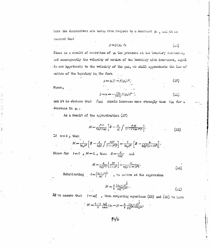
Y Y(YO' 0
Snoas a result of recucion off y/o Lo*SU' .O'O.~x;:2ac.
aV.-3 OonzC-C~un th-oo~yo'i.otion o%' tho o z n
in our hy-)otics-s to tIho ve1ocij~ of thei Laz, 11 chai ro±ooo-lz±a;
m~otIon off the bo day in tho ffomn
Y~o -f(YO.)j
=dit is ovious that f (yo) should incroaso =ore stronz].y tlhon l/Uo faor LL
yo.~
M B a [B 4
3y Op 3yI (yy,) .3YO i-y (1)8 1a yO.4O41

2a Coe Yo-Y) YYo
Homeo, O.SAi. a ta 4 ' we,0 id4
-80a Co aCosy
P1=2.
fcy' ,Lb
In aoMthir approxatioxi it c~ L o ao3 Lvle d tjj _t
an Vfc do not cp c the mass mIZionchin, cLth ation (29) ~hn
M 1 (YO-Y) 5
.(com~parison of tho e);,rcssjojj for zl.a with cuto 2~ leaws onoe again -6o
the ranult of (42) )
We nOws tace Linto aoomi~t tliat thie waneo VOXies in th Gazeo o
mti=6!l It in obviowjti. ,
U(4

Mliorci'ore cciuation (28)G muz-t bc tw~itten in tho £forrn
Musj'x equation (2o) rnuot be f'inJaly -written' in tho f'oni,
Eq.aU~n 4~~ ill be val~id if each elc2cn .,,~rcc on the i:ao
pendcrt3tly of -djacnt elomcrn L, L%. a mattor o' wi~&c~n ;ll.
ocour. HoueverD, an a rezult of' thin Firuarc 2.,. Def'orimtion o'6 a ywci-
we can use thec equ.ations presentod - lcative su='±aco viitrt-ac. .
above.
Aotually' despite tha fact that
the anrle ' ohaies ebxrinZ thie pror.
cess of' mi~ori since the canal
betwveen the vector vclooitj of' eah
cloment and the tan~rert to a Xivon .
element of sura'Tho Yvill not ohanrje, it can be accumod that -11.1 direction of'
notion of the Zaa ir11l not chan~c.
.PO hJl idte peOf' tho Bur±facc ,to wh.,'ich' is applied ext on i.
pr~trai f'or thio ihylothosis thiat th e direction off ,o-iion of' each one u it
elements doesn not oharwe. It is obvious a6 .a rosult of! twhis, that (F 32c)
*c X-yam 4h (ya -y)w ;. (50)

Elirdinatin - '(x cos + y sin ": .n from equation (51) MCI ut; ~lw
of motion
TIO find tho ecp.inion of rw~tion of tho o'uri=o; J'i forr,
y s(X; t), (53)
F'urthrr, since for the shook~ front thVe re2.atior-shi:
iaolds coo&., where y. is the~ ooorc~nates of the shook Pront, wo have
-A+ I k-I Jcg yifsn.-x )
ot:aLon (55z) is theo oci~ltion OtC the surf ioe ot the shook
As a result of thle ooliverZoloo of Z"Inil a -ln''
point of their intewsection. vill move wvi-Li variable vo*Icei ty, veliohl leada to
a, variable jet velociy. As~ a result of tis it is pow >ThI to obtain in,
certain PflaC-Oz. a volocity. hisi boosted in con),rj.SQn j~jth theo aVeO'a)e Ivelocity. In or&Thr that the jet Waoufl.be st'able and not 11 ayingj itiessential tha-. on thle averago the vcilocity :Laulz 4 ition i:Loul. not be larre aad
that tho velocity of the rear portions nboule, icrease relative to tho front--1
portions

SUBJECT INDEX
CHAPTER CHAPMTER
Abel's equation of state 7 Characteristic temperature 3Acetylides 1 w" .. surface 5Active portion of a charge 11 Coefficient of activity 4
It It " " " " thermal - 0limiting length.. II conductivityActivity 4 Coefficient of thermal" pattial 4 diffusivity 10
Adiabatic, for detonation Combustion 10wave 7 Combustion, normal 10
Adiabatic, Hugoniot 6 " of condensed explo-" Poisson 6 sives 10
Ammonites 1 Combustion of gases 10Anmotol 1 it ItArrhenius' Equation 2 concentration/livits 10Arrhenius' Law 10 Combustion of daseous ex-Autocatalytic reactions 2 plosive systems 10Average "retarded" pressure 13 Combustion of powders 10Axial cumulation 12 Combustion, theory of-Azides 1 Zel'dovich-Frank-)all indicator 13 Kamenetakii 10Ballistic pendulum 11 Combustion,. velocity of
mechanism of a propagtion 10reaction 8 Composition of explosive
Balliatites 1 products 4Belyayev - Zel'(tovich Theory Compression of copper
of combustion 10 crushers .1.Binding energy 2 Compression of lead cylindersilBoiling point of explosives 10 Conditions at a surface ofBoltzmann districution 6 discontinuity 6Bireskov's formula 13 Conditions for chain auto-Bra hing of a chain 10 ignition 10Brisance 1 Conditions for adiabaticBrisance meter 11 medium 5Calorimetric bomb 3 Constant, reaction velocity 4Capsule effect 19 " of chemical equili-Cavitation of a sense medium 14 brium 6Central ,'ves 10 Contact discontinuity 9Chain ignition 10 Continuance of a chain 10
" t theory of 10 " " " "
Chf, .1:,h 10 velocity constant 10'Chair •,,.'lons 10 Control of chemical reactions 4" " effect of Cordites 1ady . ures 10 Co-Volume 7
Chain reactions, induction Criterion, of Landau 10period 10 " " Nussel't 10
Chain reactions, non-statio- " " strongnary regime 10 degeneration 12
75.o0

CHAPTER CHAPTER
Critical charge diameter 8 Efficiency of explosives 13Critical ignition condition 10 Electro-drop hammer,Critical length of stationary 8 Rdultovskii's 2regime Electro-optical transformer 8Critical 3hock energy 2 Energy, binding 2Critical stress 2 Energy of a crystal lattice 2Cumulation of gases 5 Energy of activation ofCiuu2lat ive charge 12 explosives 2
" ",active portion 12 Energy of interaction ofCumulative charge, with lens 12 molecules 8
effect 12 Energy stress as a result of" focus 12 an explosion II
* gap 12 Equation, Arrhenius's 2/ " Jet 12 " " rd-ije 1 for a de-process of generated electron gas 12formatiort 12 Equation, Bernoulli' s £3
Cumulative surface 12 , Euler's 5Curved drop hammer 2 , of a chem isotherm 4D'Authriche's method 8 " of a polarpographicDegenerated electron gas 12' spiral 12
to it it , t of a streamline 5equation of state iR " , of continuity
Debye-Einstein formula 3 " of diffusion 10Depth, armour piercing 12 of polytropy ofDestructive effect 13 state, Abel's of thermalDetonation 7 conductivity
concentration limits 7 Equtions, basic, of gas dynamics 5Iof condensed ex- Euler's methodplosives 7 Euler's variables 5
Detonation, sympathetic 15 Explosion 1i , wave velocity 7 " field 13wave, process of in a confined medium 14formation 7 " i t confined meteoric
Detonation wave parameters 7 medium 14" conditions for " in an unconfined liquid 13
stationary state 7 Dispersion of detonation pro.Detonation wave, limiting con- ducts from an inclined
ditions of stability 7 medium 13Diffused ignition I0 Double piston impulsometer 13Direct shock wave 6 Dynamites 1Disc Photorecorder 8 Effective length of jet 12Dispersion of detonation pro- t portion of reaction
ducts in air 13 -- zone 8Dispersion of detonation pro- Explosion in the ground .14dicts ft vact'o extinction " of a cumulative charge 12of explosion 13 , point 13
95-,-

CIAPTER CHAPTER
Explosion, spherical 13 Initiating explosives 1Explosive chemical compounds 1 ".-.. impulse 2
if mixtures 1 Tnternal energy 6Explosophoric atomic com- Ionisation data unit 8
plexes 1 Isentropic motionFinal temperdture of an Isomeric effect 3
explosion 3 Kast's formula 3First principles of therm- Lagrange's method 5
odynamics / 7 " problem 14Flash point 2 Laval nozzle 5" '" minimum 2 Law, Hess's 3
Fluid drift mechanism of a 8 Law, of areas(square'law) 10reaction Law, of cosines 10
Formula, Debye-Einstein 3 Law, mass action 2
Formula, Kast's 3 Leading wave 9Diaphrag rusher gauge 13 Lengendre transformation 5Formula, Sadovskii's 13 Limiting active mass 11Foucault-Tepler's method 8 limiting charge diameter 7Free energy 6 Limiting initiating charge 2
Friction pendulum 2 Limit of autoignition 10jFugacity effect 13 Liquid explosive mixtures 1
Fulminate- of mercury 1 " systems 10Fulminating (detonating jelly) 1 Mach angle 12Fulminates 1 Mach wave 9Gaseous bubble 14 mass velocity of combustion 10Gaseous explosion mixture 1 Mechanical. pi.essure gauge 13Gas evolution 1 Method, Dautriche 8Gas generating reaction 4 " , Euler's 5Gelatine dynamites 1 , Foucault-Tfpler's 8Grisoutine ,. " , lagrange' s 5Heat of combustion 3 of explosion 3Heat of evaporation of " of formation 3.explosives 10 Heterogeoeous breakaway 10
Heat of unconfined medium 14 Hess's law of Active Masses 3" " " metallic medium 13 Hexogen 1." " " meteoric medium 14 High explosives 1
Hudronite 1 "Hot spots" ..2Hugionot adiabatic 6 "Hot spots", critical temp-Hydrodynamic theory of erature 2detonation 7 Non-gaseous compositions 10
Ideal liquid 5 Non-stationary motiL_ of aIgnition (detonation) delay medium 5
time 2 Normal chemical agent . 4
Tmpulse opoillograph 8 Normal flame velocity 10Impulsive action 13 Nozzle theory
forcs 11 Origin of chains 10Incompressible liquid 5 Partial activity 4Induction period 2 " pressui'e 4
Peninsula of ignition 10
q,52

HAPI 75R CHAPTER
Period of uto-acceleration 2 Shock wave 6of a reac ion Shock wave, conditions otPeriod of damping of a reaction 2 creation 5
, induction 2 Shock wave, dissipation of
PETN (Pentaerythritol energy 6tetranitrate) ]- Shock wave, initial parameters 6
Phlegmatizers 2 Shock wave, initial parametersPhotographic drum recorder 8 in air 9Picric acid 1 Shock wave, initial parametersPiezoelectric manometer 13 in metals 9Plunger instrument 2 Shockywave, instial parameters
Kholevo's 2 in water 9Potential energy of an explosive 13 Propagation of detonation in"Power" of explosives 11 condensed explosives 8Prandtl-Mayer problem 13 Propagation of detonation inPrinciple of tautochronism 12 gases 8Propagation of a shock wave in Pyrotechnic compositions 1
a dense medium 14 Pyroxyline powder 1Propagation of a shock wave iii Quantum yield 10
solid bodies 14 Radial cumulation .12Propagation of a shock wave in Radial detonation 11
water 14 Range of transmission ofof characteristics 5 detonation 15ofconjugate isentropes 9 Rdultovskii's electro-drop
, instantaneous X-ray 12 hammer 2, soap bubble 10 Riemann invariant 5
Michelson's straight line 7 Sensitivij- of explosives 2Mirror scanning 8 ,, " " to the.Motion of a cumulative jet 12 action of initiators 2Mixing mechanism of a reaction 8 Sensitivity of explosives toNitrocellulose powder 1 concussion (vibration) 2Nitro-compounds 1 Ground dispersion ' 6Nitroglycerine 1 Spatial transverse shock wave 6Nitroguanidine 1 Specific breakaway 6Sensitivity of explosives to Specifi - heat 3friction 2 Specific ea- at constant 3
Sensitivity of explosives to pressureshoCk 2 Specific heat at constant
Sensitivity of explosives to volume 3shock, lower limit 2 Specific impulse from an
Sensitivity of explosives to explosion 11shock, upper limit 2 Spectral luminosity 3
Ser~itivity of explosives to Stable motion of a medium 5thermal pulses 2 "Static" effect 13
Sensitivity of e.plosives to Statisticil sum 6tilt 2 Statistical sum of a diatomic
Sensitizers 2 molecule 6Shadbw method 10 Statistical sum of an atom 6Shock adiabatic 6 Stimulation of detonationShock front 6 process 8Shock front, width of 6 Stream lnes 8Shock mechanism of a reaction 8 Super high-speed cumulation 12
Tangential shear 6

CHAPTER CHAPTER
Temperature coefricient of Thermal effect3velocity 2 Thermal ignition 10
Temperature of an explosion 3 Thermal ignition, theory 10Temperature, parameters of 6 Thermal ignition, theor-j of
It , plane, direct 6 non-stationary 10" plar 6 Thermal ignition, theory of
properties of 6 stationary 10transition zone 6 Velocity of detonation, effect
•t" , transverse 6 of admixtures 7width of shock front 6 Velocity of detonation, effect
Similarity solution motion 13 of casing 8Simple (plane) waves 5 Velocity of detonation, effectSmokeless powders 1 of density .7Smoke powders 1 Velocity of detonation, opticalThermite reaction 1 methods of measuring 8Thermodynamic potential 4 Velocity of propagation of anTopochemicall reaction 2 ex1 los ion 1Transition of combustion Vertical drop hamer 2
into detonation 10 Zone of combustion 10Transition of combustion " " " , width of 10
into detonation for " coipression 13;condensed explosives 10 " " crushing (destruction) 1,3
Transition of combustion " " preheating 10into detonation in " " shock 13gaseous systems 10
Transverse reflections 9Transverse (inclined) shock
waves 6Triboehemical hypothesis 2Trotyl 1True stresses, diagram of 12Velocity for armour piercing 12
critical 12Velocity of combustion 10
effect of density 10Velocity of combustion,
effect of temperature 10detonation 7
chronographic method of'measuring 8
Temperature of flash(flash point)
Temperature of flash minimumTetranitromethane 1Tetrazine 1Tetryl 1Theory of convergent jets 12" " thermal flamepropagation 10
Ax i;v tions 3
75Al