Compact Genset Controller, CGC 400 - DEIF
98
DEIF A/S · Frisenborgvej 33 · DK-7800 Skive Tel.: +45 9614 9614 · Fax: +45 9614 9615 [email protected] · www.deif.com PARAMETER LIST Compact Genset Controller, CGC 400 ● Alarm list ● Parameter list Document no.: 4189340789A SW version:
-
Upload
khangminh22 -
Category
Documents
-
view
0 -
download
0
Transcript of Compact Genset Controller, CGC 400 - DEIF
DEIF A/S · Frisenborgvej 33 · DK-7800 Skive · Tel.: +45 9614 9614 · Fax: +45 9614 9615 · [email protected] · www.deif.com
DEIF A/S · Frisenborgvej 33 · DK-7800 Skive · Tel.: +45 9614 9614 · Fax: +45 9614 9615 · [email protected] · www.deif.com
DEIF A/S · Frisenborgvej 33 · DK-7800 Skive · Tel.: +45 9614 9614 · Fax: +45 9614 9615 · [email protected] · www.deif.com
PARAMETER LIST
Compact Genset Controller, CGC 400● Alarm list● Parameter list
Document no.: 4189340789ASW version:

1. General information1.1. Warnings, legal information and safety..................................................................................................4
1.1.1. Warnings and notes ......................................................................................................................41.1.2. Legal information and disclaimer ..................................................................................................41.1.3. Safety issues ................................................................................................................................41.1.4. Electrostatic discharge awareness ...............................................................................................41.1.5. Factory settings ............................................................................................................................5
1.2. About the Parameter List........................................................................................................................51.2.1. General purpose of the Parameter List..........................................................................................51.2.2. Intended users...............................................................................................................................51.2.3. Contents and overall structure ......................................................................................................5
2. Alarm list2.1. General information about the alarm list................................................................................................6
2.1.1. Alarm list features and options .....................................................................................................62.2. Protection parameters............................................................................................................................8
2.2.1. Reverse power and overcurrent protection....................................................................................82.2.2. Voltage protections......................................................................................................................122.2.3. Frequency protections.................................................................................................................142.2.4. Busbar voltage protections..........................................................................................................172.2.5. Busbar frequency protections......................................................................................................192.2.6. Overload protections....................................................................................................................212.2.7. Undervoltage and reactive power low..........................................................................................23
2.3. Breaker control parameters..................................................................................................................252.3.1. Breaker alarms............................................................................................................................25
2.4. Input/output parameters, binary input setup.........................................................................................282.4.1. Digital input 10-15 and 56-57 setup.............................................................................................282.4.2. Digital input 6-8 setup..................................................................................................................292.4.3. Emergency stop...........................................................................................................................302.4.4. M-Logic alarm 1-5 setup .............................................................................................................31
2.5. Analogue input setup............................................................................................................................322.5.1. Multi-input no. 6...........................................................................................................................322.5.2. Multi-input no. 7 ..........................................................................................................................372.5.3. Multi-input no. 8...........................................................................................................................422.5.4. Speed and running feedback setup.............................................................................................472.5.5. Differential measurement.............................................................................................................502.5.6. Aux. supply setup........................................................................................................................532.5.7. Multi-input no. 58.........................................................................................................................542.5.8. Multi-input no. 59.........................................................................................................................59
2.6. System parameters, general setup......................................................................................................642.6.1. Engine heater failure....................................................................................................................642.6.2. Max. ventilation............................................................................................................................652.6.3. Switchboard error - Block and Stop.............................................................................................662.6.4. Switchboard error - Not in auto....................................................................................................672.6.5. Avg U BB.....................................................................................................................................68
2.7. System parameters, communication....................................................................................................692.7.1. External communication error......................................................................................................692.7.2. Engine interface communication alarms......................................................................................70
3. Parameter list3.1. General information about the parameter list.......................................................................................74
3.1.1. Parameter list settings.................................................................................................................743.2. Control parameter, regulation...............................................................................................................75
3.2.1. Regulation....................................................................................................................................753.3. Control parameters, output setup.........................................................................................................76
3.3.1. Digital output setup......................................................................................................................763.4. System parameters..............................................................................................................................773.5. System parameters, general setup......................................................................................................78
CGC 400 parameter list 4189340789 UK
DEIF A/S Page 2 of 98
3.5.1. General setup..............................................................................................................................783.5.2. Counters and timers....................................................................................................................813.5.3. Alarm horn...................................................................................................................................823.5.4. Run coil setup..............................................................................................................................823.5.5. Running, start and stop................................................................................................................833.5.6. Breaker control............................................................................................................................853.5.7. Idle start.......................................................................................................................................853.5.8. Engine heater..............................................................................................................................863.5.9. Cooling ventilation.......................................................................................................................863.5.10. Summer/winter time...................................................................................................................863.5.11. Fuel transfer pump logic............................................................................................................873.5.12. Alarm jump.................................................................................................................................873.5.13. Command timers.......................................................................................................................88
3.6. System parameters, mains setup.........................................................................................................893.6.1. Test..............................................................................................................................................893.6.2. Mains failure................................................................................................................................90
3.7. System parameters, external communication......................................................................................913.7.1. External communication..............................................................................................................91
3.8. System parameters, engine interface communication.........................................................................923.8.1. Engine interface communication..................................................................................................92
3.9. System parameters, setup menu.........................................................................................................933.9.1. Password config. ........................................................................................................................933.9.2. AC config.....................................................................................................................................933.9.3. Display control ............................................................................................................................93
3.10. System parameters, RMI inputs.........................................................................................................943.10.1. RMI 6.........................................................................................................................................943.10.2. RMI 7.........................................................................................................................................953.10.3. RMI 8.........................................................................................................................................953.10.4. RMI 58.......................................................................................................................................963.10.5. RMI 59.......................................................................................................................................963.10.6. Multi-input selections.................................................................................................................973.10.7. Analogue unit input scaling........................................................................................................98
CGC 400 parameter list 4189340789 UK
DEIF A/S Page 3 of 98
1. General information1.1 Warnings, legal information and safety
1.1.1 Warnings and notesThroughout this document, a number of warnings and notes with helpful user information will be presented.To ensure that these are noticed, they will be highlighted as follows in order to separate them from the gener-al text.
Warnings
Warnings indicate a potentially dangerous situation, which could result in death, personal in-jury or damaged equipment, if certain guidelines are not followed.
Notes
Notes provide general information, which will be helpful for the reader to bear in mind.
1.1.2 Legal information and disclaimerDEIF takes no responsibility for installation or operation of the generator set. If there is any doubt about howto install or operate the engine/generator controlled by the unit, the company responsible for the installation orthe operation of the set must be contacted.
The unit is not to be opened by unauthorised personnel. If opened anyway, the warranty will belost.
DisclaimerDEIF A/S reserves the right to change any of the contents of this document without prior notice.
1.1.3 Safety issuesInstalling and operating the unit may imply work with dangerous currents and voltages. Therefore, the instal-lation should only be carried out by authorised personnel who understand the risks involved in working withlive electrical equipment.
Be aware of the hazardous live currents and voltages. Do not touch any AC measurement in-puts as this could lead to injury or death.
DEIF do not recommend to use the USB as the primary power supply for the unit.
1.1.4 Electrostatic discharge awarenessSufficient care must be taken to protect the terminal against static discharges during the installation. Once theunit is installed and connected, these precautions are no longer necessary.
CGC 400 parameter list 4189340789 UK General information
DEIF A/S Page 4 of 98

1.1.5 Factory settingsThe unit is delivered from factory with certain factory settings. These are based on average values and arenot necessarily the correct settings for matching the engine/generator set in question. Precautions must betaken to check the settings before running the engine/generator set.
1.2 About the Parameter List
1.2.1 General purpose of the Parameter ListThis document is a complete parameter list including all parameters, which means that some of the optionparameters included may not be accessible in the system in question.
The document includes a complete standard alarm list and a complete standard parameter list for setup.Therefore, this document is to be used for reference, when information about specific alarms and parametersis needed.
Please make sure to read this document before starting to work with the unit and the genset tobe controlled. Failure to do this could result in human injury or damage to the equipment.
1.2.2 Intended usersThis Parameter List is mainly intended for the person responsible for the unit parameter setup. In most cases,this would be a panel builder designer. Naturally, other users might also find useful information here.
1.2.3 Contents and overall structureThis document is divided into chapters, and in order to make the structure simple and easy to use, eachchapter will begin from the top of a new page.
CGC 400 parameter list 4189340789 UK General information
DEIF A/S Page 5 of 98

2. Alarm list2.1 General information about the alarm list
2.1.1 Alarm list features and options
In the following, these abbreviations are used:G: GeneratorGB: Generator breakerMB: Mains breakerN/A: Not available
This chapter includes a complete alarm list, including all possible options. Therefore, this chapter is to beused for reference when specific information about the individual parameters is needed for the unit setup.
The table consists of the following possible adjustments:
Set point: The alarm set point is adjusted in the set point menu. The setting is a percentage ofthe nominal values.
Delay: The timer setting is the time that must expire from the alarm level is reached until thealarm occurs.
Relay output A: A relay can be activated by output A.
Relay output B: A relay can be activated by output B.
Enable: The alarm can be activated or deactivated. ON means always activated, RUN meansthat the alarm has run status. This means it is activated when the running signal ispresent.
Fail class: When the alarm occurs the unit will react depending on the selected fail class.
Fail classes are:
Fail class DG (diesel generator) Mains unit
F1 Block Block
F2 Warning Warning
F3 Trip GB Trip TB
F4 Trip + Stop Trip MB
F5 Shutdown N/A
F6 Trip MB N/A
F7 Safety stop N/A
F8 Trip MB/GB N/A
Small differences due to the character of the parameters may exist between the individual ta-bles.
CGC 400 parameter list 4189340789 UK Alarm list
DEIF A/S Page 6 of 98
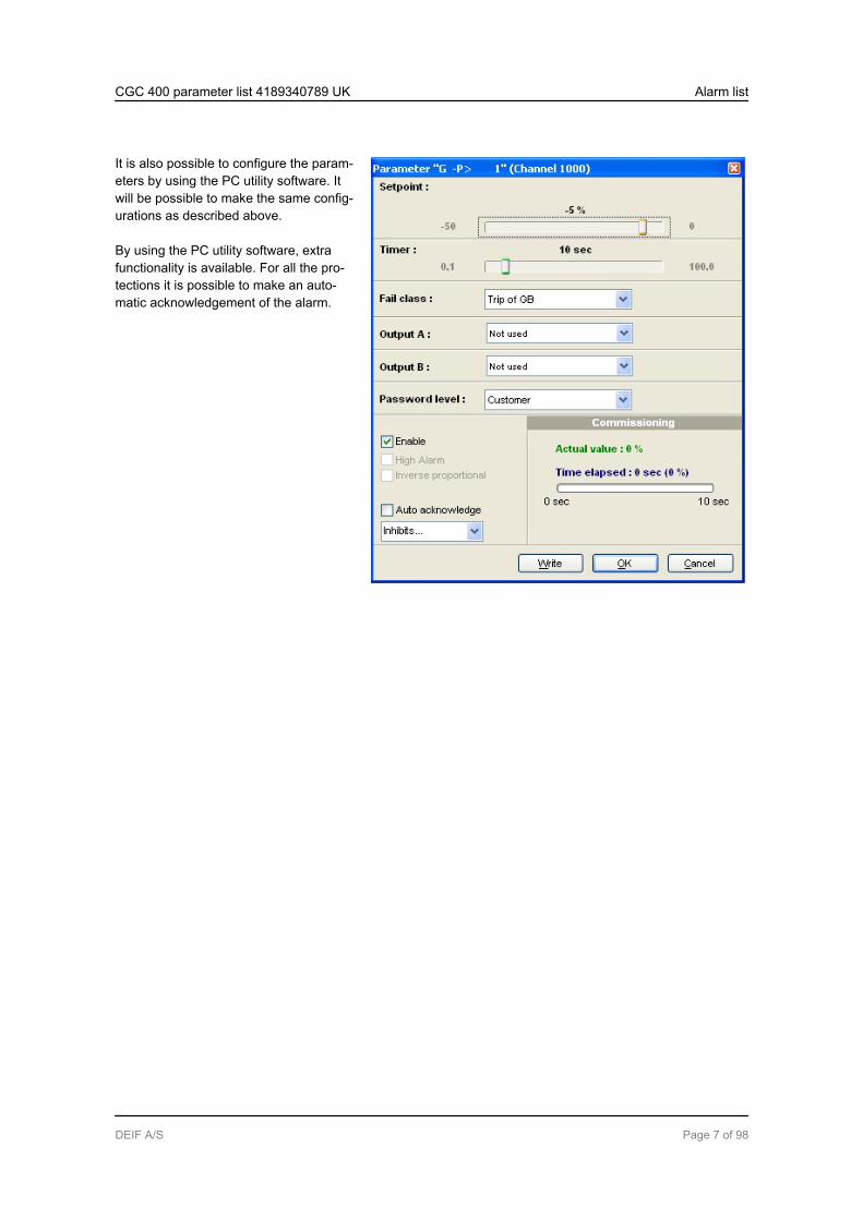
It is also possible to configure the param-eters by using the PC utility software. Itwill be possible to make the same config-urations as described above.
By using the PC utility software, extrafunctionality is available. For all the pro-tections it is possible to make an auto-matic acknowledgement of the alarm.
CGC 400 parameter list 4189340789 UK Alarm list
DEIF A/S Page 7 of 98
2.2 Protection parameters
2.2.1 Reverse power and overcurrent protection
No. Setting Min.Max.
Factorysetting
Notes Ref. Description
1000 Reverse power 1
1001 –P> 1 Setpoint
-200.0 %0.0 %
-5.0 % Designer’sReferenceHandbook
The alarm and fail class are ac-tivated when the reverse powerhas been continuously abovethe programmed value duringthe programmed delay.
1002 –P> 1 Timer 0.1 s100.0 s
10.0 s
1003 –P> 1 RelayoutputA
Not usedOption-depend-ent
Not used
1004 –P> 1 RelayoutputB
Not usedOption-depend-ent
Not used
1005 –P> 1 Enable OFFON
ON
1006 –P> 1 Failclass
F1…F8 Trip GB(F3)
1010 Reverse power 2
1011 –P> 2 Setpoint
-200.0 %0.0 %
-5.0 % Designer’sReferenceHandbook
The alarm and fail class are ac-tivated when the reverse powerhas been continuously abovethe programmed value duringthe programmed delay.
1012 –P> 2 Timer 0.1 s100.0 s
10.0 s
1013 –P> 2 RelayoutputA
Not usedOption-depend-ent
Not used
1014 –P> 2 RelayoutputB
Not usedOption-depend-ent
Not used
1015 –P> 2 Enable OFFON
ON
1016 –P> 2 Failclass
F1…F8 Trip GB(F3)
1030 Overcurrent 1
CGC 400 parameter list 4189340789 UK Alarm list
DEIF A/S Page 8 of 98
No. Setting Min.Max.
Factorysetting
Notes Ref. Description
1031 I> 1 Setpoint
50.0 %200.0 %
115.0 % Designer’sReferenceHandbook
The alarm and fail class are ac-tivated when the current hasbeen continuously above theprogrammed value during theprogrammed delay.
1032 I> 1 Timer 0.1 s3200.0 s
10.0 s
1033 I> 1 RelayoutputA
Not usedOption-depend-ent
Not used
1034 I> 1 RelayoutputB
Not usedOption-depend-ent
Not used
1035 I> 1 Enable OFFON
ON
1036 I> 1 Failclass
F1…F8 Warn-ing(F2)
1040 Overcurrent 2
1041 I> 2 Setpoint
50.0 %200.0 %
120.0 % Designer’sReferenceHandbook
The alarm and fail class are ac-tivated when the current hasbeen continuously above theprogrammed value during theprogrammed delay.
1042 I> 2 Timer 0.1 s3200.0 s
5.0 s
1043 I> 2 RelayoutputA
Not usedOption-depend-ent
Not used
1044 I> 2 RelayoutputB
Not usedOption-depend-ent
Not used
1045 I> 2 Enable OFFON
ON
1046 I> 2 Failclass
F1…F8 Trip GB(F3)
1050 Overcurrent 3
1051 I> 3 Setpoint
50.0 %200.0 %
115.0 % Designer’sReferenceHandbook
The alarm and fail class are ac-tivated when the current hasbeen continuously above theprogrammed value during theprogrammed delay.
1052 I> 3 Timer 0.1 s3200.0 s
10.0 s
1053 I> 3 RelayoutputA
Not usedOption-depend-ent
Not used
CGC 400 parameter list 4189340789 UK Alarm list
DEIF A/S Page 9 of 98
No. Setting Min.Max.
Factorysetting
Notes Ref. Description
1054 I> 3 RelayoutputB
Not usedOption-depend-ent
Not used
1055 I> 3 Enable OFFON
ON
1056 I> 3 Failclass
F1…F8 Trip GB(F3)
1060 Overcurrent 4
1061 I> 4 Setpoint
50.0 %200.0 %
120.0 % Designer’sReferenceHandbook
The alarm and fail class are ac-tivated when the current hasbeen continuously above theprogrammed value during theprogrammed delay.
1062 I> 4 Timer 0.1 s3200.0 s
5.0 s
1063 I> 4 RelayoutputA
Not usedOption-depend-ent
Not used
1064 I> 4 RelayoutputB
Not usedOption-depend-ent
Not used
1065 I> 4 Enable OFFON
ON
1066 I> 4 Failclass
F1…F8 Trip GB(F3)
1080 I> inverse
1081 I> in-verseType
Setpoint
IEC In-verseCustom
IEC In-verse
Designer’sReferenceHandbook
Type selections are:IEC InverseIEC Very InverseIEC Extremely Inv.IEEE Moderately Inv.IEEE Very InverseIEEE Extremely Inv.Custom
Output B is only available in theutility software.
1082 I> in-verseLimit
Setpoint
50 %200 %
110.0 %
1083 I> in-verseTMS
Setpoint
0.1100.0
1.0
1084 I> in-verse k
Setpoint
0.001 s32.000 s
0.140 s
1085 I> in-verse c
Setpoint
0.000 s32.000 s
0.000 s
1086 I> in-verse a
Setpoint
0.00132.000
0.020
CGC 400 parameter list 4189340789 UK Alarm list
DEIF A/S Page 10 of 98

No. Setting Min.Max.
Factorysetting
Notes Ref. Description
1087 I> in-verse
RelayoutputA
Not usedOption-depend-ent
Not used
1088 I> in-verse
Enable OFFON
ON
1089 I> in-verse
Failclass
F1…F8 Trip GB(F3)
1130 Fast overcurrent 1
1131 I>> 1 Setpoint
150.0 %350.0 %
150.0 % Designer’sReferenceHandbook
The alarm settings relate to thenominal current setting. Thealarm and fail class are activa-ted when the current has beencontinuously above the pro-grammed value during the pro-grammed delay.
1132 I>> 1 Timer 0.0 s100.0 s
2.0 s
1133 I>> 1 RelayoutputA
Not usedOption-depend-ent
Not used
1134 I>> 1 RelayoutputB
Not usedOption-depend-ent
Not used
1135 I>> 1 Enable OFFON
OFF
1136 I>> 1 Failclass
F1...F8 Trip GB(F3)
1140 Fast overcurrent 2
1141 I>> 2 Setpoint
150.0 %350.0 %
200 % Designer’sReferenceHandbook
The alarm and fail class are ac-tivated when the current hasbeen continuously above theprogrammed value during theprogrammed delay
1142 I>> 2 Delay 0.0 s100.0 s
0.5 s
1143 I>> 2 RelayoutputA
Not usedOption-depend-ent
Not used
1144 I>> 2 RelayoutputB
Not usedOption-depend-ent
Not used
1145 I>> 2 Enable OFFON
OFF
1146 I>> 2 Failclass
F1...F8 Trip GB(F3)
CGC 400 parameter list 4189340789 UK Alarm list
DEIF A/S Page 11 of 98
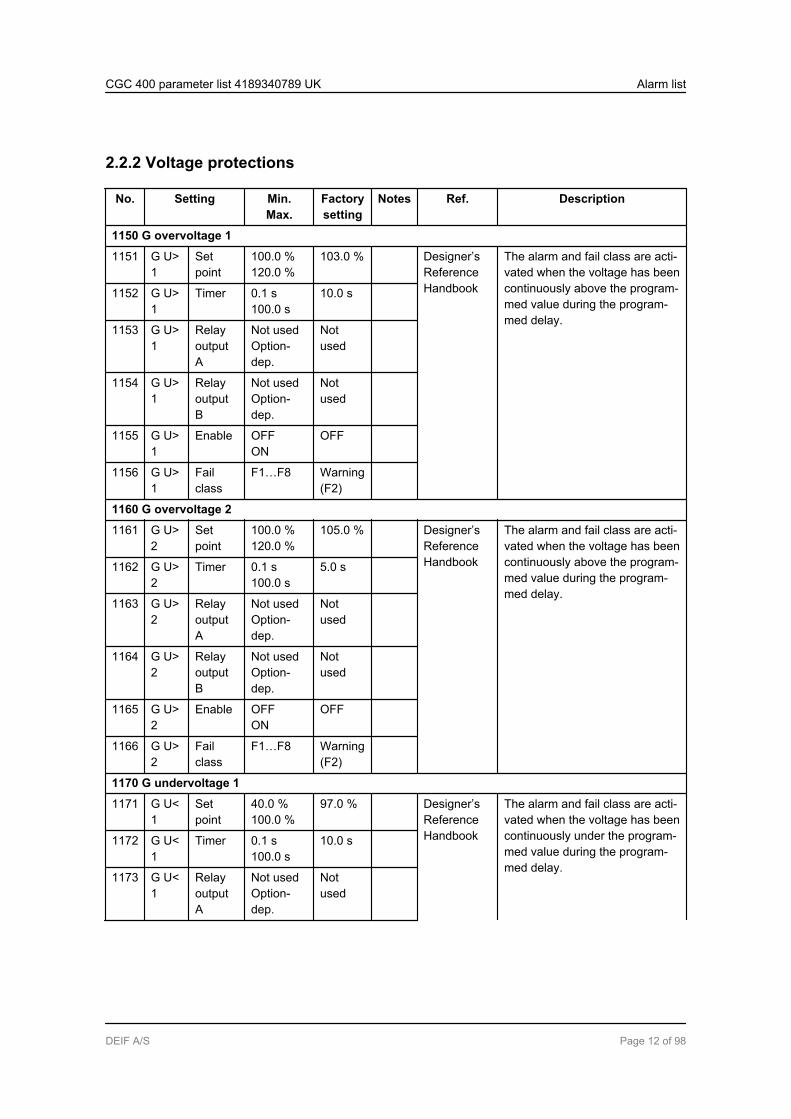
2.2.2 Voltage protections
No. Setting Min.Max.
Factorysetting
Notes Ref. Description
1150 G overvoltage 1
1151 G U>1
Setpoint
100.0 %120.0 %
103.0 % Designer’sReferenceHandbook
The alarm and fail class are acti-vated when the voltage has beencontinuously above the program-med value during the program-med delay.
1152 G U>1
Timer 0.1 s100.0 s
10.0 s
1153 G U>1
RelayoutputA
Not usedOption-dep.
Notused
1154 G U>1
RelayoutputB
Not usedOption-dep.
Notused
1155 G U>1
Enable OFFON
OFF
1156 G U>1
Failclass
F1…F8 Warning(F2)
1160 G overvoltage 2
1161 G U>2
Setpoint
100.0 %120.0 %
105.0 % Designer’sReferenceHandbook
The alarm and fail class are acti-vated when the voltage has beencontinuously above the program-med value during the program-med delay.
1162 G U>2
Timer 0.1 s100.0 s
5.0 s
1163 G U>2
RelayoutputA
Not usedOption-dep.
Notused
1164 G U>2
RelayoutputB
Not usedOption-dep.
Notused
1165 G U>2
Enable OFFON
OFF
1166 G U>2
Failclass
F1…F8 Warning(F2)
1170 G undervoltage 1
1171 G U<1
Setpoint
40.0 %100.0 %
97.0 % Designer’sReferenceHandbook
The alarm and fail class are acti-vated when the voltage has beencontinuously under the program-med value during the program-med delay.
1172 G U<1
Timer 0.1 s100.0 s
10.0 s
1173 G U<1
RelayoutputA
Not usedOption-dep.
Notused
CGC 400 parameter list 4189340789 UK Alarm list
DEIF A/S Page 12 of 98

No. Setting Min.Max.
Factorysetting
Notes Ref. Description
1174 G U<1
RelayoutputB
Not usedOption-dep.
Notused
1175 G U<1
Enable OFFON
OFF
1176 G U<1
Failclass
F1…F8 Warning(F2)
1180 G undervoltage 2
1181 G U<2
Setpoint
40.0 %100.0 %
95.0 % Designer’sReferenceHandbook
The alarm and fail class are acti-vated when the voltage has beencontinuously under the program-med value during the program-med delay.
1182 G U<2
Timer 0.1 s100.0 s
5.0 s
1183 G U<2
RelayoutputA
Not usedOption-dep.
Notused
1184 G U<2
RelayoutputB
Not usedOption-dep.
Notused
1185 G U<2
Enable OFFON
OFF
1186 G U<2
Failclass
F1…F8 Warning(F2)
1190 G undervoltage 3
1191 G U<3
Setpoint
40.0 %100.0 %
95.0 % Designer’sReferenceHandbook
The alarm and fail class are acti-vated when the voltage has beencontinuously under the program-med value during the program-med delay.
1192 G U<3
Timer 0.1 s100.0 s
5.0 s
1193 G U<3
RelayoutputA
Not usedOption-dep.
Notused
1194 G U<3
RelayoutputB
Not usedOption-dep.
Notused
1195 G U<3
Enable OFFON
OFF
1196 G U<3
Failclass
F1...F8 Warning(F2)
CGC 400 parameter list 4189340789 UK Alarm list
DEIF A/S Page 13 of 98

2.2.3 Frequency protections
Frequency settings relate to the nominal frequency setting.
No. Setting Min.Max.
Factorysetting
Notes Ref. Description
1210 G overfrequency 1
1211 G f>1
Setpoint
100.0 %120.0 %
103.0 % Designer’sReferenceHandbook
The alarm and fail class are acti-vated when the frequency hasbeen continuously above the pro-grammed value during the pro-grammed delay. Frequency set-tings relate to nominal frequencysetting.
1212 G f>1
Timer 0.2 s100.0 s
10.0 s
1213 G f>1
RelayoutputA
Not usedOption-depend-ent
Notused
1214 G f>1
RelayoutputB
Not usedOption-depend-ent
Notused
1215 G f>1
Enable OFFON
OFF
1216 G f>1
Failclass
F1…F8 Warning(F2)
1220 G overfrequency 2
1221 G f>2
Setpoint
100.0 %120.0 %
105.0 % Designer’sReferenceHandbook
The alarm and fail class are acti-vated when the frequency hasbeen continuously above the pro-grammed value during the pro-grammed delay.
1222 G f>2
Timer 0.2 s100.0 s
5.0 s
1223 G f>2
RelayoutputA
Not usedOption-depend-ent
Notused
1224 G f>2
RelayoutputB
Not usedOption-depend-ent
Notused
1225 G f>2
Enable OFFON
OFF
1226 G f>2
Failclass
F1…F8 Warning(F2)
1230 G overfrequency 3
CGC 400 parameter list 4189340789 UK Alarm list
DEIF A/S Page 14 of 98
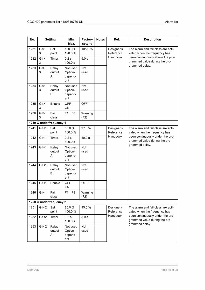
No. Setting Min.Max.
Factorysetting
Notes Ref. Description
1231 G f>3
Setpoint
100.0 %120.0 %
105.0 % Designer’sReferenceHandbook
The alarm and fail class are acti-vated when the frequency hasbeen continuously above the pro-grammed value during the pro-grammed delay.
1232 G f>3
Timer 0.2 s100.0 s
5.0 s
1233 G f>3
RelayoutputA
Not usedOption-depend-ent
Notused
1234 G f>3
RelayoutputB
Not usedOption-depend-ent
Notused
1235 G f>3
Enable OFFON
OFF
1236 G f>3
Failclass
F1…F8 Warning(F2)
1240 G underfrequency 1
1241 G f<1 Setpoint
80.0 %100.0 %
97.0 % Designer’sReferenceHandbook
The alarm and fail class are acti-vated when the frequency hasbeen continuously under the pro-grammed value during the pro-grammed delay.
1242 G f<1 Timer 0.2 s100.0 s
10.0 s
1243 G f<1 RelayoutputA
Not usedOption-depend-ent
Notused
1244 G f<1 RelayoutputB
Not usedOption-depend-ent
Notused
1245 G f<1 Enable OFFON
OFF
1246 G f<1 Failclass
F1…F8 Warning(F2)
1250 G underfrequency 2
1251 G f<2 Setpoint
80.0 %100.0 %
95.0 % Designer’sReferenceHandbook
The alarm and fail class are acti-vated when the frequency hasbeen continuously under the pro-grammed value during the pro-grammed delay.
1252 G f<2 Timer 0.2 s100.0 s
5.0 s
1253 G f<2 RelayoutputA
Not usedOption-depend-ent
Notused
CGC 400 parameter list 4189340789 UK Alarm list
DEIF A/S Page 15 of 98
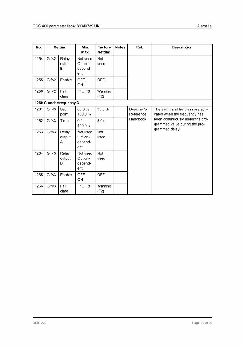
No. Setting Min.Max.
Factorysetting
Notes Ref. Description
1254 G f<2 RelayoutputB
Not usedOption-depend-ent
Notused
1255 G f<2 Enable OFFON
OFF
1256 G f<2 Failclass
F1…F8 Warning(F2)
1260 G underfrequency 3
1261 G f<3 Setpoint
80.0 %100.0 %
95.0 % Designer’sReferenceHandbook
The alarm and fail class are acti-vated when the frequency hasbeen continuously under the pro-grammed value during the pro-grammed delay.
1262 G f<3 Timer 0.2 s100.0 s
5.0 s
1263 G f<3 RelayoutputA
Not usedOption-depend-ent
Notused
1264 G f<3 RelayoutputB
Not usedOption-depend-ent
Notused
1265 G f<3 Enable OFFON
OFF
1266 G f<3 Failclass
F1…F8 Warning(F2)
CGC 400 parameter list 4189340789 UK Alarm list
DEIF A/S Page 16 of 98
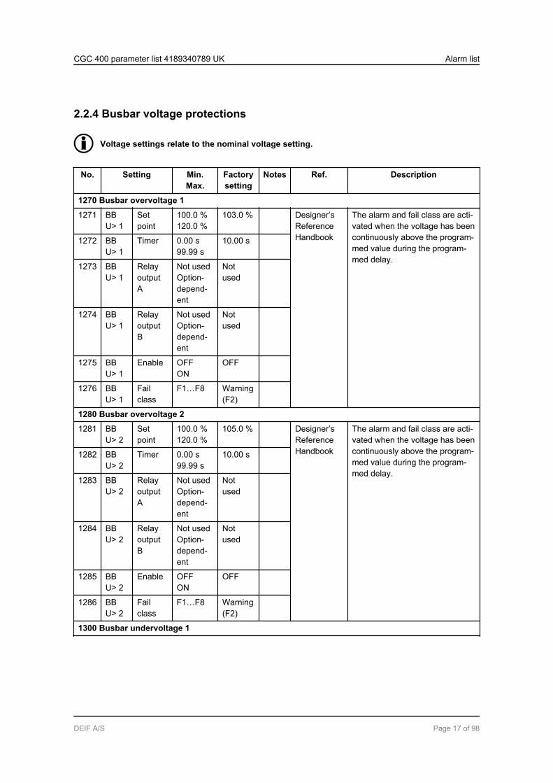
2.2.4 Busbar voltage protections
Voltage settings relate to the nominal voltage setting.
No. Setting Min.Max.
Factorysetting
Notes Ref. Description
1270 Busbar overvoltage 1
1271 BBU> 1
Setpoint
100.0 %120.0 %
103.0 % Designer’sReferenceHandbook
The alarm and fail class are acti-vated when the voltage has beencontinuously above the program-med value during the program-med delay.
1272 BBU> 1
Timer 0.00 s99.99 s
10.00 s
1273 BBU> 1
RelayoutputA
Not usedOption-depend-ent
Notused
1274 BBU> 1
RelayoutputB
Not usedOption-depend-ent
Notused
1275 BBU> 1
Enable OFFON
OFF
1276 BBU> 1
Failclass
F1…F8 Warning(F2)
1280 Busbar overvoltage 2
1281 BBU> 2
Setpoint
100.0 %120.0 %
105.0 % Designer’sReferenceHandbook
The alarm and fail class are acti-vated when the voltage has beencontinuously above the program-med value during the program-med delay.
1282 BBU> 2
Timer 0.00 s99.99 s
10.00 s
1283 BBU> 2
RelayoutputA
Not usedOption-depend-ent
Notused
1284 BBU> 2
RelayoutputB
Not usedOption-depend-ent
Notused
1285 BBU> 2
Enable OFFON
OFF
1286 BBU> 2
Failclass
F1…F8 Warning(F2)
1300 Busbar undervoltage 1
CGC 400 parameter list 4189340789 UK Alarm list
DEIF A/S Page 17 of 98

No. Setting Min.Max.
Factorysetting
Notes Ref. Description
1301 BBU< 1
Setpoint
40.0 %100.0 %
97.0 % Designer’sReferenceHandbook
The alarm and fail class are acti-vated when the voltage has beencontinuously under the program-med value during the program-med delay.
1302 BBU< 1
Timer 0.00 s99.99 s
10.00 s
1303 BBU< 1
RelayoutputA
Not usedOption-depend-ent
Notused
1304 BBU< 1
RelayoutputB
Not usedOption-depend-ent
Notused
1305 BBU< 1
Enable OFFON
OFF
1306 BBU< 1
Failclass
F1…F8 Warning(F2)
1310 Busbar undervoltage 2
1311 BBU< 2
Setpoint
40.0 %100.0 %
95.0 % Designer’sReferenceHandbook
The alarm and fail class are acti-vated when the voltage has beencontinuously under the program-med value during the program-med delay.
1312 BBU< 2
Timer 0.00 s99.99 s
5.00 s
1313 BBU< 2
RelayoutputA
Not usedOption-depend-ent
Notused
1314 BBU< 2
RelayoutputB
Not usedOption-depend-ent
Notused
1315 BBU< 2
Enable OFFON
OFF
1316 BBU< 2
Failclass
F1…F8 Warning(F2)
CGC 400 parameter list 4189340789 UK Alarm list
DEIF A/S Page 18 of 98

2.2.5 Busbar frequency protections
Frequency settings relate to the nominal frequency setting.
No. Setting Min.Max.
Factorysetting
Notes Ref. Description
1350 Busbar overfrequency 1
1351 BB f>1
Setpoint
100.0 %120.0 %
103.0 % Designer’sReferenceHandbook
The alarm and fail class are acti-vated when the frequency hasbeen continuously above the pro-grammed value during the pro-grammed delay.
1352 BB f>1
Timer 0.00 s99.99 s
10.00 s
1353 BB f>1
RelayoutputA
Not usedOption-dep.
Notused
1354 BB f>1
RelayoutputB
Not usedOption-dep.
Notused
1355 BB f>1
Enable OFFON
OFF
1356 BB f>1
Failclass
F1…F8 Warning(F2)
1360 Busbar overfrequency 2
1361 BB f>2
Setpoint
100.0 %120.0 %
105.0 % Designer’sReferenceHandbook
The alarm and fail class are acti-vated when the frequency hasbeen continuously above the pro-grammed value during the pro-grammed delay.
1362 BB f>2
Timer 0.00 s99.99 s
5.00 s
1363 BB f>2
RelayoutputA
Not usedOption-dep.
Notused
1364 BB f>2
RelayoutputB
Not usedOption-dep.
Notused
1365 BB f>2
Enable OFFON
OFF
1366 BB f>2
Failclass
F1…F8 Warning(F2)
1380 Busbar underfrequency 1
1381 BB f<1
Setpoint
80.0 %100.0 %
97.0 % Designer’sReferenceHandbook
The alarm and fail class are acti-vated when the frequency hasbeen continuously under the pro-grammed value during the pro-grammed delay.
1382 BB f<1
Timer 0.00 s99.99 s
10.00 s
CGC 400 parameter list 4189340789 UK Alarm list
DEIF A/S Page 19 of 98
No. Setting Min.Max.
Factorysetting
Notes Ref. Description
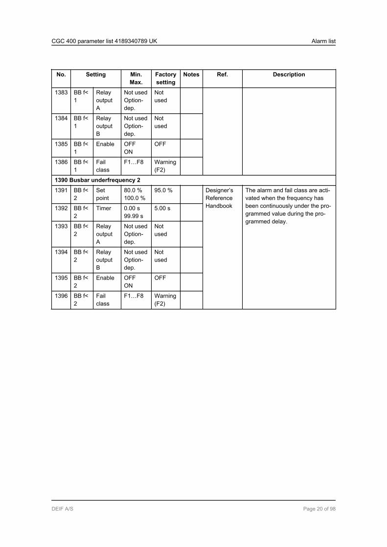
1383 BB f<1
RelayoutputA
Not usedOption-dep.
Notused
1384 BB f<1
RelayoutputB
Not usedOption-dep.
Notused
1385 BB f<1
Enable OFFON
OFF
1386 BB f<1
Failclass
F1…F8 Warning(F2)
1390 Busbar underfrequency 2
1391 BB f<2
Setpoint
80.0 %100.0 %
95.0 % Designer’sReferenceHandbook
The alarm and fail class are acti-vated when the frequency hasbeen continuously under the pro-grammed value during the pro-grammed delay.
1392 BB f<2
Timer 0.00 s99.99 s
5.00 s
1393 BB f<2
RelayoutputA
Not usedOption-dep.
Notused
1394 BB f<2
RelayoutputB
Not usedOption-dep.
Notused
1395 BB f<2
Enable OFFON
OFF
1396 BB f<2
Failclass
F1…F8 Warning(F2)
CGC 400 parameter list 4189340789 UK Alarm list
DEIF A/S Page 20 of 98

2.2.6 Overload protections
No. Setting Min.Max.
Factorysetting
Notes Ref. Description
1450 Overload 1
1451 P> 1 Setpoint
-200.0 %200.0 %
100.0 % Designer’sReferenceHandbook
Settings relate to nominal power.The alarm and fail class are activa-ted when the power has been con-tinuously above the programmedvalue during the programmed de-lay.
1452 P> 1 Timer 0.1 s3200.0 s
10.0 s
1453 P> 1 RelayoutputA
Not usedOption-dep.
Notused
1454 P> 1 RelayoutputB
Not usedOption-dep.
Notused
1455 P> 1 Enable OFFON
OFF
1456 P> 1 Failclass
F1…F8 Warn-ing (F2)
1460 Overload 2
1461 P> 2 Setpoint
-200.0 %200.0 %
110.0 % Designer’sReferenceHandbook
The alarm and fail class are activa-ted when the power has been con-tinuously above the programmedvalue during the programmed de-lay.
1462 P> 2 Timer 0.1 s3200.0 s
5.0 s
1463 P> 2 RelayoutputA
Not usedOption-dep.
Notused
1464 P> 2 RelayoutputB
Not usedOption-dep.
Notused
1465 P> 2 Enable OFFON
OFF
1466 P> 2 Failclass
F1…F8 Trip GB(F3)
1470 Overload 3
1471 P> 3 Setpoint
-200.0 %200.0 %
100.0 % Designer’sReferenceHandbook
The alarm and fail class are activa-ted when the power has been con-tinuously above the programmedvalue during the programmed de-lay.
1472 P> 3 Timer 0.1 s3200.0 s
10.0 s
1473 P> 3 RelayoutputA
Not usedOption-dep.
Notused
CGC 400 parameter list 4189340789 UK Alarm list
DEIF A/S Page 21 of 98

No. Setting Min.Max.
Factorysetting
Notes Ref. Description
1474 P> 3 RelayoutputB
Not usedOption-dep.
Notused
1475 P> 3 Enable OFFON
OFF
1476 P> 3 Failclass
F1…F8 Trilp GB(F3)
1480 Overload 4
1481 P> 4 Setpoint
-200.0 %200.0 %
110.0 % Designer’sReferenceHandbook
The alarm and fail class are activa-ted when the power has been con-tinuously above the programmedvalue during the programmed de-lay.
1482 P> 4 Timer 0.1 s3200.0 s
5.0 s
1483 P> 4 RelayoutputA
Not usedOption-dep.
Notused
1484 P> 4 RelayoutputB
Not usedOption-dep.
Notused
1485 P> 4 Enable OFFON
OFF
1486 P> 4 Failclass
F1…F8 Trip GB(F3)
1490 Overload 5
1491 P> 5 Setpoint
-200.0 %200.0 %
100.0 % Designer’sReferenceHandbook
The alarm and fail class are activa-ted when the power has been con-tinuously above the programmedvalue during the programmed de-lay.
1492 P> 5 Timer 0.1 s3200.0 s
10.0 s
1493 P> 5 RelayoutputA
Not usedOption-dep.
Notused
1494 P> 5 RelayoutputB
Not usedOption-dep.
Notused
1495 P> 5 Enable OFFON
OFF
1496 P> 5 Failclass
F1...F8 Trip GB(F3)
CGC 400 parameter list 4189340789 UK Alarm list
DEIF A/S Page 22 of 98
2.2.7 Undervoltage and reactive power low
No. Setting Min.Max.
Factorysetting
Notes Ref. Description
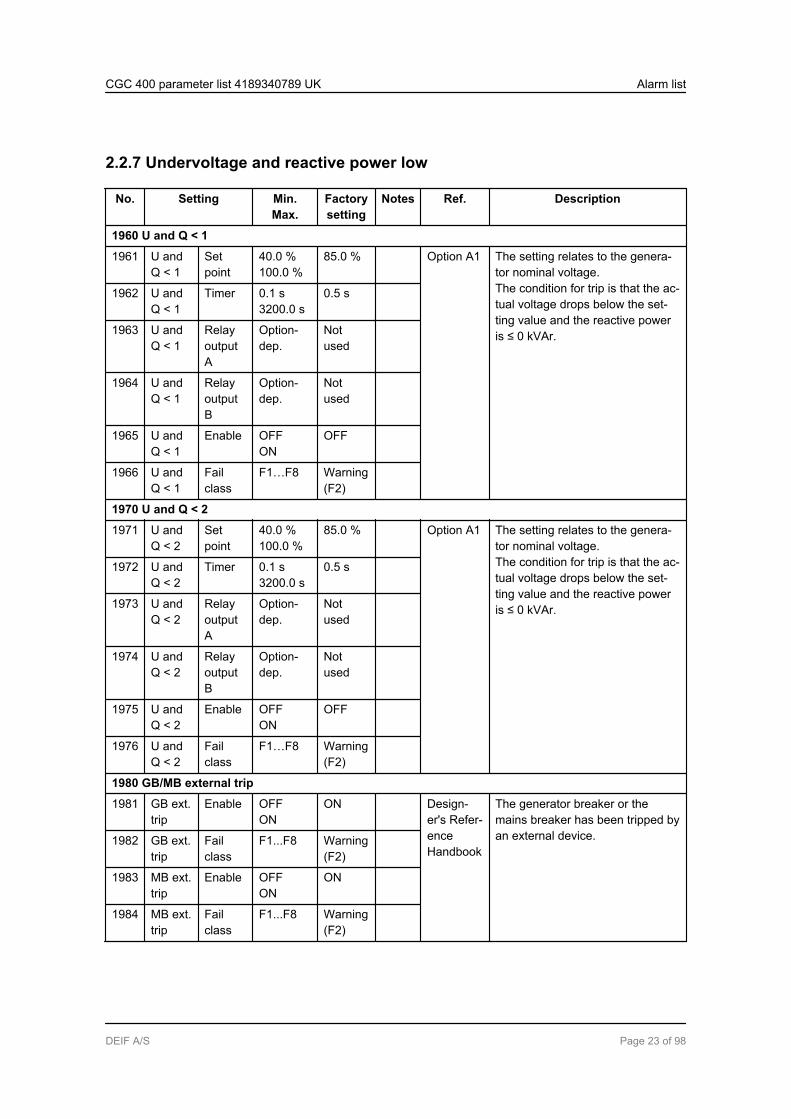
1960 U and Q < 1
1961 U andQ < 1
Setpoint
40.0 %100.0 %
85.0 % Option A1 The setting relates to the genera-tor nominal voltage.The condition for trip is that the ac-tual voltage drops below the set-ting value and the reactive poweris ≤ 0 kVAr.
1962 U andQ < 1
Timer 0.1 s3200.0 s
0.5 s
1963 U andQ < 1
RelayoutputA
Option-dep.
Notused
1964 U andQ < 1
RelayoutputB
Option-dep.
Notused
1965 U andQ < 1
Enable OFFON
OFF
1966 U andQ < 1
Failclass
F1…F8 Warning(F2)
1970 U and Q < 2
1971 U andQ < 2
Setpoint
40.0 %100.0 %
85.0 % Option A1 The setting relates to the genera-tor nominal voltage.The condition for trip is that the ac-tual voltage drops below the set-ting value and the reactive poweris ≤ 0 kVAr.
1972 U andQ < 2
Timer 0.1 s3200.0 s
0.5 s
1973 U andQ < 2
RelayoutputA
Option-dep.
Notused
1974 U andQ < 2
RelayoutputB
Option-dep.
Notused
1975 U andQ < 2
Enable OFFON
OFF
1976 U andQ < 2
Failclass
F1…F8 Warning(F2)
1980 GB/MB external trip
1981 GB ext.trip
Enable OFFON
ON Design-er's Refer-enceHandbook
The generator breaker or themains breaker has been tripped byan external device.1982 GB ext.
tripFailclass
F1...F8 Warning(F2)
1983 MB ext.trip
Enable OFFON
ON
1984 MB ext.trip
Failclass
F1...F8 Warning(F2)
CGC 400 parameter list 4189340789 UK Alarm list
DEIF A/S Page 23 of 98
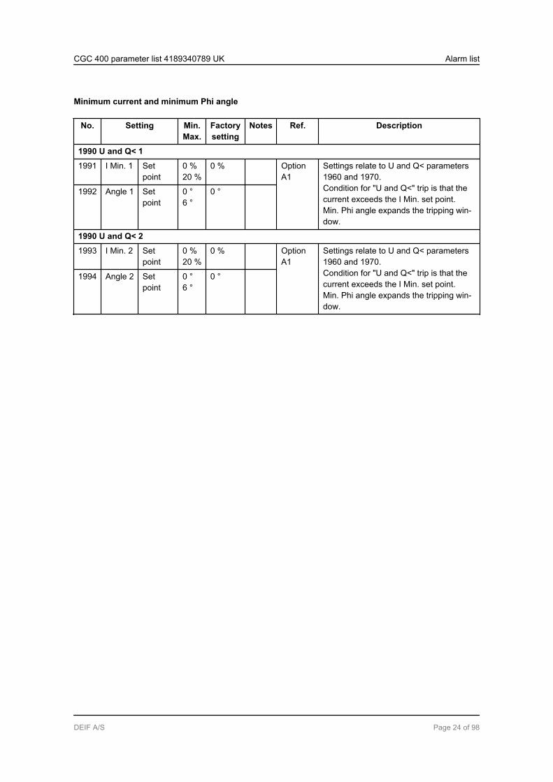
Minimum current and minimum Phi angle
No. Setting Min.Max.
Factorysetting
Notes Ref. Description
1990 U and Q< 1
1991 I Min. 1 Setpoint
0 %20 %
0 % OptionA1
Settings relate to U and Q< parameters1960 and 1970.Condition for "U and Q<" trip is that thecurrent exceeds the I Min. set point.Min. Phi angle expands the tripping win-dow.
1992 Angle 1 Setpoint
0 °6 °
0 °
1990 U and Q< 2
1993 I Min. 2 Setpoint
0 %20 %
0 % OptionA1
Settings relate to U and Q< parameters1960 and 1970.Condition for "U and Q<" trip is that thecurrent exceeds the I Min. set point.Min. Phi angle expands the tripping win-dow.
1994 Angle 2 Setpoint
0 °6 °
0 °
CGC 400 parameter list 4189340789 UK Alarm list
DEIF A/S Page 24 of 98
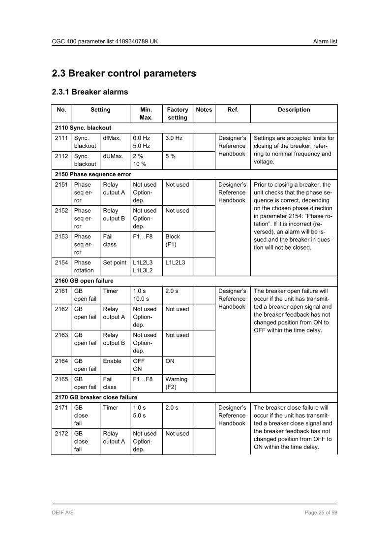
2.3 Breaker control parameters
2.3.1 Breaker alarms
No. Setting Min.Max.
Factorysetting
Notes Ref. Description
2110 Sync. blackout
2111 Sync.blackout
dfMax. 0.0 Hz5.0 Hz
3.0 Hz Designer’sReferenceHandbook
Settings are accepted limits forclosing of the breaker, refer-ring to nominal frequency andvoltage.
2112 Sync.blackout
dUMax. 2 %10 %
5 %
2150 Phase sequence error
2151 Phaseseq er-ror
Relayoutput A
Not usedOption-dep.
Not used Designer’sReferenceHandbook
Prior to closing a breaker, theunit checks that the phase se-quence is correct, dependingon the chosen phase directionin parameter 2154: “Phase ro-tation”. If it is incorrect (re-versed), an alarm will be is-sued and the breaker in ques-tion will not be closed.
2152 Phaseseq er-ror
Relayoutput B
Not usedOption-dep.
Not used
2153 Phaseseq er-ror
Failclass
F1…F8 Block(F1)
2154 Phaserotation
Set point L1L2L3L1L3L2
L1L2L3
2160 GB open failure
2161 GBopen fail
Timer 1.0 s10.0 s
2.0 s Designer’sReferenceHandbook
The breaker open failure willoccur if the unit has transmit-ted a breaker open signal andthe breaker feedback has notchanged position from ON toOFF within the time delay.
2162 GBopen fail
Relayoutput A
Not usedOption-dep.
Not used
2163 GBopen fail
Relayoutput B
Not usedOption-dep.
Not used
2164 GBopen fail
Enable OFFON
ON
2165 GBopen fail
Failclass
F1…F8 Warning(F2)
2170 GB breaker close failure
2171 GBclosefail
Timer 1.0 s5.0 s
2.0 s Designer’sReferenceHandbook
The breaker close failure willoccur if the unit has transmit-ted a breaker close signal andthe breaker feedback has notchanged position from OFF toON within the time delay.
2172 GBclosefail
Relayoutput A
Not usedOption-dep.
Not used
CGC 400 parameter list 4189340789 UK Alarm list
DEIF A/S Page 25 of 98
No. Setting Min.Max.
Factorysetting
Notes Ref. Description
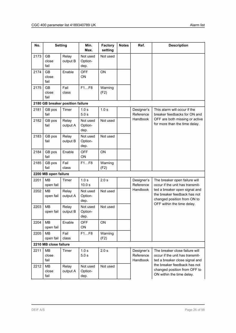
2173 GBclosefail
Relayoutput B
Not usedOption-dep.
Not used
2174 GBclosefail
Enable OFFON
ON
2175 GBclosefail
Failclass
F1…F8 Warning(F2)
2180 GB breaker position failure
2181 GB posfail
Timer 1.0 s5.0 s
1.0 s Designer’sReferenceHandbook
This alarm will occur if thebreaker feedbacks for ON andOFF are both missing or activefor more than the time delay.
2182 GB posfail
Relayoutput A
Not usedOption-dep.
Not used
2183 GB posfail
Relayoutput B
Not usedOption-dep.
Not used
2184 GB posfail
Enable OFFON
ON
2185 GB posfail
Failclass
F1…F8 Warning(F2)
2200 MB open failure
2201 MBopen fail
Timer 1.0 s10.0 s
2.0 s Designer’sReferenceHandbook
The breaker open failure willoccur if the unit has transmit-ted a breaker open signal andthe breaker feedback has notchanged position from ON toOFF within the time delay.
2202 MBopen fail
Relayoutput A
Not usedOption-dep.
Not used
2203 MBopen fail
Relayoutput B
Not usedOption-dep.
Not used
2204 MBopen fail
Enable OFFON
ON
2205 MBopen fail
Failclass
F1…F8 Warning(F2)
2210 MB close failure
2211 MBclosefail
Timer 1.0 s5.0 s
2.0 s Designer’sReferenceHandbook
The breaker close failure willoccur if the unit has transmit-ted a breaker close signal andthe breaker feedback has notchanged position from OFF toON within the time delay.
2212 MBclosefail
Relayoutput A
Not usedOption-dep.
Not used
CGC 400 parameter list 4189340789 UK Alarm list
DEIF A/S Page 26 of 98
No. Setting Min.Max.
Factorysetting
Notes Ref. Description
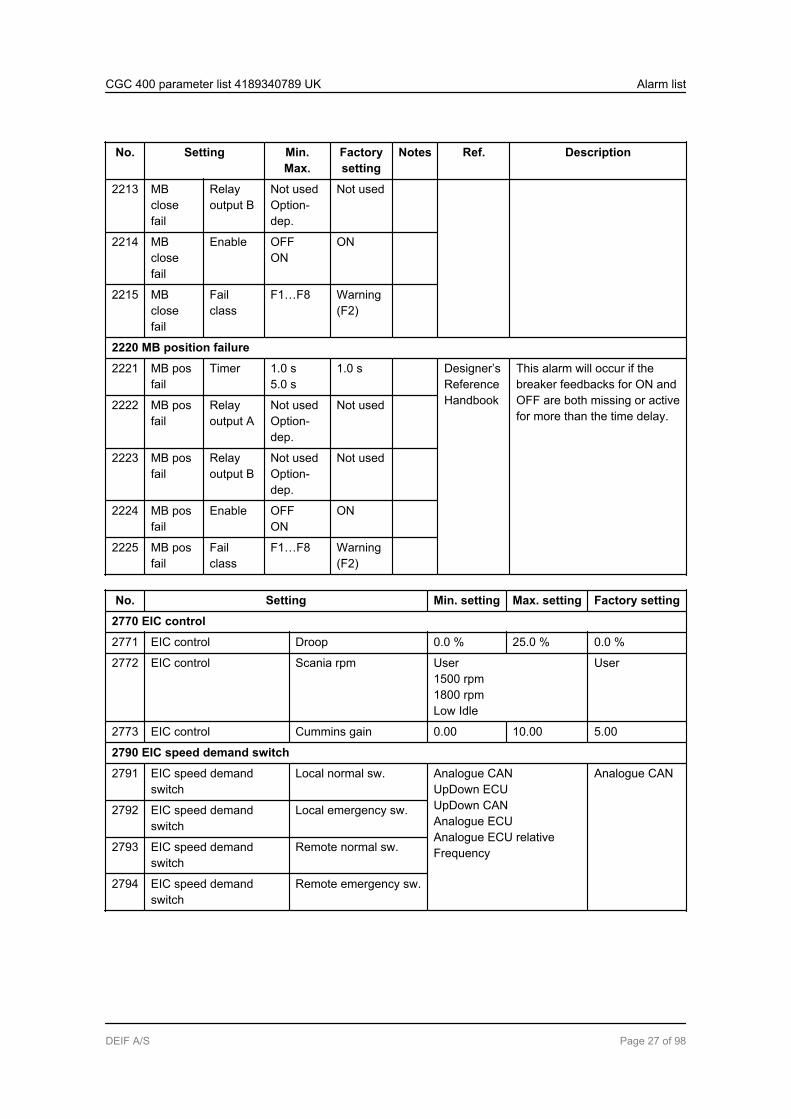
2213 MBclosefail
Relayoutput B
Not usedOption-dep.
Not used
2214 MBclosefail
Enable OFFON
ON
2215 MBclosefail
Failclass
F1…F8 Warning(F2)
2220 MB position failure
2221 MB posfail
Timer 1.0 s5.0 s
1.0 s Designer’sReferenceHandbook
This alarm will occur if thebreaker feedbacks for ON andOFF are both missing or activefor more than the time delay.
2222 MB posfail
Relayoutput A
Not usedOption-dep.
Not used
2223 MB posfail
Relayoutput B
Not usedOption-dep.
Not used
2224 MB posfail
Enable OFFON
ON
2225 MB posfail
Failclass
F1…F8 Warning(F2)
No. Setting Min. setting Max. setting Factory setting
2770 EIC control
2771 EIC control Droop 0.0 % 25.0 % 0.0 %
2772 EIC control Scania rpm User1500 rpm1800 rpmLow Idle
User
2773 EIC control Cummins gain 0.00 10.00 5.00
2790 EIC speed demand switch
2791 EIC speed demandswitch
Local normal sw. Analogue CANUpDown ECUUpDown CANAnalogue ECUAnalogue ECU relativeFrequency
Analogue CAN
2792 EIC speed demandswitch
Local emergency sw.
2793 EIC speed demandswitch
Remote normal sw.
2794 EIC speed demandswitch
Remote emergency sw.
CGC 400 parameter list 4189340789 UK Alarm list
DEIF A/S Page 27 of 98

2.4 Input/output parameters, binary input setup
2.4.1 Digital input 10-15 and 56-57 setup
No. Setting Min.Max.
Factorysetting
Notes Ref. Description
3000 Digital input 10
3001 Dig. in-put 10
Timer 0.0 s100.0 s
10.0 s Designer’sReferenceHandbook
The input is configurableand can have differentfunctions in different units.3002 Dig. in-
put 10Relayoutput A
Not usedOption-dep.
Not used
3003 Dig. in-put 10
Relayoutput B
Not usedOption-dep.
Not used
3004 Dig. in-put 10
Enable OFFON
OFF
3005 Dig. in-put 10
Fail class F1…F8 Warning(F2)
3006 Dig. in-put 10
HighAlarm
OFFON
ON
The same settings apply to inputs 11-15 and 56-57, menus 3010 to 3070.
CGC 400 parameter list 4189340789 UK Alarm list
DEIF A/S Page 28 of 98
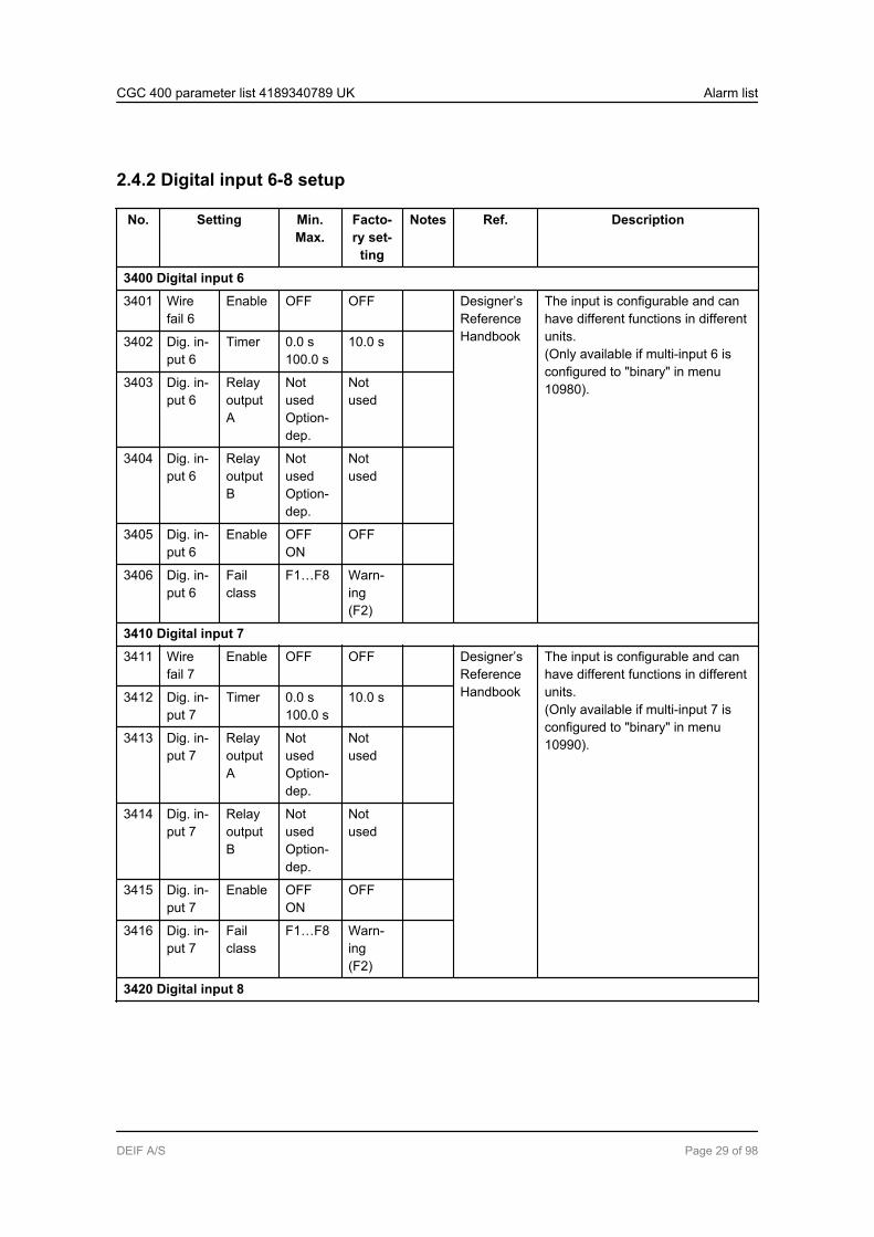
2.4.2 Digital input 6-8 setup
No. Setting Min.Max.
Facto-ry set-
ting
Notes Ref. Description
3400 Digital input 6
3401 Wirefail 6
Enable OFF OFF Designer’sReferenceHandbook
The input is configurable and canhave different functions in differentunits.(Only available if multi-input 6 isconfigured to "binary" in menu10980).
3402 Dig. in-put 6
Timer 0.0 s100.0 s
10.0 s
3403 Dig. in-put 6
RelayoutputA
NotusedOption-dep.
Notused
3404 Dig. in-put 6
RelayoutputB
NotusedOption-dep.
Notused
3405 Dig. in-put 6
Enable OFFON
OFF
3406 Dig. in-put 6
Failclass
F1…F8 Warn-ing(F2)
3410 Digital input 7
3411 Wirefail 7
Enable OFF OFF Designer’sReferenceHandbook
The input is configurable and canhave different functions in differentunits.(Only available if multi-input 7 isconfigured to "binary" in menu10990).
3412 Dig. in-put 7
Timer 0.0 s100.0 s
10.0 s
3413 Dig. in-put 7
RelayoutputA
NotusedOption-dep.
Notused
3414 Dig. in-put 7
RelayoutputB
NotusedOption-dep.
Notused
3415 Dig. in-put 7
Enable OFFON
OFF
3416 Dig. in-put 7
Failclass
F1…F8 Warn-ing(F2)
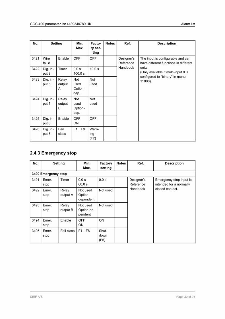
3420 Digital input 8
CGC 400 parameter list 4189340789 UK Alarm list
DEIF A/S Page 29 of 98
No. Setting Min.Max.
Facto-ry set-
ting
Notes Ref. Description
3421 Wirefail 8
Enable OFF OFF Designer’sReferenceHandbook
The input is configurable and canhave different functions in differentunits.(Only available if multi-input 8 isconfigured to "binary" in menu11000).
3422 Dig. in-put 8
Timer 0.0 s100.0 s
10.0 s
3423 Dig. in-put 8
RelayoutputA
NotusedOption-dep.
Notused
3424 Dig. in-put 8
RelayoutputB
NotusedOption-dep.
Notused
3425 Dig. in-put 8
Enable OFFON
OFF
3426 Dig. in-put 8
Failclass
F1…F8 Warn-ing(F2)
2.4.3 Emergency stop
No. Setting Min.Max.
Factorysetting
Notes Ref. Description
3490 Emergency stop
3491 Emer.stop
Timer 0.0 s60.0 s
0.0 s Designer’sReferenceHandbook
Emergency stop input isintended for a normallyclosed contact.3492 Emer.
stopRelayoutput A
Not usedOption-dependent
Not used
3493 Emer.stop
Relayoutput B
Not usedOption-de-pendent
Not used
3494 Emer.stop
Enable OFFON
ON
3495 Emer.stop
Fail class F1…F8 Shut-down(F5)
CGC 400 parameter list 4189340789 UK Alarm list
DEIF A/S Page 30 of 98

2.4.4 M-Logic alarm 1-5 setup
No. Setting Min.Max.
Factorysetting
Notes Ref. Description
3570 Mlogic alarm 1
3570 Mlogic alarm 1 Timer 0.0 s100.0 s
10.0 s The input is configura-ble.
3571 Mlogic alarm 1 Relay outputA
Not usedOption-dep.
Not used
3572 Mlogic alarm 1 Relay outputB
Not usedOption-dep.
Not used
3573 Mlogic alarm 1 Enable OFFON
OFF
3574 Mlogic alarm 1 Fail class F1…F8 Warning(F2)
3575 Mlogic alarm 1 High alarm OFFON
ON
The same settings apply to alarm inputs 2-5, menus 3580 to 3610.
CGC 400 parameter list 4189340789 UK Alarm list
DEIF A/S Page 31 of 98
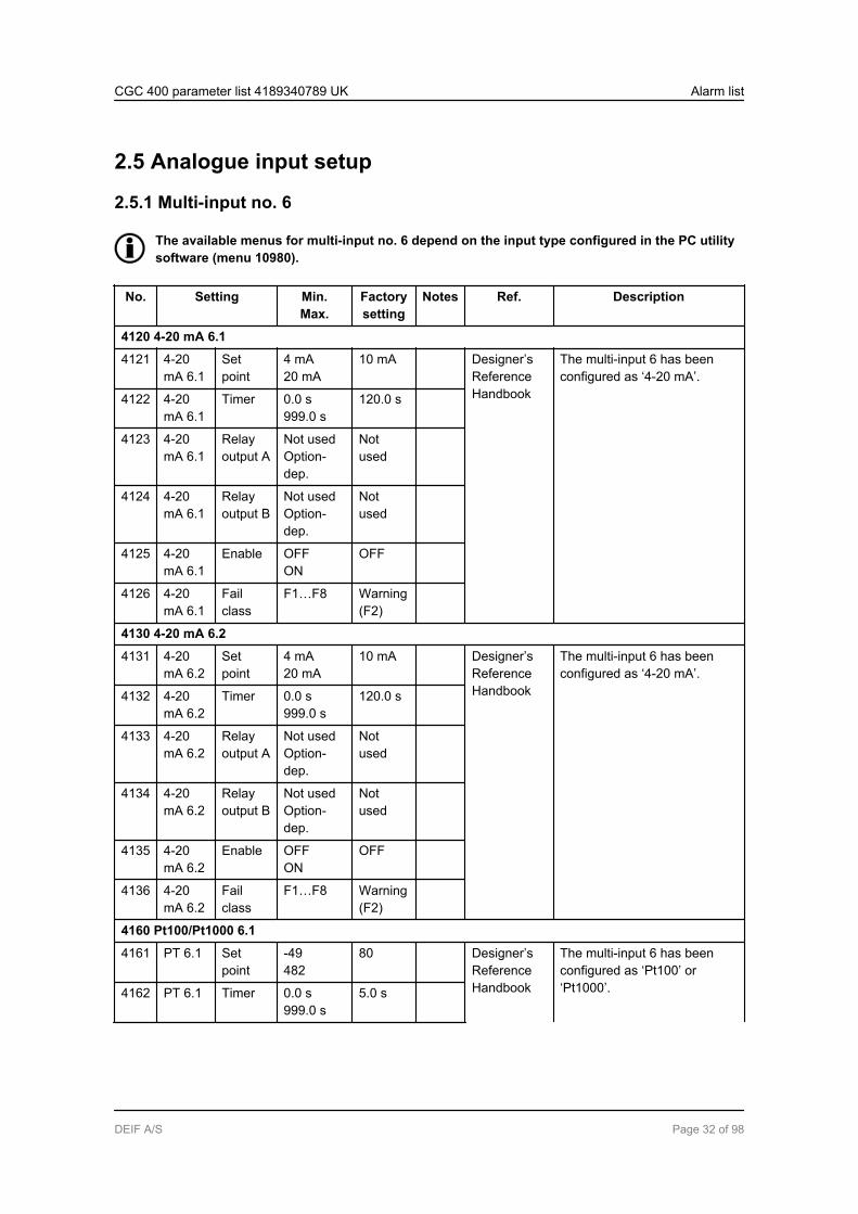
2.5 Analogue input setup
2.5.1 Multi-input no. 6
The available menus for multi-input no. 6 depend on the input type configured in the PC utilitysoftware (menu 10980).
No. Setting Min.Max.
Factorysetting
Notes Ref. Description
4120 4-20 mA 6.1
4121 4-20mA 6.1
Setpoint
4 mA20 mA
10 mA Designer’sReferenceHandbook
The multi-input 6 has beenconfigured as ‘4-20 mA’.
4122 4-20mA 6.1
Timer 0.0 s999.0 s
120.0 s
4123 4-20mA 6.1
Relayoutput A
Not usedOption-dep.
Notused
4124 4-20mA 6.1
Relayoutput B
Not usedOption-dep.
Notused
4125 4-20mA 6.1
Enable OFFON
OFF
4126 4-20mA 6.1
Failclass
F1…F8 Warning(F2)
4130 4-20 mA 6.2
4131 4-20mA 6.2
Setpoint
4 mA20 mA
10 mA Designer’sReferenceHandbook
The multi-input 6 has beenconfigured as ‘4-20 mA’.
4132 4-20mA 6.2
Timer 0.0 s999.0 s
120.0 s
4133 4-20mA 6.2
Relayoutput A
Not usedOption-dep.
Notused
4134 4-20mA 6.2
Relayoutput B
Not usedOption-dep.
Notused
4135 4-20mA 6.2
Enable OFFON
OFF
4136 4-20mA 6.2
Failclass
F1…F8 Warning(F2)
4160 Pt100/Pt1000 6.1
4161 PT 6.1 Setpoint
-49482
80 Designer’sReferenceHandbook
The multi-input 6 has beenconfigured as ‘Pt100’ or‘Pt1000’.4162 PT 6.1 Timer 0.0 s
999.0 s5.0 s
CGC 400 parameter list 4189340789 UK Alarm list
DEIF A/S Page 32 of 98

No. Setting Min.Max.
Factorysetting
Notes Ref. Description
4163 Pt100/Pt1000 set point can bein deg. C or F, dependent onthe unit selection (menu10970).
PT 6.1 Relayoutput A
Not usedOption-dep.
Notused
4164 PT 6.1 Relayoutput B
Not usedOption-dep.
Notused
4165 PT 6.1 Enable OFFON
OFF
4166 PT 6.1 Failclass
F1…F8 Warning(F2)
4167 PT 6.1 Offset 0.0 Ohm5.0 Ohm
0.0 Ohm
4170 Pt100/Pt1000 6.2
4171 PT 6.2 Setpoint
-49482
80 Designer’sReferenceHandbook
The multi-input 6 has beenconfigured as ‘Pt100’ or‘Pt1000’.Pt100/Pt1000 set point can bein deg. C or F, dependent onthe unit selection (menu10970).
4172 PT 6.2 Timer 0.0 s999.0 s
10.0 s
4173 PT 6.2 Relayoutput A
Not usedOption-dep.
Notused
4174 PT 6.2 Relayoutput B
Not usedOption-dep.
Notused
4175 PT 6.2 Enable OFFON
OFF
4176 PT 6.2 Failclass
F1...F8 Warning(F2)
4180 Resistance measurement input, oil pressure 6.1
4181 RMI oil6.1
Setpoint
0.0145.0
2.0 Designer’sReferenceHandbook
The multi-input 6 has beenconfigured as ‘RMI oil pres-sure’.Oil pressure set point can bein Bar or PSI, dependent onthe unit selection (menu10970).
4182 RMI oil6.1
Timer 0.0 s999.0 s
5.0 s
4183 RMI oil6.1
Relayoutput A
Not usedOption-dep.
Notused
4184 RMI oil6.1
Relayoutput B
Not usedOption-dep.
Notused
4185 RMI oil6.1
Enable OFFON
OFF
4186 RMI oil6.1
Failclass
F1…F8 Warning(F2)
CGC 400 parameter list 4189340789 UK Alarm list
DEIF A/S Page 33 of 98
No. Setting Min.Max.
Factorysetting
Notes Ref. Description
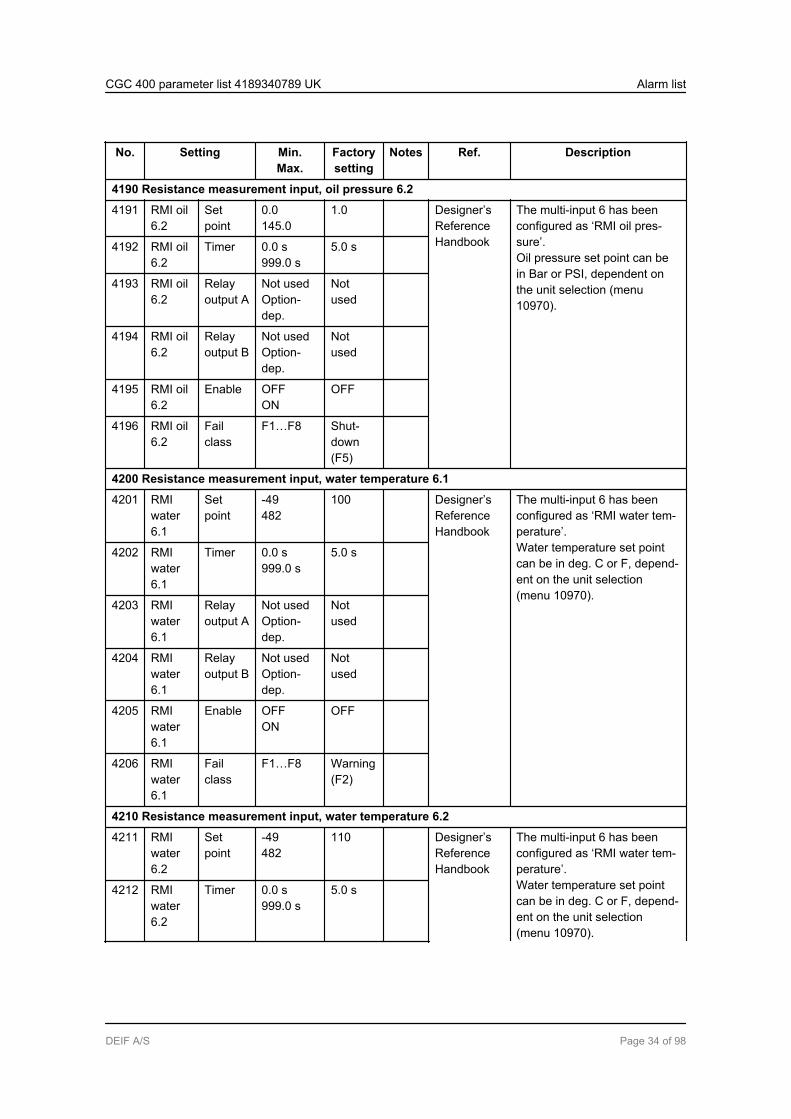
4190 Resistance measurement input, oil pressure 6.2
4191 RMI oil6.2
Setpoint
0.0145.0
1.0 Designer’sReferenceHandbook
The multi-input 6 has beenconfigured as ‘RMI oil pres-sure’.Oil pressure set point can bein Bar or PSI, dependent onthe unit selection (menu10970).
4192 RMI oil6.2
Timer 0.0 s999.0 s
5.0 s
4193 RMI oil6.2
Relayoutput A
Not usedOption-dep.
Notused
4194 RMI oil6.2
Relayoutput B
Not usedOption-dep.
Notused
4195 RMI oil6.2
Enable OFFON
OFF
4196 RMI oil6.2
Failclass
F1…F8 Shut-down(F5)
4200 Resistance measurement input, water temperature 6.1
4201 RMIwater6.1
Setpoint
-49482
100 Designer’sReferenceHandbook
The multi-input 6 has beenconfigured as ‘RMI water tem-perature’.Water temperature set pointcan be in deg. C or F, depend-ent on the unit selection(menu 10970).
4202 RMIwater6.1
Timer 0.0 s999.0 s
5.0 s
4203 RMIwater6.1
Relayoutput A
Not usedOption-dep.
Notused
4204 RMIwater6.1
Relayoutput B
Not usedOption-dep.
Notused
4205 RMIwater6.1
Enable OFFON
OFF
4206 RMIwater6.1
Failclass
F1…F8 Warning(F2)
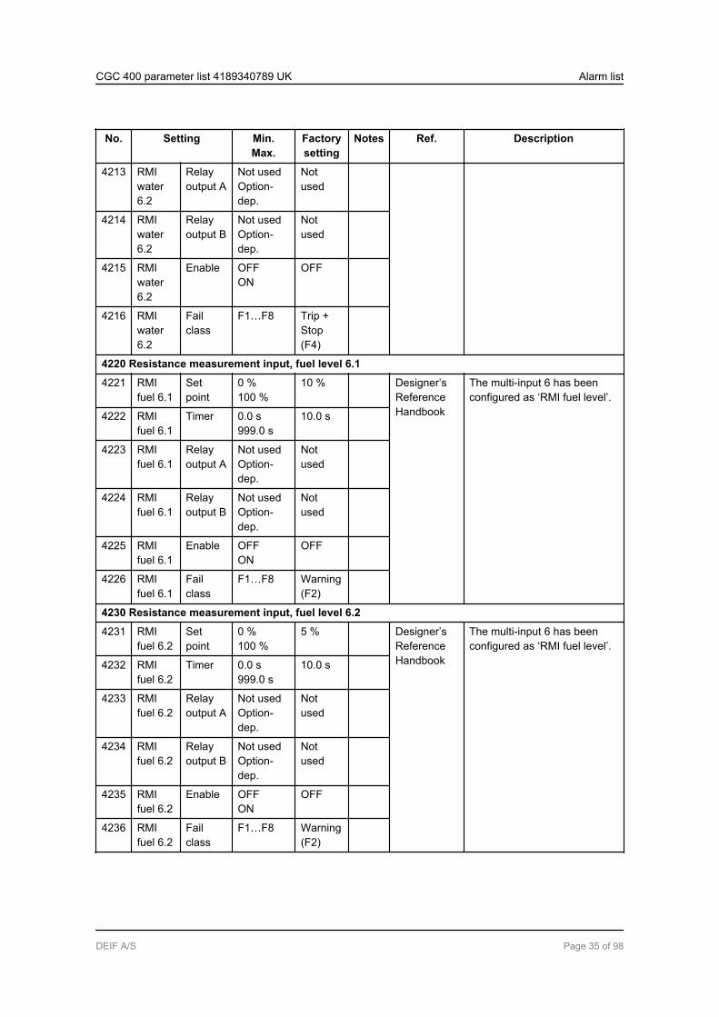
4210 Resistance measurement input, water temperature 6.2
4211 RMIwater6.2
Setpoint
-49482
110 Designer’sReferenceHandbook
The multi-input 6 has beenconfigured as ‘RMI water tem-perature’.Water temperature set pointcan be in deg. C or F, depend-ent on the unit selection(menu 10970).
4212 RMIwater6.2
Timer 0.0 s999.0 s
5.0 s
CGC 400 parameter list 4189340789 UK Alarm list
DEIF A/S Page 34 of 98
No. Setting Min.Max.
Factorysetting
Notes Ref. Description
4213 RMIwater6.2
Relayoutput A
Not usedOption-dep.
Notused
4214 RMIwater6.2
Relayoutput B
Not usedOption-dep.
Notused
4215 RMIwater6.2
Enable OFFON
OFF
4216 RMIwater6.2
Failclass
F1…F8 Trip +Stop(F4)
4220 Resistance measurement input, fuel level 6.1
4221 RMIfuel 6.1
Setpoint
0 %100 %
10 % Designer’sReferenceHandbook
The multi-input 6 has beenconfigured as ‘RMI fuel level’.
4222 RMIfuel 6.1
Timer 0.0 s999.0 s
10.0 s
4223 RMIfuel 6.1
Relayoutput A
Not usedOption-dep.
Notused
4224 RMIfuel 6.1
Relayoutput B
Not usedOption-dep.
Notused
4225 RMIfuel 6.1
Enable OFFON
OFF
4226 RMIfuel 6.1
Failclass
F1…F8 Warning(F2)
4230 Resistance measurement input, fuel level 6.2
4231 RMIfuel 6.2
Setpoint
0 %100 %
5 % Designer’sReferenceHandbook
The multi-input 6 has beenconfigured as ‘RMI fuel level’.
4232 RMIfuel 6.2
Timer 0.0 s999.0 s
10.0 s
4233 RMIfuel 6.2
Relayoutput A
Not usedOption-dep.
Notused
4234 RMIfuel 6.2
Relayoutput B
Not usedOption-dep.
Notused
4235 RMIfuel 6.2
Enable OFFON
OFF
4236 RMIfuel 6.2
Failclass
F1…F8 Warning(F2)
CGC 400 parameter list 4189340789 UK Alarm list
DEIF A/S Page 35 of 98

No. Setting Min.Max.
Factorysetting
Notes Ref. Description
4240 Wire fail 6
4241 W. fail6
Relayoutput A
Not usedOption-dep.
Notused
Designer’sReferenceHandbook
The wire break fault detectionis activated.
4242 W. fail6
Relayoutput B
Not usedOption-dep.
Notused
4243 W. fail6
Enable OFFON
OFF
4244 W. fail6
Failclass
F1…F8 Warning(F2)
CGC 400 parameter list 4189340789 UK Alarm list
DEIF A/S Page 36 of 98

2.5.2 Multi-input no. 7
The available menus for multi-input no. 7 depend on the input type configured in the PC utilitysoftware (menu 10990).
No. Setting Min.Max.
Factorysetting
Notes Ref. Description
4250 4-20 mA 7.1
4251 4-20mA 7.1
Setpoint
4 mA20 mA
10 mA Designer’sReferenceHandbook
The multi-input 7 has beenconfigured as ‘4-20 mA’.
4252 4-20mA 7.1
Timer 0.0 s999.0 s
120.0 s
4253 4-20mA 7.1
Relayoutput A
Not usedOption-dep.
Notused
4254 4-20mA 7.1
Relayoutput B
Not usedOption-dep.
Notused
4255 4-20mA 7.1
Enable OFFON
OFF
4256 4-20mA 7.1
Failclass
F1…F8 Warning(F2)
4260 4-20 mA 7.2
4261 4-20mA 7.2
Setpoint
4 mA20 mA
10 mA Designer’sReferenceHandbook
The multi-input 7 has beenconfigured as ‘4-20 mA’.
4262 4-20mA 7.2
Timer 0.0 s999.0 s
120.0 s
4263 4-20mA 7.2
Relayoutput A
Not usedOption-dep.
Notused
4264 4-20mA 7.2
Relayoutput B
Not usedOption-dep.
Notused
4265 4-20mA 7.2
Enable OFFON
OFF
4266 4-20mA 7.2
Failclass
F1…F8 Warning(F2)
4290 Pt100/Pt1000 7.1
4291 PT 7.1 Setpoint
-49482
80 Designer’sReferenceHandbook
The multi-input 7 has beenconfigured as ‘Pt100’ or‘Pt1000’.4292 PT 7.1 Timer 0.0 s
999.0 s5.0 s
CGC 400 parameter list 4189340789 UK Alarm list
DEIF A/S Page 37 of 98
No. Setting Min.Max.
Factorysetting
Notes Ref. Description
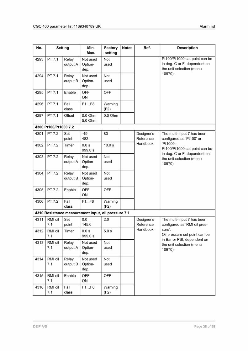
4293 PT 7.1 Relayoutput A
Not usedOption-dep.
Pt100/Pt1000 set point can bein deg. C or F, dependent onthe unit selection (menu10970).
Notused
4294 PT 7.1 Relayoutput B
Not usedOption-dep.
Notused
4295 PT 7.1 Enable OFFON
OFF
4296 PT 7.1 Failclass
F1…F8 Warning(F2)
4297 PT 7.1 Offset 0.0 Ohm5.0 Ohm
0.0 Ohm
4300 Pt100/Pt1000 7.2
4301 PT 7.2 Setpoint
-49482
80 Designer’sReferenceHandbook
The multi-input 7 has beenconfigured as ‘Pt100’ or‘Pt1000’.Pt100/Pt1000 set point can bein deg. C or F, dependent onthe unit selection (menu10970).
4302 PT 7.2 Timer 0.0 s999.0 s
10.0 s
4303 PT 7.2 Relayoutput A
Not usedOption-dep.
Notused
4304 PT 7.2 Relayoutput B
Not usedOption-dep.
Notused
4305 PT 7.2 Enable OFFON
OFF
4306 PT 7.2 Failclass
F1...F8 Warning(F2)
4310 Resistance measurement input, oil pressure 7.1
4311 RMI oil7.1
Setpoint
0.0145.0
2.0 Designer’sReferenceHandbook
The multi-input 7 has beenconfigured as ‘RMI oil pres-sure’.Oil pressure set point can bein Bar or PSI, dependent onthe unit selection (menu10970).
4312 RMI oil7.1
Timer 0.0 s999.0 s
5.0 s
4313 RMI oil7.1
Relayoutput A
Not usedOption-dep.
Notused
4314 RMI oil7.1
Relayoutput B
Not usedOption-dep.
Notused
4315 RMI oil7.1
Enable OFFON
OFF
4316 RMI oil7.1
Failclass
F1…F8 Warning(F2)
CGC 400 parameter list 4189340789 UK Alarm list
DEIF A/S Page 38 of 98

No. Setting Min.Max.
Factorysetting
Notes Ref. Description
4320 Resistance measurement input, oil pressure 7.2
4321 RMI oil7.2
Setpoint
0.0145.0
1.0 Designer’sReferenceHandbook
The multi-input 7 has beenconfigured as ‘RMI oil pres-sure’.Oil pressure set point can bein Bar or PSI, dependent onthe unit selection (menu10970).
4322 RMI oil7.2
Timer 0.0 s999.0 s
5.0 s
4323 RMI oil7.2
Relayoutput A
Not usedOption-dep.
Notused
4324 RMI oil7.2
Relayoutput B
Not usedOption-dep.
Notused
4325 RMI oil7.2
Enable OFFON
OFF
4326 RMI oil7.2
Failclass
F1…F8 Shut-down(F5)
4330 Resistance measurement input, water temperature 7.1
4331 RMIwater7.1
Setpoint
-49482
100 Designer’sReferenceHandbook
The multi-input 7 has beenconfigured as ‘RMI water tem-perature’.Water temperature set pointcan be in deg. C or F, depend-ent on the unit selection(menu 10970).
4332 RMIwater7.1
Timer 0.0 s999.0 s
5.0 s
4333 RMIwater7.1
Relayoutput A
Not usedOption-dep.
Notused
4334 RMIwater7.1
Relayoutput B
Not usedOption-dep.
Notused
4335 RMIwater7.1
Enable OFFON
OFF
4336 RMIwater7.1
Failclass
F1…F8 Warning(F2)
4340 Resistance measurement input, water temperature 7.2
4341 RMIwater7.2
Setpoint
-49482
110 Designer’sReferenceHandbook
The multi-input 7 has beenconfigured as ‘RMI water tem-perature’.Water temperature set pointcan be in deg. C or F, depend-ent on the unit selection(menu 10970).
4342 RMIwater7.2
Timer 0.0 s999.0 s
5.0 s
CGC 400 parameter list 4189340789 UK Alarm list
DEIF A/S Page 39 of 98

No. Setting Min.Max.
Factorysetting
Notes Ref. Description
4343 RMIwater7.2
Relayoutput A
Not usedOption-dep.
Notused
4344 RMIwater7.2
Relayoutput B
Not usedOption-dep.
Notused
4345 RMIwater7.2
Enable OFFON
OFF
4346 RMIwater7.2
Failclass
F1…F8 Trip +Stop(F4)
4350 Resistance measurement input, fuel level 7.1
4351 RMIfuel 7.1
Setpoint
0 %100 %
10 % Designer’sReferenceHandbook
The multi-input 7 has beenconfigured as ‘RMI fuel level’.
4352 RMIfuel 7.1
Timer 0.0 s999.0 s
10.0 s
4353 RMIfuel 7.1
Relayoutput A
Not usedOption-dep.
Notused
4354 RMIfuel 7.1
Relayoutput B
Not usedOption-dep.
Notused
4555 RMIfuel 7.1
Enable OFFON
OFF
4356 RMIfuel 7.1
Failclass
F1…F8 Warning(F2)
4360 Resistance measurement input, fuel level 7.2
4361 RMIfuel 7.2
Setpoint
0 %100 %
5 % Designer’sReferenceHandbook
The multi-input 7 has beenconfigured as ‘RMI fuel level’.
4362 RMIfuel 7.2
Timer 0.0 s999.0 s
10.0 s
4363 RMIfuel 7.2
Relayoutput A
Not usedOption-dep.
Notused
4364 RMIfuel 7.2
Relayoutput B
Not usedOption-dep.
Notused
4365 RMIfuel 7.2
Enable OFFON
OFF
4366 RMIfuel 7.2
Failclass
F1…F8 Warning(F2)
CGC 400 parameter list 4189340789 UK Alarm list
DEIF A/S Page 40 of 98
No. Setting Min.Max.
Factorysetting
Notes Ref. Description
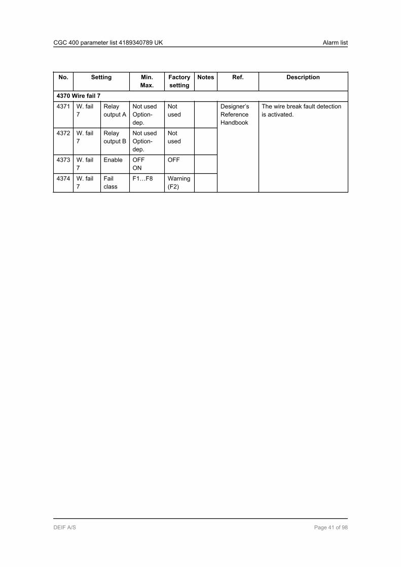
4370 Wire fail 7
4371 W. fail7
Relayoutput A
Not usedOption-dep.
Notused
Designer’sReferenceHandbook
The wire break fault detectionis activated.
4372 W. fail7
Relayoutput B
Not usedOption-dep.
Notused
4373 W. fail7
Enable OFFON
OFF
4374 W. fail7
Failclass
F1…F8 Warning(F2)
CGC 400 parameter list 4189340789 UK Alarm list
DEIF A/S Page 41 of 98
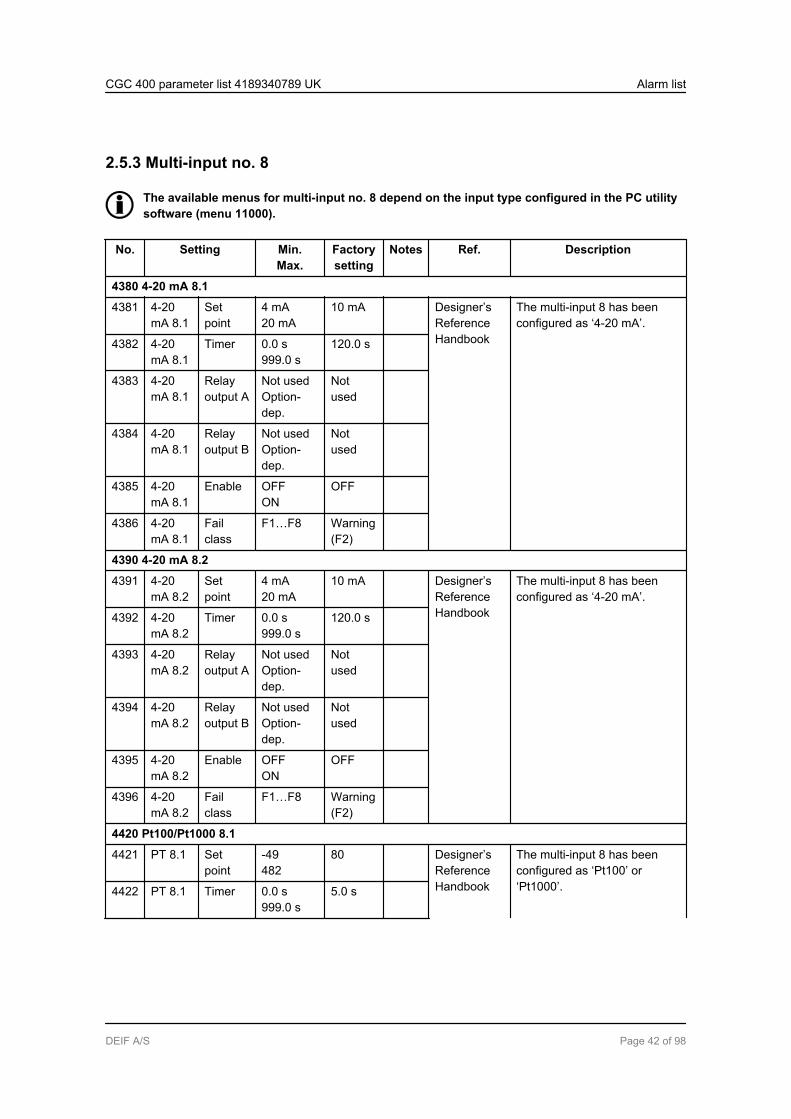
2.5.3 Multi-input no. 8
The available menus for multi-input no. 8 depend on the input type configured in the PC utilitysoftware (menu 11000).
No. Setting Min.Max.
Factorysetting
Notes Ref. Description
4380 4-20 mA 8.1
4381 4-20mA 8.1
Setpoint
4 mA20 mA
10 mA Designer’sReferenceHandbook
The multi-input 8 has beenconfigured as ‘4-20 mA’.
4382 4-20mA 8.1
Timer 0.0 s999.0 s
120.0 s
4383 4-20mA 8.1
Relayoutput A
Not usedOption-dep.
Notused
4384 4-20mA 8.1
Relayoutput B
Not usedOption-dep.
Notused
4385 4-20mA 8.1
Enable OFFON
OFF
4386 4-20mA 8.1
Failclass
F1…F8 Warning(F2)
4390 4-20 mA 8.2
4391 4-20mA 8.2
Setpoint
4 mA20 mA
10 mA Designer’sReferenceHandbook
The multi-input 8 has beenconfigured as ‘4-20 mA’.
4392 4-20mA 8.2
Timer 0.0 s999.0 s
120.0 s
4393 4-20mA 8.2
Relayoutput A
Not usedOption-dep.
Notused
4394 4-20mA 8.2
Relayoutput B
Not usedOption-dep.
Notused
4395 4-20mA 8.2
Enable OFFON
OFF
4396 4-20mA 8.2
Failclass
F1…F8 Warning(F2)
4420 Pt100/Pt1000 8.1
4421 PT 8.1 Setpoint
-49482
80 Designer’sReferenceHandbook
The multi-input 8 has beenconfigured as ‘Pt100’ or‘Pt1000’.4422 PT 8.1 Timer 0.0 s
999.0 s5.0 s
CGC 400 parameter list 4189340789 UK Alarm list
DEIF A/S Page 42 of 98
No. Setting Min.Max.
Factorysetting
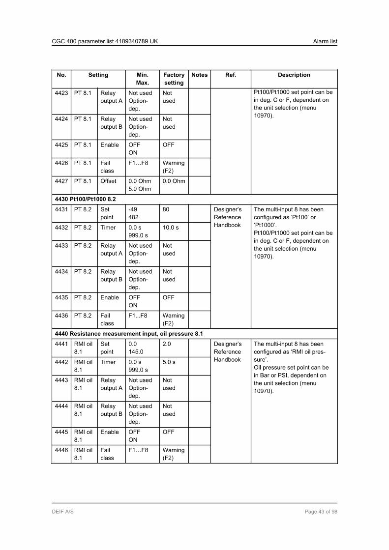
Notes Ref. Description
4423 PT 8.1 Relayoutput A
Not usedOption-dep.
Pt100/Pt1000 set point can bein deg. C or F, dependent onthe unit selection (menu10970).
Notused
4424 PT 8.1 Relayoutput B
Not usedOption-dep.
Notused
4425 PT 8.1 Enable OFFON
OFF
4426 PT 8.1 Failclass
F1…F8 Warning(F2)
4427 PT 8.1 Offset 0.0 Ohm5.0 Ohm
0.0 Ohm
4430 Pt100/Pt1000 8.2
4431 PT 8.2 Setpoint
-49482
80 Designer’sReferenceHandbook
The multi-input 8 has beenconfigured as ‘Pt100’ or‘Pt1000’.Pt100/Pt1000 set point can bein deg. C or F, dependent onthe unit selection (menu10970).
4432 PT 8.2 Timer 0.0 s999.0 s
10.0 s
4433 PT 8.2 Relayoutput A
Not usedOption-dep.
Notused
4434 PT 8.2 Relayoutput B
Not usedOption-dep.
Notused
4435 PT 8.2 Enable OFFON
OFF
4436 PT 8.2 Failclass
F1...F8 Warning(F2)
4440 Resistance measurement input, oil pressure 8.1
4441 RMI oil8.1
Setpoint
0.0145.0
2.0 Designer’sReferenceHandbook
The multi-input 8 has beenconfigured as ‘RMI oil pres-sure’.Oil pressure set point can bein Bar or PSI, dependent onthe unit selection (menu10970).
4442 RMI oil8.1
Timer 0.0 s999.0 s
5.0 s
4443 RMI oil8.1
Relayoutput A
Not usedOption-dep.
Notused
4444 RMI oil8.1
Relayoutput B
Not usedOption-dep.
Notused
4445 RMI oil8.1
Enable OFFON
OFF
4446 RMI oil8.1
Failclass
F1…F8 Warning(F2)
CGC 400 parameter list 4189340789 UK Alarm list
DEIF A/S Page 43 of 98
No. Setting Min.Max.
Factorysetting
Notes Ref. Description
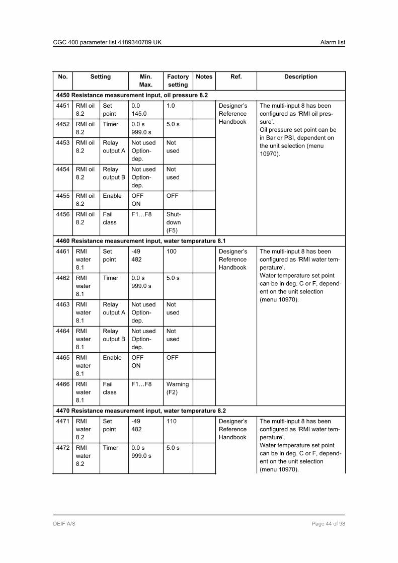
4450 Resistance measurement input, oil pressure 8.2
4451 RMI oil8.2
Setpoint
0.0145.0
1.0 Designer’sReferenceHandbook
The multi-input 8 has beenconfigured as ‘RMI oil pres-sure’.Oil pressure set point can bein Bar or PSI, dependent onthe unit selection (menu10970).
4452 RMI oil8.2
Timer 0.0 s999.0 s
5.0 s
4453 RMI oil8.2
Relayoutput A
Not usedOption-dep.
Notused
4454 RMI oil8.2
Relayoutput B
Not usedOption-dep.
Notused
4455 RMI oil8.2
Enable OFFON
OFF
4456 RMI oil8.2
Failclass
F1…F8 Shut-down(F5)
4460 Resistance measurement input, water temperature 8.1
4461 RMIwater8.1
Setpoint
-49482
100 Designer’sReferenceHandbook
The multi-input 8 has beenconfigured as ‘RMI water tem-perature’.Water temperature set pointcan be in deg. C or F, depend-ent on the unit selection(menu 10970).
4462 RMIwater8.1
Timer 0.0 s999.0 s
5.0 s
4463 RMIwater8.1
Relayoutput A
Not usedOption-dep.
Notused
4464 RMIwater8.1
Relayoutput B
Not usedOption-dep.
Notused
4465 RMIwater8.1
Enable OFFON
OFF
4466 RMIwater8.1
Failclass
F1…F8 Warning(F2)
4470 Resistance measurement input, water temperature 8.2
4471 RMIwater8.2
Setpoint
-49482
110 Designer’sReferenceHandbook
The multi-input 8 has beenconfigured as ‘RMI water tem-perature’.Water temperature set pointcan be in deg. C or F, depend-ent on the unit selection(menu 10970).
4472 RMIwater8.2
Timer 0.0 s999.0 s
5.0 s
CGC 400 parameter list 4189340789 UK Alarm list
DEIF A/S Page 44 of 98

No. Setting Min.Max.
Factorysetting
Notes Ref. Description
4473 RMIwater8.2
Relayoutput A
Not usedOption-dep.
Notused
4474 RMIwater8.2
Relayoutput B
Not usedOption-dep.
Notused
4475 RMIwater8.2
Enable OFFON
OFF
4476 RMIwater8.2
Failclass
F1…F8 Trip +Stop(F4)
4480 Resistance measurement input, fuel level 8.1
4481 RMIfuel 8.1
Setpoint
0 %100 %
10 % Designer’sReferenceHandbook
The multi-input 8 has beenconfigured as ‘RMI fuel level’.
4482 RMIfuel 8.1
Timer 0.0 s999.0 s
10.0 s
4483 RMIfuel 8.1
Relayoutput A
Not usedOption-dep.
Notused
4484 RMIfuel 8.1
Relayoutput B
Not usedOption-dep.
Notused
4485 RMIfuel 8.1
Enable OFFON
OFF
4486 RMIfuel 8.1
Failclass
F1…F8 Warning(F2)
4490 Resistance measurement input, fuel level 8.2
4491 RMIfuel 8.2
Setpoint
0 %100 %
5 % Designer’sReferenceHandbook
The multi-input 8 has beenconfigured as ‘RMI fuel level’.
4492 RMIfuel 8.2
Timer 0.0 s999.0 s
10.0 s
4493 RMIfuel 8.2
Relayoutput A
Not usedOption-dep.
Notused
4494 RMIfuel 8.2
Relayoutput B
Not usedOption-dep.
Notused
4495 RMIfuel 8.2
Enable OFFON
OFF
4496 RMIfuel 8.2
Failclass
F1…F8 Warning(F2)
CGC 400 parameter list 4189340789 UK Alarm list
DEIF A/S Page 45 of 98

No. Setting Min.Max.
Factorysetting
Notes Ref. Description
4500 Wire fail 8
4501 W. fail8
Relayoutput A
Not usedOption-dep.
Notused
Designer’sReferenceHandbook
The wire break fault detectionis activated.
4502 W. fail8
Relayoutput B
Not usedOption-dep.
Notused
4503 W. fail8
Enable OFFON
OFF
4504 W. fail8
Failclass
F1…F8 Warning(F2)
CGC 400 parameter list 4189340789 UK Alarm list
DEIF A/S Page 46 of 98
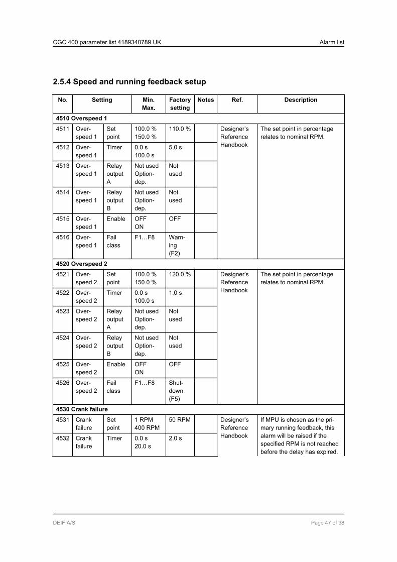
2.5.4 Speed and running feedback setup
No. Setting Min.Max.
Factorysetting
Notes Ref. Description
4510 Overspeed 1
4511 Over-speed 1
Setpoint
100.0 %150.0 %
110.0 % Designer’sReferenceHandbook
The set point in percentagerelates to nominal RPM.
4512 Over-speed 1
Timer 0.0 s100.0 s
5.0 s
4513 Over-speed 1
RelayoutputA
Not usedOption-dep.
Notused
4514 Over-speed 1
RelayoutputB
Not usedOption-dep.
Notused
4515 Over-speed 1
Enable OFFON
OFF
4516 Over-speed 1
Failclass
F1…F8 Warn-ing(F2)
4520 Overspeed 2
4521 Over-speed 2
Setpoint
100.0 %150.0 %
120.0 % Designer’sReferenceHandbook
The set point in percentagerelates to nominal RPM.
4522 Over-speed 2
Timer 0.0 s100.0 s
1.0 s
4523 Over-speed 2
RelayoutputA
Not usedOption-dep.
Notused
4524 Over-speed 2
RelayoutputB
Not usedOption-dep.
Notused
4525 Over-speed 2
Enable OFFON
OFF
4526 Over-speed 2
Failclass
F1…F8 Shut-down(F5)
4530 Crank failure
4531 Crankfailure
Setpoint
1 RPM400 RPM
50 RPM Designer’sReferenceHandbook
If MPU is chosen as the pri-mary running feedback, thisalarm will be raised if thespecified RPM is not reachedbefore the delay has expired.
4532 Crankfailure
Timer 0.0 s20.0 s
2.0 s
CGC 400 parameter list 4189340789 UK Alarm list
DEIF A/S Page 47 of 98

No. Setting Min.Max.
Factorysetting
Notes Ref. Description
4533 Crankfailure
RelayoutputA
Not usedOption-dep.
Notused
4534 Crankfailure
RelayoutputB
Not usedOption-dep.
Notused
4535 Crankfailure
Enable OFFON
OFF
4536 Crankfailure
Failclass
F1…F8 Warn-ing(F2)
4540 Running feedback failure
4541 Runfeedb.fail
Timer 0.0 s20.0 s
2.0 s Designer’sReferenceHandbook
If running is detected on thefrequency (secondary), butthe primary running feedback,e.g. digital input, has not de-tected running, this alarm willbe raised after the adjusteddelay time.
4542 Runfeedb.fail
RelayoutputA
Not usedOption-dep.
Notused
4543 Runfeedb.fail
RelayoutputB
Not usedOption-dep.
Notused
4544 Runfeedb.fail
Enable OFFON
ON
4545 Runfeedb.fail
Failclass
F1...F8 Warn-ing(F2)
4560 Hz/voltage failure
4561 Hz/V fail-ure
Timer 1.0 s99.0 s
30.0 s Designer’sReferenceHandbook
If the frequency and voltageare not within the limits afterthe running feedback is re-ceived, this alarm will beraised when the delay timehas expired. Limits are placedin menu 2110 (Sync. black-out).
4562 Hz/V fail-ure
RelayoutputA
Not usedOption-dep.
Notused
4563 Hz/V fail-ure
RelayoutputB
Not usedOption-dep.
Notused
4564 Hz/V fail-ure
Enable OFFON
ON
4565 Hz/V fail-ure
Failclass
F1...F8 Shut-down(F5)
4570 Start failure
CGC 400 parameter list 4189340789 UK Alarm list
DEIF A/S Page 48 of 98
No. Setting Min.Max.
Factorysetting
Notes Ref. Description
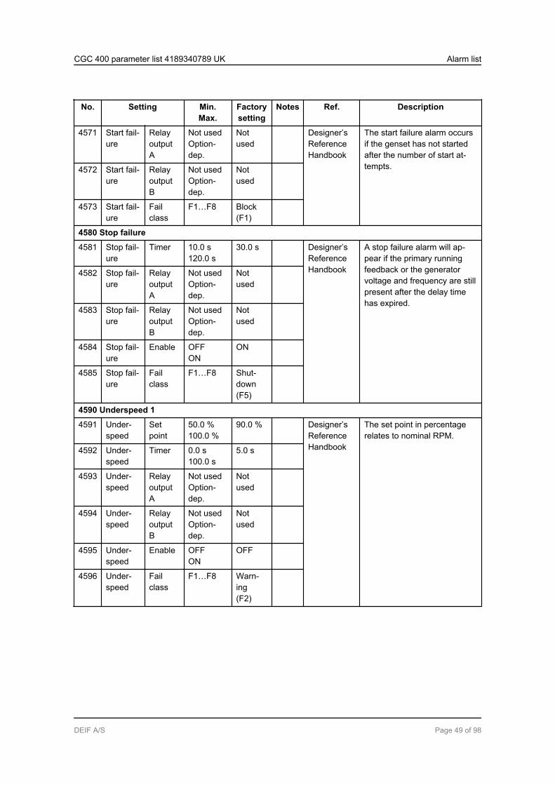
4571 Start fail-ure
RelayoutputA
Not usedOption-dep.
Notused
Designer’sReferenceHandbook
The start failure alarm occursif the genset has not startedafter the number of start at-tempts.4572 Start fail-
ureRelayoutputB
Not usedOption-dep.
Notused
4573 Start fail-ure
Failclass
F1…F8 Block(F1)
4580 Stop failure
4581 Stop fail-ure
Timer 10.0 s120.0 s
30.0 s Designer’sReferenceHandbook
A stop failure alarm will ap-pear if the primary runningfeedback or the generatorvoltage and frequency are stillpresent after the delay timehas expired.
4582 Stop fail-ure
RelayoutputA
Not usedOption-dep.
Notused
4583 Stop fail-ure
RelayoutputB
Not usedOption-dep.
Notused
4584 Stop fail-ure
Enable OFFON
ON
4585 Stop fail-ure
Failclass
F1…F8 Shut-down(F5)
4590 Underspeed 1
4591 Under-speed
Setpoint
50.0 %100.0 %
90.0 % Designer’sReferenceHandbook
The set point in percentagerelates to nominal RPM.
4592 Under-speed
Timer 0.0 s100.0 s
5.0 s
4593 Under-speed
RelayoutputA
Not usedOption-dep.
Notused
4594 Under-speed
RelayoutputB
Not usedOption-dep.
Notused
4595 Under-speed
Enable OFFON
OFF
4596 Under-speed
Failclass
F1…F8 Warn-ing(F2)
CGC 400 parameter list 4189340789 UK Alarm list
DEIF A/S Page 49 of 98
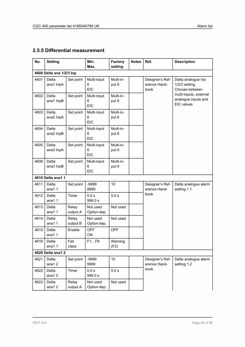
2.5.5 Differential measurement
No. Setting Min.Max.
Factorysetting
Notes Ref. Description
4600 Delta ana 1/2/3 Inp
4601 Deltaana1 InpA
Set point Multi-input6EIC
Multi-in-put 6
Designer’s Ref-erence Hand-book
Delta analogue Inp1/2/3 setting.Choose betweenmulti-inputs, externalanalogue inputs andEIC values
4602 Deltaana1 InpB
Set point Multi-input6EIC
Multi-in-put 6
4603 Deltaana2 InpA
Set point Multi-input6EIC
Multi-in-put 6
4604 Deltaana2 InpB
Set point Multi-input6EIC
Multi-in-put 6
4605 Deltaana3 InpA
Set point Multi-input6EIC
Multi-in-put 6
4606 Deltaana3 InpB
Set point Multi-input6EIC
Multi-in-put 6
4610 Delta ana1 1
4611 Deltaana1 1
Set point -99999999
10 Designer’s Ref-erence Hand-book
Delta analogue alarmsetting 1.1
4612 Deltaana1 1
Timer 0.0 s999.0 s
5.0 s
4613 Deltaana1 1
Relayoutput A
Not usedOption-dep.
Not used
4614 Deltaana1 1
Relayoutput B
Not usedOption-dep.
Not used
4615 Deltaana1 1
Enable OFFON
OFF
4616 Deltaana1 1
Failclass
F1…F8 Warning(F2)
4620 Delta ana1 2
4621 Deltaana1 2
Set point -99999999
10 Designer’s Ref-erence Hand-book
Delta analogue alarmsetting 1.2
4622 Deltaana1 2
Timer 0.0 s999.0 s
5.0 s
4623 Deltaana1 2
Relayoutput A
Not usedOption-dep.
Not used
CGC 400 parameter list 4189340789 UK Alarm list
DEIF A/S Page 50 of 98
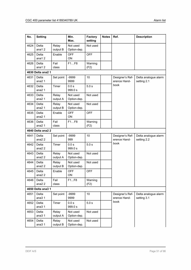
No. Setting Min.Max.
Factorysetting
Notes Ref. Description
4624 Deltaana1 2
Relayoutput B
Not usedOption-dep.
Not used
4625 Deltaana1 2
Enable OFFON
OFF
4626 Deltaana1 2
Failclass
F1…F8 Warning(F2)
4630 Delta ana2 1
4631 Deltaana2 1
Set point -99999999
10 Designer’s Ref-erence Hand-book
Delta analogue alarmsetting 2.1
4632 Deltaana2 1
Timer 0.0 s999.0 s
5.0 s
4633 Deltaana2 1
Relayoutput A
Not usedOption-dep.
Not used
4634 Deltaana2 1
Relayoutput B
Not usedOption-dep.
Not used
4635 Deltaana2 1
Enable OFFON
OFF
4636 Deltaana2 1
Failclass
F1…F8 Warning(F2)
4640 Delta ana2 2
4641 Deltaana2 2
Set point -9999999
10 Designer’s Ref-erence Hand-book
Delta analogue alarmsetting 2.2
4642 Deltaana2 2
Timer 0.0 s999.0 s
5.0 s
4643 Deltaana2 2
Relayoutput A
Not usedOption-dep.
Not used
4644 Deltaana2 2
Relayoutput B
Not usedOption-dep.
Not used
4645 Deltaana2 2
Enable OFFON
OFF
4646 Deltaana2 2
Failclass
F1...F8 Warning(F2)
4650 Delta ana3 1
4651 Deltaana3 1
Set point -99999999
10 Designer’s Ref-erence Hand-book
Delta analogue alarmsetting 3.1
4652 Deltaana3 1
Timer 0.0 s999.0 s
5.0 s
4653 Deltaana3 1
Relayoutput A
Not usedOption-dep.
Not used
4654 Deltaana3 1
Relayoutput B
Not usedOption-dep.
Not used
CGC 400 parameter list 4189340789 UK Alarm list
DEIF A/S Page 51 of 98
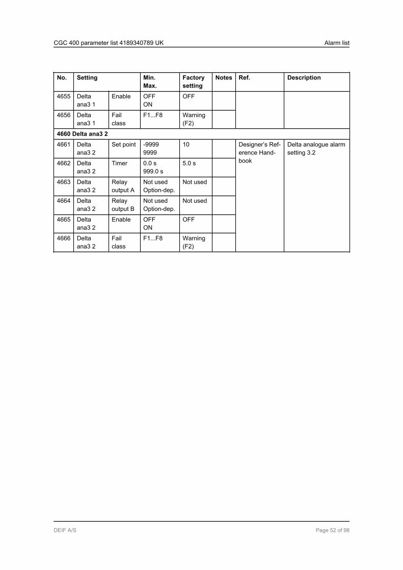
No. Setting Min.Max.
Factorysetting
Notes Ref. Description
4655 Deltaana3 1
Enable OFFON
OFF
4656 Deltaana3 1
Failclass
F1...F8 Warning(F2)
4660 Delta ana3 2
4661 Deltaana3 2
Set point -99999999
10 Designer’s Ref-erence Hand-book
Delta analogue alarmsetting 3.2
4662 Deltaana3 2
Timer 0.0 s999.0 s
5.0 s
4663 Deltaana3 2
Relayoutput A
Not usedOption-dep.
Not used
4664 Deltaana3 2
Relayoutput B
Not usedOption-dep.
Not used
4665 Deltaana3 2
Enable OFFON
OFF
4666 Deltaana3 2
Failclass
F1...F8 Warning(F2)
CGC 400 parameter list 4189340789 UK Alarm list
DEIF A/S Page 52 of 98
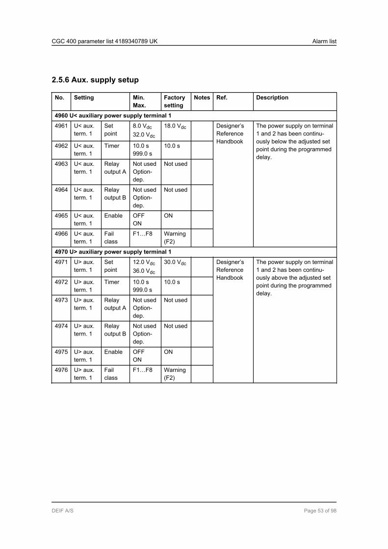
2.5.6 Aux. supply setup
No. Setting Min.Max.
Factorysetting
Notes Ref. Description
4960 U< auxiliary power supply terminal 1
4961 U< aux.term. 1
Setpoint
8.0 Vdc32.0 Vdc
18.0 Vdc Designer’sReferenceHandbook
The power supply on terminal1 and 2 has been continu-ously below the adjusted setpoint during the programmeddelay.
4962 U< aux.term. 1
Timer 10.0 s999.0 s
10.0 s
4963 U< aux.term. 1
Relayoutput A
Not usedOption-dep.
Not used
4964 U< aux.term. 1
Relayoutput B
Not usedOption-dep.
Not used
4965 U< aux.term. 1
Enable OFFON
ON
4966 U< aux.term. 1
Failclass
F1…F8 Warning(F2)
4970 U> auxiliary power supply terminal 1
4971 U> aux.term. 1
Setpoint
12.0 Vdc36.0 Vdc
30.0 Vdc Designer’sReferenceHandbook
The power supply on terminal1 and 2 has been continu-ously above the adjusted setpoint during the programmeddelay.
4972 U> aux.term. 1
Timer 10.0 s999.0 s
10.0 s
4973 U> aux.term. 1
Relayoutput A
Not usedOption-dep.
Not used
4974 U> aux.term. 1
Relayoutput B
Not usedOption-dep.
Not used
4975 U> aux.term. 1
Enable OFFON
ON
4976 U> aux.term. 1
Failclass
F1…F8 Warning(F2)
CGC 400 parameter list 4189340789 UK Alarm list
DEIF A/S Page 53 of 98
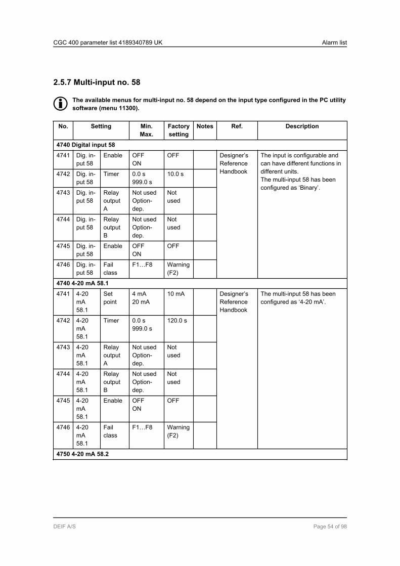
2.5.7 Multi-input no. 58
The available menus for multi-input no. 58 depend on the input type configured in the PC utilitysoftware (menu 11300).
No. Setting Min.Max.
Factorysetting
Notes Ref. Description
4740 Digital input 58
4741 Dig. in-put 58
Enable OFFON
OFF Designer’sReferenceHandbook
The input is configurable andcan have different functions indifferent units.The multi-input 58 has beenconfigured as ‘Binary’.
4742 Dig. in-put 58
Timer 0.0 s999.0 s
10.0 s
4743 Dig. in-put 58
RelayoutputA
Not usedOption-dep.
Notused
4744 Dig. in-put 58
RelayoutputB
Not usedOption-dep.
Notused
4745 Dig. in-put 58
Enable OFFON
OFF
4746 Dig. in-put 58
Failclass
F1…F8 Warning(F2)
4740 4-20 mA 58.1
4741 4-20mA58.1
Setpoint
4 mA20 mA
10 mA Designer’sReferenceHandbook
The multi-input 58 has beenconfigured as ‘4-20 mA’.
4742 4-20mA58.1
Timer 0.0 s999.0 s
120.0 s
4743 4-20mA58.1
RelayoutputA
Not usedOption-dep.
Notused
4744 4-20mA58.1
RelayoutputB
Not usedOption-dep.
Notused
4745 4-20mA58.1
Enable OFFON
OFF
4746 4-20mA58.1
Failclass
F1…F8 Warning(F2)
4750 4-20 mA 58.2
CGC 400 parameter list 4189340789 UK Alarm list
DEIF A/S Page 54 of 98

No. Setting Min.Max.
Factorysetting
Notes Ref. Description
4751 4-20mA58.2
Setpoint
4 mA20 mA
10 mA Designer’sReferenceHandbook
The multi-input 58 has beenconfigured as ‘4-20 mA’.
4752 4-20mA58.2
Timer 0.0 s999.0 s
120.0 s
4753 4-20mA58.2
RelayoutputA
Not usedOption-dep.
Notused
4754 4-20mA58.2
RelayoutputB
Not usedOption-dep.
Notused
4755 4-20mA58.2
Enable OFFON
OFF
4756 4-20mA58.2
Failclass
F1…F8 Warning(F2)
4740 Pt100/Pt1000 58.1
4741 PT58.1
Setpoint
-49482
80 Designer’sReferenceHandbook
The multi-input 58 has beenconfigured as ‘Pt100’ or‘Pt1000’.Pt100/Pt1000 set point can bein deg. C or F, dependent onthe unit selection (menu10970).
4742 PT58.1
Timer 0.0 s999.0 s
5.0 s
4743 PT58.1
RelayoutputA
Not usedOption-dep.
Notused
4744 PT58.1
RelayoutputB
Not usedOption-dep.
Notused
4745 PT58.1
Enable OFFON
OFF
4746 PT58.1
Failclass
F1…F8 Warning(F2)
4750 Pt100/Pt1000 58.2
4751 PT58.2
Setpoint
-49482
80 Designer’sReferenceHandbook
The multi-input 58 has beenconfigured as ‘Pt100’ or‘Pt1000’.Pt100/Pt1000 set point can bein deg. C or F, dependent onthe unit selection (menu10970).
4752 PT58.2
Timer 0.0 s999.0 s
10.0 s
4753 PT58.2
RelayoutputA
Not usedOption-dep.
Notused
CGC 400 parameter list 4189340789 UK Alarm list
DEIF A/S Page 55 of 98
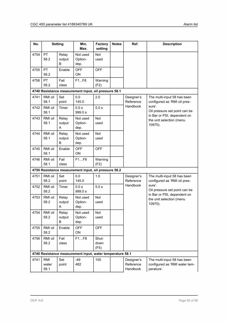
No. Setting Min.Max.
Factorysetting
Notes Ref. Description
4754 PT58.2
RelayoutputB
Not usedOption-dep.
Notused
4755 PT58.2
Enable OFFON
OFF
4756 PT58.2
Failclass
F1...F8 Warning(F2)
4740 Resistance measurement input, oil pressure 58.1
4741 RMI oil58.1
Setpoint
0.0145.0
2.0 Designer’sReferenceHandbook
The multi-input 58 has beenconfigured as ‘RMI oil pres-sure’.Oil pressure set point can bein Bar or PSI, dependent onthe unit selection (menu10970).
4742 RMI oil58.1
Timer 0.0 s999.0 s
5.0 s
4743 RMI oil58.1
RelayoutputA
Not usedOption-dep.
Notused
4744 RMI oil58.1
RelayoutputB
Not usedOption-dep.
Notused
4745 RMI oil58.1
Enable OFFON
OFF
4746 RMI oil58.1
Failclass
F1…F8 Warning(F2)
4750 Resistance measurement input, oil pressure 58.2
4751 RMI oil58.2
Setpoint
0.0145.0
1.0 Designer’sReferenceHandbook
The multi-input 58 has beenconfigured as ‘RMI oil pres-sure’.Oil pressure set point can bein Bar or PSI, dependent onthe unit selection (menu10970).
4752 RMI oil58.2
Timer 0.0 s999.0 s
5.0 s
4753 RMI oil58.2
RelayoutputA
Not usedOption-dep.
Notused
4754 RMI oil58.2
RelayoutputB
Not usedOption-dep.
Notused
4755 RMI oil58.2
Enable OFFON
OFF
4756 RMI oil58.2
Failclass
F1…F8 Shut-down(F5)
4740 Resistance measurement input, water temperature 58.1
4741 RMIwater58.1
Setpoint
-49482
100 Designer’sReferenceHandbook
The multi-input 58 has beenconfigured as ‘RMI water tem-perature’.
CGC 400 parameter list 4189340789 UK Alarm list
DEIF A/S Page 56 of 98

No. Setting Min.Max.
Factorysetting
Notes Ref. Description
4742 Water temperature set pointcan be in deg. C or F, depend-ent on the unit selection (menu10970).
RMIwater58.1
Timer 0.0 s999.0 s
5.0 s
4743 RMIwater58.1
RelayoutputA
Not usedOption-dep.
Notused
4744 RMIwater58.1
RelayoutputB
Not usedOption-dep.
Notused
4745 RMIwater58.1
Enable OFFON
OFF
4746 RMIwater58.1
Failclass
F1…F8 Warning(F2)
4750 Resistance measurement input, water temperature 58.2
4751 RMIwater58.2
Setpoint
-49482
110 Designer’sReferenceHandbook
The multi-input 58 has beenconfigured as ‘RMI water tem-perature’.Water temperature set pointcan be in deg. C or F, depend-ent on the unit selection (menu10970).
4752 RMIwater58.2
Timer 0.0 s999.0 s
5.0 s
4753 RMIwater58.2
RelayoutputA
Not usedOption-dep.
Notused
4754 RMIwater58.2
RelayoutputB
Not usedOption-dep.
Notused
4755 RMIwater58.2
Enable OFFON
OFF
4756 RMIwater58.2
Failclass
F1…F8 Trip +Stop(F4)
4740 Resistance measurement input, fuel level 58.1
4741 RMIfuel58.1
Setpoint
0 %100 %
10 % Designer’sReferenceHandbook
The multi-input 58 has beenconfigured as ‘RMI fuel level’.
4742 RMIfuel58.1
Timer 0.0 s999.0 s
10.0 s
CGC 400 parameter list 4189340789 UK Alarm list
DEIF A/S Page 57 of 98
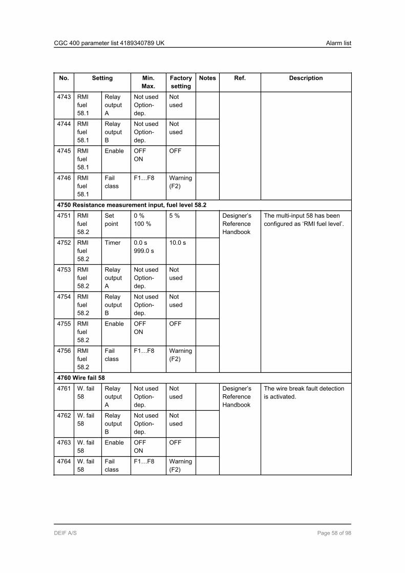
No. Setting Min.Max.
Factorysetting
Notes Ref. Description
4743 RMIfuel58.1
RelayoutputA
Not usedOption-dep.
Notused
4744 RMIfuel58.1
RelayoutputB
Not usedOption-dep.
Notused
4745 RMIfuel58.1
Enable OFFON
OFF
4746 RMIfuel58.1
Failclass
F1…F8 Warning(F2)
4750 Resistance measurement input, fuel level 58.2
4751 RMIfuel58.2
Setpoint
0 %100 %
5 % Designer’sReferenceHandbook
The multi-input 58 has beenconfigured as ‘RMI fuel level’.
4752 RMIfuel58.2
Timer 0.0 s999.0 s
10.0 s
4753 RMIfuel58.2
RelayoutputA
Not usedOption-dep.
Notused
4754 RMIfuel58.2
RelayoutputB
Not usedOption-dep.
Notused
4755 RMIfuel58.2
Enable OFFON
OFF
4756 RMIfuel58.2
Failclass
F1…F8 Warning(F2)
4760 Wire fail 58
4761 W. fail58
RelayoutputA
Not usedOption-dep.
Notused
Designer’sReferenceHandbook
The wire break fault detectionis activated.
4762 W. fail58
RelayoutputB
Not usedOption-dep.
Notused
4763 W. fail58
Enable OFFON
OFF
4764 W. fail58
Failclass
F1…F8 Warning(F2)
CGC 400 parameter list 4189340789 UK Alarm list
DEIF A/S Page 58 of 98

2.5.8 Multi-input no. 59
The available menus for multi-input no. 59 depend on the input type configured in the PC utilitysoftware (menu 11310).
No. Setting Min.Max.
Factorysetting
Notes Ref. Description
4770 Digital input 59
4771 Dig. in-put 59
Enable OFFON
OFF Designer’sReferenceHandbook
The input is configurable andcan have different functions indifferent units.The multi-input 59 has beenconfigured as ‘Binary’.
4772 Dig. in-put 59
Timer 0.0 s999.0 s
10.0 s
4773 Dig. in-put 59
RelayoutputA
Not usedOption-dep.
Notused
4774 Dig. in-put 59
RelayoutputB
Not usedOption-dep.
Notused
4775 Dig. in-put 59
Enable OFFON
OFF
4776 Dig. in-put 59
Failclass
F1…F8 Warning(F2)
4770 4-20 mA 59.1
4771 4-20mA59.1
Setpoint
4 mA20 mA
10 mA Designer’sReferenceHandbook
The multi-input 59 has beenconfigured as ‘4-20 mA’.
4772 4-20mA59.1
Timer 0.0 s999.0 s
120.0 s
4773 4-20mA59.1
RelayoutputA
Not usedOption-dep.
Notused
4774 4-20mA59.1
RelayoutputB
Not usedOption-dep.
Notused
4775 4-20mA59.1
Enable OFFON
OFF
4776 4-20mA59.1
Failclass
F1…F8 Warning(F2)
4780 4-20 mA 59.2
CGC 400 parameter list 4189340789 UK Alarm list
DEIF A/S Page 59 of 98
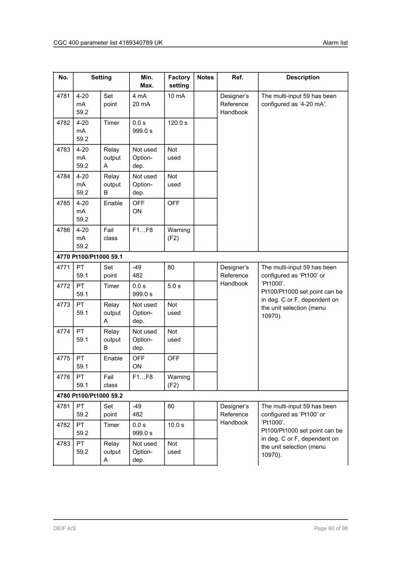
No. Setting Min.Max.
Factorysetting
Notes Ref. Description
4781 4-20mA59.2
Setpoint
4 mA20 mA
10 mA Designer’sReferenceHandbook
The multi-input 59 has beenconfigured as ‘4-20 mA’.
4782 4-20mA59.2
Timer 0.0 s999.0 s
120.0 s
4783 4-20mA59.2
RelayoutputA
Not usedOption-dep.
Notused
4784 4-20mA59.2
RelayoutputB
Not usedOption-dep.
Notused
4785 4-20mA59.2
Enable OFFON
OFF
4786 4-20mA59.2
Failclass
F1…F8 Warning(F2)
4770 Pt100/Pt1000 59.1
4771 PT59.1
Setpoint
-49482
80 Designer’sReferenceHandbook
The multi-input 59 has beenconfigured as ‘Pt100’ or‘Pt1000’.Pt100/Pt1000 set point can bein deg. C or F, dependent onthe unit selection (menu10970).
4772 PT59.1
Timer 0.0 s999.0 s
5.0 s
4773 PT59.1
RelayoutputA
Not usedOption-dep.
Notused
4774 PT59.1
RelayoutputB
Not usedOption-dep.
Notused
4775 PT59.1
Enable OFFON
OFF
4776 PT59.1
Failclass
F1…F8 Warning(F2)
4780 Pt100/Pt1000 59.2
4781 PT59.2
Setpoint
-49482
80 Designer’sReferenceHandbook
The multi-input 59 has beenconfigured as ‘Pt100’ or‘Pt1000’.Pt100/Pt1000 set point can bein deg. C or F, dependent onthe unit selection (menu10970).
4782 PT59.2
Timer 0.0 s999.0 s
10.0 s
4783 PT59.2
RelayoutputA
Not usedOption-dep.
Notused
CGC 400 parameter list 4189340789 UK Alarm list
DEIF A/S Page 60 of 98

No. Setting Min.Max.
Factorysetting
Notes Ref. Description
4784 PT59.2
RelayoutputB
Not usedOption-dep.
Notused
4785 PT59.2
Enable OFFON
OFF
4786 PT59.2
Failclass
F1...F8 Warning(F2)
4770 Resistance measurement input, oil pressure 59.1
4771 RMI oil59.1
Setpoint
0.0145.0
2.0 Designer’sReferenceHandbook
The multi-input 59 has beenconfigured as ‘RMI oil pres-sure’.Oil pressure set point can bein Bar or PSI, dependent onthe unit selection (menu10970).
4772 RMI oil59.1
Timer 0.0 s999.0 s
5.0 s
4773 RMI oil59.1
RelayoutputA
Not usedOption-dep.
Notused
4774 RMI oil59.1
RelayoutputB
Not usedOption-dep.
Notused
4775 RMI oil59.1
Enable OFFON
OFF
4776 RMI oil59.1
Failclass
F1…F8 Warning(F2)
4780 Resistance measurement input, oil pressure 59.2
4781 RMI oil59.2
Setpoint
0.0145.0
1.0 Designer’sReferenceHandbook
The multi-input 59 has beenconfigured as ‘RMI oil pres-sure’.Oil pressure set point can bein Bar or PSI, dependent onthe unit selection (menu10970).
4782 RMI oil59.2
Timer 0.0 s999.0 s
5.0 s
4783 RMI oil59.2
RelayoutputA
Not usedOption-dep.
Notused
4784 RMI oil59.2
RelayoutputB
Not usedOption-dep.
Notused
4785 RMI oil59.2
Enable OFFON
OFF
4786 RMI oil59.2
Failclass
F1…F8 Shut-down(F5)
4770 Resistance measurement input, water temperature 59.1
4771 RMIwater59.1
Setpoint
-49482
100 Designer’sReferenceHandbook
The multi-input 59 has beenconfigured as ‘RMI water tem-perature’.
CGC 400 parameter list 4189340789 UK Alarm list
DEIF A/S Page 61 of 98
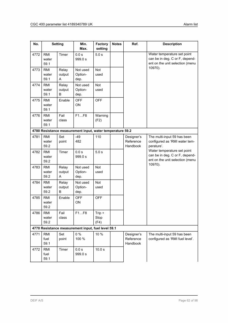
No. Setting Min.Max.
Factorysetting
Notes Ref. Description
4772 Water temperature set pointcan be in deg. C or F, depend-ent on the unit selection (menu10970).
RMIwater59.1
Timer 0.0 s999.0 s
5.0 s
4773 RMIwater59.1
RelayoutputA
Not usedOption-dep.
Notused
4774 RMIwater59.1
RelayoutputB
Not usedOption-dep.
Notused
4775 RMIwater59.1
Enable OFFON
OFF
4776 RMIwater59.1
Failclass
F1…F8 Warning(F2)
4780 Resistance measurement input, water temperature 59.2
4781 RMIwater59.2
Setpoint
-49482
110 Designer’sReferenceHandbook
The multi-input 59 has beenconfigured as ‘RMI water tem-perature’.Water temperature set pointcan be in deg. C or F, depend-ent on the unit selection (menu10970).
4782 RMIwater59.2
Timer 0.0 s999.0 s
5.0 s
4783 RMIwater59.2
RelayoutputA
Not usedOption-dep.
Notused
4784 RMIwater59.2
RelayoutputB
Not usedOption-dep.
Notused
4785 RMIwater59.2
Enable OFFON
OFF
4786 RMIwater59.2
Failclass
F1…F8 Trip +Stop(F4)
4770 Resistance measurement input, fuel level 59.1
4771 RMIfuel59.1
Setpoint
0 %100 %
10 % Designer’sReferenceHandbook
The multi-input 59 has beenconfigured as ‘RMI fuel level’.
4772 RMIfuel59.1
Timer 0.0 s999.0 s
10.0 s
CGC 400 parameter list 4189340789 UK Alarm list
DEIF A/S Page 62 of 98

No. Setting Min.Max.
Factorysetting
Notes Ref. Description
4773 RMIfuel59.1
RelayoutputA
Not usedOption-dep.
Notused
4774 RMIfuel59.1
RelayoutputB
Not usedOption-dep.
Notused
4775 RMIfuel59.1
Enable OFFON
OFF
4776 RMIfuel59.1
Failclass
F1…F8 Warning(F2)
4780 Resistance measurement input, fuel level 59.2
4781 RMIfuel59.2
Setpoint
0 %100 %
5 % Designer’sReferenceHandbook
The multi-input 59 has beenconfigured as ‘RMI fuel level’.
4782 RMIfuel59.2
Timer 0.0 s999.0 s
10.0 s
4783 RMIfuel59.2
RelayoutputA
Not usedOption-dep.
Notused
4784 RMIfuel59.2
RelayoutputB
Not usedOption-dep.
Notused
4785 RMIfuel59.2
Enable OFFON
OFF
4786 RMIfuel59.2
Failclass
F1…F8 Warning(F2)
4790 Wire fail 59
4791 W. fail59
RelayoutputA
Not usedOption-dep.
Notused
Designer’sReferenceHandbook
The wire break fault detectionis activated.
4792 W. fail59
RelayoutputB
Not usedOption-dep.
Notused
4793 W. fail59
Enable OFFON
OFF
4794 W. fail59
Failclass
F1…F8 Warning(F2)
CGC 400 parameter list 4189340789 UK Alarm list
DEIF A/S Page 63 of 98
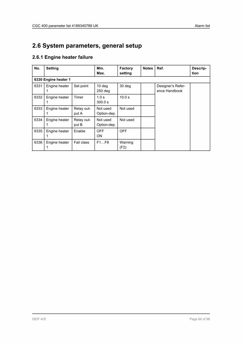
2.6 System parameters, general setup
2.6.1 Engine heater failure
No. Setting Min.Max.
Factorysetting
Notes Ref. Descrip-tion
6330 Engine heater 1
6331 Engine heater1
Set point 10 deg250 deg
30 deg Designer’s Refer-ence Handbook
6332 Engine heater1
Timer 1.0 s300.0 s
10.0 s
6333 Engine heater1
Relay out-put A
Not usedOption-dep.
Not used
6334 Engine heater1
Relay out-put B
Not usedOption-dep.
Not used
6335 Engine heater1
Enable OFFON
OFF
6336 Engine heater1
Fail class F1…F8 Warning(F2)
CGC 400 parameter list 4189340789 UK Alarm list
DEIF A/S Page 64 of 98

2.6.2 Max. ventilation
No. Setting Min.Max.
Factorysetting
Notes Ref. Description
6470 Max vent 1
6471 Maxvent 1
Setpoint
20 deg250 deg
95 deg Designer’sReferenceHandbook
If the cooling fans fail to oper-ate and the coolant tempera-ture exceeds the setting, thealarm will activate.
6472 Maxvent 1
Timer 0.0 s60.0 s
1.0 s
6473 Maxvent 1
Relayoutput A
Not usedOption-dep.
Notused
6474 Maxvent 1
Relayoutput B
Not usedOption-dep.
Notused
6475 Maxvent 1
Enable OFFON
OFF
6476 Maxvent 1
Failclass
F1…F8 Warning(F2)
6480 Max vent 2
6481 Maxvent 2
Setpoint
20 deg250 deg
98 deg Designer’sReferenceHandbook
If the cooling fans fail to oper-ate and the coolant tempera-ture exceeds the setting, thealarm will activate.
6482 Maxvent 2
Timer 0.0 s60.0 s
1.0 s
6483 Maxvent 2
Relayoutput A
Not usedOption-dep.
Notused
6484 Maxvent 2
Relayoutput B
Not usedOption-dep.
Notused
6485 Maxvent 2
Enable OFFON
OFF
6486 Maxvent 2
Failclass
F1…F8 Shut-down(F5)
CGC 400 parameter list 4189340789 UK Alarm list
DEIF A/S Page 65 of 98

2.6.3 Switchboard error - Block and Stop
No. Setting Min.Max.
Factorysetting
Notes Ref. Description
6500 Block switchboard error
6501 Blk.swbd er-ror
Timer 0.0 s999.0 s
10.0 s Designer’sReferenceHandbook
If the binary input “switchboarderror” activates, a stopped gen-erator will be blocked for start.Parameter 6502:OFF: Only AMF start is affec-ted.ON: All starts are affected.
6502 Blk.swbd er-ror
Parallel ONOFF
OFF
6503 Blk.swbd er-ror
RelayoutputA
NotusedOption-dep.
Notused
6504 Blk.swbd er-ror
RelayoutputB
NotusedOption-dep.
Notused
6505 Blk.swbd er-ror
Enable OFFON
OFF
6506 Blk.swbd er-ror
Failclass
F1…F8 Warning(F2)
6510 Stop switchboard error
6511 Stp.swbd er-ror
Timer 0.0 s999.0 s
1.0 s Designer’sReferenceHandbook
If the binary input “switchboarderror” activates, the generatorwill be stopped.
6512 Stp.swbd er-ror
RelayoutputA
NotusedOption-dep.
Notused
6513 Stp.swbd er-ror
RelayoutputB
NotusedOption-dep.
Notused
6514 Stp.swbd er-ror
Enable OFFON
OFF
6515 Stp.swbd er-ror
Failclass
F1…F8 Shut-down(F5)
CGC 400 parameter list 4189340789 UK Alarm list
DEIF A/S Page 66 of 98

2.6.4 Switchboard error - Not in auto
No. Setting Min.Max.
Factorysetting
Notes Ref. Descrip-tion
6540 Not in auto
6541 Not in auto Timer 10.0 s900.0 s
300.0 s Designer’s ReferenceHandbook
6542 Not in auto Relay outputA
Not usedOption-dep.
Not used
6543 Not in auto Relay outputB
Not usedOption-dep.
Not used
6544 Not in auto Enable OFFON
OFF
6545 Not in auto Fail class F1…F8 Warning(F2)
CGC 400 parameter list 4189340789 UK Alarm list
DEIF A/S Page 67 of 98

2.6.5 Avg U BB
No. Setting Min.Max.
Factory setting Notes Ref. Description
7480 Avg U BB> 1
7481 Avg U BB> 1 Set point 100.0 %120.0 %
110.0 %
7482 Avg U BB> 1 Timer 0.1 s3200.0 s
10.0 s
7483 Avg U BB> 1 Relay output A Not usedOption-dep.
Not used
7484 Avg U BB> 1 Enable OFFON
OFF
7485 Avg U BB> 1 Fail class F1...F8 Warning(F2)
7486 Avg U BB> 1 AVG timer 30.0 s900.0 s
600.0 s
7490 Avg U BB> 2
7491 Avg U BB> 2 Set point 100.0 %120.0 %
110.0 %
7492 Avg U BB> 2 Timer 0.1 s3200.0 s
10.0 s
7493 Avg U BB> 2 Relay output A Not usedOption-dep.
Not used
7494 Avg U BB> 2 Enable OFFON
OFF
7495 Avg U BB> 2 Fail class F1...F8 Warning(F2)
7496 Avg U BB> 2 AVG timer 30.0 s900.0 s
600.0 s
CGC 400 parameter list 4189340789 UK Alarm list
DEIF A/S Page 68 of 98
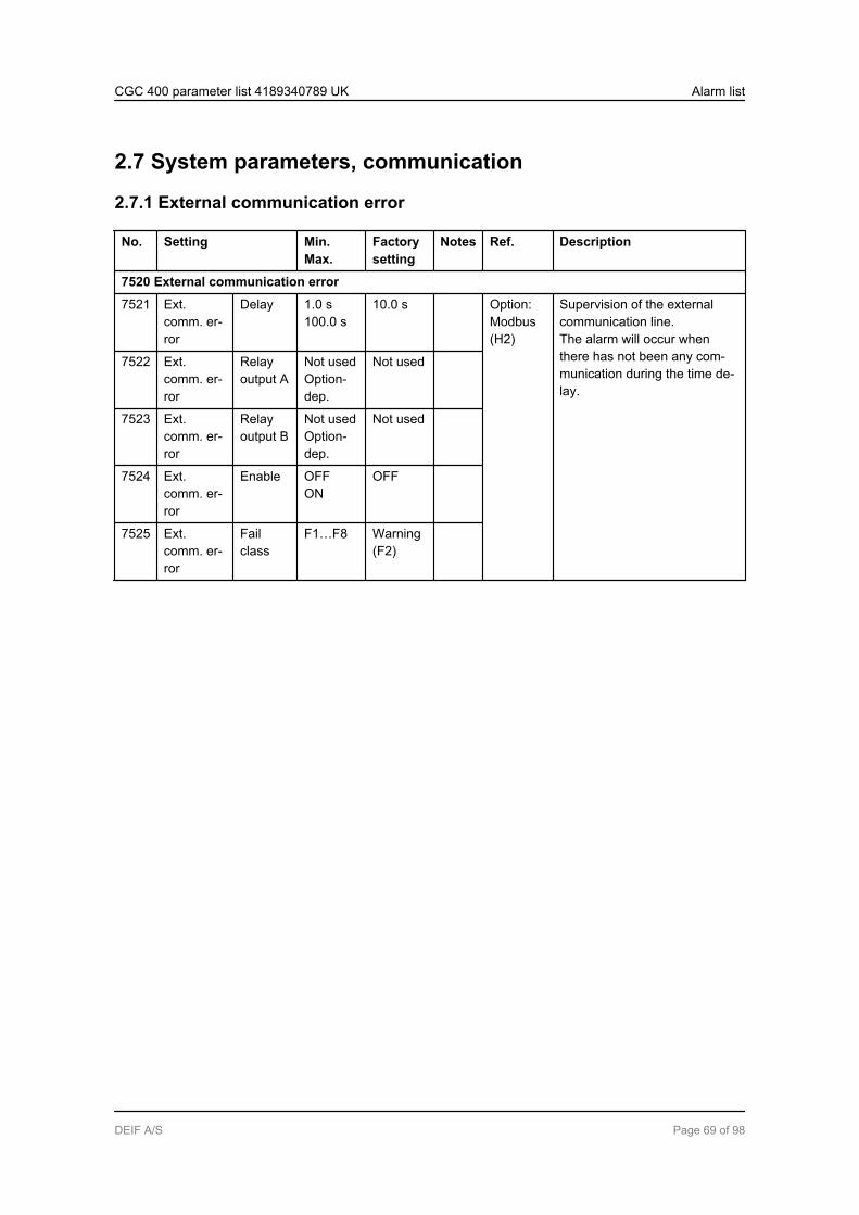
2.7 System parameters, communication
2.7.1 External communication error
No. Setting Min.Max.
Factorysetting
Notes Ref. Description
7520 External communication error
7521 Ext.comm. er-ror
Delay 1.0 s100.0 s
10.0 s Option:Modbus(H2)
Supervision of the externalcommunication line.The alarm will occur whenthere has not been any com-munication during the time de-lay.
7522 Ext.comm. er-ror
Relayoutput A
Not usedOption-dep.
Not used
7523 Ext.comm. er-ror
Relayoutput B
Not usedOption-dep.
Not used
7524 Ext.comm. er-ror
Enable OFFON
OFF
7525 Ext.comm. er-ror
Failclass
F1…F8 Warning(F2)
CGC 400 parameter list 4189340789 UK Alarm list
DEIF A/S Page 69 of 98
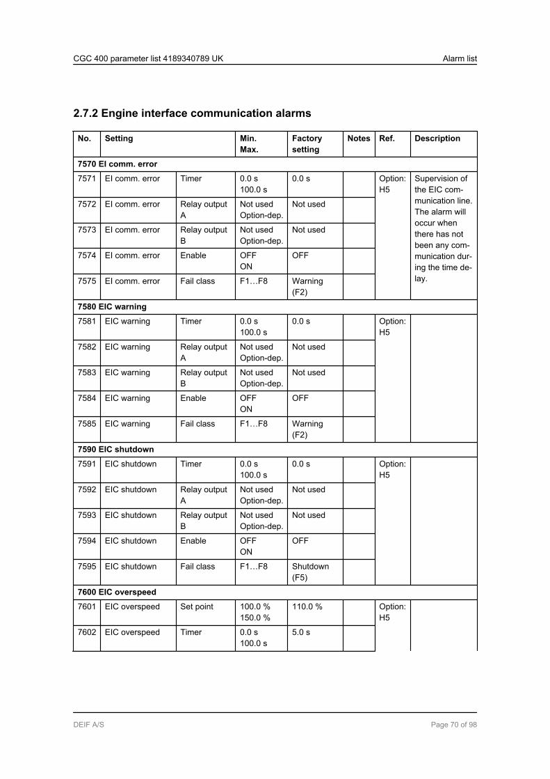
2.7.2 Engine interface communication alarms
No. Setting Min.Max.
Factorysetting
Notes Ref. Description
7570 EI comm. error
7571 EI comm. error Timer 0.0 s100.0 s
0.0 s Option:H5
Supervision ofthe EIC com-munication line.The alarm willoccur whenthere has notbeen any com-munication dur-ing the time de-lay.
7572 EI comm. error Relay outputA
Not usedOption-dep.
Not used
7573 EI comm. error Relay outputB
Not usedOption-dep.
Not used
7574 EI comm. error Enable OFFON
OFF
7575 EI comm. error Fail class F1…F8 Warning(F2)
7580 EIC warning
7581 EIC warning Timer 0.0 s100.0 s
0.0 s Option:H5
7582 EIC warning Relay outputA
Not usedOption-dep.
Not used
7583 EIC warning Relay outputB
Not usedOption-dep.
Not used
7584 EIC warning Enable OFFON
OFF
7585 EIC warning Fail class F1…F8 Warning(F2)
7590 EIC shutdown
7591 EIC shutdown Timer 0.0 s100.0 s
0.0 s Option:H5
7592 EIC shutdown Relay outputA
Not usedOption-dep.
Not used
7593 EIC shutdown Relay outputB
Not usedOption-dep.
Not used
7594 EIC shutdown Enable OFFON
OFF
7595 EIC shutdown Fail class F1…F8 Shutdown(F5)
7600 EIC overspeed
7601 EIC overspeed Set point 100.0 %150.0 %
110.0 % Option:H5
7602 EIC overspeed Timer 0.0 s100.0 s
5.0 s
CGC 400 parameter list 4189340789 UK Alarm list
DEIF A/S Page 70 of 98

No. Setting Min.Max.
Factorysetting
Notes Ref. Description
7603 EIC overspeed Relay outputA
Not usedOption-dep.
Not used
7604 EIC overspeed Relay outputB
Not usedOption-dep.
Not used
7605 EIC overspeed Enable OFFON
OFF
7606 EIC overspeed Fail class F1…F8 Warning(F2)
7610 EIC Coolant temp. 1
7611 EIC coolant t. 1 Set point -40 deg410 deg
100 deg Option:H5
7612 EIC coolant t. 1 Timer 0.0 s100.0 s
5.0 s
7613 EIC coolant t. 1 Relay outputA
Not usedOption-dep.
Not used
7614 EIC coolant t. 1 Relay outputB
Not usedOption-dep.
Not used
7615 EIC coolant t. 1 Enable OFFON
OFF
7616 EIC coolant t. 1 Fail class F1…F8 Warning(F2)
7620 EIC Coolant temp. 2
7621 EIC coolant t. 2 Set point -40 deg410 deg
110 deg Option:H5
7622 EIC coolant t. 2 Timer 0.0 s100.0 s
5.0 s
7623 EIC coolant t. 2 Relay outputA
Not usedOption-dep.
Not used
7624 EIC coolant t. 2 Relay outputB
Not usedOption-dep.
Not used
7625 EIC coolant t. 2 Enable OFFON
OFF
7626 EIC coolant t. 2 Fail class F1…F8 Warning(F2)
7630 EIC Oil pressure 1
7631 EIC oil press. 1 Set point 0.0 bar145.0 bar
2.0 bar Option:H5
7632 EIC oil press. 1 Timer 0.0 s100.0 s
5.0 s
7633 EIC oil press. 1 Relay outputA
Not usedOption-dep.
Not used
CGC 400 parameter list 4189340789 UK Alarm list
DEIF A/S Page 71 of 98
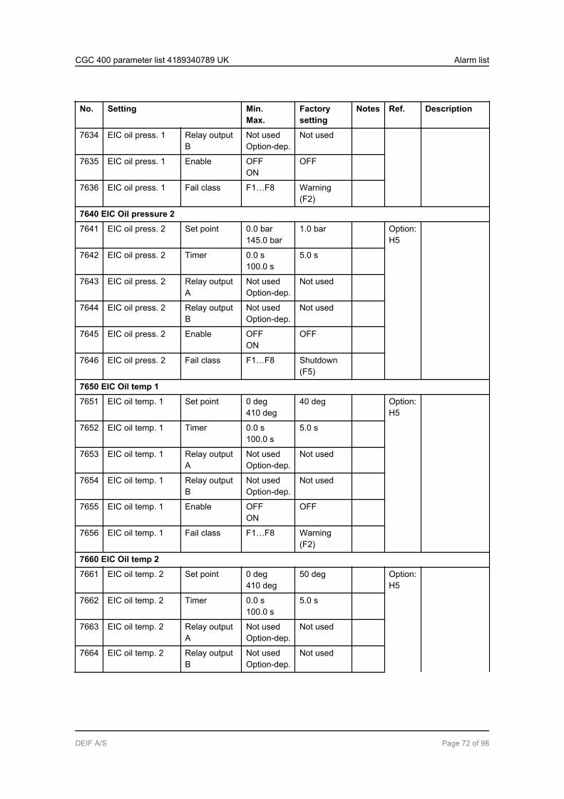
No. Setting Min.Max.
Factorysetting
Notes Ref. Description
7634 EIC oil press. 1 Relay outputB
Not usedOption-dep.
Not used
7635 EIC oil press. 1 Enable OFFON
OFF
7636 EIC oil press. 1 Fail class F1…F8 Warning(F2)
7640 EIC Oil pressure 2
7641 EIC oil press. 2 Set point 0.0 bar145.0 bar
1.0 bar Option:H5
7642 EIC oil press. 2 Timer 0.0 s100.0 s
5.0 s
7643 EIC oil press. 2 Relay outputA
Not usedOption-dep.
Not used
7644 EIC oil press. 2 Relay outputB
Not usedOption-dep.
Not used
7645 EIC oil press. 2 Enable OFFON
OFF
7646 EIC oil press. 2 Fail class F1…F8 Shutdown(F5)
7650 EIC Oil temp 1
7651 EIC oil temp. 1 Set point 0 deg410 deg
40 deg Option:H5
7652 EIC oil temp. 1 Timer 0.0 s100.0 s
5.0 s
7653 EIC oil temp. 1 Relay outputA
Not usedOption-dep.
Not used
7654 EIC oil temp. 1 Relay outputB
Not usedOption-dep.
Not used
7655 EIC oil temp. 1 Enable OFFON
OFF
7656 EIC oil temp. 1 Fail class F1…F8 Warning(F2)
7660 EIC Oil temp 2
7661 EIC oil temp. 2 Set point 0 deg410 deg
50 deg Option:H5
7662 EIC oil temp. 2 Timer 0.0 s100.0 s
5.0 s
7663 EIC oil temp. 2 Relay outputA
Not usedOption-dep.
Not used
7664 EIC oil temp. 2 Relay outputB
Not usedOption-dep.
Not used
CGC 400 parameter list 4189340789 UK Alarm list
DEIF A/S Page 72 of 98

No. Setting Min.Max.
Factorysetting
Notes Ref. Description
7665 EIC oil temp. 2 Enable OFFON
OFF
7666 EIC oil temp. 2 Fail class F1…F8 Shutdown(F5)
7670 EIC Coolant level 1
7671 EIC coolant level1
Set point 0 %100 %
20 % Option:H5
7672 EIC coolant level1
Timer 0.0 s100.0 s
5.0 s
7673 EIC coolant level1
Relay outputA
Not usedOption-dep.
Not used
7674 EIC coolant level1
Relay outputB
Not usedOption-dep.
Not used
7675 EIC coolant level1
Enable OFFON
OFF
7676 EIC coolant level1
Fail class F1...F8 Warning(F2)
7680 EIC Coolant level 2
7681 EIC coolant level2
Set point 0 %100 %
10 % Option:H5
7682 EIC coolant level2
Timer 0.0 s100.0 s
5.0 s
7683 EIC coolant level2
Relay outputA
Not usedOption-dep.
Not used
7684 EIC coolant level2
Relay outputB
Not usedOption-dep.
Not used
7685 EIC coolant level2
Enable OFFON
OFF
7686 EIC coolant level2
Fail class F1...F8 Shutdown(F5)
CGC 400 parameter list 4189340789 UK Alarm list
DEIF A/S Page 73 of 98

3. Parameter list3.1 General information about the parameter list
3.1.1 Parameter list settingsThe parameter list contains settings for regulators and other non-alarm-related settings.
CGC 400 parameter list 4189340789 UK Parameter list
DEIF A/S Page 74 of 98

3.2 Control parameter, regulation
3.2.1 Regulation
No. Setting Min.Max.
Factorysetting
Notes Ref. Description
2770 EIC speed control
2771 Scaniacontrol
Droop 0.0 %25.0 %
0.0 % Only applica-ble if "Scania"is selected inmenu 7561.
OptionH5
Setting of speedcontrol via enginecommunication in-terface.
2772 Scaniacontrol
RPM User1500 RPM1800 RPMLow idle
User
2773 CumminsGain
Kp 0.0010.00
5.00 Only applica-ble when"Cummins" isselected inmenu 7561.
2790 EIC speed demand switch
2791 EIC speeddem. sw.
Localnorm sw.
Ana. CANUp/Down ECUUp/Down CANAna. ECUAna. ECU rel.Frequency
Ana.CAN
OptionH5
See description inoption H5 manual.
2792 EIC speeddem. sw.
LocalEmergsw.
Ana. CANUp/Down ECUUp/Down CANAna. ECUAna. ECU rel.Frequency
Ana.CAN
2793 EIC speeddem. sw.
Remotenorm sw.
Ana. CANUp/Down ECUUp/Down CANAna. ECUAna. ECU rel.Frequency
Ana.CAN
2794 EIC speeddem. sw.
RemoteEmergsw.
Ana. CANUp/Down ECUUp/Down CANAna. ECUAna. ECU rel.Frequency
Ana.CAN
CGC 400 parameter list 4189340789 UK Parameter list
DEIF A/S Page 75 of 98

3.3 Control parameters, output setup
3.3.1 Digital output setup
No. Setting Min.Max.
Factorysetting
Notes Ref. Description
5000 Relay 03
5001 Relay03
Function Alarm relayNDAlarm relayNE
Horn relay Designer’s Ref-erence Hand-book
Function selections:- Alarm relay ND- Limit relay- Horn relay- Alarm relay NE5002 Relay
03OFF de-lay
0.0 s999.9 s
5.0 s
5010 Relay 21
5011 Relay21
Function Alarm relayNDAlarm relayNE
Alarm re-lay ND
Designer’s Ref-erence Hand-book
Function selections:- Alarm relay ND- Limit relay- Horn relay- Alarm relay NE5012 Relay
21OFF de-lay
0.0 s999.9 s
5.0 s
5020 Relay 22
5021 Relay22
Function Alarm relayNDAlarm relayNE
Alarm re-lay ND
Designer’s Ref-erence Hand-book
Function selections:- Alarm relay ND- Limit relay- Horn relay- Alarm relay NE5022 Relay
22OFF de-lay
0.0 s999.9 s
5.0 s
5030 Relay 23
5031 Relay23
Function Alarm relayNDAlarm relayNE
Alarm re-lay ND
Designer’s Ref-erence Hand-book
Function selections:- Alarm relay ND- Limit relay- Horn relay- Alarm relay NE5032 Relay
23OFF de-lay
0.0 s999.9 s
5.0 s
5040 Relay 24
5041 Relay24
Function Alarm relayNDAlarm relayNE
Alarm re-lay ND
Designer’s Ref-erence Hand-book
Function selections:- Alarm relay ND- Limit relay- Horn relay- Alarm relay NE5042 Relay
24OFF de-lay
0.0 s999.9 s
5.0 s
5050 Relay 26
CGC 400 parameter list 4189340789 UK Parameter list
DEIF A/S Page 76 of 98
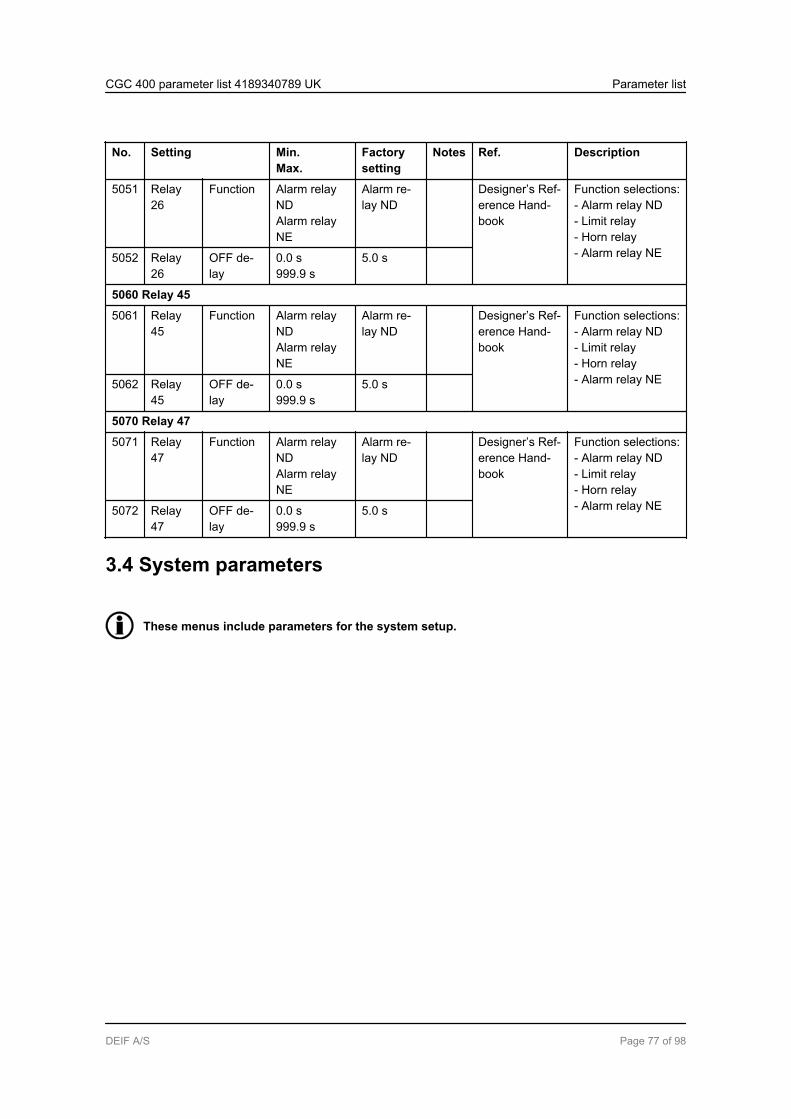
No. Setting Min.Max.
Factorysetting
Notes Ref. Description
5051 Relay26
Function Alarm relayNDAlarm relayNE
Alarm re-lay ND
Designer’s Ref-erence Hand-book
Function selections:- Alarm relay ND- Limit relay- Horn relay- Alarm relay NE5052 Relay
26OFF de-lay
0.0 s999.9 s
5.0 s
5060 Relay 45
5061 Relay45
Function Alarm relayNDAlarm relayNE
Alarm re-lay ND
Designer’s Ref-erence Hand-book
Function selections:- Alarm relay ND- Limit relay- Horn relay- Alarm relay NE5062 Relay
45OFF de-lay
0.0 s999.9 s
5.0 s
5070 Relay 47
5071 Relay47
Function Alarm relayNDAlarm relayNE
Alarm re-lay ND
Designer’s Ref-erence Hand-book
Function selections:- Alarm relay ND- Limit relay- Horn relay- Alarm relay NE5072 Relay
47OFF de-lay
0.0 s999.9 s
5.0 s
3.4 System parameters
These menus include parameters for the system setup.
CGC 400 parameter list 4189340789 UK Parameter list
DEIF A/S Page 77 of 98
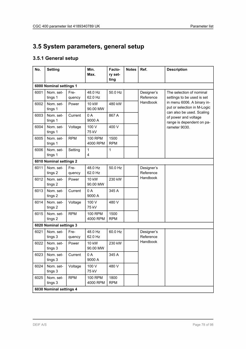
3.5 System parameters, general setup
3.5.1 General setup
No. Setting Min.Max.
Facto-ry set-ting
Notes Ref. Description
6000 Nominal settings 1
6001 Nom. set-tings 1
Fre-quency
48.0 Hz62.0 Hz
50.0 Hz Designer’sReferenceHandbook
The selection of nominalsettings to be used is setin menu 6006. A binary in-put or selection in M-Logiccan also be used. Scalingof power and voltagerange is dependent on pa-rameter 9030.
6002 Nom. set-tings 1
Power 10 kW90.00 MW
480 kW
6003 Nom. set-tings 1
Current 0 A9000 A
867 A
6004 Nom. set-tings 1
Voltage 100 V75 kV
400 V
6005 Nom. set-tings 1
RPM 100 RPM4000 RPM
1500RPM
6006 Nom. set-tings 1
Setting 14
1
6010 Nominal settings 2
6011 Nom. set-tings 2
Fre-quency
48.0 Hz62.0 Hz
50.0 Hz Designer’sReferenceHandbook6012 Nom. set-
tings 2Power 10 kW
90.00 MW230 kW
6013 Nom. set-tings 2
Current 0 A9000 A
345 A
6014 Nom. set-tings 2
Voltage 100 V75 kV
480 V
6015 Nom. set-tings 2
RPM 100 RPM4000 RPM
1500RPM
6020 Nominal settings 3
6021 Nom. set-tings 3
Fre-quency
48.0 Hz62.0 Hz
60.0 Hz Designer’sReferenceHandbook6022 Nom. set-
tings 3Power 10 kW
90.00 MW230 kW
6023 Nom. set-tings 3
Current 0 A9000 A
345 A
6024 Nom. set-tings 3
Voltage 100 V75 kV
480 V
6025 Nom. set-tings 3
RPM 100 RPM4000 RPM
1800RPM
6030 Nominal settings 4
CGC 400 parameter list 4189340789 UK Parameter list
DEIF A/S Page 78 of 98

No. Setting Min.Max.
Facto-ry set-ting
Notes Ref. Description
6031 Nom. set-tings 4
Fre-quency
48.0 Hz62.0 Hz
60.0 Hz Designer’sReferenceHandbook6032 Nom. set-
tings 4Power 10 kW
90.00 kW230 kW
6033 Nom. set-tings 4
Current 0 A9000 A
345 A
6034 Nom. set-tings 4
Voltage 100 V75 kV
480 V
6035 Nom. set-tings 4
RPM 100 RPM4000 RPM
1800RPM
6040 G transformer
6041 G trans-former
U pri-mary
100 V75 kV
400 V Designer’sReferenceHandbook
If no voltage transformer ispresent, the primary andsecondary side values areset to generator nominalvalue.
6042 G trans-former
U secon-dary
100 V480 V
400 V
6043 G trans-former
I primary 5 A9000 A
1000 A
6044 G trans-former
I secon-dary
1 A5 A
1 A
6050 Busbar settings
6051 BB trans-former
U pri-mary
100 V75 kV
400 V Designer’sReferenceHandbook
If no voltage transformer ispresent, the primary andsecondary side values areset to generator nominalvalue.
6052 BB trans-former
U secon-dary
100 V480 V
400 V
6053 BB trans-former
NominalU 1
100 V75 kV
400 V
6054 BB trans-former
Busnom. set
Param set1Param set2
Paramset 1
6060 Busbar settings 2
6061 BB trans-former
U pri-mary
100 V75 kV
400 V Designer'sReferenceHandbook
If no voltage transformer ispresent, the primary andsecondary side values areset to generator nominalvalue.
6062 BB trans-former
U secon-dary
100 V480 V
400 V
6063 BB trans-former
NominalU 2
100 V75 kV
400 V
6070 Genset mode
CGC 400 parameter list 4189340789 UK Parameter list
DEIF A/S Page 79 of 98

No. Setting Min.Max.
Facto-ry set-ting
Notes Ref. Description
6071 Gensetmode
IslandLoad take-over
Designer’sReferenceHandbook
Selections are:-Island-Auto Mains Failure-Load takeover
6080 Language
6081 Language EnglishLanguage3
English Designer’sReferenceHandbook
The master language isEnglish. Additionally, 11different languages can beconfigured with the PC util-ity software. Only 3 differ-ent languages can be writ-ten to the controller.
CGC 400 parameter list 4189340789 UK Parameter list
DEIF A/S Page 80 of 98
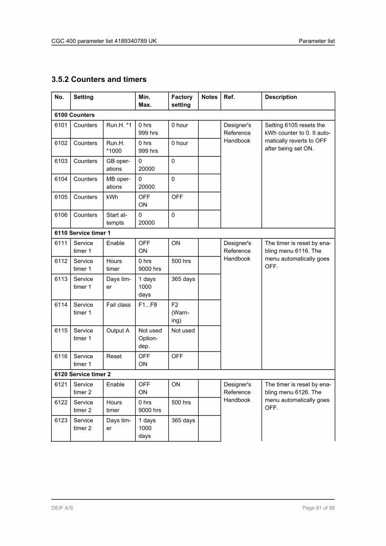
3.5.2 Counters and timers
No. Setting Min.Max.
Factorysetting
Notes Ref. Description
6100 Counters
6101 Counters Run.H. *1 0 hrs999 hrs
0 hour Designer'sReferenceHandbook
Setting 6105 resets thekWh counter to 0. It auto-matically reverts to OFFafter being set ON.
6102 Counters Run.H.*1000
0 hrs999 hrs
0 hour
6103 Counters GB oper-ations
020000
0
6104 Counters MB oper-ations
020000
0
6105 Counters kWh OFFON
OFF
6106 Counters Start at-tempts
020000
0
6110 Service timer 1
6111 Servicetimer 1
Enable OFFON
ON Designer'sReferenceHandbook
The timer is reset by ena-bling menu 6116. Themenu automatically goesOFF.
6112 Servicetimer 1
Hourstimer
0 hrs9000 hrs
500 hrs
6113 Servicetimer 1
Days tim-er
1 days1000days
365 days
6114 Servicetimer 1
Fail class F1...F8 F2(Warn-ing)
6115 Servicetimer 1
Output A Not usedOption-dep.
Not used
6116 Servicetimer 1
Reset OFFON
OFF
6120 Service timer 2
6121 Servicetimer 2
Enable OFFON
ON Designer'sReferenceHandbook
The timer is reset by ena-bling menu 6126. Themenu automatically goesOFF.
6122 Servicetimer 2
Hourstimer
0 hrs9000 hrs
500 hrs
6123 Servicetimer 2
Days tim-er
1 days1000days
365 days
CGC 400 parameter list 4189340789 UK Parameter list
DEIF A/S Page 81 of 98
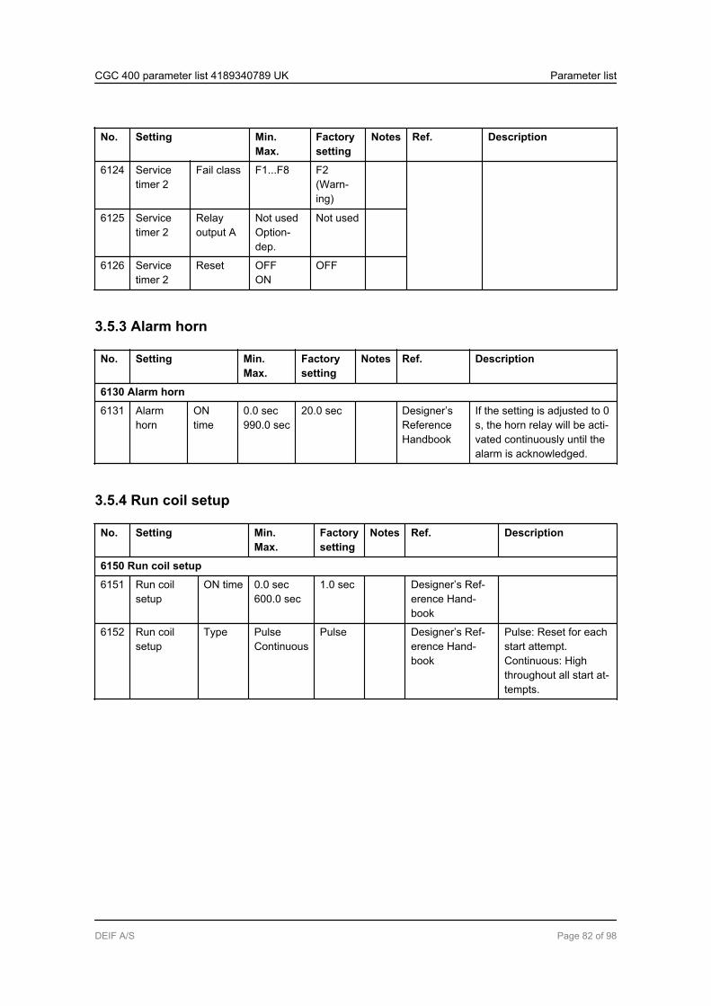
No. Setting Min.Max.
Factorysetting
Notes Ref. Description
6124 Servicetimer 2
Fail class F1...F8 F2(Warn-ing)
6125 Servicetimer 2
Relayoutput A
Not usedOption-dep.
Not used
6126 Servicetimer 2
Reset OFFON
OFF
3.5.3 Alarm horn
No. Setting Min.Max.
Factorysetting
Notes Ref. Description
6130 Alarm horn
6131 Alarmhorn
ONtime
0.0 sec990.0 sec
20.0 sec Designer’sReferenceHandbook
If the setting is adjusted to 0s, the horn relay will be acti-vated continuously until thealarm is acknowledged.
3.5.4 Run coil setup
No. Setting Min.Max.
Factorysetting
Notes Ref. Description
6150 Run coil setup
6151 Run coilsetup
ON time 0.0 sec600.0 sec
1.0 sec Designer’s Ref-erence Hand-book
6152 Run coilsetup
Type PulseContinuous
Pulse Designer’s Ref-erence Hand-book
Pulse: Reset for eachstart attempt.Continuous: Highthroughout all start at-tempts.
CGC 400 parameter list 4189340789 UK Parameter list
DEIF A/S Page 82 of 98
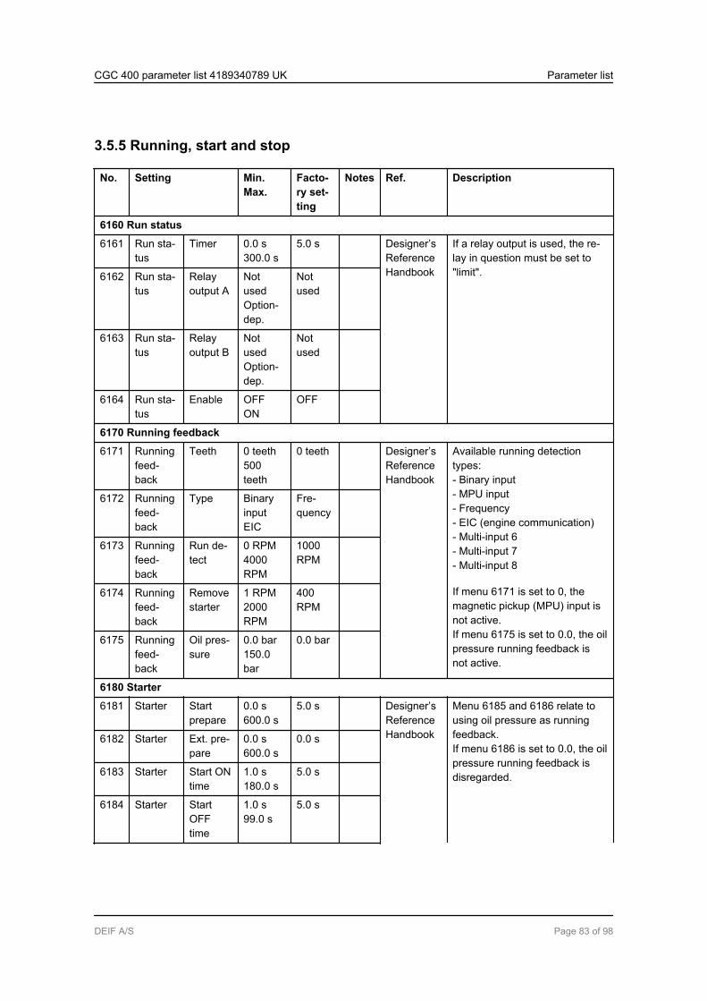
3.5.5 Running, start and stop
No. Setting Min.Max.
Facto-ry set-ting
Notes Ref. Description
6160 Run status
6161 Run sta-tus
Timer 0.0 s300.0 s
5.0 s Designer’sReferenceHandbook
If a relay output is used, the re-lay in question must be set to"limit".6162 Run sta-
tusRelayoutput A
NotusedOption-dep.
Notused
6163 Run sta-tus
Relayoutput B
NotusedOption-dep.
Notused
6164 Run sta-tus
Enable OFFON
OFF
6170 Running feedback
6171 Runningfeed-back
Teeth 0 teeth500teeth
0 teeth Designer’sReferenceHandbook
Available running detectiontypes:- Binary input- MPU input- Frequency- EIC (engine communication)- Multi-input 6- Multi-input 7- Multi-input 8
If menu 6171 is set to 0, themagnetic pickup (MPU) input isnot active.If menu 6175 is set to 0.0, the oilpressure running feedback isnot active.
6172 Runningfeed-back
Type BinaryinputEIC
Fre-quency
6173 Runningfeed-back
Run de-tect
0 RPM4000RPM
1000RPM
6174 Runningfeed-back
Removestarter
1 RPM2000RPM
400RPM
6175 Runningfeed-back
Oil pres-sure
0.0 bar150.0bar
0.0 bar
6180 Starter
6181 Starter Startprepare
0.0 s600.0 s
5.0 s Designer’sReferenceHandbook
Menu 6185 and 6186 relate tousing oil pressure as runningfeedback.If menu 6186 is set to 0.0, the oilpressure running feedback isdisregarded.
6182 Starter Ext. pre-pare
0.0 s600.0 s
0.0 s
6183 Starter Start ONtime
1.0 s180.0 s
5.0 s
6184 Starter StartOFFtime
1.0 s99.0 s
5.0 s
CGC 400 parameter list 4189340789 UK Parameter list
DEIF A/S Page 83 of 98

No. Setting Min.Max.
Facto-ry set-ting
Notes Ref. Description
6185 Starter Type Multi-in-put 6Multi-in-put 8
Multi-input 6
6186 Starter Set point 0.0 bar300.0bar
0.0 bar
6190 Start attempts
6191 Start at-tempts
Set point 110
3 Designer’sReferenceHandbook
Number of start attempts.
6200 Shutdown override
6201 Shut-downoverride
Attempts 110
7 Designer’sReferenceHandbook
Shutdown override turns allshutdowns into warnings. Onlyexception is overspeed andemergency stop.6202 Shut-
downoverride
Coolingdowntimer
0 s9900 s
240 s
6203 Shut-downoverride
Reset OFFON
OFF
6210 Stop
6211 Stop Coolingdown
0 s9900 s
240 s Designer’sReferenceHandbook
The extended stop timer startswhen the running feedback dis-appears. During the delay time itis not possible to start the en-gine.
6212 Stop Exten-ded stop
1.0 s99.0 s
5.0 s
6213 Stop TYPE Multi-in-put 6EIC
Multi-input 6
6214 Stop Set point 0 deg.482 deg.
0 deg.
6220 Hz/V OK
6221 HZ/V OK Timer 1.0 s99.0 s
5.0 s Designer’sReferenceHandbook
The voltage and frequency haveto be continuously within the lim-its during the delay timer beforethe breaker can be closed.
CGC 400 parameter list 4189340789 UK Parameter list
DEIF A/S Page 84 of 98

3.5.6 Breaker control
No. Setting Min.Max.
Factorysetting
Notes Ref. Description
6230 GB control
6231 GB con-trol
Close de-lay
0.0 s30.0 s
2.0 s Designer’s Ref-erence Hand-book
Menu 6232 is for com-pact breakers (need tocharge spring beforeclosing).
6232 GB con-trol
Load time 0.0 s30.0 s
0.0 s
3.5.7 Idle start
No. Setting Min.Max.
Factorysetting
Notes Ref. Descrip-tion
6290 Idle running
6291 Idle start Start timer 0.0 min.999.0 min.
300.0 min. Designer’s ReferenceHandbook
6292 Idle start Enable start OFFON
OFF
6293 Idle stop Stop timer 0.0 min.999.0 min.
300.0 min.
6294 Idle stop Enable stop OFFON
OFF
6295 Idle active Relay outputA
Not usedOption-dep.
Not used
6296 Idle active Idle running OFFON
OFF
CGC 400 parameter list 4189340789 UK Parameter list
DEIF A/S Page 85 of 98

3.5.8 Engine heater
No. Setting Min.Max.
Factorysetting
Notes Ref. Description
6320 Engine heater
6321 Engineheater
Setpoint
20 deg.250 deg.
40 deg. Designer’sReferenceHandbook
Heater function for standstill.Type:- Multi-input 6- Multi-input 7- Multi-input 8- EIC
6322 Engineheater
Relayoutput A
Not usedOption-dep.
Notused
6323 Engineheater
Type Multi-inp6EIC
Multi-inp6
6324 Engineheater
Hystere-sis
1 deg.70 deg.
3 deg.
6325 Engineheater
Enable OFFON
OFF
3.5.9 Cooling ventilation
No. Setting Min.Max.
Factorysetting
Notes Ref. Description
6460 Max. ventilation
6461 Max. ventila-tion
Set point 20 deg.250 deg.
90 deg. Designer's Ref-erence Hand-book
Ventilation fancontrol.
6462 Max. ventila-tion
Relay out-put A
Not usedOption-dep.
Not used
6463 Max. ventila-tion
Hysteresis 1 deg.70 deg.
5 deg.
6464 Max. ventila-tion
Enable OFFON
OFF
3.5.10 Summer/winter time
No. Setting Min.Max.
Factory set-ting
Notes Ref. Description
6490 Summer/winter time
6491 Sum/wintime
Enable OFFON
OFF Designer’s Ref-erence Hand-book
The summer/winter timechange follows themainland Europe rules.
CGC 400 parameter list 4189340789 UK Parameter list
DEIF A/S Page 86 of 98

3.5.11 Fuel transfer pump logic
No. Setting Min.Max.
Factorysetting
Notes Ref. Description
6550 Fuel pump logic
6551 Fuel pumplogic
Pump start 0 %100 %
20 % Designer’s Refer-ence Handbook
Type:- Multi-input 6- Multi-input 7- Multi-input 8
6552 Fuel pumplogic
Pump stop 0 %100 %
80 %
6553 Fuel pumplogic
Fill checktime
0.1 s300.0 s
60.0 s
6554 Fuel pumplogic
Relay out-put A
Not usedOption-dep.
Not used
6555 Fuel pumplogic
Set point Multi-inp 6Multi-inp 8
Multi-inp 6
6556 Fuel pumplogic
Fail class F1…F8 Warning(F2)
3.5.12 Alarm jump
No. Setting Min.Max.
Factorysetting
Notes Ref. Description
6900 Alarm jump
6901 Alarm jump Enable OFFON
ON Designer's Ref-erence Hand-book
Selection of jump to alarm listview on the display if an alarmappears (ON), or stay atpresent view (OFF).
CGC 400 parameter list 4189340789 UK Parameter list
DEIF A/S Page 87 of 98
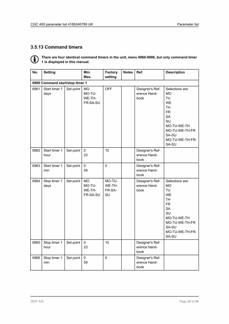
3.5.13 Command timers
There are four identical command timers in the unit, menu 6960-6996, but only command timer1 is displayed in this manual.
No. Setting Min.Max.
Factorysetting
Notes Ref. Description
6960 Command start/stop timer 1
6961 Start timer 1days
Set point MOMO-TU-WE-TH-FR-SA-SU
OFF Designer's Ref-erence Hand-book
Selections are:MOTUWETHFRSASUMO-TU-WE-THMO-TU-WE-TH-FRSA-SUMO-TU-WE-TH-FR-SA-SU
6962 Start timer 1hour
Set point 023
10 Designer's Ref-erence Hand-book
6963 Start timer 1min
Set point 059
0 Designer's Ref-erence Hand-book
6964 Stop timer 1days
Set point MOMO-TU-WE-TH-FR-SA-SU
MO-TU-WE-TH-FR-SA-SU
Designer's Ref-erence Hand-book
Selections are:MOTUWETHFRSASUMO-TU-WE-THMO-TU-WE-TH-FRSA-SUMO-TU-WE-TH-FR-SA-SU
6965 Stop timer 1hour
Set point 023
10 Designer's Ref-erence Hand-book
6966 Stop timer 1min
Set point 059
0 Designer's Ref-erence Hand-book
CGC 400 parameter list 4189340789 UK Parameter list
DEIF A/S Page 88 of 98
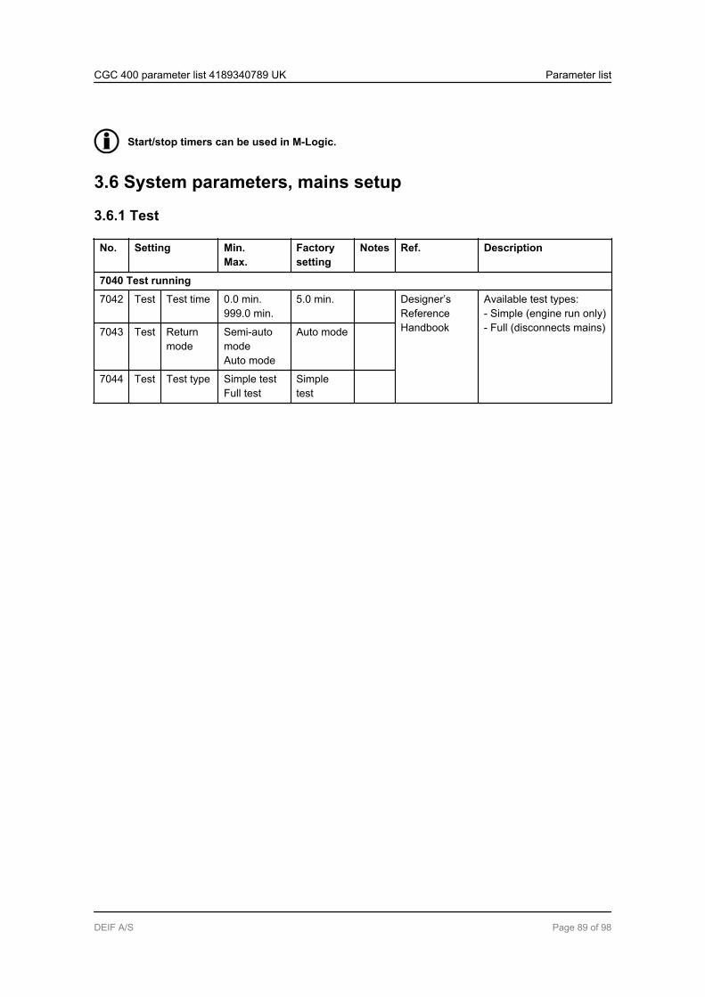
Start/stop timers can be used in M-Logic.
3.6 System parameters, mains setup
3.6.1 Test
No. Setting Min.Max.
Factorysetting
Notes Ref. Description
7040 Test running
7042 Test Test time 0.0 min.999.0 min.
5.0 min. Designer’sReferenceHandbook
Available test types:- Simple (engine run only)- Full (disconnects mains)7043 Test Return
modeSemi-automodeAuto mode
Auto mode
7044 Test Test type Simple testFull test
Simpletest
CGC 400 parameter list 4189340789 UK Parameter list
DEIF A/S Page 89 of 98
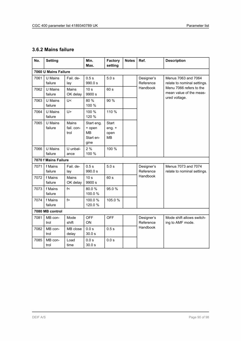
3.6.2 Mains failure
No. Setting Min.Max.
Factorysetting
Notes Ref. Description
7060 U Mains Failure
7061 U Mainsfailure
Fail. de-lay
0.5 s990.0 s
5.0 s Designer’sReferenceHandbook
Menus 7063 and 7064relate to nominal settings.Menu 7066 refers to themean value of the meas-ured voltage.
7062 U Mainsfailure
MainsOK delay
10 s9900 s
60 s
7063 U Mainsfailure
U< 80 %100 %
90 %
7064 U Mainsfailure
U> 100 %120 %
110 %
7065 U Mainsfailure
Mainsfail. con-trol
Start eng.+ openMBStart en-gine
Starteng. +openMB
7066 U Mainsfailure
U unbal-ance
2 %100 %
100 %
7070 f Mains Failure
7071 f Mainsfailure
Fail. de-lay
0.5 s990.0 s
5.0 s Designer’sReferenceHandbook
Menus 7073 and 7074relate to nominal settings.
7072 f Mainsfailure
MainsOK delay
10 s9900 s
60 s
7073 f Mainsfailure
f< 80.0 %100.0 %
95.0 %
7074 f Mainsfailure
f> 100.0 %120.0 %
105.0 %
7080 MB control
7081 MB con-trol
Modeshift
OFFON
OFF Designer’sReferenceHandbook
Mode shift allows switch-ing to AMF mode.
7082 MB con-trol
MB closedelay
0.0 s30.0 s
0.5 s
7085 MB con-trol
Loadtime
0.0 s30.0 s
0.0 s
CGC 400 parameter list 4189340789 UK Parameter list
DEIF A/S Page 90 of 98

3.7 System parameters, external communication
3.7.1 External communication
No. Setting Min.Max.
Factorysetting
Notes Ref. Description
7510 External communication
7511 Ext. communi-cation
ID 1247
3 Option H2 The mode ASCII is used formodem communication (ASCII:7 data bit, RTU: 8 data bit).7512 Ext. communi-
cationMode RTU
ASCIIRTU Option H2
CGC 400 parameter list 4189340789 UK Parameter list
DEIF A/S Page 91 of 98
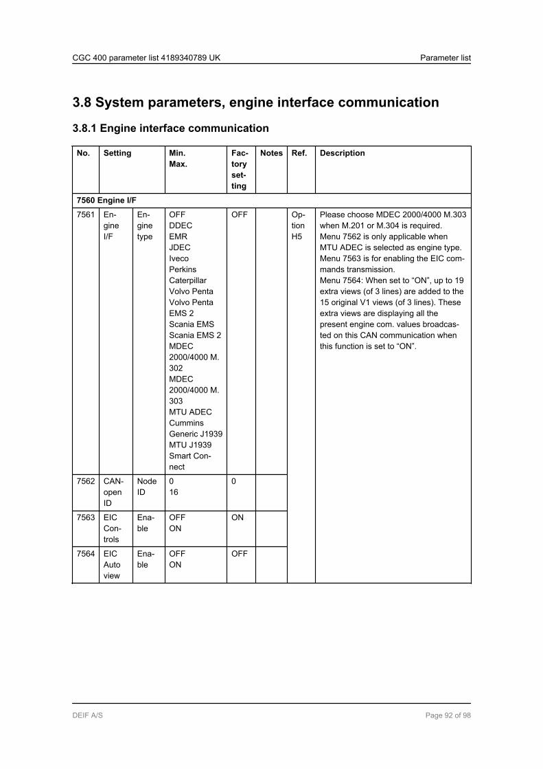
3.8 System parameters, engine interface communication
3.8.1 Engine interface communication
No. Setting Min.Max.
Fac-toryset-ting
Notes Ref. Description
7560 Engine I/F
7561 En-gineI/F
En-ginetype
OFFDDECEMRJDECIvecoPerkinsCaterpillarVolvo PentaVolvo PentaEMS 2Scania EMSScania EMS 2MDEC2000/4000 M.302MDEC2000/4000 M.303MTU ADECCumminsGeneric J1939MTU J1939Smart Con-nect
OFF Op-tionH5
Please choose MDEC 2000/4000 M.303when M.201 or M.304 is required.Menu 7562 is only applicable whenMTU ADEC is selected as engine type.Menu 7563 is for enabling the EIC com-mands transmission.Menu 7564: When set to “ON”, up to 19extra views (of 3 lines) are added to the15 original V1 views (of 3 lines). Theseextra views are displaying all thepresent engine com. values broadcas-ted on this CAN communication whenthis function is set to “ON”.
7562 CAN-openID
NodeID
016
0
7563 EICCon-trols
Ena-ble
OFFON
ON
7564 EICAutoview
Ena-ble
OFFON
OFF
CGC 400 parameter list 4189340789 UK Parameter list
DEIF A/S Page 92 of 98
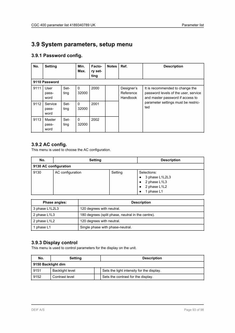
3.9 System parameters, setup menu
3.9.1 Password config.
No. Setting Min.Max.
Facto-ry set-ting
Notes Ref. Description
9110 Password
9111 Userpass-word
Set-ting
032000
2000 Designer’sReferenceHandbook
It is recommended to change thepassword levels of the user, serviceand master password if access toparameter settings must be restric-ted
9112 Servicepass-word
Set-ting
032000
2001
9113 Masterpass-word
Set-ting
032000
2002
3.9.2 AC config.This menu is used to choose the AC configuration.
No. Setting Description
9130 AC configuration
9130 AC configuration Setting Selections:● 3 phase L1L2L3● 2 phase L1L3● 2 phase L1L2● 1 phase L1
Phase angles: Description
3 phase L1L2L3 120 degrees with neutral.
2 phase L1L3 180 degrees (split phase, neutral in the centre).
2 phase L1L2 120 degrees with neutral.
1 phase L1 Single phase with phase-neutral.
3.9.3 Display controlThis menu is used to control parameters for the display on the unit.
No. Setting Description
9150 Backlight dim
9151 Backlight level Sets the light intensity for the display.
9152 Contrast level Sets the contrast for the display.
CGC 400 parameter list 4189340789 UK Parameter list
DEIF A/S Page 93 of 98
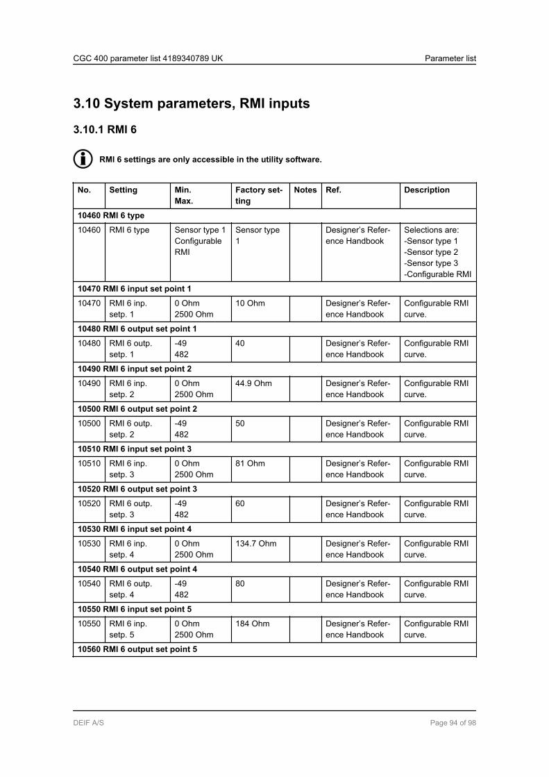
3.10 System parameters, RMI inputs
3.10.1 RMI 6
RMI 6 settings are only accessible in the utility software.
No. Setting Min.Max.
Factory set-ting
Notes Ref. Description
10460 RMI 6 type
10460 RMI 6 type Sensor type 1ConfigurableRMI
Sensor type1
Designer’s Refer-ence Handbook
Selections are:-Sensor type 1-Sensor type 2-Sensor type 3-Configurable RMI
10470 RMI 6 input set point 1
10470 RMI 6 inp.setp. 1
0 Ohm2500 Ohm
10 Ohm Designer’s Refer-ence Handbook
Configurable RMIcurve.
10480 RMI 6 output set point 1
10480 RMI 6 outp.setp. 1
-49482
40 Designer’s Refer-ence Handbook
Configurable RMIcurve.
10490 RMI 6 input set point 2
10490 RMI 6 inp.setp. 2
0 Ohm2500 Ohm
44.9 Ohm Designer’s Refer-ence Handbook
Configurable RMIcurve.
10500 RMI 6 output set point 2
10500 RMI 6 outp.setp. 2
-49482
50 Designer’s Refer-ence Handbook
Configurable RMIcurve.
10510 RMI 6 input set point 3
10510 RMI 6 inp.setp. 3
0 Ohm2500 Ohm
81 Ohm Designer’s Refer-ence Handbook
Configurable RMIcurve.
10520 RMI 6 output set point 3
10520 RMI 6 outp.setp. 3
-49482
60 Designer’s Refer-ence Handbook
Configurable RMIcurve.
10530 RMI 6 input set point 4
10530 RMI 6 inp.setp. 4
0 Ohm2500 Ohm
134.7 Ohm Designer’s Refer-ence Handbook
Configurable RMIcurve.
10540 RMI 6 output set point 4
10540 RMI 6 outp.setp. 4
-49482
80 Designer’s Refer-ence Handbook
Configurable RMIcurve.
10550 RMI 6 input set point 5
10550 RMI 6 inp.setp. 5
0 Ohm2500 Ohm
184 Ohm Designer’s Refer-ence Handbook
Configurable RMIcurve.
10560 RMI 6 output set point 5
CGC 400 parameter list 4189340789 UK Parameter list
DEIF A/S Page 94 of 98

No. Setting Min.Max.
Factory set-ting
Notes Ref. Description
10560 RMI 6 outp.setp. 5
-49482
100 Designer’s Refer-ence Handbook
Configurable RMIcurve.
10570 RMI 6 input set point 6
10570 RMI 6 inp.setp. 6
0 Ohm2500 Ohm
200 Ohm Designer’s Refer-ence Handbook
Configurable RMIcurve.
10580 RMI 6 output set point 6
10580 RMI 6 outp.setp. 6
-49482
110 Designer’s Refer-ence Handbook
Configurable RMIcurve.
10590 RMI 6 input set point 7
10590 RMI 6 inp.setp. 7
0 Ohm2500 Ohm
210 Ohm Designer’s Refer-ence Handbook
Configurable RMIcurve.
10600 RMI 6 output set point 7
10600 RMI 6 outp.setp. 7
-49482
115 Designer’s Refer-ence Handbook
Configurable RMIcurve.
10610 RMI 6 input set point 8
10610 RMI 6 inp.setp. 8
0 Ohm2500 Ohm
220 Ohm Designer’s Refer-ence Handbook
Configurable RMIcurve.
10620 RMI 6 output set point 8
10620 RMI 6 outp.setp. 8
-49482
120 Designer’s Refer-ence Handbook
Configurable RMIcurve.
3.10.2 RMI 7
RMI 7 settings are only accessible in the utility software.
Menus 10630-10790 equal the settings for RMI 6 (10460-10620).
3.10.3 RMI 8
RMI 8 settings are only accessible in the utility software.
Menus 10800-10960 equal the settings for RMI 6 (10460-10620).
CGC 400 parameter list 4189340789 UK Parameter list
DEIF A/S Page 95 of 98
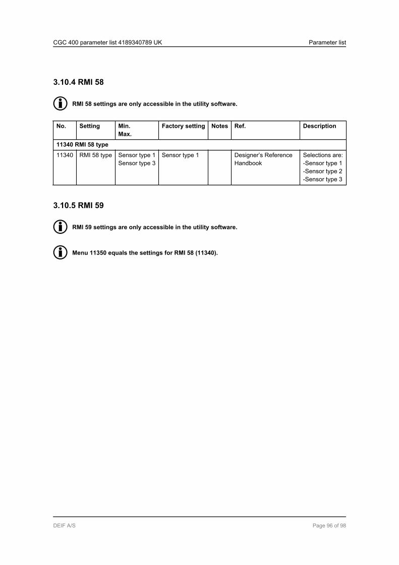
3.10.4 RMI 58
RMI 58 settings are only accessible in the utility software.
No. Setting Min.Max.
Factory setting Notes Ref. Description
11340 RMI 58 type
11340 RMI 58 type Sensor type 1Sensor type 3
Sensor type 1 Designer’s ReferenceHandbook
Selections are:-Sensor type 1-Sensor type 2-Sensor type 3
3.10.5 RMI 59
RMI 59 settings are only accessible in the utility software.
Menu 11350 equals the settings for RMI 58 (11340).
CGC 400 parameter list 4189340789 UK Parameter list
DEIF A/S Page 96 of 98

3.10.6 Multi-input selections
No. Setting Min.Max.
Factory setting Notes Ref. Description
10970 Engineering units
10970 Engineering units Bar/CelsiusPsi/Fahrenheit
Bar/Celsius
10980 Multi-input configuration 6
10980 Multi inp. conf. 6 4-20 mABinary
Binary Possible selections:4-20 mAPt100Pt1000RMI oil pressureRMI water tempRMI fuel levelBinary
10990 Multi-input configuration 7
10990 Multi inp. conf. 7 4-20 mABinary
Binary Possible selections:4-20 mAPt100Pt1000RMI oil pressureRMI water tempRMI fuel levelBinary
11000 Multi-input configurable 8
11000 Multi inp. conf. 8 4-20 mABinary
Binary Possible selections:4-20 mAPt100Pt1000RMI oil pressureRMI water tempRMI fuel levelBinary
11300 Multi-input configurable 58
11300 Multi inp. conf. 58 4-20 mABinary
Binary Possible selections:4-20 mAPt100Pt1000RMI oil pressureRMI water tempRMI fuel levelBinary
11310 Multi-input configurable 59
CGC 400 parameter list 4189340789 UK Parameter list
DEIF A/S Page 97 of 98
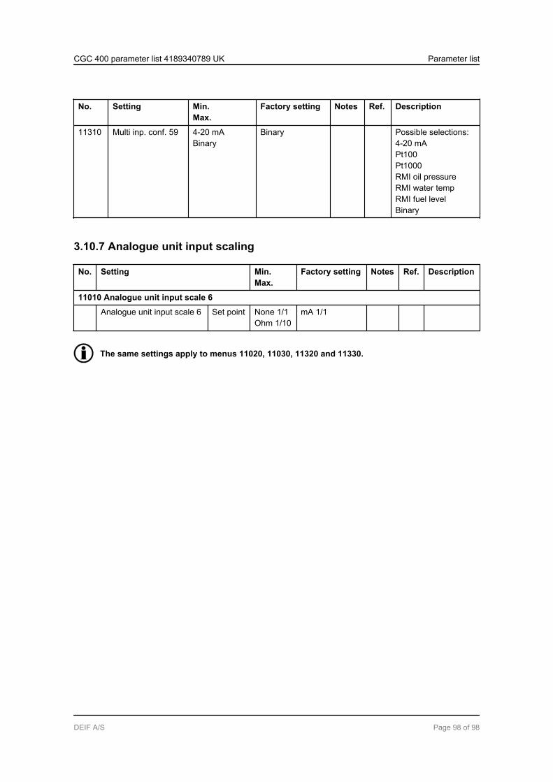
No. Setting Min.Max.
Factory setting Notes Ref. Description
11310 Multi inp. conf. 59 4-20 mABinary
Binary Possible selections:4-20 mAPt100Pt1000RMI oil pressureRMI water tempRMI fuel levelBinary
3.10.7 Analogue unit input scaling
No. Setting Min.Max.
Factory setting Notes Ref. Description
11010 Analogue unit input scale 6
Analogue unit input scale 6 Set point None 1/1Ohm 1/10
mA 1/1
The same settings apply to menus 11020, 11030, 11320 and 11330.
CGC 400 parameter list 4189340789 UK Parameter list
DEIF A/S Page 98 of 98