Service and Maintenance Manual Model 600SC 660SJC - JLG
400
Service and Maintenance Manual Model 600SC 660SJC S/N 0300074875 to S/N 0300174703 P/N - 3121157 November 22, 2016
-
Upload
khangminh22 -
Category
Documents
-
view
1 -
download
0
Transcript of Service and Maintenance Manual Model 600SC 660SJC - JLG

Service and Maintenance Manual
Model600SC660SJC
S/N 0300074875 to S/N 0300174703
P/N - 3121157
November 22, 2016


INTRODUCTION
3121157 – JLG Lift – A-1
SECTION A. INTRODUCTION - MAINTENANCE SAFETY PRECAUTIONS
A GENERAL
This section contains the general safety precautionswhich must be observed during maintenance of the aerialplatform. It is of utmost importance that maintenance per-sonnel pay strict attention to these warnings and precau-tions to avoid possible injury to themselves or others, ordamage to the equipment. A maintenance program mustbe followed to ensure that the machine is safe to operate.
MODIFICATION OR ALTERATION OF AN AERIAL WORK PLATFORMSHALL BE MADE ONLY WITH WRITTEN PERMISSION FROM THEMANUFACTURER.
Specific precautions to be observed during maintenanceare inserted at the appropriate point in the manual. Theseprecautions are, for the most part, those that apply whenservicing hydraulic and larger machine component parts.
Your safety, and that of others, is the first considerationwhen engaging in the maintenance of equipment. Alwaysbe conscious of weight. Never attempt to move heavyparts without the aid of a mechanical device. Do not allowheavy objects to rest in an unstable position. When raisinga portion of the equipment, ensure that adequate supportis provided.
SINCE THE MACHINE MANUFACTURER HAS NO DIRECT CON-TROL OVER THE FIELD INSPECTION AND MAINTENANCE, SAFETYIN THIS AREA RESPONSIBILITY OF THE OWNER/OPERATOR.
B HYDRAULIC SYSTEM SAFETY
It should be noted the machines hydraulic systems oper-ate at extremely high potentially dangerous pressures.Every effort should be made to relieve any system pres-sure prior to disconnecting or removing any portion of thesystem.
C MAINTENANCE
FAILURE TO COMPLY WITH SAFETY PRECAUTIONS LISTED INTHIS SECTION COULD RESULT IN MACHINE DAMAGE, PERSON-NEL INJURY OR DEATH AND IS A SAFETY VIOLATION.
• ENSURE REPLACEMENT PARTS OR COMPONENTSARE IDENTICAL OR EQUIVALENT TO ORIGINAL PARTSOR COMPONENTS.
• NO SMOKING IS MANDATORY. NEVER REFUEL DUR-ING ELECTRICAL STORMS. ENSURE THAT FUELCAP IS CLOSED AND SECURE AT ALL OTHERTIMES.
• REMOVE ALL RINGS, WATCHES AND JEWELRYWHEN PERFORMING ANY MAINTENANCE.
• DO NOT WEAR LONG HAIR UNRESTRAINED, ORLOOSE-FITTING CLOTHING AND NECKTIES WHICHARE APT TO BECOME CAUGHT ON OR ENTANGLEDIN EQUIPMENT.
• OBSERVE AND OBEY ALL WARNINGS AND CAU-TIONS ON MACHINE AND IN SERVICEMANUAL.
• KEEP OIL, GREASE, WATER, ETC. WIPED FROMSTANDING SURFACES AND HAND HOLDS.
• USE CAUTION WHEN CHECKING A HOT, PRESSUR-IZED COOLANT SYSTEM.
• NEVER WORK UNDER AN ELEVATED BOOM UNTILBOOM HAS BEEN SAFELY RESTRAINED FROM ANYMOVEMENT BY BLOCKING OR OVERHEAD SLING,OR BOOM SAFETY PROP HAS BEEN ENGAGED.
• BEFORE MAKING ADJUSTMENTS, LUBRICATING ORPERFORMING ANY OTHER MAINTENANCE, SHUTOFF ALL POWER CONTROLS.
• BATTERY SHOULD ALWAYS BE DISCONNECTED-DURING REPLACEMENT OF ELECTRICAL COMPO-NENTS.
• KEEP ALL SUPPORT EQUIPMENT AND ATTACH-MENTS STOWED IN THEIR PROPER PLACE.
• USE ONLY APPROVED, NONFLAMMABLE CLEANINGSOLVENTS.
INTRODUCTION
A-2 – JLG Lift – 3121157
REVISON LOG
Original IssueRevisedRevisedRevisedRevisedRevisedRevised
December 4, 2003 November 14, 2005 July 28, 2009January 20, 2011 May 24, 2011January 7, 2015November 22, 2016
3121157 – JLG Lift – i
TABLE OF CONTENTS
SECTION NO. TITLE PAGE NO.
SECTION A - INTRODUCTION - MAINTENANCE SAFETY PRECAUTIONS
A General . . . . . . . . . . . . . . . . . . . . . . . . . . . . . . . . . . . . . . . . . . . . . . . . . . . . . . . . . . . . . . . . . . . . . .A-1B Hydraulic System Safety . . . . . . . . . . . . . . . . . . . . . . . . . . . . . . . . . . . . . . . . . . . . . . . . . . . . . . . . .A-1C Maintenance . . . . . . . . . . . . . . . . . . . . . . . . . . . . . . . . . . . . . . . . . . . . . . . . . . . . . . . . . . . . . . . . . .A-1
SECTION 1 - SPECIFICATIONS
1.1 Operating specifications . . . . . . . . . . . . . . . . . . . . . . . . . . . . . . . . . . . . . . . . . . . . . . . . . . . . . . . . .1-11.2 Capacities . . . . . . . . . . . . . . . . . . . . . . . . . . . . . . . . . . . . . . . . . . . . . . . . . . . . . . . . . . . . . . . . . . . .1-11.3 Engine Data . . . . . . . . . . . . . . . . . . . . . . . . . . . . . . . . . . . . . . . . . . . . . . . . . . . . . . . . . . . . . . . . . .1-11.4 Component Data . . . . . . . . . . . . . . . . . . . . . . . . . . . . . . . . . . . . . . . . . . . . . . . . . . . . . . . . . . . . . . .1-2
Swing System . . . . . . . . . . . . . . . . . . . . . . . . . . . . . . . . . . . . . . . . . . . . . . . . . . . . . . . . . . . . 1-2Auxiliary Power Pump . . . . . . . . . . . . . . . . . . . . . . . . . . . . . . . . . . . . . . . . . . . . . . . . . . . . . . 1-2Hydraulic Filters . . . . . . . . . . . . . . . . . . . . . . . . . . . . . . . . . . . . . . . . . . . . . . . . . . . . . . . . . . . 1-2
1.5 Performance Data . . . . . . . . . . . . . . . . . . . . . . . . . . . . . . . . . . . . . . . . . . . . . . . . . . . . . . . . . . . . . .1-2Function Speeds . . . . . . . . . . . . . . . . . . . . . . . . . . . . . . . . . . . . . . . . . . . . . . . . . . . . . . . . . . 1-2Dimensions . . . . . . . . . . . . . . . . . . . . . . . . . . . . . . . . . . . . . . . . . . . . . . . . . . . . . . . . . . . . . . 1-3
1.6 Torque Requirements . . . . . . . . . . . . . . . . . . . . . . . . . . . . . . . . . . . . . . . . . . . . . . . . . . . . . . . . . . .1-31.7 Pressure Settings . . . . . . . . . . . . . . . . . . . . . . . . . . . . . . . . . . . . . . . . . . . . . . . . . . . . . . . . . . . . . .1-31.8 Cylinder Specifications . . . . . . . . . . . . . . . . . . . . . . . . . . . . . . . . . . . . . . . . . . . . . . . . . . . . . . . . . .1-31.9 Major Component Weights . . . . . . . . . . . . . . . . . . . . . . . . . . . . . . . . . . . . . . . . . . . . . . . . . . . . . . .1-31.10 Serial Number Locations. . . . . . . . . . . . . . . . . . . . . . . . . . . . . . . . . . . . . . . . . . . . . . . . . . . . . . . . .1-41.11 Hydraulic Oil . . . . . . . . . . . . . . . . . . . . . . . . . . . . . . . . . . . . . . . . . . . . . . . . . . . . . . . . . . . . . . . . . .1-41.12 Operator Maintenance and Lubrication . . . . . . . . . . . . . . . . . . . . . . . . . . . . . . . . . . . . . . . . . . . . .1-5
SECTION 2 - GENERAL
2.1 Machine Preparation, Inspection, and Maintenance . . . . . . . . . . . . . . . . . . . . . . . . . . . . . . . . . . .2-1General. . . . . . . . . . . . . . . . . . . . . . . . . . . . . . . . . . . . . . . . . . . . . . . . . . . . . . . . . . . . . . . . . . 2-1Preparation, Inspection, and Maintenance . . . . . . . . . . . . . . . . . . . . . . . . . . . . . . . . . . . . . . 2-1Pre-Start Inspection . . . . . . . . . . . . . . . . . . . . . . . . . . . . . . . . . . . . . . . . . . . . . . . . . . . . . . . . 2-1Pre-Delivery Inspection and Frequent Inspection . . . . . . . . . . . . . . . . . . . . . . . . . . . . . . . . . 2-1Annual Machine Inspection . . . . . . . . . . . . . . . . . . . . . . . . . . . . . . . . . . . . . . . . . . . . . . . . . . 2-1Preventative Maintenance . . . . . . . . . . . . . . . . . . . . . . . . . . . . . . . . . . . . . . . . . . . . . . . . . . . 2-1
2.2 Service and Guidelines . . . . . . . . . . . . . . . . . . . . . . . . . . . . . . . . . . . . . . . . . . . . . . . . . . . . . . . . . .2-2General. . . . . . . . . . . . . . . . . . . . . . . . . . . . . . . . . . . . . . . . . . . . . . . . . . . . . . . . . . . . . . . . . . 2-2Safety and Workmanship . . . . . . . . . . . . . . . . . . . . . . . . . . . . . . . . . . . . . . . . . . . . . . . . . . . 2-2Cleanliness. . . . . . . . . . . . . . . . . . . . . . . . . . . . . . . . . . . . . . . . . . . . . . . . . . . . . . . . . . . . . . . 2-2Components Removal and Installation . . . . . . . . . . . . . . . . . . . . . . . . . . . . . . . . . . . . . . . . . 2-3Component Disassembly and Reassembly . . . . . . . . . . . . . . . . . . . . . . . . . . . . . . . . . . . . . 2-3Pressure-Fit Parts. . . . . . . . . . . . . . . . . . . . . . . . . . . . . . . . . . . . . . . . . . . . . . . . . . . . . . . . . . 2-3Bearings. . . . . . . . . . . . . . . . . . . . . . . . . . . . . . . . . . . . . . . . . . . . . . . . . . . . . . . . . . . . . . . . . 2-3Gaskets . . . . . . . . . . . . . . . . . . . . . . . . . . . . . . . . . . . . . . . . . . . . . . . . . . . . . . . . . . . . . . . . . 2-3Bolt Usage and Torque Application . . . . . . . . . . . . . . . . . . . . . . . . . . . . . . . . . . . . . . . . . . . 2-3Hydraulic Lines and Electrical Wiring . . . . . . . . . . . . . . . . . . . . . . . . . . . . . . . . . . . . . . . . . . 2-3Hydraulic System. . . . . . . . . . . . . . . . . . . . . . . . . . . . . . . . . . . . . . . . . . . . . . . . . . . . . . . . . . 2-3Lubrication . . . . . . . . . . . . . . . . . . . . . . . . . . . . . . . . . . . . . . . . . . . . . . . . . . . . . . . . . . . . . . . 2-4Battery . . . . . . . . . . . . . . . . . . . . . . . . . . . . . . . . . . . . . . . . . . . . . . . . . . . . . . . . . . . . . . . . . . 2-4Lubrication and Servicing . . . . . . . . . . . . . . . . . . . . . . . . . . . . . . . . . . . . . . . . . . . . . . . . . . . 2-4
2.3 Lubrication and Information . . . . . . . . . . . . . . . . . . . . . . . . . . . . . . . . . . . . . . . . . . . . . . . . . . . . . .2-4Hydraulic System. . . . . . . . . . . . . . . . . . . . . . . . . . . . . . . . . . . . . . . . . . . . . . . . . . . . . . . . . . 2-4Hydraulic Oil . . . . . . . . . . . . . . . . . . . . . . . . . . . . . . . . . . . . . . . . . . . . . . . . . . . . . . . . . . . . . 2-4Changing Hydraulic Oil . . . . . . . . . . . . . . . . . . . . . . . . . . . . . . . . . . . . . . . . . . . . . . . . . . . . . 2-5Lubrication Specifications . . . . . . . . . . . . . . . . . . . . . . . . . . . . . . . . . . . . . . . . . . . . . . . . . . . 2-5
2.4 Cylinder Drift Test . . . . . . . . . . . . . . . . . . . . . . . . . . . . . . . . . . . . . . . . . . . . . . . . . . . . . . . . . . . . . .2-5Platform Drift . . . . . . . . . . . . . . . . . . . . . . . . . . . . . . . . . . . . . . . . . . . . . . . . . . . . . . . . . . . . . 2-5Cylinder Drift . . . . . . . . . . . . . . . . . . . . . . . . . . . . . . . . . . . . . . . . . . . . . . . . . . . . . . . . . . . . . 2-5
2.5 Pins and Composite Bearing Repair Guidelines . . . . . . . . . . . . . . . . . . . . . . . . . . . . . . . . . . . . . .2-62.6 Welding on JLG Equipment . . . . . . . . . . . . . . . . . . . . . . . . . . . . . . . . . . . . . . . . . . . . . . . . . . . . . .2-6
ii – JLG Lift – 3121157
TABLE OF CONTENTS
SECTION NO. TITLE PAGE NO.SECTION 3 - GRADALL CHASSIS
3.1 Assembly . . . . . . . . . . . . . . . . . . . . . . . . . . . . . . . . . . . . . . . . . . . . . . . . . . . . . . . . . . . . . . . . . . . . .3-13.2 Track tensioning . . . . . . . . . . . . . . . . . . . . . . . . . . . . . . . . . . . . . . . . . . . . . . . . . . . . . . . . . . . . . . .3-163.3 Rubber Track Pad Installation. . . . . . . . . . . . . . . . . . . . . . . . . . . . . . . . . . . . . . . . . . . . . . . . . . . . .3-17
SECTION 4 - CAT CHASSIS (PRIOR TO S/N 0300128000)
4.1 Duo-Cone Conventional Seals . . . . . . . . . . . . . . . . . . . . . . . . . . . . . . . . . . . . . . . . . . . . . . . . . . . .4-1Installation . . . . . . . . . . . . . . . . . . . . . . . . . . . . . . . . . . . . . . . . . . . . . . . . . . . . . . . . . . . . . . . 4-1Assembly and Installation . . . . . . . . . . . . . . . . . . . . . . . . . . . . . . . . . . . . . . . . . . . . . . . . . . . 4-1Acceptable Lubricants for Assembly. . . . . . . . . . . . . . . . . . . . . . . . . . . . . . . . . . . . . . . . . . . 4-4
4.2 System Pressure - Release . . . . . . . . . . . . . . . . . . . . . . . . . . . . . . . . . . . . . . . . . . . . . . . . . . . . . . .4-5Procedure for Releasing Pressure. . . . . . . . . . . . . . . . . . . . . . . . . . . . . . . . . . . . . . . . . . . . . 4-5Release Of Hydraulic Pressure From A Single Hydraulic Circuit . . . . . . . . . . . . . . . . . . . . . 4-6Release Of Hydraulic Pressure From Multiple Hydraulic Circuits. . . . . . . . . . . . . . . . . . . . . 4-7
4.3 Track Carrier Roller . . . . . . . . . . . . . . . . . . . . . . . . . . . . . . . . . . . . . . . . . . . . . . . . . . . . . . . . . . . . .4-8Removal . . . . . . . . . . . . . . . . . . . . . . . . . . . . . . . . . . . . . . . . . . . . . . . . . . . . . . . . . . . . . . . . . 4-8Installation . . . . . . . . . . . . . . . . . . . . . . . . . . . . . . . . . . . . . . . . . . . . . . . . . . . . . . . . . . . . . . . 4-8
4.4 Track Roller . . . . . . . . . . . . . . . . . . . . . . . . . . . . . . . . . . . . . . . . . . . . . . . . . . . . . . . . . . . . . . . . . . .4-9Removal . . . . . . . . . . . . . . . . . . . . . . . . . . . . . . . . . . . . . . . . . . . . . . . . . . . . . . . . . . . . . . . . . 4-9Installation . . . . . . . . . . . . . . . . . . . . . . . . . . . . . . . . . . . . . . . . . . . . . . . . . . . . . . . . . . . . . . . 4-10
4.5 Track . . . . . . . . . . . . . . . . . . . . . . . . . . . . . . . . . . . . . . . . . . . . . . . . . . . . . . . . . . . . . . . . . . . . . . . .4-11Separation . . . . . . . . . . . . . . . . . . . . . . . . . . . . . . . . . . . . . . . . . . . . . . . . . . . . . . . . . . . . . . . 4-11Connection. . . . . . . . . . . . . . . . . . . . . . . . . . . . . . . . . . . . . . . . . . . . . . . . . . . . . . . . . . . . . . . 4-12
4.6 Front Idler and Recoil Spring . . . . . . . . . . . . . . . . . . . . . . . . . . . . . . . . . . . . . . . . . . . . . . . . . . . . .4-14Removal . . . . . . . . . . . . . . . . . . . . . . . . . . . . . . . . . . . . . . . . . . . . . . . . . . . . . . . . . . . . . . . . . 4-14
4.7 Recoil Spring . . . . . . . . . . . . . . . . . . . . . . . . . . . . . . . . . . . . . . . . . . . . . . . . . . . . . . . . . . . . . . . . . .4-15Disassembly. . . . . . . . . . . . . . . . . . . . . . . . . . . . . . . . . . . . . . . . . . . . . . . . . . . . . . . . . . . . . . 4-15Assembly . . . . . . . . . . . . . . . . . . . . . . . . . . . . . . . . . . . . . . . . . . . . . . . . . . . . . . . . . . . . . . . . 4-18
4.8 Front Idler and Recoil Spring . . . . . . . . . . . . . . . . . . . . . . . . . . . . . . . . . . . . . . . . . . . . . . . . . . . . .4-20Installation . . . . . . . . . . . . . . . . . . . . . . . . . . . . . . . . . . . . . . . . . . . . . . . . . . . . . . . . . . . . . . . 4-20
4.9 Track Adjuster . . . . . . . . . . . . . . . . . . . . . . . . . . . . . . . . . . . . . . . . . . . . . . . . . . . . . . . . . . . . . . . . .4-21Removal . . . . . . . . . . . . . . . . . . . . . . . . . . . . . . . . . . . . . . . . . . . . . . . . . . . . . . . . . . . . . . . . . 4-21Installation . . . . . . . . . . . . . . . . . . . . . . . . . . . . . . . . . . . . . . . . . . . . . . . . . . . . . . . . . . . . . . . 4-22
4.10 Sprocket . . . . . . . . . . . . . . . . . . . . . . . . . . . . . . . . . . . . . . . . . . . . . . . . . . . . . . . . . . . . . . . . . . . . .4-24Removal . . . . . . . . . . . . . . . . . . . . . . . . . . . . . . . . . . . . . . . . . . . . . . . . . . . . . . . . . . . . . . . . . 4-24Installation . . . . . . . . . . . . . . . . . . . . . . . . . . . . . . . . . . . . . . . . . . . . . . . . . . . . . . . . . . . . . . . 4-24
4.11 Final Drive and Travel Motor . . . . . . . . . . . . . . . . . . . . . . . . . . . . . . . . . . . . . . . . . . . . . . . . . . . . . .4-25Removal . . . . . . . . . . . . . . . . . . . . . . . . . . . . . . . . . . . . . . . . . . . . . . . . . . . . . . . . . . . . . . . . . 4-25Installation . . . . . . . . . . . . . . . . . . . . . . . . . . . . . . . . . . . . . . . . . . . . . . . . . . . . . . . . . . . . . . . 4-26
4.12 Track Adjustment . . . . . . . . . . . . . . . . . . . . . . . . . . . . . . . . . . . . . . . . . . . . . . . . . . . . . . . . . . . . . .4-27Measuring Track Tension . . . . . . . . . . . . . . . . . . . . . . . . . . . . . . . . . . . . . . . . . . . . . . . . . . . 4-27Adjusting Track Tension . . . . . . . . . . . . . . . . . . . . . . . . . . . . . . . . . . . . . . . . . . . . . . . . . . . . 4-28Track Adjustment - Inspect . . . . . . . . . . . . . . . . . . . . . . . . . . . . . . . . . . . . . . . . . . . . . . . . . . 4-29
SECTION 5 - CAT CHASSIS (S/N 0300128000 TO S/N 0300174703)
5.1 Precautions For Use . . . . . . . . . . . . . . . . . . . . . . . . . . . . . . . . . . . . . . . . . . . . . . . . . . . . . . . . . . . .5-1General . . . . . . . . . . . . . . . . . . . . . . . . . . . . . . . . . . . . . . . . . . . . . . . . . . . . . . . . . . . . . . . . . 5-1Installation . . . . . . . . . . . . . . . . . . . . . . . . . . . . . . . . . . . . . . . . . . . . . . . . . . . . . . . . . . . . . . . 5-1Hydraulic System. . . . . . . . . . . . . . . . . . . . . . . . . . . . . . . . . . . . . . . . . . . . . . . . . . . . . . . . . . 5-1Hydraulic Fluid. . . . . . . . . . . . . . . . . . . . . . . . . . . . . . . . . . . . . . . . . . . . . . . . . . . . . . . . . . . . 5-1Lubricating Oil for Reduction Gears . . . . . . . . . . . . . . . . . . . . . . . . . . . . . . . . . . . . . . . . . . . 5-2Motor Operation. . . . . . . . . . . . . . . . . . . . . . . . . . . . . . . . . . . . . . . . . . . . . . . . . . . . . . . . . . . 5-2Parking Brake . . . . . . . . . . . . . . . . . . . . . . . . . . . . . . . . . . . . . . . . . . . . . . . . . . . . . . . . . . . . 5-3Overrun Prevention . . . . . . . . . . . . . . . . . . . . . . . . . . . . . . . . . . . . . . . . . . . . . . . . . . . . . . . . 5-3Setting Self-Priming Circuit . . . . . . . . . . . . . . . . . . . . . . . . . . . . . . . . . . . . . . . . . . . . . . . . . . 5-3Hydraulic Circuit . . . . . . . . . . . . . . . . . . . . . . . . . . . . . . . . . . . . . . . . . . . . . . . . . . . . . . . . . . 5-3
5.2 General . . . . . . . . . . . . . . . . . . . . . . . . . . . . . . . . . . . . . . . . . . . . . . . . . . . . . . . . . . . . . . . . . . . . . .5-4
3121157 – JLG Lift – iii
TABLE OF CONTENTS
SECTION NO. TITLE PAGE NO.
5.3 Construction and Function . . . . . . . . . . . . . . . . . . . . . . . . . . . . . . . . . . . . . . . . . . . . . . . . . . . . . . .5-5Working Principle of Swash Plate Type Axial Piston Motor . . . . . . . . . . . . . . . . . . . . . . . . . 5-5Working Principle of Shuttle Valve . . . . . . . . . . . . . . . . . . . . . . . . . . . . . . . . . . . . . . . . . . . . 5-6Working Principle of Relief Valve. . . . . . . . . . . . . . . . . . . . . . . . . . . . . . . . . . . . . . . . . . . . . . 5-7Working Principle of Low Pressure Relief Valve . . . . . . . . . . . . . . . . . . . . . . . . . . . . . . . . . . 5-7Two-Speed Changeover System. . . . . . . . . . . . . . . . . . . . . . . . . . . . . . . . . . . . . . . . . . . . . . 5-8Working Principle of Parking Brake. . . . . . . . . . . . . . . . . . . . . . . . . . . . . . . . . . . . . . . . . . . . 5-10Procedures for manually releasing parking brake (This mechanism is optional.) . . . . . . . . 5-11Reduction Gears . . . . . . . . . . . . . . . . . . . . . . . . . . . . . . . . . . . . . . . . . . . . . . . . . . . . . . . . . . 5-13
5.4 Precautions and warnings. . . . . . . . . . . . . . . . . . . . . . . . . . . . . . . . . . . . . . . . . . . . . . . . . . . . . . . .5-14Inspection . . . . . . . . . . . . . . . . . . . . . . . . . . . . . . . . . . . . . . . . . . . . . . . . . . . . . . . . . . . . . . . 5-14Direction of Rotation . . . . . . . . . . . . . . . . . . . . . . . . . . . . . . . . . . . . . . . . . . . . . . . . . . . . . . . 5-14Hydraulic Fluid . . . . . . . . . . . . . . . . . . . . . . . . . . . . . . . . . . . . . . . . . . . . . . . . . . . . . . . . . . . . 5-15Filters . . . . . . . . . . . . . . . . . . . . . . . . . . . . . . . . . . . . . . . . . . . . . . . . . . . . . . . . . . . . . . . . . . . 5-15Piping Work . . . . . . . . . . . . . . . . . . . . . . . . . . . . . . . . . . . . . . . . . . . . . . . . . . . . . . . . . . . . . . 5-15Lubricating Oil for Reduction Gears . . . . . . . . . . . . . . . . . . . . . . . . . . . . . . . . . . . . . . . . . . . 5-15Cautions in Using Parking Brake. . . . . . . . . . . . . . . . . . . . . . . . . . . . . . . . . . . . . . . . . . . . . . 5-15
5.5 Operating Steps and Precautions. . . . . . . . . . . . . . . . . . . . . . . . . . . . . . . . . . . . . . . . . . . . . . . . . .5-16Precautions at Startup . . . . . . . . . . . . . . . . . . . . . . . . . . . . . . . . . . . . . . . . . . . . . . . . . . . . . . 5-16Hydraulic Fluid Temperature during Operation . . . . . . . . . . . . . . . . . . . . . . . . . . . . . . . . . . 5-18Maintenance and Inspection . . . . . . . . . . . . . . . . . . . . . . . . . . . . . . . . . . . . . . . . . . . . . . . . . 5-18
5.6 Periodic Inspection and Change Criteria . . . . . . . . . . . . . . . . . . . . . . . . . . . . . . . . . . . . . . . . . . . .5-18Hydraulic Fluid . . . . . . . . . . . . . . . . . . . . . . . . . . . . . . . . . . . . . . . . . . . . . . . . . . . . . . . . . . . . 5-18Filters . . . . . . . . . . . . . . . . . . . . . . . . . . . . . . . . . . . . . . . . . . . . . . . . . . . . . . . . . . . . . . . . . . . 5-18Lubricating Oil for Reduction Gears . . . . . . . . . . . . . . . . . . . . . . . . . . . . . . . . . . . . . . . . . . . 5-19Gauging Procedure . . . . . . . . . . . . . . . . . . . . . . . . . . . . . . . . . . . . . . . . . . . . . . . . . . . . . . . . 5-19New Lubricant Replacement Procedure . . . . . . . . . . . . . . . . . . . . . . . . . . . . . . . . . . . . . . . . 5-19Inspection for Hydraulic Fluid and Lubricant Leaks, and Torque of Bolts and Plugs . . . . . 5-20
5.7 Troubleshooting . . . . . . . . . . . . . . . . . . . . . . . . . . . . . . . . . . . . . . . . . . . . . . . . . . . . . . . . . . . . . . .5-21Troubleshooting for Piston Motor . . . . . . . . . . . . . . . . . . . . . . . . . . . . . . . . . . . . . . . . . . . . . 5-21Troubleshooting for Parking Brake . . . . . . . . . . . . . . . . . . . . . . . . . . . . . . . . . . . . . . . . . . . . 5-22Troubleshooting for High Pressure Relief Valve . . . . . . . . . . . . . . . . . . . . . . . . . . . . . . . . . . 5-22Troubleshooting for Low Pressure Shuttle Valve . . . . . . . . . . . . . . . . . . . . . . . . . . . . . . . . . 5-23Troubleshooting for 2-speed Controls . . . . . . . . . . . . . . . . . . . . . . . . . . . . . . . . . . . . . . . . . 5-24Troubleshooting for Low Pressure Relief Valve . . . . . . . . . . . . . . . . . . . . . . . . . . . . . . . . . . 5-25
5.8 Maintenance and repair procedures. . . . . . . . . . . . . . . . . . . . . . . . . . . . . . . . . . . . . . . . . . . . . . . .5-26Tools for Disassembly and Reassembly . . . . . . . . . . . . . . . . . . . . . . . . . . . . . . . . . . . . . . . . 5-26
5.9 Precautions for Disassembly. . . . . . . . . . . . . . . . . . . . . . . . . . . . . . . . . . . . . . . . . . . . . . . . . . . . . .5-385.10 Disassembly instructions . . . . . . . . . . . . . . . . . . . . . . . . . . . . . . . . . . . . . . . . . . . . . . . . . . . . . . . .5-41
Motor Disassembly . . . . . . . . . . . . . . . . . . . . . . . . . . . . . . . . . . . . . . . . . . . . . . . . . . . . . . . . 5-41Reduction Gear Disassembly . . . . . . . . . . . . . . . . . . . . . . . . . . . . . . . . . . . . . . . . . . . . . . . . 5-43Maintenance Standards For Disassembled Parts. . . . . . . . . . . . . . . . . . . . . . . . . . . . . . . . . 5-45
5.11 Precautions for Reassembly . . . . . . . . . . . . . . . . . . . . . . . . . . . . . . . . . . . . . . . . . . . . . . . . . . . . . .5-485.12 Reassembly . . . . . . . . . . . . . . . . . . . . . . . . . . . . . . . . . . . . . . . . . . . . . . . . . . . . . . . . . . . . . . . . . . .5-485.13 Quality Check After Reassembly. . . . . . . . . . . . . . . . . . . . . . . . . . . . . . . . . . . . . . . . . . . . . . . . . . .5-54
SECTION 6 - TURNTABLE
6.1 Swing Hub . . . . . . . . . . . . . . . . . . . . . . . . . . . . . . . . . . . . . . . . . . . . . . . . . . . . . . . . . . . . . . . . . . . .6-1Adjustment Procedures . . . . . . . . . . . . . . . . . . . . . . . . . . . . . . . . . . . . . . . . . . . . . . . . . . . . . 6-1
6.2 Swing Bearing . . . . . . . . . . . . . . . . . . . . . . . . . . . . . . . . . . . . . . . . . . . . . . . . . . . . . . . . . . . . . . . . .6-1Turntable Bearing Mounting Bolt Condition Check . . . . . . . . . . . . . . . . . . . . . . . . . . . . . . . 6-1Wear Tolerance . . . . . . . . . . . . . . . . . . . . . . . . . . . . . . . . . . . . . . . . . . . . . . . . . . . . . . . . . . . 6-2Swing Bearing Replacement . . . . . . . . . . . . . . . . . . . . . . . . . . . . . . . . . . . . . . . . . . . . . . . . . 6-2Swing Bearing Torque Values. . . . . . . . . . . . . . . . . . . . . . . . . . . . . . . . . . . . . . . . . . . . . . . . 6-5
6.3 Swing Brake - Mico . . . . . . . . . . . . . . . . . . . . . . . . . . . . . . . . . . . . . . . . . . . . . . . . . . . . . . . . . . . . .6-5Disassembly. . . . . . . . . . . . . . . . . . . . . . . . . . . . . . . . . . . . . . . . . . . . . . . . . . . . . . . . . . . . . . 6-5Inspection . . . . . . . . . . . . . . . . . . . . . . . . . . . . . . . . . . . . . . . . . . . . . . . . . . . . . . . . . . . . . . . 6-5Assembly . . . . . . . . . . . . . . . . . . . . . . . . . . . . . . . . . . . . . . . . . . . . . . . . . . . . . . . . . . . . . . . . 6-7
iv – JLG Lift – 3121157
TABLE OF CONTENTS
SECTION NO. TITLE PAGE NO.6.4 Generator. . . . . . . . . . . . . . . . . . . . . . . . . . . . . . . . . . . . . . . . . . . . . . . . . . . . . . . . . . . . . . . . . . . . .6-7
Every 250 hours. . . . . . . . . . . . . . . . . . . . . . . . . . . . . . . . . . . . . . . . . . . . . . . . . . . . . . . . . . . 6-7Every 500 hours. . . . . . . . . . . . . . . . . . . . . . . . . . . . . . . . . . . . . . . . . . . . . . . . . . . . . . . . . . . 6-7Overload Protection. . . . . . . . . . . . . . . . . . . . . . . . . . . . . . . . . . . . . . . . . . . . . . . . . . . . . . . . 6-8
6.5 Spark Arrester Cleaning Instructions . . . . . . . . . . . . . . . . . . . . . . . . . . . . . . . . . . . . . . . . . . . . . . .6-86.6 Deutz EMR 2 (S/N 85110 to Present) . . . . . . . . . . . . . . . . . . . . . . . . . . . . . . . . . . . . . . . . . . . . . . .6-116.7 CAT DGC DIAGNOSTIC SUPPORT AND TROUBLE CODE DEFINITIONS . . . . . . . . . . . . . . . . . .6-26
List of Abbreviations in this Section . . . . . . . . . . . . . . . . . . . . . . . . . . . . . . . . . . . . . . . . . . . 6-28Diagnostic Trouble Codes. . . . . . . . . . . . . . . . . . . . . . . . . . . . . . . . . . . . . . . . . . . . . . . . . . . 6-30CAN . . . . . . . . . . . . . . . . . . . . . . . . . . . . . . . . . . . . . . . . . . . . . . . . . . . . . . . . . . . . . . . . . . . . 6-30MIL Output . . . . . . . . . . . . . . . . . . . . . . . . . . . . . . . . . . . . . . . . . . . . . . . . . . . . . . . . . . . . . . . 6-30DTC 116- ECT Higher Than Expected Stage 1. . . . . . . . . . . . . . . . . . . . . . . . . . . . . . . . . . . 6-31DTC 117- ECT/CHT Low Voltage . . . . . . . . . . . . . . . . . . . . . . . . . . . . . . . . . . . . . . . . . . . . . 6-32DTC 118- ECT/CHT High Voltage . . . . . . . . . . . . . . . . . . . . . . . . . . . . . . . . . . . . . . . . . . . . . 6-34DTC 122- TPS1 Signal Voltage Low . . . . . . . . . . . . . . . . . . . . . . . . . . . . . . . . . . . . . . . . . . . 6-36DTC 123- TPS1 Signal Voltage High. . . . . . . . . . . . . . . . . . . . . . . . . . . . . . . . . . . . . . . . . . . 6-38DTC 217- ECT Higher Than Expected 2 . . . . . . . . . . . . . . . . . . . . . . . . . . . . . . . . . . . . . . . . 6-40DTC 219- RPM Higher Than Max Allowed Governed Speed . . . . . . . . . . . . . . . . . . . . . . . . 6-41DTC 336- Crank Signal Input Noise . . . . . . . . . . . . . . . . . . . . . . . . . . . . . . . . . . . . . . . . . . . 6-42DTC 337- Loss of Crank Input Signal . . . . . . . . . . . . . . . . . . . . . . . . . . . . . . . . . . . . . . . . . . 6-44DTC 521- Oil Pressure Sender/Switch High Pressure . . . . . . . . . . . . . . . . . . . . . . . . . . . . . 6-45DTC 524- Oil Pressure Low . . . . . . . . . . . . . . . . . . . . . . . . . . . . . . . . . . . . . . . . . . . . . . . . . . 6-46DTC 562- Battery Voltage (VBat) Low . . . . . . . . . . . . . . . . . . . . . . . . . . . . . . . . . . . . . . . . . . 6-48DTC 563- Battery Voltage (VBat) High . . . . . . . . . . . . . . . . . . . . . . . . . . . . . . . . . . . . . . . . . 6-50DTC 601- Microprocessor Failure - FLASH. . . . . . . . . . . . . . . . . . . . . . . . . . . . . . . . . . . . . . 6-52DTC 604- Microprocessor Failure - RAM. . . . . . . . . . . . . . . . . . . . . . . . . . . . . . . . . . . . . . . . 6-54DTC 606- Microprocessor Failure - COP. . . . . . . . . . . . . . . . . . . . . . . . . . . . . . . . . . . . . . . . 6-56DTC 642- 5 Volt External Low Voltage . . . . . . . . . . . . . . . . . . . . . . . . . . . . . . . . . . . . . . . . . 6-58DTC 643- 5 Volt External High Voltage . . . . . . . . . . . . . . . . . . . . . . . . . . . . . . . . . . . . . . . . . 6-59DTC 1612- Microprocessor Failure - RTI 1 . . . . . . . . . . . . . . . . . . . . . . . . . . . . . . . . . . . . . . 6-60DTC 1613- Microprocessor Failure - RTI 2 . . . . . . . . . . . . . . . . . . . . . . . . . . . . . . . . . . . . . . 6-61DTC 1614- Microprocessor Failure - RTI 3 . . . . . . . . . . . . . . . . . . . . . . . . . . . . . . . . . . . . . . 6-63DTC 1615- Microprocessor Failure - A/D . . . . . . . . . . . . . . . . . . . . . . . . . . . . . . . . . . . . . . . 6-65DTC 1616- Microprocessor Failure - interrupt. . . . . . . . . . . . . . . . . . . . . . . . . . . . . . . . . . . . 6-67DTC 1625- CAN J1939 Shutdown Request . . . . . . . . . . . . . . . . . . . . . . . . . . . . . . . . . . . . . 6-69DTC 1626- CAN J1939 Transmit (Tx) Fault . . . . . . . . . . . . . . . . . . . . . . . . . . . . . . . . . . . . . . 6-70DTC 1627- CAN J1939 Receive (Rx) Fault . . . . . . . . . . . . . . . . . . . . . . . . . . . . . . . . . . . . . . 6-71DTC 1628- CAN Address Conflict Failure . . . . . . . . . . . . . . . . . . . . . . . . . . . . . . . . . . . . . . . 6-72DTC 1629- J1939 TSC1 Message Reciept Loss . . . . . . . . . . . . . . . . . . . . . . . . . . . . . . . . . . 6-74DTC 1652- TPS1 Loss of Communications. . . . . . . . . . . . . . . . . . . . . . . . . . . . . . . . . . . . . . 6-75DTC 2111- Unable to Reach Lower TPS . . . . . . . . . . . . . . . . . . . . . . . . . . . . . . . . . . . . . . . . 6-76DTC 2112- Unable to Reach Higher TPS . . . . . . . . . . . . . . . . . . . . . . . . . . . . . . . . . . . . . . . 6-78DTC 9999- Throttle Actuator Failsafe Spring Failure. . . . . . . . . . . . . . . . . . . . . . . . . . . . . . . 6-79DTC to SPN/FMI Table . . . . . . . . . . . . . . . . . . . . . . . . . . . . . . . . . . . . . . . . . . . . . . . . . . . . . 6-80
SECTION 7 - BOOM & PLATFORM
7.1 Platform . . . . . . . . . . . . . . . . . . . . . . . . . . . . . . . . . . . . . . . . . . . . . . . . . . . . . . . . . . . . . . . . . . . . . .7-1Platform Sections Replacement . . . . . . . . . . . . . . . . . . . . . . . . . . . . . . . . . . . . . . . . . . . . . . 7-1
7.2 Boom Rope Torquing Procedures . . . . . . . . . . . . . . . . . . . . . . . . . . . . . . . . . . . . . . . . . . . . . . . . .7-1Torque Procedures . . . . . . . . . . . . . . . . . . . . . . . . . . . . . . . . . . . . . . . . . . . . . . . . . . . . . . . . 7-1
7.3 Wear Pads . . . . . . . . . . . . . . . . . . . . . . . . . . . . . . . . . . . . . . . . . . . . . . . . . . . . . . . . . . . . . . . . . . . .7-2Main Boom. . . . . . . . . . . . . . . . . . . . . . . . . . . . . . . . . . . . . . . . . . . . . . . . . . . . . . . . . . . . . . . 7-2
7.4 Wire Rope . . . . . . . . . . . . . . . . . . . . . . . . . . . . . . . . . . . . . . . . . . . . . . . . . . . . . . . . . . . . . . . . . . . .7-3Inspection . . . . . . . . . . . . . . . . . . . . . . . . . . . . . . . . . . . . . . . . . . . . . . . . . . . . . . . . . . . . . . . 7-3Three Month Inspection. . . . . . . . . . . . . . . . . . . . . . . . . . . . . . . . . . . . . . . . . . . . . . . . . . . . . 7-312 Year or 7000 Hour Replacement . . . . . . . . . . . . . . . . . . . . . . . . . . . . . . . . . . . . . . . . . . . 7-3Additional Replacement Criteria . . . . . . . . . . . . . . . . . . . . . . . . . . . . . . . . . . . . . . . . . . . . . . 7-3
7.5 Boom Maintenance . . . . . . . . . . . . . . . . . . . . . . . . . . . . . . . . . . . . . . . . . . . . . . . . . . . . . . . . . . . . .7-3
3121157 – JLG Lift – v
TABLE OF CONTENTS
SECTION NO. TITLE PAGE NO.
Removal . . . . . . . . . . . . . . . . . . . . . . . . . . . . . . . . . . . . . . . . . . . . . . . . . . . . . . . . . . . . . . . . . 7-3Disassembly of Boom Sections. . . . . . . . . . . . . . . . . . . . . . . . . . . . . . . . . . . . . . . . . . . . . . . 7-8Inspection . . . . . . . . . . . . . . . . . . . . . . . . . . . . . . . . . . . . . . . . . . . . . . . . . . . . . . . . . . . . . . . 7-9Assembly . . . . . . . . . . . . . . . . . . . . . . . . . . . . . . . . . . . . . . . . . . . . . . . . . . . . . . . . . . . . . . . . 7-10Installation . . . . . . . . . . . . . . . . . . . . . . . . . . . . . . . . . . . . . . . . . . . . . . . . . . . . . . . . . . . . . . . 7-13
7.6 Articulating Jib Boom . . . . . . . . . . . . . . . . . . . . . . . . . . . . . . . . . . . . . . . . . . . . . . . . . . . . . . . . . . .7-13Removal . . . . . . . . . . . . . . . . . . . . . . . . . . . . . . . . . . . . . . . . . . . . . . . . . . . . . . . . . . . . . . . . . 7-13Disassembly. . . . . . . . . . . . . . . . . . . . . . . . . . . . . . . . . . . . . . . . . . . . . . . . . . . . . . . . . . . . . . 7-13Inspection . . . . . . . . . . . . . . . . . . . . . . . . . . . . . . . . . . . . . . . . . . . . . . . . . . . . . . . . . . . . . . . 7-13Assembly . . . . . . . . . . . . . . . . . . . . . . . . . . . . . . . . . . . . . . . . . . . . . . . . . . . . . . . . . . . . . . . . 7-14
7.7 Limit Switch Adjustment . . . . . . . . . . . . . . . . . . . . . . . . . . . . . . . . . . . . . . . . . . . . . . . . . . . . . . . . .7-147.8 Rotator - Helac (Prior to S/N 0300132437) . . . . . . . . . . . . . . . . . . . . . . . . . . . . . . . . . . . . . . . . . .7-16
Disassembly. . . . . . . . . . . . . . . . . . . . . . . . . . . . . . . . . . . . . . . . . . . . . . . . . . . . . . . . . . . . . . 7-16Inspection . . . . . . . . . . . . . . . . . . . . . . . . . . . . . . . . . . . . . . . . . . . . . . . . . . . . . . . . . . . . . . . 7-18Assembly . . . . . . . . . . . . . . . . . . . . . . . . . . . . . . . . . . . . . . . . . . . . . . . . . . . . . . . . . . . . . . . . 7-18
7.9 Rotary Actuator (S/N 0300132437 to Present) . . . . . . . . . . . . . . . . . . . . . . . . . . . . . . . . . . . . . . . .7-19Theory of Operation. . . . . . . . . . . . . . . . . . . . . . . . . . . . . . . . . . . . . . . . . . . . . . . . . . . . . . . . 7-19Required Tools. . . . . . . . . . . . . . . . . . . . . . . . . . . . . . . . . . . . . . . . . . . . . . . . . . . . . . . . . . . . 7-20Disassembly. . . . . . . . . . . . . . . . . . . . . . . . . . . . . . . . . . . . . . . . . . . . . . . . . . . . . . . . . . . . . . 7-23Inspection . . . . . . . . . . . . . . . . . . . . . . . . . . . . . . . . . . . . . . . . . . . . . . . . . . . . . . . . . . . . . . . 7-27Assembly . . . . . . . . . . . . . . . . . . . . . . . . . . . . . . . . . . . . . . . . . . . . . . . . . . . . . . . . . . . . . . . . 7-27Installing Counterbalance Valve . . . . . . . . . . . . . . . . . . . . . . . . . . . . . . . . . . . . . . . . . . . . . . 7-32
7.10 Foot Switch Adjustment . . . . . . . . . . . . . . . . . . . . . . . . . . . . . . . . . . . . . . . . . . . . . . . . . . . . . . . . .7-33
SECTION 8 - HYDRAULICS & HYDRAULIC SCHEMATICS
8.1 Lubricating O-Rings in the Hydraulic System. . . . . . . . . . . . . . . . . . . . . . . . . . . . . . . . . . . . . . . . .8-1Cup and Brush. . . . . . . . . . . . . . . . . . . . . . . . . . . . . . . . . . . . . . . . . . . . . . . . . . . . . . . . . . . . 8-1Dip Method . . . . . . . . . . . . . . . . . . . . . . . . . . . . . . . . . . . . . . . . . . . . . . . . . . . . . . . . . . . . . . 8-2Spray Method . . . . . . . . . . . . . . . . . . . . . . . . . . . . . . . . . . . . . . . . . . . . . . . . . . . . . . . . . . . . 8-2Brush-on Method . . . . . . . . . . . . . . . . . . . . . . . . . . . . . . . . . . . . . . . . . . . . . . . . . . . . . . . . . . 8-2
8.2 Valves - Theory of Operation. . . . . . . . . . . . . . . . . . . . . . . . . . . . . . . . . . . . . . . . . . . . . . . . . . . . . .8-3Solenoid Control Valve . . . . . . . . . . . . . . . . . . . . . . . . . . . . . . . . . . . . . . . . . . . . . . . . . . . . . 8-3Relief Valves. . . . . . . . . . . . . . . . . . . . . . . . . . . . . . . . . . . . . . . . . . . . . . . . . . . . . . . . . . . . . . 8-3
8.3 Cylinders - Theory of Operation . . . . . . . . . . . . . . . . . . . . . . . . . . . . . . . . . . . . . . . . . . . . . . . . . . .8-3Systems Incorporating Double Acting Cylinders . . . . . . . . . . . . . . . . . . . . . . . . . . . . . . . . . 8-3Systems Incorporating Holding Valves . . . . . . . . . . . . . . . . . . . . . . . . . . . . . . . . . . . . . . . . . 8-3
8.4 Cylinder Checking Procedure. . . . . . . . . . . . . . . . . . . . . . . . . . . . . . . . . . . . . . . . . . . . . . . . . . . . .8-3Cylinders Without Counterbalance Valves . . . . . . . . . . . . . . . . . . . . . . . . . . . . . . . . . . . . . . 8-3Cylinders With Single Counterbalance Valve . . . . . . . . . . . . . . . . . . . . . . . . . . . . . . . . . . . . 8-4Cylinders With Dual Counterbalance Valves. . . . . . . . . . . . . . . . . . . . . . . . . . . . . . . . . . . . . 8-4
8.5 Cylinder Repair . . . . . . . . . . . . . . . . . . . . . . . . . . . . . . . . . . . . . . . . . . . . . . . . . . . . . . . . . . . . . . . .8-5Disassembly. . . . . . . . . . . . . . . . . . . . . . . . . . . . . . . . . . . . . . . . . . . . . . . . . . . . . . . . . . . . . . 8-5Cleaning and Inspection . . . . . . . . . . . . . . . . . . . . . . . . . . . . . . . . . . . . . . . . . . . . . . . . . . . . 8-6Assembly . . . . . . . . . . . . . . . . . . . . . . . . . . . . . . . . . . . . . . . . . . . . . . . . . . . . . . . . . . . . . . . . 8-7
8.6 Cylinder Removal and Installation . . . . . . . . . . . . . . . . . . . . . . . . . . . . . . . . . . . . . . . . . . . . . . . . .8-11Main Boom Telescope Cylinder Removal . . . . . . . . . . . . . . . . . . . . . . . . . . . . . . . . . . . . . . . 8-11Main Boom Telescope Cylinder Installation . . . . . . . . . . . . . . . . . . . . . . . . . . . . . . . . . . . . . 8-11Main Boom Lift Cylinder Removal . . . . . . . . . . . . . . . . . . . . . . . . . . . . . . . . . . . . . . . . . . . . . 8-12Main Boom Lift Cylinder Installation . . . . . . . . . . . . . . . . . . . . . . . . . . . . . . . . . . . . . . . . . . . 8-12
8.7 Pressure Setting Procedures . . . . . . . . . . . . . . . . . . . . . . . . . . . . . . . . . . . . . . . . . . . . . . . . . . . . .8-13Main Relief . . . . . . . . . . . . . . . . . . . . . . . . . . . . . . . . . . . . . . . . . . . . . . . . . . . . . . . . . . . . . . . 8-13Lift Down . . . . . . . . . . . . . . . . . . . . . . . . . . . . . . . . . . . . . . . . . . . . . . . . . . . . . . . . . . . . . . . . 8-13Swing . . . . . . . . . . . . . . . . . . . . . . . . . . . . . . . . . . . . . . . . . . . . . . . . . . . . . . . . . . . . . . . . . . . 8-13Platform Level Up. . . . . . . . . . . . . . . . . . . . . . . . . . . . . . . . . . . . . . . . . . . . . . . . . . . . . . . . . . 8-13Platform Level Down . . . . . . . . . . . . . . . . . . . . . . . . . . . . . . . . . . . . . . . . . . . . . . . . . . . . . . . 8-13Jib Up. . . . . . . . . . . . . . . . . . . . . . . . . . . . . . . . . . . . . . . . . . . . . . . . . . . . . . . . . . . . . . . . . . . 8-13Jib Down . . . . . . . . . . . . . . . . . . . . . . . . . . . . . . . . . . . . . . . . . . . . . . . . . . . . . . . . . . . . . . . . 8-13
8.8 Hydraulic Pump (Gear) . . . . . . . . . . . . . . . . . . . . . . . . . . . . . . . . . . . . . . . . . . . . . . . . . . . . . . . . . .8-20
vi – JLG Lift – 3121157
TABLE OF CONTENTS
SECTION NO. TITLE PAGE NO.Disassembly. . . . . . . . . . . . . . . . . . . . . . . . . . . . . . . . . . . . . . . . . . . . . . . . . . . . . . . . . . . . . . 8-20Inspect Parts For Wear . . . . . . . . . . . . . . . . . . . . . . . . . . . . . . . . . . . . . . . . . . . . . . . . . . . . . 8-22General Information . . . . . . . . . . . . . . . . . . . . . . . . . . . . . . . . . . . . . . . . . . . . . . . . . . . . . . . . 8-23Reverse Shaft Rotation of Pump . . . . . . . . . . . . . . . . . . . . . . . . . . . . . . . . . . . . . . . . . . . . . . 8-23Assembly . . . . . . . . . . . . . . . . . . . . . . . . . . . . . . . . . . . . . . . . . . . . . . . . . . . . . . . . . . . . . . . . 8-23Placing Pump Back Into Service . . . . . . . . . . . . . . . . . . . . . . . . . . . . . . . . . . . . . . . . . . . . . . 8-26
8.9 Variable Pump . . . . . . . . . . . . . . . . . . . . . . . . . . . . . . . . . . . . . . . . . . . . . . . . . . . . . . . . . . . . . . . . .8-26Ports and Pressure Gauges . . . . . . . . . . . . . . . . . . . . . . . . . . . . . . . . . . . . . . . . . . . . . . . . . 8-26NFPE Control . . . . . . . . . . . . . . . . . . . . . . . . . . . . . . . . . . . . . . . . . . . . . . . . . . . . . . . . . . . . . 8-26Removal and Installation of FNR and NFPE Modules . . . . . . . . . . . . . . . . . . . . . . . . . . . . . 8-27Removal and Installation of FNR and NFPE Control Orifices . . . . . . . . . . . . . . . . . . . . . . . . 8-27Charge Relief Valve . . . . . . . . . . . . . . . . . . . . . . . . . . . . . . . . . . . . . . . . . . . . . . . . . . . . . . . . 8-27Shaft Seal and Shaft Replacement . . . . . . . . . . . . . . . . . . . . . . . . . . . . . . . . . . . . . . . . . . . . 8-30Charge Pump. . . . . . . . . . . . . . . . . . . . . . . . . . . . . . . . . . . . . . . . . . . . . . . . . . . . . . . . . . . . . 8-32
8.10 Hydraulic Pump W/Hayes Pump Drive Coupling Lubrication . . . . . . . . . . . . . . . . . . . . . . . . . . . .8-348.11 Hydraulic Component Start-Up Procedures and recommendations . . . . . . . . . . . . . . . . . . . . . . .8-34
SECTION 9 - JLG CONTROL SYSTEM
9.1 Introduction . . . . . . . . . . . . . . . . . . . . . . . . . . . . . . . . . . . . . . . . . . . . . . . . . . . . . . . . . . . . . . . . . . .9-19.2 To Connect the JLG Control System Analyzer . . . . . . . . . . . . . . . . . . . . . . . . . . . . . . . . . . . . . . . .9-39.3 Using the Analyzer . . . . . . . . . . . . . . . . . . . . . . . . . . . . . . . . . . . . . . . . . . . . . . . . . . . . . . . . . . . . .9-39.4 Changing the Access Level of the Hand Held Analyzer. . . . . . . . . . . . . . . . . . . . . . . . . . . . . . . . .9-59.5 Adjusting Parameters Using the Hand Held Analyzer . . . . . . . . . . . . . . . . . . . . . . . . . . . . . . . . . .9-79.6 Machine Setup . . . . . . . . . . . . . . . . . . . . . . . . . . . . . . . . . . . . . . . . . . . . . . . . . . . . . . . . . . . . . . . .9-89.7 Level Vehicle Description . . . . . . . . . . . . . . . . . . . . . . . . . . . . . . . . . . . . . . . . . . . . . . . . . . . . . . . .9-89.8 Machine Personality Settings . . . . . . . . . . . . . . . . . . . . . . . . . . . . . . . . . . . . . . . . . . . . . . . . . . . . .9-239.9 Analyzer Diagnostics Menu Structure. . . . . . . . . . . . . . . . . . . . . . . . . . . . . . . . . . . . . . . . . . . . . . .9-64
SECTION 10 - BASIC ELECTRICAL INFORMATION & ELECTRICAL SCHEMATICS
10.1 General . . . . . . . . . . . . . . . . . . . . . . . . . . . . . . . . . . . . . . . . . . . . . . . . . . . . . . . . . . . . . . . . . . . . . .10-110.2 Multimeter Basics . . . . . . . . . . . . . . . . . . . . . . . . . . . . . . . . . . . . . . . . . . . . . . . . . . . . . . . . . . . . . .10-1
Grounding . . . . . . . . . . . . . . . . . . . . . . . . . . . . . . . . . . . . . . . . . . . . . . . . . . . . . . . . . . . . . . . 10-1Backprobing . . . . . . . . . . . . . . . . . . . . . . . . . . . . . . . . . . . . . . . . . . . . . . . . . . . . . . . . . . . . . 10-1Min/Max . . . . . . . . . . . . . . . . . . . . . . . . . . . . . . . . . . . . . . . . . . . . . . . . . . . . . . . . . . . . . . . . . 10-1Polarity . . . . . . . . . . . . . . . . . . . . . . . . . . . . . . . . . . . . . . . . . . . . . . . . . . . . . . . . . . . . . . . . . . 10-1Scale . . . . . . . . . . . . . . . . . . . . . . . . . . . . . . . . . . . . . . . . . . . . . . . . . . . . . . . . . . . . . . . . . . . 10-1Voltage Measurement . . . . . . . . . . . . . . . . . . . . . . . . . . . . . . . . . . . . . . . . . . . . . . . . . . . . . . 10-1Resistance Measurement . . . . . . . . . . . . . . . . . . . . . . . . . . . . . . . . . . . . . . . . . . . . . . . . . . . 10-2Continuity Measurement . . . . . . . . . . . . . . . . . . . . . . . . . . . . . . . . . . . . . . . . . . . . . . . . . . . . 10-2Current Measurement . . . . . . . . . . . . . . . . . . . . . . . . . . . . . . . . . . . . . . . . . . . . . . . . . . . . . . 10-3
10.3 Applying Silicone Dielectric Compound to Electrical Connections . . . . . . . . . . . . . . . . . . . . . . . .10-3Installation of Dielectric Grease. . . . . . . . . . . . . . . . . . . . . . . . . . . . . . . . . . . . . . . . . . . . . . . 10-4Deutsch HD, DT, DTM, DRC Series . . . . . . . . . . . . . . . . . . . . . . . . . . . . . . . . . . . . . . . . . . . 10-4AMP Seal . . . . . . . . . . . . . . . . . . . . . . . . . . . . . . . . . . . . . . . . . . . . . . . . . . . . . . . . . . . . . . . . 10-4AMP Mate-N-Lok . . . . . . . . . . . . . . . . . . . . . . . . . . . . . . . . . . . . . . . . . . . . . . . . . . . . . . . . . . 10-5DIN Connectors . . . . . . . . . . . . . . . . . . . . . . . . . . . . . . . . . . . . . . . . . . . . . . . . . . . . . . . . . . . 10-5Exclusions . . . . . . . . . . . . . . . . . . . . . . . . . . . . . . . . . . . . . . . . . . . . . . . . . . . . . . . . . . . . . . . 10-5
10.4 AMP Connector . . . . . . . . . . . . . . . . . . . . . . . . . . . . . . . . . . . . . . . . . . . . . . . . . . . . . . . . . . . . . . . .10-7Applying Silicone Dielectric Compound to AMP Connectors. . . . . . . . . . . . . . . . . . . . . . . . 10-7Assembly . . . . . . . . . . . . . . . . . . . . . . . . . . . . . . . . . . . . . . . . . . . . . . . . . . . . . . . . . . . . . . . . 10-7Disassembly. . . . . . . . . . . . . . . . . . . . . . . . . . . . . . . . . . . . . . . . . . . . . . . . . . . . . . . . . . . . . . 10-10Wedge Lock. . . . . . . . . . . . . . . . . . . . . . . . . . . . . . . . . . . . . . . . . . . . . . . . . . . . . . . . . . . . . . 10-10Service - Voltage Reading . . . . . . . . . . . . . . . . . . . . . . . . . . . . . . . . . . . . . . . . . . . . . . . . . . . 10-10
10.5 Deutsch Connectors . . . . . . . . . . . . . . . . . . . . . . . . . . . . . . . . . . . . . . . . . . . . . . . . . . . . . . . . . . . .10-12DT/DTP Series Assembly. . . . . . . . . . . . . . . . . . . . . . . . . . . . . . . . . . . . . . . . . . . . . . . . . . . . 10-12DT/DTP Series Disassembly . . . . . . . . . . . . . . . . . . . . . . . . . . . . . . . . . . . . . . . . . . . . . . . . . 10-12HD30/HDP20 Series Assembly . . . . . . . . . . . . . . . . . . . . . . . . . . . . . . . . . . . . . . . . . . . . . . . 10-13HD30/HDP20 Series Disassembly. . . . . . . . . . . . . . . . . . . . . . . . . . . . . . . . . . . . . . . . . . . . . 10-13
3121157 – JLG Lift – vii
LIST OF FIGURES
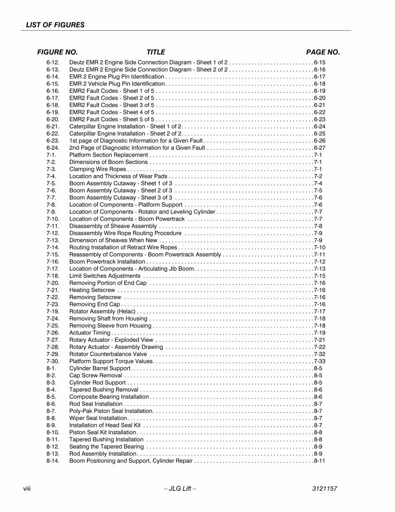
FIGURE NO. TITLE PAGE NO.1-1. Serial Number Locations. . . . . . . . . . . . . . . . . . . . . . . . . . . . . . . . . . . . . . . . . . . . . . . . . . . . . . . . .1-41-2. Operator Maintenance and Lubrication Diagram . . . . . . . . . . . . . . . . . . . . . . . . . . . . . . . . . . . . . .1-51-3. Torque Chart (SAE Fasteners - Sheet 1 of 7) . . . . . . . . . . . . . . . . . . . . . . . . . . . . . . . . . . . . . . . . .1-81-4. Torque Chart (SAE Fasteners - Sheet 2 of 7) . . . . . . . . . . . . . . . . . . . . . . . . . . . . . . . . . . . . . . . . .1-91-5. Torque Chart (SAE Fasteners - Sheet 3 of 7) . . . . . . . . . . . . . . . . . . . . . . . . . . . . . . . . . . . . . . . . .1-101-6. Torque Chart (SAE Fasteners - Sheet 4 of 7) . . . . . . . . . . . . . . . . . . . . . . . . . . . . . . . . . . . . . . . . .1-111-7. Torque Chart (METRIC Fasteners - Sheet 5 of 7). . . . . . . . . . . . . . . . . . . . . . . . . . . . . . . . . . . . . .1-121-8. Torque Chart (METRIC Fasteners - Sheet 6 of 7). . . . . . . . . . . . . . . . . . . . . . . . . . . . . . . . . . . . . .1-131-9. Torque Chart (METRIC Fasteners - Sheet 7 of 7). . . . . . . . . . . . . . . . . . . . . . . . . . . . . . . . . . . . . .1-142-1. Engine Operating Temperature Specifications - Deutz . . . . . . . . . . . . . . . . . . . . . . . . . . . . . . . . .2-112-2. Engine Operating Temperature Specifications - Caterpillar. . . . . . . . . . . . . . . . . . . . . . . . . . . . . .2-123-1. Chassis Service Notes - Sheet 1 of 2 . . . . . . . . . . . . . . . . . . . . . . . . . . . . . . . . . . . . . . . . . . . . . . .3-23-2. Chassis Service Notes - Sheet 2 of 2 . . . . . . . . . . . . . . . . . . . . . . . . . . . . . . . . . . . . . . . . . . . . . . .3-33-3. Chassis Components . . . . . . . . . . . . . . . . . . . . . . . . . . . . . . . . . . . . . . . . . . . . . . . . . . . . . . . . . . .3-43-4. Bottom Track Roller Assembly . . . . . . . . . . . . . . . . . . . . . . . . . . . . . . . . . . . . . . . . . . . . . . . . . . . .3-63-5. Carrier Track Roller Assembly. . . . . . . . . . . . . . . . . . . . . . . . . . . . . . . . . . . . . . . . . . . . . . . . . . . . .3-73-6. Hose Routing - Sheet 1 of 2 . . . . . . . . . . . . . . . . . . . . . . . . . . . . . . . . . . . . . . . . . . . . . . . . . . . . . .3-83-7. Hose Routing - Sheet 2 of 2 . . . . . . . . . . . . . . . . . . . . . . . . . . . . . . . . . . . . . . . . . . . . . . . . . . . . . .3-93-8. Track Chain Assembly . . . . . . . . . . . . . . . . . . . . . . . . . . . . . . . . . . . . . . . . . . . . . . . . . . . . . . . . . .3-113-9. Idler Assembly . . . . . . . . . . . . . . . . . . . . . . . . . . . . . . . . . . . . . . . . . . . . . . . . . . . . . . . . . . . . . . . . .3-123-10. Spring & Shock Assembly . . . . . . . . . . . . . . . . . . . . . . . . . . . . . . . . . . . . . . . . . . . . . . . . . . . . . . .3-133-11. Rotary Coupling Installation . . . . . . . . . . . . . . . . . . . . . . . . . . . . . . . . . . . . . . . . . . . . . . . . . . . . . .3-144-1. Correct Assembly of Conventional Duo-Cone Seals . . . . . . . . . . . . . . . . . . . . . . . . . . . . . . . . . . .4-14-2. Examples of incorrect assembly . . . . . . . . . . . . . . . . . . . . . . . . . . . . . . . . . . . . . . . . . . . . . . . . . . .4-35-1. Structure of Drive Motor . . . . . . . . . . . . . . . . . . . . . . . . . . . . . . . . . . . . . . . . . . . . . . . . . . . . . . . . .5-55-2. Structure of Swash Plate Type Axial Piston Motor . . . . . . . . . . . . . . . . . . . . . . . . . . . . . . . . . . . . .5-55-3. Structure of Shuttle Valve . . . . . . . . . . . . . . . . . . . . . . . . . . . . . . . . . . . . . . . . . . . . . . . . . . . . . . . .5-65-4. Shuttle Valve (Shuttle) . . . . . . . . . . . . . . . . . . . . . . . . . . . . . . . . . . . . . . . . . . . . . . . . . . . . . . . . . . .5-65-5. Structure of Relief Valve . . . . . . . . . . . . . . . . . . . . . . . . . . . . . . . . . . . . . . . . . . . . . . . . . . . . . . . . .5-75-6. Structure of Relief Valve . . . . . . . . . . . . . . . . . . . . . . . . . . . . . . . . . . . . . . . . . . . . . . . . . . . . . . . . .5-75-7. Structure of Low Pressure Relief Valve . . . . . . . . . . . . . . . . . . . . . . . . . . . . . . . . . . . . . . . . . . . . . .5-75-8. Structure of Two Speed Changeover System . . . . . . . . . . . . . . . . . . . . . . . . . . . . . . . . . . . . . . . .5-85-9. Structure of Two Speed Changeover System at High Speed . . . . . . . . . . . . . . . . . . . . . . . . . . . .5-85-10. Structure of Two Speed Changeover System at Low Speed. . . . . . . . . . . . . . . . . . . . . . . . . . . . .5-95-11. Parking Brake System. . . . . . . . . . . . . . . . . . . . . . . . . . . . . . . . . . . . . . . . . . . . . . . . . . . . . . . . . . .5-105-12. Position of Parking Brake Manual Release Ports . . . . . . . . . . . . . . . . . . . . . . . . . . . . . . . . . . . . . .5-115-13. Procedures for Manually Releasing Parking Brake (step 1). . . . . . . . . . . . . . . . . . . . . . . . . . . . . .5-125-14. Procedures for Manually Releasing Parking Brake (step 2). . . . . . . . . . . . . . . . . . . . . . . . . . . . . .5-125-15. Procedures for Manually Releasing Parking Brake (step 3). . . . . . . . . . . . . . . . . . . . . . . . . . . . . .5-125-16. Structure of Reduction Gear . . . . . . . . . . . . . . . . . . . . . . . . . . . . . . . . . . . . . . . . . . . . . . . . . . . . . .5-135-17. Direction of Rotation . . . . . . . . . . . . . . . . . . . . . . . . . . . . . . . . . . . . . . . . . . . . . . . . . . . . . . . . . . . .5-145-18. Oil level of hydraulic fluid at the initial stage. . . . . . . . . . . . . . . . . . . . . . . . . . . . . . . . . . . . . . . . . .5-165-19. Lubricant Change . . . . . . . . . . . . . . . . . . . . . . . . . . . . . . . . . . . . . . . . . . . . . . . . . . . . . . . . . . . . . .5-175-20. Inspection of oil leak, bolts and plugs . . . . . . . . . . . . . . . . . . . . . . . . . . . . . . . . . . . . . . . . . . . . . .5-205-21. Exploded View of Motor . . . . . . . . . . . . . . . . . . . . . . . . . . . . . . . . . . . . . . . . . . . . . . . . . . . . . . . . .5-395-22. Exploded View of Reduction Gear Assembly . . . . . . . . . . . . . . . . . . . . . . . . . . . . . . . . . . . . . . . . .5-406-1. Swing Torque Hub Adjustment . . . . . . . . . . . . . . . . . . . . . . . . . . . . . . . . . . . . . . . . . . . . . . . . . . . .6-16-2. Swing Bearing Bolt Feeler Gauge Check . . . . . . . . . . . . . . . . . . . . . . . . . . . . . . . . . . . . . . . . . . . .6-26-3. Swing Bearing Tolerance Measuring Point. . . . . . . . . . . . . . . . . . . . . . . . . . . . . . . . . . . . . . . . . . .6-26-4. Swing Bearing Tolerance Boom Placement . . . . . . . . . . . . . . . . . . . . . . . . . . . . . . . . . . . . . . . . . .6-36-5. Swing Bearing Torque Sequence . . . . . . . . . . . . . . . . . . . . . . . . . . . . . . . . . . . . . . . . . . . . . . . . . .6-46-6. Swing Brake Assembly (Mico) . . . . . . . . . . . . . . . . . . . . . . . . . . . . . . . . . . . . . . . . . . . . . . . . . . . .6-66-7. Deutz Engine Installation - Sheet 1 of 2 . . . . . . . . . . . . . . . . . . . . . . . . . . . . . . . . . . . . . . . . . . . . .6-96-8. Deutz Engine Installation - Sheet 2 of 2 . . . . . . . . . . . . . . . . . . . . . . . . . . . . . . . . . . . . . . . . . . . . .6-106-9. EMR 2 Engine Side Equipment. . . . . . . . . . . . . . . . . . . . . . . . . . . . . . . . . . . . . . . . . . . . . . . . . . . .6-126-10. Deutz EMR 2 Troubleshooting Flow Chart . . . . . . . . . . . . . . . . . . . . . . . . . . . . . . . . . . . . . . . . . . .6-136-11. Deutz EMR 2 Vehicle Side Connection Diagram . . . . . . . . . . . . . . . . . . . . . . . . . . . . . . . . . . . . . .6-14
viii – JLG Lift – 3121157
LIST OF FIGURES
FIGURE NO. TITLE PAGE NO.6-12. Deutz EMR 2 Engine Side Connection Diagram - Sheet 1 of 2 . . . . . . . . . . . . . . . . . . . . . . . . . . .6-156-13. Deutz EMR 2 Engine Side Connection Diagram - Sheet 2 of 2 . . . . . . . . . . . . . . . . . . . . . . . . . . .6-166-14. EMR 2 Engine Plug Pin Identification . . . . . . . . . . . . . . . . . . . . . . . . . . . . . . . . . . . . . . . . . . . . . . .6-176-15. EMR 2 Vehicle Plug Pin Identification . . . . . . . . . . . . . . . . . . . . . . . . . . . . . . . . . . . . . . . . . . . . . . .6-186-16. EMR2 Fault Codes - Sheet 1 of 5 . . . . . . . . . . . . . . . . . . . . . . . . . . . . . . . . . . . . . . . . . . . . . . . . . .6-196-17. EMR2 Fault Codes - Sheet 2 of 5 . . . . . . . . . . . . . . . . . . . . . . . . . . . . . . . . . . . . . . . . . . . . . . . . . .6-206-18. EMR2 Fault Codes - Sheet 3 of 5 . . . . . . . . . . . . . . . . . . . . . . . . . . . . . . . . . . . . . . . . . . . . . . . . . .6-216-19. EMR2 Fault Codes - Sheet 4 of 5 . . . . . . . . . . . . . . . . . . . . . . . . . . . . . . . . . . . . . . . . . . . . . . . . . .6-226-20. EMR2 Fault Codes - Sheet 5 of 5 . . . . . . . . . . . . . . . . . . . . . . . . . . . . . . . . . . . . . . . . . . . . . . . . . .6-236-21. Caterpillar Engine Installation - Sheet 1 of 2. . . . . . . . . . . . . . . . . . . . . . . . . . . . . . . . . . . . . . . . . .6-246-22. Caterpillar Engine Installation - Sheet 2 of 2. . . . . . . . . . . . . . . . . . . . . . . . . . . . . . . . . . . . . . . . . .6-256-23. 1st page of Diagnostic Information for a Given Fault . . . . . . . . . . . . . . . . . . . . . . . . . . . . . . . . . . .6-266-24. 2nd Page of Diagnostic Information for a Given Fault . . . . . . . . . . . . . . . . . . . . . . . . . . . . . . . . . .6-277-1. Platform Section Replacement . . . . . . . . . . . . . . . . . . . . . . . . . . . . . . . . . . . . . . . . . . . . . . . . . . . .7-17-2. Dimensions of Boom Sections . . . . . . . . . . . . . . . . . . . . . . . . . . . . . . . . . . . . . . . . . . . . . . . . . . . .7-17-3. Clamping Wire Ropes . . . . . . . . . . . . . . . . . . . . . . . . . . . . . . . . . . . . . . . . . . . . . . . . . . . . . . . . . . .7-17-4. Location and Thickness of Wear Pads . . . . . . . . . . . . . . . . . . . . . . . . . . . . . . . . . . . . . . . . . . . . . .7-27-5. Boom Assembly Cutaway - Sheet 1 of 3 . . . . . . . . . . . . . . . . . . . . . . . . . . . . . . . . . . . . . . . . . . . .7-47-6. Boom Assembly Cutaway - Sheet 2 of 3 . . . . . . . . . . . . . . . . . . . . . . . . . . . . . . . . . . . . . . . . . . . .7-57-7. Boom Assembly Cutaway - Sheet 3 of 3 . . . . . . . . . . . . . . . . . . . . . . . . . . . . . . . . . . . . . . . . . . . .7-67-8. Location of Components - Platform Support . . . . . . . . . . . . . . . . . . . . . . . . . . . . . . . . . . . . . . . . .7-67-9. Location of Components - Rotator and Leveling Cylinder . . . . . . . . . . . . . . . . . . . . . . . . . . . . . . .7-77-10. Location of Components - Boom Powertrack . . . . . . . . . . . . . . . . . . . . . . . . . . . . . . . . . . . . . . . .7-77-11. Disassembly of Sheave Assembly . . . . . . . . . . . . . . . . . . . . . . . . . . . . . . . . . . . . . . . . . . . . . . . . .7-87-12. Disassembly Wire Rope Routing Procedure . . . . . . . . . . . . . . . . . . . . . . . . . . . . . . . . . . . . . . . . .7-97-13. Dimension of Sheaves When New . . . . . . . . . . . . . . . . . . . . . . . . . . . . . . . . . . . . . . . . . . . . . . . . .7-97-14. Routing Installation of Retract Wire Ropes . . . . . . . . . . . . . . . . . . . . . . . . . . . . . . . . . . . . . . . . . . .7-107-15. Reassembly of Components - Boom Powertrack Assembly . . . . . . . . . . . . . . . . . . . . . . . . . . . . .7-117-16. Boom Powertrack Installation . . . . . . . . . . . . . . . . . . . . . . . . . . . . . . . . . . . . . . . . . . . . . . . . . . . . .7-127-17. Location of Components - Articulating Jib Boom. . . . . . . . . . . . . . . . . . . . . . . . . . . . . . . . . . . . . .7-137-18. Limit Switches Adjustments . . . . . . . . . . . . . . . . . . . . . . . . . . . . . . . . . . . . . . . . . . . . . . . . . . . . . .7-157-20. Removing Portion of End Cap . . . . . . . . . . . . . . . . . . . . . . . . . . . . . . . . . . . . . . . . . . . . . . . . . . . .7-167-21. Heating Setscrew . . . . . . . . . . . . . . . . . . . . . . . . . . . . . . . . . . . . . . . . . . . . . . . . . . . . . . . . . . . . . .7-167-22. Removing Setscrew . . . . . . . . . . . . . . . . . . . . . . . . . . . . . . . . . . . . . . . . . . . . . . . . . . . . . . . . . . . .7-167-23. Removing End Cap . . . . . . . . . . . . . . . . . . . . . . . . . . . . . . . . . . . . . . . . . . . . . . . . . . . . . . . . . . . . .7-167-19. Rotator Assembly (Helac) . . . . . . . . . . . . . . . . . . . . . . . . . . . . . . . . . . . . . . . . . . . . . . . . . . . . . . . .7-177-24. Removing Shaft from Housing . . . . . . . . . . . . . . . . . . . . . . . . . . . . . . . . . . . . . . . . . . . . . . . . . . . .7-187-25. Removing Sleeve from Housing . . . . . . . . . . . . . . . . . . . . . . . . . . . . . . . . . . . . . . . . . . . . . . . . . . .7-187-26. Actuator Timing . . . . . . . . . . . . . . . . . . . . . . . . . . . . . . . . . . . . . . . . . . . . . . . . . . . . . . . . . . . . . . . .7-197-27. Rotary Actuator - Exploded View . . . . . . . . . . . . . . . . . . . . . . . . . . . . . . . . . . . . . . . . . . . . . . . . . .7-217-28. Rotary Actuator - Assembly Drawing . . . . . . . . . . . . . . . . . . . . . . . . . . . . . . . . . . . . . . . . . . . . . . .7-227-29. Rotator Counterbalance Valve . . . . . . . . . . . . . . . . . . . . . . . . . . . . . . . . . . . . . . . . . . . . . . . . . . . .7-327-30. Platform Support Torque Values. . . . . . . . . . . . . . . . . . . . . . . . . . . . . . . . . . . . . . . . . . . . . . . . . . .7-338-1. Cylinder Barrel Support. . . . . . . . . . . . . . . . . . . . . . . . . . . . . . . . . . . . . . . . . . . . . . . . . . . . . . . . . .8-58-2. Cap Screw Removal . . . . . . . . . . . . . . . . . . . . . . . . . . . . . . . . . . . . . . . . . . . . . . . . . . . . . . . . . . . .8-58-3. Cylinder Rod Support . . . . . . . . . . . . . . . . . . . . . . . . . . . . . . . . . . . . . . . . . . . . . . . . . . . . . . . . . . .8-58-4. Tapered Bushing Removal . . . . . . . . . . . . . . . . . . . . . . . . . . . . . . . . . . . . . . . . . . . . . . . . . . . . . . .8-68-5. Composite Bearing Installation . . . . . . . . . . . . . . . . . . . . . . . . . . . . . . . . . . . . . . . . . . . . . . . . . . . .8-68-6. Rod Seal Installation . . . . . . . . . . . . . . . . . . . . . . . . . . . . . . . . . . . . . . . . . . . . . . . . . . . . . . . . . . . .8-78-7. Poly-Pak Piston Seal Installation. . . . . . . . . . . . . . . . . . . . . . . . . . . . . . . . . . . . . . . . . . . . . . . . . . .8-78-8. Wiper Seal Installation. . . . . . . . . . . . . . . . . . . . . . . . . . . . . . . . . . . . . . . . . . . . . . . . . . . . . . . . . . .8-78-9. Installation of Head Seal Kit . . . . . . . . . . . . . . . . . . . . . . . . . . . . . . . . . . . . . . . . . . . . . . . . . . . . . .8-78-10. Piston Seal Kit Installation . . . . . . . . . . . . . . . . . . . . . . . . . . . . . . . . . . . . . . . . . . . . . . . . . . . . . . . .8-88-11. Tapered Bushing Installation . . . . . . . . . . . . . . . . . . . . . . . . . . . . . . . . . . . . . . . . . . . . . . . . . . . . .8-88-12. Seating the Tapered Bearing . . . . . . . . . . . . . . . . . . . . . . . . . . . . . . . . . . . . . . . . . . . . . . . . . . . . .8-98-13. Rod Assembly Installation. . . . . . . . . . . . . . . . . . . . . . . . . . . . . . . . . . . . . . . . . . . . . . . . . . . . . . . .8-98-14. Boom Positioning and Support, Cylinder Repair . . . . . . . . . . . . . . . . . . . . . . . . . . . . . . . . . . . . . .8-11
3121157 – JLG Lift – ix
LIST OF FIGURES
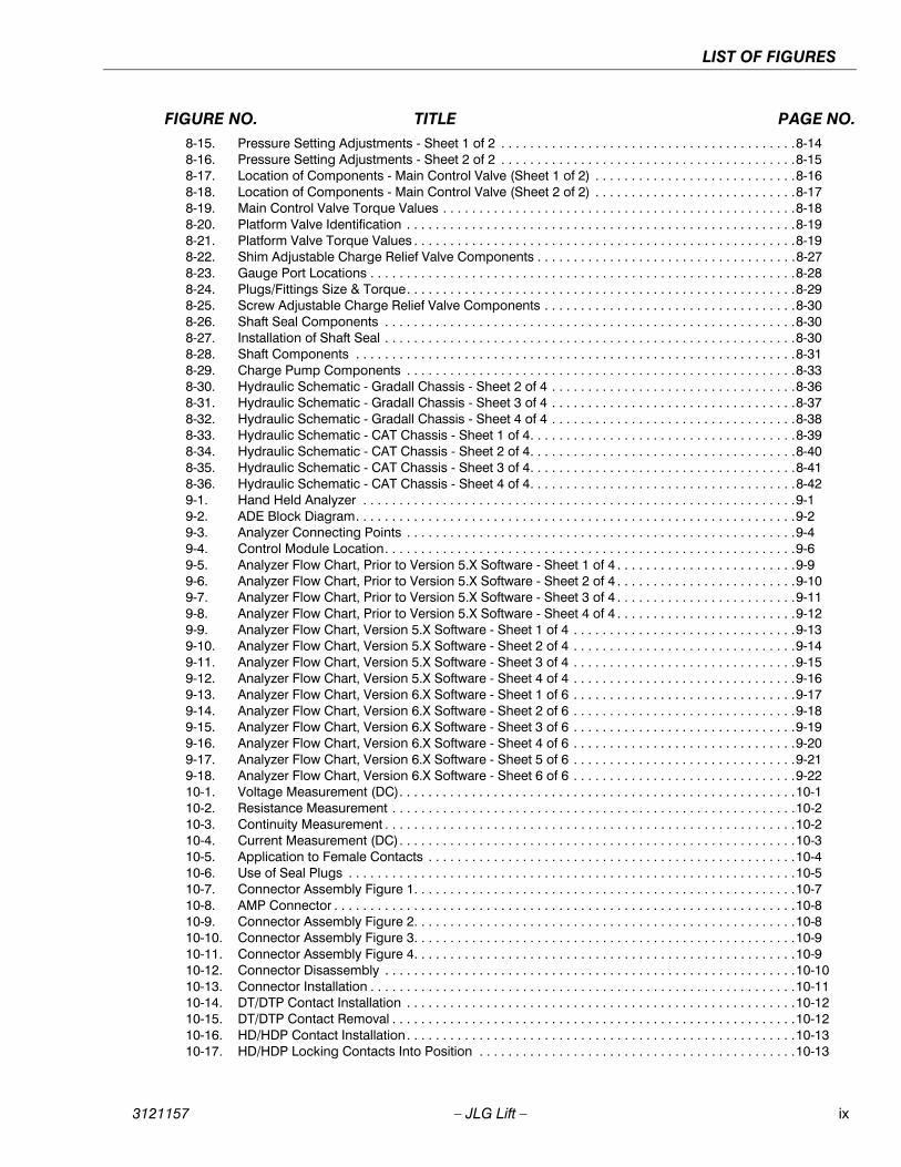
FIGURE NO. TITLE PAGE NO.8-15. Pressure Setting Adjustments - Sheet 1 of 2 . . . . . . . . . . . . . . . . . . . . . . . . . . . . . . . . . . . . . . . . .8-148-16. Pressure Setting Adjustments - Sheet 2 of 2 . . . . . . . . . . . . . . . . . . . . . . . . . . . . . . . . . . . . . . . . .8-158-17. Location of Components - Main Control Valve (Sheet 1 of 2) . . . . . . . . . . . . . . . . . . . . . . . . . . . .8-168-18. Location of Components - Main Control Valve (Sheet 2 of 2) . . . . . . . . . . . . . . . . . . . . . . . . . . . .8-178-19. Main Control Valve Torque Values . . . . . . . . . . . . . . . . . . . . . . . . . . . . . . . . . . . . . . . . . . . . . . . . .8-188-20. Platform Valve Identification . . . . . . . . . . . . . . . . . . . . . . . . . . . . . . . . . . . . . . . . . . . . . . . . . . . . . .8-198-21. Platform Valve Torque Values . . . . . . . . . . . . . . . . . . . . . . . . . . . . . . . . . . . . . . . . . . . . . . . . . . . . .8-198-22. Shim Adjustable Charge Relief Valve Components . . . . . . . . . . . . . . . . . . . . . . . . . . . . . . . . . . . .8-278-23. Gauge Port Locations . . . . . . . . . . . . . . . . . . . . . . . . . . . . . . . . . . . . . . . . . . . . . . . . . . . . . . . . . . .8-288-24. Plugs/Fittings Size & Torque. . . . . . . . . . . . . . . . . . . . . . . . . . . . . . . . . . . . . . . . . . . . . . . . . . . . . .8-298-25. Screw Adjustable Charge Relief Valve Components . . . . . . . . . . . . . . . . . . . . . . . . . . . . . . . . . . .8-308-26. Shaft Seal Components . . . . . . . . . . . . . . . . . . . . . . . . . . . . . . . . . . . . . . . . . . . . . . . . . . . . . . . . .8-308-27. Installation of Shaft Seal . . . . . . . . . . . . . . . . . . . . . . . . . . . . . . . . . . . . . . . . . . . . . . . . . . . . . . . . .8-308-28. Shaft Components . . . . . . . . . . . . . . . . . . . . . . . . . . . . . . . . . . . . . . . . . . . . . . . . . . . . . . . . . . . . .8-318-29. Charge Pump Components . . . . . . . . . . . . . . . . . . . . . . . . . . . . . . . . . . . . . . . . . . . . . . . . . . . . . .8-338-30. Hydraulic Schematic - Gradall Chassis - Sheet 2 of 4 . . . . . . . . . . . . . . . . . . . . . . . . . . . . . . . . . .8-368-31. Hydraulic Schematic - Gradall Chassis - Sheet 3 of 4 . . . . . . . . . . . . . . . . . . . . . . . . . . . . . . . . . .8-378-32. Hydraulic Schematic - Gradall Chassis - Sheet 4 of 4 . . . . . . . . . . . . . . . . . . . . . . . . . . . . . . . . . .8-388-33. Hydraulic Schematic - CAT Chassis - Sheet 1 of 4. . . . . . . . . . . . . . . . . . . . . . . . . . . . . . . . . . . . .8-398-34. Hydraulic Schematic - CAT Chassis - Sheet 2 of 4. . . . . . . . . . . . . . . . . . . . . . . . . . . . . . . . . . . . .8-408-35. Hydraulic Schematic - CAT Chassis - Sheet 3 of 4. . . . . . . . . . . . . . . . . . . . . . . . . . . . . . . . . . . . .8-418-36. Hydraulic Schematic - CAT Chassis - Sheet 4 of 4. . . . . . . . . . . . . . . . . . . . . . . . . . . . . . . . . . . . .8-429-1. Hand Held Analyzer . . . . . . . . . . . . . . . . . . . . . . . . . . . . . . . . . . . . . . . . . . . . . . . . . . . . . . . . . . . .9-19-2. ADE Block Diagram. . . . . . . . . . . . . . . . . . . . . . . . . . . . . . . . . . . . . . . . . . . . . . . . . . . . . . . . . . . . .9-29-3. Analyzer Connecting Points . . . . . . . . . . . . . . . . . . . . . . . . . . . . . . . . . . . . . . . . . . . . . . . . . . . . . .9-49-4. Control Module Location. . . . . . . . . . . . . . . . . . . . . . . . . . . . . . . . . . . . . . . . . . . . . . . . . . . . . . . . .9-69-5. Analyzer Flow Chart, Prior to Version 5.X Software - Sheet 1 of 4 . . . . . . . . . . . . . . . . . . . . . . . . .9-99-6. Analyzer Flow Chart, Prior to Version 5.X Software - Sheet 2 of 4 . . . . . . . . . . . . . . . . . . . . . . . . .9-109-7. Analyzer Flow Chart, Prior to Version 5.X Software - Sheet 3 of 4 . . . . . . . . . . . . . . . . . . . . . . . . .9-119-8. Analyzer Flow Chart, Prior to Version 5.X Software - Sheet 4 of 4 . . . . . . . . . . . . . . . . . . . . . . . . .9-129-9. Analyzer Flow Chart, Version 5.X Software - Sheet 1 of 4 . . . . . . . . . . . . . . . . . . . . . . . . . . . . . . .9-139-10. Analyzer Flow Chart, Version 5.X Software - Sheet 2 of 4 . . . . . . . . . . . . . . . . . . . . . . . . . . . . . . .9-149-11. Analyzer Flow Chart, Version 5.X Software - Sheet 3 of 4 . . . . . . . . . . . . . . . . . . . . . . . . . . . . . . .9-159-12. Analyzer Flow Chart, Version 5.X Software - Sheet 4 of 4 . . . . . . . . . . . . . . . . . . . . . . . . . . . . . . .9-169-13. Analyzer Flow Chart, Version 6.X Software - Sheet 1 of 6 . . . . . . . . . . . . . . . . . . . . . . . . . . . . . . .9-179-14. Analyzer Flow Chart, Version 6.X Software - Sheet 2 of 6 . . . . . . . . . . . . . . . . . . . . . . . . . . . . . . .9-189-15. Analyzer Flow Chart, Version 6.X Software - Sheet 3 of 6 . . . . . . . . . . . . . . . . . . . . . . . . . . . . . . .9-199-16. Analyzer Flow Chart, Version 6.X Software - Sheet 4 of 6 . . . . . . . . . . . . . . . . . . . . . . . . . . . . . . .9-209-17. Analyzer Flow Chart, Version 6.X Software - Sheet 5 of 6 . . . . . . . . . . . . . . . . . . . . . . . . . . . . . . .9-219-18. Analyzer Flow Chart, Version 6.X Software - Sheet 6 of 6 . . . . . . . . . . . . . . . . . . . . . . . . . . . . . . .9-2210-1. Voltage Measurement (DC). . . . . . . . . . . . . . . . . . . . . . . . . . . . . . . . . . . . . . . . . . . . . . . . . . . . . . .10-110-2. Resistance Measurement . . . . . . . . . . . . . . . . . . . . . . . . . . . . . . . . . . . . . . . . . . . . . . . . . . . . . . . .10-210-3. Continuity Measurement . . . . . . . . . . . . . . . . . . . . . . . . . . . . . . . . . . . . . . . . . . . . . . . . . . . . . . . . .10-210-4. Current Measurement (DC). . . . . . . . . . . . . . . . . . . . . . . . . . . . . . . . . . . . . . . . . . . . . . . . . . . . . . .10-310-5. Application to Female Contacts . . . . . . . . . . . . . . . . . . . . . . . . . . . . . . . . . . . . . . . . . . . . . . . . . . .10-410-6. Use of Seal Plugs . . . . . . . . . . . . . . . . . . . . . . . . . . . . . . . . . . . . . . . . . . . . . . . . . . . . . . . . . . . . . .10-510-7. Connector Assembly Figure 1. . . . . . . . . . . . . . . . . . . . . . . . . . . . . . . . . . . . . . . . . . . . . . . . . . . . .10-710-8. AMP Connector . . . . . . . . . . . . . . . . . . . . . . . . . . . . . . . . . . . . . . . . . . . . . . . . . . . . . . . . . . . . . . . .10-810-9. Connector Assembly Figure 2. . . . . . . . . . . . . . . . . . . . . . . . . . . . . . . . . . . . . . . . . . . . . . . . . . . . .10-810-10. Connector Assembly Figure 3. . . . . . . . . . . . . . . . . . . . . . . . . . . . . . . . . . . . . . . . . . . . . . . . . . . . .10-910-11. Connector Assembly Figure 4. . . . . . . . . . . . . . . . . . . . . . . . . . . . . . . . . . . . . . . . . . . . . . . . . . . . .10-910-12. Connector Disassembly . . . . . . . . . . . . . . . . . . . . . . . . . . . . . . . . . . . . . . . . . . . . . . . . . . . . . . . . .10-1010-13. Connector Installation . . . . . . . . . . . . . . . . . . . . . . . . . . . . . . . . . . . . . . . . . . . . . . . . . . . . . . . . . . .10-1110-14. DT/DTP Contact Installation . . . . . . . . . . . . . . . . . . . . . . . . . . . . . . . . . . . . . . . . . . . . . . . . . . . . . .10-1210-15. DT/DTP Contact Removal . . . . . . . . . . . . . . . . . . . . . . . . . . . . . . . . . . . . . . . . . . . . . . . . . . . . . . . .10-1210-16. HD/HDP Contact Installation. . . . . . . . . . . . . . . . . . . . . . . . . . . . . . . . . . . . . . . . . . . . . . . . . . . . . .10-1310-17. HD/HDP Locking Contacts Into Position . . . . . . . . . . . . . . . . . . . . . . . . . . . . . . . . . . . . . . . . . . . .10-13
x – JLG Lift – 3121157
LIST OF FIGURES
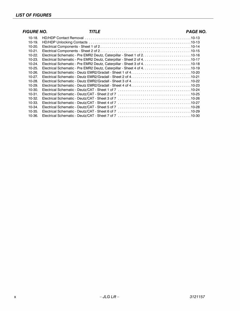
FIGURE NO. TITLE PAGE NO.10-18. HD/HDP Contact Removal . . . . . . . . . . . . . . . . . . . . . . . . . . . . . . . . . . . . . . . . . . . . . . . . . . . . . . .10-1310-19. HD/HDP Unlocking Contacts . . . . . . . . . . . . . . . . . . . . . . . . . . . . . . . . . . . . . . . . . . . . . . . . . . . . .10-1310-20. Electrical Components - Sheet 1 of 2 . . . . . . . . . . . . . . . . . . . . . . . . . . . . . . . . . . . . . . . . . . . . . . .10-1410-21. Electrical Components - Sheet 2 of 2 . . . . . . . . . . . . . . . . . . . . . . . . . . . . . . . . . . . . . . . . . . . . . . .10-1510-22. Electrical Schematic - Pre EMR2 Deutz, Caterpillar - Sheet 1 of 2. . . . . . . . . . . . . . . . . . . . . . . . .10-1610-23. Electrical Schematic - Pre EMR2 Deutz, Caterpillar - Sheet 2 of 4. . . . . . . . . . . . . . . . . . . . . . . . .10-1710-24. Electrical Schematic - Pre EMR2 Deutz, Caterpillar - Sheet 3 of 4. . . . . . . . . . . . . . . . . . . . . . . . .10-1810-25. Electrical Schematic - Pre EMR2 Deutz, Caterpillar - Sheet 4 of 4. . . . . . . . . . . . . . . . . . . . . . . . .10-1910-26. Electrical Schematic - Deutz EMR2/Gradall - Sheet 1 of 4 . . . . . . . . . . . . . . . . . . . . . . . . . . . . . . .10-2010-27. Electrical Schematic - Deutz EMR2/Gradall - Sheet 2 of 4 . . . . . . . . . . . . . . . . . . . . . . . . . . . . . . .10-2110-28. Electrical Schematic - Deutz EMR2/Gradall - Sheet 3 of 4 . . . . . . . . . . . . . . . . . . . . . . . . . . . . . . .10-2210-29. Electrical Schematic - Deutz EMR2/Gradall - Sheet 4 of 4 . . . . . . . . . . . . . . . . . . . . . . . . . . . . . . .10-2310-30. Electrical Schematic - Deutz/CAT - Sheet 1 of 7 . . . . . . . . . . . . . . . . . . . . . . . . . . . . . . . . . . . . . .10-2410-31. Electrical Schematic - Deutz/CAT - Sheet 2 of 7 . . . . . . . . . . . . . . . . . . . . . . . . . . . . . . . . . . . . . .10-2510-32. Electrical Schematic - Deutz/CAT - Sheet 3 of 7 . . . . . . . . . . . . . . . . . . . . . . . . . . . . . . . . . . . . . .10-2610-33. Electrical Schematic - Deutz/CAT - Sheet 4 of 7 . . . . . . . . . . . . . . . . . . . . . . . . . . . . . . . . . . . . . .10-2710-34. Electrical Schematic - Deutz/CAT - Sheet 5 of 7 . . . . . . . . . . . . . . . . . . . . . . . . . . . . . . . . . . . . . .10-2810-35. Electrical Schematic - Deutz/CAT - Sheet 6 of 7 . . . . . . . . . . . . . . . . . . . . . . . . . . . . . . . . . . . . . .10-2910-36. Electrical Schematic - Deutz/CAT - Sheet 7 of 7 . . . . . . . . . . . . . . . . . . . . . . . . . . . . . . . . . . . . . .10-30

3121157 – JLG Lift – xi
LIST OF TABLES
TABLE NO. TITLE PAGE NO.
1-1 Operating Specifications . . . . . . . . . . . . . . . . . . . . . . . . . . . . . . . . . . . . . . . . . . . . . . . . . . . . . . . . .1-11-2 Capacities . . . . . . . . . . . . . . . . . . . . . . . . . . . . . . . . . . . . . . . . . . . . . . . . . . . . . . . . . . . . . . . . . . . .1-11-3 Deutz F4M1011F/F4M2011 Specifications . . . . . . . . . . . . . . . . . . . . . . . . . . . . . . . . . . . . . . . . . . .1-11-4 Deutz D2011L04 Specifications . . . . . . . . . . . . . . . . . . . . . . . . . . . . . . . . . . . . . . . . . . . . . . . . . . .1-11-5 Caterpillar 3044C/Caterpillar 3.4 . . . . . . . . . . . . . . . . . . . . . . . . . . . . . . . . . . . . . . . . . . . . . . . . . . .1-21-6 Swing System . . . . . . . . . . . . . . . . . . . . . . . . . . . . . . . . . . . . . . . . . . . . . . . . . . . . . . . . . . . . . . . . .1-21-7 Auxiliary Power Pump . . . . . . . . . . . . . . . . . . . . . . . . . . . . . . . . . . . . . . . . . . . . . . . . . . . . . . . . . . .1-21-8 Hydraulic Filters. . . . . . . . . . . . . . . . . . . . . . . . . . . . . . . . . . . . . . . . . . . . . . . . . . . . . . . . . . . . . . . .1-21-9 Function Speeds . . . . . . . . . . . . . . . . . . . . . . . . . . . . . . . . . . . . . . . . . . . . . . . . . . . . . . . . . . . . . . .1-21-10 Dimensions . . . . . . . . . . . . . . . . . . . . . . . . . . . . . . . . . . . . . . . . . . . . . . . . . . . . . . . . . . . . . . . . . . .1-31-11 Torque Requirements . . . . . . . . . . . . . . . . . . . . . . . . . . . . . . . . . . . . . . . . . . . . . . . . . . . . . . . . . . .1-31-12 Pressure Settings . . . . . . . . . . . . . . . . . . . . . . . . . . . . . . . . . . . . . . . . . . . . . . . . . . . . . . . . . . . . . .1-31-13 Cylinder Specifications . . . . . . . . . . . . . . . . . . . . . . . . . . . . . . . . . . . . . . . . . . . . . . . . . . . . . . . . . .1-31-14 Major Component Weights . . . . . . . . . . . . . . . . . . . . . . . . . . . . . . . . . . . . . . . . . . . . . . . . . . . . . . .1-31-15 Hydraulic Oil . . . . . . . . . . . . . . . . . . . . . . . . . . . . . . . . . . . . . . . . . . . . . . . . . . . . . . . . . . . . . . . . . .1-41-16 Mobilfluid 424 Specs. . . . . . . . . . . . . . . . . . . . . . . . . . . . . . . . . . . . . . . . . . . . . . . . . . . . . . . . . . . .1-41-17 Mobil DTE 13M Specs. . . . . . . . . . . . . . . . . . . . . . . . . . . . . . . . . . . . . . . . . . . . . . . . . . . . . . . . . . .1-41-18 Lubrication Specifications . . . . . . . . . . . . . . . . . . . . . . . . . . . . . . . . . . . . . . . . . . . . . . . . . . . . . . . .1-52-1 Inspection and Maintenance. . . . . . . . . . . . . . . . . . . . . . . . . . . . . . . . . . . . . . . . . . . . . . . . . . . . . .2-22-2 Cylinder Drift . . . . . . . . . . . . . . . . . . . . . . . . . . . . . . . . . . . . . . . . . . . . . . . . . . . . . . . . . . . . . . . . . .2-52-3 Inspection and Preventive Maintenance Schedule. . . . . . . . . . . . . . . . . . . . . . . . . . . . . . . . . . . . .2-74-1 Duo-Cone Required Tools - Installation . . . . . . . . . . . . . . . . . . . . . . . . . . . . . . . . . . . . . . . . . . . . .4-14-2 Track Carrier Roller Required Tools - Removal . . . . . . . . . . . . . . . . . . . . . . . . . . . . . . . . . . . . . . .4-84-3 Track Carrier Roller Required Tools - Installation . . . . . . . . . . . . . . . . . . . . . . . . . . . . . . . . . . . . . .4-84-4 Track Roller Required Tools - Removal . . . . . . . . . . . . . . . . . . . . . . . . . . . . . . . . . . . . . . . . . . . . .4-94-5 Track Roller Required Tools - Installation . . . . . . . . . . . . . . . . . . . . . . . . . . . . . . . . . . . . . . . . . . . .4-104-6 Track Required Tools - Separation . . . . . . . . . . . . . . . . . . . . . . . . . . . . . . . . . . . . . . . . . . . . . . . . .4-114-7 Track Required Tools - Connection . . . . . . . . . . . . . . . . . . . . . . . . . . . . . . . . . . . . . . . . . . . . . . . .4-124-8 Front Idler & Recoil Spring Required Tools - Remove . . . . . . . . . . . . . . . . . . . . . . . . . . . . . . . . . .4-144-9 Track Required Tools - Connection . . . . . . . . . . . . . . . . . . . . . . . . . . . . . . . . . . . . . . . . . . . . . . . .4-154-10 Recoil Spring Required Tools - Assembly . . . . . . . . . . . . . . . . . . . . . . . . . . . . . . . . . . . . . . . . . . .4-184-11 Front Idler & Recoil Required Tools - Installation . . . . . . . . . . . . . . . . . . . . . . . . . . . . . . . . . . . . . .4-204-12 Track Adjuster Required Tools - Installation . . . . . . . . . . . . . . . . . . . . . . . . . . . . . . . . . . . . . . . . . .4-224-13 Sprocket Required Tools - Removal . . . . . . . . . . . . . . . . . . . . . . . . . . . . . . . . . . . . . . . . . . . . . . . .4-244-14 Sprocket Required Tools - Installation . . . . . . . . . . . . . . . . . . . . . . . . . . . . . . . . . . . . . . . . . . . . . .4-244-15 Final Drive Required Tools - Removal. . . . . . . . . . . . . . . . . . . . . . . . . . . . . . . . . . . . . . . . . . . . . . .4-254-16 Final Drive Required Tools - Installation . . . . . . . . . . . . . . . . . . . . . . . . . . . . . . . . . . . . . . . . . . . . .4-265-1 List of Standard Tools . . . . . . . . . . . . . . . . . . . . . . . . . . . . . . . . . . . . . . . . . . . . . . . . . . . . . . . . . . .5-265-2 List of Special Purpose Tools . . . . . . . . . . . . . . . . . . . . . . . . . . . . . . . . . . . . . . . . . . . . . . . . . . . . .5-275-3 List of Subsidiary Material . . . . . . . . . . . . . . . . . . . . . . . . . . . . . . . . . . . . . . . . . . . . . . . . . . . . . . . .5-365-4 List of Tightening Torque . . . . . . . . . . . . . . . . . . . . . . . . . . . . . . . . . . . . . . . . . . . . . . . . . . . . . . . .5-366-1 J1939 Diagnostic Lamp Configuration . . . . . . . . . . . . . . . . . . . . . . . . . . . . . . . . . . . . . . . . . . . . . .6-308-1 Cylinder Head and Tapered Bushing Torque Specifications. . . . . . . . . . . . . . . . . . . . . . . . . . . . .8-98-2 Holding Valve Torque Specifications . . . . . . . . . . . . . . . . . . . . . . . . . . . . . . . . . . . . . . . . . . . . . . .8-108-3 Hydraulic Pump Bolt Torque Chart . . . . . . . . . . . . . . . . . . . . . . . . . . . . . . . . . . . . . . . . . . . . . . . . .8-258-4 Recommended Gauge Size . . . . . . . . . . . . . . . . . . . . . . . . . . . . . . . . . . . . . . . . . . . . . . . . . . . . . .8-269-1 Personality Ranges/Defaults . . . . . . . . . . . . . . . . . . . . . . . . . . . . . . . . . . . . . . . . . . . . . . . . . . . . . .9-239-2 Help Fault Codes, Displayed Faults, and Descriptions . . . . . . . . . . . . . . . . . . . . . . . . . . . . . . . . .9-279-3 Machine Configuration Programming Information Prior to Software Version P5.3 . . . . . . . . . . . .9-389-4 Machine Configuration Programming Information Software Version P5.3 to P6.1 . . . . . . . . . . . .9-429-5 Machine Configuration Programming Information Software Version P6.1 to Present. . . . . . . . . .9-479-6 Fault Code Listing . . . . . . . . . . . . . . . . . . . . . . . . . . . . . . . . . . . . . . . . . . . . . . . . . . . . . . . . . . . . . .9-579-7 Adjustments - Personality Descriptions . . . . . . . . . . . . . . . . . . . . . . . . . . . . . . . . . . . . . . . . . . . . .9-649-8 Diagnostic Menu Descriptions . . . . . . . . . . . . . . . . . . . . . . . . . . . . . . . . . . . . . . . . . . . . . . . . . . . .9-67

This Page Intentionally Blank.
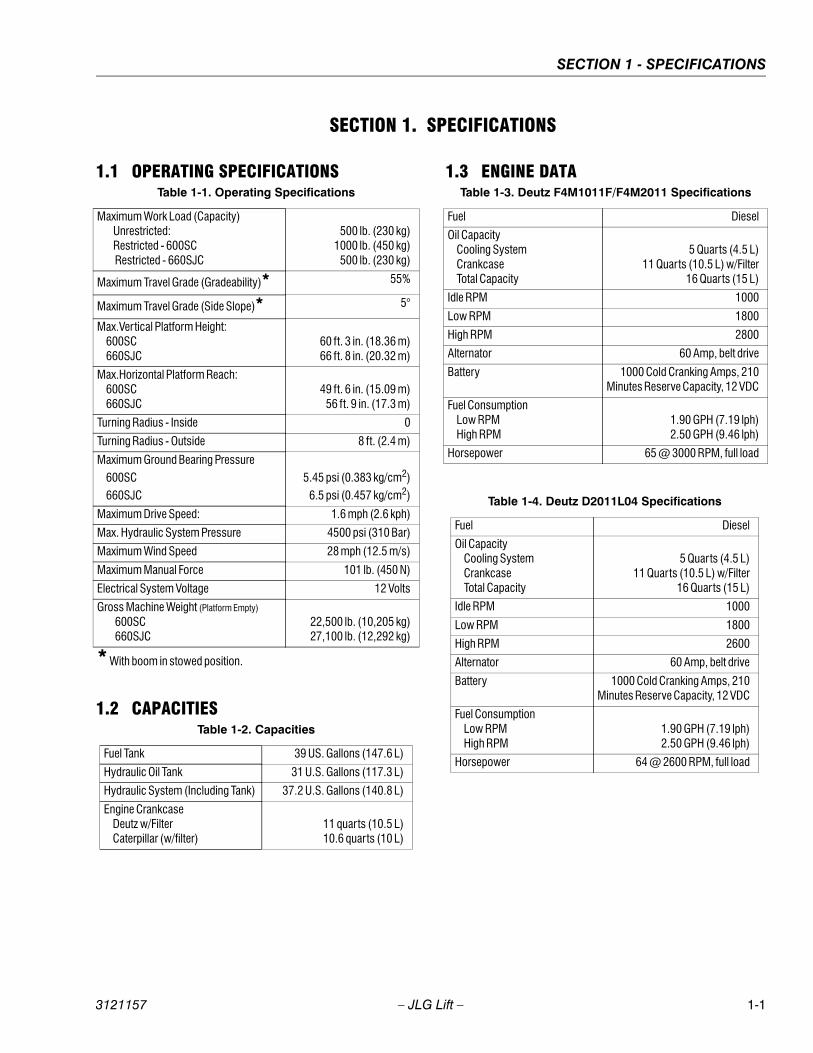
SECTION 1 - SPECIFICATIONS
3121157 – JLG Lift – 1-1
SECTION 1. SPECIFICATIONS
1.1 OPERATING SPECIFICATIONS
1.2 CAPACITIES
1.3 ENGINE DATA
Table 1-1. Operating Specifications
Maximum Work Load (Capacity) Unrestricted: Restricted - 600SC Restricted - 660SJC
500 lb. (230 kg)1000 lb. (450 kg)
500 lb. (230 kg)
Maximum Travel Grade (Gradeability)* 55%
Maximum Travel Grade (Side Slope)* 5°
Max.Vertical Platform Height: 600SC 660SJC
60 ft. 3 in. (18.36 m)66 ft. 8 in. (20.32 m)
Max.Horizontal Platform Reach: 600SC 660SJC
49 ft. 6 in. (15.09 m)56 ft. 9 in. (17.3 m)
Turning Radius - Inside 0
Turning Radius - Outside 8 ft. (2.4 m)
Maximum Ground Bearing Pressure 600SC
660SJC 5.45 psi (0.383 kg/cm2)
6.5 psi (0.457 kg/cm2)
Maximum Drive Speed: 1.6 mph (2.6 kph)
Max. Hydraulic System Pressure 4500 psi (310 Bar)
Maximum Wind Speed 28 mph (12.5 m/s)
Maximum Manual Force 101 lb. (450 N)
Electrical System Voltage 12 Volts
Gross Machine Weight (Platform Empty)
600SC 660SJC
22,500 lb. (10,205 kg)27,100 lb. (12,292 kg)
* With boom in stowed position.
Table 1-2. Capacities
Fuel Tank 39 US. Gallons (147.6 L)
Hydraulic Oil Tank 31 U.S. Gallons (117.3 L)
Hydraulic System (Including Tank) 37.2 U.S. Gallons (140.8 L)
Engine Crankcase Deutz w/Filter Caterpillar (w/filter)
11 quarts (10.5 L)10.6 quarts (10 L)
Table 1-3. Deutz F4M1011F/F4M2011 Specifications
Fuel Diesel
Oil Capacity Cooling System Crankcase Total Capacity
5 Quarts (4.5 L)11 Quarts (10.5 L) w/Filter
16 Quarts (15 L)
Idle RPM 1000
Low RPM 1800
High RPM 2800
Alternator 60 Amp, belt drive
Battery 1000 Cold Cranking Amps, 210Minutes Reserve Capacity, 12 VDC
Fuel Consumption Low RPM High RPM
1.90 GPH (7.19 lph)2.50 GPH (9.46 lph)
Horsepower 65 @ 3000 RPM, full load
Table 1-4. Deutz D2011L04 Specifications
Fuel Diesel
Oil Capacity Cooling System Crankcase Total Capacity
5 Quarts (4.5 L)11 Quarts (10.5 L) w/Filter
16 Quarts (15 L)
Idle RPM 1000
Low RPM 1800
High RPM 2600
Alternator 60 Amp, belt drive
Battery 1000 Cold Cranking Amps, 210Minutes Reserve Capacity, 12 VDC
Fuel Consumption Low RPM High RPM
1.90 GPH (7.19 lph)2.50 GPH (9.46 lph)
Horsepower 64 @ 2600 RPM, full load
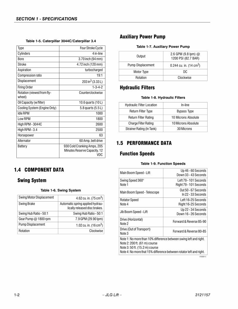
SECTION 1 - SPECIFICATIONS
1-2 – JLG Lift – 3121157
1.4 COMPONENT DATA
Swing System
Auxiliary Power Pump
Hydraulic Filters
1.5 PERFORMANCE DATA
Function Speeds
Table 1-5. Caterpillar 3044C/Caterpillar 3.4
Type Four Stroke Cycle
Cylinders 4 in-line
Bore 3.70 inch (94 mm)
Stroke 4.72 inch (120 mm)
Aspiration turbocharged
Compression ratio 19:1
Displacement 203 in3 (3.33 L)
Firing Order 1-3-4-2
Rotation (viewed from fly-wheel)
Counterclockwise
Oil Capacity (w/filter) 10.6 quarts (10 L)
Cooling System (Engine Only) 5.8 quarts (5.5 L)
Idle RPM 1000
Low RPM 1800
High RPM - 3044C 2600
High RPM - 3.4 2500
Horsepower 63
Alternator 60 Amp, belt drive
Battery 930 Cold Cranking Amps, 205Minutes Reserve Capacity, 12
VDC
Table 1-6. Swing System
Swing Motor Displacement 4.62 cu. in. (75 cm3)
Swing Brake Automatic spring applied hydrau-lically released disc brakes.
Swing Hub Ratio - 50:1 Swing Hub Ratio - 50:1
Gear Pump @ 1800 rpm 7.9 GPM (29.90 lpm)
Pump Displacement 1.02 cu. in. (16 cm3)
Rotation Clockwise
Table 1-7. Auxiliary Power Pump
Output2.6 GPM (9.8 lpm) @1200 PSI (82.7 BAR)
Pump Displacement 0.244 cu. in. (14 cm3)
Motor Type DC
Rotation Clockwise
Table 1-8. Hydraulic Filters
Hydraulic Filter Location In-line
Return Filter Type Bypass Type
Return Filter Rating 10 Microns Absolute
Charge Filter Rating 10 Microns Absolute
Strainer Rating (In Tank) 30 Microns
Table 1-9. Function Speeds
Main Boom Speed - LiftUp 46 - 60 Seconds
Down 33 - 43 Seconds
Swing Speed 360° Note 1
Left 79 - 101 SecondsRight 79 - 101 Seconds
Main Boom Speed - TelescopeOut 50 - 67 Seconds
In 22 - 33 Seconds
Rotator SpeedNote 4
Left 16-25 SecondsRight 16-25 Seconds
Jib Boom Speed - LiftUp 22 - 34 Seconds
Down 16 - 26 Seconds
Drive (Horizontal)Note 2
Forward & Reverse 85-90
Drive (Out of Transport)Note 3
Forward & Reverse 80-85
Note 1: No more than 10% difference between swing left and right.Note 2: 200 ft. (61 m) courseNote 3: 50 ft. (15.2 m) courseNote 4: No more that 15% difference between rotator left and right.
4150501-E
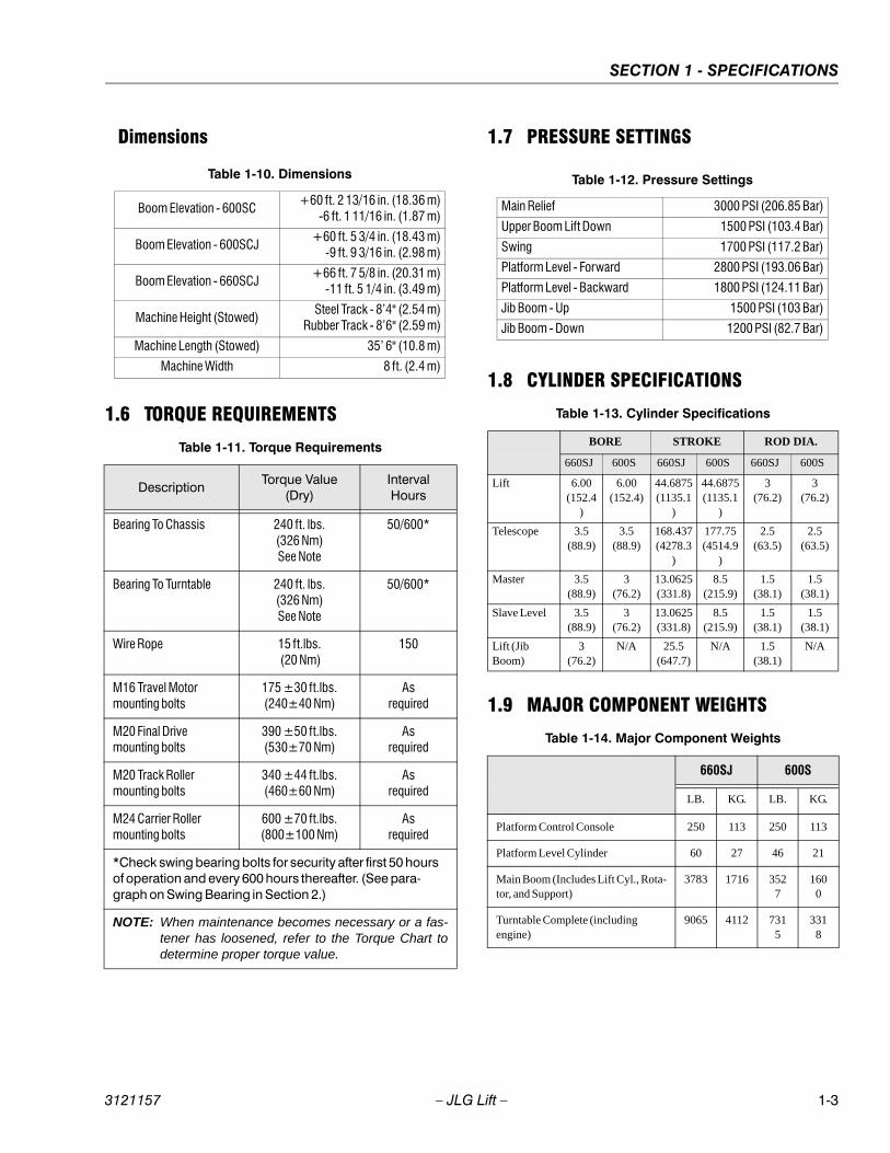
SECTION 1 - SPECIFICATIONS
3121157 – JLG Lift – 1-3
Dimensions
1.6 TORQUE REQUIREMENTS
1.7 PRESSURE SETTINGS
1.8 CYLINDER SPECIFICATIONS
1.9 MAJOR COMPONENT WEIGHTS
Table 1-11. Torque Requirements
DescriptionTorque Value
(Dry)Interval Hours
Bearing To Chassis 240 ft. lbs.(326 Nm)See Note
50/600*
Bearing To Turntable 240 ft. lbs.(326 Nm)See Note
50/600*
Wire Rope 15 ft.lbs. (20 Nm)
150
M16 Travel Motor mounting bolts
175 ±30 ft.lbs.(240±40 Nm)
Asrequired
M20 Final Drivemounting bolts
390 ±50 ft.lbs.(530±70 Nm)
Asrequired
M20 Track Rollermounting bolts
340 ±44 ft.lbs.(460±60 Nm)
Asrequired
M24 Carrier Rollermounting bolts
600 ±70 ft.lbs.(800±100 Nm)
Asrequired
*Check swing bearing bolts for security after first 50 hours of operation and every 600 hours thereafter. (See para-graph on Swing Bearing in Section 2.)
NOTE: When maintenance becomes necessary or a fas-tener has loosened, refer to the Torque Chart todetermine proper torque value.
Table 1-10. Dimensions
Boom Elevation - 600SC +60 ft. 2 13/16 in. (18.36 m)
-6 ft. 1 11/16 in. (1.87 m)
Boom Elevation - 600SCJ+60 ft. 5 3/4 in. (18.43 m)
-9 ft. 9 3/16 in. (2.98 m)
Boom Elevation - 660SCJ+66 ft. 7 5/8 in. (20.31 m)
-11 ft. 5 1/4 in. (3.49 m)
Machine Height (Stowed)Steel Track - 8’4" (2.54 m)
Rubber Track - 8’6" (2.59 m)
Machine Length (Stowed) 35’ 6" (10.8 m)
Machine Width 8 ft. (2.4 m)
Table 1-13. Cylinder Specifications
BORE STROKE ROD DIA.
660SJ 600S 660SJ 600S 660SJ 600S
Lift 6.00(152.4
)
6.00(152.4)
44.6875(1135.1
)
44.6875(1135.1
)
3(76.2)
3(76.2)
Telescope 3.5(88.9)
3.5(88.9)
168.437(4278.3
)
177.75(4514.9
)
2.5(63.5)
2.5(63.5)
Master 3.5(88.9)
3(76.2)
13.0625(331.8)
8.5(215.9)
1.5(38.1)
1.5(38.1)
Slave Level 3.5(88.9)
3(76.2)
13.0625(331.8)
8.5(215.9)
1.5(38.1)
1.5(38.1)
Lift (Jib Boom)
3(76.2)
N/A 25.5(647.7)
N/A 1.5(38.1)
N/A
Table 1-14. Major Component Weights
660SJ 600S
LB. KG. LB. KG.
Platform Control Console 250 113 250 113
Platform Level Cylinder 60 27 46 21
Main Boom (Includes Lift Cyl., Rota-tor, and Support)
3783 1716 3527
1600
Turntable Complete (including engine)
9065 4112 7315
3318
Table 1-12. Pressure Settings
Main Relief 3000 PSI (206.85 Bar)
Upper Boom Lift Down 1500 PSI (103.4 Bar)
Swing 1700 PSI (117.2 Bar)
Platform Level - Forward 2800 PSI (193.06 Bar)
Platform Level - Backward 1800 PSI (124.11 Bar)
Jib Boom - Up 1500 PSI (103 Bar)
Jib Boom - Down 1200 PSI (82.7 Bar)
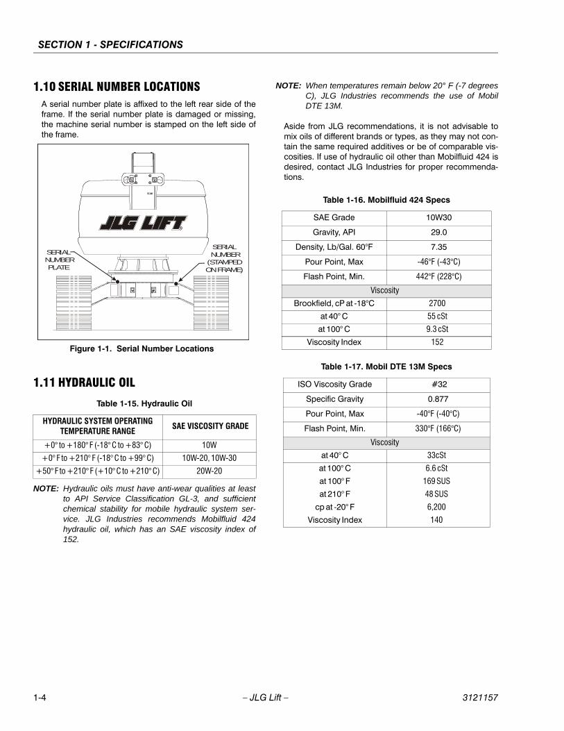
SECTION 1 - SPECIFICATIONS
1-4 – JLG Lift – 3121157
1.10 SERIAL NUMBER LOCATIONSA serial number plate is affixed to the left rear side of theframe. If the serial number plate is damaged or missing,the machine serial number is stamped on the left side ofthe frame.
1.11 HYDRAULIC OIL
NOTE: Hydraulic oils must have anti-wear qualities at leastto API Service Classification GL-3, and sufficientchemical stability for mobile hydraulic system ser-vice. JLG Industries recommends Mobilfluid 424hydraulic oil, which has an SAE viscosity index of152.
NOTE: When temperatures remain below 20° F (-7 degreesC), JLG Industries recommends the use of MobilDTE 13M.
Aside from JLG recommendations, it is not advisable tomix oils of different brands or types, as they may not con-tain the same required additives or be of comparable vis-cosities. If use of hydraulic oil other than Mobilfluid 424 isdesired, contact JLG Industries for proper recommenda-tions.
Table 1-15. Hydraulic Oil
HYDRAULIC SYSTEM OPERATING TEMPERATURE RANGE
SAE VISCOSITY GRADE
+0° to +180° F (-18° C to +83° C) 10W
+0° F to +210° F (-18° C to +99° C) 10W-20, 10W-30
+50° F to +210° F (+10° C to +210° C) 20W-20
SERIAL NUMBER
PLATE
SERIAL NUMBER(STAMPED ON FRAME)
Figure 1-1. Serial Number Locations
Table 1-16. Mobilfluid 424 Specs
SAE Grade 10W30
Gravity, API 29.0
Density, Lb/Gal. 60°F 7.35
Pour Point, Max -46°F (-43°C)
Flash Point, Min. 442°F (228°C)
Viscosity
Brookfield, cP at -18°C 2700
at 40° C 55 cSt
at 100° C 9.3 cSt
Viscosity Index 152
Table 1-17. Mobil DTE 13M Specs
ISO Viscosity Grade #32
Specific Gravity 0.877
Pour Point, Max -40°F (-40°C)
Flash Point, Min. 330°F (166°C)
Viscosity
at 40° C 33cSt
at 100° C 6.6 cSt
at 100° F 169 SUS
at 210° F 48 SUS
cp at -20° F 6,200
Viscosity Index 140
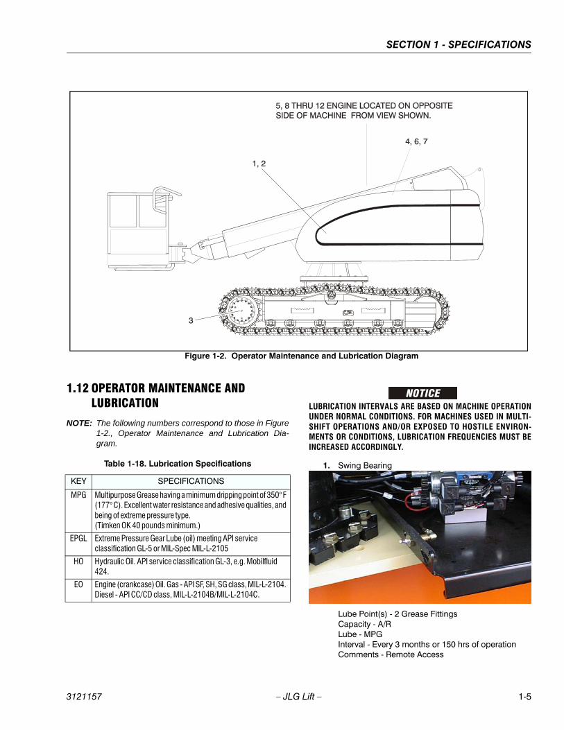
SECTION 1 - SPECIFICATIONS
3121157 – JLG Lift – 1-5
1.12 OPERATOR MAINTENANCE AND LUBRICATION
NOTE: The following numbers correspond to those in Figure1-2., Operator Maintenance and Lubrication Dia-gram.
LUBRICATION INTERVALS ARE BASED ON MACHINE OPERATIONUNDER NORMAL CONDITIONS. FOR MACHINES USED IN MULTI-SHIFT OPERATIONS AND/OR EXPOSED TO HOSTILE ENVIRON-MENTS OR CONDITIONS, LUBRICATION FREQUENCIES MUST BEINCREASED ACCORDINGLY.
1. Swing Bearing
Lube Point(s) - 2 Grease FittingsCapacity - A/RLube - MPGInterval - Every 3 months or 150 hrs of operationComments - Remote Access
Figure 1-2. Operator Maintenance and Lubrication Diagram
Table 1-18. Lubrication Specifications
KEY SPECIFICATIONS
MPG Multipurpose Grease having a minimum dripping point of 350° F (177° C). Excellent water resistance and adhesive qualities, and being of extreme pressure type. (Timken OK 40 pounds minimum.)
EPGL Extreme Pressure Gear Lube (oil) meeting API service classification GL-5 or MIL-Spec MIL-L-2105
HO Hydraulic Oil. API service classification GL-3, e.g. Mobilfluid 424.
EO Engine (crankcase) Oil. Gas - API SF, SH, SG class, MIL-L-2104. Diesel - API CC/CD class, MIL-L-2104B/MIL-L-2104C.

SECTION 1 - SPECIFICATIONS
1-6 – JLG Lift – 3121157
2. Swing Drive Hub
Lube Point(s) - Level/Fill PlugCapacity - 17 oz. (1/2 Full)Lube - EPGLInterval - Check level every 3 months or 150 hrs ofoperation; change every 2 years or 1200 hours ofoperation
3. Final Drive Hub
Lube Point(s) - Level/Fill PlugCapacity - 2.1 gal.(7.9 L); 1/2 FullLube - EPGLInterval - Check level every 3 months or 150 hrs ofoperation; change every 2 years or 1200 hours ofoperation
4. Hydraulic Return Filter
Interval - Change after first 50 hrs. and every 6months or 300 hrs. thereafter or as indicated byCondition Indicator.
5. Hydraulic Charge Filter
Interval - Change after first 50 hrs. and every 6months or 300 hrs. thereafter or as indicated byCondition Indicator.
6. Hydraulic Tank
Lube Point(s) - Fill CapCapacity - 30.6 gal. Tank; 32.7 gal. SystemLube - HOInterval - Check Level daily; Change every 2 years or1200 hours of operation.
NORMAL OPERATINGRANGE WITH BOOMIN STOWED POSITION
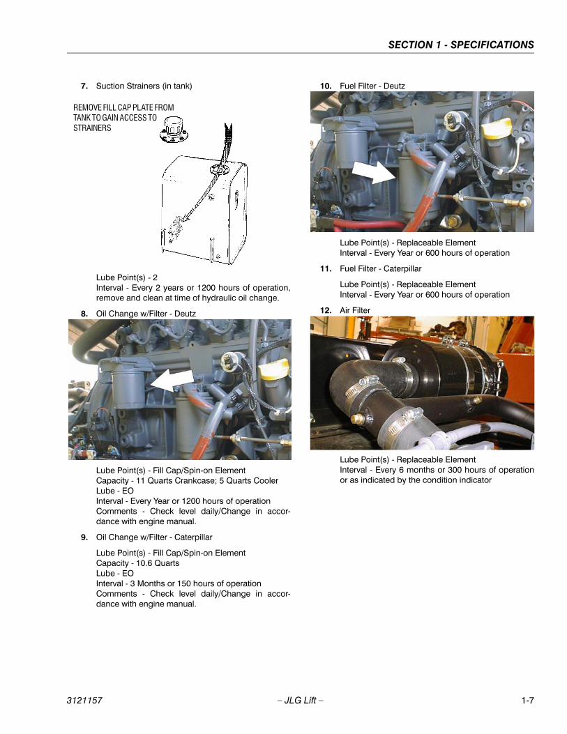
SECTION 1 - SPECIFICATIONS
3121157 – JLG Lift – 1-7
7. Suction Strainers (in tank)
Lube Point(s) - 2Interval - Every 2 years or 1200 hours of operation,remove and clean at time of hydraulic oil change.
8. Oil Change w/Filter - Deutz
Lube Point(s) - Fill Cap/Spin-on ElementCapacity - 11 Quarts Crankcase; 5 Quarts CoolerLube - EOInterval - Every Year or 1200 hours of operationComments - Check level daily/Change in accor-dance with engine manual.
9. Oil Change w/Filter - Caterpillar
Lube Point(s) - Fill Cap/Spin-on ElementCapacity - 10.6 QuartsLube - EOInterval - 3 Months or 150 hours of operationComments - Check level daily/Change in accor-dance with engine manual.
10. Fuel Filter - Deutz
Lube Point(s) - Replaceable ElementInterval - Every Year or 600 hours of operation
11. Fuel Filter - Caterpillar
Lube Point(s) - Replaceable ElementInterval - Every Year or 600 hours of operation
12. Air Filter
Lube Point(s) - Replaceable ElementInterval - Every 6 months or 300 hours of operationor as indicated by the condition indicator
REMOVE FILL CAP PLATE FROM TANK TO GAIN ACCESS TO STRAINERS
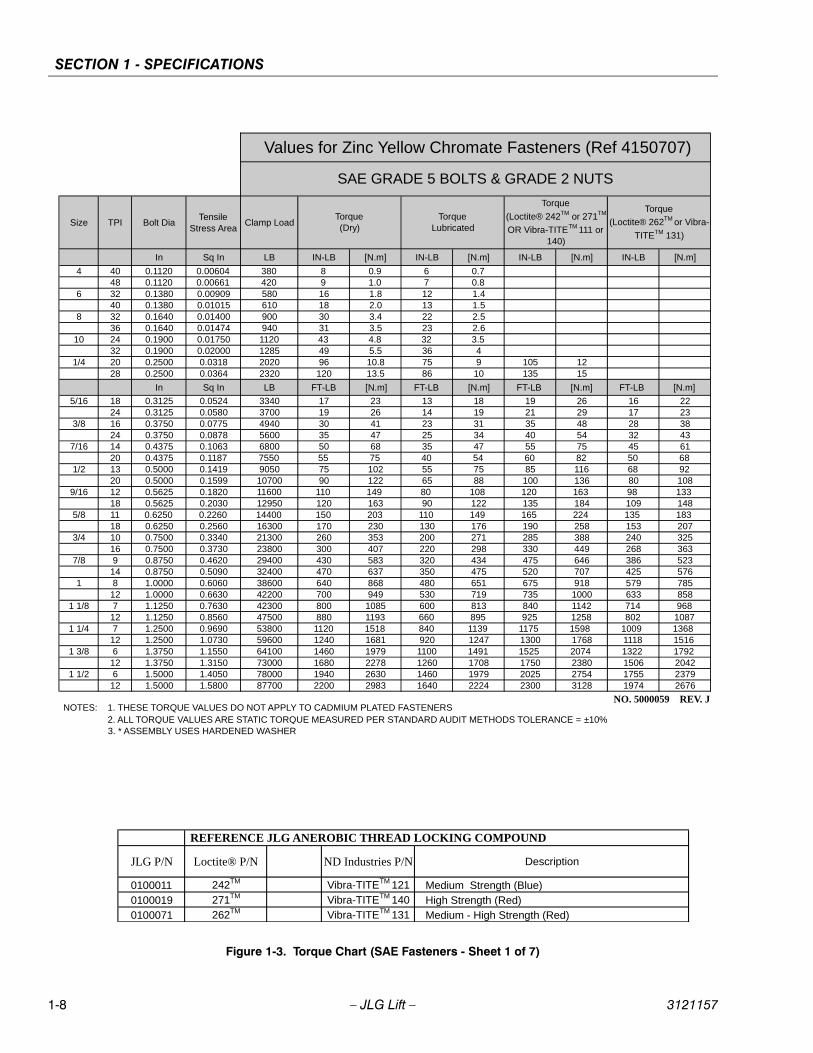
SECTION 1 - SPECIFICATIONS
1-8 – JLG Lift – 3121157
Figure 1-3. Torque Chart (SAE Fasteners - Sheet 1 of 7)
REFERENCE JLG ANEROBIC THREAD LOCKING COMPOUND
JLG P/N Loctite® P/N ND Industries P/N Description
0100011 242TM Vibra-TITETM 121 Medium Strength (Blue) 0100019 271TM Vibra-TITETM 140 High Strength (Red)0100071 262TM Vibra-TITETM 131 Medium - High Strength (Red)
Size TPI Bolt DiaTensile
Stress AreaClamp Load
In Sq In LB IN-LB [N.m] IN-LB [N.m] IN-LB [N.m] IN-LB [N.m]
4 40 0.1120 0.00604 380 8 0.9 6 0.748 0.1120 0.00661 420 9 1.0 7 0.8
6 32 0.1380 0.00909 580 16 1.8 12 1.440 0.1380 0.01015 610 18 2.0 13 1.5
8 32 0.1640 0.01400 900 30 3.4 22 2.536 0.1640 0.01474 940 31 3.5 23 2.6
10 24 0.1900 0.01750 1120 43 4.8 32 3.532 0.1900 0.02000 1285 49 5.5 36 4
1/4 20 0.2500 0.0318 2020 96 10.8 75 9 105 1228 0.2500 0.0364 2320 120 13.5 86 10 135 15
In Sq In LB FT-LB [N.m] FT-LB [N.m] FT-LB [N.m] FT-LB [N.m]
5/16 18 0.3125 0.0524 3340 17 23 13 18 19 26 16 2224 0.3125 0.0580 3700 19 26 14 19 21 29 17 23
3/8 16 0.3750 0.0775 4940 30 41 23 31 35 48 28 3824 0.3750 0.0878 5600 35 47 25 34 40 54 32 43
7/16 14 0.4375 0.1063 6800 50 68 35 47 55 75 45 6120 0.4375 0.1187 7550 55 75 40 54 60 82 50 68
1/2 13 0.5000 0.1419 9050 75 102 55 75 85 116 68 9220 0.5000 0.1599 10700 90 122 65 88 100 136 80 108
9/16 12 0.5625 0.1820 11600 110 149 80 108 120 163 98 13318 0.5625 0.2030 12950 120 163 90 122 135 184 109 148
5/8 11 0.6250 0.2260 14400 150 203 110 149 165 224 135 18318 0.6250 0.2560 16300 170 230 130 176 190 258 153 207
3/4 10 0.7500 0.3340 21300 260 353 200 271 285 388 240 32516 0.7500 0.3730 23800 300 407 220 298 330 449 268 363
7/8 9 0.8750 0.4620 29400 430 583 320 434 475 646 386 52314 0.8750 0.5090 32400 470 637 350 475 520 707 425 576
1 8 1.0000 0.6060 38600 640 868 480 651 675 918 579 78512 1.0000 0.6630 42200 700 949 530 719 735 1000 633 858
1 1/8 7 1.1250 0.7630 42300 800 1085 600 813 840 1142 714 96812 1.1250 0.8560 47500 880 1193 660 895 925 1258 802 1087
1 1/4 7 1.2500 0.9690 53800 1120 1518 840 1139 1175 1598 1009 136812 1.2500 1.0730 59600 1240 1681 920 1247 1300 1768 1118 1516
1 3/8 6 1.3750 1.1550 64100 1460 1979 1100 1491 1525 2074 1322 179212 1.3750 1.3150 73000 1680 2278 1260 1708 1750 2380 1506 2042
1 1/2 6 1.5000 1.4050 78000 1940 2630 1460 1979 2025 2754 1755 237912 1.5000 1.5800 87700 2200 2983 1640 2224 2300 3128 1974 2676
NO. 5000059 REV. J
Values for Zinc Yellow Chromate Fasteners (Ref 4150707)
SAE GRADE 5 BOLTS & GRADE 2 NUTS
Torque (Dry)
Torque
(Loctite® 262TM or Vibra-
TITETM 131)
Torque Lubricated
Torque
(Loctite® 242TM or 271TM
OR Vibra-TITETM 111 or 140)
3. * ASSEMBLY USES HARDENED WASHER
NOTES: 1. THESE TORQUE VALUES DO NOT APPLY TO CADMIUM PLATED FASTENERS2. ALL TORQUE VALUES ARE STATIC TORQUE MEASURED PER STANDARD AUDIT METHODS TOLERANCE = ±10%
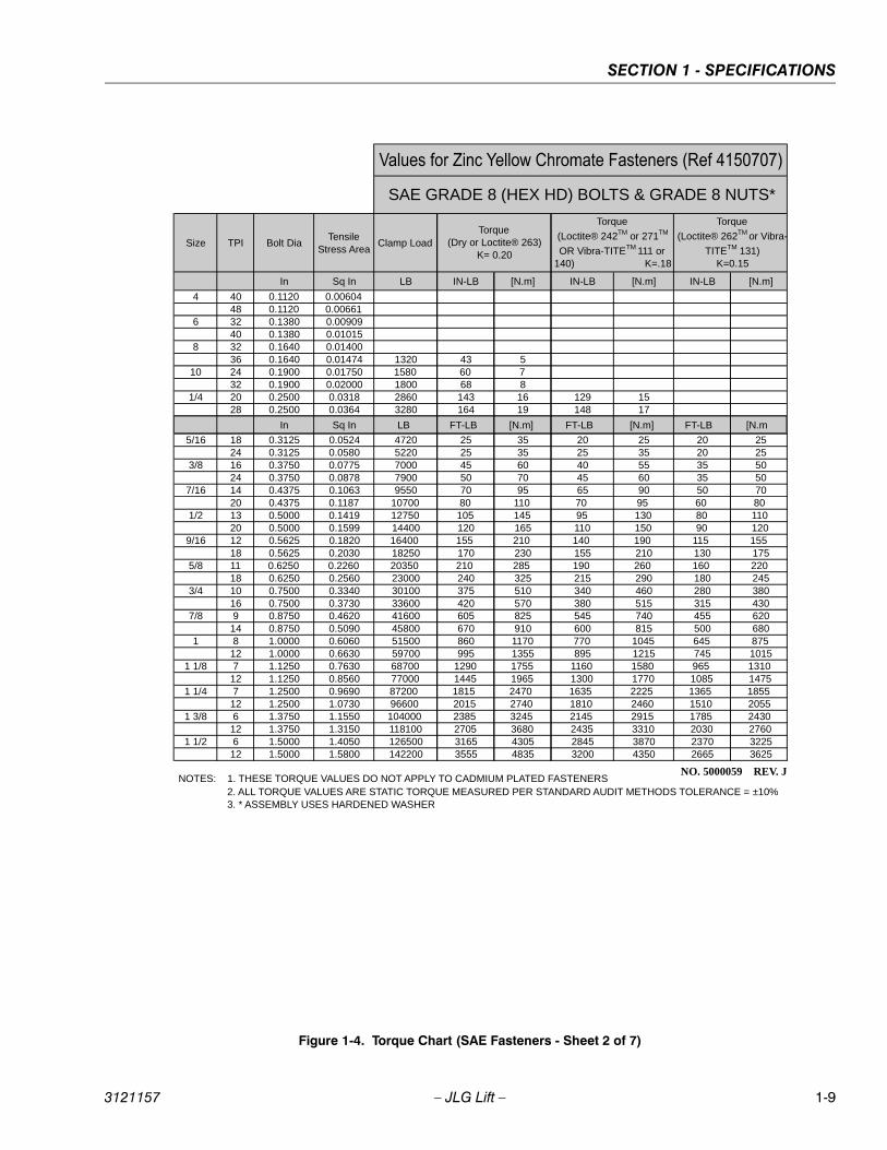
SECTION 1 - SPECIFICATIONS
3121157 – JLG Lift – 1-9
Figure 1-4. Torque Chart (SAE Fasteners - Sheet 2 of 7)
Size TPI Bolt DiaTensile
Stress AreaClamp Load
In Sq In
4 40 0.1120 0.0060448 0.1120 0.00661
6 32 0.1380 0.0090940 0.1380 0.01015
8 32 0.1640 0.0140036 0.1640 0.01474
10 24 0.1900 0.0175032 0.1900 0.02000
1/4 20 0.2500 0.031828 0.2500 0.0364
In Sq In
5/16 18 0.3125 0.052424 0.3125 0.0580
3/8 16 0.3750 0.077524 0.3750 0.0878
7/16 14 0.4375 0.106320 0.4375 0.1187
1/2 13 0.5000 0.141920 0.5000 0.1599
9/16 12 0.5625 0.182018 0.5625 0.2030
5/8 11 0.6250 0.226018 0.6250 0.2560
3/4 10 0.7500 0.334016 0.7500 0.3730
7/8 9 0.8750 0.462014 0.8750 0.5090
1 8 1.0000 0.606012 1.0000 0.6630
1 1/8 7 1.1250 0.763012 1.1250 0.8560
1 1/4 7 1.2500 0.969012 1.2500 1.0730
1 3/8 6 1.3750 1.155012 1.3750 1.3150
1 1/2 6 1.5000 1.405012 1.5000 1.5800
NO. 5000059 REV. J
3. * ASSEMBLY USES HARDENED WASHER
NOTES: 1. THESE TORQUE VALUES DO NOT APPLY TO CADMIUM PLATED FASTENERS2. ALL TORQUE VALUES ARE STATIC TORQUE MEASURED PER STANDARD AUDIT METHODS TOLERANCE = ±10%
LB IN-LB [N.m] IN-LB [N.m] IN-LB [N.m]
1320 43 51580 60 71800 68 82860 143 16 129 153280 164 19 148 17
LB FT-LB [N.m] FT-LB [N.m] FT-LB [N.m
4720 25 35 20 25 20 255220 25 35 25 35 20 257000 45 60 40 55 35 507900 50 70 45 60 35 509550 70 95 65 90 50 70
10700 80 110 70 95 60 8012750 105 145 95 130 80 11014400 120 165 110 150 90 12016400 155 210 140 190 115 15518250 170 230 155 210 130 17520350 210 285 190 260 160 22023000 240 325 215 290 180 24530100 375 510 340 460 280 38033600 420 570 380 515 315 43041600 605 825 545 740 455 62045800 670 910 600 815 500 68051500 860 1170 770 1045 645 87559700 995 1355 895 1215 745 101568700 1290 1755 1160 1580 965 131077000 1445 1965 1300 1770 1085 147587200 1815 2470 1635 2225 1365 185596600 2015 2740 1810 2460 1510 2055104000 2385 3245 2145 2915 1785 2430118100 2705 3680 2435 3310 2030 2760126500 3165 4305 2845 3870 2370 3225142200 3555 4835 3200 4350 2665 3625
Torque
(Loctite® 242TM or 271TM
OR Vibra-TITETM 111 or 140) K=.18
Torque
(Loctite® 262TM or Vibra-
TITETM 131) K=0.15
SAE GRADE 8 (HEX HD) BOLTS & GRADE 8 NUTS*
Torque (Dry or Loctite® 263)
K= 0.20
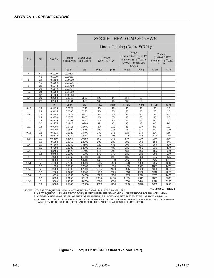
SECTION 1 - SPECIFICATIONS
1-10 – JLG Lift – 3121157
Figure 1-5. Torque Chart (SAE Fasteners - Sheet 3 of 7)
Size TPI Bolt DiaTensile
Stress AreaClamp Load See Note 4
In Sq In LB IN-LB [N.m] IN-LB [N.m] IN-LB [N.m]
4 40 0.1120 0.0060448 0.1120 0.00661
6 32 0.1380 0.0090940 0.1380 0.01015
8 32 0.1640 0.0140036 0.1640 0.01474
10 24 0.1900 0.0175032 0.1900 0.02000
1/4 20 0.2500 0.0318 2860 122 14 114 1328 0.2500 0.0364 3280 139 16 131 15
In Sq In LB FT-LB [N.m] FT-LB [N.m] FT-LB [N.m]
5/16 18 0.3125 0.0524 4720 20 25 20 25 20 2524 0.3125 0.0580 5220 25 35 20 25 20 25
3/8 16 0.3750 0.0775 7000 35 50 35 50 35 5024 0.3750 0.0878 7900 40 55 40 55 35 50
7/16 14 0.4375 0.1063 9550 60 80 55 75 50 7020 0.4375 0.1187 10700 65 90 60 80 60 80
1/2 13 0.5000 0.1419 12750 90 120 85 115 80 11020 0.5000 0.1599 14400 100 135 95 130 90 120
9/16 12 0.5625 0.1820 16400 130 175 125 170 115 15518 0.5625 0.2030 18250 145 195 135 185 130 175
5/8 11 0.6250 0.2260 20350 180 245 170 230 160 22018 0.6250 0.2560 23000 205 280 190 260 180 245
3/4 10 0.7500 0.3340 30100 320 435 300 410 280 38016 0.7500 0.3730 33600 355 485 335 455 315 430
7/8 9 0.8750 0.4620 41600 515 700 485 660 455 62014 0.8750 0.5090 45800 570 775 535 730 500 680
1 8 1.0000 0.6060 51500 730 995 685 930 645 87512 1.0000 0.6630 59700 845 1150 795 1080 745 1015
1 1/8 7 1.1250 0.7630 68700 1095 1490 1030 1400 965 131012 1.1250 0.8560 77000 1225 1665 1155 1570 1085 1475
1 1/4 7 1.2500 0.9690 87200 1545 2100 1455 1980 1365 185512 1.2500 1.0730 96600 1710 2325 1610 2190 1510 2055
1 3/8 6 1.3750 1.1550 104000 2025 2755 1905 2590 1785 243012 1.3750 1.3150 118100 2300 3130 2165 2945 2030 2760
1 1/2 6 1.5000 1.4050 126500 2690 3660 2530 3440 2370 322512 1.5000 1.5800 142200 3020 4105 2845 3870 2665 3625
NO. 5000059 REV. J
4. CLAMP LOAD LISTED FOR SHCS IS SAME AS GRADE 8 OR CLASS 10.9 AND DOES NOT REPRESENT FULL STRENGTH CAPABILITY OF SHCS. IF HIGHER LOAD IS REQUIRED, ADDITIONAL TESTING IS REQUIRED.
SOCKET HEAD CAP SCREWS
Magni Coating (Ref 4150701)*
Torque (Dry) K = .17
Torque
(Loctite® 242TM or 271TM
OR Vibra-TITETM 111 or 140 OR Precoat 85®
K=0.16
Torque (Loctite® 262TM
or Vibra-TITETM 131) K=0.15
2. ALL TORQUE VALUES ARE STATIC TORQUE MEASURED PER STANDARD AUDIT METHODS TOLERANCE = ±10% NOTES: 1. THESE TORQUE VALUES DO NOT APPLY TO CADMIUM PLATED FASTENERS
*3. ASSEMBLY USES HARDENED WASHER OR FASTENER IS PLACED AGAINST PLATED STEEL OR RAW ALUMINUM
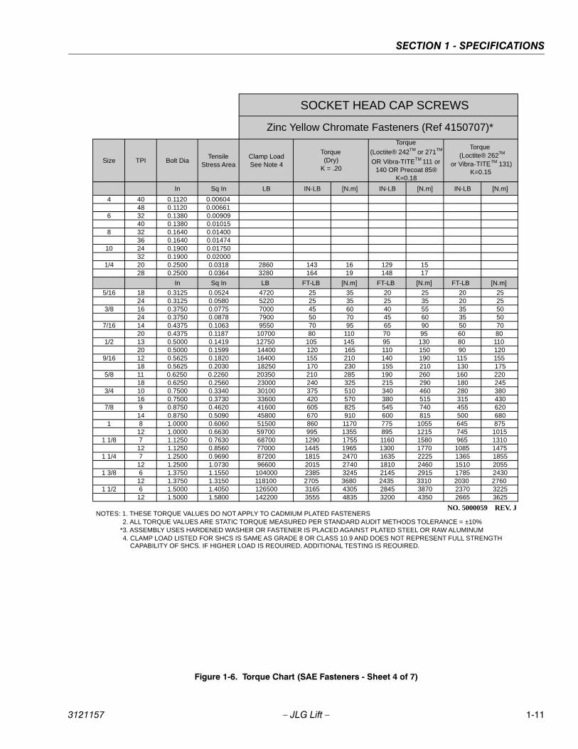
SECTION 1 - SPECIFICATIONS
3121157 – JLG Lift – 1-11
Figure 1-6. Torque Chart (SAE Fasteners - Sheet 4 of 7)
Size TPI Bolt DiaTensile
Stress AreaClamp Load See Note 4
In Sq In LB IN-LB [N.m] IN-LB [N.m] IN-LB [N.m]
4 40 0.1120 0.0060448 0.1120 0.00661
6 32 0.1380 0.0090940 0.1380 0.01015
8 32 0.1640 0.0140036 0.1640 0.01474
10 24 0.1900 0.0175032 0.1900 0.02000
1/4 20 0.2500 0.0318 2860 143 16 129 1528 0.2500 0.0364 3280 164 19 148 17
In Sq In LB FT-LB [N.m] FT-LB [N.m] FT-LB [N.m]
5/16 18 0.3125 0.0524 4720 25 35 20 25 20 2524 0.3125 0.0580 5220 25 35 25 35 20 25
3/8 16 0.3750 0.0775 7000 45 60 40 55 35 5024 0.3750 0.0878 7900 50 70 45 60 35 50
7/16 14 0.4375 0.1063 9550 70 95 65 90 50 7020 0.4375 0.1187 10700 80 110 70 95 60 80
1/2 13 0.5000 0.1419 12750 105 145 95 130 80 11020 0.5000 0.1599 14400 120 165 110 150 90 120
9/16 12 0.5625 0.1820 16400 155 210 140 190 115 15518 0.5625 0.2030 18250 170 230 155 210 130 175
5/8 11 0.6250 0.2260 20350 210 285 190 260 160 22018 0.6250 0.2560 23000 240 325 215 290 180 245
3/4 10 0.7500 0.3340 30100 375 510 340 460 280 38016 0.7500 0.3730 33600 420 570 380 515 315 430
7/8 9 0.8750 0.4620 41600 605 825 545 740 455 62014 0.8750 0.5090 45800 670 910 600 815 500 680
1 8 1.0000 0.6060 51500 860 1170 775 1055 645 87512 1.0000 0.6630 59700 995 1355 895 1215 745 1015
1 1/8 7 1.1250 0.7630 68700 1290 1755 1160 1580 965 131012 1.1250 0.8560 77000 1445 1965 1300 1770 1085 1475
1 1/4 7 1.2500 0.9690 87200 1815 2470 1635 2225 1365 185512 1.2500 1.0730 96600 2015 2740 1810 2460 1510 2055
1 3/8 6 1.3750 1.1550 104000 2385 3245 2145 2915 1785 243012 1.3750 1.3150 118100 2705 3680 2435 3310 2030 2760
1 1/2 6 1.5000 1.4050 126500 3165 4305 2845 3870 2370 322512 1.5000 1.5800 142200 3555 4835 3200 4350 2665 3625
NO. 5000059 REV. J
4. CLAMP LOAD LISTED FOR SHCS IS SAME AS GRADE 8 OR CLASS 10.9 AND DOES NOT REPRESENT FULL STRENGTH CAPABILITY OF SHCS. IF HIGHER LOAD IS REQUIRED, ADDITIONAL TESTING IS REQUIRED.
SOCKET HEAD CAP SCREWS
Torque (Dry)
K = .20
Torque
(Loctite® 242TM or 271TM
OR Vibra-TITETM 111 or 140 OR Precoat 85®
K=0.18
Zinc Yellow Chromate Fasteners (Ref 4150707)*
2. ALL TORQUE VALUES ARE STATIC TORQUE MEASURED PER STANDARD AUDIT METHODS TOLERANCE = ±10% NOTES: 1. THESE TORQUE VALUES DO NOT APPLY TO CADMIUM PLATED FASTENERS
*3. ASSEMBLY USES HARDENED WASHER OR FASTENER IS PLACED AGAINST PLATED STEEL OR RAW ALUMINUM
Torque (Loctite® 262TM
or Vibra-TITETM 131) K=0.15
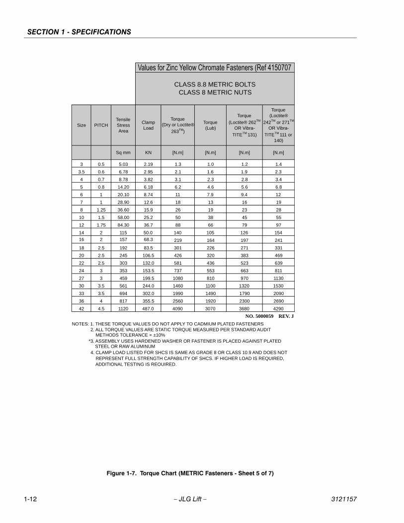
SECTION 1 - SPECIFICATIONS
1-12 – JLG Lift – 3121157
Figure 1-7. Torque Chart (METRIC Fasteners - Sheet 5 of 7)
Size PITCHTensile Stress Area
Clamp Load
Torque (Dry or Loctite®
263TM)
Torque (Lub)
Torque
(Loctite® 262TM
OR Vibra-
TITETM 131)
Torque (Loctite®
242TM or 271TM
OR Vibra-
TITETM 111 or 140)
Sq mm KN [N.m] [N.m] [N.m] [N.m]
3 0.5 5.03 2.19 1.3 1.0 1.2 1.4
3.5 0.6 6.78 2.95 2.1 1.6 1.9 2.3
4 0.7 8.78 3.82 3.1 2.3 2.8 3.4
5 0.8 14.20 6.18 6.2 4.6 5.6 6.8
6 1 20.10 8.74 11 7.9 9.4 12
7 1 28.90 12.6 18 13 16 19
8 1.25 36.60 15.9 26 19 23 28
10 1.5 58.00 25.2 50 38 45 55
12 1.75 84.30 36.7 88 66 79 97
14 2 115 50.0 140 105 126 154
16 2 157 68.3 219 164 197 241
18 2.5 192 83.5 301 226 271 331
20 2.5 245 106.5 426 320 383 469
22 2.5 303 132.0 581 436 523 639
24 3 353 153.5 737 553 663 811
27 3 459 199.5 1080 810 970 1130
30 3.5 561 244.0 1460 1100 1320 1530
33 3.5 694 302.0 1990 1490 1790 2090
36 4 817 355.5 2560 1920 2300 2690
42 4.5 1120 487.0 4090 3070 3680 4290
4. CLAMP LOAD LISTED FOR SHCS IS SAME AS GRADE 8 OR CLASS 10.9 AND DOES NOT REPRESENT FULL STRENGTH CAPABILITY OF SHCS. IF HIGHER LOAD IS REQUIRED, ADDITIONAL TESTING IS REQUIRED.
*3. ASSEMBLY USES HARDENED WASHER OR FASTENER IS PLACED AGAINST PLATED STEEL OR RAW ALUMINUM
CLASS 8.8 METRIC BOLTS CLASS 8 METRIC NUTS
NOTES: 1. THESE TORQUE VALUES DO NOT APPLY TO CADMIUM PLATED FASTENERS2. ALL TORQUE VALUES ARE STATIC TORQUE MEASURED PER STANDARD AUDIT METHODS TOLERANCE = ±10%
NO. 5000059 REV. J
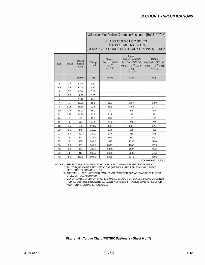
SECTION 1 - SPECIFICATIONS
3121157 – JLG Lift – 1-13
Figure 1-8. Torque Chart (METRIC Fasteners - Sheet 6 of 7)
Size PITCHTensile Stress Area
Clamp Load
Torque (Dry or Loctite®
263TM) K = 0.20
Torque (Lub OR Loctite®
242TM or 271TM OR
Vibra-TITETM 111 or 140)
K= 0.18
Torque
(Loctite® 262TM OR
Vibra-TITETM 131) K=0.15
Sq mm KN [N.m] [N.m] [N.m]
3 0.5 5.03 3.13
3.5 0.6 6.78 4.22
4 0.7 8.78 5.47
5 0.8 14.20 8.85
6 1 20.10 12.5
7 1 28.90 18.0 25.2 22.7 18.9
8 1.25 36.60 22.8 36.5 32.8 27.4
10 1.5 58.00 36.1 70 65 55
12 1.75 84.30 52.5 125 115 95
14 2 115 71.6 200 180 150
16 2 157 97.8 315 280 235
18 2.5 192 119.5 430 385 325
20 2.5 245 152.5 610 550 460
22 2.5 303 189.0 830 750 625
24 3 353 222.0 1065 960 800
27 3 459 286.0 1545 1390 1160
30 3.5 561 349.5 2095 1885 1575
33 3.5 694 432.5 2855 2570 2140
36 4 817 509.0 3665 3300 2750
42 4.5 1120 698.0 5865 5275 4395
CLASS 10.9 METRIC BOLTS CLASS 10 METRIC NUTS
CLASS 12.9 SOCKET HEAD CAP SCREWS M3 - M5*
4. CLAMP LOAD LISTED FOR SHCS IS SAME AS GRADE 8 OR CLASS 10.9 AND DOES NOT REPRESENT FULL STRENGTH CAPABILITY OF SHCS. IF HIGHER LOAD IS REQUIRED, ADDITIONAL TESTING IS REQUIRED.
*3. ASSEMBLY USES HARDENED WASHER OR FASTENER IS PLACED AGAINST PLATED STEEL OR RAW ALUMINUM
NOTES: 1. THESE TORQUE VALUES DO NOT APPLY TO CADMIUM PLATED FASTENERS2. ALL TORQUE VALUES ARE STATIC TORQUE MEASURED PER STANDARD AUDIT METHODS TOLERANCE = ±10%
NO. 5000059 REV. J

SECTION 1 - SPECIFICATIONS
1-14 – JLG Lift – 3121157
Figure 1-9. Torque Chart (METRIC Fasteners - Sheet 7 of 7)
Size PITCHTensile Stress Area
Clamp Load See Note 4
Torque (Dry or Loctite®
263TM) K = .17
Torque (Lub OR Loctite®
242TM or 271TM
OR Vibra-TITETM
111 or 140) K = .16
Torque
(Loctite® 262TM
OR Vibra-TITETM
131) K = .15
Sq mm kN [N.m] [N.m] [N.m]
3 0.5 5.03
3.5 0.6 6.78
4 0.7 8.78
5 0.8 14.20
6 1 20.10 12.5 13 12 11
7 1 28.90 18.0 21 20 19
8 1.25 36.60 22.8 31 29 27
10 1.5 58.00 36.1 61 58 54
12 1.75 84.30 52.5 105 100 95
14 2 115 71.6 170 160 150
16 2 157 97.8 265 250 235
18 2.5 192 119.5 365 345 325
20 2.5 245 152.5 520 490 460
22 2.5 303 189.0 705 665 625
24 3 353 220.0 900 845 790
27 3 459 286.0 1315 1235 1160
30 3.5 561 349.5 1780 1680 1575
33 3.5 694 432.5 2425 2285 2140
36 4 817 509.0 3115 2930 2750
42 4.5 1120 698.0 4985 4690 4395
CLASS 12.9 SOCKET HEAD CAP SCREWS M6 AND ABOVE*
4. CLAMP LOAD LISTED FOR SHCS IS SAME AS GRADE 8 OR CLASS 10.9 AND DOES NOT REPRESENT FULL STRENGTH CAPABILITY OF SHCS. IF HIGHER LOAD IS REQUIRED, ADDITIONAL TESTING IS REQUIRED.
*3. ASSEMBLY USES HARDENED WASHER OR FASTENER IS PLACED AGAINST PLATED STEEL OR RAW ALUMINUM
NOTES: 1. THESE TORQUE VALUES DO NOT APPLY TO CADMIUM PLATED FASTENERS2. ALL TORQUE VALUES ARE STATIC TORQUE MEASURED PER STANDARD AUDIT METHODS TOLERANCE = ±10%
NO. 5000059 REV. J
Magni Coating (Ref 4150701)*
SECTION 2 - GENERAL
3121157 – JLG Lift – 2-1
SECTION 2. GENERAL
2.1 MACHINE PREPARATION, INSPECTION, AND MAINTENANCE
GeneralThis section provides the necessary information neededby those personnel that are responsible to place themachine in operation readiness and maintain its safeoperating condition. For maximum service life and safeoperation, ensure that all the necessary inspections andmaintenance have been completed before placing themachine into service.
Preparation, Inspection, and MaintenanceIt is important to establish and conform to a comprehen-sive inspection and preventive maintenance program. Thefollowing table outlines the periodic machine inspectionsand maintenance recommended by JLG Industries, Inc.Consult your national, regional, or local regulations for fur-ther requirements for aerial work platforms. The frequencyof inspections and maintenance must be increased asenvironment, severity and frequency of usage requires.
Pre-Start InspectionIt is the User’s or Operator’s primary responsibility to per-form a Pre-Start Inspection of the machine prior to usedaily or at each change of operator. Reference the Opera-tor’s and Safety Manual for completion procedures for thePre-Start Inspection. The Operator and Safety Manualmust be read in its entirety and understood prior to per-forming the Pre-Start Inspection.
Pre-Delivery Inspection and Frequent InspectionThe Pre-Delivery Inspection and Frequent Inspection shallbe performed by a qualified JLG equipment mechanic.JLG Industries, Inc. recognizes a qualified JLG equipmentmechanic as a person who, by possession of a recog-nized degree, certificate, extensive knowledge, training, orexperience, has successfully demonstrated the ability andproficiency to service, repair, and maintain the subjectJLG product model.
The Pre-Delivery Inspection and Frequent Inspection pro-cedures are performed in the same manner, but at differ-ent times. The Pre-Delivery Inspection shall be performedprior to each sale, lease, or rental delivery. The FrequentInspection shall be accomplished for each machine in ser-vice for 3 months or 150 hours (whichever comes first);out of service for a period of more than 3 months; or whenpurchased used. The frequency of this inspection must beincreased as environment, severity and frequency ofusage requires.
Reference the JLG Pre-Delivery and Frequent InspectionForm and the Inspection and Preventative MaintenanceSchedule for items requiring inspection during the perfor-mance of these inspections. Reference the appropriateareas of this manual for servicing and maintenance proce-dures.
Annual Machine Inspection The Annual Machine Inspection must be performed by aFactory-Certified Service Technician on an annual basis,no later than thirteen (13) months from the date of theprior Annual Machine Inspection. JLG Industries, Inc. rec-ognizes a Factory-Certified Service Technician as a per-son who has successfully completed the JLG ServiceTraining School for the subject JLG product model. Refer-ence the machine Service and Maintenance Manual andappropriate JLG inspection form for performance of thisinspection.
Reference the JLG Annual Machine Inspection Form andthe Inspection and Preventative Maintenance Schedule foritems requiring inspection during the performance of thisinspection. Reference the appropriate areas of this man-ual for servicing and maintenance procedures.
For the purpose of receiving safety-related bulletins, it isimportant that JLG Industries, Inc. has updated ownershipinformation for each machine. When performing eachAnnual Machine Inspection, notify JLG Industries, Inc. ofthe current machine ownership.
Preventative MaintenanceIn conjunction with the specified inspections, mainte-nance shall be performed by a qualified JLG equipmentmechanic. JLG Industries, Inc. recognizes a qualified JLGequipment mechanic as a person who, by possession of arecognized degree, certificate, extensive knowledge, train-ing, or experience, has successfully demonstrated theability and proficiency to service, repair, and maintain thesubject JLG product model.
Reference the Preventative Maintenance Schedule andthe appropriate areas of this manual for servicing andmaintenance procedures. The frequency of service andmaintenance must be increased as environment, severityand frequency of usage requires.
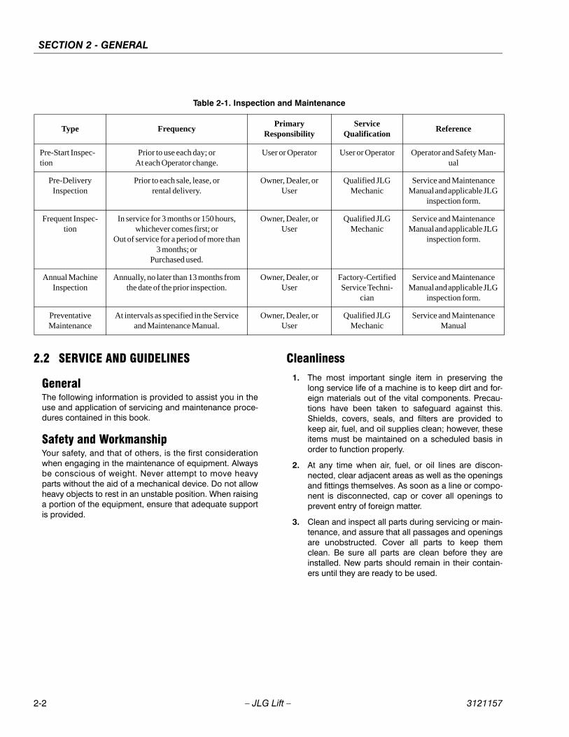
SECTION 2 - GENERAL
2-2 – JLG Lift – 3121157
2.2 SERVICE AND GUIDELINES
GeneralThe following information is provided to assist you in theuse and application of servicing and maintenance proce-dures contained in this book.
Safety and WorkmanshipYour safety, and that of others, is the first considerationwhen engaging in the maintenance of equipment. Alwaysbe conscious of weight. Never attempt to move heavyparts without the aid of a mechanical device. Do not allowheavy objects to rest in an unstable position. When raisinga portion of the equipment, ensure that adequate supportis provided.
Cleanliness1. The most important single item in preserving the
long service life of a machine is to keep dirt and for-eign materials out of the vital components. Precau-tions have been taken to safeguard against this.Shields, covers, seals, and filters are provided tokeep air, fuel, and oil supplies clean; however, theseitems must be maintained on a scheduled basis inorder to function properly.
2. At any time when air, fuel, or oil lines are discon-nected, clear adjacent areas as well as the openingsand fittings themselves. As soon as a line or compo-nent is disconnected, cap or cover all openings toprevent entry of foreign matter.
3. Clean and inspect all parts during servicing or main-tenance, and assure that all passages and openingsare unobstructed. Cover all parts to keep themclean. Be sure all parts are clean before they areinstalled. New parts should remain in their contain-ers until they are ready to be used.
Table 2-1. Inspection and Maintenance
Type FrequencyPrimary
ResponsibilityService
QualificationReference
Pre-Start Inspec-tion
Prior to use each day; or At each Operator change.
User or Operator User or Operator Operator and Safety Man-ual
Pre-Delivery Inspection
Prior to each sale, lease, or rental delivery.
Owner, Dealer, or User
Qualified JLG Mechanic
Service and Maintenance Manual and applicable JLG
inspection form.
Frequent Inspec-tion
In service for 3 months or 150 hours, whichever comes first; or
Out of service for a period of more than 3 months; or
Purchased used.
Owner, Dealer, or User
Qualified JLG Mechanic
Service and Maintenance Manual and applicable JLG
inspection form.
Annual Machine Inspection
Annually, no later than 13 months from the date of the prior inspection.
Owner, Dealer, or User
Factory-Certified Service Techni-
cian
Service and Maintenance Manual and applicable JLG
inspection form.
Preventative Maintenance
At intervals as specified in the Service and Maintenance Manual.
Owner, Dealer, or User
Qualified JLG Mechanic
Service and Maintenance Manual
SECTION 2 - GENERAL
3121157 – JLG Lift – 2-3
Components Removal and Installation1. Use adjustable lifting devices, whenever possible, if
mechanical assistance is required. All slings (chains,cables, etc.) should be parallel to each other and asnear perpendicular as possible to top of part beinglifted.
2. Should it be necessary to remove a component onan angle, keep in mind that the capacity of an eye-bolt or similar bracket lessens, as the angle betweenthe supporting structure and the componentbecomes less than 90 degrees.
3. If a part resists removal, check to see whether allnuts, bolts, cables, brackets, wiring, etc., have beenremoved and that no adjacent parts are interfering.
Component Disassembly and ReassemblyWhen disassembling or reassembling a component, com-plete the procedural steps in sequence. Do not partiallydisassemble or assemble one part, then start on another.Always recheck your work to assure that nothing has beenoverlooked. Do not make any adjustments, other thanthose recommended, without obtaining proper approval.
Pressure-Fit PartsWhen assembling pressure-fit parts, use an anti-seize ormolybdenum disulfide base compound to lubricate themating surface.
Bearings1. When a bearing is removed, cover it to keep out dirt
and abrasives. Clean bearings in nonflammablecleaning solvent and allow to drip dry. Compressedair can be used but do not spin the bearing.
2. Discard bearings if the races and balls (or rollers)are pitted, scored, or burned.
3. If bearing is found to be serviceable, apply a lightcoat of oil and wrap it in clean (waxed) paper. Do notunwrap reusable or new bearings until they areready to install.
4. Lubricate new or used serviceable bearings beforeinstallation. When pressing a bearing into a retaineror bore, apply pressure to the outer race. If the bear-ing is to be installed on a shaft, apply pressure to theinner race.
GasketsCheck that holes in gaskets align with openings in themating parts. If it becomes necessary to hand-fabricate agasket, use gasket material or stock of equivalent materialand thickness. Be sure to cut holes in the right location, asblank gaskets can cause serious system damage.
Bolt Usage and Torque Application1. Use bolts of proper length. A bolt which is too long
will bottom before the head is tight against its relatedpart. If a bolt is too short, there will not be enoughthread area to engage and hold the part properly.When replacing bolts, use only those having thesame specifications of the original, or one which isequivalent.
2. Unless specific torque requirements are given withinthe text, standard torque values should be used onheat-treated bolts, studs, and steel nuts, in accor-dance with recommended shop practices. (SeeTorque Chart Section 1.)
Hydraulic Lines and Electrical WiringClearly mark or tag hydraulic lines and electrical wiring, aswell as their receptacles, when disconnecting or removingthem from the unit. This will assure that they are correctlyreinstalled.
Hydraulic System1. Keep the system clean. If evidence of metal or rub-
ber particles are found in the hydraulic system, drainand flush the entire system.
2. Disassemble and reassemble parts on clean worksurface. Clean all metal parts with non-flammablecleaning solvent. Lubricate components, asrequired, to aid assembly.
SECTION 2 - GENERAL
2-4 – JLG Lift – 3121157
LubricationService applicable components with the amount, type,and grade of lubricant recommended in this manual, atthe specified intervals. When recommended lubricants arenot available, consult your local supplier for an equivalentthat meets or exceeds the specifications listed.
BatteryClean battery, using a non-metallic brush and a solution ofbaking soda and water. Rinse with clean water. Aftercleaning, thoroughly dry battery and coat terminals withan anti corrosion compound.
Lubrication and ServicingComponents and assemblies requiring lubrication andservicing are shown in the Lubrication Chart in Section 1.
2.3 LUBRICATION AND INFORMATION
Hydraulic System1. The primary enemy of a hydraulic system is contam-
ination. Contaminants enter the system by variousmeans, e.g., using inadequate hydraulic oil, allowingmoisture, grease, filings, sealing components, sand,etc., to enter when performing maintenance, or bypermitting the pump to cavitate due to insufficientsystem warm-up or leaks in the pump supply (suc-tion) lines.
2. The design and manufacturing tolerances of thecomponent working parts are very close, therefore,even the smallest amount of dirt or foreign matterentering a system can cause wear or damage to thecomponents and generally results in faulty opera-tion. Every precaution must be taken to keephydraulic oil clean, including reserve oil in storage.Hydraulic system filters should be checked,cleaned, and/or replaced as necessary, at the speci-fied intervals required in the Lubrication Chart inSection 1. Always examine filters for evidence ofmetal particles.
3. Cloudy oils indicate a high moisture content whichpermits organic growth, resulting in oxidation or cor-rosion. If this condition occurs, the system must bedrained, flushed, and refilled with clean oil.
4. It is not advisable to mix oils of different brands ortypes, as they may not contain the same requiredadditives or be of comparable viscosities. Goodgrade mineral oils, with viscosities suited to theambient temperatures in which the machine is oper-ating, are recommended for use.
NOTE: Metal particles may appear in the oil or filters of newmachines due to the wear-in of meshing compo-nents.
Hydraulic Oil1. Refer to Section 1 for recommendations for viscosity
ranges.
2. JLG recommends Mobilfluid 424 hydraulic oil, whichhas an SAE viscosity of 10W-30 and a viscosityindex of 152.
NOTE: Start-up of hydraulic system with oil temperaturesbelow -15 degrees F (-26 degrees C) is not recom-mended. If it is necessary to start the system in asub-zero environment, it will be necessary to heatthe oil with a low density, 100VAC heater to a mini-mum temperature of -15 degrees F (-26 degrees C).
3. The only exception to the above is to drain and fillthe system with Mobil DTE 13 oil or its equivalent.This will allow start up at temperatures down to -20degrees F (-29 degrees C). However, use of this oilwill give poor performance at temperatures above120 degrees F (49 degrees C). Systems using DTE13 oil should not be operated at temperatures above200 degrees F (94 degrees C) under any condition.

SECTION 2 - GENERAL
3121157 – JLG Lift – 2-5
Changing Hydraulic Oil1. Use of any of the recommended crankcase or
hydraulic oils eliminates the need for changing theoil on a regular basis. However, filter elements mustbe changed after the first 50 hours of operation andevery 300 hours thereafter. If it is necessary tochange the oil, use only those oils meeting orexceeding the specifications appearing in this man-ual. If unable to obtain the same type of oil suppliedwith the machine, consult local supplier for assis-tance in selecting the proper equivalent. Avoid mix-ing petroleum and synthetic base oils.
2. Use every precaution to keep the hydraulic oil clean.If the oil must be poured from the original containerinto another, be sure to clean all possible contami-nants from the service container. Always clean themesh element of the filter and replace the cartridgeany time the system oil is changed.
3. While the unit is shut down, a good preventive main-tenance measure is to make a thorough inspectionof all hydraulic components, lines, fittings, etc., aswell as a functional check of each system, beforeplacing the machine back in service.
Lubrication SpecificationsSpecified lubricants, as recommended by the componentmanufacturers, are always the best choice, however,multi-purpose greases usually have the qualities whichmeet a variety of single purpose grease requirements.Should any question arise, regarding the use of greases inmaintenance stock, consult your local supplier for evalua-tion. Refer to Section 1 for an explanation of the lubricantkey designations appearing in the Lubrication Chart.
2.4 CYLINDER DRIFT TESTMaximum acceptable cylinder drift is to be measuredusing the following methods.
Platform DriftMeasure the drift of the platform to the ground. Lowerbooms (if equipped) slightly elevated, upper boom fullyextended with the rated load in the platform and power off.Maximum allowable drift is 2 inches (5 cm) in 10 minutes.If the machine does not pass this test, proceed with thefollowing.
Cylinder Drift
Drift is to be measured at the cylinder rod with a calibrateddial indicator. The cylinder oil must be at ambient temper-ature and temperature stabilized.
The cylinder must have the normal load, which is the nor-mal platform load applied.
If the cylinder passes this test, it is acceptable.
NOTE: This information is based on 6 drops per minute cyl-inder leakage.
Table 2-2. Cylinder Drift
Cylinder Bore DiameterMax. Acceptable Drift
in 10 Minutes
inches mm inches mm
3 76.2 0.026 0.66
3.5 89 0.019 0.48
4 101.6 0.015 0.38
5 127 0.009 0.22
6 152.4 0.006 0.15
7 177.8 0.005 0.13
8 203.2 0.0038 0.10
9 228.6 0.0030 0.08
SECTION 2 - GENERAL
2-6 – JLG Lift – 3121157
2.5 PINS AND COMPOSITE BEARING REPAIR GUIDELINES
Filament wound bearings.
1. Pinned joints should be disassembled andinspected if the following occurs:
a. Excessive sloppiness in joints.
b. Noise originating from the joint during operation.
2. Filament wound bearings should be replaced if anyof the following is observed:
a. Frayed or separated fibers on the liner surface.
b. Cracked or damaged liner backing.
c. Bearings that have moved or spun in their hous-ing.
d. Debris embedded in liner surface.
3. Pins should be replaced if any of the following isobserved (pin should be properly cleaned prior toinspection):
a. Detectable wear in the bearing area.
b. Flaking, pealing, scoring, or scratches on the pinsurface.
c. Rusting of the pin in the bearing area.
4. Re-assembly of pinned joints using filament woundbearings.
a. Housing should be blown out to remove all dirtand debris...bearings and bearing housingsmust be free of all contamination.
b. Bearing / pins should be cleaned with a solventto remove all grease and oil...filament woundbearing are a dry joint and should not be lubri-cated unless otherwise instructed (i.e. sheavepins).
c. Pins should be inspected to ensure it is free ofburrs, nicks, and scratches which would dam-age the bearing during installation and opera-tion.
2.6 WELDING ON JLG EQUIPMENT
NOTE: This instruction applies to repairs, or modifications tothe machine and to welding performed from themachine on an external structure, or component,
Do the Following When Welding on JLGEquipment• Disconnect the battery.
• Disconnect the moment pin connection (where fitted)
• Ground only to structure being welded.
Do NOT Do the Following When Weldingon JLG Equipment• Ground on frame and weld on any other area than the
chassis.
• Ground on turntable and weld on any other area thanthe turntable.
• Ground on the platform/support and weld on any otherarea than the platform/support.
• Ground on a specific boom section and weld on anyother area than that specific boom section.
• Allow pins, wear pads, wire ropes, bearings, gearing,seals, valves, electrical wiring, or hoses to be betweenthe grounding position and the welded area.
FAILURE TO COMPLY WITH ABOVE REQUIREMENTS MAYRESULT IN COMPONENT DAMAGE (I.E. ELECTRONIC MODULES,SWING BEARING, COLLECTOR RING, BOOM WIRE ROPES ETC.)
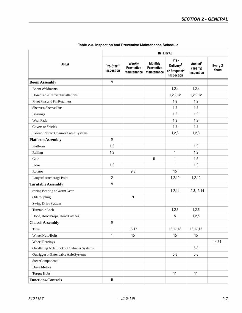
SECTION 2 - GENERAL
3121157 – JLG Lift – 2-7
Table 2-3. Inspection and Preventive Maintenance Schedule
AREA
INTERVAL
Pre-Start1
Inspection
WeeklyPreventive
Maintenance
MonthlyPreventive
Maintenance
Pre-Delivery2
or Frequent3
Inspection
Annual4
(Yearly)Inspection
Every 2Years
Boom Assembly 9
Boom Weldments 1,2,4 1,2,4
Hose/Cable Carrier Installations 1,2,9,12 1,2,9,12
Pivot Pins and Pin Retainers 1,2 1,2
Sheaves, Sheave Pins 1,2 1,2
Bearings 1,2 1,2
Wear Pads 1,2 1,2
Covers or Shields 1,2 1,2
Extend/Retract Chain or Cable Systems 1,2,3 1,2,3
Platform Assembly 9
Platform 1,2 1,2
Railing 1,2 1 1,2
Gate 5 1 1,5
Floor 1,2 1 1,2
Rotator 9,5 15
Lanyard Anchorage Point 2 1,2,10 1,2,10
Turntable Assembly 9
Swing Bearing or Worm Gear 1,2,14 1,2,3,13,14
Oil Coupling 9
Swing Drive System
Turntable Lock 1,2,5 1,2,5
Hood, Hood Props, Hood Latches 5 1,2,5
Chassis Assembly 9
Tires 1 16,17 16,17,18 16,17,18
Wheel Nuts/Bolts 1 15 15 15
Wheel Bearings 14,24
Oscillating Axle/Lockout Cylinder Systems 5,8
Outrigger or Extendable Axle Systems 5,8 5,8
Steer Components
Drive Motors
Torque Hubs 11 11
Functions/Controls 9
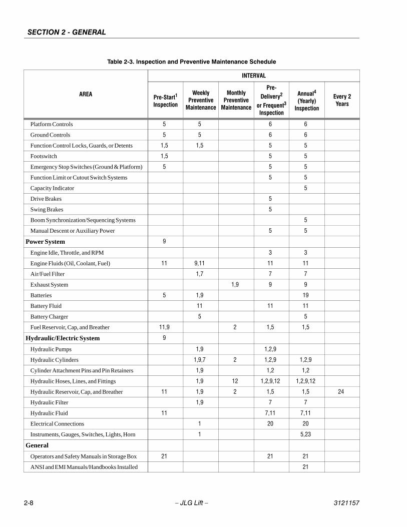
SECTION 2 - GENERAL
2-8 – JLG Lift – 3121157
Platform Controls 5 5 6 6
Ground Controls 5 5 6 6
Function Control Locks, Guards, or Detents 1,5 1,5 5 5
Footswitch 1,5 5 5
Emergency Stop Switches (Ground & Platform) 5 5 5
Function Limit or Cutout Switch Systems 5 5
Capacity Indicator 5
Drive Brakes 5
Swing Brakes 5
Boom Synchronization/Sequencing Systems 5
Manual Descent or Auxiliary Power 5 5
Power System 9
Engine Idle, Throttle, and RPM 3 3
Engine Fluids (Oil, Coolant, Fuel) 11 9,11 11 11
Air/Fuel Filter 1,7 7 7
Exhaust System 1,9 9 9
Batteries 5 1,9 19
Battery Fluid 11 11 11
Battery Charger 5 5
Fuel Reservoir, Cap, and Breather 11,9 2 1,5 1,5
Hydraulic/Electric System 9
Hydraulic Pumps 1,9 1,2,9
Hydraulic Cylinders 1,9,7 2 1,2,9 1,2,9
Cylinder Attachment Pins and Pin Retainers 1,9 1,2 1,2
Hydraulic Hoses, Lines, and Fittings 1,9 12 1,2,9,12 1,2,9,12
Hydraulic Reservoir, Cap, and Breather 11 1,9 2 1,5 1,5 24
Hydraulic Filter 1,9 7 7
Hydraulic Fluid 11 7,11 7,11
Electrical Connections 1 20 20
Instruments, Gauges, Switches, Lights, Horn 1 5,23
General
Operators and Safety Manuals in Storage Box 21 21 21
ANSI and EMI Manuals/Handbooks Installed 21
Table 2-3. Inspection and Preventive Maintenance Schedule
AREA
INTERVAL
Pre-Start1
Inspection
WeeklyPreventive
Maintenance
MonthlyPreventive
Maintenance
Pre-Delivery2
or Frequent3
Inspection
Annual4
(Yearly)Inspection
Every 2Years
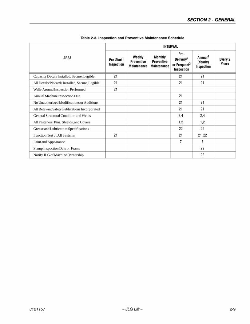
SECTION 2 - GENERAL
3121157 – JLG Lift – 2-9
Capacity Decals Installed, Secure, Legible 21 21 21
All Decals/Placards Installed, Secure, Legible 21 21 21
Walk-Around Inspection Performed 21
Annual Machine Inspection Due 21
No Unauthorized Modifications or Additions 21 21
All Relevant Safety Publications Incorporated 21 21
General Structural Condition and Welds 2,4 2,4
All Fasteners, Pins, Shields, and Covers 1,2 1,2
Grease and Lubricate to Specifications 22 22
Function Test of All Systems 21 21 21, 22
Paint and Appearance 7 7
Stamp Inspection Date on Frame 22
Notify JLG of Machine Ownership 22
Table 2-3. Inspection and Preventive Maintenance Schedule
AREA
INTERVAL
Pre-Start1
Inspection
WeeklyPreventive
Maintenance
MonthlyPreventive
Maintenance
Pre-Delivery2
or Frequent3
Inspection
Annual4
(Yearly)Inspection
Every 2Years
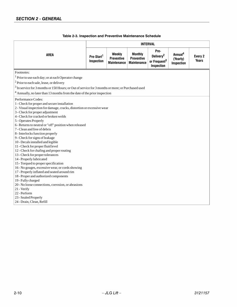
SECTION 2 - GENERAL
2-10 – JLG Lift – 3121157
Footnotes:1 Prior to use each day; or at each Operator change2 Prior to each sale, lease, or delivery3 In service for 3 months or 150 Hours; or Out of service for 3 months or more; or Purchased used4 Annually, no later than 13 months from the date of the prior inspection
Performance Codes:1 - Check for proper and secure installation2 - Visual inspection for damage, cracks, distortion or excessive wear3 - Check for proper adjustment4 - Check for cracked or broken welds5 - Operates Properly6 - Returns to neutral or "off" position when released7 - Clean and free of debris8 - Interlocks function properly9 - Check for signs of leakage10 - Decals installed and legible11 - Check for proper fluid level12 - Check for chafing and proper routing13 - Check for proper tolerances14 - Properly lubricated15 - Torqued to proper specification16 - No gouges, excessive wear, or cords showing17 - Properly inflated and seated around rim18 - Proper and authorized components19 - Fully charged20 - No loose connections, corrosion, or abrasions21 - Verify22 - Perform23 - Sealed Properly24 - Drain, Clean, Refill
Table 2-3. Inspection and Preventive Maintenance Schedule
AREA
INTERVAL
Pre-Start1
Inspection
WeeklyPreventive
Maintenance
MonthlyPreventive
Maintenance
Pre-Delivery2
or Frequent3
Inspection
Annual4
(Yearly)Inspection
Every 2Years
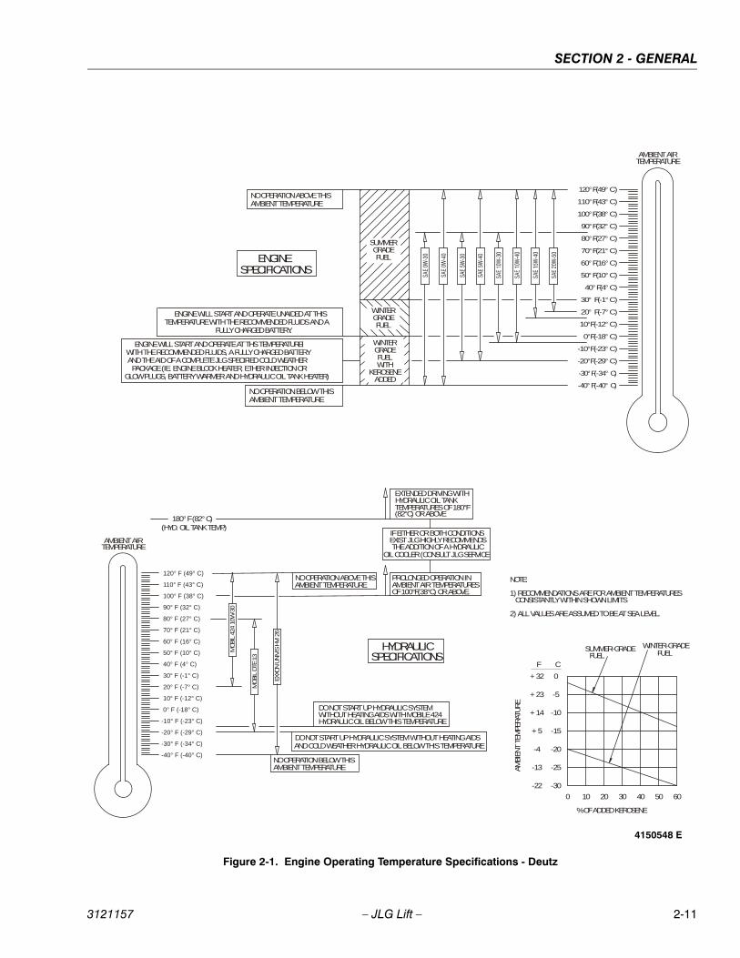
SECTION 2 - GENERAL
3121157 – JLG Lift – 2-11
-40°F(-40° C)
-30°F(-34° C)
-20°F(-29° C)
-10°F(-23° C)
0°F(-18° C)
10°F(-12° C)
20° F(-7° C)
30° F(-1° C)
40°F(4° C)
50°F(10° C)
60°F(16° C)
70°F(21° C)
80°F(27° C)
90°F(32° C)
100°F(38° C)
110°F(43° C)
120°F(49° C)
ENGINESPECIFICATIONS
ENGINE WILL START AND OPERATE AT TH IS TEMPERATUREWITH THE RECOMMENDED FLUIDS, A FULLY CHARGED BATTERY AND THE AID OF A COMPLETE JLG SPECIFIED COLD WEATHERPACKAGE (IE. ENGINE BLOCK HEATER, ETHER INJECTION OR
GLOW PLUGS, BATTERY WARMER AND HYDRAULIC OIL TANK HEATER)
ENGINE WILL START AND OPERATE UNAIDED AT THISTEMPERATURE WITH THE RECOMMENDED FLUIDS AND A
FULLY CHARGED BATTERY.
AMBIENT AIRTEMPERATURE
SUMMERGRADEFUEL
WINTERGRADEFUEL
WINTERGRADEFUELWITH
KEROSENEADDED
NO OPERATION BELOW THISAMBIENT TEMPERATURE
NO OPERATION ABOVE THISAMBIENT TEMPERATURE
(HYD. OIL TANK TEMP.)IF EITHER OR BOTH CONDITIONSEXIST JLG HIGHLY RECOMMENDSTHE ADDITION OF A HYDRAULIC
OIL COOLER (CONSULT JLG SERVICE
180° F (82° C)
-40° F (-40° C)
-30° F (-34° C)
-20° F (-29° C)
-10° F (-23° C)
0° F (-18° C)
10° F (-12° C)
20° F (-7° C)
30° F (-1° C)
40° F (4° C)
50° F (10° C)
60° F (16° C)
70° F (21° C)
80° F (27° C)
90° F (32° C)
100° F (38° C)
110° F (43° C)
120° F (49° C)
AMBIENT AIRTEMPERATURE
PROLONGED OPERATION INAMBIENT AIR TEMPERATURESOF 100°F(38°C) OR ABOVE.
EXTENDED DRIVING WITHHYDRAULIC OIL TANKTEMPERATURES OF 180°F(82°C) OR ABOVE
NO OPERATION BELOW THISAMBIENT TEMPERATURE
MOBI
L 42
4 10
W-3
0
HYDRAULICSPECIFICATIONS
NO OPERATION ABOVE THISAMBIENT TEMPERATURE
DO NOT START UP HYDRAULIC SYSTEM WITHOUT HEATING AIDS WITH MOBILE 424 HYDRAULIC OIL BELOW THIS TEMPERATURE
DO NOT START UP HYDRAULIC SYSTEM WITHOUT HEATING AIDSAND COLD WEATHER HYDRAULIC OIL BELOW THIS TEMPERATURE
EXXO
N U
NIV
IS H
VI 2
6
MOBI
L DTE
13
NOTE:
1) RECOMMENDATIONS ARE FOR AMBIENT TEMPERATURES CONSISTANTLY WITHIN SHOWN LIMITS
2) ALL VALUES ARE ASSUMED TO BE AT SEA LEVEL.
0+ 32
-5
-10
-15
-20
-25
-30
+ 23
+ 14
+ 5
-4
-13
-22
CF
0 10 20 30 40 50 60
% OF ADDED KEROSENE
AMBI
ENT
TEM
PERAT
URE
SUMMER-GRADEFUEL
WINTER-GRADEFUEL
Figure 2-1. Engine Operating Temperature Specifications - Deutz
4150548 E
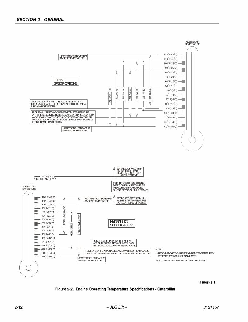
SECTION 2 - GENERAL
2-12 – JLG Lift – 3121157
-40 F(-40 C)
-30 F(-34 C)
-20 F(-29 C)
-10 F(-23 C)
0 F(-18 C)
10 F(-12 C)
20 F(-7 C)
30 F(-1 C)
40 F(4 C)
50 F(10 C)
60 F(16 C)
70 F(21 C)
80 F(27 C)
90 F(32 C)
100 F(38 C)
110 F(43 C)
120 F(49 C)
ENGINESPECIFICATIONS
ENGINE WILL START AND OPERATE AT THIS TEMPERATUREWITH THE RECOMMENDED FLUIDS, A FULLY CHARGED BATTERYAND THE AID OF A COMPLETE JLG SPECIFIED COLD WEATHERPACKAGE (IE. ENGINE BLOCK HEATER, BATTERY WARMER ANDHYDRAULIC OIL TANK HEATER)
ENGINE WILL START AND OPERATE UNAIDED AT THISTEMPERATURE WITH THE RECOMMENDED FLUIDS AND AFULLY CHARGED BATTERY.
AMBIENT AIRTEMPERATURE
NO OPERATION BELOW THISAMBIENT TEMPERATURE
NO OPERATION ABOVE THISAMBIENT TEMPERATURE
(HYD. OIL TANK TEMP.)
IF EITHER OR BOTH CONDITIONSEXIST JLG HIGHLY RECOMMENDSTHE ADDITION OF A HYDRAULICOIL COOLER (CONSULT JLG SERVICE
180° F (82° C)
PROLONGED OPERATION INAMBIENT AIR TEMPERATURESOF 100° F (38°C) OR ABOVE.
EXTENDED DRIVING WITHHYDRAULIC OIL TANKTEMPERATURES OF 180° F
(82°C) OR ABOVE.
NO OPERATION BELOW THISAMBIENT TEMPERATURE
MOBI
L 42
4 10
W-3
0
HYDRAULICSPECIFICATIONS
NO OPERATION ABOVE THISAMBIENT TEMPERATURE
DO NOT START UP HYDRAULIC SYSTEM WITHOUT HEATING AIDS WITH MOBILE 424 HYDRAULIC OIL BELOW THIS TEMPERATURE
DO NOT START UP HYDRAULIC SYSTEM WITHOUT HEATING AIDS AND COLD WEATHERHYDRAULIC OIL BELOW THIS TEMPERATURE
EXXO
N U
NIV
IS H
VI 2
6
MOBI
L DTE
13
NOTE:
1) RECOMMENDATIONS ARE FOR AMBIENT TEMPERATURES CONSISTENTLY WITHIN SHOWN LIMITS
2) ALL VALUES ARE ASSUMED TO BE AT SEA LEVEL.
-40° F (-40° C)
-30° F (-34° C)
-20° F (-29° C)
-10° F (-23° C)
0° F (-18° C)
10° F (-12° C)
20° F (-7° C)
30° F (-1° C)
40° F (4° C)
50° F (10° C)
60° F (16° C)
70° F (21° C)
80° F (27° C)
90° F (32° C)
100° F (38° C)
110° F (43° C)
120° F (49° C)
AMBIENT AIRTEMPERATURE
Figure 2-2. Engine Operating Temperature Specifications - Caterpillar
4150548 E
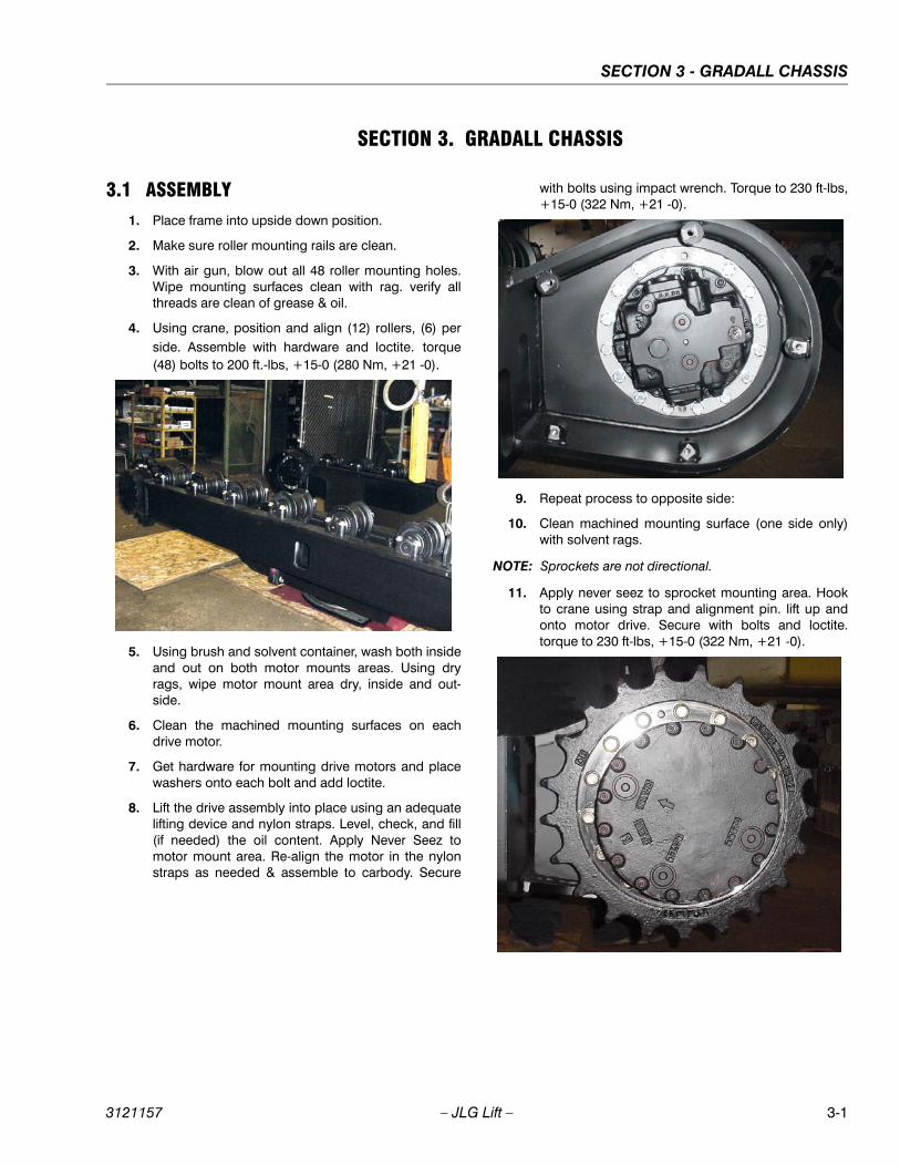
SECTION 3 - GRADALL CHASSIS
3121157 – JLG Lift – 3-1
SECTION 3. GRADALL CHASSIS
3.1 ASSEMBLY1. Place frame into upside down position.
2. Make sure roller mounting rails are clean.
3. With air gun, blow out all 48 roller mounting holes.Wipe mounting surfaces clean with rag. verify allthreads are clean of grease & oil.
4. Using crane, position and align (12) rollers, (6) perside. Assemble with hardware and loctite. torque(48) bolts to 200 ft.-lbs, +15-0 (280 Nm, +21 -0).
5. Using brush and solvent container, wash both insideand out on both motor mounts areas. Using dryrags, wipe motor mount area dry, inside and out-side.
6. Clean the machined mounting surfaces on eachdrive motor.
7. Get hardware for mounting drive motors and placewashers onto each bolt and add loctite.
8. Lift the drive assembly into place using an adequatelifting device and nylon straps. Level, check, and fill(if needed) the oil content. Apply Never Seez tomotor mount area. Re-align the motor in the nylonstraps as needed & assemble to carbody. Secure
with bolts using impact wrench. Torque to 230 ft-lbs,+15-0 (322 Nm, +21 -0).
9. Repeat process to opposite side:
10. Clean machined mounting surface (one side only)with solvent rags.
NOTE: Sprockets are not directional.
11. Apply never seez to sprocket mounting area. Hookto crane using strap and alignment pin. lift up andonto motor drive. Secure with bolts and loctite.torque to 230 ft-lbs, +15-0 (322 Nm, +21 -0).
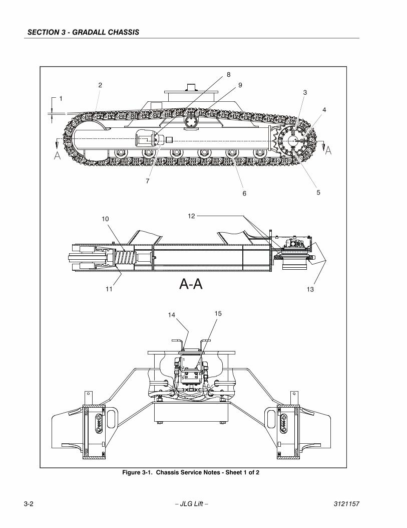
SECTION 3 - GRADALL CHASSIS
3-2 – JLG Lift – 3121157
Figure 3-1. Chassis Service Notes - Sheet 1 of 2
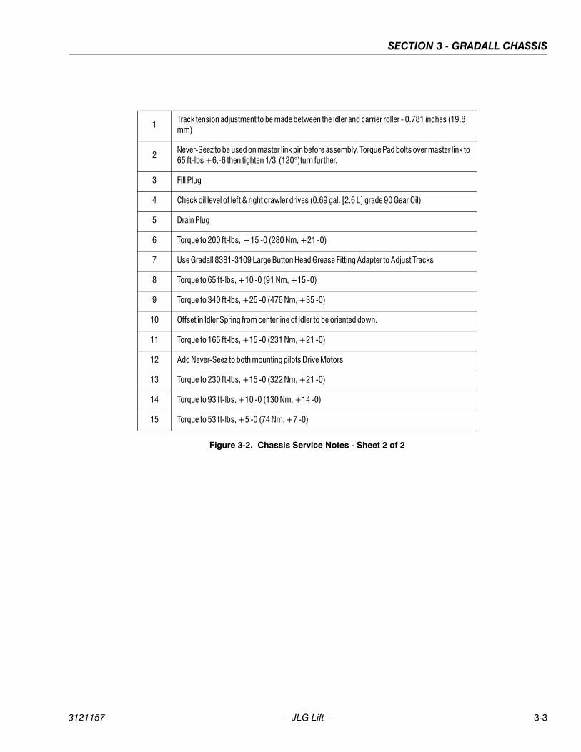
SECTION 3 - GRADALL CHASSIS
3121157 – JLG Lift – 3-3
1Track tension adjustment to be made between the idler and carrier roller - 0.781 inches (19.8 mm)
2Never-Seez to be used on master link pin before assembly. Torque Pad bolts over master link to 65 ft-lbs +6,-6 then tighten 1/3 (120°)turn further.
3 Fill Plug
4 Check oil level of left & right crawler drives (0.69 gal. [2.6 L] grade 90 Gear Oil)
5 Drain Plug
6 Torque to 200 ft-lbs, +15 -0 (280 Nm, +21 -0)
7 Use Gradall 8381-3109 Large Button Head Grease Fitting Adapter to Adjust Tracks
8 Torque to 65 ft-lbs, +10 -0 (91 Nm, +15 -0)
9 Torque to 340 ft-lbs, +25 -0 (476 Nm, +35 -0)
10 Offset in Idler Spring from centerline of Idler to be oriented down.
11 Torque to 165 ft-lbs, +15 -0 (231 Nm, +21 -0)
12 Add Never-Seez to both mounting pilots Drive Motors
13 Torque to 230 ft-lbs, +15 -0 (322 Nm, +21 -0)
14 Torque to 93 ft-lbs, +10 -0 (130 Nm, +14 -0)
15 Torque to 53 ft-lbs, +5 -0 (74 Nm, +7 -0)
Figure 3-2. Chassis Service Notes - Sheet 2 of 2
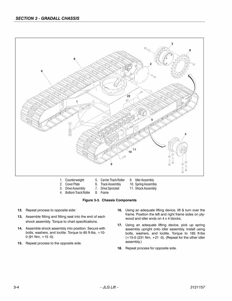
SECTION 3 - GRADALL CHASSIS
3-4 – JLG Lift – 3121157
12. Repeat process to opposite side:
13. Assemble fitting and fitting seal into the end of eachshock assembly. Torque to chart specifications.
14. Assemble shock assembly into position. Secure withbolts, washers, and loctite. Torque to 65 ft-lbs, +10-0 (91 Nm, +15 -0).
15. Repeat process to the opposite side.
16. Using an adequate lifting device, lift & turn over theframe. Position the left and right frame sides on ply-wood and idler ends on 4 x 4 blocks.
17. Using an adequate lifting device, pick up springassembly upright onto idler assembly. Install usingbolts, washers, and loctite. Torque to 165 ft-lbs(+15-0 (231 Nm, +21 -0). (Repeat for the other idlerassembly.)
18. Repeat process for opposite side.
1. Counterweight 2. Cover Plate3. Drive Assembly4. Bottom Track Roller
5. Carrier Track Roller6. Track Assembly7. Drive Sprocket8. Frame
9. Idler Assembly10. Spring Assembly11. Shock Assembly
Figure 3-3. Chassis Components
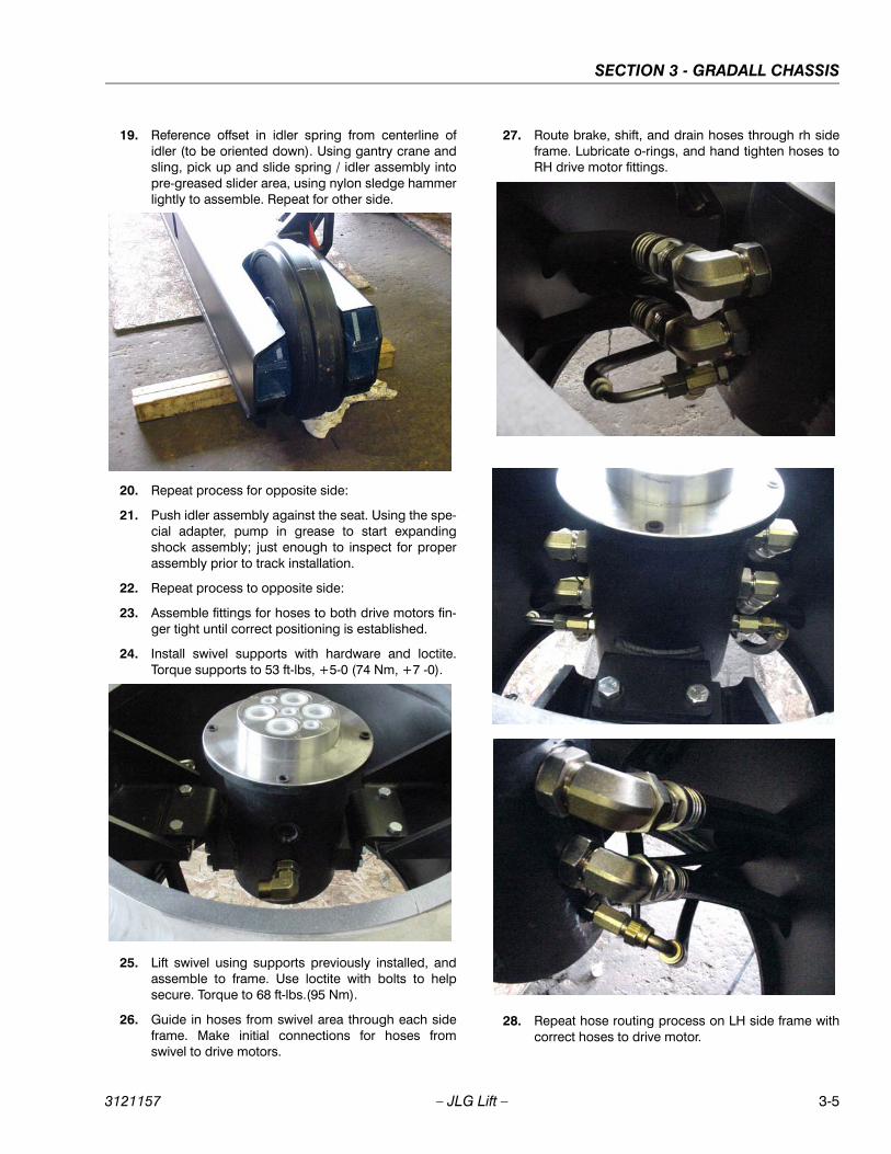
SECTION 3 - GRADALL CHASSIS
3121157 – JLG Lift – 3-5
19. Reference offset in idler spring from centerline ofidler (to be oriented down). Using gantry crane andsling, pick up and slide spring / idler assembly intopre-greased slider area, using nylon sledge hammerlightly to assemble. Repeat for other side.
20. Repeat process for opposite side:
21. Push idler assembly against the seat. Using the spe-cial adapter, pump in grease to start expandingshock assembly; just enough to inspect for properassembly prior to track installation.
22. Repeat process to opposite side:
23. Assemble fittings for hoses to both drive motors fin-ger tight until correct positioning is established.
24. Install swivel supports with hardware and loctite.Torque supports to 53 ft-lbs, +5-0 (74 Nm, +7 -0).
25. Lift swivel using supports previously installed, andassemble to frame. Use loctite with bolts to helpsecure. Torque to 68 ft-lbs.(95 Nm).
26. Guide in hoses from swivel area through each sideframe. Make initial connections for hoses fromswivel to drive motors.
27. Route brake, shift, and drain hoses through rh sideframe. Lubricate o-rings, and hand tighten hoses toRH drive motor fittings.
28. Repeat hose routing process on LH side frame withcorrect hoses to drive motor.

SECTION 3 - GRADALL CHASSIS
3-6 – JLG Lift – 3121157
1. Guide Roller2. Shaft3. Plug
4. Bearing5. Ring6. Seal
7. Mounting Bracket8. O-ring9. Roll Pin
Figure 3-4. Bottom Track Roller Assembly
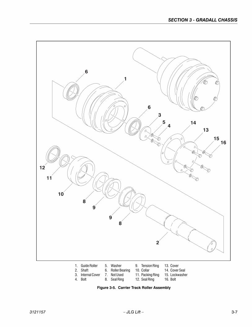
SECTION 3 - GRADALL CHASSIS
3121157 – JLG Lift – 3-7
1. Guide Roller2. Shaft3. Internal Cover4. Bolt
5. Washer6. Roller Bearing7. Not Used8. Seal Ring
9. Tension Ring10. Collar11. Packing Ring12. Seal Ring
13. Cover14. Cover Seal15. Lockwasher16. Bolt
Figure 3-5. Carrier Track Roller Assembly

SECTION 3 - GRADALL CHASSIS
3-8 – JLG Lift – 3121157
Figure 3-6. Hose Routing - Sheet 1 of 2
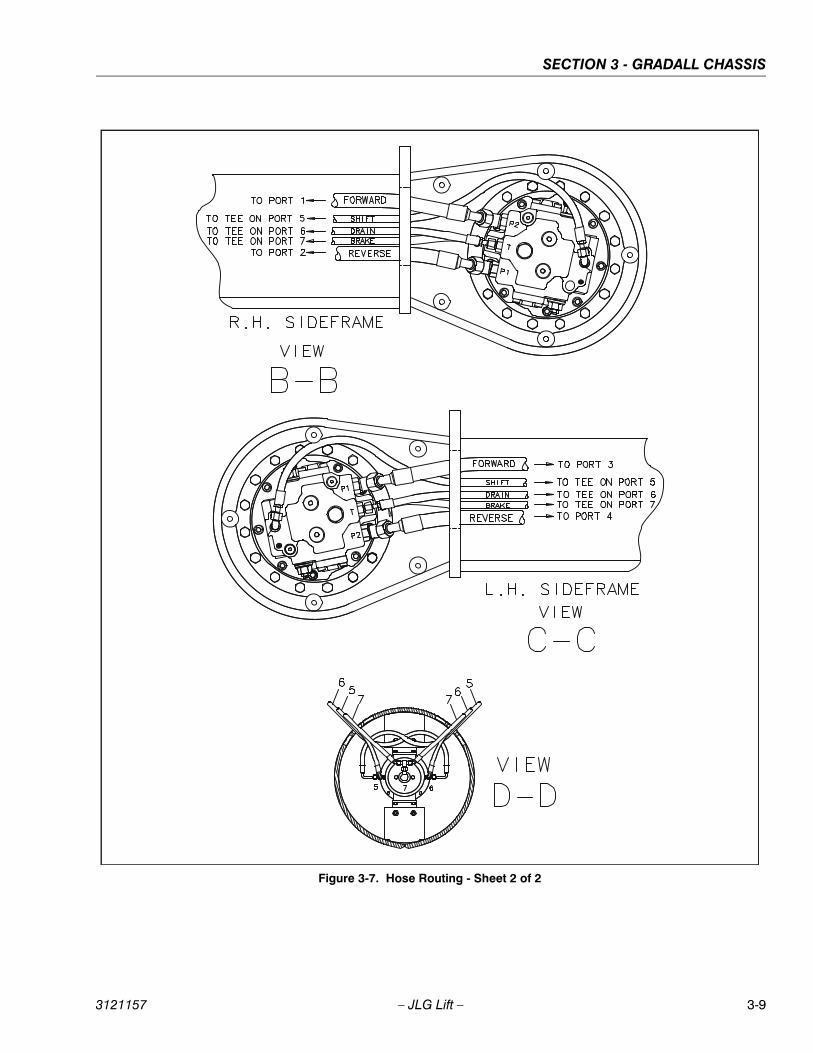
SECTION 3 - GRADALL CHASSIS
3121157 – JLG Lift – 3-9
Figure 3-7. Hose Routing - Sheet 2 of 2
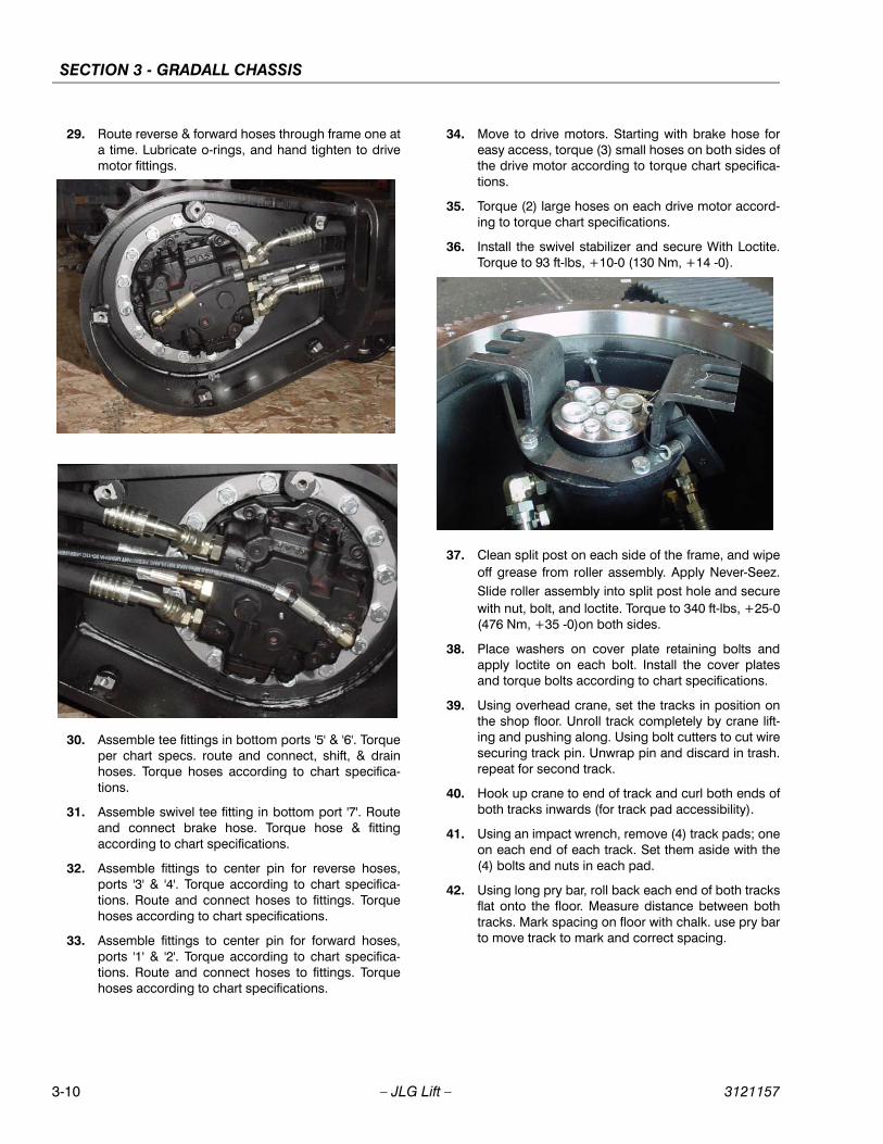
SECTION 3 - GRADALL CHASSIS
3-10 – JLG Lift – 3121157
29. Route reverse & forward hoses through frame one ata time. Lubricate o-rings, and hand tighten to drivemotor fittings.
30. Assemble tee fittings in bottom ports '5' & '6'. Torqueper chart specs. route and connect, shift, & drainhoses. Torque hoses according to chart specifica-tions.
31. Assemble swivel tee fitting in bottom port '7'. Routeand connect brake hose. Torque hose & fittingaccording to chart specifications.
32. Assemble fittings to center pin for reverse hoses,ports '3' & '4'. Torque according to chart specifica-tions. Route and connect hoses to fittings. Torquehoses according to chart specifications.
33. Assemble fittings to center pin for forward hoses,ports '1' & '2'. Torque according to chart specifica-tions. Route and connect hoses to fittings. Torquehoses according to chart specifications.
34. Move to drive motors. Starting with brake hose foreasy access, torque (3) small hoses on both sides ofthe drive motor according to torque chart specifica-tions.
35. Torque (2) large hoses on each drive motor accord-ing to torque chart specifications.
36. Install the swivel stabilizer and secure With Loctite.Torque to 93 ft-lbs, +10-0 (130 Nm, +14 -0).
37. Clean split post on each side of the frame, and wipeoff grease from roller assembly. Apply Never-Seez.Slide roller assembly into split post hole and securewith nut, bolt, and loctite. Torque to 340 ft-lbs, +25-0(476 Nm, +35 -0)on both sides.
38. Place washers on cover plate retaining bolts andapply loctite on each bolt. Install the cover platesand torque bolts according to chart specifications.
39. Using overhead crane, set the tracks in position onthe shop floor. Unroll track completely by crane lift-ing and pushing along. Using bolt cutters to cut wiresecuring track pin. Unwrap pin and discard in trash.repeat for second track.
40. Hook up crane to end of track and curl both ends ofboth tracks inwards (for track pad accessibility).
41. Using an impact wrench, remove (4) track pads; oneon each end of each track. Set them aside with the(4) bolts and nuts in each pad.
42. Using long pry bar, roll back each end of both tracksflat onto the floor. Measure distance between bothtracks. Mark spacing on floor with chalk. use pry barto move track to mark and correct spacing.
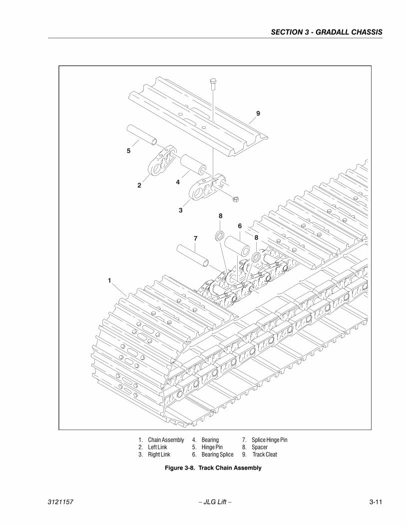
SECTION 3 - GRADALL CHASSIS
3121157 – JLG Lift – 3-11
1. Chain Assembly2. Left Link3. Right Link
4. Bearing5. Hinge Pin6. Bearing Splice
7. Splice Hinge Pin8. Spacer9. Track Cleat
Figure 3-8. Track Chain Assembly
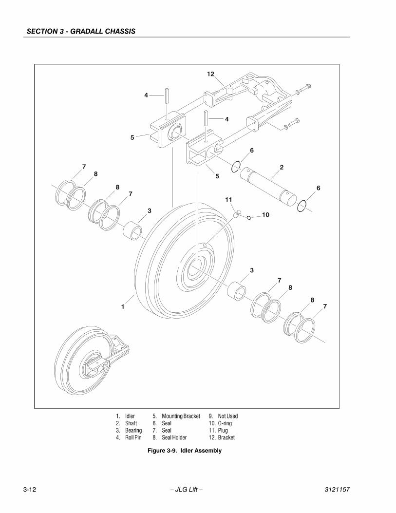
SECTION 3 - GRADALL CHASSIS
3-12 – JLG Lift – 3121157
1. Idler2. Shaft3. Bearing4. Roll Pin
5. Mounting Bracket6. Seal7. Seal8. Seal Holder
9. Not Used10. O-ring11. Plug12. Bracket
Figure 3-9. Idler Assembly
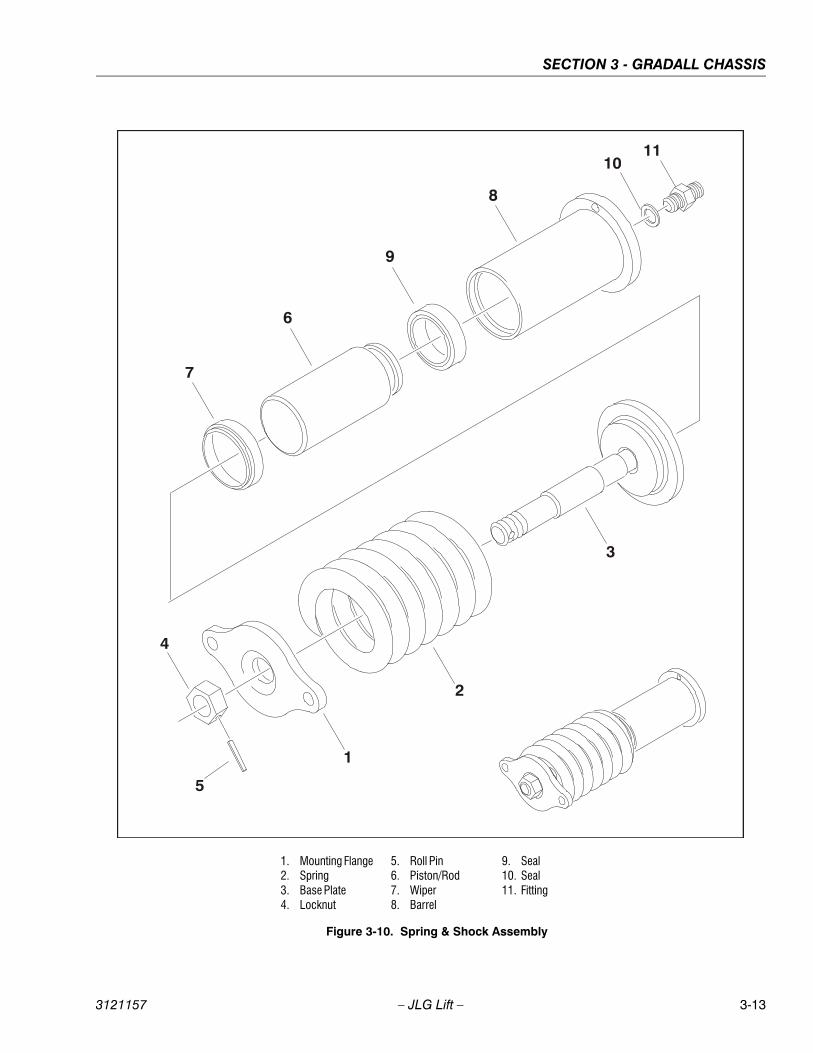
SECTION 3 - GRADALL CHASSIS
3121157 – JLG Lift – 3-13
1. Mounting Flange2. Spring3. Base Plate4. Locknut
5. Roll Pin6. Piston/Rod7. Wiper8. Barrel
9. Seal10. Seal11. Fitting
Figure 3-10. Spring & Shock Assembly
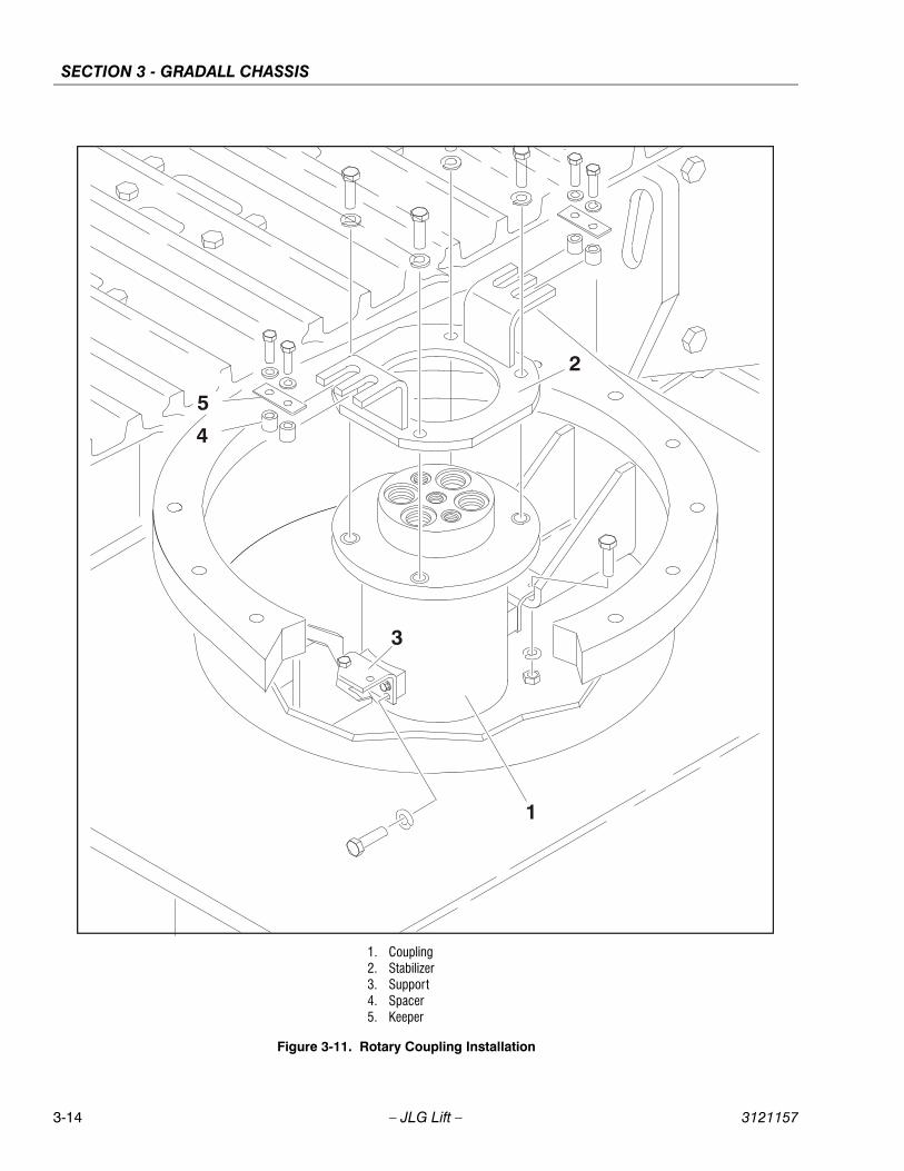
SECTION 3 - GRADALL CHASSIS
3-14 – JLG Lift – 3121157
1. Coupling2. Stabilizer3. Support4. Spacer5. Keeper
Figure 3-11. Rotary Coupling Installation
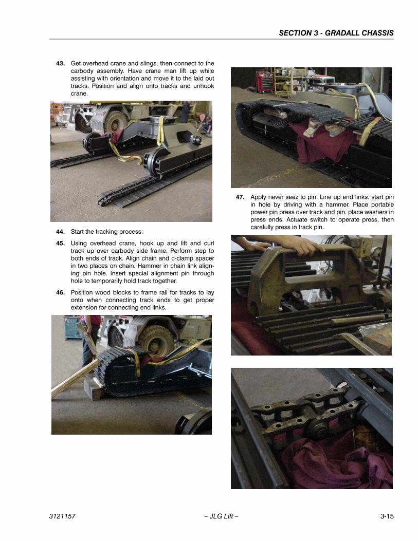
SECTION 3 - GRADALL CHASSIS
3121157 – JLG Lift – 3-15
43. Get overhead crane and slings, then connect to thecarbody assembly. Have crane man lift up whileassisting with orientation and move it to the laid outtracks. Position and align onto tracks and unhookcrane.
44. Start the tracking process:
45. Using overhead crane, hook up and lift and curltrack up over carbody side frame. Perform step toboth ends of track. Align chain and c-clamp spacerin two places on chain. Hammer in chain link align-ing pin hole. Insert special alignment pin throughhole to temporarily hold track together.
46. Position wood blocks to frame rail for tracks to layonto when connecting track ends to get properextension for connecting end links.
47. Apply never seez to pin. Line up end links. start pinin hole by driving with a hammer. Place portablepower pin press over track and pin. place washers inpress ends. Actuate switch to operate press, thencarefully press in track pin.
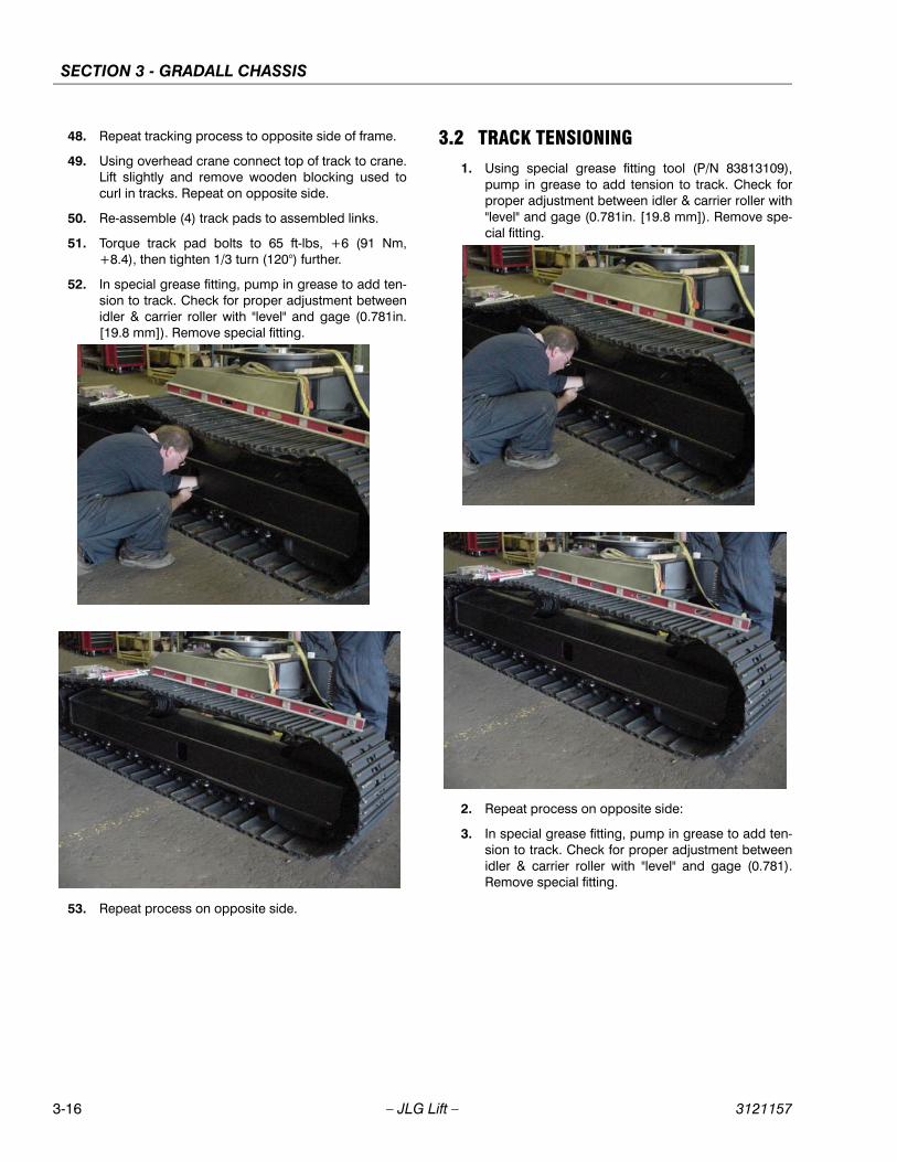
SECTION 3 - GRADALL CHASSIS
3-16 – JLG Lift – 3121157
48. Repeat tracking process to opposite side of frame.
49. Using overhead crane connect top of track to crane.Lift slightly and remove wooden blocking used tocurl in tracks. Repeat on opposite side.
50. Re-assemble (4) track pads to assembled links.
51. Torque track pad bolts to 65 ft-lbs, +6 (91 Nm,+8.4), then tighten 1/3 turn (120°) further.
52. In special grease fitting, pump in grease to add ten-sion to track. Check for proper adjustment betweenidler & carrier roller with "level" and gage (0.781in.[19.8 mm]). Remove special fitting.
53. Repeat process on opposite side.
3.2 TRACK TENSIONING1. Using special grease fitting tool (P/N 83813109),
pump in grease to add tension to track. Check forproper adjustment between idler & carrier roller with"level" and gage (0.781in. [19.8 mm]). Remove spe-cial fitting.
2. Repeat process on opposite side:
3. In special grease fitting, pump in grease to add ten-sion to track. Check for proper adjustment betweenidler & carrier roller with "level" and gage (0.781).Remove special fitting.
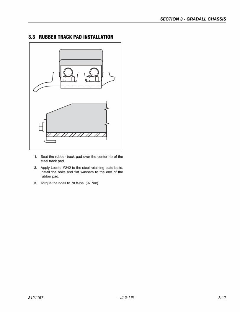
SECTION 3 - GRADALL CHASSIS
3121157 – JLG Lift – 3-17
3.3 RUBBER TRACK PAD INSTALLATION
1. Seat the rubber track pad over the center rib of thesteel track pad.
2. Apply Loctite #242 to the steel retaining plate bolts.Install the bolts and flat washers to the end of therubber pad.
3. Torque the bolts to 70 ft-lbs. (97 Nm).

SECTION 3 - GRADALL CHASSIS
3-18 – JLG Lift – 3121157
NOTES:
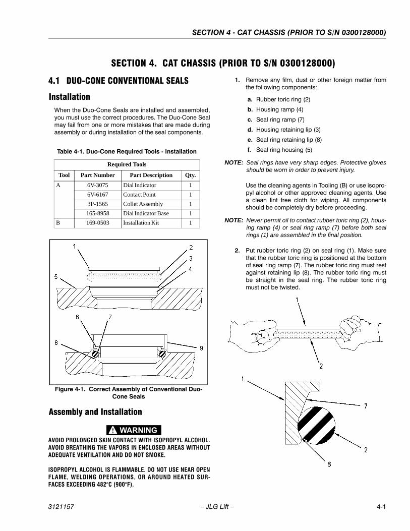
SECTION 4 - CAT CHASSIS (PRIOR TO S/N 0300128000)
3121157 – JLG Lift – 4-1
SECTION 4. CAT CHASSIS (PRIOR TO S/N 0300128000)
4.1 DUO-CONE CONVENTIONAL SEALS
InstallationWhen the Duo-Cone Seals are installed and assembled,you must use the correct procedures. The Duo-Cone Sealmay fail from one or more mistakes that are made duringassembly or during installation of the seal components.
Assembly and Installation
AVOID PROLONGED SKIN CONTACT WITH ISOPROPYL ALCOHOL.AVOID BREATHING THE VAPORS IN ENCLOSED AREAS WITHOUTADEQUATE VENTILATION AND DO NOT SMOKE.
ISOPROPYL ALCOHOL IS FLAMMABLE. DO NOT USE NEAR OPENFLAME, WELDING OPERATIONS, OR AROUND HEATED SUR-FACES EXCEEDING 482°C (900°F).
1. Remove any film, dust or other foreign matter fromthe following components:
a. Rubber toric ring (2)
b. Housing ramp (4)
c. Seal ring ramp (7)
d. Housing retaining lip (3)
e. Seal ring retaining lip (8)
f. Seal ring housing (5)
NOTE: Seal rings have very sharp edges. Protective glovesshould be worn in order to prevent injury.
Use the cleaning agents in Tooling (B) or use isopro-pyl alcohol or other approved cleaning agents. Usea clean lint free cloth for wiping. All componentsshould be completely dry before proceeding.
NOTE: Never permit oil to contact rubber toric ring (2), hous-ing ramp (4) or seal ring ramp (7) before both sealrings (1) are assembled in the final position.
2. Put rubber toric ring (2) on seal ring (1). Make surethat the rubber toric ring is positioned at the bottomof seal ring ramp (7). The rubber toric ring must restagainst retaining lip (8). The rubber toric ring mustbe straight in the seal ring. The rubber toric ringmust not be twisted.
Table 4-1. Duo-Cone Required Tools - Installation
Required Tools
Tool Part Number Part Description Qty.
A 6V-3075 Dial Indicator 1
6V-6167 Contact Point 1
3P-1565 Collet Assembly 1
165-8958 Dial Indicator Base 1
B 169-0503 Installation Kit 1
Figure 4-1. Correct Assembly of Conventional Duo-Cone Seals
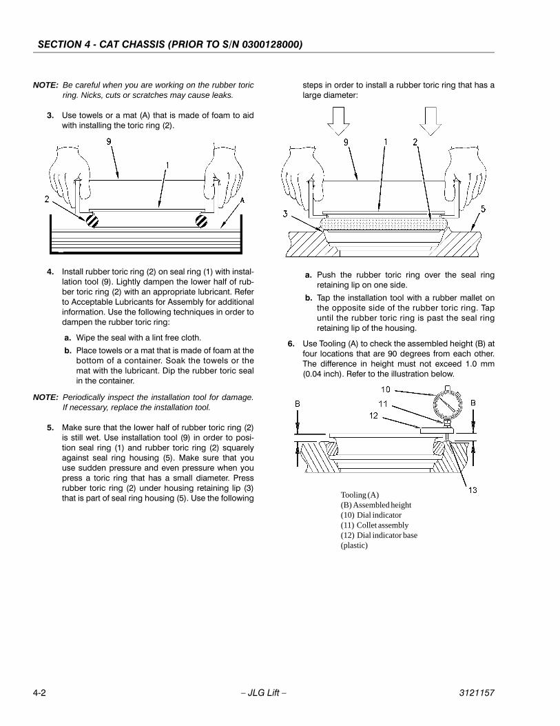
SECTION 4 - CAT CHASSIS (PRIOR TO S/N 0300128000)
4-2 – JLG Lift – 3121157
NOTE: Be careful when you are working on the rubber toricring. Nicks, cuts or scratches may cause leaks.
3. Use towels or a mat (A) that is made of foam to aidwith installing the toric ring (2).
4. Install rubber toric ring (2) on seal ring (1) with instal-lation tool (9). Lightly dampen the lower half of rub-ber toric ring (2) with an appropriate lubricant. Referto Acceptable Lubricants for Assembly for additionalinformation. Use the following techniques in order todampen the rubber toric ring:
a. Wipe the seal with a lint free cloth.
b. Place towels or a mat that is made of foam at thebottom of a container. Soak the towels or themat with the lubricant. Dip the rubber toric sealin the container.
NOTE: Periodically inspect the installation tool for damage.If necessary, replace the installation tool.
5. Make sure that the lower half of rubber toric ring (2)is still wet. Use installation tool (9) in order to posi-tion seal ring (1) and rubber toric ring (2) squarelyagainst seal ring housing (5). Make sure that youuse sudden pressure and even pressure when youpress a toric ring that has a small diameter. Pressrubber toric ring (2) under housing retaining lip (3)that is part of seal ring housing (5). Use the following
steps in order to install a rubber toric ring that has alarge diameter:
a. Push the rubber toric ring over the seal ringretaining lip on one side.
b. Tap the installation tool with a rubber mallet onthe opposite side of the rubber toric ring. Tapuntil the rubber toric ring is past the seal ringretaining lip of the housing.
6. Use Tooling (A) to check the assembled height (B) atfour locations that are 90 degrees from each other.The difference in height must not exceed 1.0 mm(0.04 inch). Refer to the illustration below.
Tooling (A)(B) Assembled height(10) Dial indicator(11) Collet assembly(12) Dial indicator base (plastic)
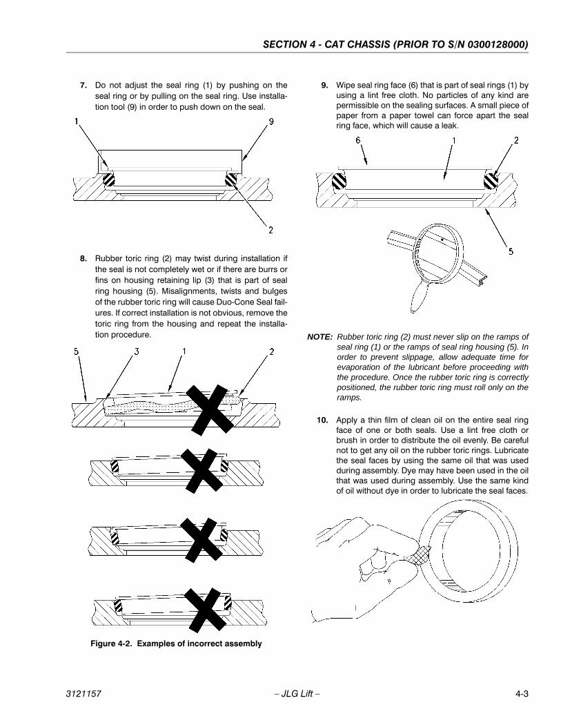
SECTION 4 - CAT CHASSIS (PRIOR TO S/N 0300128000)
3121157 – JLG Lift – 4-3
7. Do not adjust the seal ring (1) by pushing on theseal ring or by pulling on the seal ring. Use installa-tion tool (9) in order to push down on the seal.
8. Rubber toric ring (2) may twist during installation ifthe seal is not completely wet or if there are burrs orfins on housing retaining lip (3) that is part of sealring housing (5). Misalignments, twists and bulgesof the rubber toric ring will cause Duo-Cone Seal fail-ures. If correct installation is not obvious, remove thetoric ring from the housing and repeat the installa-tion procedure.
9. Wipe seal ring face (6) that is part of seal rings (1) byusing a lint free cloth. No particles of any kind arepermissible on the sealing surfaces. A small piece ofpaper from a paper towel can force apart the sealring face, which will cause a leak.
NOTE: Rubber toric ring (2) must never slip on the ramps ofseal ring (1) or the ramps of seal ring housing (5). Inorder to prevent slippage, allow adequate time forevaporation of the lubricant before proceeding withthe procedure. Once the rubber toric ring is correctlypositioned, the rubber toric ring must roll only on theramps.
10. Apply a thin film of clean oil on the entire seal ringface of one or both seals. Use a lint free cloth orbrush in order to distribute the oil evenly. Be carefulnot to get any oil on the rubber toric rings. Lubricatethe seal faces by using the same oil that was usedduring assembly. Dye may have been used in the oilthat was used during assembly. Use the same kindof oil without dye in order to lubricate the seal faces.
Figure 4-2. Examples of incorrect assembly
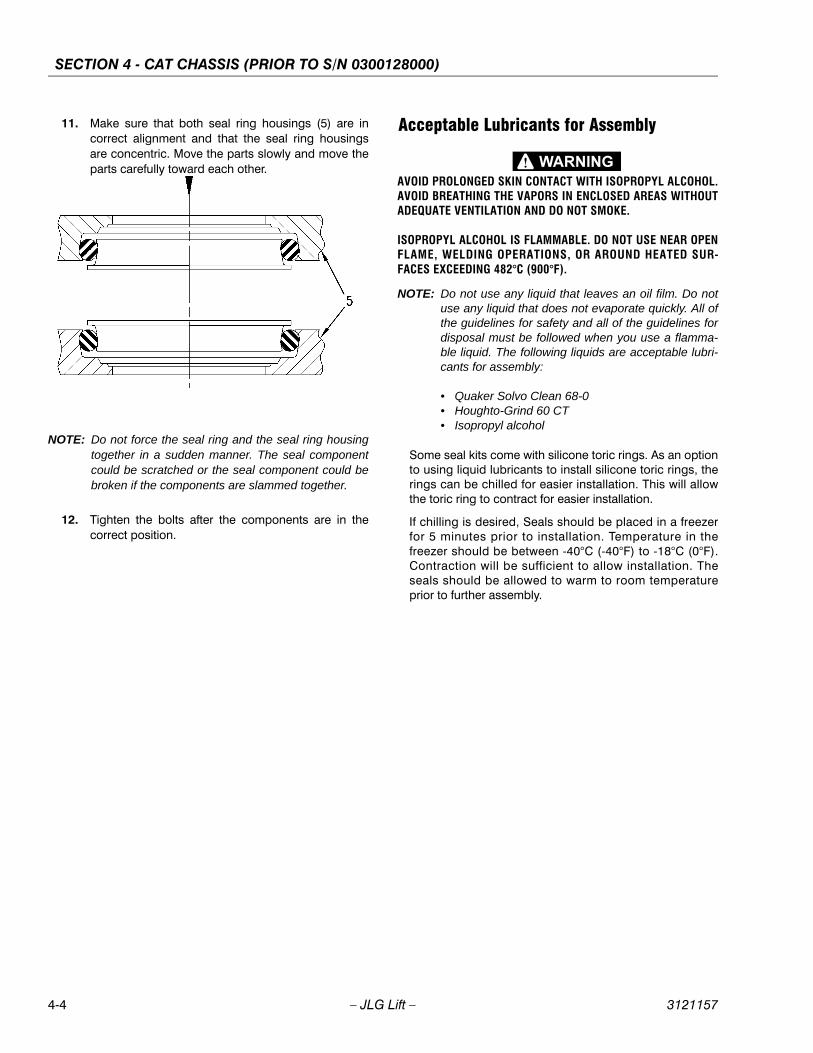
SECTION 4 - CAT CHASSIS (PRIOR TO S/N 0300128000)
4-4 – JLG Lift – 3121157
11. Make sure that both seal ring housings (5) are incorrect alignment and that the seal ring housingsare concentric. Move the parts slowly and move theparts carefully toward each other.
NOTE: Do not force the seal ring and the seal ring housingtogether in a sudden manner. The seal componentcould be scratched or the seal component could bebroken if the components are slammed together.
12. Tighten the bolts after the components are in thecorrect position.
Acceptable Lubricants for Assembly
AVOID PROLONGED SKIN CONTACT WITH ISOPROPYL ALCOHOL.AVOID BREATHING THE VAPORS IN ENCLOSED AREAS WITHOUTADEQUATE VENTILATION AND DO NOT SMOKE.
ISOPROPYL ALCOHOL IS FLAMMABLE. DO NOT USE NEAR OPENFLAME, WELDING OPERATIONS, OR AROUND HEATED SUR-FACES EXCEEDING 482°C (900°F).
NOTE: Do not use any liquid that leaves an oil film. Do notuse any liquid that does not evaporate quickly. All ofthe guidelines for safety and all of the guidelines fordisposal must be followed when you use a flamma-ble liquid. The following liquids are acceptable lubri-cants for assembly:
• Quaker Solvo Clean 68-0• Houghto-Grind 60 CT• Isopropyl alcohol
Some seal kits come with silicone toric rings. As an optionto using liquid lubricants to install silicone toric rings, therings can be chilled for easier installation. This will allowthe toric ring to contract for easier installation.
If chilling is desired, Seals should be placed in a freezerfor 5 minutes prior to installation. Temperature in thefreezer should be between -40°C (-40°F) to -18°C (0°F).Contraction will be sufficient to allow installation. Theseals should be allowed to warm to room temperatureprior to further assembly.
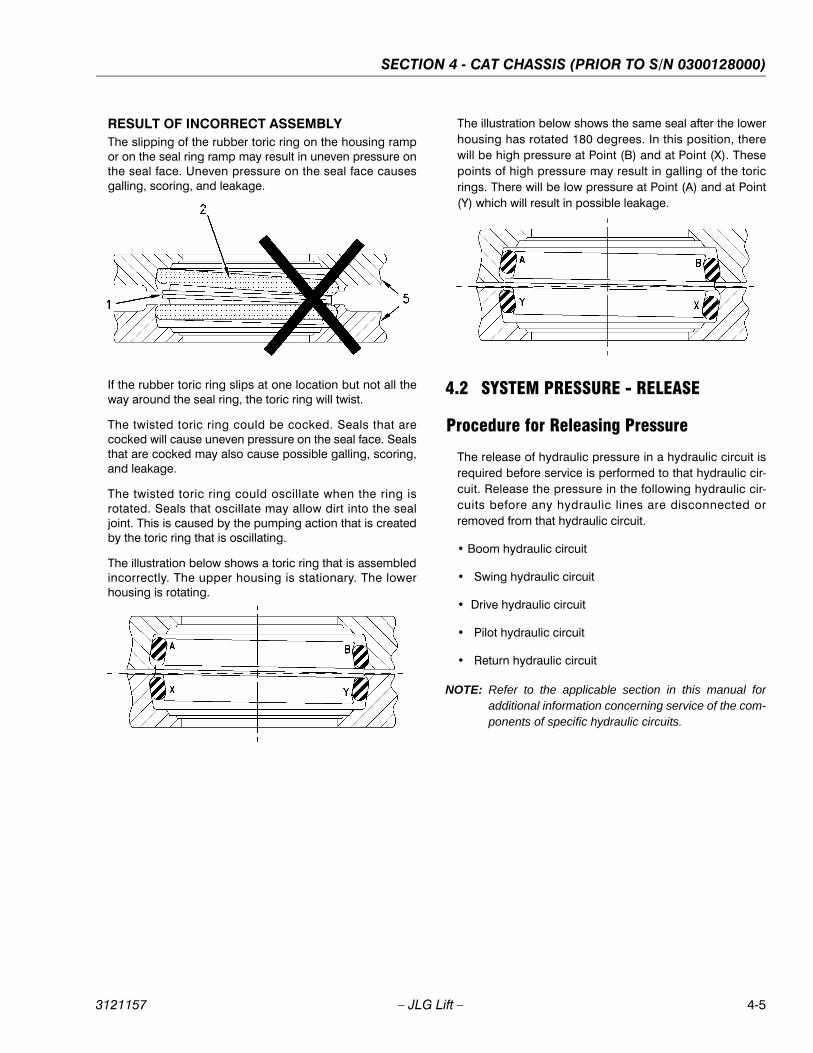
SECTION 4 - CAT CHASSIS (PRIOR TO S/N 0300128000)
3121157 – JLG Lift – 4-5
RESULT OF INCORRECT ASSEMBLYThe slipping of the rubber toric ring on the housing rampor on the seal ring ramp may result in uneven pressure onthe seal face. Uneven pressure on the seal face causesgalling, scoring, and leakage.
If the rubber toric ring slips at one location but not all theway around the seal ring, the toric ring will twist.
The twisted toric ring could be cocked. Seals that arecocked will cause uneven pressure on the seal face. Sealsthat are cocked may also cause possible galling, scoring,and leakage.
The twisted toric ring could oscillate when the ring isrotated. Seals that oscillate may allow dirt into the sealjoint. This is caused by the pumping action that is createdby the toric ring that is oscillating.
The illustration below shows a toric ring that is assembledincorrectly. The upper housing is stationary. The lowerhousing is rotating.
The illustration below shows the same seal after the lowerhousing has rotated 180 degrees. In this position, therewill be high pressure at Point (B) and at Point (X). Thesepoints of high pressure may result in galling of the toricrings. There will be low pressure at Point (A) and at Point(Y) which will result in possible leakage.
4.2 SYSTEM PRESSURE - RELEASE
Procedure for Releasing Pressure
The release of hydraulic pressure in a hydraulic circuit isrequired before service is performed to that hydraulic cir-cuit. Release the pressure in the following hydraulic cir-cuits before any hydraulic lines are disconnected orremoved from that hydraulic circuit.
• Boom hydraulic circuit
• Swing hydraulic circuit
• Drive hydraulic circuit
• Pilot hydraulic circuit
• Return hydraulic circuit
NOTE: Refer to the applicable section in this manual foradditional information concerning service of the com-ponents of specific hydraulic circuits.
SECTION 4 - CAT CHASSIS (PRIOR TO S/N 0300128000)
4-6 – JLG Lift – 3121157
Release Of Hydraulic Pressure From A Single Hydraulic Circuit
PERSONAL INJURY CAN RESULT FROM HYDRAULIC OIL PRES-SURE AND HOT OIL.
HYDRAULIC OIL PRESSURE CAN REMAIN IN THE HYDRAULICSYSTEM AFTER THE ENGINE HAS BEEN STOPPED. SERIOUSINJURY CAN BE CAUSED IF THIS PRESSURE IS NOT RELEASEDBEFORE ANY SERVICE IS DONE ON THE HYDRAULIC SYSTEM.
MAKE SURE ALL OF THE ATTACHMENTS HAVE BEEN LOWEREDTO THE GROUND, AND THE OIL IS COOL BEFORE REMOVING ANYCOMPONENTS OR LINES. REMOVE THE OIL FILLER CAP ONLYWHEN THE ENGINE IS STOPPED, AND THE FILLER CAP IS COOLENOUGH TO TOUCH WITH YOUR BARE HAND.
CARE MUST BE TAKEN TO ENSURE THAT FLUIDS ARE CON-TAINED DURING PERFORMANCE OF INSPECTION, MAINTE-NANCE, TESTING, ADJUSTING AND REPAIR OF THE PRODUCT.BE PREPARED TO COLLECT THE FLUID WITH SUITABLE CON-TAINERS BEFORE OPENING ANY COMPARTMENT OR DISASSEM-BLING ANY COMPONENT CONTAINING FLUIDS.
DISPOSE OF ALL FLUIDS ACCORDING TO LOCAL REGULATIONSAND MANDATES.
Perform the following steps in order to release the hydrau-lic pressure from a single hydraulic circuit of the mainhydraulic system.
1. Position the machine on level ground.
2. Fully retract the stick cylinder rod. Adjust the posi-tion of the bucket so that the bucket is parallel to theground. Lower the boom until the bucket is flat onthe ground.
3. Shut off the engine.
4. Turn the engine start switch to the ON position with-out starting the engine.
5. Place the hydraulic activation control lever in theUNLOCKED position.
6. Move only the joysticks or the pedals of the hydrau-lic circuit that requires service to the FULL STROKEpositions. This will release the high pressure only inthat single hydraulic circuit. This will also release anypressure that might be present in the pilot hydrauliccircuit.
NOTE: If the desired hydraulic circuit that requires servicerequires the activation of a switch for operation, acti-vate the necessary switches for the operation of thehydraulic circuit.
7. Place the hydraulic activation control lever in theLOCKED position.
8. Turn the engine start switch to the OFF position.
9. Slowly loosen the filler plug on the hydraulic tankand release the pressure from the hydraulic tank.Leave the filler plug loose for a minimum of 45 sec-onds. This will release the pressure that may bepresent in the return hydraulic circuit.
10. Tighten the filler plug on the hydraulic tank to thespecified torque.
11. The pressure in the single hydraulic circuit thatrequires service is now released and lines and com-ponents can be disconnected or removed from thathydraulic circuit.
SECTION 4 - CAT CHASSIS (PRIOR TO S/N 0300128000)
3121157 – JLG Lift – 4-7
Release Of Hydraulic Pressure From Multiple Hydraulic Circuits
PERSONAL INJURY CAN RESULT FROM HYDRAULIC OIL PRES-SURE AND HOT OIL.
HYDRAULIC OIL PRESSURE CAN REMAIN IN THE HYDRAULICSYSTEM AFTER THE ENGINE HAS BEEN STOPPED. SERIOUSINJURY CAN BE CAUSED IF THIS PRESSURE IS NOT RELEASEDBEFORE ANY SERVICE IS DONE ON THE HYDRAULIC SYSTEM.
MAKE SURE ALL OF THE ATTACHMENTS HAVE BEEN LOWEREDTO THE GROUND, AND THE OIL IS COOL BEFORE REMOVING ANYCOMPONENTS OR LINES. REMOVE THE OIL FILLER CAP ONLYWHEN THE ENGINE IS STOPPED, AND THE FILLER CAP IS COOLENOUGH TO TOUCH WITH YOUR BARE HAND.
CARE MUST BE TAKEN TO ENSURE THAT FLUIDS ARE CON-TAINED DURING PERFORMANCE OF INSPECTION, MAINTE-NANCE, TESTING, ADJUSTING AND REPAIR OF THE PRODUCT.BE PREPARED TO COLLECT THE FLUID WITH SUITABLE CON-TAINERS BEFORE OPENING ANY COMPARTMENT OR DISASSEM-BLING ANY COMPONENT CONTAINING FLUIDS.
DISPOSE OF ALL FLUIDS ACCORDING TO LOCAL REGULATIONSAND MANDATES.
Perform the following Steps in order to release the hydrau-lic pressure from multiple hydraulic circuits of the mainhydraulic system.
1. Position the machine on level ground.
2. Fully retract the stick cylinder rod. Adjust the posi-tion of the bucket so that the bucket is parallel to theground. Lower the boom until the bucket is flat onthe ground.
3. Shut off the engine.
4. Turn the engine start switch to the ON position with-out starting the engine.
5. Place the hydraulic activation control lever in theUNLOCKED position.
6. Move only the joysticks or the pedals of the hydrau-lic circuit that requires service to the FULL STROKEpositions. This will release the high pressure only inthat hydraulic circuit. This will also release any pres-sure that might be present in the pilot hydraulic cir-cuit.
NOTE: If the hydraulic circuit that requires service requiresthe activation of a switch for operation, activate thenecessary switches for the operation of the hydrauliccircuit.
7. Place the hydraulic activation control lever in theLOCKED position.
8. Start the engine.
9. Place the hydraulic activation control lever in theUNLOCKED position. Do not move any joysticks orpedals from the NEUTRAL position during this step.Do not activate any switches during this Step.
10. Return the hydraulic activation control lever to theLOCKED position.
11. Shut off the engine.
12. Repeat Steps 4 through 11 for each additionalhydraulic circuit that requires service.
13. After releasing the hydraulic pressure in each of thedesired hydraulic circuits, place the hydraulic activa-tion control lever in the LOCKED position.
14. Turn the engine start switch to the OFF position.
15. Slowly loosen the filler plug on the hydraulic tankand release the pressure. Leave the filler plug loosefor a minimum of 45 seconds. This will release thepressure that may be present in the return hydrauliccircuit.
16. Tighten the filler plug on the hydraulic tank to thespecified torque.
17. The pressure in the multiple hydraulic circuits thatrequire service is now released and lines and com-ponents can be disconnected or removed fromthose hydraulic circuits.
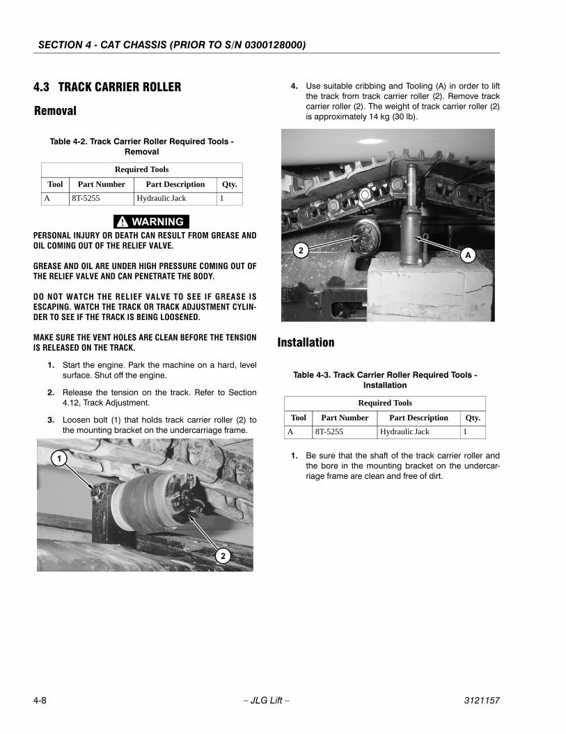
SECTION 4 - CAT CHASSIS (PRIOR TO S/N 0300128000)
4-8 – JLG Lift – 3121157
4.3 TRACK CARRIER ROLLER
Removal
PERSONAL INJURY OR DEATH CAN RESULT FROM GREASE ANDOIL COMING OUT OF THE RELIEF VALVE.
GREASE AND OIL ARE UNDER HIGH PRESSURE COMING OUT OFTHE RELIEF VALVE AND CAN PENETRATE THE BODY.
DO NOT WATCH THE RELIEF VALVE TO SEE IF GREASE ISESCAPING. WATCH THE TRACK OR TRACK ADJUSTMENT CYLIN-DER TO SEE IF THE TRACK IS BEING LOOSENED.
MAKE SURE THE VENT HOLES ARE CLEAN BEFORE THE TENSIONIS RELEASED ON THE TRACK.
1. Start the engine. Park the machine on a hard, levelsurface. Shut off the engine.
2. Release the tension on the track. Refer to Section4.12, Track Adjustment.
3. Loosen bolt (1) that holds track carrier roller (2) tothe mounting bracket on the undercarriage frame.
4. Use suitable cribbing and Tooling (A) in order to liftthe track from track carrier roller (2). Remove trackcarrier roller (2). The weight of track carrier roller (2)is approximately 14 kg (30 lb).
Installation
1. Be sure that the shaft of the track carrier roller andthe bore in the mounting bracket on the undercar-riage frame are clean and free of dirt.
Table 4-2. Track Carrier Roller Required Tools - Removal
Required Tools
Tool Part Number Part Description Qty.
A 8T-5255 Hydraulic Jack 1
Table 4-3. Track Carrier Roller Required Tools - Installation
Required Tools
Tool Part Number Part Description Qty.
A 8T-5255 Hydraulic Jack 1
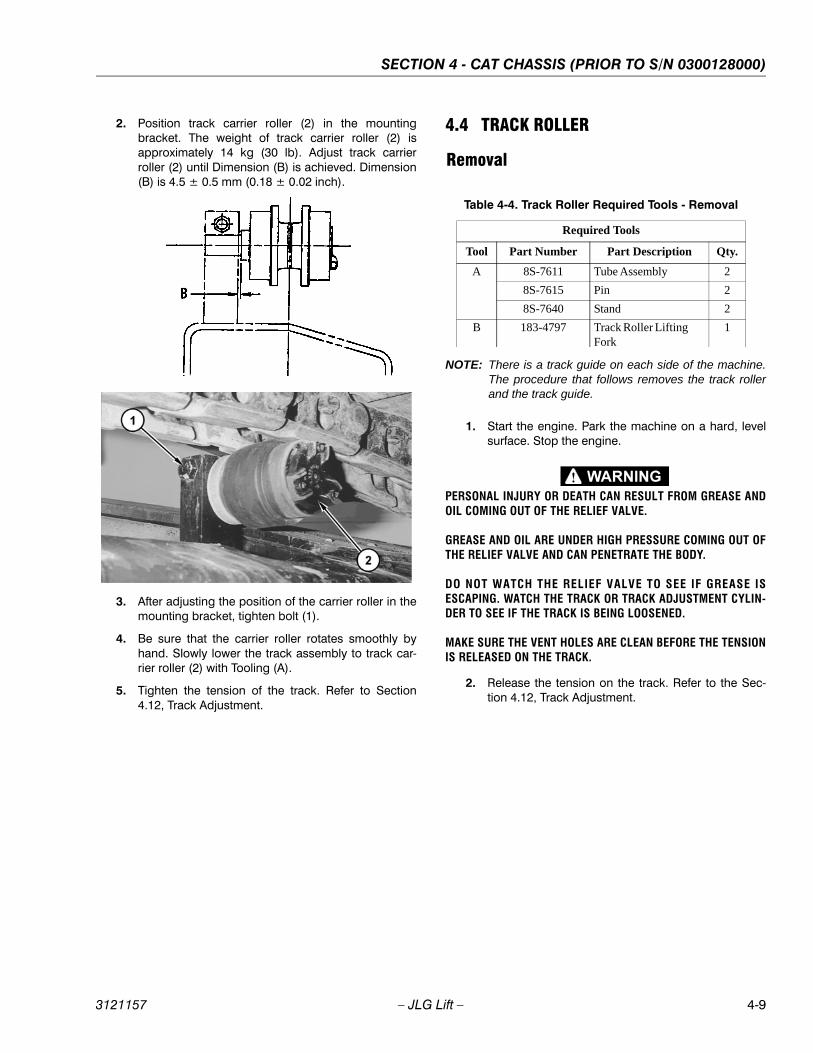
SECTION 4 - CAT CHASSIS (PRIOR TO S/N 0300128000)
3121157 – JLG Lift – 4-9
2. Position track carrier roller (2) in the mountingbracket. The weight of track carrier roller (2) isapproximately 14 kg (30 lb). Adjust track carrierroller (2) until Dimension (B) is achieved. Dimension(B) is 4.5 ± 0.5 mm (0.18 ± 0.02 inch).
3. After adjusting the position of the carrier roller in themounting bracket, tighten bolt (1).
4. Be sure that the carrier roller rotates smoothly byhand. Slowly lower the track assembly to track car-rier roller (2) with Tooling (A).
5. Tighten the tension of the track. Refer to Section4.12, Track Adjustment.
4.4 TRACK ROLLER
Removal
NOTE: There is a track guide on each side of the machine.The procedure that follows removes the track rollerand the track guide.
1. Start the engine. Park the machine on a hard, levelsurface. Stop the engine.
PERSONAL INJURY OR DEATH CAN RESULT FROM GREASE ANDOIL COMING OUT OF THE RELIEF VALVE.
GREASE AND OIL ARE UNDER HIGH PRESSURE COMING OUT OFTHE RELIEF VALVE AND CAN PENETRATE THE BODY.
DO NOT WATCH THE RELIEF VALVE TO SEE IF GREASE ISESCAPING. WATCH THE TRACK OR TRACK ADJUSTMENT CYLIN-DER TO SEE IF THE TRACK IS BEING LOOSENED.
MAKE SURE THE VENT HOLES ARE CLEAN BEFORE THE TENSIONIS RELEASED ON THE TRACK.
2. Release the tension on the track. Refer to the Sec-tion 4.12, Track Adjustment.
Table 4-4. Track Roller Required Tools - Removal
Required Tools
Tool Part Number Part Description Qty.
A 8S-7611 Tube Assembly 2
8S-7615 Pin 2
8S-7640 Stand 2
B 183-4797 Track Roller Lifting Fork
1
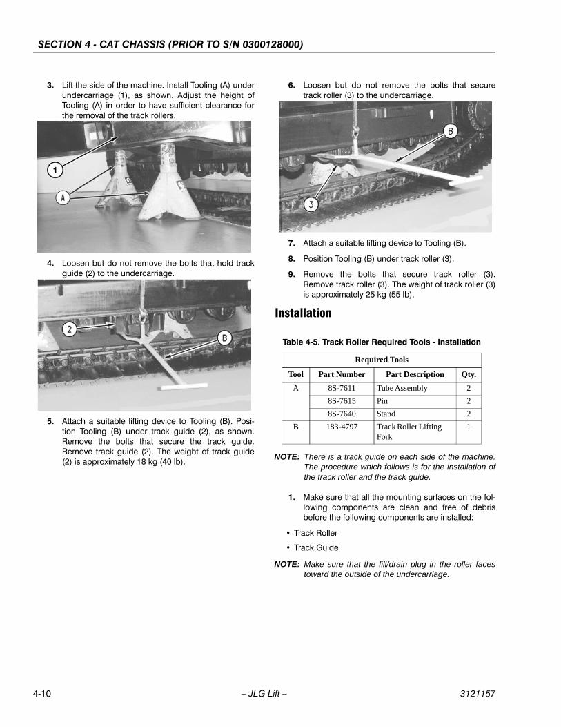
SECTION 4 - CAT CHASSIS (PRIOR TO S/N 0300128000)
4-10 – JLG Lift – 3121157
3. Lift the side of the machine. Install Tooling (A) underundercarriage (1), as shown. Adjust the height ofTooling (A) in order to have sufficient clearance forthe removal of the track rollers.
4. Loosen but do not remove the bolts that hold trackguide (2) to the undercarriage.
5. Attach a suitable lifting device to Tooling (B). Posi-tion Tooling (B) under track guide (2), as shown.Remove the bolts that secure the track guide.Remove track guide (2). The weight of track guide(2) is approximately 18 kg (40 lb).
6. Loosen but do not remove the bolts that securetrack roller (3) to the undercarriage.
7. Attach a suitable lifting device to Tooling (B).
8. Position Tooling (B) under track roller (3).
9. Remove the bolts that secure track roller (3).Remove track roller (3). The weight of track roller (3)is approximately 25 kg (55 lb).
Installation
NOTE: There is a track guide on each side of the machine.The procedure which follows is for the installation ofthe track roller and the track guide.
1. Make sure that all the mounting surfaces on the fol-lowing components are clean and free of debrisbefore the following components are installed:
• Track Roller
• Track Guide
NOTE: Make sure that the fill/drain plug in the roller facestoward the outside of the undercarriage.
Table 4-5. Track Roller Required Tools - Installation
Required Tools
Tool Part Number Part Description Qty.
A 8S-7611 Tube Assembly 2
8S-7615 Pin 2
8S-7640 Stand 2
B 183-4797 Track Roller Lifting Fork
1
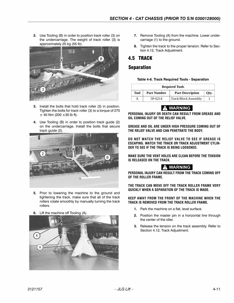
SECTION 4 - CAT CHASSIS (PRIOR TO S/N 0300128000)
3121157 – JLG Lift – 4-11
2. Use Tooling (B) in order to position track roller (3) onthe undercarriage. The weight of track roller (3) isapproximately 25 kg (55 lb).
3. Install the bolts that hold track roller (3) in position.Tighten the bolts for track roller (3) to a torque of 270± 40 Nm (200 ±30 lb ft).
4. Use Tooling (B) in order to position track guide (2)on the undercarriage. Install the bolts that securetrack guide (2).
5. Prior to lowering the machine to the ground andtightening the track, make sure that all of the trackrollers rotate smoothly by manually turning the trackrollers.
6. Lift the machine off Tooling (A).
7. Remove Tooling (A) from the machine. Lower under-carriage (1) to the ground.
8. Tighten the track to the proper tension. Refer to Sec-tion 4.12, Track Adjustment.
4.5 TRACK
Separation
PERSONAL INJURY OR DEATH CAN RESULT FROM GREASE ANDOIL COMING OUT OF THE RELIEF VALVE.
GREASE AND OIL ARE UNDER HIGH PRESSURE COMING OUT OFTHE RELIEF VALVE AND CAN PENETRATE THE BODY.
DO NOT WATCH THE RELIEF VALVE TO SEE IF GREASE ISESCAPING. WATCH THE TRACK OR TRACK ADJUSTMENT CYLIN-DER TO SEE IF THE TRACK IS BEING LOOSENED.
MAKE SURE THE VENT HOLES ARE CLEAN BEFORE THE TENSIONIS RELEASED ON THE TRACK.
PERSONAL INJURY CAN RESULT FROM THE TRACK COMING OFFOF THE ROLLER FRAME.
THE TRACK CAN MOVE OFF THE TRACK ROLLER FRAME VERYQUICKLY WHEN A SEPARATION OF THE TRACK IS MADE.
KEEP AWAY FROM THE FRONT OF THE MACHINE WHEN THETRACK IS REMOVED FROM THE TRACK ROLLER FRAME.
1. Park the machine on a flat, level surface.
2. Position the master pin in a horizontal line throughthe center of the idler.
3. Release the tension on the track assembly. Refer toSection 4.12, Track Adjustment.
Table 4-6. Track Required Tools - Separation
Required Tools
Tool Part Number Part Description Qty.
A 5P-6214 Track Block Assembly 1
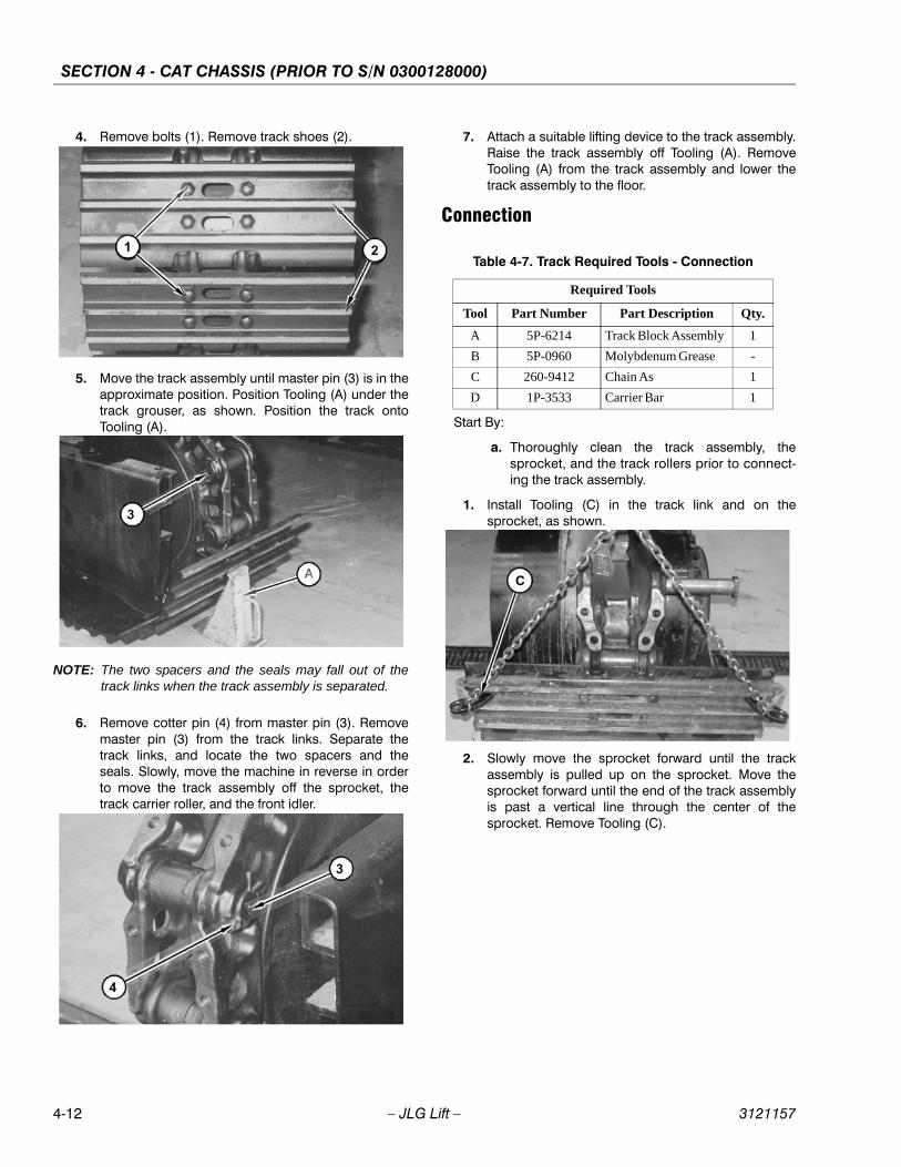
SECTION 4 - CAT CHASSIS (PRIOR TO S/N 0300128000)
4-12 – JLG Lift – 3121157
4. Remove bolts (1). Remove track shoes (2).
5. Move the track assembly until master pin (3) is in theapproximate position. Position Tooling (A) under thetrack grouser, as shown. Position the track ontoTooling (A).
NOTE: The two spacers and the seals may fall out of thetrack links when the track assembly is separated.
6. Remove cotter pin (4) from master pin (3). Removemaster pin (3) from the track links. Separate thetrack links, and locate the two spacers and theseals. Slowly, move the machine in reverse in orderto move the track assembly off the sprocket, thetrack carrier roller, and the front idler.
7. Attach a suitable lifting device to the track assembly.Raise the track assembly off Tooling (A). RemoveTooling (A) from the track assembly and lower thetrack assembly to the floor.
Connection
Start By:
a. Thoroughly clean the track assembly, thesprocket, and the track rollers prior to connect-ing the track assembly.
1. Install Tooling (C) in the track link and on thesprocket, as shown.
2. Slowly move the sprocket forward until the trackassembly is pulled up on the sprocket. Move thesprocket forward until the end of the track assemblyis past a vertical line through the center of thesprocket. Remove Tooling (C).
Table 4-7. Track Required Tools - Connection
Required Tools
Tool Part Number Part Description Qty.
A 5P-6214 Track Block Assembly 1
B 5P-0960 Molybdenum Grease -
C 260-9412 Chain As 1
D 1P-3533 Carrier Bar 1

SECTION 4 - CAT CHASSIS (PRIOR TO S/N 0300128000)
3121157 – JLG Lift – 4-13
3. Install Tooling (D) between the first bushing in thetrack link and the sprocket, as shown.
4. Move the sprocket forward. Use Tooling (D) to guidethe track assembly over the carrier roller and thefront idler.
5. Slowly move the machine forward until the separa-tion in the track assembly is below a horizontal linethrough the center of the front idler.
6. Put Tooling (B) on spacers (6) in order to hold spac-ers (6) and the seals in place. Install spacers (6) andthe seals in the track links.
7. Raise the front of the track assembly, and installTooling (A) under the track assembly. Slowly movethe machine forward until the separation in the trackassembly closes, and the pin bores in each end ofthe track assembly are in alignment with each other.The machine may need to be moved back and forthin order to align the pin bores.
8. Put Tooling (B) in the master pin bores in the trackassembly and on master pin (3). Install master pin(3). Install cotter pin (4) in order to retain the masterpin. Remove Tooling (A).
9. Install track shoes (2) over the master pin on thetrack assembly. Tighten bolts (1) to a torque of 175± 40 Nm (130 ± 30 lb ft). Tighten bolts (1) by anadditional 120°.
10. Adjust the track tension. Refer to Section 4.12, TrackAdjustment.
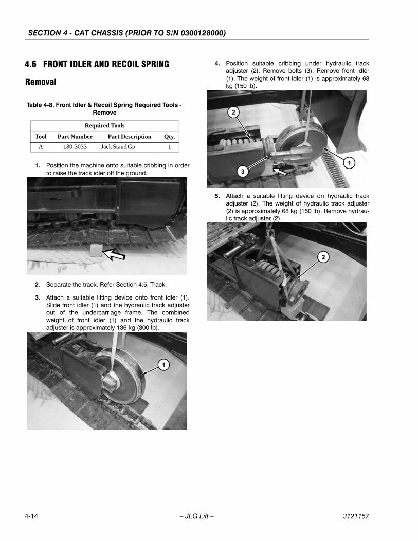
SECTION 4 - CAT CHASSIS (PRIOR TO S/N 0300128000)
4-14 – JLG Lift – 3121157
4.6 FRONT IDLER AND RECOIL SPRING
Removal
1. Position the machine onto suitable cribbing in orderto raise the track idler off the ground.
2. Separate the track. Refer Section 4.5, Track.
3. Attach a suitable lifting device onto front idler (1).Slide front idler (1) and the hydraulic track adjusterout of the undercarriage frame. The combinedweight of front idler (1) and the hydraulic trackadjuster is approximately 136 kg (300 lb).
4. Position suitable cribbing under hydraulic trackadjuster (2). Remove bolts (3). Remove front idler(1). The weight of front idler (1) is approximately 68kg (150 lb).
5. Attach a suitable lifting device on hydraulic trackadjuster (2). The weight of hydraulic track adjuster(2) is approximately 68 kg (150 lb). Remove hydrau-lic track adjuster (2).
Table 4-8. Front Idler & Recoil Spring Required Tools - Remove
Required Tools
Tool Part Number Part Description Qty.
A 180-3033 Jack Stand Gp 1
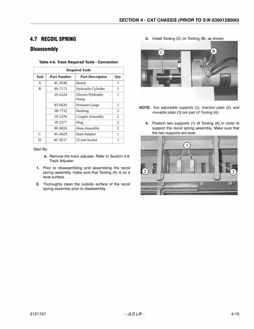
SECTION 4 - CAT CHASSIS (PRIOR TO S/N 0300128000)
3121157 – JLG Lift – 4-15
4.7 RECOIL SPRING
Disassembly
Start By:
a. Remove the track adjuster. Refer to Section 4.9,Track Adjuster.
1. Prior to disassembling and assembling the recoilspring assembly, make sure that Tooling (A) is on alevel surface.
2. Thoroughly clean the outside surface of the recoilspring assembly prior to disassembly.
3. Install Tooling (C) on Tooling (B), as shown.
NOTE: Two adjustable supports (1), reaction plate (2), andmovable plate (3) are part of Tooling (A).
4. Position two supports (1) of Tooling (A) in order tosupport the recoil spring assembly. Make sure thatthe two supports are level.
Table 4-9. Track Required Tools - Connection
Required Tools
Tool Part Number Part Description Qty.
A 4C-9540 Bench 1
B 8S-7172 Hydraulic Cylinder 1
3S-6224 Electric Hydraulic Pump
1
8T-0820 Pressure Gauge 1
3B-7722 Bushing 2
1P-2376 Coupler Assembly 2
1P-2377 Plug 2
8F-0024 Hose Assembly 2
C 4C-6629 Ram Adapter 1
D 4C-8217 55 mm Socket 1
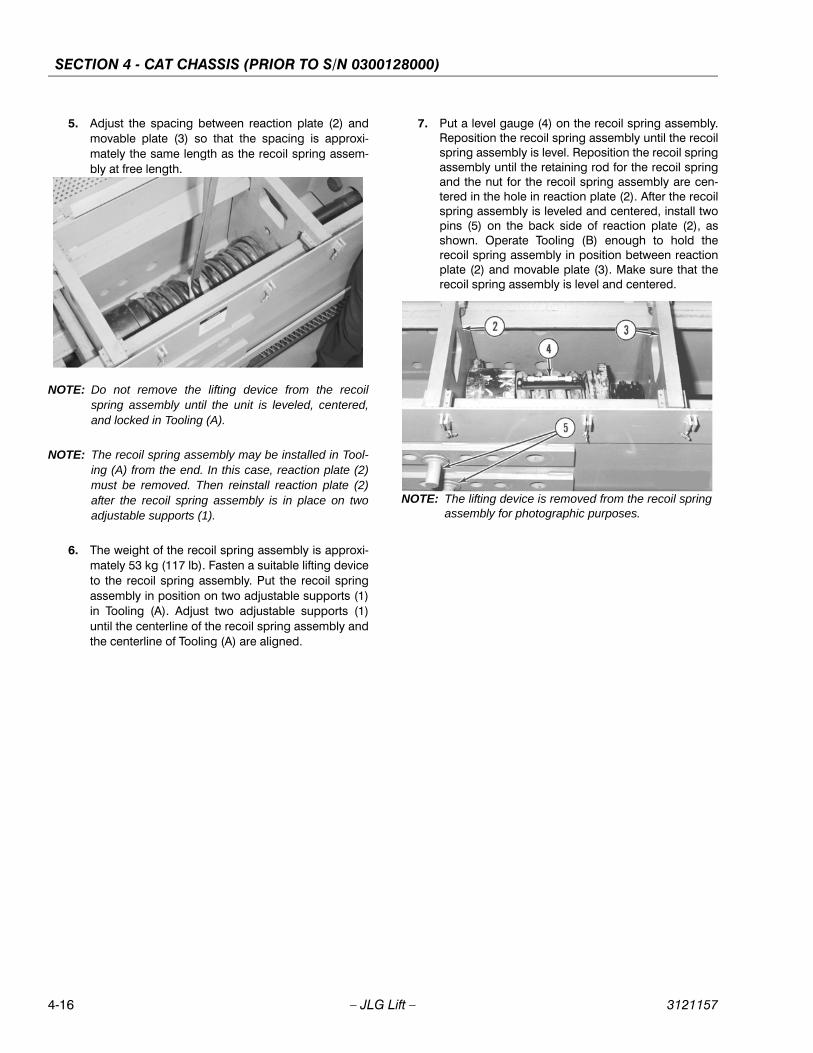
SECTION 4 - CAT CHASSIS (PRIOR TO S/N 0300128000)
4-16 – JLG Lift – 3121157
5. Adjust the spacing between reaction plate (2) andmovable plate (3) so that the spacing is approxi-mately the same length as the recoil spring assem-bly at free length.
NOTE: Do not remove the lifting device from the recoilspring assembly until the unit is leveled, centered,and locked in Tooling (A).
NOTE: The recoil spring assembly may be installed in Tool-ing (A) from the end. In this case, reaction plate (2)must be removed. Then reinstall reaction plate (2)after the recoil spring assembly is in place on twoadjustable supports (1).
6. The weight of the recoil spring assembly is approxi-mately 53 kg (117 lb). Fasten a suitable lifting deviceto the recoil spring assembly. Put the recoil springassembly in position on two adjustable supports (1)in Tooling (A). Adjust two adjustable supports (1)until the centerline of the recoil spring assembly andthe centerline of Tooling (A) are aligned.
7. Put a level gauge (4) on the recoil spring assembly.Reposition the recoil spring assembly until the recoilspring assembly is level. Reposition the recoil springassembly until the retaining rod for the recoil springand the nut for the recoil spring assembly are cen-tered in the hole in reaction plate (2). After the recoilspring assembly is leveled and centered, install twopins (5) on the back side of reaction plate (2), asshown. Operate Tooling (B) enough to hold therecoil spring assembly in position between reactionplate (2) and movable plate (3). Make sure that therecoil spring assembly is level and centered.
NOTE: The lifting device is removed from the recoil springassembly for photographic purposes.
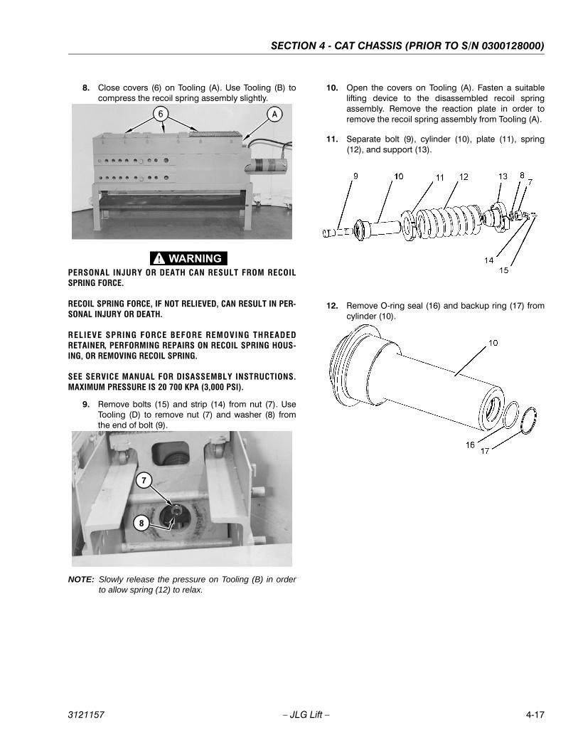
SECTION 4 - CAT CHASSIS (PRIOR TO S/N 0300128000)
3121157 – JLG Lift – 4-17
8. Close covers (6) on Tooling (A). Use Tooling (B) tocompress the recoil spring assembly slightly.
PERSONAL INJURY OR DEATH CAN RESULT FROM RECOILSPRING FORCE.
RECOIL SPRING FORCE, IF NOT RELIEVED, CAN RESULT IN PER-SONAL INJURY OR DEATH.
RELIEVE SPRING FORCE BEFORE REMOVING THREADEDRETAINER, PERFORMING REPAIRS ON RECOIL SPRING HOUS-ING, OR REMOVING RECOIL SPRING.
SEE SERVICE MANUAL FOR DISASSEMBLY INSTRUCTIONS.MAXIMUM PRESSURE IS 20 700 KPA (3,000 PSI).
9. Remove bolts (15) and strip (14) from nut (7). UseTooling (D) to remove nut (7) and washer (8) fromthe end of bolt (9).
NOTE: Slowly release the pressure on Tooling (B) in orderto allow spring (12) to relax.
10. Open the covers on Tooling (A). Fasten a suitablelifting device to the disassembled recoil springassembly. Remove the reaction plate in order toremove the recoil spring assembly from Tooling (A).
11. Separate bolt (9), cylinder (10), plate (11), spring(12), and support (13).
12. Remove O-ring seal (16) and backup ring (17) fromcylinder (10).

SECTION 4 - CAT CHASSIS (PRIOR TO S/N 0300128000)
4-18 – JLG Lift – 3121157
Assembly
1. Install backup ring (17) and O-ring seal (16) into cyl-inder (10).
PERSONAL INJURY OR DEATH CAN RESULT FROM RECOILSPRING FORCE.
RECOIL SPRING FORCE, IF NOT RELIEVED, CAN RESULT IN PER-SONAL INJURY OR DEATH.
RELIEVE SPRING FORCE BEFORE REMOVING THREADEDRETAINER, PERFORMING REPAIRS ON RECOIL SPRING HOUS-ING, OR REMOVING RECOIL SPRING.
SEE SERVICE MANUAL FOR DISASSEMBLY INSTRUCTIONS.MAXIMUM PRESSURE IS 20 700 KPA (3,000 PSI).
2. Check the condition of the threads on bolt (9) andnut (7). If any of the threads are worn or damaged,install new parts.
3. Loosely assemble bolt (9), cylinder (10), plate (11),spring (12), and support (13).
4. Install Tooling (C) on Tooling (B), as shown.
NOTE: Two adjustable supports (1), reaction plate (2) andmovable plate (3) are part of Tooling (A).
Table 4-10. Recoil Spring Required Tools - Assembly
Required Tools
Tool Part Number Part Description Qty.
A 4C-9540 Bench 1
B 8S-7172 Hydraulic Cylinder 1
3S-6224 Electric Hydraulic Pump
1
8T-0820 Pressure Gauge 1
3B-7722 Bushing 2
1P-2376 Coupler Assembly 2
1P-2377 Plug 2
8F-0024 Hose Assembly 2
C 4C-6629 Ram Adapter 1
D 4C-8217 55 mm Socket 1
E 5P-3931 Anti-Seize Compound -
F 4C-4030 Thread Lock Com-pound
-
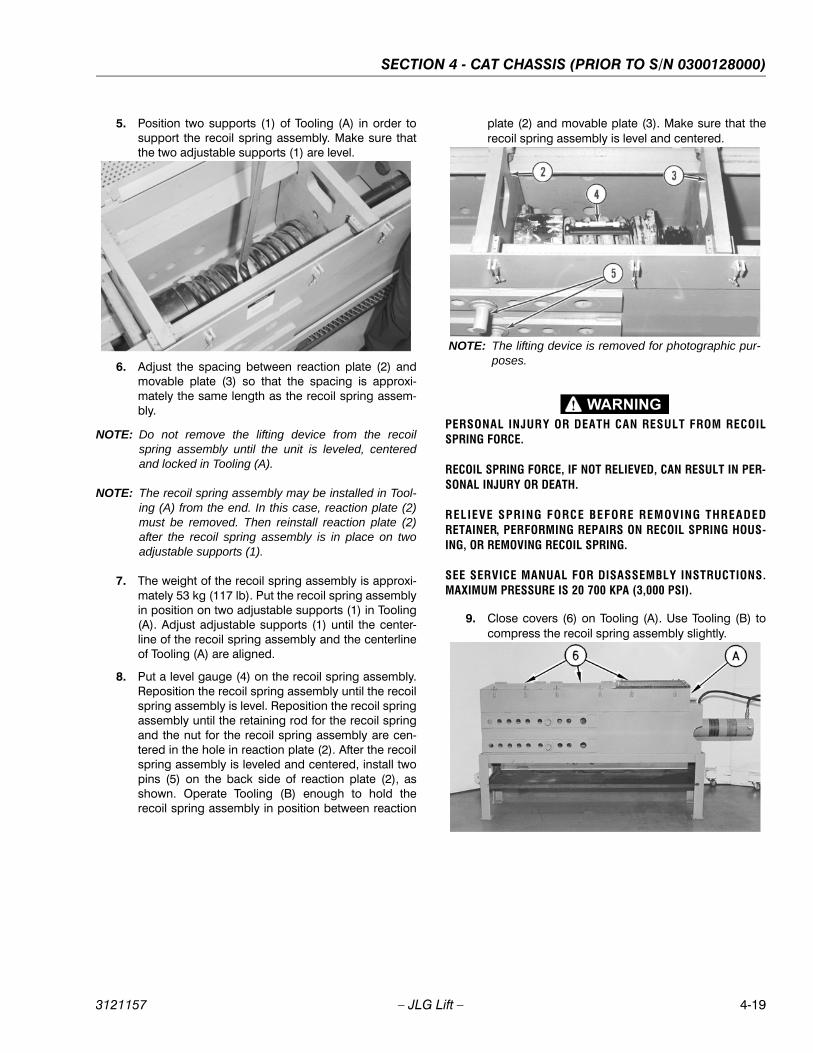
SECTION 4 - CAT CHASSIS (PRIOR TO S/N 0300128000)
3121157 – JLG Lift – 4-19
5. Position two supports (1) of Tooling (A) in order tosupport the recoil spring assembly. Make sure thatthe two adjustable supports (1) are level.
6. Adjust the spacing between reaction plate (2) andmovable plate (3) so that the spacing is approxi-mately the same length as the recoil spring assem-bly.
NOTE: Do not remove the lifting device from the recoilspring assembly until the unit is leveled, centeredand locked in Tooling (A).
NOTE: The recoil spring assembly may be installed in Tool-ing (A) from the end. In this case, reaction plate (2)must be removed. Then reinstall reaction plate (2)after the recoil spring assembly is in place on twoadjustable supports (1).
7. The weight of the recoil spring assembly is approxi-mately 53 kg (117 lb). Put the recoil spring assemblyin position on two adjustable supports (1) in Tooling(A). Adjust adjustable supports (1) until the center-line of the recoil spring assembly and the centerlineof Tooling (A) are aligned.
8. Put a level gauge (4) on the recoil spring assembly.Reposition the recoil spring assembly until the recoilspring assembly is level. Reposition the recoil springassembly until the retaining rod for the recoil springand the nut for the recoil spring assembly are cen-tered in the hole in reaction plate (2). After the recoilspring assembly is leveled and centered, install twopins (5) on the back side of reaction plate (2), asshown. Operate Tooling (B) enough to hold therecoil spring assembly in position between reaction
plate (2) and movable plate (3). Make sure that therecoil spring assembly is level and centered.
PERSONAL INJURY OR DEATH CAN RESULT FROM RECOILSPRING FORCE.
RECOIL SPRING FORCE, IF NOT RELIEVED, CAN RESULT IN PER-SONAL INJURY OR DEATH.
RELIEVE SPRING FORCE BEFORE REMOVING THREADEDRETAINER, PERFORMING REPAIRS ON RECOIL SPRING HOUS-ING, OR REMOVING RECOIL SPRING.
SEE SERVICE MANUAL FOR DISASSEMBLY INSTRUCTIONS.MAXIMUM PRESSURE IS 20 700 KPA (3,000 PSI).
9. Close covers (6) on Tooling (A). Use Tooling (B) tocompress the recoil spring assembly slightly.
NOTE: The lifting device is removed for photographic pur-poses.
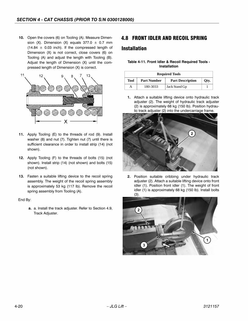
SECTION 4 - CAT CHASSIS (PRIOR TO S/N 0300128000)
4-20 – JLG Lift – 3121157
10. Open the covers (6) on Tooling (A). Measure Dimen-sion (X). Dimension (X) equals 377.0 ± 0.7 mm(14.84 ± 0.03 inch). If the compressed length ofDimension (X) is not correct, close covers (6) onTooling (A) and adjust the length with Tooling (B).Adjust the length of Dimension (X) until the com-pressed length of Dimension (X) is correct.
11. Apply Tooling (E) to the threads of rod (9). Installwasher (8) and nut (7). Tighten nut (7) until there issufficient clearance in order to install strip (14) (notshown).
12. Apply Tooling (F) to the threads of bolts (15) (notshown). Install strip (14) (not shown) and bolts (15)(not shown).
13. Fasten a suitable lifting device to the recoil springassembly. The weight of the recoil spring assemblyis approximately 53 kg (117 lb). Remove the recoilspring assembly from Tooling (A).
End By:
a. a. Install the track adjuster. Refer to Section 4.9,Track Adjuster.
4.8 FRONT IDLER AND RECOIL SPRING
Installation
1. Attach a suitable lifting device onto hydraulic trackadjuster (2). The weight of hydraulic track adjuster(2) is approximately 68 kg (150 lb). Position hydrau-lic track adjuster (2) into the undercarriage frame.
2. Position suitable cribbing under hydraulic trackadjuster (2). Attach a suitable lifting device onto frontidler (1). Position front idler (1). The weight of frontidler (1) is approximately 68 kg (150 lb). Install bolts(3).
Table 4-11. Front Idler & Recoil Required Tools - Installation
Required Tools
Tool Part Number Part Description Qty.
A 180-3033 Jack Stand Gp 1
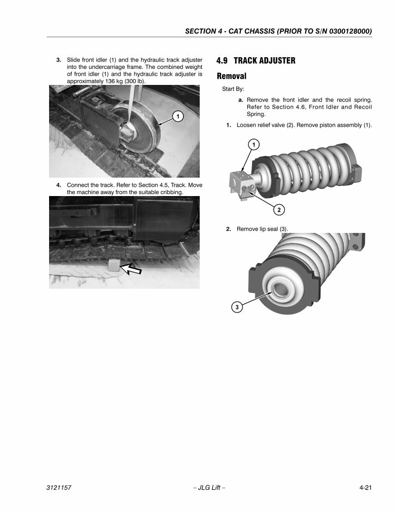
SECTION 4 - CAT CHASSIS (PRIOR TO S/N 0300128000)
3121157 – JLG Lift – 4-21
3. Slide front idler (1) and the hydraulic track adjusterinto the undercarriage frame. The combined weightof front idler (1) and the hydraulic track adjuster isapproximately 136 kg (300 lb).
4. Connect the track. Refer to Section 4.5, Track. Movethe machine away from the suitable cribbing.
4.9 TRACK ADJUSTER
RemovalStart By:
a. Remove the front idler and the recoil spring.Refer to Section 4.6, Front Idler and RecoilSpring.
1. Loosen relief valve (2). Remove piston assembly (1).
2. Remove lip seal (3).
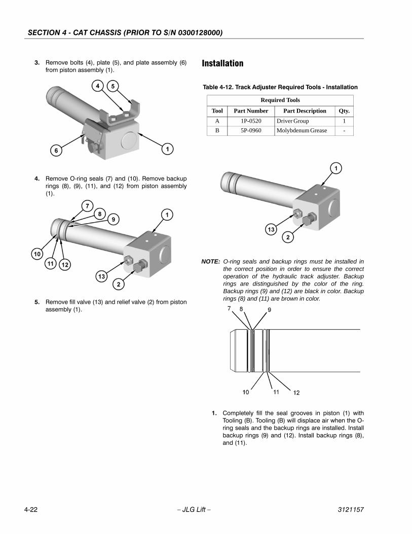
SECTION 4 - CAT CHASSIS (PRIOR TO S/N 0300128000)
4-22 – JLG Lift – 3121157
3. Remove bolts (4), plate (5), and plate assembly (6)from piston assembly (1).
4. Remove O-ring seals (7) and (10). Remove backuprings (8), (9), (11), and (12) from piston assembly(1).
5. Remove fill valve (13) and relief valve (2) from pistonassembly (1).
Installation
NOTE: O-ring seals and backup rings must be installed inthe correct position in order to ensure the correctoperation of the hydraulic track adjuster. Backuprings are distinguished by the color of the ring.Backup rings (9) and (12) are black in color. Backuprings (8) and (11) are brown in color.
1. Completely fill the seal grooves in piston (1) withTooling (B). Tooling (B) will displace air when the O-ring seals and the backup rings are installed. Installbackup rings (9) and (12). Install backup rings (8),and (11).
Table 4-12. Track Adjuster Required Tools - Installation
Required Tools
Tool Part Number Part Description Qty.
A 1P-0520 Driver Group 1
B 5P-0960 Molybdenum Grease -
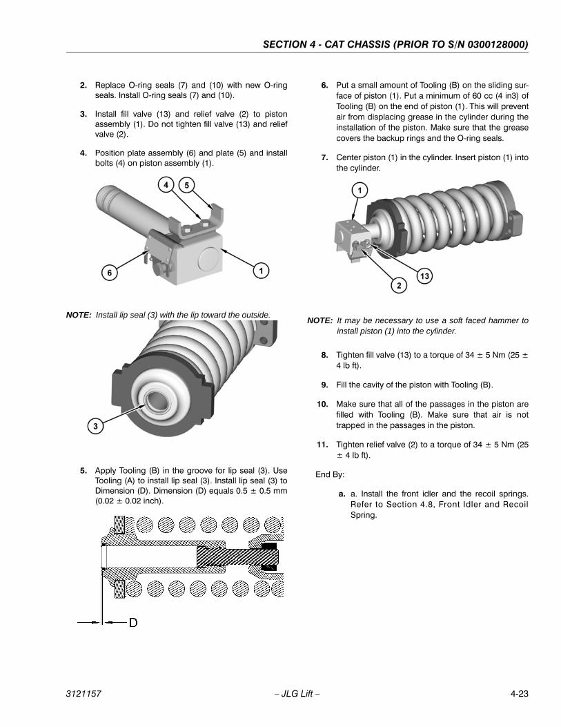
SECTION 4 - CAT CHASSIS (PRIOR TO S/N 0300128000)
3121157 – JLG Lift – 4-23
2. Replace O-ring seals (7) and (10) with new O-ringseals. Install O-ring seals (7) and (10).
3. Install fill valve (13) and relief valve (2) to pistonassembly (1). Do not tighten fill valve (13) and reliefvalve (2).
4. Position plate assembly (6) and plate (5) and installbolts (4) on piston assembly (1).
NOTE: Install lip seal (3) with the lip toward the outside.
5. Apply Tooling (B) in the groove for lip seal (3). UseTooling (A) to install lip seal (3). Install lip seal (3) toDimension (D). Dimension (D) equals 0.5 ± 0.5 mm(0.02 ± 0.02 inch).
6. Put a small amount of Tooling (B) on the sliding sur-face of piston (1). Put a minimum of 60 cc (4 in3) ofTooling (B) on the end of piston (1). This will preventair from displacing grease in the cylinder during theinstallation of the piston. Make sure that the greasecovers the backup rings and the O-ring seals.
7. Center piston (1) in the cylinder. Insert piston (1) intothe cylinder.
NOTE: It may be necessary to use a soft faced hammer toinstall piston (1) into the cylinder.
8. Tighten fill valve (13) to a torque of 34 ± 5 Nm (25 ±4 lb ft).
9. Fill the cavity of the piston with Tooling (B).
10. Make sure that all of the passages in the piston arefilled with Tooling (B). Make sure that air is nottrapped in the passages in the piston.
11. Tighten relief valve (2) to a torque of 34 ± 5 Nm (25± 4 lb ft).
End By:
a. a. Install the front idler and the recoil springs.Refer to Section 4.8, Front Idler and RecoilSpring.

SECTION 4 - CAT CHASSIS (PRIOR TO S/N 0300128000)
4-24 – JLG Lift – 3121157
4.10 SPROCKET
Removal
1. Position the machine onto suitable cribbing belowthe first roller, as shown. Ensure that the master pinis above the center line of the sprocket.
2. Separate the track assembly. Refer to Section 4.5,Track.
3. Remove bolts (1) which fasten sprocket (2) to thefinal drive.
4. Attach Tooling (A) and a suitable lifting device tosprocket (2). Remove sprocket (2). The weight ofsprocket (2) is approximately 38 kg (85 lb).
Installation
1. Thoroughly clean the mating surfaces of thesprocket and the final drive prior to installation of thesprocket.
2. Attach Tooling (A) and a suitable lifting device tosprocket (2). Position sprocket (2). The weight ofsprocket (2) is approximately 38 kg (85 lb).
3. Remove Tooling (A) and the suitable lifting devicefrom sprocket (2).
Table 4-13. Sprocket Required Tools - Removal
Required Tools
Tool Part Number Part Description Qty.
A 138-7574 Link Bracket 1
Table 4-14. Sprocket Required Tools - Installation
Required Tools
Tool Part Number Part Description Qty.
A 138-7574 Link Bracket 1
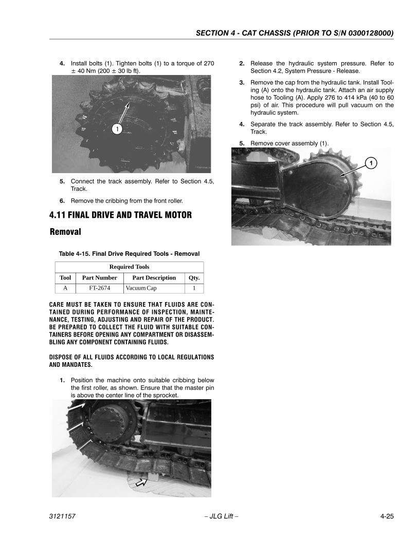
SECTION 4 - CAT CHASSIS (PRIOR TO S/N 0300128000)
3121157 – JLG Lift – 4-25
4. Install bolts (1). Tighten bolts (1) to a torque of 270± 40 Nm (200 ± 30 lb ft).
5. Connect the track assembly. Refer to Section 4.5,Track.
6. Remove the cribbing from the front roller.
4.11 FINAL DRIVE AND TRAVEL MOTOR
Removal
CARE MUST BE TAKEN TO ENSURE THAT FLUIDS ARE CON-TAINED DURING PERFORMANCE OF INSPECTION, MAINTE-NANCE, TESTING, ADJUSTING AND REPAIR OF THE PRODUCT.BE PREPARED TO COLLECT THE FLUID WITH SUITABLE CON-TAINERS BEFORE OPENING ANY COMPARTMENT OR DISASSEM-BLING ANY COMPONENT CONTAINING FLUIDS.
DISPOSE OF ALL FLUIDS ACCORDING TO LOCAL REGULATIONSAND MANDATES.
1. Position the machine onto suitable cribbing belowthe first roller, as shown. Ensure that the master pinis above the center line of the sprocket.
2. Release the hydraulic system pressure. Refer toSection 4.2, System Pressure - Release.
3. Remove the cap from the hydraulic tank. Install Tool-ing (A) onto the hydraulic tank. Attach an air supplyhose to Tooling (A). Apply 276 to 414 kPa (40 to 60psi) of air. This procedure will pull vacuum on thehydraulic system.
4. Separate the track assembly. Refer to Section 4.5,Track.
5. Remove cover assembly (1).
Table 4-15. Final Drive Required Tools - Removal
Required Tools
Tool Part Number Part Description Qty.
A FT-2674 Vacuum Cap 1
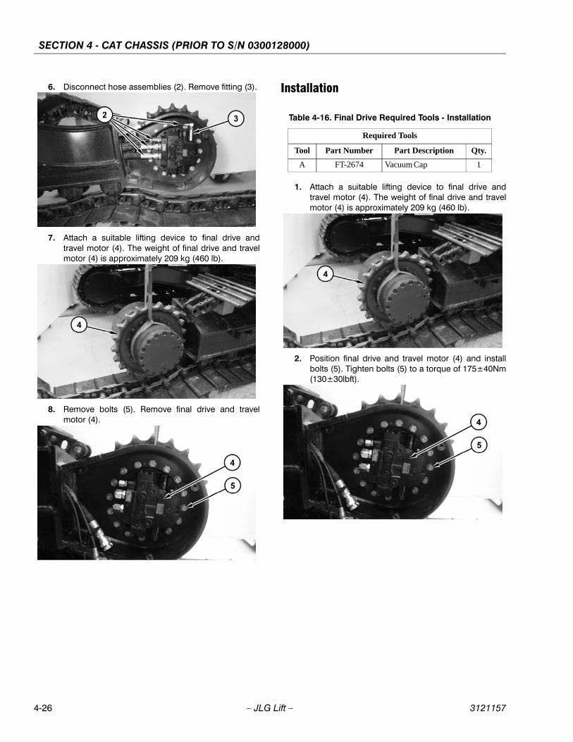
SECTION 4 - CAT CHASSIS (PRIOR TO S/N 0300128000)
4-26 – JLG Lift – 3121157
6. Disconnect hose assemblies (2). Remove fitting (3).
7. Attach a suitable lifting device to final drive andtravel motor (4). The weight of final drive and travelmotor (4) is approximately 209 kg (460 lb).
8. Remove bolts (5). Remove final drive and travelmotor (4).
Installation
1. Attach a suitable lifting device to final drive andtravel motor (4). The weight of final drive and travelmotor (4) is approximately 209 kg (460 lb).
2. Position final drive and travel motor (4) and installbolts (5). Tighten bolts (5) to a torque of 175±40Nm(130±30lbft).
Table 4-16. Final Drive Required Tools - Installation
Required Tools
Tool Part Number Part Description Qty.
A FT-2674 Vacuum Cap 1
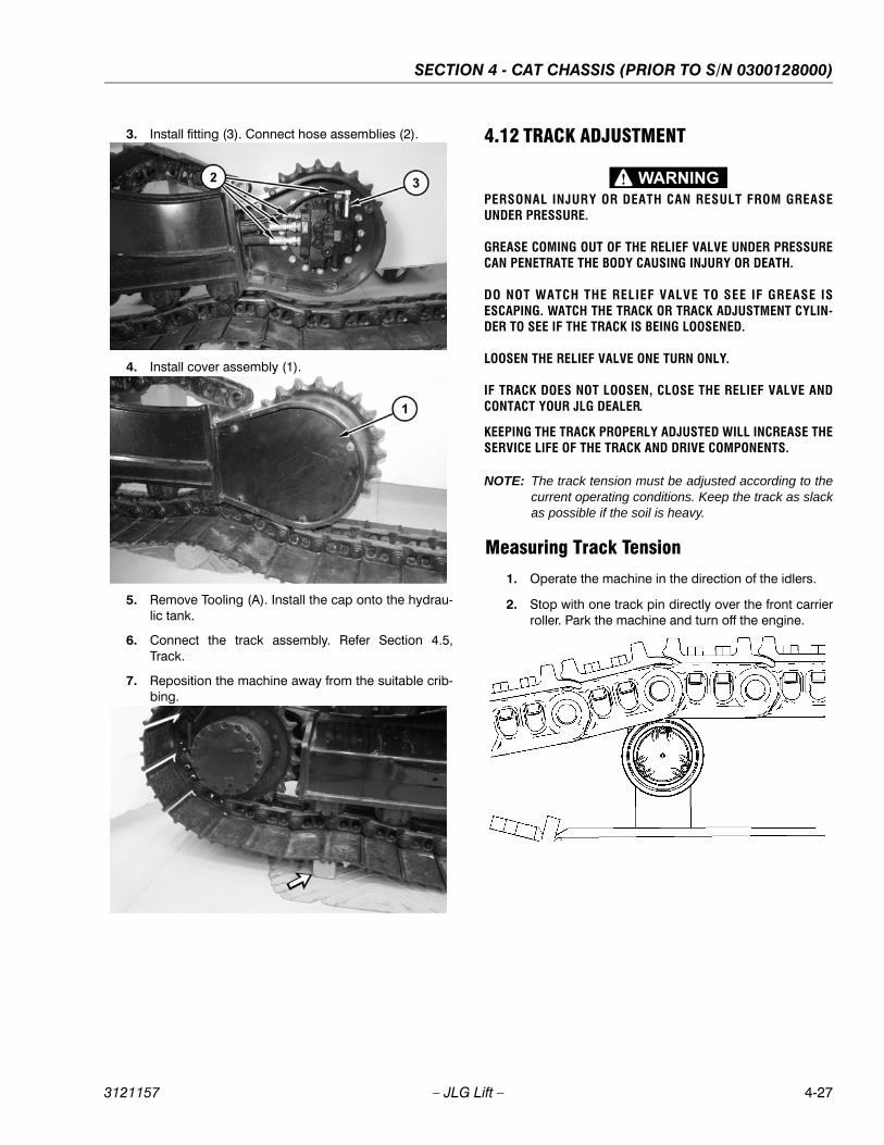
SECTION 4 - CAT CHASSIS (PRIOR TO S/N 0300128000)
3121157 – JLG Lift – 4-27
3. Install fitting (3). Connect hose assemblies (2).
4. Install cover assembly (1).
5. Remove Tooling (A). Install the cap onto the hydrau-lic tank.
6. Connect the track assembly. Refer Section 4.5,Track.
7. Reposition the machine away from the suitable crib-bing.
4.12 TRACK ADJUSTMENT
PERSONAL INJURY OR DEATH CAN RESULT FROM GREASEUNDER PRESSURE.
GREASE COMING OUT OF THE RELIEF VALVE UNDER PRESSURECAN PENETRATE THE BODY CAUSING INJURY OR DEATH.
DO NOT WATCH THE RELIEF VALVE TO SEE IF GREASE ISESCAPING. WATCH THE TRACK OR TRACK ADJUSTMENT CYLIN-DER TO SEE IF THE TRACK IS BEING LOOSENED.
LOOSEN THE RELIEF VALVE ONE TURN ONLY.
IF TRACK DOES NOT LOOSEN, CLOSE THE RELIEF VALVE ANDCONTACT YOUR JLG DEALER.
KEEPING THE TRACK PROPERLY ADJUSTED WILL INCREASE THESERVICE LIFE OF THE TRACK AND DRIVE COMPONENTS.
NOTE: The track tension must be adjusted according to thecurrent operating conditions. Keep the track as slackas possible if the soil is heavy.
Measuring Track Tension
1. Operate the machine in the direction of the idlers.
2. Stop with one track pin directly over the front carrierroller. Park the machine and turn off the engine.

SECTION 4 - CAT CHASSIS (PRIOR TO S/N 0300128000)
4-28 – JLG Lift – 3121157
3. Place a straight edge on top of the track grousersbetween the front carrier roller and the idler. Thestraight edge should be long enough to reach fromthe front carrier roller to the idler.
4. Measure the maximum amount of sag in the track.The sag is measured from the highest point of thetrack grouser to the bottom of the straight edge. Atrack that is properly adjusted will have a sag of 40.0to 55.0 mm (1.57 to 2.17 inch).
5. If the track is too tight, or if the track is too loose,adjust the track tension according to the appropriateprocedure below.
Adjusting Track Tension
The track adjuster is located on the track frame.
TIGHTENING THE TRACK
WIPE THE FITTING BEFORE YOU ADD GREASE.
1. Add grease through grease fitting (1) until the cor-rect track tension is reached.
2. Operate the machine back and forth in order toequalize the pressure.
3. Check the amount of sag. Adjust the track, asneeded.
GREASE FIT- RELIEF
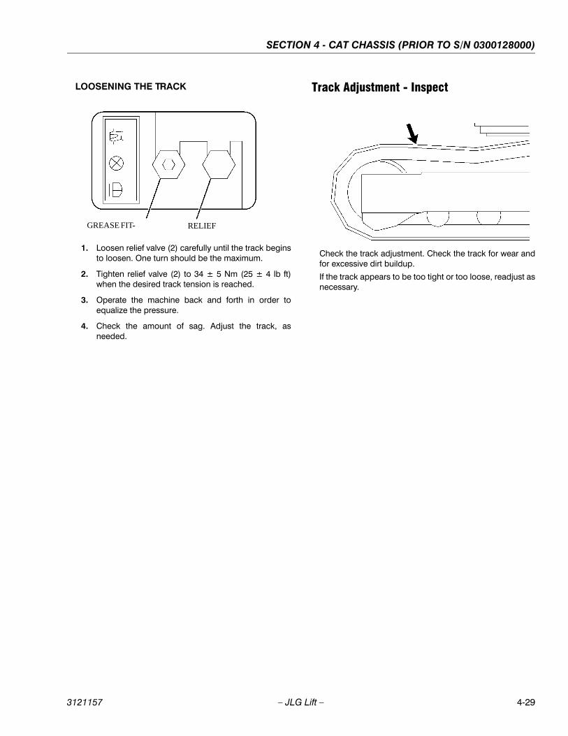
SECTION 4 - CAT CHASSIS (PRIOR TO S/N 0300128000)
3121157 – JLG Lift – 4-29
LOOSENING THE TRACK
1. Loosen relief valve (2) carefully until the track beginsto loosen. One turn should be the maximum.
2. Tighten relief valve (2) to 34 ± 5 Nm (25 ± 4 lb ft)when the desired track tension is reached.
3. Operate the machine back and forth in order toequalize the pressure.
4. Check the amount of sag. Adjust the track, asneeded.
Track Adjustment - Inspect
Check the track adjustment. Check the track for wear andfor excessive dirt buildup.
If the track appears to be too tight or too loose, readjust asnecessary.
GREASE FIT- RELIEF

SECTION 4 - CAT CHASSIS (PRIOR TO S/N 0300128000)
4-30 – JLG Lift – 3121157
NOTES:
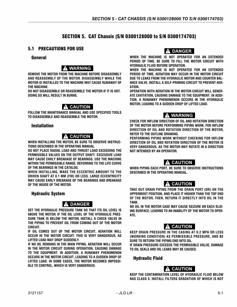
SECTION 5 - CAT CHASSIS (S/N 0300128000 TO S/N 0300174703)
3121157 – JLG Lift – 5-1
SECTION 5. CAT Chassis (S/N 0300128000 to S/N 0300174703)
5.1 PRECAUTIONS FOR USE
General
REMOVE THE MOTOR FROM THE MACHINE BEFORE DISASSEMBLYAND REASSEMBLY OF THE MOTOR. DISASSEMBLY WHILE THEMOTOR IS INSTALLED TO THE MACHINE MAY CAUSE RUNAWAY OFTHE MACHINE.DO NOT DISASSEMBLE OR REASSEMBLE THE MOTOR IF IT IS HOT.DOING SO WILL RESULT IN BURNS.
FOLLOW THE MAINTENANCE MANUAL AND USE SPECIFIED TOOLSTO DISASSEMBLE AND REASSEMBLE THE MOTOR.
Installation
WHEN INSTALLING THE MOTOR, BE SURE TO OBSERVE INSTRUC-TIONS DESCRIBED IN THE OPERATING MANUAL.DO NOT PLACE RADIAL LOAD AND THRUST LOAD EXCEEDING THEPERMISSIBLE VALUES ON THE OUTPUT SHAFT. EXCESSIVE LOADMAY CAUSE EARLY BREAKAGE OF BEARINGS. USE THE MACHINEWITHIN THE PERMISSIBLE RANGE, REFERRING TO THE LIFE CURVEOF THE BEARINGS IN THE CATALOG.WHEN INSTALLING, MAKE THE ECCENTRIC AMOUNT TO THEDRIVEN SHAFT AT 0.1 MM (FIR) OR LESS. LARGE ECCENTRICITYMAY CAUSE EARLY BREAKAGE OF THE BEARINGS AND BREAKAGEOF THE INSIDE OF THE MOTOR.
Hydraulic System
SET THE HYDRAULIC PRESSURE TANK SO THAT ITS OIL LEVEL ISABOVE THE MOTOR. IF THE OIL LEVEL OF THE HYDRAULIC PRES-SURE TANK IS BELOW THE MOTOR, INSTALL A CHECK VALVE INTHE PIPING TO PREVENT OIL FROM COMING OUT OF THE MOTORCIRCUIT.IF OIL COMES OUT OF THE MOTOR CIRCUIT, AERATION WILLOCCUR IN THE MOTOR CIRCUIT. THIS IS VERY DANGEROUS, ASLIFTED LOAD MAY DROP SUDDENLY.IF NO OIL REMAINS IN THE MAIN PIPING, AERATION WILL OCCURIN THE MOTOR CIRCUIT DURING OPERATION, CAUSING DAMAGETO THE EQUIPMENT. IN ADDITION, A RUNAWAY PHENOMENONOCCURS IN THE MOTOR CIRCUIT, LEADING TO A SUDDEN DROP OFLIFTED LOAD. IN SOME CASES, THE MOTOR BECOMES IMPOSSI-BLE TO CONTROL, WHICH IS VERY DANGEROUS.
WHEN THE MACHINE IS NOT OPERATED FOR AN EXTENDEDPERIOD OF TIME, BE SURE TO FILL THE MOTOR CIRCUIT WITHHYDRAULIC FLUID BEFORE OPERATION.WHEN THE MACHINE IS NOT OPERATED FOR AN EXTENDEDPERIOD OF TIME, AERATION MAY OCCUR IN THE MOTOR CIRCUITDUE TO LEAKS FROM THE HYDRAULIC MOTOR AND COUNTER BAL-ANCE VALVE. INSTALL A SELF-PRIMING CIRCUIT TO PREVENT AER-ATION.OPERATION WITH AERATION IN THE MOTOR CIRCUIT WILL GENER-ATE CAVITATION, CAUSING DAMAGE TO THE EQUIPMENT. IN ADDI-TION, A RUNAWAY PHENOMENON OCCURS IN THE HYDRAULICMOTOR, LEADING TO A SUDDEN DROP OF LIFTED LOAD.
CHECK FOR INFLOW DIRECTION OF OIL AND ROTATION DIRECTIONOF THE MOTOR BEFORE PERFORMING PIPING WORK. FOR INFLOWDIRECTION OF OIL AND ROTATION DIRECTION OF THE MOTOR,REFER TO THE OUTLINE DRAWING.PERFORMING PIPING WORK WITHOUT CHECKING FOR INFLOWDIRECTION OF OIL AND ROTATION DIRECTION OF THE MOTOR ISVERY DANGEROUS, AS THE MOTOR MAY ROTATE IN A DIRECTIONNOT INTENDED BY AN OPERATOR.
WHEN PIPING EACH PORT, BE SURE TO OBSERVE INSTRUCTIONSDESCRIBED IN THE OPERATING MANUAL.
TAKE OUT DRAIN PIPING FROM THE DRAIN PORT (DR) ON THEUPPERMOST POSITION, AND PLACE IT HIGHER THAN THE TOP ENDOF THE MOTOR. THEN, RETURN IT DIRECTLY INTO OIL IN THETANK.NO OIL IN THE MOTOR CASE MAY CAUSE SEIZURE ON EACH SLID-ING SURFACE, LEADING TO AN INABILITY OF THE MOTOR TO OPER-ATE.
KEEP DRAIN PRESSURE IN THE CASING AT 0.2 MPA OR LESS(WORKING CONDITION) AS PERMISSIBLE PRESSURE, AND BESURE TO RETURN THE PIPING END INTO OIL.IF DRAIN PRESSURE EXCEEDS THE PERMISSIBLE VALUE, DAMAGETO OIL SEALS AND OIL LEAKS MAY BE CAUSED.
Hydraulic Fluid
KEEP THE CONTAMINATION LEVEL OF HYDRAULIC FLUID BELOWNAS CLASS 9. INSTALL FILTERS GRADATION OF WHICH IS NOT
SECTION 5 - CAT CHASSIS (S/N 0300128000 TO S/N 0300174703)
5-2 – JLG Lift – 3121157
GREATER THAN 10 � M IN THE HYDRAULIC CIRCUIT.THE CONTAMINATION LEVEL OF HYDRAULIC FLUID HAS A GREATINFLUENCE ON LIFE-SPAN OF A MOTOR. POOR CONTROL OFCLEANLINESS OF HYDRAULIC FLUID MAY CAUSE SEIZURE ANDEARLY WEAR IN EACH SLIDING SURFACE, RESULTING IN ANINABILITY OF THE MOTOR TO OPERATE.
FOR TYPE OF HYDRAULIC FLUID IN USE, USE RECOMMENDEDHYDRAULIC FLUIDS. KEEP THE TEMPERATURE AND VISCOSITY OFHYDRAULIC FLUID IN USE WITHIN THE USAGE CONDITION LIMIT.USE OF HYDRAULIC FLUID WITH THE TEMPERATURE AND VISCOS-ITY BEYOND THE USAGE CONDITION LIMIT MAY CAUSE EARLYWEAR OF EACH SLIDING SURFACE AND SEIZURE, RESULTING INAN INABILITY OF THE MOTOR TO OPERATE.
IF YOU USE FIRE-RESISTANT HYDRAULIC FLUID, OR USE HYDRAU-LIC FLUID BEYOND THE PERMISSIBLE OIL TEMPERATURE, PLEASECONTACT US.USAGE AREA OF THE MOTOR MAY BE LIMITED.
Lubricating Oil for Reduction Gears
For lubricating oil for reduction gears, use recommendedlubricant, and change lubricant according to the followinginterval.
Recommended lubricant: Diamond Hypoid Gear Oil #90from Mitsubishi Oil (equivalent to API category GL-4#90)
Interval of oil change
• Initial oil change: 100 - 250 hours of operation
• Succeeding oil change: every 1000 - 1500 hours ofoperation
Periodic oil change extends life-span of reduction gears,and ensures stable performance.
Hydraulic fluids with the oil of different property should notbe mixed. When changing hydraulic fluid type, flush thereduction gears.
KEEP TEMPERATURE OF LUBRICANT FOR REDUCTION GEARWITHIN THE USAGE CONDITION LIMIT. FAILURE TO DO SO WILLDRASTICALLY SHORTEN THE LIFE-SPAN OF THE REDUCTION GEAR,CAUSING EARLY BREAKAGE.
Motor Operation
DO NOT GENERATE CAVITATION. EXCESSIVE ROTATION SPEED OFMOTOR MAY CAUSE SEIZURE ON EACH SLIDING SURFACE. ASPRESSURE IN THE CIRCUIT BECOMES NEGATIVE, THE INSIDE MAYFAIL.
AS PRESSURE IN THE CIRCUIT BECOMES NEGATIVE, THE MOTORCANNOT BE CONTROLLED, WHICH MAY LEAD TO A SUDDEN DROPOF LIFTED LOAD OR RUNAWAY.
WHEN OPERATING THE MOTOR, BE SURE TO OBSERVE INSTRUC-TIONS DESCRIBED IN THE OPERATING MANUAL.
OPERATE THE MOTOR WITHIN THE SPECIFICATION RANGE. IF THEMOTOR IS OPERATED BEYOND THE SPECIFICATION RANGE,PLEASE CONTACT US.
BEFORE OPERATING THE MOTOR, LUBRICATE HYDRAULIC FLUIDINTO THE MOTOR CASE FROM DRAIN PORT ON THE UPPER SIDE.
OPERATION OF MOTOR WITH MOTOR CASE EMPTY MAY CAUSEBREAKAGE OF THE INSIDE OF THE MOTOR, LEADING TO AN INABIL-ITY OF THE MOTOR TO OPERATE.
KEEP THE PRESSURE WITHIN THE USAGE CONDITION LIMIT.FAILURE TO DO SO MAY NOT ONLY SHORTEN THE LIFE-SPAN OFTHE MOTOR DRASTICALLY, BUT ALSO BREAK STRUCTURAL COM-PONENTS.
KEEP ROTATION SPEED IN USE WITHIN PRODUCT SPECIFICATIONRANGE. KEEP FLOW RATE WITHIN USAGE CONDITION LIMIT. FAIL-URE TO DO SO MAY CAUSE SEIZURE ON EACH SLIDING SURFACE,RESULTING IN BREAKAGE OF THE INSIDE OF THE MOTOR.
KEEP REVERSE INPUT TORQUE WITHIN USAGE CONDITION LIMIT.FAILURE TO DO SO MAY CAUSE BENDING BREAKAGE OF REDUC-TION GEARS AND FAILURE OF STRUCTURAL COMPONENTS.
APPLY EXTERNAL RADIAL LOAD ON THE SPECIFIED LOCATION. DONOT APPLY LOAD EXCEEDING PERMISSIBLE RANGE. FAILURE TODO SO WILL DRASTICALLY SHORTEN REDUCTION GEAR LIFE-SPANAND BREAKAGE OF MAIN BEARING WILL OCCUR.
DO NOT APPLY AN AXIAL LOAD. AXIAL LOADS MAY CAUSE EARLYWEAR OF REDUCTION GEAR

SECTION 5 - CAT CHASSIS (S/N 0300128000 TO S/N 0300174703)
3121157 – JLG Lift – 5-3
Parking Brake
RELEASE PARKING BRAKE TO OPERATE MOTOR. IF MOTOR ISOPERATED WITH PARKING BRAKE ENGAGED, A DISK FOR THEPARKING BRAKE MAY WEAR QUICKLY, RESULTING IN PARKINGBRAKE FAILURE. A PARKING BRAKE FAILURE WILL LEAD TO ADROP OF LIFTED LOAD OR RUNAWAY, WHICH IS VERY DANGER-OUS.
DO NOT USE THE PARKING BRAKE FOR CONTROLLING ROTATIONOF THE MOTOR. EARLY BREAKAGE OF THE DISK FOR THE PARKINGBRAKE LEADS TO A PARKING BRAKE FAILURE. AS A RESULT,LIFTED LOAD MAY DROP, WHICH IS VERY DANGEROUS.
EXCESSIVE TORQUE EXERTED ON THE MOTOR SHAFT AND DRIVEGEAR SHAFT OF THE REDUCTION GEAR WILL CAUSE BREAKAGE OFTHE MOTOR SHAFT AND DRIVE GEAR SHAFT OF THE REDUCTIONGEAR. THE RESULT WILL LEAD TO A DROP OF LIFTED LOAD DUR-ING OPERATION, WHICH IS VERY DANGEROUS.
WHEN STOPPING THE MOTOR, BE SURE TO APPLY THE PARKINGBRAKE. FAILURE TO DO SO IS VERY DANGEROUS BECAUSE LIFTEDLOAD MAY DROP OR MOTOR MAY RUNAWAY.
Overrun Prevention
DEPENDING ON PIPING VOLUME FROM HYDRAULIC SUPPLY TOHYDRAULIC MOTOR, AND PROPERTY OF THE COUNTER BALANCEVALVE, THE HYDRAULIC MOTOR MAY OVERRUN, RESULTING INEARLY BREAKAGE OF THE HYDRAULIC MOTOR. THEREFORE, PRE-VENT THE MOTOR FROM OVERRUNNING FOR PROTECTION OF THEEQUIPMENT AND USE FOR AN EXTENDED PERIOD OF TIME (ESPE-CIALLY DURING WINDING DOWN). IF OCCURRENCE OF OVERRUNCANNOT BE FULLY PREVENTED, ADJUST SO THAT THE MAXIMUMROTATION SPEED OF THE MOTOR WHEN OVERRUN OCCURSBECOMES WITHIN THE ROTATION SPEED RANGE OF THE EQUIP-MENT SPECIFICATIONS.
Setting Self-Priming Circuit
LEAKS FROM THE HYDRAULIC MOTOR AND COUNTER BALANCEVALVE MAY CAUSE AERATION IN THE HYDRAULIC MOTOR CIR-CUIT, LEADING TO CAVITATION AND TRAVEL MOVEMENT OF THEHYDRAULIC MOTOR. INSTALLATION OF A SELF-PRIMING CIRCUITIS NECESSARY TO PREVENT CAVITATION AND TRAVEL MOVEMENTOF THE HYDRAULIC MOTOR.
ESPECIALLY AFTER A LONG PERIOD OF QUIESCENT OPERATION, ITIS ESSENTIAL TO FILL HYDRAULIC MOTOR CIRCUIT WITHHYDRAULIC FLUID. THUS, INSTALL THE SELF-PRIMING CIRCUIT,CONSIDERING LOCATION RELATIONSHIP BETWEEN HYDRAULICMOTOR AND THE OIL LEVEL OF THE HYDRAULIC PRESSURE TANK.EXERT PRESSURE OF 0.3 TO 0.5 MPA ON THE SELF-PRIMING CIR-CUIT TO PREVENT CAVITATION DURING HALTS OF MOTOR ROTA-TION.
IF THE HYDRAULIC MOTOR IS POSITIONED LOWER THAN THE OILLEVEL OF THE HYDRAULIC PRESSURE TANK, AND THE CONTROLVALVE OPERATES FROM A TO B, AND TO T OPEN, NO INSTALLA-TION OF THE SELF-PRIMING CIRCUIT IS NECESSARY IN PRINCIPLE.
Hydraulic Circuit
SET BACK PRESSURE VALUE SO NO CAVITATION OCCURS.
IF HYDRAULIC MOTOR IS POSITIONED HIGHER THAN OIL LEVEL INHYDRAULIC TANK, FILL HYDRAULIC MOTOR CIRCUIT WITHHYDRAULIC FLUID BEFORE OPERATING HYDRAULIC MOTOR.
PROVIDE THE SELF-PRIMING CIRCUIT.
PLEASE CONTACT US IF ANY CIRCUIT OTHER THAN THE ONESDESCRIBED IN ATTACHED PAPERS IS USED.
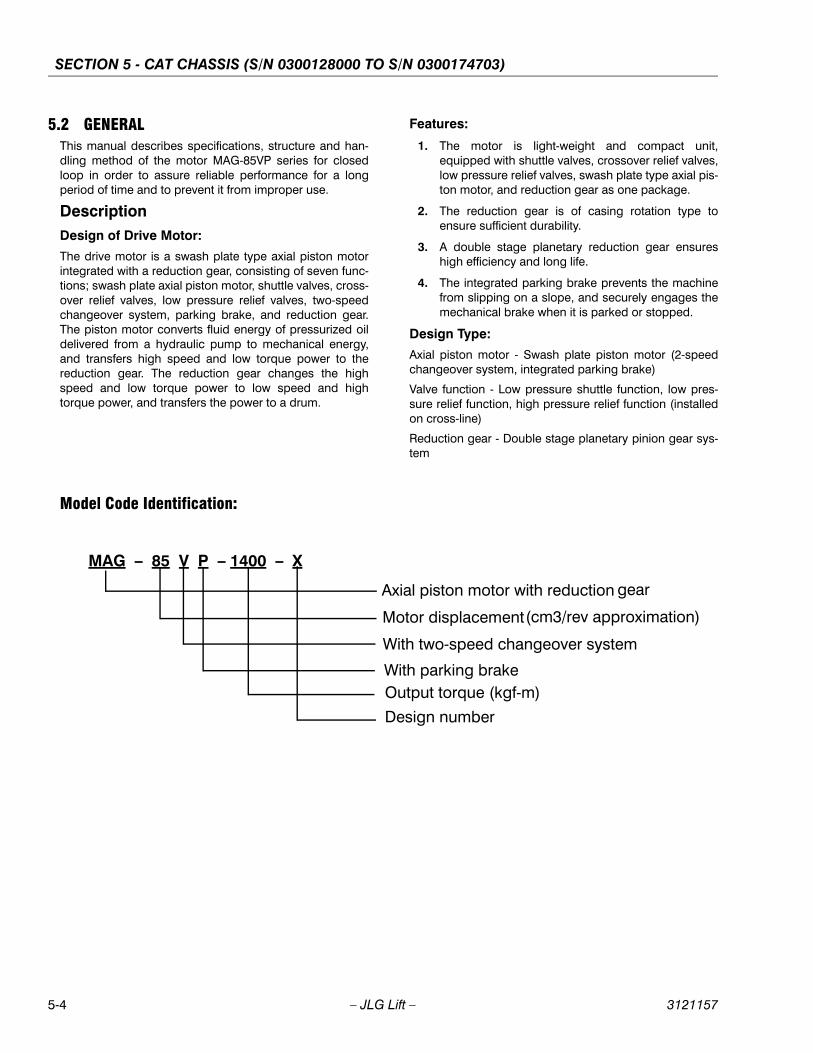
SECTION 5 - CAT CHASSIS (S/N 0300128000 TO S/N 0300174703)
5-4 – JLG Lift – 3121157
5.2 GENERALThis manual describes specifications, structure and han-dling method of the motor MAG-85VP series for closedloop in order to assure reliable performance for a longperiod of time and to prevent it from improper use.
DescriptionDesign of Drive Motor:
The drive motor is a swash plate type axial piston motorintegrated with a reduction gear, consisting of seven func-tions; swash plate axial piston motor, shuttle valves, cross-over relief valves, low pressure relief valves, two-speedchangeover system, parking brake, and reduction gear.The piston motor converts fluid energy of pressurized oildelivered from a hydraulic pump to mechanical energy,and transfers high speed and low torque power to thereduction gear. The reduction gear changes the highspeed and low torque power to low speed and hightorque power, and transfers the power to a drum.
Model Code Identification:
Features:
1. The motor is light-weight and compact unit,equipped with shuttle valves, crossover relief valves,low pressure relief valves, swash plate type axial pis-ton motor, and reduction gear as one package.
2. The reduction gear is of casing rotation type toensure sufficient durability.
3. A double stage planetary reduction gear ensureshigh efficiency and long life.
4. The integrated parking brake prevents the machinefrom slipping on a slope, and securely engages themechanical brake when it is parked or stopped.
Design Type:
Axial piston motor - Swash plate piston motor (2-speedchangeover system, integrated parking brake)
Valve function - Low pressure shuttle function, low pres-sure relief function, high pressure relief function (installedon cross-line)
Reduction gear - Double stage planetary pinion gear sys-tem
MAG – 85 V P – 1400 – X
Axial piston motor with reduction gear
Motor displacement(cm3/rev approximation)
With two-speed changeover system
With parking brakeOutput torque (kgf-m)
Design number
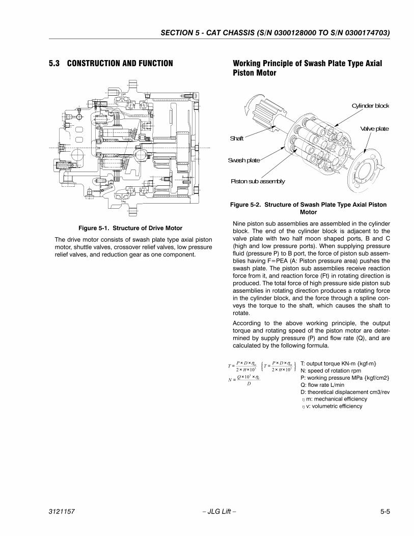
SECTION 5 - CAT CHASSIS (S/N 0300128000 TO S/N 0300174703)
3121157 – JLG Lift – 5-5
5.3 CONSTRUCTION AND FUNCTION
The drive motor consists of swash plate type axial pistonmotor, shuttle valves, crossover relief valves, low pressurerelief valves, and reduction gear as one component.
Working Principle of Swash Plate Type Axial Piston Motor
Nine piston sub assemblies are assembled in the cylinderblock. The end of the cylinder block is adjacent to thevalve plate with two half moon shaped ports, B and C(high and low pressure ports). When supplying pressurefluid (pressure P) to B port, the force of piston sub assem-blies having F=PEA (A: Piston pressure area) pushes theswash plate. The piston sub assemblies receive reactionforce from it, and reaction force (Ft) in rotating direction isproduced. The total force of high pressure side piston subassemblies in rotating direction produces a rotating forcein the cylinder block, and the force through a spline con-veys the torque to the shaft, which causes the shaft torotate.
According to the above working principle, the outputtorque and rotating speed of the piston motor are deter-mined by supply pressure (P) and flow rate (Q), and arecalculated by the following formula.
Figure 5-1. Structure of Drive Motor
Figure 5-2. Structure of Swash Plate Type Axial Piston Motor
Cylinder block
Shaft
Swash plate
Piston sub assembly
Valve plate
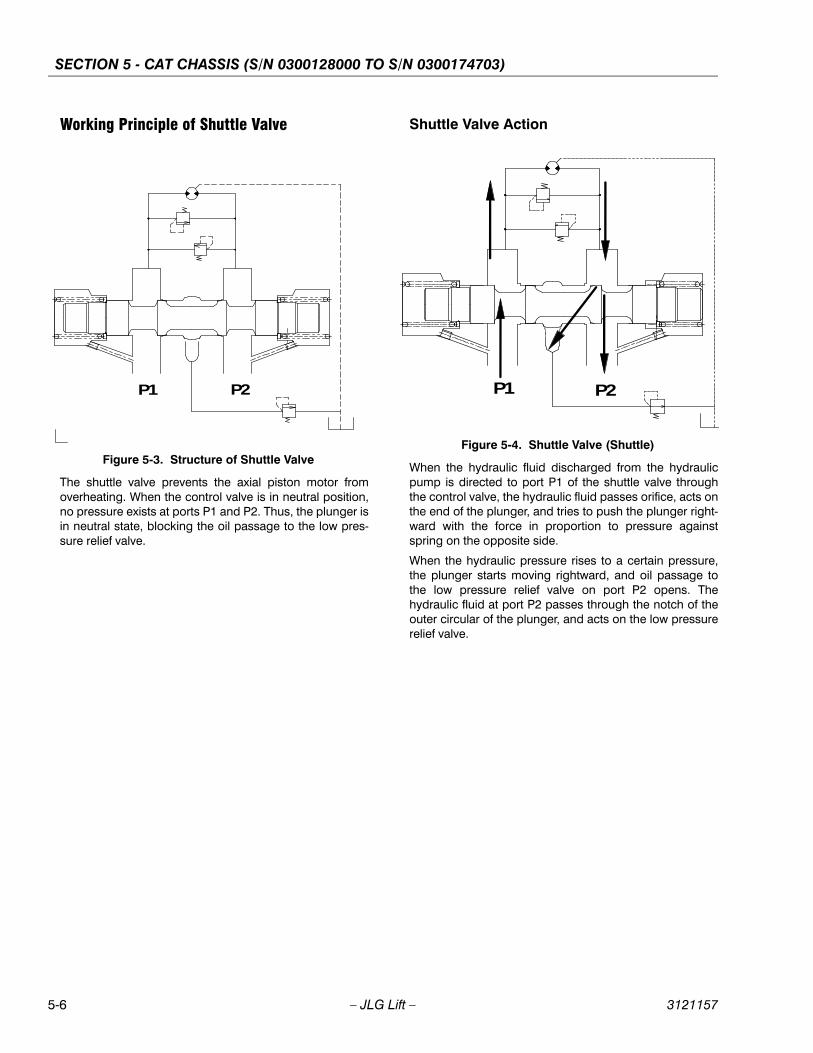
SECTION 5 - CAT CHASSIS (S/N 0300128000 TO S/N 0300174703)
5-6 – JLG Lift – 3121157
Working Principle of Shuttle Valve
The shuttle valve prevents the axial piston motor fromoverheating. When the control valve is in neutral position,no pressure exists at ports P1 and P2. Thus, the plunger isin neutral state, blocking the oil passage to the low pres-sure relief valve.
Shuttle Valve Action
When the hydraulic fluid discharged from the hydraulicpump is directed to port P1 of the shuttle valve throughthe control valve, the hydraulic fluid passes orifice, acts onthe end of the plunger, and tries to push the plunger right-ward with the force in proportion to pressure againstspring on the opposite side.
When the hydraulic pressure rises to a certain pressure,the plunger starts moving rightward, and oil passage tothe low pressure relief valve on port P2 opens. Thehydraulic fluid at port P2 passes through the notch of theouter circular of the plunger, and acts on the low pressurerelief valve.
Figure 5-3. Structure of Shuttle Valve
P1 P2
Figure 5-4. Shuttle Valve (Shuttle)
P1 P2
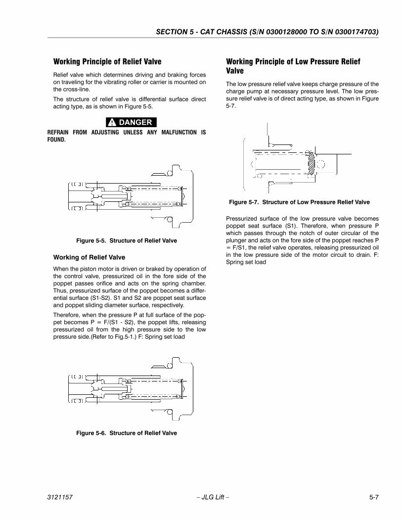
SECTION 5 - CAT CHASSIS (S/N 0300128000 TO S/N 0300174703)
3121157 – JLG Lift – 5-7
Working Principle of Relief Valve
Relief valve which determines driving and braking forceson traveling for the vibrating roller or carrier is mounted onthe cross-line.
The structure of relief valve is differential surface directacting type, as is shown in Figure 5-5.
REFRAIN FROM ADJUSTING UNLESS ANY MALFUNCTION ISFOUND.
Working of Relief Valve
When the piston motor is driven or braked by operation ofthe control valve, pressurized oil in the fore side of thepoppet passes orifice and acts on the spring chamber.Thus, pressurized surface of the poppet becomes a differ-ential surface (S1-S2). S1 and S2 are poppet seat surfaceand poppet sliding diameter surface, respectively.
Therefore, when the pressure P at full surface of the pop-pet becomes P = F/(S1 - S2), the poppet lifts, releasingpressurized oil from the high pressure side to the lowpressure side.(Refer to Fig.5-1.) F: Spring set load
Working Principle of Low Pressure Relief Valve
The low pressure relief valve keeps charge pressure of thecharge pump at necessary pressure level. The low pres-sure relief valve is of direct acting type, as shown in Figure5-7.
Pressurized surface of the low pressure valve becomespoppet seat surface (S1). Therefore, when pressure Pwhich passes through the notch of outer circular of theplunger and acts on the fore side of the poppet reaches P= F/S1, the relief valve operates, releasing pressurized oilin the low pressure side of the motor circuit to drain. F:Spring set load
Figure 5-5. Structure of Relief Valve
Figure 5-6. Structure of Relief Valve
Figure 5-7. Structure of Low Pressure Relief Valve
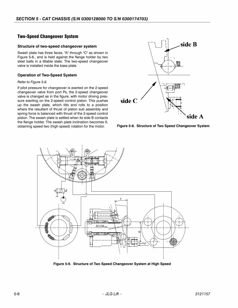
SECTION 5 - CAT CHASSIS (S/N 0300128000 TO S/N 0300174703)
5-8 – JLG Lift – 3121157
Two-Speed Changeover System
Structure of two-speed changeover system
Swash plate has three faces, "A" through "C" as shown inFigure 5-8., and is held against the flange holder by twosteel balls in a tiltable state. The two-speed changeovervalve is installed inside the base plate.
Operation of Two-Speed System
Refer to Figure 5-9.
If pilot pressure for changeover is exerted on the 2-speedchangeover valve from port Ps, the 2-speed changeovervalve is changed as in the figure, with motor driving pres-sure exerting on the 2-speed control piston. This pushesup the swash plate, which tilts and rolls to a positionwhere the resultant of thrust of piston sub assembly andspring force is balanced with thrust of the 2-speed controlpiston. The swash plate is settled when its side B contactsthe flange holder. The swash plate inclination becomes ß,obtaining speed two (high speed) rotation for the motor. Figure 5-8. Structure of Two Speed Changeover System
Figure 5-9. Structure of Two Speed Changeover System at High Speed
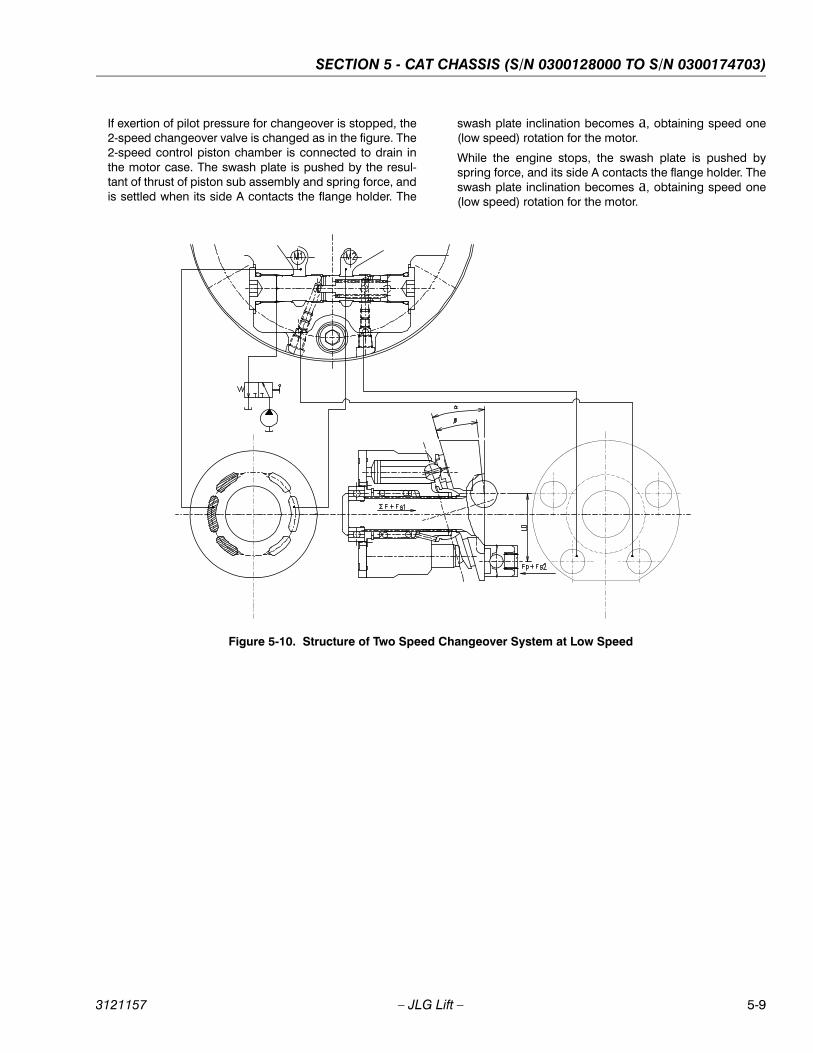
SECTION 5 - CAT CHASSIS (S/N 0300128000 TO S/N 0300174703)
3121157 – JLG Lift – 5-9
If exertion of pilot pressure for changeover is stopped, the2-speed changeover valve is changed as in the figure. The2-speed control piston chamber is connected to drain inthe motor case. The swash plate is pushed by the resul-tant of thrust of piston sub assembly and spring force, andis settled when its side A contacts the flange holder. The
swash plate inclination becomes a, obtaining speed one(low speed) rotation for the motor.
While the engine stops, the swash plate is pushed byspring force, and its side A contacts the flange holder. Theswash plate inclination becomes a, obtaining speed one(low speed) rotation for the motor.
Figure 5-10. Structure of Two Speed Changeover System at Low Speed

SECTION 5 - CAT CHASSIS (S/N 0300128000 TO S/N 0300174703)
5-10 – JLG Lift – 3121157
Working Principle of Parking Brake
Parking brake is a negative brake consisting of a rotatingdisk (frictional material), brake piston and spring. Refer tothe Figure 5-11.
Pressurized oil, when acting on parking brake release port(Pp), is directed to cylinder chamber for parking brakerelease, and pushes up brake piston with thrust corre-
sponding to the pressure surface area of brake piston.This force overcomes spring force, pushing up brake pis-ton and releasing parking brake. When parking brakerelease port (Pp) is connected to the tank, pressurized oilin cylinder chamber for parking brake release is releasedinto the tank, and brake piston pushed by spring forceactivates the parking brake.
Figure 5-11. Parking Brake System
Pp port
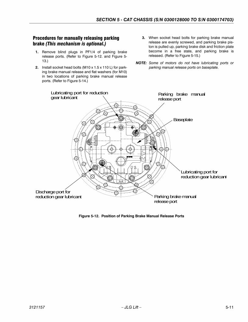
SECTION 5 - CAT CHASSIS (S/N 0300128000 TO S/N 0300174703)
3121157 – JLG Lift – 5-11
Procedures for manually releasing parking brake (This mechanism is optional.)
1. Remove blind plugs in PF1/4 of parking brakerelease ports. (Refer to Figure 5-12. and Figure 5-13.)
2. Install socket head bolts (M10 x 1.5 x 110 L) for park-ing brake manual release and flat washers (for M10)in two locations of parking brake manual releaseports. (Refer to Figure 5-14.)
3. When socket head bolts for parking brake manualrelease are evenly screwed, and parking brake pis-ton is pulled up, parking brake disk and friction platebecome in a free state, and parking brake isreleased. (Refer to Figure 5-15.)
NOTE: Some of motors do not have lubricating ports orparking manual release ports on baseplate.
Figure 5-12. Position of Parking Brake Manual Release Ports
Parking brake manual release port
Discharge port forreduction gear lubricant Parking brake manual
release port
Lubricating port forreduction gear lubricant
Lubricating port for reductiongear lubricant
Baseplate
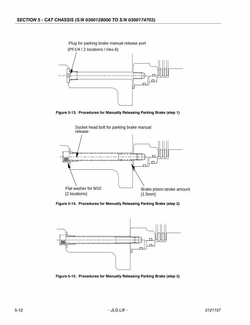
SECTION 5 - CAT CHASSIS (S/N 0300128000 TO S/N 0300174703)
5-12 – JLG Lift – 3121157
Figure 5-13. Procedures for Manually Releasing Parking Brake (step 1)
Plug for parking brake manual release port (PF1/4 / 2 locations / Hex.6)
Figure 5-14. Procedures for Manually Releasing Parking Brake (step 2)
Socket head bolt for parking brake manualrelease
Flat washer for M10 (2 locations)
Brake piston stroke amount(1.5mm)
Figure 5-15. Procedures for Manually Releasing Parking Brake (step 3)
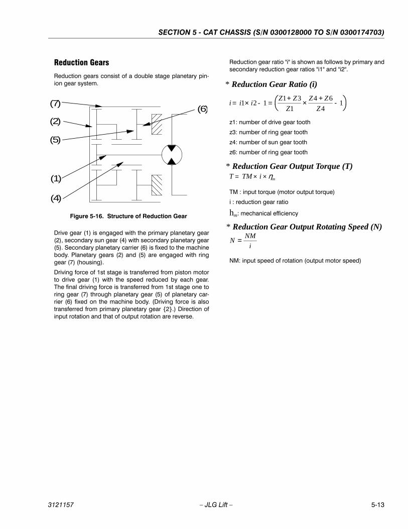
SECTION 5 - CAT CHASSIS (S/N 0300128000 TO S/N 0300174703)
3121157 – JLG Lift – 5-13
Reduction Gears
Reduction gears consist of a double stage planetary pin-ion gear system.
Drive gear (1) is engaged with the primary planetary gear(2), secondary sun gear (4) with secondary planetary gear(5). Secondary planetary carrier (6) is fixed to the machinebody. Planetary gears (2) and (5) are engaged with ringgear (7) (housing).
Driving force of 1st stage is transferred from piston motorto drive gear (1) with the speed reduced by each gear.The final driving force is transferred from 1st stage one toring gear (7) through planetary gear (5) of planetary car-rier (6) fixed on the machine body. (Driving force is alsotransferred from primary planetary gear {2}.) Direction ofinput rotation and that of output rotation are reverse.
Reduction gear ratio "i" is shown as follows by primary andsecondary reduction gear ratios "i1" and "i2".
z1: number of drive gear tooth
z3: number of ring gear tooth
z4: number of sun gear tooth
z6: number of ring gear tooth
TM : input torque (motor output torque)
i : reduction gear ratio
hm: mechanical efficiency
NM: input speed of rotation (output motor speed)
Figure 5-16. Structure of Reduction Gear
(1)
(5)
(2)
(6)
(4)
(7)
* Reduction Gear Ratio (i)
i i iZ Z
Z
Z Z
Z= × - = + × + -1 2 1
1 3
1
4 6
41
* Reduction Gear Output Torque (T) T TM i m= × ×
* Reduction Gear Output Rotating Speed (N)
NNM
i=
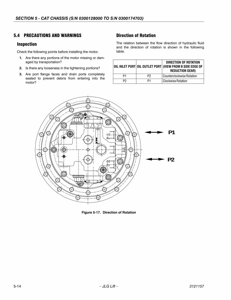
SECTION 5 - CAT CHASSIS (S/N 0300128000 TO S/N 0300174703)
5-14 – JLG Lift – 3121157
5.4 PRECAUTIONS AND WARNINGS
Inspection
Check the following points before installing the motor.
1. Are there any portions of the motor missing or dam-aged by transportation?
2. Is there any looseness in the tightening portions?
3. Are port flange faces and drain ports completelysealed to prevent debris from entering into themotor?
Direction of Rotation
The relation between the flow direction of hydraulic fluidand the direction of rotation is shown in the followingtable.
OIL INLET PORT OIL OUTLET PORTDIRECTION OF ROTATION
(VIEW FROM B SIDE EDGE OF REDUCTION GEAR)
P1 P2 Counterclockwise RotationP2 P1 Clockwise Rotation
Figure 5-17. Direction of Rotation
P1
P2

SECTION 5 - CAT CHASSIS (S/N 0300128000 TO S/N 0300174703)
3121157 – JLG Lift – 5-15
Hydraulic Fluid
1. Hydraulic fluid is an important factor for transmissionof power and lubrication of hydraulic components.Selection and handling of the hydraulic fluid have agreat influence on the performance and life-span ofhydraulic equipment.
Lubricating oil having superior quality is generallyused as hydraulic fluid. It must be excellent in lubri-cating ability, oxidization stability, corrosion protec-tion and anti-emulsification. It must not be erosive topacking and sealing materials. Hydraulic fluids withthe oil of different property should not be mixed.
2. Range of Viscosity
(Idemitsu Daphne Hydraulic Fluid 46WR)
When starting up in low temperature, operate hydraulicequipment in idle with no load.
Filters
The piston motor and the shuttle valve are so designedthat each of its parts is high in accuracy, clearance amongparts is very much limited, and parts are much sensitive toforeign matters, such as sludge, iron powder, rust, filings,grinding powder, etc.
Performance degradation of the piston motor and theshuttle valves, and wear in sliding parts may be avoidedby keeping the oil clean.
Therefore, adequate filters are required to keep hydraulicfluid in the hydraulic system clean, durable and reliable forlong term services with less maintenance and inspection.The contamination level should be below NAS Class 9.
Filters should be placed at the discharge side of hydraulicpump or at the return side of piston motor. Filter gradationshould be smaller than 10 microns (nominal). Use filter(s)with a visual indicator by which the clogging is found fromthe outside, and with a relief valve which by-passes the oildepending on the clogged condition when the filter ele-ment is clogged.
It is recommended that the contamination level ofhydraulic fluid should be below NAS Class 9.
Piping Work
1. Do acid-cleaning and remove scales inside thetubes thoroughly before the assembly.
2. Ensure that foreign articles will not enter into the pis-ton motor case from each port during the pipingwork.
3. Flush the pipes thoroughly upon completion of pip-ing work.
4. The drain piping should be separate and connecteddirectly to the tank.
5. It is recommended that the piston motor case beconstantly filled with oil to maintain satisfactory lubri-cation.
Lubricating Oil for Reduction Gears
The following products are recommended.
Mitsubishi Diamond Hypoid Gear Oil #90 (Equivalentto GL-4)
Notes:
1. Gear oil marked (*) is filled at the time of shipmentfrom our factory.
2. Use the same brand,if the oil is supplied.
3. Select any of the above listed products at time of oilchange.
Cautions in Using Parking Brake
This motor is equipped with parking brake. (Refer to Fig-ure 5-11. for working principle of parking brake.)
The parking brake is so designed as to operate when themachine is stopped or parked. If the parking brake is usedas a brake during traveling of the machine (for brakingmotor rotation), the motor shaft or reduction gear drivegear may break as well as the disk plate may quickly wear.This will result in brake failure, leading to personal injuriesby runaway of the machine.
Therefore, never use the parking brake as a brake whilethe machine is traveling (for braking motor rotation).
VISCOSITYEQUIVALENT OIL
TEMPERATURE (DEG)
Optimum Range of Viscosity 25 to 100 +22 to +55
Practical Range of Viscosity 20 to 500 – 3 to +63
DRAIN PRESSURE IN PISTON MOTOR CASE
Constant at 0.2 MPa or lessIntermittent at 0.5 MPa or less
BRAND MANUFACTURER
(*)Diamond Hypoid Gear Oil #90 Mitsubishi OilApolloil Gear HE90 Idemitsu KosanShell Hypoid Gear Oil CT90 Shell OilCosmo Gear GL-490 Cosmo OilGear Lub SP90 Nippon Oil

SECTION 5 - CAT CHASSIS (S/N 0300128000 TO S/N 0300174703)
5-16 – JLG Lift – 3121157
5.5 OPERATING STEPS AND PRECAUTIONS
Precautions at Startup
After installation of a new or serviced drive motor on themachine, prepare for inspection and startup using the fol-lowing procedures.
1. Fill the piston motor case with hydraulic fluid. (SeeFigure 5-18.) Remove air from the hydraulic circuit.
NOTE: When a hand-operated or electrically operated pumpin small capacity is used, carefully check to see thatthe internal pressure of the motor case does notexceed 0.3 MPa.
2. Fill the reduction gear case with the lubricating oil upto the specified level. (See Figure 5-19.) Remove theplugs of lubricating and gauging ports, and addlubricant until it flows out of the gauging port. Rein-stall and tighten the plug of each port after makingsure that lubricant flows out. (Standard LubricantQuantity: 2600 cm2)
NOTE: The reduction gear box has been fully lubricated upto the specified level at the time of shipment from ourfactory.Some of motors do not have lubricating ports orparking manual release ports on base-plate.
Initial Operation
Repeat the initial operations at low speed. Residual air inthe circuit may cause unusual noise at the valve, but con-tinue the operation at low speed. Ensure that there is nooil leakage around the equipment. Ensure that the resid-ual air is purged and there is no oil leakage and that thereis no unusual noise or vibration caused by the drive motorunder loaded conditions, prior to start of working opera-tions.
Figure 5-18. Oil level of hydraulic fluid at the initial stage
Fill the piston motor case withhydraulic fluid up to this level.
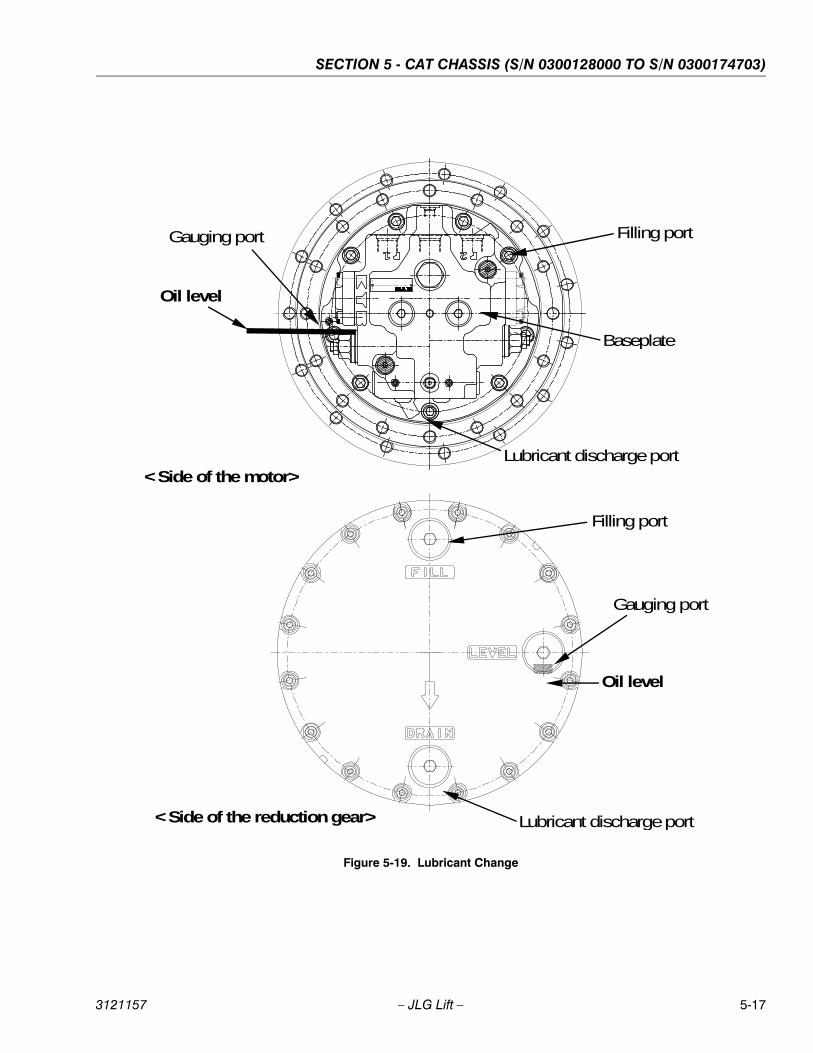
SECTION 5 - CAT CHASSIS (S/N 0300128000 TO S/N 0300174703)
3121157 – JLG Lift – 5-17
Figure 5-19. Lubricant Change
Lubricant discharge port
Filling port
Gauging port
Oil level
<Side of the reduction gear>
<Side of the motor>
Oil level
Lubricant discharge port
Gauging port Filling port
Baseplate
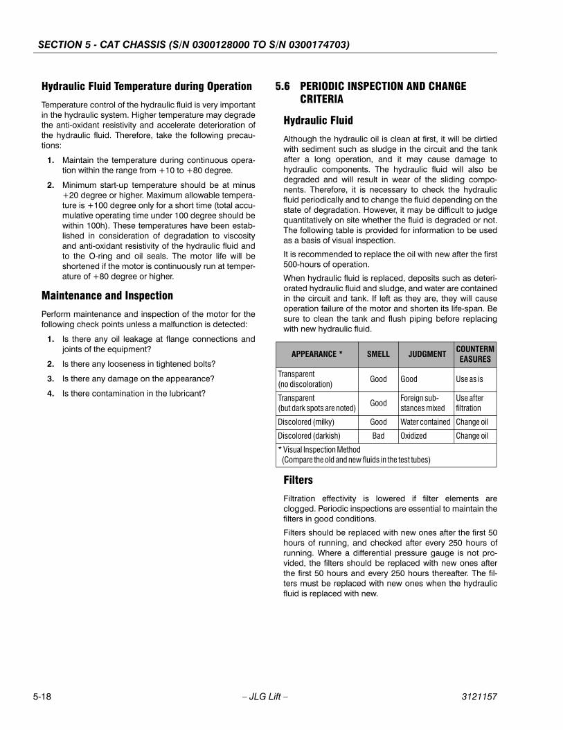
SECTION 5 - CAT CHASSIS (S/N 0300128000 TO S/N 0300174703)
5-18 – JLG Lift – 3121157
Hydraulic Fluid Temperature during Operation
Temperature control of the hydraulic fluid is very importantin the hydraulic system. Higher temperature may degradethe anti-oxidant resistivity and accelerate deterioration ofthe hydraulic fluid. Therefore, take the following precau-tions:
1. Maintain the temperature during continuous opera-tion within the range from +10 to +80 degree.
2. Minimum start-up temperature should be at minus+20 degree or higher. Maximum allowable tempera-ture is +100 degree only for a short time (total accu-mulative operating time under 100 degree should bewithin 100h). These temperatures have been estab-lished in consideration of degradation to viscosityand anti-oxidant resistivity of the hydraulic fluid andto the O-ring and oil seals. The motor life will beshortened if the motor is continuously run at temper-ature of +80 degree or higher.
Maintenance and Inspection
Perform maintenance and inspection of the motor for thefollowing check points unless a malfunction is detected:
1. Is there any oil leakage at flange connections andjoints of the equipment?
2. Is there any looseness in tightened bolts?
3. Is there any damage on the appearance?
4. Is there contamination in the lubricant?
5.6 PERIODIC INSPECTION AND CHANGE CRITERIA
Hydraulic Fluid
Although the hydraulic oil is clean at first, it will be dirtiedwith sediment such as sludge in the circuit and the tankafter a long operation, and it may cause damage tohydraulic components. The hydraulic fluid will also bedegraded and will result in wear of the sliding compo-nents. Therefore, it is necessary to check the hydraulicfluid periodically and to change the fluid depending on thestate of degradation. However, it may be difficult to judgequantitatively on site whether the fluid is degraded or not.The following table is provided for information to be usedas a basis of visual inspection.
It is recommended to replace the oil with new after the first500-hours of operation.
When hydraulic fluid is replaced, deposits such as deteri-orated hydraulic fluid and sludge, and water are containedin the circuit and tank. If left as they are, they will causeoperation failure of the motor and shorten its life-span. Besure to clean the tank and flush piping before replacingwith new hydraulic fluid.
Filters
Filtration effectivity is lowered if filter elements areclogged. Periodic inspections are essential to maintain thefilters in good conditions.
Filters should be replaced with new ones after the first 50hours of running, and checked after every 250 hours ofrunning. Where a differential pressure gauge is not pro-vided, the filters should be replaced with new ones afterthe first 50 hours and every 250 hours thereafter. The fil-ters must be replaced with new ones when the hydraulicfluid is replaced with new.
APPEARANCE * SMELL JUDGMENTCOUNTERMEASURES
Transparent(no discoloration)
Good Good Use as is
Transparent(but dark spots are noted)
GoodForeign sub-stances mixed
Use afterfiltration
Discolored (milky) Good Water contained Change oil
Discolored (darkish) Bad Oxidized Change oil
* Visual Inspection Method (Compare the old and new fluids in the test tubes)
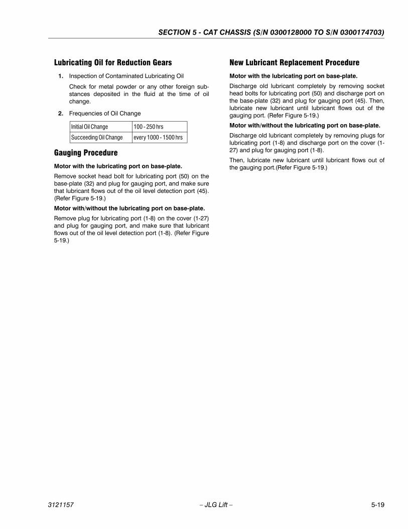
SECTION 5 - CAT CHASSIS (S/N 0300128000 TO S/N 0300174703)
3121157 – JLG Lift – 5-19
Lubricating Oil for Reduction Gears
1. Inspection of Contaminated Lubricating Oil
Check for metal powder or any other foreign sub-stances deposited in the fluid at the time of oilchange.
2. Frequencies of Oil Change
Gauging Procedure
Motor with the lubricating port on base-plate.
Remove socket head bolt for lubricating port (50) on thebase-plate (32) and plug for gauging port, and make surethat lubricant flows out of the oil level detection port (45).(Refer Figure 5-19.)
Motor with/without the lubricating port on base-plate.
Remove plug for lubricating port (1-8) on the cover (1-27)and plug for gauging port, and make sure that lubricantflows out of the oil level detection port (1-8). (Refer Figure5-19.)
New Lubricant Replacement Procedure
Motor with the lubricating port on base-plate.
Discharge old lubricant completely by removing sockethead bolts for lubricating port (50) and discharge port onthe base-plate (32) and plug for gauging port (45). Then,lubricate new lubricant until lubricant flows out of thegauging port. (Refer Figure 5-19.)
Motor with/without the lubricating port on base-plate.
Discharge old lubricant completely by removing plugs forlubricating port (1-8) and discharge port on the cover (1-27) and plug for gauging port (1-8).
Then, lubricate new lubricant until lubricant flows out ofthe gauging port.(Refer Figure 5-19.)
Initial Oil Change 100 - 250 hrs
Succeeding Oil Change every 1000 - 1500 hrs
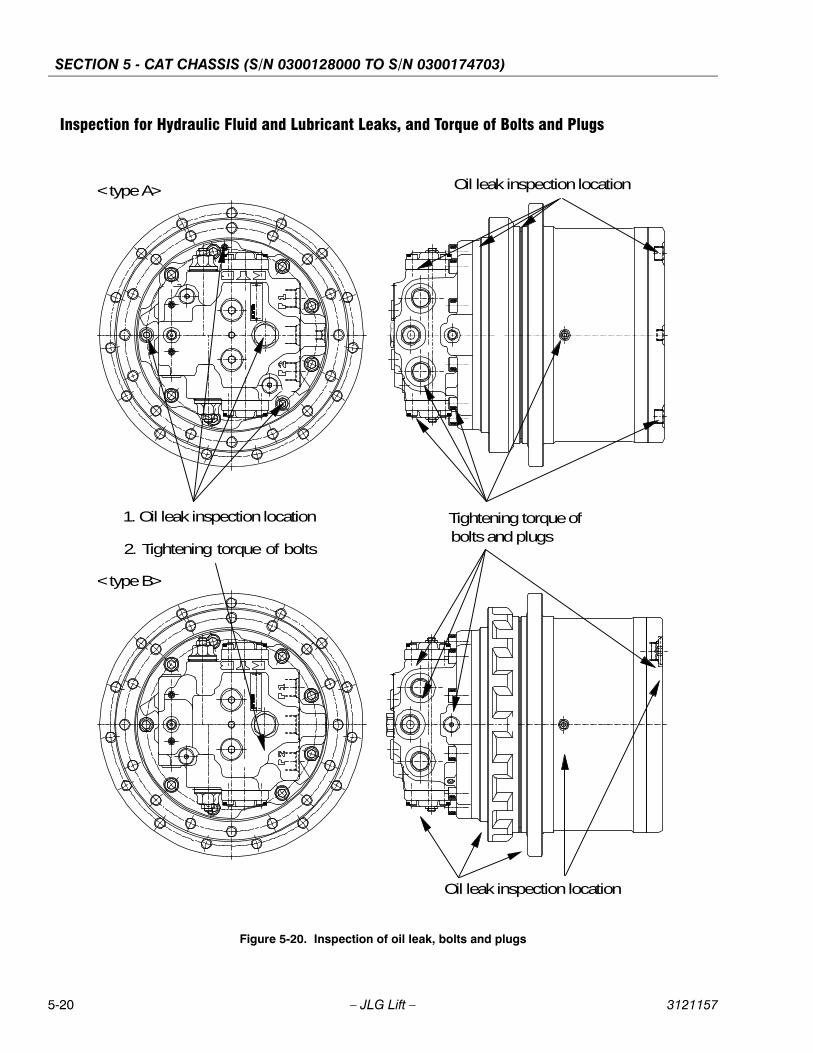
SECTION 5 - CAT CHASSIS (S/N 0300128000 TO S/N 0300174703)
5-20 – JLG Lift – 3121157
Inspection for Hydraulic Fluid and Lubricant Leaks, and Torque of Bolts and Plugs
Figure 5-20. Inspection of oil leak, bolts and plugs
<type A>
<type B>
1. Oil leak inspection location
2. Tightening torque of bolts
Oil leak inspection location
Oil leak inspection location
Tightening torque of bolts and plugs
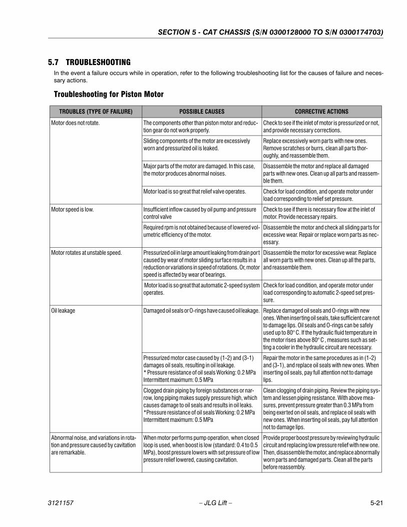
SECTION 5 - CAT CHASSIS (S/N 0300128000 TO S/N 0300174703)
3121157 – JLG Lift – 5-21
5.7 TROUBLESHOOTINGIn the event a failure occurs while in operation, refer to the following troubleshooting list for the causes of failure and neces-sary actions.
Troubleshooting for Piston Motor
TROUBLES (TYPE OF FAILURE) POSSIBLE CAUSES CORRECTIVE ACTIONS
Motor does not rotate. The components other than piston motor and reduc-tion gear do not work properly.
Check to see if the inlet of motor is pressurized or not, and provide necessary corrections.
Sliding components of the motor are excessively worn and pressurized oil is leaked.
Replace excessively worn parts with new ones. Remove scratches or burrs, clean all parts thor-oughly, and reassemble them.
Major parts of the motor are damaged. In this case, the motor produces abnormal noises.
Disassemble the motor and replace all damaged parts with new ones. Clean up all parts and reassem-ble them.
Motor load is so great that relief valve operates. Check for load condition, and operate motor under load corresponding to relief set pressure.
Motor speed is low. Insufficient inflow caused by oil pump and pressure control valve
Check to see if there is necessary flow at the inlet of motor. Provide necessary repairs.
Required rpm is not obtained because of lowered vol-umetric efficiency of the motor.
Disassemble the motor and check all sliding parts for excessive wear. Repair or replace worn parts as nec-essary.
Motor rotates at unstable speed. Pressurized oil in large amount leaking from drain port caused by wear of motor sliding surface results in a reduction or variations in speed of rotations. Or, motor speed is affected by wear of bearings.
Disassemble the motor for excessive wear. Replace all worn parts with new ones. Clean up all the parts, and reassemble them.
Motor load is so great that automatic 2-speed system operates.
Check for load condition, and operate motor under load corresponding to automatic 2-speed set pres-sure.
Oil leakage Damaged oil seals or O-rings have caused oil leakage. Replace damaged oil seals and O-rings with new ones. When inserting oil seals, take sufficient care not to damage lips. Oil seals and O-rings can be safely used up to 80° C. If the hydraulic fluid temperature in the motor rises above 80° C , measures such as set-ting a cooler in the hydraulic circuit are necessary.
Pressurized motor case caused by (1-2) and (3-1) damages oil seals, resulting in oil leakage.* Pressure resistance of oil seals Working: 0.2 MPa Intermittent maximum: 0.5 MPa
Repair the motor in the same procedures as in (1-2) and (3-1), and replace oil seals with new ones. When inserting oil seals, pay full attention not to damage lips.
Clogged drain piping by foreign substances or nar-row, long piping makes supply pressure high, which causes damage to oil seals and results in oil leaks. *Pressure resistance of oil seals Working: 0.2 MPa Intermittent maximum: 0.5 MPa
Clean clogging of drain piping. Review the piping sys-tem and lessen piping resistance. With above mea-sures, prevent pressure greater than 0.3 MPa from being exerted on oil seals, and replace oil seals with new ones. When inserting oil seals, pay full attention not to damage lips.
Abnormal noise, and variations in rota-tion and pressure caused by cavitation are remarkable.
When motor performs pump operation, when closed loop is used, when boost is low (standard: 0.4 to 0.5 MPa), boost pressure lowers with set pressure of low pressure relief lowered, causing cavitation.
Provide proper boost pressure by reviewing hydraulic circuit and replacing low pressure relief with new one. Then, disassemble the motor, and replace abnormally worn parts and damaged parts. Clean all the parts before reassembly.
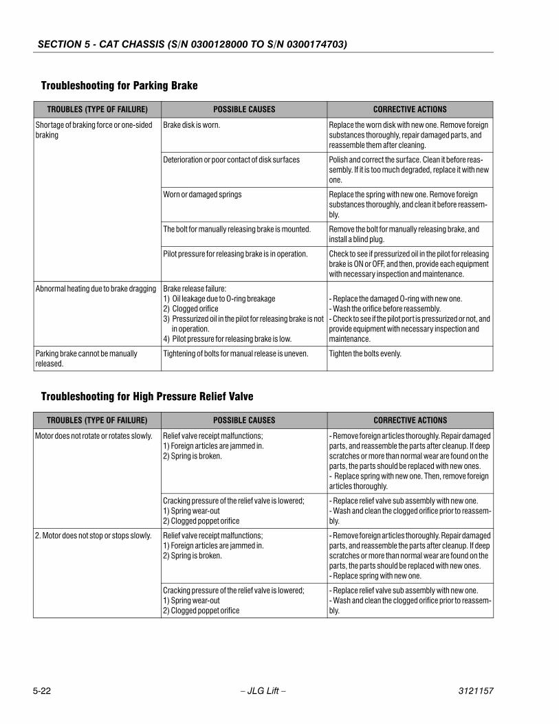
SECTION 5 - CAT CHASSIS (S/N 0300128000 TO S/N 0300174703)
5-22 – JLG Lift – 3121157
Troubleshooting for Parking Brake
Troubleshooting for High Pressure Relief Valve
TROUBLES (TYPE OF FAILURE) POSSIBLE CAUSES CORRECTIVE ACTIONS
Shortage of braking force or one-sided braking
Brake disk is worn. Replace the worn disk with new one. Remove foreign substances thoroughly, repair damaged parts, and reassemble them after cleaning.
Deterioration or poor contact of disk surfaces Polish and correct the surface. Clean it before reas-sembly. If it is too much degraded, replace it with new one.
Worn or damaged springs Replace the spring with new one. Remove foreign substances thoroughly, and clean it before reassem-bly.
The bolt for manually releasing brake is mounted. Remove the bolt for manually releasing brake, and install a blind plug.
Pilot pressure for releasing brake is in operation. Check to see if pressurized oil in the pilot for releasing brake is ON or OFF, and then, provide each equipment with necessary inspection and maintenance.
Abnormal heating due to brake dragging Brake release failure:1) Oil leakage due to O-ring breakage2) Clogged orifice3) Pressurized oil in the pilot for releasing brake is not in operation.4) Pilot pressure for releasing brake is low.
- Replace the damaged O-ring with new one.- Wash the orifice before reassembly.- Check to see if the pilot port is pressurized or not, and provide equipment with necessary inspection and maintenance.
Parking brake cannot be manually released.
Tightening of bolts for manual release is uneven. Tighten the bolts evenly.
TROUBLES (TYPE OF FAILURE) POSSIBLE CAUSES CORRECTIVE ACTIONS
Motor does not rotate or rotates slowly. Relief valve receipt malfunctions;1) Foreign articles are jammed in.2) Spring is broken.
- Remove foreign articles thoroughly. Repair damaged parts, and reassemble the parts after cleanup. If deep scratches or more than normal wear are found on the parts, the parts should be replaced with new ones.- Replace spring with new one. Then, remove foreign articles thoroughly.
Cracking pressure of the relief valve is lowered;1) Spring wear-out2) Clogged poppet orifice
- Replace relief valve sub assembly with new one.- Wash and clean the clogged orifice prior to reassem-bly.
2. Motor does not stop or stops slowly. Relief valve receipt malfunctions;1) Foreign articles are jammed in.2) Spring is broken.
- Remove foreign articles thoroughly. Repair damaged parts, and reassemble the parts after cleanup. If deep scratches or more than normal wear are found on the parts, the parts should be replaced with new ones.- Replace spring with new one.
Cracking pressure of the relief valve is lowered;1) Spring wear-out2) Clogged poppet orifice
- Replace relief valve sub assembly with new one.- Wash and clean the clogged orifice prior to reassem-bly.
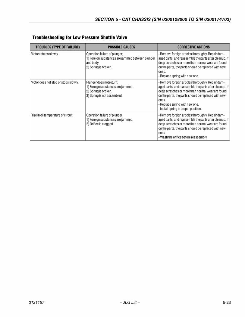
SECTION 5 - CAT CHASSIS (S/N 0300128000 TO S/N 0300174703)
3121157 – JLG Lift – 5-23
Troubleshooting for Low Pressure Shuttle Valve
TROUBLES (TYPE OF FAILURE) POSSIBLE CAUSES CORRECTIVE ACTIONS
Motor rotates slowly. Operation failure of plunger;1) Foreign substances are jammed between plunger and body.2) Spring is broken.
- Remove foreign articles thoroughly. Repair dam-aged parts, and reassemble the parts after cleanup. If deep scratches or more than normal wear are found on the parts, the parts should be replaced with new ones.- Replace spring with new one.
Motor does not stop or stops slowly. Plunger does not return;1) Foreign substances are jammed.2) Spring is broken.3) Spring is not assembled.
- Remove foreign articles thoroughly. Repair dam-aged parts, and reassemble the parts after cleanup. If deep scratches or more than normal wear are found on the parts, the parts should be replaced with new ones.- Replace spring with new one.- Install spring in proper position.
Rise in oil temperature of circuit Operation failure of plunger1) Foreign substances are jammed.2) Orifice is clogged.
- Remove foreign articles thoroughly. Repair dam-aged parts, and reassemble the parts after cleanup. If deep scratches or more than normal wear are found on the parts, the parts should be replaced with new ones.- Wash the orifice before reassembly.

SECTION 5 - CAT CHASSIS (S/N 0300128000 TO S/N 0300174703)
5-24 – JLG Lift – 3121157
Troubleshooting for 2-speed Controls
TROUBLES (TYPE OF FAILURE) POSSIBLE CAUSES CORRECTIVE ACTIONS
The machine does not go straight. Plunger is not shifted;1) Foreign substances are bitten between plunger and body.2) Spring is not installed in place.3) Spring is broken.
- Remove foreign articles thoroughly. Repair dam-aged parts, and reassemble the parts after cleanup. If deep scratches or more than normal wear are found on the parts, the parts should be replaced with new ones.- Install spring in proper position.- Replace spring with new one. Then, remove foreign articles thoroughly. Repair damaged parts, and reas-semble the parts after cleanup. If deep scratches or more than normal wear are found on the parts, the parts should be replaced with new ones.
Oil leaks by abnormal wear on 2-seed control piston. Replace 2-speed control piston with new one. Remove foreign substances thoroughly, and wash the parts before reassembly.
2-speed control piston is not installed in place. Install 2-speed control piston in proper location.
Steel balls are excessively worn. Replace steel balls with new ones. Then, remove for-eign articles thoroughly. Repair damaged parts, and clean the parts before reassembly.
Orifice in oil passage of 2-speed control piston cham-ber is different.
Check for orifice diameter.
Orifice in oil passage of 2-speed control piston cham-ber is clogged.
Wash orifice before reassembly.
Plunger is installed backward. Check plunger for installing direction, and install it in a proper direction.
Speed Two cannot be engaged. Plunger is not shifted;Foreign substances are bitten between plunger and body.
Remove foreign articles thoroughly. Repair damaged parts, and reassemble the parts after cleanup. If deep scratches or more than normal wear are found on the parts, the parts should be replaced with new ones. Wash the orifice before reassembly.
Oil leaks due to abnormal wear on 2-seed control pis-ton.
Replace 2-speed control piston with new one. Remove foreign substances thoroughly, and wash the parts before reassembly.
2-speed control piston is not installed in place. Install 2-speed control piston in proper location.
Orifice in oil passage of 2-speed control piston cham-ber is clogged.
Wash orifice before reassembly.
Plunger is installed backward. Check plunger for installing direction, and install it in a proper direction.
3. Speed One cannot be engaged. Spring is not set in place. Install spring in proper position.
Spring is broken. Replace spring with new one. Then, remove foreign articles thoroughly. Repair damaged parts, and reas-semble the parts after cleanup. If deep scratches or more than normal wear are found on the parts, the parts should be replaced with new ones.
Plunger is installed backward. Check plunger for installing direction, and install it in a proper direction.
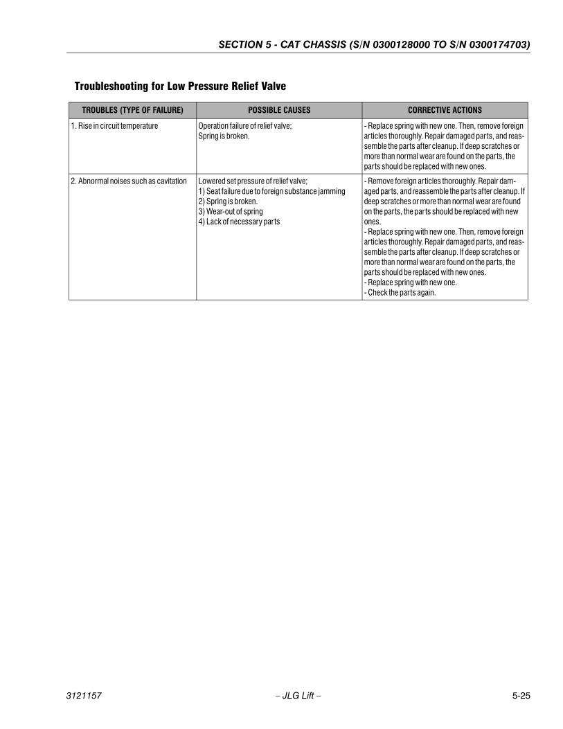
SECTION 5 - CAT CHASSIS (S/N 0300128000 TO S/N 0300174703)
3121157 – JLG Lift – 5-25
Troubleshooting for Low Pressure Relief Valve
TROUBLES (TYPE OF FAILURE) POSSIBLE CAUSES CORRECTIVE ACTIONS
1. Rise in circuit temperature Operation failure of relief valve;Spring is broken.
- Replace spring with new one. Then, remove foreign articles thoroughly. Repair damaged parts, and reas-semble the parts after cleanup. If deep scratches or more than normal wear are found on the parts, the parts should be replaced with new ones.
2. Abnormal noises such as cavitation Lowered set pressure of relief valve;1) Seat failure due to foreign substance jamming2) Spring is broken.3) Wear-out of spring4) Lack of necessary parts
- Remove foreign articles thoroughly. Repair dam-aged parts, and reassemble the parts after cleanup. If deep scratches or more than normal wear are found on the parts, the parts should be replaced with new ones.- Replace spring with new one. Then, remove foreign articles thoroughly. Repair damaged parts, and reas-semble the parts after cleanup. If deep scratches or more than normal wear are found on the parts, the parts should be replaced with new ones.- Replace spring with new one.- Check the parts again.
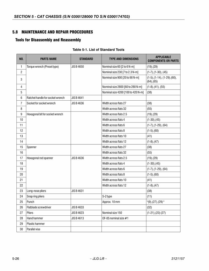
SECTION 5 - CAT CHASSIS (S/N 0300128000 TO S/N 0300174703)
5-26 – JLG Lift – 3121157
5.8 MAINTENANCE AND REPAIR PROCEDURES
Tools for Disassembly and Reassembly
Table 5-1. List of Standard Tools
NO. PARTS NAME STANDARD TYPE AND DIMENSIONS APPLICABLE
COMPONENTS OR PARTS
1 Torque wrench (Preset type) JIS B 4650 Nominal size 60 [2 to 6 N-m] (19),(29)
2 Nominal size 230 [7 to 2.3 N-m] (1-7),(1-30), (45)
3Nominal size 900 [20 to 90 N-m] (1-5),(1-14), (1-29),(60),
(64),(65)
4 Nominal size 2800 [60 to 280 N-m] (1-8),(41), (55)
5 Nominal size 4200 [100 to 420 N-m] (38)
6 Ratchet handle for socket wrench JIS B 4641
7 Socket for socket wrench JIS B 4636 Width across flats 27 (38)
8 Width across flats 32 (55)
9 Hexagonal bit for socket wrench Width across flats 2.5 (19),(29)
10 Width across flats 4 (1-30),(45)
11 Width across flats 6 (1-7),(1-29), (64)
12 Width across flats 8 (1-5),(60)
13 Width across flats 10 (41)
14 Width across flats 12 (1-8),(47)
15 Spanner Width across flats 27 (38)
16 Width across flats 32 (55)
17 Hexagonal rod spanner JIS B 4636 Width across flats 2.5 (19),(29)
18 Width across flats 4 (1-30),(45)
19 Width across flats 6 (1-7),(1-29), (64)
20 Width across flats 8 (1-5),(60)
21 Width across flats 10 (41)
22 Width across flats 12 (1-8),(47)
23 Long-nose pliers JIS B 4631 (38)
24 Snap ring pliers S-2 type (11)
25 Punch Approx. 10 mm "(9),(27),(29) "
26 Flatblade screwdriver JIS B 4633 (32)
27 Pliers JIS B 4623 Nominal size 150 (1-21),(23) (27)
28 Hand hammer JIS B 4613 OF-05 nominal size #1
29 Plastic hammer
30 Parallel vise

SECTION 5 - CAT CHASSIS (S/N 0300128000 TO S/N 0300174703)
3121157 – JLG Lift – 5-27
Table 5-2. List of Special Purpose Tools
No. Parts Name Standard Type and Dimensions Applicable Components
or Parts
1 Angular bearing disassembly jig 20946-99388 (1-3)
2 Angular bearing outer ring press fitting jig 20946-99387 (1-3)
3 Angular bearing inner ring press fitting jig 20946-99390 (1-3)
4 Ring nut disassembly and tightening jig (1-4)
5 Brake piston positioning jig 20468-99903 (17)
6 Oil seal press fitting jig (4)
7 Snap ring assembly jig (11)
8 Bearing assembly jig (28)
9 Floating seal assembly jig (1-2)
10Screw disassembly and assembly jig JIS B 1015
ISO 10664 Drive size of Hexalobular driving feature for screw is T50(No.50)
(1-14)
11 Crane Lifting load 200 kgf
12 Eyebolt For PT 1/2
13 For M16
14 Chain string (wire)
NOTE: No.8: TORX T-shaped drive T50 (manufactured by Saga Tekkou)
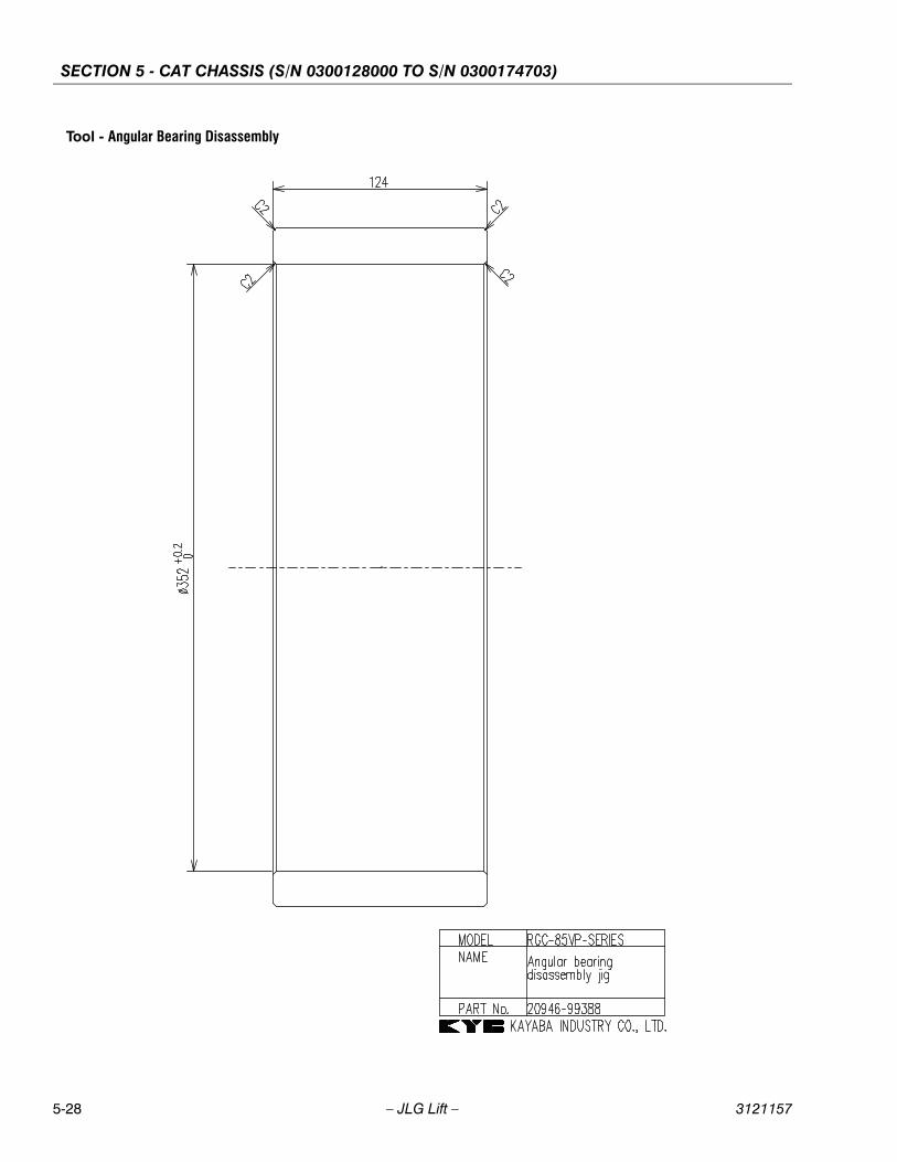
SECTION 5 - CAT CHASSIS (S/N 0300128000 TO S/N 0300174703)
5-28 – JLG Lift – 3121157
Tool - Angular Bearing Disassembly
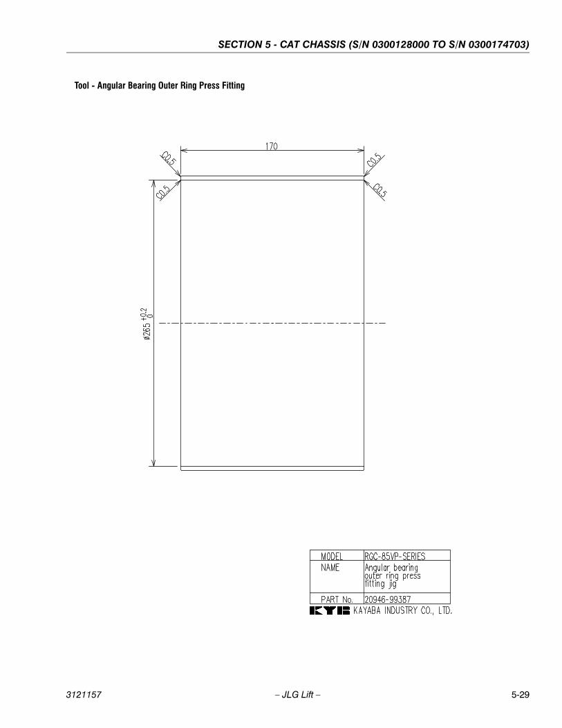
SECTION 5 - CAT CHASSIS (S/N 0300128000 TO S/N 0300174703)
3121157 – JLG Lift – 5-29
Tool - Angular Bearing Outer Ring Press Fitting
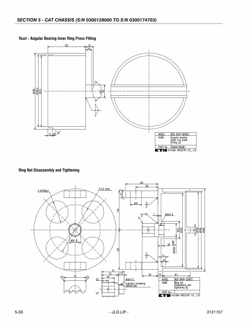
SECTION 5 - CAT CHASSIS (S/N 0300128000 TO S/N 0300174703)
5-30 – JLG Lift – 3121157
Tool - Angular Bearing Inner Ring Press Fitting
Ring Nut Disassembly and Tightening
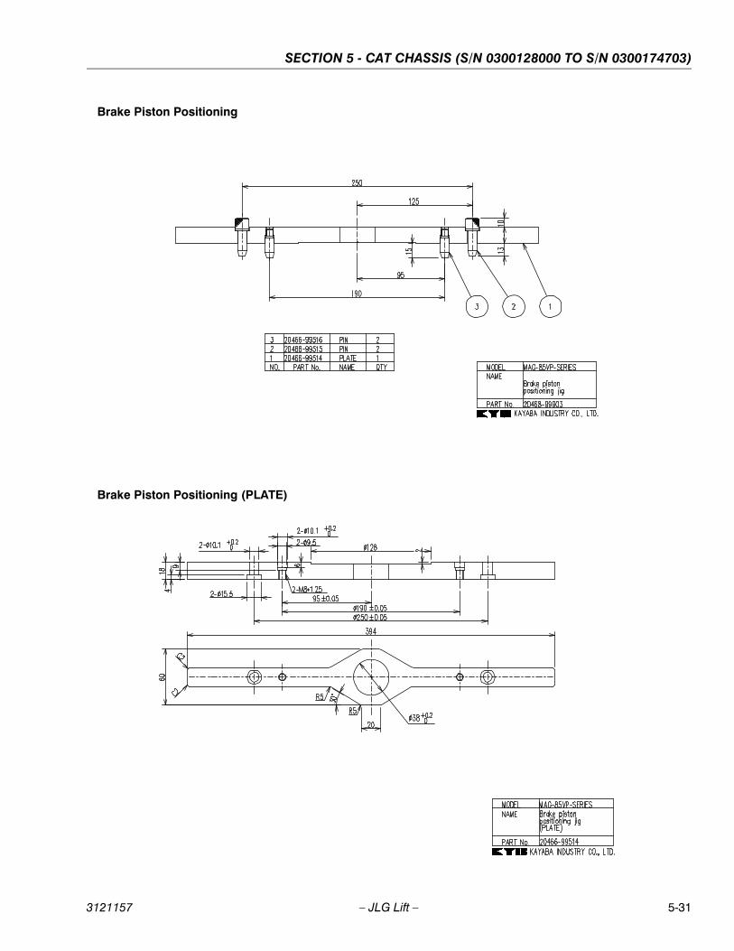
SECTION 5 - CAT CHASSIS (S/N 0300128000 TO S/N 0300174703)
3121157 – JLG Lift – 5-31
Brake Piston Positioning
Brake Piston Positioning (PLATE)
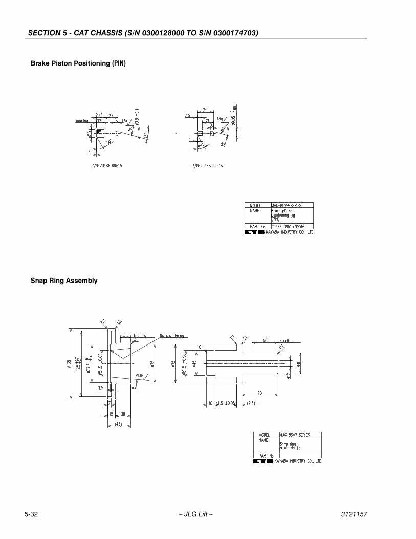
SECTION 5 - CAT CHASSIS (S/N 0300128000 TO S/N 0300174703)
5-32 – JLG Lift – 3121157
Brake Piston Positioning (PIN)
Snap Ring Assembly

SECTION 5 - CAT CHASSIS (S/N 0300128000 TO S/N 0300174703)
3121157 – JLG Lift – 5-33
Tool - Angular Bearing Outer Ring Press Fitting
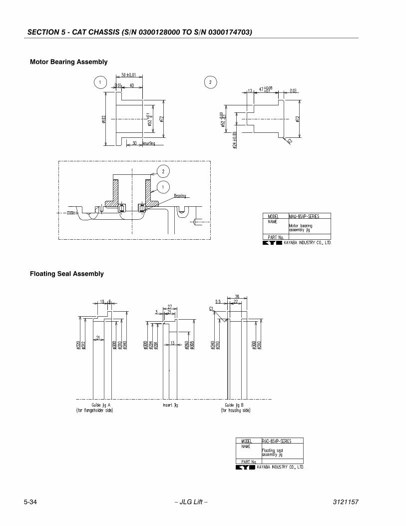
SECTION 5 - CAT CHASSIS (S/N 0300128000 TO S/N 0300174703)
5-34 – JLG Lift – 3121157
Motor Bearing Assembly
Floating Seal Assembly
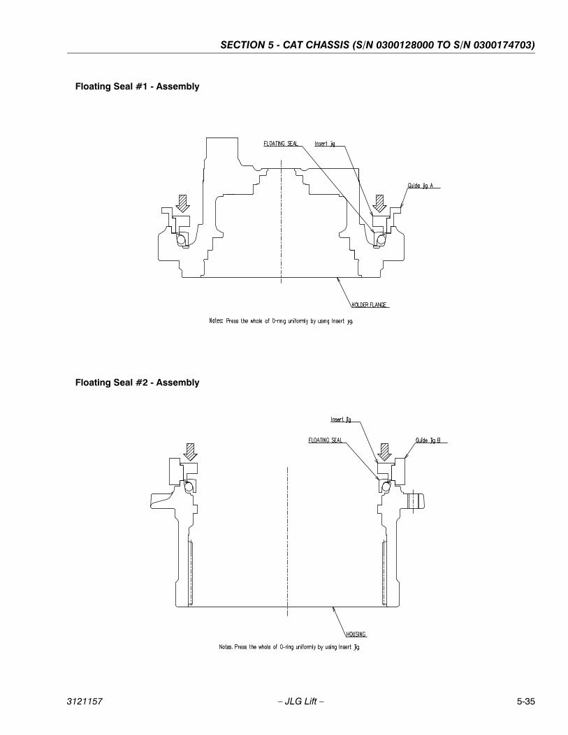
SECTION 5 - CAT CHASSIS (S/N 0300128000 TO S/N 0300174703)
3121157 – JLG Lift – 5-35
Floating Seal #1 - Assembly
Floating Seal #2 - Assembly

SECTION 5 - CAT CHASSIS (S/N 0300128000 TO S/N 0300174703)
5-36 – JLG Lift – 3121157
Table 5-3. List of Subsidiary Material
No. Parts Name Standard Type and DimensionsApplicable Components
or Parts
1 Spring balance 196 N-m or more (1-1), (1-4)
2 Seal tape (1-7), (1-8), (45)
3 Engine oil Equivalent to SAE 30CD class
4 Refined kerosene JIS K 2203 Equivalent to No.2
5 Thinner
6 Lapping plate For correcting sliding surfaces (5), (7), (15), (26)
7 Lapping agent #1000 (5), (7), (15), (26)
8 Copper plate (32), (33)
9
Grease Shell Albania Grease 2 (1-2), (1-28), (4), (18), (20), (21), (22), (26), (30), (31), (38-7), (38-14), (38-17), (38-18), (42), (61)
10 Tube brush For washing inside of bore (7), (32)
11 Bamboo brush For washing
12 Oil pan For receiving hydraulic fluid
13 Plastic container Containing grease
14 Waste cloth
Table 5-4. List of Tightening Torque
Parts Name Nominal SizeHexagon Width Across
Flats (mm)Tightening Torque
Applicable Components or Parts(1)
Plug PT 3/8 825 ft lb (± 3)
34.3 N-m (±4.9) (1-5)
Plug PT 1/4 69 ft lb (± 1)
12.3 N-m (±2.5)(1-7)
Plug PT 1/2 1032 ft lb (±3)
44.1 N-m (±4.9)(1-8)
Plug PF 3/4 12115 ft lb (± 5)157 N-m (±8)
(1-8)
Screw M10 Special type 25 ft lb (± 3)
34.3 N-m (±4.9)(1-14)
Socket head bolt M8 621 ft lb (± 1)
29.4 N-m (±2.0)(1-29)
Plug NPTF1/16 3.967 ft lb (±0.7)
9.8 N-m (±1.0)(1-30), (45)
Orifice M5*0.8*5L 2.52 ft lb (±0.36 )
2.45 N-m (±0.49)(19), (36)
Plug 27275 ft lb (±15 )373 N-m (±20)
(38-6)
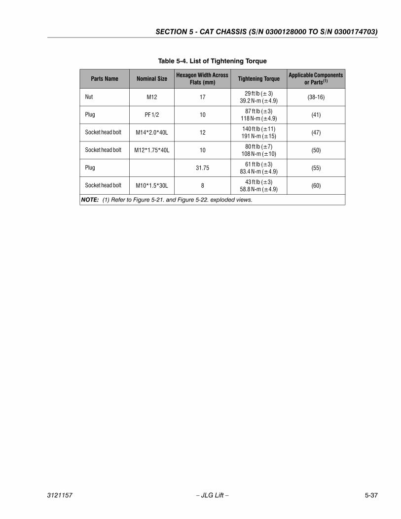
SECTION 5 - CAT CHASSIS (S/N 0300128000 TO S/N 0300174703)
3121157 – JLG Lift – 5-37
Nut M12 1729 ft lb (± 3)
39.2 N-m (±4.9)(38-16)
Plug PF 1/2 1087 ft lb (±3)
118 N-m (±4.9)(41)
Socket head bolt M14*2.0*40L 12140 ft lb (±11)191 N-m (±15)
(47)
Socket head bolt M12*1.75*40L 1080 ft lb (±7)
108 N-m (±10)(50)
Plug 31.7561 ft lb (±3)
83.4 N-m (±4.9)(55)
Socket head bolt M10*1.5*30L 843 ft lb (±3)
58.8 N-m (±4.9)(60)
NOTE: (1) Refer to Figure 5-21. and Figure 5-22. exploded views.
Table 5-4. List of Tightening Torque
Parts Name Nominal SizeHexagon Width Across
Flats (mm)Tightening Torque
Applicable Components or Parts(1)
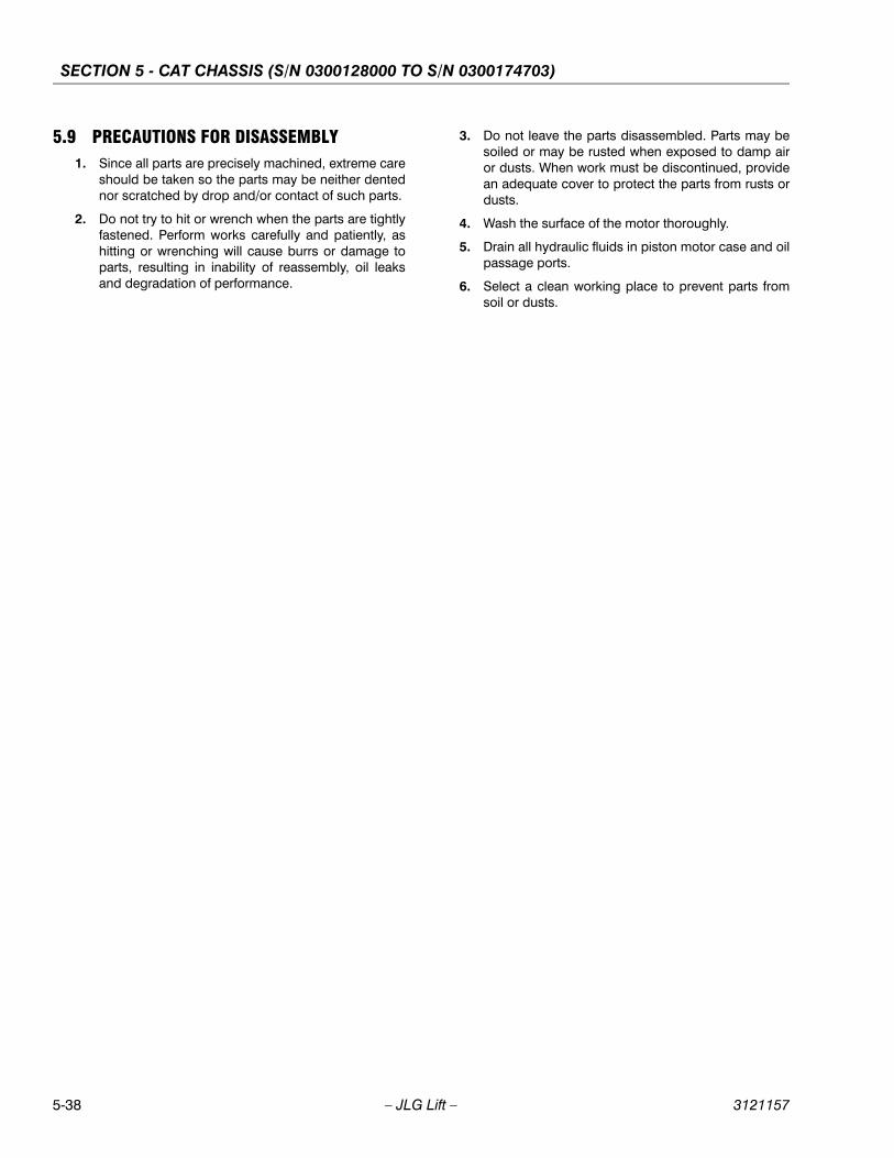
SECTION 5 - CAT CHASSIS (S/N 0300128000 TO S/N 0300174703)
5-38 – JLG Lift – 3121157
5.9 PRECAUTIONS FOR DISASSEMBLY1. Since all parts are precisely machined, extreme care
should be taken so the parts may be neither dentednor scratched by drop and/or contact of such parts.
2. Do not try to hit or wrench when the parts are tightlyfastened. Perform works carefully and patiently, ashitting or wrenching will cause burrs or damage toparts, resulting in inability of reassembly, oil leaksand degradation of performance.
3. Do not leave the parts disassembled. Parts may besoiled or may be rusted when exposed to damp airor dusts. When work must be discontinued, providean adequate cover to protect the parts from rusts ordusts.
4. Wash the surface of the motor thoroughly.
5. Drain all hydraulic fluids in piston motor case and oilpassage ports.
6. Select a clean working place to prevent parts fromsoil or dusts.
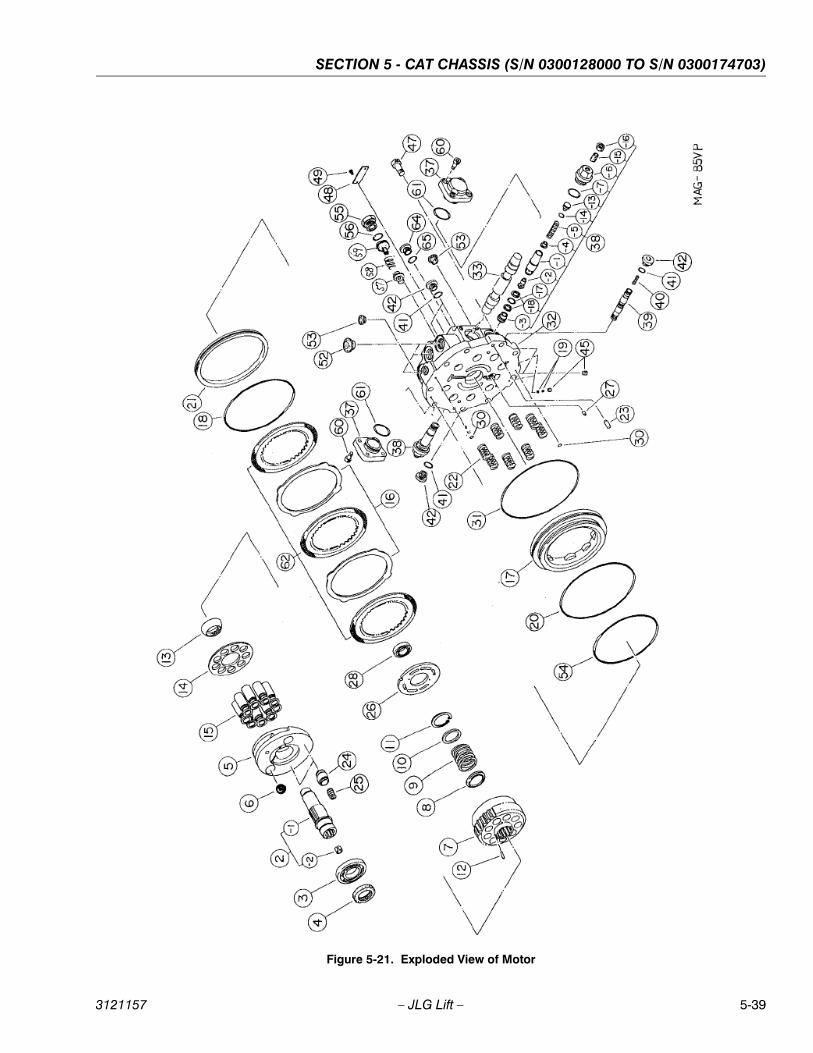
SECTION 5 - CAT CHASSIS (S/N 0300128000 TO S/N 0300174703)
3121157 – JLG Lift – 5-39
Figure 5-21. Exploded View of Motor
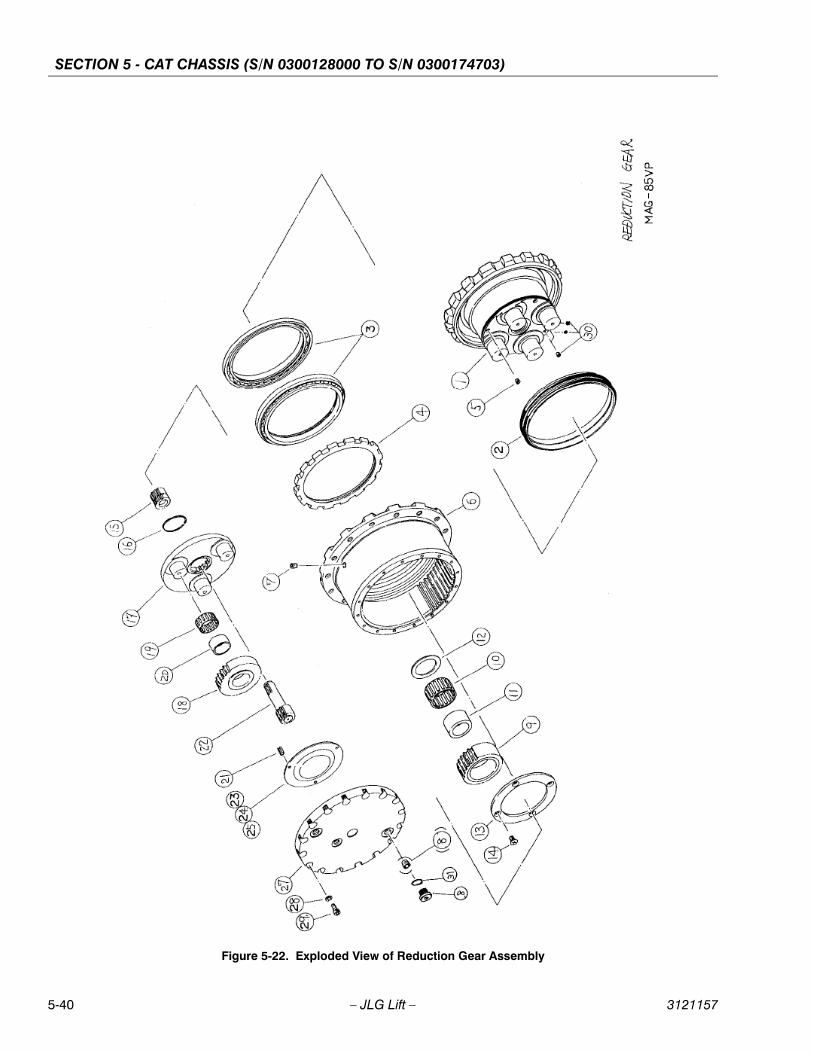
SECTION 5 - CAT CHASSIS (S/N 0300128000 TO S/N 0300174703)
5-40 – JLG Lift – 3121157
Figure 5-22. Exploded View of Reduction Gear Assembly
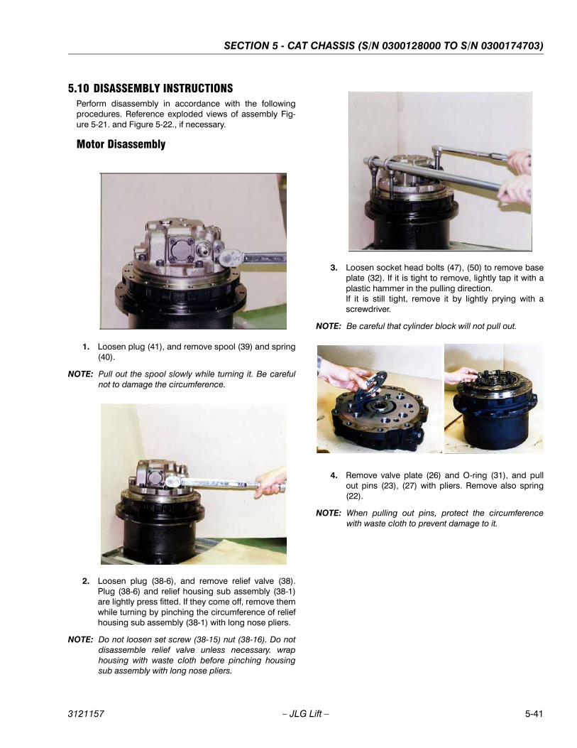
SECTION 5 - CAT CHASSIS (S/N 0300128000 TO S/N 0300174703)
3121157 – JLG Lift – 5-41
5.10 DISASSEMBLY INSTRUCTIONSPerform disassembly in accordance with the followingprocedures. Reference exploded views of assembly Fig-ure 5-21. and Figure 5-22., if necessary.
Motor Disassembly
1. Loosen plug (41), and remove spool (39) and spring(40).
NOTE: Pull out the spool slowly while turning it. Be carefulnot to damage the circumference.
2. Loosen plug (38-6), and remove relief valve (38).Plug (38-6) and relief housing sub assembly (38-1)are lightly press fitted. If they come off, remove themwhile turning by pinching the circumference of reliefhousing sub assembly (38-1) with long nose pliers.
NOTE: Do not loosen set screw (38-15) nut (38-16). Do notdisassemble relief valve unless necessary. wraphousing with waste cloth before pinching housingsub assembly with long nose pliers.
3. Loosen socket head bolts (47), (50) to remove baseplate (32). If it is tight to remove, lightly tap it with aplastic hammer in the pulling direction.If it is still tight, remove it by lightly prying with ascrewdriver.
NOTE: Be careful that cylinder block will not pull out.
4. Remove valve plate (26) and O-ring (31), and pullout pins (23), (27) with pliers. Remove also spring(22).
NOTE: When pulling out pins, protect the circumferencewith waste cloth to prevent damage to it.
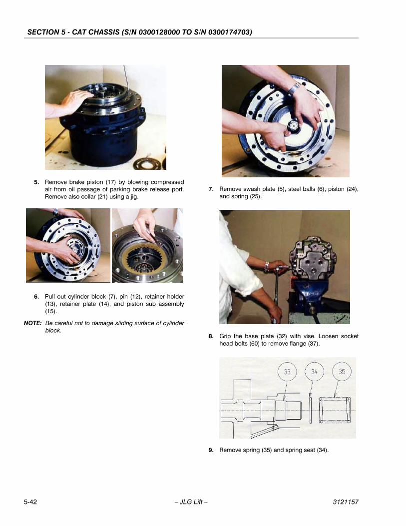
SECTION 5 - CAT CHASSIS (S/N 0300128000 TO S/N 0300174703)
5-42 – JLG Lift – 3121157
5. Remove brake piston (17) by blowing compressedair from oil passage of parking brake release port.Remove also collar (21) using a jig.
6. Pull out cylinder block (7), pin (12), retainer holder(13), retainer plate (14), and piston sub assembly(15).
NOTE: Be careful not to damage sliding surface of cylinderblock.
7. Remove swash plate (5), steel balls (6), piston (24),and spring (25).
8. Grip the base plate (32) with vise. Loosen sockethead bolts (60) to remove flange (37).
9. Remove spring (35) and spring seat (34).
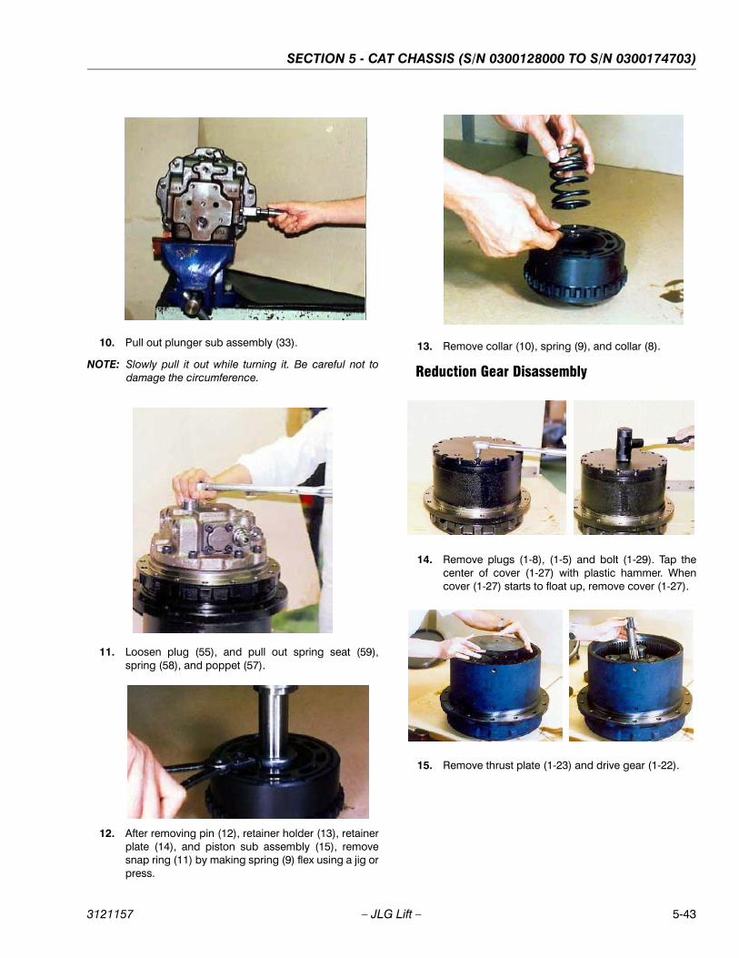
SECTION 5 - CAT CHASSIS (S/N 0300128000 TO S/N 0300174703)
3121157 – JLG Lift – 5-43
10. Pull out plunger sub assembly (33).
NOTE: Slowly pull it out while turning it. Be careful not todamage the circumference.
11. Loosen plug (55), and pull out spring seat (59),spring (58), and poppet (57).
12. After removing pin (12), retainer holder (13), retainerplate (14), and piston sub assembly (15), removesnap ring (11) by making spring (9) flex using a jig orpress.
13. Remove collar (10), spring (9), and collar (8).
Reduction Gear Disassembly
14. Remove plugs (1-8), (1-5) and bolt (1-29). Tap thecenter of cover (1-27) with plastic hammer. Whencover (1-27) starts to float up, remove cover (1-27).
15. Remove thrust plate (1-23) and drive gear (1-22).
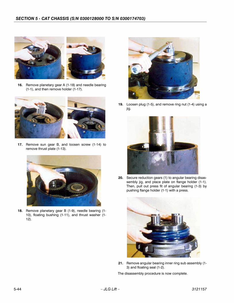
SECTION 5 - CAT CHASSIS (S/N 0300128000 TO S/N 0300174703)
5-44 – JLG Lift – 3121157
16. Remove planetary gear A (1-18) and needle bearing(1-1), and then remove holder (1-17).
17. Remove sun gear B, and loosen screw (1-14) toremove thrust plate (1-13).
18. Remove planetary gear B (1-9), needle bearing (1-10), floating bushing (1-11), and thrust washer (1-12).
19. Loosen plug (1-5), and remove ring nut (1-4) using ajig.
20. Secure reduction gears (1) to angular bearing disas-sembly jig, and place plate on flange holder (1-1).Then, pull out press fit of angular bearing (1-3) bypushing flange holder (1-1) with a press.
21. Remove angular bearing inner ring sub assembly (1-3) and floating seal (1-2).
The disassembly procedure is now complete.
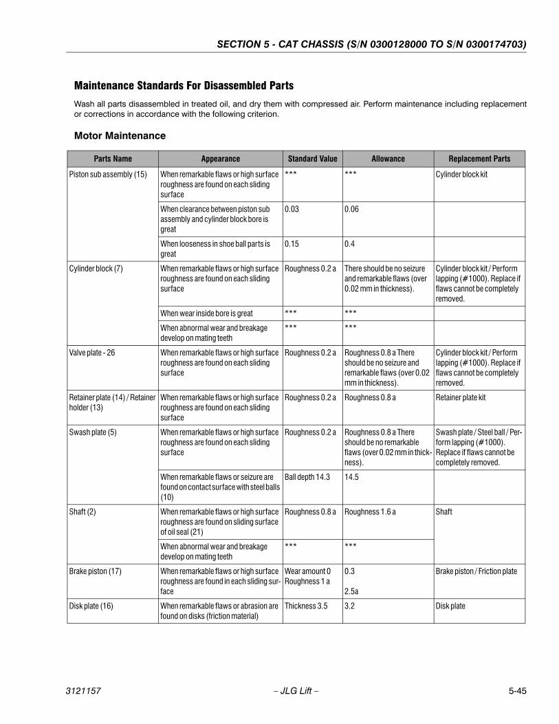
SECTION 5 - CAT CHASSIS (S/N 0300128000 TO S/N 0300174703)
3121157 – JLG Lift – 5-45
Maintenance Standards For Disassembled Parts
Wash all parts disassembled in treated oil, and dry them with compressed air. Perform maintenance including replacementor corrections in accordance with the following criterion.
Motor Maintenance
Parts Name Appearance Standard Value Allowance Replacement Parts
Piston sub assembly (15) When remarkable flaws or high surface roughness are found on each sliding surface
*** *** Cylinder block kit
When clearance between piston sub assembly and cylinder block bore is great
0.03 0.06
When looseness in shoe ball parts is great
0.15 0.4
Cylinder block (7) When remarkable flaws or high surface roughness are found on each sliding surface
Roughness 0.2 a There should be no seizure and remarkable flaws (over 0.02 mm in thickness).
Cylinder block kit / Perform lapping (#1000). Replace if flaws cannot be completely removed.
When wear inside bore is great *** ***
When abnormal wear and breakage develop on mating teeth
*** ***
Valve plate - 26 When remarkable flaws or high surface roughness are found on each sliding surface
Roughness 0.2 a Roughness 0.8 a There should be no seizure and remarkable flaws (over 0.02 mm in thickness).
Cylinder block kit / Perform lapping (#1000). Replace if flaws cannot be completely removed.
Retainer plate (14) / Retainer holder (13)
When remarkable flaws or high surface roughness are found on each sliding surface
Roughness 0.2 a Roughness 0.8 a Retainer plate kit
Swash plate (5) When remarkable flaws or high surface roughness are found on each sliding surface
Roughness 0.2 a Roughness 0.8 a There should be no remarkable flaws (over 0.02 mm in thick-ness).
Swash plate / Steel ball / Per-form lapping (#1000). Replace if flaws cannot be completely removed.
When remarkable flaws or seizure are found on contact surface with steel balls (10)
Ball depth 14.3 14.5
Shaft (2) When remarkable flaws or high surface roughness are found on sliding surface of oil seal (21)
Roughness 0.8 a Roughness 1.6 a Shaft
When abnormal wear and breakage develop on mating teeth
*** ***
Brake piston (17) When remarkable flaws or high surface roughness are found in each sliding sur-face
Wear amount 0 Roughness 1 a
0.3
2.5a
Brake piston / Friction plate
Disk plate (16) When remarkable flaws or abrasion are found on disks (friction material)
Thickness 3.5 3.2 Disk plate

SECTION 5 - CAT CHASSIS (S/N 0300128000 TO S/N 0300174703)
5-46 – JLG Lift – 3121157
Roller bearing (3) / Roller bearing (28)
When flaking and abrasion develop on rolling surface
*** *** Roller bearing
When indentation is found on rolling sur-face
*** ***
When abnormality is found in rotation (abnormal noise, irregular rotation)
*** ***
Piston sub assembly (15) When remarkable flaws or high surface roughness are found on each sliding surface
*** *** Piston sub assembly / Case
When clearance to case is great 0.020 0.040
When looseness in shoe ball parts is great
0.5 1.0
Steel ball (6) When seizure is found on contact sur-face with swash plate (9)
*** *** Swash plate/ Steel ball
Plunger (33) When clearance to base plate (2-1) is great
0.020 0.060 Base plate sub assembly
Base plate (32) When remarkable flaws or high surface roughness are found on sliding surface
*** *** Base plate sub assembly
When flaws which may cause oil leaks are found
*** ***
Spool (39) When remarkable flaws or high surface roughness are found on sliding surface
*** *** Base plate sub assembly
When clearance to base plate (32) is great
0.025 0.050
Poppet (57) When remarkable flaws or high surface roughness are found on sliding surface
*** *** Base plate sub assembly
When clearance to base plate (32) is great
*** ***
When remarkable flaws or high surface roughness are found on seat surface
*** ***
When breakage or deformation is great Free length Each spring
Spring (9) 52.2 50.7
Spring (22) 37.7 36.2
Spring (25) 24.0 22.5
Spring (35) 51.7 50.2
Spring (40) 40.0 38.5
Spring (58) 45.0 43.5
Parts Name Appearance Standard Value Allowance Replacement Parts

SECTION 5 - CAT CHASSIS (S/N 0300128000 TO S/N 0300174703)
3121157 – JLG Lift – 5-47
Reduction Gear Maintenance
NOTE: Pitching in this instance refers to a case where pitching occurs in more than 10% of engagement area per tooth surface.
Parts Name Appearance Standard Value Allowance Replacement Parts
Drive gear (1-22) / Sun gear B (1-15) / Housing (1-6)
When pitching (note 1) and abrasion develop on gear tooth surface
*** *** Drive gear (1-22) / Sun gear B (1-15) / Housing (1-6)
Planetary gear A (1-18) / Planetary gear B (1-9)
When pitching (note 1) and abrasion develop on gear tooth surface
*** *** Planetary gear A (1-18) / Planetary gear B (1-9)
When flaking and abrasion develop on rolling surface of needle bearing
*** ***
Needle bearing (1-19) / Inner race (1-20) / Needle bearing (1-10) / Floating bushing (1-11)
When flaking and abrasion develop on needle and rolling surface
*** *** Needle bearing (1-19) / Inner race (1-20) / Needle bearing (1-10) / Floating bushing (1-11)
When indentation is found on needle and rolling surface
*** ***
When abnormality is found in rotation of bearings (abnormal noise, irregular rotation)
*** ***
Thrust washer (1-12) 3.5 3.4 Thrust washer (1-12)
Thrust plate (1-23) 2.63.03.4
2.52.93.3
Thrust plate (1-23)
Ring nut (1-4) When replaced Ring nut (1-4) / Plug (1-5)
Floating seal (1-2) When flaws that may cause oil leaks develop on sliding surface
Floating seal (1-2)
Thrust plate (1-13) When remarkable deformation is found 6 5.6 Thrust plate (1-13)

SECTION 5 - CAT CHASSIS (S/N 0300128000 TO S/N 0300174703)
5-48 – JLG Lift – 3121157
5.11 PRECAUTIONS FOR REASSEMBLY1. Wash all parts in treated oil, and remove metal
pieces and foreign substances. Ensure that thereare no burrs or bruise.
2. Replace seals, bearings and pins with new ones inprinciple.
3. Take care not to damage seals at time of reassem-bly. (Apply a small amount of grease prior to installa-tion.)
4. Protect all cleaned parts from dusts, flaws and otherdamages. Handle them with extreme care.
5. Tighten bolts to specified torque.
6. After reassembly, plug all ports with shipping plugsto prevent dusts from entering.
5.12 REASSEMBLYPerform reassembly in accordance with the following pro-cedures. Reference exploded views of assembly Figure 5-21. and Figure 5-22., if necessary.
1. Apply grease to floating seal (1-2) and install it onflange holder (1-1).
NOTE: Apply grease or gear oil to seal surface.
2. Press fit both outer rings of angular bearing (1-3) tohousing (1-6).
3. Apply grease to the second floating seal (1-2) andinstall it on housing (1-6).
NOTE: Apply grease or gear oil to seal surface.
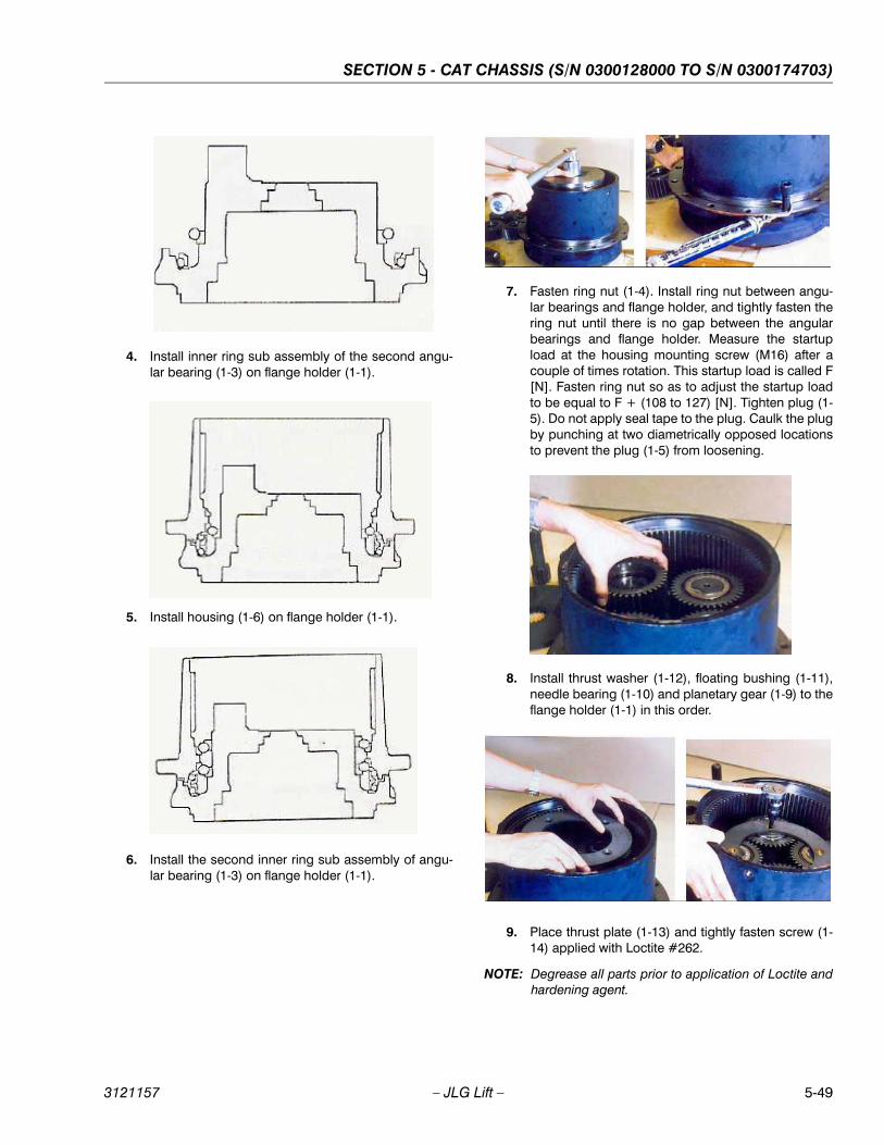
SECTION 5 - CAT CHASSIS (S/N 0300128000 TO S/N 0300174703)
3121157 – JLG Lift – 5-49
4. Install inner ring sub assembly of the second angu-lar bearing (1-3) on flange holder (1-1).
5. Install housing (1-6) on flange holder (1-1).
6. Install the second inner ring sub assembly of angu-lar bearing (1-3) on flange holder (1-1).
7. Fasten ring nut (1-4). Install ring nut between angu-lar bearings and flange holder, and tightly fasten thering nut until there is no gap between the angularbearings and flange holder. Measure the startupload at the housing mounting screw (M16) after acouple of times rotation. This startup load is called F[N]. Fasten ring nut so as to adjust the startup loadto be equal to F + (108 to 127) [N]. Tighten plug (1-5). Do not apply seal tape to the plug. Caulk the plugby punching at two diametrically opposed locationsto prevent the plug (1-5) from loosening.
8. Install thrust washer (1-12), floating bushing (1-11),needle bearing (1-10) and planetary gear (1-9) to theflange holder (1-1) in this order.
9. Place thrust plate (1-13) and tightly fasten screw (1-14) applied with Loctite #262.
NOTE: Degrease all parts prior to application of Loctite andhardening agent.

SECTION 5 - CAT CHASSIS (S/N 0300128000 TO S/N 0300174703)
5-50 – JLG Lift – 3121157
10. Assemble sun gear B (1-15) mounted with snap ring(1-16).
11. Assemble holder (1-17) mounted with inner race (1-20) and spring pin (1-21).
12. Assemble needle bearing (1-19) and planetary gearA (1-18) in this order, and then assemble drive gear(1-22).
13. Assemble thrust plate (1-23).
NOTE: Note: Before installation, select a thrust plate so thatA dimension will be 0.3 to 0.8 mm.
14. Apply liquid gasket (ThreeBond 11041) evenly to thecircumference of contact surface of cover (1-27) andhousing (1-6), and assemble cover so that bolt holeswill align.
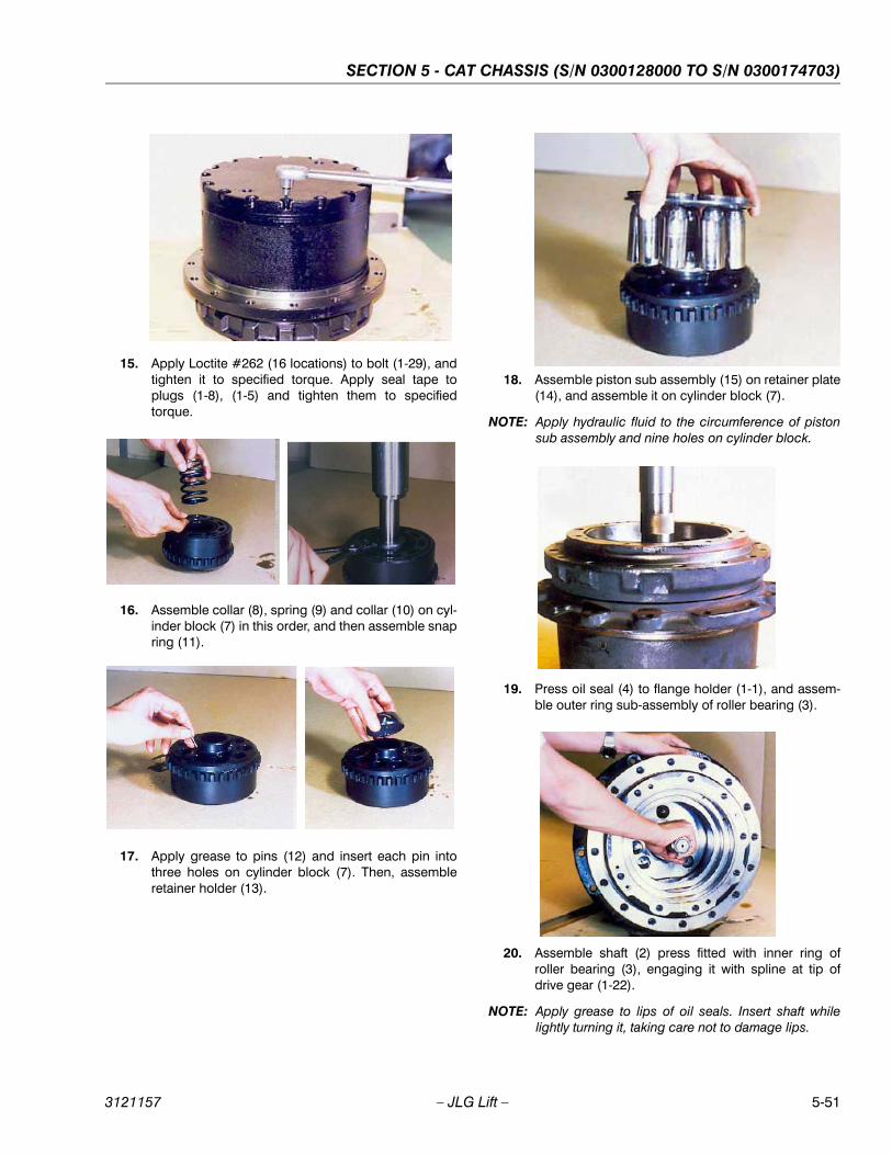
SECTION 5 - CAT CHASSIS (S/N 0300128000 TO S/N 0300174703)
3121157 – JLG Lift – 5-51
15. Apply Loctite #262 (16 locations) to bolt (1-29), andtighten it to specified torque. Apply seal tape toplugs (1-8), (1-5) and tighten them to specifiedtorque.
16. Assemble collar (8), spring (9) and collar (10) on cyl-inder block (7) in this order, and then assemble snapring (11).
17. Apply grease to pins (12) and insert each pin intothree holes on cylinder block (7). Then, assembleretainer holder (13).
18. Assemble piston sub assembly (15) on retainer plate(14), and assemble it on cylinder block (7).
NOTE: Apply hydraulic fluid to the circumference of pistonsub assembly and nine holes on cylinder block.
19. Press oil seal (4) to flange holder (1-1), and assem-ble outer ring sub-assembly of roller bearing (3).
20. Assemble shaft (2) press fitted with inner ring ofroller bearing (3), engaging it with spline at tip ofdrive gear (1-22).
NOTE: Apply grease to lips of oil seals. Insert shaft whilelightly turning it, taking care not to damage lips.
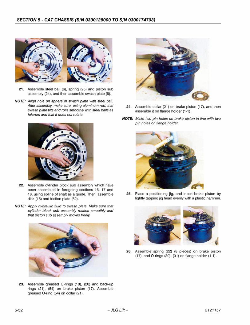
SECTION 5 - CAT CHASSIS (S/N 0300128000 TO S/N 0300174703)
5-52 – JLG Lift – 3121157
21. Assemble steel ball (6), spring (25) and piston subassembly (24), and then assemble swash plate (5).
NOTE: Align hole on sphere of swash plate with steel ball.After assembly, make sure, using aluminum rod, thatswash plate tilts and rolls smoothly with steel balls asfulcrum and that it does not rotate.
22. Assemble cylinder block sub assembly which havebeen assembled in foregoing sections 16, 17 and18, using spline of shaft as a guide. Then, assembledisk (16) and friction plate (62).
NOTE: Apply hydraulic fluid to swash plate. Make sure thatcylinder block sub assembly rotates smoothly andthat piston sub assembly moves freely.
23. Assemble greased O-rings (18), (20) and back-uprings (21), (54) on brake piston (17). Assemblegreased O-ring (54) on collar (21).
24. Assemble collar (21) on brake piston (17), and thenassemble it on flange holder (1-1).
NOTE: Make two pin holes on brake piston in line with twopin holes on flange holder.
25. Place a positioning jig, and insert brake piston bylightly tapping jig head evenly with a plastic hammer.
26. Assemble spring (22) (8 pieces) on brake piston(17), and O-rings (30), (31) on flange holder (1-1).

SECTION 5 - CAT CHASSIS (S/N 0300128000 TO S/N 0300174703)
3121157 – JLG Lift – 5-53
27. Grip base plate (32) with vise, and assemble plungersub assembly (33).
NOTE: Insert plunger sub assembly while slowly turning it.
28. Assemble spring seat (34) and spring (35) in thisorder. After assembling flange (37), tighten sockethead bolts (60) to specified torque.
29. Secure base plate (32) on workbench, and assem-ble outer ring sub assembly (27) of roller bearing(28), pin (27), pins (23) (4 pieces) and O-rings (43)(2 pieces), and then assemble valve plate (26).
NOTE: Apply grease to non-sliding surface of valve plateand to base plate. Be careful not to damage slidingsurface of valve plate.
30. Assemble base plate on reduction gear.
NOTE: Apply hydraulic fluid to sliding surface of cylinderblock. Pay attention to assembling direction of baseplate. Align pins with pin holes.
31. Tighten socket head bolts (47) to specified torque.
NOTE: Note: Tighten the bolts evenly, as base plate ispushed by spring.
32. Assemble relief valve sub assembly (38) on baseplate (32), and tighten it to specified torque. Assem-ble poppet (57), spring (58) and spring seat (59) inthis order, and tighten plug (41) to specified torque.

SECTION 5 - CAT CHASSIS (S/N 0300128000 TO S/N 0300174703)
5-54 – JLG Lift – 3121157
33. Insert spool (39) and spring (40) into base plate, andassemble plugs (41), (43) mounted with O-rings(42), (43), and then tighten them to specified torque.Assemble poppet (57), spring (58) and spring seat(59) in this order, and tighten plug (41) to specifiedtorque.
34. Assemble bonded seal (51) and socket head bolt(50) in this order. Lubricate one location of sockethead bolt (50) with specified amount (2600 cc) oftightening lubricant, and then tighten remaining plug(45) and socket head bolt (50).
NOTE: Apply seal tape to plug (45).
The reassembly process is now complete.
5.13 QUALITY CHECK AFTER REASSEMBLY1. Air Leak Test of Reduction Gear Assembly
Remove one plug (1-8) of the reduction gear assem-bly and apply compressed air (0.03 MPa) throughtapped hole of plug in water for two minutes, andobserve that there are no bubbles.
2. Air Leak Test of Motor
Seal all piping ports on the motor except one portwith plugs, and apply compressed air (0.3 MPa)through open port in water. Observe that there areno bubbles.
3. Upon completion of leak tests in subparagraphs (1)and (2) above, fill the motor case with fresh hydrau-lic fluid. Run the motor crosswise for two minutes fill-ing hydraulic fluid at flow rate of 20 liters per minute.Verify that there is no excessive heat, vibration ornoise during running.
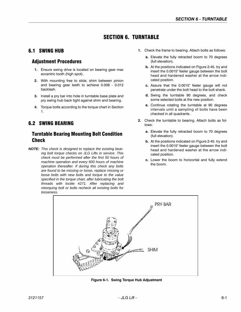
SECTION 6 - TURNTABLE
3121157 – JLG Lift – 6-1
SECTION 6. TURNTABLE
6.1 SWING HUB
Adjustment Procedures1. Ensure swing drive is located on bearing gear max
eccentric tooth (high spot).
2. With mounting free to slide, shim between pinionand bearing gear teeth to achieve 0.008 - 0.012backlash.
3. Install a pry bar into hole in turntable base plate andpry swing hub back tight against shim and bearing.
4. Torque bolts according to the torque chart in Section1.
6.2 SWING BEARING
Turntable Bearing Mounting Bolt Condition Check
NOTE: This check is designed to replace the existing bear-ing bolt torque checks on JLG Lifts in service. Thischeck must be performed after the first 50 hours ofmachine operation and every 600 hours of machineoperation thereafter. If during this check any boltsare found to be missing or loose, replace missing orloose bolts with new bolts and torque to the valuespecified in the torque chart, after lubricating the boltthreads with loctite #271. After replacing andretorquing bolt or bolts recheck all existing bolts forlooseness.
1. Check the frame to bearing. Attach bolts as follows:
a. Elevate the fully retracted boom to 70 degrees(full elevation).
b. At the positions indicated on Figure 2-45. try andinsert the 0.0015" feeler gauge between the bolthead and hardened washer at the arrow indi-cated position.
c. Assure that the 0.0015" feeler gauge will notpenetrate under the bolt head to the bolt shank.
d. Swing the turntable 90 degrees, and checksome selected bolts at the new position.
e. Continue rotating the turntable at 90 degreesintervals until a sampling of bolts have beenchecked in all quadrants.
2. Check the turntable to bearing. Attach bolts as fol-lows:
a. Elevate the fully retracted boom to 70 degrees(full elevation).
b. At the positions indicated on Figure 2-45. try andinsert the 0.0015" feeler gauge between the bolthead and hardened washer at the arrow indi-cated position.
c. Lower the boom to horizontal and fully extendthe boom.
Figure 6-1. Swing Torque Hub Adjustment

SECTION 6 - TURNTABLE
6-2 – JLG Lift – 3121157
d. At the position indicated on figure 2-45. try andinsert the 0.0015" feeler gauge between the bolthead and hardened washer at the arrow indi-cated position.
Wear Tolerance1. From the underside of the machine, at rear center,
with the boom fully elevated and fully retracted, asshown in A, Figure 6-4., Swing Bearing ToleranceBoom Placement, using a magnetic base dial indica-tor, measure and record the distance between theswing bearing and turntable. (See Figure 6-3., SwingBearing Tolerance Measuring Point.)
2. At the same point, with the boom at horizontal andfully extended, and the tower boom fully elevated asshown in (Figure 6-4., Swing Bearing ToleranceBoom Placement) B, using a magnetic base dialindicator, measure and record the distance betweenthe swing bearing and turntable. (See Figure 6-3.,Swing Bearing Tolerance Measuring Point.)
3. If a difference greater than 0.079 in. (2.00 mm) isdetermined, the swing bearing should be replaced.
4. If a difference less than 0.079 in. (2.00 mm) is deter-mined, and any of the following conditions exist, thebearing should be removed, disassembled, andinspected for the following:
a. Metal particles in the grease.
b. Increased drive power required.
c. Noise.
d. Rough rotation.
5. If bearing inspection shows no defects, reassembleand return to service.
THE SWING BEARING IS ONE OF THE MOST CRITICAL POINTS ONAN AERIAL LIFT. IT IS HERE THAT THE STRESSES OF LIFTINGARE CONCENTRATED, AT THE CENTER OF ROTATION. BECAUSEOF THIS, PROPER MAINTENANCE OF THE SWING BEARINGBOLTS IS A MUST FOR SAFE OPERATION.
Swing Bearing Replacement1. Removal.
a. From Ground Control station, operate the boomadequately to provide access to frame openingor, if equipped, to rotary coupling.
NEVER WORK BENEATH THE BOOM WITHOUT FIRST ENGAGINGBOOM SAFETY PROP OR PROVIDING ADEQUATE OVERHEADSLING SUPPORT AND/OR BLOCKING.
b. Attach an adequate support sling to the boomand draw all slack from sling. Prop or block theboom if feasible.
c. From inside turntable, remove mounting hard-ware which attach rotary coupling retaining yokebrackets to turntable.
HYDRAULIC LINES AND PORTS SHOULD BE CAPPED IMMEDI-ATELY AFTER DISCONNECTING LINES TO AVOID THE ENTRY OFCONTAMINANTS INTO THE SYSTEM.
d. Tag and disconnect the hydraulic lines from thefittings on the top of the rotary coupling. Use asuitable container to retain any residual hydrau-lic fluid. Immediately cap lines and ports.
e. Attach suitable overhead lifting equipment to thebase of the turntable weldment.
.0015" Feeler Gauge
Figure 6-2. Swing Bearing Bolt Feeler Gauge Check
SWINGBEARING
FRAME REF.
TURNTABLE REF.
MEASURINGPOINT
Figure 6-3. Swing Bearing Tolerance Measuring Point
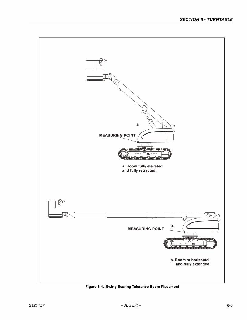
SECTION 6 - TURNTABLE
3121157 – JLG Lift – 6-3
Figure 6-4. Swing Bearing Tolerance Boom Placement
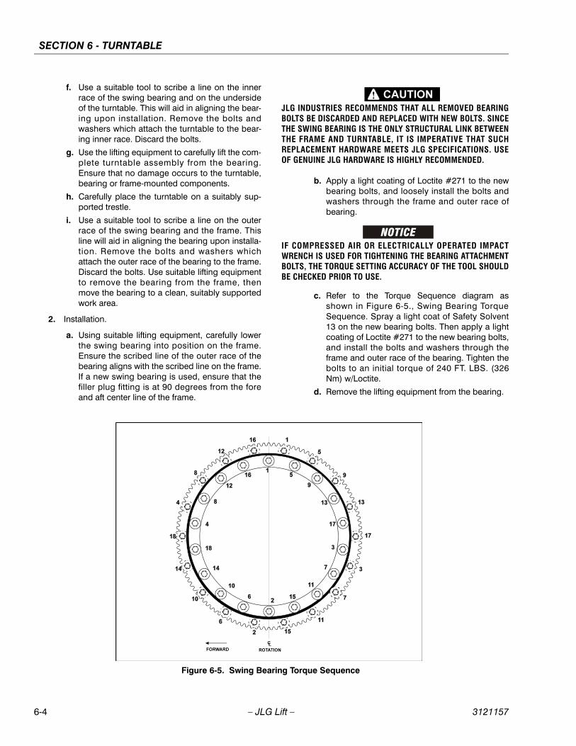
SECTION 6 - TURNTABLE
6-4 – JLG Lift – 3121157
f. Use a suitable tool to scribe a line on the innerrace of the swing bearing and on the undersideof the turntable. This will aid in aligning the bear-ing upon installation. Remove the bolts andwashers which attach the turntable to the bear-ing inner race. Discard the bolts.
g. Use the lifting equipment to carefully lift the com-plete turntable assembly from the bearing.Ensure that no damage occurs to the turntable,bearing or frame-mounted components.
h. Carefully place the turntable on a suitably sup-ported trestle.
i. Use a suitable tool to scribe a line on the outerrace of the swing bearing and the frame. Thisline will aid in aligning the bearing upon installa-tion. Remove the bolts and washers whichattach the outer race of the bearing to the frame.Discard the bolts. Use suitable lifting equipmentto remove the bearing from the frame, thenmove the bearing to a clean, suitably supportedwork area.
2. Installation.
a. Using suitable lifting equipment, carefully lowerthe swing bearing into position on the frame.Ensure the scribed line of the outer race of thebearing aligns with the scribed line on the frame.If a new swing bearing is used, ensure that thefiller plug fitting is at 90 degrees from the foreand aft center line of the frame.
JLG INDUSTRIES RECOMMENDS THAT ALL REMOVED BEARINGBOLTS BE DISCARDED AND REPLACED WITH NEW BOLTS. SINCETHE SWING BEARING IS THE ONLY STRUCTURAL LINK BETWEENTHE FRAME AND TURNTABLE, IT IS IMPERATIVE THAT SUCHREPLACEMENT HARDWARE MEETS JLG SPECIFICATIONS. USEOF GENUINE JLG HARDWARE IS HIGHLY RECOMMENDED.
b. Apply a light coating of Loctite #271 to the newbearing bolts, and loosely install the bolts andwashers through the frame and outer race ofbearing.
IF COMPRESSED AIR OR ELECTRICALLY OPERATED IMPACTWRENCH IS USED FOR TIGHTENING THE BEARING ATTACHMENTBOLTS, THE TORQUE SETTING ACCURACY OF THE TOOL SHOULDBE CHECKED PRIOR TO USE.
c. Refer to the Torque Sequence diagram asshown in Figure 6-5., Swing Bearing TorqueSequence. Spray a light coat of Safety Solvent13 on the new bearing bolts. Then apply a lightcoating of Loctite #271 to the new bearing bolts,and install the bolts and washers through theframe and outer race of the bearing. Tighten thebolts to an initial torque of 240 FT. LBS. (326Nm) w/Loctite.
d. Remove the lifting equipment from the bearing.
Figure 6-5. Swing Bearing Torque Sequence
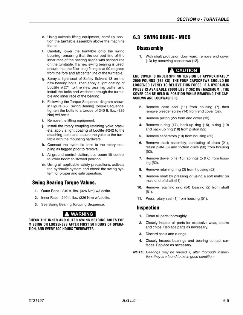
SECTION 6 - TURNTABLE
3121157 – JLG Lift – 6-5
e. Using suitable lifting equipment, carefully posi-tion the turntable assembly above the machineframe.
f. Carefully lower the turntable onto the swingbearing, ensuring that the scribed line of theinner race of the bearing aligns with scribed lineon the turntable. If a new swing bearing is used,ensure that the filler plug fitting is at 90 degreesfrom the fore and aft center line of the turntable.
g. Spray a light coat of Safety Solvent 13 on thenew bearing bolts. Then apply a light coating ofLoctite #271 to the new bearing bolts, andinstall the bolts and washers through the turnta-ble and inner race of the bearing.
h. Following the Torque Sequence diagram shownin Figure 6-5., Swing Bearing Torque Sequence,tighten the bolts to a torque of 240 ft. lbs. (326Nm) w/Loctite.
i. Remove the lifting equipment.
j. Install the rotary coupling retaining yoke brack-ets, apply a light coating of Loctite #242 to theattaching bolts and secure the yoke to the turn-table with the mounting hardware.
k. Connect the hydraulic lines to the rotary cou-pling as tagged prior to removal.
l. At ground control station, use boom lift controlto lower boom to stowed position.
m. Using all applicable safety precautions, activatethe hydraulic system and check the swing sys-tem for proper and safe operation.
Swing Bearing Torque Values.1. Outer Race - 240 ft. lbs. (326 Nm) w/Loctite.
2. Inner Race - 240 ft. lbs. (326 Nm) w/Loctite.
3. See Swing Bearing Torquing Sequence.
CHECK THE INNER AND OUTER SWING BEARING BOLTS FORMISSING OR LOOSENESS AFTER FIRST 50 HOURS OF OPERA-TION, AND EVERY 600 HOURS THEREAFTER.
6.3 SWING BRAKE - MICO
Disassembly1. With shaft protrusion downward, remove end cover
(13) by removing capscrews (12).
END COVER IS UNDER SPRING TENSION OF APPROXIMATELY2000 POUNDS (681 KG). THE FOUR CAPSCREWS SHOULD BELOOSENED EVENLY TO RELIEVE THIS FORCE. IF A HYDRAULICPRESS IS AVAILABLE (3000 LBS (1362 KG) MAXIMUM), THECOVER CAN BE HELD IN POSITION WHILE REMOVING THE CAP-SCREWS AND LOCKWASHERS.
2. Remove case seal (11) from housing (7) thenremove bleeder screw (14) from end cover (52).
3. Remove piston (22) from end cover (13).
4. Remove o-ring (17), back-up ring (16), o-ring (19)and back-up ring (18) from piston (22).
5. Remove separators (10) from housing (52).
6. Remove stack assembly, consisting of discs (21),return plate (8) and friction discs (20) from housing(52).
7. Remove dowel pins (15), springs (5 & 6) from hous-ing (52).
8. Remove retaining ring (3) from housing (52).
9. Remove shaft by pressing or using a soft mallet onmale end of shaft (51).
10. Remove retaining ring (54) bearing (2) from shaft(51).
11. Press rotary seal (1) from housing (51).
Inspection1. Clean all parts thoroughly.
2. Closely inspect all parts for excessive wear, cracksand chips. Replace parts as necessary.
3. Discard seals and o-rings.
4. Closely inspect bearings and bearing contact sur-faces. Replace as necessary.
NOTE: Bearings may be reused if, after thorough inspec-tion, they are found to be in good condition.
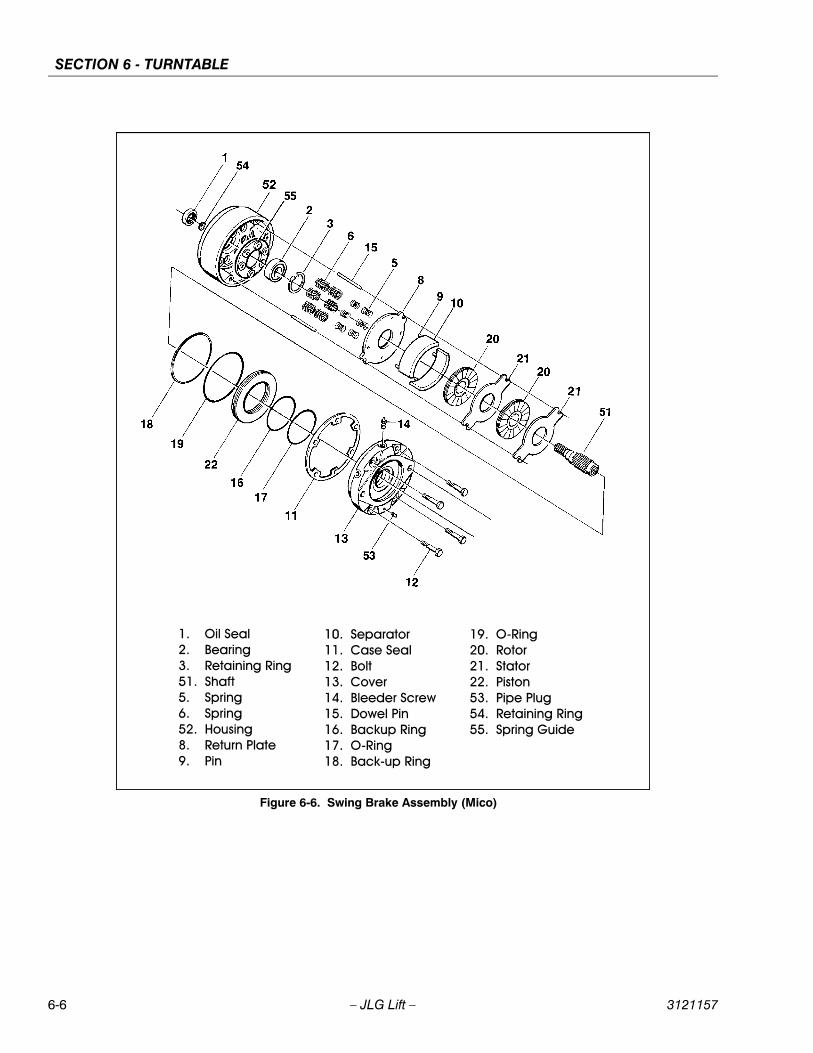
SECTION 6 - TURNTABLE
6-6 – JLG Lift – 3121157
Figure 6-6. Swing Brake Assembly (Mico)
SECTION 6 - TURNTABLE
3121157 – JLG Lift – 6-7
Assembly
NOTE: Lubricate all seals and o-rings with clean hydraulicoil prior to assembly.
1. Press new rotary seal (1) into housing (52). Note thedirection of seal.
2. Install new bearing (2) on shaft (51).
3. Install shaft assembly and retaining ring (3) intohousing (52).
4. Install dowel pins (15), spring retainer (55), andsprings (5 & 6) into housing (52).
NOTE: Be sure to use the same number of springs andspring pattern as recorded during disassembly.
5. Position new large diameter return plate (8) in hous-ing with tabs guided by dowel pins (15) until discrests on springs (5 & 6).
NOTE: Discs (21 & 8) and friction discs (20) should remaindry during installation. Oil will contaminate disc sur-faces.
6. Place new disc (20) on shaft (51) until it contactsreturn plate (8).
7. Add additional discs (21) as required to completeassembly.
8. Insert separators (10) in holes of return plate (8).
9. Install new o-ring (17), new back-up ring (16), new o-ring (19) and new back-up ring (18) on piston (22).Insert piston (22) into end cover (13), being carefulnot to shear o-rings or back-up rings.
10. Install new case seal (11) in housing (52), theninstall bleeder screw (14) in end cover.
11. Position end cover (13) on housing (52), aligningdowel pins (15) with holes in end cover.
12. Insert capscrews (12) and tighten evenly to drawend cover (13) to housing (52). Torque capscrews to55 ft. lbs. (75 Nm).
6.4 GENERATOR
Every 250 hoursEvery 250 hours of operation, check the drive belt forproper tension.
Every 500 hoursEvery 500 hours of operation, service the generatorbrushes and slip rings. Hostile environments may requiremore frequent service.
Every 500 hours of service, blow out the inside of the gen-erator. If operating in a hostile environment, cleanmonthly.
1/2 in.(13 mm)

SECTION 6 - TURNTABLE
6-8 – JLG Lift – 3121157
Overload Protection
STOP THE ENGINE WHENEVER CHECKING OR INSPECTING THECIRCUIT BREAKER.
The circuit breaker protects the generator windings fromoverload. If the circuit breaker opens, generator outputstops. If the circuit breaker continues to open, check forfaulty equipment connected to the platform receptacles.
6.5 SPARK ARRESTER CLEANING INSTRUCTIONS
1. Remove the cleanout plug in the bottom of sparkarrester (muffler).
2. Without causing deformation (or any type of dam-age to the spark arrester) repeatedly tap on thearrester near the cleanout plug. This may be enoughto begin drainage of the spark trap.
3. An industrial vacuum cleaner can do a complete jobat this point.
a. Or, IN A SAFE AREA, start the engine. Thenalternate between low idle and high idle for twoto three minutes.
b. Or, operate the engine as required by the appli-cation for two to three minutes.
4. Install the cleanout plug. (See Table 2-4. PreventiveMaintenance and Inspection Schedule.)
CIRCUITBREAKER
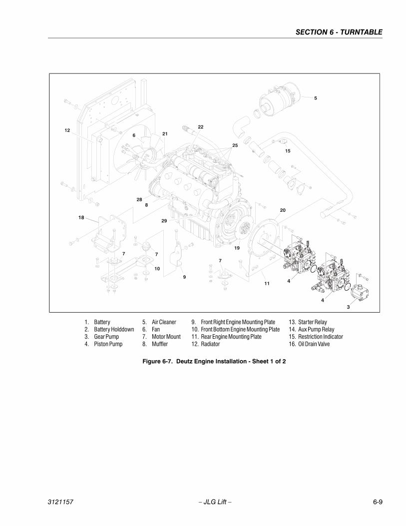
SECTION 6 - TURNTABLE
3121157 – JLG Lift – 6-9
1. Battery2. Battery Holddown3. Gear Pump4. Piston Pump
5. Air Cleaner6. Fan7. Motor Mount8. Muffler
9. Front Right Engine Mounting Plate10. Front Bottom Engine Mounting Plate11. Rear Engine Mounting Plate12. Radiator
13. Starter Relay14. Aux Pump Relay15. Restriction Indicator16. Oil Drain Valve
Figure 6-7. Deutz Engine Installation - Sheet 1 of 2
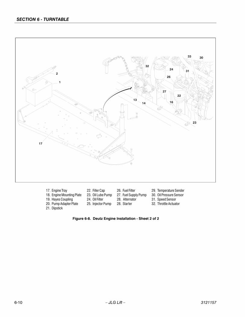
SECTION 6 - TURNTABLE
6-10 – JLG Lift – 3121157
17. Engine Tray18. Engine Mounting Plate19. Hayes Coupling20. Pump Adapter Plate21. Dipstick
22. Filler Cap23. Oil Lube Pump24. Oil Filter25. Injector Pump
26. Fuel Filter27. Fuel Supply Pump28. Alternator28. Starter
29. Temperature Sender30. Oil Pressure Sensor31. Speed Sensor32. Throttle Actuator
Figure 6-8. Deutz Engine Installation - Sheet 2 of 2
SECTION 6 - TURNTABLE
3121157 – JLG Lift – 6-11
6.6 DEUTZ EMR 2 (S/N 85110 TO PRESENT)The EMR2 consists of the sensors, the control unit and theactuator. Engine-side controls as well as the JLG ControlSystem are connected by means of separate cable har-nesses to the EMR control unit.
The sensors attached to the engine provide the electron-ics in the control unit with all the relevant physical parame-ters In accordance with the information of the currentcondition of the engine and the preconditions (throttleposition etc.), the EMR2 controls an actuator that operatesthe control rod of the injection pump and thus doses thefuel quantity in accordance with the performance require-ments.
The exact position of the regulating rod is reported backand, if necessary, is corrected, by means of the controlrod travel sensor, situated together with the rotation mag-nets in a housing of the actuator.
The EMR2 is equipped with safety devices and measuresin the hardware and software in order to ensure emer-gency running (Limp home) functions.
In order to switch the engine off, the EMR2 is switched in ade-energized fashion over the ignition switch. A strongspring in the actuator presses the control rod in the de-energized condition into the zero position. As a redun-dancy measure, an additional solenoid serves for switch-ing off and this, independently of the actuator, also movesthe control rod in the de-energized condition into the zeroposition.
After the programming, that is carried out over theISO9141 interface, the EMR2 is possesses a motor-spe-cific data set and this is then fixedly assigned to theengine. Included in this are the various application casesas well as the customer’s wishes regarding a particularscope of function.
Each EMR2 module is matched by serial number to theengine. Modules cannot be swapped between engines.
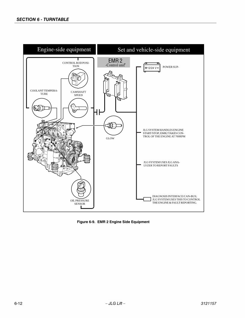
SECTION 6 - TURNTABLE
6-12 – JLG Lift – 3121157
Figure 6-9. EMR 2 Engine Side Equipment
GLOW
POWER SUP-
COOLANT TEMPERA-TURE
CONTROL ROD POSI-TION
CAMSHAFT SPEED
OIL PRESSURESENSOR
JLG SYSTEM USES JLG ANA-LYZER TO REPORT FAULTS
DIAGNOSIS INTERFACE/CAN-BUS; JLG SYSTEM USES THIS TO CONTROL THE ENGINE & FAULT REPORTING.
JLG SYSTEM HANDLES ENGINE START/STOP; EMR2 TAKES CON-TROL OF THE ENGINE AT 700RPM
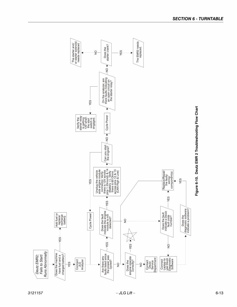
SECTION 6 - TURNTABLE
3121157 – JLG Lift – 6-13
Fig
ure
6-10
. D
eutz
EM
R 2
Tro
uble
sho
otin
g F
low
Ch
art

SECTION 6 - TURNTABLE
6-14 – JLG Lift – 3121157
Fig
ure
6-11
. D
eutz
EM
R 2
Veh
icle
Sid
e C
on
nect
ion
Dia
gra
m
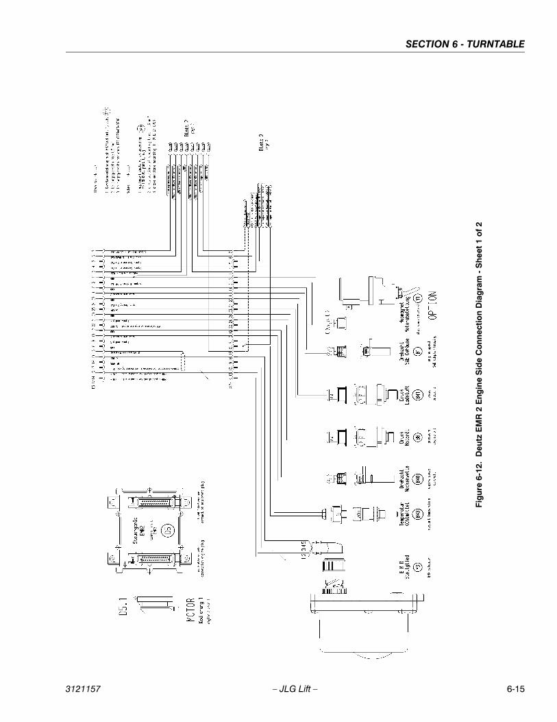
SECTION 6 - TURNTABLE
3121157 – JLG Lift – 6-15
Fig
ure
6-12
. D
eutz
EM
R 2
Eng
ine
Sid
e C
onn
ectio
n D
iag
ram
- S
hee
t 1
of
2

SECTION 6 - TURNTABLE
6-16 – JLG Lift – 3121157
Fig
ure
6-13
. D
eutz
EM
R 2
Eng
ine
Sid
e C
onn
ectio
n D
iag
ram
- S
hee
t 2
of
2
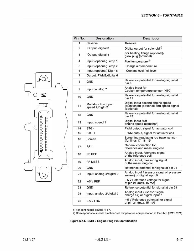
SECTION 6 - TURNTABLE
3121157 – JLG Lift – 6-17
Figure 6-14. EMR 2 Engine Plug Pin Identification
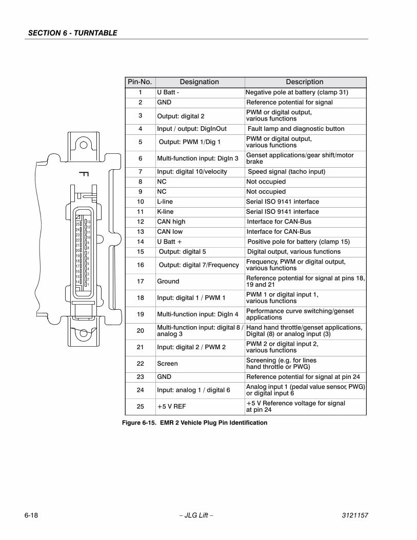
SECTION 6 - TURNTABLE
6-18 – JLG Lift – 3121157
Figure 6-15. EMR 2 Vehicle Plug Pin Identification
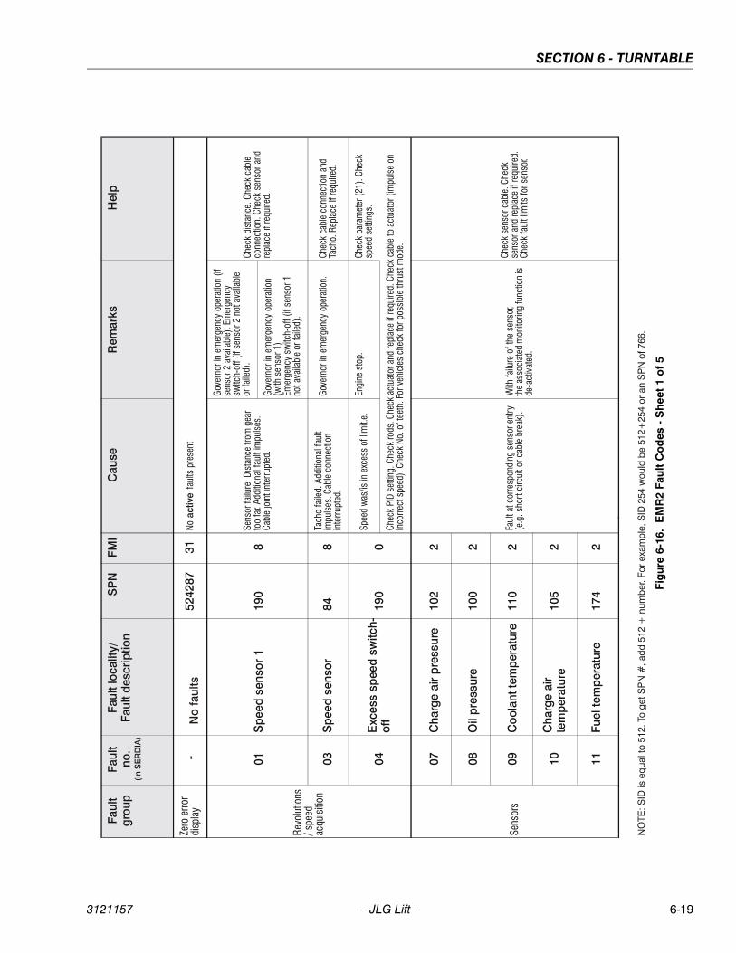
SECTION 6 - TURNTABLE
3121157 – JLG Lift – 6-19
Fig
ure
6-16
. E
MR
2 Fa
ult
Co
des
- S
hee
t 1
of
5

SECTION 6 - TURNTABLE
6-20 – JLG Lift – 3121157
Fig
ure
6-17
. E
MR
2 Fa
ult
Co
des
- S
hee
t 2
of
5

SECTION 6 - TURNTABLE
3121157 – JLG Lift – 6-21
Fig
ure
6-18
. E
MR
2 Fa
ult
Co
des
- S
hee
t 3
of
5

SECTION 6 - TURNTABLE
6-22 – JLG Lift – 3121157
Fig
ure
6-19
. E
MR
2 Fa
ult
Co
des
- S
hee
t 4
of
5
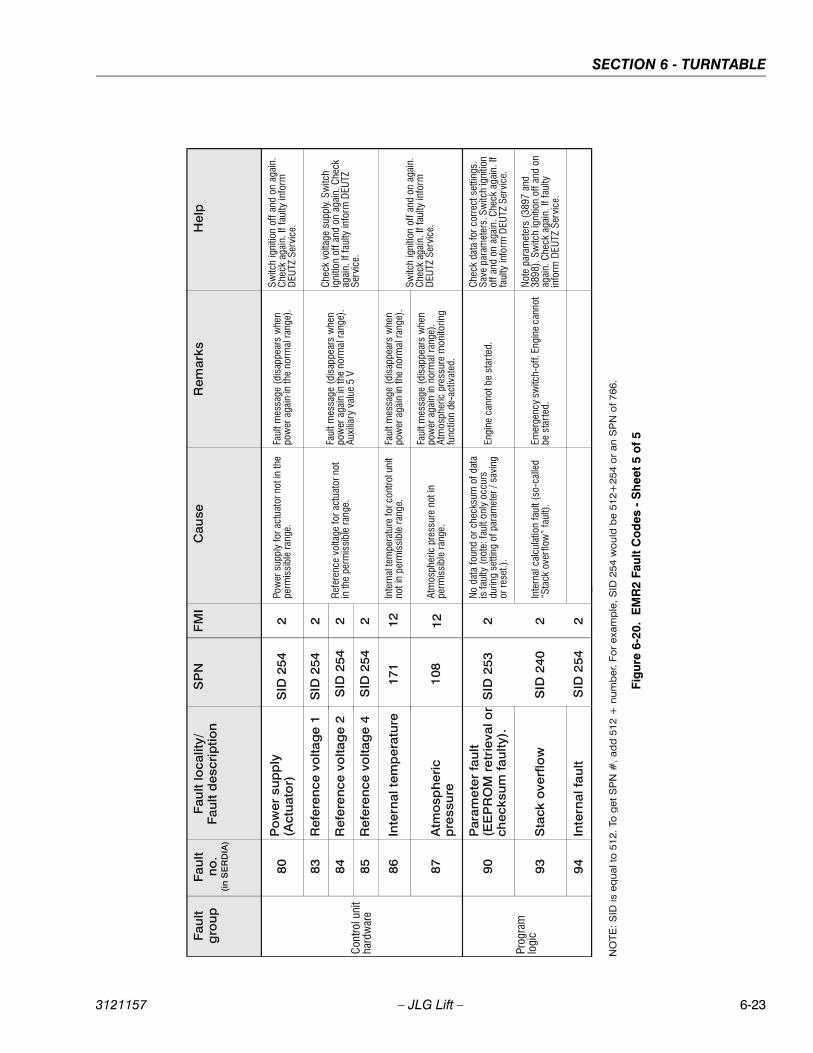
SECTION 6 - TURNTABLE
3121157 – JLG Lift – 6-23
Fig
ure
6-20
. E
MR
2 Fa
ult
Co
des
- S
hee
t 5 o
f 5
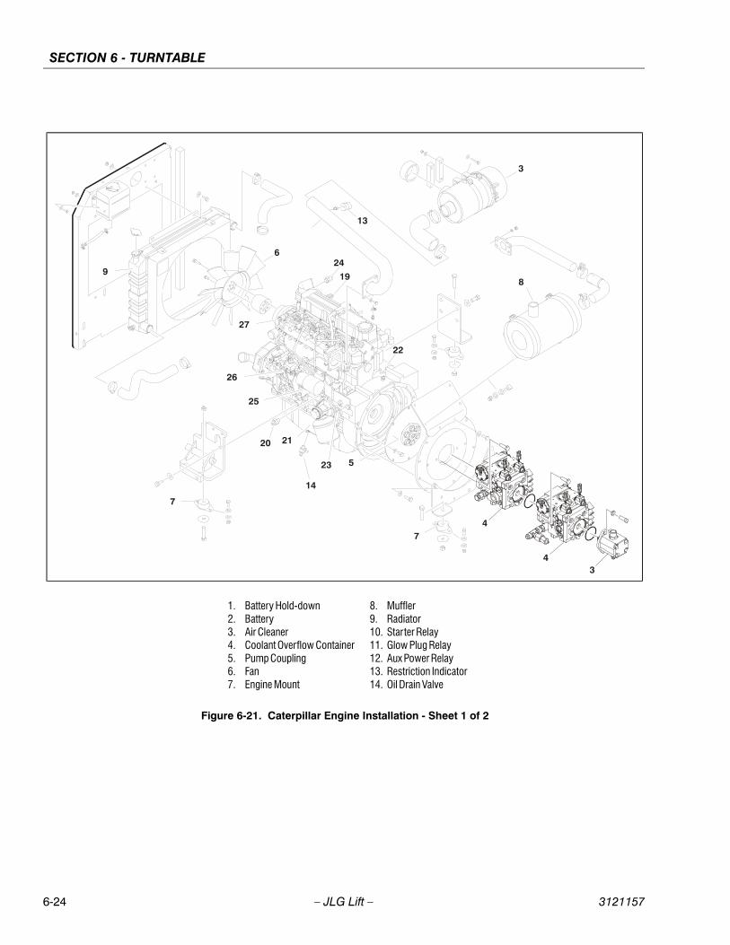
SECTION 6 - TURNTABLE
6-24 – JLG Lift – 3121157
1. Battery Hold-down2. Battery3. Air Cleaner4. Coolant Overflow Container5. Pump Coupling6. Fan7. Engine Mount
8. Muffler9. Radiator10. Starter Relay11. Glow Plug Relay12. Aux Power Relay13. Restriction Indicator14. Oil Drain Valve
Figure 6-21. Caterpillar Engine Installation - Sheet 1 of 2
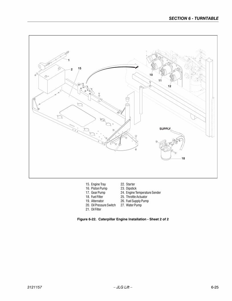
SECTION 6 - TURNTABLE
3121157 – JLG Lift – 6-25
15. Engine Tray16. Piston Pump17. Gear Pump18. Fuel Filter19. Alternator20. Oil Pressure Switch21. Oil Filter
22. Starter23. Dipstick24. Engine Temperature Sender25. Throttle Actuator26. Fuel Supply Pump27. Water Pump
Figure 6-22. Caterpillar Engine Installation - Sheet 2 of 2
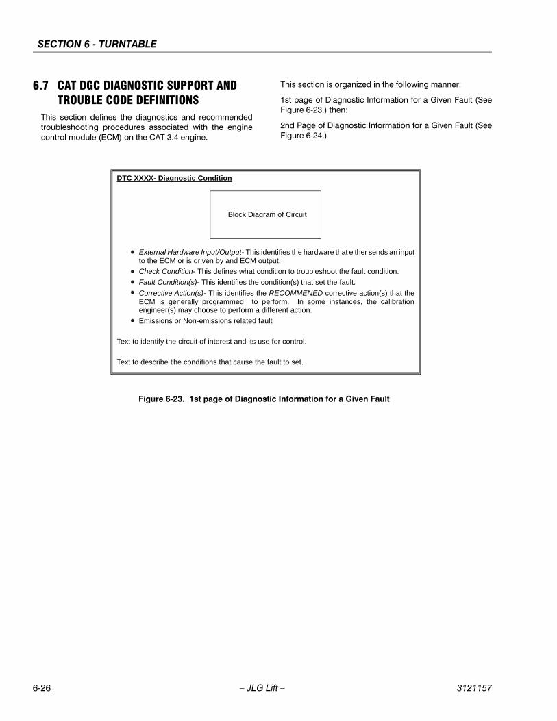
SECTION 6 - TURNTABLE
6-26 – JLG Lift – 3121157
6.7 CAT DGC DIAGNOSTIC SUPPORT AND TROUBLE CODE DEFINITIONS
This section defines the diagnostics and recommendedtroubleshooting procedures associated with the enginecontrol module (ECM) on the CAT 3.4 engine.
This section is organized in the following manner:
1st page of Diagnostic Information for a Given Fault (SeeFigure 6-23.) then:
2nd Page of Diagnostic Information for a Given Fault (SeeFigure 6-24.)
DTC XXXX- Diagnostic Condition
Block Diagram of Circuit
External Hardware Input/Output- This identifies the hardware that either sends an input to the ECM or is driven by and ECM output.
Check Condition- This defines what condition to troubleshoot the fault condition.
Fault Condition(s)- This identifies the condition(s) that set the fault.
Corrective Action(s)- This identifies the RECOMMENED corrective action(s) that the ECM is generally programmed to perform. In some instances, the calibration engineer(s) may choose to perform a different action.
Emissions or Non-emissions related fault
Text to identify the circuit of interest and its use for control.
Text to describe the conditions that cause the fault to set.
Figure 6-23. 1st page of Diagnostic Information for a Given Fault
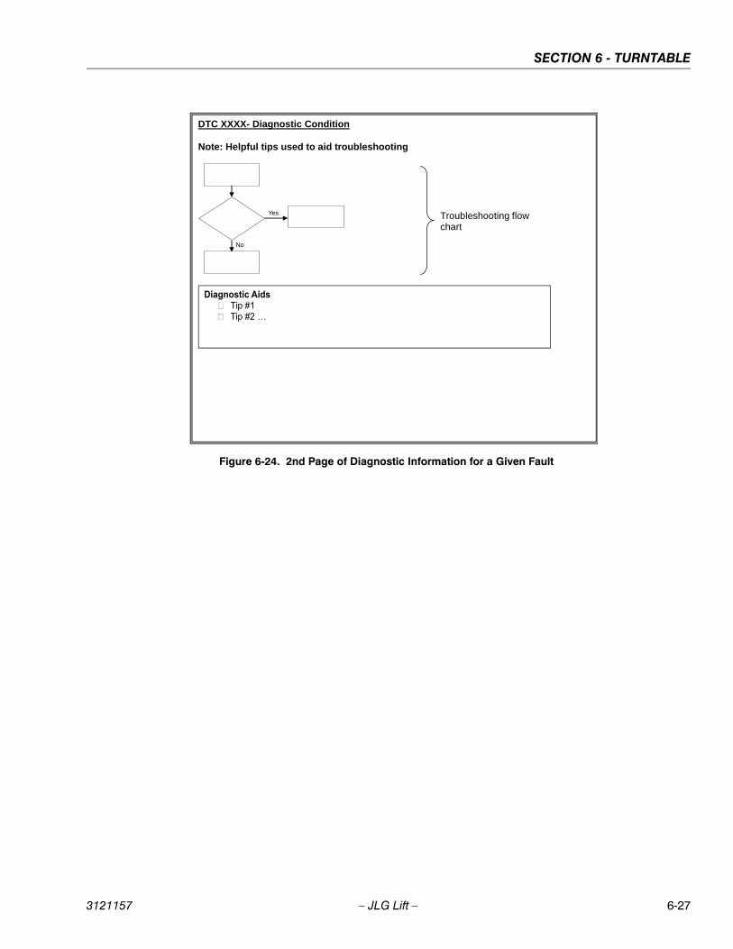
SECTION 6 - TURNTABLE
3121157 – JLG Lift – 6-27
DTC XXXX- Diagnostic Condition Note: Helpful tips used to aid troubleshooting
Yes
No
Troubleshooting flow chart
Figure 6-24. 2nd Page of Diagnostic Information for a Given Fault
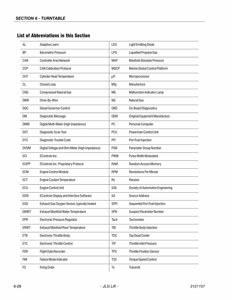
SECTION 6 - TURNTABLE
6-28 – JLG Lift – 3121157
List of Abbreviations in this Section
AL Adaptive Learn LED Light Emitting Diode
BP Barometric Pressure LPG Liquefied Propane Gas
CAN Controller Area Network MAP Manifold Absolute Pressure
CCP CAN Calibration Protocol MGCP Marine Global Control Platform
CHT Cylinder Head Temperature μP Microprocessor
CL Closed Loop Mfg Manufacture
CNG Compressed Natural Gas MIL Malfunction Indicator Lamp
DBW Drive-By-Wire NG Natural Gas
DGC Diesel Governor Control OBD On-Board Diagnostics
DM Diagnostic Message OEM Original Equipment Manufacture
DMM Digital Multi-Meter (high impedance) PC Personal Computer
DST Diagnostic Scan Tool PCU Powertrain Control Unit
DTC Diagnostic Trouble Code PFI Port Fuel Injection
DVOM Digital Voltage and Ohm Meter (high impedance) PGN Parameter Group Number
ECI EControls Inc. PWM Pulse Width Modulated
ECIPP EControls Inc. Proprietary Protocol RAM Random Access Memory
ECM Engine Control Module RPM Revolutions Per Minute
ECT Engine Coolant Temperature Rx Receive
ECU Engine Control Unit SAE Society of Automotive Engineering
EDIS EControls Display and Interface Software SA Source Address
EGO Exhaust Gas Oxygen Sensor, typically heated SPFI Sequential Port Fuel Injection
EMWT Exhaust Manifold Water Temperature SPN Suspect Parameter Number
EPR Electronic Pressure Regulator Tach Tachometer
ERWT Exhaust Manifold Riser Temperature TBI Throttle Body Injection
ETB Electronic Throttle Body TDC Top Dead Center
ETC Electronic Throttle Control TIP Throttle Inlet Pressure
FDR Flight Data Recorder TPS Throttle Position Sensor
FMI Failure Mode Indicator TSC Torque/Speed Control
FO Firing Order Tx Transmit
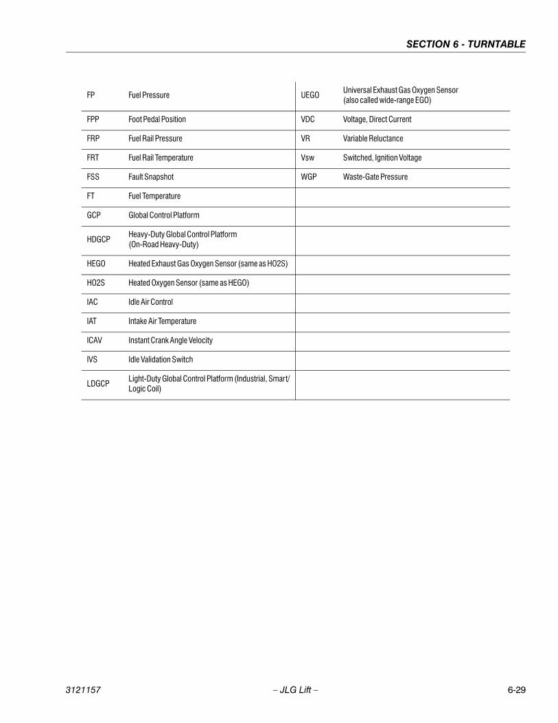
SECTION 6 - TURNTABLE
3121157 – JLG Lift – 6-29
FP Fuel Pressure UEGOUniversal Exhaust Gas Oxygen Sensor(also called wide-range EGO)
FPP Foot Pedal Position VDC Voltage, Direct Current
FRP Fuel Rail Pressure VR Variable Reluctance
FRT Fuel Rail Temperature Vsw Switched, Ignition Voltage
FSS Fault Snapshot WGP Waste-Gate Pressure
FT Fuel Temperature
GCP Global Control Platform
HDGCPHeavy-Duty Global Control Platform(On-Road Heavy-Duty)
HEGO Heated Exhaust Gas Oxygen Sensor (same as HO2S)
HO2S Heated Oxygen Sensor (same as HEGO)
IAC Idle Air Control
IAT Intake Air Temperature
ICAV Instant Crank Angle Velocity
IVS Idle Validation Switch
LDGCPLight-Duty Global Control Platform (Industrial, Smart/Logic Coil)
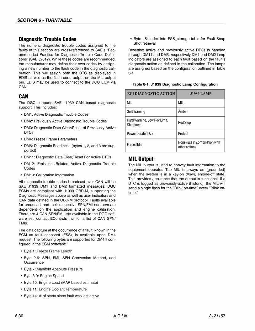
SECTION 6 - TURNTABLE
6-30 – JLG Lift – 3121157
Diagnostic Trouble CodesThe numeric diagnostic trouble codes assigned to thefaults in this section are cross-referenced to SAE’s "Rec-ommended Practice for Diagnostic Trouble Code Defini-tions" (SAE J2012). While these codes are recommended,the manufacturer may define their own codes by assign-ing a new number to the flash code in the diagnostic cali-bration. This will assign both the DTC as displayed inEDIS as well as the flash code output on the MIL outputpin. EDIS may be used to connect to the DGC ECM viaCAN.
CANThe DGC supports SAE J1939 CAN based diagnosticsupport. This includes:
• DM1: Active Diagnostic Trouble Codes
• DM2: Previously Active Diagnostic Trouble Codes
• DM3: Diagnostic Data Clear/Reset of Previously ActiveDTCs
• DM4: Freeze Frame Parameters
• DM5: Diagnostic Readiness (bytes 1, 2, and 3 are sup-ported)
• DM11: Diagnostic Data Clear/Reset For Active DTCs
• DM12: Emissions-Related Active Diagnostic TroubleCodes
• DM19: Calibration Information
All diagnostic trouble codes broadcast over CAN will beSAE J1939 DM1 and DM2 formatted messages. DGCECMs are compliant with J1939 OBD-M, supporting theDiagnostic Messages above as well as user indicators andCAN data defined in the OBD-M protocol. Faults availablefor broadcast and their respective SPN/FMI numbers aredependent on the application and engine calibration.There are 4 CAN SPN/FMI lists available in the DGC soft-ware set, contact EControls Inc. for a list of CAN SPN/FMIs.
The data capture at the occurrence of a fault, known in theECM as fault snapshot (FSS), is available upon DM4request. The following bytes are supported for DM4 if con-figured in the ECM software:
• Byte 1: Freeze Frame Length
• Byte 2-6: SPN, FMI, SPN Conversion Method, andOccurrence
• Byte 7: Manifold Absolute Pressure
• Byte 8-9: Engine Speed
• Byte 10: Engine Load (MAP based estimate)
• Byte 11: Engine Coolant Temperature
• Byte 14: # of starts since fault was last active
• Byte 15: Index into FSS_storage table for Fault SnapShot retrieval
Resetting active and previously active DTCs is handledthrough DM11 and DM3, respectively DM1 and DM2 lampindicators are assigned to each fault based on the fault.sdiagnostic action as defined in the calibration. The lampsare assigned based on the configuration outlined in Table6-1.
MIL OutputThe MIL output is used to convey fault information to theequipment operator. The MIL is always on (grounded)when the system is in a key-on (Vsw), engine-off state.This provides assurance that the output is functional. If aDTC is logged as previously-active (historic), the MIL willsend a single flash for the “Blink on-time” every “Blink off-time.”
Table 6-1. J1939 Diagnostic Lamp Configuration
ECI DIAGNOSTIC ACTION J1939 LAMP
MIL MIL
Soft Warning Amber
Hard Warning, Low Rev Limit, Shutdown
Red Stop
Power Derate 1 & 2 Protect
Forced IdleNone (use in combination with other action)
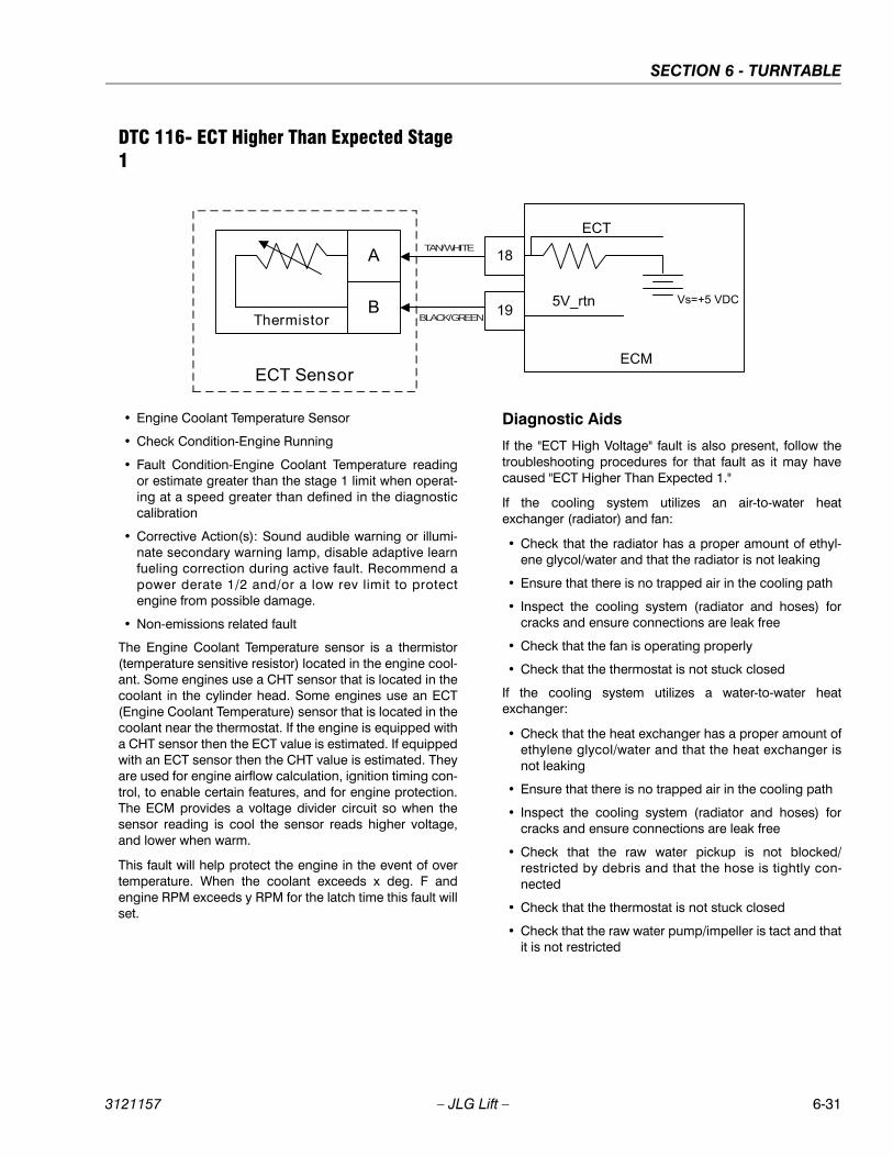
SECTION 6 - TURNTABLE
3121157 – JLG Lift – 6-31
DTC 116- ECT Higher Than Expected Stage 1
• Engine Coolant Temperature Sensor
• Check Condition-Engine Running
• Fault Condition-Engine Coolant Temperature readingor estimate greater than the stage 1 limit when operat-ing at a speed greater than defined in the diagnosticcalibration
• Corrective Action(s): Sound audible warning or illumi-nate secondary warning lamp, disable adaptive learnfueling correction during active fault. Recommend apower derate 1/2 and/or a low rev limit to protectengine from possible damage.
• Non-emissions related fault
The Engine Coolant Temperature sensor is a thermistor(temperature sensitive resistor) located in the engine cool-ant. Some engines use a CHT sensor that is located in thecoolant in the cylinder head. Some engines use an ECT(Engine Coolant Temperature) sensor that is located in thecoolant near the thermostat. If the engine is equipped witha CHT sensor then the ECT value is estimated. If equippedwith an ECT sensor then the CHT value is estimated. Theyare used for engine airflow calculation, ignition timing con-trol, to enable certain features, and for engine protection.The ECM provides a voltage divider circuit so when thesensor reading is cool the sensor reads higher voltage,and lower when warm.
This fault will help protect the engine in the event of overtemperature. When the coolant exceeds x deg. F andengine RPM exceeds y RPM for the latch time this fault willset.
Diagnostic Aids
If the "ECT High Voltage" fault is also present, follow thetroubleshooting procedures for that fault as it may havecaused "ECT Higher Than Expected 1."
If the cooling system utilizes an air-to-water heatexchanger (radiator) and fan:
• Check that the radiator has a proper amount of ethyl-ene glycol/water and that the radiator is not leaking
• Ensure that there is no trapped air in the cooling path
• Inspect the cooling system (radiator and hoses) forcracks and ensure connections are leak free
• Check that the fan is operating properly
• Check that the thermostat is not stuck closed
If the cooling system utilizes a water-to-water heatexchanger:
• Check that the heat exchanger has a proper amount ofethylene glycol/water and that the heat exchanger isnot leaking
• Ensure that there is no trapped air in the cooling path
• Inspect the cooling system (radiator and hoses) forcracks and ensure connections are leak free
• Check that the raw water pickup is not blocked/restricted by debris and that the hose is tightly con-nected
• Check that the thermostat is not stuck closed
• Check that the raw water pump/impeller is tact and thatit is not restricted
TAN/WHITE
BLACK/GREEN
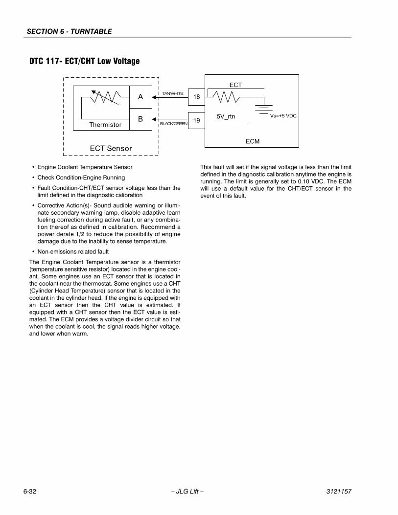
SECTION 6 - TURNTABLE
6-32 – JLG Lift – 3121157
DTC 117- ECT/CHT Low Voltage
• Engine Coolant Temperature Sensor
• Check Condition-Engine Running
• Fault Condition-CHT/ECT sensor voltage less than thelimit defined in the diagnostic calibration
• Corrective Action(s)- Sound audible warning or illumi-nate secondary warning lamp, disable adaptive learnfueling correction during active fault, or any combina-tion thereof as defined in calibration. Recommend apower derate 1/2 to reduce the possibility of enginedamage due to the inability to sense temperature.
• Non-emissions related fault
The Engine Coolant Temperature sensor is a thermistor(temperature sensitive resistor) located in the engine cool-ant. Some engines use an ECT sensor that is located inthe coolant near the thermostat. Some engines use a CHT(Cylinder Head Temperature) sensor that is located in thecoolant in the cylinder head. If the engine is equipped withan ECT sensor then the CHT value is estimated. Ifequipped with a CHT sensor then the ECT value is esti-mated. The ECM provides a voltage divider circuit so thatwhen the coolant is cool, the signal reads higher voltage,and lower when warm.
This fault will set if the signal voltage is less than the limitdefined in the diagnostic calibration anytime the engine isrunning. The limit is generally set to 0.10 VDC. The ECMwill use a default value for the CHT/ECT sensor in theevent of this fault.
TAN/WHITE
BLACK/GREEN
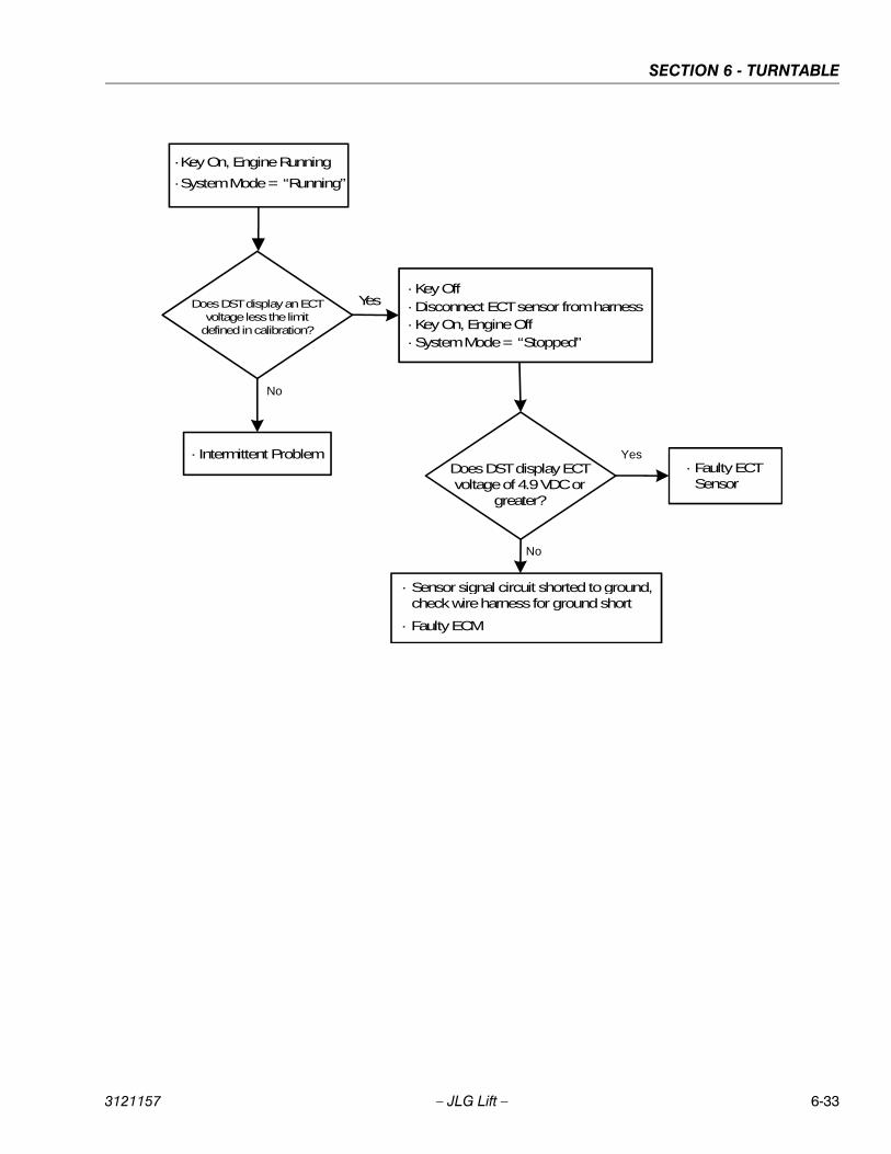
SECTION 6 - TURNTABLE
3121157 – JLG Lift – 6-33
Does DST display ECTvoltage of 4.9 VDC or
greater?
·Key Off·Disconnect ECT sensor from harness·Key On, Engine Off·System Mode = “Stopped”
· Sensor signal circuit shorted to ground,check wire harness for ground short
· Faulty ECM
· Faulty ECTSensor
Yes
No
Does DST display an ECTvoltage less the limit
defined in calibration?
· Intermittent Problem
Yes
No
·Key On, Engine Running
·System Mode = “Running”
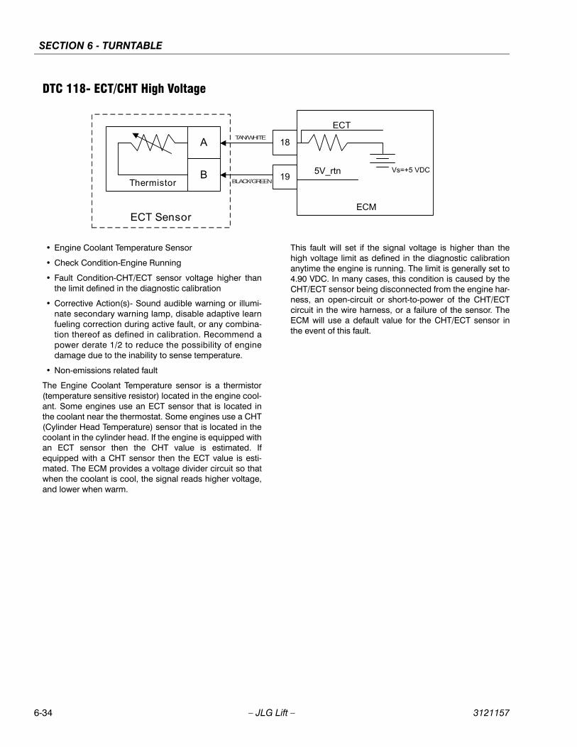
SECTION 6 - TURNTABLE
6-34 – JLG Lift – 3121157
DTC 118- ECT/CHT High Voltage
• Engine Coolant Temperature Sensor
• Check Condition-Engine Running
• Fault Condition-CHT/ECT sensor voltage higher thanthe limit defined in the diagnostic calibration
• Corrective Action(s)- Sound audible warning or illumi-nate secondary warning lamp, disable adaptive learnfueling correction during active fault, or any combina-tion thereof as defined in calibration. Recommend apower derate 1/2 to reduce the possibility of enginedamage due to the inability to sense temperature.
• Non-emissions related fault
The Engine Coolant Temperature sensor is a thermistor(temperature sensitive resistor) located in the engine cool-ant. Some engines use an ECT sensor that is located inthe coolant near the thermostat. Some engines use a CHT(Cylinder Head Temperature) sensor that is located in thecoolant in the cylinder head. If the engine is equipped withan ECT sensor then the CHT value is estimated. Ifequipped with a CHT sensor then the ECT value is esti-mated. The ECM provides a voltage divider circuit so thatwhen the coolant is cool, the signal reads higher voltage,and lower when warm.
This fault will set if the signal voltage is higher than thehigh voltage limit as defined in the diagnostic calibrationanytime the engine is running. The limit is generally set to4.90 VDC. In many cases, this condition is caused by theCHT/ECT sensor being disconnected from the engine har-ness, an open-circuit or short-to-power of the CHT/ECTcircuit in the wire harness, or a failure of the sensor. TheECM will use a default value for the CHT/ECT sensor inthe event of this fault.
TAN/WHITE
BLACK/GREEN
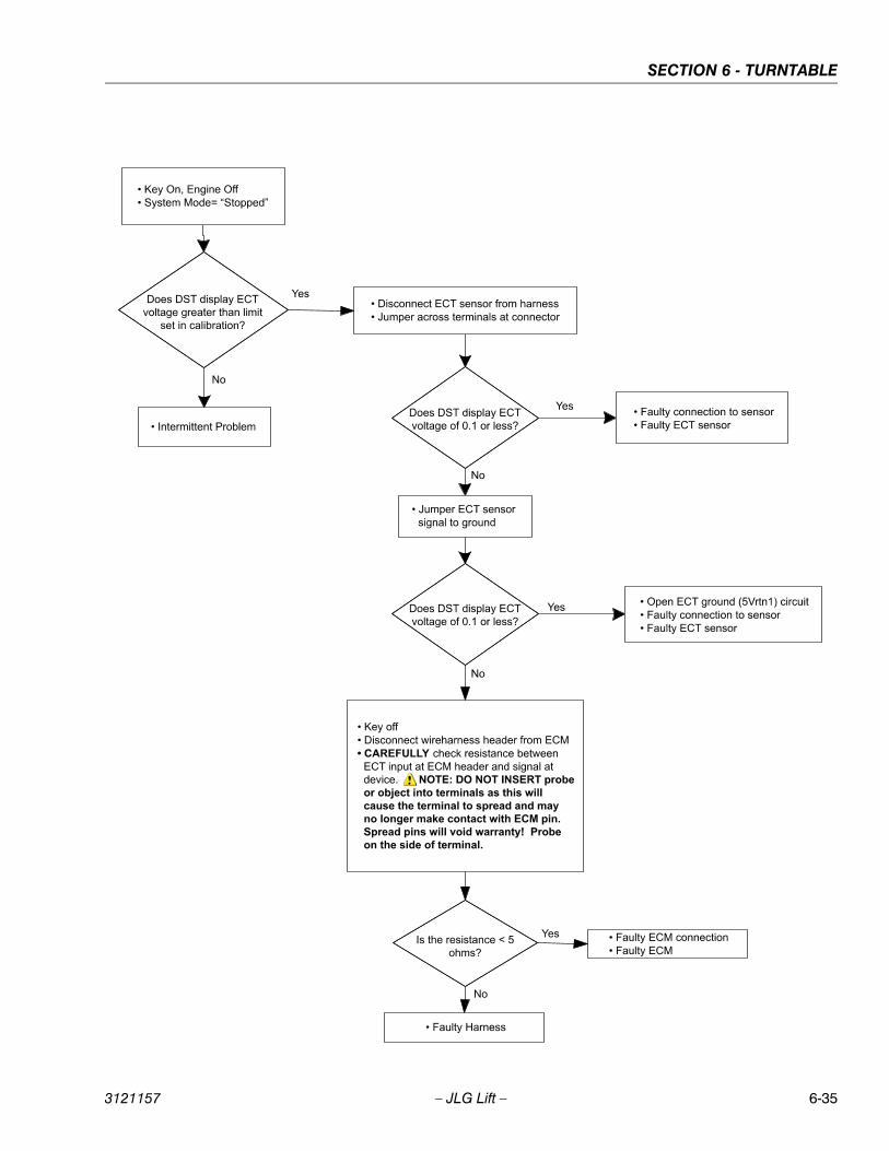
SECTION 6 - TURNTABLE
3121157 – JLG Lift – 6-35
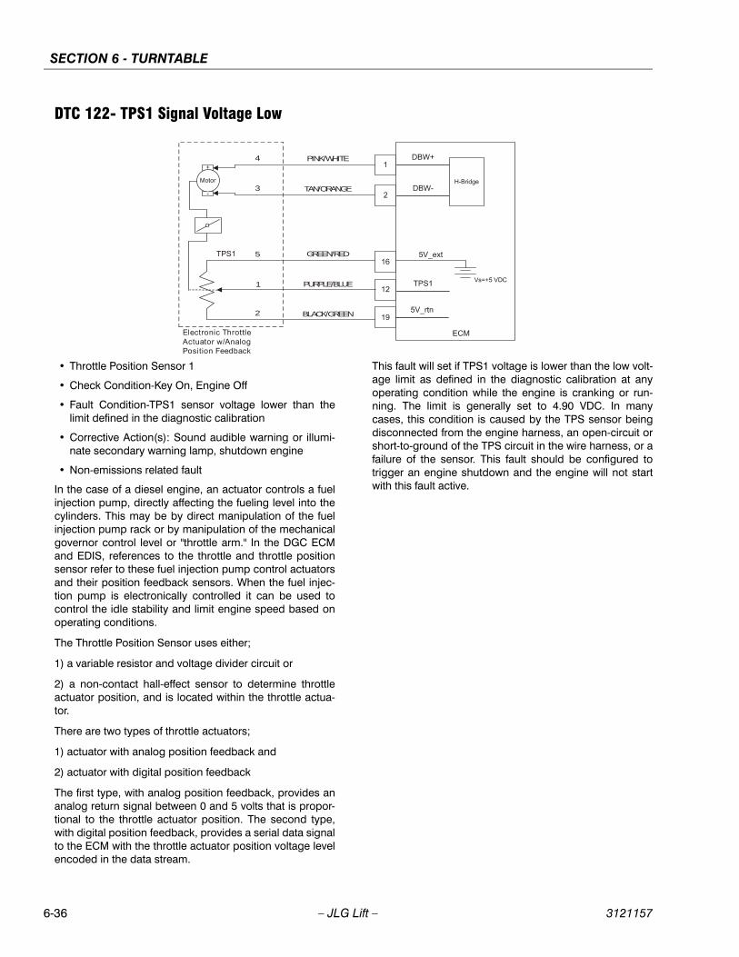
SECTION 6 - TURNTABLE
6-36 – JLG Lift – 3121157
DTC 122- TPS1 Signal Voltage Low
• Throttle Position Sensor 1
• Check Condition-Key On, Engine Off
• Fault Condition-TPS1 sensor voltage lower than thelimit defined in the diagnostic calibration
• Corrective Action(s): Sound audible warning or illumi-nate secondary warning lamp, shutdown engine
• Non-emissions related fault
In the case of a diesel engine, an actuator controls a fuelinjection pump, directly affecting the fueling level into thecylinders. This may be by direct manipulation of the fuelinjection pump rack or by manipulation of the mechanicalgovernor control level or "throttle arm." In the DGC ECMand EDIS, references to the throttle and throttle positionsensor refer to these fuel injection pump control actuatorsand their position feedback sensors. When the fuel injec-tion pump is electronically controlled it can be used tocontrol the idle stability and limit engine speed based onoperating conditions.
The Throttle Position Sensor uses either;
1) a variable resistor and voltage divider circuit or
2) a non-contact hall-effect sensor to determine throttleactuator position, and is located within the throttle actua-tor.
There are two types of throttle actuators;
1) actuator with analog position feedback and
2) actuator with digital position feedback
The first type, with analog position feedback, provides ananalog return signal between 0 and 5 volts that is propor-tional to the throttle actuator position. The second type,with digital position feedback, provides a serial data signalto the ECM with the throttle actuator position voltage levelencoded in the data stream.
This fault will set if TPS1 voltage is lower than the low volt-age limit as defined in the diagnostic calibration at anyoperating condition while the engine is cranking or run-ning. The limit is generally set to 4.90 VDC. In manycases, this condition is caused by the TPS sensor beingdisconnected from the engine harness, an open-circuit orshort-to-ground of the TPS circuit in the wire harness, or afailure of the sensor. This fault should be configured totrigger an engine shutdown and the engine will not startwith this fault active.
PINK/WHITE4
3
5
1
2
TAN/ORANGE
GREEN/RED
PURPLE/BLUE
BLACK/GREEN
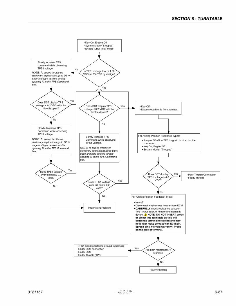
SECTION 6 - TURNTABLE
3121157 – JLG Lift – 6-37
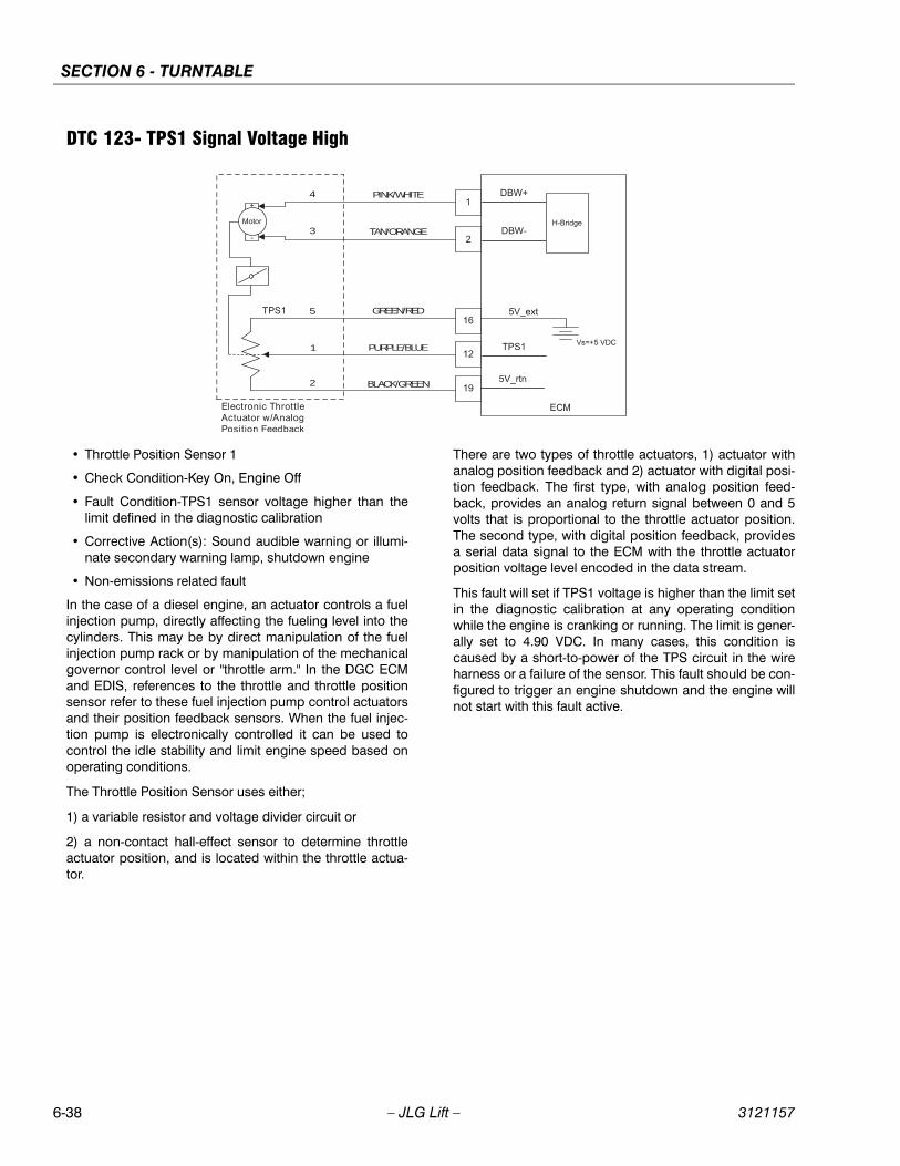
SECTION 6 - TURNTABLE
6-38 – JLG Lift – 3121157
DTC 123- TPS1 Signal Voltage High
• Throttle Position Sensor 1
• Check Condition-Key On, Engine Off
• Fault Condition-TPS1 sensor voltage higher than thelimit defined in the diagnostic calibration
• Corrective Action(s): Sound audible warning or illumi-nate secondary warning lamp, shutdown engine
• Non-emissions related fault
In the case of a diesel engine, an actuator controls a fuelinjection pump, directly affecting the fueling level into thecylinders. This may be by direct manipulation of the fuelinjection pump rack or by manipulation of the mechanicalgovernor control level or "throttle arm." In the DGC ECMand EDIS, references to the throttle and throttle positionsensor refer to these fuel injection pump control actuatorsand their position feedback sensors. When the fuel injec-tion pump is electronically controlled it can be used tocontrol the idle stability and limit engine speed based onoperating conditions.
The Throttle Position Sensor uses either;
1) a variable resistor and voltage divider circuit or
2) a non-contact hall-effect sensor to determine throttleactuator position, and is located within the throttle actua-tor.
There are two types of throttle actuators, 1) actuator withanalog position feedback and 2) actuator with digital posi-tion feedback. The first type, with analog position feed-back, provides an analog return signal between 0 and 5volts that is proportional to the throttle actuator position.The second type, with digital position feedback, providesa serial data signal to the ECM with the throttle actuatorposition voltage level encoded in the data stream.
This fault will set if TPS1 voltage is higher than the limit setin the diagnostic calibration at any operating conditionwhile the engine is cranking or running. The limit is gener-ally set to 4.90 VDC. In many cases, this condition iscaused by a short-to-power of the TPS circuit in the wireharness or a failure of the sensor. This fault should be con-figured to trigger an engine shutdown and the engine willnot start with this fault active.
PINK/WHITE4
3
5
1
2
TAN/ORANGE
GREEN/RED
PURPLE/BLUE
BLACK/GREEN
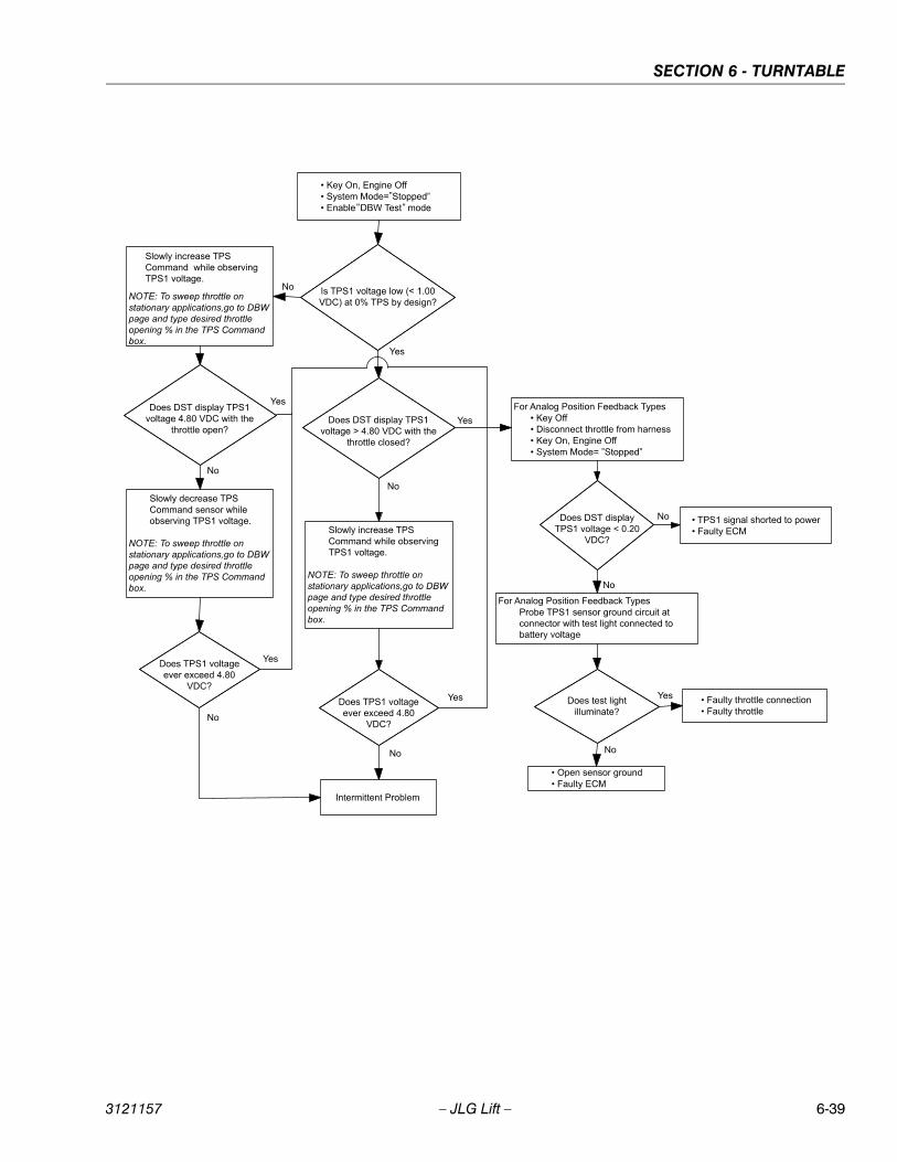
SECTION 6 - TURNTABLE
3121157 – JLG Lift – 6-39
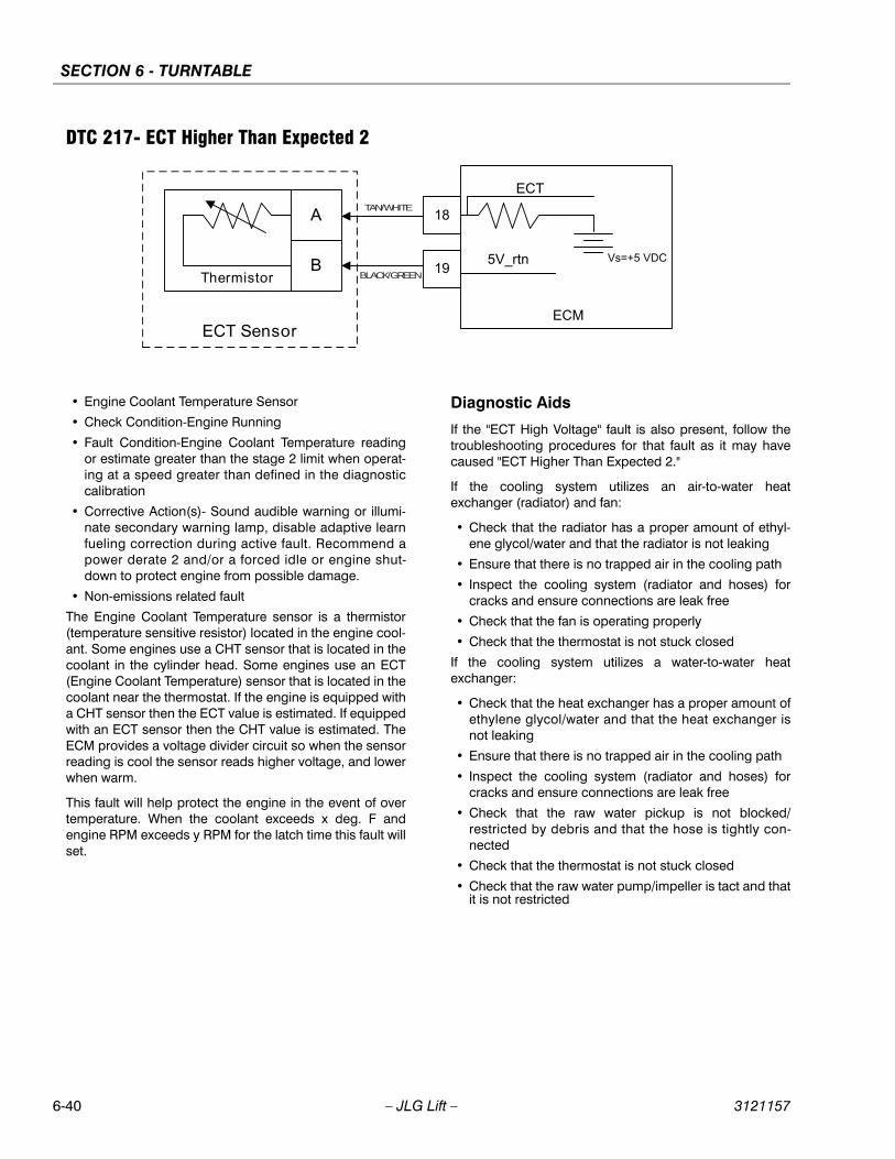
SECTION 6 - TURNTABLE
6-40 – JLG Lift – 3121157
DTC 217- ECT Higher Than Expected 2
• Engine Coolant Temperature Sensor
• Check Condition-Engine Running
• Fault Condition-Engine Coolant Temperature readingor estimate greater than the stage 2 limit when operat-ing at a speed greater than defined in the diagnosticcalibration
• Corrective Action(s)- Sound audible warning or illumi-nate secondary warning lamp, disable adaptive learnfueling correction during active fault. Recommend apower derate 2 and/or a forced idle or engine shut-down to protect engine from possible damage.
• Non-emissions related fault
The Engine Coolant Temperature sensor is a thermistor(temperature sensitive resistor) located in the engine cool-ant. Some engines use a CHT sensor that is located in thecoolant in the cylinder head. Some engines use an ECT(Engine Coolant Temperature) sensor that is located in thecoolant near the thermostat. If the engine is equipped witha CHT sensor then the ECT value is estimated. If equippedwith an ECT sensor then the CHT value is estimated. TheECM provides a voltage divider circuit so when the sensorreading is cool the sensor reads higher voltage, and lowerwhen warm.
This fault will help protect the engine in the event of overtemperature. When the coolant exceeds x deg. F andengine RPM exceeds y RPM for the latch time this fault willset.
Diagnostic Aids
If the "ECT High Voltage" fault is also present, follow thetroubleshooting procedures for that fault as it may havecaused "ECT Higher Than Expected 2."
If the cooling system utilizes an air-to-water heatexchanger (radiator) and fan:
• Check that the radiator has a proper amount of ethyl-ene glycol/water and that the radiator is not leaking
• Ensure that there is no trapped air in the cooling path
• Inspect the cooling system (radiator and hoses) forcracks and ensure connections are leak free
• Check that the fan is operating properly
• Check that the thermostat is not stuck closed
If the cooling system utilizes a water-to-water heatexchanger:
• Check that the heat exchanger has a proper amount ofethylene glycol/water and that the heat exchanger isnot leaking
• Ensure that there is no trapped air in the cooling path
• Inspect the cooling system (radiator and hoses) forcracks and ensure connections are leak free
• Check that the raw water pickup is not blocked/restricted by debris and that the hose is tightly con-nected
• Check that the thermostat is not stuck closed
• Check that the raw water pump/impeller is tact and thatit is not restricted
TAN/WHITE
BLACK/GREEN
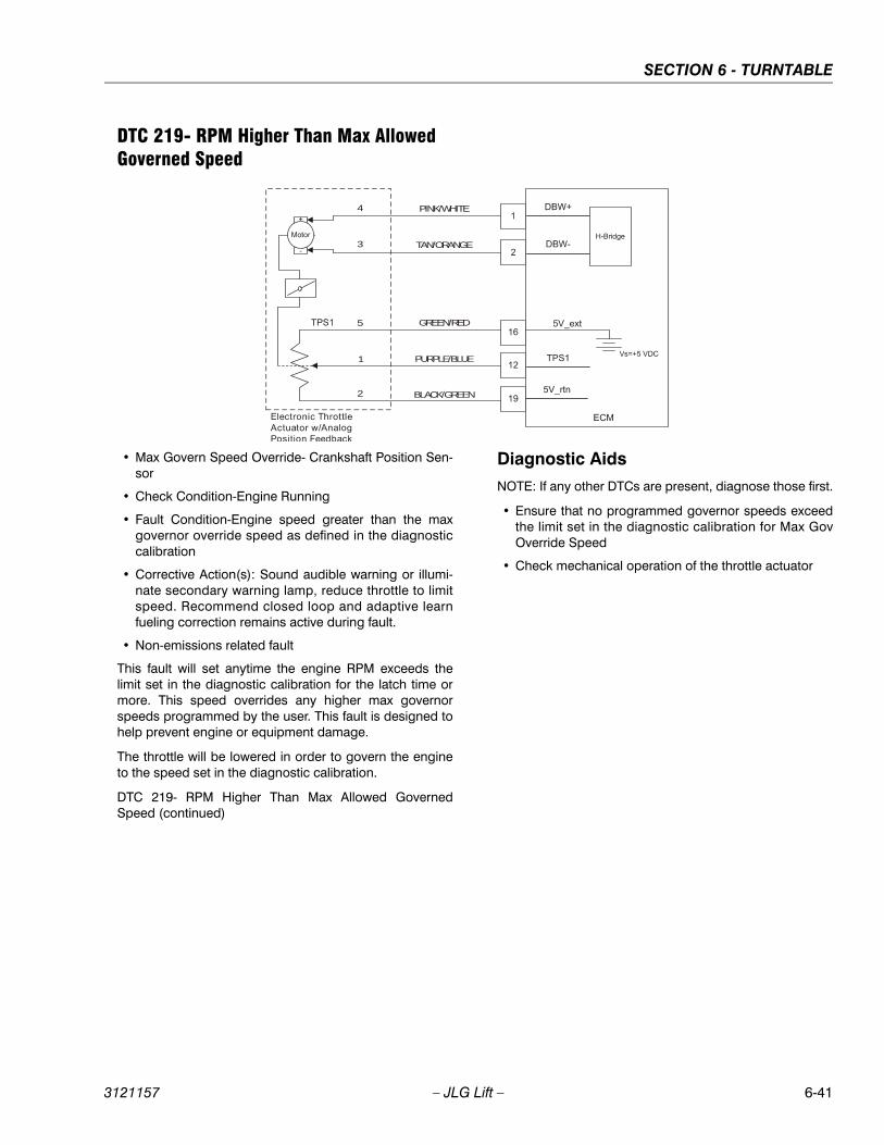
SECTION 6 - TURNTABLE
3121157 – JLG Lift – 6-41
DTC 219- RPM Higher Than Max Allowed Governed Speed
• Max Govern Speed Override- Crankshaft Position Sen-sor
• Check Condition-Engine Running
• Fault Condition-Engine speed greater than the maxgovernor override speed as defined in the diagnosticcalibration
• Corrective Action(s): Sound audible warning or illumi-nate secondary warning lamp, reduce throttle to limitspeed. Recommend closed loop and adaptive learnfueling correction remains active during fault.
• Non-emissions related fault
This fault will set anytime the engine RPM exceeds thelimit set in the diagnostic calibration for the latch time ormore. This speed overrides any higher max governorspeeds programmed by the user. This fault is designed tohelp prevent engine or equipment damage.
The throttle will be lowered in order to govern the engineto the speed set in the diagnostic calibration.
DTC 219- RPM Higher Than Max Allowed GovernedSpeed (continued)
Diagnostic Aids
NOTE: If any other DTCs are present, diagnose those first.
• Ensure that no programmed governor speeds exceedthe limit set in the diagnostic calibration for Max GovOverride Speed
• Check mechanical operation of the throttle actuator
PINK/WHITE4
3
5
1
2
TAN/ORANGE
GREEN/RED
PURPLE/BLUE
BLACK/GREEN
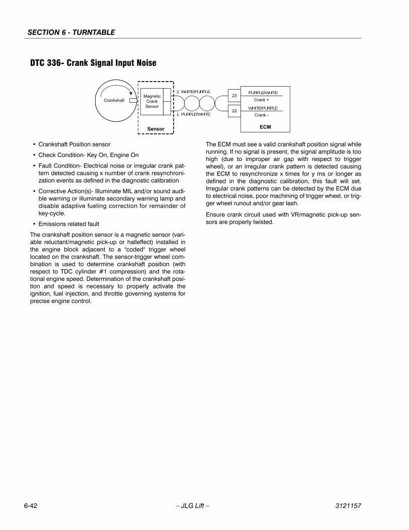
SECTION 6 - TURNTABLE
6-42 – JLG Lift – 3121157
DTC 336- Crank Signal Input Noise
• Crankshaft Position sensor
• Check Condition- Key On, Engine On
• Fault Condition- Electrical noise or irregular crank pat-tern detected causing x number of crank resynchroni-zation events as defined in the diagnostic calibration
• Corrective Action(s)- Illuminate MIL and/or sound audi-ble warning or illuminate secondary warning lamp anddisable adaptive fueling correction for remainder ofkey-cycle.
• Emissions related fault
The crankshaft position sensor is a magnetic sensor (vari-able reluctant/magnetic pick-up or halleffect) installed inthe engine block adjacent to a "coded" trigger wheellocated on the crankshaft. The sensor-trigger wheel com-bination is used to determine crankshaft position (withrespect to TDC cylinder #1 compression) and the rota-tional engine speed. Determination of the crankshaft posi-tion and speed is necessary to properly activate theignition, fuel injection, and throttle governing systems forprecise engine control.
The ECM must see a valid crankshaft position signal whilerunning. If no signal is present, the signal amplitude is toohigh (due to improper air gap with respect to triggerwheel), or an irregular crank pattern is detected causingthe ECM to resynchronize x times for y ms or longer asdefined in the diagnostic calibration, this fault will set.Irregular crank patterns can be detected by the ECM dueto electrical noise, poor machining of trigger wheel, or trig-ger wheel runout and/or gear lash.
Ensure crank circuit used with VR/magnetic pick-up sen-sors are properly twisted.
WHITE/PURPLE
WHITE/PURPLE
2
1 PURPLE/WHITE
PURPLE/WHITE
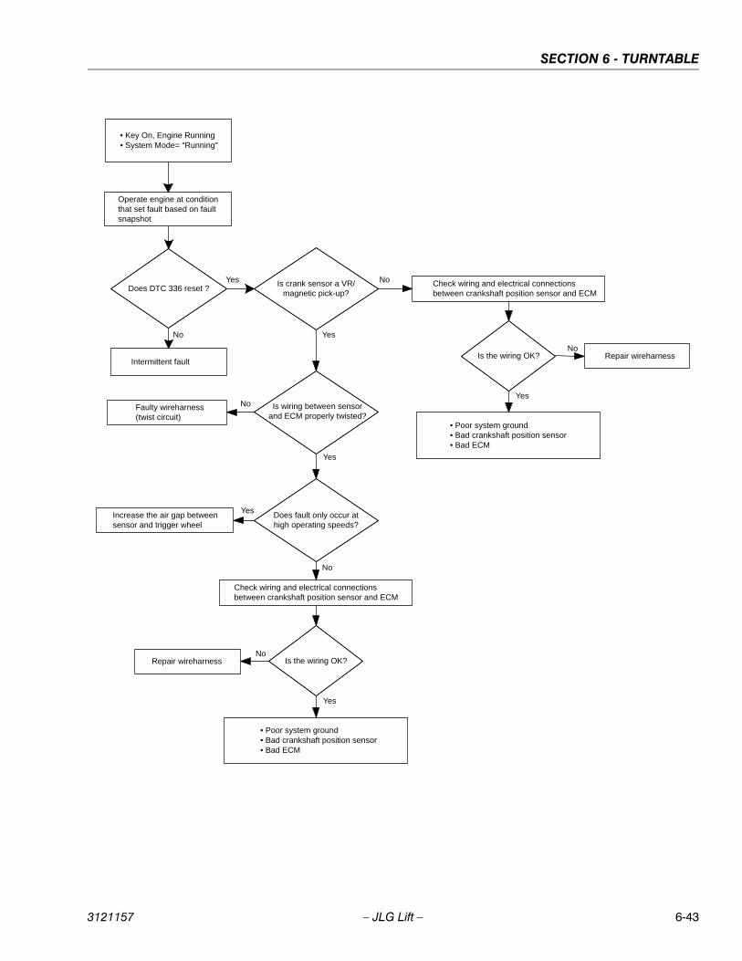
SECTION 6 - TURNTABLE
3121157 – JLG Lift – 6-43
• Key On, Engine Running• System Mode= “Running”
Does DTC 336 reset ?
Intermittent fault
No
Yes Check wiring and electrical connections between crankshaft position sensor and ECM
No
Yes
• Poor system ground• Bad crankshaft position sensor• Bad ECM
Operate engine at condition that set fault based on fault snapshot
Is crank sensor a VR/magnetic pick-up?
Is the wiring OK?
Faulty wireharness(twist circuit)
Is wiring between sensor and ECM properly twisted?
No
Does fault only occur at high operating speeds?
Yes
Increase the air gap between sensor and trigger wheel
Yes
No
Check wiring and electrical connections between crankshaft position sensor and ECM
NoRepair wireharness
Yes
• Poor system ground• Bad crankshaft position sensor• Bad ECM
Is the wiring OK?No
Repair wireharness
Yes
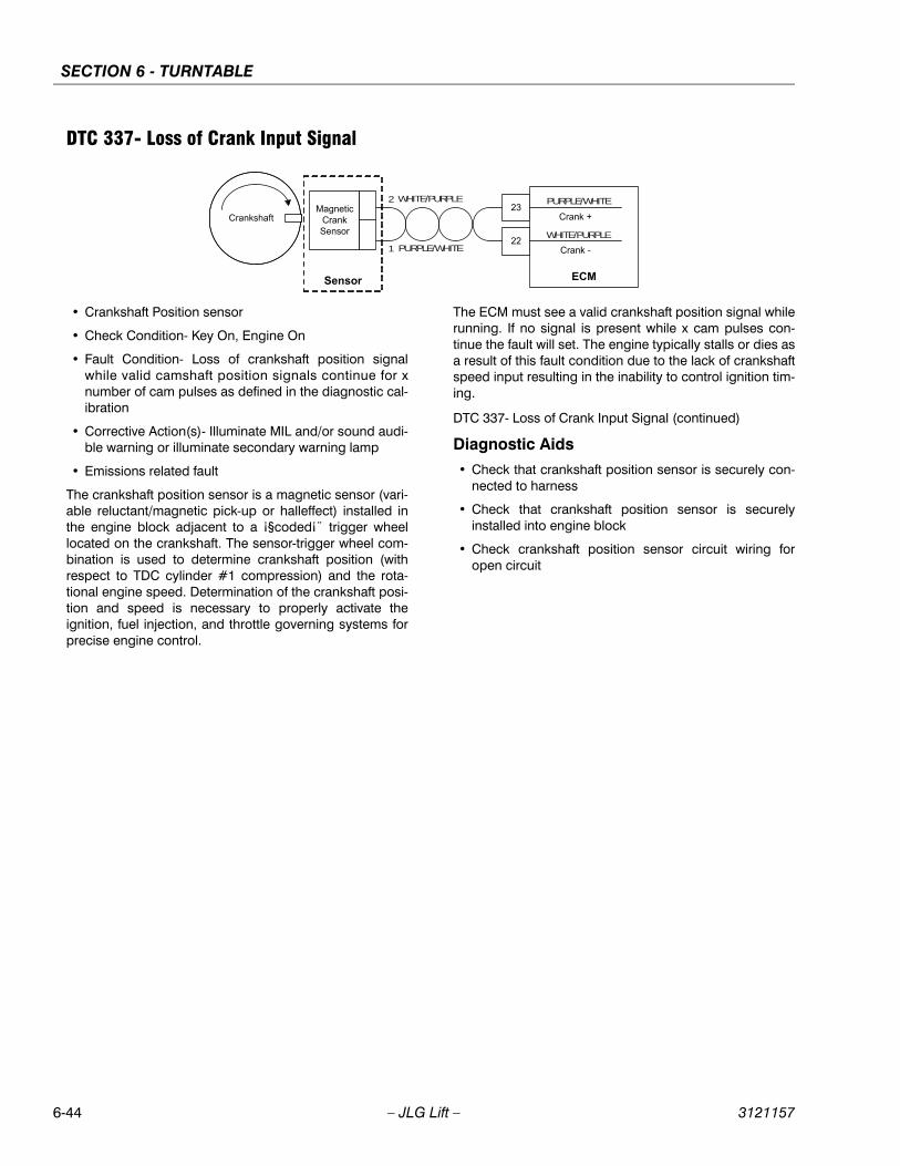
SECTION 6 - TURNTABLE
6-44 – JLG Lift – 3121157
DTC 337- Loss of Crank Input Signal
• Crankshaft Position sensor
• Check Condition- Key On, Engine On
• Fault Condition- Loss of crankshaft position signalwhile valid camshaft position signals continue for xnumber of cam pulses as defined in the diagnostic cal-ibration
• Corrective Action(s)- Illuminate MIL and/or sound audi-ble warning or illuminate secondary warning lamp
• Emissions related fault
The crankshaft position sensor is a magnetic sensor (vari-able reluctant/magnetic pick-up or halleffect) installed inthe engine block adjacent to a ¡§coded¡¨ trigger wheellocated on the crankshaft. The sensor-trigger wheel com-bination is used to determine crankshaft position (withrespect to TDC cylinder #1 compression) and the rota-tional engine speed. Determination of the crankshaft posi-tion and speed is necessary to properly activate theignition, fuel injection, and throttle governing systems forprecise engine control.
The ECM must see a valid crankshaft position signal whilerunning. If no signal is present while x cam pulses con-tinue the fault will set. The engine typically stalls or dies asa result of this fault condition due to the lack of crankshaftspeed input resulting in the inability to control ignition tim-ing.
DTC 337- Loss of Crank Input Signal (continued)
Diagnostic Aids
• Check that crankshaft position sensor is securely con-nected to harness
• Check that crankshaft position sensor is securelyinstalled into engine block
• Check crankshaft position sensor circuit wiring foropen circuit
WHITE/PURPLE
WHITE/PURPLE
2
1 PURPLE/WHITE
PURPLE/WHITE
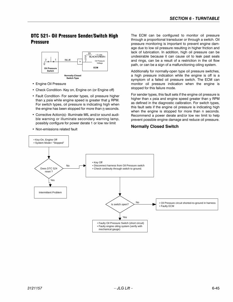
SECTION 6 - TURNTABLE
3121157 – JLG Lift – 6-45
DTC 521- Oil Pressure Sender/Switch High Pressure
• Engine Oil Pressure
• Check Condition- Key on, Engine on (or Engine off)
• Fault Condition- For sender types, oil pressure higherthan x psia while engine speed is greater that y RPM.For switch types, oil pressure is indicating high whenthe engine has been stopped for more than n seconds.
• Corrective Action(s)- Illuminate MIL and/or sound audi-ble warning or illuminate secondary warning lamp,possibly configure for power derate 1 or low rev limit
• Non-emissions related fault
The ECM can be configured to monitor oil pressurethrough a proportional transducer or through a switch. Oilpressure monitoring is important to prevent engine dam-age due to low oil pressure resulting in higher friction andlack of lubrication. In addition, high oil pressure can beundesirable because it can cause oil to leak past sealsand rings, can be a result of a restriction in the oil flowpath, or can be a sign of a malfunctioning oiling system.
Additionally for normally-open type oil pressure switches,a high pressure indication while the engine is off is asymptom of a failed oil pressure switch. The ECM canmonitor oil pressure indication when the engine isstopped for this failure mode.
For sender types, this fault sets if the engine oil pressure ishigher than x psia and engine speed greater than y RPMas defined in the diagnostic calibration. For switch types,this fault sets if the engine oil pressure is indicating highwhen the engine is stopped for more than n seconds.Recommend a power derate and/or low rev limit to helpprevent possible engine damage and reduce oil pressure.
Normally Closed Switch
BLUE
BLACK/GREEN
19
12
• Key-On, Engine Off• System Mode= “Stopped”
Does DTC 524 reset ?
Intermittent Problem
No• Key Off• Disconnect harness from Oil Pressure switch• Check continuity through switch to ground.
Yes
Is switch open? • Oil Pressure circuit shorted-to-ground in harness• Faulty ECM
• Faulty Oil Pressure Switch (short circuit)• Faulty engine oiling system (verify with
mechanical gauge)
No
Yes
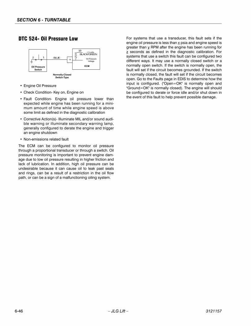
SECTION 6 - TURNTABLE
6-46 – JLG Lift – 3121157
DTC 524- Oil Pressure Low
• Engine Oil Pressure
• Check Condition- Key on, Engine on
• Fault Condition- Engine oil pressure lower thanexpected while engine has been running for a mini-mum amount of time while engine speed is abovesome limit as defined in the diagnostic calibration
• Corrective Action(s)- Illuminate MIL and/or sound audi-ble warning or illuminate secondary warning lamp,generally configured to derate the engine and triggeran engine shutdown
• Non-emissions related fault
The ECM can be configured to monitor oil pressurethrough a proportional transducer or through a switch. Oilpressure monitoring is important to prevent engine dam-age due to low oil pressure resulting in higher friction andlack of lubrication. In addition, high oil pressure can beundesirable because it can cause oil to leak past sealsand rings, can be a result of a restriction in the oil flowpath, or can be a sign of a malfunctioning oiling system.
For systems that use a transducer, this fault sets if theengine oil pressure is less than x psia and engine speed isgreater than y RPM after the engine has been running forz seconds as defined in the diagnostic calibration. Forsystems that use a switch this fault can be configured twodifferent ways. It may use a normally closed switch or anormally open switch. If the switch is normally open, thefault will set if the circuit becomes grounded. If the switchis normally closed, the fault will set if the circuit becomesopen. Go to the Faults page in EDIS to determine how theinput is configured. ("Open=OK" is normally open and"Ground=OK" is normally closed). The engine will shouldbe configured to derate or force idle and/or shut down inthe event of this fault to help prevent possible damage.
BLUE
BLACK/GREEN
19
12
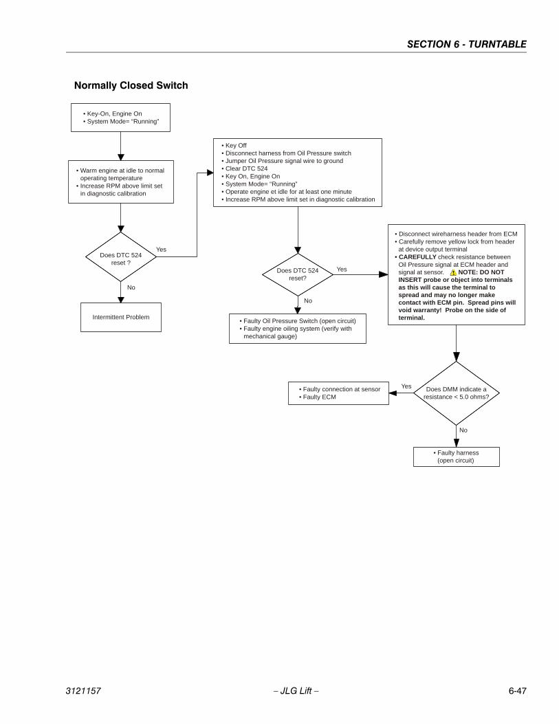
SECTION 6 - TURNTABLE
3121157 – JLG Lift – 6-47
Normally Closed Switch
• Key-On, Engine On• System Mode= “Running”
• Warm engine at idle to normal operating temperature
• Increase RPM above limit set in diagnostic calibration
Does DTC 524 reset ?
Intermittent Problem
No
• Key Off• Disconnect harness from Oil Pressure switch• Jumper Oil Pressure signal wire to ground• Clear DTC 524• Key On, Engine On• System Mode= “Running”• Operate engine et idle for at least one minute• Increase RPM above limit set in diagnostic calibration
Yes
Does DTC 524 reset?
• Faulty connection at sensor• Faulty ECM
• Faulty Oil Pressure Switch (open circuit)• Faulty engine oiling system (verify with
mechanical gauge)
No
Yes
Does DMM indicate a resistance < 5.0 ohms?
• Disconnect wireharness header from ECM• Carefully remove yellow lock from header
at device output terminal• CAREFULLY check resistance between
Oil Pressure signal at ECM header and signal at sensor. NOTE: DO NOT INSERT probe or object into terminals as this will cause the terminal to spread and may no longer make contact with ECM pin. Spread pins will void warranty! Probe on the side of terminal.
• Faulty harness(open circuit)
No
Yes
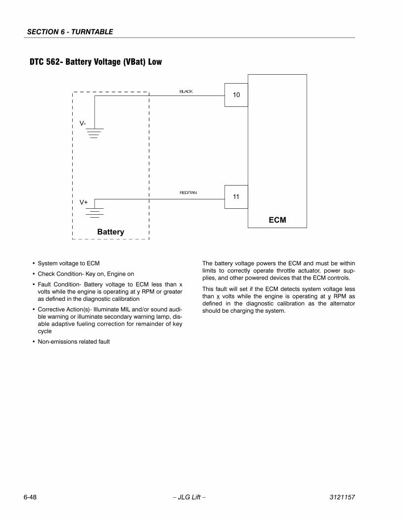
SECTION 6 - TURNTABLE
6-48 – JLG Lift – 3121157
DTC 562- Battery Voltage (VBat) Low
• System voltage to ECM
• Check Condition- Key on, Engine on
• Fault Condition- Battery voltage to ECM less than xvolts while the engine is operating at y RPM or greateras defined in the diagnostic calibration
• Corrective Action(s)- Illuminate MIL and/or sound audi-ble warning or illuminate secondary warning lamp, dis-able adaptive fueling correction for remainder of keycycle
• Non-emissions related fault
The battery voltage powers the ECM and must be withinlimits to correctly operate throttle actuator, power sup-plies, and other powered devices that the ECM controls.
This fault will set if the ECM detects system voltage lessthan x volts while the engine is operating at y RPM asdefined in the diagnostic calibration as the alternatorshould be charging the system.
BLACK
RED/TAN
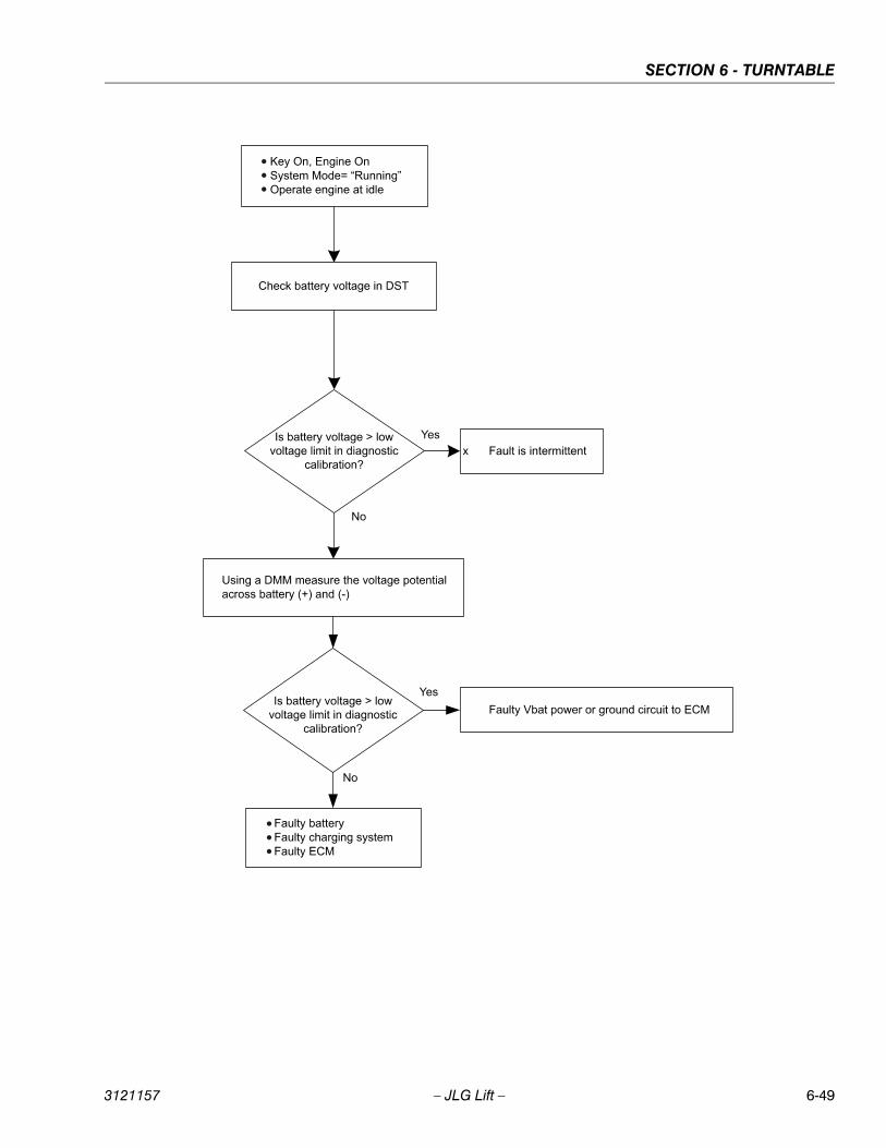
SECTION 6 - TURNTABLE
3121157 – JLG Lift – 6-49
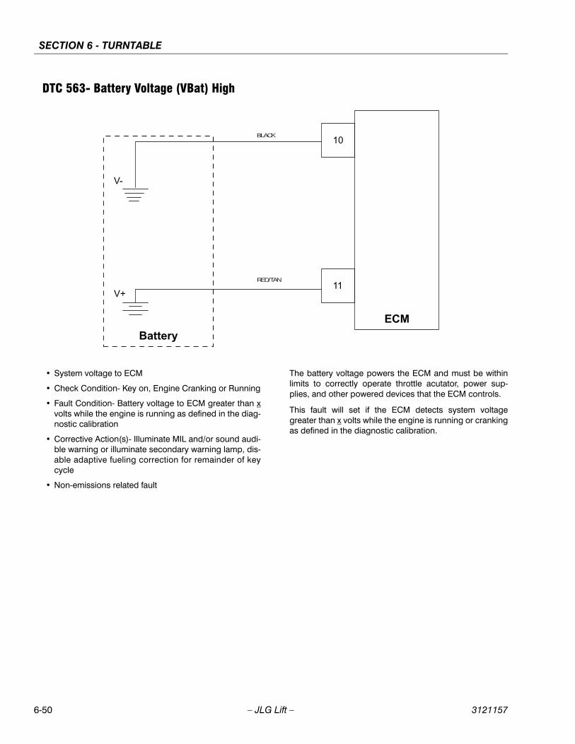
SECTION 6 - TURNTABLE
6-50 – JLG Lift – 3121157
DTC 563- Battery Voltage (VBat) High
• System voltage to ECM
• Check Condition- Key on, Engine Cranking or Running
• Fault Condition- Battery voltage to ECM greater than xvolts while the engine is running as defined in the diag-nostic calibration
• Corrective Action(s)- Illuminate MIL and/or sound audi-ble warning or illuminate secondary warning lamp, dis-able adaptive fueling correction for remainder of keycycle
• Non-emissions related fault
The battery voltage powers the ECM and must be withinlimits to correctly operate throttle acutator, power sup-plies, and other powered devices that the ECM controls.
This fault will set if the ECM detects system voltagegreater than x volts while the engine is running or crankingas defined in the diagnostic calibration.
BLACK
RED/TAN
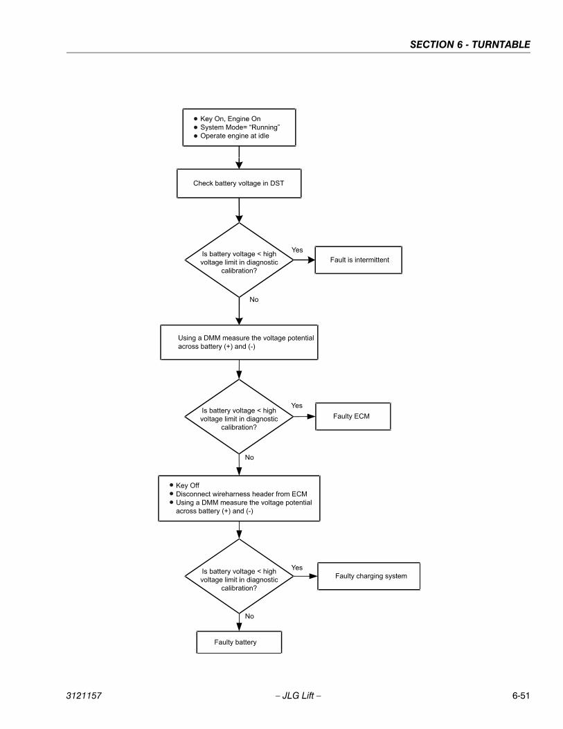
SECTION 6 - TURNTABLE
3121157 – JLG Lift – 6-51
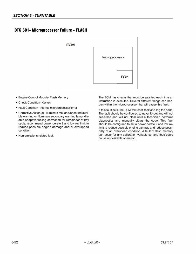
SECTION 6 - TURNTABLE
6-52 – JLG Lift – 3121157
DTC 601- Microprocessor Failure - FLASH
• Engine Control Module- Flash Memory
• Check Condition- Key on
• Fault Condition- Internal microprocessor error
• Corrective Action(s)- Illuminate MIL and/or sound audi-ble warning or illuminate secondary warning lamp, dis-able adaptive fueling correction for remainder of keycycle, recommend power derate 2 and low rev limit toreduce possible engine damage and/or overspeedcondition
• Non-emissions related fault
The ECM has checks that must be satisfied each time aninstruction is executed. Several different things can hap-pen within the microprocessor that will cause this fault.
If this fault sets, the ECM will reset itself and log the code.The fault should be configured to never forget and will notself-erase and will not clear until a technician performsdiagnostics and manually clears the code. This faultshould be configured to set a power derate 2 and low revlimit to reduce possible engine damage and reduce possi-bility of an overspeed condition. A fault of flash memorycan occur for any calibration variable set and thus couldcause undesirable operation.
RAM
ECM
Microprocessor
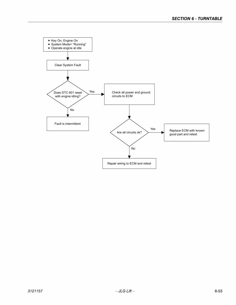
SECTION 6 - TURNTABLE
3121157 – JLG Lift – 6-53

SECTION 6 - TURNTABLE
6-54 – JLG Lift – 3121157
DTC 604- Microprocessor Failure - RAM
• Engine Control Module- Random Access Memory
• Check Condition- Key on
• Fault Condition- Internal ECM microprocessor memoryaccess failure
• Corrective Action(s)- Illuminate MIL and/or sound audi-ble warning or illuminate secondary warning lamp, dis-able adaptive fueling correction for remainder of keycycle, recommend power derate 2 and low rev limit toreduce possible engine damage and/or overspeedcondition
• Non-emissions related fault
Random Access Memory is located within the micropro-cessor and can be read from or written to at any time.Data stored in RAM include DTCs (when fault configura-tion is set to "Battery Power Retained"), adaptive fuel learntables, octane adaptation table, misfire adaption tables,and closed loop fuel multipliers. The ECM has checks thatmust be satisfied each time an instruction is executed.
This fault will set if the ECM detects a problem accessingor writing information to RAM and should be configured toset a power derate 2 and low rev limit to reduce possibleengine damage and reduce possibility of an overspeedcondition. If this fault sets, the ECM will reset itself and logthe code. This fault should be erased by a technician afterdiagnostics are performed. The fault should be configuredto never forget and will not self-erase.
RAM
ECM
Microprocessor
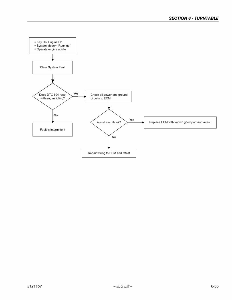
SECTION 6 - TURNTABLE
3121157 – JLG Lift – 6-55
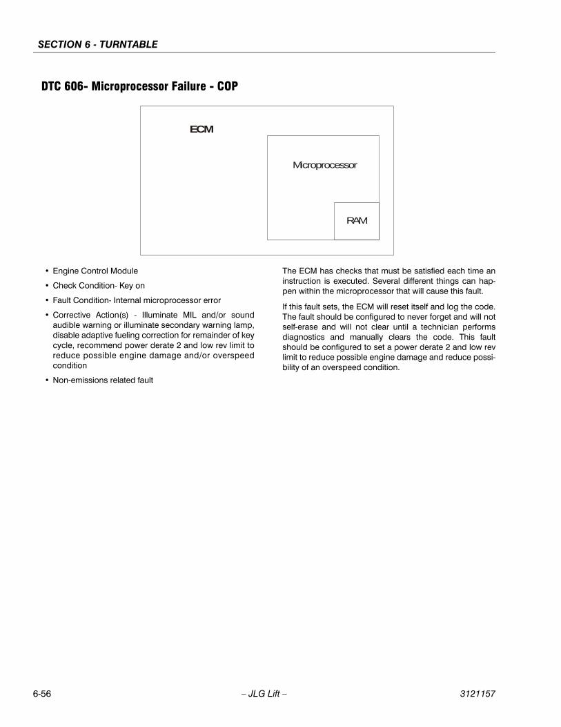
SECTION 6 - TURNTABLE
6-56 – JLG Lift – 3121157
DTC 606- Microprocessor Failure - COP
• Engine Control Module
• Check Condition- Key on
• Fault Condition- Internal microprocessor error
• Corrective Action(s) - Illuminate MIL and/or soundaudible warning or illuminate secondary warning lamp,disable adaptive fueling correction for remainder of keycycle, recommend power derate 2 and low rev limit toreduce possible engine damage and/or overspeedcondition
• Non-emissions related fault
The ECM has checks that must be satisfied each time aninstruction is executed. Several different things can hap-pen within the microprocessor that will cause this fault.
If this fault sets, the ECM will reset itself and log the code.The fault should be configured to never forget and will notself-erase and will not clear until a technician performsdiagnostics and manually clears the code. This faultshould be configured to set a power derate 2 and low revlimit to reduce possible engine damage and reduce possi-bility of an overspeed condition.
RAM
ECM
Microprocessor
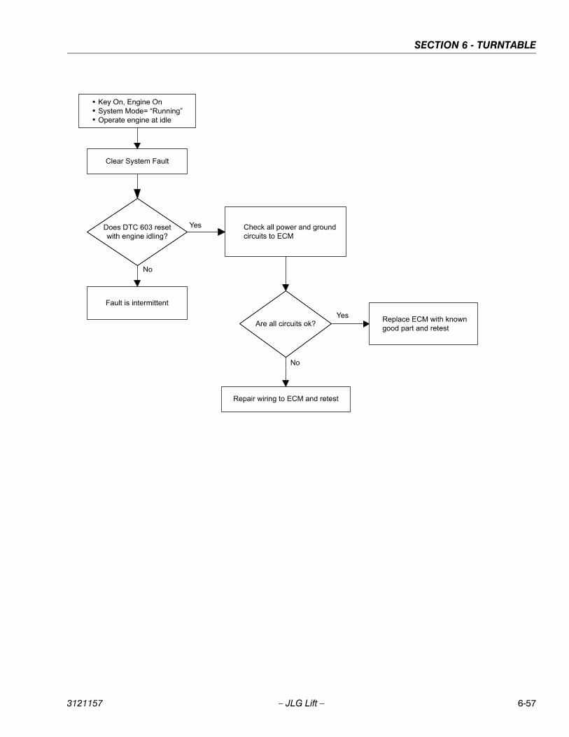
SECTION 6 - TURNTABLE
3121157 – JLG Lift – 6-57
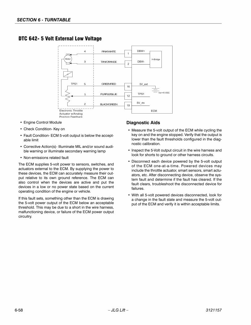
SECTION 6 - TURNTABLE
6-58 – JLG Lift – 3121157
DTC 642- 5 Volt External Low Voltage
• Engine Control Module
• Check Condition- Key on
• Fault Condition- ECM 5-volt output is below the accept-able limit
• Corrective Action(s)- Illuminate MIL and/or sound audi-ble warning or illuminate secondary warning lamp
• Non-emissions related fault
The ECM supplies 5-volt power to sensors, switches, andactuators external to the ECM. By supplying the power tothese devices, the ECM can accurately measure their out-put relative to its own ground reference. The ECM canalso control when the devices are active and put thedevices in a low or no power state based on the currentoperating condition of the engine or vehicle.
If this fault sets, something other than the ECM is drawingthe 5-volt power output of the ECM below an acceptablethreshold. This may be due to a short in the wire harness,malfunctioning device, or failure of the ECM power outputcircuitry.
Diagnostic Aids
• Measure the 5-volt output of the ECM while cycling thekey on and the engine stopped. Verify that the output islower than the fault thresholds configured in the diag-nostic calibration.
• Inspect the 5-Volt output circuit in the wire harness andlook for shorts to ground or other harness circuits.
• Disconnect each device powered by the 5-volt outputof the ECM one-at-a-time. Powered devices mayinclude the throttle actuator, smart sensors, smart actu-ators, etc. After disconnecting device, observe the sys-tem fault and determine if the fault has cleared. If thefault clears, troubleshoot the disconnected device forfailures.
• With all 5-volt powered devices disconnected, look fora change in the fault state and measure the 5-volt out-put of the ECM and verify it is within acceptable limits.
PINK/WHITE4
3
5
1
2
TAN/ORANGE
GREEN/RED
PURPLE/BLUE
BLACK/GREEN
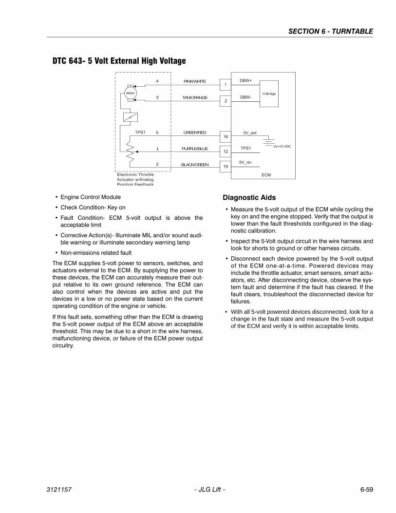
SECTION 6 - TURNTABLE
3121157 – JLG Lift – 6-59
DTC 643- 5 Volt External High Voltage
• Engine Control Module
• Check Condition- Key on
• Fault Condition- ECM 5-volt output is above theacceptable limit
• Corrective Action(s)- Illuminate MIL and/or sound audi-ble warning or illuminate secondary warning lamp
• Non-emissions related fault
The ECM supplies 5-volt power to sensors, switches, andactuators external to the ECM. By supplying the power tothese devices, the ECM can accurately measure their out-put relative to its own ground reference. The ECM canalso control when the devices are active and put thedevices in a low or no power state based on the currentoperating condition of the engine or vehicle.
If this fault sets, something other than the ECM is drawingthe 5-volt power output of the ECM above an acceptablethreshold. This may be due to a short in the wire harness,malfunctioning device, or failure of the ECM power outputcircuitry.
Diagnostic Aids
• Measure the 5-volt output of the ECM while cycling thekey on and the engine stopped. Verify that the output islower than the fault thresholds configured in the diag-nostic calibration.
• Inspect the 5-Volt output circuit in the wire harness andlook for shorts to ground or other harness circuits.
• Disconnect each device powered by the 5-volt outputof the ECM one-at-a-time. Powered devices mayinclude the throttle actuator, smart sensors, smart actu-ators, etc. After disconnecting device, observe the sys-tem fault and determine if the fault has cleared. If thefault clears, troubleshoot the disconnected device forfailures.
• With all 5-volt powered devices disconnected, look for achange in the fault state and measure the 5-volt outputof the ECM and verify it is within acceptable limits.
PINK/WHITE4
3
5
1
2
TAN/ORANGE
GREEN/RED
PURPLE/BLUE
BLACK/GREEN
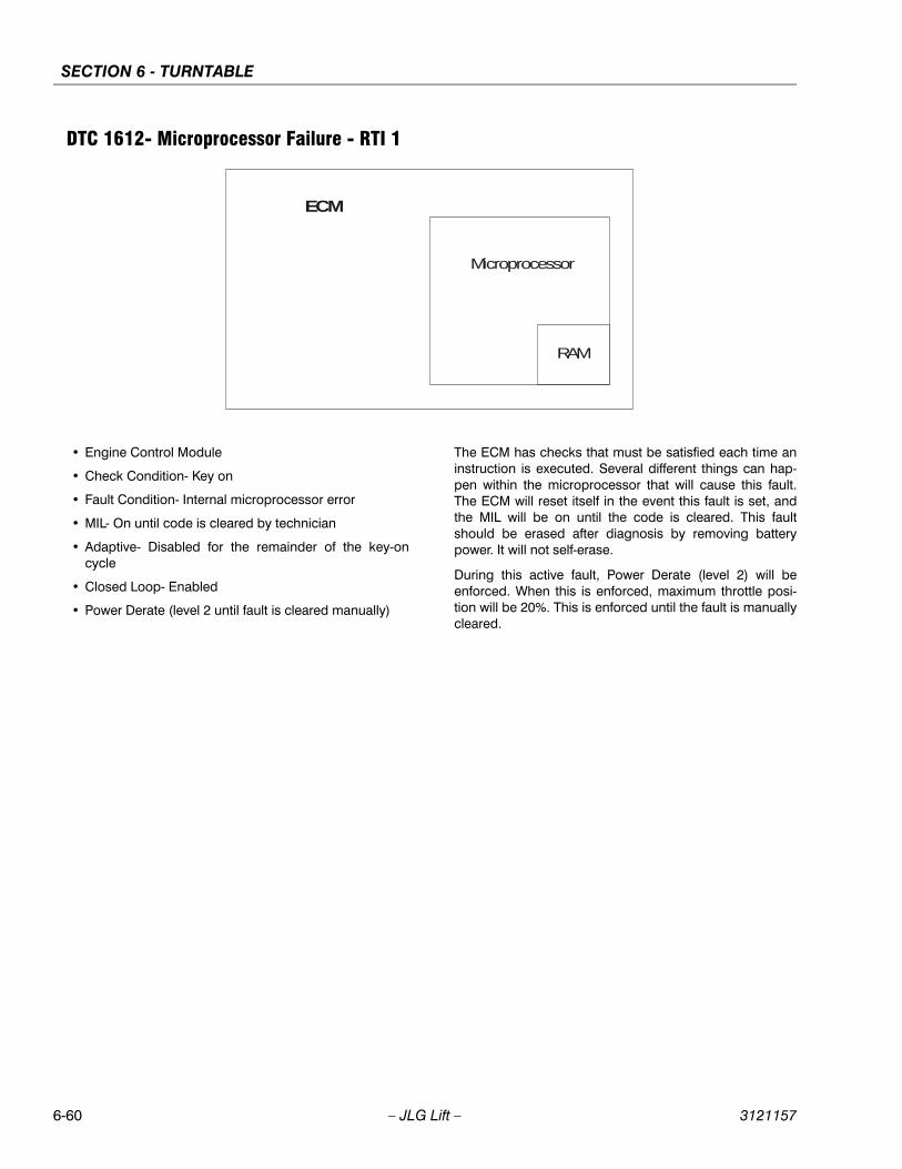
SECTION 6 - TURNTABLE
6-60 – JLG Lift – 3121157
DTC 1612- Microprocessor Failure - RTI 1
• Engine Control Module
• Check Condition- Key on
• Fault Condition- Internal microprocessor error
• MIL- On until code is cleared by technician
• Adaptive- Disabled for the remainder of the key-oncycle
• Closed Loop- Enabled
• Power Derate (level 2 until fault is cleared manually)
The ECM has checks that must be satisfied each time aninstruction is executed. Several different things can hap-pen within the microprocessor that will cause this fault.The ECM will reset itself in the event this fault is set, andthe MIL will be on until the code is cleared. This faultshould be erased after diagnosis by removing batterypower. It will not self-erase.
During this active fault, Power Derate (level 2) will beenforced. When this is enforced, maximum throttle posi-tion will be 20%. This is enforced until the fault is manuallycleared.
RAM
ECM
Microprocessor
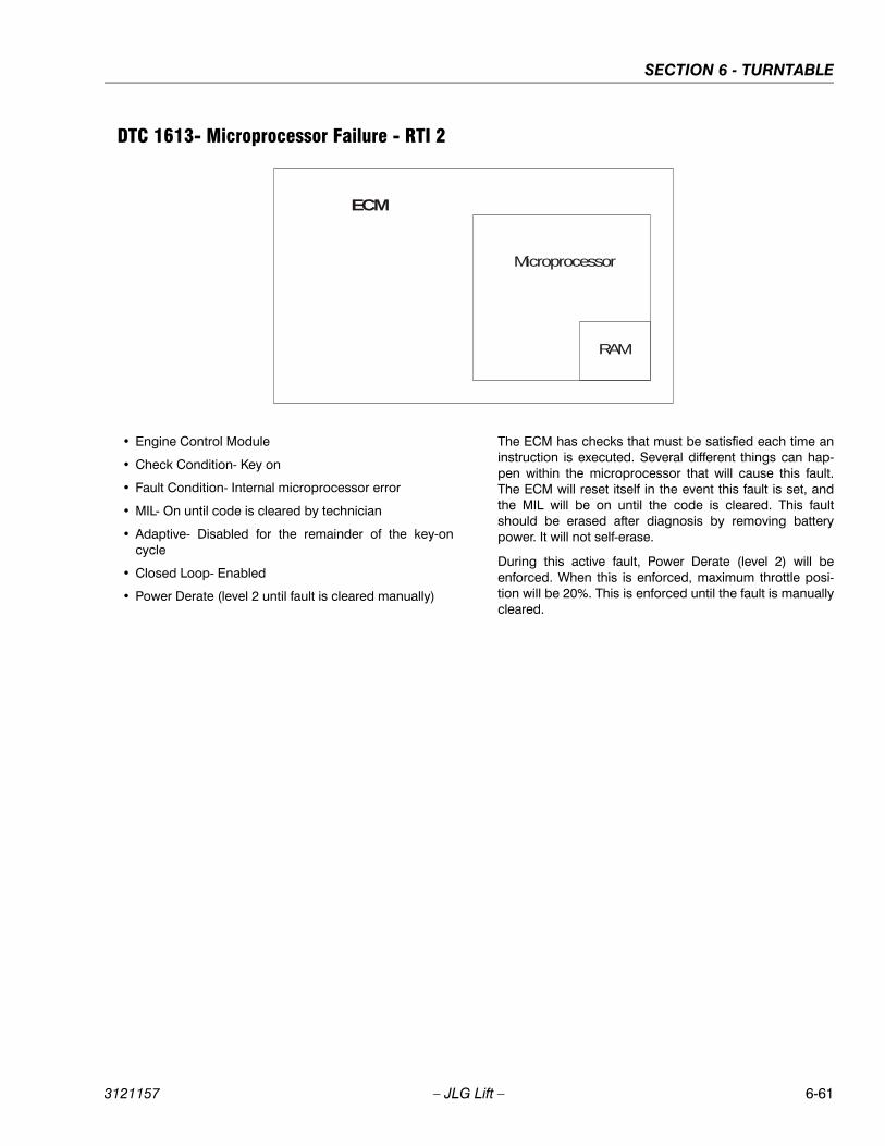
SECTION 6 - TURNTABLE
3121157 – JLG Lift – 6-61
DTC 1613- Microprocessor Failure - RTI 2
• Engine Control Module
• Check Condition- Key on
• Fault Condition- Internal microprocessor error
• MIL- On until code is cleared by technician
• Adaptive- Disabled for the remainder of the key-oncycle
• Closed Loop- Enabled
• Power Derate (level 2 until fault is cleared manually)
The ECM has checks that must be satisfied each time aninstruction is executed. Several different things can hap-pen within the microprocessor that will cause this fault.The ECM will reset itself in the event this fault is set, andthe MIL will be on until the code is cleared. This faultshould be erased after diagnosis by removing batterypower. It will not self-erase.
During this active fault, Power Derate (level 2) will beenforced. When this is enforced, maximum throttle posi-tion will be 20%. This is enforced until the fault is manuallycleared.
RAM
ECM
Microprocessor
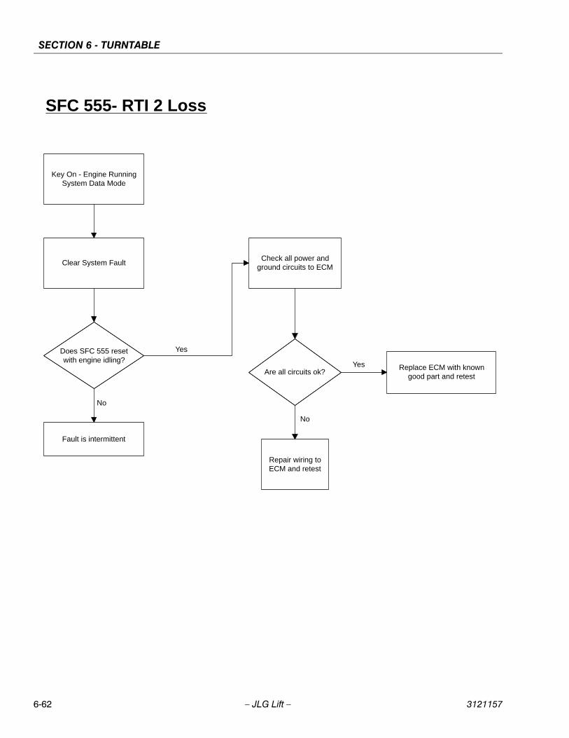
SECTION 6 - TURNTABLE
6-62 – JLG Lift – 3121157
SFC 555- RTI 2 Loss
Key On - Engine RunningSystem Data Mode
Clear System Fault
Does SFC 555 resetwith engine idling?
Fault is intermittent
Replace ECM with knowngood part and retest
No
Check all power andground circuits to ECM
Are all circuits ok?
Repair wiring toECM and retest
Yes
Yes
No

SECTION 6 - TURNTABLE
3121157 – JLG Lift – 6-63
DTC 1614- Microprocessor Failure - RTI 3
• Engine Control Module
• Check Condition- Key on
• Fault Condition- Internal microprocessor error
• MIL- On until code is cleared by technician
• Adaptive- Disabled for the remainder of the key-oncycle
• Closed Loop- Enabled
• Power Derate (level 2 until fault is cleared manually)
The ECM has checks that must be satisfied each time aninstruction is executed. Several different things can hap-pen within the microprocessor that will cause this fault.The ECM will reset itself in the event this fault is set, andthe MIL will be on until the code is cleared. This faultshould be erased after diagnosis by removing batterypower. It will not self-erase.
During this active fault, Power Derate (level 2) will beenforced. When this is enforced, maximum throttle posi-tion will be 20%. This is enforced until the fault is manuallycleared.
RAM
ECM
Microprocessor
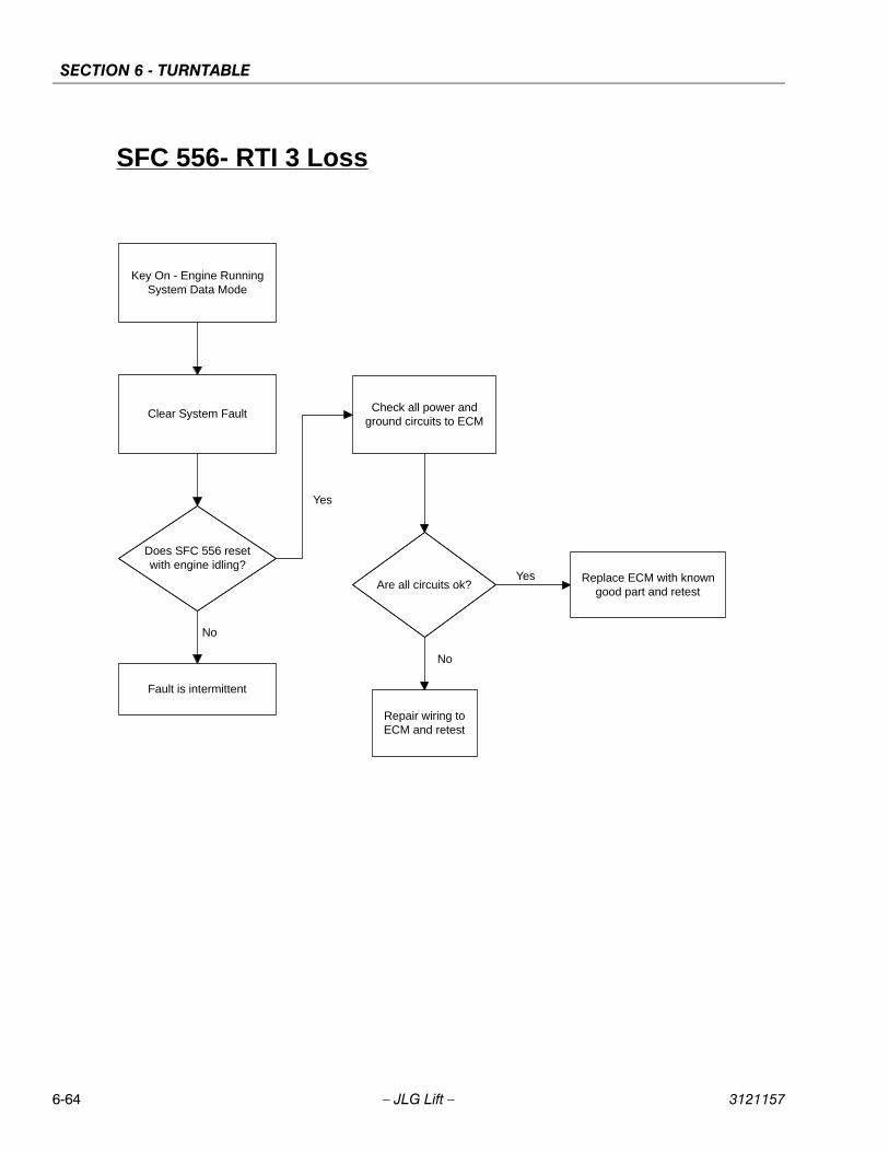
SECTION 6 - TURNTABLE
6-64 – JLG Lift – 3121157
SFC 556- RTI 3 Loss
Key On - Engine RunningSystem Data Mode
Clear System Fault
Does SFC 556 resetwith engine idling?
Fault is intermittent
Replace ECM with knowngood part and retest
No
Check all power andground circuits to ECM
Are all circuits ok?
Repair wiring toECM and retest
Yes
Yes
No

SECTION 6 - TURNTABLE
3121157 – JLG Lift – 6-65
DTC 1615- Microprocessor Failure - A/D
• Engine Control Module
• Check Condition- Key on
• Fault Condition- Internal microprocessor error
• MIL- On until code is cleared by technician
• Adaptive- Disabled for the remainder of the key-oncycle
• Closed Loop- Enabled
• Power Derate (level 2 until fault is cleared manually)
The ECM has checks that must be satisfied each time aninstruction is executed. Several different things can hap-pen within the microprocessor that will cause this fault.The ECM will reset itself in the event this fault is set, andthe MIL will be on until the code is cleared. This faultshould be erased after diagnosis by removing batterypower. It will not self-erase.
During this active fault, Power Derate (level 2) will beenforced. When this is enforced, maximum throttle posi-tion will be 20%. This is enforced until the fault is manuallycleared.
RAM
ECM
Microprocessor
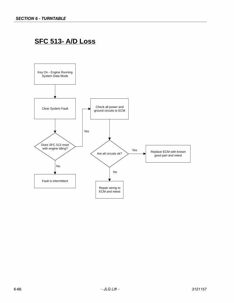
SECTION 6 - TURNTABLE
6-66 – JLG Lift – 3121157
SFC 513- A/D Loss
Key On - Engine RunningSystem Data Mode
Clear System Fault
Does SFC 513 resetwith engine idling?
Fault is intermittent
Replace ECM with knowngood part and retest
No
Check all power andground circuits to ECM
Are all circuits ok?
Repair wiring toECM and retest
Yes
Yes
No
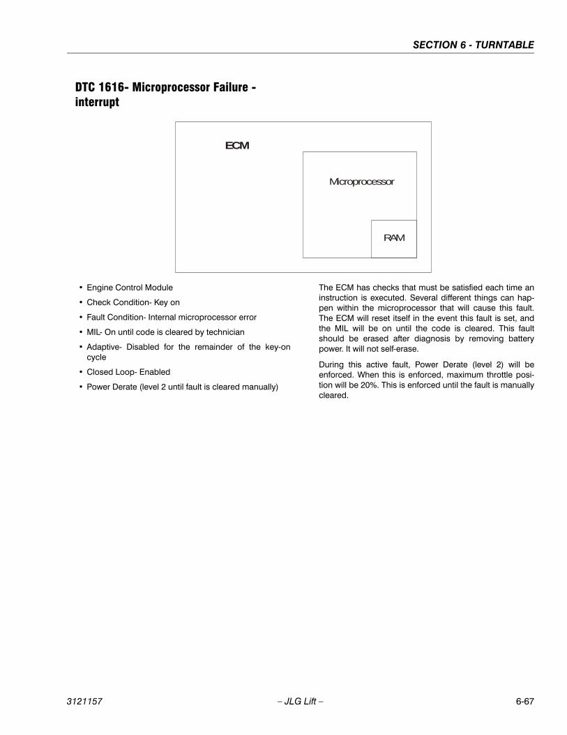
SECTION 6 - TURNTABLE
3121157 – JLG Lift – 6-67
DTC 1616- Microprocessor Failure - interrupt
• Engine Control Module
• Check Condition- Key on
• Fault Condition- Internal microprocessor error
• MIL- On until code is cleared by technician
• Adaptive- Disabled for the remainder of the key-oncycle
• Closed Loop- Enabled
• Power Derate (level 2 until fault is cleared manually)
The ECM has checks that must be satisfied each time aninstruction is executed. Several different things can hap-pen within the microprocessor that will cause this fault.The ECM will reset itself in the event this fault is set, andthe MIL will be on until the code is cleared. This faultshould be erased after diagnosis by removing batterypower. It will not self-erase.
During this active fault, Power Derate (level 2) will beenforced. When this is enforced, maximum throttle posi-tion will be 20%. This is enforced until the fault is manuallycleared.
RAM
ECM
Microprocessor

SECTION 6 - TURNTABLE
6-68 – JLG Lift – 3121157
SFC 512- Invalid Interrupt
Key On - Engine RunningSystem Data Mode
Clear System Fault
Does SFC 512 resetwith engine idling?
Fault is intermittent
Replace ECM with knowngood part and retest
No
Check all power andground circuits to ECM
Are all circuits ok?
Repair wiring toECM and retest
Yes
Yes
No
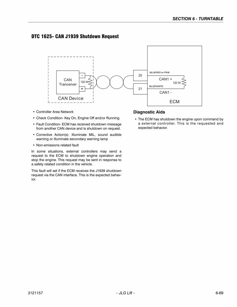
SECTION 6 - TURNTABLE
3121157 – JLG Lift – 6-69
DTC 1625- CAN J1939 Shutdown Request
• Controller Area Network
• Check Condition- Key On, Engine Off and/or Running
• Fault Condition- ECM has received shutdown messagefrom another CAN device and is shutdown on request.
• Corrective Action(s)- Illuminate MIL, sound audiblewarning or illuminate secondary warning lamp
• Non-emissions related fault
In some situations, external controllers may send arequest to the ECM to shutdown engine operation andstop the engine. This request may be sent in response toa safety related condition in the vehicle.
This fault will set if the ECM receives the J1939 shutdownrequest via the CAN interface. This is the expected behav-ior.
Diagnostic Aids
• The ECM has shutdown the engine upon command bya external controller. This is the requested andexpected behavior.
BLUE/RED or PINK
BLUE/WHITE
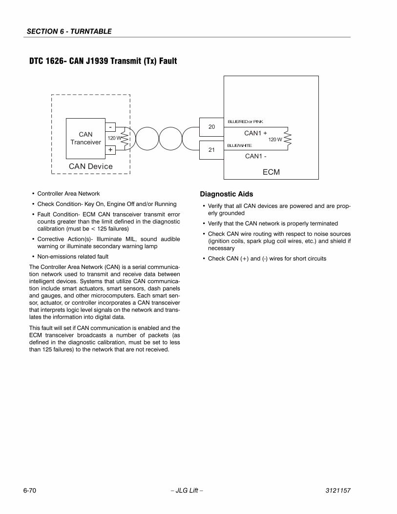
SECTION 6 - TURNTABLE
6-70 – JLG Lift – 3121157
DTC 1626- CAN J1939 Transmit (Tx) Fault
• Controller Area Network
• Check Condition- Key On, Engine Off and/or Running
• Fault Condition- ECM CAN transceiver transmit errorcounts greater than the limit defined in the diagnosticcalibration (must be < 125 failures)
• Corrective Action(s)- Illuminate MIL, sound audiblewarning or illuminate secondary warning lamp
• Non-emissions related fault
The Controller Area Network (CAN) is a serial communica-tion network used to transmit and receive data betweenintelligent devices. Systems that utilize CAN communica-tion include smart actuators, smart sensors, dash panelsand gauges, and other microcomputers. Each smart sen-sor, actuator, or controller incorporates a CAN transceiverthat interprets logic level signals on the network and trans-lates the information into digital data.
This fault will set if CAN communication is enabled and theECM transceiver broadcasts a number of packets (asdefined in the diagnostic calibration, must be set to lessthan 125 failures) to the network that are not received.
Diagnostic Aids
• Verify that all CAN devices are powered and are prop-erly grounded
• Verify that the CAN network is properly terminated
• Check CAN wire routing with respect to noise sources(ignition coils, spark plug coil wires, etc.) and shield ifnecessary
• Check CAN (+) and (-) wires for short circuits
BLUE/RED or PINK
BLUE/WHITE
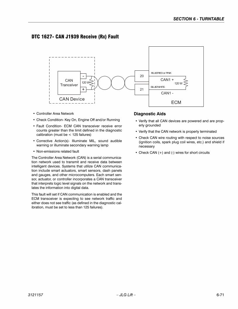
SECTION 6 - TURNTABLE
3121157 – JLG Lift – 6-71
DTC 1627- CAN J1939 Receive (Rx) Fault
• Controller Area Network
• Check Condition- Key On, Engine Off and/or Running
• Fault Condition- ECM CAN transceiver receive errorcounts greater than the limit defined in the diagnosticcalibration (must be < 125 failures)
• Corrective Action(s)- Illuminate MIL, sound audiblewarning or illuminate secondary warning lamp
• Non-emissions related fault
The Controller Area Network (CAN) is a serial communica-tion network used to transmit and receive data betweenintelligent devices. Systems that utilize CAN communica-tion include smart actuators, smart sensors, dash panelsand gauges, and other microcomputers. Each smart sen-sor, actuator, or controller incorporates a CAN transceiverthat interprets logic level signals on the network and trans-lates the information into digital data.
This fault will set if CAN communication is enabled and theECM transceiver is expecting to see network traffic andeither does not see traffic (as defined in the diagnostic cal-ibration, must be set to less than 125 failures).
Diagnostic Aids
• Verify that all CAN devices are powered and are prop-erly grounded
• Verify that the CAN network is properly terminated
• Check CAN wire routing with respect to noise sources(ignition coils, spark plug coil wires, etc.) and shield ifnecessary
• Check CAN (+) and (-) wires for short circuits
BLUE/RED or PINK
BLUE/WHITE
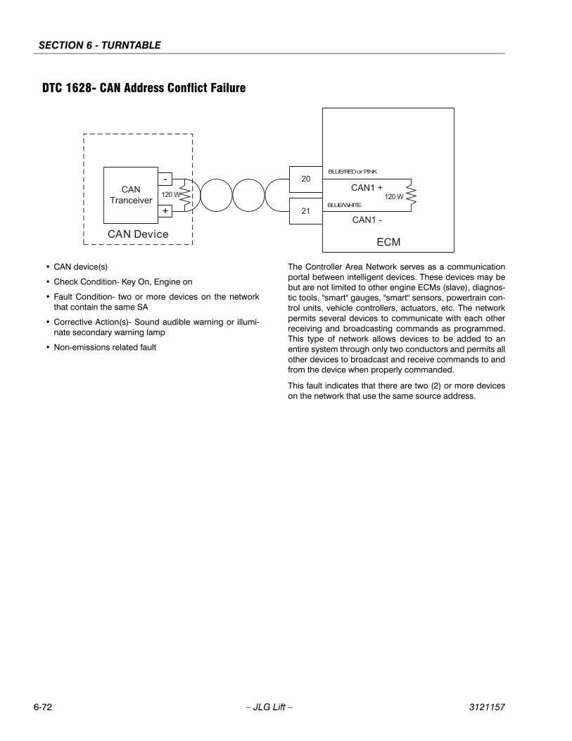
SECTION 6 - TURNTABLE
6-72 – JLG Lift – 3121157
DTC 1628- CAN Address Conflict Failure
• CAN device(s)
• Check Condition- Key On, Engine on
• Fault Condition- two or more devices on the networkthat contain the same SA
• Corrective Action(s)- Sound audible warning or illumi-nate secondary warning lamp
• Non-emissions related fault
The Controller Area Network serves as a communicationportal between intelligent devices. These devices may bebut are not limited to other engine ECMs (slave), diagnos-tic tools, "smart" gauges, "smart" sensors, powertrain con-trol units, vehicle controllers, actuators, etc. The networkpermits several devices to communicate with each otherreceiving and broadcasting commands as programmed.This type of network allows devices to be added to anentire system through only two conductors and permits allother devices to broadcast and receive commands to andfrom the device when properly commanded.
This fault indicates that there are two (2) or more deviceson the network that use the same source address.
BLUE/RED or PINK
BLUE/WHITE
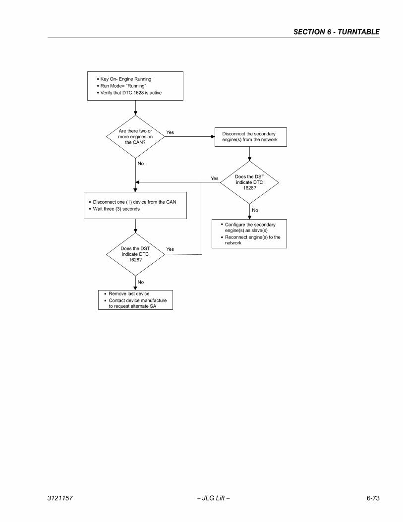
SECTION 6 - TURNTABLE
3121157 – JLG Lift – 6-73
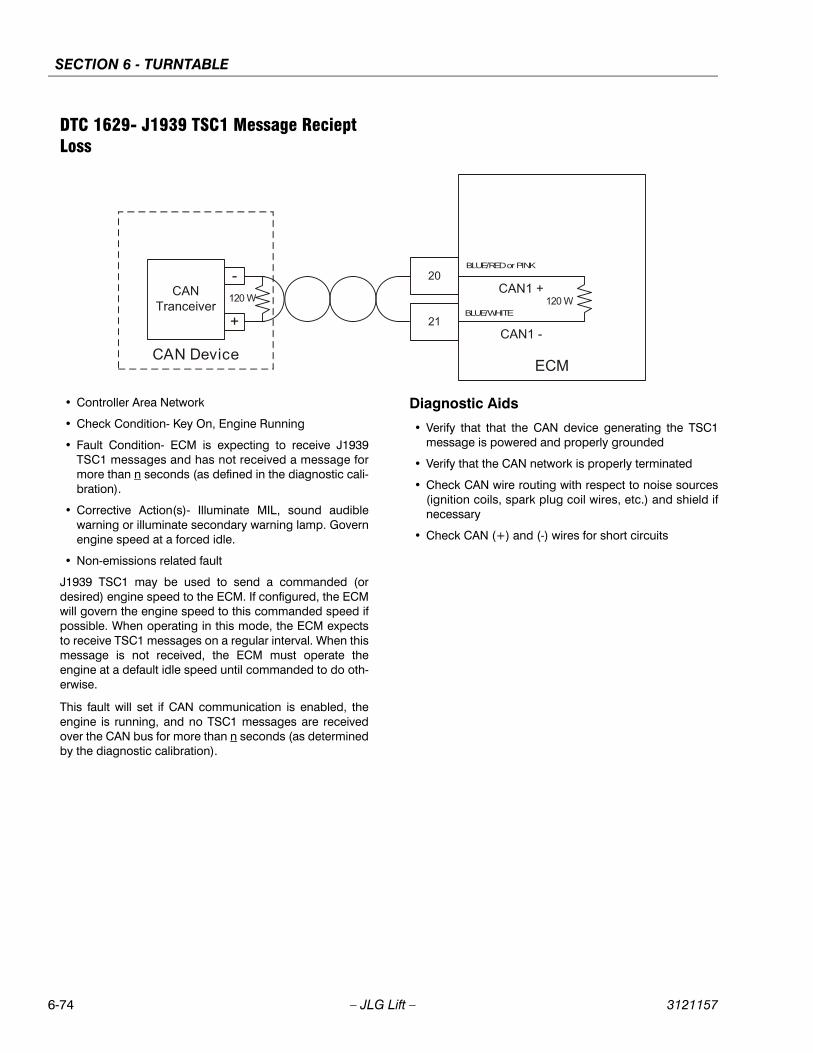
SECTION 6 - TURNTABLE
6-74 – JLG Lift – 3121157
DTC 1629- J1939 TSC1 Message Reciept Loss
• Controller Area Network
• Check Condition- Key On, Engine Running
• Fault Condition- ECM is expecting to receive J1939TSC1 messages and has not received a message formore than n seconds (as defined in the diagnostic cali-bration).
• Corrective Action(s)- Illuminate MIL, sound audiblewarning or illuminate secondary warning lamp. Governengine speed at a forced idle.
• Non-emissions related fault
J1939 TSC1 may be used to send a commanded (ordesired) engine speed to the ECM. If configured, the ECMwill govern the engine speed to this commanded speed ifpossible. When operating in this mode, the ECM expectsto receive TSC1 messages on a regular interval. When thismessage is not received, the ECM must operate theengine at a default idle speed until commanded to do oth-erwise.
This fault will set if CAN communication is enabled, theengine is running, and no TSC1 messages are receivedover the CAN bus for more than n seconds (as determinedby the diagnostic calibration).
Diagnostic Aids
• Verify that that the CAN device generating the TSC1message is powered and properly grounded
• Verify that the CAN network is properly terminated
• Check CAN wire routing with respect to noise sources(ignition coils, spark plug coil wires, etc.) and shield ifnecessary
• Check CAN (+) and (-) wires for short circuits
BLUE/RED or PINK
BLUE/WHITE
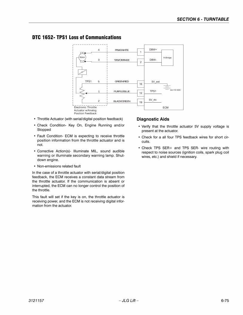
SECTION 6 - TURNTABLE
3121157 – JLG Lift – 6-75
DTC 1652- TPS1 Loss of Communications
• Throttle Actuator (with serial/digital position feedback)
• Check Condition- Key On, Engine Running and/orStopped
• Fault Condition- ECM is expecting to receive throttleposition information from the throttle actuator and isnot.
• Corrective Action(s)- Illuminate MIL, sound audiblewarning or illuminate secondary warning lamp. Shut-down engine.
• Non-emissions related fault
In the case of a throttle actuator with serial/digital positionfeedback, the ECM receives a constant data stream fromthe throttle actuator. If the communication is absent orinterrupted, the ECM can no longer control the position ofthe throttle.
This fault will set if the key is on, the throttle actuator isreceiving power, and the ECM is not receiving digital infor-mation from the actuator.
Diagnostic Aids
• Verify that the throttle actuator 5V supply voltage ispresent at the actuator.
• Check for a all four TPS feedback wires for short cir-cuits.
• Check TPS SER+ and TPS SER- wire routing withrespect to noise sources (ignition coils, spark plug coilwires, etc.) and shield if necessary.
PINK/WHITE4
3
5
1
2
TAN/ORANGE
GREEN/RED
PURPLE/BLUE
BLACK/GREEN

SECTION 6 - TURNTABLE
6-76 – JLG Lift – 3121157
DTC 2111- Unable to Reach Lower TPS
• Throttle Position Sensor
• Check Condition-Cranking or Running
• Fault Condition-Throttle command is 20% less thanthrottle position for 200ms or longer
• MIL-On during active fault
• Engine Shut Down
In the case of a diesel engine, an actuator controls a fuelinjection pump, directly affecting the fueling level into thecylinders. This may be by direct manipulation of the fuelinjection pump rack or by manipulation of the mechanicalgovernor control level or "throttle arm." In the DGC ECMand EDIS, references to the throttle and throttle positionsensor refer to these fuel injection pump control actuatorsand their position feedback sensors. When the fuel injec-tion pump is electronically controlled it can be used tocontrol the idle stability and limit engine speed based onoperating conditions.
The Throttle Position Sensor uses either 1) a variableresistor and voltage divider circuit or 2) a non-contact hall-effect sensor to determine throttle actuator position, and islocated within the throttle actuator.
There are two types of throttle actuators, 1) actuator withanalog position feedback and 2) actuator with digital posi-tion feedback. The first type, with analog position feed-back, provides an analog return signal between 0 and 5volts that is proportional to the throttle actuator position.The second type, with digital position feedback, providesa serial data signal to the ECM with the throttle actuatorposition voltage level encoded in the data stream.
This fault will set if the throttle command is 20% less thanthe actual throttle position. During this active fault the MILlight will be on and the engine will shut down.
PINK/WHITE4
3
5
1
2
TAN/ORANGE
GREEN/RED
PURPLE/BLUE
BLACK/GREEN
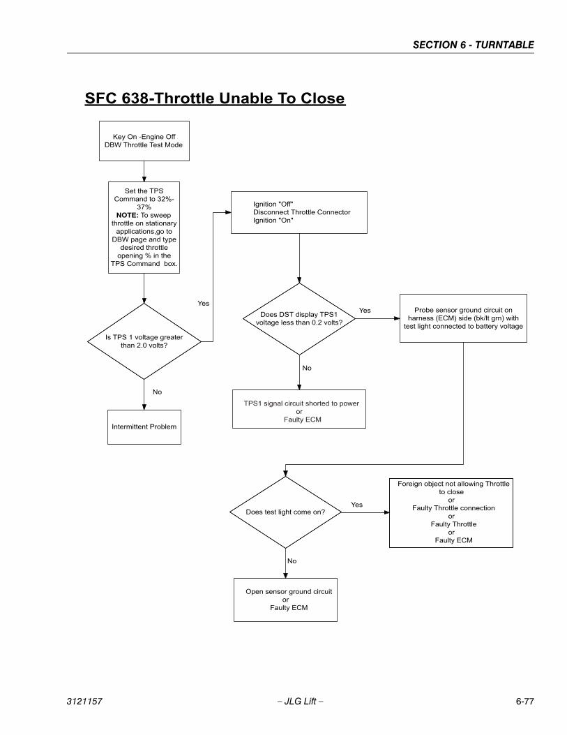
SECTION 6 - TURNTABLE
3121157 – JLG Lift – 6-77
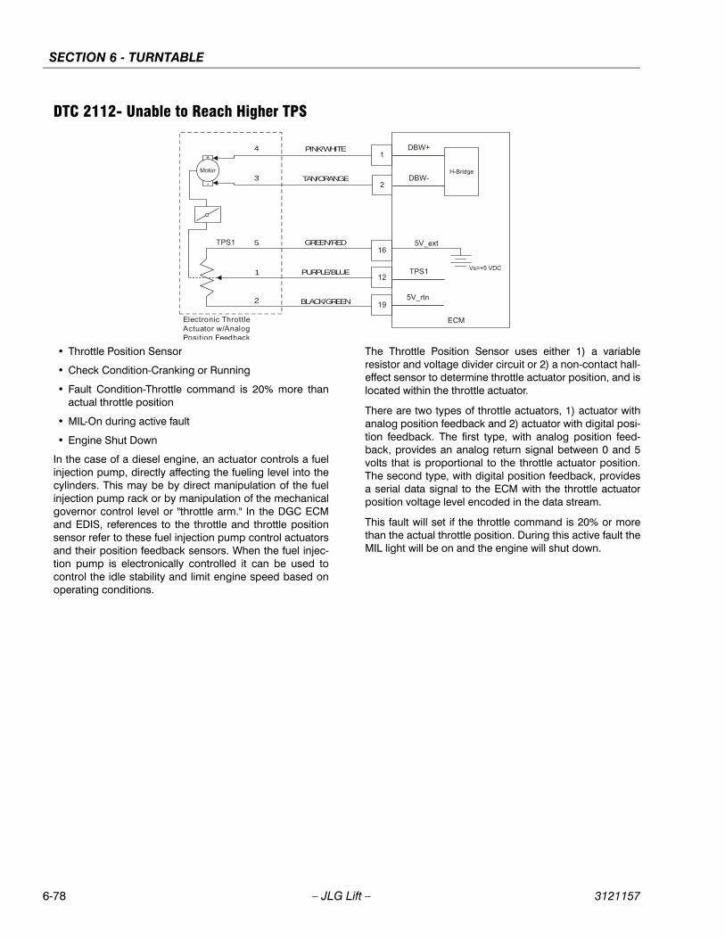
SECTION 6 - TURNTABLE
6-78 – JLG Lift – 3121157
DTC 2112- Unable to Reach Higher TPS
• Throttle Position Sensor
• Check Condition-Cranking or Running
• Fault Condition-Throttle command is 20% more thanactual throttle position
• MIL-On during active fault
• Engine Shut Down
In the case of a diesel engine, an actuator controls a fuelinjection pump, directly affecting the fueling level into thecylinders. This may be by direct manipulation of the fuelinjection pump rack or by manipulation of the mechanicalgovernor control level or "throttle arm." In the DGC ECMand EDIS, references to the throttle and throttle positionsensor refer to these fuel injection pump control actuatorsand their position feedback sensors. When the fuel injec-tion pump is electronically controlled it can be used tocontrol the idle stability and limit engine speed based onoperating conditions.
The Throttle Position Sensor uses either 1) a variableresistor and voltage divider circuit or 2) a non-contact hall-effect sensor to determine throttle actuator position, and islocated within the throttle actuator.
There are two types of throttle actuators, 1) actuator withanalog position feedback and 2) actuator with digital posi-tion feedback. The first type, with analog position feed-back, provides an analog return signal between 0 and 5volts that is proportional to the throttle actuator position.The second type, with digital position feedback, providesa serial data signal to the ECM with the throttle actuatorposition voltage level encoded in the data stream.
This fault will set if the throttle command is 20% or morethan the actual throttle position. During this active fault theMIL light will be on and the engine will shut down.
PINK/WHITE4
3
5
1
2
TAN/ORANGE
GREEN/RED
PURPLE/BLUE
BLACK/GREEN
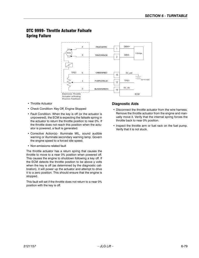
SECTION 6 - TURNTABLE
3121157 – JLG Lift – 6-79
DTC 9999- Throttle Actuator Failsafe Spring Failure
• Throttle Actuator
• Check Condition- Key Off, Engine Stopped
• Fault Condition- When the key is off (or the actuator isunpowered), the ECM is expecting the failsafe spring inthe actuator to return the throttle position to near 0%. Ifthe throttle does not reach this position when the actu-ator is powered, a fault is generated.
• Corrective Action(s)- Illuminate MIL, sound audiblewarning or illuminate secondary warning lamp. Governthe engine speed to a forced idle speed.
• Non-emissions related fault
The throttle actuator has a return spring that causes thethrottle to move to a near 0% position when powered off.This causes the engine to shutdown following a key off. Ifthe ECM detects the throttle position to be above x voltswhen the key is off (as determined by the diagnostic cali-bration), it will power up the actuator and attempt to driveit to a zero position. This should ensure that the engine isstopped.
This fault will set if the throttle does not return to a near 0%position with the key is off.
Diagnostic Aids
• Disconnect the throttle actuator from the wire harness.Remove the throttle actuator from the engine and man-ually move it. Verify that the internal spring forces thethrottle back to near 0% position.
• Inspect the throttle arm or fuel rack on the fuel pump.Verify that it is not stuck.
PINK/WHITE4
3
5
1
2
TAN/ORANGE
GREEN/RED
PURPLE/BLUE
BLACK/GREEN
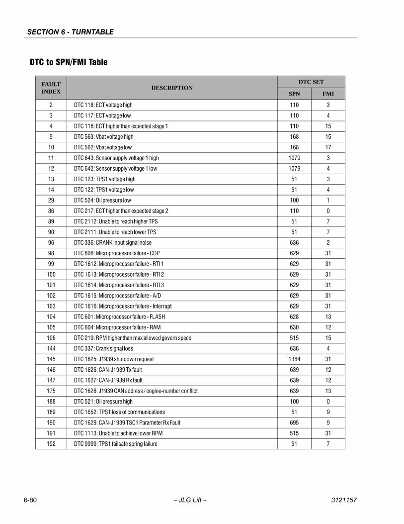
SECTION 6 - TURNTABLE
6-80 – JLG Lift – 3121157
DTC to SPN/FMI Table
FAULTINDEX
DESCRIPTIONDTC SET
SPN FMI
2 DTC 118: ECT voltage high 110 3
3 DTC 117: ECT voltage low 110 4
4 DTC 116: ECT higher than expected stage 1 110 15
9 DTC 563: Vbat voltage high 168 15
10 DTC 562: Vbat voltage low 168 17
11 DTC 643: Sensor supply voltage 1 high 1079 3
12 DTC 642: Sensor supply voltage 1 low 1079 4
13 DTC 123: TPS1 voltage high 51 3
14 DTC 122: TPS1 voltage low 51 4
29 DTC 524: Oil pressure low 100 1
86 DTC 217: ECT higher than expected stage 2 110 0
89 DTC 2112: Unable to reach higher TPS 51 7
90 DTC 2111: Unable to reach lower TPS 51 7
96 DTC 336: CRANK input signal noise 636 2
98 DTC 606: Microprocessor failure - COP 629 31
99 DTC 1612: Microprocessor failure - RTI 1 629 31
100 DTC 1613: Microprocessor failure - RTI 2 629 31
101 DTC 1614: Microprocessor failure - RTI 3 629 31
102 DTC 1615: Microprocessor failure - A/D 629 31
103 DTC 1616: Microprocessor failure - Interrupt 629 31
104 DTC 601: Microprocessor failure - FLASH 628 13
105 DTC 604: Microprocessor failure - RAM 630 12
106 DTC 219: RPM higher than max allowed govern speed 515 15
144 DTC 337: Crank signal loss 636 4
145 DTC 1625: J1939 shutdown request 1384 31
146 DTC 1626: CAN-J1939 Tx fault 639 12
147 DTC 1627: CAN-J1939 Rx fault 639 12
175 DTC 1628: J1939 CAN address / engine-number conflict 639 13
188 DTC 521: Oil pressure high 100 0
189 DTC 1652: TPS1 loss of communications 51 9
190 DTC 1629: CAN-J1939 TSC1 Parameter Rx Fault 695 9
191 DTC 1113: Unable to achieve lower RPM 515 31
192 DTC 9999: TPS1 failsafe spring failure 51 7
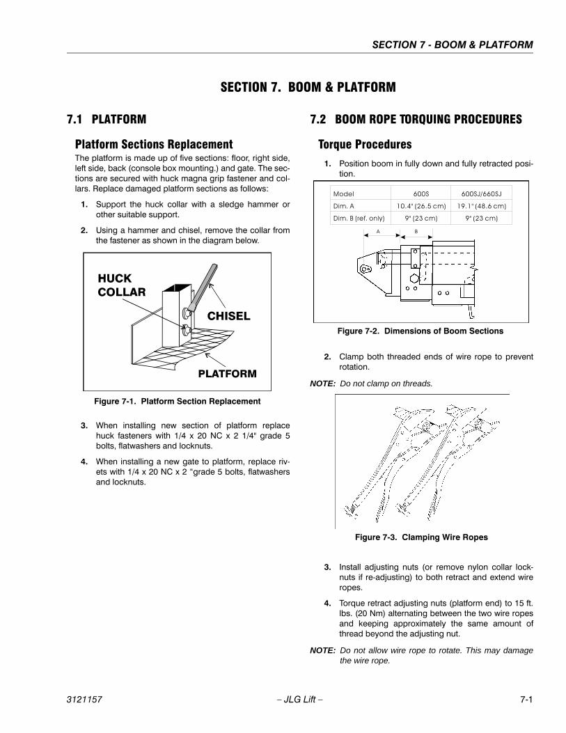
SECTION 7 - BOOM & PLATFORM
3121157 – JLG Lift – 7-1
SECTION 7. BOOM & PLATFORM
7.1 PLATFORM
Platform Sections ReplacementThe platform is made up of five sections: floor, right side,left side, back (console box mounting.) and gate. The sec-tions are secured with huck magna grip fastener and col-lars. Replace damaged platform sections as follows:
1. Support the huck collar with a sledge hammer orother suitable support.
2. Using a hammer and chisel, remove the collar fromthe fastener as shown in the diagram below.
3. When installing new section of platform replacehuck fasteners with 1/4 x 20 NC x 2 1/4" grade 5bolts, flatwashers and locknuts.
4. When installing a new gate to platform, replace riv-ets with 1/4 x 20 NC x 2 “grade 5 bolts, flatwashersand locknuts.
7.2 BOOM ROPE TORQUING PROCEDURES
Torque Procedures1. Position boom in fully down and fully retracted posi-
tion.
2. Clamp both threaded ends of wire rope to preventrotation.
NOTE: Do not clamp on threads.
3. Install adjusting nuts (or remove nylon collar lock-nuts if re-adjusting) to both retract and extend wireropes.
4. Torque retract adjusting nuts (platform end) to 15 ft.lbs. (20 Nm) alternating between the two wire ropesand keeping approximately the same amount ofthread beyond the adjusting nut.
NOTE: Do not allow wire rope to rotate. This may damagethe wire rope.
Figure 7-1. Platform Section Replacement
Figure 7-2. Dimensions of Boom Sections
Figure 7-3. Clamping Wire Ropes
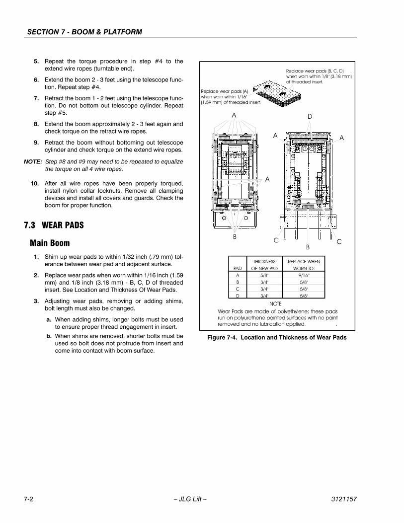
SECTION 7 - BOOM & PLATFORM
7-2 – JLG Lift – 3121157
5. Repeat the torque procedure in step #4 to theextend wire ropes (turntable end).
6. Extend the boom 2 - 3 feet using the telescope func-tion. Repeat step #4.
7. Retract the boom 1 - 2 feet using the telescope func-tion. Do not bottom out telescope cylinder. Repeatstep #5.
8. Extend the boom approximately 2 - 3 feet again andcheck torque on the retract wire ropes.
9. Retract the boom without bottoming out telescopecylinder and check torque on the extend wire ropes.
NOTE: Step #8 and #9 may need to be repeated to equalizethe torque on all 4 wire ropes.
10. After all wire ropes have been properly torqued,install nylon collar locknuts. Remove all clampingdevices and install all covers and guards. Check theboom for proper function.
7.3 WEAR PADS
Main Boom1. Shim up wear pads to within 1/32 inch (.79 mm) tol-
erance between wear pad and adjacent surface.
2. Replace wear pads when worn within 1/16 inch (1.59mm) and 1/8 inch (3.18 mm) - B, C, D of threadedinsert. See Location and Thickness Of Wear Pads.
3. Adjusting wear pads, removing or adding shims,bolt length must also be changed.
a. When adding shims, longer bolts must be usedto ensure proper thread engagement in insert.
b. When shims are removed, shorter bolts must beused so bolt does not protrude from insert andcome into contact with boom surface.
Figure 7-4. Location and Thickness of Wear Pads
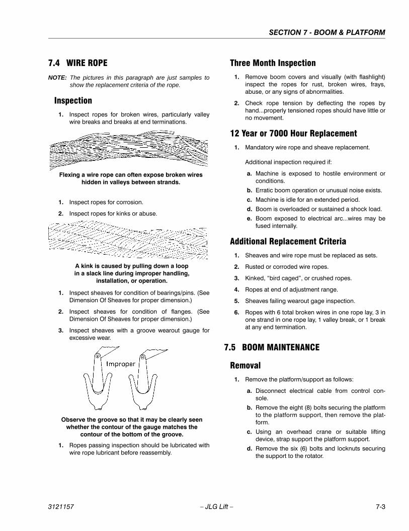
SECTION 7 - BOOM & PLATFORM
3121157 – JLG Lift – 7-3
7.4 WIRE ROPE
NOTE: The pictures in this paragraph are just samples toshow the replacement criteria of the rope.
Inspection1. Inspect ropes for broken wires, particularly valley
wire breaks and breaks at end terminations.
1. Inspect ropes for corrosion.
2. Inspect ropes for kinks or abuse.
1. Inspect sheaves for condition of bearings/pins. (SeeDimension Of Sheaves for proper dimension.)
2. Inspect sheaves for condition of flanges. (SeeDimension Of Sheaves for proper dimension.)
3. Inspect sheaves with a groove wearout gauge forexcessive wear.
1. Ropes passing inspection should be lubricated withwire rope lubricant before reassembly.
Three Month Inspection1. Remove boom covers and visually (with flashlight)
inspect the ropes for rust, broken wires, frays,abuse, or any signs of abnormalities.
2. Check rope tension by deflecting the ropes byhand...properly tensioned ropes should have little orno movement.
12 Year or 7000 Hour Replacement1. Mandatory wire rope and sheave replacement.
Additional inspection required if:
a. Machine is exposed to hostile environment orconditions.
b. Erratic boom operation or unusual noise exists.
c. Machine is idle for an extended period.
d. Boom is overloaded or sustained a shock load.
e. Boom exposed to electrical arc...wires may befused internally.
Additional Replacement Criteria1. Sheaves and wire rope must be replaced as sets.
2. Rusted or corroded wire ropes.
3. Kinked, “bird caged”, or crushed ropes.
4. Ropes at end of adjustment range.
5. Sheaves failing wearout gage inspection.
6. Ropes with 6 total broken wires in one rope lay, 3 inone strand in one rope lay, 1 valley break, or 1 breakat any end termination.
7.5 BOOM MAINTENANCE
Removal1. Remove the platform/support as follows:
a. Disconnect electrical cable from control con-sole.
b. Remove the eight (8) bolts securing the platformto the platform support, then remove the plat-form.
c. Using an overhead crane or suitable liftingdevice, strap support the platform support.
d. Remove the six (6) bolts and locknuts securingthe support to the rotator.
Flexing a wire rope can often expose broken wires hidden in valleys between strands.
A kink is caused by pulling down a loop in a slack line during improper handling,
installation, or operation.
Observe the groove so that it may be clearly seen whether the contour of the gauge matches the
contour of the bottom of the groove.
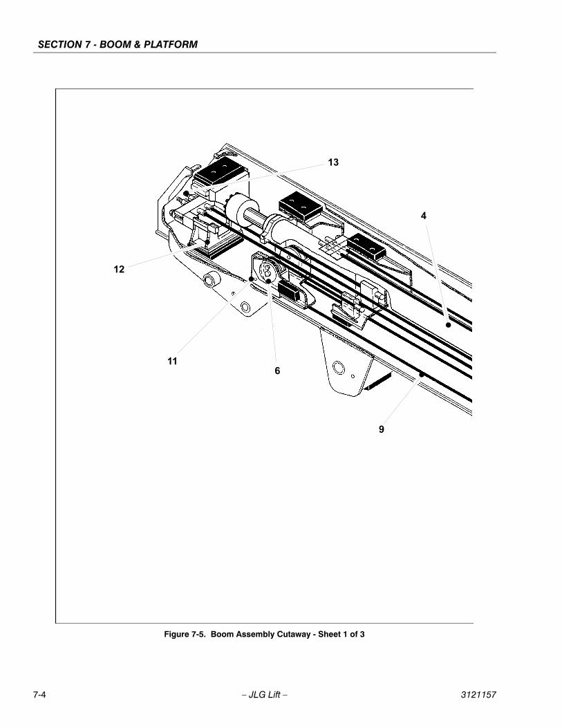
SECTION 7 - BOOM & PLATFORM
7-4 – JLG Lift – 3121157
Figure 7-5. Boom Assembly Cutaway - Sheet 1 of 3
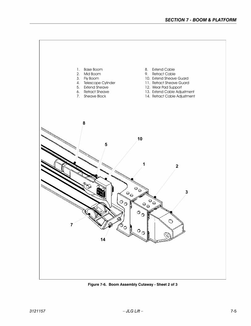
SECTION 7 - BOOM & PLATFORM
3121157 – JLG Lift – 7-5
Figure 7-6. Boom Assembly Cutaway - Sheet 2 of 3
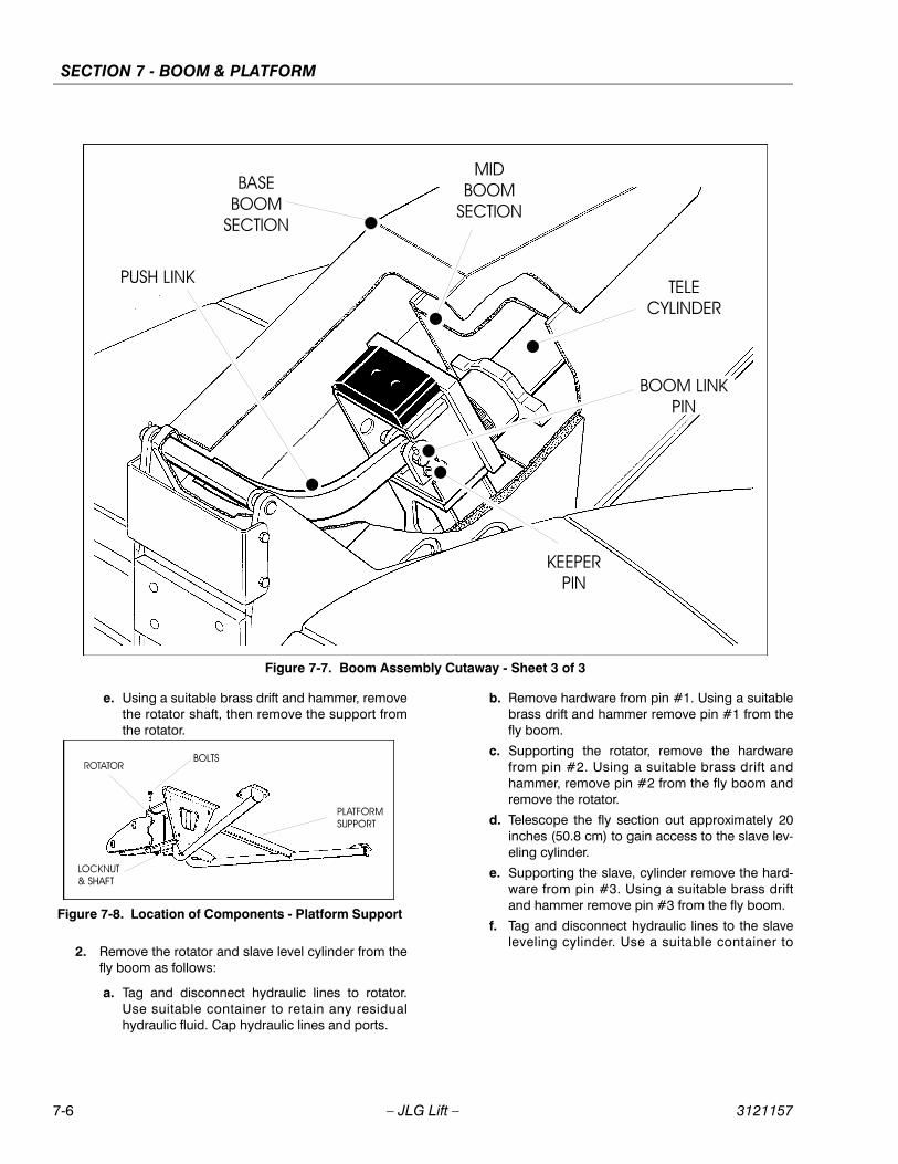
SECTION 7 - BOOM & PLATFORM
7-6 – JLG Lift – 3121157
e. Using a suitable brass drift and hammer, removethe rotator shaft, then remove the support fromthe rotator.
2. Remove the rotator and slave level cylinder from thefly boom as follows:
a. Tag and disconnect hydraulic lines to rotator.Use suitable container to retain any residualhydraulic fluid. Cap hydraulic lines and ports.
b. Remove hardware from pin #1. Using a suitablebrass drift and hammer remove pin #1 from thefly boom.
c. Supporting the rotator, remove the hardwarefrom pin #2. Using a suitable brass drift andhammer, remove pin #2 from the fly boom andremove the rotator.
d. Telescope the fly section out approximately 20inches (50.8 cm) to gain access to the slave lev-eling cylinder.
e. Supporting the slave, cylinder remove the hard-ware from pin #3. Using a suitable brass driftand hammer remove pin #3 from the fly boom.
f. Tag and disconnect hydraulic lines to the slaveleveling cylinder. Use a suitable container to
Figure 7-7. Boom Assembly Cutaway - Sheet 3 of 3
Figure 7-8. Location of Components - Platform Support
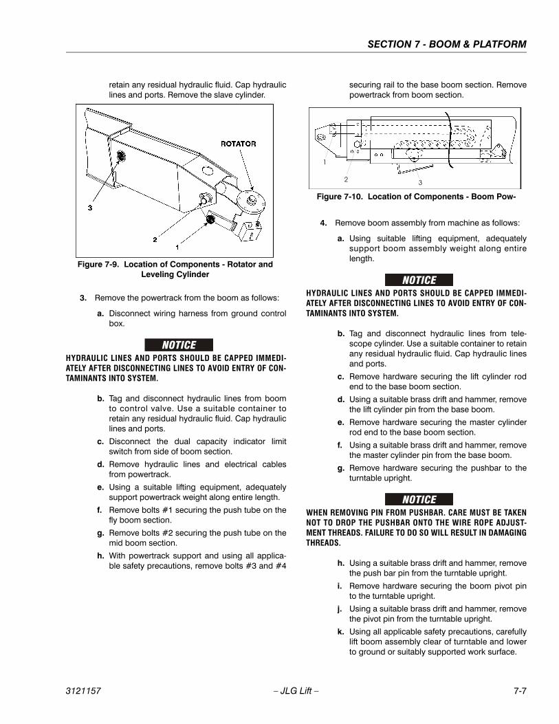
SECTION 7 - BOOM & PLATFORM
3121157 – JLG Lift – 7-7
retain any residual hydraulic fluid. Cap hydrauliclines and ports. Remove the slave cylinder.
3. Remove the powertrack from the boom as follows:
a. Disconnect wiring harness from ground controlbox.
HYDRAULIC LINES AND PORTS SHOULD BE CAPPED IMMEDI-ATELY AFTER DISCONNECTING LINES TO AVOID ENTRY OF CON-TAMINANTS INTO SYSTEM.
b. Tag and disconnect hydraulic lines from boomto control valve. Use a suitable container toretain any residual hydraulic fluid. Cap hydrauliclines and ports.
c. Disconnect the dual capacity indicator limitswitch from side of boom section.
d. Remove hydraulic lines and electrical cablesfrom powertrack.
e. Using a suitable lifting equipment, adequatelysupport powertrack weight along entire length.
f. Remove bolts #1 securing the push tube on thefly boom section.
g. Remove bolts #2 securing the push tube on themid boom section.
h. With powertrack support and using all applica-ble safety precautions, remove bolts #3 and #4
securing rail to the base boom section. Removepowertrack from boom section.
4. Remove boom assembly from machine as follows:
a. Using suitable lifting equipment, adequatelysupport boom assembly weight along entirelength.
HYDRAULIC LINES AND PORTS SHOULD BE CAPPED IMMEDI-ATELY AFTER DISCONNECTING LINES TO AVOID ENTRY OF CON-TAMINANTS INTO SYSTEM.
b. Tag and disconnect hydraulic lines from tele-scope cylinder. Use a suitable container to retainany residual hydraulic fluid. Cap hydraulic linesand ports.
c. Remove hardware securing the lift cylinder rodend to the base boom section.
d. Using a suitable brass drift and hammer, removethe lift cylinder pin from the base boom.
e. Remove hardware securing the master cylinderrod end to the base boom section.
f. Using a suitable brass drift and hammer, removethe master cylinder pin from the base boom.
g. Remove hardware securing the pushbar to theturntable upright.
WHEN REMOVING PIN FROM PUSHBAR. CARE MUST BE TAKENNOT TO DROP THE PUSHBAR ONTO THE WIRE ROPE ADJUST-MENT THREADS. FAILURE TO DO SO WILL RESULT IN DAMAGINGTHREADS.
h. Using a suitable brass drift and hammer, removethe push bar pin from the turntable upright.
i. Remove hardware securing the boom pivot pinto the turntable upright.
j. Using a suitable brass drift and hammer, removethe pivot pin from the turntable upright.
k. Using all applicable safety precautions, carefullylift boom assembly clear of turntable and lowerto ground or suitably supported work surface.
Figure 7-9. Location of Components - Rotator and Leveling Cylinder
Figure 7-10. Location of Components - Boom Pow-

SECTION 7 - BOOM & PLATFORM
7-8 – JLG Lift – 3121157
Disassembly of Boom Sections1. Remove hardware securing the push bar to aft end
of the telescope cylinder, then remove pin from cyl-inder.
2. Remove hardware securing the cover plate on thebottom front of the base boom section.
NOTE: Do not allow wire rope to rotate. This may damagethe wire rope.
3. Clamp both threaded ends of wire rope to preventrotation. Note: Do not clamp on threads. Removejam nuts and nuts which secure the wire ropeadjustments to the bottom front of the base boomsection.
4. Remove hardware securing the wire rope adjust-ment block to aft end of the base boom section andremove the block.
5. Remove hardware securing the telescope cylinderto aft end of the mid boom section.
WHEN REMOVING THE TELESCOPE CYLINDER FROM THE BOOM,IT MAY BE NECESSARY AT SOME POINT IN ORDER TO CLEARASSEMBLIES MOUNTED WITHIN THE BOOM. CARE MUST BETAKEN TO MOVE THE CYLINDER SLOWLY FROM THE BOOM.DAMAGE TO COMPONENTS MAY RESULT FROM FORCIBLEIMPACT WITH THESE ASSEMBLIES.
6. Remove bolts securing wire rope attach bar to top offly boom section.
7. Pull the telescope cylinder and wire ropes partiallyfrom aft end of the base boom section; secure thecylinder with a suitable sling and lifting device atapproximately the center of gravity.
8. Carefully remove the telescope cylinder and sheaveassembly. Place telescope cylinder on a suitabletrestle.
a. Remove hardware from the wear pads; removewear pads from cylinder.
b. Remove hardware from the wire rope guard;remove guard from cylinder.
c. Remove hardware from the sheave pin; removepin and sheave from cylinder.
9. Remove hardware which secures the wear pads tothe front of base boom section; remove wear padsfrom the top, sides and bottom of the base boomsection.
10. Using an overhead crane or suitable lifting device,remove mid and fly boom sections from base sec-tion. Note: When removing mid and fly boom sec-tions from base boom section, retract wire ropemust be dragged along with boom sections.
11. Remove hardware which secures the wear pads tothe aft end of mid boom section; remove the wearpads from the top, sides and bottom of the midboom section.
12. Remove hardware which secures the sheave guardsand sheave assemblies to mid boom section,remove sheave assemblies from mid boom section.
13. Remove hardware which secures the wear pads tothe front of mid boom section; remove wear padsfrom the top, sides and bottom of the mid boom sec-tion.
14. Using an overhead crane or suitable lifting device,remove fly boom section from mid section. Note:When removing fly boom section from mid boomsection, retract wire rope must be dragged alongwith fly boom section.
15. Remove hardware which secures the wear pads tothe aft end of fly boom section; remove wear padsfrom the top, sides and bottom of the fly boom sec-tion.
Figure 7-11. Disassembly of Sheave Assembly

SECTION 7 - BOOM & PLATFORM
3121157 – JLG Lift – 7-9
16. When removing wire rope from fly boom section,push the cable into fly boom. Route wire rope backthrough holes in the side of the fly boom section.
Inspection
NOTE: When inspecting pins and bearings Ref. to Pins andComposite Bearing Repair Guidelines in Section 2.
1. Inspect all sheaves (extend and retract wire ropesand telescope cylinder) for excessive groove wear,burrs or other damage. Replace sheaves as neces-sary.
NOTE: To check the size, contour and amount of wear, agroove gauge is used. Replace the sheave if wornas shown in the following drawing.
2. Inspect extend and retract wire rope sheave bear-ings for wear, scoring, or other damage, and forovality.
3. Inspect extend wire rope and retract wire ropesheave pins for scoring, tapering and ovality.Replace pins as necessary.
4. Inspect telescope cylinder sheave pin for scoring,tapering and ovality. Replace pins as necessary.
5. Inspect boom pivot pin for wear, scoring, taperingand ovality, or other damage. Replace pins as nec-essary.
6. Inspect telescope cylinder attach point for scoring,tapering and ovality. Replace pins as necessary.
7. Inspect upper lift cylinder attach pin for wear, scor-ing, tapering and ovality, or other damage. Ensurepin surfaces are protected prior to installation.Replace pins as necessary.
8. Inspect inner diameter of boom pivot bushing forscoring, distortion, wear, or other damage. Replacebearing as necessary.
9. Inspect all wear pads for excessive wear or otherdamage. Replace pads when worn to within 1/8 inch(3.2 mm) of threaded insert.
Figure 7-12. Disassembly Wire Rope Routing Proce-
Figure 7-13. Dimension of Sheaves When New
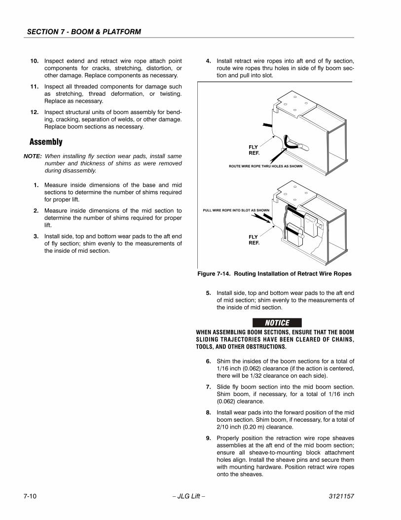
SECTION 7 - BOOM & PLATFORM
7-10 – JLG Lift – 3121157
10. Inspect extend and retract wire rope attach pointcomponents for cracks, stretching, distortion, orother damage. Replace components as necessary.
11. Inspect all threaded components for damage suchas stretching, thread deformation, or twisting.Replace as necessary.
12. Inspect structural units of boom assembly for bend-ing, cracking, separation of welds, or other damage.Replace boom sections as necessary.
Assembly
NOTE: When installing fly section wear pads, install samenumber and thickness of shims as were removedduring disassembly.
1. Measure inside dimensions of the base and midsections to determine the number of shims requiredfor proper lift.
2. Measure inside dimensions of the mid section todetermine the number of shims required for properlift.
3. Install side, top and bottom wear pads to the aft endof fly section; shim evenly to the measurements ofthe inside of mid section.
4. Install retract wire ropes into aft end of fly section,route wire ropes thru holes in side of fly boom sec-tion and pull into slot.
5. Install side, top and bottom wear pads to the aft endof mid section; shim evenly to the measurements ofthe inside of mid section.
WHEN ASSEMBLING BOOM SECTIONS, ENSURE THAT THE BOOMSLIDING TRAJECTORIES HAVE BEEN CLEARED OF CHAINS,TOOLS, AND OTHER OBSTRUCTIONS.
6. Shim the insides of the boom sections for a total of1/16 inch (0.062) clearance (if the action is centered,there will be 1/32 clearance on each side).
7. Slide fly boom section into the mid boom section.Shim boom, if necessary, for a total of 1/16 inch(0.062) clearance.
8. Install wear pads into the forward position of the midboom section. Shim boom, if necessary, for a total of2/10 inch (0.20 m) clearance.
9. Properly position the retraction wire rope sheavesassemblies at the aft end of the mid boom section;ensure all sheave-to-mounting block attachmentholes align. Install the sheave pins and secure themwith mounting hardware. Position retract wire ropesonto the sheaves.
Figure 7-14. Routing Installation of Retract Wire Ropes
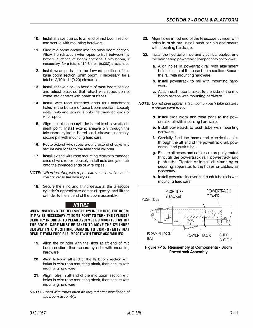
SECTION 7 - BOOM & PLATFORM
3121157 – JLG Lift – 7-11
10. Install sheave guards to aft end of mid boom sectionand secure with mounting hardware.
11. Slide mid boom section into the base boom section.Allow the retraction wire ropes to trail between thebottom surfaces of boom sections. Shim boom, ifnecessary, for a total of 1/16 inch (0.062) clearance.
12. Install wear pads into the forward position of thebase boom section. Shim boom, if necessary, for atotal of 2/10 inch (0.20) clearance.
13. Install sheave block to bottom of base boom sectionand adjust block so that retract wire ropes do notcome into contact with boom surfaces.
14. Install wire rope threaded ends thru attachmentholes in the bottom of base boom section. Looselyinstall nuts and jam nuts onto the threaded ends ofwire ropes.
15. Align the telescope cylinder barrel-to-sheave attach-ment point. Install extend sheave pin through thetelescope cylinder barrel and sheave assembly;secure pin with mounting hardware.
16. Route extend wire ropes around extend sheave andsecure wire ropes to the telescope cylinder.
17. Install extend wire rope mounting blocks to threadedends of wire ropes. Loosely install nuts and jam nutsonto the threaded ends of wire ropes.
NOTE: When installing wire ropes, care must be taken not totwist or cross the wire ropes.
18. Secure the sling and lifting device at the telescopecylinder’s approximate center of gravity, and lift thecylinder to the aft end of the boom assembly.
WHEN INSERTING THE TELESCOPE CYLINDER INTO THE BOOM,IT MAY BE NECESSARY AT SOME POINT TO TURN THE CYLINDERSLIGHTLY IN ORDER TO CLEAR ASSEMBLIES MOUNTED WITHINTHE BOOM. CARE MUST BE TAKEN TO MOVE THE CYLINDERSLOWLY INTO POSITION. DAMAGE TO COMPONENTS MAYRESULT FROM FORCIBLE IMPACT WITH THESE ASSEMBLIES.
19. Align the cylinder with the slots at aft end of midboom section, then secure cylinder with mountinghardware.
20. Align holes in aft end of the fly boom section withholes in wire rope mounting block, then secure withmounting hardware.
21. Align holes in aft end of the mid boom section withholes in wire rope mounting block, then secure withmounting hardware.
NOTE: Boom wire ropes must be torqued after installation ofthe boom assembly.
22. Align holes in rod end of the telescope cylinder withholes in push bar. Install push bar pin and securewith mounting hardware.
23. Install the hydraulic lines and electrical cables, andthe harnessing powertrack components as follows:
a. Align holes in powertrack rail with attachmentholes in side of the base boom section. Securethe rail with mounting hardware.
b. Install powertrack to rail with mounting hard-ware.
c. Attach push tube bracket to the side of the midboom section with mounting hardware.
NOTE: Do not over tighten attach bolt on push tube bracket.It should pivot freely.
d. Install slide block and wear pads to the pow-ertrack rail with mounting hardware.
e. Install powertrack to push tube with mountinghardware.
f. Carefully feed the hoses and electrical cablesthrough the aft end of the powertrack rail, pow-ertrack and push tube.
g. Ensure all hoses and cables are properly routedthrough the powertrack rail, powertrack andpush tube. Tighten or install all clamping orsecuring apparatus to the hoses or cables, asnecessary.
h. Install powertrack cover and push tube rods withmounting hardware.
Figure 7-15. Reassembly of Components - Boom Powertrack Assembly
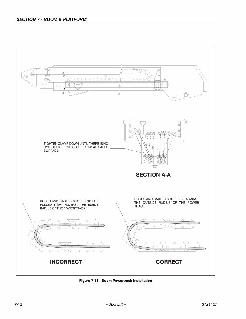
SECTION 7 - BOOM & PLATFORM
7-12 – JLG Lift – 3121157
Figure 7-16. Boom Powertrack Installation
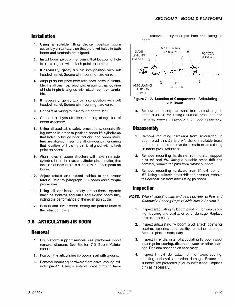
SECTION 7 - BOOM & PLATFORM
3121157 – JLG Lift – 7-13
Installation1. Using a suitable lifting device, position boom
assembly on turntable so that the pivot holes in bothboom and turntable are aligned.
2. Install boom pivot pin, ensuring that location of holein pin is aligned with attach point on turntable.
3. If necessary, gently tap pin into position with softheaded mallet. Secure pin mounting hardware.
4. Align push bar pivot hole with pivot holes in turnta-ble. Install push bar pivot pin, ensuring that locationof hole in pin is aligned with attach point on turnta-ble.
5. If necessary, gently tap pin into position with softheaded mallet. Secure pin mounting hardware.
6. Connect all wiring to the ground control box.
7. Connect all hydraulic lines running along side ofboom assembly.
8. Using all applicable safety precautions, operate lift-ing device in order to position boom lift cylinder sothat holes in the cylinder rod end and boom struc-ture are aligned. Insert the lift cylinder pin, ensuringthat location of hole in pin is aligned with attachpoint on boom.
9. Align holes in boom structure with hole in mastercylinder. Insert the master cylinder pin, ensuring thatlocation of hole in pin is aligned with attach point onboom.
10. Adjust retract and extend cables to the propertorque. Refer to paragraph 2-6, boom cable torqueprocedures.
11. Using all applicable safety precautions, operatemachine systems and raise and extend boom fully,noting the performance of the extension cycle.
12. Retract and lower boom, noting the performance ofthe retraction cycle.
7.6 ARTICULATING JIB BOOM
Removal1. For platform/support removal see platform/support
removal diagram. See Section 7.5, Boom Mainte-nance.
2. Position the articulating jib boom level with ground.
3. Remove mounting hardware from slave leveling cyl-inder pin #1. Using a suitable brass drift and ham-
mer, remove the cylinder pin from articulating jibboom.
4. Remove mounting hardware from articulating jibboom pivot pin #2. Using a suitable brass drift andhammer, remove the pivot pin from boom assembly.
Disassembly1. Remove mounting hardware from articulating jib
boom pivot pins #3 and #4. Using a suitable brassdrift and hammer, remove the pins from articulatingjib boom pivot weldment.
2. Remove mounting hardware from rotator supportpins #5 and #6. Using a suitable brass drift andhammer, remove the pins from rotator support.
3. Remove mounting hardware from lift cylinder pin#7. Using a suitable brass drift and hammer, removethe cylinder pin from articulating jib boom.
Inspection
NOTE: When inspecting pins and bearings refer to Pins andComposite Bearing Repair Guidelines in Section 2.
1. Inspect articulating fly boom pivot pin for wear, scor-ing, tapering and ovality, or other damage. Replacepins as necessary.
2. Inspect articulating fly boom pivot attach points forscoring, tapering and ovality, or other damage.Replace pins as necessary.
3. Inspect inner diameter of articulating fly boom pivotbearings for scoring, distortion, wear, or other dam-age. Replace bearings as necessary.
4. Inspect lift cylinder attach pin for wear, scoring,tapering and ovality, or other damage. Ensure pinsurfaces are protected prior to installation. Replacepins as necessary.
Figure 7-17. Location of Components - Articulating Jib Boom
SECTION 7 - BOOM & PLATFORM
7-14 – JLG Lift – 3121157
5. Inspect inner diameter of rotator attach point bear-ings for scoring, distortion, wear, or other damage.Replace bearing as necessary.
6. Inspect all threaded components for damage suchas stretching, thread deformation, or twisting.Replace as necessary.
7. Inspect structural units of articulating jib boomassembly for bending, cracking, separation ofwelds, or other damage. Replace boom sections asnecessary.
Assembly
NOTE: For location of components See Section 7-17., Loca-tion of Components - Articulating Jib Boom.
1. Align lift cylinder with attach holes in articulating jibboom. Using a soft head mallet, install cylinder pin#7 into articulating jib boom and secure with mount-ing hardware.
2. Align rotator support with attach hole in articulatingjib boom. Using a soft head mallet, install rotatorsupport pin #6 into articulating jib boom and securewith mounting hardware.
3. Align bottom tubes with attach holes in rotator sup-port. Using a soft head mallet, install rotator supportpin #5 into articulating jib boom and secure withmounting hardware.
4. Align articulating jib boom with attach hole in articu-lating jib boom pivot weldment. Using a soft headmallet, install rotator support pin #4 into articulatingjib boom and secure with mounting hardware.
5. Align bottom tubes with attach holes in articulatingjib boom pivot weldment. Using a soft head mallet,install rotator support pin #3 into articulating jibboom pivot weldment and secure with mountinghardware.
6. Align articulating jib boom pivot weldment withattach holes in fly boom assembly. Using a soft headmallet, install pivot pin #2 into fly boom assemblyand secure with mounting hardware.
7. Align the slave leveling cylinder with attach holes inarticulating jib boom pivot weldment. Using a softhead mallet, install slave leveling cylinder pin #1into articulating jib boom pivot weldment and securewith mounting hardware.
7.7 LIMIT SWITCH ADJUSTMENTAdjust switches and cam valve as shown in Limit SwitchesAdjustment.

SECTION 7 - BOOM & PLATFORM
3121157 – JLG Lift – 7-15
Figure 7-18. Limit Switches Adjustments
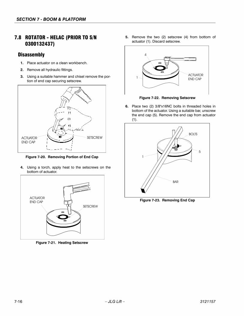
SECTION 7 - BOOM & PLATFORM
7-16 – JLG Lift – 3121157
7.8 ROTATOR - HELAC (PRIOR TO S/N 0300132437)
Disassembly1. Place actuator on a clean workbench.
2. Remove all hydraulic fittings.
3. Using a suitable hammer and chisel remove the por-tion of end cap securing setscrew.
4. Using a torch, apply heat to the setscrews on thebottom of actuator.
5. Remove the two (2) setscrew (4) from bottom ofactuator (1). Discard setscrew.
6. Place two (2) 3/8"x16NC bolts in threaded holes inbottom of the actuator. Using a suitable bar, unscrewthe end cap (5). Remove the end cap from actuator(1).
Figure 7-20. Removing Portion of End Cap
Figure 7-21. Heating Setscrew
Figure 7-22. Removing Setscrew
Figure 7-23. Removing End Cap
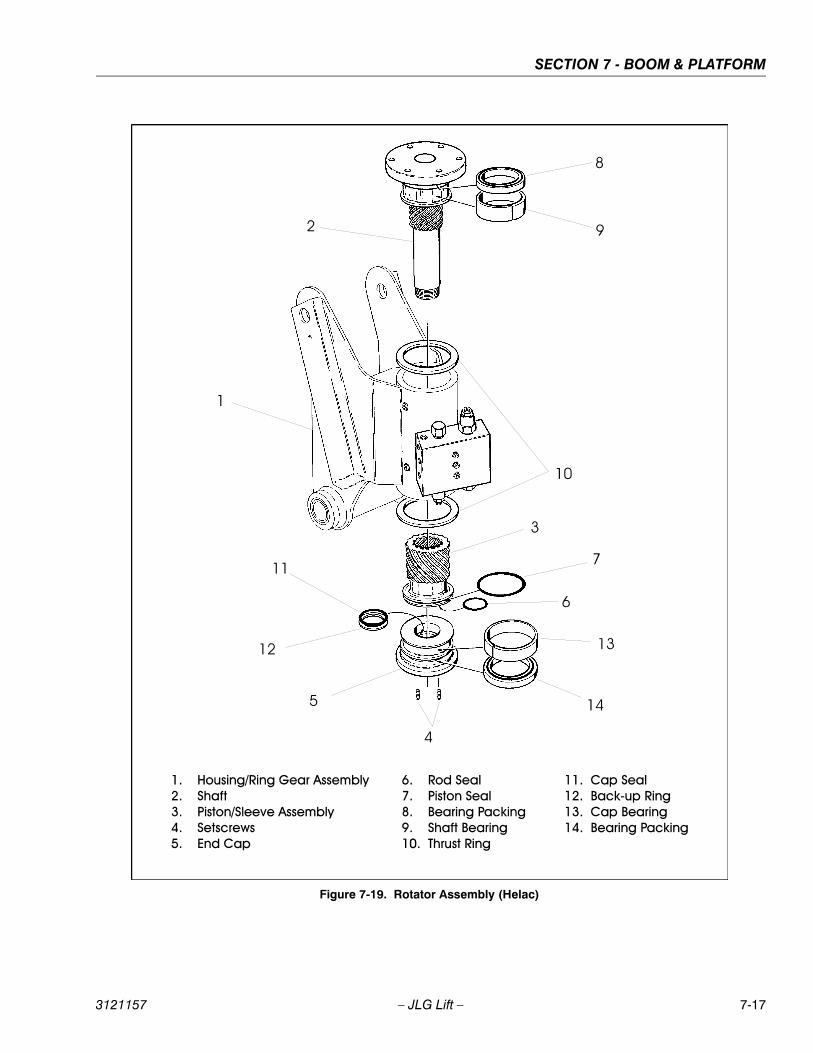
SECTION 7 - BOOM & PLATFORM
3121157 – JLG Lift – 7-17
Figure 7-19. Rotator Assembly (Helac)
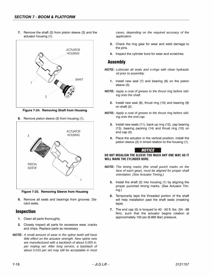
SECTION 7 - BOOM & PLATFORM
7-18 – JLG Lift – 3121157
7. Remove the shaft (2) from piston sleeve (3) and theactuator housing (1).
8. Remove piston sleeve (3) from housing (1).
9. Remove all seals and bearings from grooves. Dis-card seals.
Inspection1. Clean all parts thoroughly.
2. Closely inspect all parts for excessive wear, cracksand chips. Replace parts as necessary.
NOTE: A small amount of wear in the spline teeth will havelittle effect on the actuator strength. New spline setsare manufactured with a backlash of about 0.005 in.per mating set. After long service, a backlash ofabout 0.015 per set may still be acceptable in most
cases, depending on the required accuracy of theapplication.
3. Check the ring gear for wear and weld damage tothe pins.
4. Inspect the cylinder bore for wear and scratches.
Assembly
NOTE: Lubricate all seals and o-rings with clean hydraulicoil prior to assembly.
1. Install new seal (7) and bearing (6) on the pistonsleeve (3).
NOTE: Apply a coat of grease to the thrust ring before slid-ing onto the shaft.
2. Install new seal (8), thrust ring (10) and bearing (9)on shaft (2).
NOTE: Apply a coat of grease to the thrust ring before slid-ing onto the end cap.
3. Install new seals (11), back-up ring (12), cap bearing(13), bearing packing (14) and thrust ring (10) onend cap (5).
4. Place the actuator in the vertical position, install thepiston sleeve (3) in timed relation to the housing (1).
DO NOT MISALIGN THE SLEEVE TOO MUCH ANY ONE WAY, AS ITWILL MARK THE CYLINDER BORE.
NOTE: The timing marks (the small punch marks on theface of each gear), must be aligned for proper shaftorientation. (See Actuator Timing.)
5. Install the shaft (2) into housing (1) by aligning theproper punched timing marks. (See Actuator Tim-ing.)
6. Temporarily tape the threaded portion of the shaftwill help installation past the shaft seals (maskingtape).
7. The end cap (5) is torqued to 40 - 50 ft. lbs. (54 - 68Nm), such that the actuator begins rotation atapproximately 100 psi (6.895 Bar) pressure.
Figure 7-24. Removing Shaft from Housing
Figure 7-25. Removing Sleeve from Housing
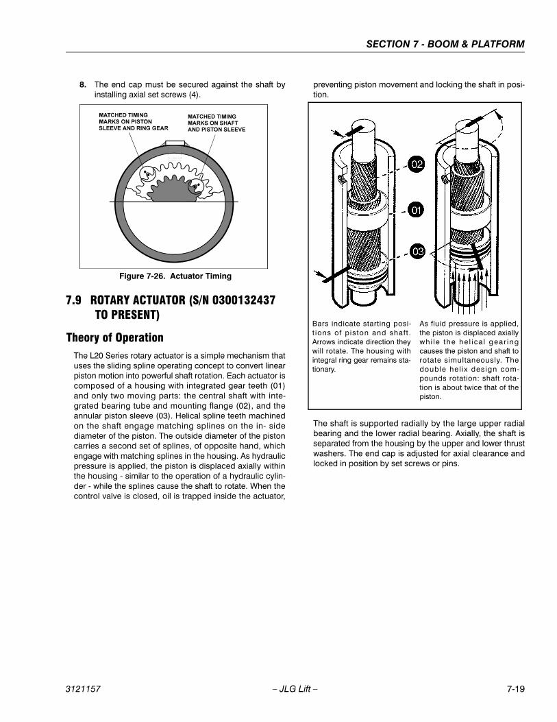
SECTION 7 - BOOM & PLATFORM
3121157 – JLG Lift – 7-19
8. The end cap must be secured against the shaft byinstalling axial set screws (4).
7.9 ROTARY ACTUATOR (S/N 0300132437 TO PRESENT)
Theory of OperationThe L20 Series rotary actuator is a simple mechanism thatuses the sliding spline operating concept to convert linearpiston motion into powerful shaft rotation. Each actuator iscomposed of a housing with integrated gear teeth (01)and only two moving parts: the central shaft with inte-grated bearing tube and mounting flange (02), and theannular piston sleeve (03). Helical spline teeth machinedon the shaft engage matching splines on the in- sidediameter of the piston. The outside diameter of the pistoncarries a second set of splines, of opposite hand, whichengage with matching splines in the housing. As hydraulicpressure is applied, the piston is displaced axially withinthe housing - similar to the operation of a hydraulic cylin-der - while the splines cause the shaft to rotate. When thecontrol valve is closed, oil is trapped inside the actuator,
preventing piston movement and locking the shaft in posi-tion.
The shaft is supported radially by the large upper radialbearing and the lower radial bearing. Axially, the shaft isseparated from the housing by the upper and lower thrustwashers. The end cap is adjusted for axial clearance andlocked in position by set screws or pins.
Figure 7-26. Actuator Timing
Bars indicate starting posi-t ions of piston and shaft .Arrows indicate direction theywill rotate. The housing withintegral ring gear remains sta-tionary.
As fluid pressure is applied,the piston is displaced axiallywhi le the he l ica l gear ingcauses the piston and shaft torotate simultaneously. Thedouble hel ix design com-pounds rotation: shaft rota-tion is about twice that of thepiston.
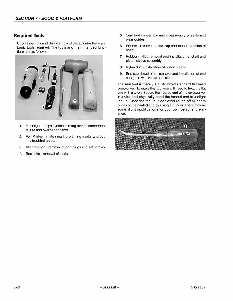
SECTION 7 - BOOM & PLATFORM
7-20 – JLG Lift – 3121157
Required ToolsUpon assembly and disassembly of the actuator there arebasic tools required. The tools and their intended func-tions are as follows:
1. Flashlight - helps examine timing marks, componentfailure and overall condition.
2. Felt Marker - match mark the timing marks and out-line troubled areas.
3. Allen wrench - removal of port plugs and set screws.
4. Box knife - removal of seals.
5. Seal tool - assembly and disassembly of seals andwear guides.
6. Pry bar - removal of end cap and manual rotation ofshaft.
7. Rubber mallet- removal and installation of shaft andpiston sleeve assembly.
8. Nylon drift - installation of piston sleeve
9. End cap dowel pins - removal and installation of endcap (sold with Helac seal kit).
The seal tool is merely a customized standard flat headscrewdriver. To make this tool you will need to heat the flatend with a torch. Secure the heated end of the screwdriverin a vice and physically bend the heated end to a slightradius. Once the radius is achieved round off all sharpedges of the heated end by using a grinder. There may besome slight modifications for your own personal prefer-ence.
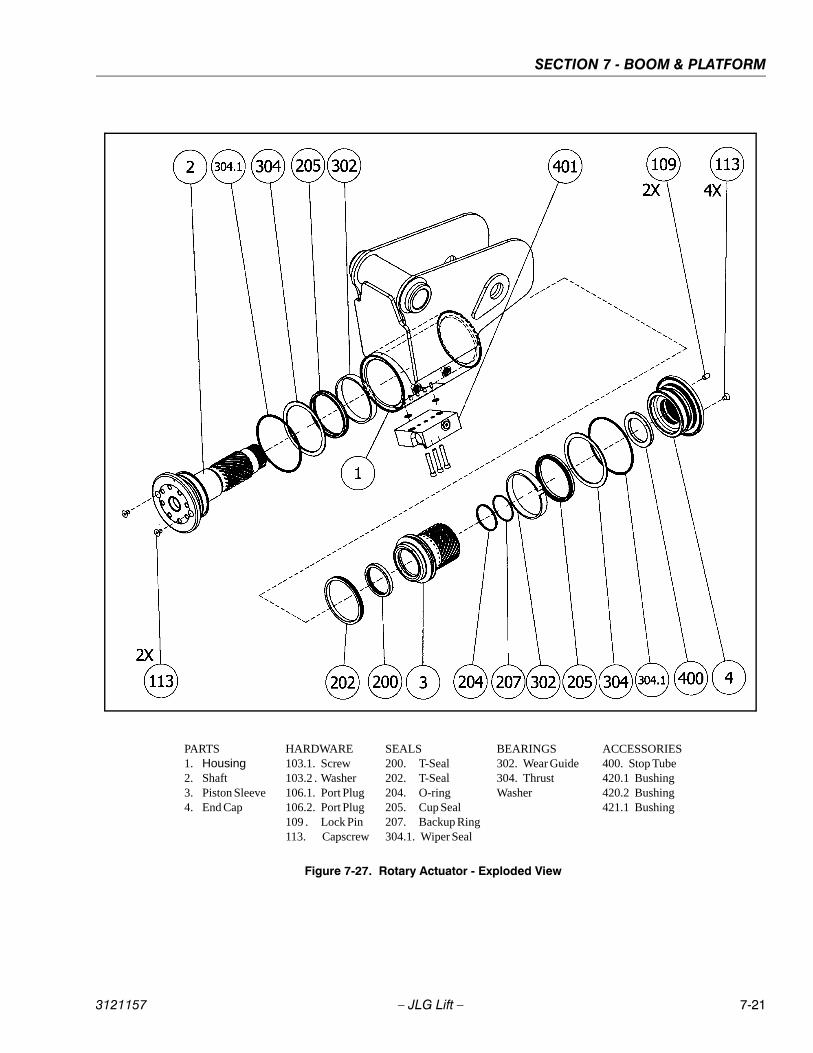
SECTION 7 - BOOM & PLATFORM
3121157 – JLG Lift – 7-21
PARTS1. Housing 2. Shaft 3. Piston Sleeve4. End Cap
HARDWARE103.1. Screw103.2 . Washer106.1. Port Plug106.2. Port Plug109 . Lock Pin113. Capscrew
SEALS200. T-Seal202. T-Seal204. O-ring205. Cup Seal207. Backup Ring304.1. Wiper Seal
BEARINGS302. Wear Guide304. Thrust Washer
ACCESSORIES400. Stop Tube420.1 Bushing420.2 Bushing421.1 Bushing
Figure 7-27. Rotary Actuator - Exploded View
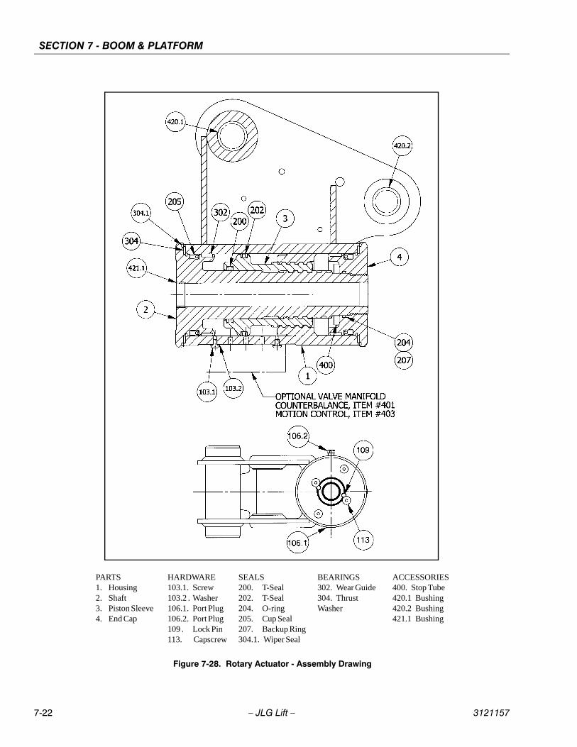
SECTION 7 - BOOM & PLATFORM
7-22 – JLG Lift – 3121157
PARTS1. Housing 2. Shaft 3. Piston Sleeve4. End Cap
HARDWARE103.1. Screw103.2 . Washer106.1. Port Plug106.2. Port Plug109 . Lock Pin113. Capscrew
SEALS200. T-Seal202. T-Seal204. O-ring205. Cup Seal207. Backup Ring304.1. Wiper Seal
BEARINGS302. Wear Guide304. Thrust Washer
ACCESSORIES400. Stop Tube420.1 Bushing420.2 Bushing421.1 Bushing
Figure 7-28. Rotary Actuator - Assembly Drawing
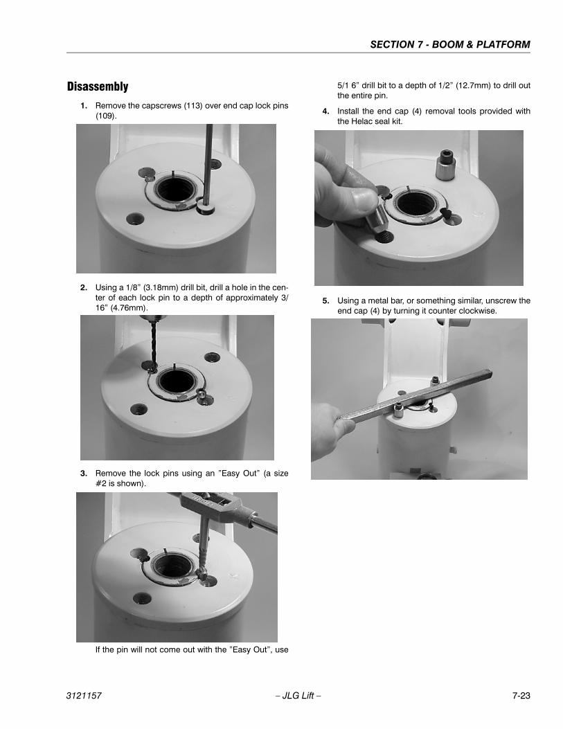
SECTION 7 - BOOM & PLATFORM
3121157 – JLG Lift – 7-23
Disassembly1. Remove the capscrews (113) over end cap lock pins
(109).
2. Using a 1/8” (3.18mm) drill bit, drill a hole in the cen-ter of each lock pin to a depth of approximately 3/16” (4.76mm).
3. Remove the lock pins using an ”Easy Out” (a size#2 is shown).
If the pin will not come out with the ”Easy Out”, use
5/1 6” drill bit to a depth of 1/2” (12.7mm) to drill outthe entire pin.
4. Install the end cap (4) removal tools provided withthe Helac seal kit.
5. Using a metal bar, or something similar, unscrew theend cap (4) by turning it counter clockwise.

SECTION 7 - BOOM & PLATFORM
7-24 – JLG Lift – 3121157
6. Remove the end cap (4) and set aside for laterinspection.
7. Remove the stop tube if included. The stop tube isan available option to limit the rotation of the actua-tor.
8. Every actuator has timing marks for proper engage-ment.
9. Prior to removing the shaft, (2), use a felt marker toclearly indicate the timing marks between shaft andpiston. This will greatly simplify timing during assem-bly.
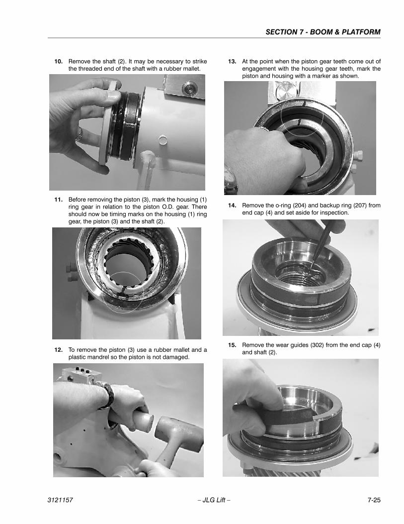
SECTION 7 - BOOM & PLATFORM
3121157 – JLG Lift – 7-25
10. Remove the shaft (2). It may be necessary to strikethe threaded end of the shaft with a rubber mallet.
11. Before removing the piston (3), mark the housing (1)ring gear in relation to the piston O.D. gear. Thereshould now be timing marks on the housing (1) ringgear, the piston (3) and the shaft (2).
12. To remove the piston (3) use a rubber mallet and aplastic mandrel so the piston is not damaged.
13. At the point when the piston gear teeth come out ofengagement with the housing gear teeth, mark thepiston and housing with a marker as shown.
14. Remove the o-ring (204) and backup ring (207) fromend cap (4) and set aside for inspection.
15. Remove the wear guides (302) from the end cap (4)and shaft (2).
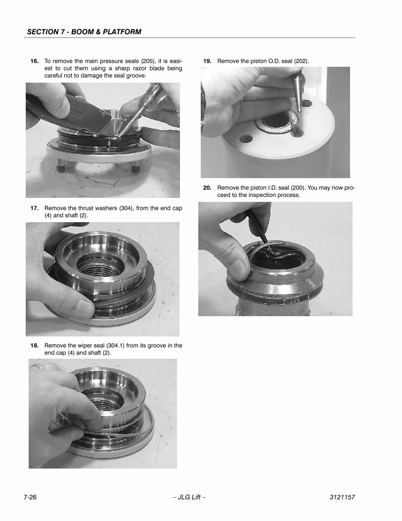
SECTION 7 - BOOM & PLATFORM
7-26 – JLG Lift – 3121157
16. To remove the main pressure seals (205), it is easi-est to cut them using a sharp razor blade beingcareful not to damage the seal groove.
17. Remove the thrust washers (304), from the end cap(4) and shaft (2).
18. Remove the wiper seal (304.1) from its groove in theend cap (4) and shaft (2).
19. Remove the piston O.D. seal (202).
20. Remove the piston I.D. seal (200). You may now pro-ceed to the inspection process.
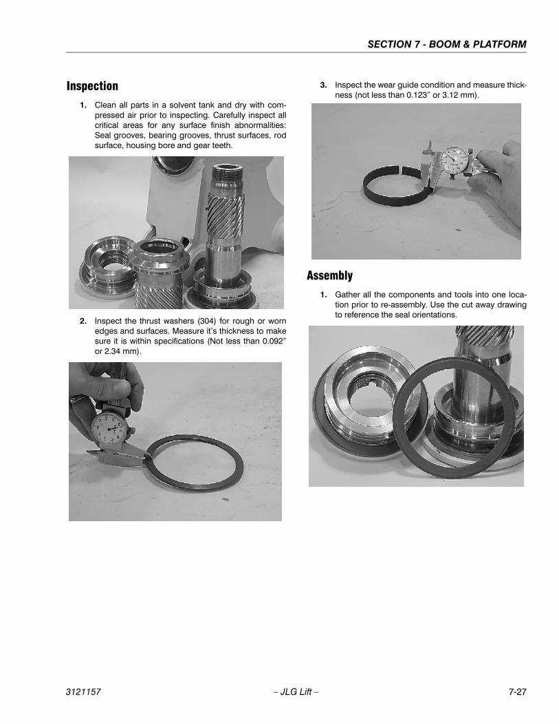
SECTION 7 - BOOM & PLATFORM
3121157 – JLG Lift – 7-27
Inspection1. Clean all parts in a solvent tank and dry with com-
pressed air prior to inspecting. Carefully inspect allcritical areas for any surface finish abnormalities:Seal grooves, bearing grooves, thrust surfaces, rodsurface, housing bore and gear teeth.
2. Inspect the thrust washers (304) for rough or wornedges and surfaces. Measure it’s thickness to makesure it is within specifications (Not less than 0.092”or 2.34 mm).
3. Inspect the wear guide condition and measure thick-ness (not less than 0.123” or 3.12 mm).
Assembly1. Gather all the components and tools into one loca-
tion prior to re-assembly. Use the cut away drawingto reference the seal orientations.

SECTION 7 - BOOM & PLATFORM
7-28 – JLG Lift – 3121157
2. Install the thrust washer (304) onto shaft (2) and endcap (4).
3. Install the wiper seal (304.1/green 0-ring) into it’sgroove on the shaft (2) and end cap (4) around theoutside edge of the thrust washer (304).
4. Using a seal tool install the main pressure seal (205)onto shaft (2) and end cap (4). Use the seal tool in acircular motion.
5. Install the wear guide (302) on the end cap (4) andshaft (2).
6. Install the inner T-seal (200) into the piston (3) usinga circular motion.
Install the outer T-seal (202) by stretching it aroundthe groove in a circular motion.
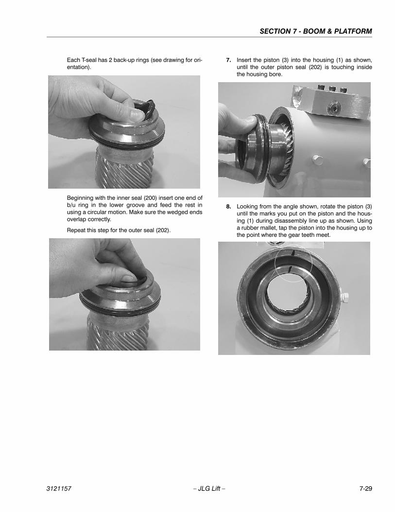
SECTION 7 - BOOM & PLATFORM
3121157 – JLG Lift – 7-29
Each T-seal has 2 back-up rings (see drawing for ori-entation).
Beginning with the inner seal (200) insert one end ofb/u ring in the lower groove and feed the rest inusing a circular motion. Make sure the wedged endsoverlap correctly.
Repeat this step for the outer seal (202).
7. Insert the piston (3) into the housing (1) as shown,until the outer piston seal (202) is touching insidethe housing bore.
8. Looking from the angle shown, rotate the piston (3)until the marks you put on the piston and the hous-ing (1) during disassembly line up as shown. Usinga rubber mallet, tap the piston into the housing up tothe point where the gear teeth meet.
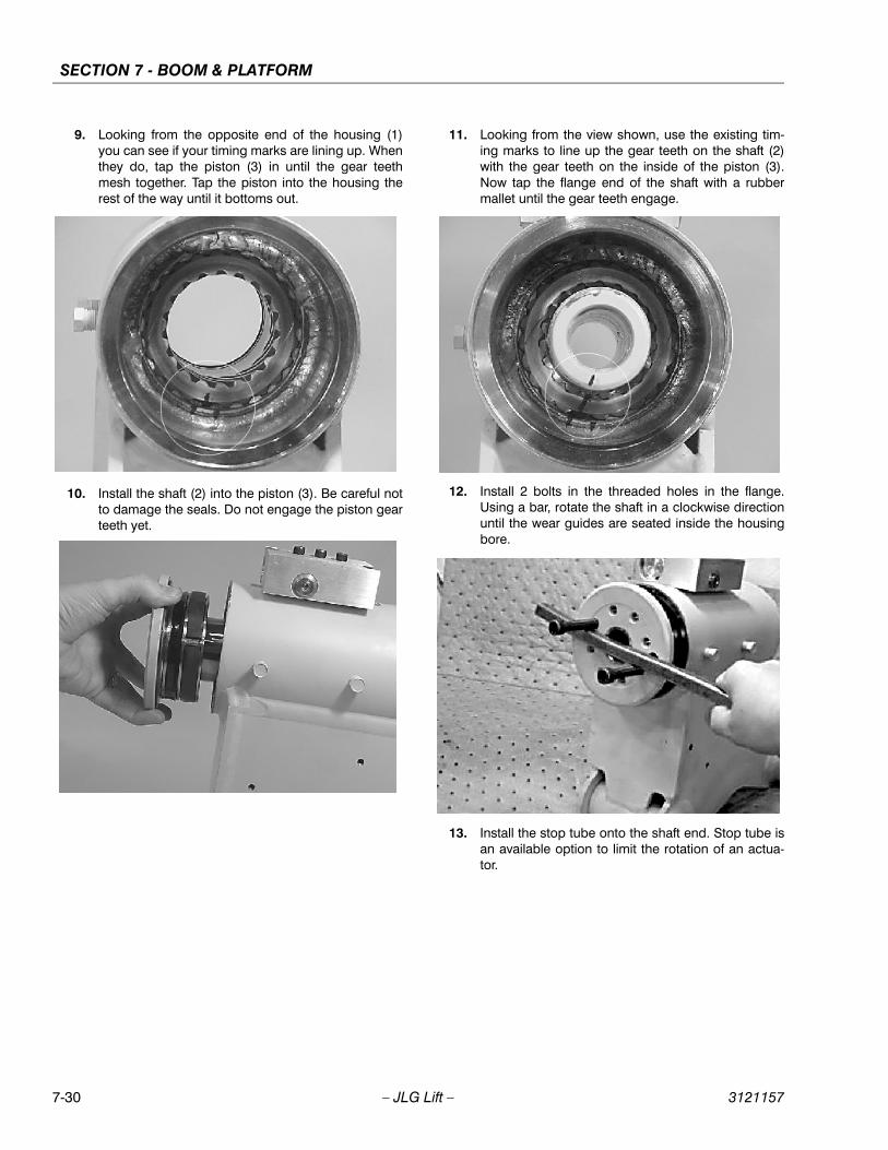
SECTION 7 - BOOM & PLATFORM
7-30 – JLG Lift – 3121157
9. Looking from the opposite end of the housing (1)you can see if your timing marks are lining up. Whenthey do, tap the piston (3) in until the gear teethmesh together. Tap the piston into the housing therest of the way until it bottoms out.
10. Install the shaft (2) into the piston (3). Be careful notto damage the seals. Do not engage the piston gearteeth yet.
11. Looking from the view shown, use the existing tim-ing marks to line up the gear teeth on the shaft (2)with the gear teeth on the inside of the piston (3).Now tap the flange end of the shaft with a rubbermallet until the gear teeth engage.
12. Install 2 bolts in the threaded holes in the flange.Using a bar, rotate the shaft in a clockwise directionuntil the wear guides are seated inside the housingbore.
13. Install the stop tube onto the shaft end. Stop tube isan available option to limit the rotation of an actua-tor.

SECTION 7 - BOOM & PLATFORM
3121157 – JLG Lift – 7-31
14. Coat the threads on the end of the shaft with anti-seize grease to prevent galling.
15. Install the 0-ring (204) and back-up ring (207) intothe inner seal groove on the end cap (4).
16. Thread the end cap (4) onto the shaft (2) end. Makesure the wear guide stays in place on the end cap asit is threaded into the housing (1).
17. Tighten the end cap (4). In most cases the originalholes for the lock pins will line up.
18. Place the lock pins (109) provided in the Helac sealkit in the holes with the dimple side up. Then, usinga punch, tap the lock pins to the bottom of the hole.
19. Insert the set screws (113) over the lock pins.Tighten them to 25 in. lbs. (2.825 Nm).
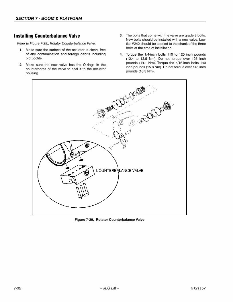
SECTION 7 - BOOM & PLATFORM
7-32 – JLG Lift – 3121157
Installing Counterbalance ValveRefer to Figure 7-29., Rotator Counterbalance Valve.
1. Make sure the surface of the actuator is clean, freeof any contamination and foreign debris includingold Loctite.
2. Make sure the new valve has the O-rings in thecounterbores of the valve to seal it to the actuatorhousing.
3. The bolts that come with the valve are grade 8 bolts.New bolts should be installed with a new valve. Loc-tite #242 should be applied to the shank of the threebolts at the time of installation.
4. Torque the 1/4-inch bolts 110 to 120 inch pounds(12.4 to 13.5 Nm). Do not torque over 125 inchpounds (14.1 Nm). Torque the 5/16-inch bolts 140inch pounds (15.8 Nm). Do not torque over 145 inchpounds (16.3 Nm).
Figure 7-29. Rotator Counterbalance Valve
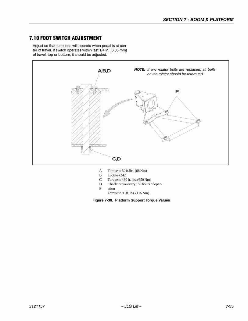
SECTION 7 - BOOM & PLATFORM
3121157 – JLG Lift – 7-33
7.10 FOOT SWITCH ADJUSTMENTAdjust so that functions will operate when pedal is at cen-ter of travel. If switch operates within last 1/4 in. (6.35 mm)of travel, top or bottom, it should be adjusted.
A,B,D
C,D
E
ABCDE
Torque to 50 ft.lbs. (68 Nm)Loctite #242Torque to 480 ft. lbs. (650 Nm)Check torque every 150 hours of oper-ationTorque to 85 ft. lbs. (115 Nm)
Figure 7-30. Platform Support Torque Values
NOTE: If any rotator bolts are replaced, all boltson the rotator should be retorqued.

SECTION 7 - BOOM & PLATFORM
7-34 – JLG Lift – 3121157
NOTES:
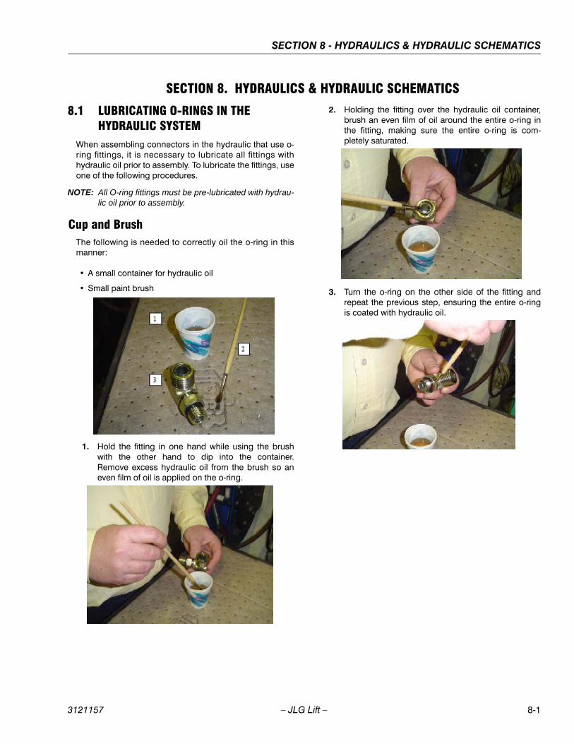
SECTION 8 - HYDRAULICS & HYDRAULIC SCHEMATICS
3121157 – JLG Lift – 8-1
SECTION 8. HYDRAULICS & HYDRAULIC SCHEMATICS
8.1 LUBRICATING O-RINGS IN THE HYDRAULIC SYSTEM
When assembling connectors in the hydraulic that use o-ring fittings, it is necessary to lubricate all fittings withhydraulic oil prior to assembly. To lubricate the fittings, useone of the following procedures.
NOTE: All O-ring fittings must be pre-lubricated with hydrau-lic oil prior to assembly.
Cup and BrushThe following is needed to correctly oil the o-ring in thismanner:
• A small container for hydraulic oil
• Small paint brush
1. Hold the fitting in one hand while using the brushwith the other hand to dip into the container.Remove excess hydraulic oil from the brush so aneven film of oil is applied on the o-ring.
2. Holding the fitting over the hydraulic oil container,brush an even film of oil around the entire o-ring inthe fitting, making sure the entire o-ring is com-pletely saturated.
3. Turn the o-ring on the other side of the fitting andrepeat the previous step, ensuring the entire o-ringis coated with hydraulic oil.

SECTION 8 - HYDRAULICS & HYDRAULIC SCHEMATICS
8-2 – JLG Lift – 3121157
Dip Method
NOTE: This method works best with Face Seal o-rings, butwill work for all o-ring fitting types.
The following is needed to correctly oil the o-ring in thismanner:
• A small leak proof container
• Sponge cut to fit inside the container
• A small amount of hydraulic oil to saturate the sponge.
1. Place the sponge inside the container and addhydraulic oil to the sponge until it is fully saturated.
2. Dip the fitting into the sponge using firm pressure.Upon lifting the fitting, a small droplet will form anddrip from the bottom of the fitting. This should signifyan even coating of oil on the fitting.
3. O-ring Boss type fittings will require more pressurein able to immerse more of the fitting into the satu-rated sponge. This will also cause more oil to be dis-persed from the sponge.
Spray MethodThis method requires a pump or trigger spray bottle.
1. Fill the spray bottle with hydraulic oil.
2. Hold the fitting over a suitable catch can.
3. Spray the entire o-ring surface with a medium coatof oil.
Brush-on MethodThis method requires a sealed bottle brush.
1. Fill the bottle with hydraulic oil.
2. Using slight pressure to the body of the spray bottle,invert the bottle so the brush end is in the downwardposition.
3. Brush hydraulic oil on the entire o-ring, applying aneven coat of oil.
SECTION 8 - HYDRAULICS & HYDRAULIC SCHEMATICS
3121157 – JLG Lift – 8-3
8.2 VALVES - THEORY OF OPERATION
Solenoid Control ValveControl valves used are four-way three-position solenoidvalves of the sliding spool design. When a circuit is acti-vated and the control valve solenoid energizes, the spoolis shifted and the corresponding work port opens to per-mit oil flow to the component in the selected circuit withthe opposite work port opening to reservoir. Once the cir-cuit is deactivated (control returned to neutral) the valvespool returns to neutral (center) and oil flow is thendirected through the valve body and returns to reservoir. Atypical control valve consist of the valve body, slidingspool, and two solenoid assemblies. The spool ismachine fitted in the bore of the valve body. Lands on thespool divide the bore into various chambers, which, whenthe spool is shifted, align with corresponding ports in thevalve body open to common flow. At the same time otherports would be blocked to flow. The spool is spring loadedto center position, therefore when the control is released,the spool automatically returns to neutral, prohibiting anyflow through the circuit.
Relief ValvesRelief valves are installed at various points within thehydraulic system to protect associated systems and com-ponents against excessive pressure. Excessive pressurecan be developed when a cylinder reaches its limit oftravel and the flow of pressurized fluid continues from thesystem control. The relief valve provides an alternate pathfor the continuing flow from the pump, thus preventingrupture of the cylinder, hydraulic line or fitting. Completefailure of the system pump is also avoided by relieving cir-cuit pressure. The relief valve is installed in the circuitbetween the pump outlet (pressure line) and the cylinderof the circuit, generally as an integral part of the systemvalve bank. Relief pressures are set slightly higher thanthe load requirement, with the valve diverting excesspump delivery back to the reservoir when operating pres-sure of the component is reached.
8.3 CYLINDERS - THEORY OF OPERATION
Systems Incorporating Double Acting CylindersCylinders are of the double acting type. Systems incorpo-rating double acting cylinders are as follows: Slave Level,Master Level, Lift, Telescope, Articulating Jib Boom Lift. Adouble acting cylinder is one that requires oil flow to oper-ate the cylinder rod in both directions. Directing oil (byactuating the corresponding control valve to the pistonside of the cylinder) forces the piston to travel toward therod end of the barrel, extending the cylinder rod (pistonattached to rod). When the oil flow is stopped, movementof rod will stop. By directing oil to the rod side of the cylin-der, the piston will be forced in the opposite direction andthe cylinder rod will retract.
Systems Incorporating Holding ValvesHolding valves are used in the - Lift, Telescope, Lockout,Slave Level and Articulating Jib Boom Lift circuits to pre-vent retraction of the cylinder rod should a hydraulic linerupture or a leak develop between the cylinder and itsrelated control valve.
8.4 CYLINDER CHECKING PROCEDURE
NOTE: Cylinder check must be performed anytime a systemcomponent is replaced or when improper systemoperation is suspected.
Cylinders Without Counterbalance ValvesMaster Cylinder and Steer Cylinder
1. Using all applicable safety precautions, activateengine and fully extend cylinder to be checked. Shutdown engine.
2. Carefully disconnect hydraulic hoses from retractport of cylinder. There will be some initial weeping ofhydraulic fluid which can be caught in a suitablecontainer. After the initial discharge, there should beno further drainage from the retract port.
3. Activate engine and extend cylinder.
4. If cylinder retract port leakage is less than 6-8 dropsper minute, carefully reconnect hose to port andretract cylinder. If leakage continues at a rate of 6-8drops per minute or more, cylinder repair must bemade.
5. With cylinder fully retracted, shut down engine andcarefully disconnect hydraulic hose from cylinderextend port.
6. Activate engine and retract cylinder. Check extendport for leakage.
SECTION 8 - HYDRAULICS & HYDRAULIC SCHEMATICS
8-4 – JLG Lift – 3121157
7. If extend port leakage is less than 6-8 drops per min-ute, carefully reconnect hose to extend port, thanactivate cylinder through one complete cycle andcheck for leaks. If leakage continues at a rate of 6-8drops per minute or more, cylinder repairs must bemade.
Cylinders With Single Counterbalance ValveLift Cylinder
OPERATE ALL FUNCTIONS FROM GROUND CONTROL STATIONONLY.
1. Using all applicable safety precautions, activatehydraulic system.
WHEN WORKING ON THE MAIN LIFT CYLINDER, RAISE THEBOOM TO HORIZONTAL AND PLACE A BOOM PROP APPROXI-MATELY 1 INCH (2.54 CM) BELOW THE MAIN BOOM. DO NOTWORK ON THE CYLINDER WITHOUT A SUITABLE PROP IN PLACE.
2. Shut down hydraulic system and allow machine tosit for 10-15 minutes. If machine is equipped withbang-bang or proportional control valves, turn IGNI-TION SWITCH to ON, move control switch or leverfor applicable cylinder in each direction, then turnIGNITION SWITCH to OFF. If machine is equippedwith hydraulic control valves, move control lever forapplicable cylinder in each direction. This is done torelieve pressure in the hydraulic lines. Carefullyremove hydraulic hoses from appropriate cylinderport block.
3. There will be initial weeping of hydraulic fluid, whichcan be caught in a suitable container. After the initialdischarge, there should be no further leakage fromthe ports. If leakage continues at a rate of 6-8 dropsper minute or more, the counterbalance valve isdefective and must be replaced.
4. To check piston seals, carefully remove the counter-balance valve from the retract port. After initial dis-charge, there should be no further leakage from theports. If leakage occurs at a rate of 6-8 drops perminute or more, the piston seals are defective andmust be replaced.
5. If no repairs are necessary or when repairs havebeen made, replace counterbalance valve and care-fully connect hydraulic hoses to cylinder port block.
6. If used, remove lifting device from upright or removeprop from below main boom, activate hydraulic sys-
tem and run cylinder through one complete cycle tocheck for leaks.
Cylinders With Dual Counterbalance ValvesArticulating Jib Boom Lift, and Slave), Slave Level, Telescope
OPERATE ALL FUNCTIONS FROM GROUND CONTROLS ONLY.
1. Using all applicable safety precautions, activatehydraulic system.
IF WORKING ON THE PLATFORM LEVEL CYLINDER, STROKEPLATFORM LEVEL CYLINDER FORWARD UNTIL PLATFORM SITSAT A 45 DEGREE ANGLE.
2. Shut down hydraulic system and allow machine tosit for 10-15 minutes. If machine is equipped withbang-bang or proportional control valves, turn IGNI-TION SWITCH to ON, move control switch or leverfor applicable cylinder in each direction, then turnIGNITION SWITCH to OFF. If machine is equippedwith hydraulic control valves, move control lever forapplicable cylinder in each direction. This is done torelieve pressure in the hydraulic lines. Removehoses from appropriate cylinder port block.
3. There will be initial weeping of hydraulic fluid, whichcan be caught in a suitable container. After the initialdischarge, there should be no further leakage fromthe ports. If leakage continues at a rate of 6-8 dropsper minute or more, the counterbalance valve isdefective and must be replaced.
4. To check piston seals, carefully remove the counter-balance valve from the retract port. After initial dis-charge, there should be no further leakage from theports. If leakage occurs at a rate of 6-8 drops perminute or more, the piston seals are defective andmust be replaced.
5. If no repairs are necessary or when repairs havebeen made, replace counterbalance valve and care-fully connect hydraulic hoses to cylinder port block.
6. If used, remove lifting device from upright or removeprop from below main boom, activate hydraulic sys-tem and run cylinder through one complete cycle tocheck for leaks.
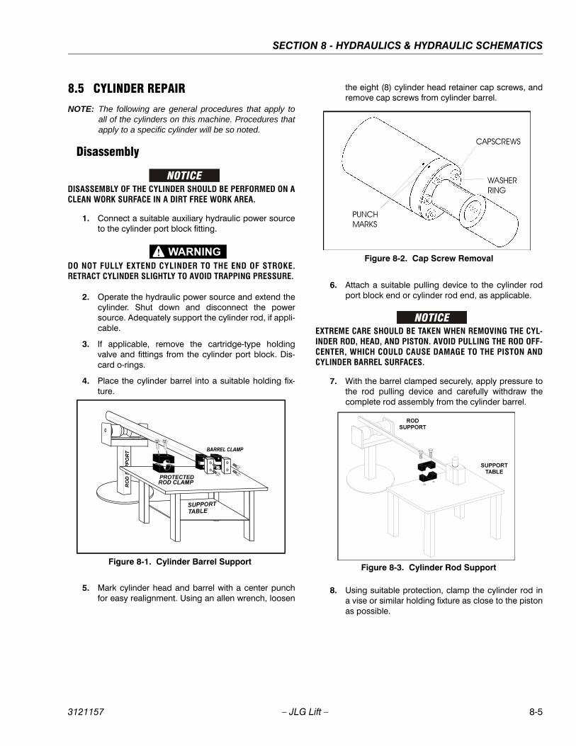
SECTION 8 - HYDRAULICS & HYDRAULIC SCHEMATICS
3121157 – JLG Lift – 8-5
8.5 CYLINDER REPAIR
NOTE: The following are general procedures that apply toall of the cylinders on this machine. Procedures thatapply to a specific cylinder will be so noted.
Disassembly
DISASSEMBLY OF THE CYLINDER SHOULD BE PERFORMED ON ACLEAN WORK SURFACE IN A DIRT FREE WORK AREA.
1. Connect a suitable auxiliary hydraulic power sourceto the cylinder port block fitting.
DO NOT FULLY EXTEND CYLINDER TO THE END OF STROKE.RETRACT CYLINDER SLIGHTLY TO AVOID TRAPPING PRESSURE.
2. Operate the hydraulic power source and extend thecylinder. Shut down and disconnect the powersource. Adequately support the cylinder rod, if appli-cable.
3. If applicable, remove the cartridge-type holdingvalve and fittings from the cylinder port block. Dis-card o-rings.
4. Place the cylinder barrel into a suitable holding fix-ture.
5. Mark cylinder head and barrel with a center punchfor easy realignment. Using an allen wrench, loosen
the eight (8) cylinder head retainer cap screws, andremove cap screws from cylinder barrel.
6. Attach a suitable pulling device to the cylinder rodport block end or cylinder rod end, as applicable.
EXTREME CARE SHOULD BE TAKEN WHEN REMOVING THE CYL-INDER ROD, HEAD, AND PISTON. AVOID PULLING THE ROD OFF-CENTER, WHICH COULD CAUSE DAMAGE TO THE PISTON ANDCYLINDER BARREL SURFACES.
7. With the barrel clamped securely, apply pressure tothe rod pulling device and carefully withdraw thecomplete rod assembly from the cylinder barrel.
8. Using suitable protection, clamp the cylinder rod ina vise or similar holding fixture as close to the pistonas possible.
Figure 8-1. Cylinder Barrel Support
Figure 8-2. Cap Screw Removal
Figure 8-3. Cylinder Rod Support
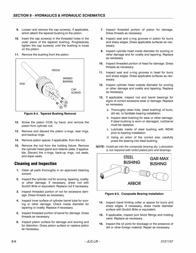
SECTION 8 - HYDRAULICS & HYDRAULIC SCHEMATICS
8-6 – JLG Lift – 3121157
9. Loosen and remove the cap screw(s), if applicable,which attach the tapered bushing to the piston.
10. Insert the cap screw(s) in the threaded holes in theouter piece of the tapered bushing. Progressivelytighten the cap screw(s) until the bushing is looseon the piston.
11. Remove the bushing from the piston.
12. Screw the piston CCW, by hand, and remove thepiston from cylinder rod.
13. Remove and discard the piston o-rings, seal rings,and backup rings.
14. Remove piston spacer, if applicable, from the rod.
15. Remove the rod from the holding fixture. Removethe cylinder head gland and retainer plate, if applica-ble. Discard the o-rings, back-up rings, rod seals,and wiper seals.
Cleaning and Inspection1. Clean all parts thoroughly in an approved cleaning
solvent.
2. Inspect the cylinder rod for scoring, tapering, ovality,or other damage. If necessary, dress rod withScotch Brite or equivalent. Replace rod if necessary.
3. Inspect threaded portion of rod for excessive dam-age. Dress threads as necessary.
4. Inspect inner surface of cylinder barrel tube for scor-ing or other damage. Check inside diameter fortapering or ovality. Replace if necessary.
5. Inspect threaded portion of barrel for damage. Dressthreads as necessary.
6. Inspect piston surface for damage and scoring andfor distortion. Dress piston surface or replace pistonas necessary.
7. Inspect threaded portion of piston for damage.Dress threads as necessary.
8. Inspect seal and o-ring grooves in piston for burrsand sharp edges. Dress applicable surfaces as nec-essary.
9. Inspect cylinder head inside diameter for scoring orother damage and for ovality and tapering. Replaceas necessary.
10. Inspect threaded portion of head for damage. Dressthreads as necessary.
11. Inspect seal and o-ring grooves in head for burrsand sharp edges. Dress applicable surfaces as nec-essary.
12. Inspect cylinder head outside diameter for scoringor other damage and ovality and tapering. Replaceas necessary.
13. If applicable, inspect rod and barrel bearings forsigns of correct excessive wear or damage. Replaceas necessary.
a. Thoroughly clean hole, (steel bushing) of burrs,dirt etc. to facilitate bearing installation.
b. Inspect steel bushing for wear or other damage.If steel bushing is worn or damaged, rod/barrelmust be replaced.
c. Lubricate inside of steel bushing with WD40prior to bearing installation.
d. Using an arbor of the correct size, carefullypress the bearing into steel bushing.
NOTE: Install pin into the composite bearing dry. Lubricationis not required with nickel plated pins and bearings.
14. Inspect travel limiting collar or spacer for burrs andsharp edges. If necessary, dress inside diametersurface with Scotch Brite or equivalent.
15. If applicable, inspect port block fittings and holdingvalve. Replace as necessary.
16. Inspect the oil ports for blockage or the presence ofdirt or other foreign material. Repair as necessary.
Figure 8-4. Tapered Bushing Removal
Figure 8-5. Composite Bearing Installation

SECTION 8 - HYDRAULICS & HYDRAULIC SCHEMATICS
3121157 – JLG Lift – 8-7
17. If applicable, inspect piston rings for cracks or otherdamage. Replace as necessary.
Assembly
NOTE: Prior to cylinder assembly, ensure that the propercylinder seal kit is used. See your JLG Parts Manual.
Apply a light film of hydraulic oil to all components prior toassembly.
1. A special tool is used to install a new rod seal intothe applicable cylinder head gland groove.
WHEN INSTALLING ‘POLY-PAK’ PISTON SEALS, ENSURE SEALSARE INSTALLED PROPERLY. REFER TO WIPER SEAL INSTALLA-TION FOR CORRECT SEAL ORIENTATION. IMPROPER SEALINSTALLATION COULD RESULT IN CYLINDER LEAKAGE ANDIMPROPER CYLINDER OPERATION.
2. Use a soft mallet to tap a new wiper seal into theapplicable cylinder head gland groove. Install a newwear ring into the applicable cylinder head gland
groove.
3. Place a new “o”ring and back-up seal in the applica-ble outside diameter groove of the cylinder head.
4. Install washer ring onto rod, carefully install the headgland on the rod, ensuring that the wiper and rodseals are not damaged or dislodged. Push the headalong the rod to the rod end, as applicable.
5. Carefully slide the piston spacer on the rod.
NOTE: Upper telescope cylinder piston has an o-ringinstalled inside the spacer.
Figure 8-6. Rod Seal Installation
Figure 8-7. Poly-Pak Piston Seal Installation
Figure 8-8. Wiper Seal Installation
Figure 8-9. Installation of Head Seal Kit
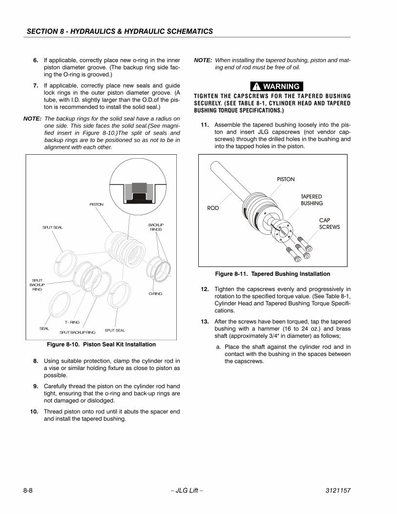
SECTION 8 - HYDRAULICS & HYDRAULIC SCHEMATICS
8-8 – JLG Lift – 3121157
6. If applicable, correctly place new o-ring in the innerpiston diameter groove. (The backup ring side fac-ing the O-ring is grooved.)
7. If applicable, correctly place new seals and guidelock rings in the outer piston diameter groove. (Atube, with I.D. slightly larger than the O.D.of the pis-ton is recommended to install the solid seal.)
NOTE: The backup rings for the solid seal have a radius onone side. This side faces the solid seal.(See magni-fied insert in Figure 8-10.)The split of seals andbackup rings are to be positioned so as not to be inalignment with each other.
8. Using suitable protection, clamp the cylinder rod ina vise or similar holding fixture as close to piston aspossible.
9. Carefully thread the piston on the cylinder rod handtight, ensuring that the o-ring and back-up rings arenot damaged or dislodged.
10. Thread piston onto rod until it abuts the spacer endand install the tapered bushing.
NOTE: When installing the tapered bushing, piston and mat-ing end of rod must be free of oil.
TIGHTEN THE CAPSCREWS FOR THE TAPERED BUSHINGSECURELY. (SEE TABLE 8-1, CYLINDER HEAD AND TAPEREDBUSHING TORQUE SPECIFICATIONS.)
11. Assemble the tapered bushing loosely into the pis-ton and insert JLG capscrews (not vendor cap-screws) through the drilled holes in the bushing andinto the tapped holes in the piston.
12. Tighten the capscrews evenly and progressively inrotation to the specified torque value. (See Table 8-1,Cylinder Head and Tapered Bushing Torque Specifi-cations.
13. After the screws have been torqued, tap the taperedbushing with a hammer (16 to 24 oz.) and brassshaft (approximately 3/4" in diameter) as follows;
a. Place the shaft against the cylinder rod and incontact with the bushing in the spaces betweenthe capscrews.
BACKUP RINGS
O-RING
PISTON
SPLIT SEAL
SEALSPLIT BACKUP RING
T - RING
SPLITBACKUP
RING
Figure 8-10. Piston Seal Kit Installation
Figure 8-11. Tapered Bushing Installation
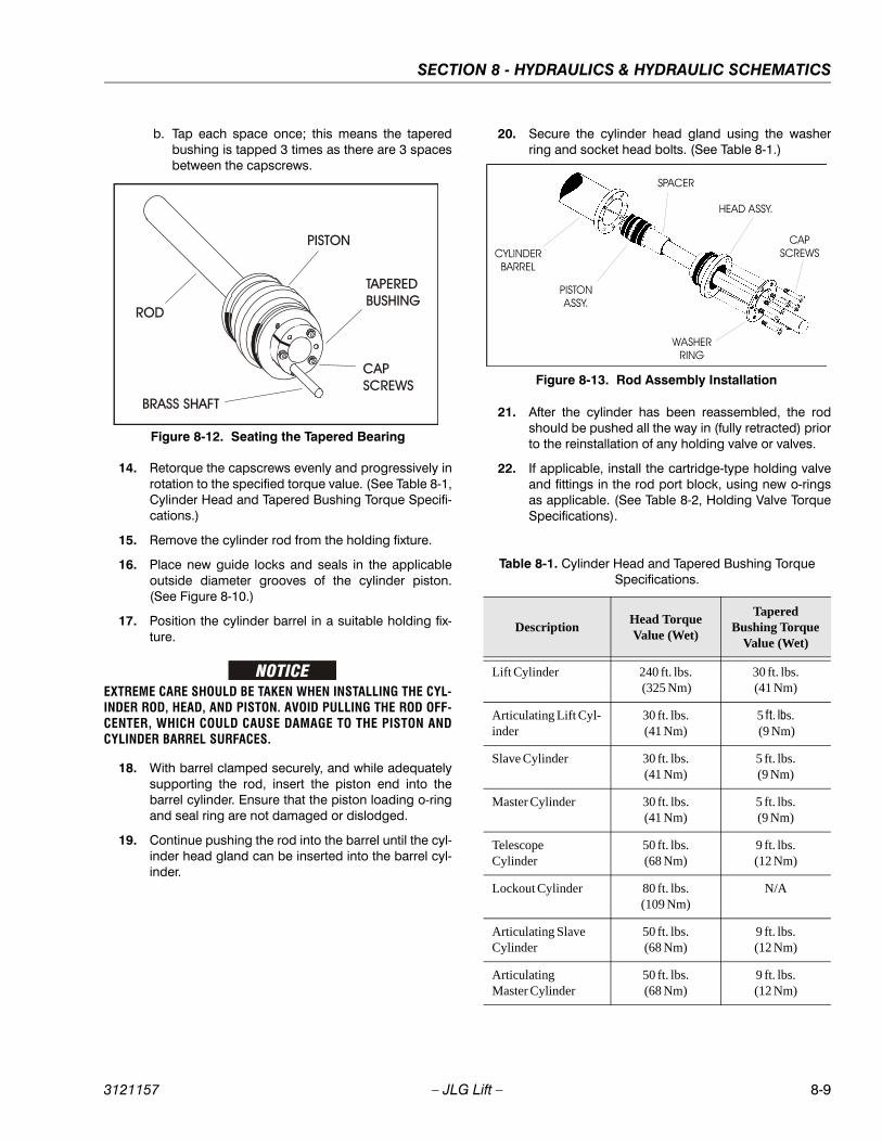
SECTION 8 - HYDRAULICS & HYDRAULIC SCHEMATICS
3121157 – JLG Lift – 8-9
b. Tap each space once; this means the taperedbushing is tapped 3 times as there are 3 spacesbetween the capscrews.
14. Retorque the capscrews evenly and progressively inrotation to the specified torque value. (See Table 8-1,Cylinder Head and Tapered Bushing Torque Specifi-cations.)
15. Remove the cylinder rod from the holding fixture.
16. Place new guide locks and seals in the applicableoutside diameter grooves of the cylinder piston.(See Figure 8-10.)
17. Position the cylinder barrel in a suitable holding fix-ture.
EXTREME CARE SHOULD BE TAKEN WHEN INSTALLING THE CYL-INDER ROD, HEAD, AND PISTON. AVOID PULLING THE ROD OFF-CENTER, WHICH COULD CAUSE DAMAGE TO THE PISTON ANDCYLINDER BARREL SURFACES.
18. With barrel clamped securely, and while adequatelysupporting the rod, insert the piston end into thebarrel cylinder. Ensure that the piston loading o-ringand seal ring are not damaged or dislodged.
19. Continue pushing the rod into the barrel until the cyl-inder head gland can be inserted into the barrel cyl-inder.
20. Secure the cylinder head gland using the washerring and socket head bolts. (See Table 8-1.)
21. After the cylinder has been reassembled, the rodshould be pushed all the way in (fully retracted) priorto the reinstallation of any holding valve or valves.
22. If applicable, install the cartridge-type holding valveand fittings in the rod port block, using new o-ringsas applicable. (See Table 8-2, Holding Valve TorqueSpecifications).
Figure 8-12. Seating the Tapered Bearing
Table 8-1. Cylinder Head and Tapered Bushing Torque Specifications.
DescriptionHead Torque Value (Wet)
Tapered Bushing Torque
Value (Wet)
Lift Cylinder 240 ft. lbs. (325 Nm)
30 ft. lbs.(41 Nm)
Articulating Lift Cyl-inder
30 ft. lbs.(41 Nm)
5 ft. lbs. (9 Nm)
Slave Cylinder 30 ft. lbs.(41 Nm)
5 ft. lbs.(9 Nm)
Master Cylinder 30 ft. lbs.(41 Nm)
5 ft. lbs.(9 Nm)
Telescope Cylinder
50 ft. lbs.(68 Nm)
9 ft. lbs.(12 Nm)
Lockout Cylinder 80 ft. lbs.(109 Nm)
N/A
Articulating Slave Cylinder
50 ft. lbs.(68 Nm)
9 ft. lbs.(12 Nm)
Articulating Master Cylinder
50 ft. lbs.(68 Nm)
9 ft. lbs.(12 Nm)
Figure 8-13. Rod Assembly Installation
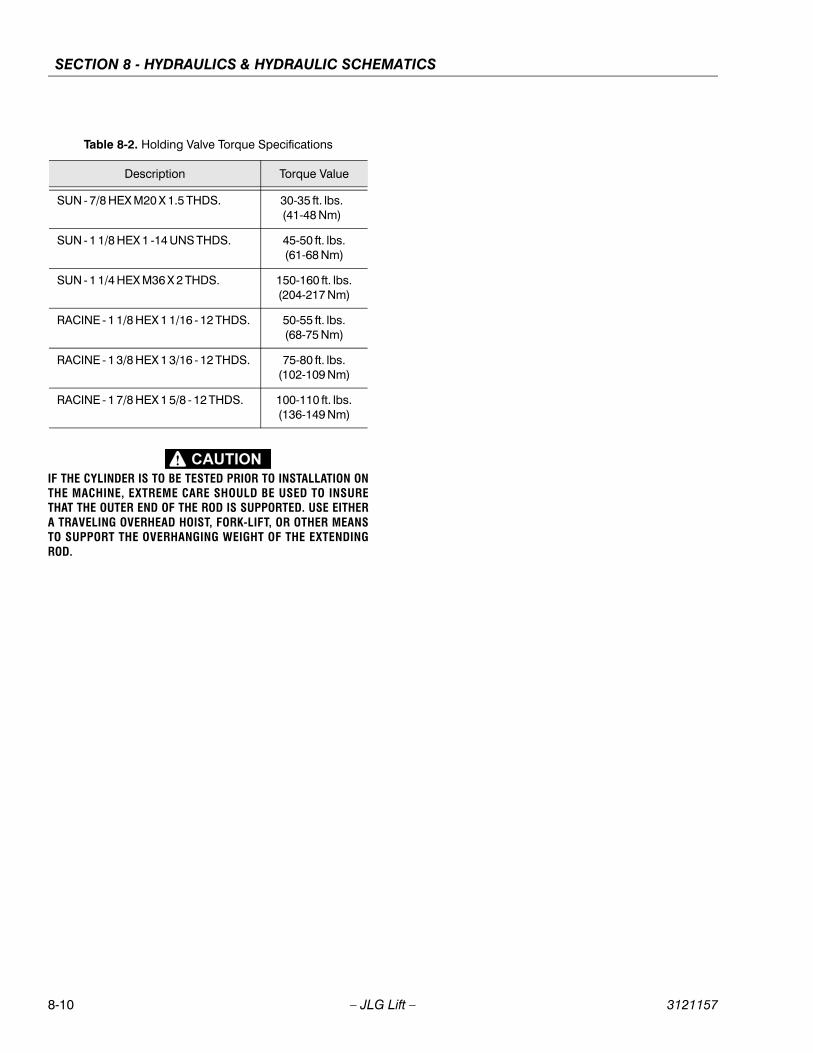
SECTION 8 - HYDRAULICS & HYDRAULIC SCHEMATICS
8-10 – JLG Lift – 3121157
IF THE CYLINDER IS TO BE TESTED PRIOR TO INSTALLATION ONTHE MACHINE, EXTREME CARE SHOULD BE USED TO INSURETHAT THE OUTER END OF THE ROD IS SUPPORTED. USE EITHERA TRAVELING OVERHEAD HOIST, FORK-LIFT, OR OTHER MEANSTO SUPPORT THE OVERHANGING WEIGHT OF THE EXTENDINGROD.
Table 8-2. Holding Valve Torque Specifications
Description Torque Value
SUN - 7/8 HEX M20 X 1.5 THDS. 30-35 ft. lbs.(41-48 Nm)
SUN - 1 1/8 HEX 1 -14 UNS THDS. 45-50 ft. lbs.(61-68 Nm)
SUN - 1 1/4 HEX M36 X 2 THDS. 150-160 ft. lbs.(204-217 Nm)
RACINE - 1 1/8 HEX 1 1/16 - 12 THDS. 50-55 ft. lbs.(68-75 Nm)
RACINE - 1 3/8 HEX 1 3/16 - 12 THDS. 75-80 ft. lbs.(102-109 Nm)
RACINE - 1 7/8 HEX 1 5/8 - 12 THDS. 100-110 ft. lbs.(136-149 Nm)
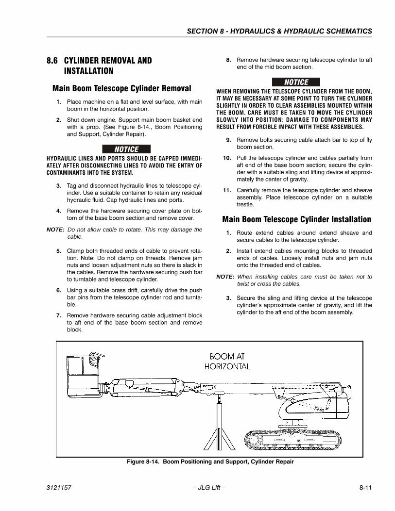
SECTION 8 - HYDRAULICS & HYDRAULIC SCHEMATICS
3121157 – JLG Lift – 8-11
8.6 CYLINDER REMOVAL AND INSTALLATION
Main Boom Telescope Cylinder Removal1. Place machine on a flat and level surface, with main
boom in the horizontal position.
2. Shut down engine. Support main boom basket endwith a prop. (See Figure 8-14., Boom Positioningand Support, Cylinder Repair).
HYDRAULIC LINES AND PORTS SHOULD BE CAPPED IMMEDI-ATELY AFTER DISCONNECTING LINES TO AVOID THE ENTRY OFCONTAMINANTS INTO THE SYSTEM.
3. Tag and disconnect hydraulic lines to telescope cyl-inder. Use a suitable container to retain any residualhydraulic fluid. Cap hydraulic lines and ports.
4. Remove the hardware securing cover plate on bot-tom of the base boom section and remove cover.
NOTE: Do not allow cable to rotate. This may damage thecable.
5. Clamp both threaded ends of cable to prevent rota-tion. Note: Do not clamp on threads. Remove jamnuts and loosen adjustment nuts so there is slack inthe cables. Remove the hardware securing push barto turntable and telescope cylinder.
6. Using a suitable brass drift, carefully drive the pushbar pins from the telescope cylinder rod and turnta-ble.
7. Remove hardware securing cable adjustment blockto aft end of the base boom section and removeblock.
8. Remove hardware securing telescope cylinder to aftend of the mid boom section.
WHEN REMOVING THE TELESCOPE CYLINDER FROM THE BOOM,IT MAY BE NECESSARY AT SOME POINT TO TURN THE CYLINDERSLIGHTLY IN ORDER TO CLEAR ASSEMBLIES MOUNTED WITHINTHE BOOM. CARE MUST BE TAKEN TO MOVE THE CYLINDERSLOWLY INTO POSITION: DAMAGE TO COMPONENTS MAYRESULT FROM FORCIBLE IMPACT WITH THESE ASSEMBLIES.
9. Remove bolts securing cable attach bar to top of flyboom section.
10. Pull the telescope cylinder and cables partially fromaft end of the base boom section; secure the cylin-der with a suitable sling and lifting device at approxi-mately the center of gravity.
11. Carefully remove the telescope cylinder and sheaveassembly. Place telescope cylinder on a suitabletrestle.
Main Boom Telescope Cylinder Installation1. Route extend cables around extend sheave and
secure cables to the telescope cylinder.
2. Install extend cables mounting blocks to threadedends of cables. Loosely install nuts and jam nutsonto the threaded end of cables.
NOTE: When installing cables care must be taken not totwist or cross the cables.
3. Secure the sling and lifting device at the telescopecylinder’s approximate center of gravity, and lift thecylinder to the aft end of the boom assembly.
Figure 8-14. Boom Positioning and Support, Cylinder Repair
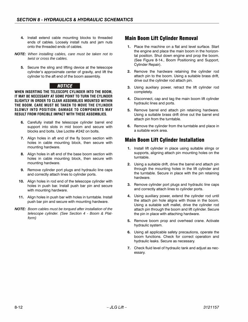
SECTION 8 - HYDRAULICS & HYDRAULIC SCHEMATICS
8-12 – JLG Lift – 3121157
4. Install extend cable mounting blocks to threadedends of cables. Loosely install nuts and jam nutsonto the threaded ends of cables.
NOTE: When installing cables, care must be taken not totwist or cross the cables.
5. Secure the sling and lifting device at the telescopecylinder’s approximate center of gravity, and lift thecylinder to the aft end of the boom assembly.
WHEN INSERTING THE TELESCOPE CYLINDER INTO THE BOOM,IT MAY BE NECESSARY AT SOME POINT TO TURN THE CYLINDERSLIGHTLY IN ORDER TO CLEAR ASSEMBLIES MOUNTED WITHINTHE BOOM. CARE MUST BE TAKEN TO MOVE THE CYLINDERSLOWLY INTO POSITION: DAMAGE TO COMPONENTS MAYRESULT FROM FORCIBLE IMPACT WITH THESE ASSEMBLIES.
6. Carefully install the telescope cylinder barrel endsupport into slots in mid boom and secure withblocks and bolts. Use Loctite #242 on bolts.
7. Align holes in aft end of the fly boom section withholes in cable mounting block, then secure withmounting hardware.
8. Align holes in aft end of the base boom section withholes in cable mounting block, then secure withmounting hardware.
9. Remove cylinder port plugs and hydraulic line capsand correctly attach lines to cylinder ports.
10. Align holes in rod end of the telescope cylinder withholes in push bar. Install push bar pin and securewith mounting hardware.
11. Align holes in push bar with holes in turntable. Installpush bar pin and secure with mounting hardware.
NOTE: Boom cables must be torqued after installation of thetelescope cylinder. (See Section 4 - Boom & Plat-form)
Main Boom Lift Cylinder Removal1. Place the machine on a flat and level surface. Start
the engine and place the main boom in the horizon-tal position. Shut down engine and prop the boom.(See Figure 8-14., Boom Positioning and Support,Cylinder Repair).
2. Remove the hardware retaining the cylinder rodattach pin to the boom. Using a suitable brass drift,drive out the cylinder rod attach pin.
3. Using auxiliary power, retract the lift cylinder rodcompletely.
4. Disconnect, cap and tag the main boom lift cylinderhydraulic lines and ports.
5. Remove barrel end attach pin retaining hardware.Using a suitable brass drift drive out the barrel endattach pin from the turntable.
6. Remove the cylinder from the turntable and place ina suitable work area.
Main Boom Lift Cylinder Installation1. Install lift cylinder in place using suitable slings or
supports, aligning attach pin mounting holes on theturntable.
2. Using a suitable drift, drive the barrel end attach pinthrough the mounting holes in the lift cylinder andthe turntable. Secure in place with the pin retaininghardware.
3. Remove cylinder port plugs and hydraulic line capsand correctly attach lines to cylinder ports.
4. Using auxiliary power, extend the cylinder rod untilthe attach pin hole aligns with those in the boom.Using a suitable soft mallet, drive the cylinder rodattach pin through the boom and lift cylinder. Securethe pin in place with attaching hardware.
5. Remove boom prop and overhead crane. Activatehydraulic system.
6. Using all applicable safety precautions, operate theboom functions. Check for correct operation andhydraulic leaks. Secure as necessary.
7. Check fluid level of hydraulic tank and adjust as nec-essary.

SECTION 8 - HYDRAULICS & HYDRAULIC SCHEMATICS
3121157 – JLG Lift – 8-13
8.7 PRESSURE SETTING PROCEDURESCold temperatures have a significant impact on pressurereadings. JLG Industries Inc. recommends operating themachine until the hydraulic system has warmed to normaloperating temperatures prior to checking pressures. JLGIndustries Inc. also recommends the use of a calibratedgauge. Pressure readings are acceptable if they are within± 5% of specified pressures.
Main Relief1. Install pressure gauge at quick disconnect on port
MP on main valve.
2. With the aid of an assistant, activate telescope in.
3. While monitoring pressure gauge, adjust main reliefto 3000 PSI (206.85 Bar). Turn the adjuster clock-wise to increase pressure or counterclockwise todecrease pressure.
Lift Down1. Install pressure gauge at quick disconnect on port
MP on main valve.
2. With the aid of an assistant, activate lift down.
3. While monitoring pressure gauge, adjust the liftdown relief to 1500 PSI (103 Bar). Turn the adjusterclockwise to increase pressure or counterclockwiseto decrease pressure.
Swing
NOTE: Left and right swing pressures are set with oneadjustment.
1. Install pressure gauge at quick disconnect on portMP on main valve.
2. Lock the turntable using the turntable lock.
3. With the aid of an assistant, activate swing left orright
4. While monitoring pressure gauge, adjust the swingrelief to 1700 PSI (117 Bar). Turn the adjuster clock-wise to increase pressure or counterclockwise todecrease pressure.
Platform Level Up
PRESSURE IS TRAPPED AT PORT M3.
1. Install pressure gauge at quick disconnect on portM3 on main valve after releasing the pressure. Torelease the pressure, activate level down to the end
of the stroke. This will release the pressure and allowinstallation of a pressure gauge.
2. With the aid of an assistant, activate level up.
3. While monitoring pressure gauge, adjust the levelup relief to 2800 PSI (193 Bar). Turn the adjusterclockwise to increase pressure or counterclockwiseto decrease pressure.
Platform Level Down
PRESSURE IS TRAPPED AT PORT M4.
1. Install pressure gauge at quick disconnect on portM4 on main valve after releasing the pressure. Torelease the pressure, activate level up to the end ofthe stroke. This will release the pressure and allowinstallation of a pressure gauge.
2. With the aid of an assistant, activate level down.
3. While monitoring pressure gauge, adjust the levelup relief to 1800 PSI (124 Bar). Turn the adjusterclockwise to increase pressure or counterclockwiseto decrease pressure.
Jib Up1. Install pressure gauge on the M port on the jib block.
2. With the aid of an assistant, activate jib up.
3. While monitoring pressure gauge, adjust the jib uprelief to 1500 PSI (103 Bar). Turn the adjuster clock-wise to increase pressure or counterclockwise todecrease pressure.
Jib Down1. Install pressure gauge on the M port on the jib block.
2. With the aid of an assistant, activate jib down.
3. While monitoring pressure gauge, adjust the jibdown relief to 1200 PSI (82 Bar). Turn the adjusterclockwise to increase pressure or counterclockwiseto decrease pressure.
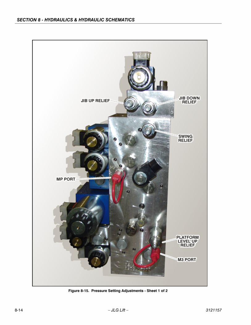
SECTION 8 - HYDRAULICS & HYDRAULIC SCHEMATICS
8-14 – JLG Lift – 3121157
Figure 8-15. Pressure Setting Adjustments - Sheet 1 of 2
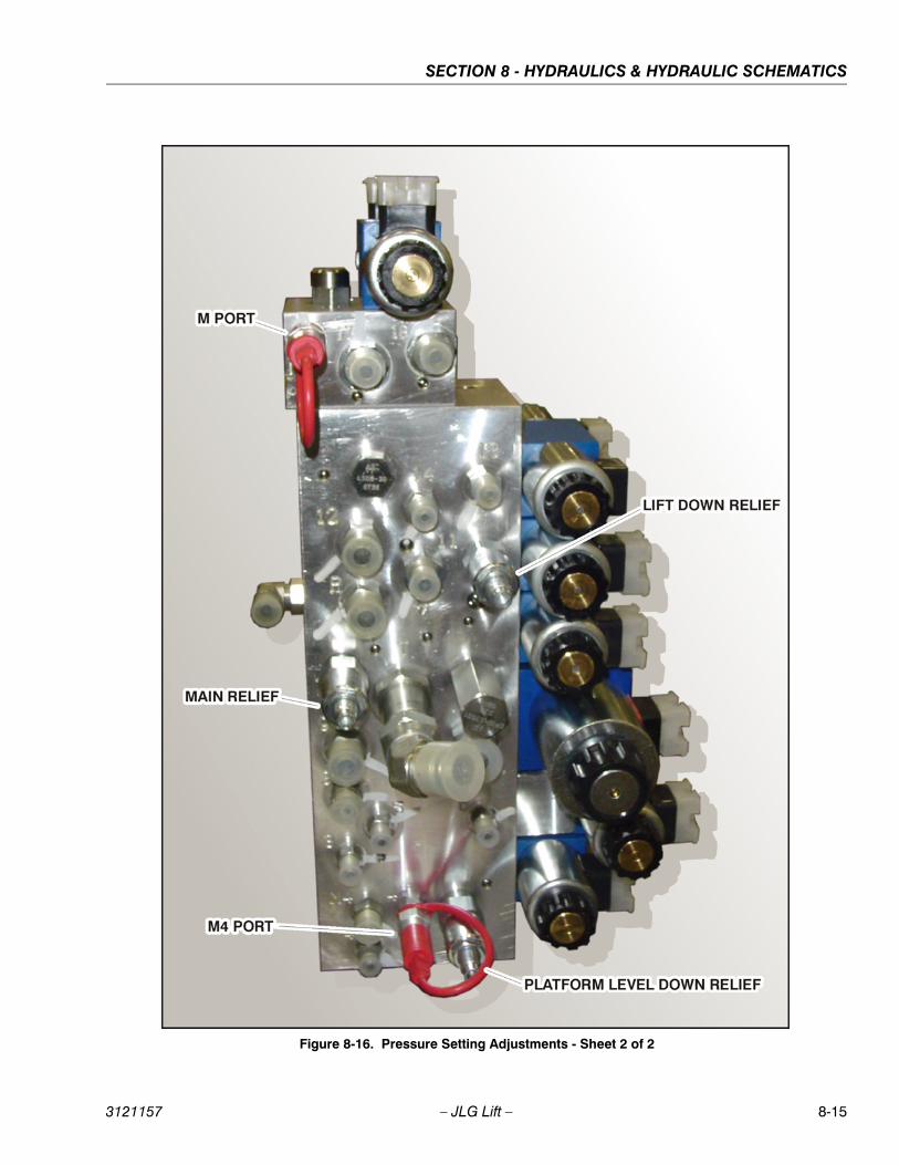
SECTION 8 - HYDRAULICS & HYDRAULIC SCHEMATICS
3121157 – JLG Lift – 8-15
Figure 8-16. Pressure Setting Adjustments - Sheet 2 of 2
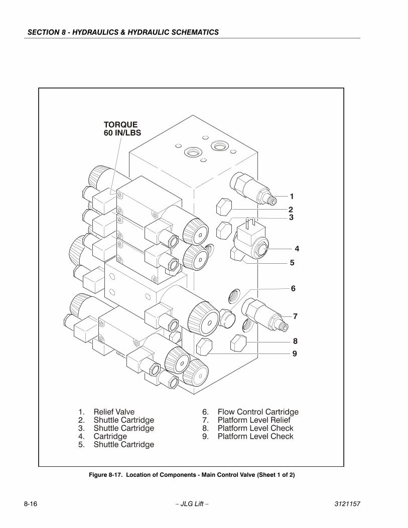
SECTION 8 - HYDRAULICS & HYDRAULIC SCHEMATICS
8-16 – JLG Lift – 3121157
Figure 8-17. Location of Components - Main Control Valve (Sheet 1 of 2)
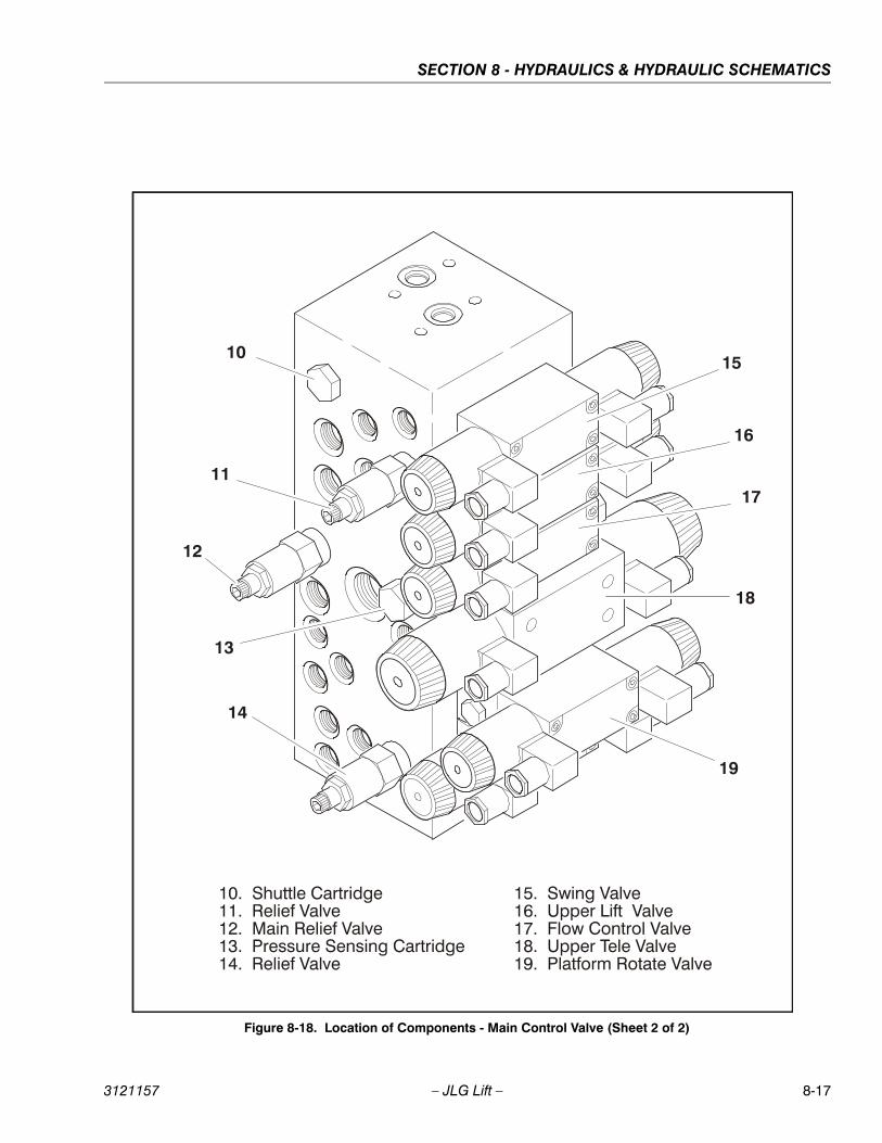
SECTION 8 - HYDRAULICS & HYDRAULIC SCHEMATICS
3121157 – JLG Lift – 8-17
Figure 8-18. Location of Components - Main Control Valve (Sheet 2 of 2)
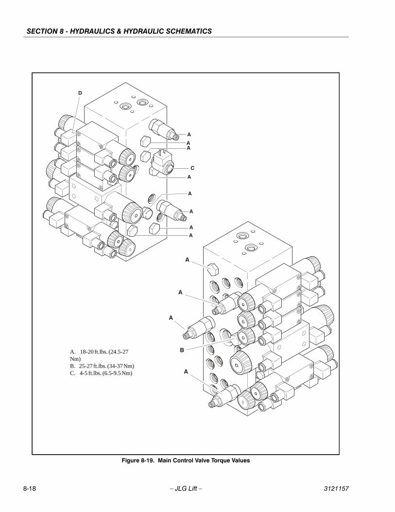
SECTION 8 - HYDRAULICS & HYDRAULIC SCHEMATICS
8-18 – JLG Lift – 3121157
Figure 8-19. Main Control Valve Torque Values
A. 18-20 ft.lbs. (24.5-27 Nm)B. 25-27 ft.lbs. (34-37 Nm)C. 4-5 ft.lbs. (6.5-9.5 Nm)
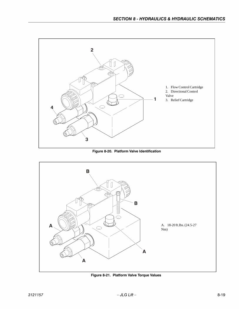
SECTION 8 - HYDRAULICS & HYDRAULIC SCHEMATICS
3121157 – JLG Lift – 8-19
Figure 8-20. Platform Valve Identification
1. Flow Control Cartridge2. Directional Control Valve3. Relief Cartridge
Figure 8-21. Platform Valve Torque Values
A. 18-20 ft.lbs. (24.5-27 Nm)

SECTION 8 - HYDRAULICS & HYDRAULIC SCHEMATICS
8-20 – JLG Lift – 3121157
8.8 HYDRAULIC PUMP (GEAR)
Disassembly
NOTE: The following general instructions also apply to mul-tiple section gear pumps, the only extra parts are thecoupling between the drive shafts and the center dis-tance plate which divides the two pump sections.This repair procedure also applies to the "W" seriesGear Motors.
1. It is very important to work in a clean work areawhen repairing hydraulic products. Plug ports andwash exterior of pump with a proper cleaning sol-vent before continuing.
2. Remove port plugs and drain oil from pump.
3. Use a permanent marker pen to mark a line acrossthe mounting flange, gear housing and end cover.This will assure proper reassembly and rotation ofpump.
4. Remove key from drive shaft if applicable.
5. Clamp the mounting flange in a protected jaw visewith the pump shaft facing down.
6. Loosen the four metric hex head bolts.
7. Remove pump from vise and place on clean workbench, remove the four hex head bolts and spacersif applicable.
8. Lift and remove end cover.
9. Carefully remove gear housing and place on workbench. Make sure the rear bearing block remains onthe drive and idler shafts.
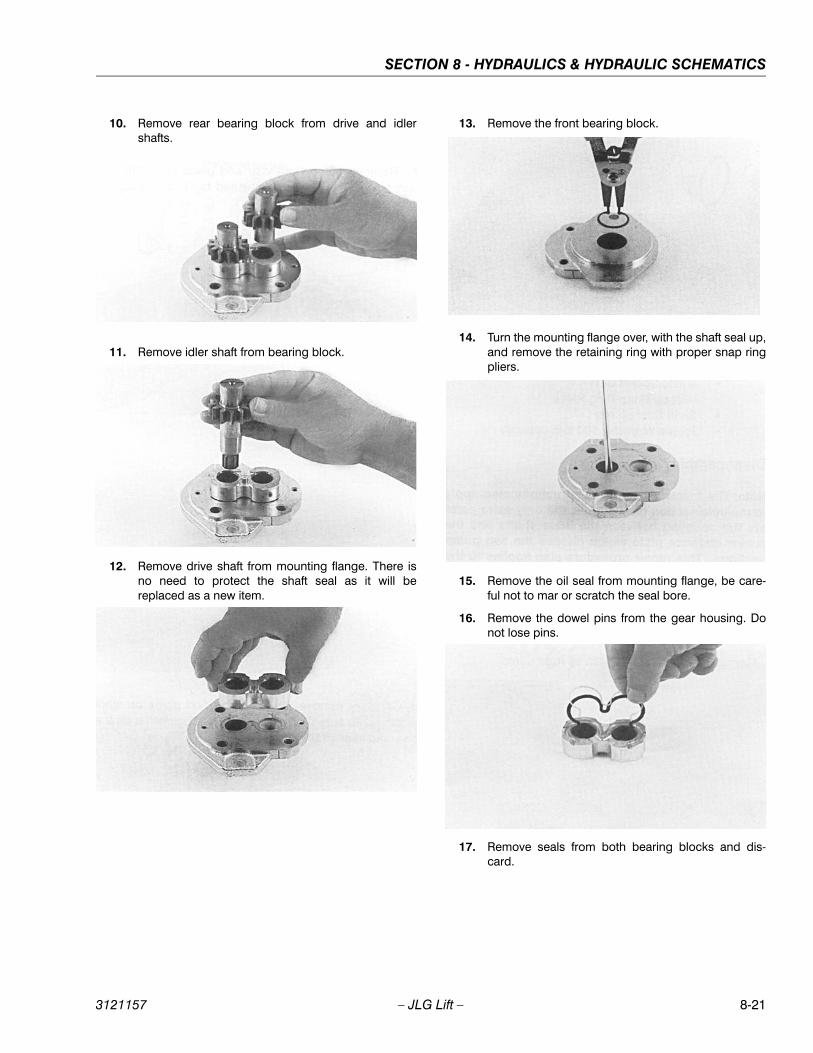
SECTION 8 - HYDRAULICS & HYDRAULIC SCHEMATICS
3121157 – JLG Lift – 8-21
10. Remove rear bearing block from drive and idlershafts.
11. Remove idler shaft from bearing block.
12. Remove drive shaft from mounting flange. There isno need to protect the shaft seal as it will bereplaced as a new item.
13. Remove the front bearing block.
14. Turn the mounting flange over, with the shaft seal up,and remove the retaining ring with proper snap ringpliers.
15. Remove the oil seal from mounting flange, be care-ful not to mar or scratch the seal bore.
16. Remove the dowel pins from the gear housing. Donot lose pins.
17. Remove seals from both bearing blocks and dis-card.
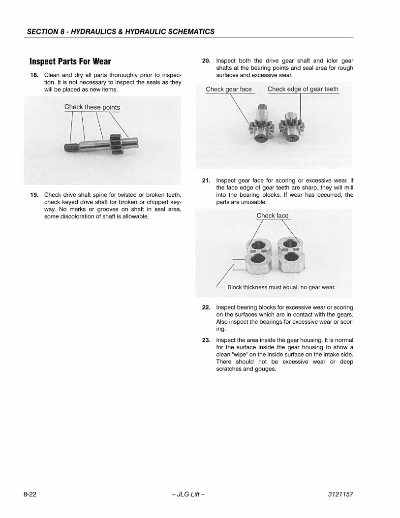
SECTION 8 - HYDRAULICS & HYDRAULIC SCHEMATICS
8-22 – JLG Lift – 3121157
Inspect Parts For Wear18. Clean and dry all parts thoroughly prior to inspec-
tion. It is not necessary to inspect the seals as theywill be placed as new items.
19. Check drive shaft spine for twisted or broken teeth,check keyed drive shaft for broken or chipped key-way. No marks or grooves on shaft in seal area,some discoloration of shaft is allowable.
20. Inspect both the drive gear shaft and idler gearshafts at the bearing points and seal area for roughsurfaces and excessive wear.
21. Inspect gear face for scoring or excessive wear. Ifthe face edge of gear teeth are sharp, they will millinto the bearing blocks. If wear has occurred, theparts are unusable.
22. Inspect bearing blocks for excessive wear or scoringon the surfaces which are in contact with the gears.Also inspect the bearings for excessive wear or scor-ing.
23. Inspect the area inside the gear housing. It is normalfor the surface inside the gear housing to show aclean "wipe" on the inside surface on the intake side.There should not be excessive wear or deepscratches and gouges.
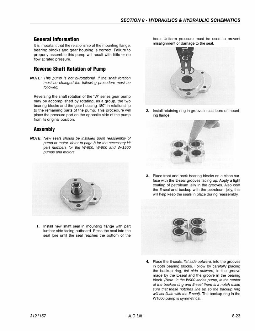
SECTION 8 - HYDRAULICS & HYDRAULIC SCHEMATICS
3121157 – JLG Lift – 8-23
General InformationIt is important that the relationship of the mounting flange,bearing blocks and gear housing is correct. Failure toproperly assemble this pump will result with little or noflow at rated pressure.
Reverse Shaft Rotation of Pump
NOTE: This pump is not bi-rotational, if the shaft rotationmust be changed the following procedure must befollowed.
Reversing the shaft rotation of the "W" series gear pumpmay be accomplished by rotating, as a group, the twobearing blocks and the gear housing 180° in relationshipto the remaining parts of the pump. This procedure willplace the pressure port on the opposite side of the pumpfrom its original position.
Assembly
NOTE: New seals should be installed upon reassembly ofpump or motor. deter to page 8 for the necessary kitpart numbers for the W-600, W-900 and W-1500pumps and motors.
1. Install new shaft seal in mounting flange with partlumber side facing outboard. Press the seal into theseal lore until the seal reaches the bottom of the
bore. Uniform pressure must be used to preventmisalignment or damage to the seal.
2. Install retaining ring in groove in seal bore of mount-ing flange.
3. Place front and back bearing blocks on a clean sur-face with the E-seal grooves facing up. Apply a lightcoating of petroleum jelly in the grooves. Also coatthe E-seal and backup with the petroleum jelly, thiswill help keep the seals in place during reassembly.
4. Place the E-seals, flat side outward, into the groovesin both bearing blocks. Follow by carefully placingthe backup ring, flat side outward, in the groovemade by the E-seal and the groove in the bearingblock. (Note: in the W900 series pump, in the centerof the backup ring and E-seal there is a notch makesure that these notches line up so the backup ringwill set flush with the E-seal). The backup ring in theW1500 pump is symmetrical.

SECTION 8 - HYDRAULICS & HYDRAULIC SCHEMATICS
8-24 – JLG Lift – 3121157
5. Place mounting flange, with shaft seal side down, ona clean flat surface.
6. Apply a light coating of petroleum jelly to theexposed face of the front bearing block.
7. Insert the drive end of the drive shaft through thebearing block with the seal side down, and the openside of the E-seal pointing to the intake side of thepump.
8. Install the seal sleeve over the drive shaft and care-fully slide the drive shaft through the shaft seal.Remove the seal sleeve from shaft.
9. Install the idler gear shaft in the remaining position inthe bearing block. Apply a light coat of clean oil tothe face of the drive and idler gears.
10. Pick up the rear bearing block, with seal side up andwith open end of the E-seal facing the intake side ofthe pump, place over the drive and idler gear shafts.
11. Install two dowel pins in the holes in the mountingflange or two long dowel pins through gear housingif pump is a multiple section pump.
12. To install the O-rings in the gear housing, apply alight coating of petroleum jelly in the grooves onboth sides of the gear housing. Also coat the new O-rings and install them in the grooves.
13. Gently slide the gear housing over the rear bearingblock assembly, slide housing down until the hous-ing engages the dowel pins. Press firmly in placewith hands, do not force or use any tool. Check tomake sure the in-take port in the housing is on thesame side as the open end of the E-seal and that themarked lines on the mounting flange and gear hous-ing are in alignment.
14. The surface of the rear bearing block should beslightly below the face of the gear housing. If thebearing block sits higher then the rear face of thegear housing then the E-seal or o-ring have shifted
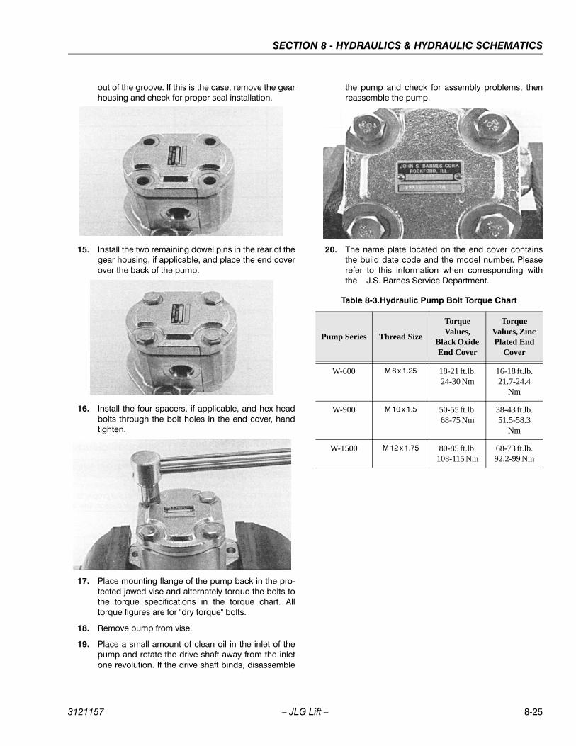
SECTION 8 - HYDRAULICS & HYDRAULIC SCHEMATICS
3121157 – JLG Lift – 8-25
out of the groove. If this is the case, remove the gearhousing and check for proper seal installation.
15. Install the two remaining dowel pins in the rear of thegear housing, if applicable, and place the end coverover the back of the pump.
16. Install the four spacers, if applicable, and hex headbolts through the bolt holes in the end cover, handtighten.
17. Place mounting flange of the pump back in the pro-tected jawed vise and alternately torque the bolts tothe torque specifications in the torque chart. Alltorque figures are for "dry torque" bolts.
18. Remove pump from vise.
19. Place a small amount of clean oil in the inlet of thepump and rotate the drive shaft away from the inletone revolution. If the drive shaft binds, disassemble
the pump and check for assembly problems, thenreassemble the pump.
20. The name plate located on the end cover containsthe build date code and the model number. Pleaserefer to this information when corresponding withthe J.S. Barnes Service Department.
Table 8-3.Hydraulic Pump Bolt Torque Chart
Pump Series Thread Size
Torque Values,
Black Oxide End Cover
Torque Values, Zinc Plated End
Cover
W-600 M 8 x 1.25 18-21 ft.lb.24-30 Nm
16-18 ft.lb.21.7-24.4
Nm
W-900 M 10 x 1.5 50-55 ft.lb.68-75 Nm
38-43 ft.lb.51.5-58.3
Nm
W-1500 M 12 x 1.75 80-85 ft.lb.108-115 Nm
68-73 ft.lb.92.2-99 Nm
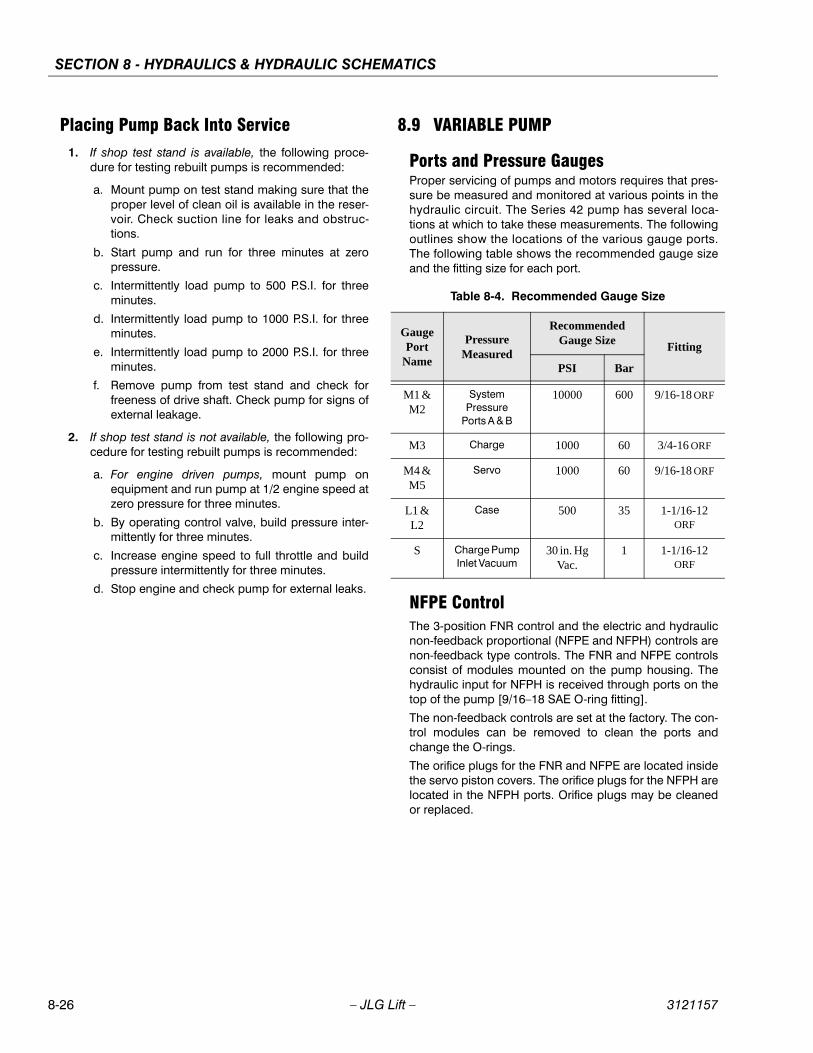
SECTION 8 - HYDRAULICS & HYDRAULIC SCHEMATICS
8-26 – JLG Lift – 3121157
Placing Pump Back Into Service1. If shop test stand is available, the following proce-
dure for testing rebuilt pumps is recommended:
a. Mount pump on test stand making sure that theproper level of clean oil is available in the reser-voir. Check suction line for leaks and obstruc-tions.
b. Start pump and run for three minutes at zeropressure.
c. Intermittently load pump to 500 P.S.I. for threeminutes.
d. Intermittently load pump to 1000 P.S.I. for threeminutes.
e. Intermittently load pump to 2000 P.S.I. for threeminutes.
f. Remove pump from test stand and check forfreeness of drive shaft. Check pump for signs ofexternal leakage.
2. If shop test stand is not available, the following pro-cedure for testing rebuilt pumps is recommended:
a. For engine driven pumps, mount pump onequipment and run pump at 1/2 engine speed atzero pressure for three minutes.
b. By operating control valve, build pressure inter-mittently for three minutes.
c. Increase engine speed to full throttle and buildpressure intermittently for three minutes.
d. Stop engine and check pump for external leaks.
8.9 VARIABLE PUMP
Ports and Pressure GaugesProper servicing of pumps and motors requires that pres-sure be measured and monitored at various points in thehydraulic circuit. The Series 42 pump has several loca-tions at which to take these measurements. The followingoutlines show the locations of the various gauge ports.The following table shows the recommended gauge sizeand the fitting size for each port.
NFPE ControlThe 3-position FNR control and the electric and hydraulicnon-feedback proportional (NFPE and NFPH) controls arenon-feedback type controls. The FNR and NFPE controlsconsist of modules mounted on the pump housing. Thehydraulic input for NFPH is received through ports on thetop of the pump [9/16–18 SAE O-ring fitting].
The non-feedback controls are set at the factory. The con-trol modules can be removed to clean the ports andchange the O-rings.
The orifice plugs for the FNR and NFPE are located insidethe servo piston covers. The orifice plugs for the NFPH arelocated in the NFPH ports. Orifice plugs may be cleanedor replaced.
Table 8-4. Recommended Gauge Size
Gauge Port
Name
Pressure Measured
Recommended Gauge Size Fitting
PSI Bar
M1 & M2
System Pressure
Ports A & B
10000 600 9/16-18 ORF
M3 Charge 1000 60 3/4-16 ORF
M4 & M5
Servo 1000 60 9/16-18 ORF
L1 & L2
Case 500 35 1-1/16-12 ORF
S Charge Pump Inlet Vacuum
30 in. Hg Vac.
1 1-1/16-12 ORF
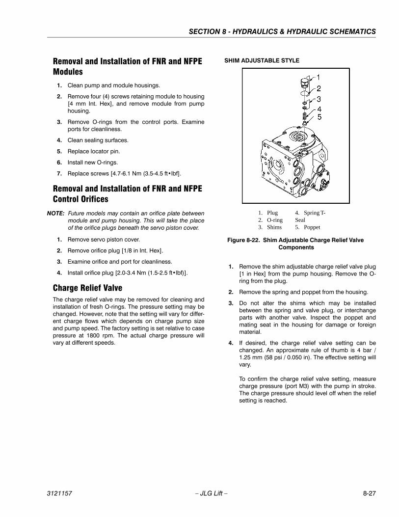
SECTION 8 - HYDRAULICS & HYDRAULIC SCHEMATICS
3121157 – JLG Lift – 8-27
Removal and Installation of FNR and NFPE Modules
1. Clean pump and module housings.
2. Remove four (4) screws retaining module to housing[4 mm Int. Hex], and remove module from pumphousing.
3. Remove O-rings from the control ports. Examineports for cleanliness.
4. Clean sealing surfaces.
5. Replace locator pin.
6. Install new O-rings.
7. Replace screws [4.7-6.1 Nm (3.5-4.5 ft•lbf].
Removal and Installation of FNR and NFPE Control Orifices
NOTE: Future models may contain an orifice plate betweenmodule and pump housing. This will take the placeof the orifice plugs beneath the servo piston cover.
1. Remove servo piston cover.
2. Remove orifice plug [1/8 in Int. Hex].
3. Examine orifice and port for cleanliness.
4. Install orifice plug [2.0-3.4 Nm (1.5-2.5 ft•lbf)].
Charge Relief ValveThe charge relief valve may be removed for cleaning andinstallation of fresh O-rings. The pressure setting may bechanged. However, note that the setting will vary for differ-ent charge flows which depends on charge pump sizeand pump speed. The factory setting is set relative to casepressure at 1800 rpm. The actual charge pressure willvary at different speeds.
SHIM ADJUSTABLE STYLE
1. Remove the shim adjustable charge relief valve plug[1 in Hex] from the pump housing. Remove the O-ring from the plug.
2. Remove the spring and poppet from the housing.
3. Do not alter the shims which may be installedbetween the spring and valve plug, or interchangeparts with another valve. Inspect the poppet andmating seat in the housing for damage or foreignmaterial.
4. If desired, the charge relief valve setting can bechanged. An approximate rule of thumb is 4 bar /1.25 mm (58 psi / 0.050 in). The effective setting willvary.
To confirm the charge relief valve setting, measurecharge pressure (port M3) with the pump in stroke.The charge pressure should level off when the reliefsetting is reached.
1. Plug 2. O-ring 3. Shims
4. Spring T-Seal5. Poppet
Figure 8-22. Shim Adjustable Charge Relief Valve Components
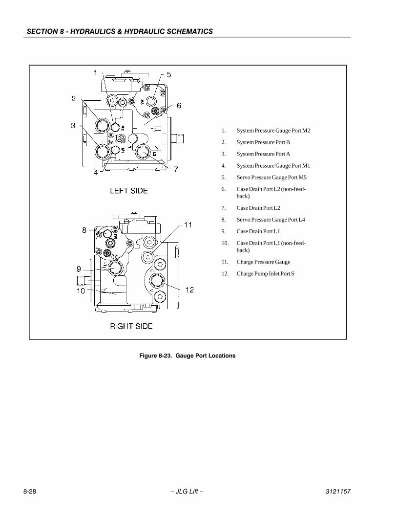
SECTION 8 - HYDRAULICS & HYDRAULIC SCHEMATICS
8-28 – JLG Lift – 3121157
Figure 8-23. Gauge Port Locations
1. System Pressure Gauge Port M2
2. System Pressure Port B
3. System Pressure Port A
4. System Pressure Gauge Port M1
5. Servo Pressure Gauge Port M5
6. Case Drain Port L2 (non-feed-back)
7. Case Drain Port L2
8. Servo Pressure Gauge Port L4
9. Case Drain Port L1
10. Case Drain Port L1 (non-feed-back)
11. Charge Pressure Gauge
12. Charge Pump Inlet Port S
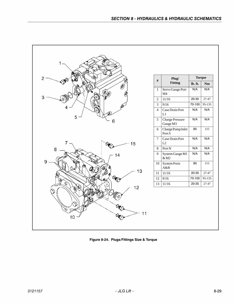
SECTION 8 - HYDRAULICS & HYDRAULIC SCHEMATICS
3121157 – JLG Lift – 8-29
Figure 8-24. Plugs/Fittings Size & Torque
#Plug/
Fitting
Torque
lb. ft. Nm
1 Servo Gauge Port M4
N/A N/A
2 11/16 20-35 27-47
3 9/16 70-100 95-135
4 Case Drain Port L1
N/A N/A
5 Charge Pressure Gauge M3
N/A N/A
6 Charge Pump Inlet Port S
85 115
7 Case Drain Port L2
N/A N/A
8 Port N N/A N/A
9 System Gauge M1 & M2
N/A N/A
10 System Ports A&B
85 115
11 11/16 20-35 27-47
12 9/16 70-100 95-135
13 11/16 20-35 27-47
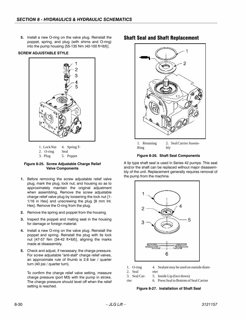
SECTION 8 - HYDRAULICS & HYDRAULIC SCHEMATICS
8-30 – JLG Lift – 3121157
5. Install a new O-ring on the valve plug. Reinstall thepoppet, spring, and plug (with shims and O-ring)into the pump housing [55-135 Nm (40-100 ft•lbf)].
SCREW ADJUSTABLE STYLE
1. Before removing the screw adjustable relief valveplug, mark the plug, lock nut, and housing so as toapproximately maintain the original adjustmentwhen assembling, Remove the screw adjustablecharge relief valve plug by loosening the lock nut [1-1/16 in Hex] and unscrewing the plug [8 mm Int.Hex]. Remove the O-ring from the plug.
2. Remove the spring and poppet from the housing.
3. Inspect the poppet and mating seat in the housingfor damage or foreign material.
4. Install a new O-ring on the valve plug. Reinstall thepoppet and spring. Reinstall the plug with its locknut [47-57 Nm (34-42 ft•lbf)], aligning the marksmade at disassembly.
5. Check and adjust, if necessary, the charge pressure.For screw adjustable "anti-stall" charge relief valves,an approximate rule of thumb is 2.8 bar / quarterturn (40 psi / quarter turn).
To confirm the charge relief valve setting, measurecharge pressure (port M3) with the pump in stroke.The charge pressure should level off when the reliefsetting is reached.
Shaft Seal and Shaft Replacement
A lip type shaft seal is used in Series 42 pumps. This sealand/or the shaft can be replaced without major disassem-bly of the unit. Replacement generally requires removal ofthe pump from the machine.
1. Lock Nut 2. O-ring 3. Plug
4. Spring T-Seal5. Poppet
Figure 8-25. Screw Adjustable Charge Relief Valve Components
1. Retaining Ring
2. Seal Carrier Assem-bly
Figure 8-26. Shaft Seal Components
1. O-ring2. Seal 3. Seal Car-rier
4. Sealant may be used on outside diam-eter5. Inside Lip (face down)6. Press Seal to Bottom of Seal Carrier
Figure 8-27. Installation of Shaft Seal
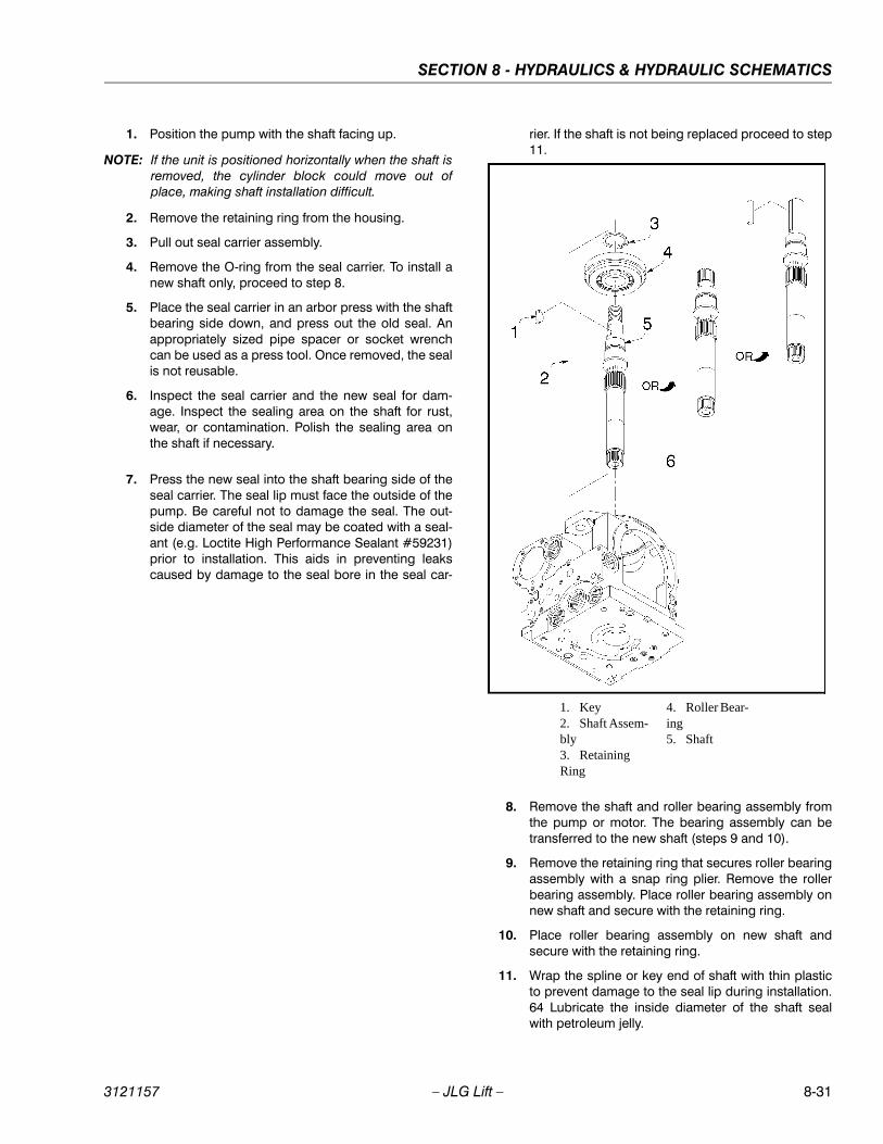
SECTION 8 - HYDRAULICS & HYDRAULIC SCHEMATICS
3121157 – JLG Lift – 8-31
1. Position the pump with the shaft facing up.
NOTE: If the unit is positioned horizontally when the shaft isremoved, the cylinder block could move out ofplace, making shaft installation difficult.
2. Remove the retaining ring from the housing.
3. Pull out seal carrier assembly.
4. Remove the O-ring from the seal carrier. To install anew shaft only, proceed to step 8.
5. Place the seal carrier in an arbor press with the shaftbearing side down, and press out the old seal. Anappropriately sized pipe spacer or socket wrenchcan be used as a press tool. Once removed, the sealis not reusable.
6. Inspect the seal carrier and the new seal for dam-age. Inspect the sealing area on the shaft for rust,wear, or contamination. Polish the sealing area onthe shaft if necessary.
7. Press the new seal into the shaft bearing side of theseal carrier. The seal lip must face the outside of thepump. Be careful not to damage the seal. The out-side diameter of the seal may be coated with a seal-ant (e.g. Loctite High Performance Sealant #59231)prior to installation. This aids in preventing leakscaused by damage to the seal bore in the seal car-
rier. If the shaft is not being replaced proceed to step11.
8. Remove the shaft and roller bearing assembly fromthe pump or motor. The bearing assembly can betransferred to the new shaft (steps 9 and 10).
9. Remove the retaining ring that secures roller bearingassembly with a snap ring plier. Remove the rollerbearing assembly. Place roller bearing assembly onnew shaft and secure with the retaining ring.
10. Place roller bearing assembly on new shaft andsecure with the retaining ring.
11. Wrap the spline or key end of shaft with thin plasticto prevent damage to the seal lip during installation.64 Lubricate the inside diameter of the shaft sealwith petroleum jelly.
1. Key 2. Shaft Assem-bly 3. Retaining Ring
4. Roller Bear-ing5. Shaft

SECTION 8 - HYDRAULICS & HYDRAULIC SCHEMATICS
8-32 – JLG Lift – 3121157
12. Place the O-ring onto the shaft bearing and lubricatewith petroleum jelly.
13. Slide the seal carrier assembly over the shaft andinto the housing bore. Press against O-ring. Holdinward pressure against the shaft to compress thecylinder block spring while pressing the seal carrierinto place.
14. Install the retaining ring.
Charge PumpThe charge pump may be disassembled to inspectand clean, or to change the auxiliary shaft drive cou-pling.
1. Remove auxiliary pump, if necessary.
2. Remove the screws retaining the charge pumpcover to the pump housing [Torx T45] (seven (7)screws are used with the "no pad" or SAE "A" auxil-iary mounting pad charge pump cover, while six (6)screws are used with the SAE "B" auxiliary mountingpad charge pump cover). Remove the charge pumpcover, gasket, and the cover locating pins.
3. Remove the gerotor cover assembly from thecharge pump cover or the back of the pump hous-ing. Remove the gerotor cover O-rings. Two (2) O-rings are used on the gerotor cover of all pumps.(An additional O-ring was used on the gerotor coverof very early production pumps with the SAE "A" padoption.)
4. Remove the gerotor assembly from the gerotorcover or pump housing.
5. Remove the gerotor drive pin and drive coupling.Remove the gerotor cover locating pin from thepump housing.
6. Each part should be inspected separately if they areto be reused. If either of the gerotor assembly partsneeds to be replaced, they must both be replaced.Always replace the O-rings and charge pump covergasket. Inspect the journal bearing in the gerotorcover for excessive wear.
7. Prior to assembly, lubricate the gerotor assemblywith clean hydraulic oil.
8. Install the gerotor drive pin into the hole in the drivecoupling, and retain with grease or petroleum jelly.
9. Install the drive coupling onto the pump shaft withthe smaller outside diameter oriented away from thepump shaft. Different couplings are used with thedifferent auxiliary pad options.
10. Install the gerotor assembly onto the coupling.
11. Install the gerotor cover locating pin into the pumphousing. Install the gerotor cover assembly over thegerotor. The locating pin must engage the slot in thegerotor cover.
NOTE: The charge pump rotation is determined by the loca-tion of the gerotor recess and pressure balance holein the gerotor cover. Different gerotor covers areused for clockwise and counterclockwise rotationpumps.
12. Install new pressure balance O-rings onto the gero-tor cover and retain with petroleum jelly or grease.(An additional O-ring was used on the gerotor coverof very early production pumps with the SAE "A" padoption.)
13. Install the charge pump cover locating pins and anew charge pump cover gasket.
14. Install the charge pump cover. The cover mustengage the gerotor cover and the locating pins.Install the charge pump cover screws and torqueevenly [36-43 Nm (26-32 ft•lbf)].
15. If necessary, reinstall auxiliary pump.

SECTION 8 - HYDRAULICS & HYDRAULIC SCHEMATICS
3121157 – JLG Lift – 8-33
Figure 8-29. Charge Pump Components
1.
Cover Retaining Screw
2.
O-ring
3.
Gerotor Cover
4.
Gerotor Assembly
5.
Drive Coupling
6.
Gerotor Cover Locating Pin
SECTION 8 - HYDRAULICS & HYDRAULIC SCHEMATICS
8-34 – JLG Lift – 3121157
8.10 HYDRAULIC PUMP W/HAYES PUMP DRIVE COUPLING LUBRICATION
Any time pump or pump drive coupling is removed coat,pump and drive coupling splines with Lithium Soap BaseGrease (TEXACO CODE 1912 OR EQUIVALENT) couplingis greased before assembly.
8.11 HYDRAULIC COMPONENT START-UP PROCEDURES AND RECOMMENDATIONS
From a hydrostatic component standpoint, the goal atsystem start up is to put into functional operation, thehydrostatic system in such a way as to preserve thedesigned life span of the system. The following start-upprocedure should be adhered to whenever a new pumpor motor is initially installed into a machine, or a system isrestarted after either a pump or motor has been removedand/or replaced.
THE FOLLOWING PROCEDURE MAY REQUIRE THE MACHINE TOBE DISABLED (WHEELS RAISED OFF THE GROUND, WORK FUNC-TIONS DISCONNECTED, ETC.) WHILE PERFORMING THE PROCE-DURE IN ORDER TO PREVENT INJURY. TAKE NECESSARY SAFETYPRECAUTIONS BEFORE MOVING THE VEHICLE/MACHINE.
Prior to installing the pump and/or motor, inspect theunit(s) for damage that may have been incurred duringshipping and handling. Make certain that all system com-ponents (reservoir, hoses, valves, fittings, heat exchanger,etc.) are clean prior to filling with fluid.
Fill the reservoir with recommended hydraulic fluid. Thisfluid should be passed through a 10 micron (nominal, nobypass) filter prior to entering the reservoir. The use ofcontaminated fluid will cause damage to the components,which may result in unexpected vehicle/machine move-ment.
NOTE: If a pump or motor is being replaced due to internaldamage, the remaining units (pump or motors) needto be inspected for damage and contamination, andthe entire hydraulic system will need to be flushedand the fluid replaced. Failure to do so may causeconsiderable damage to the entire system.
The inlet line leading from the reservoir to the pump mustbe filled prior to start-up. Check the inlet line for propertytightened fittings and make sure it is free of restrictionsand air leaks.
NOTE: In most cases, the reservoir is above the pump inletso that the pressure head created by the higher oillevel helps to keep the inlet pressures within anacceptable range and prevent high vacuum levels.However, due to hose routing or low reservoir loca-tions, there may be air trapped within this line. It isimportant to assure that the air is bled from this line.This can be accomplished by loosening the hose atthe fitting closest the pump. When oil begins to flow,the line is full, the air has been purged, and the fittingcan be retightened to its specified torque. If the tankneeds to be pressurized in order to start the flow ofoil, a vacuum reading should be taken at the inlet ofthe pump during operation in order to verify that thepump is not being asked to draw an inlet vacuumhigher than it is capable of.
Be certain to fill the pump and/or motor housing withclean hydraulic fluid prior to start up. Fill the housing bypouring filtered oil into the upper case drain port.
NOTE: It is highly recommended to use the highest possiblecase drain port, this ensures that the housing con-tains as much oil as possible and offers the greatestamount of lubrication to the internal components.
NOTE: In initial start-up conditions, it may be convenient tofill the housing, just prior to installing the case drainline. Component, (especially motor), location may besuch that access to the case drain port after installa-tion is not realistic.
NOTE: Make certain that the oil being used to fill the compo-nent housing is as clean as possible, and store thefill container in such a way as to prevent it frombecoming contaminated.
Install a 60 bar (or 1000 psi) pressure gauge in the chargepressure gauge port in order to monitor the charge pres-sure during start-up.
It is recommended that the external control input signal,(electrical connections for EDC), be disconnected at thepump control until after initial start-up. This will ensure thatthe pump remains in its neutral position.
DO NOT START THE ENGINE UNLESS PUMP IS IN THE NEUTRALPOSITION (0 DEGREES SWASHPLATE ANGLE). TAKE PRECAU-TIONS TO PREVENT MACHINE MOVEMENT IN CASE PUMP ISACTUATED DURING INITIAL START-UP.
"Jog" or slowly rotate the engine until charge pressurestarts to rise. Start the engine and run at the lowest possi-ble RPM until charge pressure has been established.Excess air should be bled from the system lines as closeto the motors as possible.
SECTION 8 - HYDRAULICS & HYDRAULIC SCHEMATICS
3121157 – JLG Lift – 8-35
NOTE: With engine on low idle, "crack", (loosen-don'tremove), system lines at the motor(s). Continue torun engine at low idle and tighten system lines assoon as oil is observed to leak from them. When oilis observed to "leak" at the motor, line is full and airhas been purged.Tighten system hoses to theirspecified torque.
Once charge pressure has been established, increasespeed to normal operating RPM. Charge pressure shouldbe as indicated in the pump model code. If charge pres-sure is inadequate, shut down and determine the causefor improper pressure.
INADEQUATE CHARGE PRESSURE WILL AFFECT THE OPERA-TOR'S ABILITY TO CONTROL THE MACHINE.
Shut down engine and connect external control input sig-nal. Reconnect machine function(s), if disconnected ear-lier. Start engine, checking to be certain pump remains inneutral. With engine at normal operating RPM, slowlycheck forward and reverse machine operation.
Charge pressure may slightly decrease during forward orreverse operation. Continue to cycle slowly between for-ward and reverse for at least five minutes.
Shut down engine, remove gauges, and plug ports.Check reservoir level and add filtered fluid if needed.
Machine is now ready for operation.
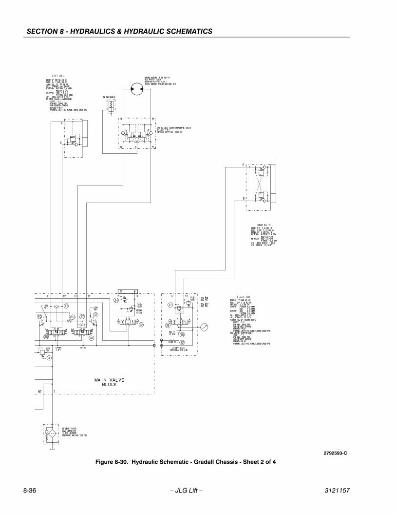
SECTION 8 - HYDRAULICS & HYDRAULIC SCHEMATICS
8-36 – JLG Lift – 3121157
Figure 8-30. Hydraulic Schematic - Gradall Chassis - Sheet 2 of 4
2792593-C
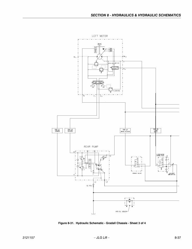
SECTION 8 - HYDRAULICS & HYDRAULIC SCHEMATICS
3121157 – JLG Lift – 8-37
Figure 8-31. Hydraulic Schematic - Gradall Chassis - Sheet 3 of 4
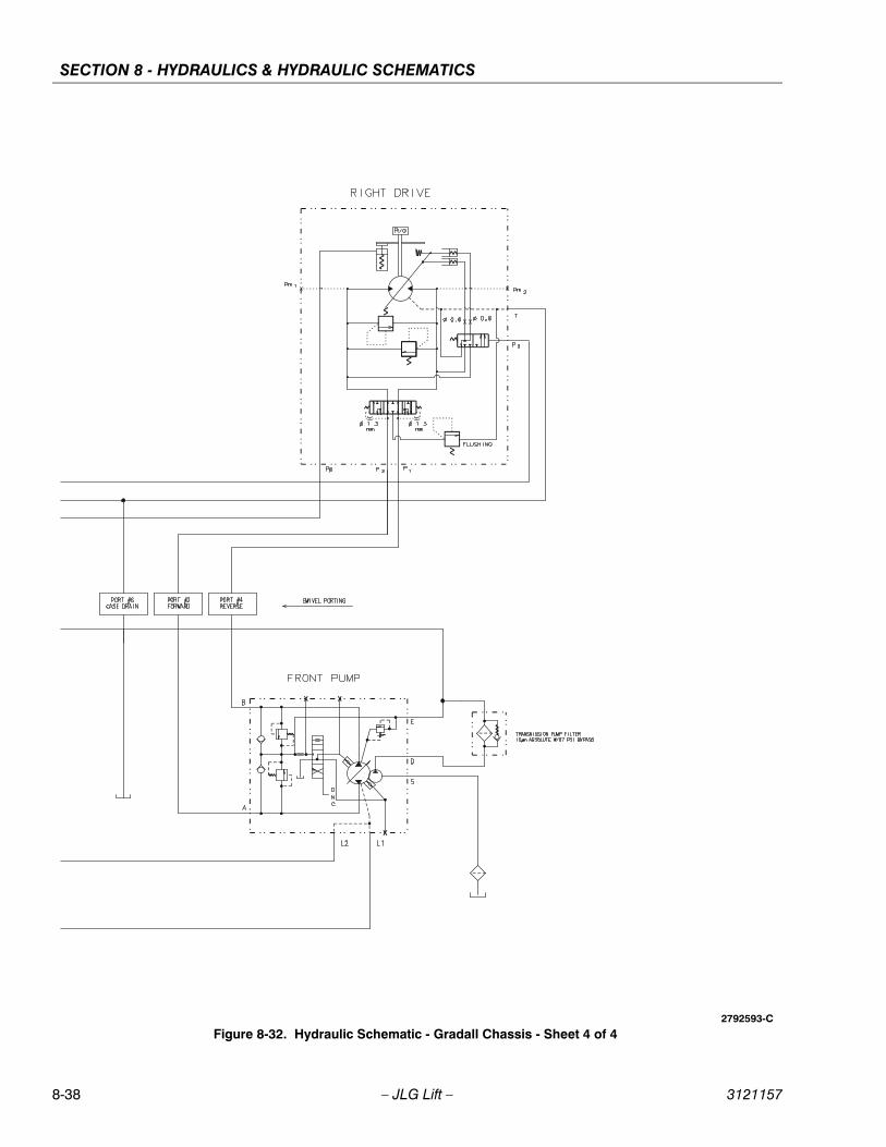
SECTION 8 - HYDRAULICS & HYDRAULIC SCHEMATICS
8-38 – JLG Lift – 3121157
Figure 8-32. Hydraulic Schematic - Gradall Chassis - Sheet 4 of 42792593-C
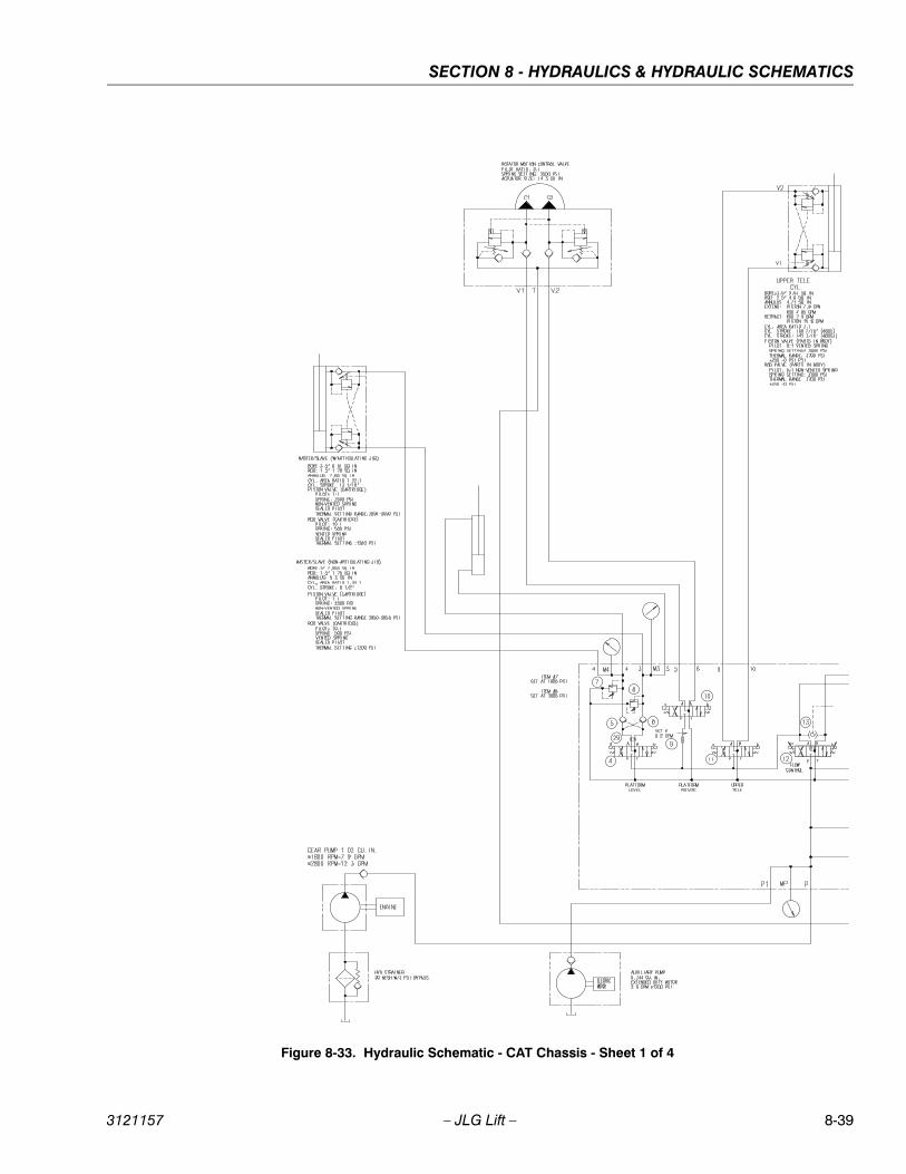
SECTION 8 - HYDRAULICS & HYDRAULIC SCHEMATICS
3121157 – JLG Lift – 8-39
Figure 8-33. Hydraulic Schematic - CAT Chassis - Sheet 1 of 4
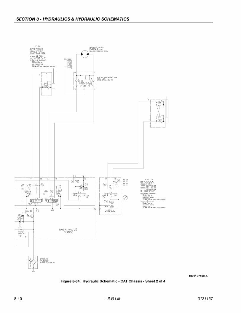
SECTION 8 - HYDRAULICS & HYDRAULIC SCHEMATICS
8-40 – JLG Lift – 3121157
Figure 8-34. Hydraulic Schematic - CAT Chassis - Sheet 2 of 4
1001107109-A
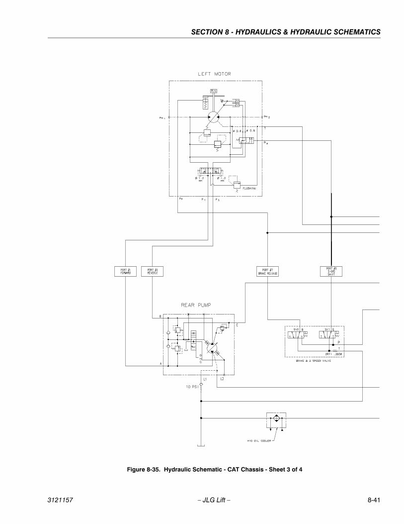
SECTION 8 - HYDRAULICS & HYDRAULIC SCHEMATICS
3121157 – JLG Lift – 8-41
Figure 8-35. Hydraulic Schematic - CAT Chassis - Sheet 3 of 4
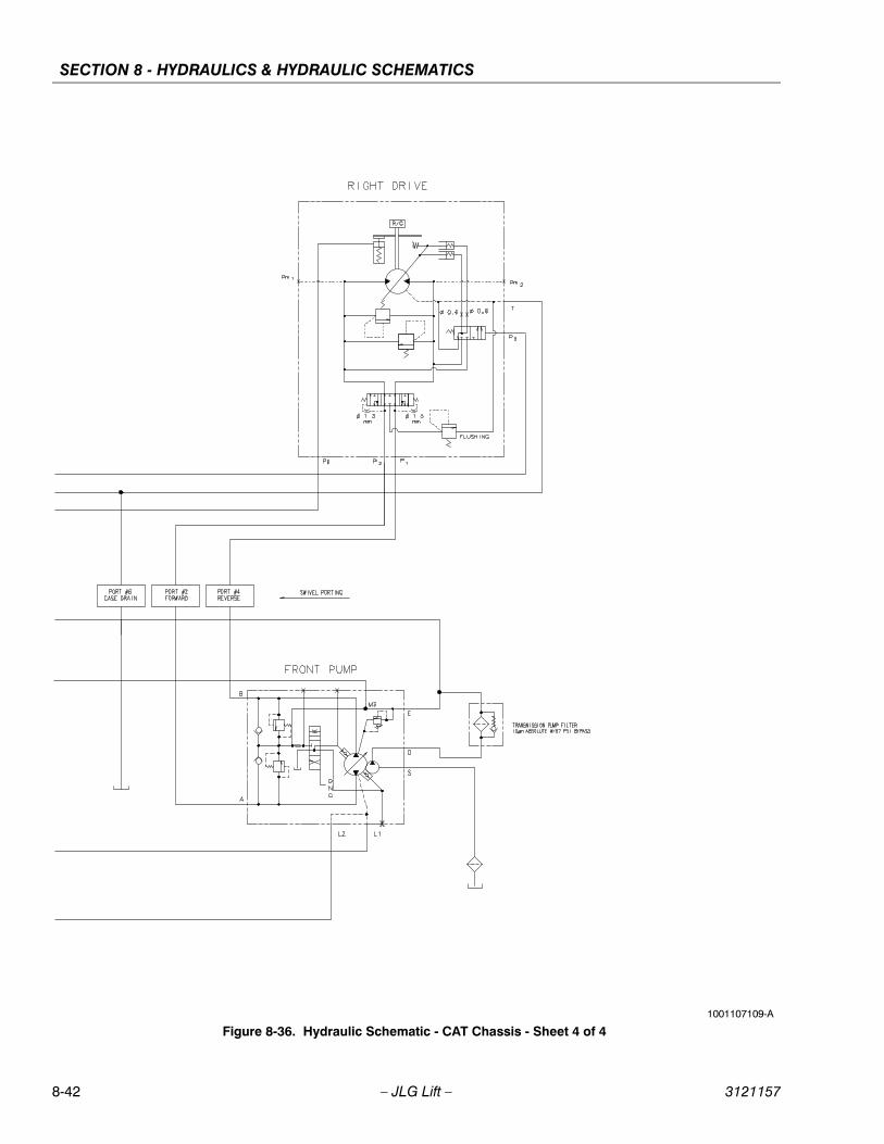
SECTION 8 - HYDRAULICS & HYDRAULIC SCHEMATICS
8-42 – JLG Lift – 3121157
Figure 8-36. Hydraulic Schematic - CAT Chassis - Sheet 4 of 41001107109-A
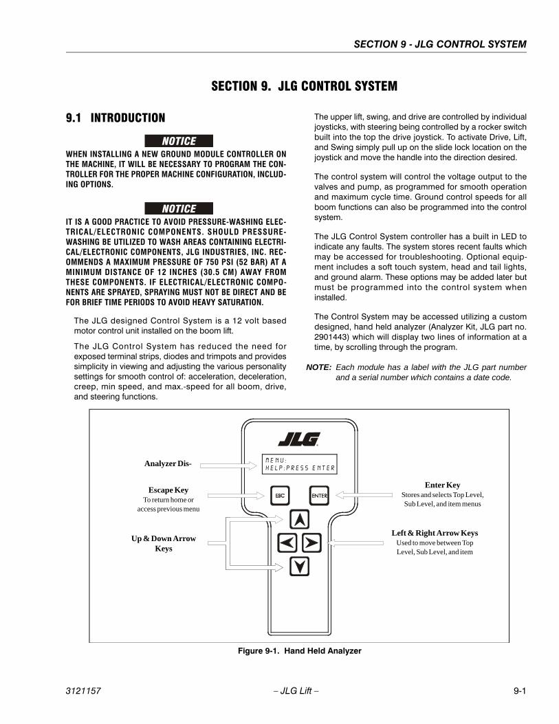
SECTION 9 - JLG CONTROL SYSTEM
3121157 – JLG Lift – 9-1
SECTION 9. JLG CONTROL SYSTEM
9.1 INTRODUCTION
WHEN INSTALLING A NEW GROUND MODULE CONTROLLER ONTHE MACHINE, IT WILL BE NECESSARY TO PROGRAM THE CON-TROLLER FOR THE PROPER MACHINE CONFIGURATION, INCLUD-ING OPTIONS.
IT IS A GOOD PRACTICE TO AVOID PRESSURE-WASHING ELEC-TRICAL/ELECTRONIC COMPONENTS. SHOULD PRESSURE-WASHING BE UTILIZED TO WASH AREAS CONTAINING ELECTRI-CAL/ELECTRONIC COMPONENTS, JLG INDUSTRIES, INC. REC-OMMENDS A MAXIMUM PRESSURE OF 750 PSI (52 BAR) AT AMINIMUM DISTANCE OF 12 INCHES (30.5 CM) AWAY FROMTHESE COMPONENTS. IF ELECTRICAL/ELECTRONIC COMPO-NENTS ARE SPRAYED, SPRAYING MUST NOT BE DIRECT AND BEFOR BRIEF TIME PERIODS TO AVOID HEAVY SATURATION.
The JLG designed Control System is a 12 volt basedmotor control unit installed on the boom lift.
The JLG Control System has reduced the need forexposed terminal strips, diodes and trimpots and providessimplicity in viewing and adjusting the various personalitysettings for smooth control of: acceleration, deceleration,creep, min speed, and max.-speed for all boom, drive,and steering functions.
The upper lift, swing, and drive are controlled by individualjoysticks, with steering being controlled by a rocker switchbuilt into the top the drive joystick. To activate Drive, Lift,and Swing simply pull up on the slide lock location on thejoystick and move the handle into the direction desired.
The control system will control the voltage output to thevalves and pump, as programmed for smooth operationand maximum cycle time. Ground control speeds for allboom functions can also be programmed into the controlsystem.
The JLG Control System controller has a built in LED toindicate any faults. The system stores recent faults whichmay be accessed for troubleshooting. Optional equip-ment includes a soft touch system, head and tail lights,and ground alarm. These options may be added later butmust be programmed into the control system wheninstalled.
The Control System may be accessed utilizing a customdesigned, hand held analyzer (Analyzer Kit, JLG part no.2901443) which will display two lines of information at atime, by scrolling through the program.
NOTE: Each module has a label with the JLG part numberand a serial number which contains a date code.
Analyzer Dis-
Escape KeyTo return home or
access previous menu
Enter KeyStores and selects Top Level, Sub Level, and item menus
Left & Right Arrow KeysUsed to move between Top Level, Sub Level, and item
Up & Down Arrow Keys
Figure 9-1. Hand Held Analyzer
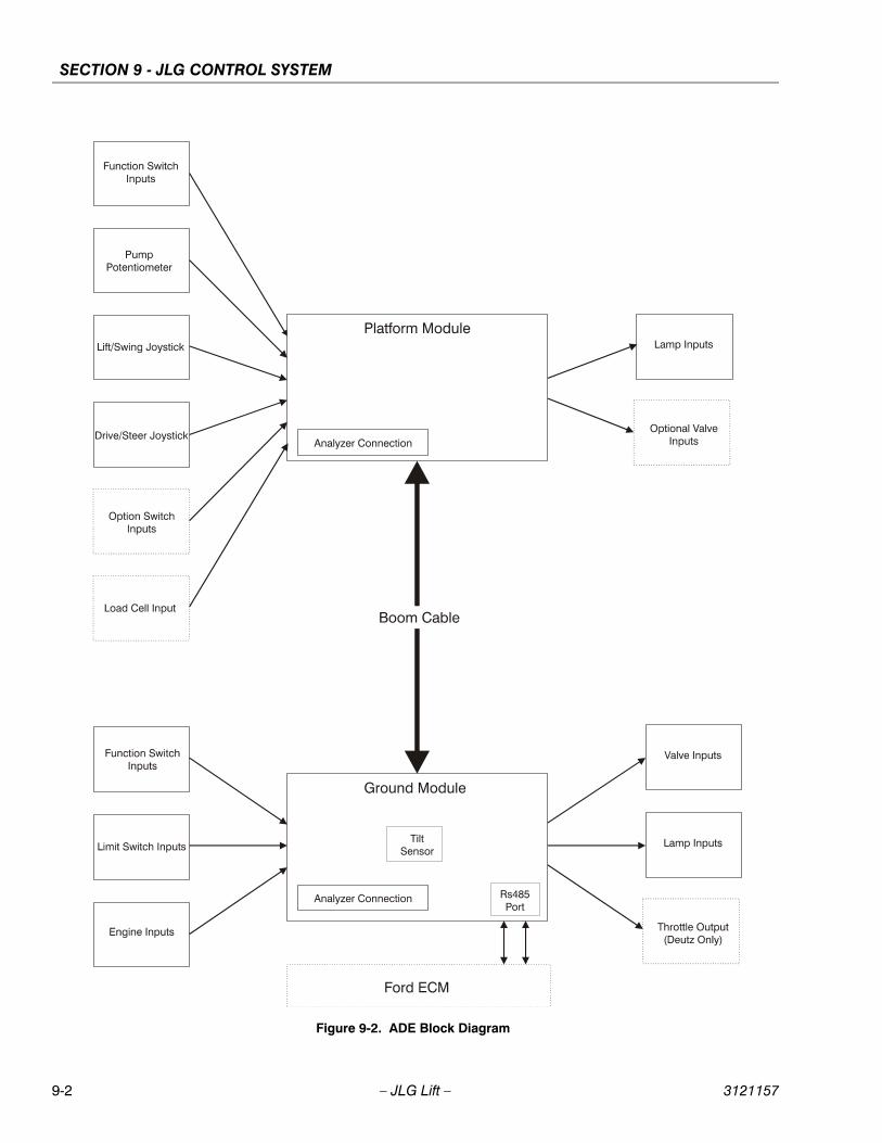
SECTION 9 - JLG CONTROL SYSTEM
9-2 – JLG Lift – 3121157
Figure 9-2. ADE Block Diagram

SECTION 9 - JLG CONTROL SYSTEM
3121157 – JLG Lift – 9-3
9.2 TO CONNECT THE JLG CONTROL SYSTEM ANALYZER
1. Connect the four pin end of the cable supplied withthe analyzer, to the controller module located in theplatform box or at the controller module in theground control box and connect the remaining endof the cable to the analyzer.
NOTE: The cable has a four pin connector at each end ofthe cable; the cable cannot be connected back-wards.
2. Power up the Control System by turning the lowerkey to the platform or ground position and pullingboth emergency stop buttons on.
9.3 USING THE ANALYZERWith the machine power on and the analyzer connectedproperly, the analyzer will display the following:
HELP:PRESS ENTER
At this point, using the RIGHT and LEFT arrow keys, youcan move between the top level menu items. To select adisplayed menu item, press ENTER. To cancel a selectedmenu item, press ESC.; then you will be able to scrollusing the right and left arrow keys to select a differentmenu item.
The top level menus are as follows:
HELPDIAGNOSTICSSYSTEM TESTACCESS LEVELPERSONALITIESMACHINE SETUPCALIBRATIONS (view only)
If you press ENTER, at the HELP: PRESS ENTER display,and a fault is present, the analyzer display will scroll thefault across the screen. If there was no fault detected, thedisplay will read: HELP: EVERYTHING OK. If powered upat the ground station, the display will read: GROUND OK.
If ENTER is pressed again, the display moves to the fol-lowing display:
LOGGED HELP1: POWER CYCLE (0/0)
At this point, the analyzer will display the last fault the sys-tem has seen, if any are present. You may scroll throughthe fault logs to view what the last 25 faults were. Use theright and left arrow keys to scroll through the fault logs. Toreturn to the beginning, press ESC. two times. POWERCYCLE (0/0) indicates a power up.
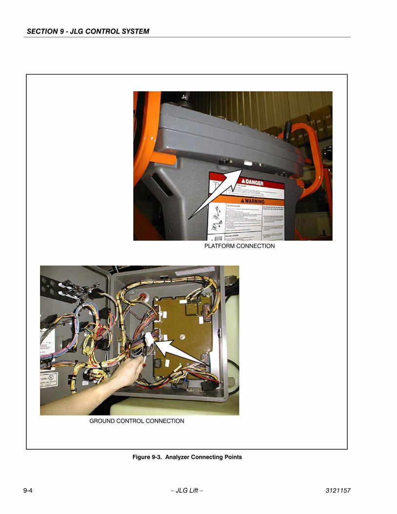
SECTION 9 - JLG CONTROL SYSTEM
9-4 – JLG Lift – 3121157
Figure 9-3. Analyzer Connecting Points
PLATFORM CONNECTION
GROUND CONTROL CONNECTION
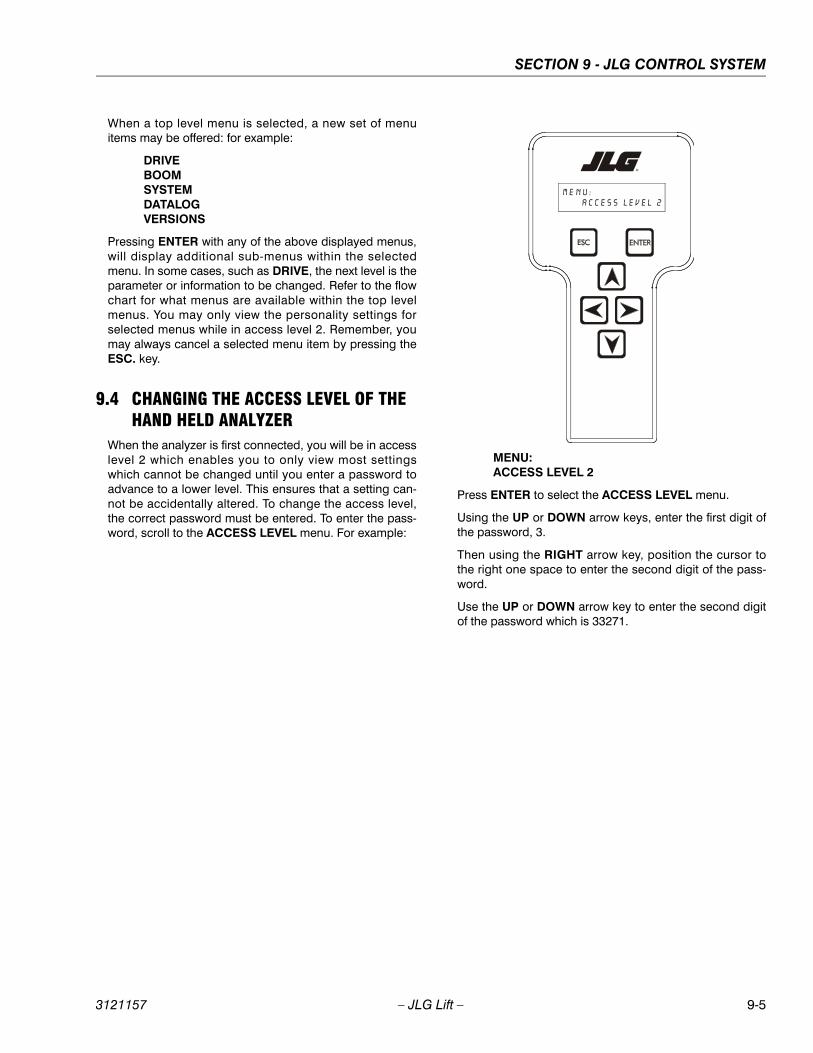
SECTION 9 - JLG CONTROL SYSTEM
3121157 – JLG Lift – 9-5
When a top level menu is selected, a new set of menuitems may be offered: for example:
DRIVEBOOMSYSTEMDATALOGVERSIONS
Pressing ENTER with any of the above displayed menus,will display additional sub-menus within the selectedmenu. In some cases, such as DRIVE, the next level is theparameter or information to be changed. Refer to the flowchart for what menus are available within the top levelmenus. You may only view the personality settings forselected menus while in access level 2. Remember, youmay always cancel a selected menu item by pressing theESC. key.
9.4 CHANGING THE ACCESS LEVEL OF THE HAND HELD ANALYZER
When the analyzer is first connected, you will be in accesslevel 2 which enables you to only view most settingswhich cannot be changed until you enter a password toadvance to a lower level. This ensures that a setting can-not be accidentally altered. To change the access level,the correct password must be entered. To enter the pass-word, scroll to the ACCESS LEVEL menu. For example:
MENU:ACCESS LEVEL 2
Press ENTER to select the ACCESS LEVEL menu.
Using the UP or DOWN arrow keys, enter the first digit ofthe password, 3.
Then using the RIGHT arrow key, position the cursor tothe right one space to enter the second digit of the pass-word.
Use the UP or DOWN arrow key to enter the second digitof the password which is 33271.
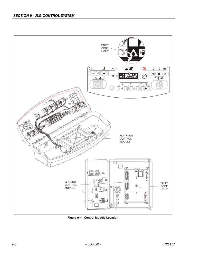
SECTION 9 - JLG CONTROL SYSTEM
9-6 – JLG Lift – 3121157
Figure 9-4. Control Module Location
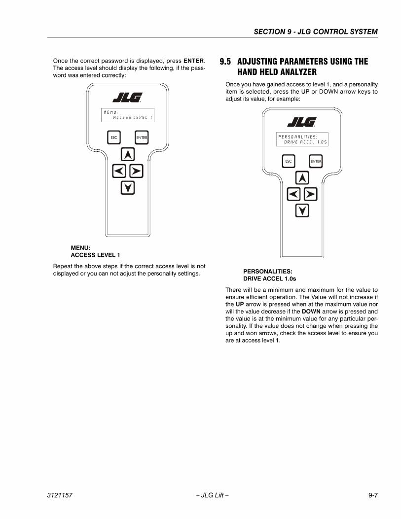
SECTION 9 - JLG CONTROL SYSTEM
3121157 – JLG Lift – 9-7
Once the correct password is displayed, press ENTER.The access level should display the following, if the pass-word was entered correctly:
MENU: ACCESS LEVEL 1
Repeat the above steps if the correct access level is notdisplayed or you can not adjust the personality settings.
9.5 ADJUSTING PARAMETERS USING THE HAND HELD ANALYZER
Once you have gained access to level 1, and a personalityitem is selected, press the UP or DOWN arrow keys toadjust its value, for example:
PERSONALITIES:DRIVE ACCEL 1.0s
There will be a minimum and maximum for the value toensure efficient operation. The Value will not increase ifthe UP arrow is pressed when at the maximum value norwill the value decrease if the DOWN arrow is pressed andthe value is at the minimum value for any particular per-sonality. If the value does not change when pressing theup and won arrows, check the access level to ensure youare at access level 1.
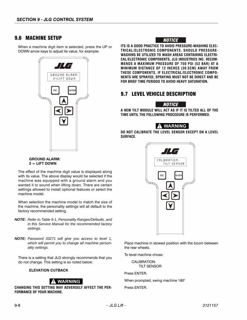
SECTION 9 - JLG CONTROL SYSTEM
9-8 – JLG Lift – 3121157
9.6 MACHINE SETUP
When a machine digit item is selected, press the UP orDOWN arrow keys to adjust its value, for example:
GROUND ALARM:2 = LIFT DOWN
The effect of the machine digit value is displayed alongwith its value. The above display would be selected if themachine was equipped with a ground alarm and youwanted it to sound when lifting down. There are certainsettings allowed to install optional features or select themachine model.
When selection the machine model to match the size ofthe machine, the personality settings will all default to thefactory recommended setting.
NOTE: Refer to Table 9-1, Personality Ranges/Defaults, andin this Service Manual for the recommended factorysettings.
NOTE: Password 33271 will give you access to level 1,which will permit you to change all machine person-ality settings.
There is a setting that JLG strongly recommends that youdo not change. This setting is so noted below:
ELEVATION CUTBACK
CHANGING THIS SETTING MAY ADVERSELY AFFECT THE PER-FORMANCE OF YOUR MACHINE.
ITS IS A GOOD PRACTICE TO AVOID PRESSURE-WASHING ELEC-TRICAL/ELECTRONIC COMPONENTS. SHOULD PRESSURE-WASHING BE UTILIZED TO WASH AREAS CONTAINING ELECTRI-CAL/ELECTRONIC COMPONENTS, JLG INDUSTRIES INC. RECOM-MENDS A MAXIMUM PRESSURE OF 750 PSI (52 BAR) AT AMINIMUM DISTANCE OF 12 INCHES (30.5CM) AWAY FROMTHESE COMPONENTS. IF ELECTRICAL/ELECTRONIC COMPO-NENTS ARE SPRAYED, SPRAYING MUST NOT BE DIRECT AND BEFOR BRIEF TIME PERIODS TO AVOID HEAVY SATURATION.
9.7 LEVEL VEHICLE DESCRIPTION
A NEW TILT MODULE WILL ACT AS IF IT IS TILTED ALL OF THETIME UNTIL THE FOLLOWING PROCEDURE IS PERFORMED.
DO NOT CALIBRATE THE LEVEL SENSOR EXCEPT ON A LEVELSURFACE.
Place machine in stowed position with the boom betweenthe rear wheels.
To level machine chose:
CALIBRATION:TILT SENSOR
Press ENTER.
When prompted, swing machine 180°
Press ENTER.
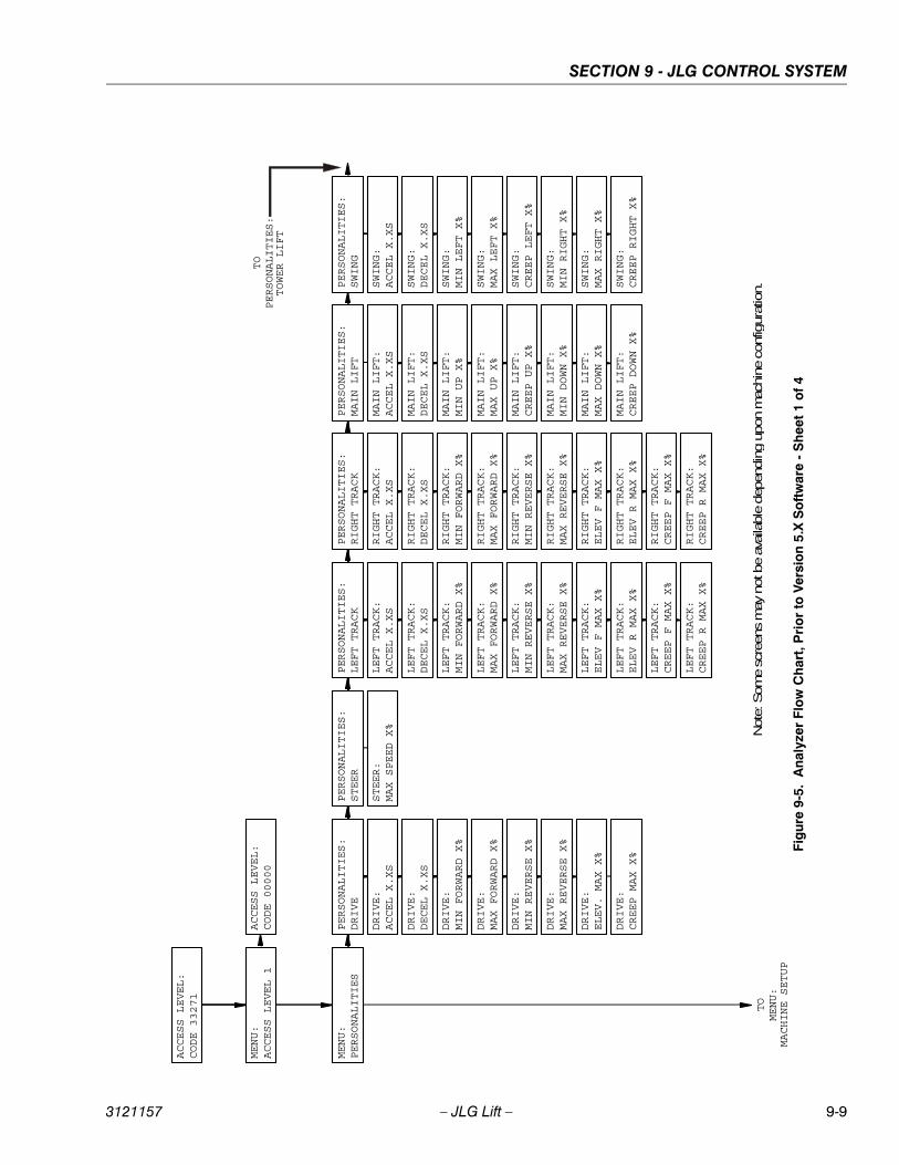
SECTION 9 - JLG CONTROL SYSTEM
3121157 – JLG Lift – 9-9
ACCESS LEVEL:
CODE 33271
MENU:
ACCESS LEVEL 1
MENU:
PERSONALITIES
TO
MENU:
MACHINE SETUP
PERSONALITIES:
DRIVE
PERSONALITIES:
STEER
PERSONALITIES:
MAIN LIFT
PERSONALITIES:
SWING
TO
PERSONALITIES:
TOWER LIFT
ACCESS LEVEL:
CODE 00000
PERSONALITIES:
LEFT TRACK
PERSONALITIES:
RIGHT TRACK
LEFT TRACK:
ACCEL X.XS
LEFT TRACK:
DECEL X.XS
LEFT TRACK:
MIN FORWARD X%
LEFT TRACK:
MAX FORWARD X%
LEFT TRACK:
MIN REVERSE X%
LEFT TRACK:
MAX REVERSE X%
LEFT TRACK:
ELEV F MAX X%
LEFT TRACK:
ELEV R MAX X%
LEFT TRACK:
CREEP F MAX X%
LEFT TRACK:
CREEP R MAX X%
RIGHT TRACK:
ACCEL X.XS
RIGHT TRACK:
DECEL X.XS
RIGHT TRACK:
MIN FORWARD X%
RIGHT TRACK:
MAX FORWARD X%
RIGHT TRACK:
MIN REVERSE X%
RIGHT TRACK:
MAX REVERSE X%
RIGHT TRACK:
ELEV F MAX X%
RIGHT TRACK:
ELEV R MAX X%
RIGHT TRACK:
CREEP F MAX X%
RIGHT TRACK:
CREEP R MAX X%
DRIVE:
ACCEL X.XS
DRIVE:
DECEL X.XS
DRIVE:
MIN FORWARD X%
DRIVE:
MAX FORWARD X%
DRIVE:
MIN REVERSE X%
DRIVE:
MAX REVERSE X%
DRIVE:
ELEV. MAX X%
DRIVE:
CREEP MAX X%
STEER:
MAX SPEED X%
MAIN LIFT:
ACCEL X.XS
MAIN LIFT:
DECEL X.XS
MAIN LIFT:
MIN UP X%
MAIN LIFT:
MAX UP X%
MAIN LIFT:
CREEP UP X%
MAIN LIFT:
MIN DOWN X%
MAIN LIFT:
MAX DOWN X%
MAIN LIFT:
CREEP DOWN X%
SWING:
ACCEL X.XS
SWING:
DECEL X.XS
SWING:
MIN LEFT X%
SWING:
MAX LEFT X%
SWING:
CREEP LEFT X%
SWING:
MIN RIGHT X%
SWING:
MAX RIGHT X%
SWING:
CREEP RIGHT X%
Note
: Som
e sc
reen
s m
ay
not b
e av
aila
ble
dep
endin
g u
pon m
achin
e co
nfig
ura
tion.
Fig
ure
9-5.
Ana
lyze
r Fl
ow
Ch
art,
Pri
or
to V
ersi
on
5.X
So
ftw
are
- S
hee
t 1 o
f 4
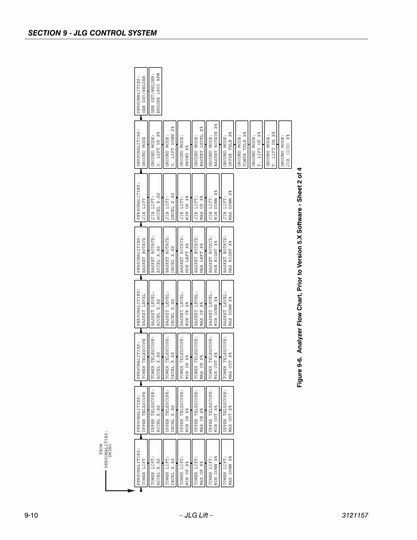
SECTION 9 - JLG CONTROL SYSTEM
9-10 – JLG Lift – 3121157
FROM
PERSONALITIES:
SWING
PERSONALITIES:
TOWER LIFT
PERSONALITIES:
UPPER TELESCOPE
PERSONALITIES:
BASKET LEVEL
PERSONALITIES:
TOWER TELESCOPE
PERSONALITIES:
BASKET ROTATE
PERSONALITIES:
JIB LIFT
PERSONALITIES:
GROUND MODE
PERSONALITIES:
GEN SET/WELDER
TOWER LIFT:
ACCEL X.XS
TOWER LIFT:
DECEL X.XS
TOWER LIFT:
MIN UP X%
TOWER LIFT:
MAX UP X%
TOWER LIFT:
MIN DOWN X%
TOWER LIFT:
MAX DOWN X%
UPPER TELESCOPE:
ACCEL X.XS
UPPER TELESCOPE:
DECEL X.XS
UPPER TELESCOPE:
MIN IN X%
UPPER TELESCOPE:
MAX IN X%
UPPER TELESCOPE:
MIN OUT X%
UPPER TELESCOPE:
MAX OUT X%
TOWER TELESCOPE:
ACCEL X.XS
TOWER TELESCOPE:
DECEL X.XS
TOWER TELESCOPE:
MIN IN X%
TOWER TELESCOPE:
MAX IN X%
TOWER TELESCOPE:
MIN OUT X%
TOWER TELESCOPE:
MAX OUT X%
BASKET LEVEL:
ACCEL X.XS
BASKET LEVEL:
DECEL X.XS
BASKET LEVEL:
MIN UP X%
BASKET LEVEL:
MAX UP X%
BASKET LEVEL:
MIN DOWN X%
BASKET LEVEL:
MAX DOWN X%
BASKET ROTATE:
ACCEL X.XS
BASKET ROTATE:
DECEL X.XS
BASKET ROTATE:
MIN LEFT X%
BASKET ROTATE:
MAX LEFT X%
BASKET ROTATE:
MIN RIGHT X%
BASKET ROTATE:
MAX RIGHT X%
JIB LIFT:
ACCEL X.XS
JIB LIFT:
DECEL X.XS
JIB LIFT:
MIN UP X%
JIB LIFT:
MAX UP X%
JIB LIFT:
MIN DOWN X%
JIB LIFT:
MAX DOWN X%
GROUND MODE:
U. LIFT UP X%
GROUND MODE:
U. LIFT DOWN X%
GROUND MODE:
SWING X%
GROUND MODE:
BASKET LEVEL X%
GROUND MODE:
BASKET ROTATE X%
GROUND MODE:
UPPER TELE X%
GROUND MODE:
TOWER TELE X%
GROUND MODE:
T. LIFT UP X%
GROUND MODE:
T. LIFT DN X%
GROUND MODE:
JIB (U/D) X%
GEN SET/WELDER:
ENGINE 1800 RPM
Fig
ure
9-6.
Ana
lyze
r F
low
Ch
art,
Pri
or
to V
ersi
on
5.X
So
ftw
are
- S
hee
t 2
of
4
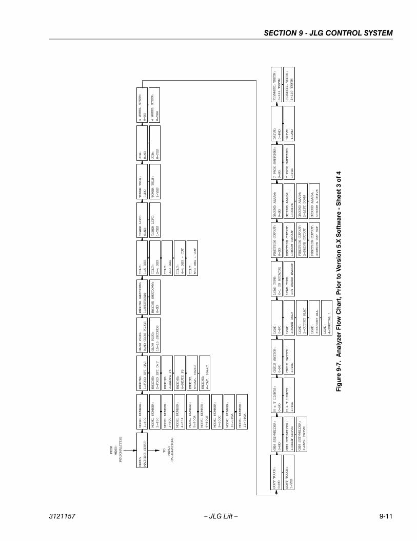
SECTION 9 - JLG CONTROL SYSTEM
3121157 – JLG Lift – 9-11
FROM
MENU:
PERSONALITIES
MENU:
MACHINE SETUP
TO
MENU:
CALIBRATIONS
MODEL NUMBER:
1=400
ENGINE:
1=FORD EFI GAS
GLOW PLUG:
0=NO GLOW PLUGS
ENGINE SHUTDOWN:
1=SHUTDOWN
TILT:
1=5 DEG
JIB:
TOWER LIFT:
TOWER TELE:
0=NO
0=NO
0=NO
4 WHEEL STEER:
0=NO
SOFT TOUCH:
0=NO
GEN SET/WELDER:
0=NO
H & T LIGHTS:
0=NO
CABLE SWITCH:
0=NO
LOAD:
0=NO
LOAD TYPE:
0=1 ON ROTATOR
FUNCTION CUTOUT:
0=NO
GROUND ALARM:
0=NO
DRIVE:
T PROX SWITCHES:
FLYWHEEL TEETH:
0=4WD
0=NO
0=133 TEETH
MODEL NUMBER:
2=450
MODEL NUMBER:
3=600
MODEL NUMBER:
4=601
MODEL NUMBER:
5=800A
MODEL NUMBER:
6=800S
MODEL NUMBER:
9=600C
MODEL NUMBER:
10=510A
MODEL NUMBER:
11=740A
ENGINE:
2=FORD EFI D/F
ENGINE:
3=DEUTZ F4
ENGINE:
4=DEUTZ F3
ENGINE:
5=CAT. 3024C
ENGINE:
6=CAT. 3044C
GLOW PLUG:
15=15 SECONDS
ENGINE SHUTDOWN:
0=NO
TILT:
2=4 DEG
TILT:
3=3 DEG
TILT:
4=4 DEG + CUT
TILT:
5=3 DEG + CUT
JIB:
TOWER LIFT:
TOWER TELE:
0=YES
1=YES
1=YES
4 WHEEL STEER:
0=YES
SOFT TOUCH:
1=YES
GEN SET/WELDER:
GEN SET/WELDER:
1=BELT DRIVE
2=HYD. DRIVE
H & T LIGHTS:
1=YES
CABLE SWITCH:
1=YES
LOAD:
1=WARN ONLY
LOAD:
2=CUTOUT PLAT
LOAD:
3=CUTOUT ALL
LOAD:
4=SPECIAL 1
LOAD TYPE:
1=4 UNDER BASKET
FUNCTION CUTOUT:
1=BOOM CUTOUT
FUNCTION CUTOUT:
2=DRIVE CUTOUT
FUNCTION CUTOUT:
3=DRIVE CUT E&T
GROUND ALARM:
1=DRIVE
GROUND ALARM:
2=LIFT DOWN
GROUND ALARM:
3=BOOM & DRIVE
DRIVE:
T PROX SWITCHES:
FLYWHEEL TEETH:
1=2WD
1=YES
1=110 TEETH
Fig
ure
9-7
. A
nal
yzer
Flo
w C
har
t, P
rio
r to
Ver
sio
n 5.
X S
oft
war
e -
Sh
eet
3 o
f 4
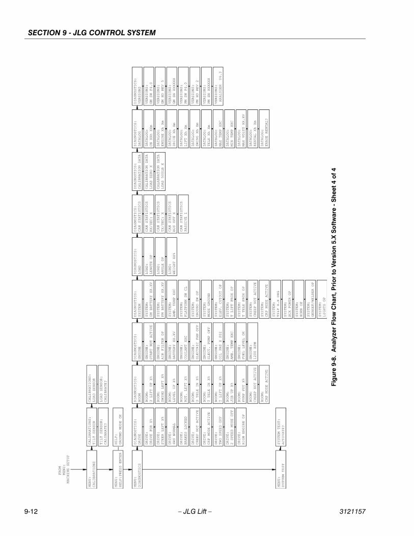
SECTION 9 - JLG CONTROL SYSTEM
9-12 – JLG Lift – 3121157
Fig
ure
9-8.
Ana
lyze
r Fl
ow
Ch
art,
Pri
or
to V
ersi
on
5.X
So
ftw
are
- S
hee
t 4
of
4
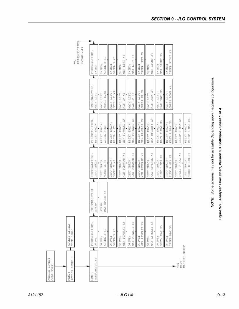
SECTION 9 - JLG CONTROL SYSTEM
3121157 – JLG Lift – 9-13
Fig
ure
9-9.
An
alyz
er F
low
Ch
art,
Ver
sio
n 5.
X S
oft
war
e -
Sh
eet
1 o
f 4
NO
TE
:S
ome
scre
ens
ma
y n
ot b
e a
vaila
ble
dep
end
ing
upon
mac
hine
con
figur
atio
n.
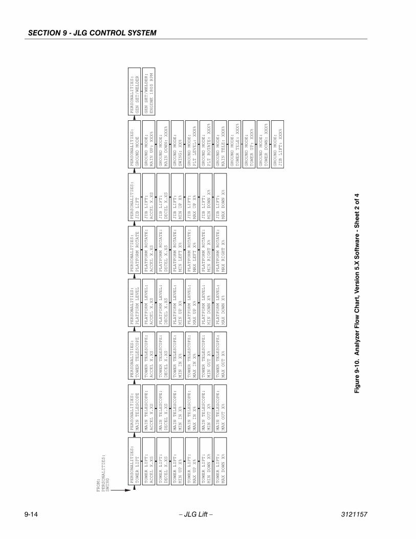
SECTION 9 - JLG CONTROL SYSTEM
9-14 – JLG Lift – 3121157
Fig
ure
9-10
. A
naly
zer
Flo
w C
har
t, V
ersi
on
5.X
So
ftw
are
- S
hee
t 2
of
4
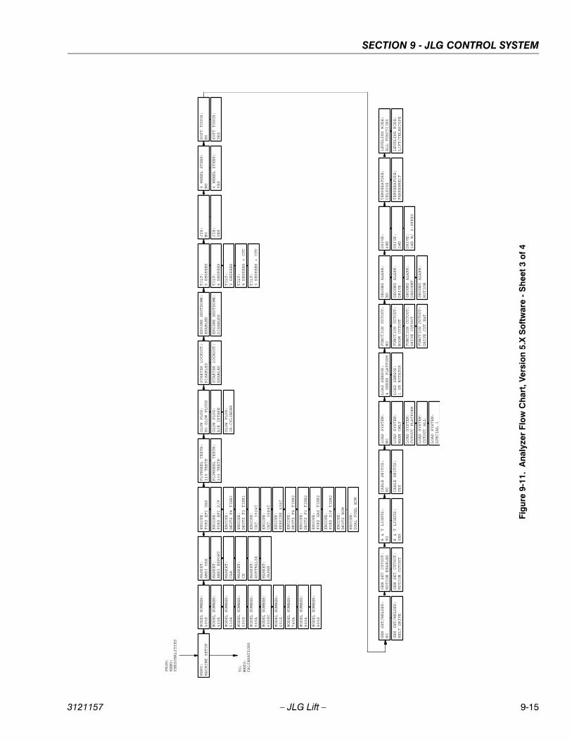
SECTION 9 - JLG CONTROL SYSTEM
3121157 – JLG Lift – 9-15
FROM:
MENU:
PERSONALITIES
MENU:
MACHINE SETUP
TO:
MENU:
CALIBRATIONS
MODEL NUMBER:
400S
ENGINE:
FORD EFI GAS
GLOW PLUG:
NO GLOW PLUGS
ENGINE SHUTDOWN:
STARTER LOCKOUT:
ENABLED
DISABLED
TILT:
5 DEGREES
JIB:
NO
4 WHEEL STEER:
NO
SOFT TOUCH:
NO
GEN SET/WELDER:
NO
H & T LIGHTS:
NO
CABLE SWITCH:
NO
LOAD SYSTEM:
NO
LOAD SENSOR:
4 UNDER PLATFORM
FUNCTION CUTOUT:
NO
GROUND ALARM:
NO
DRIVE:
4WD
MODEL NUMBER:
450A
MODEL NUMBER:
510A
MODEL NUMBER:
600S
MODEL NUMBER:
600A
MODEL NUMBER:
600SC
MODEL NUMBER:
601S
MODEL NUMBER:
740A
MODEL NUMBER:
800A
ENGINE:
FORD EFI D/F
ENGINE:
DEUTZ F4 TIER1
ENGINE:
DEUTZ F3 TIER1
ENGINE:
CAT. 3024C
ENGINE:
ENGINE:
CAT. 3044C
PERKINS 404C
GLOW PLUG:
AIR INTAKE
ENGINE SHUTDOWN:
STARTER LOCKOUT:
DISABLED
ENABLED
TILT:
4 DEGREES
TILT:
3 DEGREES
TILT:
4 DEGREES + CUT
TILT:
3 DEGREES + CUT
JIB:
YES
4 WHEEL STEER:
YES
SOFT TOUCH:
YES
GEN SET/WELDER:
BELT DRIVE
H & T LIGHTS:
YES
CABLE SWITCH:
YES
LOAD SYSTEM:
WARN ONLY
LOAD SYSTEM:
CUTOUT PLATFORM
LOAD SYSTEM:
CUTOUT ALL
LOAD SYSTEM:
SPECIAL 1
LOAD SENSOR:
1 ON ROTATOR
FUNCTION CUTOUT:
BOOM CUTOUT
FUNCTION CUTOUT:
DRIVE CUTOUT
FUNCTION CUTOUT:
DRIVE CUT E&T
GROUND ALARM:
DRIVE
GROUND ALARM:
DESCENT
GROUND ALARM:
MOTION
DRIVE:
2WD
ENGINE:
DEUTZ F4 TIER2
ENGINE:
DEUTZ F3 TIER2
GLOW PLUG:
IN-CYLINDER
ENGINE:
FORD GAS TIER2
ENGINE:
FORD D/F TIER2
MODEL NUMBER:
800S
ENGINE:
ENGINE:
DEUTZ ECM
DUAL FUEL ECM
DRIVE:
2WD W/ 2-SPEED
MARKET:
ANSI USA
MARKET:
ANSI EXPORT
MARKET:
CSA
MARKET:
CE
MARKET:
AUSTRALIA
MARKET:
JAPAN
FLYWHEEL TEETH:
110 TEETH
FLYWHEEL TEETH:
133 TEETH
TEMPERATURE:
CELSIUS
TEMPERATURE:
FAHRENHEIT
GEN SET CUTOUT:
MOTION ENABLED
GEN SET CUTOUT:
MOTION CUTOUT
LEVELING MODE:
ALL FUNCTIONS
LEVELING MODE:
LIFT/TELESCOPE
Fig
ure
9-11
. A
naly
zer
Flo
w C
har
t, V
ersi
on
5.X
So
ftw
are
- S
hee
t 3
of
4
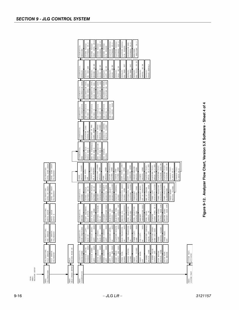
SECTION 9 - JLG CONTROL SYSTEM
9-16 – JLG Lift – 3121157
MENU:
HELP:PRESS ENTER
HELP:
GROUND MODE OK
FROM:
MENU:
MACHINE SETUP
MENU:
CALIBRATIONS
MENU:
DIAGNOSTICS
MENU:
SYSTEM TEST
DIAGNOSTICS:
DRIVE/STEER
DIAGNOSTICS:
BOOM FUNCTIONS
DIAGNOSTICS:
ENGINE
DIAGNOSTICS:
SYSTEM
DIAGNOSTICS:
DIAGNOSTICS:
LOAD
UMS
DIAGNOSTICS:
CAN STATISTICS
DIAGNOSTICS:
DATALOG
DIAGNOSTICS:
VERSIONS
DIAGNOSTICS:
CALIBRATION DATA
SYSTEM TEST:
ACTIVATE?
CALIBRATIONS:
TILT SENSOR
CALIBRATIONS:
LEVEL UP CRKPT
TILT SENSOR
CALIBRATE?
LEVEL UP CRKPT
CALIBRATE?
LIFT OUTPUT:
MAIN UP XXX%
SWING OUTPUT:
LEFT XXX%
PLATFORM LEVEL:
UP XXX%
PLATFORM ROTATE:
RIGHT XXX%
MAIN TELESCOPE:
IN XXX%
TOWER TELESCOPE:
IN XXX%
TOWER LIFT:
DOWN XXX%
PLATFORM CONTROL
VALVE: OFF
FUNCTION SPEED:
PUMP POT XXX%
CREEP
SWITCH: CLOSED
CREEP MODE:
OFF
GROUND MODULE
BATTERY: XX.XV
PLATFORM MODULE
BATTERY: XX.XV
AMBIENT
TEMPERATURE:XXXC
PLATFORM SELECT
KEYSWITCH: OPEN
GROUND SELECT
KEYSWITCH:CLOSED
STATION CONTROL:
GROUND
TRANSPORT
SWITCHES: OPEN
TOWER LIFT
PROXIMITY:CLOSED
TOWER TELESCOPE
TOWER POSITION:
PROXIMITY:CLOSED
UP/RETRACTED
CREEP
SWITCH: CLOSED
CREEP MODE:
OFF
CHASSIS TILT:
XX.X DEGREES
AUXILIARY POWER
SWITCH: OPEN
HORN
SWITCH: OPEN
SOFT TOUCH LIMIT
SWITCH: OPEN
SOFT TOUCH
OVERRIDE: OPEN
DRIVE OUTPUT:
FORWARD XXX%
STEER OUTPUT:
LEFT XXX%
STEER TYPE:
NORMAL
BRAKES STATUS:
LOCKED
CREEP
SWITCH: CLOSED
CREEP MODE:
OFF
2-SPEED
SWITCH: OPEN
2-SPEED VALVE
OUTPUT: OFF
HIGH ENGINE
SWITCH: OPEN
START SEQUENCE:
NOT ACTIVE
BATTERY VOLTAGE:
XX.XV
COOLANT
TEMPERATURE:XXXC
ENGINE OIL
PRESSURE:XXXXPSI
AMBIENT
TEMPERATURE:XXXC
FUEL LEVEL
SENSOR: OK
ENGINE SPEED
ACTUAL: XXXX RPM
CAPACITY LENGTH
CHASSIS TILT
SWITCH: CLOSED
ANGLE XXX.X
CAPACITY ANGLE
UMS TO TURNTABLE
SWITCH: CLOSED
ANGLE XXX.X
PLATFORM LOAD
UMS STATUS:
STATE:OK
NORMAL
CAN STATISTICS
RX/SEC: X
CAN STATISTICS
TX/SEC: X
CAN STATISTICS
BUS OFF: X
CAN STATISTICS
PASSIVE: 1
CALIBRATION DATA
LOAD ZERO: XXX
CALABRATION DATA
LOAD 500LB: XXX
DATALOG:
ON: XXH XXM
DATALOG:
ENGINE: XH XM
DATALOG:
DRIVE: XH XM
DATALOG:
LIFT: XH XM
DATALOG:
SWING: XH XM
DATALOG:
TELE: XH XM
DATALOG:
MAX TEMP: XXC
DATALOG:
MIN TEMP: XXC
DATALOG:
MAX VOLTS: XX.XV
DATALOG:
RENTAL: XH XM
DATALOG:
ERASE RENTAL?
GROUND MODULE
SOFTWARE: P5.0
GROUND MODULE
HARDWARE: REV X
GROUND MODULE
S/N: XXXXXX
PLATFORM MODULE
SOFTWARE: P5.0
PLATFORM MODULE
HARDWARE: REV X
PLATFORM MODULE
S/N: XXXXXX
ANALYZER:
ANALYZER V6.3
ELECTRIC FAN
OUTPUT: OFF
ELECTRIC FUEL
PUMP OUTPUT: OFF
ENGINE SPEED
TARGET: XXXX RPM
END OF STROKE
PROXIMITY: OPEN
CABLE BREAK
SWITCH: CLOSED
GENSET/WELDER
SWITCH: OPEN
LIGHTS
SWITCH: OPEN
PLATFORM TILT1
ANGLE: XX.X DEG
PLATFORM TILT2
ANGLE: XX.X DEG
PLATFORM TILT1
CHASSIS TILT:
VOLTAGE: XXXX MV
X-AXIS XX.X
PLATFORM TILT2
CHASSIS TILT:
VOLTAGE: XXXX MV
Y-AXIS XX.X
JIB LIFT:
UP XXX%
CALIBRATION DATA
PLATFORM UP: XXX
CALABRATION DATA
PLATFORM DN: XXX
STARTER
CRANK TIME: XX S
CALIBRATIONS:
CALIBRATIONS:
DEUTZ SETUP
UMS SENSOR
DEUTZ SETUP
UMS SENSOR:
SETUP X
CALIBRATE?
PROPULSION MOD.
SOFTWARE: PX.X
GROUND MODULE
CNST. DATA: PX.X
CALIBRATIONS:
LEVEL DOWN CRKPT
LEVEL DOWN CRKPT
CALIBRATE?
LEFT TRACK
OUTPUT: FWD XXX%
RIGHT TRACK
OUTPUT: FWD XXX%
JOYSTICK DRIVE:
FORWARD XXX%
JOYSTICK STEER:
LEFT XXX%
FOOTSWITCH INPUT
GROUND: OPEN
FOOTSWITCH INPUT
PLATFORM: CLOSED
TRANSPORT MODE:
OUT OF TRANSPORT
DRIVE MODE:
MID ENGINE
RETURN HYDRAULIC
FILTER: OPEN
CHARGE PUMP
FILTER: OPEN
FUEL SELECTION
FUEL SELECTION
SWITCH:GAS
STATUS:GAS
CAN STATISTICS
MSG ERROR: XXXX
AIR FILTER
SWITCH: OPEN
PERCENT OF MAX
UMS INCLINATION
LOAD: XXXX%
ANGLE XXX.X
JOYSTICK LIFT:
MAIN UP XXX%
JOYSTICK SWING:
LEFT XXX%
Fig
ure
9-12
. A
naly
zer
Flo
w C
har
t, V
ersi
on
5.X
So
ftw
are
- S
hee
t 4
of
4
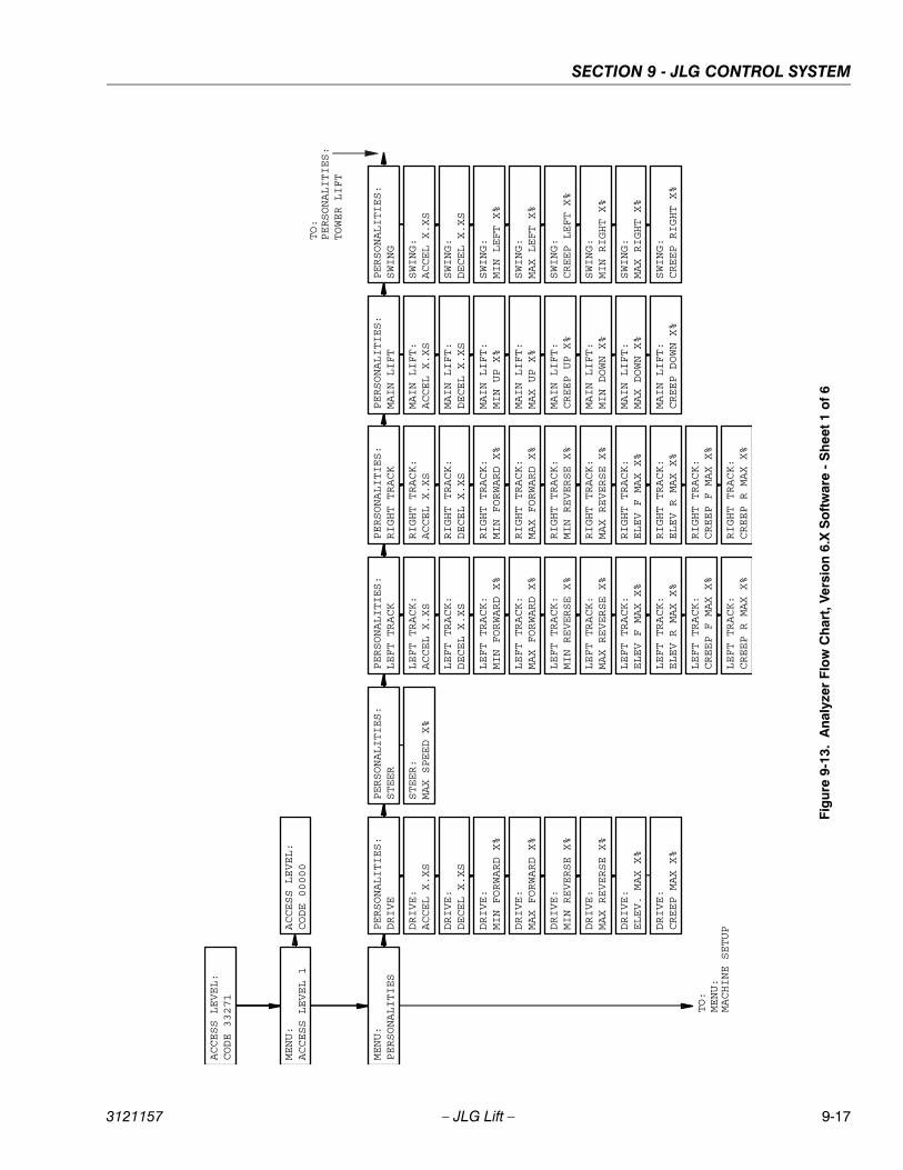
SECTION 9 - JLG CONTROL SYSTEM
3121157 – JLG Lift – 9-17
ACCESS LEVEL:
CODE 33271
MENU:
ACCESS LEVEL 1
MENU:
PERSONALITIES
TO:
MENU:
MACHINE SETUPPERSONALITIES:
DRIVE
PERSONALITIES:
STEER
PERSONALITIES:
MAIN LIFT
PERSONALITIES:
SWING
PERSONALITIES:
TOWER LIFT
TO:
ACCESS LEVEL:
CODE 00000
PERSONALITIES:
LEFT TRACK
PERSONALITIES:
RIGHT TRACK
LEFT TRACK:
ACCEL X.XS
LEFT TRACK:
DECEL X.XS
LEFT TRACK:
MIN FORWARD X%
LEFT TRACK:
MAX FORWARD X%
LEFT TRACK:
MIN REVERSE X%
LEFT TRACK:
MAX REVERSE X%
LEFT TRACK:
ELEV F MAX X%
LEFT TRACK:
ELEV R MAX X%
LEFT TRACK:
CREEP F MAX X%
LEFT TRACK:
CREEP R MAX X%
RIGHT TRACK:
ACCEL X.XS
RIGHT TRACK:
DECEL X.XS
RIGHT TRACK:
MIN FORWARD X%
RIGHT TRACK:
MAX FORWARD X%
RIGHT TRACK:
MIN REVERSE X%
RIGHT TRACK:
MAX REVERSE X%
RIGHT TRACK:
ELEV F MAX X%
RIGHT TRACK:
ELEV R MAX X%
RIGHT TRACK:
CREEP F MAX X%
RIGHT TRACK:
CREEP R MAX X%
DRIVE:
ACCEL X.XS
DRIVE:
DECEL X.XS
DRIVE:
MIN FORWARD X%
DRIVE:
MAX FORWARD X%
DRIVE:
MIN REVERSE X%
DRIVE:
MAX REVERSE X%
DRIVE:
ELEV. MAX X%
DRIVE:
CREEP MAX X%
STEER:
MAX SPEED X%
MAIN LIFT:
ACCEL X.XS
MAIN LIFT:
DECEL X.XS
MAIN LIFT:
MIN UP X%
MAIN LIFT:
MAX UP X%
MAIN LIFT:
CREEP UP X%
MAIN LIFT:
MIN DOWN X%
MAIN LIFT:
MAX DOWN X%
MAIN LIFT:
CREEP DOWN X%
SWING:
ACCEL X.XS
SWING:
DECEL X.XS
SWING:
MIN LEFT X%
SWING:
MAX LEFT X%
SWING:
CREEP LEFT X%
SWING:
MIN RIGHT X%
SWING:
MAX RIGHT X%
SWING:
CREEP RIGHT X%
Fig
ure
9-13
. A
naly
zer
Flo
w C
har
t, V
ersi
on
6.X
So
ftw
are
- S
hee
t 1
of
6

SECTION 9 - JLG CONTROL SYSTEM
9-18 – JLG Lift – 3121157
FROM:
PERSONALITIES:
SWING PERSONALITIES:
TOWER LIFT
PERSONALITIES:
MAIN TELESCOPE
PERSONALITIES:
PLATFORM LEVEL
PERSONALITIES:
TOWER TELESCOPE
PERSONALITIES:
PLATFORM ROTATE
PERSONALITIES:
JIB LIFT
PERSONALITIES:
GROUND MODE
PERSONALITIES:
GEN SET/WELDER
TOWER LIFT:
ACCEL X.XS
TOWER LIFT:
DECEL X.XS
TOWER LIFT:
MIN UP X%
TOWER LIFT:
MAX UP X%
TOWER LIFT:
MIN DOWN X%
TOWER LIFT:
MAX DOWN X%
MAIN TELESCOPE:
ACCEL X.XS
MAIN TELESCOPE:
DECEL X.XS
MAIN TELESCOPE:
MIN IN X%
MAIN TELESCOPE:
MAX IN X%
MAIN TELESCOPE:
MIN OUT X%
MAIN TELESCOPE:
MAX OUT X%
TOWER TELESCOPE:
ACCEL X.XS
TOWER TELESCOPE:
DECEL X.XS
TOWER TELESCOPE:
MIN IN X%
TOWER TELESCOPE:
MAX IN X%
TOWER TELESCOPE:
MIN OUT X%
TOWER TELESCOPE:
MAX OUT X%
PLATFORM LEVEL:
ACCEL X.XS
PLATFORM LEVEL:
DECEL X.XS
PLATFORM LEVEL:
MIN UP X%
PLATFORM LEVEL:
MAX UP X%
PLATFORM LEVEL:
MIN DOWN X%
PLATFORM LEVEL:
MAX DOWN X%
PLATFORM ROTATE:
ACCEL X.XS
PLATFORM ROTATE:
DECEL X.XS
PLATFORM ROTATE:
MIN LEFT X%
PLATFORM ROTATE:
MAX LEFT X%
PLATFORM ROTATE:
MIN RIGHT X%
PLATFORM ROTATE:
MAX RIGHT X%
JIB LIFT:
ACCEL X.XS
JIB LIFT:
DECEL X.XS
JIB LIFT:
MIN UP X%
JIB LIFT:
MAX UP X%
JIB LIFT:
MIN DOWN X%
JIB LIFT:
MAX DOWN X%
GROUND MODE:
MAIN UP: XXX%
GROUND MODE:
MAIN DOWN: XXX%
GROUND MODE:
SWING: XX%
GROUND MODE:
PLT LEVEL: XXX%
GROUND MODE:
PLT ROTATE: XXX%
GROUND MODE:
MAIN TELE: XXX%
GROUND MODE:
TOWER TELE: XXX%
GROUND MODE:
TOWER UP: XXX%
GROUND MODE:
TOWER DOWN: XXX%
GROUND MODE:
JIB LIFT: XXX%
GEN SET/WELDER:
ENGINE 1800 RPM
Fig
ure
9-14
. A
nal
yzer
Flo
w C
har
t, V
ersi
on
6.X
So
ftw
are
- S
hee
t 2
of
6

SECTION 9 - JLG CONTROL SYSTEM
3121157 – JLG Lift – 9-19
FROM:
MENU:
TO
TILT:
PERSONALITIES
MENU:
MACHINE SETUP
TO:
MENU:
CALIBRATIONS
MODEL NUMBER:
400S
ENGINE:
FORD EFI GAS
GLOW PLUG:
NO GLOW PLUGS
ENGINE SHUTDOWN:
STARTER LOCKOUT:
ENABLED
DISABLED
MODEL NUMBER:
450A
MODEL NUMBER:
510A
MODEL NUMBER:
600S
MODEL NUMBER:
600A
MODEL NUMBER:
600SC
MODEL NUMBER:
601S
MODEL NUMBER:
740A
MODEL NUMBER:
800A
ENGINE:
FORD EFI D/F
ENGINE:
DEUTZ F4 TIER1
ENGINE:
DEUTZ F3 TIER1
ENGINE:
CAT. 3024C
ENGINE:
ENGINE:
ENGINE:
CAT. 3044C
PERKINS ECM
CAT ECM
GLOW PLUG:
AIR INTAKE
ENGINE SHUTDOWN:
STARTER LOCKOUT:
DISABLED
ENABLED
ENGINE:
DEUTZ F4 TIER2
ENGINE:
DEUTZ F3 TIER2
GLOW PLUG:
IN-CYLINDER
ENGINE:
FORD GAS TIER2
ENGINE:
FORD D/F TIER2
MODEL NUMBER:
800S
ENGINE:
ENGINE:
DEUTZ ECM
DUAL FUEL ECM
MARKET:
ANSI USA
MARKET:
ANSI EXPORT
MARKET:
CSA
MARKET:
CE
MARKET:
AUSTRALIA
MARKET:
JAPAN
FLYWHEEL TEETH:
110 TEETH
FLYWHEEL TEETH:
133 TEETH
Fig
ure
9-15
. A
naly
zer
Flo
w C
har
t, V
ersi
on
6.X
So
ftw
are
- S
hee
t 3
of
6
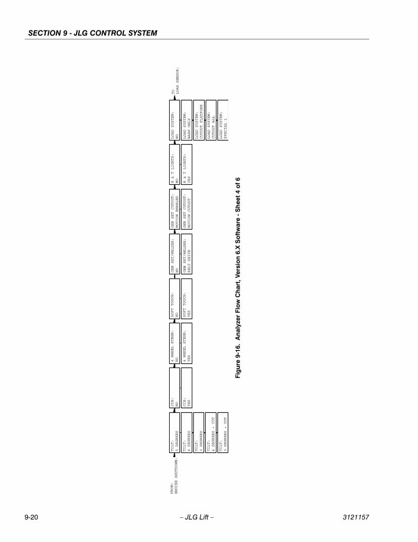
SECTION 9 - JLG CONTROL SYSTEM
9-20 – JLG Lift – 3121157
FROM:
ENGINE SHUTDOWN:
TOLOAD SENSOR:
TILT:
5 DEGREES
JIB:
NO
4 WHEEL STEER:
NO
SOFT TOUCH:
NO
GEN SET/WELDER:
NO
H & T LIGHTS:
NO
LOAD SYSTEM:
NO
TILT:
4 DEGREES
TILT:
3 DEGREES
TILT:
4 DEGREES + CUT
TILT:
3 DEGREES + CUT
JIB:
YES
4 WHEEL STEER:
YES
SOFT TOUCH:
YES
GEN SET/WELDER:
BELT DRIVE
H & T LIGHTS:
YES
LOAD SYSTEM:
WARN ONLY
LOAD SYSTEM:
CUTOUT PLATFORM
LOAD SYSTEM:
CUTOUT ALL
LOAD SYSTEM:
SPECIAL 1
GEN SET CUTOUT:
MOTION ENABLED
GEN SET CUTOUT:
MOTION CUTOUT
Fig
ure
9-16
. A
naly
zer
Flo
w C
har
t, V
ersi
on
6.X
So
ftw
are
- S
hee
t 4
of
6
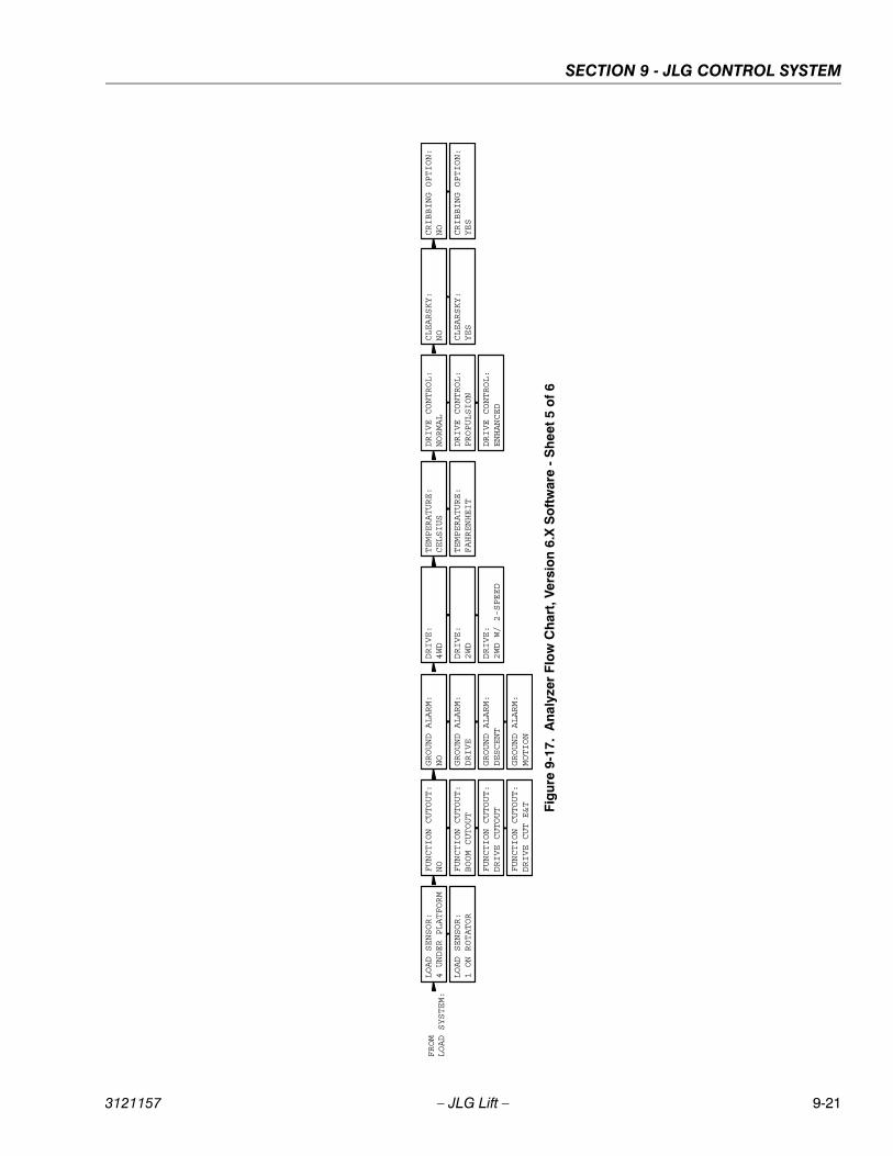
SECTION 9 - JLG CONTROL SYSTEM
3121157 – JLG Lift – 9-21
FROM
LOAD SYSTEM:
LOAD SENSOR:
4 UNDER PLATFORM
FUNCTION CUTOUT:
NO
GROUND ALARM:
NO
DRIVE:
4WD
LOAD SENSOR:
1 ON ROTATOR
FUNCTION CUTOUT:
BOOM CUTOUT
FUNCTION CUTOUT:
DRIVE CUTOUT
FUNCTION CUTOUT:
DRIVE CUT E&T
GROUND ALARM:
DRIVE
GROUND ALARM:
DESCENT
GROUND ALARM:
MOTION
DRIVE:
2WD
DRIVE:
2WD W/ 2-SPEED
TEMPERATURE:
CLEARSKY:
CRIBBING OPTION:
CELSIUS
NO
NO
TEMPERATURE:
CLEARSKY:
CRIBBING OPTION:
FAHRENHEIT
YES
YES
DRIVE CONTROL:
NORMAL
DRIVE CONTROL:
DRIVE CONTROL:
PROPULSION
ENHANCED
Fig
ure
9-17
. A
naly
zer
Flo
w C
har
t, V
ersi
on
6.X
So
ftw
are
- S
hee
t 5
of
6
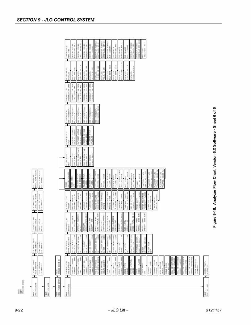
SECTION 9 - JLG CONTROL SYSTEM
9-22 – JLG Lift – 3121157
MENU:
MENU:
HELP:PRESS ENTER
SERVICE MODE
HELP:
GROUND MODE OK
FROM:
MENU:
MACHINE SETUP
MENU:
CALIBRATIONS
MENU:
DIAGNOSTICS
MENU:
SYSTEM TEST
DIAGNOSTICS:
DRIVE/STEER
DIAGNOSTICS:
BOOM FUNCTIONS
DIAGNOSTICS:
ENGINE
DIAGNOSTICS:
SYSTEM
DIAGNOSTICS:
DIAGNOSTICS:
LOAD
UMS
DIAGNOSTICS:
CAN STATISTICS
DIAGNOSTICS:
DATALOG
DIAGNOSTICS:
VERSIONS
DIAGNOSTICS:
CALIBRATION DATA
SYSTEM TEST:
ACTIVATE?
CALIBRATIONS:
TILT SENSOR
CALIBRATIONS:
LEVEL UP CRKPT
TILT SENSOR
CALIBRATE?
LEVEL UP CRKPT
CALIBRATE?
LIFT OUTPUT:
MAIN UP XXX%
SWING OUTPUT:
LEFT XXX%
PLATFORM LEVEL:
UP XXX%
PLATFORM ROTATE:
RIGHT XXX%
MAIN TELESCOPE:
IN XXX%
TOWER TELESCOPE:
IN XXX%
TOWER LIFT:
DOWN XXX%
PLATFORM CONTROL
VALVE: OFF
FUNCTION SPEED:
PUMP POT XXX%
CREEP
SWITCH: CLOSED
CREEP MODE:
OFF
GROUND MODULE
BATTERY: XX.XV
PLATFORM MODULE
BATTERY: XX.XV
AMBIENT
TEMPERATURE:XXXC
PLATFORM SELECT
KEYSWITCH: OPEN
GROUND SELECT
KEYSWITCH:CLOSED
STATION CONTROL:
GROUND
TRANSPORT
SWITCHES: OPEN
TOWER LIFT
PROXIMITY:CLOSED
TOWER TELESCOPE
TOWER POSITION:
PROXIMITY:CLOSED
UP/RETRACTED
CREEP
SWITCH: CLOSED
CREEP MODE:
OFF
CHASSIS TILT:
CHASSIS TILT:
CHASSIS TILT:
XX.X DEGREES
X-AXIS: 0.0
Y-AXIS: 0.0
AUXILIARY POWER
SWITCH: OPEN
HORN
SWITCH: OPEN
SOFT TOUCH LIMIT
SWITCH: OPEN
SOFT TOUCH
OVERRIDE: OPEN
DRIVE OUTPUT:
DRIVE FORWARD
DRIVE REVERSE
DRIVE OUTPUT
FORWARD XXX%
COMMANDED:XXXXMA
COMMANDED:XXXXMA
ACTUAL:XXXXMA
STEER OUTPUT:
LEFT XXX%
STEER TYPE:
NORMAL
BRAKES STATUS:
LOCKED
CREEP
SWITCH: CLOSED
CREEP MODE:
OFF
2-SPEED
SWITCH: OPEN
2-SPEED VALVE
OUTPUT: OFF
HIGH ENGINE
DRV. ORIENTATION
DRV. ORIENTATION
DRV. ORIENTATION
DRV. ORIENTATION
DRIVE CONTROL:
SWITCH: OPEN
FEATURE:ENABLED
OVERRIDE:OPEN
STATUS:CONFIRMED
ENHANCED
START SEQUENCE:
NOT ACTIVE
BATTERY VOLTAGE:
XX.XV
COOLANT
TEMPERATURE:XXXC
ENGINE OIL
PRESSURE:XXXXPSI
AMBIENT
TEMPERATURE:XXXC
FUEL LEVEL
SENSOR: OK
ENGINE SPEED
ACTUAL: XXXX RPM
CAPACITY LENGTH
CHASSIS TILT
SWITCH: CLOSED
ANGLE XXX.X
CAPACITY ANGLE
UMS TO TURNTABLE
SWITCH: CLOSED
ANGLE XXX.X
PLATFORM LOAD
UMS STATUS:
STATE:OK
SENSOR FAULT
CAN STATISTICS
RX/SEC: X
CAN STATISTICS
TX/SEC: X
CAN STATISTICS
BUS OFF: X
CAN STATISTICS
PASSIVE: 1
CALIBRATION DATA
LOAD ZERO: XXX
CALABRATION DATA
LOAD 500LB: XXX
DATALOG:
ON: XXH XXM
DATALOG:
ENGINE: XH XM
DATALOG:
DRIVE: XH XM
DATALOG:
LIFT: XH XM
DATALOG:
SWING: XH XM
DATALOG:
TELE: XH XM
DATALOG:
MAX TEMP: XXC
DATALOG:
MIN TEMP: XXC
DATALOG:
MAX VOLTS: XX.XV
DATALOG:
RENTAL: XH XM
DATALOG:
ERASE RENTAL?
GROUND MODULE
SOFTWARE: P5.X
GROUND MODULE
HARDWARE: REV X
GROUND MODULE
S/N: XXXXXX
PLATFORM MODULE
SOFTWARE: P5.X
PLATFORM MODULE
HARDWARE: REV X
PLATFORM MODULE
S/N: XXXXXX
ANALYZER:
ANALYZER V6.3
ELECTRIC FAN
OUTPUT: OFF
ELECTRIC FUEL
PUMP OUTPUT: OFF
ENGINE SPEED
TARGET: XXXX RPM
END OF STROKE
PROXIMITY: OPEN
CABLE BREAK
SWITCH: CLOSED
GENSET/WELDER
SWITCH: OPEN
LIGHTS
SWITCH: OPEN
PLATFORM TILT1
ANGLE: XX.X DEG
PLATFORM TILT2
ANGLE: XX.X DEG
PLATFORM TILT1
VOLTAGE: XXXX MV
PLATFORM TILT2
VOLTAGE: XXXX MV
JIB LIFT:
UP XXX%
CALIBRATION DATA
PLATFORM UP: XXX
CALABRATION DATA
PLATFORM DN: XXX
STARTER
CRANK TIME: XX S
CALIBRATIONS:
CALIBRATIONS:
DEUTZ SETUP
UMS SENSOR
DEUTZ SETUP
UMS SENSOR:
SETUP X
CALIBRATE?
TCU MODULE
TCU MODULE
TCU MODULE
GATEWAY MODULE
GATEWAY MODULE
SOFTWARE: XXX
HARDWARE REV XXX
S/N: XXXXXXX
SOFTWARE: XXX
HARDWARE REV XXX
GROUND MODULE
CNST. DATA: PX.X
CALIBRATIONS:
LEVEL DOWN CRKPT
LEVEL DOWN CRKPT
CALIBRATE?
LEFT TRACK
OUTPUT: FWD XXX%
RIGHT TRACK
OUTPUT: FWD XXX%
JOYSTICK DRIVE:
FORWARD XXX%
JOYSTICK STEER:
LEFT XXX%
FOOTSWITCH INPUT
GROUND: OPEN
FOOTSWITCH INPUT
PLATFORM: CLOSED
TRANSPORT MODE:
OUT OF TRANSPORT
DRIVE MODE:
MID ENGINE
RETURN HYDRAULIC
FILTER: OPEN
CHARGE PUMP
FILTER: OPEN
FUEL SELECTION
FUEL SELECTION
SWITCH:GAS
STATUS:GAS
CAN STATISTICS
MSG ERROR: XXXX
PERCENT OF MAX
UMS INCLINATION
LOAD: XXXX%
ANGLE XXX.X
JOYSTICK LIFT:
MAIN UP XXX%
JOYSTICK SWING:
LEFT XXX%
Fig
ure
9-18
. A
naly
zer
Flo
w C
har
t, V
ersi
on
6.X
So
ftw
are
- S
hee
t 6
of
6
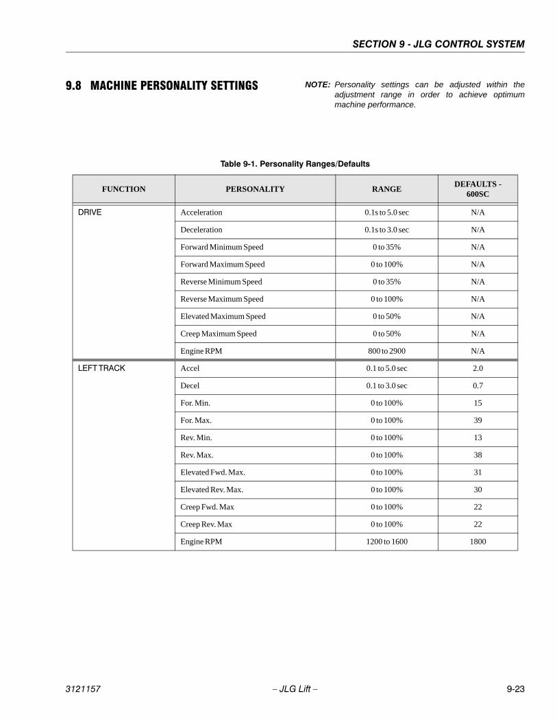
SECTION 9 - JLG CONTROL SYSTEM
3121157 – JLG Lift – 9-23
9.8 MACHINE PERSONALITY SETTINGS NOTE: Personality settings can be adjusted within theadjustment range in order to achieve optimummachine performance.
Table 9-1. Personality Ranges/Defaults
FUNCTION PERSONALITY RANGEDEFAULTS -
600SC
DRIVE Acceleration 0.1s to 5.0 sec N/A
Deceleration 0.1s to 3.0 sec N/A
Forward Minimum Speed 0 to 35% N/A
Forward Maximum Speed 0 to 100% N/A
Reverse Minimum Speed 0 to 35% N/A
Reverse Maximum Speed 0 to 100% N/A
Elevated Maximum Speed 0 to 50% N/A
Creep Maximum Speed 0 to 50% N/A
Engine RPM 800 to 2900 N/A
LEFT TRACK Accel 0.1 to 5.0 sec 2.0
Decel 0.1 to 3.0 sec 0.7
For. Min. 0 to 100% 15
For. Max. 0 to 100% 39
Rev. Min. 0 to 100% 13
Rev. Max. 0 to 100% 38
Elevated Fwd. Max. 0 to 100% 31
Elevated Rev. Max. 0 to 100% 30
Creep Fwd. Max 0 to 100% 22
Creep Rev. Max 0 to 100% 22
Engine RPM 1200 to 1600 1800
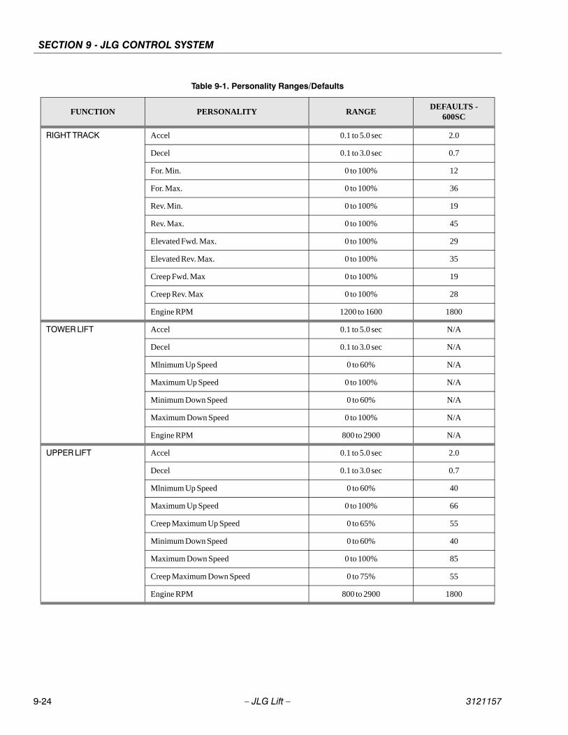
SECTION 9 - JLG CONTROL SYSTEM
9-24 – JLG Lift – 3121157
RIGHT TRACK Accel 0.1 to 5.0 sec 2.0
Decel 0.1 to 3.0 sec 0.7
For. Min. 0 to 100% 12
For. Max. 0 to 100% 36
Rev. Min. 0 to 100% 19
Rev. Max. 0 to 100% 45
Elevated Fwd. Max. 0 to 100% 29
Elevated Rev. Max. 0 to 100% 35
Creep Fwd. Max 0 to 100% 19
Creep Rev. Max 0 to 100% 28
Engine RPM 1200 to 1600 1800
TOWER LIFT Accel 0.1 to 5.0 sec N/A
Decel 0.1 to 3.0 sec N/A
Mlnimum Up Speed 0 to 60% N/A
Maximum Up Speed 0 to 100% N/A
Minimum Down Speed 0 to 60% N/A
Maximum Down Speed 0 to 100% N/A
Engine RPM 800 to 2900 N/A
UPPER LIFT Accel 0.1 to 5.0 sec 2.0
Decel 0.1 to 3.0 sec 0.7
Mlnimum Up Speed 0 to 60% 40
Maximum Up Speed 0 to 100% 66
Creep Maximum Up Speed 0 to 65% 55
Minimum Down Speed 0 to 60% 40
Maximum Down Speed 0 to 100% 85
Creep Maximum Down Speed 0 to 75% 55
Engine RPM 800 to 2900 1800
Table 9-1. Personality Ranges/Defaults
FUNCTION PERSONALITY RANGEDEFAULTS -
600SC
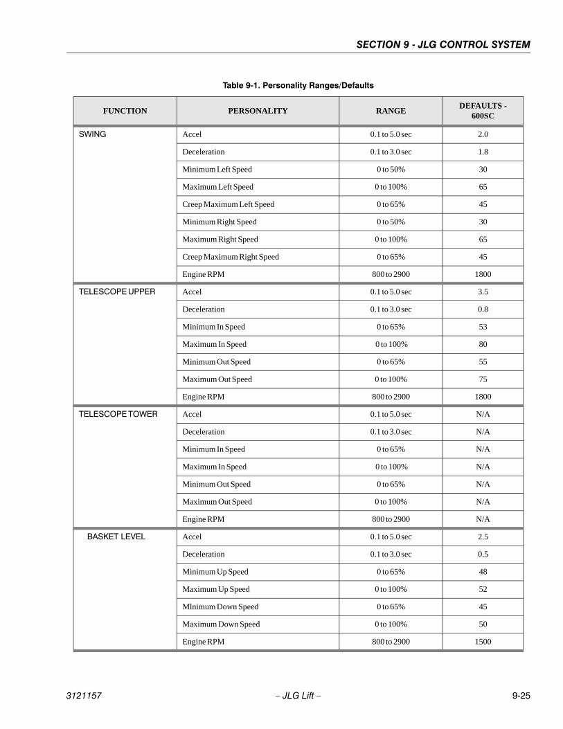
SECTION 9 - JLG CONTROL SYSTEM
3121157 – JLG Lift – 9-25
SWING Accel 0.1 to 5.0 sec 2.0
Deceleration 0.1 to 3.0 sec 1.8
Minimum Left Speed 0 to 50% 30
Maximum Left Speed 0 to 100% 65
Creep Maximum Left Speed 0 to 65% 45
Minimum Right Speed 0 to 50% 30
Maximum Right Speed 0 to 100% 65
Creep Maximum Right Speed 0 to 65% 45
Engine RPM 800 to 2900 1800
TELESCOPE UPPER Accel 0.1 to 5.0 sec 3.5
Deceleration 0.1 to 3.0 sec 0.8
Minimum In Speed 0 to 65% 53
Maximum In Speed 0 to 100% 80
Minimum Out Speed 0 to 65% 55
Maximum Out Speed 0 to 100% 75
Engine RPM 800 to 2900 1800
TELESCOPE TOWER Accel 0.1 to 5.0 sec N/A
Deceleration 0.1 to 3.0 sec N/A
Minimum In Speed 0 to 65% N/A
Maximum In Speed 0 to 100% N/A
Minimum Out Speed 0 to 65% N/A
Maximum Out Speed 0 to 100% N/A
Engine RPM 800 to 2900 N/A
BASKET LEVEL Accel 0.1 to 5.0 sec 2.5
Deceleration 0.1 to 3.0 sec 0.5
Minimum Up Speed 0 to 65% 48
Maximum Up Speed 0 to 100% 52
Mlnimum Down Speed 0 to 65% 45
Maximum Down Speed 0 to 100% 50
Engine RPM 800 to 2900 1500
Table 9-1. Personality Ranges/Defaults
FUNCTION PERSONALITY RANGEDEFAULTS -
600SC
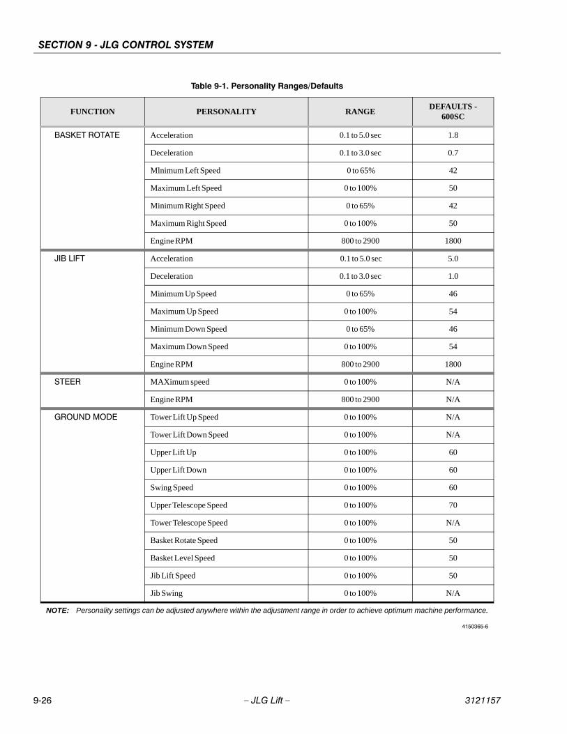
SECTION 9 - JLG CONTROL SYSTEM
9-26 – JLG Lift – 3121157
BASKET ROTATE Acceleration 0.1 to 5.0 sec 1.8
Deceleration 0.1 to 3.0 sec 0.7
Mlnimum Left Speed 0 to 65% 42
Maximum Left Speed 0 to 100% 50
Minimum Right Speed 0 to 65% 42
Maximum Right Speed 0 to 100% 50
Engine RPM 800 to 2900 1800
JIB LIFT Acceleration 0.1 to 5.0 sec 5.0
Deceleration 0.1 to 3.0 sec 1.0
Minimum Up Speed 0 to 65% 46
Maximum Up Speed 0 to 100% 54
Minimum Down Speed 0 to 65% 46
Maximum Down Speed 0 to 100% 54
Engine RPM 800 to 2900 1800
STEER MAXimum speed 0 to 100% N/A
Engine RPM 800 to 2900 N/A
GROUND MODE Tower Lift Up Speed 0 to 100% N/A
Tower Lift Down Speed 0 to 100% N/A
Upper Lift Up 0 to 100% 60
Upper Lift Down 0 to 100% 60
Swing Speed 0 to 100% 60
Upper Telescope Speed 0 to 100% 70
Tower Telescope Speed 0 to 100% N/A
Basket Rotate Speed 0 to 100% 50
Basket Level Speed 0 to 100% 50
Jib Lift Speed 0 to 100% 50
Jib Swing 0 to 100% N/A
NOTE: Personality settings can be adjusted anywhere within the adjustment range in order to achieve optimum machine performance.
4150365-6
Table 9-1. Personality Ranges/Defaults
FUNCTION PERSONALITY RANGEDEFAULTS -
600SC
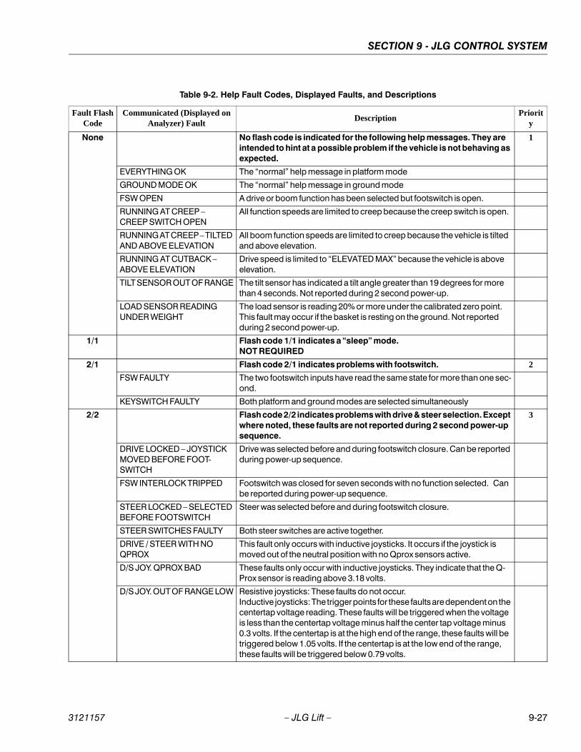
SECTION 9 - JLG CONTROL SYSTEM
3121157 – JLG Lift – 9-27
Table 9-2. Help Fault Codes, Displayed Faults, and Descriptions
Fault FlashCode
Communicated (Displayed on Analyzer) Fault
DescriptionPriorit
y
None No flash code is indicated for the following help messages. They are intended to hint at a possible problem if the vehicle is not behaving as expected.
1
EVERYTHING OK The “normal” help message in platform mode
GROUND MODE OK The “normal” help message in ground mode
FSW OPEN A drive or boom function has been selected but footswitch is open.
RUNNING AT CREEP – CREEP SWITCH OPEN
All function speeds are limited to creep because the creep switch is open.
RUNNING AT CREEP – TILTED AND ABOVE ELEVATION
All boom function speeds are limited to creep because the vehicle is tilted and above elevation.
RUNNING AT CUTBACK – ABOVE ELEVATION
Drive speed is limited to “ELEVATED MAX” because the vehicle is above elevation.
TILT SENSOR OUT OF RANGE The tilt sensor has indicated a tilt angle greater than 19 degrees for more than 4 seconds. Not reported during 2 second power-up.
LOAD SENSOR READING UNDER WEIGHT
The load sensor is reading 20% or more under the calibrated zero point. This fault may occur if the basket is resting on the ground. Not reported during 2 second power-up.
1/1 Flash code 1/1 indicates a “sleep” mode.NOT REQUIRED
2/1 Flash code 2/1 indicates problems with footswitch. 2
FSW FAULTY The two footswitch inputs have read the same state for more than one sec-ond.
KEYSWITCH FAULTY Both platform and ground modes are selected simultaneously
2/2 Flash code 2/2 indicates problems with drive & steer selection. Except where noted, these faults are not reported during 2 second power-up sequence.
3
DRIVE LOCKED – JOYSTICK MOVED BEFORE FOOT-SWITCH
Drive was selected before and during footswitch closure. Can be reported during power-up sequence.
FSW INTERLOCK TRIPPED Footswitch was closed for seven seconds with no function selected. Can be reported during power-up sequence.
STEER LOCKED – SELECTED BEFORE FOOTSWITCH
Steer was selected before and during footswitch closure.
STEER SWITCHES FAULTY Both steer switches are active together.
DRIVE / STEER WITH NO QPROX
This fault only occurs with inductive joysticks. It occurs if the joystick is moved out of the neutral position with no Qprox sensors active.
D/S JOY. QPROX BAD These faults only occur with inductive joysticks. They indicate that the Q-Prox sensor is reading above 3.18 volts.
D/S JOY. OUT OF RANGE LOW Resistive joysticks: These faults do not occur.Inductive joysticks: The trigger points for these faults are dependent on the centertap voltage reading. These faults will be triggered when the voltage is less than the centertap voltage minus half the center tap voltage minus 0.3 volts. If the centertap is at the high end of the range, these faults will be triggered below 1.05 volts. If the centertap is at the low end of the range, these faults will be triggered below 0.79 volts.

SECTION 9 - JLG CONTROL SYSTEM
9-28 – JLG Lift – 3121157
D/S JOY. OUT OF RANGE HIGH
Resistive joysticks: These faults do not occur if the Vref voltage is below 8.1 volts. If Vref is above 7.7 volts, Vref is operating out of tolerance or a short to battery has occurred. Inductive joysticks: The trigger points for these faults are dependent on the centertap voltage reading. These faults will be triggered when the voltage is more than the centertap voltage plus half the centertap voltage plus 0.3 volts. If the centertap is at the high end of the range, these faults will be trig-gered above 4.35 volts. If the centertap is at the low end of the range, these faults will be triggered above 3.8 volts.
D/S JOY. CENTER TAP BAD Resistive joysticks: These faults occur when the center tap voltage is not between 3.08 volts and 3.83 volts. Due to resistor tolerances there is a +/-.1 volt range around these values where the fault may be indicated.Inductive joysticks: These faults occur when the center tap voltage is not between 2.18 volts and 2.70 volts. Due to resistor tolerances there is a +/-.1 volt range around these values where the fault may be indicated.
WAITING FOR FSW TO BE OPEN
Footswitch was closed when platform mode was selected. Can be reported during power-up sequence.
2/3 Flash code 2/3 indicates problems with boom function selection. 3
LIFT/SWING LOCKED – JOY-STICK MOVED BEFORE FOOTSWITCH
Platform upper lift or swing was selected before and during footswitch clo-sure.
PUMP SWITCHES FAULTY – CHECK DIAGNOSTICS/BOOM
A boom function (lower lift, telescope, basket level, basket rotate, jib) has both directions selected together.
PUMP SWITCHES LOCKED – SELECTED BEFORE FOOT-SWITCH
A platform boom function (lower lift, telescope, basket level, basket rotate, jib) was selected before key switch or footswitch closure.
PUMP SWITCHES LOCKED – SELECTED BEFORE AUX POWER
A ground boom function (lower lift, telescope, basket level, basket rotate, jib) was selected before aux power.
LIFT / SWING WITH NO QPROX
This fault only occurs with inductive joysticks. It occurs if the joystick is moved out of the neutral position with no Qprox sensors active.
l/s joy. qprox bad These faults only occur with inductive joysticks. They indicate that the Q-Prox sensor is reading above 3.18 volts.
l/s joy. out of range low Resistive joysticks: These faults do not occur.Inductive joysticks: The trigger points for these faults are dependent on the centertap voltage reading. These faults will be triggered when the voltage is less than the centertap voltage minus half the center tap voltage minus 0.3 volts. If the centertap is at the high end of the range, these faults will be triggered below 1.05 volts. If the centertap is at the low end of the range, these faults will be triggered below 0.79 volts.
l/s joy. out of range high Resistive joysticks: These faults do not occur if the Vref voltage is below 8.1 volts. If Vref is above 7.7 volts, Vref is operating out of tolerance or a short to battery has occurred. Inductive joysticks: The trigger points for these faults are dependent on the centertap voltage reading. These faults will be triggered when the voltage is more than the centertap voltage plus half the centertap voltage plus 0.3 volts. If the centertap is at the high end of the range, these faults will be trig-gered above 4.35 volts. If the centertap is at the low end of the range, these faults will be triggered above 3.8 volts.
Table 9-2. Help Fault Codes, Displayed Faults, and Descriptions
Fault FlashCode
Communicated (Displayed on Analyzer) Fault
DescriptionPriorit
y
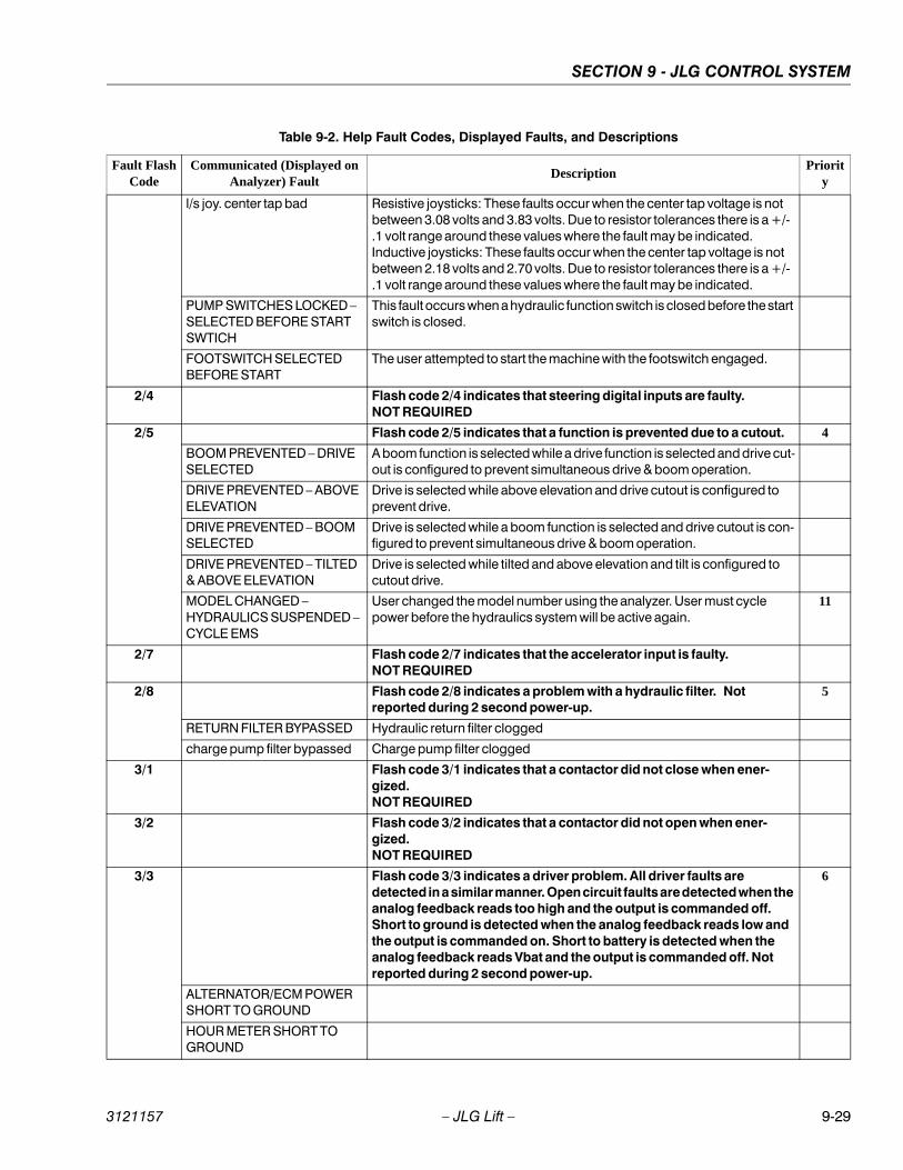
SECTION 9 - JLG CONTROL SYSTEM
3121157 – JLG Lift – 9-29
l/s joy. center tap bad Resistive joysticks: These faults occur when the center tap voltage is not between 3.08 volts and 3.83 volts. Due to resistor tolerances there is a +/-.1 volt range around these values where the fault may be indicated.Inductive joysticks: These faults occur when the center tap voltage is not between 2.18 volts and 2.70 volts. Due to resistor tolerances there is a +/-.1 volt range around these values where the fault may be indicated.
PUMP SWITCHES LOCKED – SELECTED BEFORE START SWTICH
This fault occurs when a hydraulic function switch is closed before the start switch is closed.
FOOTSWITCH SELECTED BEFORE START
The user attempted to start the machine with the footswitch engaged.
2/4 Flash code 2/4 indicates that steering digital inputs are faulty.NOT REQUIRED
2/5 Flash code 2/5 indicates that a function is prevented due to a cutout. 4
BOOM PREVENTED – DRIVE SELECTED
A boom function is selected while a drive function is selected and drive cut-out is configured to prevent simultaneous drive & boom operation.
DRIVE PREVENTED – ABOVE ELEVATION
Drive is selected while above elevation and drive cutout is configured to prevent drive.
DRIVE PREVENTED – BOOM SELECTED
Drive is selected while a boom function is selected and drive cutout is con-figured to prevent simultaneous drive & boom operation.
DRIVE PREVENTED – TILTED & ABOVE ELEVATION
Drive is selected while tilted and above elevation and tilt is configured to cutout drive.
MODEL CHANGED – HYDRAULICS SUSPENDED – CYCLE EMS
User changed the model number using the analyzer. User must cycle power before the hydraulics system will be active again.
11
2/7 Flash code 2/7 indicates that the accelerator input is faulty.NOT REQUIRED
2/8 Flash code 2/8 indicates a problem with a hydraulic filter. Not reported during 2 second power-up.
5
RETURN FILTER BYPASSED Hydraulic return filter clogged
charge pump filter bypassed Charge pump filter clogged
3/1 Flash code 3/1 indicates that a contactor did not close when ener-gized.NOT REQUIRED
3/2 Flash code 3/2 indicates that a contactor did not open when ener-gized.NOT REQUIRED
3/3 Flash code 3/3 indicates a driver problem. All driver faults are detected in a similar manner. Open circuit faults are detected when the analog feedback reads too high and the output is commanded off. Short to ground is detected when the analog feedback reads low and the output is commanded on. Short to battery is detected when the analog feedback reads Vbat and the output is commanded off. Not reported during 2 second power-up.
6
ALTERNATOR/ECM POWER SHORT TO GROUND
HOUR METER SHORT TO GROUND
Table 9-2. Help Fault Codes, Displayed Faults, and Descriptions
Fault FlashCode
Communicated (Displayed on Analyzer) Fault
DescriptionPriorit
y
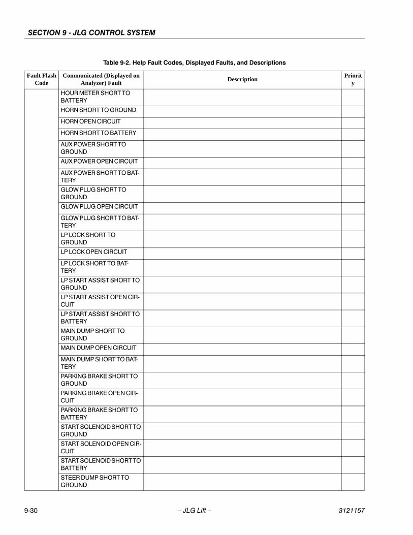
SECTION 9 - JLG CONTROL SYSTEM
9-30 – JLG Lift – 3121157
HOUR METER SHORT TO BATTERY
HORN SHORT TO GROUND
HORN OPEN CIRCUIT
HORN SHORT TO BATTERY
AUX POWER SHORT TO GROUND
AUX POWER OPEN CIRCUIT
AUX POWER SHORT TO BAT-TERY
GLOW PLUG SHORT TO GROUND
GLOW PLUG OPEN CIRCUIT
GLOW PLUG SHORT TO BAT-TERY
LP LOCK SHORT TO GROUND
LP LOCK OPEN CIRCUIT
LP LOCK SHORT TO BAT-TERY
LP START ASSIST SHORT TO GROUND
LP START ASSIST OPEN CIR-CUIT
LP START ASSIST SHORT TO BATTERY
MAIN DUMP SHORT TO GROUND
MAIN DUMP OPEN CIRCUIT
MAIN DUMP SHORT TO BAT-TERY
PARKING BRAKE SHORT TO GROUND
PARKING BRAKE OPEN CIR-CUIT
PARKING BRAKE SHORT TO BATTERY
START SOLENOID SHORT TO GROUND
START SOLENOID OPEN CIR-CUIT
START SOLENOID SHORT TO BATTERY
STEER DUMP SHORT TO GROUND
Table 9-2. Help Fault Codes, Displayed Faults, and Descriptions
Fault FlashCode
Communicated (Displayed on Analyzer) Fault
DescriptionPriorit
y
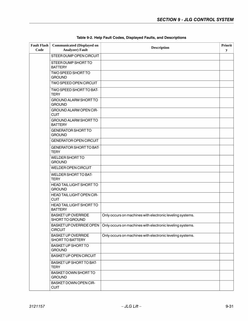
SECTION 9 - JLG CONTROL SYSTEM
3121157 – JLG Lift – 9-31
STEER DUMP OPEN CIRCUIT
STEER DUMP SHORT TO BATTERY
TWO SPEED SHORT TO GROUND
TWO SPEED OPEN CIRCUIT
TWO SPEED SHORT TO BAT-TERY
GROUND ALARM SHORT TO GROUND
GROUND ALARM OPEN CIR-CUIT
GROUND ALARM SHORT TO BATTERY
GENERATOR SHORT TO GROUND
GENERATOR OPEN CIRCUIT
GENERATOR SHORT TO BAT-TERY
WELDER SHORT TO GROUND
WELDER OPEN CIRCUIT
WELDER SHORT TO BAT-TERY
HEAD TAIL LIGHT SHORT TO GROUND
HEAD TAIL LIGHT OPEN CIR-CUIT
HEAD TAIL LIGHT SHORT TO BATTERY
BASKET UP OVERRIDE SHORT TO GROUND
Only occurs on machines with electronic leveling systems.
BASKET UP OVERRIDE OPEN CIRCUIT
Only occurs on machines with electronic leveling systems.
BASKET UP OVERRIDE SHORT TO BATTERY
Only occurs on machines with electronic leveling systems.
BASKET UP SHORT TO GROUND
BASKET UP OPEN CIRCUIT
BASKET UP SHORT TO BAT-TERY
BASKET DOWN SHORT TO GROUND
BASKET DOWN OPEN CIR-CUIT
Table 9-2. Help Fault Codes, Displayed Faults, and Descriptions
Fault FlashCode
Communicated (Displayed on Analyzer) Fault
DescriptionPriorit
y
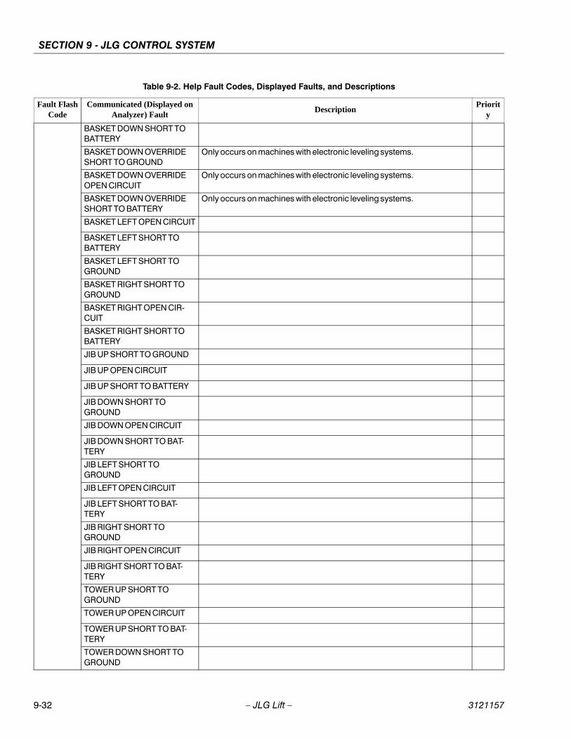
SECTION 9 - JLG CONTROL SYSTEM
9-32 – JLG Lift – 3121157
BASKET DOWN SHORT TO BATTERY
BASKET DOWN OVERRIDE SHORT TO GROUND
Only occurs on machines with electronic leveling systems.
BASKET DOWN OVERRIDE OPEN CIRCUIT
Only occurs on machines with electronic leveling systems.
BASKET DOWN OVERRIDE SHORT TO BATTERY
Only occurs on machines with electronic leveling systems.
BASKET LEFT OPEN CIRCUIT
BASKET LEFT SHORT TO BATTERY
BASKET LEFT SHORT TO GROUND
BASKET RIGHT SHORT TO GROUND
BASKET RIGHT OPEN CIR-CUIT
BASKET RIGHT SHORT TO BATTERY
JIB UP SHORT TO GROUND
JIB UP OPEN CIRCUIT
JIB UP SHORT TO BATTERY
JIB DOWN SHORT TO GROUND
JIB DOWN OPEN CIRCUIT
JIB DOWN SHORT TO BAT-TERY
JIB LEFT SHORT TO GROUND
JIB LEFT OPEN CIRCUIT
JIB LEFT SHORT TO BAT-TERY
JIB RIGHT SHORT TO GROUND
JIB RIGHT OPEN CIRCUIT
JIB RIGHT SHORT TO BAT-TERY
TOWER UP SHORT TO GROUND
TOWER UP OPEN CIRCUIT
TOWER UP SHORT TO BAT-TERY
TOWER DOWN SHORT TO GROUND
Table 9-2. Help Fault Codes, Displayed Faults, and Descriptions
Fault FlashCode
Communicated (Displayed on Analyzer) Fault
DescriptionPriorit
y
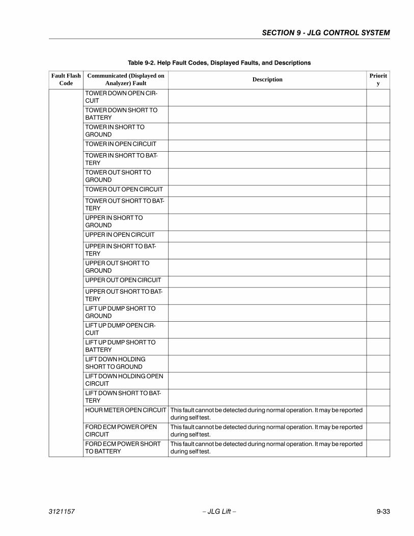
SECTION 9 - JLG CONTROL SYSTEM
3121157 – JLG Lift – 9-33
TOWER DOWN OPEN CIR-CUIT
TOWER DOWN SHORT TO BATTERY
TOWER IN SHORT TO GROUND
TOWER IN OPEN CIRCUIT
TOWER IN SHORT TO BAT-TERY
TOWER OUT SHORT TO GROUND
TOWER OUT OPEN CIRCUIT
TOWER OUT SHORT TO BAT-TERY
UPPER IN SHORT TO GROUND
UPPER IN OPEN CIRCUIT
UPPER IN SHORT TO BAT-TERY
UPPER OUT SHORT TO GROUND
UPPER OUT OPEN CIRCUIT
UPPER OUT SHORT TO BAT-TERY
LIFT UP DUMP SHORT TO GROUND
LIFT UP DUMP OPEN CIR-CUIT
LIFT UP DUMP SHORT TO BATTERY
LIFT DOWN HOLDING SHORT TO GROUND
LIFT DOWN HOLDING OPEN CIRCUIT
LIFT DOWN SHORT TO BAT-TERY
HOUR METER OPEN CIRCUIT This fault cannot be detected during normal operation. It may be reported during self test.
FORD ECM POWER OPEN CIRCUIT
This fault cannot be detected during normal operation. It may be reported during self test.
FORD ECM POWER SHORT TO BATTERY
This fault cannot be detected during normal operation. It may be reported during self test.
Table 9-2. Help Fault Codes, Displayed Faults, and Descriptions
Fault FlashCode
Communicated (Displayed on Analyzer) Fault
DescriptionPriorit
y
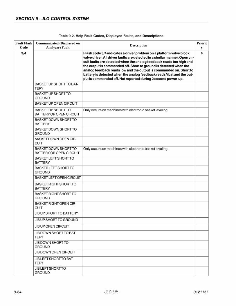
SECTION 9 - JLG CONTROL SYSTEM
9-34 – JLG Lift – 3121157
3/4 Flash code 3/4 indicates a driver problem on a platform valve block valve driver. All driver faults are detected in a similar manner. Open cir-cuit faults are detected when the analog feedback reads too high and the output is commanded off. Short to ground is detected when the analog feedback reads low and the output is commanded on. Short to battery is detected when the analog feedback reads Vbat and the out-put is commanded off. Not reported during 2 second power-up.
6
BASKET UP SHORT TO BAT-TERY
BASKET UP SHORT TO GROUND
BASKET UP OPEN CIRCUIT
BASKET UP SHORT TO BATTERY OR OPEN CIRCUIT
Only occurs on machines with electronic basket leveling
BASKET DOWN SHORT TO BATTERY
BASKET DOWN SHORT TO GROUND
bASKET DOWN OPEN CIR-CUIT
BASKET DOWN SHORT TO BATTERY OR OPEN CIRCUIT
Only occurs on machines with electronic basket leveling.
BASKET LEFT SHORT TO BATTERY
BASKER LEFT SHORT TO GROUND
BASKET LEFT OPEN CIRCUIT
BASKET RIGHT SHORT TO BATTERY
BASKET RIGHT SHORT TO GROUND
BASKET RIGHT OPEN CIR-CUIT
JIB UP SHORT TO BATTERY
JIB UP SHORT TO GROUND
JIB UP OPEN CIRCUIT
JIB DOWN SHORT TO BAT-TERY
JIB DOWN SHORT TO GROUND
JIB DOWN OPEN CIRCUIT
JIB LEFT SHORT TO BAT-TERY
JIB LEFT SHORT TO GROUND
Table 9-2. Help Fault Codes, Displayed Faults, and Descriptions
Fault FlashCode
Communicated (Displayed on Analyzer) Fault
DescriptionPriorit
y
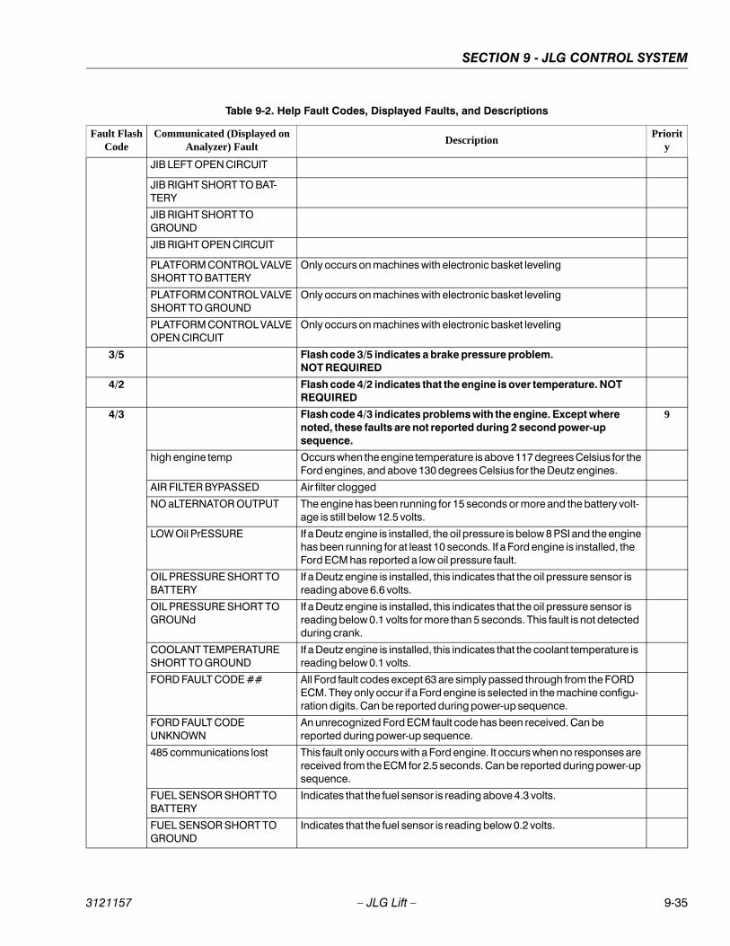
SECTION 9 - JLG CONTROL SYSTEM
3121157 – JLG Lift – 9-35
JIB LEFT OPEN CIRCUIT
JIB RIGHT SHORT TO BAT-TERY
JIB RIGHT SHORT TO GROUND
JIB RIGHT OPEN CIRCUIT
PLATFORM CONTROL VALVE SHORT TO BATTERY
Only occurs on machines with electronic basket leveling
PLATFORM CONTROL VALVE SHORT TO GROUND
Only occurs on machines with electronic basket leveling
PLATFORM CONTROL VALVE OPEN CIRCUIT
Only occurs on machines with electronic basket leveling
3/5 Flash code 3/5 indicates a brake pressure problem.NOT REQUIRED
4/2 Flash code 4/2 indicates that the engine is over temperature. NOT REQUIRED
4/3 Flash code 4/3 indicates problems with the engine. Except where noted, these faults are not reported during 2 second power-up sequence.
9
high engine temp Occurs when the engine temperature is above 117 degrees Celsius for the Ford engines, and above 130 degrees Celsius for the Deutz engines.
AIR FILTER BYPASSED Air filter clogged
NO aLTERNATOR OUTPUT The engine has been running for 15 seconds or more and the battery volt-age is still below 12.5 volts.
LOW Oil PrESSURE If a Deutz engine is installed, the oil pressure is below 8 PSI and the engine has been running for at least 10 seconds. If a Ford engine is installed, the Ford ECM has reported a low oil pressure fault.
OIL PRESSURE SHORT TO BATTERY
If a Deutz engine is installed, this indicates that the oil pressure sensor is reading above 6.6 volts.
OIL PRESSURE SHORT TO GROUNd
If a Deutz engine is installed, this indicates that the oil pressure sensor is reading below 0.1 volts for more than 5 seconds. This fault is not detected during crank.
COOLANT TEMPERATURE SHORT TO GROUND
If a Deutz engine is installed, this indicates that the coolant temperature is reading below 0.1 volts.
FORD FAULT CODE ## All Ford fault codes except 63 are simply passed through from the FORD ECM. They only occur if a Ford engine is selected in the machine configu-ration digits. Can be reported during power-up sequence.
FORD FAULT CODE UNKNOWN
An unrecognized Ford ECM fault code has been received. Can be reported during power-up sequence.
485 communications lost This fault only occurs with a Ford engine. It occurs when no responses are received from the ECM for 2.5 seconds. Can be reported during power-up sequence.
FUEL SENSOR SHORT TO BATTERY
Indicates that the fuel sensor is reading above 4.3 volts.
FUEL SENSOR SHORT TO GROUND
Indicates that the fuel sensor is reading below 0.2 volts.
Table 9-2. Help Fault Codes, Displayed Faults, and Descriptions
Fault FlashCode
Communicated (Displayed on Analyzer) Fault
DescriptionPriorit
y
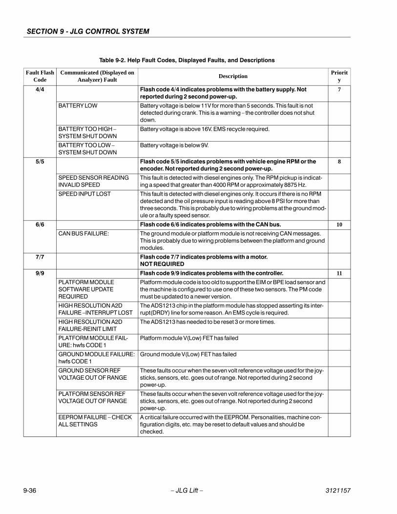
SECTION 9 - JLG CONTROL SYSTEM
9-36 – JLG Lift – 3121157
4/4 Flash code 4/4 indicates problems with the battery supply. Not reported during 2 second power-up.
7
BATTERY LOW Battery voltage is below 11V for more than 5 seconds. This fault is not detected during crank. This is a warning – the controller does not shut down.
BATTERY TOO HIGH – SYSTEM SHUT DOWN
Battery voltage is above 16V. EMS recycle required.
BATTERY TOO LOW – SYSTEM SHUT DOWN
Battery voltage is below 9V.
5/5 Flash code 5/5 indicates problems with vehicle engine RPM or the encoder. Not reported during 2 second power-up.
8
SPEED SENSOR READING INVALID SPEED
This fault is detected with diesel engines only. The RPM pickup is indicat-ing a speed that greater than 4000 RPM or approximately 8875 Hz.
SPEED INPUT LOST This fault is detected with diesel engines only. It occurs if there is no RPM detected and the oil pressure input is reading above 8 PSI for more than three seconds. This is probably due to wiring problems at the ground mod-ule or a faulty speed sensor.
6/6 Flash code 6/6 indicates problems with the CAN bus. 10
CAN BUS FAILURE: The ground module or platform module is not receiving CAN messages. This is probably due to wiring problems between the platform and ground modules.
7/7 Flash code 7/7 indicates problems with a motor.NOT REQUIRED
9/9 Flash code 9/9 indicates problems with the controller. 11
PLATFORM MODULE SOFTWARE UPDATE REQUIRED
Platform module code is too old to support the EIM or BPE load sensor and the machine is configured to use one of these two sensors. The PM code must be updated to a newer version.
HIGH RESOLUTION A2D FAILURE –INTERRUPT LOST
The ADS1213 chip in the platform module has stopped asserting its inter-rupt(DRDY) line for some reason. An EMS cycle is required.
HIGH RESOLUTION A2D FAILURE-REINIT LIMIT
The ADS1213 has needed to be reset 3 or more times.
PLATFORM MODULE FAIL-URE: hwfs CODE 1
Platform module V(Low) FET has failed
GROUND MODULE FAILURE: hwfs CODE 1
Ground module V(Low) FET has failed
GROUND SENSOR REF VOLTAGE OUT OF RANGE
These faults occur when the seven volt reference voltage used for the joy-sticks, sensors, etc. goes out of range. Not reported during 2 second power-up.
PLATFORM SENSOR REF VOLTAGE OUT OF RANGE
These faults occur when the seven volt reference voltage used for the joy-sticks, sensors, etc. goes out of range. Not reported during 2 second power-up.
EEPROM FAILURE – CHECK ALL SETTINGS
A critical failure occurred with the EEPROM. Personalities, machine con-figuration digits, etc. may be reset to default values and should be checked.
Table 9-2. Help Fault Codes, Displayed Faults, and Descriptions
Fault FlashCode
Communicated (Displayed on Analyzer) Fault
DescriptionPriorit
y
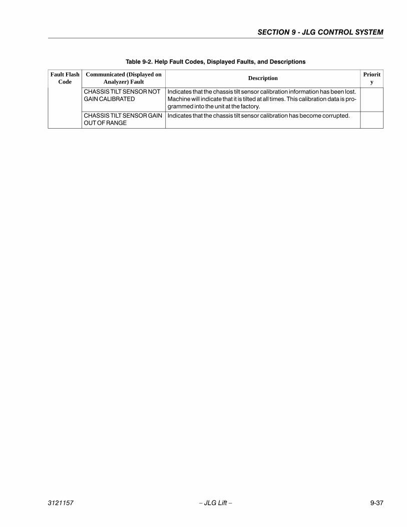
SECTION 9 - JLG CONTROL SYSTEM
3121157 – JLG Lift – 9-37
CHASSIS TILT SENSOR NOT GAIN CALIBRATED
Indicates that the chassis tilt sensor calibration information has been lost. Machine will indicate that it is tilted at all times. This calibration data is pro-grammed into the unit at the factory.
CHASSIS TILT SENSOR GAIN OUT OF RANGE
Indicates that the chassis tilt sensor calibration has become corrupted.
Table 9-2. Help Fault Codes, Displayed Faults, and Descriptions
Fault FlashCode
Communicated (Displayed on Analyzer) Fault
DescriptionPriorit
y
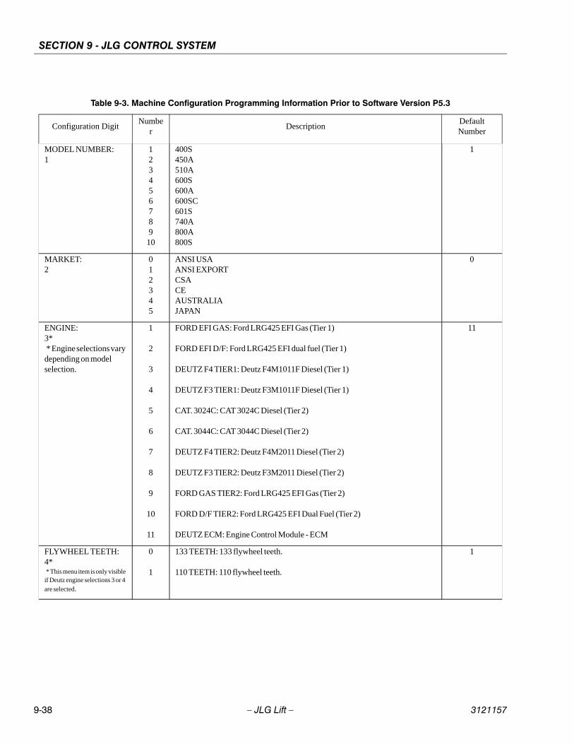
SECTION 9 - JLG CONTROL SYSTEM
9-38 – JLG Lift – 3121157
Table 9-3. Machine Configuration Programming Information Prior to Software Version P5.3
Configuration DigitNumbe
rDescription
Default Number
MODEL NUMBER:1
12345678910
400S450A510A600S600A600SC601S740A800A800S
1
MARKET:2
012345
ANSI USAANSI EXPORTCSACEAUSTRALIAJAPAN
0
ENGINE:3* * Engine selections vary depending on model selection.
1
2
3
4
5
6
7
8
9
10
11
FORD EFI GAS: Ford LRG425 EFI Gas (Tier 1)
FORD EFI D/F: Ford LRG425 EFI dual fuel (Tier 1)
DEUTZ F4 TIER1: Deutz F4M1011F Diesel (Tier 1)
DEUTZ F3 TIER1: Deutz F3M1011F Diesel (Tier 1)
CAT. 3024C: CAT 3024C Diesel (Tier 2)
CAT. 3044C: CAT 3044C Diesel (Tier 2)
DEUTZ F4 TIER2: Deutz F4M2011 Diesel (Tier 2)
DEUTZ F3 TIER2: Deutz F3M2011 Diesel (Tier 2)
FORD GAS TIER2: Ford LRG425 EFI Gas (Tier 2)
FORD D/F TIER2: Ford LRG425 EFI Dual Fuel (Tier 2)
DEUTZ ECM: Engine Control Module - ECM
11
FLYWHEEL TEETH:4* * This menu item is only visible if Deutz engine selections 3 or 4
are selected.
0
1
133 TEETH: 133 flywheel teeth.
110 TEETH: 110 flywheel teeth.
1
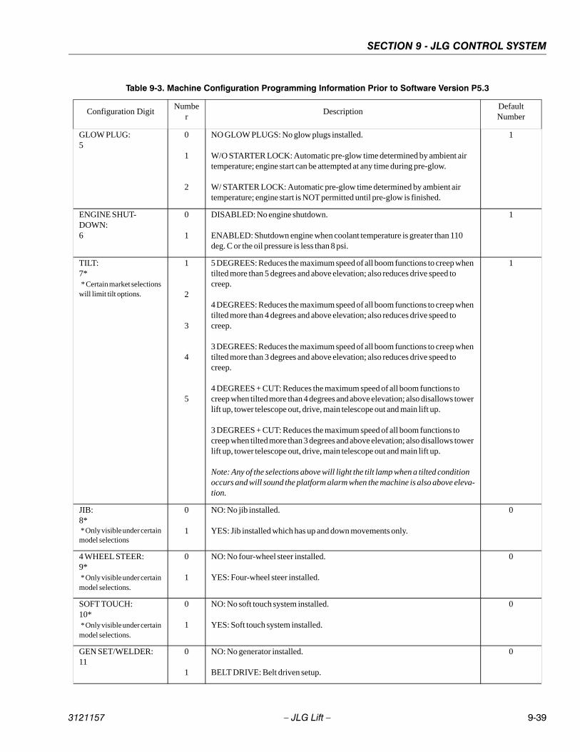
SECTION 9 - JLG CONTROL SYSTEM
3121157 – JLG Lift – 9-39
GLOW PLUG:5
0
1
2
NO GLOW PLUGS: No glow plugs installed.
W/O STARTER LOCK: Automatic pre-glow time determined by ambient air temperature; engine start can be attempted at any time during pre-glow.
W/ STARTER LOCK: Automatic pre-glow time determined by ambient air temperature; engine start is NOT permitted until pre-glow is finished.
1
ENGINE SHUT-DOWN:6
0
1
DISABLED: No engine shutdown.
ENABLED: Shutdown engine when coolant temperature is greater than 110 deg. C or the oil pressure is less than 8 psi.
1
TILT:7* * Certain market selections will limit tilt options.
1
2
3
4
5
5 DEGREES: Reduces the maximum speed of all boom functions to creep when tilted more than 5 degrees and above elevation; also reduces drive speed to creep.
4 DEGREES: Reduces the maximum speed of all boom functions to creep when tilted more than 4 degrees and above elevation; also reduces drive speed to creep.
3 DEGREES: Reduces the maximum speed of all boom functions to creep when tilted more than 3 degrees and above elevation; also reduces drive speed to creep.
4 DEGREES + CUT: Reduces the maximum speed of all boom functions to creep when tilted more than 4 degrees and above elevation; also disallows tower lift up, tower telescope out, drive, main telescope out and main lift up.
3 DEGREES + CUT: Reduces the maximum speed of all boom functions to creep when tilted more than 3 degrees and above elevation; also disallows tower lift up, tower telescope out, drive, main telescope out and main lift up.
Note: Any of the selections above will light the tilt lamp when a tilted condition occurs and will sound the platform alarm when the machine is also above eleva-tion.
1
JIB:8* * Only visible under certain model selections
0
1
NO: No jib installed.
YES: Jib installed which has up and down movements only.
0
4 WHEEL STEER:9* * Only visible under certain model selections.
0
1
NO: No four-wheel steer installed.
YES: Four-wheel steer installed.
0
SOFT TOUCH:10* * Only visible under certain model selections.
0
1
NO: No soft touch system installed.
YES: Soft touch system installed.
0
GEN SET/WELDER:11
0
1
NO: No generator installed.
BELT DRIVE: Belt driven setup.
0
Table 9-3. Machine Configuration Programming Information Prior to Software Version P5.3
Configuration DigitNumbe
rDescription
Default Number
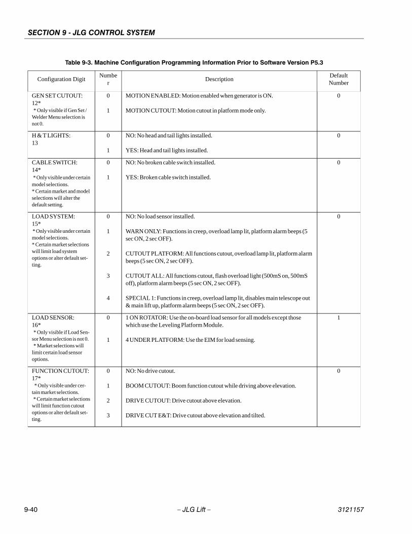
SECTION 9 - JLG CONTROL SYSTEM
9-40 – JLG Lift – 3121157
GEN SET CUTOUT:12* * Only visible if Gen Set / Welder Menu selection is not 0.
0
1
MOTION ENABLED: Motion enabled when generator is ON.
MOTION CUTOUT: Motion cutout in platform mode only.
0
H & T LIGHTS:13
0
1
NO: No head and tail lights installed.
YES: Head and tail lights installed.
0
CABLE SWITCH:14* * Only visible under certain model selections.* Certain market and model selections will alter the default setting.
0
1
NO: No broken cable switch installed.
YES: Broken cable switch installed.
0
LOAD SYSTEM:15* * Only visible under certain model selections.* Certain market selections will limit load system options or alter default set-ting.
0
1
2
3
4
NO: No load sensor installed.
WARN ONLY: Functions in creep, overload lamp lit, platform alarm beeps (5 sec ON, 2 sec OFF).
CUTOUT PLATFORM: All functions cutout, overload lamp lit, platform alarm beeps (5 sec ON, 2 sec OFF).
CUTOUT ALL: All functions cutout, flash overload light (500mS on, 500mS off), platform alarm beeps (5 sec ON, 2 sec OFF).
SPECIAL 1: Functions in creep, overload lamp lit, disables main telescope out & main lift up, platform alarm beeps (5 sec ON, 2 sec OFF).
0
LOAD SENSOR:16* * Only visible if Load Sen-sor Menu selection is not 0. * Market selections will limit certain load sensor options.
0
1
1 ON ROTATOR: Use the on-board load sensor for all models except those which use the Leveling Platform Module.
4 UNDER PLATFORM: Use the EIM for load sensing.
1
FUNCTION CUTOUT:17* * Only visible under cer-tain market selections. * Certain market selections will limit function cutout options or alter default set-ting.
0
1
2
3
NO: No drive cutout.
BOOM CUTOUT: Boom function cutout while driving above elevation.
DRIVE CUTOUT: Drive cutout above elevation.
DRIVE CUT E&T: Drive cutout above elevation and tilted.
0
Table 9-3. Machine Configuration Programming Information Prior to Software Version P5.3
Configuration DigitNumbe
rDescription
Default Number

SECTION 9 - JLG CONTROL SYSTEM
3121157 – JLG Lift – 9-41
GROUND ALARM:18* * Certain market selections will alter default setting.
0
1
2
3
NO: No ground alarm installed.
DRIVE: Travel alarm sounds when the drive function is active (Option).
DESCENT: Descent alarm sounds when lift down is active (Option).
MOTION: Motion alarm sounds when any function is active (Option).
0
DRIVE:19* * Only visible under certain model selections.
0
1
2
4WD: Four wheel drive.
2WD: Two wheel drive.
2WD W/ 2-SPEED: Two wheel drive with 2-speed valve.
0
TEMPERATURE:20
0
1
CELSIUS: Celsius unit selection.
FAHRENHEIT: Fahrenheit unit selection.
1
LEVELING MODE:21* * Only visible on 800S models.
0
1
ALL FUNCTIONS: Platform level with all functions.
LEVEL LIFT/TELESCOPE: Platform level on lift and telescope only.
0
4150364-14
Table 9-3. Machine Configuration Programming Information Prior to Software Version P5.3
Configuration DigitNumbe
rDescription
Default Number
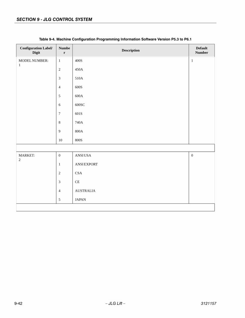
SECTION 9 - JLG CONTROL SYSTEM
9-42 – JLG Lift – 3121157
Table 9-4. Machine Configuration Programming Information Software Version P5.3 to P6.1
Configuration Label/Digit
Number
DescriptionDefault Number
MODEL NUMBER:1
1
2
3
4
5
6
7
8
9
10
400S
450A
510A
600S
600A
600SC
601S
740A
800A
800S
1
MARKET:2
0
1
2
3
4
5
ANSI USA
ANSI EXPORT
CSA
CE
AUSTRALIA
JAPAN
0
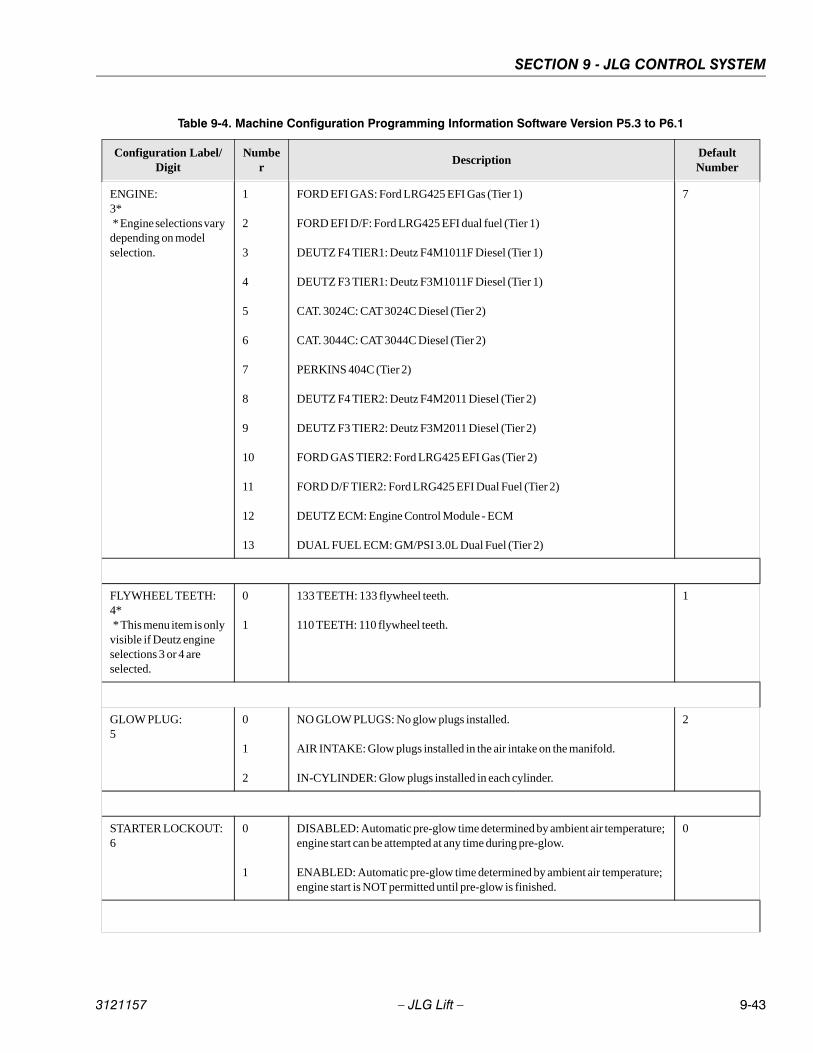
SECTION 9 - JLG CONTROL SYSTEM
3121157 – JLG Lift – 9-43
ENGINE:3* * Engine selections vary depending on model selection.
1
2
3
4
5
6
7
8
9
10
11
12
13
FORD EFI GAS: Ford LRG425 EFI Gas (Tier 1)
FORD EFI D/F: Ford LRG425 EFI dual fuel (Tier 1)
DEUTZ F4 TIER1: Deutz F4M1011F Diesel (Tier 1)
DEUTZ F3 TIER1: Deutz F3M1011F Diesel (Tier 1)
CAT. 3024C: CAT 3024C Diesel (Tier 2)
CAT. 3044C: CAT 3044C Diesel (Tier 2)
PERKINS 404C (Tier 2)
DEUTZ F4 TIER2: Deutz F4M2011 Diesel (Tier 2)
DEUTZ F3 TIER2: Deutz F3M2011 Diesel (Tier 2)
FORD GAS TIER2: Ford LRG425 EFI Gas (Tier 2)
FORD D/F TIER2: Ford LRG425 EFI Dual Fuel (Tier 2)
DEUTZ ECM: Engine Control Module - ECM
DUAL FUEL ECM: GM/PSI 3.0L Dual Fuel (Tier 2)
7
FLYWHEEL TEETH:4* * This menu item is only visible if Deutz engine selections 3 or 4 are selected.
0
1
133 TEETH: 133 flywheel teeth.
110 TEETH: 110 flywheel teeth.
1
GLOW PLUG:5
0
1
2
NO GLOW PLUGS: No glow plugs installed.
AIR INTAKE: Glow plugs installed in the air intake on the manifold.
IN-CYLINDER: Glow plugs installed in each cylinder.
2
STARTER LOCKOUT:6
0
1
DISABLED: Automatic pre-glow time determined by ambient air temperature; engine start can be attempted at any time during pre-glow.
ENABLED: Automatic pre-glow time determined by ambient air temperature; engine start is NOT permitted until pre-glow is finished.
0
Table 9-4. Machine Configuration Programming Information Software Version P5.3 to P6.1
Configuration Label/Digit
Number
DescriptionDefault Number

SECTION 9 - JLG CONTROL SYSTEM
9-44 – JLG Lift – 3121157
ENGINE SHUT-DOWN:7
0
1
DISABLED: No engine shutdown.
ENABLED: Shutdown engine when coolant temperature is greater than 110 deg. C or the oil pressure is less than 8 PSI.
1
TILT:8* * Certain market selec-tions will limit tilt options and alter default setting.
Note: Any of the selec-tions above will light the tilt lamp when a tilted condition occurs and will sound the platform alarm when the machine is also above elevation.
1
2
3
4
5
5 DEGREES: Reduces the maximum speed of all boom functions to creep when tilted more than 5 degrees and above elevation; also reduces drive speed to creep.
4 DEGREES: Reduces the maximum speed of all boom functions to creep when tilted more than 4 degrees and above elevation; also reduces drive speed to creep.
3 DEGREES: Reduces the maximum speed of all boom functions to creep when tilted more than 3 degrees and above elevation; also reduces drive speed to creep.
4 DEGREES + CUT: Reduces the maximum speed of all boom functions to creep when tilted more than 4 degrees and above elevation; also disallows tower lift up, tower telescope out, drive, main telescope out and main lift up.
3 DEGREES + CUT: Reduces the maximum speed of all boom functions to creep when tilted more than 3 degrees and above elevation; also disallows tower lift up, tower telescope out, drive, main telescope out and main lift up.
1
JIB:9* * Only visible under certain model selections.
0
1
NO: No jib installed.
YES: Jib installed which has up and down movements only.
0
4 WHEEL STEER:10* * Only visible under certain model selections.
0
1
NO: No four-wheel steer installed.
YES: Four-wheel steer installed.
0
SOFT TOUCH:11* * Only visible under certain model selections.
0
1
NO: No soft touch system installed.
YES: Soft touch system installed.
0
GEN SET/WELDER:12
0
1
NO: No generator installed.
BELT DRIVE: Belt driven setup.
0
Table 9-4. Machine Configuration Programming Information Software Version P5.3 to P6.1
Configuration Label/Digit
Number
DescriptionDefault Number
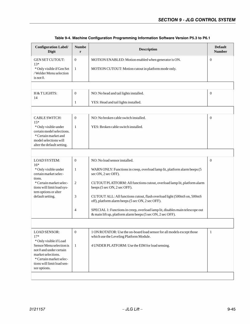
SECTION 9 - JLG CONTROL SYSTEM
3121157 – JLG Lift – 9-45
GEN SET CUTOUT:13* * Only visible if Gen Set / Welder Menu selection is not 0.
0
1
MOTION ENABLED: Motion enabled when generator is ON.
MOTION CUTOUT: Motion cutout in platform mode only.
0
H & T LIGHTS:14
0
1
NO: No head and tail lights installed.
YES: Head and tail lights installed.
0
CABLE SWITCH:15* * Only visible under certain model selections. * Certain market and model selections will alter the default setting.
0
1
NO: No broken cable switch installed.
YES: Broken cable switch installed.
0
LOAD SYSTEM:16* * Only visible under certain market selec-tions. * Certain market selec-tions will limit load sys-tem options or alter default setting.
0
1
2
3
4
NO: No load sensor installed.
WARN ONLY: Functions in creep, overload lamp lit, platform alarm beeps (5 sec ON, 2 sec OFF).
CUTOUT PLATFORM: All functions cutout, overload lamp lit, platform alarm beeps (5 sec ON, 2 sec OFF).
CUTOUT ALL: All functions cutout, flash overload light (500mS on, 500mS off), platform alarm beeps (5 sec ON, 2 sec OFF).
SPECIAL 1: Functions in creep, overload lamp lit, disables main telescope out & main lift up, platform alarm beeps (5 sec ON, 2 sec OFF).
0
LOAD SENSOR:17* * Only visible if Load Sensor Menu selection is not 0 and under certain market selections. * Certain market selec-tions will limit load sen-sor options.
0
1
1 ON ROTATOR: Use the on-board load sensor for all models except those which use the Leveling Platform Module.
4 UNDER PLATFORM: Use the EIM for load sensing.
1
Table 9-4. Machine Configuration Programming Information Software Version P5.3 to P6.1
Configuration Label/Digit
Number
DescriptionDefault Number

SECTION 9 - JLG CONTROL SYSTEM
9-46 – JLG Lift – 3121157
FUNCTION CUTOUT:18* * Only visible under certain market selec-tions. * Certain market selec-tions will limit function cutout options or alter default setting.
0
1
2
3
NO: No drive cutout.
BOOM CUTOUT: Boom function cutout while driving above elevation.
DRIVE CUTOUT: Drive & steer cutout above elevation.
DRIVE CUT E&T: Drive & steer cutout above elevation and tilted.
0
GROUND ALARM:19* * Certain market selec-tions will alter default setting.
0
1
2
3
NO: No ground alarm installed.
DRIVE: Travel alarm sounds when the drive function is active (Option).
DESCENT: Descent alarm sounds when lift down is active (Option).
MOTION: Motion alarm sounds when any function is active (Option).
3
DRIVE:20* * Only visible under certain model selections.
0
1
2
4WD: Four wheel drive.
2WD: Two wheel drive.
2WD W/ 2-SPEED: Two wheel drive with 2-speed valve.
0
TEMPERATURE:21* * Certain market selec-tions will alter default setting.
0
1
CELSIUS: Celsius unit selection.
FAHRENHEIT: Fahrenheit unit selection.
1
LEVELING MODE:22* * Only visible on 800S models.
0
1
ALL FUNCTIONS: Platform level with all functions.
LEVEL LIFT/TELESCOPE: Platform level on lift and telescope only.
0
4150364-18
Table 9-4. Machine Configuration Programming Information Software Version P5.3 to P6.1
Configuration Label/Digit
Number
DescriptionDefault Number
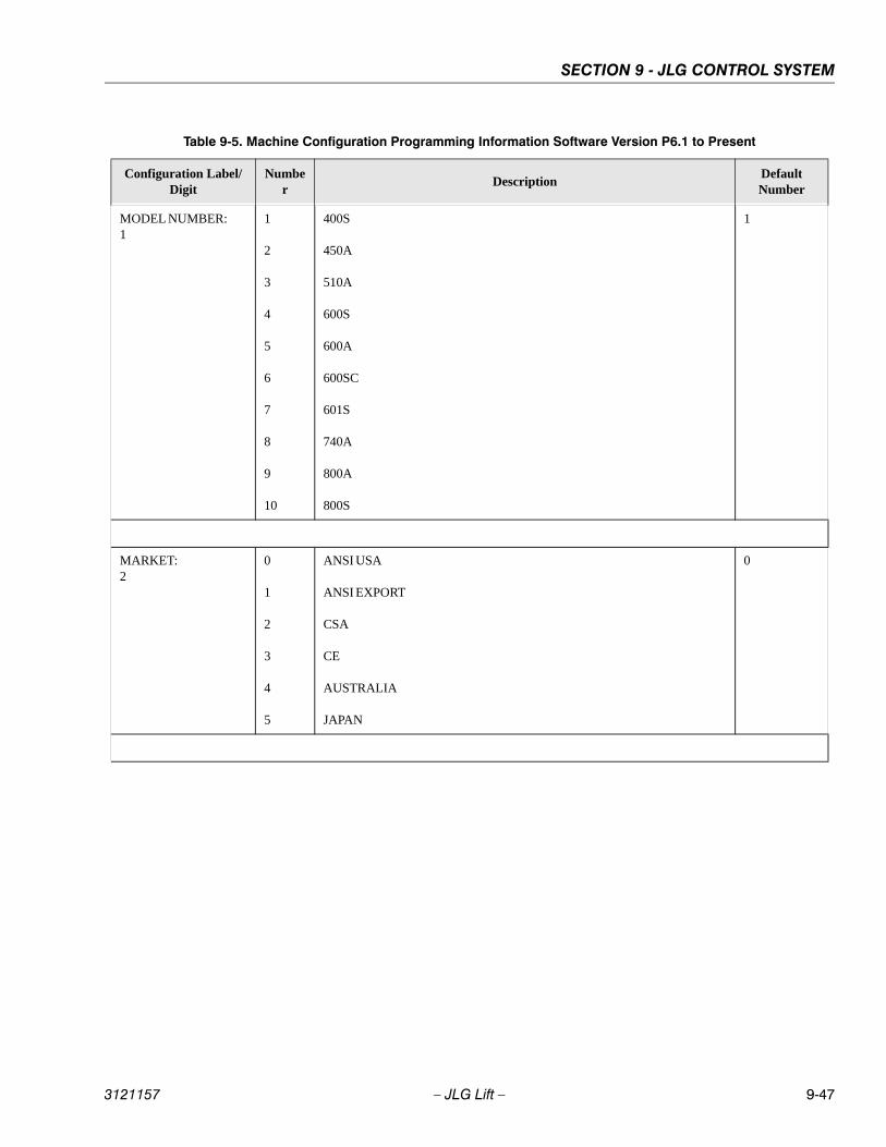
SECTION 9 - JLG CONTROL SYSTEM
3121157 – JLG Lift – 9-47
Table 9-5. Machine Configuration Programming Information Software Version P6.1 to Present
Configuration Label/Digit
Number
DescriptionDefault Number
MODEL NUMBER:1
1
2
3
4
5
6
7
8
9
10
400S
450A
510A
600S
600A
600SC
601S
740A
800A
800S
1
MARKET:2
0
1
2
3
4
5
ANSI USA
ANSI EXPORT
CSA
CE
AUSTRALIA
JAPAN
0
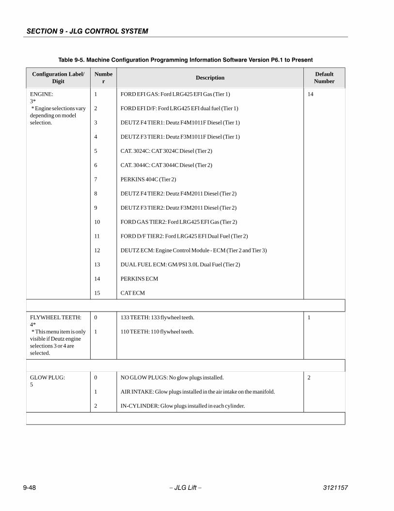
SECTION 9 - JLG CONTROL SYSTEM
9-48 – JLG Lift – 3121157
ENGINE:3* * Engine selections vary depending on model selection.
1
2
3
4
5
6
7
8
9
10
11
12
13
14
15
FORD EFI GAS: Ford LRG425 EFI Gas (Tier 1)
FORD EFI D/F: Ford LRG425 EFI dual fuel (Tier 1)
DEUTZ F4 TIER1: Deutz F4M1011F Diesel (Tier 1)
DEUTZ F3 TIER1: Deutz F3M1011F Diesel (Tier 1)
CAT. 3024C: CAT 3024C Diesel (Tier 2)
CAT. 3044C: CAT 3044C Diesel (Tier 2)
PERKINS 404C (Tier 2)
DEUTZ F4 TIER2: Deutz F4M2011 Diesel (Tier 2)
DEUTZ F3 TIER2: Deutz F3M2011 Diesel (Tier 2)
FORD GAS TIER2: Ford LRG425 EFI Gas (Tier 2)
FORD D/F TIER2: Ford LRG425 EFI Dual Fuel (Tier 2)
DEUTZ ECM: Engine Control Module - ECM (Tier 2 and Tier 3)
DUAL FUEL ECM: GM/PSI 3.0L Dual Fuel (Tier 2)
PERKINS ECM
CAT ECM
14
FLYWHEEL TEETH:4* * This menu item is only visible if Deutz engine selections 3 or 4 are selected.
0
1
133 TEETH: 133 flywheel teeth.
110 TEETH: 110 flywheel teeth.
1
GLOW PLUG:5
0
1
2
NO GLOW PLUGS: No glow plugs installed.
AIR INTAKE: Glow plugs installed in the air intake on the manifold.
IN-CYLINDER: Glow plugs installed in each cylinder.
2
Table 9-5. Machine Configuration Programming Information Software Version P6.1 to Present
Configuration Label/Digit
Number
DescriptionDefault Number

SECTION 9 - JLG CONTROL SYSTEM
3121157 – JLG Lift – 9-49
STARTER LOCKOUT:6
0
1
DISABLED: Automatic pre-glow time determined by ambient air temperature; engine start can be attempted at any time during pre-glow.
ENABLED: Automatic pre-glow time determined by ambient air temperature; engine start is NOT permitted until pre-glow is finished.
0
ENGINE SHUT-DOWN:7
0
1
DISABLED: No engine shutdown.
ENABLED: Shutdown engine when coolant temperature is greater than 110 deg. C or the oil pressure is less than 8 PSI.
1
TILT:8* * Certain market selec-tions will limit tilt options and alter default setting.
Note: Any of the selec-tions above will light the tilt lamp when a tilted condition occurs and will sound the platform alarm when the machine is also above elevation.
1
2
3
4
5
5 DEGREES: Reduces the maximum speed of all boom functions to creep when tilted more than 5 degrees and above elevation; also reduces drive speed to creep.
4 DEGREES: Reduces the maximum speed of all boom functions to creep when tilted more than 4 degrees and above elevation; also reduces drive speed to creep.
3 DEGREES: Reduces the maximum speed of all boom functions to creep when tilted more than 3 degrees and above elevation; also reduces drive speed to creep.
4 DEGREES + CUT: Reduces the maximum speed of all boom functions to creep when tilted more than 4 degrees and above elevation; also disallows tower lift up, tower telescope out, drive, main telescope out and main lift up.
3 DEGREES + CUT: Reduces the maximum speed of all boom functions to creep when tilted more than 3 degrees and above elevation; also disallows tower lift up, tower telescope out, drive, main telescope out and main lift up.
1
JIB:9* * Only visible under certain model selections.
0
1
NO: No jib installed.
YES: Jib installed which has up and down movements only.
0
4 WHEEL STEER:10* * Only visible under certain model selections.
0
1
NO: No four-wheel steer installed.
YES: Four-wheel steer installed.
0
Table 9-5. Machine Configuration Programming Information Software Version P6.1 to Present
Configuration Label/Digit
Number
DescriptionDefault Number

SECTION 9 - JLG CONTROL SYSTEM
9-50 – JLG Lift – 3121157
SOFT TOUCH:11* * Only visible under certain model selections.
0
1
NO: No soft touch system installed.
YES: Soft touch system installed.
0
GEN SET/WELDER:12
0
1
NO: No generator installed.
BELT DRIVE: Belt driven setup.
0
GEN SET CUTOUT:13* * Only visible if Gen Set / Welder Menu selection is not 0.
0
1
MOTION ENABLED: Motion enabled when generator is ON.
MOTION CUTOUT: Motion cutout in platform mode only.
0
H & T LIGHTS:14
0
1
NO: No head and tail lights installed.
YES: Head and tail lights installed.
0
CABLE SWITCH:15* * Only visible under certain model selections. * Certain market and model selections will alter the default setting.
0
1
NO: No broken cable switch installed.
YES: Broken cable switch installed.
0
LOAD SYSTEM:16* * Only visible under certain market selec-tions. * Certain market selec-tions will limit load sys-tem options or alter default setting.
0
1
2
3
4
NO: No load sensor installed.
WARN ONLY: Functions in creep, overload lamp lit, platform alarm beeps (5 sec ON, 2 sec OFF).
CUTOUT PLATFORM: All functions cutout, overload lamp lit, platform alarm beeps (5 sec ON, 2 sec OFF).
CUTOUT ALL: All functions cutout, flash overload light (500mS on, 500mS off), platform alarm beeps (5 sec ON, 2 sec OFF).
SPECIAL 1: Functions in creep, overload lamp lit, disables main telescope out & main lift up, platform alarm beeps (5 sec ON, 2 sec OFF).
0
Table 9-5. Machine Configuration Programming Information Software Version P6.1 to Present
Configuration Label/Digit
Number
DescriptionDefault Number
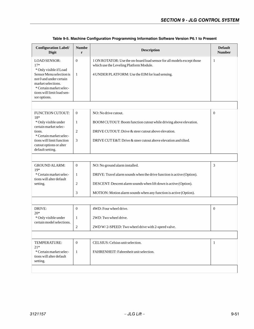
SECTION 9 - JLG CONTROL SYSTEM
3121157 – JLG Lift – 9-51
LOAD SENSOR:17* * Only visible if Load Sensor Menu selection is not 0 and under certain market selections. * Certain market selec-tions will limit load sen-sor options.
0
1
1 ON ROTATOR: Use the on-board load sensor for all models except those which use the Leveling Platform Module.
4 UNDER PLATFORM: Use the EIM for load sensing.
1
FUNCTION CUTOUT:18* * Only visible under certain market selec-tions. * Certain market selec-tions will limit function cutout options or alter default setting.
0
1
2
3
NO: No drive cutout.
BOOM CUTOUT: Boom function cutout while driving above elevation.
DRIVE CUTOUT: Drive & steer cutout above elevation.
DRIVE CUT E&T: Drive & steer cutout above elevation and tilted.
0
GROUND ALARM:19* * Certain market selec-tions will alter default setting.
0
1
2
3
NO: No ground alarm installed.
DRIVE: Travel alarm sounds when the drive function is active (Option).
DESCENT: Descent alarm sounds when lift down is active (Option).
MOTION: Motion alarm sounds when any function is active (Option).
3
DRIVE:20* * Only visible under certain model selections.
0
1
2
4WD: Four wheel drive.
2WD: Two wheel drive.
2WD W/ 2-SPEED: Two wheel drive with 2-speed valve.
0
TEMPERATURE:21* * Certain market selec-tions will alter default setting.
0
1
CELSIUS: Celsius unit selection.
FAHRENHEIT: Fahrenheit unit selection.
1
Table 9-5. Machine Configuration Programming Information Software Version P6.1 to Present
Configuration Label/Digit
Number
DescriptionDefault Number
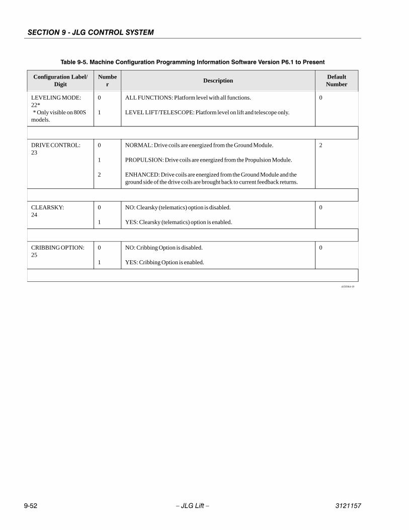
SECTION 9 - JLG CONTROL SYSTEM
9-52 – JLG Lift – 3121157
LEVELING MODE:22* * Only visible on 800S models.
0
1
ALL FUNCTIONS: Platform level with all functions.
LEVEL LIFT/TELESCOPE: Platform level on lift and telescope only.
0
DRIVE CONTROL:23
0
1
2
NORMAL: Drive coils are energized from the Ground Module.
PROPULSION: Drive coils are energized from the Propulsion Module.
ENHANCED: Drive coils are energized from the Ground Module and the ground side of the drive coils are brought back to current feedback returns.
2
CLEARSKY:24
0
1
NO: Clearsky (telematics) option is disabled.
YES: Clearsky (telematics) option is enabled.
0
CRIBBING OPTION:25
0
1
NO: Cribbing Option is disabled.
YES: Cribbing Option is enabled.
0
4150364-19
Table 9-5. Machine Configuration Programming Information Software Version P6.1 to Present
Configuration Label/Digit
Number
DescriptionDefault Number
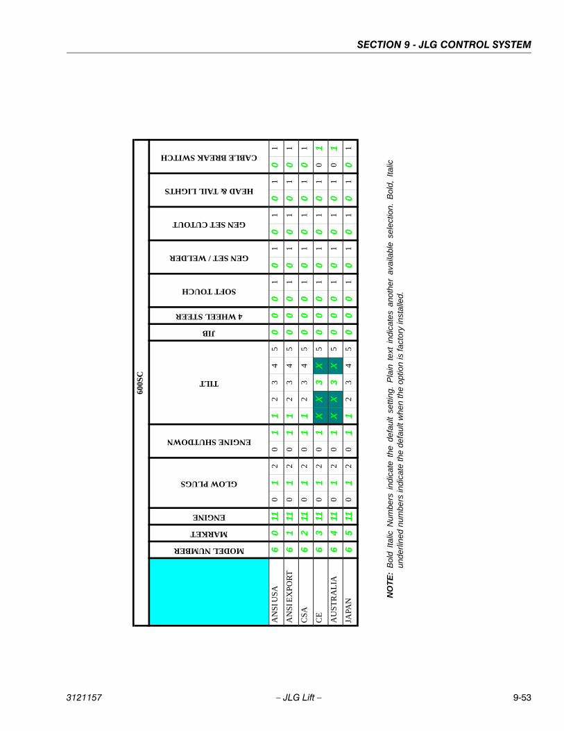
SECTION 9 - JLG CONTROL SYSTEM
3121157 – JLG Lift – 9-53
NO
TE
:B
old
Italic
Num
bers
ind
icat
e th
e d
efau
lt se
tting
. P
lain
tex
t in
dica
tes
anot
her
avai
labl
e se
lect
ion.
Bol
d, I
talic
und
erlin
ed n
umbe
rs in
dica
te th
e de
fau
lt w
hen
the
optio
n is
fact
ory
inst
alle
d.
600S
C
MODEL NUMBER
MARKET
ENGINE
GLOW PLUGS
ENGINE SHUTDOWN
TILT
JIB
4 WHEEL STEER
SOFT TOUCH
GEN SET / WELDER
GEN SET CUTOUT
HEAD & TAIL LIGHTS
CABLE BREAK SWITCH
AN
SI U
SA
60
110
12
01
12
34
50
00
10
10
10
10
1
AN
SI E
XP
OR
T6
111
01
20
11
23
45
00
01
01
01
01
01
CS
A6
211
01
20
11
23
45
00
01
01
01
01
01
CE
63
110
12
01
XX
3X
50
00
10
10
10
10
1
AU
ST
RA
LIA
64
110
12
01
XX
3X
50
00
10
10
10
10
1
JAPA
N6
511
01
20
11
23
45
00
01
01
01
01
01
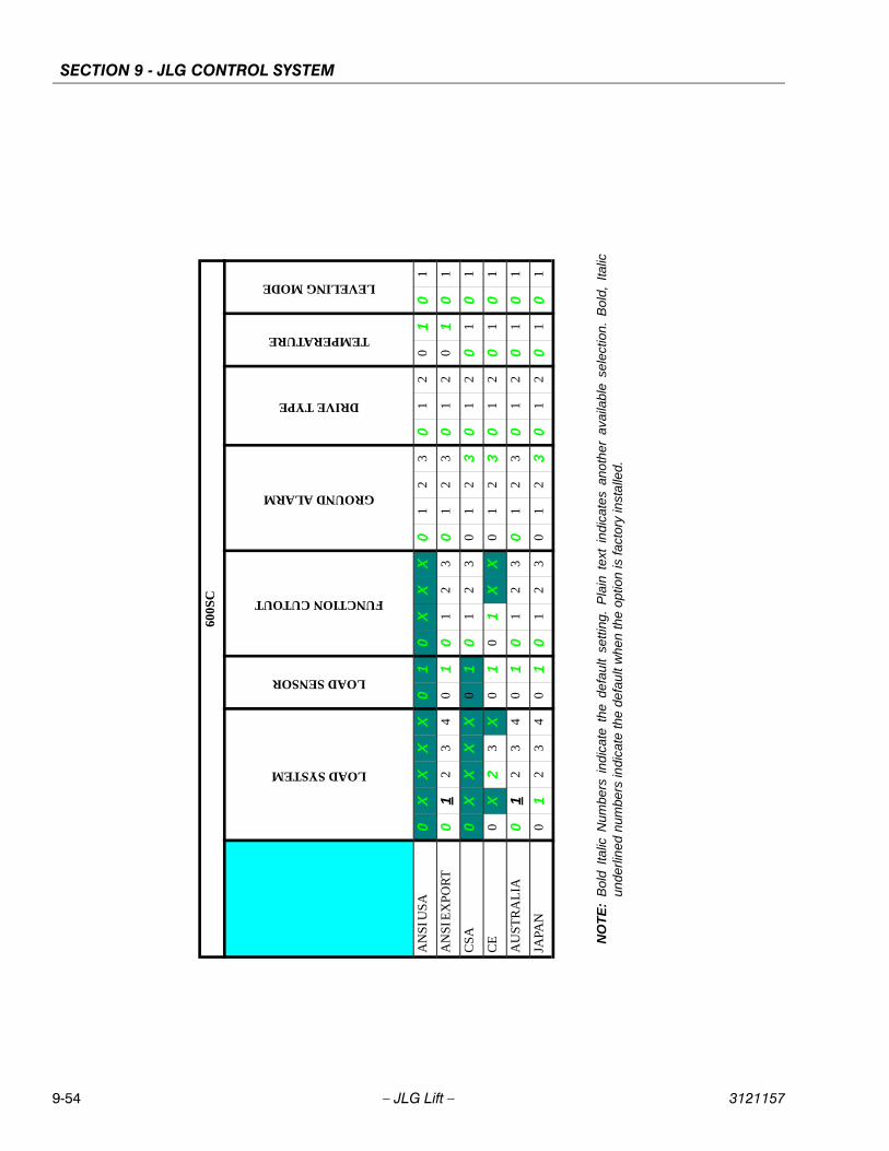
SECTION 9 - JLG CONTROL SYSTEM
9-54 – JLG Lift – 3121157
600S
C
LOAD SYSTEM
LOAD SENSOR
FUNCTION CUTOUT
GROUND ALARM
DRIVE TYPE
TEMPERATURE
LEVELING MODE
AN
SI U
SA
0X
XX
X0
10
XX
X0
12
30
12
01
01
AN
SI E
XP
OR
T0
12
34
01
01
23
01
23
01
20
10
1
CS
A0
XX
XX
01
01
23
01
23
01
20
10
1
CE
0X
23
X0
10
1X
X0
12
30
12
01
01
AU
ST
RA
LIA
01
23
40
10
12
30
12
30
12
01
01
JAPA
N0
12
34
01
01
23
01
23
01
20
10
1
NO
TE
:B
old
Italic
Num
bers
ind
icat
e th
e d
efau
lt se
tting
. P
lain
tex
t in
dica
tes
anot
her
avai
labl
e se
lect
ion.
Bol
d, I
talic
und
erlin
ed n
umbe
rs in
dica
te th
e de
fau
lt w
hen
the
optio
n is
fact
ory
inst
alle
d.
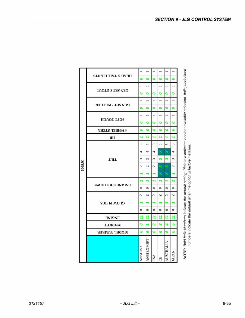
SECTION 9 - JLG CONTROL SYSTEM
3121157 – JLG Lift – 9-55
600S
JCMODEL NUMBER
MARKET
ENGINE
GLOW PLUGS
ENGINE SHUTDOWN
TILT
JIB
4 WHEEL STEER
SOFT TOUCH
GEN SET / WELDER
GEN SET CUTOUT
HEAD & TAIL LIGHTS
AN
SI U
SA
60
110
12
01
12
34
51
00
10
10
10
1
AN
SI E
XP
OR
T6
111
01
20
11
23
45
10
01
01
01
01
CS
A6
211
01
20
11
23
45
10
01
01
01
01
CE
63
110
12
01
XX
3X
51
00
10
10
10
1
AU
ST
RA
LIA
64
110
12
01
XX
3X
51
00
10
10
10
1
JAPA
N6
511
01
20
11
23
45
10
01
01
01
01
NO
TE
:B
old
Ital
ic N
umbe
rs in
dic
ate
the
defa
ult
setti
ng. P
lain
text
ind
icat
es a
noth
er a
vaila
ble
se
lect
ion.
Ital
ic, u
nde
rline
dn
umbe
rs in
dic
ate
the
def
ault
whe
n th
e o
ptio
n is
fact
ory
inst
alle
d.
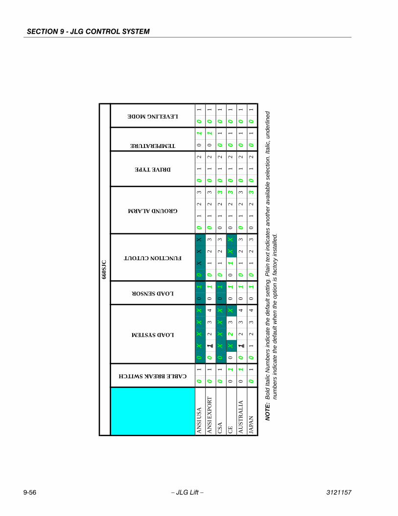
SECTION 9 - JLG CONTROL SYSTEM
9-56 – JLG Lift – 3121157
660S
JC
CABLE BREAK SWITCH
LOAD SYSTEM
LOAD SENSOR
FUNCTION CUTOUT
GROUND ALARM
DRIVE TYPE
TEMPERATURE
LEVELING MODE
AN
SI U
SA
01
0X
XX
X0
10
XX
X0
12
30
12
01
01
AN
SI E
XP
OR
T0
10
12
34
01
01
23
01
23
01
20
10
1
CS
A0
10
XX
XX
01
01
23
01
23
01
20
10
1
CE
01
0X
23
X0
10
1X
X0
12
30
12
01
01
AU
ST
RA
LIA
01
01
23
40
10
12
30
12
30
12
01
01
JAPA
N0
10
12
34
01
01
23
01
23
01
20
10
1
NO
TE
:B
old
Ital
ic N
umbe
rs in
dic
ate
the
defa
ult
setti
ng. P
lain
text
ind
icat
es a
noth
er a
vaila
ble
se
lect
ion.
Ital
ic, u
nde
rline
dn
umbe
rs in
dic
ate
the
defa
ult w
hen
the
opt
ion
is fa
cto
ry in
stal
led.
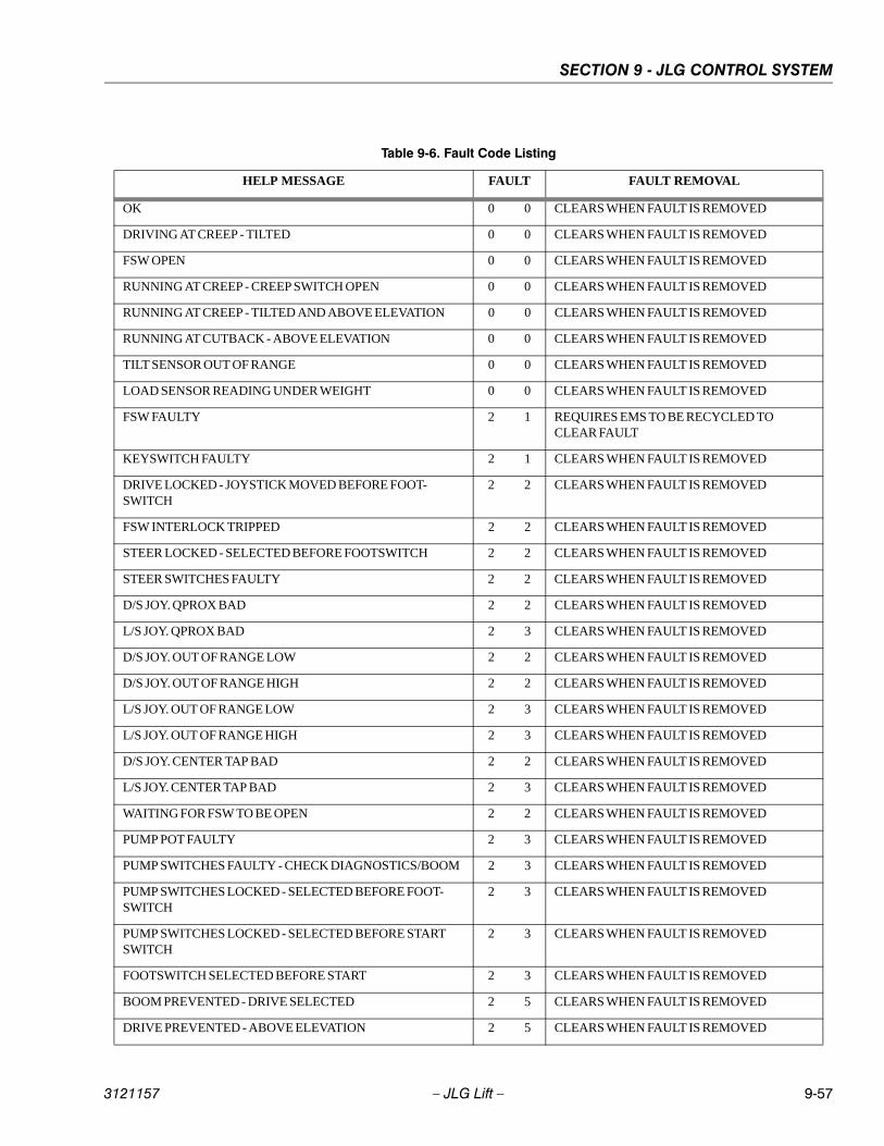
SECTION 9 - JLG CONTROL SYSTEM
3121157 – JLG Lift – 9-57
Table 9-6. Fault Code Listing
HELP MESSAGE FAULT FAULT REMOVAL
OK 0 0 CLEARS WHEN FAULT IS REMOVED
DRIVING AT CREEP - TILTED 0 0 CLEARS WHEN FAULT IS REMOVED
FSW OPEN 0 0 CLEARS WHEN FAULT IS REMOVED
RUNNING AT CREEP - CREEP SWITCH OPEN 0 0 CLEARS WHEN FAULT IS REMOVED
RUNNING AT CREEP - TILTED AND ABOVE ELEVATION 0 0 CLEARS WHEN FAULT IS REMOVED
RUNNING AT CUTBACK - ABOVE ELEVATION 0 0 CLEARS WHEN FAULT IS REMOVED
TILT SENSOR OUT OF RANGE 0 0 CLEARS WHEN FAULT IS REMOVED
LOAD SENSOR READING UNDER WEIGHT 0 0 CLEARS WHEN FAULT IS REMOVED
FSW FAULTY 2 1 REQUIRES EMS TO BE RECYCLED TO CLEAR FAULT
KEYSWITCH FAULTY 2 1 CLEARS WHEN FAULT IS REMOVED
DRIVE LOCKED - JOYSTICK MOVED BEFORE FOOT-SWITCH
2 2 CLEARS WHEN FAULT IS REMOVED
FSW INTERLOCK TRIPPED 2 2 CLEARS WHEN FAULT IS REMOVED
STEER LOCKED - SELECTED BEFORE FOOTSWITCH 2 2 CLEARS WHEN FAULT IS REMOVED
STEER SWITCHES FAULTY 2 2 CLEARS WHEN FAULT IS REMOVED
D/S JOY. QPROX BAD 2 2 CLEARS WHEN FAULT IS REMOVED
L/S JOY. QPROX BAD 2 3 CLEARS WHEN FAULT IS REMOVED
D/S JOY. OUT OF RANGE LOW 2 2 CLEARS WHEN FAULT IS REMOVED
D/S JOY. OUT OF RANGE HIGH 2 2 CLEARS WHEN FAULT IS REMOVED
L/S JOY. OUT OF RANGE LOW 2 3 CLEARS WHEN FAULT IS REMOVED
L/S JOY. OUT OF RANGE HIGH 2 3 CLEARS WHEN FAULT IS REMOVED
D/S JOY. CENTER TAP BAD 2 2 CLEARS WHEN FAULT IS REMOVED
L/S JOY. CENTER TAP BAD 2 3 CLEARS WHEN FAULT IS REMOVED
WAITING FOR FSW TO BE OPEN 2 2 CLEARS WHEN FAULT IS REMOVED
PUMP POT FAULTY 2 3 CLEARS WHEN FAULT IS REMOVED
PUMP SWITCHES FAULTY - CHECK DIAGNOSTICS/BOOM 2 3 CLEARS WHEN FAULT IS REMOVED
PUMP SWITCHES LOCKED - SELECTED BEFORE FOOT-SWITCH
2 3 CLEARS WHEN FAULT IS REMOVED
PUMP SWITCHES LOCKED - SELECTED BEFORE START SWITCH
2 3 CLEARS WHEN FAULT IS REMOVED
FOOTSWITCH SELECTED BEFORE START 2 3 CLEARS WHEN FAULT IS REMOVED
BOOM PREVENTED - DRIVE SELECTED 2 5 CLEARS WHEN FAULT IS REMOVED
DRIVE PREVENTED - ABOVE ELEVATION 2 5 CLEARS WHEN FAULT IS REMOVED
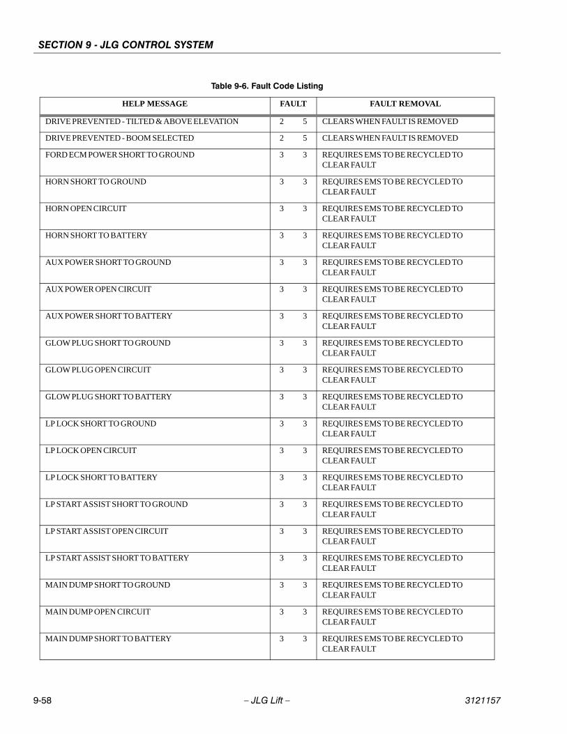
SECTION 9 - JLG CONTROL SYSTEM
9-58 – JLG Lift – 3121157
DRIVE PREVENTED - TILTED & ABOVE ELEVATION 2 5 CLEARS WHEN FAULT IS REMOVED
DRIVE PREVENTED - BOOM SELECTED 2 5 CLEARS WHEN FAULT IS REMOVED
FORD ECM POWER SHORT TO GROUND 3 3 REQUIRES EMS TO BE RECYCLED TO CLEAR FAULT
HORN SHORT TO GROUND 3 3 REQUIRES EMS TO BE RECYCLED TO CLEAR FAULT
HORN OPEN CIRCUIT 3 3 REQUIRES EMS TO BE RECYCLED TO CLEAR FAULT
HORN SHORT TO BATTERY 3 3 REQUIRES EMS TO BE RECYCLED TO CLEAR FAULT
AUX POWER SHORT TO GROUND 3 3 REQUIRES EMS TO BE RECYCLED TO CLEAR FAULT
AUX POWER OPEN CIRCUIT 3 3 REQUIRES EMS TO BE RECYCLED TO CLEAR FAULT
AUX POWER SHORT TO BATTERY 3 3 REQUIRES EMS TO BE RECYCLED TO CLEAR FAULT
GLOW PLUG SHORT TO GROUND 3 3 REQUIRES EMS TO BE RECYCLED TO CLEAR FAULT
GLOW PLUG OPEN CIRCUIT 3 3 REQUIRES EMS TO BE RECYCLED TO CLEAR FAULT
GLOW PLUG SHORT TO BATTERY 3 3 REQUIRES EMS TO BE RECYCLED TO CLEAR FAULT
LP LOCK SHORT TO GROUND 3 3 REQUIRES EMS TO BE RECYCLED TO CLEAR FAULT
LP LOCK OPEN CIRCUIT 3 3 REQUIRES EMS TO BE RECYCLED TO CLEAR FAULT
LP LOCK SHORT TO BATTERY 3 3 REQUIRES EMS TO BE RECYCLED TO CLEAR FAULT
LP START ASSIST SHORT TO GROUND 3 3 REQUIRES EMS TO BE RECYCLED TO CLEAR FAULT
LP START ASSIST OPEN CIRCUIT 3 3 REQUIRES EMS TO BE RECYCLED TO CLEAR FAULT
LP START ASSIST SHORT TO BATTERY 3 3 REQUIRES EMS TO BE RECYCLED TO CLEAR FAULT
MAIN DUMP SHORT TO GROUND 3 3 REQUIRES EMS TO BE RECYCLED TO CLEAR FAULT
MAIN DUMP OPEN CIRCUIT 3 3 REQUIRES EMS TO BE RECYCLED TO CLEAR FAULT
MAIN DUMP SHORT TO BATTERY 3 3 REQUIRES EMS TO BE RECYCLED TO CLEAR FAULT
Table 9-6. Fault Code Listing
HELP MESSAGE FAULT FAULT REMOVAL
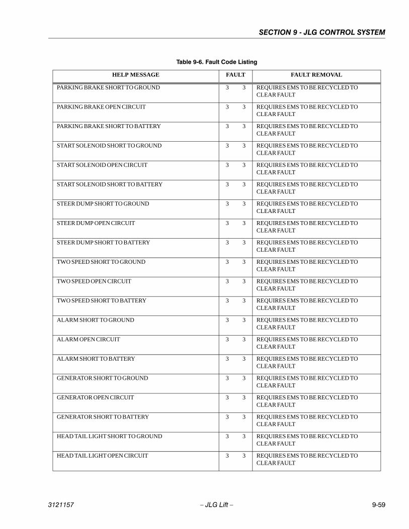
SECTION 9 - JLG CONTROL SYSTEM
3121157 – JLG Lift – 9-59
PARKING BRAKE SHORT TO GROUND 3 3 REQUIRES EMS TO BE RECYCLED TO CLEAR FAULT
PARKING BRAKE OPEN CIRCUIT 3 3 REQUIRES EMS TO BE RECYCLED TO CLEAR FAULT
PARKING BRAKE SHORT TO BATTERY 3 3 REQUIRES EMS TO BE RECYCLED TO CLEAR FAULT
START SOLENOID SHORT TO GROUND 3 3 REQUIRES EMS TO BE RECYCLED TO CLEAR FAULT
START SOLENOID OPEN CIRCUIT 3 3 REQUIRES EMS TO BE RECYCLED TO CLEAR FAULT
START SOLENOID SHORT TO BATTERY 3 3 REQUIRES EMS TO BE RECYCLED TO CLEAR FAULT
STEER DUMP SHORT TO GROUND 3 3 REQUIRES EMS TO BE RECYCLED TO CLEAR FAULT
STEER DUMP OPEN CIRCUIT 3 3 REQUIRES EMS TO BE RECYCLED TO CLEAR FAULT
STEER DUMP SHORT TO BATTERY 3 3 REQUIRES EMS TO BE RECYCLED TO CLEAR FAULT
TWO SPEED SHORT TO GROUND 3 3 REQUIRES EMS TO BE RECYCLED TO CLEAR FAULT
TWO SPEED OPEN CIRCUIT 3 3 REQUIRES EMS TO BE RECYCLED TO CLEAR FAULT
TWO SPEED SHORT TO BATTERY 3 3 REQUIRES EMS TO BE RECYCLED TO CLEAR FAULT
ALARM SHORT TO GROUND 3 3 REQUIRES EMS TO BE RECYCLED TO CLEAR FAULT
ALARM OPEN CIRCUIT 3 3 REQUIRES EMS TO BE RECYCLED TO CLEAR FAULT
ALARM SHORT TO BATTERY 3 3 REQUIRES EMS TO BE RECYCLED TO CLEAR FAULT
GENERATOR SHORT TO GROUND 3 3 REQUIRES EMS TO BE RECYCLED TO CLEAR FAULT
GENERATOR OPEN CIRCUIT 3 3 REQUIRES EMS TO BE RECYCLED TO CLEAR FAULT
GENERATOR SHORT TO BATTERY 3 3 REQUIRES EMS TO BE RECYCLED TO CLEAR FAULT
HEAD TAIL LIGHT SHORT TO GROUND 3 3 REQUIRES EMS TO BE RECYCLED TO CLEAR FAULT
HEAD TAIL LIGHT OPEN CIRCUIT 3 3 REQUIRES EMS TO BE RECYCLED TO CLEAR FAULT
Table 9-6. Fault Code Listing
HELP MESSAGE FAULT FAULT REMOVAL
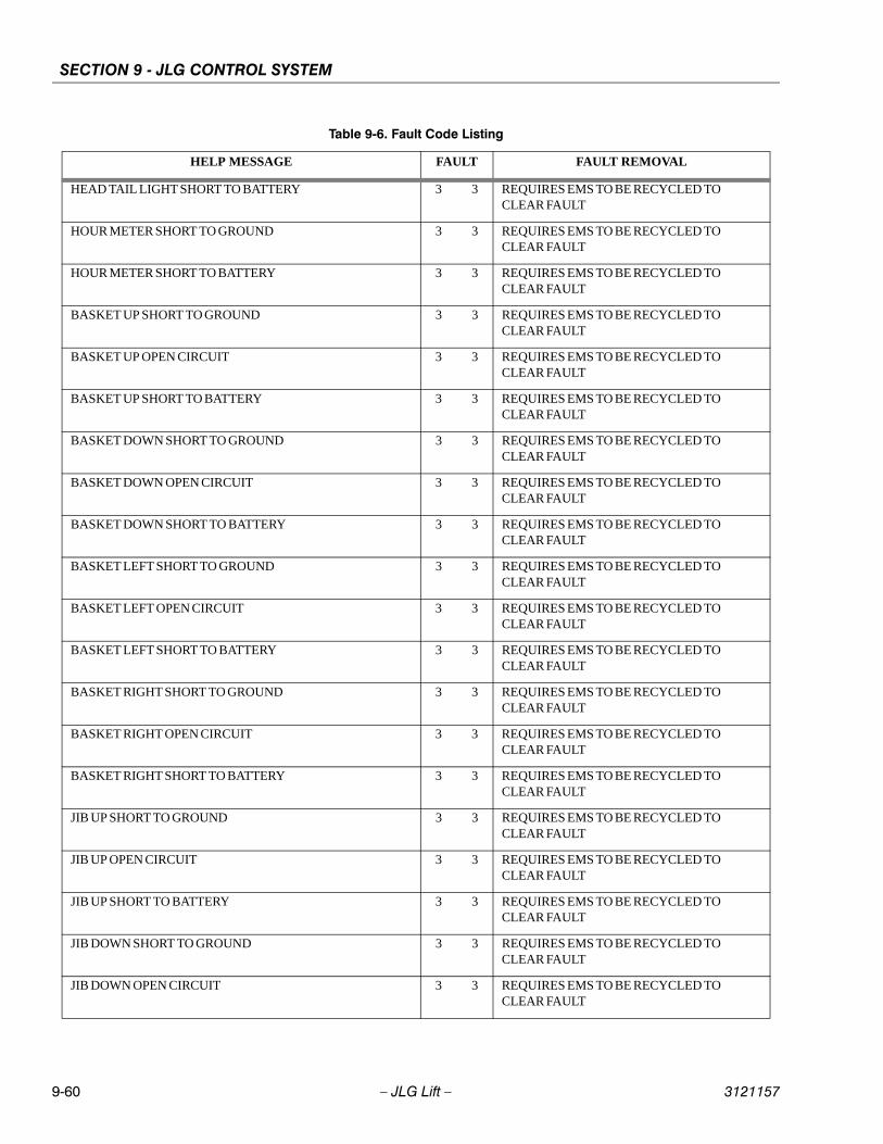
SECTION 9 - JLG CONTROL SYSTEM
9-60 – JLG Lift – 3121157
HEAD TAIL LIGHT SHORT TO BATTERY 3 3 REQUIRES EMS TO BE RECYCLED TO CLEAR FAULT
HOUR METER SHORT TO GROUND 3 3 REQUIRES EMS TO BE RECYCLED TO CLEAR FAULT
HOUR METER SHORT TO BATTERY 3 3 REQUIRES EMS TO BE RECYCLED TO CLEAR FAULT
BASKET UP SHORT TO GROUND 3 3 REQUIRES EMS TO BE RECYCLED TO CLEAR FAULT
BASKET UP OPEN CIRCUIT 3 3 REQUIRES EMS TO BE RECYCLED TO CLEAR FAULT
BASKET UP SHORT TO BATTERY 3 3 REQUIRES EMS TO BE RECYCLED TO CLEAR FAULT
BASKET DOWN SHORT TO GROUND 3 3 REQUIRES EMS TO BE RECYCLED TO CLEAR FAULT
BASKET DOWN OPEN CIRCUIT 3 3 REQUIRES EMS TO BE RECYCLED TO CLEAR FAULT
BASKET DOWN SHORT TO BATTERY 3 3 REQUIRES EMS TO BE RECYCLED TO CLEAR FAULT
BASKET LEFT SHORT TO GROUND 3 3 REQUIRES EMS TO BE RECYCLED TO CLEAR FAULT
BASKET LEFT OPEN CIRCUIT 3 3 REQUIRES EMS TO BE RECYCLED TO CLEAR FAULT
BASKET LEFT SHORT TO BATTERY 3 3 REQUIRES EMS TO BE RECYCLED TO CLEAR FAULT
BASKET RIGHT SHORT TO GROUND 3 3 REQUIRES EMS TO BE RECYCLED TO CLEAR FAULT
BASKET RIGHT OPEN CIRCUIT 3 3 REQUIRES EMS TO BE RECYCLED TO CLEAR FAULT
BASKET RIGHT SHORT TO BATTERY 3 3 REQUIRES EMS TO BE RECYCLED TO CLEAR FAULT
JIB UP SHORT TO GROUND 3 3 REQUIRES EMS TO BE RECYCLED TO CLEAR FAULT
JIB UP OPEN CIRCUIT 3 3 REQUIRES EMS TO BE RECYCLED TO CLEAR FAULT
JIB UP SHORT TO BATTERY 3 3 REQUIRES EMS TO BE RECYCLED TO CLEAR FAULT
JIB DOWN SHORT TO GROUND 3 3 REQUIRES EMS TO BE RECYCLED TO CLEAR FAULT
JIB DOWN OPEN CIRCUIT 3 3 REQUIRES EMS TO BE RECYCLED TO CLEAR FAULT
Table 9-6. Fault Code Listing
HELP MESSAGE FAULT FAULT REMOVAL
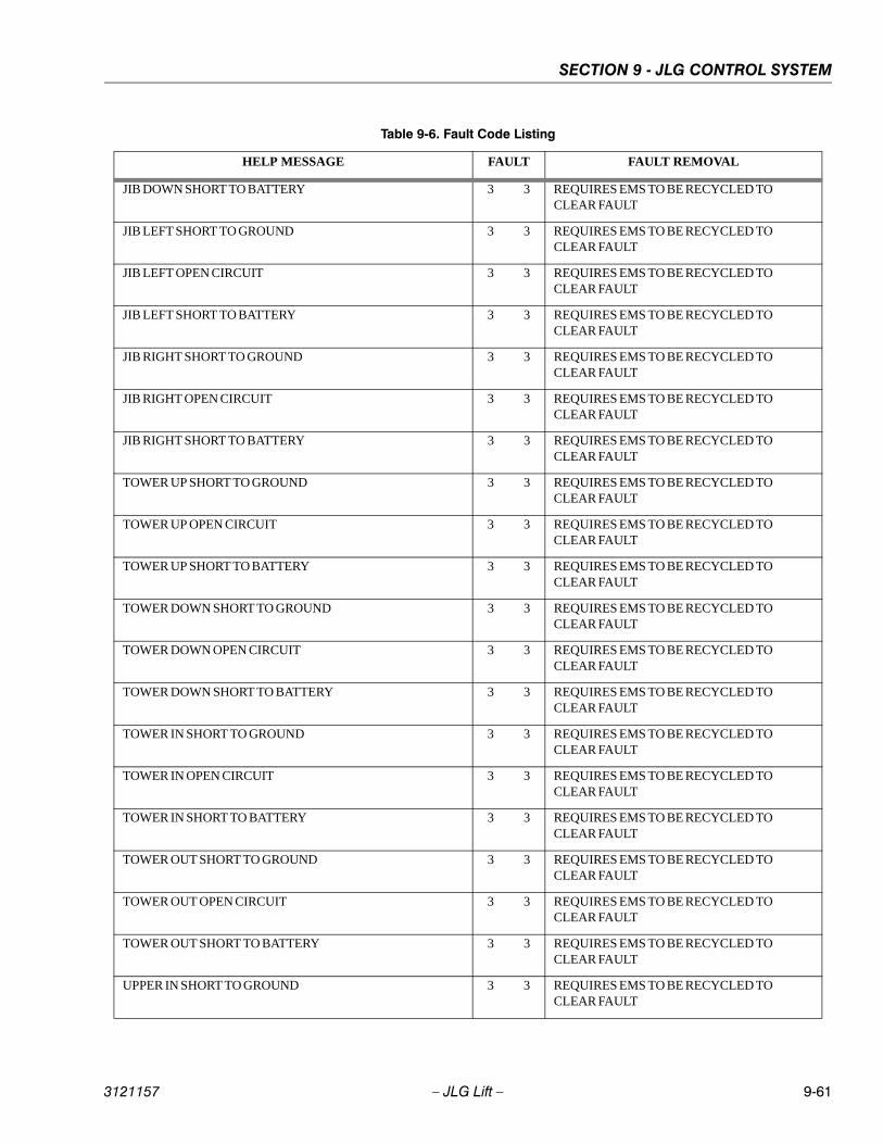
SECTION 9 - JLG CONTROL SYSTEM
3121157 – JLG Lift – 9-61
JIB DOWN SHORT TO BATTERY 3 3 REQUIRES EMS TO BE RECYCLED TO CLEAR FAULT
JIB LEFT SHORT TO GROUND 3 3 REQUIRES EMS TO BE RECYCLED TO CLEAR FAULT
JIB LEFT OPEN CIRCUIT 3 3 REQUIRES EMS TO BE RECYCLED TO CLEAR FAULT
JIB LEFT SHORT TO BATTERY 3 3 REQUIRES EMS TO BE RECYCLED TO CLEAR FAULT
JIB RIGHT SHORT TO GROUND 3 3 REQUIRES EMS TO BE RECYCLED TO CLEAR FAULT
JIB RIGHT OPEN CIRCUIT 3 3 REQUIRES EMS TO BE RECYCLED TO CLEAR FAULT
JIB RIGHT SHORT TO BATTERY 3 3 REQUIRES EMS TO BE RECYCLED TO CLEAR FAULT
TOWER UP SHORT TO GROUND 3 3 REQUIRES EMS TO BE RECYCLED TO CLEAR FAULT
TOWER UP OPEN CIRCUIT 3 3 REQUIRES EMS TO BE RECYCLED TO CLEAR FAULT
TOWER UP SHORT TO BATTERY 3 3 REQUIRES EMS TO BE RECYCLED TO CLEAR FAULT
TOWER DOWN SHORT TO GROUND 3 3 REQUIRES EMS TO BE RECYCLED TO CLEAR FAULT
TOWER DOWN OPEN CIRCUIT 3 3 REQUIRES EMS TO BE RECYCLED TO CLEAR FAULT
TOWER DOWN SHORT TO BATTERY 3 3 REQUIRES EMS TO BE RECYCLED TO CLEAR FAULT
TOWER IN SHORT TO GROUND 3 3 REQUIRES EMS TO BE RECYCLED TO CLEAR FAULT
TOWER IN OPEN CIRCUIT 3 3 REQUIRES EMS TO BE RECYCLED TO CLEAR FAULT
TOWER IN SHORT TO BATTERY 3 3 REQUIRES EMS TO BE RECYCLED TO CLEAR FAULT
TOWER OUT SHORT TO GROUND 3 3 REQUIRES EMS TO BE RECYCLED TO CLEAR FAULT
TOWER OUT OPEN CIRCUIT 3 3 REQUIRES EMS TO BE RECYCLED TO CLEAR FAULT
TOWER OUT SHORT TO BATTERY 3 3 REQUIRES EMS TO BE RECYCLED TO CLEAR FAULT
UPPER IN SHORT TO GROUND 3 3 REQUIRES EMS TO BE RECYCLED TO CLEAR FAULT
Table 9-6. Fault Code Listing
HELP MESSAGE FAULT FAULT REMOVAL
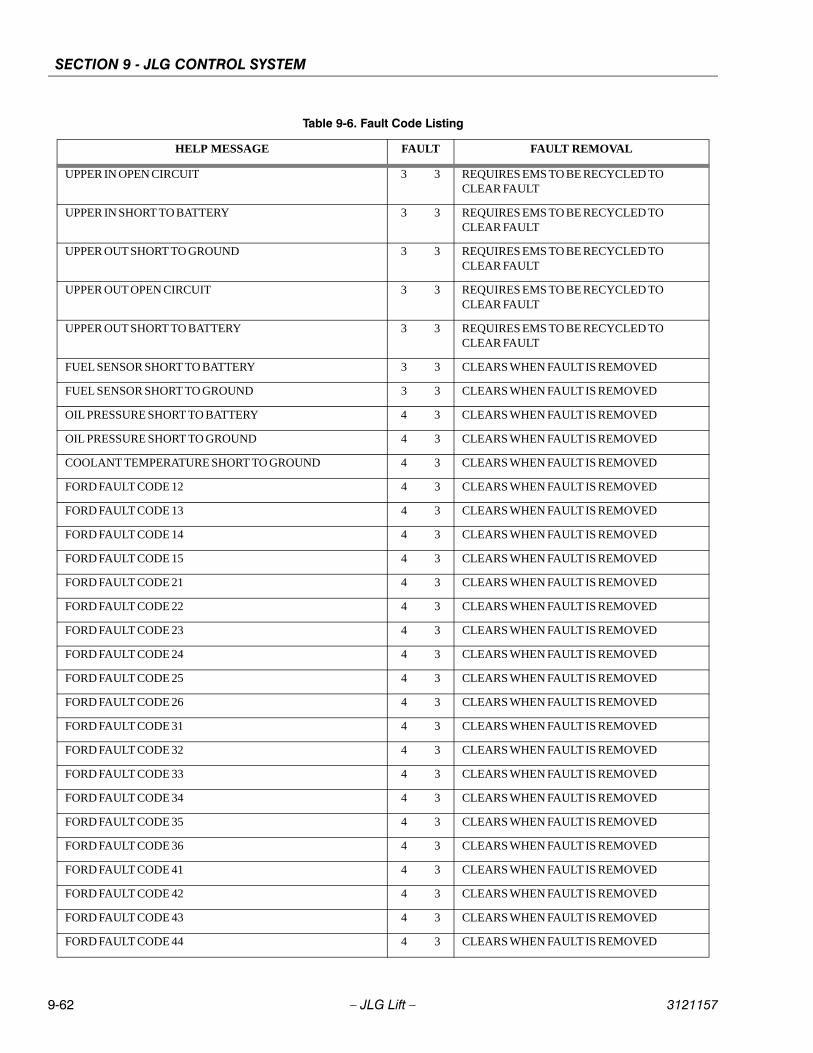
SECTION 9 - JLG CONTROL SYSTEM
9-62 – JLG Lift – 3121157
UPPER IN OPEN CIRCUIT 3 3 REQUIRES EMS TO BE RECYCLED TO CLEAR FAULT
UPPER IN SHORT TO BATTERY 3 3 REQUIRES EMS TO BE RECYCLED TO CLEAR FAULT
UPPER OUT SHORT TO GROUND 3 3 REQUIRES EMS TO BE RECYCLED TO CLEAR FAULT
UPPER OUT OPEN CIRCUIT 3 3 REQUIRES EMS TO BE RECYCLED TO CLEAR FAULT
UPPER OUT SHORT TO BATTERY 3 3 REQUIRES EMS TO BE RECYCLED TO CLEAR FAULT
FUEL SENSOR SHORT TO BATTERY 3 3 CLEARS WHEN FAULT IS REMOVED
FUEL SENSOR SHORT TO GROUND 3 3 CLEARS WHEN FAULT IS REMOVED
OIL PRESSURE SHORT TO BATTERY 4 3 CLEARS WHEN FAULT IS REMOVED
OIL PRESSURE SHORT TO GROUND 4 3 CLEARS WHEN FAULT IS REMOVED
COOLANT TEMPERATURE SHORT TO GROUND 4 3 CLEARS WHEN FAULT IS REMOVED
FORD FAULT CODE 12 4 3 CLEARS WHEN FAULT IS REMOVED
FORD FAULT CODE 13 4 3 CLEARS WHEN FAULT IS REMOVED
FORD FAULT CODE 14 4 3 CLEARS WHEN FAULT IS REMOVED
FORD FAULT CODE 15 4 3 CLEARS WHEN FAULT IS REMOVED
FORD FAULT CODE 21 4 3 CLEARS WHEN FAULT IS REMOVED
FORD FAULT CODE 22 4 3 CLEARS WHEN FAULT IS REMOVED
FORD FAULT CODE 23 4 3 CLEARS WHEN FAULT IS REMOVED
FORD FAULT CODE 24 4 3 CLEARS WHEN FAULT IS REMOVED
FORD FAULT CODE 25 4 3 CLEARS WHEN FAULT IS REMOVED
FORD FAULT CODE 26 4 3 CLEARS WHEN FAULT IS REMOVED
FORD FAULT CODE 31 4 3 CLEARS WHEN FAULT IS REMOVED
FORD FAULT CODE 32 4 3 CLEARS WHEN FAULT IS REMOVED
FORD FAULT CODE 33 4 3 CLEARS WHEN FAULT IS REMOVED
FORD FAULT CODE 34 4 3 CLEARS WHEN FAULT IS REMOVED
FORD FAULT CODE 35 4 3 CLEARS WHEN FAULT IS REMOVED
FORD FAULT CODE 36 4 3 CLEARS WHEN FAULT IS REMOVED
FORD FAULT CODE 41 4 3 CLEARS WHEN FAULT IS REMOVED
FORD FAULT CODE 42 4 3 CLEARS WHEN FAULT IS REMOVED
FORD FAULT CODE 43 4 3 CLEARS WHEN FAULT IS REMOVED
FORD FAULT CODE 44 4 3 CLEARS WHEN FAULT IS REMOVED
Table 9-6. Fault Code Listing
HELP MESSAGE FAULT FAULT REMOVAL
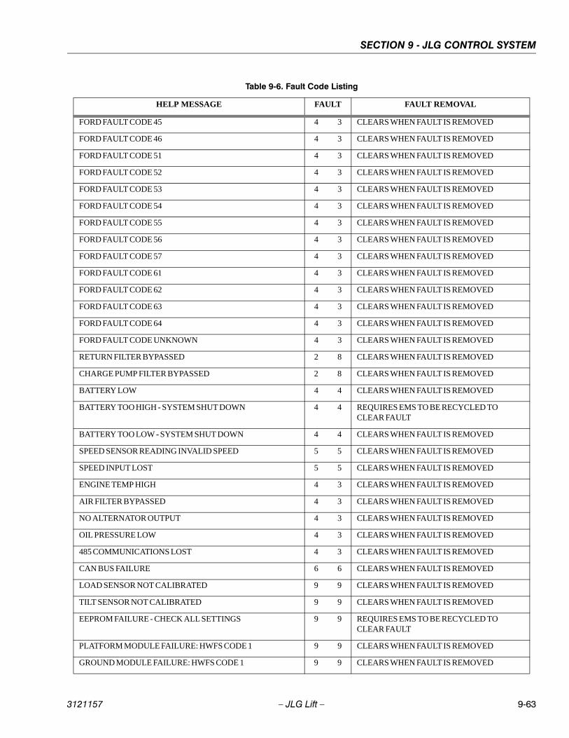
SECTION 9 - JLG CONTROL SYSTEM
3121157 – JLG Lift – 9-63
FORD FAULT CODE 45 4 3 CLEARS WHEN FAULT IS REMOVED
FORD FAULT CODE 46 4 3 CLEARS WHEN FAULT IS REMOVED
FORD FAULT CODE 51 4 3 CLEARS WHEN FAULT IS REMOVED
FORD FAULT CODE 52 4 3 CLEARS WHEN FAULT IS REMOVED
FORD FAULT CODE 53 4 3 CLEARS WHEN FAULT IS REMOVED
FORD FAULT CODE 54 4 3 CLEARS WHEN FAULT IS REMOVED
FORD FAULT CODE 55 4 3 CLEARS WHEN FAULT IS REMOVED
FORD FAULT CODE 56 4 3 CLEARS WHEN FAULT IS REMOVED
FORD FAULT CODE 57 4 3 CLEARS WHEN FAULT IS REMOVED
FORD FAULT CODE 61 4 3 CLEARS WHEN FAULT IS REMOVED
FORD FAULT CODE 62 4 3 CLEARS WHEN FAULT IS REMOVED
FORD FAULT CODE 63 4 3 CLEARS WHEN FAULT IS REMOVED
FORD FAULT CODE 64 4 3 CLEARS WHEN FAULT IS REMOVED
FORD FAULT CODE UNKNOWN 4 3 CLEARS WHEN FAULT IS REMOVED
RETURN FILTER BYPASSED 2 8 CLEARS WHEN FAULT IS REMOVED
CHARGE PUMP FILTER BYPASSED 2 8 CLEARS WHEN FAULT IS REMOVED
BATTERY LOW 4 4 CLEARS WHEN FAULT IS REMOVED
BATTERY TOO HIGH - SYSTEM SHUT DOWN 4 4 REQUIRES EMS TO BE RECYCLED TO CLEAR FAULT
BATTERY TOO LOW - SYSTEM SHUT DOWN 4 4 CLEARS WHEN FAULT IS REMOVED
SPEED SENSOR READING INVALID SPEED 5 5 CLEARS WHEN FAULT IS REMOVED
SPEED INPUT LOST 5 5 CLEARS WHEN FAULT IS REMOVED
ENGINE TEMP HIGH 4 3 CLEARS WHEN FAULT IS REMOVED
AIR FILTER BYPASSED 4 3 CLEARS WHEN FAULT IS REMOVED
NO ALTERNATOR OUTPUT 4 3 CLEARS WHEN FAULT IS REMOVED
OIL PRESSURE LOW 4 3 CLEARS WHEN FAULT IS REMOVED
485 COMMUNICATIONS LOST 4 3 CLEARS WHEN FAULT IS REMOVED
CAN BUS FAILURE 6 6 CLEARS WHEN FAULT IS REMOVED
LOAD SENSOR NOT CALIBRATED 9 9 CLEARS WHEN FAULT IS REMOVED
TILT SENSOR NOT CALIBRATED 9 9 CLEARS WHEN FAULT IS REMOVED
EEPROM FAILURE - CHECK ALL SETTINGS 9 9 REQUIRES EMS TO BE RECYCLED TO CLEAR FAULT
PLATFORM MODULE FAILURE: HWFS CODE 1 9 9 CLEARS WHEN FAULT IS REMOVED
GROUND MODULE FAILURE: HWFS CODE 1 9 9 CLEARS WHEN FAULT IS REMOVED
Table 9-6. Fault Code Listing
HELP MESSAGE FAULT FAULT REMOVAL
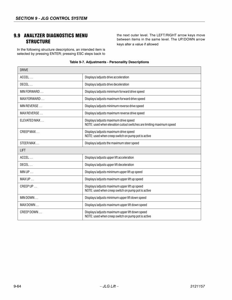
SECTION 9 - JLG CONTROL SYSTEM
9-64 – JLG Lift – 3121157
9.9 ANALYZER DIAGNOSTICS MENU STRUCTURE
In the following structure descriptions, an intended item isselected by pressing ENTER; pressing ESC steps back to
the next outer level. The LEFT/RIGHT arrow keys movebetween items in the same level. The UP/DOWN arrowkeys alter a value if allowed
Table 9-7. Adjustments - Personality Descriptions
DRIVE
ACCEL … Displays/adjusts drive acceleration
DECEL … Displays/adjusts drive deceleration
MIN FORWARD … Displays/adjusts minimum forward drive speed
MAX FORWARD … Displays/adjusts maximum forward drive speed
MIN REVERSE … Displays/adjusts minimum reverse drive speed
MAX REVERSE … Displays/adjusts maximum reverse drive speed
ELEVATED MAX … Displays/adjusts maximum drive speedNOTE: used when elevation cutout switches are limiting maximum speed
CREEP MAX … Displays/adjusts maximum drive speedNOTE: used when creep switch on pump pot is active
STEER MAX … Displays/adjusts the maximum steer speed
LIFT
ACCEL … Displays/adjusts upper lift acceleration
DECEL … Displays/adjusts upper lift deceleration
MIN UP … Displays/adjusts minimum upper lift up speed
MAX UP … Displays/adjusts maximum upper lift up speed
CREEP UP … Displays/adjusts maximum upper lift up speedNOTE: used when creep switch on pump pot is active
MIN DOWN … Displays/adjusts minimum upper lift down speed
MAX DOWN … Displays/adjusts maximum upper lift down speed
CREEP DOWN … Displays/adjusts maximum upper lift down speedNOTE: used when creep switch on pump pot is active
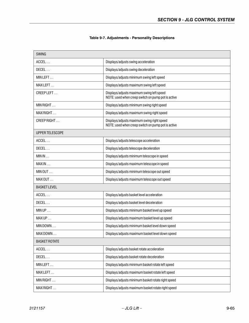
SECTION 9 - JLG CONTROL SYSTEM
3121157 – JLG Lift – 9-65
SWING
ACCEL … Displays/adjusts swing acceleration
DECEL … Displays/adjusts swing deceleration
MIN LEFT … Displays/adjusts minimum swing left speed
MAX LEFT … Displays/adjusts maximum swing left speed
CREEP LEFT … Displays/adjusts maximum swing left speedNOTE: used when creep switch on pump pot is active
MIN RIGHT … Displays/adjusts minimum swing right speed
MAX RIGHT … Displays/adjusts maximum swing right speed
CREEP RIGHT … Displays/adjusts maximum swing right speedNOTE: used when creep switch on pump pot is active
UPPER TELESCOPE
ACCEL … Displays/adjusts telescope acceleration
DECEL … Displays/adjusts telescope deceleration
MIN IN … Displays/adjusts minimum telescope in speed
MAX IN … Displays/adjusts maximum telescope in speed
MIN OUT … Displays/adjusts minimum telescope out speed
MAX OUT … Displays/adjusts maximum telescope out speed
BASKET LEVEL
ACCEL … Displays/adjusts basket level acceleration
DECEL … Displays/adjusts basket level deceleration
MIN UP … Displays/adjusts minimum basket level up speed
MAX UP … Displays/adjusts maximum basket level up speed
MIN DOWN … Displays/adjusts minimum basket level down speed
MAX DOWN … Displays/adjusts maximum basket level down speed
BASKET ROTATE
ACCEL … Displays/adjusts basket rotate acceleration
DECEL … Displays/adjusts basket rotate deceleration
MIN LEFT … Displays/adjusts minimum basket rotate left speed
MAX LEFT … Displays/adjusts maximum basket rotate left speed
MIN RIGHT … Displays/adjusts minimum basket rotate right speed
MAX RIGHT … Displays/adjusts maximum basket rotate right speed
Table 9-7. Adjustments - Personality Descriptions
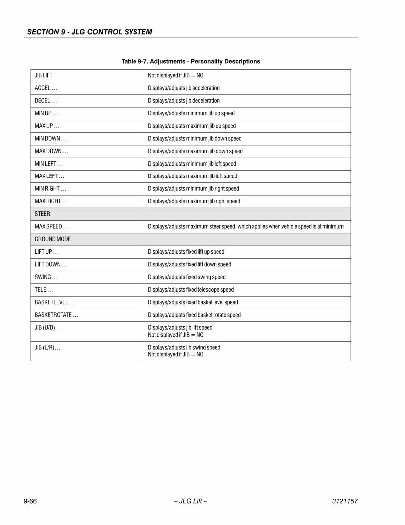
SECTION 9 - JLG CONTROL SYSTEM
9-66 – JLG Lift – 3121157
JIB LIFT Not displayed if JIB = NO
ACCEL … Displays/adjusts jib acceleration
DECEL … Displays/adjusts jib deceleration
MIN UP … Displays/adjusts minimum jib up speed
MAX UP … Displays/adjusts maximum jib up speed
MIN DOWN … Displays/adjusts minimum jib down speed
MAX DOWN … Displays/adjusts maximum jib down speed
MIN LEFT … Displays/adjusts minimum jib left speed
MAX LEFT … Displays/adjusts maximum jib left speed
MIN RIGHT … Displays/adjusts minimum jib right speed
MAX RIGHT … Displays/adjusts maximum jib right speed
STEER
MAX SPEED … Displays/adjusts maximum steer speed, which applies when vehicle speed is at minimum
GROUND MODE
LIFT UP … Displays/adjusts fixed lift up speed
LIFT DOWN … Displays/adjusts fixed lift down speed
SWING … Displays/adjusts fixed swing speed
TELE … Displays/adjusts fixed telescope speed
BASKETLEVEL … Displays/adjusts fixed basket level speed
BASKETROTATE … Displays/adjusts fixed basket rotate speed
JIB (U/D) … Displays/adjusts jib lift speedNot displayed if JIB = NO
JIB (L/R)… Displays/adjusts jib swing speedNot displayed if JIB = NO
Table 9-7. Adjustments - Personality Descriptions
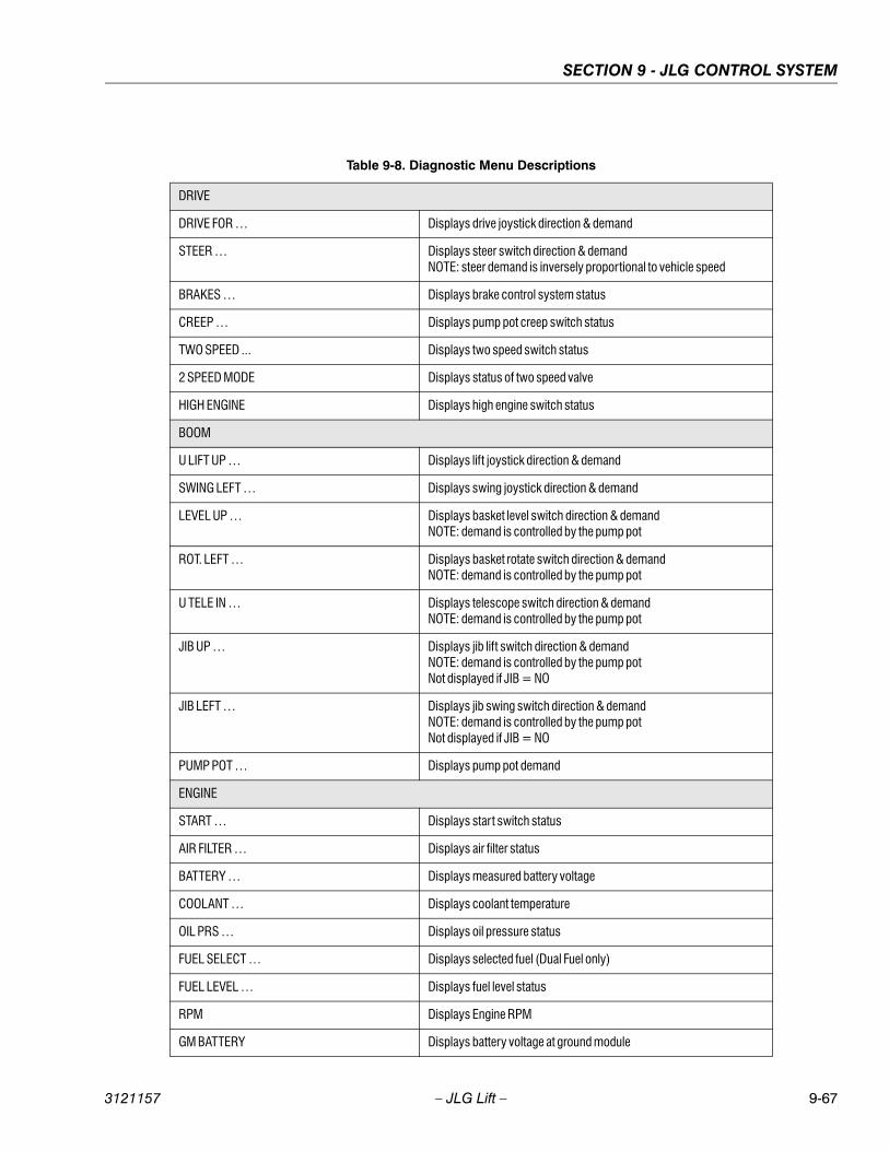
SECTION 9 - JLG CONTROL SYSTEM
3121157 – JLG Lift – 9-67
Table 9-8. Diagnostic Menu Descriptions
DRIVE
DRIVE FOR … Displays drive joystick direction & demand
STEER … Displays steer switch direction & demandNOTE: steer demand is inversely proportional to vehicle speed
BRAKES … Displays brake control system status
CREEP … Displays pump pot creep switch status
TWO SPEED ... Displays two speed switch status
2 SPEED MODE Displays status of two speed valve
HIGH ENGINE Displays high engine switch status
BOOM
U LIFT UP … Displays lift joystick direction & demand
SWING LEFT … Displays swing joystick direction & demand
LEVEL UP … Displays basket level switch direction & demandNOTE: demand is controlled by the pump pot
ROT. LEFT … Displays basket rotate switch direction & demandNOTE: demand is controlled by the pump pot
U TELE IN … Displays telescope switch direction & demandNOTE: demand is controlled by the pump pot
JIB UP … Displays jib lift switch direction & demandNOTE: demand is controlled by the pump potNot displayed if JIB = NO
JIB LEFT … Displays jib swing switch direction & demandNOTE: demand is controlled by the pump potNot displayed if JIB = NO
PUMP POT … Displays pump pot demand
ENGINE
START … Displays start switch status
AIR FILTER … Displays air filter status
BATTERY … Displays measured battery voltage
COOLANT … Displays coolant temperature
OIL PRS … Displays oil pressure status
FUEL SELECT … Displays selected fuel (Dual Fuel only)
FUEL LEVEL … Displays fuel level status
RPM Displays Engine RPM
GM BATTERY Displays battery voltage at ground module

SECTION 9 - JLG CONTROL SYSTEM
9-68 – JLG Lift – 3121157
PM BATTERY … Displays battery voltage at platform module
TEMP ... Displays ground module temperature
ELEV. CUTOUT … Displays elevation cutout switch status
FUNC. CUTOUT … Displays function cutout switch status
CREEP… Displays creep switch status
TILT … Displays measured vehicle tilt
AUX POWER … Displays status of auxiliary power switch
HORN … Displays status of horn switch
R FILTER … Displays status of return filter switch
C FILTER … Displays status of charge pump filter
LOAD LENGTH … Displays length switch status
ANGLE … Displays angle switch status
LOAD … Displays load sensor value NOTE: Not displayed if load = 0.
DATALOG
ON … Displays total controller on (EMS) time
ENGINE … Displays engine run time
DRIVE … Displays total controller drive operation time
LIFT … Displays total controller lift operation time
SWING … Displays total controller swing operation time
TELE … Displays total controller tele operation time
MAX.TEMP … Displays maximum measured heatsink temp.
MIN.TEMP … Displays minimum measured heatsink temp.
MAX.VOLTS … Displays maximum measured battery voltage
RENTAL … Displays total controller operation timeNOTE: can be reset
ERASE RENTAL Not available at password level 2
YES:ENTER, NO:ESC ENTER resets rental datalog time to zero
VERSIONS
GROUND … Displays ground module software version
PLATFORM … Displays platform module software version
ANALYSER … Displays Analyzer software version
Table 9-8. Diagnostic Menu Descriptions
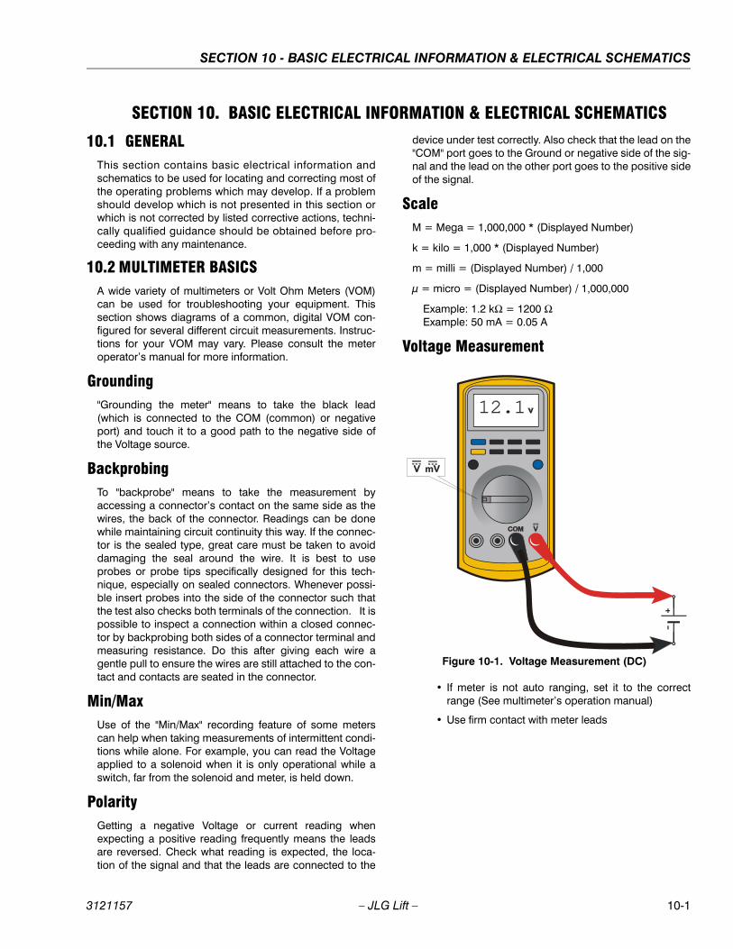
SECTION 10 - BASIC ELECTRICAL INFORMATION & ELECTRICAL SCHEMATICS
3121157 – JLG Lift – 10-1
SECTION 10. BASIC ELECTRICAL INFORMATION & ELECTRICAL SCHEMATICS
10.1 GENERALThis section contains basic electrical information andschematics to be used for locating and correcting most ofthe operating problems which may develop. If a problemshould develop which is not presented in this section orwhich is not corrected by listed corrective actions, techni-cally qualified guidance should be obtained before pro-ceeding with any maintenance.
10.2 MULTIMETER BASICSA wide variety of multimeters or Volt Ohm Meters (VOM)can be used for troubleshooting your equipment. Thissection shows diagrams of a common, digital VOM con-figured for several different circuit measurements. Instruc-tions for your VOM may vary. Please consult the meteroperator’s manual for more information.
Grounding"Grounding the meter" means to take the black lead(which is connected to the COM (common) or negativeport) and touch it to a good path to the negative side ofthe Voltage source.
BackprobingTo "backprobe" means to take the measurement byaccessing a connector’s contact on the same side as thewires, the back of the connector. Readings can be donewhile maintaining circuit continuity this way. If the connec-tor is the sealed type, great care must be taken to avoiddamaging the seal around the wire. It is best to useprobes or probe tips specifically designed for this tech-nique, especially on sealed connectors. Whenever possi-ble insert probes into the side of the connector such thatthe test also checks both terminals of the connection. It ispossible to inspect a connection within a closed connec-tor by backprobing both sides of a connector terminal andmeasuring resistance. Do this after giving each wire agentle pull to ensure the wires are still attached to the con-tact and contacts are seated in the connector.
Min/MaxUse of the "Min/Max" recording feature of some meterscan help when taking measurements of intermittent condi-tions while alone. For example, you can read the Voltageapplied to a solenoid when it is only operational while aswitch, far from the solenoid and meter, is held down.
PolarityGetting a negative Voltage or current reading whenexpecting a positive reading frequently means the leadsare reversed. Check what reading is expected, the loca-tion of the signal and that the leads are connected to the
device under test correctly. Also check that the lead on the"COM" port goes to the Ground or negative side of the sig-nal and the lead on the other port goes to the positive sideof the signal.
ScaleM = Mega = 1,000,000 * (Displayed Number)
k = kilo = 1,000 * (Displayed Number)
m = milli = (Displayed Number) / 1,000
μ = micro = (Displayed Number) / 1,000,000
Example: 1.2 kΩ = 1200 ΩExample: 50 mA = 0.05 A
Voltage Measurement
• If meter is not auto ranging, set it to the correctrange (See multimeter’s operation manual)
• Use firm contact with meter leads
Figure 10-1. Voltage Measurement (DC)

SECTION 10 - BASIC ELECTRICAL INFORMATION & ELECTRICAL SCHEMATICS
10-2 – JLG Lift – 3121157
Resistance Measurement
• First test meter and leads by touching leadstogether. Resistance should read a short circuit(very low resistance)
• Circuit power must be turned OFF before testingresistance
• Disconnect component from circuit before testing
• If meter is not auto ranging, set it to the correctrange (See multimeter’s operation manual)
• Use firm contact with meter leads
Continuity Measurement
• Some meters require a separate button press toenable audible continuity testing
• Circuit power must be turned OFF before testingcontinuity
• Disconnect component from circuit before testing
• Use firm contact with meter leads
• First test meter and leads by touching leadstogether. Meter should produce an audible alarm,indicating continuity
Figure 10-2. Resistance Measurement
Figure 10-3. Continuity Measurement
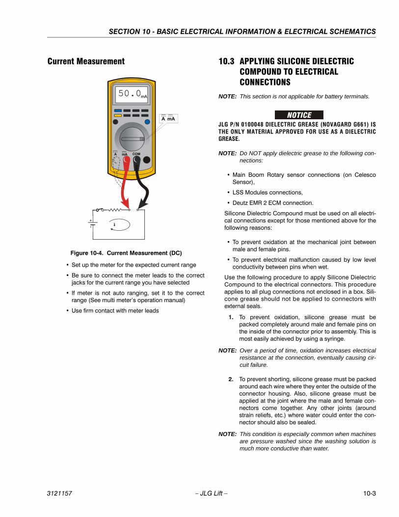
SECTION 10 - BASIC ELECTRICAL INFORMATION & ELECTRICAL SCHEMATICS
3121157 – JLG Lift – 10-3
Current Measurement
• Set up the meter for the expected current range
• Be sure to connect the meter leads to the correctjacks for the current range you have selected
• If meter is not auto ranging, set it to the correctrange (See multi meter’s operation manual)
• Use firm contact with meter leads
10.3 APPLYING SILICONE DIELECTRIC COMPOUND TO ELECTRICAL CONNECTIONS
NOTE: This section is not applicable for battery terminals.
JLG P/N 0100048 DIELECTRIC GREASE (NOVAGARD G661) ISTHE ONLY MATERIAL APPROVED FOR USE AS A DIELECTRICGREASE.
NOTE: Do NOT apply dielectric grease to the following con-nections:
• Main Boom Rotary sensor connections (on CelescoSensor),
• LSS Modules connections,
• Deutz EMR 2 ECM connection.
Silicone Dielectric Compound must be used on all electri-cal connections except for those mentioned above for thefollowing reasons:
• To prevent oxidation at the mechanical joint betweenmale and female pins.
• To prevent electrical malfunction caused by low levelconductivity between pins when wet.
Use the following procedure to apply Silicone DielectricCompound to the electrical connectors. This procedureapplies to all plug connections not enclosed in a box. Sili-cone grease should not be applied to connectors withexternal seals.
1. To prevent oxidation, silicone grease must bepacked completely around male and female pins onthe inside of the connector prior to assembly. This ismost easily achieved by using a syringe.
NOTE: Over a period of time, oxidation increases electricalresistance at the connection, eventually causing cir-cuit failure.
2. To prevent shorting, silicone grease must be packedaround each wire where they enter the outside of theconnector housing. Also, silicone grease must beapplied at the joint where the male and female con-nectors come together. Any other joints (aroundstrain reliefs, etc.) where water could enter the con-nector should also be sealed.
NOTE: This condition is especially common when machinesare pressure washed since the washing solution ismuch more conductive than water.
Figure 10-4. Current Measurement (DC)

SECTION 10 - BASIC ELECTRICAL INFORMATION & ELECTRICAL SCHEMATICS
10-4 – JLG Lift – 3121157
3. Anderson connectors for the battery boxes and bat-tery chargers should have silicone grease applied tothe contacts only.
NOTE: Curing-type sealants might also be used to preventshorting and would be less messy, but would makefuture pin removal more difficult.
When applied to electrical connections, dielectric greasehelps to prevent corrosion of electrical contacts andimproper conductivity between contacts from moistureintrusion. Open and sealed connectors benefit from theapplication of dielectric grease.
Dielectric grease shall be applied to all electrical connec-tors at the time of connection (except those noted underExclusions).
Installation of Dielectric GreaseBefore following these instructions, refer to excluded con-nector types (See Exclusions below).
1. Use dielectric grease in a tube for larger connectionpoints or apply with a syringe for small connectors.
2. Apply dielectric grease to the female contact (fill itapproximately ½ full; see example below)
3. Leave a thin layer of dielectric grease on the face ofthe connector
4. Assemble the connector system immediately to pre-vent moisture ingress or dust contamination
5. Pierce one of the unused wire seals prior to assem-bly if the connector system tends to trap air (i.e.AMP Seal) and then install a seal plug.
Deutsch HD, DT, DTM, DRC SeriesThe Deutsch connector system is commonly used forharsh environment interconnect. Follow the installationinstructions.
AMP SealThe AMP Seal connector system is used on the ControlADE Platform and Ground Modules.
Apply dielectric grease to the female contact. If trapped airprevents the connector from latching, pierce one of theunused wire seals. After assembly, install a seal plug (JLG#4460905) in that location to prevent moisture ingress.
Note that seal plugs may be installed by the wire harnessmanufacturer if an unused wire seal becomes compro-mised (wire inserted in the wrong cavity during assemblyand then corrected).
Figure 10-5. Application to Female Contacts
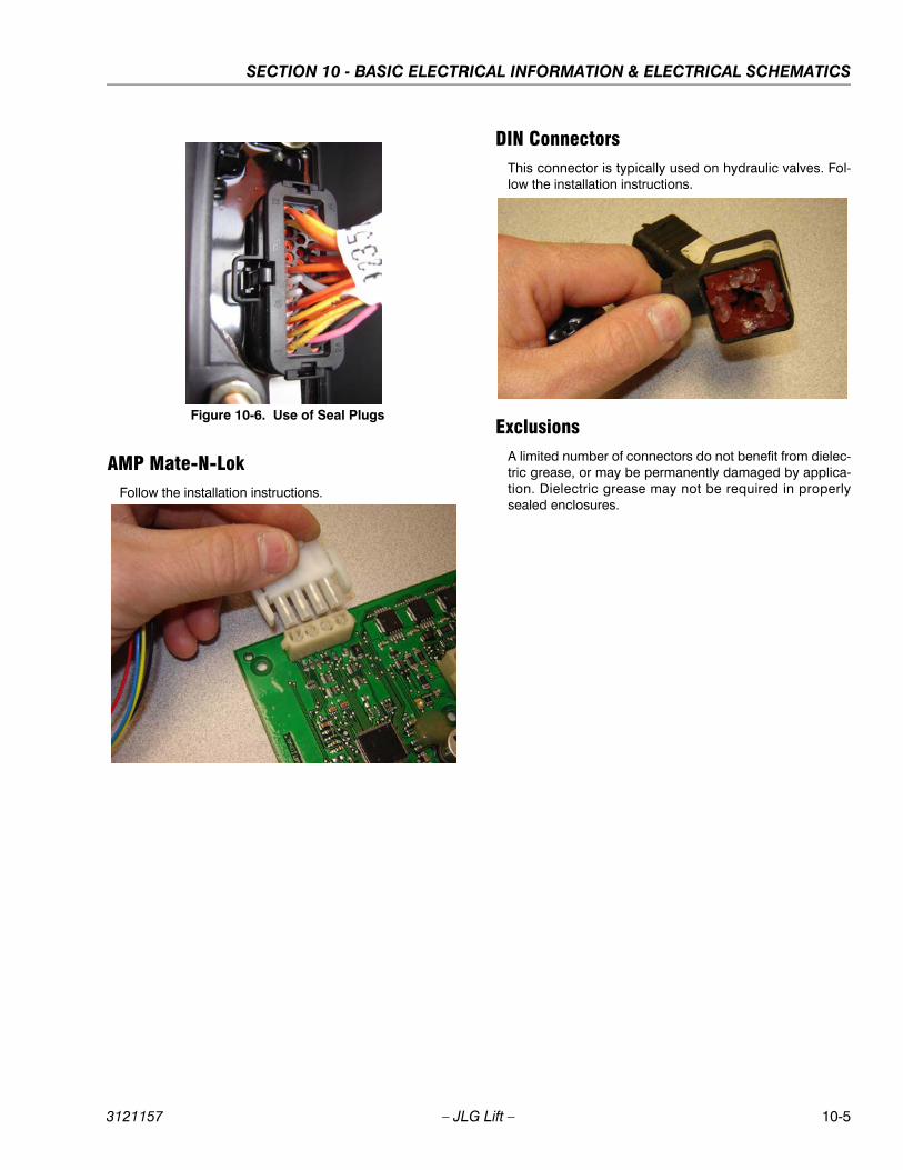
SECTION 10 - BASIC ELECTRICAL INFORMATION & ELECTRICAL SCHEMATICS
3121157 – JLG Lift – 10-5
AMP Mate-N-LokFollow the installation instructions.
DIN ConnectorsThis connector is typically used on hydraulic valves. Fol-low the installation instructions.
ExclusionsA limited number of connectors do not benefit from dielec-tric grease, or may be permanently damaged by applica-tion. Dielectric grease may not be required in properlysealed enclosures.
Figure 10-6. Use of Seal Plugs
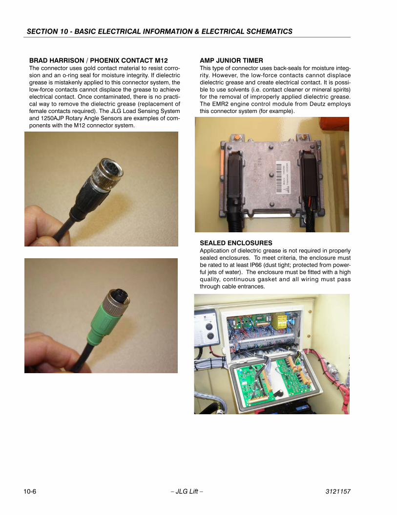
SECTION 10 - BASIC ELECTRICAL INFORMATION & ELECTRICAL SCHEMATICS
10-6 – JLG Lift – 3121157
BRAD HARRISON / PHOENIX CONTACT M12 The connector uses gold contact material to resist corro-sion and an o-ring seal for moisture integrity. If dielectricgrease is mistakenly applied to this connector system, thelow-force contacts cannot displace the grease to achieveelectrical contact. Once contaminated, there is no practi-cal way to remove the dielectric grease (replacement offemale contacts required). The JLG Load Sensing Systemand 1250AJP Rotary Angle Sensors are examples of com-ponents with the M12 connector system.
AMP JUNIOR TIMERThis type of connector uses back-seals for moisture integ-rity. However, the low-force contacts cannot displacedielectric grease and create electrical contact. It is possi-ble to use solvents (i.e. contact cleaner or mineral spirits)for the removal of improperly applied dielectric grease.The EMR2 engine control module from Deutz employsthis connector system (for example).
SEALED ENCLOSURES Application of dielectric grease is not required in properlysealed enclosures. To meet criteria, the enclosure mustbe rated to at least IP66 (dust tight; protected from power-ful jets of water). The enclosure must be fitted with a highquality, continuous gasket and all wiring must passthrough cable entrances.

SECTION 10 - BASIC ELECTRICAL INFORMATION & ELECTRICAL SCHEMATICS
3121157 – JLG Lift – 10-7
MIL-C-5015 SPEC CONNECTORSCrown Connector Inc's recommendation is to not usedielectric grease for this series connector. For similarmodel series connectors, the manufacturer should becontacted for confirmation before applying dielectricgrease. A typical application for this connector is on DavidClark Intercom connections in Aerial Work Platforms.
10.4 AMP CONNECTOR
Applying Silicone Dielectric Compound to AMP Connectors
Silicone Dielectric Compound must be used on the AMPconnections for the following reasons:
• To prevent oxidation at the mechanical joint betweenmale and female pins.
• To prevent electrical malfunction caused by low levelconductivity between pins when wet.
Use the following procedure to apply Silicone DielectricCompound to the electrical connectors.
1. To prevent oxidation and low level conductivity, sili-cone dielectric grease must be packed completelyaround male and female pins on the inside of theconnector after the mating of the housing to theheader. This is easily achieved by using a syringe tofill the header with silicone dielectric compound, to apoint just above the top of the male pins inside theheader. When assembling the housing to theheader, it is possible that the housing will becomeair locked, thus preventing the housing latch fromengaging.
2. Pierce one of the unused wire seals to allow thetrapped air inside the housing to escape.
3. Install a hole plug into this and/or any unused wireseal that has silicone dielectric compound escapingfrom it.
AssemblyCheck to be sure the wedge lock is in the open, or as-shipped, position (See Figure 10-7.). Proceed as follows:
1. To insert a contact, push it straight into the appropri-ate circuit cavity as far as it will go (See Figure 10-9.).
Figure 10-7. Connector Assembly Figure 1
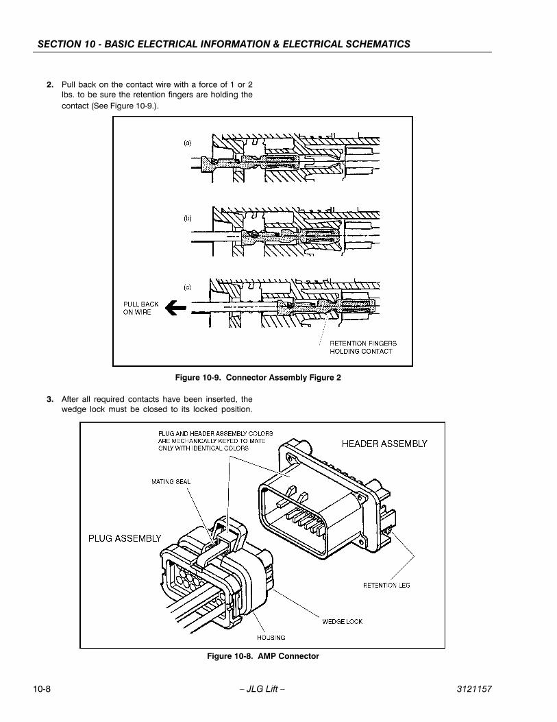
SECTION 10 - BASIC ELECTRICAL INFORMATION & ELECTRICAL SCHEMATICS
10-8 – JLG Lift – 3121157
2. Pull back on the contact wire with a force of 1 or 2lbs. to be sure the retention fingers are holding thecontact (See Figure 10-9.).
3. After all required contacts have been inserted, thewedge lock must be closed to its locked position.
Figure 10-8. AMP Connector
Figure 10-9. Connector Assembly Figure 2
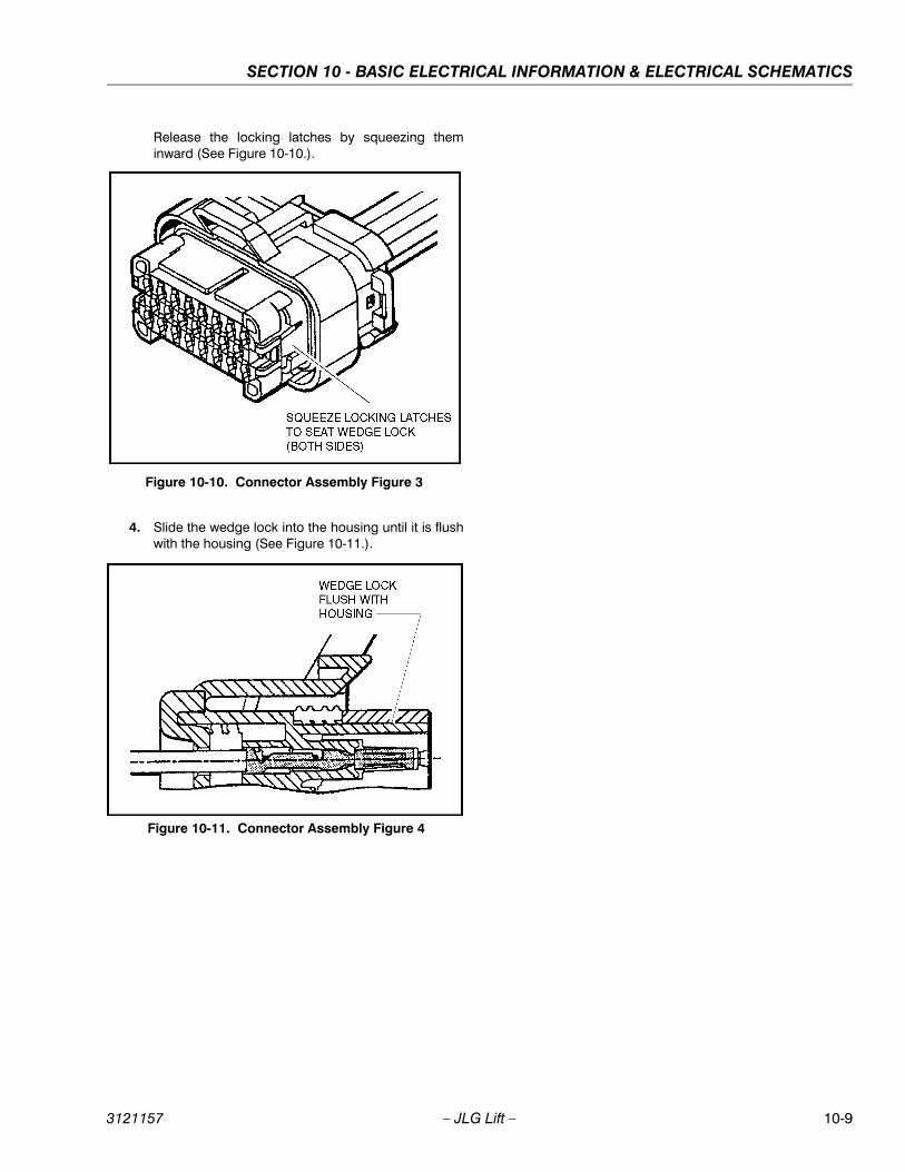
SECTION 10 - BASIC ELECTRICAL INFORMATION & ELECTRICAL SCHEMATICS
3121157 – JLG Lift – 10-9
Release the locking latches by squeezing theminward (See Figure 10-10.).
4. Slide the wedge lock into the housing until it is flushwith the housing (See Figure 10-11.).
Figure 10-10. Connector Assembly Figure 3
Figure 10-11. Connector Assembly Figure 4

SECTION 10 - BASIC ELECTRICAL INFORMATION & ELECTRICAL SCHEMATICS
10-10 – JLG Lift – 3121157
Disassembly1. Insert a 4.8 mm (3/16") wide screwdriver blade
between the mating seal and one of the red wedgelock tabs.
2. Pry open the wedge lock to the open position.
3. While rotating the wire back and forth over a halfturn (1/4 turn in each direction), gently pull the wireuntil the contact is removed.
NOTE: The wedge lock should never be removed from thehousing for insertion or removal of the contacts.
Wedge LockThe wedge lock has slotted openings in the forward, ormating end. These slots accommodate circuit testing inthe field, by using a flat probe such as a pocket knife. DONOT use a sharp point such as an ice pick.
Service - Voltage Reading
DO NOT PIERCE WIRE INSULATION TO TAKE VOLT-AGE READINGS.
It has been common practice in electrical troubleshootingto probe wires by piercing the insulation with a sharppoint. This practice should be discouraged when dealingwith the AMPSEAL plug assembly, or any other sealedconnector system. The resulting pinholes in the insulationwill allow moisture to invade the system by traveling alongthe wire strands. This nullifies the effectiveness of the con-nector seals and could result in system failure.
Figure 10-12. Connector Disassembly

SECTION 10 - BASIC ELECTRICAL INFORMATION & ELECTRICAL SCHEMATICS
3121157 – JLG Lift – 10-11
Figure 10-13. Connector Installation
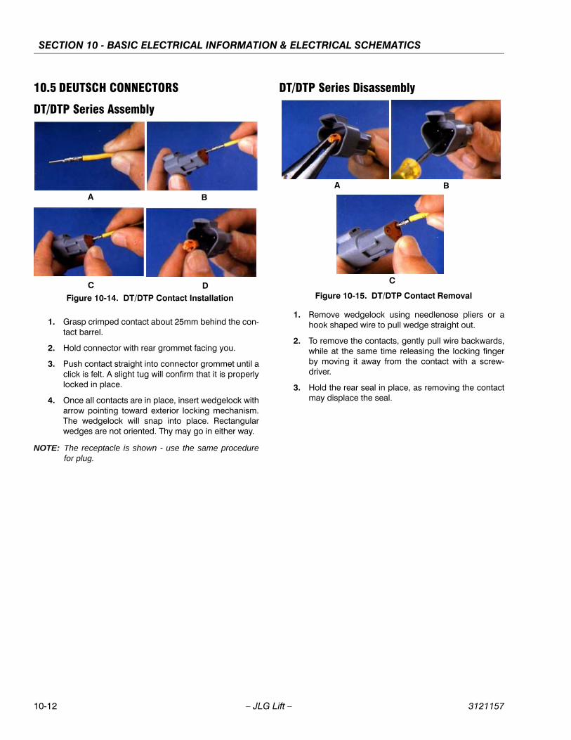
SECTION 10 - BASIC ELECTRICAL INFORMATION & ELECTRICAL SCHEMATICS
10-12 – JLG Lift – 3121157
10.5 DEUTSCH CONNECTORS
DT/DTP Series Assembly
1. Grasp crimped contact about 25mm behind the con-tact barrel.
2. Hold connector with rear grommet facing you.
3. Push contact straight into connector grommet until aclick is felt. A slight tug will confirm that it is properlylocked in place.
4. Once all contacts are in place, insert wedgelock witharrow pointing toward exterior locking mechanism.The wedgelock will snap into place. Rectangularwedges are not oriented. Thy may go in either way.
NOTE: The receptacle is shown - use the same procedurefor plug.
DT/DTP Series Disassembly
1. Remove wedgelock using needlenose pliers or ahook shaped wire to pull wedge straight out.
2. To remove the contacts, gently pull wire backwards,while at the same time releasing the locking fingerby moving it away from the contact with a screw-driver.
3. Hold the rear seal in place, as removing the contactmay displace the seal.
Figure 10-14. DT/DTP Contact Installation
A B
C DFigure 10-15. DT/DTP Contact Removal
A B
C
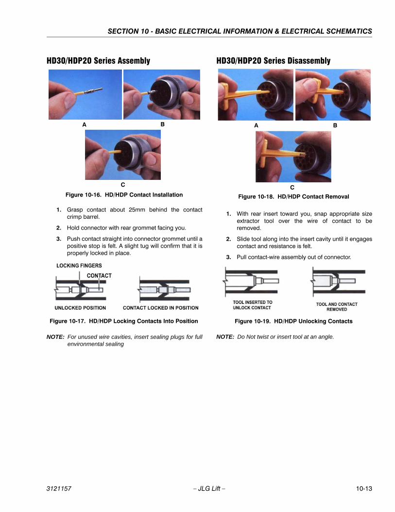
SECTION 10 - BASIC ELECTRICAL INFORMATION & ELECTRICAL SCHEMATICS
3121157 – JLG Lift – 10-13
HD30/HDP20 Series Assembly
1. Grasp contact about 25mm behind the contactcrimp barrel.
2. Hold connector with rear grommet facing you.
3. Push contact straight into connector grommet until apositive stop is felt. A slight tug will confirm that it isproperly locked in place.
NOTE: For unused wire cavities, insert sealing plugs for fullenvironmental sealing
HD30/HDP20 Series Disassembly
1. With rear insert toward you, snap appropriate sizeextractor tool over the wire of contact to beremoved.
2. Slide tool along into the insert cavity until it engagescontact and resistance is felt.
3. Pull contact-wire assembly out of connector.
NOTE: Do Not twist or insert tool at an angle.
Figure 10-16. HD/HDP Contact Installation
A B
C
Figure 10-17. HD/HDP Locking Contacts Into Position
Figure 10-18. HD/HDP Contact Removal
A B
C
Figure 10-19. HD/HDP Unlocking Contacts
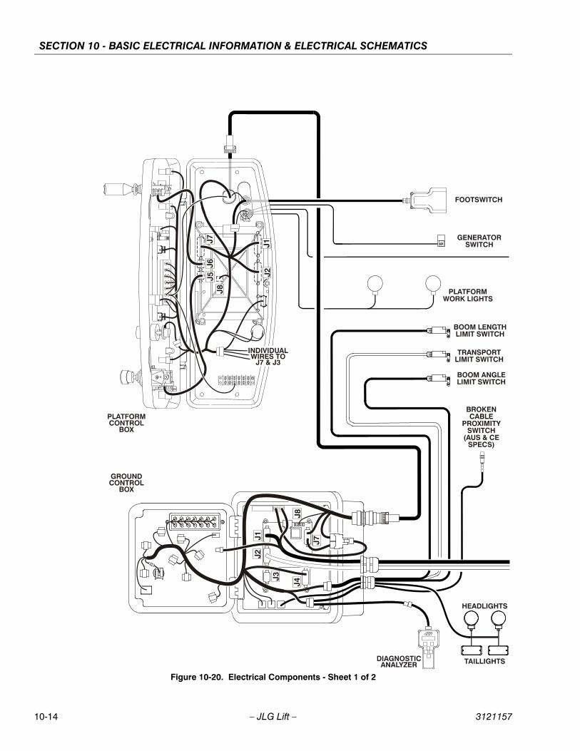
SECTION 10 - BASIC ELECTRICAL INFORMATION & ELECTRICAL SCHEMATICS
10-14 – JLG Lift – 3121157
Figure 10-20. Electrical Components - Sheet 1 of 2
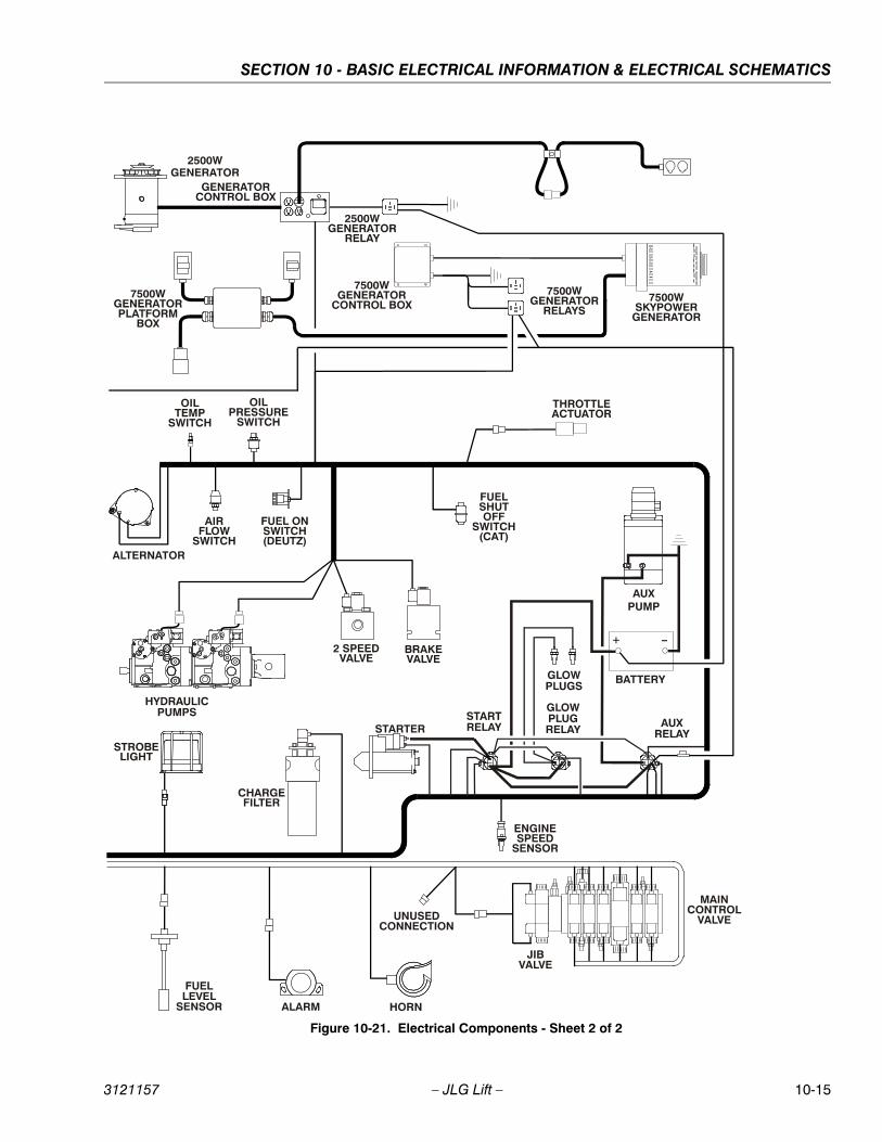
SECTION 10 - BASIC ELECTRICAL INFORMATION & ELECTRICAL SCHEMATICS
3121157 – JLG Lift – 10-15
Figure 10-21. Electrical Components - Sheet 2 of 2
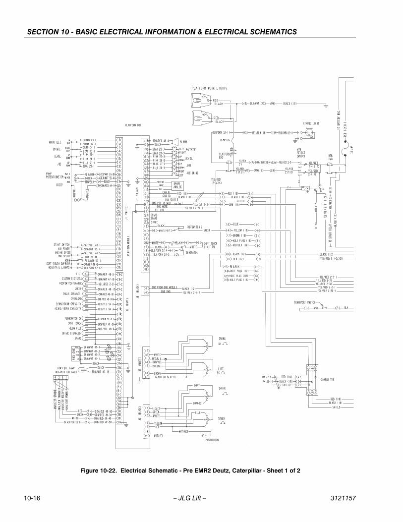
SECTION 10 - BASIC ELECTRICAL INFORMATION & ELECTRICAL SCHEMATICS
10-16 – JLG Lift – 3121157
Figure 10-22. Electrical Schematic - Pre EMR2 Deutz, Caterpillar - Sheet 1 of 2
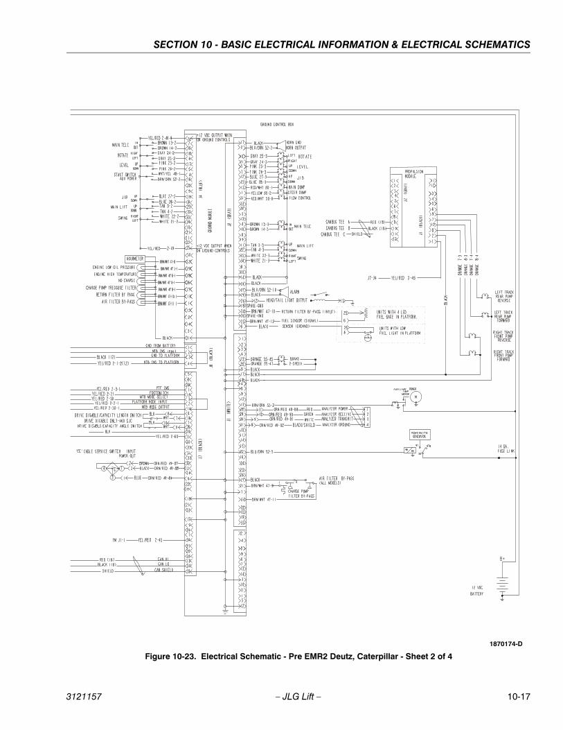
SECTION 10 - BASIC ELECTRICAL INFORMATION & ELECTRICAL SCHEMATICS
3121157 – JLG Lift – 10-17
Figure 10-23. Electrical Schematic - Pre EMR2 Deutz, Caterpillar - Sheet 2 of 4
1870174-D
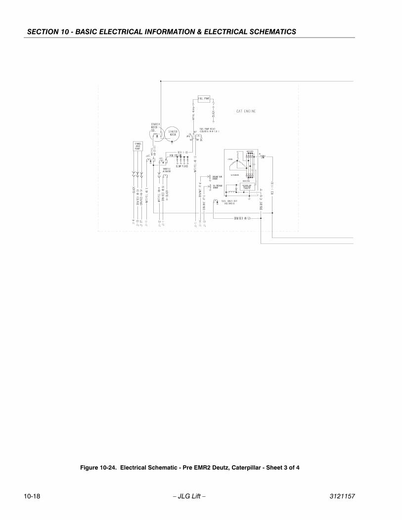
SECTION 10 - BASIC ELECTRICAL INFORMATION & ELECTRICAL SCHEMATICS
10-18 – JLG Lift – 3121157
Figure 10-24. Electrical Schematic - Pre EMR2 Deutz, Caterpillar - Sheet 3 of 4
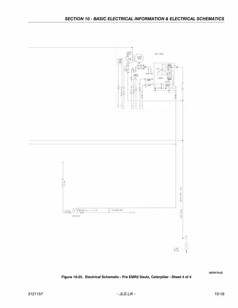
SECTION 10 - BASIC ELECTRICAL INFORMATION & ELECTRICAL SCHEMATICS
3121157 – JLG Lift – 10-19
Figure 10-25. Electrical Schematic - Pre EMR2 Deutz, Caterpillar - Sheet 4 of 41870174-D
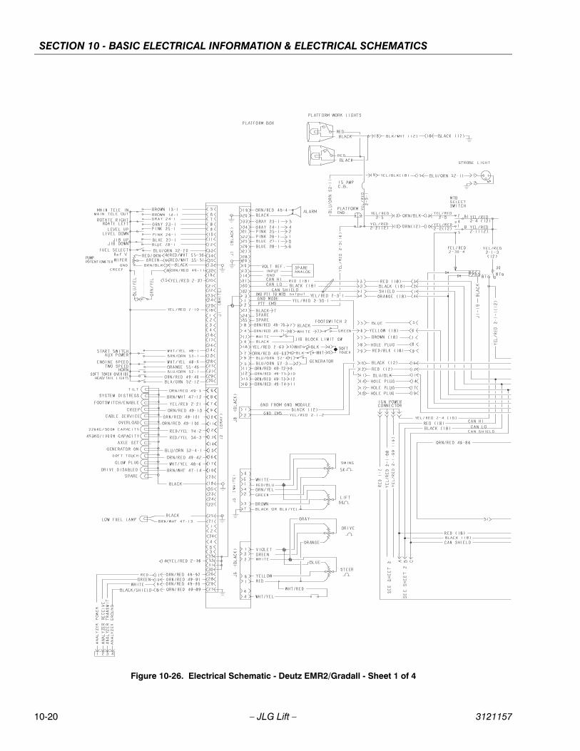
SECTION 10 - BASIC ELECTRICAL INFORMATION & ELECTRICAL SCHEMATICS
10-20 – JLG Lift – 3121157
Figure 10-26. Electrical Schematic - Deutz EMR2/Gradall - Sheet 1 of 4
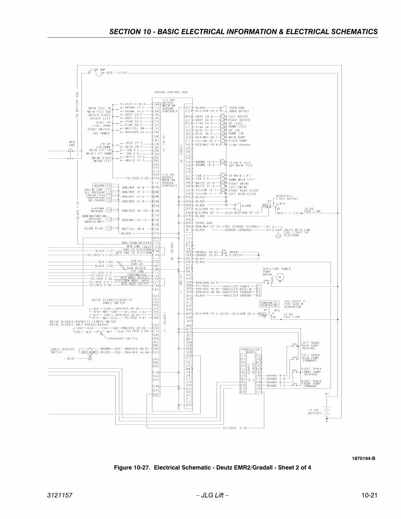
SECTION 10 - BASIC ELECTRICAL INFORMATION & ELECTRICAL SCHEMATICS
3121157 – JLG Lift – 10-21
Figure 10-27. Electrical Schematic - Deutz EMR2/Gradall - Sheet 2 of 4
1870194-B
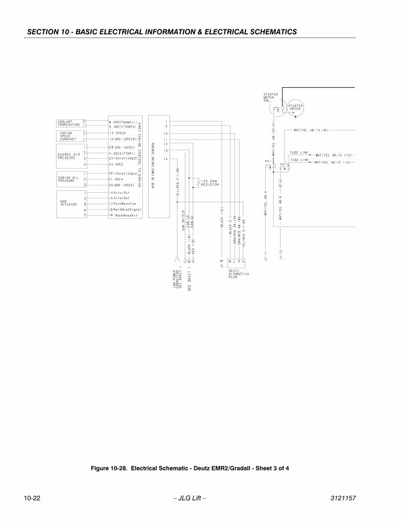
SECTION 10 - BASIC ELECTRICAL INFORMATION & ELECTRICAL SCHEMATICS
10-22 – JLG Lift – 3121157
Figure 10-28. Electrical Schematic - Deutz EMR2/Gradall - Sheet 3 of 4
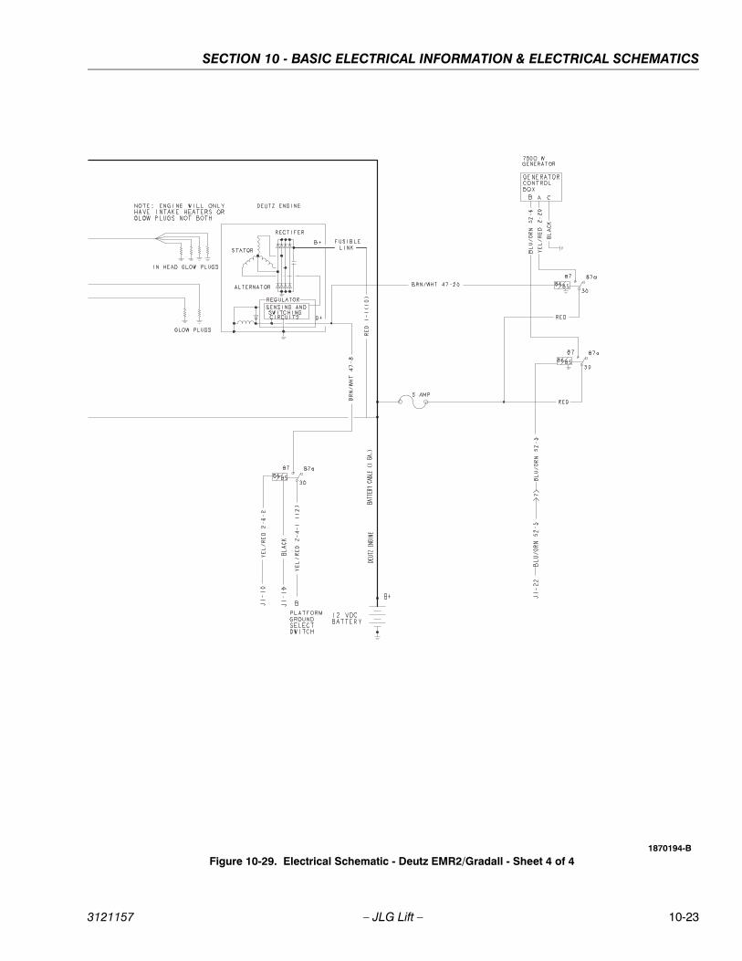
SECTION 10 - BASIC ELECTRICAL INFORMATION & ELECTRICAL SCHEMATICS
3121157 – JLG Lift – 10-23
Figure 10-29. Electrical Schematic - Deutz EMR2/Gradall - Sheet 4 of 41870194-B
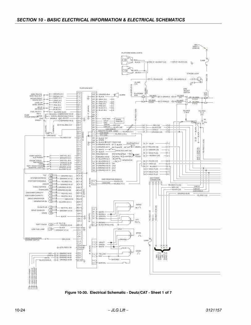
SECTION 10 - BASIC ELECTRICAL INFORMATION & ELECTRICAL SCHEMATICS
10-24 – JLG Lift – 3121157
REDBLACK
BLACKRED
PLATFORM WORK LIGHTS
ALARMMAIN TELE INMAIN TELE OUT
ROTATE RIGHTROATE LEFT
LEVEL UPLEVEL DOWN
JIB UPJIB DOWN
EMS PTF TO MTB
PTF EMSGND MODE
GND EMS
GND FROM GND MODULE
CAN LOCAN HI
START SWITCHAUX POWER
TWO SPEEDENGINE SPEED
SOFT TOUCH OVERIDEHEAD/TAIL LIGHTS
HORN
FOOTSWITCH 2
CREEP
FUEL SELECT
GENERATOR
JIB BLOCK LIMIT SW
SOFTTOUCH
TILT
SYSTEM DISTRESS
FOOTSWITCH/ENABLE
CREEP
CABLE SERVICE
OVERLOAD
226KG/500# CAPACITY
453KG/1000# CAPACITY
DRIVE ORIENTATION
GENERATOR ON
SOFT TOUCH
GLOW PLUG
DRIVE DISABLED
SPARE
PUMP POTENTIOMETER
AN
ALY
ZE
R P
OW
ER
AN
ALY
ZE
R R
EC
EIV
EA
NA
LYZ
ER
TR
AN
SM
ITA
NA
LYZ
ER
GR
OU
ND
PLATFORM BOX
J1
(WH
ITE
)
SPARE ANALOG
VOLT REF.
GNDINPUT
ORN/RED 49-3
BRN/WHT 47-12
YEL/RED 2-21
ORN/RED 49-15
RED/YEL 54-2
RED/YEL 54-3
BLU/ORN 52-4-1
WHT/YEL 48-6
GRAY 23-1
GRAY 24-1PINK 25-1PINK 26-1BLUE 27-1
BLUE 28-1
SWING
LIFT
BLU/ORN 52-12
BLUE 27-1BLUE 28-1
PINK 26-1
PINK 25-1GRAY 23-1
GRAY 24-1BROWN 14-1
BROWN 13-1
SPAREBLACK TO SOFT TOUCH IND.
J2
(GR
AY
)
J5 (
WH
ITE
)J6
(B
LA
CK
)
output
PLATFORM EMS
MTBSELECTSWITCH MTB
EMS
CAN SHIELD
STROBE LIGHT
5
6789
1011
12
33343513
321920
2122
2324
251812
34
1617
2614
15
2827
312930
J8
(BLA
CK
)J7
(B
LA
CK
)
19
20
33
3421
22252627
282910
1314
3130
32312
23
24358
4
176
18
79
5
15
11
12
16
1
2
6
8
7
9
10
11
12
13
14
15
16
17
19
20
18
3523
24
25
21
12
34
4
53
333231
30
262829
6
73
2
51
6
4
Ref.V
WIPER
GND
LOW FUEL LAMP
27
BLK/WHT (12)
BLU
/OR
N 5
2-1
1
YE
L/R
ED
2-3
(16)
YEL/RED2-2(12) ORN(12) YEL/RED
2-2(12)
RED (18)BLACK (18)
SHIELDORANGE (18)
18 BLACK (12)
YEL/BLK(18) BLU/ORN 52-1115 15
13 13YEL/RED
2-5 ORN/BLKYEL/RED
2-5
1010
32
14
32
14
6 6YELLOW (18)
16
12
16
12
BLACK (12)
RED (12)
11 11BLU/BLK
BLU/ORN 52-20
WHT/YEL 48-1BRN/ORN 53-1
WHT/YEL 48-5
BLU/ORN 52-1
BRN/WHT 47-13
ORN/RED 49-4
RED (18)BLACK (18)
YEL/RED 2-3-1YEL/RED 2-30-1
BLACK (12)
YEL/RED 2-1-2
REDGREEN
WHITE
BLACK/SHIELD
4321
2
41
3
B1
B
YEL/RED 2-4 (12)
YEL/RED 2-1(12)
BLUE
BROWN (18)
RED/BLK (18)
HOLE PLUG
HOLE PLUG
HOLE PLUG
HOLE PLUG
YE
L/R
ED
2-1
-1(1
2)
5
7
9
8
14
17
19 19
17
14
8
9
7
5
4
65
3
2
YEL/RED 2-10
RED/WHT 55-30RED/WHT 55-31
BLACK
ORN/RED 49-11
ORANGE 55-46
ORN/RED 49-40
GREEN
BLACK
WHITE
BLU/ORN 52-4
BLU/ORN 52-3
15 AMPC.B.
YE
L/R
ED
2
-5-1
ORN/RED 49-100
ORN/RED 49-101
ORN/RED 49-42
BLACK
BLACK
18
5K
5K
5142
37
2
1
RED/ORNGREEN
BRN/BLK
OR
N/Y
EL
BL
U/Y
EL
8 7
WHITEBLACK
BLK6
BLK
WHT
3 4
5R
1
2
ORN/RED 49-92ORN/RED 49-91ORN/RED 49-90
ORN/RED 49-89
11109
8
WHITERED/BLUGRN/YEL
GREEN
BROWNBLACK OR BLU/YEL
30
8787a
RE
D 1
-2
ORN/RED 49-86
86 85
L
YEL/RED2-30-4
YEL/RED2-1-3(12)
YEL/RED 2-4 (16)
YE
L/R
ED
2-1
-99
(16
)
IGN POWERCONNECTOR
CAN HIRED (18)
CAN LOBLACK (18)CAN SHIELD
A B C
SE
E
SH
EE
T 2
ZO
NE
F7
OR
SH
EE
T 4
ZO
NE
C5
15 YEL/RED 2-37
BLACK
BRN/WHT 47-14
YEL/RED 2-3614
ORN/RED 49-71
ORN/RED 49-69
7ORN/RED 49-70
9ORN/RED 49-72
10ORN/RED 49-73
12ORN/RED 49-75
11ORN/RED 49-74
YEL/RED 2-63 WHT
BLACK 7
342156
BLA
CK
J1-1
9
DRIVE
STEER
VIOLETGREENWHITE
RED
GRAY
BLUE
ORANGE
YELLOW
WHT/YEL
WHT/RED
ORN 55-52
DRIVE ORIENTATION OVERIDE SWITCH ORN 55-50
ORN 55-51
YEL/RED 2-63
TO J7-35
RE
D 1
-90
5 AMP
5 AMP
YE
L/R
ED
2-9
0
SEESHEET 1ZONE B2
SH
T 2
, Z
ON
E E
6S
HT
4,
ZO
NE
D7
{
BL
AC
K
Figure 10-30. Electrical Schematic - Deutz/CAT - Sheet 1 of 7
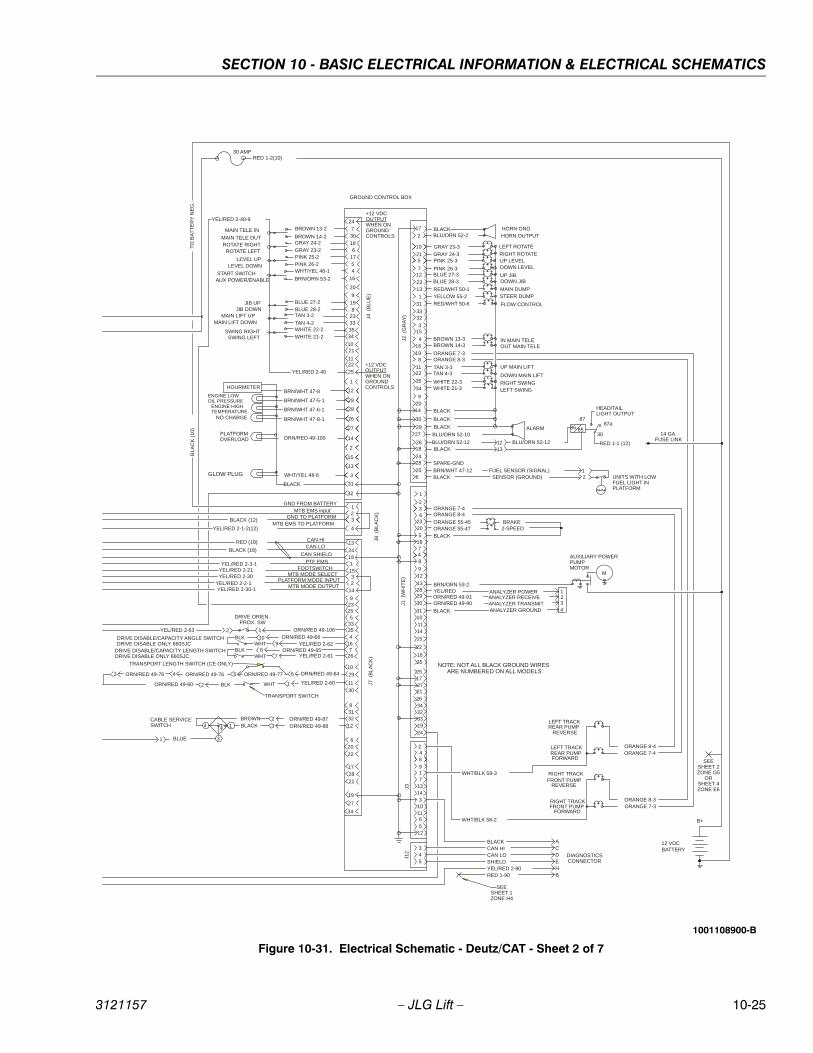
SECTION 10 - BASIC ELECTRICAL INFORMATION & ELECTRICAL SCHEMATICS
3121157 – JLG Lift – 10-25
AUXILIARY POWERPUMPMOTOR
M
UP LEVELDOWN LEVEL
RIGHT ROTATE
LEFT ROTATE
DOWN JIBUP JIB
ALARM
MAIN TELE IN
MAIN TELE OUTROTATE RIGHT
ROTATE LEFT
LEVEL UPLEVEL DOWN
JIB UPJIB DOWN
PTF EMS
MTB MODE OUTPUT
START SWITCHAUX POWER/ENABLE
SWING LEFTSWING RIGHT
MAIN LIFT DOWNMAIN LIFT UP
ENGINE LOWOIL PRESSURE
ENGINE HIGHTEMPERATURE
NO CHARGE
GROUND CONTROL BOX
HOURMETER
OUT MAIN TELEIN MAIN TELE
UP MAIN LIFT
DOWN MAIN LIFT
LEFT SWINGRIGHT SWING
MAIN DUMPSTEER DUMP
FLOW CONTROL
17
2
10
215
712
2313
131
3332
315
4
24730186
1754
16
20
9
198
23333534
1021
112225
32
12
29
28
26
27
13
1
14
2
15
3
31
16
819
1122
35
34
92014
30
2729
2618
2428
256
HEAD/TAILLIGHT OUTPUT
FUEL SENSOR (SIGNAL)SENSOR (GROUND)
J4 (
BLU
E)
2
7
12
13
21
22
35
251727
31
302928
3233
34
24
1532
14
29
11
30
23
3335
3212
6
9
10
27
20
255
831
FOOTSWITCHMTB MODE SELECT
PLATFORM MODE INPUT
23
4
1MTB EMS input
GND FROM BATTERY
GND TO PLATFORMMTB EMS TO PLATFORM
TO
BA
TT
ER
Y N
EG
.
J2 (
GR
AY
)
J8
(BLA
CK
)J7
(B
LAC
K)
J1
(WH
ITE
)
248917
13143
101165
12
HORN OUTPUTHORN GND
BLACK
SPARE-GND
1
BLACKBLU/ORN 52-2
GRAY 23-3
GRAY 24-3PINK 25-3
PINK 26-3BLUE 27-3BLUE 28-3
RED/WHT 50-1YELLOW 55-2
RED/WHT 50-6
BROWN 13-3BROWN 14-3
TAN 3-3TAN 4-3
WHITE 22-3WHITE 21-3
BLACK
BLACK
BLU/ORN 52-10
BLACK
BRN/WHT 47-12
BRN/ORN 53-2
YEL/RED 2-40-9
BROWN 13-2
BROWN 14-2GRAY 24-2
GRAY 23-2PINK 25-2PINK 26-2WHT/YEL 48-1
BRN/ORN 53-2
BLUE 27-2BLUE 28-2TAN 3-2
TAN 4-2WHITE 22-2WHITE 21-2
BRN/WHT 47-8
BRN/WHT 47-5-1
BRN/WHT 47-6-1
BRN/WHT 47-8-1
BLACK
BLA
CK
(10
)
BLACK (12)
YEL/RED 2-1-2(12)
YEL/RED 2-30YEL/RED 2-2-1YEL/RED 2-30-1
YEL/RED 2-3-1
+12 VDCOUTPUTWHEN ONGROUNDCONTROLS
BLACK12 UNITS WITH LOW
FUEL LIGHT INPLATFORM
ANALYZER POWERANALYZER RECEIVEANALYZER TRANSMITANALYZER GROUNDBLACK
1234
3
185
6
BLACK
2-SPEEDBRAKE
2023
ORANGE 55-47ORANGE 55-45
YEL/RED 2-21
RED 1-2(10)
1
15
4
1411
8
10
9
19
26
16
TRANSPORT SWITCH
30 AMP
1
3
4
22
34
17
21
28
19
BROWNBLACK
BLUE
CAN SHIELD
CAN LOCAN HI
13
2418
RED (18)
BLACK (18)
BLK WHT
4167
26WHTBLK
WHTBLK
DRIVE DISABLE/CAPACITY LENGTH SWITCHDRIVE DISABLE ONLY 660SJC
DRIVE DISABLE/CAPACITY ANGLE SWITCHDRIVE DISABLE ONLY 660SJC
YEL/RED 2-40
12
YEL/RED 2-601
3
910
78
YEL/RED ORN/RED 49-91ORN/RED 49-90
ORN/RED 49-87ORN/RED 49-88
23
1
WHT/YEL 48-6
B+
12 VDCBATTERY
+12 VDCOUTPUTWHEN ONGROUNDCONTROLS
YEL/RED 2-62ORN/RED 49-66
ORN/RED 49-65YEL/RED 2-61
BLU/ORN 52-12
86 85
87
30
87a
14 GA. FUSE LINK
RED 1-1 (12)BLU/ORN 52-12
CABLE SERVICESWITCH
ORN/RED 49-100PLATFORMOVERLOAD
ORN/RED 49-64
2
4 5 6
GLOW PLUG
WHT/BLK 58-3
ORN/RED 49-60
ORN/RED 49-76 ORN/RED 49-76 ORN/RED 49-77
NOTE: NOT ALL BLACK GROUND WIRES ARE NUMBERED ON ALL MODELS
ORN/RED 49-106YEL/RED 2-63
DRIVE ORIEN.PROX. SW
345
J3J1
2
ORANGE 8-3ORANGE 7-3
LEFT TRACKREAR PUMP
REVERSE
LEFT TRACKREAR PUMP
REVERSE
FORWARD
RIGHT TRACK
RIGHT TRACK
FORWARD
FRONT PUMP
FRONT PUMP
ORANGE 8-4ORANGE 7-4
BLACKCAN HICAN LOSHIELDYEL/RED 2-90RED 1-90
ACDEHB
DIAGNOSTICSCONNECTOR
SEESHEET 1 ZONE H4
12
ORANGE 7-3ORANGE 8-3
ORANGE 7-4ORANGE 8-4
WHT/BLK 58-2
SEESHEET 2ZONE G5
ORSHEET 4ZONE E6
TRANSPORT LENGTH SWITCH (CE ONLY)
13
Figure 10-31. Electrical Schematic - Deutz/CAT - Sheet 2 of 7
1001108900-B
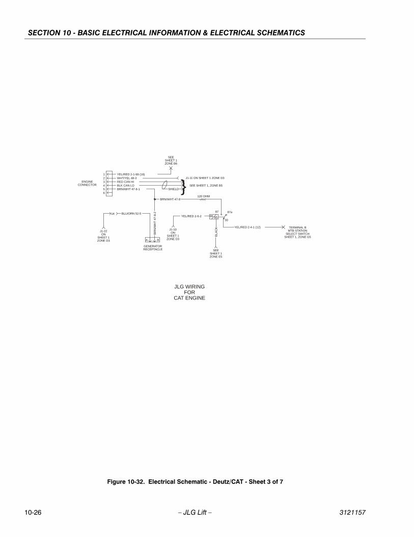
SECTION 10 - BASIC ELECTRICAL INFORMATION & ELECTRICAL SCHEMATICS
10-26 – JLG Lift – 3121157
21
ENGINECONNECTOR
YEL/RED 2-1-99 (16)WHT/YEL 48-3
3456
RED CAN HIBLK CAN LOBRN/WHT 47-8-1
SEESHEET 1ZONE B6
J1-11 ON SHEET 1 ZONE D3
} SEE SHEET 1, ZONE B5SHIELD
14 BLU/ORN 52-5
J1-22ON
SHEET 1ZONE D3
BR
N/W
HT
47-
8-2
86 85
87
30
87a
YEL/RED 2-4-1 (12) TERMINAL BMTB STATION
SELECT SWITCHSHEET 1, ZONE G5
YEL/RED 2-6-2
120 OHM
BLA
CKJ1-10
ONSHEET 1ZONE D3
BRN/WHT 47-8
SEESHEET 1ZONE E5
GENERATORRECEPTACLE
A B
JLG WIRINGFOR
CAT ENGINE
Figure 10-32. Electrical Schematic - Deutz/CAT - Sheet 3 of 7
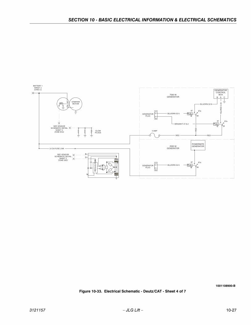
SECTION 10 - BASIC ELECTRICAL INFORMATION & ELECTRICAL SCHEMATICS
3121157 – JLG Lift – 10-27
86 85
87
30
87a
BLU/ORN 52-5
7500 WGENERATOR
86 85
87
30
87a
RED
5 AMP
RED
BLU/ORN 52-6
YE
L/R
ED
2-2
0
CAB
GENERATORCONTROL
BOX
B+
D+
W
RE
GU
LA
TO
R
STARTERMOTOR
BATTERY +SHEET 1ZONE C1
SEE VENDORSCHEMATIC DETAIL
SHEET 4ZONE E/G2
GLOWPLUGS
SEE VENDORSCHEMATIC DETAIL
SHEET 2ZONE G/E2
14 GA FUSE LINK
GENERATORPLUG
B
A
RE
D
BRN/WHT 47-8-2
86 85
87
30
87a
BLU/ORN 52-5
2500 WGENERATOR
POWERMITEGENERATOR
GENERATORPLUG
B
A
Figure 10-33. Electrical Schematic - Deutz/CAT - Sheet 4 of 7
1001108900-B
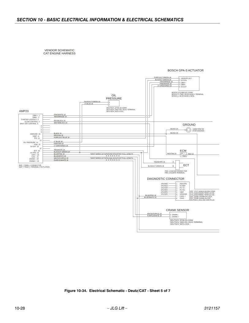
SECTION 10 - BASIC ELECTRICAL INFORMATION & ELECTRICAL SCHEMATICS
10-28 – JLG Lift – 3121157
21
1 ANA RTN
EPC_1F1T-14A624-AA-004 CONNGTS_0330-930009 TERM (18-29)GTS_0330-940001 TERM (14-16)EPC_E6DB-14A468-DA LOCKEPC_F5AB-14A666-AA CAPDEUTSCH_0413-204-2005 PLUG
DIAGNOSTIC CONNECTOR
1 SENSOR OUT2 5V RTN
5 5V EXT4 DBW -3 DBW +
BOSCH GPA-S ACTUATOR
B
BOSCH_872-860-521 CONNBOSCH_C-TAB 2 99 00 49262 2 TERMINALBOSCH_1 99 00 44435 2 SEALOIL
PRESSURE
DEUTSCH_DT06-2S CONNDEUTSCH_0462-201-16141 TERMINALDEUTSCH_W2S LOCK
A
AMP_770680_1 CONNECTORAMP_770520_1 TERMINAL (TIN PLATED)
AMP23DBW + 1DBW - 2
STARTER LOCKOUT 3GLOW CONTROL 4
SHUT OFF CONTROL 56789
GROUND 10VBAT 11
TPS 1213
OIL PRESSURE 14VSW 15
5V EXT 1617
ECT 185V RTN 19
CAN + 20CAN - 21
CRANK - 22CRANK + 23
PINK/WHITE 18TAN/ORANGE 18
TAN/WHITE 18
LT GREEN/RED 18
PURPLE/LT BLUE 18RED/TAN 16BLACK 16
LT BLUE 18PINK/TAN 18
BLACK/LT GREEN 18BLUE/PINK 18BLUE/WHITE 18WHITE/PURPLE 18PURPLE/WHITE 18
RED/BLACK 18
LT BLUE 18BLACK/LT GREEN 18
PURPLE/LT GREEN 18BLACK/LT GREEN 18
LT GREEN/RED 18
TAN/ORANGE 18PINK/WHITE 18
TWIST WIRES 10 TURNS(360 DEG)/FOOT FULL LENGTH
TWIST WIRES 10 TURNS(360 DEG)/FOOT FULL LENGTH
TAN/WHITE 18
BLACK/LT GREEN 18 ECT
PED_12162193 CONNECTORPED_12124075 TERMINAL
UNUSEDUNUSEDUNUSEDUNUSEDUNUSEDUNUSED
BLUE/PINK 18BLUE/WHITE 18
2345678
5V REFPC TXPC RXVBATGROUNDCAN1 +CAN1 -
WHITE/PURPLE 18PURPLE/WHITE 18
2 CRANK -1 CRANK +
CRANK SENSOR
DEUTSCH_DT06-2S CONNDEUTSCH_0462-201-16141 TERMINALDEUTSCH_W2S LOCK
GROUNDBLACK 14
BLACK 18
13MM RING W/STAR WASHER
F210A
ECMRED/TAN 16 RED 16
VENDOR SCHEMATICCAT ENGINE HARNESS
WHITE/BLACK 18
Figure 10-34. Electrical Schematic - Deutz/CAT - Sheet 5 of 7
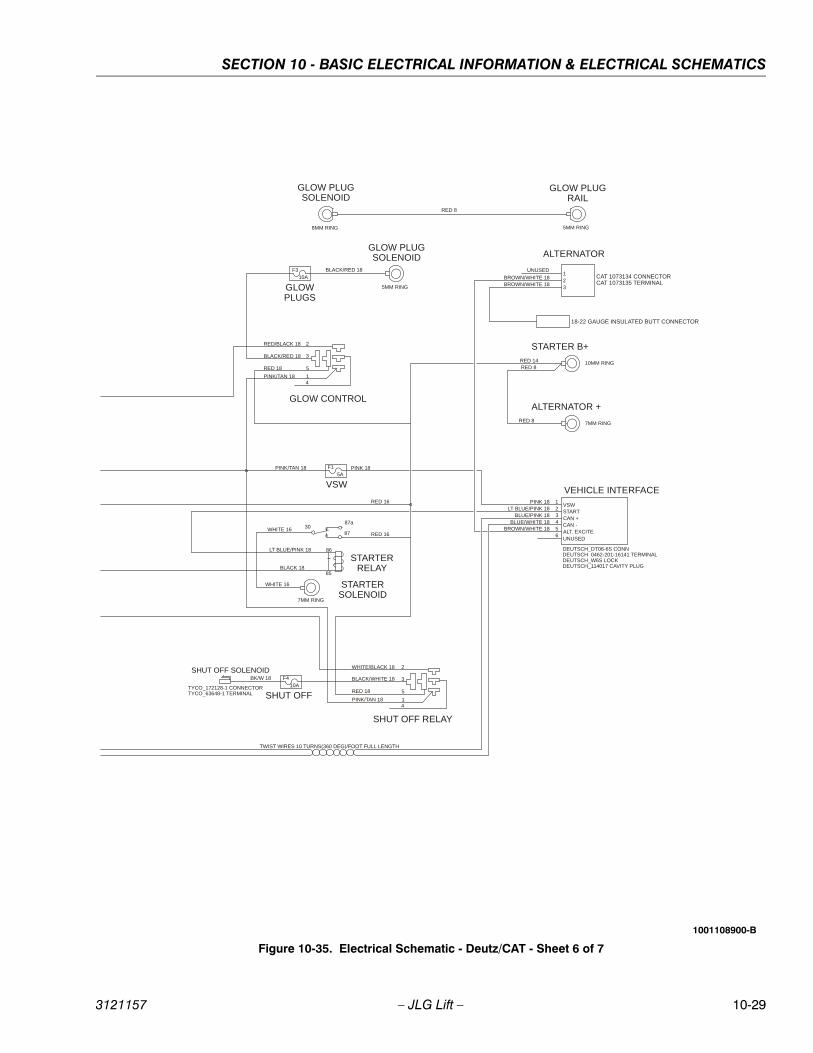
SECTION 10 - BASIC ELECTRICAL INFORMATION & ELECTRICAL SCHEMATICS
3121157 – JLG Lift – 10-29
PINK 18
DEUTSCH_DT06-6S CONNDEUTSCH_0462-201-16141 TERMINALDEUTSCH_W6S LOCKDEUTSCH_114017 CAVITY PLUG
VEHICLE INTERFACE
RED 14
RED 8
RED 8
ALT. EXCITEUNUSED
STARTCAN +
VSW123456
CAN -
F310A
GLOWPLUGS
GLOW CONTROL
RED 18
BLACK/RED 18
PINK/TAN 18
RED/BLACK 18
F1
5A
VSW
PINK/TAN 18 PINK 18
TWIST WIRES 10 TURNS(360 DEG)/FOOT FULL LENGTH
GLOW PLUGSOLENOID
5MM RING
BLACK/RED 18
3087
86
85
STARTERRELAY
87a
RED 16WHITE 16
LT BLUE/PINK 18
BLACK 18
STARTERSOLENOID
STARTER B+
10MM RING
ALTERNATOR
ALTERNATOR +
7MM RING
LT BLUE/PINK 18BLUE/PINK 18
BLUE/WHITE 18BROWN/WHITE 18
RED 16
BROWN/WHITE 18BROWN/WHITE 18
123
UNUSED
18-22 GAUGE INSULATED BUTT CONNECTOR
CAT 1073134 CONNECTORCAT 1073135 TERMINAL
GLOW PLUGRAIL
5MM RING
GLOW PLUGSOLENOID
8MM RING
RED 8
7MM RING
WHITE 16
1
2
5
4
3
SHUT OFF RELAY
RED 18
BLACK/WHITE 18
PINK/TAN 18
WHITE/BLACK 18
1
2
5
4
3F4
10A
SHUT OFF
BK/W 18
TYCO_172128-1 CONNECTORTYCO_63648-1 TERMINAL
SHUT OFF SOLENOID
Figure 10-35. Electrical Schematic - Deutz/CAT - Sheet 6 of 7
1001108900-B
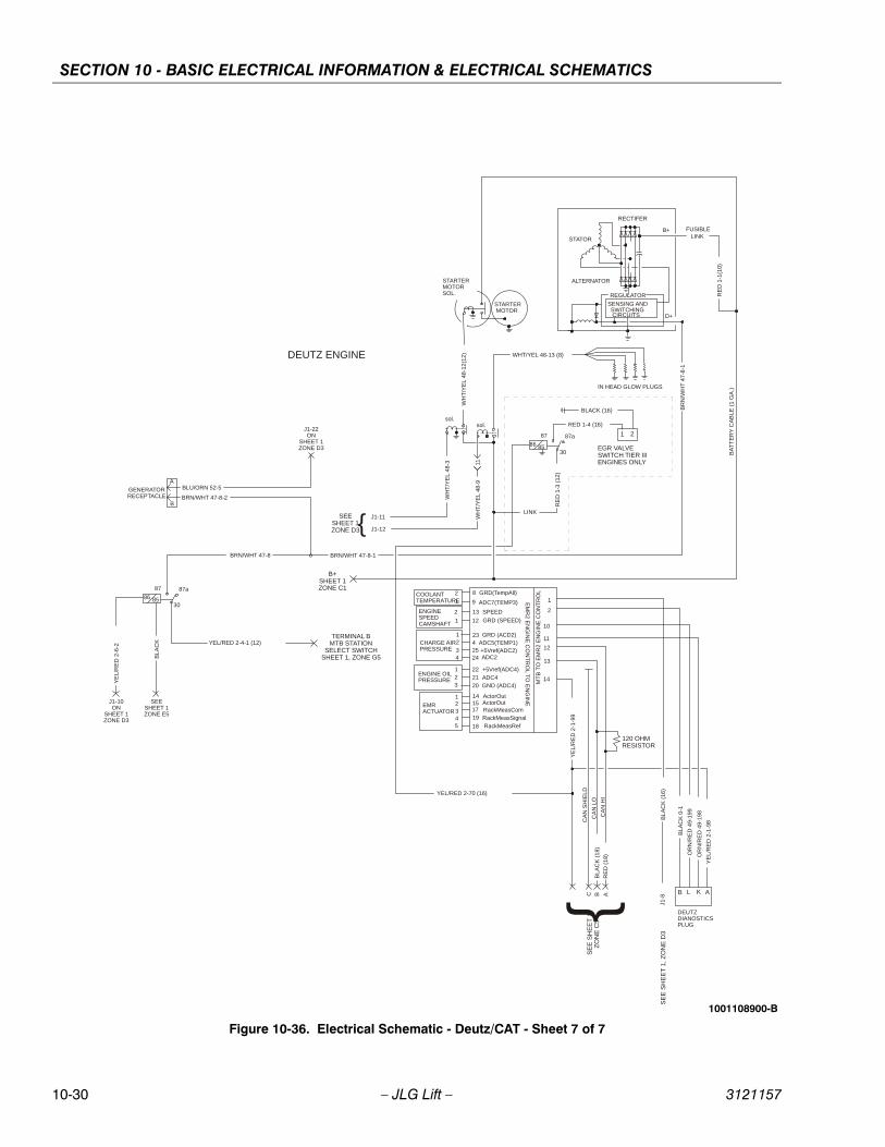
SECTION 10 - BASIC ELECTRICAL INFORMATION & ELECTRICAL SCHEMATICS
10-30 – JLG Lift – 3121157
B+ FUSIBLELINK
RECTIFER
REGULATOR
ALTERNATOR
STATOR
SENSING ANDSWITCHINGCIRCUITS
WH
T/Y
EL
48-1
2(1
2)
J1-12
IN HEAD GLOW PLUGS
D+
sol.sol.
J1-8
J1-11
RE
D 1
-1(1
0)
STARTERMOTORSOL.
STARTER MOTOR
BR
N/W
HT
47-
8-1
BL
AC
K (
16)
WH
T/Y
EL
48-
3
BA
TT
ER
Y C
AB
LE (
1 G
A.)
WH
T/Y
EL
48-9
11
OR
N/R
ED
49
-19
8
1
2
10
11
12
13
14MT
B T
O E
MR
2 E
NG
INE
CO
NT
RO
L
OR
N/R
ED
49-
199
BLA
CK
0-1
AKLB
DEUTZDIANOSTICSPLUG
ENGINE OILPRESSURE
COOLANTTEMPERATURE
EMRACTUATOR
ENGINESPEEDCAMSHAFT
CHARGE AIRPRESSURE
8
9
13
12
2342524
2221
20
14151719
GRD (SPEED)
SPEED
GRD(TempAll)
GRD (ACD2)ADC5(TEMP1)+5Vref(ADC2)ADC2
+5Vref(ADC4)
ADC4GND (ADC4)
ActorOutActorOutRackMeasCom
RackMeasRef18
RackMeasSignal
ADC7(TEMP3) EM
R2 E
NG
INE
CO
NT
RO
L TO
EN
GIN
E
YE
L/R
ED
2-1
-98
YE
L/R
ED
2-1
-99
CA
N H
IR
ED
(1
8)
CA
N L
OB
LAC
K (
18)
CA
N S
HIE
LD
ABCS
EE
SH
EE
T 1
ZO
NE
C5
86 85
87
30
87a
YEL/RED 2-4-1 (12)TERMINAL B
MTB STATIONSELECT SWITCH
SHEET 1, ZONE G5
YE
L/R
ED
2-6
-2
J1-10ON
SHEET 1ZONE D3
2
1
2
1
12
34
123
12345
120 OHMRESISTOR
WHT/YEL 48-13 (8)
BRN/WHT 47-8
BL
AC
K
DEUTZ ENGINE
86 85
87
30
87a
LINK
RE
D 1
-3 (
12)
RED 1-4 (16)
EGR VALVE SWITCH TIER IIIENGINES ONLY
1 2
BLACK (16)
YEL/RED 2-70 (16)
{B+
SHEET 1ZONE C1
BLU/ORN 52-5
J1-22ON
SHEET 1ZONE D3
BRN/WHT 47-8-2GENERATORRECEPTACLE
A
B
BRN/WHT 47-8-1
SEESHEET 1ZONE E5
{SEESHEET 1ZONE D3
SE
E S
HE
ET
1,
ZO
NE
D3
Figure 10-36. Electrical Schematic - Deutz/CAT - Sheet 7 of 7
1001108900-B
Corporate OfficeJLG Industries, Inc.
1 JLG DriveMcConnellsburg PA. 17233-9533
USA (717) 485-5161(Corporate)
(800) 554-5438(Service) (717) 485-6417
JLG Worldwide LocationsJLG Industries 358 Park RoadRegents ParkNSW 2143Sydney 2143Australia
+6 (12) 87186300 +6 (12) 65813058
Email: [email protected]
JLG Ground Support OudeBunders 1034Breitwaterstraat 12A3630 MaasmechelenBelgium
+32 (0) 89 84 82 26Email: [email protected]
JLG Latino Americana LTDARua Antonia Martins Luiz, 580Distrito Industrial Joao NarezziIndaiatuba-SP 13347-404Brasil
+55 (19) 3936 7664 (Parts) +55(19)3936 9049 (Service)
Email: [email protected]: [email protected]
Oshkosh-JLG (Tianjin) Equipment Technology LTD Shanghai BranchNo 465 Xiao Nan RoadFeng Xian DistrictShanghai 201204China
+86 (21) 800 819 0050
JLG Industries DubaiJafza ViewPO Box 262728, LB 1920th Floor, Office 05Jebel Ali, Dubai
+971 (0) 4 884 1131 +971 (0) 4 884 7683
Email: [email protected]
JLG France SASZ.I. Guillaume Mon Amy30204 Fauillet47400 TonniensFrance
+33 (0) 553 84 85 86 +33 (0) 553 84 85 74
Email: [email protected]
JLG Deutschland GmbHMax Planck Str. 2127721 Ritterhude - IhlpohlGermany
+49 (0) 421 69350-0 +49 (0) 421 69350-45
Email:[email protected]
JLG Equipment Services Ltd.Rm 1107 Landmark North39 Lung Sum AvenueSheung Shui N. T.Hong Kong
+(852) 2639 5783 +(852) 2639 5797
JLG Industries (Italia) S.R.L.Via Po. 2220010 Pregnana Milanese (MI)Italy
+39 (0) 2 9359 5210 +39 (0) 2 9359 5211
Email: [email protected]
JLG EMEA B.V. Polaris Avenue 632132 JH HoofdorfThe Netherlands
+31 (0) 23 565 5665Email: [email protected]
JLG NZ Access Equipment & Services2B Fisher CresentMt Wellington 1060Auckland, New Zealand
+6 (12) 87186300 +6 (12) 65813058
Email:[email protected]
JLG IndustriesVahutinskoe shosse 24b.KhimkiMoscow Region 141400Russia Federation
+7 (499) 922 06 99 +7 (499) 922 06 99
Oshkosh-JLG Singapore Technology Equipment Pte Ltd.35 Tuas Avenue 2Jurong Industrial Estate Singapore 639454
+65 6591 9030 +65 6591 9045
Email: [email protected]
JLG Iberica S.L.Trapadella, 2Pol. Ind. Castellbisbal Sur08755 Castellbisbal BarcelonaSpain
+34 (0) 93 772 47 00 +34 (0) 93 771 1762
Email:[email protected]
JLG Sverige ABEnkopingsvagen 150176 27 JarfallaSweden
+46 (0) 8 506 595 00 +46 (0) 8 506 595 27
Email: [email protected]
JLG Industries (UK) Ltd.Bentley HouseBentley AvenueMiddleton, Greater ManchesterM24 2GPUnited Kingdom
+44 (0) 161 654 1000 +44 (0) 161 654 1003
Email: [email protected]
3121157