
Maintenance Section - cloudfront.net
190
Pneumatic System Page Issue Levels Scheduled Maintenance Hydraulic System Electrical System Water System Wearing Items Remove and Refit Procedures Fault Diagnosis Service Tools Warranty Health and Safety E.C.M. Issue - 709886 Print date - 08/01/2013 Maintenance Section VT* & VS 500 l 605 l 650 l 800 Range of Twin Engined & Hydrostatic Sweepers From Manufacture Sequence No. 07/2057 * With Stage 3a/Tier 3 Auxiliary Engines Part No 02617-4-M Revision Level 16 P 7 8 9 10 11 12 13 14 15 16 17 Copyright and rights are the property of Johnston Sweepers Ltd.
-
Upload
khangminh22 -
Category
Documents
-
view
1 -
download
0
Transcript of Maintenance Section - cloudfront.net

Pneumatic System
Page Issue Levels
Scheduled Maintenance
Hydraulic System
Electrical System
Water System
Wearing Items
Remove and Refit Procedures
Fault Diagnosis
Service Tools
Warranty
Health and Safety
E.C.M. Issue - 709886 Print date - 08/01/2013
MaintenanceSection
VT* & VS 500 l 605 l 650 l 800Range of Twin Engined & Hydrostatic Sweepers
From Manufacture Sequence No. 07/2057
* With Stage 3a/Tier 3 Auxiliary Engines
Part No 02617-4-M
Revision Level 16
P 7 8 9
10
11
12
13
14
15
16
17
Cop
yrig
ht a
nd ri
ghts
are
the
prop
erty
of J
ohns
ton
Swee
pers
Ltd
.

VT & VS - Maintenance
Cop
yrig
ht a
nd ri
ghts
are
the
prop
erty
of J
ohns
ton
Swee
pers
Ltd
.

Page Issue Levels
CHAPTER P Page Issue Levels
Description
This chapter lists each page in the Maintenance section, it’s issue level and whether it has changed since the previous revision level. Changed pages are indicated by the letter ‘C’ in the changed column, and new pages by the letter ‘N’.
P1Section Revision Level 16
VT & VS - MaintenanceC
opyr
ight
and
righ
ts a
re th
e pr
oper
ty o
f Joh
nsto
n Sw
eepe
rs L
td.

Page Issue LevelsP2
P Chapter - Page Issue Levels Page Issue Changed Page Issue Changed
P1 16 C P2 16 C P3 16 C P4 16 C
7 Chapter - Scheduled Maintenance Page Issue Changed Page Issue Changed
7:1 05 7:2 01 7:3 01 7:4 08 7:5 08 7:6 10 7:7 05 7:8 12 7:9 08 7:10 05 7:11 05 7:12 05 7:13 05 7:14 05 7:15 05 7:16 05 7:17 05 7:18 05
8 Chapter - Hydraulic System Page Issue Changed Page Issue Changed
8:1 01 8:2 01 8:3 04 8:4 01 8:5 01 8:6 01 8:7 01 8:8 01 8:9 12 8:10 16 C 8:11 16 C 8:12 01 8:13 01 8:14 03 8:15 02 8:16 16 C 8:17 01 8:18 01 8:19 12 8:20 16 C
9 Chapter - Electrical System Page Issue Changed Page Issue Changed
9:1 05 9:2 01 9:3 01 9:4 02 9:5 15 9:6 12 9:7 02 9:8 02 9:9 02 9:10 02 9:11 02 9:12 02 9:13 09 9:14 09 9:15 05 9:16 05 9:17 05 9:18 05 9:19 05 9:20 05 9:21 05 9:22 05 9:23 05 9:24 05 9:25 05 9:26 05
Section Revision Level 16
VT & VS - Maintenance
Cop
yrig
ht a
nd ri
ghts
are
the
prop
erty
of J
ohns
ton
Swee
pers
Ltd
.

9 Chapter - Electrical System continued ...... Page Issue Changed Page Issue Changed
9:27 05 9:28 05 9:29 05 9:30 05 9:31 05 9:32 05 9:33 13 9:34 05 9:35 05 9:36 05 9:37 05 9:38 05 9:39 08 9:40 05 9:41 05 9:42 05 9:43 09 9:44 09 9:45 09 9:46` 09 9:47 09 9:48 09 9:49 09 9:50 15 9:51 07 9:52 09 9:53 09 9:54 09 9:55 08 9:56 08
10 Chapter - Water System Page Issue Changed Page Issue Changed
10:1 12 10:2 01 10:3 01 10:4 01 10:5 01 10:6 01 10:7 01 10:8 12 10:9 12 10:10 12 10:11 12 10:12 12 10:13 12 10:14 12 10:15 12 10:16 12 10:17 13 10:18 12
11 Chapter - Pneumatic System Page Issue Changed Page Issue Changed
11:1 01 11:2 01 11:3 01 11:4 01 11:5 01 11:6 01 11:7 07 11:8 07 11:9 01 11:10 01 11:11 12 11:12 04 11:13 07 11:14 04 11:15 09 11:16 09
12 Chapter - Wearing Items Page Issue Changed Page Issue Changed
12:1 01 12:2 09 12:3 14 12:4 01 12:5 01 12:6 01 12:7 01 12:8 01
Page Issue Levels P3Section Revision Level 16
VT & VS - MaintenanceC
opyr
ight
and
righ
ts a
re th
e pr
oper
ty o
f Joh
nsto
n Sw
eepe
rs L
td.

Page Issue LevelsP4 Section Revision Level 16
VT & VS - Maintenance
13 Chapter - Remove and Refit Procedures Page Issue Changed Page Issue Changed
13:1 01 13:2 01 13:3 01 13:4 01 13:5 01 13:6 14 13.7 08 13.8 01
14 Chapter - Fault Diagnosis Page Issue Changed Page Issue Changed
14:1 01 14:2 01 14:3 01 14:4 16 C 14:5 01 14:6 01 14:7 01 14:8 01 14.9 01 14:10 01
15 Chapter - Service Tools Page Issue Changed Page Issue Changed
15:1 01 15:2 13 15.3 01 15.4 01 15.5 01 15.6 01 15.7 01 15.8 01 15.9 01 15.10 01 15.11 01 15.12 01 15.13 01 15.14 01 15.15 01 15.16 01
16 Chapter - Warranty Page Issue Changed Page Issue Changed
16:1 01 16:2 10 16:3 10 16:4 10 16:5 03 16:6 01
17 Chapter - Health and Safety Page Issue Changed Page Issue Changed
17:1 01 17:2 01 17:3 01 17:4 01 17:5 01 17:6 01 17:7 01 17:8 01
Cop
yrig
ht a
nd ri
ghts
are
the
prop
erty
of J
ohns
ton
Swee
pers
Ltd
.

Chapter - Scheduled Maintenance
CHAPTER 7Scheduled Maintenance
7:1
Table of Contents
Section Page
Introduction Regular Maintenance 7 : 2 Security of Sweeping Equipment 7 : 3
Circuit Diagram Finders Fluid (Hydraulic, Pneumatic, Water) Circuits 7 : 4 Electrical Circuits 7 : 5
Auxiliary Engine Fuel System Bleeding - VT 7 : 6 Throttle Settings 7 : 7 Fluid Flywheel - VT Maintenance 7 : 9 Filling and Draining Instructions 7 : 9 Hydraulics Hydraulic Oil Reservoir - VT 7 : 10 Hydraulic Oil Reservoir - VS 7 : 11
Pneumatics Filter regulator Unit 7 : 12 Body/Cowl Cowl Silencer Assembly 7 : 13 Body Roof Duct 7 : 13
Additional Information VS Range 7 : 15
Page Issue 05
VT & VS - MaintenanceC
opyr
ight
and
righ
ts a
re th
e pr
oper
ty o
f Joh
nsto
n Sw
eepe
rs L
td.

Page Issue 01Chapter - Scheduled Maintenance7:2
VT Only - Maintenance
INTRODUCTION
REGULAR MAINTENANCE
It is impossible to over emphasise the importance of regular maintenance, inspection and running adjustments to maintain efficiency and obtain trouble free service from the machine.
Attention is drawn to the recommendation in the Auxiliary Engine Handbook relating to the post delivery check over.
The maintenance schedule specified are for average operating conditions. Under particularly dry and dusty conditions, it is essential that more frequent attention is given to:
1 Air cleaner servicing.2 Engine oil changes.3 Fluid oil changes.4 Gearbox oil changes.5 Hydraulic oil changes.
A flap is provided in the rear valance of the engine mounting tub to give access to the engine when carrying out servicing and for cleaning spilt oil etc. from under the tub floor which could be a fire hazard.
Attention to the servicing of air cleaners fitted to both auxiliary and vehicle engines is of vital importance as clean air is essential for the proper functioning and ultimate life of an engine. Badly serviced air cleaners can allow dust particles to be directly induced into the internal working surfaces with a resulting rapid increase in engine wear and eventually complete failure. This also applies to any air leaks occurring between the air cleaner and the engine inlet manifold. See separate instructions for Air Cleaner Servicing.
It is important that the following Safety Precautions are observed when working on the machine.
l Ensure the machine is standing on firm, level ground and there are no obstructions above or to the rear before raising the body.
l Ensure the safety prop is used at all times when working under the body.l Ensure operators are fully conversant with the controls and operation.l Isolate the air in the systems locker before working on any pneumatically operated or
controlled equipment.l Disconnect or isolate the vehicle battery when working on the electrical system.l Ensure the auxiliary engine is switched off once the channel brush has been lowered for
adjustment.l Be aware of the safety instructions relative to the suction fan given in the equipment
maintenance notes.l Keep hands, loose clothing, hair etc. well clear of moving parts.l Do not climb on the engine walkways unnecessarily or approach the fan inlet whilst the
engine is running.l Do not grasp any part of the engine or exhaust system without first ascertaining whether it
has cooled sufficiently to avoid scalding.l Do not use ill-fitting tools such as spanners that may slip and cause injury.l Use approved safety platforms/gantries when working above ground level. Get a second person to check periodically when only one person is working on access equipment or inside the body.l The use of ‘needle stick gloves’ is recommended when changing brushes, using the wanderhose/Littasnatch and when cleaning out the machine.
Safety Precautions
Cop
yrig
ht a
nd ri
ghts
are
the
prop
erty
of J
ohns
ton
Swee
pers
Ltd
.

Page Issue 01 Chapter - Scheduled Maintenance 7:3
VT & VS - Maintenance
SECURITY OF SWEEPING EQUIPMENT
It is necessary to check every six months the security of various components as part of the maintenance programme.
These fixings are detailed on the illustration below.
95MA. 024
ALTERNATIVE END MOUNTING POSITIONS(HARDWARE AS PREFERED POSITIONS ie. ‘C’ and ‘D’)
‘A’ = M12 Standard ‘B’ = M12 Grade 10.9 ‘C’ = M14 Grade 10.9‘D’ = M12, M14 Grade depending on chassis10.9 or M16 Standard
Torque Settings
M12 Standard = 95 Nm (70 lbf/ft)M12 Grade10.9 = 135 Nm M16 = 235 Nm
M14 Grade 10.9 = 215 Nm (160 lbf/ft)(100 lbf/ft) Standard (150 lbf/ft)
CCC C
C
A AD D D D
C C
A
A
CIRCUIT DIAGRAMS
A chart can be found overleaf to assist in finding the circuit diagram required.
The actual circuit diagrams will be found in the appropriate chapter.
Cop
yrig
ht a
nd ri
ghts
are
the
prop
erty
of J
ohns
ton
Swee
pers
Ltd
.

Page Issue 08Chapter - Scheduled Maintenance7:4
VT & VS - Maintenance
Fluid Finder - Diagram SF500z02
Cop
yrig
ht a
nd ri
ghts
are
the
prop
erty
of J
ohns
ton
Swee
pers
Ltd
.

Page Issue 08 Chapter - Scheduled Maintenance 7:5
VT & VS - Maintenance
Type B - Electrical Diagram Index - SE550z10
Cop
yrig
ht a
nd ri
ghts
are
the
prop
erty
of J
ohns
ton
Swee
pers
Ltd
.

Page Issue 10Chapter - Scheduled Maintenance7:6
VT Only - Maintenance
Please refer to the Operator’s Guide, Chapter 6, for the Routine Maintenance Schedules.
The following items are not covered in the Operator’s Guide.
MAINTENANCE AND ADJUSTMENT INSTRUCTIONS
AUXILIARY ENGINE - FUEL SYSTEM BLEEDING
IVECO - HP Turbo Charged
Under no circumstances should injector pipes be loosened and the engine cranked. This engine uses very high injection pressures and will cause injury. The system is self priming by using the manual plunger on the fop of the fuel filter.
A = Manual Fuel Primer
When starting the engine for the first time after bleeding the fuel system, or if the engine has run out of fuel, air pockets in the fuel system may prevent the engine from starting correctly. The procedure for priming the fuel system and removing the air pockets is as follows.
1 Locate the fuel priming pump on the fuel prefilter unit located on the left hand side of the vehicle above the fuel tank, as shown above right.
2 Alternatively, press and depress the priming button on the top to the pump/prefilter unit (A), as indicated, until it becomes difficult/stiff to operate (this may take several minutes).
3 Crank the engine until the engine fires. The maximum cranking time should not exceed 15 seconds or damage to the fuel pump may occur. It may be necessary to repeat step two. Wait at least a minute for the battery to recover before recranking the engine.
Cop
yrig
ht a
nd ri
ghts
are
the
prop
erty
of J
ohns
ton
Swee
pers
Ltd
.

Page Issue 05 Chapter - Scheduled Maintenance 7:7
VT Only - Maintenance
SET UP
Raise the body, operate the actuator to ensure that it is in the minimum speed position (L).
1 Check that the cable (C) is not under tension and that the arm (A) on the injector pump is resting against the engine idle adjuster screw. If not, loosen the screw in the cable nipple (B) to allow a little slack in the cable (C).
2 The following adjustments should be made with the fan outlet safety flap closed and a plate (suitably secured with clamp) completely blanking the fan inlet. Start auxiliary engine and allow to warm up.
3 Set throttle to idle. Check engine idle speed as shown in the table below. Adjust if necessary by way of the idle adjuster screw to give a smooth tickover.
4 Start engine. Actuate throttle control in cab to give maximum engine speed (H). Measure engine speed with tachometer and measure the off load speed as shown in the following table. At this speed setting ensure there is 0.25 - 0.5mm clearance between the arm and the maximum throttle screw.
5 Stop the auxiliary engine.
6 Remove fan inlet blanking plate before lowering the body.
95MA. 026-3 H L
TICKOVERMAX. REVS
BC
Iveco - Standard Power John Deere - Standard Power
Do not attempt to increase the ‘off load’ or ‘flight speed’ of the engine/fan impeller as these are safety critical items and have been preset at the factory
THROTTLE SETTINGS
Cop
yrig
ht a
nd ri
ghts
are
the
prop
erty
of J
ohns
ton
Swee
pers
Ltd
.

Page Issue 12Chapter - Scheduled Maintenance7:8
VT Only - Maintenance
THROTTLE SETTINGS
These engines have their own ECU and the speeds are preset and can only be checked.
1 Raise the body.2 With the fan safety flap closed and a plate (suitably secured with clamps) completely blanking the
fan inlet.3 Start the engine and allow to warm up.4 Check the tickover speed and the maximum flight speeds. If these are incorrect, they must be
reset by an authorised distributor.
5 NOTE : Remove the fan inlet blanking plate before lowering the body.
ENGINE TYPE
JOHNSTONPART NO.
IDLE SPEEDRev./Min.
MAXIMUM FLIGHT SPEED
(Off Load)Rev./Min.
Iveco Stage 3a SP 283850-24 800 2200
Iveco Stage 3a HP 283805-24 800 2000
John Deere Tier 3 SP 283845-12 850 2200
John Deere Tier 3 HP 283791-12 800 2000
Cop
yrig
ht a
nd ri
ghts
are
the
prop
erty
of J
ohns
ton
Swee
pers
Ltd
.

Page Issue 08 Chapter - Scheduled Maintenance 7:9
VT Only - Maintenance (Stage 3a & Mk 2 Supawash)
AUXILIARY ENGINE - FLUID FLYWHEEL
The fluid flywheel transmits power from the engine to the gearbox. Its design allows for the minium of maintenance, minimal mechanical wear and superior longevity to the remainder of the transmission system. With the correct attention it should last the life of the sweeper.
(A) Flywheel with side cover (C) removed.
(B) Flywheel filler/inspection port visible through side cover sight hole.
(C) Flywheel side cover.(D) Step-up gearbox.
MAINTENANCE
After the first 50 hours operation check the fluid level; this operation must be carried out with the unit cold. Repeat this check every 500 hours. The fluid flywheel is fitted with a fusible plug which melts at 198°C (recognised by four equi-spaced indentations round the hexagonal socket). Oil should be replaced after 4,000 hours operation.
FILLING INSTRUCTIONS
Rotate flywheel (A) until its filler port aligns with sight hole (B) in either of the two flywheel side covers (C), approximately 2 o’clock and 10 o’clock. Remove the side cover and spacers. Remove filler plug using a 5/16 AF allen key and fill with Johnston Fluid Flywheel Oil, Part No. 39673-5 until it reaches the level of the port. During filling, carefully rock the flywheel to ensure that no air pockets form below the oil level.
DO NOT OVERFILL AS THIS WILL CAUSE THE UNIT TO OVERHEAT AND RAPID SEAL DETERIORATION WILL OCCUR
Replace the filler plug using thread sealant to ensure a good seal. Visually check for oil leaks and replace the flywheel cover.
DRAINING INSTRUCTIONS
Place a suitable drain tray under the flywheel housing if removing the Fan Case, remove filler plug and turn flywheel through 150° so that port is at lowest position.
If changing the oil use a propietry vacuum oil extractor/syringe after removing the filler plug.
M. 0023
(A)
(D)
(B)
(C)
FLUID FLYWHEEL FILLING PORTS(VIEWED WITH FAN CASE AND FAN REMOVED FOR CLARITY)
Cop
yrig
ht a
nd ri
ghts
are
the
prop
erty
of J
ohns
ton
Swee
pers
Ltd
.

Page Issue 05Chapter - Scheduled Maintenance7:10
VT Only - Maintenance
HYDRAULIC OIL RESERVOIR
RENEWING THE RETURN FILTERUnscrew cover (A) with a suitable spanner and lift out the cartridge element (B). Refit cartridge and screw on the cover, some force will be required to compress the carriage retaining spring.
SYSTEM DRAININGThe oil can be changed by removing the return filter A and the element and inserting standard gauge equipment for extraction of oil from engine sumps and tanks.
RENEWING THE SUCTION FILTERThe filter is best changed whilst the system is empty to prevent contaminated oil entering the suction port when the filter is removed. The filter is changed as follows.
Release the four retaining screws and remove the return filter assembly (C). There should be enough slack to remove the filter assembly with the 3 hydraluic hoses connected. The suction filter (E) can be reached by hand via the port and are removed by unscrewing. Similarly, the filter (F) option can be unscrewed and replaced. After fitting a new filter, replace the cover ensuring the ‘O’ ring is seated in its groove.
SYSTEM REFILLING
The system capacity dry is 90 litres. Refer to Chapter 6 of the Operator’s Guide detailing the correct oil level in the reservoir.
Cop
yrig
ht a
nd ri
ghts
are
the
prop
erty
of J
ohns
ton
Swee
pers
Ltd
.

Page Issue 05 Chapter - Scheduled Maintenance 7:11
VS Only - Maintenance
Please refer to the Operator’s Guide Section 6 for the Routine Maintenance Schedules. The following covers items not included in the above guide. HYDRAULIC OIL RETURN FILTER The filter should be changed every 1000 hours, however there is an integral filter indicator on the side of the filter head and, should this indicate red whilst the suction fan is operating, i.e. body raised, then the filter is contaminated and requires changing at an earlier interval.
HYDRAULIC OIL RESERVOIR
RENEWING THE RETURN FILTERUnscrew cover (A) with a suitable spanner and lift out the cartridge element (B). Refit cartridge and screw on the cover, some force will be required to compress the carriage retaining spring.
SYSTEM DRAININGThe oil can be changed by removing the return filter A and the element and inserting standard gauge equipment for extraction of oil from engine sumps and tanks.
RENEWING THE SUCTION FILTERThe filter is best changed whilst the system is empty to prevent contaminated oil entering the suction port when the filter is removed. The filter is changed as follows.
Release the four retaining screws and remove the return filter assembly C. There should be enough slack to remove the filter assembly with the 3 hydraulic hoses connected. The suction filter (E) can be reached by hand via the port and are removed by unscrewing. Similarly, the filter (F option) can be unscrewed and replaced. After fitting a new filter, replace the cover ensuring the ‘O’ ring is seated in its groove.
SYSTEM REFILLINGThe system capacity dry is 90 litres. Refer to Chapter 6 of the Operator’s Guide detailing the correct oil level in the reservoir.
This should only be changed when the oil is cold, as the system could be pressurised. Leave for 60 seconds after stopping for any pressure to be disapated before removing the return filter.
95MA. 003-2
B
C
A
E
D
F
Cop
yrig
ht a
nd ri
ghts
are
the
prop
erty
of J
ohns
ton
Swee
pers
Ltd
.

Page Issue 05Chapter - Scheduled Maintenance7:12
VT & VS - Maintenance
FILTER REGULATOR UNIT
Comprises of a combined air filter/pressure regulator. It is mounted in the systems locker.
The shut off valve must be used when servicing any item on the air system
Safety Precautions
B95MA. 004-4
IN
A
C
D
The air filter unit incorporates a drain which automatically dumps accumulated water when the machine is shut down or when the air supply is isolated by the shut off valve (C). It can also be drained by pushing up the drain tube (B) that protrudes from the underside of the systems locker.
The pressure regulator (A) ensures the equipment is not over pressurised. It is factory set and sealed at 7.5 bar (108 psi).
A pressure switch (D) is fitted to illuminate the low air pressure warning lamp on the cab switch panel. Cop
yrig
ht a
nd ri
ghts
are
the
prop
erty
of J
ohns
ton
Swee
pers
Ltd
.

Page Issue 05 Chapter - Scheduled Maintenance 7:13
VT & VS - Maintenance
COWL SILENCER ASSEMBLY
The silencer chamber in the roof of the cowl should be cleaned periodically or the performance of the machine could be adversely affected.
Access to the chamber is gained by first removing the two screws (A). raise the top cover (B) on the hinge and secure on the prop (C).
BODY ROOF DUCT INSPECTION PLATE/ACCESS DOOR OPTION
With mesh screens removed or lowered and the body raised (supported on its prop), clean the ducting in the top of the body using a broom and hosepipe. Access is gained by removing the top inspection plate, or hinged door (if option is fitted). Care should be taken not to get water into the fan case.
PNEUMATIC CYLINDER MAINTENANCE
Periodically inspect the cylinder rods for damage, blemishes or build up of material such as tar, cement, paint etc. The rods can be cleaned with fine wire wool and/or spirit and should be kept clean to ensure long seal life.
HYDRAULIC CYLINDER MAINTENANCE
Observe the notes on damage etc. described under pneumatic cylinders, especially with regard to the wide sweep brush slewing cylinder on dual sweep machines and the channel brush lift cylinder.Avoid playing the water washdown hose over the body tip cylinder when in the fully raised condition.
CLEANING THE VEHICLE
With the advent of high pressure steam and washdown equipment, damage can be caused by playing this equipment onto the electrical control system, paintwork etc. and great care should be exercised when it is carried out.
Low pressure should always be used
95MA. 010
(A)
95MA. 009
(B)(C)
(A)
Safety platform/gantry to be used for this procedure
Safety platform/gantry to be used for this procedure
Cop
yrig
ht a
nd ri
ghts
are
the
prop
erty
of J
ohns
ton
Swee
pers
Ltd
.

Chapter - Scheduled Maintenance7:14
VT & VS - Maintenance
Page Issue 05
This pag
e is i
ntentio
nally b
lank
Cop
yrig
ht a
nd ri
ghts
are
the
prop
erty
of J
ohns
ton
Swee
pers
Ltd
.

Page Issue 05 Chapter - Scheduled Maintenance 7:15
VS Only - Maintenance
Additional Information for
VS Range
Cop
yrig
ht a
nd ri
ghts
are
the
prop
erty
of J
ohns
ton
Swee
pers
Ltd
.

Page Issue 05Chapter - Scheduled Maintenance7:16
Introduction The VS Range is the latest generation of chassis mounted road sweepers. The drive systems when sweeping are controlled by an on board microprocessor, which embodies a suite of software programs to suit specific applications and duties. This system allows the chassis to be driven normally from A to B and hydrostatically when in the work mode. The engine is controlled by the chassis ECU.
To guard against EMC interference, the controller casing is metallic encased and fully grounded to earth, and complies with EEC 89/336.
A typical circuit for the dual-mode hydromechanical propulsion system showing the various connections to external switches and sensors system is shown below.
VS Only - Maintenance
Cop
yrig
ht a
nd ri
ghts
are
the
prop
erty
of J
ohns
ton
Swee
pers
Ltd
.

Page Issue 05 Chapter - Scheduled Maintenance 7:17
VS Only - Maintenance
With the advent of electronically controlled engines the D-Tec no longer controls the engine revs in work mode, it only controls the transmission.
The D-Tec controller module has five built-in status lamps in its upper surface, surrounded by a decal as shown below. These lamps provide indication of correct operation and assists in fault diagnosis if the need arises.
Top view of D-Tec Controller
Status Lamps
Power (green)
Lamp illuminates whenever the controller has electrical power applied to it.
Tacho (orange)
Lamp illuminates when the tachometer, using a Hall-Effect gear tooth sensor, correctly senses rotation whenever the engine runs above 300 rpm. If this lamp does not illuminate either the engine has stopped, the chassis gearbox is in neutral, or the sensor is positioned too far away from the tooth wheel in the case of the Hall-Effect sensors, or the electrical connections are disconnected in some way. Throttle (yellow) Lamp pulses progressively, increasing engine speed, increases pulse rate of lamp until 100% of throttle is achieved when lamp stays illuminated.
Reset (red)
Illuminates when there is a poor electrical connection, also illuminates when saving a setup parameter.
Status (yellow) Lamp illuminates when ‘work’ mode is engaged. Note: The D-Tec control unit is sealed and factory set, and cannot be adjusted. Inspection/testing of the unit can only be carried out with specialist equipment.
See Section 15 for D-Tec Set Up Procedure
M. 0097
SERIAL NO.
MODEL
POWER
ZETA
ZETATACHO THROTTLE RESET STATUS
Cop
yrig
ht a
nd ri
ghts
are
the
prop
erty
of J
ohns
ton
Swee
pers
Ltd
.

Page Issue 05Chapter - Scheduled Maintenance7:18
REGULAR MAINTENANCE
It is impossible to over emphasise the importance of regular maintenance, inspection and running adjustments to maintain efficiency and obtain trouble free service from the machine.
Attention is drawn to the recommendation in the Chassis Handbook relating to the post delivery check over.
ENGINE MANAGEMENT ECU
Please note that the chassis manufacturers Engine Management System has been set in accordance with our requirements. If a malfunction of the ECU occurs and the component replaced then the parameters would require downloading and reset in the new component.
Failure to do this will cause the machine to malfunction.
VS Only - Maintenance
l It is important that the Safety Precautions shown at the front of this chapter are observed when working on the VS machine.
Safety Precautions
TRANSMISSION PUMP OIL FILTER REPLACEMENT This filter should be changed every 500 hours. With the vehicle engine not running, remove the filter alongside the transmission pump. 1. Transmission Pump Filter
Fit a new filter as quickly as possible to minimise the loss of any hydraulic oil. Ensure the correct filter is fitted, Part No 224-15, as this item is under pressure and ‘Pattern Parts’ may not be suitable. Start engine and engage Hydrodrive. Allow system to tick over for a few minutes to purge air from the circuits.
Cop
yrig
ht a
nd ri
ghts
are
the
prop
erty
of J
ohns
ton
Swee
pers
Ltd
.

Chapter - Hydraulic System
CHAPTER 8Hydraulic System
8:1
Table of Contents
Section Page Introduction General Description 8 : 2
Circuit Pressures Body Discharge System - VT & VS 8 : 2 Sweeping System - VT & VS 8 : 3 Supawash Option - VT & VS 8 : 3 Fan Drive System - VS Only 8 : 4
Hydraulic System Initial Operation 8 : 5
Systems Locker Valve Block Valve Identification 8 : 5 Modus Operandi 8 : 6
Circuit Diagrams Reservoir and System Services 8 : 8 Dual Sweep/Discharge System 8 : 10 Single Sweep/Discharge System 8 : 11 Fan Drive System - VS Only 8 : 12 Hydrodrive - VS Only 8 : 13 Powaboom 8 : 14 Secondary Pump Option Systems 8 : 15 Combivak Nozzle Option 8 : 16 Pump Services 8 : 17
Page Issue 01
VT & VS MaintenanceC
opyr
ight
and
righ
ts a
re th
e pr
oper
ty o
f Joh
nsto
n Sw
eepe
rs L
td.

Page Issue 01Chapter - Hydraulic System8:2
VT & VS Maintenance
GENERAL DESCRIPTION
The hydraulic system may be divided into four hydraulic circuits fed from a common hydraulic reservoir.
1 Sweep system and load discharge.
2 Options system for Supawash etc.
3 VS - Fan Drive
4 VS Only - Hydro drive system.
Hydraulic filtration is provided by suction filters within the hydraulic tank, together with replaceable type ‘in line’ return filter mounted externally on the upper face of the hydraulic tank.
CIRCUIT PRESSURES
Test points are provided on the hydraulic system to carry out pressure checks.
POINT NO. FUNCTION MACHINE TYPE
T1 Boost pressure, reverse pressure, antiskid VS T2 Pump control pressure VS T3 Boost pressure, forward pressure VS T4 Pump boost pressure VS T4B Motor Pressure Control VS T5 Case pressure pump/motor VS T6 Coast pressure VS T7 Sweep sytem test point VT & VS T8 Fan drive system VS T9 Options system ie Supawash VT & VS GL Body Lower VT & VS
BODY DISCHARGE SYSTEM
Connect a suitable 250 bar gauge to Test Point T7 (see Valve Identification). Operate auxiliary engine at tick over, activate the body discharge system, press the rear door close button and read the pressure on T7. This should be 175 bar; adjust the discharge relief valve RV1 if necessary.
The system also has another relief valve of 80 bar on the body lower circuit to prevent damage to the body prop. To check pressure fit a 250 bar pressure gauge to Test Point GL. Operate the’body down’ button and record the pressure, adjust RV4 if necessary.
The door locking valve unit DL and sequence valve is preset and cannot be adjusted on the machine.
Tip Cylinder Descent Control (PC Flow Valve)The flow restrictor is adjusted so the body descent empty is in excess of 15 seconds.
Note: Do not run the pressure test for move than 30 seconds.
Cop
yrig
ht a
nd ri
ghts
are
the
prop
erty
of J
ohns
ton
Swee
pers
Ltd
.

Page Issue 04 Chapter - Hydraulic System 8:3
VT & VS Maintenance
SWEEPING SYSTEM
Connect a suitable 250 bar gauge to Test Point T7 (see Valve Identification).
To check main relief valve 225 bar, first remove solenoid valve plug Y on the dual machine (Z on single). Start auxiliary engine, increase engine speed to maximum. Run the auxiliary engine at 2000 rpm. Operate RH wide sweep brush and one channel brush, screw speed control in to give maximum brush speed. The pressure reading should be 225 bar. NB : Brushes will not rotate.
Adjust relief valve RV2 if necessary. NB : Do not run the pressure test for more than 30 seconds.
SUPAWASH OPTION
Connect a 250 bar gauge to Test Point T9 (see Hydraulics, Chapter 28).
It is necessary to remove hose 105 in Port MA of the valve and seal with a suitable plug - the hose will also need capping. Run auxiliary engine (VT)/engage hydrodrive (VS) and select Supawash and take a pressure reading, adjust the relief valve if necessary to give 220 bar. Turn off Supawash and stop engine. Reconnect pipework.
Note: Do not run the pressure test for more than 30 seconds.
Cop
yrig
ht a
nd ri
ghts
are
the
prop
erty
of J
ohns
ton
Swee
pers
Ltd
.

Page Issue 01Chapter - Hydraulic System8:4
VS Only - Maintenance
FAN DRIVE SYSTEM
Fit a 250 bar minimum pressure gauge to test point T8.
Open rear door, open inlet flap.
Run the truck engine and engage hydrodrive, engage work mode and raise the engine speed tomaximum 1700 rpm.
There should be a nominal reading of 18 bar which is the standby pressure. If this requires adjustment see chapter 22 VS section.
Operate the fan switch in enviro mode (middle position). The reading on the pressure gauge should be 150 bar. If this requires adjustment the relief valve is shown in Chapter 28 VS section. Remove the sealing cap and adjust allen screw to give required pressure. Refit sealing cap. Only carry out adjustment when fan switch is in the off position.
Operate the fan switch in the Boost Mode. The pressure reading should be 175 bar. If this requires adjustment, the relief valve is shown in Chapter 1.
Cop
yrig
ht a
nd ri
ghts
are
the
prop
erty
of J
ohns
ton
Swee
pers
Ltd
.

Page Issue 01 Chapter - Hydraulic System 8:5
VT & VS Maintenance
HYDRAULIC SYSTEM INITIAL OPERATION
When the hydraulic system is first commissioned, or after changing a hydraulic hose on the hydraulic pumps on the body discharge circuit, it is necessary to purge any air from the system.
Firstly operate the electric discharge pump to open the rear door.
Then start the auxiliary engine on VT units, or engage the hydrodrive gearbox on VS units, and open and close the rear door three times to ensure all air is purged from the system.
Failure to carry out this procedure may cause the rear door locks to function incorrectly.
VALVE IDENTIFICATION
W1
W2 W7
W3 W8
W4 W9
W10
WTP
RV4
RV2
X
Z
Y
C
D
SP
A1
A2 B2
B1
V
L
J
M
V1
V2
V4
V6
V8
V10
V15
V17
V3
V5
V7
V9
V11
V12
V13
V14
V16
K
ZL
YL
T7
TS
R2
VM
R3
GL
SPV
RV1
LOCKER DOOR SIDE
95MA. 036-3
Cop
yrig
ht a
nd ri
ghts
are
the
prop
erty
of J
ohns
ton
Swee
pers
Ltd
.

Page Issue 01Chapter - Hydraulic System8:6
VT & VS Maintenance
MODUS OPERANDI
Cop
yrig
ht a
nd ri
ghts
are
the
prop
erty
of J
ohns
ton
Swee
pers
Ltd
.

Page Issue 01 Chapter - Hydraulic System 8:7
VT & VS Maintenance
This page is intentionally blank
Cop
yrig
ht a
nd ri
ghts
are
the
prop
erty
of J
ohns
ton
Swee
pers
Ltd
.

Page Issue 01Chapter - Hydraulic System8:8
VT Only - Maintenance
ENGINE BAYEXTERNALEQUIPMENT
HO
LH
YD O
IL L
EVEL
SECONDARY PUMPSYSTEMS ONLY
300E12
F1 F3
OIL
CO
OLE
R
VT R
ange
SH52
1a01
RD
-060
508
Res
ervo
ir &
Sys
tem
s Se
rvic
es03
Port/
Con
nect
ion
Iden
tific
atio
n As
soci
ated
Circ
uit N
umbe
r
= In
put f
rom
Ass
ocia
ted
Circ
uit
= O
utpu
t to
Asso
ciat
ed C
ircui
t
SH??
?
SH??
?
?? ??
Hos
e Id
ent N
umbe
rH
ose
Type
Hos
e Si
ze (
X 1/
16 in
ch)
XX?X
X
SH52
2/52
34
SH52
2/52
31 SH
522/
523
4
SH52
2/52
33
SH52
2/52
33
SH52
2/52
33
04E12 35E12
1 =
SWEE
P SY
STEM
VAL
VE (r
etur
n)2
= R
H/S
ingl
e - C
B (re
turn
)3
= BR
USH
SPE
ED C
ON
TRO
L (re
turn
)4
= W
SB M
OTO
R (d
rain
)5
= W
ATER
PU
MP
MO
TOR
(dra
in)
6 =
SEC
ON
DAR
Y PU
MP
RV
(retu
rn -
whe
n sp
ecifi
ed)
7 =
SUPA
WAS
H O
R F
RO
NT
BRU
SH (r
etur
n - w
hen
spec
ified
)
A =
SWEE
P SY
STEM
PU
MP
(feed
)B
= EM
ERG
ENC
Y D
ISC
HAR
GE
PUM
P (fe
ed)
NO
TE: A
dditi
onal
retu
rn c
onne
ctio
ns c
an a
lso
be u
sed
for o
ther
uns
peci
fied
retu
rns
anti-
syph
onic
ser
vice
ven
t
FILT
ERU
NIT
FILL
ERBR
EATH
ER
OIL LEVEL
HYD
RA
ULI
C S
YSTE
MR
eser
voir
and
Syst
em S
ervi
ces
(Tw
in E
ngin
e In
stal
latio
n)
36E1
2
LH s
ide
SH53
1A SH
528
6
RH
sid
e
SH52
87
LH s
ide
SH52
86
RH
sid
e
SH531B
SH522/523 5
SH52
87
SH52
87
SH52
2/52
31
SH52
2/52
34
SH52
86
SH52
2/52
31
SH52
2/52
32
SH52
2/52
34
DU
AL S
WEE
P EQ
UIP
MEN
T
SIN
GLE
SW
EEP
EQU
IPM
ENT
LH o
r RH
SH52
2/52
32
SH52
2/52
32
ED22
432
Reservoir and System Services - Diagram SH521a01
Cop
yrig
ht a
nd ri
ghts
are
the
prop
erty
of J
ohns
ton
Swee
pers
Ltd
.

Page Issue 12 Chapter - Hydraulic System 8:9
VS Only - Maintenance
Reservoir and System Services - Diagram SH521b03
Cop
yrig
ht a
nd ri
ghts
are
the
prop
erty
of J
ohns
ton
Swee
pers
Ltd
.

Page Issue 16Chapter - Hydraulic System8:10
VT & VS Maintenance
Dual Sweep/Discharge System - Diagram SH522z01
Cop
yrig
ht a
nd ri
ghts
are
the
prop
erty
of J
ohns
ton
Swee
pers
Ltd
.

Page Issue 16 Chapter - Hydraulic System 8:11
VT & VS Maintenance
Single Sweep/Discharge System - Diagram SH523z01
Cop
yrig
ht a
nd ri
ghts
are
the
prop
erty
of J
ohns
ton
Swee
pers
Ltd
.

Page Issue 01Chapter - Hydraulic System8:12
VS Only - Maintenance
Fan Drive Diagram SH524z01
2. F
AN
DR
IVE
P
UM
P
9. F
AN
DR
IVE
VA
LVE
BLO
CK
FAN
MO
TOR
Cop
yrig
ht a
nd ri
ghts
are
the
prop
erty
of J
ohns
ton
Swee
pers
Ltd
.

Page Issue 01 Chapter - Hydraulic System 8:13
VS Only - Maintenance
Hydrodrive Diagram SH525z01
7. A
NTI
-SK
ID
MO
DU
LE
6. T
RA
NSM
ISSI
ON
MO
TOR
4. T
RA
NSM
ISSI
ON
PU
MP
Cop
yrig
ht a
nd ri
ghts
are
the
prop
erty
of J
ohns
ton
Swee
pers
Ltd
.

Page Issue 03Chapter - Hydraulic System8:14
VT & VS Maintenance
Powaboom - Diagram SH527z01
POW
ABO
OM
BA
P T
A B
P
150C
04
151C
04
152C
04
153C
04
PL PR
8 l/min
LOW
ER
RAI
SE
V Ra
nge
SH52
7z01
RD
-24/
09/0
7Se
ries
2 Sy
stem
02
Port/
Con
nect
ion
Iden
tific
atio
n As
soci
ated
Circ
uit N
umbe
r
= In
put f
rom
Ass
ocia
ted
Circ
uit
= O
utpu
t to
Asso
ciat
ed C
ircui
t
SH??
?
SH??
?
?? ??
Hos
e Id
ent N
umbe
rH
ose
Type
Hos
e Si
ze (
X 1/
16 in
ch)
XX?X
X
HYD
RA
ULI
C S
YSTE
MPo
wab
oom
Wan
derh
ose
SH52
1
1SH
522/
523
SH53
1P
SH52
2/52
3
ED23
643
Cop
yrig
ht a
nd ri
ghts
are
the
prop
erty
of J
ohns
ton
Swee
pers
Ltd
.

Page Issue 02 Chapter - Hydraulic System 8:15
VT & VS Maintenance
103C
08
MA
SW-M
104C
08
T9
105C
08
HYD
RA
ULI
C S
YSTE
M(s
econ
dary
pum
p op
tion
syst
ems)
SH52
17
Port/
Con
nect
ion
Iden
tific
atio
n As
soci
ated
Circ
uit N
umbe
r
= In
put f
rom
Ass
ocia
ted
Circ
uit
= O
utpu
t to
Asso
ciat
ed C
ircui
t
SH??
?
SH??
?
?? ??
2836
89
102C
08
101C
08
SV1
P T
A MB
TP 220
BAR
Hos
e Id
ent N
umbe
rH
ose
Type
Hos
e Si
ze (
X 1/
16 in
ch)
XX?X
X
19.1
2cc
/rev
2cc
/rev
SH52
15a
SH53
1
SH52
1
P1
6
ED23
184
VT/V
S Ra
nge
SH52
8a04
RD
-22/
02/0
7M
k2 S
econ
dary
Pum
p O
ptio
n01
Type ‘D’ Secondary Pump Option Systems - Diagram SH528a04
Cop
yrig
ht a
nd ri
ghts
are
the
prop
erty
of J
ohns
ton
Swee
pers
Ltd
.

Page Issue 16Chapter - Hydraulic System8:16
VT & VS Maintenance
Combivak Nozzle Option - Diagram SH529z01
Cop
yrig
ht a
nd ri
ghts
are
the
prop
erty
of J
ohns
ton
Swee
pers
Ltd
.

Page Issue 01 Chapter - Hydraulic System 8:17
VT Only - Maintenance
Pump Services - Diagram SH531a01
Cop
yrig
ht a
nd ri
ghts
are
the
prop
erty
of J
ohns
ton
Swee
pers
Ltd
.

Chapter - Hydraulic System Page Issue 018:18
VS Only Maintenance
Pump Services - Diagram SH531b01
Cop
yrig
ht a
nd ri
ghts
are
the
prop
erty
of J
ohns
ton
Swee
pers
Ltd
.

Page Issue12 Chapter - Hydraulic System 8:19
VT & VS Maintenance
Wide Sweep Brush Speed Control - Option - Diagram SH532z01
Cop
yrig
ht a
nd ri
ghts
are
the
prop
erty
of J
ohns
ton
Swee
pers
Ltd
.

Page Issue 16Chapter - Hydraulic System8:20
VT & VS Maintenance
Low Pressure Water Pump Shut Off - Option - Diagram SH534z01
Cop
yrig
ht a
nd ri
ghts
are
the
prop
erty
of J
ohns
ton
Swee
pers
Ltd
.

Chapter - Electrical System
CHAPTER 9Electrical System
9:1
Table of Contents
Section Page
Introduction General Description 9 : 2 System Description 9 : 2
Component Identification Systems Locker 9 : 3 Relay Box 9 : 3 Relay/Diode/Fuse and Connector Refs. 9 : 4 Powapak Management Boxes 9 : 13
Component Codes and Descriptions Component Index and Identifier 9 : 15 Circuit Diagrams Circuit Diagrams 9 : 17
Page Issue 05
VT & VS Maintenance
NB - The electrical system uses Type B switches.
Cop
yrig
ht a
nd ri
ghts
are
the
prop
erty
of J
ohns
ton
Swee
pers
Ltd
.

Page Issue 01Chapter - Electrical System9:2
VT & VS Maintenance
GENERAL DESCRIPTION
The system is integrated with that of the chassis in that it shares its battery and power source. The auxiliary engine is equipped with a second alternator to supplement power generation. The system activates all operational functions of the machine except channel brush speed regulation.
SYSTEM DESCRIPTION
The electrical system circuit diagrams are sub divided into modularised sub circuits and are identified by an eight digit code, i.e. SE511Z01. The first five digits identify the machine and a particular control feature, the last three digits identify variation and design status of the particular control feature. When the sixth digit is a ‘Z’, then there is only one design variation, thought there could be other variations identified by the seventh and eighth digits.
To assist fault finding and troubleshooting, the solenoids have an LED in the electrical connection plug which illuminate when power is achieved.
The electrical system is protected by various fuses - See Chapter 2.
The main feed from the battery to the electrical system is protected by a circuit breaker (B) which is mounted in the systems wafer.
The button (B) will pop out when activated and is ‘pushed in’ to reset when the fault has been cleared.
The electrical system uses Type B switches, the Type A switch is shown below for reference only.
KEY
A = EDS
B = MCB
95MA. 037
TYPE 'B'SWITCH
TYPE 'A'SWITCH
Cop
yrig
ht a
nd ri
ghts
are
the
prop
erty
of J
ohns
ton
Swee
pers
Ltd
.

Page Issue 01 Chapter - Electrical System 9:3
VT & VS Maintenance
WDT
FR
ACPTP
W1
W2 W7
W3 W8
W4 W9
W10
WTP
WTP
PT
PZ P48
RV4
RV2
RV1
X
Z
Y
D
C
SP
A1
A2 B2
B1V
L
J
M
V1
V2
V4
V6
V8
V10
V15
V17
V3
V5
V7
V9
V11
V12
V13
V14
V16
K
MCB EDS
ZL
YL
T7
TS
R2
VM
VM
SPV
R3
GL
SPV
LOCKER DOOR SIDE
95MA. 036-4
SYSTEMS LOCKER
RELAY BOXDual sweep box shown
COMPONENT IDENTIFICATION
Cop
yrig
ht a
nd ri
ghts
are
the
prop
erty
of J
ohns
ton
Swee
pers
Ltd
.

Page Issue 02Chapter - Electrical System9:4
VT & VS Maintenance
Relays
Item Description / Function VT VS LocationR1 Main power relay
Fuses 3-8 √ √ Relay BoxR2 to
R4 Not fitted N/A
R5Sweeping hours
Signal for wizard monitorActive with right hand nozzle
√ √ Relay Box
R6 Discharge controlPendant power supply √ √ Relay Box
R7Supawash control
Active with full water tank switching negative between hydraulic valve and low water level lamp
√ √ Relay Box
R8 Hydrodrive Select InterlockActive with Hand brake and Clutch Switch X √ D-Tec Box
R10 Suction Fan ControlActive With Reverse/Ergo Selected X √ Fan Pack Management
Box
R11Transmission Control
Active with Forward Selected - Interrupted with Air Suspension Active
X √ Fan Pack Management Box
R12Handbrake signaldischarge select
(Only ever active if a positive signal is used)√ √ Relay Box
R20 Auxiliary engine ECU ignitionInterlock relay for timer relay 7 √ X E/Man Box
R21 Auxiliary engine ECU ignitionInterlock relay for oil pressure √ X E/Man Box
R22 Auxiliary engine ECU ignitionInterlock relay for water temperature √ X E/Man Box
K1 Auxiliary engine ignitionActive with auxiliary ignition switch - signals ECU √ X E/Man Box
P.C.B PCB Pendant control Active with Pendant control Buttons √ √ Relay Box
FB Front beaconActive with beacon switch √ √ Relay Box
PR2 Provides power to fuses 3-6Active with auxiliary ignition √ √ Relay Box
PR3 Provides power to sweep gear when InertActive with Program button or Reverse √ √ Relay Box
PSM 1 PTO 1 In PSM - Fixed Engine SpeedActive with Air Suspension X √ D-Tec Box
PSM 2 WLI Lamp ControlActive with Air Suspension - Switches Off Lamp X √ D-Tec Box
PSM 3Hydrostatic Road Speed Reduction
Active with Air Suspension - Switches –Ve to R11 Transmission Control
X √ D-Tec Box
PSM 4PTO 3 - Feed Back
Active with Master Switch - Sends –Ve to PTO 3 - Feed Back
X √ D-Tec Box
Cop
yrig
ht a
nd ri
ghts
are
the
prop
erty
of J
ohns
ton
Swee
pers
Ltd
.

Page Issue 15 Chapter - Electrical System 9:5
VT & VS Maintenance
Relays (continued)
RA Auxiliary engine alternator charge lampLocated in ignition switch √ X E/Man Box
RCPositive cranking
Provides a continuous earth to relay RS while auxiliary engine is cranking
√ X E/Man Box
RFh Auxiliary engine fuel heaterControlled by ECU √ X E/Man Box
RN Front brush control √ √ Relay Box
RP Autoprop controlActive with hopper raise switch deactivating valve v √ √ Relay Box
RS Power relay for crankingActive with crank button √ X E/Man Box
RT1 External throttleActive for speed down – switching negative √ X Subframe
RT2 External throttleActive for speed up – switching negative √ X Subframe
RTD 1 Accelerator Pedal Change OverActive with Master Switch X √ D-Tec Box
RTD 2 Accelerator Pedal Change OverActive with Master Switch X √ D-Tec Box
RWSimultaneous sweep
Active with LH CB – de-activates Y and activates SP
√ √ Relay Box
RX Work ModeActive with Master Switch X √ D-Tec Box
RY Neutral SimulationActive with Work Mode X √ D-Tec Box
RZ Anti-Crank / AlternatorActive with Ignition Only √ X E/Man Box J/D Only
T1
W/Sweep PowascrubW/Sweep rotation delayed for duration of timer
Powascrub active for duration of timerSet to 0.5 sec - activated by turning WSB on
√ √ Relay Box
T2L/H Channel brush auto out
Active for duration of timerSet to 6.0 sec - activated by turning L/H C/Brush on
√ √ Relay Box
T3L/H Channel brush auto inActive for duration of timer
Set to 8.0 sec - activated by turning L/H C/Brush off√ √ Relay Box
T4R/H Channel brush auto out
Active for duration of timerSet to 6.0 sec - activated by turning R/H C/Brush on
√ √ Relay Box
T5R/H Channel brush auto inActive for duration of timer
Set to 8.0 sec - activated by turning R/H C/Brush off√ √ Relay Box
T6Anti-Crank
Set to 0.5 sec - activated on releasing the Crank switch
√ X E/Man Box
T7Auxiliary engine ECU ignition
Set to 8.0 sec - activated when pressing the Crank switch
√ X E/Man Box
Timer Relays
Cop
yrig
ht a
nd ri
ghts
are
the
prop
erty
of J
ohns
ton
Swee
pers
Ltd
.

Page Issue 12Chapter - Electrical System9:6
VT & VS Maintenance
Resistors
Diodes
Ident. Description / Function VT VS Location
RS1 Stage 3 Engine CAN 120R √ X E/Man BoxRS2 Simulates Accelerator Pedal 100R √ X E/Man BoxRS3 Simulates Accelerator Pedal 1k0 √ X E/Man BoxRS4 Simulates Accelerator Pedal 910R √ X E/Man BoxRS5 Simulates Vehicle Road Speed 3k3 √ X E/Man BoxRT Simulates - Heatstart Relay √ X Engine Loom??? Simulates Accelerator Pedal 300R X √ D-Tec Box??? Simulates Accelerator Pedal 2k2 X √ D-Tec Box
Ident. Description / Function LocationD1 Operation – Valve D Relay BoxD2 Operation – Valve D Relay BoxD3 Wide sweep brush slew Relay BoxD4 Wide sweep brush slew Relay BoxD5 Operation – Valve X Relay BoxD6 Operation – Valve X Relay BoxD7 Nozzle water control Relay BoxD8 Nozzle water control Relay BoxD9 Park brake signal Relay Box
D10 Operation – Valve K Relay BoxD11 Program button isolate Relay BoxD12 Operation – Valve D Relay BoxD13 Operation – Valve D Relay BoxD14 D.A.W. Operation during load discharge Relay BoxD15 Earth for Powaboom Relay Box
D16 to D18 Vacant N/AD19 Operation – Valve M Relay BoxD21 Reverse signal isolation Relay BoxD24 Varagap isolation Relay BoxD25 Varagap isolation Relay BoxD26 Auxiliary engine crank E/Man Box
Cop
yrig
ht a
nd ri
ghts
are
the
prop
erty
of J
ohns
ton
Swee
pers
Ltd
.

Page Issue 02 Chapter - Electrical System 9:7
VT & VS Maintenance
Diodes (continued)
Fuses
D27 Program isolation Relay BoxD28 Program isolation Relay BoxD29 Timer relay isolation Relay BoxD30 Timer relay isolation Relay BoxD31 Timer relay isolation Relay BoxD32 Timer relay isolation Relay BoxD40 Auxiliary engine anti-crank E/Man BoxD41 Auxiliary engine anti-crank E/Man BoxD42 Auxiliary engine alternator charge lamp isolation E/Man BoxDB1 Hydraulic oil level switch isolation Relay BoxDB2 Rear door closed switch isolation Relay BoxDB3 Low air pressure switch isolation Relay BoxDB4 Auxiliary engine ignition isolation Relay BoxDB5 Hopper raised switch isolation Relay BoxDB6 Low water level switch isolation Relay Box
Ident. Description / Function Rating (A) LocationMCB Main Circuit Breaker 50amp@12V
30amp@24VSystems Locker
F1 Rear Beacons 15 Relay BoxF2 Front Beacons / AWB 15 Relay BoxF3 Work lights / AWL 15 Relay BoxF4 Channel brush / Nozzle / Flaps 15 Relay BoxF5 Wide sweep brush / Supawash 15 Relay BoxF6 Discharge select / Pendant 15 Relay Box
F7 Auto lube / Cowl Work lamp / Audible Buzzer / Instrument Panel 15 Relay Box
F8 Auxiliary Ignition Supply / Switch Location LED’s 15 Relay Box
F20 SpareF21 SpareFE1 Battery +Ve ECU 30 E/Man BoxFE2 Battery + Ve Diagnosis Plug 5 E/Man BoxFE3 Battery + Ve Power Supply to Relay K1 5 E/Man BoxFE4 Battery + Ve Power Supply to Relay RFh 15 E/Man BoxFE5 Battery + Ve Power Supply to Relay RS 15 E/Man BoxFE6 Spare E/Man Box
Cop
yrig
ht a
nd ri
ghts
are
the
prop
erty
of J
ohns
ton
Swee
pers
Ltd
.

Page Issue 02Chapter - Electrical System9:8
VT & VS Maintenance
Connectors P01 - P60
Ident. No.Ways Location Harness Ref. (Female) Harness Ref. (Male)P01 17 Relay Box 283399 / 283502 283260
P02 17 Relay Box 283399 / 283502 283260
P03 17 Relay Box 283399 / 283502 283260
P04 17 Relay Box 283399 283265
P05 17 Relay Box 283399 / 283502 282022
P06 17 Relay Box 283399 / 283502 282022
P07 17 Relay Box 283399 282023
P08 9 Relay Box 283399 / 283502 282199
P09 17 Relay Box 283399 / 283502 283186
P10 3 Switch Panel 809308/809440 809312
P11 5 Switch Panel 950312 282053
P12 17 Relay Box 283399 / 283502 282022
P14 17 Switch Panel 950312 282020
P15 17 Switch Panel 950312 282022
P16 17 Switch Panel 950312 282022
P17 17 Switch Panel 950312 282023
P18 9 Switch Panel 950312 283853
P19 7 Switch Panel 809441 809440
P20 7 Chassis Cab 809441 809442
P21 5 Switch Panel 950312 283233//809308/809440
P21-A 5 Switch Panel 809308/809440 Not used
P22 17 Switch Panel 950312 282022
P23 3 Switch Panel 809313 809308
P24 11 Switch Panel 809309 809308
P25 13 Chassis Cab 809309 809310C
opyr
ight
and
righ
ts a
re th
e pr
oper
ty o
f Joh
nsto
n Sw
eepe
rs L
td.

Page Issue 02 Chapter - Electrical System 9:9
VT & VS Maintenance
Connectors P01 to P60 (continued)
Ident. No.Ways Location Harness Ref. (Female)
Harness Ref. (Male)
P26 2 Chassis Cab 809309 809311
P28 7 Relay box 283399/283502 283440-1/283440/2
P26 to P30 Not used
P31 8 Subframe 282062 282063
P32 8 Powaboom Pend. 282063 282061
P33 to p47 Not used
P48 48 Systems locker 283260 282063
P49 to p50 Not used
P51 9 Switch Panel 950312 283186
P52 to P53 Not used
P54 8 Fr. Brush Control Not yet issued Not yet issued
P55 8 Fr. Brush Control Not yet issued Not yet issued
P56 to P60 Not used
Cop
yrig
ht a
nd ri
ghts
are
the
prop
erty
of J
ohns
ton
Swee
pers
Ltd
.

Page Issue 02Chapter - Electrical System9:10
VT & VS Maintenance
Connectors Axx - Zxx
Ident. No.Ways Location Harness Ref. (Female) Harness Ref. (Male)AL 2 Autoloc 283261/809311/809442
AL-A 2 Not used 809357
AL-D 2 809357 Not used
AL-E 2 809357 Not used
AWL 2 Subframe 293774 283235BEAC 5 Chassis Cab 283186
BL 8 Subframe 283261 283262C2 3 Chassis Cab 809313 809206
CAM 5 Chassis Cab 283186
CWL 2 Body 282456 283262
CV 4 Subframe 283566 283260
DAW 2 Power Pack 30/184 283263
DD1 17 Relay Box 283398 283399
DG1 2 Man/Box 283857 283857
DL 2 Subframe 283261 281907
DR 3 Subframe 283261 282187
DS1 17 Relay Box 283399 / 283502 283501
DS2 13 Relay Box 283399 / 283502 283501
DT 33 DTec Box
DT01 13 DTec Box
DX1 17 Switch Panel
DX2 17 DTec Box
EC 12 Edge Cutter 809442 809444
EDP 1 Subframe 281938 283261
Cop
yrig
ht a
nd ri
ghts
are
the
prop
erty
of J
ohns
ton
Swee
pers
Ltd
.

Page Issue 02 Chapter - Electrical System 9:11
VT & VS Maintenance
Connectors Axx to Zxx
Ident. No.Ways Location Harness Ref. (Female) Harness Ref. (Male)ESC(A) 4 Subframe 282020 (282060 ext. throttle) 282020
ESC(B) 4 Subframe 282020 282020 (282060 ext. throttle)
FB1 2 Relay Box Not yet issued Not yet issued
FLS 2 Fuel Tank 281967 283263
GP 23 (VS) Power Pack 282049 – VS 282050 – VS
HOL 2 Hydraulic Tank 48/328 283263
HR 1 Body 283261 Hopper Raised Switch
L-BEAC 2 Body 282793 283262
LH-AWL 2 Body 293774 Worklight
LRML 2 Body Marker Light 283262
LS 2 Body 282186 283262
LW 2 Body 48/238 283261
ML 2 Subframe
807613 – DAF LF55807617 – Volvo807718 – Iveco807908 – MAN
807586 – Scania
283261
NP 2 Subframe Not used 283261
OPS 2 Power Pack Fitted on Iveco stage 3 Engine. 283851 Iveco Stage 3 .
PB 3 Subframe 282065 282062, 282160, 282161
PC 3 Subframe 282062, 282160, 282161 283261
PCI 17 Cab 283186
283222 – Daf283223 – Iveco283224 – Man283227 – Renault283429 – Mercedes809760 -- Scania
PCB1 10 Relay box 283399/283502 283646-1
PCB2 8 Relay box 283399/283502 283646-1
PE 31 Power Pack283851 Iveco Stage 3
282050 – Hydrostatic
283852 Iveco Stage 3
282135 – Hydrostatic
Cop
yrig
ht a
nd ri
ghts
are
the
prop
erty
of J
ohns
ton
Swee
pers
Ltd
.

Page Issue 02Chapter - Electrical System9:12
VT & VS Maintenance
Connectors Axx to Zxx (continued)
Rev. WD 234 issue 01
Ident. No.Ways Location Harness Ref. (Female) Harness Ref. (Male)
PP 17 Power Pack 282020282050 – Hydrostatic283851 Iveco Stage 3
PS 4 Front Brush/ Edge Cutter 809205 809204/809442
PT 6 Power Pack 283263 283264
PZ 29 Systems Locker 283265 283264
R-BEAC 2 Body 282793 283262
RH-AWL 2 Body 293774 Worklight
RRML 2 Body Marker Light 283262
RT1 2 Channel Brush 282508 282053
RT2 2 Channel Brush 282508 282053
SC 12 Front Brush 809310 809204
SF 12 Subframe 283260 283261
SV 2 Subframe 282069 283260
WD 2 Subframe 282456 283265
WS 2 Subframe 282456 283260
VB 12 Front Brush 809314 809204
Cop
yrig
ht a
nd ri
ghts
are
the
prop
erty
of J
ohns
ton
Swee
pers
Ltd
.

Chapter - Electrical System 9:13
VT Only - Maintenance
Page Issue 09
RS
RA
RC
R9
FP
RB
R0
D26D22
RZ
EP
F21
R1
D23 D33
95EC.004-8M
D23 D20 D29 D50
FU
SE
D22 D26
RA
R9
RB
R0
RS
RF
RC
T6
T7
95EC.006-13M
John Deere Tier 3 Standard Power
Iveco Stage 3a Standard Power
Powapack Management Box
95EC.004-9M
RT1
RT2
RA
RC
FP
RS
FE
-1
EP
RZ
10
10
D22,26,34
John Deere Tier 3 High Power
Iveco Stage 3a High Power
95EC.005-8M
RFh
RA
T6T7RS
D4
3
D4
2D
41
D4
0D
26
R20
K1
R21
RC
R22
D4
4
Cop
yrig
ht a
nd ri
ghts
are
the
prop
erty
of J
ohns
ton
Swee
pers
Ltd
.

Page Issue 09Chapter - Electrical System9:14
VS Only - Maintenance
Powapak Management Box
R11
D31
EP
R10
PE
95EC.007-4M
D-Tec Box in Cab - VS
Hydrostatic - VS
Cop
yrig
ht a
nd ri
ghts
are
the
prop
erty
of J
ohns
ton
Swee
pers
Ltd
.

Page Issue 05 Chapter - Electrical System 9:15
VT & VS - Maintenance
Type B Switches - Electrical Components Diagram - SE550z11
Cop
yrig
ht a
nd ri
ghts
are
the
prop
erty
of J
ohns
ton
Swee
pers
Ltd
.

Page Issue 05Chapter - Electrical System9:16
VT & VS Maintenance
Type B Switches - Electrical Components Diagram - SE550z12
Cop
yrig
ht a
nd ri
ghts
are
the
prop
erty
of J
ohns
ton
Swee
pers
Ltd
.

Page Issue 05 Chapter - Electrical System 9:17
VT & VS Maintenance
System Map Mk II Systems Wafer Black Discharge Pendant Diagram - SE551z04
Cop
yrig
ht a
nd ri
ghts
are
the
prop
erty
of J
ohns
ton
Swee
pers
Ltd
.

Page Issue 05Chapter - Electrical System9:18
VT & VS Maintenance
Switch Panel Diagram Stage 3a Engines - SE552z04
Cop
yrig
ht a
nd ri
ghts
are
the
prop
erty
of J
ohns
ton
Swee
pers
Ltd
.

Page Issue 05 Chapter - Electrical System 9:19
VT & VS Maintenance
Diode Pack Diagram - SE553z02
Cop
yrig
ht a
nd ri
ghts
are
the
prop
erty
of J
ohns
ton
Swee
pers
Ltd
.

Page Issue 07Chapter - Electrical System9:20
VT & VS Maintenance
Page Issue 05
Relay Panel Diagram - SE553z04
Cop
yrig
ht a
nd ri
ghts
are
the
prop
erty
of J
ohns
ton
Swee
pers
Ltd
.

Page Issue 07 Chapter - Electrical System 9:21
VT & VS Maintenance
Page Issue 05 Chapter - Electrical System 9:21
VT & VS Maintenance
Fuse / Main Relay Diagram - SE554z02
Cop
yrig
ht a
nd ri
ghts
are
the
prop
erty
of J
ohns
ton
Swee
pers
Ltd
.

Chapter - Electrical System Page Issue 079:22
VT & VS Maintenance
Page Issue 05
Program & Discharge Diagram Type B Switches - SE555z03
Cop
yrig
ht a
nd ri
ghts
are
the
prop
erty
of J
ohns
ton
Swee
pers
Ltd
.

Page Issue 07 Chapter - Electrical System 9:23
VT & VS Maintenance
Page Issue 05
Black Discharge Control Pendant Diagram - SE556z03
Cop
yrig
ht a
nd ri
ghts
are
the
prop
erty
of J
ohns
ton
Swee
pers
Ltd
.

Page Issue 05Chapter - Electrical System9:24
VT & VS Maintenance
Beacons Diagram Type B Switches - SE557z03
Cop
yrig
ht a
nd ri
ghts
are
the
prop
erty
of J
ohns
ton
Swee
pers
Ltd
.

Page Issue 05 Chapter - Electrical System 9:25
VT & VS Maintenance
Worklamps & Marker Lights Diagram Type B Switches - SE558z03
Cop
yrig
ht a
nd ri
ghts
are
the
prop
erty
of J
ohns
ton
Swee
pers
Ltd
.
Page Issue 07Chapter - Electrical System9:26
VT & VS Maintenance
Page Issue 05
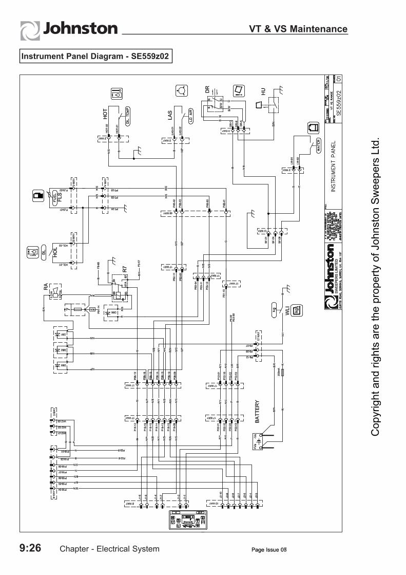
Instrument Panel Diagram - SE559z02
Cop
yrig
ht a
nd ri
ghts
are
the
prop
erty
of J
ohns
ton
Swee
pers
Ltd
.

Page Issue 05 Chapter - Electrical System 9:27
VT & VS Maintenance
Channel Brush Single Sweep Diagram Type B Switches - SE561z03
Cop
yrig
ht a
nd ri
ghts
are
the
prop
erty
of J
ohns
ton
Swee
pers
Ltd
.

Page Issue 05Chapter - Electrical System9:28
VT & VS Maintenance
Channel Brush Dual Sweep Diagram Type B Switches - SE562z03
Cop
yrig
ht a
nd ri
ghts
are
the
prop
erty
of J
ohns
ton
Swee
pers
Ltd
.

Page Issue 05 Chapter - Electrical System 9:29
VT & VS Maintenance
Nozzle Single Sweep Diagram Type B Switches - SE563z03
Cop
yrig
ht a
nd ri
ghts
are
the
prop
erty
of J
ohns
ton
Swee
pers
Ltd
.

Page Issue 07Chapter - Electrical System9:30
VT & VS Maintenance
Page Issue 05
Nozzle Dual Sweep Diagram Type B Switches - SE564z03
Cop
yrig
ht a
nd ri
ghts
are
the
prop
erty
of J
ohns
ton
Swee
pers
Ltd
.

Page Issue 05 Chapter - Electrical System 9:31
VT & VS Maintenance
Wide Sweep Single Diagram Type B Switches - SE565z03
Cop
yrig
ht a
nd ri
ghts
are
the
prop
erty
of J
ohns
ton
Swee
pers
Ltd
.

Page Issue 05Chapter - Electrical System9:32
VT & VS Maintenance
Wide Sweep Dual Diagram Type B Switches - SE566z03
Cop
yrig
ht a
nd ri
ghts
are
the
prop
erty
of J
ohns
ton
Swee
pers
Ltd
.

Page Issue 13 Chapter - Electrical System 9:33
VT & VS Maintenance
Intake Flaps Diagram - SE567z02
Cop
yrig
ht a
nd ri
ghts
are
the
prop
erty
of J
ohns
ton
Swee
pers
Ltd
.

Page Issue 07Chapter - Electrical System9:34
VT & VS Maintenance
Page Issue 05
Powaboom Diagram - SE568a01
Cop
yrig
ht a
nd ri
ghts
are
the
prop
erty
of J
ohns
ton
Swee
pers
Ltd
.

Page Issue 07 Chapter - Electrical System 9:35
VT & VS Maintenance
Page Issue 05 Chapter - Electrical System 9:35
VT & VS Maintenance
Variabrush / Rotatilt Diagram Type B Switches - SE571z03
Cop
yrig
ht a
nd ri
ghts
are
the
prop
erty
of J
ohns
ton
Swee
pers
Ltd
.

Page Issue 07Chapter - Electrical System9:36
VT & VS Maintenance
Page Issue 05
Independant / Simultaneous Sweep Diagram Type B Switches - SE572z03
Cop
yrig
ht a
nd ri
ghts
are
the
prop
erty
of J
ohns
ton
Swee
pers
Ltd
.

Page Issue 05 Chapter - Electrical System 9:37
VT & VS Maintenance
Water Recirculation Diagram Type B Switches - SE573z03
Cop
yrig
ht a
nd ri
ghts
are
the
prop
erty
of J
ohns
ton
Swee
pers
Ltd
.

Page Issue 05Chapter - Electrical System9:38
VT & VS Maintenance
Varagap Option Diagram Type B Switches - SE574z03
Cop
yrig
ht a
nd ri
ghts
are
the
prop
erty
of J
ohns
ton
Swee
pers
Ltd
.

Page Issue 08 Chapter - Electrical System 9:39
VT & VS Maintenance
Supawash Option Diagram Type B Switches - SE575z03
Cop
yrig
ht a
nd ri
ghts
are
the
prop
erty
of J
ohns
ton
Swee
pers
Ltd
.

Page Issue 05Chapter - Electrical System9:40
VT & VS Maintenance
Additional Throttle Diagram - SE578a01
Cop
yrig
ht a
nd ri
ghts
are
the
prop
erty
of J
ohns
ton
Swee
pers
Ltd
.
Page Issue 05 Chapter - Electrical System 9:41
VT & VS Maintenance
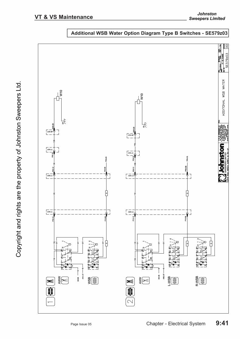
Additional WSB Water Option Diagram Type B Switches - SE579z03
Cop
yrig
ht a
nd ri
ghts
are
the
prop
erty
of J
ohns
ton
Swee
pers
Ltd
.

Page Issue 07Chapter - Electrical System9:42
VT & VS Maintenance
Page Issue 05
Program / Maxigap / Varagap Diagram Type B Switches - SE580z03
Cop
yrig
ht a
nd ri
ghts
are
the
prop
erty
of J
ohns
ton
Swee
pers
Ltd
.
Page Issue 07 Chapter - Electrical System 9:43
VS Only - Maintenance
Page Issue 09 Chapter - Electrical System 9:43
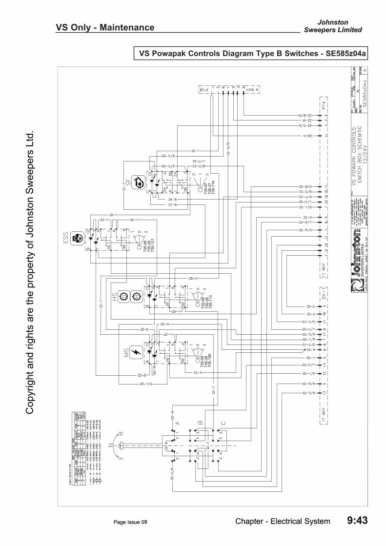
VS Powapak Controls Diagram Type B Switches - SE585z04a
Cop
yrig
ht a
nd ri
ghts
are
the
prop
erty
of J
ohns
ton
Swee
pers
Ltd
.

Page Issue 09Chapter - Pneumatic System9:44
VS Only Maintenance
VS Powapak D-Tec Diagram Type B Switches - SE585z04b
Cop
yrig
ht a
nd ri
ghts
are
the
prop
erty
of J
ohns
ton
Swee
pers
Ltd
.

Page Issue 09 Chapter - Electrical System 9:45
VS Only - Maintenance
VS Powapak Controls Diagram Type B Switches - SE585z04c
Cop
yrig
ht a
nd ri
ghts
are
the
prop
erty
of J
ohns
ton
Swee
pers
Ltd
.

Page Issue 07Chapter - Electrical System9:46
VT & VS Maintenance
Page Issue 09
VT Only - Maintenance
Iveco Stage 3a HP Engine Diagram - SE587z03aA
Cop
yrig
ht a
nd ri
ghts
are
the
prop
erty
of J
ohns
ton
Swee
pers
Ltd
.

Page Issue 09 Chapter - Electrical System 9:47
VT Only - Maintenance
Iveco Stage 3a HP Engine Diagram - SE587z03bA
Cop
yrig
ht a
nd ri
ghts
are
the
prop
erty
of J
ohns
ton
Swee
pers
Ltd
.

Page Issue 09Chapter - Electrical System9:48
VT Only Maintenance
Iveco Stage 3a HP Engine Diagram - SE587z03cA
Cop
yrig
ht a
nd ri
ghts
are
the
prop
erty
of J
ohns
ton
Swee
pers
Ltd
.

Page Issue 09 Chapter - Electrical System 9:49
VT Only - Maintenance
John Deere Tier 3 HP Engine Diagram - SE588z03a
Cop
yrig
ht a
nd ri
ghts
are
the
prop
erty
of J
ohns
ton
Swee
pers
Ltd
.

Chapter - Electrical System Page Issue 159:50
VT Only - Maintenance
John Deere Tier 3 HP Engine Diagram - SE588z03b
Cop
yrig
ht a
nd ri
ghts
are
the
prop
erty
of J
ohns
ton
Swee
pers
Ltd
.
Page Issue 07 Chapter - Electrical System 9:51
VT Only - Maintenance
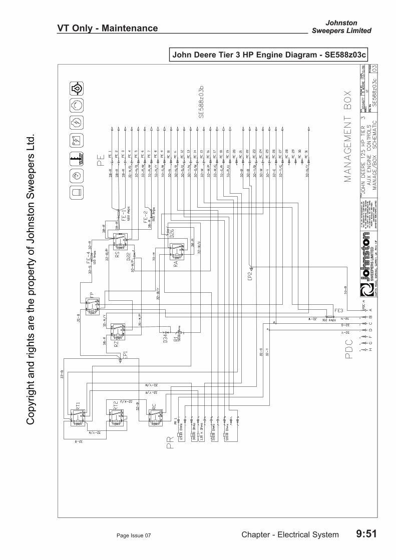
John Deere Tier 3 HP Engine Diagram - SE588z03c
Cop
yrig
ht a
nd ri
ghts
are
the
prop
erty
of J
ohns
ton
Swee
pers
Ltd
.

Chapter - Electrical System Page Issue 099:52
VT Only - Maintenance
Iveco Stage 3a SP Engine Diagram - SE589z03aA
Cop
yrig
ht a
nd ri
ghts
are
the
prop
erty
of J
ohns
ton
Swee
pers
Ltd
.

Page Issue 09 Chapter - Electrical System 9:53
VT Only - Maintenance
Iveco Stage 3a SP Engine Diagram - SE589z03bA
Cop
yrig
ht a
nd ri
ghts
are
the
prop
erty
of J
ohns
ton
Swee
pers
Ltd
.

Chapter - Electrical System Page Issue 099:54
VT Only - Maintenance
John Deere Tier 3 SP Engine Diagram - SE590z03
Cop
yrig
ht a
nd ri
ghts
are
the
prop
erty
of J
ohns
ton
Swee
pers
Ltd
.

Page Issue 08 Chapter - Electrical System 9:55
VT & VS Maintenance
Low Pressure Water Pump Bypass - Option - Diagram SE687z03
Cop
yrig
ht a
nd ri
ghts
are
the
prop
erty
of J
ohns
ton
Swee
pers
Ltd
.

Page Issue 08Chapter - Electrical System9:56
VT & VS Maintenance
Cop
yrig
ht a
nd ri
ghts
are
the
prop
erty
of J
ohns
ton
Swee
pers
Ltd
.

Chapter - Water System
CHAPTER 10Water System
10:1
Table of Contents
Section Page
Introduction General Description 10 : 2 Circuit Pressures 10 : 2
Component Maintenance and Settings Water Pump 10 : 3 Relief Valve 10 : 4 Solenoid Valves 10 : 4 Hydrant Filler 10 : 4 Recirculation Valves 10 : 5 Piping Diagram 10 : 6
Supawash Pump Pump Repair 10 : 8 Seal and Valve Maintenance 10 : 9 Exploded View of Pump 10 : 12
Circuit Diagrams Low Pressure - Single Sweep 10 : 13 Low Pressure - Dual Sweep 10 : 14 Microtrap - Single Sweep 10 : 15 Microtrap - Dual Sweep 10 : 16 Supawash 10 : 17
Page Issue 12
VT & VS MaintenanceC
opyr
ight
and
righ
ts a
re th
e pr
oper
ty o
f Joh
nsto
n Sw
eepe
rs L
td.

Page Issue 01Chapter - Water System10:2
VT & VS Maintenance
GENERAL DESCRIPTION
Pressure for the water supply is provided by a twin diaphragm pump hydraulically driven from the auxiliary engine. Pressure regulation is by a relief valve situated at the rear of the machine. Filtration is by two filters, one mounted within the water tank and a second in-line type located at the right hand rear of the machine. An isolator valve is built into the in-line filter for ease of element servicing. All sweeping spray jets are controlled by simple solenoid valves, manifold mounted within the systems locker.
Control of the washdown hose and wanderhose water injection is by manual valves at the rear of the machine subframe.
SUPAWASH OPTION
This optional equipment comprises a hydraulically driven high pressure water pump, and a hand lance mounted on the chassis of the machine with a 15 metre hose wound onto a recoiling reel.
Front and nozzle spraybars are optional equipment.
Supawash Unloader Valve - Pressure Setting
1. Ensure that the hydraulic relief valve has been set as outlined in section 8.
2. Fit a hydraulic test gauge to the Supawash manifold (T13).
3. Disconnect the 3/8” bypass pipe at the unloader valve and plug the hose end.
4. Turn on the front spraybar tap.
5. Activate the Supawash and increase the engine speed to 2000 rpm. Check to see if any water is leaking from the bypass port on the unloader, if not loosen the retaining nut on the top of the unloader and unscrew anticlockwise until water dribbles from the bypass port. Gently turn the adjuster clockwise until water stops dribbling, then turn the adjuster 1/2 turn clockwise and lock off the retaining nut. The operational pressure at the manifold should be 100 bar nominal. If the pressure is higher check again for blocked jets.If the pump operates at a pressure in excess of 100 bar there is a problem that will effect the life of the pump and invalidate any warranty.
NB - Do not turn off the front Supawash spraybar or water will be ejected from the bypass valve where the hose has been removed.
6. Stop the engine and reconnect the bypass hose.
CIRCUIT PRESSURES
Two test points are provided for checking the water pressures.
Test Point No. Function
WTP Dust Suppression Sweep System T13 Supawash System
Cop
yrig
ht a
nd ri
ghts
are
the
prop
erty
of J
ohns
ton
Swee
pers
Ltd
.

Page Issue 01 Chapter - Water System 10:3
VT & VS Maintenance
The assembly of the twin diaphragm pump is quite simple and straightforward, but attention to the undermentioned points will afford economy by prolonging the life of the pump and, more especially, the expendable components.
1 Diaphragms - When replacing a diaphragm, turn the crankshaft until the relative connecting rod is at TDC so that
when securing the diaphragm and the tension pad by means of the tension pad bolt, the periphery of the diaphragm is free of the crank case.
Ensure that the tension pad is pulled down onto the connecting rod.2 Pump Chambers - Before fitting a pump chamber, turn the crankshaft until the relative diaphragm is at the centre of
its stroke, i.e. so that the periphery of the diaphragm is just resting on the face of the crankcase. Place the pump chamber in position, place the bolts and nuts in position and tighten ‘finger tight’. Tighten down, but make sure that the pump chamber is pulled down square so that the lower face of the chamber is correctly located against the crankcase.
3 Manifolds and Valves - Fit the valve sealing rings onto the valve seat. Place the delivery valve (stem upwards) over the
delivery orifice of the pump chamber and push the sealing ring down so that it is flush with the pump chamber. Fit the suction valves in a similar manner, but with stem downwards. Place the manifold over the valves and see that it sits square. If the manifold does not sit square, then either the valves or the sealing rings are not correctly located. Place the securing bolts in position and pull down squarely.
It is important that these instructions are carried out, especially with regard to the fitting of the manifolds, to ensure a satisfactory seal at the valve sealing rings. Unless these instructions are followed, leakage will be experienced at the joint between the manifold and the pump chambers. On dismantling a pump for examination, if the valve sealing rings have taken on a permanent set to their location (roughly triangular in cross section), they should be replaced.
A) ManifoldB) Suction PortC) Delivery PortD) Suction ValveE) Delivery ValveF) Valve Sealing RingsG) Pump ChamberH) Tension Pad BoltsJ) Tension PadsK) DiaphragmsL) Connecting Rods
WATER PUMP
Cop
yrig
ht a
nd ri
ghts
are
the
prop
erty
of J
ohns
ton
Swee
pers
Ltd
.

Page Issue 01Chapter - Water System10:4
VT & VS Maintenance
RELIEF VALVE
This valve is factory set and should not normally be touched, but should it be necessary to make adjustments, the pressure is set as follows.
PRESSURE SETTINGRemove the cover (A) and loosen adjuster locknut (B). Connect a pressure gauge to the test point located in the systems locker. With the auxiliary engine running at low idle speed (750/800), and all water sprays switched off, turn adjuster screw (C) until gauge reads 3.5 bar (50 psi). Tighten locknut and replace cover.
SOLENOID VALVES
Solenoid valves control the water spray jets and are located in the systems locker. Each valve incorporates a filter (A) in its suction port and a manual lift override lever (B). Turning the lever anticlockwise opens the valve; clockwise closes it. This manual lift facility can be used when draining the water system in winter (see Operator’s Guide, Chapter 3) and for actuating the valve should it for any reason fail to operate electrically.
The valve is readily dismantled for inspection or cleaning by unscrewing the retaining cap (C) through the coil (D).
To access the armature, unscrew the four retaining screws (E) and remove the armature cover (F). The armature (G) can be removed. When refitting parts ensure the ‘O’ ring (H) is in good condition and located correctly.
HYDRANT FILTER
Periodically the hydrant filler filter (A) should be cleaned, or replaced if damaged. To gain access to the filter, unscrew the hydrant coupling (B) and withdraw the filter from its housing (C).
95MA. 021
(A)
(C)
(B)
95MA. 020
(C)
(A)
(B)
95MA. 019
(C)
(D)
(B)
(H)
(E)
(F)
(G)
(A)
ON
Cop
yrig
ht a
nd ri
ghts
are
the
prop
erty
of J
ohns
ton
Swee
pers
Ltd
.

Page Issue 01 Chapter - Water System 10:5
VT & VS Maintenance
RECIRCULATION VALVES
Isolate the air supply at the Filter regulator unit before removing the valve for maintenance, cleaning or replacement
There is no routine maintenance required on these valves.
Cop
yrig
ht a
nd ri
ghts
are
the
prop
erty
of J
ohns
ton
Swee
pers
Ltd
.

Page Issue 01Chapter - Water System10:6
VT & VS Maintenance
Piping Diagram
Cop
yrig
ht a
nd ri
ghts
are
the
prop
erty
of J
ohns
ton
Swee
pers
Ltd
.

Page Issue 01 Chapter - Water System 10:7
VT & VS Maintenance
Illustration Component Key
1 Water tank 2 Tank overflow vent 3 Water pump - output 28 l/m 4 Water tank primary filter 5 Suction filter 6 Tank flushing ports 7 Tank filler port - hosepipe 8 Water level sight glass 9 Tank drain/flushing valve 10a Hydrant filler port for water tank 10b Recirc water body filler * 11 ‘Type A’ anti syphon water break 12 Relief valve 13 Washdown hose 14 Wanderhose and Littasnatch valves * 15 Water valve manifold - see table below (A) Supply (B) Manual override levers WTP Water test point
* Options
VS & VT MODULAR SERIES - WATER SYSTEM - WATER VALVE STATION UTILISATION
Note:
(1) Where the words ‘not used’ appear this means that the valve is fitted to the mounting station and is only used for various option.
(2) Where the words ‘not fitted’ appear this means that the valve is not fitted to the mounting station.
Cop
yrig
ht a
nd ri
ghts
are
the
prop
erty
of J
ohns
ton
Swee
pers
Ltd
.

Water Pump Repair
Water pumps by their very nature are subject to erosion and wear from the process of pumping water. The life of the pump will depend on the quality of the water being used. The more particles that are in suspension in the water the sooner the seals and valves in the pump will wear and require replacing and are therefore considered as consumable items.The main components in the pump that will require servicing are the suction and discharge valves and the seals on the plunger pipes.A pump working correctly will normally not have any water leaks. If the plunger seals wear water will leak from the underside of the pump as shown below.
Page Issue 12Chapter - Water System10:8
VT & VS Maintenance
A drip ever 5 -10 seconds is an indication that the seals need replacing in the very near future.A continuous drip from underneath the pump shows the seals are severely worn and require urgent and prompt replacement. Shown by the arrows in the above picture.
If a steady stream of water leaking from the pump is observed the pump should NOT be used. Should the pump be used in this condition water will be drawn back into the crankcase by the motion of the plungers. This water ingress into the crankcase will cause a catastrophic failure of the pump.
When the suction and discharge valves wear the out put of the pump will be reduced and this will be noticed as reduced output from the spray jets.
Cop
yrig
ht a
nd ri
ghts
are
the
prop
erty
of J
ohns
ton
Swee
pers
Ltd
.

Page Issue 12 Chapter - Water System 10:9
VT & VS Maintenance
P22/34-100 Johnston Waterpump 283701-1Seal and Valve Maintenance Instructions
The following shows the overhaul procedure for the valves and plunger seals
Cop
yrig
ht a
nd ri
ghts
are
the
prop
erty
of J
ohns
ton
Swee
pers
Ltd
.

Page Issue 12Chapter - Water System10:10
VT & VS Maintenance
Cop
yrig
ht a
nd ri
ghts
are
the
prop
erty
of J
ohns
ton
Swee
pers
Ltd
.

Page Issue 12 Chapter - Water System 10:11
VT & VS MaintenanceC
opyr
ight
and
righ
ts a
re th
e pr
oper
ty o
f Joh
nsto
n Sw
eepe
rs L
td.

Page Issue 12Chapter - Water System10:12
VT & VS Maintenance
Cop
yrig
ht a
nd ri
ghts
are
the
prop
erty
of J
ohns
ton
Swee
pers
Ltd
.

Page Issue 12 Chapter - Water System 10:13
VT & VS Maintenance
Water System Low Pressure Single Sweep - Diagram SW511a02
Cop
yrig
ht a
nd ri
ghts
are
the
prop
erty
of J
ohns
ton
Swee
pers
Ltd
.

Page Issue 12Chapter - Water System10:14
VT & VS Maintenance
Water System Low Pressure Dual Sweep - Diagram SW511b02
Cop
yrig
ht a
nd ri
ghts
are
the
prop
erty
of J
ohns
ton
Swee
pers
Ltd
.

Page Issue 12 Chapter - Water System 10:15
VT & VS Maintenance
Water System Microtrap Single Sweep - Diagram SW512a02
Cop
yrig
ht a
nd ri
ghts
are
the
prop
erty
of J
ohns
ton
Swee
pers
Ltd
.

Page Issue 12
VT & VS Maintenance
Chapter - Water System10:16
Water System Microtrap Dual Sweep - Diagram SW512b02
Cop
yrig
ht a
nd ri
ghts
are
the
prop
erty
of J
ohns
ton
Swee
pers
Ltd
.

Page Issue 13 Chapter - Water System 10:17
VT & VS Maintenance
Water System Supawash - Diagram SW513a02
Cop
yrig
ht a
nd ri
ghts
are
the
prop
erty
of J
ohns
ton
Swee
pers
Ltd
.

Page Issue 12Chapter - Water System10:18
VT & VS Maintenance
Cop
yrig
ht a
nd ri
ghts
are
the
prop
erty
of J
ohns
ton
Swee
pers
Ltd
.

Chapter - Pneumatic System
CHAPTER 11Pneumatic System
11:1
Table of Contents
Section Page
Introduction General Description 11 : 2 Circuit Pressures 11 : 2 Pneumatic Pipe Colours 11 : 2 Valve Identification/Location 11 : 3
Component Removal Air Filtration and Regulator (FR) 11 : 4 Pneumatic Valve Island 11 : 4 Wide Sweep Brush Regulator Maintenance 11 : 6
Circuit Diagrams Maxigap Single Sweep 11 : 7 Maxigap Dual Sweep 11 : 8 Recirculation Water Option 11 : 9 Recirculation Water Option 11 : 9 Autolok Cylinder Option 11 : 10 Mesh Shakers and Littasnatch Options 11 : 11 Hydrodrive Gearbox 11 : 12 Varagap Option 11 : 13
Page Issue 01
VT & VS MaintenanceC
opyr
ight
and
righ
ts a
re th
e pr
oper
ty o
f Joh
nsto
n Sw
eepe
rs L
td.

Page Issue 01Chapter - Pneumatic System11:2
VT & VS Maintenance
GENERAL DESCRIPTION
The air supply for the pneumatic system is taken from the vehicle braking system via a safety regulating valve that ensures the braking system receives priority in the event of a failure to the sweeper air system. A filter regulator unit with integral shut off/drain facility and low air pressure warning buzzers are located within the systems locker, as are the electrical solenoid control valves for operation of channel brush/nozzle and wide sweep brush, and intake duct flap. Wide sweep brush balance adjustment is provided by pressure regulators.
CIRCUIT PRESSURES
A test point PTP (on piping diagram) is provided in the systems locker to carry out pressure checks, i.e. 8.0 bar (115 PSI).
The pressure in the Powathrust system is preset at 3.5 bar.
The pressure in the Powascrub system (option) is preset at 2 bar.
1 First ensure truck air system is up to pressure and sweepgear is lifted.2 Fit a 25 bar minimum pressure gauge to test point PTP.
If pressure is incorrect, adjustment is carried out by turning the regulator control on the filter regulator unit.
NB : Provided in the systems locker is an air charge point (AC) via an airline push in connector supplied with the sweeper.
PNEUMATIC PIPE COLOURS
A system of colour coding has been introduced to assist pipe identification and fault finding. The following colours have been adopted.
R = Red - used for live feed/supply U = Blue - used for switched supply via valve or tap B = Black - used for permanent vent/exhaust line
Before servicing any components on this system, the air supply should be shut off by means of the shut off valve mounted on top of the filter regulator unit. This not only severs the pneumatic supply, it also exhausts the air from the system causing the nozzle and wide sweep brush to lower. Wait approximately 15 seconds to allow air to completely exhaust before carrying out any work. The shut off valve does not drain air from the vehicle braking system.
Safety Precautions
Cop
yrig
ht a
nd ri
ghts
are
the
prop
erty
of J
ohns
ton
Swee
pers
Ltd
.

Page Issue 01 Chapter - Pneumatic System 11:3
VT & VS Maintenance
VALVE IDENTIFICATION/LOCATION
W1
W2 W7
W3 W8
W4 W9
W10
WTP
WTP
PT
PZ P48
RV4
RV2
RV1
X
Z
Y
D
C
SP
A1
A2 B2
B1
V
L
J
M
V1
V2
V4
V6
V8
V10
V15
V17
V3
V5
V7
V9
V11
V12
V13
V14
V16
K
MCB EDS
ZL
YL
T7
TS
R2
VM
VM
SPV
R3
GL
WDT
FR
ACPTP
SPV
LOCKER DOOR SIDE
95MA. 001-7
SYSTEMS LOCKER
Cop
yrig
ht a
nd ri
ghts
are
the
prop
erty
of J
ohns
ton
Swee
pers
Ltd
.

Page Issue 01Chapter - Pneumatic System11:4
VT & VS Maintenance
AIR FILTRATION AND REGULATOR (FR)
A filter regulator unit, located in the systems locker on the left hand side of the body, filters the air for the sweeper section of the pneumatic system to prolong the life of the components served by it.
Before carrying out any major work on the unit, other than that described in the Routine Maintenance Section of the Operator’s Guide, it will be necessary to remove it from the locker by first draining the vehicle air system, then disconnecting the supply pipes and releasing the fixing bolts.
PNEUMATIC VALVE ISLAND
The pneumatic valve island is a modular unit comprising various valve segments. Each valve segment has an indicator light that illuminates when energised (A) and a manual override button (B) for ports 2 or 4 on each segment
The segments are identified by a code and are not all the same - see following tables.
To replace a valve segment - 1) Remove the 4 fixing screws (C). 2) Remove the 4 socket head screws (D). 3) Remove the valve cover containing the valve operating coils (E). 4) Unscrew (F) each side of the segment to be replaced. 5) Fold open the segment (G) and replace ensuring the rubber gasket (H) is in position. 6) Tighten screws (F). 7) Replace top cover (E). 8) Replace screws (D).
Cop
yrig
ht a
nd ri
ghts
are
the
prop
erty
of J
ohns
ton
Swee
pers
Ltd
.

Page Issue 01 Chapter - Pneumatic System 11:5
VT & VS MaintenanceC
opyr
ight
and
righ
ts a
re th
e pr
oper
ty o
f Joh
nsto
n Sw
eepe
rs L
td.

Page Issue 01Chapter - Pneumatic System11:6
VT & VS Maintenance
WIDE SWEEP BRUSH REGULATOR MAINTENANCE
Before any work can be carried out on these units, they must be removed from their locations under the ends of the subframe crossmember+ as follows.
Exhaust the system using filter regulator shut off valve, disconnect pipes from regulator and shuttle valve, unscrew regulator securing nut. The regulator, shuttle and non-return valves can be removed as a complete assembly.
REGULATOR
Remove the regulator by undoing the securing nut (A). Use retaining ring pliers to remove the top plate (6) and retaining ring (7). Pull cap (8) and ‘O’ ring (9) from body.
Unscrew socket head screw (1), then remove button (2), spring (3), knob (4), tumblers (5), couple (10) and ‘O’ ring (11).
Remove, as an assembled unit, the adjusting screw (12) with upper and lower piston assemblies (Items 13 through 20). Remove spring (21).
Unscew the adjusting screw (12), then separate upper and lower piston assemblies (Item 13 through 20). The adjusting screw has left hand threads. Make sure ‘O’ ring (19) remains attached to the lower piston. If not, retrieve it from inside the upper piston (13).
Unscrew bottom plug (22) to gain access to the parts (23 through 36) located in the lower portion of the body.
Clean and inspect each item for damage.
A repair kit, Part No. 253-10, is available comprising Items 9, 11, 12, 14, 19, 20, 23-27, 29, 30 and 36.
When reassembling, lightly smear the ‘O’ rings and rubbers with a silicon grease. Reassemble in the reverse procedure.
PC. 0014
1 19
18
20
21
37
2526
27
28
29
362324
22
30
2
3
4
5
A
6
7
8
9
11
10
12
14
13
15
Make sure retaining ring (7) is fully seated in the groove in the body before testing or refitting onto the machine.
Cop
yrig
ht a
nd ri
ghts
are
the
prop
erty
of J
ohns
ton
Swee
pers
Ltd
.

Page Issue 07 Chapter - Pneumatic System 11:7
VT & VS Maintenance
Maxigap Single Sweep - Diagram SP541a02
Cop
yrig
ht a
nd ri
ghts
are
the
prop
erty
of J
ohns
ton
Swee
pers
Ltd
.

Page Issue 07Chapter - Pneumatic System11:8
VT & VS Maintenance
Maxigap Dual Sweep - Diagram SP542a02
Cop
yrig
ht a
nd ri
ghts
are
the
prop
erty
of J
ohns
ton
Swee
pers
Ltd
.

Page Issue 01 Chapter - Pneumatic System 11:9
VT & VS Maintenance
Recirculation Water Option - Diagram SP543a02
Cop
yrig
ht a
nd ri
ghts
are
the
prop
erty
of J
ohns
ton
Swee
pers
Ltd
.

Autolok Option - Diagram SP544a02
Page Issue 01Chapter - Pneumatic System11:10
VT & VS Maintenance
Cop
yrig
ht a
nd ri
ghts
are
the
prop
erty
of J
ohns
ton
Swee
pers
Ltd
.

Page Issue 12 Chapter - Pneumatic System 11:11
VT & VS Maintenance
Littasnatch - Diagram SP545a02
Cop
yrig
ht a
nd ri
ghts
are
the
prop
erty
of J
ohns
ton
Swee
pers
Ltd
.

Page Issue 01Chapter - Pneumatic System11:12
VS Only - Maintenance
Hydrodrive Gearbox - Diagram SP546a02
Cop
yrig
ht a
nd ri
ghts
are
the
prop
erty
of J
ohns
ton
Swee
pers
Ltd
.

Page Issue 07 Chapter - Pneumatic System 11:13
VT & VS - Maintenance
Varagap Option - Diagram SP547a02
Cop
yrig
ht a
nd ri
ghts
are
the
prop
erty
of J
ohns
ton
Swee
pers
Ltd
.

Page Issue 04Chapter - Pneumatic System11:14
VT & VS Maintenance
Rear Wander Hose - Diagram SP548z00
Cop
yrig
ht a
nd ri
ghts
are
the
prop
erty
of J
ohns
ton
Swee
pers
Ltd
.

Page Issue 09 Chapter - Pneumatic System 11:15
VT & VS Maintenance
Mesh Shaker in Cab - Diagram SP550a02
Cop
yrig
ht a
nd ri
ghts
are
the
prop
erty
of J
ohns
ton
Swee
pers
Ltd
.

Page Issue 09Chapter - Pneumatic System11:16
VT & VS Maintenance
Mesh Shaker - Diagram SP550b02
Cop
yrig
ht a
nd ri
ghts
are
the
prop
erty
of J
ohns
ton
Swee
pers
Ltd
.

Chapter - Wearing Items
CHAPTER 12Wearing Items
12:1Page Issue 01
VT & VS Maintenance
Table of Contents
Section Page
Replacement Instructions
Fan Impeller 12 : 2
Intake Duct Flap 12 : 3 Wear Plate 12 : 4 Intake Duct 12 : 4 Intake Trunking 12 : 4 Intake Seat 12 : 5
Nozzle Wheel 12 : 5 Tyre 12 : 5 Wheel Bearings 12 : 6 Nozzle Rubbers 12 : 6
Channel Brush 12 : 6
Wide Sweep Brush Fills 12 : 6
Cop
yrig
ht a
nd ri
ghts
are
the
prop
erty
of J
ohns
ton
Swee
pers
Ltd
.

Page Issue 09Chapter - Wearing Items12:2
VT & VS Maintenance
] THESE ITEMS HAVE BEEN SPECIFICALLY DESIGNED FOR LO-NOISE EMISSIONS AND FITTING OF ALTERNATIVE ITEMS COULD CAUSE AN INCREASE IN THE OPERATIONAL NOISE OF THE MACHINE.
FAN IMPELLER ]
INSPECTION -This should be on a regular basis as outlined in the routine maintenance. The impeller should be replaced as soon as the blade thickness is less than 2mm or the blades have visible signs of wear/damage.
REMOVALRaise the body and ensure the body prop is engaged in the rack.Remove the fan case inspection plate. 5 bolts Item 2.Remove the fan case cover Item 1. 10 bolts.
l Ensure the machine is standing on firm, level ground and there are no obstructions above or to the rear before raising the body.
l Ensure the safety prop is engaged at all times when working under the body.l Ensure operators are fully conversant with the controls and operation.l Isolate the air in the systems locker before working on any pneumatically operated or
controlled equipment.l Disconnect or isolate the vehicle battery when working on the electrical system.l Do not approach the fan inlet while the fan is running.l Do not grasp any part of the engine or exhaust system without first ascertaining whether it
has cooled sufficiently to avoid scalding.l Be aware of the safety instructions relative to the suction fan given in the equipment
maintenance notes.l Keep hands, loose clothing, hair etc. well clear of moving parts.l Do not climb on the engine walkways unnecessarily or approach the fan inlet whilst the
engine is running.l Do not use ill-fitting tools such as spanners that may slip and cause injury.l Always get a second person to check periodically that all is well when only one person is
working on the machine or inside the body.
Safety Precautions
95MA. 033-24
7
6
3
5
2
3mm
1
4
4= VT
= VS
WEARING PARTS REPLACEMENT INSTRUCTIONS
It is important that the following safety precautions are observed when working on the machines.
Cop
yrig
ht a
nd ri
ghts
are
the
prop
erty
of J
ohns
ton
Swee
pers
Ltd
.
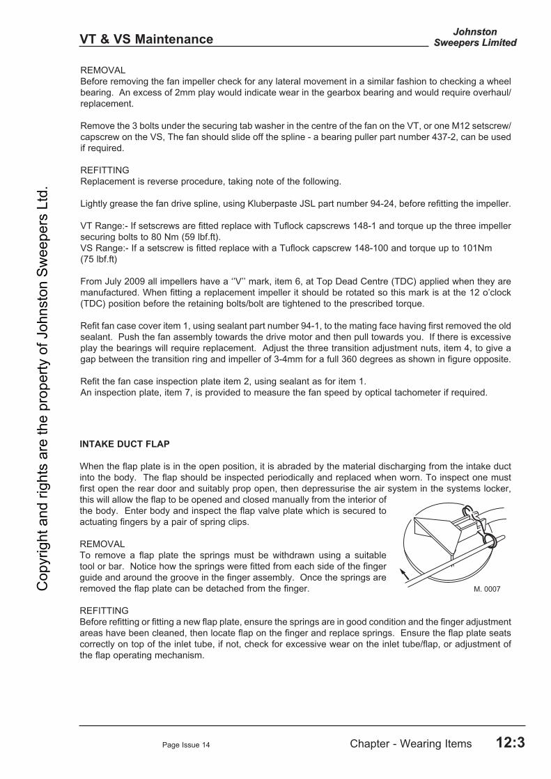
Page Issue 14 Chapter - Wearing Items 12:3
VT & VS Maintenance
REMOVALBefore removing the fan impeller check for any lateral movement in a similar fashion to checking a wheel bearing. An excess of 2mm play would indicate wear in the gearbox bearing and would require overhaul/replacement.
Remove the 3 bolts under the securing tab washer in the centre of the fan on the VT, or one M12 setscrew/capscrew on the VS, The fan should slide off the spline - a bearing puller part number 437-2, can be used if required.
REFITTING Replacement is reverse procedure, taking note of the following.
Lightly grease the fan drive spline, using Kluberpaste JSL part number 94-24, before refitting the impeller. VT Range:- If setscrews are fitted replace with Tuflock capscrews 148-1 and torque up the three impeller securing bolts to 80 Nm (59 lbf.ft). VS Range:- If a setscrew is fitted replace with a Tuflock capscrew 148-100 and torque up to 101Nm (75 lbf.ft)
From July 2009 all impellers have a ‘’V’’ mark, item 6, at Top Dead Centre (TDC) applied when they are manufactured. When fitting a replacement impeller it should be rotated so this mark is at the 12 o’clock (TDC) position before the retaining bolts/bolt are tightened to the prescribed torque.
Refit fan case cover item 1, using sealant part number 94-1, to the mating face having first removed the old sealant. Push the fan assembly towards the drive motor and then pull towards you. If there is excessive play the bearings will require replacement. Adjust the three transition adjustment nuts, item 4, to give a gap between the transition ring and impeller of 3-4mm for a full 360 degrees as shown in figure opposite.
Refit the fan case inspection plate item 2, using sealant as for item 1.An inspection plate, item 7, is provided to measure the fan speed by optical tachometer if required.
INTAKE DUCT FLAP
When the flap plate is in the open position, it is abraded by the material discharging from the intake duct into the body. The flap should be inspected periodically and replaced when worn. To inspect one must first open the rear door and suitably prop open, then depressurise the air system in the systems locker, this will allow the flap to be opened and closed manually from the interior of the body. Enter body and inspect the flap valve plate which is secured to actuating fingers by a pair of spring clips.
REMOVALTo remove a flap plate the springs must be withdrawn using a suitable tool or bar. Notice how the springs were fitted from each side of the finger guide and around the groove in the finger assembly. Once the springs are removed the flap plate can be detached from the finger.
REFITTINGBefore refitting or fitting a new flap plate, ensure the springs are in good condition and the finger adjustment areas have been cleaned, then locate flap on the finger and replace springs. Ensure the flap plate seats correctly on top of the inlet tube, if not, check for excessive wear on the inlet tube/flap, or adjustment of the flap operating mechanism.
Cop
yrig
ht a
nd ri
ghts
are
the
prop
erty
of J
ohns
ton
Swee
pers
Ltd
.

Page Issue 01Chapter - Wearing Items12:4
VT & VS Maintenance
WEAR PLATE
REMOVALEnter the body after carrying out precautions as for intake duct flap. The wear plate (A) is secured by two screws and a clamp bar (B). It is a wise precaution to prop the wear plate before attempting to remove these screws. Once the screws are removed, support the wear plate and remove the prop. Allow the wear plate to fall slightly and unhook from the hooks (C) attached to the body outer skin, and remove. Help may be required in removal as this unit weighs approximately 36kg.
INTAKE DUCT
These parts are also abraded by the material being conveyed from the suction nozzle and must be periodically inspected and replaced when worn or holed. The duct is 250mm diameter.
REMOVALEnter body after carrying out the same precautions as for intake flap replacement. Remove the four bolts securing the collar (A) around the intake duct (B). Lift up the flap manually (if fitted) and remove collar. A rubber cord (C) will now be visible which should also be removed with care to prevent damage. Dismount from body. Tip body and support on prop. Remove the four bolts in the square flange carrying the flexible trunking seat seal (D). The intake duct can now be pulled downwards clear of the body.
REFITTINGReverse of removal procedure, but if fitting a new duct a new trunking seat seal should be used and secured using a contact adhesive, Part No. 9903. Fit two bolts in diagonal holes, the duct (B) has two holes with keyhole slots. Align slots over the bolt heads and twist. Fit the other two bolts and tighten. The rest is the reverse of the removal instructions. Replace the rubber cord (C) and collar plate (A) inside the body and secure. Finally, fully tighten the four duct top retaining bolts.NB. Torque for brass M12 bolts 22 Nm (25ftlbf).
FLEXIBLE INTAKE TRUNKING ]
REMOVALLower suction nozzle to the ground, release worm drive clips at either end and remove trunking. The nozzle trunking has an inside diameter of 250mm.
REFITTING
Loosely fit worm drive clips to either end of trunking. Engage trunking onto the nozzle with a 55mm (2”) overlap and tighten clip. Fit other end to the intake seat and secure. Check trunking is not twisted or rucked and does not foul anything when the nozzle is raised or lowered again.
Cop
yrig
ht a
nd ri
ghts
are
the
prop
erty
of J
ohns
ton
Swee
pers
Ltd
.

Page Issue 01 Chapter - Wearing Items 12:5
VT & VS Maintenance
SUCTION NOZZLE WHEEL
REMOVALRelease nozzle wheel adjustment nut (A) on inner end of wheel spindle. Remove wheel complete.
REFITTINGReverse of removal procedure.
TYRE - SUCTION NOZZLE WHEEL
REMOVALRemove nozzle wheel as above. Remove five screws securing tyre plate (B) and prise off. Remove tyre from hub.
REFITTINGReverse of removal procedure.Note : Ensure correct re-setting of nozzle rubbers in relation to the ground.
Inlet Seat Dimension A Part No. ‘B’
900 - 999 94990-1 1000 - 1099 94990-3 1100 - 1199 94990-4
INTAKE SEAT
REMOVALFirstly tip body and support on prop. Release trunking from tube as described on previous page. Release and remove the three countersunk screws and nuts (A). Lift seat (B) clear of bracket.
REFITTINGReverse of removal procedure. As no adjustment for seal compression is provided, it is wise to check seal compression when the body is lowered.
Note : When replacing the intake seat, it is important that the correct length is used. The correct length of intake seat is determined by measuring dimension A, as shown below, from ground to underside of the subframe (i.e. top of chassis).
Cop
yrig
ht a
nd ri
ghts
are
the
prop
erty
of J
ohns
ton
Swee
pers
Ltd
.

Page Issue 01Chapter - Wearing Items12:6
VT & VS Maintenance
NOZZLE WHEEL BEARINGS
REMOVALTo withdraw bearing remove wheel assembly from carriage and remove the three setscrews from the retaining plate. Refit washer and nut, insert M6c x 50mm setscrews, Part No. 124-113, in the three unused retainer plate holes. Tighten each bolt half a turn at a time to extract the bearing. Remove drift bearing from shaft.
REFITTINGReverse of removal procedures.
SUCTION NOZZLE RUBBERS
REMOVALThis can be effected without removing the nozzle assembly from the machine but if personnel are inexperienced it will probably be easier to remove nozzle assembly and turn upside down. Release two screws retaining bump bar at kerb end of nozzle. Release securing nuts retaining the rubbers. Pull away the two short end rubbers, then remove the front and rear side rubbers.
REFITTINGReverse of removal procedure remembering to fit the radius rubber to the nozzle rear. Do not over tighten the nuts as this will cause distortion of the rubber. Refit bump bar.
CHANNEL BRUSH
REMOVALIt is preferable to have brush in working position with auxiliary engine stopped. Release four nuts from coach bolts securing brush stock assembly drive plate. Remove brush.
REFITTINGReverse of removal procedure. Any loops of steel tines which project above the head of the stock should be hammered flush before offering up brush stock assembly to driving plate.
WIDE SWEEP BRUSH CORE ASSEMBLY
See Chapter 6 in the Operator’s Guide.
WIDE SWEEP BRUSH FILLS
There are two types of brush fills:
a) Replacement segmentsb) Plastic ‘throw away’ stock tines.
Replaceable Segments
95MA. 034-2
(A)
(G)
(B)
(C)
(E)
(F)
(D)
Sharp objects
Sharp objectsC
opyr
ight
and
righ
ts a
re th
e pr
oper
ty o
f Joh
nsto
n Sw
eepe
rs L
td.

Page Issue 01 Chapter - Wearing Items 12:7
VT & VS Maintenance
REMOVALRelease and remove the retaining screws (F) securing the end plate / adaptor (A). Slide off the segments (B) and spacers (C) from the central core. Note : On earlier machines the driving pin (E) on the inner diameter of the segments must be aligned with a slot (D) on the core (G) where the two parts join.
REFITTING First slide on a segment then alternately a spacer and a segment. Sufficient spacers and segments must be fitted to allow the end plate to nearly abut with the core and also clamp them tightly. The peg (E) on the segment (B) to be alternatively located round the core clockface at 12, 2, 4 o’clock and so on until the core is filled, failure to observe this could cause the brush to bounce. The last segment must have the pin (E) on the segment (B) located in the cutout (D) to ensure the peg does not interfer when the parts are bolted together.
Note : Lightly smear the retaining screws (F) with grease with grease.
This assembly is designed to accommodate 406mm diameter segments.
Plastic Throw Away Stock
95MA. 011-2(H)The stock (H) is removed and can be recycled as plastic waste.
Cop
yrig
ht a
nd ri
ghts
are
the
prop
erty
of J
ohns
ton
Swee
pers
Ltd
.

Page Issue 01Chapter - Wearing Items12:8
VT & VS Maintenance
Cop
yrig
ht a
nd ri
ghts
are
the
prop
erty
of J
ohns
ton
Swee
pers
Ltd
.

Chapter - Controls
CHAPTER 13Remove and Refit Procedures
13:1
Table of Contents
Section Pages
Removal and Refitting Instructions
Water Pump VT & VS 13 : 2 Wide Sweep Brush Motor VT & VS 13 : 3 Channel Brush Motor VT & VS 13 : 3 Channel Brush Cylinder VT & VS 13 : 4
Hydrodrive Gearbox & Pumps VS Only 13 : 5 Fan Drive Motor VS Only 13 : 5
Radiator VT Only 13 : 6 Hydraulic Pump VT Only 13 : 6 Fan Impeller VT Only 13 : 6 Fan Case VT Only 13 : 6 & 8 Gearbox VT Only 13 : 7 & 8 Fluid Drive Coupling VT Only 13 : 7 & 8 Flywheel VT Only 13 : 7
Page Issue 01
VT & VS MaintenanceC
opyr
ight
and
righ
ts a
re th
e pr
oper
ty o
f Joh
nsto
n Sw
eepe
rs L
td.

Page Issue 01Chapter - Remove and Refit Procedures13:2
VT & VS Maintenance
This section describes the removal and refitting of some of the major components on the machine. These are not routine jobs and should normally only need to be undertaken when overhauling or exchanging these units.
1. WATER PUMP - DUST SUPPRESSION - Removal and refitting
1 Isolate the water supply at the filter unit. 2 Disconnect the feed and pressure water pipes (A) to the pump. 3 Remove the 4 bolts (B) holding the water pump to the drive motor. 4 Withdraw the pump assembly from the drive coupling (C). 5 Refitting is the reverse procedure, ensure that the pump drive gear does not bottom in the drive coupling. NB It is possible to replace the pump diaphragms and valves with the pump in situ.
The hinged prop stowed beneath the body SHOULD BE USED AT ALL TIMES to prop the body when carrying out any inspection, servicing or maintenance work beneath the body.
Disconnect the battery negative lead before undertaking any of the following operationson the auxiliary pack.
Safety Precautions
Cop
yrig
ht a
nd ri
ghts
are
the
prop
erty
of J
ohns
ton
Swee
pers
Ltd
.

Page Issue 01 Chapter - Remove and Refit Procedures 13:3
VT & VS Maintenance
95MA. 014-3
1
32
5
6
7
2. WIDE SWEEP BRUSH MOTOR - Removal and Refitting
1 Remove the brush stock as described in Chapter 6. 2 Unscrew the four end plate securing setscrews and remove plate complete with motor
assembly and drive shaft or drive dog.
FIGURE 4 - WIDE SWEEP BRUSH MOTOR
1 End plate securing screws. 2 Drive shaft retaining screws. 3 Drive shaft/drive dog. 4 - 5 Drive adaptor retaining screw. 6 Drive adaptor 7 Motor securing screws
3. CHANNEL BRUSH MOTOR - Removal and refitting
1. Unscrew the four nuts (A) from the coach bolts securing the channel brush to the drive adaptor plate and remove brush.
2. Unscrew the retention screw (B) from the centre of the drive adaptor plate and remove plate. 3. Disconnect the two hydraulic hoses from the motor. 4. Unscrew the two bolts securing the motor to mounting bracket and lift off motor. 5. Refitting is the reverse of removal.
Cop
yrig
ht a
nd ri
ghts
are
the
prop
erty
of J
ohns
ton
Swee
pers
Ltd
.

Page Issue 16Chapter - Remove and Refit Procedures13:4
VT & VS Maintenance
4. CHANNEL BRUSH CYLINDER - Removal and refitting
1. Disconnect the two hydraulic hoses from rear of the cylinder. 2. Remove cylinder pin (B). 3. Remove stop from pivot frame (D). 4. Remove cylinder eye pivot (E) from pivot head lever (F). Lift out cylinder. 5. Refitting is the reverse of removal, grease items (B) and (E) prior to refitting.
5. LIFTING OR REMOVAL OF THE BODY
If it is necessary to raise the body, two holes are provided in the front of the body.
l Remove blanking bolts (A).
l Insert eye bolt item (B) part no. 442-1 into the M16 socket.
If the body has to be removed use the two lifting eyes and point (C) with a suitable chain or web strap.
(B)
(D)
(F)(E)
M. 0054-2
95EM. 002-2
(A)
(C)(B)
Cop
yrig
ht a
nd ri
ghts
are
the
prop
erty
of J
ohns
ton
Swee
pers
Ltd
.

Page Issue 01 Chapter - Remove and Refit Procedures 13:5
VS Only - Maintenance
10. HYDROSTATIC GEARBOX AND PUMPS The individual pumps may be removed in situ if required. However, the following criteria applies. On the end of the transmission pump (identified by an oil filter mounted on the side of the pump) is mounted the sweep gear drive pump. The fan drive pump is mounted on the opposite side of the gearbox to the transmission pump (i.e. front to rear). On the end of the fan drive pump is mounted an option pump to drive supawash or other accessories. The transmission drive motor(s) are always mounted on the opposite side of the gearbox to the transmission pump. If the removal of any pump is required, it is first necessary to minimise oil loss by loosening the cap on the hydraulic return filter.
All hoses should be plugged after the removal of any pump to prevent dirt ingress and oil loss from the hoses. HYDRODRIVE GEARBOX The hydrodrive gearbox and pump assemblies can be removed as a complete unit by using a lifting jig, Part No 93828-1.
11. FAN DRIVE MOTOR - Removal and refitting
Care should be taken as the oil may be under pressure if the vehicle has just stopped, and the cap loosened slowly.
If the gearbox is to be removed, the truck will be immobile. The ignition keys should be removed to prevent inadvertent starting and consequential damage to the drive line and components.
1 Remove fan case cover and impeller as described earlier.2 Loosen cap on hydraulic return filter. 3 Disconnect hydraulic hoses from ports A, B, C
and D.4 Remove 4 setscrews (E) holding motor on to
the mount. 5 Withdraw motor. 6 Refitting is the reverse procedure to removal.
Lubricate motor drive shaft with Molykote DX (Part No 30-100) before refitting.
7 Motor securing capscrew should be tightened to torque of 101 Nm.
8 Retighten cap on hydraulic return filter.
Cop
yrig
ht a
nd ri
ghts
are
the
prop
erty
of J
ohns
ton
Swee
pers
Ltd
.

Page Issue 14Chapter - Remove and Refit Procedures13:6
VT Only - Maintenance
20. RADIATOR - Removal and Refitting
1 Remove lower hose from water pump and direct flow of coolant into a suitable container. 2 Remove top hose from radiator. 3 Unscrew the five button headed socket screws and remove walkway in front of radiator. 4 Unscrew the four mounting screws and withdraw radiator from shroud. 5 Refitting is reverse of removal, but fit lower two mounting screws first to allow radiator
to pivot making the lower hose fitment easier. Refill cooling system with specified anti-freeze mixture.
21. HYDRAULIC PUMP - Removal and Refitting
1 Remove both low and high pressure pipes from pump. 2 Remove the setscrews from the pump flange to timing case and remove pump. NB : Iveco engine has a pump drive adaptor. 3 Refitting is the reverse of removal. Apply a little grease, not sealant, to mating surfaces
and fit a new gasket. Torque gear securing nut to 27 lbf/ft (50 Nm)(Perkins).
22. FAN IMPELLER - Removal
Before removing the fan impeller check for any lateral movement in a similar fashion to checking a wheel bearing. Any excessive play would indicate wear in the bearing/gearbox assembly and would require an overhaul.
1 Unscrew the ten fan case cover securing setscrews and remove cover (see chapter 2). 2 Unscrew the three impeller securing setscrews having first straightened the tab washer. 3 Withdraw the impeller from the splined shaft, Puller, Part No. 437-2, is available for this
purpose (if required). Lift fan from case.
23. FAN CASE - Removal
1 Carry out procedure 22. 2 Remove the screws (B) holding the mask plate onto the gearbox and remove the mask. 3 Disconnect the silencer assembly at the flexible joint on the exhaust manifold. 4 Unscrew the four setscrews (two per side) holding the fan case to the front and rear
valances. 5 Unscrew the two button head socket screws, one at each end of walkway togethr with the two setscrews 5a. 6 Unscrew the two lower setscrews (5a) securing the fuel tank to front and rear valances.
Loosen the two upper setscrews each side (5b) in the elongated holes allowing the tank to slide outwards. Lift out fan case.
FIGURE 1 - FAN CASE (Procedures 22 and 23)
(1) Rubber diaphragm. (2) Mask and special securing
screws. (3) Fan case securing screws. (4) Button headed screws. (5) Fuel tank securing screws. (a) remove (b) loosen
Cop
yrig
ht a
nd ri
ghts
are
the
prop
erty
of J
ohns
ton
Swee
pers
Ltd
.

Page Issue 08 Chapter - Remove and Refit Procedures 13:7
VT Only - Maintenance
24. GEARBOX - Removal
1 Carry out procedures 22 and 23. 2 Drain fluid drive coupling as described in Chapter 7. 3 Remove the six setscrews securing the gearbox to the bell housing and the four bolts
holding the two cover plates to the flywheel housing. 4 Withdraw the gearbox, supporting its weight so as not to damage the input shaft fluid drive
coupling. 5 On some installations there may be an adaptor ring between gearbox and flywheel
housing.
25. FLUID DRIVE COUPLING - Removal
1 Carry out procedures 22, 23 and 24. 2 Remove the twenty socket head screws securing the coupling to the flywheel. 3 Insert M8 setscrews in the two blind extractor holes and tighten each half a turn at a time
to ease the coupling from the flywheel.
FIGURE 2 - FLUID DRIVE COUPLING AND FLYWHEEL (Procedures 7 to 10)
1 Fluid coupling.2 Flywheel.3 Bell housing.4 Gearbox.5 Gearbox input shaft.6 Rubber cover if fitted. Part No. 221-3.7 Gearbox support bearing.8 Oil seal, Part No. 77-39.9 ‘O’ ring, Part No. 656-2.10 ‘O’ ring, Part No. 656-1.11 Adaptor ring.
26. FLYWHEEL - Removal
1 Carry out procedures 22, 23, 24 and 25. 2 On Perkins engines only - pierce and prise out rubber covers from retaining bolts. 3 Remove setscrews and withdraw the flywheel.
27. FLYWHEEL - Refitting
1 On Iveco and John Deere units apply Loctite 510 between the crankshaft palm and the flywheel around the mounting holes. Also apply Loctite 275 onto the fixing bolts.
2 Refit flywheel and torque retaining setscrews to 138 Nm on Iveco and John Deere units and 108 Nm on Perkins units. 3 On Perkins engines only - fit new retaining screw covers flush with flywheel, having
ensured the screw heads and flywheel undercuts are clean and oil free. Leave 10-15 minutes then check covers have not pushed out, tap in if they have.
4 Replace the support bearing in the centre of the flywheel.
Cop
yrig
ht a
nd ri
ghts
are
the
prop
erty
of J
ohns
ton
Swee
pers
Ltd
.

Page Issue 01Chapter - Remove and Refit Procedures13:8
VT Only - Maintenance
28. FLUID DRIVE COUPLING - Refitting
1 Before fitting coupling, renew oil seal and ‘O’ rings (Items 8, 9 and 10, Figure 2). 2 Generously grease both ‘O’ rings and internal splines with Kluber Paste 46MR401, JSL
Part No. 94-24. 3 Offer fluid drive to the flywheel ensuring bolt holes are in line. Push assembly together
by hand, making sure not to trap and damage the large ‘O’ ring. 4 Refit the ring of M8 cap screws and tighten to a torque of 26 Nm (19 lbf.ft) on Perkins and
Iveco engines.
NB : On the John Deere engines the cap screws are M6 and torqued up to 19 Nm (14 lbf.ft)
29. GEARBOX - Refitting
1 Lightly grease splines on the input shaft with Kluber Paste, JSL Part No. 94-24. 2 Some engine installations have an adaptor ring between the flywheel housing and the
gearbox. (See Fig. 2, Item 11) 3 Ease the gearbox onto the engine bell housing whilst rotating the output shaft. Use the
securing setscrews to finally pull the gearbox up to the housing. 4 Ensure the output shaft rotates freely after assembly. 5 Refit the two side cover plates. 6 At this point it is advisable to refill the fluid coupling and gearbox (if it has been drained)
as described in Chapter 7 of this manual.
30. FAN CASE - Refitting
Refitting is the reverse of removal described in Chapter 12, but when refitting the mask to the gearbox, ensure it abuts or is very close to the rubber diaphragm attached to the fan case. Apply stud lock to the mask retaining screws before fitting.
31. FAN IMPELLER - Refitting
See Chapter 12.
32. FAN CASE COVER - Refitting
See Chapter 12.
Cop
yrig
ht a
nd ri
ghts
are
the
prop
erty
of J
ohns
ton
Swee
pers
Ltd
.

Chapter - Fault Diagnosis
CHAPTER 14Fault Diagnosis
14:1
Table of Contents
Section Page
Power Systems Hydraulic VT & VS 14 : 2 Pneumatic VT & VS 14 : 2 Water VT & VS 14 : 2 Electrical VT & VS 14 : 3
Suction System Suction System VT & VS 14 : 4
Power Pack Auxiliary Engine VT Only 14 : 5 Electrics and Shut Down System VT Only 14 : 5
Sweep Gear Wide Sweep Brush VT & VS 14 : 6 Channel Brush VT & VS 14 : 7 Maxigap Nozzle VT & VS 14 : 7
Discharge Body Tip VT & VS 14 : 8 Hydrodrive VS Only 14 : 9
Page Issue 01
VT & VS MaintenanceC
opyr
ight
and
righ
ts a
re th
e pr
oper
ty o
f Joh
nsto
n Sw
eepe
rs L
td.

Page Issue 01Chapter - Fault Diagnosis14:2
VT & VS Maintenance
HYDRAULIC SYSTEMS
FAULT SYMPTOM POSSIBLE CAUSE
Hydraulic oil frothing 1. Air getting into system. Check LP pipe to pump. 2. Defective pump shaft seal. 3. Wide sweep brush lift cylinder seals defective. 4. Return pipe separated from underside of return
filter inside hydraulic tank.
Sluggish hydraulics 1. Cartridge valve not travelling full extent - measure oil flow.
2. Blocked filters. 3. Air in oil
PNEUMATIC SYSTEMS FAULT SYMPTOM POSSIBLE CAUSE
Low pressure warning 1. Air pressure switch faulty. buzzer on continuously 2. Insufficient pressure in Johnston system. Constant air leak from 1. Cylinder seals leaking internally. solenoid block 2. Air solenoid faulty.
WATER SYSTEMS FAULT SYMPTOM POSSIBLE CAUSE
Jet continuously leaking 1. Grit under armature seating. 2. Armature stuck open. 3. Manual override on. No water to wash down 1. Water pump filter blocked. hose or jets 2. Water tank filter blocked. 3 Water pump belt loose or broken. 4. Drain tap on filter open. 5. Filter isolation valve closed. 6. Filter assembled incorrectly 7. Pump valves fitted incorrectly after overhaul. Lack of pressure 1. Grit under relief valve seating. 2. Relief valve spring broken. 3. Relief valve stuck open. 4. Relief valve worn.
Cop
yrig
ht a
nd ri
ghts
are
the
prop
erty
of J
ohns
ton
Swee
pers
Ltd
.

Page Issue 01 Chapter - Fault Diagnosis 14:3
VT & VS Maintenance
ELECTRICAL SYSTEM
FAULT SYMPTOM POSSIBLE CAUSE Beacon not working 1. Check vehicle ignition is on 2. Check beacon bulb/motor 3. Check feed to beacon 4. Check earth wire 5. Check fuse No. 1 for front. Fuse 2 for rear 6. Check switches
Work lights not working 1. Check vehicle ignition is on, master switch V is illuminated
2. Check bulb 3. Check feed to light 4. Check earth wire 5. Check fuse No. 1 6. Check switch Flap (duals) fail to operate 1. Check feed to solenoid/Plug LED’s V11 or V12 2. Check solenoid 3. Check earth wires 4. Check fuse No. 4 5. Check switch Nozzle pneumatic solenoids 1. Check feed to solenoid/Plug LED V2 or V10fail to operate 2. Check solenoid 3. Check earth wires 4. Check fuse No. 4 5. Check switch
Channel Brush fails to lower 1. Check feed to solenoid/Plug LED V4 or V10 2. Check solenoid 3. Check earth wires 4. Check fuse No. 4 5. Check switch Channel Brush fails to rotate 1. Check feed to solenoids/Plug LED (see Modus
Operandi) 2. Check solenoid 3. Check earth wire 4. Check fuse No. 4 5. Check switch Channel Brush water 1. Check feed to solenoid/Plug LED’s W03/W08 fails to operate 2. Check solenoid for operation/obstruction 3. Check earth wire 4. Check fuse No. 4 5. Check Wide Sweep Brush hydraulicWide Sweep Brush fails to lower 1. Check feed to solenoids/Plug LED’s V4 2. Check solenoid 3. Check earth wire 4. Check fuse No. 5 5. Check switch Wide Sweep Brush fails to rotate 1. Check feed to solenoid/Plug LED (see Modus
Operandi) 2. Check coil for operation 3. Check earth wire 4. Check fuse No. 5 5. Check switch Wide Sweep Brush water 1. Check feed to solenoid/Plug LED W01 solenoid fails to operate 2. Check solenoid for operation/obstruction 3. Check earth wire 4. Check fuse No. 5 5. Check switch
Cop
yrig
ht a
nd ri
ghts
are
the
prop
erty
of J
ohns
ton
Swee
pers
Ltd
.

Page Issue 01Chapter - Fault Diagnosis14:4
VT & VS Maintenance
SUCTION SYSTEM FAULT SYMPTOM POSSIBLE CAUSE
No pickup performance 1. Hopper full, causing airflow to be throttled: - Discharge load. 2. Nozzle or nozzle trunking blocked or restricted
by debris. Check the nozzle water jets are not blocked, are
working correctly and lubricating the intake duct. 3. Intake flap not open (dual m/c’s). Blanking plate
not removed after using the wanderhose (single m/c).
Poor pickup performance 1. Maxigap nozzle not set to the optimum opening.,
i.e. too close to ground
2. Nozzle trunking partially restricted by debris. Check nozzle water jets are working correctly and so lubricating the duct.
3. Channel brush incorrectly set, not directing
debris in line with nozzle. 4. Intake flap not fully opened (dual m/c’s). 5. Rear body meshes blocked or restricted. 6. Fan case transition ring not correctly set. 7. Fan flap incorrectly set or is incapable of
attaining correct opening due to damaged relay mechanism.
8. Low oil level in fluid flywheel. 9. Air silencer pack in roof of cowl blocked
with debris and/or sound absorbent material separating from its substrate causing a restriction.
10. Fan case inlet make and break seal fitted to
flanged duct on body front face either degraded and not sealing or missing. Note: The fan case outlet seal, unlike the inlet seal, has no effect on air performance and only provides the function of a dust seal.
11. Engine is not running at correct operational
speeds. Check fuel filter or air filter blocked/ causing a restriction.
Cop
yrig
ht a
nd ri
ghts
are
the
prop
erty
of J
ohns
ton
Swee
pers
Ltd
.

Page Issue 01 Chapter - Fault Diagnosis 14:5
VT Only - Maintenance
AUXILIARY ENGINE
FAULT SYMPTOM POSSIBLE CAUSE
Auxiliary engine fails to turn over 1. Check truck ignition is on 2. Check battery and connections 3. Check ignition switch 4. Check starter motor Auxiliary engine starts 1. Check throttle cable is not broken/jammed but will not accelerate 2. Check feed to actuator 3. Check fuse No. 8 4. Check switch
Auxiliary engine turns 1. Check fuel tank over but will not start 2. Check electric feed to engine injector shut off
fuse 8 3. Check injector shut off valve 4. Check fuel lines for loose connections 5. Check oil pressure sender and connections 6. Check water temperature sender 7. Bleed fuel system
Auxiliary engine runs but 1. Check engine oil pressure is above 0.5 bar stops after 8 seconds 2. Oil pressure switch faulty (Not Iveco engine)
AUXILIARY ENGINE ELECTRICS AND SHUT DOWN SYSTEM
FAULT SYMPTOMS POSSIBLE CAUSE
Oil pressure warning light not 1. Check fuse No. 9illuminated when ignition on 2. Check feed to oil pressure switch engine stopped (Not Iveco E3) 3. Check earth wire 4. Check bulb. Water temperature 1. Unit overheated warning light illuminated 2. Low coolant level (Not Iveco E3) 3. Blocked radiator 4. Check temp. sender if engine fails to shut down ESOS electric failure 1. Check fuse No. 8 (Not Iveco E3) 2. Check oil pressure switch 3. Check water temperature switch 4. Check feeds to ESOS 5. Check ESOS valve
Cop
yrig
ht a
nd ri
ghts
are
the
prop
erty
of J
ohns
ton
Swee
pers
Ltd
.

Page Issue 01Chapter - Fault Diagnosis14:6
VT & VS Maintenance
WIDE SWEEP BRUSH FAULT SYMPTOM POSSIBLE CAUSE
Not rotating 1. Worn drive adaptor and plate 2. Bearings seized 3. Motor seized 4. Foreign matter jammed in brush. 5. Check electrical feed to solenoid/Plug LED (see
Modus Operandi) 6. Check hydraulic system for pressures for
diagnosis of problem
Rotating slowly 1. Motor worn 2. Hydraulic pump worn 3. Brush end bearing seized Bouncing 1. Regulator adjustment incorrect 2. Brush stock bent 3. Linkage pins/brackets worn/damaged 4. Air damping system not working Not dropping 1. Check feed to solenoid/Plug LED V4 2. Solenoid faulty 3. Switch on control box faulty 4. Linkage/pivots/cylinders seized Lifts intermittently 1. Faulty or loose electrical connections while in
working mode
Air leaking from Wide Sweep Brush 1. Shuttle valve or regulator defective 2. Lift ram seals worn Brush not slewing - 1. Check slew cylinder for damage/corrosion dual sweep machines 2. Solenoids B1 B2 not operating
Cop
yrig
ht a
nd ri
ghts
are
the
prop
erty
of J
ohns
ton
Swee
pers
Ltd
.

Page Issue 01 Chapter - Fault Diagnosis 14:7
VT & VS Maintenance
CHANNEL BRUSH
FAULT SYMPTOM POSSIBLE CAUSE
Brush slows down after 1. Hydraulic pump worn 2. Channel brush worn 3. Check hydraulic pressure for fault diagnosis Works intermittently 1. Check switch in Control Panel and looms for
loose connections Brush fails to lift 1. Check for electrical power at solenoid/Plug LED
V5 or V6 if a dual. 2. Check pneumatic solenoid for correct operation 3. Seals in cylinder leaking
MAXIGAP NOZZLE FAULT SYMPTOM POSSIBLE CAUSE
Maxigap will not tilt 1. Check feed to pneumatic solenoid/Plug LED V1 or V9 if a dual.
2. Pneumatic solenoid valve faulty. 3. Cylinder pivot/linkage seized.
Cop
yrig
ht a
nd ri
ghts
are
the
prop
erty
of J
ohns
ton
Swee
pers
Ltd
.

Page Issue 01Chapter - Fault Diagnosis14:8
VT & VS Maintenance
BODY TIP FAULT SYMPTOM POSSIBLE CAUSE
Rear door will not open 1. Check handbrake is on 2. Check master switch V is illuminated 3. Check green safety run button is pressed on
pedant unit 4. Check pendant unit has not become unplugged
Body will not tip 1. Ensure handbrake is on 2. Ensure master switch V is on (illuminated) 3. Check feed to solenoids/Plug LED 4. Check green safety run button is pressed on
pedant unit 5. Check pendant unit has not become unplugged
Cop
yrig
ht a
nd ri
ghts
are
the
prop
erty
of J
ohns
ton
Swee
pers
Ltd
.

Page Issue 01 Chapter - Fault Diagnosis 14:9
VS Only - Maintenance
HYDRODRIVE GEARBOX SYSTEM
FAULT SYMPTOM POSSIBLE CAUSE
No forward/reverse drive 1. Is truck chassis in 1:1 gear. 2. On dual sweep m/c has drive for power steering
changeover been correctly selected 3. Is master switch V1 illuminated 4. Has engine rpm increased from tickover to 1,100 5. Check boost pressure on transmission pump is
24 bar. 6. If fan/sweep gear operates check feed at Mills
plug on transmission pump. The voltage at pins A and B should be 0-2.5 volts dependant upon pedal position. If okay, refit plug ensuring it is screwed fully home. If no voltage, call for service assistance.
Cop
yrig
ht a
nd ri
ghts
are
the
prop
erty
of J
ohns
ton
Swee
pers
Ltd
.

Page Issue 01Chapter - Fault Diagnosis14:10
VT & VS Maintenance
Cop
yrig
ht a
nd ri
ghts
are
the
prop
erty
of J
ohns
ton
Swee
pers
Ltd
.

Chapter - Service Tools
CHAPTER 15Service Tools
15:1
Table of Contents
Section Page
Service Tools
Service Tools VT & VS 15 : 2
Microprocessor Controller VS Only 15 : 3 Hydrodrive Transmission VS Only 15 : 11
Page Issue 01
VT & VS MaintenanceC
opyr
ight
and
righ
ts a
re th
e pr
oper
ty o
f Joh
nsto
n Sw
eepe
rs L
td.

Page Issue 13Chapter - Service Tools15:2
VT & VS Maintenance
The following tools are available through our Spares Network TOOL NO ITEM FUNCTION
> 283266-1 ESU Unpacking Rear door control (single plug) Control Unit to enable ESU’s to be unpacked 437-2 Bearing Puller Removal of fan impeller bearings etc 437-3 Pressure Gauge Set Measure hydraulic, pneumatic and
water pressures 437-4 Optical Tachometer Measure fan rpm 437-7 0-55 Litres/Min Flow Gauge Hydraulic flows 437-8 Impulse Adaptor Connects to 437-4 to measure engine
speeds from fuel injection pipes
437-9 D-TEC Programme (PPU) For calibration on D-TEC Units
437-11 Check valve insertion tool To fit check valve 421-278
437-311 Nylon Tube Cutter Ø5 - Ø6mm TN 7964 Torque Wrench Extension Fits special bolts 62077-1 on WS Brush Spanner Compensator Shaft
93828-1 Hydrodrive Gearbox-Lift Jig Removal of hydrodrive gearbox and pump assemblies by a cradle to fit a trolley lift jack.
422-1 Body Eye Bolt Raising/lifting of body
201208-1 Workshop Body Prop Used when replacing a damaged body prop
283306-1 Pocket Used when replacing a damaged body prop
Cop
yrig
ht a
nd ri
ghts
are
the
prop
erty
of J
ohns
ton
Swee
pers
Ltd
.

Page Issue 01 Chapter - Service Tools 15:3
VS Only - Maintenance
D-TecMICROPROCESSOR
CONTROLLER
Set-Up and Commissioning ProcedureFor
Truck Mounted Units
D-Tec Version 04 Onwards Softwareemploying Sauer Sundstrand Hydrostatic
Transmission Components
Cop
yrig
ht a
nd ri
ghts
are
the
prop
erty
of J
ohns
ton
Swee
pers
Ltd
.

Page Issue 01Chapter - Service Tools15:4
VS Only - Maintenance
1 - INTRODUCTION
The purpose of this Chapter is to provide specific data and instruction for setting-up and commissioning the D-Tec microprocessor controller on a Johnston truck chassis based sweeper with the Johnston HydroDrive hydrostatic transmission employing Sauer Sundstrand equipment. The data is also specific to the D-Tec software version 04 onwards. The D-Tec controller is factory pre-programmed with a set of parameters which are optimised to allow a first-time start-up. A list of these parameters and their values are shown on the ‘log sheet’ on the next page of this chapter.
Unfortunately, due to mechanical and electrical control tolerances within the hydrostatic pump, the foot pedal control, it is necessary to ascertain and adjust six specific physical parameter adjustments which have an effect on the way the controller performs. These six parameters are:-
A2 - Pulses per rev (number of pulses from the speed sensor per engine revolution) A4 - Calibrate the throttle (programme injector pump movement) B5 - Min. pedal posn (foot pedal position relaxed) C5 - Max. pedal posn (foot pedal position deflected) C2 - Minimum current (minimum current applied to the transmission system) B7 - Maximum current work forward (maximum current applied to the transmission system) B8 - Maximum current work reverse
The log sheet example which is included in the booklet shows two numerically valued columns, one with all the factory set pre-programmed default parameter values for the VS Range. In the second column it provides spaces for recording the actual set values which will be determined by following the instructions in setting-up the five variable parameters described above. Log sheets should be retained for each machine with its service records.
Please note that all parameters shown in bold script on the log sheet should be maintained and not varied from. It is prudent to check that these bold values have been correctly programmed as variations have occurred on occasion.
Currently two D-Tec models are used, i.e. Z910 and Z918. See Section 3 of this chapter for identification of model.
NB : On chassis with electronic fuel injection, the engine management system will have been employed and therefore some parameters will have been reset to allow it to function within our specifications.
A copy of this setting information can be obtained from our Service Department on quotation of the machine serial number - EQ ..............
Cop
yrig
ht a
nd ri
ghts
are
the
prop
erty
of J
ohns
ton
Swee
pers
Ltd
.

Page Issue 01 Chapter - Service Tools 15:5
VS Only - MaintenanceC
opyr
ight
and
righ
ts a
re th
e pr
oper
ty o
f Joh
nsto
n Sw
eepe
rs L
td.

Page Issue 01Chapter - Service Tools15:6
VS Only - Maintenance
Cop
yrig
ht a
nd ri
ghts
are
the
prop
erty
of J
ohns
ton
Swee
pers
Ltd
.

Page Issue 01 Chapter - Service Tools 15:7
VS Only - Maintenance
2 - USING THE PORTABLE PROGRAMMING UNIT (PPU)
The Johnston D-Tec portable programming unit (PPU) can also be used to set-up and tune the controller whilst the engine is running. To set-up the controller for adjustments, the following procedure should be adopted;
D-Tec programmer control interface
(1) Insert the programmer unit connector lead into the communication (COMM) port which is found under the main cable socket. The port also provides power to the PPU.
(2) The programming unit should briefly display the ‘Zeta Banner’ after the vehicle’s ignition has been switched on and then show one of the parameters by name and value.
(3) Using the three position rotary switch, set the parameter range to either A, B or C as desired.
(4) Using the 16 position rotary switch, select a parameter 1 to 16 for alteration as desired, values prefixed with * cannot be adjusted and are ‘read-only’ features.
(5) Only adjust the value of the parameters, not in bold type, with the up/down toggle switch.
(6) Repeat steps (3), (4) and (5) for any other parameters that require alteration. Parameters may be altered in any sequence.
(7) When the performance of the system is satisfactory press the red SAVE button to ‘log-in’ the set parameters.
IMPORTANT - DO NOT REMOVE THE ‘COMM’ PLUG OR SWITCH OFF THE IGNITION POWER UNTIL THE “PROGRAMMING” BANNER DISAPPEARS
(8) When the message PROGRAMMING disappears and the unit displays the currently selected parameter, it may be disconnected from the controller.
(9) The SAVE button may be pressed any number of times during a programming session, but MUST always be pressed after the final parameter is changed. Failure to press the SAVE button will cause the controller to revert to the previously saved setting when powering down.
(10) In order to record and establish a basis for further adjustments, the parameter settings should be recorded on the log sheet for a particular vehicle, typically as shown on the previous page.
Cop
yrig
ht a
nd ri
ghts
are
the
prop
erty
of J
ohns
ton
Swee
pers
Ltd
.

Page Issue 01Chapter - Service Tools15:8
VS Only - Maintenance
3 - PHYSICAL SET-UP PARAMETER ADJUSTMENT
The following notes pertain to the six physical adjustments required and the order sequence should be followed.
Firstly, select switch position C15 and check the display reading is T02 or above on D-Tec Z910, or M03 and above on Z918. If not, check that the reading on switch position A1 (with ignition only on) is Model Number 910 or 918. Check which model is required for your particular chassis by looking at the existing unit fitted.
A2 - Pulses per revThe engine speed sensor has bee nre-positioned to read the pulses provided by the input shaft to the hydrostatic gearbox.This means that for all VS Range of vehicles irrespective of chassis typethe number of pulses will not vary. However, the operating functions do differ to previous models, the controller will no longer recognise that the engine is running until the hydrostatic gear box is selected together with the appropriate gear.
Remember to save the adjustments by pressing SAVE and to record the values on the log sheet.
B5 / C5 - MIN. PEDAL POSN / MAX. PEDAL POSNThese two parameters input to the D-Tec the physical characteristics of the foot pedal’s in-built potentiometer in two conditions, one with the pedal fully relaxed and one with it fully depressed. As this component is a mechanical device it must be realised that variances in the potentiometer resistance (ohms) can be expected.
The set-up for B5 is as follows;-
With the foot pedal fully relaxed and in its un-deflected state, look at the reading for ‘pedal position’ A5, then set the indicated value +5 higher, i.e. if the ‘pedal position’ reading is 24 at minimum position, then set pedal min, switch position B5, to 29. This ensures there is a small safety band and that the pedal has to be deflected a small amount before anything happens.
The set-up for C5 is as follows;-
With the foot pedal fully deflected, look at the reading for ‘pedal position’ A5, then set the parameter to -5 lower, i.e. if the ‘pedal position’ reads 195 when fully deflected, then set pedal max, switch position C5, to 190.
Remember to save the adjustments by pressing SAVE and to record the values on the log sheet.
Cop
yrig
ht a
nd ri
ghts
are
the
prop
erty
of J
ohns
ton
Swee
pers
Ltd
.

Page Issue 01 Chapter - Service Tools 15:9
VS Only - Maintenance
C2 - MINIMUM CURRENTThis parameter sets the minimum current output threshold to the transmission pump’s proportional control. Ideally the current should be set as high as possible to a stage where once the foot pedal is deflected past its ‘safety-band’ setting, movement of the swash plate occurs. Note: C2, B7 and B8 cannot be set until the HydroDrive hydraulic system has been primed and the system working mechanically with the wheels turning hydrostatically. They should be left at the default settings.
The procedure for setting C2 is as follows;-
With the engine running and all systems active (Hydrodrive in operation), set the machine into Forward Work Mode and with the PPU unit adjust the C2 parameter in steps until a ‘clutch-bite’ condition occurs, i.e. a condition when the wheels start to turn and the machine just wants to move. Now repeat the test in reverse and note the reading. The lower of the two readings should then be reduced by 5 to establish the correct setting for C2. Conduct the procedure several times to ensure an average condition for C2 is established. The procedure should also be reconducted on level ground and after a period of running or warm-up.
Remember to save the adjustment by pressing SAVE and to record the value on the log sheet.Please note that the pre-programmed default value is 3, but from experience this has been found to vary on occasions.
B7- MAXIMUM CURRENT WORK FORWARDSelect the parameter B7 and increase the reading to 120. Press save and record the setting on the Log Sheet.
B8 - MAXIMUM CURRENT WORK REVERSESelect B8 and input the figure in B7 above.
Cop
yrig
ht a
nd ri
ghts
are
the
prop
erty
of J
ohns
ton
Swee
pers
Ltd
.

Page Issue 01Chapter - Service Tools15:10
VS Only - Maintenance
4. TROUBLESHOOTING
There are various diagnostic functions that can be carried out to ensure the D-Tec and its connections are functioning correctly.Firstly, check the indication on the LED’s as detailed in Chapter 20 and that C15 on the PPU reads software T02 on D-Tec Z910 or M03 or above on Z918.
There are diagnostic facilities on the Programmer (PPU) which enables you to view the input signals being received from various input sources.
Using the PPU select position C3, with the unit plugged in, ignition switched on and hydrodrive selected, the following readings should be seen.
Switch Input Value on C3 Neutral (hydrodrive gear selector) 32 (work mode engaged) Forward selected 2 Reverse selected 1 Foot brake signal 64
Please note that these figures can be built up in any combination. i.e. Work Mode and Forward Drive 32 + 2 = 34 If foot brake is then pressed reading = 34 + 64 = 98
Additional input signals are:
Accelerator - Select position A5, with ignition turned on the reading will increase from the min position (about 25) to the max position (about 190) as the pedal is pressed - this confirms that the pedal and wiring are all satisfactory.
Engine Speed Sensor - Select position A1, with the engine running and hydrodrive selected, (ensure chassis gearbox 1:1) the engine rpm should be displayed. This confirms that the speed sensor is in order.This information confirms continuity of signals and wiring to the D-Tec controller.
D-Tec Output - Using the PPU select switch position A4, engine running, select Forward, with handbrake applied note the reading on A4 (probably about 4mA). As the accelerator pedal is pressed the pump will try to drive and the current going to the EDC on the pump can be measured, it should achieve the reading shown in B7.This confirms that a current is going to the transmission pump to drive the machine.
Cop
yrig
ht a
nd ri
ghts
are
the
prop
erty
of J
ohns
ton
Swee
pers
Ltd
.

Page Issue 01 Chapter - Service Tools 15:11
VS Only - Maintenance
HydroDriveTransmission System
Set-Up and Commissioning ProcedureFor
Truck Mounted Units
D-Tec Version 04 Onwards SoftwareEmploying Sauer Sundstrand Hydrostatic
Transmission Components
Cop
yrig
ht a
nd ri
ghts
are
the
prop
erty
of J
ohns
ton
Swee
pers
Ltd
.

Page Issue 01Chapter - Service Tools15:12
VS Only - Maintenance
1 - INTRODUCTION
The purpose of this booklet is to provide guidance and set-up data for commissioning the hydrostatic transmission components associated with the Johnston HydroDrive system. The data is specific to truck chassis based sweepers when employing Sauer Sundstrand transmission equipment and the Johnston D-Tec control system.
It is presumed that in commissioning, the selection of the chassis and its characteristics along with the HydroDrive system would have already been predetermined and installed to the relative guidelines. This Chapter only gives details on the set-up and adjustments required to the hydrostatic pump and motor together with associated components.
2 - INITIAL SET-UP PROCEDURES
When starting the chassis engine and engaging the Hydrostatic gearbox for the first time from a ‘dry-start’ for commissioning and set-up, the following procedures must be adhered to;- 1. Jack-up the rear wheels and secure on axle stands and fully chock both front wheels.
Suitably guard/fence off the machine to ensure no personnel can inadvertently walk into the revolving rear wheels.
2. Fill hydraulic reservoir to the middle of the sight glass with Shell Tellus T46 oil or equivalent. Note: Hopper resting on prop.3. Remove the top cap of the boost canister and fill with filtered oil. The oil will drain into the pumps,
at the same time displacing air, so the canister will require topping-up several times. It may take some time before the oil in the canister maintains its correct level (i.e. covering the filter) at which time the top can be replaced and tightened.
4. Attach a suitable 0-25 bar gauge via an extension tube to the test point T4, refer to section 23 of the Technical Manual for test point location.
5. On the clutch system a mechanical switch has been fitted that is made when the clutch is pressed. 6. With chassis gearbox in neutral, start chassis engine to ensure air pressure is present (7.5 bar)
108 PSI. C
opyr
ight
and
righ
ts a
re th
e pr
oper
ty o
f Joh
nsto
n Sw
eepe
rs L
td.

Page Issue 01 Chapter - Service Tools 15:13
VS Only - Maintenance
Note: On new machines, or after repairs check, to select HydroDrive gearbox press the appropriate switch W and the warning lights H and D should illuminate. If the warning lights do not come on, simply select 1st gear, release the clutch to its bite point and the HydroDrive gearbox will engage and the emblem illuminate. DO NOT fully release the clutch.
7. Having engaged HydroDrive keep the clutch depressed. Select 1st gear on the chassis lift
the clutch for no more than 20 seconds. Wait a short while then repeat. Keep repeating this process until the gauge connected to T4 starts to show a pressure. Depending on the ratio of the chassis gearbox the pressure may vary. In order to achieve a higher pressure, one may need to progressively increase the speed by changing gear i.e. 2nd - 3rd etc. until 24 bar is achieved. Top up hydraulic tank if necessary.
8. To operate the transmission motor that drives the rear wheels, select the correct gear that gives 1:1 ratio.
Release the handbrake, activate the master switch next to the drive selector. This will increase the chassis engine rpm to the lower speed limit of 1100 rpm.
Ensure all other switches are in their off position - select forward using the drive select switch. Progressively press the pedal until the rear wheels start to rotate.
Allow the wheels to rotate slowly for a short while then return the drive select to neutral and allow the wheels to stop. Select reverse and again allow the wheels to rotate slowly, for a short while.
During this process keep an eye on the oil level - top up as required.9. Alternating between forward and reverse, repeat this process six times. Note: At all times the pressure on the gauge for T4 should be maintained at approximately 24
bar. The 1:1 ratio can be verified by checking switch position A1 on the D-Tec with the truck engine
rev counter. 3 - PUMP SET-UP - RELIEF VALVE SETTINGS Pressure setting - Maximum forward - 420 bar - test point T3 Maximum reverse - 350 bar - test point T1 anti skid block. Attach suitable 0-500 bar gauges via an extension tube to the test points T1 and T3, refer to
section 23 of the Technical Manual for test point locations.
If the clutch is released while the HydroDrive is engaged and any gear selected on the
chassis gearbox, the front prop shaft will be turning
Cop
yrig
ht a
nd ri
ghts
are
the
prop
erty
of J
ohns
ton
Swee
pers
Ltd
.

Page Issue 01Chapter - Service Tools15:14
VS Only - Maintenance
Pump Set Up continued:
1. With the vehicle jacked-up and secured on axle stands and both front wheels fully chocked - engage the HydroDrive and select the 1:1 ratio.
2. Release the clutch and increase the engine rpm to the maximum 1700. Keep handbrake applied, select forward using the drive select control, depress the accelerator pedal and read the pressure from test point T3,
3. Then select reverse and read the pressure from test point T1.
Note: The forward and reverse relief valves are located adjacent to the filter on the transmission pump. The top valve is for reverse (350 bar) and the lower for forward (420 bar). Adjustments are made by turning the valves clockwise to increase the pressure and counterclockwise to reduce it. See Figure ? of the Technical Manual. Now ensure C2, B7 and B8 have been set before proceeding.
4 - PUMP - CONTROL SYSTEM CHECKSThe pump is equipped with an electronically controlled proportional control valve which acts to convert an electrical current (mA) input into a hydraulic servo control pressure. In order to check that this function is operating correctly, a pressure signal of 8-18 bar should be recorded at test point T2 with accelerator pedal fully relaxed or fully deflected.
5 - ANTI SKID MODULE SET-UP
1. Fit a 400 bar minimum pressure gauge on test point T1 adjacent to the valve on the anti skid block
2. Disconnect and remove the electrical connection from the valve (RL) and energise the valve from a remote battery/supply.
3. With HydroDrive engaged, select reverse using the joy stick, (the chassis gearbox in 1:1 drive on a manual gearbox or D on an automatic gearbox) and the parking brake applied, depress the go pedal to its maximum position and read the pressure on the gauge. Adjust the relief valve CT2 on the antiskid module required to achieve a nominal 200 bar setting.
Cop
yrig
ht a
nd ri
ghts
are
the
prop
erty
of J
ohns
ton
Swee
pers
Ltd
.

Page Issue 01 Chapter - Service Tools 15:15
VS Only - Maintenance
6 - MOTOR SET-UP - PRESSURE CONTROL ADJUSTMENT
The motor is equipped with two in-built pre-set control features: (1) to instigate a decrease in the motor displacement resulting from a signal from the main control valve in the pump, this control is called the threshold control. (2) a pressure compensator valve that increases motor displacement when higher circuit pressures occur, this control is called the pressure compensator override (PCOR). Both these controls are pressure sensitive and factory set and on this basis should not be adjusted. However, to ensure conformity we like to check the displacement actuation pressure. This is achieved by connecting suitable pressure gauges (40 bar) to test point T4B with hydrodrive engaged, handbrake released, select forward drive and using the hand held PPU on position C2, slowly increase its value until a road speed of between 8-10 km/h is reached, at the same time observing the reading on pressure gauge, it should be 24 bar, until 8-10 km/h is reached. At this point the pressure should start to reduce.The object of this test is to ensure the pump boost pressure (24 bar) is maintained until the speed criteria is achieved when motor displacement starts to change.
Section of Sauer Variable Deplacement Motor
7 - COMPLETION OF SETUP Remove guarding. Lower the vehicle off the axle stands and road test the vehicle in hydrostatic drive to confirm 40 kph can be achieved along the flat and that the vehicle can climb hills in Forward and Reverse. Please note max speed in reverse along the flat is restricted to 10 kph approx.
M. 0042
1 23 4 5 6 7
89
10
123456
Control Pressure PortHydraulic Proportional ControlPressure Compensator OverrideMinimum Displacement LimiterValve SegmentBearing Plate
Tapered Roller BearingsSynchronizing ShaftPistonChange Pressure Relief ValveServo Piston Cylinder
7891011
11
Cop
yrig
ht a
nd ri
ghts
are
the
prop
erty
of J
ohns
ton
Swee
pers
Ltd
.

Page Issue 01Chapter - Service Tools15:16
VT & VS Maintenance
Cop
yrig
ht a
nd ri
ghts
are
the
prop
erty
of J
ohns
ton
Swee
pers
Ltd
.

Chapter - Warranty
CHAPTER 16Warranty
16:1
Table of Contents
Section Page
Warranty
Warranty 16 : 2
Page Issue 01
VT & VS MaintenanceC
opyr
ight
and
righ
ts a
re th
e pr
oper
ty o
f Joh
nsto
n Sw
eepe
rs L
td.

Page Issue 10Chapter - Warranty16:2
VT & VS Maintenance
1 WARRANTY TERMS AND CONDITIONS
Johnston Sweepers Limited (JSL) undertakes to repair or replace, free of charge, any part manufactured by it which is proved to be defective through inadequate workmanship or materials during the first two thousand hours of operation, or within a period of twelve months (whichever is the sooner) from the date of delivery from JSL unless the warranty is registered to the buyer (the Customer) through our website at http://www.johnstonsweepers.com/warranty_registration.asp. This warranty is not transferable. Any original equipment part replaced at JSL cost carries the remaining period of warranty for any defective material or workmanship. Qualifying parts fitted outside the JSL machine warranty period carry a twelve months parts only warranty for defective material or workmanship.
Warranty is given subject to the following conditions:
a) The machine shelf life of 6 months has not been exceeded. “Shelf Life” means time stored in good condition by the distributor from the date on which the product was despatched by JSL. For spare parts the shelf life is 1 year.
b) A suitable working area is provided for the work required. c) Adequate written notice of the defect is submitted to JSL within 30 days of the discovery of the
defect. This must include a written detailed report describing the problem, the circumstances applying at the time and any additional relevant information. The report must contain sufficient information to allow JSL to understand the problem and action taken. Claims relating to damage incurred during delivery to the Customer must be notified within 24 hours of receipt of the equipment.
d) Defective parts are held by the Customer until disposal has been authorised by JSL. If JSL requests the return of the parts then JSL will pay reasonable carriage charges.
e) The defect has not been caused by carelessness, vandalism, accident, incorrect maintenance, improper operation, abnormal working conditions, tampering with sealed settings, failure to follow JSL’s instructions, inadequate lubrication or fair wear and tear.
f) For parts not manufactured by JSL, no attempt shall have been made to dismantle or repair the parts without the written approval of the relevant manufacturer, JSL, or an authorised agent of either.
Replacement parts for warranty claims shall be purchased and a claim submitted to recover costs. Parts replaced under warranty will be credited along with carriage charges for that item. JSL will not pay any Customer profit element on parts replaced under warranty.
JSL will not be liable for replacement of any parts designated as consumable items (see separate list, available on request), for fuel, hydraulic fluid, antifreeze or lubricants used in maintenance or warranty work, downtime or for any consequential loss or charges, including transportation or recovery charges.
As JSL are not authorised repairers of engines or proprietary chassis’ JSL are unable to accept any claims relating to them. JSL will therefore pass on to the customer the benefit of any warranty provided by the manufacturers in respect of them and as such any repairs or claims should be submitted to the manufacturer or its locally appointed agent. Any claim received by JSL for such repairs will be forwarded to the relevant manufacturer for their acceptance before it is credited.
This warranty applies only to the original equipment supplied by JSL and genuine Johnston spare parts. It shall not apply to unauthorised alternative parts or materials or any consequential damage or failure resulting from the use of fitting of such parts or materials.
Provided that the claim is justified and that the correct procedure has been followed, claims will be paid within 30 days of receipt. Offset of claims against sums due to Johnston is hereby specifically prohibited.
Cop
yrig
ht a
nd ri
ghts
are
the
prop
erty
of J
ohns
ton
Swee
pers
Ltd
.

Page Issue 10 Chapter - Warranty 16:3
VT & VS Maintenance
ENGINES
The standard warranty from the engine’s supplier is passed on in full without reduction as specified in the engine manufacturers standard Terms and Conditions.
FUELS
In line with the engine manufacturers specifications all fuel used must be in line with EN590:1993 and can incorporate a maximum of 5% Bio-diesel.
2 CONSUMABLES LIST Body Inlet Ducts, Flaps and MeshesBrush Linkages, Bushes and PivotsAll Sweeping BrushesDrive Couplings, Bearings and BeltsCurtains and MudflapsFilters and ElementsImpellers and Casings Supawash Hoses, Jets, Lances and FittingsLift CablesLight Bulbs and FusesNozzles, Nozzle Wheels and/or Skids, Guards, Rubbers and Retaining Strips,Nozzle and Wanderhose TrunkingsSeals and RubbersTyres and Friction MaterialsWanderhose Turrets, Ducts, and BearingsWater JetsWater Pump Pistons, Diaphragms, Seals and RotorsWearing Plates, Strips and BafflesWindows, Mirrors and Inspection GlassesAny other items normally regarded as consumables
3 EXTENDED WARRANTY OPTIONS
JSL offer 2 extended warranty options, Silver or Gold to cover the whole machine (excluding proprietry chassis) for upto 3 years, or 6000 hours, whichever the sooner..
• TheSilverWarrantyprovidesfullcoverforyear2,upto4000Hours• TheGoldWarrantyprovidesfullcoverforyears2and3,upto6000Hours
All other terms and conditions are as described above.
Cop
yrig
ht a
nd ri
ghts
are
the
prop
erty
of J
ohns
ton
Swee
pers
Ltd
.

Page Issue 10Chapter - Warranty16:4
VT & VS Maintenance
Cop
yrig
ht a
nd ri
ghts
are
the
prop
erty
of J
ohns
ton
Swee
pers
Ltd
.

Page Issue 03 Chapter - Warranty 16:5
VT & VS MaintenanceYOUR COMMITMENT
In order to register your warranty please complete and return the form below.
I have read the Warranty Terms and Conditions as shown above and understand that the equipment must be operated and maintained in accordance with requirements of this warranty to retain entitlement to its benefit. Any failure to comply with conditions shown above renders this warranty null and void and the standard 12 month warranty then applies.
(tick as appropriate)
This form registers the Standard Silver Gold warranty for the following vehicle.
To register the date into service, please complete and return.
Model Delivery Date
EQ No Registration No
Signed by or on behalfof the Purchaser
Name
Position
Date
The vehicle is located at
The vehicle is serviced / maintained at the following depot
Depot Manager details
Name
Telephone
Fax
Please forward the completed form to the Warranty Department at the following address:
JOHNSTON SWEEPERS LIMITEDCURTIS ROAD
DORKINGSURREYRH4 1XF
TEL: +44 (0)1306 884722FAX: +44 (0)1306 740369
e-mail: [email protected]
Rev. 11 doc01.11.07.
Cop
yrig
ht a
nd ri
ghts
are
the
prop
erty
of J
ohns
ton
Swee
pers
Ltd
.

Page Issue 01Chapter - Warranty16:6
VT & VS Maintenance
Cop
yrig
ht a
nd ri
ghts
are
the
prop
erty
of J
ohns
ton
Swee
pers
Ltd
.

Chapter - Health and Safety
CHAPTER 17Health and Safety
17:1
Introduction
The information presented in this chapter does not infer that there are hazards associated with the Johnston sweepers. It is given as a guide to general precautions that should be exercised in the course of their maintenance work.
Whilst every effort has been made to ensure completeness of this document, owners and operators of Johnston sweepers are reminded of their responsibilities to comply with all relevant legislation including Risk/COSHH Assessments and Approved Codes of Practice.
Page Issue 01
VT & VS MaintenanceC
opyr
ight
and
righ
ts a
re th
e pr
oper
ty o
f Joh
nsto
n Sw
eepe
rs L
td.

Page Issue 01Chapter - Health and Safety17:2
VT & VS Maintenance
HEALTH AND SAFETY PRECAUTIONS
The information presented in this section does not infer there are any particular hazards associated with these machines. It is given as a guide to the general precautions that should be taken in any workshop environment when working on machines of this nature in the course of their maintenance.
Safety symbol:The universal symbol is used throughout this manual to indicate information which is essential for health and safety of all operating personnel.
Refer to all state, district/company, or council Health and Safety Regulations and follow the procedures laid down.
The repair and maintenance of machinery such as this can involve physical hazards or other risks to health. This section lists some of these hazards and the precautions necessary to avoid them.
The list is only general but all other operations, procedures and the handling of materials should be carried out in accordance with the requirement of health and safety laws, which is the responsibility of the Owner/Operator/Maintainer.
Sharp objects warning:There can be a risk of injury from sharp objects such as discarded hypodermic needles becoming lodged in the sweeping system. The use of ‘needle stick gloves’ is recommended when changing brushes, using the wanderhose/Littasnatch and when cleaning out the machine.
Anti Freeze:Anti-freeze may be absorbed though the skin in toxic or harmful quantities.If swallowed, seek medical attention immediately.Some types, i.e., isopropanol, ethylene glycol and methanol are flammable.
Batteries:Gases released during charging are explosive. Never use naked flames or allow sparks near charging or recently charged batteries.
Disconnection:Disconnect the negative battery lead from battery first. The positive cable must always be disconnected last.
Reconnection:Always reconnect the positive battery cable first.
Jump-starting and use of auxiliary (booster) batteries:Do not jump-start maintenance free batteries if in a deeply discharged state as internal short circuits may occur.
If a maintenance free battery is found to be in a deeply discharged state, it is essential to remove the battery and recharge off the vehicle. Jump-starting will not enable the vehicles own charging system to initiate the charging process.
Cop
yrig
ht a
nd ri
ghts
are
the
prop
erty
of J
ohns
ton
Swee
pers
Ltd
.

Page Issue 01 Chapter - Health and Safety 17:3
VT & VS Maintenance
Jump starting procedure:Always follow this procedure when connecting a booster battery.
Take care not to cause sparking which could ignite hydrogen gas being given off by the batteries.
1. Apply the park brake, turn off ignition, lights and other electrical loads.2. If the slave battery is mounted on another vehicle, ensure that the vehicles are not
touching.3. Ensure that the donor battery voltage is compatible with the vehicle battery.4. Ensure that adequate ventilation is available to the vehicle and slave batteries.5. Connect positive terminal of the donor battery group to positive terminal of the
discharged battery group.6. Connect negative terminal or slave battery group to chassis earth of the discharged
battery group.7. Attempt to start the casualty vehicle.8. Once the vehicle has started, remove the negative lead from the chassis and then
the slave battery.9. Remove positive lead from discharged chassis and then the donor chassis.
If the vehicle will not start with a booster battery, contact your local Johnston Service Network.
Chemical materials:Chemical materials such as solvents, sealers, adhesive, paints, resin foams, battery acids, anti-freezes, brake fluids, oils and grease should always be used with caution and stored and handled with care.
Chemical materials may be toxic, harmful, corrosive, irritant or highly flammable and give rise to hazardous fumes and dust.
Always consult the appropriate safety standards for handling such materials.
Typical biohazard symbol
Typical radioactive material symbol
Typical poison symbol
Always use appropriate protective clothing
Cop
yrig
ht a
nd ri
ghts
are
the
prop
erty
of J
ohns
ton
Swee
pers
Ltd
.

Page Issue 01Chapter - Health and Safety17:4
VT & VS Maintenance
REMINDERSChemical materials
remove chemical materials from the skin and clothing as soon as practical after soiling. Change heavily soiled clothing and have it cleaned.
carefully read and observe hazard and precaution warnings given on hazardous material containers and in any accompanying leaflets, posters or other instructions. Hazardous material health and safety data can be obtained from manufacturers.
organise work practices and use protective clothing to avoid soiling of the skin and eyes; breathing vapours, aerosols, dust, and fumes; inadequate container labelling; fire and explosive hazards.
wash before job breaks, before eating, smoking, drinking or using toilet facilities when handling chemical materials.
keep work areas clean, uncluttered and free of spills.
mix chemical materials except in accordance with the manufacturer’s instructions. Some chemicals can form other toxic or harmful substances; give off toxic or harmful fumes; be explosive when mixed together.
spray chemical materials, particularly those based on solvents, in confined spaces; for example, when people are inside a vehicle.
apply heat or flame to chemical materials, except under the manufacturer’s instructions. Some are highly flammable and some may release toxic or harmful fumes.
leave containers open. Fumes given off can build up to toxic, harmful or explosive concentrations. Some fumes are heavier than air and will accumulate in confined areas, pits, etc.
transfer chemical materials to unlabelled containers.
clean hands or clothing with chemical materials. Chemicals, particularly solvents and fuels will dry the skin and may cause irritation with dermatitis. Some can be absorbed through the skin in toxic or harmful quantities.
DO
DO
DO
DO
DO
DO NOT
DO NOT
DO NOT
DO NOT
DO NOT
DO NOTC
opyr
ight
and
righ
ts a
re th
e pr
oper
ty o
f Joh
nsto
n Sw
eepe
rs L
td.

Page Issue 01 Chapter - Health and Safety 17:5
VT & VS Maintenance
Dusts:Powder, dusts or clouds may be irritant, harmful or toxic. Avoid breathing dusts from powdery chemical materials or those arising from dry abrasion operations.Wear respiratory protection in accordance with the requirement of the Health and Safety Acts.
Electric shocks:When working on electrical systems, remove watches, bracelets and rings as these can conduct electricity and cause shorts and/or burns.
Electric shocks can result from the use of faulty electrical equipment or from the misuse of equipment even in good condition.
Ensure that electrical equipment is maintained in good condition and frequently inspected and tested.
Ensure that flexes, cables, plugs and sockets are not frayed, kinked, cut, cracked or otherwise damaged.
Ensure that electrical equipment is protected by the correct rated fuse and if used outside an earth-leakage circuit breaker is used.
Never misuse electrical equipment and never use equipment that is in any way faulty. The results could be fatal.
Use reduced voltage equipment (110 or 24 volt) for inspection and working lights where possible.
Ensure that the cables of mobile electrical equipment cannot be trapped and damaged such as in a vehicle hoist, trolley jacks, etc.
Use air operated mobile equipment where possible in preference to electrical equipment.
Exhaust fumes:These contain asphyxiating, harmful and toxic chemicals and particles such as carbon oxides, nitrogen oxides, aldehydes, leads and aromatic hydrocarbons.Engines should only be run under conditions of adequate extraction or general ventilation and not in confined spaces.NB : Catalyst exhausts/silencers can run at extremely high temperatures.
Fire and welding:Observe strict fire safety when storing and handling flammable materials or solvents, particularly near electrical equipment or welding processes.Disconnect battery, microprocessors, etc. before commencing welding. Failure to observe this could cause failure of components.Ensure before using electrical or welding equipment that there is no fire hazard present.Have a suitable fire extinguisher available when using welding or heating equipment.Special precautions must be taken before any welding or cutting takes place on vessels which have contained combustible materials, e.g. fuel tanks.The sound insulation foam used on the equipment must be removed if any welding is to be carried out in that area of the machine.
Cop
yrig
ht a
nd ri
ghts
are
the
prop
erty
of J
ohns
ton
Swee
pers
Ltd
.

Page Issue 01Chapter - Health and Safety17:6
VT & VS Maintenance
First aid:It is desirable for someone in the workshop to be trained in the first aid procedures.Splashes or particles in the eye should be flushed with clean water for at least ten minutes and medical attention sought.Soiled skin should be washed with soap and water.Inhalation affected individuals should be removed to fresh air immediately.If hazardous material has been swallowed or if the effects of exposure to hazardous materials persist, consult a doctor with information (label) on material used.Do not induce vomiting (unless indicated by the manufacturer).
High-pressure air and lubrication equipment:Always keep high-pressure equipment in good condition and regularly maintained, particularly at joints and unions.
Never direct a high (or low) pressure nozzle at the skin as the fluid may penetrate to the underlying tissue, etc, and cause serious and potentially fatal injury.
Oils and greases:Prolonged and repeated contact with mineral oil may result in the removal of natural fats from the skin, leading to dryness, irritation and dermatitis.Gross and prolonged contact, especially with used engine oil, which contains potentially harmful contaminants, may cause skin cancer.
Where there is a risk of eye contact, e.g., by splashing, eye protection should be worn, for example, chemical goggles or face shields; in addition, an eyewash facility should be provided.
Adequate means of skin protection and washing facilities should be provided.
Repeated or prolonged skin contact should be avoided by wearing protective clothing, including impervious gloves where practical. Particular care should be taken with used oils and greases containing lead.
First Aid treatment should be obtained immediately for open cuts and wounds.
Apply barrier cream before each work period to help when removing oil from the skin.
Use proprietary hand cleaners only if they can be removed from the skin using water.
Overalls must be cleaned regularly. Discard clothing that cannot be cleaned and footwear that has become impregnated.
In the event of a skin condition occurring consult a doctor and tell him/her that your work involves using oil.
Cop
yrig
ht a
nd ri
ghts
are
the
prop
erty
of J
ohns
ton
Swee
pers
Ltd
.

Page Issue 01 Chapter - Health and Safety 17:7
VT & VS Maintenance
Solvents:Solvents such as acetone, white spirit, toluene, xylene and trichloroethane are flammable.
Avoid splashes to the skin, eyes and clothing. Wear protective gloves, goggles and clothing.
When using solvents ensure good ventilation; avoid breathing fumes, vapours, spray-mists and keep containers tightly sealed. Do not use in confined spaces. When spraying materials containing solvents, for example paints, adhesives or coatings, use extraction ventilation or personal respiratory protection in the absence of adequate general ventilation.
Do not apply heat or flame except under specific and detailed manufacturer’s instructions.
Suspended loads:Never work under an unsupported, suspended or raised load. For example, jacked up vehicle, raised tipper body, suspended engine, etc.
Always ensure that lifting equipment e.g., jacks, hoists, axle stands, slings, etc are adequate and suitable for the job, in good condition and regularly maintained.
NEVER improvise lifting tackle. ALWAYS ensure body props and/or axle stands are used when working under bodies or chassis.
Workshop tools and equipment:Only use tools and equipment for their intended purposes.
Never overload equipment such as hoists, jacks, axles stands or lifting slings. Damage caused by overloading is not always immediately apparent and may result in a fatal failure the next time the equipment is used.
Never use damaged or defective tools or equipment.
Always wear suitable eye protection when using grinding, chiselling or air guns.
Always wear a suitable breathing mask when using sand blasting equipment, working with asbestos based materials (such as brake linings) or using spraying equipment.
ALWAYS use approved safety platforms/gantries when working above ground level. Cop
yrig
ht a
nd ri
ghts
are
the
prop
erty
of J
ohns
ton
Swee
pers
Ltd
.

Page Issue 01Chapter - Health and Safety17:8
VT & VS Maintenance
Cop
yrig
ht a
nd ri
ghts
are
the
prop
erty
of J
ohns
ton
Swee
pers
Ltd
.