st. gerard social ministries directory 2018-2019 - cloudfront.net
Upload
khangminh22Category
view
4download
0
®
Volume 19 Number 6 - June 2019

www.rosen-group.com
LOOKING AHEAD.
We plan for the future. More than one-third of ROSEN employ ees work in research and development, creating innovative products needed by the industry. An invest ment we are proud of.

Contents
ON THIS MONTH'S COVER
Member of ABC Audit Bureau of Circulations
ISSN
14
72-7
390
Reader enquiries [www.worldpipelines.com]
Copyright© Palladian Publications Ltd 2019. All rights reserved. No part of this publication may be reproduced, stored in a retrieval system, or transmitted in any form or by any means, electronic, mechanical, photocopying, recording or otherwise, without the prior permission of the copyright owner. All views expressed in this journal are those of the respective contributors and are not necessarily the opinions of the publisher, neither do the publishers endorse any of the claims made in the articles or the advertisements. Printed in the UK.
®
Volume 19 Number 6 - June 2019
WORLD PIPELINES | VOLUME 19 | NUMBER 6 | JUNE 2019
NeXray is a real-time radiography system designed for small and large diameter pipelines applicable to both mainline and tie-in for onshore and
offshore applications. The system provides cost reduction of pipeline construction projects while improving inspection quality, safety and
reducing environmental impact, which was recognised when it was recently awarded the Stanley Black & Decker 2017 ECOSMARTTM Planet award.
03. Guest commentStuart Jordan, Baker Botts.
05. CommentA tech cold war.
07. Pipeline newsUpdates on Balticconnector, steel import tariffs, Nord Stream 2, and more.
PAGE
14
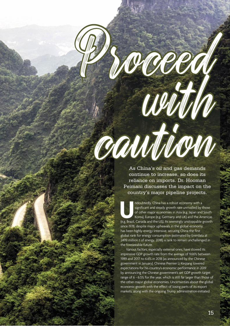
Proceed with
cautionAs China’s oil and gas demands continue to increase, so does its reliance on imports. Dr. Hooman
Peimani discusses the impact on the country’s major pipeline projects.
Undoubtedly, China has a robust economy with a significant and steady growth rate unrivalled by those of other major economies in Asia (e.g. Japan and South Korea), Europe (e.g. Germany and UK) and the Americas
(e.g. Brazil, Canada and the US). Its seemingly unstoppable growth since 1978, despite major upheavals in the global economy, has been highly energy-intensive, securing China the first global rank for energy consumption (estimated by Enerdata at 2499 million toe, 2018), a rank to remain unchallenged in the foreseeable future.
Various factors, especially external ones, have slowed its impressive GDP growth rate from the average of 9.66% between 1989 and 2017 to 6.6% in 2018 (as announced by the Chinese government in January). Chinese Premier Li Keqiang lowered expectations for his country’s economic performance in 2019 by announcing the Chinese government’s set GDP growth target range of 6 - 6.5% for the year, which is still far larger than those of the other major global economies. Uncertainties about the global economic growth with the effect of losing parts of its export markets, along with the ongoing Trump administration-initiated
14 15
35 71 87
REGIONAL REPORT: CHINA
14. Proceed with cautionAs China’s oil and gas demands continue to increase, so does its reliance on imports. Dr. Hooman Peimani discusses the impact on the country’s major pipeline projects.
KEYNOTE
19. Pipeline's got talentJames Leigh, ABN Resource, UK.
CATHODIC PROTECTION
24. The significance of samplesJoe Gallo Jr. and Christopher Todd Musgrave, Cathodic Protection Solutions LLC, USA.
29. Started from the bottomChristophe Baeté, Elsyca nv, Belgium, Len Krissa and Alfonso Garcia, Enbridge Pipelines Inc., Canada.
35. Preventing deteriorationSimon Dobson, Buckleys (UVRAL) Ltd, UK.
PIPELINE CONSTRUCTION EQUIPMENT
38. A history of weightMeghan Connors, President, PipeSak, Canada.
43. Erasing the clipboardRob Koot, Trimble, USA.
SECURITY SOFTWARE
49. A blockchain barracadeRoman Arutyunov, Xage Security, USA.
53. Analytical algorithmsMichael Barth and Michael Kasch, ILF, Germany.
ROVS & UNDERWATER INSPECTION
59. Subsea drones take flightJim Jamieson, i-Tech 7, UK.
63. Listening for movementStephen Auld, Sonardyne, UK.
ISOLATION & PIG TRACKING
66. Isolation and the turnaround timetableRolf Gunnar Lie, T.D. Williamson, Singapore.
WELD PREPARATION: BEVELLING & CUTTING
71. Preparation is paramountTony Hufford and David Jescovitch, Weiler Abrasives, USA.
75. The safest of repairsMark Leska, E.H. Wachs, USA.
JOINING TECHNOLOGIES
81. Feeling the grooveKevin Rizo, Victaulic, USA.
COVER STORY
83. Instantaneous imagesJeremy Guretzki, President, Stanley Inspection, USA.
COMPOSITE COATINGS
87. A triple threatHåvard Høydalsvik, Rädlinger primus line GmbH, Germany.
CORROSION PROTECTION
93. Taking the guesswork out of inspectionIan Macleod, Wood, UK.
NDT
95. CUI, C U LATERJohn Musgrave and Kelly Morris, MISTRAS Group, USA.
99. Tests upon testsDr. Basab Bhattacharya, Element Materials Technology, Singapore.
104. Getting to know...Sean McNally, PipeLine Machinery International.

All round ability
raises pipelayingto new heights
With its unique, 360° swinging upper structure, the Rotating Pipelayers from Volvo Construction Equipment
offers infinite pipe placement possibilities. With huge 50t, 96t and 110t tipping capacities, heavy duty tasks
such as offloading, lowering-in, tie-ins and feeding pipe-bending machines are well within its reach. The
PL3005E / PL4809E’s sure footed, excavator-based platform provides unshakeable stability on slopes up
to 35 degrees, pipelayer to excavator convertibility and ease of transportation with no disassembly required,
saving cost and minimizing productivity losses. Combined with advanced load management and telematics
systems and an elevating cab and two extra cameras to increase visibility; operational safety, productivity
and versatility are all raised to new heights. Find out how the Volvo PL3005E and PL4809E pipelayers offer
unrivalled performance across a variety of applications.
www.volvoce.com
VOLVO PL3005E AND PL4809E Rotating PIPELAYERS
JUNE 2019 / World Pipelines 3
CommentGuestGuest
STUART JORDAN Partner, Baker Botts
P ipeline construction is part of a wave of increasingly ambitious engineering projects, particularly deepwater offshore work, often in harsh conditions. In frontier projects like these, owner teams try harder
to place the risk of defects and failures onto contractors, with ever longer lists of requirements. For pipelines, these might include: exercise professional skill and care in the design; build with good workmanship; use new and suitable materials; apply ‘Good Engineering Practice’; ensure ‘fitness for purpose’ of the completed works; ensure a minimum ‘design life’; comply with an existing FEED (front-end engineering and design); comply with industry standards; and apply extensive testing and inspection procedures during construction.
Some obvious questions arise: Can these requirements somehow undermine each other such that a contractor might avoid liability? What is fitness for purpose? What is design life?
The English courts have examined these questions recently. MT Hojgaard A/S (MTH) vs E.ON Climate & Renewables (E.ON) looked at potentially conflicting EPC requirements. E.ON awarded a contract to MTH to design, manufacture and install foundations for offshore wind turbines.
Allowing for different wording, the contract contained all of the above-listed features, including:
) That MTH prepare the detailed design of the foundations in accordance with ‘J101’ (a published international standard for offshore foundation design).
) That the design of the foundations shall ensure a lifetime of 20 years in every aspect without planned replacement.
The introduction to the design basis stated:
) “It is stressed that the requirements contained in this section…are the minimum requirements of [E.ON] to be taken into account in the design. It shall be the responsibility of [MTH] to identify areas where the works need to be designed to any additional or more rigorous requirements or parameters.”
Unfortunately, J101 contained an error which overstated the strength of grouted connections in foundations by a factor of ten – which resulted in failures in the works.
MTH argued that the works specification had been complied with (by the use of professional skill and care, adherence to Good Industry Practice and compliance with J101) and that any 20 year warranty (if it existed) was impossible to achieve because of the error in J101. In other words: the specification, read as a whole, was in conflict with itself.
The court decided (referring to the design basis introduction, above) that “the more rigorous or demanding of
the two standards or requirements must prevail.” The Judgment cited a string of cases in which a contractor
was obliged to bring about a prescribed result even where this could not be achieved by the prescribed means – following all technical requirements. In these situations, the court said that a contractor is required to examine and improve the given requirements. Of course, that depends on the wording of the contract.
Another court decision has examined the concept of fitness for purpose (FFP). Although this project was also about offshore wind, the dispute was all about welding and weld scanning: both critical to pipeline EPCs.
In Fluor Limited vs Shanghai Zhenhua Heavy Industries (SZ), Fluor was an EPC contractor appointed to make and install foundations for 140 wind turbines. Fluor subcontracted the fabrication to SZ but did not impose the same ultrasonic weld scanning regime as was required under the EPC. Because of this, certain transverse cracks were not identified during production but were later found during re-scanning under the EPC, following which some monopiles were rejected by Fluor’s employer under the EPC and all welds had to be retested, with necessary repairs made.
Fluor sought to recover the cost of this from SZ, on the basis that the goods did not meet the subcontract requirement of FFP. SZ contended that the goods objectively met their FFP requirements because they would perform their function for the required life of 25 years. Fluor did not allege that the welds would actually fail but said that this is not the test of FFP.
The court agreed, saying that the standard requires the goods to be “in such an actual state that a buyer fully acquainted with the facts and, therefore, knowing what hidden defects exist and not being limited to their apparent condition, would buy them without abatement of the price obtainable for such goods if in reasonably sound order and condition and without special terms.” The goods did not meet FFP because Fluor would not purchase them without imposing “special terms” i.e. additional testing and repairs.
The impact of this decision is illustrated by the fact that these goods were held not to be compliant with the contract even though: they had passed testing under the subcontract; they had not failed; and there was no allegation that they would fail within the 25 year design life.
In these decisions, English law is confirming (of course depending on wording) that some essential EPC concepts mean what they say. Firstly, employers are entitled to rely on the expertise of EPC contractors to achieve, by whatever means necessary, a certain functional or performance outcome in works they design and construct. Secondly, FFP is not just the meeting of functional or performance requirements (or the absence of proof to the contrary) but can amount to an assurance that they have been met.

sidebooms.com I 918-858-4201
Midwestern’s NEW M100C sideboom attachment for John Deere’s 850L PL platform. 100,000 lb lifting capacity.
Accept No Imitations
CommentASSISTANT EDITORLydia [email protected]
Annual subscription £60 UK including postage/£75 overseas (postage airmail). Special two year discounted rate: £96 UK including postage/£120 overseas (postage airmail). Claims for non receipt of issues must be made within three months of publication of the issue or they will not be honoured without charge.
Applicable only to USA & Canada:World Pipelines (ISSN No: 1472-7390, USPS No: 020-988) is published monthly by Palladian Publications Ltd, GBR and distributed in the USA by Asendia USA, 17B S Middlesex Ave, Monroe NJ 08831. Periodicals postage paid New Brunswick, NJ and additional mailing offices. POSTMASTER: send address changes to World Pipelines, 701C Ashland Ave, Folcroft PA 19032
Palladian Publications Ltd, 15 South Street, Farnham, Surrey, GU9 7QU, ENGLANDTel: +44 (0) 1252 718 999 Fax: +44 (0) 1252 718 992 Website: www.worldpipelines.com Email: [email protected]
Approximately 7000 miles separates the US and China, but distance is no inconvenience for the trade war between these
two countries. With new tariffs being imposed at an escalating rate, the hostility and lack of negotiations is spreading to other countries, presenting a threat to global peace and economic stability.
The latest development in the US-China trade war concerns cyber security and technology, specifically the world’s second largest smartphone manufacturer: Huawei. Generally, the latest, smartest, fastest developments in tech are met with premium prices and queues at retail shop entrances. However the release of the fifth generation, or 5G, mobile phone has caused a worldwide commotion.
Simply, the involvement of Chinese 5G technology in countries other than China, is believed to pose a security risk. Last week, President Trump signed an executive order declaring a national emergency and preventing any US company from utilising foreign telecommunications equipment that could threaten the country. No specific telecoms companies were named but it is widely understood that the trade blacklist was aimed at Huawei.
The US is not alone in its concern. Australia has already banned any 5G involvement by Huawei, whilst Europe has been torn between the attractive tech prices and the risk to national security. Companies too are becoming involved; Panasonic has stopped supplying components to Huawei, joining the likes of Google and Intel in cutting all association with the conglomerate.
Very quickly, the trade war has escalated from US-imposed tariffs on over US$200 billion worth of Chinese goods and China’s retaliation of tariffs on US$110 billion of US goods, to a fear of espionage and sabotage by a Chinese telecoms giant. The items that have been tariffed range from LNG to soybeans, however, China has not imposed any tariff on US crude – though they have reduced the quantity of US oil imports.
It has been alleged that the oil and gas sector is the second most targeted
industry by cyberattacks, with breaches disrupting pipeline operations and releasing confidential information. Attacks can be motivated by numerous factors, with espionage between countries an increasing concern.
Pipeline cyber security has been widely criticised in the US, with companies and lawmakers urging the Transportation Security Administration to do more. In Europe, the story is different. Bulgartransgaz has recently been approved by the European Commission for two cyber security projects that will be funded under the Connecting Europe Facility, Telecommunications sector. This is a positive step, but with the rapid advancements made in the digital world, it
is surprising that energy companies are spending less than 0.2% of their revenue on protecting their assets from cyber threats.1
Whilst China and the US retaliate back and forth, they do agree on their fear of Russia’s dominance in the energy
industry and becoming over dependent on Russian supplies. China and Russia have been unsuccessful in their discussions to construct a pipeline transporting Russian gas to Chin; meanwhile, US Energy Secretary Rick Perry has expressed his disfavour for Russia’s Nord Stream 2 pipeline, suggesting sanctions should be imposed over concern that the pipeline would be used as a political weapon. However, Huawei has already begun construction of a 5G network in Russia, so maybe the common ground between the US and China regarding pipelines is limited to solely that.
Every step in the digital age is a step into the unknown; assets need to be protected as cyberattacks can be detrimental to people, the economy and the environment. It is promising that companies and countries alike are concerned that the widespread adoption of Huawei’s technology could be a risk to national security, but perhaps more attention needs also be focused on the oil and gas industry’s protection against the threats of cyberattack. 1. Digital Energy Journal, 2019, ‘The best way to mitigate
cyber threats.’
MANAGING EDITORJames [email protected]
EDITORIAL ASSISTANT Aimee [email protected]
SALES DIRECTORRod [email protected]
SALES MANAGERChris [email protected]
DEPUTY SALES MANAGERWill [email protected]
PRODUCTIONBethany Rees [email protected]
DIGITAL EDITORIAL ASSISTANTJohn [email protected]
DIGITAL EDITORIAL ASSISTANTNaomi [email protected]
ADMIN MANAGERLaura [email protected]
WEBSITE MANAGERTom [email protected]
A FEAR OF A FEAR OF ESPIONAGE ESPIONAGE
AND SABOTAGE AND SABOTAGE BY A CHINESE BY A CHINESE
TELECOMS TELECOMS GIANTGIANT
A TECH COLD WAR

A Division of STANLEY Oil & Gas I STANLEYInspection.com
The time is now for a real breakthrough in pipeline inspection.
Real-time digital imaging is the new standard in
pipeline inspection. NEXRAY is the new standard
in real-time digital imaging.
The NEXRAY real-time radiography system is made
up of two main components—a medical-grade
digital detector and an x-ray source—used to
generate inspection images digitally and deliver
real-time image output.
Engineered to inspect the integrity of girth welds,
NEXRAY is designed for onshore, offshore, spoolbase,
and tie-in use in both small-diameter and large-
diameter applications.

JUNE 2019 / World Pipelines 7
World NewsOffshore pipeline installation of Balticconnector starts
Pipeline installation of the offshore part of Balticconnector, the Estonian-Finnish gas interconnection, began on 20 May 2019. In 2018, all preparatory offshore works were completed, and the seabed was made ready for the pipeline to be installed.
All the offshore pipes – more than 6400 in number – with a total weight of 36 000 t, arrived in the Port of Paldiski from Greece. The ship installing the offshore pipeline, Lorelay, arrived in the Port of Paldiski on 16 May and sailed from there to the southside of Skämmö Island in Inkoo, Finland. The installation work of the pipeline began on 20 May and the pipeline installation will progress at a rate of 2 - 3 km/d towards Estonia. Pipe post-lay intervention work will begin in June and progress in parallel with pipelay operations. The installation work will be ready in July and after that the offshore pipeline will undergo pressure testing, after which it will be dried and connected to the onshore pipelines in Finland and Estonia.
“The offshore pipeline is a crucial part of the Balticconnector pipeline and we are happy to start the pipeline installation as planned”, said Tom Främling, Project Director of Baltic Connector Oy.
“It is a great pleasure to note that our project proceeds according to the schedule. Connecting the offshore pipe to the onshore pipelines in Finland and Estonia will intertwine all the project’s construction sites together and will mark the integration of Finnish
and Estonian gas markets. The completion of this phase of the project will ensure opening of the Balticconnector pipeline and consequently also the Finnish gas market at the beginning of 2020”, said Herkko Plit, President and CEO of Baltic Connector Oy.
“...I can assure that the goal Elering set up during acquiring the Estonian gas transmission network to launch the Finnish-Baltic gas market in 2020, will be met. That brings greater security of supply, more effective market and presumably better price for consumers,” said Taavi Veskimägi, Chairman of the Board and CEO of Elering AS.
The construction work of the Finnish onshore parts has progressed as planned. The onshore pipeline welding will be ready in June and mechanical completion will be in August. Inkoo compressor station construction works also progress as planned and mechanical completion will be also reached in August. Test runs with gas will start in September and the onshore parts in Finland will be ready for commercial operation in December 2019.
The construction of the Estonian onshore part of Balticconnector has proceeded on schedule and 92% of the welding work and 90% of the insulation work has been completed, and 34 km of pipeline has been trenched. The construction of Paldiski and Puiatu compressor stations has commenced. The current progress allows for the operation of the pipeline at a reduced capacity at the beginning of 2020.
Second environmental decision on project for Baltic Pipe
On 17 May 2019, the Regional Director for Environmental Protection in Szczecin (Poland) issued a decision on environmental conditions for the project to be developed by GAZ-SYSTEM: ‘Investment constituting the infrastructure necessary to service the international Baltic gas pipeline (Baltic Pipe) constituting a connection of transmission systems of the Republic of Poland and the Kingdom of Denmark – an onshore part’. It is one of the five component projects implemented under the Baltic Pipe in Poland.
The gas pipeline connecting the offshore pipeline with the National Transmission System will be approximately 85 - 90 km long, its nominal diameter will be 900 mm (the onshore gas pipeline from the line valve station in Niechorze to the receiving terminal) and its operating pressure will be 12 MPa and 8.4 MPa.
The construction of a gas pipeline connecting the offshore gas pipeline through the receiving terminal with the National Transmission System will allow gas to be received from Norway and ensure technical possibility of two-way gas transmission: 10 billion m3/y from Norway to Poland and 3 billion m3/y from Poland to Denmark. The implementation of this project will contribute to the optimisation of the capacity of the Polish transmission system and will constitute an important element of the North-South Gas Corridor.
This is the second environmental decision for the project under the Baltic Pipe Programme in Poland. The first decision was issued by the Regional Director for Environmental Protection in Gorzów Wielkopolski on 4 February 2019, for the project ‘Construction of the DN1000 Goleniów-Lwówek gas pipeline’.
NEB approves applications to abandon pipelines
The National Energy Board (NEB) has approved two applications to abandon the NEB-regulated parts of Exxon Mobil’s Sable Offshore Energy Project and Encana Corporation’s Deep Panuke Project. These projects, both located offshore Nova Scotia (Canada), had reached a stage of naturally declining production. The Sable Offshore Energy Project stopped producing natural gas in December 2018 and Deep Panuke ceased production in May 2018.
In its Reasons for Decisions, the NEB approved the plans to abandon the pipelines in place, saying that with appropriate mitigation, any potential environmental impacts could be minimised.
The NEB’s jurisdiction over pipelines continues after they are abandoned in place, and the NEB will hold ExxonMobil and Encana responsible for the safety and security of their infrastructure.
Under the NEB Act, the NEB must hold a public hearing to consider an application for Leave to Abandon a pipeline. Given that many of the potential concerns and issues were similar, the NEB considered both applications concurrently. During the hearings, the NEB gathered input from Indigenous groups, federal and provincial departments, industry, and local municipalities.
ExxonMobil applied on 29 March 2018 to abandon the NEB-regulated portions of the Sable Offshore Energy Project, including the Goldboro Gas Plant and the approximately 200 km long gathering pipeline. Encana applied to abandon the NEB-regulated Deep Panuke pipeline and associated onshore facilities, including a beach valve station, pipeline terminus site and access roads, on 19 June 2018. The Deep Panuke Pipeline runs approximately 175 km from an offshore production platform to an interconnection with the Maritimes and Northeast Pipeline facilities in Goldboro, Nova Scotia.
As this project falls under section 74 of the NEB Act, the NEB is the final decision maker.

8 World Pipelines / JUNE 2019
IN BRIEF World NewsNORWAYWintershall Dea has installed two subsea templates on the ocean floor in Norway, marking the first operational landmark for the newly merged global company. The installation unlocks the next phase of the field development, with 65 km of pipelines now ready to be laid in preparation for tie-back to the nearby Gjøa platform in the North Sea.
OMANWeir Oil & Gas has announced that it has been awarded a four-year contract with Oman Oil Company Exploration & Production (OOCEP) to provide wellhead equipment and services.
RUSSIANord Stream 2 AG has reported that its environmental conservation measures at the Russian landfall are showing early signs of success.
BULGARIABulgartransgaz has received approval from the European Commission for two project proposals in the field of cyber security which will be funded under the Connecting Europe Facility, Telecommunications Sector.
ITALYEni and Sonatrach have signed agreements to renew the gas supply contract to import Algerian gas into Italy until 2027, as well as defining the transportation arrangements through the pipeline crossing the Mediterranean Sea.
USAExxonMobil has said a new study estimates the company’s development of Permian Basin resources in New Mexico will generate approximately US$64 billion in net economic benefits for the state and local communities over the next 40 years.
API on the lifting of Section 232 on steel tariffs
API has released the following statement on the Administration’s decision to lift tariffs on steel and aluminium imports under Section 232 on Canada and Mexico:
“We applaud the Administration for reaching an agreement with Canada and Mexico to lift the 25% steel tariffs and not replace them with harmful quotas that would stifle US investment in manufacturing and energy infrastructure,” said Kyle Isakower, API Vice President for Economic and Regulatory Policy. “We look forward to reviewing the details of this important agreement, and commend the Administration for recognising the negative ripple effects the steel tariffs can have on long-term energy investments in America.”
“By lifting these burdensome tariffs and not replacing them with quotas, the Administration is enabling construction projects and the jobs that support them to move forward without fear of supply chain disruptions. The announcement is another step in enabling the long-term delivery of reliable, affordable American energy to families and businesses.”
Cisco and Snam MoU on digital training
Cisco, a provider of technology solutions for companies, and Snam, a European natural gas utility, have signed a Memorandum of Understanding (MoU) to develop joint research, development and innovation initiatives in the Industrial Internet of Things (IIoT) sector and train future generations of ‘digital’ professionals. The agreement was signed by Marco Alverà, CEO of Snam, Chuck Robbins, CEO of Cisco Inc. and Agostino Santoni, CEO of Cisco Italia, in the presence of Cosma Panzacchi, Snam Digital Transformation & Technology Executive Vice President.
The companies will work together to create innovative Internet of Things technology solutions for infrastructure (IIoT for networks) and provide training for workers and students to prepare them for the ‘digital’ professions of the future.
Cisco and Snam will potentially partner to develop smart 4.0 sensors that will optimise the monitoring and maintenance of infrastructures, state-of-the-art Fog Computing technologies and new connectivity systems aimed at making energy networks more intelligent and efficient. This will in turn generate positive impact for communities, allowing for the potential creation of new services related to the circular economy, environmental sustainability and safety.
With regards to training, companies will
promote digital and general development courses aimed at both the professional world and schools, with a particular focus on topics such as data science, artificial intelligence and robotics.
“Snam has a strong tradition of using technology to create a positive impact within the communities in which it operates. To support this commitment, Cisco is proud to work in partnership with Snam to enable its digital transformation, supporting the company in making its energy network increasingly sustainable, using cutting-edge technologies, IoT, 5G and artificial intelligence”, commented Chuck Robbins, CEO of Cisco.
Snam CEO, Marco Alverà, said: “This agreement marks a further step forward for Snam’s digital transformation process. Our goal is to seize the opportunities offered by new technologies to drive the energy transition, making our network increasingly intelligent, through IoT systems, machine learning and the use of drones, satellites and sensors to optimise infrastructure monitoring and management. Innovation is one of the key pillars of the Snamtec project, in which we will invest €850 million by 2022 to build an energy company of the future which is more digital, sustainable and closer to local communities”.
Tallgrass Energy announces open season for Pony Express pipeline expansion
Tallgrass Energy, LP, through its affiliate Tallgrass Pony Express Pipeline, LLC (Pony Express), has announced a new project to support crude oil production in northern Weld County, Colorado (USA), near the border between Wyoming and Colorado.
The Hereford Project will include approximately 30 miles of new 12 in. pipeline, as well as expanded capacity on the Pony Express system.
Sufficient interest arose during Pony Express’ existing open season for expansion capacity from origin points in Colorado and Wyoming to destinations along the system to justify the Hereford Project as a stand-alone project.
The new 30 mile pipeline, the Hereford Lateral, will connect crude oil gathering facilities and/or terminal facilities near Hereford, Colorado, with existing Pony Express facilities located near the Pawnee origin facility in Weld County. Pony Express expects the Hereford Lateral to be in service by July 2019, and the expansion capacity on the existing Pony Express system to be in service by May 2020 – both ahead of the larger Pony Express system expansion.

LOW TEMPERATURE CURE
SP-2831®
0°C (32°F)&
ANNOUNCING SP-2810
-10°C (14°F)
HDD & ARO
SP-2888®R.G. &
SP-9888® HARC
TO LEARN MORE ABOUT SPC’S SOLUTIONS,
PLEASE CONTACT:
CAN: 1.604.514.9711USA: 1.281.595.3530
WWW.SPC-NET.COM
PROTECT YOUR ASSETS
TRUST THE WORLD LEADER IN SPECIALTY COATINGS
Specialty Polymer Coatings (SPC) is a leading formulator, manufacturer and distributor of “state of the art” 100% solids liquid epoxy and polyurethane coatings. SPC has a broad line of coating solutions which are utilized extensively in the pipeline industry, on railway cars, lining for tanks and steel structures as well as marine docks, ship decks, hulls and other aqueous applications. SPC promotes environmentally sound practices with the majority of products being VOC free. SPC’s high performance coating products are manufactured to the highest quality standards and are available
applications.

10 World Pipelines / JUNE 2019
EVENTS DIARYWorld News
➤ Over 87% of Trans Adriatic Pipeline complete
➤ Rovco awarded suite of HSEQ certifi cations
➤ Buckeye Partners, L.P. agrees to be acquired by IFM investors
➤ SemCAMS Midstream and Keyera to build Canadian liquids pipeline system
To read more about the articles go towww.worldpipelines.com
Web Highlights
Approval for EUGAL pipeline compressor station
The State Office for the Environment Brandenburg has completed the approval process for the Radeland 2 compressor station in Baruth/Mark (Germany). The approved facility is part of the infrastructure of the European Gas Lines (EUGAL). The Radeland 2 compressor station was requested and approved in a stand-alone procedure.
On 6 February 2019, the company GASCADE Gastransport GmbH as a developer received a permit for an early start of construction. The permit covers, among other things, the clearing of trees on the site of the future Radeland 2 compressor station, earthworks and foundations, and the erection of a site for assembly.
The Radeland 2 compressor station comprises three compressors and a gas pressure regulating and measuring system. In addition, the station will be connected to the Yamal gas connection line (JAGAL). The completion of the Radeland 2 compressor station is scheduled for the end of 2020.
Compressor stations are an important element in the pipeline network. From source to consumer, natural gas travels many kilometres and loses pressure. This loss must be compensated – compressor stations increase the natural gas pressure and continue to ‘pump’ the gas.
11 - 13 June 2019
Global Petroleum Show 2019
Calgary, Canadahttps://globalpetroleumshow.com/
18 - 19 June 2019
Integrity 2019
An online conference from World Pipelineshttps://www.worldpipelines.com/integrity/
15 - 17 July 2019
Energy Pipeline Management
Summit
New Orleans, USAhttps://events.marcusevans-events.com/energypipelinepipeline-19/
3 - 6 September 2019
Offshore Europe
Aberdeen, UKhttps://www.offshore-europe.co.uk/
17 - 19 September 2019
GASTECH 2019
Houston, USAhttps://www.gastechevent.com/
30 September - 4 October 2019
IPLOCA Convention
Bangkok, Thailandhttp://www.iploca.com
11 - 14 November 2019
ADIPEC 2019
Abu Dhabi, UAEhttps://www.adipec.com/
Pipelay in Russian waters for Nord Stream 2
Pipelay vessel Solitaire has started laying the first line of the Nord Stream 2 twin gas pipeline in Russian waters. Solitaire will spend about a month constructing one of the two approximately 100 km long sections in the Russian territorial sea.
Solitaire, operated by Allseas, is a 300 m long and 41 m wide dynamically positioned vessel that will lay pipes around the clock seven days a week. It accommodates up to 420 people on board. A vessel that is positioned using thrusters instead of anchors helps to minimise the impact on the environment and marine traffic, as only the pipeline itself touches the seabed along the pipeline route.
The activities are performed in accordance with the national permits granted by responsible authorities. During operations, a safety zone of 1.85 km (1 nautical mile) is applied around the working vessel.
Pipe supply vessels will deliver the 12 m, 24 t concrete weight coated steel pipes from the project’s nearest logistics hub in Kotka, Finland.
Construction works are proceeding well and according to plans also at the Russian and German landfalls – the entry and exit points of the pipeline system. Furthermore, offshore pipelay is ongoing in the Swedish exclusive economic zone by Pioneering Spirit. Over 1100 km of the Nord Stream 2 pipeline have been laid in total so far.
Nord Stream 2 AG: public consultation process for third route begins in Denmark
The Environmental Impact Assessment (EIA) report for the route of the Nord Stream 2 AG natural gas offshore pipeline to the south-east of Bornholm has been made available for public display by the co-ordinating authority, the Danish Energy Agency (DEA). This route passes outside Danish territorial waters and stretches within the exclusive economic zone (EEZ) of Denmark.
The EIA is based on detailed environmental research conducted along the pipeline route where the pipeline is planned to be constructed. The comprehensive report describes the main characteristics and technical solutions of the planned pipeline system, as well as detailed assessments of potential impacts on the physio-chemical, biological and socio-economic environment in the Danish sector. The EIA also includes an assessment of potential transboundary impacts which may arise from activities to be carried out in Denmark, and identifies measures to prevent and mitigate potential adverse environmental impacts.
Organisations and the public are invited to provide comments or raise their questions on the filed EIA report to the DEA until 10 July.
PROTAL™ SPRAY GRADEEPOXY
TANK LININGS & COATINGS
BITUMEN & BUTYL TAPES
PETROLATUM TAPE SYSTEMS
PROTAL 7200™ROLLER/BRUSH APPLIED LIQUID EPOXY COATING
FOR CORROSION PREVENTION
DENSO® are leaders in corrosion prevention and sealing technology. With over 135 year’s service to
offer reliable and cost effective protection for buried pipelines worldwide.
United Kingdom, UAE & IndiaUSA & CanadaAustralia & New ZealandRepublic of South Africa
www.denso.netwww.densona.comwww.densoaustralia.com.auwww.denso.co.za
SELF-REPAIRING SHRINK SLEEVES
A MEMBER OF WINN & COALES INTERNATIONAL
OPTIMUM PROTECTION FOR WELDED PIPELINE JOINTS
PREMIER SHRINK SLEEVES™ offer self-repairing technology in the event

12 World Pipelines / JUNE 2019
Jemena appoints Atlas Gas Pipeline construction partner
Jemena has announced it has appointed Spiecapag Australia to construct a 60 km pipeline, which forms part of Jemena’s AUS$140 million Atlas Gas Pipeline Project, in south-west Queensland.
Jemena’s Atlas Gas Pipeline Project Director, Mark Turner, said Spiecapag was selected following a competitive tender process in 1Q19. “Spiecapag has a proven record in constructing complex pipelines in regional Queensland, and brings to the table an exceptional understanding of the local terrain and environment,” said Mr Turner.
“Spiecapag’s performance as Jemena’s Queensland construction partner on the AUS$800 million Northern Gas Pipeline in 2018 means we have every confidence that they are the right team to help us deliver this project on time and on budget.”
Mr Turner said Spiecapag will join Jemena at a series of information sessions in Roma, Miles, and Wandoan where it will outline business and other opportunities associated with the construction of the Atlas Gas Pipeline.
“In its entirety, we expect the construction of the Atlas Gas Pipeline Project will create between 150 to 200 jobs.”
Jemena was awarded the right to build, own, and operate the Atlas Gas Pipeline Project by Senex Energy in 2018. The Atlas acreage is the first of 13 acreages awarded by the Queensland government, with all gas from the project ear-marked for the domestic market.
The Atlas Gas Pipeline will span 60 km from Senex Energy’s Atlas acreage, south-west of Wandoan, to Jemena’s Darling Downs Pipeline, near Yuleba.
The project also includes a compressor station, currently under construction by Valmec, approximately 20 km from Wandoan.
Once completed by the end of 2019, the Atlas Gas Pipeline will have the capacity to transport 40 TJ/d of gas.
Cortez Subsea awarded contract for subsea pipeline
Subsea services company and technology enabler, Cortez Subsea, has more than doubled its team across Aberdeen and Kuala Lumpur (KL) after being awarded a contract to lay the first ever subsea pipeline using mechanical connectors offshore Malaysia.
The work will be jointly executed with Alam Maritim Resources Berhad under its consortium agreement with Cortez which will deliver the engineering, procurement and operational activities from its office in KL.
The pipeline system is for the Tembikai Non-Associated Gas (TNAG) development by Vestigo Petroleum and uses the National Oilwell Varco (NOV)-Tuboscope Zap-LokTM connectors which will be joined to the rigid pipeline using diverless connections.
Alasdair Cowie, Managing Director of Cortez Subsea, said: “We pioneer the latest developments to support our clients with ingenious technology and in-depth knowledge.
“The Zap-Lok technology is proven with more than 7000 km of subsea hydrocarbon pipelines installed worldwide and zero
recorded failures in operation of over 70 000 joints. It is also approved by Lloyds Register and Bureau Veritas for hydrocarbons.
“We form genuine partnerships and co-operate to support and lead the development of services, to conquer new and innovative subsea frontiers and deliver projects which are safer, cheaper and reduce our carbon footprint.
“The future is bright for Cortez and its partners. We have been working with NOV-Tuboscope to deliver the Zap-Lok mechanical connector into the Malaysian offshore market for several years. We are delighted that our partnership with Alam Maritim enables us to deliver this project in Malaysia, and we look forward to working together further in the future.
“We are also delighted to welcome so many new faces to the company and will continue to bolster our team in Aberdeen and at our locations around the globe as we accomplish our ambitious growth plan for subsea pipeline technology.”
Contract NewsCorinth Pipeworks awarded pipe work for the Midia gas project
Corinth Pipeworks (CPW) was selected to manufacture and supply 8 in. steel pipes for the in-field line and 16 in. steel pipes for the offshore gas transport pipeline. The pipes will be manufactured during 2019 in CPW’s factory in Greece, and installation work will commence according to schedule in 2020. CPW’s scope of supply also includes external 3LPE anti-corrosion coating and concrete weight coating applied at the same location as pipe manufacturing in Thisvi, Greece.
The Midia Gas Development project (MGD) comprises the Ana and Doina gas fields (estimated reserves 320 billion ft3) discovered in 2007 and 1995 respectively, 120 km off the Romanian coast, in 70 m of water.
The XV Midia shallow block is owned by a joint venture of Black Sea Oil & Gas (65%, operator), Petro Ventures Resources (20%), and Gas Plus International (15%). Black Sea Oil & Gas is a subsidiary of Carlyle International Energy Partners.
Final investment decision (FID) along with commencement of construction of the project was announced in February 2019. The MGD project will be developed with an estimated investment of US$400 million. It is expected to be commissioned by early 2021 and produce 1 billion m3/y of gas, which represents 10% of Romania’s consumption.
The field development plan for the MGD project includes drilling of five production wells, including one at Doina field and four at the Ana field, and installation of a subsea production system at the Doina field.
The subsea gas production system will be tied-back to an unmanned production platform installed at the Ana field through an 18 km long pipeline. A 121 km long gas pipeline will transport gas from the Ana platform to an onshore location. A 4.1 km underground pipeline will deliver the gas transported by the pipeline to a new gas treatment plant (GTP).
The processed gas will be delivered into the NTS operated by Transgaz at the gas metering station to be found within the GTP.

CRC-Evans.com
Outperform vacuum lifts with the DECKHAND® Pipe Handling System by LaValley Industries.
Securely grip pipe in even the most challenging positions.
Easily handle pipe covered in mud, snow, or ice— even pipe fully submerged in water.
adjust to any condition.
with DECKHAND.

14
Proceed with
cautionProceed
with caution
As China’s oil and gas demands continue to increase, so does its reliance on imports. Dr. Hooman
Peimani discusses the impact on the country’s major pipeline projects.
Undoubtedly, China has a robust economy with a significant and steady growth rate unrivalled by those of other major economies in Asia (e.g. Japan and South Korea), Europe (e.g. Germany and UK) and the Americas
(e.g. Brazil, Canada and the US). Its seemingly unstoppable growth since 1978, despite major upheavals in the global economy, has been highly energy-intensive, securing China the first global rank for energy consumption (estimated by Enerdata at 2499 million t of energy, 2018), a rank to remain unchallenged in the foreseeable future.
Various factors, especially external ones, have slowed its impressive GDP growth rate from the average of 9.66% between 1989 and 2017, to 6.6% in 2018 (as announced by the Chinese government in January). Chinese Premier Li Keqiang lowered expectations for his country’s economic performance in 2019 by announcing the Chinese government’s set GDP growth target range of 6 - 6.5% for the year, which is still far larger than those of the other major global economies. Uncertainties about the global economic growth with the effect of losing parts of its export markets, along with the ongoing Trump administration-initiated
15
trade war with its restrictive impact on China’s exports, have contributed to such a modest target rate by Chinese standards. Given the government’s set target for 2018 of “about 6.5%” proved to be correct, the country’s actual economic growth in 2019 will likely be within the targeted range, should the current situation continue.
Growing energy requirementsWhile the lowering of China’s economic growth rate since 2017 has certainly reduced its energy demand from the expected one, the continuity of such growth at impressive rates has resulted in its growing demand for energy. As reported by Gazprom in February, China became the world’s largest natural gas importer in 2018 when its gas imports totalled 125.7 billion m3, registering a 31% increase (30.3 billion m3) against 2017. The country’s oil and gas demands are expected to further increase in 2019 because of its growing economy and its population’s improving living standards. China’s oil demand in 2019, for example, is estimated to increase by 400 000 bpd from 2018, according to ESAI Energy’s latest China Watch.
Yet there is an additional reason behind its growing gas imports, namely President Xi Jinping’s policy of curbing air pollution caused mainly, but not exclusively, by China’s phenomenal consumption of coal for power generation and heating. Especially since Xi Jinping’s election in 2013, China has aggressively pursued a policy of replacing coal with natural gas as a less pollutive fuel especially for power generation, adding to the expansion of renewable and nuclear energy sectors started in the preceding decade. For example, as reported by Reuters, China shifted an additional three million more homes this winter to gas to create “an additional 4.53 billion m3 of demand during the 15 November 2018 - 16 March 2019 winter heating period”. Consequently, China’s gas demand will continue to increase in the near future even if its overall energy demand does not.
China’s dependency on imports has been increasing despite its efforts to raise its domestic oil and gas production. As well as maximising their conventional oil and gas production, the Chinese have embarked on a range of projects to expand their unconventional oil and gas production, such as shale gas and coal-bed methane as well as bioenergy (e.g. biofuels and biogas). Nevertheless, their domestic production is far below the country’s consumption, making large imports of oil and gas a necessity so long as fossil energy accounts for the bulk of China’s demand.
Holding backHowever, due to certain reasons, growing oil and gas imports will not necessarily be translated into many pipeline projects. Chief among them are concerns about overdependency on a small number of suppliers, supply routes and means of receiving supplies to make the Chinese economy vulnerable to external developments over which the government has no control – which could impact the country’s economic development.
To avoid this scenario, China has been importing a large portion of its oil demand by sea tankers from a wide range of suppliers in the Asia-Pacific region, the Persian Gulf and Latin America. This is in addition to piped imports from Kazakhstan
(Kazakhstan-China crude oil pipeline, 2789 km, 32 in.), Russia (Skovorodino-Daqing, 1030 km, 26 in.; Mohe-Daqing pipeline, 932.1 km, 32 in.) and Myanmar (China-Myanmar oil pipeline, 771 km, 32 in.).
This risk aversion policy has become evident in China’s gas imports, now divided between piped gas and LNG. Surpassing Japan to become the world’s largest gas importer and third largest gas consumer only after the US and Japan in 2018, China now meets approximately 40% of its gas requirements via imports. According to China National Offshore Oil Corp. (CNOOC) Vice President Li Hui, China’s gas imports will continue to grow to approximately 57 billion m3 and 63 billion m3 in 2019 and 2020, respectively. China’s LNG imports increased phenomenally in 2018 to exceed that of South Korea as the world’s second largest LNG importer, but still behind Japan, which relies on LNG imports for 100% of its gas requirements. In January, according to China’s General Administration of Customs, China’s LNG imports rose 27.8% from a year earlier to 6.58 million t, while its total gas imports (LNG and piped) increased by 26.8% from the previous year to 9.81 million t – making LNG its main type of gas import.
The main factors responsible for this development reflect China’s fear of overdependency on a few piped gas suppliers with proven or potential unreliability. For this reason, China’s concern about heavy dependency on the Central Asian gas suppliers, particularly Turkmenistan, prompted it to put an indefinite stop to the construction of Line D, the last remaining segment of the Central Asian Gas Pipeline system (CAGP), designed to increase the system’s realised nominal capacity of 55 billion m3/y by an additional 30 billion m3/y. As its undertaker, China National Petroleum Corp. (CNPC) cited “frequent equipment failures” in Turkmenistan as the major reason for its questioning the wisdom of increasing China’s dependency on Turkmen gas, and thereby the long-term reliability of the pipeline system as its major means of gas imports. As a result, the three operating CAGP lines (Lines A, B and C) supplied 46.9 billion m3 of gas in 2018 as of 20 December, according to CNPC – well below the pipeline system’s capacity. Problems in Myanmar also prevented the China-Myanmar Gas Pipeline from reaching its capacity of 12 billion m3/y as reflected in its actual delivery of 3.1 billion m3 in 2018, approximately a quarter of its capacity, as announced by CNPC.
Perhaps China’s fear of overdependency on Russia for piped gas, with its similar possibility, has so far discouraged Beijing from concluding an agreement for the construction of the West Route Gas Pipeline (WRGP), over which it has been negotiating with Russia since 2015. The latter is meant to increase China’s gas imports from Russia by 30 billion m3/y, beginning in December 2019 when the under-construction East Route Gas Pipeline (38 billion m3/y) is set to go online.
While China is still looking for more piped gas imports, demonstrated by the expression of its interest in a spur of the under-construction Turkmenistan-Afghanistan-Pakistan-India gas pipeline (TAPI), it has increased its LNG imports, which could be supplied by alternative suppliers to its current major ones (Australia, Qatar and Malaysia).
However, LNG’s prominence is not expected to last long, for various reasons: primarily, its higher cost compared to piped
16 World Pipelines / JUNE 2019


gas (even though the abundance of gas and large number of LNG suppliers have drastically decreased LNG prices) added to the high cost of its respective infrastructure for storage and regasification. Consequently, piped gas will eventually lead China’s gas imports, as noted by China’s largest LNG buyer CNOOC, which in April warned that the country’s LNG imports would grow much slower than its piped imports over the next 12 years. Against this background, China’s few ongoing major pipeline projects are discussed.
East Route Gas Pipeline (ERGS)The construction of the joint venture of CNPC and Gazprom has been progressing well, as its two separate Russian (Power of Siberia) and Chinese pipeline systems – to be connected at a border point – are nearing completion. As announced by Alexey Miller (Chairman of the Gazprom Management Committee) during his February meeting in Beijing with Wang Yilin (Chairman of the Board of Directors of CNPC), the Power of Siberia’s construction was going “ahead of schedule, and Gazprom will start delivering gas to China well in advance, as early as 1 December 2019” instead of the previously agreed date of 20 December 2019.
This was followed by Gazprom’s announcement in March that the Russian system was 99% complete, while that of China was “nearing completion”. The two underwater tunnels to connect the two systems (each 1139 m) were completed and “passed acceptance checks” in that month. As reported by news agency Xinhua, the tunnels passing through the Heilongjiang River along the Sino-Russian border connect Heihe in northeast China’s Heilongjiang Province and Blagoveshchensk in Russia.
The ERGS is part of Russia’s largest energy deal (US$400 billion) made in 2014. Strengthening Russia’s foothold on the Chinese energy market – along with its associated positive impact on Sino-Russian relations – aside, the pipeline’s importance lies in its decreasing China’s dependency on more expensive LNG imports.
The construction of the Russian and Chinese sections of the ERGS for exporting 38 billion m3/y of Russian gas to China for 30 years started on 1 September 2014 in Yakutsk and on 30 June 2015 near Heihe in China’s northern province of Heilongjiang bordering Russia, respectively.
The Russian section will be constructed in three phases, consisting of a pipeline (approximately 2200 km) from the Chayandinskoye field (Yakutia) to Blagoveshchensk (Chinese border) to be completed in its ongoing first phase. Its second phase includes the construction of a section stretching for approximately 800 km from the Kovyktinskoye field (Irkutsk Region) to the Chayandinskoye field. The third stage provides for expanding gas transmission capacities between the Chayandinskoye field and Blagoveshchensk (1000 km). Gas exports will begin after the completion of the first two phases, and the 3000 km pipeline has been tested.
With northern, southern and central sections, the Chinese section consists of a 3170 km pipeline, auxiliary underground gas storage and an existing 1800 km pipeline passing through six Chinese provinces (Heilongjiang, Jilin, Liaoning, Hebei, Shandong and Jiangsu), the Inner Mongolia Autonomous Region, Tianjin and Shanghai.
Ethiopia-Djibouti natural gas pipelineThe Ethiopia Ministry of Mines and Petroleum (MoMP) announced on 16 February that Chinese firm Poly-GCL Petroleum Group Holdings Limited (Poly-GCL) would construct the 767 km Ethiopia-Djibouti natural gas pipeline this year. Planned to be completed in two years, the pipeline – of which 700 km will be laid in landlocked Ethiopia – is the necessary means for transferring oil from Ethiopia’s eastern Ogaden Basin to a Djibouti export terminal on the Red Sea, to make US$1 billion/y from oil and gas exports over an unspecified period of time.
The Chinese company, which discovered an estimated 6 - 8 trillion ft3 of natural gas in Ethiopia’s eastern part, is reportedly a subsidiary of Golden Concord Group Limited – a Hong Kong based diversified energy conglomerate that specialises in a range of activities from green energy generation to downstream activities.
Poly-GCL signed a Memorandum of Understanding with Djibouti in 2018 to invest US$4 billion to build the pipeline, a liquefaction plant and an export terminal in Damerjog, near the country’s border with Somalia.
The project demonstrates China’s growing presence in Africa, which is a strategically important continent for China due to its resources, including energy, and markets where China’s engagement is welcome. In particular, it signifies China’s expanding involvement in energy projects overseas, not only for their obvious financial rewards, but also for their giving China access to oil and gas reserves to feed its growing energy demands.
West Route Gas Pipeline (WRGP)The fate of the project for exporting 30 billion m3/y of Russian gas to China, which was discussed and received preliminary interest from China in 2015, is still unknown. Despite China’s need for more imported gas, the two countries have since negotiated without signing any agreement for its construction – because of China’s non-committal approach. The contributing reasons include concerns about overdependency on Russia, which could be used by Moscow for extracting concessions in different fields. Russia’s use of its piped gas exports to and via Ukraine for such a purpose justifies Beijing’s concern, although its repetition is highly unlikely in the case of Russia’s ties with China as a strong rising superpower.
Uncertainties over the extent of China’s additional gas requirements in the long-term is another argument, justified by its lowering economic growth and exportable goods for various reasons – such as its trade disputes with the US, the shrinking markets of Europe and a range of sanctions on its non-Western rich trade partners such as Iran and Venezuela.
Gazprom’s Chairman, Alexey Miller, raised the project in the company’s February meeting with its CNPC counterpart without any apparent result. Yet, the project’s realisation in another form could be possible due to its offering a cheaper alternative to China’s large, growing, and costly LNG imports when a much shorter route than its envisaged 2800 km one is available. During the 12 September 2018 meeting of the Eastern Economic Forum (EEF) in Vladivostok, in which China, Japan, South Korea and Mongolia participated, Mongolian President Khaltmaa Battulga proposed that Russia build a natural gas pipeline to China via Mongolia – as part of Mongolia’s trilateral Economic Corridor policy. The proposal, which received President Putin’s positive reaction, is yet to be accepted by China.
18 World Pipelines / JUNE 2019

Pipeline’s got
James Leigh, ABN Resource, UK, considers the skills gap in the
pipeline industry and how a better understanding of young professionals
can help tackle this problem.
There has been much discussion in the pipeline market and in the oil industry as a whole about how severe the skills shortage really is and how we should resolve it. Some argue that the problem
lies not with us struggling to attract young people into the industry, but rather with us failing to upskill the current young professionals we already have.
TALENT 19
As an experienced Recruitment Director in the pipeline sector, I make it a priority to understand the trends and issues the market faces. Following on from numerous conversations with individuals at all stages of their careers, it became apparent to me that there was a need to look into how we can better understand young professionals, in order to secure a better future in the pipeline industry.
As a result, over the last year, ABN Resource commissioned a series of interviews with various young professionals from organisations such as the YPPE, YPAC and YPP USA, along with a survey of young professionals in our global network, to really understand what challenges young pipeline professionals are facing right now, how they feel about working in the industry and how they think we could better attract new talent. The results shed light on some important findings on attraction and retention.
Initial attraction: how did they get here? It may not be surprising to find that the majority of the young professionals told us they came into the industry via recommendation from a family member or friend. It is a familiar story. What is surprising though, is that of everyone we surveyed and spoke to, not one young professional said they gained an interest in the pipeline sector from school age. This highlights an important point around gaining awareness from young people much earlier, rather than relying on referrals from those already working in the industry – something which is even more pressing as the older generation reach closer to retirement.
But how do we do this? The obvious answer is for companies to invest in engagement strategies with educational institutions – schools, colleges, universities – to help spark interest in pipeline careers much sooner. I see a real opportunity for the industry to provide learning materials to help teach young people just how essential pipelines are to everyday life. The current global teaching system seems to largely focus on renewable energy sources like solar and wind power, but we need to ensure we are getting across the entire energy system as it is today – pipelines included.
Other educational investments include implementing community engagement programmes which drive awareness in young people from local communities. T.D. Williamson is a great example of a company that does this well, through its STEM activities. The company invites kids to work with its engineers on a brief, in order to build a robot to compete in a Lego® league – a fun and effective way of building interest early.
Attracting the next generation through social media Another focus of the research was to find out what young pipeliners thought the industry could do better to attract new recruits. Improved use of social media came out on top (with 58% of the overall vote) – not that surprising from an audience who have grown up with technology as an integral part of their lives.
However, they have a point – more often than not, young people now look to social media to get a sense of what a company is like to work at. If you compare the social media channels of rival industries (like tech) with some of our pipeline companies, it is clear which would appear more attractive to a new job seeker.
Whilst we may not be an industry that has an abundance of fancy nap pods (Google) or out of the box office spaces, what we can showcase is the innovative work and technology we create and its importance in everyday lives. The industry is also very collaborative in nature with a great community, offering many long-term career opportunities – all of which can be turned into attractive social media content.
Your choice of channel matters too. Focusing on LinkedIn (whilst an important hiring tool) is not enough – we need to be on the platforms where young people are, which includes the likes of Youtube and Instagram.
I asked Henri Tausch – Senior Vice President of Corporate Development & Solutions at Shawcor – to weigh in on our results, and he added “The new workforce processes data differently than the previous generation. There is a lot more data available at their fingertips, so to get attention from this generation, the information has to be quick and easy and to the point. Social media is the means of communication now.”
Changing perceptions It is also time we became more confident at promoting the positives of the pipeline industry. Why? A 2016 study showed that 64% of millennials will not even consider a job from a company that does not have strong Corporate Social Responsibility practices – so there is a solid case for changing perceptions to attract new talent.
We know the industry faces strong public opposition, blamed for rising emissions and global warming, but we have plenty of positives and progress we can talk about. As Henri Tausch added, “The energy industry is seen by many as a dirty industry...companies like British Petroleum (now Beyond Petroleum) and StatOil (now Equinor) have changed their name to avoid this negative perception. In reality, the industry has evolved exponentially over the last few decades with regards to emissions, safety and the environment. Also, there is a misconception that oil or gas is only used for power generation or as a fuel for transportation. Often, it is forgotten that carbohydrates are needed for many products in our society, not only for plastics, but also for medical treatment, electronic components, composites etc. – many things that we use on a daily basis.”
In my interview with Molly Laughlin Doran, founding member of YPP USA, these sentiments were echoed further as she explained to me how the industry often takes the ‘out of sight, out of mind’ approach due to the opposition the industry faces – meaning we do not get the chance to present the positives. As Molly added, “Once someone actually enters the industry they can really see the opportunities and the work that pipeline companies
20 World Pipelines / JUNE 2019

INTERNALBENDER
WELCOME TO THE (B) ENDGAME
QUALITYRELIABILITYFLEXIBILITY
MAATS PIPELINE PROFESSIONALS
P.O. BOX 165 | 7470 AD GOOR, THE NETHERLANDST +31 547 260 000 F +31 547 261 000E [email protected] I MAATS.COM
QualityReliabilityFlexibility
MAATS PIPELINE PROFESSIONALSP.O. Box 165 | 7470 AD Goor, the NetherlandsT + 31 547 260 000 F + 31 547 261 000E [email protected] I maats.com
RENTAL
SALES

are doing to try be safer, reliant and green. You understand what a great community it is and what a secure industry it is to be in for your long-term career. However, often from the outside looking in, when you don’t know the whole truth, there are concerns which prevent people entering the pipeline industry.”
It is not just perceptions of the industry’s image either; many see the pipeline sector as a career only for scientists or engineers. There is an opportunity to broaden understanding of the many career paths available to new professionals – including HR, Marketing, IT and other disciplines spread throughout the industry. And, as we look to the future, completely new career opportunities will arise around blockchain technology, automation, etc.
Retaining the talent – a matter of personal developmentI found it interesting that when asked what keeps them interested in pursuing a career in the pipeline industry, 50% of our survey respondents said it was the investment in their personal development which has played the biggest role.
It is clear that personal development can no longer be viewed as an unnecessary expense. Whether you are a large or small business (it is now expected for companies to factor in employee improvement strategies in the workplace), employees need to feel invested in.
Successful personal development strategies can include: offering training opportunities throughout employment (not just in the initial years); giving a clear career path and framework; the use of mentorship programmes to encourage critical thinking; and even factoring in creative downtime to allow employees autonomy to work on side projects for the business, outside of their core responsibilities.
Understanding frustrationsRetaining talent is not just limited to what employees value, it is also about looking at the fears and frustrations they face. When asked about their biggest frustrations, it was actually poor leadership which was cited as the most frustrating issue for young professionals in the industry. It makes sense. At a time where there is fear of a skills gap, young professionals need strong leaders to guide them through. Unfortunately, the talent shortage can often prevent our senior professionals from giving the time to lead, due to their own overflowing workloads.
I asked Mike Kirkwood, Director of Integrity Engineering at T.D. Williamson, for his thoughts. Mike explained “I would say that the comment on ‘poor leadership’ seems a little harsh but not surprising. I feel that the industry is changing, I remember when I was a young engineer, ‘leadership’ was a term confused with ‘management,’ very akin to following rules rather than the developing, challenging and mentoring
IPLOCA - Promoting environmentally friendly pipeline construction
Visit www.iploca.com to find out more
53rd IPLOCA Annual Convention:
30 September to 4 October 2019,
Bangkok, Thailand
Make plans now to meet with key players in the international onshore and offshore pipeline construction industry.
International Pipe Line & Offshore
Contractors Association
Geneva - Switzerland

that we strive to achieve in these times of true leadership. It may be that we have lost a generation and are seen as ‘old school’ in terms of leadership, but my own view is that we are catching up, and fast. Our generation loss may have resulted from more interesting careers in the fast-paced world of finance, information technology, software, high-tech products, etc. which, compared with ‘dirty old oil and gas,’ may not have looked as attractive and hence new leadership blood may have bypassed us. This may be the view looking in from the outside, but my own view is that we have had to change to attract new talent. Clearly now the necessities of our young engineers are recognised and I personally embrace this challenge.”
So how can we ensure we have strong leaders in place? Good leadership comes from knowing how to delegate work, showing trust in young employees, and not being afraid to play both the teacher and the student by understanding that young professionals can bring their own useful insights. Also, not being afraid to adapt. Sticking to old ways ‘just because we’ve always done it that way’ tends not to move a company or its people forward. Finally, being able to handle stress and keep calm even in the face of adversity is key.
Look at your company structure – do you have strong leaders in place that tick all of the above and are they finding the time to lead young professionals alongside their other work?
The biggest fears When we posed the question: What is your biggest concern of working in the industry? Our young professionals’ most prolific answers were around the skills shortage and career longevity.
For tackling career longevity concerns I believe transparency is key here. Companies should provide greater transparency on their plans for the future – especially around succession planning, hiring and future ambitions. On top of this, introducing a clear career path and framework will also help to reinforce trust in the business and their own future within the pipeline sector.
With the skill shortage, we know that many senior experienced colleagues have less time to provide guidance and transfer knowledge to the younger members of staff. However, as an industry, we have to push for this knowledge transfer – providing mentorship opportunities and knowledge resources where young professionals can look for answers.
Providing better supportWhen asked how pipeline companies could better support and retain their employees, the vote was clear: more recognition for the work young pipeliners do. This ties into the previous insight around the lack of good leadership. A great leader knows to give praise where praise is due, and will show their appreciation for staff regularly – boosting morale and motivation in the process.
I recently spoke to ENTEGRA President Mark Olson about this and he explained that he had previously been
quite cynical towards giving ‘participation awards’ or giving recognition for ‘simply doing your job’ – especially since he is an extremely self-motivated person himself. However, once he further learned about motivating young people and teams he realised he needed to change this attitude. As a manager, his number one priority is the success of his team, so if giving some simple recognition motivates them then it is a (cost free) no brainer.
Second to requiring more recognition, actually involving young professionals in senior decision making was cited as another way the industry could better support its employees and improve retention. Something I have seen work well in this area is allowing young employees to sit in on important decision making meetings – an excellent way to expose them to high pressure environments and develop their critical thinking skills. Involving them this way can be beneficial for business, since they will bring with them the perspective of a different generation – which may prove useful to the problem you are trying to solve.
What are they looking for?When it comes to choosing a new workplace, we found that good company culture is at the forefront of professionals’ minds when choosing their next employer. This view was way above the percentage of pipeliners who felt that competitive salary and benefits were most important – proving it is not all about money.
When I asked Thomas Wolf, CEO of NDT Europe, for his thoughts, he commented: “I am not surprised at all. Company culture has such high importance when it comes to motivating professionals today. Certainly, salary is not to be neglected but should be considered a ‘hygiene factor’ more than a ‘motivator’. I have seen people who were changing employers with the motivation of trading up to a better company culture at no salary increase – and be happier as a result.”
A further point of note is that other rival industries (like tech) have now caught up with the once attractive high salaries of oil and gas jobs. The pay gap has reduced, meaning our high salaries have lost some of the attraction power they once had, allowing rival industries to allure the engineering students who would have previously flocked to our industry.
Key lessonsSo, what have we learnt about attracting and retaining your professionals in the pipeline industry? The biggest takeaways for me are around challenging perceptions, leveraging social media, ensuring a better work experience through proper leadership and personal development strategies, and even involving young employees in senior decision making – in order to pass on the critical thinking skills of the older generation. Finally, with high salaries no longer setting the industry apart from rival industries, and company culture being a key deciding factor when choosing a new job, we had better showcase a company culture worth sticking around for.
JUNE 2019 / World Pipelines 23

24

Joe Gallo Jr. and Christopher Todd Musgrave, Cathodic Protection Solutions
LLC, USA, describe a recent study on a liquids pipeline to investigate
microbially influenced corrosion and monitor weight loss coupons.
In 1991, when Joe Gallo Jr. was 22 years old and finding his way in life, he was offered a job in the oilfields of West Texas. Like an epiphany, Joe found his calling and began on a lifelong journey in the cathodic protection, corrosion control field.
After years of demonstrating an innovative passion for cathodic protection and the corrosion control industry, as well as loyalty to his customer relationships, Joe was awarded a research and development contract to engineer technological improvements of internal pipeline programmes. One such development was the internal pipeline corrosion management system: the Excalibur Shield.
Internal pipeline corrosion systemThe Excalibur Shield utilises a combination of weight loss coupon monitoring and internal pipeline liquid and solid sample collecting for bulletproof pipeline analysis, assessment and treatment at the worst-case scenarios.
Collecting liquid and solid samples from inside the pipeline, analysing for microbially influenced corrosion (MIC) and monitoring coupon weight loss in mils per year (mpy), results in a highly accurate assessment that leads to more effective mitigation using an optimised chemical treatment programme.
Microbially influenced corrosion MIC refers to corrosion caused by the presence and activity of microorganisms such as microalgae, bacteria and fungi. Microorganisms do not produce unique types of corrosion; however, they accelerate and shift the various corrosion mechanisms.
Microbial action contributes to the rapid corrosion of metals and alloys exposed to soils, seawater, produced water, freshwater, crude oil, hydrocarbon fuels, processed chemicals and sewage.
The The significance significance of samplesof samples
25

Many industries and infrastructures are affected by MIC, including oil production, power generation, transportation, water and wastewater.
Techniques to identify MIC are non-standard and subject to interpretation. Cathodic Protection Solutions suspects that MIC is found at interfaces where scale, wax and other solids can settle or precipitate. Areas downstream of welds (where cleaning pigs have difficulty removing deposits); dead legs; low velocity areas; and tank bottoms where solids, bacteria and biofilms accumulate, are also susceptible to corrosion. Pitting is often isolated, with one hole surrounded by a number of shallower pits.
Case study in West Texas The Excalibur Shield was installed at multiple representative locations to collect solid samples, chemical residuals, analyse for MIC and monitor weight loss coupons on a 20 mile long, 10 in. carbon steel condensate liquid pipeline in West Texas, operating at 700 psi and suffering from a 50% intermittent flowrate.
The internal pipeline conditions were ideal for bacteria growth and MIC, and the pipeline system was only being monitored by a retriever style coupon. The pipeline segment was suffering from a lack of internal monitoring, corrosion rate monitoring at the most severe locations, and insufficient solid and liquid sampling and analysis.
The pipeline operator was injecting biocide and corrosion inhibitors with minimal opportunity to monitor the effectiveness, and the chemical treatment testing was only available while the operator used a solid urethane maintenance cleaning pig. The cleaning pig cycles were also not consistent with best practice for monitoring, and there was no co-ordination between the field pipeline technician and corrosion technician during the pig runs. For example, the corrosion technician was notified weeks after sample collection. The corrosion control programme lacked proper corrosion identification, co-ordination, mechanisms and optimisation of chemical treatment programmes.
The only effective analysis came from the retriever style coupon. The weight loss coupon measured 2 in. × 0.25 in. in diameter and was installed and exposed to the internal pipeline conditions for 117 days, resulting in a 0.17 mpy wall loss rate. The corrosion rate of a coupon is expressed in mpy, with one mil being the same as 1/1000 in. of metal loss inside the pipeline at the coupon surface over a one year period.
The localised average corrosion and pitting rates from the coupon are categorised as low, moderate, high and severe in accordance with NACE classification SP0775-2013 (Table 1). Ideally, coupons are inserted at the 12 o’clock position and lowered to the six o’clock position in a horizontal pipeline. The placement of the coupon is the most critical decision in determining the most
Figure 1. A carbon steel condensate 10 in. pipeline with a retrieval style coupon holder in the Permian Basin, West Texas, USA.
Table 1. Qualitative categorisation of carbon steel corrosion
rates for oil production systems
Average corrosion rate Maximum pitting rate
Category mm/y mpy mm/y mpy
Low <0.025 <1.0 <0.13 <5.0
Moderate 0.025 - 0.12 1.0 - 4.9 0.13 - 0.20 5.0 - 7.9
High 0.13 - 0.25 5.0 - 10 0.21 - 0.38 8.0 - 15
Severe >0.25 >10 >0.38 >15
Figure 2. The Excalibur Shield was easily installed on the existing infrastructure, requiring only a 13 in. minimum clearance and no welding.
Figure 3. Cathodic Protection Solutions acquired fresh solid samples from above the primary filtering system.
26 World Pipelines / JUNE 2019

Innovation based. Employee owned. Expect more.OWNERShielding of cathodic protection currents is a technical subject. At Polyguard, we have our proven non-shielding RD-6 coating system, but we also have employee-owners who’ll personally explain why it’s better. You deserve the attention of an owner.
www.Polyguard.com281-580-5700
Our OWNERSWhy NON-SHIELDING?
can explain.
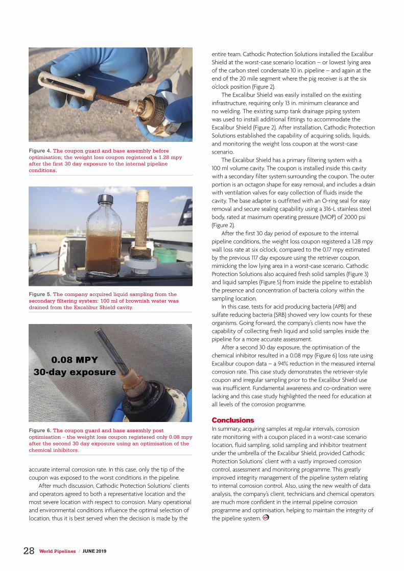
accurate internal corrosion rate. In this case, only the tip of the coupon was exposed to the worst conditions in the pipeline.
After much discussion, Cathodic Protection Solutions’ clients and operators agreed to both a representative location and the most severe location with respect to corrosion. Many operational and environmental conditions influence the optimal selection of location, thus it is best served when the decision is made by the
entire team. Cathodic Protection Solutions installed the Excalibur Shield at the worst-case scenario location – or lowest lying area of the carbon steel condensate 10 in. pipeline – and again at the end of the 20 mile segment where the pig receiver is at the six o’clock position (Figure 2).
The Excalibur Shield was easily installed on the existing infrastructure, requiring only 13 in. minimum clearance and no welding. The existing sump tank drainage piping system was used to install additional fittings to accommodate the Excalibur Shield (Figure 2). After installation, Cathodic Protection Solutions established the capability of acquiring solids, liquids, and monitoring the weight loss coupon at the worst-case scenario.
The Excalibur Shield has a primary filtering system with a 100 ml volume cavity. The coupon is installed inside this cavity with a secondary filter system surrounding the coupon. The outer portion is an octagon shape for easy removal, and includes a drain with ventilation valves for easy collection of fluids inside the cavity. The base adapter is outfitted with an O-ring seal for easy removal and secure sealing capability using a 316-L stainless steel body, rated at maximum operating pressure (MOP) of 2000 psi (Figure 2).
After the first 30 day period of exposure to the internal pipeline conditions, the weight loss coupon registered a 1.28 mpy wall loss rate at six o’clock, compared to the 0.17 mpy estimated by the previous 117 day exposure using the retriever coupon, mimicking the low lying area in a worst-case scenario. Cathodic Protection Solutions also acquired fresh solid samples (Figure 3) and liquid samples (Figure 5) from inside the pipeline to establish the presence and concentration of bacteria colony within the sampling location.
In this case, tests for acid producing bacteria (APB) and sulfate reducing bacteria (SRB) showed very low counts for these organisms. Going forward, the company’s clients now have the capability of collecting fresh liquid and solid samples inside the pipeline for a more accurate assessment.
After a second 30 day exposure, the optimisation of the chemical inhibitor resulted in a 0.08 mpy (Figure 6) loss rate using Excalibur coupon data – a 94% reduction in the measured internal corrosion rate. This case study demonstrates the retriever-style coupon and irregular sampling prior to the Excalibur Shield use was insufficient. Fundamental awareness and co-ordination were lacking and this case study highlighted the need for education at all levels of the corrosion programme.
ConclusionsIn summary, acquiring samples at regular intervals, corrosion rate monitoring with a coupon placed in a worst-case scenario location, fluid sampling, solid sampling and inhibitor treatment under the umbrella of the Excalibur Shield, provided Cathodic Protection Solutions’ client with a vastly improved corrosion control, assessment and monitoring programme. This greatly improved integrity management of the pipeline system relating to internal corrosion control. Also, using the new wealth of data analysis, the company’s client, technicians and chemical operators are much more confident in the internal pipeline corrosion programme and optimisation, helping to maintain the integrity of the pipeline system.
Figure 4. The coupon guard and base assembly before optimisation; the weight loss coupon registered a 1.28 mpy after the first 30 day exposure to the internal pipeline conditions.
Figure 5. The company acquired liquid sampling from the secondary filtering system: 100 ml of brownish water was drained from the Excalibur Shield cavity.
Figure 6. The coupon guard and base assembly post optimisation – the weight loss coupon registered only 0.08 mpy after the second 30 day exposure using an optimisation of the chemical inhibitors.
28 World Pipelines / JUNE 2019

started from started from the bottomthe bottomChristophe Baeté, Elsyca nv, Belgium, Len Krissa and Alfonso Garcia, Enbridge Pipelines Inc., Canada, outline the 3D bottom-up approach applied by mechanistic modelling for pipeline integrity management.
Pipeline integrity management software programs (PIMS) generally rely on statistical correlations between big data collected over many years of pipeline operation. However, with respect to corrosion assessment, the ‘devil
sits in the details’ and corrosion rates are difficult to monitor directly, which often results in post-mortem assessment by inline
inspection (ILI) tools. This is not the case when using mechanistic modelling.
ModellingMechanistic modelling applies a 3D bottom-up approach. Through mechanistic modelling, the cathodic protection (CP)
29

current and AC and DC interference current are computed in a 3D soil environment. The current distribution is determined by the coating condition and the soil corrosivity (current demand of bare steel), and once known, the corrosion rate is calculated at each coating defect predicated from the ILI corrosion anomalies identified on pipelines. As such, the ongoing corrosion process at coating defects is identified and can be monitored. To obtain quantitative results, conventional field data that has been collected at grade is used to calibrate the
mechanistic models for the unknown parameters such as the coating condition. Once calibrated, output from the mechanistic model can be leveraged, offering added value to ECDA field data by providing IR-free potentials, current densities and corrosion rates along the pipeline. Obtaining corrosion rates is very valuable for timely detection of detrimental events, identifying root causes of corrosion anomalies, interpreting RMU alarms, finding inconsistencies in the survey data, and monitoring the accumulated metal loss over time for integrity assessment at the uppermost level.
Leveraging field dataA case study is discussed on a 320 mile long corridor consisting of four parallel pipelines sharing the same CP system (60 rectifiers in total) and being in collocation with high voltage AC power lines (56 in total). Accidental shorts may exist with casings (264 in total) and the neutrals at motorised valves (31 in total). The total steel surface to be protected is approximately 5 million m2. The mechanistic model was prepared in the GIS based Elsyca V-PIMS software platform, and enabled bridging pipeline operating data with corrosion anomalies.
The pipelines cross 15 different soil types, for which the soil physico-chemical properties are extracted from the Web Soil Survey operated from USDA Natural Resources Conservation Service (NRCS). The soil properties are attributed to the 2935 different pipeline sections that consist of one or more pipe joints. As an example, soil texture (sand/silt/clay) and moisture content are leveraged to the soil corrosivity and current demand of bare steel.
ILI data was investigated to the dimensions of the anomalies used to estimate the area of exposed steel on each joint. Figure 2 provides the distribution of the percentage bare steel for each joint showing corrosion anomaly features. Line 1 is a vintage PE tape/coal tar coated pipeline, while the other pipelines have a fusion-bonded epoxy (FBE) coating. Most of the coating defects are small for the newer FBE coating, resulting in a percentage of bare steel below 0.04%, while for the older PE tape/coal tar coating it has the largest coating defects, resulting in 5% bare steel for most of the corroded joints. The percentage of bare steel and size of the coating defects result in coating resistance that will influence the current demand of the CP system. It must be noted that the mechanistic model revealed the coating resistance was overestimated for the PE tape/coal tar coating and corrosion anomalies could not be associated with open coating defects. Imposing the rectifier current in the model caused pipe-to-soil potentials that were far more electronegative than the survey readings, indicating CP shielding effects and corrosion under disbonded coating.
The total current consumed by the pipeline corridor was 403 A ±78. The current output of each rectifier was imposed in the mechanistic model, and the coating resistance and accidental current leaks were further refined based on the pipe-to-soil ON potential measurements. After calibration, the model provides the IR-free potential, current density and corrosion rates along the pipelines.
The AC interference level of the pipeline is simulated by introducing the 56 power lines in the mechanistic model. The power line properties are calibrated based on the measured AC
Figure 1. Soil properties along the pipeline corridor.
Figure 2. Distribution of the percentage bare steel.
Figure 3. Simulated (line) and measured (squares) PSP ON with rectifier locations (diamonds).
30 World Pipelines / JUNE 2019

TeamInc.com
A Better Way to Manage Your Pipeline’s Structural Integrity
hard to match. Our expertise in defect assessment enables us to support unique repairs to more challenging defects such as wrinkle bends, cracked pipelines and severe dents. Our composite
provide our clients with traceability of all materials used and installation conditions.
Optimize your integrity and repair solutions with TEAM.
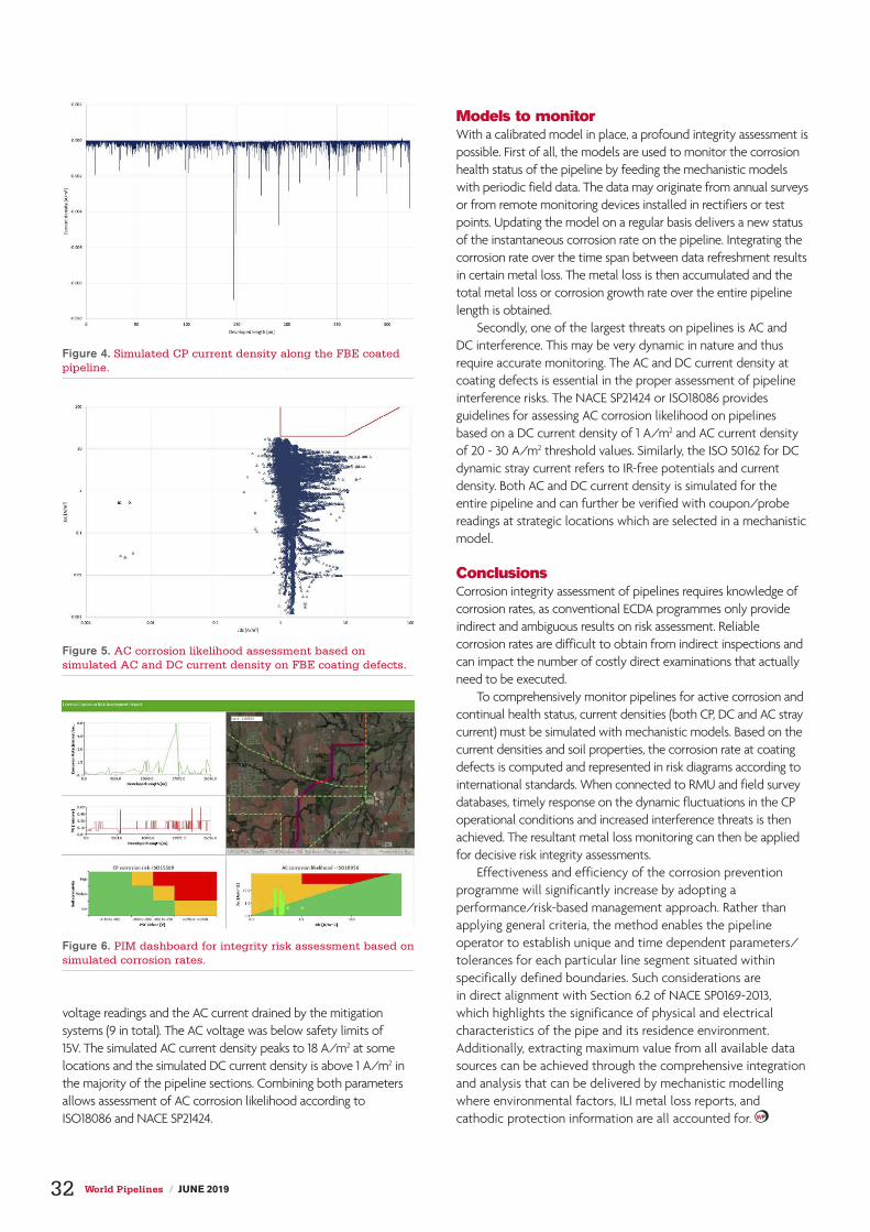
voltage readings and the AC current drained by the mitigation systems (9 in total). The AC voltage was below safety limits of 15V. The simulated AC current density peaks to 18 A/m2 at some locations and the simulated DC current density is above 1 A/m2 in the majority of the pipeline sections. Combining both parameters allows assessment of AC corrosion likelihood according to ISO18086 and NACE SP21424.
Models to monitorWith a calibrated model in place, a profound integrity assessment is possible. First of all, the models are used to monitor the corrosion health status of the pipeline by feeding the mechanistic models with periodic field data. The data may originate from annual surveys or from remote monitoring devices installed in rectifiers or test points. Updating the model on a regular basis delivers a new status of the instantaneous corrosion rate on the pipeline. Integrating the corrosion rate over the time span between data refreshment results in certain metal loss. The metal loss is then accumulated and the total metal loss or corrosion growth rate over the entire pipeline length is obtained.
Secondly, one of the largest threats on pipelines is AC and DC interference. This may be very dynamic in nature and thus require accurate monitoring. The AC and DC current density at coating defects is essential in the proper assessment of pipeline interference risks. The NACE SP21424 or ISO18086 provides guidelines for assessing AC corrosion likelihood on pipelines based on a DC current density of 1 A/m2 and AC current density of 20 - 30 A/m2 threshold values. Similarly, the ISO 50162 for DC dynamic stray current refers to IR-free potentials and current density. Both AC and DC current density is simulated for the entire pipeline and can further be verified with coupon/probe readings at strategic locations which are selected in a mechanistic model.
ConclusionsCorrosion integrity assessment of pipelines requires knowledge of corrosion rates, as conventional ECDA programmes only provide indirect and ambiguous results on risk assessment. Reliable corrosion rates are difficult to obtain from indirect inspections and can impact the number of costly direct examinations that actually need to be executed.
To comprehensively monitor pipelines for active corrosion and continual health status, current densities (both CP, DC and AC stray current) must be simulated with mechanistic models. Based on the current densities and soil properties, the corrosion rate at coating defects is computed and represented in risk diagrams according to international standards. When connected to RMU and field survey databases, timely response on the dynamic fluctuations in the CP operational conditions and increased interference threats is then achieved. The resultant metal loss monitoring can then be applied for decisive risk integrity assessments.
Effectiveness and efficiency of the corrosion prevention programme will significantly increase by adopting a performance/risk-based management approach. Rather than applying general criteria, the method enables the pipeline operator to establish unique and time dependent parameters/tolerances for each particular line segment situated within specifically defined boundaries. Such considerations are in direct alignment with Section 6.2 of NACE SP0169-2013, which highlights the significance of physical and electrical characteristics of the pipe and its residence environment. Additionally, extracting maximum value from all available data sources can be achieved through the comprehensive integration and analysis that can be delivered by mechanistic modelling where environmental factors, ILI metal loss reports, and cathodic protection information are all accounted for.
Figure 4. Simulated CP current density along the FBE coated pipeline.
Figure 5. AC corrosion likelihood assessment based on simulated AC and DC current density on FBE coating defects.
Figure 6. PIM dashboard for integrity risk assessment based on simulated corrosion rates.
32 World Pipelines / JUNE 2019

Each pipeline is unique. Quest Integrity’s breakthrough tool
technologies can be tailored to your specific pipeline’s needs,
within a matter of days. Complete tool customization and inspection
support provides an unparalleled in-line inspection, capable of
successfully navigating the world’s most challenging pipelines.
Achieve the ultimate peace of mind with Quest Integrity.
Visit QuestIntegrity.com to learn more.
CHALLENGE CONVENTION
TAILORED TECHNOLOGIES CUSTOMIZED FOR YOUR PIPELINES

Get the Pipeline Equipment You Need.
Tap into a selection of quality gear.If you need pipeline equipment, don’t miss our upcoming Columbus auction on June 27 & 28
featuring assets from Welded Construction, L.P. and other pipeline contractors.
▸ Wide selection of equipment for pipeline and other sectors
▸ Bid in person or online
▸ No minimum bids or reserve prices
▸ Test and inspect on-site
▸ Open to the public, free registration
▸ Financing & leasing available
Columbus, OH unreserved auction – Jun 27 & Jun 28
For more information on selling equipment, speak with your representative or call 1.937.568.9500
See complete listings at
rbauction.com/Columbus

Preventing
deterioration
Preventing Preventing
deteriorationdeteriorationSimon Dobson, Buckleys (UVRAL) Ltd,
UK, discusses the physical isolation and electrochemical protection
implemented to prolong the life of pipeline steelwork.
Long-term environmental protection of capital assets is a key objective of the pipeline industry. Considerable time, effort and expertise is invested in the prevention of deterioration, of which – for structural steel – the
biggest cause is corrosion. It is well known that corrosion is an electrochemical effect which manifests itself in various ways, dependent on the mix of environmental factors at play. Subtle changes in salinity, water flow, temperature, oxygenation and
Figure 1. Example of coated pipes for prevention of corrosion. ©Eupec.
35

more obvious variation in the condition of surface coatings (such as damage and other protection systems), will affect the rate of corrosion, and thus the factor of safety that the steelwork under consideration provides over and above its design working loads, and ultimately, the life of the asset.
There are two key approaches to protection: physical isolation by means of surface treatments, coatings and overwraps,
and electrochemical protection by means of passive or active anodes. It is normal to use both approaches.
The physical approach to protection typically starts with a coating plant. The process involves shot-blast cleaning of the steelwork followed by surface coatings (such as fusion-bonded epoxy) which provide a waterproof layer with excellent adhesion to the cleaned steel. Epoxy has sufficient flexibility to ensure that it is not damaged by the continual dimensional variation of steel, due to thermal expansion, contraction and load effects. Various layers may be applied to offer further mechanical and chemical protection, including hot-applied extruded polymers wrapped onto the pipe’s surface.
The pipes are handled in such a way as to minimise damage to these layers. Field joints will be created during the installation of the string and these are protected by similar adhesive and wrapping systems – an area of considerable specialisation, with several companies providing services using highly skilled operators. Following completion of the welded joints, the pipeline is coated and overwrapped, prior to the string being buried or launched. As part of the burial process, the pipeline may be further wrapped in a rock protection layer to prevent or minimise physical damage.
The pipeline will typically be provided with fixed sacrificial anode installations at calculated intervals. The anodes are installed on pads, which are welded to the pipes and protrude through the insulating layer to be in intimate contact with the electrolyte, be it groundwater or sea water. Alternatively, an impressed-current corrosion prevention system may be implemented, along with a suitable bedding material for buried pipelines.
The combination of physical isolation and electrochemical protection – coupled with appropriate maintenance – will aim to ensure that the pipeline meets its design life.
Pinhole detectorsBuckleys (UVRAL) Ltd is a provider of test instruments for a variety of markets including the construction, coatings and plastics industries, and in particular provides pinhole detectors.
Pinhole or ‘holiday’ detectors are high-voltage generators with built-in current monitoring capabilities, which detect flaws in the coating and are used to ensure that the isolation integrity during the pipe coating application and pipeline field jointing processes have been achieved and are maintained up to the point of burial or launch. Buckleys also produce a range of corrosion monitoring and mitigation devices which may be deployed along the length of the pipe installation, or in the case of subsea pipelines, on a topical/periodic basis to assess the effectiveness of the corrosion protection systems.
Quality control plans in the pipe coating plants will typically call for a testing regime using pinhole detectors, accompanied by visual and dimensional assessment. A number of bodies, including NACE, have created a range of standards, which provide recommended voltage levels dependent on the coating thickness under test. Buckleys’ DCCT pinhole detectors are intended for the factory environment, being mains powered, rack-mounted and designed for continuous operation with a range of outputs up to 40 kV. Conversely, in the field, following field jointing or patch repair, the requirement is for a battery-powered and easily
Figure 1. A Buckleys trainer demonstrating use of the rolling spring electrode on pipes prior to field jointing.
Figure 3. A diver carrying out a spot corrosion voltage measurement on an underwater rig structure.
Figure 2. Customer inspector checking the coating on a prepared pipe string prior to burial.
36 World Pipelines / JUNE 2019

portable instrument. Buckleys’ PHD Pro range of detectors is designed to address this need, with instruments ranging from 1 kV to 40 kV capability.
To complement the test instruments, a range of standard electrodes are available, including rolling spring, metal brush and conductive rubber types for both the exterior and, where required, the interior of the pipe. The company also offers custom electrode design, source and manufacture, including the electrodes, insulators, support structure and associated wiring.
Case studyThis case study refers to a gas pipeline relocation under the M20 as part of the current works to develop Junction 10a, carried out by Fabricon Pipeline Ltd. It was necessary to assemble a pipe string and then draw that through a culvert under the M20 at a greater depth than the original pipe had been laid – to meet SGN requirements. The pipe string was approximately 500 m in length, comprising 457 mm pipe with a 15.9 mm wall, which was FBE coated to 700 μm. Following field jointing and completion of the protection, the string was inspected at 5 kV using the 250 mm phosphor bronze brush, prior to installation in the culvert.
The team were able to illustrate the effectiveness of Buckleys’ pinhole/holiday detectors in testing for defects, porosity and pinholes on the non-conductive coating of the pipeline.
MonitoringFollowing installation, monitoring equipment is required. The company’s range of ground electrodes includes copper-copper sulfate reference cells; machined steel probes of
known surface areas which may be fitted to insulated ‘T-Handles’ for instantaneous ground current measurements; potted buried coupons for ongoing monitoring; and AC mitigation diodes. Design and manufacture for special and custom electrodes are carried out in-house, using state-of-the-art 3D CAD and CNC machining processes. For underwater corrosion monitoring, Buckleys provides silver-silver chloride reference cells, for temporary or permanent installation, along with a series of test devices.
The BathyCorrometer® Pro is a diver-carried, self-contained point measurement device comprising a high accuracy voltmeter, reference cell, test probe and a four digit display; all contained in a pressure-tight housing. There is the option for it to be fitted with an umbilical, allowing connection to a surface display unit onboard the dive vessel. There is also a range of corrosion probes suitable for ROV mounting, as contact, proximity and field measurement versions. These are provided with cable tails, which would normally be terminated at the ROV’s auxiliary inputs, enabling data acquisition via the ROV’s umbilical. Where very shallow waters indicate the use of lightweight ROVs, corrosion probes with longer cable tails – for direct connection to the surface vessel – running parallel to the ROV’s umbilical, are also available.
Buckleys’ instruments have been designed and developed to provide non-destructive testing to verify the quality and condition of protective coatings during pipe manufacture, on site during assembly and installation, and throughout the lifetime of the pipeline to assist in the maintenance of these high value assets in service.

A history of WEIGHTA history of WEIGHT38

Buried pipelines have always required a certain level of additional weight to counteract the buoyant force exerted on them from groundwater. Like the hull of a boat in water, an empty or partially filled pipeline
can pop right out of the ground in areas where groundwater is present. This means that pipeline weights are not an option, they are a necessity. The method used to weight a pipeline also plays a key role in maintaining long-term integrity. Like many advancements in pipeline design and construction, pipeline weighting has evolved over the last 70 years as engineering and economic needs demanded. To ensure the integrity of pipeline coatings and cathodic protection systems are protected, today’s pipelines are generally weighted with either concrete coated pipe or geotextile pipeline weights.
How pipelines are protected Pipeline owning companies and constructors go to great lengths to ensure the long-term integrity of the pipelines they build.
Corrosion, commonly known as rust, is enemy number one. Two safeguards put in place to prevent corrosion are: pipeline coatings and cathodic protection systems. With that in mind, the type of buoyancy control must also ensure the pipe coating and CP systems are not compromised.
Pipeline coatingsBuried steel pipelines can be dated back to the late 1800s. It did not take long for operators to realise how aggressive corrosion could be, and that without some sort of protection, pipeline leaks were inevitable. As pipeline construction boomed from the 1930s to the 1950s, pipelines were coated with either hot asphalt or coal tar reinforced with felt matting and topped off with a spiral wrap of kraft paper. This hot coating was normally applied in the field over the trench – not something that would pass safety inspection these days. Another popular coating used a petroleum-based wax that was reinforced with fibre mesh, also applied in the field. In the mid-1950s new polymers were introduced to pipeline coatings,
Meghan Connors, President, PipeSak, Canada, provides a brief history of pipeline weighting and how it has evolved to meet engineering and economic demands.
39
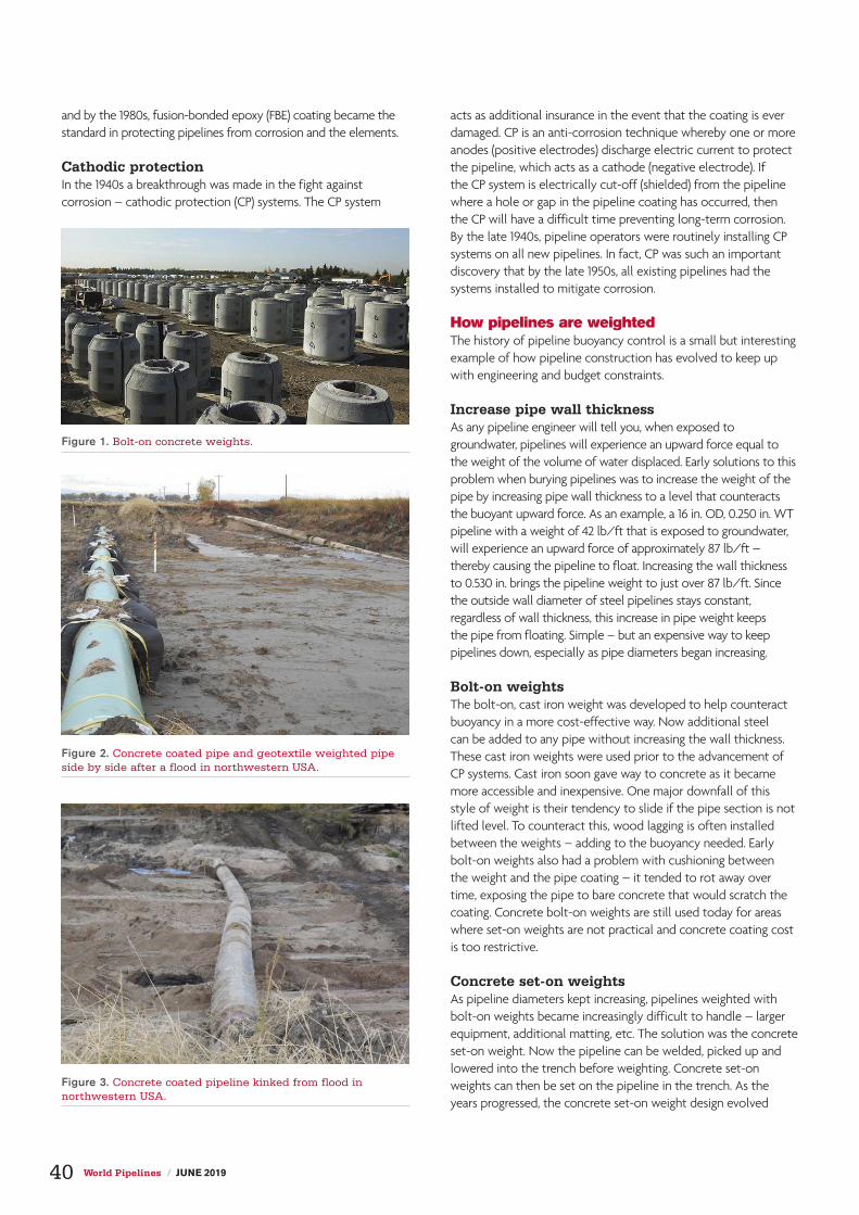
and by the 1980s, fusion-bonded epoxy (FBE) coating became the standard in protecting pipelines from corrosion and the elements.
Cathodic protection In the 1940s a breakthrough was made in the fight against corrosion – cathodic protection (CP) systems. The CP system
acts as additional insurance in the event that the coating is ever damaged. CP is an anti-corrosion technique whereby one or more anodes (positive electrodes) discharge electric current to protect the pipeline, which acts as a cathode (negative electrode). If the CP system is electrically cut-off (shielded) from the pipeline where a hole or gap in the pipeline coating has occurred, then the CP will have a difficult time preventing long-term corrosion. By the late 1940s, pipeline operators were routinely installing CP systems on all new pipelines. In fact, CP was such an important discovery that by the late 1950s, all existing pipelines had the systems installed to mitigate corrosion.
How pipelines are weightedThe history of pipeline buoyancy control is a small but interesting example of how pipeline construction has evolved to keep up with engineering and budget constraints.
Increase pipe wall thicknessAs any pipeline engineer will tell you, when exposed to groundwater, pipelines will experience an upward force equal to the weight of the volume of water displaced. Early solutions to this problem when burying pipelines was to increase the weight of the pipe by increasing pipe wall thickness to a level that counteracts the buoyant upward force. As an example, a 16 in. OD, 0.250 in. WT pipeline with a weight of 42 lb/ft that is exposed to groundwater, will experience an upward force of approximately 87 lb/ft – thereby causing the pipeline to float. Increasing the wall thickness to 0.530 in. brings the pipeline weight to just over 87 lb/ft. Since the outside wall diameter of steel pipelines stays constant, regardless of wall thickness, this increase in pipe weight keeps the pipe from floating. Simple – but an expensive way to keep pipelines down, especially as pipe diameters began increasing.
Bolt-on weightsThe bolt-on, cast iron weight was developed to help counteract buoyancy in a more cost-effective way. Now additional steel can be added to any pipe without increasing the wall thickness. These cast iron weights were used prior to the advancement of CP systems. Cast iron soon gave way to concrete as it became more accessible and inexpensive. One major downfall of this style of weight is their tendency to slide if the pipe section is not lifted level. To counteract this, wood lagging is often installed between the weights – adding to the buoyancy needed. Early bolt-on weights also had a problem with cushioning between the weight and the pipe coating – it tended to rot away over time, exposing the pipe to bare concrete that would scratch the coating. Concrete bolt-on weights are still used today for areas where set-on weights are not practical and concrete coating cost is too restrictive.
Concrete set-on weightsAs pipeline diameters kept increasing, pipelines weighted with bolt-on weights became increasingly difficult to handle – larger equipment, additional matting, etc. The solution was the concrete set-on weight. Now the pipeline can be welded, picked up and lowered into the trench before weighting. Concrete set-on weights can then be set on the pipeline in the trench. As the years progressed, the concrete set-on weight design evolved
Figure 1. Bolt-on concrete weights.
Figure 2. Concrete coated pipe and geotextile weighted pipe side by side after a flood in northwestern USA.
Figure 3. Concrete coated pipeline kinked from flood in northwestern USA.
40 World Pipelines / JUNE 2019

A Single Carrier For Any Task
Email us at [email protected] or visit superiormftg.com/carrier
Superior Manufacturing™ is a trademark of Worldwide Machinery.
Introducing the all-new crawler carrier from Superior™Modular bed system: change the bed to flatbed dump, welding unit, rock dump, and more.
Swappable tracks: install rubber or steel u/c depending on soil conditions.
Swappable cabins: change cabin to accommodate a two-person crew.
30,000lb22,000lb15,000lb
ST-150X Rock DumpST-220XRST-220X ST-300X

with better, longer lasting cushioning between the concrete and the important pipe coatings, as well as longer legs to help restrict tipping. Concrete set-on weights have always been top heavy, with most of the weight directed on top of the pipeline, necessitating a deeper trench to achieve adequate cover – which is often difficult in wet terrain.
Until geotextile set-on weights became a common construction practice in the early 2000s, the use of concrete set-on weights was widespread. Although concrete set-on weights do offer the flexibility to install weights after the pipe is laid in the trench, this benefit does not come without risk. Extreme care must be taken when installing the top-heavy weights to ensure the coating, or even the pipe, is not damaged during installation. When you combine coating damage with the potential for concrete set-on weights to block CP, disaster can occur. This was seen in late 2017 when the 4324 km Keystone pipeline, built in 2008, leaked an estimated 5000 bbls of oil in South Dakota, USA. The Pipeline and Hazardous Materials Safety Administration attributed the leak to possible damage done during the installation of concrete set-on weights.
Concrete coated pipeConcrete coated pipe is typically the most expensive form of buoyancy control and was initially developed for offshore use prior to finding its way to onshore pipelines. Used particularly for areas where set-on concrete weights were not applicable, concrete coated pipe can be either formed onsite or plant applied and shipped to a site. When plant applied, concrete
coating for onshore use has stepped pipeline weighting back to the early days of bolt-on weights. Not only does the contractor now have to truck heavily weighted pipe from the coating plant to site, they also have to handle and weld weighted pipe on the right-of-way. Larger and more equipment, more matting through wet areas, more in-trench welding – overall costs skyrocket.
Great care must be employed when relocating a long string of concrete coated pipe into the trench to ensure buckling is controlled – particularly with larger diameter pipelines where the weight of a fully concrete coated pipeline is extreme. Concrete coated pipe has also been known to kink in areas that are prone to earth movement. This was seen in the northwestern US when a flood washed away 4 ft of cover, exposing two pipelines that travelled the same pipeline corridor. One pipeline was weighted using concrete coating, the other using geotextile pipeline weights. The heavy concrete coated pipe sunk deeper into the saturated ground, resulting in a kinked pipe that had to be replaced. The pipe weighted with geotextile pipeline weights remained undamaged and in place, allowing the flood waters to pass under the pipe and through the permeable weights.
Geotextile pipeline weightsBallast filled geotextile fabric pipeline weights (GPW) were initially developed in the mid-1990s to ensure CP currents had an easier path to the pipe. Since GPWs are made from woven, uncoated polypropylene fabrics, they have a long life and are also as porous as the natural products used as ballast – giving CP currents an easy path. Once GPWs found themselves on construction sites, contractors quickly discovered their ease of use. When combined with the short lead times (often filled and used the same day), GPWs very quickly became the weight of choice for most onshore projects. Not only can geotextile fabric weights save time and money during installation, but they are considered more environmentally and pipe friendly. Since geotextile fabric weights provide a ‘softer’ method of buoyancy control, pipelines also have the ability to move slightly while buoyancy control is maintained. This is particularly important in earthquake zones or areas of other earth instability.
The use of GPWs can also decrease the number of overall weights necessary for any given project. Since the stone ballast used to fill fabric weights generally has a higher specific gravity than concrete, fabric weights tend to weigh more underwater than concrete weights – which means fewer weights to buy and install. No extra ROW width is required, and no extra equipment is necessary. The overall installation costs of using GPWs is typically much lower than any other method of pipeline buoyancy control.
ConclusionOnshore, GPWs have become the standard. They are economical, can be filled locally with natural ballast, help maintain the integrity of CP systems, and are safe and easy to install. Concrete coated pipelines are typically reserved for offshore construction and for areas where the less expensive GPW placement would be difficult (e.g. lakes, large swamp areas, or wide rivers). Helical screw anchors also play a small but significant role – particularly for remote areas of extreme muskeg-type conditions such as the Canadian north.
Figure 4. Filled PipeSaks in Texas, USA.
Figure 5. PipeSaks sinking a floating pipe in Minnesota, USA.
42 World Pipelines / JUNE 2019

Erasing the
clipboard
Rob Koot, Trimble, USA, describes the change from paper records to an integrated task-specific approach to positioning and data management for pipeline construction.
W hen conducting pipeline construction surveys in today’s environment, information management requires levels of accuracy and efficiency that match or exceed those
required in measurement and positioning. That is the
Figure 1. Surveyors record pipe locations prior to backfill. Precise measurement is essential in complex or crowded installations.
43

viewpoint of Lee Drennan, a surveying expert who serves as R&D and training co-ordinator for Morris P. Hebert, Inc. (MPH), a Louisiana-based engineering, surveying, environmental and GIS company. In addition to a lead role in the company’s complex work in GPS measurement and analysis, Drennan identifies and evaluates technologies and processes that can improve MPH’s efficiency, safety and profitability. Through collaboration with a supplier, he has implemented advanced software that streamlines key MPH workflows.
The surveying business at MPH concentrates mainly on serving the oil and gas business. The industry thrives on productivity and Drennan has examined an array of technologies including laser scanning, GNSS and unmanned aerial systems (UAS) for use in pipeline applications. Upon joining MPH in 2013, Drennan, who was already familiar with surveying for planning and construction, dove into the process of getting pipe into the ground. He quickly learned that in addition to traditional surveying applications, MPH crews devoted large portions of their work to tracking pipeline materials and activities.
The material tracking work is essential, as pipeline contractors and owners need detailed information on their assets for financial, safety and compliance requirements. But traditional approaches to pipeline tracking, which relied on handwritten notes, were inefficient and rife with opportunity for errors. Drennan knew there was a better way for MPH to do the work – even if they needed to invent it themselves.
Managing the details: the manual method“One of the primary things that we do is keep track of every joint of pipe and every weld,” Drennan said. “We track material from the time it arrives on site until just before the trench is backfilled.” The work requires MPH teams to maintain reams of information. The data
begins with a unique identifier for each joint, stamped or written on the pipe. Additional information including manufacturer, heat (or batch) number, material, dimensions and coatings is tied to the joint. The information must be carried with the joint from its arrival on site through excavation, backfill and final documentation.
Gathering and recording information occurs multiple times during the construction process. In many cases, surveyors must confirm and cross check information contained in a pipe manifest received from the manufacturer or pipe yard. When the pipe is moved to the construction site and laid out along the trench, crews conduct a tally to capture the location of each joint and record the joint identifier, dimensions and related data.
Additional information is captured when the joints have been welded together into long sections; survey crews record weld details and verify the information for the joints on both sides of the weld.
When the long sections of pipe have been placed in the trench, the final locations of the welds are captured. Additional measurements are needed to confirm that the pipe is in its right-of-way and that there will be sufficient cover. Survey crews are under pressure to complete the critical measurements and documentation as quickly as possible. Measurements to capture the final weld locations, typically using RTK GNSS, must be completed before the trench can be backfilled. It is time-sensitive work; construction crews have little tolerance for delay by surveyors.
Under the old process, each survey crew would record the information on paper. Depth of cover needed to be determined by comparing measured data against pipeline design profile sheets. At the end of each day, a supervisor needed to compile the written notes from several crews to put together a comprehensive pipe tally. It was a very laborious task and introduced multiple chances for mistakes. “A lot of things can go wrong when you’re in the
field with contractors breathing down your neck and you are trying to write notes in hot or difficult environments,” Drennan said. “It just wasn’t an efficient way to do it.”
Automated approach to pipeline data managementAt the time that Drennan was hired, MPH was looking for ways to improve the field process. With no commercial solutions available, they were considering whether to develop their own in-house software. In addition to handling positioning and material management on the jobsite, they needed to deliver comprehensive information to their clients in the form of written reports,
Figure 2. During the tally, crews use software to manage and confirm attributes of each joint in the line.
44 World Pipelines / JUNE 2019

WE ARE PROUD TO INTRODUCE OUR NEW GREEN ROCKSHIELD - PIPEJACKET™PipeJacket™ flexible PVC wrap protects the pipe from minor impact and abrasions during backfilling in rocky conditions and does not interfere with cathodic protection systems.
ENGINEERED PIPELINE SOLUTIONS +1 866.PIPESAK (747.3725) PIPESAK.COM
WE PROTECT WHAT YOU BUILD MANUFACTURED IN THE USA
SMART CHOICE
EASY INSTALLMORE EFFICIENT
STRONG
THE NEWEST COLOR IN PIPELINE PROTECTION
High Visibility For safer pipelines
Superior Design Proven to provide the best impact protection
Lightweight Design For easier installation
Ultimate Flexibility For all weather conditions
In Stock and Ready to Ship

INTEGRITY 2019INTERNATIONAL ONLINE PIPELINE CONFERENCE
#Integrity19
18 - 19 June 2019With participation from:
worldpipelines.com/integrity

tabulations, drawings and maps. Developing the solution would combine high-accuracy GNSS positioning with GIS-style feature and attribute management. The application needed to work in the field and run on rugged tablets or handheld data collectors.
MPH was already using Trimble GNSS for their surveying work and wanted to connect their pipeline applications to existing workflows. “I had been with MPH for about six months when Trimble asked if we were interested in helping to develop the pipeline software,” Drennan recalled. “While we were concerned about opening up our information and processes to an outside company, Trimble had our respect as well as more resources and software expertise. So, we decided to go with them.”
With a long history in the oil and gas arena, Trimble wanted to address the specialised needs of pipeline construction. The company developed the application as a module within its Trimble Access software, which operates on field hardware and supports all Trimble surveying instruments including GNSS and total stations. The software, known simply as Trimble Access Pipelines, builds and maintains a database of all the pipe joints and welds and combines the data with precise positioning.
Trimble Marketing Director, Jason Rossback, said that the application was developed over a 12 month period. Trimble developers spent weeks visiting pipeline surveyors and working with MPH and others in the pipeline industry to develop and test the new software. “The basic workflows for measuring and recording attributes are generally straightforward,” Rossback said. “We needed to develop a workflow where we could digitally record joint and weld attributes while the pipeline was above ground, and then seamlessly link them to welds when the welds were surveyed in their final location.”
Attribute collection was the key activity targeted by the software team. “In addition to being the primary source of error, it’s also the time critical point for the surveyor,” Rossback said. “Crews need to get in, measure the weld, record the attributes, confirm cover depth and then get out so the trench can be backfilled. With Pipelines this can now all be done in a minute or two.” The team also worked to understand and streamline processes for partial unit of pipe (PUP) creation, pipe crossings, bend calculations and other special situations.
The data management process often starts with a manifest from the pipe manufacturer or yard, which contains all of the necessary attributes for each joint. Digital manifests can be imported into the software to create the pipe database for a project. A unique identifier for each joint is written onto the pipe, or barcode ID stickers may also be used. When the pipe is strung along the ditch, survey crews conduct a tally to record or confirm the attributes of each joint.
After the user enters the joint ID (or scans the barcode), the software recalls and displays all attributes for the joint. The tally crew simply verifies the information and moves on to the next joint. Stationing is
automatically computed according to previously defined alignment information for the project. If a digital manifest is not available, crews can key in the joint attributes as part of the tally process. Once entered, the attributes are managed and displayed as necessary as part of subsequent work.
During tally time, any adjustments to joint length will guide the surveyor through the process of creating a PUP for the joint. In the event of pipe crossings, the software uses field measurements to compute crossing angles and separation.
The survey crew returns when the joints have been welded together. In a process called weld mapping they capture data on the welds, which are assigned unique identifiers by X-ray technicians who inspect each weld. Using information from the tally, the Pipelines software displays the ID for joints at the weld (referred to as the joint ahead and joint back). Drennan added that at
Figure 3. Surveyors work on a pipe crossing. Their software uses GNSS data to compute crossing angle and vertical separation.
Figure 4. Using a KML file from Trimble Access Pipelines, clients can view location and attributes of pipeline welds in Google Earth.
JUNE 2019 / World Pipelines 47

www.boehmer.de
WHAT CAN ENSURE MY PLANT‘S LONG-TERM
EFFICIENCY?
EXPERIENCE!The know-how of more than 60 years in valve manufac-turing empowers Böhmer to build Ball Valves that help
successfully for the long term.
OIL, GAS, STEAM, CHEMICALS & SPECIAL APPLICATIONS
1/8 TO 56 INCH
UP TO 800 BAR
VISIT US:
JUNE 19TH - 20TH 2019HALL D | BOOTH 432
this stage they can use the internal GNSS on their data collectors to provide metadata during the tally and weld mapping; the time and location of the data capture is stored to provide backup documentation on crew activities.
After the pipe has been placed into the trench, survey crews again visit the site to conduct as-built surveys. They use RTK GNSS to capture precise location of the welds, and enter the Weld ID assigned during weld mapping. The Weld ID links to the joint ahead and joint back IDs in the weld map record, which in turn retrieves the attributes for the two joints from the tally – all of which are recorded with the RTK measurement. Accurate to 1 - 2 cm, the RTK measurement also automatically calculates the depth of cover from a previously measured ground shot. The field crew is alerted if the pipe cover does not meet a predefined minimum depth, or if it is located outside the working corridor.
The GNSS also helps ensure accurate tally and weld data. For example, if the distance between two welds is less than the length of the joint stored in the database, the software alerts the crew that the joint length recorded in the tally does not match the distance computed between two consecutive weld measurements. Once the surveyors have completed the as-built survey, backfilling can proceed.
“The software has other intelligence as well,” Drennan said. “If the crew is shooting the pipe in in the same order that they tallied it, the software will automatically advance from one weld to the next. Even if they need to key in the weld number, as soon as they key it in, the system populates the fields for joint ahead and joint back. All the attributes are available to check again if required, and are automatically recorded with the weld measurement.”
Drennan added that they use the database approach to simplify preparation of summaries and report. “We can run a tally report and, if everything’s correct, we hand it to the client and that’s the end of it. It’s the same thing with the weld map. Nobody’s sitting down and laboriously building reports from a bunch of pieces of paper.” While it is possible to generate a report in the field on the crew’s tablet or handheld, MPH crews typically return each day’s information to their onsite survey co-ordinator. The co-ordinator can combine work of multiple crews on the job and perform additional QA/QC on the results. Field information is also provided to MPH drafters and GIS technicians who prepare as-built surveys and alignment and weld maps.
The automated Pipelines application helps MPH provide better service to its clients. Survey crews already use the Trimble system for pre-construction surveys and to stake out rights-of-way and construction easements. “The technology is enabling us to provide reliable data in less time,” Drennan said. “It translates directly to lower cost. In the end it’s all about working safely and being able to provide a quality product in a much more efficient manner.”

A BLOCKCHAIN A BLOCKCHAIN BARRACADEBARRACADERoman Arutyunov, Xage Security, USA, addresses why tamperproof blockchain solutions are a viable option for oil and gas security.
The adoption of digitally connected infrastructure is critical for industry growth and efficiency. While successful hacks hold the risk of shutting down entire countries, companies cannot afford to linger
with legacy systems and are moving fast to modernise.
Figure 1. Distributed systems require distributed security solutions across the edge.
49

50% of oil and gas organisations have made the switch to digitised systems across all stages of production – from automated pre-drilling site research, to building new pipelines, to Shell’s line data monitoring. At the same time, 68% of companies reported at least one cyber compromise. With cyberattacks growing year after year, it is clear the security systems in place are not enough. The industry needs a solution that is created distinctly for distributed oil and gas networks, protecting assets and production today while enabling growth for tomorrow.
Digitisation has many benefitsSmart sensors, digitised control systems, connected oil pads, and other smart devices are massively improving operational efficiency and decreasing device downtime in the oil and gas industry. Through the use of Industrial Internet of Things (IIoT) devices, data collection is streamlined and accurate, leaks are detected early, and device maintenance is proactive – reducing employee travel time and improving physical safety.
With the petabytes of field data stored by each individual oil and gas company (the equivalent of millions of gigabytes), real-time data cannot be collected manually without a high likelihood of human error and without significant overhead costs such as long-distance employee travel or a permanent housing station. Enabling remote access through IoT devices means that data collection – measuring pressure, flow and density at refineries, or leaks, progress and chemical makeup in pipelines – can be performed from afar, rather than requiring an individual onsite.
Long-term productivity is often interrupted by lengthy equipment maintenance periods. This downtime has accounted for 10 - 20% of industrial drilling costs (with the upstream industry losing up to US$8 billion/y as a result of inefficiencies). With digitised systems, the risk of inefficiencies in devices and outages are mitigated
through early, often automated, detection and proactive maintenance. For example, pipeline operation centres monitor the compressors, machines, and other field assets from afar. They monitor bearing vibration as a predictive indicator of future failure. Doing so allows them to repair and service devices proactively, in order to avoid unplanned downtime. Real-time data will indicate immediately that a leak has occurred within a pipeline and where, whereas previously, a company would have to send someone to check pressure monitors and determine discrepancies in data, sometimes taking days or even weeks. Immediate detection can save companies thousands of dollars in relocation costs, travel costs and product loss.
Digitisation also has risks As analog systems are digitised, operators are quickly learning that the systems in place fail to protect critical assets from cyberattacks. It is a two-fold issue: new security systems are not applicable to legacy SCADA devices, and older security methods, like air-gapping, are not designed to protect modern devices. Industries need to employ a comprehensive solution for modern and legacy systems, and need to do it fast, or risk long-term consequences to companies and communities.
Security risks are not confined to money loss or inefficiency for the supplier alone – as seen with data and customer service outages last year at Energy Transfer Partners LP, Boardwalk Pipeline Partners LP, Chesapeake Utilities Corp. and Eastern Shore Natural Gas. More critically, oil and gas hacks can have serious consequences for the general public – as with the failed hack on a petrochemical company in Saudi Arabia intended to cause a devastating explosion – and the environment, with something as small as an inadequately secured pressure monitor causing oil spills. It is a high-stakes situation that must be accounted for responsibly.
Unique challenges need universal solutions Oil and gas operators face unique security challenges because of the diversity and geographic distribution of devices they deploy, and the severe consequences of potential cyberattacks.
Today, most oil and gas systems are centralised, meaning there is one, single point of security, which is the opposite of how the systems themselves are constructed – thousands of devices each with their own security specifications, access requirements and safety concerns. For example, pressure is generated by individual compressor stations along pipelines, each of which is equipped with its own industrial control system.
Figure 2. Xage Enforcement Point enables secure digitisation of existing industrial assets.
50 World Pipelines / JUNE 2019


But without secure role-based access control, these individual, in-the-field systems can be hacked through one malicious act on the central system, directly impacting oil and gas pressure within the pipelines. And with pipelines of all sizes spread across millions of miles internationally, a single hack of one contractor’s laptop connected to the larger network could have cascading effects on the quality and productivity of the pipeline. Network-based security approaches such as firewalls and VPN connections, are not flexible enough to handle the diversity of interactions that need to be secured within the oil and gas space. Data integrity and authenticity of signals sent between devices is essential. False signals or errors in data may cause incorrect instructions to individual compressors. There must be a more localised method of protection to prevent single points of failure.
Decentralisation is essential to oil and gas security for a number of reasons. First, distributed security reduces network-level risks. When one device is compromised – whether intentional or not – it is isolated and therefore unable to infect the entire network or groups of other connected devices. Second, distributed security is scalable for millions of connected devices, enabling device security on the industrial edge itself, bringing security onto each individual device, no matter the type. And finally, it provides speed without reducing efficiency. Decentralised security platforms are instantly responsive and power continuous operation by removing the delays that come with one central system.
The best way to achieve a distributed, decentralised security system? A blockchain-based network. Blockchain allows for a distributed platform that secures identity, authentication, enrolment, and peer-to-peer data exchange at the industrial edge, and enables security systems to strengthen as each individual device is added to a network. Since blockchain systems are themselves distributed by nature, they are able to provide redundancy and reliability through a distributed architecture, ultimately scalable to thousands, even millions, of nodes across an industrial system.
Deploying effective securityXage created the first blockchain-protected security platform for the IIoT. The system distributes identity and policy data across a network of devices, creating a tamperproof fabric for authenticating any-to-any communication, ensuring security at scale.
When the Xage solution was originally created, it was done so with the aim of securing traditional control systems with security protocols and credentials already in place, however not all industrial devices are protected this way. The complexity of industrial operation networks, combined with the rapid implementation of digitised devices, makes it exceedingly difficult to keep up security protocols on a device-by-device basis within installed systems. In response, Xage created the Xage Enforcement Point (XEP) in February this year, building on past solutions to meet the specific needs of the oil and gas industry. XEP
provides role-based access control, single sign-on, data integrity and privacy for every device within a network. In addition, XEP provides powerful cyber security to every device within a network, without major investment (in terms of money or time) and without disrupting or replacing existing infrastructure systems. It works for all devices in a system, not just the more sophisticated, modern digitised devices. This solution results in up-to-date, adequate security for every controller, machine, meter and individual transient device, with any level of connectivity, of any age, and from any vendor.
XEP acts as a filter, allowing varying levels of access to different employees and departments within an organisation, while enabling any-to-any, machine-to-machine co-operation and automation. Oil and gas companies need powerful access control and in-field identity management. XEP ensures appropriate access through preapproved policies stored within the nodes of the Xage fabric. By securely matching technician access rights with specific devices and functions, XEP allows companies to remove the cost, in money and in time, of travelling to remote locations for maintenance and data collection.
In addition to saving organisations time and money, XEP gives administrators full visibility into logins and updates of their system. At the moment, only 17% of oil and gas companies believe they would be able to detect a hack immediately with their current security system. XEP’s added layer of information helps in determining malicious hack attempts – and locking bad actors out of a system for good. Any unauthorised attempt to enter the industrial system alerts administrators, isolates the device from the rest of the system, and enables the team to take action with time to spare and before a crisis hits, rather than after the hack has occurred and caused potentially irreversible damage.
Make the most of digitisation As oil and gas companies continue to grow and employ diverse networks of devices – according to Statista, the 23.14 billion devices installed in 2018 will grow to more than 75 billion by 2025 – security must be paramount and all connected devices must be adequately protected.
This will only be achieved by removing singular points of failure, employing identity and role-based access control, and utilising a decentralised blockchain-based system created for the large, distributed networks that exist within the industry. A tamperproof blockchain solution is ideal for the oil and gas industry, because it allows companies to maintain security across geographic locales, no matter the type of device employed, remaining strong throughout updates, maintenance, and varying degrees of network connectivity.
Only with such uniquely suited systems will oil and gas companies be able to ensure that digitisation is saving them time and money, and increasing employee safety, rather than creating additional risk and complexity for their business.
52 World Pipelines / JUNE 2019

Analytical algorithms Analytical algorithms Michael Barth and Michael Kasch, ILF, Germany, explain how artificial intelligence
can help operators find hidden correlations and patterns in their data.
Buzzwords like ‘data mining’, ‘deep learning’ and ‘artificial intelligence’ (AI) are currently flying around in almost every business and industry area. The same technologies used for screening users’ privacy and
analysing customers’ preferences to improve sales figures are also applied to optimise technical processes for maintenance of assets and, with constantly growing attention, for physical and cyber protection of critical infrastructure. This article presents
an overview of the methods currently being used, and outlines opportunities to add value to the safe and efficient operation of pipelines by applying AI methods to their data, which are rapidly growing as pipeline systems and facilities are operated, monitored and controlled in 24/7 mode.
Pipelines are equipped with sensors, actuators, specific automation systems and control loops. Sensor data, being continuously interrogated with the aim of monitoring process
53
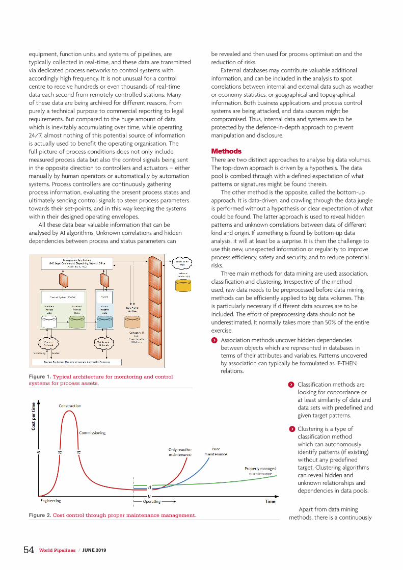
equipment, function units and systems of pipelines, are typically collected in real-time, and these data are transmitted via dedicated process networks to control systems with accordingly high frequency. It is not unusual for a control centre to receive hundreds or even thousands of real-time data each second from remotely controlled stations. Many of these data are being archived for different reasons, from purely a technical purpose to commercial reporting to legal requirements. But compared to the huge amount of data which is inevitably accumulating over time, while operating 24/7, almost nothing of this potential source of information is actually used to benefit the operating organisation. The full picture of process conditions does not only include measured process data but also the control signals being sent in the opposite direction to controllers and actuators – either manually by human operators or automatically by automation systems. Process controllers are continuously gathering process information, evaluating the present process states and ultimately sending control signals to steer process parameters towards their set-points, and in this way keeping the systems within their designed operating envelopes.
All these data bear valuable information that can be analysed by AI algorithms. Unknown correlations and hidden dependencies between process and status parameters can
be revealed and then used for process optimisation and the reduction of risks.
External databases may contribute valuable additional information, and can be included in the analysis to spot correlations between internal and external data such as weather or economy statistics, or geographical and topographical information. Both business applications and process control systems are being attacked, and data sources might be compromised. Thus, internal data and systems are to be protected by the defence-in-depth approach to prevent manipulation and disclosure.
MethodsThere are two distinct approaches to analyse big data volumes. The top-down approach is driven by a hypothesis. The data pool is combed through with a defined expectation of what patterns or signatures might be found therein.
The other method is the opposite, called the bottom-up approach. It is data-driven, and crawling through the data jungle is performed without a hypothesis or clear expectation of what could be found. The latter approach is used to reveal hidden patterns and unknown correlations between data of different kind and origin. If something is found by bottom-up data analysis, it will at least be a surprise. It is then the challenge to use this new, unexpected information or regularity to improve process efficiency, safety and security, and to reduce potential risks.
Three main methods for data mining are used: association, classification and clustering. Irrespective of the method used, raw data needs to be preprocessed before data mining methods can be efficiently applied to big data volumes. This is particularly necessary if different data sources are to be included. The effort of preprocessing data should not be underestimated. It normally takes more than 50% of the entire exercise.
) Association methods uncover hidden dependencies between objects which are represented in databases in terms of their attributes and variables. Patterns uncovered by association can typically be formulated as IF-THEN relations.
) Classification methods are looking for concordance or at least similarity of data and data sets with predefined and given target patterns.
) Clustering is a type of classification method which can autonomously identify patterns (if existing) without any predefined target. Clustering algorithms can reveal hidden and unknown relationships and dependencies in data pools.
Apart from data mining methods, there is a continuously
Figure 1. Typical architecture for monitoring and control systems for process assets.
Figure 2. Cost control through proper maintenance management.
54 World Pipelines / JUNE 2019


growing number of AI algorithms. Deep learning is a class of optimisation methods for artificial neural networks with multiple ‘hidden’ layers of neurons between the input and output (result) interface layers. Such neural networks are characterised by a high level of internal complexity and are called ‘deep’ in terms of their large number of hidden layers. Such methods are typically used for machine learning, pattern and face recognition, real-time language processing and other complex challenges. Deep learning methods are based on self-adapting algorithms, and they need a learning or training phase to become effective and reliable.
Potential applicationsThe following sections present a small selection of possible applications for data mining and deep learning in the process industry, but can also be used for inspiration in identifying organisation-specific topics and potential tasks that employ AI technology.
Pipeline corridor monitoringA technology called distributed acoustic sensing (DAS) allows an operator to listen in to a fibre optic cable (FOC) over long distances. Laser pulses are sent through one of the fibres inside the FOC. The tiny portion of backscattered light carries information about the mechanical stress/strain conditions of the fibre.1 Bending the FOC or vibrations imposed on it cause disturbance on the local backscattering characteristics of the fibre. Such anomalies can be detected and precisely located by using optical time domain reflectometer (OTDR) technology. The fibre functions as a spatially distributed sensor for static and dynamic mechanical stress, and can therefore be regarded as a spatially distributed microphone over distances of currently up to 50 km with a single DAS interrogator unit. It is worth noting that DAS systems use standard fibres of ordinary telecommunication FOCs, and no special sensor fibres are required.
Fibre optic cables are typically installed along pipelines to establish communication between pipeline stations and control centres. When installed close to the pipeline, preferably in the same trench, DAS can continuously monitor the pipeline corridor for acoustic anomalies. Earthworks, manual digging, landslides and earthquakes cause acoustic signatures in the ground which can be detected and localised by DAS.
Software algorithms are used to evaluate the complex signal patterns received by the DAS interrogator. AI algorithms can substantially improve the evaluation process by deep learning and finally by autonomously interpreting the backscattered light patterns for alarming, in case of third-party activities on the pipeline corridor.
When properly designed and installed, DAS systems can even detect and precisely locate leaks due to their characteristic sound patterns in high pressure pipelines.
Perimeter security DAS technology can also be used to monitor and secure the perimeter of pipeline stations. The FOC can either be buried or mounted to the fence and used for physical intrusion
detection. When installed underground, the FOC is the DAS sensor for detecting vehicles or persons approaching or trespassing the secured area. Climbing or cutting the fence, as well as digging underneath, is detected and located by the same method.
Cyber securityCyberattacks on industrial control systems or critical infrastructure bear enormous social and economic risks. Many of the traditional IT security approaches and techniques used today require prior knowledge of the patterns or signatures of potentially compromising data packages in the incoming data stream (classification). In many cases, these tools (or the way they were deployed) failed to successfully defend systems from cyber intrusion and clandestine installation of malware.
With the constantly growing computing power and improving AI algorithms, new tools are emerging which are capable of analysing network traffic almost in real-time. Such advanced systems use AI algorithms which autonomously learn to identify potentially compromising patterns in the data stream (clustering). This capability is an indispensable precondition for fast and effective responses to cyberattacks.
Process and integrity monitoringPipelines are monitored constantly. Core process data are typically visualised at control centres in order to provide the operators there with comprehensive, but easy to grasp, real-time status information. Normal operating states yield characteristic patterns of process data. Deviations from normal operation will result in deviating patterns that can be spotted by algorithms much faster than by human operators, especially for process data which are not permanently visualised. Such algorithms need to learn how abnormal process states appear, and they are rare under normal circumstances. Therefore, it may take weeks, months or even longer before AI can reliably support the control room operators.
Process simulation could be a valuable measure to shorten the learning phase.2 Feeding the learning algorithm with the simulated process data of operating scenarios which do not normally occur or would not be intentionally provoked, even for testing purposes, would reduce the learning phase.
A prudently trained AI algorithm can be regarded as an equivalent to a driving assistant on a car. The support for the operator can range from hints, reminders and messages up to serious alarms. Conventional hydraulic-based leak detection systems (LDS) are a good example for such an improvement potential.
A well known flaw of all hydraulic-based LDS is their sensitivity. The limitations of such systems, which cannot be circumvented, are given through the accuracy of instrumentation, the underlying hydraulic modelling as well as system-specific factors.
Many leaks with severe consequences remain undetected for a long period of time, even if equipped with the best available instruments. No alarm is raised in due time, and this makes many pipeline operators conclude that LDS are of very limited use. But is this the right conclusion? It rather reflects the gap between expectation (driven by overly optimistic promises)
56 World Pipelines / JUNE 2019

and the principle capabilities of conventional hydraulic or SCADA-based LDS.
Imagine a perfect LDS which can technically detect leaks at 0.25% of design throughput. To avoid false alarms, the alarm threshold selected may be 0.5%. Perfect LDS then means that a leak of 0.49% of design throughput would not raise an alarm, and this in full compliance with its specification. In other words, the LDS works as per approved specification. However, the patterns of process data indicating leakage would be very similar to a situation with a slightly higher leak rate, for which an alarm would be raised. AI technology can substantially reduce the safety margin between technical sensitivity and the practically chosen alarm threshold.
Computerised maintenance management systemsCurrently, maintenance of assets and the integrity management for assets is risk based and includes proactive condition monitoring. All asset data are administered with computerised maintenance management systems (CMMS). The CMMS is a software tool based on a database hosting all available data and condition information about each piece of equipment, which is continuously updated according to its utilisation and updated after maintenance or repair activities; hence, it is a big data volume which is constantly growing. External statistics on the utilised equipment and instrumentation can be included in condition evaluation processes.
As every piece of equipment is interacting with other equipment, there are quite obvious interdependencies. However, there might be hidden dependencies which can be uncovered by clustering and association.
Maintenance management, as part of integrity and lifecycle management, is essential for cost control, safe and efficient operations and ensuring operational availability. Typical cost developments over the lifetime of pipeline systems with respect to different maintenance approaches is illustrated in Figure 2.
Unknown optimisation potential for maintenance can be uncovered using AI methods, and in this way can contribute to both mid and long-term cost reduction.
SummarySteady advances in AI and constantly growing computing power are advancing
into almost every realm today. Many more potential uses than those outlined in this article can and will be identified for AI applications. Wherever analysis and evaluation of complex situations or patterns is required, AI can provide valuable support. Uses for pipeline operators extend from control room operating (SCADA), integrity monitoring and maintenance, to physical and cyber security.
Notes1. Analogue to the presumably better known fibre optic distributed temperature
sensing (DTS).2. Offline simulation without any feedback into the productive process systems.
UNPARALLELED EXPERIENCE
Developed by Industry,Globally Recognized.
NACE Career Development,
nace.org/career-development
The NACE Institute has given me the opportunity to develop my skills, learn from industry experts, travel to far destinations, share my knowledge, observe the coatings industry from a global perspective, and help others, both as an instructor and colleague, to develop their skills as well.
— Justin Rigby, NACE Lead CIP Instructor, NACE CIP Level 1, 2 &
Remedy Asset Protection (Australia)

Accurate • Tough • re l iab le THE LEADING BRAND OF HOLIDAY DETECTION EQUIPMENT SINCE 1953PICLTD.COM I (713) 681-5837

Subsea drones take flight
Subsea drones take flight
Jim Jamieson, i-Tech 7, UK, examines the development of autonomous subsea vehicles for IRM activities.
In the subsea environment, inspection, repair and maintenance (IRM) services have traditionally relied on vessel-based, ROV or diver operations. In the longer-term, the drive to continually identify significant incremental
savings in these operations is not sustainable and a more innovative approach, deploying digital technologies, is being investigated.
With the aim of significantly reducing OPEX costs as well as minimising environmental impact, industry leaders are embracing the future value of autonomous subsea vehicles. These underwater drones can potentially be the resident eyes and ears on the seabed, reducing the need for a field support vessel to oversee all IRM activities (Figure 1).
A blueprint for autonomous subsea vehiclesFor more than two decades, i-Tech 7 has been actively developing its autonomous subsea inspection vehicle capability to support and maintain the integrity of subsea production assets. The current system, the autonomous inspection vehicle (AIV) (Figure 2), is essentially a hovering vehicle – much like an ROV without a tether, which can stop, carry out its inspection task, and then travel to and autonomously dock into a recovery basket.
Based on its track record in supplying ROV and intervention services, and knowledge of autonomy in subsea vehicles, Equinor engaged the company in 2017 to investigate a new method of providing field-wide IRM services.
Named the Underwater Intervention Drone (UID®), the pilot study investigated and reported on its use for the Snorre Expansion Project (SEP) and Snorre A (SNA) field, located in the Tampen area of the North Sea. It also considered its use for other fields. The field layouts of SNA and SEP were selected because of their three pipeline production bundles, which can support hosting of the vehicle systems on the seabed. The EPCI contract for three bundles was awarded to Subsea 7 last year, with offshore operations taking place in 2019 and 2020. Dedicated power and fibre optic cables fitted into the pipeline bundle have been sanctioned at seven locations.
For long-term deployment, protective docking stations are to be strategically positioned on the seabed. Towhead connectors will provide power and communications to the subsea docking station and a central onshore control centre (OCC) will manage and control the tasks allocated to the vehicles. This network will provide communication connectivity between the OCC and docking stations and the SNA platform for power (Figure 3).
59

Over the six month investigation, the study assessed the potential for introducing subsea hybrid vehicles by identifying any technical gaps that would prevent the long-term deployment of the UID on the seabed. It also evaluated and recommended
options for docking station configurations to support the vehicle, by providing an overview of the configurations and characteristics required. Since power and a reliable data network are integral to its success, the company examined operational and management provisions to support activity by the subsea hybrid vehicle. The ultimate aim of the project was to recommend a development plan to enable the drones to go ‘live’ by late 2020.
While the study concluded that there were no technical show stoppers for an autonomous underwater vehicle to be ready for deployment within two years, it did assert that elements of its development and transformation of existing infrastructure would need to be accelerated to deliver a viable and reliable service within the tight timeline. The study recommended addressing the following issues:
Power distributionThe power available at the docking station is limited by the power available at the SNA platform, component rating and the transmission distance to the subsea docking stations. Careful management of the power distribution is required to ensure that the maximum amount of power is available to the vehicle or docking station that has operational priority. An intelligent rule-based power management system maintains service utilisation suitable for the field operational tempo.
Communications infrastructureCareful management of network traffic is required to ensure reliability and security of the communications link.
For example, when the hybrid vehicle is resident in a docking station, high bandwidth communications between it and the OCC are achieved using the bundle network and SNA to onshore communications links.
In ROV mode with real-time, human-in-the-loop control, communications are extended from the docking station to the deployed vehicle. This can be achieved by using an umbilical tether, though this introduces a risk of entanglement, or a high bandwidth through water telemetry link – which itself has challenges in coverage and range. Optical technology is currently considered the most applicable to move large volumes of data in real-time.
Docking stationSeveral options for the configuration and location of the docking stations are possible, depending on the type of vehicle and the economics around the installation and lifetime servicing of the dock. For instance, they can be built into the pipeline bundle or be a standalone structure tied back into the connection points on the bundle.
In all cases, the main foundations of the dock (which will consist of structural elements only) are expected to be in place for the lifetime of the field and will not be serviceable items. Therefore, a replaceable power and communications interface should be fitted to the foundation structure to support recharging and links with the vehicle. While the docking station interface (DSI) should not require routine maintenance, a change-out will be possible in the event of failure or upgrade.
To provide protection and direct interfaces to the vehicle, the main components will be enclosed in the docking station where routine recovery is possible for servicing caused by wear and tear.
Figure 1. The AIV in action subsea.
Figure 3. The onshore control centre will manage and control the tasks allocated to the vehicles.
Figure 2. AIV with deployment basket.
60 World Pipelines / JUNE 2019

Network managementVarious personnel will use the DSI system both simultaneously and independently. The operator of the DSI infrastructure will need to control and monitor the infrastructure for general housekeeping checks and controlling the power distribution at DSI stations, for example.
As the backbone of efficient, real-time communications, it is paramount to ensure that the OCC networks are aligned to provide seamless tunnelling of data and to encapsulate standard LAN network interfaces between the OCC, the DSIs and the vehicles.
While these developments, changes and adaptations are not insurmountable, they do require careful engineering to ensure the configurations comply with requirements and meet the goal of reducing OPEX costs and CO
2 emissions.
Differing demandsA subsea hybrid vehicle should be capable of both autonomous flight and real-time, human-in-the-loop control. However, this is currently not met by a single vehicle on the market. As such, this requires a new type of vehicle that fuses both capabilities and addresses differing vehicle requirements, depending on its location on the seabed.
For instance, around the platform, it would be expected to perform cleaning, dredging and component change-out, as well as autonomous general inspection and observation tasks. This requires high levels of power over significant timescales. Currently, a system that has the characteristics of the more conventional work ROV with access to high levels of power through a dedicated umbilical, seems more suited than one configured for the in-field area.
The features of the platform area that drive this are:
) Dynamic risers and mooring chains.
) Complex sea current interactions around the mid-water structures.
) Strong sea currents at shallower depths (<50 m).
) Hard and dense marine growth in shallow depths (<50 m).
For the in-field area, the vehicle will typically carry out inspection and light intervention tasks in and around the templates, where it will have constant communications with the OCC. It will have the ability to autonomously navigate across the field to relocate to each template or conduct inspection of the interconnecting pipeline bundle. For more complex operations, a pilot can supervise the vehicle in real-time. On completion of its duties, the vehicle will return to the docking station for recharging. The development of this hybrid vehicle will encompass existing ROV technology with autonomous capability.
Essentially, the hybrid system must typically balance the requirements of hydrodynamic efficiency, available power and intervention capability. Working examples of vehicles on the market today that have the required characteristics are the i-Tech 7 AIV and the SAAB Seaeye Sabretooth.
The i-Tech 7 AIV is a hovering, autonomous and intelligent inspection vehicle that can be deployed from a host platform,
FLNG, FPSO, vessels of convenience or ROVSVs within the field. It carries the latest sonars and cameras for general visual inspection of facilities, pipelines and risers within offshore fields and can be deployed in depths up to 3000 m. The AIV technology is an enabler for a full seabed hosted option. The knowledge of i-Tech 7 in developing and operating the AIV technology was used as the basis of the pilot study with Equinor.
An autonomous futureThe oil and gas industry has already seen huge strides in the understanding and acceptance of robotic equipment to perform tasks; the addition of autonomy and intelligent behaviour is the natural evolution and has the potential to transform operations across the sector.
Equinor is now utilising findings from the study, with the aim of sanctioning the UID as a permanently available subsea inspection and light intervention capability at all production locations in the Snorre field. By reducing the need for field support vessels, autonomous systems can provide a step change in the way that IRM work is carried out in the future.
A pilot study of this kind shows that the industry is taking such innovation seriously. For a sector considered conservative in its approach, this is a major step forward in its quest to deliver sustainable and profitable subsea operations.
NoteThis article is an abridged copy of an SPE paper OTC-28766-MS, presented at the Offshore Technology Conference 2018 held in Houston, Texas, USA.
The PHD Pro’ pipeline range of compact, portable holiday detector kits are ideal for testing pipeline coatings from 4 microns up to 25.6mm in thickness.
An extensive range of accessories and electrodes are available separately.
• 0.5-6kV, 1-30kV or 2-40kV outputs• Robust cast aluminium enclosure• Clear display and controls• Visual and audible alarm• Compact and portable• Simple to use• Accurate sensitivity control• Automatic output • CE approved
email: [email protected] tel: 01303 278888
Contact us today for more information
www.buckleysinternational.com
MANUFACTURERS OF SPECIALIST TEST EQUIPMENT

Your job is too hard
weld seam.
Only DENSOLEN® protects like DENSOLEN®. The only corrosion prevention tape with 40 years’ proven durability. Extremely resilient. Easy to process – using DENSOMAT® wrapping machines. denso-group.com
DENSOLEN® Protection for Eternity
DENSOLEN®
to have a badly protected

Listening for movementStephen Auld, Sonardyne, UK, details the critical task of the management of subsea pipelines and their supporting infrastructure.
The globally installed base of subsea production pipelines and flowlines continues to grow. As well as increasing in number, they are being installed in harder to reach places, in deeper waters, in harsher conditions and with more challenging fluids and gases passing through them.
Monitoring and managing pipeline integrity through the lifecycle is an ever-increasing requirement. While pipeline integrity management can be guided by computer simulations and models, such as finite element analysis, in-situ data is still needed to: verify these models; verify that the pipelines are behaving as expected, i.e. that they are not experiencing ‘creep’, ‘walking’ or excessive
vibration; aid proactive maintenance; and monitor for any unexpected events or integrity issues. No amount of finite element analysis can
predict an issue with an unknown irregular weld. While technology exists to bring smart or intelligent
pipeline systems to the market, using the likes of fibre optic sensing along the length of a pipe,
not all new projects meet the economic hurdles required to install the latest
63

technologies. It also does not help monitor the vast amount of already installed pipeline. In the North Sea alone, there was 14 000 km of pipeline in 2014, much of it commissioned in the 1970s, and more has been built since. The challenge is that operators are still very much focused on keeping their spending in check; they need pipeline monitoring and integrity management solutions that provide the data they need, when they need it, cost-efficiently.
Approaches to pipeline inspectionTraditionally, pipeline inspection is undertaken via lengthy – and costly – surveys using remotely operated vehicles (ROVs), supported by heavily manned support vessels. However, for pipelines where regular periodic surveys are required, there has been a move towards the use of autonomous underwater vehicles (AUV) – which can move faster than conventional ROVs – and new ‘fast’ ROVs to scan the length of a pipeline and which can operate largely independent of a support vessel. But they still
need to be deployed and recovered from a vessel and, on longer surveys, AUVs will need their batteries replaced or recharged.
For more complex in-field pipeline infrastructure, like spool pieces, and where an operator wants more regular or even real-time data, alternative approaches are still required.
Sonardyne has been developing highly configurable remote systems that enable operators to monitor their pipelines for integrity issues, from pipeline lateral buckling, walking or creeping (caused by axial stress in the pipe), and high frequency vibration due to slugging. Using both inertial and acoustic technologies, Sonardyne can measure precise pipeline movement and then process that information in-situ, before using acoustic through-water communication technology to send the data up to a manned or unmanned vessel, topside or subsea. From there, it is transmitted via satellite or 4G offshore networks to shore. The data can also be transmitted from onsite via hardwired umbilical, where access to already installed communications infrastructure is available.
The backbone of the system is Sonardyne’s 6G acoustic technology, supported by the company’s Wideband 3 signal architecture. Using this backbone, Sonardyne can then build a wide range of applications to support subsea positioning, monitoring, tracking, control, communication and navigation needs via the company’s 6G hardware. This hardware includes Sonardyne’s subsea monitoring, analysis and reporting technology (SMART) and autonomous monitoring transponders (AMTs).
SMART is an easy to deploy, low power, long duration, subsea data logging/processing and acoustic telemetry instrument, all in one. SMART can interface with a wide range of internal and external sensors and other data sources, and uses both standard or bespoke data
analysis algorithms to provide down-sampled summary data that operators need, when they want it – including real-time computations. It is a highly flexible instrument that can be used for everything from anchor leg, riser and wellhead monitoring to pipeline or spool piece vibration.
Sonardyne’s AMT is a long-endurance transponder, based on the Compatt 6 subsea survey transponder, which is capable of autonomously acquiring and logging acoustic ranges and sensor data without surface control. This means that Sonardyne’s AMTs can be used as a fixed seafloor Long BaseLine (LBL) array to measure subtle changes in distance (range) between any ‘mobile’ AMTs within the array, i.e. AMTs mounted on a pipeline that an operator suspects is moving. Each AMT also has a highly accurate pressure sensor and sound velocity sensor, so that
Figure 1. AMTs ready to be deployed offshore Australia.
Figure 2. Typical monitoring arrangement, showing both an AMT array, monitoring position, and a pipeline mounted SMART measuring dynamic movement.
64 World Pipelines / JUNE 2019

vertical movement of the pipeline, as well as horizontal movement, can be observed. Once deployed, they are programmed to wake up at set intervals to acoustically interrogate the AMTs around them, gathering highly precise ranges between each unit, which means lateral movement can be measured. Vertical movement, which could be due to seabed settlement or pipeline buckling, is measured using an onboard, high-accuracy pressure sensor, while inclinometers integrated into the AMT can detect any changes to the pitch and roll of the asset being monitored.
For a recent project, Sonardyne provided an operator with a hybrid system consisting of a series of ‘mobile’ SMART sensors, fixed to spools, inside an array of AMTs. This combination was able to monitor both dynamic motion and positions of the monitored spools. Sonardyne’s SMART technology was used to autonomously log the dynamic movement at set locations on a number of pipelines. Each SMART was fitted with an internal six degrees of freedom inertial measurement unit (IMU) sensor. Acceleration and angular rate data logged by each unit was processed by the SMARTs, ready for acoustic through-water transmission at periodic intervals to a surface vessel mounted with an acoustic transceiver. To verify that the system was working properly, footage from an ROV was used to compare the vertical motion observed. All of the raw data gathered was also stored for full retrieval when required.
The data provided was, and continues to be, extremely valuable for the operator. It delivered information they have not previously had access to at such a level of detail and over such an extended period of time. What is important is that it was all provided through a fully autonomous stand-alone system, completely independent of the operator’s existing power, communications and controls infrastructure.
In another project, offshore Australia, using Sonardyne’s AMTs, the company was able to help an operator to monitor pipeline walking, i.e. lateral movement. Pipeline walking (also known as pipeline creep) is caused by repeated expansion and contraction of a pipe, induced by internal pressure and temperature fluctuations. It is a common behaviour in high-pressure, high-temperature fields, and where the seafloor offers low resistance to the pipe’s movement.
An array of AMTs were deployed in fixed positions on the seabed to create an LBL, or reference array. Mobile AMTs were then placed on the pipeline being monitored.
So that the operator could get real-time data from these instruments, a SMART transceiver was used to collect the ranges between the AMTs. Instead of using a vessel or subsea vehicle mounted transceiver to collect the data, existing wired subsea communications infrastructure was used, via a spare interface on a subsea control module. Using the hardwired SMART meant that, rather than sending all the raw data topside, the operator was just sent the Least Squares adjusted positions on demand – while the hundreds of raw ranges and sound velocity observations were stored onboard for any future use. Nevertheless,
the raw data could also be recovered from each AMT acoustically using a conventional Dunker 6 transceiver, either vessel or ROV mounted, if required.
In a further project, offshore West Africa, subsea contractor Subsea 7 used Sonardyne’s AMTs to monitor for pipeline creep in 1500 m water depth. Suspected creep was spotted during an ROV survey, but longer-term data was needed to enable meaningful analysis. Three AMTs were deployed at strategic locations to allow Subsea 7 to remotely monitor the behaviour of the pipeline. One was on a nearby pipeline end termination, another was 60 m away down the pipeline and held in a seabed frame 10 m offset from the pipeline, and the third was mounted in a clamp attached to the pipeline.
These are just three examples. In each case, Sonardyne was able to provide a cost-efficient solution, which either reduced or eliminated the use of ROVs and vessels for the monitoring and gave the operator meaningful data about the status of their subsea pipelines. Both SMARTs and AMTs are able to stay subsea for many years, making them suitable for long-term deployments.
Indeed, at the Ormen Lange field, offshore Norway, AMTs were deployed for six years as part of a seafloor deformation project, where information about movement of the seabed, rather than pipelines, was the goal.
For all of Sonardyne’s projects, the company is able to provide full customer support, including project management, array planning, data processing, field support and post-processing software development – enabling the most efficient project outcome while providing the operator with all of their subsea asset monitoring data requirements.
Figure 3. Two frame mounted AMTs ready to be installed subsea for a project with Subsea 7.
JUNE 2019 / World Pipelines 65

Isolation and the turnaround timetableRolf Gunnar Lie, T.D. Williamson, Singapore, discusses how isolation prior to offshore valve replacement helped keep an integrated turnaround on schedule.
For nearly three-quarters of Western Australia, natural gas comes from a single source: an integrated offshore gas production system and onshore processing plant north of Perth. The facility, which is fed by a number of reservoirs deep below the
Indian Ocean seabed, also produces LNG for export. In fact, it markets 12 million tpy of LNG, primarily to Japan and South Korea.
With totals like that at risk, the operator takes no chances when it comes to keeping assets up and running. Although regular maintenance helps ensure the system meets technical specifications and high production levels – daily capacity can reach 36 000 t of gas and 11 000 t of condensate – sometimes that is not enough. For modifications, tie-ins and major equipment repairs and replacement, often the only option is a turnaround: a scheduled event where facilities are taken off stream so large-scale projects can be completed efficiently.
When the operator decided to upgrade equipment and systems at the gas plant and replace an ageing interfield line riser emergency shutdown valve (RESDV) at the gas export pipeline of one of the production platforms, there was no other choice. The company spent two years planning what would be a 34 day shutdown of the two assets – an ambitious schedule by any measure. It was not just the timetable that was strenuous: in the company’s history, no other maintenance or repair project rivalled this one in scope or complexity.
While effective, planned outages can also be costly in many ways, including production and revenue losses, making restoration of service a priority. To minimise downtime and complete the turnaround successfully, the operator relied on partners, including global pipeline solutions provider T.D. Williamson (TDW).
66

67
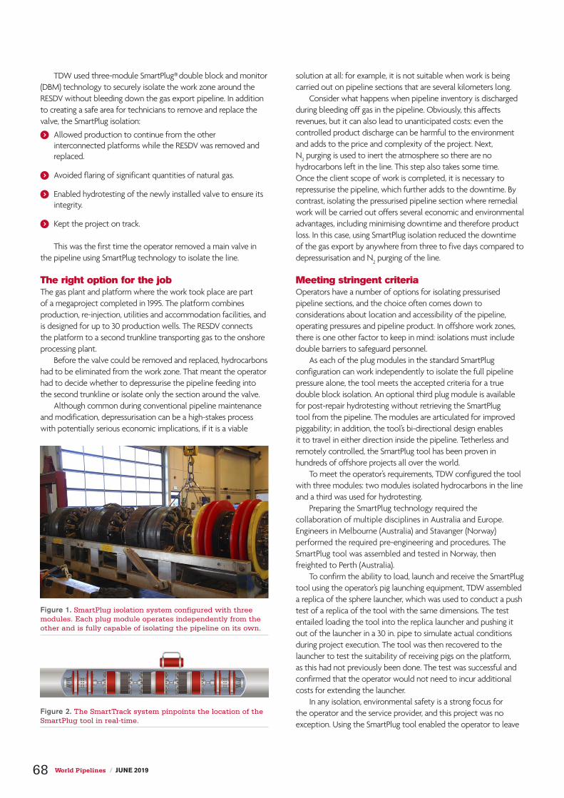
TDW used three-module SmartPlug® double block and monitor (DBM) technology to securely isolate the work zone around the RESDV without bleeding down the gas export pipeline. In addition to creating a safe area for technicians to remove and replace the valve, the SmartPlug isolation:
) Allowed production to continue from the other interconnected platforms while the RESDV was removed and replaced.
) Avoided flaring of significant quantities of natural gas.
) Enabled hydrotesting of the newly installed valve to ensure its integrity.
) Kept the project on track.
This was the first time the operator removed a main valve in the pipeline using SmartPlug technology to isolate the line.
The right option for the jobThe gas plant and platform where the work took place are part of a megaproject completed in 1995. The platform combines production, re-injection, utilities and accommodation facilities, and is designed for up to 30 production wells. The RESDV connects the platform to a second trunkline transporting gas to the onshore processing plant.
Before the valve could be removed and replaced, hydrocarbons had to be eliminated from the work zone. That meant the operator had to decide whether to depressurise the pipeline feeding into the second trunkline or isolate only the section around the valve.
Although common during conventional pipeline maintenance and modification, depressurisation can be a high-stakes process with potentially serious economic implications, if it is a viable
solution at all: for example, it is not suitable when work is being carried out on pipeline sections that are several kilometers long.
Consider what happens when pipeline inventory is discharged during bleeding off gas in the pipeline. Obviously, this affects revenues, but it can also lead to unanticipated costs: even the controlled product discharge can be harmful to the environment and adds to the price and complexity of the project. Next, N2
purging is used to inert the atmosphere so there are no hydrocarbons left in the line. This step also takes some time. Once the client scope of work is completed, it is necessary to repressurise the pipeline, which further adds to the downtime. By contrast, isolating the pressurised pipeline section where remedial work will be carried out offers several economic and environmental advantages, including minimising downtime and therefore product loss. In this case, using SmartPlug isolation reduced the downtime of the gas export by anywhere from three to five days compared to depressurisation and N
2 purging of the line.
Meeting stringent criteriaOperators have a number of options for isolating pressurised pipeline sections, and the choice often comes down to considerations about location and accessibility of the pipeline, operating pressures and pipeline product. In offshore work zones, there is one other factor to keep in mind: isolations must include double barriers to safeguard personnel.
As each of the plug modules in the standard SmartPlug configuration can work independently to isolate the full pipeline pressure alone, the tool meets the accepted criteria for a true double block isolation. An optional third plug module is available for post-repair hydrotesting without retrieving the SmartPlug tool from the pipeline. The modules are articulated for improved piggability; in addition, the tool’s bi-directional design enables it to travel in either direction inside the pipeline. Tetherless and remotely controlled, the SmartPlug tool has been proven in hundreds of offshore projects all over the world.
To meet the operator’s requirements, TDW configured the tool with three modules: two modules isolated hydrocarbons in the line and a third was used for hydrotesting.
Preparing the SmartPlug technology required the collaboration of multiple disciplines in Australia and Europe. Engineers in Melbourne (Australia) and Stavanger (Norway) performed the required pre-engineering and procedures. The SmartPlug tool was assembled and tested in Norway, then freighted to Perth (Australia).
To confirm the ability to load, launch and receive the SmartPlug tool using the operator’s pig launching equipment, TDW assembled a replica of the sphere launcher, which was used to conduct a push test of a replica of the tool with the same dimensions. The test entailed loading the tool into the replica launcher and pushing it out of the launcher in a 30 in. pipe to simulate actual conditions during project execution. The tool was then recovered to the launcher to test the suitability of receiving pigs on the platform, as this had not previously been done. The test was successful and confirmed that the operator would not need to incur additional costs for extending the launcher.
In any isolation, environmental safety is a strong focus for the operator and the service provider, and this project was no exception. Using the SmartPlug tool enabled the operator to leave
Figure 1. SmartPlug isolation system configured with three modules. Each plug module operates independently from the other and is fully capable of isolating the pipeline on its own.
Figure 2. The SmartTrack system pinpoints the location of the SmartPlug tool in real-time.
68 World Pipelines / JUNE 2019

elcometer.com
Measure material thickness quickly and accurately, using Elcometer’s MTG range of ultrasonic thickness gauges.
THICKNESS
Measu
re·
FAST
· REPEATABLE ·
ACCURATE · D
URABL
E
MATERIAL
Versatility Across Terrain
Swappable UndercarriageEasily change the undercarriage – rubber or steel – to meet changing soil conditions.
Email us at [email protected] or visit superiormftg.com/carrier
Superior Manufacturing™ is a trademark of Worldwide Machinery.

most of the pipeline pressurised and bleed off only a short section, avoiding flaring large volumes of gas.
Set, sealed and trackedThe successful isolation began when TDW launched the three-module SmartPlug tool and pigged it with nitrogen through the topside piping into the horizontal section downstream of the RESDV, a total distance of approximately 52 m (170 ft). Once both plug modules of the SmartPlug tool had been set, the annulus pressure (between the plug modules) was monitored for 13 hrs. Then TDW issued the isolation certificate, per TDW procedure, verifying the tool was effectively sealing against a line pressure of 82 bar (1189 psi). The operator depressurised the isolated section and performed the valve repairs.
An additional benefit of the SmartPlug system is that a third plug module can be added so that a leak test can be conducted swiftly prior to unsetting the isolation. After the valve repair work was completed, TDW activated the third plug module, allowing the operator to perform an integrity leak test at a pressure of 78 bar (1131 psi). After the leak test, the pressure across the SmartPlug was equalised, the plug modules unset and the tool pigged back into the launcher.
Throughout the isolation, TDW continuously monitored and tracked the SmartPlug tool from the platform using its SmartTrackTM two-way communication system and a satellite monitoring kit. Originally developed to track and identify SmartPlug isolation tools and now used with other equipment as well, the SmartTrack system provides real-time information about
the location and passage of pigs and tools within the pipeline. It is capable of through-wall communication in buried or subsea pipes up to 50 mm (2 in.) thick. For this operation, additional SmartTrack transceivers, strapped to the launcher and to the pipe at the set location, facilitated tracking.
The isolation remained in place for the 19 days it took to remove, replace and test the RESDV. TDW then unset the SmartPlug tool and pigged it back to the launcher using gas pressure from the pipeline.
From turnaround to tomorrowThere is no getting around it: turnarounds are tough. They typically require extensive, long-term planning and close collaboration among technical experts from wide-ranging disciplines. To say they can be time-consuming is an understatement. According to the operator, work teams at the two sites delivered more than 150 000 hrs total during the project. The costs can also be considerable, especially when the revenue lost by shutting down production is added to the figures for tools and labour. Avoiding unanticipated issues that can arise during these events takes skill, foresight and sometimes even a little luck.
However in this case, at least, the payoff is clear; with the new RESDV in place, the operator believes they have extended the platform’s operational life by at least 20 years. By providing a precise and safe isolation, TDW helped one of Australia’s largest oil and gas developments meet its turnaround goals and be even better positioned for the future.

Preparation is paramountTony Hufford and David Jescovitch, Weiler Abrasives, USA, discuss key factors for operators to consider when choosing
abrasives for weld prep in steel pipeline applications.
Improper or inadequate weld preparation can cost significant time and money in steel pipeline welding – holding up the line and keeping welders from completing work.
While proper cleaning and preparation of the weld joint is important in any application, it is especially critical in pipeline welding. Each complete pipeline weld undergoes non-destructive testing such as X-ray testing, so any rust, bug holes, contaminations or inclusions will show up as defects and require costly rework.
It is important to learn how choosing the right abrasive or wire brush product, and using it properly, promotes safer and more productive prep and cleaning in pipeline welding.
Pipeline challenges The bottom line in pipeline welding is to complete as many weld joints as possible each day. It is critical to keep the crew moving down the line to maintain productivity. Maximising the time a welder spends welding – and minimising the time spent waiting
71

for the welder’s helper to complete joint prep, fit-up and cleaning – helps achieve this goal.
Often, full lengths of pipe are delivered to the jobsite already cut and bevelled. They still require cleaning and shoring up (facing) the land, which is the flat portion at the bottom of the bevel toward the ID of the pipe. The bevelled ends may also have rust and pits that require cleaning. In most cases, just superficial rust needs to be cleaned from the bevel, which may be achieved with a buffing wheel (bead brush).
For bevels with pitted surfaces or ones that have been cut in the field for tie-ins, a flap disc or a grinding wheel is needed to prepare the surface.
As an additional prep step before fit-up, a grinding wheel or flap disc may also be used to regrind the inside surface if the pipe is not perfectly round – a process known as transitioning the pipe.
Abrasive and power brush consumables such as buffing brushes, grinding wheels and flap discs are used for many steps in the weld prep and cleaning process. For example, a grinding wheel is used to smooth out tacks welds if they are used in the fitting process. Bead or root welds, which are produced by stick welding, are completely ground to ensure any impurities are removed, bug holes exposed and wagon tracks are ground down, leaving a slight ‘u’ shape in preparation for the hot pass. This preparation allows the hot pass to push into the joint, ensuring full penetration.
After the hot pass and in between all subsequent weld passes, (including filler and cap passes), a wire brush is used to clean the weld before laying down the next pass. This inter-pass cleaning,
undertaken immediately after welding, is important to prevent any contamination or inclusions. Welds with inclusions must be ground out and rewelded – adding considerable time and expense to the process.
Maximising productivity and efficiency is key in pipeline grinding and cleaning applications, so the welder can get back under the hood and move the line forward as quickly as possible.
Choosing a product for weld prep The condition of the pipe ends can vary greatly when pipe pieces arrive on the jobsite. It is common for rust to accumulate. A pipe with only light surface rust calls for a different conditioning product than a pipe with pitting. The size of the pipe also plays a role in choosing the right product for the job. The primary options for cleaning and grinding pipe include:
Buffing wheels (wire wheels and bead brushes)The many product options in this category include knotted wire wheels, stringer bead wheels, wire cup brushes and encapsulated wheels (also called rubber buffing brushes). A wire cup brush is good for cleaning a larger surface area, for example. No matter what form, wire brushes efficiently remove loose material on the surface of the pipe but do not remove base material. They can also be used to remove burrs that may form when creating the land on the bevel.
Flap discsThe next level in terms of cleaning action and aggression is a flap disc. These products are a good choice to smooth out uneven surfaces on the bevel. Flap discs do remove some base material, but at a controlled rate when using a mid-range grit size, so there is less potential for gouging. It is important to look for a flap disc with very rigid backing, such as aluminium, which holds a straight edge during use in pipeline applications. Flap discs are also commonly used in weld repair to shine the surface so any defects in the weld can be found easily.
Grinding wheelsFor removal of very heavy surface rust or pits, a grinding wheel provides the most aggressive action. It is recommended that operators keep in mind that grinding wheels do remove base material as they work, and should look for a grinding wheel that is designed specifically for pipeline applications. Many products identify their functions on the wheel, making it easier for operators to know what function a product is designed for (Figure 3).
Product choice is often a matter of operator preference, but it is important to consider the job to be carried out and pick a product that is best suited to that work. Operators should always read the labels and manufacturer’s instructions for all products.
It is also important to match the accessory and tool size to the application. When cleaning and preparing a large area, such as a 42 in. pipe, operators may want something that delivers faster surface speed per minute and faster cleaning action. Some prefer a 9 in. grinding wheel for maximum surface speed per minute, but
Figure 1. Choosing the right abrasive and using it properly promotes safer and more productive weld prep and cleaning.
72 World Pipelines / JUNE 2019


keep in mind that a 9 in. grinder is much heavier than a 7 in. or 6 in. grinder.
The bottom line is to consider which accessories help the operator get the job completed most efficiently.
Common weld prep mistakes Some common mistakes in weld prep and cleaning can hinder operator safety, productivity and weld quality in pipeline applications.
Choosing the wrong product Operators may use the tool and product that is at hand, rather than considering what is the best tool for the job. For example, a harder wheel is often used because it lasts longer and, therefore, reduces changeover time compared to a softer wheel. However, harder wheels can load and glaze over, resulting in slow cut rates and chatter or vibration when grinding. To prevent this glazing, operators notch or chip into the side of the wheel with a file or other means, but this is a dangerous practice that is detrimental to the wheel and will result in flying debris or complete failure of the wheel. It is better instead to switch to a wheel specifically designed for pipelines that is not prone to loading or glazing, but will still give operators the product life they demand. This helps operators grind the weld as quickly and safely as possible.
Using all wheels the same wayIt is a common misunderstanding that all grinding wheels work the same way. Actually, some wheels are made only for notching or only for vertical grinding, while others are designed for vertical grinding in addition to bevelling and facing. For optimal and safe performance, operators should always check what the product is designed to do and match it to the job. Finding one wheel that does it all eliminates the chance of using the wrong wheel on the wrong application, which can lead to a safety concern.
Using wire brushes incorrectlyThere are many products to choose from in the wire brush category. Encapsulated wheel brushes (rubber buffing wheels) are a good option to prevent long wire breakage and deliver aggressive cleaning action. However, operators may try to soften the wheel by heating the outside edges or running the wheel on concrete. They also hit the wheels with a file to loosen the encapsulation. These are safety hazards and they add time for brush conditioning. Instead, operators should look for a product that does not need to be softened before use, so it is ready for cleaning right out of the box. Also, they should consider a wire brush that is designed to be easily flipped over, which provides maximum cleaning action, longer life and safer use. As wire wheels and brushes are designed to let the wire tips do the work, it is important to orient the wheel so only the wire tips hit the work surface and to not use too much pressure.
Improperly storing tools and productsPipelines can be challenging environments. Tossing abrasive products and hand tools into the dirt or snow can potentially cause damage and shorten product life. It is important to keep products clean and dry, and store them properly in a safe location.
Improve safety and efficiency in weld prep Weld quality is critical in pipeline applications, since every weld defect costs time and money to repair and delays the crew. Achieving high-quality welds starts with properly preparing the base material.
Choosing the appropriate product for weld preparation and cleaning, and following common tips for proper usage, helps optimise productivity and efficiency in these deadline-driven applications, while also helping to ensure operator safety on the jobsite.
Figure 2. Proper cleaning and preparation of the weld joint is especially critical in pipeline welding. Each pipeline weld undergoes X-ray testing to reveal any defects.
Figure 3. Products that identify their functions on the wheel make it easier for operators to know if a product is designed for grinding and bevelling or facing.
74 World Pipelines / JUNE 2019

THE SAFEST OF REPAIRS
Mark Leska, E.H. Wachs, USA, discusses the application of new technology to optimise pipeline maintenance and repair operations.
F or pipeline rehabilitation and repair projects, where downtime costs are measured in thousands or hundreds of thousands a day in lost revenue,
an investment in doing the job right the first time with cold cutting machine tools pays a huge dividend. At a recent pipeline
75

maintenance, repair and operations (MRO) project, a national pipeline distribution company utilised E.H. Wachs’ DynaPrep MDSF® Split Frame technology to quickly deliver the precise fit-ups the repair required.
Advancing pipeline MROThe project scope called for installation of a replacement section, including an elbow affected by
erosion corrosion, that was remotely fabricated, cold cut and weld prepped on site, lowered into its cradle and welded. The DynaPrep MDSF Split Frame pipeline series selected for the project utilised out-of-round tracking tool slides to simultaneously cut and bevel a precision weld prep with a 1/16 in. (0.0625 in. or 1.59 mm) land. These preps were weld ready, and required no further hand working.
This project began with torch cutting of destructive cuts following inerting (although often cold cutting is specified for the entire procedure). Torch cutting carries limitations and risks; it can only be used where precision is not a major factor, where there are no explosive hazards, or where the creation of an undesirable heat affected zone (HAZ) is not an issue. Cold cutting, or more precisely utilising portable pipe cutting and bevelling machine tools for cold cutting, minimises these risks.
The defective pipeline sections in this example were cut undersize, to allow adequate length for machine cutting and bevelling of the torched ends of the pipeline to remove the HAZ tainted pipe stubs. A significant advantage of the machining or cold cutting process over thermal is preventing the creation of a HAZ. Applying extreme temperature to a pipe, such as that produced by plasma or acetylene torches, changes the molecular structure of the metal itself, often altering its properties to detrimental effect.
When the time came to prep the sections for the critical fit-ups (the so-called ‘money cuts’), cold cutting precision was required. This phase involved Wachs’ DynaPrep MDSF Split Frame pipeline series, selected for their ability to maintain the critical specified tolerances (0.0313 in. or 0.794 mm) that are difficult or impossible to achieve using other methods. Plus, unlike thermal cutting and grinding, only machining can produce the compound bevels and complex ‘J’ prep specified by leading welding equipment manufacturers.
Pipeline professionals know that thin wall, large-diameter pipe is seldom perfectly round, due to its relatively lightweight construction that can be easily deformed during manufacturing, transit or handling. Ideally suited for machining a uniform prep and consistent land on pipelines are Wachs’ OD tracking tool slides, standard on the DynaPrep MDSF pipeline kits. The term ‘tracking slides’ refers to the mechanism that slides or advances the tooling (cutting and bevelling tool bits) into the workpiece, and that follows or tracks the pipe OD with a spring-loaded guide wheel.
Tracking slides allow the creation of a uniform land, which is the portion of the weld prep that accepts the critical weld root pass. The land is the most important part of the prep. If the land is too narrow, then the welder may burn a hole through it. If the land is too thick, then there may not be proper penetration to the base metal. Out-of-round tracking slides also speed up the set-up of the machine, making it less critical that the machine is perfectly centred on the pipe. This is a very useful feature for both out-of-round and round pipe.
Figure 2. Pneumatic-powered cold cutting machine tools in the field.
Figure 1. Split frame technology is designed to speed up pipeline section replacement.
76 World Pipelines / JUNE 2019

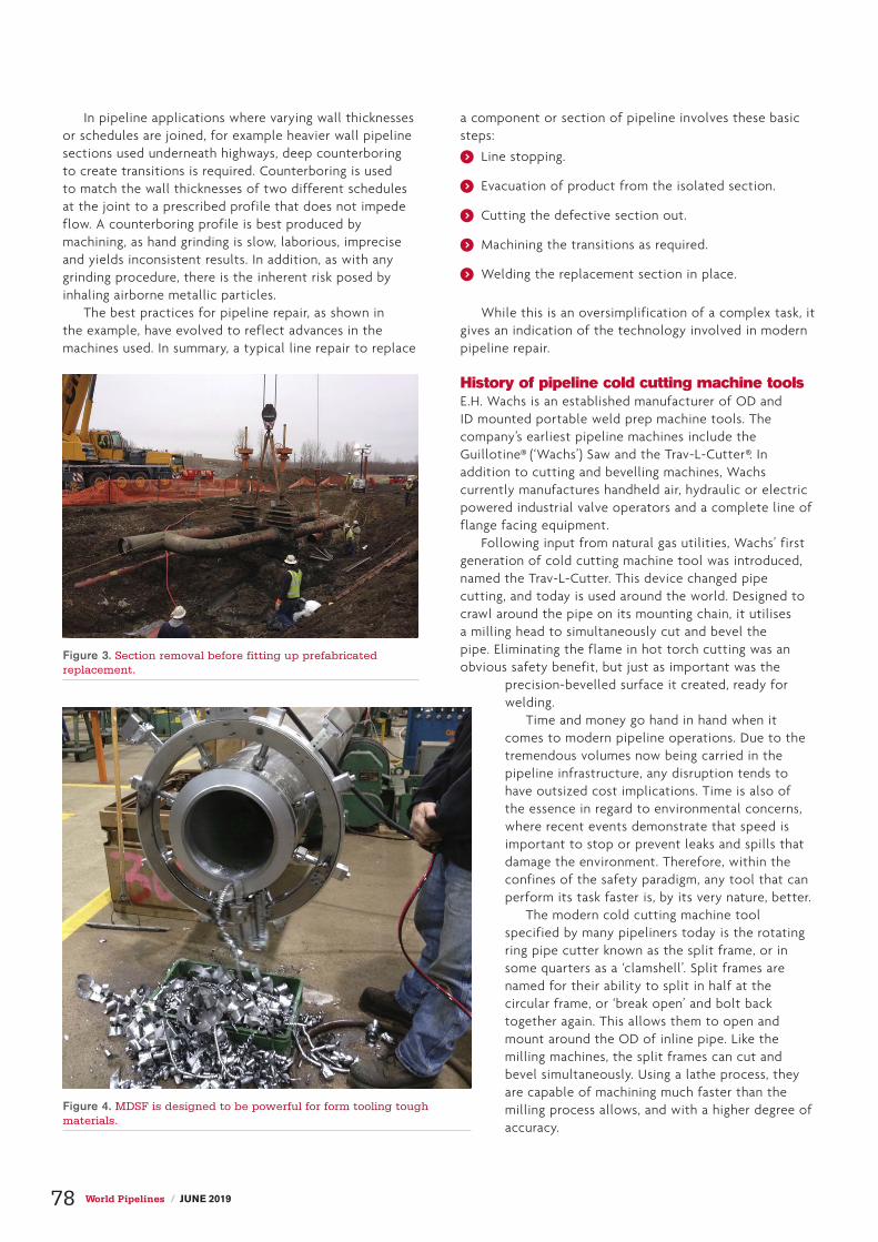
In pipeline applications where varying wall thicknesses or schedules are joined, for example heavier wall pipeline sections used underneath highways, deep counterboring to create transitions is required. Counterboring is used to match the wall thicknesses of two different schedules at the joint to a prescribed profile that does not impede flow. A counterboring profile is best produced by machining, as hand grinding is slow, laborious, imprecise and yields inconsistent results. In addition, as with any grinding procedure, there is the inherent risk posed by inhaling airborne metallic particles.
The best practices for pipeline repair, as shown in the example, have evolved to reflect advances in the machines used. In summary, a typical line repair to replace
a component or section of pipeline involves these basic steps:
) Line stopping.
) Evacuation of product from the isolated section.
) Cutting the defective section out.
) Machining the transitions as required.
) Welding the replacement section in place.
While this is an oversimplification of a complex task, it gives an indication of the technology involved in modern pipeline repair.
History of pipeline cold cutting machine toolsE.H. Wachs is an established manufacturer of OD and ID mounted portable weld prep machine tools. The company’s earliest pipeline machines include the Guillotine® (‘Wachs’) Saw and the Trav-L-Cutter®. In addition to cutting and bevelling machines, Wachs currently manufactures handheld air, hydraulic or electric powered industrial valve operators and a complete line of flange facing equipment.
Following input from natural gas utilities, Wachs’ first generation of cold cutting machine tool was introduced, named the Trav-L-Cutter. This device changed pipe cutting, and today is used around the world. Designed to crawl around the pipe on its mounting chain, it utilises a milling head to simultaneously cut and bevel the pipe. Eliminating the flame in hot torch cutting was an obvious safety benefit, but just as important was the
precision-bevelled surface it created, ready for welding.
Time and money go hand in hand when it comes to modern pipeline operations. Due to the tremendous volumes now being carried in the pipeline infrastructure, any disruption tends to have outsized cost implications. Time is also of the essence in regard to environmental concerns, where recent events demonstrate that speed is important to stop or prevent leaks and spills that damage the environment. Therefore, within the confines of the safety paradigm, any tool that can perform its task faster is, by its very nature, better.
The modern cold cutting machine tool specified by many pipeliners today is the rotating ring pipe cutter known as the split frame, or in some quarters as a ‘clamshell’. Split frames are named for their ability to split in half at the circular frame, or ‘break open’ and bolt back together again. This allows them to open and mount around the OD of inline pipe. Like the milling machines, the split frames can cut and bevel simultaneously. Using a lathe process, they are capable of machining much faster than the milling process allows, and with a higher degree of accuracy.
Figure 3. Section removal before fitting up prefabricated replacement.
Figure 4. MDSF is designed to be powerful for form tooling tough materials.
78 World Pipelines / JUNE 2019


Split frames come in various configurations and sizes, with E.H. Wachs’ SDSF and MDSF models designed to balance weight, clearance and portability issues, and LDSF large-diameter models designed for larger pipe or vessels, or large-diameter, heavy wall pipe. Available in pneumatic, hydraulic or electric drive (depending on model), Wachs’ split frames form the basis of a complete machining system. While superficially resembling other machines, they are built for long life, incorporating advanced features that facilitate quick set-ups and fast, precise machining.
Modules and accessories are available that allow the DynaPrep MDSF to perform functions including cutting, bevelling, simultaneous cutting and bevelling, counterboring, heavy wall machining, flange facing (both regular and raised
faced), RTJ grooving, socket weld removal and weld crown removal. Mounting leg and laser alignment accessories allow the MDSF to miter cut and bevel misaligned pipeline sections or elbows. Collectively speaking, the DynaPrep MDSF system can tackle just about any onsite machining project likely to be encountered in the field.
Wachs’ weld prep machine tools, like the split frames, produce square cuts and uniform lands for an accurate root pass, to ensure a quality weld, repeatability and a level of workmanship that virtually eliminates reworks. With the proper weld prep and a skilled welder, the ensuing welded connection is as strong or stronger than the parent pipe material.
Pipeline MRO safetyPipelines pose their own unique set of challenges for maintenance professionals in the field. Apart from the physical demands – repairs always seem to be needed in the middle of nowhere – there can be operating envelope concerns. Working in oil and petrochemical plants can mean extremely tight clearances, where it can be difficult to fit an arm between two pipes, let alone a cutting machine tool. Unique or unusual weld profile specifications can also make for different challenges.
The first generation of cold cutting machine tools set the priorities for pipeline repairs that remain true to this day, and are the drivers for best practices. In order they are safety, time and money. Safety is first and foremost, the primary consideration in pipeline project planning. The current generation of cold cutting machine tools is designed to eliminate the hazards associated with thermal cutting, and increasingly is being specified for its inherent safety advantages.
The bottom line is this: safe, accurate and cost-effective cold cutting machine tool technology continues to advance, allowing pipeline professionals to realise great strides in safety, decreases in downtime and overall savings in repair costs. Manufacturer of the first-generation machine tools, E.H. Wachs engineers tools for pipeliners, so they can continue to make the pipeline infrastructure one of the safest ways to transport products.

Feeling the grooveFeeling the groove
Chemical and refinery personnel face fluctuating market conditions on a daily basis. Controlling construction and maintenance costs is critical to protecting margins. The effort to streamline work and maintain acceptable
safety standards has led to a search for cutting-edge ways to achieve greater efficiencies.
Finding ways to perform work more economically is integral to achieving real economies of scale. In some cases, this has involved investing in new technologies. In others, it has led to the adoption of a progressive means of working, as many companies are factoring breakthrough tools and materials into their equation.
The advantage of simplicityHistorically, most industrial construction projects have relied on flanged and welded piping connections. When faced with the need to repair or replace ageing pipe or segments, many view these options as default solutions. While they are functional solutions, they might not be ideal, safe or cost-effective.
Assembling flanged valves can be tedious and they require significant force to operate. When it comes to maintenance, they are difficult to disassemble and reassemble. They are also subject to dynamic pressures and movement, causing bolts to
stretch and fatigue over time. Welded joints present limitations as well: the process is time-consuming, and welding presents a high fire hazard along with a high risk of injury.
A Victaulic pipe system in place of welded or flanged joints ensures pipeline integrity, accelerates schedule, reduces jobsite congestion and provides design options with rigid and/or flexible couplings. Victaulic couplings have been utilised in oil, gas and chemical applications since the early 1920s. These couplings have become the standard joining method in critical areas of the upstream and downstream markets. Owners of industrial facilities have not had the same exposure and thus have gradually recognised their inherent value. However, successes in the field are now changing the outlook owners and operators have towards mechanical couplings and their willingness to use them throughout their systems.
Alternative solutionsOne chemical company recently made the decision to use Victaulic grooved couplings during a turnaround when it became apparent that traditional solutions would make it impossible to keep the project’s fast-track schedule.
Designing, fabricating and installing the subject piping within the required schedule was extremely challenging, allowing just three months for completion. The installation location was congested with existing piping, equipment and steel. Buried piping in this facility was over 50 years old and needed to be replaced. Aboveground cooling-water piping was prepared and installed through several buildings in advance of the scheduled shutdown. Tying in the new piping segments would require the
Kevin Rizo, Victaulic, USA, discusses non-traditional joining methods for reducing construction and
maintenance costs.
81

service to be shut off temporarily to connect to the existing system. Once removed from service and filled with concrete, the old pipe would remain in place. The schedule allowed for only two weeks for the tie-in work to be completed.
The chemical company invested a year in the planning and design of the system upgrade and engaged Victaulic for the mechanical joining. Victaulic generated a set of non-dimensional drawings, used to estimate labour costs for the project using multiple methods – including grooved couplings. Once the owner and contractor saw the cost and labour savings, Victaulic was chosen as the preferred method, including 42 in. headers.
In a welded system, when large outlets are directly connected to a header, steel reinforcement pads around the penetration are utilised to provide additional support and corrosion resistance to the header pipe. Alternatively, specialty full-encirclement fittings can be made to fit around the full circumference of the header, but as specialty items, these require significant lead time and extra care in installation. Since the schedule was tight, and safety could not be compromised, an alternative solution was needed.
The engineering teams from Yates Construction and Victaulic collaborated to design a solution using a more robust pipe wall and grooved joining components, eliminating the need for full-encirclement fittings. This effort led to the decision to increase the pipe schedule from the standard 0.375 in. to Schedule 40 pipe (0.5 in.). Victaulic provided 30 in. Style W77 flexible couplings for piping between header and valves, which allowed for axial or angular movement due to misalignment. The Victaulic manufactured headers combined with couplings for piping greater than 30 in. (instead of traditional welding or flanges), shortened the installation process, eliminated the risk of rework and maximised productivity – allowing the plant owner to meet the demanding project schedule.
The plant was fully operational during installation, with multiple crews onsite and considerable congestion. Rigging and lifting the large-diameter pipe posed challenges due to space constraints. In those sections of the plant, the pipe had to be fed between buildings and other structures. The pipe lengths – the longest of which was 35 ft – compounded this problem.
With the pressure of the condensed schedule, alternative pipe joining methods were evaluated to reduce risk and avoid cost overruns. By using Victaulic joints, the maintenance cycle was completed ahead of schedule using standard tools and equipment. The couplings feature bolt pad to bolt pad installation confirmation, so it was easy for workers to visually inspect the integrity of each joint. These joints can be installed up to 90% faster than welded joints.
Installers were trained on site by a Victaulic factory representative, ensuring delivery of a consistent, high quality system. The crew was trained on the pipe end preparation and the roll grooving process, along with quality control implemented to ensure proper installation. The team was also prepared to use the best methods for rigging and installing the large mechanical couplings and positioning them correctly on the pipe. Within hours, the project team was comfortable with pipe grooving and coupling assembly. On average, the large-diameter grooved couplings were assembled in less than 30 min., compared to traditional 24 in. code weld connections which could take 2 - 3 days to complete. The speed of grooved coupling installation eliminated jobsite congestion, fire risk and the complications and risk of welding.
Moving forwardThe successful execution of the initial project at this plant led the owner to specify Victaulic large-diameter grooved couplings (8 - 24 in.) on a future project. The owner leveraged the Victaulic Virtual Design and Construction team to assist with pipe layout, material list and delivery co-ordination.
These installations illustrate how innovative products are being designed to meet the rigorous demands and challenging environments of the chemical, oil and gas industry. Because they are designed to make pipe joining faster, easier and more economical, these couplings, valves, fittings and specialty products allow engineers and owners to build complete piping systems from a single source. Continued innovation will add more time-saving, cost-saving and risk mitigating solutions to the line-up.
Figure 1. 42 in. header staged for installation.
Figure 2. 24 in. cooling water pipe between buildings and existing pipe.
82 World Pipelines / JUNE 2019

Instantaneous imagesJeremy Guretzki, President, Stanley Inspection,
USA, describes how the NeXray system has
utilised advancements in radiography and digital
technologies.
There is a growing industry demand for improving girth weld quality while
reducing the cost of pipeline construction operations. As a result, there
is an increased demand for higher quality and more cost effective non-
destructive (NDT) methods of inspecting pipeline girth welds.
Real-time radiography
NeXray is a real-time radiography system designed for small and large diameter
pipelines applicable to both mainline and tie-in for onshore and offshore
applications. The system provides cost reduction of pipeline construction projects
while improving inspection quality, safety and reducing environmental impact.
With conventional film radiography, film is exposed to radiation, capturing
the image. The film then requires processing and drying before the technician can
interpret it. In this scenario, and for safety reasons, pipeline construction personnel
cover story
83

are required to move outside of the radiation exposure area. The radiation exposure area is significantly reduced in the case of real-time radiography, along with inspection time, and does not require significant movement of pipeline construction personnel – which increases crew safety while reducing production time and cost. It also eliminates the need for film and the harmful chemicals used to develop, lessening the environmental impact. This was recognised when NeXray was recently awarded the Stanley Black & Decker 2017 ECOSMARTTM Planet award.
With NeXray, the image becomes available in real-time as the radiation source and detector scan around the
circumference of the girth weld. This provides users with instant results upon completion of each weld inspection. The inspection file is then stored on redundant hard drives and on the cloud, allowing easy access at any time – which makes it possible for auditors to monitor several pipeline construction projects concurrently from a remote central location.
Technology
HardwareThe system consists of two main parts: a detector and a source. For tie-in or double wall applications, the source and the detector are mounted on the independent carriage systems, which are driven by a stepper gear motor that includes a break assembly for added safety. Each carriage is adjustable by pipe size and travels on a size-specific band, which is mounted on the pipe OD. The current size range is 8 - 48 in. and the travel speed is 0.5 - 100 mm/s. The position feedback is provided by an encoder.
The detector uses the latest in hardware and software technology. This detector provides a better quality image than previous generations and meets ISO Class B and Pipeline NDT Codes such as API 1104 & CSA Z662 standards.
The detector can withstand shocks of 220 G. The radiation source is either a directional tube featuring a robust field-tested design, or an internal panoramic X-ray crawler. The external source is IP65 and the detector is IP67 rated.
Software The NeXray software package allows for easy set-up with a set-up Wizard. It provides an easy change-over from one pipe size/wall thickness change to the other. The software is optimised to include the motion control, acquisition, analysis and reporting tools.
During the acquisition, the software monitors the photon counts and the quality of image in real-time. The technician can perform mark-ups and measurements while the scan is still in process and does not need to wait for the entire scan to be finished to do so. Once the acquisition is complete, the software allows the technician to save a permanent image of the inspection with all the indications and annotations in DICONDE format. The files can be backed up locally or pushed to the cloud.
The customers and auditors can view these files via the NeXray DICONDE viewer and are able to perform basic operations and measurements on the image.
ConclusionThe NeXray system is designed to provide exceptional cycle time and quality on applications from 8 - 48 in. and wall thickness up to 1 in. (25.4 mm).
The system is compatible with both DWSI and SWSI applications and is designed to operate in the ambient temperature range of -40˚F to 122˚F (-40˚C to 50˚C).
NeXray uses advancements in radiography and digital technologies to reduce OPEX of pipeline construction by delivering cycle time reduction, real-time reporting, as well as enhanced safety for all involved.
Figure 1. NeXray state-of-the-art mechanical design.
Figure 2. Directional X-ray minimising the radiation area.
Figure 3. NeXray versatility: operating from -40˚C to 50˚C.
84 World Pipelines / JUNE 2019

5162 S 24th W Ave, Tulsa, OK 74107 www.lifttechnologiesinc.comTel: 918-794-8088 Fax: 918-794-8090
SOLUTION TO PIPE LIFTING?
ARE YOU LOOKING FOR A ...
SAFERFASTERMORE EFFICIENT
QUALITYDurable components used for extended lifespan and consistent equipment operation
SAFETY• High capacity rotator• Digitally encoded radio remote control• Large vacuum reservoir to maintain load
SERVICEQuality customer service and maintenance after your purchase
COST SAVINGSQuality construction, reliable customer service and dependable components reduce operating costs
Manufacturing High Quality, Reliable Vacuum Lifting Equipment

DeFelsko Corporation Ogdensburg, New York USATel: +1-315-393-4450 Email: [email protected]
+1-315-393-4450www.defelsko.com
Unrivaled probe interchangeability
Award Winning Compatibility! The PosiTector gage body accepts ALL coating thickness (6000/200),surface profile (SPG/RTR), environmental (DPM), , salt contamination(SST), ultrasonic wall thickness (UTG) and hardness (SHD/BHI) probes.
PosiTector ® Inspection
Coating Thickness
Environmental Conditions
Ultrasonic Wall Thickness
Surface Profile
Salt Contamination
Hardness

Håvard Høydalsvik, Rädlinger primus line GmbH, Germany, details the rehabilitation of high-pressure pipes
using an innovative composite relining system.
T raditionally, pipelines that are reaching the end of their useful life will be replaced by new steel pipes. Composite pipe solutions such as Primus Line® can
delay the replacement and extend the life of existing assets, providing network operators with significant CAPEX and OPEX savings. Especially in low and volatile oil price environments, innovative
and cost-effective solutions can provide economic benefits rather than deploying large-scale replacement projects.
The composite lining system The system consists of the Kevlar®-reinforced liner and specifically developed termination fittings, and is available from DN 150 to DN 500.
A triple A triple threatthreat
Figure 1. Installation of the end connectors.
87

The composite liner consists of three different layers (Figure 2). The inner layer is media-specific and either made of a low-density polyethylene (PE) for water applications or a thermoplastic polyurethane (TPU) for oil and gas applications. Depending on the pressure rating, the middle layer – a seamless aramid reinforcement – is either made of a mixture of polyester and Kevlar for low-pressure applications (hybrid construction), a pure Kevlar fabric for medium-pressure applications, or a double-layer Kevlar construction for high-pressure applications. The fabric’s purpose is to accommodate both the operating pressure independently from the host pipe, and also the insertion forces during the installation process. The outer layer (cover) is made of PE, with the sole function to protect the middle layer during the installation process.
Furthermore, along the entire Primus Line section, there will be a steady or constantly increasing/decreasing pressure level. The minimum operating pressure of the system has to be 1.0 bar. The flow velocity in the entire Primus Line section is constant as well. Pipes are usually operated with up to 3 m/s.
Termination fittingsThe second part of the system is the specifically developed termination fittings. There are two types: the low-pressure fitting that is available from DN 150 to DN 300 and that can be re-used (Figure 3), or a medium/high-pressure fitting available from DN 150 to DN 500. Installation is performed with a two-component epoxy resin. The outer Primus Line sleeve with flange is mounted to a corresponding flange at the host pipe. The Primus Liner is trimmed and secured. Then, the connector core with a contour is inserted. A two-component epoxy resin is injected with high pressure into the outer sleeve and a malleable steel jacket on the inside of the outer sleeve forces the Primus Liner into the connector core. There is a curing time of six hours with an ambient temperature of 20˚C (68˚F) before a leak test can be performed.
Installation through bendsThe operating pressures of the individual diameters and systems (system meaning liner and corresponding termination fitting) are based on the minimum burst pressure of each diameter and liner type. A creep test according to ISO 9080 derived a fabric factor of 2.0 to realise a minimum life span of 50 years. An additional safety factor of 1.25 for water and 2.0 for oil and gas applications is considered.
Due to the material’s flexibility, the installation through bends is feasible. With an installation through bends, the burst pressure of the lining material in the bend is reduced since only a certain amount of yarns is accommodating the pressure. The burst pressure reduction in the bend depends on the bend radius and the host pipe diameter. The number of bends does not have an effect on the system’s pressure rating. This means on the one hand that the lining material can be installed through bends as tight as 1.5 × D, but it also means that smaller liners can be installed into larger host pipe diameters.
Areas of applicationDue to its unique product characteristics (chemical resistance, flexibility, strength, etc.), the Kevlar-reinforced lining system is suitable for various fields of application throughout the entire hydrocarbon value chain. Starting with traditionally trenchless rehabilitation of difficult to access pipelines that the system has originally been designed for, to temporary overland water transfer systems used for water supply during fracture operations, or as emergency bypasses in a refinery environment.
Trenchless pipeline rehabilitation of a DN 300 (12 in.) crude oil gathering pipelineA Romanian pipeline service company approached Rädlinger primus line GmbH to provide a state-of-the-art solution for the renovation of an 11.7 km long DN 300 (12 in.) crude oil gathering pipeline for its client. An ILI inspection in summer 2018 indicated several critical observations that required an immediate and
Figure 2. Structure of the Primus Line® system.
Figure 3. The Primus Line connector.
88 World Pipelines / JUNE 2019

complete rehabilitation of the entire pipeline originally built in 2012. The detected defects were caused by the pipeline’s exposure to heavy crude oil containing highly corrosive SR bacteria. Since having built the pipeline, significant OPEX investments connected to cleaning and maintenance of this pipeline had been required. As a result, Rädlinger primus line was asked to provide an economical solution that manoeuvres around bends; permits long insertion lengths; has an excellent hydrocarbon and chemical resistance; is characterised by a high-performance corrosion-resistant barrier; and accommodates temperatures of up to 50˚C. In addition, the system should show extremely low permeability, be easily transportable and able to be installed quickly while having few equipment requirements.
After having finalised the technical product qualification, Rädlinger was contracted in October 2018. Due to the project’s urgency, the lead time was extremely critical. Already ten weeks after contract, the material was supplied to the site. The installation was performed in 16 pipe shots with installation lengths of up to 1000 m (Figure 4). To reduce the impact on the client’s operations to a minimum, the installation was executed in two time windows of 14 days each. In February 2019, the pipeline was handed over to the client after a successful pressure test and is now back in operation.
Rehabilitation of a subsea jetty pipelineAfter two years of project discussion, a major oil company awarded Rädlinger primus line with the rehabilitation contract for a subsea offloading pipeline in Italy in 2017. The pipeline to be rehabilitated was an abandoned DN 900 (36 in.) subsea offloading pipeline that had been out of service for several years. It should be put back into operation in order to realise a special connection to the refinery’s crude oil sourcing. For the rehabilitation of the 3.2 km pipeline running from the docking station in the Mediterranean Sea to an onshore terminal, a DN 400 (16 in.) high-pressure Primus Line oil application was selected. For economic reasons, the decision was taken to perform the rehabilitation with four liner sections connected with intermediate connectors, assembled on the pontoon during the insertion process.
In a first step, the pipeline to be rehabilitated was inspected with pigs sent through the host pipeline with water pressure. The inspection results revealed that there were no longitudinal grooves, indentations or abrasions on the pigs – which would have indicated obstacles protruding into the pipeline’s cross-section. To achieve best results, pigs oversized relatively to the pipeline’s diameter were sent through the pipeline. The clean pipeline with a free inner diameter was thus ready for installation.
Specially trained divers took over insertion, with the rope protection unit used to safeguard the Primus Line hose and the rope of the winch during the installation process. The first rope connection was created with a
Heavy Duty Through-wall Reference Electrode

pig sent through the pipeline with water pressure. The Primus Line hoses that had already been pre-folded at the manufacturer’s factory were delivered on transportation drums with a length up to 11 m and a diameter of 2.46 m. Pre-folding the hose reduces the maximum pulling forces significantly and thus long installation lengths are feasible. The transport drum was placed on an A-frame to facilitate the controlled uncoiling of the hose. Since the starting point of the installation was beneath the docking station in the Mediterranean Sea, the A-frame was placed on a pontoon and the insertion was performed by an experienced diving crew (Figure 5). The pulling winch was placed at the onshore terminal. The maximum tolerable pulling force for the Primus Line DN 400 is 39 t. The entire insertion of the four Primus Line hose sections was completed in less than one working week. Finally, Primus Line delivered tailored end fittings with ANSI flanges specifically manufactured for this project. After
installation of the hose and the end fittings, a leak test was performed. The test pressure was 15 bar (218 psi).
Rehabilitation of a refinery processed water mainA Houston (US) refinery recently required rehabilitation of 4880 m of DN 150 ductile iron pipe as it was experiencing multiple leaks at the pipe’s joints and pinholes. This particular processed water line – that carries treated wastewater to a treatment facility located approximately 4.8 km north of the refinery – was 35 years old. The multiple failures and leaks forced the terminal to suspend the use of the processed water line. The terminal owners had to truck the material to the treatment plant at exorbitant costs.
After the pipe owner’s engineers had evaluated all proposed technologies, they decided in favour of Primus Line as the best solution for this project compared to the alternative technologies submitted. The decision was based on: product performance; installation time (one-third of CIPP); overall cost savings (US$1.5 million cheaper than CIPP); a smaller footprint; and the ability to withstand the average daily temperatures of 40˚C (103˚F) and the heavy rains during installation.
The challenges associated with this particular project included long runs as well as several runs inside the active refinery itself, with multiple bends including two runs with vertical 90˚ turns. Complicating the installation process was that the refinery could not be shut down during the project. The installation consisted of nine pulls of DN 150 flexible low-pressure liners.
Two pulls were in excess of 1200 m of continuous liner, one pull was excessing 920 m and there were multiple shorter runs with 90˚ bends. The project duration was only four weeks. One section was located outside the refinery’s perimeter in the so-called ‘Exxon corridor’.
This was an even greater problem for conventional rehabilitation methods, since multiple pits in this location would require co-ordination with numerous property owners for the permission to dig and work in the pits. This would have created greater overlay of safety and security and doubled the cost for work in this area. One section spanned 1300 m with three bends up to 30˚. Conventional CIPP would require at least four runs with five pits; conversely, Primus Line was pulled into place in one section within two hours. Once the two end connectors were attached (Figure 1), the pipe was ready for service within six hours. Two of the sections, approximately 260 m long, ran under an active rail system, had two bends of 30˚ and one of 45˚, and ended by a 90˚ transition vertically to the surface. This could be accomplished without any problems with the flexible Kevlar liner.
Figure 4. Rehabilitation of a crude oil pipeline in Romania.
Figure 5. Unrolling a Primus liner from a pontoon for a subsea installation.
90 World Pipelines / JUNE 2019

Field Joint Coating and
Custom CoatingServices
Pipeline Induction Heat (PIH) provide specialist fieldjoint coating services at spool base locations, offshorepipe lay barges and onshore pipeline constructionprojects around the world, involving the use of state-of-the-art equipment and processes for the applicationof a wide range of field joint coating materials.
PIH also provide Custom Coating services for theapplication of the latest Thermal Insulation solutions(IMPP and IMPU) to bends and spools.
DedicationInnovationIntegrity
Offshore Onshore Spoolbase Custom Coating
Pipeline Induction Heat Ltd, Burnley, UKTel: +44 (0) 1282 415 323 Fax: +44 (0) 1282 415 326
E-mail: [email protected] Web: www.crc-evans.com/PIH

MORE THAN 50 YEARS OF PROVEN PERFORMANCE
Pipeline Machinery
Cold Cutting Process -
Accurate, Dependable, High Capacities, High Precision, Mobile, Per-fect Surface Finish, Re-duced Installation Costs, Enhanced Productivity
PROTEM provides innova-tive solutions where others give up
Expert in Advanced Technologies for the Tube Processing Industry
For more Information, visit our Website: www.protem.fr or write us an e-mail: [email protected]

Ian Macleod, Wood, UK, discusses the most effective methods of reliable
corrosion assessment.
When pipelines have been too structurally complex or operationally challenging for inline inspections (ILI), basic assumptions have often ruled the day.
In a situation where ILI were impossible or impractical, a common historical approach for operators was to assume that the lowest physical points of a subsea pipeline would have a higher risk of corrosion. Thus, the majority of inspection efforts were focused on these spots.
In some cases, analysis has proven this basic assumption to be false.
The risk of corrosion is highly correlated with a complex interplay of factors. If false confidence thrives, the risk of operators missing actual problems and exposing themselves to structural weaknesses intensifies. Further, pipeline inspection places a huge burden on OPEX – so getting it right is not only paramount to assessing current and future integrity but also to controlling associated costs.
Where other techniques have hit a wall, Wood’s multi-disciplinary modelling and analytics-driven approach of internal corrosion assessment for pipelines (ICAP) has broken through. Supported by NACE standard practices and utilising
operational data that companies often already possess, ICAP enables operators to pinpoint the real threats, build confidence in their assessment capabilities and ultimately optimise their inspection processes.
Modelling that pinpoints riskThe more structural limitations there are to an internal pipeline assessment, the more complex it is to verify the structural integrity of a pipeline.
In those situations, the questions that operators and their regulators will ask around validation will be just as complex. With high-risk pipelines, operators and their regulators need to assure themselves that appropriate analysis has been performed to demonstrate integrity – and validate that they can back up these assertions.
There is a multitude of factors that underlie the likelihood for weakness in a pipeline. These go beyond depth, with wax, sand, local process parameters and water drop rates all coming into play.
In situations where ILI are not possible or a tethered pig option is unfeasible, operators have often been left with little more than guesswork: deducing where the high-risk areas are,
Taking the Taking the guesswork out guesswork out of inspectionof inspection
93

conducting a number of internal inspections and trusting that this is enough to assure integrity.
Operational data provides the key to unlocking a new, more effective approach to internal pipeline assessment. Data points around flowrates, fluid composition, pressure, temperature and other factors can reveal a lot about the likelihood of corrosion. With analytics, this information can be assessed and transformed into models that predict where the potential weaknesses may be.
One of the strengths of the ICAP approach is that data does not have to be complete to create a full picture. Where information for a specific pipeline is incomplete or unavailable, information from comparable pipelines or databases may be used to build out a risk-based projection.
Once the data is set, it feeds into the analytics and modelling. Flow modelling takes historical flow data, factors in multiple attributes – such as the system geometry (i.e. the configuration of subsea structures, risers and pipeline elevation profiles) and thermal properties – and runs various simulations to determine critical aspects, such as fluid composition changes over time.
Flow modelling then helps to define sub-regions for the pipeline, identifying areas like wellheads, connectors, jumpers and manifolds, which influence the make-up of the data and modelling outputs.
The outputs of flow simulations are then used to feed into a range of corrosion and erosion rate models. To put it differently, the intelligence gleaned from flowrate modelling helps to identify the locations of sand deposition, wax deposition, extreme process conditions and other signs which may be conducive to severe internal corrosion. The areas with a higher likelihood of corrosion are then identified, thus making them priorities for direct inspection. This also enables a corrosion risk profile to be developed for the entire length of the pipeline, with most susceptible locations clearly identified.
With the right expertise behind the complex interrelated modelling process, operators can make projections of existing flow characteristics and corrosion predictions with a high degree of confidence.
Greater accuracy, greater trustICAP is not just about crunching data and building models, rather it is a multi-disciplinary approach that incorporates
the direct inspections that follow. And with the accuracy that modelling delivers in identifying potential trouble spots and the specific degradation mechanisms at play, pipeline operators can rely on ICAP to prime their approach to pipeline inspections.
With ICAP, direct inspections – whether they be a partial ILI, tethered ILI or an alternative external physical inspection – are more targeted. Moreover, as operators gain confidence in the accuracy of the modelling, they are able to undertake direct inspections in a more cost-effective manner. For example, an engineer could elect to undertake an inspection adjacent to a potential point of corrosion if getting to the actual location is difficult, and still be confident in the accuracy of the measurement.
Additionally, as the accuracy of modelling is validated through inspections, operators will have the flexibility to adjust inspection regimes. Knowing which factors – whether they be flowrates, dropouts or temperature changes – to watch for and how much of a change is needed to warrant a more immediate inspection, will enable engineers to de-prioritise inspections that are not as critical. Therefore, by reducing the frequency of necessary inspections on lower risk pipelines, operators stand to reduce costs, while enabling resources to be focused on higher risk pipelines, or even specific pipeline segments.
This can also be achieved by optimising the operational conditions of the pipeline by selecting an operating envelope that will result in acceptable corrosion rates at the most susceptible locations. Wood’s ICAP process provides a suite of various operating scenarios and corresponding corrosion rates, which are derived from the historical data clustering carried out during initial stages of the process.
The value of the ICAP approach is not limited to situations where pipelines are not piggable. The ability of ICAP to create an accurate, detailed projection with even partial data gives operators the option to run partial ILIs, instead of full ILIs, and use modelling to build out a complete picture of potential corrosion risk. In essence, ICAP complements ILIs to optimise inspections.
ICAP also introduces a new level of scalability into inspections. As modelling and projections are validated for one pipeline, engineers can have the confidence to extend the same approach to others, knowing that the outputs will be highly accurate. Once again, this can reduce the cost of deploying full or partial ILIs.
ConclusionMitigating operational threats can never be justified by using an approach that is built primarily on assumptions. With pipeline assessments, the modelling and analysis of the ICAP approach stands to not only provide a more targeted and accurate view into potential corrosion threats, but to make direct inspections a much more strategic and cost-effective process, using analytics to push past physical limitations.
Building and assuring confidence in pipeline inspection practices, especially for more complex situations, is essential. And with an integrated approach combining experience and modelling, guesswork is swept away to create a stronger foundation for future inspections, pipeline integrity and future operations.
Figure 1. ICAP is not just about crunching data and building models – it is a multi-disciplinary approach.
94 World Pipelines / JUNE 2019

John Musgrave and Kelly Morris, MISTRAS Group, USA, outline a pipeline inspection technology to
provide advanced corrosion under insulation detection.
Corrosion under insulation (CUI) in piping can be difficult to detect and even harder to mitigate, particularly when CUI is present in areas that can be challenging to access or inspect through traditional
methods.Imagine this: owner-users are presented with a myriad of
problems in conducting a thorough screening for CUI in piping systems and circuits. The limitations presented by access issues, surface condition, insulation type, probability of occurrence and speed of inspection, often lead to costly scaffolding builds and insulation removal to attain an appropriate level of assurance.
In these situations, many times, non-destructive evaluation (NDE) screening mechanisms leave an owner-user in the uncomfortable position of not having a complete picture of what is happening within their asset. Adjacent to that problem lays the unsustainable cost of massive insulation removal projects and/or an overwhelming commitment of manpower and money towards quantitative NDE methods – such as profile radiography or stripping, and using visual inspection and/or 3D corrosion mapping.
In this untenable situation, industry leaders in the non-destructive testing (NDT) field – such as MISTRAS Group, a global, OneSource provider of asset protection solutions – are constantly searching for new, more effective ways to combat CUI. To this end, MISTRAS utilises a cost-effective solution: the automated radiography (ART) system, an inspection tool designed to provide more insightful data and faster inspection results than before.
95

Traditional vs automated radiography: the results are clear While both conventional radiographic testing (RT) and computed radiography (CR) provide a permanent record of inspection, they are both exceedingly slow when trying to conduct large scale screening efforts. A typical crew output in an 8 hour day would be hard pressed to provide more than 50 ft of quality inspection results. Utilising current handheld digital radiography (DR) units, crews are able to turn out 3 - 4× more work than RT or CR, but at a much lower quality of inspection.
The current handheld DR technology supplies radiographic images to the operator in low quality video; the detection of either wet insulation or corrosion issues are entirely dependent on the aptitude and attentiveness of the operator and a permanent, auditable record is not maintained. Confounding the issues with DR are the difficult ergonomics and overall reliability of the handheld DR systems.
MISTRAS’ ART system utilises a tangential radiography method. The radiation beam is positioned perpendicular to the tangent of concern on the pipe (typically six o’clock, the bottom of the pipe), with the radiation detector (RT film, CR plate, DR panel) positioned perpendicular. The resulting radiograph displays the pipe to insulation interface, any associated corrosion scale or wall loss, and the moisture content of the insulation captured in the radiograph.
State-of-the-artUtilising the ART system, many of these concerns in conducting a thorough CUI survey are addressed head on, specifically in terms of speed of data acquisition and the resulting imagery.
The crawler is capable of inspecting 100% of a piping circuit in the time it takes manual methods to inspect 10% of the line. It has also enabled a crew of three technicians to inspect over 1 mile/d of pipe.
ART’s data archiving capabilities also offer significant benefits over traditional RT, by supplying images compliant with the Digital Imaging and Communication in Non-destructive Evaluation (DICONDE) standard. While traditional radiography provides data imaging by utilising film and subsequent slower process speeds, ART comes through with a more advanced alternative. Delivering a 100% image retention and corresponding DICONDE-compliant high quality radiographs, ART technology allows radiography operators to review video and radiographic results simultaneously, allowing for faster data collection, processing, and analysis. These images are also automatically digitally stored, providing a long-term, easily traceable, and readily available record of damage inception and growth.
Other advantages of utilising automated radiography in combination with a pipeline crawling device include:
) Crews only need to handle the unit when moving it around obstructions.
) Every foot scanned is saved and able to be reviewed and/or audited as operators use software-based measurement, analytical and annotation tools.
) Scans 20× the amount of piping accomplished by a manual method crew, enabling 100% screening when only a spot inspection was possible before.
Figure 1. High-definition pipeline scans show potential pipeline abnormalities with DICONDE-compliant radiographs.
Figure 2. Using a tangential radiography technique, the SMART Crawler conducts scans through insulation, including lines with product in the pipeline.
Figure 3. The SMART Crawler enables inspections in hard-to-access areas, with its mobility limited only by obstructions on the pipe itself.
96 World Pipelines / JUNE 2019

) The system can be set on the pipe and driven to a dangerous or at height area for inspection – keeping personnel safe and access costs down.
) Typical end costs are reduced by 50 - 75%.
) Technicians can instantly email inspection results of concern to the appropriate owner-user.
) ART can be configured to take up to four radiographic views in one pass.
) With the system operating at full power, the exclusion zone is typically 6 ft.
) A singular data package is produced per work shift of DICONDE-compliant high-quality radiographs and accompanying NDE report.
) Produces a corresponding, customisable visual inspection record along with radiographic images.
Case studies: ART for CUI detectionThe ART system is not only a proven high-quality inspection method, but offers significant savings in terms of time, costs and resources needed to complete inspections. Recent case studies comparing MISTRAS’ ART for CUI detection to manual inspection technicians, demonstrate that the use of ART can be tremendously beneficial for owners.
In one case, 200 000 ft of insulated piping required inspection. Using handheld DR systems, the project would have taken an estimated 278 days, while costing the owner-user over US$1.5 million. When deploying the ART system in conjunction with manual DR methods (for elbows and vertical piping), inspection time was cut to merely 33 days, while the costs were reduced to just over US$300 000 – saving the company over US$1 million and eight months of inspection time.
In a second project, just over 95 000 ft of insulated piping was inspected for potential CUI concerns. The use of ART again proved to offer significant time and costs savings, completing the project in just 16 days (compared to an estimated 238 when using handheld DR) and providing savings of over US$1.1 million.
The ART system is proven to be a time-saving, economically-efficient inspection technique vs comparable manual radiography techniques.
Stepping into the futureWhile RT, CR and DR will continue to be used as reliable NDE inspection techniques for the detection of CUI, automated radiographic testing takes this task to much greater heights. With quicker inspection times, enhanced data archiving capabilities and safer operations, the ART system is an advanced technology to help owner-users detect CUI and make more informed decisions, while gaining required insight into the condition of their asset.
Extend the Life of Your Premium Assets with These New Titles
Detailed descriptions on various types of pipeline coatingsThis title by Y. Frank Cheng and Richard Norsworthy shows you how to select, test, evaluate, and
with cathodic protection (CP) and
be of particular interest to those
Item # 37616
Assess, control, and manage the pipeline systemsCorrosion expert Rick Eckert cation, fundamental processes of
divided into three main sections to
Item # 37610
1 281 228 6223 (worldwide)
Order your copies today from nace.org/store

Register for free at:www.worldpipelines.com
Worldwide Coverage
A global industry requires a global
publication

TestsTests upon upon teststests
Dr. Basab Bhattacharya, Element Materials Technology, Singapore,
provides an overview of the laboratory testing and certification of materials
for the oil and gas industry.
A s a provider of materials testing services to the global oil and gas sector and with over 100 years of experience in the sector, Element understands the testing required to support the global oil and
gas industry. Element’s unique combination of over 450 oil and gas specific materials scientists and engineers, located in 16 facilities in the US, Europe, the Middle East and Asia,
99

deliver an advanced range of services designed to test and qualify materials intended for use within increasingly harsh environments, as the sector pushes the physical boundaries of exploration, refinement, production and distribution.
In a further expansion of its global offering, Element has opened a new laboratory in Singapore, servicing customers in the oil and gas sector. Located in Tuas, West Point Bizhub, Element Singapore is an ISO 17025 SINGLAS
accredited materials testing laboratory that also holds a Bizsafe HSE certification for providing services to marine industries. Although the facility’s main focus is on providing testing services to all the major oil and gas EPC contractors and fabricators around the Asia Pacific region – such as Shell, Exxon, Woodside, Serimax, TechnipFMC, Sapura, OneSubsea and Subsea 7 – it also provides services to the marine, shipyard and construction industries, including companies like Keppel Shipyard and Malaysia Marine and Heavy Engineering, among others.
Laboratory testingThe laboratory specialises in fracture mechanics, fatigue and corrosion testing, as well as a failure analysis (FA) service, and is one of the few facilities in Asia-Pacific offering independent testing in these disciplines. Fracture toughness is the property of a material which is defined as its ability to resist fracture – a critical parameter in the design of structures. Fracture toughness values depend on several factors such as temperature, loading (i.e. tensile or bending), size of the materials, etc. Therefore, in order to evaluate fracture toughness, it is essential to measure this property under the correct load, environment and temperature conditions. Element Singapore is able to perform fracture toughness testing both by tensile or bend loading conditions, using single edge notch bend (SENB) or single edge notch tensile (SENT) sample geometry at sub-zero and elevated temperatures.
Other services offered by the facility include metallurgical testing, materials testing, chemical analysis, corrosion and material selection as well as metallurgical consultancy. The significant investment of US$5 million has been made in the form of state-of-
the-art equipment to ensure the provision of the most efficient service for Element Singapore’s customers.
The laboratory has highly qualified specialists who analyse test results and material properties to perform high-end engineering analysis for the oil and gas industry. The company’s specialists include PhD and Masters graduates from engineering disciplines such as materials science, metallurgy and mechanical engineering. High-quality data and analysis enable the laboratory to offer high-end services like engineering critical assessment
Figure 1. Fracture toughness testing by bend loading conditions using SENB sample geometry.
Figure 2. Sour service corrosion chamber.
100 World Pipelines / JUNE 2019
(ECA), fit for service (FFS) analysis, remnant life assessments (RLA) and FA to customers around the region.
ECA is conducted to optimise weld flaw acceptance criteria and minimise costs and time spent on unnecessary repairs, while determining the overall integrity of the pipeline. Element Singapore currently provide ECA services to all the major pipeline contractors in the Asia-Pacific region, including Brunei Shell, TechnipFMC and Subsea 7. The facility has local capabilities to provide both the engineering analysis capability and testing services required to perform these analyses. Element Singapore has been supporting pipeline industries and has performed several engineering analyses for pipeline installation projects in Malaysia, Vietnam, Indonesia, Brunei and Australia.
Metallurgical analysisElement Singapore offers high-end metallurgical analysis for carbon steel, duplex, super duplex and nickel based alloys, as well as validation of automatic ultrasonic equipment. Automatic ultrasonic testing (AUT) is a commonly accepted method for the inspection of pipeline girth welds as it provides the most reliable sizing of flaws in the welds during fabrication. However, it is a mandatory industry standard to estimate the error of flaw sizing during inspection for each project in order to confirm the proficiency of the equipment. This validation is conducted as per the guidelines given in industry standards (i.e. DNV OS F101) by undertaking an AUT inspection of a girth weld with seeded defect, followed by actual measurements of the flaws using salami sectioning of the girth weld at the flaw location. Element Singapore supports many of the major NDT contractors, namely Applus RTD, Oceaneering, Shawcor and Oilfield Technical Inspection Sdn Bhd, with their projects across the region. The laboratory was involved in AUT validation for projects like Hasbah II in Saudi Arabia, the Greater Enfield project in Australia and the Petronas F12 projects in Malaysia.
Mechanical testing capabilities include tensile testing at ambient and elevated temperatures, charpy impact testing at a broad temperature range (ambient to
-196˚C), bend test, nick break and rebar fatigue testing. Element Singapore is supporting rebar manufacturers in Malaysia by rebar fatigue testing – a requirement of the construction industry. Hardness testing is essential for materials and welding procedure qualification. The facility is capable of performing all the common forms of hardness measurements such as Vickers, micro-Vickers, Rockwell and Brinell. The laboratory has an Automatic Vickers hardness testing machine which enables fast turnaround times for qualification testing. The laboratory is undertaking welding qualification testing for clients including Serimax, TechnipFMC and Sapura’s pipeline installation projects.
T: +31 (0) 78 610 1428 F: +31 (0) 78 610 2128
E: [email protected] W: www.pipesurveyinternational.com
PIPELINE INSPECTIONS AND INTEGRITY ASSESMENT
Your trusted partner for
• XYZ pipeline mapping
• Active speed control
• Multi-diameter inspection
• Bidirectional inspection
And more...
• Corrosion
• Geometry
• Cleaning
• Pipeline integrity assessment

Product qualificationIt is very important to qualify the products or welded joints prepared using stainless steel, duplex or corrosion resistant alloys used for subsea applications. These products need to be qualified as per the industrial standard to confirm their corrosion resistant properties. Element Singapore’s corrosion suite includes the capability to perform pitting corrosion testing (ASTM G48A) at ambient and elevated temperatures, intergranular corrosion testing and salt spray testing, etc. The laboratory also has a newly renovated state-of-the-art sour service testing unit which performs hydrogen induced cracking (HIC) and stress corrosion cracking (SCC) testing for carbon steels. Element Singapore regularly performs sour service testing for Thailand, Malaysia, Australia and Indonesia-based clients for their offshore projects where pipelines are designated as ‘sour’ pipelines.
Subsea pipelines will generally have a polymeric coating applied for corrosion protection and, in the case of flowlines, for thermal insulation. The major lengths of pipe are coated under factory conditions in a permanent, purpose-built plant. The ends of the pipe have to be left as bare metal to enable the girth welds to be produced. This creates the need to be able to apply coating over the exposed metal at the fabrication site. These field joints need to be qualified to ensure that they remain effective throughout installation and service. Singapore’s coating testing capabilities include cathodic disbondment (CD) testing at ambient and elevated temperatures; hot water
soak testing; lap shear testing; indentation testing and impact testing for field joint coating (FJC); and heat shrink sleeve (HSS) for pipeline welded joints and marine paints.
Element Singapore performs FA for a wide range of customers from a variety of industries, providing FA services using the latest testing and scanning electron microscopy (SEM)/energy dispersive X-ray spectroscopy (EDS/EDX) technology. These services are delivered by Element’s team of highly qualified and experienced metallurgists, materials scientists and engineers, as well as qualified welding inspectors with CSWIP certification from The Welding Institute (UK). The team routinely perform detailed failure analyses that could have occurred as a result of material issues, manufacturing/fabrication issues, operations issues, overloading, fatigue, corrosion and environmental damage.
Element’s experts are capable of working with clients to determine the root cause of the failure and provide recommendations to prevent it from occurring again, regardless of the original cause. The laboratory is experienced in performing root cause failure analysis of ferrous and non-ferrous materials for various industries. Element Singapore’s FA track record includes analysis of failed rotors, drills, aluminium brackets, welded components, heat exchanger pipes, etc. The facility also provides onsite testing services such as replica analysis, hardness testing, ferritescope and coating thickness measurement to clients around the Asia-Pacific region, and is actively involved in undertaking condition assessments of oil and gas platforms in Brunei.
Pipeline Industry Website
Visit our website today
www.worldpipelines.com
The home for the latest pipeline news, analysis,
comment and events

Advertiser Page
ABC 86
Aegion Corporation 70
Böhmer GmbH 48
Buckleys (UVRAL) Ltd 61
CDI 46
CRC-Evans 13, 91
Creaform 80
DeFelsko 86
DENSO GmbH 62
Elcometer Limited 69
Electrochemical Devices, Inc. 89
ENTEGRA 77
Evonik Oil Additives 79
Girard Industries 79
Integrity 2019 46
IPLOCA 22
Lift Technologies Inc. 85
Maats Pipeline Equipment 21
MESA 92
Midwestern 4
NACE International 57, 97
Optasense 17
Advertiser Page
Pigs Unlimited International, Inc. 37
Pipeline Inspection Company Ltd 58
PipeSak® Pipeline Products & Engineering Services
45
Pipesurvey International 101
Polyguard Products 27
Protem SAS 92
Quest Integrity 33
Ritchie Bros 34
ROSEN Group IFC
SCAIP S.p.A 51
Specialty Polymer Coatings, Inc. 9
Stanley Inspection OFC, 6
STATS Group 73
TEAM 31
Tracerco IBC
Vermeer Corporation OBC
Vietz 55
Volvo Construction Equipment AB 2
Winn & Coales International Ltd 11
Worldwide Machinery 41, 69
World Pipelines 98, 102
Advertisers’ Directory
JUNE 2019 / World Pipelines 103

104 World Pipelines / JUNE 2019
Describe your current job role in one sentenceI am currently the Director of Business Development for PipeLine Machinery International (PLM) for Europe, Africa and Middle East. In my role I support the development and growth of pipeline specific equipment in my region.
How did you get where you are today?Early on in my career I took an overseas assignment in Asia. It was this assignment that paved the way for my international business career. The opportunity to live and work in several different countries has given me both positive business and personal experiences.
Tell us something we might not know about your companyPLM is a Caterpillar Dealer. We are unique in the fact that instead of just a specific regional territory, we support the global needs of mainline pipeline construction customers worldwide with purpose-built pipeline equipment, expertise, technology and training in safety and equipment operation.
What’s great about the pipeline industry?The people! I find the people working in the pipeline industry to be some of the most resilient and interesting people I have had the pleasure of working with. It is a very international group of individuals that have had the opportunity to live and do business all over the world. This international piece gives many of my
industry colleagues an interesting perspective on global business...and certainly provides for some good stories along the way.
Do you have a mentor in the industry?Yes. I feel very fortunate to call my fellow PLM colleague, Gerry Grothe, my mentor in this industry. Gerry had 30+ years experience in the pipeline and heavy equipment industry, both in the US and international markets. Gerry has many positive relationships in the pipeline industry and he was able to introduce me to many of the key players.
Describe your ideal day offMy ideal day off is a run or mountain bike ride before my wife and kids get up, and then the rest of the day spent with my family. In the Netherlands we live quite close to the sea, so we often spend our afternoons at the beach on the North Sea.
What is your favourite holiday/travel destination?Chamonix, France. My family and I greatly enjoy the outdoors. In Chamonix you can ski in the winter and bike/hike in the summer. French food is really great after any activity.
Which music is currently on repeat in your car/on your headphones?Country music. No matter where I am in the world I find this music always keeps me reminded of where I grew up in the Midwest.
What motivates you to go to work every day?Growth. From a business perspective I greatly enjoy analysing markets and supporting our customer base that allows PLM to grow our market share in Europe, Africa and Middle East.
What is your proudest career achievement?Coming to work with PLM has been my proudest career movement so far. I was born in Peoria, Illinois (Caterpillar’s original Headquarters) and my grandfather worked for Caterpillar for 30+ years and my father worked for Caterpillar and CAT dealers for 17+ years. To have the opportunity to be the third generation in my family to be involved with Caterpillar is a great honour and something I’m very proud of. The Hague, Netherlands.
Getting to know...Sean McNallyPipeLine Machinery InternationalSean McNally joined PLM in 2017 as the Director of Business Development for the EAME (Europe, Africa and Middle East) region and in 2019 assumed all sales and business development responsibilities for this region. Sean graduated from Miami University, Ohio (USA), in 2000 with a Bachelor of Science in Marketing. Prior to PLM, Sean worked for Hayes Performance Systems (HB) for 11 years. Sean’s experience includes Director of Business Development for HB’s Asia Operations, residing in Taiwan for five years, and for their European operations, residing in Munich, Germany for four years. Sean was later the Director of Global Sales, Marketing, and Tech Services for the Bicycle Division of HB and its brands. Sean and his family reside in The Hague, Netherlands.

Better data leads to better decisionsGet real-time insights into your subsea pipelines,
• Non-intrusive inspection of any pipeline system
• Full tomographic images of pipe wall thickness and pipe contents – in a single scan
• Visualisation of wall deterioration without stopping or interrupting production
• Save up to 1/3 on the cost of an inspection campaign
tracerco.com
@tracerco
Find out how Discovery™ can keep production targets
subsea CT scanner, allowing operators to see, measure and validate pipeline integrity.

Copyright © 2022 FDOKUMEN