URS2 - cloudfront.net
108
National Aeronautics and Space Administration Headquarters Washington, DC 20546-0001 May 18, 2018 Dear Colleague, The draft Proposal Information Package (PIP) and Environmental Requirements Document (ERD) were written to support an Announcement of Opportunity (AO) for instruments for a potential Europa lander mission. For that use the information and parameters in a PIP and ERD are typically considered binding. For the Instrument Concepts for Europa Exploration 2 (ICEE 2) opportunity, the PIP and ERD serve a different purpose. They provide information and parameters that reflect our current best understanding of the mission concept. But that understanding continues to evolve with further study, and the ICEE 2 effort provides an invaluable opportunity for instrument developers to collaborate with the lander team on instrument accommodation to further advance that understanding. Under this scenario the PIP and ERD should be viewed as informational rather than binding as it is expected that some changes will arise because of this collaboration. Some limitations in the draft PIP are in place because the resources needed to provide them were judged too excessive to accommodate. Specifically, the draft PIP does not support the following capabilities: Capability to deploy (i.e., place) of an instrument(s) on the surface using the robotic arm; Capability to locate instrument(s) outside of the vault (except for the Context Remote Sensing Instrument); and Capability to mount an instrument(s) on the robotic arm. However, proposers may submit instrument concepts requiring these capabilities provided that a) the additional resources likely needed (additional survival heating, cabling, radiation shielding, etc.) come from the instrument’s resource allocation and/or b) the proposal describes an implementation demonstrating that additional resources are unneeded. Any further questions or requests for clarifications should be emailed to me. Good luck on your proposals! Dr. Curt Niebur Program Officer, ICEE 2
-
Upload
khangminh22 -
Category
Documents
-
view
0 -
download
0
Transcript of URS2 - cloudfront.net
National Aeronautics and
Space Administration
Headquarters
Washington, DC 20546-0001
May 18, 2018
Dear Colleague,
The draft Proposal Information Package (PIP) and Environmental Requirements Document
(ERD) were written to support an Announcement of Opportunity (AO) for instruments for a
potential Europa lander mission. For that use the information and parameters in a PIP and ERD
are typically considered binding. For the Instrument Concepts for Europa Exploration 2 (ICEE
2) opportunity, the PIP and ERD serve a different purpose. They provide information and
parameters that reflect our current best understanding of the mission concept. But that
understanding continues to evolve with further study, and the ICEE 2 effort provides an
invaluable opportunity for instrument developers to collaborate with the lander team on
instrument accommodation to further advance that understanding. Under this scenario the PIP
and ERD should be viewed as informational rather than binding as it is expected that some
changes will arise because of this collaboration.
Some limitations in the draft PIP are in place because the resources needed to provide them were
judged too excessive to accommodate. Specifically, the draft PIP does not support the following
capabilities:
Capability to deploy (i.e., place) of an instrument(s) on the surface using the robotic arm;
Capability to locate instrument(s) outside of the vault (except for the Context Remote
Sensing Instrument); and
Capability to mount an instrument(s) on the robotic arm.
However, proposers may submit instrument concepts requiring these capabilities provided that a)
the additional resources likely needed (additional survival heating, cabling, radiation shielding,
etc.) come from the instrument’s resource allocation and/or b) the proposal describes an
implementation demonstrating that additional resources are unneeded.
Any further questions or requests for clarifications should be emailed to me. Good luck on your
proposals!
Dr. Curt Niebur
Program Officer, ICEE 2
Europa Lander Project PreliminaryEnvironmentalRequirementsDocument Draft Release Prepared by: ____________________________ _____________________________ Michael Kokorowski Date Environmental Requirements Engineer Paper copies of this document may not be current and should not be relied on for official purposes. The current version is available in PDMS, https://pdms.jpl.nasa.gov. Pre-Decisional Information — For Planning and Discussion Purposes Only
May 23, 2018
JPL D-97633
Jet Propulsion Laboratory California Institute of Technology The research was carried out at the Jet Propulsion Laboratory, California Institute of Technology, under a contract with the National Aeronautics and Space Administration. © 2018 California Institute of Technology. Government sponsorship acknowledged.
EuropaLanderPreliminaryEnvironmentalReqirementsDocument JPLD-97633Draft0.1May23,2018
Pre-DecisionalInformation—ForPlanningandDiscussionPurposesOnly
2
Approved:____________________________ ______________JohnForgrave DateSupervisor,EnvironmentalRequirementsEngineering ParvizDanesh DatePre-ProjectMissionAssuranceManager(MAM) JenniferDooley DatePre-ProjectSystemEngineer SteveLee DatePre-ProjectFlightSystemManager JoelKrajewski DatePre-ProjectPayloadManager RogerGibbs DatePre-ProjectManager
EuropaLanderPreliminaryEnvironmentalReqirementsDocument JPLD-97633Draft0.1May23,2018
Pre-DecisionalInformation—ForPlanningandDiscussionPurposesOnly
3
CHANGELOG
DATE SECTIONSCHANGED REASONFORCHANGE REVISION04/26/2018 ALL New Preliminary
DraftRelease
EuropaLanderPreliminaryEnvironmentalReqirementsDocument JPLD-97633Draft0.1May23,2018
Pre-DecisionalInformation—ForPlanningandDiscussionPurposesOnly
4
TableofContents
1 Introduction.....................................................................................................................61.1 Purpose..........................................................................................................................................61.2 ApplicableDocuments...................................................................................................................61.2.1 GovernmentDocuments........................................................................................................61.2.2 LaunchSystemUserGuides...................................................................................................6
1.3 NASAReferenceDocuments.........................................................................................................61.4 ProjectReferenceDocuments.......................................................................................................61.5 ProjectBackground........................................................................................................................71.5.1 EuropaLanderFlightSystemComponentsandNomenclature..............................................71.5.2 EuropaLanderLaunchVehicle...............................................................................................7
2 EnvironmentalProgramandVerificationRequirements...................................................72.1 General..........................................................................................................................................72.2 EnvironmentalVerificationRequirements....................................................................................72.3 EnvironmentalTesting.................................................................................................................112.3.1 QualificationTestApproach.................................................................................................112.3.2 ProtoflightTestApproach....................................................................................................112.3.3 FlightAcceptanceTestApproach.........................................................................................112.3.4 AssemblyLevelEnvironmentalTests....................................................................................12
2.4 EnvironmentalAnalyses..............................................................................................................12
3 EnvironmentalTestPolicies............................................................................................123.1 General........................................................................................................................................123.2 TestConfiguration.......................................................................................................................123.3 AssemblyOperation/FunctionalTest..........................................................................................133.4 TestSequence..............................................................................................................................133.5 EnvironmentalTestFacilities.......................................................................................................133.6 EnvironmentalTestPans.............................................................................................................133.7 EnvironmentalTestProcedures...................................................................................................143.8 EnvironmentalTestAuthorizationandSummary........................................................................143.9 TestFailure..................................................................................................................................153.10 TestReports.............................................................................................................................153.11 Re-TestPolicies........................................................................................................................15
4 EnvironmentalDesignandVerificationRequirements....................................................164.1 HandlingandGroundOperationEnvironments..........................................................................164.1.1 TransportationandHandlingDynamicsEnvironments........................................................164.1.2 Thermal,Pressure,andRelativeHumidityEnvironment......................................................16
4.2 LaunchPressureChangeEnvironments......................................................................................174.2.1 Venting.................................................................................................................................174.2.2 RFandHVBreakdownDuringLaunchandinFlight.............................................................17
4.3 StructuralLoadsandDynamicsEnvironments............................................................................184.3.1 StructuralLoads....................................................................................................................194.3.2 RandomandSinusoidalVibration........................................................................................204.3.3 AcousticsEnvironment.........................................................................................................23

EuropaLanderPreliminaryEnvironmentalReqirementsDocument JPLD-97633Draft0.1May23,2018
Pre-DecisionalInformation—ForPlanningandDiscussionPurposesOnly
5
4.3.4 PyrotechnicShock................................................................................................................234.3.5 InducedMicrophonicsandJitterEffects..............................................................................274.3.6 FlightSystemModalTest.....................................................................................................284.3.7 DynamicsTestTolerances....................................................................................................28
4.4 ThermalEnvironments................................................................................................................294.4.1 Definitions............................................................................................................................294.4.2 LaunchThermalEnvironment..............................................................................................304.4.3 PlanetaryProtectionThermalEnvironment.........................................................................304.4.4 SpaceandEuropaSurfaceThermalEnvironment................................................................314.4.5 FlightSystemThermalVacuumTest....................................................................................344.4.6 Assembly/SubsystemThermalDesignandVerificationRequirements................................344.4.7 ThermalTestTolerancesandStabilizationCriteria..............................................................364.4.8 ThermalCyclingDesignCriteria............................................................................................36
4.5 ElectromagneticInterferenceandCompatibility(EMI/EMC)......................................................374.5.1 LaunchVehicle/LaunchSiteElectromagneticEnvironments...............................................374.5.2 ElectromagneticInterference/Compatibility(EMI/EMC)RequirementsforInstruments,Subsystems,andAssemblies..............................................................................................................404.5.3 PowerTransients..................................................................................................................524.5.4 LightningProtection.............................................................................................................554.5.5 Grounding,EMIBonding,andIsolation................................................................................554.5.6 Wiring/CableShielding[TBR]................................................................................................584.5.7 EMI/EMCRequirementsVerification...................................................................................594.5.8 FlightSystemChargingandElectrostaticDischargeRequirements.....................................64
4.6 SolidParticleEnvironments.........................................................................................................694.6.1 MeteoroidEnvironment.......................................................................................................694.6.2 EuropaSurfaceSolidParticleEnvironment..........................................................................74
4.7 High-EnergyRadiationEnvironments..........................................................................................754.7.1 EnergeticParticleFluence....................................................................................................754.7.2 IonizingRadiation.................................................................................................................804.7.3 PeakFluxofJovianElectronsandProtons...........................................................................934.7.4 SingleEventEffects(SEE).....................................................................................................95
4.8 AtomicOxygenEnvironments.....................................................................................................974.9 EuropaGravity.............................................................................................................................984.10 SolarSpectralIrradiance..........................................................................................................98
5 AppendixA:AcronymsandAbbreviations......................................................................99
6 AppendixB:ETASForm(EnvironmentalTestAuthorizationSummary).........................102
7 AppendixC:ECASForm(EnvironmentalAnalysisCompletionStatement).....................106

EuropaLanderPreliminaryEnvironmentalReqirementsDocument JPLD-97633Draft0.1May23,2018
Pre-DecisionalInformation—ForPlanningandDiscussionPurposesOnly
6
1 Introduction
1.1 Purpose
ThisdocumentdefinesenvironmentaldesignandverificationrequirementsfortheEuropaLanderMission.Successfuldefinitionandimplementationoftheenvironmentalrequirementsisexpectedtoresultinflighthardwarethatisfullycompatiblewithallanticipatednaturalorinducedground,launch,andmissionenvironments.ThisversionisaPreliminaryDraftwhichwillbeupdatedpriortothefirstofficialrelease.Thefollowingdefinitionsareusedthroughoutthisdocument:
“Shall”=required“Should”=recommended“Will”=plannedtobecarriedout
1.2 ApplicableDocuments
Thefollowingdocumentsformapartofthisdocumenttotheextentspecifiedherein.Unlessotherwisespecified,thecurrentissueofthedocumentapplies.
1.2.1 GovernmentDocuments
MIL-STD461C ElectromagneticEmissionandSusceptibilityRequirementsfortheControlof ElectromagneticInterference,4August1986.MIL-STD-461F ElectromagneticEmissionandSusceptibilityRequirementsfortheControlof ElectromagneticInterference,10December2007.MIL-STD-462 ElectromagneticInterferenceCharacteristics,Measurementof.MIL-STD-704F AircraftElectricPowerCharacteristics
1.2.2 LaunchSystemUserGuides
FalconHeavy FalconHeavyPayloadPlanner’sGuide,[TBD]DeltaIVHeavy DeltaIVLaunchServicesUser’sGuide,UnitedLaunchAlliance,June2013.SLS SpaceLaunchSystemPayloadPlanner’sGuide,[TBD].
1.3 NASAReferenceDocuments
ThefollowingreferencedocumentsincludevariousNASAguidelineswhicharecalledoutinthisdocumentforfurtherinformationondesignortestguidance.OthersareNASAstandards,uponwhichsomeoftherequirementsinthisdocumentarebased.NASA-HDBK-4002A MitigatingIn-SpaceChargingEffects–AGuideline,Mar.3,2011NASA-STD-4003A ElectricalBondingforNASALaunchVehicles,Spacecraft,Payloads,andFlight
Equipment,January19,2016.NASA-STD-5001B StructuralDesignandTestFactorsofSafetyforSpaceflightHardware,August6,2014.NASA-STD-7001A PayloadVibroacousticTestCriteria,January20,2011.NASA-STD-7003A PyroshockTestCriteria,December20,2011.NASA-HDBK-7004C ForceLimitedVibrationTestingHandbook,November30,2012.NASA-HDBK-7008 SpacecraftDynamicEnvironmentsTesting,June12,2014.GSFC-STD-7000A GeneralEnvironmentalVerificationSpecification,April22,2013
1.4 ProjectReferenceDocuments
Thefollowingisalistofrelevantprojectdocuments.Notalldocumentshavebeenreleased.JPLD-97628 EuropaLanderSafetyandMissionAssurancePlanJPLD-97629 EuropaLanderPartsProgramRequirementsJPLD-97630 EuropaLanderReliabilityAssuranceRequirements
EuropaLanderPreliminaryEnvironmentalReqirementsDocument JPLD-97633Draft0.1May23,2018
Pre-DecisionalInformation—ForPlanningandDiscussionPurposesOnly
7
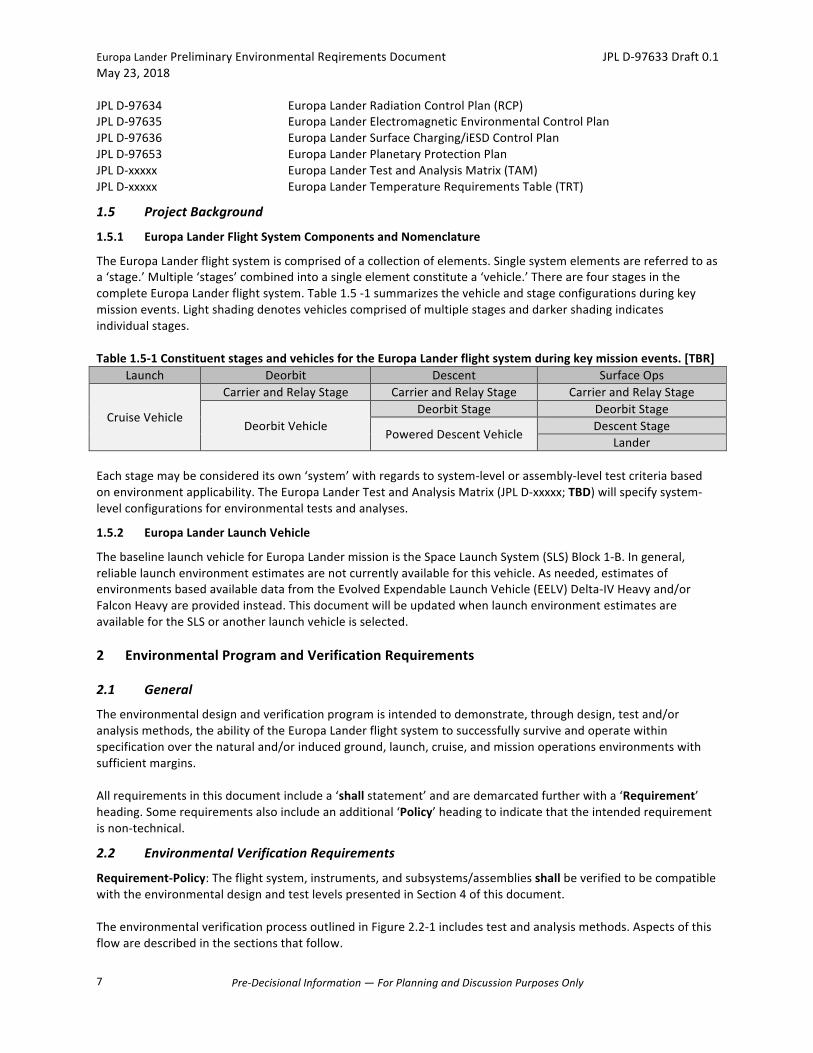
JPLD-97634 EuropaLanderRadiationControlPlan(RCP)JPLD-97635 EuropaLanderElectromagneticEnvironmentalControlPlanJPLD-97636 EuropaLanderSurfaceCharging/iESDControlPlanJPLD-97653 EuropaLanderPlanetaryProtectionPlanJPLD-xxxxx EuropaLanderTestandAnalysisMatrix(TAM)JPLD-xxxxx EuropaLanderTemperatureRequirementsTable(TRT)
1.5 ProjectBackground
1.5.1 EuropaLanderFlightSystemComponentsandNomenclature
TheEuropaLanderflightsystemiscomprisedofacollectionofelements.Singlesystemelementsarereferredtoasa‘stage.’Multiple‘stages’combinedintoasingleelementconstitutea‘vehicle.’TherearefourstagesinthecompleteEuropaLanderflightsystem.Table1.5-1summarizesthevehicleandstageconfigurationsduringkeymissionevents.Lightshadingdenotesvehiclescomprisedofmultiplestagesanddarkershadingindicatesindividualstages.Table1.5-1ConstituentstagesandvehiclesfortheEuropaLanderflightsystemduringkeymissionevents.[TBR]
Launch Deorbit Descent SurfaceOps
CruiseVehicle
CarrierandRelayStage CarrierandRelayStage CarrierandRelayStage
DeorbitVehicleDeorbitStage DeorbitStage
PoweredDescentVehicleDescentStage
Lander
Eachstagemaybeconsidereditsown‘system’withregardstosystem-levelorassembly-leveltestcriteriabasedonenvironmentapplicability.TheEuropaLanderTestandAnalysisMatrix(JPLD-xxxxx;TBD)willspecifysystem-levelconfigurationsforenvironmentaltestsandanalyses.
1.5.2 EuropaLanderLaunchVehicle
ThebaselinelaunchvehicleforEuropaLandermissionistheSpaceLaunchSystem(SLS)Block1-B.Ingeneral,reliablelaunchenvironmentestimatesarenotcurrentlyavailableforthisvehicle.Asneeded,estimatesofenvironmentsbasedavailabledatafromtheEvolvedExpendableLaunchVehicle(EELV)Delta-IVHeavyand/orFalconHeavyareprovidedinstead.ThisdocumentwillbeupdatedwhenlaunchenvironmentestimatesareavailablefortheSLSoranotherlaunchvehicleisselected.
2 EnvironmentalProgramandVerificationRequirements
2.1 General
Theenvironmentaldesignandverificationprogramisintendedtodemonstrate,throughdesign,testand/oranalysismethods,theabilityoftheEuropaLanderflightsystemtosuccessfullysurviveandoperatewithinspecificationoverthenaturaland/orinducedground,launch,cruise,andmissionoperationsenvironmentswithsufficientmargins.Allrequirementsinthisdocumentincludea‘shallstatement’andaredemarcatedfurtherwitha‘Requirement’heading.Somerequirementsalsoincludeanadditional‘Policy’headingtoindicatethattheintendedrequirementisnon-technical.
2.2 EnvironmentalVerificationRequirements
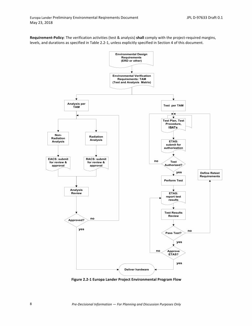
Requirement-Policy:Theflightsystem,instruments,andsubsystems/assembliesshallbeverifiedtobecompatiblewiththeenvironmentaldesignandtestlevelspresentedinSection4ofthisdocument.TheenvironmentalverificationprocessoutlinedinFigure2.2-1includestestandanalysismethods.Aspectsofthisflowaredescribedinthesectionsthatfollow.
EuropaLanderPreliminaryEnvironmentalReqirementsDocument JPLD-97633Draft0.1May23,2018
Pre-DecisionalInformation—ForPlanningandDiscussionPurposesOnly
8
Requirement-Policy:Theverificationactivities(test&analysis)shallcomplywiththeproject-requiredmargins,levels,anddurationsasspecifiedinTable2.2-1,unlessexplicitlyspecifiedinSection4ofthisdocument.
Figure2.2-1EuropaLanderProjectEnvironmentalProgramFlow
�! �������&�! � ��+%�%�
� (�$! �� &�����%�� ���#'�$��� &%�����!$�!&��$�
� (�$! �� &�����$�����&�! ���#'�$��� &%����
���%&�� �� ��+%�%����&$�*�
��+%�%���(��)
�����%'���&��!$�
�'&�!$�,�&�!
����%'���&��!$�$�(��)����""$!(��
����%'���&��!$�$�(��)����""$!(��
��%&��"�$���
�����&�! � ��+%�%�
""$!(���
��+%�%�"�$���
����(�$���$�)�$�
��%&���� ����%&��$!���'$���
��
��$�!$����%&
�����$�"!$&�&�%&�$�%'�&%
��%&���%'�&%���(��)�
��%&�'&�!$�,���
���� ����&�%&���#'�$��� &%
��%%���%&�+�%
!
!
+�%
+�%
!
""$!(������
+�%
!
IBATs
EuropaLanderPreliminaryEnvironmentalReqirementsDocument JPLD-97633Draft0.1May23,2018
Pre-DecisionalInformation—ForPlanningandDiscussionPurposesOnly
9
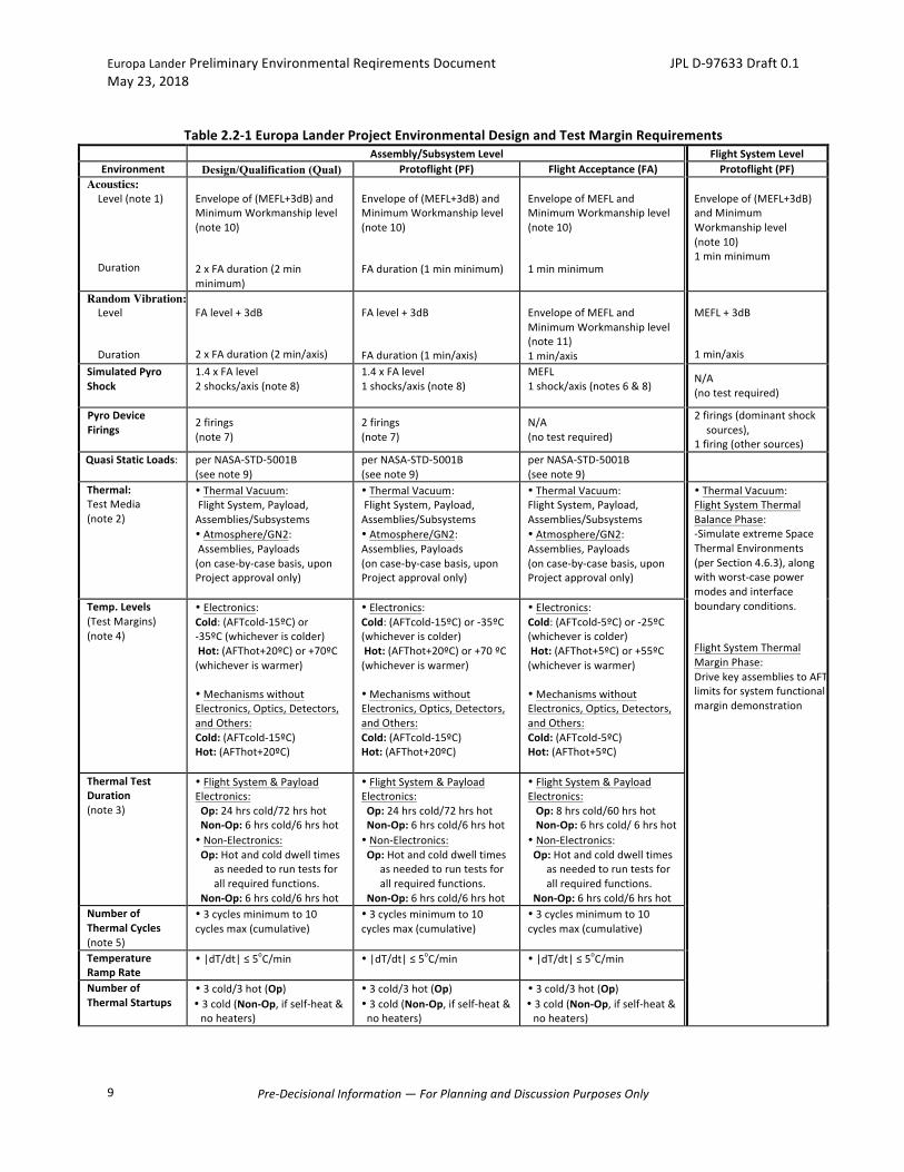
Table2.2-1EuropaLanderProjectEnvironmentalDesignandTestMarginRequirements
Assembly/SubsystemLevel FlightSystemLevelEnvironment Design/Qualification (Qual) Protoflight(PF) FlightAcceptance(FA) Protoflight(PF)
Acoustics: Level(note1) Duration
Envelopeof(MEFL+3dB)andMinimumWorkmanshiplevel(note10) 2xFAduration(2minminimum)
Envelopeof(MEFL+3dB)andMinimumWorkmanshiplevel(note10) FAduration(1minminimum)
EnvelopeofMEFLandMinimumWorkmanshiplevel(note10) 1minminimum
Envelopeof(MEFL+3dB)andMinimumWorkmanshiplevel(note10)1minminimum
Random Vibration: Level Duration
FAlevel+3dB 2xFAduration(2min/axis)
FAlevel+3dB FAduration(1min/axis)
EnvelopeofMEFLandMinimumWorkmanshiplevel(note11)1min/axis
MEFL+3dB 1min/axis
SimulatedPyroShock
1.4xFAlevel2shocks/axis(note8)
1.4xFAlevel1shocks/axis(note8)
MEFL1shock/axis(notes6&8)
N/A(notestrequired)
PyroDeviceFirings
2firings(note7)
2firings(note7)
N/A(notestrequired)
2firings(dominantshocksources),
1firing(othersources)QuasiStaticLoads: perNASA-STD-5001B
(seenote9)perNASA-STD-5001B(seenote9)
perNASA-STD-5001B(seenote9)
Thermal:TestMedia(note2)
•ThermalVacuum:FlightSystem,Payload,Assemblies/Subsystems•Atmosphere/GN2:Assemblies,Payloads(oncase-by-casebasis,uponProjectapprovalonly)
•ThermalVacuum:FlightSystem,Payload,Assemblies/Subsystems•Atmosphere/GN2:Assemblies,Payloads(oncase-by-casebasis,uponProjectapprovalonly)
•ThermalVacuum:FlightSystem,Payload,Assemblies/Subsystems•Atmosphere/GN2:Assemblies,Payloads(oncase-by-casebasis,uponProjectapprovalonly)
•ThermalVacuum:FlightSystemThermalBalancePhase:-SimulateextremeSpaceThermalEnvironments(perSection4.6.3),alongwithworst-casepowermodesandinterfaceboundaryconditions. FlightSystemThermalMarginPhase:DrivekeyassembliestoAFTlimitsforsystemfunctionalmargindemonstration
Temp.Levels(TestMargins)(note4)
•Electronics:Cold:(AFTcold-15ºC)or-35ºC(whicheveriscolder)Hot:(AFThot+20ºC)or+70ºC(whicheveriswarmer) •MechanismswithoutElectronics,Optics,Detectors,andOthers:Cold:(AFTcold-15ºC)Hot:(AFThot+20ºC)
•Electronics:Cold:(AFTcold-15ºC)or-35ºC(whicheveriscolder)Hot:(AFThot+20ºC)or+70ºC(whicheveriswarmer) •MechanismswithoutElectronics,Optics,Detectors,andOthers:Cold:(AFTcold-15ºC)Hot:(AFThot+20ºC)
•Electronics:Cold:(AFTcold-5ºC)or-25ºC(whicheveriscolder)Hot:(AFThot+5ºC)or+55ºC(whicheveriswarmer) •MechanismswithoutElectronics,Optics,Detectors,andOthers:Cold:(AFTcold-5ºC)Hot:(AFThot+5ºC)
ThermalTestDuration
(note3)
•FlightSystem&PayloadElectronics:Op:24hrscold/72hrshotNon-Op:6hrscold/6hrshot•Non-Electronics:Op:Hotandcolddwelltimes
asneededtoruntestsforallrequiredfunctions.
Non-Op:6hrscold/6hrshot
•FlightSystem&PayloadElectronics:Op:24hrscold/72hrshotNon-Op:6hrscold/6hrshot•Non-Electronics:Op:Hotandcolddwelltimes
asneededtoruntestsforallrequiredfunctions.
Non-Op:6hrscold/6hrshot
•FlightSystem&PayloadElectronics:Op:8hrscold/60hrshotNon-Op:6hrscold/6hrshot•Non-Electronics:Op:Hotandcolddwelltimes
asneededtoruntestsforallrequiredfunctions.
Non-Op:6hrscold/6hrshotNumberofThermalCycles(note5)
•3cyclesminimumto10cyclesmax(cumulative)
•3cyclesminimumto10cyclesmax(cumulative)
•3cyclesminimumto10cyclesmax(cumulative)
TemperatureRampRate
•|dT/dt|≤5oC/min
•|dT/dt|≤5oC/min
•|dT/dt|≤5oC/min
NumberofThermalStartups
•3cold/3hot(Op)•3cold(Non-Op,ifself-heat&noheaters)
•3cold/3hot(Op)•3cold(Non-Op,ifself-heat&noheaters)
•3cold/3hot(Op)•3cold(Non-Op,ifself-heat&noheaters)
EuropaLanderPreliminaryEnvironmentalReqirementsDocument JPLD-97633Draft0.1May23,2018
Pre-DecisionalInformation—ForPlanningandDiscussionPurposesOnly
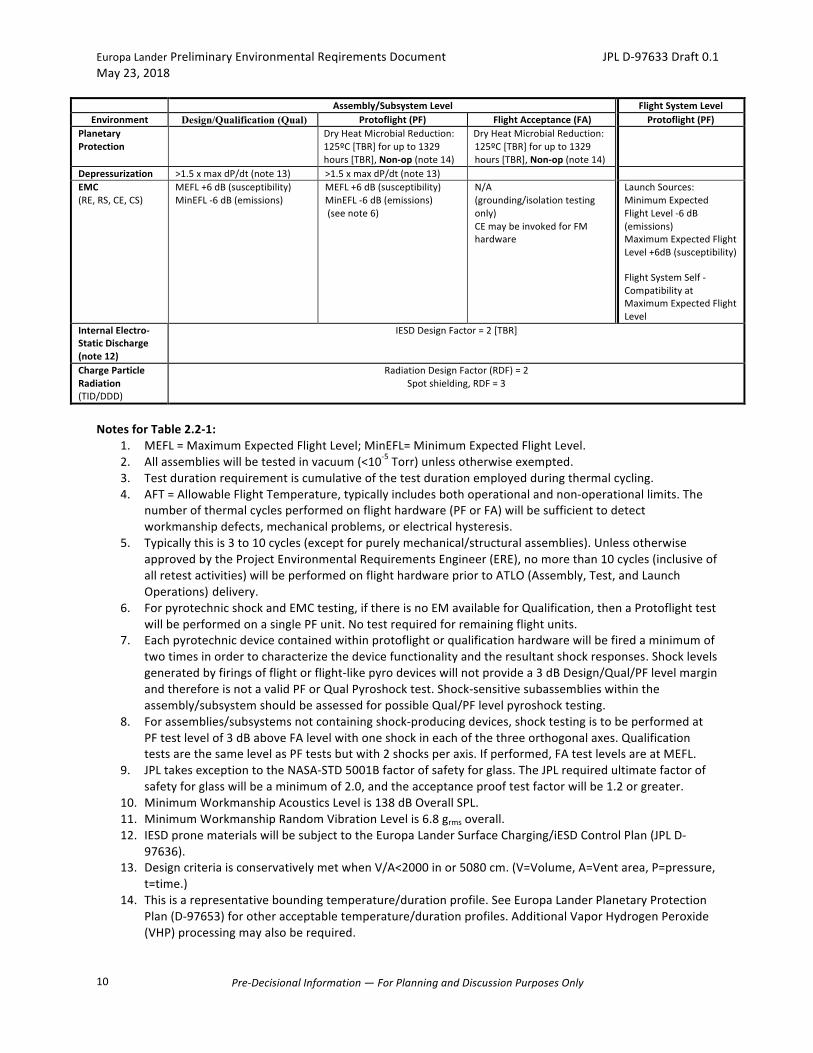
10
Assembly/SubsystemLevel FlightSystemLevelEnvironment Design/Qualification (Qual) Protoflight(PF) FlightAcceptance(FA) Protoflight(PF)
PlanetaryProtection
DryHeatMicrobialReduction:125ºC[TBR]forupto1329hours[TBR],Non-op(note14)
DryHeatMicrobialReduction:125ºC[TBR]forupto1329hours[TBR],Non-op(note14)
Depressurization >1.5xmaxdP/dt(note13) >1.5xmaxdP/dt(note13) EMC(RE,RS,CE,CS)
MEFL+6dB(susceptibility)MinEFL-6dB(emissions)
MEFL+6dB(susceptibility)MinEFL-6dB(emissions)(seenote6)
N/A(grounding/isolationtestingonly)CEmaybeinvokedforFMhardware
LaunchSources:MinimumExpectedFlightLevel-6dB(emissions)MaximumExpectedFlightLevel+6dB(susceptibility) FlightSystemSelf-CompatibilityatMaximumExpectedFlightLevel
InternalElectro-StaticDischarge(note12)
IESDDesignFactor=2[TBR]
ChargeParticleRadiation(TID/DDD)
RadiationDesignFactor(RDF)=2Spotshielding,RDF=3
NotesforTable2.2-1:
1. MEFL=MaximumExpectedFlightLevel;MinEFL=MinimumExpectedFlightLevel.2. Allassemblieswillbetestedinvacuum(<10-5Torr)unlessotherwiseexempted.3. Testdurationrequirementiscumulativeofthetestdurationemployedduringthermalcycling.4. AFT=AllowableFlightTemperature,typicallyincludesbothoperationalandnon-operationallimits.The
numberofthermalcyclesperformedonflighthardware(PForFA)willbesufficienttodetectworkmanshipdefects,mechanicalproblems,orelectricalhysteresis.
5. Typicallythisis3to10cycles(exceptforpurelymechanical/structuralassemblies).UnlessotherwiseapprovedbytheProjectEnvironmentalRequirementsEngineer(ERE),nomorethan10cycles(inclusiveofallretestactivities)willbeperformedonflighthardwarepriortoATLO(Assembly,Test,andLaunchOperations) delivery.
6. ForpyrotechnicshockandEMCtesting,ifthereisnoEMavailableforQualification,thenaProtoflighttestwillbeperformedonasinglePFunit.Notestrequiredforremainingflightunits.
7. Eachpyrotechnicdevicecontainedwithinprotoflightorqualificationhardwarewillbefiredaminimumoftwotimesinordertocharacterizethedevicefunctionalityandtheresultantshockresponses.Shocklevelsgeneratedbyfiringsofflightorflight-likepyrodeviceswillnotprovidea3dBDesign/Qual/PFlevelmarginandthereforeisnotavalidPForQualPyroshocktest.Shock-sensitivesubassemblieswithintheassembly/subsystemshouldbeassessedforpossibleQual/PFlevelpyroshocktesting.
8. Forassemblies/subsystemsnotcontainingshock-producingdevices,shocktestingistobeperformedatPFtestlevelof3dBaboveFAlevelwithoneshockineachofthethreeorthogonalaxes.QualificationtestsarethesamelevelasPFtestsbutwith2shocksperaxis.Ifperformed,FAtestlevelsareatMEFL.
9. JPLtakesexceptiontotheNASA-STD5001Bfactorofsafetyforglass.TheJPLrequiredultimatefactorofsafetyforglasswillbeaminimumof2.0,andtheacceptanceprooftestfactorwillbe1.2orgreater.
10. MinimumWorkmanshipAcousticsLevelis138dBOverallSPL.11. MinimumWorkmanshipRandomVibrationLevelis6.8grmsoverall.12. IESDpronematerialswillbesubjecttotheEuropaLanderSurfaceCharging/iESDControlPlan(JPLD-
97636).13. DesigncriteriaisconservativelymetwhenV/A<2000inor5080cm.(V=Volume,A=Ventarea,P=pressure,
t=time.)14. Thisisarepresentativeboundingtemperature/durationprofile.SeeEuropaLanderPlanetaryProtection
Plan(D-97653)forotheracceptabletemperature/durationprofiles.AdditionalVaporHydrogenPeroxide(VHP)processingmayalsoberequired.
EuropaLanderPreliminaryEnvironmentalReqirementsDocument JPLD-97633Draft0.1May23,2018
Pre-DecisionalInformation—ForPlanningandDiscussionPurposesOnly
11
2.3 EnvironmentalTesting
EnvironmentaltestingapproachesarecategorizedforthepurposeofhardwarequalityverificationasQualification(Qual),Protoflight(PF),andFlightAcceptance(FA).Requirement-Policy:Flight,spare,andqualificationhardwaredesign,performance,andworkmanshipqualityshallbeverifiedbytestusingaProtoflight(PF)testprogramoraQualification/FlightAcceptance(Q/FA)testprogram.ProjectEnvironmentalRequirementsEngineers(EREs)willapprovetheverificationapproachforflighthardwarethroughdevelopmentoftheTestandAnalysisMatrix(TAM)(JPLD-xxxxxTBD)inconjunctionwiththeengineeringteams.Requirement-Policy:Formalenvironmentaltestsshallbeperformedonallflight,spare,andqualificationhardwareatthelevelofassemblyindicatedintheenvironmentalTestandAnalysisMatrix(TAM)(JPLD-xxxxxTBD).Requirement-Policy:AllformalenvironmentaltestsshallbeauthorizedpriortotestingandsummarizedsubsequenttotestingusingtheEnvironmentalTestAuthorizationandSummaryform(AppendixB:ETASForm(EnvironmentalTestAuthorizationSummary),JPLForm2683).
2.3.1 QualificationTestApproach
Qualification(Qual)testingisperformedonadedicatedQualification(orEngineering)Modeloftheflighthardwarethatisnotintendedtofly,inordertoqualifythehardwaredesignforthemaximumexpectedflightenvironmentplusmargin,includingmarginonenvironmentdurationorcycles.IfapprovedbytheProjectERE,anengineeringmodelofanassemblymaybeusedasaqualificationunitandbesubjectedtoqualificationenvironmentaltesting.Requirement-Policy:Ifusedforqualificationtesting,theengineeringmodelshallbeflight-likeandmanufacturedusingthesameassemblytechniquesandfabricationprocessesastheflighthardwareincluding:structure,thermaldesign,shielding,cabling,circuitlayout,powerconsumption,functionalmodes,andelectricalpartswiththesamesignalcharacteristics.Requirement-Policy:Hardwarethathasbeenusedasaqualificationunitandisbeingconsideredforuseasaflightunitorspareshallbeevaluateduponcompletionoftestingtodeterminethedetailsofrefurbishmentandretest,ifany,andanassessmentoftheresidualrisktotheprojectforusingthehardware.
2.3.2 ProtoflightTestApproach
Protoflight(PF)testingisperformedonflighthardwareandservestosimultaneouslyfulfilltherequirementsofdesignqualificationandworkmanshipdemonstrationforflightacceptance.Protoflightenvironmentaltestingdemonstratesdesignadequacyandflighthardwarereadiness,includingappropriateperformanceandmargin.
2.3.3 FlightAcceptanceTestApproach
FlightAcceptance(FA)testingisperformedonflighthardwareandsparesonlywhenapreviousqualificationtesthasbeenperformedonanidenticalitem.If,asdeterminedbyaHeritageReview,previousqualificationtestlevelsofaheritageassemblyareadequateforthemissionandtheheritagedesignandoperationisnotmodifiedinawaythatnegatesthepreviousqualification,thentheassemblymaybetestedtoFlightAcceptancelevelsanddurations.FlightAcceptancetestingmayalsoberequiredtoverifyhardwarequalityandworkmanshipfollowingminormodifications,rework,orrepairs.
EuropaLanderPreliminaryEnvironmentalReqirementsDocument JPLD-97633Draft0.1May23,2018
Pre-DecisionalInformation—ForPlanningandDiscussionPurposesOnly
12
2.3.4 AssemblyLevelEnvironmentalTests
Requirement-Policy:Assembly/instrumentleveltestingshallbeperformedpriortodeliveryforhigher-levelintegration.Requirement-Policy:FlighthardwarewithdocumentationclaimingpriorQualificationbyHeritageorSimilarityfortherequiredenvironmentaltestsshallbeevaluatedandapprovedbytheProjectERE.
2.4 EnvironmentalAnalyses
Environmentalanalysesareperformedtoverifyhardwaredesigncompatibilitywithground,transportation,storage,launch,andmissionenvironmentsthatmaybeimpracticaltoverifybytestorthataremorecosteffectivelyanalyzedthantested(e.g.radiationdosagecompatibility,venting,andatomicoxygensusceptibility),orwhereanalysisisabetterverificationmethod.Requirement-Policy:EnvironmentalanalysesshallbeperformedagainsttheenvironmentaldesigncriteriainSection4ofthisdocument.Requirement-Policy:Eachlevelofassembly,whereanalysesareindicated,shallsummarizethoseanalysesusingtheEnvironmentalAnalysisCompletionStatement(AppendixC:ECASForm(EnvironmentalAnalysisCompletionStatement),JPLForm2566).Requirement-Policy:Sinceanalysisresultsmayaffecthardwaredesign,allreportsforagivenhardwareitemshallbesubmittedtotheProjectOfficepriortothebeginningofflighthardwareenvironmentaltesting.
3 EnvironmentalTestPolicies
3.1 General
Thissectionestablishestheimplementation,control,andreportingpoliciesforenvironmentaltestingofEuropaLanderflightandqualificationhardware,whetherperformedatJPLorsubcontractorfacilities.Requirement-Policy:Allflightandqualificationhardwareshallbeenvironmentallytestedinaccordancewiththerequirementsofthisdocument.Requirement-Policy:DeviationsfromtheEnvironmentalProgramrequirementsshallrequireapprovalthroughoneofthefollowingprocessespriortostartofanyenvironmentaltesting:
1. ACategoryAwaiverforproject-widedeviationsfromJPLinstitutionalstandards,includingthisstandard.2. ACategoryBwaiverforalldeviationsthatcompromisetheintentoftheEnvironmentalProgramas
containedintheapprovedprojectenvironmentaldocumentation.Thisincludesdeviationsfornon-technicalreasons,suchasthoseresultingfromscheduleorcostconstraints.
3. TheEnvironmentalTestAuthorizationandSummary(ETAS)formdocumentationofminortestdeviationswithtechnicaljustificationwithconcurrenceoftheERE.
3.2 TestConfiguration
Requirement-Policy:Flightsystemlevelenvironmentaltestingshallbeinaflight-likeconfigurationpertheEuropaLanderEnvironmentalTestandAnalysisMatrix(TAM)(JPLD-xxxxxTBD).Requirement-Policy:Allassembly,instrument,andsubassemblylevelenvironmentaltesting(includingspares)shallbeinaflight-likeconfigurationpertheEuropaLanderEnvironmentalTestandAnalysisMatrix(TAM)(JPLD-xxxxxTBD).Requirement-Policy:Electricalcabling,connectors,andotherflightfittingsnormallyassociatedwiththeassemblyorthesystemshallbeusedaspartofthetestarticle.
EuropaLanderPreliminaryEnvironmentalReqirementsDocument JPLD-97633Draft0.1May23,2018
Pre-DecisionalInformation—ForPlanningandDiscussionPurposesOnly
13
Requirement-Policy:ThesameconfigurationshallbeusedforQualification,Protoflight,andFlightAcceptanceenvironmentaltesting.Requirement-Policy:HardwareconfigurationsqualifiedinpreviousenvironmentaltestprogramsshallbeevaluatedforconsistencywithEuropaLanderenvironmentaltesting.
3.3 AssemblyOperation/FunctionalTest
Thehardwarewilloperateinlogicandpowerstatesthatvalidatetheintegrityofallelectricalcircuitsandinterfaces,includingredundantcircuitry,andeveryeffortshouldbemadetosimulatealloperationalmodes.ThisincludescircuitsinternaltotheassemblyandcircuitsthatinterfacedirectlywithotherassembliesoftheEuropaLanderflightsystem.Requirement-Policy:Duringenvironmentaltesting,hardwareshallbeoperatedintheappropriatefunctionalmodesasdefinedintheirfunctionalspecifications,demonstratingthattheassemblyperformstospecificationwhenexposedtothetestenvironment.Requirement-Policy:Functionaltestproceduresshallensureallelectricalcircuitsandinterfaces,asdefinedintheirfunctionalspecifications,areexercised.
3.4 TestSequence
Forelectronicassemblies,dynamictestingshouldprecedethermaltesting(inorderofflightexposure).Forcertaincompositestructures,thermalcyclingshouldprecededynamictestingformoreeffectiveworkmanshipverification.EMCtestingmaybeconductedwhenconvenient.However,anyre-workduetoEMCanomalies(e.g.,connectorbackshellreworkandgasketinstallations)shouldbecompletedpriortodynamicsandthermaltesting.Requirement-Policy:ThesequenceofenvironmentaltestsonagivenflighthardwareassemblyshallbeestablishedbytheresponsibleengineerandconcurredbytheProjectEREs,basedontheflightenvironmentsequenceorareviewofthehardwaredesignandmaterials,thesensitivityoftheassemblytoeachenvironment,andthepotentialeffectofeachenvironmentonotherenvironmentalcharacteristics.Requirement-Policy:Whereapplicable,theQualificationorProtoflighttestarticleforagivenassemblyconfigurationshallsuccessfullypassitsQual/PFtestspriortocommencingwithFAtestsonanidenticalflightarticle.
3.5 EnvironmentalTestFacilities
Anyagencythatperformsenvironmentaltestingwilldosoinaccordancewithcertainminimumstandards,whetherthesefacilitiesareatJPL,atasubcontractor’sfacility,oratanindependenttestlaboratory.FortestingperformedforJPL-developedflighthardware,theseminimumstandardsaredefinedinStandardEnvironmentalTestingFacilitiesandPracticesdocument.TestfacilityconformancetothisStandardwillbereviewedandevaluatedbytheJPLEnvironmentalTestLab(ETL).Forhardwaredevelopedanddeliveredbyotheragencies,testfacilitiesshouldincludeprovisionstoprotectflighthardwarefromfacilityanomalies(i.e.powerfailures,temperatureexcursions,etc.).TheapplicableteststandardsforEMCtestsaregiveninMIL-STD-461F/462.Requirement-Policy:ThehardwareCognizantEngineershallberesponsibleforthehandlingofatestarticleinanenvironmentaltestfacility,includingattachmentofanytestfixture.
3.6 EnvironmentalTestPans
Requirement-Policy:EnvironmentalTestPlansorSpecificationsshallbepreparedbyeachsuppliertodefinetheenvironmentaltestlevelsanddurationsforassembly/subsystemandinstrumentlevelenvironmentaltesting.
EuropaLanderPreliminaryEnvironmentalReqirementsDocument JPLD-97633Draft0.1May23,2018
Pre-DecisionalInformation—ForPlanningandDiscussionPurposesOnly
14
Environmentaltestplansshouldcoverthefollowingtopics:
• Descriptionofthetestarticle• Testobjectives• Testsetup,testsupportequipment,andtestfacility• Instrumentationanddata• Testtolerances• Environmentalsimulationsandtestmedia,ifapplicable • Testphases,testcases,andtestprofiles• Testparameters(Testlevels,margins,anddurations),asapplicable• Functionalandperformanceverifications• Success/failurecriteria• RequirementsforETAS,Problem/FailureReporting(PFRs)• Flighthardwareandpersonnelprotection• QAprovisions• Post-testactivitiesandanalysis
Requirement-Policy:EnvironmentalTestPlansandtheirrevisionsshallbesubmittedtotheProjectEREforapprovalbeforebeginninganenvironmentaltest.Requirement-Policy:EnvironmentalTestPlansshallbeunderrevisioncontrol,withredlinesincorporatedpriortoenvironmentaltestingofanyredundantunits.
3.7 EnvironmentalTestProcedures
Requirement-Policy:Theoperationofenvironmentaltestequipmentandfacilitiesduringtheperformanceofenvironmentaltestsofflighthardwareshallbeaccomplishedinaccordancewithapprovedtestprocedures.
3.8 EnvironmentalTestAuthorizationandSummary
Forthepurposeofassuringflighthardwarereadinessforenvironmentaltestinganddocumentingtestresults,theEnvironmentalTestAuthorizationandSummary(ETAS)formisthedocumentofrecord.Fortestauthorizationandapprovalaswellasrequirementverifications,theappropriateportionsoftheETASform,anditssupportingdocuments,mustbesubmittedtotheProjectERE.Requirement-Policy:Forthepurposeofassuringflighthardwarereadinessforenvironmentaltestinganddocumentingtestresults,theEnvironmentalTestAuthorizationandCompletionStatement(ETAS)Processshallbefollowed.Requirement-Policy:TheTestAuthorizationportionoftheETASformshallbecompletedbytheCognizantEngineerforthetestarticleandapprovedbytheProjectEREforeachflighthardwareserialnumberpriortocommencingenvironmentaltesting.Requirement-Policy:TheETASshallreferencetheapprovedtestplanandprocedures.Requirement-Policy:TheETASshalldescribeanydeviationsfromthehardware’sflightconfiguration.Requirement-Policy:Uponconclusionoftheenvironmentaltests,theTestResultsportionoftheETASformshallbecompletedandapproved,clearlydenotingthepass/faildispositionoftheflighthardware.Requirement-Policy:TheETASshallreferencetheenvironmentaltestreportsandincludeadescriptionofanyanomaliesrecordedduringenvironmentaltestingandreferencetheassociatedProblem/FailureReports(P/FRs).
EuropaLanderPreliminaryEnvironmentalReqirementsDocument JPLD-97633Draft0.1May23,2018
Pre-DecisionalInformation—ForPlanningandDiscussionPurposesOnly
15
AppendixB:ETASForm(EnvironmentalTestAuthorizationSummary)containsasampleETASform.Additionally,theprojectwillusetheon-lineETASintheMissionAssuranceInformationSystem(MAIS)system.
3.9 TestFailure
Requirement-Policy:AnyhardwarefailureormalfunctionduringanenvironmentaltestoranyfailureormalfunctionofanenvironmentaltestfacilitythatwouldaffectanenvironmentaltestshallbecausefortheissuanceofaP/FR(Problem/FailureReport).Requirement-Policy:Hardwarefailure,malfunction,orout-of-specificationperformanceduringformalenvironmentaltestingshallbeinterpretedasatestfailure.Forassembly-levelenvironmentaltesting,thetestmaybecontinuediftheCognizantEngineerandTestEngineeragreethatcontinuationisofdiagnosticvalueandwillnotdamagetheflighthardware.Requirement-Policy:Atthesystem(andInstrument)level,theapplicabletestplanshalldesignatetheresponsiblerepresentativewiththeauthoritytodeterminewhetherornottointerruptthetestintheeventofafailureormalfunctionoftheflighthardware.Requirement-Policy:Failuresassociatedwithenvironments,butacceptedbytheproject,shallbehandledthroughtheCategoryBWaiverprocess.
3.10 TestReports
Requirement-Policy:Aftereachassembly,subsystem,Instrumentorsystemenvironmentaltestisterminated(whetherbecausethetestrequirementsweresuccessfullycompletedorbecauseatestfailurehasoccurred)thetestingagencyshallprepareaTestAgencyReport,thatincludesoraddressesanydeviationsfromtheapprovedtestprocedure.Requirement-Policy:Foreachserialnumberofeachhardwaregroupsubjectedtoformalenvironmentaltesting,areportshallbepreparedbythehardwareprovider.Requirement-Policy:Thereport(s)shallbeavailableforProjectReviewsandasinputstotheassemblyDeliveryandPre-ShipmentReviewBoards.
3.11 Re-TestPolicies
Requirement-Policy:Environmentalretestsofassembliesshallberequiredunderthefollowingcircumstances:1. Tocompletetheprotoflightorflightacceptancetestingofhardwarethathasfailedduringits
environmentaltestprogram.2. Tore-qualifyflighthardwaredesignwheredesignchanges,modificationsorconfigurationchangesoccur
aftercompletionofenvironmentaltesting.3. Toverifytheflightworthinessofrefurbishedunitsusedasflightspares.4. Toverifytheflightacceptabilityofworkmanshipperformedaspartofreworknotcoveredbyitems1to3.
Requirement-Policy:Re-testingofassembliestoenvironmentalrequirementsshallbecoordinatedwiththeProjectEREs.Requirement-Policy:Thespecificre-testrequirementsshallbedeterminedjointlybetweenthecognizantengineerandtheProjectEREs(withMAMconcurrence).Requirement-Policy:Flighthardwareshallnotberetestedwithoutare-approvaloftheupdatedETASortestapprovaldocumentation.
EuropaLanderPreliminaryEnvironmentalReqirementsDocument JPLD-97633Draft0.1May23,2018
Pre-DecisionalInformation—ForPlanningandDiscussionPurposesOnly
16
4 EnvironmentalDesignandVerificationRequirements
TheenvironmentaldesignandverificationrequirementscontainedwithinthissectionareestablishedtoassuredesigncompatibilityofEuropaLanderProjectflightandqualificationhardwarewiththespecifiedenvironmentsandcorrespondingmissionmodes.
4.1 HandlingandGroundOperationEnvironments
Thehandlingandgroundoperationsenvironmentaldesignrequirementsincludetheenvironmentsthattheflighthardwarewouldencounterduringfabrication,integration,calibration,alignment,andpre-launchoperations.Thegroundhandlingenvironmentsalsoincludetransportationandstorageoftheflighthardwareinhandlingfixturesorshippingcontainers.
4.1.1 TransportationandHandlingDynamicsEnvironments
Requirement:Flighthardwareshallbedesignedtosurvivewithoutdegradationthegroundtransportationandhandlingvibration,acceleration,andshockenvironmentsspecifiedinTable4.1.1-1Table4.1.1-1EnvironmentsforGroundTransportationandHandlingVibration,Acceleration,andShock.[TBD]
4.1.2 Thermal,Pressure,andRelativeHumidityEnvironment
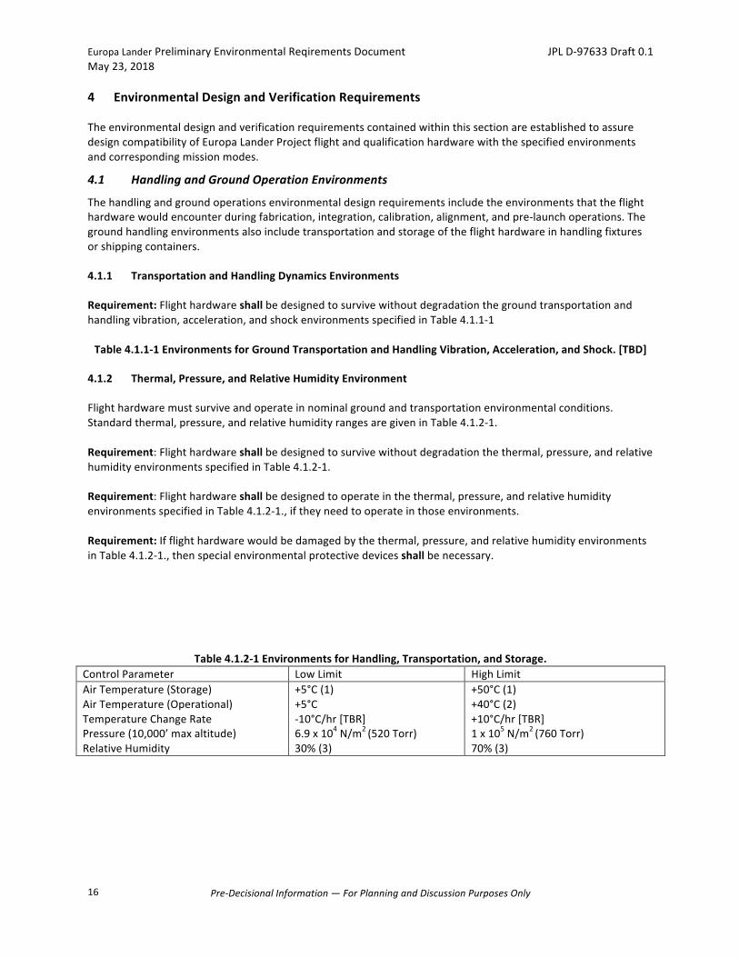
Flighthardwaremustsurviveandoperateinnominalgroundandtransportationenvironmentalconditions.Standardthermal,pressure,andrelativehumidityrangesaregiveninTable4.1.2-1.Requirement:Flighthardwareshallbedesignedtosurvivewithoutdegradationthethermal,pressure,andrelativehumidityenvironmentsspecifiedinTable4.1.2-1.Requirement:Flighthardwareshallbedesignedtooperateinthethermal,pressure,andrelativehumidityenvironmentsspecifiedinTable4.1.2-1.,iftheyneedtooperateinthoseenvironments.Requirement:Ifflighthardwarewouldbedamagedbythethermal,pressure,andrelativehumidityenvironmentsinTable4.1.2-1.,thenspecialenvironmentalprotectivedevicesshallbenecessary.
Table4.1.2-1EnvironmentsforHandling,Transportation,andStorage.ControlParameter LowLimit HighLimitAirTemperature(Storage)AirTemperature(Operational)TemperatureChangeRatePressure(10,000’maxaltitude)RelativeHumidity
+5°C(1)+5°C-10°C/hr[TBR]6.9x104N/m2(520Torr)30%(3)
+50°C(1)+40°C(2)+10°C/hr[TBR]1x105N/m2(760Torr)70%(3)
EuropaLanderPreliminaryEnvironmentalReqirementsDocument JPLD-97633Draft0.1May23,2018
Pre-DecisionalInformation—ForPlanningandDiscussionPurposesOnly
17
NOTES:1)Limitscouldbeaswideas-40°Cto+70°Cduringshippingorstorageiftheenvironmentisnotcontrolled(suchas
thecargobayofanaircraftoroutsideinthedirectsun).ProvisionsshouldbemadetolimitthetemperaturetothoseinTable4.1.2-1.
2)Ifthehardwareisoperatinginanenvironmentthatiswithin10°Cofthislimit,thehardwareshouldbemonitoredtoensurethatitsFlightAcceptancetemperatureisnotexceeded.
3)Relativehumiditycouldbeaslowas0%duringshippingorstorageorashighas100%inuncontrolledcontainers.ProvisionsshouldbemadetolimittherelativehumiditytothoseinTable4.1.2-1.
4.2 LaunchPressureChangeEnvironments
4.2.1 Venting
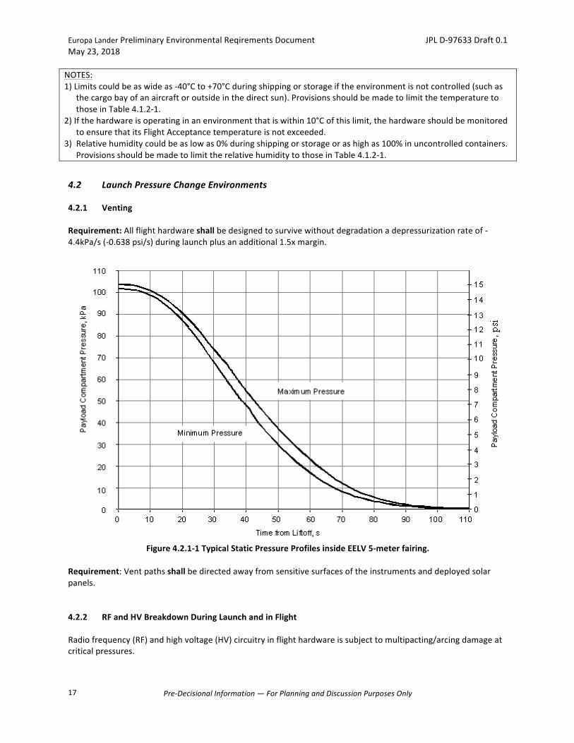
Requirement:Allflighthardwareshallbedesignedtosurvivewithoutdegradationadepressurizationrateof-4.4kPa/s(-0.638psi/s)duringlaunchplusanadditional1.5xmargin.
Figure4.2.1-1TypicalStaticPressureProfilesinsideEELV5-meterfairing.
Requirement:Ventpathsshallbedirectedawayfromsensitivesurfacesoftheinstrumentsanddeployedsolarpanels.
4.2.2 RFandHVBreakdownDuringLaunchandinFlight
Radiofrequency(RF)andhighvoltage(HV)circuitryinflighthardwareissubjecttomultipacting/arcingdamageatcriticalpressures.
EuropaLanderPreliminaryEnvironmentalReqirementsDocument JPLD-97633Draft0.1May23,2018
Pre-DecisionalInformation—ForPlanningandDiscussionPurposesOnly
18
Requirement:Flighthardwarethatoperatesduringlaunchorotherpartialpressureconditionsshallbedesignedtopreventcorona,oranyotherformsofhighvoltagebreakdownatpressuresbetween50and5x10-4Torr.Requirement:AllMicrowaveandRFcomponentssubjectedtohighRFpowerlevels(>1Watt)shalldemonstrateadequatemarginstomultipactionand/orRFbreakdownviaeithertest(>6dB)oranalysis(>10dB).
4.3 StructuralLoadsandDynamicsEnvironments
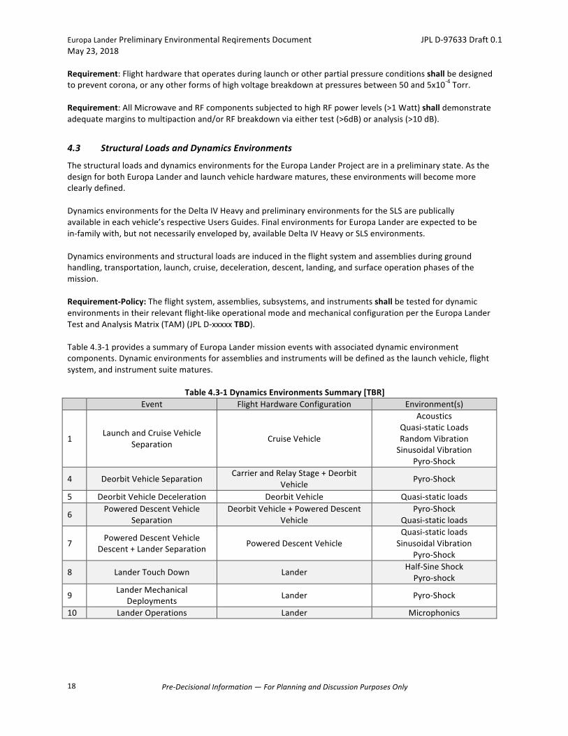
ThestructuralloadsanddynamicsenvironmentsfortheEuropaLanderProjectareinapreliminarystate.AsthedesignforbothEuropaLanderandlaunchvehiclehardwarematures,theseenvironmentswillbecomemoreclearlydefined.DynamicsenvironmentsfortheDeltaIVHeavyandpreliminaryenvironmentsfortheSLSarepublicallyavailableineachvehicle’srespectiveUsersGuides.FinalenvironmentsforEuropaLanderareexpectedtobein-familywith,butnotnecessarilyenvelopedby,availableDeltaIVHeavyorSLSenvironments.Dynamicsenvironmentsandstructuralloadsareinducedintheflightsystemandassembliesduringgroundhandling,transportation,launch,cruise,deceleration,descent,landing,andsurfaceoperationphasesofthemission.Requirement-Policy:Theflightsystem,assemblies,subsystems,andinstrumentsshallbetestedfordynamicenvironmentsintheirrelevantflight-likeoperationalmodeandmechanicalconfigurationpertheEuropaLanderTestandAnalysisMatrix(TAM)(JPLD-xxxxxTBD).Table4.3-1providesasummaryofEuropaLandermissioneventswithassociateddynamicenvironmentcomponents.Dynamicenvironmentsforassembliesandinstrumentswillbedefinedasthelaunchvehicle,flightsystem,andinstrumentsuitematures.
Table4.3-1DynamicsEnvironmentsSummary[TBR] Event FlightHardwareConfiguration Environment(s)
1LaunchandCruiseVehicle
Separation CruiseVehicle
AcousticsQuasi-staticLoadsRandomVibrationSinusoidalVibration
Pyro-Shock
4 DeorbitVehicleSeparationCarrierandRelayStage+Deorbit
Vehicle Pyro-Shock
5 DeorbitVehicleDeceleration DeorbitVehicle Quasi-staticloads
6PoweredDescentVehicle
SeparationDeorbitVehicle+PoweredDescent
VehiclePyro-Shock
Quasi-staticloads
7 PoweredDescentVehicleDescent+LanderSeparation PoweredDescentVehicle
Quasi-staticloadsSinusoidalVibration
Pyro-Shock
8 LanderTouchDown Lander Half-SineShockPyro-shock
9 LanderMechanicalDeployments Lander Pyro-Shock
10 LanderOperations Lander Microphonics
EuropaLanderPreliminaryEnvironmentalReqirementsDocument JPLD-97633Draft0.1May23,2018
Pre-DecisionalInformation—ForPlanningandDiscussionPurposesOnly
19
4.3.1 StructuralLoads
Quasi-staticstructuraldesignloadsrepresentthecombinedquasi-steadyaccelerationsandthelowfrequencymechanicallytransmitteddynamicaccelerationsoccurringduringlaunch,deorbit,anddescent.4.3.1.1 LaunchStructuralLoads
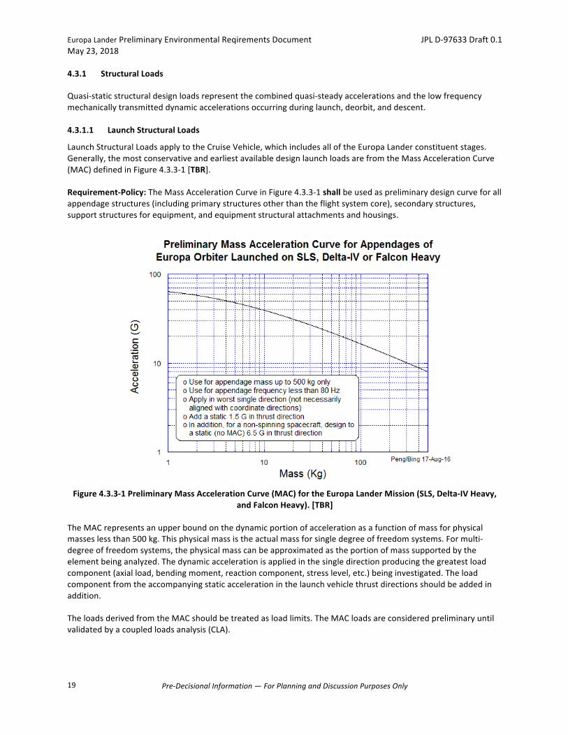
LaunchStructuralLoadsapplytotheCruiseVehicle,whichincludesalloftheEuropaLanderconstituentstages.Generally,themostconservativeandearliestavailabledesignlaunchloadsarefromtheMassAccelerationCurve(MAC)definedinFigure4.3.3-1[TBR].Requirement-Policy:TheMassAccelerationCurveinFigure4.3.3-1shallbeusedaspreliminarydesigncurveforallappendagestructures(includingprimarystructuresotherthantheflightsystemcore),secondarystructures,supportstructuresforequipment,andequipmentstructuralattachmentsandhousings.
Figure4.3.3-1PreliminaryMassAccelerationCurve(MAC)fortheEuropaLanderMission(SLS,Delta-IVHeavy,
andFalconHeavy).[TBR]TheMACrepresentsanupperboundonthedynamicportionofaccelerationasafunctionofmassforphysicalmasseslessthan500kg.Thisphysicalmassistheactualmassforsingledegreeoffreedomsystems.Formulti-degreeoffreedomsystems,thephysicalmasscanbeapproximatedastheportionofmasssupportedbytheelementbeinganalyzed.Thedynamicaccelerationisappliedinthesingledirectionproducingthegreatestloadcomponent(axialload,bendingmoment,reactioncomponent,stresslevel,etc.)beinginvestigated.Theloadcomponentfromtheaccompanyingstaticaccelerationinthelaunchvehiclethrustdirectionsshouldbeaddedinaddition.TheloadsderivedfromtheMACshouldbetreatedasloadlimits.TheMACloadsareconsideredpreliminaryuntilvalidatedbyacoupledloadsanalysis(CLA).
EuropaLanderPreliminaryEnvironmentalReqirementsDocument JPLD-97633Draft0.1May23,2018
Pre-DecisionalInformation—ForPlanningandDiscussionPurposesOnly
20
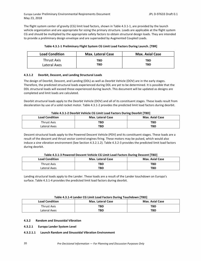
Theflightsystemcenterofgravity(CG)limitloadfactors,showninTable4.3.1-1,areprovidedbythelaunchvehicleorganizationandareappropriateforsizingtheprimarystructure.LoadsareapplicableattheflightsystemCGandshouldbemultipliedbytheappropriatesafetyfactorstoobtainstructuraldesignloads.TheyareintendedtoprovideapreliminarydesignenvelopeandaresupersededbyAugmentedCoupledLoads.
Table4.3.1-1PreliminaryFlightSystemCGLimitLoadFactorsDuringLaunch.[TBR]
4.3.1.2 Deorbit,Descent,andLandingStructuralLoads
ThedesignofDeorbit,Descent,andLanding(DDL)aswellasDeorbitVehicle(DOV)areintheearlystages.Therefore,thepredictedstructuralloadsexperiencedduringDDLareyettobedetermined.ItispossiblethattheDDLstructuralloadswillexceedthoseexperiencedduringlaunch.Thisdocumentwillbeupdatedasdesignsarecompletedandlimitloadsarecalculated.DeorbitstructuralloadsapplytotheDeorbitVehicle(DOV)andallofitsconstituentstages.Theseloadsresultfromdecelerationbyuseofasolidrocketmotor.Table4.3.1-2providesthepredictedlimitloadfactorsduringdeorbit.
Table4.3.1-2DeorbitVehicleCGLimitLoadFactorsDuringDeorbit[TBD]LoadCondition Max.LateralCase Max.AxialCaseThrustAxisLateralAxes
TBDTBD
TBDTBD
DescentstructuralloadsapplytothePoweredDescentVehicle(PDV)anditsconstituentstages.Theseloadsarearesultofthedescentandthrustvectorcontrolenginesfiring.Thesemotorsmaybepulsed,whichwouldalsoinduceasinevibrationenvironment(SeeSection4.3.2.1.2).Table4.3.2-3providesthepredictedlimitloadfactorsduringdeorbit.
Table4.3.1-3PoweredDescentVehicleCGLimitLoadFactorsDuringDescent[TBD]LoadCondition Max.LateralCase Max.AxialCaseThrustAxisLateralAxes
TBDTBD
TBDTBD
LandingstructuralloadsapplytotheLander.TheseloadsarearesultoftheLandertouchdownonEuropa’ssurface.Table4.3.1-4providesthepredictedlimitloadfactorsduringdeorbit.
Table4.3.1-4LanderCGLimitLoadFactorsDuringTouchdown[TBD]LoadCondition Max.LateralCase Max.AxialCaseThrustAxisLateralAxes
TBDTBD
TBDTBD
4.3.2 RandomandSinusoidalVibration
4.3.2.1 EuropaLanderSystemLevel
4.3.2.1.1 LaunchRandomandSinusoidalVibrationEnvironment
LoadCondition Max.LateralCase Max.AxialCaseThrustAxis
LateralAxesTBDTBD
TBDTBD

EuropaLanderPreliminaryEnvironmentalReqirementsDocument JPLD-97633Draft0.1May23,2018
Pre-DecisionalInformation—ForPlanningandDiscussionPurposesOnly
21
Theflightsystemwillexperiencerandom,periodic,andtransientvibrationmechanicallytransmittedfromthelaunchvehicle.TheseenvironmentsarespecifiedasrandomandsinusoidalvibrationtestrequirementswiththeaccelerationattheflightsystemadapterbaseinterfacedefinedinTable4.3.2-1andTable4.3.2-2.Theobjectiveoftheflightsystemrandomandsinusoidalvibrationtestisworkmanshipverificationandqualificationoftheassembledflightsystem,interconnections,andelectromechanicalequipment.Atthetimeoflaunch,theflightsystemisintheCruiseVehicleconfiguration.Requirement:TheflightsystemshallbecapableofoperatingwithinspecificationafterbeingsubjectedtothespecifiedrandomvibrationtestlevelsdefinedinTable4.3.2-1.
Table4.3.2-1FlightSystemRandomVibrationTestLevels.[Preliminary,TBR]Frequency
HzFA
AccelerationSpectralDensityQual/PF
AccelerationSpectralDensity5–10
10–200Overall
TBDTBDTBD
TBDTBDTBD
Qual:2minutesineachofthethreeorthogonalaxes,oneofwhichisthelaunchthrustaxis.PF/FA:1minuteineachofthethreeorthogonalaxes,oneofwhichisthelaunchthrustaxis.
Requirement:TheflightsystemshallbecapableofoperatingwithinspecificationafterbeingsubjectedtothespecifiedsinevibrationtestlevelsdefinedinTable4.3.2-2.
Table4.3.2-2FlightSystemSinusoidalVibrationTestLevels.[Placeholder,TBD]
1g=standardaccelerationduetogravity=9.81m/s2.
QualTestsweeprate:2octave/minuteineachofthreeorthogonalaxes,oneofwhichisthelaunchthrustaxis.PF/FATestsweeprate:4octave/minuteineachofthreeorthogonalaxes,oneofwhichisthelaunchthrustaxis.D.A.=DoubleAmplitude.
Requirement-Policy:Theflightsystemrandomandsinusoidalvibrationtestshallbeforce-limitedtoreduceover-testingathardmountedresonancefrequencies.TheupperboundforcespectruminTable4.3.2-3andTable4.3.2-4maybeusedtolimittheinputaccelerationtotheflightsystem.AdditionalnotchingoftherandomandsinusoidalvibrationinputlevelsatflightsystemresonancesmayberequiredduringtestingandshouldbebasedontheresultsoftheCLAmultipliedby1.2.Theforceandaccelerationlimitvaluesmaybemodifiedbasedoninformationgatheredduringshakertesting.TherandomandsinusoidalvibrationlevelsTable4.3.2-1andTable4.3.2-2arenotintendedforuseinthedesignoftheflightsystemprimarystructure,orforthestructuralintegrityofequipmentsupports.
Table4.3.2-3FlightSystemRandomVibrationTestForceLimitSpecification.Frequency,Hz ForceSpectralDensityLevel
f<fof≥fo
SFF=C2*Mo
2*SAASFF=C
2*Mo2*SAA*(fo/f)
2
[Note:fisfrequency,foisthelastpredominantfrequencyintheaxisoftesting,SFFistheforcespectraldensity,Cisadimensionlessconstantwhichdependsontheconfiguration,Moisthetotalmassofthetestitem,andSAAistheaccelerationspectraldensity(giveninTable4.3-6forFAandQual/PF).ThevalueofC2willbederivedusingthemethodologyofNASA-HDBK-7004C.ContacttheprojectdynamicistsforassistancewithdetermininganappropriatevalueofC.TheequationsinError!Referencesourcenotfound.aretobeinconsistentunits.]
EuropaLanderPreliminaryEnvironmentalReqirementsDocument JPLD-97633Draft0.1May23,2018
Pre-DecisionalInformation—ForPlanningandDiscussionPurposesOnly
22
Table4.3.2-4FlightSystemSinusoidalVibrationTestForceLimitSpecificationFrequency,Hz ForceSpectralDensityLevel
f<fof≥fo
F=C*Mo*A(f)F=C*Mo*(fo/f)*A(f)
Note:fisfrequency,foisthelastpredominantfrequencyintheaxisoftesting,Fistheforcelimit,Cisadimensionlessconstantwhichdependsontheconfiguration,Moisthetotalmassofthetestitem,andAistheinputacceleration(giveninTable4.3-7forFAandQual/PF).ThevalueofCwillbederivedusingthemethodologyofNASA-HDBK-7004C.ContacttheprojectdynamicistsforassistancewithdetermininganappropriatevalueofC.TheequationsinError!Referencesourcenotfound.aretobeinconsistentunits.
4.3.2.1.2 DescentThrusterPulsingEnvironment[TBR]
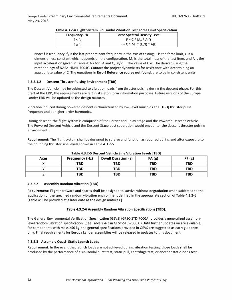
TheDescentVehiclemaybesubjectedtovibrationloadsfromthrusterpulsingduringthedescentphase.ForthisdraftoftheERD,therequirementsareleftinskeletonforminformationpurposes.FutureversionsoftheEuropaLanderERDwillbeupdatedasthedesignmatures.Vibrationinducedduringpowereddescentischaracterizedbylow-levelsinusoidsata[TBD]thrusterpulsefrequencyandathigher-orderharmonics.Duringdescent,theflightsystemiscomprisedoftheCarrierandRelayStageandthePoweredDescentVehicle.ThePoweredDescentVehicleandtheDescentStagepostseparationwouldencounterthedescentthrusterpulsingenvironment.Requirement:TheflightsystemshallbedesignedtosurviveandfunctionasrequiredduringandafterexposuretotheboundingthrustersinelevelsshowninTable4.3.2-5
Table4.3.2-5DescentVehicleSineVibrationLevels[TBD]Axes Frequency(Hz) DwellDuration(s) FA(g) PF(g)X TBD TBD TBD TBDY TBD TBD TBD TBDZ TBD TBD TBD TBD
4.3.2.2 AssemblyRandomVibration[TBD]
Requirement:FlighthardwareandsparesshallbedesignedtosurvivewithoutdegradationwhensubjectedtotheapplicationofthespecifiedrandomvibrationenvironmentdefinedintheappropriatesectionofTable4.3.2-6[Tablewillbeprovidedatalaterdateasthedesignmatures.]
Table4.3.2-6AssemblyRandomVibrationSpecifications[TBD].TheGeneralEnvironmentalVerificationSpecification(GEVS)(GFSC-STD-7000A)providesageneralizedassembly-levelrandomvibrationspecification.(SeeTable2.4-3inGFSC-STC-7000A.)Untilfurtherupdatesonareavailable,forcomponentswithmass>50kg,thegeneralspecificationsprovidedinGEVSaresuggestedasearlyguidanceonly.FinalrequirementsforEuropaLanderassemblieswillbereleasedinupdatestothisdocument.
4.3.2.3 AssemblyQuasi-StaticLaunchLoadsRequirement:Intheeventthatlaunchloadsarenotachievedduringvibrationtesting,thoseloadsshallbeproducedbytheperformanceofasinusoidalbursttest,staticpull,centrifugetest,oranotherstaticloadstest.
EuropaLanderPreliminaryEnvironmentalReqirementsDocument JPLD-97633Draft0.1May23,2018
Pre-DecisionalInformation—ForPlanningandDiscussionPurposesOnly
23
4.3.3 AcousticsEnvironment
4.3.3.1 LaunchAcousticEnvironment
Theacousticenvironment(Table4.3.3-1)istheenvelopeoftheacousticenvironmentsforthealternatecandidateEELVlaunchvehicles(FalconHeavyandDelta-IVHeavy)andthecurrentacousticpredictionforthe5mfairingontheSpaceLaunchSystem(SLS)launchvehicle.TheboundingcaseistheenvelopeoftheDelta-IVHwithcompositePLF(payloadfairing)andDelta-IVHwithisogridPLFandthecurrentacousticpredictionforthe5mSLSfairing.ThisdocumentwillbeupdatedwhenreliableacousticlevelsforthebaselineSLS,orotherpotentialalternatelaunchvehicles,isavailable.ThemaximumacousticenvironmentfortheEuropaLanderflightsystemoccursduringlift-offandtransonicflight.Theenvironmentisrepresentedasadiffuseacousticfieldwithrandomincidencespecifiedin1/3-octavebands.4.3.3.1.1 FlightSystemAcoustics
Atthetimeoflaunch,theflightsystemisintheCruiseVehicleconfiguration.Requirement:TheflightsystemshallperformwithinspecificationafterbeingsubjectedtoacoustictestlevelsdefinedinTable4.3.3-1
Table4.3.3-1AcousticQual/ProtoflightandFlightAcceptanceTestLevels(Placeholder–TBD)
(Duration:Qual:2minutes;PFandFA:1minute.)
4.3.3.1.2 AssemblyAcoustics
Requirement:Flighthardwareandsparesshallbedesignedtosurvivewithoutdegradation,whensubjectedtotheapplicationofthespecifiedacoustictestenvironmentinTable4.3.3-2
Table4.3.3-2AssemblyLevelAcousticQual/ProtoflightandFlightAcceptanceTestLevels[TBD].
Note:AssemblieswithahighsurfaceareatomassratiomayseehigherlevelsthantheFlightSystem.
4.3.4 PyrotechnicShock
PyrotechnicshocktestingwilloccurattheEuropaLanderflightsystemandassemblylevel.Flightsystemtestingisintendedtovalidatethecapabilityoftheflightsystemandverifytheexpecteddominantshocksourcesforpotentiallysusceptiblehardware.Anyassembliesthatmightbesusceptibletoshockdynamicsaretestedatalower-levelofassembly.4.3.4.1 FlightSystemShockEnvironments
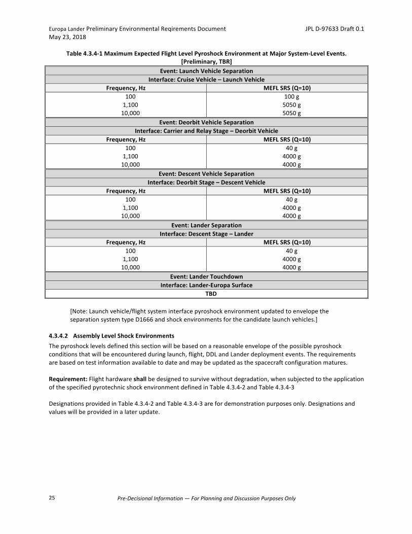
Thesystemlevelseparation/deploymentpyrotechnicshocktestswillbeemployedtoverifytheadequacyoftheassemblyQual/Protoflightpyrotechnicshocktestenvironments,whichwillbeprovidedinanupdatetotheERD.Forassemblylevelshocktesting,theMEFLwillbemultipliedbyafactorof1.4forQual/PF.Requirement:TheflightsystemshallbedesignedtosurvivewithoutdegradationandtofunctionsafelywhensubjectedtotheinducedshockenvironmentsduringseparationeventwithaMaximumExpectedFlightLevel(MEFL)showninTable4.3.4-1.Theselevelsarepredictedatabout6-inchfromthesource.

EuropaLanderPreliminaryEnvironmentalReqirementsDocument JPLD-97633Draft0.1May23,2018
Pre-DecisionalInformation—ForPlanningandDiscussionPurposesOnly
24
Forreference,Table4.3.4-1containsmaximumpredictedshocklevelsforLaunchVehicleSeparationattheflightsysteminterfaceduetopayloadseparationfromthePAFforthealternatecandidateEELVlaunchvehicles(Atlas-VandDelta-IVHeavy).TheERDwillbeupdatedwhenreliablepayloadseparationshocklevelsforthebaselineSLS,orotherpotentialalternatelaunchvehicles,isavailable.
EuropaLanderPreliminaryEnvironmentalReqirementsDocument JPLD-97633Draft0.1May23,2018
Pre-DecisionalInformation—ForPlanningandDiscussionPurposesOnly
25
Table4.3.4-1MaximumExpectedFlightLevelPyroshockEnvironmentatMajorSystem-LevelEvents.[Preliminary,TBR]
Event:LaunchVehicleSeparationInterface:CruiseVehicle–LaunchVehicle
Frequency,Hz MEFLSRS(Q=10)1001,10010,000
100g5050g5050g
Event:DeorbitVehicleSeparationInterface:CarrierandRelayStage–DeorbitVehicle
Frequency,Hz MEFLSRS(Q=10)1001,10010,000
40g4000g4000g
Event:DescentVehicleSeparationInterface:DeorbitStage–DescentVehicle
Frequency,Hz MEFLSRS(Q=10)1001,10010,000
40g4000g4000g
Event:LanderSeparationInterface:DescentStage–Lander
Frequency,Hz MEFLSRS(Q=10)1001,10010,000
40g4000g4000g
Event:LanderTouchdownInterface:Lander-EuropaSurface
TBD[Note:Launchvehicle/flightsysteminterfacepyroshockenvironmentupdatedtoenvelopetheseparationsystemtypeD1666andshockenvironmentsforthecandidatelaunchvehicles.]
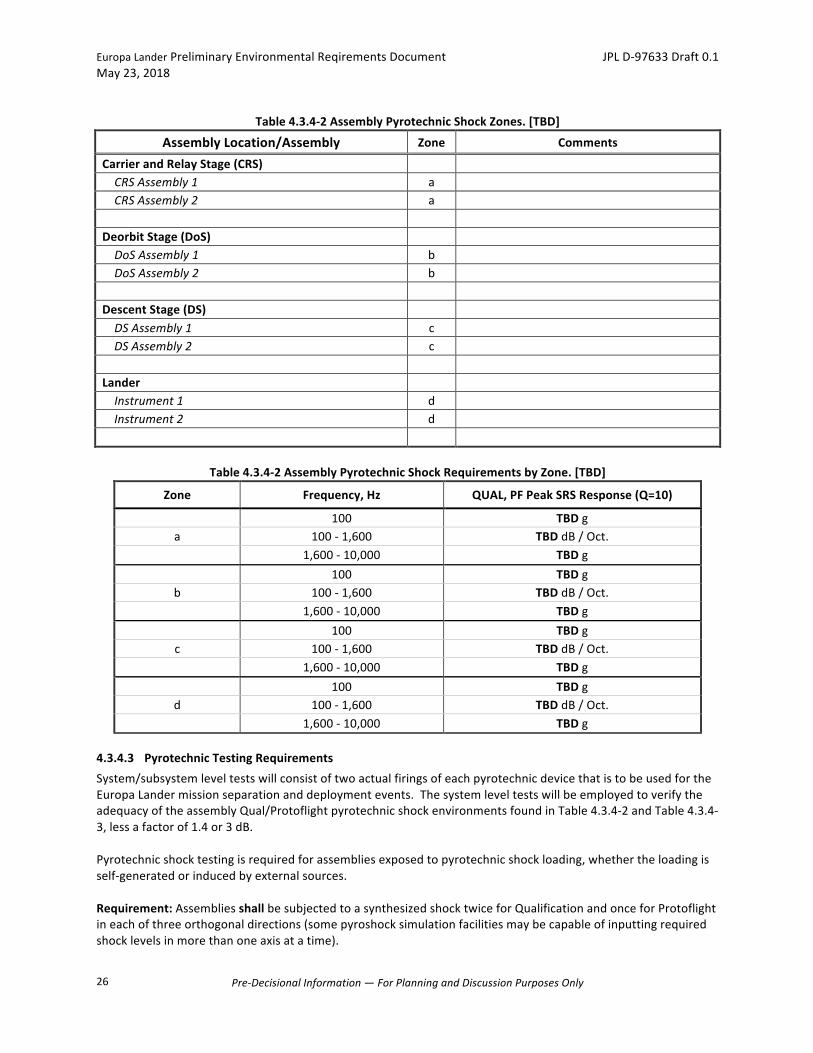
4.3.4.2 AssemblyLevelShockEnvironmentsThepyroshocklevelsdefinedthissectionwillbebasedonareasonableenvelopeofthepossiblepyroshockconditionsthatwillbeencounteredduringlaunch,flight,DDLandLanderdeploymentevents.Therequirementsarebasedontestinformationavailabletodateandmaybeupdatedasthespacecraftconfigurationmatures.Requirement:Flighthardwareshallbedesignedtosurvivewithoutdegradation,whensubjectedtotheapplicationofthespecifiedpyrotechnicshockenvironmentdefinedinTable4.3.4-2andTable4.3.4-3DesignationsprovidedinTable4.3.4-2andTable4.3.4-3arefordemonstrationpurposesonly.Designationsandvalueswillbeprovidedinalaterupdate.
EuropaLanderPreliminaryEnvironmentalReqirementsDocument JPLD-97633Draft0.1May23,2018
Pre-DecisionalInformation—ForPlanningandDiscussionPurposesOnly
26
Table4.3.4-2AssemblyPyrotechnicShockZones.[TBD]
AssemblyLocation/Assembly Zone Comments CarrierandRelayStage(CRS) CRSAssembly1 a CRSAssembly2 a
DeorbitStage(DoS) DoSAssembly1 b DoSAssembly2 b
DescentStage(DS) DSAssembly1 c DSAssembly2 c
Lander Instrument1 d Instrument2 d
Table4.3.4-2AssemblyPyrotechnicShockRequirementsbyZone.[TBD]
Zone Frequency,Hz QUAL,PFPeakSRSResponse(Q=10)
100 TBDga 100-1,600 TBDdB/Oct. 1,600-10,000 TBDg 100 TBDgb 100-1,600 TBDdB/Oct. 1,600-10,000 TBDg 100 TBDgc 100-1,600 TBDdB/Oct. 1,600-10,000 TBDg 100 TBDgd 100-1,600 TBDdB/Oct. 1,600-10,000 TBDg
4.3.4.3 PyrotechnicTestingRequirementsSystem/subsystemleveltestswillconsistoftwoactualfiringsofeachpyrotechnicdevicethatistobeusedfortheEuropaLandermissionseparationanddeploymentevents.ThesystemleveltestswillbeemployedtoverifytheadequacyoftheassemblyQual/ProtoflightpyrotechnicshockenvironmentsfoundinTable4.3.4-2andTable4.3.4-3,lessafactorof1.4or3dB.
Pyrotechnicshocktestingisrequiredforassembliesexposedtopyrotechnicshockloading,whethertheloadingisself-generatedorinducedbyexternalsources.Requirement:AssembliesshallbesubjectedtoasynthesizedshocktwiceforQualificationandonceforProtoflightineachofthreeorthogonaldirections(somepyroshocksimulationfacilitiesmaybecapableofinputtingrequiredshocklevelsinmorethanoneaxisatatime).
EuropaLanderPreliminaryEnvironmentalReqirementsDocument JPLD-97633Draft0.1May23,2018
Pre-DecisionalInformation—ForPlanningandDiscussionPurposesOnly
27
FlightAcceptancepyroshocktestingattheassemblylevelisnotrequired.However,eachassemblywillbefurthersubjectedtopyrotechnicshockduringspacecraftsystemand/orsubsystemleveltesting.Requirement:Thetestarticleshallbemountedtothetestfixtureatitsnormalflightinterfacesandshallbeinitsflightconfigurationatthetimeoftheflightpyroshockevent.Testshocksshallbeappliedatassemblymountingpoints.Thepyroshocktestmaybeconductedeithera)usinganelectro-dynamicshakerorb)usingashock-generatingapparatus.Theshakershocktestmaybeconductedinconjunctionwiththerandomvibrationtest,buttherearesomeoperatinglimitations(e.g.,maximumaccelerationlevelsandsevereroll-offatfrequencyabove3000Hz).Requirement:Synthesizedshockwaveformsshallmeetthefollowingcriteria:thetimehistoryshallbeoscillatoryinnature,andthepulseshalldecaytolessthan10%ofitspeakvaluewithin20milliseconds.Requirement-Policy:Asinglepointopenloopcontrolshallbeutilizedusinglowerlevel'spectrumshaping'runstocalibratethetestcontrol.Requirement-Policy:Controlandmonitoraccelerometersshallbemountedonthetestfixturenearthetestarticleattachmentpoint.Requirement-Policy:Thecontrolshockspectrumatthecontrolaccelerometershallbematchedtotherequiredspectrum.Requirement-Policy:Timehistorydatafromcontrolandanymonitoringaccelerometersshallberecordedandpreserved.Requirement:Sincetestmarginisunachievable,robustnesstoself-inducedshockenvironmentsshallbeverifiedthroughaminimumof(2)actualfiringsofpyrotechnicdevicesinaconfigurationwhichisrepresentativeofflightTheassemblymechanical/pyroshocktestlevelswillbeprovidedatalaterdate.Requirement:Flighthardwarethatperformscriticaloperationsduringashock-producingeventshallbedesignedtofunctionwithinspecificationduringtheapplicationofthespecifiedpyrotechnicshockenvironment. FormoreinformationonpyrotechnicshocktestingconsultNASA-STD-7003A.
4.3.5 InducedMicrophonicsandJitterEffects
Low-leveldynamicenvironmentswouldoccurduringpost-separationoperations.Theprincipalsourcesoftheseenvironmentsareflightsystemdeployments,nominalarticulationofsolararrays,attitudecontrolmaneuvers,nominalmainengineburnaswellasothermechanicalsystemoperations,includingreactionwheels,andsensorsandinstrumentswithmovingmasses.Theselow-levelvibrationsmayinducemicrophonicsorjittereffectsinscienceinstrumentsorflightsystemhardware.(Note:Microphonicsistheinducementofnoiseinelectricaldevicesandjitteristhesmearingofimagesinopticalsystemscausedbyvibration-inducedmotions).Landerinstrumentsandflightsubsystemswillbesubjecttomicrophonicsandjittereffectsfromarticulationofstabilizers,telecomantennae,instrumentssubsystemsinsideandoutsidethevault,andsamplingsystem.Theseenvironmentsarenotyetdefinedandwillbeincludedinupdatestothisdocument.ThevaluespresentedherearerepresentativeandmayberevisedastheLanderdesignmatures.
EuropaLanderPreliminaryEnvironmentalReqirementsDocument JPLD-97633Draft0.1May23,2018
Pre-DecisionalInformation—ForPlanningandDiscussionPurposesOnly
28
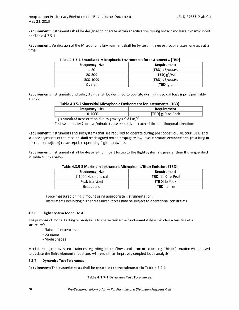
Requirement:InstrumentsshallbedesignedtooperatewithinspecificationduringbroadbandbasedynamicinputperTable4.3.5-1.Requirement:VerificationoftheMicrophonicEnvironmentshallbebytestinthreeorthogonalaxes,oneaxisatatime.
Table4.3.5-1BroadbandMicrophonicEnvironmentforInstruments.[TBD]Frequency(Hz) Requirement
1-20 [TBD]dB/octave20-300 [TBD]g2/Hz
300-1000 [TBD]dB/octaveOverall [TBD]grms
Requirement:InstrumentsandsubsystemsshallbedesignedtooperateduringsinusoidalbaseinputsperTable4.3.5-2.
Table4.3.5-2SinusoidalMicrophonicEnvironmentforInstruments.[TBD]Frequency(Hz) Requirement
10-1000 [TBD]g,0-to-Peak1g=standardaccelerationduetogravity=9.81m/s2.
Testsweeprate:2octave/minute(upsweeponly)ineachofthreeorthogonaldirections.Requirement:Instrumentsandsubsystemsthatarerequiredtooperateduringpostboost,cruise,tour,DDL,andsciencesegmentsofthemissionshallbedesignednottopropagatelow-levelvibrationenvironments(resultinginmicrophonics/jitter)tosusceptibleoperatingflighthardware.Requirement:InstrumentsshallbedesignedtoimpartforcestotheflightsystemnogreaterthanthosespecifiedinTable4.3.5-3below.
Table4.3.5-3MaximumInstrumentMicrophonic/JitterEmission.[TBD]Frequency(Hz) Requirement
1-1000Hzsinusoidal [TBD]lb,0-to-PeakPeaktransient [TBD]lbPeakBroadband [TBD]lbrms
Forcemeasuredonrigidmountusingappropriateinstrumentation.Instrumentsexhibitinghighermeasuredforcesmaybesubjecttooperationalconstraints.
4.3.6 FlightSystemModalTest
Thepurposeofmodaltestingoranalysisistocharacterizethefundamentaldynamiccharacteristicsofastructure’s:
-Naturalfrequencies-Damping-ModeShapes
Modaltestingremovesuncertaintiesregardingjointstiffnessandstructuredamping.Thisinformationwillbeusedtoupdatethefiniteelementmodelandwillresultinanimprovedcoupledloadsanalysis.
4.3.7 DynamicsTestTolerances
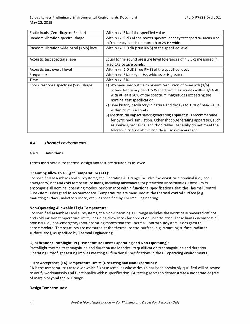
Requirement:ThedynamicstestsshallbecontrolledtothetolerancesinTable4.3.7-1.
Table4.3.7-1DynamicsTestTolerances.
EuropaLanderPreliminaryEnvironmentalReqirementsDocument JPLD-97633Draft0.1May23,2018
Pre-DecisionalInformation—ForPlanningandDiscussionPurposesOnly
29
Staticloads(CentrifugeorShaker) Within+/-5%ofthespecifiedvalue.Randomvibrationspectralshape Within+/-3dBofthepowerspectraldensitytestspectra,measured
infrequencybandsnomorethan25Hzwide.Randomvibrationwide-band(RMS)level Within+/-1.0dB(trueRMS)ofthespecifiedlevel.
Acoustictestspectralshape Equaltothesoundpressureleveltolerancesof4.3.3-1measuredinfixed1/3-octavebands.
Acoustictestoveralllevel Within+/-1.0dB(trueRMS)ofthespecifiedlevel.Frequency Within+/-5%or+/-1Hz,whicheverisgreater.Time Within+/-5%.Shockresponsespectrum(SRS)shape 1)SRSmeasuredwithaminimumresolutionofone-sixth(1/6)
octavefrequencyband.SRSspectrummagnitudeswithin+/-6dB,withatleast50%ofthespectrummagnitudesexceedingthenominaltestspecification.
2)Timehistoryoscillatoryinnatureanddecaysto10%ofpeakvaluewithin20milliseconds.
3)Mechanicalimpactshock-generatingapparatusisrecommendedforpyroshocksimulation.Othershock-generatingapparatus,suchasshakers,ordnance,anddroptables,generallydonotmeetthetolerancecriteriaaboveandtheiruseisdiscouraged.
4.4 ThermalEnvironments
4.4.1 Definitions
Termsusedhereinforthermaldesignandtestaredefinedasfollows:OperatingAllowableFlightTemperature(AFT):Forspecifiedassembliesandsubsystems,theOperatingAFTrangeincludestheworstcasenominal(i.e.,non-emergency)hotandcoldtemperaturelimits,includingallowancesforpredictionuncertainties.Theselimitsencompassallnominaloperatingmodes,performancewithinfunctionalspecifications,thattheThermalControlSubsystemisdesignedtoaccommodate.Temperaturesaremeasuredatthethermalcontrolsurface(e.g.mountingsurface,radiatorsurface,etc.),asspecifiedbyThermalEngineering.Non-OperatingAllowableFlightTemperature:Forspecifiedassembliesandsubsystems,theNon-OperatingAFTrangeincludestheworstcasepowered-offhotandcoldmissiontemperaturelimits,includingallowancesforpredictionuncertainties.Theselimitsencompassallnominal(i.e.,non-emergency)non-operatingmodesthattheThermalControlSubsystemisdesignedtoaccommodate.Temperaturesaremeasuredatthethermalcontrolsurface(e.g.mountingsurface,radiatorsurface,etc.),asspecifiedbyThermalEngineering.Qualification/Protoflight(PF)TemperatureLimits(OperatingandNon-Operating):Protoflightthermaltestmagnitudeanddurationareidenticaltoqualificationtestmagnitudeandduration.OperatingProtoflighttestingimpliesmeetingallfunctionalspecificationsinthePFoperatingenvironments.FlightAcceptance(FA)TemperatureLimits(OperatingandNon-Operating):FAisthetemperaturerangeoverwhichflightassemblieswhosedesignhasbeenpreviouslyqualifiedwillbetestedtoverifyworkmanshipandfunctionalitywithinspecification.FAtestingservestodemonstrateamoderatedegreeofmarginbeyondtheAFTrange.DesignTemperatures:

EuropaLanderPreliminaryEnvironmentalReqirementsDocument JPLD-97633Draft0.1May23,2018
Pre-DecisionalInformation—ForPlanningandDiscussionPurposesOnly
30
Designtemperaturesarethetemperaturelimitstowhichassembliesaredesignedtomeetfunctionalandperformancespecifications.DesigntemperaturesarenormallyequivalenttoorexceedtheQualification/Protoflightlimits.
Figure4.4.1-1ExampleThermalDesignLimitsforOperationalandNon-OperationalRanges.Designlimitsare
normallyequivalenttoorexceedtheQualification/Protoflightlimits.
4.4.2 LaunchThermalEnvironment
Thelaunchthermalenvironmentisdependentonboththelaunchvehicleandtheflighttrajectory.Thevaluespresentedinthissectionarepreliminaryandmaychange.Thisdocumentwillbeupdatedasthedesignmatures.Requirement:ThethermalcontroldesignshallmaintainassemblieswithintheirrespectiveAFTlimitswhileexposedtothelaunchinducedthermalenvironmentsinSection4.4.2.1andSectionError!Referencesourcenotfound..4.4.2.1 PayloadFairingWallTemperature
TheinnersurfacesoftheEELVcomposite5-mPLFconeandcylinderhaveanemittanceof0.9.ThepeakheatfluxradiatedbytheinnersurfacesoftheLVconeandcylinderofthe5-mPLFislessthan914W/m2(290Btu/hr-ft2),andpeaktemperaturesremainbelow93°C(200°F)atthewarmestlocation.SLSfairingthermalconditionsareexpectedtobesimilartoEELVenvironments.
4.4.3 PlanetaryProtectionThermalEnvironment
TheEuropaLanderPlanetaryProtectionPlan(JPLD-97653)isthereferencedocumentforplanetaryprotectionrequirements.OneoftheplanetaryprotectionprocessesavailableisDryHeatMicrobialReduction(DHMR)andthereforewouldlikelydriveanon-operationalthermalenvironmentforflighthardware.Here,ashortdescriptionofDHMRandnotionalspecificationsaregiven.DHMRDescription:DryHeatMicrobialReduction(DHMR)isabake-outprocesswherethehardwareisheldatanelevatedtemperature,typically>125°Cformanyhoursinacontrolledhumidity(<25%relativehumidity)
OperationalRangeNon-OperationalRange
70
60
50
40
30
20100
-10
-20
-30
-40-50-60-70
Temperature
AllowableFlightTem
perature
FlightAcceptance
Qualification/Protoflight
Allowab
leFlightTe
mpe
rature
FlightAccep
tance
Qua
lifica
tion/Protoflight
EuropaLanderPreliminaryEnvironmentalReqirementsDocument JPLD-97633Draft0.1May23,2018
Pre-DecisionalInformation—ForPlanningandDiscussionPurposesOnly
31
environment,suchaspartialvacuumordrynitrogen.Exacttemperaturesanddurationsforthehardwarewouldbedependentonaccommodationofthehardwareonthespacecraftandwouldbeinvestigatedindetailwhenthermalmodelsbecomeavailable.Stepsshouldbetakenafterbioburdenreductionprocessingtopreventrecontamination,potentiallyinvolvingspecializedhandlingprocedures,seals,covers,filtersand/orothertechniquesincorporatedinthedesign.Recently,NASAspecificationshavebeenchangedtoallowHMRwithouthumiditycontrol.Whilesimplertoimplement,thedurationsarelongerforequivalentmicrobiallethality.Forsurfaceandencapsulatedelements,a4-orderofmagnitudebioburdenreductionequatestoaDHMRbakeatslightlyhigherthan125˚Cfor88.6hoursand442.9hours,respectively.
4.4.4 SpaceandEuropaSurfaceThermalEnvironment
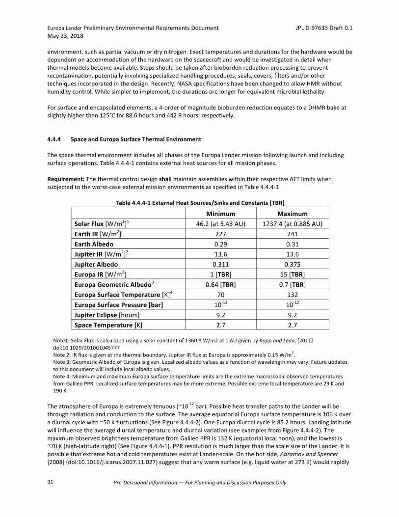
ThespacethermalenvironmentincludesallphasesoftheEuropaLandermissionfollowinglaunchandincludingsurfaceoperations.Table4.4.4-1containsexternalheatsourcesforallmissionphases.Requirement:ThethermalcontroldesignshallmaintainassemblieswithintheirrespectiveAFTlimitswhensubjectedtotheworst-caseexternalmissionenvironmentsasspecifiedinTable4.4.4-1
Table4.4.4-1ExternalHeatSources/SinksandConstants[TBR]
Minimum Maximum
SolarFlux[W/m2]1 46.2(at5.43AU) 1737.4(at0.885AU)EarthIR[W/m2] 227 241EarthAlbedo 0.29 0.31JupiterIR[W/m2]2 13.6 13.6JupiterAlbedo 0.311 0.375EuropaIR[W/m2] 1[TBR] 15[TBR]EuropaGeometricAlbedo3 0.64[TBR] 0.7[TBR]EuropaSurfaceTemperature[K]4 70 132EuropaSurfacePressure[bar] 10-12 10-12JupiterEclipse[hours] 9.2 9.2SpaceTemperature[K] 2.7 2.7
Note1:SolarFluxiscalculatedusingasolarconstantof1360.8W/m2at1AUgivenbyKoppandLean,[2011]doi:10.1029/2010GL045777Note2:IRfluxisgivenatthethermalboundary.JupiterIRfluxatEuropaisapproximately0.15W/m2.Note3:GeometricAlbedoofEuropaisgiven.Localizedalbedovaluesasafunctionofwavelengthmayvary.Futureupdatestothisdocumentwillincludelocalalbedovalues.Note4:MinimumandmaximumEuropasurfacetemperaturelimitsaretheextrememacroscopicobservedtemperaturesfromGalileoPPR.Localizedsurfacetemperaturesmaybemoreextreme.Possibleextremelocaltemperatureare29Kand190K.
TheatmosphereofEuropaisextremelytenuous(~10-12bar).PossibleheattransferpathstotheLanderwillbethroughradiationandconductiontothesurface.TheaverageequatorialEuropasurfacetemperatureis106Koveradiurnalcyclewith~50Kfluctuations(SeeFigure4.4.4-2).OneEuropadiurnalcycleis85.2hours.Landinglatitudewillinfluencetheaveragediurnaltemperatureanddiurnalvariation(seeexamplesfromFigure4.4.4-2).ThemaximumobservedbrightnesstemperaturefromGalileoPPRis132K(equatoriallocalnoon),andthelowestis~70K(high-latitudenight)(SeeFigure4.4.4-1).PPRresolutionismuchlargerthanthescalesizeoftheLander.ItispossiblethatextremehotandcoldtemperaturesexistatLander-scale.Onthehotside,AbramovandSpencer[2008](doi:10.1016/j.icarus.2007.11.027)suggestthatanywarmsurface(e.g.liquidwaterat273K)wouldrapidly

EuropaLanderPreliminaryEnvironmentalReqirementsDocument JPLD-97633Draft0.1May23,2018
Pre-DecisionalInformation—ForPlanningandDiscussionPurposesOnly
32
coolto<190Kwithin10Earthdays.Onthecoldside,Paigeetal.,[2010](10.1126/science.1187726)measuredtemperaturesaslowas29KinpolarLunarcraters.WhileshadedLunarcratersarenotaone-to-oneanalog,theyrepresentapotentialextremecoldthatmayalsoexistonEuropainlocalizedareas.Therefore,wespecify29Kand190KasthelocaltemperatureextremesthatcouldbefoundonEuropa’ssurface.
Figure4.4.4-1BrightnesstemperatureobservationsfromGalileoPPR.[FromRathbun,Rodriguez,andSpencer,
2009.](doi:10.1016/j.icarus.2010.07.017)
In general, daytime temperatures behave as expected, with tem-peratures peaking at approximately 130 K near the subsolar pointin all images covering a substantial portion of the disk and droppingoff away from the subsolar point. Nighttime temperatures varywith location and local time, but are generally less than 100 K.One surprising feature in the nighttime data is in the region be-tween 0 and 90 west longitude where the nighttime temperatures
are highest at mid-latitudes and drop not only toward higher lati-tudes, but also toward the equator (Spencer et al., 1999). Thischange is not apparently correlated with any surface features or al-bedo. Spencer et al. (1999) suggested that thermal inertia variationscould account for the observed temperature difference, but couldnot rule out warming of mid-latitude surfaces by widely-distrib-uted endogenic heat as a possibility. They also fit a diurnal thermal
Table 1List of the PPR data sets with high spatial resolution, low noise, and coverage of a large area. Time of day is given in degrees where 0 is midnight, 90 dawn, 180 noon, and 270 dusk.
Filename Date of obs. Filter Latitude range Longitude range Resn. (km/pixel) Time of day range
E6EPDGTM_01 February 1997 27 lm !80 80 140 310 130 70 220G7EPDGTM_01 April 1997 27 lm !80 80 100 270 180 90 240E11EPHOTSPT 01 November 1997 17 lm !40 50 230 310 120 40 100E11EPHOTSPT 02 November 1997 17 lm !10 30 0 170 80 190 340E12EPHOTSPT 01 December 1997 17 lm !20 20 290 360 100 40 90E12PHOTSPT 02 December 1997 17 lm !5 25 70 130 80 290 330E14EPDGTMHR01 March 1998 27 lm !80 80 80 230 120 190 320E15EPDRTMHR01 May 1998 27 lm !20 90 120 300 110 40 200E17EPDARKHR01 September 1998 Open !50 50 200 310 110 20 110E17EPDARKHR02 September 1998 Open !25 40 0 70 80 280 330E17EPDRKMAP02 September 1998 Open !70 70 0 70 180 280 330E17EPDRKMAP03 September 1998 Open !70 70 0 70 230 290 340I25EPDGTM__01 November 1999 17 lm !70 80 135 270 190 140 230I25EPDRKMAP01 November 1999 Open !80 90 0 110 210 -40 80I25EPH2040_02 November 1999 17 lm !10 50 0 110 280 140 230
Fig. 1. Composite of five of the best PPR data sets. The daytime images are G7EPDGTM_01 and 25EPDGTM_01 while the nighttime images are E17DARKHR01,25EPDRKMAP01, and E17EPDRKMAP02 (west to east).
764 J.A. Rathbun et al. / Icarus 210 (2010) 763–769
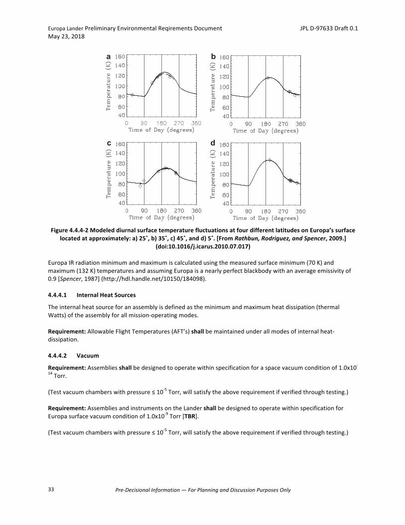
EuropaLanderPreliminaryEnvironmentalReqirementsDocument JPLD-97633Draft0.1May23,2018
Pre-DecisionalInformation—ForPlanningandDiscussionPurposesOnly
33
Figure4.4.4-2ModeleddiurnalsurfacetemperaturefluctuationsatfourdifferentlatitudesonEuropa’ssurface
locatedatapproximately:a)25˚,b)35˚,c)45˚,andd)5˚.[FromRathbun,Rodriguez,andSpencer,2009.](doi:10.1016/j.icarus.2010.07.017)
EuropaIRradiationminimumandmaximumiscalculatedusingthemeasuredsurfaceminimum(70K)andmaximum(132K)temperaturesandassumingEuropaisanearlyperfectblackbodywithanaverageemissivityof0.9[Spencer,1987](http://hdl.handle.net/10150/184098).4.4.4.1 InternalHeatSources
Theinternalheatsourceforanassemblyisdefinedastheminimumandmaximumheatdissipation(thermalWatts)oftheassemblyforallmission-operatingmodes.Requirement:AllowableFlightTemperatures(AFT’s)shallbemaintainedunderallmodesofinternalheat-dissipation.4.4.4.2 Vacuum
Requirement:Assembliesshallbedesignedtooperatewithinspecificationforaspacevacuumconditionof1.0x10-14Torr.(Testvacuumchamberswithpressure≤10-5Torr,willsatisfytheaboverequirementifverifiedthroughtesting.)Requirement:AssembliesandinstrumentsontheLandershallbedesignedtooperatewithinspecificationforEuropasurfacevacuumconditionof1.0x10-9Torr[TBR].(Testvacuumchamberswithpressure≤10-5Torr,willsatisfytheaboverequirementifverifiedthroughtesting.)
model to the G7 and E17 observations, finding that the low-latitudeobservations were best fit by a surface with a bolometric albedo of0.55, a thermal inertia of 7 ! 104 erg cm"2 s"1/2 K"1, and no endo-genic emission. However, the data they used for this fit comes frommany different points on the surface, and different locations maynot have the same thermophysical properties.
Thermal inertias provide clues to surface physical propertiesthat are essential for predicting diurnal temperatures. Mappingof the thermal inertia, and therefore the diurnal temperatures,across the surface can predict volatile stability across the surfaceover the course of a day. Furthermore, knowledge of diurnal tem-perature variations can assist with planning future missions, par-ticularly with designing instruments to search for endogenicemission.
2. Determination of thermophysical properties
Here we map thermophysical properties as a function of loca-tion on Europa by applying the same one-dimensional numericalthermal model used by Spencer et al. (1999) to individual pointson the surface for which we have temperature data from differenttimes of day. This model calculates the surface temperature as afunction of time of day based on the thermal inertia and bolometricalbedo, assuming vertically-homogeneous thermophysical proper-ties (Spencer et al., 1989). We divided the surface into 10 squaredegree bins. For each bin, we searched the PPR observations forall data obtained within that bin. For each data set, measurementswithin the bin were averaged, thus reducing noise. In order to ade-quately constrain the thermophysical properties, at least one mea-surement must have been made at night and at least one within20! of noon. For every point on the surface with such measure-ments, we applied the thermal model to find the best fit thermalinertia and bolometric albedo. Observations were obtained on dif-ferent dates and, thus, when Europa was at a different heliocentricdistance. Since differences in heliocentric distance as small as a fewhundredths of an AU lead to modeled temperature differences of afew degrees, we ran the thermal model separately for each data
point we were trying to fit. Fig. 2 shows four example best fitcurves for four locations on the surface (indicated by X’s in Figs.3 and 4).
We did not use all 15 data sets for this calculation; the four datasets obtained during E11 and E12 were noisier than the rest andcovered too small an area to be useful. The resulting bolometric al-bedo and thermal inertia maps are shown in Figs. 3 and 4 and coverapproximately 20% of Europa’s surface. The bolometric albedosvary significantly across the surface and show a general darkeningtoward the trailing hemisphere that is consistent with albedo vari-ations observed in visible images (McEwen, 1986).
The computed thermal inertias generally range from 4 ! 104 to15 ! 104 erg cm"2 s"1/2 K"1, bracketing the thermal inertia foundby Spencer et al. (1999). These thermal inertias are too low for so-lid ice, so at least the mapped 20% of the surface, and likely most ofit, is composed of unconsolidated regolith. The lower nighttimetemperatures observed at the equator can be explained by lowerthermal inertias there. Thermal inertia variations better matchboth the daytime and nighttime temperatures than thermal mod-els that include endogenic heating at mid-latitudes, because endo-genic heating would increase both daytime and nighttimetemperatures, and that is not observed. The increased thermalinertia at higher latitudes can be explained by a more compactedsurface, but these variations are not correlated with any observa-tions of albedo, geology, etc. Furthermore, the trend to lower equa-torial thermal inertias appears to be more widespread than just atthe leading hemisphere where the nighttime temperature anoma-lies were first observed (Spencer et al., 1999). The thermal inertiaswe calculated on the anti-Jupiter hemisphere also show a drop atthe equator. Exogenic processes, such as radiation processing orsputtering, may modify the surface. However, the effects of suchprocesses on thermal inertia have not been modeled.
3. Detection limits for hotspots
All of the observed surface temperatures can be successfullymodeled as passive reradiation of sunlight, thus no endogenic
a b
dc
Fig. 2. Temperature as a function of time of day for four different locations (indicated by X’s in Figs. 3 and 4) on the surface. Diamonds indicate average temperature at thatlocation from a single PPR data set. The line is the best fit thermal model to the data and the plus signs are the model points corresponding to the data points.
J.A. Rathbun et al. / Icarus 210 (2010) 763–769 765
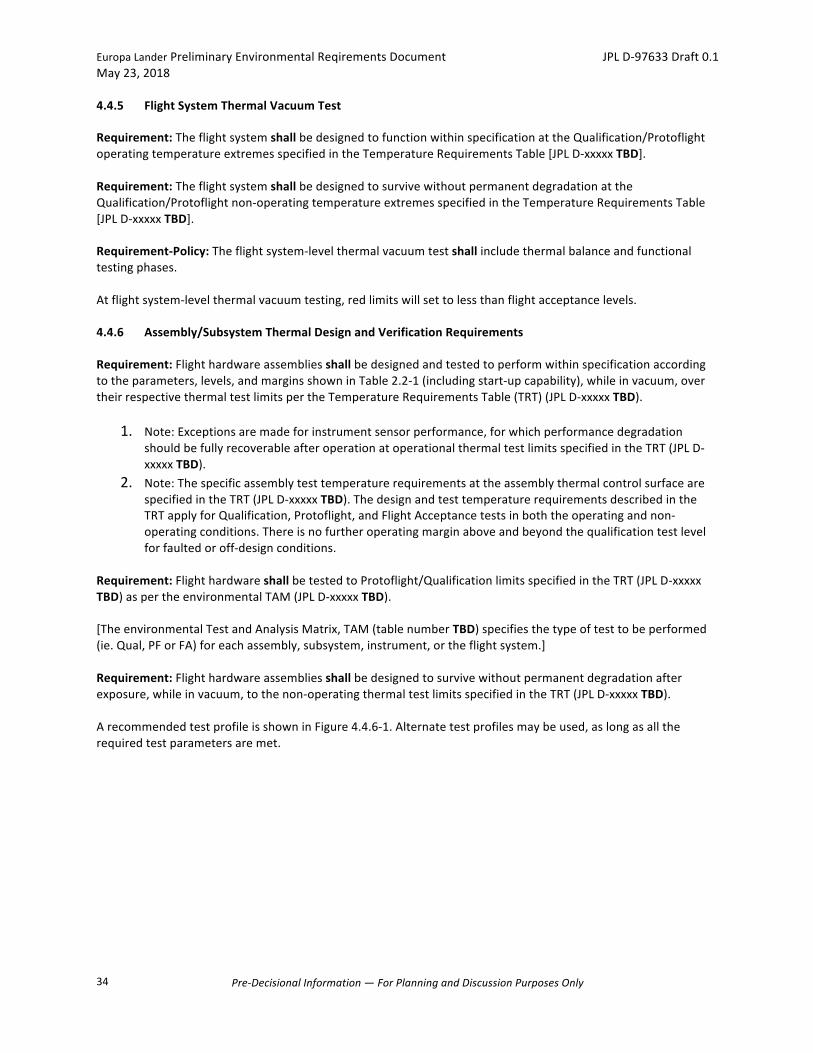
EuropaLanderPreliminaryEnvironmentalReqirementsDocument JPLD-97633Draft0.1May23,2018
Pre-DecisionalInformation—ForPlanningandDiscussionPurposesOnly
34
4.4.5 FlightSystemThermalVacuumTest
Requirement:TheflightsystemshallbedesignedtofunctionwithinspecificationattheQualification/ProtoflightoperatingtemperatureextremesspecifiedintheTemperatureRequirementsTable[JPLD-xxxxxTBD].Requirement:TheflightsystemshallbedesignedtosurvivewithoutpermanentdegradationattheQualification/Protoflightnon-operatingtemperatureextremesspecifiedintheTemperatureRequirementsTable[JPLD-xxxxxTBD].Requirement-Policy:Theflightsystem-levelthermalvacuumtestshallincludethermalbalanceandfunctionaltestingphases.Atflightsystem-levelthermalvacuumtesting,redlimitswillsettolessthanflightacceptancelevels.
4.4.6 Assembly/SubsystemThermalDesignandVerificationRequirements
Requirement:Flighthardwareassembliesshallbedesignedandtestedtoperformwithinspecificationaccordingtotheparameters,levels,andmarginsshowninTable2.2-1(includingstart-upcapability),whileinvacuum,overtheirrespectivethermaltestlimitspertheTemperatureRequirementsTable(TRT)(JPLD-xxxxxTBD).
1. Note:Exceptionsaremadeforinstrumentsensorperformance,forwhichperformancedegradationshouldbefullyrecoverableafteroperationatoperationalthermaltestlimitsspecifiedintheTRT(JPLD-xxxxxTBD).
2. Note:ThespecificassemblytesttemperaturerequirementsattheassemblythermalcontrolsurfacearespecifiedintheTRT(JPLD-xxxxxTBD).ThedesignandtesttemperaturerequirementsdescribedintheTRTapplyforQualification,Protoflight,andFlightAcceptancetestsinboththeoperatingandnon-operatingconditions.Thereisnofurtheroperatingmarginaboveandbeyondthequalificationtestlevelforfaultedoroff-designconditions.
Requirement:FlighthardwareshallbetestedtoProtoflight/QualificationlimitsspecifiedintheTRT(JPLD-xxxxxTBD)aspertheenvironmentalTAM(JPLD-xxxxxTBD).[TheenvironmentalTestandAnalysisMatrix,TAM(tablenumberTBD)specifiesthetypeoftesttobeperformed(ie.Qual,PForFA)foreachassembly,subsystem,instrument,ortheflightsystem.]Requirement:Flighthardwareassembliesshallbedesignedtosurvivewithoutpermanentdegradationafterexposure,whileinvacuum,tothenon-operatingthermaltestlimitsspecifiedintheTRT(JPLD-xxxxxTBD).ArecommendedtestprofileisshowninFigure4.4.6-1.Alternatetestprofilesmaybeused,aslongasalltherequiredtestparametersaremet.
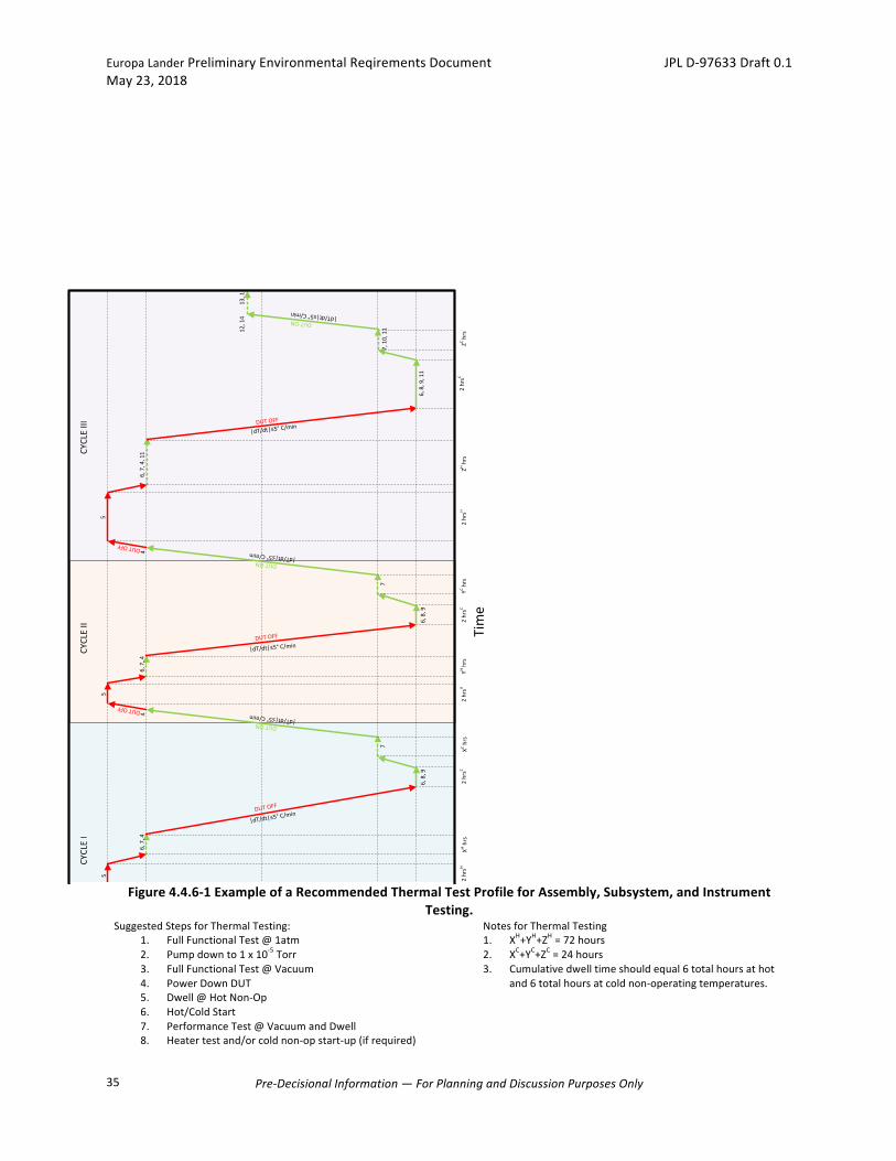
EuropaLanderPreliminaryEnvironmentalReqirementsDocument JPLD-97633Draft0.1May23,2018
Pre-DecisionalInformation—ForPlanningandDiscussionPurposesOnly
35
Figure4.4.6-1ExampleofaRecommendedThermalTestProfileforAssembly,Subsystem,andInstrument
Testing.SuggestedStepsforThermalTesting:
1. FullFunctionalTest@1atm2. Pumpdownto1x10-5Torr3. FullFunctionalTest@Vacuum4. PowerDownDUT5. Dwell@HotNon-Op6. Hot/ColdStart7. PerformanceTest@VacuumandDwell8. Heatertestand/orcoldnon-opstart-up(ifrequired)
NotesforThermalTesting1. XH+YH+ZH=72hours2. XC+YC+ZC=24hours3. Cumulativedwelltimeshouldequal6totalhoursathot
and6totalhoursatcoldnon-operatingtemperatures.
Re
com
me
nd
ed
Th
erm
al V
acu
um
Te
st P
rofi
le-
EC
OST
RE
SS
Tim
e
Control Temperature
DUT ON
Cold
Qua
l/PF
Op
[(A
FT -
15
°C)
or
(-3
5°C
)
wh
ich
eve
r is
co
lde
r]
Cold
Qua
l/PF
Non
-Op
[(A
FT -
15
°C)
or
(-3
5°C
)
wh
ich
eve
r is
co
lde
r]
DUT OFF
Hot Q
ual/
PF O
p[(
AFT
+ 2
0°C
) o
r (+
70
°C)
wh
ich
eve
r is
wa
rme
r]
Hot Q
ual/
PF N
on-O
p[(
AFT
+ 2
0°C
) o
r (+
70
°C)
wh
ich
eve
r is
wa
rme
r]
SUGG
ESTE
D ST
EPS:
1)
Full
Fun
ctio
na
l Te
st @
1 a
tm
2)
Pu
mp
do
wn
to
1 x
10
-5 T
orr
(1
*)
3)
Full
Fun
ctio
na
l Te
st @
Va
cuu
m
4)
Po
we
r D
ow
n D
UT
5)
Dw
ell
@ H
ot
No
n-O
p (
4*
)
6)
Ho
t/C
old
Sta
rt
7)
Pe
rfo
rma
nce
Te
st @
Va
cuu
m a
nd
Dw
ell
8)
He
ate
r te
sts
an
d/o
r co
ld n
on
-op
sta
rt-u
p (
if r
eq
uir
ed
)
9)
Dw
ell
@ C
old
No
n-O
p (
4*
)
10
) Fu
ll P
erf
orm
an
ce T
est
@ V
acu
um
an
d D
we
ll
11
) A
ccu
mu
late
Re
ma
inin
g O
pe
rati
ng
/No
n-O
pe
rati
ng
Ho
urs
as
Re
qu
ire
d
12
) T
em
pe
ratu
re=
Am
bie
nt
+ 5
°C
(2
*)
13
) R
etu
rn t
o A
mb
ien
t P
ress
ure
an
d T
em
pe
ratu
re (
3*
)
14
) Fu
ll Fu
nct
ion
al T
est
@ V
acu
um
XH+
YH+
ZH=
72
ho
urs
XC+
YC+
ZC=
24
ho
urs
2 h
rsH
1,
2,
3
4
5
6,
7,
4
|dT/dt|≤5° C/min
|dT/dt|≤5° C/min
XH h
rsX
C h
rs
6,
8,
9
7
DUT OFF
DUT ON|dT/dt|≤5° C/min
2 h
rsC
DUT OFF
4
5
6,
7,
4
|dT/dt|≤5° C/minDUT OFF
2 h
rsH
YH h
rsY
C h
rs
DUT OFF
4
5
6,
7,
4,
11
DUT ON|dT/dt|≤5° C/min
|dT/dt|≤5° C/minDUT OFF
2 h
rsH
ZH h
rs2
hrs
C
ZC h
rs2
hrs
C
6,
8,
96
, 8
, 9
, 1
1
77
, 1
0,
1112
, 1
41
3,
1
CY
CLE
IC
YC
LE I
IC
YC
LE I
II
DUT ON|dT/dt|≤5° C/min
No
tes:
(1*
) A
ll EC
OST
RESS
har
dwar
e op
erat
es a
t vol
tage
s <
48 V
dc,
less
than
cri
teri
a fo
r co
rona
, but
m
ay r
equi
re a
n ex
cept
ion.
(2*)
To
ensu
re n
o co
nden
satio
n(3
*) B
ackf
ill/v
ent t
he c
ham
ber
with
nitr
ogen
or
argo
n to
1 a
tm o
nly
whe
n th
e ch
ambe
r is
ab
ove
or @
roo
m te
mpe
ratu
re(4
*) C
umm
aliti
ve d
wel
l tim
e at
hot
and
col
d no
n-op
erat
ing
tem
pera
ture
s sh
ould
equ
al to
6
hour
s to
tal
EuropaLanderPreliminaryEnvironmentalReqirementsDocument JPLD-97633Draft0.1May23,2018
Pre-DecisionalInformation—ForPlanningandDiscussionPurposesOnly
36
9. Dwell@ColdNon-Op10. FullPerformanceTest@VacuumandDwell11. AccumulateRemainingOperating/Non-OperatingHours
asRequired12. Temperature=Ambient+5C13. ReturntoAmbientPressureandTemperature14. FullFunctionalTest@Vacuum
Requirement:Assemblies,whicharepowered-onduringlaunch,shallbeoperatedduringchamberevacuationtomonitorcoronaeffects.Requirement:Eachtemperatureplateaushallbemaintainedforaminimumof2hours,oncetemperaturestabilizationisachieved.
Requirement:Functionaltestingshallbeperformedaminimumofthreetimesatthehotoperationaltestlimitsandaminimumofthreetimesatthecoldoperationaltestlimits.Ideally,afunctionaltestwouldberunateachtemperatureplateauforatotalof6times,minimum.Requirement:Assembliesshalldemonstrateaminimumofthreeproperstart-upsatthehotandthreeproperstart-upsatcoldoperationaltestlimitsandalsoatthecoldnon-operationaltestlimit(ifrequired*).
Exception:One-timedeployablemechanisms,orlaunchlatchesandrestraints,withtheapprovalofthe
ProjectEREandtheenvironmentaldisciplinespecialists,anddocumentedintheproject-approvedERD,maybeoperatedataminimumoffouroperations,definedasonceatambienttemperature,onceatPFhotbound,onceatPFcoldbound,andonceinsystemtestontheflightsystem.*Note:Start-upsfromthecoldnon-optestlimitarerequiredifthemissionthermalcontrolschemerequirespoweringonequipmentatthecoldnon-operationalAllowableFlightTemperature.
Specialthermaldesignfeatures,suchasheaterandlouveroperations,shouldbedemonstratedifapplicable.Additionally,anyflighttemperaturesensingdevicesshouldbecalibratedinthistest.
4.4.7 ThermalTestTolerancesandStabilizationCriteria
Requirement:ThethermaltesttoleranceshallbeasTable4.4.7-1.
Table4.4.7-1ThermalTestTolerancesandStabilizationCriteria.
4.4.8 ThermalCyclingDesignCriteria
Allflighthardwarewillbedesignedtoaccommodatetheeffectsofthermalcycling.
Temperature Within+2°C.Time Within0and+15minutes.
Pressure+5%above1Torr.Atvacuumconditions,toleranceswillbesuchthatapressureof<10-5Torrismaintained.
ThermalStabilityTemperaturecontrolsystemsforthermalvacuumenvironmentswillhavethecapabilityofholdingthecontrolpointthermocouplereadingstowithin+2ºC.
ThermalEquilibriumChangeoftemperatureoflargestcentrally-locatedthermalmassislessthan2ºC/hourforthreeconsecutivereadingstaken15minutesapartanddT/dtslopeisapproachingzero.

EuropaLanderPreliminaryEnvironmentalReqirementsDocument JPLD-97633Draft0.1May23,2018
Pre-DecisionalInformation—ForPlanningandDiscussionPurposesOnly
37
Requirement-Policy:Electronichardwareshallbecapableofsurvivingthreetimestheplannedmissionexpectednumberofthermalcycles,eachovertheallowableflighttemperature(AFT)extremes,plusanestimateofthethermalcyclesexpectedintheplannedgroundoperations.(Thisrequirementmaybeverifiedviaanalysisorsamplecoupontest.)Requirement-Policy:Intheabsenceofaspecificmissionthermalcyclingprofile,electronichardwareshallbecapableofsurviving10,000cycles,eachofa15CΔTexcursion.
4.5 ElectromagneticInterferenceandCompatibility(EMI/EMC)
TheEMCdesignandverificationprogramisintendedtoproduceaEuropaLanderflightsystemthatwouldbeelectromagneticallycompatiblewithitselfanditsexternalenvironmentduringallmissionphases.Thisincludesperformance-compliantflightsystemoperationinspaceandinthelaunchenvironment(launchvehicleandlaunchsite)underallmissionoperationconditions.ThissectiondescribestheElectromagneticInterference/ElectromagneticCompatibility(EMI/EMC)requirementsapplicabletotheEuropaLanderflightsystemanditsinstruments,subsystems,andassembliesthroughoutitsentiremissionduration.Thissectionwillbeupdatedinfuturereleasesastheflightsystemandpayloaddesignsmature.Requirement:Theflightsystemhardwareshallbedesignedandverifiedtobeelectromagneticallyself-compatibleperTable2.2-1.
4.5.1 LaunchVehicle/LaunchSiteElectromagneticEnvironments
Flightsystemelectromagneticcompatibilitywiththelaunchvehicleandthelaunchsite(LV/LS)shouldbeconsideredintwoareas:
• Compatibilitywiththelaunchvehicleandlaunchsitepowersystem.• Electromagnetic/RFcompatibility(emissions,susceptibility,transmitters,receivers).
4.5.1.1 FlightSystemPowerSubsystemCompatibilitywiththeLV/LS
Theflightsystemwillbepoweredbytheumbilicalpowersupplyduringtestingatthelaunchsitefacility.Itisassumedthattheumbilicalpowersubsystemwillprovidepowertotheflightsystem,willnotgeneratenoiseandtransientsthatexceedtheconductedsusceptibility(Section4.5.2.2)andpowertransient(Section4.5.3)requirementsinordertoprovidecompatibilitybetweentherespectivepowersystems.Iftherespectiverequirementsarenotcompatible,however,itwillbenecessarytoprovidepowerprofilesoftheumbilicalpowersupply.Itshouldbenotedthattheflightsystempowersupply,beingasubsystem,mustcomplywiththerequirementspresentedinthissection.Further,sincethepowersupplyprovidespowertotheinstruments,subsystems,andassemblies,itsoutputpowercharacteristicsmustbecompatiblewiththespecifiedpowerrequirements.Thefollowingrequirementsarethereforeimposedinordertoprovideclarityincompliance.4.5.1.1.1 FlightSystemPowerSubsystemConductedEmissionsandSusceptibilityRequirements[TBR]
Tobeprovidedinalaterrevision.
4.5.1.1.2 FlightSystemPowerSupplyOutputNoiseRequirements
Tobeprovidedinalaterrevision.
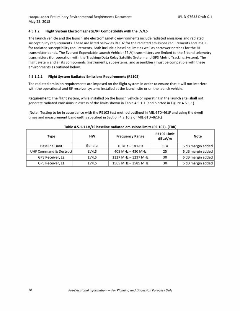
EuropaLanderPreliminaryEnvironmentalReqirementsDocument JPLD-97633Draft0.1May23,2018
Pre-DecisionalInformation—ForPlanningandDiscussionPurposesOnly
38
4.5.1.2 FlightSystemElectromagnetic/RFCompatibilitywiththeLV/LS
Thelaunchvehicleandthelaunchsiteelectromagneticenvironmentsincluderadiatedemissionsandradiatedsusceptibilityrequirements.ThesearelistedbelowasRE102fortheradiatedemissionsrequirementsandRS103forradiatedsusceptibilityrequirements.BothincludeabaselinelimitaswellasnarrowernotchesfortheRFtransmitterbands.TheEvolvedExpendableLaunchVehicle(EELV)transmittersarelimitedtotheS-bandtelemetrytransmitters(foroperationwiththeTracking/DataRelaySatelliteSystemandGPSMetricTrackingSystem).Theflightsystemandallitscomponents(instruments,subsystems,andassemblies)mustbecompatiblewiththeseenvironmentsasoutlinedbelow.4.5.1.2.1 FlightSystemRadiatedEmissionsRequirements(RE102)
TheradiatedemissionrequirementsareimposedontheflightsysteminordertoensurethatitwillnotinterferewiththeoperationalandRFreceiversystemsinstalledatthelaunchsiteoronthelaunchvehicle.Requirement:Theflightsystem,whileinstalledonthelaunchvehicleoroperatinginthelaunchsite,shallnotgenerateradiatedemissionsinexcessofthelimitsshowninTable4.5.1-1(andplottedinFigure4.5.1-1).(Note:TestingtobeinaccordancewiththeRE102testmethodoutlinedinMIL-STD-461FandusingthedwelltimesandmeasurementbandwidthsspecifiedinSection4.3.10.3ofMIL-STD-461F.)
Table4.5.1-1LV/LSbaselineradiatedemissionslimits(RE102).[TBR]
Type HW FrequencyRangeRE102LimitdBμV/m Note
BaselineLimit General 10kHz–18GHz 114 6dBmarginaddedUHFCommand&Destruct LV/LS 408MHz–430MHz 25 6dBmarginadded
GPSReceiver,L2 LV/LS 1127MHz–1237MHz 30 6dBmarginaddedGPSReceiver,L1 LV/LS 1565MHz–1585MHz 30 6dBmarginadded

EuropaLanderPreliminaryEnvironmentalReqirementsDocument JPLD-97633Draft0.1May23,2018
Pre-DecisionalInformation—ForPlanningandDiscussionPurposesOnly
39
Figure4.5.1-1LV/LSbaselineradiatedemissionslimits(RE102).[TBR]
4.5.1.2.2 FlightSystemRadiatedSusceptibilityRequirements(RS103)
Thisrequirementisimposedtoensuretheflightsystemwillnotbedamagedandwilloperateasrequiredwheninstalledonthelaunchvehicleoroperatingatthelaunchsite.Requirement:Theflightsystem,whileinstalledonthelaunchvehicleoroperatinginthelaunchsite,shallmeetitsperformancerequirementsafterexposuretotheRS103environmentsshowninTable4.5.1-2(andplottedFigure4.5.1-2).Note:EquipmentthatisrequiredtooperateduringlaunchmustmeetitsperformancerequirementswhileexposedtotheradiatedfieldsinTable4.5.1-2.Note:TestingtobeinaccordancewiththeRS103testmethodandSection4.3.10.4inMIL-STD-461F.
Table4.5.1-2LV/LSBaselineRadiatedSusceptibilityLimits(RS103).*[TBR]
Type FrequencyRange RS103LimitV/m
Note
GeneralBaseline 10kHz–18GHz 20 6dBmarginaddedS-BandTransmitter 2200MHz–2300MHz 85 6dBmarginaddedS-BandTransmitter 2300MHz–2400MHz 20 6dBmarginadded
*Note:TheselimitscoveranyofthepotentiallaunchvehiclesaswellasthelaunchsiteRS103environments.Thesearesurvivalrequirementsforequipmentthatisoffduringlaunchandperformancerequirementsforequipmentrequiredtooperateduringlaunch.
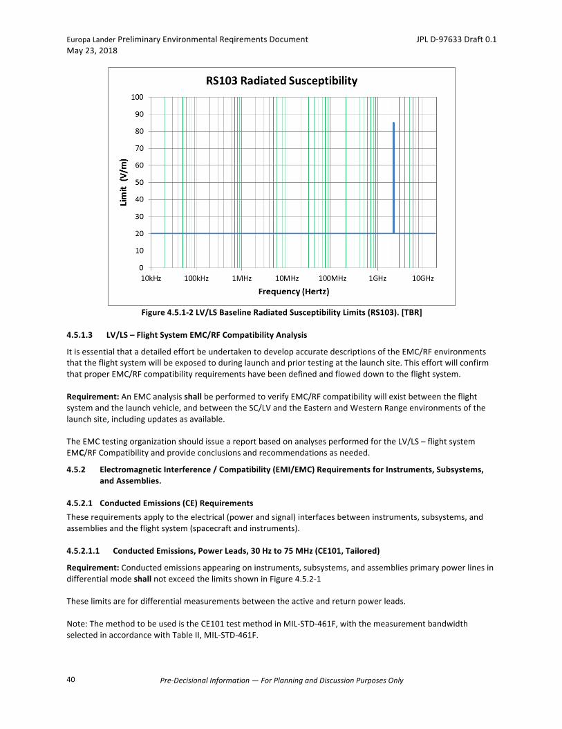
EuropaLanderPreliminaryEnvironmentalReqirementsDocument JPLD-97633Draft0.1May23,2018
Pre-DecisionalInformation—ForPlanningandDiscussionPurposesOnly
40
Figure4.5.1-2LV/LSBaselineRadiatedSusceptibilityLimits(RS103).[TBR]
4.5.1.3 LV/LS–FlightSystemEMC/RFCompatibilityAnalysis
ItisessentialthatadetailedeffortbeundertakentodevelopaccuratedescriptionsoftheEMC/RFenvironmentsthattheflightsystemwillbeexposedtoduringlaunchandpriortestingatthelaunchsite.ThiseffortwillconfirmthatproperEMC/RFcompatibilityrequirementshavebeendefinedandfloweddowntotheflightsystem.Requirement:AnEMCanalysisshallbeperformedtoverifyEMC/RFcompatibilitywillexistbetweentheflightsystemandthelaunchvehicle,andbetweentheSC/LVandtheEasternandWesternRangeenvironmentsofthelaunchsite,includingupdatesasavailable.TheEMCtestingorganizationshouldissueareportbasedonanalysesperformedfortheLV/LS–flightsystemEMC/RFCompatibilityandprovideconclusionsandrecommendationsasneeded.
4.5.2 ElectromagneticInterference/Compatibility(EMI/EMC)RequirementsforInstruments,Subsystems,andAssemblies.
4.5.2.1 ConductedEmissions(CE)RequirementsTheserequirementsapplytotheelectrical(powerandsignal)interfacesbetweeninstruments,subsystems,andassembliesandtheflightsystem(spacecraftandinstruments).4.5.2.1.1 ConductedEmissions,PowerLeads,30Hzto75MHz(CE101,Tailored)
Requirement:Conductedemissionsappearingoninstruments,subsystems,andassembliesprimarypowerlinesindifferentialmodeshallnotexceedthelimitsshowninFigure4.5.2-1Theselimitsarefordifferentialmeasurementsbetweentheactiveandreturnpowerleads.Note:ThemethodtobeusedistheCE101testmethodinMIL-STD-461F,withthemeasurementbandwidthselectedinaccordancewithTableII,MIL-STD-461F.
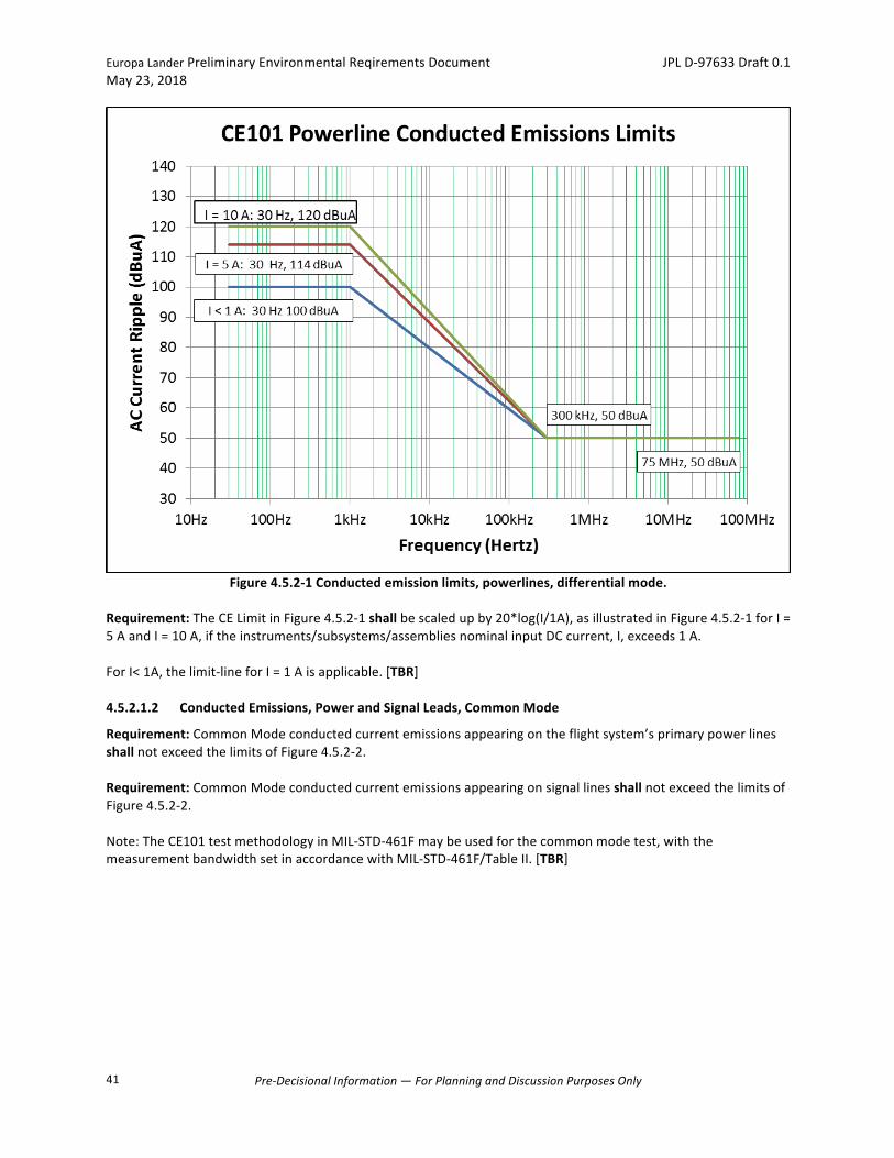
EuropaLanderPreliminaryEnvironmentalReqirementsDocument JPLD-97633Draft0.1May23,2018
Pre-DecisionalInformation—ForPlanningandDiscussionPurposesOnly
41
Figure4.5.2-1Conductedemissionlimits,powerlines,differentialmode.
Requirement:TheCELimitinFigure4.5.2-1shallbescaledupby20*log(I/1A),asillustratedinFigure4.5.2-1forI=5AandI=10A,iftheinstruments/subsystems/assembliesnominalinputDCcurrent,I,exceeds1A.ForI<1A,thelimit-lineforI=1Aisapplicable.[TBR]4.5.2.1.2 ConductedEmissions,PowerandSignalLeads,CommonMode
Requirement:CommonModeconductedcurrentemissionsappearingontheflightsystem’sprimarypowerlinesshallnotexceedthelimitsofFigure4.5.2-2.Requirement:CommonModeconductedcurrentemissionsappearingonsignallinesshallnotexceedthelimitsofFigure4.5.2-2.Note:TheCE101testmethodologyinMIL-STD-461Fmaybeusedforthecommonmodetest,withthemeasurementbandwidthsetinaccordancewithMIL-STD-461F/TableII.[TBR]
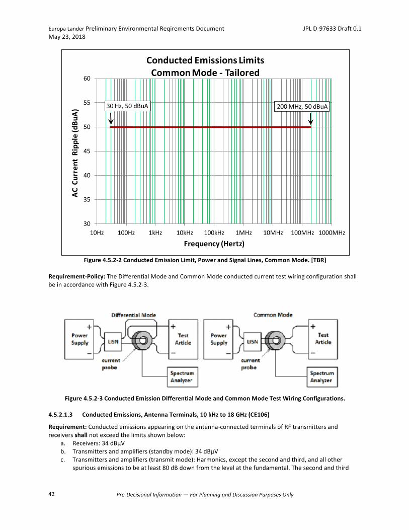
EuropaLanderPreliminaryEnvironmentalReqirementsDocument JPLD-97633Draft0.1May23,2018
Pre-DecisionalInformation—ForPlanningandDiscussionPurposesOnly
42
Figure4.5.2-2ConductedEmissionLimit,PowerandSignalLines,CommonMode.[TBR]
Requirement-Policy:TheDifferentialModeandCommonModeconductedcurrenttestwiringconfigurationshallbeinaccordancewithFigure4.5.2-3.
Figure4.5.2-3ConductedEmissionDifferentialModeandCommonModeTestWiringConfigurations.
4.5.2.1.3 ConductedEmissions,AntennaTerminals,10kHzto18GHz(CE106)
Requirement:Conductedemissionsappearingontheantenna-connectedterminalsofRFtransmittersandreceiversshallnotexceedthelimitsshownbelow:
a. Receivers:34dBμVb. Transmittersandamplifiers(standbymode):34dBμVc. Transmittersandamplifiers(transmitmode):Harmonics,exceptthesecondandthird,andallother
spuriousemissionstobeatleast80dBdownfromthelevelatthefundamental.Thesecondandthird
30Hz,50dBuA 200MHz,50dBuA
30
35
40
45
50
55
60
10Hz 100Hz 1kHz 10kHz 100kHz 1MHz 10MHz 100MHz 1000MHz
ACCurrentRipple(dBu
A)
Frequency(Hertz)
ConductedEmissionsLimitsCommonMode- Tailored
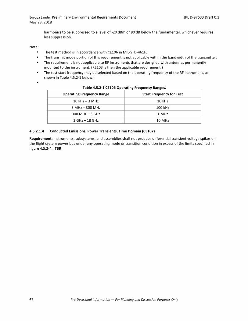
EuropaLanderPreliminaryEnvironmentalReqirementsDocument JPLD-97633Draft0.1May23,2018
Pre-DecisionalInformation—ForPlanningandDiscussionPurposesOnly
43
harmonicstobesuppressedtoalevelof-20dBmor80dBbelowthefundamental,whicheverrequireslesssuppression.
Note:
• ThetestmethodisinaccordancewithCE106inMIL-STD-461F.• Thetransmitmodeportionofthisrequirementisnotapplicablewithinthebandwidthofthetransmitter.• TherequirementisnotapplicabletoRFinstrumentsthataredesignedwithantennaspermanently
mountedtotheinstrument.(RE103isthentheapplicablerequirement.)• TheteststartfrequencymaybeselectedbasedontheoperatingfrequencyoftheRFinstrument,as
showninTable4.5.2-1below:•
Table4.5.2-1CE106OperatingFrequencyRanges.
OperatingFrequencyRange StartFrequencyforTest
10kHz–3MHz 10kHz
3MHz–300MHz 100kHz
300MHz–3GHz 1MHz
3GHz–18GHz 10MHz4.5.2.1.4 ConductedEmissions,PowerTransients,TimeDomain(CE107)
Requirement:Instruments,subsystems,andassembliesshallnotproducedifferentialtransientvoltagespikesontheflightsystempowerbusunderanyoperatingmodeortransitionconditioninexcessofthelimitsspecifiedinfigure4.5.2-4.[TBR]
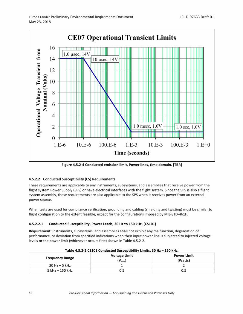
EuropaLanderPreliminaryEnvironmentalReqirementsDocument JPLD-97633Draft0.1May23,2018
Pre-DecisionalInformation—ForPlanningandDiscussionPurposesOnly
44
Figure4.5.2-4Conductedemissionlimit,Powerlines,timedomain.[TBR]
4.5.2.2 ConductedSusceptibility(CS)RequirementsTheserequirementsareapplicabletoanyinstruments,subsystems,andassembliesthatreceivepowerfromtheflightsystemPowerSupply(SPS)orhaveelectricalinterfaceswiththeflightsystem.SincetheSPSisalsoaflightsystemassembly,theserequirementsarealsoapplicabletotheSPSwhenitreceivespowerfromanexternalpowersource.Whentestsareusedforcomplianceverification,groundingandcabling(shieldingandtwisting)mustbesimilartoflightconfigurationtotheextentfeasible,exceptfortheconfigurationsimposedbyMIL-STD-461F.4.5.2.2.1 ConductedSusceptibility,PowerLeads,30Hzto150kHz,(CS101)
Requirement:Instruments,subsystems,andassembliesshallnotexhibitanymalfunction,degradationofperformance,ordeviationfromspecifiedindicationswhentheirinputpowerlineissubjectedtoinjectedvoltagelevelsorthepowerlimit(whicheveroccursfirst)showninTable4.5.2-2.
Table4.5.2-2CS101ConductedSusceptibilityLimits,30Hz–150kHz.
FrequencyRange VoltageLimit(Vrms)
PowerLimit(Watts)
30Hz–5kHz 1 25kHz–150kHz 0.5 0.5
1.0 µsec, 14V 10 µsec, 14V
1.0 msec, 1.0V 1.0 sec, 1.0V
0
2
4
6
8
10
12
14
16
1.E-6 10.E-6 100.E-6 1.E-3 10.E-3 100.E-3 1.E+0
Ope
ratio
nal
Volta
ge T
rans
ient
fro
m
Nom
inal
(Vol
ts)
Time (seconds)
CE07 Operational Transient Limits
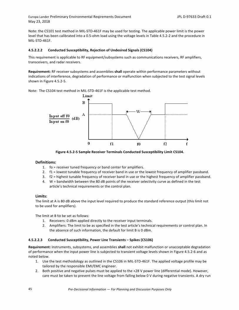
EuropaLanderPreliminaryEnvironmentalReqirementsDocument JPLD-97633Draft0.1May23,2018
Pre-DecisionalInformation—ForPlanningandDiscussionPurposesOnly
45
Note:theCS101testmethodinMIL-STD-461Fmaybeusedfortesting.Theapplicablepowerlimitisthepowerlevelthathasbeencalibratedintoa0.5-ohmloadusingthevoltagelevelsinTable4.5.2-2andtheprocedureinMIL-STD-461F.4.5.2.2.2 ConductedSusceptibility,RejectionofUndesiredSignals(CS104)
ThisrequirementisapplicabletoRFequipment/subsystemssuchascommunicationsreceivers,RFamplifiers,transceivers,andradarreceivers.Requirement:RFreceiversubsystemsandassembliesshalloperatewithinperformanceparameterswithoutindicationsofinterference,degradationofperformanceormalfunctionwhensubjectedtothetestsignallevelsshowninFigure4.5.2-5.Note:TheCS104testmethodinMIL-STD-461Fistheapplicabletestmethod.
Figure4.5.2-5SampleReceiverTerminalsConductedSusceptibilityLimitCS104.
Definitions:
1. fo=receivertunedfrequencyorbandcenterforamplifiers.2. f1=lowesttunablefrequencyofreceiverbandinuseorthelowestfrequencyofamplifierpassband.3. f2=highesttunablefrequencyofreceiverbandinuseorthehighestfrequencyofamplifierpassband.4. W=bandwidthbetweenthe80dBpointsofthereceiverselectivitycurveasdefinedinthetest
article’stechnicalrequirementsorthecontrolplan.
Limits:ThelimitatAis80dBabovetheinputlevelrequiredtoproducethestandardreferenceoutput(thislimitnottobeusedforamplifiers).ThelimitatBtobesetasfollows:
1. Receivers:0dBmapplieddirectlytothereceiverinputterminals.2. Amplifiers:Thelimittobeasspecifiedinthetestarticle’stechnicalrequirementsorcontrolplan.In
theabsenceofsuchinformation,thedefaultforlimitBis0dBm.4.5.2.2.3 ConductedSusceptibility,PowerLineTransients–Spikes(CS106)
Requirement:Instruments,subsystems,andassembliesshallnotexhibitmalfunctionorunacceptabledegradationofperformancewhentheinputpowerlineissubjectedtotransientvoltagelevelsshowninFigure4.5.2-6andasnotedbelow.
1. UsethetestmethodologyasoutlinedintheCS106inMIL-STD-461F.TheappliedvoltageprofilemaybetailoredbytheresponsibleEMI/EMCengineer.
2. Bothpositiveandnegativepulsesmustbeappliedtothe+28Vpowerline(differentialmode).However,caremustbetakentopreventthelinevoltagefromfallingbelow0Vduringnegativetransients.Adryrun
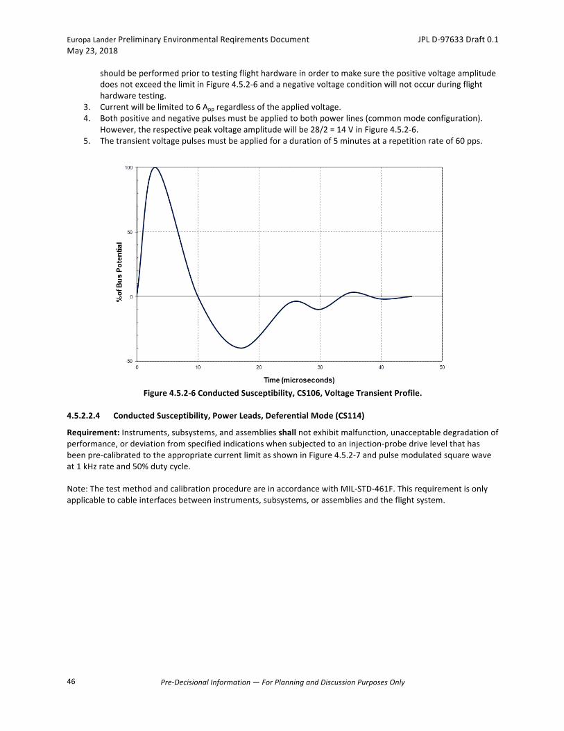
EuropaLanderPreliminaryEnvironmentalReqirementsDocument JPLD-97633Draft0.1May23,2018
Pre-DecisionalInformation—ForPlanningandDiscussionPurposesOnly
46
shouldbeperformedpriortotestingflighthardwareinordertomakesurethepositivevoltageamplitudedoesnotexceedthelimitinFigure4.5.2-6andanegativevoltageconditionwillnotoccurduringflighthardwaretesting.
3. Currentwillbelimitedto6Appregardlessoftheappliedvoltage.4. Bothpositiveandnegativepulsesmustbeappliedtobothpowerlines(commonmodeconfiguration).
However,therespectivepeakvoltageamplitudewillbe28/2=14VinFigure4.5.2-6.5. Thetransientvoltagepulsesmustbeappliedforadurationof5minutesatarepetitionrateof60pps.
Figure4.5.2-6ConductedSusceptibility,CS106,VoltageTransientProfile.
4.5.2.2.4 ConductedSusceptibility,PowerLeads,DeferentialMode(CS114)
Requirement:Instruments,subsystems,andassembliesshallnotexhibitmalfunction,unacceptabledegradationofperformance,ordeviationfromspecifiedindicationswhensubjectedtoaninjection-probedrivelevelthathasbeenpre-calibratedtotheappropriatecurrentlimitasshowninFigure4.5.2-7andpulsemodulatedsquarewaveat1kHzrateand50%dutycycle.Note:ThetestmethodandcalibrationprocedureareinaccordancewithMIL-STD-461F.Thisrequirementisonlyapplicabletocableinterfacesbetweeninstruments,subsystems,orassembliesandtheflightsystem.

EuropaLanderPreliminaryEnvironmentalReqirementsDocument JPLD-97633Draft0.1May23,2018
Pre-DecisionalInformation—ForPlanningandDiscussionPurposesOnly
47
Figure4.5.2-7CS114CalibrationLimit.
4.5.2.2.5 ConductedSusceptibility,PowerLeads,DifferentialMode(CS02)
Requirement:Instruments,subsystems,andassembliesshallnotexhibitmalfunction,unacceptabledegradationofperformance,ordeviationfromspecifiedindicationswhentheinputpowerleads(primepoweronly)aresubjectedtotherequirementsofMIL-STD-461C/462,testmethodCS02,astailoredbelow:
1. Testfrequencyrange:150kHzto50MHz2. Injectedsignalamplitude:0.5Vrms,butinjectedpowernottoexceedacalibratedlimitof0.5W.3. Theapplicablepowerlimitisthepowerlevelthathasbeencalibratedintoa0.5-ohmloadusinga0.5Vrms
drivesignal.4. Pulsemodulationat1kHz,50%dutycycle.5. Signalinjectiontobeappliedhighsidetoreturn(differentialmode),andhighsidetochassis.
4.5.2.3 RadiatedEmission(RE)RequirementsTheradiatedemissionsrequirements,RE101andRE102,areimposedtosafeguardagainstinterferencewithflightsystemandRFreceiversfromnoiseemittedfrominstruments,subsystems,orassemblies.TheRE103requirementsapplytoradartransmittersandplaceout-of-bandspectrallimitsonantennaradiatedspectrum.Theselimitsareintendedtopreventinterferencewithotherreceivers.RadartransmittersmustalsocomplywiththeFederalCommunicationsCommission(FCC)andNationalTelecommunicationsandInformationAdministration(NTIA)requirementsonbroadcastinginfreespace.Thesetypesofrequirements,however,arenotcoveredinthisdocument.4.5.2.3.1 RadiatedEmission,ACMagneticField,30Hzto100kHz(RE101)[TBR]
Requirement:Instruments,subsystems,andassembliesshallmeetthetailoredacmagneticfieldlimitsshowninFigure4.5.2-8atfrequenciesabove30Hzwhenmeasuredatadistanceof1meterfromthetestarticle,usingtechniquessimilartomethodRE101ofMIL-STD-462.Theapplicablelimitisdeterminedbythephysicaldistancebetweenthetestarticleandthesensitiveunitontheflightsystemintheinstalledconfiguration;allmeasurementsaremadeat1meterdistance.

EuropaLanderPreliminaryEnvironmentalReqirementsDocument JPLD-97633Draft0.1May23,2018
Pre-DecisionalInformation—ForPlanningandDiscussionPurposesOnly
48
Note:ThemagneticfieldprobestypicallyusedforMIL-STD-462methodRE101measurementsarenotsufficientlysensitivetomeasuretothelevelsshowninFigure4.5.2-8.SpecifictestinstrumentationandprocedureswillbedocumentedintheindividualequipmentEMItestplan.
Figure4.5.2-8RE101MagneticFieldEmissionsLimit.[TBR]
4.5.2.3.2 RadiatedEmissions,ElectricField,30Hzto18GHz(RE102)
Requirement:Electricfieldradiatedemissionsfrominstruments,subsystems,andassembliesshallnotexceedthelimitslistedbelow:
a) Forequipmentlocatedwithintheshieldedvaultarea,thelimitis60dBµV/mfrom30Hzto18GHz.b) Forequipmentlocatedoutsidethevault,thegenerallimitisasshowninFigure4.5.2-9andasshown
inTable4.5.2-3forReceivernotches.Notethatthelimitwith6dBmarginistheapplicablelimitin4.5.2-3.
Note:ThetestmethodisinaccordancewithMIL-STD-461F/RE102method.
50
70
90
110
130
150
170
190
210
230
250
0.01 0.1 1 10 100 1000 10000 100000
ACMagneticLimit(dBpT/RootHz)
Frequency(Hz)
ACMagneticFieldEmissionsLimit
1meter 2meters 3meters 4meters 5meters
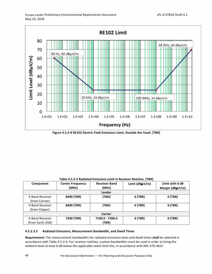
EuropaLanderPreliminaryEnvironmentalReqirementsDocument JPLD-97633Draft0.1May23,2018
Pre-DecisionalInformation—ForPlanningandDiscussionPurposesOnly
49
Figure4.5.2-9RE102ElectricFieldEmissionsLimit,OutsidetheVault.[TBR]
Table4.5.2-3RadiatedEmissionsLimitinReceiverNotches.[TBR]Component CenterFrequency
(MHz)ReceiverBand
(MHz)Limit(dBµV/m) Limitwith6dB
Margin(dBµV/m)Lander
X-BandReceiver(fromCarrier)
8400(TBR) (TBD) 6(TBR) 0(TBR)
X-BandReceiver(fromClipper)
8400(TBR) (TBD) 6(TBR) 0(TBR)
CarrierX-BandReceiver(fromEarthDSN)
7200(TBR) 7100.0-7300.0(TBR)
6(TBR) 0(TBR)
4.5.2.3.3 RadiatedEmissions,MeasurementBandwidth,andDwellTimes
Requirement:ThemeasurementbandwidthsforradiatedemissionstestsanddwelltimesshallbeselectedinaccordancewithTable4.5.2-4.Forreceivernotches,custombandwidthsmustbeusedinordertobringtheambientlevelatleast6dBbelowtheapplicablenotchlimitline,inaccordancewithMIL-STD-461F.
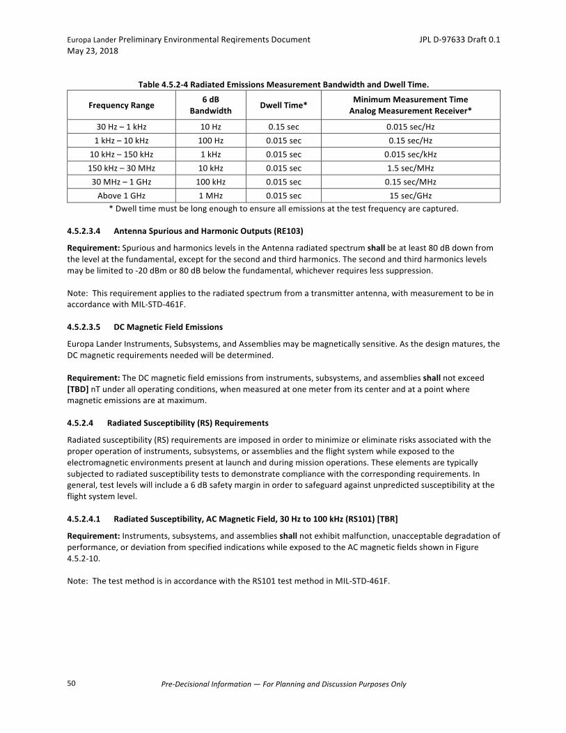
EuropaLanderPreliminaryEnvironmentalReqirementsDocument JPLD-97633Draft0.1May23,2018
Pre-DecisionalInformation—ForPlanningandDiscussionPurposesOnly
50
Table4.5.2-4RadiatedEmissionsMeasurementBandwidthandDwellTime.
FrequencyRange6dB
Bandwidth DwellTime*MinimumMeasurementTimeAnalogMeasurementReceiver*
30Hz–1kHz 10Hz 0.15sec 0.015sec/Hz1kHz–10kHz 100Hz 0.015sec 0.15sec/Hz
10kHz–150kHz 1kHz 0.015sec 0.015sec/kHz150kHz–30MHz 10kHz 0.015sec 1.5sec/MHz30MHz–1GHz 100kHz 0.015sec 0.15sec/MHzAbove1GHz 1MHz 0.015sec 15sec/GHz
*Dwelltimemustbelongenoughtoensureallemissionsatthetestfrequencyarecaptured.4.5.2.3.4 AntennaSpuriousandHarmonicOutputs(RE103)
Requirement:SpuriousandharmonicslevelsintheAntennaradiatedspectrumshallbeatleast80dBdownfromthelevelatthefundamental,exceptforthesecondandthirdharmonics.Thesecondandthirdharmonicslevelsmaybelimitedto-20dBmor80dBbelowthefundamental,whicheverrequireslesssuppression.Note:Thisrequirementappliestotheradiatedspectrumfromatransmitterantenna,withmeasurementtobeinaccordancewithMIL-STD-461F.4.5.2.3.5 DCMagneticFieldEmissions
EuropaLanderInstruments,Subsystems,andAssembliesmaybemagneticallysensitive.Asthedesignmatures,theDCmagneticrequirementsneededwillbedetermined.Requirement:TheDCmagneticfieldemissionsfrominstruments,subsystems,andassembliesshallnotexceed[TBD]nTunderalloperatingconditions,whenmeasuredatonemeterfromitscenterandatapointwheremagneticemissionsareatmaximum.4.5.2.4 RadiatedSusceptibility(RS)Requirements
Radiatedsusceptibility(RS)requirementsareimposedinordertominimizeoreliminaterisksassociatedwiththeproperoperationofinstruments,subsystems,orassembliesandtheflightsystemwhileexposedtotheelectromagneticenvironmentspresentatlaunchandduringmissionoperations.Theseelementsaretypicallysubjectedtoradiatedsusceptibilityteststodemonstratecompliancewiththecorrespondingrequirements.Ingeneral,testlevelswillincludea6dBsafetymargininordertosafeguardagainstunpredictedsusceptibilityattheflightsystemlevel.4.5.2.4.1 RadiatedSusceptibility,ACMagneticField,30Hzto100kHz(RS101)[TBR]
Requirement:Instruments,subsystems,andassembliesshallnotexhibitmalfunction,unacceptabledegradationofperformance,ordeviationfromspecifiedindicationswhileexposedtotheACmagneticfieldsshowninFigure4.5.2-10.Note:ThetestmethodisinaccordancewiththeRS101testmethodinMIL-STD-461F.

EuropaLanderPreliminaryEnvironmentalReqirementsDocument JPLD-97633Draft0.1May23,2018
Pre-DecisionalInformation—ForPlanningandDiscussionPurposesOnly
51
Figure4.5.2-10RS101MagneticFieldLimit.[TBR]
4.5.2.4.2 RadiatedSusceptibility,ElectricField,10kHzto18GHz(RS103)
Requirement:Instruments,subsystems,andassembliesshallnotexhibitmalfunction,unacceptabledegradationofperformance,ordeviationfromspecifiedindicationswhenexposedtotheradiatedE-fieldlevelsshownbelow:
1. SurvivalE-FieldLevels:20V/mfrom10kHzto18GHzandTransmittersfieldsperTable4.5.1-2forinstrumentsthatarepoweredoffduringLaunch.
2. OperationalE-FieldLevels:20V/mfrom10kHzto18GHzandTransmittersfieldsperTable4.5.1-2forinstrumentsthatareoperatingduringLaunch.
3. 2V/mfrom10kHzto18GHz,On-Orbit/SurfaceOperationalFieldLevel.TheOn-Orbit/SurfaceE-fieldenvironmentalsoincludesflightsystemtransmittersaslistedbelowinTable4.5.2-5.
Note:ThetestmethodisinaccordancewiththeRS103testmethodinMIL-STD-461Fusingpulsemodulationofa1kHzsquarewaveand50%dutycycleasoutlinedinMIL-STD-461F.Note:Thesurvivalrequirementappliestoinstrumentswithinstrumentinpoweroffconfiguration,andInstrumentmustmeetitsperformancerequirementafterexposuretotheradiatedfields.Note:Theoperationalrequirementapplieswhileaninstrumentinitsnormaloperationalmode.Aninstrumentmustmeetitsperformancerequirementduringexposuretotheradiatedfields.Note:Upto30MHz,onlyverticallypolarizedE-fieldsarerequiredforRS103tests.Above30MHz,therequirementappliesforbothhorizontallyandverticallypolarizedE-fields.Circularpolarizedfieldsarenotacceptable.
Table4.5.2-5FlightSystemTransmittersOn-Orbit/SurfaceE-FieldLevels.[TBR]Transmitter FrequencyRange(MHz) Power(dBm) RadiatedField(V/m)
110
120
130
140
10Hz 100Hz 1kHz 10kHz 100kHz
LimitLevels(dBp
T)
Frequency(Hertz)
TailoredRS101RadiatedSusceptibility - Magnetics

EuropaLanderPreliminaryEnvironmentalReqirementsDocument JPLD-97633Draft0.1May23,2018
Pre-DecisionalInformation—ForPlanningandDiscussionPurposesOnly
52
X-Band(Carrier) 8400+/-(TBD) (TBD) (TBD)X-Band(Lander) 7200+/-(TBD) (TBD) (TBD)
4.5.2.4.3 RadiatedSusceptibility,MeasurementScanRates
Requirement:ThemeasurementscanratesorstepsizeforRS103radiatedsusceptibilitytestsshallbeselectedinaccordancewithTable4.5.2-6.
Tabel4.5.2-6RS103ScanRates/StepSize.
FrequencyRangeAnalogScans
MaximumScanRatesSteppedScans
MaximumStepSize
30Hz–1MHz 0.0333f0/sec 0.05f01MHz–30MHz 0.000667f0/sec 0.01f030MHz–1GHz 0.00333f0/sec 0.005f01GHz–40GHz 0.00167f0/sec 0.0025f0
4.5.2.4.4 RadiatedSusceptibility,MeasurementDwellTimes
Requirement:Whenusingstepscans,dwelltimeateachtunedfrequencyshallbe0.15secondsupto1kHzand0.015secondsabove1kHz.Note:Thescanratesnotedabovemustbeslowenough,orthedwelltimelongenough,toallowfortheobservationandrecordingofthetestarticleresponsetotheradiatedE-fieldsunderworst-caseoperatingconditions.UsetheguidelinesinMIL-STD-461F.4.5.2.4.5 RadiatedSusceptibility,TestConfiguration
Requirement-Policy:ForRadiatedSusceptibilitytesting,totheextentfeasible,thetestarticlegrounding,cabling,andRFshieldingshallbesimilartoflightconfiguration.4.5.2.4.6 DCMagneticSusceptibility
Allflighthardwarewillberequiredtooperateinthenaturalbackgroundmagneticfield.OnEarthandinLow-EarthOrbit,theDCmagneticfieldstrengthisapproximately0.61Gauss.NearEuropa,Jupiter’sintrinsicfieldisapproximatelytwoordersofmagnitudesmaller.Somesubsystems(e.g.motorsandtelecomsystems)arealsopossiblesourcesofDCmagneticfield.Asthedesignmatures,thetotalexpectedDCfieldwillbedetermined.Requirement:Instruments,subsystems,andassembliesshalloperatewithoutdamageorperformancedegradationwhenexposedtoaDCmagneticfieldof[TBD]Gauss.
4.5.3 PowerTransients
Thepowertransientrequirementsareimposedtoensureeachinstrument,subsystem,orassemblywillbecompatiblewiththetransientcharacteristicsandrequirementsoftheflightsystempowerbus.4.5.3.1 Turn-OnandOffTransientCharacteristics
4.5.3.1.1 Turn-onIn-RushCurrent
Requirement:CurrentLimit.Instrument,subsystem,orassemblyinrushcurrentatturn-onshallnotexceedthelimitsshownFigure4.5.3-1,or50A[TBR],whicheverissmaller.

EuropaLanderPreliminaryEnvironmentalReqirementsDocument JPLD-97633Draft0.1May23,2018
Pre-DecisionalInformation—ForPlanningandDiscussionPurposesOnly
53
Figure4.5.3-1Inrushcurrentlimitatturn-on.[TBR]
4.5.3.2 OperationalTransients.[TBR]
4.5.3.2.1 NormalTransients
Requirement:Instruments,subsystems,orassembliesshallwithstandvoltagetransientsoninputpowerlineswithinthepowerenvelopeasshowninFigure4.5.3-2.Note:Theenvelopeincludestwoseparatelimits:a)voltageincreasefromnominal28VDCto50VDC,followedbyvoltagerampdownfrom50Vdownto29V;andb)voltagerampdownfromnominal28VDCto18VDC,followedvoltagerampupfrom18Vto22V,asshowninFigure4.5.3-2.
0
100
200
300
400
500
600
700
800
900
1000
1100
1.E-6 10.E-6 100.E-6 1.E-3 10.E-3 100.E-3 1.E+0
Perc
ent
of P
eak
Cur
rent
Time (seconds)
Inrush Current Limit at Turn on
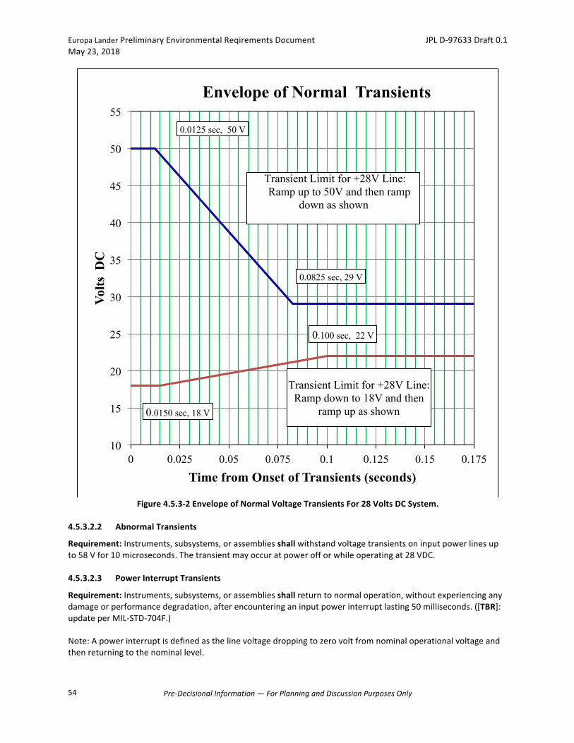
EuropaLanderPreliminaryEnvironmentalReqirementsDocument JPLD-97633Draft0.1May23,2018
Pre-DecisionalInformation—ForPlanningandDiscussionPurposesOnly
54
Figure4.5.3-2EnvelopeofNormalVoltageTransientsFor28VoltsDCSystem.
4.5.3.2.2 AbnormalTransients
Requirement:Instruments,subsystems,orassembliesshallwithstandvoltagetransientsoninputpowerlinesupto58Vfor10microseconds.Thetransientmayoccuratpowerofforwhileoperatingat28VDC.4.5.3.2.3 PowerInterruptTransients
Requirement:Instruments,subsystems,orassembliesshallreturntonormaloperation,withoutexperiencinganydamageorperformancedegradation,afterencounteringaninputpowerinterruptlasting50milliseconds.([TBR]:updateperMIL-STD-704F.)Note:Apowerinterruptisdefinedasthelinevoltagedroppingtozerovoltfromnominaloperationalvoltageandthenreturningtothenominallevel.
0.0125 sec, 50 V
0.0825 sec, 29 V
0.0150 sec, 18 V
0.100 sec, 22 V
10
15
20
25
30
35
40
45
50
55
0 0.025 0.05 0.075 0.1 0.125 0.15 0.175
Volts
DC
Time from Onset of Transients (seconds)
Envelope of Normal Transients
Transient Limit for +28V Line: Ramp up to 50V and then ramp
down as shown
Transient Limit for +28V Line: Ramp down to 18V and then
ramp up as shown

EuropaLanderPreliminaryEnvironmentalReqirementsDocument JPLD-97633Draft0.1May23,2018
Pre-DecisionalInformation—ForPlanningandDiscussionPurposesOnly
55
4.5.3.2.4 GroundFault
Requirement:Instruments,subsystems,orassembliesshallreturntonormaloperation,withoutexperiencinganydamageorperformancedegradation,afterbeingsubjectedtoaGroundFaulttest.TheGroundFaulttestconfigurationisshowninFigure4.5.3-3.
Figure4.5.3-3PowerSystemsFaultTestConfiguration.[Preliminary]
4.5.4 LightningProtection
Requirement:AnyinterfacecircuitconnectedtotheT-0umbilicalshallbeabletosurvivelighting-inducedvoltagetransientsof200voltspeakand10microsecondsindurationwhichhasbeencalibratedagainsta5-Ohmresistor.([TBR]:NeedtoconsiderT-0umbilicallengthinductiveeffectswhichcanproducelongertransientswithhigherenergy.)
4.5.5 Grounding,EMIBonding,andIsolation
TherequirementsofthissectionaregenerallyconsistentwiththerecommendationsofNASAHDBK4001,ElectricalGroundingArchitectureforUnmannedSpacecraft,Feb17,1998.Thegroundingrequirementsareintendedtoestablishagroundingarchitecturebasedonasingle-pointgroundsystemforinstruments,subsystems,orassembliesandtoimplementazero-voltgroundreference/chassistowhichallflightsystemhardwarewouldbereferenced.Figure4.5.5-1illustratesaDistributedSinglePointGroundingScheme.EMIbondingrequirementsareimposedinordertoprovidecompliancewithtwoimportantdesignobjectives:
1. EMI/RFgroundingofelectronicequipmenttosystemGroundReference.2. EMI/RFshieldingforcompliancewithapplicableradiatedemissions,radiatedsusceptibility,andRF
compatibilityrequirements.
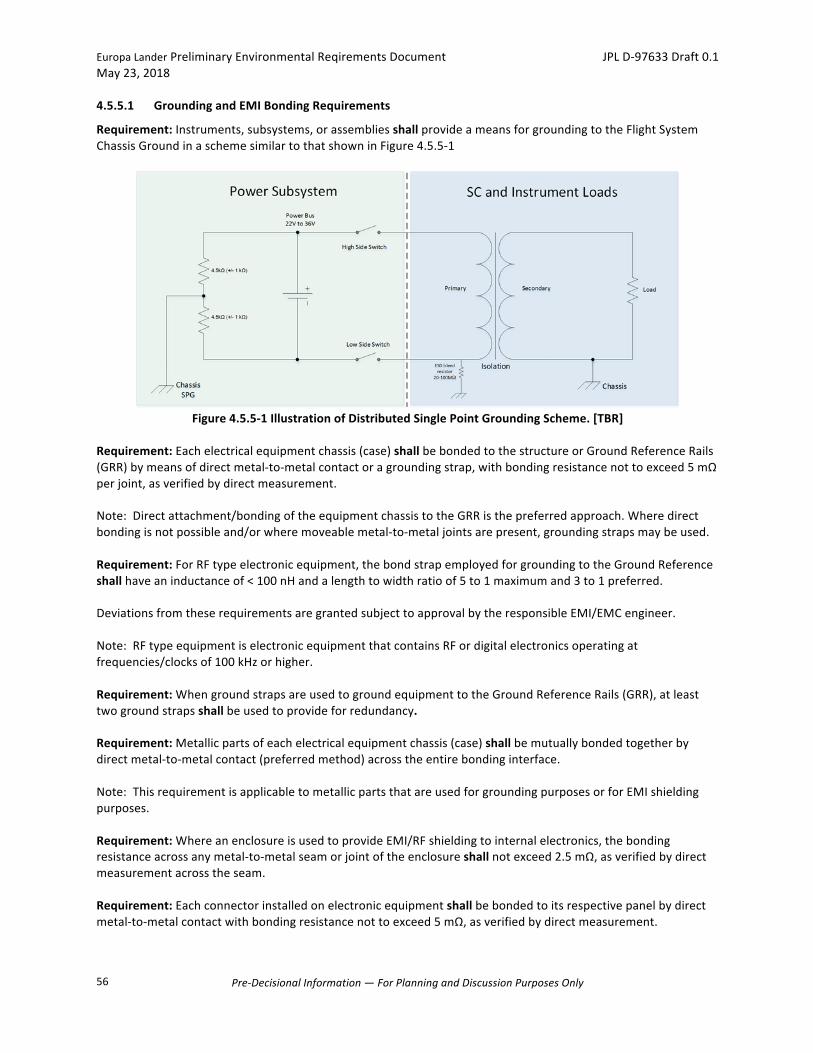
EuropaLanderPreliminaryEnvironmentalReqirementsDocument JPLD-97633Draft0.1May23,2018
Pre-DecisionalInformation—ForPlanningandDiscussionPurposesOnly
56
4.5.5.1 GroundingandEMIBondingRequirements
Requirement:Instruments,subsystems,orassembliesshallprovideameansforgroundingtotheFlightSystemChassisGroundinaschemesimilartothatshowninFigure4.5.5-1
Figure4.5.5-1IllustrationofDistributedSinglePointGroundingScheme.[TBR]
Requirement:Eachelectricalequipmentchassis(case)shallbebondedtothestructureorGroundReferenceRails(GRR)bymeansofdirectmetal-to-metalcontactoragroundingstrap,withbondingresistancenottoexceed5mΩperjoint,asverifiedbydirectmeasurement.Note:Directattachment/bondingoftheequipmentchassistotheGRRisthepreferredapproach.Wheredirectbondingisnotpossibleand/orwheremoveablemetal-to-metaljointsarepresent,groundingstrapsmaybeused.Requirement:ForRFtypeelectronicequipment,thebondstrapemployedforgroundingtotheGroundReferenceshallhaveaninductanceof<100nHandalengthtowidthratioof5to1maximumand3to1preferred.DeviationsfromtheserequirementsaregrantedsubjecttoapprovalbytheresponsibleEMI/EMCengineer.Note:RFtypeequipmentiselectronicequipmentthatcontainsRFordigitalelectronicsoperatingatfrequencies/clocksof100kHzorhigher.Requirement:WhengroundstrapsareusedtogroundequipmenttotheGroundReferenceRails(GRR),atleasttwogroundstrapsshallbeusedtoprovideforredundancy.Requirement:Metallicpartsofeachelectricalequipmentchassis(case)shallbemutuallybondedtogetherbydirectmetal-to-metalcontact(preferredmethod)acrosstheentirebondinginterface.Note:ThisrequirementisapplicabletometallicpartsthatareusedforgroundingpurposesorforEMIshieldingpurposes.Requirement:WhereanenclosureisusedtoprovideEMI/RFshieldingtointernalelectronics,thebondingresistanceacrossanymetal-to-metalseamorjointoftheenclosureshallnotexceed2.5mΩ,asverifiedbydirectmeasurementacrosstheseam.Requirement:Eachconnectorinstalledonelectronicequipmentshallbebondedtoitsrespectivepanelbydirectmetal-to-metalcontactwithbondingresistancenottoexceed5mΩ,asverifiedbydirectmeasurement.

EuropaLanderPreliminaryEnvironmentalReqirementsDocument JPLD-97633Draft0.1May23,2018
Pre-DecisionalInformation—ForPlanningandDiscussionPurposesOnly
57
Requirement:TheDCresistancebetweenaconnectoronacableandtherespectiveconnectingpanelshallnotexceed20milliohm.Requirement:Preparationandsurfacefinishofmetal-to-metalsurfacesforelectricalbondingpurposesshallbemadeinaccordancewithNASA-STD-4003,paragraph5.2,"Surfacecleaningandfinishing."4.5.5.2 Isolation[TBR]
4.5.5.2.1 Power
Requirement:Anypowerleadthatmaybedisconnectedshallbeisolatedfromchassisground,butterminatedfromlinetochassiswitha20MΩresistorforESDbleed.Requirement:End-circuitsreceivingflightsystempowershallbeisolatedfromchassisbyatleast20MΩbutnotmorethan100MΩ.Requirement:Powerconvertersshallbeisolatedfromchassisbypermittingnolumpedcapacitancetochassisgreaterthan0.1uF.Requirement:Flightandgroundsupportequipmentshallmaintainend-circuitisolationduringbothpower-onandpower-offconditions.
Requirement:Eachsecondarypowerformshallhaveadedicatedpowerreturn.
Requirement:Secondarypoweroutputsateachinstrument,subsystem,orassembly’spowersupplyshallbeisolatedfromchassisgroundwithresistanceof100kΩorgreaterforloadswithRFcircuits.Requirement:Fornon-RFequipment,secondarypowerreturnshallbegroundedtochassisatthepowersupply,butnotgroundedtochassisattheload.Requirement:Chassisgroundshallnotbeusedaspowerreturn.Requirement:Cableshieldsshallnotbeusedasapowerconductor.Requirement:Signalreturnshallnotbeusedasapowerconductor.4.5.5.2.2 SignalandData
Requirement:Foreverysignal,data,andcommandend-circuitpairforminganelectricalinterface,oneendandonlyoneendshallbeisolatedfromchassisby>20MΩ.Requirement:Allpyrofiringcircuitryshallbeisolatedfromchassisby>5kΩ.Requirement:Signalcircuitsshallbeisolatedfromeachend-circuitterminalcircuitcommonby<400pFwhenmeasuredfromthatinterfacepintochassis.Requirement:ForstandarddifferentialinterfacessuchasRS-422,MIL-STD-1553,LVDSisolationshallbeconfirmedbyresistancemeasurementusingaDCohmmeter(seeNASAHDBK-4001,par4.2.5).RS-422willnotmeetthisisolationlimit(seeRS-422differentialcircuitsbelow).Requirement:RS-422differentialcircuits,whichdonothave"true"high-impedanceisolation,shallbeconsideredtohavevirtualhigh-impedancebecauseofthedifferentialnatureofthecircuitscurrentflow(whenbothendsarepowered-on).Theyareacceptableforgeneraluse,andonlyneedtoverifytheirstandardlevelofisolation.

EuropaLanderPreliminaryEnvironmentalReqirementsDocument JPLD-97633Draft0.1May23,2018
Pre-DecisionalInformation—ForPlanningandDiscussionPurposesOnly
58
Requirement:Multiplesignalend-circuits.Theminimumnetisolationresistanceandcapacitance(betweencircuitcommonandlocalchassis)requiredoftwoormoresignalend-circuitssharingacommonreturnshallbe,respectively,1MΩdividedbythenumberofsharingend-circuits,and400pFmultipliedbythenumberofsharingend-circuits.Requirement:Exceptforbleedresistors,nocapacitor,diode,filter,orothershuntingdeviceshallbeconnectedbetweenchassisandtheinputterminalofanisolatedsignalend-circuit.Shuntingcomponentconnectedfromtheinputterminalofanisolatedsignalend-circuit,tochassisortocircuitcommon,maycreateadeleteriousgroundloop.Further,theuseofdiscretecouplingcapacitorsbetweencircuitelementsreferencedtodifferentgroundtreeslimitsACisolationandallowsinter-groundtreetransientcoupling.Requirement:Digitalrelayacquisitionsandrelaycommandsshallbecompletelyelectricallyisolatedwithdedicatedreturn.Note:AnESDbleedrequirementof20MΩto100MΩ,though,stillexists.Requirement:CoaxialCableEnd-CircuitIsolation.ForcoaxialcircuitsthatconnectflightequipmenttoGSE,T-0umbilicalcircuits,ordirectaccesscircuitsreferencedtodifferentgroundtrees,highpassfiltering(DCblocking)>1.0MΩshallbeprovidedinthecenterconductorand/orshieldtomaintainisolationwherenecessarytopreventtheformationofaDCgroundloop.Requirement:UmbilicalandDirectAccessEnd-CircuitIsolation.Theflightsystemend-circuitsforallumbilicalanddirectaccesscircuitsshallprovidethereferenceforthecircuitexceptforcircuitsusingtemperaturetransducers,switchcontacts,orrelaycoilsasisolatedflightend-circuits.Requirement:IsolationtestsshallbeperformedonallcircuitsrequiredtobeisolatedfromcircuitcommonorchassisgroundduringEMCtesting.
4.5.6 Wiring/CableShielding[TBR]
4.5.6.1 StandardCables
Requirement:Interfacecables(bundles)thatjoinequipmenthousingsshallusegroundedover-braidsorotherapprovedwire/cableshieldingmethod.Note:Theover-braidstogetherwiththeequipmenthousingseffectivelyenclosetheentiresysteminasingleelectricallycontinuousFaradaychamber.SinglelayerwrapwithcoppertapeorequivalentmaybeusedifapprovedbytheEMCengineer.Requirement:Thecable/wireover-braidsshallbeconnectedtoequipmenthousings(housingsarestructuregrounded)usingconnectorEMIback-shells.Note:TheEMIback-shellsservetobondthecablebraidtothehousing-mountedconnectorthroughanideal360-degreetermination.Requirement:Signalorwiringshieldsshallnotbeusedasanintentionalpowerorsignalreturnconductor(exceptcoaxialcables,whereshieldisusedassignalreturn).Requirement:Cablewiringshallbeconfiguredasfollows:
1. Wirecableswillconsistofindividuallyshieldedtwistedpairs,triples,orquads.2. Braidshieldswillcoverthetwistedpairortwistedgroupratherthanindividualwires.

EuropaLanderPreliminaryEnvironmentalReqirementsDocument JPLD-97633Draft0.1May23,2018
Pre-DecisionalInformation—ForPlanningandDiscussionPurposesOnly
59
3. Basicwiregroupsofsystemelectricalinterfacesshouldconsistoftwowirespercircuitorasinglewireforeachofseveralcircuitsthatshareacircuitreturnwire.
4. Thewiresshouldberoutedtominimizetheareaenclosedbythewiresandtwistedtogether.5. Eachcablebundleshouldcontain"out"and"return"wiringsuchthatmaximumelectromagneticfield
cancellationisachieved.Allwiresprovidingreturncurrentforinterfaceswithinabundleshould,themselves,residewithinthatbundle.Innocaseshouldtherebeasecondaryorpartialcurrentpathinadifferentbundle.
4.5.6.2 RibbonandFlexCables
Requirement:Tominimizemagneticfieldgenerationandalsotoprotectagainstshorting,primaryandsecondarypowerandreturnlinesshallbelocatedonnearbypinswithinaconnectorwitha"guard"pininbetween,oronadjacentlayersofribboncabling.Requirement:Fordifferentialcircuits,eachsignalpairshallbeassignedtoconductorsonimmediatelyadjacentlayers.Requirement:Forsingle-endedcircuitssharingacommonreturn,thesignalrunsshallbeclusteredintoagroupononelayer,withthesharedreturnspanningtheclusterontheimmediateadjacentlayer.Requirement:Forshieldedconductors(singles,pairs,ormultipleconductors),theshieldshallbeimplementedusingcontinuousconductorsimmediatelyaboveandbelowtosufficientlycoverthesignalline(s).4.5.6.3 Pyro-CircuitCableShielding
Requirement:Pyrocircuitpairsshallbemadefromtwistedshieldedpair(TSP)usingbraidedshieldingterminatedintheconnectorback-shells.Requirement:Individualbraidshieldsshallbeterminatedusinghaloringsorequivalentandstructure-terminated(grounded)totheback-shells.Requirement:Pigtails,ifrequired,shallnotexceed1inch(2.54cm)andtotallycontainedwithintheouteroverallshieldtotheback-shelloneitherendofacable.Requirement:Pigtailsshallnotterminate(grounded)throughaconnectorpin.Requirement:Pyrocontrol,monitoring,andfiringcircuitsshallmeettherequirementsoftheEasternandWesternRange(EWR)127-1RangeSafetyRequirementsdocument,Section3.13.
4.5.7 EMI/EMCRequirementsVerification
4.5.7.1 TestMethod
ThissectiondescribesthetestmethodsandrelatedrequirementsforverificationoftheapplicableEMI/EMCrequirements.Testmethodsapplyattheinstrument,subsystem,orassemblylevelorattheflightsystemlevel.Table4.5.7-1showstheapplicabletests.
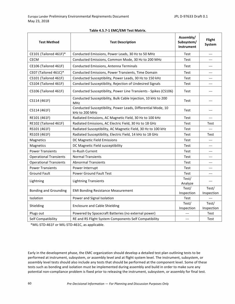
EuropaLanderPreliminaryEnvironmentalReqirementsDocument JPLD-97633Draft0.1May23,2018
Pre-DecisionalInformation—ForPlanningandDiscussionPurposesOnly
60
Table4.5.7-1EMC/EMITestMatrix.
TestMethod TestDescriptionAssembly/Subsystem/Instrument
FlightSystem
CE101(Tailored461F)* ConductedEmissions,PowerLeads,30Hzto50MHz Test ---CECM ConductedEmissions,CommonMode,30Hzto200MHz Test ---
CE106(Tailored461F) ConductedEmissions,AntennaTerminals Test ---
CE07(Tailored461C)* ConductedEmissions,PowerTransients,TimeDomain Test ---CS101(Tailored461F) ConductedSusceptibility,PowerLeads,30Hzto150kHz Test ---CS104(Tailored461F) ConductedSusceptibility,RejectionofUndesiredSignals Test ---
CS106(Tailored461F) ConductedSusceptibility,PowerLineTransients-Spikes(CS106) Test ---
CS114(461F) ConductedSusceptibility,BulkCableInjection,10kHzto200MHz
Test ---
CS114(461F) ConductedSusceptibility,PowerLeads,DifferentialMode,10kHzto200MHz
Test ---
RE101(461F) RadiatedEmissions,ACMagneticField,30Hzto100kHz Test ---RE102(Tailored461F) RadiatedEmissions,ACElectricField,30Hzto18GHz Test TestRS101(461F) RadiatedSusceptibility,ACMagneticField,30Hzto100kHz Test ---RS103(461F) RadiatedSusceptibility,ElectricField,14kHzto18GHz Test TestMagnetics DCMagneticFieldEmissions Test ---Magnetics DCMagneticFieldsusceptibility Test ---PowerTransients In-RushCurrent Test ---OperationalTransients NormalTransients Test ---OperationalTransients AbnormalTransients Test ---PowerTransients PowerInterrupt Test ---GroundFault PowerGroundFaultTest Test ---
Lightning LightningTransients Test/Analyze
---
BondingandGrounding EMIBondingResistanceMeasurement Test/Inspection
Test/Inspection
Isolation PowerandSignalIsolation Test ---
Shielding EnclosureandCableShieldingTest/
InspectionTest/
InspectionPlugsout PoweredbySpacecraftBatteries(noexternalpower) --- TestSelfCompatibility REandRSFlightSystemComponentsSelfCompatibility --- Test*MIL-STD-461ForMIL-STD-461C,asapplicable.
Earlyinthedevelopmentphase,theEMCorganizationshoulddevelopadetailedtestplanoutliningteststobeperformedatinstrument,subsystem,orassemblylevelandatflightsystemlevel.Theinstrument,subsystem,orassemblyleveltestsshouldalsoincludeanyteststhatshouldbeperformedatthecomponentlevel.Someofthesetestssuchasbondingandisolationmustbeimplementedduringassemblyandbuildinordertomakesureanypotentialnon-complianceproblemisfixedpriortoreleasingtheinstrument,subsystem,orassemblyforfinaltest.

EuropaLanderPreliminaryEnvironmentalReqirementsDocument JPLD-97633Draft0.1May23,2018
Pre-DecisionalInformation—ForPlanningandDiscussionPurposesOnly
61
Thetestplanshouldalsostatetestlocationsforeachinstrument,subsystem,orassemblyandfortheflightsystem.
Requirement:VerificationoftheEMI/EMCrequirementsoutlinedaboveshallbebyTestinaccordancewithMIL-STD-461F,orMIL-STD-461/462,asapplicable.Requirement:Thetestsetupshalluseeitherthe5micro-HenryLineImpedanceStabilizationNetwork(LISN)describedinMIL-STD-461Foracustomdevicedescribedbelow.Requirement:ThecustomLISNshallbeasshowninFigure4.5.7-1andFigure4.5.7-2.(Note:Impedancelevelinthelow-frequencyregionofplotassumespower-sourceimpedance;theplotshownassumesa1ohmsource).
Figure4.5.7-1SampleLISNCircuitDiagram.
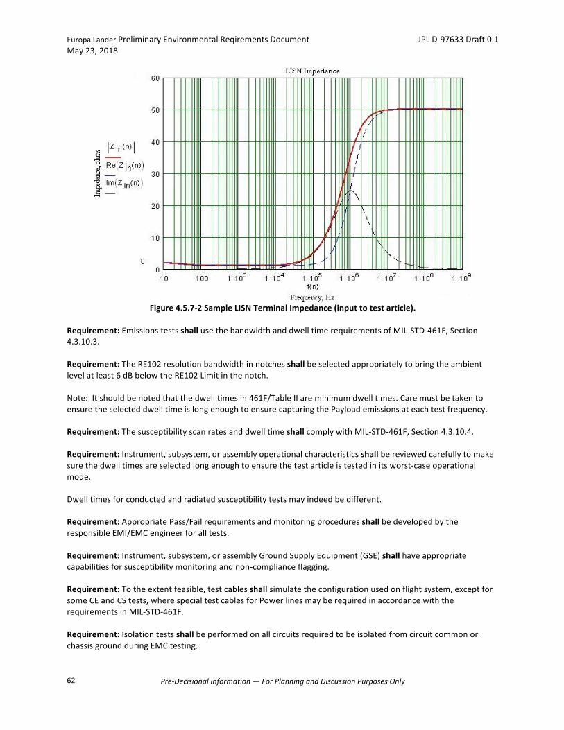
EuropaLanderPreliminaryEnvironmentalReqirementsDocument JPLD-97633Draft0.1May23,2018
Pre-DecisionalInformation—ForPlanningandDiscussionPurposesOnly
62
Figure4.5.7-2SampleLISNTerminalImpedance(inputtotestarticle).
Requirement:EmissionstestsshallusethebandwidthanddwelltimerequirementsofMIL-STD-461F,Section4.3.10.3.Requirement:TheRE102resolutionbandwidthinnotchesshallbeselectedappropriatelytobringtheambientlevelatleast6dBbelowtheRE102Limitinthenotch.Note:Itshouldbenotedthatthedwelltimesin461F/TableIIareminimumdwelltimes.CaremustbetakentoensuretheselecteddwelltimeislongenoughtoensurecapturingthePayloademissionsateachtestfrequency.Requirement:ThesusceptibilityscanratesanddwelltimeshallcomplywithMIL-STD-461F,Section4.3.10.4.Requirement:Instrument,subsystem,orassemblyoperationalcharacteristicsshallbereviewedcarefullytomakesurethedwelltimesareselectedlongenoughtoensurethetestarticleistestedinitsworst-caseoperationalmode.Dwelltimesforconductedandradiatedsusceptibilitytestsmayindeedbedifferent.Requirement:AppropriatePass/FailrequirementsandmonitoringproceduresshallbedevelopedbytheresponsibleEMI/EMCengineerforalltests.Requirement:Instrument,subsystem,orassemblyGroundSupplyEquipment(GSE)shallhaveappropriatecapabilitiesforsusceptibilitymonitoringandnon-complianceflagging.Requirement:Totheextentfeasible,testcablesshallsimulatetheconfigurationusedonflightsystem,exceptforsomeCEandCStests,wherespecialtestcablesforPowerlinesmayberequiredinaccordancewiththerequirementsinMIL-STD-461F.Requirement:IsolationtestsshallbeperformedonallcircuitsrequiredtobeisolatedfromcircuitcommonorchassisgroundduringEMCtesting.
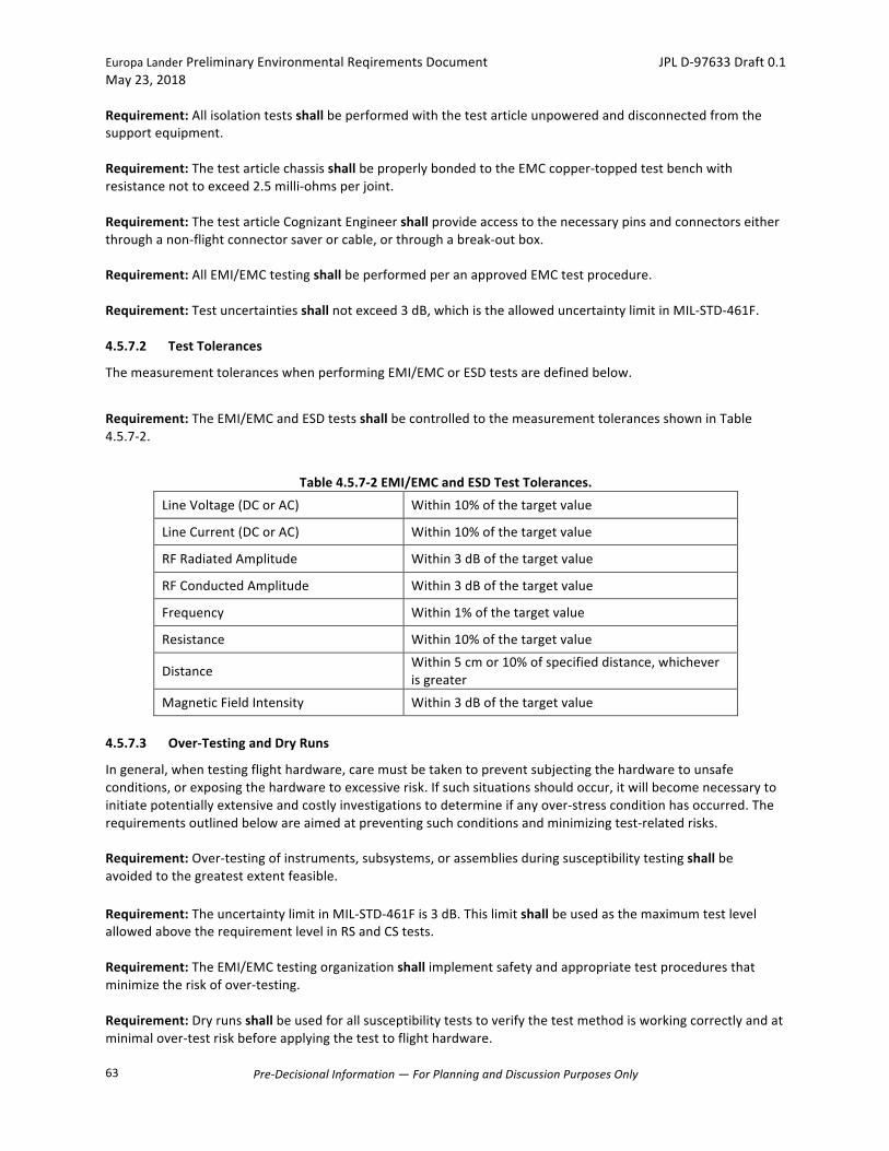
EuropaLanderPreliminaryEnvironmentalReqirementsDocument JPLD-97633Draft0.1May23,2018
Pre-DecisionalInformation—ForPlanningandDiscussionPurposesOnly
63
Requirement:Allisolationtestsshallbeperformedwiththetestarticleunpoweredanddisconnectedfromthesupportequipment.Requirement:ThetestarticlechassisshallbeproperlybondedtotheEMCcopper-toppedtestbenchwithresistancenottoexceed2.5milli-ohmsperjoint.Requirement:ThetestarticleCognizantEngineershallprovideaccesstothenecessarypinsandconnectorseitherthroughanon-flightconnectorsaverorcable,orthroughabreak-outbox.Requirement:AllEMI/EMCtestingshallbeperformedperanapprovedEMCtestprocedure.Requirement:Testuncertaintiesshallnotexceed3dB,whichisthealloweduncertaintylimitinMIL-STD-461F.4.5.7.2 TestTolerances
ThemeasurementtoleranceswhenperformingEMI/EMCorESDtestsaredefinedbelow.
Requirement:TheEMI/EMCandESDtestsshallbecontrolledtothemeasurementtolerancesshowninTable4.5.7-2.
Table4.5.7-2EMI/EMCandESDTestTolerances.
LineVoltage(DCorAC) Within10%ofthetargetvalue
LineCurrent(DCorAC) Within10%ofthetargetvalue
RFRadiatedAmplitude Within3dBofthetargetvalue
RFConductedAmplitude Within3dBofthetargetvalue
Frequency Within1%ofthetargetvalue
Resistance Within10%ofthetargetvalue
DistanceWithin5cmor10%ofspecifieddistance,whicheverisgreater
MagneticFieldIntensity Within3dBofthetargetvalue
4.5.7.3 Over-TestingandDryRuns
Ingeneral,whentestingflighthardware,caremustbetakentopreventsubjectingthehardwaretounsafeconditions,orexposingthehardwaretoexcessiverisk.Ifsuchsituationsshouldoccur,itwillbecomenecessarytoinitiatepotentiallyextensiveandcostlyinvestigationstodetermineifanyover-stressconditionhasoccurred.Therequirementsoutlinedbelowareaimedatpreventingsuchconditionsandminimizingtest-relatedrisks.Requirement:Over-testingofinstruments,subsystems,orassembliesduringsusceptibilitytestingshallbeavoidedtothegreatestextentfeasible. Requirement:TheuncertaintylimitinMIL-STD-461Fis3dB.ThislimitshallbeusedasthemaximumtestlevelallowedabovetherequirementlevelinRSandCStests.Requirement:TheEMI/EMCtestingorganizationshallimplementsafetyandappropriatetestproceduresthatminimizetheriskofover-testing.Requirement:Dryrunsshallbeusedforallsusceptibilityteststoverifythetestmethodisworkingcorrectlyandatminimalover-testriskbeforeapplyingthetesttoflighthardware.
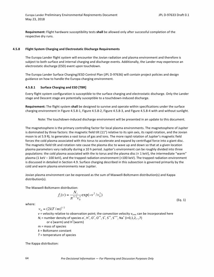
EuropaLanderPreliminaryEnvironmentalReqirementsDocument JPLD-97633Draft0.1May23,2018
Pre-DecisionalInformation—ForPlanningandDiscussionPurposesOnly
64
Requirement:Flighthardwaresusceptibilitytestsshallbeallowedonlyaftersuccessfulcompletionoftherespectivedryruns.
4.5.8 FlightSystemChargingandElectrostaticDischargeRequirements
TheEuropaLanderflightsystemwillencountertheJovianradiationandplasmaenvironmentandthereforeissubjecttobothsurfaceandinternalcharginganddischargeevents.Additionally,theLandermayexperienceanelectrostaticdischarge(ESD)eventupontouchdown.TheEuropaLanderSurfaceCharging/iESDControlPlan(JPLD-97636)willcontainprojectpoliciesanddesignguidanceonhowtohandletheEuropachargingenvironment.4.5.8.1 SurfaceChargingandESD[TBR]
Everyflightsystemconfigurationissusceptibletothesurfacechargingandelectrostaticdischarge.OnlytheLanderstageandDescentstagearepotentiallysusceptibletoatouchdown-induceddischarge.Requirement:TheflightsystemshallbedesignedtosurviveandoperatewithinspecificationsunderthesurfacechargingenvironmentinFigure4.5.8-1,Figure4.5.8-2,Figure4.5.8-3,andFigure4.5.8-4withandwithoutsunlight.
Note:Thetouchdown-induceddischargeenvironmentwillbepresentedinanupdatetothisdocument.Themagnetosphereistheprimarycontrollingfactorforlocalplasmaenvironments.ThemagnetosphereofJupiterisdominatedbythreefactors:themagneticfieldtilt(11°)relativetoitsspinaxis,itsrapidrotation,andtheJovianmoonIoat5.9Rj.Iogeneratesavasttorusofgasandions.ThemorerapidrotationofJupiter’smagneticfieldforcesthecoldplasmaassociatedwiththistorustoaccelerateandexpandbycentrifugalforceintoagiantdisc.Themagneticfieldtiltandrotationratecausetheplasmadisctowaveupanddownsothatatagivenlocationplasmaparametersvaryradicallyduringa10hperiod.Jupiter’senvironmentcanberoughlydividedintothreepopulations:thecoldplasmaassociatedwiththeIotorusandtheplasmadisc(<1keV),theintermediate“warm”plasma(1keV–100keV),andthetrappedradiationenvironment(>100keV).ThetrappedradiationenvironmentisdiscussedindetailedinSection4.9.SurfacechargingdescribedinthissubsectionisgovernedprimarilybythecoldandwarmplasmaenvironmentsnearJupiter.JovianplasmaenvironmentcanbeexpressedasthesumofMaxwell-Boltzmanndistribution(s)andKappadistribution(s).TheMaxwell-Boltzmanndistribution:
(Eq.1)where:
v=velocityrelativetoobservationpoint;theconvectionvelocityvcnvccanbeincorporatedhere Ni=numberdensityofspeciese-,H+,O+,O++,S+,S++,S+++,Na+(i=0,1,2,..,7)
ore-(warm)andH+(warm) m=massofspecies k=Boltzmannconstant T=temperatureofspeciesTheKappadistribution:
€
fi(v) =Ni
π 3 / 2v03 exp(−v
2 /v02)
€
v0 = (2kT /m)1/ 2

EuropaLanderPreliminaryEnvironmentalReqirementsDocument JPLD-97633Draft0.1May23,2018
Pre-DecisionalInformation—ForPlanningandDiscussionPurposesOnly
65
(Eq.2)where: E=½mv2 Nκ=Kappanumberdensity(cm-3)ofspecies(e-andH+) mκ=Kappamass(g)ofspecies(e-andH+) κ=Kappavalue E0=KappatemperatureorcharacteristicenergyTheplasmaparametersfromthenewDivine-Garrett(DG2)plasmamodelat9.5Rj,110°WestLongitude,and0°Latitudeare: Electrons: Ne=46.05cm
-3, T=100.8eV coldelectron Ne=3.278cm
-3, T=3720.eV warmelectron Nκ=0.5666cm
-3, E0=949.0eV, κ=1.617 Kappaelectron Protons: Np=6.557cm
-3, T=143.1eV coldproton Np=3.278cm
-3, T=30000eV warmproton. Nκ=4.167cm
-3, E0=32420eV, κ=3.368 Kappaproton Ions: NT=46.06cm
-3, T=143.1eV, vcnvc=112.6km/s totalions NO+=3.224cm
-3,NO2+=2.763cm-3, NNa=2.303cm
-3 O+,O2+,Na+ NS+=2.763cm
-3,NS2+=11.97cm-3, NS3+=2.763cm
-3 S+,S2+,S3+TheplasmadistributionfunctionsforeachofthecomponentshavebeenconvertedtoDifferentialFluxesandareplottedinFigure4.5.8-1,Figure4.5.8-2,andFigure4.5.8-3.Thespecificcomponentsareasfollowsforthecold(Boltzmann)electron,proton,andheavyionsandforthewarm(BoltzmannandKappa)electronandprotondistributionfunctionsversusenergy(note:forthecoldprotonandioncomponents,onecanincludetheeffectsoftheconvectionvelocity,vcnvc–seeEq.1).Thelegendlabelsaredefinedasfollows: DFE1=DifferentialFluxforcoldelectrons DFE2=DifferentialFluxforwarmelectrons DFE3=DifferentialFluxforhighenergyelectrons(E>100keV) DFE4=DifferentialFluxforKappaelectrons DFH1=DifferentialFluxforcoldprotons DFH2=DifferentialFluxforwarmprotons DFH3=DifferentialFluxforhighenergyprotons(E>0.6MeV) DFH4=DifferentialFluxforKappaprotons DFS1=DifferentialFluxforS+ DFS2=DifferentialFluxforS++ DFS3=DifferentialFluxforS+++ DFO1=DifferentialFluxforO+ DFO2=DifferentialFluxforO++ DFNA=DifferentialFluxforNa+
EPD=GalileoEnergeticParticleDetectormeasurementsTheindividualDifferentialFluxspectrainunitsof(cm2ssreV)-1aregiveninFigure4.5.8-1,Figure4.5.8-2,andFigure4.5.8-3.
€
fκ (E) = Nκ (mκ /2πE0)3 / 2κ−3 / 2 Γ(κ +1)
Γ(κ −1/2)1
(1+ E /κE0)κ +1
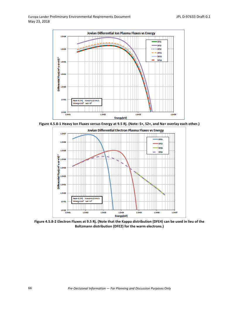
EuropaLanderPreliminaryEnvironmentalReqirementsDocument JPLD-97633Draft0.1May23,2018
Pre-DecisionalInformation—ForPlanningandDiscussionPurposesOnly
66
Figure4.5.8-1HeavyIonFluxesversusEnergyat9.5Rj.(Note:S+,S2+,andNa+overlayeachother.)
Figure4.5.8-2ElectronFluxesat9.5Rj.(NotethattheKappadistribution(DFE4)canbeusedinlieuofthe
Boltzmanndistribution(DFE2)forthewarmelectrons.)
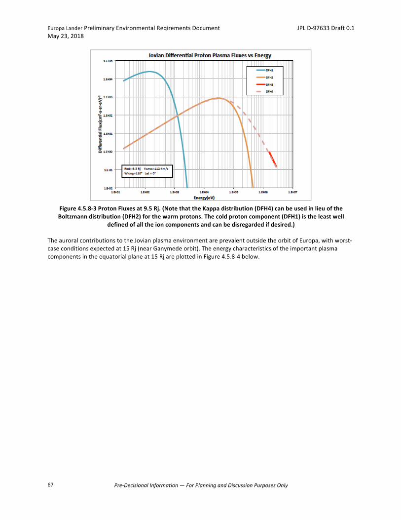
EuropaLanderPreliminaryEnvironmentalReqirementsDocument JPLD-97633Draft0.1May23,2018
Pre-DecisionalInformation—ForPlanningandDiscussionPurposesOnly
67
Figure4.5.8-3ProtonFluxesat9.5Rj.(NotethattheKappadistribution(DFH4)canbeusedinlieuoftheBoltzmanndistribution(DFH2)forthewarmprotons.Thecoldprotoncomponent(DFH1)istheleastwell
definedofalltheioncomponentsandcanbedisregardedifdesired.)TheauroralcontributionstotheJovianplasmaenvironmentareprevalentoutsidetheorbitofEuropa,withworst-caseconditionsexpectedat15Rj(nearGanymedeorbit).Theenergycharacteristicsoftheimportantplasmacomponentsintheequatorialplaneat15RjareplottedinFigure4.5.8-4below.
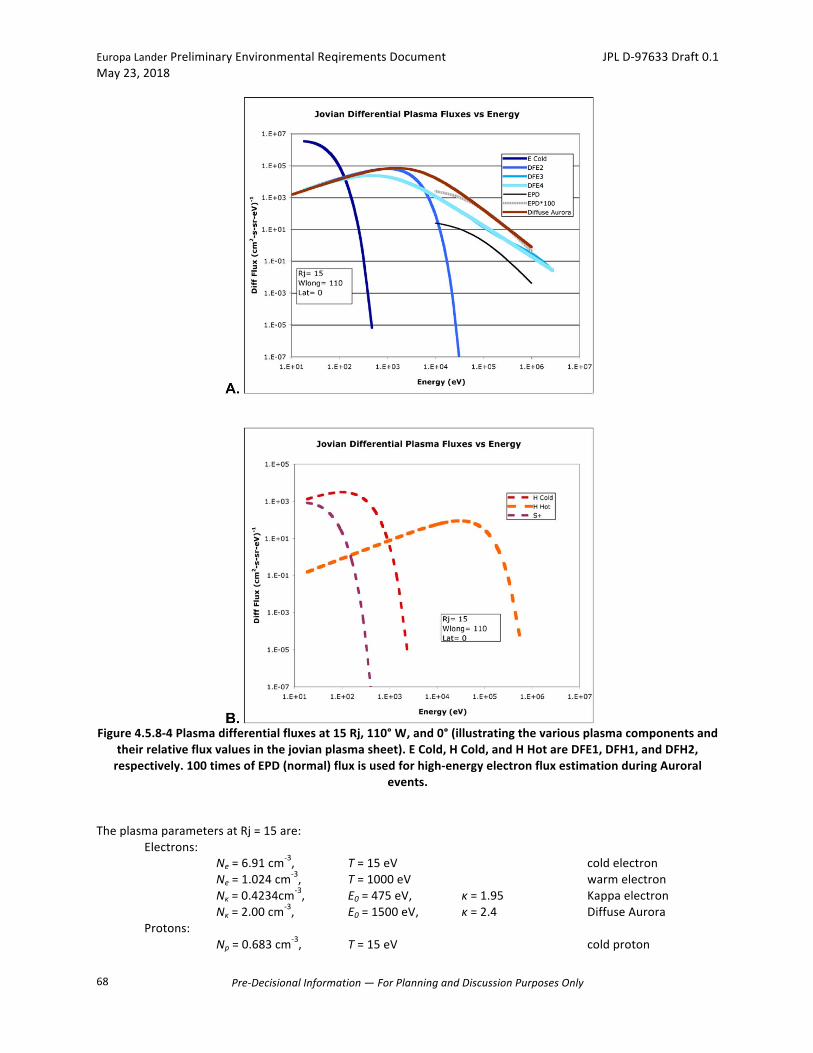
EuropaLanderPreliminaryEnvironmentalReqirementsDocument JPLD-97633Draft0.1May23,2018
Pre-DecisionalInformation—ForPlanningandDiscussionPurposesOnly
68
Figure4.5.8-4Plasmadifferentialfluxesat15Rj,110°W,and0°(illustratingthevariousplasmacomponentsand
theirrelativefluxvaluesinthejovianplasmasheet).ECold,HCold,andHHotareDFE1,DFH1,andDFH2,respectively.100timesofEPD(normal)fluxisusedforhigh-energyelectronfluxestimationduringAuroral
events.TheplasmaparametersatRj=15are: Electrons: Ne=6.91cm
-3, T=15eV coldelectron Ne=1.024cm
-3, T=1000eV warmelectron Nκ=0.4234cm
-3, E0=475eV, κ=1.95 Kappaelectron Nκ=2.00cm
-3, E0=1500eV, κ=2.4 DiffuseAurora Protons: Np=0.683cm
-3, T=15eV coldproton
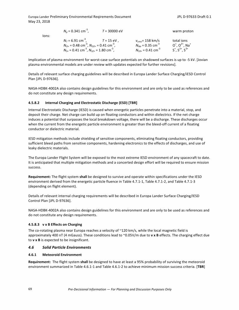
EuropaLanderPreliminaryEnvironmentalReqirementsDocument JPLD-97633Draft0.1May23,2018
Pre-DecisionalInformation—ForPlanningandDiscussionPurposesOnly
69
Np=0.341cm-3, T=30000eV warmproton
Ions: NT=6.91cm
-3, T=15eV, vcnvc=158km/s totalions NO+=0.48cm
-3,NO2+=0.41cm-3, NNa=0.35cm
-3 O+,O2+,Na+ NS+=0.41cm
-3,NS2+=1.80cm-3, NS3+=0.41cm
-3 S+,S2+,S3+Implicationofplasmaenvironmentforworst-casesurfacepotentialsonshadowedsurfacesisupto-5kV.[Jovianplasmaenvironmentalmodelsareunderreviewwithupdatesexpectedforfurtherrevisions].DetailsofrelevantsurfacechargingguidelineswillbedescribedinEuropaLanderSurfaceCharging/iESDControlPlan[JPLD-97636].NASA-HDBK-4002Aalsocontainsdesignguidelinesforthisenvironmentandareonlytobeusedasreferencesanddonotconstituteanydesignrequirements.4.5.8.2 InternalChargingandElectrostaticDischarge(ESD)[TBR]
InternalElectrostaticDischarge(IESD)iscausedwhenenergeticparticlespenetrateintoamaterial,stop,anddeposittheircharge.Netchargecanbuilduponfloatingconductorsandwithindielectrics.Ifthenetchargeinducesapotentialthatsurpassesthelocalbreakdownvoltage,therewillbeadischarge.Thesedischargesoccurwhenthecurrentfromtheenergeticparticleenvironmentisgreaterthanthebleed-offcurrentofafloatingconductorordielectricmaterial.IESDmitigationmethodsincludeshieldingofsensitivecomponents,eliminatingfloatingconductors,providingsufficientbleedpathsfromsensitivecomponents,hardeningelectronicstotheeffectsofdischarges,anduseofleakydielectricmaterials.TheEuropaLanderFlightSystemwillbeexposedtothemostextremeIESDenvironmentofanyspacecrafttodate.Itisanticipatedthatmultiplemitigationmethodsandaconcerteddesigneffortwillberequiredtoensuremissionsuccess.Requirement:TheflightsystemshallbedesignedtosurviveandoperatewithinspecificationsundertheIESDenvironmentderivedfromtheenergeticparticlefluenceinTable4.7.1-1,Table4.7.1-2,andTable4.7.1-3(dependingonflightelement).DetailsofrelevantinternalchargingrequirementswillbedescribedinEuropaLanderSurfaceCharging/IESDControlPlan[JPLD-97636].NASA-HDBK-4002Aalsocontainsdesignguidelinesforthisenvironmentandareonlytobeusedasreferencesanddonotconstituteanydesignrequirements.
4.5.8.3 vxBEffectsonChargingTheco-rotatingplasmanearEuropareachesavelocityof~120km/s,whilethelocalmagneticfieldisapproximately400nT(4mGauss).Theseconditionsleadto~0.05V/mduetovxBeffects.ThechargingeffectduetovxBisexpectedtobeinsignificant.
4.6 SolidParticleEnvironments
4.6.1 MeteoroidEnvironment
Requirement:Theflightsystemshallbedesignedtohaveatleasta95%probabilityofsurvivingthemeteoroidenvironmentsummarizedinTable4.6.1-1andTable4.6.1-2toachieveminimummissionsuccesscriteria.[TBR]

EuropaLanderPreliminaryEnvironmentalReqirementsDocument JPLD-97633Draft0.1May23,2018
Pre-DecisionalInformation—ForPlanningandDiscussionPurposesOnly
70
ThemeteoroidenvironmentpresentedwasgeneratedusinganEVEEGAtrajectorywithan8-yearcruiseoriginallystudiedfortheEuropaClippermission(JPLIOM5132-14-054A).Thisestimategivesanupperboundofthemeteoroidenvironmentduetolongermissionduration.Thisenvironmentwillbeupdatedasmissiondesignscenariosmature.ThefluenceversusmassandspeeddistributionisshowninTable4.6.1-1andTable4.6.1-2.ThemicrometeoroidfluencedistrubustionswerecalculatedusingtheMSFC’sMeteoroidEnvironmentModel(MEM)insideof2.3AUandJPL’sMETeoroidEnvironmentModel(METEM)outsideof2.3AU.DustandothersolidparticleswithinJupiter’sringsarelocatedwithintheorbitofIo(~5.9RJ)andexcludedfromthisestimate.
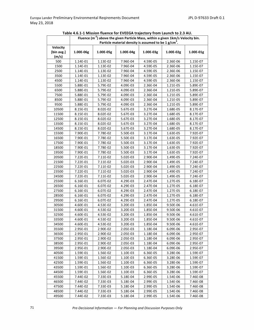
EuropaLanderPreliminaryEnvironmentalReqirementsDocument JPLD-97633Draft0.1May23,2018
Pre-DecisionalInformation—ForPlanningandDiscussionPurposesOnly
71
Table4.6.1-1MissionfluenceforEVEEGAtrajectoryfromLaunchto2.3AU.
Fluence(m-2)abovethegivenParticleMass,withinagiven1km/sVelocitybin.Particlematerialdensityisassumedtobe1g/cm3.
Velocity[binavg.](m/s)
1.00E-06g 1.00E-05g 1.00E-04g 1.00E-03g 1.00E-02g 1.00E-01g
500 1.14E-01 1.13E-02 7.96E-04 4.59E-05 2.36E-06 1.15E-071500 1.14E-01 1.13E-02 7.96E-04 4.59E-05 2.36E-06 1.15E-072500 1.14E-01 1.13E-02 7.96E-04 4.59E-05 2.36E-06 1.15E-073500 1.14E-01 1.13E-02 7.96E-04 4.59E-05 2.36E-06 1.15E-074500 1.14E-01 1.13E-02 7.96E-04 4.59E-05 2.36E-06 1.15E-075500 5.88E-01 5.79E-02 4.09E-03 2.36E-04 1.21E-05 5.89E-076500 5.88E-01 5.79E-02 4.09E-03 2.36E-04 1.21E-05 5.89E-077500 5.88E-01 5.79E-02 4.09E-03 2.36E-04 1.21E-05 5.89E-078500 5.88E-01 5.79E-02 4.09E-03 2.36E-04 1.21E-05 5.89E-079500 5.88E-01 5.79E-02 4.09E-03 2.36E-04 1.21E-05 5.89E-0710500 8.15E-01 8.02E-02 5.67E-03 3.27E-04 1.68E-05 8.17E-0711500 8.15E-01 8.02E-02 5.67E-03 3.27E-04 1.68E-05 8.17E-0712500 8.15E-01 8.02E-02 5.67E-03 3.27E-04 1.68E-05 8.17E-0713500 8.15E-01 8.02E-02 5.67E-03 3.27E-04 1.68E-05 8.17E-0714500 8.15E-01 8.02E-02 5.67E-03 3.27E-04 1.68E-05 8.17E-0715500 7.90E-01 7.78E-02 5.50E-03 3.17E-04 1.63E-05 7.92E-0716500 7.90E-01 7.78E-02 5.50E-03 3.17E-04 1.63E-05 7.92E-0717500 7.90E-01 7.78E-02 5.50E-03 3.17E-04 1.63E-05 7.92E-0718500 7.90E-01 7.78E-02 5.50E-03 3.17E-04 1.63E-05 7.92E-0719500 7.90E-01 7.78E-02 5.50E-03 3.17E-04 1.63E-05 7.92E-0720500 7.22E-01 7.11E-02 5.02E-03 2.90E-04 1.49E-05 7.24E-0721500 7.22E-01 7.11E-02 5.02E-03 2.90E-04 1.49E-05 7.24E-0722500 7.22E-01 7.11E-02 5.02E-03 2.90E-04 1.49E-05 7.24E-0723500 7.22E-01 7.11E-02 5.02E-03 2.90E-04 1.49E-05 7.24E-0724500 7.22E-01 7.11E-02 5.02E-03 2.90E-04 1.49E-05 7.24E-0725500 6.16E-01 6.07E-02 4.29E-03 2.47E-04 1.27E-05 6.18E-0726500 6.16E-01 6.07E-02 4.29E-03 2.47E-04 1.27E-05 6.18E-0727500 6.16E-01 6.07E-02 4.29E-03 2.47E-04 1.27E-05 6.18E-0728500 6.16E-01 6.07E-02 4.29E-03 2.47E-04 1.27E-05 6.18E-0729500 6.16E-01 6.07E-02 4.29E-03 2.47E-04 1.27E-05 6.18E-0730500 4.60E-01 4.53E-02 3.20E-03 1.85E-04 9.50E-06 4.61E-0731500 4.60E-01 4.53E-02 3.20E-03 1.85E-04 9.50E-06 4.61E-0732500 4.60E-01 4.53E-02 3.20E-03 1.85E-04 9.50E-06 4.61E-0733500 4.60E-01 4.53E-02 3.20E-03 1.85E-04 9.50E-06 4.61E-0734500 4.60E-01 4.53E-02 3.20E-03 1.85E-04 9.50E-06 4.61E-0735500 2.95E-01 2.90E-02 2.05E-03 1.18E-04 6.09E-06 2.95E-0736500 2.95E-01 2.90E-02 2.05E-03 1.18E-04 6.09E-06 2.95E-0737500 2.95E-01 2.90E-02 2.05E-03 1.18E-04 6.09E-06 2.95E-0738500 2.95E-01 2.90E-02 2.05E-03 1.18E-04 6.09E-06 2.95E-0739500 2.95E-01 2.90E-02 2.05E-03 1.18E-04 6.09E-06 2.95E-0740500 1.59E-01 1.56E-02 1.10E-03 6.36E-05 3.28E-06 1.59E-0741500 1.59E-01 1.56E-02 1.10E-03 6.36E-05 3.28E-06 1.59E-0742500 1.59E-01 1.56E-02 1.10E-03 6.36E-05 3.28E-06 1.59E-0743500 1.59E-01 1.56E-02 1.10E-03 6.36E-05 3.28E-06 1.59E-0744500 1.59E-01 1.56E-02 1.10E-03 6.36E-05 3.28E-06 1.59E-0745500 7.44E-02 7.33E-03 5.18E-04 2.99E-05 1.54E-06 7.46E-0846500 7.44E-02 7.33E-03 5.18E-04 2.99E-05 1.54E-06 7.46E-0847500 7.44E-02 7.33E-03 5.18E-04 2.99E-05 1.54E-06 7.46E-0848500 7.44E-02 7.33E-03 5.18E-04 2.99E-05 1.54E-06 7.46E-0849500 7.44E-02 7.33E-03 5.18E-04 2.99E-05 1.54E-06 7.46E-08
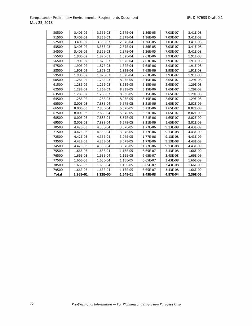
EuropaLanderPreliminaryEnvironmentalReqirementsDocument JPLD-97633Draft0.1May23,2018
Pre-DecisionalInformation—ForPlanningandDiscussionPurposesOnly
72
50500 3.40E-02 3.35E-03 2.37E-04 1.36E-05 7.03E-07 3.41E-0851500 3.40E-02 3.35E-03 2.37E-04 1.36E-05 7.03E-07 3.41E-0852500 3.40E-02 3.35E-03 2.37E-04 1.36E-05 7.03E-07 3.41E-0853500 3.40E-02 3.35E-03 2.37E-04 1.36E-05 7.03E-07 3.41E-0854500 3.40E-02 3.35E-03 2.37E-04 1.36E-05 7.03E-07 3.41E-0855500 1.90E-02 1.87E-03 1.32E-04 7.63E-06 3.93E-07 1.91E-0856500 1.90E-02 1.87E-03 1.32E-04 7.63E-06 3.93E-07 1.91E-0857500 1.90E-02 1.87E-03 1.32E-04 7.63E-06 3.93E-07 1.91E-0858500 1.90E-02 1.87E-03 1.32E-04 7.63E-06 3.93E-07 1.91E-0859500 1.90E-02 1.87E-03 1.32E-04 7.63E-06 3.93E-07 1.91E-0860500 1.28E-02 1.26E-03 8.93E-05 5.15E-06 2.65E-07 1.29E-0861500 1.28E-02 1.26E-03 8.93E-05 5.15E-06 2.65E-07 1.29E-0862500 1.28E-02 1.26E-03 8.93E-05 5.15E-06 2.65E-07 1.29E-0863500 1.28E-02 1.26E-03 8.93E-05 5.15E-06 2.65E-07 1.29E-0864500 1.28E-02 1.26E-03 8.93E-05 5.15E-06 2.65E-07 1.29E-0865500 8.00E-03 7.88E-04 5.57E-05 3.21E-06 1.65E-07 8.02E-0966500 8.00E-03 7.88E-04 5.57E-05 3.21E-06 1.65E-07 8.02E-0967500 8.00E-03 7.88E-04 5.57E-05 3.21E-06 1.65E-07 8.02E-0968500 8.00E-03 7.88E-04 5.57E-05 3.21E-06 1.65E-07 8.02E-0969500 8.00E-03 7.88E-04 5.57E-05 3.21E-06 1.65E-07 8.02E-0970500 4.42E-03 4.35E-04 3.07E-05 1.77E-06 9.13E-08 4.43E-0971500 4.42E-03 4.35E-04 3.07E-05 1.77E-06 9.13E-08 4.43E-0972500 4.42E-03 4.35E-04 3.07E-05 1.77E-06 9.13E-08 4.43E-0973500 4.42E-03 4.35E-04 3.07E-05 1.77E-06 9.13E-08 4.43E-0974500 4.42E-03 4.35E-04 3.07E-05 1.77E-06 9.13E-08 4.43E-0975500 1.66E-03 1.63E-04 1.15E-05 6.65E-07 3.43E-08 1.66E-0976500 1.66E-03 1.63E-04 1.15E-05 6.65E-07 3.43E-08 1.66E-0977500 1.66E-03 1.63E-04 1.15E-05 6.65E-07 3.43E-08 1.66E-0978500 1.66E-03 1.63E-04 1.15E-05 6.65E-07 3.43E-08 1.66E-0979500 1.66E-03 1.63E-04 1.15E-05 6.65E-07 3.43E-08 1.66E-09Total 2.36E+01 2.32E+00 1.64E-01 9.45E-03 4.87E-04 2.36E-05
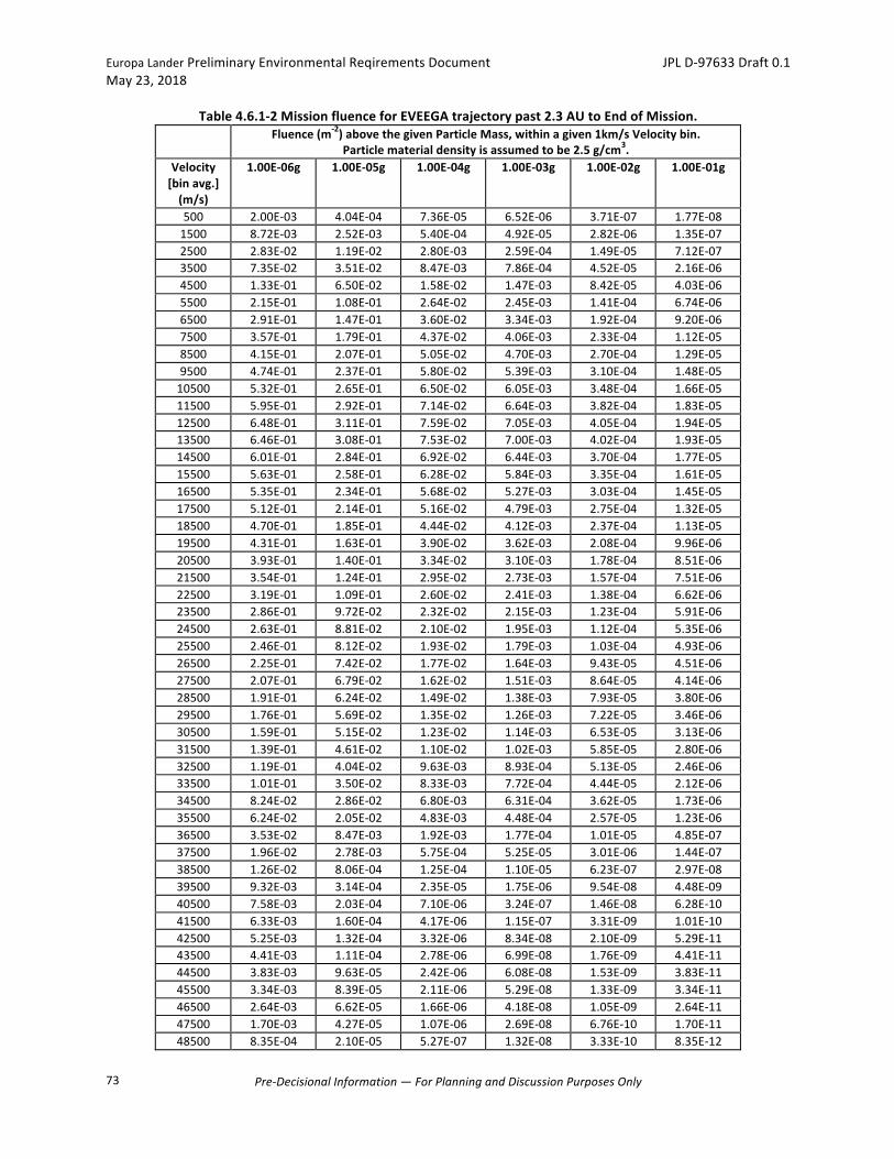
EuropaLanderPreliminaryEnvironmentalReqirementsDocument JPLD-97633Draft0.1May23,2018
Pre-DecisionalInformation—ForPlanningandDiscussionPurposesOnly
73
Table4.6.1-2MissionfluenceforEVEEGAtrajectorypast2.3AUtoEndofMission. Fluence(m-2)abovethegivenParticleMass,withinagiven1km/sVelocitybin.
Particlematerialdensityisassumedtobe2.5g/cm3.Velocity[binavg.](m/s)
1.00E-06g 1.00E-05g 1.00E-04g 1.00E-03g 1.00E-02g 1.00E-01g
500 2.00E-03 4.04E-04 7.36E-05 6.52E-06 3.71E-07 1.77E-081500 8.72E-03 2.52E-03 5.40E-04 4.92E-05 2.82E-06 1.35E-072500 2.83E-02 1.19E-02 2.80E-03 2.59E-04 1.49E-05 7.12E-073500 7.35E-02 3.51E-02 8.47E-03 7.86E-04 4.52E-05 2.16E-064500 1.33E-01 6.50E-02 1.58E-02 1.47E-03 8.42E-05 4.03E-065500 2.15E-01 1.08E-01 2.64E-02 2.45E-03 1.41E-04 6.74E-066500 2.91E-01 1.47E-01 3.60E-02 3.34E-03 1.92E-04 9.20E-067500 3.57E-01 1.79E-01 4.37E-02 4.06E-03 2.33E-04 1.12E-058500 4.15E-01 2.07E-01 5.05E-02 4.70E-03 2.70E-04 1.29E-059500 4.74E-01 2.37E-01 5.80E-02 5.39E-03 3.10E-04 1.48E-0510500 5.32E-01 2.65E-01 6.50E-02 6.05E-03 3.48E-04 1.66E-0511500 5.95E-01 2.92E-01 7.14E-02 6.64E-03 3.82E-04 1.83E-0512500 6.48E-01 3.11E-01 7.59E-02 7.05E-03 4.05E-04 1.94E-0513500 6.46E-01 3.08E-01 7.53E-02 7.00E-03 4.02E-04 1.93E-0514500 6.01E-01 2.84E-01 6.92E-02 6.44E-03 3.70E-04 1.77E-0515500 5.63E-01 2.58E-01 6.28E-02 5.84E-03 3.35E-04 1.61E-0516500 5.35E-01 2.34E-01 5.68E-02 5.27E-03 3.03E-04 1.45E-0517500 5.12E-01 2.14E-01 5.16E-02 4.79E-03 2.75E-04 1.32E-0518500 4.70E-01 1.85E-01 4.44E-02 4.12E-03 2.37E-04 1.13E-0519500 4.31E-01 1.63E-01 3.90E-02 3.62E-03 2.08E-04 9.96E-0620500 3.93E-01 1.40E-01 3.34E-02 3.10E-03 1.78E-04 8.51E-0621500 3.54E-01 1.24E-01 2.95E-02 2.73E-03 1.57E-04 7.51E-0622500 3.19E-01 1.09E-01 2.60E-02 2.41E-03 1.38E-04 6.62E-0623500 2.86E-01 9.72E-02 2.32E-02 2.15E-03 1.23E-04 5.91E-0624500 2.63E-01 8.81E-02 2.10E-02 1.95E-03 1.12E-04 5.35E-0625500 2.46E-01 8.12E-02 1.93E-02 1.79E-03 1.03E-04 4.93E-0626500 2.25E-01 7.42E-02 1.77E-02 1.64E-03 9.43E-05 4.51E-0627500 2.07E-01 6.79E-02 1.62E-02 1.51E-03 8.64E-05 4.14E-0628500 1.91E-01 6.24E-02 1.49E-02 1.38E-03 7.93E-05 3.80E-0629500 1.76E-01 5.69E-02 1.35E-02 1.26E-03 7.22E-05 3.46E-0630500 1.59E-01 5.15E-02 1.23E-02 1.14E-03 6.53E-05 3.13E-0631500 1.39E-01 4.61E-02 1.10E-02 1.02E-03 5.85E-05 2.80E-0632500 1.19E-01 4.04E-02 9.63E-03 8.93E-04 5.13E-05 2.46E-0633500 1.01E-01 3.50E-02 8.33E-03 7.72E-04 4.44E-05 2.12E-0634500 8.24E-02 2.86E-02 6.80E-03 6.31E-04 3.62E-05 1.73E-0635500 6.24E-02 2.05E-02 4.83E-03 4.48E-04 2.57E-05 1.23E-0636500 3.53E-02 8.47E-03 1.92E-03 1.77E-04 1.01E-05 4.85E-0737500 1.96E-02 2.78E-03 5.75E-04 5.25E-05 3.01E-06 1.44E-0738500 1.26E-02 8.06E-04 1.25E-04 1.10E-05 6.23E-07 2.97E-0839500 9.32E-03 3.14E-04 2.35E-05 1.75E-06 9.54E-08 4.48E-0940500 7.58E-03 2.03E-04 7.10E-06 3.24E-07 1.46E-08 6.28E-1041500 6.33E-03 1.60E-04 4.17E-06 1.15E-07 3.31E-09 1.01E-1042500 5.25E-03 1.32E-04 3.32E-06 8.34E-08 2.10E-09 5.29E-1143500 4.41E-03 1.11E-04 2.78E-06 6.99E-08 1.76E-09 4.41E-1144500 3.83E-03 9.63E-05 2.42E-06 6.08E-08 1.53E-09 3.83E-1145500 3.34E-03 8.39E-05 2.11E-06 5.29E-08 1.33E-09 3.34E-1146500 2.64E-03 6.62E-05 1.66E-06 4.18E-08 1.05E-09 2.64E-1147500 1.70E-03 4.27E-05 1.07E-06 2.69E-08 6.76E-10 1.70E-1148500 8.35E-04 2.10E-05 5.27E-07 1.32E-08 3.33E-10 8.35E-12
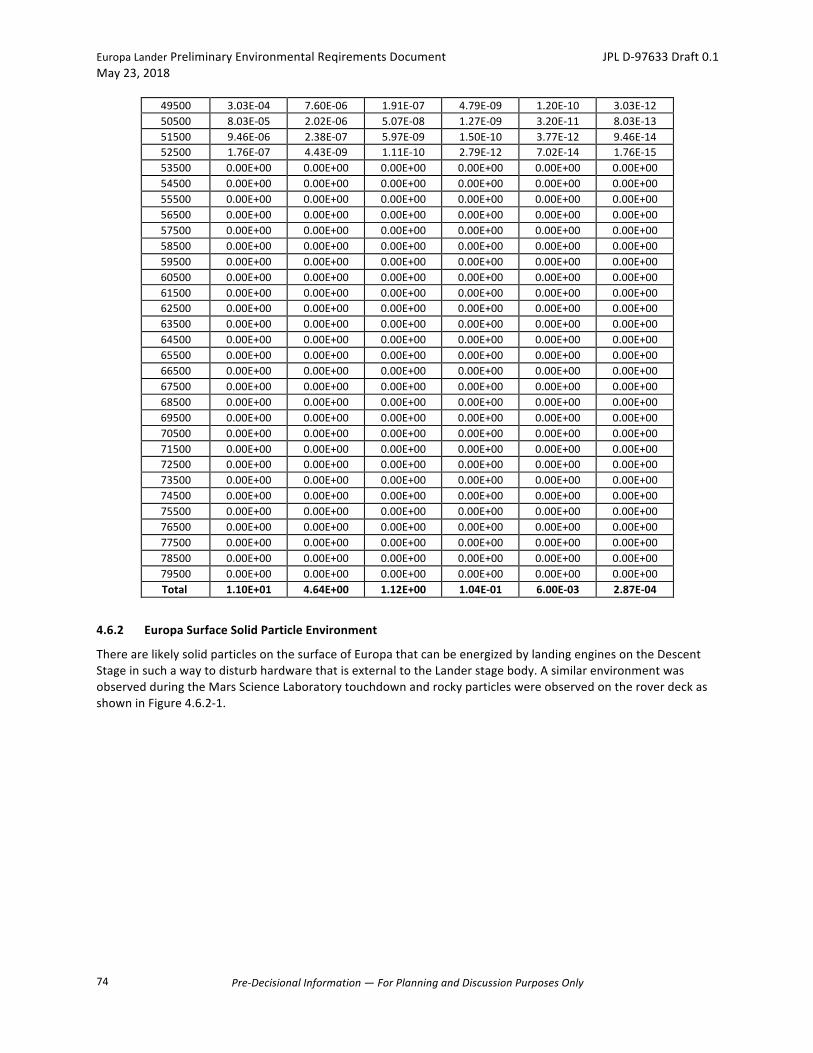
EuropaLanderPreliminaryEnvironmentalReqirementsDocument JPLD-97633Draft0.1May23,2018
Pre-DecisionalInformation—ForPlanningandDiscussionPurposesOnly
74
49500 3.03E-04 7.60E-06 1.91E-07 4.79E-09 1.20E-10 3.03E-1250500 8.03E-05 2.02E-06 5.07E-08 1.27E-09 3.20E-11 8.03E-1351500 9.46E-06 2.38E-07 5.97E-09 1.50E-10 3.77E-12 9.46E-1452500 1.76E-07 4.43E-09 1.11E-10 2.79E-12 7.02E-14 1.76E-1553500 0.00E+00 0.00E+00 0.00E+00 0.00E+00 0.00E+00 0.00E+0054500 0.00E+00 0.00E+00 0.00E+00 0.00E+00 0.00E+00 0.00E+0055500 0.00E+00 0.00E+00 0.00E+00 0.00E+00 0.00E+00 0.00E+0056500 0.00E+00 0.00E+00 0.00E+00 0.00E+00 0.00E+00 0.00E+0057500 0.00E+00 0.00E+00 0.00E+00 0.00E+00 0.00E+00 0.00E+0058500 0.00E+00 0.00E+00 0.00E+00 0.00E+00 0.00E+00 0.00E+0059500 0.00E+00 0.00E+00 0.00E+00 0.00E+00 0.00E+00 0.00E+0060500 0.00E+00 0.00E+00 0.00E+00 0.00E+00 0.00E+00 0.00E+0061500 0.00E+00 0.00E+00 0.00E+00 0.00E+00 0.00E+00 0.00E+0062500 0.00E+00 0.00E+00 0.00E+00 0.00E+00 0.00E+00 0.00E+0063500 0.00E+00 0.00E+00 0.00E+00 0.00E+00 0.00E+00 0.00E+0064500 0.00E+00 0.00E+00 0.00E+00 0.00E+00 0.00E+00 0.00E+0065500 0.00E+00 0.00E+00 0.00E+00 0.00E+00 0.00E+00 0.00E+0066500 0.00E+00 0.00E+00 0.00E+00 0.00E+00 0.00E+00 0.00E+0067500 0.00E+00 0.00E+00 0.00E+00 0.00E+00 0.00E+00 0.00E+0068500 0.00E+00 0.00E+00 0.00E+00 0.00E+00 0.00E+00 0.00E+0069500 0.00E+00 0.00E+00 0.00E+00 0.00E+00 0.00E+00 0.00E+0070500 0.00E+00 0.00E+00 0.00E+00 0.00E+00 0.00E+00 0.00E+0071500 0.00E+00 0.00E+00 0.00E+00 0.00E+00 0.00E+00 0.00E+0072500 0.00E+00 0.00E+00 0.00E+00 0.00E+00 0.00E+00 0.00E+0073500 0.00E+00 0.00E+00 0.00E+00 0.00E+00 0.00E+00 0.00E+0074500 0.00E+00 0.00E+00 0.00E+00 0.00E+00 0.00E+00 0.00E+0075500 0.00E+00 0.00E+00 0.00E+00 0.00E+00 0.00E+00 0.00E+0076500 0.00E+00 0.00E+00 0.00E+00 0.00E+00 0.00E+00 0.00E+0077500 0.00E+00 0.00E+00 0.00E+00 0.00E+00 0.00E+00 0.00E+0078500 0.00E+00 0.00E+00 0.00E+00 0.00E+00 0.00E+00 0.00E+0079500 0.00E+00 0.00E+00 0.00E+00 0.00E+00 0.00E+00 0.00E+00Total 1.10E+01 4.64E+00 1.12E+00 1.04E-01 6.00E-03 2.87E-04
4.6.2 EuropaSurfaceSolidParticleEnvironment
TherearelikelysolidparticlesonthesurfaceofEuropathatcanbeenergizedbylandingenginesontheDescentStageinsuchawaytodisturbhardwarethatisexternaltotheLanderstagebody.AsimilarenvironmentwasobservedduringtheMarsScienceLaboratorytouchdownandrockyparticleswereobservedontheroverdeckasshowninFigure4.6.2-1.

EuropaLanderPreliminaryEnvironmentalReqirementsDocument JPLD-97633Draft0.1May23,2018
Pre-DecisionalInformation—ForPlanningandDiscussionPurposesOnly
75
Figure4.6.2-1ParticulatesontheMarsScienceLaboratoryroverdeckaftertouchdown.
Requirement:ExternalcomponentsoftheLandershallbedesignedtosurvivethesolidparticleparticulateenvironmentcreatedduringtouchdownasdescribedTable4.6.2-1.
Table4.6.2-1EuropaLandersolidparticleenvironment[placeholder].[TBD]
4.7 High-EnergyRadiationEnvironments
4.7.1 EnergeticParticleFluence
FortheEuropaLanderMission,theenergeticparticlefluenceisthedrivingenvironmentforallradiationeffects.ThefollowingtablesandfiguresgivetheJupitertrappedparticlefluencesofarepresentativemissiontrajectory(12L04_50km)derivedusingtheJPLJupiterradiationmodelsdescribedin“UpdatingtheJovianPlasmaandRadiationEnvironments:TheLatestResultsfor2015”byGarrett,Kim,andEvans[2016](doi:10.2514/1.A33510).Specifically,weusetheGridversionofGIRE2p.Particlepeakfluxandfluencewillchangefordifferentmissiondesignsandcouldincreaseordecreaserelativetotherepresentativevaluesfoundhere.
EuropaLanderPreliminaryEnvironmentalReqirementsDocument JPLD-97633Draft0.1May23,2018
Pre-DecisionalInformation—ForPlanningandDiscussionPurposesOnly
76
ProtonandelectronmissionintegralfluencesarelistedTable4.7.1-1,Table4.7.1-2,andTable4.7.1-3fortheCarrierandRelayStage,DeorbitVehicle,andtheLander,respectively.Figure4.7.1-1showsthemissionintegralfluencesfortheCarrierandRelayStage,DeorbitVehicle,andtheLander.Integralfluenceisinunitsparticles/cm2forenergyequaltoandgreaterthantheenergylisted.Thehighestenergyelectronfluencesmodeled(upto150MeV)arebaseduponpower-lawextrapolationsofelectronswithenergies<30MeV.Unlessotherwisestated,alltablesandgraphswithinthissectionrepresentenvironmentsexternaltotheFlightSystem,anddonotcontainadesignfactor(i.e.,RDF=1).TheRadiationDesignFactor(RDF)isdefinedas:
RDF = Radiation-tolerancelevelofapartorcomponentinagivenapplication RadiationenvironmentpresentatthelocationofthepartorcomponentTheCruiseVehicle(CV)iscomprisedoftheCarrierandRelayStage(CRS)andtheDeorbitVehicle(DOV).Duringinterplanetarycruise,throughJupiterorbitalinsertion(JOI),allthewayuntilDOVseparation,theflightsystemisinasingle,CVconfigurationandallsystemelementsareexposedtothesameradiationenvironment.FollowingDOVseparation,theCOSremainsinorbitaroundEuropa,buttheorbitaldistanceisassumedtobesufficientlylargethatEuropa,itself,providesnoradiationshielding.TheDOVisalsoassumedtohavenoshieldingfromEuropa.OncetheLanderisonthesurface,thefluenceisassumedtobeonehalfofthevalueatEuropa’sorbitaldistanceduetoshieldingbyEuropaitself.Afterthesurfacemissionisover,theCRSwillbeplacedintoastableorbitforplanetaryprotectionpurposes.TheseassumptionsprovideanupperboundontheenergeticparticlefluenceandmaintainstheentiresurfaceofEuropaasanacceptablelandingzonefromatotaldoseperspective.Requirement:Theflightsystemshallbedesignedtosurviveandoperatewithinspecificationsunderthehigh-energyparticleenvironmentinTable4.7.1-1,Table4.7.1-2,andTable4.7.1-3(dependingontheflightelement)and,Table4.7.1-4(allflightelements).
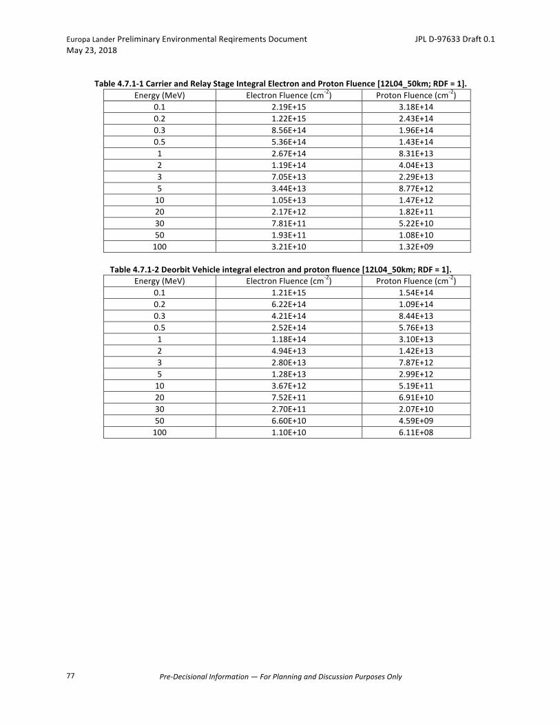
EuropaLanderPreliminaryEnvironmentalReqirementsDocument JPLD-97633Draft0.1May23,2018
Pre-DecisionalInformation—ForPlanningandDiscussionPurposesOnly
77
Table4.7.1-1CarrierandRelayStageIntegralElectronandProtonFluence[12L04_50km;RDF=1].
Energy(MeV) ElectronFluence(cm-2) ProtonFluence(cm-2)0.1 2.19E+15 3.18E+140.2 1.22E+15 2.43E+140.3 8.56E+14 1.96E+140.5 5.36E+14 1.43E+141 2.67E+14 8.31E+132 1.19E+14 4.04E+133 7.05E+13 2.29E+135 3.44E+13 8.77E+1210 1.05E+13 1.47E+1220 2.17E+12 1.82E+1130 7.81E+11 5.22E+1050 1.93E+11 1.08E+10100 3.21E+10 1.32E+09
Table4.7.1-2DeorbitVehicleintegralelectronandprotonfluence[12L04_50km;RDF=1].
Energy(MeV) ElectronFluence(cm-2) ProtonFluence(cm-2)0.1 1.21E+15 1.54E+140.2 6.22E+14 1.09E+140.3 4.21E+14 8.44E+130.5 2.52E+14 5.76E+131 1.18E+14 3.10E+132 4.94E+13 1.42E+133 2.80E+13 7.87E+125 1.28E+13 2.99E+1210 3.67E+12 5.19E+1120 7.52E+11 6.91E+1030 2.70E+11 2.07E+1050 6.60E+10 4.59E+09100 1.10E+10 6.11E+08

EuropaLanderPreliminaryEnvironmentalReqirementsDocument JPLD-97633Draft0.1May23,2018
Pre-DecisionalInformation—ForPlanningandDiscussionPurposesOnly
78
Table4.7.1-3Landerintegralelectronandprotonfluence[12L04_50km;RDF=1].Energy(MeV) ElectronFluence(cm-2) ProtonFluence(cm-2)
0.1 1.39E+15 1.86E+140.2 7.31E+14 1.39E+140.3 5.03E+14 1.10E+140.5 3.08E+14 7.88E+131 1.50E+14 4.52E+132 6.56E+13 2.17E+133 3.85E+13 1.23E+135 1.86E+13 4.70E+1210 5.63E+12 7.89E+1120 1.16E+12 9.92E+1030 4.15E+11 2.87E+1050 1.02E+11 6.05E+09100 1.70E+10 7.57E+08
Figure4.7.1-1GIRE2pIntegralprotonandelectronfluence[trajectory12L4_50km;RDF=1].AnestimatedEuropaLanderMissionsolarprotonenvironmentisbasedontheJPL-SPEmodelandshowninTable4.7.1-4andFigure4.7.1-2.

EuropaLanderPreliminaryEnvironmentalReqirementsDocument JPLD-97633Draft0.1May23,2018
Pre-DecisionalInformation—ForPlanningandDiscussionPurposesOnly
79
Table4.7.1-4SolarprotonfluenceforinterplanetarycruisefromEarthtoJupiterapplicabletotheentireCruise
Vehicle.[RDF=1]
Energy FLUENCE
(protons/cm2) (MeV) scaled 95%
1 1.90E+11 4 6.37E+10
10 2.46E+10 30 6.74E+09 60 3.03E+09
100 1.68E+09 150 1.05E+09 200 7.54E+08 300 4.72E+08 500 2.62E+08
1000 1.17E+08 2000 5.28E+07
Figure4.7.1-2SolarprotonintegralfluenceforinterplanetarycruisefromEarthtoJupiterapplicabletothe
entireCruiseVehicle.[RDF=1]
1.00E+07
1.00E+08
1.00E+09
1.00E+10
1.00E+11
1.00E+12
1 10 100 1000 10000
Fluence(protons/cm^2)
Energy(MeV)
SolarProtonFluence
EuropaLanderPreliminaryEnvironmentalReqirementsDocument JPLD-97633Draft0.1May23,2018
Pre-DecisionalInformation—ForPlanningandDiscussionPurposesOnly
80
4.7.2 IonizingRadiation
TheionizingradiationexposureofEuropaLanderflighthardwarewillcomeprimarilyfromtheJovianradiationbeltenvironment,andalsofromsolarprotons.Solarheavyionsandgalacticcosmicrays,andJovianheavyionsdonotcontributesignificantlytotheionizingradiationexposureandcanbeignoredwhenassessingtheofeffectsofionizingradiationeffectsonpartsandmaterials.Thecontributionfromhigh-energyelectronsandprotonsinJovianradiationbeltsisexpectedtodominateforallhardware.Requirement:FlightSystem,Subsystem,Assembly,andInstrumentcomponentsanddevicesshallbeselectedsuchthattheyoperatewithinperformancespecificationduringandaftertheexposuretotheTIDandDDDradiationenvironmentdocumentedhereinataradiationdesignfactor(RDF)of2timesthelevelpresentatthelocationofthedevice. Requirement:DevicesthatrequirespotshieldingshallbeassessedatanRDFof3timestheTIDlevelpresentatthelocationofthedevice.Note:ThedefinitionofspotshieldingwillbedescribedintheEuropaLanderRadiationControlPlan[JPLD-97634].
4.7.2.1 TotalIonizingDoseTable4.7.2-1,Table4.7.2-2,andTable4.7.2-3listthetotalionizingdoseusingNOVICE(ThomasJordan1993,NOVICE,ARadiationTransportShieldingCode,ExperimentalandMathematicalPhysicsConsultants,Jan.2006Version)forthemissionfluenceofeachflightsystemelementspecifiedinSection4.7.1.Figure4.7.2-1,Figure4.7.2-1,andFigure4.7.2-3showthetotaldoseforaluminumandtantalumsphericalshellshieldthicknessesforeachflightsystemstage,withtherelativedosecontributionsfromelectrons,secondarybremsstrahlungphotons,trappedprotons,andsolarprotonsbasedonNOVICEtransportcalculationsforthemissionfluencesfortrajectory12L04_50km.Doseisinrad(Si),andshieldingthicknessisinmil.Thefluxofgalacticcosmicrays(GCR)contributesapproximately0.02rad(Si)/daytothemissiondose,independentofshielding.TheJovianmagneticfieldprovidessomeshieldingfromGCRs,withincreasingprotectionclosertoJupiter.FortheEuropaLanderMission,GCRcontributiontoTIDwillbeneglected.

EuropaLanderPreliminaryEnvironmentalReqirementsDocument JPLD-97633Draft0.1May23,2018
Pre-DecisionalInformation—ForPlanningandDiscussionPurposesOnly
81
Table4.7.2-1Totalionizingdose-depthtableasafunctionofsphericalshellaluminumshieldingthicknessfortheCarrierandRelayStagefortrajectory12L04_50km.RDF=1.[TBR]
TotalIonizingDose(TID),rad-Si
milsAluminum bremsstrahlung electron proton Total
0.10 9.64E+01 6.69E+07 7.97E+08 8.64E+081 2.63E+03 9.37E+07 1.31E+08 2.25E+0810 9.90E+03 2.11E+07 7.42E+06 2.85E+0720 1.07E+04 1.21E+07 2.01E+06 1.42E+0730 1.08E+04 8.67E+06 9.61E+05 9.64E+0640 1.07E+04 6.75E+06 5.21E+05 7.28E+0650 1.06E+04 5.52E+06 3.10E+05 5.84E+0660 1.08E+04 4.66E+06 2.21E+05 4.90E+0670 1.07E+04 4.01E+06 1.57E+05 4.17E+0680 1.07E+04 3.53E+06 1.17E+05 3.65E+0690 1.09E+04 3.12E+06 9.14E+04 3.22E+06100 1.08E+04 2.80E+06 7.09E+04 2.88E+06120 1.09E+04 2.31E+06 4.85E+04 2.37E+06140 1.10E+04 1.95E+06 3.56E+04 1.99E+06160 1.11E+04 1.67E+06 2.64E+04 1.71E+06180 1.12E+04 1.45E+06 2.02E+04 1.48E+06200 1.14E+04 1.27E+06 1.60E+04 1.30E+06220 1.15E+04 1.13E+06 1.28E+04 1.16E+06240 1.17E+04 1.01E+06 1.08E+04 1.03E+06260 1.19E+04 9.12E+05 8.87E+03 9.33E+05280 1.19E+04 8.26E+05 7.55E+03 8.46E+05300 1.21E+04 7.50E+05 6.52E+03 7.69E+05320 1.22E+04 6.83E+05 5.53E+03 7.01E+05400 1.26E+04 4.86E+05 3.48E+03 5.02E+05500 1.29E+04 3.40E+05 2.11E+03 3.55E+05600 1.30E+04 2.47E+05 1.51E+03 2.62E+05700 1.30E+04 1.81E+05 1.11E+03 1.95E+05800 1.29E+04 1.37E+05 8.29E+02 1.51E+05900 1.28E+04 1.05E+05 6.60E+02 1.19E+051000 1.27E+04 8.32E+04 5.40E+02 9.64E+041100 1.25E+04 6.67E+04 4.55E+02 7.97E+041200 1.29E+04 5.39E+04 4.00E+02 6.71E+041300 1.29E+04 4.40E+04 3.60E+02 5.73E+041400 1.27E+04 3.62E+04 3.70E+02 4.93E+041500 1.25E+04 3.01E+04 3.41E+02 4.29E+041600 1.22E+04 2.51E+04 2.13E+02 3.75E+041700 1.18E+04 2.07E+04 1.33E+02 3.27E+041800 1.15E+04 1.74E+04 9.14E+01 2.90E+041900 1.13E+04 1.44E+04 6.03E+01 2.58E+042000 1.10E+04 1.20E+04 3.64E+01 2.30E+043000 8.56E+03 1.26E+03 2.78E+00 9.83E+034000 6.87E+03 5.34E+01 3.78E-01 6.92E+035000 5.41E+03 1.99E+00 8.22E-02 5.41E+036000 4.34E+03 1.09E-01 2.23E-02 4.34E+038000 2.91E+03 3.74E-04 2.84E-03 2.91E+0310000 2.12E+03 5.56E-07 0.00E+00 2.12E+03

EuropaLanderPreliminaryEnvironmentalReqirementsDocument JPLD-97633Draft0.1May23,2018
Pre-DecisionalInformation—ForPlanningandDiscussionPurposesOnly
82
Figure4.7.2-1Ionizingdose-depthcurvesasafunctionofsphericalshellaluminumshieldingthicknessforthe
CarrierandRelayStagefortrajectory12L04_50km.RDF=1[TBR]
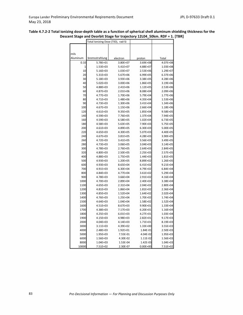
EuropaLanderPreliminaryEnvironmentalReqirementsDocument JPLD-97633Draft0.1May23,2018
Pre-DecisionalInformation—ForPlanningandDiscussionPurposesOnly
83
Table4.7.2-2Totalionizingdose-depthtableasafunctionofsphericalshellaluminumshieldingthicknessfortheDescentStageandDeorbitStagefortrajectory12L04_50km.RDF=1.[TBR]
TotalIonizingDose(TID),rad-Si
milsAluminum bremsstrahlung electron proton Total
0.10 5.78E+01 3.80E+07 3.69E+08 4.07E+081 1.53E+03 5.41E+07 4.88E+07 1.03E+0810 5.16E+03 1.03E+07 2.53E+06 1.29E+0720 5.31E+03 5.67E+06 6.99E+05 6.37E+0630 5.18E+03 3.93E+06 3.38E+05 4.28E+0640 5.02E+03 3.00E+06 1.86E+05 3.19E+0650 4.88E+03 2.41E+06 1.12E+05 2.53E+0660 4.87E+03 2.01E+06 8.08E+04 2.09E+0670 4.77E+03 1.70E+06 5.79E+04 1.77E+0680 4.71E+03 1.48E+06 4.35E+04 1.53E+0690 4.73E+03 1.30E+06 3.41E+04 1.34E+06100 4.67E+03 1.15E+06 2.66E+04 1.18E+06120 4.61E+03 9.35E+05 1.85E+04 9.58E+05140 4.59E+03 7.76E+05 1.37E+04 7.94E+05160 4.59E+03 6.58E+05 1.02E+04 6.73E+05180 4.58E+03 5.63E+05 7.90E+03 5.75E+05200 4.61E+03 4.89E+05 6.30E+03 5.00E+05220 4.65E+03 4.30E+05 5.07E+03 4.40E+05240 4.67E+03 3.81E+05 4.28E+03 3.90E+05260 4.72E+03 3.41E+05 3.56E+03 3.49E+05280 4.73E+03 3.06E+05 3.04E+03 3.14E+05300 4.78E+03 2.76E+05 2.64E+03 2.84E+05320 4.80E+03 2.50E+05 2.25E+03 2.57E+05400 4.88E+03 1.75E+05 1.44E+03 1.81E+05500 4.93E+03 1.20E+05 8.89E+02 1.26E+05600 4.93E+03 8.65E+04 6.41E+02 9.21E+04700 4.91E+03 6.30E+04 4.79E+02 6.84E+04800 4.84E+03 4.77E+04 3.61E+02 5.29E+04900 4.78E+03 3.66E+04 2.91E+02 4.16E+041000 4.70E+03 2.89E+04 2.40E+02 3.38E+041100 4.65E+03 2.31E+04 2.04E+02 2.80E+041200 4.81E+03 1.86E+04 1.81E+02 2.36E+041300 4.85E+03 1.52E+04 1.64E+02 2.02E+041400 4.76E+03 1.25E+04 1.70E+02 1.74E+041500 4.64E+03 1.04E+04 1.58E+02 1.52E+041600 4.51E+03 8.67E+03 9.90E+01 1.33E+041700 4.38E+03 7.17E+03 6.20E+01 1.16E+041800 4.25E+03 6.01E+03 4.27E+01 1.03E+041900 4.15E+03 4.98E+03 2.82E+01 9.17E+032000 4.04E+03 4.14E+03 1.71E+01 8.19E+033000 3.11E+03 4.39E+02 1.33E+00 3.55E+034000 2.48E+03 1.92E+01 1.84E-01 2.50E+035000 1.95E+03 7.55E-01 4.04E-02 1.95E+036000 1.56E+03 4.30E-02 1.11E-02 1.56E+038000 1.04E+03 1.53E-04 1.42E-03 1.04E+0310000 7.51E+02 2.30E-07 0.00E+00 7.51E+02

EuropaLanderPreliminaryEnvironmentalReqirementsDocument JPLD-97633Draft0.1May23,2018
Pre-DecisionalInformation—ForPlanningandDiscussionPurposesOnly
84
Figure4.7.2-2Ionizingdose-depthcurvesasafunctionofsphericalshellaluminumshieldingthicknessforthe
DescentStageandDeorbitStagefortrajectory12L4_50km.RDF=1.[TBR]
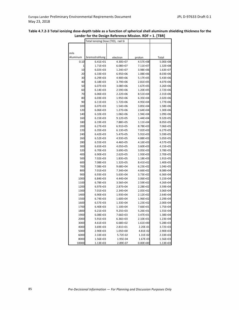
EuropaLanderPreliminaryEnvironmentalReqirementsDocument JPLD-97633Draft0.1May23,2018
Pre-DecisionalInformation—ForPlanningandDiscussionPurposesOnly
85
Table4.7.2-3Totalionizingdose-depthtableasafunctionofsphericalshellaluminumshieldingthicknessfortheLanderfortheDesignReferenceMission.RDF=1.[TBR]
TotalIonizingDose(TID),rad-Si
milsAluminum bremsstrahlung electron proton Total
0.10 6.41E+01 4.30E+07 4.57E+08 5.00E+081 1.71E+03 6.08E+07 7.11E+07 1.32E+0810 6.02E+03 1.24E+07 3.98E+06 1.63E+0720 6.33E+03 6.95E+06 1.08E+06 8.03E+0630 6.29E+03 4.90E+06 5.17E+05 5.43E+0640 6.18E+03 3.79E+06 2.81E+05 4.07E+0650 6.07E+03 3.08E+06 1.67E+05 3.26E+0660 6.14E+03 2.59E+06 1.20E+05 2.72E+0670 6.06E+03 2.22E+06 8.51E+04 2.31E+0680 6.03E+03 1.95E+06 6.35E+04 2.02E+0690 6.11E+03 1.72E+06 4.95E+04 1.77E+06100 6.07E+03 1.54E+06 3.85E+04 1.58E+06120 6.06E+03 1.27E+06 2.64E+04 1.30E+06140 6.10E+03 1.06E+06 1.94E+04 1.09E+06160 6.15E+03 9.12E+05 1.44E+04 9.32E+05180 6.19E+03 7.88E+05 1.11E+04 8.05E+05200 6.27E+03 6.91E+05 8.78E+03 7.06E+05220 6.35E+03 6.13E+05 7.02E+03 6.27E+05240 6.42E+03 5.47E+05 5.91E+03 5.59E+05260 6.52E+03 4.93E+05 4.88E+03 5.05E+05280 6.55E+03 4.46E+05 4.16E+03 4.57E+05300 6.65E+03 4.05E+05 3.60E+03 4.15E+05320 6.70E+03 3.69E+05 3.05E+03 3.78E+05400 6.90E+03 2.62E+05 1.93E+03 2.70E+05500 7.02E+03 1.83E+05 1.18E+03 1.91E+05600 7.08E+03 1.32E+05 8.41E+02 1.40E+05700 7.08E+03 9.68E+04 6.23E+02 1.04E+05800 7.01E+03 7.34E+04 4.66E+02 8.08E+04900 6.93E+03 5.63E+04 3.73E+02 6.36E+041000 6.84E+03 4.44E+04 3.06E+02 5.15E+041100 6.78E+03 3.56E+04 2.59E+02 4.26E+041200 6.97E+03 2.87E+04 2.28E+02 3.59E+041300 7.01E+03 2.34E+04 2.05E+02 3.06E+041400 6.90E+03 1.93E+04 2.12E+02 2.64E+041500 6.74E+03 1.60E+04 1.96E+02 2.29E+041600 6.57E+03 1.33E+04 1.23E+02 2.00E+041700 6.40E+03 1.10E+04 7.66E+01 1.75E+041800 6.21E+03 9.25E+03 5.26E+01 1.55E+041900 6.08E+03 7.66E+03 3.47E+01 1.38E+042000 5.91E+03 6.36E+03 2.10E+01 1.23E+043000 4.61E+03 6.68E+02 1.61E+00 5.28E+034000 3.69E+03 2.81E+01 2.20E-01 3.72E+035000 2.90E+03 1.05E+00 4.81E-02 2.90E+036000 2.33E+03 5.72E-02 1.31E-02 2.33E+038000 1.56E+03 1.95E-04 1.67E-03 1.56E+0310000 1.13E+03 2.89E-07 0.00E+00 1.13E+03
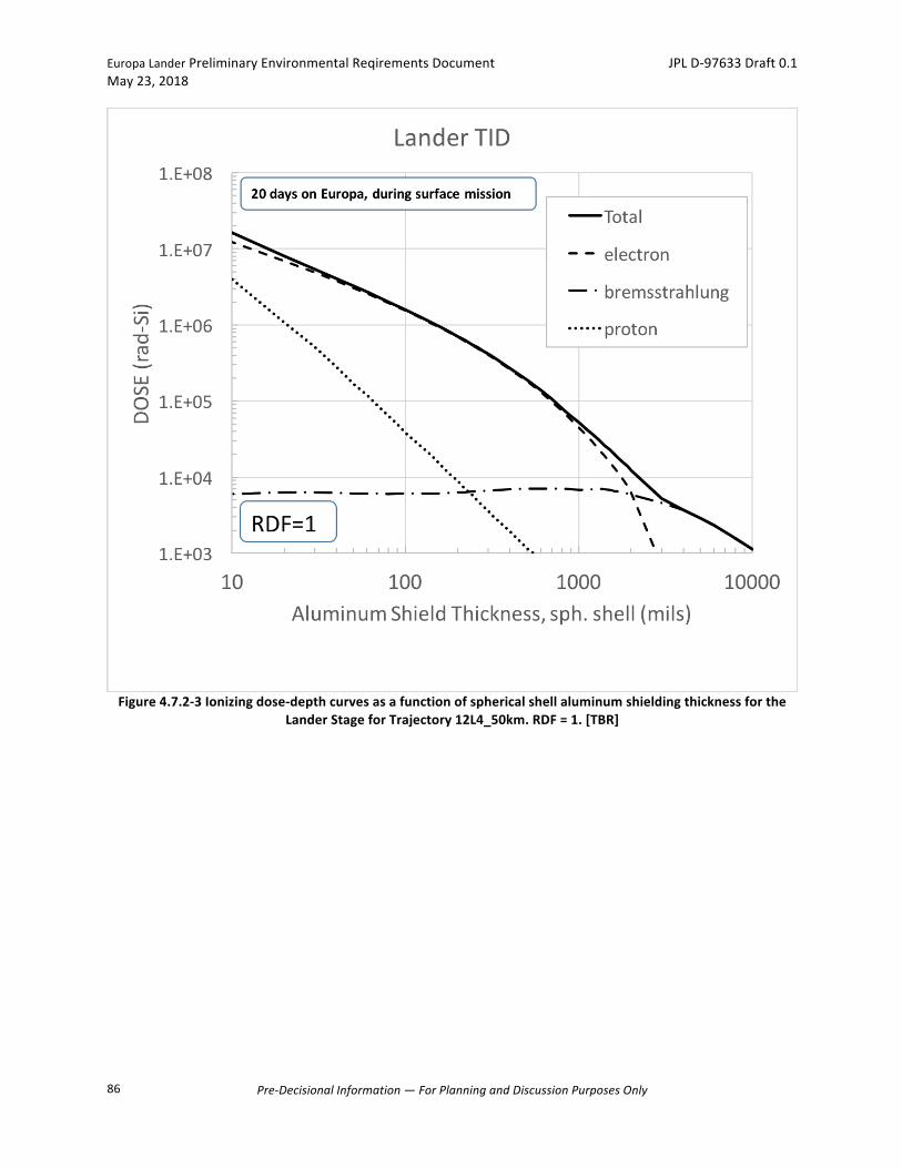
EuropaLanderPreliminaryEnvironmentalReqirementsDocument JPLD-97633Draft0.1May23,2018
Pre-DecisionalInformation—ForPlanningandDiscussionPurposesOnly
86
Figure4.7.2-3Ionizingdose-depthcurvesasafunctionofsphericalshellaluminumshieldingthicknessfortheLanderStageforTrajectory12L4_50km.RDF=1.[TBR]
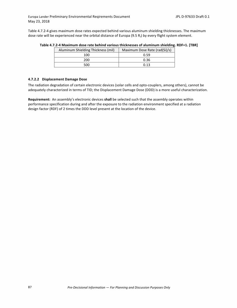
EuropaLanderPreliminaryEnvironmentalReqirementsDocument JPLD-97633Draft0.1May23,2018
Pre-DecisionalInformation—ForPlanningandDiscussionPurposesOnly
87
Table4.7.2-4givesmaximumdoseratesexpectedbehindvariousaluminumshieldingthicknesses.ThemaximumdoseratewillbeexperiencedneartheorbitaldistanceofEuropa(9.5RJ)byeveryflightsystemelement.
Table4.7.2-4Maximumdoseratebehindvariousthicknessesofaluminumshielding.RDF=1.[TBR]AluminumShieldingThickness(mil) MaximumDoseRate(rad(Si)/s)
100 0.59200 0.36500 0.13
4.7.2.2 DisplacementDamageDoseTheradiationdegradationofcertainelectronicdevices(solarcellsandopto-couplers,amongothers),cannotbeadequatelycharacterizedintermsofTID;theDisplacementDamageDose(DDD)isamoreusefulcharacterization.Requirement:Anassembly’selectronicdevicesshallbeselectedsuchthattheassemblyoperateswithinperformancespecificationduringandaftertheexposuretotheradiationenvironmentspecifiedataradiationdesignfactor(RDF)of2timestheDDDlevelpresentatthelocationofthedevice.
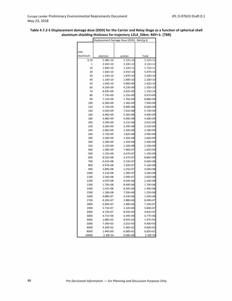
EuropaLanderPreliminaryEnvironmentalReqirementsDocument JPLD-97633Draft0.1May23,2018
Pre-DecisionalInformation—ForPlanningandDiscussionPurposesOnly
88
Table4.7.2-5Displacementdamagedose(DDD)fortheCarrierandRelayStageasafunctionofsphericalshellaluminumshieldingthicknessfortrajectory12L4_50km.RDF=1.[TBR]
DisplacementDamageDose(DDD),MeV/g-Si
milsAluminum electron proton Total
0.10 2.38E+10 2.12E+13 2.12E+131 2.34E+10 3.10E+12 3.12E+1210 1.90E+10 1.52E+11 1.71E+1120 1.56E+10 3.91E+10 5.47E+1030 1.33E+10 1.87E+10 3.20E+1040 1.16E+10 1.00E+10 2.16E+1050 1.03E+10 5.89E+09 1.62E+1060 9.29E+09 4.23E+09 1.35E+1070 8.43E+09 3.02E+09 1.15E+1080 7.73E+09 2.25E+09 9.97E+0990 7.12E+09 1.76E+09 8.88E+09100 6.58E+09 1.36E+09 7.94E+09120 5.72E+09 9.48E+08 6.66E+09140 5.03E+09 7.01E+08 5.73E+09160 4.46E+09 5.26E+08 4.99E+09180 3.98E+09 4.04E+08 4.38E+09200 3.59E+09 3.21E+08 3.91E+09220 3.26E+09 2.59E+08 3.52E+09240 2.96E+09 2.20E+08 3.18E+09260 2.72E+09 1.82E+08 2.90E+09280 2.50E+09 1.56E+08 2.66E+09300 2.30E+09 1.35E+08 2.44E+09320 2.12E+09 1.16E+08 2.24E+09400 1.58E+09 7.46E+07 1.65E+09500 1.15E+09 4.67E+07 1.19E+09600 8.52E+08 3.37E+07 8.86E+08700 6.41E+08 2.53E+07 6.66E+08800 4.97E+08 1.92E+07 5.16E+08900 3.89E+08 1.55E+07 4.04E+081000 3.13E+08 1.28E+07 3.26E+081100 2.54E+08 1.09E+07 2.65E+081200 2.07E+08 9.54E+06 2.16E+081300 1.70E+08 8.49E+06 1.79E+081400 1.41E+08 8.26E+06 1.49E+081500 1.18E+08 7.20E+06 1.25E+081600 9.88E+07 4.53E+06 1.03E+081700 8.20E+07 2.88E+06 8.49E+071800 6.90E+07 1.98E+06 7.10E+071900 5.71E+07 1.32E+06 5.84E+072000 4.73E+07 8.03E+05 4.81E+073000 4.71E+06 6.39E+04 4.77E+064000 1.88E+05 8.92E+03 1.97E+055000 7.39E+03 2.01E+03 9.40E+036000 4.20E+02 5.46E+02 9.66E+028000 1.44E+00 6.68E+01 6.82E+0110000 2.30E-03 0.00E+00 2.30E-03
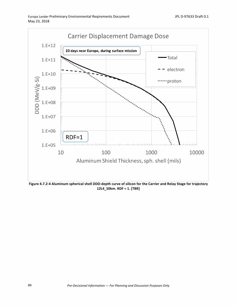
EuropaLanderPreliminaryEnvironmentalReqirementsDocument JPLD-97633Draft0.1May23,2018
Pre-DecisionalInformation—ForPlanningandDiscussionPurposesOnly
89
Figure4.7.2-4AluminumsphericalshellDDD-depthcurveofsiliconfortheCarrierandRelayStagefortrajectory12L4_50km.RDF=1.[TBR]
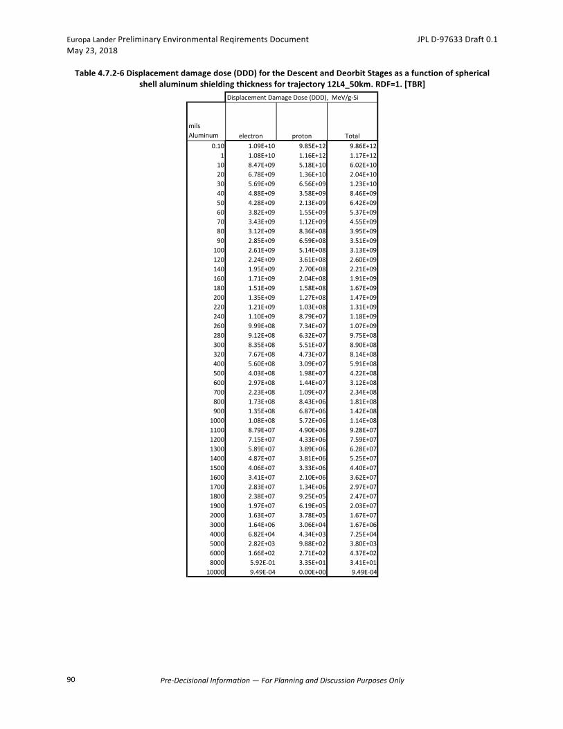
EuropaLanderPreliminaryEnvironmentalReqirementsDocument JPLD-97633Draft0.1May23,2018
Pre-DecisionalInformation—ForPlanningandDiscussionPurposesOnly
90
Table4.7.2-6Displacementdamagedose(DDD)fortheDescentandDeorbitStagesasafunctionofsphericalshellaluminumshieldingthicknessfortrajectory12L4_50km.RDF=1.[TBR]
DisplacementDamageDose(DDD),MeV/g-Si
milsAluminum electron proton Total
0.10 1.09E+10 9.85E+12 9.86E+121 1.08E+10 1.16E+12 1.17E+1210 8.47E+09 5.18E+10 6.02E+1020 6.78E+09 1.36E+10 2.04E+1030 5.69E+09 6.56E+09 1.23E+1040 4.88E+09 3.58E+09 8.46E+0950 4.28E+09 2.13E+09 6.42E+0960 3.82E+09 1.55E+09 5.37E+0970 3.43E+09 1.12E+09 4.55E+0980 3.12E+09 8.36E+08 3.95E+0990 2.85E+09 6.59E+08 3.51E+09100 2.61E+09 5.14E+08 3.13E+09120 2.24E+09 3.61E+08 2.60E+09140 1.95E+09 2.70E+08 2.21E+09160 1.71E+09 2.04E+08 1.91E+09180 1.51E+09 1.58E+08 1.67E+09200 1.35E+09 1.27E+08 1.47E+09220 1.21E+09 1.03E+08 1.31E+09240 1.10E+09 8.79E+07 1.18E+09260 9.99E+08 7.34E+07 1.07E+09280 9.12E+08 6.32E+07 9.75E+08300 8.35E+08 5.51E+07 8.90E+08320 7.67E+08 4.73E+07 8.14E+08400 5.60E+08 3.09E+07 5.91E+08500 4.03E+08 1.98E+07 4.22E+08600 2.97E+08 1.44E+07 3.12E+08700 2.23E+08 1.09E+07 2.34E+08800 1.73E+08 8.43E+06 1.81E+08900 1.35E+08 6.87E+06 1.42E+081000 1.08E+08 5.72E+06 1.14E+081100 8.79E+07 4.90E+06 9.28E+071200 7.15E+07 4.33E+06 7.59E+071300 5.89E+07 3.89E+06 6.28E+071400 4.87E+07 3.81E+06 5.25E+071500 4.06E+07 3.33E+06 4.40E+071600 3.41E+07 2.10E+06 3.62E+071700 2.83E+07 1.34E+06 2.97E+071800 2.38E+07 9.25E+05 2.47E+071900 1.97E+07 6.19E+05 2.03E+072000 1.63E+07 3.78E+05 1.67E+073000 1.64E+06 3.06E+04 1.67E+064000 6.82E+04 4.34E+03 7.25E+045000 2.82E+03 9.88E+02 3.80E+036000 1.66E+02 2.71E+02 4.37E+028000 5.92E-01 3.35E+01 3.41E+0110000 9.49E-04 0.00E+00 9.49E-04
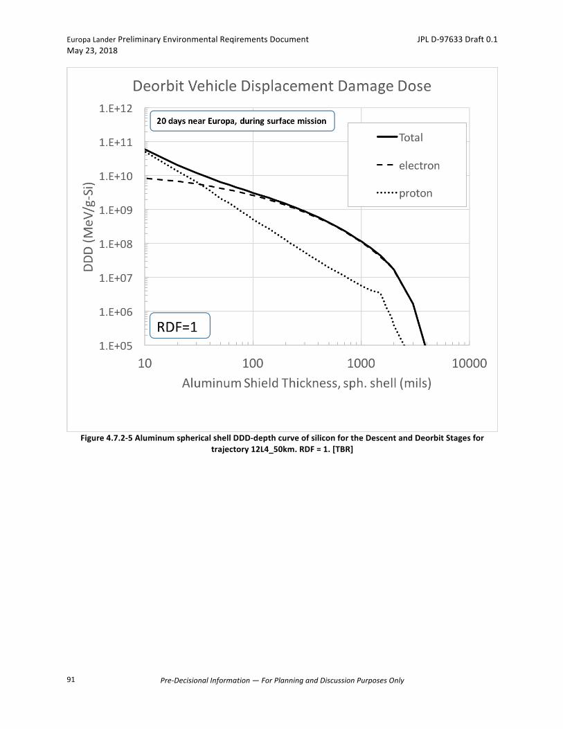
EuropaLanderPreliminaryEnvironmentalReqirementsDocument JPLD-97633Draft0.1May23,2018
Pre-DecisionalInformation—ForPlanningandDiscussionPurposesOnly
91
Figure4.7.2-5AluminumsphericalshellDDD-depthcurveofsiliconfortheDescentandDeorbitStagesfortrajectory12L4_50km.RDF=1.[TBR]

EuropaLanderPreliminaryEnvironmentalReqirementsDocument JPLD-97633Draft0.1May23,2018
Pre-DecisionalInformation—ForPlanningandDiscussionPurposesOnly
92
Table4.7.2-7Displacementdamagedose(DDD)fortheLanderasafunctionofsphericalshellaluminumshieldingthicknessfortrajectory12L4_50km.RDF=1.[TBR]
DisplacementDamageDose(DDD),MeV/g-Si
milsAluminum bremsstrahlung electron proton Total
0.10 0.00E+00 1.36E+10 1.22E+13 1.22E+131 0.00E+00 1.34E+10 1.68E+12 1.70E+1210 0.00E+00 1.07E+10 8.14E+10 9.21E+1020 0.00E+00 8.71E+09 2.10E+10 2.97E+1030 0.00E+00 7.40E+09 1.00E+10 1.74E+1040 0.00E+00 6.42E+09 5.40E+09 1.18E+1050 0.00E+00 5.68E+09 3.18E+09 8.86E+0960 0.00E+00 5.11E+09 2.29E+09 7.40E+0970 0.00E+00 4.63E+09 1.64E+09 6.26E+0980 0.00E+00 4.23E+09 1.22E+09 5.45E+0990 0.00E+00 3.89E+09 9.55E+08 4.85E+09100 0.00E+00 3.59E+09 7.41E+08 4.33E+09120 0.00E+00 3.12E+09 5.16E+08 3.63E+09140 0.00E+00 2.74E+09 3.82E+08 3.12E+09160 0.00E+00 2.42E+09 2.88E+08 2.71E+09180 0.00E+00 2.16E+09 2.21E+08 2.38E+09200 0.00E+00 1.94E+09 1.76E+08 2.12E+09220 0.00E+00 1.76E+09 1.42E+08 1.90E+09240 0.00E+00 1.60E+09 1.21E+08 1.72E+09260 0.00E+00 1.47E+09 1.00E+08 1.57E+09280 0.00E+00 1.35E+09 8.61E+07 1.43E+09300 0.00E+00 1.24E+09 7.48E+07 1.31E+09320 0.00E+00 1.14E+09 6.40E+07 1.21E+09400 0.00E+00 8.47E+08 4.14E+07 8.88E+08500 0.00E+00 6.14E+08 2.61E+07 6.40E+08600 0.00E+00 4.56E+08 1.89E+07 4.75E+08700 0.00E+00 3.43E+08 1.42E+07 3.57E+08800 0.00E+00 2.66E+08 1.08E+07 2.76E+08900 0.00E+00 2.07E+08 8.78E+06 2.16E+081000 0.00E+00 1.67E+08 7.26E+06 1.74E+081100 0.00E+00 1.35E+08 6.18E+06 1.41E+081200 0.00E+00 1.10E+08 5.44E+06 1.16E+081300 0.00E+00 9.06E+07 4.86E+06 9.54E+071400 0.00E+00 7.50E+07 4.74E+06 7.97E+071500 0.00E+00 6.25E+07 4.13E+06 6.66E+071600 0.00E+00 5.25E+07 2.60E+06 5.51E+071700 0.00E+00 4.35E+07 1.66E+06 4.52E+071800 0.00E+00 3.66E+07 1.14E+06 3.77E+071900 0.00E+00 3.03E+07 7.61E+05 3.10E+072000 0.00E+00 2.51E+07 4.64E+05 2.55E+073000 0.00E+00 2.49E+06 3.71E+04 2.53E+064000 0.00E+00 9.93E+04 5.20E+03 1.04E+055000 0.00E+00 3.88E+03 1.18E+03 5.06E+036000 0.00E+00 2.20E+02 3.20E+02 5.40E+028000 0.00E+00 7.53E-01 3.93E+01 4.00E+0110000 0.00E+00 1.20E-03 0.00E+00 1.20E-03
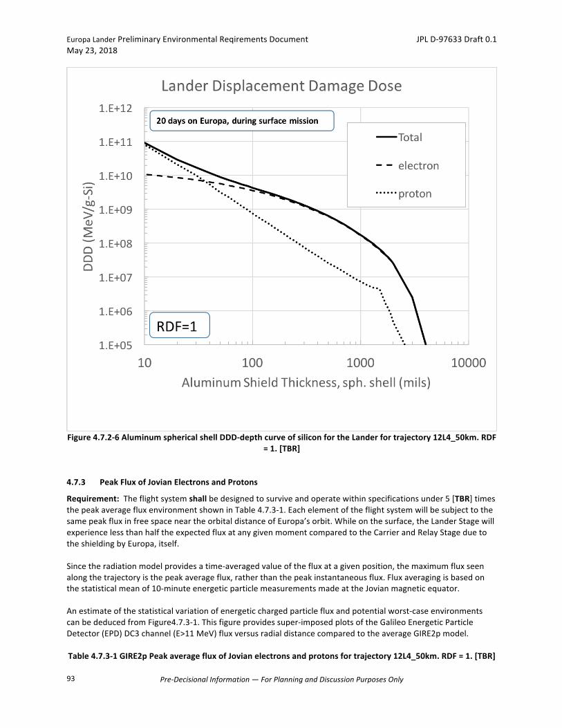
EuropaLanderPreliminaryEnvironmentalReqirementsDocument JPLD-97633Draft0.1May23,2018
Pre-DecisionalInformation—ForPlanningandDiscussionPurposesOnly
93
Figure4.7.2-6AluminumsphericalshellDDD-depthcurveofsiliconfortheLanderfortrajectory12L4_50km.RDF=1.[TBR]
4.7.3 PeakFluxofJovianElectronsandProtons
Requirement:Theflightsystemshallbedesignedtosurviveandoperatewithinspecificationsunder5[TBR]timesthepeakaveragefluxenvironmentshowninTable4.7.3-1.EachelementoftheflightsystemwillbesubjecttothesamepeakfluxinfreespaceneartheorbitaldistanceofEuropa’sorbit.Whileonthesurface,theLanderStagewillexperiencelessthanhalftheexpectedfluxatanygivenmomentcomparedtotheCarrierandRelayStageduetotheshieldingbyEuropa,itself.Sincetheradiationmodelprovidesatime-averagedvalueofthefluxatagivenposition,themaximumfluxseenalongthetrajectoryisthepeakaverageflux,ratherthanthepeakinstantaneousflux.Fluxaveragingisbasedonthestatisticalmeanof10-minuteenergeticparticlemeasurementsmadeattheJovianmagneticequator.Anestimateofthestatisticalvariationofenergeticchargedparticlefluxandpotentialworst-caseenvironmentscanbededucedfromFigure4.7.3-1.Thisfigureprovidessuper-imposedplotsoftheGalileoEnergeticParticleDetector(EPD)DC3channel(E>11MeV)fluxversusradialdistancecomparedtotheaverageGIRE2pmodel.Table4.7.3-1GIRE2pPeakaveragefluxofJovianelectronsandprotonsfortrajectory12L4_50km.RDF=1.[TBR]
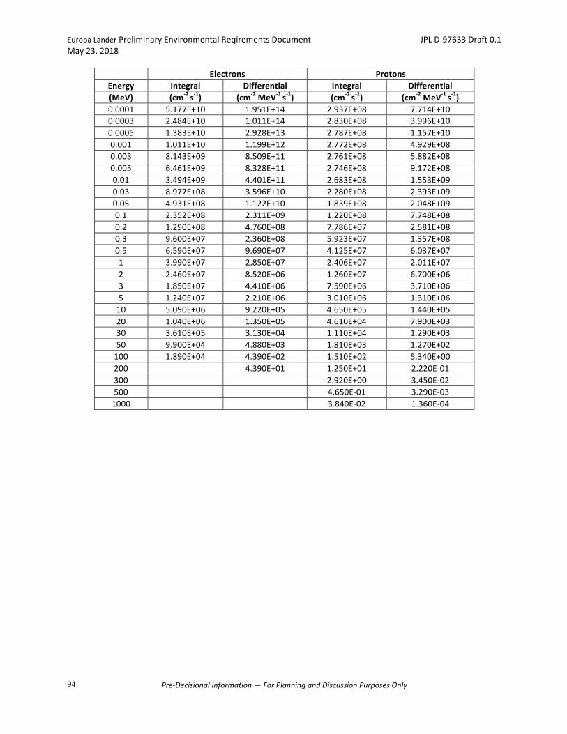
EuropaLanderPreliminaryEnvironmentalReqirementsDocument JPLD-97633Draft0.1May23,2018
Pre-DecisionalInformation—ForPlanningandDiscussionPurposesOnly
94
Electrons ProtonsEnergy Integral Differential Integral Differential(MeV) (cm-2s-1) (cm-2MeV-1s-1) (cm-2s-1) (cm-2MeV-1s-1)0.0001 5.177E+10 1.951E+14 2.937E+08 7.714E+100.0003 2.484E+10 1.011E+14 2.830E+08 3.996E+100.0005 1.383E+10 2.928E+13 2.787E+08 1.157E+100.001 1.011E+10 1.199E+12 2.772E+08 4.929E+080.003 8.143E+09 8.509E+11 2.761E+08 5.882E+080.005 6.461E+09 8.328E+11 2.746E+08 9.172E+080.01 3.494E+09 4.401E+11 2.683E+08 1.553E+090.03 8.977E+08 3.596E+10 2.280E+08 2.393E+090.05 4.931E+08 1.122E+10 1.839E+08 2.048E+090.1 2.352E+08 2.311E+09 1.220E+08 7.748E+080.2 1.290E+08 4.760E+08 7.786E+07 2.581E+080.3 9.600E+07 2.360E+08 5.923E+07 1.357E+080.5 6.590E+07 9.690E+07 4.125E+07 6.037E+071 3.990E+07 2.850E+07 2.406E+07 2.011E+072 2.460E+07 8.520E+06 1.260E+07 6.700E+063 1.850E+07 4.410E+06 7.590E+06 3.710E+065 1.240E+07 2.210E+06 3.010E+06 1.310E+0610 5.090E+06 9.220E+05 4.650E+05 1.440E+0520 1.040E+06 1.350E+05 4.610E+04 7.900E+0330 3.610E+05 3.130E+04 1.110E+04 1.290E+0350 9.900E+04 4.880E+03 1.810E+03 1.270E+02100 1.890E+04 4.390E+02 1.510E+02 5.340E+00200 4.390E+01 1.250E+01 2.220E-01300 2.920E+00 3.450E-02500 4.650E-01 3.290E-031000 3.840E-02 1.360E-04
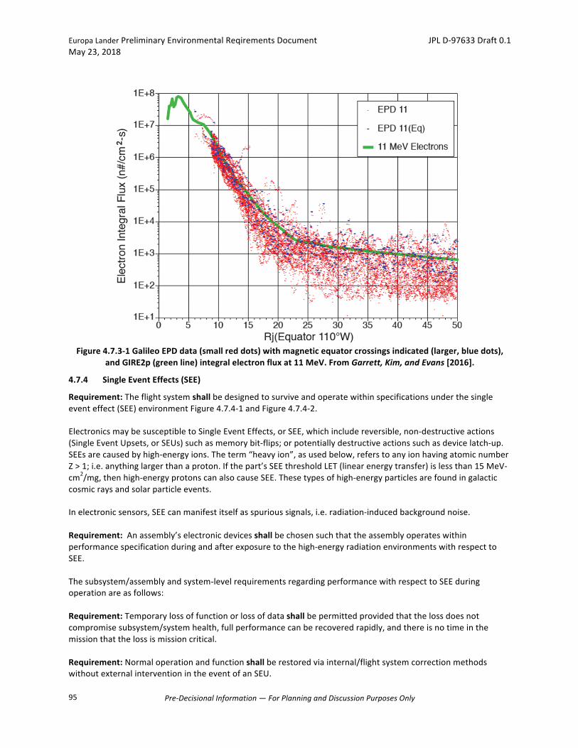
EuropaLanderPreliminaryEnvironmentalReqirementsDocument JPLD-97633Draft0.1May23,2018
Pre-DecisionalInformation—ForPlanningandDiscussionPurposesOnly
95
Figure4.7.3-1GalileoEPDdata(smallreddots)withmagneticequatorcrossingsindicated(larger,bluedots),
andGIRE2p(greenline)integralelectronfluxat11MeV.FromGarrett,Kim,andEvans[2016].
4.7.4 SingleEventEffects(SEE)
Requirement:Theflightsystemshallbedesignedtosurviveandoperatewithinspecificationsunderthesingleeventeffect(SEE)environmentFigure4.7.4-1andFigure4.7.4-2.ElectronicsmaybesusceptibletoSingleEventEffects,orSEE,whichincludereversible,non-destructiveactions(SingleEventUpsets,orSEUs)suchasmemorybit-flips;orpotentiallydestructiveactionssuchasdevicelatch-up.SEEsarecausedbyhigh-energyions.Theterm“heavyion”,asusedbelow,referstoanyionhavingatomicnumberZ>1;i.e.anythinglargerthanaproton.Ifthepart’sSEEthresholdLET(linearenergytransfer)islessthan15MeV-cm2/mg,thenhigh-energyprotonscanalsocauseSEE.Thesetypesofhigh-energyparticlesarefoundingalacticcosmicraysandsolarparticleevents.Inelectronicsensors,SEEcanmanifestitselfasspurioussignals,i.e.radiation-inducedbackgroundnoise.Requirement:Anassembly’selectronicdevicesshallbechosensuchthattheassemblyoperateswithinperformancespecificationduringandafterexposuretothehigh-energyradiationenvironmentswithrespecttoSEE.Thesubsystem/assemblyandsystem-levelrequirementsregardingperformancewithrespecttoSEEduringoperationareasfollows:Requirement:Temporarylossoffunctionorlossofdatashallbepermittedprovidedthatthelossdoesnotcompromisesubsystem/systemhealth,fullperformancecanberecoveredrapidly,andthereisnotimeinthemissionthatthelossismissioncritical.Requirement:Normaloperationandfunctionshallberestoredviainternal/flightsystemcorrectionmethodswithoutexternalinterventionintheeventofanSEU.
the equator. (The observation that the two data sets appear to besimilarly distributed implies that the equatorial values are not skewedto higher levels as would be expected in the latter case.) In contrast,outside 17 RJ , the equatorial crossing data are basically the highest
values at anygivenRJ , and showhow the fluxes fall off away from theflux maxima at the magnetic equator. The GIRE2 model predictionsbased on themagnetic-equator valueswell fit the observations at bothenergies at all distances (provided the distance from the equator isconsidered outside 17 RJ).In Fig. 14, the GIRE2 model has been used to generate meridian
contours of the 1 MeV (Fig. 14a) and 10 MeV (Fig. 14b) electron-integral fluxes (cm−2 · s−1) for the 110°Wmeridian and for the sun at110° W. The “outer” GIRE2 model has been extrapolated inward of∼15RJ and up to!20RJ in Zmap to fill in the region outside an L of22.5 where little observational data currently exist. A 1MeVelectronwill typically penetrate∼2.54 mm (100mils) of aluminum shielding,whereas a 10 MeV beam of electrons will penetrate upward of25.4 mm (1 in.) of shielding— common design points for radiation-shielding designs. Figure 15 demonstrates the use of GIRE2 inpredicting the average worst-case dose rate (rad"Si#∕s) for variousshielding levels for a Europa design reference mission.
IV. Proton-Radiation ModelThe high-energy proton component of the original DG1modelwas
limited to L values less than 12. Although electrons dominate theenvironment at Jupiter, there are some applications that require thesurface dose due to protons.As an example, theEuropamission solar-array cover-glass layer is potentially sensitive to protons. To evaluatethe possible effects of the protons, the DG2 model was extended to∼50RJ . To accomplish this, the Galileo EPD proton data werereviewed for their applicability to modeling the high-energy protonsfrom 50 keV to∼20 − 50 MeV. Unfortunately, only one of the high-energy proton channels was found not to be contaminated by
Fig. 13 EPD data (small dots), Khurana crossings (large dots), andGIRE2 (line) electron integral fluxes at a) 2.0 and b) 11.0 MeV.
Fig. 14 GIRE2 contours (Log10) a) 1 MeV; b) 10 MeV electron integral fluxes.
Fig. 15 Worst-case Europa flyby dose rates through various aluminumshielding thicknesses.
Article in Advance / GARRETT, KIM, AND EVANS 9
Dow
nloa
ded
by JE
T PR
OPU
LSIO
N L
ABO
RATO
RY o
n Ju
ly 5
, 201
6 | h
ttp://
arc.
aiaa
.org
| D
OI:
10.2
514/
1.A
3351
0
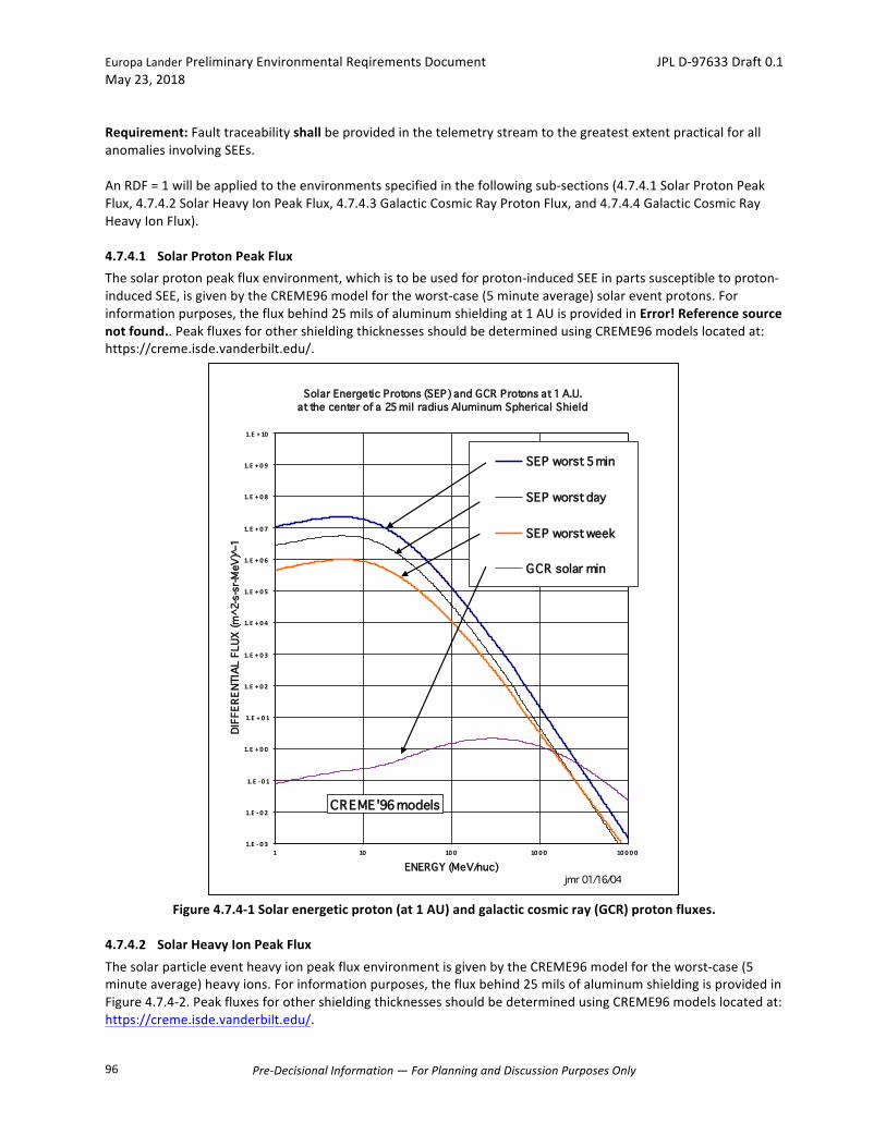
EuropaLanderPreliminaryEnvironmentalReqirementsDocument JPLD-97633Draft0.1May23,2018
Pre-DecisionalInformation—ForPlanningandDiscussionPurposesOnly
96
Requirement:FaulttraceabilityshallbeprovidedinthetelemetrystreamtothegreatestextentpracticalforallanomaliesinvolvingSEEs.AnRDF=1willbeappliedtotheenvironmentsspecifiedinthefollowingsub-sections(4.7.4.1SolarProtonPeakFlux,4.7.4.2SolarHeavyIonPeakFlux,4.7.4.3GalacticCosmicRayProtonFlux,and4.7.4.4GalacticCosmicRayHeavyIonFlux).
4.7.4.1 SolarProtonPeakFluxThesolarprotonpeakfluxenvironment,whichistobeusedforproton-inducedSEEinpartssusceptibletoproton-inducedSEE,isgivenbytheCREME96modelfortheworst-case(5minuteaverage)solareventprotons.Forinformationpurposes,thefluxbehind25milsofaluminumshieldingat1AUisprovidedinError!Referencesourcenotfound..PeakfluxesforothershieldingthicknessesshouldbedeterminedusingCREME96modelslocatedat:https://creme.isde.vanderbilt.edu/.
Figure4.7.4-1Solarenergeticproton(at1AU)andgalacticcosmicray(GCR)protonfluxes.
4.7.4.2 SolarHeavyIonPeakFluxThesolarparticleeventheavyionpeakfluxenvironmentisgivenbytheCREME96modelfortheworst-case(5minuteaverage)heavyions.Forinformationpurposes,thefluxbehind25milsofaluminumshieldingisprovidedinFigure4.7.4-2.PeakfluxesforothershieldingthicknessesshouldbedeterminedusingCREME96modelslocatedat:https://creme.isde.vanderbilt.edu/.
Solar Energetic Protons (SEP) and GCR Protons at 1 A.U.at the center of a 25 mil radius Aluminum Spherical Shield
1.E - 0 3
1.E - 0 2
1.E - 0 1
1.E + 0 0
1.E + 0 1
1.E + 0 2
1.E + 0 3
1.E + 0 4
1.E + 0 5
1.E + 0 6
1.E + 0 7
1.E + 0 8
1.E + 0 9
1.E + 10
1 10 10 0 10 0 0 10 0 0 0
ENERGY (MeV/nuc)
DIFF
EREN
TIAL
FLU
X (m
^2-s
-sr-M
eV)̂
-1
SEP worst 5 min
SEP worst day
SEP worst week
GCR solar min
jmr 01/16/04
CREME'96 models
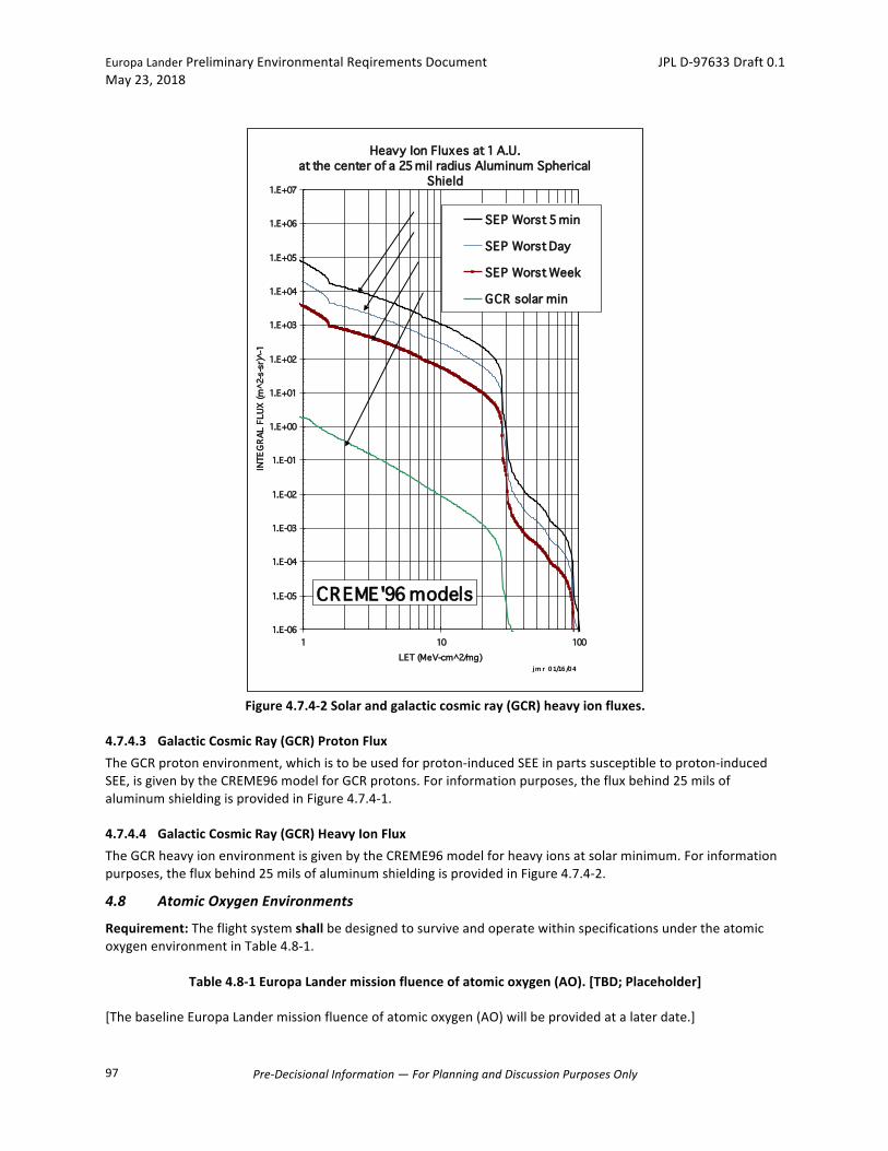
EuropaLanderPreliminaryEnvironmentalReqirementsDocument JPLD-97633Draft0.1May23,2018
Pre-DecisionalInformation—ForPlanningandDiscussionPurposesOnly
97
Figure4.7.4-2Solarandgalacticcosmicray(GCR)heavyionfluxes.
4.7.4.3 GalacticCosmicRay(GCR)ProtonFluxTheGCRprotonenvironment,whichistobeusedforproton-inducedSEEinpartssusceptibletoproton-inducedSEE,isgivenbytheCREME96modelforGCRprotons.Forinformationpurposes,thefluxbehind25milsofaluminumshieldingisprovidedinFigure4.7.4-1.
4.7.4.4 GalacticCosmicRay(GCR)HeavyIonFluxTheGCRheavyionenvironmentisgivenbytheCREME96modelforheavyionsatsolarminimum.Forinformationpurposes,thefluxbehind25milsofaluminumshieldingisprovidedinFigure4.7.4-2.
4.8 AtomicOxygenEnvironments
Requirement:TheflightsystemshallbedesignedtosurviveandoperatewithinspecificationsundertheatomicoxygenenvironmentinTable4.8-1.
Table4.8-1EuropaLandermissionfluenceofatomicoxygen(AO).[TBD;Placeholder]
[ThebaselineEuropaLandermissionfluenceofatomicoxygen(AO)willbeprovidedatalaterdate.]
Heavy Ion Fluxes at 1 A.U.at the center of a 25 mil radius Aluminum Spherical
Shield
1.E-06
1.E-05
1.E-04
1.E-03
1.E-02
1.E-01
1.E+00
1.E+01
1.E+02
1.E+03
1.E+04
1.E+05
1.E+06
1.E+07
1 10 100LET (MeV-cm^2/mg)
INTE
GRA
L FL
UX (m
^2-s
-sr)̂
-1
SEP Worst 5 min
SEP Worst Day
SEP Worst Week
GCR solar min
jm r 01/16/04
CREME'96 models
EuropaLanderPreliminaryEnvironmentalReqirementsDocument JPLD-97633Draft0.1May23,2018
Pre-DecisionalInformation—ForPlanningandDiscussionPurposesOnly
98
Requirement:MaterialsexposedtospacewithavectorintheramdirectionshallsurvivethemissionexposuretoAOinTable4.8-1withacceptablepropertycharacteristics.
4.9 EuropaGravity
Europa'ssurfacegravitationalaccelerationisapproximately1.31m/s2,ornearly2/15thatofEarth’sgravitationalacceleration.
4.10 SolarSpectralIrradiance
ThesolarelectromagneticenvironmentmeanfluxforeachmissionphaseisasstatedinTable4.4.3-1withasolarirradiancespectrumisshowninTable4.10-1.

EuropaLanderPreliminaryEnvironmentalReqirementsDocument JPLD-97633Draft0.1May23,2018
Pre-DecisionalInformation—ForPlanningandDiscussionPurposesOnly
99
Table4.10-1SolarSpectralIrradiance0.0850–7.0Microns.λ(µm) P(%) λ(µm) P(%) λ(µm) P(%)0.08500.09000.09500.10000.10500.11000.11500.12000.12500.13200.13500.14000.14500.15000.15500.16000.16500.17000.17500.18000.18500.19000.19500.20000.20500.21000.21500.220.2250.230.2350.240.2450.250.2550.260.2650.270.2750.280.2850.290.2950.300.3050.310.3150.320.3250.330.3350.340.3450.350.355
3.8x10-43.9x10-4
4.0x10⁻⁴
4.1x10⁻⁴
4.2x10⁻⁴
4.2x10⁻⁴
4.3x10⁻⁴
4.4x10⁻⁴
4.7x10⁻⁴
4.9x10⁻⁴
5.2x10⁻⁴
5.4x10⁻⁴
5.6x10⁻⁴
5.8x10⁻⁴
6.3x10⁻⁴
6.9x10⁻⁴
8.2x10⁻⁴
1.01x10⁻³
1.31x10⁻³
1.70x10⁻³
2.33x10⁻³
3.16x10⁻³
5.2x10⁻³
8.1x10⁻³
1.34x10⁻²
2.05x10⁻²
3.53x10⁻²
0.05020.07290.09720.12050.14300.16810.19440.22670.2700.3280.4050.4860.4650.6440.8111.0081.2111.4171.6561.9242.2192.5522.9283.3243.7224.1184.5174.919
0.360.3650.370.3750.380.3850.390.3950.400.4050.410.4150.420.4250.430.4350.440.4450.450.4550.460.4650.470.4750.480.4850.490.4950.500.5050.510.5150.520.5250.530.5350.540.5450.550.5550.560.5650.570.5750.580.5850.590.5950.600.610.620.630.640.650.66
5.3175.7236.1516.5837.0037.4137.8198.2428.7259.2939.92010.57211.22211.85812.47413.08413.72614.41515.14115.89216.65317.41418.16818.92119.68220.43021.15621.87822.59923.31324.01524.70225.37926.06026.74329.41928.08428.73829.38130.01730.64831.27631.90832.54233.17633.80934.44035.06535.68336.90238.09839.27040.42141.55042.658
0.670.680.690.700.710.720.730.740.750.800.850.900.951.01.11.21.31.41.51.61.71.81.92.02.12.22.32.42.52.62.72.82.93.03.13.23.33.43.53.63.73.83.94.04.14.24.34.44.54.64.74.84.95.06.07.0
43.74544.81645.85646.88047.88248.86549.82750.76951.69156.01959.89063.35866.54469.46574.40978.38681.63884.34386.64588.60790.25691.59092.64393.48994.20294.82795.37095.85896.29496.67197.00797.31097.58497.82898.03898.21898.37298.50598.62098.72598.81998.90698.98599.05899.12599.18699.24199.29199.33799.37999.41699.45099.48299.51199.71899.819
λ(µm)iswavelength;andPisthepercentageofthesolarconstantassociatedwithwavelengthsshorterthanλ.
5 AppendixA:AcronymsandAbbreviations
AC AlternatingCurrent

EuropaLanderPreliminaryEnvironmentalReqirementsDocument JPLD-97633Draft0.1May23,2018
Pre-DecisionalInformation—ForPlanningandDiscussionPurposesOnly
100
AFT AllowableFlightTemperatureAM AmplitudeModulationAO AnnouncementofOpportunityAO AtomicOxygenATLO Assembly,Test,andLaunchOperationsCE ConductedEmissionsc.g. CenterofGravityCLA CoupledLoadsAnalysisCS ConductedSusceptibilityCogE CognizantEngineerdB DecibelDC DirectCurrentDDD DisplacementDamageDoseEELV EvolvedExpendableLaunchVehiclesEM EuropaMissionEM EngineeringModelEMC ElectromagneticCompatibilityEMI ElectromagneticInterferenceERD EnvironmentalRequirementsDocumentERE EnvironmentalRequirementsEngineerESD ElectrostaticDischargeEACS EnvironmentalAnalysisCompletionStatement(form)ETAS EnvironmentalTestAuthorizationSummary(form)EVEEGA EarthVenusEarthEarthGravityAssistFA FlightAcceptanceFMH FreeMolecularHeatingg AccelerationofGravitygrms AccelerationRootMeanSquareGCR GalacticCosmicRayGHz Giga-HertzGN2 GaseousNitrogenHi-Rtn High-ReturnHrs Hour(s)HV HighVoltageHz HertzIESD InternalElectrostaticDischargeJPL JetPropulsionLaboratoryK KelvinkHz kilo-HertzLISN LineImpedanceSimulationNetworkLV LaunchVehicleLS LaunchSiteLVDS LowVoltageDifferentialSignalingMAC MassAccelerationCurveMAM MissionAssuranceManagerMeV MillionelectronVoltsMEFL MaximumExpectedFlightLevelmin MinuteMinEFL MinimumExpectedFlightLevelMHz Mega-HertzMIL-STD MilitaryStandardmΩ Milli-Ohm

EuropaLanderPreliminaryEnvironmentalReqirementsDocument JPLD-97633Draft0.1May23,2018
Pre-DecisionalInformation—ForPlanningandDiscussionPurposesOnly
101
MΩ Meg-OhmN/A NotApplicableNASA NationalAeronauticsandSpaceAdministrationNon-Op Non-OperatingnT nano-TestlaOp OperatingPAF PayloadAdapterFairingPF ProtoflightPLF PayloadFairingPSI PoundsperSquareInchQA QualityAssuranceQual Qualification(Model)RACS RadiationAnalysisCompletionStatement(form)RDF RadiationDesignFactorRE RadiatedEmissionsRF RadioFrequencyRj JupiterRadiusRMS RootMeanSquareRS RadiatedSusceptibilitys SecondSEE SingleEventEffectsSEP SolarEnergeticParticle(orProton)SEU SingleEventUpsetSLS SpaceLaunchSystemSPL SoundPressureLevelSRS ShockResponseSpectrumTAM TestandAnalysisMatrixTBC ToBeCompletedorConfirmedTBD ToBeDeterminedTBR ToBeReviewed/RevisedTID TotalIonizingDoseTRT TemperatureRequirementsTableVac VacuumW/m2 WattperSquareMeterWC WorstCase
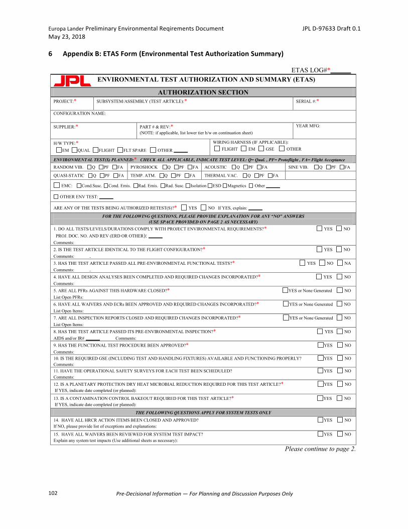
EuropaLanderPreliminaryEnvironmentalReqirementsDocument JPLD-97633Draft0.1May23,2018
Pre-DecisionalInformation—ForPlanningandDiscussionPurposesOnly
102
6 AppendixB:ETASForm(EnvironmentalTestAuthorizationSummary)
ETAS LOG#*
ENVIRONMENTAL TEST AUTHORIZATION AND SUMMARY (ETAS)
AUTHORIZATION SECTION PROJECT:*
SUBSYSTEM/ASSEMBLY (TEST ARTICLE):* SERIAL #:*
CONFIGURATION NAME: SUPPLIER:*
PART # & REV:* (NOTE: if applicable, list lower tier h/w on continuation sheet)
YEAR MFG:
H/W TYPE:* EM QUAL FLIGHT FLT SPARE OTHER
WIRING HARNESS (IF APPLICABLE): FLIGHT EM GSE OTHER
ENVIRONMENTAL TEST(S) PLANNED:* CHECK ALL APPLICABLE, INDICATE TEST LEVEL: Q= Qual. , PF= Protoflight , FA= Flight Acceptance RANDOM VIB. Q PF FA PYROSHOCK Q PF FA ACOUSTIC Q PF FA SINE VIB. Q PF FA
QUASI-STATIC Q PF FA TEMP. ATM. Q PF FA THERMAL VAC. Q PF FA
EMC: Cond.Susc. Cond. Emis. Rad. Emis. Rad. Susc. Isolation ESD Magnetics Other
OTHER ENV TEST:
ARE ANY OF THE TESTS BEING AUTHORIZED RETEST(S)?* YES NO If YES, explain:
FOR THE FOLLOWING QUESTIONS, PLEASE PROVIDE EXPLANATION FOR ANY “NO” ANSWERS (USE SPACE PROVIDED ON PAGE 2 AS NECESSARY)
1. DO ALL TESTS/LEVELS/DURATIONS COMPLY WITH PROJECT ENVIRONMENTAL REQUIREMENTS?* YES NO PROJ. DOC. NO. AND REV (ERD OR OTHER): Comments: 2. IS THE TEST ARTICLE IDENTICAL TO THE FLIGHT CONFIGURATION?* YES NO Comments: . 3. HAS THE TEST ARTICLE PASSED ALL PRE-ENVIRONMENTAL FUNCTIONAL TESTS?* YES NO NA Comments: . 4. HAVE ALL DESIGN ANALYSES BEEN COMPLETED AND REQUIRED CHANGES INCORPORATED?* YES NO Comments: 5. ARE ALL PFRs AGAINST THIS HARDWARE CLOSED?* YES or None Generated NO List Open PFRs: 6. HAVE ALL WAIVERS AND ECRs BEEN APPROVED AND REQUIRED CHANGES INCORPORATED?* YES or None Generated NO List Open Items: 7. ARE ALL INSPECTION REPORTS CLOSED AND REQUIRED CHANGES INCORPORATED?* YES or None Generated NO List Open Items: 8. HAS THE TEST ARTICLE PASSED ITS PRE-ENVIRONMENTAL INSPECTION?* YES NO AIDS and/or IR# Comments: 9. HAS THE FUNCTIONAL TEST PROCEDURE BEEN APPROVED?* YES NO Comments: 10. IS THE REQUIRED GSE (INCLUDING TEST AND HANDLING FIXTURES) AVAILABLE AND FUNCTIONING PROPERLY? YES NO Comments: 11. HAVE THE OPERATIONAL SAFETY SURVEYS FOR EACH TEST BEEN SCHEDULED? YES NO Comments: 12. IS A PLANETARY PROTECTION DRY HEAT MICROBIAL REDUCTION REQUIRED FOR THIS TEST ARTICLE?* YES NO If YES, indicate date completed (or planned):
13. IS A CONTAMINATION CONTROL BAKEOUT REQUIRED FOR THIS TEST ARTICLE?* YES NO If YES, indicate date completed (or planned):
THE FOLLOWING QUESTIONS APPLY FOR SYSTEM TESTS ONLY
14. HAVE ALL HRCR ACTION ITEMS BEEN CLOSED AND APPROVED? YES NO If NO, please provide list of exceptions and explanations:
15. HAVE ALL WAIVERS BEEN REVIEWED FOR SYSTEM TEST IMPACT? YES NO Explain any system test impacts (Use additional sheets as necessary):
Please continue to page 2.
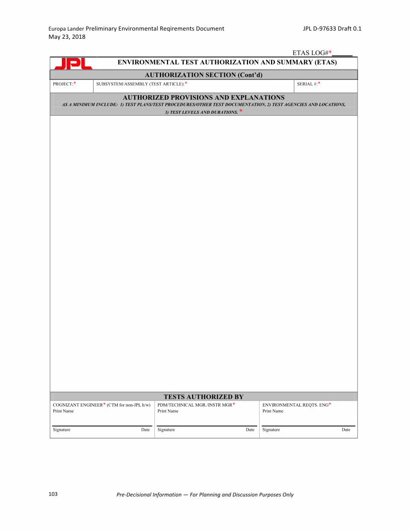
EuropaLanderPreliminaryEnvironmentalReqirementsDocument JPLD-97633Draft0.1May23,2018
Pre-DecisionalInformation—ForPlanningandDiscussionPurposesOnly
103
ETAS LOG#*
ENVIRONMENTAL TEST AUTHORIZATION AND SUMMARY (ETAS)
AUTHORIZATION SECTION (Cont’d) PROJECT:*
SUBSYSTEM/ASSEMBLY (TEST ARTICLE):* SERIAL #:*
AUTHORIZED PROVISIONS AND EXPLANATIONS AS A MINIMUM INCLUDE: 1) TEST PLANS/TEST PROCEDURES/OTHER TEST DOCUMENTATION, 2) TEST AGENCIES AND LOCATIONS,
3) TEST LEVELS AND DURATIONS. *
TESTS AUTHORIZED BY COGNIZANT ENGINEER* (CTM for non-JPL h/w) Print Name Signature Date
PDM/TECHNICAL MGR./INSTR MGR* Print Name Signature Date
ENVIRONMENTAL REQTS. ENG* Print Name Signature Date
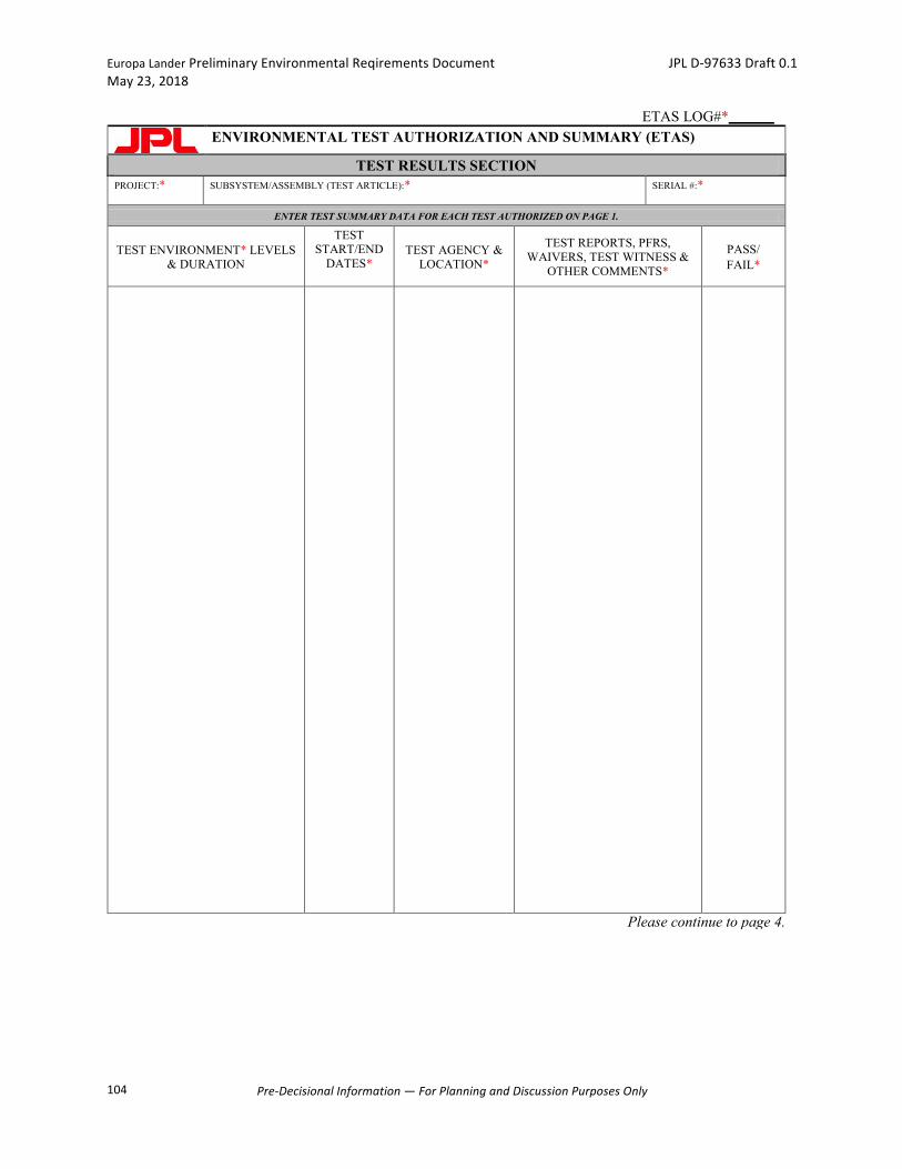
EuropaLanderPreliminaryEnvironmentalReqirementsDocument JPLD-97633Draft0.1May23,2018
Pre-DecisionalInformation—ForPlanningandDiscussionPurposesOnly
104
ETAS LOG#*
ENVIRONMENTAL TEST AUTHORIZATION AND SUMMARY (ETAS)
TEST RESULTS SECTION PROJECT:*
SUBSYSTEM/ASSEMBLY (TEST ARTICLE):* SERIAL #:*
ENTER TEST SUMMARY DATA FOR EACH TEST AUTHORIZED ON PAGE 1.
TEST ENVIRONMENT* LEVELS & DURATION
TEST START/END
DATES*
TEST AGENCY & LOCATION*
TEST REPORTS, PFRS, WAIVERS, TEST WITNESS &
OTHER COMMENTS*
PASS/ FAIL*
Please continue to page 4.
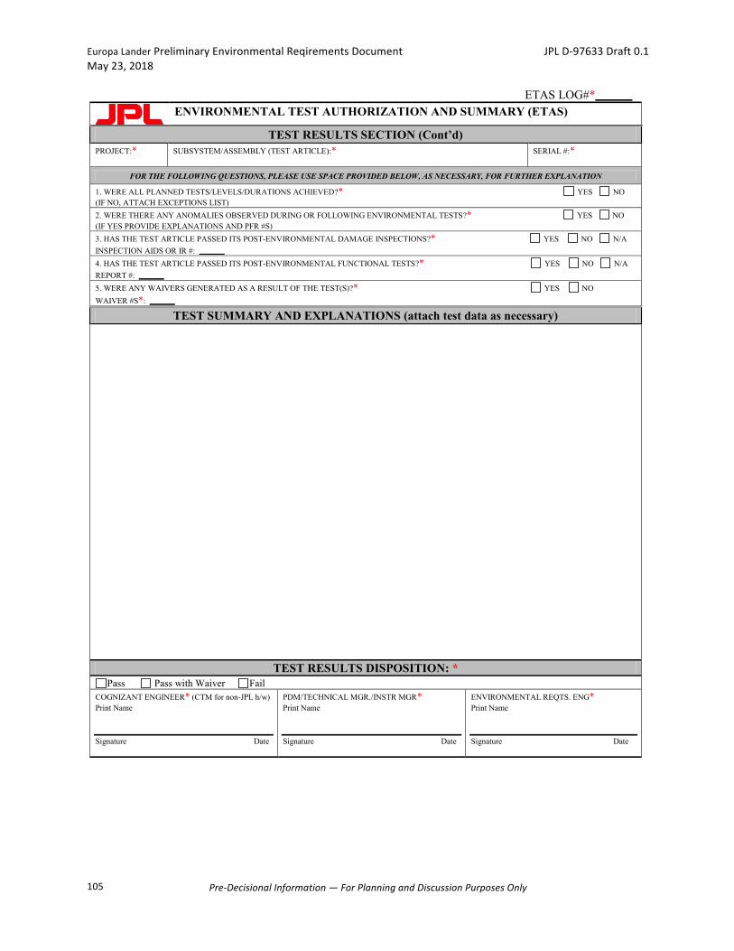
EuropaLanderPreliminaryEnvironmentalReqirementsDocument JPLD-97633Draft0.1May23,2018
Pre-DecisionalInformation—ForPlanningandDiscussionPurposesOnly
105
ETAS LOG#*
ENVIRONMENTAL TEST AUTHORIZATION AND SUMMARY (ETAS)
TEST RESULTS SECTION (Cont’d) PROJECT:*
SUBSYSTEM/ASSEMBLY (TEST ARTICLE):* SERIAL #:*
FOR THE FOLLOWING QUESTIONS, PLEASE USE SPACE PROVIDED BELOW, AS NECESSARY, FOR FURTHER EXPLANATION
1. WERE ALL PLANNED TESTS/LEVELS/DURATIONS ACHIEVED?* YES NO (IF NO, ATTACH EXCEPTIONS LIST) 2. WERE THERE ANY ANOMALIES OBSERVED DURING OR FOLLOWING ENVIRONMENTAL TESTS?* YES NO (IF YES PROVIDE EXPLANATIONS AND PFR #S) 3. HAS THE TEST ARTICLE PASSED ITS POST-ENVIRONMENTAL DAMAGE INSPECTIONS?* YES NO N/A INSPECTION AIDS OR IR #: 4. HAS THE TEST ARTICLE PASSED ITS POST-ENVIRONMENTAL FUNCTIONAL TESTS?* YES NO N/A REPORT #: 5. WERE ANY WAIVERS GENERATED AS A RESULT OF THE TEST(S)?* YES NO WAIVER #S*:
TEST SUMMARY AND EXPLANATIONS (attach test data as necessary)
TEST RESULTS DISPOSITION: * Pass Pass with Waiver Fail
COGNIZANT ENGINEER* (CTM for non-JPL h/w) Print Name Signature Date
PDM/TECHNICAL MGR./INSTR MGR* Print Name Signature Date
ENVIRONMENTAL REQTS. ENG* Print Name Signature Date
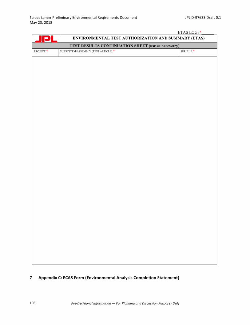
EuropaLanderPreliminaryEnvironmentalReqirementsDocument JPLD-97633Draft0.1May23,2018
Pre-DecisionalInformation—ForPlanningandDiscussionPurposesOnly
106
7 AppendixC:ECASForm(EnvironmentalAnalysisCompletionStatement)
ETAS LOG#*
ENVIRONMENTAL TEST AUTHORIZATION AND SUMMARY (ETAS)
TEST RESULTS CONTINUATION SHEET (use as necessary) PROJECT:*
SUBSYSTEM/ASSEMBLY (TEST ARTICLE):* SERIAL #:*

EuropaLanderPreliminaryEnvironmentalReqirementsDocument JPLD-97633Draft0.1May23,2018
Pre-DecisionalInformation—ForPlanningandDiscussionPurposesOnly
107
PROJECT ASSEMBL/SUBASSEMBLY TITLE
ENVIRONMENT SPECIFICATION: (ERD paragraph # or attach as necessary). ANALYSIS APPROACH : ANALYSIS CONCLUSIONS: Hardware compliance with design environment? _______yes _________no (explain)
LIST OF PERTINENT DOCUMENTS (IOM’S, REPORTS): ATTACH AS APPROPRIATE
_____________________________________ ________________________________________ _____________________________________ ________________________________________ PREPARED BY: _____________________________________ ____________
_____________________________________
Cognizant Engineer date phone # APPROVED BY: _____________________________________ _____________________________________ Technical Manager / Instrument Mgr. or P.I. Environmental Requirements Engineer (ERE) After Technical Manager approval, send statement and supporting documentation to the Project ERE.