VT Parts Section R06 - cloudfront.net
394
E.C.N. Issue - C/21561 Print date - 26.08.05 Parts Section VT & VS 500 z 605 z 650 z 800 Range of Twin Engined & Hydrostatic Sweepers Part No 02617-1-P Revision Level 13 Page Issue Levels Body/Cowl/Rear Door Subframe/Body Prop Powapak Systems Locker Channel Brush Nozzle Wide Sweep Brush Wanderhose/Littasnatch Hydraulics Pneumatics Water System Electrical System Cab Controls Chassis Application Miscellaneous Optional Equipment P 20 21 22 23 24 25 26 27 28 29 30 31 32 33 34 35
-
Upload
khangminh22 -
Category
Documents
-
view
3 -
download
0
Transcript of VT Parts Section R06 - cloudfront.net

E.C.N. Issue - C/21561 Print date - 26.08.05
Parts Section
VT & VS
500 605 650 800Range of Twin Engined & Hydrostatic Sweepers
Part No 02617-1-P
Revision Level 13
Page Issue Levels
Body/Cowl/Rear Door
Subframe/Body Prop
Powapak
Systems Locker
Channel Brush
Nozzle
Wide Sweep Brush
Wanderhose/Littasnatch
Hydraulics
Pneumatics
Water System
Electrical System
Cab Controls
Chassis Application
Miscellaneous
Optional Equipment
P
20
21
22
23
24
25
26
27
28
29
30
31
32
33
34
35

Page Issue 13
VT & VS - Parts
ForewordF1
ForewordThis section of the manual will help you when ordering parts and serves as an assembly/disassemblyreference when used in conjunction with the Maintenance Section procedures.
About this section
Chapters 20 to 34, listed on the front sheet, cover the major areas of the machine. Some of the morepopular options such as the Supawash hi-pressure water system, Channel Brush Rotatilt, Powaboom andLittasnatch wanderhoses are also covered in these chapters. Other more specialised options will be foundin the Optional Equipment Chapter 35.
The Table of Contents on page 1 of each chapter locates the exact page a particular illustration or partslist is on. Parts that have been superseded and are not interchangable with the new items are shown in a‘Superseded Parts’ section at the end of the chapter.
The BoM numbers above the parts lists are for Johnston internal reference only.
On pages that have more than one part number column, the symbol ‘<‘ indicates that the number in thatcolumn is the same as that in the column on the left. The symbol ‘>’ in front of an item number indicates that item has changed from the one shown on theprevious issue of that page.
Chassis Related Parts
The items listed below vary depending on what chassis the Johnston sweeper equipment is mounted to.If any parts for these areas are required, contact the Johnston Parts Department quoting the machineserial number shown on the plate fitted to the subframe crossmember below the body rear door.
Batteries and battery mountingCab - Sweep control installations (Chapter 32)Cab - single and dual steer partsBody discharge interlockRear mounted fuel tankGutter and wide sweep brush water spraybar mountings (Chapters 24 and 26)Supawash hose reel and front bumper spraybar mountings (Chapter 30.SW)Rear underrun bumperRear mudguards and mudflapsSubframe to chassis mountsWork lights (Chapter 31)Channel brush pivot frame support posts (Chapter 24)Channel brush hydraulic hoses 75 and 84 (Chapter 24)Wide sweep brush hydraulic hoses 70 to 74 (Chapter 26)Customer options i.e. autolube, special beacons, reversing camera, handwash etc.

Page Issue Levels
CHAPTER PPage Issue Levels
Description
This chapter lists each page in the Parts section, it’s issue level and whether ithas changed since the previous revision level. Changed pages are indicatedby the letter ‘C’ in the changed column, and new pages by the letter ‘N’.
P1Section Revision Level 13
VT & VS - Parts

Section Revision Level 13Page Issue LevelsP2
Page Issue Changed Page Issue Changed
Front Sheet 13 C Foreword 1 13 C
P Chapter - Page Issue LevelsPage Issue Changed Page Issue Changed
P1 13 C P2 13 CP3 13 C P4 13 CP5 13 C P6 13 CP7 13 C P8 13 C
20 Chapter - Body/Rear Door/CowlPage Issue Changed Page Issue Changed
20:01 10 20:02 0720:03 10 20:04 1220:05 10 20:06 1120:07 11 20:08 0720:09 10 20:10 1020:11 10 20:12 0720:13 10 20:14 1020:15 10 20:16 0720:17 10 20:18 13 C20:19 13 C 20:20 0820:21 10 20:22 0720:23 07 20:24 0720:25 11 20:26 0720:27 10 20:28 10
21 Chapter - Subframe/Body PropPage Issue Changed Page Issue Changed
21:01 07 21:02 0821:03 13 C 21:04 13 C21:05 10 21:06 08
22 Chapter - PowapakPage Issue Changed Page Issue Changed
22:01 13 C 22:02 08
22.CP:01 10 22.CP:02 13 C22.CP:03 10 22.CP:04 13 C22.CP:05 13 C 22.CP:06 0822.CP:07 08 22.CP:08 1022.CP:09 10 22.CP:10 0822.CP:11 08 22.CP:12 0822.CP:13 08 22.CP:14 08
22.EC:01 13 N 22.EC:02 13 N22.EC:03 13 N 22.EC:04 13 N
VT & VS - Parts

Section Revision Level 13 Page Issue Levels P3
22 Chapter - Powapak - ContinuedPage Issue Changed Page Issue Changed
22.EI:01 09 22.EI:02 1222.EI:03 11 22.EI:04 1222.EI:05 09 22.EI:06 0922.EI:07 09 22.EI:08 13 C22.EI:09 09 22.EI:10 1222.EI:11 12 22.EI:12 0922.EI:13 13 C 22.EI:14 1022.EI:15 09 22.EI:16 0922.EI:17 09 22.EI:18 13 C22.EI:19 13 C 22.EI.20 1222.EI:21 13 C 22.EI.22 0922.EI:23 09 22.EI.24 13 C22.EI:25 13 N 22.EI.26 13 N
22.EJ:01 09 22.EJ:02 0922.EJ:03 11 22.EJ:04 0922.EJ:05 09 22.EJ:06 0922.EJ:07 09 22.EJ:08 0922.EJ:09 10 22.EJ:10 0922.EJ:11 09 22.EJ:12 0922.EJ:13 09 22.EJ:14 13 C22.EJ:15 09 22.EJ:16 13 C22.EJ:17 09 22.EJ:18 0922.EJ:19 09 22.EJ:20 0922.EJ:21 12 22.EJ:22 0922.EJ:23 10 22.EJ:24 1222.EJ:25 10 22.EJ:26 12
22.EP:01 08 22.EP:02 1222.EP:03 11 22.EP:04 1222.EP:05 08 22.EP:06 0822.EP:07 08 22.EP:08 13 C22.EP:09 08 22.EP:10 13 C22.EP:11 09 22.EP:12 0822.EP:13 08 22.EP:14 0822.EP:15 08 22.EP:16 0822.EP:17 08 22.EP:18 08
22.ET:01 08 22.ET:02 1222.ET.03 12 22.ET:04 0822.ET:05 12 22.ET:06 0822.ET:07 08 22.ET:08 08
22.HD:01 08 22.HD:02 0822.HD:03 08 22.HD:04 0822.HD:05 10 22.HD:06 0822.HD:07 08 22.HD:08 1222.HD:09 08 22.HD:10 1222.HD:11 08 22.HD:12 0822.HD:13 08 22.HD:14 0822.HD:15 08 22.HD:16 0822.HD:17 08 22.HD:18 12
22.HD continued over page.
VT & VS - Parts

Page Issue LevelsP4
22 Chapter - Powapak - Continued ...Page Issue Changed Page Issue Changed
22.HD:19 12 22.HD:20 0822.HD:21 08 22.HD:22 1222.HD:23 12 22.HD:24 0822.HD:25 08 22.HD:26 08
22.HI:01 08 22.HI:02 0822.HI:03 08 22.HI:04 0822.HI:05 10 22.HI:06 0822.HI:07 13 C 22.HI:08 0822.HI:09 08 22.HI:10 13 C22.HI:11 13 C 22.HI:12 0822.HI:13 10 22.HI:14 0822.HI:15 08 22.HI:16 08
23 Chapter - Systems LockerPage Issue Changed Page Issue Changed
23:01 07 23:02 1023:03 10 23:04 07
24 Chapter - Channel BrushPage Issue Changed Page Issue Changed
24:01 07 24:02 13 C24:03 13 C 24:04 1124:05 10 24:06 0724:07 13 C 24:08 0724:09 07 24:10 0724:11 07 24:12 1024:13 10 24:14 13 C24:15 13 C 24:16 0724:17 08 24:18 13 C24:19 13 C 24:20 07
25 Chapter - NozzlePage Issue Changed Page Issue Changed
25:01 07 25:02 1225:03 12 25:04 1225:05 07 25:06 0725:07 10 25:08 07
Section Revision Level 13
VT & VS - Parts

Page Issue Levels P5
26 Chapter - Wide Sweep BrushPage Issue Changed Page Issue Changed
26:01 10 26:02 1026:03 10 26:04 1126:05 12 26:06 1026:07 07 26:08 0726:09 07 26:10 0726:11 07 26:12 0726:13 07 26:14 1226:15 10 26:16 1026:17 10 26:18 1026:19 10 26:20 10
27 Chapter - Wanderhose/LittasnatchPage Issue Changed Page Issue Changed
27:01 08 27:02 0827:03 13 C 27:04 0927:05 08 27:06 1227:07 10 27:08 1227:09 12 27:10 0827:11 12 27:12 0827:13 13 C 27:14 0827:15 13 C 27:16 13 C27:17 13 C 27:18 13 C27:19 08 27:20 0827:21 10 27:22 0827:23 10 27:24 0827:25 10 27:26 10
28 Chapter - HydraulicsPage Issue Changed Page Issue Changed
28:01 09 28:02 0728:03 07 28:04 1028:05 10 28:06 1228:07 12 28:08 1128:09 11 28:10 1228:11 11 28:12 1128:13 11 28:14 1228:15 13 C 28:16 1128:17 11 28:18 1128:19 11 28:20 1128:21 11 28:22 1128:23 11 28:24 1128:25 11 28:26 11
VT & VS - Parts
Section Revision Level 13

Page Issue LevelsP6
29 Chapter - PneumaticsPage Issue Changed Page Issue Changed
29:01 07 29:02 0729:03 07 29:04 1029:05 10 29:06 1029:07 10 29:08 0729:09 12 29:10 0829:11 07 29:12 07
30 Chapter - Water SystemPage Issue Changed Page Issue Changed
30:01 09 30:02 1030:03 08 30:04 0730:05 07 30:06 13 C30:07 13 C 30:08 0730:09 07 30:10 0730:11 09 30:12 0730:13 07 30:14 1030:15 08 30:16 08
30.SW:01 12 30.SW:02 1030.SW:03 10 30.SW:04 1030.SW:05 10 30.SW:06 1030.SW:07 10 30.SW:08 1030.SW:09 11 30.SW:10 1230.SW:11 12 30.SW:12 1230.SW:13 12 30.SW:14 1230.SW:15 12 30.SW:16 1030.SW:17 10 30.SW:18 1030.SW:19 12 30.SW:20 1230.SW:21 12 30.SW:22 1230.SW:23 12 30.SW:24 12
31 Chapter - Electrical SystemPage Issue Changed Page Issue Changed
31:01 10 31:02 0731:03 07 31:04 0731:05 07 31:06 1231:07 12 31:08 1231:09 12 31:10 13 C31:11 09 31:12 13 C31:13 10 31:14 10
VT & VS - Parts
Section Revision Level 13

P7
32 Chapter - Cab ControlsPage Issue Changed Page Issue Changed
32:01 10 32:02 1032:03 10 32:04 1032:05 08 32:06 0832:07 11 32:08 1032:09 10 32:10 0932:11 10 32:12 1032:13 10 32:14 10
33 Chapter - Chassis ApplicationPage Issue Changed Page Issue Changed
33:01 07 33:02 1033:03 07 33:04 0733:05 08 33:06 0733:07 10 33:08 10
34 Chapter - MiscellaneousPage Issue Changed Page Issue Changed
34:01 07 34:02 0734:03 07 34:04 0734:05 07 34:06 07
35 Chapter - Optional EquipmentPage Issue Changed Page Issue Changed
35:01 13 C 35:02 10
35.AE:01 13 N 35.AE:02 13 N35.AE:03 13 N 35.AE:04 13 N35.AE:05 13 N 35.AE:06 13 N35.AE:07 13 N 35.AE:08 13 N
35.SG:01 10 35.SG:02 1035.SG:03 10 35.SG:04 10
35.WS:01 12 35.WS:02 1235.WS:03 12 35.WS:04 1235.WS:05 10 35.WS:06 1035.WS:07 10 35.WS:08 1035.WS:09 10 35.WS:10 10
VT & VS - Parts
Section Revision Level 13 Page Issue Levels

Page Issue LevelsP8 Section Revision Level 13
VT & VS - Parts

Chapter - Body/Rear Door/Cowl
CHAPTER 20Body/Rear Door/Cowl
20:1
Table of Contents
Section Page
Body Common Parts
Mesh Screens and Doors 20 : 2Discharge Components 20 : 6Door Clamp Assembly 20 : 8Water Components 20 : 10
Body ConfigurationIntake Components 20 : 5
Rear DoorDoor Assembly and Installation 20 : 12Door Screens 20 : 14Door Drains 20 : 16
Cowl Common PartsSeals and Soundproofing 20 : 18Wafer Pack and Wear Plates 20 : 20
Cowl ConfigurationIntake Duct Flaps 20 : 22
Hydraulic HosesBody Discharge System 20 : 24
> Superseded PartsBody Water Components 20 : 28
Page Issue 10
VT & VS - Parts

Chapter - Body/Rear Door/Cowl Page Issue 0720:2
Body Common Parts (1) - Mesh Screens and Doors
VT & VS - Parts
95BD. 002-295BD. 002-2
3232
3131
22
29,3029,30
55
2222
1616
1313
1414
1515
1010
99
77
88
66
66 66 33
1717
18182121
20201919
27272626
1111
1212
2424
2525
22222525
2323
55
1b1b
1c1c
2828 - Lifting eye boss blanking screws- Lifting eye boss blanking screws

Page Issue 10 Chapter - Body/Rear Door/Cowl 20:3
Body Common Parts (1) - Mesh Screens and Doors
VT & VS - Parts
Body Welded Assemblies comprise items 1 to 3
BoM 940611
Item No. Part No. Description Quantity500 605 650 800
1a 294000-2 500 Body, Chrome Steel (4003) Not shown - - -294000-3 500 Body, Stainless Steel (316) Not shown - -
BoM 950611
1b 281150-2 605 Body, Chrome Steel (4003) - - -281150-3 605 Body, Stainless Steel (316) - - -
1c 280650-2 650 Body, Chrome Steel (4003) - - -280650-3 650 Body, Stainless Steel (316) - - -
BoM 960611
1d 280950-2 800 Body, Chrome Steel (4003) Not Shown - - -280950-3 800 Body, Stainless Steel (316) Not Shown - - -
2 280528-2 Roof Access Panel (4003) - 1 1 1280528-3 Roof Access Panel (316) - 1 1 1124-437 Screw M8 x 25 - 10 10 10460-10 Washer - Spring Ø8 - 10 10 10
3 280582-2 Blanking Plate - Recirculation (4003) - 1 1 1280582-4 Blanking Plate - Recirculation (316) - 1 1 1282574-1 Gasket - 1 1 1
> 118-169 Screw M10 x 25 - Stainless Steel - 2 2 2> 451-6 Washer - Sealing M10 - 2 2 2
4 - -
5 41776-2 Cap 4 4 4 440643-1 Cap Seal 4 4 4 4
6 281376-2 Wanderhose Blanking Plate (4003) 2 2 1 1281376-3 Wanderhose Blanking Plate (316) 2 2 1 1118-199 Screw M12 x 20 Stainless Steel 8 8 4 4458-12 Washer - Spring Ø12 Stainless Steel 8 8 4 4
7 281947-2 Blanking Plate - Littasnatch (4003) - - 1 1281947-3 Blanking Plate - Littasnatch (316) - - 1 1118-167 Screw M10 x 20 Stainless Steel - - 4 4458-10 Washer - Spring Ø10 Stainless Steel - - 4 4
8 200345-1 Access Door 2 2 2 2281217-1 Seal 2 2 2 2
9 123-149 Bolt M12 x 55 4 4 4 4425-16 Nut M12 4 4 4 4
10 200342-2 Catch 2 2 2 211 282474-1 Shaft 2 2 2 2
124-105 Screw M6 x 25 2 2 2 2457-2 Washer - Plain Ø6 2 2 2 2460-8 Washer - Spring Ø6 2 2 2 2

Chapter - Body/Rear Door/Cowl Page Issue 1220:4
Body Common Parts (1) - Mesh Screens and Doors
VT & VS - Parts
Item No. Part No. Description Quantity500 605 650 800
12 63065-2 Handle 2 2 2 213 59-1 Cotter Pin 2 2 2 214 290-28 Buffer 2 2 - -15 455-14 Washer - Plain Ø16 2 2 - -
16 200712-1 Mesh 2 2 2 -280043-1 Mesh - - - 2
17 200714-9 Handle 2 2 - -200714-11 Handle - - - 4200714-13 Handle - - 2 -
> 18 42111-2 Eye - Mesh Handle - - 2 463761-2 Eye - Mesh Handle 2 2 - -
19 118-141 Screw M8 x 35 Stainless Steel 4 4 4 8415-8 Nut M8 Stainless Steel 4 4 4 8458-8 Washer - Spring Ø8 Stainless Steel 4 4 4 8454-8 Washer - Plain Ø8 Stainless Steel 12 12 12 24
20 60-1 Lynch Pin 2 2 2 421 284-13 Chain - 7 Links 2 2 2 4
22 282872-2 Locker Door (4003) - 2 2 -282872-3 Locker Door (316) - 2 2 -
23 129-183 Screw M12 x 25 Cap Head - 2 2 -24 293-14 Gas Strut - 4 4 -25 425-14 Nut - Nyloc M8 - 8 8 -26 211-34 Latch - 2 2 -
211-35 Latch Key - 4 4 -27 720-2 Superseded Latch - Non Lockable, available
as a spares item. Does not fit current door. - - - -
28 124-265 Screw M16 x 25 2 2 2 2455-14 Washer - Plain Ø16 2 2 2 2460-14 Washer - Spring Ø16 2 2 2 2
29 281377-2 Blanking Plate - Mesh Shaker (4003) 2 2 2 2118-135 Screw M8 x 20 8 8 8 8454-8 Washer - Plain Ø8 8 8 8 8458-8 Washer - Spring Ø8 8 8 8 8
30 281377-3 Blanking Plate - Mesh Shaker (316) 2 2 2 2118-135 Screw M8 x 20 - Stainless Steel 8 8 8 8454-8 Washer - Plain Ø8 - Stainless Steel 8 8 8 8458-8 Washer - Spring Ø8 - Stainless Steel 8 8 8 8
31 282421-1 Limit Switch Mount 1 1 1 1124-135 Screw M8 x 20 2 2 2 2460-10 Washer - Spring Ø8 2 2 2 2455-10 Washer - Plain Ø8 2 2 2 2
32 282186-1 Limit Switch 1 1 1 184-51 Switch Actuator Arm - Spares item129-36 Screw M4 x 20 Cap Head 2 2 2 2

Page Issue 10 Chapter - Body/Rear Door/Cowl 20:5
VT & VS - Parts
11
101099 88
44
66
1111
77
55
33
1212
22
95BD. 00695BD. 006
BoM 950612, 960612
Item No. Part No. Description QuantitySingle Dual
1 280694-1 Intake Duct - Unlined, V500, 605, 650 1 2280694-50 Intake Duct - Rubbed Lined, V500, 605, 650281943-1 Intake Duct - Unlined, V800 1 2281943-2 Intake Duct - Rubbed Lined, V800
> 2 118-201 Screw M12 x 25 Stainless Steel 4 8485-12 Washer - Spring Ø12 Stainless Steel 4 8
3 93404-1 Make/Break Seal 1 2
4 93400-1 Sealing Ring 1 25 95775-5 Seal Ring Clamp 1 2
> 118-205 Screw M12 x 35 Stainless Steel 4 8
6 95774-2 Blanking Plate (Redundant Inlet) 1 -135-1 Screw M12 x 25 4 -460-12 Washer - Spring Ø12 4 -
7 40243-1 Centre Baffle - 18 41234-1 Locking ring - 2
9 281190-2 LH Wear Plate 605 Lo-Top 1 1281190-1 RH Wear Plate 605 Lo-Top 1 161102-1 Standard Plate - 650, 800 1 2
10 40223-1 Clamp Bar 1 211 124-167 Screw M10 x 20 2 4
460-11 Washer - Spring Ø10 2 4
12 97944-1 Blanking Plate - Used with Wanderhose 1 -
Body Configuration - Intake Components

Chapter - Body/Rear Door/Cowl Page Issue 1320:6
Body Common Parts (2) - Discharge Components
VT & VS - Parts

Page Issue 11 Chapter - Body/Rear Door/Cowl 20:7
Body Common Parts (2) - Discharge Components
VT & VS - Parts
BoM’s 940611, 950611, 960611.
Item No. Part No. Description Quantity
1 800862-1 Piston 12 200755-1 Spring 13 124-70 Screw M5 x 16 1
460-7 Spring Washer Ø5 1455-7 Washer - Plain Ø5 1457-1 Washer - Plain Ø5 Large 1
4 41120-1 Boot 1
5 28940-4 Body Tip Cylinder - 500/605/650 Series 128940-5 Body Tip Cylinder - 800 Series Only 1
6 71283-1 PC Flow Valve 17 263-3 Adaptor G3/8" 1
451-18 Washer - Sealing 3/8" 1
8 42072-1 Trunnion Block 29 38-1 Grease Nipple 210 41817-1 Sealing Plate 1
123-203 Setscrew M12 x 30 4460-12 Washer - Spring Ø12 4
11 282396-1 Body Make/Break Seal 1
> 12 282473-1 RH Pivot Bracket - 605/650/800 Series 1> 294060-2 RH Pivot Bracket - 500 Series Only 1> 13 282473-2 LH Pivot Bracket - 605/650/800 Series 1> 294060-1 LH Pivot Bracket - 500 SeriesOnly 1
14 124-207 Screw M12 x 40 2425-16 Nut M12 2455-12 Washer - Plain Ø12 2
15 124-239 Screw M14 x 40 8425-17 Nut M14 8455-13 Washer - Plain Ø14 8
16 201248-1 Body Pivot Pin 217 123-159 Bolt M12 x 110 2
425-16 Nut N12 Nyloc 218 38-30 Grease Nipple 2
19 281443-1 Door Clamp Assembly - See over page 120 124-277 Screw M16 x 70 4
455-14 Washer - Plain Ø16 4460-14 Washer - Spring Ø16 4
21 281200-2 Sound Attenuation Kit - 800 Series Only 1281196-3 Sound Attenuation Kit - Lo-Top Body 1280805-2 Sound Attenuation Kit - Hi -Top Body 1
22 283-23 Retainer Nail 22283-25 Retainer Cap 22

Chapter - Body/Rear Door/Cowl Page Issue 0720:8
Body Common Parts (2) - Door Clamp Assembly
VT & VS - Parts

Page Issue 10 Chapter - Body/Rear Door/Cowl 20:9
Body Common Parts (2) - Door Clamp Assembly
VT & VS - Parts
Drg. No. 281443 Rev.07
Item No. Part No. Description Quantity
281443-1 Door Clamp Assembly
1 281427-1 Chute Weld Assembly 1> 2 282845-1 Fulcrum 1
3 281429-1 Lever - Cranked 14 281431-1 Lever 15 281430-1 Claw 2
6 281442-3 Pivot Bolt 17 281434-3 Spacer 28 281435-3 Pin 19 281439-3 Pivot Bolt 110 281964-3 Pivot Bolt 1
11 282579-3 Spacer 112 281958-3 Pivot Pin 113 282026-3 Spacer 114 455-12 Washer - Plain M12 315 425-16 Nut - Nyloc M12 616 123-190 Bolt M16 x 90 1
425-18 Nut - Nyloc M16 1455-14 Washer - Plain M16 2
17 124-215 Setscrew M12 x 80 2420-16 Nut M12 2
18 281565-1 Cylinder 119 29145-1 Clevis Pin 1
39624 Spring Clip 1
20 282187-1 Limit Switch 121 129-38 Screw Cap Head M4 x 25 2
455-5 Washer - Plain Ø4 2460-5 Washer - Spring Ø4 2
22 282676-1 Actuating Arm 123 282705-3 Spacer 124 282706-3 Spacer 1
Notes

Chapter - Body/Rear Door/Cowl Page Issue 1020:10
Body Common Parts (3) - Water Components
VT & VS - Parts

Chapter - Body/Rear Door/Cowl 20:11
Body Common Parts (3) - Water Components
VT & VS - Parts
BoM’s 940611, 950611, 960611
Item No. Part No. Description Quantity
1 667-31 Hydrant Coupling - Stortz 1> 18684-1 Hydrant Coupling - UK Machines only 1
2 42119-1 Body Hydrant Filler 13 39402 Filter Element 14 61096-2 Rubber Elbow 1
> 501-9 Hose Clip - Elbow to Body 1> 501-7 Hose Clip - Elbow to Basket 1
5 95814-1 Water Filler Basket 16 95813-1 Bracket 1
> 7 501-11 Hose Clip 18 124-99 Screw M6 x 10 2
460-8 Washer - Spring Ø6 2> 9 272-33 Hose x 0.3m 1> 501-11 Hose Clip 1
10 44-28 Plastic Cap 1
> 11 45-29 Plastic Cap 2
12 42213-1 Hose 113 501-6 Hose Clip 414 90663-2 Tube 115 22773-1 Spacer 3
124-139 Screw M8 x 30 3425-14 Nut M8 3455-10 Washer - Spring Ø8 3
16 39253 Ball Valve 117 15656-1 Sight Tube 118 22-7 Ball Float 119 501-2 Hose Clip 220 55-4 Plug R1 - 1/4" 3
283062-2 Body Filter Assembly - Comprising items 21 to 28
21 6974-1 Suction Element 122 283033-1 Flange 123 277-198 Backnut 1 1/2” BSP 1
> 24 277-214 Gasket 1 1/2” 125 277-212 Nipple 1 1/2” BSP 126 277-213 Hose Tail 1 1/2” BSP x 90° 127 277-170 Fly-nut 1 1/2” BSP 128 277-171 ‘O’ Ring 1
29 80-143 ‘O’ Ring 130 124-135 Screw M8 x 20 4
460-10 Washer - Spring Ø8 4> 31 277-230 Elbow 1
32 48-328 Level Switch 1
33 277-186 Elbow 134 277-159 Fly Nut 135 277-188 ‘O’ Ring 136 277-189 Blanking Cap 137 277-160 Gasket 1
Page Issue 10

Chapter - Body/Rear Door/Cowl Page Issue 0720:12
Door Assembly and Installation
VT & VS - Parts
9988
5577
1919
1717
1515
1616 2121
2020
1818
2222
1010 22
11
1313
5566
1414
2323
1212 1111
33
44
For Limit Switch details see Body Common Parts (1)For Limit Switch details see Body Common Parts (1)
95BD. 00795BD. 007

Page Issue 10 Chapter - Body/Rear Door/Cowl 20:13
Rear Door Assembly and Installation
VT & VS - Parts
BoM 950811 - Door Assembly
Item No. Part No. Description Quantity4003 316
1 281620-2 Rear Door - Chrome Steel (4003) 1281620-3 Rear Door - Stainless Steel (316) 1
2 29128-3 Bush 4 4
3 281777-1 Door Seal 1 14 281778-1 Door Seal - Re-circulation Port 1 15 41776-2 Cap 2 2
40643-1 Seal 2 2
6 281718-2 Guard/Stowage - Chrome Steel 1281718-3 Guard/Stowage - Stainless Steel 1
7 124-135 Screw M8 x 20 4460-10 Washer - Spring Ø8 4455-10 Washer - Plain Ø8 4135-122 Screw M8 x 20 - Stainless Steel 4
> 458-8 Washer - Spring Ø8 - Stainless Steel 4> 454-8 Washer - Plain Ø8 - Stainless Steel 4
BoM 950813 - Door Installation
8 40578-1 Hinge Pin 29 124-132 Screw M8 x 12 2
460-10 Washer - Spring Ø8 2
10 40897-1 Relay 111 29128-3 Bush 212 40573-1 Hinge Pin 1
124-132 Screw M8 x 12 1460-10 Washer - Spring Ø8 1
13 60113-9 Door Actuation Shaft 114 40572-1 Hinge Pin 1
124-132 Screw M8 x 12 1460-10 Washer - Spring Ø8 1
15 29170-1 Hydraulic Cylinder 116 241-216 CV Assembly 117 40553-1 Pin 1
425-18 Nut - Nyloc M8 2> 18 262-2 Adaptor G1/4” 3
451-18 Washer - Sealing G1/4" 319 255-11 Swivel Tee 1/4” 120 262-2 Swivel Elbow 1/4” 121 5194 Check Valve G1/4” 1
451-18 Washer - Sealing 222 267-2 Swivel Adaptor G 1/4” 1
23 40572-1 Hinge Pin 1124-132 Screw M8 x 12 1460-10 Washer - Spring Ø8 1

Chapter - Body/Rear Door/Cowl Page Issue 1020:14
Rear Door Screens
VT & VS - Parts

Page Issue 10 Chapter - Body/Rear Door/Cowl 20:15
Rear Door Screens
VT & VS - Parts
BoM 950812
Item No. Part No. Description Quantity
Standard Perforated Wedge Wire
1 281693-1 Standard Panel Assembly 2 - -2 281664-3 Pin Mesh Retainer 8 8 8
417-8 Nut - Nyloc M8 - Stainless Steel 8 8 83 289-27 ‘R’ Spring Clip 8 8 10
4 281651-1 Hinge Bracket 2 2 25 281651-2 Hinge Bracket 2 2 26 118-137 Screw M8 x 25 - Stainless Steel 8 8 16
454-8 Washer - Plain Ø8 - Stainless Steel 8 8 16458-8 Washer - Spring Ø8 - Stainless Steel 8 8 16
7 39624 Spring Clip 2 2 2
8 281650-1 Wedge Wire Panel Assembly - - 2> 9 281680-1 Primary Panel Assembly - - 1
10 281685-1 Locking Bracket - - 211 281684-2 Pivot Bracket - - 212 284-12 ‘R’ Spring Clip - - 1
284-15 Chain - 5 Links - - 1
13 281690-1 Perforated Panel Assembly - 2 -
14 3162 Plug - R 1/4’’ 1 1 -15 88-15 Ball Valve - 1/4’’M/F - - 116 451-124 Copper Washer G 1/4’’ 1 1 1
Notes

Chapter - Body/Rear Door/Cowl Page Issue 0720:16
Rear Door Drains
VT & VS - Parts
55
9,69,6
1010
12121313 141422 11
3355 44 66
88
77
1515
11111111
95BD. 00995BD. 009
‘A‘A’’
‘B‘B’’ ‘C‘C’’
‘D‘D’’
7788
4,64,655
Base System comprises assemblies ‘A’ and ‘B’
De-watering and Recirculation Systems comprise assemblies ‘A’ and ‘C’ 4" Valve Option comprises assembly ‘D’. This can be fitted with Base or De-
watering/Recirculation Systems as required.

Page Issue 10 Chapter - Body/Rear Door/Cowl 20:17
Rear Door Drain
VT & VS - Parts
BoM 950814
Item No. Part No. Description Quantity‘A’ ‘B’ ‘C’
Assemblies ‘A’, ‘B’ and ‘C’comprising items 1 to 10:
1 281392-2 Layflat Stowage Plate 1 - -2 281395-1 Gasket 1 - -3 118-167 Screw M10 x 20 ) Stainless 8 - -
> 454-10 Washer - Plain Ø10 ) Steel 8 - -> 458-10 Washer - Spring Ø10 ) 8 - -
451-6 Washer - Sealing Ø10 8 - -
4 281452-1 Drain Spigot 1 1 -5 281411-1 Gasket 1 1 16 118-135 Screw M8 x 20 ) Stainless 3 3 3
> 454-8 Washer - Plain Ø8 ) Steel 3 3 3> 458-8 Washer - Spring Ø8 ) 3 3 3
451-3 Washer - Sealing Ø 3 3 3
7 9983 Layflat Hose x 1m 1 1 -8 501-7 Circlip 1 1 -
9 281715-3 1 1/2" Valve Drain Spigot - - 110 39253 1 1/2" Ball Valve - - 1
11 288-29 Lifting Eye Plug x 2
KT01795
Assembly ‘D’ comprising items 12 to 15: ‘D’
12 281393-3 4" Valve Drain Spigot 113 281395-1 Gasket 114 118-167 Screw M10 x 20 ) Stainless 8
> 454-10 Washer - Plain Ø10 ) Steel 8> 458-10 Washer - Spring Ø10 ) 8
451-6 Washer - Sealing Ø10 815 88-24 4" Drain Valve 4
Notes

Chapter - Body/Rear Door/Cowl Page Issue 1320:18
Cowl - Common Parts (1) - Seals and Soundproofing
VT & VS - Parts

Page Issue 13 Chapter - Body/Rear Door/Cowl 20:19
Cowl - Common Parts (1) - Seals and Soundproofing
VT & VS - Parts
BoM 951511 - 500, 605, 650
Item No. Part No. Description Quantity
1 281170-1 Cowl - Lo-Top Mild Steel 1281170-2 Cowl - Lo-Top Chrome Steel (4003) 1281170-3 Cowl - Lo-Top Stainless Steel (316) 1 280700-1 Cowl - Hi- Top Mild Steel 1280700-2 Cowl - Hi- Top Chrome Steel (4003) 1280700-3 Cowl - Hi- Top Stainless Steel (316) 1
Cowl BoM 961511 - 800
280930-1 Cowl - Hi-Top Mild Steel 1280930-2 Cowl - Hi-Top Chrome Steel (4003) 1280930-3 Cowl - Hi-Top Stainless Steel (316) 1
2 282225-1 Cowl Seal 13 282397-1 Cowl/Fan Case Seal 1
4 42613-1 Radiator Rubber Seal 15 42610-1 Radiator Rubber Clamp 16 42612-1 Radiator Rubber Seal 17 42611-1 Radiator Rubber Clamp 18 42607-1 Radiator Rubber Seal 19 42610-1 Radiator Rubber Clamp 1
10 124-135 Screw M8 x 20 17420-14 Nut M8 17460-10 Washer - Spring Ø8 17
11 281196-1 Sound Attenuation Kit - Lo-Top Cowl - 500, 605 Series 1280805-1 Sound Attenuation Kit - Hi -Top Cowl - 650 Series 1281200-1 Sound Attenuation Kit - 800 1
> 12 283-23 Retainer Nail 100283-25 Retainer Cap 100
Notes

Chapter - Body/Rear Door/Cowl Page Issue 0820:20
Cowl Common Parts (2) - Wafer Pack and Wear Plates
VT & VS - Parts
95BD. 003-2
16
17
3
3
15
15
7
6
8
13
14
5
9
4
10
11
18
19
20
22
21
122
1

Page Issue 10 Chapter - Body/Rear Door/Cowl 20:21
Cowl Common Parts (2) - Wafer Pack and Wear Plates
VT & VS - Parts
Bom’s 951511, 961511
Item No. Part No. Description Quantity
1 282371-1 Cowl Hood/Wafer Pack Assembly - Comprising Items 2-12
2 282370-1 Wafer Plate 23 282369-1 Hood 1 4 282955-1 Stud 6
282385-1 Sound Attenuating Foam Kit - Comprising Items 5-8
5 282385-5 Sound Attenuating Foam - Wafer Panels 4
6 282385-2 Sound Attenuating Foam - Hood Rear Section 17 282385-3 Sound Attenuating Foam - Hood Mid Section 18 282385-4 Sound Attenuating Foam - Hood Front Section 1
9 803555-1 Retainer Strip 2> 10 283307-1 Spacer - Black Nylon 12
11 426-5 Nut - Philidas M10 6457-5 Washer - Extra Large Ø10 6
12 283-25 Retainer Cap 64
13 280905-3 Spacer Hood Pivot 214 124-135 Screw M8 x 20 2
460-10 Washer - Spring Ø8 215 124-137 Screw M8 x 25 2
457-4 Washer - Spring Ø8 4425-14 Nut - Nyloc M8 2
16 280537-1 Hood Stay 117 124-185 Screw M10 x 90 1
425-15 Nut M10 1
18 42739-1 Cover Plate - Hydraulic Tank Access 1135-56 Screw M6 x 12 518872 Sealing Strip 1
19 61005-1 Wear Plate - 800 Series 142663-1 Wear Plate - 500,605,650 Series 1
20 135-60 Screw M10 x 20 2420-15 Nut M10 2460-11 Washer - Spring Ø10 2
21 124-203 Screw M12 x 30 4460-11 Washer - Spring Ø12 4455-12 Washer - Plain Ø12 4
22 124-171 Screw M10 x 30 6460-11 Washer - Spring Ø10 6455-11 Washer - Plain Ø10 6

Chapter - Body/Rear Door/Cowl Page Issue 0720:22
Cowl Configuration - Intake Duct Flaps
VT & VS - Parts

Page Issue 07 Chapter - Body/Rear Door/Cowl 20:23
Cowl Configuration - Intake Duct Flaps
VT & VS - Parts
BoM 951512 - 500, 605, 650BoM 961512 - 800
Single Sweep without Powered Flap Plate - Items 1 to 5:
Item No. Part No. Description Quantity
1 42940-1 Blanking Plate 22 135-56 Screw M6 x 12 8
460-8 Washer - Spring M6 8
3 42956-1 Blanking Plug 2
4 40250-1 Blanking Plate 25 124-139 Screw M8 x 30 8
460-10 Washer - Spring M8 8
Single and Dual Sweep with Powered Flap Plate - Items 6 to 24: Single Dual
6 282503-12 Flap Valve Assembly 12v 1 2282503-24 Flap Valve Assembly 24v 1 2
7 135-56 Screw M6 x 12 4 8460-8 Washer - Spring M6 4 8
8 63523-1 Flap Bearing 1 29 124-139 Screw M8 x 30 4 8
460-10 Washer - Spring M8 4 8
10 29128-2 Bush 1 2
11 281030-1 Bracket - 800 Series 1 242216-1 Bracket - 500, 605, 650 Series 1 2
12 124-135 Screw M8 x 20 4 8420-14 Nut M8 4 8460-10 Washer - Spring M8 4 8
13 280840-1 Pneumatic Cylinder 1 214 29149-1 Pin - Spares item only 1 215 39624 Spring Clip - Spares item only 1 216 273-20 Tube - Pneumatics Ø6 Blue 2m 4m
17 280424-1 Lever 1 218 40456-2 Bar 1 219 124-179 Screw M10 x 60 2 4
460-11 Washer - Spring M10 2 4
20 124-208 Screw M12 x 45 1 2420-16 Nut M12 1 2460-12 Washer - Spring M12 1 2
21 42733-1 Bush 1 2
22 40442-12 Shaft 1 223 282577-1 Flap Plate 1 224 40516-1 Clip - Hairpin 2 4

Chapter - Body/Rear Door/Cowl Page Issue 1220:24
Body Discharge - Hydraulic Hoses
VT & VS - Parts

Page Issue 12 Chapter - Body/Rear Door/Cowl 20:25
Body Discharge - Hydraulic Hoses
VT & VS - Parts
Subframe - BoM 950714
Item No. Part No. Description
32 HC04001-352 Hydraulic Hose33 HC04001-352 Hydraulic Hose
Body - BoM 950611, BoM 960611
Item No. Part No. Description
45 HC04001-146 Hydraulic Hose46 HC06001-191 Hydraulic Hose47 HC04002-95 Hydraulic Hose48 HC04002-95 Hydraulic Hose
Body Prop - BoM 950720, BoM 960720
Item No. Part No. Description
49 HC04001-370 Hydraulic Hose50 HC04001-370 Hydraulic Hose51 HC04002-189 Hydraulic Hose52 HC04002-155 Hydraulic Hose
Rear Door - BoM 950813
Item No. Part No. Description
53 HC04002-400 Hydraulic Hose54 HC04002-400 Hydraulic Hose55 HC04000-23 Hydraulic Hose
Notes
> * For hoses 02(VS) and 34 see Emergency Discharge Pump, chapter 28.

Chapter - Body/Rear Door/Cowl Page Issue 0720:26
VT & VS - Parts

Page Issue 10 Chapter - Body/Rear Door/Cowl 20:27
VT & VS - Parts
Superseded Parts
Table of Contents
Section Page
Body Water Components 20 : 28

Chapter - Body/Rear Door/Cowl Page Issue 1020:28
Body Water Components - Superseded
VT & VS - Parts
7
6
1
2
4
3
595BD. 011-4
Item No. Part No. Description Quantity
1 6974-1 Suction Element ) 12 80-143 ‘O’ Ring ) As 13 124-135 Screw M8 x 20 ) Current 4
460-10 Washer - Spring ) 4
4 40098-1 Flange 15 40600-1 Elbow 1
6 40242-1 Adaptor 17 3836 Plug R 3/8” 1

Chapter - Subframe/Body Prop
CHAPTER 21Subframe/Body Prop
21:1
Table of Contents
Section Page
SubframeSubframe Assembly 21 : 2
Body PropsManual Release Body Prop 21 : 5Auto Release Body Prop - Optional 21 : 6
Page Issue 07
VT & VS - Parts

Chapter - Subframe/Body Prop Page Issue 0821:2
Subframe Assembly
VT & VS - Parts
Dimension ‘A’ Side Rail Lengths
VT500 only = 3060VT605/650/800 Short = 3245 Medium = 3635 *Long = 4085
Lengths are chassis dependent.* Long rails used when additional water tank is fitted.
Dimension ‘B’ Side Rail Widths
Standard = 864, using outer fixing holes in Items 3, 6, 31, 32Narrow = 790, using inner fixing holes in Items 3, 6, 31, 32

Page Issue 13 Chapter - Subframe/Body Prop 21:3
Subframe Assembly
VT & VS - Parts
Side Rails 940711 - 500 Series
Item No. Part No. Description Quantity
1 294050-1 Side Rail LH 12 294051-1 Side Rail RH 1
Side Rails 950711 - 605, 650 Series
1 281512-1 Side Rail LH Short 1281512-2 Side Rail LH Medium 1281512-3 Side Rail LH Long 1
2 281513-1 Side Rail RH Short 1281513-2 Side Rail RH Medium 1281513-3 Side Rail RH Long 1
Side Rails 960711 - 800 Series
1 281759-1 Side Rail LH Short 1281759-2 Side Rail LH Medium 1281759-3 Side Rail LH Long 1
2 281758-1 Side Rail RH Short 1281758-2 Side Rail RH Medium 1281758-3 Side Rail RH Long 1
Crossmembers 950712, 960712
3 281511-1 Rear Pivot Member 14 281519-1 Stretch Plate 25 122-164 Bolt M14 x 45 8
455-13 Washer - Plain M14 8
6 281514-1 Centre Crossmember 1> 7 122-164 Bolt M14 x 45 ) Also Used 8
425-17 Nut M14 ) with 8455-13 Washer - Plain M14 ) Items 33 and 34 16
8 93665-1 Body Tip Mount - 605, 650 Series 162900-1 Body Tip Mount - 500, 800 Series 1
9 124-203 Screw M12 x 30 7425-16 Nut M12 3
10 42432-1 Pivot Pin 111 124-134 Screw M8 x 16 1
460-10 Washer - Plain M8 1
Configuration 940713, 950713 Single Dual
12 280880-1 Bracket - Intake Seat 1 213 124-171 Screw M10 x 30 4 8
460-11 Washer - Plain M10 4 8420-1 Nut M10 4 8

Chapter - Subframe/Body Prop Page Issue 1321:4
Subframe Assembly
VT & VS - Parts
Configuration 940713, 950713 - continued
Item No. Part No. Description QuantitySingle Dual
14 40269-1 Cylinder Hook - Nozzle Lift 1 215a 294100-1 Cylinder Hook Plate - 500 Series 1 215b 50603-1 Cylinder Hook Bracket - 605, 650, 800 Series 1 2
> 16 124-173 Screw M10 x 35 2 4425-15 Nut M10 2 4
> 17 124-171 Screw M10 x 30 - 605, 650, 800 Series 2 4425-15 Nut M10 2 4
18 281548-1 Manifold - Hydraulic 1 219 124-147 Screw M8 x 60 2 4
460-10 Washer - Spring M8 2 4
20 200577 Shuttle/Exhaust Valve Block - See Chapter 26 - 221 124-102 Screw M6 x 16 - 4
460-8 Washer - Spring M6 - 422 253-9 Regulator - See Chapter 26 2 4
410-86 Nut 2 4
Services 950714
Item No. Part No. Description Quantity
23 281075-1 Manifold - Water Relief Valve - See Chapter 30 124 3698-11 Water Relief Valve - See Chapter 30 1
25 281750-1 Water Filter Assembly - See Chapter 30 126 124-137 Screw M8 x 25 2
455-10 Washer - Plain M8 2425-14 Nut - Nyloc M8 2
27 281907-1 Sequence Valve - 12 volt ) See 1281907-2 Sequence Valve - 24 volt ) Chapter 28 1281952-1 Plate 1
28 124-121 Screw M6 x 90 2460-8 Washer - Spring M6 1
29 281076-1 Wanderhose Water Manifold - See Chapter 30 130 281653-1 Body Pump Bracket 131 124-169 Screw M10 x 25 4
460-11 Washer - Spring M10 4455-11 Washer - Plain M10 4
32 806953-1 Serial Number Plate 1
Various - See Chapter 22.CP
33 281283-1 Engine Beam Front - Reference 134 281282-1 Engine Beam Rear - Reference 1
Page Issue 10 Chapter - Subframe/Body Prop
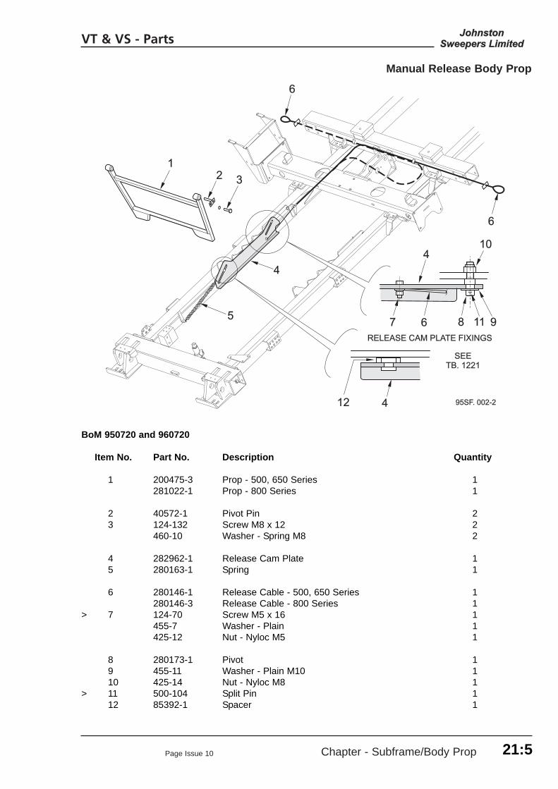
Manual Release Body Prop
VT & VS - Parts
95SF95SF. 002-2. 002-2
66
77
441212
66 88 1111 99
101044
44
55
66
1122 33
RELEASE CAM PLARELEASE CAM PLATE FIXINGSTE FIXINGS
SEESEETB. 1221TB. 1221
BoM 950720 and 960720
Item No. Part No. Description Quantity
1 200475-3 Prop - 500, 650 Series 1281022-1 Prop - 800 Series 1
2 40572-1 Pivot Pin 23 124-132 Screw M8 x 12 2
460-10 Washer - Spring M8 2
4 282962-1 Release Cam Plate 15 280163-1 Spring 1
6 280146-1 Release Cable - 500, 650 Series 1280146-3 Release Cable - 800 Series 1
> 7 124-70 Screw M5 x 16 1455-7 Washer - Plain 1425-12 Nut - Nyloc M5 1
8 280173-1 Pivot 19 455-11 Washer - Plain M10 110 425-14 Nut - Nyloc M8 1
> 11 500-104 Split Pin 112 85392-1 Spacer 1
21:5
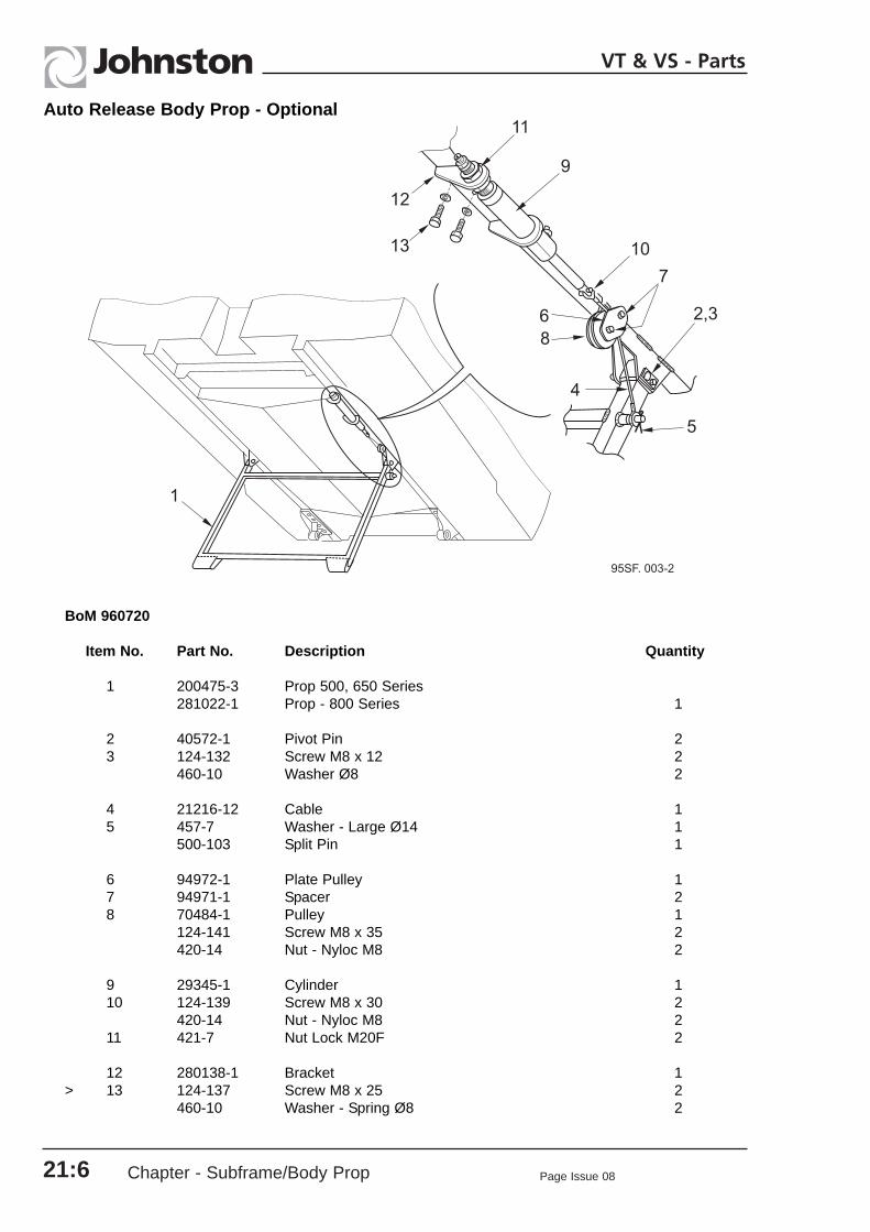
Chapter - Subframe/Body Prop Page Issue 0821:6
VT & VS - Parts
BoM 960720
Item No. Part No. Description Quantity
1 200475-3 Prop 500, 650 Series281022-1 Prop - 800 Series 1
2 40572-1 Pivot Pin 23 124-132 Screw M8 x 12 2
460-10 Washer Ø8 2
4 21216-12 Cable 15 457-7 Washer - Large Ø14 1
500-103 Split Pin 1
6 94972-1 Plate Pulley 17 94971-1 Spacer 28 70484-1 Pulley 1
124-141 Screw M8 x 35 2420-14 Nut - Nyloc M8 2
9 29345-1 Cylinder 110 124-139 Screw M8 x 30 2
420-14 Nut - Nyloc M8 211 421-7 Nut Lock M20F 2
12 280138-1 Bracket 1> 13 124-137 Screw M8 x 25 2
460-10 Washer - Spring Ø8 2
Auto Release Body Prop - Optional

Chapter - Powapak
CHAPTER 22Powapak
22:1
Table of Contents
VT / VS Section PageCommon Parts
Powapak Tub 22.CP : 1 Fan Case 22.CP : 1
VT SectionEngine Common Parts
Exhaust and Electrical Parts 22.EC : 1
Engine OptionsIveco Nat. Asp and Turbo 22.EI : 1 John Deere Turbo 22.EJ : 1Perkins Nat. Asp and Turbo 22.EP : 1
Transmission and ImpellerTransmission and Impeller 22.ET : 1
VS SectionHydroDrive Transmission
Gearbox and Selectors 22.HD : 1 Ancilliary Equipment 22.HD : 1Gearbox Installation 22.HD : 1
Hydrostatic Impeller Drive, Cooler and ControlsOil Cooler Assembly 22.HI : 1 Fan Drive Assembly 22.HI : 1HydroDrive Controls 22.HI : 1 Fan Tub 22.HI : 1
Page Issue 13
VT & VS - Parts

22:2 Chapter - Powapak Page Issue 08
VT & VS - Parts

Page Issue 10 Chapter - Powapak CP:1
VT & VS - Parts
22.
22.CPVT & VS Common Parts
Table of Contents
Section Page
Powapak TubPowapak Tub Assembly 22.CP : 2 3/4” Water Pump Feed Pipe Assembly 22.CP : 71” Water Pump Feed Pipe Assembly 22.CP : 8
Suction SystemFan Case and Impeller 22.CP : 10Fan Case Outlet Flap 22.CP : 12

Chapter - Powapak Page Issue 13CP:2
VT & VS - Parts
22.
Powapak Tub

Page Issue 10 Chapter - Powapak CP:3
Powapak Tub
VT & VS - Parts
22.
BoM 950512
Item No. Part No. Description Quantity
1 281283-1 Engine Beam - Front 12 281282-1 Engine Beam - Rear 1
3 281643-1 Deck Plate 14 281881-1 Hose Tray 15 124-134 Screw M8 x 16 6
460-10 Washer - Spring M8 6
6, 7 - Engine Front Cradle/Panel and Screws SeeChapter 22.ET(VT) and Chapter 22.HI(VS)
8 282375-1 Rear Engine Cradle 19 124-272 Screw M16 x 45 2
460-14 Washer - Spring M16 2
10 200510-1 Front Valance 111 124-169 Screw M10 x 25 6
425-15 Nut - Nyloc M10 6455-11 Washer - Plain M10 6
12 124-137 Screw M8 x 25 2455-10 Washer - Plain M8 2425-14 Nut - Nyloc M8 2
13 30-184 Reverse Alarm with Connector 1> 14 283229-6 Spacer 1
457-2 Washer - Large M6 2420-13 Nut - M6 1
15 287-12 Grommet 1
> 16 282818-1 Rear Valance 1> 17 124-169 Screw M10 x 25 6
455-11 Washer - Plain M10 618 124-137 Screw M8 x 25 2
455-10 Washer - Plain M8 2425-14 Nut - Nyloc M8 2
19 281698-1 Flap - Valance ) 120 720-1 Latch - Flap ) Superseded Items 121 42596-2 Hinge - Flap ) For Current Parts See 1
42591-2 Hinge Strip ) Chapter 22.ET(VT) 122 134-41 Screw M4 x 10 ) Chapter 22.HI(VS) 4
425-11 Nut - Nyloc M4 ) 4
23 288-11 Blind Grommet Ø5/8" 424 288-9 Blind Grommet Ø1/2" 4
25 - Systems Locker Assembly - See Chapter 23 126 124-135 Screw M8 x 20 7
425-14 Nut - Nyloc M6 4> 27 282340-2 190 Litre Fuel Tank 1

Chapter - Powapak Page Issue 13CP:4
VT & VS - Parts
22.
Powapak Tub

Page Issue 13 Chapter - Powapak CP:5
VT & VS - Parts
22.
Powapak Tub
Item No. Part No. Description Quantity
28 69-27 Locking Filler Cap (Large) 129 124-169 Screw M10 x 25 4
455-11 Washer - Plain M10 6425-15 Nut - Nyloc M10 4
30 124-167 Screw M10 x 20 2460-11 Washer - Spring M10 2
31 283323-1 Fuel Level Sender (Curtis) 1> 32 283324-1 Adaptor Plate - Curtis Sender 1> 33 66136-1 Gasket - Adaptor Plate 1
34 124-103 Screw M6 x 20 4460-8 Washer - Spring M6 4433-2 Clufix M6 4
35 521-8 Adaptor Elbow 236 510-4 Nut - Tubing Ø8 2
511-4 Sleeve - Tubing Ø8 237 39024 Tubing - Nylon Ø8 0.4
38 281902-1 Walkway 139 281600-1 Support Strip 240 211-12 Anti-slip Surface x 1240 Long 141 135-57 Screw - Button Head M8 x 20 9
425-14 Nut - Nyloc M8 9
42 7684-1 Plug G1/2" 1451-19 Washer - Sealing G1/2" 1
43 281610-1 Plate - Walkway 144 135-57 Screw - Button Head M8 x 20 3
457-4 Washer - Large Flat M8 3
45 282021-1 Powapack Services Loom 146 24-1 Cable Tie 5
47 282812-1 Water Pump Assembly 148 124-137 Screw M8 x 25 4
455-10 Washer - Plain M8 4
49 281669-1,2 Water Pump 1" Feed Pipe Assembly ) See Over 150 281670-1 Water System 3/4" Feed Pipe Assembly ) Page 1
51 3823 Collar Plug G3/8" ) 2451-18 Washer - Sealing ) 2VT Only

Chapter - Powapak Page Issue 08
VS - Parts
Powapak Tub
VS Only
Item No. Part No. Description Quantity
52 3823 Collar Plug G3/8" 2451-18 Washer - Sealing 2
53 3823 Collar Plug G3/8" ) ESU Units 2451-18 Washer - Sealing ) only 2
54 88-28 Tap R3/8” 2>
* 55 83-78 Elbow R1/2” for Ø8 Fuel Pipe 283-81 Elbow R3/8” for Ø10 Fuel Pipe 283-83 Elbow R3/8” for Ø12 Fuel Pipe 2
802776-1 Special Mercedes Adaptor G3/8” for 12mm I.D. Fuel Pipe 2
805931-1 Special MAN Adaptor M14 x M16 1805932-1 Special MAN Adaptor M14 x M18 1
Notes
* Item 55 lists a range of fittings required for various fuel pipe sizes - Select as required.The Fuel Pipe is that supplied with the chassis .
CP:622.

Page Issue 08 Chapter - Powapak CP:7
VT - Parts
95WC. 007-2
1
8
7
6
5
5
4
2
3
21
DECKPLATE - SEEPOWAPAK TUB
ASSEMBLY ITEM 3
BoM 950512
Item No. Part No. Description Quantity
281670-1 3/4" System Feed Pipe Assembly
1 277-130 Hose Tail 3/4" NB x G3/4" 22 277-148 ‘O’ Ring 23 277-133 Equal Tee 14 281668-1 PVC Pipe 15 277-164 Backnut G3/4" 26 277-160 Gasket 1 7 277-158 Hose Tail Flat Seat G3/4" 18 277-159 Flynut G3/4" 1
Notes
Use Loctite 5331 to seal thread marked †.Do not use PTFE (Teflon) based tape to seal other threads.To avoid breakage do not over tighten screwed fitting.
3/4” Water Pump Feed Pipe Assembly
22.

Chapter - Powapak Page Issue 10CP:8
VT & VS - Parts
22.
DECKPLATE - SEEPOWAPAK TUB
ASSEMBLY ITEM 3
1
2
3
4
5
6
7
5
95WC.006-4
1” Water Pump Feed Pipe Assembly
Use Loctite 5331 to seal thread marked †.Do not use PTFE (Teflon) based tape to seal other threads.To avoid breakage, do not over tighten screwed fitting.Ensure Check Valve (6) is fitted with flow indicating arrow pointing upwards as shown.

Page Issue 10 Chapter - Powapak CP:9
VT & VS - Parts
22.
1” Water Pump Feed Pipe Assembly
BoM 950512
Item No. Part No. Description Quantity
293280-2 1" Pump Feed Pipe Assembly
1 281667-1 Pipe - Water 1” 12 277-129 Elbow 1” BSP x 90° 13 277-149 ‘O’ Ring 14 277-125 Hosetail 1” BSP / 1” NB Hose 15 277-165 Backnut 1” 26 277-174 Check Valve 1” x 1” BSP 17 277-219 Hosetail 1” BSP 1
Notes
This current 1” Feed Pipe Assembly has been introduced to use common parts with the revisedSupawash Assembly shown in Chapter 30.SW.

Chapter - Powapak Page Issue 08CP:10
VT & VS - Parts
Suction System - Fan Case and Impeller
95FI. 00195FI. 001
THE DISTTHE DISTANCE BETWEEN THEANCE BETWEEN THETRANSITION RING (8) ANDTRANSITION RING (8) ANDFFAN (18) SHOULD BE 4mm.AN (18) SHOULD BE 4mm.ENSURE THE GAP IS EQUALENSURE THE GAP IS EQUALALL ROUND THE RING USINGALL ROUND THE RING USINGADJUSTER NUTS (12).ADJUSTER NUTS (12).
GEARBOXGEARBOX
66
99
44
1111 1212
1212
1010
1414
55
2121
66
77
77
1919
88
2020
2222
1212
1313
11
22
11
2222
1717
1616
1717
77
1515
88
33
22
2323
1818
1818
1818
22.

Page Issue 08 Chapter - Powapak CP:11
VT & VS - Parts
22.
Suction System - Fan Case and Impeller
BoM 950513
Item No. Part No. Description Quantity
Fan Case Common Parts
1 282390-1 Fan Case 12 124-169 Screw M10 x 25 4
455-11 Washer - Plain M10 4425-15 Nut - Nyloc M10 4
3 42239-2 Flange 14 42382-1 Diaphragm 15 124-137 Screw M8 x 25 12
425-14 Nut - Nyloc M8 12
6 93875-1 Fan Case Cover 17 124-135 Screw M8 x 20 10
460-10 Washer - Spring M8 10457-4 Washer - Extra Large M8 10
8 42401-1 Transition Ring 19 285-2 Spring - Compression 3
10 62770-1 Sleeve 311 457-5 Washer 312 425-15 Nut - Nyloc M10 3
455-11 Washer - Plain M10 3
13 42587-1 Cover Plate 1124-134 Screw M8 x 16 1460-10 Washer - Spring M8 1
14 42238-1 Access Cover 115 124-134 Screw M8 x 16 5
460-10 Washer - Spring M8 5
16 62407-1 Grab Handle 117 124-135 Screw M8 x 20 4
460-10 Washer - Spring M8 2426-4 Nut N8 2
Fan Case Variable Parts
18 - Suction Fan Impeller ) 19 - Spinner - Gearbox ) 20 - Impeller Retention )21 - Mask - Fan Case ) 22 - Screw - Special )
23 - Safety Flap Assembly - See next page 1
See 22.ET for VTSee 22.HI for VS

Chapter - Powapak Page Issue 08CP:12
VT & VS - Parts
22.
Fan Case Oulet Flap
95FI. 002
LUBRICATIONHOLE
2-3mm
7 8 9 19
2023
21
22
2
3
4
6
5
1
14
1013
11,12
1718
16
15
Ensure the outlet flap is correctly set - see below.
Safety Precautions
Setting Procedures
There should be 2-3mm of free play between the flap (1) and the angle stop inside the fan outlet, asshown, when the flap actuator (7) is fully depressed against the fan case seal face. Adjustment is madeby releasing the yoke end locknut (13) and rotating the actuation rod (14) to move the yoke end up or downthe rod as required. Having achieved the correct setting, retighten the locknut.

Page Issue 08 Chapter - Powapak CP:13
VT & VS - Parts
22.
Fan Case Outlet Flap
Item No. Part No. Description Quantity
282383-1 Safety Flap Assembly comprising:
1 42582-1 Safety Flap 12 42729-1 Rod - Pivot 13 29128-1 Bush 24 42728-1 Spacer 25 42723-1 Tab - Washer 26 124-134 Screw M8 x 16 4
7 42947-1 Flap - Actuator 18 42993-1 Actuator Rod 19 42992-1 U-Bolt 2
460-8 Washer - Spring M6 4420-13 Nut M6 4
10 42952-1 Actuator Flap 111 289-4 Yoke End 112 289-21 Pin - Spring 113 420-15 Locknut M10 114 42990-5 Actuation Rod 1
15 42986-1 Sleeve 116 42988-1 Clevis 117 29145-2 Pin - Clevis 118 39624 Spring Retaining Clip 1
19 80766-1 Tension Spring 120 123-108 Bolt M8 x 40 121 457-4 Washer - Plain M8 122 425-14 Nut - Nyloc M8 123 42586-1 Spacer 1
Notes

Chapter - Powapak Page Issue 08CP:14
VT & VS - Parts
22.

Page Issue 13 Chapter - Powapak EC:1
VT - Parts
22.
Table of Contents
Section Page
Exhaust Tail PipeTailpipe Installation 22.EC : 2
Electrical ItemsStarter and Earth Cables 22.EC : 3
Engine Common Parts
22.EC

Chapter - Powapak Page Issue 13
Tailpipe Installation
VT - Parts
BoM 950520 and 960520
Item No. Part No. Description Quantity
1 42649-3 Tailpipe - VT 500, 605 142649-1 Tailpipe - VT 650 1281946-1 Tailpipe - VT 800 1
2 200063-1 Support - VT 500, 605, 650 1281945-1 Support - VT 800 1
3 124-169 Screw M10 x 25 2455-11 Washer - Plain 2426-5 Nut - Philidas M10 2
4 6645-14 Exhaust Clamp 2 3/4” 15 42647-1 Heat Sheild 16 124-100 Screw M6 x 12 3
460-8 Washer - Spring 3
EC:222.

Page Issue 13 Chapter - Powapak EC:3
Starter and Earth Cables
VT - Parts
Drg. 807340
Item No. Part No. Description Quantity
1 92105-300 Starter Cable Ø8 x 3000 Long - Red 192105-301 Starter Cable Ø10 x 3010 Long - Red (Daf 12 - 8 only) 1
2 17936-305 Earth Cable 3050 Long - Black 1
282147-1 Chassis Interface Loom - ESU’s only (Not shown)
Notes
22.

Chapter - Powapak Page Issue 13
VT - Parts
EC:422.

Page Issue 12 Chapter - Powapak EI:1
VT - Parts
Iveco Engines
22.EI
22.
Table of Contents
Section Page
Nat. Asp and Turbo Engines - Common PartsDressed Engines and Spares Items 22.EI:2Combi Filter (Air Cleaner) Spare Parts 22.EI:4P.T.O. Pumps 22.EI:6Pump Installations 22.EI:7Powapak Common Parts 22.EI.8
Tier II Nat. Asp. EngineDressed Engine Parts and Spares Items 22.EI:10Throttle Actuator 22.EI:13Fuel Pre-Filter Installation 22.EI:14Radiator and Air Cleaner Installations 22.EI:15Engine Management Box 22.EI:16
Euro III Turbo EngineDressed Engine Parts and Spares Items 22.EI:18
> Fuel Pre-Filter Installation 22.EI:21Engine Management Box 22.EI:22
> Radiator and Heat Start Relay Installation 22.EI:24

EI:2 Chapter - Powapak Page Issue 12
VT - Parts
Iveco Nat. Asp. and Turbo Dressed Engines - Common Parts
Spares Items ‘S’ see end of parts list
22.

Page Issue 11 Chapter - Powapak EI:3
Iveco Nat. Asp. and Turbo Dressed Engines - Common Parts
VT - Parts
BoM 950511
Item No. Part No. Description Quantity
1 281448-1 L.H. Front Engine Mount 12 281448-2 R.H. Front Engine Mount 13 124-205 Screw M12 x 35 6
460-12 Washer - Spring 6
4 6953 Mount - Metacone 25 123-154 Bolt M12 x 80 2
460-12 Washer - Spring 2457-6 Washer - Plain 2
6 124-171 Screw M10 x 30 4460-11 Washer - Spring 4420-15 Nut M10 4
7 14-7 Bearing 18 42501-3 Fluid Coupling 19 129-127 Cap Head Screw M8 x 30 20
452-57 Washer - Plain 20
10 42270-1 Gearbox 111 123-131 Bolt M10 x 55 6
460-11 Washer - Spring 612 42299-1 Safety Cover 2
> 13 920000-32 Spacer - Plain 614 123-137 Bolt M10 x 85 6
460-11 Washer - Spring 6
15 HC08001-48 Hose 1/2” 116 263-4 Adaptor G 1/2” 1
451-19 Washer - Sealing 117 265-4 Adaptor G3/8” x 1/2” 1
451-18 Washer - Sealing G 3/8” 1
18 40525-1 Drain - Gearbox 119 124-167 Screw M10 x 20 1
460-11 Washer - Spring 1420-15 Nut M10 1
20 3823 Plug 3/8” BSP 1451-18 Washer - Sealing G 3/8” 1
21 281-7 Cooling Fan 122 281458-1 Cooling Fan Spacer 123 123-134 Bolt M10 x 70 4
460-11 Washer - Spring 4
24 282513-1 Adaptor M22 x 3/4” 1451-20 Washer - Sealing 1
25 HE12003-57 Hose 126 62903-1 Drain - Engine 127 7684-1 Collar Plug 1/2” BSP Brass 1
451-19 Washer Sealing 1
22.

Chapter - Powapak Page Issue 12
Iveco Nat. Asp. and Turbo Dressed Engines - Common Parts
VT - Parts
EI:4
Item No. Part No. Description Quantity
28 124-167 Screw M10 x 20 1460-11 Washer - Spring 1420-15 Nut M10 1
29 282034-3 Alternator Cable 1
Spares Items
S1 845-100 Oil FilterS2 845-103 Starter Motor 24vS3 845-104 Alternator 28v
> S4 - Flywheel845-159 Starter Ring Gear
Notes
22.

Page Issue 09 Chapter - Powapak EI:5
Combi Filter - Spares Items
VT - Parts
Item No. Part No. Description Quantity
280850-1 Combi Filter Assembly comprising:-
1 280850-2 Main Element 12 280850-3 Safety Element 13 280850-4 Housing 1
4 280850-5 Wing Bolt Kit - Metric5 280850-6 Element Nut Kit - Imperial
Notes
95AE. 019-2
2
3
4
45
1
22.

Chapter - Powapak Page Issue 09
Iveco P.T.O. Pumps
VT - Parts
22.EI:6
BoM 950514
Item No. Part No. Description QuantitySingle Tandem
1 239-39 Pump - Single 1 -239-40 Pump - Tandem - 1
2 263-8 Adaptor 1 1/4” 1 1451-111 Washer - Sealing 1 1/4” 1 1
3 262-8 Swivel Elbow 90° 1 1/4 1 14 263-4 Adaptor 1/2” 1 2
451-19 Washer - Sealing 1/2” 1 2
5 123-155 Bolt M12 x 85 2 2457-6 Washer - Plain 2 2460-12 Washer - Spring 2 2

22.Page Issue 09 Chapter - Powapak EI:7
Pump Installations - Iveco Engines
VT - Parts
95HC. 01895HC. 018
1313
22
1212
1111
1111
1010
22
11
11
44
33
SINGLESINGLEPUMPPUMP
TTANDEMANDEMPUMPPUMP
BoM 950514
Item No. Part No. Description Quantity Single Tandem
1* HX 20002-94 Suction Hose - Nat. Asp. Engine 1 1HX 20002-72 Suction Hose - Turbo Engine 1 1
2* HCO8002-108 Sweep Systems Hydraulic Hose 1 13* HCO8002-91 Auxiliary Systems Hydraulic Hose 1 14* HE12001-122 Tank Return Hydraulic Hose 1 1
5-9 -
10 - Hydraulic Tank - Covered else where in this chapter
11 264-4 1/2” Bulkhead Adaptor + Locknut 2 212 264-6 3/4” Bulkhead Adaptor + Locknut 1 113 262-6 Swivel Elbow 3/4” 1 1
Notes
*Hose item numbers correspond with those in Hydraulic diagrams SH521a01and SH531a01 in Chapter 8.

Chapter - Powapak Page Issue 13
Iveco Nat. Asp. and Turbo Engine Powapak - Common Parts
VT - Parts
EI:822.
See Section 22.EC forStarter and Earth Cables

Page Issue 09 Chapter - Powapak EI:9
Iveco Nat. Asp. and Turbo Engine Powapak Common Parts
VT - Parts
BoM 950511
Item No. Part No. Description Quantity
1 281475-1 Front Engine Cradle 12 124-272 Screw M16 x 45 2
460-14 Washer - Spring 2
3 281455-1 Radiator Shroud 14 124-167 Screw M10 x 20 2
460-11 Washer - Spring 25 124-167 Screw M10 x 20 2
425-15 Nut - Nyloc M10 2
6 280850-1 Combi - Filter 17 124-167 Screw M10 x 20 2
460-11 Washer - Spring 2
8 904-58 Adaptor - Restriction Pipe 19 904-56 Connector 110 904-55 Restriction Indicator 111 124-103 Screw M6 x 20 2
457-2 Washer - Plain 2425-13 Nut - Nyloc M6 2
12 12870 Tube - Black Nylon Ø8 x 0.8m 1
13 281418-1 Silencer - For Tailpipe etc., See Section 22:EE 114 281444-1 Mounting Bracket 115 124-135 Screw M8 x 20 2
460-10 Washer - Spring 2420-14 Nut M8 2
16 903-9 Mounting Band 117 124-135 Screw M8 x 20 2
460-10 Washer - Spring 2420-14 Nut M8 2
18 6645-12 Exhaust Clip 2 1/2” 3
19 281704-1 Heat Shield 120 124-97 Screw M6 x 6 4
457-2 Washer - Large 4
21 42421-3 Stud M10 x 65 122 42660-1 Spacer - Nylon 123 42661-1 Washer - Nylon 124 410-49 Nut - Brass M10 4
455-11 Washer - Plain 225 124-175 Screw M10 x 40 1
455-11 Washer - Plain 1420-15 Nut M10 2
26 281563-1 System Locker Cover Plate 127 124-134 Screw M8 x 16 4
460-10 Washer - Spring 428 217-2 Rubber Seal 1
22.

Chapter - Powapak Page Issue 12
Iveco Tier II Nat. Asp. Dressed Engine Parts and Spares Items
VT - Parts
EI:10
Spares Items ‘S’ see end of parts list
22.

Page Issue 12 Chapter - Powapak
Iveco Tier II Nat. Asp. Dressed Engine Parts and Spares Items
VT - Parts
BoM 950511
Item No. Part No. Description Quantity
1 282500-1 Engine - Iveco F4AE0407AD 24v NAT2
2 282460-1 L.H. Rear Engine Mount 13 282460-2 R.H. Rear Engine Mount 14 124-205 Screw M12 x 35 4
460-12 Washer Spring 45 22826-1 Mount - Metacone 26 123-154 Bolt M12 x 80 2
460-12 Washer - Spring 2457-6 Washer - Plain 2
7 124-171 Screw M10 x 30 4460-11 Washer - Spring 4420-15 Nut M10 4
8 282467-1 Radiator Hose - Top 19 501-5 Hose Clip 2
10 282468-1 Radiator Hose - Bottom 111 501-6 Hose Clip 2
12 282595-1 Exhaust Inlet 413 124-137 Screw M8 x 25 4
460-10 Washer - Spring 4
14 282667-1 Fuel Line - Feed 1501-30 Clip 1
15 282668-1 Fuel Line - Return 1501-30 Clip 1
16 664-8 Pipe Clamp 1” 1124-99 Screw M6 x 10 1460-8 Washer - Spring 1
17 282042-1 Engine Loom 118 496-P02 Breather Pipe 1
19 - Throttle Actuator - See over page 1> 20 845-162 Water Temperature Switch 1
KT00695 - Optional Oil Pressure / Water Temperature Gauge Pack
21 87-16 Oil Pressure Sender 1283215-1 Adaptor 180-43 ‘O’ Ring 1
22 87-54 Water Temperature Sender 1
282043-1 Gauge Sender Loom (Not Shown) 1
282740-1 Water Temp./ Oil Press. Gauge - See Powapak ControlPanels, Chapter 32
EI:1122.

Chapter - Powapak Page Issue 09
VT - Parts
EI:1222.
Iveco Tier II Nat. Asp. Dressed Engine Parts and Spares Items
Spares Items
S1 845-144 Fuel FilterS2 845-145 Thermostat
845-146 Thermostat SealS3 845-151 Oil Filler Cap
845-152 Oil Filler Seal
S4 845-147 Rocker Cover GasketS5 281942-1 Oil Pressure Switch
> 283215-1 Adaptor> 80-43 ‘O’ Ring
S6 845-158 Alternator/Fan Belt
Notes

Page Issue 13
Throttle Actuator - Iveco Tier II Nat. Asp. Engine
Chapter - Powapak EI:13
VT - Parts
Item No. Part No. Description Quantity
1 283150-1 Actuator Mount 12 124-167 Screw M10 x 20 2
460-11 Washer - Spring 2
> 3 281729-2 Actuator Assembly 24v 14 281707-1 Actuator Side Plate 15 42774-4 Spacer x 36 Long 16 124-102 Screw M6 x 16 4
460-8 Washer - Spring 47 455-8 Washer - Plain. Act as spacers between 3
Actuator/Mount and Actuator/Side Plate
8 281728-1 Throttle Cable 19 38-32 Solderless Nipple 3
22.

Chapter - Powapak Page Issue 10
VT - Parts
22.EI:14
BoM 950511
Item No. Part No. Description Quantity
1 42295-1 Mounting Plate 1
2 124-135 Screw M8 x 20 4425-14 Nut-Nyloc M8 4
3 15314-1 Pre-Filter 1
4 42683-4 Fuel Pipe 1> 5 25977-1 Nut - Sleeve 2
511-4 Olive 26 40448-1 Adaptor 1
451-17 Washer - Sealing 1510-4 Nut - Sleeve 1511-4 Olive 1
7 40448-1 Adaptor 1451-17 Washer - Sealing 1
Spares Items
S1 15314-1 Pre-Filter (Item 3)
1
95AE. 018
2
3
4
5
5
26
7
S1
Fuel Pre-Filter Installation - Iveco Tier II Nat. Asp. Engines

Page Issue 09 Chapter - Powapak
VT - Parts
EI:1522.
95AE. 017
9 87
9
8
21
10
6
3
4
2
5
BoM 950511
Powapak Parts
Item No. Part No. Description Quantity
1 281562-2 Walkway 12 281600-1 Support Strip 23 135-69 Screw - Button Head M8 x 25 9
455-10 Washer - Plain 4425-14 Nut - Nyloc M8 4
4 211-12 Anti - Slip Surface x 0.03m 1
5 200923-1 Radiator 16 124-166 Screw M10 x 16 4
460-11 Washer - Spring 4455-11 Washer - Plain 4
7 282516-1 Induction Pipe 18 903-11 Elbow 90° 29 501-8 Hose Clip 4
10 - Engine Management Box - See Over Page
Radiator and Air Cleaner Installations - Iveco Tier II Nat. Asp. Engine

Chapter - Powapak Page Issue 09
VT - Parts
EI:1622.
12
13
2
10
9
11
16 3 6 4,5
11 10
11 9
1
13 7
8
RS
RA R9 RB R0
FUSE
D26
D20 D23
D22
95EC.006-4
RF
8 7 6 5
1
2
3
4
RCT6
14 15
Engine Management Box - Iveco Tier II Nat. Asp. Engines
BoM 950511
Item No. Part No. Description Quantity
282134-1 Engine Management Box 24v comprising:-
1 282122-1 Box and Lid 1134-44 Screw Pan Head M4 x 20 4425-11 Nut-Nyloc M4 4
2 282125-1 Mounting Plate 1
3 710-67 HDP 31 Way Socket Housing 1710-70 Jam Nut 1281545-2 Sealing Washer 1
4 30-267 Fuse Holder 15 30-268 Midi Link 30 Amp 16 134-43 Screw M4 x 16 2
455-5 Washer Plain 2425-11 Nut Nyloc M4 2
*14 *15 *7

Page Issue 09 Chapter - Powapak EI:17
VT - Parts
22.
Item No. Part No. Description Quantity
* 7 48-89 Relay Base 612926 Relay 24 x Type 6RA 6
8 134-42 Screw Pan Head M4 x 12 2455-5 Washer - Plain 2425-11 Nut - Nyloc M4 2
9 30-256 4 Way Terminal Block 830-254 End Plate - Terminal Block 2
10 134-12 Screw Pan Head M3 x 10 4455-3 Washer - Plain 4425-10 Nut - Nyloc M3 4
11 13984 Diode 6 Amp 412 48-36 Relay 24v 113 134-42 Screw Pan Head M4 x 12 4
460-5 Washer - Spring 4420-11 Nut M4 4
* 14 13981 Timer Relay 12v 113982 Timer Relay 24v 113983 Relay Base 1
* 15 283198-1 Timer Relay Bracket 1
16 124-39 Screw M4 x 20 1460-5 Washer - Spring 1420-11 Nut M4 1455-5 Washer - Plain 1425-11 Nut Mylock M4 1
Notes
* Additional components. Item 7 - Relay RC, Item 14 - Relay T6 and Mounting Bracket 15 added.Refer to Technical Bulletin TB 1217 Issue 03.
Engine Management Box - Iveco Tier II Nat. Asp. Engines

Chapter - Powapak Page Issue 13
Iveco Euro III Turbo Dressed Engine Parts and Spares Items
VT - Parts
EI:18
Spares Items ‘S’ see end of parts list
22.

Page Issue 13 Chapter - Powapak
Iveco Euro III Turbo Dressed Engine Parts and Spares Items
VT - Parts
BoM 950511/005
Item No. Part No. Description Quantity
1 280888-1 Engine - Iveco F4AEO487AC 24v TCA E32 281450-1 L.H. Rear Engine Mount 13 281450-2 R.H. Rear Engine Mount 14 124-205 Screw M12 x 35 8
460-12 Washer - Spring 8
5 22826-1 Mount - Metacone 26 123-154 Bolt M12 x 80 2
460-12 Washer - Spring 2457-6 Washer - Plain 2
7 124-171 Screw M10 x 30 4460-11 Washer - Spring 4420-15 Nut M10 4
8 281506-1 Radiator Hose - Bottom 19 501-5 Hose Clip 2
10 281507-1 Radiator Hose - Top 111 501-6 Hose Clip 2
12 281561-1 CAC Hose 113 501-7 Hose Clip 2
14 281414-1 Turbocharger Charge Air Outlet Adaptor 115 281417-1 Exhaust Inlet Pipe 1
16 282031-1 Engine Loom 24v 1> 17 282034-4 Heat Start Cable - Red. See ‘Radiator and Heat Start’ 1
elsewhere in this section.18 282035-2 Heat Start Cable - Black 1
19 271-23 Cuff 220 501-6 Hose Clip 421 281480-1 Charge Air Pipe 122 281708-1 Pipe Support 1
23 124-166 Screw M10 x 16 2460-11 Washer - Spring 2
24 6645-12 Exhaust Clip 2 1/2” 1
25 904-51 Rubber Elbow 45o 1
26 501-7 Hose Clip 227 281415-1 Induction Air Tube 128 904-57 Rubber Elbow 90o 129 501-7 Hose Clip 1
30 497-P02 Hose 3/4” x 0.06 131 231-42 Elbow 3/4” 132 497-P02 Hose 3/4” x 0.45 1
EI:1922.

Chapter - Powapak Page Issue 12
VT - Parts
EI:2022.
Iveco Euro III Turbo Dressed Engine Parts and Spares Items
Item No. Part No. Description Quantity
33 281939-1 Bracket 134 124-99 Screw M6 x 10 3
460-8 Washer - Spring 3420-13 Nut M6 1
35 664-8 Pipe Clamp 1” 136 501-3 Hose Clip 4
Spares Items
S1 845-101 Fuel FilterS2 845-153 Thermostat
845-146 Thermostat SealS3 845-149 Oil Filler Cap
S4 845-150 Rocker Cover GasketS5 845-148 Oil Level DipstikS6 845-142 Alternator/Fan BeltS7 845-160 Water Temp. SensorS8 845-161 Oil Sensor
S9 845-108 ClampS10 845-109 ‘O’ Ring - Used with item 14
> S11 845-110 Clamp
S12 845-183 Blow-By Filter Kit
Notes

Page Issue 13 Chapter - Powapak EI:21
VT - Parts
22.
Fuel Pre-Filter Installation - Iveco Euro III Turbo Engine
66
1010
88
99
77
5533
44
22
11 95AE. 01395AE. 013
S1S1
BoM 950511/005
Item No. Part No. Description Quantity
> 1 281487-1 Suction Pipe 12 451-17 Washer - Sealing 1/4” BSP 13 282488-1 Fuel Hose 14 277-85 Straight Connector x Ø10 1
5 42683-3 Return Pipe 16 40448-1 Adaptor 1/4” BSP x Ø8 1
451-17 Washer - Sealing 1/4” BSP 1510-4 Tubing Nut Ø8 1511-4 Tubing Sleeve Ø8 1
7 277-48 Straight Connector x Ø8 1
8 281470-1 Mounting Plate 19 124-135 Screw M8 x 20 2
460-10 Washer - Spring 2420-14 Nut M8 2
10 124-139 Screw M8 x30 2460-10 Washer Spring 2420-14 Nut M8 2
Spares Items
SI 845-102 Fuel Pre-Filter

Chapter - Powapak Page Issue 09
VT - Parts
BoM 950511
Item No. Part No. Description Quantity
282120-1 Engine Management Box 24v comprising:-
1 282122-1 Box and Lid 1134-44 Screw Pan Head M4 x 20 4425-11 Nut - Nyloc M4 4
2 282133-1 Mounting Plate 1
3 845-16 Diagnostic Connector 14 134-13 Screw Pan Head M3 x12 4
455-3 Washer - Plain 4420-10 Nut M3 4
5 30-256 4 Way Terminal Block 230-254 End Plate 2
6 134-13 Screw Pan Head M3 x 12 2455 - 3 Washer - Plain 2420-10 Nut M3 2
Engine Management Box - Iveco Euro III Turbo Engine
22.EI:22

Page Issue 09 Chapter - Powapak EI:23
VT - Parts
Item No. Part No. Description Quantity
7 282130-1 Resistor Board 130-280 Board Support 430-281 Snap Rivet 4
8 13194 Relay 24v - Model 6RA 39 181-4 Screw Pan Head M5 x 12 3
455-7 Washer - Plain 3420-12 Nut M5 3
10 48-36 Relay 111 13984 Diode 6 Amp 1
12 30-279 Fuse Holder 113 134-42 Screw Pan Head M4 x 12 2
455-5 Washer - Plain 2420-11 Nut M4 2
14 30-99 Fuse 30 Amp 115 30-45 Fuse 15 Amp 216 30-93 Fuse 5 Amp 2
17 124-45 Screw M4 x 35 1460-5 Washer - Spring 1455-5 Washer - Plain 1420-11 Nut M4 1425-11 Nut-Nyloc 1
Notes
Engine Management Box - Iveco Euro III Turbo Engine
22.

EI:24 Chapter - Powapak Page Issue 13
VT - Parts
22.
Radiator and Heat Start Relay - Iveco Euro III Turbo Engine
BoM 950511
Powapak Parts
Item No. Part No. Description Quantity
1 281562-1 Walkway 12 281600-1 Support Strip 23 135-69 Screw - Button Head M8 x 25 9
455-10 Washer - Plain 4425-14 Nut - Nyloc M8 4
4 211-12 Anti-slip Surface x 0.03m 1
5 281570-1 Radiator / Intercooler 16 124-166 Screw M10 x 16 4
460-11 Washer - Spring 4
Dressed Engine Parts
7 282120-1 Engine Management Box 24v - See Previous Pages 1134-44 Screw Pan Head M4 x 20 4425-11 Nut - Nyloc M4 4

Page Issue 13 Chapter - Powapak EI:25
Radiator and Heat Start Relay - Iveco Euro III Turbo Engine
VT - Parts
BoM 950511
Item No. Part No. Description Quantity
8 282034-3 Heat Start Cable - Red x 500 Long 19 845-139 Heat Start ‘Intelligent’ Relay 1
10 845-140 ‘Intelligent’ Relay Loom 111 845-141 Cover 1
12 282034-4 Heat Start Cable - Red x 2500 Long ) See Notes 113 282035-2 Heat Start Cable - Black ) below 1
Spares Items
S1 845-139 Heat Start ‘Intelligent’ Relay (Item 9)
Notes
Items 12 and 13, see ‘Dressed Engine Parts and Spares Items’ elsewhere in this section, items 17 and 18 respectively.
22.

Chapter - Powapak Page Issue 12
VT - Parts
EI:2622.

Page Issue 09 Chapter - Powapak EJ:1
VT - Parts
Table of Contents
Section Page
EngineDressed ‘LP’ and ‘HP’ Engines 22.EJ : 2‘LP’ Throttle Actuator 22.EJ : 7P.T.O. Pumps - Current 22.EJ : 8Pump Installations - Current 22.EJ : 9‘LP’ Engine Management Box 22.EJ : 10‘HP’ Engine Management Box 22.EJ : 12
PowapaksPowapak Parts 22.EJ : 14Air Cleaner Installation 22.EJ : 18
Superseded PartsTandem P.T.O. Pump 22.EJ : 22 Tandem P.T.O. Pump Installation 22.EJ : 23
John Deere Engines
22.EJ
22.

95AE. 007
43
49
50
1
3029
36 35 34
9
10
11
12
13
3
7 5
46
31 32
33
39,40
2930
48
52
51
24
5
6
7
37
39
42
40
41
38
8
10
11
12
13
4344 46
4547
21 22
23
2425
2627
14
15 16
18 19
20
28
17
S2
S1
53
54
Chapter - Powapak Page Issue 09
John Deere ‘LP’ and ‘HP’ Dressed Engines - Common PartsThe ‘LP’ Engine can be identified by having a Throttle Actuator as shown on page 22.EJ:7The ‘HP’ Engine is controlled electronically by an ECU unit
VT - Parts
EJ:2
Spares Items ‘S’ see end of parts list
22.

Page Issue 11 Chapter - Powapak EJ:3
VT - Parts
John Deere ‘LP’ and ‘HP’ Dressed Engines - Common Parts
BoM 950511
Item No. Part No. Description Quantity
1 282420-1 ‘LP’ Engine - John Deere 4045TF 270 12v TC LP T2With Mechanically Controlled Fuel Injection
282860-1 ‘HP’ Engine - John Deere 4045TF 275 12v TC HP T2With Electronically Controlled Fuel Injection
2 280150-4 Bracket - Engine Mounting LH Front 13 280150-2 Bracket - Engine Mounting RH Front 14 124-199 Screw M12 x 20 6
460-12 Washer - Spring 65 22826-1 Mount - Metacone 26 123-151 Bolt M12 x 65 2
457-6 Washer - Plain 2460-12 Washer - Spring 2
7 124-171 Screw M10 x 30 4460-11 Washer-Spring 4420-15 Nut M10 4
8 280135-1 Bracket-Engine Mounting LH Rear 19 280135-2 Bracket-Engine Mounting RH Rear 110 124-199 Screw M12 x 20 8
460-12 Washer - Spring 811 22826-1 Mount Metacone 212 123-152 Bolt M12 x 70 2
457-6 Washer - Plain 2460-12 Washer - Spring 2
13 124-171 Screw M10 x 30 4460-11 Washer-Spring 4420-15 Nut M10 4
14 14-7 Bearing 177-39 Shaft Oil Seal 1
15 42501-2 Fluid Coupling - See Section 22.ET 116 129-98 Cap Head Screw M6 x 30 20
280149-1 Washer - Special 2017 63641-1 Transmission Ring Adaptor 1
18 42270-1 Gearbox - Fan Drive - See Section 22.ET 119 123-131 Bolt M10 x 55 6
460-11 Washer - Spring 620 42299-1 Safety Cover 2
> 21 920000-32 Spacer - Plain 622 123-137 Bolt M10 x 85 6
460-11 Washer - Spring 6
23 HC08001-48 Hose 1/2” - Megaflex straight 45os 124 263-4 Adaptor G1/2” 1
451-19 Washer - Sealing 1/2” 125 265-4 Adaptor G3/8” x 1/2” 1
451-18 Washer - Sealing G 3/8” 1
22.

Chapter - Powapak Page Issue 09
VT - Parts
EJ:4
95AE. 007
43
49
50
1
3029
36 35 34
9
10
11
12
13
3
7 5
46
31 32
33
39,40
2930
48
52
51
24
5
6
7
37
39
42
40
41
38
8
10
11
12
13
4344 46
4547
21 22
23
2425
2627
14
15 16
18 19
20
28
17
S2
S1
53
54
John Deere ‘LP’ and ‘HP’ Dressed Engines - Common PartsThe ‘LP’ Engine can be identified by having a Throttle Actuator as shown on page 22.EJ:7The ‘HP’ Engine is controlled electronically by an ECU unit
22.
Spares Items ‘S’ see end of parts list

Page Issue 09 Chapter - Powapak EJ:5
John Deere ‘LP’ and ‘HP’ Dressed Engines - Common Parts
VT - Parts
BoM 950511
Item No. Part No. Description Quantity
26 40525-1 Drain - Gearbox 127 124-167 Screw M10 x 20 1
460-11 Washer - Spring 1420-15 Nut M10 1
28 3823 Plug 3/8” BSP 1451-18 Washer - Sealing G 3/8” 1
29 280088-1 Hose - Radiator Inlet - Top 130 501-6 Hose Clip 231 280089-1 Hose - Radiator - Lower 132 501-6 Hose Clip 1
33 282041-1 ‘LP’ Engine Loom 1282048-1 ‘HP’ Engine Loom 1508-4 ‘P’ Clip 6
34 282044-1 Cable - Relay to Heat Start 135 281224-1 Starter Cable 136 281224-2 Earth Cable 1
37 282590-1 Temperature Switch 138 281942-1 Oil Pressure Switch 1
39 282587-1 Spacer - Cooling Fan 140 281-7 Cooling Fan 1
41 280153-1 Air Inlet Bracket 142 6645-21 Exhaust Clamp 3 5/8” 1
43 270-8 Adaptor M18 x 3/4” 1451-8 Washer - Sealing 1
44 HE12003-80 Hydraulic Hose 145 62903-1 Drain 146 7684-1 Collar Plug 1/2” BSP Brass 1
451-19 Washer - Sealing 147 124-167 Screw M10 x 20 1
460-11 Washer - Spring 1420-15 Nut M10 1
48 282585-1 Exhaust Inlet Pipe 149 282689-1 Fuel Suction Hose 1
> 50 848-24 Lift Pump Adaptor - ‘LP’ Engine only 1
51 282697-1 Adaptor G 1/4” 1848-21 Seal 1
52 282692-1 Fuel Return Hose 1
KT00695 - Optional Oil Pressure / Water Temperature Gauge Pack - ‘LP’ Engines only
53 87-16 Oil Pressure Sender 154 87-54 Water Temperature Sender 1
282043-1 Gauge Sender Loom (Not Shown) 1
22.

VT - Parts
Chapter - Powapak Page Issue 09
John Deere ‘LP’ and ‘HP’ Dressed Engines - Common Parts
EJ:622.
KT00695 - Optional Oil Pressure / Water Temperature Gauge Pack
Item No. Part No. Description Quantity
282740-1 Water Temp./ Oil Press. Gauge - See Powapak Control 1Panels, Chapter 32
Spares Items
S1 848-23 Fuel FilterS2 848-22 Oil Filter
Notes

Page Issue 09 Chapter - Powapak EJ:7
VT - Parts
95AE. 008
1
5
2
3
8
4
9
10
11
7
6
13
12
BoM 950511
Item No. Part No. Description Quantity
1 282643-1 Throttle lever 12 282645-1 Actuator Mount 13 124-263 Screw M16 x 20 2
460-14 Washes - Spring 2
> 4 281729-1 Throttle Actuator 12v 15 282644-1 Actuator Lever 16 281707-1 Actuator Side Plate 2
7 42774-4 Spacer x 36 1> 8 124-100 Screw M6 x 12 2
460-8 Washer - Spring 29 124-101 Screw M6 x 16 2
460-8 Washer Spring 2
10 281728-1 Throttle Cable 111 38-32 Solderless Nipple 3
> 12 837-47 Fork 1> 13 837-48 Pin 1
837-49 Split Pin 1
Throttle Actuator - John Deere ‘LP’ Engine Only
22.

Chapter - Powapak Page Issue 09
John Deere P.T.O. Pumps - Current
VT - Parts
22.
95HC. 019
44
32
3
2
1
1
Note
The previous 4 port Tandem Pumpand Pump Installation are shown inthe ‘Superseded Parts’ section at
the end of this chapter.
BoM 950514
Item No. Part No. Description QuantitySingle Tandem
1 239-27 Pump - Single 1 -239-34 Pump - Tandem - 1
2 263-8 Adaptor 1 1/4” 1 1451-111 Washer - Sealing 1 1/4” 1 1
3 263-4 Adaptor 1/2” 1 2451-19 Washer - Sealing 1/2” 1 2
4 123-152 Bolt M12 x 70 2 2457-6 Washer - Plain 2 2460-12 Washer - Spring 2 2
EJ:8

Page Issue 10 Chapter - Powapak EJ:9
Pump Installations, Current - John Deere Engines
VT - Parts
22.
BoM 950514
Item No. Part No. Description Quantity Single Tandem
1* HX 20002-175 Suction Hose 1 12* HC08000-114 Sweep Systems Hose 1 13* HC08002-170 Auxiliary Systems Hose - 14* HE12001-122 Tank Return Hose 1 1
5 601-7 Tee Adaptor 1 1/4” 1 16 262-6 Swivel Elbow 3/4” 1 17 264-4 1/2” Bulkhead Adaptor + Locknut 1 28 264-6 3/4” Bulkhead Adaptor + Locknut 1 19 508-12 ‘P’ Clip 1 1
Notes
* Hose numbers in circles correspond with those on Hydraulic diagrams SH521a01 and SH531a01 in Chapter 8.

Chapter - Powapak Page Issue 09
Engine Management Box - John Deere ‘LP’ Engine with Mechanically Controlled Fuel Injection Pump
VT - Parts
1122
1414
1212
12121212
1111
RSRS
RARA R9R9 RBRB R0R0
FUSEFUSE
D26D26
D22D22
D23D23
66 77
88
95EC.00495EC.004
1313
33 66 4,54,5
77
99
11
22
33
44
10101111
BoM 950511
Item No. Part No. Description Quantity
282137-1 Engine Management Box 12v Comprising:-
1 282122-1 Box and Lid 1134-44 Screw Pan Head M4 x 20 4425-11 Nut - Nyloc M4 4
2 282125-1 Mounting Plate 13 710-67 HDP 31 Way Socket Housing 1
710-70 Jam Nut 1281545-2 Sealing Washer 1
4 30-267 Fuse Holder 15 30-269 Midi Link 60 Amp 16 134-43 Screw M4 x 16 2
455-5 Washer Plain 2425-11 Nut Nyloc M4 2
7 48-89 Relay Base 4134-42 Screw Pan Head M4 x 12 4455-3 Washer Spring 4425-10 Nut M4 4
8 13193 Relay 4
22.EJ:10

Page Issue 09 Chapter - Powapak EJ:11
VT - Parts
Engine Management Box - John Deere ‘LP’ Enginewith Mechanically Controlled Fuel Injection Pump
Item No. Part No. Description Quantity
9 30-256 Terminal Block - 4 Way 430-254 Terminal Block - End Plate 1
10 30-256 Terminal Block - 4 Way 230-254 Terminal Block - End Plate 1
11 134-12 Screw Pan Head M3 x 10 4455-3 Washer Plain 4425-10 Nut - Nyloc M3 4
12 13984 Diode 6 Amp 313 48-34 Relay 2
134-42 Screw Pan Head M4 x 12 4455-3 Washer Spring 4425-10 Nut M4 4
14 134-59 Screw Plan Head M5 x 20 1420-12 Nut M5 1425-12 Nut - Nyloc M5 1460-7 Washer - Spring 1455-7 Washer - Plain 1
Notes
22.

Chapter - Powapak Page Issue 09
Engine Management Box - John Deere ‘HP’ Engine with Electronically Controlled Fuel Injection Pump
VT - Parts
EJ:1222.
95EC.004-3
RT1 RT2 RA
F2
F1
F3
DC
PE
PE
RS
PE
PR
EP
A
B
D26
D22
1234
12
15
1414171819
16
1
3
5
6
8
9
10
211
7
13
BoM 950511
Item No. Part No. Description Quantity
282138-1 Engine Management Box 12v Comprising:-
1 282122-1 Box and Lid 1134-44 Screw Pan Head M4 x 20 4425-11 Nut - Nyloc M4 4
2 282174-1 Mounting Plate 13 30-267 Midi Fuse Holder 1
30-269 Midi Fuse Link - 60 Amp 1425-11 Nut - Nyloc M4 1
4 134-43 Screw M4 x 16 2455-5 Washer Plain 2425-11 Nut Nyloc M4 2
5 30-95 Blade Fuse - 10 Amp Red 2

Page Issue 09 Chapter - Powapak EJ:13
Engine Management Box - John Deere ‘HP’ Engine with Electronically Controlled Fuel Injection Pump
VT - Parts
22.
Item No. Part No. Description Quantity
6 124-35 Screw M4 x 10 2460-5 Washer - Plain 2420-11 Nut M4 2
7 134-13 Screw M3 x 12 4455-5 Washer - Plain 4425-10 Nut Nyloc M3 4
8 13193 Relay - 12v (Model 6RA) 39 134-42 Screw M4 x 12 3
455-5 Washer - Spring 3420-11 Nut M4 3
10 48-34 Relay - Green 111 282171-1 Resistor Board 1
30-280 Board Support 430-281 Snap Rivet 4
12 30-256 Terminal Block - 4 Way 213 30-254 Terminal Block - End Plate 114 13984 Diode - 6 Amp 215 134-13 Screw M3 x 12 2
455-5 Washer - Plain 2425-10 Nut Nyloc M3 2
16 124-39 Screw M4 x 20 117 420-11 Nut M4 1
460-5 Washer - Spring 118 455-5 Washer - Plain 119 425-11 Nut Nyloc M4 1
Notes

Chapter - Powapak Page Issue 13
VT - Parts
John Deere Powapak Parts
22.EJ:14
See Section 22.EC forStarter and Earth Cables

Page Issue 09 Chapter - Powapak EJ:15
VT - Parts
John Deere Powapak Parts
BoM 950511
Item No. Part No. Description Quantity
1 282425-1 Front Engine Cradle 12 124-272 Screw M16 x 45 2
460-14 Washer - Spring M16 2
3 282490-1 Radiator Shroud 14 124-167 Screw M10 x 20 2
460-11 Washer - Spring M10 25 124-169 Screw M10 x 25 2
425-15 Nut - Nyloc M10 2
6 200923-1 Radiator 17 124-166 Screw M10 x 16 4
460-11 Washer - Spring M10 4455-11 Washer - Plain M10 4
8 94523-1 Silencer - For Tailpipe etc. See sections 22.EE 19 281444-1 Mount - Silencer 110 124-135 Screw M8 x 20 2
460-10 Washer - Spring M8 2420-14 Nut M8 2
11 903-9 Mounting Band 112 124-135 Screw M8 x 20 2
460-10 Washer - Spring M8 2420-14 Nut M8 2
13 6645-12 Exhaust Clip 1
14 281704-2 Heat Shield 115 457-2 Washer - Large M6 4
124-100 Screw M6 x 12 4
16 - Air Filter and Prefilter Installation - Covered In This Section > 17 - Engine Management Box - See Previous Pages
18 48-271 Heat Start Relay 1124-101 Screw M6 x 16 2455-8 Washer - Plain 2425-8 Nut - Nyloc M6 2
19 282605-1 Walkway 120 281600-1 Support Strip 221 135-69 Screw - Button Head M8 x 25 9
455-10 Washer - Plain M8 4425-14 Nut - Nyloc M8 4
> 22 211-12 Anti-slip Surface x 1240 Long 1
23 282629-1 Plate - Pre-Filter Mounting 124 124-134 Screw M8 x 16 2
455-10 Washer Plain 2425-14 Nut - Nyloc M8 2
22.

Chapter - Powapak Page Issue 13
John Deere Powapak Parts
VT - Parts
EJ:1622.
See Section 22.EC forStarter and Earth Cables

Page Issue 12 Chapter - Powapak EJ:17
VT - Parts
John Deere Powapak Parts
BoM 950511
Item No. Part No. Description Quantity
25 80-40 ‘O’ Ring 226 282696-1 Suction Pipe 1
451-17 Washer - Sealing 1/4” BSP 1> 27 282691-1 Fuel Suction Hose with Adaptor 1
28 42421-3 Stud M10 x 65 129 42660-1 Spacer - Nylon 130 42661-1 Washer - Nylon 131 455-11 Washer - Plain M10 2
410-49 Nut - Brass M10 432 282034-1 Heat Start Cable - Power to Relay (18) 1
33 124-175 Screw M10 x 40 - Earthing Point 1455-11 Washer - Plain M10 1420-15 Nut M10 2
34 282586-1 Systems Locker Cover Plate 135 124-134 Screw M8 x 16 4
460-10 Washer - Spring M8 436 217-2 Rubber Seal 455 Long 2
37 904-55 Restriction Indicator - 7.5kPa 1
Notes
22.

Chapter - Powapak Page Issue 09
VT - Parts
Air Cleaner Installation
95AE. 00995AE. 009
2244
88
9977 66
33
55
2525
23232626
2626
2424
2222
2626
2121
2626
1010
1515
1414
1313
1212
1111
2020
161617171818
1919
11
S1S1
S2S2
22.EJ:18

Page Issue 09 Chapter - Powapak EJ:19
VT - Parts
BoM 950511
Item No. Part No. Description Quantity
1 281048-1 Air Filter Mount Assembly comprising items 2 - 9:-2 280125-1 Mounting Bracket 13 281047-1 Pivot Bracket 14 436-10 Catch 15 134-44 Screw M4 x 20 Pan Head 8
455-5 Washer Plain 8425-11 Nut - Nyloc M4 8
6 124-135 Screw M8 x 20 27 441-1 Screw M8 x 4 Insert 28 425-14 Nut - Nyloc M8 29 455-10 Washer Plain 4
10 94954-1 Air Cleaner 111 124-135 Screw M8 x 20 4
460-10 Washer - Spring 412 904-58 Adaptor 1
13 904-23 Pre Cleaner 114 282497-1 Securing Ring 115 123-98 Bolt M6 X 100 3
455-8 Washer - Plain 6425-13 Nut - Nyloc M6 3
16 904-56 Connector 1
17 124-103 Screw M6 x 20 2457-2 Washe - Plain 2425-13 Nut - Nyloc M6 2
18 904-55 Restriction Indicator - 7.5kPa 119 12870 Tube - Black Nylon 8 O/D x 0.8 1
20 276-13 Flexible Ducting 121 61096-3 Elbow - Rubber 122 280154-1 Pipe - Air Inlet 123 904-12 Elbow 3 1/2” 124 280156-1 Elbow - Air Inlet 125 61096-3 Elbow - Rubber 126 501-8 Hose Clip 6
Spares Items
S1 61026-3 Safety ElementS2 94954-2 Main Element
Air Cleaner Installation
22.

Chapter - Powapak Page Issue 09
VT - Parts
22.EJ:20

Page Issue 09 Chapter - Powapak EJ:21
VT - Parts
Superseded Parts
Table of Contents
Section Page
Tandem P.T.O. Pump 22.EJ:22 Tandem P.T.O. Pump Installation 22.EJ:23
22.

Chapter - Powapak Page Issue 09
Tandem P.T.O. Pump - Superseded
VT - Parts
EJ:22
95HC. 019-2
4
3 3
2 2
1
BoM 950514
Item No. Part No. Description Quantity
1 239-28 Pump - Tandem 1
2 263-8 Adaptor 1 1/4” 2451-111 Washer - Sealing 1 1/4” 2
3 263-4 Adaptor 1/2” 2451-19 Washer - Sealing 1/2” 2
4 123-152 Bolt M12 x 70 2457-6 Washer - Plain 2460-12 Washer - Spring 2
Notes
22.

Page Issue 10 Chapter - Powapak EJ:23
Tandem P.T.O. Pump Installation - Superseded
VT - Parts
BoM 950514
Item No. Part No. Description Quantity
1* HX 20002-175 Suction Hose 12* HC08000-114 Sweep Systems Hose 13* HC08002-170 Auxiliary Systems Hose 14* HE12001-122 Tank Return Hose 1
282886-1 Twin to Common Conversion Kit comprising items 5 to 10:-
5 601-7 Tee Adaptor 1 1/4” 16 265-16 Reducer Adaptor 1 1/4” x 3/4” 27 262-6 Elbow 3/4” 18 HE12003-26 Hydraulic Hose 3/4” 19 HE12003-33 Hydraulic Hose 3/4” 1
10 263-6 Adaptor 3/4” 2451-21 Washer - Sealing 2
11 262-8 Swivel Elbow 1 1/4” 112 264-4 1/2” Bulkhead Adaptor + Locknut 213 264-6 3/4” Bulkhead Adaptor + Locknut 114 262-6 Swivel Elbow 3/4” 1
22.

Chapter - Powapak Page Issue 09
VT - Parts
EJ:2422.

Page Issue 08 Chapter - Powapak EP:1
VT - Parts
Table of Contents
Section Page
Nat Asp. and Turbo Engines - Common PartsDressed Engines 22.EP : 2Throttle Actuator 22.EP : 5P.T.O. Pumps 22.EP : 6Pump Installations 22.EP : 7Powapak Common Parts 22.EP : 8Engine Management Box 22.EP : 12
Nat Asp and Turbo Engines - Variable PartsDressed Engines 22.EP : 14Nat. Asp Air Cleaner Installation and Cooling Fan Adaptor 22.EP : 16Turbo Air Cleaner Installation 22.EP : 17
Perkins Engines
22.EP
22.

Chapter - Powapak Page Issue 12EP:2
Perkins Nat. Asp. and Turbo Dressed Engines - Common Parts
VT - Parts
22.
Spares Items ‘S’ see end of parts list

Page Issue 12 Chapter - Powapak EP:3
Perkins Nat. Asp. and Turbo Dressed Engines - Common Parts
VT - Parts
BoM 950511
Item No. Part No. Description Quantity
1 280080-2 Engine - Perkins NA 1004-40 12v EPA280080-1 Engine - Perkins NA 1004-40 24v EPA94581-2 Engine - Perkins TC 1004-40T 12v EPA94581-1 Engine - Perkins TC 1004-40T 24v EPA
2 42181-2 Bracket - Engine Mounting, Front 23 6953 Mounting - Metacone, Front 24 123-154 Bolt M12 x 80 2
457-6 Washer - Plain M12 2460-12 Washer - Spring M12 2
5 124-171 Screw M10 x 30 8455-11 Washer - Plain M10 8425-15 Nut - Nyloc M10 8
6 63536-1 Mount - Engine Throttle 17 42645-2 Mount - Engine Rear 18 124-201 Screw M12 x 25 8
457-6 Washer - Plain M12 89 22826-1 Mounting, Metacone, Rear 210 123-153 Bolt M12 x 75 2
457-6 Washer - Plain M12 2460-12 Washer - Spring 2
11 14-7 Bearing 112 42501-3 Coupling - Fluid, See Notes on next page 113 129-127 Screw Cap Socket Head M8 x 30 20
455-10 Washer - Plain M8 20
14 42270-1 Gearbox - Fan Drive, See Notes on next page 115 124-169 Screw M10 x 25 6
460-11 Washer - Spring M10 616 42299-1 Safety Cover 217 920000-32 Spacer - Plain 418 124-177 Screw M10 x 50 4
460-10 Washer - Spring M8 4
19 HC08001-48 Hose 1/2" - Megaflex Straight 45°s 120 263-4 Adaptor G1/2" 1
451-19 Washer - Sealing G1/2" 121 265-4 Adaptor G3/8" x 1/2" 1
451-18 Washer - Sealing G3/8" 1
22 40525-1 Drain - Gearbox 123 124-167 Setscrew M10 x 20 1
460-11 Washer - Spring M10 1420-15 Nut M10 1
24 3823 Plug G3/8" 1451-18 Washer - Sealing G3/8” 1
25 42657-1 Hose - Radiator Inlet - Top 126 501-6 Hose Clip 2
22.

Chapter - Powapak Page Issue 12EP:4
Perkins Nat.Asp. and Turbo Dressed Engines - Common Parts
VT - Parts
BoM 950511
Item No. Part No. Description Quantity
27 42656-1 Hose - Radiator Lower 128 501-6 Hose Clip 229 281941-1 Switch - Temperature 130 281942-1 Switch - Oil Pressure 1
31 HE12002-69 Hose - Hydraulic 3/4" Straight x 90°s 132 263-6 Adaptor 133 62903-1 Drain - Engine 134 7684-1 Plug - Collar G1/2" Brass 1
451-19 Washer - Sealing G1/2" 135 124-167 Screw M10 x 20 1
425-15 Nut - Nyloc M10 1455-11 Washer - Plain M10 1
36 533-254 Braided Tube 137 25977-1 Nut - Sleeve 1
511-4 Olive - Tube 8mm O/D 1> 38 282255-1 Braided Tube 1
39 518-7 Adaptor 6 OD x G1/4" 1451-17 Washer - Sealing G1/4" 1
40 282040-1 Engine Loom 12v 1282030-1 Engine Loom 24v 1
41 508-4 ‘P’ Clip 542 24-1 Cable Tie 1043 92105-60 Starter Cable 144 17936-61 Earth Cable 1
45 - Throttle Actuator - See Next Page
Spares Items
S1 837-7 Fuel FilterS2 837-11 Oil FilterS3 280-5 Alternator/Fan BeltS4 653-22 Starter Motor 12v
653-10 Starter Motor 24vS5 12017 Cold Start ResistorS6 838-55 Heat Start SwitchS7 837-67 ESOS ValveS8 653-208 Alternator 12v
653-14 Alternator 24vS9 837-136 ThermostatS10 837-138 Rocker Cover Filler Cap - Nat. Asp. Engine Only
> S11 837-19 Flywheel> S12 221-3 Cover Seal - six off
Notes
Item 12, Fluid Coupling, and Item 14, Fan Drive Gearbox are detailed elsewhere in this Chapter
22.

Page Issue 08 Chapter - Powapak EP:5
Throttle Actuator Installation - Perkins Nat. Asp. and Turbo Engines
VT - Parts
95AE. 00595AE. 005
22
1133
44
55
55
66
77
88
99
1010
Item No. Part No. Description Quantity
281727-1 12v Actuator Assembly281727-2 24v Actuator Assembly
1 281729-1 Actuator 12v 1281729-2 Actuator 24v 1
2 281612-1 Actuator Bracket 13 281707-1 Side Plate 14 42774-4 Spacer - 36 Long 15 124-100 Screw M6 x 12 4
460-8 Washer - Spring M6 46 124-137 Screw M8 x 25 2
425-14 Nut - Nyloc M8 2
7 281728-1 Throttle Cable 18 38-32 Solderless Nipple 39 Ref. Lever, Pin and Split Pin10 Ref. LH Rear Engine Mount
22.

Chapter - Powapak Page Issue 08EP:6
Perkins P.T.O. Pumps
VT - Parts
22.
95HC. 00495HC. 004
22
55
66
44
55
99
88
1010 1111
1212
99
77
55
11
33
66
BoM 950514
Item No. Part No. Description QuantitySingle Tandem
1 239-2 Pump - Single 1 -2 239-38 Pump - Tandem - 13 265-16 Adaptor 3/4" x 1 1/4" 1 -
451-21 Washer - Sealing 3/4" 1 -
4 263-8 Adaptor 1 1/4" - 1451-111 Washer - Sealing 1 1/4" - 1
5 263-4 Adaptor 1/2" 1 2451-19 Washer - Sealing 1/2" 1 2
6 262-8 Swivel Elbow 1 1/4" x 90° 1 17 123-104 Bolt M8 x 30 5 58 123-114 Bolt M8 x 70 1 19 455-10 Washer - Plain M8 6 6
Pump Spares
10 12785-1 Gear 1 153-8 Key (not shown) 1 1
11 420-16 Nut 1 1460-12 Tab Washer 1 1
12 N.S.S. ‘O’ Ring 1 1

Page Issue 08 Chapter - Powapak EP:7
Pump Installations - Perkins Engines
VT - Parts
22.
95HC. 00595HC. 005
1313
22
11
1212
1111
1111
1010
22
11
44
33
SINGLE PUMPSINGLE PUMP
TTANDEMANDEMPUMPPUMP
BoM 950514
Item No. Part No. Description QuantitySingle Tandem
1 * HX20002-72 Hydraulic Hose - Suction 1 12 * HC08002-73 Hydraulic Hose - Sweep System 1 13 * HC08002-64 Hydraulic Hose - Auxiliary Systems - 14 * HE12001-122 Hydraulic Hose - Tank Return 1 1
5 - 9 -
10 - Hydraulic Tank - Covered elsewhere in this chapter 1 1
11 264-4 1/2" Bulkhead Adaptor + Locknut 2 212 264-6 3/4" Bulkhead Adaptor + Locknut 1 113 262-6 Swivel Elbow 90° 1 1
Notes
* Hose item numbers correspond with those in Hydraulic diagrams SH521a01 and SH531a01 in Chapter 8

Chapter - Powapak Page Issue 13EP:8
Perkins Nat. Asp. and Turbo Engine Powapak - Common Parts
VT - Parts
22.
Note: See Section 22.EC for Starter and Earth Cables

Page Issue 08 Chapter - Powapak EP:9
Perkins Nat. Asp. and Turbo Engine Powapak - Common Parts
VT - Parts
BoM 950511
Item No. Part No. Description Quantity
1 281678-1 Front Engine Cradle 12 124-272 Screw M16 x 45 2
460-14 Washer - Spring M16 2
3 281710-1 Radiator Shroud 14 124-167 Screw M10 x 20 2
460-11 Washer - Spring M10 25 124-169 Screw M10 x 25 2
425-15 Nut - Nyloc M10 2
6 61028-1 Radiator 17 124-166 Screw M10 x 16 4
460-11 Washer - Spring M10 4455-11 Washer - Plain M10 4
8 61024-1 Silencer - For Tailpipe etc. See Section 22.EE 19 61022-1 Mount - Silencer 110 124-135 Screw M8 x 20 2
460-10 Washer - Spring M8 2420-14 Nut M8 2
11 61017-2 Mounting Band 112 124-135 Screw M8 x 20 2
460-10 Washer - Spring M8 2420-14 Nut M8 2
13 6645-14 Exhaust Clip 1
14 281701-1 Heat Shield 115 457-2 Washer - Large M6 4
124-100 Screw M6 x 12 4
16 280850-1 Combi-Filter - See Spares Items Over Page 117 124-167 Screw M10 x 20 2
460-11 Washer - Spring M10 218 904-58 Adaptor - Restriction Pipe 1
19 200513-1 Walkway 120 281600-1 Support Strip 221 135-69 Screw - Button Head M8 x 25 9
455-10 Washer - Plain M8 4425-14 Nut - Nyloc M8 4
22 211-12 Anti-slip Surface 0.03M
23 42295-1 Plate - Pre-Filter Mounting 124 124-135 Screw M8 x 20 2
425-14 Nut - Nyloc M8 225 15314 Pre-Filter 126 124-135 Screw M8 x 20 2
425-14 Nut M8 2
22.

Chapter - Powapak Page Issue 13EP:10
Perkins Nat. Asp. and Turbo Engine Powapak - Common Parts
VT - Parts
22.
Note: See Section 22.EC for Starter and Earth Cables

Page Issue 09 Chapter - Powapak EP:11
Perkins Nat. Asp. and Turbo Engine Powapak - Common Parts
VT - Parts
Item No. Part No. Description Quantity
27 42683-4 Fuel - Pipe 128 25977-1 Nut - Sleeve 1
511-4 Olive - Tube 8 O/D 129 510-4 Nut - Sleeve 130 40448-1 Adaptor 1
451-17 Washer - Sealing G1/4" 1510-4 Nut - Tube 8 O/D 1511-4 Olive - Tube O/D 1
31 263-2 Adaptor G1/4" 1451-17 Washer - Sealing G1/4" 1
32 904-56 Connector 133 124-103 Screw M6 x 20 2
457-2 Washer - Plain M6 2425-13 Nut - Nyloc M6 2
34 12870 Tube - Nylon Black 8 O/D 0.8M35 24-7 Cable Tie 2
36 42421-3 Stud M10 x 65 137 42660-1 Spacer - Nylon 138 42661-1 Washer - Nylon 139 455-11 Washer - Plain M10 2
410-49 Nut - Brass M10 4
40 124-175 Screw M10 x 40 1455-11 Washer - Plain M10 1420-15 Nut M10 2
41 200543-1 Systems Locker Cover Plate 142 124-134 Screw M8 x 16 4
460-10 Washer - Spring M8 443 217-2 Rubber Seal 455 Long 2
95AE. 019
Spares ItemsCombi-Filter (Item 16)
280850-3 Safety Filter
280850-4 Housing
280850-6 Element Nut Kit(Imperial Thread)
280850-5 Wing Bolt Kit(Metric Thread)
280850-2 Main Filter
22.

Chapter - Powapak Page Issue 08EP:12
VT - Parts
BoM 950511
Item No. Part No. Description Quantity12v 24v
282124-1 Engine Management Box 12v Comprising282124-2 Engine Management Box 24v items 1 to 11:
1 282122-1 Box and Lid 1 1134-44 Screw Pan Head M4 x 20 4 4425-11 Nut - Nyloc M4 4 4
2 282125-1 Mounting Plate 1 13 710-67 HDP 31 Way Socket Housing 1 1
710-70 Jam Nut 1 1281545-2 Sealing Washer 1 1
4 30-267 Fuse Holder 1 15 134-43 Screw M4 x 16 2 2
455-5 Washer Plain 2 2425-11 Nut Nyloc M4 2 2
6 48-89 Relay Base 4 4134-42 Screw Pan Head M4 x 12 4 4455-3 Washer Spring 4 4425-10 Nut M4 4 4
7 13194 Relay - 413193 Relay 4 -
Engine Management Box - Perkins Engines
22.

Page Issue 08 Chapter - Powapak EP:13
VT - Parts
Item No. Part No. Description Quantity12v 24v
8 30-256 Terminal Block - 4 Way 4 430-254 Terminal Block - End Plate 1 1
9 134-12 Screw Pan Head M3 x 10 2 2455-3 Washer Plain 2 2425-10 Nut - Nyloc M3 2 2
10 282126-1 Adaptor Block 1 -11 30-29 Resistor 10R 10 Watt - 112 134-42 Screw Pan Head M4 x 12 - 2
455-5 Washer - Plain - 2460-5 Washer - Spring - 2420-11 Nut M4 - 2
13 13984 Diode 6 Amp 3 214 48-36 Relay - 2
48-34 Relay 2 -134-42 Screw Pan Head M4 x 12 4 4455-3 Washer Spring 4 4425-10 Nut M4 4 4
15 134-59 Screw Pan Head M5 x 20 1 1420-12 Nut M5 1 1425-12 Nut - Nyloc M5 1 1460-7 Washer - Spring 1 1455-7 Washer - Plain 1 1
Notes
Engine Management Box - Perkins Engines
22.

Chapter - Powapak Page Issue 08EP:14
Perkins Nat. Asp. and Turbo Engine - Variable Parts
VT - Parts
22.

Page Issue 08 Chapter - Powapak EP:15
VT - Parts
Perkins Nat. Asp. and Turbo Engine - Variable Parts
BoM 950511
Item No. Part No. Description QuantityNat.Asp. Turbo
1 94952-1 Exhaust Inlet Pipe 1 -61025-1 Exhaust Inlet Pipe - 1
2 62478-1 Manifold - Oil Cooler - 1837-36 Gasket - 1
3 HF12022-116-225 Hydraulic Hose - 24 499-3 Adaptor G3/4" x SAE Ø7/8" - 2
451-20 Washer - Sealing Ø7/8" - 2
5 280841-1 Loom Routing Plate - Not Shown. Attaches toInlet Manifold Fixings. - 1
24-1 Cable Tie - 7
Notes
22.

Chapter - Powapak Page Issue 08EP:16
Air Cleaner Installation and Cooling Fan Adaptor - Perkins Nat. Asp. Engine
VT - Parts
4
95AE. 004
6
56
4
2
7
1
3
BoM 950511
Item No. Part No. Description Quantity
1 433-2 Rivet Nut M6 82 280184-1 Cooling Fan Adaptor 13 124-103 Screw M6 x 20 8
460-8 Washer - Spring M6 8
4 904-8 Elbow - Rubber 25 280848-1 Induction Elbow 16 501-7 Hose Clip 4
7 12188 Air Filter Restrictor - 5.5kPa 1
22.

Page Issue 08 Chapter - Powapak EP:17
Air Cleaner Installation - Perkins Turbo Engine
VT - Parts
3
4
2
1
95AE. 004-2
4
5
BoM 9510511
Item No. Part No. Description Quantity
1 904-9 Hose - Hump 12 281025-1 Induction Air Pipe 13 271-25 Elbow 14 501-7 Hose Clip 4
5 904-55 Air Filter Restrictor - 7.5kPa 1
22.

Chapter - Powapak Page Issue 08EP:18
VT - Parts
22.

Page Issue 08 Chapter - Powapak ET:1
VT - Parts
Table of Contents
Section Page
TransmissionFluid Coupling 22.ET : 2Fan Drive Gearbox 22.ET : 4
Suction SystemFan Case Installation and Impeller 22.ET : 6
Powapak TubTub - VT Parts Only 22.ET : 7
Transmission, Impeller and Powapak Tub
22.ET
22.

Chapter - Powapak Page Issue 12ET:2
VT - Parts
22.
Fluid Coupling

Page Issue 12 Chapter - Powapak ET:3
VT - Parts
22.
Item No. Part No. Description Quantity
* 1 - Flywheel ) 1* 2 - End Cover Seal ) 6
3,4,5 Covered in Dressed Engine Sections>
6 - Gearbox - See next page 1
7 42501-2 Fluid Coupling - John Deere 142501-3 Fluid Coupling - Iveco and Perkins 1
8 77-39 Rotary Seal 19 656-1 ‘O’ Ring 1
10 656-2 ‘O’ Ring 111 656-3 Fusible Plug 112 656-4 Circlip - External 213 656-5 Circlip - External 114 656-6 Circlip - Internal 1
15 656-7 Bearing 116 656-8 Oil Seal 117 656-9 Gasket 118 656-10 Impeller Inner 119 656-12 Centre Hub 120 656-13 Bearing Carrier 121 656-14 Screw 12
42501-500 Overhaul Kit Comprising Items:- > 2, 4, 8, 9, 10, 11, 12, 13, 14, 15, 16, 17
Notes
On assembly, coat internal spline of Item 19 with Kluber Paste 46MR410, JSL Part No. 94-24
> * Items 1 & 2, ‘’See Perkins Dressed Engines - Common Parts’’
Fluid Coupling
Perkins Parts Shown

Chapter - Powapak Page Issue 08ET:4
VT - Parts
22.
Item No. Part No. Description Quantity
42270-1 Gearbox comprising: 1
2 42271-2 Casing - Gearbox 13 42272-2 Housing - Bearing 14 42466-1 Shaft - Input 15 42274-19 Shaft - Output 1
6 42275-34 Gear 17 42255-1 Cap - Bearing 18 42277-1 Plate - Cover 19 42278-1 Spacer 110 42279-1 Gasket 111 42280-1 Washer 1
Fan Drive Gearbox
95FG.00195FG.001
1010
882525
2424
2929
551313
2828
1717
1616
20201515
33
1111
3131
2323
7718181414 1919
25,2625,26
232328283131
24242727
22 21,2221,22
3030
1717
66
1212
99
44

Page Issue 12 Chapter - Powapak ET:5
VT - Parts
22.
Item No. Part No. Description Quantity
12 42281-1 Spacer 113 42283-1 Spacer 114 10-21 Bearing 115 10-22 Bearing 116 14-46 Bearing 1
17 77-21 Seal - Rotary 218 80-95 Seal - ‘O’ Ring 119 80-100 Seal - ‘O’ Ring 1
> 20 54-4 Plug - Collar 321 13109 Plug - Magnetic 1
22 451-126 Washer - Copper 123 121-41 Screw M10F x 25 624 124-137 Screw M8 x 25 1025 460-10 Washer - Spring M8 1626 124-143 Screw M8 x 40 6
27 457-4 Washer - Extra Large M8 228 42659-1 Tab Washer 229 16978-1 Breather 130 87-7 Oil Level Indicator 131 42282-2 Clamp Plate 2
Notes
Fan Drive Gearbox

Chapter - Powapak Page Issue 08ET:6
VT - Parts
Fan Case Installation and Impeller
22.
95FI. 001-295FI. 001-2GEARBOXGEARBOX
22
33
4,54,5
33
11
66 77
77
BoM 950513
Item No. Part No. Description Quantity
1 Fan Case and Fittings - See Section 22:CP2 42284-1 Mask - Fan Case 13 827-37 Screw - Special M8 x 20 4
4 280730-1 Suction Fan Impeller - Ø760 Nat. Asp. Engine 15 280830-1 Suction Fan Impeller - Ø800 Turbo charged Engine 16 62025-1 Spinner - Gearbox 1
7 Impeller Retention - See Gearbox on previous page

Page Issue 08 Chapter - Powapak ET:7
Powapak Tub - VT Parts Only
VT - Parts
22.
BoM 950511
Item No. Part No. Description Quantity
1 281475-1 Front Engine Cradle - Iveco Engine 1281678-1 Front Engine Cradle - Perkins Engines 1282425-1 Front Engine Cradle - John Deere Engine 1
2 124-272 Screw M16 x 45 2460-14 Washer - Spring 2
BoM 950512
282816-1 Valance Access Hatch comprising items 3 to 7
3 282801-1 Neoprene Flap 14 282804-1 Securing Plate 15 282802-1 Tension Plate 16 124-135 Bolt M8 x 20 8
455-10 Washer - Plain 8425-14 Nut - Nylock M8 8
7 283-36 Drop - Loc Bolt 1455-10 Washer - Plain 1425-14 Nut - Nyloc M* 1
95PT95PT. 002-3. 002-3
77
1122
For all other itemsFor all other itemssee Common Partssee Common PartsChapter 22.CPChapter 22.CP
6644
33
66
55

Chapter - Powapak Page Issue 08
VT - Parts
22.ET:8

Page Issue 08 Chapter - Powapak HD:1
VS - Parts
22.
22.HDHydroDrive Transmission
Table of Contents
Section Page
Gearbox and SelectorsGearbox Assembly 22.HD : 2Gearbox Selector Assemblies 22.HD : 6
Ancillary EquipmentPumps and Motors 22.HD : 8Port Fittings 22.HD : 12Settings and Assembly Details 22.HD : 18Remote Transmission Filter 22.HD : 19
Hydraulic HosesHydrodrive Hoses 22.HD : 20Hydrodrive Installation Hoses 22.HD : 22
Gearbox InstallationGearbox Installation 22.HD : 24 Prop Shafts and Sensors 22.HD : 25

Chapter - Powapak Page Issue 08
VS - Parts
22.
Mk III Gearbox Assembly
95HT. 019
27
1919
20
29
246
7
8,9
26
18
21
21
11
2325
16
5
22
6
15
10
30
29
40
28
14
38
37
32333436
35
37
13
12
11
1,2,3
39
31
4 17
HD:2

Page Issue 08 Chapter - Powapak HD:3
Mk III Gearbox Assembly
VS - Parts
22.
Item No. Part No. Description Quantity
29800-3 Gearbox Assembly comprising:
1 29701-1 Case 12 280195-1 Lid ) 13 124-134 Screw M8 x 16 ) 12
460-10 Washer - Spring M8 ) 12
29770-1 Gear Set comprising items 4,5,6, 16,17,18, 27, 31,32.
4 29706-1 Shaft - Input 15 29708-1 Gear - Input 16 29714-1 Drive Flange 27 29518-1 Washer 28 121-45 Screw M10F x 35 69 29521-1 Tab Washer 2
10 14-53 Ball Bearing - Snap Ring 111 77-40 Combi Seal 212 29722-1 Housing - Input 1
> 13 14-37 Bearing - Angular Contact 2
14 29732-1 Spacer - Input 115 29512-1 Ring and Circlip 116 29715-1 Sliding Dog Gear 117 29767-1 Shaft - Output 118 29766-1 Output Gear 1
19 14-54 Ball Bearing 220 29771-1 Housing - Output, See notes over page. 121 124-37 Screw M8 x 25 14
460-10 Washer - Spring M8 1
22 14-55 Bearing - Angular Contact 223 28-36 Circlip - Internal 1
24 29772-1 Spacer Assembly - Output BearingsComprises Inner and Outer Spacers 1
25 27-23 Circlip 126 12-24 Needle Roller 17
27 29746-1 Shaft - Trans Pump/Water Pump Drive 1
28 29729-1 Adaptor Flange - Motor (Transmission) 129 77-42 Oil Seal 230 29728-1 Adaptor Flange - Pump (Fan) 1
31 29712-1 Shaft - Trans. Motor Driven 132 29765-1 Gear - Trans. Motor Driven 1
33 29710-3 Selector Ring 134 27-13 Circlip 1
Not shown - See notes over page

Chapter - Powapak Page Issue 08HD:4
VS - Parts
22.
Mk III Gearbox Assembly
95HT. 019
27
1919
20
29
246
7
8,9
26
18
21
21
11
2325
16
5
22
6
15
10
30
29
40
28
14
38
37
32333436
35
37
13
12
11
1,2,3
39
31
4 17

Page Issue 10 Chapter - Powapak HD:5
Mk III Gearbox Assembly
VS - Parts
22.
Apply Sealant to housing (12,30,35,39)/Case (1) interfaces NB. Input shaft endfloat to be 0.05mm
Item 26 - Needle rollers MUST haveend float of 0.2 - 0.25mm. Adjust, ifnecessary, by shiming housing (20)/Case (1) interface.
Items 27 & 31 MUST have end floatof 0.2 - 0.25mm Adjust if necessaryby fitting shim.
Item 8 - Setscrew 6 off:-Torque to 69 Nm (50 lbft)
Items 22 & 41 - BearingsMUST be assembled backto back as shown.
Mk III gearboxes can beidentified by the circularOutput Bearing Housing,item 20. Earlier Mks hada sculpted profile.
Items 3:-Setscrews 12 off,Torque to 33 Nm(24 lbft). Ensure‘O’ ring is seatedin groove beforefitting lid.
12
Shims29742-129742-229742-3
8
1
1
20
Shims
Shims
95HT. 023
1 28
Torque to 33 Nm
29741-1 = 0.4mm29741-2 = 0.2mm29741-3 = 0.1mm
29742-1 = 0.4mm29742-2 = 0.2mm29742-3 = 0.1mm
Item No. Part No. Description Quantity
35 29730-1 End Cap 236 124-201 Screw M12 x 25 4
460-12 Washer - Spring M12 437 14-26 Ball Bearing 238 77-41 Oil Seal 1
39 29726-1 Flange - Motor Adaptor 1
> 40 121-81 Bolt M12f x 50 8419-12 Nut M12f Torque Prevailing 8
Notes
Mk I and Mk II gearboxes have never been fitted to VS machines

Chapter - Powapak Page Issue 08HD:6
Gear Selector Assemblies
VS - Parts
22.
HT. 0007-2
OUTPUT SELECTOR (MOTOR DRIVE)
220
3 4 5
10
1
18
2219
9 8
17
7 7 6
1621
151213141197mm
220
3 4 5
910 8 7
17
12131411
1
18
2219
INPUT SELECTOR (PUMP DRIVE)
7
21
78mm
16
6
15

Page Issue 08 Chapter - Powapak HD:7
VS - Parts
22.
Item No. Part No. Description Quantity Input Output Per Cylinder
Selector Selector
1 29731-2 29731-1 Rod Air-shift 12 29523-1 29751-1 Yoke 13 29527-1 < Bolt Retaining M10F 14 135-23 < Grubscrew M6 15 29747-1 29748-1 Guide Sensor 1
6 29528-1 29763-1 Head 17 80-33 < ‘O’ Ring 2/18 29531-2 29764-1 Barrel 19 29529-1 29761-1 Gland 110 663-71 < ‘O’ Ring 1
11 80-55 < ‘O’ Ring 112 124-171 < Setscrew M10 x 30 1
455-11 < Plain - Washer M10 113 28868-12 28868-15 Piston Seal 114 29533-1 < Stroke Limiter 1
15 126-121 Setscrew M6 x 90 3124-123 Setscrew M6 x 100 3
460-8 < Washer - Spring M616 537-3 < Adaptor 6 x 1/8” BSP 117 552-3 < Adaptor Elbow 6 x 1/8” BSP 118 221-2 < End Cap 1
19 280195-1 Lid Cover 120 40-82 ‘O’ Ring 121 282054-1 < Switch Sensor 122 29756-1 < Sensor Spacer 1
23 N/A 80-265 ‘O’ Ring 224 N/A 29762-1 Sleeve 125 N/A 129-93 Bolt M6 x 16 Cap. Hd. 3
† Apply Loctite 275 to Item 3 Retaining Screw and torque to 58 Nm (43 Lbft)
Ø Apply Thread Sealant Loctite 542
Notes
Gear Selector Assemblies
>
>>
>

Chapter - Powapak Page Issue 12HD:8
VS - Parts
22.
Pumps & Motors

Page Issue 08 Chapter - Powapak HD:9
VS - Parts
22.
BoM 950412
Item No. Part No. Description Quantity
1 97161-1 Transmission Pump - 55 series (CCW) 1 97161-2 Forward/Reverse Servo Valve + EDC (Service Item)97161-3 EDC (Solenoid + ‘Mil’ Plug Service Items)
2 224-15 Filter Element - (Service item) 3 29729-1 Adaptor Flange 1 4 29569-1 Stud - Shanked M12 x 65 4 5 45014-8 Spacer Ø13 x 8 4 6 460-12 Washer - Spring 4
420-16 Nut M12 4 7 129-183 Cap Hd. Setscrew M12 x 25 4 8 -9 79-99 ‘O’ Ring 1
BoM 950413
10a 239-7 Pump - Sweepgear (14cc/rev CCW Rotation) 110b 239-33 Tandem Pump - (A) Sweepgear, (B) Options (CCW Rotation)
(Used when there is insufficient room to fit item (45) 2 x 14cc/rev) 11 103-39 Bolt 3/8” UNC x 1 1/4” 2
455-11 Washer - Plain M10 2 460-11 Washer - Spring M10 2
12 79-97 'O' Ring - (Spares Item) 1
13 - 24 -
BoM 950412
25 29752-1 160cc Trans. Motor (HSR2) (CW Rotation) X = 374mm 1*29753-1 110cc Trans. Motor (HSR2) (CW Rotation) X = 333mm 1*
26 80-109 'O' Ring - (Spares item) 1 27 29726-1 Adaptor Flange 1 28 29758-1 Stud - Shanked M20 x 85 429 455-16 Washer - Plain M20 2
460-16 Washer - Spring M20 2 420-20 Nut M20 2
30 129-185 Cap Hd. Setscrew M12 x 30 831 -
BoM 950412
35 29749-1 Pump - Fan Drive (CW Rotation) 1 36 29728-1 Adaptor Flange 1 37 29557-1 Stud - Shanked M12 x 80 2 38 455-12 Washer - Plain M12 2
460-12 Washer - Spring M12 2 420-16 Nut M12 2
39 129-183 Cap Hd. Setscrew M12 x 25 4
Pumps & Motors

Chapter - Powapak Page Issue 12HD:10
VS - Parts
22.
Pumps & Motors

Page Issue 08 Chapter - Powapak HD:11
VS - Parts
22.
BoM 950411
Item No. Part No. Description Quantity
45 239-11 Pump - Options (14.4cc/rev CW Rotation) 1 46 - Blanking Plate - Supplied with Item 35
129-154 Cap Hd. Screw M10 x 25 2 460-11 Washer - Spring M10 2
47 103-39 Bolt 3/8”UNC x 1 1/4” 2455-11 Washer - Plain M10 2 460-11 Washer - Spring M10 2
48 80-94 ‘O’ Ring (Service item) 49 294-22 Drive Adaptor - 9 x 23 Spline
50 527-3 Tee 2 51 124-112 Setscrew M6 x 45 1
425-13 Nut M6 Nyloc 1 52 29559-1 Bracket - Mounting 1 53 273-20 Tubing Ø6mm Blue 0.6m
4104-1 Sleeve510-3 Nut 4511-3 Olive 4
54 - Input selector assembly ] See Gear Selector 55 - Output selector assembly ] Assemblies
Notes
Pumps & Motors
] Spares] Items

Chapter - Powapak Page Issue 08HD:12
Port Fittings - Underside & Rear Views
VS - Parts
22.

Page Issue 08 Chapter - Powapak HD:13
VS - Parts
22.
Port Fittings - Underside & Rear Views

Chapter - Powapak Page Issue 08HD:14
VS - Parts
22.
Port Fittings
BoM 950412 Transmission Motor (Item 6)
Port Part No. Description
A & B 498-N09 1" H.P. Flange Kit - Comprising:- 40-74 'O' Ring Seal )Spares Item 1 off N.S.S. Flange Half 2 off 103-58 Bolt - Cap Head 7/16" UNC x 1 3/4" 4 off 450-30 Washer - Spring 4 off
Tow Valve OptionA & B 29757-1 Adaptor Block
151-100 Bolt 7/16" UNC x 3"40-74 ‘O’ Ring ) Spares Item263-4 Adaptor - 1/2" BSP
L1 499-4 Adaptor 1 1/16" UNF x 3/4" BSP for 110cc Motor(Top) 499-15 Adaptor 1 5/18" UNF x 3/4" BSP for 160cc Motor
79-18 'O' Ring Seal for 110cc Motor ) Spares80-? 'O' Ring Seal for 160cc Motor ) Items
L2 90671-1 Test Point Adaptor 1 1/16" UNF for 110cc motor(Bottom) 66086-1 Test Point Adaptor 1 5/16" UNF for 160cc motor
79-18 'O' Ring Seal for 110cc Motor ) Spares80-54 'O' Ring Seal for 160cc Motor ) Items665-17 Test Point Valve 79-48 'O' Ring Seal ) Spares Items
M1 665-17 Test Point Valve (Forward) 79-48 'O' Ring Seal ) Spares Item
M2 29671-1 Adaptor 9/16" UNF x 1/4" BSP(Reverse) 79-48 'O' Ring Seal )Spares Item
28753-5 Orifice
M3, M5 499-2 Adaptor 9/16" UNF x 1/4" BSPXA 79-48 ‘O’ Ring ) Spares Item
XB 79-48 ‘O’ Ring ) Spares Item499-2 Adaptor 9/16" UNF x 1/4" BSP255-11 Swivel Tee457-17 Washer - Sealing 2 Off2565-6 Adaptor G 1/4"665-18 Test point G 1/4"

Page Issue 08 Chapter - Powapak HD:15
VS - Parts
22.
Port Fittings
BoM 950412
Transmission Pump (Item 4)
Port Part No. Description
A 498-N09 1" H.P. Flange Kit - Comprising: 40-74 'O' Ring Seal 1 off N.S.S. Flange Half ) 2 off 103-58 Bolt 3/8" UNC x 1 1/2" ) 4 off 450-30 Washer - Spring) 4 off
B 498-N09 1" H.P. Flange Kit - Comprising:- 40-74 'O' Ring Seal 1 off N.S.S. Flange Half ) 2 off 103-58 Bolt 7/16" UNC x 1 3/4” ) 4 off 450-30 Washer - Spring) 4 off
X1 499-2 Adaptor 9/16" UNF x G 1/4" 79-13 'O' Ring Seal ) Spares Item
L1 499-4 Adaptor 1 1/16" UNF x G 3/4, includes:- 79-18 'O' Ring Seal ) Spares Item
L2 499-4 Adaptor 1 5/16" UNF x G 3/4", includes:- 79-8 'O' Ring Seal ) Spares Item
M3 499-6 Tee 9/16" UNF x G 1/4" x G 1/4", includes:- 79-48 'O' Ring Seal ) Spares Item
S 499-5 Adaptor 1 5/16" UNF x G 1", includes:- 80-54 'O' Ring Seal ) Spares Item
M6 665-17 Test Point Valve 79-48 'O' Ring Seal ) Spares Item
SparesItems
SparesItems

Chapter - Powapak Page Issue 08HD:16
VS - Parts
22.
Port Fittings
Fan Drive Pump (Item 2)
Port Part No. Description
B 498-N03 1" L.P. Flange Kit - Comprising:- 79-78 'O' Ring Seal 1 off N.S.S. Flange Half 2 off 103-41 Bolt 3/8" UNC x 1 1/2" 4 off 450-29 Washer - Spring 4 off
S 802853-1 Adaptor Block 79-85 'O' Ring Seal151-115 Cap Hd. Screw 1/2" UNC x 1 1/2"
> 450-31 Washer - Spring263-8 Adaptor 1 1/4" BSP451-111 Washing - Sealing
L 499-12 Adaptor 7/8" UNF x G 1/2", includes:- 79-8 'O' Ring Seal ) Spares Item
RP 499-1 Adaptor 7/16" UNF x G 1/4", includes:- 79-13 'O' Ring Seal ) Spares Item
BoM 950413 and 950414Sweep Gear Pump (Item 5)
T 262-7 Elbow 1” BSP )Inlet 79-34 'O' Ring Seal ) Spares
(Top) 129-123 Cap Hd. Screw M8c x 20mm ) Items460-10 Washer - Spring M8 )265-10 Adaptor 3/4" x 1" BSP451-22 Washer - Sealing 1" BSP
T 262-4 Elbow 1/2" BSP )Outlet 79-34 'O' Ring Seal ) Spares
(Bottom) 129-123 Cap Hd. Screw M8c x 20mm ) Items460-10 Washer - Spring M8 )263-4 Adaptor 1/2" BSP451-19 Washer - Sealing 1/2" BSP
BoM 950412
SparesItems

Page Issue 08 Chapter - Powapak HD:17
VS - Parts
22.
Port Fittings
Options Pump (Item 3)
Port Part No. Description
T 247-1 Elbow 1/2" BSPOutlet 79-34 'O' Ring Seal )(Top) 51-55 Cap Hd. Screw ) Spares
5/16" UNC x 2 1/4" ) Items450-28 Washer - Spring ) 263-4 Adaptor 1/2" BSP451-19 Washer - Sealing 1/2" BSP
T 247-2 Elbow 3/4" BSP )Inlet 79-34 'O' Ring Seal ) Spares
(Bottom) 151-55 Cap Hd. Screw ) Items5/16" UNC x 2 1/4" )
450-28 Washer - Spring 263-6 Adaptor 3/4" BSP451-21 Washer - Sealing 3/4" BSP
Gearbox (Item 1)
G1 13538 i) Breather41963-1 ii) Adaptor451-18 Washer - Sealing
G2 7684 Collar Plug 1/2” BSP451-19 Washer - Sealing 1/2" BSP
G4 5259 Plug 1/8" BSPT - Socket Hd.
G3, G5 54-50 Magnetic Plug 1/4" BSP451-124 Washer - Copper
G6 18892 Plug 3/8" BSPT - Socket Hd.
G7 87-25 Oil Level Gauge
BoM950413
BoM 950411

Chapter - Powapak Page Issue 12HD:18
VS - Parts
22.
Settings and Assembly Details

Page Issue 12 Chapter - Powapak HD:19
VS - Parts
22.
Remote Transmission Filter
Item No. Part No. Description Quantity
1 97841-1 Filter Block (Replaces Filter on Pump 12 97840-1 Filter Adaptor Block 13 91282-1 Adaptor - Hose 2
4 - Transmission Pump 15 * Hydraulic Hose 15 * Hydraulic Hose 1
Notes
* Dependent upon chassis application

Chapter - Powapak Page Issue 08HD:20
VS - Parts
22.
Hydrodrive Hydraulic Hoses
TTOP VIEWOP VIEW
FEED FROMFEED FROMBOOSTBOOST
CANISTERCANISTER
95HT95HT. 022. 022
3344
55
11
66
22X1X1
XBXB
L1L1
UNDERSIDE VIEWUNDERSIDE VIEW
L1L1
(T(TOP)OP)
BB
SEE TSEE TOPOPVIEW ABOVEVIEW ABOVE
M4M4
AA
BB
22 44
XXBB L1L1
L1L1
L2L2
M3M3
T4T4
JO
HN
STO
NH
YDR
OD
RIVE
JO
HN
STO
NH
YDR
OD
RIVE
SEE UNDERSIDESEE UNDERSIDEVIEW BELOWVIEW BELOW
RETURNRETURN
AA
M5M5
BB
XBXB
T2T2
66
AA
SS
TTOWOWVVALALVEVEOPTIONOPTION
55 33
OROR
222222
218218
221221224224
223223
220220
219219
219219
218218
220220
222222
1 Gearbox 4 Transmission Pump2 Fan Drive Pump 5 Sweepgear Pump3 Options Pump 6 Transmission Motor

Page Issue 08 Chapter - Powapak HD:21
VS - Parts
22.
Hydrodrive Hydraulic Hoses
Item No. Part No. Description
2 - Fan Drive Pump3 - Options Pump 4 - Transmission Pump5 - Sweepgear Pump 6 - Transmission Motor
218 HB16148-117-275 1" Hydraulic Hose 219 HB16148-200-275 1" Hydraulic Hose 220 HF04002-140 1/4" Hydraulic Hose 221 HF04002-150 1/4" Hydraulic Hose 222 HE12063-113-310 3/4" Hydraulic Hose
*223 HE16023-170-190 1/4" Hydraulic Hose*224 HE12002-151 1/4" Hydraulic Hose
Notes
Hose item numbers correspond with those in diagram SH525z01 in Chapter 8 of the MaintenanceSection.
*Hoses 223 and 224 see Hydrodrive Transmission Installation diagram over the page.
BoM 950414

Chapter - Powapak Page Issue 12HD:22
Hydrodrive Installation
VS - Parts
Key - Components with Circuit Diagram references - See Maintenance Section Chapter 8
1. Gear Box 6. Transmission Motor - SH525z012. Fan Drive Pump - SH524z01 7. Antiskid Module - SH525z013. Options Pump - SH528a02 8. Sweepgear Valve Block - SH523z014. Transmission Pump - SH525z01 9. Fan Drive Valve Block - SH524z015. Sweepgear Pump - SH531b01 10. Hydraulic Oil Reservoir - SH521b01
22.

Page Issue 12 Chapter - Powapak HD:23
Hydrodrive Installation - Hydraulic Hoses
VS - Parts
BoM 950414
Item No. Part No. Description Diagram
01 HE16003-300 1” Hydraulic Hose Hose shown on SH531b01
02 - See Emergency DischargePump - Chapter 28
BoM 950714
30 - See Emergency DischargePump - Chapter 28
BoM 950514
101 - See Options Pump Valve BlockChapter 28
200 -201 -202 - See Fan Tub Hydraulic Hoses209 - Section 22.HI215 -216 -217 -
BoM 950414
223 HE16023-170-190 1” Hydraulic Hose224 HE12002-151 3/4” Hydraulic Hose225 HFO4003-104 1/4” Hydraulic Hose These hoses are shown226 HFO4003-114 1/4” Hydraulic Hose on SH525z01227 HFO4003-114 1/4” Hydraulic Hose228 HFO4003-114 1/4” Hydraulic Hose
229 HE20001-214 1 1/4” Hydraulic Hose230 HF12307-100 3/4” Hydraulic Hose These hoses are shown231 HCO8002-78 1/2” Hydraulic Hose on SH525z01232 HFO4002-124 1/4” Hydraulic Hose
233 HE16001-75 1” Hydraulic Hose
Notes
See Maintenance Section Chapter 8 for Hydraulic Diagrams.
22.

Chapter - Powapak Page Issue 08HD:24
VS - Parts
22.
Gearbox installation
A - Some chassis have below bracket mountingB - Some chassis have above bracket mounting
Chassis Installation Drawing
Mercedes 13/5 807520 AF LF-55-220 & 180 806622MAN 15 808226Renault 12 807979
‘A‘A’’ ‘B‘B’’
95HT95HT. 021. 021
JOHNSTON
Installation Cradle Pt.No. 802085-1 AInstallation Cradle Pt.No. 802085-1 Available on Requestvailable on Request

Page Issue 08 Chapter - Powapak HD:25
VS - Parts
Prop Shafts & Sensors
95HT95HT. 020. 020
(1)(1)
‘A‘A’’
(2)(2)
HYDRODRIVEHYDRODRIVEGEARBOXGEARBOX
CHASSISCHASSISFRONTFRONT
124-109 Setscrew M12 x 50 8 of124-109 Setscrew M12 x 50 8 offf426-6 Nut M12 Philidas 8 of426-6 Nut M12 Philidas 8 offf
TTorque to 1orque to 117 Nm (86 lbf)17 Nm (86 lbf)
‘B‘B’’
Chassis A & B Propshaft Drawing Ref.
Mercedes 13/5 807383DAF LF-55-220 & 180 806884MAN 15 808225Renault 12 807907
Sensors
Item No Part No. Description
1 280856-1 Engine Speed Sensor Assembly282810-1 Mounting Bracket
2 280856-1 Road Speed Sensor Assembly282424-1 Mounting Bracket
22.

Chapter - Powapak Page Issue 08HD:26
VS - Parts
22.

Page Issue 08 Chapter - Powapak
VS - Parts
22.HIHydrostatic Impeller Drive, Cooler and Controls
Table of Contents
Section Page
Oil Cooler AssemblyOil Cooler and Fan Installation 22.HI : 2
Suction SystemFan Drive Mount Assembly 22.HI : 4Fan Drive Motor Installation 22.HI: 6Fan Drive Block 22.HI : 8
Hydraulic HosesFan Tub Hoses 22.HI : 10
ControlsAntiskid Module 22.HI : 12HydroDrive Selector Valve and HWE Switch 22.HI : 13Management Box 22.HI : 14
Fan TubTub - VS Parts Only 22.HI : 15
HI:122.

Chapter - Powapak Page Issue 08
VS - Parts
22.
Oil Cooler and Fan Installation
95HC. 02395HC. 023
‘A‘A’’
VIEW ON ARROWVIEW ON ARROW ‘A‘A’’
22
22
33
44
8899
1212
1414
1515
1616
1313 1414
11
11
1010
1111
1313
5566
6655
55
55
77
1717
1818
HI:2

Page Issue 08 Chapter - Powapak HI:3
VS - Parts
Oil Cooler and Fan Installation
Bom 950511
Item No. Part No. Description Quantity
1 66075-1 Oil Cooler Shroud 1 2 124-167 Screw M10 x 20 2
460-11 Washer - Spring 23 124-167 Screw M10 x 20 2
425-15 Nut - Nyloc M10 2
4 90536-1 Oil Cooler 15 265-11 Adaptor 1 1/4” BSP x 1”BSP 2
451-111 Washer - Sealing 1 1/4” BSP 2> 6 54-3 Plug - With Integral Seal 2
7 70540-1 Oil Cooler Motor 18 90549-1 Adaptor - Special 29 79-34 ‘O’ Ring 210 151-50 Capscrew 5/16” UNC x 3/4” 8
450-28 Washer - Spring 5/16” 811 263-2 Adaptor 1/4” BSP 1
451-17 Washer - Sealing 112 124-141 Screw M8 x 35 4
460-10 Washer - Spring 4
13 90532-1 Motor Mount and Shroud 114 124-137 Screw m8 X 25 6
425-14 Nut - Nyloc M8 6
15 90517-1 Boss - Fan Drive 116 42816-1 Nut 1
12405 Tab Washer 1
17 90829-1 Cooling Fan 118 124-103 Screw M6 x 20 4
460-8 Washer - Spring 4
Notes
22.

Chapter - Powapak Page Issue 08HI:4
VS - Parts
Fan Drive Mount Assembly
22.

Page Issue 10 Chapter - Powapak HI:5
VS - Parts
Fan Drive Mount Assembly
BoM 950513, Drg: 282415-1
Item No. Part No. Description Quantity
1 282405-1 Fan Drive Frame 1 2 282407-1 Adaptor Plate 1
3 290-26 Anti-vibration Mount 24 282885-1 Rebound Washer 25 124-139 Screw M8 x 30 4
460-10 Washer - Spring M8 4455-10 Washer - Plain M8 4425-14 Nut - Nyloc M8 4
6 123-131 Bolt M10 x 55 2425-15 Nut - Nyloc M10 2
> 457-5 Washer - Large M10 2
7 282408-1 Top Mount Plate 18 124-135 Screw M8 x 20 4
455-10 Washer - Plain 4
9 290-29 Anti-vibration Mount 110 124-135 Screw M8 x 20 2
455-10 Washer - Plain M8 2425-14 Nut - Nyloc M8 2
11 123-132 Bolt M10 x 60 112 282885-1 Rebound Washer 213 457-5 Washer - Large M10 1
425-15 Nut - Nyloc - M10 1
14 66049-1 Spacer - Tapered 215 66048-1 Spacer - Parellel 216 66071-1 Stud M12 x 215 417 420-16 Nut M12 4
460-12 Washer - Spring M12 4
18 - Fancase - See Section 22.CP19 - Rear Cradle - See Section 22.CP
Notes
22.

Chapter - Powapak Page Issue 08HI:6
VS - Parts
22.
Fan Drive Motor Installation
95FI. 00395FI. 003
1.02 - 2.03 mm1.02 - 2.03 mm
The gap between sensorThe gap between sensor, item 1, item 11 and the1 and theimpeller bolt should be betweenimpeller bolt should be between 1.02 and1.02 and2.03 mm, as shown. A selection of shims,2.03 mm, as shown. A selection of shims,in addition to that shown in item 12, arein addition to that shown in item 12, areavailable to achieve this setting. These are:-available to achieve this setting. These are:-
282547-1 = 1.0mm thick282547-1 = 1.0mm thick282547-2 = 2.0mm thick282547-2 = 2.0mm thick282547-5 = 5.0mm thick282547-5 = 5.0mm thick
16161717
1515
1818
4466
5577112233
1010
1111
1313 1212
88
99
1414

Page Issue 13 Chapter - Powapak HI:7
VS - Parts
Fan Drive Motor Installation
BoM 950513
Item No. Part No. Description Quantity
1 78184-1 Fan Motor 1 2 124-269 Screw M16 x 35 23 90949-1 Adaptor - Vent Line 1
451-8 Washer - Sealing 1
4 29667-1 Adaptor 279-32 ‘O’ Ring 1
5 263-2 Adaptor 1/4” BSP 1451-17 Washer - Sealing 1
> * 6 498-N08 Flange Kit - See notes below 2
7 66104-1 Adaptor 3/8” x M14 1451-112 Washer - Spring 1
8 66072-2 Motor Mount 19 66073-1 Mask 110 124-103 Screw M6 x 20 6
460-8 Washer - Spring 6425-13 Nut - Nyloc M6 6
11 280856 Speed Sensor 112 282547-10 Shim x 10 Thick 113 124-109 Bolt M6 x 35 1
460-8 Washer - Spring 1
14 280830-2 Fan Impeller x 800 Dia 115 78401-1 Spacer 116 78404-1 Washer 117 124-205 Screw M12 x 35 1
460-12 Washer- Spring 1
18 - Fan Case and Fittings - See VT/VS Section 22:CP
Notes
> * Bolts and washers supplied with Flange Kits item 6 must be replaced with the following:-
123-131 Bolt M10 x 55 - Port ‘A’ (with adaptor item 4) 4 off 123-128 Bolt M10 x 40 - Port ‘B’ 4 off460-11 Washer - Spring 8 off
22.

Chapter - Powapak Page Issue 08HI:8
VS - Parts
22.
Fan Drive Block
95HC. 02495HC. 024
P1P1
G1G1
G2G2
RRVV
VV
TT
MM
G1G1
G2G2
X1X1
R1R1
XXRR
PP
CVCV
TTOPOP
77
1111
33
22
1010
44
1313
11
1212
77
88
99
66
55
(T8)(T8)

Page Issue 08 Chapter - Powapak HI:9
VS - Parts
22.
Fan Drive Block
Item No. Part No. Description Quantity
90875-2 Valve Block Assembly - 12v 90875-1 Valve Block Assembly - 24v
1 29542-1 Block 1 2 90261-2 Solenoid Valve NC - 12v (Coil 254-4) 1
90261-1 Solenoid Valve NC - 24v (Coil 254-3) 1 3 90262-2 Solenoid Valve NO - 12v (Coil 254-4) 1
90262-1 Solenoid Valve NO - 24v (Coil 254-3) 1 4 90264-1 Relief Valve Cartridge 1 5 90265-1 Check Valve Cartridge 1
6 281712-1 Extention Pipe 11/4” BSP 1 451-17 Washer - Sealing 1/4" BSP 1
7 263-6 Adaptor 3/4" BSP 3 451-21 Washer - Sealing 3/4" BSP 3
8 28753-3 Orifice 1
9 281649-1 Extention Pipe 3/4" BSP 1 451-17 Washer - Sealing 3/4" BSP 1
10 665-6 Test Point Valve 1 451-4 Washer - Sealing 1/8" BSP 1
11 124-132 Setscrew M8c x 12mm 3 460-10 Washer - Spring 3
12 5104 Collar Plug 1/8" BSP 2 451-4 Washer - Sealing 1/8" BSP 2
13 265-2 Adaptor 3/8" x 1/4" BSP 1451-17 Washer - Sealing 1/4" BSP 1
‘O’ Ring Seal Kit for items 2 - 5
Notes

Chapter - Powapak Page Issue 13HI:10
Fan Tub - Hydraulic Hoses
VS - Parts
22.

Page Issue 13 Chapter - Powapak HI:11
Fan Tub - Hydraulic Hoses
VS - Parts
BoM 950514
Item No. Part No. Description Diagram
200 HE20000-108 1/4” Hydraulic Hose201 HE16000-108 1” Hydraulic Hose202 HE12001-68 3/4” Hydraulic Hose203 HE16003-90 1” Hydraulic Hose204 HE16000-65 1” Hydraulic Hose208 HCO4002-180 1/4” Hydraulic Hose
05 HCO4002-105 1/4” Hydraulic Hose205 HCO4003-85 1/4” Hydraulic Hose206 HCO8002-75 1/2” Hydraulic Hose207 HCO8002-75 1/2” Hydraulic Hose
209 HCO8003-135 1/2” Hydraulic Hose210 HE12003-42 3/4” Hydraulic Hose211 HF12011-101 3/4” Hydraulic Hose
> 212 HF12052-102-270 3/4” Hydraulic Hose213 HCO6002-113 3/8” Hydraulic Hose214 HCO4001-45 1/4” Hydraulic Hose
215 HFO4002-41 1/4” Hydraulic Hose216 HFO4000-34 1/4” Hydraulic Hose217 HFO4000-34 1/4” Hydraulic Hose
Notes
See Maintenance Section Chapter 8 for Hydraulic Diagrams.
These hoses are shown on SH521b01
These hoses are shown onSH522/523z01
These hoses are shown on SH524z01
These hoses are shown on SH525z01
22.

Chapter - Powapak Page Issue 08HI:12
VS - Parts
BoM 950511
Item No. Part No. Description Quantity
1 66110-1 Antiskid Manifold Assembly 24v 166110-2 Antiskid Manifold Assembly 12v 1
2 70849-1 Brake Light Switch 1451-17 Washer - Sealing 1
3 665-17 Test Point Valve 9/19” UNF 24 263-2 Adaptor 1/4” BSP 3
451-17 Washer - Sealing 35 124-148 Screw M8 x 65 2
425-14 Nut - Nyloc M8 2
95HC. 02595HC. 025
SS
CT2CT2
SWSW
TP1TP1
TP2TP2
BB
CT4CT4
TT RR
PP
RLRL
RLRL
‘A‘A’’
‘A‘A’’
‘B‘B’’
‘B‘B’’
1122
33
(T6)(T6)
(T1)(T1)
44
44
55
55
Antiskid Module
22.
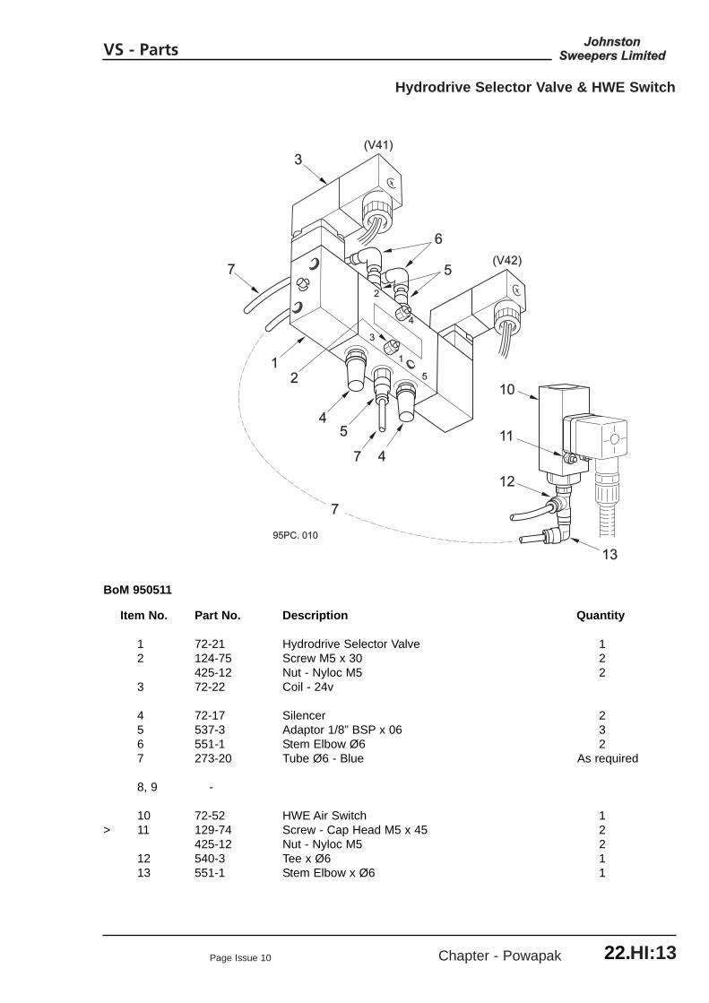
Page Issue 10 Chapter - Powapak HI:13
Hydrodrive Selector Valve & HWE Switch
VS - Parts
95PC. 01095PC. 010
(V42)(V42)
(V41)(V41)
33
11
55
22
44
11
66
33
55
55
22
77
77
44
44
1010
1111
1212
1313
77
BoM 950511
Item No. Part No. Description Quantity
1 72-21 Hydrodrive Selector Valve 12 124-75 Screw M5 x 30 2
425-12 Nut - Nyloc M5 23 72-22 Coil - 24v
4 72-17 Silencer 25 537-3 Adaptor 1/8” BSP x 06 36 551-1 Stem Elbow Ø6 27 273-20 Tube Ø6 - Blue As required
8, 9 -
10 72-52 HWE Air Switch 1> 11 129-74 Screw - Cap Head M5 x 45 2
425-12 Nut - Nyloc M5 212 540-3 Tee x Ø6 113 551-1 Stem Elbow x Ø6 1
22.

Chapter - Powapak Page Issue 08HI:14
VS - Parts
22.
Management Box
BoM 950511
Item No. Part No. Description Quantity
282135-1 Hydro Management Box 12v282135-2 Hydro Management Box 24v
1 282122-1 Box and Lid 1134-44 Screw Pan Head M4 x 20 4425-11 Nut - Nyloc M4 4
2 282125-1 Mounting Plate 13 710-67 HDP 31 Way Socket Housing 1
710-70 Jam Nut 1281545-2 Sealing Washer 1
4 48-89 Relay Base 25 13193 Relay 12v Type 6RA 2
13194 Relay 24v Type 6RA 2
6 30-256 Terminal Block - 4 Way 330-254 Terminal Block - End Plate 1
7 13984 Diode 6 Amp 1
8 124-73 Screw M5 X 25 1460-7 Washer - Spring 1420-12 Nut M5 1455-7 Washer Plain 1425-12 Nut Nyloc M5 1
12
7
95EC.0073
54
68
R11
D31
PE
EPR10

Page Issue 08 Chapter - Powapak HI:15
Fan Tub VS Parts Only
VS - Parts
22.
95PT. 002-2
77
88
6644
33
55
66
1122
For all other itemsFor all other itemssee Common Partssee Common PartsChapter 22.CPChapter 22.CP
BoM 950511
Item No. Part No. Description Quantity
1 281695-1 Rear Panel - System Locker 12 124-272 Screw M16 x 45 2
460-14 Washer - Spring 2
BoM 950512
282816-2 Valance Access Hatch comprising items 3 to 7
3 282803-1 Neoprene Flap 14 282804-1 Securing Plate 15 282802-1 Tension Plate 16 124-135 Bolt M8 x 20 8
455-10 Washer - Plain 8425-14 Nut - Nyloc M8 8
7 283-36 Drop - Loc Bolt 1455-10 Washer - Plain 1425-14 Nut - Nyloc M8 1
8 281922-1 Bracket - Hose Support 1124-137 Screw M8 x 25 2455-10 Washer - Plain 2425-14 Nut - Nyloc M8 2

Chapter - Powapak Page Issue 08HI:16
VS - Parts
22.

Chapter - Systems Locker
CHAPTER 23Systems Locker
23:1
Table of Contents
Section Page
Systems LockerSystems Wafer Assembly 23 : 2Systems Locker Enclosure 23 : 4
Page Issue 07
VT & VS - Parts

Chapter - Systems Locker Page Issue 1023:2
Systems Wafer Assembly
VT & VS - Parts

Page Issue 10 Chapter - Systems Locker 23:3
Systems Wafer Assembly
VT & VS - Parts
Base Assemblies
Part No. Description
950912-001 Wafer Assembly - 12v Single950912-002 Wafer Assembly - 12v Dual950912-003 Wafer Assembly - 24v Single950912-004 Wafer Assembly - 24v Dual
Options Assemblies for:
Recirculating Water and Autoloc Cylinders
950912-009 Wafer Assembly - 12v Single950912-010 Wafer Assembly - 12v Dual950912-011 Wafer Assembly - 24v Single950912-012 Wafer Assembly - 24v Dual
Components
Item No. Part No. Description See Chapter
1 - Main Hydraulic Valve Block 282 200576-1 Channel Brush Control Module -3 - Pneumatic Valve Assemblies 294 - WSB Selector Valve (PV51) 295 - FRL Unit 296 - Pressadrain Purge Block (WDT) 297 - Water Manifold Assembly 308 Thermal Trip:-
30-297 MCB Cutout - 12v = 50Amp -30-292 MCB Cutout - 24v = 30Amp -
9 Emergency Discharge Pump Switch comprising:-99-67 Button 199-2 Body 199-4 Contact 1
Notes
Wiring Looms - Spares Items
Looms for the Wafer pneumatic, hydraulic and water control systems are shown in Chapter 31.
>
>
>

Chapter - Systems Locker Page Issue 0723:4
Systems Locker Enclosure
VT & VS - Parts
1010
99
33
22
95SL. 004-295SL. 004-2
77
88
44
66
55
11
1111
BoM 950512
Item No. Part No. Description Quantity
282868-1 Frame and Door Assembly, comprising items 1 to 8 1
1 281660-1 Locker Frame 1 2 282869-1 Locker Door - Systems 1
211-33 Edge Trim x 1m 1
3 211-34 Latch 1211-35 Latch Key 2
4 28287-1 Latch Plate 15 135-91 Button Head Screw M6c x 20 2
425-13 Nut - Nyloc M6 2
6 42597-5 Hinge 1134-41 Screw Pozidrive M4 x 10 12425-11 Nut - Nyloc M4 12
7 39435 Gas Spring 28 420-12 Nut M5 2
9 - Cover Plate, Screws and Rubber Seals See Chapter 22 - Powapak Sections
10 - Wafer Assembly - see previous page
11 720-2 Superseded Latch - Non Lockable, available as aspares item. Does not fit current door.

Chapter - Channel Brush
CHAPTER 24Channel Brush
24:1
Table of Contents
Section Page
Channel BrushPivot Frame Assembly 24 : 2Water Jet Assembly 24 : 5Arm Assembly 24 : 6Head Assembly 24 : 10
Channel Brush InstallationsPivot Frame to Subframe 24 : 12Hydraulic Hoses 24 : 14Pneumatic Tubing 24 : 16Water Sprays 24 : 17Rotatilt Option 24 : 18
Page Issue 07
VT & VS - Parts

Chapter - Channel Brush Page Issue 1324:2
Channel Brush - Pivot Frame Assembly
VT & VS - Parts

Page Issue 13 Chapter - Channel Brush 24:3
Channel Brush - Pivot Frame Assembly
VT & VS - Parts
BoM 951211
Item No. Part No. Description QuantitySingle Dual
1 200075-1 Pivot Frame 1 2
> 2 281587-1 Stop 2 43 124-169 Screw M10 x 25 4 8
460-11 Washer - Spring M10 4 8
4 67348-1 Fork 1 25 41911-1 Washer - Kick Back Spring 1 26 425-18 Nut - Nyloc M16 1 27 41895-2 Compression Spring 1 2
8 40295-1 Nozzle Tow Pin 1 29 123-146 Screw M12 x 40 2 4
425-16 Nut - Nyloc M12 2 4
10 281601-1 Cylinder 1 2
11 40421-1 Spacer 2 412 40420-1 Pin 1 213 123-109 Bolt M8 x 45 1 2
14 800678-1 Lever - Brush Curtain 1 215 40384-1 Catch 1 216 124-103 Screw M6 x 20 1 2
460-8 Washer - Spring M6 1 2420-13 Nut M6 1 2
17 200051-1 Davit Hinge 2 418 127-139 Screw - Csk M8 x 30 4 8
460-10 Washer - Spring M8 4 8420-14 Nut M8 4 8
19 200046-1 Davit 1 220 40382-1 Link 1 221 40383-1 Bush - Curtain 1 2
124-143 Screw M8 x 40 1 222 40385-1 Link Retaining Pin 1 223 124-141 Screw M8 x 35 1 2
460-10 Washer - Spring M8 1 2420-14 Nut M8 1 2
24 200050-1 Curtain 1 225 63582-1 Curtain Quick Release Pin 2 426 289-27 Spring Clip 2 4
27 62454-1 Clamp Strip 1 228 124-169 Screw M10 x 25 5 10
457-5 Washer - Plain M10 5 10

Chapter - Channel Brush Page Issue 1124:4
Channel Brush - Pivot Frame Assembly
VT & VS - Parts
Item No. Part No. Description QuantitySingle Dual
29 62822-1 Bracket - Mudflap Mounting 1 230 124-169 Screw M10 x 25 2 4
460-11 Washer - Spring M10 2 4420-15 Nut M10 2 4
31 62819-1 Tow Point 1 232 123-151 Bolt M12 x 65 2 4
460-12 Washer - Spring M12 2 4420-16 Nut M12 2 4
33 67375-1 Plate - Mud Flap 1 234 124-167 Screw M10 x 20 2 4
460-11 Washer - Spring M10 2 4420-15 Nut M10 2 4
35 124-201 Screw M12 x 25 1 2460-12 Washer - Spring M12 1 2420-16 Nut M12 1 2
36 282207-1 Water Jet Assembly - See next page 1 2
37 67372-1 Clamp Strip 1 238 67378-1 Clamp Bar 1 239 457-4 Washer - Plain M8 5 10
425-14 Nut - Nyloc M8 5 10
40 200110-1 Adaptor - Bulkhead G1/2" x G1/4" 1 241 410-11 Locknut - G1/4" 1 242 255-13 Tee - G1/2" 1 2
Curtains
43 63334-1 Rubber Curtain 1 244 67368-1 Rubber Mudflap 1 2
Hydraulic Hoses
* 65/66 HC04002-55 Hose - Megaflex 1/4" Straight x 90°s 1 2* 67/68 HC04000-50 Hose - Megaflex 1/4" Straight x Straight 1 2
Notes
* Hose item numbers correspond with those on diagrams SH522 and SH523 in MaintenanceSection, Chapter 8.
>

Page Issue 10 Chapter - Channel Brush 24:5
Water Jet Assembly
VT & VS - Parts
95WC. 00195WC. 001
11
33
44
55
22
66
77
BoM 951211
Item No. Part No. Description Quantity
282207-1 Jet Assembly comprising:
1 282214-1 Pipe - Hose Adaptor 12 282206-1 Angle Bracket 13 410-55 Nut G1/4" 14 21-58 Double Swivel Nozzle Holder 1
> 5 21-66 Fan Tip Jet - Red 2 6 460-8 Washer - Spring M6 17 420-13 Nut M6 1
Notes

Chapter - Channel Brush Page Issue 0724:6
Channel Brush - Arm Assembly
VT & VS - Parts
95CB. 002-295CB. 002-2
21212222
2323
3434
*20*20
1111
28283434
3030
*10*10
2525
2424
2626
4343
4141
2727
4242
*5*5
11
*3*3
*3*3
*4*4
*6*6
*8*8*10*10*9*9
*2*2
*2*2
3333
1414
*19*19
46464444
4545
*18*18*12*12
77
*17*17
2929
1313
3939 4040
30,3230,32
3535
3737
3838
3636
3131
2929
*15*15*16*16
3030
3232
Fit Stowage StopFit Stowage StopBolt this way roundBolt this way round

Page Issue 13 Chapter - Channel Brush 24:7
Channel Brush - Arm Assembly
VT & VS - Parts
BoM 951212
Item No. Part No. Description Quantity
1 40272-2 Pivot Head 1
* 2 40292-1 Bush 4* 3 40360-1 Pivot Pin - Channel Brush Head 1* 4 38-1 Grease Nipple Straight G1/8" 1* 5 38-1 Grease Nipple Straight G1/8" 1* 6 124-178 Screw M10 x 55 1
420-15 Nut M10 1
7 200025-1 Lower Arm 1* 8 282028-1 Pivot Pin 1* 9 124-135 Screw M8 x 20 1
460-10 Washer - Spring 1* 10 38-1 Grease Nipple Straight G1/8" 2
11 200026-1 Upper Arm Assembly 1* 12 29128-4 Bush - Non Lube, Part of Item 11 4
> 13 40361-1 Pivot Pin - Upper Arm 1460-12 Washer - Spring M12 1420-16 Nut M12 1
14 282505-1 Motor Mount 1
* 15 40389-1 Pivot Pin 1* 16 38-1 Grease Nipple Straight G1/8" 2* 17 124-146 Screw M8 x 55 1
460-10 Washer - Spring M8 1420-14 Nut M8 1
* 18 40362-1 Bush - Upper Arm 1* 19 40363-1 Spacer M12 2* 20 123-159 Bolt M12 x 110 1
9331-1 Washer - Packing 2425-16 Nut - Nyloc M12 1
21 51-43 Plate - Top Clamp 151-44 Clamp 1
22 200082-1 Plate - Clamp Spacer 123 123-117 Bolt M8 x 85 1
425-14 Nut - Nyloc M8 1
24 800677-1 Lever - Pivot Head 125 124-171 Screw M10 x 30 226 124-173 Screw M10 x 35 2
460-11 Washer - Spring M10 427 121-115 Screw M14 x 60 1
420-4 Nut M14 1
28 200071-1 Mast 1
29 200355-1 Lift Cylinder - Pneumatic 1

Chapter - Channel Brush Page Issue 0724:8
Channel Brush - Arm Assembly
VT & VS - Parts
95CB. 002-295CB. 002-2
21212222
2323
3434
*20*20
1111
28283434
3030
*10*10
2525
2424
2626
4343
4141
2727
4242
*5*5
11
*3*3
*3*3
*4*4
*6*6
*8*8*10*10*9*9
*2*2
*2*2
3333
1414
*19*19
46464444
4545
*18*18*12*12
77
*17*17
2929
1313
3939 4040
30,3230,32
3535
3737
3838
3636
3131
2929
*15*15*16*16
3030
3232
Fit Stowage StopFit Stowage StopBolt this way roundBolt this way round

Page Issue 07 Chapter - Channel Brush 24:11
Channel Brush - Head Assembly
VT & VS - Parts
BoM 951213
Item No. Part No. Description Quantity500 Dia. 650 Dia. Brush Brush
1 42533-1 Mounting - Brush Motor 1 12 281325-2 Bush 3 33 123-148 Bolt M12 x 50 3 3
425-16 Nut - Nyloc M12 3 3455-12 Washer - Plain M12 3 3
4 40550-1 Hydraulic Motor 1 -61108-1 Hydraulic Motor - 1
5 124-208 Setscrew M12 x 45 2 2460-12 Washer - Spring M12 2 2420-16 Nut - M12 2 2
6 263-4 Adaptor G1/2" 2 2451-126 Washer - Copper G1/2" 2 2
7 281586-1 Adaptor - Drive Plate 1 -8 281584-1 Adaptor - Drive Plate - 19 135-58 Bolt - Tuflock M8 x 25 1 1
460-10 Washer - Spring M8 1
Brushes. BoM 951230
10 281893-2 Brush Ø500 with Bright Steel Tines - Green Top 1 -281893-10 Brush Ø500 with Polypropylene Tines - Natural Top 1 -
281899-2 Brush Ø650 with Bright Steel Tines - Green Top - 1281899-10 Brush Ø650 with Polypropylene Tines - Natural Top - 1
Notes

Chapter - Channel Brush Page Issue 1024:12
CB Installation - Pivot Frame to Subframe
VT & VS - Parts
95CB.006
CHANNEL BRUSH PIVOT FRAME
WIDE SWEEP BRUSH TOW PINMOUNTING - SINGLE SWEEP
1
2
2
2
1 7
8
1
9
12
11
10
5
3
6
4

Page Issue 10 Chapter - Channel Brush 24:13
CB Installation - Pivot Frame to Subframe
VT & VS - Parts
BoM 951220
Item No. Part No. Description QuantitySingle Dual
> 1 282502-1 Mounting Bracket 3 42 123-147 Bolt M12 x 45 12 16
45014-25 Spacer 12 16425-16 Nut - Nyloc M12 12 16
3 * 281292-1 Support Post - Front 0.9 to 0.99m in Chassis Height 1 2281292-2 Support Post - Front 1.0 to 1.099m in Chassis Height 1 2
4 * 281292-3 Support Post - Front 0.8 to 0.89m in Chassis Height 1 2
5 281274-1 U-Bolt M12 2 4> 455-12 Washer - Plain M12 4 8
425-16 Nut - Nyloc M12 4 86 124-207 Screw M12 x 40 5 10
455-12 Washer - Plain M12 5 10460-12 Washer - Spring M12 5 10425-16 Nut - Nyloc M12 5 10
7 * 281296-1 Support Post - WSB 0.9 to 0.99m in Chassis Height 1 -281296-2 Support Post - WSB 1.0 to 1.099m in Chassis Height 1 -281296-3 Support Post - WSB 0.8 to 0.89m in Chassis Height 1 -
8 281274-1 U-Bolt M12 2 -> 455-12 Washer - Plain M12 4 -
425-16 Nut - Nyloc M12 4 -
9 * 281298-1 Support Post - Rear 0.9 to 0.99m in Chassis Height 1 2281298-2 Support Post - Rear 1.0 to 1.099m in Chassis Height 1 2
10 * 282541-1 Support Post - Rear 0.8 to 0.89m in Chassis Height 1 211 281274-1 U-Bolt M12 2 4
> 455-12 Washer - Plain M12 4 8425-16 Nut - Nyloc M12 4 8
12 124-207 Screw M12 x 40 2 4455-12 Washer - Plain M12 2 4460-12 Washer - Spring M12 2 4425-16 Nut - Nyloc M12 2 4
Notes
* Support Posts items 3, 4, 7, 9, 10 see Chapter 33Post, Item 7, is also shown in Wide Sweep Brush section

Chapter - Channel Brush Page Issue 1224:14
CB Single Sweep Installation - Hydraulic Hoses
VT & VS - Parts
BoM 950713
Item Nos. Part No. Description QuantitySingle Dual
42 HC04001-141 1/4” Hydraulic Hose 1 1> 43 HC08001-167 1/2” Hydraulic Hose 1 1
44 HC08001-167 1/2” Hydraulic Hose - 1
BoM 951220
65/66 - See Pivot Frame Assembly - -67/68 - See Pivot Frame Assembly - -75/76 HC04001-78 Hose, 0.8 to 0.99m Chassis Height 1 2
HC04001-98 Hose, 0.9 to 0.99m Chassis Height 1 2HC04001-98 Hose, 1.0 to 1.099m Chassis Height 1 2
Continued on next page

Page Issue 12 Chapter - Channel Brush 24:15
CB Dual Sweep Installation - Hydraulic Hoses
VT & VS - Parts
BoM 951220
Item Nos. Part No. Description QuantitySingle Dual
77/78 HC08002-228 Hose, Common to all variants 1 279/80 HC08001-70 Hose, 0.8 to 0.99m Chassis Height 1 2
HC08001-130 Hose, 0.9 to 0.99m Chassis Height 1 2HC08001-130 Hose, 1.0 to 1.099m Chassis Height 1 2
81/82 HC08002-202 Hose, 0.8 to 0.89m Chassis Height 1 2HC08002-222 Hose, 0.9 to 0.99m Chassis Height 1 2HC08002-222 Hose, 1.0 to 1.099m Chassis Height 1 2
83/84 - See Chapter 33

Chapter - Channel Brush Page Issue 0724:16
CB Installation - Pneumatic Tubing
VT & VS - Parts
BoM 951220
Item Nos. Part No. Description QuantitySingle Dual
1 510-4 Tubing Nut - 1511-4 Olive M8 - 1
2 521-8 Elbow - 13 12870 Black Tubing 8 Diameter 4m 7m4 273-20 Blue Tubing 6 Diameter 12m 18m
95CB. 00795CB. 007
FRONTFRONT
L.H. C.B.L.H. C.B.CYLINDERSCYLINDERS
R.H. CHANNEL BRUSHR.H. CHANNEL BRUSH
44
44

Page Issue 08 Chapter - Channel Brush 24:17
CB Installation - Water Sprays
VT & VS - Parts
BoM 951220
Item Nos. Part No. Description Quantity
1 - Water Hoses - See Chapter 30 -2 282207 Water Jet Assembly - See elsewhere in this chapter -
95EM. 005-2
TO L.H.SPRAYS
CHANNEL BRUSHSPRAYS
GUTTER SPRAYS
W02 - L.H. OR R.H. GUTTER - SINGLE SWEEP M/CSL.H. GUTTER - DUAL SWEEP M/CS
WO7 - R.H. GUTTER, DUAL SWEEP M/CS
WO8 - .
WO3 -L.H. C.B. - DUAL SWEEP M/CSL.H. OR R.H. - SINGLE SWEEP M/CS
R.H. C.B - DUALSWEEP M/CS
2
2
1
1
2

Chapter - Channel Brush Page Issue 0824:18
Rotatilt Option
VT & VS - Parts
95CB. 008
2
43
111
1
109
6
5
7
12
8
3CHASSIS
KERB
FRONT
REAR
CHASSIS
KERB
L.H. ASSEMBLY SHOWN
(R.H. ASSEMBLY IS A MIRROR IMAGE)

Page Issue 08 Chapter - Channel Brush 24:19
Rotatilt Option
VT & VS - Parts
KT 02295
Item No. Part No. Description Quantity
282509-1 Rotatilt Installation 12v282509-2 Rotatilt Installation 24v
1 282505-1 Motor Mount 12 123-148 Screw M12 x 50 3
281325-1 Bush x 6.5 Long 3455-12 Washer 3425-16 Nut - Nyloc M12 3
3 282508-12 Electric Actuator 12v 1282508-24 Electric Actuator 24v 1
4 282506-1 Pylon 1
5 42533-1 Brush Motor Mount 16 282507-1 Lower Mount Bracket 17 281330-2 Clevis Pin 1
124-135 Bolt M8 x 20 1425-14 Nut - Nyloc M8 1
> 8 138-152 Screw Button Head M10 x 20 3
9 281330-1 Clevis Pin 1124-135 Bolt M8 x 20 1425-14 Nut - Nyloc M8 1
10 281314-1 Spacer 211 124-171 Bolt M10 x30 3
460 - 11 Washer 3
12 282053-1 Loom - Switch Panel to Actuator 12v 1282053-2 Loom - Swtich Panel to Actuator 24v 1
Notes
The Rotatilt option requires an Options Switch Panel, see Chapter 32, that includes the necessary switches and wiring.
See Diagram SE571z01 in Chapter 9 of the Maintenance Section for wiring details.

Chapter - Channel Brush Page Issue 0724:20
VT & VS - Parts

Chapter - Nozzle
CHAPTER 25Nozzle
25:1
Table of Contents
Section Page
NozzleNozzle Assembly 25 : 2Wheel Assembly 25 : 5Nozzle Installation 25 : 6
Page Issue 07
VT & VS - Parts

Chapter - Nozzle Page Issue 1225:2
Nozzle Assembly
VT & VS - Parts

Page Issue 12 Chapter - Nozzle 25:3
Nozzle Assembly
VT & VS - Parts
Item No. Part No. Description Quantity
Carriage. BoM 941111, 951111
> 1 294081-1 Tow Eye - V 500 Only 1201227-1 Tow Eye - V 605, 650, 800 1
2 201240-1 Towbar 13 124-173 Screw M10 x 35 1
425-15 Nut M10 14 124-181 Screw M10 x 70 1
425-15 Nut M10 1
5 280870-1 Carriage 16 124-173 Screw M10 x 35 4
425-15 Nut M10 4457-5 Washer Ø10
7 63491-1 Nozzle Wheel - See over page 2
Dressing. BoM 951112
8 281420-2 Nozzle - Fully Lined 1
9 281754-1 Bumper 110 124-207 Screw N12 x 40 2
425-16 Nut M12 2455-12 Washer Ø12 2
11 281752-1 Actuator Arm 112 281751-1 Pivot Arm 113 124-175 Screw M10 x 40 4
425-15 Nut M10 4455-11 Washer Ø10 4
14 280866-1 Mast 115 124-175 Screw M10 x 40 2
460-11 Washer Ø10 2425-15 Nut M10 2
16 281753-1 Pivot 2425-20 Nut M20 2455-16 Washer Ø20 2
17 282968-1 Hook 118 62353-4 Link 119 124-201 Screw M12 x 25 1
425-16 Nut M12 1455-12 Washer Ø12 1

Chapter - Nozzle Page Issue 1225:4
Nozzle Assembly
VT & VS - Parts
Item No. Part No. Description Quantity
20 62005-1 Nozzle Rubber - Front 121 282230-1 Nozzle Rubber - Rear 122 281045-1 Nozzle Rubber - Inner 123 281044-1 Nozzle Rubber - Outer 124 94017-1 Clamp Plate - Front/Rear 125 63667-1 Clamp Plate - Inner 126 63666-1 Clamp Plate - Outer 127 136-24 Carriage Bolt M8 x 50 16
455-10 Washer Ø8 16410-30 Nut M8 16
28 282781-1 Water Jet 1.6mm 229 453-1 Fibre Washer Ø20 - 4 Per Jet 8
> 30 416-12 Locknut M12 - Stainless Steel 231 418-12 Domed Nut - Stainless Steel 232 26997-1 Banjo Connector 233 90696-1 Tee Connector 1
34 46382-3 Hose Adaptor 135 39444 Hose 0.34m36 501-1 Hose Clip 2
> 37 124-203 Screw M12 x 30 ) Not required when 2455-12 Washer Ø12 ) Additional Water Option 2425-16 Nut M12 ) items 45 - 47 is fitted 2
38 40404-1 Clamp Washer 139 40405-1 Lifting Eye 140 63345-1 Clamp Block 141 124-178 Screw M10 x 55 2
425-15 Nut M10 2
42 281755-1 Plug G3/4" 1410-57 Nut G3/4" 1
Actuation. BoM 951113
43 290001-1 Maxigap Cylinder 1> 44 - Varagap Cylinder - See Options Section 35.SG 1
Additional Water Option KT 00995
> 45 - Injection Parts - as standard Front Sprays, items 28 to 36> 46 277-2 Tee Connector 1> 47 39444 Hose 0.34m
501-1 Hose Clip 4

Page Issue 07 Chapter - Nozzle 25:5
Nozzle Wheel
VT & VS - Parts
13
14
12
118
10
4,53
1
2
9
*6,7
95NZ. 003
Item No. Part No. Description Quantity
63491-1 Nozzle Wheel comprising:
1 16752 Tyre 12 63493-1 Hub 13 16750-1 Backplate - Tyre 14 124-134 Screw M8 x 16 5
5 460-10 Washer - Spring M8 56 124-102 Screw M6 x 16 37 460-8 Washer - Spring M6 38 63495-1 Retainer Plate 19 63492-1 Spindle 1
10 14-52 Bearing 111 63494-1 Collar 112 9114-2 Washer - Special 213 425-18 Nut - Nyloc M16 214 38-30 Grease Nipple M6 Straight 1
Notes
To withdraw bearing, remove wheel assembly from carriage and refit washer and nut, items 12 and 13. Insert M6c x 50mm screws (124-113) in the three unused retainerplate holes*. Tighten each bolt half a turn at a time to extract bearing.

Nozzle Installation
Chapter - Nozzle Page Issue 0725:6
VT & VS - Parts

Page Issue 10 Chapter - Nozzle 25:7
Nozzle Installation
VT & VS - Parts
BoM 951120
Item No. Part No. Description QuantitySingle Dual
1 94990-1 Intake Seat - 0.8 to 0.99m Chassis Height 1 294990-3 Intake Seat - 1.0 to 1.099m Chassis Height 1 2
2 127-139 Screw - Countersunk M8 x 30 3 6460-10 Washer M8 3 6420-10 Nut M8 3 6
3 94992-2 Nozzle Trunking 1 24 504-54 Hose Clip 2 4
5 28903-1 Lift Cylinder 1 2> 28903-111 Rod Eye 1 2
807186 High Chassis Installation Drawing Items 6 and 7:6 807182-1 Adaptor Plate 1 27 124-171 Screw M10 x 35 2 4
455-11 Washer M10 2 4425-15 Nut - Nyloc 2 4
8 273-20 Pneumatic Tubing Ø6 Blue 10m 16m9 12869 Pneumatic Tubing Ø6 Black 9m 15m10 39444 Water Pipe 5m 8m11 501-1 Hose Clip 2 4
12 60-1 Linch Pin 1 2
Notes

Chapter - Nozzle Page Issue 0725:8
VT & VS - Parts

Chapter - Wide Sweep Brush
CHAPTER 26Wide Sweep Brush
26:1
Table of Contents
Section Page
AssemblyCurrent Type ‘B’ Wide Sweep Brush Assembly 26 : 2Tow Bar Installations 26 : 6
InstallationPneumatics - Suspension Cylinders 26 : 7Pneumatics - Suspension Regulation, Single Sweep 26 : 8Pneumatics - Suspension Regulation, Dual Sweep 26 : 9Hydraulic Hoses 26 : 10Water - Spray Bar 26 : 14
Superseded PartsType ‘A’ Wide Sweep Brush Assembly 26 : 16Type ‘A’ Two Piece Segment Stock 26 : 20
Page Issue 10
VT & VS - Parts

Chapter - Wide Sweep Brush Page Issue 1026:2
VT & VS - Parts
Current Type ‘B’ Wide Sweep Brush Assembly

Page Issue 10 Chapter - Wide Sweep Brush 26:3
VT & VS - Parts
Current Type ‘B’ Wide Sweep Brush Assembly
Carriage Assembly - BoM 951011
Item No. Part No. Description Quantity
1 283102-1 Carriage 1
2 283091-1 Curtain 13 124-169 Screw M10 x 25 4
455-11 Washer - Plain M10 8425-15 Nut - Nyloc M10 4
4 200055-1 Rubber Curtain 15 283126-1 Retaining Strip 16 124-137 Screw M8 x 25 6
455-10 Washer - Plain M8 12425-14 Nut - Nyloc M8 6
7 283090-1 Curtain Support 28 124-169 Screw M10 x 25 8
455-11 Washer - Plain M10 16425-15 Nut - Nyloc M10 8
9 62097-1 Anchor Pin 210 27-2 Circlip 4
11 283103-1 Compensator 112 62095-1 Plate - Keeper 113 29395-2 Bearing 114 124-135 Screw M8 x 20 2
460-10 Washer - Spring M8 2
15 283092-1 Shaft 116 455-16 Washer - Plain M20 1
425-7 Nut - Nyloc M20 1
17 265-1 Adaptor 1/8” x 1/4” BSP 1451-4 Washer - Sealing 1/8” BSP 1
18 262-2 Adaptor - Bulkhead G1/4” 119 38-11 Grease Nipple - 90° 120 HC04036-87 Hose - 1/4" Megaflex 1
21 264-4 Adaptor - Bulkhead G1/2” 222 264-2 Adaptor - Bulkhead G1/4” 1
WSB Slew - BoM 951012
Single Dual
23 283127-1 Slew Retainer - 124 283127-2 Slew Retainer 1 -25 283128-1 Spacer - 226 123-154 Bolt M12 x 80 2 2
454-12 Washer - Plain M12 - Stainless Steel 4 4425-16 Nut - Nyloc M12 2 2

Chapter - Wide Sweep Brush Page Issue 1126:4
VT & VS - Parts
Current Type ‘B’ Wide Sweep Brush Assembly
WSB Slew - BoM 951012
Item No. Part No. Description Quantity Single Dual
27 29160-1 Cylinder - 128 283129-1 Bush - Cylinder Mount - 129 123-140 Bolt M10 x 100 - 1
455-11 Washer - Plain M10 - 2457-5 Washer - Plain M10 Large - 1425-15 Nut - Nyloc M10 - 1
30 124-199 Screw M12 x 20 - 1460-12 Washer - Spring M12 - 1457-6 Washer - Plain M12 Large - 1
31 264-2 Adaptor - Bulkhead G1/4” - 2
32 51-51 Clamp - Single 2 -33 51-50 Clamp - Twin - 234 124-111 Screw M6 x 40 2 2
425-13 Nut - Nyloc M6 2 2
Motor Assembly - BoM 941013, 951013
Segment Stock Seg. -Modular Stock - Mod.
>35 283112-1 End Plate - All models except V 500 1 1
283231-1 End Plate - V 500 only 1 1
36 99972-1 Motor - OMPW 200 1 137 124-171 Screw - M10 x 30 4 4
460-11 Washer - Spring M10 4 4455-11 Washer - Plain M10 4 4
38 283109-1 Drive Motor Adaptor 1 139 62064-1 Washer - Special 1 1
124-136 Screw M8 x 22 1 1460-10 Washer - Spring M8 1 1
40 38-30 Grease Nipple 1 1
41 283105-1 Drive Dog 1 -42 124-137 Setscrew M8 x 25 4 -
460-10 Washer - Spring M8 4 -455-10 Washer - Plain M8 4 -
43 283123-1 Stock Tube - 144 283124-1 Driver Spacer - 445 281249-1 Driver Retaining Plate - 146 129-129 Screw Socket Head M8 x 35 - 4
460-10 Washer - Spring M8 - 4
47 124-169 Screw M10 x 25 4 4460-11 Washer - Spring M10 4 4455-11 Washer - Plain M10 4 4

Page Issue 12 Chapter - Wide Sweep Brush 26:5
VT & VS - Parts
Current Type ‘B’ Wide Sweep Brush Assembly
Bearing Assembly - BoM 941014, 951014
Item No. Part No. Description Quantity
Segment Stock Seg. -Modular Stock - Mod.
48 283112-1 Side Plate - All models except V 500 1 1283231-1 Side Plate - V 500 only 1 1
49 283107-1 Bearing - Housing 1 150 14-47 Bearing 1 1
51 283108-1 Drive Adaptor 1 152 27-15 Circlip - External 1 153 283121-1 Labyrinth 1 154 80-94 ‘O’ Ring 1 1
55 124-169 Screw M10 x 25 4 4460-11 Washer - Spring M10 4 4455-11 Washer - Plain M10 4 4
56 38-30 Grease Nipple 1 1
57 283106-1 Driven Dog 1 -58 124-137 Setscrew M8 x 25 4 4
460-10 Washer - Spring M8 4 459 281237-1 Tube - Stock Guide - 1
60 124-169 Screw M10 x 25 4 4460-11 Washer - Spring M10 4 4455-11 Washer - Plain M10 4 4
WSB Dressing - BoM 941030, 951030
Segment System
283114-1 Stock Assembly comprising items 61, 62, 63:-
> 61 283101-1 Stock - One Piece 1 -62 283115-1 Closing Plate - Driven End 1 -63 118-137 Screw M8 x 25 - Stainless Steel 4 -
454-8 Washer - Plain M8 Stainless Steel 4 -458-8 Washer - Spring M8 Stainless Steel 4 -
64 834-1 Poly Segment - V605, 650, 800 43 -> 283385-340 Poly Segment - V500 43 -
65 13515 Spacer 41 -
Modular System
66 281895-1 Poly Brush Stock - V605, 650, 800 - 2 Set> 294110-1 Poly Brush Stock - V500 - 2 Set

Chapter - Wide Sweep Brush Page Issue 1026:6
VT & VS - Parts
Towbar Assembly - BoM 951015 (V650, 800). BoM 941015 (V500)
1 62070-1 Towbar - V650, 800 Range 12 808008-1 Towbar - V500 Range 1
WSB Installation - BoM 951020Single Dual
3 281296-1 Support - Chassis Height 0.9 - 0.99m 1 -281296-2 Support - Chassis Height 1.0 - 1.099m 1 -281296-3 Support - Chassis Height 0.8 - 0.99m 1 -
4 281274-1 U-Bolt M12 2 -455-12 Washer - Plain 4 -425-16 Nut - Nyloc M12 4 -
5 62099-2 Tow Point - Bush 2 26 124-217 Screw M12 x 90 2 2
455-12 Washer - Plain M12 2 2425-16 Nut - Nyloc M12 2 2
7 62819-1 Box - Towpoint 1 -8 123-151 Bolt M12 x 65 2 -
460-12 Washer - Spring 2 -425-16 Nut - Nyloc M12 2 -
Tow Bar Installations

Page Issue 07 Chapter - Wide Sweep Brush 26:7
WSB Installation - Pneumatics - Suspension Cylinders
VT & VS - Parts
BoM 951020
Item No. Part No. Description Quantity
1 281549-1 Suspension Bracket 22 124-199 Screw M12 x 20 4
460-12 Washer - Spring M12 4 3 40404-1 Clamp Washer 24 63345-1 Clamp Block 25 40405-1 Lifting Eye 26 124-178 Screw M10 x 55 4
455-11 Washer - Plain M10 4425-15 Nut - Nyloc M10 4
7 29284-2 Pneumatic Cylinder 28 273-20 Tube - Blue Nylon 6mm OD
0.9 to 0.99m Chassis Height 6m1.0 to 1.099m Chassis Height 6.5m
9 24-1 Cable Tie 4
95WB. 00595WB. 005
PORPORTT ‘B‘B’’
PORPORTT ‘B‘B’’
TTO PORO PORT 2 IN SYSTEMST 2 IN SYSTEMSLOCKER FLOOR VIALOCKER FLOOR VIA
HOSE TRAHOSE TRAYYHOSE TRAHOSE TRAYY
6 DIA. BLUE TUBING6 DIA. BLUE TUBINGTHROUGHOUTTHROUGHOUT
88
TTO TO TOPOPOF L.H.OF L.H.
CYLINDERCYLINDER
PORPORT 2T 2
2211
445533
66
77
77
99
88

Chapter - Wide Sweep Brush Page Issue 0726:8
WSB Pneumatics - Suspension Regulation, Single Sweep
VT & VS - Parts
‘REAR‘REAR’’
95WB. 00895WB. 008
R.H.R.H.
L.H.L.H.
WW.S.B. LIFT CYLINDERS.S.B. LIFT CYLINDERSSEE PREVIOUS PSEE PREVIOUS PAGEAGE
PV2PV2
PV2PV2
L.H.L.H.CYLINDERCYLINDER
R.H.R.H.CYLINDERCYLINDER
PV3PV3
77
PORPORT 7T 7
6622
1111
1313
1212
55 66 77 88 99
2211
33
55 66 44
1414
1010
1010
1010
1313
1212
BoM 950713
Item No. Part No. Description Quantity
1 253-9 Regulator 22 410-86 Panel Nut 23 9756 Plug R1/4" 44 552-8 Elbow R1/4" x Ø6 4
5 554-3 Tee Ø6 26 549-3 Stem Connector Ø6 2
7 537-8 Straight Adaptor R1/4" x Ø6 28 41211-1 Quick Exhaust Valve 29 266-2 Adaptor G1/4" x R1/4" 2
451-17 Washing - Sealing 2
10 273-20 Tubing Ø6 Blue 1.16m11 273-21 Tubing Ø6 Red 0.95m12 273-20 Tubing Ø6 Blue 0.62m13 273-21 Tubing Ø6 Red 0.74m
14 551-1 Elbow

Page Issue 07 Chapter - Wide Sweep Brush 26:9
WSB Pneumatics - Suspension Regulation, Dual Sweep
VT & VS - Parts
‘REAR‘REAR’’
1,21,2
3 - 63 - 6
3 - 63 - 6
1,21,27,87,8
5533 44
99
66
95WB. 00795WB. 007
EE
EE
CC
CC
AA
AA
BB
BB
FF
FF
DD
DD
R.H.R.H.
L.H.L.H.
WW.S.B. LIFT CYLINDERS.S.B. LIFT CYLINDERSSEE PREVIOUS PSEE PREVIOUS PAGEAGE
ALL TUBING 6 DIA BLUEALL TUBING 6 DIA BLUE
88
PV2PV2PV3PV3
77
6622
FF
CC
BB
DD
EEAA
REARREARVIEWVIEW
FRONT VIEWFRONT VIEW
1010
1010
BoM 950713
Item No. Part No. Description Quantity
1 200577 Shuttle/Exhaust Valve Block 22 124-102 Screw M6 x 16 4
460-8 Washer - Spring M6 4
3 253-9 Regulator 44 410-86 Panel Nut 45 9756 Plug R1/4" 86 552-8 Elbow R1/4" x Ø6 8
7 554-3 Tee Ø6 48 549-3 Stem Connector Ø6 49 551-1 Elbow 310 273-20 Tubing Ø6 Blue x 1 Reel 1

Chapter - Wide Sweep Brush Page Issue 0726:10
WSB Installation - Hydraulic Hoses
VT & VS - Parts

Page Issue 12 Chapter - Wide Sweep Brush 26:11
WSB Installation - Hydraulic Hoses
VT & VS - Parts
Subframe Configuration BoM 950713, 940713
Item No. Part No. Description Quantity
37 HC08001-155 Hydraulic Hose - Single and Dual Sweep 1> 38 HC04002-144 Hydraulic Hose - Dual Sweep Only 1
39 HC08001-98 Hydraulic Hose - Single and Dual Sweep 1HC08001-86 Hydraulic Hose - Single and Dual Sweep VT500 Only 1
Carriage Assembly BoM 951011
60 HC08001-73 Hydraulic Hose - Single and Dual Sweep 161 HC08001-160 Hydraulic Hose - Single and Dual Sweep 162 HC04002-87 Hydraulic Hose - Single and Dual Sweep 1
WSB Slew - BoM 951012
63 HC04003-95 Hydraulic Hose - Dual Sweep Only 164 HC04003-36 Hydraulic Hose - Dual Sweep Only 1
WSB Installation BoM 951020 Chassis Height
70 * HC04002-95 Hydraulic Hose - Dual Sweep Only 0.8 to 0.99mHC04002-115 Hydraulic Hose - Dual Sweep Only 0.9 to 099mHC04002-115 Hydraulic Hose - Dual Sweep Only 1.0 to 1.099m
71 * HC04001-128 Hydraulic Hose - Dual Sweep Only 0.8 to 0.99mHC04001-148 Hydraulic Hose - Dual Sweep Only 09.0 to .099mHC04001-148 Hydraulic Hose - Dual Sweep Only 1.0 to 1.099m
72 * HC08002-105 Hydraulic Hose - Single and Dual Sweep 0.9 to 0.99mHC08002-115 Hydraulic Hose - Single and Dual Sweep 1.0 to 1.099m
73 * HC08002-105 Hydraulic Hose - Single and Dual Sweep 0.9 to 0.99mHC08002-115 Hydraulic Hose - Single and Dual Sweep 1.0 to 1.099m
74 * HC04002-136 Hydraulic Hose - Dual Sweep Only 0.9 to 0.99m HC04002-146 Hydraulic Hose - Dual Sweep Only 1.0 to 1.099mHC04002-196 Hydraulic Hose - Single Sweep Only 0.9 to 0.99mHC04002-206 Hydraulic Hose - Single Sweep Only 1.0 to 1.099m
Notes
Item numbers correspond to those on Diagram SH522z01 in Maintenance Section, Chapter 8
* Hoses 70 to 74 see Chapter 33 - Chassis Related Parts

WSB Installation - Hydraulic Hoses
Chapter - Wide Sweep Brush Page Issue 0726:12
VT & VS - Parts

Page Issue 12 Chapter - Wide Sweep Brush 26:13
VT & VS - Parts
WSB Installation - Hydraulic Hoses
Subframe Configuration BoM 950713, 940713
Item No. Part No. Description Quantity
37 HC08001-155 Hydraulic Hose - Single and Dual Sweep 1> 38 HC04002-144 Hydraulic Hose - Dual Sweep Only 1
39 HC08001-98 Hydraulic Hose - Single and Dual Sweep 1HC08001-86 Hydraulic Hose - Single and Dual Sweep VT500 Only 1
Carriage Assembly BoM 951011
60 HC08001-73 Hydraulic Hose - Single and Dual Sweep 161 HC08001-160 Hydraulic Hose - Single and Dual Sweep 162 HC04002-80 Hydraulic Hose - Single and Dual Sweep 1
WSB Slew - BoM 951012
63 HC04003-95 Hydraulic Hose - Dual Sweep Only 164 HC04003-36 Hydraulic Hose - Dual Sweep Only 1
WSB Installation BoM 951020Chassis Height
70 * HC04002-95 Hydraulic Hose - Dual Sweep Only 0.8 to 0.99mHC04002-115 Hydraulic Hose - Dual Sweep Only 0.9 to 099mHC04002-115 Hydraulic Hose - Dual Sweep Only 1.0 to 1.099m
71 * HC04001-128 Hydraulic Hose - Dual Sweep Only 0.8 to 0.99mHC04001-148 Hydraulic Hose - Dual Sweep Only 09.0 to .099mHC04001-148 Hydraulic Hose - Dual Sweep Only 1.0 to 1.099m
72 HC08002-105 Hydraulic Hose - Single and Dual Sweep 0.9 to 0.99mHC08002-115 Hydraulic Hose - Single and Dual Sweep 1.0 to 1.099m
37 HC08001-155 Hydraulic Hose - Single and Dual Sweep 173 HC08002-105 Hydraulic Hose - Single and Dual Sweep 0.9 to 0.99m
HC08002-115 Hydraulic Hose - Single and Dual Sweep 1.0 to 1.099m74 HC04002-146 Hydraulic Hose - Single and Dual Sweep 0.9 to 0.99m
HC04002-156 Hydraulic Hose - Single and Dual Sweep 1.0 to 1.099m
Notes
Item numbers correspond to those on Diagram SH522z01 in Maintenance Section, Chapter 8
* Hoses 70 to 74 see Chapter 33 - Chassis Related Parts

WSB Installation - Low Pressure Water Spray Bar
Chapter - Wide Sweep Brush Page Issue 1226:14
VT & VS - Parts
BoM 951020
Item No. Part No. Description Quantity
1 282236-1 Spray Bar Assembly, comprising items 2 to 7:- 1
2 21-334 Spraybar 13 21-335 Hosetail 14 21-60 Nozzle Holder 15 21-64 Seal 16 21-66 Fan Tip - Red 17 21-63 Bayonet Cap 1
8 39444 Hose 5m9 501-1 Hose Clip 2
10 - Spray Bar Mounting - varies with chassis (Contact the Johnston Parts Department for further information)

Page Issue 10 Chapter - Wide Sweep Brush 26:15
VT & VS - Parts
Superseded Parts
Table of Contents
Section Page
Superseded Type ‘A’ Wide Sweep Brush Assembly 26 : 16Superseded Type ‘A’ Two Piece Segment Stock 26 : 20

Chapter - Wide Sweep Brush Page Issue 1026:16
VT & VS - Parts
Superseded Type ‘A’ Wide Sweep Brush Assembly

Page Issue 10 Chapter - Wide Sweep Brush 26:17
VT & VS - Parts
Superseded Type ‘A’ Wide Sweep Brush Assembly
Carriage Assembly - BoM 951011
Item No. Part No. Description Quantity
1 281236-1 Carriage 12 281246-1 Screw - Location 4
425-15 Nut - Nyloc M10 4
3 200045-1 Curtain 14 124-167 Screw M10 x 20 6
425-15 Nut - Nyloc M10 6
5 200055-1 Rubber Curtain 16 54013-1 Retaining Strip 17 124-137 Screw M8 x 25 6
455-10 Washer - Plain M8 6425-14 Nut - Nyloc M8 6
8 200042-1 LH Curtain Support 19 124-169 Screw M10 x 25 4
425-15 Nut - Nyloc M10 4
10 200042-2 RH Curtain Support 111 124-169 Screw M10 x 25 4
425-15 Nut - Nyloc M10 4
12 90553-2 Angle - Pipe Bracket 213 124-103 Screw M6 x 20 4
425-13 Nut - Nyloc M6 4
14 62097-1 Anchor Pin 215 27-2 Circlip 4
16 62080-1 Compensator 117 29395-2 Bearing 118 62095-1 Plate - Keeper 119 124-135 Screw M8 x 20 2
460-10 Washer - Spring M8 2
20 HC04036-87 Hose - 1/4" Megaflex 121 38-11 Grease Nipple - 90° 1
22 62073-1 Shaft 123 62077-1 Bolt - Special 224 200449-1 Tab Washer 225 265-1 Adaptor - G1/8" x 1/4” 126 5104 Collared Plug 127 451-4 Washer 3/8" 2
28 - Hose - See WSB Installation Item 60 129 - Hose - See WSB Installation Item 61 130 264-4 Adaptor - Bulkhead G1/2” 231 - Hose - See WSB Installation Item 6232 264-2 Connector - Bulkhead 1
33 - 34 - - -

Chapter - Wide Sweep Brush Page Issue 1026:18
VT & VS - Parts
Superseded Type ‘A’ Wide Sweep Brush Assembly
WSB Slew - BoM 951012
Item No. Part No. Description Quantity Single Dual
35 62065-1 Strip - Retaining 1 -36 62075-1 Strip - Retaining - 137 62074-1 Spacer 2 238 124-213 Screw M12 x 70 2 2
425-16 Nut - Nyloc M12 2 2
39 29160-1 Cylinder - 140 62078-1 Bush - Cylinder Mount - 141 124-185 Screw M10 x 90 - 1
425-15 Nut - Nyloc M10 - 142 124-199 Screw M12 x 20 - 1
457-6 Washer - Plain M12 - 1
43 - Hose - See WSB Installation Item 63 - 144 - Hose - See WSB Installation Item 64 - 145 264-2 Adaptor - Bulkhead G1/4” - 2
46 51-51 Clamp - Single 2 -47 51-50 Clamp - Twin - 248 124-11 Screw M6 x 40 2 2
425-13 Nut - Nyloc M6 2 2
Motor Assembly - BoM 951013
49 281459-1 Motor Plate - All Models except V 500 1281461-1 Motor Plate - V 500 only 1
50 124-171 Screw M10 x 30 4425-15 Nut - Nyloc M10 4
51 99972-1 Motor - OMPW 200 152 124-171 Screw - M10 x 30 4
460-11 Washer - Spring M10 4
53 263-4 Adaptor - 1/2" BSP 2451-126 Washer - Copper 1/2" BSP 2
54 263-2 Adaptor 1/4" 1451-17 Washer - Sealing 1/4" 1
55 281251-1 Drive Motor Adaptor 156 62064-1 Washer - Special 157 124-136 Screw M8 x 22 1
460-10 Washer - Spring M8 158 38-30 Grease Nipple 1
59 281239-1 Tube - Stock 160 281249-1 Plate - Retaining 161 129-127 Cap Screw M8 x 30 4

Page Issue 10 Chapter - Wide Sweep Brush 26:19
VT & VS - Parts
Superseded Type ‘A’ Wide Sweep Brush Assembly
Bearing Assembly - BoM 951014
Item No. Part No. Description Quantity
62 281243-1 Bearing Plate - All Models except V 500 1281460-1 Bearing Plate - V 500 only 1
63 62054-1 Bearing - Housing 164 124-139 Screw M8 x 30 4
425-14 Nut - Nyloc M8 465 38-30 Grease Nipple 1
66 14-47 Bearing 167 80-94 ‘O’ Ring 168 62053-1 Labyrinth 169 281252-1 Drive Adaptor 170 27-15 Circlip -External 1
71 281237-1 Tube - Stock Guide 172 124-137 Screw M8 x 25 4
460-10 Washer - Spring M8 4
73 281244-1 Keep Plate 174 124-135 Screw M8 x 20 1
460-10 Washer - Spring M8 1
75 Tow Bars and Installations - See Current Type ‘B’Wide Sweep Brush
Note

Chapter - Wide Sweep Brush Page Issue 1026:20
VT & VS - Parts
Superseded Type ‘A’ Two Piece Segment Stock
BoM 951030
Item No. Part No. Description Quantity
Poly/WireSegments
1 281253-1 Stock 22 834-1 Poly Segment 203 834-3 Wire Segment 204 13515 Spacer 385 281250-1 Drive Plate 26 129-154 Screwcap Head M10 x 25 8
460-11 Washer - Spring M10 8

Chapter - Wanderhose/Littasnatch
CHAPTER 27Wanderhose/Littasnatch
27:1
Table of Contents
Section Page
Top Mounted WanderhoseWanderhose Assembly 27 : 2Stowage and Trunkings 27 : 6Extension Hose Stowage Trays 27 : 10
OptionsPowaboom Controls - Installation 27 : 12 Powaboom - Hydraulic Hoses 27 : 14Powaboom - Looms 27 : 15
Littasnatch 27 : 16Wanderhose and Littasnatch Water Hose Installation 27 : 19Littasnatch Controls 27 : 20
Mesh Shaker 27 : 22Littasnatch Combined Mesh Shaker Controls 27 : 24
Mounting FrameOptions Frame 27 : 26
Page Issue 08
VT & VS - Parts

Chapter - Wanderhose/Littasnatch Page Issue 0827:2
Top Mounted Wanderhoses
VT & VS - Parts

Page Issue 12 Chapter - Wanderhose/Littasnatch 27:3
Top Mounted Wanderhoses
VT & VS - Parts
Wanderhose Assembly - BoM 941311, 951311
Item No. Part No. Description Quantity150 Dia. 200 Dia.
1 41803-1 Turret 1 12 41833-1 Pivot Block 2 -
40728-1 Pivot Block - 23 123-131 Bolt M10 x 55 4 4
460-11 Washer M10 4 4
4 294085-1 Boom x 150 Dia. - V 500 Only 1 -294086-1 Boom x 200 Dia. - V 500 Only - 1281255-1 Boom x 150 Dia. - V 605, 650, 800 Only 1 -281089-1 Boom x 200 Dia. - V 605, 650, 800 Only - 1
5 40780-1 Flexible Joint 1 16 504-51 Hose Clip 1 -
504-52 Hose Clip - 17 504-55 Hose Clip 1 1
8 39382 Rubber Stop 1 1129-65 Screw M5 x 20 2 2455-7 Washer M5 2 2425-12 Nut M5 2 2
9 290-28 Bump Stop 1 1124-36 Screw M4 x 12 1 1460-5 Washer - Spring 1 1
10 282470-1 Jib 1 -11 282545-1 Jib - 112 124-199 Screw M12 x 20 4 4
460-12 Washer M12 4 4
13 40755-1 Water Jet 1 114 453-1 Fibre Washer 3 315 26997-1 Banjo 1 1
> 16 410-12 Domed Nut M12 1 117 46382-3 Hose Adaptor 1 1
18 40746-1 Claw 1 -41814-1 Claw - 1
19 40420-1 Pin 1 120 124-137 Screw M8 x 25 1 1
460-10 Washer M8 1 1
21 62367-1 Anchor 1 122 41374-1 Pin 1 1
455-14 Washer Ø16 2 223 59-10 Cotter Pin 2 224 290-3 Rubber Spring 2 2
124-207 Screw M12 x 40 2 2425-16 Nut M12 2 2

Chapter - Wanderhose/Littasnatch Page Issue 0927:4
Top Mounted Wanderhoses
VT & VS - Parts
Wanderhose Assembly - BoM 951310 - Continued
Item No. Part No. Description Quantity150 Dia. 200 Dia.
25 29170-1 Hydraulic Cylinder - See Chapter 28 1 126 29301-1 Flow Control Valve 1 1
451-17 Washer - Sealing 1/4 1 127 263-2 1/4" Adaptor 1 1
451-17 Washer - Sealing 1/4 1 128 262-2 1/4" Elbow Adaptor 1 129 62365-1 Pivot Pin 1 1
455-16 Washer Ø20 2 2500-106 Split Pin 2 2
30 62366-1 Fork 1 113501 Spring 1 1
31 44031-1 Locater 1 1425-7 Nut M20F 1 1
32 62952-1 Pivot 1 -49051-1 Pivot - 1
33 49053-1 Pivot Pin 2 -49052-1 Pivot Pin - 2455-14 Washer Ø16 2 2425-18 Nut M16 2 2
34 40746-2 Claw 1 -41814-2 Claw - 1
35 41836-1 Nut - Special M16 2 2455-16 Washer Ø20 2 2
> 36 40691-1 Spring 5 6
37 62953-1 Extension Tube 1 -62608-1 Extension Tube - 1
38 39382 Rubber Stop 1 1124-27 Screw M5 x 20 2 2455-7 Washer Ø5 2 2425-12 Nut M5 2 2
39 62254-2 Pin 1 -62254-1 Pin - 1
40 455-16 Washer Ø20 2 241 500-106 Split Pin 2 242 40377-4 Bush 1 143 124-182 Screw M10 x 75 1 1
457-5 Washer Ø10 2 2425-15 Nut M10 1 1

Page Issue 08 Chapter - Wanderhose/Littasnatch 27:5
Top Mounted Wanderhoses
VT & VS - Parts
Turret Turntable - BoM 951322
Item No. Part No. Description Quantity
44 40722-1 Outer Race 145 5955-1 Seal 146 124-167 Screw M10 x 20 6
460-11 Washer Ø10 647 38-3 Grease Nipple 1
48 22-8 Steel Ball 105
49 40721-1 Inner Race 150 40723-1 Seal Plate 151 5955-1 Seal 152 124-169 Screw M10 x 25 8
460-11 Washer Ø10 8
Notes
>

Chapter - Wanderhose/Littasnatch Page Issue 1227:6
Wanderhoses - Stowage and Trunkings
VT & VS - Parts

Page Issue 10 Chapter - Wanderhose/Littasnatch 27:7
Wanderhoses - Stowage and Trunkings
VT & VS - Parts
Dressing - BoM 951330 and 961330
Item No. Part No. Description QuantityØ150 Ø200
282897-1 Trunking Assembly Ø150 - V 605,650 ) 1 - 282897-2 Trunking Assembly Ø200 - V 605,650 ) Comprising - 1282900-1 Trunking Assembly Ø150 - V 800 only ) items1 to 3 1 - 282900-2 Trunking Assembly Ø200 - V 800 only ) - 1
1 6004-1 Trunking Ø150 1 -15916-1 Trunking Ø200 - 1
> 2 504-51 Hose Clip 2 -503-52 Hose Clip - 2
3 6003-1 Coupling Ø150 - V 605,650 1 -6003-8 Coupling Ø200 - V 605,650 - 1
61045-2 Coupling Ø150 ) 1 -61045-1 Coupling Ø200 ) - 1124-201 Setscrew M12c x 25 ) 1 1453-1 Fibre Washer ) 1 1
4 504-51 Hose Clip 1 -504-52 Hose Clip - 1
Powaboom Additions - Items 5 to 10:
5 21216-8 Lift Cable 2 26 282637-1 Cable Support 1 -
282638-1 Cable Support - 17 123-112 Bolt M8 x 60 1 1
425-14 Nut M8 1 1
8 - Control Loom ) Covered elsewhere 9 - Extension Loom ) in this Chapter10 6032-1 ‘D’ Shackle
11 6005-1 Trunking 1 -15917-1 Trunking - 1
12 5996-1 Coupling 1 -5996-4 Coupling - 1
13 504-51 Hose Clip 1 -504-52 Hose Clip - 1
14 6027-1 Hose End Fitting 1 -15899-1 Hose End Fitting - 1
15 6212-1 Handle 1 -15920-1 Handle - 1
16 504-51 Hose Clip 1 -504-52 Hose Clip - 1
17 282893-1 Extension x 1250 long - Includes Clips item 30 1 -282890-3 Extension x 1250 long - Includes Clips item 30 - 1
V 800 only

Chapter - Wanderhose/Littasnatch Page Issue 1227:8
Wanderhoses - Stowage and Trunkings
VT & VS - Parts

Page Issue 12 Chapter - Wanderhose/Littasnatch 27:9
Wanderhoses - Stowage and Trunkings
VT & VS - Parts
Stowage - BoM 951321 and 961321
Item No. Part No. Description QuantityØ150 Ø200
18 40781-1 Grab - Spring Balanced Only 1 119 40207-1 Hook 1 120 294120-1 Boom Support - Powaboom only 1 121 420-18 Nut M16 2 2
22 282739-1 Stowage Boss ) 1 123 282738 Plate ) 1 124 124-137 Screw M8 x 25 ) V 500, 605 only 2 2
455-10 Washer - Plain ) 2 2425-14 Nut - Nyloc M8 ) 2 2
25 42463-1 Anchor Bracket - V 605, 650 1 161044-1 Anchor Bracket - V 800 only 1 1
26 135-57 Screw M8 x 20 2 2460-10 Washer 2 2420-14 Nut M8 2 2
27 42462-1 Anchor 1 -42738-1 Anchor - 1
28 124-169 Screw M10 x 25 2 2460-11 Washer 2 2
29 5688-1 Rubber Disc 1 -5688-2 Rubber Disc - 1
30 6043-1 Retaining Plate 1 131 124-103 Screw M6 x 20 1 1
> 460-8 Washer 1 1420-13 Nut M6 1 1
Spare Parts Items
32 Coupling Assemblies Item 3 comprising:5992-1 Sleeve Ø150 - V 605, 650 1 -15895-1 Sleeve Ø200 - V 605, 650 - 1
61063-1 Sleeve Ø150 - V 800 only 1 -61046 Sleeve Ø200 - V 800 only - 1
5999-1 Catch 2 258-6 Pin 2 26002-1 Spring 2 2193-8 Screw Pan Head 6 6
33 6216-1 Spring Clip 2 2

Chapter - Wanderhose/Littasnatch Page Issue 0827:10
Extension Hose Stowage Trays
Standard on V 500 and 800 machines, optional on 605/650 machines(500 and 800 bodies have no side lockers)
VT & VS - Parts
95WH. 010
FRONT INSTALLATION
REAR INSTALLATION
‘OPTIONS FRAME’COVERED ELSEWHERE
IN THIS CHAPTER
POWAPAKFRONT VALANCE
16
6
2 455 3
711
96
6
810
9

Page Issue 08 Chapter - Wanderhose/Littasnatch 27:11
Extension Hose Stowage Trays
VT & VS - Parts
BoM KT 05795
Item No. Part No. Description QuantityFront Rear
282867-1 Front Installation -281995-1 Rear Installation -
1 282698-1 Hose Tray Assembly 1 12 282879-1 Plunger 4 43 282880-1 Knob 4 44 285-27 Spring 4 45 457-5 Washer - Large 8 8
* 6 124-169 Screw M10 x 25 6 -455-10 Washer - Plain 6 -
+ 7 20674-1 L.H. Reflective Marker - 1+ 8 20674-2 R.H. Reflective Marker - 1+ 9 282704-1 Marker Mounting Bracket - 2+ 10 138-122 Screw - Socket Hd. Button M8 x 16 - 8
455-10 Washer - Plain - 8425-14 Nut - Nyloc M8 - 8
11 124-137 Bolt M8 x 25 - 6455-10 Washer - Plain - 6425-14 Nut - Nyloc M8 - 6
Notes
* Item 6 - These are the existing screws and washers used to fix the front valance to the Powapak cradles.
+ Items 7 to 10 are only required on UK spec. machines.

Chapter - Wanderhose/Littasnatch Page Issue 0827:12
Powaboom Controls - Installation
VT & VS - Parts

Page Issue 08 Chapter - Wanderhose/Littasnatch 27:13
Powaboom Controls - Installation
VT & VS - Parts
BoM KT 07595
Item No. Part No. Description Quantity
282055-1 Powaboom Control 12v282055-2 Powaboom Control 24v
Throttle Installation Items 1to 5:1 - Throttle Loom - See Item 17 12 129-36 Screw - Socket Head M4 x 20 2
425-11 Nut - Nyloc M4 23 282056-1 Throttle Mount Plate Clamp 14 282057-1 Throttle Mount Plate 15 124-71 Bolt M5 x 20 2
425-12 Nut - Nyloc M5 2
Control and Lock Valves Installation Items 6 to 16:6 78352-1 Solenoid Valve 12v 1
200833-1 Solenoid Valve 24v 17 201098-1 Solenoid Base 18 129-71 Screw - Socket Head M5 x 35 2
425-12 Nut - Nyloc M5 2
9 282533-1 Mounting Bracket 110 123-104 Screw M8 x 30 2
455-10 Washer Ø8 2425-14 Nut - Nyloc M8 2
11 267-2 1/4" Swivel Adaptor 1451-17 Washer - Sealing 1/4" 1
12 262-2 1/4" Adaptor 90° 113 263-2 1/4" Adaptor 2
451-17 Washer - Sealing 1/4" 2
14 463-2 1/4" Adaptor 3451-17 Washer - Sealing 1/4" 3
15 242-2 1/4" Swivel Elbow 116 241-150 Regulator 1
17 - Looms - See over page
150 to 153 Hoses - See over page
Notes
* Hose item numbers correspond with those in hydraulic diagram SH527z01 in Chapter 8.

Chapter - Wanderhose/Littasnatch Page Issue 0827:14
Powaboom - Hydraulic Hoses. Drg 282055
VT & VS - Parts
95HC. 010
P SYSTEMSLOCKER
152
153
151 150
B
A
A
PTB
151
153152
150
(b)(a)
Boom RaiseBoom Lower
(a)(b)
1
KT07595
Item No. Part No. Description Quantity
1 255-30 Swivel Tee 2
150 HC04002-430 Hydraulic Hose 1/4" 1151 HC04002-324 Hydraulic Hose 1/4" 1152 HC04002-730 Hydraulic Hose 1/4" 1153 HC04002-600 Hydraulic Hose 1/4" 1
Notes
Hose item numbers correspond with those in hydraulic diagram SH527z01 in Chapter 8

Page Issue 10 Chapter - Wanderhose/Littasnatch
Powaboom - Looms
VT & VS - Parts
27:15
KT07595 - Control Valves
Item No. Part No. Description Quantity
* 1 282060-1 Remote Throttle Loom 12 282062-1 Powaboom Loom 1
BoM 951330 - Dressing
3 282063-1 Extension Loom4 282061-1 Control Loom VT Series
282061-2 Control Loom VS Series
Notes
* The remote throttle loom relay box, item 1a, must be adapted to suit VS or 12v / 24v VTapplications. Refer to drawing 282140 for further details
For electrical circuit see diagram SE568z01 in Chapter 9

Chapter - Wanderhose/Littasnatch Page Issue 0827:16
VT & VS - Parts
3035
363738
40
42
36
38
58
33
3132
25
95WH. 004-2
4143
56
46 49,50
46
51
47
52
50
57
21
49
48
2934
39
1
535455
9
6
5 3
24
10
8
14
13
10
7
1117
19
22
23
20
2421
16
18 1210
15
15
27
4445
28
46
50
37
26
Littasnatch

Page Issue 10 Chapter - Wanderhose/Littasnatch 27:17
Littasnatch
VT & VS - Parts
BoM KT04795
Item No. Part No. Description Quantity
1 282476-1 Cassette Assembly comprising items 2 to 262 281365-1 Inner Plate 13 281375-1 Outer Plate 14 281370-1 Gate 15 118-171 Screw M10 x 30 Stainless Steel 4
458-10 Washer - Spring M10 Stainless Steel 4420-15 Nut M10 4
6 63449-1 Cylinder - See Chapter 29 17 60303-1 Pivot Pin 18 29128-1 Bush 29 60309-1 Universal Joint 110 59-8 Tension Pin 211 282990-1 Davit 112 60317-1 Pivot Pin 1
13 3637-1 Spring 314 60326-1 Location Pin 115 60734-1 Spacer 416 123-132 Bolt M10 x 60 4
455-11 Washer - Plain M10 8425-15 Nut - Nyloc M10 4
17 60724-1 Link Tube - Suspension 218 60697-1 Tube - Hose Connection 1
19 40755-1 Water Jet M12 120 451-17 Washer - Sealing G1/4" 121 46382-3 Hose Adaptor 122 453-1 Fibre Washer 223 418-12 Domed Nut - M12 Stainless Steel 124 26997-1 Banjo 1
25 60744-1 Duct 126 504-51 Hose Clip 2
27 280821-1 Stowage Plate -VT650 1281101-1 Stowage Plate - VT800 1
28 118-169 Screw M10 x 25 Stainless Steel 2458-10 Washer - Spring M10 Stainless Steel 2
> 454-10 Washer - Plain M10 Stainless Steel 2
29 282482-1 Trough Assembly comprising items 30 to 33 230 801928-1 Trough 131 281580-1 Post 232 138-123 Screw Button Head M8 x 20 4
455-10 Washer - Plain M8 4425-14 Nut - Nyloc M8 4
33 123-110 Bolt M8 x 50 2455-10 Washer - Plain M8 2425-14 Nut - Nyloc M8 2

Chapter - Wanderhose/Littasnatch Page Issue 1027:18
Littasnatch
VT & VS - Parts
BoM KT04795
Item No. Part No. Description Quantity
34 282484-1 Holster Assembly comprising items 35 to 38 135 280560-1 Holster 136 282483-1 Support 237 124-137 Screw M8 x 25 6
455-10 Washer - Plain M8 6425-14 Nut - Nyloc M8 6
38 123-82 Bolt M6 x 30 4455-8 Washer - Plain M6 4425-13 Nut - Nyloc M6 4
> 39 282448-2 Suction Tube Assembly comprising items 40 to 43 1> 40 60739-2 Section Tube 1> 41 60716-2 Handle 1
42 138-94 Screw Button Head M6 x 20 2457-2 Washer - Large M6 2425-13 Nut - Nyloc M6 2
43 124-105 Screw M6 x 25 2455-8 Washer - Plain M6 2425-13 Nut - Nyloc M6 2
44 60744-2 Duct 145 504-51 Hose Clip 1
46 282504-1 Hook Assembly comprising items 47 and 48 347 280563-1 Hook 148 220-65 Plastic Plug 2
49 281579 Star Plate 250 124-137 Screw M8 x 25 10
455-10 Washer - Plain M8 20425-14 Nut - Nyloc M8 10
51 280423-1 Baffle Installation comprising items 52 and 5352 280360-1 Baffle 153 118-135 Screw M8 x 20 4
454-10 Washer - Plain M8 8425-14 Nut - Nyloc M8 4
54 282881-1 Spreader Plate 155 127-137 Screw Csk. Head M8 x 25 2
288-33 Round Insert 2
56 282523-3 Pneumatic Controls - Covered elsewhere in this chapter
57 - Water Hose - Covered elsewhere in this chapter
58 - Mounting Frame - Covered elsewhere in this chapter.

Page Issue 08 Chapter - Wanderhose/Littasnatch 27:19
Wanderhose/Littasnatch - Water Hose Installation
VT & VS - Parts
95WH. 00995WH. 009
HOSE INSTHOSE INSTALLAALLATION FOR RHTION FOR RHBIASED SWEEP MACHINESBIASED SWEEP MACHINES
HOSE INSTHOSE INSTALLAALLATION FOR LHTION FOR LHBIASED SWEEP MACHINESBIASED SWEEP MACHINES
LITTLITTASNAASNATCHTCH
LITTLITTASNAASNATCHTCH
LITTLITTASNAASNATCHTCH
WWANDERHOSEANDERHOSE
NEITHERNEITHERFITTEDFITTED
WWANDERHOSEANDERHOSE
112233 44 55
7,87,86,86,8
BoM 950714 - Subframe Services
Item No. Part No. Description Quantity
1 281076-1 Manifold 12 124-134 Screw M8 x 16 2
460-10 Washer - Spring Ø8 23 18892 Plug R3/8" As Req’d
BoM 951330 - Wanderhose, KT04795 - Littasnatch
4 88-5 Ball Valve As Req’d5 41006-2 Adaptor - Hose Tail As Req’d6 39444 Hose Ø10 - Wanderhose 7m7 39444 Hose Ø10 - Littasnatch 5m8 501-1 Hose Clip 2

Chapter - Wanderhose/Littasnatch Page Issue 0827:20
Littasnatch Controls
VT & VS - Parts
95WH. 00595WH. 005
AA
BB
CC
DD
A) AIR SUPPLA) AIR SUPPLY LINEY LINE
B) SUPPLB) SUPPLY TY TO CONTROL SWITCH - 8 DIA.O CONTROL SWITCH - 8 DIA.
C) TC) TO LITTO LITTASNAASNATCH CYLINDER, GATCH CYLINDER, GATE OPENTE OPEN
DD
REDRED
- 6 DIA. BLUE- 6 DIA. BLUE
) T) TO LITTO LITTASNAASNATCH CYLINDER, GATCH CYLINDER, GATE CLOSE - 6 DIA. BLUETE CLOSE - 6 DIA. BLUE
LITTLITTASNAASNATCHTCHGAGATE CYLINDERTE CYLINDER
66
5533
22
44
11
NOTENOTE
L.H. INSTL.H. INSTALLAALLATION SHOWNTION SHOWNFOR R.H. INSTFOR R.H. INSTALLAALLATION SWITCH BOX AND PIPEWORK MIRRORED.TION SWITCH BOX AND PIPEWORK MIRRORED.

Page Issue 10 Chapter - Wanderhose/Littasnatch 27:21
Littasnatch Controls
VT & VS - Parts
BoM KT04795-1
Item No. Part No. Description Quantity
282523-3 Pneumatic Controls comprising items:
1 282522-1 Switch Box 12 72-50 Air Switch 13 124-135 Screw M8 x 20 2
455-10 Washer - Plain M8 4425-14 Nut - Nyloc M8 2
4 288-28 Grommet 15 282458-1 Littasnatch Label No. 2.14 - See Chapter 34 1
> 6 559-8 Tee Ø8
Tubing
A - See Pneumatics Chapter 29B 273-23 Tube - Red Ø8 2m
C & D 273-20 Tube - Blue Ø6 10m
Notes

Chapter - Wanderhose/Littasnatch Page Issue 0827:22
Mesh Shaker
VT & VS - Parts
95WH. 00695WH. 006
AA
BB
CC
A) AIR SUPPLA) AIR SUPPLY LINEY LINE
B) SUPPLB) SUPPLY TY TO CONTROL SWITCHES - 8 DIA.O CONTROL SWITCHES - 8 DIA.
C) TC) TO MESH SHAKERO MESH SHAKER
REDRED
- 6 DIA. BLUE- 6 DIA. BLUE
A) AIR SUPPLA) AIR SUPPLY LINEY LINE
B) SUPPLB) SUPPLY TY TO CONTROL SWITCHES - 8 DIA.O CONTROL SWITCHES - 8 DIA.
C) TC) TO MESH SHAKERO MESH SHAKER
REDRED
- 6 DIA. BLUE- 6 DIA. BLUE
NOTE: L.H. INSTNOTE: L.H. INSTALLAALLATION SHOWN - R.H. IS MIRROR IMAGETION SHOWN - R.H. IS MIRROR IMAGE
6666
77
55553333
2222
44441111
8899
1010
1111
1212
1313

Page Issue 10 Chapter - Wanderhose/Littasnatch 27:23
Mesh Shaker
VT & VS - Parts
BoM KT03195
Item No. Part No. Description Quantity
282523-2 Pneumatic Controls comprising items 1 to 8 plus tubing
1 282522-1 Switch Box 12 72-51 Push Button 13 124-135 Screw M8 x 20 2
455-10 Washer - Plain M8 4425-14 Nut - Nyloc M8 2
4 288-28 Grommet 15 282458-1 Mesh Shaker Label No. 2.13 - See Chapter 34 1
> 6 559-8 Tee Ø8 17 554-3 Tee Ø6 1
Tubing
A - See Pneumatics Chapter 29B 273-23 Tube - Red Ø8 2mC 273-20 Tube - Blue Ø6 20m
282519-1 Mesh Shaker Installation comprising items 8 to 13
8 282515-2 Connection Plate (4003) 29 118-135 Screw M8 x 20 ) 8
454-10 Washer - Plain M8 ) Stainless Steel 8460-10 Washer - Spring M8 ) 8
10 555-3 Bulkhead Adaptor Ø6 2551-1 Stem Elbow Ø6 4
11 282520-1 Vibrator 212 118-201 Screw M12 x 25 ) 2
460-12 Washer - Spring M12 ) Stainless Steel 2457-6 Washer - Large M12 ) 2
13 537-3 Adaptor G1/8" 2
Notes

Chapter - Wanderhose/Littasnatch Page Issue 08 27:24
Littasnatch Combined Mesh Shaker Controls
VT & VS - Parts
95WH. 00795WH. 007
AA
BB
BB
CC
DD
EE
A) AIR SUPPLA) AIR SUPPLY LINEY LINE
B) SUPPLB) SUPPLY TY TO CONTROL SWITCHES - 8 DIA.O CONTROL SWITCHES - 8 DIA.
C) TC) TO MESH SHAKERO MESH SHAKER
D) TD) TO LITTO LITTASNAASNATCH CYLINDER, GATCH CYLINDER, GATE OPENTE OPEN
EE
REDRED
- 6 DIA. BLUE- 6 DIA. BLUE
- 6 DIA. BLUE- 6 DIA. BLUE
) T) TO LITTO LITTASNAASNATCH CYLINDER, GATCH CYLINDER, GATE CLOSE - 6 DIA. BLUETE CLOSE - 6 DIA. BLUE
LITTLITTASNAASNATCHTCHGAGATE CYLINDERTE CYLINDER
NOTE: L.H. INSTNOTE: L.H. INSTALLAALLATION SHOWN - R.H. IS MIRROR IMAGETION SHOWN - R.H. IS MIRROR IMAGE
88
6644
33
88
77
55
11
22
66
11

Page Issue 10 Chapter - Wanderhose/Littasnatch 27:25
Littasnatch Combined Mesh Shaker Controls
VT & VS - Parts
BoM’s KT04795, KT03195
Item No. Part No. Description Quantity
282523-1 Pneumatic Controls comprising items 1 to 8 plus tubing
1 282522-1 Switch Box 12 72-50 Air Switch 13 72-51 Push Button 14 124-135 Screw M8 x 20 2
455-10 Washer - Plain M8 4425-14 Nut - Nyloc M8 2
5 282458-1 Littasnatch Label No. 2.14 ) See 16 282458-1 Mesh Shaker Label No. 2.13 ) Chapter 34 17 549-4 Stem Ø8 1
> 8 559-8 Tee Ø8 2
Tubing
A - See Pneumatics Chapter 29B 273-23 Tube - Red Ø8 2.5m
C,D,E 273-20 TUbe - Blue Ø6 30m
For Mesh Shaker Installation see previous page
Notes

Chapter - Wanderhose/Littasnatch Page Issue 1027:26
Options Frame
VT & VS - Parts
11
22
667,97,9
4455
8,98,9
33
33
33
33
95WH.00395WH.003
BoM KT01695
Item No. Part No. Description Quantity
282437-1 Options Frame Assembly comprising items 1 to 9
1 282432-1 Upper Cross Member 12 282433-1 Lower Cross Member 13 124-171 Screw M10 x 30 4
455-11 Washer - Plain M10 8425-15 Nut - Nyloc M10 4
4 282439-1 Vertical Strut Assembly comprising items 5 to 9 45 282435-1 Strut 1
> 6 282438-37 Spacer 17 123-110 Bolt M8 x 50 18 124-137 Screw M8 x 25 29 455-10 Washer - Plain M8 6
425-14 Nut - Nyloc M8 3

Chapter - Hydraulics
CHAPTER 28Hydraulics
28:1
Table of Contents
Section Page
ReservoirHydraulic Tank Assembly - VT Range 28 : 2Hydraulic Tank Assembly - VS Range 28 : 4
Valve Block and Return ManifoldsMain Valve Block (In Systems Locker) 28 : 6Return Manifolds 28 : 8
Tandem Pump Auxiliary SystemsAuxiliary Valve Block Installation - Current 28 : 10Oil Cooler Installation 28 : 12
Body DischargeEmergency Discharge Pump 28 : 14Sequence Valve - Rear Door Locking 28 : 16
Hydraulic HosesHose Part Numbering System 28 : 17
CylindersBody Tip Cylinder 28 : 18Body Prop Cylinder 28 : 20Rear Door and Powaboom Cylinders 28 : 21Rear Door Clamping Cylinder 28 : 22Wide Sweep Brush Slew Cylinder 28 : 23Channel Brush Pivot Cylinder 28 : 24
Superseded PartsAuxiliary Valve Block Installation 28 : 25
Page Issue 11
VT & VS - Parts

Chapter - Hydraulics Page Issue 0728:2
Hydraulic Tank Assembly - VT Range
VT - Parts
95HC. 00295HC. 002
11
22
33
4455
771414
1515
1616
1717
1010
1111
88
1313
99
1212
66
**
**
**

Page Issue 07 Chapter - Hydraulics 28:3
Hydraulic Tank Assembly - VT Range
VT - Parts
BoM 950514
Item No. Part No. Description Quantity
281761-1 Hydraulic Tank Assembly Comprising Items 1 to 16: 1
1 281640-1 Tank 12 282852-1 Multiflow Filter 13 42206-1 Return Pipe 14 266-6 Adaptor G3/4" 15 124-103 Screw M6 x 20 4
460-8 Washer - Spring M6 4
6 69-30 Filler Breather 17 134-59 Screw Pan Head M5 x 20 6
425-12 Nut - Nyloc M5 6
8 15411 Filter 29 * 89-15 Valve R1" x G1" 110 * 277-137 Adaptor G 1/2” x R1” 1
11 48-328 Level Switch with Connector 112 87-1 Level Gauge 113 265-2 Adaptor G1/4" x 3/8" 1
451-18 Washer - Sealing G3/8" 1
14 281960-1 Suction Pipe 115 281965-1 Gasket 116 124-167 Screw M10 x 20 4
460-11 Washer - Spring M10 4
Mounting Screws
17 124-167 Screw M10 x 20 4457-5 Washer - Large M10 4
Notes
† Arrow on level switch, Item 11, must point towards top of tank as shown.
* Apply Loctite 542 to tapered threads on Items 4, 9 and 10.

Chapter - Hydraulics Page Issue 1028:4
Hydraulic Tank Assembly - VS Range
VS - Parts
19
95HC. 021-2
1
21
16
13
15
14
17
11
12
13
8
97
4
4
6
5
3
2
10
18
20

Page Issue 10 Chapter - Hydraulics 28:5
Hydraulic Tank Assembly - VS Range
VS - Parts
BoM 950514
Item No. Part No. Description Quantity
> 281880-1 Tank Assembly comprising:-
1 281635-1 Tank 12 281779-1 Suction/Return Filter 1
Filter Element3 66105-1 Adaptor R1 1/4” x G1 x G3/4” 14 451-22 Washer - Sealing 1” BSP 25 265-11 Adaptor G1 1/4” x G1 16 263-7 Adaptor G1” 1
7 54-7 Collar Plug 1 1/4” 18 124-171 Screw M10 x 30 4
460-11 Washer - Spring 4> 9 69-30 Filler/Breather 1
10 134-59 Screw M5 x 20 6425-12 Nut - Nyloc M5 6
11 54-3 Collar Plug 3/8” 112 265-2 Adaptor G1 1/4” x G3/8” 2
451-18 Washer - Sealing 3/8” 213 264-4 Adaptor G1/2” 2
451-19 Washer - Sealing 1/2” 2
14 15411 Suction Filter 215 89-15 1” Valve 216 66162-1 Adaptor R1” x G1” x G1/2” 117 266-7 Adaptor R1” x G1” 118 68-26 Swivel Blanking Cap G1” 1
> 19 87-1 Level Gauge 120 48-328 Level Switch 1
Mounting Screws21 124-167 Screw M10 x 20 4
457-5 Washer - Large M10 4
Notes
† Arrow on level switch, Item 18, must point towards top of tank as shown.

Chapter - Hydraulics Page Issue 1228:6
VT & VS - Parts
Main Valve Block - In Systems Locker

Page Issue 12 Chapter - Hydraulics 28:7
VT & VS - Parts
Part No. Description
281885-1 Main Valve Block - 12v Single Sweep281885-2 Main Valve Block - 24v Single Sweep
281886-1 Main Valve Block - 12v Dual Sweep281886-2 Main Valve Block - 24v Dual Sweep
Valve Part No. Description
A1, A2, B1, B2 241-171 Valve - Spool (3W 2P)241-176 Seal Kit241-180 Coil 12v241-181 Coil 24v
C, Y, Z 241-154 Valve - Spool (2W NC)241-163 Seal Kit241-01 Coil 12v241-02 Coil 24v
D, X, SP 241-153 Valve - Spool (2W NO)241-163 Seal Kit241-161 Coil 12v241-162 Coil 24v
J, L 241-166 Valve - Spool (4W 2P)241-163 Seal Kit241-01 Coil 12241-02 Coil 24v
V 241-172 Valve - Spool (4W 2P Criss-Cross)241-177 Seal Kit241-180 Coil 12241-181 Coil 24v
K, M, YL, ZL 241-175 Valve - Spool (2W NC)241-177 Seal Kit241-180 Coil 12v241-181 Coil 24v
RV1 241-165 Relief Valve - 175 BARRV2 241-276 Relief Valve - 225 BARRV4 241-156 Relief Valve - 80 BAR
> 40 241-280 Plug - Size 02
55 241-278 Check Valve Cartridge
TS 282920 Temperature Switch (See TB 1225)
T7, GL 665-18 Test Point G1/4”451-17 Washer - Sealing G1/4”
Main Valve Block - In Systems Locker

Chapter - Hydraulics Page Issue 1128:8
VT & VS - Parts
Return Manifolds

Page Issue 11 Chapter - Hydraulics 28:9
VT & VS - Parts
Return Manifolds
BoM 940713, 950713 Components
Item No. Part No. Description Quantity Single Dual
282336 Manifold Installation Drawing
1 281548-1 Return Manifold 1 12 54-4 Plug 1/2” - 33 263-4 Adaptor 1/2” 4 5
451-19 Washer - Sealing 1/2” 4 54 68-17 Cap - Sealing G1/2” - Req’d when Tandem Pump 1 2
is not fitted.
5 262-4 Swivel Elbow 90° 1/2” 1 16 241-3 Check Valve - 4.5 Bar 1 17 265-4 Adaptor 1/2” x 3/8” 1 1
451-19 Washer - Sealing 1/2” 1 1
8 263-2 Adaptor 1/4” 1 2451-17 Washer - Sealing 1/4” 1 2
9 68-19 Cap - Sealing G1/4” - Fitted to Fuel Tank side on - 1R.H. Sweep and Systems Locker side on L.H. Sweep
10 263-6 Adaptor 3/4” 1 2451-21 Washer - Sealing 3/4” 1 2
11 255-15 Tee Adaptor - 112 124-147 Screw M8 x 60 2 4
460-10 Washer - Spring M8 2 4
* 35 HE12003-80 Hydraulic Hose 3/4” 1 1* 36 HE12003-38 Hydraulic Hose 3/4” - 1
* Hose numbers correspond with those in diagrams SH521a01 and b01 in Chapter 8
ConnectionsPort Connection
(P1) From port ‘T’ on Systems Locker Main Valve Block (Hose 41)(P2) From Channel Brush motor (Hose 81 Single Sweep, Hose 82 Dual Sweep)(P3) From Channel Brush Speed Control in cab (Hose 84) (P4) From WSB Motor Drain (Hose 74) - Fuel Tank side, R.H. Sweep
- Systems Locker side, L.H. Sweep(P5) -(P6) From Tandem/Options Pump Valve Block port ‘T’ (Hose 102)(P7) From Tandem/Options Pump Valve Block port ‘A’ (Hose 103)
See Tandem/Options Pump Valve Block, over page for single sweep fittings.(P8) VT Series - From Hydraulic Tank Return Filter via hose 04 and Powapak floor plate.
See Engine PTO Pump Installations, Chapter 22.VS Series - From Oil Cooler via hose 203 and Powapak floor plate.
See Fan Tub - Hydraulic Hoses, Chapter 22.HI.
Port numbers correspond with those in diagrams SH521a01 and b01 in Chapter 8

Chapter - Hydraulics Page Issue 1228:10
Current Tandem/Options Pump Valve Block Installation
VT & VS - Parts

Page Issue 11 Chapter - Hydraulics 28:11
Current Tandem/Options Pump Valve Block Installation
VT & VS - Parts
BoM 950514 - Valve and Hoses
Item No. Part No. Description Quantity
1 282996-12 Valve Block Assembly 12v 1282996-24 Valve Block Assembly 24v 1
2 124-135 Screw M8 x 20 2455-10 Washer - Plain Ø8 2460-10 Washer - Spring Ø8 2
3 282984-1 Mounting Bracket 14 124-171 Screw M10 x 30 - See Emergency Discharge Pump 2
elsewhere in this chapter.
03 ^ See Chapters 22.EI, EJ and EP - Tandem PTO Pumps -101VT * HC08001-200 Hydraulic Hose 1/2" 1
102 * HC08000-168 Hydraulic Hose 1/2" 1103 * HC08000-168 Hydraulic Hose 1/2" 1
BoM 950414 - Hoses, VS Hydrodrive Gearbox
5 262-4 Swivel Elbow 90° 1/2” 1101VS * HC08001-245 Hydraulic Hose 1/2" 1
BoM 950713 - Return Manifold (also see previous page)
6 255-13 Swivel Tee 1/2" 17 262-4 Swivel Elbow 90° 1/2” 1
Note
* Hose item numbers correspond with those in hydraulic diagram SH528a01 in Chapter 8.^ Hose item number corresponds with that in hydraulic diagram SH531a01 in Chapter 8.

Chapter - Hydraulics Page Issue 1128:12
VT - Parts
Tandem Pump Circuit Oil Cooler Installation

Page Issue 11 Chapter - Hydraulics 28:13
Tandem Pump Circuit Oil Cooler Installation
VT - Parts
BoM 950514
Item No. Part No. Description Quantity
282971-1 Oil Cooler Installation Kit
1 282963-1 Hydraulic Oil Cooler - Superseded 12 282963-2 Hydraulic Oil Cooler - Current 1
3 124-135 Screw M8 x 20 2460-10 Washer - Spring M8 2
4 124-135 Screw M8 x 20 2460-10 Washer - Spring M8 2420-14 Nut - M8 2
5 282973-1 Retaining Brace 2217-35 Rubber Strip x 0.25m 2
6 124-137 Screw M8 x 25 4455-10 Washer - Plain 4425-14 Nut - Nyloc M8 4
7 282972-1 Mounting Plate 18 124-139 Screw M8 x 30 2
455-10 Washer - Plain 2425-14 Nut - Nyloc M8 2
9 263-6 Adaptor 3/4” BSP 2451-21 Washer - Sealing 3/4” BSP 2
10 231-43 Hosetail Adaptor 211 497-H12 Hose 3/4” 1.0m
501-3 Hose Clip 212 497-H12 Hose 3/4” - Existing Pump Feed ) See Water Hoses 0.5m
501-3 Hose Clip ) Chapter 30 2
13 262-6 Swivel Elbow 3/4” x 90° 114 255-15 Swivel Tee 3/4” BSP 215 451-21 Washer - Sealing 3/4” BSP 116 241-277 Check Valve 4.5 Bar 117 263-6 Adaptor 3/4” BSP 1
* 04 HE12001-122 Hydraulic Hose 3/4” 1* 300 HE12002-180 Hydraulic Hose 3/4” 1* 301 HE12002-180 Hydraulic Hose 3/4” 1
Notes
* Hose item numbers correspond with those in hydraulic diagram SH521a01 in Chapter 8.
See Technical Bulletin TB 1224 for Supawash Oil Cooler Retro-fit kit
See Technical Bulletin TB 1244 for Supawash Oil Cooler mounting arrangements.

Chapter - Hydraulics Page Issue 1228:14
VT & VS - Parts
Emergency Discharge Pump

Page Issue 12 Chapter - Hydraulics 28:15
VT & VS - Parts
BoM 950714
Item No. Part No. Description Quantity
1 281653-1 Pump Mounting Bracket 12 124-171 Screw M10 x 30 4
455-11 Washer - Plain Ø10 4460-11 Washer - Spring Ø10 4
3 281938-1 Pump/Motor Assembly 12v 1281938-2 Pump/Motor Assembly 24v 1
4 124-169 Screw M10 x 25 2460-1 Washer - Plain Ø10 2460-11 Washer - Spring Ø10 2
5 265-4 Adaptor 1/2" x 3/8" 1451-18 Washer - Sealing 3/8" 2
6 265-2 Adaptor 1/4" x 3/8" 1451-18 Washer - Sealing 3/8" 1
7 262-2 Swivel Elbow 1/4" x 90° 1
8 202687-1 Solenoid Cover 19 282036-1 Pump Cable - Red 110 282036-2 Pump Cable - Black 111 Earth Cable 1
12 - Subframe Loom Ref.13 - Hydraulic Tank - covered elsewhere in this chapter
30 * HC08001-224 Hydraulic Hose 1/2" 131 * HC04001-194 Hydraulic Hose 1/4" 1
BoM 950713 - VT Hoses
34 * HC08001-49 Hydraulic Hose 1/2" 1
BoM 950515 - VT Hoses
02VT See Chapters 22.EI, EJ, and EP - Pump Installations
BoM 950414 - VS Hoses
02VS ^ HC08001-239 Hydraulic Hose 1/2" 1
Notes
* Hose item numbers correspond with those in hydraulic diagram SH531a01 in Chapter 8.^ Hose item number corresponds with that in hydraulic diagram SH531b01 in Chapter 8.
Emergency Discharge Pump

Chapter - Hydraulics Page Issue 1128:16
VT & VS - Parts
Sequence Valve - Rear Door Locking
C1B
C2AC2A
C1A
C2B
V2
V1
95HC. 030
SPARES ITEMS
1
2
Item No. Part No. Description Quantity
281907-1 12v Sequence Valve/Manifold Assembly281907-2 24v Sequence Valve/Manifold Assembly
1 241-175 Valve Cartridge (2 Way NC)241-180 Coil - 12v241-181 Coil - 24v
2 241-156 Sequence Valve
Notes
Valve fitted to rear of subframe - See Chapter 21 for fitting details

Page Issue 11 Chapter - Hydraulics 28:17
VT & VS - Parts
Hydraulic Hose Part Numbering System
Example
Denotes Hydraulic Hose Hose Size Hose Length (Centimetres)
HE 04044-123-180
Hose Type (Specification) Orientation, degrees(Clockwise of 1st to 2nd)
Coupling Code
Denoted by JEL hose type** Gates
B Type B MegaSpiral Plus (6 Braid)C Type C Megaflex (M1T)E Type E Sng. Braid (BE7)F Type F Twinflex (CM2T)K Type K MegaSpiral (4 Braid)
**B497 :- For full specification of hose.
Hose Diameter (Bore Size)
03 :- Denotes 3/16" Hose. 12 :- Denotes 3/4" Hose.04 :- Denotes 1/4" Hose. 16 :- Denotes 1" Hose.05 :- Denotes 5/16" Hose. 20 :- Denotes 1¼" Hose.06 :- Denotes 3/8" Hose. 24 :- Denotes 1½" Hose.08 :- Denotes 1/2" Hose. 32 :- Denotes 2" Hose.

Chapter - Hydraulics Page Issue 1128:18
VT & VS - Parts
Body Tip Cylinder
2222
17172020
2121
16161919
15151818
1212
44
1414
66
1111
1313
88
99
33
77 55
22
95HC. 0195HC. 0111

Page Issue 11 Chapter - Hydraulics 28:19
Body Tip Cylinder
VT & VS - Parts
BoM 950611 Drg. 28940
Item No. Part No. Description Quantity 500/605/650 800
1 28940-4 28940-5 Body Tip Cylinder Assembly 12 29100-7 < Spherical Bearing 13 38-8 < Grease Nipple 1/8" 90° 1
4 263-2 < Adaptor 1/4" 15 263-4 < Adaptor 3/8" x 1/2” 16 451-17 < Washer - Sealing 1/4" 17 451-19 < Washer - Sealing 1/2” 1
8 241-265 < Valve - Over Centre 19 5259 < Plug 1/8" 1
Seal Kit 28940-500 comprising:
Item No Description Quantity
11 Seal - 2nd Stage Rod 112 Seal - 1st Stage Rod 1
13 Wiper Seal - 2nd Stage Rod 114 Wiper Seal - 1st Stage Rod 115 ‘O’ Ring 116 ‘O’ Ring 117 ‘O’ Ring 1
18 Spirol Back-up Ring 119 Spirol Back-up Ring 120 Spirol Back-up Ring 221 Seal - 2nd Stage Piston 1
22 Grub Screw 1
Notes

Chapter - Hydraulics Page Issue 1128:20
VT & VS - Parts
Body Prop Cylinder
95HC. 01395HC. 013
33 44 22 66 77 8899
4,54,5
Item No. Part No. Description Quantity
29345-1 Body Prop Cylinder Assembly
2 421-7 Locknut M20 23 265-1 Adaptor 1/8" x 1/4" 14 451-4 Washer - Sealing 25 29332-1 Special Adaptor 1/8" x 1/4" 1
Seal Kit 29345-50 comprising:
Item No. Description Quantity
6 Piston Seal 17 Rod Seal 18 Wiper Seal 19 ‘O’ Ring 1
Notes

Page Issue 11 Chapter - Hydraulics 28:21
VT & VS - Parts
Rear Door and Powaboom Cylinders
Item No. Part No. Description Quantity
29170-1 Rear Door Cylinder29170-20 Powaboom Cylinder
2 29128 Bush 23 135-2 Grubscrew M6c x 6mm 14 265-2 Adaptor 1/4" x 3/8" 25 451-18 Washer - Sealing 3/8" 2
Seal Kit 29170-500 comprising:
Item No. Description Quantity
2 Bush 26 Wiper Seal 17 Rod Seal 18 ‘O’ Ring 19 Back-up Ring 1
10 Piston Seal 1
Notes

Chapter - Hydraulics Page Issue 1128:22
VT & VS - Parts
Rear Door Clamping Cylinder
Item No. Part No. Description Quantity
281565-1 Cylinder Assembly
2 28929-1 Fork End 13 263-2 Adaptor 24 451-17 Washer - Sealing 2
Seal Kit 29465-500 comprising:
Item No. Description Quantity
5 Piston Seal 16 Rod Seal 17 Wiper Seal 18 ‘O’ Ring 19 Back-up Ring 1
Notes

Page Issue 11 Chapter - Hydraulics 28:23
VT & VS - Parts
HC. 0014-2
3 2 6 7 8,9 4 5 10 54
Item No. Part No. Description Quantity
1 29160-1 Wide Sweep Brush Slew Cylinder
2 28928-1 Eye 13 29128-1 Bush 14 263-2 Adaptor 1/4" 24 451-17 Washer - Sealing 1/4" 2
Seal Kit 29160-500 comprising:
Item No. Description Quantity
3 Bush 16 Wiper Seal 17 Rod Seal 18 Back-up Ring 19 ‘O’ Ring 1
10 Piston Seal 1
Notes

Chapter - Hydraulics Page Issue 1128:24
VT & VS - Parts
Channel Brush Pivot Cylinder
Item No. Part No. Description Quantity
281601-1 Cylinder Assembly 12 28928-1 Eye 13 29128-1 Bush 14 263-2 Adaptor 1/4" 25 451-17 Washer - Sealing 2
Seal Kit 29160-500 comprising:
Item No. Description Quantity
3 Bush 16 Piston Seal 17 Rod Seal 18 Wiper Seal 19 ‘O’ Ring 1
10 Back-up Ring 1
Notes

Page Issue 11 Chapter - Hydraulics 28:25
VT & VS Parts
Superseded Parts
Table of Contents
Section Page
Valve Block Installation - Tandem Pump 28:26

Chapter - Hydraulics Page Issue 1128:26
VT Parts
Superseded Valve Block Installation - Tandem Pump
95HC. 00695HC. 00633
22
331111
AA
TT BB
PPBBTT
102102
103103
55
66
44
101101
101101
102102
102102
103103
103103
XX XX
VIEW ONVIEW ON ‘XX‘XX’’
BoM 950514 - Valve and Hoses
Item No. Part No. Description Quantity
1 282301-1 Valve Block Assembly 12v 1282301-2 Valve Block Assembly 24v 1
2 124-135 Screw M8 x 20 2455-10 Washer - Plain Ø8 2460-10 Washer - Spring Ø8 2
3 - Mounting Bracket covered elsewhere in this chapter
101 * HC08001-200 Hydraulic Hose 1/2" 1102 * HC08002-170 Hydraulic Hose 1/2" 1103 * HC08002-170 Hydraulic Hose 1/2" 1
BoM 950713 - Return Manifold
4 263-4 Adaptor 1/2" 1451-19 Washer - Sealing 1/2" 1
5 255-13 Swivel Tee 16 264-4 Swivel Elbow 1
Note : * Hose item numbers correspond with those in hydraulic diagram SH528a01 in Chapter 8.

Chapter - Pneumatics
CHAPTER 29Pneumatics
29:1
Table of Contents
Section Page
CylindersCylinder Seal Kits 29 : 2
Systems Locker Components6-Station Valve Assembly 29 : 43-Station Valve Assemblies 29 : 6Regulators 29 : 8FRL Unit 29 : 9Pressadrain Purge Block (WDT) 29 : 10WSB Selector Valve (PV51) 29 : 11
Page Issue 07
VT & VS - Parts

Chapter - Pneumatics Page Issue 0729:2
Cylinder Seal Kits
VT & VS - Parts
95PC. 00295PC. 002
22 44 55 4466 3311 33
11 33 22 44 33
11 33 22 44 33
O 50mm Bore Cylinders -O 50mm Bore Cylinders - andandB, E, FB, E, F,, GG
O 70mm Bore Cylinder -O 70mm Bore Cylinder - AA
O 50mm Bore Cylinder -O 50mm Bore Cylinder - CC
O 50mm Bore Cylinder -O 50mm Bore Cylinder - DD

Page Issue 07 Chapter - Pneumatics 29:3
Cylinder Seal Kits
VT & VS - Parts
Channel Brush Cylinders
Cylinder Cylinder Cylinder Seal Kit Letter Part No. Description Part No.
A 200355-1 Lift Cylinder 200355-500 Not Shown 281614-1 Latch Cylinder Not Repairable
Nozzle Cylinders
B 28903-1 Lift Cylinder 290001-500C 290001-1 Maxigap Cylinder 290001-500D 290002-1 Varagap Cylinder 290002-500
Wide Sweep Brush Cylinders
E 29284-2 Lift Cylinders 290001-500
Littasnatch Cylinder
F 63449-1 Gate Cylinder (6") 290001-500
Intake Flap Cylinder
G 280840-1 Flap Cylinder 290001-500
Seals Included in Kits 290001-500 and 200355-500
Item No. Description Quantity Item No. Description Quantity
1 Rod Seal 1 3 ‘O’ Ring 22 Bearing 1 4 Piston Seal 1
Seals Included in Kit 290002-500
Item No. Description Quantity Item No. Description Quantity
1 Rod Seal 2 4 Piston Seal Ø50 22 Bearing 1 5 ‘O’ Ring 13 ‘O’ Ring 2 6 Piston Seal Ø25 1

Chapter - Pneumatics Page Issue 1029:4
12v and 24v 6-Station Valve Assembly
VT & VS - Parts
95PC. 003-2
PV2PV3PV4PV5PV6PV8
5 4 614 8
10
9
2 11 13222
7
1211
3
SYSTEMSLOCKER
LOCATION
FRONT
SINGLE AND DUALSWEEP BLOCK

Page Issue 10 Chapter - Pneumatics 29:5
12v and 24v 6-Station Valve Assembly
VT & VS - Parts
Item No. Part No. Description Quantity
282930-12 6 Station Valve Assembly 12V282930-24 6 Station Valve Assembly 24V
1 241-270 24v Valve N.O. 2241-272 12v Valve N.O. 2
2 241-271 24v Valve N.C. 4241-273 12v Valve N.C. 4
3 282931-1 Manifold 1
4 72-57 Quick Release Socket 15 72-58 Quick Release Plug 16 72-60 Elbow 1/4" 1
7 559-40 Plug 18 559-30 Expander 19 559-20 Manifold 1
> 10 548-10 Reducer 2
11 665-26 Test Point 112 72-20 Silencer 1/4" 113 538-9 Swivel Elbow x Ø8mm 1
14 282932-1 Electrical Harness
Notes

Chapter - Pneumatics Page Issue 1029:6
12v and 24v 3-Station Valve Assemblies
VT & VS - Parts
95PC. 004-2
PV23PV22PV24
3
PV9PV7PV21
OPTIONS BLOCKSINGLE AND DUAL SWEEP
SYSTEMSLOCKER
LOCATION
122
FRONT
DUAL SWEEPBLOCK
4
5
6
2 2 2
7FRONT

Page Issue 10 Chapter - Pneumatics 29:7
12v and 24v 3-Station Valve Assemblies
VT & VS - Parts
Item No. Part No. Description Quantity
282935-12 3 - Station Valve Assembly - Dual Sweep Block 12V 282935-24 2 - Station Valve Assembly - Dual Sweep Block 24V 282936-12 3 - Station Valve Assembly - Options Block 12V282936-24 3 - Station Valve Assembly - Options Block 24V
1 241-270 24v Valve N.O. 1 -241-272 12v Valve N.O. 1 -
2 241-271 24v Valve N.C. 2 3241-273 12v Valve N.C. 2 3
3 282937-1 Manifold 1 1
4 72-20 Silencer 1/4" 1 15 538-9 Swivel Elbow x Ø8 1 1
6 282938-1 Electrical Harness 1 -7 282939-1 Electrical Harness - 1
Notes

Chapter - Pneumatics Page Issue 0729:8
Regulators
VT & VS - Parts
95PC. 00595PC. 005
R1 PRESSADRAINR1 PRESSADRAIN(FIXED A(FIXED AT 4.5 BAR)T 4.5 BAR)
R1 POWR1 POWASCRUBASCRUB(SET A(SET AT 2 BAR)T 2 BAR)
R3 POWR3 POWAATHRUSTTHRUST(ADJUST(ADJUSTABLE)ABLE)
SYSTEMSSYSTEMSLOCKERLOCKER
LOCALOCATIONTION
5555
44
11
66 55 77
44
22
55
44
33
Item No. Part No. Description QuantityR1 R2 R3
1 72-14PS Pre-set Regulator 1 - -2 72 Set Regulator - 1 -3 72-14 Standard Regulator - - 14 72-15 Panel Nut 1 1 15 538-3 Swivel Elbow 1/8" x Ø6 1 1 26 538-4 Swivel Elbow 1/8" x Ø8 1 - -7 537-3 Straight Adaptor 1/8" x Ø6 - 1 -
Notes

Page Issue 12 Chapter - Pneumatics 29:9
FRL Unit
VT & VS - Parts
Item No. Part No. Description Quantity
282994-1 FRL Assembly comprising:-
1 72-24 Filter Unit 12 538-9 Swivel Elbow 23 * 72-71 Pressure Switch and Connector 1
- Adaptor 1/8” NPTF to BSP 1
Spares Items for Filter Unit
S1 72-28 Lubricator BowlS2 72-27 Gaskit Kit - Lubricator Section, Not ShownS3 72-42 Oil Filler ScrewS4 72-30 Air Filter BowlS5 72-39 Air Bowl FilterS6 72-29 Gaskit Kit - Air Filter Section, Not Shown
Notes
* Item 3, Pressure Switch etc, is fitted to the opposite side of the unit so cannot be seen in this view.

Chapter - Pneumatics Page Issue 0829:10
Pressadrain Purge Block Assembly (WDT)
VT & VS - Parts
Item No. Part No. Description Quantity
282995-1 Pressadrain Assembly comprising:-
1 - Ball Valve 12 - Non-Return Valve 13 - Adaptor 1/8" BSP 14 538-3 Swivel Elbow 1/8" BSP x Ø6 1
Notes

Page Issue 07 Chapter - Pneumatics 29:11
WSB Selector Valve (PV51) Dual Sweep Only
VT & VS - Parts
Item No. Part No. Description Quantity
1 254-134 Solenoid Spring Valve 12 Coil 12v 1
254-133 Coil 24v 13 72-17 Silencer 24 538-3 Swivel Elbow 1/8" x Ø6 3

Chapter - Pneumatics Page Issue 0729:12
VT & VS - Parts

Chapter - Water System
CHAPTER 30Water System
30:1
Table of Contents
Section Page
DiagramsCircuit Diagrams - See Chapter 10
HosesWater Hoses - Basic System 30 : 2
PumpPump Assembly 30 : 4Pump Installation 30 : 6
Control ValvesSolenoid Valve Assembly 30 : 8Valves and Manifold - Single Sweep 30 : 9Valves and Manifold - Dual Sweep 30 : 10
FiltersRear Water Filter - Current 30 : 11
Relief ValveRelief Valve Assembly 30 : 12Relief Valve Installation 30 : 13
Washdown HoseWashdown Hose 30 : 14
Superseded Parts 30 : 15
Supawash Option 30.SW : 1
Page Issue 09
VT & VS - Parts

Chapter - Water System Page Issue 1030:2
Water Hoses - Basic System
VT & VS - Parts
95WC. 021
10
9
2
11
15
34
14
15
13
1
7
6
8
12
5
BoM 950714 - Subframe Services
Item No. Part No. Description Quantity
> 1 497-H24 Hose 1 1/2” 1.5m501-4 Hose Clip 2
2 6117 Hose 1” 2.0m501-4 Hose Clip 224-1 Cable Tie 3
3 497-H12 Hose 3/4” 2.5m501-3 Hose Clip 224-1 Cable Tie 4
4 497-H12 Hose 3/4” 1.2m501-3 Hose Clip 2
5 6111 Hose 1/2” 0.4m501-2 Hose Clip 2

Page Issue 08 Chapter - Water System 30:3
Water Hoses - Basic System
VT & VS - Parts
BoM 950512 - Powapak Tub
Item No. Part No. Description Quantity
6 6117 Hose 1” - Pump Suction 0.7m501-4 Hose Clip 224-1 Cable Tie 2
7 497-H12 Hose 3/4” - Pump Feed 0.5m501-3 Hose Clip 2
8 497-H12 Hose 3/4” 1.0m501-3 Hose Clip 2
BoM 951220 - C.B. Installation, See Chapter 24
9 39444 Hose 3/8” - R.H. Brush Spray (Shown) 3.0m501-1 Hose Clip 239444 Hose 3/8” - L.H. Brush Spray 5.0m501-1 Hose Clip 2
10 39444 Hose 3/8” - R.H. Gutter Spray (Shown) 6.2m501-1 Hose Clip 239444 Hose 3/8” - L.H. Gutter Spray 11.3m501-1 Hose Clip 2
BoM 951020 - W.S.B. Installation, See Chapter 26
11 39444 Hose 3/8” 5.0m501-1 Hose Clip 2
BoM 951120 - Nozzle Installation, See Chapter 25
12 39444 Hose 3/8” - R.H. Nozzle Sprays (Shown) 5.0m501-1 Hose Clip 239444 Hose 3/8” - L.H. Nozzle Sprays 8.0m501-1 Hose Clip 2
Drg. 807839 - Washdown Hose, See this Chapter
13 6111 Hose 1/2” 1.0m501-2 Hose Clip 2
14 6111 Hose 1/2” 6.0m501-2 Hose Clip 2
BoM 951330 - Wanderhose Installation, See Chapter 27
15 39444 Hose 3/8” 7.0m501-1 Hose Clip 2

Chapter - Water System Page Issue 0730:4
Pump Assembly
VT & VS - Parts
95WC. 01095WC. 010
111111
1818
1515
1616
1717
88
44
991212
13131414
1010
66
1212
77
1313
1919
66
10101414
22
33
55

Page Issue 07 Chapter - Water System 30:5
Pump Assembly
VT & VS - Parts
Item No. Part No. Description Quantity
22599-1 Water Pump Assembly comprising:1 15824-2 Bolt 42 15824-3 Valve Assembly 4 3 15824-4 ‘O’ Ring 44 15824-5 Diaphragm 2
5 15824-7 Cylinder Head 26 15824-8 Crankcase 1 Pair7 15824-9 Connecting Rod 28 15824-10 Tension Pad 2
9 22599-2 Crankshaft 110 15824-12 Felt Ring 211 15824-13 Manifold 112 14-18 Bearing - Connecting Rod 213 14-32 Bearing - Crankshaft 2
14 15824-16 Dust Cover 215 15824-17 Bolt - Tension Pad 216 15824-18 Washer 217 15824-19 ‘O’ Ring 218 15824-2 Bolt 8
19 - See Pump Installation over page -
15824-6 Repair Kit comprising items 2, 3 and 4
Notes

661414 11
22
1717
1818
3344
131355
95WC. 009-295WC. 009-2
77
88
99 991010111112121616
1919
2020
1515
Chapter - Water System Page Issue 1230:6
VT & VS - Parts
Item No. Part No. Description Quantity
> 282812-1 Water Pump Assembly comprising:
1 22599-1 Water Pump 12 49827-1 Elbow 13 277-30 Elbow 14 13164 Bush 1
5 244-10 Hydraulic Motor 1244-500 Motor Seal Kit11879 Key
6 281916-1 Adaptor 1/2" 2451-126 Copper Washer - Sealing 1/2" 2
7 263-2 Adaptor 1/4" 1451-17 Washer - Sealing 1/4" 1
8 282809-1 Drive Coupling comprising: 19 282809-2 Drive Coupling ] Spares 210 282809-3 Drive Coupling - Sleeve ] Items 111 282817-1 Key 1
12 282811-1 Mounting 113 124-207 Screw M12 x 40 2
455-12 Washer Ø12 2425-16 Nut - Nyloc M12 2
Water Pump InstallationDrg 282812
NB. Drive coupling item 8 and Mounting item 12 are interchangeable with the superseded versions. See TB1188

Page Issue 07 Chapter - Water System 30:7
Water Pump InstallationDrg 282812
VT & VS - Parts
Item No. Part No. Description Quantity
14 123-120 Bolt M8 x 90 2455-10 Washer Ø8 4425-14 Nut - Nyloc M8 2
15 282815-1 Spacer 216 103-38 Bolt 3/8 UNC 2
450-9 Washer 2
17 95780-1 Adaptor 118 38-8 Grease Nipple 1/8" x 90° 1
BoM 950512
19 255-13 Swivel Tee 1/2” 120 255-13 Swivel Tee 1/2” - VS only 1
277-56 Swivel Tee 1/2” x 1/2” x 3/8” - VT only 1
Notes

Chapter - Water System Page Issue 0730:8
Solenoid Valve Assembly
VT & VS - Parts
95WC. 01395WC. 013
11
22
33
44 5566 77 88 99
Item No. Part No. Description Quantity
281372-1 Water Valve Assembly 12v281372-2 Water Valve Assembly 24v
Each comprising:1 13170 Filter 12 NSS Base 13 281372-5 Lock Nut 14 40664-13 Lever Kit comprising:
Lever, ‘O’ Ring and Circlip
5 281372-12 Coil 12v 1281372-24 Coil 24v 1
6 NSS Armature 17 NSS ‘O’ Ring 18 NSS Armature Housing 19 NSS Setscrews 4
281372-3 Overhaul Kit comprising items1, 2, 4, 6, 7, 8 and 9
281372-4 Seal Kit comprising items 6 and 7

Page Issue 07 Chapter - Water System 30:9
Valves and Manifold - Single Sweep
VT & VS - Parts
95WC. 01295WC. 012
W5W5 W4W4 W3W3 W2W2 W1W1
11
99
88 1212
22
1010
33
1111
1111
5,6,75,6,7
44
Item No. Part No. Description Quantity
282940-12 Water Manifold Assembly - Single Sweep 12V282940-24 Water Manifold Assembly - Single Sweep 24V
1 281372-1 Valve 12v 5281372-2 Valve 24v 5
2 Hose Tail 53 282942-1 Manifold 1
4 532-13 Stem 1/4" x Ø8 55 516-11 Adaptor 1/4" x Ø8 56 511-4 Olive 57 510-4 Nut 58 Reducer 3/8" x 1/4" 19 Elbow 1/4" 1
10 Test Point 111 282943-1 Loom - 6 Point 112 Plug 1/4" 4

Chapter - Water System Page Issue 0730:10
Water Valve and Manifold - Dual Sweep
VT & VS - Parts
W5W5 W4W4 W3W3 W2W2 W1W1
W10W10 W9W9 W8W8 W7W7
99 88
1212
1212
1010
11
5,6,75,6,7
44
95WC. 0195WC. 0111
22
1111
11
5,6,75,6,7
44
33
1111
Item No. Part No. Description Quantity
282941-12 Water Manifold Assembly - Dual Sweep 12V282941-24 Water Manifold Assembly - Dual Sweep 24V
1 281372-1 Valve 12v 5281372-2 Valve 24v 5
2 Hose Tail 53 282942-1 Manifold 1
4 532-13 Stem 1/4" x Ø8 55 516-11 Adaptor 1/4" x 1/4" 56 511-4 Olive 57 510-4 Nut 58 Reducer 3/8" x 1/4" 19 Elbow 1/4" 1
10 Test Point 111 282943-1 Loom - 6 Point 112 282944-1 Loom - 3 Point 1

Page Issue 09 Chapter - Water System 30:11
Rear Water Filter - Current
VT & VS - Parts
95WC. 014-2
6
37 2
5
4
9 8
1
Current Filter has a Red PlungerSuperseded Filter has a Yellow Plunger
95WC. 014-3
The original Filter, with yellow plunger,is shown in the ‘Superseded Parts’section at the end of this chapter.
See Technical Bulletin TB 1211
Item No. Part No. Description Quantity
> 1 * 281750-15 Water Filter Assembly comprising items 2 to 7 12 281750-2 Filter Element with ‘O’ Rings Spares Item3 281750-3 Filter Body comprising items 2, 6, 7 1
> 4 281750-9 Straight Connector Assembly 1 1/2” Feed 15 281750-6 90° Connector Assembly 16 80-139 ‘O’ Ring Spares Item7 281750-8 Bowl Assembly - Red Plug Spares Item
8 281905-1 Mounting Bracket 19 124-132 Screw M8 x 12 3
460-10 Washer - Spring Ø8 3
> * Filter Assembly 281750-1 with 1” Feed connector 281750-5, item 4, was used up toManufacturing Sequence number 0410525
Note

Chapter - Water System Page Issue 0730:12
Relief Valve Assembly
VT & VS - Parts
WC. 0006
10
8
11
9
7
2
6
7
5
4
3
BoM 950714
Item No. Part No. Description Quantity
1 3698-11 Relief Valve Assembly comprising: 12 3698-2 Body 1 3 3698-12 Seat 14 3698-4 Valve 15 3698-5 Spindle 1
6 3698-6 Spring 17 3698-7 Spring End Plate 28 3698-8 Adjusting Screw 19 3698-9 Locknut 110 3698-10 Dome 111 22-1 Ball 1

Page Issue 07 Chapter - Water System 30:13
Relief Valve Installation
VT & VS - Parts
Subframe Services BoM 950714
Item No. Part No. Description Quantity
1 281075-1 Manifold 12 124-134 Screw M8 x 16 2
460-10 Washer - Spring Ø8 23a 9757 Plug - Used when Wanderhose/Littasnatch
is not fitted 13b 9757 Plug - Used to blank off washdown port
when Supawash is fitted 14 3698-11 Relief Valve - See previous page 15 231-19 Hose Adaptor 1

Chapter - Water System Page Issue 1030:14
VT & VS - Parts
Washdown Hose - Not fitted with Supawash Option
95WC. 01695WC. 016
33
11
99
88
101022 44 55 66 44 77
Item No. Part No. Description Quantity
1 6137 Spray Nozzle 12 6111 Hose 1/2" Bore 6m
501-2 Hose Clip 23 3786 Strap and Buckle 14 41006-1 Hose Adaptor 2
5 89-1 Valve 3/8" BSP 16 6105-1 ‘U’ Bolt 2
455-8 Washer - Plain 4425-13 Nut - Nyloc M6 4
7 6111 Hose 1/2" Bore x 1m 1 501-2 Hose Clip 2
8,9,10 - See notes below
Notes
Items 8,9,10 - valve mounting and hose stowage are chassis dependant. Contact the JohnstonParts Department, quoting the machine serial number, for further information.
These parts are not supplied with a standard ESU.

Page Issue 08 Chapter - Water System 30:15
VT & VS - Parts
Superseded Parts
Table of Contents
Section Page
Rear Water Filter 30 : 16

Chapter - Water System Page Issue 0830:16
Superseded Rear Water FilterIdentified by the Yellow Plunger, item 11
VT & VS - Parts
95WC. 01495WC. 014
11
22 66
22
33
44
55
7788
11111212 1313131314141515
1616
66
Item No. Part No. Description Quantity
281750-1 Water Filter Assembly comprising items 1 to 8:1 277-142 Filter Complete With Element 12 277-138 Reducing Bush 23 277-151 ‘O’ Ring 14 277-139 Hose Tail - Straight and Nut 1
5 277-140 Hose Tail - 90° and Nut 16 277-141 ‘O’ Ring 27 281905-1 Mounting Bracket 18 124-132 Screw M8 x 12 3
460-10 Washer - Spring Ø8 39 - 10 - -
Spares Kit281750-2 Stainless Steel Filter Kit comprising items 11 to 14:
11 277-143 Plunger Assembly - Yellow Ref.12 277-145 No. 50 ‘Blue’ Stainless Element 113 277-146 ‘O’ Ring - Filter 214 277-144 ‘O’ Ring - Hood 115 277-177 Hood 116 277-176 Securing Ring 1

Page Issue 12 Chapter - Water System
VT & VS Parts
30.SWSupawash Option
Table of Contents
Section Page
Circuit Diagram and HosesCircuit and Hoses - Feed and Bypass 30.SW : 2Circuit and Hoses - Hose Reel and Spraybars 30.SW : 4Circuit Diagram - Schematic 30.SW : 6
Pump InstallationPump Installation - 1” Water Feed Pipe Assembly 30.SW : 7Pump Installation - Hydraulics 30.SW : 8
Hose Reel InstallationsL.H. V 605, 650 - Iveco 13 and 15 Tonne Chassis 30.SW : 10L.H./R.H. V 605, 650 - Most Other Chassis 30.SW : 12L.H. V 800 - Most Chassis 30.SW : 14
Spraybar InstallationsFront Spraybar 30.SW : 16Recirculating Option Backflush 30.SW : 17Nozzle Spraybar 30.SW : 18
> Detergent Injection OptionSupawash Detergent Injection System 30.SW : 20
Superseded PartsPump Installation - Hydraulics 30.SW : 24
SW:130.

Chapter - Water System Page Issue 10SW:2
VT & VS Parts
30.
Circuit and Hoses - Feed and Bypass
95WC. 023
SUBFRAME
11
10
912
SUPAWASHPUMP
2
1
3
6 78
4
15
14
14
15
45
14
15
BODY FILTER ASSY.SEE CHAPTER 20
13
REAR FILTERSEE CHAPTER 30
16
17
18
19
19
18
SUPAWASH FEED PIPESEE ELSEWHERE IN
THIS SECTION
APPLY LOCTITE 5331 TO PUMPTHREAD WHEN FITTING ELBOW
TO HOSE REELAND SPRAYBARSSEE NEXT PAGE

Page Issue 10 Chapter - Water System SW:3
VT & VS Parts
30.
Circuit and Hoses - Feed and Bypass
BoM KT00195
Item No. Part No. Description Quantity
1, 2, 3 - Pump and Fittings - See Page 30.SW:8
4 - See Chapter 30 - Water Hoses, Item 15 - See Chapter 30 - Water Hoses, Item 2
6 283196-1 Bracket 17 283197-1 Bracket 18 124-137 Screw M8 x 25 1
425-14 Nut - Nyloc M8 1
9 277-215 Equal Tee 1 1/2” BSP 110 281750-5 Hose Tail 1” Straight and Flynut 111 281750-9 Hose Tail 1 1/2” Straight and Flynut 112 277-214 Gasket 1 1/2” BSP 113 281750-6 Hose Tail 90° x 1” Elbow + Flynut (From Filter Unit) 1
14 6117 Hose 1” NB x 1.5m 115 501-4 Hose Clip 216 277-213 Hose Tail 90° x Ø1 1/2” 1
277-170 Flynut 1 1/2” BSP 1277-171 ‘O’ Ring 1
17 497-H24 Hose 1 1/2” NB x 0.25m 1501-5 Hose Clip 2
18 6111 Hose 1/2” NB x 0.5m 1501-2 Hose Clip 2
Notes
Machines with the earlier the Supply Pipe arrangement should be updated in line with TB. 1235 for V650 or TB. 1238 for V500 and V800.

Chapter - Water System Page Issue 10SW:4
VT & VS Parts
30.
Circuit and Hoses - Hose Reel and Spraybars

Page Issue 10 Chapter - Water System SW:5
VT & VS Parts
30.
Circuit and Hoses - Hose Reel and Spraybars
BoM KT00195 - Supawash Pump
Item No. Part No. Description Quantity
1 - Pump Installation - See Page 30.SW:8
BoM KT06195 - Hose Reel
2 - Hose Reels - See Pages 30.SW:10 to 14
106 HC08002-320 Hydraulic Hose 1/2” BSP - V 605, 650, 800 1107 HC06043-51-190 Hydraulic Hose 3/8” BSP - V 605, 650 1
HC06002-51-30 Hydraulic Hose 3/8” BSP - V 800 1
BoM KT05995 - Front Spraybar
3 282466-1 Front Spraybar 14 21-31 Spray Jet 75 - Front Spraybar Installation - See Page 30.SW:16
108 HC08002-372 Hydraulic Hose 1/2” BSP 1
BoM KT02595 - Nozzle Spraybars
6 282240-1 Nozzle Spraybar 1/27 21-31 Spray Jet 2/48 - Nozzle Spraybar Installation - See Page 30.SW:18
109 HC06002-400 Hydraulic Hose 3/8” BSP 1110 HC06002-320 Hydraulic Hose 3/8” BSP 1
BoM KT05895 - Recirc. Backflushing
9 88-33 Valve 1/2” BSPF 110 266-4 Adaptor 1/2” BSP x 1/2” BSPT 1
> 451-19 Washer - Sealing 1/2” BSP 111 265-3 Adaptor 1/2” x 1/4” BSP 1
451-19 Washer - Sealing 1/2” BSP 1
111 HC04001-454 Hydraulic Hose 1/4” BSP 1> 112 HC04002-290 Hydraulic Hose 1/4” BSP 1
Notes
Hose item numbers correspond with those on Supawash diagram SW513a01 on the next page.

Chapter - Water System Page Issue 10SW:6
VT & VS - Parts
30.
Circuit Diagram SW513a01

Page Issue 10 Chapter - Water System SW:7
VT & VS - Parts
30.
1” Water Pump Feed Pipe Assembly
BoM KT00195
Item No. Part No. Description Quantity
293280-2 1" Pump Feed Pipe Assembly for Supawash
1 281667-1 Pipe - Water 1” 12 277-128 Tee 1” BSP 13 277-149 ‘O’ Ring 24 277-125 Hosetail 1” BSP / 1” NB Hose 15 277-216 Reducer 1” x 1/2” BSP 16 277-149 ‘O’ Ring 17 277-217 Hosetail 18 277-218 Flynut 1/2” BSP 19 277-165 Backnut 1” 2
10 277-174 Check Valve 1” x 1” BSP 111 277-219 Hosetail 1” BSP 1
DECKPLATE - SEEPOWAPAK TUB
ASSEMBLY ITEM 3
1
2
3
34 5
67
8
9
9
10
11
95WC.006-3
Use Loctite 5331 to seal threads marked †.Do not use PTFE (Teflon) based tape to seal other threads.To avoid breakage, do not over tighten screwed fitting.Ensure Check Valve (10) is fitted with flow indicating arrow pointing upwards as shown.

Chapter - Water System Page Issue 10SW:8
VT & VS - Parts
30.
4
8
57
6
2
X
X
VIEW ON ‘XX’
1
2
Note
The installation using theis shown in
the ‘Supawash Superseded Parts’section at the back of this chapter.
previousValve Block 282301,
95HC.007-4
10P
3
9
104
105
Supawash Pump Installation - Hydraulics

Page Issue 11 Chapter - Water System SW:9
VT & VS - Parts
30.
Supawash Pump Installation - Hydraulics
BoM KT00195
Item No. Part No. Description Quantity
1 282300-1 Pump - Supawash 12 263-4 Adapter 1/2” BSP 2
451-19 Washer - Sealing 1/2” BSP 23 262-4 Swivel Elbow 1/2” BSP 24 124-212 Screw M8 x 20 2
455-10 Washer - Plain Ø8 2460-10 Washer - Spring Ø8 2
5 277-222 Elbow 3/4” BSP x 90 16 277-223 Hose Tail 3/4” BSP x 1” NB 17 277-148 ‘O’ Ring Ø3/4” 18 277-225 Elbow 3/8” x 3/8” BSP 19 40096-1 Hosetail 3/8” BSP x 3/8” NB 1
> 10 - Valve Block - See Chapter 28, Valve Block Installation
104 * HC08003-76 Hydraulic Hose 1/2" 1105 * HC08003-76 Hydraulic Hose 1/2" 1
Notes
* Hose item numbers correspond with those in hydraulic diagram SH528a01 in Chapter 8.

Chapter - Water System Page Issue 12SW:10
VT & VS Parts
30.
Supawash Lance & Reel - V 605, 650, Left Hand InstallationIveco 13 and 15 Tonne Chassis only

Page Issue 12
VT & VS Parts
SW:1130.Chapter - Water System
Supawash Lance & Reel - V 605, 650, Left Hand InstallationIveco 13 and 15 Tonne Chassis only
BoM KT 06195
Item No. Part No. Description Quantity
1 667-49 Hose Reel 12 - Hydraulic Hose - See item 107 on page 30.SW:4 13 263-3 Adaptor 3/8” BSP 1
451-18 Washer - Sealing 3/8” BSP 14 21-306 Lance 15 267-20 Swivel Adaptor 1
451-18 Washer - Sealing 2
282475-1 Manifold Assembly comprising items 5 to 9
6 282229-1 Water Manifold 17 54-4 Collared Plug (Remove as Required - See item 11) 68 263-4 Adaptor 1/2” BSP 1
451-19 Washer - Sealing 1/2” BSP 19 265-4 Adaptor 1/2” x 3/8” BSP 1
> 451-19 Washer - Sealing 1/2” BSP 110 665-8 Test Point 1
11 - Hydraulic Hose - See item 106 on page 30.SW:4 1
Valves and Decal Quantities, Items 11 to 14, depend on Supawash equipment fitted
12 88-33 Valve 1/2” BSPF As Req’d13 266-4 Adaptor 1/2” x 1/2” BSPT 1 per Valve
451-19 Washer - Sealing 1 per Valve14 265-4 Adaptor 1/2” x 3/8” BSP 1 per Valve
451-19 Washer - Sealing 1/2” 1 per Valve
15 - Decals - See Chapter 34
*16 - *26 - See notes below
Notes
* Items 16 to 26 - Hose reel and hand lance installation parts are chassis related. Contact the Johnston Parts Department, quoting the machine serial number, for further information.
These parts are not supplied with standard ESU’s.
Johnston reference drawings: The relevent installation drawing can be found via the Chassis Drawing Matrix shown in chapter 33 page 33:2.

Chapter - Water System Page Issue 12SW:12
VT & VS Parts
30.
Supawash Lance & Reel - V 605, 650, Multiuse Left and Right Hand InstallationsUsed on most chassis except Ivecos

SW:13Page Issue 12
VT & VS Parts
Chapter - Water System 30.
Supawash Lance & Reel - V 605, 650, Multiuse Left and Right Hand InstallationsUsed on most chassis except Ivecos
BoM KT 06195
Item No. Part No. Description Quantity
1 667-49 Hose Reel 12 - Hydraulic Hose - See item 107 on page 30.SW:4 13 263-3 Adaptor 3/8” BSP 1
451-18 Washer - Sealing 3/8” BSP 14 21-306 Lance 15 267-20 Swivel Adaptor 1
451-18 Washer - Sealing 2
282475-1 Manifold Assembly comprising items 5 to 9
6 282229-1 Water Manifold 17 54-4 Collared Plug (Remove as Required - See item 11) 68 263-4 Adaptor 1/2” BSP 1
451-19 Washer - Sealing 1/2” BSP 19 265-4 Adaptor 1/2” x 3/8” BSP 1
> 451-19 Washer - Sealing 1/2” BSP 110 665-8 Test Point 1
11 - Hydraulic Hose - See item 106 on page 30.SW:4 1
Valves and Decal Quantities, Items 12 to 15, depend on Supawash equipment fitted
12 88-33 Valve 1/2” BSPF As Req’d13 266-4 Adaptor 1/2” x 1/2” BSPT 1 per Valve
451-19 Washer - Sealing 1 per Valve14 265-4 Adaptor 1/2” x 3/8” BSP 1 per Valve
451-19 Washer - Sealing 1/2” 1 per Valve
15 - Decals - See Chapter 34
*16 - *29 - See notes below
Notes
* Items 16 to 29 - Hose reel and hand lance installation parts are chassis related. Contact the Johnston Parts Department, quoting the machine serial number, for further information.
These parts are not supplied with standard ESU’s.
Johnston reference drawings: The relevent installation drawing can be found via the Chassis Drawing Matrix shown in chapter 33 page 33:2.

Chapter - Water System Page Issue 12SW:14
VT & VS Parts
30.
Supawash Lance & Reel - V 650, 800 Multiuse Installation

Page Issue 12 Chapter - Water System SW:15
VT & VS Parts
30.
Supawash Lance & Reel - V 650, 800 Multiuse Installation
BoM KT 06195
Item No. Part No. Description Quantity
1 667-49 Hose Reel 12 - Hydraulic Hose - See item 107 on page 30.SW:4 13 263-3 Adaptor 3/8” BSP 1
451-18 Washer - Sealing 3/8” BSP 14 21-306 Lance 15 267-20 Swivel Adaptor 1
451-18 Washer - Sealing 2
282475-1 Manifold Assembly comprising items 5 to 9
6 282229-1 Water Manifold 17 54-4 Collared Plug (Remove as Required - See item 11) 68 263-4 Adaptor 1/2” BSP 1
451-19 Washer - Sealing 1/2” BSP 19 265-4 Adaptor 1/2” x 3/8” BSP 1
> 451-19 Washer - Sealing 1/2” BSP 110 665-8 Test Point 1
11 - Hydraulic Hose - See item 106 on page 30.SW:4 1
Valves and Decal Quantities, Items 12 to 15, depend on Supawash equipment fitted
12 88-33 Valve 1/2” BSPF As Req’d13 266-4 Adaptor 1/2” x 1/2” BSPT 1 per Valve
451-19 Washer - Sealing 1 per Valve14 265-4 Adaptor 1/2” x 3/8” BSP 1 per Valve
451-19 Washer - Sealing 1/2” 1 per Valve
15 - Decals - See Chapter 34
*16 - *23 - See notes below
Notes
* Items 16 to 23 - Hose reel and hand lance installation parts are chassis related. Contact the Johnston Parts Department, quoting the machine serial number, for further information.
These parts are not supplied with standard ESU’s.
Johnston reference drawings: The relevent installation drawing can be found via the Chassis Drawing Matrix shown in chapter 33 page 33:2.

Chapter - Water System Page Issue 10SW:16
Front Spraybar Installation
VT & VS Parts
30.
95WC. 019-2
The Front Spraybar Installation parts are chassis related. Contact the Johnston Parts Department, quoting the machine serial number, for further information.
These parts are not supplied with standard ESU’s.
Johnston reference drawings: The relevent installation drawing can be found via the Chassis Drawing Matrix shown in chapter 33 page 33:2.

Page Issue 10 Chapter - Water System SW:17
VT & VS Parts
30.
Recirculating Water Option - Backflushing Installation
BoM KT 05895
Item No. Part No. Description Quantity
1 265-3 Adaptor 1/2” x 1/4” BSP 1451-19 Washer - Sealing 1/2” BSP 1
2 264-2 Bulkhead Adaptor 13 460-13 Washer - Spring M14 14 451-17 Washer - Sealing 1/4” BSP 25 241-279 Check Valve 1/4” BSP 16 263-2 Adaptor 1/4” BSP 1
111 - Hydraulic Hose - See Circuit and Hoses page 30.SW:4112 - Hydraulic Hose - See Circuit and Hoses page 30.SW:4
Hose item numbers correspond with those on Supawash diagram SW513a01 on page 30.SW:6.

Chapter - Water System Page Issue 10SW:18
Nozzle Spraybar Installation
VT & VS Parts
95WC. 018
STANDARDSPRAYBAR POSITION
REAR MOUNTED POSITION REQUIRED WHENPM10 MICROTRAP SPRAY OPTION IS FITTED
2
1,6
5
3
4
6
1,2,3,4,5
30.

30.Page Issue 12 Chapter - Water System SW:19
Nozzle Spraybar Installation
VT & VS Parts
BoM KT 02595
Item No. Part No. Description Quantity
282240-1 Spraybar Installation comprising items 1 to 5
1 282231-1 Spraybar 12 21-31 Spray Jet 23 282238-1 Mounting Bracket 24 124-137 Screw M8 x 25 2
> 455-10 Washer - Plain M8 2> 425-14 Nut - Nyloc M8 2
5 6105-1 ‘U’ Bolt M6 2455-8 Washer - Plain 4425-13 Nut - Nyloc M6 4
6 68-18 Swivel Blanking Cap 1
Notes

Supawash Optional Detergent Injection System
Chapter - Water System Page Issue 12SW:20
VT & VS Parts
30.

Page Issue 12 Chapter - Water System SW:21
Supawash Optional Detergent Injection System
VT & VS - Parts
30.
BoM KT 10795, 10796
Item No. Part No. Description Quantity
283314-1 Tank Assembly comprising items 1 to 9:-
1 283313-1 Detergent Tank - 6 Litre 12 21-351 Filter and Hose 13 277-233 Hosetail - Straight 14 740-3 Washer 15 277-221 Cap 1
6 277-232 Hosetail - 90° 17 272-4 Water Hose - Clear Ø8 I.D. 2m8 501-1 Hose Clip 29 69-30 Filler Breather - 10 Micron 1
283315-1 System Installation - V650 )283315-2 System Installation - V800 )
10 21-350 Chemical Injector 111 492-13 Adaptor 112 451-19 Washer - Sealing 1/2”BSP 113 124-137 Screw M8 x 25 1
14 - Lance - See ‘’Supawash Lance and Reel’’ 1elsewhere in this chapter.
15 21-352 Adjustable Pressure Head - Specific for this 1 application.
* 107 HC06043-60-190 Hydraulic Hose 3/8”BSP - V650 1HC06002-60-30 Hydraulic Hose 3/8”BSP - V800 1
Notes
* Item 107 - These hoses replace the standard ones listed on page 30.SW:4
Comprising items 10 to 15:-

Chapter - Water System Page Issue 12SW:22
VT & VS - Parts
30.

Page Issue 12 Chapter - Water System SW:23
VT & VS Parts
Supawash Superseded Parts
Table of Contents
Section Page
Supawash Pump Installation - Hydraulics 30.SW : 24
30.

Chapter - Water System Page Issue 12SW:24
VT & VS Parts
Superseded Supawash Pump Installation - Hydraulics
95HC. 007
2
A
T B
CBA
104
105
A C
13
A
C
6
5
7
8
9
4
B
P
Item No. Part No. Description Quantity
1 282300-1 Pump - Supawash 12 124-135 Screw M8 x 20 3
455-10 Washer - Plain Ø8 3460-10 Washer - Spring Ø8 3
3 282301-1 Valve Block Assembly 12v 1282301-2 Valve Block Assembly 24v 1
4 241-264 Pressure Compensator Flow Valve - 25 l/min 1451-19 Washer - Sealing 1/2" 1
5 71457-1 Check Valve 1/2" 16 262-4 Swivel Elbow 1/2" 17 263-4 Adaptor 1/2" 1
451-19 Washer - Sealing 18 665-8 Test Point 1
104 * HC08003-76 Hydraulic Hose 1105 * HC08003-76 Hydraulic Hose 1
Spares Items
9 241-1 Coil - 12v241-2 Coil - 24v
Note : *Hose item numbers correspond with those in hydraulic diagram SH528a01 in Chapter 8.
BoM KT00195
30.

Chapter - Electrical System
CHAPTER 31Electrical System
31:1Page Issue 10
VT & VS - Parts
Table of Contents
VS Section PageHydrodrive Control Box Core Module 31 : 2Mercedes Hydrodrive Control Box Module 31 : 4
VT & VS SectionRelay Box 31 : 6
LightsBeacons, Lights and Looms 31 : 10
> Spares ItemsSystems Wafer Wiring Looms 31 : 14

Chapter - Electrical System Page Issue 0731:2
VS Hydrodrive Control Box Core Module
VS - Parts
95EC. 00895EC. 008
P8P8
P8P8
PYPY
DX2DX2
PEDAL INTERFPEDAL INTERFACEACEPLUG APERPLUG APERTURETURE
D-T
EC
D-T
EC
1717
1818
1919
2020
2121
11111010
24242525
66
77
88
1414
15,1615,16
2244
55
2828
11
RDTRDT11
RDTRDT222222
2323
33
2626
99
2727
1212
1313
R8R8
RXRX
RRYYD31D31
D32D32
Note
The Control Box Module assemblies listed below comprise the core module, pt.no.282916-1 shown onthis page, plus a specific Foot Pedal Module, item 28. Also shown are drawings listing the various looms,switches etc. required for the installation.
Chassis Module Core Foot Pedal InstallationType Assembly Module Module Drawing
MAN 282925-1 comprising 282916-1 + 282912-1 808340DAF 282926-1 comprising 282916-1 + 282911-1 808342Renault 282927-1 comprising 282916-1 + 282154-1 808343Iveco 282928-1 comprising 282916-1 + 808341
The Mercedes box is unique and is shown over the page.

Page Issue 07 Chapter - Electrical System 31:3
VS Hydrodrive Control Box Core Module
VS - Parts
BoM 950420
Item No. Part No. Description Quantity
282916-1 Control Box Core Module comprising:-
1 282823-1 Base 12 433-2 Clufix fastening M6 43 124-100 Bolt M6 x 12 4
4 200469-4 D-Tec 910 V04 Unit - See over page 15 124-102 Bolt M6 x 16 4
455-8 Washer - Plain 4425-13 Nut - Nyloc M6 4
6 99-29 Override Button 199-2 Body Contact N.C. 1
7 282857-1 Support Plate 18 42774-5 Spacer 2
124-100 Bolt M6 x 12 4
9 30-256 Dual Terminal Block 730-254 End Plate 1
10 124-4 Bolt M3 x 12 2455-3 Washer - Plain 2425-10 Nut - Nyloc M3 2
11 13984 Diode 6A 212 30-229 Resistor 2k2 21watt 113 30-173 Resistor 300 Ohm 6watt 1
14 13194 Relay 24V 315 48-89 Relay Base 316 124-67 Bolt M5 x 10 3
455-7 Washer - Plain 3425-12 Nut - Nyloc M5 3
17 124-113 Bolt M6 x 50 118 460-8 Washer - Spring 119 455-8 Washer - Plain 420 420-13 Nut M6 121 425-13 Nut - Nyloc M6 1
22 282824-1 Lid 123 138-91 Socket Button Head Bolt 4
24 31-218 Plug - 17 Way 125 124-69 Bolt M5 x 14 2
26 31-391 Plug Housing - 9 - Way 127 31-127 Receptacle Housing - 7 Way (DTO1, loose item) 1
28 - Foot Pedal Module - Typical not part of Core Module

Chapter - Electrical System Page Issue 0731:4
VS Mercedes Hydrodrive Control Box
VS - Parts
95EC. 008-495EC. 008-4
D-T
EC
D-T
EC
1717
1818
1919
2020
2121
111110102525
66
77
88
1414
2244
55
11
2222
2323
33
12121313
RXRX
R8R8
PSM1PSM1
PSM2PSM2
PSM3PSM3
PSM4PSM4
D30D30
D31D31
D32D32
15,1615,16
99
2424
P8P8
DX2DX2
PEDALPEDALINTERFINTERFACEACE
PLUGPLUG

Page Issue 07 Chapter - Electrical System 31:5
VS Mercedes Hydrostatic Control Box Module
VS - Parts
BoM 950420
Item No. Part No. Description Quantity
282864-1 Mercedes Control Box Module comprising:-
1 282823-1 Base 12 433-2 Clufix fastening M6 43 124-100 Bolt M6 x 12 4
4 200441-1 D-Tec 910 V04 Unit 15 124-102 Bolt M6 x 16 4
455-8 Washer - Plain 4425-13 Nut - Nyloc M6 4
6 99-29 Override Button 199-2 Body Contact N.C. 1
7 282857-1 Support Plate 18 42774-5 Spacer 2
124-100 Bolt M6 x 12 4
9 30-256 Dual Terminal Block 730-254 End Plate 1
10 124-4 Bolt M3 x 12 2455-3 Washer - Plain 2425-10 Nut - Nyloc M3 2
11 13984 Diode 6A 2
12 200440-1 Pedal Interface 113 124-68 Bolt M5 x 12 2
455-7 Washer - Plain 2425-12 Nut - Nyloc M5 2
14 13194 Relay 24V 315 48-89 Relay Base 316 124-67 Bolt M5 x 10 3
455-7 Washer - Plain 3425-12 Nut - Nyloc M5 3
17 124-113 Bolt M6 x 50 118 460-8 Washer - Spring 119 455-8 Washer - Plain 420 420-13 Nut M6 121 425-13 Nut - Nyloc M6 1
22 282824-1 Lid 123 138-91 Socket Button Head Bolt 4
24 31-218 Plug - 17 Way 225 124-69 Bolt M5 x 14 4

Chapter - Electrical System Page Issue 1231:6
VT & VS - Parts
Relay Box - VT & VS

Page Issue 12 Chapter - Electrical System 31:7
Relay Box - VT & VS
VT & VS - Parts
BoM 950311
Item No. Part No. Description QuantitySingle Dual
1 282108-1 Base Plate 1 1
2 282114-1 Side Wall 1 1433-2 Clufix Threaded Insert M6 4 4
> 138-91 Screw M6 x 12 2 2
3 282117-1 Relay Plate 1 1433-2 Clufix Threaded Insert M6 2 2
> 138-91 Screw M6 x 12 2 2
4 48-360 Relay 12v 1 148-361 Relay 24v 1 1
5 181-1 Screw Pozidriv M5 x 10 2 2420-12 Nut M5 2 2
6 48-89 Relay - Base 1 1181-1 Screw Pozidriv M5 x 10 1 1420-12 Nut M5 1 1
7 48-252 Audible Warning Relay 12v 1 148-253 Audible Warning Relay 24v 1 1
8 13981 Relay - Timer 12v 3 513982 Relay - Timer 24v 3 513983 Timer Relay - Base 3 5
9 281904-1 Arm - Fuse Box Support 1 1433-2 Clufix Insert M6 2 2
> 138-91 Screw M6 x 12 2 2
10 30-151 Fuse Box (8 way) 1 130-45 Fuse 15 Amp 8 8181-3 Screw Pozidriv M5 x 16 2 2460-7 Washer - Spring M5 2 2420-12 Nut M5 2 2
11 30-254 End Plate - Terminal Block 1 130-256 Terminal Block (4 way) 3 3
> 124-7 Screw - M3 x 20 2 2420-10 Nut M3 2 2
12 13984 Diode 3 3
13 282115-1 Relay Support Plate 1 1433-2 Clufix Insert M6 2 2
> 138-91 Screw M6 x 12 2 2

Chapter - Electrical System Page Issue 1231:8
Relay Box - VT & VS
VT & VS - Parts
Item No. Part No. Description QuantitySingle Dual
14 48-89 Relay - Base 6 6181-1 Screw Pozidriv M5 x 10 4 4420-12 Nut M5 4 4
15 13193-1 Relay 12v 6 813194-1 Relay 24v 6 8
16 282112-1 Plate - Plug Mounting 1 1433-2 Clufix Insert M6 4 4
> 138-91 Screw M6 x 12 2 2
17 31-218 Connector - Housing (17 way) 7 9181-1 Screw Pozidriv M5 x 10 14 18420-12 Nut M5 14 18
18 31-391 Receptacle Housing (9 way) 4 431-393 Receptacle Housing (4 way) 1 1
19 281903-1 Plate - Tee Relay Mounting 1 1433-2 Clufix Insert M6 2 2
> 138-91 Screw M6 x 12 2 2
20 39353 Relay - Base 2 2134-46 Screw Pan Hd. M4 x 30 4 4420-11 Nut M4 4 4
21 12904 Relay - 3 Channel 12v 2 213867 Relay - 3 Channel 24v 2 2
22 282109-1 Back Plate 1 1138-91 Screw M6 x 12 4 4283-14 Clip 1 1
23 282110-1 Front Plate 1 1283-16 Fastener 1 1283-15 Retainer 1 1
>24 30-254 End Plate - Terminal Block 1 1
30-256 Terminal Block (4 way) 28 44138-6 Screw - Pan Hd. M3 x 16 4 4420-10 Nut M3 4 4
25 13984 Diode 14 22
26 31-131 Plug - Housing (17 way) 1 131-146 Connector (13 way) 1 131-130 Connector (17 way) - 1

Page Issue 12 Chapter - Electrical System 31:9
Relay Box - VT & VS
VT & VS - Parts
Item No. Part No. Description QuantitySingle Dual
27 31-130 Connector (17 way) 1 131-149 Plug - Housing (13 way) 1 1
> 31-131 Plug - Housing (17 way) - 1
28 283242-1 Label 1 1
Notes

Chapter - Electrical System Page Issue 1031:10
Beacons, Lights and Looms
VT & VS - Parts
95EC. 009-2
TYPICAL LAYOUT
PX1PZ1
PY1
P09P51
SF
ML
CC
LP
BP
282065-1
282010-1
282000-1
CHASSISLOOM
11
14
12
22
24
23
36
3831
32
33
34
35
*L1
*L3
*L2
37
25
26
27
27
13
15
15
3 2
21
46
7
5
1
P01P02P03P13
Note: Beacons, Marker and Work lights are not supplied on standard ESU’s. They are available as options.

Page Issue 09 Chapter - Electrical System 31:11
Beacons, Lights and Looms
VT & VS - Parts
BoM KT 01195 - Rear Beacons
Item No. Part No. Description Quantity
1 282793-1 Beacon 12v - Rotating 2282793-2 Beacon 24v - Rotating 2
2 282462-1 Beacon 24v - Xenon 23 282959-1 Beacon 12v - Airport Flashing 2
282959-2 Beacon 24v - Airport Flashing 2
Rear Beacon Installation Drawings:-
282791 Rotating Beacon 282792 Xenon Beacon 282960 Airport Flashing Beacon
Each comprising a beacon, item 1, 2 or 3, plus items 4 to 7
4 282733-1 Cage 15 282731-1 Base 16 124-102 Screw M6 x 16 4
460-8 Washer - Spring 4455-8 Washer - Plain 4
7 124-102 Screw M6 x 20 2460-10 Washer - Spring 2455-10 Washer - Plain 2
8 - 10 - - -
BoM KT 070999 - Front Beacons
11 46-15-24 Beacon 24v - Rotating 1 or 246-265 Beacon 24v - Xenon 1 or 246-264 Beacon 24v - Airport 1 or 2
Front Beacon Installation Drawings:-
807193-1 24v Rotating Beacon (Includes Wiring, Item15) 807193-2 24v Xenon Beacon (Includes Wiring, Item15) 807193-3 24v Airport Flashing Beacon (Includes Wiring, Item15)
Each comprises a beacon, item 11, plus items 12 to 15:-
12 129-94 Capscrew M6 x 20 3 per beacon13 433-11 Blind Rivet M6 3 per beacon14 86-23 Cable Gland 1 per beacon15 32-17 Cable x 3m (Fittings listed on 807193) 1 per beacon
16 - 20 - - -
Front Beacon Positioning Drawings:-
807198 Single Beacon - Cab Mounted807199 Dual Beacons - Cab Mounted

Chapter - Electrical System Page Issue 1031:12
Beacons, Lights and Looms
VT & VS - Parts
BoM KT 070999 - Front Beacon Bars
Item No. Part No. Description Quantity
21 46-290 Beacon Bar 24v - Rotating 146-291 Beacon Bar 24v - Xenon 146-292 Beacon Bar 4 Mod 146-289 Beacon Bar LED 1
Front Beacon Bar Installation Drawings:-
807195-1 24v Rotating Beacon (Includes Wiring, Item 27) 807195-2 24v Xenon Beacon (Includes Wiring, Item 27) 807195-3 24v 4 Mod Beacon (Includes Wiring, Item 27)807195-4 24v 3 LED Beacon (Includes Wiring, Item 27)
Each comprises a beacon bar, item 21, plus items 22 to 27:-
22 807232-1 Support Plate 123 433-12 Blind Rivet M8 424 56569-4 Spacer 425 123-116 Screw M8 x 80 4
460 - 10 Washer - Spring 4455-10 Washer - Plain 4
26 86-20 Cable Gland 127 32-78 Cable (Fittings listed on 807195) 3m
28 - 30 - - -
950342/001 - Worklights
31 283230-1 Worklight - 12V As req’d47-10 Bulb 12v - 55 Watt283230-2 Worklight - 24V As req’d47-9 Bulb 24v - 70 Watt
32 283256-1 Extension Loom - Spares item only.Required when replacing a superseded ‘round’ worklampwith the current ‘square’ lamp shown here.
807418/1/INST - Rear Marker Lights<
33 46-270 Marker Light 234 124-103 Screw Pan Head M3 x 15 4
425-13 Nut M3 435 282013-1 Loom 1
807412/1/INST - Side Marker Lights
36 46-267 Marker Light 437 134-42 Screw Pan Head M4 x 12 2 per light
455-5 Washer - Plain 2 per light425-11 Nut - Nyloc M4 2 per light

Page Issue 10 Chapter - Electrical System 31:13
Beacons, Lights and Looms
VT & VS - Parts
BoM 950324 - Valance and Fittings
Item No. Part No. Description Quantity
> 38 808576-1 Fuel Tank Valance (LH Side) - Shown 1124-166 Screw M10 x 16 ) Valance to 4460-11 Washer - Spring M10 ) Fuel Tank 4
808575-1 Systems Locker Valance (RH Side) 1124-103 Screw M6 x 20 ) 4455-8 Washer - Plain M6 ) 4425-13 Nut - Nyloc M6 ) 4
Notes
* Looms L1, L2 and L3 are chassis specific. If a replacement is required quote the machine serial number when ordering.
Reference Drawings
Side Marker Light Looms L1 and L2 Installations
Chassis Drg. Number Chassis Drg. Number
Iveco 13/5 807740 Scania 18 807568DAF 13/5 807612 MAN 15 807909Volvo 15/8 807616 Renault 12 807963
Chassis Interface Looms L3
Chassis VS VT
DAF 282169-1 282142-1Renault 283227-1 282149-1Iveco 283223-1 282143-1Mercedes 282136-1 & 282144-1
808259-1Scania - 282145-1Volvo - 282146-1E. S. Unit - 282147-1
Valance toSystems Locker

Chapter - Electrical System Page Issue1031:14
VT & VS - Parts
System Wafer Wiring Looms - Spares Items
SP1 SH2DP1 DH1
PT
PZ PY
PX
SW1XP1 SH1
SPARE
DOOR SIDE
282950-1
VARAGAPOPTION
DW1
SIN
GLE
PN
EU
.282932-1
SIN
GLE
HY
D-2
.282948
SIN
GLE
WA
TE
R-1
282943
LOW AIR PRESSUREEMERG. DISCHARGECIRCUIT BREAKER
DU
AL
PN
EU
.282938-2
DU
AL
HY
D.
282949-1
2
OP
TIO
NS
PN
EU
282939-1
DU
AL
WA
TE
R282944-1
95EC. 010
Notes

Chapter - Cab Controls
CHAPTER 32Cab Controls
32:1
Table of Contents
Section Page
Cab ControlsCab Mounted Controls 32 : 2
Discharge ControlLoad Discharge Pendant 32 : 3
Switch PanelSwitch Panel Assembly 32 : 4Powapak Control Panel - VT Range 32 : 8Powapak Control Panel - VS Range 32 : 10
Channel BrushChannel Brush Speed Control 32 : 11Powasave Control - Option 32 : 12
Dual SteerDual Steer Changeover Control 32 : 13
Page Issue 10
VT & VS - Parts

Chapter - Cab Controls Page Issue 1032:2
Cab Mounted Controls
VT & VS - Parts
95CN. 002-23
2 5
6 4 1
Item No. Description Page
1 Load Discharge Pendant 32 : 3
* 2 Switch Panel 32 : 4
* 3 Channel Brush Speed Control 32 : 10
* 4 Powasave Pressure Control 32 : 11
* 5 Dual Steer Changeover Control 32 : 13
6 Control Relay Box Chapter 31
Note
* The Mountings and positions of these controls are chassis related. Contact the Johnston Parts Department, quoting the machine serial number, for further information.
The Mounting Parts are not supplied with standard ESU’s.
Johnston reference drawings: The relevent installation drawing can be found via the Chassis Drawing Matrix shown in chapter 33 page 33:2.

Page Issue 10 Chapter - Cab Controls 32:3
VT & VS - Parts
Load Discharge Pendant
95CN. 00695CN. 006
11
BoM 950321
Item No. Part No. Description Quantity
> 1 282199-1 Discharge Pendant Assembly 1
Notes

Chapter - Cab Controls Page Issue 1032:4
Switch Panel
VT & VS - Parts
20
18 22 23 12 14 13 17 21 18
207 76 6515
1010 10
16
11
52
2 3 3 3 3 3 3 3 2
8 9 9 8
23 33 32
1
2
19 19
4,24
26
25
95CN. 003-2
BoM 950310VT Panels
Part No. Description
950312-021 to 024 Iveco NA 24v Switch Panels950312-009 to 012 Iveco Turbo 24v Switch Panels
950312-005 to 008 Perkins 24v Switch Panels.
950312-001 to 004 John Deere 12v ‘LP’ (Mechanical) Switch Panels> 950312-025 to 028 John Deere 12v ‘HP’ (Electronic) Switch Panels
VS Panels
950312-013 to 016 Hydrodrive 12v Switch Panels950312-017 to 020 Hydrodrive 24v Switch Panels
Note
Quote machine serial number when ordering a replacement panel.

Page Issue 08 Chapter - Cab Controls 32:5
Switch Panel
VT & VS - Parts
Assembly List 282191-282194
Item No. Part No. Description QuantitySingle Dual
1 282350-1 Switch Panel Casing 1 1> 2 48-170 Switch Frame - End Piece 6 6
3 48-171 Switch Frame - Centre Piece 11 11
4 Maxigap:99-95 Joystick - 2 position 1 199-1 Body Contact 1 1
5 Wide Sweep Brush:42-11 Switch - 3 position 12v 1 242-21 Switch - 3 position 24v 1 242-103 Decal - Wide Sweep Brush 1 248-19 Blanking Plate 1 -
6 Nozzle:42-11 Switch - 3 position 12v 1 242-21 Switch - 3 position 24v 1 242-102 Decal - Nozzle 1 148-19 Blanking Plate 1 -
7 Channel Brush:42-11 Switch - 3 position 12v 1 242-21 Switch - 3 position 24v 1 242-101 Decal - Channel Brush 1 148-19 Blanking Plate 1 -
8 Gutter Spray:43-100 Switch - Low Pressure Water 12v 1 243-200 Switch - Low Pressure Water 24v 1 243-1 Blanking Plate 1 -
9 Inlet Flap:43-102 Switch - Inlet Flap 12v - 243-202 Switch - Inlet Flap 24v - 243-1 Blanking Plate 2 -
10 Work Lamp:43-101 Switch - Work Lamp 12v 1 243-201 Switch - Work Lamp 24v 1 243-1 Blanking Plate 1 -
11 Programme Switch:99-92 Base + Light 12v 1 199-93 Base + Light 24v 1 199-4 Contact - N.O. 1 199-94 Operating Head 1 1
12 Discharge Select:42-16 Switch - 3 position 12v 1 142-26 Switch - 3 position 24v 1 142-115 Decal - Discharge Select 1 1

Chapter - Cab Controls Page Issue 0832:6
Switch Panel
VT & VS - Parts
Item No. Part No. Description QuantitySingle Dual
13 Beacon:42-12 Switch - 2 position 12v 1 142-22 Switch - 2 position 24v 1 142-108 Decal - Beacon 1 1
14 Low Water/Speed Selector:42-16 Switch - 3 position 12v 1 142-26 Switch - 3 position 24v 1 142-121 Decal - Low Water/Speed Select 1 1
Options
> 15 Powathrust - KT0039543-103 Switch 12v 1 1
> 43-204 Switch 24v 1 143-1 Blanking Plate (when not fitted) 1 1
> 16 Powascrub - KT0049543-104 Switch 12v 1 1
> 43-203 Switch 24v 1 143-1 Blanking Plate (when not fitted) 1 1
17 Supawash - KT0659542-12 Switch 12v 1 142-22 Switch 24v 1 142-106 Decal - Supawash 1 148-19 Blanking Plate (when not fitted) 1 1
18 Recirculation Water - KT0779542-12 Switch 12v 1 242-22 Switch 24v 1 242-107 Decal - Recirculation Water 1 249-19 Blanking Plate 1 -
Blanking Plate (when not fitted) 2 2
19 Variabrush - KT00295 LHS RHS Dual42-13 Switch - Spring Centred 12v 1 1 242-23 Switch - Spring Centred 24v 1 1 242-110 Decal - LH Variabrush 1 - 142-111 Decal - RH Variabrush - 1 148-19 Blanking Plate (when not fitted) 1 1 2
20 Rototilt - KT0769542-13 Switch - Spring Centred 12v 1 1 242-23 Switch - Spring Centred 24v 1 1 242-104 Decal - LH Rototilt 1 - 142-105 Decal - RH Rototilt - 1 148-19 Blanking Plate (when not fitted) 1 1 2

Page Issue 11 Chapter - Cab Controls 32:7
Switch Panel
VT & VS - Parts
Item No. Part No. Description QuantitySingle Dual
21 Additional Lights - KT0819542-12 Switch 12v 1 142-22 Switch 24v 1 1
> 42-120 Decal - Additional Lights 1 148-19 Blanking Plate (when not fitted) 1 1
22 Additional Work Light - KT0799542-12 Switch 12v 1 142-22 Switch 24v 1 142-118 Decal - Additional Work Light 1 148-19 Blanking Plate (when not fitted) 1 1
23 Additional WSB Water - KT0809542-12 Switch - 12v 1 142-22 Switch - 24v 1 142-119 Decal - Additional WSB Water 1 148-19 Blanking Plate (when not fitted) 1 1
24 Varagap - KT0789599-96 Joystick - 3 position, Spring Return 1 199-1 Body Contact 1 1
BoM 950312
25 282237-1 Instrument Panel - Perkins Engines 1282237-2 Instrument Panel - Iveco Euro 3 Turbo Engines 1282237-3 Instrument Panel - VS Hydrodrive 1 282237-4 Instrument Panel - Iveco Nat. Asp. and John Deere Engines 1
26 Powapak Control Panel - See over page
Notes
Instrument panels, item 25, have a code number on a label on the back. Quote thisnumber when ordering a replacement.
The numbers are:-Perkins - Code No.0002Iveco E3 - Code No.0003Hydrodrive - Code No.0005Iveco NA &John Deere - Code No.0004

Chapter - Cab Controls Page Issue 1032:8
VT Range Powapak Control Panels
VT - Parts

Page Issue 10 Chapter - Cab Controls 32:9
VT Range Powapak Control Panels
VT - Parts
Item No. Part No. Description Quantity
1 282353-1 Plate - Iveco Euro 3 only 12 282353-2 Plate - All Other Engines 13 135-151 Screw Pan Hd. M4 x16 4
4 Engine Ignition42-14 Switch - 3 position 12v (John Deere ‘LP’ only) 142-24 Switch - 3 position 24v (All others) 142-125 Insert - Engine Ignition/Alternator 1
5 PTO Resume - Iveco Euro 3 only42-26 Switch - 3 position 24v 142-116 Insert - Auxiliary Engine PTO 1
6 43-1 Blanking Plate 1
7 Engine Start99-92 Base + Light 12v (John Deere only) 199-93 Base + Light 24v (All others) 199-4 Contact - N.O. 199-67 Operating Head 199-81 Decal - Engine Start 1
8 Warning Lights - Iveco Euro 3 only48-10 Pilot Light 24v 148-336 Decal (i) Water in Fuel 148-337 Decal (ii) Thermostart 1
9 Optional Gauge Pack - KT00695282740-1 Water Temperature/Oil Pressure Gauge 1
> 12705 Blanking Plate (when not fitted) 1
10 48-170 Switch Frame - End Piece 2
11 282934-1 Diagnostics Gauge 1
12 42-12 Switch - 2 position 12v 142-125 Insert - Engine Ignition/Alternator 1
* 13 282353-4 Plate 1* 14 31-495 Potentiometer 4k7 - Engine Speed Control 1
Notes
* Items 13 and 14 are part of Control Panel Loom 282947-1

Chapter - Cab Controls Page Issue 0932:10
VS Range Powapak Control Panel
VS - Parts
Item No. Part No. Description Quantity
1 282353-3 Plate - Hydrodrive 12 135-151 Screw Pan Hd. M4 x 16 4
3 42-16 Switch - 3 position 12v 142-26 Switch - 3 position 24v 142-109 Insert - Master Switch 1
4 42-16 Switch - 3 position 12v 142-26 Switch - 3 position 24v 142-113 Insert - Gearbox Engage 1
5 48-170 Switch Frame - End Piece 2
6 42-11 Switch - 3 position 12v 142-21 Switch - 3 position 24v 142-114 Insert - Suction Fan 1
7 48-83 Joystick, Forward/Neutral/Reverse 148-85 Contact 2
1
95CN. 004-5
62
45
35 7
282185-12 HydroDrive 12v282185-24 HydroDrive 24v
H

Page Issue10 Chapter - Cab Controls 32:11
VT & VS - Parts
Channel Brush Speed Control
95CN. 005-2
3
2
4
7
6
5
1
8,9
10
11
BoM 950322
Item No. Part No. Description Quantity
3730-1 Flow Control Valve comprising: 11 26106-1 Body 12 26107-1 Spindle 13 26108-1 Gland 14 79-52 ‘O’ Ring 2
5 41045-2 Handwheel 16 135-9 Grubscrew M6c x 8 17 410-18 Nut - Mounting 3/4" 18 265-2 Adaptor - Reducing 3/8" x 1/4" BSP 19 451-17 Washer - Sealing 1/4" BSP 1
> 10 - Label 2:12 on Decals Chapter 34 -11 450-16 Washer - Plain, for mounting valve 2

Powasave Pressure Control - Option
Chapter - Cab Controls Page Issue1032:12
VT & VS - Parts
33
44 33
22
44
11
95PC. 00995PC. 009
KT00395
Item No. Part No. Description Quantity
282627 Regulator Assembly comprising items 1 to 3:
1 72-14 Regulator 12 72-15 Panel Nut 13 538-3 Swivel Elbow 1/8" x Ø6 2
4 273-21 Tube - Red Ø6 12m
Notes

Page Issue 10 Chapter - Cab Controls 32:13
VT & VS - Parts
112233
4495CN.00895CN.008
KT 10095
Item No. Part No. Description Quantity
808013-1 Power Switch Assembly Comprising:-
1 808014-1 Blank - Cab Facia 12 48-88 Rocker Switch 13 48-111 Lens Insert 14 808045-1 Label 1
Notes
Dual Steer Changeover Control

Chapter - Cab Controls Page Issue 1032:14
VT & VS - Parts

Chapter - Chassis Application
CHAPTER 33Chassis Application
33:1
Table of Contents
Section Page
IntroductionChassis Related Parts 33 : 2
ComponentsWeight Load Indicator - Steel Suspension 33 : 3Weight Load Indicator - Air Suspension 33 : 5Fuel Tank Access Ladder 33 : 6
VS HydrodriveClutch Safety Switch Installation 33 : 7
Page Issue 07
VT & VS - Parts

Chapter - Chassis Application Page Issue1033:2
VT & VS - Parts
Chassis Related Parts
The items listed below vary depending on what chassis the Johnston sweeper equipment is mounted to.
If any parts for these areas are required, contact the Johnston Parts Department quoting the machineserial number shown on the plate fitted to the subframe crossmember below the body rear door.
Batteries and battery mountingCab - Sweep control installations (Chapters 24 and 32)Cab - single and dual steer partsBody discharge interlockRear mounted fuel tankGutter and wide sweep brush water spraybar mountings (Chapters 24 and 26)Supawash hose reel and front bumper spraybar mountings (Chapter 30.SW)Rear underrun bumperRear mudguards and mudflapsSubframe to chassis mountsWork lights (Chapter 31)Channel brush pivot frame support posts (Chapter 24)Channel brush hydraulic hoses 75 and 84 (Chapter 24)Wide sweep brush hydraulic hoses 70 to 74 (Chapter 26)Customer options i.e. autolube, special beacons, reversing camera, handwash etc.
Chassis Specification Sheets plus Drawing Lists covering the above components are as follows:
Chassis Chassis Spec. No. Chassis Matrix List No.*T *S *T *S
DAF FA LF45 12 Tonne C201 - CM202 -DAF FA LF55 13 Tonne C202 - CM202 -DAF FA LF55 15 Tonne C203 C103 CM203 CM103DAF FA LF55 18 Tonne C204 - CM204 -
IVECO ML 130E 13 Tonne Tector C209 - CM209 -IVECO ML 150E 15 Tonne Tector C210 - CM210 -IVECO ML 180E 18 Tonne Tector C211 - CM211 -IVECO ML 120E 12 Tonne Tector C212 C112 CM212 CM112
MAN 15.225 LK 15 Tonne C216 C116 CM216 CM116
MERCEDES ATEGO 10.5 Tonne, KO C219 - CM219 -MERCEDES ATEGO 13.5 Tonne, LKO C220 - CM220 -MERCEDES ATEGO 15 Tonne, LKO C221 - CM221 -MERCEDES ATEGO 18 Tonne, K C222 C122 CM222 CM122
RENAULT MIDLUM 220-12 ‘Balayeuse’ C223 C123 CM223 CM123RENAULT MIDLUM 220-14 ‘Balayeuse’ C224 - CM224 -RENAULT MIDLUM 220-15 ‘Balayeuse’ C225 C125 CM225 CM125
SCANIA P94DB NZ C227 - CM227 -
VOLVO FLH 15 Tonne C228 - CM228 -VOLVO FLE 18 Tonne C229 - CM229 -

Page Issue 07 Chapter - Chassis Application 33:3
Weight Load Indicator - Steel Suspension Chassis
VT & VS - Parts
95CA. 00195CA. 001
22
33
44
55
55
5566
77
88
99
1010
1111
12121313
1414
1515
1515
1616
1717
1818
1919
1919
20,2120,21
Chassis Matrix - Various
Item No. Part No. Description Quantity
807336-1 Load Indicator - Short, comprising items 1 and 20807336-2 Load Indicator - Long, comprising items 1 and 21
1 20724-1 Weight Load Indicator Assembly comprising items 2 to 19
2 281745-1 Arm 13 281739-1 Stop Plate 14 281738-1 Support Bracket 15 124-103 Screw M6 x 20 5
460-8 Washer - Spring M6 5420-13 Nut M6 5
6 281742-1 Pin 1455-10 Washer - Plain M8 4500-70 Split Pin 2
7 6275-1 Spring 18 20723-1 Support Link 19 20722-1 Support Bracket 1
10 124-105 Screw M6 x 25 2460-8 Washer - Spring M6 2420-13 Nut M6 2
11 455-8 Washer - Plain M6 212 124-113 Screw M6 x 50 1
420-13 Nut M6 2

Chapter - Chassis Application Page Issue 0733:4
Weight Load Indicator Switch - Steel Suspension Chassis
VT & VS - Parts
Item No. Part No. Description Quantity
13 124-113 Setscrew M6c x 50 1 14 410-27 Nut - M6c x 50 215 6272-10 Washer - Fibre 216 425-13 Nut - Nyloc M6c 117 17369 Insulator - Nylon Tube x Ø10 118 50-43 Ring Terminal 119 457-2 Washer - Large M6 2
20 6369-1 Contact Bracket - Short21 6369-9 Contact Bracket - Long
Notes

Page Issue 08 Chapter - Chassis Application 33:5
Weight Load Indicator Switch - Air Suspension Chassis
VT & VS - Parts
95CA. 003-2
1
3
4
5 2
7
6
Chassis Matrix - Various
Item No. Part No. Description Quantity
802780-2 Air Switch Assembly comprising:
1 802779-1 Air Switch Block 12 4505-469 Elbow x Ø8 Tube 13 72-52 Air Pressure Switch 14 263-2 Adaptor 1/4” BSP 1
451-17 Washer - Sealing 1/4” BSP 2
5 54-12 Collar Plug 1451-17 Washer - Sealing 1/4” BSP 1
6 277-54 Equal Tee x Ø8 Tube 17 39394 Air Brake Tube As Req’d

Chapter - Chassis Application Page Issue 1033:6
Access Ladder
VT & VS - Parts
Chassis Matrix - Various
Item No. Part No. Description Quantity
282440 Installation Drawing comprising items 1 to 6
1 282561-1 Access Ladder 12 200517-1 Stay 23 282575-1 Bottom Mount 14 124-169 Screw M10 x 25 2
460-11 Washer - Spring 25 124-137 Screw M8 x 25 2
455-10 Washer - Plain 2425-14 Nut - Nyloc M8 2
6 136-22 Carriage Bolt M8 x 40 6455-10 Washer - Plain 6425-14 Nut - Nyloc M8 6
7 - Fuel Tank - See Chapter 22 -8 281214-1 Valance Reference

Page Issue 10 Chapter - Chassis Application 33:7
VS - Parts
VS Clutch Switch Safety Feature
95CN. 009
PEDAL BOX
TYPICAL INSTALLATIONS
1
1
2
2
3
3
Item No. Part No. Description Quantity
* 1 48-149 Sensor Switch 1* 2 457-6 Washer - Plain Ø12 2* 3 410-33 Lock Nut 1
Note
* These parts are chassis related. Contact the Johnston Parts Department, quoting the machine serial number, for further information.
The above parts are not supplied with standard ESU’s.
Johnston reference drawings: The relevent installation drawing can be found via the Chassis Drawing Matrix shown in chapter 33 page 33:2.

Chapter - Chassis Application Page Issue 1033:8
VT & VS - Parts

Chapter - Miscellaneous
CHAPTER 34Miscellaneous
34:1
Table of Contents
Section Page
Decals - VT Only 34 : 2Decals - VS Only 34 : 4
Lubricants and Tool Kit 34 : 6
Page Issue 07
VT & VS - Parts

Chapter - Miscellaneous Page Issue 0734:2
VT - Parts
95MS. 00195MS. 001
2:12:1
1:61:6
1:11:1
2:62:6
1:71:7
44
2:172:17 2:182:18 2:192:19 2:202:20
**1:2 & 1:4 Fit to1:2 & 1:4 Fit to ‘main‘main’ side of machine, i.e. R.H. dual sweep machine R.H. side (As shown)’ side of machine, i.e. R.H. dual sweep machine R.H. side (As shown)
1:6 & 1:7 Fit to both sides of machine, single & dual sweep machines.1:6 & 1:7 Fit to both sides of machine, single & dual sweep machines.
3 Fit label appropriate to vehicle height + 50mm.3 Fit label appropriate to vehicle height + 50mm.
X:XX Optional equipment.X:XX Optional equipment.
44
2:222:22
OFFSIDEOFFSIDEVIEWVIEW
1:81:8
1:81:8
1:71:7
2:162:16
2:302:30
2:232:23
2:12:111
33
1:51:5
2:212:21
44 2:12:1
1:61:6
1:41:4 2:102:10
2:122:12
2:52:5
2:22:2
1:71:7
2:82:8
44
2:15 2:152:9 2:9
2:152:152:92:9
2:132:132:142:14
44
2:32:32:42:4
NEARSIDE (NEARSIDE (’MAIN’MAIN’ SIDE)’ SIDE)VIEWVIEW
1:21:2**
**
Decals - VT Only

Page Issue 07 Chapter - Miscellaneous 34:3
Decals - VT Only
VT - Parts
Pa
rtN
o.
28
24
57
-1P
art
No
.2
82
45
7-1
95
LB
-00
124
/06
/03
95
LB
-00
12
4/0
6/0
3
1:71:71:71:71:31:31:61:61:61:6
009
Matt
PV
CU
SP
009
Matt
PV
CU
SP
3M
467
MP
HiP
erf
orm
ance
Adhesiv
e3M
467
MP
HiP
erf
orm
ance
Adhesiv
e
BoM 951811

Chapter - Miscellaneous Page Issue 0734:4
VS - Parts
Decals - VS Only

Page Issue 07 Chapter - Miscellaneous 34:5
VS - Parts
Pa
rtN
o.
28
24
57
-1P
art
No
.2
82
45
7-1
95
LB
-00
12
4/0
6/0
39
5L
B-0
01
24
/06
/03
1:71:71:71:71:31:31:61:61:61:6
00
9M
att
PV
CU
SP
00
9M
att
PV
CU
SP
3M
46
7M
PH
iP
erf
orm
an
ce
Ad
he
siv
e3
M4
67
MP
HiP
erf
orm
an
ce
Ad
he
siv
e
Decals - VS OnlyBoM 951811

Chapter - Miscellaneous Page Issue 0734:6
Lubricants
VT & VS - Parts
Part No. Description Quantity
39671 Vitaliser Fluid Top Up Bottle39672-5 Hydraulic Oil 5 Litre Can39673-5 Fluid Flywheel Oil 5 Litre Can39675-5 Automatic Transmission and Power Steering Fluid 5 Litre Can39676-5 Engine Oil 5 Litre Can39677-5 Gearbox Oil 5 Litre Can39678-5 Antifreeze 5 Litre Can
Tool Kit - KT03995
95MS. 00595MS. 005
Part No. Description282499-1 Tool Kit

Chapter - Optional Equipment
CHAPTER 35Optional Equipment
Table of Contents
Section Page
Sweep GearVaragap Nozzle 35.SG : 1
Water SystemPM10 Water Spray System 35.WS : 1Water Recirculation System 35.WS : 5
Page Issue 10
VT & VS - Parts
35:1

Chapter - Optional Equipment Page Issue 1035:2
VT & VS - Parts

Chapter - Optional Equipment 35. SG:1Page Issue 10
VT & VS - Parts
35.SGSweep Gear - Varagap Nozzle
Table of Contents
Section Page
Varagap Installation 35.SG : 2

Page Issue 10Chapter - Optional EquipmentSG:2
Varagap Nozzle Installation
VT & VS - Parts
95NZ. 004-2
PV62 PV61
PV22
PV5
L.H.
R.H.
W.S.B. SELECTOR VALVEDUAL SWEEP ONLY
6 STATION VALVE ASSEMBLY
LOOM 282950-1SEE CHAPTER 31
442
3
153
12
13
14 15
15
1110
6,7,8
9
12
11
DUAL SWEEP INSTALLATION SHOWN
35.

Chapter - Optional EquipmentPage Issue 10 SG:3
VT & VS - Parts
Varagap Nozzle Installation
BoM KT 07895
Item No. Part No. Description Quantity Dual Sweep
1 72-54 Pneumatic Solenoid Valve 24v 172-55 Pneumatic Solenoid Valve 12v 1
2 245-133 Coil 24V 2245- Coil 12V 2
3 538-3 Swivel Elbow 34 72-17 Exhaust Silencer 25 135-10 Screw M4c x 55 26 555-3 Bulkhead Adaptor 27 549-3 Stem Adaptor 28 554-3 Tee Adaptor 2
9 549-3 Stem Adaptor ) Not required on 110 554-3 Tee Adaptor ) Single Sweep 1
11 273-20 Pneumatic Pipe Ø6 Blue 18m12 273-21 Pneumatic Pipe Ø6 Red 0.5m
13 282070-1 Loom 1
14 41041-1 Restrictor Ø6 Pipe 4
BoM 951113
15 290002-1 Varagap Cylinder 2
Notes
For Varagap Joystick Control see Switch Panel chapter 32.
For Varagap Cylinder Seal Kit see chapter 29.
Refer to Electrical Diagram SE574z01 in chapter 9
Refer to Pneumatic Diagram SP547a01 in chapter 11
35.

Chapter - Optional Equipment Page Issue 10SG:4
VT & VS - Parts
35.

Page Issue 12 Chapter - Optional Equipment WS:1
VT & VS Parts
35.
Water System - PM10 Water Sprays
Table of Contents
Section Page
> 200 Micron Spraybar Installation - Nozzle Draw Bar 35.WS : 2> 100 Micron Spraybar Installation - Nozzle Draw Bar 35.WS : 3
100 Micron Spraybar Installation - C.B. Pivot Frame 35.WS : 4
35.WS

Chapter - Optional Equipment Page Issue 12WS:2
VT & VS Parts
35.
200 Micron Water Spray Bar Installation - Nozzle Draw Bar
BoM KT01995
Item No. Part No. Description Quantity
1 63584-1 Spray Bar 12 263-2 Adaptor 1/4” BSP 3
60690-1 Nozzle Jet 360689-1 Clamp - Jet 3
3 68-18 Blanking Cap 1
4 201232-1 Mounting Plate 25 124-138 Screw M8 x 28 2
425-14 Nut - Nyloc M8 2
6 6105-1 U-Bolt M6 2457-2 Washer - Plain Large M6 4425-13 Nut - Nyloc M6 4
> 7 242-51 Elbow 3/8" BSP - Swivel 18 88-4 Tap 19 265-2 Adaptor 1/4” x 3/8”BSP 1
10 46382-3 Hose Adaptor 1
11 39444 Hose As Req’d12 501-1 Hose Clip 413 277-2 Tee Connector 1
For Water Circuit diagrams see SW511b01 (Single) and SW512b011 (Dual) in Chapter 10

Page Issue 12 Chapter - Optional Equipment WS:3
VT & VS Parts
35.
100 Micron (Atomising) Spray Bar InstallationNozzle Draw Bar
BoM KT01995
Item No. Part No. Description Quantity
1 201076-1 Spray Bar 12 21-319 Nozzle Jet 3
> 3 124-138 Screw M8 x 28 2425-14 Nut - Nyloc M8 2
4 88-4 Tap 15 277-20 Elbow - Hose Connector 16 39444 Hose 3/8” Bore As Req’d7 501-1 Hose Clip 2
> 8 39640 ‘Y’ Connector 1
Notes
For Water Circuit diagrams see SW511b01 (Single) and SW512b011 (Dual) in Chapter 10

Chapter - Optional Equipment Page Issue 12WS:4
VT & VS Parts
35.
100 Micron (Atomising) Spray InstallationChannel Brush Pivot Frame
BoM KT01995
Item No. Part No. Description Quantity
1 201076-1 Spray Bar 12 21-319 Nozzle - Water Atomising 33 283317-1 Mounting Bracket 2
> 4 124-138 Setscrew M8 x 28 4425-14 Nut - Nyloc M8 4
5 66-36 Adaptor G1/4” 16 277-20 Hose Connector Elbow R1/4” x Ø10 17 39444 Hose 3/8” Bore As Req’d8 501-1 Hose Clip 19 - ‘Y’ Connector (See Nozzle Atomising Spraybar
on previous page)
For Water Circuit diagrams see SW511b01 (Single) and SW512b011 (Dual) in Chapter 10

Page Issue 10 Chapter - Optional Equipment WS:5
VT & VS Parts
35.
Water System - Water Recirculation
Table of Contents
Section Page
System Components 35.WS : 6Valve Installation 35.WS : 8
35.WS

Chapter - Optional Equipment Page Issue 10WS:6
VT & VS Parts
35.
Recirculation System Components

Page Issue 10 Chapter - Optional Equipment WS:7
VT & VS Parts
35.
Recirculation System Components
BoM KT09195
Item No. Part No. Description QuantitySingle Dual
1 667-31 Hydrant Coupling - Stortz 1 1186481-1 Hydrant Coupling - UK Machines only 1 1
2 42119-1 Body - Hydrant Filler Filter 1 13 39402 Filter Element 1 1
BoM KT05495
4 272-21 Hose ‘Lay Flat’ x 750mm long 1 15 501-4 Hose Clip 2 2
6 200429-1 Mounting Plate 1 17 124-169 Screw M10 x 25 3 3
455-11 Washer - Plain 3 3460-11 Washer - Spring 3 3
Make and Break Seal comprising items 8 to 12 8 282751-1 Stem 1 29 282765-1 Seal 1 2
10 282752-1 Seal Support 1 211 200174-1 Wave Spring 1 212 27-5 Circlip 1 2
13 272-20 Hose - Clear 0.4m 0.8m501-4 Hose Clip 2 4
14 281576-1 Support 1 2124-135 Screw M8 x 20 1 2455-10 Washer - Plain 1 2425-14 Nut - Nyloc M8 1 2
BoM KT05595
15 272-20 Hose - Clear 1.5m 3.0m501-4 Hose Clip 2 4
16 200493-1 Elbow 1 2410-57 Locknut 1 2
17 - Valves - See next page - -18 - Supawash Backflush System - See Supawash Section 30.SW
Notes

Chapter - Optional Equipment Page Issue 10WS:8
VT & VS Parts
35.
Valve Installation

Page Issue 10 Chapter - Optional Equipment WS:9
VT & VS Parts
35.
BoM KT05495
Item No. Part No. Description QuantitySingle Dual
1 280586-2 Valve Box 1 12 123-129 Bolt M10 x 45 4 4
460-11 Washer - Spring M10 4 43 54-4 Plug G 1/2” Brass - Used when Supawash 1 1
Backflush is not fitted. See Chapter 30.SW
4 200402-1 Butterfly Valve - Pneumatic 1 25 552-3 Elbow G 1/8” x Ø6 1 26 72-17 Exhaust 1 27 200431-1 Clamp Plate 1 28 124-181 Screw M10 x 70 2 4
460-11 Washer - Spring M10 2 4
9 273-20 Tubing - Blue Ø6 10m 20m10 547-3 Straight Connector 1 2
11 200788-1 Blanking Plate - Seals redundant port on singles 1 -12 124-166 Screw M10 x 16 2 -
460-11 Washer - Spring M10 2 -
13 272-15 Flexible Tube x Ø50 Bore 2m 2m14 504-6 Hose Clip 2 2
15 280581-2 Stub Tube 1 1
BoM 950611, 960611
16 282574-1 Gasket 1 117 118-169 Screw M10 x 25 - Stainless Steel 2 2
451-6 Washer - Sealing M10 2 2
Notes
For Pneumatic Circuit see diagram SP543a01 in Chapter 11
Valve Installation

Chapter - Optional Equipment Page Issue 10WS:10
VT & VS Parts
35.