Operating-Instructions-1500-ZZP.pdf - Mace Industries
114
Page 1 of 114 Rev.: 005 BL 076 GB Translation of the original operating manual 2011 / 03 Operating Manual Construction hoist / transport platform For persons and loads
-
Upload
khangminh22 -
Category
Documents
-
view
1 -
download
0
Transcript of Operating-Instructions-1500-ZZP.pdf - Mace Industries

Page 1 of 114 Rev.: 005 BL 076 GB Translation of the original operating manual 2011 / 03
Operating Manual
Construction hoist / transport platform For persons and loads

GEDA® 1500 Z / ZP
Page 2 of 114 Rev.: 005 BL 076 GB Translation of the original operating manual 2011 / 03

GEDA® 1500 Z / ZP
Page 3 of 114 Rev.: 005 BL 076 GB Translation of the original operating manual 2011 / 03
EC Declaration of Conformity 1 GUIDE .......................................................................................................................... 7
1.1 IMAGES .............................................................................................................................................. 7 1.2 WARNINGS ......................................................................................................................................... 7 1.3 OVERVIEW OF WARNINGS IN THE MANUAL ............................................................................................. 8
1.3.1 Electric shock ............................................................................................................................... 8 1.3.2 Crushing by car ............................................................................................................................ 8 1.3.3 Do not use the hoist if there is a fire ............................................................................................ 8 1.3.4 Reaching into the travel path during operation ............................................................................ 8 1.3.5 Secure machine against being switched on ................................................................................ 9 1.3.6 Falling tools/parts ......................................................................................................................... 9 1.3.7 Fall and trip hazard ...................................................................................................................... 9 1.3.8 Suspended loads ......................................................................................................................... 9 1.3.9 Prevent access for unauthorised persons ................................................................................... 9 1.3.10 Wear safety clothing .............................................................................................................. 10
1.4 ABBREVIATIONS ................................................................................................................................ 11 1.5 IMPRINT ........................................................................................................................................... 11
2 IDENTIFICATION DATA ............................................................................................ 12 2.1 MACHINE .......................................................................................................................................... 12 2.2 MANUFACTURER ............................................................................................................................... 12 2.3 GEDA REPRESENTATIVES................................................................................................................. 12 2.4 ORDERING SPARE PARTS .................................................................................................................. 13
3 TECHNICAL DATA .................................................................................................... 14 3.1 SPEEDS ........................................................................................................................................... 14 3.2 DRIVES ............................................................................................................................................ 14 3.3 ASSEMBLY HEIGHT ............................................................................................................................ 14 3.4 EMISSIONS ....................................................................................................................................... 14 3.5 DIMENSIONS AND WEIGHT ................................................................................................................. 15
3.5.1 Base unit: ................................................................................................................................... 15 3.5.2 Platform A .................................................................................................................................. 15 3.5.3 Platform B .................................................................................................................................. 15 3.5.4 Platform BL ................................................................................................................................ 16 3.5.5 Platform BS ................................................................................................................................ 16 3.5.6 Platform BLL .............................................................................................................................. 16 3.5.7 Platform C .................................................................................................................................. 17 3.5.8 Platform D .................................................................................................................................. 17 3.5.9 Platform E .................................................................................................................................. 17 3.5.10 Platform F .............................................................................................................................. 18 3.5.11 Platform G .............................................................................................................................. 18 3.5.12 Platform H .............................................................................................................................. 18 3.5.13 Platform I ............................................................................................................................... 19 3.5.14 Mast ....................................................................................................................................... 19 3.5.15 Inclination of mast .................................................................................................................. 19
3.6 LANDING LEVEL SAFETY GATES .......................................................................................................... 19 3.7 TIGHTENING TORQUES ...................................................................................................................... 20
3.7.1 Mechanical fittings without tightening-torque control ................................................................. 20 3.7.2 Mechanical screw connections with torque control.................................................................... 20 3.7.3 Electrical screw connections (metal screw connections) ........................................................... 20
3.8 SAFETY DISTANCE TO LIVE WIRES ...................................................................................................... 20 3.9 TECHNICAL INFORMATION FOR ASSEMBLY .......................................................................................... 21
3.9.1 Foundation ................................................................................................................................. 21 3.9.2 Ground pressure ........................................................................................................................ 21 3.9.3 European wind regions .............................................................................................................. 22 3.9.4 Assembly geometry ................................................................................................................... 23 3.9.5 Anchoring forces ........................................................................................................................ 25 3.9.6 Reinforcing tubes ....................................................................................................................... 28 3.9.7 Operating materials .................................................................................................................... 29 3.9.8 Electrics ...................................................................................................................................... 29 3.9.9 Tests .......................................................................................................................................... 30

GEDA® 1500 Z / ZP
Page 4 of 114 Rev.: 005 BL 076 GB Translation of the original operating manual 2011 / 03
3.9.10 Operating and environmental conditions ............................................................................... 30 4 SAFETY INFORMATION ........................................................................................... 31
4.1 PROPER USE .................................................................................................................................... 31 4.2 MACHINE LIMITS ............................................................................................................................... 31 4.3 CONVERSIONS/ALTERATIONS............................................................................................................. 31 4.4 LINKING TO OTHER MACHINERY .......................................................................................................... 32 4.5 PROHIBITION OF CERTAIN ACTIVITIES ................................................................................................. 32 4.6 MACHINE OPERATION ........................................................................................................................ 32 4.7 FORESEEABLE MISUSE ...................................................................................................................... 32 4.8 MACHINE HAZARDS ........................................................................................................................... 33 4.9 HAZARD SOURCES/RESIDUAL HAZARDS .............................................................................................. 33
4.9.1 Mobile, rotating, pointed and sharp-edged parts ....................................................................... 33 4.9.2 Power sources/energy ............................................................................................................... 33 4.9.3 Operating materials .................................................................................................................... 33 4.9.4 Emergency ................................................................................................................................. 33
4.10 OTHER APPLICABLE DOCUMENTS ....................................................................................................... 34 4.11 EXPORT LICENCE .............................................................................................................................. 34 4.12 WARRANTY ...................................................................................................................................... 34 4.13 GEDA TRAINING SESSIONS ............................................................................................................... 34
5 OBLIGATIONS OF THE OPERATING COMPANY ................................................... 35 5.1 DUTY TO INSTRUCT/PROVIDE QUALIFICATIONS .................................................................................... 35 5.2 ACCESSIBILITY TO NECESSARY INFORMATION ..................................................................................... 36 5.3 INSPECTING CORRECT AND PROPER CONDITION AND USE .................................................................... 36 5.4 ESTABLISHING HAZARDS AT THE PLACE OF USE .................................................................................. 36 5.5 MACHINES/INSTALLATIONS THAT ARE SUBJECT TO REGISTRATION ........................................................ 36 5.6 RECURRING INSPECTIONS ................................................................................................................. 36 5.7 TRANSPORTING SUSPENDED LOADS OVER THE MACHINE ..................................................................... 37 5.8 PREPARING AN EMERGENCY/EVACUATION PLAN.................................................................................. 37 5.9 INSTRUCTING ASSEMBLY ENGINEERS FROM OTHER COMPANIES ........................................................... 37 5.10 FOLLOW THE INSTRUCTIONS OF GEDA ASSEMBLY ENGINEERS ............................................................ 37 5.11 PROVISION OF PERSONAL PROTECTIVE GEAR ..................................................................................... 37
6 FOR USE BY AUTHORISED PEOPLE ...................................................................... 38 6.1 OPERATOR ....................................................................................................................................... 38 6.2 SUPERVISOR .................................................................................................................................... 38 6.3 SPECIALISTS FOR MAINTENANCE/SERVICING ....................................................................................... 38 6.4 PROTECTION OF PARTICULAR GROUPS ............................................................................................... 38
6.4.1 Young people, pregnant women, disabled people..................................................................... 38 6.4.2 People with pacemakers and metal implants ............................................................................ 38
7 OBLIGATORY SAFETY INSTRUCTIONS ................................................................. 39 7.1 BASIC CONDUCT WHILE WORKING WITH THE MACHINE ......................................................................... 39 7.2 SUPPLEMENTARY SAFETY INSTRUCTIONS - TRANSPORTING THE MACHINE/DISPOSING OF THE MACHINE.. 40 7.3 SUPPLEMENTARY SAFETY INSTRUCTIONS - SET UP AND CONNECTION/INSTALLATION ............................. 41 7.4 SUPPLEMENTARY SAFETY INSTRUCTIONS - FIRST COMMISSIONING/DAILY COMMISSIONING .................... 42 7.5 SUPPLEMENTARY SAFETY INSTRUCTIONS – TRANSPORTING PERSONS ................................................. 43 7.6 SUPPLEMENTARY SAFETY INSTRUCTIONS - TRANSPORTING MATERIALS ................................................ 44 7.7 SUPPLEMENTARY SAFETY INSTRUCTIONS SERVICING/REPAIRS/MAINTENANCE ...................................... 45 7.8 SAFETY INSTRUCTIONS FOR CLEANING ............................................................................................... 46 7.9 SAFE CONDUCT IN AN EMERGENCY .................................................................................................... 47
7.9.1 Hazard area can be left .............................................................................................................. 47 7.9.2 Hazard area cannot be left ......................................................................................................... 47
7.10 SUPPLEMENTARY SAFETY INSTRUCTIONS - COMPONENTS FROM OTHER MANUFACTURERS .................... 47 7.11 EXTREME WEATHER CONDITIONS ....................................................................................................... 48
8 BRIEF DESCRIPTION OF THE MACHINE ................................................................ 50 9 OPERATING AND CONTROL ELEMENTS .............................................................. 53
9.1 MAIN SWITCH.................................................................................................................................... 53 9.2 PLATFORM CONTROL ........................................................................................................................ 53 9.3 MANUAL CONTROL ............................................................................................................................ 54 9.4 CONTROL LIGHT, OVERLOAD AND ELECTRIC SOCKET ........................................................................... 54 9.5 PLATFORM ACCESS GROUND STATION ............................................................................................... 55 9.6 DROP TEST CONTROL........................................................................................................................ 57

GEDA® 1500 Z / ZP
Page 5 of 114 Rev.: 005 BL 076 GB Translation of the original operating manual 2011 / 03
10 SAFETY AND EMERGENCY EQUIPMENT .............................................................. 58 10.1 EMERGENCY STOP ...................................................................................................................... 59 10.2 TRIGGERING AN EMERGENCY STOP/SHUTTING DOWN THE MACHINE IN AN EMERGENCY ................... 59 10.3 FINISHING THE EMERGENCY STOP SITUATION ............................................................................... 59 10.4 DEFECT AFTER AN EMERGENCY STOP SITUATION ......................................................................... 59 10.5 LOCATION OF THE EMERGENCY STOP BUTTONS ........................................................................... 60 10.6 SAFETY STOP ................................................................................................................................... 61 10.7 SAFETY GEAR ................................................................................................................................... 61 10.8 EMERGENCY LIMIT SWITCHES ........................................................................................................ 61 10.9 LOCKS TO PREVENT UNAUTHORISED USE ........................................................................................... 61 10.10 EMERGENCY LOWER ................................................................................................................ 62
11 COUNTRY-SPECIFIC EQUIPMENT VARIANTS/ACCESSORIES ............................ 63 11.1 COLLISION GRILLE............................................................................................................................. 63 11.2 ROOF ............................................................................................................................................... 63 11.3 ENCLOSURE WITH BARRIER ............................................................................................................... 64 11.4 COLD PACKAGE ................................................................................................................................ 65 11.5 OPERATING TIME INDICATOR ............................................................................................................. 65
12 OPERATION .............................................................................................................. 66 12.1 DAILY INSPECTIONS BEFORE STARTING WORK .................................................................................... 66
12.1.1 Visual inspections .................................................................................................................. 66 12.1.2 Function tests ........................................................................................................................ 67 12.1.3 Test run by platform operator/person authorised to carry out tests and inspections ............ 67
12.2 OPERATION OF THE PLATFORM ACCESS POINTS AND THE LANDING LEVEL SAFETY DOORS ..................... 68 12.2.1 Base enclosure barrier (optional) .......................................................................................... 68 12.2.2 Platform access Ground station ............................................................................................ 68 12.2.3 Barrier with unloading ramp ................................................................................................... 69 12.2.4 Landing gate .......................................................................................................................... 69 12.2.5 Operating as a material hoist ................................................................................................. 70 12.2.6 Operating as transport platform ............................................................................................. 74
13 RECOVERY OF PEOPLE LOCKED INSIDE ............................................................. 76 13.1 BASIC CONDUCT IN THE EVENT OF A RESCUE/MALFUNCTION ................................................................ 76 13.2 RESCUE MEASURES PLAN .................................................................................................................. 77 13.3 RESCUING PEOPLE FROM THE PLATFORM ........................................................................................... 77
14 CLEANING ................................................................................................................. 78 14.1 INTERNAL/EXTERNAL CLEANING OF THE MACHINE................................................................................ 78 14.2 CLEANING THE AREA AROUND THE MACHINE ....................................................................................... 78
15 ASSEMBLY ................................................................................................................ 79 15.1 TRANSPORT TO ASSEMBLY SITE ......................................................................................................... 81
15.1.1 Unloading / loading the base unit using a forklift ................................................................... 81 15.1.2 Unloading / loading the base unit using a crane ................................................................... 81
15.2 ASSEMBLY PLAN ............................................................................................................................... 82 15.3 ASSEMBLING THE BASE UNIT .............................................................................................................. 83 15.4 ASSEMBLE CABLE BIN AND TRAILING CABLE BRACKET .......................................................................... 84 15.5 ASSEMBLY / ANCHORING THE MAST .................................................................................................... 85
15.5.1 Assemble mast bracket ......................................................................................................... 86 15.5.2 Use of the assembly bridge ................................................................................................... 89 15.5.3 Assemble trailing cable guide ................................................................................................ 89 15.5.4 Assemble EMERGENCY limit switch bar .............................................................................. 90 15.5.5 Safeguarding loading and unloading points .......................................................................... 91 15.5.6 Assembly of landing level, limit switch bar ............................................................................ 91 15.5.7 Tests after assembly / tests before initial commissioning ..................................................... 91
16 DISMANTLING ........................................................................................................... 92 17 DISPOSAL OF THE MACHINE.................................................................................. 92 18 MAINTENANCE ......................................................................................................... 93
18.1 WARNINGS AND SAFETY INSTRUCTIONS TO BE COMPLIED WITH DURING SERVICING/REPAIRS ................. 93 18.2 MAINTENANCE SCHEDULE ................................................................................................................. 95 18.3 TESTS .............................................................................................................................................. 96 18.4 REPLENISHMENT AND INSPECTION TASKS ........................................................................................... 98
18.4.1 Lubrication device .................................................................................................................. 98 18.5 CHECKING FOR WEAR ....................................................................................................................... 99

GEDA® 1500 Z / ZP
Page 6 of 114 Rev.: 005 BL 076 GB Translation of the original operating manual 2011 / 03
18.5.1 Drive pinion ............................................................................................................................ 99 18.5.2 Gear rack ............................................................................................................................... 99 18.5.3 Tracks rollers ....................................................................................................................... 100 18.5.4 Drive brake .......................................................................................................................... 101
18.6 FUNCTION CHECKS ......................................................................................................................... 102 18.6.1 Safety gear .......................................................................................................................... 102 18.6.2 Drop test successful ............................................................................................................ 103 18.6.3 Drop test not successful ...................................................................................................... 103 18.6.4 Check the safety gear for damage ...................................................................................... 104 18.6.5 Safety gear replacement ..................................................................................................... 104
18.7 FAULT TABLE .................................................................................................................................. 105 19 DOCUMENTING THE TESTS .................................................................................. 107

GEDA® 1500 Z / ZP
Page 7 of 114 Rev.: 005 BL 076 GB Translation of the original operating manual 2011 / 03
1 Guide You will come across a series of illustrations and symbols while reading this manual which are intended to help you navigate through and understand this manual. The different meanings are explained below.
Textual notations
Meaning
Bold Emphasises particularly important words/passages
• List 1 Designates lists o List 2 Designates lists
(brackets) Item numbers Practical instructions Practical instructions for personnel. Always
given in chronological order The masculine form of address is used in this manual to make reading easier. It goes without saying that both genders are always implied and addressed.
1.1 Images The images used refer to a specific machine type. They may only be a schematic representation of other machine types. The fundamental function and operation is not affected by this.
1.2 Warnings Activities with specific hazards (to life and limb or potential damage to the machine) are designated by warnings. You must observe the instructions given in the warnings. Warning level Consequence Probability
DANGER Death / serious injury is imminent
WARNING serious injury possible
CAUTION minor injury possible CAUTION tangible damage possible
This is found a t po in ts where information is g iven about us ing the machine economica lly or ins truc tions a re g iven regard ing correc t working procedures .

GEDA® 1500 Z / ZP
Page 8 of 114 Rev.: 005 BL 076 GB Translation of the original operating manual 2011 / 03
1.3 Overview of warnings in the manual
1.3.1 Electric shock
1.3.2 Crushing by car
HAZARD Life-threatening hazard through crushing. Never stand underneath the car (platform) / in the hazard area during operation. Turn the master switch off and secure against being switched back on while working in the hazard area.
1.3.3 Do not use the hoist if there is a fire
1.3.4 Reaching into the travel path during operation
HAZARD Electric shock Parts remain live even after pressing the EMERGENCY STOP or after turning off the machine at the main switch. This applies to all work on electrical parts. Disconnect mains supply upstream from the main switch.
HAZARD Life-threatening hazard Do not use the hoist if there is a fire.
HAZARD Life-threatening hazard Crushing or amputation of limbs. Never reach into the travel path of the machine during operation.

GEDA® 1500 Z / ZP
Page 9 of 114 Rev.: 005 BL 076 GB Translation of the original operating manual 2011 / 03
1.3.5 Secure machine against being switched on
1.3.6 Falling tools/parts
1.3.7 Fall and trip hazard
1.3.8 Suspended loads
1.3.9 Prevent access for unauthorised persons
HAZARD Life-threatening hazard Due to the machine being switched on during servicing/repair work or when there is a defect. Secure the main switch with a padlock to prevent it being switched on.
HAZARD Life-threatening hazard Falling tools/parts Secure tools / parts against falling Use the platform.
WARNING Fall and trip hazard Look out for steps and objects on the ground when entering/exiting the platform.
WARNING Life-threatening hazard Raised load. Do not stand under a suspended load. Do not stand on a suspended load. Only raise the load at the sling points. Only use suitable hoisting gear.
WARNING Life-threatening hazard Access only for authorised persons. Access prohibited for unauthorised persons.

GEDA® 1500 Z / ZP
Page 10 of 114 Rev.: 005 BL 076 GB Translation of the original operating manual 2011 / 03
1.3.10 Wear safety clothing
HAZARD Life-threatening hazard Risk of fire and explosion due to the use of combustible cleaning agents. Only use suitable, non-combustible cleaning agents. Do not use steam-jet equipment/high-pressure cleaners. Electrical components can be damaged. Do not touch sockets, cables or electrical components with wet or damp hands. Cleaning work on live components may only be carried out by qualified electrical personnel. Wear personal protective gear.

GEDA® 1500 Z / ZP
Page 11 of 114 Rev.: 005 BL 076 GB Translation of the original operating manual 2011 / 03
1.4 Abbreviations The following abbreviations may be used in the manual.
max. maximum min. minimum Min. Minutes etc. et cetera poss. possible/possibly e.g. for example ml Millilitre mm Millimetre °C degrees Celsius °F degrees Fahrenheit ft. feet ft/m Feet per minute m/min Metres per minute inch inch etc. et cetera lbs. pounds lbf.-ft Pounds per feet Kg Kilogram L Litre gal. gallons Kip. kilopound
Nm Newton metre km/h kilometres per hour mph Miles per hour incl. including if nec. if necessary i.e. id est (that is) reg. regarding r. h. relative humidity approx. approximately Ø Diameter ® registered trademark © Copyright TM Trademark % percent ‰ Promille parts per
thousand dB (A) Sound pressure level LWA Noise capacity level > greater than < less than ± plus/minus
1.5 Imprint GEDA Dechentreiter GmbH & Co. KG Copyright © All rights reserved. No part may be reproduced in any form or processed, duplicated or disseminated using electronic media without the written permission of the manufacturer. Observe the copyright and user conditions of any software products/user documentation from other manufacturers that may be included in the scope of delivery.

GEDA® 1500 Z / ZP
Page 12 of 114 Rev.: 005 BL 076 GB Translation of the original operating manual 2011 / 03
2 Identification data
2.1 Machine Machine type GEDA 1500 Z/ZP Year of manufacture
Refer to rating plate
2.2 Manufacturer GEDA Dechentreiter GmbH & Co. KG Mertinger Straße 60 86663 Asbach-Bäumenheim Tel.: +49 (0)9 06 / 98 09-0 Fax: +49 (0)9 06 / 98 09-50 E-Mail: [email protected] Web: www.geda.de
2.3 GEDA representatives
Bergkamen Subsidiary Gera Subsidiary GEDA Dechentreiter GmbH & Co. KG Northwest branch Marie-Curie-Straße 11 59192 Bergkamen-Rünthe Tel. +49(0)2389 9874-32 Fax. +49(0)2389 9874-33
GEDA Dechentreiter GmbH & Co. KG Subsidiary Eastern Ernst-M.-Jahr Straße 5 07552 Gera Tel. +49(0)365 55280-0 Fax. +49(0)365 55280-29
USA Subsidiary Russia Subsidiary GEDA USA, LLC 1151 Butler Road USA 77573 League City, Texas Tel. +1(713) 621 7272 Fax. +1(713) 621 7279 Web: www.gedausa.com
GEDA RUS, LLC Yaroslavskoe shosse 42 129337 Moscow Russian Federation Tel. +7(495) 663 24 48 Fax. +7(495) 663 24 49 Web: www.geda-ru.com
Turkey Subsidiary GEDA MAJOR IS VE INSAAT MAKINALARI SAN. TIC. LTD. STI. Semsettin Günaltay Cad. No:224 A Blok K:2 D:5 Tüccarbasi/Erenköy TR-34734 Istanbul/Türkiye Tel.: +90 (216) 478 2108 Fax: +90 (216) 467 3564 Web: www.geda.com.tr

GEDA® 1500 Z / ZP
Page 13 of 114 Rev.: 005 BL 076 GB Translation of the original operating manual 2011 / 03
2.4 Ordering spare parts
Spare parts are ordered exclusively through the manufacturer/representative. Only original GEDA spare parts may be used! Only original GEDA spare parts guarantee full function as well as safety and reliability. The use of unapproved spare parts releases us from any liability for damage arising as a consequence of such use. Please supply the following with each spare parts' order:
• Machine type • Year of manufacture • Serial No. • Name of the component • Item No. • Order quantity • Operating voltage (if applicable)

GEDA® 1500 Z / ZP
Page 14 of 114 Rev.: 005 BL 076 GB Translation of the original operating manual 2011 / 03
3 Technical data
3.1 Speeds Hoisting speed Construction hoist 24 m / min. (External control) Transport platform / Assembly 12 m / min. (Platform control) In the safety area (0 – 2 m above the ground) 12 m / min. Safety gear Trigger speed 40 m / min.
3.2 Drives
400 V Output 2 x 3 / 6.1 kW (6.0 / 12.2 KW) Power consumption 2 x 7.5/13.8 A (15 / 27.6 A) Start up current (max.) 95/ 60 A
3.3 Assembly height max. 100 m
3.4 Emissions LWA noise capacity level:

GEDA® 1500 Z / ZP
Page 15 of 114 Rev.: 005 BL 076 GB Translation of the original operating manual 2011 / 03
3.5 Dimensions and weight
Due to the a ttachment of auxilia ry equipment (s uch as e .g . roof, a s s embly web e tc .) the ta re weight is inc reas ed . Hereby, the pa yload is accord ingly reduced .
3.5.1 Base unit: Weight (without platform) 970 kg
3.5.2 Platform A Payload (max.)
Construction Hoist 2,000 kg Transport platform 2,000 kg
(max. 7 people) 1,900 kg + 1 1,800 kg + 2 1,700 kg + 3 1,600 kg + 4 1,500 kg + 5 1,400 kg + 6 1,300 kg + 7
Assembly 1,000 kg Dimensions 1.45 x 1.65 x 1.1/1.8 m Weight (with base unit) 1,370 kg Number of entrances 1 x load; 1x unload
3.5.3 Platform B Payload (max.)
Construction Hoist 1,500 kg Transport platform 1,500 kg
(max. 7 people) 1,400 kg + 1 1,300 kg + 2 1,200 kg + 3 1,100 kg + 4 1,000 kg + 5 900 kg + 6 800 kg + 7
Assembly 500 kg Dimensions 1.45 x 3.35 x 1.1/1.8 m Weight (with base unit) 1,580 kg Number of entrances 1 x load; 1x unload

GEDA® 1500 Z / ZP
Page 16 of 114 Rev.: 005 BL 076 GB Translation of the original operating manual 2011 / 03
3.5.4 Platform BL Payload (max.)
Construction Hoist 1,200 kg Transport platform 1,200 kg
(max. 7 people) 1,100 kg + 1 1,000 kg + 2 900 kg + 3 800 kg + 4 700 kg + 5 600 kg + 6 500 kg + 7
Assembly 500 kg Dimensions 1.45 x 4.15 x 1.1/1.8 m Weight (with base unit) 1,670 kg Number of entrances 1 x load; 1x unload
3.5.5 Platform BS Payload (max.)
Construction Hoist 2,000 kg Transport platform 2,000 kg
(max. 7 people) 1900 kg + 1 1,800 kg + 2 1,700 kg + 3 1,600 kg + 4 1,500 kg + 5 1,400 kg + 6 1,300 kg + 7
Assembly 500 kg Dimensions 1.45 x 3.35 x 1.1/1.8 m Weight (with base unit) 1,580 kg Number of entrances 1 x load; 1x unload
3.5.6 Platform BLL Payload (max.)
Construction Hoist 1,000 kg Transport platform 1,000 kg
(max. 7 people) 900 kg + 1 800 kg + 2 700 kg + 3 600 kg + 4 500 kg + 5 400 kg + 6 300 kg + 7
Assembly 500 kg Dimensions 1.45 x 4.95 x 1.1/1.8 m Weight (with base unit) 1,840 kg Number of entrances 1 x load; 1x unload

GEDA® 1500 Z / ZP
Page 17 of 114 Rev.: 005 BL 076 GB Translation of the original operating manual 2011 / 03
3.5.7 Platform C Payload (max.)
Construction Hoist 2,000 kg Transport platform 2,000 kg
(max. 7 people) 1,900 kg + 1 1,800 kg + 2 1,700 kg + 3 1,600 kg + 4 1,500 kg + 5 1,400 kg + 6 1,300 kg + 7
Assembly 1,000 kg Dimensions 2.9 x 1.65 x 1.1/1.8 m Weight (with base unit) 1,560 kg Number of entrances 2 x load; 1x unload
3.5.8 Platform D Payload (max.)
Construction Hoist 2,000 kg Transport platform 2,000 kg
(max. 7 people) 1,900 kg + 1 1,800 kg + 2 1,700 kg + 3 1,600 kg + 4 1,500 kg + 5 1,400 kg + 6 1,300 kg + 7
Assembly 1,000 kg Dimensions 2.9 x 1.65 x 1.1/1.8 m Weight (with base unit) 1,560 kg Number of entrances 2 x load; 1x unload
3.5.9 Platform E Payload (max.)
Construction Hoist 2,000 kg Transport platform 2,000 kg
(max. 7 people) 1900 kg + 1 1,800 kg + 2 1,700 kg + 3 1,600 kg + 4 1,500 kg + 5 1,400 kg + 6 1,300 kg + 7
Assembly 1,000 kg Dimensions 2.9 x 1.65 x 1.1/1.8 m Weight (with base unit) 1,635 kg Number of entrances 2 x load; 2x unload

GEDA® 1500 Z / ZP
Page 18 of 114 Rev.: 005 BL 076 GB Translation of the original operating manual 2011 / 03
3.5.10 Platform F Payload (max.)
Construction Hoist 2,000 kg Transport platform 2,000 kg
(max. 7 people) 1900 kg + 1 1,800 kg + 2 1,700 kg + 3 1,600 kg + 4 1,500 kg + 5 1,400 kg + 6 1,300 kg + 7
Assembly 1,000 kg Dimensions 4.35 x 1.65 x 1.1/1.8 m Weight (with base unit) 1,785 kg Number of entrances 2 x load; 1x unload
3.5.11 Platform G Payload (max.)
Construction Hoist 2,000 kg Transport platform 2,000 kg
(max. 7 people) 1900 kg + 1 1,800 kg + 2 1,700 kg + 3 1,600 kg + 4 1,500 kg + 5 1,400 kg + 6 1,300 kg + 7
Assembly 1,000 kg Dimensions 4.35 x 1.65 x 1.1/1.8 m Weight (with base unit) 1,785 kg Number of entrances 2 x load; 1x unload
3.5.12 Platform H Payload (max.)
Construction Hoist 2,000 kg Transport platform 2,000 kg
(max. 7 people) 1900 kg + 1 1,800 kg + 2 1,700 kg + 3 1,600 kg + 4 1,500 kg + 5 1,400 kg + 6 1,300 kg + 7
Assembly 1,000 kg Dimensions 4.35 x 1.65 x 1.1/1.8 m Weight (with base unit) 1,840 kg Number of entrances 2 x load; 2x unload

GEDA® 1500 Z / ZP
Page 19 of 114 Rev.: 005 BL 076 GB Translation of the original operating manual 2011 / 03
3.5.13 Platform I Payload (max.)
Construction Hoist 2,000 kg Transport platform 2,000 kg
(max. 7 people) 1900 kg + 1 1,800 kg + 2 1,700 kg + 3 1,600 kg + 4 1,500 kg + 5 1,400 kg + 6 1,300 kg + 7
Assembly 1,000 kg Dimensions 4.35 x 1.65 x 1.1/1.8 m Weight (with base unit) 1,785 kg Number of entrances 2 x load; 1x unload
3.5.14 Mast Length 1.5 m Weight 44 kg Tightening torque, bolts 150 Nm First mast anchoring max. 6 m Vertical distance mast anchorings max. 10 m Vertical distance trailing cable guide max. 6 m Projecting mast length max. 6 m (platform A, C-I) Projecting mast length max. 2 m (platform B, BS, BL, BLL)
3.5.15 Inclination of mast Vertical inclination of the mast max. 0.5°. Check inclination during and following installation using appropriate means.
3.6 Landing level safety gates The hoist GEDA 1500 Z/ZP has been type-tested together with the GEDA landing-level safety gates:
GEDA COMFORT Item No. 01212 GEDA STANDARD Item No. 01217 GEDA STANDARD Basic Item No. 01268
and fulfils the requirements for safe transfer between landing level and platform. GEDA lifts with type test certification must also only be used in combination with tested GEDA landing-level gates. For assembly of the landing-level safety gates, refer to the corresponding manual.

GEDA® 1500 Z / ZP
Page 20 of 114 Rev.: 005 BL 076 GB Translation of the original operating manual 2011 / 03
3.7 Tightening torques
3.7.1 Mechanical fittings without tightening-torque control All information refers to bolts in strength class 8.8 Tightening
torque Tightening torque
M 8 25 Nm M 16 210 Nm M 10 49 Nm M 18 300 Nm M 12 86 Nm M 20 425 Nm M 14 135 Nm M 24 710 Nm
3.7.2 Mechanical screw connections with torque control Mast elements to one another 150 Nm Tightening torque Mast tubes 50 Nm Tightening torque
3.7.3 Electrical screw connections (metal screw connections) Tightening
torque Tightening torque
M 4 1.2 Nm M 12 15.5 Nm M 5 2 Nm M 16 30 Nm M 6 3 Nm M 20 52 Nm M 8 6 Nm M 24 80 Nm M 10 10 Nm M 30 150 Nm
3.8 Safety distance to live wires The table below shows the minimum safety distances between each machine component and live, non-insulated wires. Observe the country specific regulations.
Voltage Minimum distance 0 – 300 V Avoid contact > 300 V to 50 kV 3.0 m > 50 kV to 200 kV 4.5 m > 200 V to 350 kV 6.0 m > 350 V to 500 kV 8.0 m > 500 V to 750 kV 11.0 m > 750 V to 1000 kV 14.0 m

GEDA® 1500 Z / ZP
Page 21 of 114 Rev.: 005 BL 076 GB Translation of the original operating manual 2011 / 03
3.9 Technical information for assembly
3.9.1 Foundation The foundation must reliably transfer existing loads into the subsoil. Therefore ensure the following points before each assembly job:
• Evidence showing the load bearing capacity of the foundation • Evidence showing the load bearing capacity of the subsoil
Since the load capacity of the subsoil is often very difficult to estimate, a specialist soil investigator should be called on if there is even the slightest doubt, in particular for high/complicated superstructures. The following points must be taken into account when assessing the subsoil:
• Permissible maximum ground pressure • Predicted settlement • Predicted groundwater levels • Predicted thawing and frost processes • Construction activities expected in direct proximity to the installation
site
Steel plates and concrete can be used as load distributing base supports. The foundation must be horizontal. The ground pressure data includes no safety factors
3.9.2 Ground pressure Mast weight per meter 32 kg (with anchorings and cable guides) Weight Base unit with platform max. 1,840 kg Rated load max. 2,000 kg Base area without base support 0.5 m² (under both masts)
Assembly height (m) 10 20 30 40 50 60 70 80 90 100
Weight (kg) 4352 4992 5632 6272 6912 7552 8192 8832 9472 10112
Load bearing capacity (kN/ m2)
85 98 111 123 136 148 160 173 186 198

GEDA® 1500 Z / ZP
Page 22 of 114 Rev.: 005 BL 076 GB Translation of the original operating manual 2011 / 03
3.9.3 European wind regions
The operating company is responsible for applying the correct wind region. Local conditions such as:
• mountains, bays, valleys, • house gullies, thoroughfares, buildings, etc.
can create wind turbulences and make it necessary to apply another wind region.
Assembly height metres
Wind pressures according to region (N/m2)
A/B C D E 0 – 10 544 741 968 1225
10 – 20 627 853 1114 1410 20 – 50 757 1031 1347 1704 50 – 100 879 1196 1562 1977

GEDA® 1500 Z / ZP
Page 23 of 114 Rev.: 005 BL 076 GB Translation of the original operating manual 2011 / 03
3.9.4 Assembly geometry

GEDA® 1500 Z / ZP
Page 24 of 114 Rev.: 005 BL 076 GB Translation of the original operating manual 2011 / 03
D Platform depth G Load capacity during assembly A1/2 Distance between wall fixtures E Platform width H Distance between the centre of the
circular mast tube to the centre of the landing level gate crossbar
B1/2 Distance from the centre of the circular mast tube to the wall
F Max. projecting mast I Max. distance of cable guides C1/2 Inclined position of attachment tube
P Minimum distance between closed assembly bridge and fixing tube
> 0.1m
Q Unloading hatch to the landing level gate crossbar, centre
0.57m
T Max. assembly height ≤ 100m
U Height of 1st mast bracket < 6m
V Vertical distance to remaining mast brackets
< 10m
W Width of platform segment 1.44m
X Distance from emergency limit switch bar to mast end
> 1.26m
Y Distance from landing level floor to landing level limit switch bar
0.25m
Z Tightening torque of the mast connection bolts
150Nm

GEDA® 1500 Z / ZP
Page 25 of 114 Rev.: 005 BL 076 GB Translation of the original operating manual 2011 / 03
3.9.5 Anchoring forces The anchoring loads must be safely absorbed by the building / scaffolding. As necessary, this must be checked by a qualified building engineer. The selection of attachment elements is dependent on the circumstances (dowel / through bolts). For the anchoring loads, refer to the table below. Details are given of the peak loads for the assembly geometry shown; they do not include any safety factors. The appropriate anchoring forces must be requested if the assembly geometry shown is changed. The anchoring distance for all platforms is V = 10 m. Assembly in front of wall
Platform A (A2 = 1.2 m; B2 = 1.6 m; C2=0.28 m)
Top anchor point Mast projection 6 m
Other anchor points or uppermost anchoring without mast projection)
Wind region Fx Fy Fx Fy A/B 3.7 kN 6.4 kN 2.1 kN 3.9 kN C 3.7 kN 6.4 kN 2.2 kN 4.1 kN D 3.7 kN 6.4 kN 2.9 kN 5.4 kN E 3.7 kN 6.4 kN 3.6 kN 6.9 kN
Platform B (A2 = 1.2 m; B2 = 1.75 m; C2=0.28 m)
Top anchor point Mast projection 2 m
remaining anchorings or uppermost anchoring
without mast projection) Wind region Fx Fy Fx Fy
A/B 3.7 kN 6.4 kN 2.1 kN 3.9 kN C 3.7 kN 6.4 kN 2.2 kN 4.1 kN D 3.7 kN 6.4 kN 2.9 kN 5.4 kN E 3.7 kN 6.4 kN 3.6 kN 6.9 kN
Platform BS (A2 = 1.2 m; B2 = 2.58 m; C2=0.28 m)
Top anchor point Mast projection 2 m
remaining anchorings or uppermost anchoring
without mast projection)
Wind region Fx Fy Fx Fy A/B 2.9 kN 9.0 kN 1.8 kN 4.9 kN C 2.9 kN 9.0 kN 2.2 kN 6.1 kN D 2.9 kN 9.0 kN 2.9 kN 8.0 kN E By request

GEDA® 1500 Z / ZP
Page 26 of 114 Rev.: 005 BL 076 GB Translation of the original operating manual 2011 / 03
Platform BL (A2 = 1.2 m; B2 = 2.58 m; C2=0.28 m)
Top anchor point Mast projection 2 m
remaining anchorings or uppermost anchoring
without mast projection)
Wind region Fx Fy Fx Fy A/B 2.9 kN 8.7 kN 1.8 kN 4.9 kN C 2.9 kN 9.0 kN 2.2 kN 6.1 kN D 2.9 kN 9.0 kN 2.9 kN 8.0 kN E By request
Platform BLL (A2 = 1.6 m; B2 = 3.4 m; C2=0.28 m)
Top anchor point Mast projection 2 m
remaining anchorings or uppermost anchoring
without mast projection)
Wind region Fx Fy Fx Fy A/B 2.9 kN 8.7 kN 2.0 kN 4.5 kN C 2.9 kN 9.0 kN 2.4 kN 6.1 kN D 2.9 kN 9.0 kN 3.1 kN 7.9 kN E By request
Platform C; D; E (A2 = 1.2 m; B2 = 1.6 m; C2=0.28 m)
Top anchor point Mast projection 6 m
remaining anchorings or uppermost anchoring
without mast projection) Wind region Fx Fy Fx Fy
A/B 2.9 kN 8.7 kN 2.0 kN 4.5 kN C 2.9 kN 9.0 kN 2.4 kN 6.1 kN D 3.3 kN 9.0 kN 3.1 kN 7.9 kN E 4.2 kN 7.3 kN 3.7 kN 6.4 kN
Platform F; G; H; I (A2 = 1.2 m; B2 = 1.6 m; C2=0.28 m)
Top anchor point Mast projection 6 m
remaining anchorings or uppermost anchoring
without mast projection) Wind region Fx Fy Fx Fy
A/B 2.9 kN 8.7 kN 2.0 kN 4.5 kN C 2.9 kN 9.0 kN 2.4 kN 6.1 kN D 3.3 kN 9.0 kN 3.1 kN 7.9 kN E 4.2 kN 7.3 kN 3.7 kN 6.4 kN

GEDA® 1500 Z / ZP
Page 27 of 114 Rev.: 005 BL 076 GB Translation of the original operating manual 2011 / 03
Assembly in front of scaffolding Anchoring distances for all platforms (A2 = 1.6 m; B2 = 2.4 m; C2=0.43 m)
Platform A
Top anchor point Mast projection 6 m
remaining anchorings or uppermost anchoring
without mast projection) Wind region Fx Fy Fx Fy
A/B 1.9 kN 4.9 kN 1.9 kN 3.8 kN C 2.5 kN 5.2 kN 2.5 kN 5.2 kN D 3.3 kN 6.7 kN 3.3 kN 6.7 kN E 4.2 kN 8.5 kN 4.2 kN 8.5 kN
Platform B
Top anchor point Mast projection 2 m
remaining anchorings or uppermost anchoring
without mast projection) Wind region Fx Fy Fx Fy
A/B 1.9 kN 5.9 kN 1.9 kN 4.2 kN C 2.5 kN 5.9 kN 2.5 kN 5.3 kN D 3.3 kN 6.7 kN 3.3 kN 6.7 kN E 4.2 kN 8.5 kN 4.2 kN 8.5 kN
Platform C; D; E; F; G; H; I
Top anchor point
Mast projection 6 m remaining anchorings or
uppermost anchoring without mast projection)
Wind region Fx Fy Fx Fy A/B 1.9 kN 5.9 kN 1.9 kN 4.2 kN C 2.5 kN 5.9 kN 2.5 kN 5.3 kN D 3.3 kN 6.7 kN 3.3 kN 6.7 kN E 4.2 kN 8.5 kN 4.2 kN 8.5 kN
Platform BS; BL; BLL By request

GEDA® 1500 Z / ZP
Page 28 of 114 Rev.: 005 BL 076 GB Translation of the original operating manual 2011 / 03
3.9.6 Reinforcing tubes For certain assembly situations (very large distances to fixing points) it may be necessary to protect the anchoring tubes from buckling.
Buckling
length Permissible
pressure force
The actual forces in the tube are to be calculated using the anchor forces stated in the tables. If the forces given are exceeded, additional measures must be taken.
100 cm 52,650 N 150 cm 38,960 N 200 cm 26,720 N 250 cm 18,660 N 300 cm 13,580 N 350 cm 10,280 N 400 cm 8,030 N 450 cm 6,460 N 500 cm 5,290 N 550 cm 4,410 N 600 cm 3,730 N 650 cm 3,200 N 700 cm 2,770 N 750 cm 2,420 N 800 cm 2,140 N 850 cm 1,900 N
The table applies for smooth, one-part steel tubes without joint. ∅ 48.3 x 3.25 – St 37-2 DIN 2448 or DIN 2458

GEDA® 1500 Z / ZP
Page 29 of 114 Rev.: 005 BL 076 GB Translation of the original operating manual 2011 / 03
3.9.7 Operating materials Grease: 2.64 lbs (1.2 kg) Class / quality: NLGI 2 The grease quantity is enough for approx. 60 operating hours (5 weeks / 1 shift operation). AGIP GR MU EP or similar quality of grease. (You must observe the mixing capacity of greases). Gear oil: The motors are lifetime lubricated. Refilling is unnecessary under normal conditions. If the extent of use is greater, the oil must be changed every 10,000 operating hours. Filling quantity: 1.8 l per drive (see the manufacturer's instructions) Oil type: See gear/motor rating plate
Excess quantities must be returned or disposed off according to operational and legal instructions.
3.9.8 Electrics Operating voltage: 400 V / 50 Hz / 3 Ph Mains fuse 3 x 32 A Safety class: IP 54 (NEMA 3) The cables provided by the customer must be designed so that:
• They meet the connected load of the machine. • No interference voltages or interference frequencies occur. • The response behaviour of the safety equipment meets the
corresponding legal requirements. The necessary cable cross section must be determined while taking into account the requisite installation type according to DIN VDE 0298 Section 4 and DIN VDE 0100 Section 430. Observe the country specific regulations. A rubber hose minimum 5 x 6 mm2 is required to extend the mains supply line. Connect the machine only at a building site main cabinet according to IEC 60439-4:2004. Fuse with min. 32 A / T; Residual current circuit breaker (RCD) with a rated current of max. 0.03 A
The e ffec tivenes s of the res idua l curren t breaker (RCD) is to be checked and documented a t regula r in te rva ls .

GEDA® 1500 Z / ZP
Page 30 of 114 Rev.: 005 BL 076 GB Translation of the original operating manual 2011 / 03
3.9.9 Tests The following tests have been carried out before delivery:
• Dynamic test with the safety gear with 1.25 of the maximum load capacity using a drop test.
• Electrical tests according to EN 60204. • Function tests.
3.9.10 Operating and environmental conditions The machine may only be operated if the following operating and environmental conditions are maintained: Temperature range minimum - 20 °C maximum +40 °C Wind speed Operation/maintenance/servicing maximum 72 km/h Assembly maximum 45 km/h No bad weather with a risk of lightning. Observe the height-specific changes to the wind speed. It may be necessary to cease/prohibit operation of the machine under extreme weather conditions, even if the operating and environmental conditions fall within the bounds of those stated. For example if a sand/snow storm occurs. The operating company must provide appropriate regulations for these matters. Atmosphere The atmospheric composition on-site must be suitable for people to remain in the area for longer periods. In particular, any reduction in the oxygen content due to displacement or consumption must be prevented. The legal limit values for pollutant concentrations/aerosols and dust at the workplace must not be exceeded. Material transport Material transport must not lead to a concentration of aggressive/corrosive materials. If this cannot be ruled out with certainty, then the corrosion protection and/or the functional reliability of the electrical components must be inspected at regular intervals and if necessary replaced. The generation/collection of (explosive) micro-dust must be prevented/removed immediately. Assembly site elevation Up to max. 1000m above sea level.

GEDA® 1500 Z / ZP
Page 31 of 114 Rev.: 005 BL 076 GB Translation of the original operating manual 2011 / 03
4 Safety information The safety information must be read and observed by anyone entrusted with work on the machine or supervising or instructing those people. Non-compliance with the safety information releases GEDA from any liability.
4.1 Proper use The machine described in this manual is only for: temporary use on construction sites as:
• Construction hoist: to transport material • Transport platform: to transport material and persons in conjunction with a platform operator • Mast-guided climbing platform: To carry out construction tasks from the platform • Scaffolding assembly hoist: For assembling the scaffolding and mast from the platform.
The dimensions and weight load capacities given in the column corresponding to the platforms used must be adhered to. Improper use, non-compliance with the manual, the use of insufficiently qualified personnel or the use of non-approved spare parts excludes any liability on the part of the manufacturer.
4.2 Machine limits The machine may only be used while complying with:
• the technical data/features • the max. permissible load bearing capacity and number of people • and within the defined operating and environmental conditions
.
4.3 Conversions/alterations Arbitrary conversions/alterations can have an unforeseeable influence on the safety of the machine. For this reason arbitrary conversions/alterations are prohibited. Any arbitrary conversions that are carried out exclude the manufacturer from any liability. This also includes welding, grinding and burning operations on the machine, as well as the control programs.

GEDA® 1500 Z / ZP
Page 32 of 114 Rev.: 005 BL 076 GB Translation of the original operating manual 2011 / 03
4.4 Linking to other machinery Control-related or functional linking to other machinery is prohibited and releases GEDA from any liability.
4.5 Prohibition of certain activities The following activities may only be carried out by GEDA employees due to error sources that are potentially unrecognisable (to the operating company):
• Repairs to the safety gear • Changes to the control programs
4.6 Machine operation Operation is only permitted in agreement with:
• The information on proper use. • The information on machine limits • The information on operating and environmental conditions • All laws/regulations that must be complied with by the operating
company. • All other information in this manual.
It is prohibited to start or operate the machine without having read the manual beforehand. The manual must be kept safe for continued and future use on the machine. GEDA is not liable for any damage arising from non-compliance with the manual.
4.7 Foreseeable misuse Any use of the machine that deviates from the conditions specified above and from the stated purpose is strictly prohibited.
This in particular includes use:
• Without correctly installed landing level safety gates • With an impermissibly large distance to the building / scaffolding. • without designation of the hazard area. • In a potentially explosive area. • as crane, means of travel, platform for bungee jumping,
conveyance of persons/materials to publicly accessible places, • as a transport platform for persons without roof mounted, if there is
a risk of objects falling into the platform.

GEDA® 1500 Z / ZP
Page 33 of 114 Rev.: 005 BL 076 GB Translation of the original operating manual 2011 / 03
4.8 Machine hazards The machine has been designed and manufactured according to the current status of technology. It has been subjected to a safety inspection and acceptance procedure before delivery. Nevertheless, personal hazards or material damage may arise if operated incorrectly, used improperly, used without due care and attention, insufficiently serviced or if components fail.
4.9 Hazard sources/residual hazards As with all complex machinery, there are also potential hazard sources on GEDA machines. These are:
4.9.1 Mobile, rotating, pointed and sharp-edged parts • Drives • Chains/ropes/cables
4.9.2 Power sources/energy • Electricity • Hot surfaces • Potential energy (raised components/tipping/falling loads/falling tools)
4.9.3 Operating materials • Oils • Greases
4.9.4 Emergency • Inclusion of persons.

GEDA® 1500 Z / ZP
Page 34 of 114 Rev.: 005 BL 076 GB Translation of the original operating manual 2011 / 03
4.10 Other applicable documents In addition to this manual, the following documents must be observed by the corresponding target group:
• Instructions for the landing-level safety gates. • As necessary, instructions for the electrical modules of the landing-
level safety gates. • As necessary, customer service information. • Instructions from suppliers of purchased parts
These documents must be supplemented by the operating company with the respectively valid, national regulations of the country of use. If the machine is sold or passed on, the documentation must be passed on as well.
4.11 Export licence Parts of the machine/electrical control system can be subject to export licences depending on the current status of foreign trade law. The customer shall assume responsibility for acquiring the export licence and only proceed in accordance with this licence.
4.12 Warranty This manual does not contain any warranty agreements. They can be found in the General Terms and Conditions of Business. Proper use is a precondition for the warranty.
4.13 GEDA training sessions GEDA conducts detailed training sessions in order to enable the highest degree of safety and economic efficiency when operating the machine. When the machine is delivered, the operating company and its personnel will receive extensive instructions about the function, operation, maintenance, servicing and troubleshooting. The operating company is recommended to realise these training sessions. Please contact the GEDA GmbH customer service department for information on training.

GEDA® 1500 Z / ZP
Page 35 of 114 Rev.: 005 BL 076 GB Translation of the original operating manual 2011 / 03
5 Obligations of the operating company
5.1 Duty to instruct/provide qualifications The operating company shall clearly define the responsibilities of personnel for operating/assembly/maintenance. The operating company is obliged to instruct all people authorised to use the machine in the correct way to handle the machine based on their respective range of activities and responsibilities using practical exercises, before they use it for the first time. The instruction shall include at least the following:
• The scope and limits of the range of activities and responsibilities for the specific groups of people.
• Safety conscious conduct. • Avoidance of hazards during operation. • Conduct in an emergency. • Application of the emergency/evacuation plan. • Correct machine operation. • Meaning of the warnings, notices and pictograms. • Use and inspection of the personal protective gear. • How to handle service materials and cleaning agents.
Finally, the operating company must check that each person is capable of operating the machine independently and correctly. These instructions must be documented and repeated at regular intervals. New personnel may only operate the machine under the supervision and instruction of experienced personnel. Servicing and repair work must only be carried out by personnel qualified for this work. The use of non-qualified personnel is prohibited and releases GEDA from any liability.

GEDA® 1500 Z / ZP
Page 36 of 114 Rev.: 005 BL 076 GB Translation of the original operating manual 2011 / 03
5.2 Accessibility to necessary information The operating company must make the manual required for the particular job available to all people who are commissioned with operation, servicing and maintenance. The operating company must ensure that these people have read and understood the necessary manuals. The same applies for all relevant safety data sheets, operational instructions, accident prevention guidelines and instructions from suppliers of purchased parts and service materials. Depending on how the company is organised, the manuals may have to be provided to other people/departments.
5.3 Inspecting correct and proper condition and use At regular intervals, the operating company must take appropriate measures to check that the machine is being used as intended, that the machine has not been manipulated and that no conversions have been undertaken and that all parts are fully functioning.
5.4 Establishing hazards at the place of use The operating company must establish all hazards at the place where the machine is employed and take the necessary measures for safety and safeguarding health.
5.5 Machines/installations that are subject to registration The operating company must report machines/installations that are subject to registration to the responsible national authorities in accordance with the contents and deadlines of the regulations/obligations.
5.6 Recurring inspections The operating company must have the recurring inspections, which are stipulated and regulated by national law, carried out and the results documented in an appropriate way.

GEDA® 1500 Z / ZP
Page 37 of 114 Rev.: 005 BL 076 GB Translation of the original operating manual 2011 / 03
5.7 Transporting suspended loads over the machine The operating company must use appropriate organisational measures to ensure that no suspended loads are transported over the machine.
5.8 Preparing an emergency/evacuation plan The operating company must prepare an emergency/evacuation plan and train all relevant persons in this plan and provide appropriate instructions.
5.9 Instructing assembly engineers from other companies Before undertaking any work, assembly engineers from other companies must be informed by the operating company about the obligatory safety conditions, valid accident prevention guidelines as well as the machine's functions and its safety equipment. The corresponding instructions/manuals must be made available.
5.10 Follow the instructions of GEDA assembly engineers If the machine is assembled by GEDA assembly engineers, their instructions must be complied with.
5.11 Provision of personal protective gear
The operating company must provide personal protective gear appropriate to the respective place of use and purpose.
Protective gear must be inspected at regular intervals to ensure function and completeness. All national and trade association regulations regarding protective gear must be observed in addition to this information.

GEDA® 1500 Z / ZP
Page 38 of 114 Rev.: 005 BL 076 GB Translation of the original operating manual 2011 / 03
6 For use by authorised people
6.1 Operator A person who, due to training and experience, is capable of carrying out the functions and activities associated with normal operation. This also includes avoiding potential risks and hazards that may occur during machine operation.
6.2 Supervisor A person who, due to training and experience, is capable of starting a machine and carrying out the functions and activities associated with normal operation. This also includes avoiding potential risks and hazards that may occur during machine operation/machine commissioning. Furthermore, the hoist supervisor is responsible for adherence to/implementation of the emergency plan.
6.3 Specialists for maintenance/servicing A person who, due to qualified specialist education, training and experience, is able to recognise risks and potential hazards during work/assembly/servicing/repair work on the machine and can rectify these by introducing appropriate measures.
6.4 Protection of particular groups
6.4.1 Young people, pregnant women, disabled people The respective legal occupational restrictions apply.
6.4.2 People with pacemakers and metal implants Magnetic fields which occur around live conductors and motors/drives can represent a hazard to the people mentioned above. If it is necessary for such people to enter these areas, a doctor should be consulted beforehand as health-related impairments cannot in principle be excluded.

GEDA® 1500 Z / ZP
Page 39 of 114 Rev.: 005 BL 076 GB Translation of the original operating manual 2011 / 03
7 Obligatory safety instructions
7.1 Basic conduct while working with the machine • The machine must be in a technically fault-free condition, be used
in a hazard-conscious way and in accordance with the instructions in this manual.
• Acquaint yourself with the machine's mode of operation, the operating controls and safety equipment.
• The stipulated operating steps and their sequence must be adhered to. • These points must be clarified if there is any lack of clarity regarding
proper condition or correct operation. Operation is prohibited until the matter is clarified.
• The operator is responsible for third parties located within the working area of the machine.
• Unauthorised persons must be kept away from the machine, if necessary set up warning notices.
• All safety conditions relevant to the prospective job/activity must be adhered to.
• Responsibilities for different activities must be clearly established and adhered to. Lack of clarity considerably compromises safety.
• Safety and emergency equipment may neither be removed, altered nor made ineffective and must be inspected at regular intervals to ensure correct function and completeness.
• Rectify any faults that occur which fall within the context of your responsibility.
• If faults occur outside of your area of responsibility, inform your superior immediately.
• In the event of wind speeds of > (72 km/h), bring the platform down to the ground and cease operation.
• Smoking, eating, drinking and naked flames are prohibited. • Wear personal protective gear. • During all types of work, and if conditions are wet, frosty and/or
dirty, keep all floors, steps, pedestals, platforms, and climbing aids fall-proof and slip-resistant using appropriate measures (e.g. drying, cleaning, de-icing).
• Remove ice, snow or other contamination. • Do not use if there is a thunderstorm (lightning).

GEDA® 1500 Z / ZP
Page 40 of 114 Rev.: 005 BL 076 GB Translation of the original operating manual 2011 / 03
• Observe the load bearing capacity of pedestals, ladders and steps. • Look out for steps and objects on the ground when entering /
exiting the platform. • Fall protection must be worn when working at a height > (2.0 m). • The machine may not be used as a step or climbing aid. Only use
tested and stable steps/climbing aids. Keep steps/climbing aids free of dirt and soiling.
• At the end of work or if work is interrupted, the machine must be turned off at the main switch and secured against unauthorised switch-on (e.g. with a padlock).
• If there is a risk of parts falling onto the platform, the GEDA protective roof must be used.
7.2 Supplementary safety instructions - transporting the machine/disposing of the machine
• When transporting by lorry, secure the load according to
international transport guidelines. Avoid overloading the lorry. Pack parts in such a way to prevent damages.
• No one is allowed to remain in the area under or on the raised machine/parts of the machine.
• Only raise the machine using the necessary parts and at the prescribed sling points.
• The machine may only be transported/assembled on foundations with a sufficient bearing capacity.
• Ensure there is a stable equilibrium when transporting with forklift trucks. Secure the machine with appropriate means to prevent slipping/falling. Only transport at walking pace.
• Secure the load accordingly when transporting over steep inclines/slopes.
• Label dismantled parts to prevent any mix-up when reassembling.

GEDA® 1500 Z / ZP
Page 41 of 114 Rev.: 005 BL 076 GB Translation of the original operating manual 2011 / 03
7.3 Supplementary safety instructions - set up and connection/installation
• Precautionary measures stipulated by the company for avoiding fires, explosions, dust, gas, steam and smoke (during welding, burning and grinding work) must be observed.
• Adhere to the stated torques. To do this use a calibrated torque wrench.
• Use appropriate lifting gear when working with heavy parts. • Adhere to the minimum requirements for thoroughfares, travel paths
and emergency exits. • Provide sufficient space for opening doors and covers. • Only carry out welding, burning and grinding work on the machine
after consultation and approval from GEDA.
• Observe the reduced load-bearing capacity of the platform during assembly.
• Observe the mast anchor distances and trailing cable guides.
• Observe the load capacity of the assembly crane.
• Avoid mixing up/incorrectly re-assembling dismantled parts. Label the parts.
• In the event of wind speeds of > (45 km/h), bring the platform down to the ground and cease operation.
• During assembly, never do the following from the platform: o Reach or lean into the travel path during ascent/descent o Allow parts to project into the travel path during
ascent/descent o Stand on the load o Exit the platform to climb on to the mast or the building.
• Cordon off/mark out the assembly/hazard area.
• No one is allowed to stand under the assembly/hazard area. • Safety rails on-site may only be removed once the landing-level
safety gates have been installed.
• The hoist may only be operated once all landing-level safety devices have been fully installed and checked.

GEDA® 1500 Z / ZP
Page 42 of 114 Rev.: 005 BL 076 GB Translation of the original operating manual 2011 / 03
7.4 Supplementary safety instructions - first commissioning/daily commissioning Make sure that:
• All safety features are present and functioning • All connections are properly connected • All parts are correctly installed • No tools or other parts are inside or on the machine • No tools or other parts are in the travel path of the machine • All warning and instruction notices on the machine are complete
and available, clearly visible and undamaged • Illegible or missing warning and instruction notices must be
replaced immediately • Before first commissioning, carry out the tests stated in national
regulations.

GEDA® 1500 Z / ZP
Page 43 of 114 Rev.: 005 BL 076 GB Translation of the original operating manual 2011 / 03
7.5 Supplementary safety instructions – transporting persons
• All persons must comply with the instructions of the supervisor. It is prohibited for people:
o To stand on the load o to operate the machine, o to step on the platform. o to lean on access points, ramps, the assembly bridges or the
front wall. o Lean into the travel path of the machine.
• If there is a risk of tools/parts falling onto the platform, the GEDA protective roof must be used.
HAZARD Life-threatening hazard Crushing or amputation of limbs. Never reach into the travel path of the machine during operation.
HAZARD Life-threatening hazard Falling tools/parts Secure tools / parts against falling Use roof.

GEDA® 1500 Z / ZP
Page 44 of 114 Rev.: 005 BL 076 GB Translation of the original operating manual 2011 / 03
7.6 Supplementary safety instructions - transporting materials
• The operator is responsible for correct loading and unloading and
for correctly securing the load. • Use appropriate hoisting gear for loading and unloading. Only use
hoisting gear that is designed for the weight of the load. • Never drive the lifting equipment onto the platform. • Secure load with fastenings so that any movement during transport
is impossible. • Distribute the load evenly and centrally in the car. • Observe the maximum permissible load bearing capacity. • Store the load at a safety distance of min. (50 cm) from any moving
parts. • Never cover doors, control panels, the emergency call system, first
aid kits or warning notices with the load. They must remain accessible at all times.
• Protection to prevent persons from falling must be provided at loading points ≥ 2.0 m.
• Persons may only enter the platform once the load has been secured. • Material must not project into the travel path of the machine. • Material transport must not lead to a concentration of
aggressive/corrosive materials. If this cannot be ruled out with certainty, then the corrosion protection and/or the functional reliability of the electrical components must be inspected at regular intervals and if necessary replaced.
• The generation/accumulation of (explosive) fine particulate matter must be prevented/removed immediately.
• When transporting parts that are longer than the platform (e.g. scaffolding tubes, poles, etc), the support frame must be used.

GEDA® 1500 Z / ZP
Page 45 of 114 Rev.: 005 BL 076 GB Translation of the original operating manual 2011 / 03
7.7 Supplementary safety instructions Servicing/repairs/maintenance
• All relevant people (e.g. operating personnel, superiors) must be informed about how to carry out the work before starting work.
• Before carrying out servicing/repair work, the machine must be turned off at the main switch and secured against unauthorised switch-on (e.g. with a padlock).
• Work on the platform may only be carried out when it is at the ground station. If the platform needs to be raised, it must be secured by appropriate supports.
• Work on electric/live components may only be carried out by qualified electrical personnel.
• Affected electrical parts must be de-energised (disconnect the mains voltage upstream from the main switch).
• Do not touch sockets, cables or electrical components with wet or damp hands.
• Dry or appropriately cover wet, slippery or sharp surfaces. There must be no potential for hazards.
• All work on electrical components may only be carried out with insulated tools.
• Connect the machine only at a building site main cabinet according to IEC 60439-4:2004.
• Never bypass fuses. Only ever replace fuses with fuses of the same type.
• Use appropriate measures to ensure that mobile/loosened parts are blocked during work and that no limbs can become trapped by unintentional movements.
• Use appropriate measures to ensure that dismantled parts do not fall down.
• Loss of balance from handling heavy parts/tools. Only raise heavy parts/tools with another person or appropriate lifting equipment.
• Only use new parts according to their intended use and within the specifications of their technical data.
• Test that the parts are functioning correctly after any work. Make sure that no hazards will arise from the machine being started up.
• Only carry out welding, burning and grinding work on the machine after consultation and approval from GEDA.

GEDA® 1500 Z / ZP
Page 46 of 114 Rev.: 005 BL 076 GB Translation of the original operating manual 2011 / 03
7.8 Safety instructions for cleaning
• Risk of fire and explosion from using combustible cleaning materials.
• Only use suitable, non-combustible cleaning agents. • Label damp areas with the appropriate warning boards. • Wear personal protective gear. • Do not use any alkaline or acidic solutions or other aggressive
agents for cleaning. • Do not use steam-jet equipment/high-pressure cleaners. Electrical
components can be damaged. • Do not touch sockets, cables or electrical components with wet or
damp hands. • Cleaning work on live components may only be carried out by
qualified electrical personnel.

GEDA® 1500 Z / ZP
Page 47 of 114 Rev.: 005 BL 076 GB Translation of the original operating manual 2011 / 03
7.9 Safe conduct in an emergency
• Operational instructions for conduct in an emergency and/or the evacuation plan must be observed.
• Never use parts of the machine as a climbing aid. • Never climb hands-free. Always hold on with at least one hand. • Keep all climbing aids free of soiling and dirt.
7.9.1 Hazard area can be left • Stay calm. • Immediately leave the hazard area. • Help any injured people/evacuate people. • Prevent people from accessing the area/warn third parties. • Introduce appropriate measures for stopping/containing the
emergency. • Inform your superior.
7.9.2 Hazard area cannot be left • Stay calm. • Help any injured people. • Request help. • Wait for the rescue services.
7.10 Supplementary safety instructions - components from other manufacturers
When working on components from other manufacturers, observe the information in the respective manual from the manufacturer as well.

GEDA® 1500 Z / ZP
Page 48 of 114 Rev.: 005 BL 076 GB Translation of the original operating manual 2011 / 03
7.11 Extreme weather conditions Condition(s) Hazard / Measure Temperature NOTE: Hoists with a cold package disable upwards motion at < -20 °C. It is then
only possible to travel downwards. NOTE: If frost is expected, all limit switches and moving parts should be treated with a lubricant which is suitable for the temperature range expected in order to prevent them from freezing up in the actuated position. This is particularly important in the case of the lower limit switches to prevent them from freezing up overnight, for example, at the end of the working day.
Temperatures of 0 °C to -20 °C.
• Frostbite/hypothermia as a result of inappropriate clothing until passengers are freed in the event of a defect in the hoist. Wear sufficient clothing to keep warm. As necessary, take a
blanket in the hoist. Temperatures of -20 °C to -40 °C
• Frostbite/hypothermia as a result of inappropriate clothing until passengers are freed in the event of a defect in the hoist. Wear sufficient clothing to keep warm. As necessary, take a
blanket in the hoist. • Reduced effectiveness of the rubber buffer. Increased risk of injury when
running into the buffer in the event of a defect in the hoist. Temperatures below - 40 °C
Special test at temperatures below -40 °C NOTE: If it is unclear if the temperature fell below -40 °C, follow procedures as if this temperature had been reached when starting up the machine again. Before performing the special test, temperatures must be above -20 °C for a minimum of 3 hours.
Clear ice and snow from the hoist. Switch on the master switch (green light comes on). Press all EMERGENCY STOP buttons and then release then
again. Check all doors/entrances/footbridges/flaps. Check all limit switches are moving freely.
DANGER: Notify your superior immediately if any cracks or loose parts / loose screws are discernible. Clarify further procedure with your superior. In the test run, do not travel beyond the cracks or loose parts / loose screws. Return to the ground station. Safety inspection of the hoist by a qualified person. The safety inspection which checks for discernible cracks / loose parts / loose screws must also include inspection of the foundation and of the wall anchors. Operation is prohibited until safe conditions have successfully been restored.
Check the ground station / landing level for obvious damage such as loose or deformed parts or parts which have fallen off and cracks in components and weld seams.
Test run with empty platform as far as top limit switch: check that screw connections on the mast / ladder parts / anchors are securely fastened and check for cracks in components and weld seams.
Check the overload protection, if present (see relevant section).

GEDA® 1500 Z / ZP
Page 49 of 114 Rev.: 005 BL 076 GB Translation of the original operating manual 2011 / 03
Condition(s) Hazard / Measure High temperatures • Circulatory collapse of passengers in the event of a defect in the hoist until
passengers are freed . Take sufficient fluids along in the hoist. In the case of open platform, wear/take sunscreen.
Ice/snow • Injury to passengers/people at the ground station/landing levels as a result of snow breakage or icicles.
• Falling on snow or ice. Remove ice/snow from the platform, the roof of the platform, from
all access points, mast anchors / gear racks / cables/cable pot. Do not use saline substances for this purpose.
Ensure that no roof avalanches / icicles can fall from the building onto/into the platform or the access points. Remove hazards before start-up. Wear a helmet.
Do not use open platform where there is a danger of roof avalanches / icicles.
Ensure that all gates, hatches etc. are functional. At the end of the working day, move the platform 20 cm upwards in
order to prevent the limit switches from freezing up. In the case of large amounts/depths of snow: prevent car from
travelling as far as the layer of snow. Hoist could be damaged: Storms/lightening/hail
• Injury to people as a result of lightening or hail • Damage to the hoist as a result of strong gusts of wind/bolts of lightening.
Do not transport people. Bring the platform down to ground level.
Flooding • Damage to the hoist as a result of running into a flooded pit. Loss of stability of the foundation due to flooding. Turn off electricity. Pump pit dry. Check foundation/buffer. Check enclosure.
Sandstorm • Difficulty breathing / risk of suffocation in the event of long-term exposure, e.g. in the event of a defect in the hoist. Carry a dust mask.
• Damage to the hoist as a result of switch cabinets / filter pads becoming blocked. Clean switch cabinets / filter pads.
Fog • Injury to people as a result of parts projecting into the travel path. Transportation of parts through the travel path of the hoist using a crane. Use organisational measures to ensure that no parts project into
the travel path / that parts are not transported through the travel path of the hoist.

GEDA® 1500 Z / ZP
Page 50 of 114 Rev.: 005 BL 076 GB Translation of the original operating manual 2011 / 03
8 Brief description of the machine
Main components The machine consists of 3 main components. The base unit (1), platform (2) and mast (3) with the anchorings. These components are supplemented by corresponding landing-level doors (4).
WARNING The brief description only represents a general overview. It does not form the basis for correct and proper operation by uninformed persons. Machine operation and personnel training is always carried out using the detailed descriptions in the appropriate section of this manual.
1
3
2
4

GEDA® 1500 Z / ZP
Page 51 of 114 Rev.: 005 BL 076 GB Translation of the original operating manual 2011 / 03
Operation is from:
• the platform, as a transport platform • as a construction hoist from the ground station and landing levels.
The machine can be stopped at any desired position by releasing the respective button. If landing-level switch bars are set, a landing-level can be directly moved to by again pressing the landing-level stop button.
If entrance to or exit from the platform is required at a landing-level, the platform must be stopped so that it is at the same level as the landing level. There must be no ledge between the platform and landing level. Securing/designate the bottom hazard area
If no enclosure is to be used, then the hazard area around the machine must be designated and secured appropriately (5). National regulations on securing/designating the hazard area must be observed.
5

GEDA® 1500 Z / ZP
Page 52 of 114 Rev.: 005 BL 076 GB Translation of the original operating manual 2011 / 03
Switch boxes / Drive 1 = Drive motor 2 = Brake release lever 3 = Mains plug 4 = Switch box Ground station 5 = Socket (red) for electric module for the
landing level doors (or dummy plug during assembly)
6 = Electric socket (blue) for manual control 7 = manual control 8 = Trailing cable 9 = Automatic lubrication device
Triangular wrench (1) for emergency interlock release of the loading door and unloading hatch. This wrench can also be used for opening the switch cabinet. The triangular wrench is in the switch cabinet of the ground station.
1
5
4
1
2
7
9
3
6
8

GEDA® 1500 Z / ZP
Page 53 of 114 Rev.: 005 BL 076 GB Translation of the original operating manual 2011 / 03
9 Operating and control elements
9.1 Main switch Is used for turning the machine on/off at the start/end of work. In the event of malfunctions or servicing/repair work and at the end of work, the main switch must be secured against switch-on with a lock. 1 = Main switch 2 = Mains power control light
9.2 Platform control (Use as a transport platform / climbing platform)
Push up the cover (1) and secure
with the lock. Turn key switch (4) to position I. Control is now exclusively through the platform. The machine can now be used as a transport platform / climbing platform.
2 = EMERGENCY STOP 3 = LANDING LEVEL STOP button 4 = Key switch
Switches the platform control on/off. 5 = UP button 6 = DOWN button By releasing the button, it can be stopped in any position.
3
4
5
6
2
1
2
1

GEDA® 1500 Z / ZP
Page 54 of 114 Rev.: 005 BL 076 GB Translation of the original operating manual 2011 / 03
9.3 Manual control (Use as construction hoist) 1 = EMERGENCY STOP 2 = Selector switch MANUAL (I) - AUTOMATIC (II) 3 = UP button 4 = DOWN button
9.4 Control light, overload and electric socket 5 = overload control light 6 = Earthing contact socket outlet 230 V/16 Amp.
1
2
4
3
5
6

GEDA® 1500 Z / ZP
Page 55 of 114 Rev.: 005 BL 076 GB Translation of the original operating manual 2011 / 03
9.5 Platform access Ground station
The access can only be opened if the platform is stationary on the ground (stopped by the down limit switch).
1 = Unlocking lever for opening the door 2 = Locking pins
Emergency interlock release In case of apower cut the magnet lock can be manually released. Emergency unlock for platform type “B” - “I” Insert the triangular wrench (3) through the
hole of the side part into the lock. Turn the key (3) slightly to the right and
simultaneously push the door locking lever (1).
Turn the key back to the left and remove it Open the access point.
1
3
2

GEDA® 1500 Z / ZP
Page 56 of 114 Rev.: 005 BL 076 GB Translation of the original operating manual 2011 / 03
Emergency lock for platform type “A” Disassemble the cover panel (4) in front of
the switch box carriage.
Insert the triangular key (3) into the lock
from below. Turn the key (3) slightly to the right and
simultaneously push the door locking lever (1).
Turn the key back to the left and remove it Open the access point.
3
4 1

GEDA® 1500 Z / ZP
Page 57 of 114 Rev.: 005 BL 076 GB Translation of the original operating manual 2011 / 03
9.6 Drop test control (Used exclusively by authorised personnel). The drop test control is used exclusively to carry out a drop test or to raise, if the platform has moved too far down.
1 = EMERGENCY-STOP button 2 = UP or “neutral” run button 3 = Turnkey (release brake)
After the drop test, it is imperative to install the dummy plug (4) for the drop test control. If the dummy plug is not installed, the system cannot be operated.
1
2
3
4

GEDA® 1500 Z / ZP
Page 58 of 114 Rev.: 005 BL 076 GB Translation of the original operating manual 2011 / 03
10 Safety and emergency equipment Extensive safety and emergency equipment guarantees that people are efficiently separated from any hazards. The machine has the following safety and emergency equipment: Safety and emergency equipment Included as
standard Optional
EMERGENCY STOP button X Safety gear X Safety stop 2 m above the ground with audible warning signal for 3 seconds and subsequent descent in dead man's mode
X
Locks to prevent unauthorised use
X
EMERGENCY lowering (releasing the brake)
X
Collision grille# X Roof# X Enclosure# X
# may be stipulated by national provisions.

GEDA® 1500 Z / ZP
Page 59 of 114 Rev.: 005 BL 076 GB Translation of the original operating manual 2011 / 03
10.1 EMERGENCY STOP Only operate the EMERGENCY STOP in an emergency. The machine has 3 EMERGENCY STOPs:
• Platform control • Manual control • Drop test control
10.2 Triggering an EMERGENCY STOP/shutting down the machine in an emergency Press the EMERGENCY STOP by hand.
10.3 Finishing the EMERGENCY STOP situation Pull the EMERGENCY STOP out.
10.4 Defect after an EMERGENCY STOP situation If an EMERGENCY STOP situation cannot be rectified, the machine must be turned off at the mains switch and secured against unauthorised switch-on. The superior must be informed.
HAZARD Electric shock Parts remain live even after pressing the EMERGENCY STOP or after turning off the machine at the main switch. This applies to all work on electrical parts. Disconnect the mains supply upstream from the main switch.
HAZARD Life-threatening hazard Due to the machine being switched on during servicing/repair work or after a defect. Secure the main switch with a padlock to prevent it being switched on.

GEDA® 1500 Z / ZP
Page 60 of 114 Rev.: 005 BL 076 GB Translation of the original operating manual 2011 / 03
10.5 Location of the EMERGENCY STOP buttons Platform control
Manual control
Drop test control

GEDA® 1500 Z / ZP
Page 61 of 114 Rev.: 005 BL 076 GB Translation of the original operating manual 2011 / 03
10.6 Safety stop When the safety stop is activated, the platform stops approx.. 2 m above the ground. A warning tone sounds for approx. 3 seconds. Subsequently, the movement can be continued to the ground station by pressing the button AB. WARNING: Before travelling further it is vital to ensure that nobody remains in the hazard area beneath the platform.
10.7 Safety gear Protects the platform against an un-braked fall, e.g. in the event of gear damage.
10.8 EMERGENCY limit switches The emergency limit switch stops the platform at the top or bottom end position. This prevents, for example, the platform moving past the top end position.
10.9 Locks to prevent unauthorised use Areas with limited access (switch cabinets etc.) are secured using locks.
HAZARD Life-threatening hazard through crushing. Never stand underneath the platform/in the hazard area during operation. Turn the master switch off and secure against being switched back on while working in the hazard area.

GEDA® 1500 Z / ZP
Page 62 of 114 Rev.: 005 BL 076 GB Translation of the original operating manual 2011 / 03
10.10 EMERGENCY lower
CAUTION Avoid overheating of the brake. Interrupt the lowering process for 2 minutes at the latest after every 1-2 meters. The length of a mast section can be used for orientation.
Emergency lower, platform A, C, D, E, F, G, H, and I Attach the provided cable with the
loop to the left brake release lever and (as depicted in the adjacent Fig.) guide it over the turning vane to the right side.
Lightly pull on the cable and the right brake release-lever to release the motor brakes. The platform slides downwards.
EMERGENCY lower platform B, BS, BL and BLL Attach the two provided cables with
the loops to the brake release lever and (as depicted in the adjacent Fig.) join them together in the centre.
Lightly pull on the cables and release the motor brakes. The platform slides downwards.

GEDA® 1500 Z / ZP
Page 63 of 114 Rev.: 005 BL 076 GB Translation of the original operating manual 2011 / 03
11 Country-specific equipment variants/accessories
11.1 Collision grille
Function: To protect the hoist against damage resulting from driving into obstacles. To protect people anomalously standing beneath the platform from crushing when the platform moves downwards.
If the co llis ion grille is ac tiva ted , the contro l func tion is in te rrupted and trave l is no longer pos s ib le .
11.2 Roof
If there is a risk of parts falling onto the platform, it must be equipped with a roof (1).
Assembly Assembly is detailed in a specialist instruction manual supplied with the product.
1

GEDA® 1500 Z / ZP
Page 64 of 114 Rev.: 005 BL 076 GB Translation of the original operating manual 2011 / 03
11.3 Enclosure with barrier WARNING The distance between the enclosure and moving parts must be at least 0.5 m.
The barrier can optiona lly be h inged on the le ft o r righ t.
Assembly Place and bolt down the
enclosure elements around the base unit.
Mount the barrier (1) on the access side.
Mount the limit switch (2) and secure with the wing bolt (3).
Plug in the limit switch 7-pole plug on the cable box switch cabinet. The supply cable of the first electrical module for the landing-level gate
and/or dummy plug is plugged into the coupling.
1
2
3

GEDA® 1500 Z / ZP
Page 65 of 114 Rev.: 005 BL 076 GB Translation of the original operating manual 2011 / 03
11.4 Cold package At temperatures of under – 20 °C the machine can no longer be operated. The cold package (1) monitors the ambient temperature and disables the upward travel path at lower temperatures, so that it is only possible to travel to the ground station.
11.5 Operating time indicator An operating hours counter (2) can be installed in the sliding carriage switch cabinet to detect the operating hours (motor running time). WARNING The switch cabinet can only be opened by a qualified electrician.
2
1

GEDA® 1500 Z / ZP
Page 66 of 114 Rev.: 005 BL 076 GB Translation of the original operating manual 2011 / 03
12 Operation
12.1 Daily inspections before starting work To guarantee safety when working with the machine, the supervisor/platform operator/person appointed by the operating company is obliged to carry out a daily inspection of certain machine areas/parts. Any defects identified must be reported immediately to a superior and rectified. Faults may only be rectified by professionals responsible for servicing and repairs. Visual inspections must always be carried out before function checks. Operation is prohibited until the defects are rectified. The following points must be inspected daily.
12.1.1 Visual inspections
Entire machine • Damaged load-bearing elements/deformation. • Travel path of the machine unobstructed. • Loose or fallen parts • Damage to the platform. • Oil/grease leaks. • Discolouration and contamination, corrosion, cracks. • Green control light goes on. • No objects on collision grille (e.g. quarry etc.)
Warning and instruction notices
• All present and legible.
Safety equipment • All present. • Functioning. • Not manipulated.
Switch cabinets
• Burnt/scorched areas. • Discolouration. • Moisture.

GEDA® 1500 Z / ZP
Page 67 of 114 Rev.: 005 BL 076 GB Translation of the original operating manual 2011 / 03
12.1.2 Function tests
Test run with empty platform • Unusual odours, noises and vibrations. • Oil/grease leaks. • Move the platform to the maximum height.
- Stop the platform at the correct position. - Further upwards movement is not possible.
• Move the platform to the ground station. - Stop the platform at a height of 2m, an acoustic warning signal is emitted, further movement to the ground station is only possible in deadman mode. - Stop the platform at the correct position. - Further downwards movement is no longer possible.
12.1.3 Test run by platform operator/person authorised to carry out tests and inspections
No one else is allowed to be in the platform. • Move to each stop position. • Stop the platform inside the tolerance range max. ± 2 cm • Platform access and landing level safety doors are functioning
properly.

GEDA® 1500 Z / ZP
Page 68 of 114 Rev.: 005 BL 076 GB Translation of the original operating manual 2011 / 03
12.2 Operation of the platform access points and the landing level safety doors
12.2.1 Base enclosure barrier (optional)
Open Raise the barrier (1) up. Close Lower the barrier (1) until it lies
on the enclosure posts.
12.2.2 Platform access Ground station
This acces s poin t to the p la tform can only be opened if the p la tform is s topped by the down limit s witch a t the ground s ta tion .
Open Pull the unlocking lever (1) and
open the door. Close Close the door and push
downwards until the lock engages.
1
1
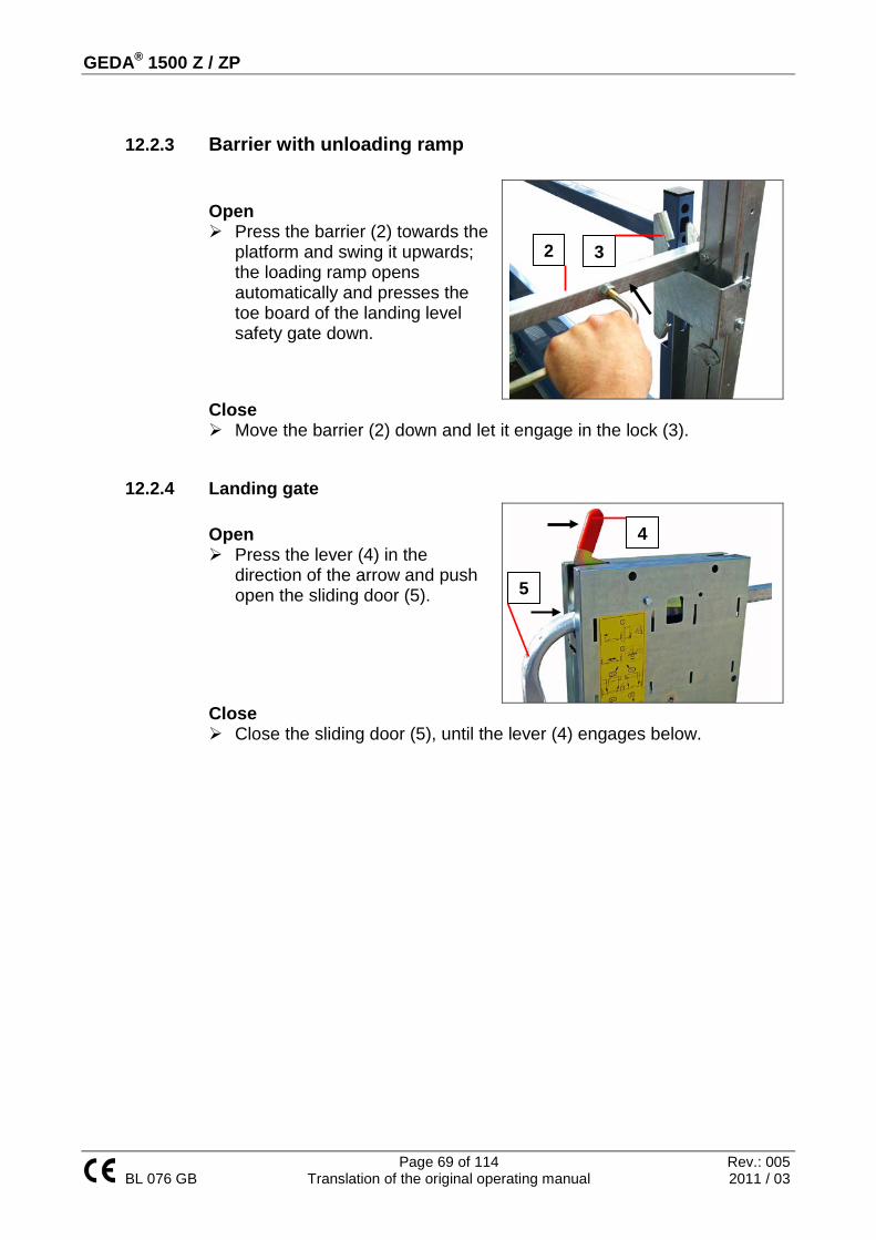
GEDA® 1500 Z / ZP
Page 69 of 114 Rev.: 005 BL 076 GB Translation of the original operating manual 2011 / 03
12.2.3 Barrier with unloading ramp Open Press the barrier (2) towards the
platform and swing it upwards; the loading ramp opens automatically and presses the toe board of the landing level safety gate down.
Close Move the barrier (2) down and let it engage in the lock (3).
12.2.4 Landing gate Open Press the lever (4) in the
direction of the arrow and push open the sliding door (5).
Close Close the sliding door (5), until the lever (4) engages below.
4
5
2 3

GEDA® 1500 Z / ZP
Page 70 of 114 Rev.: 005 BL 076 GB Translation of the original operating manual 2011 / 03
12.2.5 Operating as a material hoist • The platform access points for the ground station, barriers with unloading
ramp and assembly bridge must be closed and engaged. The assembly guard must be properly hung up.
• Activate the main switch on the switchbox of the ground station (position “I” (ON).
• Turn the key in the key switch on the platform control to the left (position 0) and remove the key.
• Push the sliding cover (6) (cover for the platform control) down and latch it with the lock (7).
The hand contro l and e lec tronic module of the landing leve l equipment a re ac tive . The machine can now be used as a material hoist.
6
7

GEDA® 1500 Z / ZP
Page 71 of 114 Rev.: 005 BL 076 GB Translation of the original operating manual 2011 / 03
Manual control Dead man's control
• Selector switch (2) to position “I” Ascent Press the UP (3) button.
The platform only moves as long as the UP (3) button is pressed.
The platform overruns the landing level limit switch approach bar and is stopped by the UP limit switch.
Descent Press the DOWN (4) button.
The platform only moves as long as the DOWN (4) button is pressed. The platform descend and stops automatically approx. 2 m above the ground. It triggers a warning tone for approx. 3 seconds. During this time the control function is interrupted.
WARNING The operator may only continue the descent after he has ensured that the travel path to the ground station is free. Press the DOWN (3) button again or hold it; after the warning tone the
platform moves down to the ground and is stopped by the limit switch. In an emergency the platform is stopped by pressing the
EMERGENCY STOP button (1).
2
1
3
4

GEDA® 1500 Z / ZP
Page 72 of 114 Rev.: 005 BL 076 GB Translation of the original operating manual 2011 / 03
Automatic travel to a landing level
• Selector switch (2) to position “II” Ascent Press and release the UP (3) button.
The platform only ascends above the area 2.0 m above the ground (safety area), if the UP (3) button is pressed. Once this safety area has been exceeded the UP (3) button must be released, and the platform travels automatically to the next level and stops there.
For continuous through-travel to the “second landing level”, hold the
UP button (3) pressed until the limit switch approach bar for the first landing level is overrun.
Descent Press and release the DOWN (4) button.
The platform travels down and stops before the 2.0 m safety area. WARNING
The operator may only continue the descent after he has ensured that the travel path to the ground station is free.
Press and hold the Down button (4) again, this will release a warning
tone, after 3 seconds the platform will move and stops at the DOWN limit switch.
In an emergency the platform is stopped by pressing the
EMERGENCY STOP button (1).
2
3
4
1

GEDA® 1500 Z / ZP
Page 73 of 114 Rev.: 005 BL 076 GB Translation of the original operating manual 2011 / 03
Control units at the landing levels (optional)
With the contro l un its a t the landing leve ls the p la tform can only be contro lled above the 2 m s a fe ty he ight. Be low th is s a fe ty le ve l the p la tform can only be moved b y hand.
Depending on the position of the switch (2) on the hand control unit the operation of the UP or DOWN button (3/4) of the electric module is identical to the hand control unit. The platform is stopped by
pressing the STOP button (8). (The STOP button does not lock into place)
8
3
4

GEDA® 1500 Z / ZP
Page 74 of 114 Rev.: 005 BL 076 GB Translation of the original operating manual 2011 / 03
12.2.6 Operating as transport platform • The transport platform can be operated from the platform only in dead
man's control. The platform only operates for as long as the operating button is pushed.
• The platform may be accessed and exited only at the installed landing level safety gates above 2m.
• The barriers for the ground fencing (where present), platform access point of the ground station and the barrier with unloading ramp have to be closed, locked in place and secured. The assembly guard must be properly hung up.
• The the main switch (on the switchbox of the ground station) has to be switched on [position “I” (ON)].
• The pusher plate (6) in front of the platform control has to be pushed up. • Insert the key (2) into the key switch and turn it right (position 1) to activate
the control console. Ascent Press and hold the UP button (3) to move
the platform up. Stopping the platform in its ascent: Release UP button (3). Platform reaches the upper limit switch
approach bar and stops automatically (the UP limit switch switches off).
In an emergency press the EMERGENCY STOP button (1).
If the platform is to be exited at a transfer point (landing level safety gate) for loading and unloading, then the platform must be stopped in such a manner that it is level with the landing level gate. Stop the platform with the LANDING LEVEL STOP button (5), which is
also pressed along with the UP button before the landing level safety gate is reached. First release the directional button (3) and then the LANDING LEVEL STOP button (or both at the same time).
Alwa ys approach landing leve ls from be low.
1
5
2
3
4
6

GEDA® 1500 Z / ZP
Page 75 of 114 Rev.: 005 BL 076 GB Translation of the original operating manual 2011 / 03
Descent Press and hold the DOWN button (4) to move the platform down. Stopping the platform in its descent: Release DOWN button (4). The platform descend and stops automatically approx. 2 m above the
ground.
WARNING The platform operator may continue the descent only after it has been ensured that the travel path below is clear. Press and hold the Down button (4) again, this will release a warning
tone, after 3 seconds the platform will move and stops at the DOWN limit switch.
In an emergency press the EMERGENCY STOP button (1).

GEDA® 1500 Z / ZP
Page 76 of 114 Rev.: 005 BL 076 GB Translation of the original operating manual 2011 / 03
13 Recovery of people locked inside
Rescue can become necessary if, e.g. • There is no mains voltage. • The electrical system has malfunctioned. • The drive has failed. • The safety gear has been triggered.
13.1 Basic conduct in the event of a rescue/malfunction • Remain calm and do not act hastily. • Get an overview of the situation. • Keep unauthorised people away. • Contact anyone trapped in the car. • Try to find out what has caused the malfunction/defect in the unit, e.g.
o Failure of the power supply o Trigger the safety gear
• Inform any persons trapped in the car about what will happen next. • Inform superiors about the malfunction. • Inform any rescue services.
WARNING If the supervisor does not feel confident or qualified to organise and carry out the rescue, notify the relevant authorities (fire brigade, technical support, factory security office).

GEDA® 1500 Z / ZP
Page 77 of 114 Rev.: 005 BL 076 GB Translation of the original operating manual 2011 / 03
The sequence of measures can / must be varied by the attendant / rescue personnel depending on the specific situation.
13.2 Rescue measures plan
People on the platform:
Measure 1: Inspect the key switch. This might have been operated accidentally.
Measure 2: Self-rescue using the release lever.
Measure 3: Rescue according to the operating company's emergency
plan.
No people on the platform:
Measure 1: Rescue according to the operating company's emergency plan.
The individual measures are explained as follows.
13.3 Rescuing people from the platform
Measure 1: Key switch Turn key switch (1) to position I. Press the UP (2) or DOWN button (3)
to continue the journey. The platform moves.
Measure 2: Self-rescue using EMERGENCY lower
See chapter 10.10
2
1
3

GEDA® 1500 Z / ZP
Page 78 of 114 Rev.: 005 BL 076 GB Translation of the original operating manual 2011 / 03
14 Cleaning
Execution, necessary safety clothing, cleaning agents and equipment according to the applicable instructions from the operating company.
14.1 Internal/external cleaning of the machine • Clean all surfaces thoroughly. • Clean switch cabinets and operating consoles separately. • Signpost wet areas and secure them against access.
14.2 Cleaning the area around the machine • The work methods, cleaning agents and equipment comply with the
applicable instructions of the operating company.
HAZARD Life-threatening hazard Risk of fire and explosion due to the use of combustible cleaning agents. Only use suitable, non-combustible cleaning agents. Do not use steam-jet equipment/high-pressure cleaners. Electrical components can be damaged. Do not touch sockets, cables or electrical components with wet or damp hands. Cleaning work on live components may only be carried out by qualified electrical personnel. Wear personal protective gear.

GEDA® 1500 Z / ZP
Page 79 of 114 Rev.: 005 BL 076 GB Translation of the original operating manual 2011 / 03
15 Assembly Safety instructions, assembly / transport
• Precautionary measures stipulated by the company for avoiding fires, explosions, dust, gas, steam and smoke (during welding, burning and grinding work) must be observed.
• Adhere to the stated torques. To do this use a calibrated torque wrench.
• Use appropriate lifting gear when working with heavy parts. • Adhere to the minimum requirements for thoroughfares, travel paths
and emergency exits. • Provide sufficient space for opening doors and covers. • Only carry out welding, burning and grinding work on the machine
after consultation and approval from GEDA.
• Observe the reduced load-bearing capacity of the platform during assembly.
• Observe the mast anchor distances and trailing cable guides.
• Observe the load capacity of the assembly crane.
• Avoid mixing up/incorrectly re-assembling dismantled parts. Label the parts.
• In the event of wind speeds of > (45 km/h), bring the platform down to the ground and cease operation.
WARNING Life-threatening hazard Raised load. Do not stand under a suspended load. Do not stand on a suspended load. Only raise the load at the sling points. Only use suitable hoisting gear.

GEDA® 1500 Z / ZP
Page 80 of 114 Rev.: 005 BL 076 GB Translation of the original operating manual 2011 / 03
• During assembly, never do the following from the platform:
o Reach or lean into the travel path during ascent/descent o Allow parts to project into the travel path during
ascent/descent o Stand on the load o Exit the platform to climb on to the mast or the building.
• Cordon off/mark out the assembly/hazard area.
• No one is allowed to stand under the assembly/hazard area.

GEDA® 1500 Z / ZP
Page 81 of 114 Rev.: 005 BL 076 GB Translation of the original operating manual 2011 / 03
15.1 Transport to assembly site Check the delivery for completeness and signs of transport damage. Immediately report any transport damage. Correctly dispose of packaging / protective covers or keep for transport
later.
15.1.1 Unloading / loading the base unit using a forklift
The lifting point (1) for the forklift is located under the bearing profile of the platform.
The forks of the forklift must be long enough to ensure safe acceptance of the base unit. Make sure that the base unit cannot fall, because the forks of the forklift are too short. Do not damage the machine when placing the forks of the forklift.
15.1.2 Unloading / loading the base unit using a crane
CAUTION
Damage to the base mast. Never attach load-carrying equipment directly to the base mast. Always use the GEDA lifting eye.
Attach the shackle (2) of the chain sling to the
slinging lug (1) and secure.
1
2
1

GEDA® 1500 Z / ZP
Page 82 of 114 Rev.: 005 BL 076 GB Translation of the original operating manual 2011 / 03
15.2 Assembly plan Fundamentally, assembly is according to the diagram as follows.
Assembly diagram
1. Position base unit 1. Align 2. Attach feet 3. Attach cable bin 4. Connect to operating company's electric power supply
2. Assemble mast 1. Connect mast elements 2. Place anchors 3. Align mast 4. Set the trailing cable guides.
3. Place EMERGENCY limit switch bar 4. Secure loading positions using landing level safety gates
1. Set the limit switch approach bar to the landing level. 5. Check machine for initial commissioning 6. Instruct authorised persons to use.

GEDA® 1500 Z / ZP
Page 83 of 114 Rev.: 005 BL 076 GB Translation of the original operating manual 2011 / 03
15.3 Assembling the base unit The base unit must be horizontal and aligned at a right-angle to the building / scaffolding. Application of force to the foundation must only be through load-distributing supports (area min. = 0.25m2). Position the base unit on the load-distributing supports and align to the
support plates.
WARNING Life-threatening hazard through fracture or slipping of the support plate. The support plate must not carry any load, it is exclusively for adjustment of the base unit. A minimum of two support plates must be secured against displacement. If this is not possible, the first mast anchor must be located at a height of one metre. After installation of the base unit, check to make sure that this is secure and can be used by persons to assemble the mast. For this, carry out a test run with an empty platform.

GEDA® 1500 Z / ZP
Page 84 of 114 Rev.: 005 BL 076 GB Translation of the original operating manual 2011 / 03
15.4 Assemble cable bin and trailing cable bracket Attach trailing cable bracket to the
sliding carriage. Assemble the cable clamp to the
tension release. Put the plug into the socket on the
sliding-carriage switch cabinet and secure with a mounting clip.
Place the cable bin on the foot section and bolt onto the round mast tubes with both scaffold couplings.
Align the cable bin so that the trailing cable is centred as it moves through the trailing cable guide.
Mount the first cable guide approx. 1 m
above the cable bin, to ensure the cable spools in correctly.
After switching on the main switch (2), the green control light (3)
indicates that the system is ready for operation.
If the green contro l ligh t does not illuminate re fe r to the Fault Table .
WARNING Life-threatening hazard After installation of the base unit, check to make sure that this is secure and can be used by persons to assemble the mast. For this, carry out a test run with an empty platform.
1
3
2

GEDA® 1500 Z / ZP
Page 85 of 114 Rev.: 005 BL 076 GB Translation of the original operating manual 2011 / 03
15.5 Assembly / anchoring the mast Assembly and anchoring of the mast is fundamentally carried out from the platform and scaffolding. If assembling without scaffolding, anchoring to the building using a mast bracket is carried out from the assembly bridge.
Load the platform. Observe the max. payload. Close the platform. Press the UP button (platform control).
The platform stops automatically at the top end. Lower the assembly guard. Apply the mast
elements by hand.
Close and tighten the four eyebolts.
(Always extend masts in pairs).
WARNING Life-threatening hazard
Mast brackets must be installed at the following distances. First mast bracket at a height of 6 m. Subsequent mast brackets every 10 metres.
After assembly of a mast bracket, the mast must be correctly aligned using a spirit level.

GEDA® 1500 Z / ZP
Page 86 of 114 Rev.: 005 BL 076 GB Translation of the original operating manual 2011 / 03
Connect the assembly guard again. Press the button UP to assemble another section of mast. Press button DOWN to collect another section of mast from the ground.
15.5.1 Assemble mast bracket In order to mount the mast bracket, ascend as far as necessary for these to be mounted easily. The minimum distance to the assembly bridge is 5 cm.
For greater building clearance distances, use telescopic tubes. Select the greatest horizontal distance as possible to the wall.
HAZARD Life-threatening hazard Crushing or amputation of limbs. Never reach into the travel path of the machine during operation.
WARNING Danger of collision The free end of the tubes must not protrude over the cross-section of the mast / travel path of the platform.

GEDA® 1500 Z / ZP
Page 87 of 114 Rev.: 005 BL 076 GB Translation of the original operating manual 2011 / 03
Install the first two mast anchors at a height of approx. 6 m. After assembly of the mast anchoring, use a spirit level to check the
alignment of the base mast. Further mast anchors are set at intervals of max. 10 m.
Attach the mast bracket (1) from the front to the round mast tube using scaffold coupling (2).
(Tightening torque 50 Nm).
Engage telescopic tube (3). Close the clamps (4) and screw them together so that the tube can still be adjusted.
To adjust the angle, release the nuts below the clamps (4) and move. Re-tighten the nuts.
Re-tighten all 4 nuts. The attachment plate should be bolted to the wall with anchor fittings or
through bolts. (See also the anchoring forces table.)
WARNING Life-threatening hazard through fracture of the mast and falling platform. - until 2 mast anchors are in position or - by negotiating the overhanging part of the mast During assembly, observe the load-carrying capacity and maximum overhanging length of mast for the individual types of platform Rubric dimensions and weights.
1 4 3
2 5

GEDA® 1500 Z / ZP
Page 88 of 114 Rev.: 005 BL 076 GB Translation of the original operating manual 2011 / 03
Secure the telescopic tube (5) to the inside of the circular mast tube
with a rigid scaffold coupling, pulling it towards the wall and anchoring it there. Select the furthest possible horizontal distance between the two anchoring tubes against the wall. (The minimum distance between the two fastening plates is dependent upon the distance between the mast and building, and extension tubes should be used with greater distances).
The vertical and rectangular alignment of the mast must be checked and corrected if necessary.
• The mast is vertically aligned by shifting the anchoring tubes in the mast bracket or scaffold coupling.
• Right-angled alignment of the mast is by using both scaffold couplings (4).
The anchoring for the left mast will be attached at the same height, inversely to the right mast anchoring described above.
In order to keep wear of the gea r racks as low as pos s ib le , we recommend to lubrica te the gea r racks each time a mas t bracke t is as s embled .

GEDA® 1500 Z / ZP
Page 89 of 114 Rev.: 005 BL 076 GB Translation of the original operating manual 2011 / 03
15.5.2 Use of the assembly bridge The assembly bridge is exclusively intended for the assembly of the mast from the platform. Each time before using the platform, make sure that the safety ratchet of the assembly bridge is fully engaged.
When the assembly bridge is open, the platform cannot be moved. Therefore, before assembly of a mast bracket the platform must be positioned so that the assembly bridge can be closed after assembly (1.6 m distance, mast anchor to floor of the platform.)
Open assembly bridge Release the safety ratchet (2), if necessary,
lightly pull the assembly bridge inwards using the handle bar (3).
Push the handle bar (3) slowly out and pull the bar (1).
Release the handle grip (3) and completely lower the bridge using the bar (1).
Push outwards the front wall.
Close assembly bridge Use the switch bar (1) and pull in the front wall. Use the handle bar (3) to fully close the assembly bridge (the safety
ratchet (2) engages in the second sprocket).
15.5.3 Assemble trailing cable guide
The trailing cable guides ensure trouble-free transport of the cable to the cable bin. Trailing cable guides must be mounted depending on the expected wind pressure. We recommend a distance of 6 m.
Assemble the trailing cable guide (1)
on the mast tube so that the guide tube (2) is located central in the trailing cable guide.
1
2
3
1
2

GEDA® 1500 Z / ZP
Page 90 of 114 Rev.: 005 BL 076 GB Translation of the original operating manual 2011 / 03
15.5.4 Assemble EMERGENCY limit switch bar An emergency limit switch bar (1) must be installed as top stop point before the drive pinions leave the gear rack. The hoist is stopped at this bar by the UP operating limit switch or the emergency limit switch in case of an error. Screw in the limit switch bar (1) with
the scaffolding clamp onto the circular mast tube of the left (control side of mast).
Mount the EMERGENCY limit switch bar so that during operation the last mast anchor can be exceeded by - max. 6 m (platform A, C-I) - maximum 2 m (platform B, BS, BL,
BLL).
The distance of the EMERGENCY limit switch bar to the top end of the mast must be a minimum of 1.25 m.
WARNING Danger of injury Operation without a correctly installed EMERGENCY limit switch bar is prohibited. EMERGENCY limit switch bars must be installed before commissioning according to the following information.

GEDA® 1500 Z / ZP
Page 91 of 114 Rev.: 005 BL 076 GB Translation of the original operating manual 2011 / 03
15.5.5 Safeguarding loading and unloading points Protection to prevent falling is to be provided at all loading and unloading points at a height of more than 2 m. Only guard rails can be used that enable transfer without danger. Type approved GEDA hoists may only be used with correspondingly approved landing level safety doors. For assembly of the landing level safety gates, refer to the corresponding manual.
15.5.6 Assembly of landing level, limit switch bar The landing level limit switch bars are positioned in the left section of the mast (control side) from the platform. Position the landing level,
limit switch bars between both square tubes and attach to the round mast tube using the scaffold coupling welded on.
Distance to landing level floor Y = 0.25 m
15.5.7 Tests after assembly / tests before initial commissioning Carry out tests in accordance with the information given in the chapter “Tests”.
GEDA® 1500 Z / ZP
Page 92 of 114 Rev.: 005 BL 076 GB Translation of the original operating manual 2011 / 03
16 Dismantling The same regulations and safety instructions as described for assembly apply for dismantling. Disassembly is generally carried out in reverse order to assembly, in addition please note the following:
• First dismantle the landing level safety equipment (fit 3-part protection first).
• Then check whether all mast connection bolts are in engaged.
• The platform must be stopped in such a way that the mast joint of the mast being removed is located over the upper edge of the sliding carriage.
• Only loosen the mast anchors if there are no longer any mast sections above the anchor point.
• Always unload the platform in the interim time (the hoist cannot be moved if overloaded).
17 Disposal of the machine Dismantle the equipment properly at the end of its service life and dispose of in an environmentally friendly way according to national provisions. It is prohibited to recycle parts from a machine that is being disposed of and use them in other machines, or to assemble such parts into a new machine.

GEDA® 1500 Z / ZP
Page 93 of 114 Rev.: 005 BL 076 GB Translation of the original operating manual 2011 / 03
18 MAINTENANCE
18.1 Warnings and safety instructions to be complied with during servicing/repairs
WARNING The entire manual must be read for all service/repair work. Work is prohibited if the type and scope of work to be carried out is unclear or if the hazards and measures to avert said hazards are unclear. All unclear issues must be resolved before starting work. All safety instructions must be complied with.
HAZARD Life-threatening hazard Crushing or amputation of limbs. Never reach into the travel path of the machine during operation.
HAZARD Life-threatening hazard Falling tools/parts Secure tools / parts against falling
HAZARD Life-threatening hazard Due to the machine being switched on during servicing/repair work or when there is a defect. Secure the main switch with a padlock to prevent it being switched on.
WARNING Fall and trip hazard Look out for steps and objects on the ground when entering/exiting the platform.

GEDA® 1500 Z / ZP
Page 94 of 114 Rev.: 005 BL 076 GB Translation of the original operating manual 2011 / 03
HAZARD Electric shock Parts remain live even after pressing the EMERGENCY STOP or after turning off the machine at the main switch. This applies to all work on electrical parts. Disconnect the mains supply upstream from the main switch.
WARNING Life-threatening hazard Raised load Do not stand under a suspended load Do not stand on a suspended load Only raise load at the sling points. Only use suitable hoisting gear
WARNING Life-threatening hazard Access only for authorised people. Access prohibited for unauthorised people.

GEDA® 1500 Z / ZP
Page 95 of 114 Rev.: 005 BL 076 GB Translation of the original operating manual 2011 / 03
18.2 Maintenance schedule Tasks to be carried out
Ever
y w
eek
Ever
y m
onth
Qua
rter
ly
Ever
y ye
ar
Check the braking distance X1
Check the gear rack and drive pinion for lubrication and wear. X1
Check the trailing cable, mains supply cable and control cables for damage.
X1
Visual inspection of all defect devices and limit switches X
Check the gear rack and drive pinion for wear X
Check that the mast connecting bolts, EMERGENCY limit switch approach bar and mast anchors/bolts are secured to the mast and the building, tighten if necessary.
X
Rub the trailing cable with lubricant. X
Check the grease quantity of the lubrication device and refill if necessary
X1
Notices present and easily legible X
Functional check of the control points [manual control, electric module (where present), platform control]
X
Functional test of the collision grille (optional) X
Check the gear oil on the drives X
Check the gear rack is positioned securely X
Check motor brakes (air gap and pad thickness) X
Check the rescue equipment X
Check the overload position X
Function check of the drop test control X
Test the safety gear X
Check the track rollers on the sliding carriage X
Earth conductor test in accordance with EN 60204, Part 1 X²
Insulation test in accordance with EN 60204, Part 1 X² 1Correspondingly more often in the case of frequent use or multi-shift operation. ² Maximum test intervals, which could be much shorted depending on the place of
installation and national regulations.

GEDA® 1500 Z / ZP
Page 96 of 114 Rev.: 005 BL 076 GB Translation of the original operating manual 2011 / 03
18.3 Tests During the tests, the relevant safety-related characteristics of the machine are checked for condition, availability and function using appropriate procedures. Appropriate procedures are:
• Visual inspections • Functional and efficiency tests • Tests using measuring and testing equipment
The scope, type and schedule of each test must be defined by the operating company and persons authorised to carry out the test.
Test schedules
Tested by a trained person
Inspection by a competent person
Inspection by an accredited supervisory body (recurring test)
Simple visual and functional checks with a few test steps and simple evaluation
For systems subject to monitoring. Testing according to national regulations
Inspection by a competent person
Testing due to particular events / damage-inducing influences, e.g.
Tests according to a maintenance schedule
Natural phenomena: • Lightning • Storm • Flooding • Cold > -20 °C
See there
Accidents: • Collision • Tip-over • Crash
Changes/modifications: • Drive replacement • Safety gear replacement • Changes to the control electronics • Replacement of control and protection equipment • Replacement of electrical power cables
Assembly: • For initial commissioning • At a new location
Exposure to harmful substances • Corrosive media • Contamination of an unknown origin

GEDA® 1500 Z / ZP
Page 97 of 114 Rev.: 005 BL 076 GB Translation of the original operating manual 2011 / 03
Visual inspections must always be carried out before function checks. Any defects identified must be reported immediately to a superior and rectified. Operation is prohibited until the defects are rectified. Faults may only be rectified by competent specialists who are authorised to implement them. Visual inspections and functional tests - see “Operation” Documentation of the results The operator must document the results of tests. The documentation must be kept for a reasonable period of time – although at least for the entire lifespan of the machine. Proof of the performance of the last test must be attached to the machine.

GEDA® 1500 Z / ZP
Page 98 of 114 Rev.: 005 BL 076 GB Translation of the original operating manual 2011 / 03
18.4 Replenishment and inspection tasks
18.4.1 Lubrication device
Replenishing through the nipple Place the grease gun to the nipple (1)
(Underside of the container). Fill reservoir to the “MAX” mark.
Quick-filling with a filling gun Remove the cap from the filling
connection (2). Insert the grease gun up to the stop
point inside the filling connection. Fill reservoir to the “MAX” mark. The function of the lubrication device
can be checked using the button (4).
Bleeding the lubrication device If the limit switch is defective, the lubrication device will run completely empty and must be bled after the limit switch has been repaired / replaced. Place the grease gun on the nipple (1). Fill up to 4 cm above the “MIN” mark. Remove the lubrication hose from the pump housing. Remove the pump element or locking screw (M20x1.5) and keep open
until bubble-free grease is discharged. Install the pump element or locking screw. Activate a lubrication pulse until bubble-free lubricant discharges. Reconnect the lubricating hose.
CAUTION Do not use grease with solid lubricants. This could damage the lubrication device.
2
3
1
4

GEDA® 1500 Z / ZP
Page 99 of 114 Rev.: 005 BL 076 GB Translation of the original operating manual 2011 / 03
18.5 Checking for wear
18.5.1 Drive pinion Number of teeth = 21
X
Module m = 6 Wear limit
Dimension X min.
Dimension X normal
27,6 mm 28,3 mm Measure dimension X on each tooth
18.5.2 Gear rack
A
Ø D
B
Wear limit
(A) min. (A) new 68,5 mm 69,6 mm Gauging pin: (D) = 12 mm (+0.0 / -0.11 mm) (B) = 65,2
Check that all gear racks are positioned securely. If necessary tighten gear racks with 60 Nm. (8 mm Allen key)
WARNING Danger of injury from components failing Parts must be replaced immediately if the specified wear limits are exceeded. Machine operation is prohibited until the parts have been replaced. All parts must also be checked for damage (deformation, cracks, cavities, etc.).

GEDA® 1500 Z / ZP
Page 100 of 114 Rev.: 005 BL 076 GB Translation of the original operating manual 2011 / 03
18.5.3 Tracks rollers Track roller (white) Item No. 13060
Wear limit (diameter)
Ø min. Ø normal 77 mm 78-0,30 mm Also check the play and condition of the bearing. There must be a circlip.
Track roller with chamfer (white) item no. 18013
Wear limit (diameter)
Ø min. Ø normal 77 mm 78-0,30 mm Also check the play and condition of the bearing. There must be a circlip.
Track roller (black) Item No. 19983
Wear limit (diameter)
Ø min. Ø normal 76 mm 77-0,30 mm Also check the play and condition of the bearing. There must be a circlip.
Changing the track roller
HAZARD Life-threatening hazard Falling tools/parts Secure tools / parts against falling

GEDA® 1500 Z / ZP
Page 101 of 114 Rev.: 005 BL 076 GB Translation of the original operating manual 2011 / 03
18.5.4 Drive brake
Brake pad wear limits Min. 11.5 mm Air gap wear limit max. nominal 0.8 mm 0.3 mm
1 = Motor bearing plate 2 = Magnetic body 3 = Anchor plate 4 = Brake pad 5 = Compression springs
6 = Banjo bolts 7 = Hexagonal screws 8 = Carrier 9 = Adjusting ring 10 = Manual release
Air gap must be the same at each position. Always check the air gap at several positions.
In addition to this information, you must observe the information in the manufacturer's manual. Non-compliance releases GEDA from any liability. Switch off the motor power supply. Unscrew the manual release bolts. Loosen the attachment bolt and remove the fan cover. Remove the cable. Pull the dust protection ring out of the SLOT in the magnetic body and
put it over the bearing plate. Remove dust with compressed air. Loosen bolts and replace them with new bolts. Screw banjo bolts into the magnetic body to achieve the specified
distance. Tighten bolts with a torque of 25 Nm. Check the air gap with a caliper. Check that the banjo bolts are secure. Assemble in reverse order. Carry out a function test.

GEDA® 1500 Z / ZP
Page 102 of 114 Rev.: 005 BL 076 GB Translation of the original operating manual 2011 / 03
18.6 Function checks
18.6.1 Safety gear The drop test is only permitted
• When no other persons are on the platform or in the travel path. • The platform is unloaded. • If there are no objects in the travel path • If the drop test is activated from a safe distance
Execution
WARNING Danger of injury The drop test may only be carried out by a qualified person, specifically appointed by the operating company who, based on their training, knowledge and practical experience, can evaluate the risks and assess the safe condition of the safety gear.
Remove the dummy plug (1). Insert the safety gear control (2).
1 2

GEDA® 1500 Z / ZP
Page 103 of 114 Rev.: 005 BL 076 GB Translation of the original operating manual 2011 / 03
18.6.2 Drop test successful
Press the UP (1) button. The platform moves out of the drop position.
Turn the turnkey (2) shortly (max. 1 sec). The platform descends. Repeat the process until the platform has descended. Disconnect the drop test control. Insert the dummy plug. Check the safety gear for damage.
18.6.3 Drop test not successful
Turn the turnkey (2) shortly (max. 1 sec). The platform descends. Repeat the process until the platform has descended. Switch the machine off at the main switch and secure is from being
switched back on.
Press the UP button (1) until the platform is approx. 6 m high.
Turn the turnkey (2) to the right.
The brake opens and the platform moves downwards. The safety gear must stop the platform after approx. 2–3 m If the platform does not stop: Release the turnkey (2).
WARNING Danger of injury Immediately replace the safety gear. Until then machine operation is prohibited.
2
1

GEDA® 1500 Z / ZP
Page 104 of 114 Rev.: 005 BL 076 GB Translation of the original operating manual 2011 / 03
18.6.4 Check the safety gear for damage If any damage is identified on the safety gear replace it immediately. Machine operation is prohibited until it is repaired. Turn the main switch to OFF. Secure it against being switched on. Loosen nut (3). Remove protective cover (4). Check brake pads for damage. Check flyweights for ease of movement. Condition of welded seams. Condition of springs. Corrosion / deformation. Replace protective cover.
Replace the protective cover (4) so that the switch tag (5) engages in
the slot in the protective cover. (Alternatively, turn the protective cover anti-clockwise until the switch tag (5) engages in the slot in the protective cover.)
Tighten nut (4).
18.6.5 Safety gear replacement GEDA safety gear must be replaced with new GEDA safety gear (safety gear exchange units) after 6 years at the latest. The obligation to replace safety gear applies to both material hoists and personnel hoists.
WARNING Danger of injury The safety gear must be inspected every 6 years by the manufacturer. Repairs maay only be carried out by the manufacturer.
3
5
4

GEDA® 1500 Z / ZP
Page 105 of 114 Rev.: 005 BL 076 GB Translation of the original operating manual 2011 / 03
18.7 Fault table
Fault Cause Remedial action Green control light off
Main switch off Illuminant defective Phase failure Incorrect phase sequence Trailing cable connected Fuses OK
Turn on main switch Replace illuminant Measure phases Correction of phase sequence at phase changer Connect trailing cable Check / correction
Red control light on Overload protection has been triggered
Reduce the load
Motor does not produce full output
Voltage drop of more than 10 %
Select a supply cable with a greater cross section
Platform runs too high
Top landing-level limit switch defective Fault in the electrical system
Test/replace the top landing-level limit switch Check system
Platform runs too low
Fault in the electrical system Excessive brake air gap
Check system Adjust air gap
The platform access door does not open.
The platform is not stopped by the DOWN limit switch Door lock defective No voltage
Move the platform to the DOWNlimit switch Emergency interlock release door Replace defective lock Connect power supply
WARNING Only have troubleshooting and fault resolution carried out by authorised personnel trained especially for these tasks. Below you will find potential faults and the appropriate remedial action.

GEDA® 1500 Z / ZP
Page 106 of 114 Rev.: 005 BL 076 GB Translation of the original operating manual 2011 / 03
Fault Cause Remedial action The platform does not move
Main switch off
Main switch on
The platform access door is not correctly closed and locked
Close the access door Check and, if necessary, replace the lock
The barrier with the unloading ramp is not correctly closed
Close the barrier Check/exchange the limit switch
The landing level door of the safety gates is not closed correctly (only for the electric module option)
Close landing gate Check/exchange the limit switch
The key switch position does not suit the operating mode
Move the key switch to suit the operating mode I = Platform control 0 = External control
Mains connection phase failure Mains connection fuses
Check the fuses
Fuses in the switch cabinet of the ground station activated
Check and, if necessary, replace fuses (primary fuse 2x630 mA, control fuse 2 A)
Emergency limit switch actuated
Correct the distance
Safety gear triggered
Check and, if necessary, replace
Distance of the proximity switch to the gear rack switch too large
Check the distance and is necessary correct (correct = 5-7 mm)
Actuating controls for the up and down limit switches functioning correctly
Check and, if necessary, replace

GEDA® 1500 Z / ZP
Page 107 of 114 Rev.: 005 BL 076 GB Translation of the original operating manual 2011 / 03
19 Documenting the tests
Documentation for a regular check according to the maintenance schedule unscheduled check after unusual events
Name: Year of manufacture:
Serial number: Factory number:
The machine was checked on______________. Thereby no the following
defects were determined:
Scope of inspection:
Outstanding part checks:
Continued operation is: prohibited permitted
Another check is necessary not necessary
Place, date Signature (Technical specialist/qualified person*)
*Name of qualified person
Operating company: Address:
Operating company: Faults acknowledged:
Defects rectified:
STAMP INSPECTOR

GEDA® 1500 Z / ZP
Page 108 of 114 Rev.: 005 BL 076 GB Translation of the original operating manual 2011 / 03
Documentation for a regular check according to the maintenance schedule unscheduled check after unusual events
Name: Year of manufacture:
Serial number: Factory number:
The machine was checked on______________. Thereby no the following
defects were determined:
Scope of inspection:
Outstanding part checks:
Continued operation is: prohibited permitted
Another check is necessary not necessary
Place, date Signature (Technical specialist/qualified person*)
*Name of qualified person
Operating company: Address:
Operating company: Faults acknowledged:
Defects rectified:
Stamp Inspector

GEDA® 1500 Z / ZP
Page 109 of 114 Rev.: 005 BL 076 GB Translation of the original operating manual 2011 / 03
Documentation for a regular check according to the maintenance schedule unscheduled check after unusual events
Name: Year of manufacture:
Serial number: Factory number:
The machine was checked on______________. Thereby no the following
defects were determined:
Scope of inspection:
Outstanding part checks:
Continued operation is: prohibited permitted
Another check is necessary not necessary
Place, date Signature (Technical specialist/qualified person*)
*Name of qualified person
Operating company: Address:
Operating company: Faults acknowledged:
Defects rectified:
Stamp Inspector

GEDA® 1500 Z / ZP
Page 110 of 114 Rev.: 005 BL 076 GB Translation of the original operating manual 2011 / 03
Documentation for a regular check according to the maintenance schedule unscheduled check after unusual events
Name: Year of manufacture:
Serial number: Factory number:
The machine was checked on______________. Thereby no the following
defects were determined:
Scope of inspection:
Outstanding part checks:
Continued operation is: prohibited permitted
Another check is necessary not necessary
Place, date Signature (Technical specialist/qualified person*)
*Name of qualified person
Operating company: Address:
Operating company: Faults acknowledged:
Defects rectified:
Stamp Inspector

GEDA® 1500 Z / ZP
Page 111 of 114 Rev.: 005 BL 076 GB Translation of the original operating manual 2011 / 03
Documentation for a regular check according to the maintenance schedule unscheduled check after unusual events
Name: Year of manufacture:
Serial number: Factory number:
The machine was checked on______________. Thereby no the following
defects were determined:
Scope of inspection:
Outstanding part checks:
Continued operation is: prohibited permitted
Another check is necessary not necessary
Place, date Signature (Technical specialist/qualified person*)
*Name of qualified person
Operating company: Address:
Operating company: Faults acknowledged:
Defects rectified:
Stamp Inspector

GEDA® 1500 Z / ZP
Page 112 of 114 Rev.: 005 BL 076 GB Translation of the original operating manual 2011 / 03
Documentation for a regular check according to the maintenance schedule unscheduled check after unusual events
Name: Year of manufacture:
Serial number: Factory number:
The machine was checked on______________. Thereby no the following
defects were determined:
Scope of inspection:
Outstanding part checks:
Continued operation is: prohibited permitted
Another check is necessary not necessary
Place, date Signature (Technical specialist/qualified person*)
*Name of qualified person
Operating company: Address:
Operating company: Faults acknowledged:
Defects rectified:
Stamp Inspector

GEDA® 1500 Z / ZP
Page 113 of 114 Rev.: 005 BL 076 GB Translation of the original operating manual 2011 / 03
Space for notices
Notice entered Name: / Date Position

GEDA® 1500 Z / ZP
Page 114 of 114 Rev.: 005 BL 076 GB Translation of the original operating manual 2011 / 03
Space for notices
Notice entered Name: / Date Position