Installation Instructions - Trane Technologies
24
Electric Heaters Precedent™ 6 to 10 Ton Models Installation Instructions April 2020 ACC-SVN67L-EN CV_ModelNum Used With: See General Information SAFETY WARNING Only qualified personnel should install and service the equipment. The installation, starting up, and servicing of heating, ventilating, and air-conditioning equipment can be hazardous and requires specific knowledge and training. Improperly installed, adjusted or altered equipment by an unqualified person could result in death or serious injury. When working on the equipment, observe all precautions in the literature and on the tags, stickers, and labels that are attached to the equipment.
-
Upload
khangminh22 -
Category
Documents
-
view
6 -
download
0
Transcript of Installation Instructions - Trane Technologies

Electric Heaters
Precedent™ 6 to 10 Ton Models
Installation Instructions
April 2020 ACC-SVN67L-EN
CV_ModelNum Used With:
See General Information
SAFETY WARNINGOnly qualified personnel should install and service the equipment. The installation, starting up, and servicing of heating, ventilating, and air-conditioning equipment can be hazardous and requires specific knowledge and training. Improperly installed, adjusted or altered equipment by an unqualified person could result in death or serious injury. When working on the equipment, observe all precautions in the literature and on the tags, stickers, and labels that are attached to the equipment.
Introduction
Read this manual thoroughly before operating or servicing this unit.
Warnings, Cautions, and Notices
Safety advisories appear throughout this manual as required. Your personal safety and the proper operation of this machine depend upon the strict observance of these precautions.
The three types of advisories are defined as follows:
WARNINGIndicates a potentially hazardous situation which, if not avoided, could result in death or serious injury.
CAUTIONsIndicates a potentially hazardous situation which, if not avoided, could result in minor or moderate injury. It could also be used to alert against unsafe practices.
NOTICE Indicates a situation that could result in equipment or property-damage only accidents.
Important Environmental Concerns
Scientific research has shown that certain man-made chemicals can affect the earth’s naturally occurring stratospheric ozone layer when released to the atmosphere. In particular, several of the identified chemicals that may affect the ozone layer are refrigerants that contain Chlorine, Fluorine and Carbon (CFCs) and those containing Hydrogen, Chlorine, Fluorine and Carbon (HCFCs). Not all refrigerants containing these compounds have the same potential impact to the environment. Trane advocates the responsible handling of all refrigerants-including industry replacements for CFCs and HCFCs such as saturated or unsaturated HFCs and HCFCs.
Important Responsible Refrigerant Practices
Trane believes that responsible refrigerant practices are important to the environment, our customers, and the air conditioning industry. All technicians who handle refrigerants must be certified according to local rules. For the USA, the Federal Clean Air Act (Section 608) sets forth the requirements for handling, reclaiming, recovering and recycling of certain refrigerants and the equipment that is used in these service procedures. In addition, some states or municipalities may have additional requirements that must also be adhered to for responsible management of refrigerants. Know the applicable laws and follow them.
WARNING
Proper Field Wiring and Grounding Required!
Failure to follow code could result in death or serious injury. All field wiring MUST be performed by qualified personnel. Improperly installed and grounded field wiring poses FIRE and ELECTROCUTION hazards. To avoid these hazards, you MUST follow requirements for field wiring installation and grounding as described in NEC and your local/state electrical codes.
WARNING
Personal Protective Equipment (PPE) Required!
Failure to wear proper PPE for the job being undertaken could result in death or serious injury. Technicians, in order to protect themselves from potential electrical, mechanical, and chemical hazards, MUST follow precautions in this manual and on the tags, stickers, and labels, as well as the instructions below:
• Before installing/servicing this unit, technicians
MUST put on all PPE required for the work being
undertaken (Examples; cut resistant gloves/sleeves,
butyl gloves, safety glasses, hard hat/bump cap, fall
protection, electrical PPE and arc flash clothing).
ALWAYS refer to appropriate Safety Data Sheets
(SDS) and OSHA guidelines for proper PPE.
• When working with or around hazardous chemicals,
ALWAYS refer to the appropriate SDS and OSHA/GHS
(Global Harmonized System of Classification and
Labeling of Chemicals) guidelines for information on
allowable personal exposure levels, proper
respiratory protection and handling instructions.
• If there is a risk of energized electrical contact, arc, or
flash, technicians MUST put on all PPE in accordance
with OSHA, NFPA 70E, or other country-specific
requirements for arc flash protection, PRIOR to
servicing the unit. NEVER PERFORM ANY
SWITCHING, DISCONNECTING, OR VOLTAGE
TESTING WITHOUT PROPER ELECTRICAL PPE AND
ARC FLASH CLOTHING. ENSURE ELECTRICAL
METERS AND EQUIPMENT ARE PROPERLY RATED
FOR INTENDED VOLTAGE.
© 2020 ACC-SVN67L-EN

Introduction
WARNING
Follow EHS Policies!
Failure to follow instructions below could result in death or serious injury.
• All Trane personnel must follow the company’s
Environmental, Health and Safety (EHS) policies
when performing work such as hot work, electrical,
fall protection, lockout/tagout, refrigerant handling,
etc. Where local regulations are more stringent than
these policies, those regulations supersede these
policies.
• Non-Trane personnel should always follow local
regulations.
Copyright
This document and the information in it are the property of Trane, and may not be used or reproduced in whole or in part without written permission. Trane reserves the right to revise this publication at any time, and to make changes to its content without obligation to notify any person of such revision or change.
Trademarks
All trademarks referenced in this document are the trademarks of their respective owners.
Revision History
Updated to include high efficiency heat pump/dual fuel for 6 to 10 tons.
ACC-SVN67L-EN 3

4 ACC-SVN67L-EN
Table of Contents
General Information . . . . . . . . . . . . . . . . . . . . . 5
General . . . . . . . . . . . . . . . . . . . . . . . . . . . . . . 8
Inspection . . . . . . . . . . . . . . . . . . . . . . . . . . 8
Installation . . . . . . . . . . . . . . . . . . . . . . . . . . . . . . 9
Electrical Data . . . . . . . . . . . . . . . . . . . . . . . . . . 13

General Information
Table 1. Heater information
Model Number Used WithBAYHTRS309
TSC072H3BAYHTRS318
BAYHTRS327
BAYHTRS336
BAYHTRS409 TSC072H4
BAYHTRS418
TSC072H4TSC072EDWSC072ED
WSC090ED TSC090EDBAYHTRS427
BAYHTRS436
BAYHTRSW09
TSC072HWBAYHTRSW18
BAYHTRSW27
BAYHTRSW36
BAYHTRT309
TSC092H3 TSC102H3BAYHTRT318
BAYHTRT327
BAYHTRT336
BAYHTRT409TSC092H4 TSC102H4
BAYHTRT418
BAYHTRT427 TSC092H4 TSC102H4 TSC102ED
BAYHTRT436 TSC120ED WSC120ED
BAYHTRT454 TSC120ED WSC120ED
BAYHTRTW18
TSC092EW TSC102EWBAYHTRTW27
BAYHTRTW36
BAYHTRA309THC074F3, TZC072F3 THC092F3, TZC090F3 WSC092H3(a),
WHC074H3, WHC092H3, WHC102H3
THC102F3, TZC102F3 TSC092H3, TSC102H3
WSC090H3(a) WSC102H3(a)
BAYHTRA318
THC074F3 THC092F3 WSC092H3(a), WHC074H3, WHC092H3, WHC102H3
THC102F3 WSC120H3
WSC090H3(a) WSC102H3(a)
BAYHTRA327
TSC120H3 THC074F3, TZC072F3 THC092F3 THC102F3, TZC102F3 WSC092H3(a), WHC074H3, WHC092H3, WHC102H3
WSC090H3(a) WSC102H3(a), WSC120H3 TZC090F3 TSC092H3, TSC102H3
BAYHTRZ318(a)TZC072F3 TZC090F3 TSC092H3
TZC102F3 TSC102H3 TSC120H3
BAYHTRA336
THC074F3 THC092F3 THC102F3 WSC092H3(a), WHC074H3, WHC092H3, WHC102H3
WSC090H3(a) WSC102H3(a) WSC120H3
BAYHTRZ336(a)TZC072F3 TZC090F3 TSC092H3 TZC102F3
TSC102H3 TSC120H3
BAYHTRA354 TSC120H3 WSC120H3
BAYHTRA409 THC074F4, THC092F4 TSC092H4, TSC102H4 WSC090H4(a) WSC102H4(a)
WSC092H4(a), WHC074H4, WHC092H4, WHC102H4
BAYHTRZ409 TZC072F4 TZC090F4 TZC102F4
BAYHTRA418
TSC120H4, TSC092H4 THC074F4, TZC072F4 THC092F4, TZC090F4 THC102F4, TZC102F4 WSC092H4(a), WHC074H4, WHC092H4, WHC102H4
TSC102H4 WSC090H4(a) WSC102H4(a) WSC120H4
ACC-SVN67L-EN 5

General Information
BAYHTRA427
TSC120H4 THC074F4, TZC072F4 THC092F4, TZC090F4 THC102F4, TZC102F4 WSC092H4(a), WHC074H4, WHC092H4, WHC102H4
TSC092H4, TSC102H4 WSC090H4(a) WSC102H4(a) WSC120H4
BAYHTRA436
TSC120H4, TSC092H4 THC074F4, TZC072F4 THC092F4, TZC090F4 THC102F4, TZC102F4 WSC092H4(a), WHC074H4, WHC092H4, WHC102H4
TSC102H4 WSC090H4(a) WSC102H4(a) WSC120H4
BAYHTRA454 TSC120H4 WSC120H4
BAYHTRZ454A TZC120H4
BAYHTRAW18TSC120HW TZC072FW,
TSC092HW, THC092FW, TZC090FW THC102FW, TZC102FW WSC092HW(a),
WHC074HW, WHC092HW, WHC102HWTSC102HQW WSC090HW(a) WSC102HW(a) WSC120HW
BAYHTRAW27 WSC090HW(a) WSC102HW(a) WSC120HW
WSC092HW(a), WHC074HW, WHC092HW, WHC102HW
BAYHTRAW36
TSC120HW, TSC092HW, TZC072FW THC092FW, TZC090FW THC102FW, TZC102FW WSC092HW(a),
WHC074HW, WHC092HW, WHC102HWTSC102HW WSC090HW(a) WSC102HW(a) WSC120HW
BAYHTRAW54 TSC120HW WSC120HW
BAYHTRB318 WHC120H3
BAYHTRB327 WHC120H3
BAYHTRB336 WHC120H3
BAYHTRB354 WHC120H3
BAYHTRB418 WHC120H4
BAYHTRB427 WHC120H4
BAYHTRB436 WHC120H4
BAYHTRB454 WHC120H4
BAYHTRBW18 TZC120FW WHC120HW
BAYHTRBW36 WHC120HW
BAYHTRBW54 WHC120HW
BAYHTRD318 THC120E3 TZC120F3
BAYHTRD327 THC120E3 TZC120F3
BAYHTRD336 THC120E3
BAYHTRZ337A TZC120F3
BAYHTRD354 THC120E3
BAYHTRZ354A TZC120F3
BAYHTRD418 THC120E4 TZC120F4
BAYHTRD427 THC120E4 TZC120F4
BAYHTRD436 THC120E4
BAYHTRZ436A TZC120F4
BAYHTRD454 THC120E4
BAYHTRZ454A TZC120F4
BAYHTRU309 THC072F3 WSC090H3 WSC092H3 WSC102H3
BAYHTRU318 THC072F3 WSC090H3 WSC092H3 WSC102H3
BAYHTRU327 THC072F3 WSC090H3 WSC092H3 WSC102H3
BAYHTRU336 THC072F3 WSC090H3 WSC092H3 WSC102H3
BAYHTRU409 THC072F4 WSC090H4 WSC092H4 WSC102H4
BAYHTRU418 THC072F4 WSC090H4 WSC092H4 WSC102H4
BAYHTRU427 THC072F4 WSC090H4 WSC092H4 WSC102H4
BAYHTRU436 THC072F4 WSC090H4 WSC092H4 WSC102H4
BAYHTRUW18 THC072FW WSC090HW WSC092HW WSC102HW
BAYHTRUW27 THC072FW WSC090HW WSC092HW WSC102HW
Table 1. Heater information (continued)
Model Number Used With
6 ACC-SVN67L-EN

General Information
BAYHTRUW36 THC072FW WSC090HW WSC092HW WSC102HW
BAYHTRW309 TSC090H3 WSC072H3
BAYHTRW318 TSC090H3 WSC072H3
BAYHTRW327 TSC090H3 WSC072H3
BAYHTRW336 TSC090H3 WSC072H3
BAYHTRW409 TSC090H4 WSC072H4
BAYHTRW418 TSC090H4 WSC072H4
BAYHTRW427 TSC090H4 WSC072H4
BAYHTRW436 TSC090H4 WSC072H4
BAYHTRWW18 TSC090HW WSC072HW
BAYHTRWW27 TSC090HW WSC072HW
BAYHTRWW36 TSC090HW WSC072HW
(a) These kits to be used with Title 24/SZVAV models.
Table 1. Heater information (continued)
Model Number Used With
ACC-SVN67L-EN 7

General Information
General
ALL phases of this installation must comply with NATIONAL, STATE AND LOCAL CODES. Installer must mark unit nameplate with heater information per instructions on nameplate.
Note: If digit 9 in the unit model number equals "E" (electromechanical control), accessory relay BAY24X042 is required if the thermostat does not energize the fan circuit in the heating mode. See Figure 1 for wiring information.
Figure 1. Electromechanical wiring diagram
Inspection
1. Unpack all components of the kit.
2. Check carefully for any shipping damage. If any damage is found it must be reported immediately and a claim made against the transportation company.
3. Check the heater nameplate model number and compare with the electrical data tables. Ensure that the available power supply and unit's model number complies with the particular heater being used.
8 ACC-SVN67L-EN

Installation
WARNING
Hazardous Voltage w/Capacitors!
Failure to disconnect power and discharge capacitors before servicing could result in death or serious injury. Disconnect all electric power, including remote disconnects and discharge all motor start/run capacitors before servicing. Follow proper lockout/tagout procedures to ensure the power cannot be inadvertently energized. Verify with an appropriate voltmeter that all capacitors have discharged.
For additional information regarding the safe discharge of capacitors, see PROD-SVB06A-EN
WARNING
Fire Hazard!
On BAYHTRA, BAYHTRB, BAYHTRD, BAYHTRU, and BAYHTRW heater kits, failure to allow a one inch clearance from the supply ductwork to any combustible materials could cause the combustible materials to catch on fire which could result in death, serious injury, or property damage.
1. Remove heater compartment access panel and unit control box access panel. See Figure 2.
Figure 2. Control covers and access panels
Note: On downflow units with or without duct work installed or horizontal units without ductwork installed, remove horizontal supply cover from the rear of the heater compartment.
2. Remove insulation to expose perimeter of removable panel in the vestibule panel. See Figure 2.
3. Clip or cut the retaining tabs around the perimeter of the removable panel.
4. Remove the panel.
5. Check the opening in the vestibule panel. Remove any metal burrs or slivers that could damage or pinch the heater elements resulting in a short circuit when elements are installed in the opening.
Note: Locator tabs on the vestibule panel support the electric heat assembly and secure the inward edge of the electric heat accessory control panel. Slits in the insulation should allow the tabs to protrude through the insulation and be visible. However, it may be necessary to work the insulation back from the tabs and slightly bend the tabs outward if difficulty is encountered engaging the electric heater panel or the electric heat accessory control panel. See Figure 3.
Figure 3. Electric heater element panel
6. The electric heater element assembly has “BOTTOM” stamped in the mounting panel to identify the proper position for mounting.
7. Refer to Table 2. If the unit/heater combination being installed is the same as any in this table and the application is for horizontal airflow, the limit control TCO-A must be replaced with the extra limit control shipped with the heater. Replace TCO-A following the instructions in steps 8 and 9. If the unit/heater combination being installed does not correspond to any in this table or if the application is for downflow airflow, skip steps 8 and 9 and go on to step 10.
HorizontalSupplyCover
ControlBoxAccessPanel
RemovableInsulation
RemovablePanel
HeatSection AccessPanel
ACC-SVN67L-EN 9

Installation
Table 2. TCO-A replaced for horizontal duct configuration
Unit Model NumberElectric Heater Model
NumberTCO-A
location
TSC120H4, WSC120H4 BAYHTRA454 Right
TSC120HW, TZC072FW, TZC090FW, and TZC102FW
BAYHTRAW18, BAYHTRAW36, W54 Right
TZC120FW, WHC120HW
BAYHTRBW18A, BAYHTRZW36A, BAYHTRZW54A,
BAYHTRBW36, W54
Right
THC092F4, THC074F4, THC102F4, TSC120H4,
TZC072F4, TZC090F4, and TZC102F, TZ102F4
BAYHTRA427, BAYHTRA436, BAYHTRZ409, BAYHTRA418
Right
THC072E4, WSC090H4 BAYHTRU427, 436 Center
WSC090HW BAYHTRUW27, W36 Center
WSC072H3 BAYHTRW327, 336 Center
TSC090E4, WSC072H4 BAYHTRW427, 436 Center
TSC090EW, WSC072HW BAYHTRWW27, W36 Center
WSC092H3, WSC102H3 BAYHTRU336 Center
WSC092H4, WSC102H4 BAYHTRU436 Center
8. TCO-A is the limit control located in the center or right part of the heater mounting plate that is located on the bottom of the two heater element assemblies. See Figure 4. To replace this device, first remove the two wires connected to the terminals. Next, remove the two screws which secure it to the heater element mounting plate. Once TCO-A has been removed from the heater element mounting plate, discard this device.
Figure 4.
9. Obtain the replacement TCO-A which is secured with a wire tie near the unit/heater terminal block located on the electric heater control panel. Attach it to the heater
element mounting plate with the two screws that were removed in step 8. Connect the two wires that were un-hooked in step 8 to the terminals on the new TCO-A. Refer to the heater package wiring diagram to assure that the wiring is connected properly.
Note: The back of the electric heater element assembly is supported by a factory installed Electric Heat Support Rod Hanger or other sheet metal device in the unit.
10. Tilt the back of the electric heater element assembly slightly upward as it is positioned in the opening to engage the support rod with the support rod hanger. The BAYHTRA, BAYHTRB, and BAYHTRD models will have a guide rod and a support bracket to help with the installation. See Figure 5. Be very careful to avoid dragging the heater element on the edges of the opening in vestibule panel, as this could damage or pinch the heater elements resulting in a short circuit. Engage the bottom edge of heater element panel with the two locator tabs. See Figure 3. BAYHTRB and BAYHTRD kits will have 4 locator tabs along the top, a filler panel to be placed below the heater, and 12 screws to attach the assembly in place. See Figure 6.
Figure 5.
TCO-A LOCATED ON THE RIGHT
TCO-A LOCATED IN THE CENTER
GUIDE RODGUIDE ROD
SUPPORT BRACKETSUPPORT BRACKET
10 ACC-SVN67L-EN

Installation
Figure 6.
11. Secure the electric heater element assembly with the necessary amount of screws.
12. Slide the electric heater control panel/access door assembly inward until the rear edge engages with retaining clips. See Figure 3. For the BAYHTRS, BAYHTRT, BAYHTRU, and BAYHTRW kits, secure the outer edge with 2 screws. The BAYHTRA, BAYHTRB, and BAYHTRD kits will secure the control panel with screws at the top against the vestibule panel and against the indoor divider panel. See Figure 7.
Figure 7.
13. To install the hinged door stops, loosen one existing screw from the upper left side of the electric heater compartment opening. Position each door stop with
outer tab flush against center post and secure each door stop with 1 or 2 screws. See zoom view in Figure 8 or Figure 9.
Figure 8. Single point power
Figure 9.
14. Remove the wire nuts from W1, W2 and W3.
15. For models with the control box in the outdoor section, route the wires through the wire access opening in the divider panel, then up to the unit control box entering through the bottom wire access opening on the left side. See Figure 8. For models with the control box above the heat exchanger section, route the wires through the hole in the panel separating the heater compartment and the control box compartment. See Figure 9. Secure wires to the existing harness.
LOCATOR TABS
SCREWS NOT REQUIRED ALONGTHE TOP
SCREWS
FILLER PANEL
SCREWS
Screws
CC1CC1
ROUTE WIRES ROUTE WIRES THROUGHTHROUGHTHE HOLE IN THE THE HOLE IN THE PANELPANEL
HINGED DOOR STOPHINGED DOOR STOP
ACC-SVN67L-EN 11

Installation
16. In the unit control box, route the wires along the existing harness to contactor CC1. Secure wires to existing harness.
17. Locate the low voltage wire harness with polarized plug in the electric heater section compartment. Remove the factory installed jumper. Connect the low voltage polarized plug from the unit to the polarized plug on the electric heater assembly.
18. Wire the heater element assembly to the electric heater control panel according to the wiring diagram attached to the electric heater control panel door.
19. Secure the green ground wire from the electric heat control panel to the right hand wall of electric heater compartment with star washer and #10 grounding screw.
20. Wire W1, W2 and W3 wires to CC1 according to the wiring diagram attached to the unit control panel door.
21. Route single point power entry wires through the front access opening of the support panel adjacent to the electric heater section compartment. Using good installation practices, provide strain relief for high voltage wires where necessary. See Figure 8 or Figure 9.
NOTICE
Use Copper Conductors Only!
Unit terminals are not designed to accept other types of conductors. Failure to use copper conductors could result in equipment damage.
WARNING
Proper Field Wiring and Grounding Required!
Failure to follow code could result in death or serious injury. All field wiring MUST be performed by qualified personnel. Improperly installed and grounded field wiring poses FIRE and ELECTROCUTION hazards. To avoid these hazards, you MUST follow requirements for field wiring installation and grounding as described in NEC and your local/state electrical codes.
22. Wire according to the wiring diagram attached to the electric heater control panel door. Ground unit at grounding lug provided on electric heater control panel assembly.
Important: After heater is installed and before applying power, verify that heating elements are not damaged or pinched and that heating elements are not short circuited to each other or to the heater frame or equipment cabinet by doing the following: Test every heater element with ohmmeter and verify that heater element terminals are electrically isolated from cabinet and ground (infinite resistance). On downflow
units with or without duct work installed or horizontal units without ductwork installed, remove horizontal supply cover and carefully inspect elements after installation for damage or proximity to supporting structure or cabinet. At least 1/4” clearance is required around electric heater coils.
Important: Be sure to check tightness of all terminal connections, clamps, screws, etc., as these may have become loose in shipment. Retighten all electrical connections after equipment has been in operation and components have reached operating temperature.
23. Install the magnets into the door as seen in Figure 8 or Figure 9. Magnets should lock into place once installed. Close electric heater control panel access door, replace heat section access panel and unit control box access panel. Replace horizontal supply cover. Be careful when replacing cover and make sure gasketing is not torn or missing. Gasket must make water tight seal.
24. Scratch out the square on unit nameplate showing heater model installed in unit.
12 ACC-SVN67L-EN

Electrical Data
Table 3. Air temperature rise (60 Hz)(a)
6 Ton 7.5 Ton 7.5 Ton 8.5 Ton 10 Ton
2000 cfm(b),
(b) The minimum allowable airflow for TSC072E, TZC072F with a 36.0 kW heater is 2200 cfm
(c) (2)
(c) The minimum allowable airflow for WSC072H with a 36.0 kW heater is 2450 cfm
3000 cfm 3000 cfm 3400 cfm 4000 cfm(d),
(d) The minimum allowable airflow for a TSC120EF, TZC120F and THC120E with a 54 kW heater is 3400 cfm
(e)
(e) The minimum allowable airflow for a WSC120 with a 54 kW heater is 4000 cfm
Nominal kW
Input
No. of Capacity Stages
T*C072E3T*C072E4T*C072EWTHC074F3THC074F4TZC072F3, TZC072F4,
and TZC072FW
WSC072H3WSC072H4WSC072HW
TSC090E3TSC090E4TSC090EW
WSC092H3 WSC092H4 WSC092HW
TSC092E3 TSC092E4 TSC092EWTHC092F3,4TZC090F3, TZC090F4,
and TZC090FW
WSC090H3 WSC090H4 WSC090HW
T*C102E3 T*C102E4
THC102F3,4TSC102EWTZC102F3, TZC102F4,
and TZC102FW
WSC102H3WSC102H4WSC102HW
THC120E3 THC120E4 TSC120H3TSC120H4TSC120HWTZC120F3, TZC120F4,
and TZC120FW
WSC120H3WSC120H4WSC120HW
9.0 1 14.2 14.2 9.5 9.5 9.5 9.5 8.4 8.4 — —
11.3 1 14.9 14.9 11.9 11.9 — — — — — —
16.9 2 22.3 22.3 17.8 17.8 15.7 15.7 15.7 15.7 13.4 13.4
18.0 1 28.5 28.5 19.0 19.0 19.0 19.0 16.7 16.7 14.2 14.2
22.6 2 29.8 29.8 23.8 23.8 21.0 21.0 7.9 17.9
27.0 2 42.7 42.7 28.5 28.5 28.5 28.5 25.1 25.1 21.3 21.3
33.80 2 — — — — — — — — 26.7 26.7
36.00 2 56.9 56.9 37.9 37.9 37.9 37.9 33.5 33.5 28.5 28.5
54.00 2 — — — — — — — — 42.7 42.7
(a) The air temperature rise (F) across the heaters is: (Heater kW x 3414)/(1.08 x cfm)
Table 4. Unit wiring with electric heat (single point connection) - standard efficiency
Standard Indoor Fan
Motor(a)Oversized Indoor Fan
Motor(b)Optional EBM Fan
Motor
Tons
Unit Model
NumberHeater Model
Number
Heater kW
RatingControl Stages MCA
Max Fuse Size or Max Circuit
Breaker MCA
Max Fuse Size or Max
Circuit Breaker MCA
Max Fuse Size or Max
Circuit Breaker
208/230 Volts Three Phase
6 TSC072H3 BAYHTRS309* 6.8/9.0 1 35/35 50/50 38/38 50/50 — —
6 TSC072H3 BAYHTRS318* 13.5/18.0 1 53/60 60/60 56/64 60/70 — —
6 TSC072H3 BAYHTRS327* 20.3/27.0 2 76/87 80/90 80/91 80/100 — —
6 TSC072H3 BAYHTRS336* 27.0/36.0 2 100/114 110/125 103/118 110/125 — —
7.5 TSC090H3 BAYHTRW309* 6.8/9.0 1 38/38 60/60 44/44 60/60 — —
7.5 TSC090H3 BAYHTRW318* 13.5/18.0 1 53/60 60/60 60/67 60/70 — —
7.5 TSC090H3 BAYHTRW327* 20.3/27.0 2 76/87 80/90 84/94 90/100 — —
7.5 TSC090H3 BAYHTRW336* 27.0/36.0 2 99/114 100/125 107/122 110/125 — —
7.5(c) TSC092H3BAYHTRT309*BAYHTRA309(d) 6.8/9.0 1 39/39 50/50 45/45 50/50 43/43 50/50
7.5(c) TSC092H3BAYHTRT318*BAYHTRZ318(d) 13.5/18.0 1 53/60 60/60 60/67 60/70 58/65 60/70
7.5(c) TSC092H3BAYHTRT327*BAYHTRA327(d) 20.3/27.0 2 76/87 80/90 84/94 90/100 81/92 90/100
7.5(c) TSC092H3BAYHTRT336*BAYHTRZ336(d) 27.0/36.0 2 99/114 100/125 107/122 110/125 104/119 110/125
8.5 TSC102H3BAYHTRT309*BAYHTRA309(d) 6.8/9.0 1 44/44 50/50 47/47 60/60 45/45 60/60
ACC-SVN67L-EN 13

Electrical Data
8.5 TSC102H3BAYHTRT318*BAYHTRZ318(d) 13.5/18.0 1 56/64 60/70 60/67 60/70 58/65 60/70
8.5 TSC102H3BAYHTRT327*BAYHTRA327(d) 20.3/27.0 2 80/91 80/100 84/94 90/100 81/92 90/100
8.5 TSC102H3BAYHTRT336*BAYHTRZ336(d) 27.0/36.0 2 103/118 110/125 107/122 110/125 104/119 110/125
10 TSC120H3 BAYHTRZ318* 13.5/18.0 1 58/65 60/70 —/— —/— — —
10 TSC120H3 BAYHTRA327* 20.3/27.0 2 81/92 90/100 —/— —/— — —
10 TSC120H3 BAYHTRZ336* 27.0/36.0 2 104/119 110/125 —/— —/— — —
10 TSC120H3 BAYHTRA354* 40.6/54.0 2 151/141 175/175 —/— —/— — —
460 Volts Three Phase
6 TSC072H4 BAYHTRS409* 9 1 17 25 19 25 — —
6 TSC072H4 BAYHTRS418* 18 1 31 35 32 35 — —
6 TSC072H4 BAYHTRS427* 27 2 44 45 46 50 — —
6 TSC072H4 BAYHTRS436* 36 2 58 60 60 60 — —
7.5 TSC090H4 BAYHTRW409* 9 1 19 30 22 30 — —
7.5 TSC090H4 BAYHTRW418* 18 1 31 35 34 35 — —
7.5 TSC090H4 BAYHTRW427* 27 2 44 45 48 50 — —
7.5 TSC090H4 BAYHTRW436* 36 2 58 60 61 70 — —
7.5(c) TSC092H4BAYHTRT409*BAYHTRA409(d) 9 1 18 20 21 25 20 25
7.5(c) TSC092H4BAYHTRT418*BAYHTRA418(d) 18 1 31 35 34 35 33 35
7.5(c) TSC092H4BAYHTRT427*BAYHTRA427(d) 27 2 44 45 48 50 47 50
7.5(c) TSC092H4BAYHTRT436*BAYHTRA436(d) 36 2 58 60 61 70 60 60
8.5 TSC102H4BAYHTRT409*BAYHTRA409(d) 9 1 21 25 23 25 22 25
8.5 TSC102H4BAYHTRT418*BAYHTRA418(d) 18 1 32 35 34 35 33 35
8.5 TSC102H4BAYHTRT427*BAYHTRA427(d) 27 2 46 50 48 50 47 50
8.5 TSC102H4BAYHTRT436*BAYHTRA436(d) 36 2 60 60 61 70 60 60
10 TSC120H4 BAYHTRA418* 18 1 33 35 — — — —
10 TSC120H4 BAYHTRA427* 27 2 47 50 — — — —
10 TSC120H4 BAYHTRA436* 36 2 60 60 — — — —
10 TSC120H4 BAYHTRA454* 54 2 71 90 — — — —
575 Volts Three Phase
6 TSC072HW BAYHTRSW18* 18 1 25 25 26 30 — —
6 TSC072HW BAYHTRSW27* 27 2 36 40 37 40 — —
6 TSC072HW BAYHTRSW36* 36 2 47 50 48 50 — —
7.5 TSC090HW BAYHTRWW18* 18 1 25 25 27 30 — —
7.5 TSC090HW BAYHTRWW27* 27 2 36 40 38 40 — —
7.5 TSC090HW BAYHTRWW36* 36 2 47 50 49 50 — —
Table 4. Unit wiring with electric heat (single point connection) - standard efficiency (continued)
Standard Indoor Fan
Motor(a)Oversized Indoor Fan
Motor(b)Optional EBM Fan
Motor
Tons
Unit Model
NumberHeater Model
Number
Heater kW
RatingControl Stages MCA
Max Fuse Size or Max Circuit
Breaker MCA
Max Fuse Size or Max
Circuit Breaker MCA
Max Fuse Size or Max
Circuit Breaker
14 ACC-SVN67L-EN

Electrical Data
7.5(c) TSC092HWBAYHTRTW18*BAYHTRAW18(d) 18 1 25 25 27 30 32 35
7.5(c) TSC092HWBAYHTRTW27*
(No kit for 27kW)(d) 27 2 36 40 38 40 43 45
7.5(c) TSC092HWBAYHTRTW36*BAYHTRAW36(d) 36 2 47 50 49 50 54 60
8.5 TSC102HWBAYHTRTW18*BAYHTRAW18(d) 18 1 26 30 27 30 32 35
8.5 TSC102HWBAYHTRTW27*
(No kit for 27kW)(d) 27 2 37 40 38 40 43 45
8.5 TSC102HWBAYHTRTW36*BAYHTRAW36(d) 36 2 48 50 49 50 54 60
10 TSC120HW BAYHTRAW18* 18 1 32 35 — — — —
10 TSC120HW BAYHTRAW36* 36 2 54 60 — — — —
10 TSC120HW BAYHTRAW54* 24 2 63 70 — — — —
(a) The standard motor for 3-phase (6 to 8.5 ton models) is a belt drive motor.(b) The oversized motor for 3-phase (6 to 8.5 ton models) is a belt drive motor.(c) Dual refrigeration system.(d) Used with Title 24/SZVAV models.
Table 4. Unit wiring with electric heat (single point connection) - standard efficiency (continued)
Standard Indoor Fan
Motor(a)Oversized Indoor Fan
Motor(b)Optional EBM Fan
Motor
Tons
Unit Model
NumberHeater Model
Number
Heater kW
RatingControl Stages MCA
Max Fuse Size or Max Circuit
Breaker MCA
Max Fuse Size or Max
Circuit Breaker MCA
Max Fuse Size or Max
Circuit Breaker
ACC-SVN67L-EN 15

Electrical Data
Table 5. Unit wiring with electric heat (single point connection) - standard efficiency
Tons
Unit Model
NumberHeater Model
Number
Heater kW
RatingControl Stages
Standard Indoor Fan Motor(a)
Oversized Indoor fan Motor
Optional EBM Fan Motor
MCA
Max Fuse Size or Max
Circuit Breaker MCA
Max Fuse Size or Max
Circuit Breaker MCA
Max Fuse Size or
Max Circuit Breaker
208/230 Volts Three Phase
6 WSC072H3 BAYHTRW309* 6.8/9.0 1 59/62 70/70 62/65 70/80 —/— —/—
6 WSC072H3 BAYHTRW318* 13.5/18.0 1 82/89 90/100 85/92 90/100 —/— —/—
6 WSC072H3 BAYHTRSW27* 20.3/27.0 2 106/116 110/125 108/119 110/125 —/— —/—
6 WSC072H3 BAYHTRW336* 27.0/36.0 2 129/142 150/150 132/146 150/150 —/— —/—
7.5 WSC090H3 BAYHTRU309* 6.8/9.0 1 59/62 70/80 65/68 80/80 —/— —/—
7.5 WSC090H3 BAYHTRU318* 13.5/18.0 1 82/89 90/100 88/95 100/100 —/— —/—
7.5 WSC090H3 BAYHTRU327* 20.3/27.0 2 105/116 110/125 112/122 125/125 —/— —/—
7.5 WSC090H3 BAYHTRU336* 27.0/36.0 2 129/143 150/150 135/149 150/150 —/— —/—
7.5 WSC092H3 BAYHTRU309*, BAYHTRA309* 6.8/9.0 1 63/67 80/80 69/73 90/90 67/71 80/90
7.5 WSC092H3 BAYHTRU318*, BAYHTRA318* 13.5/18.0 1 87/94 100/100 93/100 100/110 91/98 100/110
7.5 WSC092H3 BAYHTRU327*, BAYHTRA327* 20.3/27.0 2 110/121 110/125 116/127 125/150 114/125 125/125
7.5 WSC092H3 BAYHTRU336*, BAYHTRA336* 27.0/36.0 2 134/148 150/150 140/154 150/175 138/152 150/175
8.5 WSC102H3 BAYHTRU309*, BAYHTRA309* 6.8/9.0 1 68/72 90/90 71/75 90/90 69/73 90/90
8.5 WSC102H3 BAYHTRU318*, BAYHTRA318* 13.5/18.0 1 92/99 100/110 95/102 110/110 93/100 110/110
8.5 WSC102H3 BAYHTRU327*, BAYHTRA327* 20.3/27.0 2 115/126 125/150 118/129 125/150 116/127 125/150
8.5 WSC102H3 BAYHTRU336*, BAYHTRA336* 27.0/36.0 2 138/153 150/175 142/156 150/175 139/154 150/175
10 WSC120H3 BAYHTRB318* 13.5/18.0 1 101/108 110/125 —/— —/— —/— —/—
10 WSC120H3 BAYHTRB327* 20.3/27.0 2 124/135 125/150 —/— —/— —/— —/—
10 WSC120H3 BAYHTRB336* 27.0/36.0 2 147/162 150/175 —/— —/— —/— —/—
10 WSC120H3 BAYHTRB354* 40.6/54.0 2 194/184 200/200 —/— —/— —/— —/—
460 Volts Three Phase
6 WSC072H4 BAYHTRW409* 9.0 1 30 35 32 35 — —
6 WSC072H4 BAYHTRW418* 18.0 1 44 45 45 50 — —
6 WSC072H4 BAYHTRW427* 27.0 2 57 60 59 60 — —
6 WSC072H4 BAYHTRW436* 36.0 2 71 80 72 80 — —
7.5 WSC090H4 BAYHTRU409* 9.0 1 31 35 34 40 — —
7.5 WSC090H4 BAYHTRU418* 18.0 1 44 50 47 50 — —
7.5 WSC090H4 BAYHTRU427* 27.0 2 58 60 61 70 — —
7.5 WSC090H4 BAYHTRU436* 36.0 2 71 80 74 80 — —
7.5 WSC092H4 BAYHTRU409*, BAYHTRA409* 9.0 1 32 40 35 40 34 40
7.5 WSC092H4 BAYHTRU418*, BAYHTRA418* 18.0 1 45 50 48 50 47 50
7.5 WSC092H4 BAYHTRU427*, BAYHTRA427* 27.0 2 59 60 62 70 61 70
7.5 WSC092H4 BAYHTRU436*, BAYHTRA436* 36.0 2 72 80 75 80 74 80
8.5 WSC102H4 BAYHTRU409*, BAYHTRA409* 9.0 1 34 40 35 40 34 40
16 ACC-SVN67L-EN

Electrical Data
8.5 WSC102H4 BAYHTRU418*, BAYHTRA418* 18.0 1 47 50 49 50 48 50
8.5 WSC102H4 BAYHTRU427*, BAYHTRA427* 27.0 2 61 70 62 70 61 70
8.5 WSC102H4 BAYHTRU436*, BAYHTRA436* 36.0 2 74 80 76 80 75 80
10 WSC120H4 BAYHTRA418* 18.0 1 51 60 — — — —
10 WSC120H4 BAYHTRA427* 27.0 2 65 70 — — — —
10 WSC120H4 BAYHTRA436* 36.0 2 78 80 — — — —
10 WSC120H4 BAYHTRA454* 54.0 2 89 100 — — — —
575 Volts Three Phase
6 WSC072HW BAYHTRSW18* 18.0 1 35 35 36 40 — —
6 WSC072HW BAYHTRSW27* 27.0 2 46 50 47 50 — —
6 WSC072HW BAYHTRSW36* 36.0 2 57 60 57 60 — —
7.5 WSC090HW BAYHTRWW18* 18.0 1 35 35 37 40 — —
7.5 WSC090HW BAYHTRWW27* 27.0 2 46 50 48 50 — —
7.5 WSC090HW BAYHTRWW36* 36.0 2 56 60 58 60 — —
7.5 WSC092HW BAYHTRUW18*, BAYHTRAW18* 18.0 1 36 40 38 40 42 45
7.5 WSC092HW BAYHTRUW27*, BAYHTRAW27* 27.0 2 47 50 49 50 53 60
7.5 WSC092HW BAYHTRUW36*, BAYHTRAW36* 36.0 2 58 60 60 60 64 70
8.5 WSC102HW BAYHTRUW18*, BAYHTRAW18* 18.0 1 38 40 39 40 43 45
8.5 WSC102HW BAYHTRUW27*, BAYHTRAW27* 27.0 2 49 50 49 50 54 60
8.5 WSC102HW BAYHTRUW36*, BAYHTRAW36* 36.0 2 59 60 60 60 64 70
10 WSC120HW BAYHTRAW18* 18.0 1 44 45 — — — —
10 WSC120HW BAYHTRAW36* 36.0 2 66 70 — — — —
10 WSC120HW BAYHTRAW54* 54.0 2 75 80 — — — —
(a) The standard motor for the 1-phase models is a multispeed, direct drive motor. The standard motor for 3-phase models (10 ton) is a multispeed, direct drive motor. The standard motor for 3-phase (6 to 7.5 tons) is a belt drive motor.
Table 5. Unit wiring with electric heat (single point connection) - standard efficiency (continued)
Tons
Unit Model
NumberHeater Model
Number
Heater kW
RatingControl Stages
Standard Indoor Fan Motor(a)
Oversized Indoor fan Motor
Optional EBM Fan Motor
MCA
Max Fuse Size or Max
Circuit Breaker MCA
Max Fuse Size or Max
Circuit Breaker MCA
Max Fuse Size or
Max Circuit Breaker
ACC-SVN67L-EN 17

Electrical Data
Table 6. Unit wiring with electric heat (single point connection) - high efficiency
TonsUnit Model
NumberHeater Model
NumberHeater kW
RatingControl Stages
Standard Indoor Fan Motor(a) Oversized Indoor Fan Motor
MCA
Max Fuse Size or Max Circuit
Breaker MCA
Max Fuse Size or Max Circuit
Breaker
208/230 Volts Three Phase
6 WHC074H3 BAYHTRA309* 6.8/9.0 1 66/69 70/70 —/— —/—
6 WHC074H3 BAYHTRA318* 13.5/18.0 1 89/96 90/100 —/— —/—
6 WHC074H3 BAYHTRA327* 20.3/27.0 2 112/123 125/125 —/— —/—
6 WHC074H3 BAYHTRA336* 27.0/36.0 2 136/150 150/150 —/— —/—
7.5 WHC092H3 BAYHTRA309* 6.8/9.0 1 67/70 70/70 —/— —/—
7.5 WHC092H3 BAYHTRA318* 13.5/18.0 1 90/97 90/100 —/— —/—
7.5 WHC092H3 BAYHTRA327* 20.3/27.0 2 114/124 125/125 —/— —/—
7.5 WHC092H3 BAYHTRA336* 27.0/36.0 2 137/151 150/175 —/— —/—
8.5 WHC102H3 BAYHTRA309* 6.8/9.0 1 69/73 80/80 —/— —/—
8.5 WHC102H3 BAYHTRA318* 13.5/18.0 1 93/100 100/100 —/— —/—
8.5 WHC102H3 BAYHTRA327* 20.3/27.0 2 116/127 125/150 —/— —/—
8.5 WHC102H3 BAYHTRA336* 27.0/36.0 2 140/154 150/175 —/— —/—
10 WSC120H3 BAYHTRB318* 13.5/18.0 1 95/103 100/110 —/— —/—
10 WSC120H3 BAYHTRB327* 20.3/27.0 2 119/130 125/150 —/— —/—
10 WSC120H3 BAYHTRB336* 27.0/36.0 2 142/157 150/175 —/— —/—
10 WSC120H3 BAYHTRB354* 40.6/54.0 2 189/178 200/200 —/— —/—
460 Volts Three Phase
6 WHC074H4 BAYHTRA409* 9.0 1 33 35 — —
6 WHC074H4 BAYHTRA418* 18.0 1 47 50 — —
6 WHC074H4 BAYHTRA427* 27.0 2 60 60 — —
6 WHC074H4 BAYHTRA436* 36.0 2 74 80 — —
7.5 WHC092H4 BAYHTRA409* 9.0 1 34 35 — —
7.5 WHC092H4 BAYHTRA418* 18.0 1 47 50 — —
7.5 WHC092H4 BAYHTRA427* 27.0 2 61 70 — —
7.5 WHC092H4 BAYHTRA436* 36.0 2 74 80 — —
8.5 WHC102H4 BAYHTRA409* 9.0 1 35 35 — —
8.5 WHC102H4 BAYHTRA418* 18.0 1 49 50 — —
8.5 WHC102H4 BAYHTRA427* 27.0 2 62 70 — —
8.5 WHC102H4 BAYHTRA436* 36.0 2 76 80 — —
10 WHC120H4 BAYHTRB418* 18.0 1 51 60 — —
10 WHC120H4 BAYHTRB427* 27.0 2 64 70 — —
10 WHC120H4 BAYHTRB436* 36.0 2 78 80 — —
10 WHC120H4 BAYHTRB454* 54.0 2 89 90 — —
575 Volts Three Phase
6 WHC074HW BAYHTRAW18* 18.0 1 42 45 — —
6 WHC074HW BAYHTRAW27* 27.0 2 53 60 — —
6 WHC074HW BAYHTRAW36* 36.0 2 64 70 — —
7.5 WHC092HW BAYHTRAW18* 18.0 1 43 45 — —
7.5 WHC092HW BAYHTRAW27* 27.0 2 54 60 — —
7.5 WHC092HW BAYHTRAW36* 36.0 2 65 70 — —
8.5 WHC102HW BAYHTRAW18* 18.0 1 44 45 — —
8.5 WHC102HW BAYHTRAW27* 27.0 2 55 60 — —
8.5 WHC102HW BAYHTRAW36* 36.0 2 66 70 — —
10 WHC120HW BAYHTRBW18* 18.0 1 45 45 — —
18 ACC-SVN67L-EN

Electrical Data
10 WHC120HW BAYHTRBW36* 36.0 2 67 70 — —
10 WHC120HW BAYHTRBW54* 54.0 2 75 80 — —
(a) The standard motor for the 1-phase models is a multispeed, direct drive motor. The standard motor for 3-phase models (10 ton) is a multispeed, direct drive motor. The standard motor for 3-phase (6 to 7.5 tons) is a belt drive motor.
Table 6. Unit wiring with electric heat (single point connection) - high efficiency (continued)
TonsUnit Model
NumberHeater Model
NumberHeater kW
RatingControl Stages
Standard Indoor Fan Motor(a) Oversized Indoor Fan Motor
MCA
Max Fuse Size or Max Circuit
Breaker MCA
Max Fuse Size or Max Circuit
Breaker
Table 7. Unit wiring with electric heat (single point connection) - high efficiency and eFlex™ - 6 to 10 tons
Standard Indoor Motor Oversized Indoor Motor
TonsUnit Model
NumberHeater Model
NumberHeater kW Rating(a)
Control Stages MCA
Max Fuse Size or Max Circuit
Breaker MCA
Max Fuse Size or Max Circuit
Breaker
208/230 Volts Three Phase
6 THC072E/F3 BAYHTRU309* 6.8/9.0 1 32.3/33.4 50/50 33.6/35.0 50/50
6 THC072*3 BAYHTRU318* 13.5/18.0 1 53.1/60.4 60/70 54.8/62.0 60/70
6 THC072*3 BAYHTRU327* 20.3/27.0 2 76.6/87.5 80/90 78.3/89.1 80/90
6 THC072*3 BAYHTRU336* 27.0/36.0 2 100.1/114.5 110/125 101.8/116.1 125/110
6 THC074F3 BAYHTRA309* 6.8/9.0 1 37.4/37.8 50/50 —/— —/—
6 THC074F3 BAYHTRA318* 13.5/18.0 1 57.5/64.8 60/70 —/— —/—
6 THC074F3 BAYHTRA327* 20.3/27.0 2 81.0/91.9 90/100 —/— —/—
6 THC074F3 BAYHTRA336* 27.0/36.0 2 104.5/118.90 110/125 —/— —/—
6 TZC072F3 BAYHTRA309A 6.8/9 1 18.8/21.7 52/52 —/— —/—
6 TZC072F3 BAYHTRZ318A 13.5/18 1 37.5/43.3 86/86 —/— —/—
6 TZC072F3 BAYHTRA327A 20.3/27 2 56.3/65.0 120/120 —/— —/—
6 TZC072F3 BAYHTRZ336A 27/36 2 75.1/86.6 154/154 —/— —/—
7.5 THC092F3 BAYHTRA309* 6.8/9.0 1 41.9/41.9 50/50 —/— —/—
7.5 THC092F3 BAYHTRA318* 13.5/18.0 1 57.5/64.8 60/70 —/— —/—
7.5 THC092F3 BAYHTRA327* 20.3/27.0 2 81.0/91.9 90/100 —/— —/—
7.5 THC092F3 BAYHTRA336* 27.0/36.0 2 104.5/118.9 110/125 —/— —/—
7.5 TZC090F3 BAYHTRA309A 6.8/9 1 18.8/21.7 52/52 —/— —/—
7.5 TZC090F3 BAYHTRZ318A 13.5/18 1 37.5/43.3 86/86 —/— —/—
7.5 TZC090F3 BAYHTRA327A 20.3/27 2 56.3/65.0 120/120 —/— —/—
7.5 TZC090F3 BAYHTRZ336A 27/36 2 75.1/86.6 154/154 —/— —/—
8.5 THC102F3 BAYHTRA309* 6.8/9.0 1 42.0/42.0 50/50 —/— —/—
8.5 THC102F3 BAYHTRA318* 13.5/18.0 1 57.5/64.8 60/70 —/— —/—
8.5 THC102F3 BAYHTRA327* 20.3/27.0 2 81.0/91.9 90/100 —/— —/—
8.5 THC102F3 BAYHTRA336* 27.0/36.0 2 104.5/118.9 110/125 —/— —/—
8.5 TZC102F3 BAYHTRA309A 6.8/9 1 18.8/21.7 52/52 —/— —/—
8.5 TZC102F3 BAYHTRZ318A 13.5/18 1 37.5/43.3 86/86 —/— —/—
8.5 TZC102F3 BAYHTRA327A 20.3/27 2 56.3/65.0 120/120 —/— —/—
8.5 TZC102F3 BAYHTRZ336A 27/36 2 75.1/86.6 154/154 —/— —/—
10 THC120F3 BAYHTRD318* 13.5/18.0 1 57.5/64.8 60/70 —/— —/—
10 THC120F3 BAYHTRD327* 20.3/27.0 2 81.0/91.9 90/100 —/— —/—
10 THC120F3 BAYHTRD336* 27.0/36.0 2 104.5/118.9 110/125 —/— —/—
10 THC120F3 BAYHTRD354* 40.6/54.0 2 151.4/140.5 175/150 —/— —/—
10 TZC120F3 BAYHTRD318A 13.5/18 1 37.5/43.3 86/86 —/— —/—
10 TZC120F3 BAYHTRD327A 20.3/27 2 56.3/65.0 120/120 —/— —/—
10 TZC120F3 BAYHTRZ337A 27/36 2 75.1/86.6 154/154 —/— —/—
ACC-SVN67L-EN 19

Electrical Data
10 TZC120F3 BAYHTRZ354A 40.6/54 2 112.6/129.9 181/181 —/— —/—
460 Volts Three Phase
6 THC072*4 BAYHTRA409* 9.0 1 16.6 20 17.4 20
6 THC072*4 BAYHTRA418* 18.0 1 30.3 35 31.0 35
6 THC072*4 BAYHTRA427* 27.0 2 43.8 45 44.5 45
6 THC072*4 BAYHTRA436* 36.0 2 57.3 60 58.0 60
6 THC074F4 BAYHTRA409* 9.0 1 18.9 25 — —
6 THC074F4 BAYHTRA418* 18.0 1 32.5 35 — —
6 THC074F4 BAYHTRA427* 27.0 2 46.0 50 — —
460 Volts Three Phase
6 THC074F4 BAYHTRA436* 36.0 2 59.5 60 — —
6 TZC072F4 BAYHTRA409A 9 1 10.8 26 — —
6 TZC072F4 BAYHTRA418A 18 1 21.7 43 — —
6 TZC072F4 BAYHTRA427A 27 2 32.5 60 — —
6 TZC072F4 BAYHTRA436A 36 2 43.3 77 — —
7.5 THC092F4 BAYHTRA409* 9.0 1 19.9 25 — —
7.5 THC092F4 BAYHTRA418* 18.0 1 32.5 35 — —
7.5 THC092F4 BAYHTRA427* 27.0 2 46.0 50 — —
7.5 THC092F4 BAYHTRA436* 36.0 2 59.5 60 — —
7.5 TZC090F4 BAYHTRA409A 09 1 10.8 26 — —
7.5 TZC090F4 BAYHTRA418A 18 1 21.7 43 — —
7.5 TZC090F4 BAYHTRA427A 27 2 32.5 60 — —
7.5 TZC090F4 BAYHTRA436A 36 2 43.3 77 — —
8.5 THC102F4 BAYHTRA409* 9.0 1 21.6 25 — —
8.5 THC102F4 BAYHTRA418* 18.0 1 32.5 35 — —
8.5 THC102F4 BAYHTRA427* 27.0 2 46.0 50 — —
8.5 THC102F4 BAYHTRA436* 36.0 2 59.5 60 — —
8.5 TZC102F4 BAYHTRA409A 09 1 10.8 26 — —
8.5 TZC102F4 BAYHTRA418A 18 1 21.7 43 — —
8.5 TZC102F4 BAYHTRA427A 27 2 32.5 60 — —
8.5 TZC102F4 BAYHTRA436A 36 2 43.3 77 — —
10 THC120F4 BAYHTRD418* 18.0 1 32.5 35 — —
10 THC120F4 BAYHTRD427* 27.0 2 46.0 50 — —
10 THC120F4 BAYHTRD436* 36.0 2 59.5 60 — —
10 THC120F4 BAYHTRD454* 54.0 2 70.4 80 — —
10 TZC120F4 BAYHTRD418A 18 1 21.7 43 — —
10 TZC120F4 BAYHTRD427A 27 2 32.5 60 — —
10 TZC120F4 BAYHTRZ436A 36 2 43.3 77 — —
10 TZC120F4 BAYHTRZ454A 54 2 65.0 91 — —
575 Volts Three Phase
6 TZC072FW BAYHTRAW18* 18 1 17.3 37 — —
6 TZC072FW BAYHTRAW36* 36 2 34.6 64 — —
7.5 TZC090FW BAYHTRAW18* 18 1 17.3 37 — —
7.5 TZC090FW BAYHTRAW36* 36 2 34.6 64 — —
8.5 TZC102FW BAYHTRAW18* 18 1 17.3 37 — —
Table 7. Unit wiring with electric heat (single point connection) - high efficiency and eFlex™ - 6 to 10 tons (continued)
Standard Indoor Motor Oversized Indoor Motor
TonsUnit Model
NumberHeater Model
NumberHeater kW Rating(a)
Control Stages MCA
Max Fuse Size or Max Circuit
Breaker MCA
Max Fuse Size or Max Circuit
Breaker
20 ACC-SVN67L-EN

Electrical Data
8.5 TZC102FW BAYHTRAW36* 36 2 34.6 64 — —
10 TZC120FW BAYHTRBW18* 18 1 17.3 37 — —
10 TZC120FW BAYHTRZW36* 36 2 34.6 64 — —
10 TZC120FW BAYHTRZW54* 54 2 52.0 75 — —
Table 8. Air temperature rise 380/415 volt (50 Hz)(a)
6 Ton 7.5 Ton 10 Ton
4100 M3/H
5100 M3/H
6800 M3/H
2400cfm
3000cfm
4000cfm
kW Voltage StagesWSC072E
DWSC090E
DWSC120
ED kW Voltage StagesWSC072E
DWSC090
EDWSC120
ED
11.3 380-415/50/3 1 8.3 6.6 — 11.3 380-415/50/3 1 14.9 11.9 —
12.5 380-415/50/3 1 9.1 7.3 — 12.5 380-415/50/3 1 16.5 13.2 —
13.5 380-415/50/3 1 9.9 7.9 — 13.5 380-415/50/3 1 17.8 14.2 —
16.9 380-415/50/3 2 12.4 9.9 7.4 16.9 380-415/50/3 2 22.3 17.8 13.4
18.8 380-415/50/3 2 13.8 11.0 8.3 18.8 380-415/50/3 2 24.8 19.8 14.9
20.2 380-415/50/3 2 14.8 11.8 8.9 20.2 380-415/50/3 2 26.6 21.3 16.0
22.6 380-415/50/3 2 16.5 13.2 9.9 22.6 380-415/50/3 2 29.8 23.8 17.9
25.0 380-415/50/3 2 18.3 14.6 11.0 25.0 380-415/50/3 2 32.9 26.3 19.8
26.9 380-415/50/3 2 19.7 15.7 11.8 26.9 380-415/50/3 2 35.4 28.3 21.3
33.9 380-415/50/3 2 — — 14.9 33.9 380-415/50/3 2 — — 26.8
37.5 380-415/50/3 2 — — 16.5 37.5 380-415/50/3 2 — — 29.6
40.4 380-415/50/3 2 — — 17.7 40.4 380-415/50/3 2 — — 31.9
(a) Heater kW ratings are at 208V/240V for 208V/230V units, 480V for 460V units.
Table 7. Unit wiring with electric heat (single point connection) - high efficiency and eFlex™ - 6 to 10 tons (continued)
Standard Indoor Motor Oversized Indoor Motor
TonsUnit Model
NumberHeater Model
NumberHeater kW Rating(a)
Control Stages MCA
Max Fuse Size or Max Circuit
Breaker MCA
Max Fuse Size or Max Circuit
Breaker
(Degrees °C)(b) (Degrees °F)(c)
6 Ton 7.5 Ton 10 Ton
(a) For minimum design airflow, see performance table for each unit.(b) To calculate the temperature rise in Celsius at different airflow, use the following formula: Temperature rise (°C) across electric heater = (kW x 2985)/
(M3/H).(c) To calculate the temperature rise in Fahrenheit at different airflow, use the following formula: Temperature rise (°F) across electric heater = (kW x
3414)/(1.08/H).
ACC-SVN67L-EN 21

Electrical Data
Table 9. Air temperature rise 380/415 volt (50 Hz)(a)
(Degrees °C)(b) (Degrees °F)(c)
6 Ton 7.5 Ton 8.5 Ton 10 Ton 6 Ton 7.5 Ton 8.5 Ton 10 Ton
4100 M3/H
5100 M3/H
5800 M3/H
6800 M3/H
2400cfm
3000cfm
3400cfm
4000cfm
kW Voltage StagesTSC072
EDTSC090
EDTSC102
EDTSC120
ED kW Voltage StagesTSC072
EDTSC090
EDTSC102
EDTSC120
ED
11.3/ 13.5
380-415/50/3 1 8.3/9.9 6.6/7.9 — — 11.3/
13.5380-
415/50/3 1 14.9/ 17.8
11.9/ 14.2 — —
16.9/ 20.2
380-415/50/3 2 12.4/14.8 9.9/11.8 8.7/10.4 7.4/8.9 16.9/
20.2380-
415/50/3 2 22.3/ 26.6
17.8/ 21.3
15.7/ 18.8
13.4/ 16.0
22.6/ 26.9
380-415/50/3 2 16.5/19.7 13.2/15.7 11.7/13.9 9.9/11.8 22.6/
26.9380-
415/50/3 2 29.8/ 35.4
23.8/ 28.3
21.0/ 25.0
17.9/ 21.3
33.8/ 40.4
380-415/50/3 2 — — — 14.8 /
17.733.8/ 40.4
380-415/50/3 2 — — — 26.7/
31.9
(a) For minimum design airflow, see performance table for each unit.(b) To calculate the temperature rise in Celsius at different airflow, use the following formula: Temperature rise (°C) across electric heater = (kW x 2985)/
(M3/H).(c) To calculate the temperature rise in Fahrenheit at different airflow, use the following formula: Temperature rise (°F) across electric heater = (kW x
3414)/(1.08/H).
Table 10. Cooling only units with electric heater — single power source — 380/415 volt three phase (50 Hz)
Standard Indoor Fan Motor Oversized Indoor Fan Motor
Unit Model No.
Heater Model No.
Heater(a) kW Rating
Heater(a) MBh
Control Stages MCA
Maximum Fuse Size Or
Maximum Circuit
Breaker MCA
Maximum Fuse Size Or
Maximum Circuit
Breaker
TSC072ED
BAYHTRS418 11.3/13.5 39/47 1 26.9/28.9 35/35 28.1/30.1 35/35
BAYHTRS427 16.9/20.2 58/69 2 37.5/40.5 40/45 38.8/41.8 40/45
BAYHTRS436 22.6/26.9 78/92 2 48.3/52.1 50/60 49.5/53.4 50/60
TSC090ED
BAYHTRS418 11.3/13.5 39/47 1 28.1/30.1 35/35 30.3/32.3 35/35
BAYHTRS427 16.9/20.2 58/69 2 38.8/41.8 40/45 40.9/43.9 45/45
BAYHTRS436 22.6/26.9 78/92 2 49.5/53.4 50/60 51.6/55.5 60/60
TSC102EDBAYHTRT427 16.9/20.2 58/69 2 38.8/41.8 40/45 40.9/43.9 45/45
BAYHTRT436 22.6/26.9 78/92 2 49.5/53.4 50/60 51.6/55.5 60/60
TSC120ED
BAYHTRT427 16.9/20.2 58/69 2 40.9/43.9 45/45 40.9/43.9 45/45
BAYHTRT436 22.6/26.9 78/92 2 51.6/55.5 60/60 51.6/55.5 60/60
BAYHTRT454 33.8/40.4 116/138 2 73.1/79.0 80/80 73.1/79.0 80/80
(a) kW and MBh shown for 380V/415V
22 ACC-SVN67L-EN
Electrical Data
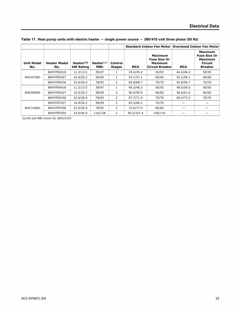
Table 11. Heat pump units with electric heater — single power source — 380/415 volt three phase (50 Hz)
Standard Indoor Fan Motor Oversized Indoor Fan Motor
Unit Model No.
Heater Model No.
Heater(a) kW Rating
Heater(a) MBh
Control Stages MCA
Maximum Fuse Size Or
Maximum Circuit Breaker MCA
Maximum Fuse Size Or
Maximum Circuit
Breaker
WSC072ED
BAYHTRS418 11.3/13.5 39/47 1 43.4/45.4 50/50 44.4/46.4 50/50
BAYHTRS427 16.9/20.2 58/69 2 54.1/57.1 60/60 55.1/58.1 60/60
BAYHTRS436 22.6/26.9 78/92 2 64.8/68.7 70/70 65.8/69.7 70/70
WSC090ED
BAYHTRS418 11.3/13.5 39/47 1 46.3/48.3 50/50 48.0/50.0 50/50
BAYHTRS427 16.9/20.2 58/69 2 56.9/59.9 60/60 58.6/61.6 60/60
BAYHTRS436 22.6/26.9 78/92 2 67.7/71.6 70/70 69.4/73.3 70/70
WSC120ED
BAYHTRT427 16.9/20.2 58/69 2 63.3/66.3 70/70 — —
BAYHTRT436 22.6/26.9 78/92 2 74.0/77.9 80/80 — —
BAYHTRT454 33.9/40.4 116/138 2 95.5/101.4 100/110 — —
(a) kW and MBh shown for 380V/415V
ACC-SVN67L-EN 23

©2020
Trane and American Standard have a policy of continuous product and product data improvement and reserve the right to change design and specifications without notice. We are committed to using environmentally conscious print practices.
Trane and American Standard create comfortable, energy efficient indoor environments for commercial and residential applications. For more information, please visit trane.com or americanstandardair.com.
ACC-SVN67L-EN 21 Apr 2020Supersedes ACC-SVN67K-EN (Nov 2018)