Mounting and Operating Instructions EB 8359-2 EN
40
Mounting and Operating Instructions EB 8359-2 EN Edition April 2014 Type 4763 Electropneumatic Positioner Type 4763 Electropneumatic Positioner
-
Upload
khangminh22 -
Category
Documents
-
view
2 -
download
0
Transcript of Mounting and Operating Instructions EB 8359-2 EN

Mounting and Operating Instructions
EB 8359-2 EN Edition April 2014
Type 4763 Electropneumatic Positioner
Type 4763 Electropneumatic Positioner

Definition of signal words
DANGER!Hazardous situations which, if not avoided, will result in death or seri-ous injury
WARNING!Hazardous situations which, if not avoided, could result in death or seri-ous injury
NOTICEProperty damage message or mal-function
Note:Additional information
Tip:Recommended action
2 EB 8359-2 EN

Contents
EB 8359-2 EN 3
1 General safety instructions .............................................................................52 Article code ...................................................................................................63 Technical data ...............................................................................................73.1 Explosionprotectioncertificates .......................................................................94 Design and principle of operation ................................................................105 Attachment .................................................................................................125.1 Attachmenttovalvewithcastyoke ................................................................125.2 Attachmenttovalvewithrod-typeyoke ..........................................................125.3 Housingcover .............................................................................................126 Connections ................................................................................................146.1 Electricalconnections ...................................................................................146.2 Pneumaticconnections..................................................................................156.3 Pressuregauge ............................................................................................156.4 Supplypressure ...........................................................................................167 Operation ...................................................................................................177.1 Assignmentofthepositionerandtheactuator ................................................177.1.1 Determiningandchangingtheoperatingdirection .........................................187.2 Startingpointandreferencevariable .............................................................207.3 Adjustmentaftermountingthepositioneronthevalve .....................................207.3.1 Settingtheairdelivery(volumerestrictionQ)andproportionalbandXp ..........207.3.2 Settingforactuatorwithfail-safeaction“stemextends” ...................................227.3.3 Settingforactuatorwithfail-safeaction“stemretracts” ...................................227.4 Exchangingtherangespring ........................................................................238 Converting the electropneumatic into a pneumatic positioner ........................249 Servicing explosion-protected devices ..........................................................2610 Maintenance, calibration and work on equipment ........................................2711 Accessories and mounting parts ...................................................................2812 Dimensions in mm .......................................................................................29


EB 8359-2 EN 5
General safety instructions
1 General safety instructionsForyourownsafety,followtheseinstructionsconcerningthemounting,startupandopera-tionofthepositioner: − Thepositioneristobemounted,starteduporoperatedonlybytrainedandexperiencedpersonnelfamiliarwiththeproduct.Accordingtothesemountingandoperatinginstructions,trainedpersonnelisreferredtoasindividualswhoareabletojudgetheworktheyareassignedtoandrecognizepossi-bledangersduetotheirspecializedtraining,theirknowledgeandexperienceaswellastheirknowledgeoftheapplicablestandards.
− Explosion-protectedversionsofthispositioneraretobeoperatedonlybypersonnelwhohasundergonespecialtrainingorinstructionsorwhoisauthorizedtoworkonexplo-sion-protecteddevicesinhazardousareas.
− Anyhazardsthatcouldbecausedinthevalvebytheprocessmedium,thesignalpres-sureorbymovingpartsaretobepreventedbytakingappropriateprecautions.
− Ifinadmissiblemotionsorforcesareproducedinthepneumaticactuatorasaresultofthesupplypressurelevel,itmustberestrictedusingasuitablesupplypressurereducingstation.
− Propershippingandstorageareassumed.
Note:Devices with a CE marking fulfill the requirements of the Directives 2014/34/EU and 2014/30/EU. The Declaration of Conformity is available on request.

6 EB 8359-2 EN
Article code
2 Article codeElectropneumatic positioners Type 4763- x 1 x 0 0 x x x x 0 x 0 x x 0Explosion protection
Without 0 2/7
ExII2GExiaIICT6GbaccordingtoATEX 1
CSA/FMintrinsicallysafe/nonincendive 3
ExII3GExnAIIT6Gc/ExicIICT6GcforZone2acc.toATEX 8 2/7
Spring
Spring1,travel=15mm 1
Spring2,travel=30mm,splitrange15mm 2
Spring3,travel=60mm,splitrange30mm 3
Pneumaticconnections
ISO 228/1 G ¼ 1
¼-18NPT 3
Electricalconnection(cablegland)
M20x1.5blue(plastic) 1
M20x1.5black(plastic) 2
M20x1.5(nickel-platedbrass) 7 2
i/pconverters
Type6109 1
Type6112 2
Referencevariable
4to20mA 0
0to20mA 2 2
1to 5mA 2 3
Temperaturerange
Standard 0
Lowtemperaturedownto–45°C 2 2
Specialversion
Without 0 0 0
Foroxygen1) 0/1 0 1 6
GOSTcertificate 8 2 0 1 0
1) Specialversionsuitableforoxygenuptomaximum+60 °C (accordingtoAIRLIQUIDEtestreportno.2014/R171a1)

EB 8359-2 EN 7
Technical data
3 Technical data
Controlledvariable(travelrange) 7.5to60 mm,withleverextension:7.5to90 mm
Referencevariable1)Split-range0to50 %or 50to100 % referencevariablespan (upto50 mmtravel)
4to20 mA(Ex), Ri=250 Ω2)
4to20 mA(withoutexplosionprotection), Ri=200 Ω2)
0to20 mA, Ri=200 Ω2)
1to5mA, Ri=880 Ω2)
Rangespring SeeTable1onpage 21
Supplyair 1.4to6bar(20to90psi)Airqualityacc.toISO8573-1:Max.particlesizeanddensity:Class4Oilcontent:Class3·Pressuredewpoint:Class3
Signalpressurepst(output) Max.0to6.0 bar(0to90 psi)
Characteristic Linearcharacteristic·Deviationfromcharacteristicaccordingtoterminalpointmethod:≤1.5 %
Hysteresis <0.5 %
Sensitivity <0.1 %
Operatingdirection Reversible
ProportionalbandXp(at1.4barsupplyair)
1to3.0 %withspring11to2.0 %withspring21to1.5 %withspring3
Airconsumptioninsteadystate(Xp=1 %)
With1.4 barsupplyair:0.19mn³/hWith6 barsupplyair:0.5mn³/h
Air output AtΔp1.4 bar:3.0mn³/hAtΔp6 bar:8.5mn³/h
TransittimewithType3271Actuator,“stemextends”
240 cm²≤1.8 s 350 cm²≤2.5 s 700 cm²≤10.0 s
Perm.ambienttemperature3),4) With Type 6109 i/p Converter:–20to+70 °C–35to+70 °C(metalcablegland)
With Type 6112 i/p Converter:–20to+80 °C–40to+80 °C(metalcablegland)–45to+80 °C(specialversion)

8 EB 8359-2 EN
Technical data
Influences Temperature:<0.03 %/1 KSupplyair:<0.3 %/0.1 barVibrations:<2 %between10upto150 Hzand4 gVariablepositionwhenturnedby180°:<3.5 %
Degreeofprotection IP54·Ventingovercheckvalve(1790-7408):IP65
Compliance ·
Electromagneticcompatibility ComplyingwithEN61000-6-2,EN61000-6-3andEN61326-1
Weight Approx.1.2kg
Materials Housing Die-castaluminum,chromatedandplasticcoated
Externalparts Stainlesssteel
1) ThedatalistedinthecertificateofconformityappliestotheversionwithtypeofprotectionExiaIIC.2) Ri=Coilresistance(atapprox.20 °C)±7 %tolerance3) Observethelimitsinthecertificateofconformityforexplosion-protectedversions.4) Withspecialversionsuitableforoxygenuptomaximum+60 °C

EB 8359-2 EN 9
Technical data
3.1 Explosion protection certificates
Type Certification Type of protection
4763-1
Number RUCDE.08.00697
1Ex iaIICT6/T5/T4GbXDate 15.12.2014
Validuntil 2019-12-14
4763-1
Number PTB 02ATEX2078
II2GEx iaIICT6GbDatum 2002-07-19ECtypeexaminationcertificate
4763-3 ®Number 1607873 Ex iaIICT6;ClassI,Zone0;
ClassI,II,Div.1,GroupsA,B,C,D,E,F,G;ClassI,II,Div.2,GroupsA,B,C,D,E,F,G;Date 2005-09-16
4763-3
Number 3020228 ClassI,Zone0AEx iaIICClassI,II,III;Div.1,GroupsA,B,C,D,E,F,GClassI,Div.2,GroupsA,B,C,D;ClassII,Div,2GroupsF,G;ClassIII;
Date 2005-02-28
4763-7 JISNumber TC14411
Ex iaIICT6Date 2015-02-09
Validuntil 2018-03-01
4763-8
Number RUCDE.08.00697
2ExnAIICT6/T5/T4GcXDate 2014-12-15
Validuntil 2019-12-14
4763-8
Number PTB 03ATEX2183X
II3GExnAicIICT6GcDate 2003-09-30Statementofconformity
10 EB 8359-2 EN
Design and principle of operation
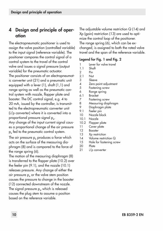
4 Design and principle of oper-ation
Theelectropneumaticpositionerisusedtoassignthevalveposition(controlledvariable)totheinputsignal(referencevariable).Thepositionercomparesthecontrolsignalofacontrolsystemtothetravelofthecontrolvalveandissuesasignalpressure(outputvariable)forthepneumaticactuator.Thepositionerconsistsofanelectropneumat-icconverterunit(21)andapneumaticunitequippedwithalever(1),shaft(1,1)andrangespringaswellasthepneumaticcon-trolsystemwithnozzle,flapperplateandbooster.TheDCcontrolsignal,e.g.4to20 mA,issuedbythecontroller,istransmit-tedtotheelectropneumaticconverterunit(i/pconverter)whereitisconvertedintoaproportionalpressuresignalpe.Anychangeoftheinputcurrentsignalcaus-esaproportionalchangeoftheairpressurepefedtothepneumaticcontrolsystem.Theairpressurepeproducesaforcewhichactsonthesurfaceofthemeasuringdia-phragm(8)andiscomparedtotheforceoftherangespring(6).Themotionofthemeasuringdiaphragm(8)istransferredtotheflapperplate(10.2)overthefeelerpin(9.1),andthenozzle(10.1)releasespressure.Anychangeofeithertheairpressurepeorthevalvestempositioncausesthepressuretochangeinthebooster(12)connecteddownstreamofthenozzle.Thesignalpressurepstwhichisreleasedcausestheplugstemtoassumeapositionbasedonthereferencevariable.
TheadjustablevolumerestrictionQ(14)andXp(gain)restriction(13)areusedtoopti-mizethecontrolloopofthepositioner.Therangespring(6),whichcanbeex-changed,isassignedtoboththeratedvalvetravelandthespanofthereferencevariable.
Legend for Fig. 1 and Fig. 21 Leverforvalvetravel1.1 Shaft2 Pin2.1 Nut3 Sleeve4 Zeropointadjustment5 Fasteningscrew6 Rangespring6.1 Bracket7 Fasteningscrew8 Measuringdiaphragm9 Diaphragmplate9.1 Feeler pin10 Nozzleblock10.1 Nozzle10.2 Flapperplate11 Coverplate12 Booster13 Xprestriction14 VolumerestrictionQ15 Holeforfasteningscrew20 Plate21 i/pconverter

EB 8359-2 EN 11
Design and principle of operation
4
21 14 13 10.2 7
1
15
8
5 6.1 6 3
Fig. 1: Positioner with cover removed
pstOutput
36
pe
Supply9
21
1.1
45
6
89
9.110.2
1010.1 6
89
9.1
10.2
10.1
10
11
i ip
12
1413
1 2 2.1 20
Travel
Arrangementofnozzle/flapperplateforreverse<>operatingdirection
Fig. 2: Functional diagram

12 EB 8359-2 EN
Attachment
5 AttachmentToattachthepositionertovalveswithcastyokesaccordingtoIEC 60534-6(NAMURrib),mountingparts(orderno.1400-5745)areused.Forvalveswithrod-typeyokes,themountingkit(orderno.1400-5745)andad-ditionallythemountingkit(orderno.1400-5342)arenecessary(seealsoaccessoriesinsection 11onpage 28).Sincethepositionercanbeattachedonei-thersideofthevalve,thephysicallocation(leftorrightattachment)shouldbedeter-minedbeforeactualattachment.
Î SeeFig. 6toFig. 9onpage 17.
5.1 Attachment to valve with cast yoke
1. Fastentheplate(20)tothestemconnec-tor(22)ofthevalveusingthescrews(21).
2. Unscrewthepositionercover,andsecurethepositionertothevalveyokeusingthefasteningscrew(15).TheO-ringinclud-edinthemountingkitisnotrequiredforthispositioner.Makesurethatthepin(2)isinsertedthroughthewirestrapand,asaresult,clampedagainsttheplate(20).
5.2 Attachment to valve with rod-type yoke
1. Fastentheplate(20),off-centered,tothetravelindicator(24)oftheplugstem(23)usingthescrews(21).
2. Placeboththesupport(28)andtheclampingplate(26)ontherod(27)andlightlyfasten.Movethesupportuntilboththecenteroftheplate(20)andthesup-port(28)arealignedwhenthevalveisathalfofthevalvetravel.
3. Fastentightthesupportandtheclamp-ingplate.
4. Mountthepositionertothesupportusingthefasteningscrew(15).Makesurethatthepin(2)isinsertedthroughthewirestrapand,asaresult,clampedagainsttheplate(20).
5.3 Housing coverAfterattachingthepositioner,makesurethattheventplugofthehousingcoverfacesdownwardwhenthevalveisinstalled.
Legend for Fig. 3 and Fig. 4:1 Lever2 Pin2.1 Nut15 Fasteningscrew20 Plate21 Screw22 Stemconnector23 Plugstem24 Travelindicator26 Clampingplate27 Rod(pillar)28 Support

EB 8359-2 EN 13
Attachment
15 1 20 2 2.1 21 22 23
Fig. 3: Attachment to valves with cast yokes (NAMUR rib)
15 1 28 27 26 20 2.1 2 21 24 23
Fig. 4: Attachment to valves with rod-type yokes

14 EB 8359-2 EN
Connections
6 Connections
6.1 Electrical connections
DANGER!For electrical installation, observe the relevant electrotechnical regulations and the accident prevention regula-tions that apply in the country of use. In Germany, these are the VDE regu-lations and the accident prevention regulations of the employers’ liability insurance.The following regulations apply to in-stallation in hazardous areas: EN 60079-14: 2008 (VDE 0165, Part 1) Explosive Atmospheres – Electrical Installations Design, Selec-tion and Erection.
NOTICEAdhere to the terminal assignment! Switching the assignment of the elec-trical terminals may cause the explo-sion protection to become ineffective. Do not loosen enameled screws in or on the housing. The maximum per-missible values specified in the EC type examination certificates apply when interconnecting intrinsically safe electrical equipment (Ui or Uo, li or Io, Pi or Po, Ci or Co and Li or Lo).
Selecting cables and wires:Observeclause 12ofEN 60079-14:2008(VDE 0165,Part 1)forinstallationofthein-trinsicallysafecircuits.Clause 12.2.2.7ap-plieswhenrunningmulti-corecablesandwireswithmorethanoneintrinsicallysafecircuit.Theradialthicknessoftheinsulationofaconductorforcommoninsulatingmaterials(e.g.polyethylene)mustnotbesmallerthan0.2 mm.Thediameterofanindividualwireinafine-strandedconductormustnotbesmallerthan0.1 mm.Protecttheconductorendsagainstsplicing,e.g.byusingwire-endferrules.Whentwoseparatecablesorwiresareusedforconnection,anadditionalcableglandcanbeinstalled.Sealcableentriesleftun-usedwithplugs.Fitequipmentusedinambi-enttemperaturesbelow–20 °Cwithmetalcableglands.

EB 8359-2 EN 15
Connections
Equipment for use in zone 2/zone 22:InequipmentoperatedaccordingtotypeofprotectionEx nAII(non-sparkingequipment)accordingtoEN 60079-15: 2003,circuitsmaybeconnected,interruptedorswitchedwhileenergizedonlyduringinstallation,maintenanceorrepair.Guidethewiresforthereferencevariableoverthecableglandtotheterminals11(+)and12(–)locatedinthehousing.Thegroundconnectioncanbeconnectedin-sideoroutsideofthepositionerhousing.
Accessories for electrical connections Î Seesection11onpage28
Input controlsignal 0/4to20 mA
Fig. 5: Electrical connection
6.2 Pneumatic connectionsThepneumaticconnectionsareoptionallydesignedasaborewith¼ NPTorISO 288/1-G ¼thread.Customaryfittingsformetalorcoppertubingorplastichosescanbeused.
NOTICERisk of malfunction due to failure to comply with required air quality. − Only use supply air that is dry and free of oil and dust. − Read the maintenance instructions for upstream pressure reducing sta-tions. − Blow through all air pipes and hos-es thoroughly before connecting them.
6.3 Pressure gaugeTomonitorthepositioner,werecommendin-stallingpressuregaugesforthesupplyairandsignalpressure.Therequiredpartsarelistedasaccessoriesinsection 11onpage 28.

16 EB 8359-2 EN
Connections
6.4 Supply pressureTherequiredsupplyairpressuredependsonthebenchrangeandtheactuator'soperatingdirection(fail-safeaction).Thebenchrangeiswrittenonthenameplateeitherasthespringrangeorsignalpressurerange.TheoperatingdirectionismarkedFA or FE,orbyasymbol.
Actuator stem extends (FA)Fail-close(forglobeandanglevalves)Requiredsupplypressure=Upperbenchrangevalue+0.2bar,minimum1.4bar
Actuator stem retracts (FE)Fail-open(forglobeandanglevalves)Fortight-closingvalves,themaximumsignalpressure pstmaxisroughlyestimatedasfol-lows:
pstmax = F+ d²·π·∆p [bar]4·A
d = Seatdiameter[cm]∆p = Differentialpressureacrossthevalve
[bar]A = Actuatordiaphragmarea[cm²]F = Upperbenchrangevalue[bar]
If there are no specifications, calculate as follows:Requiredsupplypressure=Upperbenchrangevalue+1 bar
Thepositioneroutputpressureisroutedtothetoporbottomdiaphragmcaseoftheac-tuatorasshowninFig. 6toFig. 9.

EB 8359-2 EN 17
Operation
7 Operation7.1 Assignment of the posi-
tioner and the actuatorArrangementoftheactuator,themountingpositionofthepositioner,thereferencevari-ableandtheoperatingdirection:
Î SeeFig. 6toFig. 9
Whenanysubsequentchangesaremade,e.g.reversingtheoperatingdirectionofthepositionercontrollooporchangingtheactu-atorfail-safeactionfrom“actuatorstemex-tends”to“actuatorstemretracts”orvicever-sa,thepositioner'smountingpositionmustbechangedaccordingly.
Actuator stem extends (FA)
1
20
pstw
120
pst
w
Lever(1)ontopofplate(20) Plate(20)ontopoflever(1)
Fig. 6: Operating direction << Left attachment Fig. 7: Operating direction <> Right attachment
Actuator stem retracts (FE)
pst
w
pst
w
Fig. 8: Operating direction << Right attachment
Fig. 9: Operating direction <> Left attachment

18 EB 8359-2 EN
Operation
7.1.1 Determining and changing the operating direction
Foranincreasinginputsignal(referencevariable),thesignalpressurepstcaneitherbeincreasing(directaction<<)ordecreas-ing(reverseaction<>).Similarly,asthereferencevariabledecreas-es,thesignalpressurecaneitherdecrease(directaction<<)orincrease(reverseaction<>).Ontheflapperplate,theoperatingdirectionisindicatedbysymbols(direct<<,reverse<>).Dependingonthepositionoftheflap-perplate,theadjustedoperatingdirectionandtheassociatedsymbolbecomevisible.Iftherequiredoperatingdirectiondoesnotcorrespondtothevisiblesymbol,oriftheoperatingdirectionistobechanged,pro-ceedasfollows:1. Unscrewbothscrewsonthecoverplate,
andliftoffthenozzleblockalongwiththecoverplate.
2. Reinstallthenozzleblockturned180°to-getherwiththecoverplate,andrefasten.
MakesurethatthenozzleblockandflapperplatearecorrectlylocatedaboveorbelowthefeelerpinasshowninFig. 10.Iftheoperatingdirectionistobechangedaftertheinitiallydeterminedarrangementofpositionerandactuator,notethattheposi-tionermustbemountedinadifferentloca-tionandthenozzleblockmustbeturned.Makesurethelocationofthelever(1)andtheplate(20),"leverontopofplate"orre-
versed"plateontopoflever"iscorrect(Fig. 6toFig. 9).

EB 8359-2 EN 19
Operation
Operatingdirectionincreasing/increasing(direct<<) feelerpinontopofflapperplate
Operatingdirectionincreasing/decreasing(reverse<>) flapperplateontopoffeelerpin
Rangespring
Feeler pin
Coverplate
Nozzleblock
Marking Flapper
Fig. 10: Position of nozzle block, cover plate removed
100%
0%4 20mAReferencevariable
Inputsignal
Open
Travel
Closed
100%
0%4 12 20mA
Deadband
Valve2 Valve1
Open
Travel
Closed
Fig. 11: Normal operation Fig. 12: Split-range operation, two valves operating in opposing directions

20 EB 8359-2 EN
Operation
7.2 Starting point and refer-ence variable
TheattachedleverandtheinstalledrangespringofthepositionerareassignedtothevaluesofratedvalvetravelandthereferencevariableasinTable1.Innormaloperation,thereferencevariablespanis100 %=16 mA.Asmallerspanof,forexample,50 %=8 mAisonlyrequiredforsplit-rangeoperation(Fig. 12).Thespancanbechangedbyexchangingtherangespring(section 7.4).Onmakingad-justmentstothepositioner,thetravelmustbeadaptedtothereferencevariableandviceversa.Withareferencevariable,forexample,4to20 mA,thevalvemustmovethroughitsen-tiretravelrangefrom0to100 %.Thestart-ingpointthenis4 mAandtheupperrangevalue20 mA.Insplit-rangeoperation,thecontrolleroutputsignalisusedtocontroltwocontrolvalves,dividingitsuchthatthevalvesmovethroughtheirentiretravelrangeathalftheinputsig-nalrangeeach(e.g.firstvalvesetto4to12 mA,secondvalvesetto12to20 mA).Toavoidoverlapping,allowforadeadbandof±0.5 mAasshowninFig. 12.Thestartingpoint(zero)isadjustedatthescrew(4);thereferencevariablespan,i.e.theupperrangevalue,isadjustedatthepin(2).
7.3 Adjustment after mounting the positioner on the valve
Î Connectanammetertothecontrolsignalinputattheterminals11(+)and12(–).
Î Connectthesupplyairtothesupplyin-put(supply9).
7.3.1 Setting the air delivery (volume restriction Q) and proportional band Xp
1. Closethevolumerestriction(14)asfarastherequiredpositioningspeedper-mits.Checkthepositioningspeedbypushingtherangespring(6)asfaritwillgo.
2. Adjustthereferencevariableattheinputtoapprox.50 %ofitsrange.Then,turnthezeroadjustmentscrew(4)untilthevalveisatapproximately50 %valvetravel.
OnsettingtheXprestriction,observethere-lationshipwiththesupplyairpressureasin-dicatedinFig. 13.ThepresetvalueofXpshouldbeapproximately3 %.3. Checktheplugstem'stendencytooscil-
latebypressingtherangespring(6)brieflyasfarasitwillgo.TheXpvalueistobeadjustedtobeassmallaspossible,withoutconsiderableovershootingoccurring.
Additional points that apply concerning ad-justment:
Î AlwaysadjusttheXprestrictionbeforesettingthestartingpoint.

EB 8359-2 EN 21
Operation
Table 1: Range springs
Rated travel [mm] Min./max. travel [mm] Reference variable (input signal) Range springStandardtravelsforSAMSONvalveswithleverl(40to127 mminlength)
15 7.5 to 15 100 % 50 %
1 2
30 14 to 32 100 % 50 %
2 3
60 30 to 70 100 % 3Furthertravelrangeswithleverlandleverextension(40to200 mminlength)
20 7.5 to 26 100 % 50 %
1 2
40 14 to 50 100 % 50 %
2 3
>60 30 to 90 100 % 3
Î Incaseofazeroshift(e.g.duetoasub-sequentchangeintherestrictionsettingorsupplypressure),checkthezeroset-tingandreadjustit.
Î TheadjustmentrangeoftheXprestric-tionisrestrictedbythepointerandstoptooneturn(Fig. 13).Donotremovethepointer!
Zul. Supply Alim.
Fig. 13: Setting the Xp restriction
Ifthepointerhasbeenremovedunintentionally,aninitialsettingcanbeperformedasfollows:1. Closetherestrictionbyturningitclock-
wiseuntilyoufeelaslightresistance.2. Basedonthisposition,opentherestric-
tiononequarterturn.3. Pressontheplasticringwiththepointer
atthe0°position.4. Settherestrictionintherangebetween
90°and180°.5. SetXpasdescribedinsection 7.3.1.

22 EB 8359-2 EN
Operation
7.3.2 Setting for actuator with fail-safe action “stem ex-tends”
Toensurethatthetotalclosingforceoftheactuatoractsonthevalve,proceedasfol-lows:
Î Withdirectoperatingdirection<<:ad-juststartingpointto4.5 mA(slightlyraised).
Î Withreverseoperatingdirection<>:ad-juststartingpointto19.5 mA(slightlylowered).
Starting point (zero) e.g. 4.5 mA1. Turnthezeroadjustmentscrew(4)until
theplugstemjuststartstomoveoutofitsrestingposition(observetravelindica-tor).
2. Reducetheinputsignalto0 mAandslowlyincreaseitagain.Checkwhethertheplugstemstartstomoveatexactly4.5 mAandcorrect,ifnecessary.
Upper range value (span) e.g. 20 mA3. Oncethestartingpointhasbeenset,in-
creasetheinputsignal.Atexactly20 mA,theplugstemmuststandstill,havingmovedthrough100 %travel(watchthetravelindicatoratthevalve).Iftheupperrangevalueisincorrect,movethepin(2)asfollowstocorrectit:
4. MovetowardsLeverend à ToincreasethetravelFulcrum à Toreducethetravel
Aftercorrectingtheinputsignal,re-ad-justzero.Thenchecktheupperrangevalueagain.
Repeatthecorrectionprocedureuntilbothvaluesarecorrect.
7.3.3 Setting for actuator with fail-safe action “stem re-tracts”
Whenusinganactuatorwith"actuatorstemretracts"fail-safeaction,thediaphragmchambermustbepressurizedwithasignalpressurethatishighenoughtotightlyclosethevalveagainsttheupstreampressureintheplant.
Î Operatingdirection<<:Upperrangevalueofreferencevariable20 mA
Î Operatingdirection<>:Lowerrangeval-ueofreferencevariable4 mA
Therequiredsignalpressureiseitherindicat-edonthepositionerlabelortherequiredsupplypressurecanberoughlycalculatedasdescribedinsection 6.4.
Starting point e.g. 20 mA1. Settheinputsignalattheammeterto
20 mA.Turnthezeroadjustmentscrew(4)untiltheplugstemjuststartstomoveoutofitsinitialposition.
2. Increasetheinputsignalandslowlyre-duceitagainto20 mA.Checkwhethertheplugstemstartstomoveatexactly20 mA.Correctanydeviationatthezeroadjust-mentscrew(4).Turningitcounterclock-

EB 8359-2 EN 23
Operation
wisecausestheplugstemtomovefromitsendpositionearlier;turningitclock-wisecausesittomovefromitsendposi-tionlater.
Upper range value (span) e.g. 4 mA3. Oncethestartingpointhasbeenset,in-
creasetheinputsignalto4 mAattheammeter.Atexactly4 mA,theplugstemmuststandstill,havingmovedthrough100 %travel(watchthetravelindicatoratthevalve).
4. Iftheupperrangevalueisincorrect,movethepin(2)tocorrectit.Readjust20 mAandturnthezeroadjustmentscrew(4)untilthepressuregaugeindi-catestherequired signal pressure.Ifnopressuregaugehasbeeninstalled,setthestartingpointto19.5 mAinstead.
7.4 Exchanging the range spring
Iftherangeistobealteredorchangedtosplit-rangeoperation,replacetherangespringasshowninFig. 1onpage 11asfollows:1. Unscrewscrew(7)ontherangespring.
Undohexagonsocketscrew(5)andpulloutthelevertogetherwithshaft.
2. Exchangerangespring.Slideleverwithshaftthroughsleeve(3),positionerhous-ingandbracket(6.1).
3. Securerangespringwiththescrew(7).4. Movebracketandshaftuntilthescrew
(5)sitsontheflattenedpartoftheshaft.Tightenscrew(5).Allowforaplayof0.05to0.15 mmbetweenthelever(1)andthesleeve(3)aswellasbetweentherangespring(6)andthepositionerhous-ing.

24 EB 8359-2 EN
Converting the electropneumatic into a pneumatic positioner
8 Converting the electropneu-matic into a pneumatic posi-tioner
Theelectropneumaticpositionercanbecon-vertedintoaType 4765PneumaticPosition-erwithaconversionkit.
Note:The version suitable for oxygen of the Type 4763 Pneumatic Positioner can-not be converted to form a Type 4765 Electropneumatic Position-er.
Î Requiredconversionkits:seeTable21. Unscrewfasteningscrewsandliftthei/p
convertertogetherwiththeprintedcircuitboardoutofthepositionerhousing.
2. Unthreadcablegland(1).Plugonhose(5)andscrewtheconnectingnipple(4)oftheconversionkittightlyonthehous-ing.
3. Insertsealingelement(7)intoconnectingplate(6)andfastenittightintothehous-ing.
4. Pushthefreeendofthehoseontotheconnectingplate(6).
Note:For details on the converted Type 4765 Positioner, refer to Mount-ing and Operating Instructions u EB 8359-1 EN.
Legend for Fig. 141 Cablegland2 Printedcircuitboard3 i/pconverters4 Connectingnipple5 Hose6 Connectingplate7 Sealingelement

EB 8359-2 EN 25
Converting the electropneumatic into a pneumatic positioner
1 3 2 4 5 7 6
38Fig. 14: Converting the positioner
Table 2: Conversion kits
Requiredconversionkituptodeviceindex.02.
ForconnectionwithGthread Orderno.1400-6724
ForconnectionwithNPTthread Orderno.1400-6725
Requiredconversionkitfordeviceindex.03andhigher.
ForconnectionwithGthread Orderno.1400-6795
ForconnectionwithNPTthread Orderno.1400-6796

26 EB 8359-2 EN
Servicing explosion-protected devices
9 Servicing explosion-protected devicesIfapartofthedeviceonwhichtheexplosionprotectionisbasedneedstobeserviced,thedevicemustnotbeputbackintooperationuntilaqualifiedinspectorhasassesseditaccord-ingtoexplosionprotectionrequirements,hasissuedaninspectioncertificateorgiventhede-viceamarkofconformity.Inspectionbyaqualifiedinspectorisnotrequiredifthemanufacturerperformsaroutinetestonthedevicebeforeputtingitbackintooperation.Documentthepassingoftheroutinetestbyattachingamarkofconformitytothedevice.Replaceexplosion-protectedcomponentsonlybyoriginal,routine-testedcomponentsprovid-edbythemanufacturer.Devices that have already been used outside hazardous areas and are intended for future use inside hazardous areas must comply with the safety requirements placed on serviced devices. Before being operated inside hazardous areas, test the devices according to the specifications for servicing explosion-protected devices.

EB 8359-2 EN 27
Maintenance, calibration and work on equipment
10 Maintenance, calibration and work on equipmentInterconnectionwithintrinsicallysafecircuitstocheckorcalibratetheequipmentinsideoroutsidehazardousareasistobeperformedonlywithintrinsicallysafecurrent/voltagecali-bratorsandmeasuringinstrumentstoruleoutanydamagetocomponentsrelevanttoexplo-sion protection.Observethemaximumpermissiblevaluesspecifiedinthecertificatesforintrinsicallysafecir-cuits.

28 EB 8359-2 EN
Accessories and mounting parts
11 Accessories and mounting partsAccessories – Mounting parts Order no.
Rangespring1Rangespring2Rangespring3LeverILeverextensionPressuregaugeattachmentPressuregaugeattachment(copper-free)
1190-07361190-07371190-07381690-64691400-67161400-69501400-6951
MountingunitforvalveswithcastyokeaccordingtoNAMURValveswithrod-typeyokeaccordingtoNAMURfor18to35 mmroddiameter
1400-57451400-5745and1400-5342
Assortmentofsparepartsincludinggasketsanddiaphragms 1400-6792
Assortmentofsparepartsincludinggasket,diaphragmsandpneu-maticparts(forpositionerswithdeviceindex.02andhigher)
1402-0040
UpgradetodegreeofprotectionIP 65:Ventingovercheckvalve 1790-7408
Accessories for electrical connections Order no.
BlackcableglandM20x1.5BrowncableglandM20x1.5
1400-69851400-6986
AdapterM20x1.5to½NPT,powder-coatedaluminum: 0310-2149

EB 8359-2 EN 29
Dimensions in mm
12 Dimensions in mm
157
49.5
15
2.5
38
.
.
.
UseableleverlengthI: 40to127 mm (withleverextension 40to200 mm)Pneumaticconnections: ISO-228/1-G¼
Cablegland:Deviceindex.02and lower:Pg13.5Deviceindex.03and higher:M20x1.5
G 1/8 connection
forhousingwith Gthread or 1/8NPTconnection forhousingwith NPTthread

30 EB 8359-2 EN

EB 8359-2 EN 31

32 EB 8359-2 EN

EB 8359-2 EN 33

34 EB 8359-2 EN

EB 8359-2 EN 35

36 EB 8359-2 EN

EB 8359-2 EN 37

38 EB 8359-2 EN

EB 8359-2 EN 39

SAMSON AG · MESS- UND REGELTECHNIKWeismüllerstraße 3 · 60314 Frankfurt am Main, GermanyPhone: +49 69 4009-0 · Fax: +49 69 [email protected] · www.samson.de EB 8359-2 EN 20
16-05-10·English