EB 5578 EN - samson ag
318
Translation of original instructions EB 5578 EN Firmware version 2.51 Edition June 2021 TROVIS 5578 Heating and District Heating Controller With graphics display
-
Upload
khangminh22 -
Category
Documents
-
view
3 -
download
0
Transcript of EB 5578 EN - samson ag

Translation of original instructions
EB 5578 EN
Firmware version 2.51
Edition June 2021
TROVIS 5578 Heating and District Heating ControllerWith graphics display
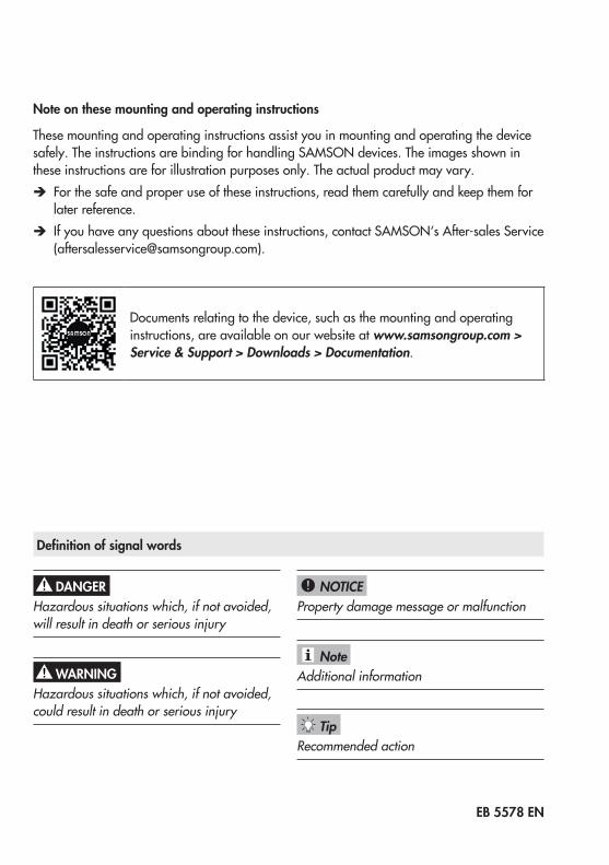
Note on these mounting and operating instructions
These mounting and operating instructions assist you in mounting and operating the device safely. The instructions are binding for handling SAMSON devices. The images shown in these instructions are for illustration purposes only. The actual product may vary.
Î For the safe and proper use of these instructions, read them carefully and keep them for later reference.
Î If you have any questions about these instructions, contact SAMSON‘s After-sales Service ([email protected]).
Documents relating to the device, such as the mounting and operating instructions, are available on our website at www.samsongroup.com > Service & Support > Downloads > Documentation.
Definition of signal words
Hazardous situations which, if not avoided, will result in death or serious injury
Hazardous situations which, if not avoided, could result in death or serious injury
Property damage message or malfunction
Additional information
Recommended action
DANGER!
WARNING!
NOTICE!
Note
Tip
EB 5578 EN

Contents
EB 5578 EN
1 Safety instructions and measures ................................................................1-11.1 Notes on possible severe personal injury ......................................................1-31.2 Notes on possible property damage .............................................................1-32 Markings on the device ..............................................................................2-12.1 Nameplate .................................................................................................2-12.2 Firmware versions .......................................................................................2-13 Design and principle of operation ...............................................................3-13.1 ConfigurationusingTROVIS-VIEW ...............................................................3-13.2 ConnectiontoSAMDISTRICTENERGY .........................................................3-23.3 Technical data ............................................................................................3-33.4 Dimensions .................................................................................................3-43.5 Valuesforresistancethermometers ...............................................................3-54 Shipment and on-site transport ...................................................................4-14.1 Accepting the delivered goods .....................................................................4-14.2 Removingthepackagingfromthecontroller ..................................................4-14.3 Transporting the heating controller ...............................................................4-14.4 Storing the controller ...................................................................................4-15 Installation .................................................................................................5-15.1 Installation conditions ..................................................................................5-15.2 Preparation for installation ...........................................................................5-15.3 Mounting the controller ................................................................................5-15.4 Electrical connection ....................................................................................5-36 Operation ..................................................................................................6-16.1 Operating controls ......................................................................................6-16.2 Interfaces ...................................................................................................6-26.2.1 M-bus interface ..........................................................................................6-26.2.2 DevicebusinterfaceRS-485 ........................................................................6-26.2.3 Optional interfaces .....................................................................................6-26.2.4 Accessories ................................................................................................6-37 Start-up and configuration ..........................................................................7-17.1 Altering the display contrast .........................................................................7-37.2 Changing the display language ...................................................................7-37.3 Setting the system code number....................................................................7-47.4 Activating and deactivating functions ...........................................................7-57.5 Changing parameters .................................................................................7-77.6 Calibrating sensors .....................................................................................7-8

Contents
EB 5578 EN
7.6.1 Special values ...........................................................................................7-117.7 Entering customized key number ................................................................7-128 Operation ..................................................................................................8-18.1 Selecttheoperatingmode ...........................................................................8-18.2 Schedules ...................................................................................................8-38.2.1 Settingthetimeanddate .............................................................................8-38.2.2 Settingthetimes-of-use ................................................................................8-58.2.3 Settingthepartytimer(specialtime-of-use) ...................................................8-78.2.4 Programmingpublicholidays(specialtimes-of-use) .......................................8-88.2.5 Programmingvacationperiods(specialtimes-of-use) ...................................8-108.3 Enteringdayandnightsetpoints ...............................................................8-128.4 Resettodefaultsettings ..............................................................................8-148.5 Readinginformation .................................................................................8-148.5.1 AdaptingtheTrend-Viewer ........................................................................8-198.6 Operatingthecontrollerinmanualmode ....................................................8-219 Malfunctions ..............................................................................................9-19.1 Errorlist .....................................................................................................9-29.2 Sensorfailure .............................................................................................9-29.3 Temperaturemonitoring ...............................................................................9-39.4 Faultalarmoutput .......................................................................................9-39.5 Errorstatusregister .....................................................................................9-410 Servicing..................................................................................................10-111 Decommissioning .....................................................................................11-112 Removal ..................................................................................................12-113 Repairs ....................................................................................................13-113.1 ReturningdevicestoSAMSON ..................................................................13-114 Disposal ...................................................................................................14-115 Certificates ...............................................................................................15-116 Annex A (configuration instructions) ..........................................................16-116.1 Systems ....................................................................................................16-116.2 Functions of the heating circuit ...............................................................16-12216.2.1 Outdoor-temperature-controlled control ..................................................16-12216.2.1.1 Outdoortemperaturereceivedorsentas0to10 Vsignal ........................16-12316.2.1.2 Outdoor temperature received or sent over the device bus ........................16-12316.2.1.3 Gradientcharacteristic ..........................................................................16-12416.2.1.4 Four-point characteristic ........................................................................16-126

Contents
EB 5578 EN
16.2.2 Fixed set point control............................................................................16-12716.2.3 Underfloorheating/dryingofjointlessfloors ...........................................16-12816.2.4 Outdoor temperature for continuous day mode .......................................16-12916.2.5 Buffer tank systems ................................................................................16-13016.2.6 Summer mode ......................................................................................16-13316.2.7 Delayed outdoor temperature adaptation ................................................16-13416.2.8 Remoteoperation ..................................................................................16-13516.2.9 Optimization ........................................................................................16-13616.2.10 Flash adaptation ...................................................................................16-13716.2.10.1 Flash adaptation without outdoor sensor (based on room temperature) .....16-13716.2.11 Adaptation ...........................................................................................16-13816.2.12 Cooling control .....................................................................................16-13916.2.13 Differential temperature control ..............................................................16-14116.3 Functions of the DHW circuit ..................................................................16-14216.3.1 DHW heating in the storage tank system .................................................16-14216.3.1.1 DHW circuit additionally controlled by a globe valve ...............................16-14416.3.2 DHW heating in the storage tank charging system ...................................16-14516.3.2.1 Cold charging protection .......................................................................16-14816.3.3 DHW heating in instantaneous heating system ........................................16-14816.3.4 Domestic hot water heating with solar system ..........................................16-14916.3.5 Intermediate heating .............................................................................16-15016.3.6 Parallel pump operation ........................................................................16-15016.3.7 Circulation pump during storage tank charging ......................................16-15116.3.8 Prioritycircuit .......................................................................................16-15116.3.8.1 Reversecontrol .....................................................................................16-15116.3.8.2 Set-backoperation ................................................................................16-15216.3.9 ForcedchargingofDHWstoragetank ....................................................16-15216.3.10 Thermal disinfection of DHW storage tank ..............................................16-15316.4 System-wide functions ...........................................................................16-15416.4.1 Automaticsummer/standardtimeswitchover ..........................................16-15416.4.2 Frost protection .....................................................................................16-15516.4.3 Forced pump operation .........................................................................16-15616.4.4 Returnflowtemperaturelimitation ..........................................................16-15616.4.5 Condensate accumulation control ...........................................................16-15716.4.6 Three-step control ..................................................................................16-15816.4.7 On/offcontrol ......................................................................................16-15816.4.8 ContinuouscontrolincontrolcircuitHC1 .................................................16-15916.4.9 Releasingacontrolcircuit/controllerwithbinaryinput .............................16-159

Contents
EB 5578 EN
16.4.10 Speed control of the charging pump .......................................................16-16016.4.11 Requestingandprocessinganexternaldemand ......................................16-16116.4.12 CapacitylimitationinRK1 .....................................................................16-16316.4.13 Creep feed rate limitation with a binary input ..........................................16-16416.4.14 Device bus ............................................................................................16-16516.4.14.1Requestingandprocessinganexternaldemand ......................................16-16516.4.14.2 Sending and receiving outdoor temperatures ...........................................16-16716.4.14.3 Synchronizing the clock .........................................................................16-16816.4.14.4 Priority over all controllers .....................................................................16-16816.4.14.5 Display error messages issued by the device bus .....................................16-16916.4.15 ActivatingTROVISI/Oexpansionmodules .............................................16-16916.4.16 Connecting potentiometers for valve position input ...................................16-17016.4.17 Locking manual level .............................................................................16-17016.4.18 Lockingtherotaryswitch .......................................................................16-17016.4.19 Feederpumpoperation .........................................................................16-17116.4.20 Externaldemandforheatduetoinsufficientheatsupply ..........................16-17116.5 Communication ....................................................................................16-17216.5.1 RS-485communicationmodule ..............................................................16-17216.5.2 Meter bus .............................................................................................16-17316.5.2.1 Activating the meter bus ........................................................................16-17316.5.2.2 Flowrateand/orcapacitylimitationwithmeterbus.................................16-17516.5.3 Returnflowtemperaturelimitationbasedoncapacity ...............................16-17716.5.4 Memorymodule/minimodule................................................................16-17816.5.5 Data logging ........................................................................................16-17916.6 Function block lists ................................................................................16-18116.7 Parameter lists ......................................................................................16-20616.8 Customer-specificdata ..........................................................................16-21617 Annex B ...................................................................................................17-117.1 Accessories ..............................................................................................17-117.2 After-sales service .....................................................................................17-2
EB 5578 EN 1-1
Safety instructions and measures
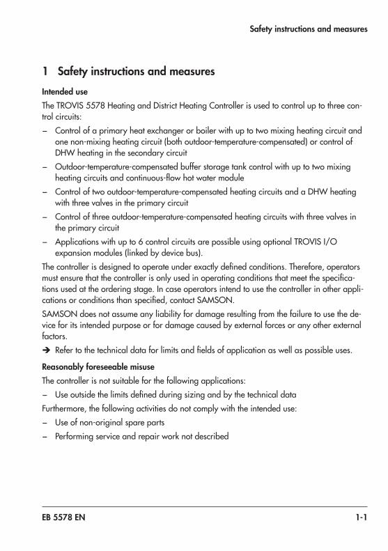
1 Safety instructions and measuresIntended useTheTROVIS 5578HeatingandDistrictHeatingControllerisusedtocontroluptothreecon-trol circuits: − Control of a primary heat exchanger or boiler with up to two mixing heating circuit and
one non-mixing heating circuit (both outdoor-temperature-compensated) or control of DHW heating in the secondary circuit
− Outdoor-temperature-compensated buffer storage tank control with up to two mixing heatingcircuitsandcontinuous-flowhotwatermodule
− Control of two outdoor-temperature-compensated heating circuits and a DHW heating with three valves in the primary circuit
− Control of three outdoor-temperature-compensated heating circuits with three valves in the primary circuit
− Applicationswithupto6controlcircuitsarepossibleusingoptionalTROVISI/Oexpansion modules (linked by device bus).
Thecontrollerisdesignedtooperateunderexactlydefinedconditions.Therefore,operatorsmustensurethatthecontrollerisonlyusedinoperatingconditionsthatmeetthespecifica-tions used at the ordering stage. In case operators intend to use the controller in other appli-cationsorconditionsthanspecified,contactSAMSON.SAMSON does not assume any liability for damage resulting from the failure to use the de-vice for its intended purpose or for damage caused by external forces or any other external factors.
Î Refertothetechnicaldataforlimitsandfieldsofapplicationaswellaspossibleuses.
Reasonably foreseeable misuseThe controller is not suitable for the following applications: − Useoutsidethelimitsdefinedduringsizingandbythetechnicaldata
Furthermore, the following activities do not comply with the intended use: − Use of non-original spare parts − Performing service and repair work not described

1-2 EB 5578 EN
Safety instructions and measures
Qualifications of operating personnelThe controller must be mounted, started up, serviced and repaired by fully trained and quali-fiedpersonnelonly;theacceptedindustrycodesandpracticesmustbeobserved.Accordingto these mounting and operating instructions, trained personnel refers to individuals who are able to judge the work they are assigned to and recognize possible hazards due to their spe-cialized training, their knowledge and experience as well as their knowledge of the applica-ble standards.
Personal protective equipmentNo personal protective equipment is required for the direct handling of the controller.
Revisions and other modificationsRevisions,conversionsorothermodificationsoftheproductarenotauthorizedbySAMSON.They are performed at the user's own risk and may lead to safety hazards, for example. Fur-thermore, the product may no longer meet the requirements for its intended use.
Warning against residual hazardsThecontrollerhasdirectinfluenceoncontrolledcomponentsoftheheatingsystem(e.g.con-trol valves and pumps). To avoid personal injury or property damage, plant operators and operating personnel must prevent hazards that could be caused in the plant components by the process medium, the operating pressure, the signal pressure or by moving parts by tak-ing appropriate precautions. Plant operators and operating personnel must observe all haz-ard statements, warning and caution notes in the referenced documents.
Responsibilities of the operatorOperators are responsible for proper use and compliance with the safety regulations. Oper-ators are obliged to provide these mounting and operating instructions as well as the refer-enced documents to the operating personnel and to instruct them in proper operation. Fur-thermore, operators must ensure that operating personnel or third parties are not exposed to any danger.
Responsibilities of operating personnelOperating personnel must read and understand these mounting and operating instructions aswellasthereferenceddocumentsandobservethespecifiedhazardstatements,warningsand caution notes. Furthermore, operating personnel must be familiar with the applicable health, safety and accident prevention regulations and comply with them.

EB 5578 EN 1-3
Safety instructions and measures
Referenced standards, directives and regulationsTheTROVIS 5578HeatingandDistrictHeatingControllerfulfillstherequirementsoftheDi-rectives2014/30/EU,2014/35/EUand2011/65/EU.Thedeclarationofconformityin-cludes information about the applied conformity assessment procedure. The controller is designed for use in low voltage installations.
Î For wiring, maintenance and repair, observe the relevant safety regulations.
1.1 Notes on possible severe personal injury
DANGER!
Risk of fatal injury due to electric shock. Î Before connecting wiring, performing any work on the controller or opening the control-ler, disconnect the supply voltage and protect it against unintentional reconnection.
Î Only use power interruption devices that can be protected against unintentional recon-nection of the power supply.
Î Do not remove any covers to perform adjustment work on live parts.
1.2 Notes on possible property damage
NOTICE!
Risk of damage to the controller due to the supply voltage exceeding the permissible toler-ances.The controller is designed for use in low voltage installations.
Î Observe the permissible tolerances of the supply voltage.

1-4 EB 5578 EN
Safety instructions and measures
Malfunction due to a configuration that does not meet the requirements of the application.Thecontrollerisconfiguredforspecificapplicationsbysettingfunctionsandparameters.Functionandparametersettingshaveandirecteffectonfinalcontrolelements.
Î Performtheconfigurationforthespecificapplication.
Manipulation of the configuration due to unauthorized access.The controller can be protected against unauthorized access through entering a key number. Thekeynumberforfirststart-upcanbefoundatthebackofthesemountingandoperatinginstructions.
Î Donotpassthekeynumberontounauthorizedpersons.Keepitinasafeplaceinacces-sible to unauthorized persons.
Risk of controller damage due to large differences in temperature. Î Before start-up, wait until the controller has reached the ambient temperature.
System damage caused by frost.Frost protection is deactivated in the manual mode.
Î Do not run the heating during cold weather in the manual mode for long periods of time.
EB 5578 EN 2-1
Markings on the device
2 Markings on the device
2.1 Nameplate
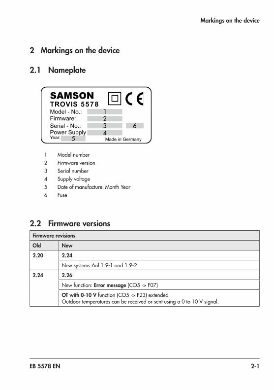
T R O V I S 5 5 7 8SAMSONModel - No.:Firmware:Serial - No.:Power SupplyYear: Made in Germany
1 Model number2 Firmware version3 Serial number4 Supply voltage5 Dateofmanufacture:MonthYear6 Fuse
2.2 Firmware versionsFirmware revisions
Old New
2.20 2.24
NewsystemsAnl1.9-1and1.9-2
2.24 2.26
New function: Error message(CO5 -> F07)
OT with 0-10 Vfunction(CO5 -> F23)extended Outdoortemperaturescanbereceivedorsentusinga0to10 Vsignal.

2-2 EB 5578 EN
Markings on the device
Firmware revisions
Old New
2.26 2.28
New system Anl 11.5
Alarm and event lists each with the last 100 entries
2.28 2.30
ItispossibletoconnectPTCorNi 1000sensors(Pt 1000sensorsonlypossiblebelowthisfirmwareversion)
2.30 2.41
Connected sensor inputs not relevant for closed-loop control are displayed on the 'Spe-cial values' screen in the controller's operating level
Newbuffertanksystems3.9,5.9,17.1and17.8
New functions and parameters for buffer tank systems: − CO1 -> F22:SLPdependingonreturnflowtemperature − CO4 -> F23:Electricheatingcartridge − CO5 -> F25:AA1reverse − CO5 -> F26:AA2reverse − CO5 -> F31:AE1zeroshift − PA1 -> P16:Minimumsetpointtochargebuffertank − PA1 -> P17:Stopchargingofthebuffertank − PA1 -> P18:Chargingtemperatureboost − PA1 -> P19:Lagtimeofchargingpump − PA4 -> P13:Maximumbuffertanktemperature − PA4 -> P21:Returnflowtemperaturelimit,layeringattop
New differential temperature controlfunction(CO1 -> F23)insystemsAnl 1.0and16.0
TROVIS 5570RoomPanelnolongeravailable.
Restrictionswhenaminimodule(orderno.1400-7436)isused
2.41 2.45
An active cold charging protection function allows the valve position to be determined between1and100 %(default10 %).

EB 5578 EN 2-3
Markings on the device
Firmware revisions
Old New
2.45 2.48
Internal revisions
2.48 2.51
NewsystemsAnl 6.1und18.1implemented
SystemsAnl9.1and9.2nowwithfeederpumpUP1
ConfigurationofuptothreeTROVISI/Oexpansionmodulespossible
Operating status reading of DHW circuit in the operating level
Only the values that are not assigned to a partial plant scheme are shown the overall plant scheme: this now includes the demand to be processed.
MeaningofCO1,CO2,CO3 -> F02F02 - 1 =Outdoor-temperature-controlledcontrolactive
Buffer tank systems: the measured value SF1 is now also relevant to end charging
Discharging protection for DHW tank and buffer tank
Separateboostadjustableforunderfloorheatingcircuits
Norestart,insteadthedryingofjointlessfloorscontinuesafterapowersupplyfailure
Heatingcircuitscanbeconfiguredtobecircuitsonlyprocessingdemandwiththeset-tingsCO1 -> F24 - 1,CO2 -> F24 - 1,CO3 -> F24 - 1
Transmissionrangesettingfor0to10 VsignaltoprocessexternaldemandchangedtoCO5 -> F31
Defaultsettingofheatingcharacteristic1.2(0.5forunderfloorheating)
Defaultsettingofthemaximumflowtemperature:70 °C
Delayedoutdoortemperatureadjustableinstepsof0.1 °C
Returnflowtemperaturelimitationbasedoncapacityconfigurable
Default setting of heat meter mode: 'Continuous'

2-4 EB 5578 EN

EB 5578 EN 3-1
Design and principle of operation
3 Design and principle of oper-ation
TheTROVIS 5578HeatingandDistrictHeat-ing Controller is used to control max. three control circuits. – Control of a primary heat exchanger or
boiler with up to two mixing heating circuit and one non-mixing heating circuit (both outdoor-temperature-compensated) or control of DHW heating in the secondary circuit
− Outdoor-temperature-compensated buffer storage tank control with up to two mixing heating circuits and continuous-flowhotwatermodule
− Control of two outdoor-temperature-compensated heating circuits and a DHW heating with three valves in the primary circuit
− Control of three outdoor-temperature-compensated heating circuits with three valves in the primary circuit
− Applications with up to 6 control circuits arepossibleusingoptionalTROVISI/Oexpansion modules (linked by device bus).
TheTROVIS 5578HeatingandDistrictHeatingControllerisadaptedtothespecificsystem by setting the appropriate system codenumber.Additionalsensorsand/orfunctions which are not part of the system's basicconfigurationcanbeselectedoverfunction blocks. The switch positions and entry of the key number allow access to the corresponding levels. For trained staff, the
configurationlevelsusedtosetfunctionblocks are indicated by “CO” and the parameter levels are indicated by “PA”. Data is retrieved and entered at the controller using a rotary pushbutton. This process is facilitated by icons and plain text displayed on the LCD. The rotary switch is used to set the operating mode and the parameters required for each circuit.
M-bus interfaceA maximum of three meters conforming to EN 1434-3canbeconnectedfordatatransfer. In addition, heat meters for each controlcircuitareavailableforflowrateand/orcapacitylimitation.Variouslimitscan be adjusted for the different operating modes “Heating control only”, “Heating control with DHW heating” and “DHW heatingonly”incontrolcircuitRK1.Outdoor-temperature-compensatedflowrateor capacity limitation can also be implemented.
3.1 Configuration using TROVIS-VIEW
ThecontrollercanbeconfiguredwiththeTROVIS-VIEWsoftware.Inthiscase,theTROVIS 5578HeatingandDistrict Heating Controller is connected to the computerattheRJ-45jackonthesideofthecontroller.TheTROVIS-VIEWsoftwareenablestheusertoeasilyconfigurethecontrolleraswellasview process parameters online.

3-2 EB 5578 EN
Design and principle of operation
TROVIS-VIEW provides a uniform user interface that allows users to configure and parameterize various SAMSON devices using device-specific database modules. The device module can be downloaded free of charge from our website at u www.samsongroup.com > SERVICE & SUPPORT > Downloads > TROVIS-VIEW . Further information on TROVIS-VIEW (e.g. system requirements) is available on our website and in the Data Sheet u T 6661.
3.2 Connection to SAM DISTRICT ENERGY
Thecontrollercanbeconfiguredandoperat-ed on a computer, smartphone or tablet computerusingtheSAMDISTRICTENERGYbusiness application.ThecontrollerisconnectedtoSAMDISTRICTENERGYovertheModbusinterfaceusingacommunication gateway.SAMDISTRICTENERGYallowsremotestart-upandset-upofthecontrollers.Keyinfor-mation of the controller and entire heating system is clearly visualized at one central lo-cation.
NoteSAM DISTRICT ENERGY is a web-based solution for managing, controlling and optimizing heating systems in the local heat supply and district heating networks. You can find more information and test SAM DISTRICT ENERGY using a demo account on our website at u www.samsongroup.com > Products & Applications > Digital solutions > SAM DISTRICT ENERGY.
Note
EB 5578 EN 3-3
Design and principle of operation
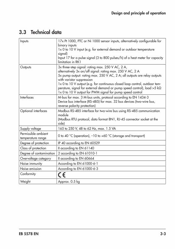
3.3 Technical dataInputs 17xPt 1000,PTCorNi 1000sensorinputs,alternativelyconfigurablefor
binary inputs1x0to10 Vinput(e.g.forexternaldemandoroutdoortemperaturesignal)Input17forapulsesignal(3to800 pulses/h)ofaheatmeterforcapacitylimitationinRK1
Outputs 3xthree-stepsignal:ratingmax.250 V AC,2 A, alternatively3xon/offsignal:ratingmax.250 V AC,2 A5xpumpoutput:ratingmax.250 V AC,2 A;alloutputsarerelayoutputswith varistor suppression1x0to10 Voutput(e.g.forcontinuousclosedloopcontrol,outdoortem-perature,signalforexternaldemandorpumpspeedcontrol),load>5 kΩ1x0to10 VoutputforPWMsignalforpumpspeedcontrol
Interfaces M-busformax.3M-busunits,protocolaccordingtoEN 1434-3Devicebusinterface(RS-485)formax.32busdevices(two-wirebus,reverse polarity protection)
Optional interfaces ModbusRS-485interfacefortwo-wirebususingRS-485communicationmodule(ModbusRTUprotocol,dataformat8N1,RJ-45connectorsocketattheside)
Supply voltage 165to250 V,48to62 Hz,max.1.5 VAPermissible ambient temperature range 0to40 °C(operation),–10to+60 °C(storageandtransport)
Degree of protection IP40accordingtoEN 60529Class of protection IIaccordingtoEN 61140Degree of contamination 2accordingtoEN 61010-1Overvoltage category IIaccordingtoEN 60664Noise immunity AccordingtoEN 61000-6-1Noise emission AccordingtoEN 61000-6-3Conformity
Weight Approx.0.5 kg

3-4 EB 5578 EN
Design and principle of operation
3.4 Dimensions
Panelcut-out138x92
Fig. 3-1: Dimensions in mm

EB 5578 EN 3-5
Design and principle of operation
3.5 Values for resistance thermometersPt 1000 sensors
Temperature °C –35 –30 –25 –20 –15 –10 –5 0 +5 +10 +15 +20
ResistanceΩ 862.5 882.2 901.9 921.6 941.2 960.9 980.4 1000.0 1019.5 1039.0 1058.5 1077.9
Temperature °C +25 +30 +35 +40 +45 +50 +55 +60 +65 +70 +75 +80
ResistanceΩ 1097.3 1116.7 1136.1 1155.4 1174.7 1194.0 1213.2 1232.4 1251.6 1270.8 1289.9 1309.0
Temperature °C +85 +90 +95 +100 +105 +110 +115 +120 +125 +130 +135 +140
ResistanceΩ 1328.1 1347.1 1366.1 1385.1 1404.0 1422.9 1441.8 1460.7 1479.5 1498.3 1517.1 1535.8
Temperature °C +145 +150 +155 +160 +165 +170 +175 +180 +185 +190 +195 +200
ResistanceΩ 1554.6 1573.3 1591.9 1610.5 1629.1 1647.7 1666.3 1684.8 1703.3 1721.7 1740.2 1758.6
PTC sensor
Temperature °C –20 –10 0 +10 +20 +30 +40 +50
ResistanceΩ 693 756 824 896 971 1050 1133 1220
Temperature °C +60 +70 +80 +90 +100 +110 +120
ResistanceΩ 1311 1406 1505 1606 1713 1819 1925
Type 5244 (remote control unit)Switch position , terminals 1 and 2
Temperature °C 10 15 20 25 30
ResistanceΩ 679 699 720 741 762
Ni 1000 sensors
Temperature °C –60 –50 –40 –30 –20 –10 0 +10 +20 +30 +40
ResistanceΩ 695 743 791 841 893 946 1000 1056 1112 1171 1230
Temperature °C +50 +60 +70 +80 +90 +100 +110 +120 +130 +140 +150
ResistanceΩ 1291 1353 1417 1483 1549 1618 1688 1760 1833 1909 1986
Temperature °C +160 +170 +180 +190 +200 +210 +220 +230 +240 +250
ResistanceΩ 2066 2148 2232 2318 2407 2498 2592 2689 2789 2892

3-6 EB 5578 EN

EB 5578 EN 4-1
Shipment and on-site transport
4 Shipment and on-site trans-port
The work described in this section is only to be performed by personnel appropriately qualifiedtocarryoutsuchtasks.
4.1 Accepting the delivered goods
After receiving the shipment, proceed as fol-lows:1. Compare the shipment received with the
delivery note.2. Check the shipment for transportation
damage.ReportanydamagetoSAMSON and the forwarding agent (re-fer to delivery note).
4.2 Removing the packaging from the controller
Do not remove the packaging until immedi-ately before mounting and start-up.
1. Removethepackagingfromthecontrol-ler.
2. Checkscopeofdelivery(seeFig. 4-1).3. Dispose and recycle the packaging in ac-
cordance with the local regulations.
Note
1x TROVIS 5578HeatingandDistrictHeat-ing Controller
1x DocumentIP 5578 (Important Product Information)
Fig. 4-1: Scope of delivery
4.3 Transporting the heating controller
Transport instructions − Protect the controller against external in-fluences(e.g.impact).
− Protect the controller against moisture and dirt.
− Observe transport temperature depend-ing on the permissible ambient tempera-ture (see the 'Design and principle of op-eration' section).
4.4 Storing the controller
Risk of controller damage due to improper storage.
Î Observe the storage instructions. Î Avoid long storage times. Î Contact SAMSON in case of different storage conditions.
We recommend regularly checking the con-troller and the prevailing storage conditions during long storage periods.
NOTICE!
Note

4-2 EB 5578 EN
Shipment and on-site transport
Storage instructions − Protect the controller against external influences(e.g.impact).
− Protect the controller against moisture and dirt. Store it at a relative humidity of lessthan75 %.Indampspaces,preventcondensation. If necessary, use a drying agent or heating.
− Make sure that the ambient air is free of acids or other corrosive media.
− Observe transport temperature depending on the permissible ambient temperature (see the 'Design and principle of operation' section).
− Do not place any objects on the control-ler.

EB 5578 EN 5-1
Installation
5 InstallationThe work described in this section is only to be performed by personnel appropriately qualifiedtocarryoutsuchtasks.
5.1 Installation conditionsWork positionThe work position for the controller is the front view onto the operating controls on the controller seen from the position of operating personnel.Operators must ensure that, after installation of the controller, the operating personnel can perform all necessary work safely and easily access the device from the work position.
5.2 Preparation for installationBefore installation, make sure the following conditions are met: − The controller is not damaged.
Proceed as follows: Î Lay out the necessary material and tools to have them ready during installation work.
5.3 Mounting the controllerThe controller consists of the housing with the electronics and the base with the terminals. It is suitable for panel, wall and rail mounting (seeFig. 5-1).
Panel mounting1. Undo the two screws (1).2. Pull apart the controller housing and the
base.3. Make panel cut-out with the dimensions
138x92 mm(WxH).4. Push the controller housing through the
panel cut-out.5. Tighten the two screws (2) to clamp the
controller housing against the control panel.
6. Perform electric wiring on the base as describedinsection 5.4.
7. Remountthecontrollerhousing.8. Tighten the two screws (1).
Wall mounting1. Undo the two screws (1).2. Pull apart the controller housing and the
base.3. Ifnecessary,drillholeswiththespecified
dimensions in the appropriate places. Fasten the base with four screws.
4. Perform electric wiring on the base as describedinsection 5.4.
5. Remountthecontrollerhousing.6. Tighten the two screws (1).
Rail mounting1. Fasten the spring-loaded hook (4) at the
bottom of the top hat rail (3).2. Slightly push the controller upwards and
pull the top hook (5) over the top hat rail. Undo the two screws (1).

5-2 EB 5578 EN
Installation
1
2
5
3
4
5
6215
4157
Panel mounting
Wall mounting
Rail mounting
(dimensions in mm)
Fig. 5-1: Installation

EB 5578 EN 5-3
Installation
3. Pull apart the controller housing and the base.
4. Perform electric wiring on the base as describedinsection 5.4.
5. Remountthecontrollerhousing.6. Tighten the two screws (1).
5.4 Electrical connection
Risk of fatal injury due to electric shock. − For electrical installation, you are required to observe the relevant electrotechnical regulations of the country of use as well as the regulations of the local power suppliers. Therefore, such work must be performed by trained and experienced personnel. − The terminals 33, 39, 42 and 45 allow the integration of safety equipment which have a direct influence on individual electric actuators and pumps. If this is not the case, connect a jumper from terminal 31 to terminals 33, 39, 42 and 45. Do not connect ELV cables (according to VDE 0100) to these terminals. Î Before performing any work on the ter-minals, disconnect the voltage supply from the heating controller.
Notes on electric wiring Î Installthe230Vpowersupplylinesandthe signal lines separately and away from each other.
Î To increase immunity, keep a minimum distanceof10 cmbetweenthelines.
DANGER!
Make sure the minimum distance is also kept when the lines are installed in a cabinet.
Î Install the lines for digital signals (bus lines) and analog signals (sensor lines, analog outputs) separately and away from each other.
Î In plants with a high electromagnetic noise level, we recommend using shield-ed cables for the analog signal lines.
Î Groundtheshieldatoneside,eitheratthe control cabinet inlet or outlet, using the largest possible cross-section. Con-nect the central grounding point and the PE grounding conductor with a cable withatleast10 mm²wirecross-sectionusing the shortest route.
Î Inductances in the control cabinet, e.g. contactor coils, must be equipped with suitableinterferencesuppressors(RCele-ments).
Î Shield control cabinet elements with high fieldstrength,e.g.transformersorfre-quency converters, with separators pro-viding a good connection to the PE grounding conductor.
Î Use wires with wire cross-sections as list-ed in Table 5-1 for terminals.
Overvoltage protection − If the signal lines are installed outside
buildings or over large distances, make sure appropriate surge or overvoltage protection measures are taken. Such measures are indispensable for bus lines.
− The shield of signal lines installed outside buildings must have current conducting
5-4 EB 5578 EN
Installation
capacity and must be grounded on both sides.
− Surge diverters must be installed at the control cabinet inlet.
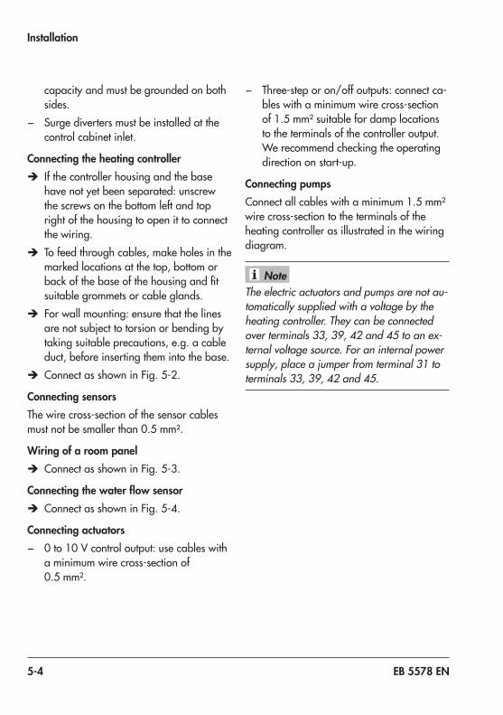
Connecting the heating controller Î If the controller housing and the base have not yet been separated: unscrew the screws on the bottom left and top right of the housing to open it to connect the wiring.
Î To feed through cables, make holes in the marked locations at the top, bottom or backofthebaseofthehousingandfitsuitable grommets or cable glands.
Î For wall mounting: ensure that the lines are not subject to torsion or bending by taking suitable precautions, e.g. a cable duct, before inserting them into the base.
Î ConnectasshowninFig. 5-2.
Connecting sensorsThe wire cross-section of the sensor cables mustnotbesmallerthan0.5 mm².
Wiring of a room panel Î ConnectasshowninFig. 5-3.
Connecting the water flow sensor Î ConnectasshowninFig. 5-4.
Connecting actuators − 0to10 Vcontroloutput:usecableswith
a minimum wire cross-section of 0.5 mm².
− Three-steporon/offoutputs:connectca-bles with a minimum wire cross-section of1.5 mm²suitablefordamplocationsto the terminals of the controller output. We recommend checking the operating direction on start-up.
Connecting pumpsConnectallcableswithaminimum1.5 mm²wire cross-section to the terminals of the heating controller as illustrated in the wiring diagram.
The electric actuators and pumps are not au-tomatically supplied with a voltage by the heating controller. They can be connected over terminals 33, 39, 42 and 45 to an ex-ternal voltage source. For an internal power supply, place a jumper from terminal 31 to terminals 33, 39, 42 and 45.
Note

EB 5578 EN 5-5
Installation
Devi
ce b
usDe
vice
bus
M-B
usM-B
us
BE1
BE2 BE
3BE
4 BE5
BE6 BE
7BE
8 BE9
BE10 BE
11BE
12 BE13
291 3 5 7 9 11 13 15 17 19 21 23 25 27
BE14 BE
15BE
16
2 4 6 8 10 12 14 16 18 20 22 24 26 28 30
BE17
423231
BA1
BA2
BA5
BA6
BA7
45 46 474443
SLP
414039383736353433
4441Rk1_
3-ste
p
Rk2_
3-ste
p
Rk2_
on/o
ff
Rk1_
on/o
ff
Sens
or C
OM
NL1
UP1
UP2
L1
ZPBA
4
L1 L1BA
8
BA9
BA3
UP3
BA10
BA11
47Rk3_
3-ste
p
Rk3_
on/o
ff
L1
+0
... 1
0 V
in –
+0/
10 V
out
(PW
M) –
+0
... 1
0 V
out –
SF3/
FG3
AF2
SF2
RF2
VF1
VF3
RüF1
RüF3
FG2
SF1
RF1
VF2
VF4
RüF2
FG1
RF3
AF1
Fig. 5-2: Electrical connection of the TROVIS 5578 Heating Controller

5-6 EB 5578 EN
Installation
Legend for Fig. 5-2:
518
TROVIS 5578
151 2 3
Type 5257-5(x) Room Panel 1)
For RK1:
618
TROVIS 5578
161 2 3
Type 5257-5(x) Room Panel 1)
For RK2:
718
TROVIS 5578
171 2 3
Type 5257-5(x) Room Panel 1)
For RK3:
1) Type 5244nolongeravailable
Fig. 5-3: Wiring of a room panel for RK1, RK2 or RK3
AF Outdoor sensorBA Binary outputBE Binary inputFG PotentiometerRF RoomsensorRüF Returnflowsensor
SF Storage tank sensorVF Flow sensorRK Control circuitUP Circulation pump
(heating)
SLP Storage tank charging pump
ZP Circulation pump (DHW)

EB 5578 EN 5-7
Installation
Waterflowsensor
2117
TROVIS 5578
20BN/BKGNWH
WH =whiteGN =greenBN =brownBK =black
Fig. 5-4: Connection of a water flow sensor
Table 5-1: Permissible wire cross-section for terminals
Cable Wire cross-section
Single-wire 0.33to2 mm²
Multi-wire 0.33to2 mm²
Lengthofinsulationtobestrippedoffwireends:6 mm

5-8 EB 5578 EN

EB 5578 EN 6-1
Operation
6 OperationThe heating controller is operated on site using the operating controls on the front.
6.1 Operating controlsThe operating controls are located in the front panel of the controller.
Rotary pushbutton
* Turn [q]:Select readings, parameters and function blocksPress [Û]:Confirmadjustedselectionorsettings
Rotary switchThe rotary switch is used to set the operating mode and the relevant parameters for each control circuit.
Operating level
Operating modes
Manual level
Day set point (rated room temperature)
Night set point (reduced room temperature)
Times-of-useforheating/DHW
Special time-of-use
Time/date
Settings

6-2 EB 5578 EN
Operation
6.2 Interfaces
6.2.1 M-bus interface Datatransmissionofmax.threemetersaccordingtoEN1434-3.SeeAnnex A(configura-tion instructions).
6.2.2 Device bus interface RS-485Connection of max. 32 bus devices (two-wire bus)
6.2.3 Optional interfacesModbus interface RS-485
Communication moduleUsingtheoptionalRS-485communicationmodule(ModbusRTUinterface for two-wire bus networks), theTROVIS 5578HeatingControllercan communicate with a control system. In combination with a suitable software for process visualization and communication, a complete control system can be implemented.
The operating software can be updated over a data cable, provided Modbus has been activated (CO6 -> F01 - 1). See Annex A (configuration instructions).
RS-232
RS-485
RS-232C
TROVIS 5578
RS-485
1
1
GLT
1:OptionalRS-485communicationmodule
Fig. 6-1: Network structure
Note

EB 5578 EN 6-3
Operation
Two-wire bus systemTheoptionalRS-485tocomputercommunicationmodule(orderno.8812-2002)isrequiredtoconnectthecontrollertoatwo-wirebusnetworkforModbusRTUcommunicationwithaprocess control system.
Modbus-TCP/IP communication and SAM DISTRICT ENERGY web applicationTheSAMMOBILE,SAMLANorSAMHOMEGatewayisrequiredforModbus-TCP/IPcom-municationandforconnectiontotheSAMDISTRICTENERGYwebapplication.
6.2.4 AccessoriesTROVISI/O(expansionmodule) Orderno.1000062999
Memory module Orderno.1400-9379
Mini module Order no. 1400-7436
Data logging module Orderno.1400-9378
USB converter 3 together with data log viewer software Orderno.1400-9377
TROVIS-VIEWsoftware(freeofcharge) Link to download at: u www.samsongroup.com>SERVICE&SUPPORT>Downloads>TROVIS-VIEW
RS-485communicationmodule Orderno.8812-2002
SurgearresterSA 5000 Orderno.1400-9868
u SAMHOMEGateway for communication over Ethernet Type 5660
u SAMMOBILEGateway for communication using mobile phone networks
Type 5655
u SAM-LANGateway for communication using unlicensed radio frequency bands
Type 5650

6-4 EB 5578 EN

EB 5578 EN 7-1
Start-up and configuration
7 Start-up and configuration
q Operating level
q Configuration and parameter level
Back
System
CO8
CO7
CO4 CO3 CO2 CO1
PA1
PA2
PA3
Display contrast
Display language
&keynumberÚ
PA4
PA13
CO6
CO5
CO13
CO12
CO11
PA12
PA11
PA6
PA1/CO1: HC1 (heating circuit 1) PA13/CO13 HC13 (heating circuit 13)PA2/CO2: HC2 (heating circuit 2) CO5: System-widePA3/CO3: HC3 (heating circuit 3) PA6/CO6: CommunicationPA4/CO4: DHW circuit CO7: Device bus
PA11/CO11 HC11 (heating circuit 11) CO8 Binary inputsPA12/CO12 HC12 (heating circuit 12) Anl: System code number
Fig. 7-1: Level structure of TROVIS 5578

7-2 EB 5578 EN
Start-up and configuration
The work described in this section is only to be performed by personnel appropriately quali-fiedtocarryoutsuchtasks.Before start-up, make sure the following conditions are met: − The controller is properly mounted according to the instructions. − The electrical connection is properly performed.
The controller is adapted to its control task by performing start-up. Start-up usually involves performing several steps:1. Change the contrast of the display to adapt it to the installation conditions (see sec-
tion 7.1).2. Changethedisplaylanguageasrequiredfortheoperatingpersonnel(seesection 7.2).3. Selectthehydraulicsystem(seesection 7.3).4. Changefunctionsandparameterstoadaptthesystem(seesections 7.4and7.5).5. Calibratethesensors(seesection 7.6).The settings during start-up can only be performed after the valid key number has been en-tered.Thevalidkeynumberforfirststart-upcanbefoundatthebackofthesemountingandoper-ating instructions. To avoid unauthorized use of the service key number, remove the page or make the key number unreadable. In addition, it is possible to enter a new, customized key number(seesection 7.7).

EB 5578 EN 7-3
Start-up and configuration
7.1 Altering the display contrastThe contrast of the display can be changed to adapt it to the installation conditions.
Turn the rotary switch to (settings). q Enter the currently valid key number. Ú Confirmkeynumber. q Select 'Display contrast'. Ú Activate editing mode for the display contrast.
The current setting is shown inverted on the display. q Set the display contrast Ú Confirmsetting.
Turn the rotary switch back to (operating level).
7.2 Changing the display languageThedefaultdisplaylanguageisGerman.ThesettingcanbechangedtoEnglish.
Turn the rotary switch to (settings). q Enter the currently valid key number. Ú Confirmkeynumber. q Select 'Display language'. Ú Activate editing mode for the language setting.
The currently valid language is selected. q Change the language setting accordingly. Ú Confirmsetting.
Turn the rotary switch back to (operating level).

7-4 EB 5578 EN
Start-up and configuration
7.3 Setting the system code numberDifferent hydraulic schematics are available. Each hydraulic schematic is represented by a systemcodenumber.Thesystemstogetherwiththeirready-configuredfunctionsareshowninAnnex A(configurationinstructions).Asystemisadaptedtoindividualrequirementsbyset-ting the functions and parameters. Changing the system code number resets previously ad-justed function blocks to their default settings (WE). Function block parameters and parame-terlevelsettingsremainunchanged.Thesystemcodenumberissetintheconfigurationandparameter level.
Turn the rotary switch to (settings). q Enter the currently valid key number. Ú Confirmkeynumber.
q Select 'System'. Ú Open 'System'.
q Selecttherequiredsystem(seeAnnex A).

EB 5578 EN 7-5
Start-up and configuration
Ú Confirmthesystemselected. q Select 'Back'. Ú Exit menu.
Turn the rotary switch to (settings).
7.4 Activating and deactivating functionsAfunctionisactivatedordeactivatedintheassociatedfunctionblock.Annex A(configura-tion instructions) contains a detailed description of all functions.
Turn the rotary switch to (settings). q Enter the currently valid key number. Ú Confirmkeynumber.
q Selecttherequiredconfigurationlevel. – CO1: Heating circuit HC1 – CO2: Heating circuit HC2 – CO3: Heating circuit HC3 – CO11: Heating circuit HC11 – CO12: Heating circuit HC12 – CO13: Heating circuit HC13 – CO4: Domestic hot water heating (DHW) – CO5: System-wide functions – CO6: Modbus communication
Active function blocks are indicated by the black squares.
Î Onlythoseconfigurationlevelsareavailableforselec-tion which can be controlled by the selected system.

7-6 EB 5578 EN
Start-up and configuration
Ú Openconfigurationlevel. Thefirstfunctionblockisselected(markedgray).
q Select the required function.
Functions without function block parameters: Ú Activate editing mode for the function. Thecurrentlyactiveconfiguration'0'or'1'isshownin-verted on the display.
q Activate function (1) or deactivate function (0). Ú Confirmconfiguration.
Functions with function block parameters: Ú Open function. q Selectconfiguration. Ú Activateeditingmodeforconfiguration. Thecurrentlyactiveconfiguration'0'or'1'isshownin-verted on the display.
q Activate function (1) or deactivate function (0). Ú Confirmconfiguration. q Select function block parameter. Ú Activate editing mode for function block parameter.
The current setting is shown inverted on the display. q Set function block parameter.
Proceed in the same manner to set further function blocks.
Exit configuration level: q Select 'Back'. q Exitconfigurationlevel.
Toadjustfurtherfunctionblocksinotherconfigurationlevels,repeat steps with gray background.Turn the rotary switch back to (operating level).

EB 5578 EN 7-7
Start-up and configuration
All function block settings are saved in a non-volatile memory in the controller.
7.5 Changing parametersDepending on the system code number selected and the activated functions, not all parame-tersmightbeavailable.Annex A(configurationinstructions)containsadetaileddescriptionof all parameters.
Turn the rotary switch to (settings). q Enter the currently valid key number. Ú Confirmkeynumber.
q Select the required parameter level. – PA1: Heating circuit HC1 – PA2: Heating circuit HC2 – PA3: Heating circuit HC3 – PA11: Heating circuit HC11 – PA12: Heating circuit HC12 – PA13: Heating circuit HC13 – PA4: Domestic hot water heating (DHW) – PA5: Boiler circuit of buffer tank systems – PA6: Modbus communication
Î Only those parameter levels are available for selection which can be controlled by the selected system.
Note

7-8 EB 5578 EN
Start-up and configuration
Ú Open parameter level. Thefirstparameterisselected(markedgray).
q Select parameter. Ú Activate editing mode for the parameter.
The current setting is shown inverted on the display. q Set the parameter. Ú Confirmsetting. Ú Proceed in the same manner to change further parame-
ters.
Exit parameter level. q Select 'Back'. q Exitconfigurationlevel.
Toadjustfurtherfunctionblocksinotherconfigurationlevels,repeat steps with gray background.Turn the rotary switch back to (operating level).
All parameter settings are saved in a non-volatile memory in the controller.
7.6 Calibrating sensorsVarioustemperaturesaremeasuredbytemperaturesensorswhichareconnectedtothecon-troller.ThecontrollerisdesignedforconnectionofPt 1000,PTCandNi 1000sensors. − CO5 -> F01 - 1,F02 - 0:Pt 1000 − CO5 -> F01 - 0,F02 - 0:PTC − CO5 -> F01 - 1,F02 - 1:Ni 1000 Î The sensor resistance values are listed in the 'Design and principle of operation' section.
Note

EB 5578 EN 7-9
Start-up and configuration
If the temperature values displayed at the controller differ from the actual temperatures, the measured values of all connected sensors can be recalibrated. To calibrate a sensor, the cur-rently displayed sensor value must be changed such that it matches the temperature (refer-ence temperature) measured directly at the point of measurement. Sensor calibration is acti-vated in CO5 in F20 function block. An incorrect sensor calibration can be deleted by setting F20 - 0.
Turn the rotary switch to (settings). q Enter the currently valid key number. Ú Confirmkeynumber.
Ú SelectCO5configurationlevel. Ú OpenCO5configurationlevel. Ú Select function block F20. Ú Activate editing mode for F20 function block.
q SelectF20configuration. Ú Activateeditingmodeforconfiguration. Thecurrentlyactiveconfiguration'0'or'1'isshownin-verted on the display.
q Activate function block ('1'). Ú Confirmactivation.

7-10 EB 5578 EN
Start-up and configuration
Ú Select the temperature that you want to calibrate. Ú Open calibration.
The temperature is shown inverted on the display. Ú Correct measured value. Readtheactualtemperaturedirectlyfromthethermome-ter at the point of measurement and enter this value as the reference temperature.
Ú Confirmcorrectedmeasuredvalue. Ú Proceed in the same manner to calibrate further sensors.
Exit configuration level: q Select 'Back'. q Exitconfigurationlevel.
Turn the rotary switch back to (operating level).

EB 5578 EN 7-11
Start-up and configuration
7.6.1 Special values
If sensor inputs not relevant for closed-loop control are con-nected, the 'Special values' screen is automatically dis-playedinthecontroller'soperatinglevel.Amaximumoffivemeasuredvalues(sensorinputsor0to10 Vinput)canbedisplayed.Thesereadingsaredisplayedwithoutaunit.'°C'is the unit for all sensor inputs. The value originating from the0to10 VinputwiththeCO5 -> F25 - 1settingisdis-played as a percentage.
Measured value number
Terminal number
1 1
2 2
3 3
4 4
5 5
6 6
7 8
8 9
9 10
Measured value number
Terminal number
10 11
11 12
12 13
13 15
14 16
15 17
16 7
17 14

7-12 EB 5578 EN
7.7 Entering customized key numberTo prevent the function and parameter settings being changed by unauthorized users, a cus-tomizedkeynumbercanbeaddedtothefixedservicekeynumber.Youcansetthecustom-izedkeynumbertobebetween0100and1900.
Turn the rotary switch to (settings). q Enterkeynumber1995. Ú Confirmkeynumber. q Enter valid key number. Ú Confirmkeynumber.
q Enter customized key number. Ú Confirmcustomizedkeynumber.
This number is the new key number.Turn the rotary switch back to (operating level).

EB 5578 EN 8-1
Operation
8 Operation
8.1 Select the operating modeThe controller can be operated in the following modes:Day mode (rated operation): regardless of the programmed times-of-use and summer mode, the set points relevant for rated operation are used by the controller. Icon: Night mode (reduced operation): regardless of the programmed times-of-use, the set points relevant for reduced operation are used by the controller. Icon: Control operation deactivated: regardless of the programmed times-of-use, control opera-tion of the heating circuits and DHW heating remains deactivated. The frost protection is ac-tivated, if need be. Icon: Icons when the frost protection is activated: HC , DHW Automatic mode: During the programmed times-of-use, the controller works in day mode. Outside these times-of-use, the controller is in night mode, unless control operation is deacti-vated depending on the outdoor temperature. The controller switches automatically between both operating modes. Icon within the times-of-use: , icon outside the times-of-use: Manual mode: valves and pumps can be controlled manually. For further details, see sec-tion 8.6.
Turn the rotary switch to (operating modes). The oper-ating states of all system control circuits are displayed: − Heating circuit HC1 − Heating circuit HC2 − Heating circuit HC3 − Heating circuit HC11 − Heating circuit HC12 − Heating circuit HC13 − DHW heating Î Only those control circuits are available for selection which can be controlled by the selected system.
q Select the control circuit.

8-2 EB 5578 EN
Operation
Ú Activate editing mode for the control circuit. The operat-ing mode is shown inverted on the display.
q Select the operating mode: Automatic mode Day mode Night mode System deactivated
Ú Confirmtheoperatingmode.
The controller is usually in automatic mode.

EB 5578 EN 8-3
Operation
8.2 SchedulesThe controller operates according to the schedules in automatic mode.
8.2.1 Setting the time and dateThe current time and date need to be set immediately after start-up and after a power failure lasting more than 24 hours. This is the case when the time blinks on the display.
Turn the rotary switch to (time/date).Thecurrenttimeisselected (gray background).
Ú Activate editing mode for the time. The time reading is inverted.
q Change the time. Ú Confirmthetimesetting.
q Select 'Date' (dd.mm) [q].
Ú Activate editing mode for the date. The date reading is inverted.
q Change date (day.month). Ú Confirmthedatesetting.

8-4 EB 5578 EN
Operation
q Select'Year'.
Ú Activate editing mode for the year. The year reading is inverted.
q Change the year. Ú Confirmtheyearsetting.
Deactivateoractivatetheautomaticsummer/standardtimeswitchover as required.
q Select 'Auto summertime'.
Ú Activatetheeditingmodeforautomaticsummer/stan-dard time switchover. The current setting is shown invert-ed on the display:ON=Summer/standardtimeswitchoveractiveOFF=Summer/standardtimeswitchovernotactive
q Deactivateoractivatetheautomaticsummer/standardtime switchover.
Ú Confirmdeactivation/activation.Turn the rotary switch back to (operating level).
The correct time is guaranteed after a power failure of 24 hours. Normally, the correct time is still retained at least 48 hours after a power failure.
Note

EB 5578 EN 8-5
Operation
8.2.2 Setting the times-of-useThree times-of-use can be set for each day of the week.
Parameters WE Value range
HC1, HC2, HC3, HC11, HC12, HC13
DHW, CP
Startfirsttime-of-use 06:00 00:00
00:00 to 24:00 hin steps of 15 minutes
Stopfirsttime-of-use 22:00 24:00
Start second time-of-use --:-- --:--
Stop second time-of-use --:-- --:--
Start third time-of-use --:-- --:--
Stop third time-of-use --:-- --:--
Turn the rotary switch to (times-of-use).Thefirstcontrolcircuit is displayed together with its programmed times-of-use.
q Program the times-of-use of another control circuit, if re-quired: – Heating circuit HC2 – Heating circuit HC3 – Heating circuit HC11 – Heating circuit HC12 – Heating circuit HC13 – DHW heating – Circulation pump ZP
Î Only those control circuits are available for selection which can be controlled by the selected system.
Ú Activate editing mode for the control circuit. The times-of-use for Monday are displayed.

8-6 EB 5578 EN
Operation
q Selectperiod/dayforwhichthetimes-of-usearetobevalid. The times-of-use can be programmed for individu-al days or for a block of days, e.g. Monday to Friday, Saturday and Sunday or Monday to Sunday. The select-ed days are shown inverted on the display.
Ú Activateeditingmodefortheperiod/day. Thestarttimeofthefirsttime-of-useperiodcannowbeedited (inverted reading).
q Change start time. The time is set in steps of 15 minutes.
Ú Confirmthestarttime. Thestoptimeofthefirsttime-of-useperiodcannowbeedited.
q End stop time. The time is set in steps of 15 minutes.
Ú Confirmthestoptime. The start time of the second time-of-use period can now be edited.
To set the second and third times-of-use periods, repeat steps with gray background. If no further times-of-use are to beprogrammedfortheselectedtimeperiod/day,exitthemenubyconfirmingtheindicatedstarttimetwice(2xÛ).Proceedinthesamemannertoprogramfurtherperiods/days.
After setting all times-of-use:
q Select 'Back'. Ú Exit the times-of-use setting.
Turn the rotary switch back to (operating level).

EB 5578 EN 8-7
Operation
8.2.3 Setting the party timer (special time-of-use)Ratedoperationinthecorrespondingcontrolcircuit(HC1,HC2,HC3orDHW)isstartedorcontinued for the time period set in the party mode. When the party timer has elapsed, the party timer returns to --:--.
Parameters WE Value range
HC1 party timer --:-- h 0to48 h;instepsof15minutes
HC2 party timer --:-- h 0to48 h;instepsof15minutes
HC3 party timer --:-- h 0to48 h;instepsof15minutes
DHW party timer --:-- h 0to48 h;instepsof15minutes
Turn the rotary switch to (special times-of-use). The party timerforthefirstcontrolcircuitisnowselected.
q Set time for party mode of another control circuit, if re-quired: – Heating circuit HC2 – Heating circuit HC3 – DHW heating
Î Only those control circuits are available for selection which can be controlled by the selected system.
Ú Activate editing mode for the party timer. The party tim-er is now in the editing mode (inverted display).
q Extend day operation as required.The time is set in steps of 15 minutes.

8-8 EB 5578 EN
Operation
Ú Confirmsetting.
After setting the party timer:Turn the rotary switch back to (operating level).
The party timer runs down in steps of 15 minutes.
8.2.4 Programming public holidays (special times-of-use)Onpublicholidays,thetimes-of-usespecifiedforSundayapply.A maximum of 20 public holidays may be entered.
Parameters WE Value range
Public holidays --:-- 01.01 to 31.12
Turn the rotary switch to (special times-of-use). The party timerforthefirstcontrolcircuitisnowselected.
q Select 'Public holidays'.
Ú Startthepublicholidaysetting.Thefirstpublicholidaysetting is now selected. --:-- is displayed if no public hol-idays (default setting) have been programmed.
q Select --:--, if applicable.
Note

EB 5578 EN 8-9
Operation
Ú Activate editing mode for public holidays. q Set the date of the public holiday. Ú Confirmthedate.
Proceed in the same manner to program further public holi-days.
Deleting a public holiday: q Select the holiday you wish to delete. Ú Confirmthedate. q Select '--:--' setting Ú Confirmsetting.
The public holiday is deleted.
After programming all public holidays: q Select 'Back'. Ú Exit the public holiday setting.
Turn the rotary switch back to (operating level).
Public holidays that are not assigned to a specific date should be deleted by the end of the year so that they are not carried on into the following year.
Note

8-10 EB 5578 EN
Operation
8.2.5 Programming vacation periods (special times-of-use)The system runs constantly in reduced mode during vacation periods. A maximum of ten va-cation periods can be entered. Each vacation period can be separately assigned to the heat-ing circuits HC1, HC2, HC3 and DHW circuit or to all control circuits.
If a vacation period is programmed to apply to all control circuits, it also applies to control circuits HC11, HC12 and HC13.
Parameters WE Value range
Vacationperiod --.-- - --.-- 01.01 to 31.12
Turn the rotary switch to (special times-of-use). The party timerforthefirstcontrolcircuitisnowselected.
q Select'Vacations'.
Ú Startthevacationssetting.Thefirstvacationssettingisnow selected. --.-- - --.--.is displayed if no vacations (de-fault setting) have been programmed.
q Select --.-- - --.--.
q Activate editing mode for vacations. The start date can now be edited (inverted reading).
q Set the start date. q Confirmthestartdate. The end date can now be edited.
q Set the end date.
Note

EB 5578 EN 8-11
Operation
q Confirmtheyearsetting.'All'isselected.Thevacationperiod then applies to all control circuits.
q If the vacation period is to be only valid for one control circuit, select the required control circuit: – Heating circuit HC1 – Heating circuit HC2 – Heating circuit HC3 – DHW heating
Î Only those control circuits are available for selection which can be controlled by the selected system.The control circuits HC11, HC12 and HC13 are not available.
Ú Confirmthecontrolcircuit.
An active vacation period is indicated on the display by the icon.
Proceed in the same manner to program further vacations.Deleting vacation periods:
q Select the start date of the period you wish to delete. Ú Confirmvacationperiod. q Select --.-- - --.--. Ú Confirmsetting.
The vacation period is deleted.
Note

8-12 EB 5578 EN
Operation
After programming all vacation periods: q Select 'Back'. Ú Exit the vacations setting.
Turn the rotary switch back to (operating level).
Vacations should be deleted by the end of the year so that they are not carried on into the following year.
8.3 Entering day and night set pointsThe day set points apply during day mode (rated operation) and during times-of-use pro-grammed for automatic mode.The night set points apply during night mode (reduced operation) and outside the times-of-use programmed for automatic mode.The desired room temperature for the day and night set points can be programmed.
Switch position
Parameters WE Value range
HC1 room temperature 20.0 °C 0.0to40.0 °C
HC2 room temperature 20.0 °C 0.0to40.0 °C
HC3 room temperature 20.0 °C 0.0to40.0 °C
HC11 room temperature 20.0 °C 0.0to40.0 °C
HC12 room temperature 20.0 °C 0.0to40.0 °C
HC13 room temperature 20.0 °C 0.0to40.0 °C
DHW temperature 60.0 °C Min. to max. DHW temperature
HC1 OT deactivation value 22.0 °C 0.0to50.0 °C
HC2 OT deactivation value 22.0 °C 0.0to50.0 °C
HC3 OT deactivation value 22.0 °C 0.0to50.0 °C
HC11 OT deactivation value 22.0 °C 0.0to50.0 °C
HC12 OT deactivation value 22.0 °C 0.0to50.0 °C
HC13 OT deactivation value 22.0 °C 0.0to50.0 °C
Note

EB 5578 EN 8-13
Operation
Switch position
Parameters WE Value range
HC1 room temperature 15.0 °C 0.0to40.0 °C
HC2 room temperature 15.0 °C 0.0to40.0 °C
HC3 room temperature 15.0 °C 0.0to40.0 °C
HC11 room temperature 15.0 °C 0.0to40.0 °C
HC12 room temperature 15.0 °C 0.0to40.0 °C
HC13 room temperature 15.0 °C 0.0to40.0 °C
DHW temperature 40.0 °C Min. to max. DHW temperature
HC1 OT deactivation value 15.0 °C –50.0to50.0 °C
HC2 OT deactivation value 15.0 °C –50.0to50.0 °C
HC3 OT deactivation value 15.0 °C –50.0to50.0 °C
HC11 OT deactivation value 15.0 °C –50.0to50.0 °C
HC12 OT deactivation value 15.0 °C –50.0to50.0 °C
HC13 OT deactivation value 15.0 °C –50.0to50.0 °C
Turn the rotary switch to (day set point) or (night set point). The day or night set points appear on the display one after the other.
Î Only those day and night set points are available for se-lection which can be controlled by the selected system.
The deactivation values are located in a separate menu (de-activation values) for systems with three control circuits.
q Select the set point.
Note

8-14 EB 5578 EN
Operation
Ú Activate editing mode for set point. q Adjust the set point. Ú Confirmsetting.
Proceed in the same manner to adjust further set points.
After adjusting all the set points:Turn the rotary switch back to (operating level).
8.4 Reset to default settingsAll parameters set over the rotary switch as well as parameters in the PA1 and PA2 parame-terlevelscanberesettotheirdefaultsettings(WE).ThisdoesnotapplytothemaximumflowtemperatureandthereturnflowtemperaturelimitsinPA1andPA2.
Turn the rotary switch to (settings). q Enterkeynumber1991. Ú Confirmkeynumber.
The settings are reset when the following icon appears on the controller display:
8.5 Reading informationDifferent kinds of information can read off the controller display during operation. The con-troller display usually shows the date, time and the actual temperature when the rotary switch is switched to the 'Operating level' position.
Outdoor-temperature-compensated control · Current temperature = outdoor temperature
Deactivation depending on outdoor temperature active)
Vacationsactive

EB 5578 EN 8-15
Operation
Fixed set point control · Current temperature = Flow temperature
Further information can be obtained by turning the rotary pushbutton:
q Operating stateThe following applies for heating circuits HC1, HC2, HC3, HC11, HC12 and HC13:
Heating circuit
Current operating
modeValve
opens closes
Current positioning value
Circulation pump (heating)ON/OFF
The following applies for DHW heating:
Current operating mode
PumpON/OFF Storage tank charging pump Circulation pump (DHW) Solar circuit pump
q Selected system code numberSeeAnnex A(configurationinstructions)forfurtherin-formation.

8-16 EB 5578 EN
Operation
Ú Keymeasuredvaluesfortheentiresystem(e.g.measuredvaluesandlimitsofaflowrateorcapacitylimitation or the demand to be processed) are shown, if activated.
q Times-of-use (depending on system code number) – Heating circuit HC1 – Heating circuit HC2 – Heating circuit HC3 – Heating circuit HC11 – Heating circuit HC12 – Heating circuit HC13 – DHW heating
The day mode times is highlighted in black on the time chart.Night mode and deactivation times are highlighted in gray on the time chart.
Ú Measured values, set points and limits of the system section shown are displayed.
The 'DHW values' page also includes information on the op-erating state of the DHW heating. The following messages are generated: − 'Standby' − 'Monitoring' − 'Circulation'(=circulationlossesarecompensatedfor) − 'Demand' − 'Charging' − 'Lag time' − 'Intermediate heating' − 'Discharging protection'

EB 5578 EN 8-17
Operation
q Alarm list The last four alarm entries are listed.
Ú Open the alarm list and select further alarm entries (q). Further information on an alarm (including time and date when it occurred) runs across the display.
q Event list The last four event entries are listed.
Ú Open the event list and select further event entries (q). Further information on an event (including time and date when it occurred) runs across the display.
q Trend-Viewer The standard graph shows the data measured at the out-doorsensorAF1andflowsensorVF1plottedovertime.

8-18 EB 5578 EN
Operation
Extended operating level
The following details on the controller version (device identi-fication,serialnumber,softwareandhardwareversions)and meter bus are displayed in the extended operating lev-el.
Turn the rotary switch to (settings). q Entercodenumber1999. Ú Confirmkeynumber.
Turn the rotary switch to (operating level). q Select 'Information'.
The additional "meter" page is displayed with connec-tion status and further meter data for meters 1 to 3 in the "extended operating level" mode when the meter bus is activated(seeAnnex A).Inaddition,therespectivemea-suringandlimitvaluesaredisplayedafterconfirmingtheplantschemewhentheflowrateand/orcapacitylimitation is active.
− The additional information is hidden when the key number 1999 is entered again. − The key number 1999 cannot be used to change the con-troller configuration and parameterization. A separate key number exists for configuration and parameterization (see the 'Start-up and configuration' section).
Note

EB 5578 EN 8-19
Operation
8.5.1 Adapting the Trend-ViewerThestandardgraphshowsthedatameasuredattheoutdoorsensorAF1andflowsensorVF1plottedovertime.
Ú OpentheTrend-Viewer.
Adding measuring data q Select – – – – on the display. Ú Activate editing mode for sensor selection. q Select the sensor. Ú Confirmsetting.
Deleting measured data: q Select the sensor whose measured data are no longer to be displayed.
Ú Activate editing mode for sensor. q Select – – – – on the display. Ú Confirmdeletion.
Shifting the time line: q Select 'Scroll'. Ú Activate editing mode for scroll function.
q Shift the time line. Ú Confirmtimedisplay.

8-20 EB 5578 EN
Operation
Zooming in/out q Select 'Zoom'. Ú Open zoom function. q Zoom in or out. Ú Confirmdisplay.
Closing the Trend-Viewer q Select 'Back'. Ú ClosetheTrend-Viewer

EB 5578 EN 8-21
Operation
8.6 Operating the controller in manual modeSwitchtomanualmodetoconfigureallcontrolleroutputs.
System damage caused by frost when manual operating mode is active!The frost protection function is deactivated in the manual operating mode.
Î Do not run the heating during cold weather in the manual mode for long periods of time.
Manually changing the positioning value/switching state:
Turn the rotary switch to (manual mode). The outputs of theconfiguredsystemarelistedonthedisplay.
q Select the output Positioning value Circulation pump (heating)
Storage tank charging pump Circulation pump (DHW) Solar circuit pump
q Activate editing mode for the output. q Changethepositioningvalue/switchingstate. q Confirmthepositioningvalue/switchingstate. Themodifiedvaluesremainactiveaslongasthecontrol-ler is in manual mode.
Turn the rotary switch to (operating level). The manual mode is deactivated.
The outputs of the controller are not affected by merely turning the rotary switch to (manu-al mode). The outputs are only changed by entering or changing the positioning values or switching states.
NOTICE!
Note

8-22 EB 5578 EN

EB 5578 EN 9-1
Malfunctions
9 MalfunctionsA malfunction is indicated by the blinking icon on the display. Additionally, the display is illuminated for one second every 10 seconds upon sensor failure. Press the rotary pushbutton to open the error level. As long as an malfunction exits, the error message is included in the reading loop, even when it has not been opened by pressing the rotary pushbutton.Intheerrorlevel,theerrormessageisdisplayedasspecifiedinthefollowinglist(seesec-tion 9.1).
Risk of electric shock while performing electrical connection.For electrical installation, you are required to observe the relevant electrotechnical regula-tions of the country of use as well as the regulations of the local power suppliers.
Î Only allow properly trained and qualified personnel to perform the work.
Risk of damage to the heating controller due to incorrectly performed work. Î Only properly trained personnel appropriately qualified to carry out such tasks must be allowed to perform corrective action.
After the system code number has been changed or after restarting the heating controller, any error messages are suppressed for approx. three minutes.
DANGER!
NOTICE!
Note

9-2 EB 5578 EN
Malfunctions
9.1 Error listSensor failure = Sensorfailure(seesection 9.2)ErrTROVIS I/O = TROVIS I/OcommunicationerrorDisinfection = Disinfection temperature not reached. See 'Thermal disin-
fectionofDHWstoragetank'functioninAnnex A(con-figurationinstructions).
Max. charging temp. = Max. charging temperature reached. See 'DHW heating inthestoragetankchargingsystem'functioninAnnex A(configurationinstructions).
External = Error message from device busTemp. monitoring = Temperature monitor alarmUnauthorized access = Unauthorizedaccessoccurred(seesection 9.4)Binary alarm = Error message of a binary inputMeter bus = Meter bus communication errorHeat meter = Heat meter error registered
If the error messages or indications that can be confirmed are included in the list shown, you can decide whether you want to confirm these error messages on exiting the error list.
9.2 Sensor failureAs described in the error list, sensor failures are indicated by the 'Sensor failure' error mes-sage in the error level. For detailed information, exit the error level and view the different temperature values in the information level: each sensor icon displayed together with three dashes instead of the measured value indicates a defective sensor. The following list explains how the heating controller responds to the failure of the different sensors. − Outdoor sensor AF1/2:whentheoutdoorsensorfails,thecontrollerusesaflowtem-peraturesetpointof50 °Corthe'Max.flowtemperature'whenthemax.flowtempera-ture(PA1,2,3 ->P07)islowerthan50 °C.WiththesettingCO1,2,3 -> F05 - 1(un-derfloorheating),theflowtemperaturesetpointis30 °Cintheeventofamalfunction.
Note

EB 5578 EN 9-3
Malfunctions
− Flow sensor(s) in heating circuit(s):whentheflowsensorsintheheatingcircuitsarede-fective,theassociatedvalvemovesto30 %travel.DHWheatingwhichusesuchasensorto measure the charging temperature is suspended. DHW heating which use such a sen-sor to measure the charging temperature is suspended.
− Flow sensors in the DHW circuit with control valve: when the DHW circuit has two chargingtemperaturesensorsVF2andVF4,thecontrollerbehavesasifVF4sensorhasnotbeenconfiguredifitisdefective.AssoonasthecontrolofthechargingtemperatureusingtheVF2sensorortheDHWtemperaturebecomesimpossible,theassociatedvalveis closed.
− Return flow sensor:whenthereturnflowsensorfails,thecontrollercontinuesoperationwithoutreturnflowtemperaturelimitation.
− Room sensor RF: when the room sensor fails, the controller uses the settings for operation without room sensor. The controller, for example switches from optimizing mode to re-duced operation. The adaptation mode is canceled. The last determined heating charac-teristic remains unchanged.
− Storage tank sensors SF1/2: when one of the two sensors fails, the storage tank is no longer charged (exception: solar system).
− Solar circuit sensors SF, VF/RüF: when one of the two sensors fails, the storage tank in the solar circuit is no longer charged.
9.3 Temperature monitoringWhenasystemdeviationgreaterthan10 °Cpersistsinacontrolcircuitfor30minutes,the'Temp. monitoring' message is generated.
Functions WE Configuration
Monitoring 0 CO5 -> F19-1
9.4 Fault alarm outputWiththesettingCO5 -> F07 - 1,theoutputatterminals37,38,43ortheoutputatterminal46isusedforfaultindication(specificterminalslistedinthetableofeachsystem).Thefaultalarmoutputisactivated(bA = 1setting)ordeactivated(bA = 0setting)whenatleastoneofthe errors from the error list (bold) occurs. ThisfunctionisnotavailableforsystemsAnl5.1,5.2,5.9,6.1,9.1,9.2,9.5,9.6,12.1,12.2,13.1,13.2,13.6,15.1,15.2,15.3,17.8,21.1and21.2.

9-4 EB 5578 EN
Malfunctions
Functions WE Configuration
Fault alarm output at terminal 37, 38,43or46(dependingonthesys-tem selected)
0 CO5 -> F07 - 1
1 bA =1,0
9.5 Error status registerThe error status register is used to indicate controller or system errors. The error messages whichcauseachangeinthestateoftheconfiguredfaultalarmoutput(CO5 -> F07 - 1)arehighlighted in the following table (bold).ThefunctionblocksintheCO8configurationlevelallowsinglecontrollerinputsthatarenotused to be added to the error status register as binary inputs. Either an open or closed bina-ryinputcanbeconfiguredtoindicateanerror.Thecontrollerindicates'Binaryalarm'whenatleastoneoftheinputsconfiguredinthiswayregistersanerror.
If free inputs are to issue binary signals to a building control station without affecting the er-ror status register, activate the corresponding function block in the CO8 configuration level and select 'None' as the function block parameter.
Error message Decimal valueSensor failure 1 1
TROVIS I/Ofailure 2
Disinfection 4
Max. charging temp. 8
External 16
Temp. monitoring 32 32
Unauthorized access 64
Binary alarm 128
Meter bus 256
Heat meter 512
Total
Example:Valueoferrorstatusregisterwhenasensorfailsandatemperaturemonitoringalarm=
33
Note

EB 5578 EN 10-1
Servicing
10 ServicingThe work described in this section is only to be performed by personnel appropriately quali-fiedtocarryoutsuchtasks.We recommend inspection and testing according to Table 10-1.
Table 10-1: Recommended inspection and testing
Inspection and testing Action to be taken in the event of a negative result
Check the markings, labels and nameplates on the controller for their readability and completeness.
Î Immediately renew damaged, missing or incorrect nameplates or labels.
ÎClean any inscriptions that are covered with dirt and are illegible.
Check the electric wiring. Î If any wires are loose, open the controller housing and tighten the terminal screws (see the 'Installation' section).
Î Renewdamagedwires.
Compare the temperature values displayed at the controller with the actual temperatures at the point of measurement.
Î If the displayed and actual temperatures differ, calibrate the sensors (see the' Start-up and configuration'section).

10-2 EB 5578 EN

EB 5578 EN 11-1
Decommissioning
11 DecommissioningThe work described in this section is only to be performed by personnel appropriately qualifiedtocarryoutsuchtasks.
Risk of fatal injury due to electric shock. Î Before disconnecting live wires, switch off the supply voltage at the controller and protect it against unintentional re-connection.
To put the controller out of operation, the controller must be disconnected from the voltage supply:
Î Controller connected to a control station: log the controller off from the control sta-tion and remove the communication modulefromtheRJ-45jack.
Î ControllerconnectedtoTROVIS-VIEW:removetheconnectingcablefromtheRJ-45 jack.
Î Ifamemorymodule/minimoduleorlog-ging module is used: save data and re-movethememorymodule/minimoduleorloggingmodulefromthetheRJ-45jack.
Î Disconnect the supply voltage and pro-tect it against unintentional reconnection.
Î Unscrew the top left and right screws on the front of the controller to open the controller housing.
Î Disconnect the electrical wires from the terminals.
Î Pull the wires out of the cable ducts.
DANGER!

11-2 EB 5578 EN

EB 5578 EN 12-1
Removal
12 RemovalThe work described in this section is only to be performed by personnel appropriately qualifiedtocarryoutsuchtasks.
Panel mounting1. Put the controller out of operation (see
the 'Decommissioning' section).2. Unscrew the top left and bottom right
screws to unfasten the controller housing from the control panel.
Wall mounting1. Put the controller out of operation (see
the 'Decommissioning' section).2. Unscrew the fastening screws and re-
move the back of the housing from the wall.
Rail mounting1. Put the controller out of operation (see
the 'Decommissioning' section).2. Unscrew the top left and bottom right
screws to unfasten the controller housing from the top-hat rail.

12-2 EB 5578 EN

EB 5578 EN 13-1
Repairs
13 RepairsA defective controller must be repaired or re-placed.
Risk of controller damage due to incorrect service or repair work.
Î Do not perform any repair work on your own.
Î Contact SAMSON's After-sales Service for repair work.
13.1 Returning devices to SAMSON
Defective controllers can be returned to SAMSON for repair.Proceed as follows to return devices to SAMSON:1. Put the controller out of operation (see
the 'Decommissioning' section).2. Removethecontroller(seethe'Removal'
section).3. ProceedasdescribedontheReturning
goods page of our website u www.samsongroup.com>Service&Support>After-salesService>Returninggoods
NOTICE! NOTICE!

13-2 EB 5578 EN

EB 5578 EN 14-1
Disposal
14 Disposal
We are registered with the Germannationalregisterforwaste electric equipment (stiftung ear) as a producer of electrical and electronic equipment, WEEEreg.no.:DE62194439
Î Observe local, national and internation-al refuse regulations.
Î Do not dispose of components, lubricants and hazardous substances together with your other household waste.
On request, we can appoint a service pro-vider to dismantle and recycle the product.
Tip

14-2 EB 5578 EN

EB 5578 EN 15-1
Certificates
15 CertificatesThefollowingcertificateisshownonthenextpage: − EU declaration of conformityThecertificateshownwasuptodateatthetimeofpublishing.Thelatestcertificatescanbefound on our website:u www.samsongroup.com>Products&Applications>Productselector>AutomationSystems>5578

15-2 EB 5578 EN
Certificates
EU declaration of conformity
SAMSON AKTIENGESELLSCHAFT Weismüllerstraße 3 60314 Frankfurt am Main
Telefon: 069 4009-0 · Telefax: 069 4009-1507 E-Mail: [email protected]
Revison 07
EU Konformitätserklärung/EU Declaration of Conformity/
Déclaration UE de conformité
Die alleinige Verantwortung für die Ausstellung dieser Konformitätserklärung trägt der Hersteller/ This declaration of conformity is issued under the sole responsibility of the manufacturer/ La présente déclaration de conformité est établie sous la seule responsabilité du fabricant. Für das folgende Produkt / For the following product / Nous certifions que le produit
Heizungs- und Fernheizungsregler / Heating and District Heating Controller / Régulateur de chauffage et de chauffage à distance
Typ/Type/Type TROVIS 5578
wird die Konformität mit den einschlägigen Harmonisierungsrechtsvorschriften der Union bestätigt / the conformity with the relevant Union harmonisation legislation is declared with/ est conforme à la législation d'harmonisation de l'Union applicable selon les normes:
EMC 2014/30/EU EN 61000-6-1:2007, EN 61000-6-3:2007 +A1:2011
LVD 2014/35/EU EN 60730-1:2016
RoHS 2011/65/EU
EN 50581:2012
Hersteller / Manufacturer / Fabricant:
SAMSON AKTIENGESELLSCHAFT Weismüllerstraße 3
D-60314 Frankfurt am Main Deutschland/Germany/Allemagne
Frankfurt / Francfort, 2017-07-29 Im Namen des Herstellers/ On behalf of the Manufacturer/ Au nom du fabricant.
Gert Nahler Hanno Zager Zentralabteilungsleiter/Head of Department/Chef du département Leiter Qualitätssicherung/Head of Quality Managment/ Entwicklung Automation und Integrationstechnologien/ Responsable de l'assurance de la qualité Development Automation and Integration Technologies
ce_5
578-
0_de
_en_
fra_r
ev07

EB 5578 EN 16-1
Annex A (configuration instructions)
16 Annex A (configuration instructions)Thisannexcontainsinformationontheconfigurationofthecontroller.
16.1 SystemsDifferent hydraulic schematics are available. The system images on the display show the structure of the hydraulic system.
Boiler systems:Single-stageboilersystemscanbeconfiguredtoincludeanysystemwhoseheatingcircuitsand DHW circuit include just one heat exchanger. These systems are 1.0-1, 1.5-1, 1.6-1, 1.6-2,1.7-1,1.8-1,1.8-2,1.9,2.x,3.x,4.x,5.x,6.0,7.x,8.x,9.x,11.1-3,14.x,15.x,16.x and 17.x.Theboilercanbecontrolledbyanon/offoutput(CO1 -> F12 - 0).
RK1/0...10V RüF1 VF1 UP1 RF1
BEBAAERK
RK1_2 Pkt VF1 UP1 RF1
BEBAAERK
Single-stage boiler
Fig. 16-1: Configuration of a boiler system

16-2 EB 5578 EN
Annex A (configuration instructions)
System Anl 1.0-1
System 1.0-1
Default settingCO1 -> F01 -0(withoutRF1)CO1 -> F02 - 1 (with AF1)CO1 -> F03 -1(withRüF1)CO5 -> F07 -0(withouterrormessageatterminal 43)
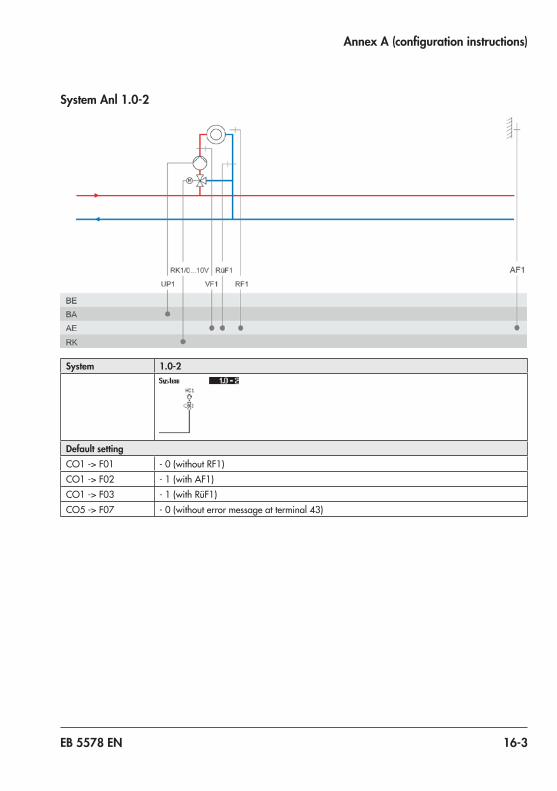
EB 5578 EN 16-3
Annex A (configuration instructions)
System Anl 1.0-2
System 1.0-2
Default settingCO1 -> F01 -0(withoutRF1)CO1 -> F02 - 1 (with AF1)CO1 -> F03 -1(withRüF1)CO5 -> F07 -0(withouterrormessageatterminal 43)

16-4 EB 5578 EN
Annex A (configuration instructions)
System Anl 1.1-1
System 1.1-1
Default settingCO1 -> F01 -0(withoutRF1)CO1 -> F02 - 1 (with AF1)CO1 -> F03 -0(withoutRüF1)CO4 -> F01 - 1 (with SF1)CO4 -> F02 - 0 (without SF2)CO4 -> F05 -0(withoutVF4)CO5 -> F07 -0(withouterrormessageatterminal 43)

EB 5578 EN 16-5
Annex A (configuration instructions)
System Anl 1.1-2
System 1.1-2
Default settingCO1 -> F01 -0(withoutRF1)CO1 -> F02 - 1 (with AF1)CO1 -> F03 -0(withoutRüF1)CO4 -> F01 - 1 (with SF1)CO4 -> F02 - 0 (without SF2)CO4 -> F05 -0(withoutVF4)CO5 -> F07 -0(withouterrormessageatterminal 43)

16-6 EB 5578 EN
Annex A (configuration instructions)
System Anl 1.2
System 1.2
Default settingCO1 -> F01 -0(withoutRF1)CO1 -> F02 - 1 (with AF1)CO1 -> F03 -0(withoutRüF1)CO4 -> F01 - 1 (with SF1)CO4 -> F02 - 1 (with SF2)CO4 -> F05 -0(withoutVF4)CO5 -> F07 -0(withouterrormessageatterminal 43)

EB 5578 EN 16-7
Annex A (configuration instructions)
System Anl 1.3-1
System 1.3-1
Default settingCO1 -> F01 -0(withoutRF1)CO1 -> F02 - 1 (with AF1)CO1 -> F03 -0(withoutRüF1)CO4 -> F01 - 1 (with SF1)CO4 -> F02 - 0 (without SF2)CO4 -> F05 -0(withoutVF4)CO5 -> F07 -0(withouterrormessageatterminal 43)

16-8 EB 5578 EN
Annex A (configuration instructions)
System Anl 1.3-2
System 1.3-2
Default settingCO1 -> F01 -0(withoutRF1)CO1 -> F02 - 1 (with AF1)CO1 -> F03 -0(withoutRüF1)CO4 -> F01 - 1 (with SF1)CO4 -> F02 - 0 (without SF2)CO4 -> F05 -0(withoutVF4)CO5 -> F07 -0(withouterrormessageatterminal 43)
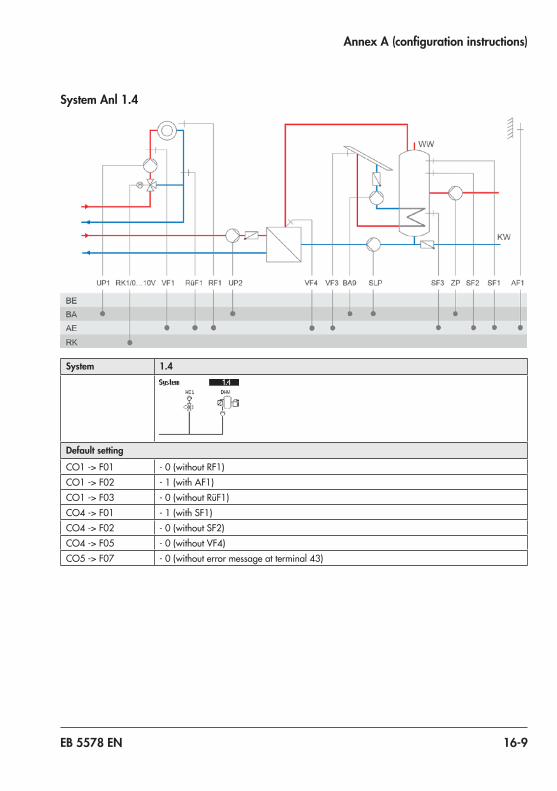
EB 5578 EN 16-9
Annex A (configuration instructions)
System Anl 1.4
System 1.4
Default settingCO1 -> F01 -0(withoutRF1)CO1 -> F02 - 1 (with AF1)CO1 -> F03 -0(withoutRüF1)CO4 -> F01 - 1 (with SF1)CO4 -> F02 - 0 (without SF2)CO4 -> F05 -0(withoutVF4)CO5 -> F07 -0(withouterrormessageatterminal 43)

16-10 EB 5578 EN
Annex A (configuration instructions)
System Anl 1.5-1
System 1.5-1
Default settingCO1 -> F03 -1(withRüF1)CO4 -> F01 - 1 (with SF1)CO4 -> F02 - 0 (without SF2)CO5 -> F07 -0(withouterrormessageatterminal 43)

EB 5578 EN 16-11
Annex A (configuration instructions)
System Anl 1.5-2
System 1.5-2
Default settingCO1 -> F03 -1(withRüF1)CO4 -> F01 - 1 (with SF1)CO4 -> F02 - 0 (without SF2)CO5 -> F07 -0(withouterrormessageatterminal 43)

16-12 EB 5578 EN
Annex A (configuration instructions)
System Anl 1.6-1
System 1.6-1
Default settingCO1 -> F03 -1(withRüF1)CO4 -> F01 - 1 (with SF1)CO4 -> F02 - 1 (with SF2)CO4 -> F10 -0(DHWcirculationreturnflowinstoragetank)CO5 -> F07 -0(withouterrormessageatterminal 43)

EB 5578 EN 16-13
Annex A (configuration instructions)
System Anl 1.6-2
System 1.6-2
Default settingCO1 -> F03 -1(withRüF1)CO4 -> F01 - 1 (with SF1)CO4 -> F02 - 1 (with SF2)CO4 -> F05 -0(withoutVF4;inthiscase,VF1usuallyinstalledatthepointofmeasurementofVF4)CO4 -> F10 -0(DHWcirculationreturnflowinstoragetank)CO5 -> F07 -0(withouterrormessageatterminal 43)

16-14 EB 5578 EN
Annex A (configuration instructions)
System Anl 1.6-3
System 1.6-3
Default settingCO1 -> F03 -1(withRüF1)CO4 -> F01 - 1 (with SF1)CO4 -> F02 - 1 (with SF2)CO4 -> F05 -0(withoutVF4;inthiscase,VF1usuallyinstalledatthepointofmeasurementofVF4)CO4 -> F10 -0(DHWcirculationreturnflowinstoragetank)CO5 -> F07 -0(withouterrormessageatterminal 43)

EB 5578 EN 16-15
Annex A (configuration instructions)
System Anl 1.7-1
System 1.7-1
Default settingCO1 -> F03 -1(withRüF1)CO4 -> F01 - 1 (with SF1)CO4 -> F02 - 0 (without SF2)CO5 -> F07 -0(withouterrormessageatterminal 43)

16-16 EB 5578 EN
Annex A (configuration instructions)
System Anl 1.7-2
System 1.7-2
Default settingCO1 -> F03 -1(withRüF1)CO4 -> F01 - 1 (with SF1)CO4 -> F02 - 0 (without SF2)CO5 -> F07 -0(withouterrormessageatterminal 43)

EB 5578 EN 16-17
Annex A (configuration instructions)
System Anl 1.8-1
System 1.8-1
Default settingCO1 -> F03 -1(withRüF1)CO4 -> F01 - 1 (with SF1)CO4 -> F02 - 1 (with SF2)CO4 -> F10 -0(DHWcirculationreturnflowinstoragetank)CO5 -> F07 -0(withouterrormessageatterminal 43)

16-18 EB 5578 EN
Annex A (configuration instructions)
System Anl 1.8-2
System 1.8-2
Default settingCO1 -> F03 -1(withRüF1)CO4 -> F01 - 1 (with SF1)CO4 -> F02 - 1 (with SF2)CO4 -> F05 -0(withoutVF4;inthiscase,VF1usuallyinstalledatthepointofmeasurementofVF4)CO4 -> F10 -0(DHWcirculationreturnflowinstoragetank)CO5 -> F07 -0(withouterrormessageatterminal 43)

EB 5578 EN 16-19
Annex A (configuration instructions)
System Anl 1.8-3
System 1.8-3
Default settingCO1 -> F03 -1(withRüF1)CO4 -> F01 - 1 (with SF1)CO4 -> F02 - 1 (with SF2)CO4 -> F05 -0(withoutVF4;inthiscase,VF1usuallyinstalledatthepointofmeasurementofVF4)CO4 -> F10 -0(DHWcirculationreturnflowinstoragetank)CO5 -> F07 -0(withouterrormessageatterminal 43)

16-20 EB 5578 EN
Annex A (configuration instructions)
System Anl 1.9-1
System 1.9-1
Default settingCO4 -> F01 - 0 (without SF1)CO4 -> F03 -0(withoutRüF2)CO4 -> F04 -0(withoutflowratesensor)CO5 -> F07 -0(withouterrormessageatterminal 37)

EB 5578 EN 16-21
Annex A (configuration instructions)
System Anl 1.9-2
System 1.9-2
Default settingCO4 -> F01 - 0 (without SF1)CO4 -> F03 -0(withoutRüF2)CO4 -> F04 -0(withoutflowratesensor)CO5 -> F07 -0(withouterrormessageatterminal 37)

16-22 EB 5578 EN
Annex A (configuration instructions)
System Anl 2.0
System 2.0
Default settingCO1 -> F01 -0(withoutRF1)CO1 -> F02 - 1 (with AF1)CO1 -> F03 -1(withRüF1)CO4 -> F01 - 1 (with SF1)CO4 -> F02 - 0 (without SF2)CO5 -> F07 -0(withouterrormessageatterminal 43)

EB 5578 EN 16-23
Annex A (configuration instructions)
System Anl 2.1
System 2.1
Default settingCO1 -> F01 -0(withoutRF1)CO1 -> F02 - 1 (with AF1)CO1 -> F03 -1(withRüF1)CO4 -> F01 - 1 (with SF1)CO4 -> F02 - 0 (without SF2)CO5 -> F07 -0(withouterrormessageatterminal 43)

16-24 EB 5578 EN
Annex A (configuration instructions)
System Anl 2.2
System 2.2
Default settingCO1 -> F01 -0(withoutRF1)CO1 -> F02 - 1 (with AF1)CO1 -> F03 -1(withRüF1)CO4 -> F01 - 1 (with SF1)CO4 -> F02 - 1 (with SF2)CO4 -> F05 -0(withoutVF4)CO5 -> F07 -0(withouterrormessageatterminal 43)

EB 5578 EN 16-25
Annex A (configuration instructions)
System Anl 2.3
System 2.3
Default settingCO1 -> F01 -0(withoutRF1)CO1 -> F02 - 1 (with AF1)CO1 -> F03 -1(withRüF1)CO4 -> F01 - 1 (with SF1)CO4 -> F02 - 0 (without SF2)CO5 -> F07 -0(withouterrormessageatterminal 43)

16-26 EB 5578 EN
Annex A (configuration instructions)
System Anl 2.4
System 2.4
Default settingCO1 -> F01 -0(withoutRF1)CO1 -> F02 - 1 (with AF1)CO1 -> F03 -1(withRüF1)CO4 -> F01 - 1 (with SF1)CO4 -> F02 - 1 (with SF2)CO4 -> F05 -0(withoutVF4)CO5 -> F07 -0(withouterrormessageatterminal 43)

EB 5578 EN 16-27
Annex A (configuration instructions)
System Anl 3.0
System 3.0
Default settingCO1 -> F02 - 1 (with AF1)CO1 -> F03 -1(withRüF1)CO2 -> F01 -0(withoutRF2)CO2 -> F02 - 1 (with AF1)CO2 -> F03 -0(withoutRüF2)CO5 -> F07 -0(withouterrormessageatterminal 37)CO5 -> F14 - 0 (UP1 only active during the processing for an external demand)

16-28 EB 5578 EN
Annex A (configuration instructions)
System Anl 3.1
System 3.1
Default settingCO1 -> F01 -0(withoutRF1)CO1 -> F02 - 1 (with AF1)CO1 -> F03 -1(withRüF1)CO2 -> F01 -0(withoutRF2)CO2 -> F02 - 1 (with AF1)CO2 -> F03 -0(withoutRüF2)CO4 -> F01 - 1 (with SF1)CO4 -> F02 - 0 (without SF2)CO5 -> F07 -0(withouterrormessageatterminal 46)

EB 5578 EN 16-29
Annex A (configuration instructions)
System Anl 3.2
System 3.2
Default settingCO1 -> F01 -0(withoutRF1)CO1 -> F02 - 1 (with AF1)CO1 -> F03 -1(withRüF1)CO2 -> F01 -0(withoutRF2)CO2 -> F02 - 1 (with AF1)CO2 -> F03 -0(withoutRüF2)CO4 -> F01 - 1 (with SF1)CO4 -> F02 - 1 (with SF2)CO4 -> F05 -0(withoutVF4)CO4 -> F10 -0(DHWcirculationreturnflowinstoragetank)CO5 -> F07 -0(withouterrormessageatterminal 46)

16-30 EB 5578 EN
Annex A (configuration instructions)
System Anl 3.3
System 3.3
Default settingCO1 -> F01 -0(withoutRF1)CO1 -> F02 - 1 (with AF1)CO1 -> F03 -1(withRüF1)CO2 -> F01 -0(withoutRF2)CO2 -> F02 - 1 (with AF1)CO2 -> F03 -0(withoutRüF2)CO4 -> F01 - 1 (with SF1)CO4 -> F02 - 0 (without SF2)CO5 -> F07 -0(withouterrormessageatterminal 46)

EB 5578 EN 16-31
Annex A (configuration instructions)
System Anl 3.4
System 3.4
Default settingCO1 -> F01 -0(withoutRF1)CO1 -> F02 - 1 (with AF1)CO1 -> F03 -1(withRüF1)CO2 -> F01 -0(withoutRF2)CO2 -> F02 - 1 (with AF1)CO2 -> F03 -0(withoutRüF2)CO4 -> F01 - 1 (with SF1)CO4 -> F02 - 0 (without SF2)CO4 -> F05 -0(withoutVF4)CO4 -> F10 -0(DHWcirculationreturnflowinstoragetank)CO5 -> F07 -0(withouterrormessageatterminal 46)

16-32 EB 5578 EN
Annex A (configuration instructions)
System Anl 3.5
System 3.5
Note: Closed control circuit and UP1 are only active during the processing for an external demandDefault settingsCO1 -> F03 -1(withRüF1)CO5 -> F07 -0(withouterrormessageatterminal 43)

EB 5578 EN 16-33
Annex A (configuration instructions)
System Anl 3.9
System 3.9
Default settingCO1 -> F02 - 1 (with AF1)CO1 -> F03 -1(withRüF1)CO1 -> F06 - 1 (with SF2)CO2 -> F01 -0(withoutRF2)CO2 -> F02 - 1 (with AF1)CO2 -> F03 -0(withoutRüF2inRK2)CO4 -> F03 -0(withoutRüF2/RüF4)CO4 -> F04 -0(withoutflowswitch)CO4 -> F14 -0(withoutRüF3)CO5 -> F07 -0(withouterrormessageatterminal 46)

16-34 EB 5578 EN
Annex A (configuration instructions)
System Anl 4.0
System 4.0
Default settingCO1 -> F01 -0(withoutRF1)CO1 -> F02 - 1 (with AF1)CO1 -> F03 -1(withRüF1)CO2 -> F01 -0(withoutRF2)CO2 -> F02 - 1 (with AF1)CO2 -> F03 -0(withoutRüF2)CO5 -> F07 -0(withouterrormessageatterminal 37)

EB 5578 EN 16-35
Annex A (configuration instructions)
System Anl 4.1
System 4.1
Default settingCO1 -> F01 -0(withoutRF1)CO1 -> F02 - 1 (with AF1)CO1 -> F03 -1(withRüF1)CO2 -> F01 -0(withoutRF2)CO2 -> F02 - 1 (with AF1)CO2 -> F03 -0(withoutRüF2)CO4 -> F01 - 1 (with SF1)CO4 -> F02 - 0 (without SF2)CO5 -> F07 -0(withouterrormessageatterminal 46)

16-36 EB 5578 EN
Annex A (configuration instructions)
System Anl 4.2
System 4.2
Default settingCO1 -> F01 -0(withoutRF1)CO1 -> F02 - 1 (with AF1)CO1 -> F03 -1(withRüF1)CO2 -> F01 -0(withoutRF2)CO2 -> F02 - 1 (with AF1)CO2 -> F03 -0(withoutRüF2)CO4 -> F01 - 1 (with SF1)CO4 -> F02 - 1 (with SF2)CO4 -> F05 -0(withoutVF4)CO5 -> F07 -0(withouterrormessageatterminal 46)

EB 5578 EN 16-37
Annex A (configuration instructions)
System Anl 4.3
System 4.3
Default settingCO1 -> F01 -0(withoutRF1)CO1 -> F02 - 1 (with AF1)CO1 -> F03 -1(withRüF1)CO2 -> F01 -0(withoutRF2)CO2 -> F02 - 1 (with AF1)CO2 -> F03 -0(withoutRüF2)CO4 -> F01 - 1 (with SF1)CO4 -> F02 - 0 (without SF2)CO5 -> F07 -0(withouterrormessageatterminal 46)

16-38 EB 5578 EN
Annex A (configuration instructions)
System Anl 4.5
System 4.5
Default settingCO1 -> F01 -0(withoutRF1)CO1 -> F02 - 1 (with AF1)CO1 -> F03 -1(withRüF1)CO2 -> F01 -0(withoutRF2)
CO2 -> F02 - 1 (with AF1)CO2 -> F03 -0(withoutRüF2)CO4 -> F01 - 1 (with SF1)CO4 -> F02 - 0 (without SF2)CO5 -> F07 -0(withouterrormessageatterminal 46)

EB 5578 EN 16-39
Annex A (configuration instructions)
System Anl 5.0
System 5.0
RK2:CO2 -> F02 - 0 =Fixedsetpointcontrol;CO2 -> F02 - 1,selectAF1 =Outdoor-temperature-compensatedcontrolwithAF1;CO2 -> F02 - 1,selectAF2 =Outdoor-temperature-compensatedcontrolwithAF2RK3:CO3 -> F02 - 0 =Fixedsetpointcontrol;CO3 -> F02 - 1,selectAF1 =Outdoor-temperature-compensatedcontrolwithAF1;CO3 -> F02 - 1,selectAF2 =Outdoor-temperature-compensatedcontrolwithAF2Default settingCO1 -> F01 -0(withoutRF1)CO1 -> F02 - 1 (with AF1)CO1 -> F03 -1(withRüF1)CO2 -> F01 -0(withoutRF2)
CO2 -> F02 - 1 (with AF1)CO2 -> F03 -0(withoutRüF2)CO3 -> F01 -0(withoutRF3)CO3 -> F02 - 1 (with AF1)CO3 -> F03 -0(withoutRüF3)CO5 -> F07 -0(withouterrormessageatterminal 37)CO5 -> F14 - 0 (UP1 only active during the processing for an external demand)

16-40 EB 5578 EN
Annex A (configuration instructions)
System Anl 5.1
System 5.1
RK2:CO2 -> F02 - 0 =Fixedsetpointcontrol;CO2 -> F02 - 1,selectAF1 =Outdoor-temperature-compensatedcontrolwithAF1;CO2 -> F02 - 1,selectAF2 =Outdoor-temperature-compensatedcontrolwithAF2RK3:CO3 -> F02 - 0 =Fixedsetpointcontrol;CO3 -> F02 - 1,selectAF1 =Outdoor-temperature-compensatedcontrolwithAF1;CO3 -> F02 - 1,selectAF2 =Outdoor-temperature-compensatedcontrolwithAF2Default settingCO1 -> F01 -0(withoutRF1)CO1 -> F02 - 1 (with AF1)CO1 -> F03 -1(withRüF1)CO2 -> F01 -0(withoutRF2)CO2 -> F02 - 1 (with AF1)CO2 -> F03 -0(withoutRüF2)CO3 -> F01 -0(withoutRF2)CO3 -> F02 - 1 (with AF1)CO3 -> F03 -0(withoutRüF2)CO4 -> F01 - 1 (with SF1)CO4 -> F02 - 0 (without SF2)

EB 5578 EN 16-41
Annex A (configuration instructions)
System Anl 5.2
System 5.2
RK2:CO2 -> F02 - 0 =Fixedsetpointcontrol;CO2 -> F02 - 1,selectAF1 =Outdoor-temperature-compensatedcontrolwithAF1;CO2 -> F02 - 1,selectAF2 =Outdoor-temperature-compensatedcontrolwithAF2RK3:CO3 -> F02 - 0 =Fixedsetpointcontrol;CO3 -> F02 - 1,selectAF1 =Outdoor-temperature-compensatedcontrolwithAF1;CO3 -> F02 - 1,selectAF2 =Outdoor-temperature-compensatedcontrolwithAF2Default settingCO1 -> F01 -0(withoutRF1)CO1 -> F02 - 1 (with AF1)CO1 -> F03 -1(withRüF1)CO2 -> F01 -0(withoutRF2)CO2 -> F02 - 1 (with AF1)CO2 -> F03 -0(withoutRüF2)CO3 -> F01 -0(withoutRF3)CO3 -> F02 - 1 (with AF1)CO3 -> F03 -0(withoutRüF3)CO4 -> F01 - 1 (with SF1)CO4 -> F02 - 1 (with SF2)CO4 -> F05 -0(withoutVF4)CO4 -> F10 -0(DHWcirculationreturnflowinstoragetank)

16-42 EB 5578 EN
Annex A (configuration instructions)
System Anl 5.9
System 5.9
RK2:CO2 -> F02 - 0 =Fixedsetpointcontrol;CO2 -> F02 - 1,selectAF1 =Outdoor-temperature-compensatedcontrolwithAF1;CO2 -> F02 - 1,selectAF2 =Outdoor-temperature-compensatedcontrolwithAF2RK3:CO3 -> F02 - 0 =Fixedsetpointcontrol;CO3 -> F02 - 1,selectAF1 =Outdoor-temperature-compensatedcontrolwithAF1;CO3 -> F02 - 1,selectAF2 =Outdoor-temperature-compensatedcontrolwithAF2Default settingCO1 -> F02 - 1 (with AF1)CO1 -> F03 -1(withRüF1)CO1 -> F06 - 1 (with SF2)CO2 -> F01 -0(withoutRF2)CO2 -> F02 - 1 (with AF1)CO2 -> F03 -0(withoutRüF2inRK2)CO3 -> F01 -0(withoutRF3)CO3 -> F02 - 1 (with AF1)CO4 -> F03 -0(withoutRüF2/RüF4)CO4 -> F04 -0(withoutflowswitch)CO4 -> F14 -0(withoutRüF3)

EB 5578 EN 16-43
Annex A (configuration instructions)
System Anl 6.0
System 6.0
RK2:CO2 -> F02 - 0 =Fixedsetpointcontrol;CO2 -> F02 - 1,selectAF1 =Outdoor-temperature-compensatedcontrolwithAF1;CO2 -> F02 - 1,selectAF2 =Outdoor-temperature-compensatedcontrolwithAF2RK3:CO3 -> F02 - 0 =Fixedsetpointcontrol;CO3 -> F02 - 1,selectAF1 =Outdoor-temperature-compensatedcontrolwithAF1;CO3 -> F02 - 1,selectAF2 =Outdoor-temperature-compensatedcontrolwithAF2Default settingCO1 -> F01 -0(withoutRF1)CO1 -> F02 - 1 (with AF1)CO1 -> F03 -1(withRüF1)CO2 -> F01 -0(withoutRF2)CO2 -> F02 - 1 (with AF1)CO2 -> F03 -0(withoutRüF2)CO3 -> F01 -0(withoutRF3)CO3 -> F02 - 1 (with AF1)CO3 -> F03 -0(withoutRüF3)CO5 -> F07 -0(withouterrormessageatterminal 37)

16-44 EB 5578 EN
Annex A (configuration instructions)
System Anl 6.1
System 6.1
RK2:CO2 -> F02 - 0 =Fixedsetpointcontrol;CO2 -> F02 - 1,selectAF1 =Outdoor-temperature-compensatedcontrolwithAF1;CO2 -> F02 - 1,selectAF2 =Outdoor-temperature-compensatedcontrolwithAF2RK3:CO3 -> F02 - 0 =Fixedsetpointcontrol;CO3 -> F02 - 1,selectAF1 =Outdoor-temperature-compensatedcontrolwithAF1;CO3 -> F02 - 1,selectAF2 =Outdoor-temperature-compensatedcontrolwithAF2Default settingCO1 -> F01 -0(withoutRF1)CO1 -> F02 - 1 (with AF1)CO1 -> F03 -1(withRüF1)CO2 -> F01 -0(withoutRF2)CO2 -> F02 - 1 (with AF1)CO2 -> F03 -0(withoutRüF2)CO3 -> F01 -0(withoutRF3)CO3 -> F02 - 1 (with AF1)CO3 -> F03 -0(withoutRüF3)CO4 -> F01 - 1 (with SF1)CO4 -> F02 - 0 (without SF2)

EB 5578 EN 16-45
Annex A (configuration instructions)
System Anl 7.1
System 7.1
Default settingCO1 -> F01 -0(withoutRF1)CO1 -> F02 - 0 (without AF1)CO1 -> F03 -1(withRüF1)CO4 -> F01 - 1 (with SF1)CO4 -> F02 - 0 (without SF2)CO4 -> F03 -0(withoutRüF2)CO5 -> F07 -0(withouterrormessageatterminal 46)CO5 -> F14 - 0 (UP1 only active during the processing for an external demand)

16-46 EB 5578 EN
Annex A (configuration instructions)
System Anl 7.2
System 7.2
Default settingCO1 -> F01 -0(withoutRF1)CO1 -> F02 - 0 (without AF1)CO1 -> F03 -1(withRüF1)CO4 -> F01 - 1 (with SF1)CO4 -> F02 - 1 (with SF2)CO4 -> F03 -0(withoutRüF2)CO4 -> F05 -0(withoutVF4;inthiscase,VF2usuallyinstalledatthepointofmeasurementofVF4)CO4 -> F10 -0(DHWcirculationreturnflowinstoragetank)CO5 -> F07 -0(withouterrormessageatterminal 46)CO5 -> F14 - 0 (UP1 only active during the processing for an external demand)

EB 5578 EN 16-47
Annex A (configuration instructions)
System Anl 8.1
System 8.1
Default settingCO1 -> F01 -0(withoutRF1)CO1 -> F02 - 1 (with AF1)CO1 -> F03 -1(withRüF1)CO4 -> F01 - 1 (with SF1)CO4 -> F02 - 0 (without SF2)CO4 -> F03 -0(withoutRüF2)CO5 -> F07 -0(withouterrormessageatterminal 46)

16-48 EB 5578 EN
Annex A (configuration instructions)
System Anl 8.2
System 8.2
Default settingCO1 -> F01 -0(withoutRF1)CO1 -> F02 - 1 (with AF1)CO1 -> F03 -1(withRüF1)CO4 -> F01 - 1 (with SF1)CO4 -> F02 - 1 (with SF2)CO4 -> F03 -0(withoutRüF2)CO4 -> F05 -0(withoutVF4;inthiscase,VF2usuallyinstalledatthepointofmeasurementofVF4)CO5 -> F07 -0(withouterrormessageatterminal 46)

EB 5578 EN 16-49
Annex A (configuration instructions)
System Anl 9.1
System 9.1
RK3:CO3 -> F02 - 0 =Fixedsetpointcontrol;CO3 -> F02 - 1,selectAF1 =Outdoor-temperature-compensatedcontrolwithAF1;CO3 -> F02 - 1,selectAF2 =Outdoor-temperature-compensatedcontrolwithAF2Default settingCO1 -> F01 -0(withoutRF1)CO1 -> F02 - 1 (with AF1)CO1 -> F03 -1(withRüF1)CO3 -> F01 -0(withoutRF3)CO3 -> F02 - 1 (with AF1)CO3 -> F03 -0(withoutRüF3)CO4 -> F01 - 1 (with SF1)CO4 -> F02 - 0 (without SF2)CO4 -> F03 -0(withoutRüF2)CO5 -> F14 - 0 (UP1 only active during the processing for an external demand)

16-50 EB 5578 EN
Annex A (configuration instructions)
System Anl 9.2
System 9.2
RK3:CO3 -> F02 - 0 =Fixedsetpointcontrol;CO3 -> F02 - 1,selectAF1 =Outdoor-temperature-compensatedcontrolwithAF1;CO3 -> F02 - 1,selectAF2 =Outdoor-temperature-compensatedcontrolwithAF2Default settingCO1 -> F01 -0(withoutRF1)CO1 -> F02 - 1 (with AF1)CO1 -> F03 -1(withRüF1)CO3 -> F01 -0(withoutRF3)CO3 -> F02 - 1 (with AF1)CO3 -> F03 -0(withoutRüF3)CO4 -> F01 - 1 (with SF1)CO4 -> F02 - 1 (with SF2)CO4 -> F03 -0(withoutRüF2)CO4 -> F05 -0(withoutVF4;inthiscase,VF2usuallyinstalledatthepointofmeasurementofVF4)CO4 -> F10 -0(DHWcirculationreturnflowinstoragetank)CO5 -> F14 - 0 (UP1 only active during the processing for an external demand)

EB 5578 EN 16-51
Annex A (configuration instructions)
System Anl 9.5
System 9.5
RK3:CO3 -> F02 - 0 =Fixedsetpointcontrol;CO3 -> F02 - 1,selectAF1 =Outdoor-temperature-compensatedcontrolwithAF1;CO3 -> F02 - 1,selectAF2 =Outdoor-temperature-compensatedcontrolwithAF2Default settingCO1 -> F01 -0(withoutRF1)CO1 -> F02 - 1 (with AF1)
CO1 -> F03 -1(withRüF1)CO3 -> F01 -0(withoutRF3)CO3 -> F02 -1 (mit AF1)CO3 -> F03 -0(withoutRüF3)CO4 -> F01 - 1 (with SF1)CO4 -> F02 - 0 (without SF2)CO4 -> F03 -0(withoutRüF2)

16-52 EB 5578 EN
Annex A (configuration instructions)
System Anl 9.6
System 9.6
RK3:CO3 -> F02 - 0 =Fixedsetpointcontrol;CO3 -> F02 - 1,selectAF1 =Outdoor-temperature-compensatedcontrolwithAF1;CO3 -> F02 - 1,selectAF2 =Outdoor-temperature-compensatedcontrolwithAF2Default settingCO1 -> F01 -0(withoutRF1)CO1 -> F02 - 1 (with AF1)
CO1 -> F03 -1(withRüF1)CO3 -> F01 -0(withoutRF3)CO3 -> F02 - 1 (with AF1)CO3 -> F03 -0(withoutRüF3)CO4 -> F01 - 1 (with SF1)
CO4 -> F02 - 1 (with SF2)CO4 -> F03 -0(withoutRüF2)CO4 -> F05 -0(withoutVF4;inthiscase,VF2usuallyinstalledatthepointofmeasurementofVF4)
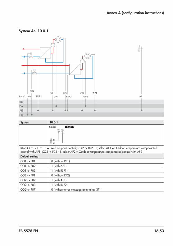
EB 5578 EN 16-53
Annex A (configuration instructions)
System Anl 10.0-1
System 10.0-1
RK2:CO2 -> F02 - 0 =Fixedsetpointcontrol;CO2 -> F02 - 1,selectAF1 =Outdoor-temperature-compensatedcontrolwithAF1;CO2 -> F02 - 1,selectAF2 =Outdoor-temperature-compensatedcontrolwithAF2Default settingCO1 -> F01 -0(withoutRF1)CO1 -> F02 - 1 (with AF1)CO1 -> F03 -1(withRüF1)CO2 -> F01 -0(withoutRF2)CO2 -> F02 - 1 (with AF1)CO2 -> F03 -1(withRüF2)CO5 -> F07 -0(withouterrormessageatterminal 37)
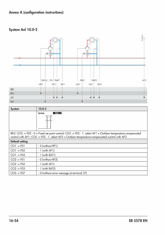
16-54 EB 5578 EN
Annex A (configuration instructions)
System Anl 10.0-2
System 10.0-2
RK2:CO2 -> F02 - 0 =Fixedsetpointcontrol;CO2 -> F02 - 1,selectAF1 =Outdoor-temperature-compensatedcontrolwithAF1;CO2 -> F02 - 1,selectAF2 =Outdoor-temperature-compensatedcontrolwithAF2Default settingCO1 -> F01 -0(withoutRF1)CO1 -> F02 - 1 (with AF1)CO1 -> F03 -1(withRüF1)CO2 -> F01 -0(withoutRF2)CO2 -> F02 - 1 (with AF1)CO2 -> F03 -1(withRüF2)CO5 -> F07 -0(withouterrormessageatterminal 37)
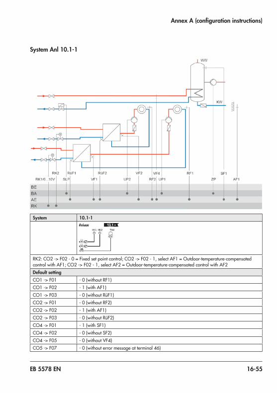
EB 5578 EN 16-55
Annex A (configuration instructions)
System Anl 10.1-1
System 10.1-1
RK2:CO2 -> F02 - 0 =Fixedsetpointcontrol;CO2 -> F02 - 1,selectAF1 =Outdoor-temperature-compensatedcontrolwithAF1;CO2 -> F02 - 1,selectAF2 =Outdoor-temperature-compensatedcontrolwithAF2Default settingCO1 -> F01 -0(withoutRF1)CO1 -> F02 - 1 (with AF1)CO1 -> F03 -0(withoutRüF1)CO2 -> F01 -0(withoutRF2)CO2 -> F02 - 1 (with AF1)CO2 -> F03 -0(withoutRüF2)CO4 -> F01 - 1 (with SF1)CO4 -> F02 - 0 (without SF2)CO4 -> F05 -0(withoutVF4)CO5 -> F07 -0(withouterrormessageatterminal 46)

16-56 EB 5578 EN
Annex A (configuration instructions)
System Anl 10.1-2
System 10.1-2
RK2:CO2 -> F02 - 0 =Fixedsetpointcontrol;CO2 -> F02 - 1,selectAF1 =Outdoor-temperature-compensatedcontrolwithAF1;CO2 -> F02 - 1,selectAF2 =Outdoor-temperature-compensatedcontrolwithAF2Default settingCO1 -> F01 -0(withoutRF1)CO1 -> F02 - 1 (with AF1)CO1 -> F03 -0(withoutRüF1)CO2 -> F01 -0(withoutRF2)CO2 -> F02 - 1 (with AF1)CO2 -> F03 -0(withoutRüF2)CO4 -> F01 - 1 (with SF1)CO4 -> F02 - 0 (without SF2)CO4 -> F05 -0(withoutVF4)CO5 -> F07 -0(withouterrormessageatterminal 46)

EB 5578 EN 16-57
Annex A (configuration instructions)
System Anl 10.2
System 10.2
RK2:CO2 -> F02 - 0 =Fixedsetpointcontrol;CO2 -> F02 - 1,selectAF1 =Outdoor-temperature-compensatedcontrolwithAF1;CO2 -> F02 - 1,selectAF2 =Outdoor-temperature-compensatedcontrolwithAF2Default settingCO1 -> F01 -0(withoutRF1)CO1 -> F02 - 1 (with AF1)CO1 -> F03 -0(withoutRüF1)CO2 -> F01 -0(withoutRF2)CO2 -> F02 - 1 (with AF1)CO2 -> F03 -0(withoutRüF2)CO4 -> F01 - 1 (with SF1)CO4 -> F02 - 1 (with SF2)CO4 -> F05 -0(withoutVF4)CO5 -> F07 -0(withouterrormessageatterminal 46)

16-58 EB 5578 EN
Annex A (configuration instructions)
System Anl 10.3-1
System 10.3-1
RK2:CO2 -> F02 - 0 =Fixedsetpointcontrol;CO2 -> F02 - 1,selectAF1 =Outdoor-temperature-compensatedcontrolwithAF1;CO2 -> F02 - 1,selectAF2 =Outdoor-temperature-compensatedcontrolwithAF2Default settingCO1 -> F01 -0(withoutRF1)CO1 -> F02 - 1 (with AF1)CO1 -> F03 -0(withoutRüF1)CO2 -> F01 -0(withoutRF2)CO2 -> F02 - 1 (with AF1)CO2 -> F03 -0(withoutRüF2)CO4 -> F01 - 1 (with SF1)CO4 -> F02 - 0 (without SF2)CO4 -> F05 -0(withoutVF4)CO5 -> F07 -0(withouterrormessageatterminal 46)

EB 5578 EN 16-59
Annex A (configuration instructions)
System Anl 10.3-2
System 10.3-2
RK2:CO2 -> F02 - 0 =Fixedsetpointcontrol;CO2 -> F02 - 1,selectAF1 =Outdoor-temperature-compensatedcontrolwithAF1;CO2 -> F02 - 1,selectAF2 =Outdoor-temperature-compensatedcontrolwithAF2Default settingCO1 -> F01 -0(withoutRF1)CO1 -> F02 - 1 (with AF1)CO1 -> F03 -0(withoutRüF1)CO2 -> F01 -0(withoutRF2)CO2 -> F02 - 1 (with AF1)CO2 -> F03 -0(withoutRüF2)CO4 -> F01 - 1 (with SF1)CO4 -> F02 - 0 (without SF2)CO4 -> F05 -0(withoutVF4)CO5 -> F07 -0(withouterrormessageatterminal 46)

16-60 EB 5578 EN
Annex A (configuration instructions)
System Anl 10.5
System 10.5
Default settingCO1 -> F02 - 0 (without AF1)CO1 -> F03 -1(withRüF1)CO2 -> F02 - 0 (without AF1)CO2 -> F03 -1(withRüF2)CO5 -> F07 -0(withouterrormessageatterminal 37)

EB 5578 EN 16-61
Annex A (configuration instructions)
System Anl 11.0
System 11.0
Default settingCO1 -> F01 -0(withoutRF1)CO1 -> F02 - 1 (with AF1)CO1 -> F03 -1(withRüF1)CO4 -> F03 -0(withoutRüF2)CO5 -> F07 -0(withouterrormessageatterminal 46)

16-62 EB 5578 EN
Annex A (configuration instructions)
System Anl 11.1-1
System 11.1-1
Default settingCO1 -> F01 -0(withoutRF1)CO1 -> F02 - 1 (with AF1)CO1 -> F03 -1(withRüF1)CO4 -> F01 - 1 (with SF1)CO4 -> F02 - 0 (without SF2)CO4 -> F03 -0(withoutRüF2)CO5 -> F07 -0(withouterrormessageatterminal 46)

EB 5578 EN 16-63
Annex A (configuration instructions)
System Anl 11.1-2
System 11.1-2
Default settingCO1 -> F01 -0(withoutRF1)CO1 -> F02 - 1 (with AF1)CO1 -> F03 -1(withRüF1)CO4 -> F01 - 1 (with SF1)CO4 -> F02 - 0 (without SF2)CO4 -> F03 -0(withoutRüF2)CO5 -> F07 -0(withouterrormessageatterminal 46)

16-64 EB 5578 EN
Annex A (configuration instructions)
System Anl 11.1-3
System 11.1-3
Default settingCO1 -> F01 -0(withoutRF1)CO1 -> F02 - 1 (with AF1)CO1 -> F03 -1(withRüF1)CO4 -> F01 - 1 (with SF1)CO4 -> F02 - 0 (without SF2)CO4 -> F03 -0(withoutRüF2)CO5 -> F07 -0(withouterrormessageatterminal 46)

EB 5578 EN 16-65
Annex A (configuration instructions)
System Anl 11.2-1
System 11.2-1
Default settingCO1 -> F01 -0(withoutRF1)CO1 -> F02 - 1 (with AF1)CO1 -> F03 -1(withRüF1)CO4 -> F01 - 1 (with SF1)CO4 -> F02 - 1 (with SF2)CO4 -> F03 -0(withoutRüF2)CO4 -> F10 -0(DHWcirculationreturnflowinstoragetank)CO5 -> F07 -0(withouterrormessageatterminal 46)

16-66 EB 5578 EN
Annex A (configuration instructions)
System Anl 11.2-2
System 11.2-2
Default settingCO1 -> F01 -0(withoutRF1)CO1 -> F02 - 1 (with AF1)CO1 -> F03 -1(withRüF1)CO4 -> F01 - 1 (with SF1)CO4 -> F02 - 1 (with SF2)CO4 -> F03 -0(withoutRüF2)CO4 -> F05 -0(withoutVF4;inthiscase,VF2usuallyinstalledatthepointofmeasurementofVF4)CO4 -> F10 -0(DHWcirculationreturnflowinstoragetank)CO5 -> F07 -0(withouterrormessageatterminal 46)

EB 5578 EN 16-67
Annex A (configuration instructions)
System Anl 11.2-3
System 11.2-3
Default settingCO1 -> F01 -0(withoutRF1)CO1 -> F02 - 1 (with AF1)CO1 -> F03 -1(withRüF1)CO4 -> F01 - 1 (with SF1)CO4 -> F02 - 1 (with SF2)CO4 -> F03 -0(withoutRüF2)CO4 -> F05 -0(withoutVF4;inthiscase,VF2usuallyinstalledatthepointofmeasurementofVF4)CO4 -> F10 -0(DHWcirculationreturnflowinstoragetank)CO5 -> F07 -0(withouterrormessageatterminal 46)

16-68 EB 5578 EN
Annex A (configuration instructions)
System Anl 11.3
System 11.3
Default settingCO1 -> F01 -0(withoutRF1)CO1 -> F02 - 1 (with AF1)CO1 -> F03 -1(withRüF1)CO4 -> F03 -0(withoutRüF2)CO5 -> F07 -0(withouterrormessageatterminal 46)

EB 5578 EN 16-69
Annex A (configuration instructions)
System Anl 11.4
System 11.4
Default settingCO1 -> F01 -0(withoutRF1)CO1 -> F02 - 1 (with AF1)CO1 -> F03 -1(withRüF1)CO4 -> F01 - 1 (with SF1)CO4 -> F02 - 1 (with SF2)CO4 -> F03 -0(withoutRüF2)CO4 -> F10 -0(DHWcirculationreturnflowinstoragetank)CO5 -> F07 -0(withouterrormessageatterminal 46)

16-70 EB 5578 EN
Annex A (configuration instructions)
System Anl 11.5
System 11.5
Note: DHW circuit with adjustable valve position for storage tank charging in absolute priorityoperation.ByusingRüF2,theready-adjustedvalvepositionissubjecttothereturnflowtemperaturelimitation.
Default settingCO1 -> F01 -0(withoutRF1)CO1 -> F02 - 1 (with AF1)CO4 -> F02 - 0 (without SF2)CO4 -> F03 -1(withRüF2)CO5 -> F07 -0(withouterrormessageatterminal 46)

EB 5578 EN 16-71
Annex A (configuration instructions)
System Anl 11.6-1
System 11.6-1
Note: Install a continuously running pump in the DHW circuit and connect it directly to the supply voltage.
Default settingCO1 -> F01 -0(withoutRF1)
CO1 -> F02 - 1 (with AF1)CO1 -> F03 -1(withRüF1)CO4 -> F01 - 1 (with SF1)CO4 -> F02 - 1 (with SF2)CO4 -> F03 -0(withoutRüF2)CO5 -> F07 -0(withouterrormessageatterminal 46)

16-72 EB 5578 EN
Annex A (configuration instructions)
System Anl 11.6-2
System 11.6-2
Note: Install a continuously running pump in the DHW circuit and connect it directly to the supply voltage.
Default settingCO1 -> F01 -0(withoutRF1)
CO1 -> F02 - 1 (with AF1)CO1 -> F03 -1(withRüF1)CO4 -> F01 - 1 (with SF1)CO4 -> F02 - 1 (with SF2)CO4 -> F03 -0(withoutRüF2)CO4 -> F05 -0(withoutVF4;inthiscase,VF2usuallyinstalledatthepointofmeasurementofVF4)CO5 -> F07 -0(withouterrormessageatterminal 46)

EB 5578 EN 16-73
Annex A (configuration instructions)
System Anl 11.9-1
System 11.9-1
Default settingCO1 -> F01 -0(withoutRF1)CO1 -> F02 - 1 (with AF1)CO1 -> F03 -1(withRüF1)CO4 -> F01 - 0 (without SF1)CO4 -> F03 -0(withoutRüF2)CO4 -> F04 -0(withoutflowratesensor)CO5 -> F07 -0(withouterrormessageatterminal 37)

16-74 EB 5578 EN
Annex A (configuration instructions)
System Anl 11.9-2
System 11.9-2
Default settingCO1 -> F01 -0(withoutRF1)CO1 -> F02 - 1 (with AF1)CO1 -> F03 -1(withRüF1)CO4 -> F01 - 0 (without SF1)CO4 -> F03 -0(withoutRüF2)CO4 -> F04 -0(withoutflowratesensor)CO5 -> F07 -0(withouterrormessageatterminal 37)
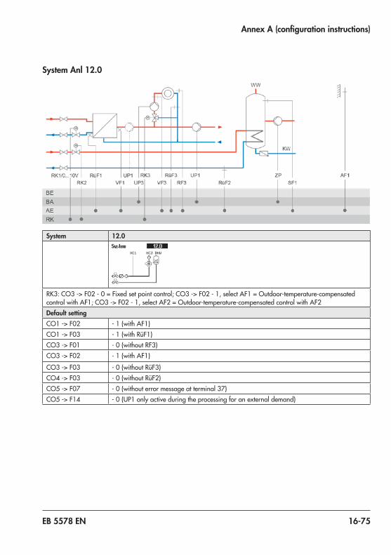
EB 5578 EN 16-75
Annex A (configuration instructions)
System Anl 12.0
System 12.0
RK3:CO3 -> F02 - 0 =Fixedsetpointcontrol;CO3 -> F02 - 1,selectAF1 =Outdoor-temperature-compensatedcontrolwithAF1;CO3 -> F02 - 1,selectAF2 =Outdoor-temperature-compensatedcontrolwithAF2Default settingCO1 -> F02 - 1 (with AF1)CO1 -> F03 -1(withRüF1)CO3 -> F01 -0(withoutRF3)CO3 -> F02 - 1 (with AF1)
CO3 -> F03 -0(withoutRüF3)CO4 -> F03 -0(withoutRüF2)CO5 -> F07 -0(withouterrormessageatterminal 37)CO5 -> F14 - 0 (UP1 only active during the processing for an external demand)

16-76 EB 5578 EN
Annex A (configuration instructions)
System Anl 12.1
System 12.1
RK3:CO3 -> F02 - 0 =Fixedsetpointcontrol;CO3 -> F02 - 1,selectAF1 =Outdoor-temperature-compensatedcontrolwithAF1;CO3 -> F02 - 1,selectAF2 =Outdoor-temperature-compensatedcontrolwithAF2Default settingCO1 -> F02 - 1 (with AF1)CO1 -> F03 -1(withRüF1)CO3 -> F01 -0(withoutRF3)CO3 -> F02 - 1 (with AF1)
CO3 -> F03 -0(withoutRüF3)CO4 -> F01 - 1 (with SF1)CO4 -> F02 - 0 (without SF2)CO4 -> F03 -0(withoutRüF2)CO5 -> F14 - 0 (UP1 only active during the processing for an external demand)

EB 5578 EN 16-77
Annex A (configuration instructions)
System Anl 12.2-1
System 12.2-1
RK3:CO3 -> F02 - 0 =Fixedsetpointcontrol;CO3 -> F02 - 1,selectAF1 =Outdoor-temperature-compensatedcontrolwithAF1;CO3 -> F02 - 1,selectAF2 =Outdoor-temperature-compensatedcontrolwithAF2Default settingCO1 -> F02 - 1 (with AF1)CO1 -> F03 -1(withRüF1)CO3 -> F01 -0(withoutRF3)CO3 -> F02 - 1 (with AF1)CO3 -> F03 -0(withoutRüF3)CO4 -> F01 - 1 (with SF1)CO4 -> F02 - 1 (with SF2)CO4 -> F03 -0(withoutRüF2)CO4 -> F10 -0(DHWcirculationreturnflowinstoragetank)CO5 -> F14 - 0 (UP1 only active during the processing for an external demand)

16-78 EB 5578 EN
Annex A (configuration instructions)
System Anl 12.2-2
System 12.2-2
RK3:CO3 -> F02 - 0 =Fixedsetpointcontrol;CO3 -> F02 - 1,selectAF1 =Outdoor-temperature-compensatedcontrolwithAF1;CO3 -> F02 - 1,selectAF2 =Outdoor-temperature-compensatedcontrolwithAF2Default settingCO1 -> F02 - 1 (with AF1)CO1 -> F03 -1(withRüF1)CO3 -> F01 -0(withoutRF3)CO3 -> F02 - 1 (with AF1)CO3 -> F03 -0(withoutRüF3)CO4 -> F01 - 1 (with SF1)CO4 -> F02 - 1 (with SF2)CO4 -> F03 -0(withoutRüF2)CO4 -> F05 -0(withoutVF4;inthiscase,VF2usuallyinstalledatthepointofmeasurementofVF4)CO4 -> F10 -0(DHWcirculationreturnflowinstoragetank)CO5 -> F14 - 0 (UP1 only active during the processing for an external demand)

EB 5578 EN 16-79
Annex A (configuration instructions)
System Anl 12.9-1
System 12.9-1
RK3:CO3 -> F02 - 0 =Fixedsetpointcontrol;CO3 -> F02 - 1,selectAF1 =Outdoor-temperature-compensatedcontrolwithAF1;CO3 -> F02 - 1,selectAF2 =Outdoor-temperature-compensatedcontrolwithAF2Default settingCO1 -> F02 - 1 (with AF1)CO1 -> F03 -1(withRüF1)CO3 -> F01 -0(withoutRF3)CO3 -> F02 - 1 (with AF1)CO3 -> F03 -0(withoutRüF3)CO4 -> F01 - 0 (without SF1)CO4 -> F03 -0(withoutRüF2)CO4 -> F04 -0(withoutflowratesensor)CO5 -> F07 -0(withouterrormessageatterminal 37)CO5 -> F14 - 0 (UP1 only active during the processing for an external demand)
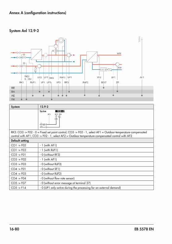
16-80 EB 5578 EN
Annex A (configuration instructions)
System Anl 12.9-2
System 12.9-2
RK3:CO3 -> F02 - 0 =Fixedsetpointcontrol;CO3 -> F02 - 1,selectAF1 =Outdoor-temperature-compensatedcontrolwithAF1;CO3 -> F02 - 1,selectAF2 =Outdoor-temperature-compensatedcontrolwithAF2Default settingCO1 -> F02 - 1 (with AF1)CO1 -> F03 -1(withRüF1)CO3 -> F01 -0(withoutRF3)CO3 -> F02 - 1 (with AF1)CO3 -> F03 -0(withoutRüF3)CO4 -> F01 - 0 (without SF1)CO4 -> F03 -0(withoutRüF2)CO4 -> F04 -0(withoutflowratesensor)CO5 -> F07 -0(withouterrormessageatterminal 37)CO5 -> F14 - 0 (UP1 only active during the processing for an external demand)

EB 5578 EN 16-81
Annex A (configuration instructions)
System Anl 13.0
System 13.0
RK3:CO3 -> F02 - 0 =Fixedsetpointcontrol;CO3 -> F02 - 1,selectAF1 =Outdoor-temperature-compensatedcontrolwithAF1;CO3 -> F02 - 1,selectAF2 =Outdoor-temperature-compensatedcontrolwithAF2Default settingCO1 -> F01 -0(withoutRF1)CO1 -> F02 - 1 (with AF1)CO1 -> F03 -1(withRüF1)CO3 -> F01 -0(withoutRF3)CO3 -> F02 - 1 (with AF1)CO3 -> F03 -0(withoutRüF3)CO4 -> F03 -0(withoutRüF2)CO5 -> F07 -0(withouterrormessageatterminal 37)

16-82 EB 5578 EN
Annex A (configuration instructions)
System Anl 13.1
System 13.1
RK3:CO3 -> F02 - 0 =Fixedsetpointcontrol;CO3 -> F02 - 1,selectAF1 =Outdoor-temperature-compensatedcontrolwithAF1;CO3 -> F02 - 1,selectAF2 =Outdoor-temperature-compensatedcontrolwithAF2Default settingCO1 -> F01 -0(withoutRF1)CO1 -> F02 - 1 (with AF1)CO1 -> F03 -1(withRüF1)CO3 -> F01 -0(withoutRF3)CO3 -> F02 - 1 (with AF1)CO3 -> F03 -0(withoutRüF3)CO4 -> F01 - 1 (with SF1)CO4 -> F02 - 0 (without SF2)CO4 -> F03 -0(withoutRüF2)

EB 5578 EN 16-83
Annex A (configuration instructions)
System Anl 13.2-1
System 13.2-1
RK3:CO3 -> F02 - 0 =Fixedsetpointcontrol;CO3 -> F02 - 1,selectAF1 =Outdoor-temperature-compensatedcontrolwithAF1;CO3 -> F02 - 1,selectAF2 =Outdoor-temperature-compensatedcontrolwithAF2Default settingCO1 -> F01 -0(withoutRF1)CO1 -> F02 - 1 (with AF1)CO1 -> F03 -1(withRüF1)CO3 -> F01 -0(withoutRF3)CO3 -> F02 - 1 (with AF1)CO3 -> F03 -0(withoutRüF3)CO4 -> F01 - 1 (with SF1)CO4 -> F02 - 1 (with SF2)CO4 -> F03 -0(withoutRüF2)CO4 -> F04 -0(withoutflowratesensor)CO4 -> F10 -0(DHWcirculationreturnflowinstoragetank)

16-84 EB 5578 EN
Annex A (configuration instructions)
System Anl 13.2-2
System 13.2-2
RK3:CO3 -> F02 - 0 =Fixedsetpointcontrol;CO3 -> F02 - 1,selectAF1 =Outdoor-temperature-compensatedcontrolwithAF1;CO3 -> F02 - 1,selectAF2 =Outdoor-temperature-compensatedcontrolwithAF2Default settingCO1 -> F01 -0(withoutRF1)CO1 -> F02 - 1 (with AF1)CO1 -> F03 -1(withRüF1)CO3 -> F01 -0(withoutRF3)CO3 -> F02 - 1 (with AF1)CO3 -> F03 -0(withoutRüF3)CO4 -> F01 - 1 (with SF1)CO4 -> F02 - 1 (with SF2)CO4 -> F03 -0(withoutRüF2)CO4 -> F04 -0(withoutflowratesensor)CO4 -> F05 -0(withoutVF4;inthiscase,VF2usuallyinstalledatthepointofmeasurementofVF4)
CO4 -> F10 -0(DHWcirculationreturnflowinstoragetank)

EB 5578 EN 16-85
Annex A (configuration instructions)
System Anl 13.6-1
System 13.6-1
RK3:CO3 -> F02 - 0 =Fixedsetpointcontrol;CO3 -> F02 - 1,selectAF1 =Outdoor-temperature-compensatedcontrolwithAF1;CO3 -> F02 - 1,selectAF2 =Outdoor-temperature-compensatedcontrolwithAF2Note: Install a continuously running pump in the DHW circuit and connect it directly to the supply
voltage.Default settingCO1 -> F01 -0(withoutRF1)CO1 -> F02 - 1 (with AF1)CO3 -> F01 -0(withoutRF3)CO3 -> F02 - 1 (with AF1)CO3 -> F03 -0(withoutRüF3)CO4 -> F01 - 1 (with SF1)CO4 -> F02 - 1 (with SF2)CO4 -> F03 -0(withoutRüF2)

16-86 EB 5578 EN
Annex A (configuration instructions)
System Anl 13.6-2
System 13.6-2
RK3:CO3 -> F02 - 0 =Fixedsetpointcontrol;CO3 -> F02 - 1,selectAF1 =Outdoor-temperature-compensatedcontrolwithAF1;CO3 -> F02 - 1,selectAF2 =Outdoor-temperature-compensatedcontrolwithAF2Note: Install a continuously running pump in the DHW circuit and connect it directly to the supply
voltage.Default settingCO1 -> F01 -0(withoutRF1)CO1 -> F02 - 1 (with AF1)CO3 -> F01 -0(withoutRF3)CO3 -> F02 - 1 (with AF1)CO3 -> F03 -0(withoutRüF3)CO4 -> F01 - 1 (with SF1)CO4 -> F02 - 1 (with SF2)CO4 -> F03 -0(withoutRüF2)CO4 -> F05 -0(withoutVF4;inthiscase,VF2usuallyinstalledatthepointofmeasurementofVF4)

EB 5578 EN 16-87
Annex A (configuration instructions)
System Anl 13.9-1
System 13.9-1
RK3:CO3 -> F02 - 0 =Fixedsetpointcontrol;CO3 -> F02 - 1,selectAF1 =Outdoor-temperature-compensatedcontrolwithAF1;CO3 -> F02 - 1,selectAF2 =Outdoor-temperature-compensatedcontrolwithAF2Default settingCO1 -> F01 -0(withoutRF1)CO1 -> F02 - 1 (with AF1)CO1 -> F03 -1(withRüF1)CO3 -> F01 -0(withoutRF3)CO3 -> F02 - 1 (with AF1)CO3 -> F03 -0(withoutRüF3)CO4 -> F01 - 0 (without SF1)CO4 -> F03 -0(withoutRüF2)CO4 -> F04 -0(withoutflowratesensor)CO5 -> F07 -0(withouterrormessageatterminal 37)

16-88 EB 5578 EN
Annex A (configuration instructions)
System Anl 13.9-2
System 13.9-2
RK3:CO3 -> F02 - 0 =Fixedsetpointcontrol;CO3 -> F02 - 1,selectAF1 =Outdoor-temperature-compensatedcontrolwithAF1;CO3 -> F02 - 1,selectAF2 =Outdoor-temperature-compensatedcontrolwithAF2Default settingCO1 -> F01 -0(withoutRF1)CO1 -> F02 - 1 (with AF1)CO1 -> F03 -1(withRüF1)CO3 -> F01 -0(withoutRF3)CO3 -> F02 - 1 (with AF1)CO3 -> F03 -0(withoutRüF3)CO4 -> F01 - 0 (without SF1)CO4 -> F03 -0(withoutRüF2)CO4 -> F04 -0(withoutflowratesensor)CO5 -> F07 -0(withouterrormessageatterminal 37)

EB 5578 EN 16-89
Annex A (configuration instructions)
System Anl 14.1
System 14.1
Default settingCO1 -> F02 - 1 (with AF1)CO1 -> F03 -1(withRüF1)CO4 -> F01 - 1 (with SF1)CO4 -> F02 - 0 (without SF2)CO5 -> F07 -0(withouterrormessageatterminal 46)

16-90 EB 5578 EN
Annex A (configuration instructions)
System Anl 14.2
System 14.2
Default settingCO1 -> F02 - 1 (with AF1)CO1 -> F03 -1(withRüF1)CO4 -> F01 - 1 (with SF1)CO4 -> F02 - 1 (with SF2)CO5 -> F07 -0(withouterrormessageatterminal 46)

EB 5578 EN 16-91
Annex A (configuration instructions)
System Anl 14.3
System 14.3
Default settingCO1 -> F02 - 1 (with AF1)CO1 -> F03 -1(withRüF1)CO4 -> F01 - 1 (with SF1)CO5 -> F07 -0(withouterrormessageatterminal 46)

16-92 EB 5578 EN
Annex A (configuration instructions)
System Anl 15.0
System 15.0
RK3:CO3 -> F02 - 0 =Fixedsetpointcontrol;CO3 -> F02 - 1,selectAF1 =Outdoor-temperature-compensatedcontrolwithAF1;CO3 -> F02 - 1,selectAF2 =Outdoor-temperature-compensatedcontrolwithAF2Default settingCO1 -> F02 - 1 (with AF1)CO1 -> F03 -1(withRüF1)CO3 -> F01 -0(withoutRF3)CO3 -> F02 - 1 (with AF1)CO3 -> F03 -0(withoutRüF3)CO4 -> F01 - 1 (with SF1)CO4 -> F02 - 0 (without SF2)CO5 -> F07 -0(withouterrormessageatterminal 43)

EB 5578 EN 16-93
Annex A (configuration instructions)
System Anl 15.1
System 15.1
RK3:CO3 -> F02 - 0 =Fixedsetpointcontrol;CO3 -> F02 - 1,selectAF1 =Outdoor-temperature-compensatedcontrolwithAF1;CO3 -> F02 - 1,selectAF2 =Outdoor-temperature-compensatedcontrolwithAF2Default settingCO1 -> F01 -0(withoutRF1)CO1 -> F02 - 1 (with AF1)CO1 -> F03 -1(withRüF1)CO3 -> F01 -0(withoutRF3)CO3 -> F02 - 1 (with AF1)CO3 -> F03 -0(withoutRüF3)CO4 -> F01 - 1 (with SF1)CO4 -> F02 - 0 (without SF2)CO5 -> F14 - 0 (UP1 only active during the processing for an external demand)

16-94 EB 5578 EN
Annex A (configuration instructions)
System Anl 15.2
System 15.2
RK3:CO3 -> F02 - 0 =Fixedsetpointcontrol;CO3 -> F02 - 1,selectAF1 =Outdoor-temperature-compensatedcontrolwithAF1;CO3 -> F02 - 1,selectAF2 =Outdoor-temperature-compensatedcontrolwithAF2Default settingCO1 -> F01 -0(withoutRF1)CO1 -> F02 - 1 (with AF1)CO1 -> F03 -1(withRüF1)CO3 -> F01 -0(withoutRF3)CO3 -> F02 - 1 (with AF1)CO3 -> F03 -0(withoutRüF3)CO4 -> F01 - 1 (with SF1)CO4 -> F02 - 1 (with SF2)

EB 5578 EN 16-95
Annex A (configuration instructions)
System Anl 15.3
System 15.3
RK3:CO3 -> F02 - 0 =Fixedsetpointcontrol;CO3 -> F02 - 1,selectAF1 =Outdoor-temperature-compensatedcontrolwithAF1;CO3 -> F02 - 1,selectAF2 =Outdoor-temperature-compensatedcontrolwithAF2Default settingCO1 -> F02 - 1 (with AF1)CO1 -> F03 -1(withRüF1)CO3 -> F01 -0(withoutRF3)CO3 -> F02 - 1 (with AF1)CO3 -> F03 -0(withoutRüF3)CO4 -> F01 - 1 (with SF1)

16-96 EB 5578 EN
Annex A (configuration instructions)
System Anl 15.4
System 15.4
RK3:CO3 -> F02 - 0 =Fixedsetpointcontrol;CO3 -> F02 - 1,selectAF1 =Outdoor-temperature-compensatedcontrolwithAF1;CO3 -> F02 - 1,selectAF2 =Outdoor-temperature-compensatedcontrolwithAF2Default settingCO1 -> F02 - 1 (with AF1)CO1 -> F03 -1(withRüF1)CO3 -> F01 -0(withoutRF3)CO3 -> F02 - 1 (with AF1)CO3 -> F03 -0(withoutRüF3)CO4 -> F01 - 1 (with SF1)CO5 -> F07 -0(withouterrormessageatterminal 43)

EB 5578 EN 16-97
Annex A (configuration instructions)
System Anl 15.5
System 15.5
RK3:CO3 -> F02 - 0 =Fixedsetpointcontrol;CO3 -> F02 - 1,selectAF1 =Outdoor-temperature-compensatedcontrolwithAF1;CO3 -> F02 - 1,selectAF2 =Outdoor-temperature-compensatedcontrolwithAF2Default settingCO1 -> F02 - 1 (with AF1)CO1 -> F03 -1(withRüF1)CO3 -> F01 -0(withoutRF3)CO3 -> F02 - 1 (with AF1)CO3 -> F03 -0(withoutRüF3)CO4 -> F01 - 1 (with SF1)CO4 -> F02 - 1 (with SF2)CO5 -> F07 -0(withouterrormessageatterminal 43)

16-98 EB 5578 EN
Annex A (configuration instructions)
System Anl 16.0
System 16.0
Default settingCO1 -> F02 - 1 (with AF1)CO1 -> F03 -1(withRüF1)CO1 -> F06 - 1 (with SF2)CO5 -> F07 -0(withouterrormessageatterminal 43)

EB 5578 EN 16-99
Annex A (configuration instructions)
System Anl 16.1
System 16.1
RK2:CO2 -> F02 - 0 =Fixedsetpointcontrol;CO2 -> F02 - 1,selectAF1 =Outdoor-temperature-compensatedcontrolwithAF1;CO2 -> F02 - 1,selectAF2 =Outdoor-temperature-compensatedcontrolwithAF2Default settingCO1 -> F02 - 1 (with AF1)CO1 -> F03 -1(withRüF1)CO1 -> F06 - 1 (with SF2)CO2 -> F01 -0(withoutRF2)CO2 -> F02 - 1 (with AF1)CO2 -> F03 -0(withoutRüF2)CO5 -> F07 -0(withouterrormessageatterminal 38)CO5 -> F14 - 0 (UP1 according to the ZP schedule or only active during the processing for an external
demand)

16-100 EB 5578 EN
Annex A (configuration instructions)
System Anl 16.2
System 16.2
Default settingCO1 -> F02 - 1 (with AF1)CO1 -> F03 -1(withRüF1)CO1 -> F06 - 1 (with SF2)CO5 -> F07 -0(withouterrormessageatterminal 43)

EB 5578 EN 16-101
Annex A (configuration instructions)
System Anl 16.3
System 16.3
Default settingCO1 -> F02 - 1 (with AF1)CO1 -> F03 -1(withRüF1)CO1 -> F06 - 1 (with SF2)CO5 -> F07 -0(withouterrormessageatterminal 43)

16-102 EB 5578 EN
Annex A (configuration instructions)
System Anl 16.4
System 16.4
Default settingCO1 -> F02 - 1 (with AF1)CO1 -> F03 -1(withRüF1)CO1 -> F06 - 1 (with SF2)CO5 -> F07 -0(withouterrormessageatterminal 43)

EB 5578 EN 16-103
Annex A (configuration instructions)
System Anl 16.8
System 16.5
RK3:CO3 -> F02 - 0 =Fixedsetpointcontrol;CO3 -> F02 - 1,selectAF1 =Outdoor-temperature-compensatedcontrolwithAF1;CO3 -> F02 - 1,selectAF2 =Outdoor-temperature-compensatedcontrolwithAF2Default settingCO1 -> F02 - 1 (with AF1)CO1 -> F03 -1(withRüF1)CO1 -> F06 - 1 (with SF2)CO3 -> F01 -0(withoutRF3)CO3 -> F02 - 1 (with AF1)CO3 -> F03 -0(withoutRüF3)CO5 -> F07 -0(withouterrormessageatterminal 38)CO5 -> F14 - 0 (UP1 according to the ZP schedule or only active during the processing for an external
demand)

16-104 EB 5578 EN
Annex A (configuration instructions)
System Anl 16.6
System 16.6
RK2:CO2 -> F02 - 0 =Fixedsetpointcontrol;CO2 -> F02 - 1,selectAF1 =Outdoor-temperature-compensatedcontrolwithAF1;CO2 -> F02 - 1,selectAF2 =Outdoor-temperature-compensatedcontrolwithAF2Default settingCO1 -> F02 - 1 (with AF1)CO1 -> F03 -1(withRüF1)CO1 -> F06 - 1 (with SF2)CO2 -> F01 -0(withoutRF2)CO2 -> F02 - 1 (with AF1)CO5 -> F07 -0(withouterrormessageatterminal 38)

EB 5578 EN 16-105
Annex A (configuration instructions)
System Anl 16.7
System 16.7
RK3:CO3 -> F02 - 0 =Fixedsetpointcontrol;CO3 -> F02 - 1,selectAF1 =Outdoor-temperature-compensatedcontrolwithAF1;CO3 -> F02 - 1,selectAF2 =Outdoor-temperature-compensatedcontrolwithAF2Default settingCO1 -> F02 - 1 (with AF1)CO1 -> F03 -1(withRüF1)CO1 -> F06 - 1 (with SF2)CO3 -> F01 -0(withoutRF3)CO3 -> F02 - 1 (with AF1)CO3 -> F03 -0(withoutRüF3)CO5 -> F07 -0(withouterrormessageatterminal 43)CO5 -> F14 - 0 (UP1 according to the ZP schedule or only active during the processing for an external
demand)

16-106 EB 5578 EN
Annex A (configuration instructions)
System Anl 16.8
System 16.8
RK2:CO2 -> F02 - 0 =Fixedsetpointcontrol;CO2 -> F02 - 1,selectAF1 =Outdoor-temperature-compensatedcontrolwithAF1;CO2 -> F02 - 1,selectAF2 =Outdoor-temperature-compensatedcontrolwithAF2RK3:CO3 -> F02 - 0 =Fixedsetpointcontrol;CO3 -> F02 - 1,selectAF1 =Outdoor-temperature-compensatedcontrolwithAF1;CO3 -> F02 - 1,selectAF2 =Outdoor-temperature-compensatedcontrolwithAF2Default settingCO1 -> F02 - 1 (with AF1)CO1 -> F03 -1(withRüF1)CO1 -> F06 - 1 (with SF2)CO2 -> F01 -0(withoutRF2)CO2 -> F02 - 1 (with AF1)CO2 -> F03 -0(withoutRüF2)CO3 -> F01 -0(withoutRF3)CO3 -> F02 - 1 (with AF1)CO3 -> F03 -0(withoutRüF3)CO5 -> F07 -0(withouterrormessageatterminal 38)CO5 -> F14 - 0 (UP1 acc. to the ZP schedule or only active during the processing for an external demand)

EB 5578 EN 16-107
Annex A (configuration instructions)
System Anl 17.1
System 17.1
RK2:CO2 -> F02 - 0 =Fixedsetpointcontrol;CO2 -> F02 - 1,selectAF1 =Outdoor-temperature-compensatedcontrolwithAF1;CO2 -> F02 - 1,selectAF2 =Outdoor-temperature-compensatedcontrolwithAF2Default settingCO1 -> F02 - 1 (with AF1)CO1 -> F03 -1(withRüF1)CO1 -> F06 - 1 (with SF2)CO2 -> F01 -0(withoutRF2)CO2 -> F02 - 1 (with AF1)CO2 -> F03 -0(withoutRüF2inRK2)CO4 -> F03 -0(withoutRüF2/RüF4)CO4 -> F04 -0(withoutflowswitch)CO4 -> F14 -0(withoutRüF3)CO4 -> F07 -0(withouterrormessageatterminal 46)

16-108 EB 5578 EN
Annex A (configuration instructions)
System Anl 17.8
System 17.8
RK2:CO2 -> F02 - 0 =Fixedsetpointcontrol;CO2 -> F02 - 1,selectAF1 =Outdoor-temperature-compensatedcontrolwithAF1;CO2 -> F02 - 1,selectAF2 =Outdoor-temperature-compensatedcontrolwithAF2RK3:CO3 -> F02 - 0 =Fixedsetpointcontrol;CO3 -> F02 - 1,selectAF1 =Outdoor-temperature-compensatedcontrolwithAF1;CO3 -> F02 - 1,selectAF2 =Outdoor-temperature-compensatedcontrolwithAF2Default settingCO1 -> F02 - 1 (with AF1)CO1 -> F03 -1(withRüF1)CO1 -> F06 - 1 (with SF2)CO2 -> F01 -0(withoutRF2)CO2 -> F02 - 1 (with AF1)CO2 -> F03 -0(withoutRüF2inRK2)CO3 -> F01 -0(withoutRF3)CO3 -> F02 - 1 (with AF1)CO4 -> F03 -0(withoutRüF2/RüF4)CO4 -> F04 -0(withoutflowswitch)CO4 -> F14 -0(withoutRüF3)

EB 5578 EN 16-109
Annex A (configuration instructions)
System Anl 18.1-1
Electric heating
System 18.1-1
RK2:CO2 -> F02 - 0 =Fixedsetpointcontrol;CO2 -> F02 - 1,selectAF1 =Outdoor-temperature-compensatedcontrolwithAF1;CO2 -> F02 - 1,selectAF2 =Outdoor-temperature-compensatedcontrolwithAF2Default settingCO1 -> F02 - 1 (with AF1)CO1 -> F03 -1(withRüF1)CO1 -> F06 - 1 (with SF2)CO2 -> F01 -0(withoutRF2)CO2 -> F02 - 1 (with AF1)CO2 -> F03 -1(withRüF2inRK2)CO4 -> F03 -0(withoutRüF2/RüF4)CO4 -> F04 -0(withoutflowswitch)CO4 -> F14 -0(withoutRüF3)CO4 -> F07 -0(withouterrormessageatterminal 46)

16-110 EB 5578 EN
Annex A (configuration instructions)
System Anl 18.1-2
Electric heating
System 18.1-2
RK2:CO2 -> F02 - 0 =Fixedsetpointcontrol;CO2 -> F02 - 1,selectAF1 =Outdoor-temperature-compensatedcontrolwithAF1;CO2 -> F02 - 1,selectAF2 =Outdoor-temperature-compensatedcontrolwithAF2Default settingCO1 -> F02 - 1 (with AF1)CO1 -> F03 -1(withRüF1)CO1 -> F06 - 1 (with SF2)CO2 -> F01 -0(withoutRF2)CO2 -> F02 - 1 (with AF1)CO2 -> F03 -1(withRüF2inRK2)CO4 -> F03 -0(withoutRüF2/RüF4)CO4 -> F04 -0(withoutflowswitch)CO4 -> F14 -0(withoutRüF3)CO4 -> F07 -0(withouterrormessageatterminal 46)

EB 5578 EN 16-111
Annex A (configuration instructions)
System Anl 21.0
System 21.0
RK3:CO3 -> F02 - 0 =Fixedsetpointcontrol;CO3 -> F02 - 1,selectAF1 =Outdoor-temperature-compensatedcontrolwithAF1;CO3 -> F02 - 1,selectAF2 =Outdoor-temperature-compensatedcontrolwithAF2Default settingCO1 -> F01 -0(withoutRF1)CO1 -> F02 - 1 (with AF1)CO1 -> F03 -1(withRüF1)CO3 -> F01 -0(withoutRF3)CO3 -> F02 - 1 (with AF1)CO3 -> F03 -1(withRüF3)CO4 -> F03 -0(withoutRüF2)CO5 -> F07 -0(withouterrormessageatterminal 37)

16-112 EB 5578 EN
Annex A (configuration instructions)
System Anl 21.1-1
System 21.1-1
RK3:CO3 -> F02 - 0 =Fixedsetpointcontrol;CO3 -> F02 - 1,selectAF1 =Outdoor-temperature-compensatedcontrolwithAF1;CO3 -> F02 - 1,selectAF2 =Outdoor-temperature-compensatedcontrolwithAF2Default settingCO1 -> F01 -0(withoutRF1)CO1 -> F02 - 1 (with AF1)CO1 -> F03 -0(withoutRüF1)CO3 -> F01 -0(withoutRF3)CO3 -> F02 - 1 (with AF1)CO3 -> F03 -0(withoutRüF3)CO4 -> F01 - 1 (with SF1)CO4 -> F02 - 0 (without SF2)CO4 -> F03 -0(withoutRüF2)

EB 5578 EN 16-113
Annex A (configuration instructions)
System Anl 21.1-2
System 21.1-2
RK3:CO3 -> F02 - 0 =Fixedsetpointcontrol;CO3 -> F02 - 1,selectAF1 =Outdoor-temperature-compensatedcontrolwithAF1;CO3 -> F02 - 1,selectAF2 =Outdoor-temperature-compensatedcontrolwithAF2Default settingCO1 -> F01 -0(withoutRF1)CO1 -> F02 - 1 (with AF1)CO1 -> F03 -0(withoutRüF1)CO3 -> F01 -0(withoutRF3)CO3 -> F02 - 1 (with AF1)CO3 -> F03 -0(withoutRüF3)CO4 -> F01 - 1 (with SF1)CO4 -> F02 - 0 (without SF2)CO4 -> F03 -0(withoutRüF2)

16-114 EB 5578 EN
Annex A (configuration instructions)
System Anl 21.2-1
System 21.2-1
RK3:CO3 -> F02 - 0 =Fixedsetpointcontrol;CO3 -> F02 - 1,selectAF1 =Outdoor-temperature-compensatedcontrolwithAF1;CO3 -> F02 - 1,selectAF2 =Outdoor-temperature-compensatedcontrolwithAF2Default settingCO1 -> F01 -0(withoutRF1)CO1 -> F02 - 1 (with AF1)CO1 -> F03 -1(withRüF1)CO3 -> F01 -0(withoutRF3)CO3 -> F02 - 1 (with AF1)CO3 -> F03 -1(withRüF3)CO4 -> F01 - 1 (with SF1)CO4 -> F02 - 1 (with SF2)CO4 -> F03 -0(withoutRüF2)CO4 -> F10 -0(DHWcirculationreturnflowinstoragetank)

EB 5578 EN 16-115
Annex A (configuration instructions)
System Anl 21.2-2
System 21.2-2
RK3:CO3 -> F02 - 0 =Fixedsetpointcontrol;CO3 -> F02 - 1,selectAF1 =Outdoor-temperature-compensatedcontrolwithAF1;CO3 -> F02 - 1,selectAF2 =Outdoor-temperature-compensatedcontrolwithAF2Default settingCO1 -> F01 -0(withoutRF1)CO1 -> F02 - 1 (with AF1)CO1 -> F03 -1(withRüF1)CO3 -> F01 -0(withoutRF3)CO3 -> F02 - 1 (with AF1)CO3 -> F03 -1(withRüF3)CO4 -> F01 - 1 (with SF1)CO4 -> F02 - 1 (with SF2)CO4 -> F03 -0(withoutRüF2)CO4 -> F05 -0(withoutVF4;inthiscase,VF2usuallyinstalledatthepointofmeasurementofVF4)CO4 -> F10 -0(DHWcirculationreturnflowinstoragetank)

16-116 EB 5578 EN
Annex A (configuration instructions)
System Anl 21.2-3
System 21.2-3
RK3:CO3 -> F02 - 0 =Fixedsetpointcontrol;CO3 -> F02 - 1,selectAF1 =Outdoor-temperature-compensatedcontrolwithAF1;CO3 -> F02 - 1,selectAF2 =Outdoor-temperature-compensatedcontrolwithAF2Default settingCO1 -> F01 -0(withoutRF1)CO1 -> F02 - 1 (with AF1)CO1 -> F03 -1(withRüF1)CO3 -> F01 -0(withoutRF3)CO3 -> F02 - 1 (with AF1)CO3 -> F03 -1(withRüF3)CO4 -> F01 - 1 (with SF1)CO4 -> F02 - 1 (with SF2)CO4 -> F03 -0(withoutRüF2)CO4 -> F05 -0(withoutVF4;inthiscase,VF2usuallyinstalledatthepointofmeasurementofVF4)CO4 -> F10 -0(DHWcirculationreturnflowinstoragetank)

EB 5578 EN 16-117
Annex A (configuration instructions)
System Anl 21.9-1
System 21.9-1
RK3:CO3 -> F02 - 0 =Fixedsetpointcontrol;CO3 -> F02 - 1,selectAF1 =Outdoor-temperature-compensatedcontrolwithAF1;CO3 -> F02 - 1,selectAF2 =Outdoor-temperature-compensatedcontrolwithAF2Default settingCO1 -> F01 -0(withoutRF1)CO1 -> F02 - 1 (with AF1)CO1 -> F03 -1(withRüF1)CO3 -> F01 -0(withoutRF3)CO3 -> F02 - 1 (with AF1)CO3 -> F03 -1(withRüF3)CO4 -> F01 - 0 (without SF1)CO4 -> F03 -0(withoutRüF2)CO4 -> F04 -0(withoutflowratesensor)CO5 -> F07 -0(withouterrormessageatterminal 37)

16-118 EB 5578 EN
Annex A (configuration instructions)
System Anl 21.9-2
System 21.9-2
RK3:CO3 -> F02 - 0 =Fixedsetpointcontrol;CO3 -> F02 - 1,selectAF1 =Outdoor-temperature-compensatedcontrolwithAF1;CO3 -> F02 - 1,selectAF2 =Outdoor-temperature-compensatedcontrolwithAF2Default settingCO1 -> F01 -0(withoutRF1)CO1 -> F02 - 1 (with AF1)CO1 -> F03 -1(withRüF1)CO3 -> F01 -0(withoutRF3)CO3 -> F02 - 1 (with AF1)CO3 -> F03 -1(withRüF3)CO4 -> F01 - 0 (without SF1)CO4 -> F03 -0(withoutRüF2)CO4 -> F04 -0(withoutflowratesensor)CO5 -> F07 -0(withouterrormessageatterminal 37)

EB 5578 EN 16-119
Annex A (configuration instructions)
System Anl 25.0-1
System 25.0-1
RK2:CO2 -> F02 - 0 =Fixedsetpointcontrol;CO2 -> F02 - 1,selectAF1 =Outdoor-temperature-compensatedcontrolwithAF1;CO2 -> F02 - 1,selectAF2 =Outdoor-temperature-compensatedcontrolwithAF2RK3:CO3 -> F02 - 0 =Fixedsetpointcontrol;CO3 -> F02 - 1,selectAF1 =Outdoor-temperature-compensatedcontrolwithAF1;CO3 -> F02 - 1,selectAF2 =Outdoor-temperature-compensatedcontrolwithAF2Default settingCO1 -> F01 -0(withoutRF1)CO1 -> F02 - 1 (with AF1)CO1 -> F03 -1(withRüF1)CO2 -> F01 -0(withoutRF2)CO2 -> F02 - 1 (with AF1)CO2 -> F03 -1(withRüF2)CO3 -> F01 -0(withoutRF3)CO3 -> F02 - 1 (with AF1)CO3 -> F03 -1(withRüF3)CO5 -> F07 -0(withouterrormessageatterminal 37)

16-120 EB 5578 EN
Annex A (configuration instructions)
System Anl 25.0-2
System 25.0-2
RK2:CO2 -> F02 - 0 =Fixedsetpointcontrol;CO2 -> F02 - 1,selectAF1 =Outdoor-temperature-compensatedcontrolwithAF1;CO2 -> F02 - 1,selectAF2 =Outdoor-temperature-compensatedcontrolwithAF2RK3:CO3 -> F02 - 0 =Fixedsetpointcontrol;CO3 -> F02 - 1,selectAF1 =Outdoor-temperature-compensatedcontrolwithAF1;CO3 -> F02 - 1,selectAF2 =Outdoor-temperature-compensatedcontrolwithAF2Default settingCO1 -> F01 -0(withoutRF1)CO1 -> F02 - 1 (with AF1)CO1 -> F03 -1(withRüF1)CO2 -> F01 -0(withoutRF2)CO2 -> F02 - 1 (with AF1)CO2 -> F03 -1(withRüF2)CO3 -> F01 -0(withoutRF3)CO3 -> F02 - 1 (with AF1)CO3 -> F03 -1(withRüF3)CO5 -> F07 -0(withouterrormessageatterminal 37)

EB 5578 EN 16-121
Annex A (configuration instructions)
System Anl 25.5
System 25.5
Default settingCO1 -> F02 - 0 (without AF1)CO1 -> F03 -1(withRüF1)CO2 -> F02 - 0 (without AF1)CO2 -> F03 -1(withRüF2)CO3 -> F02 - 0 (without AF1)CO3 -> F03 -1(withRüF3)CO5 -> F07 -0(withouterrormessageatterminal 37)

16-122 EB 5578 EN
Annex A (configuration instructions)
16.2 Functions of the heating circuitWhich controller functions are available depends on the selected system code number (Anl).
16.2.1 Outdoor-temperature-controlled controlWhenoutdoor-temperature-compensatedcontrolisused,theflowtemperatureiscontrolledbasedontheoutdoortemperature.Theheatingcharacteristicinthecontrollerdefinestheflowtemperaturesetpointasafunctionoftheoutdoortemperature(see Fig. 16-2).Theoutdoor temperature required for outdoor-temperature-compensated control can either be measuredatanoutdoorsensororreceivedoverthe0to10 Vinput.
20
30
0.2
2.42.62.93.2
2.2
2.0
1.8
1.6
1.4
1.2
1.0
0.8
0.40.6
40
50
60
70
80
90
100
110
120
130
[°C]
–20 [°C]–16–12–8–4048121620
140
150
–24 –28 –32 –36 –40
tVL
tA
tVLtA
Flow temperatureOutdoor temperature
Fig. 16-2: Gradient characteristics

EB 5578 EN 16-123
Annex A (configuration instructions)
16.2.1.1 Outdoor temperature received or sent as 0 to 10 V signal
Theoutdoortemperaturecanbereceivedatterminals19and23overthe0to10 Vinput. Alternatively, the temperature measured by the outdoor sensor can be issued at terminals 20 and21asa0to10 Vsignalforfurtherprocessing.
Functions WE Configuration
Outdoor sensor AF1, 2 1 CO1,2,3,11,12,13 -> F02 - 1CO2, 3: select AF1, AF2
Outdoor temperature received orsentas0to10 Vsignal
0 CO5 -> F23 - 1
AE Direction: input (receive), output (send)
–20 °C Lowertransmissionrange:–50to+100 °C
50 °C Uppertransmissionrange:–50to+100 °C
0to10Voutputreverse 00 %
CO5 -> F25 - 0Zero:0to50 %
PWM reverse 05 %
CO5 -> F33 - 1Zero:5to20 %
16.2.1.2 Outdoor temperature received or sent over the device bus
The measured outdoor temperature can be provided to other controllers over the device bus.
Functions WE Configuration
Outdoor sensor AF1, 2 CO1, 2, 3 -> F02 - 1
Device bus 0 CO7 -> F01 - 1,devicebusaddress
ReceivevalueAF1 0 CO7 -> F07 - 1,registernumber
Send value AF1 1) 0 CO7 -> F06 - 1,registernumber
ReceivevalueAF2 0 CO7 -> F09 - 1,registernumber
Send value AF2 1) 0 CO7 -> F08 - 1,registernumber1) Sendreceivedoutdoortemperatureas0to10 VsignalbydevicebuswithCO5 -> F23 - 1setting
and AE

16-124 EB 5578 EN
Annex A (configuration instructions)
16.2.1.3 Gradient characteristicBasically,thefollowingruleapplies:adecreaseintheoutdoortemperaturecausestheflowtemperaturetoincreaseinordertokeeptheroomtemperatureconstant.Byvaryingthe'Gra-dient' and 'Level' parameters, you can adapt the characteristic to your individual require-ments:
tA
°C
°C+20 0 –20
tVL The gradient needs to be increased if the room tempera-ture drops when it is cold outside.
tA
°C
°C+20 0 –20
tVL The gradient needs to be decreased if the room tempera-ture drops when it is cold outside.
tVL
tA
°C
°C+20 0 –20
The level needs to be increased and the gradient decreased if the room temperature drops when it is mild outside.
tVL
tA
°C
°C+20 0 –20
The level needs to be decreased and the gradient increased if the room temperature rises when it is mild outside.

EB 5578 EN 16-125
Annex A (configuration instructions)
Outsidethetimes-of-use,reducedsetpointsareusedforcontrol:thereducedflowsetpointiscalculated as the difference between the adjusted values for 'Day set point' (rated room tem-perature)and'Nightsetpoint'(reducedroomtemperature).The'Max.flowtemperature'and'Min.flowtemperature'parametersmarktheupperandlowerlimitsoftheflowtemperature.Aseparategradientcharacteristiccanbeselectedforthelimitationofthereturnflowtem-perature.
Examples for adjusting the characteristic: − Oldbuilding,radiatordesign90/70: Gradientapprox.1.8 − Newbuilding,radiatordesign70/55: Gradientapprox.1.4 − Newbuilding,radiatordesign55/45: Gradientapprox.1.0 − Underfloorheatingdependingonarrangement: Gradientsmallerthan0.5
Particularly for control operation without room sensor, the room temperatures set for day ('Day set point') and night ('Night set point') only become effective satisfactorily when the heating characteristic has been adapted to the building/heating surface layout.
Functions WE Configuration
Four-point characteristic 0 CO1,2,3,11,12,13 -> F11 - 1
Parameters WE Switch position: value range
Day set point 20.0 °C : 0.0to40.0 °C
Night set point 15.0 °C : 0.0to40.0 °C
Parameters WE Parameters: value range
Flow gradient 1.2 1) PA1,2,3,11,12,13 -> P01:0.2to3.2
Level (parallel shift) 0.0 °C PA1,2,3,11,12,13 -> P02:–30.0to30.0 °C
Min.flowtemperature 20.0 °C PA1,2,3,11,12,13 -> P06:–5.0to150.0 °C
Max.flowtemperature 70.0 °C 1) PA1,2,3,11,12,13 -> P07:5.0to150.0 °C1) With
CO1,2,3,11,12,13 -> F05 - 1the following applies:
Gradient:0.2to1.0(0.5)Max.flowtemperature:5.0to50.0 °C(50.0 °C)
Note

16-126 EB 5578 EN
Annex A (configuration instructions)
16.2.1.4 Four-point characteristicThefour-pointcharacteristicallowsyoutodefineyourownheatingcharacteristic.Itisde-finedbyfourpointsfortheoutdoortemperature,flowtemperature,reducedflowtemperatureandreturnflowtemperature.The'Max.flowtemperature'and'Min.flowtemperature'pa-rametersmarktheupperandlowerlimitsoftheflowtemperature.
100
90
80
70
60
50
40
30
20
10°C0 –5 –10 –15 –20
P1
P2
P3
P4
°C
tVLmax
tVLmin
tVL
tA
+20 +15 +10 +5
P1 to P4 Points 1 to 4tVL Flow temperaturetA Outdoor temperature--- min Min.flowtemperature---max Max.flowtemperature––––––––– Four-point characteristic–––––– Reducedfour-pointcharacteristic
Fig. 16-3: Four-point characteristic
− The 'Day set point' and 'Night set point' parameters are no longer available when the four-point characteristic has been selected when no additional functions (e.g. optimization, flash adaptation) have been selected. − The four-point characteristic function can only be activated when the adaptation function is not active (CO1, 2, 3, 11, 12, 13 -> F08 - 0).
Functions WE Configuration
Adaptation 0 CO1,2,3,11,12,13 -> F08 - 0
Four-point characteristic 0 CO1,2,3,11,12,13 -> F11 - 1
Note

EB 5578 EN 16-127
Annex A (configuration instructions)
Parameters WE Parameters: value range
Outdoor temperature Point 1Point 2Point 3Point 4
–15.0 °C–5.0 °C5.0 °C15.0 °C
PA1,2,3,11,12,13 -> P05:–50.0to+50.0 °C
Flow temperature Point 1Point 2Point 3Point 4
70.0 °C55.0 °C40.0 °C25.0 °C
PA1,2,3,11,12,13 -> P05:–5.0to+150.0 °C
Reducedflowtemperature Point 1Point 2Point 3Point 4
60.0 °C40.0 °C20.0 °C20.0 °C
PA1,2,3,11,12,13 -> P05:–5.0to+150.0 °C
Returnflowtemperature Points 1 to 4 65.0 °C PA1,2,3,11,12,13 -> P05:5.0to90.0 °C
Min.flowtemperature 20.0 °C PA1,2,3,11,12,13 -> P06:–5.0to+150.0 °C
Max.flowtemperature 70.0 °C 1) PA1,2,3,11,12,13 -> P07:5.0to150.0 °C1) With CO1, 2, 3, 11, 12,
13 -> F05 - 1thefollowingapplies: Max.flowtemperature:5.0to50.0 °C(50.0 °C)
16.2.2 Fixed set point controlDuringthetimes-of-use,theflowtemperaturecanbecontrolledaccordingtoafixedsetpoint.Outsidethetimes-of-use,thecontrollerregulatestoareducedflowtemperature.Setthedesiredratedflowtemperatureas'Daysetpoint'andthereducedflowtemperatureas'Night set point'.
Functions WE Configuration
Outdoor sensor 1 CO1,2,3,11,12,13 -> F02 - 0
Parameters WE Switch position: value range
Day set point 50.0 °C :Min.tomax.flowtemperature
Night set point 30.0 °C : Min.tomax.flowtemperature

16-128 EB 5578 EN
Annex A (configuration instructions)
Parameters WE Parameters: value range
Min.flowtemperature 20.0 °CPA1,2,3,11,12,13 -> P06:–5.0to+150.0 °C
Max.flowtemperature 70.0 °CPA1,2,3,11,12,13 -> P07:5.0to150.0 °C
16.2.3 Underfloor heating/drying of jointless floorsUsingfunctionblocksettingCO1,2,3,11,12,13 -> F05 - 1,therespectiveheatingcircuitisconfiguredasanunderfloorheatingcircuit.Indoingso,thecontrolleratfirstonlylimitsthevaluerangesoftheheatingcharacteristicgradientandthemaximumflowtemperatureinPA1, 2, 3, 11, 12, 13 parameter levels: − Valuerangeofthegradient:0.2to1.0 − Valuerangeofthemaximumflowtemperature:5to50 °C
Furthermore, it is possible to set a Boostbetween0.0to50.0 °C,whichisadditionallytakenintoaccountwhenthereisaheatdemandfortheunderfloorheatingcircuitofanupstreamcontrol circuit. The Drying of jointless floors function can be activated afterwards. The function block pa-rameters(startingwiththe'Starttemperature')determinethedryingprocess:thefirstheatingupphasestartsattheentered'Starttemperature',whichhasaflowtemperatureof25 °Cinits default setting. The start temperature is constantly regulated for the days entered in 'Hold (days)'.Afterwards,thistemperatureisraisedbythevalueenteredin'Temp.rise/day'within24hours,i.e.thedefaultsettingcausestheflowtemperaturesetpointtoriseto30 °C24hours after the holding phase. If the maximum temperature is reached, it is kept constant for thenumberofdaysenteredin'Hold(days)'.The'Temp.reduction/day'parameterdeter-minesthetemperaturereductiondownwards.Ifthe'Temp.reduction/day'issetto0,thetem-perature maintaining phase moves directly to automatic mode. If the function block parame-ter'Starttemperature'issetto25 °Cand'Temp.rise/day'to0.0 °C,thedryingfunctionsrunsasspecifiedinPart4ofDIN EN 1264:thedryingofjointlessfloorsfunctionstartswithaflowtemperatureof25 °C,whichiskeptconstantforthreedays.Afterwards,thecontrollerswitches to the maximum adjusted temperature. The further process remains unchanged. The drying of jointless floors function is activated using the adjusted 'Start temperature' by changing the setting 'Stop' to 'Start'. 'Start' is displayed when the drying function starts. The restartingstages'Raise','Hold'(holdingthemaximumtemperature)and'Reduction'canbebe selected to continue an interrupted drying process. The course of the drying process can be monitored in the operating level by reading the measured data of the associated heating circuit.

EB 5578 EN 16-129
Annex A (configuration instructions)
'Done' is displayed after the last phase is completed. This disappears from the display after resettingthedisplaytoStopinCO1,2,3 -> F05orafterinterruptingthepowersupply.Ifapower failure occurs while the drying process is in progress, the drying process continues af-terwards exactly at the point at which it was interrupted. In systems in which the drying func-tionisinterruptedduetoDHWheating(e.g.systemAnl 2.1),storagetankchargingdoesnotoccur while the drying function is active, provided it is not used for frost protection of the storage tank.
The function block parameter can only be accessed after starting the function by resetting to 'Stop' in CO1, 2, 3, 11, 12, 13 -> F05.
Functions WE Configuration
Underfloorheating/dryingofjointlessfloors
00.0 °C25.0 °C05.0 °C45.0 °C40.0 °CStop
CO1,2,3,11,12,13 -> F05 - 1Boost:0.0to50.0 °CStarttemperature:20.0to60.0 °CHold (days): 0 to 10 daysTemp.rise/day:0.0to20.0 °CMaximumtemperature:25.0to60.0 °CHold (days): 0 to 30 daysTemp.reduction/day:0.0to20.0 °CStartcondition:Stop,Start,Raise,Hold,Reduction
16.2.4 Outdoor temperature for continuous day modeIf a heating circuit is in night mode (automatic mode, ), this circuit is switched to day mode whenever the outdoor temperature falls below 'Outdoor temperature for continuous day mode'.Reducedoperationrestartsaftertheoutdoortemperaturerisesabovethelimit(plus0.5 °Chysteresis).
Note

16-130 EB 5578 EN
Annex A (configuration instructions)
This function is activated at very low temperatures to avoid that the building cools down ex-cessively outside the times-of-use when low outdoor temperatures occur.
Parameters WE Parameters: value range
Outdoor temperature for continuous day mode
–15.0 °C PA1,2,3,11,12,13 -> P09:–50.0to+5.0 °C
16.2.5 Buffer tank systemsA heating characteristic based on a gradient or four entered points can be set in PA1 for the buffertanksinsystemsAnl3.9,5.9,14.1to14.3,15.1to15.5,16.x,17.xand18.x.Abuffer tank set point for day operation and a buffer tank set point for night operation can be set without outdoor sensors in the customer level. An external demand transmitted from sec-ondary controlled heating circuits, DHW circuit or an external request (by device bus, 0 to 10 Vorbinarysignal)canoverridethecurrentbuffertanksetpoint.Themaximumdemandis indicated as the buffer tank set point for SF1. If the temperature falls below the buffer tank setpointatSF1,chargingofthebuffertankisstarted(exceptforsystemsAnl3.9,5.9and18.x).Inthesesystems,thebuffertanksetpointisonlydeterminedbytheDHWcircuit.InsystemsAnl 14.1to14.3and15.1to15.5,thesetpointofthechargingtemperatureisalways6 °Chigherthanthebuffertanksetpoint.Eachchargingofthebuffertankfinishesassoonasthetemperatureatthetopbuffertanksensoris+3 °Chigherthanthebuffertanksetpoint(bottombuffertanksensorinsystemsAnl 15.4and15.5).IfchargingoftheDHWstoragetankisdemandedinsystemsAnl 14.1to14.3and15.1to15.3,itisfirstcheckedwhether there is enough heat in the buffer tank to charge the DHW storage tank. The DHW storage tank is charged by the district heating system if the temperature in the buffer tank is insufficientforcharging.ThechargingoftheDHWstoragetankhaspriorityoverachargingdemand of the buffer tank. The buffer tank is charged once the DHW storage tank charging hasbeencompleted.InsystemsAnl 14.3and15.3,asolarcircuitwithreroutableheatex-changerflowisintegrated.IfthetemperaturedifferencebetweenthecollectorcircuitsensorRüF2andoneofthestoragetanksensorsSF3orSF4isgreaterthanthevalueof'Solarcir-cuit pump ON', the solar circuit pump UP2 is activated and the corresponding storage tank is charged. If both storage tanks can be charged, the DHW storage tank charging has priori-ty. If the temperature difference falls below the value of 'Solar circuit pump OFF' in both stor-age tank circuits, the solar circuit pump UP2 is deactivated again. Basically, the solar circuit pump is deactivated when the measured temperatures of both storage tank sensors SF3 and SF4 have reached the 'Max. storage tank temperature' or 'Maximum buffer tank tempera-ture'orwhenthesolarcollectortemperaturerisesabove120 °C.

EB 5578 EN 16-131
Annex A (configuration instructions)
InsystemsAnl 3.9,5.9,16.x,17.xand18.x,thesetpointofthechargingtemperatureisde-termined by the 'Minimum set point to charge buffer tank' parameter setting in the PA1 level. The automatic adaptation ('AUTO' setting) causes the set point of the charging temperature to always be above the current buffer tank set point by the value entered in 'Charging tem-perature boost'. Every other value entered in 'Minimum set point to charge buffer tank' is usedastheminimumsetpointforthechargingtemperaturewhichfirststartstobevariableathigherbuffertanksetpoints.WhenareturnflowtemperaturesensorRüF1isused,thechargingpumpSLP(CO1 -> F22 - 1)isfirstreleasedtoavoidcoldchargingwhenthetem-peraturemeasuredatRüF1hasreachedthesametemperaturemeasuredatSF1.Analreadyactive charging is immediately stopped (discharging protection) in case the charging tem-perature does not reach its set point even though the valve is fully open. InsystemsAnl 3.9and5.9thisfunctiononlyapplieswhentheheatingcircuitsRK2andRK3arenotrunning.The'Stopchargingofthebuffertank'parameter(PA1 -> P17,default=AU-TO) determines under which conditions the charging of the buffer tank is stopped. The auto-matic adaptation ('AUTO' setting) causes the buffer tank charging to be stopped when the temperatureinthebuffertankreachesthevalue('Buffertanksetpoint'+'Hysteresisofbuffertank'.Everyothervalueenteredfor'Stopchargingofthebuffertank'isratedasafixedswitch-offtemperatureforthebuffertankcharging.WhenSF2(CO1 -> F06 - 1)isconfig-ured, SF2 is always used to stop the charging of the buffer tank. The storage tank charging pumpisnotswitchedoffuntilthelagtime(entered'ValvetransittimeTy'forRK1multipliedby 'Lag time of charging pump') has elapsed. The operation of the feeder pump UP1 in sys-temsAnl 16.0to16.5,16.7and16.8iseitherdeterminedbytheZPtimescheduleorprompted by an external demand. For systems with downstream control circuits, either only this external demand or the demand of the downstream control circuits causes the feeder pumpUP1tobeactivated,dependingontheCO5 ->F14setting. ThepumpUP2ofthesolidfuelboilercircuitinsystemsAnl 14.1,14.2,15.1,15.2,16.2,16.4, 16.5 and 16.7 starts to run when the temperature reaches 'Start temperature for boiler pump'atVF2.TheboilerpumpisswitchedoffagainwhenthetemperatureatVF2fallsbe-lowthetemperatureT='Starttemperatureforboilerpump'–'Boilerpumphysteresis'. In systems Anl 14.3, 15.3, 16.3, 16.4, 16.6 and 16.7, a solar circuit is integrated, which uses storage tank sensor SF3 for control. The collector circuit pump CP is activated when the temperatureatthecollectorsensorRüF2ishigherthanthatatstoragetanksensorSF3bythevalue entered in 'Solar circuit pump ON'. It is deactivated when the temperature difference falls below the valve entered in 'Solar circuit pump OFF', when the temperature at the stor-age tank sensor SF3 reaches 'Max. storage tank temperature' or when the collector tempera-turerisesabove120 °C.The PWM output for the heat exchanger charging pump is used to control the DHW tem-peratureinsystemsAnl 3.9,5.9,17.xand18.x.Itsoutputsignalcanbereversedwiththe

16-132 EB 5578 EN
Annex A (configuration instructions)
CO5 -> F26 - 1setting.Foroperationoftheheatexchangerchargingpump,theminimumdelivery rate and the control parameters to control the DHW temperature can adjusted with CO4 -> F12 - 1.The0 to 10 VoutputisusedforadaptingthedeliveryrateofthechargingpumpSLPbasedonthetemperature.AflowswitchcanbeactivatedwiththeCO4 -> F04 - 1setting.TheoutputUP1forthechangeovervalveisactivatedbyconfiguringthereturnflowtemperaturesensorRüF2.Thechangeovervalveiscontrolledbasedonthe'Returnflowtem-peraturelimit,layeringattop'parameter:IfthetemperaturemeasuredatRüF2/RüF4ex-ceedstheadjustedswitchingpoint,theoutputUP1remainsdeactivatedandthereturnflowwaterislayeredatthetop.AfterthetemperaturemeasuredatRüF2hasfallenbelowtheswitchingpoint,theoutputUP1isactivatedandthereturnflowwaterislayeredatthebot-tom.TheCO4 -> F14 - 1settingactivatestheThermal disinfectionfunctionandtheinputRüF3re-quired for this function. It may be necessary for the controller to initially ensure at the start of everythermaldisinfectionthatasufficientlyhightemperatureexistsinthebuffertank.There-fore, enough time for the thermal disinfection process must be available.Alternatively,insystemsAnl 3.9,17.xand18.x,anelectricheatingcartridgecanbeusedforthethermaldisinfectionprocess.WiththeCO4 -> F23 - 1settingtheincreasedheatde-mand by the DHW circuit during an active thermal disinfection is not passed on to the buffer tankcircuitRK1.ThemeasuredtemperatureatSF1isdecisiveforthedemandforelectricheating at the start of a thermal disinfection process and during the entire process: when the temperature at SF1 is the same or greater than 'Disinfection temperature' (function block pa-rameterinCO4 -> F14)+'Setpointboost'(functionblockparameterinCO4 -> F14),thereis no demand for electric heating. When the temperature at SF1 is below this limit, the bina-ry output BA10 is activated to demand electric heating.
The buffer tank control circuit is deactivated as described in section 16.2.4. When pre-defined gradients of heating characteristic (CO1 -> F11 - 0) are used, night mode is not pos-sible in the buffer tank control circuit. In contrast to an active four-point characteristic (CO1 -> F11 - 1): in this case, a four-point characteristic exists for day and night modes.
Note

EB 5578 EN 16-133
Annex A (configuration instructions)
Functions WE Configuration
Storage tank sensor SF2 1 CO1 -> F06 - 1
SLPdependingonreturnflowtemperature 0 CO1 -> F22 - 1
ReturnflowsensorRüF2 0 CO4 -> F03 - 1
Three-step control mode 120 %2.0120 s/30 s0 s
CO4 -> F12 - 1Minimumspeed:5to50 %KP:0.1to50.0TN:1to999 sTV:0to999 s
Electric heating cartridge 0 CO4 -> F23 - 1
PWM reverse 0 CO5 -> F26 - 1
Parameters WE Parameters: value range
Minimum set point to charge buffer tank AUTO PA1 -> P16:AUTOto90.0 °C
Stop charging of the buffer tank AUTO PA1 -> P17:AUTOto90.0 °C
Charging temperature boost 6.0 °C PA1 -> P18:0.0to50.0 °C
Lag time of charging pump 1.0 PA1 -> P19:0.0to10.0
Solar circuit pump ON 10.0 °C PA4 -> P10:1.0to30.0 °C
Solar circuit pump OFF 3.0 °C PA4 -> P11:0.0to30.0 °C
Max. storage tank temperature 80.0 °C PA4 -> P12:20.0to90.0 °C
Maximum buffer tank temperature 80.0 °C PA4 -> P13:20.0to90.0 °C
Returnflowtemperaturelimit,layeringattop 25.0 °C PA4 -> P21:5.0to90.0 °C
Start temperature for boiler pump 60.0 °C PA5 -> P01:20.0to90.0 °C
Boiler pump hysteresis 5.0 °C PA5 -> P02:0.0to30.0 °C
16.2.6 Summer modeSummer mode is activated depending on the mean daytime temperature (measured between 7.00 hand22.00 h)duringtheadjustedsummertimeperiod.Ifthemeandaytimetempera-ture exceeds the 'Boost' on the number of successive days set in 'No. days until activation', summer mode is activated on the following day. This means that the valves in all heating cir-cuitsareclosedandthecirculationpumpsareswitchedoffaftert=2xvalvetransittime.Ifthe mean daytime temperature falls below the 'Limit' on the number of successive days set in 'No. days until deactivation', summer mode is deactivated on the following day.

16-134 EB 5578 EN
Annex A (configuration instructions)
Functions WE Configuration
Summer mode 001.06-30.092118.0 °C
CO5 -> F04 - 1Time: Adjustable as requiredNo. days until activation: 1 to 3No. days until deactivation: 1 to 3Limit:0.0to30.0 °C
Summer mode only becomes effective when the controller is in automatic mode ( ).
16.2.7 Delayed outdoor temperature adaptationThecalculatedoutdoortemperatureisusedtodeterminetheflowtemperaturesetpoint.Theheat response is delayed when the outdoor temperature either increases or decreases or both.Iftheoutdoortemperaturevariesby,forexample12 °Cwithinaveryshortperiodoftime, the calculated outdoor temperature is adapted to the actual outdoor temperature in smallstepsusingadelayof3 °C/hoveratimeperiodoft = 12°C
3°C/h12°C3°C/h =4 h.
The delayed outdoor temperature adaptation helps avoid unnecessary overloads of central heating stations in combination with either overheated buildings occurring, for example due to warm winds or temporarily insufficient heating due to the outdoor sensor being exposed to direct sunshine. In the operating level, the outdoor temperature blinks on the display while delayed outdoor temperature adaptation is active. A small hour glass appears next to the thermometer on the display when this function is active. The calculated outdoor temperature is displayed.
Functions WE Configuration
Delayed outdoor temperature adaptation (decreasing)
0 CO5 -> F05 - 1Delay/h:0.2to6.0 °C
Delayed outdoor temperature adaptation (increasing)
03.0 °C
CO5 -> F06 - 1Delay/h:0.2to6.0 °C
Note
Note

EB 5578 EN 16-135
Annex A (configuration instructions)
16.2.8 Remote operationApartfrommeasuringtheroomtemperature,theTypes 5257-5 1)andType 5257-51RoomPanels(Pt 1000sensor)aswellasType 5244 1)RoomPanel(PTCsensor)providethefollow-ingopportunitiesofinfluencingthecontrolprocess:
Selecting the operating mode:
Automatic modeDay modeNight mode
Set point correction: During rated operation, the room temperature set point can be increasedorreducedbyupto5 °Cusingacontinuouslyadjustablerotary knob.
With an activated room sensor, the measured room temperature is displayed when the re-mote operation is connected and activated. Nevertheless, it is not used for control when ei-ther the optimization, adaptation or flash adaptation function is activated.Alternatively,theTROVIS 5570 1)RoomPanelcanbeconnectedovermeterbus(seesec-tion 16.4.14).1) No longer available
Functions WE Configuration
Roomsensor 0 CO1,2,3 -> F01 - 1
ThefollowingmustbeconfiguredifaTROVIS 5570RoomPanelisused:
Device bus 0 CO7 -> F01 - 1,devicebusaddress
TROVIS 5570RoomPanelinRK1 0 CO7 -> F03 - 1,devicebusaddress
TROVIS 5570RoomPanelinRK2 0 CO7 -> F04 - 1,devicebusaddress
TROVIS 5570RoomPanelinRK3 0 CO7 -> F05 - 1,devicebusaddress
Room panels cannot be used for the heating circuits RK11, RK12 and RK13.Note

16-136 EB 5578 EN
Annex A (configuration instructions)
16.2.9 OptimizationThis function requires the use of a room sensor. Depending on the building characteristics, thecontrollerdeterminesandadaptstherequiredadvanceheatingtime(maximum8hours)to ensure that the desired 'Day set point' (rated room temperature) has been reached in the reference room when the time-of-use starts. During the advance heating period, the controller heatswiththemax.flowtemperature.Thistemperatureisbuiltupinstepsof10 °C.Assoonas the 'Day set point' has been reached, outdoor-temperature-compensated control is activat-ed.Depending on the room sensor, the controller switches off the heating system up to one hour before the time-of-use ends. The controller chooses the deactivation time such that the room temperaturedoesnotdropsignificantlybelowthedesiredvalueuntilthetime-of-useends.During the advance heating period and the premature deactivation of the heating system, the
or icon blinks on the display.Outside the times-of-use, the controller monitors the 'Night set point' (reduced room tempera-ture). When the temperature falls below the night set point, the controller heats with the max. flowtemperatureuntilthemeasuredroomtemperatureexceedstheadjustedvalueby1 °C.
− Direct sunshine can cause the room temperature to increase and thus result in the prema-ture deactivation of the heating system. − When the room temperature decreases while the heating system is shortly outside its times-of-use, this can prematurely cause the controller to heat up to the 'Day set point'.
Functions WE Configuration
Roomsensor 0 CO1,2,3,11,12,13 -> F01 - 1
Outdoor sensor 1 CO1,2,3,11,12,13 -> F02 - 1
Optimization 0 CO1,2,3,11,12,13 -> F07 - 1
Parameters WE Switch position: value range
Day set point 20.0 °C : 0.0to40.0 °C
Night set point 15.0 °C : 0.0to40.0 °C
Note

EB 5578 EN 16-137
Annex A (configuration instructions)
16.2.10 Flash adaptationTo ensure that the controller reacts immediately to room temperature deviations during rated andreducedoperation,thefunctionblocksettingCO1,2,3,11,12,13 -> F09 - 1needstobe made. The heating is then always switched off as soon as the room temperature exceeds the'Daysetpoint'or'Nightsetpoint'by2 °C.Heatingfirststartsagainwhentheroomhascooledoffandtheroomtemperatureis1 °Cabovethesetpoint.Theflowtemperaturesetpointiscorrectedifthe'Cycletime'or'KP(gain)' are set to a value other than 0. The 'Cycle time' determines the intervals at which the flowtemperaturesetpointiscorrectedby1 °C.A'KP(gain)'settoavalueotherthan0causesadirectincrease/decreaseinflowtemperaturesetpointwhenasuddendeviationinroomtemperaturearises.A'KP(gain)'settingof10.0isrecommended.
− Cooling loads, such as drafts or open windows, affect the control process. − Rooms may be temporarily overheated after the cooling load has been eliminated.
Functions WE Configuration
Roomsensor 0 CO1,2,3,11,12,13 -> F01 - 1
Outdoor sensor 1 CO1,2,3,11,12,13 -> F02 - 1
Flash adaptation 020 min0.0
CO1,2,3,11,12,13 -> F09 - 1Cycletime:0to100 minKP(gain):0.0to25.0
Parameters WE Switch position: value range
Day set point 20.0 °C : 0.0to40.0 °C
Night set point 15.0 °C : 0.0to40.0 °C
16.2.10.1 Flash adaptation without outdoor sensor (based on room temperature)
Theflowtemperaturecontrolstartswith'Daysetpoint'forflowinratedoperationorwith'Nightsetpoint'forflowinreducedoperationasnosetpointscalculatedusingcharacteris-tics exist without an outdoor sensor. The 'Cycle time' determines the intervals at which the flowtemperaturesetpointiscorrectedby1 °C.Theheatingisthenalwaysswitchedoffassoonastheroomtemperatureexceedsthe'Daysetpoint'or'Nightsetpoint'by2 °C.Heat-ingfirststartsagainwhentheroomhascooledoffandtheroomtemperatureis1 °Cabove
Note

16-138 EB 5578 EN
Annex A (configuration instructions)
thesetpoint.A'KP(gain)'settoavalueotherthan0causesadirectincrease/decreaseinflowtemperaturesetpointwhenasuddendeviationinroomtemperaturearises.A'KP(gain)' setting of 10.0 is recommended.
Functions WE Configuration
Roomsensor 0 CO1,2,3,11,12,13 -> F01 - 1
Outdoor sensor 1 CO1,2,3,11,12,13 -> F02 - 0
Flash adaptation 020 min0.0
CO1,2,3,11,12,13 -> F09 - 1Cycletime:1to100 minKP(gain):0.0to25.0
Parameters WE Switch position: value range
Day set point 20.0 °C : 0.0to40.0 °C
Night set point 15.0 °C : 0.0to40.0 °C
Parameters WE Parameters: value range
Flow set point (day) 50.0 °C PA1,2,3,11,12,13 -> P03:5.0to150.0 °C
Flow set point (night) 30.0 °C PA1,2,3,11,12,13 -> P04:5.0to150.0 °C
16.2.11 AdaptationThe controller is capable of automatically adapting the heating characteristic to the building characteristics. A gradient characteristic must be set in this case (CO1, 2, 3, 11, 12, 13 -> F11 - 0).Thereferenceroom,wheretheroomsensorislocated,representstheentirebuilding and is monitored to ensure that the room set point ('Day set point') is maintained. When the mean measured room temperature in rated operation deviates from the adjusted setpoint,theheatingcharacteristicismodifiedaccordinglyforthefollowingtime-of-use.ThecorrectedvalueisdisplayedinPA1,2,3,11,12,13 ->P01(Gradient,flow).
Functions WE Configuration
Roomsensor 0 CO1,2,3,11,12,13 -> F01 - 1
Outdoor sensor CO1,2,3,11,12,13 -> F02 - 1
Adaptation 0 CO1,2,3,11,12,13 -> F08 - 1
Four-point characteristic 0 CO1,2,3,11,12,13 -> F11 - 0
Parameters WE Switch position: value range
Day set point 20.0 °C : 0.0to40.0 °C
Night set point 15.0 °C : 0.0to40.0 °C

EB 5578 EN 16-139
Annex A (configuration instructions)
If the Flash adaptation function is already configured with a small cycle time, the Adaptation function should not be configured as well.
16.2.12 Cooling controlCooling control with outdoor sensorWhen the cooling control function is activated in a control circuit with outdoor sensor, the four-point characteristic of the corresponding control circuit is automatically activated and theoperatingdirectionofthecontroloutputisreversed.InPA1,PA2and/orPA3thefourpoints for the course of the set point based on the outdoor temperatures can be adjusted sep-aratelyfordayandnightmode.The'Basepointforreturnflowtemperature'thatcanbead-justedwithanactivereturnflowsensordeterminesthepointatwhichaminimumlimitationofthereturnflowtemperaturestarts:ifthemeasuredreturnflowtemperaturefallsbelowthisvalue,theflowtemperaturesetpointisraised.Thefourreturnflowtemperaturevaluesinthefour-point characteristic function have no effect.
Functions WE ConfigurationOutdoor sensor CO1,2,3 -> F02 - 1
Cooling control 0 CO1,2,3 -> F04 - 1
Four-point characteristic 0 CO1,2,3 -> F11 - 1
Parameters WE Parameters: value range
Outdoor temperature Point 1Point 2Point 3Point 4
5.0 °C15.0 °C25.0 °C35.0 °C
PA1,2,3 -> P05:–50.0to+50.0 °C
Flow temperature Point 1Point 2Point 3Point 4
20.0 °C15.0 °C10.0 °C5.0 °C
PA1,2,3 -> P05:–5.0to+150.0 °C
Reducedflowtemperature Point 1Point 2Point 3Point 4
30.0 °C25.0 °C20.0 °C15.0 °C
PA1,2,3 -> P05:–5.0to+150.0 °C
Basepointforreturnflowtemperature: 65.0 °C
PA1,2,3 -> P13:5.0to90.0 °C
Note

16-140 EB 5578 EN
Annex A (configuration instructions)
The limiting factors KP of the Return flow sensor (CO1, 2, 3 -> F03) functions apply during cooling control as well.
Cooling control without outdoor sensorWhen the cooling control function is activated in a control circuit without outdoor sensor, only the adjustment limits for the day and night set points at the rotary switch as well as the 'Base pointforreturnflowtemperature'canbeadjustedinPA1and/orPA2.
Functions WE ConfigurationOutdoor sensor CO1,2,3 -> F02 - 0
Cooling control 0 CO1,2,3 -> F04 - 1
Parameters WE Switch position: value range
Flow set point (day) 20.0 °C : –5.0to+150.0 °C
Flow set point (night) 30.0 °C : –5.0to+150.0 °C
Parameters WE Parameters: value rangeMin.flowtemperature 20.0 °C PA1,2,3 -> P06:–5.0to+150.0 °C
Max.flowtemperature 90.0 °C PA1,2,3 -> P07:5.0to150.0 °C
Basepointforreturnflowtemperature: 65.0 °C PA1,2,3 -> P13:5.0to90.0 °C
− The limiting factors KP of the Return flow sensor (CO1, 2, 3 -> F03) functions apply during cooling control as well. − The request for a signal by downstream control circuits or externally (when a pre-control circuit is used) is based on the maximum selection. Therefore, systems (e.g. system Anl 5.0) or controllers connected over a device bus are not suitable for transmitting the signal for re-quired cooling. The 'Set point boost (pre-control circuit)' parameter can only generate high-er and not lower set points in the pre-control circuit.
Note
Note

EB 5578 EN 16-141
Annex A (configuration instructions)
16.2.13 Differential temperature controlInsystemsAnl 1.0and16.0,thedifferentialtemperaturecontrolcausesthedeliveryrateofpumpUP1tobeadaptedthroughthe0to10 VorPWMoutputdependingonthedifferencebetweenthesecondaryflowtemperatureandthesecondaryreturnflowtemperature.Insys-temAnl 1.0thesensorinputRüF2isautomaticallyactivatedforthispurposewiththesettingCO1 -> F23 - 1.InsystemAnl 16.0,thesensorinputsVF2andRüF2areautomaticallyacti-vated.TheKP(influencefactor)determineshowstronglythecontrollerrespondswhenthetemperature deviates from the set point of the differential temperature control.
Functions WE ConfigurationDifferential temperature control 0
20.0 °C1.020 %
CO1 -> F23 - 1Set point of differential temperature control: 0.0 to50.0 °CKP(influencefactor):0.1to10.0Minimumspeed:0to100 %

16-142 EB 5578 EN
Annex A (configuration instructions)
16.3 Functions of the DHW circuit
16.3.1 DHW heating in the storage tank systemStart storage tank charging
KW
WW
SF1
ZP
SLP SLP Storage tank charging pumpSF1 Storage tank sensorZP Circulation pump (DHW)WW Hot waterKW Coldwater
Fig. 16-4: Schematics of a storage tank system
The controller begins charging the storage tank when the water temperature measured at storagetanksensorSF1fallsbelowthe'DHWtemperaturesetpoint'by0.1 °C.Iftheflowtemperature in the system exceeds the desired charging temperature, the controller tries to re-ducetheflowtemperatureintheheatingcircuitforuptothreeminutesbeforethestoragetankchargingpumpisactivated.Whenthereisnoheatingoperationorwhentheflowtem-perature in the system is lower, the storage tank charging pump is switched on immediately. IfthefunctionCO4 -> F15 - 1(SLP ON depending on return flow temperature) is activated, the primary valve is opened without simultaneously operating the storage tank charging pump.Thestoragetankchargingpumpisfirstswitchedonwhentheprimaryreturnflowtemperature has reached the temperature currently measured at storage tank sensor SF1. This function enables storage tank charging when the heating system is switched off, e.g. in summermode,withoutcoolingdownthestoragetankfirstbyfillingitwithcoldflowwater.Thestoragetankchargingpumpdoesnotstartoperationbeforeasufficientlyhightempera-ture has been reached at the heat exchanger. An already active charging is immediately stopped (discharging protection) in case the charging temperature does not reach its set point even though the valve is fully open.

EB 5578 EN 16-143
Annex A (configuration instructions)
The 'DHW temperature set point' is to be regarded in relation to the charging temperature if a storage tank thermostat is used.
Time-controlled switchover of storage tank sensorsByconfiguringasecondstoragetanksensorSF2,itispossibletodeterminebysettingthefunctionblockCO4 -> F19 - 1thatthestoragetanksensorSF1isusedfordaymodeintheDHW circuit and storage tank sensor SF2 for night mode. As a result, different storage tank volumes can be kept at a constant temperature according to a time schedule and also at dif-ferent temperatures if the 'DHW temperature set points' for day and night differ from one an-other.
Stop storage tank chargingThe controller stops charging the storage tank when the water temperature measured at stor-agetanksensorSF1hasreachedthetemperatureT='DHWtemperature'+'Hysteresis'.Whenthereisnoheatingoperationorwhentheflowtemperaturedemandinthesystemislower, the corresponding valve is closed. The storage tank charging pump is switched off af-tert='Lagtimeofstoragetankchargingpump'x'Valvetransittime'.Withthedefaultsettings,thetemperatureinthestoragetankisincreasedby5 °Ctoreach65 °Cwhenthestoragetanktemperaturefallsbelow60 °C.Thechargingtemperatureiscal-culatedfromtheDHWtemperature(60 °C)plusthe'Chargingtemperatureboost'(10 °C),whichequals70 °C.Whenthestoragetankhasbeencharged,theheatingvalveisclosedandthechargingpumpcontinuestorunforthetimet=P06xValvetransittime.Outsidethetimes-of-use,thestoragetankisonlychargedwhenthetemperaturefallsbelow40 °C('Night set point for DHW temperature'). In this case, the tank is charged with a charging temperatureof50 °Cuntil45 °Cisreachedinthetank.
Functions WE Configuration
Storage tank sensor SF1 CO4 -> F01 - 1
Storage tank sensor SF2 CO4 -> F02(-1whenCO4 -> F19-1)
SLPdependingonreturnflowtemperature 0 CO4 -> F15
Switchover 0 CO4 -> F19(-1onlywhenCO4 -> F02-1)
Note

16-144 EB 5578 EN
Annex A (configuration instructions)
Parameters WE Switch position: value range
Day set point for DHW temperature or charging temperature when CO4 -> F01 - 0
60.0 °C : Min. to max. adjustable DHW set point
Night set point for DHW temperature 40.0 °C : Min. to max. adjustable DHW set point
Parameters WE Parameters: value range
Min. adjustable DHW set point 1) 40.0 °C PA4 -> P01:5.0to90.0 °C
Max. adjustable DHW set point 1) 60.0 °C PA4 -> P02:5.0to90.0 °C
Hysteresis 2) 5.0 °C PA4 -> P03:0.0to30.0 °C
Charging temperature boost 3) 10.0 °C PA4 -> P04:1.0to50.0 °C
Lag time for storage tank charging pump 1.0 PA4 ->P19xValvetransittime:0.0to10.0
1) Parameters serve as limitation of the adjustment range for the DHW temperature to be set at the rotary switch
2) DeactivationvalueT=DHWtemperature+'Hysteresis'3) ChargingtemperatureT=DHWtemperature+'Chargingtemperatureboost'
16.3.1.1 DHW circuit additionally controlled by a globe valveInsystemsAnl7.1,8.1,9.1,9.5,11.1,12.1,13.1and21.1,thefollowingversionswithglobevalvecanbeconfiguredinsteadofthethree-wayvalvecontrolintheDHWcircuit:
KW
WW
SF1
VF2
ZP
SLPRk2/AA2 HC2/Y2Controlcircuit/valve2
SLP Storage tank charging pumpSF1 Storage tank sensorVF2 FlowsensorZP Circulation pump (DHW)WW Hot waterKW Coldwater
Fig. 16-5: Schematics of a storage tank system with a globe valve for return flow temperature limitation

EB 5578 EN 16-145
Annex A (configuration instructions)
GlobevalveandflowsensorVF2areusedexclusivelyforreturnflowtemperaturelimitationintheschematicsshownabove.Thepre-controlcircuitprovidesatleastthesameflowtem-perature as in the standard schematic version which is calculated from DHW temperature set point+Chargingtemperatureboost+Boostsetpointofpre-controlcircuit.The functions and parameters of the DHW heating in the storage tank system are upgraded by the following settings:
Functions WE Configuration
Returnflowcontrol 0 CO4 -> F20 - 1
Parameters WE Parameters: value range
Max.returnflowtemperature 65.0 °C PA4 -> P07:20.0to90.0 °C
16.3.2 DHW heating in the storage tank charging systemStart storage tank charging
WW
SF1
SF2
SLP
TLP
ZP
KW
VF
TLP Heat exchanger charging pump
VF FlowsensorSLP Storage tank charging
pumpSF1 Storage tank sensorSF2 Storage tank sensorZP Circulation pump (DHW)WW Hot waterKW Coldwater
Fig. 16-6: Schematics of a storage tank charging system
The controller begins charging the storage tank when the water temperature measured at storagetanksensorSF1fallsbelowthe'DHWtemperaturesetpoint'by0.1 °C.Iftheflowtemperature in the system exceeds the desired charging temperature, the controller tries to re-ducetheflowtemperatureintheheatingcircuitforuptothreeminutesbeforetheexchangercharging pump is activated together with the storage tank charging pump. When there is no heatingoperationorwhentheflowtemperatureinthesystemislower,theexchangercharging pump is switched on. If the temperature currently measured at storage tank sensor SF1isreachedattheflowsensorVF,thestoragetankchargingpumpisswitchedon.Anal-ready active charging is immediately stopped (discharging protection) in case the charging temperature does not reach its set point even though the valve is open.

16-146 EB 5578 EN
Annex A (configuration instructions)
If a storage tank thermostat is used, the storage tank charging pump is switched on as soon asthetemperatureT=Chargingtemperature–5 °CisreachedattheflowsensorVF.Ifastorage tank thermostat is used, the storage tank charging pump is switched on when the temperatureT=Chargingtemperature–5 °CisreachedattheflowsensorVF.
The 'DHW temperature set point' is to be regarded in relation to the charging temperature if a storage tank thermostat is used.
WhentheflowsensorVF4isactivated,thesetpointintheheatexchangercircuitisinflu-enced by the system deviation in the storage tank charging circuit upon activation of the stor-agetankchargingpump:ifthetemperaturemeasuredatflowsensorVF4islowerthanthedesired 'Charging temperature', the set point in the heat exchanger circuit is increased in stepsof1 °C.Whenthesetpointintheheatexchangerchargingcircuitreachesthe'Max.charging temperature', the set point is no longer increased. An error message (Max. charging temp.) is generated.
The set point in the heat exchanger circuit which is valid at the end of the charging cycle will be used again at the beginning of the next cycle.
If times-of-use have been programmed for DHW heating, the 'DHW temperature set point' adjusted at the rotary switch is applied during these times-of-use. Outside the times-of-use, the night set point for DHW temperature is used. This does not apply when a storage tank thermostat is used.
Time-controlled switchover of storage tank sensorsByconfiguringasecondstoragetanksensorSF2,itispossibletodeterminebysettingthefunctionblockCO4 -> F19 - 1thatthestoragetanksensorSF1isusedfordaymodeintheDHW circuit and storage tank sensor SF2 for night mode. As a result, different storage tank volumes can be kept at a constant temperature according to a time schedule and also at dif-ferent temperatures if the 'DHW temperature set points' for day and night differ from one an-other.
Note
Note

EB 5578 EN 16-147
Annex A (configuration instructions)
Stop storage tank chargingThe controller stops charging the storage tank when the water temperature measured at stor-agetanksensorSF2hasreachedthetemperatureT='DHWtemperature'+'Hysteresis'.Todo so, the heat exchanger charging pump is immediately switched off. When there is no heatingoperationorwhentheflowtemperaturedemandinthesystemislower,thecorre-sponding valve is closed. The storage tank charging pump is switched off after the time has elapsedt=P06xvalvetransittime.
Functions WE Configuration
Storage tank sensor SF1 CO4 -> F01 - 1
Storage tank sensor SF2 CO4 -> F02 - 1
Flow sensor 0 CO4 -> F05
Switchover 0 CO4 -> F19
Parameters WE Switch position: value range
Day set point for DHW temperature or charging temperature when CO4 -> F01 - 0
60.0 °C : Min. to max. adjustable DHW set point
Night set point for DHW temperature 40.0 °C : Min. to max. adjustable DHW set point
Min. adjustable DHW set point 1) 40.0 °C PA4 -> P01:5.0to90.0 °C
Max. adjustable DHW set point 1) 60.0 °C PA4 -> P02:5.0to90.0 °C
Hysteresis 2) 5.0 °C PA4 -> P03:1.0to30.0 °C
Charging temperature boost 3) 10.0 °C PA4 -> P04:0.0to50.0 °C
Max. charging temperature 80.0 °C PA4 -> P05:20.0to150.0 °C(onlywithVF4)
Lag time for storage tank charging pump 1.0 PA4 -> P06:0.0to10.0
1) Parameters serve as limitation of the adjustment range for the DHW temperature to be set at the rotary switch
2) DeactivationvalueT=DHWtemperature+'Hysteresis'3) ChargingtemperatureT=DHWtemperature+'Chargingtemperatureboost'

16-148 EB 5578 EN
Annex A (configuration instructions)
16.3.2.1 Cold charging protectionInsystemAnl 1.1(-1),thecold charging protection function causes a storage tank charging tobestartedfirstwhentheprimaryflowtemperatureissufficientlyhighenough.TheCO4 ->F22 - 1settingautomaticallyactivatestheFG2inputtomeasuretheprimaryflowtempera-ture.Ifthemeasuredprimaryflowtemperatureislowerthanthemeasuredstoragetanktem-perature (e.g. due too a supply line that has cooled down at the start of a storage tank charging),theheatingcircuitvalveisonlyopened10 %atfirst.Thestoragetankchargingisnotreleasedinabsolutepriorityoperationuntiltheprimaryflowtemperaturehasrisenenoughasaresult.Paralleloperationmustbeadditionallyconfiguredifitisrequired.
Functions WE ConfigurationCold charging protection 0
10 %CO4 -> F22 - 1Valveposition:1to100 %
Parallel pump operation 010 min40.0 °C
CO4 -> F06 - 1Stop:0to10 minTemperaturelimit:20.0to90.0 °C
16.3.3 DHW heating in instantaneous heating system
WW
VF
ZP
KW
VF FlowsensorZP Circulation pump (DHW)WW Hot waterKW Coldwater
WW
VF
ZP
KWWaterflowsensor
Fig. 16-7: Schematics of an instantaneous heating system
Withoutawaterratesensororflowswitch,thecontroloftherequiredDHWtemperatureattheflowsensorVFisonlyactiveduringtimes-of-useofthecirculationpumpZP.ThewaterflowsensororflowswitchallowsthecontrollertorecognizewhenDHWtappingstartsandstops. Control of the required DHW temperature can made to be active only during DHW tappingbydeletingalltimes-of-useofthecirculationpump.Ifthecontrolwithflowratesen-sorisconfigured,theattenuationintheDHWcircuit(CO4 -> F13 - 1)isautomaticallyacti-vatedandthetemperaturesetto8 °C.

EB 5578 EN 16-149
Annex A (configuration instructions)
ThecontroloftherequiredDHWtemperatureattheflowsensorVFisonlyactiveduringtimes-of-use of the circulation pump ZP.
After entering the key number 1999, the status information, e.g. operating point, valve con-troller (influence of the PI component on the valve position) and valve sensor (influence of the manipulated variable on the valve position), is displayed in the extended operating level as a percent after the sectional display of the DHW circuit.
Functions WE Configuration
Flow rate sensor 0Analog
CO4 -> F04 - 1Select:Analog(flowratesensor),Binary(flowswitch)
Parameters WE Switch position: value range
Day set point for DHW temperature 60.0 °C : Min. to max. adjustable DHW set point
Night set point for DHW temperature 40.0 °C : Min. to max. adjustable DHW set point
Parameters WE Parameters: value range
Min. adjustable DHW set point 40.0 °C PA4 -> P01:5.0to90.0 °C
Max. adjustable DHW set point 60.0 °C PA4 -> P02:5.0to90.0 °C
16.3.4 Domestic hot water heating with solar systemThesystemsAnl1.3,1.4,1.7,1.8,2.3,2.4,3.3,3.4,4.3,10.3,11.3and11.4arefittedwith a solar system for DHW heating. In these systems, the difference between the tempera-turesmeasuredatthestoragetanksensorSF3andthesensorVF3atthesolarcollectorisde-termined. The 'Solar circuit pump ON' parameter determines the minimum temperature dif-ferencebetweensensorsVF3andSF3requiredtoactivatethesolarcircuitpump.Ifthetem-perature difference falls below the value of 'Solar circuit pump OFF', the solar circuit pump is switched off. Basically, the solar circuit pump is also switched off when either the water tem-perature measured at sensor SF3 has reached the 'Max. storage tank temperature' or when thesolarcollectortemperaturerisesabove120 °C.
The times-of-use of the DHW circuit do not affect the operation of the solar system.
Note
Note

16-150 EB 5578 EN
Annex A (configuration instructions)
Afterthekeynumber1999hasbeenentered,theoperatinghoursofthesolarpumparedis-played in extended operating level (see the 'Operation' section).
Parameters WE Parameters: value range
Solar circuit pump ON 10.0 °C PA4 -> P10:1.0to30.0 °C
Solar circuit pump OFF 3.0 °C PA4 -> P11:0.0to30.0 °C
Max. storage tank temperature 80.0 °C PA4 -> P12:20.0to90.0 °C
16.3.5 Intermediate heatingThisfunctioncanonlybeactivatedinsystemsAnl2.x,4.1to4.5,8.x,9.5and9.6.WiththesettingCO4 -> F07 - 1,heatingoperationoftheUP1heatingcircuitisreactivatedfor a period of ten minutes after 20 minutes of priority operation (heating deactivated during DHWheating).BysettingCO4 -> F07 - 0,storagetankchargingisgivenunlimitedpriorityover the heating operation in the UP1 heating circuit.
Functions WE Configuration
Intermediate heating 1 CO4 -> F07 - 1
16.3.6 Parallel pump operationThisfunctioncanonlybeactivatedinsystemsAnl1.1-1,2.x,4.1to4.5,6.1,8.x,9.5and9.6.WhenCO4 -> F06 - 1,thecirculationpumpUP1remainsactivatedduringDHWheating.Thisdoesnotincludeoperatingsituationsduringwhichthecurrentflowtemperaturedemandof the pump circuit is lower than the adjusted 'Temperature limit'. In this case, the controller applies priority operation, if necessary with intermediate heating. Once a parallel pump op-eration cycle has been activated and the time period set in 'Stop' has elapsed, system devia-tionsgreaterthan5 °Ccausethecontrollertosuspendparalleloperationfor10minutesandto apply priority operation.Setting'Stop'to0 minleadstoaparalleloperationonceinitiatedremainingregardlessofadeviation.
Functions WE Configuration
Parallel pump operation 010 min40.0 °C
CO4 -> F06 - 1Stop:0to10 minTemperaturelimit:20.0to90.0 °C

EB 5578 EN 16-151
Annex A (configuration instructions)
16.3.7 Circulation pump during storage tank chargingWiththesettingCO4 -> F11 - 1,thecirculationpump(DHW)continuesoperationaccordingto the programmed time schedule even during storage tank charging. With the setting CO4 -> F11 - 0,thecirculationpumpisswitchedoffassoonasthestoragetankchargingpump is activated. The circulation pump starts to operate again according to the time sched-ule when the storage tank charging pump has been switched off again.
Functions WE Configuration
Operation of circulation pump (DHW) during storage tank charging 0 CO4 -> F11
16.3.8 Priority circuitIn many district heating systems with primary DHW heating, the allotted amount of water cannot meet DHW heating and heating operation demands when they are required at the same time. As a result, the capacity required for DHW heating needs to be taken from the heatingsystemwhengreatheatingloadsoccur;andthis,untilDHWdemandhasbeencon-cluded. Nevertheless, heating operation is not to be interrupted simply. Only the amount of energy required for DHW heating is to be deducted. This can be achieved by using the pri-ority functions: reverse control and set-back operation.
16.3.8.1 Reverse controlIn all systems with DHW heating and at least one heating circuit with a control valve, DHW heatingcanbegivenprioritybyapplyingreversecontrol.WiththesettingCO4 -> F08 - 1,thetemperatureismonitoredatsensorVFx.Insystemswithoutsensor VFxintheDHWcircuit(e.g.systemsAnl4.5,11.0,12.0,13.0and 21.0), the temperature is monitored directly at storage tank sensor SF1. If system devia-tions still occur after the time set in 'Start' has elapsed, the set point of the heating circuit with thecontrolvalveisgraduallyreducedeachminuteuntiltheflowtemperaturesetpointhasreached5 °Cattheminimum.Howstronglythecontrollerrespondsisdeterminedbythe'KP'(influencefactor).When 'Start' is set to 0, the priority operation is started regardless of the time and tempera-ture in the system. The control valves of the corresponding heating circuits are closed.

16-152 EB 5578 EN
Annex A (configuration instructions)
Functions WE Configuration
Priority (reverse) 02 min1.0
CO4 -> F08 - 1Start:0to10 minKP(influencefactor):0.1to10.0 Controlcircuit:HC1,HC2,HC3,HC1+HC2,HC1+HC3
Priority (set-back) 0 CO4 -> F09 - 0
16.3.8.2 Set-back operationIn all systems with DHW heating and at least one heating circuit with a control valve, DHW heatingcanbegivenprioritybyapplyingset-backoperation.WiththesettingCO4 ->F09 - 1,thetemperatureismonitoredatsensorVFxintheDHWcircuit.Insystemswithoutsensor VFxintheDHWcircuit(e.g.systemsAnl4.5,11.0,12.0,13.0and 21.0), the temperature is monitored directly at storage tank sensor SF1. If system devia-tions still occur after the time set in Start has elapsed, the selected heating circuits with the control valve are set to reduced operation.When 'Start' is set to 0, the priority operation is started in all heating circuits regardless of the time and temperature in the system.
Functions WE Configuration
Priority (reverse) 0 CO4 -> F08 - 0
Priority (set-back) 02 min
CO4 -> F09 - 1Start:0to10 min Controlcircuit:HC1,HC2,HC3,HC1+HC2,HC1+HC3
16.3.9 Forced charging of DHW storage tankTo provide the full network performance for room heating when the time-of-use of the heat-ing circuits begins, any storage tanks are charged one hour before the time-of-use of the heating circuits starts. For the individual controller, this means that storage tank charging is activated when the water temperature in the storage tank falls below the adjusted deactiva-tionvalueofT='DHWtemperature'+'Hysteresis'.The forced charging of the storage tank does not take place when the DHW circuit is not used at the beginning of the time-of-use set for the heating circuit(s).
This function is not available when a storage tank thermostat is used.Note

EB 5578 EN 16-153
Annex A (configuration instructions)
16.3.10 Thermal disinfection of DHW storage tankIn all systems with DHW heating, a thermal disinfection is performed on a selected day of the week or daily. − In systems with DHW storage tank, it is heated up, taking into account the Charging tem-
perature boost parameter (or Set point boost, depending on the system) to the adjusted Disinfection temperature. Disinfection takes place within the adjusted time period ('Time').
− In systems with DHW heating in instantaneous heating system, the function remains ac-tive taking into account the Boost parameter until the circulation pipe, measured at stor-age tank sensor SF1, has reached the adjusted Disinfection temperature, provided disin-fection has not been terminated prematurely at the end of the adjusted time period (Time).
The 'Duration' determines how long the disinfection temperature must be maintained within the adjusted time period to rate the process successful. If the Duration is set to a value other than 0, no intermediate heating operation takes place during thermal disinfection.When the 'Disinfection temperature' has not been reached before the end of the thermal dis-infection cycle, it is indicated correspondingly on the display. This error message can also be generated prematurely if the remaining time until the disinfection temperature is reached is shorter than the adjusted 'Duration'. The indication is automatically reset when the disinfec-tion temperature is properly reached during the following thermal disinfection cycle.Thermal disinfection for preventing legionella infection causes: − Excessivelyhighreturnflowtemperaturesduringthedisinfectioncycle(returnflowtem-
perature limitation suspended) − Excessively high DHW temperatures after thermal disinfection has been concluded − Possibly lime scale, which can have a negative effect on heat exchanger performance.
This function is not available when a storage tank thermostat is used. The return flow temperature limitation in the primary control circuit is deactivated also while thermal disinfection is active in a secondary controller in controllers linked with each other over a device bus.
The forced operation of the circulation pump (DHW) starts while thermal disinfection is ac-tive.
Note
Note

16-154 EB 5578 EN
Annex A (configuration instructions)
Functions WE Configuration
Storage tank sensor SF1 1 CO4 -> F01 - 1
Thermal disinfection
0Wednesday00:0004:0070.0 °C10.0 °C0 minON
CO4 -> F14 - 1Monday, Tuesday, ..., dailyStart: adjustable as required in steps of 15 minutesEnd: adjustable as required in steps of 15 minutesDisinfectiontemperature:60.0to90.0 °CSetpointboost:0.0to50.0 °C1)
Duration: 0 to 255 minActivewhenBI=ON,OFF(startofdisinfectionwithterminalBI17) 2)
1) SystemsAnl1.9,3.9,5.9,11.0,11.3,11.5,11.9,12.0,12.9,13.0,13.9,17.x,18.x,21.0and21.9only
2) B117onlyfunctionswhenthetimeissetto00:00 - 00:00 h
16.4 System-wide functions
16.4.1 Automatic summer/standard time switchoverThetimeisautomaticallychangedonthelastSundayinMarchat2.00 handonthelastSundayinOctoberat3.00 h.
Functions WE Configuration
Summer time 1 CO5 -> F08 - 1
The automatic summer/standard time switchover can also be programmed in the Time/date menu (see the 'Operation' section).
Note

EB 5578 EN 16-155
Annex A (configuration instructions)
16.4.2 Frost protectionFrost protection measures are taken when the outdoor temperature falls below 'Limit'. The switchingdifferentialtocancelthefrostprotectionmeasuresisalways1 °C.Restricted frost protection: frost protection measures are taken only when all heating circuits in the system are in stand-by mode. The circulation pumps are automatically switched on and theirflowtemperaturesetpointsareadjustedto10 °C.ThecirculationpumpintheDHWcir-cuit is automatically switched on only when the stand-by mode has been adjusted at the rota-ryswitchinallheatingcircuits.Nevertheless,thestoragetankisalwaysrechargedto10 °Cifthestoragetanktemperaturefallsbelow5 °C.Frost protection with highest priority: the heating circuit circulation pumps are always switchedonautomatically.Theflowtemperaturesetpointsofallheatingcircuitscurrentlyinstand-bymodearesetto+10 °C.IntheDHWcircuit,thecirculationpumpisalwaysactivat-ed.Ifthestoragetanktemperaturefallsbelow+5 °C,thestoragetankisrechargedto+10 °C.
Functions WE Configuration
Frost protection CO5 ->F09 - 0:Restrictedfrostprotection
CO5 ->F09 - 1:Highestpriorityforfrostprotection
3.0 °C Limit:–15.0to+3.0 °C
Frost protection operation of a pump, a heating circuit or the DHW circuit is only active when the frost protection icon is displayed.
System damage caused by frost.In the stand-by mode ( ) fixed set point control without outdoor temperature sensor does not include frost protection.
Î Do not switch off closed-loop operation for a long time during cold weather.
Note
NOTICE!

16-156 EB 5578 EN
Annex A (configuration instructions)
16.4.3 Forced pump operationWhen the heating circuit pumps have not been activated for 24 hours, forced operation of thepumpsisstartedbetween12.02 hand12.03 h.Thisisdonetoavoidthatthepumpsgetstuck when they are not operated for long periods of time. In the DHW circuit, the circulation pumpisoperatedbetween12.04 hand12.05 h,theotherpumpsbetween12.05 hand12.06 h.
16.4.4 Return flow temperature limitationThetemperaturedifferencebetweentheflowandreturnflowinanetworkindicateshowwelltheenergyisused:thegreaterthedifference,thehighertheefficiency.AreturnflowsensorRÜFissufficienttoevaluatethetemperaturedifferencewhentheflowtemperaturesarepre-defined.Thereturnflowtemperaturecanbelimitedeithertoavaluedependingontheout-doortemperature(variable)ortoafixedsetpoint.WhenthetemperaturemeasuredatreturnflowsensorRüFexceedsthecurrentreturnflowtemperaturelimit,thesetpointoftheflowtemperature(flowtemperatureoftheheatingsystem,chargingtemperature)isreduced.Thiscausestheprimaryflowratetobereducedandthereturnflowtemperaturetodrop.Insys-temsAnl 2.x,3.1to3.4,4.1to4.4,5.1,5.2,7.x,8.xand9.x,the'Max.returnflowtem-perature' parameter (PA4 level) is used for limitation in the primary circuit during DHW heat-ingifitisgreaterthantheparametervalidfortheprimarycircuit.TheKP(limitingfactor)de-termines how strongly the controller responds when the limits are exceeded in either direction (PI algorithm).Ifjusttheproportionalcomponentistobeimplemented,setCO5 -> F16 - 1.Thisallowstheintegral-actioncomponentinthereturnflowtemperaturelimitationalgorithmofallcontrolcircuitsofthecontrollertobedeactivated.Thesetpointreading(flowtemperatureoftheheating,chargingtemperature)blinkstoindicatethatareturnflowlimitationisactiveinthecontrol circuit concerned.
When outdoor-temperature-compensated control with gradient characteristic is used, the re-turn flow temperature is limited to a fixed value by equating the 'Base point for return flow temperature' and 'Max. return flow temperature' (PA1, 2, 3, 11, 12, 13 -> P13 and P14) parameters.
Note

EB 5578 EN 16-157
Annex A (configuration instructions)
Functions WE Configuration
ReturnflowsensorRüF1/2/3 CO1,2,3,4,11,12,13 -> F03 - 1
1.0 KP(limitingfactor):0.1to10.0
ReturnflowtemperaturelimitationwithPalgorithm 1)
0 CO5 -> F16
1) IfthecontrollerindicatesCO5 -> F00 - 1,anyaccesstothereturnflow,flowrateandcapacitysettings is locked.
Parameters WE Parameters: value range
Returnflowgradient 1.2 PA1,2,3,11,12,13 -> P11:0.2to3.2
Returnflowlevel 0.0 °C PA1,2,3,11,12,13 -> P12:–30.0to+30.0 °C
Basepointforreturnflowtemperature: 65.0 °C PA1,2,3,11,12,13 -> P13:5.0to90.0 °C
Max.returnflowtemperatureMax.returnflowtemperature
65.0 °C65.0 °C
PA1,2,3,11,12,13 -> P14:5.0to90.0 °CPA4 -> P07:5.0to90.0 °C
or:
Parameters WE Parameters: value range
Returnflowtemperature,points1to4 65.0 °C PA1,2,3,11,12,13 -> P05:5.0to90.0 °C
To ensure that the preset return flow temperature limit can be met, make sure that the heating characteristic is not adjusted to ascend too steeply, the speed of the circulation pumps is not set too high and the heating systems have been balanced.
16.4.5 Condensate accumulation controlActivate the damping function to start up condensate accumulation plants, in particular to avoid problematic excess temperatures. The controller response to set point deviations which cause the primary valve to open is attenuated. The controller response to set point deviations which cause the control valve to close remains unaffected.
The condensate accumulation control function can only be activated when the control circuit concerned is controlled using a PI algorithm (three-step control).
Note
Note

16-158 EB 5578 EN
Annex A (configuration instructions)
Functions WE Configuration
Control mode 1 CO1,2,3,4,11,12,13 -> F12 - 1
Damping 03.0 °C
CO1,2,3,4,11,12,13 -> F13 - 1Max.systemdeviation:3.0to10.0 °C
16.4.6 Three-step controlTheflowtemperaturecanbecontrolledusingaPIalgorithm.Thevalvereactstopulsesthatthecontrollersendswhenasystemdeviationoccurs.Thelengthofthefirstpulse,inparticu-lar,dependsontheextentofthesystemdeviationandtheselected'KP(gain)'(thepulselengthincreasesasKPincreases).Thepulseandpauselengthschangecontinuouslyuntilthesystem deviation has been eliminated. The pause length between the single pulses is greatly influencedbythe'Tn(resettime)'(thepauselengthincreasesasTNincreases).The'TY(valvetransittime)'specifiesthetimerequiredbythevalvetotravelthroughtherangeof0to100 %.
Functions WE Configuration
Control mode 12.0120 s0 s35 s
CO1,2,3,4,11,12,13 -> F12 - 1KP(gain):0.1to50.0Tn(resettime):1to999 sTV(derivative-actiontime):donotchangethevalue.TY(valvetransittime):15,20,25,…,240 s
16.4.7 On/off controlTheflowtemperaturecanbecontrolled,forexamplebyactivatinganddeactivatingaboiler.ThecontrollerswitchesontheboilerwhentheflowtemperaturefallsbelowthesetpointbyT=0.5x'Hysteresis'.WhenthesetpointisexceededbyT = 0.5 x 'Hysteresis',theboilerisswitched off again. The greater the value you choose for 'Hysteresis', the less frequent switch-ing on and off will be. By setting the 'Minimum ON time', an activated boiler remains switchedonduringthisperiodregardlessoftheflowtemperaturefluctuations.Similarly,adeactivatedboilerwillremainswitchedoffregardlessoftheflowtemperaturefluctuationsifthe'Min.OFFtime'hasbeenspecified.
Functions WE Configuration
Control mode 15.0 °C2 min2 min
CO1,2,3,4,11,12,13 -> F12 - 0Hysteresis:1.0to30.0 °CMin.ONtime:0to10 minMin.OFFtime:0to10 min

EB 5578 EN 16-159
Annex A (configuration instructions)
16.4.8 Continuous control in control circuit HC1TheflowtemperatureinthecontrolcircuitHC1canbecontrolledusingaPIDalgorithm.ThevalveinRK1controlcircuitreceivesananalog0to10 Vsignalfromthecontroller.Whenasystemdeviationoccurs,'KP(gain)'immediatelycausesthe0to10 Vsignaltochange(thegreatertheKP,thegreaterthechange).Theintegralcomponentbecomeseffectivewithtime:'Tn (reset time)' represents the time which elapses until the integral component has changed the output signal to the same extent as the immediate change performed by the proportional component (the greater Tn is, the slower the rate of change will be). Due to the derivative component, any change of the system deviation is incorporated into the output signal with a certaingain(thegreaterTVis,thestrongerthechangewillbe).
Functions WE Configuration
Control mode 12.0120 s0 s35 s
CO1,2,3,11,12,13 -> F12 - 1KP(gain):0.1to50.0Tn(resettime):1to999 sTV(derivative-actiontime):0to999 sTY(valvetransittime):15,20,25,…,240 s
16.4.9 Releasing a control circuit/controller with binary inputThe release of an individual control circuit or the controller with the binary input only be-comes effective when the respective control circuit is in automatic mode ( icon). The re-leasedcontrolcircuitalwaysworksinautomaticmode;thedeactivatedcontrolcircuitbe-haves as if it were transferred to stand-by mode. It remains active, however, in any case for processing an external demand. The control circuit can be released by the binary input when thebinaryinputiseitheramakecontact('ActivewhenBI'=OFF)orabreakcontact('ActivewhenBI'=ON).
− In systems with downstream heating circuit without a valve (system Anl 2.x, 4.x), BI1 only influences the operation of this heating circuit when Release control circuit is configured, while the operation of the entire controller (including the control circuits of the connected TROVIS I/O expansion modules; excluding the processing of external demand) is influ-enced when Release controller is configured. − In system Anl 3.0, BI15 influences the operation of the entire controller (except for process-ing an external demand) when Release control circuit is configured. − In buffer tank systems Anl 15.x and 16.x, BI15 influences only the operation of the buffer tank charging circuit when Release control circuit is configured.
Note

16-160 EB 5578 EN
Annex A (configuration instructions)
Functions WE Configuration
Release 0 CO1,2,3 -> F14 - 1 1)
Releasecontroller 0 CO5 -> F15 - 1 1)
ON 1) ActivewhenBI=ON,OFF
16.4.10 Speed control of the charging pumpThis function allows the delivery rate of the charging pump in systems with buffer tank (CO1 -> F21 - 1)andinsystemswithDHWstoragetank(CO4 -> F21 - 1)tobevariedbased on the temperature. When this function is activated, the input SF2 is automatically ac-tivated.IncombinationwithCO1 -> F06 - 0orCO4 -> F02 - 0,thisinputisonlyusedforspeed control and not to stop the storage tank charging.All storage tank charging actions start with the minimum delivery rate of the charging pumps. As soon as the charging temperature is nearly reached, the delivery rate of the chargingpumpisincreasedandthevalvecontrolstheflowrate.Ifthechargingtemperaturedrops5 °Cbelowitsassociatedsetpoint,thedeliveryrateisreducedagain.Atthelatestwhen the temperature at SF2 has reached the 'Start' value to reduce the delivery rate, the lin-ear reduction of the delivery rate based on the temperature at SF2 starts. If the temperature at SF2 reaches the 'Stop' value to reduce the delivery rate, the charging pump runs again at theminimumdeliveryrate.Followingthelagtime,thechargingpumpisfinallydeactivatedwhen the storage is fully charged.
Functions WE Configuration
Speed control of the charging pump
040.0 °C50.0 °C20 %
CO1 -> F21 - 1orCO4 -> F21 - 1Startspeedreduction-SF2limit:5.0to90.0 °CStopspeedreduction-SF2limit:5.0to90.0 °CMinimumspeed:0to50 %
0to10Voutputreverse 00 %
CO5 -> F25 - 1Zero:0to50 %
PWM reverse 00 %
CO5 -> F26 - 1Zero:0to50 %

EB 5578 EN 16-161
Annex A (configuration instructions)
16.4.11 Requesting and processing an external demandThe controller can process binary or analog requests for an externally required signal by a more complex secondary system. A binary request can only be processed when the input SF3orFG3isnotassigned.Processingofexternaldemandbydevicebuscanalsobecon-figured.
Overheating may occur in the heating circuits of the primary controller without control valve.
Excessive charging temperatures in DHW circuits without control valve controlled by the pri-mary controller are excluded when the default settings of the controller are used: while stor-agetankchargingisactive,noflowtemperaturehigherthanthechargingtemperatureisused by the primary controller. If the Priority for external demand function is activated, the external demand is also processed during storage tank charging. The heating circuits can be configuredinsuchawaythattheyonlyprocessexternaldemand.Thepossiblesettingsforeachheatingcircuitdonotapplywiththisconfigurationasonlytheexternaldemandispro-cessed with associated UP as feeder pump.
Functions WE Configuration
Priority for external demand 0 CO4 -> F16 - 1
Demand only 000
CO1 -> F24 - 1CO2 -> F24 - 1CO3 -> F24 - 1
Binary demand processingRegardlessoftheoperatingmodesetforcontrolcircuit,exceptformanualmode,thecontrol-lerregulatestheflowtemperatureintheheatingcircuitconcernedwheneitherthebinaryin-put(terminals17/18)isamakecontact('ActivewhenBI'=OFF)orabreakcontact('ActivewhenBI'=ON)incontrolcircuitHC1toatleasttheadjustedflowtemperatureadjustedinPA1 ->P10('MinimumflowtemperaturesetpointHCforbinarydemandprocessing').
Functions WE Configuration
Demandprocessing,0 to10V 0 CO1,2,3 -> F16 - 0
Binary demand processing 0ON
CO1 -> F17 - 1ActivewhenBI=ON,OFF
Note

16-162 EB 5578 EN
Annex A (configuration instructions)
Parameters WE Parameters: value range
MinimumflowtemperaturesetpointHCfor binary demand processing
40.0 °C PA1 -> P10:5.0to150.0 °C
Demand processing, 0 to 10 VRegardlessoftheoperatingmodesetforthecontrolcircuitaffected(exceptformanualmode),thecontrollerregulatestheflowtemperatureatleasttothetemperaturecorrespond-ingwiththe0to10 Vsignalatthe0to10 Vinput.
Functions WE Configuration
Demandprocessing,0 to10V 0 CO1,2,3 -> F16 - 1
AE Zero shift 0 CO5 -> F31 - 0
0 °C Lowertransmissionrange:0to150 °C
120 °C Uppertransmissionrange:0to150 °C
0 CO5 -> F31 - 1
5 % Zeroshift:5to20 %
0 °C Lowertransmissionrange:0to150 °C
120 °C Uppertransmissionrange:0to150 °C
Binary demand processing 0 CO1 -> F17 - 0
Parameters WE Parameter level: value range
Set point boost (primary exchanger control) 5 °C PA1,2,3:0to50 °C
External demand using a 0 to 10 V signalThecontrollercanrequestademandforthemaximumflowsetpoint(withboost,ifneedbe)byissuingananalog0to10Vsignalforexternaldemand.Forthispurpose,the0to10 Voutput is used as an alternative to issuing the control signal.Analog, binary signals or requests processed over the device bus can be integrated into the analog request for an external demand.
Functions WE Configuration
External demand 00.0 °C120.0 °C0.0 °C
CO1 -> F18 - 1Lowertransmissionrange:0.0to150.0 °CUppertransmissionrange:0.0to150.0 °CBoost:0.0to30.0 °C

EB 5578 EN 16-163
Annex A (configuration instructions)
16.4.12 Capacity limitation in RK1Thecapacitycanbelimitedbasedonapulsesignalto800 pulse/hatterminals17/18.ThisonlyappliestosystemswhichdonotuseinputSF3/FG3.Threedifferentoperatingsituationsexist: − A system with simultaneous room and DHW heating requires maximum energy. − A system with a fully charged storage tank that is only used for room heating requires
less energy. − A system that suspends room heating during DHW heating requires less energy.
As a result, three different maximum limit values can be adjusted: − Max. limit value to determine the absolute upper limit − 'Max. limit (heating)' to operate room heating only − Max. limit (DHW) to operate DHW heating only
In all systems without DHW heating or without heating circuit, only the Max. limit value for thecapacitycanbespecified.Ifthe'Max.limit'or'Max.limit(heating)'parameterissetto'OT',afour-pointcharacteristicconfiguredinCO1 ->F11 - 1allowstheinputoffourcapac-ity limits for outdoor-temperature-compensated capacity limitation in addition to the outdoor, flowandreturnflowtemperaturevalues.Alllimitsareadjustedaspulsesperhour(pulses/h).AsthereadingforthecurrentpulseratePinpulse/h(–>extendedoperatinglevel,keynumber1999)iscalculatedbasedonthetimeinterval between incoming pulses, the controller naturally cannot react immediately to every sudden capacity change in the system.TheflowsetpointofthecontrolcircuitRK1isreducedwhenthepulseratereachesthecur-rently valid maximum limit. The Limiting factor determines how strongly the controller re-sponds.
Example to determine the limit:Ifacapacityof30 kWistobelimited,thefollowinglimitmustbesetinaheatmeter,whichissues one pulse per kilowatt hour:
P =30 kW
=30 pulses/h1 kWh/pulse

16-164 EB 5578 EN
Annex A (configuration instructions)
If the controller indicates CO5 -> F00 - 1, any access to the return flow, flow rate and capac-ity settings is locked.
Functions WE Configuration
CapacitylimitationinRK11) 015 pulses/h15 pulses/h15 pulses/h1.0
CO5 -> F10 - 1 Maximumlimit:OTto800 m³/hMax. limit (heating) 2):OTto800 pulses/hMax. limit (DHW) 2):1to800 pulses/hLimiting factor: 0.1 to 10.0
CapacitylimitationinRK1bymeterbus 0 CO6 -> F12 - 01) NotinsystemAnl1.92) NotinsystemsAnl1.0,1.5-1.8,3.0,3.5,3.9,4.0,5.9,7.x,10.x,11.x,12.x,13.x,14.x,15.x,
16.x,17.x,18.x,21.xand25.x
16.4.13 Creep feed rate limitation with a binary inputIt is possible to report to the controller when the creep feed rate has fallen below a certain levelbyusingalimitswitchoftheprimaryvalveconnectedattheinputBI13ortoRüF1.Ei-thertheopen('ActivewhenBI ='Off)orclosedbinaryinputBI13('ActivewhenBI='ON)canbeconfiguredtoindicatethatthecreepfeedratehasfallenbelowacertainlevel.OnlytheclosedbinaryinputatRüF1canbeprocessed.Shortlyafterthealert,thecontrollerclosesthevalveRK1.Assoonastheflowtemperaturefallsbelowthesetpointbymorethan5 °Cafter the valve has been closed, control operation is started again.
Functions WE Configuration
Creep feed rate limitation 1) 0BinaryON
CO5 -> F12 - 1Switchingmode:Binary(terminals13/19),analog(RüF1)ActivewhenBI=ON,OFF
1) NotinsystemAnl1.9
Note

EB 5578 EN 16-165
Annex A (configuration instructions)
16.4.14 Device busThe device bus allows the connection of up to 32 participants (Series 55xx Controllers). Ter-minals29/30isusedintheTROVIS 5578Controllerforthispurpose.Noattentionmustbepaid to the polarity of the device bus wiring.Activate the device bus and specify a valid device bus address between 1 and 32 for each device. Note that the device bus address 1 is to be set for just one controller in the system and that all device bus addresses must be unique. The controller with device bus address 1 implements the required bus bias voltage for the system. Once the controllers have been con-nectedandsetaccordingly,additionalfunctionscanbeconfigured.Thesepartlyapplica-tion-specificfunctionsinclude: − Requestingandprocessinganexternaldemand(seesection 16.4.14.1) − Sendingandreceivingoutdoortemperatures(seesection 16.4.14.2) − Synchronizingtheclock(seesection 16.4.14.3) − Priorityoverallcontrollers(seesection 16.4.14.4) − Displayerrormessagesissuedbythedevicebus(seesection 16.4.14.5)
16.4.14.1 Requesting and processing an external demandIngeneral,thecontrollerwhichcontrolstheprimaryvalveorboiler(=primarycontroller)inasystemoflinkedcontrollerswillprocessthedemandofallsubsequentcontrollers(=second-arycontrollers).Asaresult,theprimarycontrollermustbeconfiguredtoreceivethisde-mand.Usually,thesecondarycontrollersareconfiguredsuchthattheysendtheirmaximumflowsetpointtotheprimarycontroller.In special cases, however, it might happen that only the set point of one control circuit is to be sent. The appropriate function blocks to do so are also available for selection. After the selected function blocks have been activated, you must specify a register number. The follow-ing applies: in a system of linked controllers which are hydraulically supplied by a primary controller, all controllers (primary and secondary controllers) must have the same register number setting for the 'Demand register'.Acontrollerwhichisconfiguredtoreceiveademandinregisterno.5willnotprocessade-mand sent to register no. 6. The primary controller compares the received requested de-mandsanditsownrequesteddemandandsuppliesthesystemwiththerequiredflowtem-perature (if necessary, increased by the 'Set point boost (pre-control circuit)'.

16-166 EB 5578 EN
Annex A (configuration instructions)
Overheating may occur in the heating circuits of the primary controller without control valve.
Primary controller:Functions WE Configuration
Device bus 0 CO7 -> F01 - 1,devicebusaddress
ReceiveexternaldemandinRK1 0 CO7 -> F15 - 1 1)
ReceiveexternaldemandinRK2 0 CO7 -> F17 - 1 1)
ReceiveexternaldemandinRK3 0 CO7 -> F18 - 1 1)
Demand only 000
CO1 -> F24 - 1CO2 -> F24 - 1CO3 -> F24 - 1
5 1) Registernumber/5to64
Parameters WE Parameters: value range
Set point boost (pre-control circuit) 5.0 °C PA1,2,3 -> P15:0.0to50.0 °C
Secondary controller:Functions WE Configuration
Device bus 0 CO7 -> F01 - 1,devicebusaddress
SenddemandRK1 0 CO7 -> F10 - 1 1)
SenddemandRK2 0 CO7 -> F11 - 1 1)
SenddemandRK3 0 CO7 -> F12 - 1 1)
Send demand DHW 0 CO7 -> F13 - 1 1)
Send max. demand 0 CO7 -> F14 - 1 1)
5 1) Registernumber/5to64
The register number specifies the location where the flow set points are saved in the primary controller. As a result, the register number set in the secondary controller in CO7 -> F10 to F14 must be the same as the register number set in CO7 -> F15 in the primary controller.
Note
Note

EB 5578 EN 16-167
Annex A (configuration instructions)
Excessive charging temperatures in DHW circuits without control valve controlled by the pri-mary controller are excluded when the default settings of the controller are used: while stor-agetankchargingisactive,noflowtemperaturehigherthanthechargingtemperatureisused by the primary controller. Nevertheless, if the Priority for external demand function is activated, the external demand is also processed during storage tank charging.
Functions WE Configuration
Priority for external demand 0 CO4 -> F16 - 1
16.4.14.2 Sending and receiving outdoor temperaturesControllersequippedwithone(two)outdoorsensor(s)canbeconfiguredtosupplyothercon-trollers with the measured outdoor temperature(s) over the device bus. This enables out-door-temperature-compensated control even in systems which do not have their own outdoor sensor.
Functions WE Configuration
Device bus 0 CO7 -> F01 - 1,devicebusaddress
Send AF1 0 CO7 -> F06 - 1 1)
ReceiveAF1 0 CO7 -> F07 - 1 1)
Send AF2 0 CO7 -> F08 - 1 2)
ReceiveAF2 0 CO7 -> F09 - 1 2)
1 1) Registernumber/1to4
2 2) Registernumber/1to4
The register number for the outdoor temperature AF1 or AF2 must be the same for the send-ing and the receiving controller.
Note

16-168 EB 5578 EN
Annex A (configuration instructions)
16.4.14.3 Synchronizing the clockOne controller in a system of linked controllers should perform the 'Clock synchronization' function. This controller sends its system time once every 24 hours to all other controllers over the device bus.Regardlessofthisfunction,thesystemtimeofallcontrollersisadaptedimmediatelywhenthetime setting of one controller is changed.
Functions WE Configuration
Device bus 0 CO7 -> F01 - 1,devicebusaddress
Clock synchronization 0 CO7 -> F02 - 1
16.4.14.4 Priority over all controllersWhen controllers are linked with each other over a device bus, the heating circuits of other controllerscanbeshutdownwhileDHWheatingisactive.Itisalsopossibletoconfigurethereturnflowtemperaturelimitationintheprimarycircuitsothatitisraisedtothevalueadjust-edforthemaximumreturnflowtemperature(orforpoint1ofthereturnflowtemperatureinafour-pointcharacteristic).Controllersconfiguredtotriggerthisfunctionmustgeneratethe'DHWheatingactive'message.'ReceivereleaseRK_'mustbeconfiguredfortheheatingcir-cuits concerned in the controllers whose heating circuit(s) are to be shut down when this DHWheatingisactive.ThesameregisternumbermustbespecifiedifonlyoneDHWcircuitis to affect one or more heating circuits. If several DHW circuits exist in the system, it is possi-ble to select the heating circuits that are only to react to one or other active DHW heating by assigning different register numbers. If a secondary heating circuit with valve is to be shut down, the valve of this circuit is closed while its circulation pump remains activated.If a secondary heating circuit without valve is to shut down, just its circulation pump and not theprimarycircuit(RK1)isshutdown,forexampleinsystemsAnl2.xbyconfiguring'Re-ceivereleaseRK1'.
Functions WE Configuration
Device bus 0 CO7 -> F01 - 1,devicebusaddress
Send 'DHW heating active' 0 CO7 -> F20 - 1 1)
ReceivereleaseRK1 0 CO7 -> F21 - 1 1)
ReceivereleaseRK2 0 CO7 -> F22 - 1 1)
ReceivereleaseRK3 0 CO7 -> F23 - 1 1)
32 1) Registernumber/5to64

EB 5578 EN 16-169
Annex A (configuration instructions)
16.4.14.5 Display error messages issued by the device busThesettingCO7 -> F16 - 1causesthecontrollertoreacttotheerrormessagesfromthede-vice bus by generating the 'External err' error message as long as the faults of the other de-vice bus participants exist.
Functions WE Configuration
Receiveerrors 0 CO7 -> F16 - 1
16.4.15 Activating TROVIS I/O expansion modulesThe function blocks F31 to F33 allows one additional heating circuit to be added to a system. OneTROVISI/Oexpansionmoduleisrequiredperheatingcircuit.TheCO7 -> F31 - 1set-tingactivatestheexpansionmoduleforheatingcircuit11,CO7 -> F32 - 1activatestheex-pansionmoduleforheatingcircuit12andCO7 -> F33activatestheexpansionmoduleforheating circuit 13 as well as all the associated levels and settings in the controller. Depending onwhichkindofcommunicationisused,theadditionallyconfiguredheatingcircuitworksei-therintheprimarycircuit,i.e.paralleltothecontrolcircuit1oftheconfiguredmainsystem,orlinkedtothecontrolcircuit1(HC1)oftheconfiguredmainsystem.Asaresult,twonewplantschemescanbeconfiguredperTROVISI/Omoduleforeachmainsystem.Heatingcir-cuitsconnectedtoHC1automaticallysendtheirflowtemperaturedemandtoHC1.
Functions WE Configuration
Ext-HC11 011To HC1
CO7 -> F31 - 1: TROVISI/Oforheatingcircuit11activeDevice bus address: 11 to 15Connected/primarycircuit,toHC1
Ext-HC12 012To HC1
CO7 -> F32 - 1: TROVISI/Oforheatingcircuit12activeDevice bus address: 11 to 15Connected/primarycircuit,toHC1
Ext-HC13 013To HC1
CO7 -> F33 - 1: TROVISI/Oforheatingcircuit13activeDevice bus address: 11 to 15Connected/primarycircuit,toHC1
The default setting for the device bus address (33) must be changed in C07 -> F01 - 1 when an extension module is used (see section 16.4.14).
Note

16-170 EB 5578 EN
Annex A (configuration instructions)
16.4.16 Connecting potentiometers for valve position inputTheFG1toFG3inputscanbeusedtoconnectpotentiometers,forexampletoinputvalvepo-sitionswhenaresistanceroomsensorisnotconfiguredinthecontrolcircuitconcerned.TheuseofTROVIS 5570RoomPanelispossible.Themeasuredvalues(inthemeasuringrangesfrom0to2000 Ω)aredisplayedasmeasuredvalue13(FG1),14(FG2)and15(FG3).They are also available as Modbus data points.
Functions WE Configuration
RoomsensorRF1,2,3
0
CO1,2,3 -> F01 - 0Exceptions:CO1 ->F01 - 1andCO7 ->F03 - 1CO2 ->F01 - 1andCO7 ->F04 - 1CO3 ->F01 - 1andCO7 ->F05 - 1
16.4.17 Locking manual levelTo protect the heating system, this function can be used to lock the manual level. When this function has been activated, automatic mode is started when the rotary switch is set to in au-tomatic mode.
Functions WE Configuration
Lock manual level 0 CO5 -> F21 - 1
16.4.18 Locking the rotary switchWhen this function has been activated, the controller remains in automatic mode regardless of the rotary switch position. The rotary switch can no longer be used to adjust the controller settings. It is still possible to enter the key number.
Functions WE Configuration
Lock rotary switch 0 CO5 -> F22 - 1

EB 5578 EN 16-171
Annex A (configuration instructions)
16.4.19 Feeder pump operationInsystemAnl3.0,5.0,7.x,9.1,9.2,12.x,15.1,16.1,16.5,16.7and16.8,thefeederpumpUP1onlystartstooperateinthedefaultsettingwhenaflowtemperaturedemandofasecondarycontrollerexists.IfCO5 -> F14 - 1isconfigured,thisisalsothecasewhenthecontroller’s own secondary circuit requires heat.
Functions WE Configuration
Operation UP1 0 CO5 -> F14 - 1
16.4.20 External demand for heat due to insufficient heat supplyAnexternalheatsourcecanbedemandedusingthe0to10 Voutput.ThefunctionblockforarequestforexternaldemandCO1 ->F18 - 1isautomaticallyset.Thefunctionblockpa-rametersallowthetransmissionrangetobedetermined.WhenasystemdeviationinRK1greaterthan10 °Clastslongerthan30minutes,avoltagesignalcorrespondingtotheactualdemandisissued.Atthesametime,theRK1valveisforcedtoclose.After30minutes,theexternaldemandforheatiscanceledandthecontrolsignaloutputinRK1isenabledagain.
Functions WE Configuration
Demand for external heat 0 CO1 -> F20 - 1

16-172 EB 5578 EN
Annex A (configuration instructions)
16.5 Communication
16.5.1 RS-485 communication moduleWhen looking onto the controller front, the connection for the optional communication mod-uleRS-485(orderno.8812-2002)islocatedontheleftsideofthecontrollerhousing(RJ-45port).Thebuslinelinksthecontrolunits/devicesinanopenring.Attheendofthebusline,thedatacableisconnectedtothecontrolstationusinganRS-485/RS-232converter(e.g.CoRe02,seeDataSheetu T 5409).The maximum range of the bus connection (cable length) is 1200 meters. For greater distanc-es,repeaters(e.g.CoRe02)mustbeusedtoregeneratethesignallevel.Amaximumof246deviceswith8-bitaddressingcanbeconnectedtoabus.Ifnocommunicationisestablishedbetween the control system and controller, the time of access by the control system can be re-stricted to dynamic process by the monitoring function. The controller resets the monitoring function, provided the valid Modbus requests are registered. However, in case of an error, all level bits are initialized back to “autonomous” after 30 minutes have elapsed.
Risk of fatal injury due to electric shock. Î Upon installation, observe the relevant standards and regulations governing lightning and overvoltage protection.
Functions WE Configuration
Modbus 1 CO6 -> F01 - 1
16-bit address 0 CO6 -> F02
Monitoring 0 CO6 -> F07
Parameters WE Parameters: value range
Modbusstationaddress(8bit) 255 PA6 ->P01:1to246 withCO6 ->F02 - 1:1to32000
Communication parameter settings − Modbusstationaddress(8bit)
This address is used to identify the controller in bus or modem mode. In a system, each controller needs to be assigned a unique address.
NOTICE!
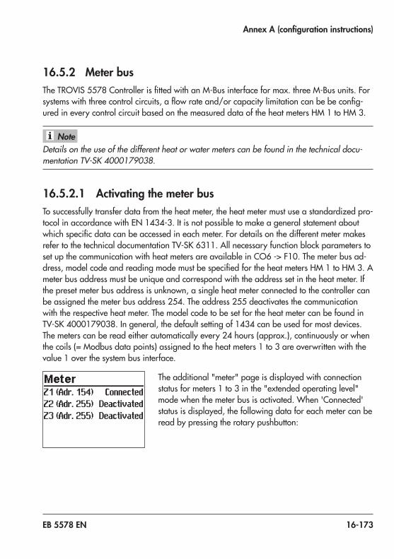
EB 5578 EN 16-173
Annex A (configuration instructions)
16.5.2 Meter busTheTROVIS 5578ControllerisfittedwithanM-Businterfaceformax.threeM-Busunits.Forsystemswiththreecontrolcircuits,aflowrateand/orcapacitylimitationcanbebeconfig-ured in every control circuit based on the measured data of the heat meters HM 1 to HM 3.
Details on the use of the different heat or water meters can be found in the technical docu-mentation TV-SK 4000179038.
16.5.2.1 Activating the meter busTo successfully transfer data from the heat meter, the heat meter must use a standardized pro-tocolinaccordancewithEN 1434-3.Itisnotpossibletomakeageneralstatementaboutwhichspecificdatacanbeaccessedineachmeter.FordetailsonthedifferentmetermakesrefertothetechnicaldocumentationTV-SK 6311.AllnecessaryfunctionblockparameterstosetupthecommunicationwithheatmetersareavailableinCO6 ->F10.Themeterbusad-dress,modelcodeandreadingmodemustbespecifiedfortheheatmetersHM1toHM3.Ameter bus address must be unique and correspond with the address set in the heat meter. If the preset meter bus address is unknown, a single heat meter connected to the controller can be assigned the meter bus address 254. The address 255 deactivates the communication with the respective heat meter. The model code to be set for the heat meter can be found in TV-SK 4000179038.Ingeneral,thedefaultsettingof1434canbeusedformostdevices.The meters can be read either automatically every 24 hours (approx.), continuously or when thecoils(=Modbusdatapoints)assignedtotheheatmeters1to3areoverwrittenwiththevalue 1 over the system bus interface.
The additional "meter" page is displayed with connection status for meters 1 to 3 in the "extended operating level" mode when the meter bus is activated. When 'Connected' status is displayed, the following data for each meter can be read by pressing the rotary pushbutton:
Note

16-174 EB 5578 EN
Annex A (configuration instructions)
− Flow rate − Volume − Capacity − Energy − Flow temperature (Flow)
− Returnflowtemperature(Returnflow) − Meter ID (ID no.) − Meter bus address (Address, sent by meter)
Functions WE Configuration
Meter bus 02551434ContinuousTar-A
CO6 -> F10 - 1HM 1...3 address: 0 to 255HM1...3model:1434,Multical3,Apator,SLS/WSFHM1...3mode:24 h,Continuous,CoilTariff:Tar-A,Tar-E(tariffscheduleON,OFF;onlyforHM1with '1434' und 'Continuous' settings) Tar-E: the consumption data are assigned to a high tariff or a low tariff depending on the time schedule programmed in the customer level. Three time periods can be entered per day of the week (not vacations or public holidays): 1–7daily,1 =Monday,2 =Tuesday,…,7 =Sunday

EB 5578 EN 16-175
Annex A (configuration instructions)
16.5.2.2 Flow rate and/or capacity limitation with meter busTherefreshingrateofthemeasuredvariable(flowrateand/orcapacity)mustbelessthanfivessecondstoensurethatthelimitationcanbeperformedproperly.Thetechnicaldocu-mentationTV-SK 6311liststheheatmeterswhichcomplywiththiscriterionand,thereforecan be used for limitation. Note that some makes, particularly battery-operated heat meters, respond with communication pauses when they are read too frequently. Others might run out ofenergyearly.FordetailsrefertotheabovementionedTV-SKdocument. − A system with simultaneous room and DHW heating requires maximum energy. − A system with a fully charged storage tank that is only used for room heating requires
less energy. − A system that suspends room heating during DHW heating requires less energy.Asaresult,threedifferentmaximumlimitvaluesforRK1canbeadjustedinallsystemswithonly one control valve and DHW heating on the secondary side: − Max. limit value to determine the absolute upper limit − Max. limit value for heating to operate room heating only − Max. limit value for DHW to operate DHW heating only
If the 'Max. limit' or 'Max. limit (heating)' parameter for HC1 is set to 'OT', a four-point characteristicconfiguredinCO1 ->F11 - 1allowstheinputoffourflowrateorcapacitylim-itsforoutdoor-temperature-compensatedflowrateorcapacitylimitationinadditiontotheoutdoor,flowandreturnflowtemperaturevalues.In all systems with two or three control valves, separate maximum limits can be adjusted for theflowrateandcapacity.
Flow limitationAllnecessaryfunctionblockparameterstosetuptheflowratelimitationareavailableinCO6 -> F11orCO6 -> F13andCO6 -> F15forthesecondandthirdcontrolcircuit.Oneafter the other, the system's max. limit or max. limit for heating and the max. limit for DHW for systems with only one primary control valve and secondary DHW heating have to be set. The 'Limiting factor' determines how strongly the controller responds when the limit values are exceeded in either direction.Whentheflowratelimitationisactivated,therespectivemeasuringandlimitvaluesaredis-playedintheextendedoperatinglevelafterconfirmingtheplantscheme.

16-176 EB 5578 EN
Annex A (configuration instructions)
If the controller indicates CO5 -> F00 - 1, any access to the return flow, flow rate and capac-ity settings is locked.
Functions WE ConfigurationMeter bus 0
2551434Continuous
CO6 -> F10 - 1HM 1...3 address: 0 to 255HM 1...3 model: 1434, CAL3, APAtO, SLSHM1...3mode:24 h,Continuous,CoiL
FlowratelimitationinRK1 01.5 m³/h1.5 m³/h1.5 m³/h1.0
CO6 -> F11 - 1Max.limit:OTto650 m³/hMax.limit(heating):OTto650 m³/hMax.limit(DHW):0.01to650 m³/hLimiting factor: 0.1 to 10.0
FlowratelimitationinRK2 01.51.0
CO6 -> F13 - 1Max.limit:0.01to650 m³/hLimiting factor: 0.1 to 10.0
FlowratelimitationinRK3 01.51.0
CO6 -> F15-1Max.limit:0.01to650 m³/hLimiting factor: 0.1 to 10.0
Capacity limitationAll necessary function block parameters to set up the capacity limitation are available in CO6 -> F12,CO6 -> F14andCO6 -> F16forthesecondandthirdcontrolcircuit.Oneaf-ter the other, the system's max. limit or max. limit for heating and the max. limit for DHW for systems with only one primary control valve and secondary DHW heating have to be set. The 'Limiting factor' determines how strongly the controller responds when the limit values are ex-ceeded in either direction.When the capacity limitation is activated, the respective measuring and limit values are dis-playedintheextendedoperatinglevelafterconfirmingtheplantscheme.
If the controller indicates CO5 -> F00 - 1, any access to the return flow, flow rate and capac-ity settings is locked.
Note
Note

EB 5578 EN 16-177
Annex A (configuration instructions)
Functions WE ConfigurationMeter bus 0
255143424h
CO6 -> F10 - 1HM 1...3 address: 0 to 255HM 1...3 model: 1434, CAL3, APAtO, SLSHM1...3mode:24 h,Continuous,CoiL
CapacitylimitationinRK1 01.5 kW1.5 kW1.5 kW1.0
CO6 -> F12 - 1Max.limit:OTto6500 kWMax.limit(heating):OTto6500 kWMax.limit(DHW):0.1to6500 kWLimiting factor: 0.1 to 10.0
CapacitylimitationinRK2 01.5 kW1.0
CO6 -> F14 - 1Max.limit:0.1to6500 kWLimiting factor: 0.1 to 10.0
CapacitylimitationinRK3 01.5 kW1.0
CO6 -> F16 - 1Max.limit:0.1to6500 kWLimiting factor: 0.1 to 10.0
16.5.3 Return flow temperature limitation based on capacityA capacity limit can be determined for control circuit based on the measured capacity value oftheheatmeter1(HM1).Thereturnflowtemperatureincontrolcircuit1islimitedaccord-ing the settings entered in PA1 as long as the measured capacity value is below the deter-mined capacity limit. When the measured capacity value exceeds the capacity limit, a return flowtemperaturelimitadjustableseparatelyforcontrolcircuit1takeseffect.
Functions WE ConfigurationRK1 Returnflowtemperaturelimitation based on capacity
0 CO6 -> F17 - 1:newmaximumreturnflowlimitatacapacity higher than the max. limit (onlywhenCO6 -> F10 - 1andactiveatedHM1)
1.5 kW Max.limit:0.1to6500 kW55 °C Max.returnflowtemperature:5.0to90.0 °C

16-178 EB 5578 EN
Annex A (configuration instructions)
16.5.4 Memory module/mini moduleTheuseofamemorymodule(orderno.1400-9379)orminimodule(orderno.1400-7436)isparticularlyusefultotransferalldatafromoneTROVIS 5578ControllertoseveralotherTROVIS 5578Controllers.
In contrast to the memory module, the mini module is not suitable for transferring the pro-grammed vacations to the individual control circuits or a data logging configuration pro-grammed in TROVIS-VIEW.
Thememorymodule/minimoduleispluggedintotheRJ-45 connector socket located at the side of the controller. Once the module has been connected, 'Save settings' ap-pears on the controller display. If the memory module al-readycontainsdatafromadifferentTROVIS 5578Con-troller, turn the rotary pushbutton until 'Load settings' is displayed. − Pressingtherotarypushbuttontoconfirm'Saveset-
tings' causes the controller settings to be transferred to thememorymodule/minimodule.
− Pressingtherotarypushbuttontoconfirm'Loadset-tings' causes the controller settings to be transferred fromthememorymodule/minimodule.
Note

EB 5578 EN 16-179
Annex A (configuration instructions)
During data transfer, the zeros and ones run across the display.Whenthetransferwassuccessful,'OK'isdis-played. After that, the connection between controller and memory module can be terminated.
UsingTROVIS-VIEW(orderno.6661-1014),itispossibletoconfigureallcontrollersettingson a convenient user interface at the computer and to document these settings.
16.5.5 Data loggingAdataloggingmodule(orderno.1400-9378)savesthefollowingcontrollerdataeverytwominutes: − Temperatures measured by the sensors − Controlsignalsin% − Switching states of the pump outputs
ThedataloggingmoduleispluggedintotheRJ-45con-nector socket located at the side of the controller. Once the module has been connected, 'Start data logging' and 'Co-py logging data' appear on the controller display. − Pressingtherotarypushbuttontoconfirm'Startdata
logging' causes the above listed operating values to be saved cyclically to the inserted data logging module. The controller display returns to the reading indicated when the data logging module was connected.

16-180 EB 5578 EN
Annex A (configuration instructions)
− Pressingtherotarypushbuttontoconfirm'Copylog-ging data' causes already logged data to be trans-ferred from the memory controller to the data logging module. During data transfer, the zeros and ones run across the display. When the transfer was successful, 'OK'isdisplayed.Afterthat,theconnectionbetweencontroller and data logging module can be terminat-ed.
− The controller starts to write over the oldest data as soon the memory of the data logging module is full after approximately eight days. The current memory capacity of the data log-ging module can be read in the extended operating level under 'Logging memory' as the second value in the sequence (range of values: 0 to 6035). Directly after inserting the data logging module, data can be first read after the first scanning cycle has been performed. − The oldest data in the internal memory of the controller are overwritten after approx. 14 days. The cycle time is one minute.
The data log viewer software allows the data to be viewed in graph format. The USB convert-er3(orderno.1400-9377)isrequiredtoconnectthedataloggingmoduletoacomputer.The data log viewer software is supplied together with the USB converter 3.
Note

EB 5578 EN 16-181
Annex A (configuration instructions)
16.6 Function block listsCO1: RK1 · Heating circuit 1 (not system Anl 1.9) 1)
F Function WE AnlComments Function block parameters: value range (default setting)
01 Roomsensor 0 Not systems Anl 1.5–1.8,3.x,5.x, 7.x, 9.x,12.x,14.x, 15.x, 16.x, 17.x,
18.x
CO1 ->F01 - 1:RoomsensorRF1,temperaturereadingandFG1inputforTypes 5244,5257-5and5257-51RoomPanelsactive
02 Outdoor sensor
0 1.5–1.8,3.5, 7.x,
10.5, 25.5
CO1 ->F02 - 1:OutdoorsensorAF1,outdoor-temperature-compensated control active
1 1.0–1.3, 2.x, 3.0–3.4,3.9,4.x–9.x,
10.0–10.3, 11.x–16.x, 17.x,18.x,21.x, 25.0
03 Returnflowsensor
0 1.1–1.4, 10.1–10.3,
21.1
CO1 -> F03 - 1:ReturnflowsensorRüF1;limitationfunctionactive
Function block parameters:KP(limitingfactor):0.1to10.0(1.0)1 1.0, 1.5, 1.6–
1.8,2.x–9.x,10.0, 10.5, 11.x– 16.x, 17.x,18.x,21.0, 21.2, 21.9,25.x
04 Cooling control
0 Not systems Anl1.9,3.9,5.9,
16.x, 17.x, 18.x
CO1 -> F04 - 1:Coolingcontrol,onlywithCO1 -> F11 - 1The cooling control function causes a reversal of the operating directionandaminimumlimitationofthereturnflowtemperatureinRK1.

16-182 EB 5578 EN
Annex A (configuration instructions)
F Function WE AnlComments Function block parameters: value range (default setting)
05 Underfloorheating
0 Not systems Anl1.5–1.8,3.x, 5.0–5.2, 7.x,9.x,
12.x, 14.x, 15.x, 16.x, 17.x,18.x
CO1 -> F05 - 1:Underfloorheating/dryingofjointlessfloorsFunction block parameters:Boost:0.0to50.0 °C(0.0 °C)Starttemperature:20.0to60.0 °C(25 °C)Hold (days): 0 to 10 days (0 days)Temp.rise/day:0.0to20.0°C(5.0 °C)Maximumtemperature:25.0to60.0 °C(45.0 °C)Hold (days): 0 to 30 days (4 days)Temp.reduction/day:0.0to20.0 °C(0.0 °C)Startcondition:Stop,Start,Hold,Reduction
06 Storage tank sensor SF2
1 Systems Anl 3.9,5.9,
16.x, 17.x, 18.xonly
CO1 -> F06 - 1:ActivateSF2toswitchoffchargingofthebuffer tank
07 Optimization 0 Not systems Anl1.5–1.8,3.x, 5.x, 7.x, 9.x,12.x,
14.x, 15.x, 16.x, 17.x,
18.x
CO1 ->F07 - 1:Optimizationofheatingtimes (onlywhenCO1 > F01 - 1andCO1 ->F02 - 1)
08 Adaptation 0 CO1 ->F08 - 1:Heatingcharacteristicadaptation (onlywhenCO1 ->F01 - 1,CO1 ->F02 - 1andCO1 ->F11 - 0)
09 Flash adaptation
0 CO1 ->F09 - 1:Flashadaptationofflowtemperature (onlywhenCO1 ->F01 - 1)
Function block parameters:Cycletime:0or1to100 min(20 min)KP(gain):0.0to25.0(0.0)
11 Four-point characteristic
0 Not Anl 1.5–1.8,
7.x
CO1 ->F11 - 1:Four-pointcharacteristic(onlywhenCO1 -> F08 - 0)CO1 ->F11 - 0:Gradientcharacteristic
12 Three-step control mode
1 All 1) CO1 -> F12 - 1:Three-stepcontrolFunction block parameters:KP(gain):0.1to50.0(2.0)Tn(resettime):1to999s(120s)TV(derivative-actiontime):0to999s(0s)TY(valvetransittime):15,20,25,…,240s(35 s)
CO1 -> F12 - 0:On/offcontrolFunction block parameters:Hysteresis:1.0to30.0°C(5.0°C)Min. ON time: 0 to 10 min (2 min)Min. OFF time: 0 to 10 min (2 min)

EB 5578 EN 16-183
Annex A (configuration instructions)
F Function WE AnlComments Function block parameters: value range (default setting)
13 Damping 0 All 1) CO1 -> F13 - 1:OPENsignaldamping(onlywhenCO1 ->F12 - 1)
Function block parameters:Max.systemdeviation:3.0to10.0°C(3.0°C)
14 Release 0 All 1) CO1 ->F14 - 1:ReleaseRK1atBI15;FG1hasnofunctionFunction block parameters:ActivewhenBI=ON,OFF(ON)
16 Demand processing, 0 to10VInputTerminals 19/23
0 All 1) CO1 -> F16 - 1:Demandprocessing,0 to10V
17 Binary demand processing
0 Not for sys-tems with
SF3
CO1 -> F17 - 1:Binarydemandprocessingatinputterminals17/18
Function block parameters:ActivewhenBI=OFF,ON(ON)
18 External demand
0 All 1) CO1 ->F18 - 1:Externaldemand0to10 V Thestandardizedsignaloutput(terminals20/21)isnotavailableanymoreasacontroloutput.Themaximumflowsetpoint(withboost,ifapplicable)isdemandedasa0to10 Vsignal at the standardized signal output.
Function block parameters:Lowertransmissionrange:0.0to150.0 °C(0.0 °C)Uppertransmissionrange:0.0to150.0 °C(120.0 °C)Boost:0.0to30.0 °C(0.0 °C)
20 Demand for external heat
0 All 1) CO1 ->F20 - 1:Externaldemandforheatduetoinsufficientheat supply
21 Speed control of the charging pump
0 Systems Anl 3.9,5.9,
16.x, 17.x, 18.xonly
CO1 -> F21 - 1:Temperature-basedadaptationofthedeliveryrate of the charging pump
Function block parameters:Startspeedreduction-SF2limit:5.0to90.0 °C(40.0 °C)Stopspeedreduction-SF2limit:5.0to90.0 °C(50.0 °C)Minimumspeed:0to50 %(20 %)
22 SLP depending on returnflowtemperature
0 Systems Anl 3.9,5.9,
16.x, 17.x, 18.xonly
CO1 -> F22 - 1:StoragetankchargingpumpnotONunlessreturnflowhot

16-184 EB 5578 EN
Annex A (configuration instructions)
F Function WE AnlComments Function block parameters: value range (default setting)
23 Differential temperature control
0 System Anl 1.0, 16.0
only
CO1 -> F23 - 1:ActivationofdifferentialtemperaturecontrolFunction block parameters:Setpointofdifferentialtemperaturecontrol:0.0to50.0 °C(20.0 °C)KP(influencefactor):0.1to10.0(1.0)Minimumspeed:0to100 %(20 %)
24 Demand only
0 All 1) CO1 -> F24 - 1:RK1worksasafeedercircuit.RK1onlyprocessesexternaldemandforheating;UP1runsdependingon demand.
F Function block number, WE Default setting, Anl System code number
CO2: RK2 · Heating circuit 2 (systems Anl 3.1–3.4, 3.9, 4.x, 5.x, 6.0, 10.x, 16.1, 16.6, 16.8, 17.x, 18.x, 25.0, 25.5) 1)
F Function WE AnlComments Function block parameters: value range (default setting)
01 Roomsensor 0 All 1) CO2 ->F01 - 1:RoomsensorRF2,temperaturereadingandFG2inputforTypes 5244,5257-5and5257-51RoomPanelsactive
02 Outdoor sensor
0 All 1) CO2 ->F02 - 1:withoutdoorsensor,outdoor-temperature-compensated control active
Function block parameters:Select AF1, AF2
03 Returnflowsensor
0 4.x–5.2, 6.x, 10.1–10.3,
16.x
CO2 -> F03 - 1:ReturnflowsensorRüF2;limitationfunctionactive
Function block parameters:KP(limitingfactor):0.1to10.0(1.0)1 3.0–3.5,
10.0, 10.5, 25.x
04 Cooling control
0 Not systems Anl3.9,5.9,16.x,17.x,18.x
CO2 -> F04 - 1:CoolingcontrolThe cooling control function causes a reversal of the operating directionandaminimumlimitationofthereturnflowtemperatureinRK2.

EB 5578 EN 16-185
Annex A (configuration instructions)
F Function WE AnlComments Function block parameters: value range (default setting)
05 Underfloorheating
0 All 1) CO2 -> F05 - 1:Underfloorheating/dryingofjointlessfloorsFunction block parameters:Boost:0.0to50.0 °C(0.0 °C)Starttemperature:20to60 °C(25 °C)Hold (days): 0 to 10 days (0 days)Temp.rise/day:0.0to20.0°C(5.0 °C)Maximumtemperature:25.0to60.0 °C(45.0 °C)Hold (days): 0 to 30 days (4 days)Temp.reduction/day:0.0to20.0 °C(0.0 °C)Startcondition:Stop,Start,Hold,Reduction
07 Optimization 0 All 1) CO2 ->F07 - 1:Optimizationofheatingtimes (onlywhenCO2 > F01 - 1andCO1(2) ->F02 - 1)
08 Adaptation 0 All 1) CO2 ->F08 - 1:Heatingcharacteristicadaptation (onlywhenCO2 ->F01 - 1,CO1(2) ->F02 - 1andCO2 ->F11 - 0)
09 Flash adaptation
0 All 1) CO2 ->F09 - 1:Flashadaptationofflowtemperature (onlywhenCO2 ->F01 - 1)
Function block parameters:Cycletime:0or1to100 min(20 min)KP(gain):0.0to25.0(0.0)
11 Four-point characteristic
0 All 1) CO2 ->F11 - 1:Four-pointcharacteristic(onlywhenCO2 -> F08 - 0)CO2 ->F11 - 0:Gradientcharacteristic
12 Three-step control mode
1 All 1) CO2 -> F12 - 1:Three-stepcontrolFunction block parameters:KP(gain):0.1to50.0(2.0)Tn(resettime):1to999s(120s)TV(derivative-actiontime):0to999s(0s)TY(valvetransittime):15,20,25,…,240s(35 s)
CO2 -> F12 - 0:On/offcontrolFunction block parameters:Hysteresis:1.0to30.0°C(5.0°C)Min. ON time: 0 to 10 min (2 min)Min. OFF time: 0 to 10 min (2 min)
13 Damping 0 All 1) CO2 -> F13 - 1:OPENsignaldamping(onlywhenCO2 ->F12 - 1)
Function block parameters:Max.systemdeviation:3.0to10.0°C(3.0°C)

16-186 EB 5578 EN
Annex A (configuration instructions)
F Function WE AnlComments Function block parameters: value range (default setting)
14 Release 0 All 1) CO2 ->F14 - 1:ReleaseRK2atBI16;FG2hasnofunctionFunction block parameters:ActivewhenBI=ON,OFF(ON)
16 Demand processing, 0 to10VInputTerminals 19/23
0 All 1) CO2 ->F16 - 1:DemandprocessinginRK2
24 Demand only 0 All 1) CO2 -> F24 - 1:RK2worksasafeedercircuit.RK2onlyprocessesexternaldemandforheating;UP2runsdependingon demand.
F Function block number, WE Default setting, Anl System code number
CO3: RK3 · Heating circuit 3 (systems Anl 3.9, 5.x, 6.x, 9.x, 12.x, 13.x, 15.x, 16.5, 16.7, 16.8, 17.x, 21.x, 25.x) 1)
F Function WE AnlComments Function block parameters: value range (default setting)
01 Roomsensor 0 All 1) CO3 ->F01 - 1:RoomsensorRF3,temperaturereadingandFG3inputforTypes 5244,5257-5and5257-51RoomPanelsactive
02 Outdoor sensor
1 All 1) CO3 ->F02 - 1:withoutdoorsensor,outdoor-temperature-compensated control activeFunction block parameters:Select AF1, AF2
03 Returnflowsensor
0 5.0–5.2, 6.x, 9.x,12.x,
13.x, 15.x, 16.5, 16.7, 16.8,21.1,
21.9
CO3 -> F03 - 1:ReturnflowsensorRüF2;limitationfunctionactive
Function block parameters:KP(limitingfactor):0.1to10.0(1.0)
1 21.2, 25.x
04 Cooling control
0 Not systems Anl5.9,
15.x, 16.x, 17.x
CO3 -> F04 - 1:CoolingcontrolThe cooling control function causes a reversal of the operating directionandaminimumlimitationofthereturnflowtemperatureinRK3.

EB 5578 EN 16-187
Annex A (configuration instructions)
F Function WE AnlComments Function block parameters: value range (default setting)
05 Underfloorheating
0 All 1) CO3 -> F05 - 1:Underfloorheating/dryingofjointlessfloorsFunction block parameters:Boost:0.0to50.0 °C(0.0 °C)Starttemperature:20to60 °C(25 °C)Hold (days): 0 to 10 days (0 days)Temp.rise/day:0.0to20.0°C(5.0 °C)Maximumtemperature:25.0to60.0 °C(45.0 °C)Hold (days): 0 to 30 days (4 days)Temp.reduction/day:0.0to20.0 °C(0.0 °C)Startcondition:Stop,Start,Hold,Reduction
07 Optimization 0 All 1) CO3 ->F07 - 1:Optimizationofheatingtimes (onlywhenCO3 > F01 - 1andCO1(3) ->F02 - 1)
08 Adaptation 0 All 1) CO3 ->F08 - 1:Heatingcharacteristicadaptation (onlywhenCO3 ->F01 - 1,CO1(3) ->F02 - 1andCO3 ->F11 - 0)
09 Flash adaptation
0 All 1) CO3 ->F09 - 1:Flashadaptationofflowtemperature (onlywhenCO3 ->F01 - 1)
Function block parameters:Cycletime:0or1to100 min(20 min)KP(gain):0.0to25.0(0.0)
11 Four-point characteristic
0 All 1) CO3 ->F11 - 1:Four-pointcharacteristic(onlywhenCO3 -> F08 - 0)CO3 ->F11 - 0:Gradientcharacteristic
12 Three-step control mode
1 All 1) CO3 -> F12 - 1:Three-stepcontrolFunction block parameters:KP(gain):0.1to50.0(2.0)Tn(resettime):1to999s(120s)TV(derivative-actiontime):0to999s(0s)TY(valvetransittime):15,20,25,…,240s(35 s)
CO3 -> F12 - 0:On/offcontrolFunction block parameters:Hysteresis:1.0to30.0°C(5.0°C)Min. ON time: 0 to 10 min (2 min)Min. OFF time: 0 to 10 min (2 min)
13 Damping 0 All 1) CO3 -> F13 - 1:OPENsignaldamping(onlywhenCO3 ->F12 - 1)
Function block parameters:Max.systemdeviation:3.0to10.0°C(3.0°C)

16-188 EB 5578 EN
Annex A (configuration instructions)
F Function WE AnlComments Function block parameters: value range (default setting)
14 Release 0 Not for sys-tems with
SF3
CO3 ->F14 - 1:ReleaseRK3atBI17;FG3hasnofunctionFunction block parameters:ActivewhenBI=ON,OFF(ON)
16 Demand processing, 0 to10VInputTerminals 19/23
0 All 1) CO3 ->F16 - 1:DemandprocessinginRK3
24 Demand only 0 All 1) CO3 -> F24 - 1:RK3worksasafeedercircuit.RK3onlyprocessesexternaldemandforheating;UP3runsdependingon demand.
F Function block number, WE Default setting, Anl System code number
CO4: DHW circuit (systems Anl 1.1–1.9, 2.x, 3.1–3.4, 3.9, 4.1–4.5, 5.1, 5.2, 7.x, 8.x, 9.x, 10.1–10.3, 11.x, 12.x, 13.x, 14.x, 15.x, 17.x, 18.x, 21.x) 1)
F Function WE AnlComments Function block parameters: value range (default setting)
01 Storage tank sensor SF1Not systems Anl3.9,5.9,11.0, 11.3, 11.5, 12.0, 13.0, 17.x, 18.x,21.0
1 1) CO4 ->F01 - 1:StoragetanksensorSF1CO4 ->F01 - 0:Storagetankthermostat (onlywhenCO4 ->F02 - 0)1) WE =1:SystemsAnl1.1–1.8,2.x,3.1–3.4,4.1–4.5,5.1,5.2,
7.x–9.x,10.1–10.3,11.1,11.2,11.4,11.6,12.1,13.1,13.2,14.x, 15.x, 21.1, 21.2
2) WE =0:SystemsAnl1.9,11.9,12.9,13.9,21.9
0 2)
02 Storage tank sensor SF2NotAnl1.9,11.0, 11.3, 11.9,12.0,12.9,13.0,13.9,14.3,15.3, 21.0, 21.9
0 1) CO4 ->F02 - 1:StoragetanksensorSF2 (onlywhenCO4 ->F01 - 1)1) WE =1:1.1,1.3,1.4,1.5,1.7,1.8-2,2.0,2.1,3.1,3.3,3.4,
4.1,4.3,4.5,5.1,7.1,8.1,9.1,9.5,10.1,10.3,11.1,11.4,11.5,11.9,12.1,13.1,14.1,15.0,15.1,21.1
2) WE =0:1.2,1.6,1.8-1,1.8-3,1.9,2.2,2.3,2.4,3.2,4.2,5.2,7.2,8.2,9.2,9.6,10.2,11.0,11.2,11.3,11.6,12.0,12.2,12.9,13.0,13.2,13.9,14.2,14.3,15.2,15.3,21.0,21.2,21.9
1 2)

EB 5578 EN 16-189
Annex A (configuration instructions)
F Function WE AnlComments Function block parameters: value range (default setting)
03 ReturnflowsensorRüF2
0 1.9,7.x,8.x,11.x, 12.x, 13.x, 21.x
CO4 -> F03 - 1:ReturnflowsensorRüF2;limitationfunctionactive
Function block parameter: KP(limitingfactor):0.1to10.0(1.0)
3.9,5.9,17.x,18.x
CO4 -> F03 - 1:returnflowsensorRüF2orRüF4whenRüF2isactivatedforHK2;outputUP1tolayerthereturnflowdependingon the temperature active
04 Flow rate sensor
0 1.9,11.9,12.9,13.9,
21.9
CO4->F04 - 1:FlowratesensoratBI17Function block parameter: Select:Analog/Binary(Analog)1)
1) Analog =flowratesensor(1400-9246) Binary =flowswitchatterminals17/18
InsystemsAnl 3.9,5.9,17.xand18.x,onlyaflowswitchcanbeconfigured.
05 Flow sensor 0 1.1–1.4, 1.6,1.8,1.9,2.2,2.4, 3.2, 3.4, 4.2, 5.2, 7.2, 8.2,9.2,9.6,10.1–10.3, 11.2, 11.9,12.2,12.9,13.2,13.9,21.2,
21.9
CO4 ->F05 - 1:FlowsensorVF4(tomeasurestoragetankcharging temperature)
06 Parallel pump operation
1 8.x,9.5,9.6 CO4 ->F06 - 1:ParallelpumpoperationFunction block parameters:Stop:0to10 min(10 min)Temperaturelimit:20.0to90.0 °C(40.0 °C)
CO4 ->F06 - 0:UP1switchedoffduringDHWheating0 2.1–2.4,
4.1–4.5
07 Intermediate heating
1 2.x, 4.1–4.5
CO4 ->F07 - 1:after20minutesofDHWheating,heatingoperation in UP1 circuit reactivated for 10 minutesCO4 ->F07 - 0:storagetankchargingisgivenunlimitedpriority concerning UP1 circuit
0 8.x,9.5,9.6

16-190 EB 5578 EN
Annex A (configuration instructions)
F Function WE AnlComments Function block parameters: value range (default setting)
08 Priority (reverse)
0
1.1–1.4, 3.1–3.4, 4.1–4.5, 5.1, 5.2, 9.x,10.1–10.3, 11.x, 12.x, 13.x, 15.0, 15.4, 15.5, 21.x
CO4 ->F08 - 1:Prioritybyreversecontrol (onlywhenCO4 ->F09 - 0)
Function block parameters:Start:0to10 min(2 min)KP(influencefactor):0.1to10.0(1.0) Controlcircuit:HC1,HC2,HC3,HC1+HC2,HC1+HC3
09 Priority (set-back)
0 CO4 ->F09 - 1:Prioritythroughset-backoperation (onlywhenCO4 ->F08 - 0)
Function block parameters:Start:0to10 min(2 min) Controlcircuit:HC1,HC2,HC3,HC1+HC2,HC1+HC3
10 Circulation pump (DHW) integrated into heat exchanger
0 1.6,1.8,3.2, 3.4, 5.2, 7.2, 9.2,11.2,
11.4, 12.2, 13.2, 21.2
CO4 ->F10 - 1:ControlofDHWcircuitactivewhilecirculation pump (ZP) is running
1 11.6, 13.6
11 Operation of circulation pump (DHW) during storage tank charging
0 NotAnl1.9,11.0, 11.3, 11.9,12.0,12.9,13.0,13.9,21.0,
21.9
CO4 ->F11 - 1:Circulationpump(ZP)runsaccordingtotimeschedule during storage tank chargingCO4 ->F11 - 0:Circulationpump(ZP)switchedoffduringstorage tank charging

EB 5578 EN 16-191
Annex A (configuration instructions)
F Function WE AnlComments Function block parameters: value range (default setting)
12 Control mode 1 1.9,3.9,5.9,7.x,8.x,9.x,11.x,12.x, 13.x, 17.x,18.x,
21.
CO4 -> F12 - 1:Three-stepcontrolFunction block parameters:Minimumspeed:5to50 %(20 %)(systemsAnl3.9,5.9,17.x,18.xonly)KP(gain):0.1to50.0(2.0;systemsAnl1.9,11.9,12.9,13.9,21.9:0.6) Tn(resettime):1to999 s(120 s,systemsAnl3.9,5.9,17.x18.x:30 s;systemsAnl1.9,11.9,12.9,13.9,21.9:12s)TV(derivative-actiontime):0to999s(0s)TY(valvetransittime):15to240s(35 s;systemsAnl1.9,11.9,12.9,13.9,21.9:20 s,notsystemsAnl3.9,5.9,17.x,18.x)
CO4 -> F12 - 0:On/offcontrol(notsystemsAnl3.9,5.9,17.x,18.x);inthiscase,F12 -0 =F12 - 1applies
Function block parameters:Hysteresis:1.0to30.0°C(5.0°C)Min. ON time: 0 to 10 min (2 min)Min. OFF time: 0 to 10 min (2 min)
13 Damping 0 All 1) CO4 -> F13 - 1:OPENsignaldamping(onlywhenCO4 ->F12 - 1)
Function block parameters:Max.systemdeviation:3.0to10.0°C(3.0°C)
1 CO4 -> F13 - 1:OPENsignaldamping(onlywhenCO4 ->F04 - 1,analogsetting)
Function block parameters:Max.systemdeviation:3.0to10.0°C(8.0°C)

16-192 EB 5578 EN
Annex A (configuration instructions)
F Function WE AnlComments Function block parameters: value range (default setting)
14 Thermal disinfection
0 Not systems Anl3.9,5.9,17.x,18.x
CO4 ->F14 - 1:Thermaldisinfection (onlywhenCO4 ->F01 - 1)
Function block parameters: Day of week: Monday, Tuesday, ..., daily (Wednesday)Time: Adjustable as required in steps of 15 minutes (00:00 – 04:00)Disinfectiontemperature:60.0to90.0 °C(70.0 °C)Setpointboost:0.0to50.0 °C(10.0 °C)(systemsAnl1.9,3.9,5.9,11.0,11.3,11.5,11.9,12.0,12.9,13.0,13.9,17.x,18.x,21.0,21.9only)Duration: 0 to 255 min (0 min)WhenStarttime =StoptimeSelect:ActivewhenBI=OFF,ON(ON)
3.9,5.9,17.x,18.x
CO4 -> F13 - 1:OPENsignaldamping(onlywhenCO4 ->F04 - 1,analogsetting)
Function block parameters:Max.systemdeviation:3.0to10.0°C(8.0°C)
15 SLP depending on returnflowtemperature
0 1.5, 1.7, 2.0, 2.1, 2.3, 3.1, 3.3, 4.1, 4.3, 5.1,
11.1
CO4 ->F15 - 1:storagetankchargingpumpnotONunlessreturnflowhot (for systems Anl 1.5, 1.7, 2.0, 2.1, 2.3, 4.1, 4.3, 5.1 only when CO1 -> F03 - 1;forsystemAnl11.1onlywhenCO4 -> F03 - 1)
16 Priority for external demand
0 1.5–1.8,2.x,3.1–3.4,
4.1–4.3, 5.x, 15.0, 15.4,
15.5
CO4 ->F16 - 1:PriorityforexternaldemandNote: a high external demand causes excessive charging temperatures in DHW circuits without control valve.
ThedefaultsettingcannotbechangedinsystemsAnl 7.xto9.x.1 7.x–9.x
19 Switchover 0 Not systems Anl1.9,3.9,5.9,11.0,
11.3, 11.5, 11.9,12.0,12.9,13.0,13.9,17.x,18.x,21.0,
21.9
CO4 ->F19 - 1:SwitchoverSF1,SF2accordingtoatimeschedule. SF1 applies for day mode and SF2 for night mode (onlywhenCO4 ->F02 - 1)
20 Returnflowcontrol
0 7.1,8.1,9.1,9.5,
11.1, 12.1, 13.1, 21.1
CO4 ->F20 - 1:DHWcircuitadditionallycontrolledbyaglobe valve

EB 5578 EN 16-193
Annex A (configuration instructions)
F Function WE AnlComments Function block parameters: value range (default setting)
21 Speed control of the charging pump
0 1.5–1.8,2.x, 3.1–3.4, 4.1–4.3, 5.1, 5.2,
7.x,8.x,9.x,10.1–10.3, 11.1–11.4, 12.1, 12.2, 13.1, 13,2, 21.1, 21.2
CO4 -> F21 - 1:Temperature-basedadaptationofthedeliveryrate of the charging pump
Function block parameters:Startspeedreduction-SF2limit:5.0to90.0 °C(40.0 °C) Stopspeedreduction-SF2limit:5.0to90.0 °C(50.0 °C) Min.speedsignal:0to50 %(20 %)
22 Cold charging protection
0 1.1 CO4 -> F22 - 1:Storagetankchargingstartedwhentheprimaryflowtemperatureishighenough
Function block parameters:Valveposition:1to100 %
23 Electric heating cartridge
0 Systems Anl 3.9,17.1,18.1
CO4 -> F23 - 1:TheoutputBO10toreleasetheelectricheating is activated based on the temperature at SF1 for thermaldisinfection(onlywhenCO4 -> F14 - 1)
F Function block number, WE Default setting, Anl System code number
CO5: System-wide functions (all systems)IfthecontrollerindicatesCO5 -> F00 - 1,anyaccesstothereturnflow,flowrateandcapac-ity settings is locked.
F Function WE AnlComments Function block parameters: value range (default setting)
01 Sensor type 1 All CO5 -> F01 - 1,F02 - 0:Pt 1000 CO5 -> F01 - 0,F02 - 0:PTC CO5 -> F01 - 1,F02 - 1:Ni 1000
020304 Summer
mode0 Not systems
Anl 1.5, 1.6,1.9,3.5, 10.5,
25.5
CO5 ->F04 - 1:SummermodeFunction block parameters:Date:Adjustableasrequired(01.06.-30.09.)No. days until activation: 1 to 3 (2)No. days until deactivation: 1 to 3 (1)Limit:0.0to30.0 °C(18.0 °C)
05 Delayed outdoor temperature adaptation (decreasing)
0 NotAnl1.9 CO5 ->F05 - 1:Delayedoutdoortemperatureadaptationasthe temperature falls
Function block parameters:Delay/h:0.2to6.0 °C(3.0 °C)

16-194 EB 5578 EN
Annex A (configuration instructions)
F Function WE AnlComments Function block parameters: value range (default setting)
06 Delayed outdoor temperature adaptation (increasing)
0 NotAnl1.9 CO5 ->F06 - 1:Delayedoutdoortemperatureadaptationasthe temperature rises
Function block parameters:Delay/h:0.2to6.0 °C(3.0 °C)
07 Error message 0 Not systems Anl 5.1, 5.2, 5.9,6.1,9.x,12.1, 12.2-x, 13.1, 13.2, 13.6, 15.1, 15.2, 15.3, 17.8,21.1,
21.2
CO5 -> F07 - 1:Terminalforerrormessage:seeplantschemetable
Function block parameters:Relaycontact=NOcontact,NCcontact(NOcontact)
08 Summer time 0 All CO5 ->F08 - 1:Summer/standardtimeswitchover09 Frost
protection1 Not systems
Anl 1.5, 1.6,1.9,
3.5, 10.5, 25.5
CO5 ->F09 - 1:HighestpriorityforfrostprotectionFunction block parameters:Limit:–15.0to+3.0 °C(+3.0 °C)
CO5 ->F09 - 0:RestrictedfrostprotectionFunction block parameters:Limit:–15.0to+3.0 °C(+3.0 °C)
0 1.5, 1.6, 1.9,3.5,
10.5, 25.5
10 Capacity limitation at terminals 17/18
0 Not for sys-tems with SF3, not
system Anl 1.9
CO5 -> F10 - 1:CapacitylimitationinRK1withpulses(onlywhenCO6 -> F12 - 0)
Function block parameters:Max.limit:OTto800 pulses/h(15 pulses/h)Max. limit (heating) 1):OTto800 pulses/h(15 pulses/h)Max. limit (DHW) 1):1to800 pulses/h(15 pulses/h)Limiting factor: 0.1 to 10.0 (1.0)
1) NotsystemsAnl1.0,1.5-1.8,3.0,3.5,3.9,4.0,5.9,7.x,10.x,11.x,12.x,13.x,14.x,15.x,16.x,17.x,18.x,21.x,25.x
12 Creep feed rate limitation
0 NotAnl1.9 CO5 ->F12 - 1:CreepfeedratelimitationFunction block parameters:Switching mode:Binaryatterminals13/19,analogatinputRüF1(binary)ActivewhenBI=ON,OFF(ON)

EB 5578 EN 16-195
Annex A (configuration instructions)
F Function WE AnlComments Function block parameters: value range (default setting)
14 Operation UP1
0 3.0, 5.0, 7.x, 9.1,9.2,
12.x, 15.1, 16.1, 16.5, 16.7,16.8
CO5 -> F14 - 1:FeederpumpUP1operationtocoverowndemandNote: the feeder pump UP1 also starts to operate to cover the demandofRK2/RK3
15 Release 0 All CO5 ->F15 - 1:ReleasecontrolleratBI15,FG1hasnofunction
Function block parameters:ActivewhenBI=ON,OFF(ON)
16 Rtnflowtemp.limitation (prop.controller)
0 All CO5 ->F16 - 1:ReturnflowtemperaturelimitationwithPalgorithm
19 Monitoring 0 All CO5 ->F19 - 1:Temperaturemonitoring20 Sensor
calibration1 All CO5 ->F20 - 1:Setallsensorcalibrationvalues
CO5 ->F20 - 0:Deleteallsensorcalibrationvalues21 Lock manual
level0 All CO5 ->F21 - 1:Lockrotaryswitch
In switch position, the controller runs in automatic mode22 Lock rotary
switch0 All CO5 ->F22 - 1:Lockrotaryswitch
Keynumberinputisstillpossible.23 OT with
0-10 V0 All CO5 ->F23 - 1:Outdoortemperaturereceivedas0to10 V
signal(terminals19/23)orsent(terminals20/21)Function block parameters:Direction: Input, Output (Input)Lowertransmissionrange:–50.0to+100.0 °C(–20.0 °C)Uppertransmissionrange:–50.0to+100.0 °C(+50.0 °C)
24 0-10 Vinput 0 All CO5 -> F24 - 1:Themeasuredvalueat0to10 Vinputisdisplayed as a special value.
25 0to10 Voutput reverse
0 All CO5 -> F25 - 0:0 V/0 %=ValveCLOSED/pumpOFF CO5 -> F25 - 1:0 V/0 %=ValveOPEN/pumpwithmax.delivery rate
Function block parameters:Zero:0to50 %(0 %)
26 PWM reverse 0 All CO5 -> F26 - 0:0 V/0 %=ValveCLOSED/pumpOFF CO5 -> F26 - 1:0 V/0 %=ValveOPEN/pumpwithmax.delivery rate
Function block parameters:Zero:0to50 %(0 %)
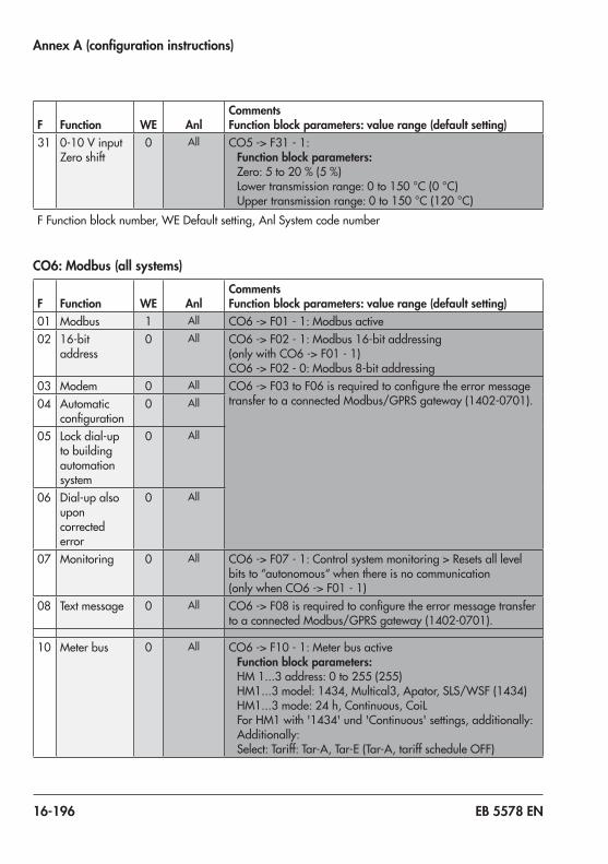
16-196 EB 5578 EN
Annex A (configuration instructions)
F Function WE AnlComments Function block parameters: value range (default setting)
31 0-10 Vinput Zero shift
0 All CO5 -> F31 - 1:Function block parameters:Zero:5to20 %(5 %)Lowertransmissionrange:0to150°C(0°C)Uppertransmissionrange:0to150 °C(120 °C)
F Function block number, WE Default setting, Anl System code number
CO6: Modbus (all systems)
F Function WE AnlComments Function block parameters: value range (default setting)
01 Modbus 1 All CO6 -> F01 - 1:Modbusactive02 16-bit
address0 All CO6 -> F02 - 1:Modbus16-bitaddressing
(onlywithCO6 -> F01 - 1)CO6 ->F02 - 0:Modbus8-bitaddressing
03 Modem 0 All CO6 -> F03toF06isrequiredtoconfiguretheerrormessagetransfertoaconnectedModbus/GPRSgateway(1402-0701).04 Automatic
configuration0 All
05 Lock dial-up to building automation system
0 All
06 Dial-up also upon corrected error
0 All
07 Monitoring 0 All CO6 ->F07 - 1:Controlsystemmonitoring>Resetsalllevelbits to “autonomous“ when there is no communication (onlywhenCO6 -> F01 - 1)
08 Text message 0 All CO6 -> F08isrequiredtoconfiguretheerrormessagetransfertoaconnectedModbus/GPRSgateway(1402-0701).
10 Meter bus 0 All CO6 ->F10 - 1:MeterbusactiveFunction block parameters:HM 1...3 address: 0 to 255 (255)HM1...3model:1434,Multical3,Apator,SLS/WSF(1434)HM1...3mode:24 h,Continuous,CoiLFor HM1 with '1434' und 'Continuous' settings, additionally: Additionally:Select: Tariff: Tar-A, Tar-E (Tar-A, tariff schedule OFF)

EB 5578 EN 16-197
Annex A (configuration instructions)
F Function WE AnlComments Function block parameters: value range (default setting)
11 Flow rate limitation in RK1
0 NotAnl1.9 CO6 -> F11 - 1:Flowratelimitation(onlywhenCO6 -> F10 - 1andHM1isactivated)
Function block parameters:Max.limit:OTto650 m³/h(1.5 m³/h)Max. limit (heating) 1):OTto650 m³/h(1.5 m³/h)Max. limit (DHW) 1):0.01to650 m³/h(1.5 m³/h)Limiting factor: 0.1 to 10 (1)
12 Capacity limitation in RK1
0 NotAnl1.9 CO6 -> F12 - 1:Capacitylimitation(onlywhenCO6 -> F10 - 1andHM1isactivated)
Function block parameters:Max.limit:OTto6500 kW(1.5 kW)Max. limit (heating) 1):OTto6500 kW(1.5 kW)Max. limit (DHW) 1):0.1to6500 kW(1.5 kW)Limiting factor: 0.1 to 10 (1)
13 Flow rate limitation in RK2
0 3.0–3.4,3.9,4.x,5.9,7.x,8.x,10.x,11.x, 12.x, 13.x, 15.x, 16.1, 16.6, 16.8,17.x,18.x,21.x,
25.x
CO6 -> F13 - 1:Flowratelimitation(onlywhenCO6 -> F10 - 1andHM2isactivated)
Function block parameters:Max.limit:0.01to650 m³/h(1.5 m³/h)Limiting factor: 0.1 to 10 (1)
14 Capacity limitation in RK2
0 CO6 -> F14 - 1:Capacitylimitation(onlywhenCO6 -> F10 - 1andHM2isactivated)
Function block parameters:Max.limit:0.1to6500 kW(1.5 kW)Limiting factor: 0.1 to 10 (1)
15 Flow rate limitation in RK3
0 5.9,12.x,13.x, 15.x, 16.5, 16.7, 16.8,17.8,21.x, 25.x
CO6 -> F15 - 1:Flowratelimitation(onlywhenCO6 -> F10 - 1andHM3isactivated)
Function block parameters:Max.limit:0.01to650 m³/h(1.5 m³/h)Limiting factor: 0.1 to 10 (1)
16 Capacity limitation in RK3
0 CO6 -> F16 - 1:Capacitylimitation(onlywhenCO6 -> F10 - 1andHM3isactivated)
Function block parameters:Max.limit:0.1to6500 kW(1.5 kW)Limiting factor: 0.1 to 10 (1)
17 Returnflowtemperature limitation based on capacity
0 All CO6 -> F17 - 1:newmaximumreturnflowlimitatacapacityhigherthanthemax.limit(onlywhenCO6 -> F10 - 1andactiveated HM1)
Function block parameters:Max.limit:0.1to6500 kW(1.5 kW)Max.returnflowtemperature:5.0to90 °C(55 °C)

16-198 EB 5578 EN
Annex A (configuration instructions)
F Function WE AnlComments Function block parameters: value range (default setting)
20 Modbus without building automation system
0 All CO6 ->F20 - 1:VariousModbusspecificationsdonothaveanyeffectonthecollectivelevel/buildingautomationsystemreading
1) NotsystemsAnl 1.0,1.5-1.8,3.0,3.5,4.0,7.x,10.x,11.x,12.x,13.x,14.x,15.x,16.x,17.x,21.x,25.x
F Function block number, WE Default setting, Anl System code number
CO7: Device bus (all systems)
F Function WE AnlComments Function block parameters: value range (default setting)
01 Device bus 0 All CO7 -> F01 - 1:DevicebusactiveFunction block parameters:Devicebusaddress/Auto1), 1 to 32 (32)
1) Auto=Automaticsearchforafreedevicebusaddressinthe system
02 Clock syn-chronization
0 All CO7 -> F02 - 1:controllersendsitssystemtimetoalldevicebus participants once every 24 hours
03 RoompanelRK1
0 1.0–1.4, 2.x, 4.x,6.0,9.5,9.6,10.x,11.x, 13.x, 21.x, 25.x
CO7 -> F03 - 1:communicationwithTROVIS 5570forRK1active,CO1 -> F01 - 1automaticallyset
Function block parameters:Devicebusaddress/Auto1), 1 to 32 (32)
1) Auto=Automaticsearchforaroompanelsettodetectionmode
04 RoompanelRK2
0 3.0–3.4, 4.x, 5.x, 6.0,
10.x, 16.1, 16.6,16.8,
25.x
CO7 -> F04 - 1:communicationwithTROVIS 5570forRK2active,CO2 -> F01 - 1automaticallyset
Function block parameters:Devicebusaddress/Auto1), 1 to 32 (32)
1) Auto=Automaticsearchforaroompanelsettodetectionmode
05 RoompanelRK3
0 5.x,6.0,9.x,12.x, 13.x, 15.x, 16.5, 16.7,16.8,21.x, 25.x
CO7 -> F05 - 1:communicationwithTROVIS 5570forRK3active,CO3 -> F01 - 1automaticallyset
Function block parameters:Devicebusaddress/Auto1), 1 to 32 (32)
1) Auto=Automaticsearchforaroompanelsettodetectionmode

EB 5578 EN 16-199
Annex A (configuration instructions)
F Function WE AnlComments Function block parameters: value range (default setting)
06 Send AF1 0 All CO7 -> F06 - 1:Function block parameters:Registernumber/1to4(1)
07 ReceiveAF1 0 All CO7 -> F07 - 1:Function block parameters:Registernumber/1to4(1)
08 Send AF2 0 All CO7 -> F08 - 1:AnalysisactiveFunction block parameters:Registernumber/1to4(2)
09 ReceiveAF2 0 NotAnl1.9 CO7 -> F09 - 1:Function block parameters:Registernumber/1to4(2)
10 Send demand RK1
0 All CO7 -> F10 - 1:SenddemandFunction block parameters:Registernumber/5to64(5)
11 Send demand RK2
0 All CO7 -> F11 - 1:Function block parameters:Registernumber/5to64(5)
12 Send demand RK3
0 All CO7 -> F12 - 1:Function block parameters: Registernumber/5to64(5)
13 Send demand DHW
0 All CO7 -> F13 - 1:'Chargingtemperatureboost'(P04)isgenerated in the PA4 level
Function block parameters:Registernumber/5to64(5)
14 Send max. demand
0 All CO7 -> F14 - 1:thecontrolleralreadydeterminesinternallythemaximumflowsetpointofitscircuitandsendsitthisvaluetothe primary controllers
15 Receiveexternal demand in RK1
0 All CO7 -> F15 - 1:ExternaldemandprocessinginRK1Function block parameters:Registernumber/5to64(5)
16 Receiveerrors 0 All CO7 -> F16 - 1:thecontrollergeneratesthe'External'messageas long as the faults of the other device bus participants exist.
17 Receiveexternal demand in RK2
0 All CO7 -> F17 - 1:ExternaldemandprocessinginRK2Function block parameters:Registernumber/5to64(5)

16-200 EB 5578 EN
Annex A (configuration instructions)
F Function WE AnlComments Function block parameters: value range (default setting)
18 Receiveexternal demand in RK3
0 All CO7 -> F18 - 1:ExternaldemandprocessinginRK3Function block parameters:Registernumber/5to64(5)
19 Raisereturnflowtemperature
0 All CO7 -> F19 - 1:ReturnflowtemperaturelimitinRK1raisedwhen 'DHW heating active' message is received over the device bus
Function block parameters:Registernumber/5to64(32)
20 Send 'DHW heating active'
0 All CO7 -> F20 - 1:Function block parameters:Registernumber/5to64(32)
21 ReceivereleaseRK1
0 All CO7 -> F21 - 1:Function block parameters:Registernumber/5to64(32)
22 ReceivereleaseRK2
0 3.1–3.4, 4.x, 5.x, 6.x,
10.x, 16.1, 16.6,16.8,
25.x
CO7 -> F22 - 1:Function block parameters:Registernumber/5to64(32)
23 ReceivereleaseRK3
0 5.x,6.x,9.x,12.x, 13.x, 15.x, 16.5, 16.7,16.8,21.x, 25.x
CO7 -> F23 - 1:Function block parameters:Registernumber/5to64(32)
31 Ext-HC11 0 All CO7 -> F31 - 1:TROVISI/Oforheatingcircuit11activeFunction block parameters:Device bus address: 11 to 15 (11)Connected/primarycircuit,toHC1(toHC1)
32 Ext-HC12 0 All CO7 -> F32 - 1:TROVISI/Oforheatingcircuit12activeFunction block parameters:Device bus address: 11 to 15 (12)Connected/primarycircuit,toHC1(toHC1)
33 Ext-HC13 0 All CO7 -> F33 - 1:TROVISI/Oforheatingcircuit13activeFunction block parameters:Device bus address: 11 to 15 (13)Connected/primarycircuit,toHC1(toHC1)
F Function block number, WE Default setting, Anl System code number

EB 5578 EN 16-201
Annex A (configuration instructions)
CO8: Initialization of BI1 and BI2 (all systems)
F Function WE AnlComments Function block parameters: value range (default setting)
01 Analysis of BI1
0 All CO8 -> F01 - 1:AnalysisactiveFunction block parameter: 1)
02 Analysis of BI2
0 All CO8 -> F02 - 1:AnalysisactiveFunction block parameter: 1)
03 Analysis of BI3
0 All CO8 -> F03 - 1:AnalysisactiveFunction block parameter: 1)
04 Analysis of BI4
0 All CO8 -> F04 - 1:AnalysisactiveFunction block parameter: 1)
05 Analysis of BI5
0 All CO8 -> F05 - 1:AnalysisactiveFunction block parameter: 1)
06 Analysis of BI6
0 All CO8 -> F06 - 1:AnalysisactiveFunction block parameter: 1)
09 Analysis of BI9
0 All CO8 -> F09 - 1:AnalysisactiveFunction block parameter: 1)
10 Analysis of BI10
0 All CO8 -> F10 - 1:AnalysisactiveFunction block parameter: 1)
11 Analysis of BI11
0 All CO8 -> F11 - 1:AnalysisactiveFunction block parameter: 1)
12 Analysis of BI12
0 All CO8 -> F12 - 1:AnalysisactiveFunction block parameter: 1)
13 Analysis of BI13
0 All CO8 -> F13 - 1:AnalysisactiveFunction block parameter: 1)
15 Analysis of BI15
0 All CO8 -> F15 - 1:AnalysisactiveFunction block parameter: 1)
16 Analysis of BI16
0 All CO8 -> F16 - 1:AnalysisactiveFunction block parameter: 1)
17 Analysis of BI17
0 All CO8 -> F17 - 1:AnalysisactiveFunction block parameter: 1)
1) ErrormessagewhenBI=0,BI=1,none(1)F Function block number, WE Default setting, Anl System code number

16-202 EB 5578 EN
Annex A (configuration instructions)
CO11: RK11 · Heating circuit 11
F Function WE AnlComments Function block parameters: value range (default setting)
01 Roomsensor 0 All CO11 -> F01 - 1:RoomsensorRF11;temperaturereadingactive
02 Outdoor sensor
0 All CO11 -> F02 - 1:UseofmeasuredvalueAF1;outdoor-temperature-compensated control active
03 Returnflowsensor
1 All CO11 -> F03 - 1:RücklaufsensorRüF11;Begrenzungsfunktionaktiv
Function block parameters:KP(limitingfactor):0.1to10.0(1.0)
05 Underfloorheating
0 All CO11 -> F05 - 1:Underfloorheating/dryingofjointlessfloorsFunction block parameters:Boost:0.0to50.0 °C(0.0 °C)Starttemperature:20to60 °C(25 °C)Hold (days): 0 to 10 days (0 days)Temp.rise/day:0.0to20.0°C(5.0 °C)Maximumtemperature:25.0to60.0 °C(45.0 °C)Hold (days): 0 to 30 days (4 days)Temp.reduction/day:0.0to20.0 °C(0.0 °C)Startcondition:Stop,Start,Hold,Reduction
07 Optimization 0 All CO11 ->F07 - 1:Optimizationofheatingtimes (onlywhenCO11 > F01 - 1andCO11 ->F02 - 1)
08 Adaptation 0 All CO11 ->F08 - 1:Heatingcharacteristicadaptation (onlywhenCO11 ->F01 - 1,CO11 ->F02 - 1andCO11 ->F11 - 0)
09 Flash adaptation
0 All CO11 ->F09 - 1:Flashadaptationofflowtemperature (onlywhenCO11 ->F01 - 1)
Function block parameters:Cycletime:0or1to100 min(20 min)KP(gain):0.0to25.0(0.0)
11 Four-point characteristic
0 All CO11 ->F11 - 1:Four-pointcharacteristic(onlywhenCO11 -> F08 - 0)CO11 ->F11 - 0:Gradientcharacteristic

EB 5578 EN 16-203
Annex A (configuration instructions)
F Function WE AnlComments Function block parameters: value range (default setting)
12 Three-step control mode
1 All CO11 -> F12 - 1:Three-stepcontrolFunction block parameters:KP(gain):0.1to50.0(2.0)Tn(resettime):1to999s(120s)TV(derivative-actiontime):0to999s(0s)TY(valvetransittime):15,20,25,…,240s(35 s)
CO11 -> F12 - 0:On/offcontrolFunction block parameters:Hysteresis:1.0to30.0°C(5.0°C)Min. ON time: 0 to 10 min (2 min)Min. OFF time: 0 to 10 min (2 min)
13 Damping 0 All CO11 -> F13 - 1:OPENsignaldamping(onlywhenCO11 ->F12 - 1)
Function block parameters:Max.systemdeviation:3.0to10.0°C(3.0°C)
F Function block number, WE Default setting, Anl System code number
CO12: RK12 · Heating circuit 12
F Function WE AnlComments Function block parameters: value range (default setting)
01 Roomsensor 0 All CO12 -> F01 - 1:RoomsensorRF12;temperaturereadingactive
02 Outdoor sensor
0 All CO12 -> F02 - 1:UseofmeasuredvalueAF1;outdoor-temperature-compensated control active
03 Returnflowsensor
1 All CO12 -> F03 - 1:ReturnflowsensorRüF12;limitationfunctionactive
Function block parameters:KP(limitingfactor):0.1to10.0(1.0)
05 Underfloorheating
0 All CO12 -> F05 - 1:Underfloorheating/dryingofjointlessfloorsFunction block parameters:Boost:0.0to50.0 °C(0.0 °C)Starttemperature:20to60 °C(25 °C)Hold (days): 0 to 10 days (0 days)Temp.rise/day:0.0to20.0°C(5.0 °C)Maximumtemperature:25.0to60.0 °C(45.0 °C)Hold (days): 0 to 30 days (4 days)Temp.reduction/day:0.0to20.0 °C(0.0 °C)Startcondition:Stop,Start,Hold,Reduction

16-204 EB 5578 EN
Annex A (configuration instructions)
F Function WE AnlComments Function block parameters: value range (default setting)
07 Optimization 0 All CO12 ->F07 - 1:Optimizationofheatingtimes (onlywhenCO12 > F01 - 1andCO12 ->F02 - 1)
08 Adaptation 0 All CO12 ->F08 - 1:Heatingcharacteristicadaptation (onlywhenCO12 ->F01 - 1,CO12 ->F02 - 1andCO12 ->F11 - 0)
09 Flash adaptation
0 All CO12 ->F09 - 1:Flashadaptationofflowtemperature (onlywhenCO12 ->F01 - 1)
Function block parameters:Cycletime:0or1to100 min(20 min)KP(gain):0.0to25.0(0.0)
11 Four-point characteristic
0 All CO12 ->F11 - 1:Four-pointcharacteristic(onlywhenCO11 -> F08 - 0)CO12 ->F11 - 0:Gradientcharacteristic
12 Three-step control mode
1 All CO12 -> F12 - 1:Three-stepcontrolFunction block parameters:KP(gain):0.1to50.0(2.0)Tn(resettime):1to999s(120s)TV(derivative-actiontime):0to999s(0s)TY(valvetransittime):15,20,25,…,240s(35 s)
CO12 -> F12 - 0:On/offcontrolFunction block parameters:Hysteresis:1.0to30.0°C(5.0°C)Min. ON time: 0 to 10 min (2 min)Min. OFF time: 0 to 10 min (2 min)
13 Damping 0 All CO12 -> F13 - 1:OPENsignaldamping(onlywhenCO11 ->F12 - 1)
Function block parameters:Max.systemdeviation:3.0to10.0°C(3.0°C)
F Function block number, WE Default setting, Anl System code number

EB 5578 EN 16-205
Annex A (configuration instructions)
CO13: RK13 · Heating circuit 13
F Function WE AnlComments Function block parameters: value range (default setting)
01 Roomsensor 0 All CO13 -> F01 - 1:RoomsensorRF13;temperaturereadingactive
02 Outdoor sensor
0 All CO13 -> F02 - 1:UseofmeasuredvalueAF1;outdoor-temperature-compensated control active
03 Returnflowsensor
1 All CO13 -> F03 - 1:ReturnflowsensorRüF13;limitationfunctionactive
Function block parameters:KP(limitingfactor):0.1to10.0(1.0)
05 Underfloorheating
0 All CO13 -> F05 - 1:Underfloorheating/dryingofjointlessfloorsFunction block parameters:Boost:0.0to50.0 °C(0.0 °C)Starttemperature:20to60 °C(25 °C)Hold (days): 0 to 10 days (0 days)Temp.rise/day:0.0to20.0°C(5.0 °C)Maximumtemperature:25.0to60.0 °C(45.0 °C)Hold (days): 0 to 30 days (4 days)Temp.reduction/day:0.0to20.0 °C(0.0 °C)Startcondition:Stop,Start,Hold,Reduction
07 Optimization 0 All CO13 ->F07 - 1:Optimizationofheatingtimes (onlywhenCO13 > F01 - 1andCO13 ->F02 - 1)
08 Adaptation 0 All CO13 ->F08 - 1:Heatingcharacteristicadaptation (onlywhenCO13 ->F01 - 1,CO13 ->F02 - 1andCO13 ->F11 - 0)
09 Flash adaptation
0 All CO13 ->F09 - 1:Flashadaptationofflowtemperature (onlywhenCO13 ->F01 - 1)
Function block parameters:Cycletime:0or1to100 min(20 min)KP(gain):0.0to25.0(0.0)
11 Four-point characteristic
0 All CO13 ->F11 - 1:Four-pointcharacteristic(onlywhenCO13 -> F08 - 0)CO13 ->F11 - 0:Gradientcharacteristic

16-206 EB 5578 EN
Annex A (configuration instructions)
F Function WE AnlComments Function block parameters: value range (default setting)
12 Three-step control mode
1 All CO13 -> F12 - 1:Three-stepcontrolFunction block parameters:KP(gain):0.1to50.0(2.0)Tn(resettime):1to999s(120s)TV(derivative-actiontime):0to999s(0s)TY(valvetransittime):15,20,25,…,240s(35 s)
CO13 -> F12 - 0:On/offcontrolFunction block parameters:Hysteresis:1.0to30.0°C(5.0°C)Min. ON time: 0 to 10 min (2 min)Min. OFF time: 0 to 10 min (2 min)
13 Damping 0 All CO13 -> F13 - 1:OPENsignaldamping(onlywhenCO11 ->F12 - 1)
Function block parameters:Max.systemdeviation:3.0to10.0°C(3.0°C)
F Function block number, WE Default setting, Anl System code number
16.7 Parameter listsPA1: Heating circuit HC1
P Reading Parameter: Value range (default setting)
01 Flow gradient:0.2 to 3.2 (1.2) 0.2to1.0(0.5)withCO1 -> F05 - 1
02 Level (parallel shift):–30.0to30.0 °C(0.0 °C)
03 Flow set point (day) (onlywhenCO1 -> F02 - 0andCO1 -> F09 - 1):–5.0to150.0 °C(50.0 °C)
04 Flow set point (night) (onlywhenCO1 ->F02 - 0andCO1 ->F09 - 1):–5.0to150.0 °C(30.0 °C)

EB 5578 EN 16-207
Annex A (configuration instructions)
P Reading Parameter: Value range (default setting)
05 Four-point characteristic
Outdoor temperature:–50.0to50.0 °C(–15.0 °C,–5.0 °C,5.0 °C,15.0 °C) –50.0to50.0 °C(5.0 °C,15.0 °C,25.0 °C,35.0 °C) 1)
Flow temperature:–5.0to150.0 °C(70.0 °C,55.0 °C,40.0 °C,25.0 °C) –5.0to150.0 °C(20.0 °C,15.0 °C,10.0 °C,5.0 °C) 1)
Reducedflowtemperature:–5.0to150.0 °C(60.0 °C,40.0 °C,20.0 °C,20.0 °C) –5.0to150.0 °C(30.0 °C,25.0 °C,20.0 °C,15.0 °C) 1)
Returnflowtemperature:5.0to90.0 °C(65.0 °C,65.0 °C,65.0 °C,65.0 °C)
Flow rate:0.01to650 m³/h(0.00 m³/h,0.00 m³/h,0.00 m³/h,0.00 m³/h)
Capacity:0.1to6500 kW(withCO6->F12 - 1)or 1to800pulse/h(withCO5->F10 - 1)(0.0 kW,0.0 kW,0.0 kW,0.0 kW)or (0.0 pulse/h,0.0 pulse/h,0.0 pulse/h,0.0 pulse/h)
06 Min.flowtemperature:–5.0to150.0 °C(20.0 °C)
07 Max.flowtemperature:5.0to150.0 °C(70.0 °C) 5.0to50.0 °C(50.0 °C)whenCO1 -> F05 - 1
09 Outdoor temperature for continuous day mode:–50.0to5.0 °C(–15 °C)

16-208 EB 5578 EN
Annex A (configuration instructions)
P Reading Parameter: Value range (default setting)
10 MinimumflowtemperaturesetpointHCforbinarydemandprocessing:5.0to150.0 °C(40.0 °C)
11 Returnflowgradient(onlywhenCO1 -> F03 - 1):0.2 to 3.2 (1.2)
12 Returnflowlevel(onlywhenCO1 -> F03 - 1):–30.0to30.0 °C(0.0 °C)
13 Basepointforreturnflowtemperature(onlywhenCO1 -> F03 - 1):5.0to90.0 °C(65.0 °C)
14 Max.returnflowtemperature(onlywhenCO1 -> F03 - 1):5.0to90.0 °C(65.0 °C)
15 Set point boost (pre-control circuit):0.0to50.0 °C(5.0 °C)
16 Minimum set point to charge buffer tank:AUTOto90.0 °C(AUTO)
17 Stop charging of the buffer tank:AUTOto90.0 °C(AUTO)
18 Charging temperature boost:0.0to50.0 °C(6.0 °C)
19 Lag time of charging pump0.0 to 10.0 (1.0)
1) With cooling control with or without outdoor sensor
PA2: Heating circuit HC2
P Reading Parameter: Value range (default setting)
01 Flow gradient:0.2 to 3.2 (1.2) 0.2to1.0(0.5)withCO2 -> F05 - 1
02 Level (parallel shift):–30.0to30.0 °C(0.0 °C)
03 Flow set point (day) (onlywhenCO1,CO2 -> F02 - 0andCO2 -> F09 - 1):–5.0to150.0 °C(50.0 °C)
04 Flow set point (night)(onlywithCO1,CO2 -> F02 - 0andCO2 > F09 - 1):–5.0to150.0 °C(30.0 °C)

EB 5578 EN 16-209
Annex A (configuration instructions)
P Reading Parameter: Value range (default setting)
05 Four-point characteristic
Outdoor temperature:–50.0to50.0 °C(–15.0 °C,–5.0 °C,5.0 °C,15.0 °C) –50.0to50.0 °C(5.0 °C,15.0 °C,25.0 °C,35.0 °C) 1)
Flow temperature:–5.0to150.0 °C(70.0 °C,55.0 °C,40.0 °C,25.0 °C) –5.0to150.0 °C(20.0 °C,15.0 °C,10.0 °C,5.0 °C) 1)
Reducedflowtemperature:–5.0to150.0 °C(60.0 °C,40.0 °C,20.0 °C,20.0 °C) –5.0to150.0 °C(30.0 °C,25.0 °C,20.0 °C,15.0 °C) 1)
Returnflowtemperature:5.0to90.0 °C(65.0 °C,65.0 °C,65.0 °C,65.0 °C)
06 Min.flowtemperature:–5.0to150.0 °C(20.0 °C)
07 Max.flowtemperature:5.0to150.0 °C(70.0 °C) 5.0to50.0 °C(50.0 °C)whenCO2 -> F05 - 1
09 Outdoor temperature for continuous day mode:–50.0to5.0 °C(–15 °C)
11 Returnflowgradient(onlywhenCO2 -> F03 - 1):0.2 to 3.2 (1.2)
12 Returnflowlevel(onlywhenCO2 -> F03 - 1):–30.0to30.0 °C(0.0 °C)
13 Basepointforreturnflowtemperature(onlywhenCO2 -> F03 - 1):5.0to90.0 °C(65.0 °C)
14 Max.returnflowtemperature:5.0to90.0 °C(65.0 °C)
15 Set point boost (pre-control circuit):0.0to50.0 °C(5.0 °C)
1) With cooling control with or without outdoor sensor

16-210 EB 5578 EN
Annex A (configuration instructions)
PA3: Heating circuit HC3P Reading Parameter: Value range (default setting)01 Flow gradient:
0.2 to 3.2 (1.2) 0.2to1.0(0.5)withCO3 -> F05 - 1
02 Level (parallel shift):–30.0to30.0 °C(0.0 °C)
03 Flowsetpoint(day)(onlywhenCO1,CO3 -> F02 - 0andCO3 -> F09 - 1):–5.0to150.0 °C(50.0 °C)
04 Flowsetpoint(night)(onlywithCO1,CO3 -> F02 - 0andCO3 > F09 - 1):–5.0to150.0 °C(30.0 °C)
05 Four-point characteristic
Outdoor temperature:–50.0to50.0 °C(–15.0 °C,–5.0 °C,5.0 °C,15.0 °C) –50.0to50.0 °C(5.0 °C,15.0 °C,25.0 °C,35.0 °C) 1)
Flow temperature:–5.0to150.0 °C(70.0 °C,55.0 °C,40.0 °C,25.0 °C) –5.0to150.0 °C(20.0 °C,15.0 °C,10.0 °C,5.0 °C) 1)
Reducedflowtemperature:–5.0to150.0 °C(60.0 °C,40.0 °C,20.0 °C,20.0 °C) –5.0to150.0 °C(30.0 °C,25.0 °C,20.0 °C,15.0 °C) 1)
Returnflowtemperature:5.0to90.0 °C(65.0 °C,65.0 °C,65.0 °C,65.0 °C)
06 Min.flowtemperature:–5.0to150.0 °C(20.0 °C)
07 Max.flowtemperature:5.0to150.0 °C(70.0 °C) 5.0to50.0 °C(50.0 °C)whenCO3 -> F05 - 1
09 Outdoor temperature for continuous day mode:–50.0to5.0 °C(–15 °C)
11 Returnflowgradient(onlywhenCO3 -> F03 - 1):0.2 to 3.2 (1.2)
12 Returnflowlevel(onlywhenCO3 -> F03 - 1):–30.0to30.0 °C(0.0 °C)
13 Basepointforreturnflowtemperature(onlywhenCO3 -> F03 - 1):5.0to90.0 °C(65.0 °C)

EB 5578 EN 16-211
Annex A (configuration instructions)
P Reading Parameter: Value range (default setting)14 Max.returnflowtemperature:
5.0to90.0 °C(65.0 °C)15 Set point boost (pre-control circuit):
0.0to50.0 °C(5.0 °C)
1) With cooling control with or without outdoor sensor
PA4: Domestic hot water heating (DHW)P Reading Parameter: Value range (default setting)01 Min. adjustable DHW set point:
5.0to90.0 °C(40.0 °C)02 Max. adjustable DHW set point:
5.0to90.0 °C(90.0 °C)03 Hysteresis:
1.0to30.0 °C(5.0 °C)04 Charging temperature boost:
0.0to50.0 °C(10.0 °C)05 Max.chargingtemperature(onlywhenCO4 -> F05 - 1):
20.0to150.0 °C(80.0 °C)
07 Max.returnflowtemperature:5.0to90.0 °C(65.0 °C)
10 Solar circuit pump ON:1.0to30.0 °C(10.0 °C)
11 Solar circuit pump OFF:0.0to30.0 °C(3.0 °C)

16-212 EB 5578 EN
Annex A (configuration instructions)
P Reading Parameter: Value range (default setting)12 Max. storage tank temperature:
20.0to90.0 °C(80.0 °C)13 Maximum buffer tank temperature:
20.0to90.0 °C(80.0 °C)14 Control signal DHW for storage tank charging:
5to100 %(100 %)
19 Lagtimeforstoragetankchargingpump(=ValvetransittimexP19):0.0 to 10.0 (1.0)
21 Returnflowtemperaturelimit,layeringattop:5.0to90.0 °C(25.0 °C)
PA5: System-wide parametersP Reading Parameter: Value range (default setting)01 Start temperature for boiler pump (only systems Anl 14.1,
14.2,15.1,15.2,16.2,16.4,16.5,16.7):20.0to90.0 °C(60.0 °C)
02 Boiler pump hysteresis (only system Anl 14.1, 14.2, 15.1, 15.2,16.2,16.4,16.5,16.7):0.0to30.0 °C(5.0 °C)
PA6: ModbusP Reading Parameter: Value range (default setting)01 Modbusstationaddress(8bit):
1 to 246 (255) 1to3200(255)withCO6 > F02 - 1
PA11: Heating circuit HC11P Reading Parameter: Value range (default setting)01 Flow gradient:
0.2 to 3.2 (1.2) 0.2to1.0(0.5)withCO11 -> F05 - 1
02 Level (parallel shift):–30.0to30.0 °C(0.0 °C)

EB 5578 EN 16-213
Annex A (configuration instructions)
P Reading Parameter: Value range (default setting)03 Flowsetpoint(day)(onlywhenCO11 -> F02 - 0and
CO11 -> F09 - 1):–5.0to150.0 °C(50.0 °C)04 Flowsetpoint(night)(onlywithCO11 -> F02 - 0and
CO11 > F09 - 1):–5.0to150.0 °C(30.0 °C)05 Four-point characteristic
Outdoor temperature:–50.0to50.0 °C(–15.0 °C,–5.0 °C,5.0 °C,15.0 °C)Flow temperature:–5.0to150.0 °C(70.0 °C,55.0 °C,40.0 °C,25.0 °C)Reducedflowtemperature:–5.0to150.0 °C(60.0 °C,40.0 °C,20.0 °C,20.0 °C)Returnflowtemperature:5.0to90.0 °C(65.0 °C,65.0 °C,65.0 °C,65.0 °C)
06 Min.flowtemperature:–5.0to150.0 °C(20.0 °C)
07 Max.flowtemperature:5.0to150.0 °C(70.0 °C) 5.0to50.0 °C(50.0 °C)whenCO11 -> F05 - 1
09 Outdoor temperature for continuous day mode:–50.0to5.0 °C(–15 °C)
11 Returnflowgradient(onlywhenCO11 -> F03 - 1):0.2 to 3.2 (1.2)
12 Returnflowlevel(onlywhenCO11 -> F03 - 1):–30.0to30.0 °C(0.0 °C)
13 Basepointforreturnflowtemperature(onlywhenCO11 -> F03 - 1):5.0to90.0 °C(65.0 °C)
14 Max.returnflowtemperature:5.0to90.0 °C(65.0 °C)
PA12: Heating circuit HC12P Reading Parameter: Value range (default setting)01 Flow gradient:
0.2 to 3.2 (1.2) 0.2to1.0(0.5)withCO12 -> F05 - 1

16-214 EB 5578 EN
Annex A (configuration instructions)
P Reading Parameter: Value range (default setting)02 Level (parallel shift):
–30.0to30.0 °C(0.0 °C)03 Flowsetpoint(day)(onlywhenCO12 -> F02 - 0and
CO12 -> F09 - 1):–5.0to150.0 °C(50.0 °C)04 Flowsetpoint(night)(onlywithCO12 -> F02 - 0and
CO12 > F09 - 1):–5.0to150.0 °C(30.0 °C)05 Four-point characteristic
Outdoor temperature:–50.0to50.0 °C(–15.0 °C,–5.0 °C,5.0 °C,15.0 °C)Flow temperature:–5.0to150.0 °C(70.0 °C,55.0 °C,40.0 °C,25.0 °C)Reducedflowtemperature:–5.0to150.0 °C(60.0 °C,40.0 °C,20.0 °C,20.0 °C)Returnflowtemperature:5.0to90.0 °C(65.0 °C,65.0 °C,65.0 °C,65.0 °C)
06 Min.flowtemperature:–5.0to150.0 °C(20.0 °C)
07 Max.flowtemperature:5.0to150.0 °C(70.0 °C) 5.0to50.0 °C(50.0 °C)whenCO12 -> F05 - 1
09 Outdoor temperature for continuous day mode:–50.0to5.0 °C(–15 °C)
11 Returnflowgradient(onlywhenCO12 -> F03 - 1):0.2 to 3.2 (1.2)
12 Returnflowlevel(onlywhenCO12 -> F03 - 1):–30.0to30.0 °C(0.0 °C)
13 Basepointforreturnflowtemperature(onlywhenCO12 -> F03 - 1):5.0to90.0 °C(65.0 °C)
14 Max.returnflowtemperature:5.0to90.0 °C(65.0 °C)

EB 5578 EN 16-215
Annex A (configuration instructions)
PA13: Heating circuit HC13P Reading Parameter: Value range (default setting)01 Flow gradient:
0.2 to 3.2 (1.2) 0.2to1.0(0.5)withCO13 -> F05 - 1
02 Level (parallel shift):–30.0to30.0 °C(0.0 °C)
03 Flowsetpoint(day)(onlywhenCO13 -> F02 - 0andCO13 -> F09 - 1):–5.0to150.0 °C(50.0 °C)
04 Flowsetpoint(night)(onlywithCO13 -> F02 - 0andCO13 > F09 - 1):–5.0to150.0 °C(30.0 °C)
05 Four-point characteristic
Outdoor temperature:–50.0to50.0 °C(–15.0 °C,–5.0 °C,5.0 °C,15.0 °C)Flow temperature:–5.0to150.0 °C(70.0 °C,55.0 °C,40.0 °C,25.0 °C)Reducedflowtemperature:–5.0to150.0 °C(60.0 °C,40.0 °C,20.0 °C,20.0 °C)Returnflowtemperature:5.0to90.0 °C(65.0 °C,65.0 °C,65.0 °C,65.0 °C)
06 Min.flowtemperature:–5.0to150.0 °C(20.0 °C)
07 Max.flowtemperature:5.0to150.0 °C(70.0 °C) 5.0to50.0 °C(50.0 °C)whenCO13 -> F05 - 1
09 Outdoor temperature for continuous day mode:–50.0to5.0 °C(–15 °C)
11 Returnflowgradient(onlywhenCO13 -> F03 - 1):0.2 to 3.2 (1.2)
12 Returnflowlevel(onlywhenCO13 -> F03 - 1):–30.0to30.0 °C(0.0 °C)
13 Basepointforreturnflowtemperature(onlywhenCO13 -> F03 - 1):5.0to90.0 °C(65.0 °C)
14 Max.returnflowtemperature:5.0to90.0 °C(65.0 °C)

16-216 EB 5578 EN
Annex A (configuration instructions)
16.8 Customer-specific dataStationOperatorSAMSONofficeSystem code number
Function block settings in configuration levelsCO1 CO2 CO3 CO4 CO5 CO6 CO7 CO8 CO11 CO12 CO13
F01F02F03F04F05F06F07F08F09F10F11F12F13F14F15F16F17F18F19F20F21F22F23F24F25F26F31F32F33

EB 5578 EN 16-217
Annex A (configuration instructions)
Settings at the rotary switch · Set pointsParameters Switch position Value rangeHC1 room temperature
0.0to40.0 °C
HC2 room temperatureHC3 room temperatureHC11 room temperatureHC12 room temperatureHC13 room temperature
DHW temperatureMin. to max. DHW temperature
HC1 OT deactivation value
–50.0 to +50.0 °C
HC2 OT deactivation valueHC3 OT deactivation valueHC11 OT deactivation valueHC12 OT deactivation valueHC13 OT deactivation value
Parameters Switch position Value rangeHC1 room temperature
0.0to40.0 °C
HC2 room temperatureHC3 room temperatureHC11 room temperatureHC12 room temperatureHC13 room temperature
DHW temperatureMin. to max. DHW temperature
HC1 OT deactivation value
–50.0 to +50.0 °C
HC2 OT deactivation valueHC3 OT deactivation valueHC11 OT deactivation valueHC12 OT deactivation valueHC13 OT deactivation value

16-218 EB 5578 EN
Annex A (configuration instructions)
Settings at the rotary switch · Times-of-use · Switch position Times-of-use HC1 Mon Tue Wed Thu Fri Sat Sun Value rangeStartfirsttime-of-use
00:00 to 24:00 h
Stopfirsttime-of-useStart second time-of-useStop second time-of-useStart third time-of-useStop third time-of-use
Times-of-use HC2 Mon Tue Wed Thu Fri Sat Sun Value rangeStartfirsttime-of-use
00:00 to 24:00 h
Stopfirsttime-of-useStart second time-of-useStop second time-of-useStart third time-of-useStop third time-of-use
Times-of-use HC3 Mon Tue Wed Thu Fri Sat Sun Value rangeStartfirsttime-of-use
00:00 to 24:00 h
Stopfirsttime-of-useStart second time-of-useStop second time-of-useStart third time-of-useStop third time-of-use
Times-of-use HC11 Mon Tue Wed Thu Fri Sat Sun Value rangeStartfirsttime-of-use
00:00 to 24:00 h
Stopfirsttime-of-useStart second time-of-useStop second time-of-useStart third time-of-useStop third time-of-use
Times-of-use HC12 Mon Tue Wed Thu Fri Sat Sun Value rangeStartfirsttime-of-use
00:00 to 24:00 h
Stopfirsttime-of-useStart second time-of-useStop second time-of-useStart third time-of-useStop third time-of-use

EB 5578 EN 16-219
Annex A (configuration instructions)
Times-of-use HC13 Mon Tue Wed Thu Fri Sat Sun Value rangeStartfirsttime-of-use
00:00 to 24:00 h
Stopfirsttime-of-useStart second time-of-useStop second time-of-useStart third time-of-useStop third time-of-use
Times-of-use DHW Mon Tue Wed Thu Fri Sat Sun Value rangeStartfirsttime-of-use
00:00 to 24:00 h
Stopfirsttime-of-useStart second time-of-useStop second time-of-useStart third time-of-useStop third time-of-use
Times-of-use ZP Mon Tue Wed Thu Fri Sat Sun Value rangeStartfirsttime-of-use
00:00 to 24:00 h
Stopfirsttime-of-useStart second time-of-useStop second time-of-useStart third time-of-useStop third time-of-use

16-220 EB 5578 EN
Annex A (configuration instructions)
PA1 parameters (heating circuit HC1), PA2 parameters (heating circuit HC2) and PA3 parameters (heating circuit HC3)
P Parameters PA1 (HC1)
PA2 (HC2)
PA3 (HC3) Value range
01 Flow gradient 0.2 to 3.202 Level (parallel shift) –30.0to+30.0 °C03 Flow set point (day) –5.0to+150.0 °C04 Flow set point (night) –5.0to+150.0 °C05 Four-point characteristic
Outdoor temperature, point 1 –50.0to+50.0 °COutdoor temperature, point 2 –50.0to+50.0 °COutdoor temperature, point 3 –50.0to+50.0 °COutdoor temperature, point 4 –50.0to+50.0 °C
05 Flow temperature, point 1 –5.0to+150.0 °CFlow temperature, point 2 –5.0to+150.0 °CFlow temperature, point 3 –5.0to+150.0 °CFlow temperature, point 4 –5.0to+150.0 °CReducedflowtemperature,point1 –5.0to+150.0 °CReducedflowtemperature,point2 –5.0to+150.0 °CReducedflowtemperature,point3 –5.0to+150.0 °CReducedflowtemperature,point4 –5.0to+150.0 °CReturnflowtemperature,point1 5.0to90.0 °CReturnflowtemperature,point2 5.0to90.0 °CReturnflowtemperature,point3 5.0to90.0 °CReturnflowtemperature,point4 5.0to90.0 °CFlow rate, point 1 – – 0.01to650 m³/hFlow rate, point 2 – – 0.01to650 m³/hFlow rate, point 3 – – 0.01to650 m³/hFlow rate, point 4 – – 0.01to650 m³/hCapacity, point 1 – –
0.1to6500 kWor
1to800pulses/h
Capacity, point 2 – –Capacity, point 3 – –Capacity, point 4 – –
06 Min.flowtemperature –5.0to+150.0 °C07 Max.flowtemperature –5.0to+150.0 °C09 Outdoor temperature for continuous
day mode –50.0to+5.0 °C

EB 5578 EN 16-221
Annex A (configuration instructions)
P Parameters PA1 (HC1)
PA2 (HC2)
PA3 (HC3) Value range
10 MinimumflowtemperaturesetpointHC for binary demand processing 5.0to150.0 °C
11 Returnflowgradient 0.2 to 3.212 Returnflowlevel –30.0to+30.0 °C13 Basepointforreturnflowtemperature: 5.0to90.0 °C14 Max.returnflowtemperature 5.0to90.0 °C15 Set point boost (pre-control circuit) 0.0to50.0 °C16 Minimum set point to charge buffer
tank – – OTto90.0 °C
17 Stop charging of the buffer tank – – OTto90.0 °C18 Charging temperature boost – – 0.0to50.0 °C19 Lag time of charging pump – – 0.0 to 10.0
PA11 parameters (heating circuit HC11), PA12 parameters (heating circuit HC12) and PA13 parameters (heating circuit HC13)
P Parameters PA11 (HC11)
PA12 (HC12)
PA13 (HC13) Value range
01 Flow gradient 0.2 to 3.202 Level (parallel shift) –30.0to30.0 °C03 Flow set point (day) –5.0to150.0 °C04 Flow set point (night) –5.0to150.0 °C

16-222 EB 5578 EN
Annex A (configuration instructions)
P Parameters PA11 (HC11)
PA12 (HC12)
PA13 (HC13) Value range
05 Four-point characteristicOutdoor temperature, point 1 –50.0to50.0 °COutdoor temperature, point 2 –50.0to50.0 °COutdoor temperature, point 3 –50.0to50.0 °COutdoor temperature, point 4 –50.0to50.0 °CFlow temperature, point 1 –5.0to150.0 °CFlow temperature, point 2 –5.0to150.0 °CFlow temperature, point 3 –5.0to150.0 °CFlow temperature, point 4 –5.0to150.0 °CReducedflowtemperature,point1 –5.0to150.0 °CReducedflowtemperature,point2 –5.0to150.0 °CReducedflowtemperature,point3 –5.0to150.0 °CReducedflowtemperature,point4 –5.0to150.0 °CReturnflowtemperature,point1 5.0to90.0 °CReturnflowtemperature,point2 5.0to90.0 °CReturnflowtemperature,point3 5.0to90.0 °CReturnflowtemperature,point4 5.0to90.0 °C
06 Min.flowtemperature –5.0to150.0 °C07 Max.flowtemperature –5.0to150.0 °C09 Outdoor temperature for continuous
day mode –50.0to5.0 °C
11 Returnflowgradient 0.2 to 3.212 Returnflowlevel –30.0to30.0 °C13 Basepointforreturnflowtemperature: 5.0to90.0 °C14 Max.returnflowtemperature 5.0to90.0 °C
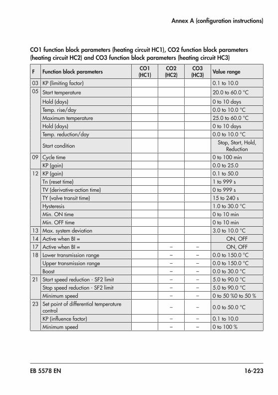
EB 5578 EN 16-223
Annex A (configuration instructions)
CO1 function block parameters (heating circuit HC1), CO2 function block parameters (heating circuit HC2) and CO3 function block parameters (heating circuit HC3)
F Function block parameters CO1 (HC1)
CO2 (HC2)
CO3 (HC3) Value range
03 KP(limitingfactor) 0.1 to 10.005 Start temperature 20.0to60.0 °C
Hold (days) 0 to 10 daysTemp.rise/day 0.0to10.0 °CMaximum temperature 25.0to60.0 °CHold (days) 0 to 10 daysTemp.reduction/day 0.0to10.0 °C
Start condition Stop, Start, Hold, Reduction
09 Cycle time 0to100 minKP(gain) 0.0 to 25.0
12 KP(gain) 0.1 to 50.0Tn (reset time) 1to999sTV(derivative-actiontime) 0to999sTY(valvetransittime) 15 to 240 sHysteresis 1.0to30.0 °CMin. ON time 0to10 minMin. OFF time 0to10 min
13 Max. system deviation 3.0to10.0 °C14 ActivewhenBI= ON, OFF17 ActivewhenBI= – – ON, OFF18 Lower transmission range – – 0.0to150.0 °C
Upper transmission range – – 0.0to150.0 °CBoost – – 0.0to30.0 °C
21 Start speed reduction - SF2 limit – – 5.0to90.0 °CStop speed reduction - SF2 limit – – 5.0to90.0 °CMinimum speed – – 0to50 %0to50 %
23 Set point of differential temperature control – – 0.0to50.0 °C
KP(influencefactor) – – 0.1 to 10.0Minimum speed – – 0to100 %

16-224 EB 5578 EN
Annex A (configuration instructions)
CO11 function block parameters (heating circuit HC11), CO12 function block parameters (heating circuit HC12) and CO13 function block parameters (heating circuit HC13)
F Function block parameters CO11 (HC11)
CO12 (HC12)
CO13 (HC13) Value range
03 KP(limitingfactor) 0.1 to 10.005 Boost 0.0to50.0 °C
Start temperature 20.0to60.0 °CHold (days) 0 to 10 daysTemp.rise/day 0.0to10.0 °CMaximum temperature 25.0to60.0 °CHold (days) 0 to 30 daysTemp.reduction/day 0.0to10.0 °C
Start condition Stop, Start, Hold, Reduction
09 Cycle time 0to100 minKP(gain) 0.0 to 25.0
12 KP(gain) 0.1 to 50.0Tn (reset time) 1to999sTV(derivative-actiontime) 0to999sTY(valvetransittime) 15 to 240 sHysteresis 1.0to30.0 °CMin. ON time 0to10 minMin. OFF time 0to10 min
13 Max. system deviation 3.0to10.0 °C
PA4 parameters (domestic hot water heating)P Parameters PA4 (DHW) Value range01 Min. adjustable DHW set point 5.0to90.0 °C02 Max. adjustable DHW set point 5.0to90.0 °C03 Hysteresis 1.0to30.0 °C04 Charging temperature boost 0.0to50.0 °C05 Max. charging temperature 20.0to150.0 °C06 Lag time for storage tank charging
pump 0.0 to 10.0 x valve transit time
07 Max.returnflowtemperature 5.0to90.0 °C10 Solar circuit pump ON 1.0to30.0 °C11 Solar circuit pump OFF 0.0to90.0 °C

EB 5578 EN 16-225
Annex A (configuration instructions)
P Parameters PA4 (DHW) Value range12 Max. storage tank temperature 20.0to90.0 °C19 Lag time for storage tank charging
pump 0.0 to 10
CO4 function block parameters (domestic hot water heating)F Function block parameters CO4 (DHW) Value range03 KP(limitingfactor) 0.1 to 10.004 Select Analog, binary06 Cancel 0to10 min
Temperature limit 20.0to90.0 °C08 Start 0to10 min
KP(influencefactor) 0.1 to 10.0Control circuit HC1,HC2,HC3,HC1+HC2,HC1+HC3
09 Start 0to10 minControl circuit HC1,HC2,HC3,HC1+HC2,HC1+HC3
12 Minimum speed 5to50 %KP(gain) 0.1 to 50.0Tn (reset time) 1to999sTV(derivative-actiontime) 0to999sTY(valvetransittime) 15 to 240 sHysteresis 1.0to30.0 °CMin. ON time 0to10 minMin. OFF time 0to10 min
13 Max. system deviation 3.0to10.0 °C14 Day of the week Monday to Sunday, daily
Time Adjustable as requiredDisinfection temperature 60.0to90.0 °CSet point boost 0.0to50.0 °CDuration 0to255 minActivewhenBI= ON, OFF
21 Start speed reduction 5.0to90.0 °CStop speed reduction 5.0to90.0 °CMinimum speed 0to50 %0to50 %
22 Valvepositionwhencoldchargingprotection is active
1to100 %
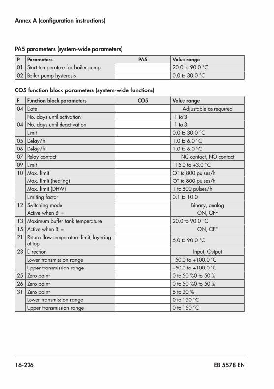
16-226 EB 5578 EN
Annex A (configuration instructions)
PA5 parameters (system-wide parameters)P Parameters PA5 Value range01 Start temperature for boiler pump 20.0to90.0 °C02 Boiler pump hysteresis 0.0to30.0 °C
CO5 function block parameters (system-wide functions)F Function block parameters CO5 Value range04 Date Adjustable as required
No. days until activation 1 to 304 No. days until deactivation 1 to 3
Limit 0.0to30.0 °C05 Delay/h 1.0to6.0 °C06 Delay/h 1.0to6.0 °C07 Relaycontact NC contact, NO contact09 Limit –15.0to+3.0 °C10 Max. limit OTto800pulses/h
Max. limit (heating) OTto800pulses/hMax. limit (DHW) 1to800 pulses/hLimiting factor 0.1 to 10.0
12 Switching mode Binary, analogActivewhenBI= ON, OFF
13 Maximum buffer tank temperature 20.0to90.0 °C15 ActivewhenBI= ON, OFF21 Returnflowtemperaturelimit,layering
at top 5.0to90.0 °C
23 Direction Input, OutputLower transmission range –50.0to+100.0 °CUpper transmission range –50.0to+100.0 °C
25 Zero point 0to50 %0to50 %26 Zero point 0to50 %0to50 %31 Zero point 5to20 %
Lower transmission range 0to150 °CUpper transmission range 0to150 °C

EB 5578 EN 16-227
Annex A (configuration instructions)
PA6 parameters (Modbus)P Parameters PA6 Value range01 Modbusstationaddress(8bit) 1 to 246
CO6 function block parameters (Modbus)F Function block parameters CO6 Value range10 Heat meter 1 address 0 to 255
HM 1 model 1434, CAL3, APAtO, SLSHeat meter 1 mode 24 h,Continuous,CoiLHeat meter 2 address 0 to 255HM 2 model 1434, CAL3, APAtO, SLSHeat meter 3 mode 24 h,Continuous,CoiLHeat meter 3 address 0 to 255HM 3 model 1434, CAL3, APAtO, SLSHeat meter 3 mode 24 h,Continuous,CoiL
11 Max. limit OTto650 m³/hMax. limit (heating) OTto650 m³/hMax. limit (DHW) 0.01to650 m³/hLimiting factor 0.1 to 10
12 Max. limit OTto6500 kWMax. limit (heating) OTto6500 kWMax. limit (DHW) 0.1to6500 kWLimiting factor 0.1 to 10
13 Max. limit 0.01to650 m³/hLimiting factor 0.1 to 10
14 Max. limit 0.1to6500 kWLimiting factor 0.1 to 10
15 Max. limit 0.01to650 m³/hLimiting factor 0.1 to 10
16 Max. limit 0.1to6500 kWLimiting factor 0.1 to 10

16-228 EB 5578 EN
Annex A (configuration instructions)
CO7 function block parameters (device bus)F Function block parameters CO7 Value range1 Device bus address Auto, 1 to 323 Device bus address Auto, 1 to 324 Device bus address Auto, 1 to 325 Device bus address Auto, 1 to 326 Registernumber 1 to 47 Registernumber 1 to 48 Registernumber 1 to 49 Registernumber 1 to 410 Registernumber 5 to 6511 Registernumber 5 to 6512 Registernumber 5 to 6513 Registernumber 5 to 6515 Registernumber 5 to 6517 Registernumber 5 to 6518 Registernumber 5 to 6519 Registernumber 5 to 6520 Registernumber 5 to 6521 Registernumber 5 to 6522 Registernumber 5 to 6523 Registernumber 5 to 65

EB 5578 EN 16-229
Annex A (configuration instructions)
CO8 function block parameters (initialization of BI1 and BI2)F Function block parameters CO8 Value range1 Error message when BI=0,BI=1,none(1)2 Error message when BI=0,BI=1,none(1)3 Error message when BI=0,BI=1,none(1)4 Error message when BI=0,BI=1,none(1)5 Error message when BI=0,BI=1,none(1)6 Error message when BI=0,BI=1,none(1)9 Error message when BI=0,BI=1,none(1)10 Error message when BI=0,BI=1,none(1)11 Error message when BI=0,BI=1,none(1)12 Error message when BI=0,BI=1,none(1)13 Error message when BI=0,BI=1,none(1)15 Error message when BI=0,BI=1,none(1)16 Error message when BI=0,BI=1,none(1)17 Error message when BI=0,BI=1,none(1)

16-230 EB 5578 EN
Annex A (configuration instructions)

EB 5578 EN 17-1
Annex B
17 Annex B
17.1 AccessoriesTROVISI/O(expansionmodule) Orderno.1000062999
Memory module Orderno.1400-9379
Mini module Order no. 1400-7436
Data logging module Orderno.1400-9378
USB converter 3 Orderno.1400-9377
TROVIS-VIEWsoftware(freeofcharge) u www.samsongroup.com>SERVICE&SUPPORT>Downloads>TROVIS-VIEW
RS-485communicationmodule Orderno.8812-2002
SurgearresterSA 5000 Orderno.1400-9868
SAMHOMEGateway Type 5660
SAMMOBILEGateway Type 5655
SAMLANGateway Type 5650

17-2 EB 5578 EN
Annex B
17.2 After-sales serviceAfter-sales serviceContact our after-sales service for support concerning service or repair work or when malfunctions or defects arise.Youcanreachourafter-salesserviceataftersalesservice@samsongroup.com .
Addresses of SAMSON AG and its subsid-iariesTheaddressesofSAMSONAG,itssubsid-iaries, representatives and service facilities worldwide can be found on our website (www.samsongroup.com) or in all SAMSON product catalogs.
Required specificationsPlease submit the following details: − Model number − Firmware version − Serial number

Key number 1732

2021
-11-
26 ·
Engl
ish
SAMSON AKTIENGESELLSCHAFTWeismüllerstraße 3 · 60314 Frankfurt am Main, GermanyPhone: +49 69 4009-0 · Fax: +49 69 [email protected] · www.samsongroup.com
EB 5578 EN