Industrial Gas Springs - Function, Calculation and Mounting Tips
59
-
Upload
khangminh22 -
Category
Documents
-
view
0 -
download
0
Transcript of Industrial Gas Springs - Function, Calculation and Mounting Tips

2ACE Controls Inc. • 800-521-3320 • (248) 476-0213 • Fax (248) 476-2470 • www.acecontrols.com • email: [email protected]
Gas springs are universally accepted, wherever you want to •push•pull• lift• lower, or •position covers, lids or other components by hand without using an external energy source.ACE gas springs are individually filled to a predetermined pressure to suit a custom-er’s requirement (extension Force F1). The cross-sectional area of the piston rod and filling pressure determines the extension force F = p*A. During the compression of the piston rod, nitrogen flows through an orifice in the piston. The nitrogen is compressed by the volume of the piston rod. As the piston rod is compressed the pressure increases, so increasing the reaction force (progression). The force depends on the proportional relationship between the piston rod and the inside tube diameter, which is approximately linear.
Force tolerance: ±7%Effect of temperature: An increase in temperature of each 50 °F (10 °C) will increase force by approx. 3.4 %.Temperature range: -4 °F (-20 °C) to 176 °F (+80 °C) – special seals from -49 °F (-45 °C) to 392 °F (200 °C)Mounting: The gas springs should ideally be installed with the piston rod pointing downwards to use the end damping during the extension stroke to smoothly decelerate the motion of the gas spring. Some ACE gas springs have a uniquely designed front bearing with an integrated grease chamber allowing the gas spring to be mounted and operated in any position if required. When fitting the gas springs ensure that the stroke is fully extended (GZ type fully compressed), this makes assembly and disassembly much easier. Support the moving mass/flap during assembly or disassembly to prevent accidents. To avoid twisting or side loading, it is recommended that ball joints or other pivoted mounting attachments are used. The mounting attachments must always be positively secured onto the threaded studs of the gas spring.
ACE gas springs are maintenance-free. DO NOT oil or grease the piston rod!The piston rod must be protected from any hits, scratches or dirt and especially paint. Damage to the surface finish of the piston rod will destroy the sealing system and cause loss of pressure. The outer body must not be deformed or mechanically damaged.ACE gas springs can be stored in any position. Experience has shown that long storage periods do not result in loss of pressure. However you may experience some “stiction” requiring a higher effort to move the gas spring for the first time after a long storage period.Generally, ACE gas springs are tested to 70,000 strokes. This is equivalent to the seal lifetime (depending on model size) to a distance travelled of 1.24 miles (2 km) up to 6.21 miles (10 km). Depending upon the application and operating environment, the service life of these gas springs may be much longer. 500,000 strokes or more have been achieved on some applications.Lifetime for traction gas springs see pages 34 to 37.
0.20(5)
0.20(5)
F 1
F 3
F 2
F 4
Total Stroke inches (mm)
F R
Stroke inch(mm)
Springforce
(N)lbs Outward StrokeInward Stroke
extension
0.20(5)
0.20(5)
F 1
F 3
F 2
F 4
Stroke inch(mm)
Springforce
(N)lbs
compressionF R
Total Stroke inches (mm)
F1 = nominal force at 68 °F (20 °C) – this is the pressure figure normally used when specifying the gas spring
F2 = force in the complete compressed position
F1 = nominal force at 68 °F (20 °C) this is the pressure figure normally used when specifying the gas spring
F2 = force in the complete extended position
When extending the piston rod, there is an additional friction force caused by the contact pressure of the seals (this only occurs during the extension stroke) FRF3 = force at the beginning of the extension strokeF4 = force at the end of the extension stroke
When compressing the piston rod, there is an additional friction force caused by the contact pressure of the seals (this only occurs during the compression stroke) FRF3 = force at the beginning of the compression strokeF4 = force at the end of the compression stroke
Force-Stroke Characteristics of Gas Spring (Push Type)
Force-Stroke Characteristics of Traction Gas Spring (Pull Type)
Service Life
Industrial Gas SpringsFunction, Calculation and Mounting Tips
Gas Springs (Push Type)Type 1 Progression
approx. %GS-8 28GS-10 20GS-12 25GS-15 27GS-19 36 - 42 3GS-22 39 - 50 3GS-28 60 - 95 3GS-40 47 - 53 3GS-70 25
Gas Springs (Push Type)Type 1 Progression
approx. %AGS-15 35AGS-19 37 - 41 2AGS-22 50 - 56 2AGS-28 48 - 52 2
Gas Springs (Pull Type)Type 1 Progression
approx. %GZ-15 23GZ-19 10GZ-28 20GZ-40 40
1 The progression (the slope of the force line in the diagrams above) is due to the reduction of the internal gas volume as the piston rod moves from its initial position to its fully stroked position. The approx. progression values given for standard springs can be altered on request. Effect of temperature: The nominal F1 figure is given at 68 °F(20 °C). An increase of 50 °F(10 °C) will increase force by 3.4%. Force tolerance on F1 force: ±7%
2 Depending on the filling force.3 Depending on the stroke.

3 ACE Controls Inc. • 800-521-3320 • (248) 476-0213 • Fax (248) 476-2470 • www.acecontrols.com • email: [email protected]
Doors open and close safely
Protection under the hood
ACE industrial gas springs make opening and closing doors of rescue helicopters easier. The maintenance-free, sealed systems are installed in the access doors of helicopters of the type EC 135. There, they allow the crew to enter or exit the helicopter quickly, thus contributing to en- hanced safety. The GS-19-300-CC gas springs provide a defined retraction speed and secure engagement of the door lock. The integrated end position damper allows gentle closing of the door and saves wear and tear on the valuable, lightweight material.
ACE industrial gas springs prevent injuries during maintenance work on harvesting machines. The blades of corn pickers are arranged under plastic hoods, which assure proper material flow within the machine. For maintenance purposes, the hoods, weighing about 15 lbs (7 kg), must be lifted up. To protect maintenance personnel from injury by falling hoods, they are kept in the open position by industrial gas springs of the type GS-22-250-DD. Another advantage they offer is their stability under rough operating conditions due to their wear-resistant coating on the piston rod and the coated housing.
Industrial gas springs: For safe entry and exit
Enhanced protection: Industrial gas springs secure heavy hoods
Industrial Gas SpringsApplication Examples
4ACE Controls Inc. • 800-521-3320 • (248) 476-0213 • Fax (248) 476-2470 • www.acecontrols.com • email: [email protected]
Industrial Gas SpringsApplication Examples
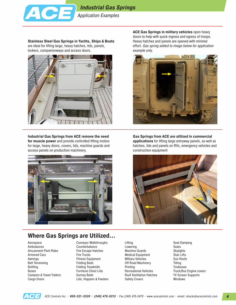
Stainless Steel Gas Springs in Yachts, Ships & Boats are ideal for lifting large, heavy hatches, lids, panels, lockers, companionways and access doors.
Industrial Gas Springs from ACE remove the need for muscle power and provide controlled lifting motion for large, heavy doors, covers, lids, machine guards and access panels on production machinery.
Where Gas Springs are Utilized…
ACE Gas Springs in military vehicles open heavy doors to help with quick ingress and egress of troops. Heavy hatches and panels are opened with minimal effort. Gas spring added to image below for application example only.
Gas Springs from ACE are utilized in commercial applications for lifting large entryway panels, as well as hatches, lids and panels on RVs, emergency vehicles and construction equipment
Aerospace Ambulances Amusement Park RidesArmored CarsAwningsBelt TensioningBottlingBusesCampers & Travel TrailersCargo Doors
Conveyor WalkthroughsCounterbalanceFire Escape HatchesFire TrucksFitness EquipmentFolding BedsFolding TreadmillsFurniture Chest LidsGurney BedsLids, Hoppers & Feeders
LiftingLoweringMachine GuardsMedical EquipmentMilitary VehiclesOff Road MachineryPrintingRecreational VehiclesRoof Ventilation HatchesSafety Covers
Seat DampingSeats SkylightsStair LiftsSun RoofsTiltingToolboxesTruck/Bus Engine coversTV Screen SupportsWindows
5 ACE Controls Inc. • 800-521-3320 • (248) 476-0213 • Fax (248) 476-2470 • www.acecontrols.com • email: [email protected]
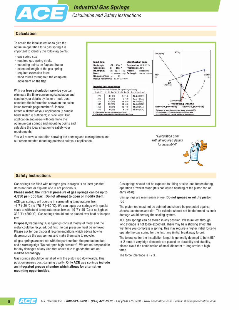
Calculation
Safety Instructions
Gas springs are filled with nitrogen gas. Nitrogen is an inert gas that does not burn or explode and is not poisonous. Please note!: the internal pressure of gas springs can be up to 4,350 psi (300 bar). Do not attempt to open or modify them. ACE gas springs will operate in surrounding temperatures from -4 °F (-20 °C) to 176 °F (+80 °C). We can equip our springs with special seals to withstand temperatures as low as -49 °F (-45 °C) or as high as 392 °F (+200 °C). Gas springs should not be placed over heat or in open fire! Disposal/Recycling: Gas Springs consist mostly of metal and the metal could be recycled, but first the gas pressure must be removed. Please ask for our disposal recommendations which advise how to depressurize the gas springs and make them safe to recycle.All gas springs are marked with the part number, the production date and a warning sign “Do not open high pressure”. We are not responsible for any damages of any kind that arises due to goods that are not marked accordingly. Gas springs should be installed with the piston rod downwards. This position ensures best damping quality. Only ACE gas springs include an integrated grease chamber which allows for alternative mounting opportunities.
“Calculation offer with all required details
for assembly!”
F1-F2/F3-F4=Hand forces for opening/closing Angle [°] F1-F2 lbs (N) F3-F4 lbs (N) length in. (mm)
270293317340363375
-3 (-13)8 (37)
13 (59)12 (53)
8 (34)6 (25)
-3 (-14)9 (42)
15 (68)14 (63)10 (44)
8 (34)
12.24 (311)12.71 (323)14.29 (363)16.46 (418)18.78 (477)19.84 (504)
26.46 lbs (12 kg)16.14” (410)
: 68 °F (20 °C): 42 %: 7 lbs (30 N): 19.84” (504 mm)
: 32.28” (820 mm)
To obtain the ideal selection to give the optimum operation for a gas spring it is important to identify the following points:•gas spring size • required gas spring stroke •mounting points on flap and frame •extended length of the gas spring • required extension force • hand forces throughout the complete
movement on the flap
With our free calculation service you can eliminate the time-consuming calculation and send us your details by fax or e-mail. Just complete the information shown on the calcu- lation formula page number 6. Please attach a sketch of your application (a simple hand sketch is sufficient) in side view. Our application engineers will determine the optimum gas springs and mounting points and calculate the ideal situation to satisfy your requirements.You will receive a quotation showing the opening and closing forces and our recommended mounting points to suit your application.
Industrial Gas SpringsCalculation and Safety Instructions
Gas springs should not be exposed to tilting or side load forces during operation or whilst static (this can cause bending of the piston rod or early wear).Gas springs are maintenance-free. Do not grease or oil the piston rod.The piston rod must not be painted and should be protected against shocks, scratches and dirt. The cylinder should not be deformed as such damage would destroy the sealing system. ACE gas springs can be stored in any position. Pressure lost through long storage is not to be expected. There may be a sticking effect the first time you compress a spring. This may require a higher initial force to operate the gas spring for the first time (initial breakaway force).The tolerance for the installation length is generally deemed to be ±.08" (± 2 mm). If very high demands are placed on durability and stability, please avoid the combination of small diameter + long stroke + high force. The force tolerance is ±7%.
6ACE Controls Inc. • 800-521-3320 • (248) 476-0213 • Fax (248) 476-2470 • www.acecontrols.com • email: [email protected]
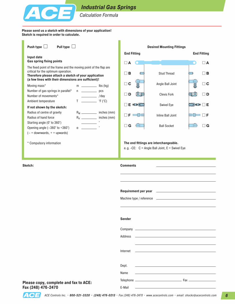
Please copy, complete and fax to ACE: Fax (248) 476-2470
Sketch:
The end fittings are interchangeable.e.g. -CE: C = Angle Ball Joint, E = Swivel Eye
Push type Pull type
Input date Gas spring fixing points
The fixed point of the frame and the moving point of the flap are critical for the optimum operation. Therefore please attach a sketch of your application (a few lines with their dimensions are sufficient)!
Moving mass* m lbs (kg)Number of gas springs in parallel* n pcsNumber of movements* /dayAmbient temperature T °F (°C)
If not shown by the sketch:Radius of centre of gravity RM inches (mm)Radius of hand force RH inches (mm)Starting angle (0° to 360°) °Opening angle (–360° to +360°) α °(– = downwards, + = upwards)
* Compulsory information
Please send us a sketch with dimensions of your application!Sketch is required in order to calculate.
A
B
C
D
E
F
G
A
B
C
D
E
F
G
Desired Mounting Fittings
End FittingEnd Fitting
Stud Thread
Angle Ball Joint
Clevis Fork
Swivel Eye
Inline Ball Joint
Ball Socket
Comments
Requirement per year
Machine type / reference
Sender
Company
Address
Internet
Dept.
Name
Telephone Fax
Industrial Gas SpringsCalculation Formula

7 ACE Controls Inc. • 800-521-3320 • (248) 476-0213 • Fax (248) 476-2470 • www.acecontrols.com • email: [email protected]
Industrial Gas Springs GS-8 to GS-70 (Push Type)
ACE industrial gas springs are mainte-nance-free and self-contained. They are avail- able with body diameters from .31" (8 mm) up to 2.76" (70 mm), and forces from 2 lbs (10 N) up to 2,923 lbs (13,000 N) ex. stock. ACE gas springs offer a high service life with a wear-resistant coating on the piston rod. Also an integrated low friction bearing with grease chamber which provides a very low break away force (GS-19 to GS-40). It allows them to be mounted in any orientation, although rod downwards is preferable if you want to take advantage of the built-in end position damping. The valve allows the force to be adjusted to your specific requirements. A wide variety of interchange-able end fittings makes installation easy and versatile. ACE gas springs are universally applicable wherever you have lifting and lowering. They remove the need for “muscle power” and provide controlled motion for lids, hoods, machine guards etc. The ACE selection software quickly specifies the correct gas spring for your individual application and we can deliver, usually within 24 hours.
Function: ACE industrial gas springs provide a maintenance-free sealed for life system, being filled with high pressure nitrogen gas. The oil zone filling provides end position damping and internal lubrication for a long lifetime. On the extension stroke of the gas spring, for example when opening a car tailgate, the nitrogen gas flows through the metering ori- fice in the piston to provide a controlled opening speed and the oil zone provides damping at the fully open position to avoid impact damage. The gas spring should be mounted “rod down” for this damping to be effective. On closing the tailgate the gas spring helps support the weight. The metering orifice controls the extension and compression velocities of the gas spring.Operating fluid: Nitrogen gas and oilMounting: In any positionOperating temperature range: -4 °F to +176 °F (-20 °C to +80 °C)On request: Without damping, extended length damping, special force curves, special lengths, alternative end fittings.
“Force adjustable to your specific requirements – with
gas valve ex. stock!”
Filled with High Pressure Nitrogen Gas
Precision Steel Tube
Metering Orifice for Controlled Extension and Compression Velocities
Integral Grease Chamber for Increased Lifetime
Piston Rod
Gas Valve
Oil Zone for End Position Damping and Lubrication (recommended mounting position: piston rod downwards)
8ACE Controls Inc. • 800-521-3320 • (248) 476-0213 • Fax (248) 476-2470 • www.acecontrols.com • email: [email protected]
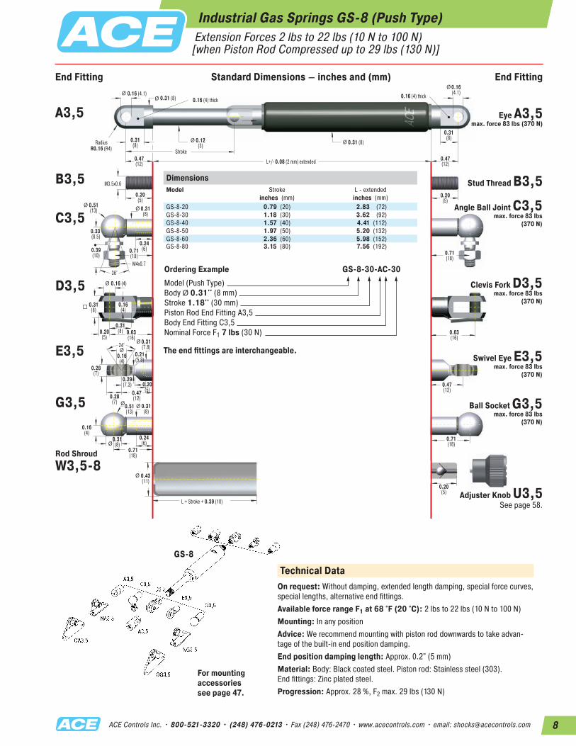
Industrial Gas Springs GS-8 (Push Type) Extension Forces 2 lbs to 22 lbs (10 N to 100 N)[when Piston Rod Compressed up to 29 lbs (130 N)]
24°
ØØ
0.20(5)
0.16 (4.1)0.16 (4) thick
0.16 (4) thick0.31 (8)
0.31 (8)
0.20(5)
M3.5x0.6
L+/- 0.08 (2 mm) extended
Stroke
RadiusR0.16 (R4)
L = Stroke + 0.39 (10)
ØØ
Ø
Ø Ø
ØØ
0.16 (4)Ø
Ø
Ø
M4x0.7
0.31(8)
0.51(13)
0.33(8.5)
0.31(8)
0.12(3)
0.24(6)0.71
(18) 0.71(18)
0.16(4)
0.31(8)
0.31(8)0.20
(5)
0.28(7)
0.16(4)
0.43(11)
0.28(7)
0.47(12)
0.47(12)
0.63(16)
0.63(16)
0.31(7.8)
0.21(5.3)
0.29(7.3)
0.16(4)
0.39(10)
36°
Ø Ø
0.20(5)
0.20(5)
0.51(13)
0.31(8)
0.31(8)
0.71(18)
0.71(18)
0.24(6)
0.47(12)
0.47(12)
0.16(4.1)
0.31(8)
DimensionsModel
Stroke inches (mm)
L - extended inches (mm)
GS-8-20 0.79 (20) 2.83 (72)GS-8-30 1.18 (30) 3.62 (92)GS-8-40 1.57 (40) 4.41 (112)GS-8-50 1.97 (50) 5.20 (132)GS-8-60 2.36 (60) 5.98 (152)GS-8-80 3.15 (80) 7.56 (192)
Ordering Example GS-8-30-AC-30Model (Push Type)Body Ø 0.31'' (8 mm)Stroke 1.18'' (30 mm)Piston Rod End Fitting A3,5Body End Fitting C3,5Nominal Force F1 7 lbs (30 N)
The end fittings are interchangeable.
A3,5 Eye A3,5 max. force 83 lbs (370 N)
B3,5 Stud Thread B3,5
C3,5Angle Ball Joint C3,5
max. force 83 lbs (370 N)
D3,5 Clevis Fork D3,5 max. force 83 lbs
(370 N)
E3,5 Swivel Eye E3,5 max. force 83 lbs
(370 N)
G3,5 Ball Socket G3,5 max. force 83 lbs
(370 N)
Rod ShroudW3,5-8
Adjuster Knob U3,5 See page 58.
GS-8
For mounting accessories see page 47.
Technical DataOn request: Without damping, extended length damping, special force curves, special lengths, alternative end fittings.Available force range F1 at 68 °F (20 °C): 2 lbs to 22 lbs (10 N to 100 N)Mounting: In any positionAdvice: We recommend mounting with piston rod downwards to take advan-tage of the built-in end position damping.End position damping length: Approx. 0.2" (5 mm)Material: Body: Black coated steel. Piston rod: Stainless steel (303). End fittings: Zinc plated steel.Progression: Approx. 28 %, F2 max. 29 lbs (130 N)
End Fitting Standard Dimensions – inches and (mm) End Fitting
9 ACE Controls Inc. • 800-521-3320 • (248) 476-0213 • Fax (248) 476-2470 • www.acecontrols.com • email: [email protected]
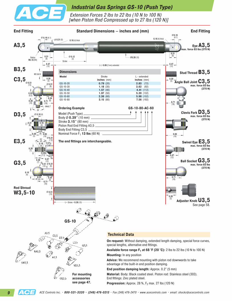
Industrial Gas Springs GS-10 (Push Type) Extension Forces 2 lbs to 22 lbs (10 N to 100 N)[when Piston Rod Compressed up to 27 lbs (120 N)]
24°
ØØ
0.20(5)
0.16 (4.1)0.16 (4) thick
0.16 (4) thick0.31 (8)
0.39 (10)
0.20(5)
M3.5x0.6
L+/- 0.08 (2 mm) extended
Stroke
RadiusR0.16 (R4)
L = Stroke + 0.39 (10)
ØØ
Ø
Ø Ø
ØØ
0.16 (4)Ø
Ø
Ø
M4x0.7
0.31(8)
0.51(13)
0.33(8.5)
0.31(8)
0.12(3)
0.24(6)0.71
(18) 0.71(18)
0.16(4)
0.31(8)
0.31(8)0.20
(5)
0.28(7)
0.16(4)
0.51(13)
0.28(7)
0.47(12)
0.47(12)
0.63(16)
0.63(16)
0.31(7.8)
0.21(5.3)
0.29(7.3)
0.16(4)
0.39(10)
36°
Ø Ø
0.20(5)
0.20(5)
0.51(13)
0.31(8)
0.31(8)
0.71(18)
0.71(18)
0.24(6)
0.47(12)
0.47(12)
0.16(4.1)
0.31(8)
Ordering Example GS-10-80-AC-60Model (Push Type)Body Ø 0.39'' (10 mm)Stroke 3.15'' (80 mm)Piston Rod End Fitting A3,5Body End Fitting C3,5Nominal Force F1 13 lbs (60 N)
The end fittings are interchangeable.
A3,5 Eye A3,5 max. force 83 lbs (370 N)
B3,5Stud Thread B3,5
C3,5 Angle Ball Joint C3,5 max. force 83 lbs
(370 N)
D3,5 Clevis Fork D3,5 max. force 83 lbs
(370 N)
E3,5 Swivel Eye E3,5 max. force 83 lbs
(370 N)
G3,5 Ball Socket G3,5 max. force 83 lbs
(370 N)
Rod ShroudW3,5-10
Adjuster Knob U3,5 See page 58.
GS-10
For mounting accessories see page 47.
DimensionsModel
Stroke inches (mm)
L - extended inches (mm)
GS-10-20 0.79 (20) 2.83 (72)GS-10-30 1.18 (30) 3.62 (92)GS-10-40 1.57 (40) 4.41 (112)GS-10-50 1.97 (50) 5.20 (132)GS-10-60 2.36 (60) 5.98 (152)GS-10-80 3.15 (80) 7.56 (192)
Technical DataOn request: Without damping, extended length damping, special force curves, special lengths, alternative end fittings.Available force range F1 at 68 °F (20 °C): 2 lbs to 22 lbs (10 N to 100 N)Mounting: In any positionAdvice: We recommend mounting with piston rod downwards to take advantage of the built-in end position damping.End position damping length: Approx. 0.2" (5 mm)Material: Body: Black coated steel. Piston rod: Stainless steel (303). End fittings: Zinc plated steel.Progression: Approx. 28 %, F2 max. 27 lbs (120 N)
End Fitting Standard Dimensions – inches and (mm) End Fitting
10ACE Controls Inc. • 800-521-3320 • (248) 476-0213 • Fax (248) 476-2470 • www.acecontrols.com • email: [email protected]
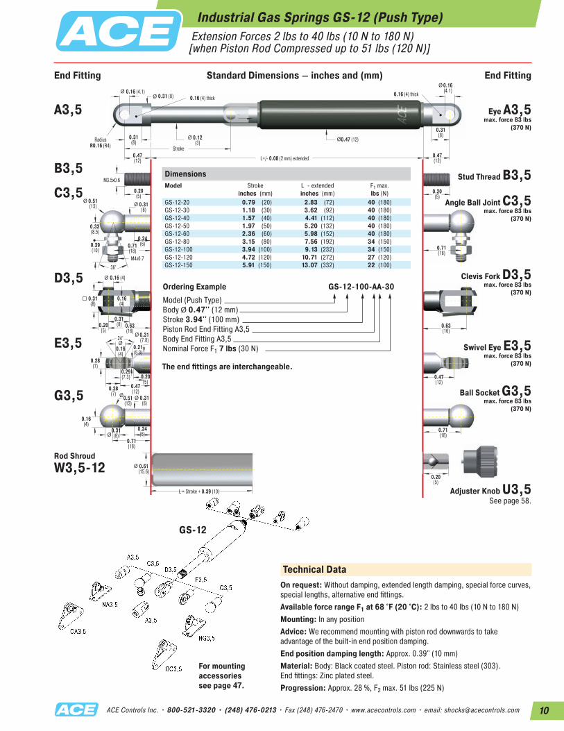
Extension Forces 2 lbs to 40 lbs (10 N to 180 N)[when Piston Rod Compressed up to 51 lbs (120 N)]
Industrial Gas Springs GS-12 (Push Type)
24°
ØØ
0.20(5)
0.16 (4.1)0.16 (4) thick
0.16 (4) thick0.31 (8)
0.47 (12)
0.20(5)
M3.5x0.6
L+/- 0.08 (2 mm) extended
Stroke
RadiusR0.16 (R4)
L = Stroke + 0.39 (10)
ØØ
Ø
Ø Ø
ØØ
0.16 (4)Ø
Ø
Ø
M4x0.7
0.31(8)
0.51(13)
0.33(8.5)
0.31(8)
0.12(3)
0.24(6)0.71
(18) 0.71(18)
0.16(4)
0.31(8)
0.31(8)0.20
(5)
0.28(7)
0.16(4)
0.61(15.6)
0.28(7)
0.47(12)
0.47(12)
0.63(16)
0.63(16)
0.31(7.8)
0.21(5.3)
0.29(7.3)
0.16(4)
0.39(10)
36°
Ø Ø
0.20(5)
0.20(5)
0.51(13)
0.31(8)
0.31(8)
0.71(18)
0.71(18)
0.24(6)
0.47(12)
0.47(12)
0.16(4.1)
0.31(8)
DimensionsModel
Stroke inches (mm)
L - extendedinches (mm)
F1 max. lbs (N)
GS-12-20 0.79 (20) 2.83 (72) 40 (180)GS-12-30 1.18 (30) 3.62 (92) 40 (180)GS-12-40 1.57 (40) 4.41 (112) 40 (180)GS-12-50 1.97 (50) 5.20 (132) 40 (180)GS-12-60 2.36 (60) 5.98 (152) 40 (180)GS-12-80 3.15 (80) 7.56 (192) 34 (150)GS-12-100 3.94 (100) 9.13 (232) 34 (150)GS-12-120 4.72 (120) 10.71 (272) 27 (120)GS-12-150 5.91 (150) 13.07 (332) 22 (100)
Ordering Example GS-12-100-AA-30Model (Push Type)Body Ø 0.47'' (12 mm)Stroke 3.94'' (100 mm)Piston Rod End Fitting A3,5Body End Fitting A3,5Nominal Force F1 7 lbs (30 N)
The end fittings are interchangeable.
A3,5 Eye A3,5 max. force 83 lbs
(370 N)
B3,5Stud Thread B3,5
C3,5Angle Ball Joint C3,5
max. force 83 lbs (370 N)
D3,5 Clevis Fork D3,5 max. force 83 lbs
(370 N)
E3,5 Swivel Eye E3,5 max. force 83 lbs
(370 N)
G3,5 Ball Socket G3,5 max. force 83 lbs
(370 N)
Rod ShroudW3,5-12
Adjuster Knob U3,5 See page 58.
GS-12
For mounting accessories see page 47.
Technical DataOn request: Without damping, extended length damping, special force curves, special lengths, alternative end fittings.Available force range F1 at 68 °F (20 °C): 2 lbs to 40 lbs (10 N to 180 N)Mounting: In any positionAdvice: We recommend mounting with piston rod downwards to take advantage of the built-in end position damping.End position damping length: Approx. 0.39" (10 mm)Material: Body: Black coated steel. Piston rod: Stainless steel (303). End fittings: Zinc plated steel.Progression: Approx. 28 %, F2 max. 51 lbs (225 N)
End Fitting Standard Dimensions – inches and (mm) End Fitting
11 ACE Controls Inc. • 800-521-3320 • (248) 476-0213 • Fax (248) 476-2470 • www.acecontrols.com • email: [email protected]
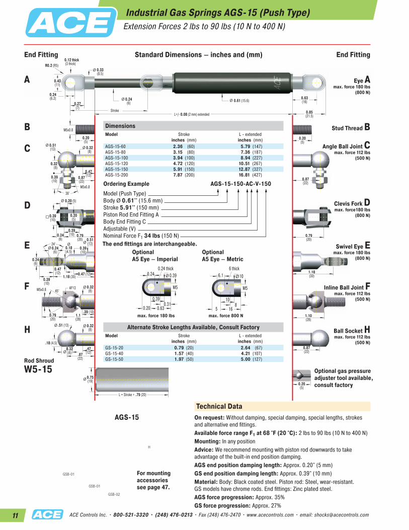
Industrial Gas Springs AGS-15 (Push Type)
24°
ØØ
0.20(5)
0.24(6.2)
0.24 (6) thick
0.33(8.5)
0.61 (15.6)
0.20(5)
M5x0.8
L+/- 0.08 (2 mm) extendedStroke
R0.2 (R5) 0.12 thick (3 thick)
Ø
Ø Ø
Ø
0.20 (5)Ø
Ø
M5x0.8
0.32(8)
0.51(13)
0.32(8)
0.27(7)
0.24(6)
0.47(12)
0.47(12)
0.87(22) 0.87
(22)
0.20(5)
0.39(10)
0.39(10)
0.39(10)
0.24(6)
0.24(6)
0.24(6)
1.18 (30)
.39 (10)
.18 (4.5)
1.18(30)
0.79(20)
0.79(20)0.51
(13)0.39(10)
0.18(4.5)
0.39(10)
36°
Ø Ø
0.47 (12)
0.87(22)
0.20(5)
0.32(8)
Ø 0.32(8)
0.75(19)
0.32(8)
0.79(20)
1.1(28)
.47(12).87
(22)
1.10(28)
0.63(16)
0.43(11)
0.85(21.5)
0.63(16)
0.24(6.1)
0.39(10)
Ø
M5x0.8 45°AF13
.51 (13)
L = Stroke + .79 (20)
Ø
Ø
Ø
DimensionsModel
Stroke inches (mm)
L - extendedinches (mm)
AGS-15-60 2.36 (60) 5.79 (147)AGS-15-80 3.15 (80) 7.36 (187)AGS-15-100 3.94 (100) 8.94 (227)AGS-15-120 4.72 (120) 10.51 (267)AGS-15-150 5.91 (150) 12.87 (327)AGS-15-200 7.87 (200) 16.81 (427)
Alternate Stroke Lengths Available, Consult FactoryModel
Stroke inches (mm)
L - extendedinches (mm)
GS-15-20 0.79 (20) 2.64 (67)GS-15-40 1.57 (40) 4.21 (107)GS-15-50 1.97 (50) 5.00 (127)
Ordering Example AGS-15-150-AC-V-150Model (Push Type)Body Ø 0.61'' (15.6 mm)Stroke 5.91'' (150 mm)Piston Rod End Fitting ABody End Fitting CAdjustable (V)Nominal Force F1 34 lbs (150 N)The end fittings are interchangeable.
Technical DataOn request: Without damping, special damping, special lengths, strokes and alternative end fittings.Available force range F1 at 68 °F (20 °C): 2 lbs to 90 lbs (10 N to 400 N)Mounting: In any positionAdvice: We recommend mounting with piston rod downwards to take advantage of the built-in end position damping.AGS end position damping length: Approx. 0.20" (5 mm)GS end position damping length: Approx. 0.39" (10 mm)Material: Body: Black coated steel. Piston rod: Steel, wear-resistant. GS models have chrome rods. End fittings: Zinc plated steel.AGS force progression: Approx. 35%GS force progression: Approx. 27%
A Eye A max. force 180 lbs
(800 N)
B Stud Thread B
C Angle Ball Joint C max. force 112 lbs
(500 N)
D Clevis Fork D max. force180 lbs
(800 N)
E Swivel Eye E max. force 180 lbs
(800 N)
F Inline Ball Joint F max. force 112 lbs
(500 N)
H Ball Socket H max. force 112 lbs
(500 N)
Rod ShroudW5-15 Optional gas pressure
adjuster tool available, consult factory
AGS-15
Extension Forces 2 lbs to 90 lbs (10 N to 400 N)
GSB-01
GSB-02
H
GSB-01 For mounting accessories see page 47.
10
16
6.16 thick
M5
85
10Ø
max. force 800 N
OptionalA5 Eye – Metric
OptionalA5 Eye – Imperial
0.39
0.63
0.240.24 thick
M5
0.310.20
0.39Ø
max. force 180 lbs
End Fitting Standard Dimensions – inches and (mm) End Fitting
12ACE Controls Inc. • 800-521-3320 • (248) 476-0213 • Fax (248) 476-2470 • www.acecontrols.com • email: [email protected]
C
GSB-06
GSB-03
GSB-03
GSB-04
GSB-05
H
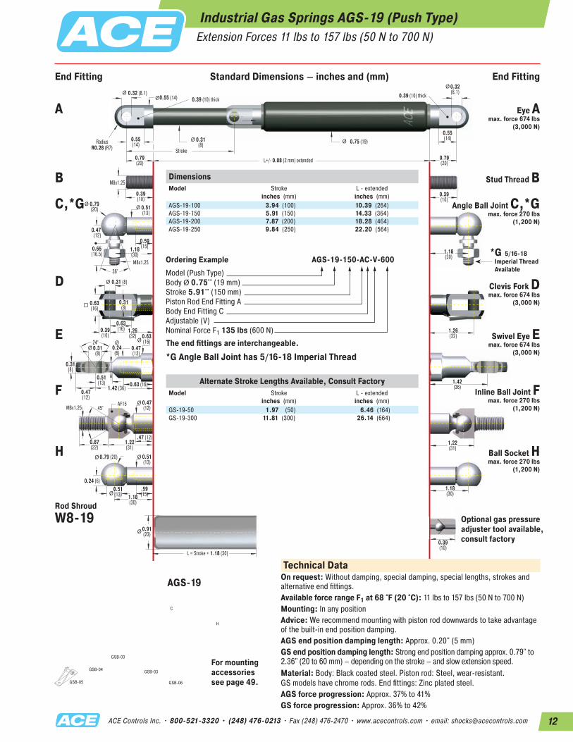
Industrial Gas Springs AGS-19 (Push Type) Extension Forces 11 lbs to 157 lbs (50 N to 700 N)
24°
ØØ
0.39(10)
0.32 (8.1)0.39 (10) thick
0.39 (10) thick0.55 (14)
0.75 (19)
0.39(10)
M8x1.25
L+/- 0.08 (2 mm) extended
Stroke
RadiusR0.28 (R7)
Ø
Ø Ø
ØØ
0.31 (8)Ø
Ø
M8x1.25
0.51(13)
0.79(20)
0.47(12)
0.55(14)
0.31(8)
0.59(15)
0.51(13)
1.18(30) 1.18
(30)
0.31(8)
0.63(16)
0.63(16)
0.47(12)
0.39(10)
0.31(8)
0.31(8)
1.42 (36)
.47 (12)
0.24 (6)
1.42(36)
1.26(32)
1.26(32)0.63
(16)0.47(12)
0.24(6)
0.65(16.5)
36°
Ø Ø
0.63 (16)
1.18(30)
0.39(10)
0.47(12)
Ø 0.51(13)
0.91(23)
0.51(13)
0.87(22)
1.22(31)
.59(15)1.18
(30)
1.22(31)
0.79(20)
0.79(20)
0.32(8.1)
0.55(14)
Ø
M8x1.25 45°AF15
0.79 (20)
L = Stroke + 1.18 (30)
Ø
Ø
Ø
DimensionsModel
Stroke inches (mm)
L - extended inches (mm)
AGS-19-100 3.94 (100) 10.39 (264)AGS-19-150 5.91 (150) 14.33 (364)AGS-19-200 7.87 (200) 18.28 (464)AGS-19-250 9.84 (250) 22.20 (564)
Ordering Example AGS-19-150-AC-V-600Model (Push Type)Body Ø 0.75'' (19 mm)Stroke 5.91'' (150 mm)Piston Rod End Fitting ABody End Fitting CAdjustable (V)Nominal Force F1 135 lbs (600 N)
The end fittings are interchangeable.
A Eye A max. force 674 lbs
(3,000 N)
B Stud Thread B
C,*G Angle Ball Joint C,*G max. force 270 lbs
(1,200 N)
D Clevis Fork D max. force 674 lbs
(3,000 N)
E Swivel Eye E max. force 674 lbs
(3,000 N)
F Inline Ball Joint F max. force 270 lbs
(1,200 N)
H Ball Socket H max. force 270 lbs
(1,200 N)
Rod Shroud W8-19
AGS-19
For mounting accessories see page 49.
Technical DataOn request: Without damping, special damping, special lengths, strokes and alternative end fittings.Available force range F1 at 68 °F (20 °C): 11 lbs to 157 lbs (50 N to 700 N)Mounting: In any positionAdvice: We recommend mounting with piston rod downwards to take advantage of the built-in end position damping.AGS end position damping length: Approx. 0.20" (5 mm)GS end position damping length: Strong end position damping approx. 0.79" to 2.36" (20 to 60 mm) – depending on the stroke – and slow extension speed.Material: Body: Black coated steel. Piston rod: Steel, wear-resistant. GS models have chrome rods. End fittings: Zinc plated steel.AGS force progression: Approx. 37% to 41%GS force progression: Approx. 36% to 42%
* G 5/16-18 Imperial Thread Available
* G Angle Ball Joint has 5/16-18 Imperial Thread
End Fitting Standard Dimensions – inches and (mm) End Fitting
Alternate Stroke Lengths Available, Consult FactoryModel
Stroke inches (mm)
L - extendedinches (mm)
GS-19-50 1.97 (50) 6.46 (164)GS-19-300 11.81 (300) 26.14 (664)
Optional gas pressureadjuster tool available, consult factory
13 ACE Controls Inc. • 800-521-3320 • (248) 476-0213 • Fax (248) 476-2470 • www.acecontrols.com • email: [email protected]
C
GSB-06
GSB-03
GSB-03
GSB-04
GSB-05
H
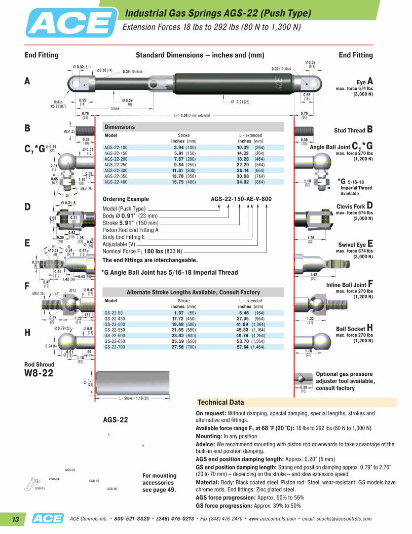
Industrial Gas Springs AGS-22 (Push Type) Extension Forces 18 lbs to 292 lbs (80 N to 1,300 N)
24°
ØØ
0.39(10)
0.32 (8.1)0.39 (10) thick
0.39 (10) thick0.55 (14)
0.91 (23)
0.39(10)
M8x1.25
L+/- 0.08 (2 mm) extended
Stroke
RadiusR0.28 (R7)
Ø
Ø Ø
ØØ
0.31 (8)Ø
Ø
M8x1.25
0.51(13)
0.79(20)
0.47(12)
0.55(14)
0.39(10)
0.59(15)
0.51(13)
1.18(30) 1.18
(30)
0.31(8)
0.63(16)
0.63(16)
0.47(12)
0.39(10)
0.31(8)
0.31(8)
1.42 (36)
.47 (12)
0.24 (6)
1.42(36)
1.26(32)
1.26(32)0.63
(16)0.47(12)
0.24(6)
0.65(16.5)
36°
Ø Ø
0.63 (16)
1.18(30)
0.39(10)
0.47(12)
Ø 0.51(13)
1.1(28)
0.51(13)
0.87(22)
1.22(31)
.59(15)1.18
(30)
1.22(31)
0.79(20)
0.79(20)
0.32(8.1)
0.55(14)
Ø
M8x1.25 45°AF13
0.79 (20)
L = Stroke + 1.18 (30)
Ø
Ø
Ø
DimensionsModel
Stroke inches (mm)
L - extendedinches (mm)
AGS-22-100 3.94 (100) 10.39 (264)AGS-22-150 5.91 (150) 14.33 (364)AGS-22-200 7.87 (200) 18.28 (464)AGS-22-250 9.84 (250) 22.20 (564)AGS-22-300 11.81 (300) 26.14 (664)AGS-22-350 13.78 (350) 30.08 (764)AGS-22-400 15.75 (400) 34.02 (864)
Ordering Example AGS-22-150-AE-V-800Model (Push Type)Body Ø 0.91'' (23 mm)Stroke 5.91'' (150 mm)Piston Rod End Fitting ABody End Fitting EAdjustable (V)Nominal Force F1 180 lbs (800 N)The end fittings are interchangeable.
A
B
C,*G
D
E
F
H
Rod ShroudW8-22
AGS-22
For mounting accessories see page 49.
Eye A max. force 674 lbs
(3,000 N)
Stud Thread B Angle Ball Joint C,*G
max. force 270 lbs (1,200 N)
Clevis Fork D max. force 674 lbs
(3,000 N)
Swivel Eye E max. force 674 lbs
(3,000 N)
Inline Ball Joint F max. force 270 lbs
(1,200 N)
Ball Socket H max. force 270 lbs
(1,200 N)
* G 5/16-18 Imperial Thread Available
* G Angle Ball Joint has 5/16-18 Imperial Thread
End Fitting Standard Dimensions – inches and (mm) End Fitting
Alternate Stroke Lengths Available, Consult FactoryModel
Stroke inches (mm)
L - extendedinches (mm)
GS-22-50 1.97 (50) 6.46 (164)GS-22-450 17.72 (450) 37.95 (964)GS-22-500 19.69 (500) 41.89 (1,064)GS-22-550 21.65 (550) 45.83 (1,164)GS-22-600 23.62 (600) 49.76 (1,264)GS-22-650 25.59 (650) 53.70 (1,364)GS-22-700 27.56 (700) 57.64 (1,464)
Optional gas pressureadjuster tool available, consult factory
Technical DataOn request: Without damping, special damping, special lengths, strokes and alternative end fittings.Available force range F1 at 68 °F (20 °C): 18 lbs to 292 lbs (80 N to 1,300 N)Mounting: In any positionAdvice: We recommend mounting with piston rod downwards to take advantage of the built-in end position damping.AGS end position damping length: Approx. 0.20" (5 mm)GS end position damping length: Strong end position damping approx. 0.79" to 2.76" (20 to 70 mm) – depending on the stroke – and slow extension speed.Material: Body: Black coated steel. Piston rod: Steel, wear-resistant. GS models have chrome rods. End fittings: Zinc plated steel.AGS force progression: Approx. 50% to 56%GS force progression: Approx. 39% to 50%
14ACE Controls Inc. • 800-521-3320 • (248) 476-0213 • Fax (248) 476-2470 • www.acecontrols.com • email: [email protected]
GSB-05
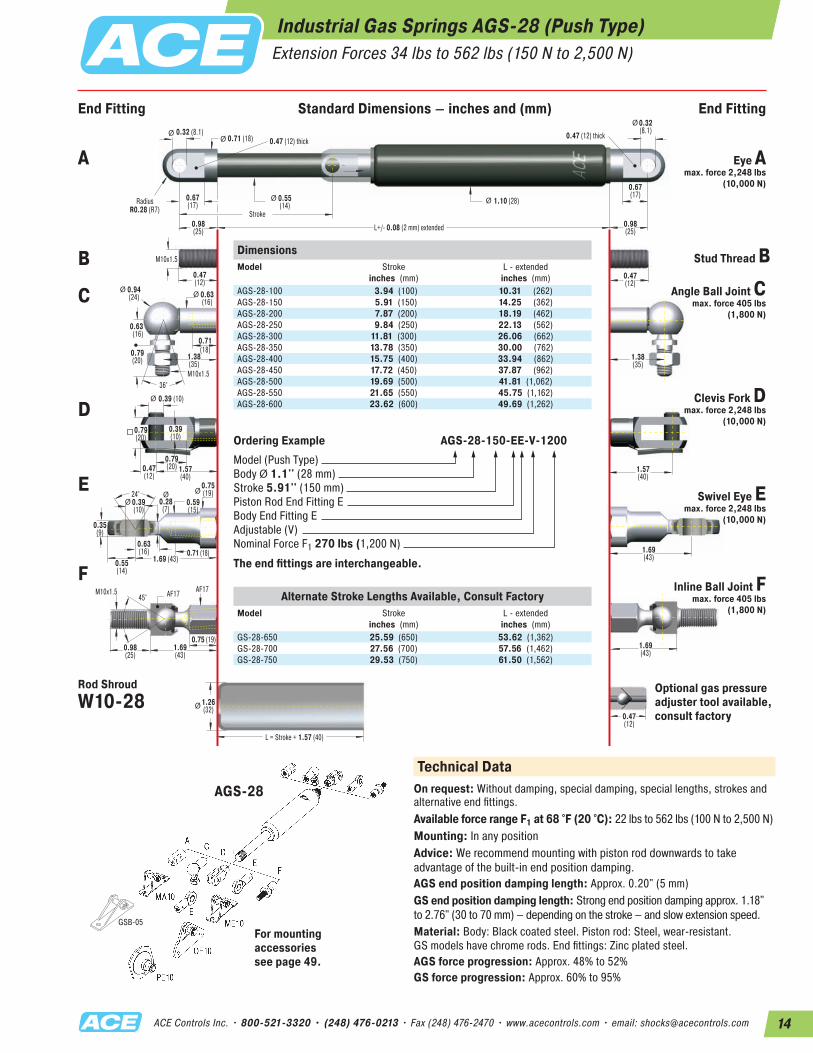
Industrial Gas Springs AGS-28 (Push Type) Extension Forces 34 lbs to 562 lbs (150 N to 2,500 N)
24°
ØØ
0.47(12)
0.32 (8.1)0.47 (12) thick
0.47 (12) thick0.71 (18)
1.10 (28)
0.47(12)
M10x1.5
L+/- 0.08 (2 mm) extended
Stroke
RadiusR0.28 (R7)
Ø Ø
ØØ
0.39 (10)Ø
Ø
M10x1.5
0.63(16)
0.94(24)
0.63(16)
0.67(17)
0.55(14)
0.71(18)
0.63(16)
1.38(35)
1.38(35)
0.39(10)
0.79(20)
0.79(20)
0.55(14)
0.47(12)
0.39(10)
0.35(9)
1.69 (43)
0.75 (19)
1.69(43)
1.57(40)
1.57(40)
0.75(19)
0.59(15)
0.28(7)
0.79(20)
36°
Ø Ø
0.71 (18)
0.47(12)
1.26(32)
0.98(25)
1.69(43)
1.69(43)
0.98(25)
0.98(25)
0.32(8.1)
0.67(17)
Ø
M10x1.545° AF17 AF17
L = Stroke + 1.57 (40)
Ø
DimensionsModel
Stroke inches (mm)
L - extendedinches (mm)
AGS-28-100 3.94 (100) 10.31 (262)AGS-28-150 5.91 (150) 14.25 (362)AGS-28-200 7.87 (200) 18.19 (462)AGS-28-250 9.84 (250) 22.13 (562)AGS-28-300 11.81 (300) 26.06 (662)AGS-28-350 13.78 (350) 30.00 (762)AGS-28-400 15.75 (400) 33.94 (862)AGS-28-450 17.72 (450) 37.87 (962)AGS-28-500 19.69 (500) 41.81 (1,062)AGS-28-550 21.65 (550) 45.75 (1,162)AGS-28-600 23.62 (600) 49.69 (1,262)
Ordering Example AGS-28-150-EE-V-1200Model (Push Type)Body Ø 1.1'' (28 mm)Stroke 5.91'' (150 mm)Piston Rod End Fitting EBody End Fitting EAdjustable (V)Nominal Force F1 270 lbs (1,200 N)
The end fittings are interchangeable.
Technical DataOn request: Without damping, special damping, special lengths, strokes and alternative end fittings.Available force range F1 at 68 °F (20 °C): 22 lbs to 562 lbs (100 N to 2,500 N)Mounting: In any positionAdvice: We recommend mounting with piston rod downwards to take advantage of the built-in end position damping.AGS end position damping length: Approx. 0.20" (5 mm)GS end position damping length: Strong end position damping approx. 1.18" to 2.76" (30 to 70 mm) – depending on the stroke – and slow extension speed.Material: Body: Black coated steel. Piston rod: Steel, wear-resistant. GS models have chrome rods. End fittings: Zinc plated steel.AGS force progression: Approx. 48% to 52%GS force progression: Approx. 60% to 95%
A Eye A max. force 2,248 lbs
(10,000 N)
B Stud Thread B
C Angle Ball Joint C max. force 405 lbs
(1,800 N)
DClevis Fork D
max. force 2,248 lbs (10,000 N)
ESwivel Eye E
max. force 2,248 lbs (10,000 N)
FInline Ball Joint F
max. force 405 lbs (1,800 N)
Rod ShroudW10-28
AGS-28
For mounting accessories see page 49.
End Fitting Standard Dimensions – inches and (mm) End Fitting
Alternate Stroke Lengths Available, Consult FactoryModel
Stroke inches (mm)
L - extendedinches (mm)
GS-28-650 25.59 (650) 53.62 (1,362)GS-28-700 27.56 (700) 57.56 (1,462)GS-28-750 29.53 (750) 61.50 (1,562)
Optional gas pressureadjuster tool available, consult factory

15 ACE Controls Inc. • 800-521-3320 • (248) 476-0213 • Fax (248) 476-2470 • www.acecontrols.com • email: [email protected]
Industrial Gas Springs GS-40 (Push Type) Extension Forces 112 lbs to 1,124 lbs (500 N to 5,000 N) [when Piston Rod Compressed up to 1,720 lbs (7,650 N)]
1.06(27)
30°
Ø
0.56 (14.1)0.55 (14) thick
0.55 (14) thick0.98 (25)
1.57 (40)
0.59(15)
L+/- 0.08 (2 mm) extended
Stroke
RadiusR0.49 (R12.5)
Ø Ø
ØØ
0.55 (14)Ø
Ø
M14x1.5
0.87(22)
0.59(15)
1.18(30)
0.79(20)
0.83(21)
0.79(20)
0.98(25)
0.71(18)
1.77(45) 1.77
(45)
0.55(14)
1.06(27)
0.71(18)
0.63(16)
0.55(14)
0.75(19)
2.24 (57)
.22 (56)
2.24(57)
2.2(56)
0.51(13)
2.2(56)
1.02(26)
Ø .79(20)
1.1(28)
36°
Ø Ø
1.18 (30)
0.59(15)
1.77(45)
1.57(40)
2.2(56)
1.57(40)
1.57(40)
0.56(14.1)
0.83(21)
Ø
L = Stroke + 1.57 (40)
Ø
.71 (18)
AF2430°M14x1.5 AF22
M14x1.5DimensionsModel
Stroke inches (mm)
L - extendedinches (mm)
GS-40-100 3.94 (100) 12.48 (317)GS-40-150 5.91 (150) 16.42 (417)GS-40-200 7.87 (200) 20.35 (517)GS-40-300 11.81 (300) 28.23 (717)GS-40-400 15.75 (400) 36.10 (917)GS-40-500 19.69 (500) 43.98 (1,117)GS-40-600 23.62 (600) 51.85 (1,317)GS-40-800 31.50 (800) 67.60 (1,717)GS-40-1000 39.37 (1,000) 83.35 (2,117)
Ordering Example AGS-40-150-DD-3500Model (Push Type)Body Ø 1.57# # (40 mm)Stroke 5.91# # (150 mm)Piston Rod End Fitting D14Body End Fitting D14Nominal Force F1 787 lbs (3,500 N)
The end fittings are interchangeable.
Technical DataOn request: Without damping, standard length damping, special force curves, special lengths, alternative end fittings, wiper, stainless steel (see pages 27 & 32).Available force range F1 at 68 °F (20 °C): 112 lbs to 1,124 lbs (500 N to 5,000 N)Mounting: In any positionAdvice: We recommend mounting with piston rod downwards to take advantage of the built-in end position damping.End position damping length: Strong end position damping approx. 1.18" to 2.76" (30 to 70 mm) – depending on the stroke – and slow extension speed.Material: Body: Black coated steel. Piston rod: With wear-resistant coating. End fittings: Zinc plated steel.Progression: Approx. 47 % to 53%, F2 max. 1,720 lbs (7,650 N)
A Eye A max. force 2,248 lbs
(10,000 N)
B Stud Thread B
C Angle Ball Joint C max. force 674 lbs
(3,000 N)
D Clevis Fork D max. force 2,248 lbs
(10,000 N)
E Swivel Eye E max. force 2,248 lbs
(10,000 N)
F Inline Ball Joint F max. force 719 lbs
(3,200 N)
Rod ShroudW14-40
Adjuster Knob U14 See page 58.
GS-40
For mounting accessories see page 51.
End Fitting Standard Dimensions – inches and (mm) End Fitting
16ACE Controls Inc. • 800-521-3320 • (248) 476-0213 • Fax (248) 476-2470 • www.acecontrols.com • email: [email protected]
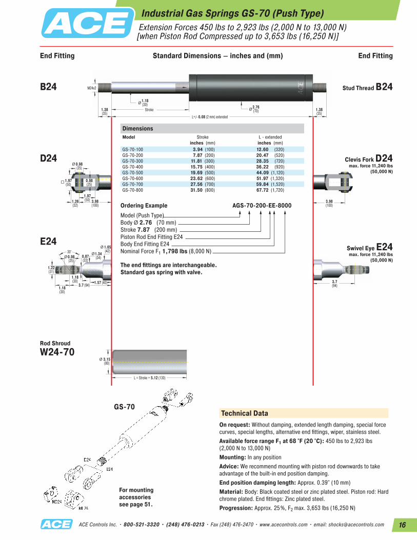
Industrial Gas Springs GS-70 (Push Type) Extension Forces 450 lbs to 2,923 lbs (2,000 N to 13,000 N) [when Piston Rod Compressed up to 3,653 lbs (16,250 N)]
Stroke
L = Stroke + 5.12 (130)
Ø
Ø
Ø
30°
Ø
Ø
M24x2
3.7 (94) 1.57 (40)1.18(30)
1.65(42)
Ø 0.98(25)
0.98(25)
1.38(35)
1.38(35)
1.18(30) 2.76
(70)
3.98(100)
3.98(100)
3.7(94)
1.97(50)1.26
(32)
1.97(50)
0.87(22)
0.98(25)
Ø1.34(34)
1.18(30)
1.22(31)
3.15(80)
L+/- 0.08 (2 mm) extended
DimensionsModel
Stroke inches (mm)
L - extendedinches (mm)
GS-70-100 3.94 (100) 12.60 (320)GS-70-200 7.87 (200) 20.47 (520)GS-70-300 11.81 (300) 28.35 (720)GS-70-400 15.75 (400) 36.22 (920)GS-70-500 19.69 (500) 44.09 (1,120)GS-70-600 23.62 (600) 51.97 (1,320)GS-70-700 27.56 (700) 59.84 (1,520)GS-70-800 31.50 (800) 67.72 (1,720)
Ordering Example AGS-70-200-EE-8000Model (Push Type)Body Ø 2.76# # (70 mm)Stroke 7.87# # (200 mm)Piston Rod End Fitting E24Body End Fitting E24Nominal Force F1 1,798 lbs (8,000 N)
The end fittings are interchangeable. Standard gas spring with valve.
Technical DataOn request: Without damping, extended length damping, special force curves, special lengths, alternative end fittings, wiper, stainless steel.Available force range F1 at 68 °F (20 °C): 450 lbs to 2,923 lbs (2,000 N to 13,000 N)Mounting: In any positionAdvice: We recommend mounting with piston rod downwards to take advantage of the built-in end position damping.End position damping length: Approx. 0.39" (10 mm)Material: Body: Black coated steel or zinc plated steel. Piston rod: Hard chrome plated. End fittings: Zinc plated steel.Progression: Approx. 25%, F2 max. 3,653 lbs (16,250 N)
B24 Stud Thread B24
D24 Clevis Fork D24 max. force 11,240 lbs
(50,000 N)
E24Swivel Eye E24 max. force 11,240 lbs
(50,000 N)
Rod ShroudW24-70
GS-70
For mounting accessories see page 51.
End Fitting Standard Dimensions – inches and (mm) End Fitting
17 ACE Controls Inc. • 800-521-3320 • (248) 476-0213 • Fax (248) 476-2470 • www.acecontrols.com • email: [email protected]
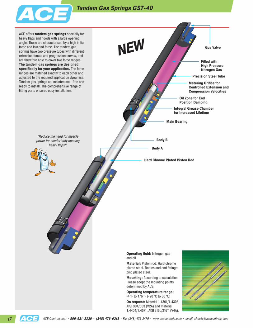
ACE offers tandem gas springs specially for heavy flaps and hoods with a large opening angle. These are characterised by a high initial force and low end force. The tandem gas springs have two pressure tubes with different extension forces and progression curves, and are therefore able to cover two force ranges. The tandem gas springs are designed specifically for your application. The force ranges are matched exactly to each other and adjusted to the required application dynamics. Tandem gas springs are maintenance-free and ready to install. The comprehensive range of fitting parts ensures easy installation.
“Reduce the need for muscle power for comfortably opening
heavy flaps!”
Tandem Gas Springs GST-40
Filled with High Pressure Nitrogen Gas
Metering Orifice forControlled Extension and Compression Velocities
Oil Zone for End Position Damping
Integral Grease Chamber for Increased Lifetime
Main Bearing
Hard Chrome Plated Piston Rod
Body B
Body A
Precision Steel Tube
Gas Valve
Operating fluid: Nitrogen gas and oilMaterial: Piston rod: Hard chrome plated steel. Bodies and end fittings: Zinc plated steel.Mounting: According to calculation. Please adopt the mounting points determined by ACE.Operating temperature range: -4 °F to 176 °F (-20 °C to 80 °C)On request: Material 1.4301/1.4305, AISI 304/303 (V2A) and material 1.4404/1.4571, AISI 316L/316Ti (V4A).
NEW

18ACE Controls Inc. • 800-521-3320 • (248) 476-0213 • Fax (248) 476-2470 • www.acecontrols.com • email: [email protected]
M14x1.5
RadiusR 0.49(12.5)
ØØ
Body A Body BStroke BStroke A
Ø
L+/- 0.08 (2 mm) extended
30°
Ø
Ø
2.24 (57)
2.2 (56)
1.18 (30)0.71(18)
1.02(26)
Ø0.55(14)
0.55 thick(14)
0.55 thick(14)
Ø1.57(40)
0.98(25) 0.79
(20)
Ø1.57(40)
0.55(14)
0.59(15)
0.59(15)
2.2(56)
2.24(57)
1.57(40)
0.83(21)
0.56(14.1)
Ø 0.56(14.1)
0.83(21)
1.57(40)
1.06(27)
0.51(13)
0.63(16)
0.55(14)
Ø0.79(20)
1.06(27)
0.71(18)
0.75(19)
Tandem Gas Springs GST-40Extension Forces 67 lbs to 1,124 lbs (300 N to 5,000 N)
DimensionsType
Stroke A inches (mm)
Stroke B inches (mm)
L - extendedinches (mm)
GST-40-50-100 1.97 (50) 3.94 (100) 19.09 (485)GST-40-50-150 1.97 (50) 5.91 (150) 23.03 (585)GST-40-50-200 1.97 (50) 7.87 (200) 26.97 (685)GST-40-70-250 2.76 (70) 9.84 (250) 32.48 (825)GST-40-70-300 2.76 (70) 11.81 (300) 36.42 (925)GST-40-70-350 2.76 (70) 13.78 (350) 40.35 (1,025)GST-40-70-400 2.76 (70) 15.75 (400) 40.35 (1,125)
Ordering Example GST-40-50-150-AD-900N-2500NModel (Tandem Gas Spring)Body Ø 1.57'' (40 mm)Stroke A 1.97''(50 mm)Stroke B 5.91'' (150 mm)Body A End Fitting, A14Body B End Fitting, D14Nominal Force Body A, 202 lbs (900 N)Nominal Force Body B, 562 lbs (2,500 N)
The end fittings are interchangeable. These gas springs are tailored to the relevant application and are therefore not available in stock.
A
ME14
D
E
ND14
ME14
Technical DataOn request: Without damping, standard length damping, special force curves, special lengths, alternative end fittings, wiper.Available force range F1 at 68 °F (20 °C): 67 lbs to 1,124 lbs (300 N to 5,000 N)Mounting: According to calculation. Please adopt the mounting points determined by ACE.End position damping length: Strong end position damping approx. 1.18" to 2.76" (30 to 70 mm) – depending on the stroke – and slow extension speed.Material: Piston rod: Hard chrome plated. Bodies and accessories: Zinc plated steel.Progression: According to calculation relating to your application.
A Eye A max. force 2,248 lbs
(10,000 N)
B Stud Thread B
D Clevis Fork D max. force 2,248 lbs
(10,000 N)
ESwivel Eye E
max. force 2,248 lbs(10,000 N)
GST-40
For mounting accessories see page 51.
End Fitting Standard Dimensions – inches and (mm) End Fitting

19 ACE Controls Inc. • 800-521-3320 • (248) 476-0213 • Fax (248) 476-2470 • www.acecontrols.com • email: [email protected]
Stainless Steel Industrial Gas Springs (Push Type)
Stainless steel gas springs (push type)Material 1.4301/1.4305, AISI 304/303 (V2A), Material 1.4404/1.4571, AISI 316L/316Ti (V4A)
In addition to the comprehensive range of in- dustrial gas springs with valve, ACE also offers a wide range of industrial gas springs made of stainless steel with body diameters from .31" to 2.76" (8 mm to 70 mm). This high-quality version is also available on request in all stroke lengths and possible extension forces. The comprehensive range of fitting parts ensures easy installation and makes the gas springs universal in use. Stainless steel industrial gas springs are used everywhere that raising and lowering is required. Due to their special properties, non-rusting and low magnet-ism, they are the preferred equipment for medical and clean-room tech- nology, the foodstuffs industry, electronics and shipbuilding sector.
Operating fluid: Nitrogen gas and oilMaterial: Piston rod, body and end fittings: Material 1.4301/1.4305, AISI 304/303 (V2A) or material 1.4404/1.4571, AISI 316L/316Ti (V4A).Mounting: In any positionAdvice: We recommend mounting with piston rod downwards to take advantage of the built-in end position damping.Operating temperature range: -4 °F to 176 F (-20 °C to 80 °C)On request: Without damping, strong end position damping, special force curves, wiper, special lengths, alternative end fittings.
Rear End Cap in Stainless Steel
Stainless Steel Body
Front Bearing in Brass
Stainless Steel Piston Rod
Gas Valve
Oil Zone for End Position Damping and Lubrication (recommended mounting position: piston rod downwards)
20ACE Controls Inc. • 800-521-3320 • (248) 476-0213 • Fax (248) 476-2470 • www.acecontrols.com • email: [email protected]
Ø
Ø
Ø
M4x0.736°
0.16(4.1)
0.24(6)0.31(8)
RadiusR0.16(4)
0.16 (4 )thick
M3.5x0.6
0.2 (5) 0.2
(5)
0.12 (3)
Stroke
0.31 (8)
L = Stroke + 0.39 (10)
Ø Ø
Ø
0.31(8)
0.16(4)
0.16(4)
0.39(10)
0.33(8.5)
0.2(5)
0.2(5)
0.43(11)
0.63(16)
L+/- 0.08 (2 mm) extended
Ø 0.51(13)
0.24(6)
0.31(8)
0.31(8)
Ø0.31(8)
Ø 0.31(8)
Ø0.51(13)
0.31(8)
0.24(6)
0.16(4)
0.43(11)
0.43(11)
0.71(18)
0.63(16)
0.71(18)
0.16(4)
0.71(18)
0.71(18)
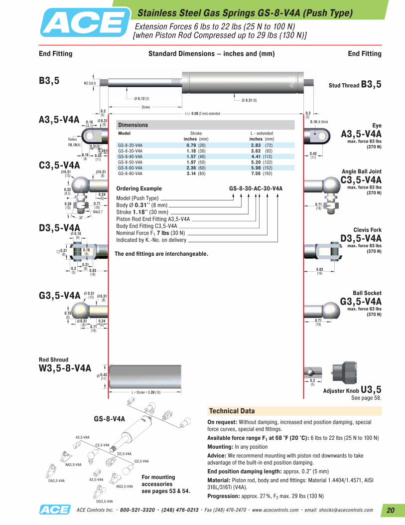
Stainless Steel Gas Springs GS-8-V4A (Push Type) Extension Forces 6 lbs to 22 lbs (25 N to 100 N) [when Piston Rod Compressed up to 29 lbs (130 N)]
DimensionsModel
Stroke inches (mm)
L - extendedinches (mm)
GS-8-20-V4A 0.79 (20) 2.83 (72)GS-8-30-V4A 1.18 (30) 3.62 (92)GS-8-40-V4A 1.57 (40) 4.41 (112)GS-8-50-V4A 1.97 (50) 5.20 (132)GS-8-60-V4A 2.36 (60) 5.98 (152)GS-8-80-V4A 3.14 (80) 7.56 (192)
Ordering Example GS-8-30-AC-30-V4AModel (Push Type)Body Ø 0.31'' (8 mm)Stroke 1.18'' (30 mm)Piston Rod End Fitting A3,5-V4A Body End Fitting C3,5-V4ANominal Force F1 7 lbs (30 N)Indicated by K.-No. on delivery
The end fittings are interchangeable.
A3,5-V4A
C3,5-V4A
NA3,5-V4A
A3,5-V4A
NG3,5-V4A
OG3,5-V4A
OA3,5-V4A
D3,5-V4A
G3,5-V4A
Technical DataOn request: Without damping, increased end position damping, special force curves, special end fittings.Available force range F1 at 68 °F (20 °C): 6 lbs to 22 lbs (25 N to 100 N)Mounting: In any positionAdvice: We recommend mounting with piston rod downwards to take advantage of the built-in end position damping.End position damping length: approx. 0.2" (5 mm)Material: Piston rod, body and end fittings: Material 1.4404/1.4571, AISI 316L/316Ti (V4A).Progression: approx. 27%, F2 max. 29 lbs (130 N)
B3,5 Stud Thread B3,5
A3,5-V4AEye
A3,5-V4A max. force 83 lbs
(370 N)
C3,5-V4AAngle Ball Joint C3,5-V4A
max. force 83 lbs (370 N)
D3,5-V4A Clevis Fork D3,5-V4A
max. force 83 lbs(370 N)
G3,5-V4A Ball Socket G3,5-V4A
max. force 83 lbs(370 N)
Adjuster Knob U3,5 See page 58.
GS-8-V4A
Rod ShroudW3,5-8-V4A
For mounting accessories see pages 53 & 54.
End Fitting Standard Dimensions – inches and (mm) End Fitting

21 ACE Controls Inc. • 800-521-3320 • (248) 476-0213 • Fax (248) 476-2470 • www.acecontrols.com • email: [email protected]
Stainless Steel Gas Springs GS-10-V4A (Push Type) Extension Forces 7 lbs to 22 lbs (30 N to 100 N) [when Piston Rod Compressed up to 26 lbs (115 N)]
End Fitting End FittingStandard Dimensions
Ø
Ø
Ø
M4x0.736°
0.164.1
0.24(6)0.31(8)
RadiusR0.16(4)
0.16 (4 )thick
M3.5x0.6
0.20(5) 0.20
(5)
0.12 (3)
Stroke
0.39 (10)
L = Stroke + 0.39 (10)
Ø Ø
Ø
0.31(8)
0.16(4)
0.16(4)
0.39(10)
0.33(8.5)
0.2(5)
0.20(5)
0.51(13)
0.63(16)
L+/- 0.08 (2 mm) extended
Ø0.51(13)
0.24(6)
0.31(8)
0.31(8)
Ø0.31(8)
Ø 0.31(8)
Ø0.51(13)
0.31(8)
0.24(6)
0.16(4)
0.43(11)
0.43(11)
0.71(18)
0.63(16)
0.71(18)
0.16(4)
0.71(18)
0.71(18)
DimensionsModel
Stroke inches (mm)
L - extendedinches (mm)
GS-10-20-V4A 0.79 (20) 2.83 (72)GS-10-30-V4A 1.18 (30) 3.62 (92)GS-10-40-V4A 1.57 (40) 4.41 (112)GS-10-50-V4A 1.97 (50) 5.20 (132)GS-10-60-V4A 2.36 (60) 5.98 (152)GS-10-80-V4A 3.14 (80) 7.56 (192)
Ordering Example GS-10-30-AC-30-V4AModel (Push Type)Body Ø 0.39'' (10 mm)Stroke 1.18'' (30 mm)Piston Rod End Fitting A3,5-V4A Body End Fitting C3,5-V4ANominal Force F1 7 lbs (30 N)Indicated by K.-No. on delivery
The end fittings are interchangeable.
A3,5-V4A
C3,5-V4A
NA3,5-V4A
A3,5-V4A
NG3,5-V4A
OG3,5-V4A
OA3,5-V4A
D3,5-V4A
G3,5-V4A
Technical DataOn request: Without damping, increased end position damping, special force curves, special end fittings.Available force range F1 at 68 °F (20 °C): 7 lbs to 22 lbs (30 N to 100 N)Mounting: In any positionAdvice: We recommend mounting with piston rod downwards to take advantage of the built-in end position damping.End position damping length: approx. 0.2" (5 mm)Material: Piston rod, body and end fittings: Material 1.4404/1.4571, AISI 316L/316Ti (V4A).Progression: approx. 12%, F2 max. 26 lbs (115 N)
B3,5 Stud Thread B3,5
A3,5-V4A Eye A3,5-V4A
max. force 83 lbs (370 N)
C3,5-V4AAngle Ball Joint C3,5-V4A
max. force 83 lbs (370 N)
D3,5-V4A Clevis Fork D3,5-V4A
max. force 83 lbs (370 N)
G3,5-V4A Ball Socket G3,5-V4A
max. force 83 lbs (370 N)
Adjuster Knob U3,5 See page 58.
GS-10-V4A
Rod ShroudW3,5-10-V4A
For mounting accessories see pages 53 & 54.
End Fitting Standard Dimensions – inches and (mm) End Fitting
22ACE Controls Inc. • 800-521-3320 • (248) 476-0213 • Fax (248) 476-2470 • www.acecontrols.com • email: [email protected]
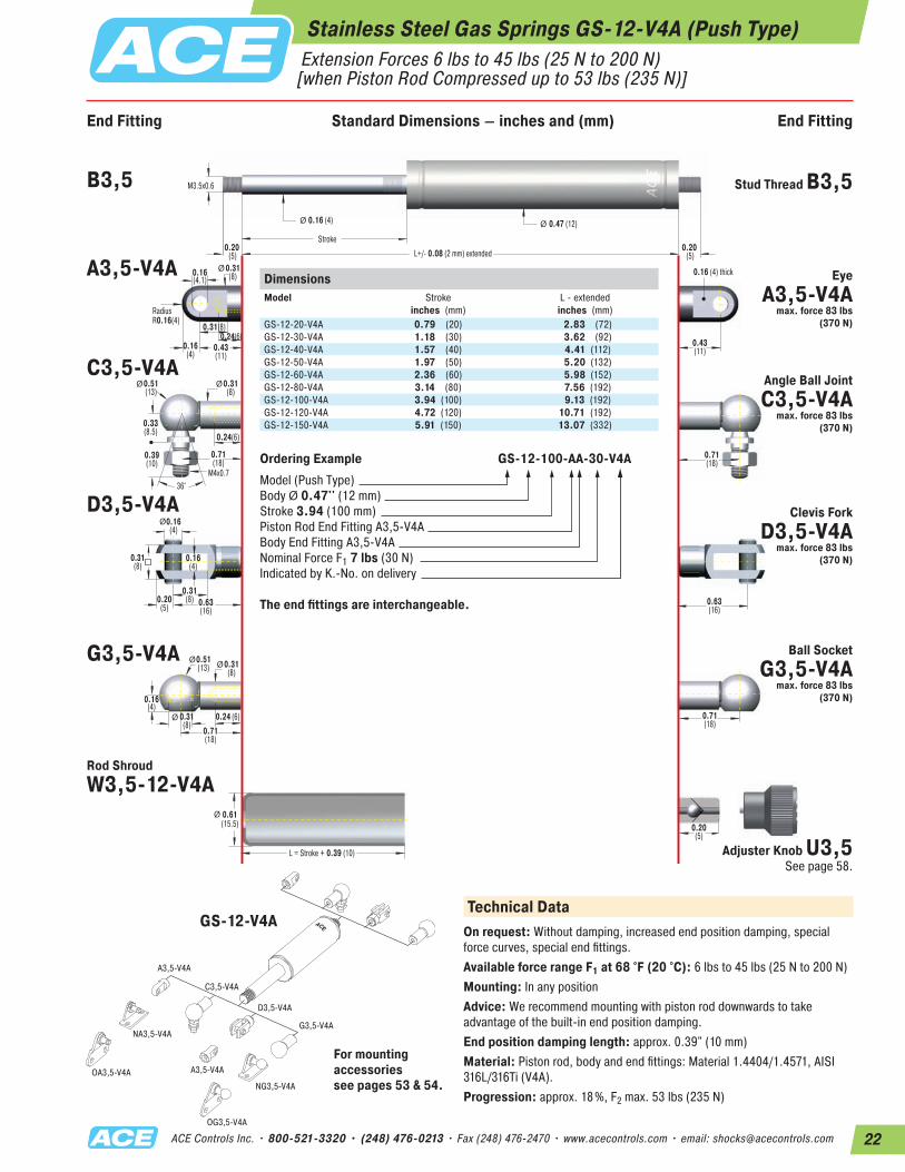
Stainless Steel Gas Springs GS-12-V4A (Push Type) Extension Forces 6 lbs to 45 lbs (25 N to 200 N) [when Piston Rod Compressed up to 53 lbs (235 N)]
End Fitting End FittingStandard Dimensions
Ø
Ø
Ø
M4x0.736°
0.16(4.1)
0.24(6)0.31(8)
RadiusR0.16(4)
0.16 (4) thick
M3.5x0.6
0.20 (5)
0.20 (5)
0.16 (4)
Stroke
0.47 (12)
L = Stroke + 0.39 (10)
Ø Ø
Ø
0.31(8)
0.16(4)
0.16(4)
0.39(10)
0.33(8.5)
0.20(5)
0.20(5)
0.61(15.5)
0.63(16)
L+/- 0.08 (2 mm) extended
Ø0.51(13)
0.24 (6)0.31(8)
0.31(8)
Ø0.31(8)
Ø 0.31(8)
Ø0.51(13)
0.31(8)
0.24(6)
0.16(4)
0.43(11)
0.43(11)
0.71(18)
0.63(16)
0.71(18)
0.16(4)
0.71(18)
0.71(18)
DimensionsModel
Stroke inches (mm)
L - extendedinches (mm)
GS-12-20-V4A 0.79 (20) 2.83 (72)GS-12-30-V4A 1.18 (30) 3.62 (92)GS-12-40-V4A 1.57 (40) 4.41 (112)GS-12-50-V4A 1.97 (50) 5.20 (132)GS-12-60-V4A 2.36 (60) 5.98 (152)GS-12-80-V4A 3.14 (80) 7.56 (192)GS-12-100-V4A 3.94 (100) 9.13 (192)GS-12-120-V4A 4.72 (120) 10.71 (192)GS-12-150-V4A 5.91 (150) 13.07 (332)
Ordering Example GS-12-100-AA-30-V4AModel (Push Type)Body Ø 0.47'' (12 mm)Stroke 3.94 (100 mm)Piston Rod End Fitting A3,5-V4A Body End Fitting A3,5-V4ANominal Force F1 7 lbs (30 N)Indicated by K.-No. on delivery
The end fittings are interchangeable.
A3,5-V4A
C3,5-V4A
NA3,5-V4A
A3,5-V4A
NG3,5-V4A
OG3,5-V4A
OA3,5-V4A
D3,5-V4A
G3,5-V4A
Technical DataOn request: Without damping, increased end position damping, special force curves, special end fittings.Available force range F1 at 68 °F (20 °C): 6 lbs to 45 lbs (25 N to 200 N)Mounting: In any positionAdvice: We recommend mounting with piston rod downwards to take advantage of the built-in end position damping.End position damping length: approx. 0.39" (10 mm)Material: Piston rod, body and end fittings: Material 1.4404/1.4571, AISI 316L/316Ti (V4A).Progression: approx. 18%, F2 max. 53 lbs (235 N)
B3,5 Stud Thread B3,5
A3,5-V4A Eye A3,5-V4A
max. force 83 lbs (370 N)
C3,5-V4AAngle Ball Joint C3,5-V4A
max. force 83 lbs (370 N)
D3,5-V4A Clevis Fork D3,5-V4A
max. force 83 lbs(370 N)
G3,5-V4A Ball Socket G3,5-V4A
max. force 83 lbs (370 N)
Adjuster Knob U3,5 See page 58.
Rod ShroudW3,5-12-V4A
GS-12-V4A
For mounting accessories see pages 53 & 54.
End Fitting Standard Dimensions – inches and (mm) End Fitting
23 ACE Controls Inc. • 800-521-3320 • (248) 476-0213 • Fax (248) 476-2470 • www.acecontrols.com • email: [email protected]
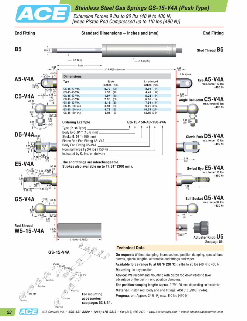
Stainless Steel Gas Springs GS-15-V4A (Push Type) Extension Forces 9 lbs to 90 lbs (40 N to 400 N) [when Piston Rod Compressed up to 110 lbs (490 N)]
End Fitting End FittingStandard Dimensions
Ø
Ø
Ø
M5x0.8
36°
0.246.1
0.31(8)
0.35(9)
RadiusR0.2 (5)
0.24 (6) thick
M5x0.8
0.28(7) 0.28
(7)
0.24 (6)
Stroke
0.61 (15.6)
L = Stroke + 0.79 (20)
Ø Ø
Ø
0.39(10)
0.20(5)
0.20(5)
0.39(10)
0.31(8)
0.24(6)
0.28 (7)
0.75(19)
0.79(20)
L+/- 0.08 (2 mm) extended
Ø0.51(13)
0.47(12)0.31(8)
0.31(8)
Ø0.31(8)
Ø0.39(10)
Ø0.51(13)
0.55(14)
0.39(10)
0.47 (12)
0.20(5)
0.63(16)
0.63(16)
0.87(22)
0.79(20)
1.06(27)
0.87(22)
0.18(4.5)
0.87(22)
0.87(22)
24°
Ø
0.47(12)
0.39 (10)
0.20(5)
0.31(8)
1.06 (27)
0.18(4.5)
0.51(13)Ø 0.39
(10)
0.47(12)
Ø
DimensionsType
Stroke inches (mm)
L - extendedinches (mm)
GS-15-20-V4A 0.79 (20) 2.91 (74)GS-15-40-V4A 1.57 (40) 4.49 (114)GS-15-50-V4A 1.97 (50) 5.28 (134)GS-15-60-V4A 2.36 (60) 6.06 (154)GS-15-80-V4A 3.15 (80) 7.64 (194)GS-15-100-V4A 3.94 (100) 9.21 (234)GS-15-120-V4A 4.72 (120) 10.79 (274)GS-15-150-V4A 5.91 (150) 13.15 (334)
Ordering Example GS-15-150-AC-150-V4AType (Push Type)Body Ø 0.61'' (15.6 mm)Stroke 5.91'' (150 mm)Piston Rod End Fitting A5-V4ABody End Fitting C5-V4ANominal Force F1 34 lbs (150 N)Indicated by K.-No. on delivery
The end fittings are interchangeable. Strokes also available up to 11.81" (300 mm).
A5-V4A
MA5-V4A
NG5-V4A
NA5-V4A
OG5-V4A
OA5-V4A
PA5-V4A
PG5-V4A
C5-V4AD5-V4A
E5-V4AG5-V4A
Technical DataOn request: Without damping, increased end position damping, special force curves, special lengths, alternative end fittings and wiper. Available force range F1 at 68 °F (20 °C): 9 lbs to 90 lbs (40 N to 400 N)Mounting: In any positionAdvice: We recommend mounting with piston rod downwards to take advantage of the built-in end position damping.End position damping length: Approx. 0.79" (20 mm) depending on the strokeMaterial: Piston rod, body and end fittings: AISI 316L/316Ti (V4A).Progression: Approx. 34%, F2 max. 110 lbs (490 N)
B5 Stud Thread B5
A5-V4A Eye A5-V4A max. force 110 lbs
(490 N)
C5-V4AAngle Ball Joint C5-V4A
max. force 97 lbs (430 N)
D5-V4A Clevis Fork D5-V4A max. force 110 lbs
(490 N)
E5-V4ASwivel Eye E5-V4A
max. force 110 lbs (490 N)
G5-V4A Ball Socket G5-V4A max. force 97 lbs
(430 N)
Rod Shroud W5-15-V4A
Adjuster Knob U5 See page 58.
For mounting accessories see pages 53 & 54.
GS-15-V4A
End Fitting Standard Dimensions – inches and (mm) End Fitting
24ACE Controls Inc. • 800-521-3320 • (248) 476-0213 • Fax (248) 476-2470 • www.acecontrols.com • email: [email protected]
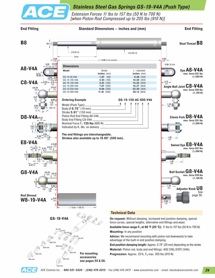
Stainless Steel Gas Springs GS-19-V4A (Push Type) Extension Forces 11 lbs to 157 lbs (50 N to 700 N) [when Piston Rod Compressed up to 205 lbs (910 N)]
End Fitting End FittingStandard Dimensions
Ø
Ø
Ø
M8x1.25
36°
0.328.1
0.39(10)
0.45(11.5)
RadiusR0.28 (7)
0.39 (10) thick
M8x1.25
0.39 (10)
0.39(10)
0.31 (8)
Stroke
0.75 (19)
L = Stroke + 1.18 (30)
Ø Ø
Ø
0.63(16)
0.31(8)
0.31(8)
0.65(16.5)
0.47(12)
0.39(10)
0.39(10)
0.91(23)
1.26(32)
L+/- 0.08 (2 mm) extended
Ø0.79(20)
0.59(15)0.51(13)
0.51(13)
Ø0.51(13)
Ø0.55(14)
Ø0.79(20)
0.87(22)
0.63(16)
0.59(15)
0.24(6)
0.75(19)
0.75(19)
1.18(30)
1.26(32)
1.42(36)
1.18(30)
0.24(6)
1.18(30)
1.18(30)
24°
Ø
0.51(13)
0.47(12)
0.31(8)
0.47(12)
1.42(36)
0.24(6)
0.63(16)Ø 0.47
(12)
0.63(16)
Ø
DimensionsModel
Stroke inches (mm)
L - extendedinches (mm)
GS-19-50-V4A 1.97 (50) 6.46 (164)GS-19-100-V4A 3.94 (100) 10.39 (264)GS-19-150-V4A 5.91 (150) 14.33 (364)GS-19-200-V4A 7.87 (200) 18.27 (464)GS-19-250-V4A 9.84 (250) 22.20 (564)GS-19-300-V4A 11.81 (300) 26.14 (664)
Ordering Example GS-19-150-AC-600-V4AModel (Push Type)Body Ø 0.75'' (19 mm)Stroke 5.91'' (150 mm)Piston Rod End Fitting A8-V4ABody End Fitting C8-V4ANominal Force F1 135 lbs (600 N)Indicated by K.-No. on delivery
The end fittings are interchangeable. Strokes also available up to 19.69" (500 mm).
A8-V4A
MA8-V4A
MA8-V4A
NG8-V4A
NA8-V4A
OG8-V4A
OA8-V4A
PA8-V4A
PG8-V4A
C8-V4AD8-V4A
E8-V4AG8-V4A
Technical DataOn request: Without damping, increased end position damping, special force curves, special lengths, alternative end fittings and wiper.Available force range F1 at 68 °F (20 °C): 11 lbs to 157 lbs (50 N to 700 N)Mounting: In any positionAdvice: We recommend mounting with piston rod downwards to take advantage of the built-in end position damping.End position damping length: Approx. 0.79" (20 mm) depending on the strokeMaterial: Piston rod, body and end fittings: AISI 316L/316Ti (V4A).Progression: Approx. 33%, F2 max. 205 lbs (910 N)
B8 Stud Thread B8
A8-V4A Eye A8-V4A max. force 351 lbs
(1,560 N)
C8-V4AAngle Ball Joint C8-V4A
max. force 256 lbs (1,140 N)
D8-V4A Clevis Fork D8-V4A max. force 351 lbs
(1,560 N)
E8-V4A Swivel Eye E8-V4A max. force 351 lbs
(1,560 N)
G8-V4A Ball Socket G8-V4A max. force 256 lbs
(1,140 N)
Rod Shroud W8-19-V4A
Adjuster Knob U8 See
page 58.
For mounting accessories see pages 55 & 56.
GS-19-V4A
End Fitting Standard Dimensions – inches and (mm) End Fitting
25 ACE Controls Inc. • 800-521-3320 • (248) 476-0213 • Fax (248) 476-2470 • www.acecontrols.com • email: [email protected]
End Fitting End FittingStandard Dimensions
Ø
Ø
Ø
M8x1.25
36°
0.328.1
0.39(10)
0.45(11.5)
RadiusR0.28 (7)
0.39 (10) thick
M8x1.25
0.39 (10)
0.39 (10)
0.39 (10)
Stroke
0.91 (23)
L = Stroke + 1.18 (30)
Ø Ø
Ø
0.63(16)
0.31(8)
0.31(8)
0.65(16.5)
0.47(12)
0.39(10)
0.39(10)
1.10(28)
1.26(32)
L+/- 0.08 (2 mm) extended
Ø0.79(20)
0.59(15)
0.51(13)
0.51(13)
Ø0.51(13)
Ø0.39(10)
Ø0.79(20)
0.87(22)
0.63(16)
0.59(15)
0.24(6)
0.75(19)
0.75(19)
1.18(30)
1.26(32)
1.42(36)
1.18(30)
0.24(6)
1.18(30)
1.18(30)
24°
Ø
0.51(13)0.47
(12)
0.31(8)
0.47(12)
1.42(36)
0.24(6)
0.63(16)Ø 0.47
(12)
0.63(16)
Ø
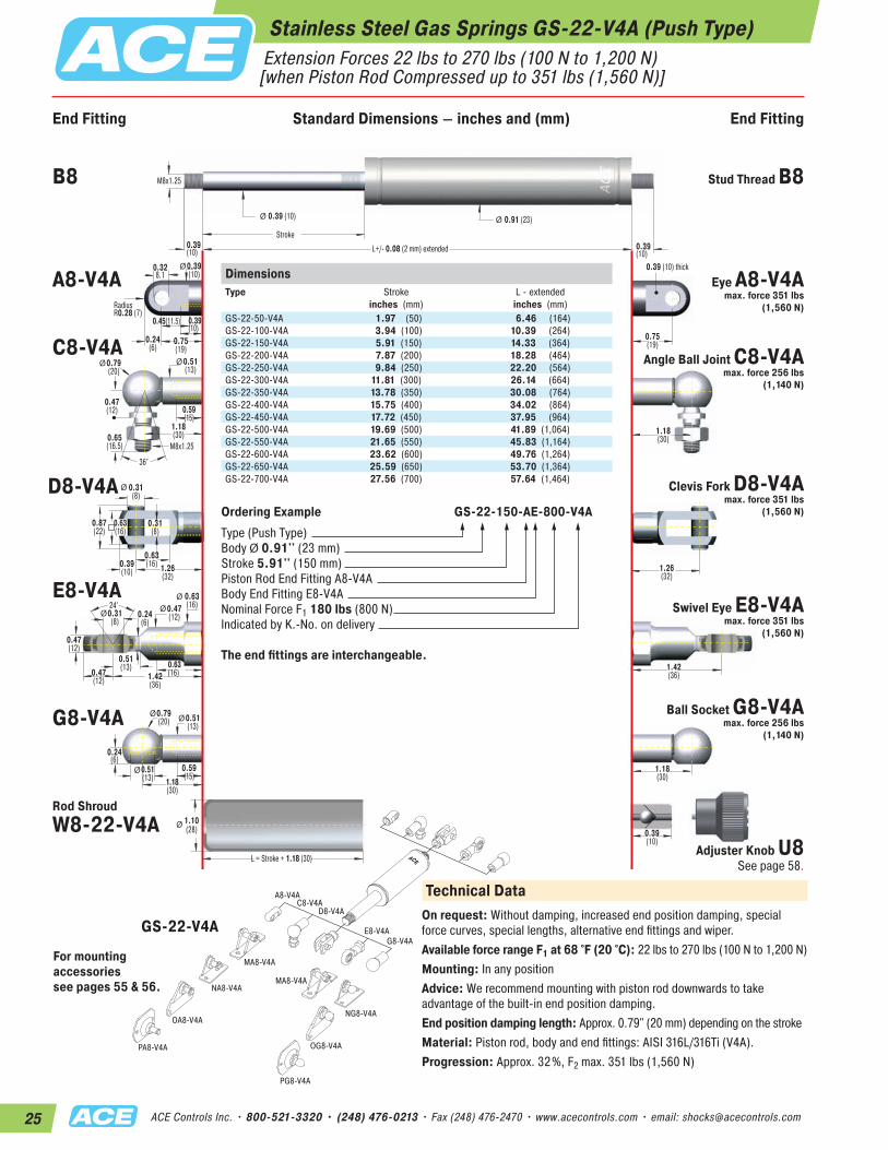
Stainless Steel Gas Springs GS-22-V4A (Push Type) Extension Forces 22 lbs to 270 lbs (100 N to 1,200 N) [when Piston Rod Compressed up to 351 lbs (1,560 N)]
DimensionsType
Stroke inches (mm)
L - extendedinches (mm)
GS-22-50-V4A 1.97 (50) 6.46 (164)GS-22-100-V4A 3.94 (100) 10.39 (264)GS-22-150-V4A 5.91 (150) 14.33 (364)GS-22-200-V4A 7.87 (200) 18.28 (464)GS-22-250-V4A 9.84 (250) 22.20 (564)GS-22-300-V4A 11.81 (300) 26.14 (664)GS-22-350-V4A 13.78 (350) 30.08 (764)GS-22-400-V4A 15.75 (400) 34.02 (864)GS-22-450-V4A 17.72 (450) 37.95 (964)GS-22-500-V4A 19.69 (500) 41.89 (1,064)GS-22-550-V4A 21.65 (550) 45.83 (1,164)GS-22-600-V4A 23.62 (600) 49.76 (1,264)GS-22-650-V4A 25.59 (650) 53.70 (1,364)GS-22-700-V4A 27.56 (700) 57.64 (1,464)
Ordering Example GS-22-150-AE-800-V4AType (Push Type)Body Ø 0.91'' (23 mm)Stroke 5.91'' (150 mm)Piston Rod End Fitting A8-V4ABody End Fitting E8-V4ANominal Force F1 180 lbs (800 N)Indicated by K.-No. on delivery
The end fittings are interchangeable.
A8-V4A
MA8-V4A
MA8-V4A
NG8-V4A
NA8-V4A
OG8-V4A
OA8-V4A
PA8-V4A
PG8-V4A
C8-V4AD8-V4A
E8-V4AG8-V4A
Technical DataOn request: Without damping, increased end position damping, special force curves, special lengths, alternative end fittings and wiper.Available force range F1 at 68 °F (20 °C): 22 lbs to 270 lbs (100 N to 1,200 N)Mounting: In any positionAdvice: We recommend mounting with piston rod downwards to take advantage of the built-in end position damping.End position damping length: Approx. 0.79" (20 mm) depending on the strokeMaterial: Piston rod, body and end fittings: AISI 316L/316Ti (V4A).Progression: Approx. 32%, F2 max. 351 lbs (1,560 N)
B8 Stud Thread B8
A8-V4A Eye A8-V4A max. force 351 lbs
(1,560 N)
C8-V4AAngle Ball Joint C8-V4A
max. force 256 lbs (1,140 N)
D8-V4A Clevis Fork D8-V4A max. force 351 lbs
(1,560 N)
E8-V4ASwivel Eye E8-V4A
max. force 351 lbs (1,560 N)
G8-V4A Ball Socket G8-V4A max. force 256 lbs
(1,140 N)
Rod Shroud W8-22-V4A
Adjuster Knob U8 See page 58.
For mounting accessories see pages 55 & 56.
GS-22-V4A
End Fitting Standard Dimensions – inches and (mm) End Fitting

26ACE Controls Inc. • 800-521-3320 • (248) 476-0213 • Fax (248) 476-2470 • www.acecontrols.com • email: [email protected]
Stainless Steel Gas Springs GS-28-V4A (Push Type) Extension Forces 34 lbs to 562 lbs (150 N to 2,500 N) [when Piston Rod Compressed up to 854 lbs (3,800 N)]
End Fitting End FittingStandard Dimensions
Ø
M10x1.5
36°
0.32(8.1)
0.59(15)
0.59(15)
RadiusR0.35 (9)
0.39 (10) thick
M10x1.5
0.47(12) 0.47
(12)
0.55 (14)
Stroke
1.10 (28)
L = Stroke + 1.57 (40)
Ø Ø
Ø
0.79(20)
0.39(10)
0.39(10)
0.79(20)
0.63(16)
0.47(12)
0.47 (12)
1.26(32)
1.57(40)
L+/- 0.08 (2 mm) extended
Ø0.63(16)
Ø 0.71(18)
Ø0.94(24)
1.04(26.5)
0.79(20)
0.71 (18)
0.35(9) 1.06
(27)1.06(27)
1.38(35)
1.57(40)
1.69(43)
1.38(35)
24°
Ø
0.63(16)
0.55 (14)
0.39(10)
0.55(14)
1.69 (43)
0.28(7)
0.75(19)
Ø 0.59(15)
0.71(18)
Ø
DimensionsType
Stroke inches (mm)
L - extendedinches (mm)
GS-28-100-V4A 3.94 (100) 10.31 (262)GS-28-150-V4A 5.91 (150) 14.25 (362)GS-28-200-V4A 7.87 (200) 18.19 (462)GS-28-250-V4A 9.84 (250) 22.13 (562)GS-28-300-V4A 11.81 (300) 26.06 (662)GS-28-350-V4A 13.78 (350) 30.00 (762)GS-28-400-V4A 15.75 (400) 33.94 (862)GS-28-450-V4A 17.72 (450) 37.87 (962)GS-28-500-V4A 19.69 (500) 41.81 (1,062)GS-28-550-V4A 21.65 (550) 45.75 (1,162)GS-28-600-V4A 23.62 (600) 49.69 (1,262)GS-28-650-V4A 25.59 (650) 53.62 (1,362)
Ordering Example GS-28-150-EE-1200-V4AType (Push Type)Body Ø 1.1'' (28 mm)Stroke 5.91'' (150 mm)Piston Rod End Fitting E10-V4ABody End Fitting E10-V4ANominal Force F1 270 lbs (1,200 N)Indicated by K.-No. on delivery
The end fittings are interchangeable. Strokes also available up to 29.53"(750 mm).
A10-V4AC10-V4A
D10-V4AE10-V4A
MA10-V4A
Technical DataOn request: Without damping, increased end position damping, special force curves, special lengths, alternative end fittings and wiper.Available force range F1 at 68 °F (20 °C): 34 lbs to 562 lbs (150 N to 2,500 N)Mounting: In any positionAdvice: We recommend mounting with piston rod downwards to take advantage of the built-in end position damping.End position damping length: Approx. 0.79" (20 mm) depending on the strokeMaterial: Piston rod, body and end fittings: AISI 316L/316Ti (V4A).Progression: Approx. 52%, F2 max. 854 lbs (3,800 N)
B10 Stud Thread B10
A10-V4A Eye A10-V4A max. force 854 lbs
(3,800 N)
C10-V4A Angle Ball JointC10-V4A max. force 393 lbs
(1,750 N)
D10-V4AClevis Fork D10-V4A
max. force 854 lbs (3,800 N)
E10-V4ASwivel Eye E10-V4A
max. force 854 lbs (3,800 N)
Rod Shroud W10-28-V4A
Adjuster Knob U10-VA See page 58.
For mounting accessories see pages 55 & 56.
GS-28-V4A
End Fitting Standard Dimensions – inches and (mm) End Fitting
27 ACE Controls Inc. • 800-521-3320 • (248) 476-0213 • Fax (248) 476-2470 • www.acecontrols.com • email: [email protected]
A14-V4AC14-V4A
D14-V4AE14-V4A
ME14-VA
ME14-VA
ND14-VA
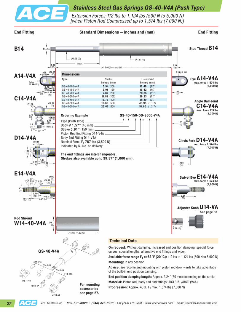
Stainless Steel Gas Springs GS-40-V4A (Push Type) Extension Forces 112 lbs to 1,124 lbs (500 N to 5,000 N) [when Piston Rod Compressed up to 1,574 lbs (7,000 N)]
End Fitting End FittingStandard Dimensions
Ø
M14x1.5
36°
0.56(14.1)
0.71(18)
0.77(9.5)
RadiusR0.49 (12.5)
0.55 (14) thick
M14x1.5
0.59(15)
0.59 (15)
0.79 (20)
Stroke
1.57 (40)
L = Stroke + 1.57 (40)
Ø Ø
Ø
1.06(27)
.55(14)
0.55(14)
1.1(28)
0.79(20)
0.63(16)
0.59 (15)
1.77(45)
2.20(56)
L+/- 0.08 (2 mm) extended
Ø0.87(22)
Ø 0.98(25)
Ø1.18(30)
1.38(35)
1.06(27)
0.98 (25)
0.47(12) 1.65
(42)1.65(42)
1.77(45)
2.20(56)
2.24(57)
1.77(45)
30°
Ø
0.71(18)
0.71 (18)
0.55(14)
0.75(19)
2.24 (57)
0.51(13)
1.02(26)
Ø 0.79(20)
1.18 (30)
Ø
DimensionsType
Stroke inches (mm)
L - extendedinches (mm)
GS-40-100-V4A 3.94 (100) 12.48 (317)GS-40-150-V4A 5.91 (150) 16.42 (417)GS-40-200-V4A 7.87 (200) 20.35 (517)GS-40-300-V4A 11.81 (300) 28.23 (717)GS-40-400-V4A 15.75 (400) 36.10 (917)GS-40-500-V4A 19.69 (500) 43.98 (1,117)GS-40-600-V4A 23.62 (600) 51.85 (1,317)
Ordering Example GS-40-150-DD-3500-V4AType (Push Type)Body Ø 1.57'' (40 mm)Stroke 5.91'' (150 mm)Piston Rod End Fitting D14-V4ABody End Fitting D14-V4ANominal Force F1 787 lbs (3,500 N)Indicated by K.-No. on delivery
The end fittings are interchangeable. Strokes also available up to 39.37" (1,000 mm).
GS-40-V4A
Technical DataOn request: Without damping, increased end position damping, special force curves, special lengths, alternative end fittings and wiper.Available force range F1 at 68 °F (20 °C): 112 lbs to 1,124 lbs (500 N to 5,000 N)Mounting: In any positionAdvice: We recommend mounting with piston rod downwards to take advantage of the built-in end position damping.End position damping length: Approx. 2.24" (30 mm) depending on the strokeMaterial: Piston rod, body and end fittings: AISI 316L/316Ti (V4A).Progression: Approx. 40%, F2 max. 1,574 lbs (7,000 N)
B14 Stud Thread B14
A14-V4AEye A14-V4A
max. force 1,574 lbs (7,000 N)
C14-V4A Angle Ball JointC14-V4A max. force 719 lbs
(3,200 N)
D14-V4A Clevis Fork D14-V4A max. force 1,574 lbs
(7,000 N)
E14-V4ASwivel Eye E14-V4A
max. force 1,574 lbs (7,000 N)
Rod Shroud W14-40-V4A
Adjuster Knob U14-VA See page 58.
For mounting accessories see page 57.
End Fitting Standard Dimensions – inches and (mm) End Fitting
28ACE Controls Inc. • 800-521-3320 • (248) 476-0213 • Fax (248) 476-2470 • www.acecontrols.com • email: [email protected]
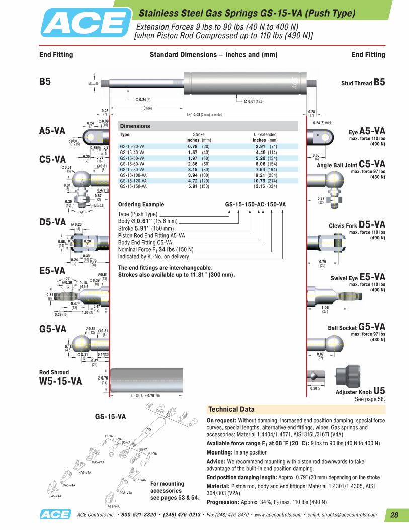
Stainless Steel Gas Springs GS-15-VA (Push Type) Extension Forces 9 lbs to 90 lbs (40 N to 400 N) [when Piston Rod Compressed up to 110 lbs (490 N)]
End Fitting End FittingStandard Dimensions
Ø
Ø
Ø
M5x0.8
36°
0.246.1
0.31(8)
0.35(9)
RadiusR0.2 (5)
0.24 (6) thick
M5x0.8
0.28(7) 0.28
(7)
0.24 (6)
Stroke
0.61 (15.6)
L = Stroke + 0.79 (20)
Ø Ø
Ø
0.39(10)
0.20(5)
0.20(5)
0.39(10)
0.31(8)
0.24(6)
0.28 (7)
0.75(19)
0.79(20)
L+/- 0.08 (2 mm) extended
Ø0.51(13)
0.47(12)0.31(8)
0.31(8)
Ø0.31(8)
Ø0.39(10)
Ø0.51(13)
0.55(14)
0.39(10)
0.47 (12)
0.20(5)
0.63(16)
0.63(16)
0.87(22)
0.79(20)
1.06(27)
0.87(22)
0.18(4.5)
0.87(22)
0.87(22)
24°
Ø
0.47(12)
0.39 (10)
0.20(5)
0.31(8)
1.06 (27)
0.18(4.5)
0.51(13)Ø 0.39
(10)
0.47(12)
Ø
DimensionsType
Stroke inches (mm)
L - extendedinches (mm)
GS-15-20-VA 0.79 (20) 2.91 (74)GS-15-40-VA 1.57 (40) 4.49 (114)GS-15-50-VA 1.97 (50) 5.28 (134)GS-15-60-VA 2.36 (60) 6.06 (154)GS-15-80-VA 3.15 (80) 7.64 (194)GS-15-100-VA 3.94 (100) 9.21 (234)GS-15-120-VA 4.72 (120) 10.79 (274)GS-15-150-VA 5.91 (150) 13.15 (334)
Ordering Example GS-15-150-AC-150-VAType (Push Type)Body Ø 0.61'' (15.6 mm)Stroke 5.91'' (150 mm)Piston Rod End Fitting A5-VABody End Fitting C5-VANominal Force F1 34 lbs (150 N)Indicated by K.-No. on delivery
The end fittings are interchangeable. Strokes also available up to 11.81" (300 mm).
A5-VA
MA5-V4A
NG5-V4A
NA5-V4A
OG5-V4A
OA5-V4A
PA5-V4A
PG5-V4A
C5-VAD5-VA
E5-VAG5-VA
Technical DataOn request: Without damping, increased end position damping, special force curves, special lengths, alternative end fittings, wiper. Gas springs and accessories: Material 1.4404/1.4571, AISI 316L/316Ti (V4A).Available force range F1 at 68 °F (20 °C): 9 lbs to 90 lbs (40 N to 400 N)Mounting: In any positionAdvice: We recommend mounting with piston rod downwards to take advantage of the built-in end position damping.End position damping length: Approx. 0.79" (20 mm) depending on the strokeMaterial: Piston rod, body and end fittings: Material 1.4301/1.4305, AISI 304/303 (V2A).Progression: Approx. 34%, F2 max. 110 lbs (490 N)
B5 Stud Thread B5
A5-VA Eye A5-VA max. force 110 lbs
(490 N)
C5-VAAngle Ball Joint C5-VA
max. force 97 lbs(430 N)
D5-VA Clevis Fork D5-VA max. force 110 lbs
(490 N)
E5-VASwivel Eye E5-VA
max. force 110 lbs(490 N)
G5-VA Ball Socket G5-VA max. force 97 lbs
(430 N)
Rod Shroud W5-15-VA
Adjuster Knob U5 See page 58.
For mounting accessories see pages 53 & 54.
GS-15-VA
End Fitting Standard Dimensions – inches and (mm) End Fitting
29 ACE Controls Inc. • 800-521-3320 • (248) 476-0213 • Fax (248) 476-2470 • www.acecontrols.com • email: [email protected]
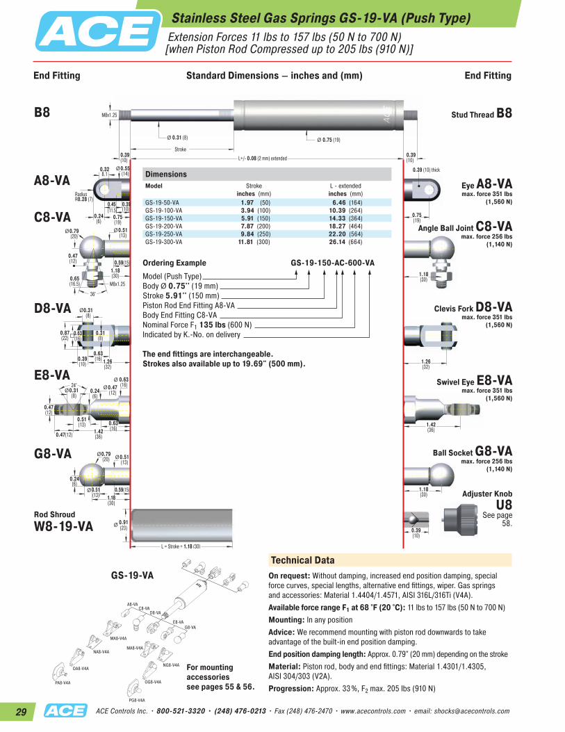
Stainless Steel Gas Springs GS-19-VA (Push Type) Extension Forces 11 lbs to 157 lbs (50 N to 700 N) [when Piston Rod Compressed up to 205 lbs (910 N)]
End Fitting End FittingStandard Dimensions
Ø
Ø
Ø
M8x1.25
36°
0.328.1
0.39(10)
0.45(11.5)
RadiusR0.28 (7)
0.39 (10) thick
M8x1.25
0.39 (10)
0.39(10)
0.31 (8)
Stroke
0.75 (19)
L = Stroke + 1.18 (30)
Ø Ø
Ø
0.63(16)
0.31(8)
0.31(8)
0.65(16.5)
0.47(12)
0.39(10)
0.39(10)
0.91(23)
1.26(32)
L+/- 0.08 (2 mm) extended
Ø0.79(20)
0.59(15)0.51(13)
0.51(13)
Ø0.51(13)
Ø0.55(14)
Ø0.79(20)
0.87(22)
0.63(16)
0.59(15)
0.24(6)
0.75(19)
0.75(19)
1.18(30)
1.26(32)
1.42(36)
1.18(30)
0.24(6)
1.18(30)
1.18(30)
24°
Ø
0.51(13)
0.47(12)
0.31(8)
0.47(12)
1.42(36)
0.24(6)
0.63(16)Ø 0.47
(12)
0.63(16)
Ø
DimensionsModel
Stroke inches (mm)
L - extendedinches (mm)
GS-19-50-VA 1.97 (50) 6.46 (164)GS-19-100-VA 3.94 (100) 10.39 (264)GS-19-150-VA 5.91 (150) 14.33 (364)GS-19-200-VA 7.87 (200) 18.27 (464)GS-19-250-VA 9.84 (250) 22.20 (564)GS-19-300-VA 11.81 (300) 26.14 (664)
Ordering Example GS-19-150-AC-600-VAModel (Push Type)Body Ø 0.75'' (19 mm)Stroke 5.91'' (150 mm)Piston Rod End Fitting A8-VABody End Fitting C8-VANominal Force F1 135 lbs (600 N)Indicated by K.-No. on delivery
The end fittings are interchangeable. Strokes also available up to 19.69" (500 mm).
A8-VA
MA8-V4A
MA8-V4A
NG8-V4A
NA8-V4A
OG8-V4A
OA8-V4A
PA8-V4A
PG8-V4A
C8-VAD8-VA
E8-VAG8-VA
Technical DataOn request: Without damping, increased end position damping, special force curves, special lengths, alternative end fittings, wiper. Gas springs and accessories: Material 1.4404/1.4571, AISI 316L/316Ti (V4A).Available force range F1 at 68 °F (20 °C): 11 lbs to 157 lbs (50 N to 700 N)Mounting: In any positionAdvice: We recommend mounting with piston rod downwards to take advantage of the built-in end position damping.End position damping length: Approx. 0.79" (20 mm) depending on the strokeMaterial: Piston rod, body and end fittings: Material 1.4301/1.4305, AISI 304/303 (V2A).Progression: Approx. 33%, F2 max. 205 lbs (910 N)
B8 Stud Thread B8
A8-VA Eye A8-VA max. force 351 lbs
(1,560 N)
C8-VAAngle Ball Joint C8-VA
max. force 256 lbs (1,140 N)
D8-VA Clevis Fork D8-VA max. force 351 lbs
(1,560 N)
E8-VA Swivel Eye E8-VA max. force 351 lbs
(1,560 N)
G8-VA Ball Socket G8-VA max. force 256 lbs
(1,140 N)
Rod Shroud W8-19-VA
Adjuster Knob U8
See page 58.
For mounting accessories see pages 55 & 56.
GS-19-VA
End Fitting Standard Dimensions – inches and (mm) End Fitting

30ACE Controls Inc. • 800-521-3320 • (248) 476-0213 • Fax (248) 476-2470 • www.acecontrols.com • email: [email protected]
End Fitting End FittingStandard Dimensions
Ø
Ø
Ø
M8x1.25
36°
0.328.1
0.39(10)
0.45(11.5)
RadiusR0.28 (7)
0.39 (10) thick
M8x1.25
0.39 (10)
0.39 (10)
0.39 (10)
Stroke
0.91 (23)
L = Stroke + 1.18 (30)
Ø Ø
Ø
0.63(16)
0.31(8)
0.31(8)
0.65(16.5)
0.47(12)
0.39(10)
0.39(10)
1.10(28)
1.26(32)
L+/- 0.08 (2 mm) extended
Ø0.79(20)
0.59(15)
0.51(13)
0.51(13)
Ø0.51(13)
Ø0.39(10)
Ø0.79(20)
0.87(22)
0.63(16)
0.59(15)
0.24(6)
0.75(19)
0.75(19)
1.18(30)
1.26(32)
1.42(36)
1.18(30)
0.24(6)
1.18(30)
1.18(30)
24°
Ø
0.51(13)0.47
(12)
0.31(8)
0.47(12)
1.42(36)
0.24(6)
0.63(16)Ø 0.47
(12)
0.63(16)
Ø
Stainless Steel Gas Springs GS-22-VA (Push Type) Extension Forces 22 lbs to 270 lbs (100 N to 1,200 N) [when Piston Rod Compressed up to 351 lbs (1,560 N)]
DimensionsType
Stroke inches (mm)
L - extendedinches (mm)
GS-22-50-VA 1.97 (50) 6.46 (164)GS-22-100-VA 3.94 (100) 10.39 (264)GS-22-150-VA 5.91 (150) 14.33 (364)GS-22-200-VA 7.87 (200) 18.28 (464)GS-22-250-VA 9.84 (250) 22.20 (564)GS-22-300-VA 11.81 (300) 26.14 (664)GS-22-350-VA 13.78 (350) 30.08 (764)GS-22-400-VA 15.75 (400) 34.02 (864)GS-22-450-VA 17.72 (450) 37.95 (964)GS-22-500-VA 19.69 (500) 41.89 (1,064)GS-22-550-VA 21.65 (550) 45.83 (1,164)GS-22-600-VA 23.62 (600) 49.76 (1,264)GS-22-650-VA 25.59 (650) 53.70 (1,364)GS-22-700-VA 27.56 (700) 57.64 (1,464)
Ordering Example GS-22-150-AE-800-VAType (Push Type)Body Ø 0.91'' (23 mm)Stroke 5.91'' (150 mm)Piston Rod End Fitting A8-VABody End Fitting E8-VANominal Force F1 180 lbs (800 N)Indicated by K.-No. on delivery
The end fittings are interchangeable.
A8-VA
MA8-V4A
MA8-V4A
NG8-V4A
NA8-V4A
OG8-V4A
OA8-V4A
PA8-V4A
PG8-V4A
C8-VAD8-VA
E8-VAG8-VA
Technical DataOn request: Without damping, increased end position damping, special force curves, special lengths, alternative end fittings, wiper. Gas springs and accessories: Material 1.4404/1.4571, AISI 316L/316Ti (V4A).Available force range F1 at 68 °F (20 °C): 22 lbs to 270 lbs (100 N to 1,200 N)Mounting: In any positionAdvice: We recommend mounting with piston rod downwards to take advantage of the built-in end position damping.End position damping length: Approx. 0.79" (20 mm) depending on the strokeMaterial: Piston rod, body and end fittings: Material 1.4301/1.4305, AISI 304/303 (V2A).Progression: Approx. 32%, F2 max. 351 lbs (1,560 N)
B8 Stud Thread B8
A8-VA Eye A8-VA max. force 351 lbs
(1,560 N)
C8-VAAngle Ball Joint C8-VA
max. force 256 lbs (1,140 N)
D8-VA Clevis Fork D8-VA max. force 351 lbs
(1,560 N)
E8-VASwivel Eye E8-VA
max. force 351 lbs (1,560 N)
G8-VA Ball Socket G8-VA max. force 256 lbs
(1,140 N)
Rod Shroud W8-22-VA
Adjuster Knob U8 See page 58.
For mounting accessories see pages 55 & 56.
GS-22-VA
End Fitting Standard Dimensions – inches and (mm) End Fitting
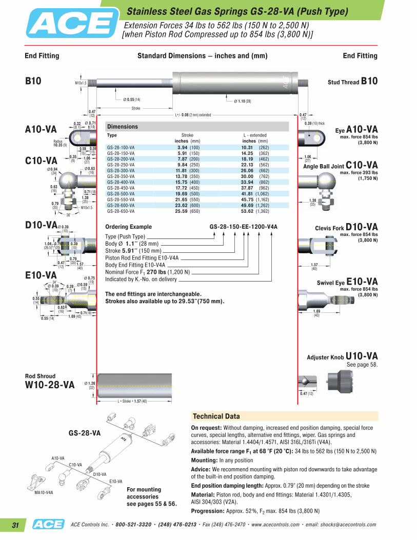
31 ACE Controls Inc. • 800-521-3320 • (248) 476-0213 • Fax (248) 476-2470 • www.acecontrols.com • email: [email protected]
Stainless Steel Gas Springs GS-28-VA (Push Type) Extension Forces 34 lbs to 562 lbs (150 N to 2,500 N) [when Piston Rod Compressed up to 854 lbs (3,800 N)]
End Fitting End FittingStandard Dimensions
Ø
M10x1.5
36°
0.32(8.1)
0.59(15)
0.59(15)
RadiusR0.35 (9)
0.39 (10) thick
M10x1.5
0.47(12) 0.47
(12)
0.55 (14)
Stroke
1.10 (28)
L = Stroke + 1.57 (40)
Ø Ø
Ø
0.79(20)
0.39(10)
0.39(10)
0.79(20)
0.63(16)
0.47(12)
0.47 (12)
1.26(32)
1.57(40)
L+/- 0.08 (2 mm) extended
Ø0.63(16)
Ø 0.71(18)
Ø0.94(24)
1.04(26.5)
0.79(20)
0.71 (18)
0.35(9) 1.06
(27)1.06(27)
1.38(35)
1.57(40)
1.69(43)
1.38(35)
24°
Ø
0.63(16)
0.55 (14)
0.39(10)
0.55(14)
1.69 (43)
0.28(7)
0.75(19)
Ø 0.59(15)
0.71(18)
Ø
DimensionsType
Stroke inches (mm)
L - extendedinches (mm)
GS-28-100-VA 3.94 (100) 10.31 (262)GS-28-150-VA 5.91 (150) 14.25 (362)GS-28-200-VA 7.87 (200) 18.19 (462)GS-28-250-VA 9.84 (250) 22.13 (562)GS-28-300-VA 11.81 (300) 26.06 (662)GS-28-350-VA 13.78 (350) 30.00 (762)GS-28-400-VA 15.75 (400) 33.94 (862)GS-28-450-VA 17.72 (450) 37.87 (962)GS-28-500-VA 19.69 (500) 41.81 (1,062)GS-28-550-VA 21.65 (550) 45.75 (1,162)GS-28-600-VA 23.62 (600) 49.69 (1,262)GS-28-650-VA 25.59 (650) 53.62 (1,362)
Ordering Example GS-28-150-EE-1200-V4AType (Push Type)Body Ø 1.1'' (28 mm)Stroke 5.91'' (150 mm)Piston Rod End Fitting E10-V4ABody End Fitting E10-V4ANominal Force F1 270 lbs (1,200 N)Indicated by K.-No. on delivery
The end fittings are interchangeable. Strokes also available up to 29.53"(750 mm).
A10-VAC10-VA
D10-VAE10-VA
MA10-V4A
Technical DataOn request: Without damping, increased end position damping, special force curves, special lengths, alternative end fittings, wiper. Gas springs and accessories: Material 1.4404/1.4571, AISI 316L/316Ti (V4A).Available force range F1 at 68 °F (20 °C): 34 lbs to 562 lbs (150 N to 2,500 N)Mounting: In any positionAdvice: We recommend mounting with piston rod downwards to take advantage of the built-in end position damping.End position damping length: Approx. 0.79" (20 mm) depending on the strokeMaterial: Piston rod, body and end fittings: Material 1.4301/1.4305, AISI 304/303 (V2A).Progression: Approx. 52%, F2 max. 854 lbs (3,800 N)
B10 Stud Thread B10
A10-VA Eye A10-VA max. force 854 lbs
(3,800 N)
C10-VAAngle Ball Joint C10-VA
max. force 393 lbs (1,750 N)
D10-VA Clevis Fork D10-VA max. force 854 lbs
(3,800 N)
E10-VASwivel Eye E10-VA
max. force 854 lbs (3,800 N)
Rod Shroud W10-28-VA
Adjuster Knob U10-VA See page 58.
For mounting accessories see pages 55 & 56.
GS-28-VA
End Fitting Standard Dimensions – inches and (mm) End Fitting
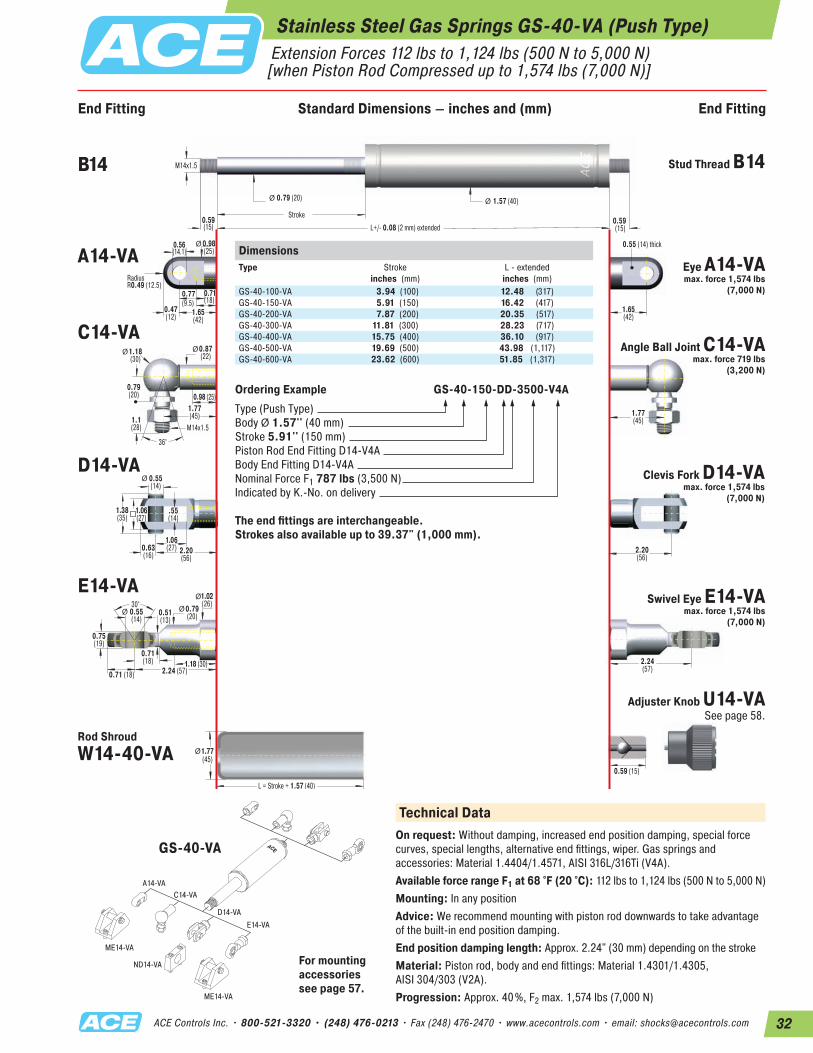
32ACE Controls Inc. • 800-521-3320 • (248) 476-0213 • Fax (248) 476-2470 • www.acecontrols.com • email: [email protected]
A14-VAC14-VA
D14-VAE14-VA
ME14-VA
ME14-VA
ND14-VA
Stainless Steel Gas Springs GS-40-VA (Push Type) Extension Forces 112 lbs to 1,124 lbs (500 N to 5,000 N) [when Piston Rod Compressed up to 1,574 lbs (7,000 N)]
End Fitting End FittingStandard Dimensions
Ø
M14x1.5
36°
0.56(14.1)
0.71(18)
0.77(9.5)
RadiusR0.49 (12.5)
0.55 (14) thick
M14x1.5
0.59(15)
0.59 (15)
0.79 (20)
Stroke
1.57 (40)
L = Stroke + 1.57 (40)
Ø Ø
Ø
1.06(27)
.55(14)
0.55(14)
1.1(28)
0.79(20)
0.63(16)
0.59 (15)
1.77(45)
2.20(56)
L+/- 0.08 (2 mm) extended
Ø0.87(22)
Ø 0.98(25)
Ø1.18(30)
1.38(35)
1.06(27)
0.98 (25)
0.47(12) 1.65
(42)1.65(42)
1.77(45)
2.20(56)
2.24(57)
1.77(45)
30°
Ø
0.71(18)
0.71 (18)
0.55(14)
0.75(19)
2.24 (57)
0.51(13)
1.02(26)
Ø 0.79(20)
1.18 (30)
Ø
DimensionsType
Stroke inches (mm)
L - extendedinches (mm)
GS-40-100-VA 3.94 (100) 12.48 (317)GS-40-150-VA 5.91 (150) 16.42 (417)GS-40-200-VA 7.87 (200) 20.35 (517)GS-40-300-VA 11.81 (300) 28.23 (717)GS-40-400-VA 15.75 (400) 36.10 (917)GS-40-500-VA 19.69 (500) 43.98 (1,117)GS-40-600-VA 23.62 (600) 51.85 (1,317)
Ordering Example GS-40-150-DD-3500-V4AType (Push Type)Body Ø 1.57'' (40 mm)Stroke 5.91'' (150 mm)Piston Rod End Fitting D14-V4ABody End Fitting D14-V4ANominal Force F1 787 lbs (3,500 N)Indicated by K.-No. on delivery
The end fittings are interchangeable. Strokes also available up to 39.37" (1,000 mm).
GS-40-VA
Technical DataOn request: Without damping, increased end position damping, special force curves, special lengths, alternative end fittings, wiper. Gas springs and accessories: Material 1.4404/1.4571, AISI 316L/316Ti (V4A).Available force range F1 at 68 °F (20 °C): 112 lbs to 1,124 lbs (500 N to 5,000 N)Mounting: In any positionAdvice: We recommend mounting with piston rod downwards to take advantage of the built-in end position damping.End position damping length: Approx. 2.24" (30 mm) depending on the strokeMaterial: Piston rod, body and end fittings: Material 1.4301/1.4305, AISI 304/303 (V2A).Progression: Approx. 40%, F2 max. 1,574 lbs (7,000 N)
B14 Stud Thread B14
A14-VAEye A14-VA max. force 1,574 lbs
(7,000 N)
C14-VAAngle Ball Joint C14-VA
max. force 719 lbs (3,200 N)
D14-VA Clevis Fork D14-VA max. force 1,574 lbs
(7,000 N)
E14-VASwivel Eye E14-VA
max. force 1,574 lbs (7,000 N)
Rod Shroud W14-40-VA
Adjuster Knob U14-VA See page 58.
For mounting accessories see page 57.
End Fitting Standard Dimensions – inches and (mm) End Fitting

33 ACE Controls Inc. • 800-521-3320 • (248) 476-0213 • Fax (248) 476-2470 • www.acecontrols.com • email: [email protected]
Industrial traction gas springs are main- tenance-free and ready to install. They are available ex-stock with body diameters from 0.59" to 1.57" (15 mm to 40 mm) and forces from 7 lbs to 1,124 lbs (30 N to 5,000 N) with valve. ACE traction gas springs offer a long service life due to the hard-chromed piston rod and integral sliding bearing. They can be installed in any position. The traction force can be subsequently adjusted by means of the valve. The comprehensive range of fitting parts ensures easy installation and makes the traction gas springs universal in use. They supply the muscle force and enable the controlled raising and lowering of covers, hoods, flaps etc. With the free ACE calculation service, the traction gas springs are designed with mounting points to fit the individual application, and can be delivered ex-stock as express deliveries within 24 hours.
Function: ACE industrial traction gas springs are maintenance-free, closed systems, which are filled with pressurised nitrogen gas. Compared to the push type, ACE traction gas springs work in the reverse way. The piston rod is retracted by the gas pressure in the cylinder. The surface of the piston ring be- tween the piston rod and the inner tube determines the force of the gas spring. Traction gas springs are always mounted with the stroke fully compressed.Operating fluid: Nitrogen gasMounting: In any positionOperating temperature range: -4 °F to 176 °F (-20 °C to 80 °C)On request: Special force curves, special lengths, alternative seals and end fittings.
Traction Gas Springs GZ-15 to GZ-40 (Pull Type)
Filled with High Pressure Nitrogen Gas
Seals
Piston Rod
Gas Valve
Main Bearing
Outer Body
Piston with Seals
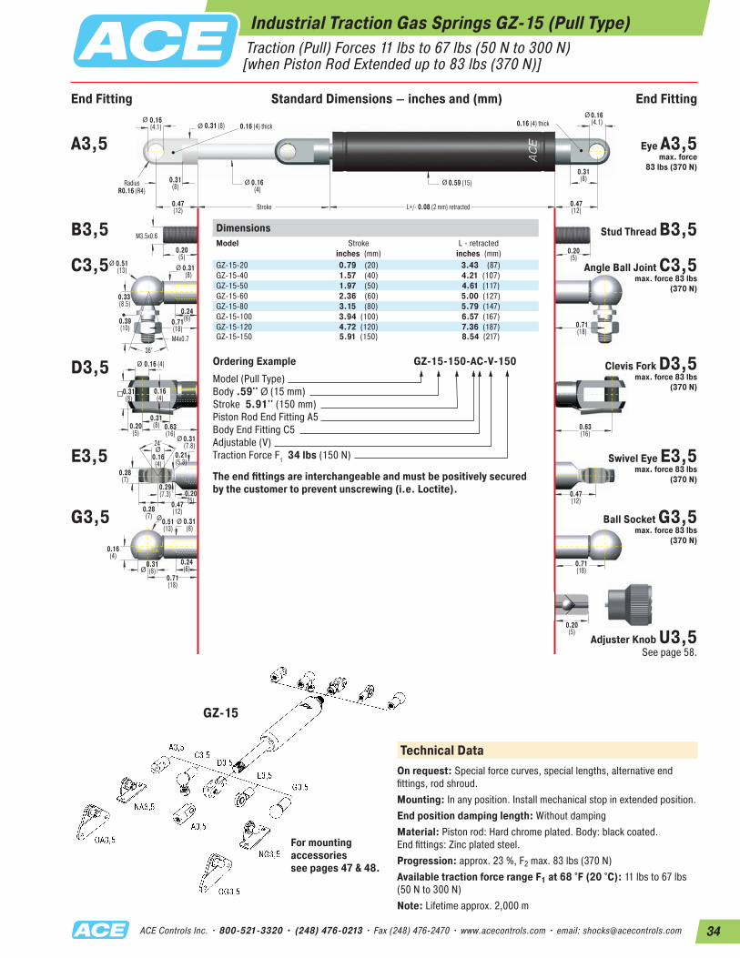
34ACE Controls Inc. • 800-521-3320 • (248) 476-0213 • Fax (248) 476-2470 • www.acecontrols.com • email: [email protected]
Industrial Traction Gas Springs GZ-15 (Pull Type) Traction (Pull) Forces 11 lbs to 67 lbs (50 N to 300 N) [when Piston Rod Extended up to 83 lbs (370 N)]
End Fitting End FittingStandard Dimensions
24°
ØØ
0.20(5)
0.16(4.1) 0.16 (4) thick 0.16 (4) thick0.31 (8)
0.59 (15)
0.20(5)
M3.5x0.6
L+/- 0.08 (2 mm) retracted
Stroke
RadiusR0.16 (R4)
ØØ
Ø
Ø Ø
ØØ
0.16 (4)Ø
Ø
M4x0.7
0.31(8)
0.51(13)
0.33(8.5)
0.31(8) 0.16
(4)
0.24(6)0.71
(18) 0.71(18)
0.16(4)
0.31(8)
0.31(8)0.20
(5)
0.28(7)
0.16(4)
0.28(7)
0.47(12)
0.47(12)
0.63(16)
0.63(16)
0.31(7.8)
0.21(5.3)
0.29(7.3)
0.16(4)
0.39(10)
36°
Ø Ø
0.20(5)
0.20(5)
0.51(13)
0.31(8)
0.31(8)
0.71(18)
0.71(18)
0.24(6)
0.47(12)
0.47(12)
0.16(4.1)
0.31(8)
DimensionsModel
Stroke inches (mm)
L - retractedinches (mm)
GZ-15-20 0.79 (20) 3.43 (87)GZ-15-40 1.57 (40) 4.21 (107)GZ-15-50 1.97 (50) 4.61 (117)GZ-15-60 2.36 (60) 5.00 (127)GZ-15-80 3.15 (80) 5.79 (147)GZ-15-100 3.94 (100) 6.57 (167)GZ-15-120 4.72 (120) 7.36 (187)GZ-15-150 5.91 (150) 8.54 (217)
Ordering Example GZ-15-150-AC-V-150Model (Pull Type)Body .59'' Ø (15 mm)Stroke 5.91'' (150 mm)Piston Rod End Fitting A5Body End Fitting C5Adjustable (V)Traction Force F1 34 lbs (150 N)
The end fittings are interchangeable and must be positively secured by the customer to prevent unscrewing (i.e. Loctite).
GZ-15
Technical DataOn request: Special force curves, special lengths, alternative end fittings, rod shroud.Mounting: In any position. Install mechanical stop in extended position.End position damping length: Without dampingMaterial: Piston rod: Hard chrome plated. Body: black coated. End fittings: Zinc plated steel.Progression: approx. 23 %, F2 max. 83 lbs (370 N)Available traction force range F1 at 68 °F (20 °C): 11 lbs to 67 lbs (50 N to 300 N)Note: Lifetime approx. 2,000 m
A3,5 Eye A3,5 max. force
83 lbs (370 N)
B3,5 Stud Thread B3,5
C3,5 Angle Ball Joint C3,5 max. force 83 lbs
(370 N)
D3,5 Clevis Fork D3,5 max. force 83 lbs
(370 N)
E3,5 Swivel Eye E3,5 max. force 83 lbs
(370 N)
G3,5 Ball Socket G3,5 max. force 83 lbs
(370 N)
Adjuster Knob U3,5 See page 58.
For mounting accessories see pages 47 & 48.
End Fitting Standard Dimensions – inches and (mm) End Fitting
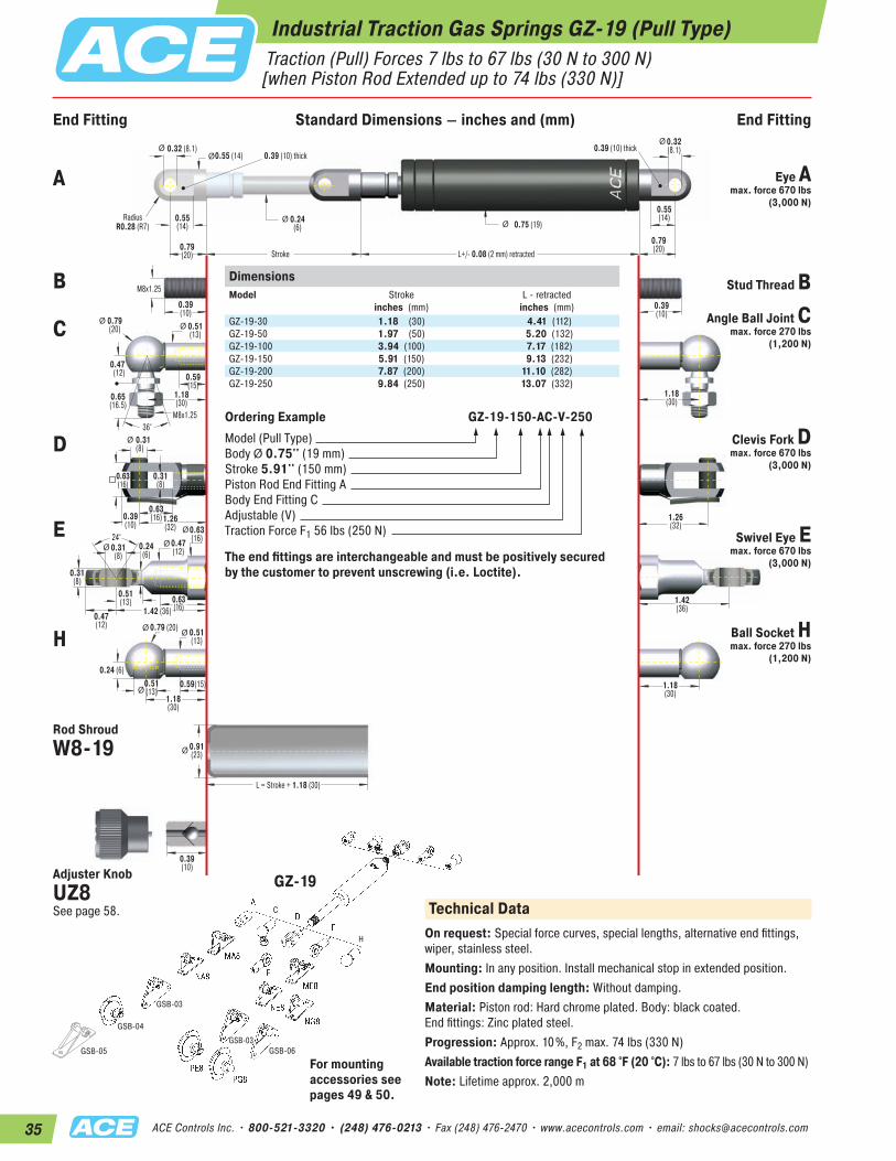
35 ACE Controls Inc. • 800-521-3320 • (248) 476-0213 • Fax (248) 476-2470 • www.acecontrols.com • email: [email protected]
C
GSB-06GSB-03
GSB-03
GSB-04
GSB-05
H
End Fitting End FittingStandard Dimensions
24°
Ø
0.39(10)
0.32 (8.1)0.39 (10) thick
0.39 (10) thick0.55 (14)
0.75 (19)
0.39(10)
M8x1.25
L+/- 0.08 (2 mm) retracted
Stroke
RadiusR0.28 (R7)
Ø Ø
ØØ
0.31(8)
Ø
Ø
M8x1.25
0.51(13)
0.79(20)
0.47(12)
0.55(14)
0.24(6)
0.59(15)
0.51(13)
1.18(30)
1.18(30)
0.31(8)
0.63(16)
0.63(16)
0.47(12)
0.39(10)
0.31(8)
0.31(8)
1.42 (36)
0.24 (6)
1.42(36)
1.26(32)
1.26(32)0.63
(16)0.47(12)0.24
(6)
0.65(16.5)
36°
Ø Ø
0.63(16)
Ø 0.51(13)
0.91(23)
0.51(13)
0.59(15)
1.18(30)
1.18(30)
0.79(20)
0.79(20)
0.32(8.1)
0.55(14)
Ø
0.79 (20)
L = Stroke + 1.18 (30)
Ø
Ø
Ø
Ø
0.39(10)
DimensionsModel
Stroke inches (mm)
L - retractedinches (mm)
GZ-19-30 1.18 (30) 4.41 (112)GZ-19-50 1.97 (50) 5.20 (132)GZ-19-100 3.94 (100) 7.17 (182)GZ-19-150 5.91 (150) 9.13 (232)GZ-19-200 7.87 (200) 11.10 (282)GZ-19-250 9.84 (250) 13.07 (332)
Ordering Example GZ-19-150-AC-V-250Model (Pull Type)Body Ø 0.75'' (19 mm)Stroke 5.91'' (150 mm)Piston Rod End Fitting ABody End Fitting CAdjustable (V)Traction Force F1 56 lbs (250 N)
The end fittings are interchangeable and must be positively secured by the customer to prevent unscrewing (i.e. Loctite).
GZ-19Technical Data
On request: Special force curves, special lengths, alternative end fittings, wiper, stainless steel.Mounting: In any position. Install mechanical stop in extended position.End position damping length: Without damping.Material: Piston rod: Hard chrome plated. Body: black coated. End fittings: Zinc plated steel.Progression: Approx. 10%, F2 max. 74 lbs (330 N)Available traction force range F1 at 68 °F (20 °C): 7 lbs to 67 lbs (30 N to 300 N)Note: Lifetime approx. 2,000 m
A Eye A max. force 670 lbs
(3,000 N)
B Stud Thread B
C Angle Ball Joint C max. force 270 lbs
(1,200 N)
D Clevis Fork D max. force 670 lbs
(3,000 N)
E Swivel Eye E max. force 670 lbs
(3,000 N)
H Ball Socket H max. force 270 lbs
(1,200 N)
Rod Shroud W8-19
Adjuster Knob UZ8 See page 58.
Industrial Traction Gas Springs GZ-19 (Pull Type) Traction (Pull) Forces 7 lbs to 67 lbs (30 N to 300 N) [when Piston Rod Extended up to 74 lbs (330 N)]
For mounting accessories see pages 49 & 50.
End Fitting Standard Dimensions – inches and (mm) End Fitting
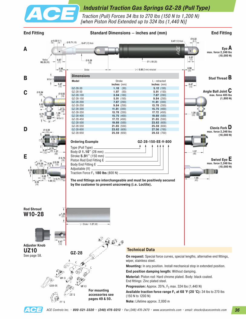
36ACE Controls Inc. • 800-521-3320 • (248) 476-0213 • Fax (248) 476-2470 • www.acecontrols.com • email: [email protected]
GSB-05
End Fitting End FittingStandard Dimensions
24°
Ø
Ø
0.47(12)
0.32 (8.1)0.47 (12) thick
0.47 (12) thick0.71 (18)
1.10 (28)
0.47(12)
M10x1.5
L+/- 0.08 (2 mm) retracted
Stroke
RadiusR0.35 (R9)
Ø Ø
ØØ
0.39(10)
Ø
Ø
M10x1.5
0.63(16)
0.94(24)
0.63(16)
0.67(17)
0.39(10)
0.71(18)
0.63(16)
1.38(35)
1.38(35)
0.39(10)
0.79(20)
0.79(20)
0.55(14)
0.47(12)
0.39(10)
0.35(9)
1.69 (43)1.69(43)
1.57(40)
1.57(40)
0.75(19)
0.59(15)0.28
(7)
0.79(20)
36°
Ø Ø
0.71 (18)
1.26(32)
0.98(25)
0.98(25)
0.32(8.1)
0.67(17)
Ø
L = Stroke + 1.57 (40)
Ø
0.47(12)
DimensionsModel
Stroke inches (mm)
L - retractedinches (mm)
GZ-28-30 1.18 (30) 5.12 (130)GZ-28-50 1.97 (50) 5.91 (150)GZ-28-100 3.94 (100) 7.87 (200)GZ-28-150 5.91 (150) 9.84 (250)GZ-28-200 7.87 (200) 11.81 (300)GZ-28-250 9.84 (250) 13.78 (350)GZ-28-300 11.81 (300) 15.75 (400)GZ-28-350 13.78 (350) 17.72 (450)GZ-28-400 15.75 (400) 19.69 (500)GZ-28-450 17.72 (450) 21.65 (550)GZ-28-500 19.69 (500) 23.62 (600)GZ-28-550 21.65 (550) 25.59 (650)GZ-28-600 23.62 (600) 27.56 (700)GZ-28-650 25.59 (650) 29.53 (750)
Ordering Example GZ-28-150-EE-V-800Type (Pull Type)Body Ø 1.10'' (28 mm)Stroke 5.91'' (150 mm)Piston Rod End Fitting EBody End Fitting EAdjustable (V)Traction Force F1 180 lbs (800 N)
The end fittings are interchangeable and must be positively secured by the customer to prevent unscrewing (i.e. Loctite).
GZ-28Technical Data
On request: Special force curves, special lengths, alternative end fittings, wiper, stainless steel.Mounting: In any position. Install mechanical stop in extended position.End position damping length: Without damping.Material: Piston rod: Hard chrome plated. Body: black coated. End fittings: Zinc plated steel.Progression: Approx. 20%, F2 max. 324 lbs (1,440 N)Available traction force range F1 at 68 °F (20 °C): 34 lbs to 270 lbs (150 N to 1200 N)Note: Lifetime approx. 2,000 m
A Eye A max. force 2,248 lbs
(10,000 N)
B Stud Thread B
C Angle Ball Joint C max. force 405 lbs
(1,800 N)
D Clevis Fork Dmax. force 2,248 lbs
(10,000 N)
E Swivel Eye E max. force 2,248 lbs
(10,000 N)
Rod Shroud W10-28
Adjuster Knob UZ10 See page 58.
For mounting accessories see pages 49 & 50.
Industrial Traction Gas Springs GZ-28 (Pull Type) Traction (Pull) Forces 34 lbs to 270 lbs (150 N to 1,200 N) [when Piston Rod Extended up to 324 lbs (1,440 N)]
End Fitting Standard Dimensions – inches and (mm) End Fitting
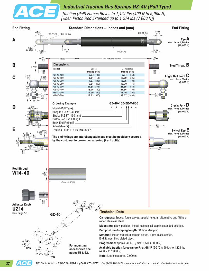
37 ACE Controls Inc. • 800-521-3320 • (248) 476-0213 • Fax (248) 476-2470 • www.acecontrols.com • email: [email protected]
End Fitting End FittingStandard Dimensions
1.06(27)
30°
Ø
0.56 (14.1) 0.55 (14) thick 0.55 (14) thick0.98 (25)
1.57 (40)
0.71(18)
L+/- 0.08 (2 mm) retracted
Stroke
RadiusR0.49 (R12.5) Ø
Ø
ØØ
0.55(14)
Ø
Ø
M14x1.5
0.87(22)
0.71(18)
1.18(30)
0.79(20)
0.83(21)
1.1(28)
0.98(25)
0.71(18)
1.77(45)
1.77(45)
0.55(14)
1.06(27)
0.71(18)
0.63(16)
0.55(14)
0.75(19)
2.24 (57)
2.24(57)
2.2(56)
0.51(13)
2.2(56)
1.02(26)Ø 0.79
(20)
1.1(28)
36°
ØØ
1.18(30)
1.77(45)
1.57(40)
1.57(40)
0.56(14.1)
0.83(21)
Ø
L = Stroke + 1.57 (40)
Ø
M14x1.5
0.59(15)
DimensionsModel
Stroke inches (mm)
L - retractedinches (mm)
GZ-40-100 3.94 (100) 9.84 (250)GZ-40-150 5.91 (150) 12.80 (325)GZ-40-200 7.87 (200) 15.75 (400)GZ-40-250 9.84 (250) 18.70 (475)GZ-40-300 11.81 (300) 21.65 (550)GZ-40-400 15.75 (400) 27.56 (700)GZ-40-500 19.69 (500) 33.46 (850)GZ-40-600 23.62 (600) 39.37 (1,000)
Ordering Example GZ-40-150-EE-V-800Model (Pull Type)Body Ø 1.57'' (40 mm)Stroke 5.91'' (150 mm)Piston Rod End Fitting EBody End Fitting EAdjustable (V)Traction Force F1 180 lbs (800 N)
The end fittings are interchangeable and must be positively secured by the customer to prevent unscrewing (i.e. Loctite).
GZ-40Technical Data
On request: Special force curves, special lengths, alternative end fittings, wiper, stainless steel.Mounting: In any position. Install mechanical stop in extended position.End position damping length: Without dampingMaterial: Piston rod: Hard chrome plated. Body: black coated. End fittings: Zinc plated steel.Progression: approx. 40%, F2 max. 1,574 (7,000 N)Available traction force range F1 at 68 °F (20 °C): 90 lbs to 1,124 lbs (400 N to 5,000 N)Note: Lifetime approx. 2,000 m
A Eye Amax. force 2,248 lbs
(10,000 N)
B Stud Thread B
C Angle Ball Joint Cmax. force 674 lbs
(3,000 N)
D Clevis Fork Dmax. force 2,248 lbs
(10,000 N)
E Swivel Eye Emax. force 2,248 lbs
(10,000 N)
Rod Shroud W14-40
Adjuster KnobUZ14See page 58.
Industrial Traction Gas Springs GZ-40 (Pull Type) Traction (Pull) Forces 90 lbs to 1,124 lbs (400 N to 5,000 N) [when Piston Rod Extended up to 1,574 lbs (7,000 N)]
For mounting accessories see pages 51 & 52.
End Fitting Standard Dimensions – inches and (mm) End Fitting

38ACE Controls Inc. • 800-521-3320 • (248) 476-0213 • Fax (248) 476-2470 • www.acecontrols.com • email: [email protected]
Operating fluid: Nitrogen gasMaterial: Piston rod, body and end fittings: Material 1.4301/1.4305, AISI 304/303 (V2A) and material 1.4404/1.4571, AISI 316L/316Ti (V4A).Mounting: In any positionOperating temperature range: -4 °F to 176 °F (-20 °C to 80 °C)On request: Special force curves, special lengths, alternative seals, wiper.
Stainless Steel Traction Gas Springs (Pull Type)
Filled with High Pressure Nitrogen Gas
Seals
Stainless Steel Piston Rod
Gas Valve
Stainless Steel Outer Body
Main Bearing
Piston with Seals
“The weatherproof ones!“
Stainless steel industrial traction gas springsMaterial 1.4301/1.4305, AISI 304/303 (V2A)Material 1.4404/1.4571, AISI 316L/316Ti (V4A)
In addition to the comprehensive range of industrial gas springs with valve, ACE also offers a wide range of industrial traction gas springs made of stainless steel with body diameters from 0.59" to 1.57" (15 mm to 40 mm). This high-quality version is also available on request in all stroke lengths and possible extension forces. The comprehensive range of fitting parts ensures easy installation and makes the gas traction springs universal in use. Stainless steel traction gas springs are used everywhere that raising and lowering is required. Due to their special properties, non-rusting and low magnetism, they are the preferred equipment for medical and clean-room technology, the foodstuffs industry, electronics and shipbuilding sector.
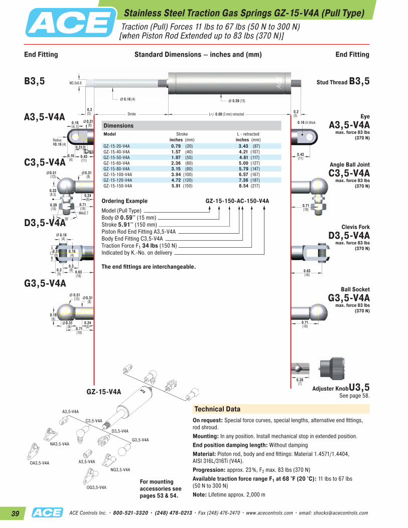
39 ACE Controls Inc. • 800-521-3320 • (248) 476-0213 • Fax (248) 476-2470 • www.acecontrols.com • email: [email protected]
End Fitting End FittingStandard Dimensions
0.24(6)
Ø
Ø
Ø
M4x0.736°
0.16(4.1)
0.24(6)0.31(8)
RadiusR0.16 (4)
0.16 (4 )thick
M3.5x0.6
0.2 (5) 0.2
(5)
0.16 (4)
Stroke
0.59 (15)Ø Ø
0.3(8)
0.16(4)
0.16(4)
0.39(10)
0.33(8.5)
0.2(5)
0.28(7)
0.63(16)
L+/- 0.08 (2 mm) retracted
Ø 0.51(13)
0.24(6)
0.31(8)
0.31(8)
Ø0.31(8)
Ø 0.31(8)
Ø0.51(13)
0.31(8)
0.16(4)
0.43(11)
0.43(11)
0.71(18)
0.63(16)
0.71(18)
0.16(4)
0.71(18)
0.71(18)
DimensionsModel
Stroke inches (mm)
L - retractedinches (mm)
GZ-15-20-V4A 0.79 (20) 3.43 (87)GZ-15-40-V4A 1.57 (40) 4.21 (107)GZ-15-50-V4A 1.97 (50) 4.61 (117)GZ-15-60-V4A 2.36 (60) 5.00 (127)GZ-15-80-V4A 3.15 (80) 5.79 (147)GZ-15-100-V4A 3.94 (100) 6.57 (167)GZ-15-120-V4A 4.72 (120) 7.36 (187)GZ-15-150-V4A 5.91 (150) 8.54 (217)
Ordering Example GZ-15-150-AC-150-V4AModel (Pull Type)Body Ø 0.59'' (15 mm)Stroke 5.91'' (150 mm)Piston Rod End Fitting A3,5-V4A Body End Fitting C3,5-V4ATraction Force F1 34 lbs (150 N)Indicated by K.-No. on delivery
The end fittings are interchangeable.
A3,5-V4A
C3,5-V4A
NA3,5-V4A
A3,5-V4A
NG3,5-V4A
OG3,5-V4A
OA3,5-V4A
D3,5-V4A
G3,5-V4A
Technical DataOn request: Special force curves, special lengths, alternative end fittings, rod shroud.Mounting: In any position. Install mechanical stop in extended position.End position damping length: Without dampingMaterial: Piston rod, body and end fittings: Material 1.4571/1.4404, AISI 316L/316Ti (V4A).Progression: approx. 23%, F2 max. 83 lbs (370 N)Available traction force range F1 at 68 °F (20 °C): 11 lbs to 67 lbs (50 N to 300 N)Note: Lifetime approx. 2,000 m
B3,5 Stud Thread B3,5
A3,5-V4A Eye A3,5-V4A
max. force 83 lbs (370 N)
C3,5-V4A Angle Ball Joint C3,5-V4A
max. force 83 lbs (370 N)
D3,5-V4A Clevis Fork D3,5-V4A
max. force 83 lbs (370 N)
G3,5-V4ABall Socket
G3,5-V4A max. force 83 lbs
(370 N)
Adjuster KnobU3,5 See page 58.GZ-15-V4A
For mounting accessories see pages 53 & 54.
Stainless Steel Traction Gas Springs GZ-15-V4A (Pull Type) Traction (Pull) Forces 11 lbs to 67 lbs (50 N to 300 N) [when Piston Rod Extended up to 83 lbs (370 N)]
End Fitting Standard Dimensions – inches and (mm) End Fitting
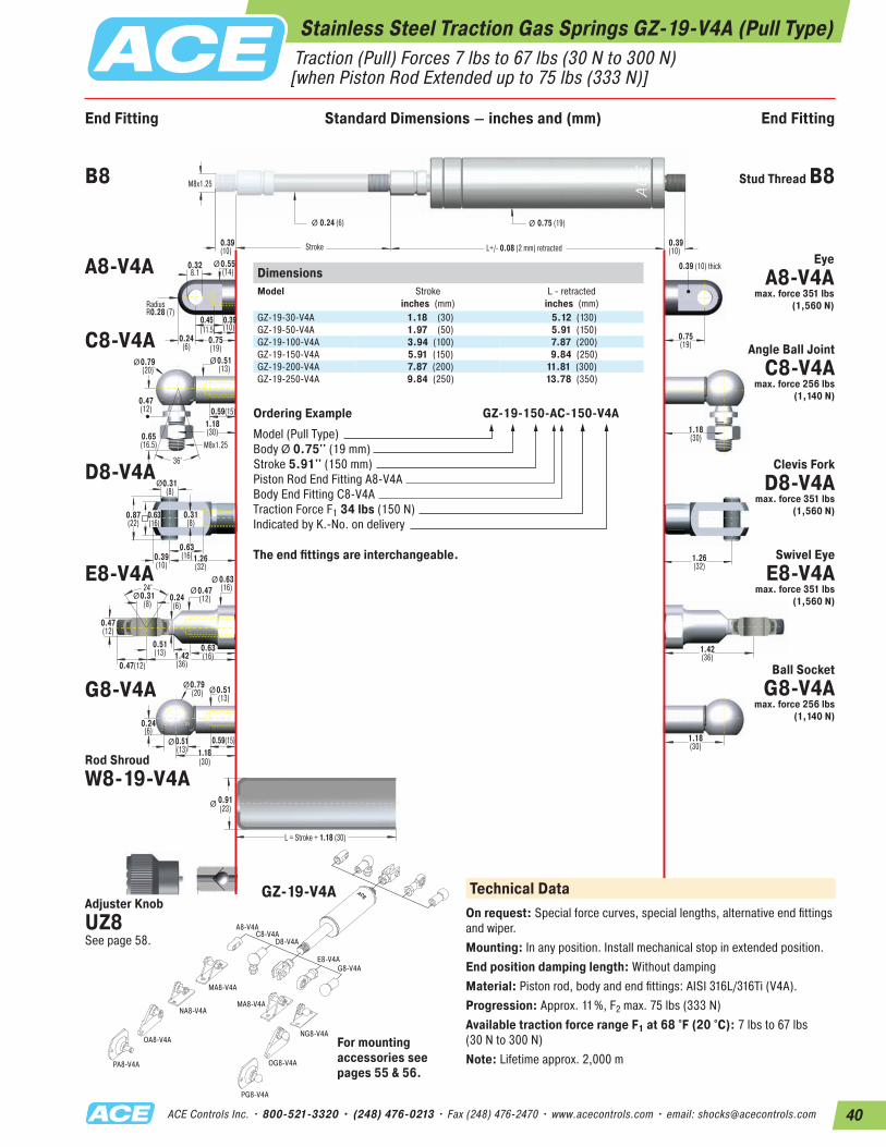
40ACE Controls Inc. • 800-521-3320 • (248) 476-0213 • Fax (248) 476-2470 • www.acecontrols.com • email: [email protected]
A8-V4A
MA8-V4A
MA8-V4A
NG8-V4A
NA8-V4A
OG8-V4A
OA8-V4A
PA8-V4A
PG8-V4A
C8-V4AD8-V4A
E8-V4AG8-V4A
End Fitting End FittingStandard Dimensions
Ø
Ø
Ø
M8x1.25
36°
0.328.1
0.39(10)
0.45(11.5)
RadiusR0.28 (7)
0.39 (10) thick
M8x1.25
0.39 (10)
0.39(10)
0.24 (6)
Stroke
0.75 (19)
L = Stroke + 1.18 (30)
Ø Ø
Ø
0.63(16)
0.31(8)
0.31(8)
0.65(16.5)
0.47(12)
0.39(10)
0.91(23)
1.26(32)
L+/- 0.08 (2 mm) retracted
Ø0.79(20)
0.59(15)0.51(13)
0.51(13)
Ø0.51(13)
Ø0.55(14)
Ø0.79(20)
0.87(22)
0.63(16)
0.59(15)
0.24(6)
0.75(19)
0.75(19)
1.18(30)
1.26(32)
1.42(36)
1.18(30)
0.24(6)
0.39(10)
1.18(30)
24°
Ø
0.51(13)
0.47(12)
0.31(8)
0.47(12)
1.42(36)
0.24(6)
0.63(16)Ø 0.47
(12)
0.63(16)
Ø
1.18(30)
DimensionsModel
Stroke inches (mm)
L - retractedinches (mm)
GZ-19-30-V4A 1.18 (30) 5.12 (130)GZ-19-50-V4A 1.97 (50) 5.91 (150)GZ-19-100-V4A 3.94 (100) 7.87 (200)GZ-19-150-V4A 5.91 (150) 9.84 (250)GZ-19-200-V4A 7.87 (200) 11.81 (300)GZ-19-250-V4A 9.84 (250) 13.78 (350)
Ordering Example GZ-19-150-AC-150-V4AModel (Pull Type)Body Ø 0.75'' (19 mm)Stroke 5.91'' (150 mm)Piston Rod End Fitting A8-V4A Body End Fitting C8-V4ATraction Force F1 34 lbs (150 N)Indicated by K.-No. on delivery
The end fittings are interchangeable.
GZ-19-V4A
B8 Stud Thread B8
A8-V4A Eye A8-V4A
max. force 351 lbs (1,560 N)
C8-V4A Angle Ball Joint C8-V4A
max. force 256 lbs (1,140 N)
D8-V4A Clevis Fork D8-V4A
max. force 351 lbs (1,560 N)
E8-V4ASwivel Eye
E8-V4A max. force 351 lbs
(1,560 N)
G8-V4ABall Socket
G8-V4A max. force 256 lbs
(1,140 N)
Rod Shroud W8-19-V4A
Adjuster KnobUZ8 See page 58.
For mounting accessories see pages 55 & 56.
Technical DataOn request: Special force curves, special lengths, alternative end fittings and wiper. Mounting: In any position. Install mechanical stop in extended position.End position damping length: Without dampingMaterial: Piston rod, body and end fittings: AISI 316L/316Ti (V4A).Progression: Approx. 11%, F2 max. 75 lbs (333 N)Available traction force range F1 at 68 °F (20 °C): 7 lbs to 67 lbs (30 N to 300 N)Note: Lifetime approx. 2,000 m
Stainless Steel Traction Gas Springs GZ-19-V4A (Pull Type) Traction (Pull) Forces 7 lbs to 67 lbs (30 N to 300 N) [when Piston Rod Extended up to 75 lbs (333 N)]
End Fitting Standard Dimensions – inches and (mm) End Fitting
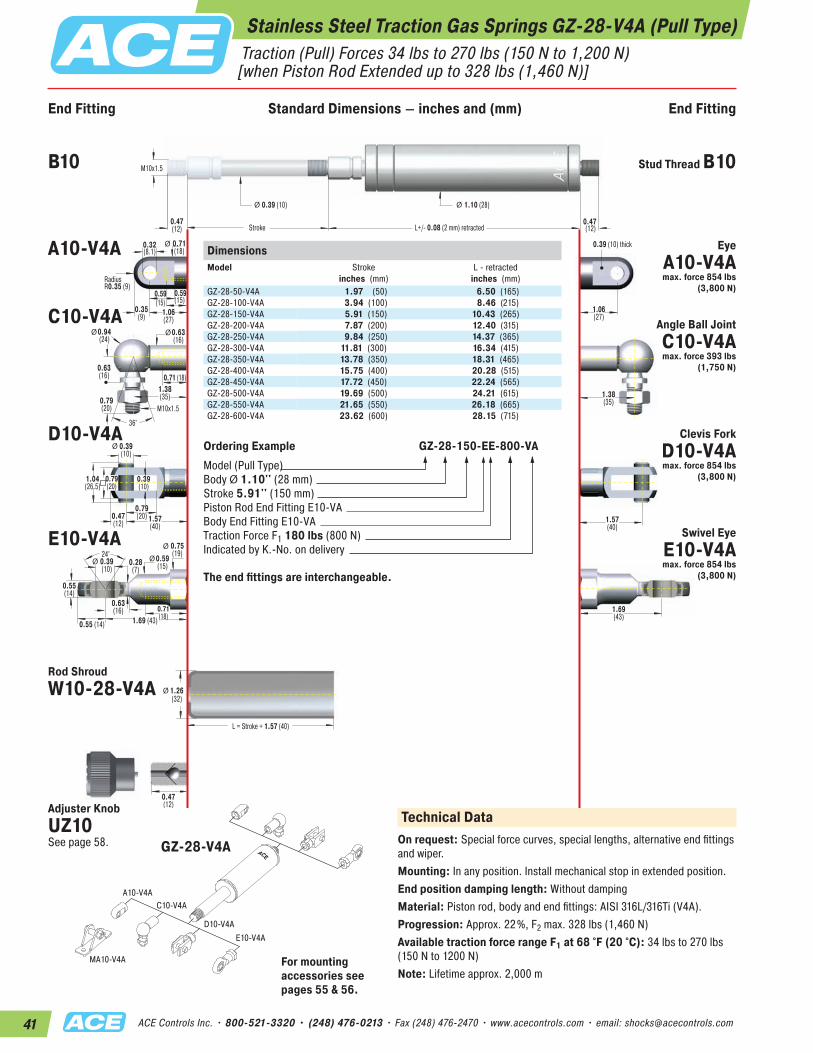
41 ACE Controls Inc. • 800-521-3320 • (248) 476-0213 • Fax (248) 476-2470 • www.acecontrols.com • email: [email protected]
End Fitting End FittingStandard Dimensions
Ø
M10x1.5
36°
0.32(8.1)
0.59(15)
0.59(15)
RadiusR0.35 (9)
0.39 (10) thick
M10x1.5
0.47(12)
0.47 (12)
0.39 (10)
Stroke
1.10 (28)
L = Stroke + 1.57 (40)
Ø Ø
Ø
0.79(20)
0.39(10)
0.39(10)
0.79(20)
0.63(16)
0.47(12)
1.26(32)
1.57(40)
L+/- 0.08 (2 mm) retracted
Ø0.63(16)
Ø 0.71(18)
Ø0.94(24)
1.04(26.5)
0.79(20)
0.71 (18)
0.35(9) 1.06
(27)1.06(27)
1.38(35)
1.57(40)
1.69(43)
1.38(35)
24°
Ø
0.63(16)
0.55 (14)
0.39(10)
0.55(14)
1.69 (43)
0.28(7)
0.75(19)
Ø 0.59(15)
0.71(18)
Ø
0.47(12)
DimensionsModel
Stroke inches (mm)
L - retractedinches (mm)
GZ-28-50-V4A 1.97 (50) 6.50 (165)GZ-28-100-V4A 3.94 (100) 8.46 (215)GZ-28-150-V4A 5.91 (150) 10.43 (265)GZ-28-200-V4A 7.87 (200) 12.40 (315)GZ-28-250-V4A 9.84 (250) 14.37 (365)GZ-28-300-V4A 11.81 (300) 16.34 (415)GZ-28-350-V4A 13.78 (350) 18.31 (465)GZ-28-400-V4A 15.75 (400) 20.28 (515)GZ-28-450-V4A 17.72 (450) 22.24 (565)GZ-28-500-V4A 19.69 (500) 24.21 (615)GZ-28-550-V4A 21.65 (550) 26.18 (665)GZ-28-600-V4A 23.62 (600) 28.15 (715)
Ordering Example GZ-28-150-EE-800-VAModel (Pull Type)Body Ø 1.10'' (28 mm)Stroke 5.91'' (150 mm)Piston Rod End Fitting E10-VA Body End Fitting E10-VATraction Force F1 180 lbs (800 N)Indicated by K.-No. on delivery
The end fittings are interchangeable.
A10-V4AC10-V4A
D10-V4AE10-V4A
MA10-V4A
Technical DataOn request: Special force curves, special lengths, alternative end fittings and wiper.Mounting: In any position. Install mechanical stop in extended position.End position damping length: Without dampingMaterial: Piston rod, body and end fittings: AISI 316L/316Ti (V4A).Progression: Approx. 22%, F2 max. 328 lbs (1,460 N)Available traction force range F1 at 68 °F (20 °C): 34 lbs to 270 lbs (150 N to 1200 N)Note: Lifetime approx. 2,000 m
B10 Stud Thread B10
A10-V4A Eye A10-V4A max. force 854 lbs
(3,800 N)
C10-V4A Angle Ball Joint C10-V4A max. force 393 lbs
(1,750 N)
D10-V4A Clevis Fork D10-V4A max. force 854 lbs
(3,800 N)
E10-V4A Swivel Eye E10-V4A max. force 854 lbs
(3,800 N)
Rod Shroud W10-28-V4A
Adjuster KnobUZ10 See page 58. GZ-28-V4A
For mounting accessories see pages 55 & 56.
Stainless Steel Traction Gas Springs GZ-28-V4A (Pull Type) Traction (Pull) Forces 34 lbs to 270 lbs (150 N to 1,200 N) [when Piston Rod Extended up to 328 lbs (1,460 N)]
End Fitting Standard Dimensions – inches and (mm) End Fitting
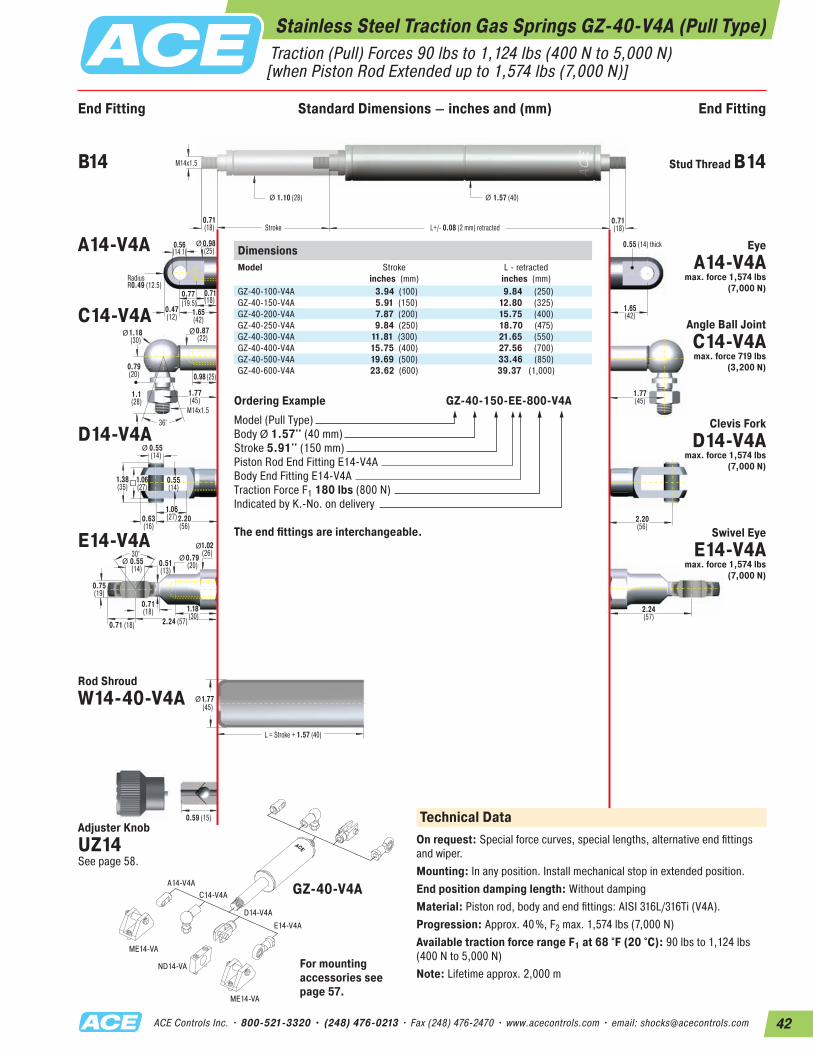
42ACE Controls Inc. • 800-521-3320 • (248) 476-0213 • Fax (248) 476-2470 • www.acecontrols.com • email: [email protected]
End Fitting End FittingStandard Dimensions
Ø
M14x1.536°
0.56(14.1)
0.71(18)
0.77(19.5)
RadiusR0.49 (12.5)
0.55 (14) thick
M14x1.5
0.71(18)
0.71 (18)
1.10 (28)
Stroke
1.57 (40)
L = Stroke + 1.57 (40)
Ø Ø
Ø
1.06(27)
0.55(14)
0.55(14)
1.1(28)
0.79(20)
0.63(16)
0.59 (15)
1.77(45)
2.20(56)
L+/- 0.08 (2 mm) retracted
Ø0.87(22)
Ø 0.98(25)
Ø1.18(30)
1.38(35)
1.06(27)
0.98 (25)
0.47(12) 1.65
(42)1.65(42)
1.77(45)
2.20(56)
2.24(57)
1.77(45)
30°
Ø
0.71(18)
0.71 (18)
0.55(14)
0.75(19)
2.24 (57)
0.51(13)
1.02(26)Ø 0.79
(20)
1.18(30)
Ø
DimensionsModel
Stroke inches (mm)
L - retractedinches (mm)
GZ-40-100-V4A 3.94 (100) 9.84 (250)GZ-40-150-V4A 5.91 (150) 12.80 (325)GZ-40-200-V4A 7.87 (200) 15.75 (400)GZ-40-250-V4A 9.84 (250) 18.70 (475)GZ-40-300-V4A 11.81 (300) 21.65 (550)GZ-40-400-V4A 15.75 (400) 27.56 (700)GZ-40-500-V4A 19.69 (500) 33.46 (850)GZ-40-600-V4A 23.62 (600) 39.37 (1,000)
Ordering Example GZ-40-150-EE-800-V4AModel (Pull Type)Body Ø 1.57'' (40 mm)Stroke 5.91'' (150 mm)Piston Rod End Fitting E14-V4A Body End Fitting E14-V4ATraction Force F1 180 lbs (800 N)Indicated by K.-No. on delivery
The end fittings are interchangeable.
A14-V4AC14-V4A
D14-V4AE14-V4A
ME14-VA
ME14-VA
ND14-VA
B14 Stud Thread B14
A14-V4A Eye A14-V4A
max. force 1,574 lbs (7,000 N)
C14-V4A Angle Ball Joint C14-V4A max. force 719 lbs
(3,200 N)
D14-V4A Clevis Fork D14-V4A
max. force 1,574 lbs (7,000 N)
E14-V4A Swivel Eye E14-V4A
max. force 1,574 lbs (7,000 N)
Rod Shroud W14-40-V4A
For mounting accessories see page 57.
GZ-40-V4A
Adjuster KnobUZ14 See page 58.
Technical DataOn request: Special force curves, special lengths, alternative end fittings and wiper.Mounting: In any position. Install mechanical stop in extended position.End position damping length: Without dampingMaterial: Piston rod, body and end fittings: AISI 316L/316Ti (V4A).Progression: Approx. 40%, F2 max. 1,574 lbs (7,000 N)Available traction force range F1 at 68 °F (20 °C): 90 lbs to 1,124 lbs (400 N to 5,000 N)Note: Lifetime approx. 2,000 m
Stainless Steel Traction Gas Springs GZ-40-V4A (Pull Type) Traction (Pull) Forces 90 lbs to 1,124 lbs (400 N to 5,000 N) [when Piston Rod Extended up to 1,574 lbs (7,000 N)]
End Fitting Standard Dimensions – inches and (mm) End Fitting

43 ACE Controls Inc. • 800-521-3320 • (248) 476-0213 • Fax (248) 476-2470 • www.acecontrols.com • email: [email protected]
A8-V4A
MA8-V4A
MA8-V4A
NG8-V4A
NA8-V4A
OG8-V4A
OA8-V4A
PA8-V4A
PG8-V4A
C8-V4AD8-V4A
E8-V4AG8-V4A
End Fitting End FittingStandard Dimensions
Ø
Ø
Ø
M8x1.25
36°
0.328.1
0.39(10)
0.45(11.5)
RadiusR0.28 (7)
0.39 (10) thick
M8x1.25
0.39 (10)
0.39(10)
0.24 (6)
Stroke
0.75 (19)
L = Stroke + 1.18 (30)
Ø Ø
Ø
0.63(16)
0.31(8)
0.31(8)
0.65(16.5)
0.47(12)
0.39(10)
0.91(23)
1.26(32)
L+/- 0.08 (2 mm) retracted
Ø0.79(20)
0.59(15)0.51(13)
0.51(13)
Ø0.51(13)
Ø0.55(14)
Ø0.79(20)
0.87(22)
0.63(16)
0.59(15)
0.24(6)
0.75(19)
0.75(19)
1.18(30)
1.26(32)
1.42(36)
1.18(30)
0.24(6)
0.39(10)
1.18(30)
24°
Ø
0.51(13)
0.47(12)
0.31(8)
0.47(12)
1.42(36)
0.24(6)
0.63(16)Ø 0.47
(12)
0.63(16)
Ø
1.18(30)
DimensionsModel
Stroke inches (mm)
L - retractedinches (mm)
GZ-19-30-VA 1.18 (30) 5.12 (130)GZ-19-50-VA 1.97 (50) 5.91 (150)GZ-19-100-VA 3.94 (100) 7.87 (200)GZ-19-150-VA 5.91 (150) 9.84 (250)GZ-19-200-VA 7.87 (200) 11.81 (300)GZ-19-250-VA 9.84 (250) 13.78 (350)
Ordering Example GZ-19-150-AC-150-VAModel (Pull Type)Body Ø 0.75# # (19 mm)Stroke 5.91# # (150 mm)Piston Rod End Fitting A8-VA Body End Fitting C8-VATraction Force F1 34 lbs (150 N)Indicated by K.-No. on delivery
The end fittings are interchangeable.
GZ-19-VA
B8 Stud Thread B8
A8-VA Eye A8-VA
max. force 351 lbs (1,560 N)
C8-VA Angle Ball Joint C8-VA
max. force 256 lbs (1,140 N)
D8-VA Clevis Fork D8-VA
max. force 351 lbs (1,560 N)
E8-VA Swivel Eye E8-VA
max. force 351 lbs (1,560 N)
G8-VABall Socket G8-VA
max. force 256 lbs (1,140 N)
Rod Shroud W8-19-VA
Adjuster KnobUZ8 See pag 58.
For mounting accessories see pages 55 & 56.
Technical DataOn request: Special force curves, special lengths, alternative end fittings, wiper. Gas springs and accessories with material 1.4404/ 1.4571 (V4A).Mounting: In any position. Install mechanical stop in extended position.End position damping length: Without dampingMaterial: Piston rod: Material 1.4401, AISI 316L (V4A). Body and end fittings: Material 1.4301, AISI 304 (V2A).Progression: Approx. 11%, F2 max. 75 lbs (333 N)Available traction force range F1 at 68 °F (20 °C): 7 lbs to 67 lbs (30 N to 300 N)Note: Lifetime approx. 2,000 m
Stainless Steel Traction Gas Springs GZ-19-VA (Pull Type) Traction (Pull) Forces 7 lbs to 67 lbs (30 N to 300 N) [when Piston Rod Extended up to 75 lbs (333 N)]
End Fitting Standard Dimensions – inches and (mm) End Fitting
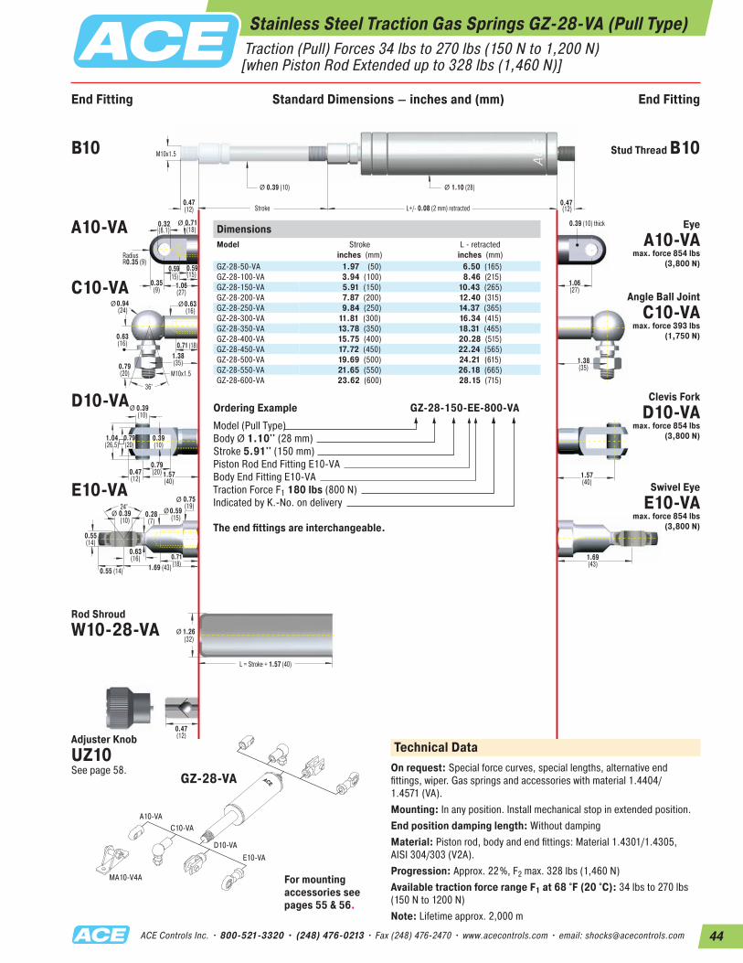
44ACE Controls Inc. • 800-521-3320 • (248) 476-0213 • Fax (248) 476-2470 • www.acecontrols.com • email: [email protected]
End Fitting End FittingStandard Dimensions
Ø
M10x1.5
36°
0.32(8.1)
0.59(15)
0.59(15)
RadiusR0.35 (9)
0.39 (10) thick
M10x1.5
0.47(12)
0.47 (12)
0.39 (10)
Stroke
1.10 (28)
L = Stroke + 1.57 (40)
Ø Ø
Ø
0.79(20)
0.39(10)
0.39(10)
0.79(20)
0.63(16)
0.47(12)
1.26(32)
1.57(40)
L+/- 0.08 (2 mm) retracted
Ø0.63(16)
Ø 0.71(18)
Ø0.94(24)
1.04(26.5)
0.79(20)
0.71 (18)
0.35(9) 1.06
(27)1.06(27)
1.38(35)
1.57(40)
1.69(43)
1.38(35)
24°
Ø
0.63(16)
0.55 (14)
0.39(10)
0.55(14)
1.69 (43)
0.28(7)
0.75(19)
Ø 0.59(15)
0.71(18)
Ø
0.47(12)
DimensionsModel
Stroke inches (mm)
L - retractedinches (mm)
GZ-28-50-VA 1.97 (50) 6.50 (165)GZ-28-100-VA 3.94 (100) 8.46 (215)GZ-28-150-VA 5.91 (150) 10.43 (265)GZ-28-200-VA 7.87 (200) 12.40 (315)GZ-28-250-VA 9.84 (250) 14.37 (365)GZ-28-300-VA 11.81 (300) 16.34 (415)GZ-28-350-VA 13.78 (350) 18.31 (465)GZ-28-400-VA 15.75 (400) 20.28 (515)GZ-28-450-VA 17.72 (450) 22.24 (565)GZ-28-500-VA 19.69 (500) 24.21 (615)GZ-28-550-VA 21.65 (550) 26.18 (665)GZ-28-600-VA 23.62 (600) 28.15 (715)
Ordering Example GZ-28-150-EE-800-VAModel (Pull Type)Body Ø 1.10'' (28 mm)Stroke 5.91'' (150 mm)Piston Rod End Fitting E10-VA Body End Fitting E10-VATraction Force F1 180 lbs (800 N)Indicated by K.-No. on delivery
The end fittings are interchangeable.
A10-VAC10-VA
D10-VAE10-VA
MA10-V4A
Technical DataOn request: Special force curves, special lengths, alternative end fittings, wiper. Gas springs and accessories with material 1.4404/ 1.4571 (VA).Mounting: In any position. Install mechanical stop in extended position.End position damping length: Without dampingMaterial: Piston rod, body and end fittings: Material 1.4301/1.4305, AISI 304/303 (V2A).Progression: Approx. 22%, F2 max. 328 lbs (1,460 N)Available traction force range F1 at 68 °F (20 °C): 34 lbs to 270 lbs (150 N to 1200 N)Note: Lifetime approx. 2,000 m
B10 Stud Thread B10
A10-VA Eye A10-VA
max. force 854 lbs (3,800 N)
C10-VA Angle Ball Joint C10-VA
max. force 393 lbs (1,750 N)
D10-VA Clevis Fork D10-VA
max. force 854 lbs (3,800 N)
E10-VA Swivel Eye E10-VA
max. force 854 lbs (3,800 N)
Rod Shroud W10-28-VA
Adjuster KnobUZ10 See page 58.
GZ-28-VA
For mounting accessories see pages 55 & 56.
Stainless Steel Traction Gas Springs GZ-28-VA (Pull Type) Traction (Pull) Forces 34 lbs to 270 lbs (150 N to 1,200 N) [when Piston Rod Extended up to 328 lbs (1,460 N)]
End Fitting Standard Dimensions – inches and (mm) End Fitting
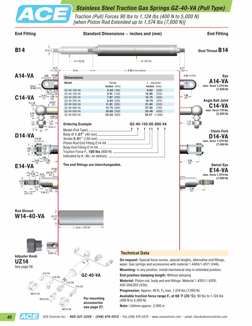
45 ACE Controls Inc. • 800-521-3320 • (248) 476-0213 • Fax (248) 476-2470 • www.acecontrols.com • email: [email protected]
End Fitting End FittingStandard Dimensions
Ø
M14x1.536°
0.56(14.1)
0.71(18)
0.77(19.5)
RadiusR0.49 (12.5)
0.55 (14) thick
M14x1.5
0.71(18)
0.71 (18)
1.10 (28)
Stroke
1.57 (40)
L = Stroke + 1.57 (40)
Ø Ø
Ø
1.06(27)
0.55(14)
0.55(14)
1.1(28)
0.79(20)
0.63(16)
0.59 (15)
1.77(45)
2.20(56)
L+/- 0.08 (2 mm) retracted
Ø0.87(22)
Ø 0.98(25)
Ø1.18(30)
1.38(35)
1.06(27)
0.98 (25)
0.47(12) 1.65
(42)1.65(42)
1.77(45)
2.20(56)
2.24(57)
1.77(45)
30°
Ø
0.71(18)
0.71 (18)
0.55(14)
0.75(19)
2.24 (57)
0.51(13)
1.02(26)Ø 0.79
(20)
1.18(30)
Ø
DimensionsModel
Stroke inches (mm)
L - retractedinches (mm)
GZ-40-100-VA 3.94 (100) 9.84 (250)GZ-40-150-VA 5.91 (150) 12.80 (325)GZ-40-200-VA 7.87 (200) 15.75 (400)GZ-40-250-VA 9.84 (250) 18.70 (475)GZ-40-300-VA 11.81 (300) 21.65 (550)GZ-40-400-VA 15.75 (400) 27.56 (700)GZ-40-500-VA 19.69 (500) 33.46 (850)GZ-40-600-VA 23.62 (600) 39.37 (1,000)
Ordering Example GZ-40-150-EE-800-VAModel (Pull Type)Body Ø 1.57'' (40 mm)Stroke 5.91'' (150 mm)Piston Rod End Fitting E14-VA Body End Fitting E14-VATraction Force F1 180 lbs (800 N)Indicated by K.-No. on delivery
The end fittings are interchangeable.
A14-VAC14-VA
D14-VAE14-VA
ME14-VA
ME14-VA
ND14-VA
B14 Stud Thread B14
A14-VA Eye A14-VA
max. force 1,574 lbs (7,000 N)
C14-VA Angle Ball Joint C14-VA
max. force 719 lbs (3,200 N)
D14-VAClevis Fork
D14-VA max. force 1,574 lbs
(7,000 N)
E14-VA Swivel Eye E14-VA
max. force 1,574 lbs (7,000 N)
Rod Shroud W14-40-VA
For mounting accessories see page 57.
GZ-40-VA
Adjuster KnobUZ14 See page 58.
Technical DataOn request: Special force curves, special lengths, alternative end fittings, wiper. Gas springs and accessories with material 1.4404/1.4571 (V4A).Mounting: In any position. Install mechanical stop in extended position.End position damping length: Without dampingMaterial: Piston rod, body and end fittings: Material 1.4301/1.4305, AISI 304/303 (V2A).Progression: Approx. 40%, F2 max. 1,574 lbs (7,000 N)Available traction force range F1 at 68 °F (20 °C): 90 lbs to 1,124 lbs (400 N to 5,000 N)Note: Lifetime approx. 2,000 m
Stainless Steel Traction Gas Springs GZ-40-VA (Pull Type) Traction (Pull) Forces 90 lbs to 1,124 lbs (400 N to 5,000 N) [when Piston Rod Extended up to 1,574 lbs (7,000 N)]
End Fitting Standard Dimensions – inches and (mm) End Fitting
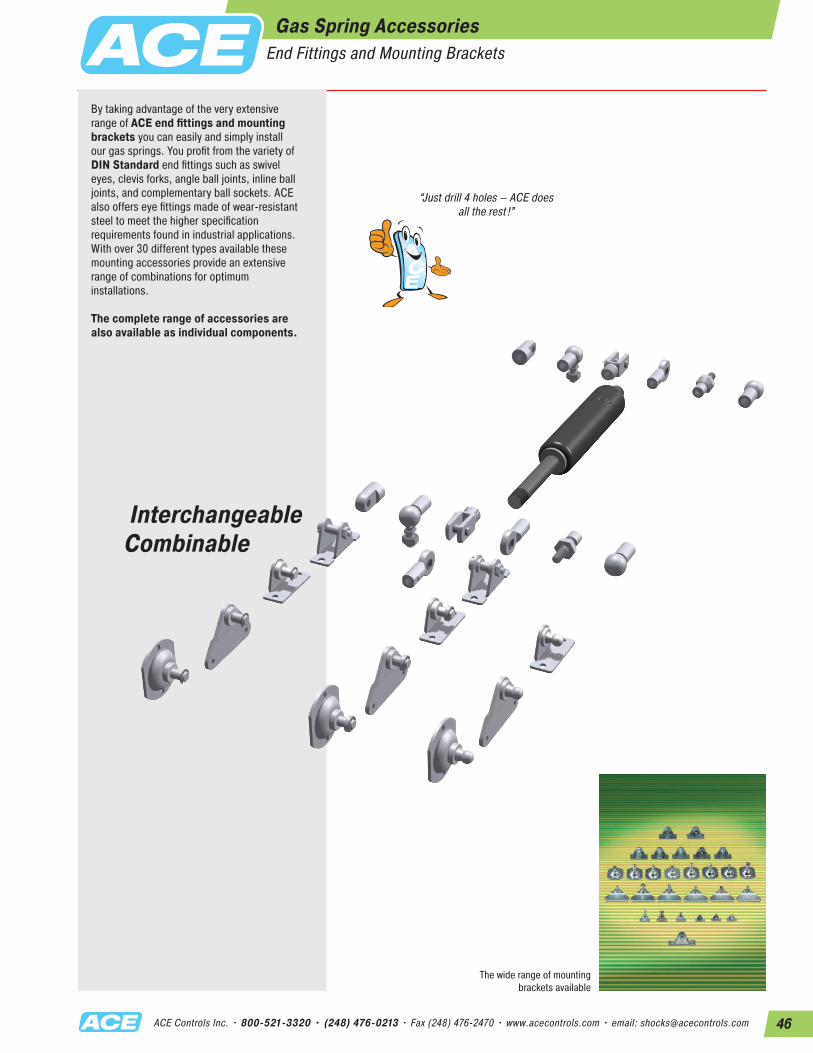
46ACE Controls Inc. • 800-521-3320 • (248) 476-0213 • Fax (248) 476-2470 • www.acecontrols.com • email: [email protected]
Interchangeable Combinable
By taking advantage of the very extensive range of ACE end fittings and mounting brackets you can easily and simply install our gas springs. You profit from the variety of DIN Standard end fittings such as swivel eyes, clevis forks, angle ball joints, inline ball joints, and complementary ball sockets. ACE also offers eye fittings made of wear-resistant steel to meet the higher specification requirements found in industrial applications. With over 30 different types available these mounting accessories provide an extensive range of combinations for optimum installations.
The complete range of accessories are also available as individual components.
The wide range of mounting brackets available
“Just drill 4 holes – ACE does all the rest !”
Gas Spring AccessoriesEnd Fittings and Mounting Brackets
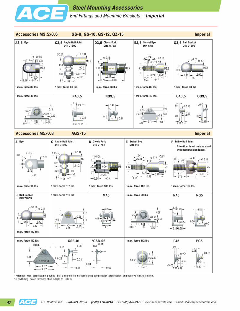
47 ACE Controls Inc. • 800-521-3320 • (248) 476-0213 • Fax (248) 476-2470 • www.acecontrols.com • email: [email protected]
Accessories M3.5x0.6 GS-8, GS-10, GS-12, GZ-15 Imperial
Accessories M5x0.8 AGS-15 Imperial
C3,5 D3,5 E3,5 G3,5
0.71M4x0.7
0.33
0.51 0.31
0.24
0.39
36°
Ø Ø
M3.50.16
0.31
0.16
0.20 0.63
0.31
Ø
M3.5 M3.5
24° 0.31 0.16
0.20
0.21
0.28 0.470.29
ØØ
0.28
0.71
0.16
0.51 0.31
0.240.31
ØØ
Ø
M3.5
1 max. force 83 lbs 1 max. force 83 lbs 1 max. force 83 lbs 1 max. force 83 lbs
NA3,5 NG3,5 OA3,5 OG3,51 max. force 40 lbs1 max. force 40 lbs
0.31
0.63 0.120.750.06
0.13
0.16
0.39ØØ
0.16
0.140.18
0.23 0.17
Ø 0.31
0.49
0.18Ø
0.710.20
0.20
0.630.31
0.51
0.20
0.17Ø
Ø
0.160.04
0.800.06
0.18 0.18
Ø0.31
0.22
0.53
Ø
A C D E F
0.87M5
0.31
0.51 0.31
0.47
0.39
36°
Ø Ø
M50.20
0.39
0.20
0.24 0.79
0.39
Ø
M5
24°0.39
0.24
0.24
0.47
0.51
0.18
0.39 1.180.47
ØØØ
M5
0.391.1
AF13
0.79
45°M5 0.31Ø
M5
1 max. force 90 lbs 1 max. force 112 lbs 1 max. force 180 lbs 1 max. force 180 lbs 1 max. force 112 lbs
H 1 max. force 112 lbs MA5 NA5 NG51 max. force 90 lbs
0.87
0.18
0.51 0.31
0.470.31
ØØ
Ø
M5
1 max. force 112 lbs
1.42 0.372.01
0.100.250.51
0.79
0.35Ø
0.24
0.26
0.71
0.10 0.16Ø
0.55
1.340.201.570.08
0.21
0.39
0.63ØØ
0.24
0.24 0.28
0.39 0.39
Ø 0.31
0.51
0.20Ø
1.73
2.171.610.21Ø
0.24
0.39
0.10
0.55 0.280.55Ø
Ø 0.31
0.83
0.31
0.08Ø
1 max. force 112 lbs GSB-01 *GSB-02 1 max. force 112 lbs PA5 PG5
Attention! Must only be used with compression loads.
1 Attention! Max. static load in pounds (lbs). Beware force increase during compression (progression) and observe max. force limit.*C end fitting, minus threaded stud, adapts to GSB-02.
A3,5
0.31
0.47
0.160.16 thick
M3.5
0.240.16
0.31Ø
1 max. force 83 lbs
Eye Angle Ball Joint DIN 71802
Clevis Fork DIN 71752
Swivel Eye DIN 648
Ball Socket DIN 71805
Eye Angle Ball Joint DIN 71802
Clevis Fork DIN 71752
Swivel Eye DIN 648
Inline Ball Joint
Ball Socket DIN 71805
Steel Mounting AccessoriesEnd Fittings and Mounting Brackets – Imperial
2.172.72
0.21R 0.39
1.18
0.35
R 0.28
0.23
1.850.280.12 thick
55
5.3R 10
30
9
R 7
6
73 thick
0.31
0.310.63
Ball8
816
Ball
47
69
0.24
R0.2 0.12 thick
0.27
0.43 11
0.33
6.2
R5 3 thick
7
8.5

48ACE Controls Inc. • 800-521-3320 • (248) 476-0213 • Fax (248) 476-2470 • www.acecontrols.com • email: [email protected]
Accessories M3.5x0.6 GS-8, GS-10, GS-12, GZ-15 Metric
Accessories M5x0.8 AGS-15 Metric
C3,5 D3,5 E3,5 G3,5
18M4x0.7
8.5
13 8
6
10
36°
Ø Ø
M3.54
8
4
5 16
8
Ø
M3.5 M3.5
24° 7.8 4
5
5.3
7 127.3
ØØ
7
18
4
13 8
68
ØØ
Ø
M3.5
1 max. force 370 N 1 max. force 370 N 1 max. force 370 N 1 max. force 370 N
NA3,5 NG3,5 OA3,5 OG3,51 max. force 180 N1 max. force 180 N
8
163191.5
3.4
4
10ØØ
4
3.5 4.5
5.75 4.25
Ø 8
12.5
4.5Ø
185
5
168
13
5
4.3Ø
Ø
41
21.5
4.5 4.5
Ø 8
5.5
13.5
Ø
A C D E F
22M5
8
13 8
12
10
36°
Ø Ø
M55
10
5
6 20
10
Ø
M5
24° 10 6
6
12
13
4.5
10 3012
ØØØ
M5
1028
AF13
20
45°M5 8Ø
M5
1 max. force 400 N 1 max. force 500 N 1 max. force 800 N 1 max. force 800 N 1 max. force 500 N
H 1 max. force 500 N MA5 NA5 NG51 max. force 400 N
22
4.5
13 8
128
ØØ
Ø
M5
1 max. force 500 N36
9.551
2.56.413
20
9Ø
6
6.5
18
2.54Ø
14
345402
5.3
10
16ØØ
6
6 7
10 10
Ø 8
13
5Ø
44
55415.3Ø
6
10
2.5
14 714Ø
Ø 8
218
2Ø
1 max. force 500 N GSB-01 *GSB-02 1 max. force 500 N PA5 PG5
Attention! Must only be used with compression loads.
1 Attention! Max. static load in Newtons. Beware force increase during compression (progression) and observe max. force limit*C end fitting, minus threaded stud, adapts to GSB-02.
A3,5
8
12
4.14 thick
M3.5
64
8Ø
1 max. force 370 N
Eye Angle Ball Joint DIN 71802
Clevis Fork DIN 71752
Swivel Eye DIN 648
Ball Socket DIN 71805
Eye Angle Ball Joint DIN 71802
Clevis Fork DIN 71752
Swivel Eye DIN 648
Inline Ball Joint
Ball Socket DIN 71805
Steel Mounting AccessoriesEnd Fittings and Mounting Brackets – Metric
2.172.72
0.21R 0.39
1.18
0.35
R 0.28
0.23
1.850.280.12 thick
55
5.3R 10
30
9
R 7
6
73 thick
0.31
0.310.63
Ball8
816
Ball
47
69
0.24
R0.2 0.12 thick
0.27
0.43 11
0.33
6.2
R5 3 thick
7
8.5
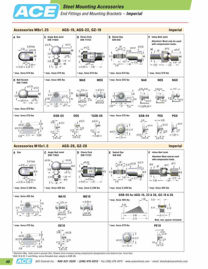
49 ACE Controls Inc. • 800-521-3320 • (248) 476-0213 • Fax (248) 476-2470 • www.acecontrols.com • email: [email protected]
Accessories M8x1.25 AGS-19, AGS-22, GZ-19 Imperial
Accessories M10x1.5 AGS-28, GZ-28 Imperial
A C D E F
0.55
0.79
0.320.39 thick
M8
0.390.24
0.55Ø
1.18M8
0.47
0.79 0.51
0.59
0.65
36°
Ø Ø
M80.31
0.63
0.31
0.39 1.26
0.63
Ø
M8
24° 0.47 0.31
0.31
0.63
0.63
0.24
0.47 1.420.51
ØØØ
M8
0.471.22
AF15
0.87
45°M8 0.47Ø
M8
1 max. force 674 lbs 1 max. force 270 lbs 1 max. force 674 lbs 1 max. force 674 lbs 1 max. force 270 lbs
H 1 max. force 405 lbs MA8 ME8 NA8 NE8 NG81 max. force 225 lbs
1.18
0.24
0.79 0.51
0.590.51
ØØ
Ø
M8
1 max. force 270 lbs
1.42 0.372.01
0.100.250.51
0.79
0.35Ø
0.71
0.31
0.51
0.16Ø 0.31
0.31
Ø
0.63
1.340.201.570.08
0.21
0.39
0.63ØØ
0.31
0.28 0.43
0.39 0.39
Ø 0.31
0.28 0.33
Ø 0.51
0.57
0.20Ø
2.170.28
0.39
1.180.63
0.91
0.28
0.21Ø
Ø
0.310.08
0.12
0.39 0.43
Ø0.31
0.200.12
0.39 0.33
Ø 0.51
0.31
0.69
Ø
1.73
2.171.610.21Ø
0.31
0.39
0.59 0.430.63Ø
Ø 0.31
0.08
0.20
0.59 0.33
Ø 0.51
0.89
0.37
Ø
1 max. force 270 lbs GSB-03 OE8 *GSB-06 1 max. force 270 lbs GSB-04 PE8 PG8
Attention! Must only be used with compression loads.
A C D E F
0.67
0.98
0.320.47 thick
M10
0.590.35
0.71Ø
1.38M10
0.63
0.94 0.63
0.71
0.79
36°
Ø Ø
M100.39
0.79
0.39
0.47 1.57
0.79
Ø
M10
24° 0.59 0.39
0.35
0.71
0.750.28
0.55 1.690.63
ØØØ
M10
0.751.69
AF17
0.98
45°M10 AF17
M10
1 max. force 2,248 lbs 1 max. force 405 lbs 1 max. force 2,248 lbs 1 max. force 2,248 lbs 1 max. force 405 lbs
1 max. force 405 lbs1 max. force 405 lbs
Bolt, nut, spacer included
MA10 ME10
1.42 0.372.01
0.10 0.250.51
0.79
0.35Ø
0.71
0.31
0.51
0.16Ø 0.39
0.35
Ø
2.170.28
0.39
1.180.63
0.91
0.28
0.21Ø
Ø
0.39
0.160.12
0.39 0.35
Ø0.08
1.73
2.171.610.21Ø
0.39
0.08
0.16
0.590.39
0.35
Ø0.63Ø
1 max. force 270 lbs OE10 1 max. force 270 lbs PE10
Attention! Must only be used with compression loads.
1 Attention! Max. static load in pounds (lbs). Beware force increase during compression (progression) and observe max. force limit. *AGS 19 & 22: C end fitting, minus threaded stud, adapts to GSB-06.
Eye Angle Ball Joint DIN 71802
Clevis Fork DIN 71752
Swivel Eye DIN 648
Inline Ball Joint
Ball Socket DIN 71805
Eye Angle Ball Joint DIN 71802
Clevis Fork DIN 71752
GSB-05 for AGS-19, 22 & 28, GZ-19 & 28
Swivel Eye DIN 648
Inline Ball Joint
Steel Mounting AccessoriesEnd Fittings and Mounting Brackets – Imperial
2.95
1.26
0.260.31
0.51
0.79
0.713.74
75
32
6.5
8
13
20
1895
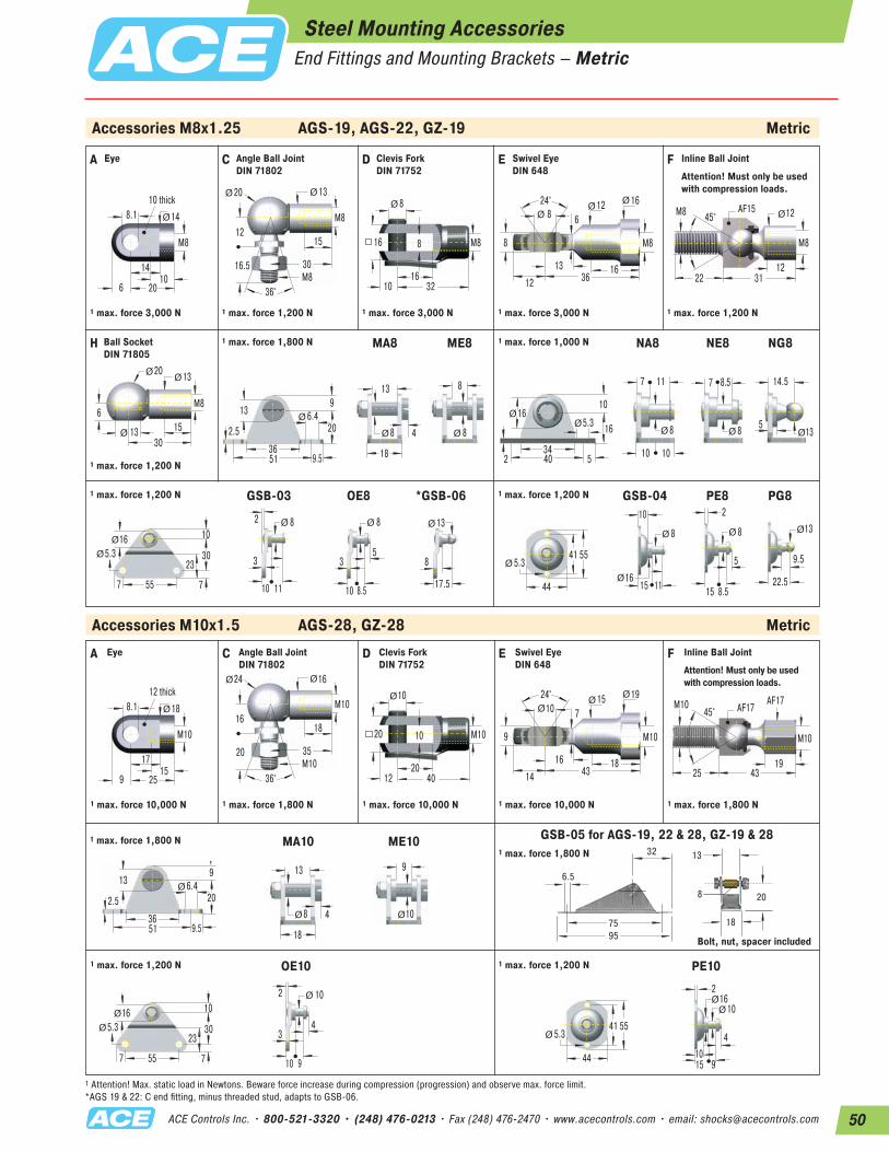
50ACE Controls Inc. • 800-521-3320 • (248) 476-0213 • Fax (248) 476-2470 • www.acecontrols.com • email: [email protected]
GSB-05 for AGS-19, 22 & 28, GZ-19 & 28
Steel Mounting AccessoriesEnd Fittings and Mounting Brackets – Metric
Accessories M8x1.25 AGS-19, AGS-22, GZ-19 Metric
Accessories M10x1.5 AGS-28, GZ-28 Metric
A C D E F
14
20
8.110 thick
M8
106
14Ø
30M8
12
20 13
15
16.5
36°
Ø Ø
M88
16
8
10 32
16
Ø
M8
24° 12 8
8
16
16
6
12 3613
ØØØ
M8
1231
AF15
22
45°M8 12Ø
M8
1 max. force 3,000 N 1 max. force 1,200 N 1 max. force 3,000 N 1 max. force 3,000 N 1 max. force 1,200 N
H 1 max. force 1,800 N MA8 ME8 NA8 NE8 NG81 max. force 1,000 N
30
6
20 13
1513
ØØ
Ø
M8
1 max. force 1,200 N36
9.551
2.56.413
20
9Ø
18
8
13
4Ø 8
8
Ø
16
345402
5.3
10
16ØØ
8
7 11
10 10
Ø 8
7 8.5
Ø 13
14.5
5Ø
557
10
3016
23
7
5.3Ø
Ø
82
3
10 11
Ø 8
53
10 8.5
Ø 13
8
17.5
Ø
44
55415.3Ø
8
10
15 1116Ø
Ø 8
2
5
15 8.5
Ø 13
22.5
9.5
Ø
1 max. force 1,200 N GSB-03 OE8 *GSB-06 1 max. force 1,200 N GSB-04 PE8 PG8
Attention! Must only be used with compression loads.
A C D E F
17
25
8.112 thick
M10
159
18Ø
35M10
16
24 16
18
20
36°
Ø Ø
M1010
20
10
12 40
20
Ø
M10
24° 15 10
9
18
19
7
14 4316
ØØØ
M10
1943
AF17
25
45°M10 AF17
M10
1 max. force 10,000 N 1 max. force 1,800 N 1 max. force 10,000 N 1 max. force 10,000 N 1 max. force 1,800 N
1 max. force 1,800 N MA10 ME10
369.551
2.56.413
20
9Ø
18
8
13
4Ø 10
9
Ø
557
10
3016
23
7
5.3Ø
Ø
10
43
10 9
Ø2
44
55415.3Ø
10
2
4
1510
9
Ø16Ø
1 max. force 1,200 N OE10 1 max. force 1,200 N
1 max. force 1,800 N
PE10
Attention! Must only be used with compression loads.
1 Attention! Max. static load in Newtons. Beware force increase during compression (progression) and observe max. force limit.*AGS 19 & 22: C end fitting, minus threaded stud, adapts to GSB-06.
Eye Angle Ball Joint DIN 71802
Clevis Fork DIN 71752
Swivel Eye DIN 648
Inline Ball Joint
Ball Socket DIN 71805
Eye Angle Ball Joint DIN 71802
Clevis Fork DIN 71752
Swivel Eye DIN 648
Inline Ball Joint
2.95
1.26
0.260.31
0.51
0.79
0.713.74
75
32
6.5
8
13
20
1895 Bolt, nut, spacer included

51 ACE Controls Inc. • 800-521-3320 • (248) 476-0213 • Fax (248) 476-2470 • www.acecontrols.com • email: [email protected]
Accessories M14x1.5 GS-40, GST-40, GZ-40 Imperial
A C D E F
0.83
1.57
0.560.55 thick
M14x1.5
0.710.47
0.98Ø
1.77M14x1.5
0.79
1.18 0.87
0.98
1.10
36°
Ø Ø
M14x1.50.55
1.06
0.55
0.63 2.20
1.06
Ø
M14x1.5
30°0.79
0.55
0.75
1.18
1.02
0.51
0.71 2.240.71
ØØØ
M14x1.5
0.712.2
AF24
1.57
30°M14x1.5 AF22
M14x1.5
1 max. force 2,248 lbs 1 max. force 674 lbs 1 max. force 2,248 lbs 1 max. force 2,248 lbs 1 max. force 719 lbs
ME14 ND141 max. force 2,248 lbs1 max. force 2,248 lbs
0.39
1.812.36
1.10
0.47
1.02
0.241.57
0.79
0.55
M8x1.25
0.79Ø
0.31
1.97
0.79
1.42
0.47
0.24 M8x1.250.55
0.55Ø
Attention! Must only be used with compression loads.
Accessories M24x2 GS-70 Imperial
D24 E241 max. force 11,240 lbs 1 max. force 11,240 lbs
ME24 ND241 max. force 11,240 lbs1 max. force 11,240 lbs
0.792.763.54
1.77
0.79
1.57
0.392.36
1.26
0.98
M12x1.75
1.30Ø
0.47
3.15
1.57
2.20
0.79
0.47 M12x1.750.94
0.98Ø
1 Attention! Max. static load in pounds (lbs). Beware force increase during compression (progression) and observe max. force limit.
0.98
1.97
0.98
1.26 3.94
1.97
Ø
M24x2
30°1.34
0.98
1.22
1.57
1.65
0.87
1.18 3.701.18
ØØØ
M24x2
Eye Angle Ball Joint DIN 71802
Clevis Fork DIN 71752
Swivel Eye DIN 648
Inline Ball Joint
Clevis Fork DIN 71752
Swivel Eye DIN 648
1 Attention! Max. static load in pounds (lbs). Beware force increase during compression (progression) and observe max. force limit.
Steel Mounting AccessoriesEnd Fittings and Mounting Brackets – Imperial
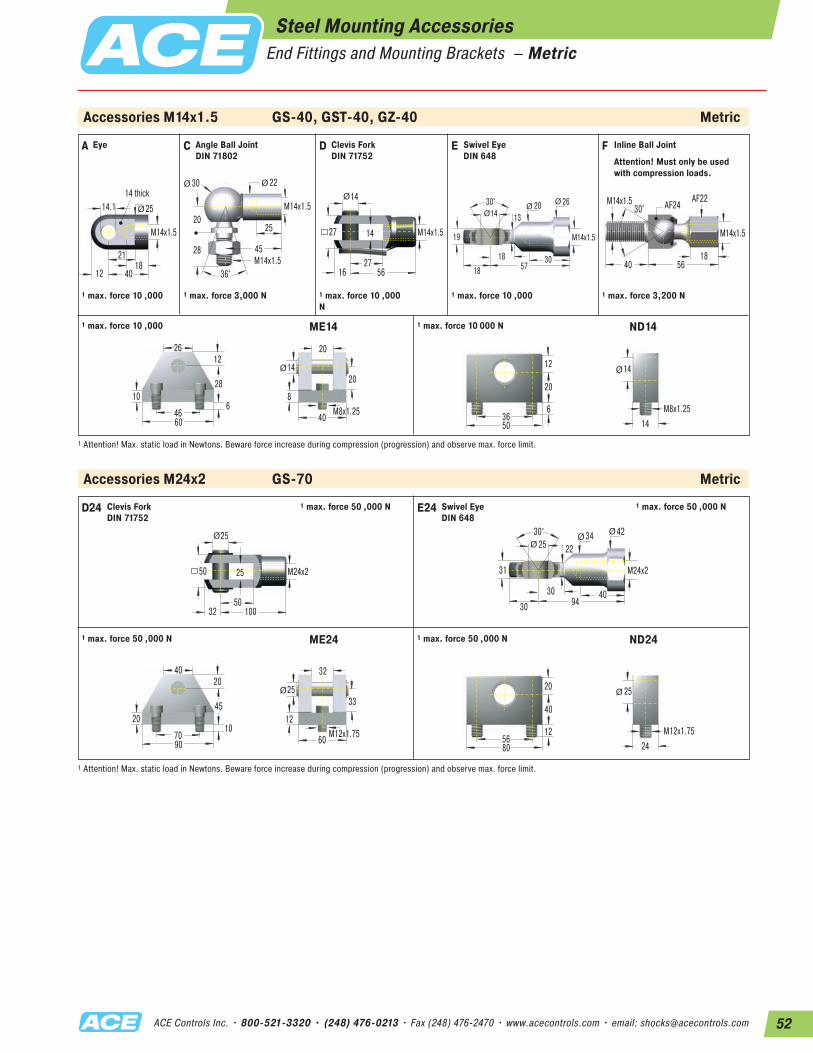
52ACE Controls Inc. • 800-521-3320 • (248) 476-0213 • Fax (248) 476-2470 • www.acecontrols.com • email: [email protected]
Accessories M14x1.5 GS-40, GST-40, GZ-40 Metric
A C D E F
21
40
14.114 thick
M14x1.5
1812
25Ø
45M14x1.5
20
30 22
25
28
36°
Ø Ø
M14x1.514
27
14
16 56
27
Ø
M14x1.5
30° 20 14
19
30
26
13
18 5718
ØØØ
M14x1.5
1856
AF24
40
30°M14x1.5 AF22
M14x1.5
1 max. force 10 ,000 1 max. force 3,000 N 1 max. force 10 ,000 N
1 max. force 10 ,000 1 max. force 3,200 N
ME14 ND141 max. force 10 000 N1 max. force 10 ,000
10
4660
28
1226
640
20
14
M8x1.25
20Ø
8
50
20
36
12
6 M8x1.2514
14Ø
Attention! Must only be used with compression loads.
Accessories M24x2 GS-70 Metric
D24 E241 max. force 50 ,000 N 1 max. force 50 ,000 N
ME24 ND241 max. force 50 ,000 N1 max. force 50 ,000 N
20
7090
45
2040
1060
32
25
M12x1.75
33Ø
12
80
40
56
20
12 M12x1.7524
25Ø
1 Attention! Max. static load in Newtons. Beware force increase during compression (progression) and observe max. force limit.
25
50
25
32 100
50
Ø
M24x2
30° 34 25
31
40
42
22
30 9430
ØØØ
M24x2
Eye Angle Ball Joint DIN 71802
Clevis Fork DIN 71752
Swivel Eye DIN 648
Inline Ball Joint
Clevis Fork DIN 71752
Swivel Eye DIN 648
1 Attention! Max. static load in Newtons. Beware force increase during compression (progression) and observe max. force limit.
Steel Mounting AccessoriesEnd Fittings and Mounting Brackets – Metric
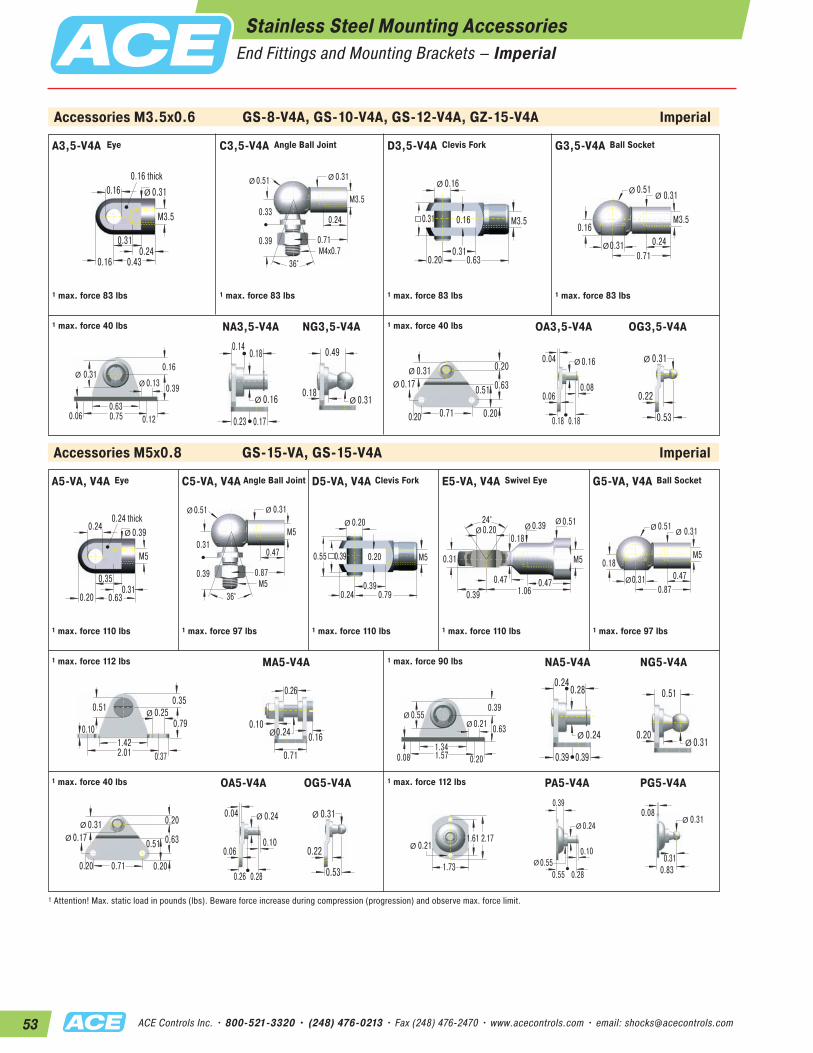
53 ACE Controls Inc. • 800-521-3320 • (248) 476-0213 • Fax (248) 476-2470 • www.acecontrols.com • email: [email protected]
Accessories M3.5x0.6 GS-8-V4A, GS-10-V4A, GS-12-V4A, GZ-15-V4A Imperial
Accessories M5x0.8 GS-15-VA, GS-15-V4A Imperial
A3,5-V4A C3,5-V4A D3,5-V4A G3,5-V4A
0.31
0.43
0.160.16 thick
M3.5
0.240.16
0.31Ø
0.71M4x0.7
0.33
0.51 0.31
0.24
0.39
36°
Ø Ø
M3.5
0.16
0.31
0.16
0.20 0.63
0.31
Ø
M3.5
0.71
0.16
0.51 0.31
0.240.31
ØØ
Ø
M3.5
1 max. force 83 lbs 1 max. force 83 lbs 1 max. force 83 lbs 1 max. force 83 lbs
NA3,5-V4A NG3,5-V4A OA3,5-V4A1 max. force 40 lbs1 max. force 40 lbs
0.31
0.630.120.750.06
0.13
0.16
0.39ØØ
0.16
0.140.18
0.23 0.17
Ø 0.31
0.49
0.18Ø
0.710.20
0.20
0.630.31
0.51
0.20
0.17Ø
Ø
0.160.04
0.080.06
0.18 0.18
Ø
A5-VA, V4A C5-VA, V4A D5-VA, V4A E5-VA, V4A
0.35
0.63
0.240.24 thick
M5
0.310.20
0.39Ø
0.87M5
0.31
0.51 0.31
0.47
0.39
36°
Ø Ø
M50.20
0.39
0.20
0.24 0.79
Ø
M50.55 0.39
24° 0.39 0.20
0.31
0.47
0.51
0.18
0.39 1.060.47
ØØØ
M5
1 max. force 110 lbs 1 max. force 97 lbs 1 max. force 110 lbs 1 max. force 110 lbs
G5-VA, V4A
1 max. force 112 lbs MA5-V4A NA5-V4A1 max. force 90 lbs
0.87
0.18
0.51 0.31
0.470.31
ØØ
Ø
M5
1 max. force 97 lbs
1.420.372.01
0.10
0.250.51
0.79
0.35Ø
0.24
0.26
0.71
0.100.16Ø
0.55
1.340.201.570.08
0.21
0.39
0.63ØØ
0.24
0.240.28
0.39 0.39
Ø0.31
0.51
0.20Ø
0.710.20
0.20
0.630.31
0.51
0.20
0.17Ø
Ø
0.240.04
0.100.06
0.26 0.28
Ø 0.31
0.22
0.53
Ø
1.73
2.171.610.21Ø
0.24
0.39
0.10
0.55 0.280.55Ø
Ø0.31
0.830.31
0.08Ø
1 max. force 40 lbs OA5-V4A OG5-V4A 1 max. force 112 lbs PA5-V4A
1 Attention! Max. static load in pounds (lbs). Beware force increase during compression (progression) and observe max. force limit.
OG3,5-V4A
0.31
0.22
0.53
Ø
NG5-V4A
PG5-V4A
Eye Angle Ball Joint Clevis Fork Ball Socket
Eye Angle Ball Joint Clevis Fork Swivel Eye Ball Socket
Stainless Steel Mounting AccessoriesEnd Fittings and Mounting Brackets – Imperial
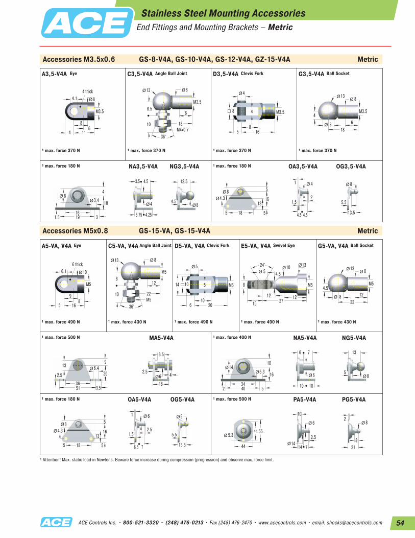
54ACE Controls Inc. • 800-521-3320 • (248) 476-0213 • Fax (248) 476-2470 • www.acecontrols.com • email: [email protected]
Accessories M3.5x0.6 GS-8-V4A, GS-10-V4A, GS-12-V4A, GZ-15-V4A Metric
Accessories M5x0.8 GS-15-VA, GS-15-V4A Metric
A3,5-V4A C3,5-V4A D3,5-V4A G3,5-V4A
8
11
4.14 thick
M3.5
64
8Ø
18M4x0.7
8.5
13 8
6
10
36°
Ø Ø
M3.5
4
8
4
5 16
8
Ø
M3.5
18
4
13 8
68
ØØ
Ø
M3.5
1 max. force 370 N 1 max. force 370 N 1 max. force 370 N 1 max. force 370 N
NA3,5-V4A NG3,5-V4A OA3,5-V4A1 max. force 180 N1 max. force 180 N
8
163191.5
3.4
4
10ØØ
4
3.5 4.5
5.75 4.25
Ø 8
12.5
4.5Ø
185
5
168
13
5
4.3Ø
Ø
41
21.5
4.5 4.5
Ø
9
16
6.16 thick
M5
85
10Ø
22M5
8
13 8
12
10
36°
Ø Ø
M55
10
5
6 20
10
Ø
M514
24° 10 5
8
12
13
4.5
10 2712
ØØØ
M5
1 max. force 490 N 1 max. force 430 N 1 max. force 490 N 1 max. force 490 N
1 max. force 500 N MA5-V4A NA5-V4A1 max. force 400 N
22
4.5
13 8
128
ØØ
Ø
M5
1 max. force 430 N
369.551
2.56.413
20
9Ø
6
6.5
18
2.54Ø
14
345402
5.3
10
16ØØ
6
6 7
10 10
Ø 8
13
5Ø
185
5
168
13
5
4.3Ø
Ø
61
2.51.5
6.5 7
Ø 8
5.5
13.5
Ø
44
55415.3Ø
6
10
2.5
14 714Ø
Ø 8
218
2Ø
1 max. force 180 N OA5-V4A OG5-V4A 1 max. force 500 N PA5-V4A
1 Attention! Max. static load in Newtons. Beware force increase during compression (progression) and observe max. force limit.
OG3,5-V4A
8
5.5
13.5
Ø
NG5-V4A
PG5-V4A
Eye Angle Ball Joint Clevis Fork Ball Socket
Stainless Steel Mounting AccessoriesEnd Fittings and Mounting Brackets – Metric
A5-VA, V4A C5-VA, V4A D5-VA, V4A E5-VA, V4A G5-VA, V4AEye Angle Ball Joint Clevis Fork Swivel Eye Ball Socket
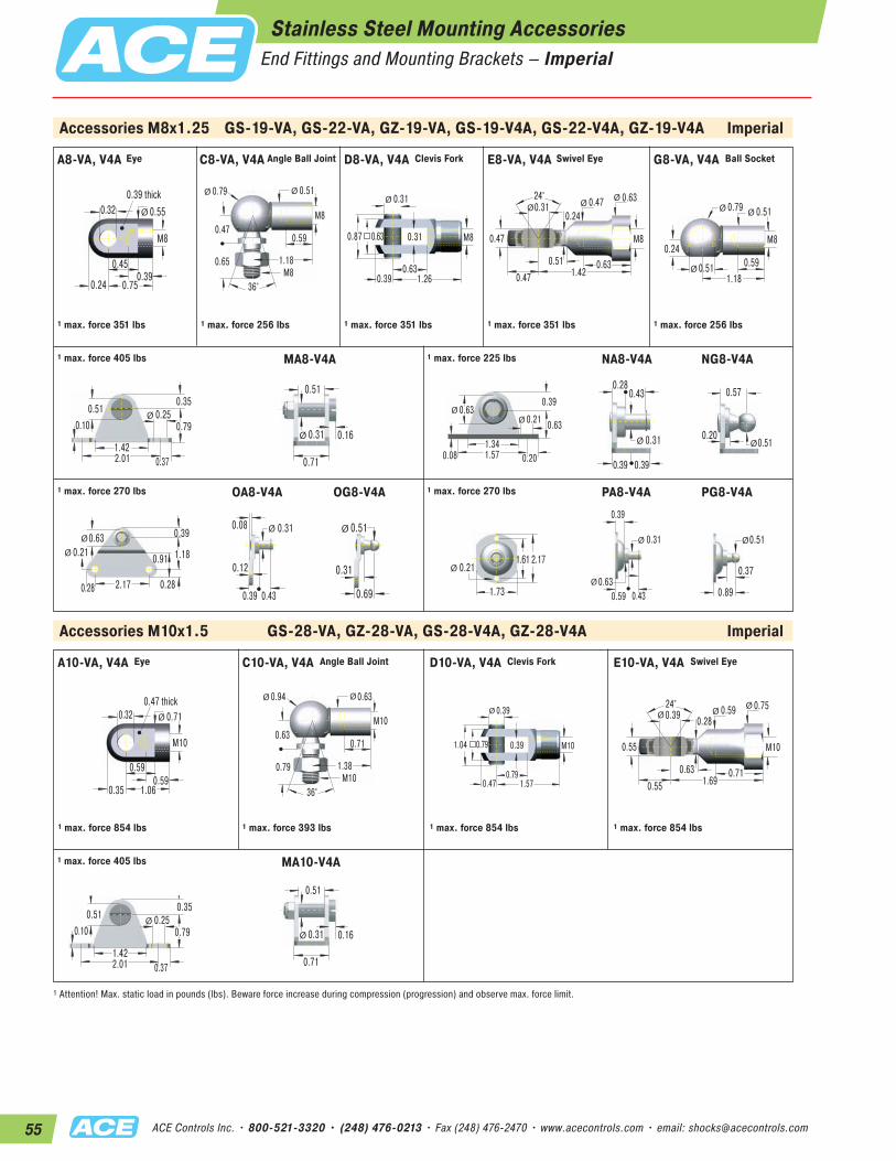
55 ACE Controls Inc. • 800-521-3320 • (248) 476-0213 • Fax (248) 476-2470 • www.acecontrols.com • email: [email protected]
Accessories M8x1.25 GS-19-VA, GS-22-VA, GZ-19-VA, GS-19-V4A, GS-22-V4A, GZ-19-V4A Imperial
Accessories M10x1.5 GS-28-VA, GZ-28-VA, GS-28-V4A, GZ-28-V4A Imperial
0.45
0.75
0.320.39 thick
M8
0.390.24
0.55Ø
1.18M8
0.47
0.79 0.51
0.59
0.65
36°
Ø Ø
M8
0.31
0.63
0.31
0.39 1.26
0.63
Ø
M80.87
24° 0.47 0.31
0.47
0.63
0.63
0.24
0.47 1.420.51
ØØØ
M8
1 max. force 351 lbs 1 max. force 256 lbs 1 max. force 351 lbs 1 max. force 351 lbs
1 max. force 405 lbs MA8-V4A NA8-V4A NG8-V4A1 max. force 225 lbs
1.18
0.24
0.79 0.51
0.590.51
ØØ
Ø
M8
1 max. force 256 lbs
1.420.372.01
0.100.250.51
0.79
0.35Ø
0.71
0.31
0.51
0.16Ø
0.63
1.340.201.570.08
0.21
0.39
0.63ØØ
0.31
0.280.43
0.39 0.39
Ø 0.51
0.57
0.20Ø
2.170.28
0.39
1.180.63
0.91
0.28
0.21Ø
Ø
0.310.08
0.12
0.39 0.43
Ø 0.51
0.31
0.69
Ø
1.73
2.170.21Ø
1.61
0.31
0.39
0.59 0.430.63Ø
Ø 0.51
0.89
0.37
Ø
1 max. force 270 lbs OA8-V4A OG8-V4A 1 max. force 270 lbs PA8-V4A PG8-V4A
A10-VA, V4A C10-VA, V4A D10-VA, V4A E10-VA, V4A
0.59
1.06
0.320.47 thick
M10
0.590.35
0.71Ø
1.38M10
0.63
0.94 0.63
0.71
0.79
36°
Ø Ø
M100.39
0.79
0.39
0.47 1.57
0.79
Ø
M101.04
24° 0.59 0.39
0.55
0.71
0.750.28
0.55 1.690.63
ØØØ
M10
1 max. force 854 lbs 1 max. force 393 lbs 1 max. force 854 lbs 1 max. force 854 lbs
1 max. force 405 lbs MA10-V4A
1.420.372.01
0.100.250.51
0.79
0.35Ø
0.71
0.31
0.51
0.16Ø
1 Attention! Max. static load in pounds (lbs). Beware force increase during compression (progression) and observe max. force limit.
Eye Angle Ball Joint Clevis Fork Swivel Eye
Stainless Steel Mounting AccessoriesEnd Fittings and Mounting Brackets – Imperial
A8-VA, V4A C8-VA, V4A D8-VA, V4A E8-VA, V4A G8-VA, V4AAngle Ball Joint Clevis Fork Swivel Eye Ball SocketEye
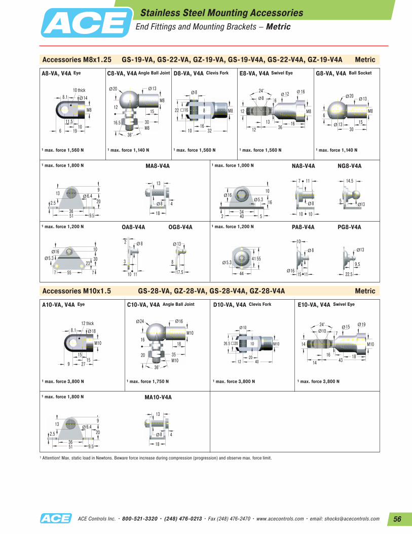
56ACE Controls Inc. • 800-521-3320 • (248) 476-0213 • Fax (248) 476-2470 • www.acecontrols.com • email: [email protected]
A10-VA, V4A C10-VA, V4A D10-VA, V4A E10-VA, V4AEye Angle Ball Joint Clevis Fork Swivel Eye
Accessories M8x1.25 GS-19-VA, GS-22-VA, GZ-19-VA, GS-19-V4A, GS-22-V4A, GZ-19-V4A Metric
Accessories M10x1.5 GS-28-VA, GZ-28-VA, GS-28-V4A, GZ-28-V4A Metric
11.5
19
8.110 thick
M8
106
14Ø
30M8
12
20 13
15
16.5
36°
Ø Ø
M8
8
16
8
10 32
16
Ø
M822
24° 12 8
12
16
16
6
12 3613
ØØ
Ø
M8
1 max. force 1,560 N 1 max. force 1,140 N 1 max. force 1,560 N 1 max. force 1,560 N
1 max. force 1,800 N MA8-V4A NA8-V4A NG8-V4A1 max. force 1,000 N
30
6
20 13
1513
ØØ
Ø
M8
1 max. force 1,140 N
369.551
2.56.413
20
9Ø
18
8
13
4Ø
16
345402
5.3
10
16ØØ
8
7 11
10 10
Ø 13
14.5
5Ø
557
10
3016
23
7
5.3Ø
Ø
82
3
10 11
Ø 13
8
17.5
Ø
44
55415.3Ø
8
10
15 1116Ø
Ø 13
22.5
9.5
Ø
1 max. force 1,200 N OA8-V4A OG8-V4A 1 max. force 1,200 N PA8-V4A PG8-V4A
15
27
8.112 thick
M10
159
18Ø
35M10
16
24 16
18
20
36°
Ø Ø
M1010
20
10
12 40
20
Ø
M1026.5
24° 15 10
14
18
19
7
14 4316
ØØØ
M10
1 max. force 3,800 N 1 max. force 1,750 N 1 max. force 3,800 N 1 max. force 3,800 N
1 max. force 1,800 N MA10-V4A
369.551
2.56.413
20
9Ø
18
8
13
4Ø
1 Attention! Max. static load in Newtons. Beware force increase during compression (progression) and observe max. force limit.
Stainless Steel Mounting AccessoriesEnd Fittings and Mounting Brackets – Metric
A8-VA, V4A C8-VA, V4A D8-VA, V4A E8-VA, V4A G8-VA, V4AAngle Ball Joint Clevis Fork Swivel Eye Ball SocketEye
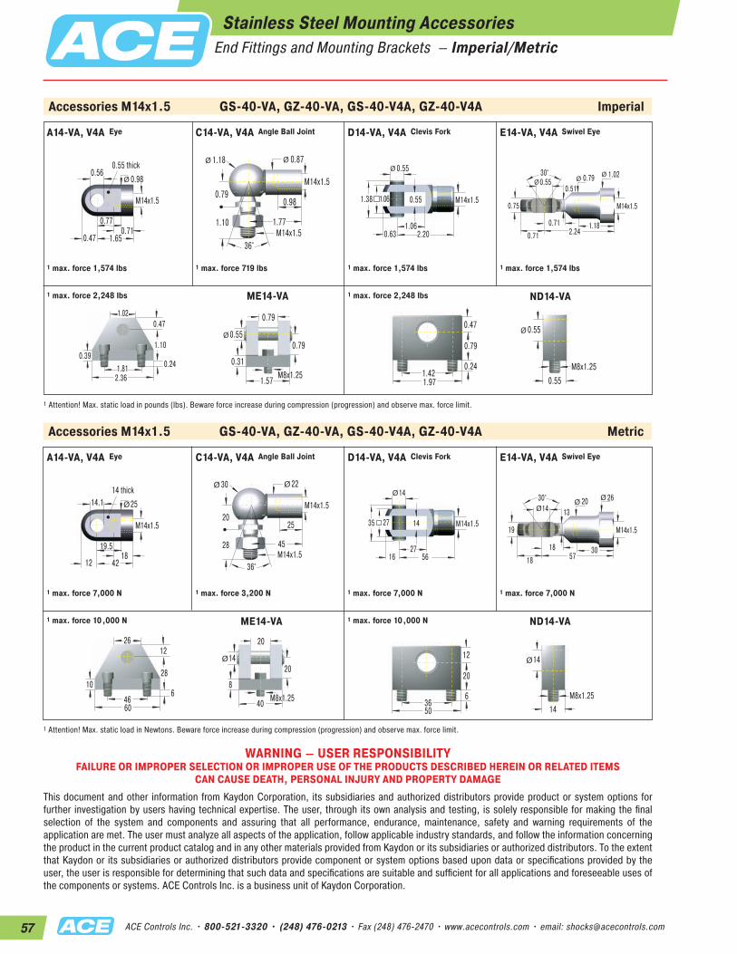
57 ACE Controls Inc. • 800-521-3320 • (248) 476-0213 • Fax (248) 476-2470 • www.acecontrols.com • email: [email protected]
Accessories M14x1.5 GS-40-VA, GZ-40-VA, GS-40-V4A, GZ-40-V4A Imperial
0.77
1.65
0.560.55 thick
M14x1.5
0.710.47
0.98Ø
1.77M14x1.5
0.79
1.18 0.87
0.98
1.10
36°
Ø Ø
M14x1.50.55
1.06
0.55
0.63 2.20
1.06
Ø
M14x1.51.38
30°0.79
0.55
0.75
1.18
1.02
0.51
0.71 2.240.71
ØØØ
M14x1.5
1 max. force 1,574 lbs 1 max. force 719 lbs 1 max. force 1,574 lbs 1 max. force 1,574 lbs
ME14-VA ND14-VA
0.391.81
2.36
1.10
0.471.02
0.24
1.57
0.79
0.55
M8x1.25
0.79Ø
0.31
1.97
0.79
1.42
0.47
0.24 M8x1.250.55
0.55Ø
1 Attention! Max. static load in pounds (lbs). Beware force increase during compression (progression) and observe max. force limit.
1 max. force 2,248 lbs1 max. force 2,248 lbs
A14-VA, V4A C14-VA, V4A D14-VA, V4A E14-VA, V4AEye Angle Ball Joint Clevis Fork Swivel Eye
A14-VA, V4A C14-VA, V4A D14-VA, V4A E14-VA, V4AEye Angle Ball Joint Clevis Fork Swivel Eye
Stainless Steel Mounting AccessoriesEnd Fittings and Mounting Brackets – Imperial/Metric
Accessories M14x1.5 GS-40-VA, GZ-40-VA, GS-40-V4A, GZ-40-V4A Metric
19.5
42
14.114 thick
M14x1.5
1812
25Ø
45M14x1.5
20
30 22
25
28
36°
Ø Ø
M14x1.514
27
14
16 56
27
Ø
M14x1.535
30° 20 14
19
30
26
13
18 5718
ØØØ
M14x1.5
1 max. force 7,000 N 1 max. force 3,200 N 1 max. force 7,000 N 1 max. force 7,000 N
ND14-VA
10
4660
28
1226
640
20
14
M8x1.25
20Ø
8
50
20
36
12
6 M8x1.2514
14Ø
1 Attention! Max. static load in Newtons. Beware force increase during compression (progression) and observe max. force limit.
1 max. force 10,000 N1 max. force 10,000 N ME14-VA
WARNING – USER RESPONSIBILITYFAILURE OR IMPROPER SELECTION OR IMPROPER USE OF THE PRODUCTS DESCRIBED HEREIN OR RELATED ITEMS
CAN CAUSE DEATH, PERSONAL INJURY AND PROPERTY DAMAGEThis document and other information from Kaydon Corporation, its subsidiaries and authorized distributors provide product or system options for further investigation by users having technical expertise. The user, through its own analysis and testing, is solely responsible for making the final selection of the system and components and assuring that all performance, endurance, maintenance, safety and warning requirements of the application are met. The user must analyze all aspects of the application, follow applicable industry standards, and follow the information concerning the product in the current product catalog and in any other materials provided from Kaydon or its subsidiaries or authorized distributors. To the extent that Kaydon or its subsidiaries or authorized distributors provide component or system options based upon data or specifications provided by the user, the user is responsible for determining that such data and specifications are suitable and sufficient for all applications and foreseeable uses of the components or systems. ACE Controls Inc. is a business unit of Kaydon Corporation.
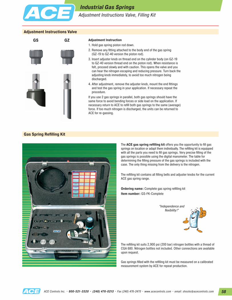
58ACE Controls Inc. • 800-521-3320 • (248) 476-0213 • Fax (248) 476-2470 • www.acecontrols.com • email: [email protected]
Industrial Gas SpringsAdjustment Instructions Valve, Filling Kit
Gas Spring Refilling Kit
GZGS
Adjustment Instructions Valve
Adjustment Instruction 1. Hold gas spring piston rod down.2. Remove any fitting attached to the body end of the gas spring
(GZ-19 to GZ-40 version the piston rod).3. Insert adjuster knob on thread end on the cylinder body (on GZ-19
to GZ-40 version thread end on the piston rod). When resistance is felt, proceed slowly and with caution. This opens the valve and you can hear the nitrogen escaping and reducing pressure. Turn back the adjusting knob immediately, to avoid too much nitrogen being discharged.
4. After adjustment, remove the adjuster knob, mount the end fittings and test the gas spring in your application. If necessary repeat the procedure.
If you use 2 gas springs in parallel, both gas springs should have the same force to avoid bending forces or side load on the application. If necessary return to ACE to refill both gas springs to the same (average) force. If too much nitrogen is discharged, the units can be returned to ACE for re-gassing.
The ACE gas spring refilling kit offers you the opportunity to fill gas springs on location or adapt them individually. The refilling kit is equipped with all the parts you need to fill gas springs. Very precise filling of the gas springs is possible using the digital manometer. The table for determining the filling pressure of the gas springs is included with the case. The only thing missing from the delivery is the nitrogen.
The refilling kit contains all filling bells and adjuster knobs for the current ACE gas spring range.
Ordering name: Complete gas spring refilling kitItem number: GS-FK-Complete
The refilling kit suits 2,900 psi (200 bar) nitrogen bottles with a thread of CGA 680. Nitrogen bottles not included. Other connections are available upon request.
“Independence and flexibility !”
Gas springs filled with the refilling kit must be measured on a calibrated measurement system by ACE for repeat production.

Gas Springs
Your Best Solution for Lifting Lids, Hoods, Panels and Guards Includes New Line of Stainless Steel Models for Packaging, Food Processing, Medical, Marine and More
05/2012ACE Controls Inc. • 800-521-3320 • (248) 476-0213 • Fax (248) 476-2470 • www.acecontrols.com • email: [email protected]
ACE Product Catalogs
© ACE Controls Inc. 2012 All Rights Reserved Catalog No. 200-0175ACE Controls Inc. is focused on continuous improvement. Therefore, ACE reserves the right to change models, dimensions or specifications without notice or obligation.
WARNING: Improper selection or improper use of the products and/or systems described herein or related items can cause personal or fatal injury and/or property damage.
SLAB Plates for Shock Absorption and Vibration Damping
Designed to Absorb Shock Loads and Insulate Vibrations for… Machine Tools, Textile Machinery, Crane Rails, Hydraulic Crushers, Presses/Stamping Machines, Air-Conditioning & Ventilating Machines and More Machines, Air-Conditioning & Ventilating Machines and More Machines and More
02/2012
© ACE Controls Inc. 2012 © ACE Controls Inc. 2012 © ACE Controls Inc. 2012 © ACE Controls Inc. 2012
Gas Springs
05 /2012