mounting Optics in Optical Instruments - GBV
8
mounting Optics in Optical Instruments Second Edition Paul H. Voder, Jr. SPIE PRESS Bellingham,Washington USA
-
Upload
khangminh22 -
Category
Documents
-
view
1 -
download
0
Transcript of mounting Optics in Optical Instruments - GBV
mounting Optics in Optical Instruments
Second Edition
Paul H. Voder, Jr.
SPIE PRESS
Bellingham,Washington USA
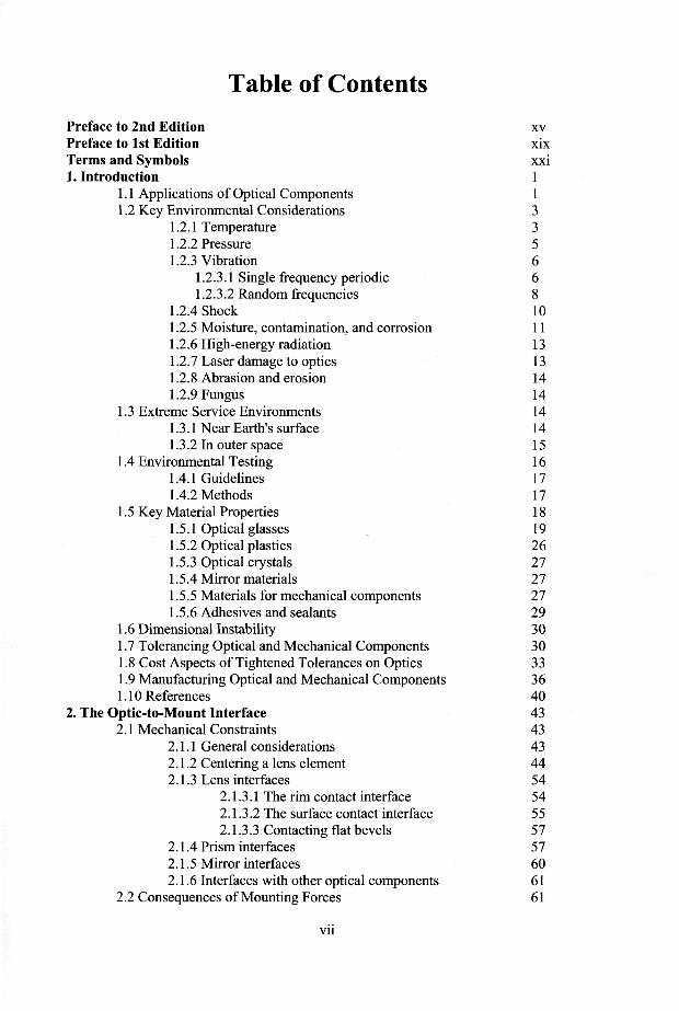
Table of Contents Preface to 2nd Edition Preface to 1st Edition Terms and Symbols 1. Introduction
1.1 Applications of Optical Components 1.2 Key Environmental Considerations
1.2.1 Temperature 1.2.2 Pressure 1.2.3 Vibration
1.2.3.1 Single frequency periodic 1.2.3.2 Random frequencies
1.2.4 Shock 1.2.5 Moisture, contamination, and corrosion 1.2.6 High-energy radiation 1.2.7 Laser damage to optics 1.2.8 Abrasion and erosion 1.2.9 Fungus
1.3 Extreme Service Environments 1.3.1 Near Earth's surface 1.3.2 In outer space
1.4 Environmental Testing 1.4.1 Guidelines 1.4.2 Methods
1.5 Key Material Properties 1.5.1 Optical glasses 1.5.2 Optical plastics 1.5.3 Optical crystals 1.5.4 Mirror materials 1.5.5 Materials for mechanical components 1.5.6 Adhesives and sealants
1.6 Dimensional Instability 1.7 Tolerancing Optical and Mechanical Components 1.8 Cost Aspects of Tightened Tolerances on Optics 1.9 Manufacturing Optical and Mechanical Components 1.10 References
2. The Optic-to-Mount Interface 2.1 Mechanical Constraints
2.1.1 General considerations 2.1.2 Centering a lens element 2.1.3 Lens interfaces
2.1.3.1 The rim contact interface 2.1.3.2 The surface contact interface 2.1.3.3 Contacting flat bevels
2.1.4 Prism interfaces 2.1.5 Mirror interfaces 2.1.6 Interfaces with other optical components
2.2 Consequences of Mounting Forces
XV
xix xxi 1 1 3 3 5 6 6 8 10 11 13 13 14 14 14 14 15 16 17 17 18 19 26 27 27 27 29 30 30 33 36 40 43 43 43 44 54 54 55 57 57 60 61 61
Vll
2.3 Sealing Considerations 61 2.4 References 64
3. Mounting Individual Lenses 65 3.1 Preload Requirements 65 3.2 Weight and Center of Gravity Calculations 68 3.3 Spring Mountings for Lenses and Filters 74 3.4 Burnished Cell Mountings 75 3.5 Snap and "Interference Fit" Rings 77 3.6 Retaining Ring Constraints 84
3.6.1 Threaded retaining rings 84 3.6.2 Clamping (flange) ring 88
3.7 Constraining the Lens with Multiple Spring Clips 92 3.8 Geometry of the Lens-to-Mount Interface 95
3.8.1 The sharp-corner interface 95 3.8.2 The tangential (conical) interface 97 3.8.3 The toroidal interface 99 3.8.4 The spherical interface 102 3.8.5 Interfaces with bevels on optics 103
3.9 Elastomeric Mountings 106 3.10 Flexure Mountings for Lenses 115 3.11 Mounting Plastic Lenses 120 3.12 References 123
4. Multiple-Component Lens Assemblies 127 4.1 Spacer Design and Manufacture 127 4.2 Drop-In Assembly 134 4.3 Lathe Assembly 135 4.4 Elastomeric Mountings 137 4.5 Poker-Chip Assembly 141 4.6 Assemblies Designed for High-Shock Environments 142 4.7 Photographic Objective Lenses 145 4.8 Modular Construction and Assembly 152 4.9 Catoptric and Catadioptric Assemblies 156 4.10 Assemblies with Plastic Housings and Lenses 160 4.11 Internal Mechanisms 165
4.11.1 Focus mechanisms 165 4.11.2 Zoom mechanisms 173
4.12 Sealing and Purging Lens Assemblies 176 4.13 References 177
5. Mounting Optical Windows, Filters, Shells, and Domes 179 5.1 Simple Window Mountings 179 5.2 Mounting "Special" Windows 183 5.3 Conformal Windows 186 5.4 Windows Subject to Pressure Differential 190
5.4.1 Survival 190 5.4.2 Optical effects 195
5.5 Filter Mountings 197 5.6 Mounting Shells and Domes 199 5.7 References 203
vin
6. Prism Design 205 6.1 Principal Functions 205 6.2 Geometric Considerations 205
6.2.1 Refraction and reflection 205 6.2.2 Total internal reflection 211
6.3 Aberration Contributions of Prisms 214 6.4 Typical Prism Configurations 214
6.4.1 Right-angle prism 215 6.4.2 Beamsplitter (or beamcombiner) cube prism 215 6.4.3 Amici prism 216 6.4.4 Porro prism 216 6.4.5 Porro erecting system 217 6.4.6 Abbe version of the Porro prism 220 6.4.7 Abbe erecting system 221 6.4.8 Rhomboid prism 221 6.4.9 Dove prism 222 6.4.10 Double Dove prism 223 6.4.11 Reversion, Abbe Type A, and Abbe Type В prisms 225 6.4.12 Pechan prism 227 6.4.13 Pentaprism 227 6.4.14 Roof penta prism 228 6.4.15 Amici/penta erecting system 228 6.4.16 Delta prism 230 6.4.17 Schmidt roof prism 232 6.4.18 The 45-deg Bauernfeind prism 234 6.4.19 Frankford Arsenal prisms nos. 1 and 2 234 6.4.20 Leman prism 236 6.4.21 Internally-reflecting axicon prism 237 6.4.22 Cube corner prism 238 6.4.23 An ocular prism for a coincidence rangefinder 239 6.4.24 Biocular prism system 242 6.4.25 Dispersing prisms 242 6.4.26 Thin wedge prisms 245 6.4.27 Risley wedge system 246 6.4.28 Sliding wedge • 248 6.4.29 Focus-adjusting wedge system 248 6.4.30 Anamorphic prism systems 250
6.5 References 251 7. Techniques for Mounting Prisms 253
7.1 Kinematic Mountings 253 7.2 Semikinematic Mountings 254 7.3 The Use of Pads on Cantilevered and Straddling Springs 265 7.4 Mechanically Clamped Nonkinematic Mountings 270 7.5 Bonded Prism Mountings 274
7.5.1 General considerations 274 7.5.2 Examples of bonded prisms 276 7.5.3 Double-sided prism support techniques 279
7.6 Flexure Mountings for Prisms 285 7.7 References 287
ix
8. Mirror Design 289 8.1 General Considerations 289 8.2 Image Orientation 290 8.3 First- and Second-Surface Mirrors 294 8.4 Ghost Image Formation with Second-Surface Mirrors 296 8.5 Approximation of Mirror Aperture 301 8.6 Weight Reduction Techniques 303
8.6.1 Contoured-back configurations 304 8.6.2 Cast ribbed substrate configurations 314 8.6.3 Built-up structural configurations 315
8.6.3.1 Egg crate construction 318 8.6.3.2 Monolithic construction 319 8.6.3.3 Frit-bonded construction 323 8.6.3.4 Hextek construction 323 8.6.3.5 Machined core construction 325 8.6.3.6 Foam core construction 328 8.6.3.7 Internally machined mirror construction 332
8.7 Thin Facesheet Configurations 334 8.8 Metallic Mirrors 336 8.9 Metallic Foam Core Mirrors 343 8.10 Pellicles 346 8.11 References 348
9. Techniques for Mounting Smaller Nonmetallic Mirrors 353 9.1 Mechanically Clamped Mirror Mountings 353 9.2 Bonded Mirror Mountings 366 9.3 Compound Mirror Mountings 371 9.4 Flexure Mountings for Smaller Mirrors 380 9.5 Central and Zonal Mountings 388 9.6 Gravitational Effects on Smaller Mirrors 390 9.7 References 396
10. Techniques for Mounting Metallic Mirrors 399 10.1 Single Point Diamond Turning of Metallic Mirrors 399 10.2 Integral Mounting Provisions 412 10.3 Flexure Mountings for Metallic Mirrors 413 10.4 Plating of Metal Mirrors 422 10.5 Interfacing Metallic Mirrors for Assembly and Alignment 424 10.6 References 429
11. Techniques for Mounting Larger Nonmetallic Mirrors 433 11.1 Mounts for Axis-Horizontal Applications 433
11.1.1 V-mounts 434 11.1.2 Multipoint edge supports 441 11.1.3 The "ideal" radial mount 442 11.1.4 Strap and roller chain supports 445 11.1.5 Comparison of dynamic relaxation and FEA
methods of analysis 449 11.1.6 Mercury tube supports 451
11.2 Mounts for Axis Vertical Applications 452 11.2.1 General considerations 452 11.2.2 Air bag axial supports 453 11.2.3 Metrology mounts 457
x
11.3 Mounts for Axis Variable Applications 465 11.3.1 Counter-weighted lever-type mountings 465 11.3.2 Hindle mounts for large mirrors 471 11.3.3 Pneumatic and hydraulic mountings 483
11.4 Supports for Large, Space-borne Mirrors 500 11.4.1 The Hubble Space Telescope 500 11.4.2 The Chandra X-Ray Telescope 503
11.5 References 506 12. Aligning Refracting, Reflecting and Catadioptric Systems 511
12.1 Aligning the Individual Lens 511 12.1.1 Simple techniques for aligning a lens 512 12.1.2 Rotating spindle techniques 514 12.1.3 Techniques using a "Point Source Microscope" 520
12.2 Aligning Multiple Lens Assemblies 524 12.2 1 Using an alignment telescope 525 12.2.2 Aligning microscope objectives 527 12.2.3 Aligning multiple lenses on a precision spindle 533 12.2.4 Aberration compensation at final assembly 535 12.2.5 Selecting aberration compensators 543
12.3 Aligning Reflecting Systems 545 12.3.1 Aligning a simple Newtonian telescope 545 12.3.2 Aligning a simple Cassegrain telescope 547 12.3.3 Aligning a simple Schmidt camera 549
12.4 References 550 13. Estimation of Mounting Stresses 553
13.1 General Considerations 553 13.2 Statistical Prediction of Optic Failure 554 13.3 Rule-of-Thumb Stress Tolerances 559 13.4 Stress Generation at Point, Line, and Area Contacts 562 13.5 Peak Contact Stress in an Annular Interface 570
13.5.1 Stress with a sharp corner interface 5 71 13.5.2 Stress with a tangential interface 572 13.5.3 Stress with a toroidal interface 574 13.5.4 Stress with a spherical interface 576 13.5.5 Stress with a flat bevel interface 576 13.5.6 Parametric comparisons of interface types 576
13.6 Bending Effects in Asymmetrically Clamped Optics 580 13.6.1 Bending stress in the optic 580 13.6.2 Change in surface sagittal depth of a bent optic 582
13.7 References 583 14. Effects of Temperature Changes 585
14.1 Athermalization Techniques for Reflective Systems 585 14.1.1 Same material designs 585 14.1.2 Metering rods and trusses 586
14.2 Athermalization Techniques for Refractive Systems 589 14.2.1 Passive athermalization 591 14.2.2 Active compensation 598
14.3 Effects of Temperature Change on Axial Preload 602 14.3.1 Axial dimension changes 602 14.3.2 Quantifying K3 605
XI
14.3.2.1 Considering bulk effects only 606 14.3.2.2 Considering other contributing factors 609
14.3.3 Advantages of athermalization and compliance 612 14.4 Radial Effects in Rim Contact Mountings 617
14.4.1 Radial stress in the optic 618 14.4.2 Tangential (hoop) stress in the mount wall 620 14.4.3 Growth of radial clearance at high temperatures 621 14.4.4 Adding radial compliance to maintain lens centration 622
14.5 Effects of Temperature Gradients 623 14.5 1 Radial temperature gradients 627 14.5.2 Axial temperature gradients 629
14.6 Temperature Change-Induced Stresses in Bonded Optics 630 14.7 References 639
15. Hardware Examples 641 15.1 Infrared Sensor Lens Assembly 641 15.2 A Family of Commercial Mid-Infrared Lenses 642 15.3 Using SPDT to Mount and Align Poker Chip Subassemblies 643 15.4 A Dual Field IR Tracker Assembly 649 15.5 A Dual Field IR Camera Lens Assembly 651 15.6 A Passively Stabilized 10:1 Zoom Lens Objective 653 15.7 A 90-mm, fll Proj ection Lens Assembly 653 15.8 A Solid Catadioptric Lens Assembly 655 15.9 An All-Aluminum Catadioptric Lens Assembly 657 15.10 A Catadioptric Star Mapping Objective Assembly 658 15.11 A 150-in.,y710 Catadioptric Camera Objective 662 15.12 The Camera Assembly for the DEIMOS Spectrograph 666 15.13 Mountings for Prisms in a Military Articulated Telescope 668 15.14 A Modular Porro Prism Erecting System for a Binocular 673 15.15 Mounting Large Dispersing Prisms in a Spectrograph Imager 676 15.16 Mounting Gratings in the FUSE Spectrograph 681 15.17 The Spitzer Space Telescope 685 15.18 A Modular Dual Collimator Assembly 689 15.19 Lens Mountings for the JWST's NIRCam 694
15.19.1 Concept for axial constraint of the LIF lens 695 15.19.2 Concept for radial constraint of the LIF lens 695 15.19.3 Analytical and experimental verification of the
Prototype lens mount 696 15.19.4 Design and initial testing of flight hardware 697 15.19.5 Long-term stability tests 699 15.19.6 Further developments 699
15.20 A Double-Arch Mirror Featuring Silicon-Foam-Core-Technology 699
15.21 References 704 Appendix A. Unit Conversion Factors 709 Appendix B. Mechanical Properties of Materials 711 Table В1 Optomechanical properties of 50 Schott optical glasses 712 Table B2 Optomechanical properties of radiation resistant Schott glasses 715 Table B3 Selected optomechanical characteristics of optical plastics 716 Table B4 Optomechanical properties of selected alkali halides and
alkaline earth halides 717
xn
Table B5 Optomechanical properties of selected IR-transmitting glasses and other oxides 719
Table B6 Optomechanical properties of diamond and selected IR-transmitting semiconductor materials 720
Table B7 Mechanical properties of selected IR-transmitting chalcogenide materials 721
Table B8a Mechanical properties of selected nonmetallic mirror substrate materials 722
Table B8b Mechanical properties of selected metallic and composite mirror substrate materials 723
Table B9 Comparison of material figures of merit for mirror design 724 Table В10a Characteristics of aluminum alloys used in mirrors 725 Table В 10b Common temper conditions for aluminum alloys 726 Table В10c Characteristics of aluminum matrix composites 726 Table BlOd Beryllium grades and some of their properties 727 Table BlOe Characteristics of major silicon carbide types 727 Table В11 Comparison of metal matrix and polymer matrix composites 728 Table В12 Mechanical properties of selected metals used for
mechanical parts in optical instruments 729 Table В13 Typical characteristics of a generic optical cement 731 Table В14 Typical characteristics of representative structural adhesives 732 Table В15 Typical physical characteristics of representative
elastomeric sealants 734 Table B16 Fracture strength SF of infrared materials 736 Appendix C. Torque-Preload Relationship for a Threaded Retaining Ring 737 Appendix D. Summary of Methods for Testing Optical Components and
Optical Instruments under Adverse Environmental Conditions 741 Index 747 CD-ROM (2nd edition) Inside back cover
xin