4230 Bubbler Flow Meter - RS Hydro
202
4230 Flow Meter Installation and Operation Guide Part #60-3233-142 of Assembly #60-3234-051 Copyright © 1994. All rights reserved, Teledyne Isco, Inc. Revision Y, April 16, 2007.
-
Upload
khangminh22 -
Category
Documents
-
view
1 -
download
0
Transcript of 4230 Bubbler Flow Meter - RS Hydro

4230 Flow MeterInstallation and Operation Guide
Part #60-3233-142 of Assembly #60-3234-051Copyright © 1994. All rights reserved, Teledyne Isco, Inc.Revision Y, April 16, 2007.


Foreword
This instruction manual is designed to help you gain a thorough understanding of theoperation of the equipment. Teledyne Isco recommends that you read this manualcompletely before placing the equipment in service.
Although Teledyne Isco designs reliability into all equipment, there is always the possi-bility of a malfunction. This manual may help in diagnosing and repairing the malfunc-tion.
If the problem persists, call or e-mail the Teledyne Isco Technical Service Departmentfor assistance. Simple difficulties can often be diagnosed over the phone.
If it is necessary to return the equipment to the factory for service, please follow theshipping instructions provided by the Customer Service Department, including theuse of the Return Authorization Number specified. Be sure to include a notedescribing the malfunction. This will aid in the prompt repair and return of theequipment.
Teledyne Isco welcomes suggestions that would improve the information presented inthis manual or enhance the operation of the equipment itself.
Teledyne Isco is continually improving its products and reserves the right tochange product specifications, replacement parts, schematics, and instruc-tions without notice.
Contact Information
Customer Service
Phone: (800) 228-4373 (USA, Canada, Mexico)
(402) 464-0231 (Outside North America)
Fax: (402) 465-3022
Email: [email protected]
Technical Service
Phone: (800) 775-2965 (Analytical)
(800) 228-4373 (Samplers and Flow Meters)
Email: [email protected]
Return equipment to: 4700 Superior Street, Lincoln, NE 68504-1398
Other Correspondence
Mail to: P.O. Box 82531, Lincoln, NE 68501-2531
Email: [email protected]
Web site: www.isco.com
Revised September 15, 2005


4230 Flow MeterSafety
iii
4230 Flow MeterSafety
General Warnings Before installing, operating, or maintaining this equipment, it isimperative that all hazards and preventive measures are fullyunderstood. While specific hazards may vary according tolocation and application, take heed of the following generalwarnings:
WARNINGAvoid hazardous practices! If you use this instrument in any way not specified in this manual, the protection provided by the instrument may be impaired.
AVERTISSEMENTÉviter les usages périlleux! Si vous utilisez cet instrument d’une manière autre que celles qui sont specifiées dans ce manuel, la protection fournie de l’instrument peut être affaiblie; cela augmentera votre risque de blessure.
Hazard Severity Levels This manual applies Hazard Severity Levels to the safety alerts,These three levels are described in the sample alerts below.
CAUTIONCautions identify a potential hazard, which if not avoided, mayresult in minor or moderate injury. This category can also warnyou of unsafe practices, or conditions that may cause propertydamage.
WARNINGWarnings identify a potentially hazardous condition, which if not avoided, could result in death or serious injury.
DANGERDANGER – limited to the most extreme situations to identify an imminent hazard, which if not avoided, will result in death or serious injury.

4230 Flow MeterSafety
iv
Hazard Symbols The equipment and this manual use symbols used to warn ofhazards. The symbols are explained below.
Hazard Symbols
Warnings and Cautions
The exclamation point within the triangle is a warning sign alerting you of important instructions in the instrument’s technical reference manual.
The lightning flash and arrowhead within the triangle is a warning sign alert-ing you of “dangerous voltage” inside the product.
Symboles de sécurité
Ce symbole signale l’existence d’instructions importantes relatives au pro-duit dans ce manuel.
Ce symbole signale la présence d’un danger d’électocution.
Warnungen und Vorsichtshinweise
Das Ausrufezeichen in Dreieck ist ein Warnzeichen, das Sie darauf aufmerksam macht, daß wichtige Anleitungen zu diesem Handbuch gehören.
Der gepfeilte Blitz im Dreieck ist ein Warnzeichen, das Sei vor “gefährlichen Spannungen” im Inneren des Produkts warnt.
Advertencias y Precauciones
Esta señal le advierte sobre la importancia de las instrucciones del manual que acompañan a este producto.
Esta señal alerta sobre la presencia de alto voltaje en el interior del producto.

- ADDENDUM -
The 4230 flow meter will become inaccurate displaying the depth, flow, andtotal flow when exposed to electromagnetic fields in excess of 1.0V/m between105 MgHz and 820 MgHz. It is suggested that the instrument be placed in alocation where these electromagnetic fields are not present, or the source of theradiation is removed from the vicinity of the instrument if possible.

4230 Flow MeterSafety
vi

vii
4230 Flow Meter
Table of Contents
Section 1 Introduction
1.1 Description. . . . . . . . . . . . . . . . . . . . . . . . . . . . . . . . . . . . . . . . . . . . . . . . . . . . . . . . . 1-11.2 Compatible Equipment . . . . . . . . . . . . . . . . . . . . . . . . . . . . . . . . . . . . . . . . . . . . . . . 1-11.3 Operating Principles . . . . . . . . . . . . . . . . . . . . . . . . . . . . . . . . . . . . . . . . . . . . . . . . . 1-2
1.3.1 Operation of the Bubbler System . . . . . . . . . . . . . . . . . . . . . . . . . . . . . . . . . 1-31.3.2 Pressure Transducer Operation . . . . . . . . . . . . . . . . . . . . . . . . . . . . . . . . . . 1-31.3.3 Automatic Drift Compensation Valve . . . . . . . . . . . . . . . . . . . . . . . . . . . . . . 1-3
1.4 Software Upgrades . . . . . . . . . . . . . . . . . . . . . . . . . . . . . . . . . . . . . . . . . . . . . . . . . . 1-41.5 Controls, Indicators, and Connectors. . . . . . . . . . . . . . . . . . . . . . . . . . . . . . . . . . . . 1-41.6 Technical Specifications . . . . . . . . . . . . . . . . . . . . . . . . . . . . . . . . . . . . . . . . . . . . . . 1-41.7 How to Make Battery Calculations . . . . . . . . . . . . . . . . . . . . . . . . . . . . . . . . . . . . 1-10
1.7.1 Calculating Current Draw . . . . . . . . . . . . . . . . . . . . . . . . . . . . . . . . . . . . . 1-11
Section 2 Programming
2.1 Getting Started . . . . . . . . . . . . . . . . . . . . . . . . . . . . . . . . . . . . . . . . . . . . . . . . . . . . . 2-12.2 Operation of the Display. . . . . . . . . . . . . . . . . . . . . . . . . . . . . . . . . . . . . . . . . . . . . . 2-12.3 Keypad Functions . . . . . . . . . . . . . . . . . . . . . . . . . . . . . . . . . . . . . . . . . . . . . . . . . . . 2-22.4 Programming Procedure . . . . . . . . . . . . . . . . . . . . . . . . . . . . . . . . . . . . . . . . . . . . . . 2-32.5 Description of Program Steps . . . . . . . . . . . . . . . . . . . . . . . . . . . . . . . . . . . . . . . . . . 2-5
2.5.1 Operating Mode . . . . . . . . . . . . . . . . . . . . . . . . . . . . . . . . . . . . . . . . . . . . . . . 2-52.5.2 Flow Conversion Type . . . . . . . . . . . . . . . . . . . . . . . . . . . . . . . . . . . . . . . . . . 2-62.5.3 Adjust Level, Parameters . . . . . . . . . . . . . . . . . . . . . . . . . . . . . . . . . . . . . . . 2-82.5.4 Reset Totalizer . . . . . . . . . . . . . . . . . . . . . . . . . . . . . . . . . . . . . . . . . . . . . . . . 2-92.5.5 Sampler Pacing . . . . . . . . . . . . . . . . . . . . . . . . . . . . . . . . . . . . . . . . . . . . . . . 2-92.5.6 Sampler Enable . . . . . . . . . . . . . . . . . . . . . . . . . . . . . . . . . . . . . . . . . . . . . . 2-102.5.7 Alarm Dialout Mode . . . . . . . . . . . . . . . . . . . . . . . . . . . . . . . . . . . . . . . . . . 2-102.5.8 Printer . . . . . . . . . . . . . . . . . . . . . . . . . . . . . . . . . . . . . . . . . . . . . . . . . . . . . 2-112.5.9 Reports/History . . . . . . . . . . . . . . . . . . . . . . . . . . . . . . . . . . . . . . . . . . . . . . 2-11
2.6 Interpreting the Program Screens . . . . . . . . . . . . . . . . . . . . . . . . . . . . . . . . . . . . . 2-122.7 Step 1 - Operating Mode . . . . . . . . . . . . . . . . . . . . . . . . . . . . . . . . . . . . . . . . . . . . . 2-12
2.7.1 Optional Outputs . . . . . . . . . . . . . . . . . . . . . . . . . . . . . . . . . . . . . . . . . . . . . 2-162.7.2 Serial Output . . . . . . . . . . . . . . . . . . . . . . . . . . . . . . . . . . . . . . . . . . . . . . . . 2-19
2.8 Step 2 - Flow Conversion . . . . . . . . . . . . . . . . . . . . . . . . . . . . . . . . . . . . . . . . . . . . 2-312.8.1 Flow Metering Inserts . . . . . . . . . . . . . . . . . . . . . . . . . . . . . . . . . . . . . . . . . 2-362.8.2 Enter Maximum Head . . . . . . . . . . . . . . . . . . . . . . . . . . . . . . . . . . . . . . . . . 2-372.8.3 Programming the 4-20 mA Outputs . . . . . . . . . . . . . . . . . . . . . . . . . . . . . . 2-37
2.9 Step 3 - Parameter to Adjust . . . . . . . . . . . . . . . . . . . . . . . . . . . . . . . . . . . . . . . . . 2-382.10 Step 4 - Reset Totalizer. . . . . . . . . . . . . . . . . . . . . . . . . . . . . . . . . . . . . . . . . . . . . 2-452.11 Step 5 - Sampler Pacing . . . . . . . . . . . . . . . . . . . . . . . . . . . . . . . . . . . . . . . . . . . . 2-452.12 Step 6 - Sampler Enable . . . . . . . . . . . . . . . . . . . . . . . . . . . . . . . . . . . . . . . . . . . . 2-472.13 Step 7 - Alarm Dialout Mode . . . . . . . . . . . . . . . . . . . . . . . . . . . . . . . . . . . . . . . . 2-512.14 Step 8 - Printer . . . . . . . . . . . . . . . . . . . . . . . . . . . . . . . . . . . . . . . . . . . . . . . . . . . 2-532.15 Step 9 - Reports/History . . . . . . . . . . . . . . . . . . . . . . . . . . . . . . . . . . . . . . . . . . . . 2-55
2.15.1 Flow Meter History Contents . . . . . . . . . . . . . . . . . . . . . . . . . . . . . . . . . . 2-57

4230 Flow MeterTable of Contents
viii
Section 3 Installation
3.1 Preparation for Use. . . . . . . . . . . . . . . . . . . . . . . . . . . . . . . . . . . . . . . . . . . . . . . . . . 3-13.1.1 Install Desiccant Canister . . . . . . . . . . . . . . . . . . . . . . . . . . . . . . . . . . . . . . . 3-13.1.2 Install External Desiccant Cartridge . . . . . . . . . . . . . . . . . . . . . . . . . . . . . . 3-13.1.3 Opening the Case . . . . . . . . . . . . . . . . . . . . . . . . . . . . . . . . . . . . . . . . . . . . . . 3-2
3.2 Connection to a Power Source . . . . . . . . . . . . . . . . . . . . . . . . . . . . . . . . . . . . . . . . . 3-23.2.1 Low Power Indication . . . . . . . . . . . . . . . . . . . . . . . . . . . . . . . . . . . . . . . . . . 3-23.2.2 Isco Sampler . . . . . . . . . . . . . . . . . . . . . . . . . . . . . . . . . . . . . . . . . . . . . . . . . . 3-33.2.3 Isco Nickel-Cadmium Battery . . . . . . . . . . . . . . . . . . . . . . . . . . . . . . . . . . . . 3-33.2.4 Isco Lead-Acid Battery . . . . . . . . . . . . . . . . . . . . . . . . . . . . . . . . . . . . . . . . . 3-43.2.5 AC Power Supplies . . . . . . . . . . . . . . . . . . . . . . . . . . . . . . . . . . . . . . . . . . . . 3-43.2.6 External 12 Volt Direct Current Source . . . . . . . . . . . . . . . . . . . . . . . . . . . . 3-5
3.3 Bubble Rate . . . . . . . . . . . . . . . . . . . . . . . . . . . . . . . . . . . . . . . . . . . . . . . . . . . . . . . . 3-53.3.1 Setting the Bubble Rate . . . . . . . . . . . . . . . . . . . . . . . . . . . . . . . . . . . . . . . . 3-63.3.2 Bubble Rate and Power Consumption . . . . . . . . . . . . . . . . . . . . . . . . . . . . . 3-63.3.3 Purging a Clogged Bubble Line . . . . . . . . . . . . . . . . . . . . . . . . . . . . . . . . . . 3-73.3.4 Adjusting the Bubble Rate . . . . . . . . . . . . . . . . . . . . . . . . . . . . . . . . . . . . . . 3-73.3.5 Locking the Bubble Rate . . . . . . . . . . . . . . . . . . . . . . . . . . . . . . . . . . . . . . . . 3-83.3.6 Effects of Changing the Bubble Rate . . . . . . . . . . . . . . . . . . . . . . . . . . . . . . 3-83.3.7 Super Bubble . . . . . . . . . . . . . . . . . . . . . . . . . . . . . . . . . . . . . . . . . . . . . . . . . 3-8
3.4 4230 Mounting and Installation. . . . . . . . . . . . . . . . . . . . . . . . . . . . . . . . . . . . . . . . 3-93.4.1 Carrying Handle . . . . . . . . . . . . . . . . . . . . . . . . . . . . . . . . . . . . . . . . . . . . . . 3-93.4.2 Location of the Flow Meter . . . . . . . . . . . . . . . . . . . . . . . . . . . . . . . . . . . . . . 3-93.4.3 Safety Considerations . . . . . . . . . . . . . . . . . . . . . . . . . . . . . . . . . . . . . . . . . . 3-9
3.5 The Bubble Line . . . . . . . . . . . . . . . . . . . . . . . . . . . . . . . . . . . . . . . . . . . . . . . . . . . 3-103.5.1 Standard Bubble Lines . . . . . . . . . . . . . . . . . . . . . . . . . . . . . . . . . . . . . . . . 3-103.5.2 Comparing Vinyl and Teflon Bubble Lines . . . . . . . . . . . . . . . . . . . . . . . . 3-103.5.3 Bubble Line Length . . . . . . . . . . . . . . . . . . . . . . . . . . . . . . . . . . . . . . . . . . . 3-113.5.4 Teflon Line Connector . . . . . . . . . . . . . . . . . . . . . . . . . . . . . . . . . . . . . . . . . 3-113.5.5 Attaching the Teflon Bubble Line . . . . . . . . . . . . . . . . . . . . . . . . . . . . . . . . 3-113.5.6 Attaching the Vinyl Bubble Line . . . . . . . . . . . . . . . . . . . . . . . . . . . . . . . . 3-123.5.7 Installing the Bubble Line . . . . . . . . . . . . . . . . . . . . . . . . . . . . . . . . . . . . . 3-123.5.8 High-Velocity Flow Streams . . . . . . . . . . . . . . . . . . . . . . . . . . . . . . . . . . . . 3-143.5.9 Stilling Wells . . . . . . . . . . . . . . . . . . . . . . . . . . . . . . . . . . . . . . . . . . . . . . . . 3-153.5.10 Flume Bubble Line Fittings . . . . . . . . . . . . . . . . . . . . . . . . . . . . . . . . . . . 3-153.5.11 Bubble Line Extensions . . . . . . . . . . . . . . . . . . . . . . . . . . . . . . . . . . . . . . . 3-153.5.12 Open Channel Installation . . . . . . . . . . . . . . . . . . . . . . . . . . . . . . . . . . . . 3-16
3.6 Flow Metering Inserts. . . . . . . . . . . . . . . . . . . . . . . . . . . . . . . . . . . . . . . . . . . . . . . 3-163.7 The Bubbler Tube Retainer Assembly . . . . . . . . . . . . . . . . . . . . . . . . . . . . . . . . . . 3-183.8 Connection to a Sampler. . . . . . . . . . . . . . . . . . . . . . . . . . . . . . . . . . . . . . . . . . . . . 3-18
3.8.1 Connection to Other Isco Equipment . . . . . . . . . . . . . . . . . . . . . . . . . . . . . 3-19
Section 4 Optional Equipment
4.1 4200T Modem . . . . . . . . . . . . . . . . . . . . . . . . . . . . . . . . . . . . . . . . . . . . . . . . . . . . . . 4-14.1.1 How it Works . . . . . . . . . . . . . . . . . . . . . . . . . . . . . . . . . . . . . . . . . . . . . . . . . 4-14.1.2 Modem and Flowlink Software . . . . . . . . . . . . . . . . . . . . . . . . . . . . . . . . . . . 4-24.1.3 Connection to a Line . . . . . . . . . . . . . . . . . . . . . . . . . . . . . . . . . . . . . . . . . . . 4-24.1.4 Types of Service . . . . . . . . . . . . . . . . . . . . . . . . . . . . . . . . . . . . . . . . . . . . . . . 4-3
4.2 Connections to External Serial Device. . . . . . . . . . . . . . . . . . . . . . . . . . . . . . . . . . . 4-44.3 4 to 20 mA (Analog) Outputs . . . . . . . . . . . . . . . . . . . . . . . . . . . . . . . . . . . . . . . . . . 4-5
4.3.1 External 4-20 mA Output Interface . . . . . . . . . . . . . . . . . . . . . . . . . . . . . . . 4-54.3.2 Internal Analog Output Board . . . . . . . . . . . . . . . . . . . . . . . . . . . . . . . . . . . 4-6
4.4 Tipping Bucket Rain Gauge . . . . . . . . . . . . . . . . . . . . . . . . . . . . . . . . . . . . . . . . . . . 4-84.5 Isco Flowlink Software . . . . . . . . . . . . . . . . . . . . . . . . . . . . . . . . . . . . . . . . . . . . . . . 4-94.6 High-Low Alarm Relay Box . . . . . . . . . . . . . . . . . . . . . . . . . . . . . . . . . . . . . . . . . . . 4-9
4.6.1 Installation . . . . . . . . . . . . . . . . . . . . . . . . . . . . . . . . . . . . . . . . . . . . . . . . . . 4-10

4230 Flow MeterTable of Contents
ix
4.6.2 Wiring to a 4200 Series Flow Meter . . . . . . . . . . . . . . . . . . . . . . . . . . . . . . 4-104.7 Parameter Sensing . . . . . . . . . . . . . . . . . . . . . . . . . . . . . . . . . . . . . . . . . . . . . . . . . 4-11
4.7.1 Installation of Parameter Probes . . . . . . . . . . . . . . . . . . . . . . . . . . . . . . . . 4-114.7.2 Temperature Probe . . . . . . . . . . . . . . . . . . . . . . . . . . . . . . . . . . . . . . . . . . . 4-12
4.8 pH Probe . . . . . . . . . . . . . . . . . . . . . . . . . . . . . . . . . . . . . . . . . . . . . . . . . . . . . . . . . 4-124.8.1 How the pH Probe Works . . . . . . . . . . . . . . . . . . . . . . . . . . . . . . . . . . . . . . 4-134.8.2 pH Probe Calibration . . . . . . . . . . . . . . . . . . . . . . . . . . . . . . . . . . . . . . . . . . 4-144.8.3 pH Probe Installation Guidelines . . . . . . . . . . . . . . . . . . . . . . . . . . . . . . . . 4-154.8.4 Storage and Maintenance of pH Probes . . . . . . . . . . . . . . . . . . . . . . . . . . . 4-18
4.9 The Dissolved Oxygen (D.O.) Probe . . . . . . . . . . . . . . . . . . . . . . . . . . . . . . . . . . . . 4-194.9.1 How the D.O. Probe Works . . . . . . . . . . . . . . . . . . . . . . . . . . . . . . . . . . . . . 4-204.9.2 Probe Preparation . . . . . . . . . . . . . . . . . . . . . . . . . . . . . . . . . . . . . . . . . . . . 4-214.9.3 Membrane Thicknesses . . . . . . . . . . . . . . . . . . . . . . . . . . . . . . . . . . . . . . . . 4-224.9.4 Probe Installation . . . . . . . . . . . . . . . . . . . . . . . . . . . . . . . . . . . . . . . . . . . . 4-224.9.5 Probe Operation and Precautions . . . . . . . . . . . . . . . . . . . . . . . . . . . . . . . . 4-224.9.6 Calibrating the D.O. Probe with a Flow Meter . . . . . . . . . . . . . . . . . . . . . 4-24
4.10 Installation of Parameter Probes in Round Pipes . . . . . . . . . . . . . . . . . . . . . . . . 4-264.10.1 Spring Rings . . . . . . . . . . . . . . . . . . . . . . . . . . . . . . . . . . . . . . . . . . . . . . . . 4-264.10.2 Scissors Rings . . . . . . . . . . . . . . . . . . . . . . . . . . . . . . . . . . . . . . . . . . . . . . 4-27
4.11 YSI 600 Multiple Parameter Sonde . . . . . . . . . . . . . . . . . . . . . . . . . . . . . . . . . . . 4-284.12 Mechanical Totalizer. . . . . . . . . . . . . . . . . . . . . . . . . . . . . . . . . . . . . . . . . . . . . . . 4-31
Section 5 Maintenance and Service
5.1 Care of the Flow Meter Case . . . . . . . . . . . . . . . . . . . . . . . . . . . . . . . . . . . . . . . . . . 5-15.1.1 Care of the Case Seal . . . . . . . . . . . . . . . . . . . . . . . . . . . . . . . . . . . . . . . . . . . 5-15.1.2 Preventing Moisture Damage . . . . . . . . . . . . . . . . . . . . . . . . . . . . . . . . . . . . 5-1
5.2 Desiccators. . . . . . . . . . . . . . . . . . . . . . . . . . . . . . . . . . . . . . . . . . . . . . . . . . . . . . . . . 5-25.2.1 Regenerating the Internal Case Desiccant . . . . . . . . . . . . . . . . . . . . . . . . . . 5-25.2.2 Regenerating the External Desiccant Cartridge . . . . . . . . . . . . . . . . . . . . . 5-3
5.3 Bubble Line Maintenance. . . . . . . . . . . . . . . . . . . . . . . . . . . . . . . . . . . . . . . . . . . . . 5-45.3.1 Inspection of the Bubble Line Outlet . . . . . . . . . . . . . . . . . . . . . . . . . . . . . . 5-45.3.2 Automatic Air Purge . . . . . . . . . . . . . . . . . . . . . . . . . . . . . . . . . . . . . . . . . . . 5-5
5.4 Maintenance of the Printer. . . . . . . . . . . . . . . . . . . . . . . . . . . . . . . . . . . . . . . . . . . . 5-55.4.1 Changing the Paper Roll . . . . . . . . . . . . . . . . . . . . . . . . . . . . . . . . . . . . . . . . 5-55.4.2 Ink Ribbon Replacement . . . . . . . . . . . . . . . . . . . . . . . . . . . . . . . . . . . . . . . . 5-75.4.3 Do Not Lubricate or Disassemble . . . . . . . . . . . . . . . . . . . . . . . . . . . . . . . . . 5-8
5.5 Servicing And Troubleshooting . . . . . . . . . . . . . . . . . . . . . . . . . . . . . . . . . . . . . . . . 5-85.5.1 Disassembling the Flow Meter . . . . . . . . . . . . . . . . . . . . . . . . . . . . . . . . . . . 5-85.5.2 Fuse Replacement . . . . . . . . . . . . . . . . . . . . . . . . . . . . . . . . . . . . . . . . . . . . . 5-95.5.3 Display Warnings . . . . . . . . . . . . . . . . . . . . . . . . . . . . . . . . . . . . . . . . . . . . 5-10
5.6 System Reset . . . . . . . . . . . . . . . . . . . . . . . . . . . . . . . . . . . . . . . . . . . . . . . . . . . . . . 5-105.7 Operation of the Bubbler System . . . . . . . . . . . . . . . . . . . . . . . . . . . . . . . . . . . . . . 5-11
5.7.1 Internal Air Pump . . . . . . . . . . . . . . . . . . . . . . . . . . . . . . . . . . . . . . . . . . . . 5-115.7.2 Air Output to Bubble Line . . . . . . . . . . . . . . . . . . . . . . . . . . . . . . . . . . . . . . 5-125.7.3 Purge . . . . . . . . . . . . . . . . . . . . . . . . . . . . . . . . . . . . . . . . . . . . . . . . . . . . . . 5-125.7.4 Pressure Transducer . . . . . . . . . . . . . . . . . . . . . . . . . . . . . . . . . . . . . . . . . . 5-135.7.5 Automatic Drift Compensation Valve . . . . . . . . . . . . . . . . . . . . . . . . . . . . . 5-13
5.8 Preliminary Troubleshooting Steps . . . . . . . . . . . . . . . . . . . . . . . . . . . . . . . . . . . . 5-145.8.1 If Serious Problems Occur . . . . . . . . . . . . . . . . . . . . . . . . . . . . . . . . . . . . . . 5-145.8.2 Processor . . . . . . . . . . . . . . . . . . . . . . . . . . . . . . . . . . . . . . . . . . . . . . . . . . . 5-14
5.9 Precautions for Servicing CMOS Circuitry . . . . . . . . . . . . . . . . . . . . . . . . . . . . . . 5-155.9.1 Hazard of Static Electricity . . . . . . . . . . . . . . . . . . . . . . . . . . . . . . . . . . . . . 5-15
5.10 Using FLASH UPDATE . . . . . . . . . . . . . . . . . . . . . . . . . . . . . . . . . . . . . . . . . . . . 5-175.10.1 Getting Started . . . . . . . . . . . . . . . . . . . . . . . . . . . . . . . . . . . . . . . . . . . . . 5-175.10.2 Before Running FLASH UPDATE . . . . . . . . . . . . . . . . . . . . . . . . . . . . . . 5-175.10.3 Running FLASH UPDATE . . . . . . . . . . . . . . . . . . . . . . . . . . . . . . . . . . . . 5-185.10.4 About Preferences . . . . . . . . . . . . . . . . . . . . . . . . . . . . . . . . . . . . . . . . . . . 5-18

4230 Flow MeterTable of Contents
x
Appendix A Accessories and Replacement Parts
A.1 Replacement Parts . . . . . . . . . . . . . . . . . . . . . . . . . . . . . . . . . . . . . . . . . . . . . . . . . . A-1A.2 Accessories . . . . . . . . . . . . . . . . . . . . . . . . . . . . . . . . . . . . . . . . . . . . . . . . . . . . . . . . A-8
Appendix B Programming Worksheets
B.1 Setup . . . . . . . . . . . . . . . . . . . . . . . . . . . . . . . . . . . . . . . . . . . . . . . . . . . . . . . . . . . . . B-1B.2 Flow Conversion: Level-to-Flow Rate . . . . . . . . . . . . . . . . . . . . . . . . . . . . . . . . . . . B-3B.3 Parameter to Adjust . . . . . . . . . . . . . . . . . . . . . . . . . . . . . . . . . . . . . . . . . . . . . . . . . B-5B.4 Reset Totalizer . . . . . . . . . . . . . . . . . . . . . . . . . . . . . . . . . . . . . . . . . . . . . . . . . . . . . B-5B.5 Sampler Pacing. . . . . . . . . . . . . . . . . . . . . . . . . . . . . . . . . . . . . . . . . . . . . . . . . . . . . B-5B.6 Sampler Enable . . . . . . . . . . . . . . . . . . . . . . . . . . . . . . . . . . . . . . . . . . . . . . . . . . . . B-5B.7 Alarm Dialout Mode . . . . . . . . . . . . . . . . . . . . . . . . . . . . . . . . . . . . . . . . . . . . . . . . . B-6B.8 Printer . . . . . . . . . . . . . . . . . . . . . . . . . . . . . . . . . . . . . . . . . . . . . . . . . . . . . . . . . . . . B-6B.9 Reports/History. . . . . . . . . . . . . . . . . . . . . . . . . . . . . . . . . . . . . . . . . . . . . . . . . . . . . B-7
Appendix C General Safety Procedures
C.1 Practical Safety Precautions . . . . . . . . . . . . . . . . . . . . . . . . . . . . . . . . . . . . . . . . . . C-1C.2 Lethal Atmospheres in Sewers . . . . . . . . . . . . . . . . . . . . . . . . . . . . . . . . . . . . . . . . C-4C.3 Hazardous Gases . . . . . . . . . . . . . . . . . . . . . . . . . . . . . . . . . . . . . . . . . . . . . . . . . . . C-6
Appendix D Material Safety Data Sheets
D.1 Overview . . . . . . . . . . . . . . . . . . . . . . . . . . . . . . . . . . . . . . . . . . . . . . . . . . . . . . . . . . D-1
List of Figures1-1 4230 Controls and Indicators . . . . . . . . . . . . . . . . . . . . . . . . . . . . . . . . . . . . . . . . . . 1-51-2 4230 Side View Showing Connectors and Pin Functions . . . . . . . . . . . . . . . . . . . . 1-61-3 Measuring Flow Meter Current . . . . . . . . . . . . . . . . . . . . . . . . . . . . . . . . . . . . . . 1-122-1 The YSI 600 Sonde . . . . . . . . . . . . . . . . . . . . . . . . . . . . . . . . . . . . . . . . . . . . . . . . . . 2-92-2 Flow Metering Insert . . . . . . . . . . . . . . . . . . . . . . . . . . . . . . . . . . . . . . . . . . . . . . . 2-372-3 Level Measurement in Round Pipes . . . . . . . . . . . . . . . . . . . . . . . . . . . . . . . . . . . 2-392-4 YSI 600 Sonde Calibration Flow Chart . . . . . . . . . . . . . . . . . . . . . . . . . . . . . . . . . 2-443-1 Battery Installed on Flow Meter . . . . . . . . . . . . . . . . . . . . . . . . . . . . . . . . . . . . . . . 3-43-2 4230 Suspended by Handle (handles may vary) . . . . . . . . . . . . . . . . . . . . . . . . . . 3-103-3 Attaching the Bubble Line to the 4230 . . . . . . . . . . . . . . . . . . . . . . . . . . . . . . . . . 3-133-4 Positioning the Bubble Line in the Flow Stream . . . . . . . . . . . . . . . . . . . . . . . . . 3-143-5 Installing the Stainless Steel Bubble Line Extension . . . . . . . . . . . . . . . . . . . . . 3-163-6 Flow Metering Insert . . . . . . . . . . . . . . . . . . . . . . . . . . . . . . . . . . . . . . . . . . . . . . . 3-173-7 Bubbler Tube Retainer Assembly . . . . . . . . . . . . . . . . . . . . . . . . . . . . . . . . . . . . . 3-184-1 4-20 mA Output Interface . . . . . . . . . . . . . . . . . . . . . . . . . . . . . . . . . . . . . . . . . . . . 4-64-2 674 Tipping Bucket Rain Gauge . . . . . . . . . . . . . . . . . . . . . . . . . . . . . . . . . . . . . . . 4-94-3 Temperature Probe . . . . . . . . . . . . . . . . . . . . . . . . . . . . . . . . . . . . . . . . . . . . . . . . 4-124-4 pH Probe With Protective Cap . . . . . . . . . . . . . . . . . . . . . . . . . . . . . . . . . . . . . . . 4-134-5 201 pH Module . . . . . . . . . . . . . . . . . . . . . . . . . . . . . . . . . . . . . . . . . . . . . . . . . . . . 4-174-6 D.O. (Dissolved Oxygen) Probe . . . . . . . . . . . . . . . . . . . . . . . . . . . . . . . . . . . . . . . 4-204-7 D.O. Parameter Module . . . . . . . . . . . . . . . . . . . . . . . . . . . . . . . . . . . . . . . . . . . . . 4-244-8 Sensor Installed on a Spring Ring . . . . . . . . . . . . . . . . . . . . . . . . . . . . . . . . . . . . . 4-264-9 Scissors Ring Adjustment . . . . . . . . . . . . . . . . . . . . . . . . . . . . . . . . . . . . . . . . . . . 4-284-10 YSI 600 Multiple Sensor Sonde . . . . . . . . . . . . . . . . . . . . . . . . . . . . . . . . . . . . . 4-295-1 Location of the Case Desiccating Canister . . . . . . . . . . . . . . . . . . . . . . . . . . . . . . . 5-25-2 Changing the Chart Paper . . . . . . . . . . . . . . . . . . . . . . . . . . . . . . . . . . . . . . . . . . . . 5-55-3 Ink Ribbon Replacement . . . . . . . . . . . . . . . . . . . . . . . . . . . . . . . . . . . . . . . . . . . . . 5-75-4 Lifting the Flow Meter from the Case . . . . . . . . . . . . . . . . . . . . . . . . . . . . . . . . . . . 5-9

4230 Flow MeterTable of Contents
xi
5-5 Location of the Three Fuses . . . . . . . . . . . . . . . . . . . . . . . . . . . . . . . . . . . . . . . . . . 5-105-6 4230 Bubbler System Pressure Control . . . . . . . . . . . . . . . . . . . . . . . . . . . . . . . . 5-125-7 Schematic Diagram of the Bubbler System . . . . . . . . . . . . . . . . . . . . . . . . . . . . . 5-135-8 Update File Menu . . . . . . . . . . . . . . . . . . . . . . . . . . . . . . . . . . . . . . . . . . . . . . . . . . 5-195-9 Options Menu . . . . . . . . . . . . . . . . . . . . . . . . . . . . . . . . . . . . . . . . . . . . . . . . . . . . . 5-195-10 Preferences Window . . . . . . . . . . . . . . . . . . . . . . . . . . . . . . . . . . . . . . . . . . . . . . 5-19
List of Tables1-1 4230 Controls, Indicators, and Connectors . . . . . . . . . . . . . . . . . . . . . . . . . . . . . . . 1-71-2 4230 Technical Specifications . . . . . . . . . . . . . . . . . . . . . . . . . . . . . . . . . . . . . . . . . 1-71-3 Technical Specifications for Flowlink and Bubbler . . . . . . . . . . . . . . . . . . . . . . . . 1-81-4 4230 Chart Longevity . . . . . . . . . . . . . . . . . . . . . . . . . . . . . . . . . . . . . . . . . . . . . . . . 1-91-5 Battery Life Expectancy . . . . . . . . . . . . . . . . . . . . . . . . . . . . . . . . . . . . . . . . . . . . . . 1-92-1 ASCII Output Codes . . . . . . . . . . . . . . . . . . . . . . . . . . . . . . . . . . . . . . . . . . . . . . . . 2-204-1 4-20 mA Output Interface: Technical Specifications . . . . . . . . . . . . . . . . . . . . . . . 4-54-2 Multiple Analog Output Board: Technical Specifications (each circuit) . . . . . . . . 4-74-3 pH Probe Technical Specifications . . . . . . . . . . . . . . . . . . . . . . . . . . . . . . . . . . . . 4-184-4 D.O. Probe Technical Specifications . . . . . . . . . . . . . . . . . . . . . . . . . . . . . . . . . . . 4-234-5 YSI 600 Technical Specifications . . . . . . . . . . . . . . . . . . . . . . . . . . . . . . . . . . . . . . 4-295-1 Minimum DOS and Computer Hardware Requirements . . . . . . . . . . . . . . . . . . 5-20C-1 Hazardous Gases . . . . . . . . . . . . . . . . . . . . . . . . . . . . . . . . . . . . . . . . . . . . . . . . . . . C-6

4230 Flow MeterTable of Contents
xii

1-1
4230 Flow Meter
Section 1 Introduction
This section provides a general introduction to the 4230 BubblerFlow Meter. It includes a description of the flow meter, an expla-nation of how the unit operates, and technical specifications.
Manual Organization – This manual provides the informationnecessary to operate, maintain, and perform minor service on the4230. The manual is organized into five sections:
Section 1: Introduction, operation, and specifications
Section 2: Keypad operation and programming for the 4230Flow Meter
Section 3: Installation and options application-specific to the4230
Section 4: Options and accessories for all 4200 Series flowmeters
Section 5: Routine maintenance and minor service
Following Section 5 are appendices covering safety, accessoryparts, replacement parts, and material safety data.
1.1 Description The 4230 uses the bubbler method of level measurement. Theflow meter is normally used with some type of primary mea-suring device to measure flow in an open channel. The 4230 hasbuilt-in standard level-to-flow conversions, that cover the vastmajority of open channel flow measurement situations. The 4230is also capable of calculating flow using the Manning Equation.Additionally, you can enter a non-standard equation or datapoints, that effectively plot a user-derived flow profile for a flowstream. The 4230 supports the Isco data acquisition, storage, andretrieval system with the use of optional Flowlink software. The4230 has enough memory to store over 40,000 data readings. Anoptional 4200T Modem, with speech capability, is available totransmit stored data over standard dial-up telephone lines.
1.2 Compatible Equipment
The 4230 Flow Meter may be used with the following equipment:
Manufactured by Teledyne Isco
• 6700 Series Portable and Refrigerated Samplers
• 3700 Series Sequential, Composite and Refrigerated Samplers
• GLS and Glacier Compact Samplers
• 4-20 mA Output Interface
• Tipping Bucket Rain Gauge
• High-Low Alarm Relay Box

4230 Flow MeterSection 1 Introduction
1-2
Manufactured by Others
• IBM Personal Computer or compatible clone with Isco Flowlink software
• Laptop Computer with Isco software
• YSI 600 Multi-Parameter SondeOptional Equipment and Accessories
• 4200T Modem - Speech-capable, with connector and cable
• D.O. (dissolved oxygen) and pH parameter probes
• Flow Metering Inserts for round-pipe installations in sizes of 6", 8", 10", and 12".
• Bubble lines, in lengths of 25 feet (Teflon 0.125" OD, 0.065" ID) and 50 feet (vinyl 0.250" OD, 0.125" ID)
• Stainless steel extension tube for the bubble line (4.0 feet 0.125" OD)
• Isco Flowlink® Software for data acquisition, storage, and management
• Carrier and Mounting rings for mounting the bubble line outlet in round pipes.
1.3 Operating Principles When measuring flow rate, the 4230 is used with a primary mea-suring device (typically a weir or a flume) or other open channelflow arrangement where a known relationship exists betweenlevel and flow rate. The level measuring device is a bubblerwhich measures the liquid level in the flow stream. The flowmeter electronically converts the level reading into aproperly-scaled flow rate value. The flow meter also providesstandard or optional flow-related output signals to be used for:
• Flow-proportional sampler pacing and enabling
• Recording flow rate information on an external printer/plotter or circular chart recorder
• Data transfer through a modem
• Control of a 4-20 mA device
• Data transfer by a laptop computerThe flow meter contains microprocessor-controlled circuitry tocalculate level and flow rate from the signals produced by thepressure transducer, store the program you entered, and operatethe display and the internal printer. An alphanumeric liquidcrystal display (LCD) is provided to show current total flow, level,and flow rate, and to prompt you in programming the flow meterduring setup or subsequent program changes. An internalprinter provides a “hard copy” printout of the information com-puted by the flow meter, plots level or flow rate, and generatesreports. Connectors for other equipment used with the 4230 arearranged vertically on the right side of the flow meter case.

4230 Flow MeterSection 1 Introduction
1-3
1.3.1 Operation of the Bubbler System
The bubbler system, used by the 4230 to sense level in the flowstream, works as follows: A small compressor pumps air into areservoir. This air is released slowly by a needle valve into abubble line, a length of small diameter flexible tubing. The otherend of this tube is submerged in the flow stream. Inside the flowmeter, the bubble line also connects to one side of a differentialpressure transducer. As air is released slowly into the bubble lineby the needle valve, pressure builds inside the line to force theair out of the line into the flow stream. When there is enoughpressure to counteract the hydrostatic pressure of the flowstream, a bubble will be forced from the end of the line. Theamount of pressure required to force the bubble from the end ofthe line is directly dependent on the hydrostatic pressure of theflow stream over the end of the bubble line. The pressure trans-ducer inside the flow meter senses this pressure and converts itinto an electrical signal that the 4230 converts into level. Fromthe measured level detected by the bubbler and consultinglookup tables for the primary device you are using, the flowmeter then calculates flow rate and total flow.
1.3.2 Pressure Transducer Operation
The differential pressure transducer used with the bubbler con-tains a resistance bridge on a silicon diaphragm. Pressureagainst one side of this diaphragm causes it to flex slightly. Thisflexing causes the resistors on one side of the bridge to stretchslightly. At the same time the resistors on the other side of thebridge compress slightly. The result is an unbalance in thebridge, proportional to the increase of air pressure, caused inturn by an increase in level of the flow stream. This bridge is fedfrom a constant-voltage source; changes in output are the resultof changes in pressure.
1.3.3 Automatic Drift Compensation Valve
The 4230 Flow Meter contains the software and circuitry nec-essary to measure the output of the pressure transducer at zeropressure. When the flow meter is first turned on, and periodicallyafter that, the processor actuates the automatic drift compen-sation valve, which connects the input port of the pressure trans-ducer to the reference port. With the two ports connected, it thenmeasures the output offset. The flow meter stores this offsetreading in memory and uses it in level calculations. The flowmeter periodically repeats this zero-offset measurement andstores the new reading in memory. The repetition of this processcauses zero drift in the pressure transducer or the amplifier tocancel out, eliminating the most significant cause of drift, espe-cially when the flow meter is operating at low water levels.
The valve also provides temperature compensation at zeropressure. The software controlling the 4230 determines howoften this compensation cycle is repeated. Drift compensationcycles range from two to fifteen minutes.

4230 Flow MeterSection 1 Introduction
1-4
1.4 Software Upgrades To update the software in a 4200 Series Flow Meter, you do nothave to return the unit to the factory or replace an EPROM. WithFlash Memory, software updates can easily be installed in thefield with a disk, a computer, and a cable. See Section 5 forinstructions for Flash software updates. For more informationabout installing software upgrades in the 4230 Flow Meter,contact your Teledyne Isco representative or call the factory.
1.5 Controls, Indicators, and Connectors
The controls, indicators, and connectors of the 4230 Flow Meterare listed in Table 1-1, and their functions are briefly described.Refer to Figure 1-1 for a view of the controls and indicators, andFigure 1-2 for a view of the connectors and their pin functions.
1.6 Technical Specifications
The technical specifications for the 4230 Flow Meter are found inTable 1-2. The anticipated longevity for a roll of paper used in theprinter is shown for various chart speeds in Table 1-4. Batterylife expectancy for three programming combinations is found inTable 1-5, with a brief description of how to make battery calcu-lations immediately following.
NoteVarious options and accessories used with the 4230 aredescribed throughout the manual. For convenience, the Tele-dyne Isco part numbers for these items are listed on theAccessory Parts List found at the end of the ReplacementParts List. Part numbers for equipment not listed on this sheetare available from the factory.

4230 Flow MeterSection 1 Introduction
1-5
Figure 1-1 4230 Controls and Indicators

4230 Flow MeterSection 1 Introduction
1-6
Figure 1-2 4230 Side View Showing Connectors and Pin Functions
Power
Sampler
Rain Gauge
Interrogator
Modem
Parameter
A GroundB 12V
Pin Function
A 12VB GroundC Flow Pulse OutputD Bottle Number InputE Event Mark InputF Inhibit/Enable Output
A 12VB GroundC SDOD Rain Gauge Input
A 12VB GroundC Sense LineD SDOE SDIF Analog Output Pulse
A = Channel 1 (-) RedB = Channel 3 (+) GreenC = Channel 1 (+) WhiteD = Channel 2 (-) BrownE = Channel 3 (-) BlackF = Channel 2 (+) Blue
A 12VB GroundC Input Signal (+)D Temp (-)E Temp (+)F Switched 12VG Input Signal (-)
C Ring
B Tip
Bubble RateAdjust Knob
(or AnalogOutput)

4230 Flow MeterSection 1 Introduction
1-7
Table 1-1 4230 Controls, Indicators, and Connectors
CONTROLS SETTINGS FUNCTION
ON/OFF On - Off Turns the flow meter on and off. Internal memory is protected with a standby battery. See Section 2.
Keypad Momentary Switches 24-key. 4 column matrix - Program flow meter through series of key-strokes prompted by messages on the display. Certain keys perform spe-cific functions, (printing reports or entering program choices into memory). Arrow keys move through menus. Number keys enter numeric values.See Section 2.
Bubble RateAdjust Valve
1 bubble per second (normally)
Controls the rate of air discharge from the pump and reservoir into the bubble line.
INDICATOR READING FUNCTION
Display Multi-function 2-line, 40 characters per line, liquid crystal display (LCD.) Prompts you through program procedure; displays total flow,. present flow rate and level. May also display parameter readings, if sensors present.
Internal Printer Various Provides hard copy of total flow, level or flow rate variation over time; pro-vides sampling information and a printout of the program. Prints reports. Generates up to 3 different linear data plots. Chart characters and plots are generated on plain paper roll with an ink ribbon.
CONNECTOR TYPE FUNCTION
12 VDC 2-pin male M/S Connects 12 VDC power to flow meter
Sampler 6-pin male M/S Connects flow meter to sampler; provides flow pulse to sampler; receives sampler bottle number, composite sample and event mark signal.
Rain Gauge/YSI 600 Sonde
9-pin female M/S
(Custom)
Connects flow meter to a Isco Rain Gauge or YSI 600 Multi-Parameter Sonde. Also provides output to High-Low Alarm Relay Box.
Interrogator 6-pin female M/S Provides serial data in/out and power. Can also be used with 4-20 mA Output Interface.
Modem (optional)
Analog Output (optional)
5-pin male M/S
6-pin male M/S
Connects flow meter to telephone line for remote data transmission. This connector will only be present on units that have the optional modem installed.
Provides analog data output from the flow meter to external, non-Isco control and recording devices.
Parameter 7-pin female M/S Connects flow meter to parameter sensor: temperature, pH, or D.O. Note that you can only have temperature and one parameter (pH or D.O.) at the same time.
Table 1-2 4230 Technical Specifications
Physical and Electrical
Size 17" high × 111⁄2" wide × 10 1⁄2" deep (without power source)
Weight 19 lb. 1 oz
Material High-impact molded polystyrene structural foam
Type Self-certified NEMA 4X Enclosure
Display Type 2-line, 40 character/line alphanumeric dot matrix liquid crystal
Power 12 -14 VDC, 16 mA average at 12.5 VDC (Printer set at 1" per hour)

4230 Flow MeterSection 1 Introduction
1-8
Typical Battery Life 7-10 days with printer at 1" per hour and 4 Ampere-hour Ni-Cad battery
12 days with purge and printer turned off and bubble rate set at 1 bubble per second
Operating Temperature 0° to 140°F (–18° to 60°C)
Storage Temperature –40° to 158°F (–40° to 70°C)
Additional Power Required for Optional Equipment
Modem 60 mA maximum during operation; 0.1 mA maximum standby
High-Low Alarm Relay Box 10 mA standby, typical; 190 mA - both relays operated
Internal Printer
Chart Speeds Off,1⁄2, 1, 2, or 4 inches per hour
Ribbon 19.7 ft. (6 m) black nylon - replaceable
Operating Speed 1.5 lines per second at 68°F. (20° C)
Character Size 0.09" high × 0.07" wide (2.4mm × 1.7 mm), 12 pitch
Printer Recording Span
Chart Resolution
Display Resolution
User-selected from 3/4 ft. (3.6 cm) to over 30 ft. (9.1 m) with multiple over-ranges1/240 of selected recording span
0.001 ft. (0.3 mm)
Paper 4.5" wide × 65 ft. (11.4 cm × 19.8 m) plain white paper, replaceable
Plotter Reliability 2.5 million lines MCBF (mean cycles before failure)
Reports Printed Program selections, interval activity reports, flow meter history
Printer Recording Modes Level over time, flow rate over time; includes totalized flow, sampler events, rainfall, temperature, pH (or) D.O.
Plotted Linear Data 3 different linear plots can be printed at the same time
Table 1-2 4230 Technical Specifications (Continued)
Table 1-3 Technical Specifications for Flowlink and Bubbler
Isco Flowlink Data Storage and Retrieval System
Memory Partitions Maximum of 6 user-defined memory partitions for level or event storage
Data Storage Rate of data storage user-selected in 1, 2, 5, 10, 15, 30, 60, or 120 minute inter-vals
Baud Rates Serial connection - 300, 1200, 2400, 4800, or 9600 baud.
Serial connection with the optional internal modem - 2400 baud
Storage 80,000 bytes, apportioned per reading as follows: flow = 4 bytes, level = 2 bytes, sample = 4 bytes, pH or D.O. = 1 byte)
Level Date Level readings are stored as a 16-bit number representing 1/10,000 meter
(0.0394 inch); effective range is 0–65279 meters
Bubbler Specifications
Measurement Range 0.01 ft. (3 mm) to 10.0 ft. (3.1 m)
Maximum Depth 21.0 ft. (6.4 m)

4230 Flow MeterSection 1 Introduction
1-9
Measurement Accuracy
(22°C, 1 bubble per second)
Long-term calibration change
Temperature effects on level mea-surement accuracy
Level change of 0.01 to 1.0 ft. (0.006 to 1.5 m) ±0.005 ft. (0.003 m)
Level change of 0.1 to 5.0 ft. (0.03 to 1.6 m) ±0.010 ft. (0.006 m)
Level change of 0.1 to 10.0 ft. (0.03 to 3.1 m) ±0.035 ft. (0.01 m)
Typically, 0.5% of reading per year
Maximum error (feet) = 0.0003 × Level (in feet) × Temperature
(Deviation from 22°C within compensated range)
Transducer Pressure Safety Range
Transducer is capable of withstanding maximum air pump outlet pressure without damage
Standard Bubble Lines 25 ft. (7.6 m) 0.125" (0.32 mm) OD, 0.065" (0.17 cm) ID Teflon®
50 ft. (15.2 m) 0.250" (0.63 cm) OD, 0.125" (0.32 cm) ID vinyl
Automatic Drift Compensation Zero-corrected to ±0.002 ft. (0.0006 m) at intervals of 2 to 15 minutes. (Interval is software-controlled.)
Optional Stainless steel extension tubes for the bubble line.
4 ft. 1.2 m long × 0.065" (0.17 cm) or 0.125" (0.32 cm) ID
Compensated Temperature Range
0° to 60°C
Miscellaneous
Flow Rate Calculations The flow meter creates a table of level-versus-flow rate from program selections; this table divides the level span into 256 equally-spaced level increments. Each level increment corresponds to a specific flow rate. During data collection, if the measured level falls between two table values, the flow meter will perform a linear interpolation to calculate the flow rate value.
Table 1-3 Technical Specifications for Flowlink and Bubbler (Continued)
Table 1-4 4230 Chart Longevity
Chart Speed, Inch/Hour(Note: Report Generator is OFF)
Time to Empty Roll
4 195 Hours (81/8Days)
2 163/4Days
1 321/2 Days
0.5 65 Days
Table 1-5 Battery Life Expectancy
Flow Meter Settings Minimum Default2 Maximum
Bubble Rate 1.5 / Second 1.5 / Second 1.5 / Second
Printer Off Off 4" per Hour
Report Generator Off Off Every Hour
Purge Interval 1 Hour 15 Minutes 5 Minutes
Purge Duration 1/2 Second 1/2 Second 3 Seconds
Average Current 14 mA 15 mA 27 mA

4230 Flow MeterSection 1 Introduction
1-10
1.7 How to Make Battery Calculations
To calculate battery life expectancy for an installation, you mustknow two things:
• The capacity of the battery you are using
• The average current draw of the flow meter or (other device) powered
Battery capacity is expressed in ampere-hours. The battery man-ufacturer provides this information for each battery. This value isthe product of a load current times an arbitrary time period, tenhours for nickel-cadmium batteries, and twenty hours forlead-acid types. The terminal voltage of the battery at the end ofthis time period is the discharged cell voltage, 10 volts fornickel-cadmium and 10.5 volts for lead-acid types. Batteries areconsidered fully discharged well before the terminal voltagedrops to zero volts.
Isco bat ter ies are rated at 4 ampere -hours for thenickel-cadmium and 6.5 ampere-hours for lead-acid types.Convert the battery current capacity into milliamperes and thendivide this figure by the average current drawn by the unit. Thiswill give you a number in hours. Divide that figure by 24, andyou will have the number of days.
Note that the published ampere-hour figures do not mean thatyou can expect to draw 4 amperes from the nickel-cadmiumbattery (or 6.5 amperes from the lead-acid battery) for one hour.At the one-hour rate, discharges are typically less than half theten- or twenty-hour rate.
Nickel-Cadmium3 10.7 Days5 10 Days 5.5 Days
Lead-Acid4 17.4 Days 16.2 Days 9 Days
Notes1. These figures are approximations based on calculations; actual
times for your flow meter may deviate due to factors of battery age, charge condition, operating temperatures, and component variations. “Minimum” settings are those providing the lowest average current draw. “Maximum” settings are those requiring the highest current draw. Your program should draw somewhere between the two.
2. The default settings are the program entered at the factory. You can reset the flow meter to the default program at any time by pressing the 1 and CLEAR ENTRY keys at the same time.
3. This battery has a capacity of 4.0 ampere-hours at room tempera-ture (20° C).
4. This battery has a capacity of 6.5 ampere-hours at room tempera-ture (20° C). (Both batteries are assumed to be fully-charged with at least 95% of rated capacity and in good condition. These calcu-lations also assume a 5% safety factor at the end of discharge. Lead-acid batteries should never be completely discharged.)
5. All fractional times are rounded down, rather than up.
Table 1-5 Battery Life Expectancy (Continued)

4230 Flow MeterSection 1 Introduction
1-11
To convert ampere-hours to milliamperes, multiply by 1,000.Examples:
4 ampere-hours × 1,000 = 4,000 mAh
6.5 ampere-hours × 1,000 = 6,500 mAh
If you divide this figure by the average current of the flow meter,say 15 mA, you will have:
4,000 ÷ 15 = 266.67 hours
Divide this number by twenty-four to get days:
266.67 hours ÷ 24 = 11.1 days
For considerations of safety, we suggest you subtract 10% fromthis number (100% – 5% for 95% capacity and 5% for a reserve atthe end of discharge).
11.1 – 1.1 = 10 days
This is the battery expectancy for a nickel-cadmium battery witha 15 mA continuous average drain, with a 10% derating factor.You can use the same method to calculate for lead-acid batteries,except the current will be 6,500 mA, and the period correspond-ingly longer, in this case a little over 16 days. You can run the fullnumber of days calculated without derating if your batteries arenew and at 100% capacity, but you will leave yourself no safetyfactor if you are in error on either of these assumptions.Remember, if the battery fails, there will be a period of timeduring which no measurements will be taken, (and no datastored, if you are also using Flowlink® software).
Batteries lose capacity as they age. Capacity also drops off astemperature falls. Low temperatures make less capacityavailable due to the slowing of the chemical reactions, while hightemperatures accelerate the deterioration of battery plate sepa-rators, particularly if they are aged. Nickel-cadmium batteriesshow fairly rapid rates of self-discharge. A battery that is fullycharged and then placed in storage will lose some capacity eachday. In a week, this could easily be 5% or more.
When using lead-acid batteries, you must be careful to avoidcomplete discharge, as this may cause cell reversal, which willruin the battery. Also, complete discharge in low temperatureambients may cause the battery to freeze, which can deform theplates or even crack the case. Always operate these batterieswith a reserve factor.
1.7.1 Calculating Current Draw
Calculating current draw for a 4230 Flow Meter is somewhatmore difficult than calculating the battery capacity. You cannotsimply measure the idle current of the unit unless the printerand report generator are turned off in the program. These func-tions require power periodically, but not all the time. If thefigures given in the previous table are not satisfactory for yourapplication, you can use the following procedure (shown inFigure 1-3) to measure the actual current draw.

4230 Flow MeterSection 1 Introduction
1-12
Figure 1-3 Measuring Flow Meter Current
NoteDo not attempt this procedure unless you have the properequipment available and know how to make electrical mea-surements.
To measure current for a varying load requires a more-sophisti-cated type of multimeter, one that is capable of averaging highand low readings over a period of time. The Fluke® 87 Multi-meter is one example of this type of meter. You should set themeter on MIN/MAX and let it run with your program for severalhours or more. Other manufacturers’ meters are also acceptable,but only if they are capable of averaging current draw. Youshould run the test for at least eight hours, longer if necessary, oruntil the flow meter has exercised the entire program. The longeryou run the test, the more accurate the average will be.
More information about batteries used to power Isco equipmentis available from the Isco Power Products Guide, which is shippedwith this manual and any flow meter order.
Com
Battery, 12 Volt–
+
FlowMeter
mAA
A
FLUKE 87 TRUE RMS MULTIMETER
00I5
mA μA V Ω
Fluke® 87
Connect Cable60-1394-023,
(or other current-averaging meter)
+ clip
+ lead
or you can make
A good quality, adjustable, regulated DC power supplycan be substituted for the 12-volt battery. The power
your own.
supply should have at least 3 Amperes output, prefer-ably more, and capable of overcurrent surges.

2-1
4230 Flow Meter
Section 2 Programming
2.1 Getting Started You must program the 4230 Flow Meter to accurately monitor aflow stream. The 4230 will usually also need a primary mea-suring device, a structure placed across a stream that regulatesflow. This section describes programming the flow meter with theaid of the keypad and display. There are nine program steps thatcontrol all aspects of the flow meter's operation.
Teledyne Isco ships the flow meter with a program alreadyinstalled that is called the default program. You can use thisprogram as an example to see the flow meter's capabilities. Thedefault program is just to test the unit at the factory. The flowmeter's internal computer must always have something pro-grammed into the unit, so that becomes the default program.Your flow situation will usually require other programmingchoices. The text provided with each screen explains the reasonsfor the various menu options.
2.2 Operation of the Display
The display is a two-line, forty character-per-line liquid crystal(LCD). It has a backlight feature for easy viewing in low light sit-uations. The display has three different operating modes,normal, programming, and messages. In the normal mode, thedisplay shows such things as level, flow rate, total flow,parameter measurement, etc. In the programming mode, the topline of the display shows each step as you work through theprogram while the bottom line shows the choices available forthat step. In the message mode, the display provides instruc-tional information, such as how to leave programming, or what todo if you have entered a number that is out-of-range.
Following is a “normal” display on the flow meter. This is typicalof what the flow meter will display when it is in the normal oper-ating mode and you are not programming it.
An interpretation of the numbers on this display would be asfollows: Time and date will be replaced by pH/D.O. and temper-ature if you are using parameter sensing. The (X X) to the rightof the time indicates letters that may appear from time to timeon the 4230 Flow Meter.
The letter C appears when the flow meter is communicating witha remote computer (Flowlink applications only). The letter Z willappear when the flow meter is doing an auto-zero. The letter Pwill appear when the flow meter is purging the bubble line. Theletters E or D will appear (Enable or Disable) when the SamplerEnable function (step 6) is programmed by condition. (Pro-
0000004.78 CF 1.13 FT 16-MAR-94 1.03 CFS (X X) 8:25:37

4230 Flow MeterSection 2 Programming
2-2
grammed by condition means that the flow meter will enable thesampler only when a certain condition or set of conditions, sensedby the flow meter, are met.)
Following is a typical programming display on the flow meter:(One of the items in the second line will be flashing. The itemflashing is the selection currently held in memory.)
Following is a typical display providing instructional infor-mation:
NoteIf you stop programming for more than two minutes, the flowmeter will time out, and whatever is on the display, (messageor program step) will revert to the “normal” display, shown pre-viously.
The program consists of steps and substeps. The steps are listedon the flow meter front panel. Most steps contain several sub-steps. Generally, you need to complete all the substeps beforestopping, or the flow meter will reject the changes you made forthat step after it times out. There are some exceptions.
The flow meter keeps in memory any changes that you made forthe finished steps (all substeps completed before stopping). Moststeps not finished when you stop will return to the previousselection.
2.3 Keypad Functions Programming is done on the flow meter's keypad in response tomessages on the display. The following sections describe thefunction of each key.
OFF and ON – These two keys turn the flow meter off and on.
Go To Program Step – Pressing this key lets you go directly toa particular step without passing through all the steps of theprogram. The display will ask you to enter the number of thestep you want to program. Enter the number by pressing one ofthe number keys. There are nine program steps, so numbersfrom one to nine are valid.
Exit Program – Press this key when you want to leave the pro-gramming mode and return to the normal operating mode.
Clear Entry – This key lets you return to the previous entry fora program step if you have changed the entry, but have not yetpressed Enter.
Total Flow Current Level Date (or pH/D.O.)Flow Rate Time (temperature)
TOTALIZED VOLUME UNITS• CF • • GAL • • M3 • • AF • • L • • MGAL •
CHANGES HAVE BEEN MADE IN STEPPRESS '0' TO CONTINUE, PRESS '1' TO DISCARD

4230 Flow MeterSection 2 Programming
2-3
Enter/Program Step – This key has two functions. One is toenter a program selection into the flow meter's memory (Enter).The other is to step through the program (Program Step).
Print Program – Pressing this key makes the flow meter printout a complete list of the current program kept in memory.
Print Report – One of the functions of the flow meter is to printperiodic reports of the activity recorded on the flow meter atregular intervals. The contents of these reports are defined instep 1. If you set up the flow meter to generate these reports, youcan have a report printed at any time by pressing this key. Thereport will cover the time interval from the last scheduled reportup to the time you press this key.
The flow meter will print the next report at the next scheduledtime. If power fails for five minutes or more, the flow meter willprint a report when power is restored that will cover the intervalbetween the last report and the time that the power failed. Thenext report will cover the time from the power failure to nextscheduled report time.
Chart Advance – Pressing this key causes the paper chart toadvance through the printer at the fastest possible speed.Nothing will be printed while you press this key.
Chart Reroll – You can unroll the chart from the take-up roll tolook at it by pulling it out with your hands. Pressing this keyrewinds the chart onto the take-up roll.
Number keys – These keys let you enter numeric values intothe flow meter.
Decimal Point – This key lets you enter a decimal point into anumeric value when programming. On flow meters equippedwith the optional modem, you can use this character as a comma(delay) when entering telephone dialout numbers.
Arrow keys – These keys, referred to as the left and right arrowkeys let you select a programming option by moving across themenus shown on the second line of the display.
+/– key – This key lets you enter a plus or minus to a quantityentered. Its most common use is in entering values for theequation, a method of flow conversion. On flow meters equippedwith the optional modem, you can use this character as a dashwhen entering dialout numbers.
Manual Purge – This key lets you purge the bubble line on the4230 at any time.
2.4 Programming Procedure
To begin programming the 4230, turn on the flow meter and waitfor the display to settle. Then either press the Enter/ProgramStep key (generally referred to as Enter) or the Go ToProgram Step key.
The display will change to two lines of text; the first linedescribes the step you are programming, and the second lineshows the menu choices available. One of the choices shown will

4230 Flow MeterSection 2 Programming
2-4
be flashing. The flashing indicates that this choice is the currentone held in memory. If you are satisfied with this choice, justpress Enter, and the flow meter will advance to the next step.
If you want a different choice from the one that is flashing, youcan move across the display by using the left and right arrowkeys. Each time you press the right arrow key, the flashingselection will move one position to the right. This will continueuntil the flashing is over the last selection.
From time to time you will notice an arrow that points to theright edge of the display. This indicates additional choices areavailable beyond what you can see on the display. By continuingto press the right arrow key, you can view these unseen options.After reaching the furthest option, the arrow will move to the leftside of the display, indicating that there are options unseen tothe left. These are the options you started with. If you want to goback to one of them, use the left arrow key until the option youneed reappears.
When the desired selection is flashing, press Enter. The displaywill then automatically advance to the next step of the program.
All of the program steps contain several substeps that must becompleted before you advance to the next program step. Somesteps, like Reset Totalizer contain only a few substeps. Somesteps will require the entry of a numeric value.
Program these steps by using the number and decimal keys toenter the correct value.
You can program most of the flow meter in the shop, rather thanat the job site, with the exception of step 3, Adjust Level/Param-eters. To set level, you must make an accurate measurement ofthe level in the flow stream and then enter that value. This canonly be done at the job site.
If you are programming the flow meter for the first time, gen-erally you will begin by pressing Enter, and start with step 1. Ifthe flow meter has been in use and you only need to change theprogram, you would be more likely to use the Go To ProgramStep key. With this key, you can go directly to the program stepyou need to change, instead of having to step through everysingle screen.
If you change an entry and want to change it again, you canmake the display revert to the original entry by pressing ClearEntry. If you have already pressed Enter, however, the newvalue will be in memory. To change it, press Exit Program. Ifyou are in the middle of a program step with multiple substeps,the flow meter will display, “Changes have been made in step;press 0 to continue or 1 to discard.” If you press 1, the displaywill return to normal and the last step you were working on willrevert to its previous selection. (Any program step you com-pletely change before you exit will remain changed.)
You can re-enter the program with either Enter or the Go ToProgram Step keys. If you become confused while pro-gramming, the best suggestion is to press Exit Program andstart over. Also remember that you can have the flow meter print

4230 Flow MeterSection 2 Programming
2-5
a complete list of your program choices by exiting the programand by pressing the Print Program key as soon as the displayreturns to the normal operating condition, displaying level andtotal flow, etc.
2.5 Description of Program Steps
The flow meter is programmed using the following steps:
1. Operating Mode
2. Flow Conversion
3. Adjust Level/Parameters
4. Reset Totalizer
5. Sampler Pacing
6. Sampler Enable
7. Alarm Dialout
8. Printer
9. Reports/HistoryThe sections that follow provide a description of each of theprogram steps.
2.5.1 Operating Mode Step 1, Operating Mode, determines how you set up the flowmeter. In this step there are two choices: Program and Setup.Program advances you into step 1, and from there on you cor-relate the flow meter to the flow stream. Setup selects variousbasic “housekeeping” features for the flow meter. Here youdetermine the internal clock, site identification, measurementsetup, hysteresis (see page 2-15), report contents, operation ofthe display backlight, and program lock. In Program, you selectthe units of measure the flow meter will use for the display, cal-culations, and reports.
NoteIf you choose NOT MEASURED for any selection, the flowmeter will make no further reference to that value or functionfor the rest of the program, and you will not be able to activatethat process or function later on unless you reprogram step 1.
If there is a feature or option you need that does not appear onyour display when the manual says it should, return to step 1and make sure you have not inadvertently left it turned off ineither the Program or Setup menus.
Selecting some features automatically excludes others. Forexample, selection of pH or D.O. excludes the other parameter,unless you use the YSI 600 Multi-Parameter Sonde, which mea-sures pH, D.O., and conductivity at the same time.
This method keeps program size manageable and makes pro-gramming more efficient. By turning off unneeded features of theprogram early, you do not have to keep de-selecting those fea-tures over and over as you work through the program.

4230 Flow MeterSection 2 Programming
2-6
Consequently, you should choose carefully from the first step. Wesuggest you study the program first, then fill out the Pro-gramming Worksheets (in the back of the manual), and programthe flow meter last, if you are unfamiliar with the unit.
2.5.2 Flow Conversion Type Step 2, Flow Conversion Type, determines how the flow metercalculates flow rate and total flow. For the 4230, flow rate is cal-culated by knowing the measured level and (usually) the charac-teristics of a structure called a primary measuring device.
A primary measuring device is a structure placed in a flowstream through which the stream flows. These devices are madein a number of styles and sizes, but they all have one thing incommon: For any type of primary measuring device there is aknown relationship between the level in the flow stream ahead ofthe device and flow rate through the device. Consequently, afteryou measure level with the flow meter, it can calculate flow rateand total flow from the measured level, by consulting built-inlook-up tables.
Information about many common primary measuring devices isprovided in the Isco Open Channel Flow MeasurementHandbook. This useful book provides formulas, flow rates atvarious levels, and values for maximum head, as well as muchinteresting descriptive material. This book is available onrequest from Teledyne Isco. If your installation uses a non-standard primary device, you should consult the manufacturer ofthe device for flow rates at given levels. The flow meter will thencalculate a flow conversion for such a device on the basis of themanufacturers' data you enter as data points or an equation. Insome instances, a nonstandard primary device could be suppliedwith a flow equation; you can enter that equation into the flowmeter and the flow meter will calculate the flow rate from thatequation.
Flow Calculations Without Primary Devices – However, itis not always necessary to have a primary measuring device. The4230 Flow Meter can measure level and calculate flow withouthaving any primary device installed in the flow stream. Some-times the shape of the flow stream itself forms the primarydevice.
The Manning formula uses the shape of a pipe or channel andits slope to calculate flow in open (non-pressurized) pipes.
An accessory is available for the 4230 called the Flow MeteringInsert. These inserts, used in round pipes of 6", 8", 10", and 12",form a primary device inside the pipe by restricting flow andmeasuring the level of the liquid backed-up behind the insert.The opening in the insert, either a smaller round opening or aV-notch that forms a weir, forms a primary device.
The conversion types available are WEIR/FLUME, MANNING,DATA POINTS, EQUATION, and FLOW METERING INSERTS.
You use Weir/Flume flow conversion when your primary mea-suring device is a weir or a flume. A weir is a wall or dam acrossthe flow stream. Water must rise to the point where it flows over

4230 Flow MeterSection 2 Programming
2-7
the top of the wall. The measured level upstream of the deviceand the appropriate formula are used to calculate flow. Flumesdiffer from weirs in that there is no wall or barrier, but instead arestriction, typically a sharp narrowing or change in the slope ofthe channel that restricts the flow.
Again, the measured level of the stream at some point ahead ofthe restriction is used by the flow meter to calculate flow. In thisflow conversion mode, the flow meter uses internal look-up tablesfor many common primary measuring devices.
An Equation is used when you have a non-standard primarydevice, or want to use different values from those programmedinto the look-up tables of the flow meter. Equation uses thestandard flow equation:
Q = k1HP1+ k2HP2
Where Q equals flow rate; k1 and k2 are constants; H is level (orhead), and P1 and P2 are the powers to which the two H termsare raised. (Your equation may not have the second term, inwhich case you would enter 0 for the second constant, k2.) Mostcommon primary devices are supported in the flow meter'ssoftware, so generally you will not need this option. But it isavailable for those needing to enter their own values, or for thosewho have a nonstandard primary device for which an equationcan correlate level and flow.
The Manning Flow Conversion uses the Manning formula tocalculate flow in open or closed (non pressurized) gravity-flow sit-uations based on slope, diameter, and roughness of the pipe. TheManning formula is named for its developer, Robert Manning, a19th-century Irish civil engineer. There is no primary measuringdevice as such. Instead the pipe, with considerations for its slopeand internal roughness, serves as the primary device. The 4230Flow Meter can calculate flow in round pipes, rectangular,U-shaped, or trapezoidal channels based on this formula.
The Data Points Flow Conversion calculates flow based on a setof user-entered data points for a flow stream. Data consists ofcorrelated level and flow measurements for the stream. Like theEquation method of flow conversion, this flow conversion is mostcommonly used where the primary measuring device is non-standard, but where tables of level and flow rate data areavailable from the device manufacturer. The 4230 has space forfour sets of data with as many as fifty points per set. The flowmeter then calculates flow from these data tables using athree-point interpolation.
Flow Metering Insert Conversion - The inserts are installed inupstream pipes and held with compressed air pressurizing abladder. They are set from street level with a handle that can beextended as far as sixteen feet. The inserts contain a bubble lineoutlet and have an opening in the face that is either round or tri-angular. The 4230 reads the upstream level (the water backs upbehind the insert) and calculates the flow through the insertfrom this measured level.

4230 Flow MeterSection 2 Programming
2-8
2.5.3 Adjust Level, Parameters
Adjust Level, Parameters calibrates the sensors that provide theflow meter with level and other information. In this step you setthe level in the flow stream. First you measure the level, as accu-rately as possible. Then you enter this value with the numerickeys. Accuracy is important. This measurement provides thebasis for all subsequent flow calculations in the flowmeter.
The flow meter also has an input port for measurements otherthan level. This is the Parameter Port. Here you can sense suchvariables in the stream as temperature, pH (the acidity or alka-linity of a solution) and D.O. (dissolved oxygen) in the flowstream. You can have either pH with temperature, D.O. withtemperature, or temperature alone. The port is not dedicated to aparticular sensor, except through programming. You can changethe sensor. For example, you can change from a pH probe to aD.O. sensor if you change the programming. Selection of eitherparameter will keep the other from appearing later on themenus. Note, however, that it is possible to measure several dif-ferent stream conditions including pH and D.O. at the same timewith the YSI 600 Sonde.
The YSI 600 Sonde – The YSI 600 Sonde is a multi-purpose,water quality measurement device. It is intended for use inresearch, assessment, and regulatory compliance. The sondeattaches to the modified RAIN GAUGE connector on the 4230.Flow meters having only a 4-pin rain gauge connector will notsupport the YSI Sonde. If you wish to upgrade your flow meter touse this system, contact the factory. Note that you can have boththe YSI 600 Sonde and the Rain Gauge connected to the flowmeter at the same time by using a special Y-connect cable.
The YSI 600 can measure the following water qualities: dis-solved oxygen (D.O.), conductivity, temperature, and pH.Conductivity measurements made by the sonde can be used tocalculate specific conductivity, salinity, and total dissolvedsolids. A brief description and specifications for the YSI 600 areprinted in Section 4 (Accessories). You may also contact thefactory or your Teledyne Isco representative. More informationon the sonde is found in the YSI 600 Manual, shipped with eachYSI 600 Sonde.

4230 Flow MeterSection 2 Programming
2-9
Figure 2-1 The YSI 600 Sonde
2.5.4 Reset Totalizer In this step you decide whether you want to reset the flowmeter's internal flow totalizers. If the installation is permanentyou generally won't reset the totalizer. If you are using the flowmeter as a portable recording unit and are moving it from onesite to another, you generally reset the totalizer between sites.
2.5.5 Sampler Pacing It is common to use a flow meter with a Isco sampler. Typically,the flow meter signals the sampler to take a sample after acertain volume has passed. This might also occur after a con-dition or set of conditions has either changed or been met. Thisstep allows you to determine that control. There are several pos-sible options—DISABLE, CONDITIONAL, VOLUME, andFLOWLINK. DISABLE will keep the sampler from receiving anyflow pulses from the flow meter. VOLUME allows the flow meterto signal the sampler whenever a specific flow volume haspassed. FLOWLINK (this option only appears if you are usingFlowlink software), allows the sampler to be signalled from theflow meter as a result of conditions determined by Flowlink.
NoteIf you choose CONDITIONAL for sampler pacing and it doesn’tseem to work properly for you, read the section explaining hys-teresis (page 2-15). Then check the hysteresis setpoints foryour conditions. (The defaults are all zero.)
You must also have the appropriate sensors to measure temper-ature, dissolved oxygen, conductivity, or pH; the flow metercannot do this by itself, nor does it occur automatically.
Flowlink is Teledyne Isco's proprietary data acquisition andmanagement software. Flowlink works with personal computers,modems, and laptop computers to monitor flow meters from adistance. Consult the factory for more information.
Assembled Sonde
Conductivity (inside)
D.O. sensor
pH glass sensorpH reference
Temperature(Cover Removed)

4230 Flow MeterSection 2 Programming
2-10
VOLUME causes the flow meter to pace the sampler after a spe-cific volume has passed through the flow stream.
CONDITIONAL allows pacing of the sampler by the flow meterwhen a particular condition has been met, or has changed.Among these conditions are changes in level, flow rate, temper-ature, rainfall, (if you are using the optional rain gauge), dis-solved oxygen, or pH. You can also use a pair of conditions, or ifyou are using the YSI 600 sonde, you can select multiple condi-tions from its sensors.
2.5.6 Sampler Enable Sampler Enable means that in a combination flow meter/samplerpair, the flow meter controls the sampler's ability to run its ownprogram. The difference between step 5, sampler pacing, andstep 6, sampler enable, is that in sampler pacing, the flow metermerely sends flow pulses to the sampler from time to time. Thesampler counts these flow pulses to determine when to take asample (according to its own programming).
With sampler pacing, the sampler is always enabled. Withsampler enabling, the flow meter can actually stop operation ofthe sampler. The sampler is still set up to run its own program,but the inhibit/enable line from the flow meter will determinewhen and whether the sampler runs its program. This feature isuseful for storm water runoff monitoring applications, where itmay be necessary for the flow meter/sampler pair to have to waita long time between storm intervals.
Again, changing or meeting a condition or set of conditionstriggers the enabling. The conditions that can be used forsampler enabling are similar to those used for sampler pacing:level, flow rate, rainfall, temperature, dissolved oxygen, pH, or acombination of these conditions. The YSI 600 Sonde providesseveral measurements at the same time. You must have theappropriate sensors for rainfall, temperature, D.O., pH, and theYSI outputs.
2.5.7 Alarm Dialout Mode This feature allows you to program a 4230 to signal a remotelocation through a telephone line. This feature is useful for trans-mitting alarm conditions or other essential information to aremote location.
NoteYou must have the optional modem installed to make use ofthis program step. The menus will not even appear unless theflow meter has a modem installed.
The Alarm Dialout feature is useful if you need to signal aremote location when there is a change of condition in the flowstream that could constitute an alarm. You can program as manyas five different twenty-digit telephone numbers into the flowmeter in decreasing order of importance. The modem is capableof speech.

4230 Flow MeterSection 2 Programming
2-11
DISABLE inhibits this function altogether. CONDITIONALlets you program the flow meter to signal these alarms for avariety of reasons. You can use rainfall, time, level, flow rate, dis-solved oxygen, pH, rate-of-change, a combination of conditions,or define the operation through Flowlink software from anothercomputer. STORM lets you set the alarm through a combinationof rainfall and time. You can also program the interval betweencalls and set up the system to reset the alarm condition bydialing back from the remote telephone.
2.5.8 Printer The 4230 has a built-in printer. The printer is also capable ofplotting linear data along with printing alphanumeric (lettersand numbers) messages. In this step you set the speed for thechart to advance, from 1/2" to 4" per hour.
Chart speed is set according to the amount of resolution youwant to see on the chart. If there is a great deal of activity on thechart, you would generally choose a faster speed so the marks aremore “spread out” and are easier to interpret. If there is littleactivity on the chart and you want the flow meter to run for longperiods without having to change the chart paper roll, you wouldprobably pick a slower speed.
The flow meter is capable of plotting three separate data lines onthe chart in addition to alphanumeric messages. These lines mayindicate various things, such as level, flow rate, pH, dissolvedoxygen, or temperature. You must have the appropriate sensorsfor pH, DO, and temperature to take advantage of the avail-ability of these plots. Rainfall is printed as a bar graph.
The printer is capable of plotting over-ranges for the data lines itplots. You can tell when the printer is in over-range if a data linegoes off the chart on the right side and then immediately startsover again plotting on the left side.
2.5.9 Reports/History This step lets you program the flow meter to print out regularreports on the internal printer. The reports the flow meter printsare a summary of activity the unit records over a period of time.Typically included are such items as maximum and minimumflow rates, the time they were reached, sample records, etc.
The flow meter will let you create two separate reports, and letyou define what appears on them to a great extent. Note that thecontents of the reports are defined in Setup in step 1. Step 9merely lets you turn them off and on and set the timing. You candefine the start time, the interval between reports and otheraspects of the report.
History provides a record of changes made to the flow meter'sprogram or operation events. As many as 50 changes can bestored in the flow meter's memory at a time. The memory canstore up to 50 history items and 200 sample events at a time.

4230 Flow MeterSection 2 Programming
2-12
2.6 Interpreting the Program Screens
Following are the program screens as they appear on the displayof a 4230. Explanations of most of the screens will be provided.
NoteSome items that appear in these menus will have parentheses(...) around them. This means that the item may or may notappear on your flow meter. Choices you make early in the pro-gram will make some options unavailable later.
An example of this is the pH/D.O. (Dissolved Oxygen) sensoroption. Selection of either in step 1 will keep the other fromappearing in all following menus. If your installation does notuse either sensor, you would select NOT MEASURED for both,and no further reference to either sensor would appear again forthe rest of the program.
As you work through the program, your selections will rule outalternatives. This will cause those alternatives not to appearlater in the program. Since there is no way of knowing whatprogram choices will be made for a particular installation, it isnecessary to provide all the possible menus in the manual, eventhough some of them will not appear on your instrument.
NoteThis list does not include all possible screens for the unit, butdoes cover the screens found in a typical programmingsequence. Some diagnostic and error screens are discussedin Section 5.
2.7 Step 1 - Operating Mode
Turn on the machine. Wait for the display to settle. Then pressthe Enter/Program Step (Enter) key. The following willappear (step 1). If the following menu does not appear, press ExitProgram, then Go To Program Step, then press 1.
PROGRAM is always the default. If you press Enter, the displaywill automatically advance to the next display, which will ask youto select units of measurement. If you select SETUP, the fol-lowing will appear:
If you press the right arrow key, the following options willappear on the display:
Then:
SELECT OPTION• PROGRAM • • SETUP •
SETUP OPTIONS: 'EXIT' TO QUIT• SET CLOCK • • SITE ID • • MEASUREMENT SETUP •
SETUP OPTIONS: 'EXIT' TO QUIT• STATUS • • ENABLE/ALARM HYSTERESIS •
SETUP OPTIONS: 'EXIT' TO QUIT• OPTIONAL OUTPUTS • • REPORT SETUP •

4230 Flow MeterSection 2 Programming
2-13
And:
Finally:
LANGUAGE may not appear on your unit. This is intended pri-marily for export models, as they are programmed in differentlanguages. Flow meters will contain English and one other lan-guage, as ordered.
If you select SET CLOCK, the following will appear:
Enter the year (four digits), the month (01-12), the day (01-31),the hour (01-24), and the minute (01-59).
If you select SITE ID, the following will appear:
You can select any suitable three-digit number for the site identi-fication.
If you select MEASUREMENT SETUP, the following will appear.You will have to use the right arrow key to bring all the optionson screen:
NoteIf you are using the Isco D.O. sensor or are sensing D.O. withthe YSI 600 Sonde, select as long a measurement interval asis practical for your application. The reasoning is that the D.O.sensor is turned off between measurement intervals and thisturned-off period prolongs the life of the sensor.
YSI 600 READING INTERVAL refers to the YSI 600 sonde. Theflow meter can measure several different aspects of the stream atthe same time, including pH, D.O., temperature, plus conduc-tivity.
If you select PURGE INTERVAL, the following will appear:
SETUP OPTIONS: 'EXIT' TO QUIT• LCD BACKLIGHT • • (LANGUAGE) • • PROGRAM LOCK •
SETUP OPTIONS: 'EXIT' TO QUIT• (LANGUAGE) • • PROGRAM LOCK • • PROGRAM •
YEAR MONTH DAY HOUR MIN XXXX XX XX XX XX
SITE ID: XXX
MEASUREMENT SETUP • DO/PH READING INTERVAL • • YSI 600 READING INT-
MEASUREMENT SETUP-ERVAL • • PURGE INTERVAL • • SUPER BUBBLE MODE •
PURGE INTERVAL• 5 MIN • • 10 MIN • • 15 MIN • • 30 MIN • • 1 HR •

4230 Flow MeterSection 2 Programming
2-14
PURGE INTERVAL refers to how often the flow meter dis-charges a blast of air through the bubble line. These periodicblasts are intended to keep the end of the bubble line clear fromany obstruction that could clog it, preventing it from releasingany bubbles. The option of setting the purge interval is offeredfor the sake of battery conservation.
If your bubble line shows a tendency to clog, characteristic ofdirty flow streams, you should select a more frequent purge. Ifthe stream is very clean and there appears to be no tendency toclog the bubble line, you could try a less frequent purge.However, if your installation is battery-powered, you should tryto get by with less frequent purges to prolong the battery life.Some experimentation may be necessary to find the right settingfor your installation.
If you select SUPER BUBBLE MODE, the following will appear:
Super Bubble is an Isco feature that increases the air supply tothe bubble line when the flow meter senses a rapidly rising liquidlevel. This allows the level measurement to be more accurate andto change more quickly. In operation, Super Bubble resemblesPurge in the way it forces a blast of air through the bubble line,but the effect is different. Without Super Bubble, there would bea period when no bubbles come out of the bubble line when thelevel rises suddenly. Until the bubble rate is re-established, theflow meter cannot accurately measure the level.
Super Bubble helps maintain accurate level measurement byfilling the bubble line with air, thereby ensuring that the bubblerate will re-establish quickly when the level stabilizes.
Operation of Super Bubble will cause an increase in power con-sumption, because the air pump has to run. If your flow meteroperates from AC power, leave Super Bubble on. If your instal-lation is battery-powered and the flow is generally stable(without sudden increases), you can probably turn Super Bubbleoff. Again, some experimentation may be necessary.
If you select DO/PH READING INTERVAL, the following willappear:
Again, this selection is offered as a means of saving batterypower (and prolonging the life of the D.O. sensor. After selectingthe appropriate parameter reading interval, press Enter. TheSetup menu will reappear. This time, select YSI 600 READINGINTERVAL from the menu. The following display will appear:
SUPER BUBBLE MODE• ON • • OFF •
DO/PH READING INTERVAL• CONTINUOUS • • 15 SEC • • 30 SEC • • 1 MIN • • 2 MIN • • 5 MIN •
YSI 600 READING INTERVAL•CONTINUOUS••15 SEC••30 SEC••1 MIN••2 MIN••5 MIN•

4230 Flow MeterSection 2 Programming
2-15
After selecting the appropriate parameter reading interval, pressEnter. The Setup menu will reappear. This time select STATUSfrom the Setup menu. The following will appear:
HW REV refers to the hardware revision number.
SW REV refers to the software revision number.
ID is an internal identification for the flow meter.
If you press Enter again, the flow meter will display the systemvoltage:
The supply voltage should be from 10.5 to 13.5 (volts DC). PUMPDUTY CYCLE tells you how much the air pump is running. Thevalue is refreshed every few minutes and should generallyaverage below 20%. If you see a value consistently higher thanthis, check the bubble line, look for leaks, or check the air systeminside the flow meter.
If you do not press Enter after the first diagnostic menuappears, the flow meter will automatically advance the displaythrough the next two screens and finally revert to the Setupmenu after a short time-out.
Return to the Setup menu if the unit has not already done so.This time select ENABLE/ALARM HYSTERESIS from themenu. The following will appear:
The HYSTERESIS menu lets you set the range over which thelevel (or other condition) can vary before the flow meter respondsto the change.
In the PROGRAM section, there are several steps that require achange in a condition to make the flow meter carry out certainactions. For example, step 6 programs the flow meter to enable(activate) a sampler. In that step, you select a condition (or set ofconditions) that must occur before the sampler is enabled. Youenter a value (level is an example) that must be met before theenabling occurs.
But what if this value is met briefly and then falls away? It ispossible for a condition to vary rapidly over a narrow range.Without hysteresis, the flow meter would turn the sampler offand on repeatedly, causing a condition known as chattering,resulting in very erratic operation of the sampler.
With hysteresis, you can enter a value that will keep the flowmeter from responding to small changes in the enabling con-dition. Select a value for hysteresis narrow enough to allow the
4230 HW REV: XXXXXX SW REV X.XXID XXXXXXXXXXX
SUPPLY VOLTAGE: XX.XPUMP DUTY CYCLE XX.X%
YSI SOFTWARE REV: XX.X
LEVEL ENABLE/ALARMHYSTERESIS X.XXX FT (or meters)

4230 Flow MeterSection 2 Programming
2-16
flow meter to respond to any significant change, but broadenough to ignore minor changes that could cause chattering.Press Enter again and the following will appear:
The next three menus may appear or not, depending on selec-tions you made earlier in Program. They concern alarm/enablehysteresis set points for parameter sensing—temperature, pH,and D.O.
If you want to set hysteresis for any of these items, you shouldenable them when you work through the program section, thenre-enter the Setup section (Hysteresis) and they will appear. Youcan measure temperature alone, or temperature with either pHor D.O. You cannot measure either pH or D.O. without mea-suring temperature.
NoteYou cannot measure pH and D.O. at the same time, and selec-tion of one will prevent the other from appearing on the menuslater.
The following will appear if you are measuring temperature:
The following will appear if you are measuring pH:
The following will appear if you are measuring D. O:
(or mg./L. depending on units selected in Program.)
A set of menus similar to those shown above for pH, D.O., andtemperature will then appear for the YSI 600 Sonde, if you haveselected it. You can set hysteresis for YSI-pH, YSI-D.O., YSI-Con-ductivity, and YSI-temperature, if these parameters have beenturned on in previous program selections.
2.7.1 Optional Outputs After all the HYSTERESIS menus have been set, press Enter.The display will return to the Setup menu. This time selectOPTIONAL OUTPUTS.
FLOW RATE ENABLE/ALARMHYSTERESIS X.XXX CFS (Or other units of measure.)
TEMPERATURE ENABLE/ALARMHYSTERESIS XX.XXX DEG F (or C)
pH ENABLE/ALARMHYSTERESIS X.XXX pH
DO ENABLE/ALARMHYSTERESIS X.XXX PPM
OPTIONAL OUTPUTS• ANALOG OUTPUT • • SERIAL OUTPUT • • ALARM BOX •

4230 Flow MeterSection 2 Programming
2-17
ALARM BOX refers to an external accessory used to signalalarms from flow meter measurements. See Section 4 for moreinformation. The choice of SERIAL OUTPUT will eliminateALARM BOX as an option. Likewise, the choice of ALARM BOXwill eliminate SERIAL OUTPUT as an option.
If you select any of these OPTIONAL OUTPUTS, the flow meterwill request that you turn them on or off. If you are running onbattery, select OFF for all unused outputs.
ANALOG OUTPUT refers to the flow meter’s capability of man-aging associated equipment through a 4-20 mA current loop. The4-20 mA current loop is a common method used to control indus-trial processes that are variable (rather than just fully off or on).At the lower value (4 mA) the control is turned off (0%); at 20 mAthe control is completely turned on (100%). In between, ratesrange from 1 to 99%. A typical application is a chlorinator, whichmust vary in application of the chlorine gas as the amount ofwater passing through the system increases or decreases.Current ranges other than 4-20 mA are also in use, althoughthey are less common than 4-20 mA. Examples are 0-20 mA (sup-ported by the flow meter on the internal card only) and for longercurrent loops, 10-50 mA (not supported by the flow meter).
Teledyne Isco offers two different arrangements for the 4-20 mAcontrol circuit. You can have either or both with the same flowmeter. One arrangement requires the use of an externalaccessory, the 4-20 mA Output Interface (see Section 4). Thismodule connects to the flow meter and a source of AC power andcontains the circuitry necessary to create the 4-20 mA currentloop. This accessory connects to the flow meter through the Inter-rogator connector.
The other 4-20 mA option is a board installed inside the flowmeter that contains circuitry for up to three separate, isolated4-20 mA current loops. This option can also be ordered with oneor two current loops supplied. If you use both the external con-verter and the internal board, you can have a total of fourcurrent loops controlled by the same flow meter. The internalcurrent loops are brought out to a 6-pin M/S connector in the slotwhere the Modem connector is usually mounted.
To activate the internal analog output(s), return to the mainscreen and press 4, 2, 0.
Additional information for the internal analog output board,including specifications for the loops, is found in Section 4.3.2.
The following menus determine the behavior of the 4-20 mAcurrent outputs. If you select ANALOG OUTPUT (another termfor the 4-20 mA Output) and the flow meter is equipped with the
ANALOG CAPABLE (‘0’ TO DISABLE)OUTPUTS 3❚ (‘EXIT PROGRAM’ WHEN DONE

4230 Flow MeterSection 2 Programming
2-18
optional internal board or the 4-20 mA external accessory hasbeen turned on, RANGE, SMOOTHING, and MANUALCONTROL will appear:
CAUTIONEach 4-20 mA output represents a constant drain on the flowmeter of at least 16 mA whether activated or not. While 4-20mA applications are generally made in installations with com-mercial power available, Teledyne Isco suggests the followingfor those who have a 4-20 mA output in a battery-poweredinstallation.
Use with battery powered flow meters only if:
• the battery is continuously on charge (for example with a Solar Panel Battery Charger)
• the battery is very large, such as a deep-cycle or marine type battery, or an Isco 35 Ampere-hour lead-acid battery.
• using only one 4-20 mA output.
Keep in mind that programming choices also affect power con-sumption. Use “minimum” settings on the flow meter whereverpossible. (See Section 1, Table 1-9.)
Even with these circumstances, you may expect significantlyshorter charge life from your battery. To determine the effect ofthis extra current draw on battery life, please refer to the sectionHow to Make Battery Calculations, at the end of Section 1.
Programming for the conditions and values that determine theoperation of the 4-20 mA loop (or loops) is done in ProgrammingStep 2, following the entry of FLOW RATE AT MAXIMUMHEAD.
CAUTIONIf you do not have the proper hardware installed and you press4 - 2 - 0 and the number of analog outputs is not zero, theexternal 4-20 mA converter will not work properly. If this occursreturn to the 4 - 2 - 0 option, and at the prompt, enter 0 for thenumber of outputs activated. This will restore the external 4-20mA converter capability.
MANUAL CONTROL will appear if you continue moving to theright. “RANGE” will appear with the ANALOG OUTPUT menuif the optional internal 4-20 mA converter is present in the flowmeter. If you select RANGE, the following will appear:
ANALOG OUTPUT• EXTERNAL 4-20 MA • • (RANGE) • • (SMOOTHING) • •

4230 Flow MeterSection 2 Programming
2-19
This menu lets you select the current value for zero-percent(baseline) compatible with your equipment (internal 4-20 mAboard only).
If you select SMOOTHING from the ANALOG OUTPUT menuthe following will appear:
The SMOOTHING option lets you stabilize operation of theoutputs by preventing a rapid reaction to sudden sharp changesin the condition being monitored that quickly return to normal(transients). Selection of a smoothing interval will prevent theequipment controlled by the 4-20 mA loop from reacting tooquickly, too much, or operating erratically. A low-pass filter algo-rithm is incorporated in the software.
If you select the MANUAL CONTROL option from the ANALOGOUTPUT menu the following will appear:
This option lets you control the operation of a 4-20 mA loop tocheck the operation of equipment controlled by the loop at anylevel from 0 to 100%. After connecting a 4-20 mA output to a con-trolled device, you can program the flow meter to put a specifiedcurrent on a specific analog output. If you are using the external4-20 mA converter, the Analog Output number will be zero.
NoteSelecting the MANUAL CONTROL option and programmingany one of the ports will prevent the values transmitted by theother active 4-20 mA ports from being updated until the test iscompleted. The other ports will continue to transmit whatevervalue they held at the start of the test. Exiting from the MAN-UAL CONTROL menu at the end of the test will return allactive 4-20 mA ports to normal operation.
Programming for the conditions and values that determine theoperation of the 4-20 mA loop (or loops) is done in ProgrammingStep 2, following the entry of FLOW RATE AT MAXIMUMHEAD
2.7.2 Serial Output Returning to the OPTIONAL OUTPUTS menu, you will see theSERIAL OUTPUT option. This feature lets the flow metertransmit the most recent values for all currently enabled ports asASCII text. You can then write a simple program to retrieve thisdata periodically, or you can do it interactively using a terminalprogram.
OUTPUT RANGE• 0 - 20 mA • • 4-20 mA •
SMOOTHING• NONE • • 15 SEC • • 30 SEC • • 1 MIN •
MANUAL CONTROL (OUTPUT 0 = EXTERNAL)OUTPUT 0 = 0.0 MA

4230 Flow MeterSection 2 Programming
2-20
NoteThe information in the following section is provided for thosewho can write their own software programs to process the datatransmitted from the Serial Output port. Special cables may berequired. Contact Teledyne Isco technical support for moreinformation.
Command Line: (Use the INTERROGATOR connector.) Thelines of text contain the port values for each port that is turnedon. The DATA command will use a special command responseprotocol. The following table provides the ASCII codes for porttypes and standard units of measure.
Table 2-1 ASCII Output Codes
Code Parameter Units
DE Description String
ID Unit specific identifier Unsigned long
MO Model String
TI Time since 1900 Days
BV Battery Voltage Volts
LE Level Meters
LSI Level Signal Strength 0 - 100%
FL Flow Cubic meters per second
VO Volume Cubic meters
FV Forward volume Cubic meters
RV Reverse volume Cubic meters
SV Sampler Enabled Volume Cubic Meters
RA Rain (rolls over every 255 tips)
Tips
CR Current day’s rain (tips since midnight)
Tips
PR Previous day’s rain (tips since midnight)
Tips
PH pH pH units
DO Dissolved Oxygen Milligrams per liter
TE Temperature Degrees Celsius
YPH YSI 600 pH pH units
YDO YSI Dissolved Oxygen Milligrams per liters
YCO YSI 600 Conductivity Millisiemens per centi-meter
YSP YSI 600 Specific Conduc-tance
Millisiemens per centi-meter
YSA YSI 600 Salinity Parts per thousand

4230 Flow MeterSection 2 Programming
2-21
You can enter the command line by connecting the interrogatorcable with the interrogator sense line shorted to ground. Thensend a series of ‘?’ (question marks) until the flow metertransmits the unit’s banner and prompt. The number of questionmarks necessary is a function of the baud rate auto detection. Atthe prompt, enter DATA<CR> and the flow meter will respondwith the appropriate ASCII output string. You can send theDATA command as often as you want. Type ‘Q’ to leave thecommand response interface.
In addition to the port values, the data includes the flow meter’scurrent time, the bottle number and time stamp of the threemost recent sample events, the previous day’s rainfall total (mid-night to midnight), the current day’s rainfall total since mid-night, and a rainfall tips counter that rolls over every 255 tips.(See Rain Gauge, page 4-8.) The port values appear in acomma-separated values format. Each data field is preceded by atwo or three-character type identifier. The table lists the typeidentifiers. The flow meter’s current time and the sample event
YTD YSI 600 Total Dissolved Solids
Milligrams per liter
YTE YSI 600Temperature Degrees Celsius
YSP YSI 600 Specific Conduc-tance
Millisiemens per centi-meter
YCO YSI 600 Conductance Millisiemens per centi-meter
YSA YSI 600 Total Salinity Parts per thousand
YTD YSI 600 Total Dissolved Solids
Milligrams per liter
YTE YSI 600 Sonde Tempera-ture
Degrees Celsius
SS Sampler Enable Status Logical
B? Bottle Number and Time Days
CS Check sum (does not include the check sum, carriage return, and line feed)
Unsigned long
Note: The output string for a given flow meter will have values only for those parameters it is currently measuring. The order of the fields in this table is subject to change. Addi-tional data types may be inserted anywhere in the list. Parsing routines for this output string should search by type identifier instead of depending on the position in the string. If an active port has an error flag set, the serial output will insert ERROR for the value.
Table 2-1 ASCII Output Codes (Continued)
Code Parameter Units

4230 Flow MeterSection 2 Programming
2-22
time stamp appear as a number in standard spreadsheet format(days since 1900). The supported baud rates are 9600, 4800,2400, and 1200 (no parity, eight bits and one stop bit).
Periodic Output: (Use a special RAIN GAUGE connectorcable—contact the factory for assistance.) Note that the periodicoutput will terminate during phone connection and when theinterrogator cable is connected.
CAUTIONIt is important to use CHECKSUM if you plan to use internalmodems or the interrogator. The UART is shared with thesedevices.
If you select SERIAL OUTPUT from the OPTIONAL OUTPUTSmenu, the following display will appear:
Selection of OFF from this menu will disable this feature, andthere will be no further references to it.
The Serial Output data appears on the Interrogator connector ofthe flow meter. You should not use a standard interrogator cablefor this application, as the sense line in the standard cable isshorted to ground.
Selection of ON from this menu will enable the feature and causethe following display to appear:
After you select the appropriate baud rate, the program willadvance to the following menu:
This menu lets you select how often the flow meter transmits theASCII text string.
Following is an example of a string showing all options:
DE,TheresaStreet,ID,0721577657,MO,4250,TI,35317.343715,BV,12.3,LE,0.1000,VE,0.1225,FL,0.001555,VO,2.199325,FV,2.199325,RV,0.000000,SV,2.195539,SS,1,B0,35317.307384,B0,35317.269907,B0,35317.232593,CS,10819
If you select any of these outputs, the flow meter will requestthat you turn them on or off. If you are running on battery and donot need these options, select OFF. Otherwise, select ON. Afterthe OPTIONAL OUTPUTS menus have been set, press Enter.The display will return to the SETUP menu.
The alarm box, also called the High-Low Alarm Box, is an Iscoproduct that allows you to operate control relays to signal alarmswhen flow rate rises above or falls below a certain set value. Youcan set both the high and low alarm values from 1 to 99% of thecontrolling condition. (See Section 4 for more information aboutthe alarm box.)
PERIODIC SERIAL OUTPUT• ON • • OFF
SELECT BAUD RATE (N81)• 9600 • • 4800 • • 2400 • • 1200 •
SERIAL OUTPUT INTERVAL• 15 SEC • • 1 MIN • • 5 MIN • • 15 MIN •

4230 Flow MeterSection 2 Programming
2-23
Return to the SETUP menu.
This time, select REPORT SETUP.
This step lets you determine the contents of the reports gen-erated by the flow meter. The flow meter's report generator iscapable of creating two different reports (A and B) that can beidentical or quite different.
The reason for two reports is to allow the summary of flow meterrecording over different time periods. For example, you mightgenerate report A weekly, and report B monthly. At this point weare only interested in selecting the items the flow meter willinclude in each report.
Press Enter and the following will appear:
FLOW METER HISTORY is just off the screen, to the right. Ifyou select FLOW, the following will appear:
Select YES if you want LEVEL to appear in the report.
Select YES if you want FLOW RATE to appear in the report.Then:
Select YES if you want RAINFALL to appear in the report. Youmust have a rain gauge connected to the flow meter to senserainfall occurrence. The following will appear:
FLOW METER HISTORY is just off the screen.
This time select DO/PH. The following will appear:
Select YES if you want DO/PH to appear in the report. You musthave the appropriate sensor connected to sense parameters; theflow meter is capable of sensing temperature, pH and temper-ature, and D.O. (dissolved oxygen) and temperature. The fol-lowing will appear:
REPORT SETUP• REPORT A • • REPORT B •
REPORT SETUP• FLOW • • DO/PH • • YSI 600 • • SAMPLE HISTORY •
LEVEL IN REPORT• YES • • NO •
FLOW RATE IN REPORT• YES • • NO •
RAINFALL IN REPORT• YES • • NO •
REPORT SETUP• FLOW • • DO/PH • • SAMPLE HISTORY • • FLOW MET...
PH OR DO IN REPORT• YES • • NO •
TEMPERATURE IN REPORT• YES • • NO •

4230 Flow MeterSection 2 Programming
2-24
Select yes if you want TEMPERATURE to appear in the report.Press Enter again and the display will return to the REPORTSETUP menu:
FLOW METER HISTORY is just off the screen.
This time select YSI 600. The following display will appear:
Press Enter again and the display will return to the REPORTSETUP menu.
This time select SAMPLE HISTORY. The following will appear:
Select YES if you want SAMPLE HISTORY to appear in thereport. Press Enter again and the display will return to theREPORT SETUP menu:
This time, select FLOW METER HISTORY. The following willappear:
Select YES if you want HISTORY to appear in the report.HISTORY is a list of the changes that have been made to the flowmeter's program.
Press Exit to leave the program. Then press Enter and reselectSETUP. The Setup menu will reappear:
SET CLOCK, SITE ID, MEASUREMENT SETUP, PROGRAMLOCK, PROGRAM are off-screen and can be accessed with thearrow keys.
Select LCD BACKLIGHT with the arrow key. The following willappear:
REPORT SETUP• FLOW • • DO/PH • • YSI 600 • • SAMPLE HISTORY •
YSI DATA IN REPORT• YES • • NO •
REPORT SETUP• FLOW • • DO/PH • • YSI 600 • • SAMPLE HISTORY •
SAMPLE HISTORY IN REPORT• YES • • NO •
REPORT SETUP• YSI 600 • • SAMPLE HISTORY • • FLOW METER HISTORY •
FLOW METER HISTORY IN REPORT• YES • • NO •
SETUP OPTIONS: 'EXIT' TO QUIT• STATUS • • REPORT SETUP • • LCD BACKLIGHT •
LCD BACKLIGHT MODE• KEYPRESS TIMEOUT • • CONTINUOUS • • OFF •

4230 Flow MeterSection 2 Programming
2-25
KEYPRESS TIMEOUT will cause the backlight to be turned onwhenever you press a key on the keypad (other than On and Off).An internal timer is started that will keep the backlight on forapproximately two minutes after you press a key.
Each time you press a key, the timer is restarted, so the backlightwill never go off as long as you continue to program the flowmeter, with keystrokes coming less than two minutes apart. Atthe end of programming, the backlight will go out, and will stayout until you start to program again.
This feature is designed to conserve battery power by de-ener-gizing the backlight when it is not needed. The backlight is stillavailable if it is necessary to program in a dark environment,such as a manhole. We recommend using this selection if the flowmeter is battery-powered, but installed in an environment wherethe lighting is poor.
CONTINUOUS will cause the backlight to be lit continuously.Where the flow meter is powered by an AC power supply, batterylife considerations do not intervene. If the backlight makes thedisplay easier to read, use it. Do not use CONTINUOUS in anyinstallation that is battery-powered, as it will cause rapid dis-charge of the battery.
OFF will keep the backlight feature turned off under all circum-stances. Select this option for maximum battery life in installa-tions where there is sufficient ambient light to read the displaywithout the backlight feature.
Press Enter. The SETUP menu will return. This time move theflashing cursor from LCD BACKLIGHT to LANGUAGE.
When LANGUAGE appears on your display, you may select analternate language to program the flow meter. The other lan-guage depends on how the flow meter was ordered. The followingdisplay will appear:
Select the language appropriate for your application. The menusand the printed reports will appear in the selected language. TheSETUP menu will reappear. This time, select PROGRAM LOCKfrom the menu.
PROGRAM LOCK keeps the program from being changed. SelectOFF while you are programming, and then go back and selectON if you need to lock the program. At that, we suggest using thelock only if there are compelling security reasons.
Further changes will require entry of the password, which is thenumber of the flow meter, 4230. If you select ON, there is atime-out before the lock engages.
If you continue to work through the rest of the program, the lockwill not engage until you are done. But if you stop programminglonger than two minutes, the lock will engage, and you will not beable to make any further program changes.
LANGUAGE• ENGLISH • • (second language, as ordered) •
PROGRAM LOCK• ON • • OFF •

4230 Flow MeterSection 2 Programming
2-26
NoteIf you choose NOT MEASURED for any selection, the flowmeter will make no further reference to that function for the restof the program, and you will be unable to activate that functionlater. If there is a feature you need that does not appear whenthe manual says it should, return to step 1 and make sure youhave not accidentally left it turned off.
If you program a parameter value as a condition for samplerenabling, pacing, dialout, etc., and then turn that parametersensor off, the flow meter will also remove that condition fromthe program. Consider all aspects of your program beforeyou make any changes.
Press Enter and the SETUP menu will reappear.
Program:
PROGRAM will be flashing. (PROGRAM is always the defaultchoice, because you are more likely to need to make changes inthe PROGRAM section of the software than in the SETUPsection.) The following will appear:
Selection of feet, inches, meters or mm depends on your situ-ation. You would select NOT MEASURED if you were using theflow meter for some other form of sensing only, such as pH, ortemperature. The following will appear. You will have to pressthe right arrow key several times to see all of the options dis-played below:
Pressing the right arrow key several times will move otherunits onto the display:
NOT MEASURED will also appear if you keep moving with theright arrow key. This step establishes the units of measure theflow meter will use in all subsequent displays and calculations.GPS = gallons per second; GPM = gallons per minute; GPH =gallons per hour; MGD = millions of gallons per day; CFS = cubicfeet per second; CFM = cubic feet per minute; CFH = cubic feetper hour; CFD = cubic feet per day; LPS = liters per second; M3S
SELECT OPTION• PROGRAM • • SETUP •
UNITS OF LEVEL MEASUREMENT • FT • • IN • • M • • MM • • NOT MEASURED •
FLOW RATE UNITS OF MEASURE• GPS • • GPM • • GPH • • MGD • • CFS • • CFM • • CF-
FLOW RATE UNITS OF MEASURE• CFH • • CFD • • LPS • • M3S • • M3M • • M3H • • M3D • • AFD •>

4230 Flow MeterSection 2 Programming
2-27
= cubic meters per second; M3M = cubic meters per minute; M3H= cubic meters per hour; M3D = cubic meters per day; AFD =acre-feet per day.
This step determines the units value the flow meter will use torecord the totalized flow volume that passes by. GAL = gallons;MGAL = millions of gallons; CF = cubic feet; L = liters; M3 =cubic meters; AF = acre-feet.
For the next several substeps you must have the appropriatesensor attached to the flow meter's Parameter Port or RainGauge Port (for the Rain Gauge or YSI 600 Sonde) to takeadvantage of the capabilities. You can only have D.O./temper-ature, pH/temperature or temperature alone on a given flowmeter, unless you use the YSI 600 Sonde. The YSI 600 Sonde pro-vides multiple outputs simultaneously. You can use the RainGauge with the YSI 600 sonde if you use a Y-connect cable.
Remember that programming for either pH or D.O. will preventthe display of any references to the other in later program steps.All sensors but the rain gauge must be fully submerged in theflow stream. The pH and D.O. probes must be kept constantlywet or they can be damaged.
The pH or D.O. probes cannot attach directly to the flow meter, astheir output signals are low. You must also install the appro-priate amplifier box between the probes and the flow meter.
NoteThe 270 D.O. module has been discontinued. Probes, servicekits, and accessories are still available to maintain existing fieldunits.
Their use in streams with intermittent flow (such as stormdrainage) is not recommended. See Section 4 (Accessories) formore information about the pH, D.O. probes, and rain gauge. ThepH probe is a consumable item, and will eventually needreplacement.
You must have an Isco 674 Rain Gauge connected to the flowmeter through the Rain Gauge Port to sense rainfall. MM = milli-meters. The rain gauge is factory-calibrated. If you do not wantto use a rain gauge, you would select NOT MEASURED for thisstep.
• If you choose NOT MEASURED, no further references to rainfall will appear in the rest of the program.
TOTALIZED VOLUME UNITS• GAL • • MGAL • • CF • • L • • M3 • • AF •
RAIN GAUGE• INCHES • • MM • • NOT MEASURED •
pH UNITS OF MEASURE• pH • • NOT MEASURED •

4230 Flow MeterSection 2 Programming
2-28
pH measurement determines the relative acidity or alkalinity ofa solution. You must have an Isco pH Probe connected to the flowmeter through the parameter port to sense pH. pH measure-ments range from 0 to 14 pH units, with solutions below 7 con-sidered acidic and solutions above 7, alkaline. Pure water has apH of 7. The pH probe requires periodic recalibration for accuratesensing of pH. See Section 4 (Accessories) for more informationabout the pH probe. If you are not using a pH probe you wouldselect NOT MEASURED for this step.
• If you choose NOT MEASURED for pH, you will be unable to activate pH later in the program.
• If you select pH, you will be unable to measure D.O. later in the program.
• If your situation requires the measurement of both pH and D.O. at the same time, or if you also need to measure conductivity, use the YSI 600 Multi-Parameter Sonde.
If you select NOT MEASURED for pH and press Enter; the fol-lowing will appear:
Measurement of dissolved oxygen is conducted in studies ofwater quality in lakes and streams. Some dissolved oxygen isnecessary for the survival of aquatic life in these waters. Youmust have an Isco Dissolved Oxygen Probe to sense dissolvedoxygen. The probe attaches to the Parameter Port. PPM = partsper million; MG/L = milligrams per liter. If you are not using theD.O. probe, you would select NOT MEASURED for this step.
• Selection of NOT MEASURED will keep D.O. from appearing on subsequent programming menus.
Selection of PPM or MG/L will keep references to pH fromshowing up on subsequent menus.
This step sets up measurement of the water temperature. Youmust have a Temperature Probe attached to the Parameter Port.The temperature probe contains a thermistor and needs no cali-bration.
Measurement is in degrees Celsius or degrees Fahrenheit. If youare not using the temperature probe, you would select NOTMEASURED for this step.
• Selection of NOT MEASURED will keep TEMPER-ATURE from appearing later.
If you are using either the pH or D.O. probe, temperature mustbe measured; the NOT MEASURED option will not even appear.
The fo l lowing menus concern the use o f the YSI 600Multi-Parameter Sonde. This probe allows you to measureseveral characteristics of a flow stream at the same time. TheYSI 600 Sonde attaches to the Rain Gauge connector. This con-nector must be a special connector with nine pins.
D.O. UNITS• MG/L • • PPM • • NOT MEASURED •
TEMPERATURE UNITS• DEG F • • DEG C • • (NOT MEASURED) •

4230 Flow MeterSection 2 Programming
2-29
Note4230 Flow meters with 4-pin Rain Gauge connectors cannotsupport the YSI 600. It is necessary to return the flow meter tothe factory for modifications. There are also significant internalmodifications to the flow meter’s electronics and software.
You can use both the YSI Sonde and a Rain Gauge on flow metersthat support the YSI with a special Y-connect cable. The YSI 600Sonde differs from the previously mentioned pH and D.O. probes.The YSI 600 can measure pH and D.O. at the same time, as wellas temperature and conductivity.
If you are not using the YSI 600 sonde, select NO in the followingdisplay and the flow meter will advance to the next step. Oth-erwise, select YES.
• If you select NO, you will be unable to activate the YSI Sonde later in the program.
If no communication has been confirmed, the following displaywill appear:
NO is the default. If you select YES, the following display willappear:
CAUTIONDo not disconnect either the sonde or flow meter power duringa communications check. The memory in the sonde can bedamaged by a power failure during an update.
If the communication check is bad, the following display willappear:
NoteThe flow meter cannot communicate at 600 baud. If yoursonde has been set up for 600 baud, you will get a communi-cations failure. Consult the YSI 600 Manual for what to do inthis case.
YSI 600 CONNECTED• YES • • NO •
YSI COMMUNICATIONS CHECK• YES • • NO •
WARNING – DO NOT DISCONNECT POWERYSI COMMUNICATION CHECK. PLEASE WAIT...
COMMUNICATIONS CHECK FAILEDPRESS ENTER TO CONTINUE

4230 Flow MeterSection 2 Programming
2-30
If the communications check is good, the following display willappear:
After you press Enter, the flow meter will advance to the fol-lowing display:
• Selection of NOT MEASURED for any of the YSI menus will prevent you from activating those functions later in the program.
If you want the YSI 600 to measure pH, select pH. If you do not,select NOT MEASURED.
If you want the YSI 600 to measure D.O., select MG/L. Oth-erwise, select NOT MEASURED.
For any of the YSI CONDUCTIVITY options, if you press Enter,the following display will appear:.
This value is provided because conductivity rises (~2%/ °C) withtemperature. The default setting is 1.91%. This value is the tem-perature coefficient for pure KCl (potassium chloride) in water.For other salts this value will be somewhat inaccurate, but itdoes provide a close approximation for solutions of many commonsalts, such as NaCl (sodium chloride), NH4Cl (ammoniumchloride) and sea water. If you use the value of 1.91, in mostcases you will be able to identify that gross changes are occurringin the ionic content of the stream. If you move with the rightarrow, the following options will appear on the display
T.D.S. stands for “total dissolved solids.” T.D.S. are measured inparts per thousand (ppt).
COMMUNICATIONS RATE SET AT 2400 BAUDPRESS ENTER TO CONTINUE
YSI 600 pH UNITS OF MEASURE• pH • • NOT MEASURED •
YSI 600 D.O. UNITS OF MEASURE• MG/L • • NOT MEASURED •
YSI 600 CONDUCTIVITY PARAMETER•YSI SP COND••YSI SALINITY••YSI CONDUCTIVITY•>
TEMPERATURE COEFFICIENT1.91%
YSI 600 CONDUCTIVITY PARAMETER• YSI T.D.S. • • NOT MEASURED •
TDS SCALE FACTOR0.75

4230 Flow MeterSection 2 Programming
2-31
Total dissolved solids are estimated by multiplying conductivityby an empirical factor. This factor can vary between 0.55 and 0.9depending on the solubility of the ionic components in the waterand its temperature.
Select the units appropriate for your application.
2.8 Step 2 - Flow Conversion
METERING INSERTS will also appear.
WEIR/FLUME = weir or flume; EQUATION = equation;MANNING = Manning; DATA POINTS = data points. If youselect WEIR/FLUME, the following display will appear:
For detailed information on weirs and flumes, refer to the IscoFlow Measurement Handbook that was shipped with your flowmeter. Consulting the manufacturer of the specific weir or flumeis also worthwhile. For weirs and flumes, there is a preferredlocation for installing the level measuring device. Propermounting of the level measurement device and accurate mea-surement of the level in the flow stream at the calibration pointare essential for accurate flow calculation by the flow meter. Ifyou select WEIR, the following display will appear:
If you select V-NOTCH, the following will appear:
If you select RECTANGULAR for the type of weir, the followingwill appear:
If you select YES, the following will appear:
If you select CIPOLLETTI, the following will appear:
YSI 600 TEMPERATURE UNITS• °F • •°C • • NOT MEASURED •
FLOW CONVERSION TYPE• WEIR/FLUME • • EQUATION • • MANNING • • DATA POINTS •>
TYPE OF DEVICE:• WEIR • • FLUME •
SELECT TYPE OF WEIR:• V-NOTCH • • RECTANGULAR • • CIPOLLETTI •
SELECT V-NOTCH WEIR ANGLE (IN DEGREES)• 22.5 • • 30 • • 45 • • 60 • • 90 • • 120 •
END CONTRACTIONS ON RECTANGULAR WEIR:• YES • • NO •
RECTANGULAR WEIR WITH END CONTRACTIONSENTER CREST LENGTH XX.XXX FEET (or meters)
CIPOLLETTI WEIRENTER CREST LENGTH XX.XXX FEET (or meters)

4230 Flow MeterSection 2 Programming
2-32
If you selected FLUME for the type of standard device, the fol-lowing display will appear:
Also available with the arrow key:
If you select PARSHALL, the following will appear:
If you press the right arrow key several times, the sizes shownbelow will move onto the screen:
If you select PALMER-BOWLUS for the type of flume, the fol-lowing will appear:
If you press the right arrow key several times, the sizes shownbelow will move onto the screen:
If you select LEOPOLD-LAGCO for the type of flume, the fol-lowing will appear:
If you press the right arrow key several times, the sizes shownbelow will move onto the screen:
If you select HS for the type of flume, the following display willappear:
SELECT TYPE OF FLUME•PARSHALL • • PALMER-BOWLUS • •LEOPOLD-LAGCO •
SELECT TYPE OF FLUME• HS • • H • • HL • • TRAPEZOIDAL •
SELECT PARSHALL SIZE:• 1" • • 2" • • 3" • • 6" • • 9" • • 1.0' • • 1.5' • • 2.0' •
SELECT PARSHALL SIZE:• 3' • • 4' • • 5' • • 6' • • 8' • • 10' • • 12' •
SELECT PALMER-BOWLUS SIZE• 4" • • 6" • • 8" • • 9" • • 10" • • 12" • • 15" • • 18" • • 21" •
SELECT PALMER-BOWLUS SIZE• 24" • • 27" • • 30" • • 48" •
LEOPOLD-LAGCO FLUME SIZE• 4" • • 6" • • 8" • • 10" • • 12" • • 15" • • 18" • • 21" •
LEOPOLD-LAGCO FLUME SIZE• 24" • • 30" •
HS FLUME SIZE• 0.4' • • 0.5' • • 0.6' • • 0.8' • • 1.0' •

4230 Flow MeterSection 2 Programming
2-33
If you select H FLUME, the following will appear:
If you select HL FLUME, the following will appear:
If you select TRAPEZOIDAL for the type of flume, the followingwill appear:
(This completes the section on WEIR/FLUME flow conversions.)Returning to step 2, SELECT FLOW CONVERSION: If youselect EQUATION the following will appear:
This step allows you to enter an equation that is appropriate foryour flow situation. The equation is expressed in the generalform of Q = k1HP1 + k2HP2, where Q = flow rate, k1 = a constant,H = level or head, and P1 is the power to which H is raised. k2and P2 are a second constant and power found in some equa-tions. If your equation has only one term, you should enter 0 forthe second constant.
Again returning to step 2, SELECT FLOW CONVERSION, ifyou select MANNING, the following display will appear:
TRAPEZOIDAL is also available, if you move to the right withthe right arrow key.
If you select ROUND PIPE for the Manning flow conversion, thefollowing displays will appear:
Slope is entered as a dimensionless quantity, delta Y/ delta X, notas percent slope. Or, as otherwise expressed:
H FLUME SIZE• 5' • • .75' • • 1' • • 2' • • 2.5' • • 3' • • 4.5' •
HL FLUME SIZE• 2.0' • • 2.5' • • 3.0' • • 3.5' • • 4.0' •
TRAPEZOIDAL SIZE• LG 60 V • • 2" 45 WSC • • 12” 45 SRCRC •
ENTER EQUATION UNITSQ = XXX.XXXH^X.XX + XXX.XXXH^X.XX
SELECT MANNING TYPE• ROUND PIPE • • U-CHANNEL • • RECTANGULAR • • T–
MANNING ROUND PIPESLOPE = X.XXXXX ROUGH = X.XXXX
XΔYΔ
-------- RiseRun-----------=

4230 Flow MeterSection 2 Programming
2-34
For example:
Roughness coefficients are published in the Isco Open ChannelFlow Measurement Handbook. You must know the material thepipe is made of. The roughness coefficients are published for allcommon materials in three grades: minimum, normal andmaximum. Then:
If you select U-CHANNEL for the Manning flow conversion, thefollowing displays will appear:
(Slope and roughness are entered as for ROUND PIPE previ-ously.) Then:
If you select RECTANGULAR for the Manning flow conversion,the following displays will appear:
(Slope and roughness are entered as for ROUND PIPE previ-ously.) Then:
If you select TRAPEZOID for the Manning flow conversion, thefollowing displays will appear:
(Slope and roughness are entered as for ROUND PIPE previ-ously.) Then:
MANNING ROUND PIPE DIAMETER = X.XXX FEET (or meters)
MANNING U-CHANNELSLOPE = X.XXXXX ROUGH = X.XXX
MANNING U-CHANNELWIDTH = X.XXX FEET (or meters)
MANNING RECTANGULARSLOPE = X.XXXXX ROUGH = X.XXX
MANNING RECTANGULARWIDTH = X.XXX FEET (or meters)
MANNING TRAPEZOIDSLOPE = X.XXXXX ROUGH = X.XXX
MANNING TRAPEZOIDTOP WIDTH = X.XXX FEET (or meters)
1100--------- 0.01=

4230 Flow MeterSection 2 Programming
2-35
Then:
Returning to step 2, FLOW CONVERSION TYPE, if you selectDATA POINTS, the following displays will appear:
Then:
This allows you to enter data points that are in different unitsthan you are using. Then:
If you press the right arrow key a few times, the following unitsof measure will appear on the display:
GPM = gallons per minute; GPS = gallons per second, MGD =million gallons per day, CFS = cubic feet per second; CFM = cubicfeet per minute, M3S = cubic meters per second; M3M = cubicmeters per minute; M3H = cubic meters per hour; M3D = cubicmeters per day; LPS = liters per second; CFD = cubic feet perday; GPH = gallons per hour; AFD = acre-feet per day; CFH =cubic feet per hour.
DATA POINT flow conversion allows you to enter measured leveland flow rate values for a number of different points. The 4230can accept as many as four sets of data points with each set con-taining up to fifty points.
The flow meter then performs a three-point interpolation to cal-culate a flow rate appropriate for the data entered. The commonuse of data point flow conversion is with unusual primary mea-suring devices, specifically devices that the 4230 does notsupport in its internal flow conversion set.
The level- to-flow rate data for such devices is usually availablefrom the manufacturer. From this the flow meter can create aconversion based on the relationship between the level and flowrate.
After the FLOW RATE UNITS menu has appeared, the nextmenu is:
MANNING TRAPEZOIDBOTTOM WIDTH = X.XXX FEET (or meters)
SELECT DATA SET• ONE • • TWO • • THREE • • FOUR • • (NONE) •
LEVEL UNITS FOR DATA POINT ENTRY• FT • • IN • • M • • MM •
FLOW RATE UNITS• GPM • • GPS • • MGD • • CFS • • CFM • • M3S • • M3H • • M3D •
FLOW RATE UNITS• LPS • • CFD • • GPH • • AFD • • CFH • • CFM • • M3M •
SET X (1-4): (0) POINTS ENTERED• ADD POINT • • (UNITS) •

4230 Flow MeterSection 2 Programming
2-36
Then:
After you have entered the data point set the following willappear:
UNITS, SAVE will also appear if you move the flashing cursorwith the right arrow key. USE will only appear after four pointshave been entered. USE tells the flow meter that the set is com-plete and can be used for the flow rate calculation.
Select EDIT POINT if you need to change either the level or theflow value for a particular data point.
Select ADD POINT if you want to add another point to a data set.
CLEAR will erase an entire set of data points from the flowmeter's memory.
PRINT will make the flow meter print out the entire data set.
UNITS allows you to set or change the units of measure used inthe data set. Note that you can only set UNITS if the set isempty, or you have cleared it. You cannot change the units onceyou have entered data points into a set unless you clear it andstart over.
SAVE will save the data set as it is.
If you select either EDIT POINT or ADD POINT, the followingdisplay will appear:
2.8.1 Flow Metering Inserts There is one more possible flow conversion for the 4230 BubblerFlow Meter. This option will appear as FLOW METERINGINSERTS. These devices are metal inserts for 6", 8", 10", and 12"diameter round pipe sewers. The inserts form a primary mea-suring device inside the pipe when they are placed. The insertsare installed from street level to a maximum depth of 16 feetwith a handle made up of snap-fit extension pipes.
The inserts are sealed into the upstream pipe by inflating arubber bladder. Each insert is supplied with two circular weirplates that provide either a round orifice or V-notch opening.Once installed, the flow backs up behind the insert and a bubblertube in the bottom of the insert measures level.
The flow meter calculates flow based on this measured level. Ifyou select METERING INSERTS for the FLOW CONVERSIONmode, the following menu will appear:
SET 1 DATA POINT 1ENTER: 0.00 (level units) 0.000 (units of volume)
SET X (1-4): XX (1-50) POINTS ENTERED• (USE) • • EDIT POINT • • ADD POINT • • CLEAR • • PRINT •
SET X (1-4) DATA POINT XX (1-50)ENTER: XX.XX (level units) XXX.XXX (volume)
SELECT WEIR/ORIFICE TYPE• V-NOTCH • • ROUND •

4230 Flow MeterSection 2 Programming
2-37
Figure 2-2 Flow Metering Insert
Then:
2.8.2 Enter Maximum Head Before advancing from step 2 (Flow Conversion) to step 3(Adjust Parameters), the flow meter will request that you enter avalue for Maximum Head (Level) for the device or flow con-version you are using.
For most standard measuring devices, this information is pub-lished or is available from the device manufacturer. Note,however that you should not arbitrarily use the largest valueavailable. Instead, use the value that is the largest expected levelfor your actual situation, even if this is less than the publishedmaximum.
The flow meter's internal resolution and its accuracy are basedon the value you enter for Maximum Head. The flow meter willdisplay:
2.8.3 Programming the 4-20 mA Outputs
If you turn on any of the 4-20 mA outputs (ANALOG OUTPUTS)in step 1 Setup, programming the actual operation of the outputappears in step 2 Select Flow Conversion.
NoteIf you do not turn on the 4-20 mA output(s) in step 1, themenus determining its (their) operation will not appear later inthe program. If you need this function and cannot find theappropriate menus in step 2, return to step 1, Setup andcheck to see that you have not inadvertently switched theoption off.
Rubber BladderBubbler
Handle
OrificeRound
Air Line
Flow
SELECT FLOW INSERT SIZE• 6" • • 8" • • 10" • • 12" •
FLOW RATE AT MAXIMUM HEAD X.XXX CFS (or other units of measure)

4230 Flow MeterSection 2 Programming
2-38
For each 4-20 mA output port turned on, the flow meter willrequest entry of the type of data that will drive the output, alongwith minimum and maximum values. Here is an example ofwhat you might see for programming analog output 1.
TEMPERATURE, DISSOLVED OXYGEN, CONDUCTIVITY,SPECIFIC CONDUCTANCE, SALINITY, and TOTAL DIS-SOLVED SOLIDS may also appear as driving conditions.
The choices available to you will depend on what parameter mea-surements you have turned on previously and what accessories(YSI, pH, DO probes, rain gauge, etc.) you are using with yourflow meter. After you select a choice, the flow meter will requestthe minimum and maximum values for that choice:
4 MA in the second line of the display could also be 0 MA if thatis what you selected for the current loop minimum in Setup. Theunits are the units of measure appropriate for the option youselected; for example, feet or meters for level, degrees F or C fortemperature, mg/l for dissolved oxygen, etc. After you have setthe minimum value for the parameter, the flow meter willrequest that you enter a value for full-scale, or 100%:
This value causes the port to transmit 100% or 20 mA. Forexample, if the data type selected for this output were level, andthe unit is measuring level in a four-foot pipe, you would enter afull-scale value of four feet. If the actual level reading is cur-rently two feet, the analog output would read 12 mA (50% if the4-20 mA current range is selected) or 10 mA (50% if the 0-20 mAcurrent range is selected).
The flow meter will then request that you repeat the process ofdefining the data type and setting the minimum and maximumvalues for any of the other analog outputs you activated previ-ously in Setup.
2.9 Step 3 - Parameter to Adjust
This step lets you enter the measured level in the flow stream. Italso lets you calibrate the pH (acidity or alkalinity), D.O. (dis-solved oxygen) parameter sensors, and the YSI 600 MultipleParameter Sonde. There is no calibration step for the temper-ature sensor because it does not need calibration. When youselect step 3 the following will appear:
DATA TYPE FOR ANALOG OUTPUT 1• (OFF)••(LEVEL)••(FLOW RATE)••(pH)•
ANALOG OUTPUT 14 MA = X.X (units)
ANALOG OUTPUT 120 MA = X.X (units)
PARAMETER TO ADJUST• NONE • • (LEVEL) • • (pH) • • (D.O.) • • (YSI 600) •

4230 Flow MeterSection 2 Programming
2-39
LEVEL will not show up if you are using the flow meter only forparameter sensing. Likewise, pH and/or D.O. and YSI 600 willnot show up on the display if you have locked them out by pro-gramming selections you made in step 1.
Remember that selection of either pH or D.O. in step 1 will keepthe other from appearing on the display in this or subsequentprogramming steps. If the parameter you want does not appearin this menu, exit the program and return to Setup. Check to seethat you have not accidentally locked out your choice with selec-tions made in the early part of the program. If you select NONE,the flow meter will advance to the next step. If you selectLEVEL, the following will appear:
For this value, you must measure the level in the stream (usuallydone with a measuring stick.) Generally, you should measure thelevel upstream from the bubble line outlet, or at the prescribedpoint in the primary measuring device. The bubbler should beinstalled in an area of stable flow.
Figure 2-3 Level Measurement in Round Pipes
You should remove the bubbler and mounting ring to measurethe level if either of the following occur:
• If it is not possible to measure the level upstream when the bubbler is installed, (cramped quarters inside smaller pipes).
• If the bubbler and its mounting ring create a visible “jump” in the stream.This “jump” would be any noticeable disturbance on the surface of the flow stream where it passes over the bubbler and mounting ring, and is typical of lower flows.
Enter this value with the number keys. LEVEL ADJUST mustbe done at the job site, while most other programming can bedone in the shop. Unless you have reliable information about thesize of the channel, you should measure that, also.
ENTER CURRENT LEVELX.XXX FEET (or other units of measure, as selected)
D
d
h
D – d = h (level)This drawing shows you howto measure level. You thenenter this value with thenumber keys. LEVELADJUST must be done at thejob site, while most other pro-gramming can be done in theshop.

4230 Flow MeterSection 2 Programming
2-40
NoteIt is very important to enter accurate measurements for boththe level in the stream and the dimension(s) of the channel, asall calculations of flow will be based on these measurements. Ifthe values entered are incorrect, even by relatively smallamounts, all subsequent flow calculations will be incorrectalso.For example, an error of only 1⁄4" for a 3" level and 1⁄4" for a 10"diameter round pipe can result in a combined error of over14%!Errors in level measurement have a greater effect on flow cal-culations at low liquid levels. Dimensional errors tend to bemore significant at higher levels.
If you select pH for port to adjust, the following display willappear. (pH will not appear as an option unless you have selectedit in step 1.) If you want to measure pH and pH does not appearin this step, you must go back to step 1 and select pH instead ofNOT MEASURED.
You can perform a two- or three-point calibration for pH with thepH sensor. Select the calibration that best suits your stream’sprofile. If the pH in your stream in generally below 7, you wouldprobably select pH 4 & 7. If the pH is generally above 7, youwould probably select pH 7 & 10. If your stream’s pH varies agreat deal, for example from 3 to 12, your best choice would bepH 4, 7, & 10. Then:
The flow meter will direct you to repeat this process with theother standard buffers (7 and/or 10) to calibrate the pH sensor. Ifthe probe fails to provide the correct output with any of thebuffer solutions you will receive the following message:
If you select D.O. for parameter to adjust, the following displaywill appear:
pH CALIBRATION• pH 4 & 7 • • pH 7 & 10 • • pH 4, 7, & 10 •
RINSE PROBE AND PLACE IN 4.0 pH SOLUTIONPRESS ENTER WHEN STABLE X.XX pH
pH BUFFER/PROBE OUT OF RANGEPRESS ENTER TO CONTINUE
DISSOLVED OXYGEN CALIBRATION•D.O. STANDARD••ABS BAROMETRIC PRESSURE•>

4230 Flow MeterSection 2 Programming
2-41
ALTITUDE is just off screen to the right. If you select D.O.STANDARD for the calibration method, the following displaywill appear:
If you select ABS (absolute) BAROMETRIC PRESSURE the fol-lowing will appear:
Absolute barometric pressure is barometric pressure not cor-rected to sea level. The barometric pressure published by theU.S. Weather Bureau is corrected to sea level. If you use theirvalue, you must convert it to the absolute pressure for youraltitude. You should use Weather Bureau barometric pressureonly if you are at sea level, or are able to correct the WeatherBureau figure to absolute pressure at your location. Enter thevalue for atmospheric pressure.
Then the display will advance to the following:
If you select ALTITUDE for D.O., the following will appear:
Select the appropriate units and press Enter.
Enter the altitude for your location. Then:
For more detailed information on the pH and D.O. probes, seeSection 4.
Returning to step 3, Parameter to adjust, the following displaywill appear:
D.O. STANDARD0.00 MG/L
ABS BAROMETRIC PRESSUREX.XX mmHg
WRAP D.O. PROBE IN MOIST CLOTHPRESS ENTER WHEN STABLE: X.XX MS/CM:
CALIBRATING...PLEASE WAIT...
UNITS FOR ALTITUDE ENTRY• FT • • M •
ALTITUDEALTITUDE = X.XX FT (or meters)
WRAP D.O. PROBE IN MOIST CLOTHPRESS ENTER WHEN STABLE: X.XXX MG/L
PARAMETER TO ADJUST• NONE • • (LEVEL) • • (pH) • • (DO) • • (YSI 600) •

4230 Flow MeterSection 2 Programming
2-42
NoteIf you are using the YSI Sonde and YSI 600 does not appearon your display, return to step 1, Program, and make sure youhave selected YES from the YSI CONNECTED menu.
If you select YSI 600, the following display will appear:
If you select pH for the parameter to calibrate, the followingdisplay will appear:
You can perform a two- or three-point calibration for pH with theYSI sonde. The menus that follow are similar to those in the pre-ceding section for the Isco pH sensor. Select the calibration thatbest suits your stream’s profile. When you complete the pH cali-bration successfully, the following display will appear:
Returning to the YSI menu, if you select D.O:
ALTITUDE is just off screen to the right. Programming for YSI600 D.O. is essentially the same as that described for the IscoD.O. sensor on the preceding section, with the exception that youalways place the sensor in a cup, rather than wrap a moist clotharound it as is done for the Isco D.O. sensor.
If you select CONDUCTIVITY for the parameter to calibrate, thefollowing display will appear:
MS/CM is millisiemens per centimeter. The siemen is the S.I.(Système Internationale) name for the unit of conductance,which is also the reciprocal of the ohm. The siemen was formerlycalled the mho (ohm spelled backwards), and that term is morefamiliar to some. PPT is parts per thousand. Select the standardmost suitable for your application.
YSI 600 PARAMETER TO CALIBRATE• NONE • • pH • • DO • • CONDUCTIVITY •
YSI 600 pH CALIBRATION• pH 4 & 7 • • pH 7 & 10 • • pH 4, 7, & 10 •
CALIBRATING...PRESS ENTER TO CONTINUE
YSI 600 DISSOLVED OXYGEN CALIBRATION• D.O. STANDARD• •ABS BAROMETRIC PRESSURE •>
CONDUCTIVITY CALIBRATION UNITS• MS/CM • • PPT •
CONDUCTIVITY STANDARDX.XX MS/CM

4230 Flow MeterSection 2 Programming
2-43
Then:
Then:
If you select PPT for the conductivity standard:
Then:
Then:
There is no need to calibrate the YSI 600 temperature sensor, asit is self-calibrating. See Figure 2-4 for a YSI calibration flowchart.
PLACE PROBE IN X.XX MS/CMPRESS ENTER WHEN STABLE: X.XX MS/CM
CALIBRATING...PLEASE WAIT...
CONDUCTIVITY STANDARDX.XX PPT
PLACE PROBE IN X.XX PPTPRESS ENTER WHEN STABLE: X.XX MS/CM
CALIBRATING...PLEASE WAIT...

4230 Flow MeterSection 2 Programming
2-44
Figure 2-4 YSI 600 Sonde Calibration Flow Chart
Prog
ram
Ste
p #
3, “A
dju
st L
evel
/Par
amet
ers”
Para
met
er T
o A
dju
stN
one
- Le
vel-Y
SI 6
00 -
Ph
- D
.o.
YSI
600
Para
met
er To
Cal
ibra
teN
one
- Ph
- C
ond
uctiv
ity
- D
.o.
YSI 6
00 P
h C
alib
rati
onp
H4
& p
H7
- pH
7 &
pH
10
- pH
4, p
H7,
& p
H10
Rins
e p
rob
e an
d p
lace
in p
h 4.
0 so
luti
onPr
ess
Ente
r w
hen
stab
le: X
.XX
pH
Cal
ibra
ting
...Pl
ease
Wa
it...
Erro
r/w
arni
ng O
verr
ide
Yes
- No
Rins
e p
rob
e an
d p
lace
in p
h 7.
0 so
luti
onPr
ess
Ente
r w
hen
read
y: X
.XX
pH
Cal
ibra
ting
...Pl
ease
Wai
t...
Erro
r/w
arni
ng O
verr
ide
Yes
- N
o
Rins
e Pr
obe
And
Pla
ce In
Ph
7.0
Solu
tion
Pres
s En
ter
whe
n st
able
: X.X
X p
H
Cal
ibra
ting
...Pl
ease
Wai
t...
Erro
r/w
arni
ng O
verr
ide
Yes
- N
o
Rins
e p
rob
e and
pla
ce in
ph
10.0
sol
utio
nPr
ess
Ente
r w
hen
stab
le: X
.XX
pH
Erro
r/w
arni
ng O
verr
ide
Yes
- N
o
Rins
e p
rob
e and
pla
ce in
ph
4.0
solu
tion
Pres
s En
ter
whe
n st
able
: X.X
X p
H
Erro
r/w
arni
ng o
verr
ide
Yes
- N
o
Rins
e p
rob
e and
pla
ce in
ph
7.0
solu
tion
Pres
s En
ter
whe
n st
able
: X.X
X p
H
Err
or/w
arn
ing
ove
rrid
eYe
s -
No
Rins
e p
rob
e and
pla
ce in
ph
10.0
sol
utio
nPr
ess
Ente
r w
hen
stab
le: X
.XX
pH
Erro
r/w
arni
ng o
verr
ide
Yes
- N
o
No
Yes
No
Yes
Goo
d Ca
libra
tio
n
Err
or/
Wa
rnin
g
Erro
r/
Wa
rnin
g
Erro
r/W
arn
ing
Erro
r/W
arn
ing
Erro
r/W
arn
ing
Erro
r/
Wa
rnin
g
Err
or/
Wa
rnin
g
Goo
d Ca
libr
atio
n
Goo
d Ca
libr
atio
n
Goo
d Ca
lib
rat
ion
Goo
d Ca
lib
rat
ion
Goo
d Ca
libr
atio
n
Goo
d Ca
lib
rat
ion
No
No
No
No
No
Yes
Yes
Yes
Yes
Yes
Cal
ibra
ting
...Pl
ease
Wai
t...
Cal
ibra
ting
...Pl
ease
wai
t...
Cal
ibra
ting
...Pl
ease
wai
t...
Cal
ibra
ting
...Pl
ease
wai
t...
YS
I 60
0 Pa
ram
eter
To C
alib
rate
Non
e - P
h -
Con
duc
tivit
y - D
.o.
YSI
600
D.O
. Cal
ibra
tion
D.O
. Sta
ndar
d -
Ab
s. B
aro
met
ric
Pres
sure
- A
ltit
ude
Plac
e Pr
obe
in X
.XX
Mg
/l s
olut
ion
Pres
s En
ter w
hen
read
y:
Erro
r/w
arni
ng O
verr
ide
Yes
- N
o
Uni
ts fo
r al
titu
de
entry
Ft. -
M
Erro
r/w
arni
ng o
verr
ide
Yes
- N
o
Ente
r co
nduc
tivit
y ca
libra
tion
unit
sm
S/cm
- p
pt
Erro
r/w
arni
ng O
verr
ide
Yes
- N
o
No
Yes
No
Yes
Goo
d Ca
libr
atio
n
Erro
r/W
arn
ing
Erro
r/W
arn
ing
Erro
r/W
arn
ing
Goo
d Ca
libr
atio
n
Goo
d Ca
libra
tion
No
Yes
D.O
. St
and
ard
X.XX
Mg
/lA
bs.
Bar
omet
ric
Pres
sure
X.XX
m
mH
g
Plac
e p
rob
e in
cal
ibra
tion
cup
Pres
s En
ter
whe
n re
ady:
Erro
r/war
nin
g O
verr
ide
Yes
- N
o
No
Yes
Goo
d Ca
libra
tion
Erro
r/W
arn
ing
Plac
e p
rob
e in
calib
rati
on c
upPr
ess
Ente
r whe
n re
ady:
Ente
r co
nduc
tivit
y st
and
ard
XXX
Uni
ts
Plac
e p
robe
in X
XX u
nits
sol
utio
nPr
ess
Ente
r w
hen
read
y
Cal
ibra
ting
...Pr
ess
Ente
r whe
n st
able
X.X
X M
g/l
Cal
ibra
ting
...Pr
ess
Ente
r w
hen
stab
le X
.XX
Mg
/l
Cal
ibra
ting
...Pr
ess
Ente
r whe
n st
able
X.X
X m
S/c
m
Cal
ibra
ting
...Pr
ess
Ente
r w
hen
stab
le X
.XX
Mg
/l

4230 Flow MeterSection 2 Programming
2-45
2.10 Step 4 - Reset Totalizer This step allows you to reset the flow meter's internal flowtotalizer. Note that there is the possibility of more than onetotalizer. All 4200 meters have the capability of maintaining aseparate totalizer for the time the sampler is enabled throughthe sampler enabling feature (step 6).
If you select step 4, the following will appear: If you select NO,the flow meter will advance to the next step. If you select YES,the flow meter will reset the internal totalizer to zero.
Then, if you have sampler enabling turned on (step 6), the flowmeter will ask you whether you want to reset the totalizer for thetotal flow during the time the sampler was enabled. (See step 6for an explanation of sampler enabling.)
(Other units of measure may appear.) Then:
2.11 Step 5 - Sampler Pacing
This step determines how the flow meter will signal an asso-ciated automatic wastewater sampler to take a sample. The flowmeter and sampler must be connected together with a cable. Theflow meter sends flow pulses to the sampler. The sampler usesthese flow pulses as counts. When an appropriate number of flowpulses has been received by the sampler, it will take a sample.
If you select step 5, the following will appear:
VOLUME will not appear if the flow meter is measuring levelonly, or is being used for parameter monitoring.
The FLOWLINK menu option will not appear unless Flowlink,Teledyne Isco's proprietary data acquisition and storagesoftware, is installed and pacing has been downloaded fromFlowlink.
If you select DISABLE for sampler pacing, the flow meter will beeffectively disconnected from the sampler. The sampler will runits program as if the flow meter weren't there. Selection ofDISABLE will also cause the flow meter to advance to the nextprogram step. If you select VOLUME for sampler pacing, the fol-lowing will appear:
(Range is max. flow ÷ 10 to max. flow × 10,000)
RESET TOTALIZER• YES • • NO •
ENABLE TOTALIZER XX CF PRESS 'ENTER
RESET SAMPLER ENABLE TOTALIZER• YES • • NO •
SAMPLER PACING• DISABLE • • (VOLUME) • • (FLOWLINK) • • CONDITIONAL •
SAMPLER PACINGENTER PACING VOLUME XX.XXXX (units)

4230 Flow MeterSection 2 Programming
2-46
If FLOWLINK appears for sampler pacing, the operation ofsampler pacing has been determined by choices made inFlowlink software. Flowlink controls the flow meter remotely, viaphone lines and a modem, or locally with a laptop computer andcable. In any event, if the sampler pacing definition is controlledby Flowlink, it can only be changed through Flowlink. If youselect CONDITIONAL for sampler pacing, the following willappear:
(TEMPERATURE), (YSI pH), (YSI DO), (YSI CONDUCTIVITY)and (YSI TEMP) may also appear. Note that all the conditionsshown above are in parentheses. Which ones actually appeardepend on your previous programming selections. At least one ofthese menu options will be available to you. Pressing the rightarrow key may be necessary to bring all items onto the display,(provided they are available for use.)
LEVEL will only appear if the flow meter is set up to measurelevel or flow. RAINFALL, D.O., pH, and TEMPERATURE mea-surement require the appropriate sensor probe be used with theflow meter. Remember that only one parameter condition (D.O.or pH) can be measured by the flow meter at a time.
RAINFALL can appear if you have a rain gauge attached to theflow meter. TEMPERATURE can be measured alone, or witheither parameter probe.
D.O. and/or pH may not appear on the menu, depending on selec-tions made in step 1. If you do not see the item you need, returnto step 1, and recheck your programming. If you did not makethe proper selections there, certain menu options will not appearhere, as they would have been locked out. The YSI 600 conditionsof pH, DO, CONDUCTIVITY, and TEMPERATURE will onlyappear on the menu if you have turned them on in steps 1 and 3.
For any of these conditions, you can set the point at which achange in the selected condition causes the flow meter to send aflow pulse to the sampler. The following menu will appear:
If you select GREATER THAN, the flow meter will ask you toenter a maximum value for the selected condition, which ifexceeded, will trigger the flow pulse.
If you select LESS THAN, the flow meter will ask you to enter aminimum value for the selected condition. If the condition fallsbelow that value later, the flow meter will send a flow pulse tothe sampler.
If you select RATE OF CHANGE, the flow meter will request twovalues, one for the condition, and the other for a period of timeover which the change occurs.
CONDITION• (LEVEL) • • (FLOW RATE) • • (RAINFALL) • • (D.O.) • • (pH) •
(Selected CONDITION)• GREATER THAN • • LESS THAN • • RATE OF CHANGE •

4230 Flow MeterSection 2 Programming
2-47
After you have determined what condition will signal thesampler and under what circumstances, the following menu willappear:
SELECT OPERATOR allows you to trigger the sampler from asingle condition or from two conditions. Suppose you wanted totrigger the sampler from only one condition and that conditionwas LEVEL. You would select level as the condition, and thenidentify what change in LEVEL would be the trigger. Then youwould select DONE for the SELECT OPERATOR step. Selectionof DONE will advance the flow meter to the next program step.
However, suppose you wanted to select two conditions, either ofwhich would trigger the sampler. In such a case you would selectOR for the SELECT OPERATOR step. The menu will return tothe one listing the conditions. This will let you define the secondcondition. Now the flow meter will trigger the sampler wheneither condition changes.
Finally, suppose you had a situation where you wanted changesin two conditions to occur before you signalled the sampler. Inthat case you would select AND for the SELECT OPERATORstep. Then you would define the second condition. Now the flowmeter will signal the sampler only after both conditions havechanged.
The next screen on the flow meter (after you have established theconditions for sampler pacing) will request the following.(Entering 0 sends no pulses.):
This option lets you send flow pulses periodically to the samplerwhen the conditions you established for sampler pacing are beingmet. Then:
This option allows you to send flow pulses periodically to thesampler during the time the conditions you established forsampler pacing are not being met. Again, entering 0 sends nopulses.
2.12 Step 6 - Sampler Enable
The operation of step 6, Sampler Enable is similar to step 5,Sampler Pacing. The menus and options are similar. The dif-ference is that where sampler pacing only causes the flow meterto send a momentary signal (flow pulse) to the sampler, samplerenabling actually controls an inhibit line to the sampler that cankeep the sampler from running its program. Sampler enabling isuseful where the sampler needs to remain idle for long periods oftime, such as storm water runoff applications.
SELECT OPERATOR• DONE • • OR • • AND •
CONDITION TRUE PACING INTERVALPACE EVERY X MINUTES
CONDITION FALSE PACING INTERVALPACE EVERY X MINUTES

4230 Flow MeterSection 2 Programming
2-48
When you select or advance to step 6, the following display willappear:
(FLOWLINK) may also appear. The FLOWLINK menu optionwill not appear unless Flowlink software has been installed.
DISABLE means that the sampler will be permanently inhibitedby the flow meter. This condition will remain until you change itin this program step, or if you are using Flowlink, until it is over-ridden by a command from Flowlink. Select the DISABLE optionwith care; it will make the sampler appear to be inoperative, andthat could easily be misinterpreted as an equipment failure bysomeone not familiar with the programming of the flow meter.
ENABLE means that the sampler is permanently enabled, freeto run its own program without any control from the flow meter.This condition will remain until you change this menu option, oruntil it is overridden by a command from Flowlink.
The STORM option will not appear unless you turned on rainfallmeasurement in step 1. STORM selection is what you use whenyou want to monitor storm water runoff. STORM enabling isreally a combination of conditions. First, enter a value forLEVEL in the flow stream. Second, enter a value for RAINFALL.Third, enter an amount of time over which the rainfall occurs.Finally, you enter a time since the last rainfall. You must have anIsco Rain Gauge to measure rainfall. The following menus arethe STORM sequence:
Then:
Then:
If you press the right arrow key several times, the followingtimes will appear:
The intervals above are the periods of time over which therainfall occurs. The amount of rain entered in the previous stepand detected by the rain gauge must fall during the time intervalchosen from this menu before the flow meter recognizes the eventas a storm.
SAMPLER ENABLE MODE• DISABLE • • ENABLE • • CONDITIONAL • • (STORM) •
LEVELGREATER THAN X.XXX FT (Or other units, as selected.)
RAINFALL AMOUNTX.XX INCHES (Or other units, as selected.)
RAINFALL TIME PERIOD• 15 MIN • • 30 MIN • • 1 HR • • 2 HR • • 4 HR •
RAINFALL TIME PERIOD• 6 HR • • 8 HR • • 12 HR • • 24 HR • • 48 HR • • 72 HR •

4230 Flow MeterSection 2 Programming
2-49
The next menu defines the interval that must pass betweenstorm events.
If you select CONDITION from SAMPLER ENABLE, the fol-lowing will appear:
(TEMPERATURE), (RAINFALL), (YSI pH), (YSI DO), (YSICONDUCTIVITY) and (YSI TEMP) may also appear. The aboveconditions are all shown in parentheses, because they may ormay not be available to you by the time you reach this menu. Themenus that do appear will depend on the flow meter type andprogramming selections made earlier in the program. At leastone of the conditions will be available to you. If you select LEVELfrom CONDITION the following will appear:
After you select one of these options, the flow meter will requestthat you enter a value, for example if you selected GREATERTHAN:
Enter a maximum value for the selected condition, which ifexceeded, will enable the sampler.
If you select LESS THAN, the flow meter will ask you to enter aminimum value for the selected condition. If the condition fallsbelow that value later, the flow meter will enable the sampler.
If you select RATE OF CHANGE, the flow meter will ask you toenter two values, one for the condition, and the other for a periodof time over which the change occurs.
After you have determined what condition will signal thesampler and under what circumstances, the following menu willappear:
This step allows you to trigger the sampler from a single con-dition or from two conditions. Suppose you wanted to trigger thesampler from only one condition and that condition was level.You would select level as the condition, and then identify whatchange in level would be the trigger. Then you would selectDONE for the SELECT OPERATOR step. Selection of DONEwill advance the flow meter to the next program step. Selection of
TIME SINCE LAST RAINFALLDAYS: X (allowable entry of 1-7)
CONDITION• (LEVEL) • • (FLOW RATE) • • (D.O.) • • (pH) •
LEVEL• GREATER THAN • • LESS THAN • • RATE OF CHANGE •
LEVELGREATER THAN X.XX FEET (Or other units.)
SELECT OPERATOR• DONE • • OR • • AND •

4230 Flow MeterSection 2 Programming
2-50
OR or AND will allow you to select another condition, and thendetermine whether both conditions are necessary for enabling(AND) or whether either condition will enable the sampler (OR).
If you select FLOW RATE:
You would select one of these options, and then enter a value, asfor LEVEL, previously.
The rest of the menus will appear the same as they did forLEVEL and FLOW RATE. D.O., pH, TEMPERATURE, andRAINFALL all require activation in step 1 and use of the appro-priate sensor. Only one parameter condition (pH, D.O.) can bemeasured by the flow meter at a time. pH and D.O. will notappear on the display at the same time.
It is possible to program the Sampler Enable option so that itoperates in two different modes, latching and non-latching. Toexplain this, in the non-latching mode the sampler will beenabled only as long as the condition that caused the enablingremains outside of “normal.” If the enabling condition returns to“normal,” the sampler enable will turn off until the next time thecondition goes outside of “normal.”
In the latching mode, the sampler will be enabled the first timethe condition goes outside of normal and it will remain enabledregardless of any subsequent changes in the enabling condition.If this is the case, the following menu will allow you to reset thesampler enable feature. This menu will not appear unless thecondition necessary to enable the sampler has been met and thesampler is currently enabled.
Or:
Select YES to reset the sampler enable feature; select NO toleave the sampler enabled:.
This selection allows you to turn the flow meter's printer on or offwhen the sampler is enabled from the flow meter. This allowsyou to conserve battery power and print a chart only when thesampler is enabled. This feature is useful for monitoring stormwater runoff.
FLOW RATE• GREATER THAN • • LESS THAN • • RATE OF CHANGE •
WHEN ENABLE CONDITION IS NO LONGER MET• DISABLE SAMPLER • • KEEP ENABLED •
ENABLE CURRENTLY LATCHED, RESET• NO • • YES •
PRINTER ON/OFF WITH ENABLE• YES • • NO •

4230 Flow MeterSection 2 Programming
2-51
2.13 Step 7 - Alarm Dialout Mode
This step lets you signal an alarm to a remote location from theflow meter. The conditions that can cause an alarm are the sameas described previously for sampler enabling.
NoteYou must have the optional internal modem installed and con-nected to a telephone network to make use of this feature. Thismenu will not even appear if you do not have a modem. Theflow meter will automatically advance to the next step.
More information about the modem can be found in Section 4. Ifyou have the modem installed and select step 7, the followingwill appear:
If you select DISABLE, this option will be inactivated until youchange the selection later. The program will advance to the nextstep. If you select STORM, the flow meter will request definitionssimilar to those for STORM in sampler enable. The following willappear:
Followed by:
Then:
If you press the right arrow key several times, the followingtimes will appear:
The intervals above are the periods of time over which therainfall occurs. The amount of rain entered in the previous stepand detected by the rain gauge must fall during the time intervalchosen from this menu before the flow meter recognizes the eventas a storm.
The next menu defines the interval that must pass betweenstorm events.
ALARM DIAL OUT • DISABLE • • CONDITIONAL • • STORM • • FLOWLINK •
LEVELGREATER THAN X.XXX FT (Or other units of measure.)
RAINFALL AMOUNTX.XX INCHES (or other units of measure)
RAINFALL TIME PERIOD• 15 MIN • • 30 MIN • • 1 HR • • 2 HR • • 4 HR •
RAINFALL TIME PERIOD• 6 HR • • 8 HR • • 12 HR • • 24 HR • • 48 HR • • 72 HR •
TIME SINCE LAST RAINFALLDAYS: X (allowable entry of 1-7)

4230 Flow MeterSection 2 Programming
2-52
If you select CONDITIONAL for alarm dialout, the following willappear:
(TEMPERATURE), (RAINFALL), (YSI pH), (YSI D.O.), (YSICONDUCTIVITY), and (YSI TEMP) may also appear. As men-tioned previously, some of these menu options may not appeardepending on selections you made earlier in the program. Atleast one of the options will be available to you.
D.O., pH, TEMPERATURE, and RAINFALL all require acti-vation in step 1 and connection of the appropriate sensor to theflow meter. D.O. and pH will never appear together, as only onecan be used at a time. When you have selected the condition youwant, the display will advance to the following:
For these conditions, you enter an amount, which if exceeded(GREATER THAN), or if dropped below (LESS THAN), or ifchanged too quickly (RATE OF CHANGE), will activate thealarm dialout. For RATE OF CHANGE, you enter two values:amount and time interval over which change occurs. Then thedisplay will advance to the following:
As described previously for sampler enabling, this step allowsyou to combine conditions to produce an alarm dialout signal.Select DONE if you need only one condition to trigger the alarm.
If you want either of two conditions to trigger an alarm, selectOR. If you want both of two conditions to be met before signallingan alarm, select AND. Selection of DONE will advance you to thenext display menu. Selection of OR or AND will return you to theCONDITION menu to select the other condition.
The flow meter will then request that you enter the telephonenumbers for the remote alarms. Five numbers are possible, indecreasing order of importance. You can enter as many aseighteen digits for each phone, so the targets need not neces-sarily be local.
If you select DONE, the flow meter will advance to the next step.If you select one of the NUM entries, such as NUM 1, the fol-lowing will appear:
CONDITION• (LEVEL) • • (FLOW RATE) • • (D.O.) • • (pH) •
CONDITION• GREATER THAN • • LESS THAN • • RATE OF CHANGE •
SELECT OPERATOR• DONE • • OR • • AND •
ALARM DIALOUT NUMBERS• DONE • • NUM 1 • • NUM 2 • • NUM 3 • • NUM 4 • • NUM 5 •
FIRST PHONE NUMBERXXXXXXXXXX

4230 Flow MeterSection 2 Programming
2-53
You can enter the phone numbers as straight multiple digitnumbers, or you can use the +/– key to enter a dash as telephonenumbers are often written. Pressing the . (decimal) key insertsa , (comma). If you want to signal more than one remote numberat a time, the numbers are arranged in decreasing priority. NUM1 carries the highest priority, followed by NUM 2 and so on. Afteryou have entered the numbers, the flow meter will request:
This is the time delay between calling the first number andcalling the second, etc. This option gives you time to respond toan alarm before the flow meter dials the next number. Select avalue between 1 and 99 minutes. Then the display will advanceto the following:
Select YES if you want to be able to acknowledge the alarm con-dition in the flow meter by calling back. No message is spoken onthis callback.
When the flow meter's modem detects the ring, it will answerand automatically reset the alarm. If there is no one available toanswer an alarm, you can have the flow meter dial a pagingservice and then someone with a pager can call back toacknowledge the alarm.
To acknowledge an alarm from a touch tone phone; wait for thespoken message to complete; then press *-X-X-X. The X-X-X arethe three digits of the site ID number.
2.14 Step 8 - Printer This step sets up the operation of the flow meter's internalprinter. This pr inter also funct ions as a plotter. Theprinter/plotter is capable of printing alphanumeric information(words and numbers), and at the same time, plotting linear datalike flow, level, pH, etc.
The unit can print as many as three different data lines while itregularly records other printed information supplied from theflow meter. Program selections made in this step will determinethe appearance of the printer/printer's chart.
The first menu will request the speed of the chart.
If you select OFF, the printer will be disabled. No data will beprinted on the chart. The flow meter will, however, still printreports if you activate that function in step 9. The choice madefrom the other speeds depends on the amount of data you need torecord on the chart.
DELAY BETWEEN DIALOUTSXX MINUTES
CALLBACK TO DISABLE ALARM• YES • • NO •
ENTER PRINTER SPEED• OFF • • 1/2"/HR • • 1"/HR • • 2"/HR • • 4"/HR •

4230 Flow MeterSection 2 Programming
2-54
If you are recording from a relatively stable situation, are usingonly one data line, and you want to achieve maximum longevityfor the chart paper roll, select a lower speed for chart advance.
On the other hand, if there is a great deal of activity in yourinstallation, and you must use all three data lines, selection of afaster chart speed will probably produce a chart more easily readand interpreted.
After you select the printer speed, the flow meter will ask you todefine what input you want depicted by printer LINE A. (Theprinter can print as many as three separate data lines at thesame time.) The following display will appear:
(TEMPERATURE), (D.O.), (YSI pH), (YSI D.O.), (YSI CONDUC-TIVITY), and (YSI TEMP) can also appear. Remember thatmenus in parentheses may or may not appear due to previousprogram selections. Either pH or D.O. may appear, but not both.The various YSI options will only appear if you have enabled theYSI 600 option in step 1, previously. You must have the appro-priate probes to sense these conditions for the flow meter. SelectOFF, if you do not wish to use this line.
If you select pH, D.O., TEMPERATURE, or any of the YSIoptions the flow meter will request that you set limits that willserve as the bottom of the chart and the chart full-scale.
You would enter here the lowest pH value you expect to see inyour flow stream:
Enter here the highest pH value (or other condition) you expectto see in your stream. Note that selection depends on the rangethat you would normally expect to see. If your stream varies from6 to 8 pH units, you would not want to enter 0 and 14 as limits.The chart resolution would be poor. You could enter 5 and 9 pHand still have good resolution if there were sharp deviationsbecause of the availability of over-ranges in the flow meter.
Selection of OFF from the INPUT FOR PRINTER LINE menuwill cause the printer to leave this line blank. Selection of condi-tions other than pH, D.O., TEMPERATURE, or YSI functionswill result in a request that you enter the full-scale value for thecondition being plotted. For example, if you selected LEVEL as acondition, the following would appear:
INPUT FOR PRINTER LINE A• (LEVEL) • • (D.O.) • • (FLOW RATE) • • (pH) • • OFF •
PRINTER LINE A BOTTOM SCALEX.XX pH (or other condition, as selected previously)
PRINTER LINE A FULL SCALEX.XX pH (or other condition, as selected previously)
PRINTER LINE A FULL SCALEX.XXXX FEET (or other units of measure, as selected)

4230 Flow MeterSection 2 Programming
2-55
The flow meter will automatically go into over-range if the datagoes higher than the full-scale value you have selected. You caneasily recognize over-range operation by the plotted line runningoff the right side of the chart and then immediately reappearingon the left side of the chart. Because of the over-range feature,you can set a full-scale value that gives you good resolution onthe chart.
At the same time, the automatic over-range will prevent the lossof data if the plotted line rises past the full-scale point. For theother conditions, the full-scale units will be appropriate for whatis being measured (D.O., pH, temperature, etc.) Note that theflow meter is capable of multiple over-ranges.
(TEMPERATURE), (YSI pH), (YSI D.O.), (YSI CONDUC-TIVITY), and (YSI TEMP) may also appear.
Again, just as for line A, you can select another condition to ploton the chart. The flow meter will request a full-scale value, orbottom and full-scale values. These values can differ from thatentered for line A.
(TEMPERATURE), (YSI pH), (YSI D.O.), (YSI CONDUC-TIVITY), and (YSI TEMP) may also appear.
For line C, you can select yet another condition to plot on thechart. The flow meter will also request entry of a full-scale, orbottom and full-scale values, as for the previous two lines.
You must have an Isco Rain Gauge connected to the flow meter tomeasure rainfall. Output is recorded in either inches or milli-meters. There is only one over-range for rainfall.
2.15 Step 9 - Reports/History
This step lets you set up the flow meter to print periodic reports.The typical report contains such information as the period oftime covered in the report, maximum and minimum levels, andwhen they occurred. You can define two different reports in thisstep. For example, this is used to provide weekly and monthlyreports. You can choose the content of the reports by workingthrough the menus in step 1.
When you go to step 9, the following display will appear:
If you select OFF, the program will advance to the next step, andthere will be no report A generated. If you select YES, the fol-lowing will appear:
INPUT FOR PRINTER LINE B•(LEVEL) • • (FLOW RATE) • • (D.O.) • • (pH) • • OFF•
INPUT FOR PRINTER LINE C•(LEVEL) • • (FLOW RATE) • • (D.O.) • • (pH) • • OFF•
PLOT RAINFALL ON CHART?• NO • • YES •
REPORT GENERATOR A• ON • • OFF • • (PRINT) •
REPORT A DURATION TO BE IN• HOURS • • DAYS • • MONTHS •

4230 Flow MeterSection 2 Programming
2-56
After you select the units of time, the following will appear.
DAYS or MONTHS could also appear depending on what youselected for the previous step. The time selected becomes thetime interval that will be covered in the report. Then the flowmeter will ask you when you want the first report printed:
Then:
The second report generator lets you program the flow meter toprint two independent reports at different intervals, for example.This is useful for those who need both a weekly and a monthlysummary of activity on the flow meter.
If you select OFF for this step, the program will advance to thenext step, and there will be no report B generated. If you selectYES, the following will appear:
Select the appropriate interval for this second report. After youselect the units of time the following will appear:
DAYS or MONTHS could also appear depending on what youselected for the previous step. The time selected becomes thetime interval that will be covered in the report. Then the flowmeter will ask you when you want the first report printed:
After you have entered the desired date for the first report, theprogram will advance to the following:
The final step on the flow meter is HISTORY. This step presentsa record of the programming activity on the flow meter that youcan have printed on the printer. The flow meter keeps a record ofcertain programming changes and prints them out. If you selectYES, the following will appear:
ENTER REPORT A DURATIONXX HOURS
PRINT REPORT A ATYR: XXXX MONTH: XX DAY: XX HR: XX MIN: XX
REPORT GENERATOR B• ON • • OFF • • (PRINT) •
REPORT B DURATION TO BE IN• HOURS • • DAYS • • MONTHS •
ENTER REPORT B DURATIONXX HOURS
PRINT REPORT A ATYR: XXXX MONTH: XX DAY: XX HR: XX MIN: XX
PRINT FLOW METER HISTORY• YES • • NO •
PRINT FLOW METER HISTORY• PRINT SINCE LAST • • PRINT ALL •

4230 Flow MeterSection 2 Programming
2-57
If you press PRINT SINCE LAST, the flow meter will only printthe changes that have occurred since the last print request. Ifthere were no changes, there will be no print. If you select PRINTALL, the flow meter will print all the changes it has in memory,as far back as 50 entries.
If you selected NO from PRINT FLOW METER HISTORY, theflow meter will advance to CLEAR HISTORY - YES, NO.
If you select NO again, the flow meter will exit programming andreturn to the normal display. If you clear the memory, previousprogramming changes will be erased, but the flow meter willagain begin keeping track of changes the next time you changethe program.
2.15.1 Flow Meter History Contents
D.O. ADJUSTEDpH ADJUSTEDLEVEL ADJUSTEDFLOW CONVERSION CHANGEDPLOTTER SPEED CHANGEDPLOTTER TURNED ONPLOTTER TURNED OFFTIME CHANGE FROMTIME CHANGE TOREPORT A CHANGEDREPORT B CHANGEDREPORT A TURNED ONREPORT B TURNED ONREPORT A TURNED OFFREPORT B TURNED OFFTOTALIZER RESETINTERROGATEDSAMPLER ENABLEDSAMPLER DISABLEDALARM ACKED BY #XALARM NOT ACKNOWLEDGEDYSI pH ADJUSTEDYSI D.O. ADJUSTEDYSI CONDUCTIVITY ADJUSTED

4230 Flow MeterSection 2 Programming
2-58

3-1
4230 Flow Meter
Section 3 Installation
This section contains instructions for installing the 4230 FlowMeter. There is also information on mounting methods, intercon-nection wiring, and the setup procedure.
3.1 Preparation for Use Teledyne Isco ships the flow meter with a roll of paper installedand a default program entered into memory. You should famil-iarize yourself with the programming procedure and practiceworking through the program steps, so you become comfortablewith programming the unit. With the exception of setting thelevel, you can program the unit in the shop, rather than on thejob site, if you want. This is a good idea as it will minimize thepossibility of dirt and contamination getting inside the flowmeter.
3.1.1 Install Desiccant Canister
If the unit is new, you can install the desiccant canister. It is pro-vided in the accessory package and looks like a small, flat canwith little holes in it. Open the flow meter case lid. Note thesmall clamp that resembles a bottle cap opener located near thebottom right-hand corner of the case lid. Install the desiccantcanister by pressing it under this bracket, with its viewingwindow lined up with the circular hole in the bracket. Make surethe clamp is fully engaged over the canister. The particles insidethe desiccant window should be blue. If the particles are pink,the desiccant is saturated and you will need to regenerate thecanister before using it. If the unit has been in use and has beenreturned for reprogramming, you should clean it and inspect it asoutlined in Section 5 of this manual.
3.1.2 Install External Desiccant Cartridge
The desiccant cartridge snaps into the large metal clampmounted on top of the cabinet. There is a short length of siliconetubing that attaches to a plastic fitting on the side of the cabinet.Attach the other end of the tubing to one end of the desiccant car-tridge. Like the case desiccant canister, the material inside theexternal desiccant cartridge should be colored a definite blue. Ifthey are violet or pink, you need to regenerate them. See Section5. You will need to dump the particles out of the cartridges into asmall heat-proof pan for regeneration; you cannot regeneratethem inside the cartridge. The cartridge is plastic and will melt.
Venting the Desiccant Cartridge – If you suspend the flowmeter over the flow stream and there is any possibility of acci-dental submersion, vinyl tubing, available from Teledyne Isco,should be attached to the vent on the end of the external des-iccant cartridge and routed to a place higher than the maximum

4230 Flow MeterSection 3 Installation
3-2
possible level of the flow stream. This will prevent any waterfrom entering the flow meter or the vent tube for the bubbler incase of accidental submersion.
CAUTIONDo not operate the 4230 with a saturated desiccator cartridge.Moisture eventually will seep inside the unit causing unseendamage.Operation in low temperature-high humidity environments isparticularly risky. Moisture drawn into the pump will form ice,jamming the pump and ruining it.Do not operate the flow meter with the door left open. Moisturewill quickly saturate the desiccator. Dust may settle inside anddamage the printer. For maximum equipment life, inspect the desiccants regularlyand regenerate them when necessary. Keep the lid closed andlatched unless you are programming or servicing the flowmeter.
3.1.3 Opening the Case To access the flow meter keypad and internal printer, you mustopen the case. Do this by unlatching the two catches on the rightside of the flow meter cabinet (as you face it) and opening the lid.Keep the flow meter lid closed and latched whenever possible.This will protect the internal components from dirt and moisture,and will prolong the life of the desiccator. A case left open willdefeat the purpose of the seal by causing the desiccant canister toquickly saturate with moisture.
Dust will also settle inside the case, wearing the moving parts ofthe printer prematurely. Many flow meters are installed in dampenvironments. Moisture and fumes dispersed inside the case canform acids that will corrode the electronics.
3.2 Connection to a Power Source
The 4230 requires a 12 volt, direct current (12 VDC) power input.This power may come from various sources.
• Companion Isco Automatic Wastewater Sampler
• Isco AC Power Supply
• Isco Battery (lead-acid or nickel-cadmium) attached to the flow meter
• External 12 VDC battery, such as a deep-cycle marine, or RV type
3.2.1 Low Power Indication When power to the flow meter falls too low for normal operation,the message POWER LOST/LOW BATTERY will appear on thedisplay. When power is lost or falls below operating limits, theflow meter will stop accumulating data (if you are usingFlowlink), and the printer will not print, but the battery-backedRAM will save stored data (if any) and the program selections forthe flow monitoring program you have entered into memory.

4230 Flow MeterSection 3 Installation
3-3
3.2.2 Isco Sampler If you are using the 4230 Flow Meter with an Isco Sampler in aflow-paced sampling system, you can power the flow meter fromthe sampler's battery or power supply. Connect the flow meter tothe sampler with the 6-pin flow meter-to-sampler cable. Use the“Flow Meter” connector on the sampler and “Sampler” connectoron the flow meter. The flow meter will then receive power fromthe sampler.
Under certain conditions, such as a “fast” setting on the printerchart speed, the flow meter will draw a significant amount ofpower from the sampler. While this is no problem for samplersand flow meters powered by AC, there could be problems withbattery. In that case, it would be better for the flow meter to haveits own battery.
NoteDo not attempt to run a sampler from a power source installedon a flow meter. The sampler's pump draws heavy current,particularly on start-up. The connect cable cannot carry suchcurrents. If you must use a single power source, always installit on the sampler.
3.2.3 Isco Nickel-Cadmium Battery
Teledyne Isco offers a 4-ampere-hour 12-volt rechargeablenickel-cadmium battery to power the flow meter. Teledyne Iscopackages this battery specifically for use with Isco flow metersand samplers. Refer to the Power Products Guide accompanyingthis manual for detailed information about this battery and theprocedure for charging it.
Install the battery on the top of the flow meter case, and attachits connector to the 12 VDC connector on the side of the flowmeter. Place the battery with its cable pointing toward the rightside of the cabinet. Secure the battery by stretching the tworubber draw catches on top of the flow meter until they slip overthe two metal “U” brackets mounted on the ends of the batterycase. Screw the battery connector into the top mating connectoron the right side of the flow meter case.

4230 Flow MeterSection 3 Installation
3-4
Figure 3-1 Battery Installed on Flow Meter
3.2.4 Isco Lead-Acid Battery Teledyne Isco also offers a 6.5 ampere-hour 12-volt rechargeablelead-acid battery. This battery is similar in size to thenickel-cadmium battery, except somewhat larger, reflecting itsgreater capacity.
For those familiar with nickel-cadmium batteries, operation andmaintenance of these batteries differs somewhat. Fewercharge-discharge cycles are possible, and a single deep dischargecan ruin a battery. There is a linear voltage decrease as thebattery discharges, while nickel-cadmium batteries show essen-tially the same voltage throughout discharge. Failure to rechargepromptly can also ruin the battery.
Proper operation is necessary for normal service life. For moreinformation on these batteries refer to the Power Products Guide.Please read that manual if you want to use lead-acid batteries.
Attaching the Isco Lead-Acid Battery – The lead-ac idbattery is installed the same as the nickel-cadmium battery.Place the battery on top of the case and secure it with the rubberdraw catches. Attach the connector to the flow meter. If your flowmeter is permanently installed, you may need to allow extraclearance above the flow meter for the slightly greater height ofthis battery.
CAUTIONDo not test any type of battery for its charge condition by“sparking” the output (shorting the terminals together with ascrewdriver or other tool).
3.2.5 AC Power Supplies Teledyne Isco offers two different AC power supplies, the HighCapacity Power Pack and the Battery-Backed Power Pack topower the flow meter. These power supplies are designed for

4230 Flow MeterSection 3 Installation
3-5
operation on 120 VAC, 50/60 Hz commercial power sources.Alternate versions, designed for operation from 240 VAC, 50/60Hz, are also available and are intended for export. Both have aline cord for convenient attachment to the AC power source, andare capable of operating the flow meter.
The Battery-Backed Power Pack provides 12 VDC at 5 Amps, andis backed by a 1.2 Ampere-hour nickel-cadmium battery. Thispower supply is built in a package the same size as the standardpower supply, and is intended for use where short-term powerinterruptions are frequent, but unacceptable for flow meter oper-ation. This power supply is also available in 120 and 240-voltversions.
Attaching the Power Supply – Mount the power supply on topof the flow meter cabinet the same as described for the battery.Secure the power supply with the two rubber draw catches pulledover the brackets on the ends of the case. Attach the short cablewith the smaller connector to the top connector on the right sideof the flow meter case. Connect the longer cord with the plug onit to an AC outlet. Refer to Power Products Guide for details con-cerning charging the batteries with the power pack.
3.2.6 External 12 Volt Direct Current Source
You can also power the flow meter from an external 12 VDCsource, such as an automotive, motorcycle, or marine battery.Many people have found that a deep-cycle marine/RV battery isparticularly well-suited to this application. However, you willhave to mount batteries of this type externally, as they are toolarge to fit on top of the flow meter. Teledyne Isco offers a specialoptional connect cable to power the flow meter from a separatebattery.
Mount the battery securely, in an upright position, so it will notinadvertently tip over, or have its cable easily pulled off. Asadvised previously for the nickel-cadmium battery, do not checkthe charge condition of lead-acid batteries by “sparking” theoutput cables (momentarily shorting the wires together).
CAUTIONBe sure of proper polarity before attaching clips to the battery.Never attach the flow meter to a source of unknown polarity orvoltage. If in doubt, check with a reliable DC voltmeter. Neverattach the flow meter directly to an AC power source regard-less of circumstances. Charge the battery in accordance withthe manufacturer's instructions.
3.3 Bubble Rate The Bubble Rate Adjust valve, located on the side of the case, is a“needle” type valve that controls the rate air is fed from the res-ervoir into the bubble line and the rate the bubbles are releasedinto the flow stream. Turning the valve knob counterclockwisecauses the bubble rate to increase. Turning the knob clockwisecauses the bubble rate to decrease. Turning the knob clockwiseuntil it stops will completely shut off the air supply to the bubbleline.

4230 Flow MeterSection 3 Installation
3-6
CAUTIONDo not use anything but your fingers to turn the Bubble RateAdjust valve. The needle and seat inside the valve are verysmall and you can damage or break them if you use tools orforce to close the valve. Once you have set the valve properly,do not overtighten the hex screw that locks the adjustmentknob or you may strip the threads or ruin the Allen wrench.
3.3.1 Setting the Bubble Rate The recommended bubble rate is approximately one bubble persecond. For relatively clean flow streams, this bubble rate pro-vides adequate sensitivity with reasonable power consumption.For flow streams with suspended solids (for example, domesticraw sewage or streams with a high grease content), two bubblesper second may help prevent plugging of the bubble line at theexpense of higher power consumption.
3.3.2 Bubble Rate and Power Consumption
Power consumption by the flow meter's air pump is directlyrelated to the setting of the bubble rate and the inside diameterof the bubble line. At one bubble per second, the 1/8" (0.32 cm) IDbubble line uses about 21/2 times more power for the air pumpthan does the 1/16" (0.16 cm) ID bubble line. Likewise, increasingthe bubble rate from 1 to 2 bubbles per second causes a 21/2 timesincrease in power usage by the air pump.
The power the rest of the flow meter uses (except the printer) isconstant and cannot be changed, but you do select bubble rateand bubble line size (as well as printer settings) and these itemsdo significantly affect power consumption. If your installationmust be battery-powered, consider the effect these factors havevery carefully before setting up the flow meter. One indication ofpower consumption is the pump duty cycle. It should run lessthan 20%. You can check this value in the STATUS menu of theprogram.
Use caution when setting the bubble rate any higher thanone bubble per second. For greatest accuracy in smallchannels, where you use either small ID tubing, or where thebubble line is long, Teledyne Isco does not recommend bubblerates over one bubble per second. When measuring low waterlevels (a few inches, typically) it is especially important to payattention to the bubble line inside diameter, length, and bubblerate.
Setting a faster bubble rate causes an increase in frictional backpressure as a result of the tubing wall's resistance to increasedair flow. For example, consider a 25 foot (7.6 m) 1/16" ID bubbleline; the back pressure at one bubble per second is approximatelyequal to 1/10" (0.25 cm) of water. If you increase the bubble rate to2 bubbles per second, the back pressure rises to approximately2/10" (0.51 cm) of water, or double what it was at one bubble persecond.
Another problem that occurs with long, small-ID bubble lines setat higher bubble rates, is that back pressure varies slightlyduring the period between air pump cycles. This will show up as

4230 Flow MeterSection 3 Installation
3-7
a change in level on the display, and it will generally also showup on the chart as a change in level. At the normal bubble ratethis variation is not noticeable, but it will become noticeable ifyou set the bubble rate too high. For greatest accuracy in mea-suring low levels, use short bubble lines with the flow meter setat one bubble per second. If you need longer lines, use the 1/8" IDline rather than the 1/16" ID line.
3.3.3 Purging a Clogged Bubble Line
When you use the 4230 to measure levels in small channels, it isbest to keep the bubble rate at one-per-second and use shorterbubble lines. Larger-ID bubble lines are less likely to clog thansmall ones, but require more energy to supply the additional airneeded.
In applications where bubble line clogging is likely to be aproblem, using the 4230 Purge feature (increasing the frequencyof the automatic purge) may be a better solution than increasingthe bubble rate. However, turning on the Purge feature will alsocause an increase in battery consumption.
3.3.4 Adjusting the Bubble Rate
Make the initial setting of the bubble rate at the shop, ratherthan at the job site. At the shop you can put the bubble line in acontainer beside the flow meter and watch the rate while youadjust it. You can, of course, set the bubble rate at the job site ifyou wish, but it is easier with clean water in a clear containerbeside the flow meter.
To set the bubble rate:
• Connect the flow meter to a power source and turn it on.
• Turn the valve knob all the way clockwise so no air is escaping.
Allow some time for the system to pressurize. (The pump motorwill stop running when the system reaches the correct operatingpressure.)
• Attach a bubble line to the barbed Bubble Line fitting on the side of the case.
• For best results, use the same size bubble line you expect to use for the installation.
Setting the bubble rate with a large ID line and then connectingthe flow meter to a small ID line will produce a much fasterbubble rate than you want. Attach the 50-foot vinyl line directlyto the barbed fitting by pressing it over the barbs. To attach theTeflon tube, press it into a short length of silicone tubing. Thenpress the other end of the silicone tube over the barbed fitting.
• Put the free end of the bubble line in a small container of water. Set it near the flow meter so you can watch the escaping bubbles as you turn the valve knob.
• Turn the valve slowly counterclockwise until bubbles start coming out of the end of the tube.
• Adjust the knob to achieve a rate of one bubble per second.

4230 Flow MeterSection 3 Installation
3-8
• Lock the adjustment knob by tightening the hex screw in the handle; do not over-tighten it. You will strip the hex screw.
NoteAlways recheck the bubble rate after you have installed theflow meter. This is particularly important if you install the bub-ble line under several feet of water. Since you set the rate withthe bubble line under only a few inches of water, it may changeif you install the line in a deep channel.
3.3.5 Locking the Bubble Rate
If you want to prevent accidental readjustment of the valve afteryou have set it, you can lock the valve knob in place. Do this bytightening the smaller of the two hex set screws on the valve'shandle with the 0.035" hex socket key included in the flowmeter's accessory package.
Be sure to loosen this screw before attempting to readjust theposition of the valve. Failure to do so may score the valve core orstrip the screw head.
3.3.6 Effects of Changing the Bubble Rate
Changing the bubble rate may cause a change in the indicatedlevel. Air flow through the relatively small diameter bubble linegenerates a frictional back pressure or head in the bubble line.For a given bubble rate, this frictional head is constant andcreates a fixed level offset for which level calibration automati-cally compensates. However, increasing the bubble rate a signif-icant amount (for example, from one to two bubbles per second)will cause an increase in the frictional head and a consequentincrease in the indicated liquid level.
• Always set the bubble rate before you adjust the liquid level reading on the flow meter.
• If you change the bubble rate for any reason, check and compare the readings between the real level in the flow stream and the indicated levels on the flow meter.
Adjust the indicated level if necessary. Since the friction headgenerated at a given flow rate is a function of the bubble linelength and ID, you can minimize these frictional effects by usingthe shortest length of bubble line possible.
3.3.7 Super Bubble The 4230 features an electronic “Super Bubble” feature thatdetects a rapidly-rising liquid level and temporarily increases thebubble rate to respond correctly to the rising level. Due to ahigher friction head generated by the increased bubble rateduring this operation, the flow meter will hold the indicatedliquid level constant until the bubble rate returns to normal.

4230 Flow MeterSection 3 Installation
3-9
3.4 4230 Mounting and Installation
Because the 4230 Flow Meter is a portable device, it may or maynot be permanently installed. You can suspend the flow meter intemporary installations, such as sewers, or mount it permanentlyin other installations, such as treatment plants, at your option.
3.4.1 Carrying Handle To assist in carrying the flow meter, a handle is provided in theinstrument's accessory package. To use the handle, snap thehooks at both ends into the two metal brackets at the top ofeither side of the flow meter case.
3.4.2 Location of the Flow Meter
Because it uses a bubble line, the 4230 Flow Meter does not haveto be mounted directly above the primary device, or particularlyclose to the flow stream. You will need to mount the unit within25 feet (7.6 m), or 50 feet (15.3 m) if you are using the 50 footbubble line. Distances greater than 50 feet are not recommended.
The 4230 does not have any special requirements for mounting.It may be located on any relatively flat surface either horizon-tally, supported by the two mounting pads and the stainless steelmounting bracket, or vertically, supported by the two plastic railson the bottom of the case. The flow meter may also be panelmounted, using the mounting bracket on the top rear of the caseor suspended from a ladder rung or hook using the optionalhandle.
3.4.3 Safety Considerations In field installations of 4230 Flow Meters and associatedequipment, the safety of the personnel involved should be theforemost consideration. No project is so important or deadline socritical as to justify the risk of human life. Refer to the appendixon working safely in manholes and avoiding hazardous gases;found at the back of this manual.
WARNINGThe 4230 Flow Meter has not been approved for use in “hazardous locations” as defined by the National Electrical Code.

4230 Flow MeterSection 3 Installation
3-10
Figure 3-2 4230 Suspended by Handle (handles may vary)
3.5 The Bubble Line Anchor the bubble line in the flow stream at the appropriatemeasuring point in the weir, flume, or other open channel flowsituation. Air slowly bubbles out of the line into the flow stream.The pressure in the bubble line is proportional to the liquid levelin the flow stream, and the flow meter measures this pressure,sensing the liquid level.
3.5.1 Standard Bubble Lines Two different bubble lines are available for use with the 4230:
• 1/8" (0.32 cm) OD, 1/16" (0.17 cm) ID, Teflon® line, 25 feet long (7.6 m).
• 1/4" (0.63 cm) OD, 1/8" inch (0.32 cm) ID, vinyl line, 50 feet long (15.2 m).
You can specify either line at the time you order the unit.Teledyne Isco ships the bubble line in the flow meter's accessorypackage, and Teledyne Isco offers replacement lengths.
3.5.2 Comparing Vinyl and Teflon Bubble Lines
The vinyl line has two significant advantages over the Teflonline. First, the vinyl line has a longer usable length than theTeflon line. This is due to the small inside diameter of the Teflontubing, which generates an undesirable friction head at lengthsgreater than 25 feet. And second, experience has shown that thelarger ID vinyl line is less likely to clog than the Teflon line whenused in flow streams with suspended solids (for example,domestic raw sewage or streams with a high grease content).

4230 Flow MeterSection 3 Installation
3-11
However, the smaller ID Teflon line also has advantages. First,since it has a very small inside diameter, the air volume nec-essary (and, as a result, battery power) is minimized, a definiteadvantage for battery-powered installations. And second, almostnothing attacks the Teflon line, while certain chemicals mayattack the vinyl.
In general, Teledyne Isco recommends that, wherever practical,you use the vinyl line. Practice has shown that this line usuallyresults in more trouble-free operation. Furthermore, if the dis-tance between the flow meter and the measuring point exceeds25 feet, you must use the vinyl bubble line. However, if powerconsumption is critical, or there are known agents in the flowstream that might attack the vinyl line, you should use theTeflon line.
3.5.3 Bubble Line Length No matter which line you use, Teledyne Isco recommends youmake it as short as possible. This will minimize friction headeffects in the line and will also minimize the amount of lineexposed to cuts, kinks, etc. Shorten the line as necessary bycutting the tubing with a sharp knife.
Long Bubble Lines – For certain applications (for example,where it is necessary to exceed the 50-foot length of the bubbleline, or where the flow stream is extremely dirty and the end ofthe line may clog), you may need to use a bubble line with aninside diameter larger than either of the two standard lines.
Consult the factory for specific recommendations regarding sizeof line, special connectors required, etc. In no case should theinside diameter of the bubble line exceed 1/4" (0.64 cm), and youshould recognize that a larger bubble line will result in increasedpower consumption, a concern if you must power the flow meterby battery. You should keep the bubble rate at one to two bubblesper second, regardless of bubble line size.
3.5.4 Teflon Line Connector The Teflon bubble line attaches to the flow meter with theBubble Line fitting on the side of the case and the silicone rubbertubing connector. The tubing connector is a short length of 0.109inch (0.20 cm) ID, 0.192 inch (0.49 cm) OD silicone tubingattached to a barbed fitting on the case.
The 1/8" OD bubble line simply slips inside the silicone tubing,forming a reliable union you can make and unmake withouttools. This type of tubing connector is superior to a ferrule orcompression type tubing fitting for this application due to itssimplicity of use (no tools required), its lack of small parts youcan easily lose or misplace (ferrules and nuts), and its long termreliability when used with the semi-rigid bubble line Teflontubing.
3.5.5 Attaching the Teflon Bubble Line
To attach the Teflon bubble line, first slip the 2 inch (5.1 cm)length of 1/4" (0.63 cm) ID vinyl tube included in the instrumentaccessory package over the end of the bubble line. Grasp the sil-icone tube to stiffen it and insert the end of the bubble line intothe silicone tube.

4230 Flow MeterSection 3 Installation
3-12
Slip the short length of vinyl tube over the union and force inonto the shoulder of the barbed fitting. The purpose of the shortlength of vinyl tube is to support the union, preventing fatigue orkinking of the silicone tube.
To remove the bubble line from the tubing connector, first pullthe vinyl tube off of the barbed fitting and slip it down the bubbleline. Grasp the end of the silicone tube and then pull the bubbleline straight out of the silicone tube.
Several replacement lengths of the silicone tubing are includedin the instrument accessory package. Install them on the unit bysimply forcing the end of the tube over the barbed tubing con-nector.
NoteAvoid placing too much tension on the silicone tube where itattaches to the barbed fitting. Try to direct the Teflon tubestraight away from the fitting rather than at a sharp angle. Thiswill reduce the likelihood that the tubing will tear and leakaround the fitting.
3.5.6 Attaching the Vinyl Bubble Line
The vinyl bubble line attaches directly to the barbed fitting.Remove the silicone tube and slip the 1/8" (0.32 cm) tubing overthe fitting.
3.5.7 Installing the Bubble Line
Install the bubble line at the recommended level measuring pointin the primary device or other open channel flow situation. If youdon't know where this is and you are using a manufacturedprimary device, consult the manufacturer.
If you are not using a fabricated device, consult the Isco OpenChannel Flow Measurement Handbook for suggestions. Many dif-ferent devices are discussed there. Proper location of the bubbleline outlet is necessary for accurate measurement. Normally, youplace the bubble line in the flow stream so the end is positionedat a right angle to the flow.
You do not need to locate the outlet of the bubble line precisely atthe “zero” liquid level of the weir or flume. The Parameter toAdjust program step of the 4230 allows you to locate the outletend of the bubble line anywhere within ten feet (3 m) above orbelow the actual zero level of the primary device. Then you cali-brate the displayed level using the Parameter to Adjust step inthe program.

4230 Flow MeterSection 3 Installation
3-13
Figure 3-3 Attaching the Bubble Line to the 4230
Flow MeterCase
SiliconeTube
¼” IDVinyl Tube
BarbedFitting
TeflonBubble Line
TM
Step 1
Step 2
Step 3
Barbed Fitting(With Silicone
Tube Removed)
A. /” OD x / ” ID Teflon Bubble Line1 8 1 16TM
Flow MeterCase
Vinyl BubbleLine Tubing
B. /” OD x /” ID Teflon Bubble Line1 4 1 8TM

4230 Flow MeterSection 3 Installation
3-14
NoteThe 4230 cannot accurately measure liquid levels that areeven with or below the bubble line outlet.If you need to measure the liquid level down to the actual“zero” level of the primary device, Teledyne Isco recommendsplacing the bubble line outlet at least 1 to 2 inches (2.5 to 5.1cm) below the primary device zero level to avoid measurementfailures when the liquid level is even with the outlet. Since theflow meter can display negative measurements, you can com-pensate when you set the level in the flow meter.
Figure 3-4 Positioning the Bubble Line in the Flow Stream
3.5.8 High-Velocity Flow Streams
The normal position of the bubble line in the flow stream is at aright angle to the flow. However, studies have indicated that atrelatively high flow stream velocities (greater than five feet persecond [1.5 meters per second]), this location may lead to a mea-sured level lower than actual. This negative level offset is due tolocalized areas of low pressure near the bubble line outlet; thesize of the offset depends upon the velocity of the flow stream andthe configuration of the flow stream channel. You can, of course,adjust the level at the flow meter to compensate for the error.However, this is only effective if the flow rate and velocity areessentially constant. If the flow rate drops and the velocitydecreases, the level adjustment you made earlier will be incorrectfor the new, lower velocity and flow rate.
If the outlet is above the zerolevel, the flow meter cannot measure this head range.
Attach bubble line to the side ofthe flow stream.Bubble
Line
End View Side View
Distance as Prescribed forPrimary Device
Bubble line Zero Liquid Levelof Weir or Flume
Vertical location of outlet end of bubble line rangesfrom ½" (1.3 cm) above. To 6" below the zero level.(The preferred location is at least 1" to 2" [2.5 to 5 cm]below the zero level.)
Flow

4230 Flow MeterSection 3 Installation
3-15
The best way to overcome this problem is to completely isolatethe bubble line from the flow stream velocity by placing it in astilling well, as described below. If this is not possible, you canperhaps create a cavity in the bottom of the channel, and locatethe outlet of the bubble line in the depression, again isolating itfrom the flow stream velocity.
In flow streams carrying large amounts of solids, however, thismay cause problems because of silt collecting in the depression,restricting the bubble line. A third alternative is to put a 90degree bend in the end of the bubble line, forming a horizontalleg approximately two inches (5 cm) long, and orienting this hori-zontal leg downstream, parallel with the flow. Tests have shownthat this orientation of the bubble line minimizes the effect offlow stream velocity.
3.5.9 Stilling Wells If the installation includes a stilling well in the primary mea-suring device, you should probably install the bubble line in thestilling well. Attach the line securely to the stilling well, usingstainless steel and/or plastic mounting hardware.
For details on the construction and use of stilling wells, refer toSection VI, Section 93, of the Water Measurement Manual, pub-lished by the United States Department of the Interior, Bureauof Reclamation (1967). Not all stilling wells are suitable forbubble line installation. If the well is subject to silting or buildupof foreign material, you should probably avoid it and mount thebubble line in the flow stream proper.
3.5.10 Flume Bubble Line Fittings
The large variety of primary measuring devices and installationsmakes comprehensive bubble line installation instructionsimpractical. However, valid general observations on bubble lineinstallation can be made. Flumes can be specified to include abubbler fitting. In new construction, this is highly recommended.It may even be possible to modify an existing installation toinclude a permanent bubbler fitting.
3.5.11 Bubble Line Extensions
For some applications, metallic bubble line extensions may behelpful. Teledyne Isco offers both stainless steel and copperbubble line extensions. The stainless steel tube may be easier toinstall in the flow stream than the plastic bubble line because ofits relative rigidity. Two different extensions are available tomatch the two standard bubble lines.
The extension for the Teflon bubble line includes a siliconerubber tubing connector, and the tubing installation is asdescribed above. The vinyl bubble line attaches by simplyslipping the vinyl tube over the end of the extension. Some peoplehave found that the use of a copper extension to the bubble line isadvantageous in applications where algae tends to grow in thebubble line.

4230 Flow MeterSection 3 Installation
3-16
The copper salts released by the tubing are algicidal agents thattend to inhibit the growth of algae. However, the copper tubingmay not be compatible with the flow stream, so use it withcaution. Attach the copper bubble line extensions to the bubbleline in the same way as the stainless steel extensions.
Figure 3-5 Installing the Stainless Steel Bubble Line Extension
3.5.12 Open Channel Installation
If you do not use a stilling well, attach the bubble line to the sideof the flow channel or flume. Make the attachment so it causes aminimum amount of disturbance to the flow stream. If possible,cut a groove in the side of the channel, place the bubble line inthe groove, and then grout over the groove.
Alternatively, you can attach the bubble line to the side of thechannel, and then grout over the line to form smooth, slopedlead-in and lead-out surfaces. However, if neither of thesemethods is practical, you may simply attach the bubble line tothe side of the channel or the upstream side of a weir usingstainless steel and/or plastic mounting hardware.
In any case, always install the bubble line so it causes as littledisturbance to the flow stream as possible. This usually meansan installation on or adjacent to a channel wall where there is acondition of stagnant flow. For temporary survey applications,you can attach the bubble line with waterproof tape or other tem-porary means.
3.6 Flow Metering Inserts Flow metering inserts are available for use with the 4230 FlowMeter that you can temporarily install inside round pipesewers and flow streams to create a primary device inside thepipe. These inserts are available to fit 6", 8", 10", and 12" pipesand install from street level.
Teledyne Isco does not recommend using these inserts forpermanent installation due to the likelihood of eventualclogging. For long-term operation, use of the Bubbler TubeRetainer Assembly, with an appropriate Isco Mounting Ring, is apreferable alternative to the Flow Metering Inserts, as there is
StainlessSteel
ExtensionSilicone
TubeTeflon Bubble
Line Tubing
TM
StainlessSteel
Extension
Vinyl BubbleLine Tubing

4230 Flow MeterSection 3 Installation
3-17
no restriction to flow. Moreover, with the Universal MountingRing, pipe sizes of as much as 72” in diameter can be accommo-dated.
Figure 3-6 Flow Metering Insert
The insert consists of a metal collar surrounded by an inflatablerubber bladder. A removable metal plate, formed with a V-notchopening, attaches to the upstream side of the insert. Each insertalso contains a bubble line for a 4230. The rubber bladder,inflated by a removable, foot-powered pump, holds the insertsecurely in place after you install it inside the pipe.
The metal plate, attached to the insert, forms a V-notch weirinside the pipe. If you remove this V-notch plate from the insert,an off-center round opening appears in the insert. This openingis 60% of the nominal pipe size. If flow in the pipe exceeds 1/4 to1/3 of full capacity, Teledyne Isco recommends you use the roundorifice rather than the V-notch plate.
CAUTIONThe flow metering inserts create a restriction in the flow streamand a corresponding head loss. Use them with care in flowstreams with suspended solids, or high grease content, suchas sanitary sewers.The inserts may cause clogging, requiring maintenance.Where this is could be a problem, we suggest using the Bub-bler Tube Retainer with an Isco Mounting Ring instead.
The inserts are anodized aluminum and are corrosion-resistant.However, you should avoid using them in flows with agentscapable of attacking either the aluminum (strong alkalies) or therubber bladder (certain organic solvents).
Rubber BladderBubbler
Handle
OrificeRound
Air Line
Flow

4230 Flow MeterSection 3 Installation
3-18
3.7 The Bubbler Tube Retainer Assembly
For situations where the Flow Metering Inserts are not an idealsolution, Teledyne Isco offers the Bubbler Tube RetainerAssembly for installation inside round pipe. This system uses abubbler tube attached to a snap-on probe carrier similar to thoseused for the other probes (see Section 4).
Figure 3-7 Bubbler Tube Retainer Assembly
The carrier snaps onto the mounting tabs of a stainless steelring. The ring itself fits inside the pipe. Teledyne Isco offers twosystems: one that attaches to an Isco Mounting Ring for pipeswith diameters 15 inches or less. For pipe sizes from 18” to 72” indiameter, Teledyne Isco offers the Universal Mounting Ring.These rings are designed to accommodate various Isco sub-merged probes, all installed with the same easy snap-on carriers.
Detailed information on the installation of probes, etc. on ringsinside round pipes is provided at the end of Section 4.
3.8 Connection to a Sampler
The following sections describe connecting the 4230 to TeledyneIsco and non-Isco samplers.
One of the uses of the 4230 Flow Meter is to control a sampler ina flow-paced sampling mode. Flow-paced sampling means thatthe flow meter signals the sampler to take a sample after acertain volume of flow has passed through the flow stream,rather than after a particular period of time. In this mode, thesampler and flow meter are able to compensate for varying flowrates.
You can use the 4230 Flow Meter with most Isco samplers andwith most other manufacturers' samplers as well.
An optional 25-foot (7.6 m) long connect cable is available toconnect the flow meter to the sampler. Attach the 6-pin femaleconnector on the cable to the Sampler connector on the side of theflow meter. (This is the second connector from the top.) Attachthe connector on the other end of the cable to the Flow Meter con-nector on the sampler. This also connects the flow meter to the

4230 Flow MeterSection 3 Installation
3-19
sampler's power supply, and the sampler will be able to receiveflow-proportional signals from the flow meter. Refer to thesampler manual for further details.
NoteThe flow meter-to-sampler connect cable has been changed. Itnow has six wires. You must use the new cable if you want totake advantage of the programming “sampler enabling” fea-ture. Earlier cables will not allow this feature to work. Pin “F” isnot connected; you can verify this pin with an ohmmeter orcontinuity checker. A “new” cable will show continuity (zeroohms) between the two “F” pins; an old” cable will show open.
3.8.1 Connection to Other Isco Equipment
Teledyne Isco manufactures a variety of useful accessories foruse with the 4230 Flow Meter. Among these options are:modems, parameter sensors, the alarm relay box, the rain gauge,a 4-20 mA output device, software, and a mechanical totalizer.
These and other options, along with details about their use, areall described in Section 4.

4230 Flow MeterSection 3 Installation
3-20

4-1
4230 Flow Meter
Section 4 Optional Equipment
This section describes accessories and companion equipmentavailable for use with the 4230 flow meter. There are two groupsof equipment. One group can be used with any 4200 series flowmeter. The other group is equipment for a specific type of levelsensing and can only be used with the 4230 flow meter. Thissection covers the accessories usable with any 4200 series flowmeter. Application-specific options are covered in the Installationsections of each type of flow meter.
Teledyne Isco offers the following options for use with all 4200series flow meters:
• 4200T Modem
• Internal and external 4-20 mA (Analog) Outputs
• 674 Tipping Bucket Rain Gauge
• Flowlink® Software (used with the modem or a laptop computer)
• Parameter Probes - Temperature, pH (acidity/alkalinity) and D.O. (dissolved oxygen)
• Mechanical Totalizer
• High-Low Alarm Relay Box
• YSI 600 Multi-Parameter SondeThe 4-20 mA Output Interface, alarm box, rain gauge, parameterprobes are options you can field-install any time. The modemsrequire factory modification to the flow meter, and you shouldspecify these options when you order. If you want to add any ofthese later, you will need to return the flow meter to the factory.
4.1 4200T Modem The 4200T Modem is a circuit board installed inside the flowmeter that transmits flow meter data over standard telephonelines. The modem also makes it possible for the flow meter toreceive data from compatible equipment at the other end of thephone line. Modems allow digital equipment to talk and listen toother remotely-located digital equipment over telephone lines.
4.1.1 How it Works The analog phone system cannot transmit digital signalsthrough repeaters; digital machines cannot communicatedirectly over phone lines. Modems convert the data into tonesand transmit them over phone lines. The equipment on the otherend of the line answers with tones through its modem. The firstmodem converts these tones back to digital data and interpretsit. The 4200T Modem is full duplex and works in the auto-answer

4230 Flow MeterSection 4 Optional Equipment
4-2
mode. It operates at 300/1200/2400 baud. This modem hasspeech and tone capabilities and comes with a connect cable toattach to the telephone line.
NoteThe modem is disabled when an interrogator cable is con-nected to the flow meter’s interrogator port. It cannot receiveincoming calls, and the alarm dialout will be rendered inopera-ble, while this cable is connected. Disconnect the interroga-tor cable in order to use the 4200T Modem.
4.1.2 Modem and Flowlink Software
The 4200T Modem communicates with Teledyne Isco's Flowlinkdata storage and acquisition software, setting up the flow meterto collect blocks of data. Flowlink allows storage and interpre-tation of flow meter data. Other Flowlink software packages canwrite reports with this collected data.
4.1.3 Connection to a Line The FCC (Federal Communications Commission) governs com-munications over telephone lines. Your local telephone companywill provide you with the line between the flow meter and thecomputer. Call them for connection information. The FCCrequires the following information be published for connectingthe modem to the phone line.
Note“This equipment complies with part 68 of the FCC rules.On the case of this equipment is a label that contains,among other information, the FCC registration numberand ringer equivalence number for this equipment. Ifrequested, this information must be provided to the tele-phone company.”“This equipment uses the following USOC jacks: USOCRJ11C.“The REN is used to determine the quantity of devicesthat may be connected to the telephone line. ExcessiveREN's on the telephone line may result in the devices notringing in response to an incoming call. In most, but notall areas, the sum of REN's should not exceed five (5.0). Tobe certain of the number of devices that may be con-nected to the line, as determined by the total REN's, con-tact the telephone company to determine the maximumREN for the calling area.“If this equipment causes harm to the telephone network,the telephone company will notify you in advance thattemporary discontinuance of service may be required. Ifadvance notice isn't practical, the telephone company willnotify the customer as soon as possible. Also, you will beadvised of your right to file a complaint with the FCC ifyou believe it is necessary.“The telephone company may make changes in its facili-ties, equipment, operations, or procedures that couldaffect the operation of the equipment. If this happens, thetelephone company will provide advance notice in order

4230 Flow MeterSection 4 Optional Equipment
4-3
for you to make the necessary modifications in order tomaintain uninterrupted service.“If trouble is experienced with this equipment, please con-tact the Teledyne Isco Customer Service Department,(800) 228-4373 or, outside the U.S.A., call (402) 464-0231,4700 Superior St., Lincoln Nebraska, 68504-1398, forrepair and (or) warranty information. If the trouble is caus-ing harm to the telephone network, the telephone com-pany may request you remove the equipment from thenetwork until the problem is resolved.“The following repairs can be done by the customer:None.“This equipment cannot be used on telephone com-pany-provided coin service. Connection to Party Line Ser-vice is subject to state tariffs.“When programming and/or making test calls to emer-gency numbers:“Remain on the line and briefly explain to the dispatcherthe reason for making the call.”“Perform such activities in the off-peak hours, such as theearly morning or late evenings.”
4.1.4 Types of Service The 4200T Modem is compatible with standard telephone linesand comes with a 12 foot cable. The cable connects the flowmeter's Modem connector to a standard telephone jack, typeUSOC RJ11C, supplied by the phone company. You must mountthe flow meter within 12 feet of this jack.
We are required by the FCC to provide the following notice:
Note“This equipment generates and uses radio frequencyenergy and if not installed and used properly, in strictaccordance with the manufacturer's directions, maycause interference with radio and television reception.There is no guarantee that interference will not occur in aparticular installation. If this equipment does cause inter-ference to radio or television reception, which can bedetermined by turning equipment off and on, the user isencouraged to try to correct the interference by one ormore of the following measures.”
•Reorient the receiving antenna on the television.•Relocate the unit with respect to the receiver.•Plug the unit into a different outlet so the
unit and receiver are on different branch circuits.•If necessary, consult the manufacturer or an
experienced radio-television technician foradditional suggestions.

4230 Flow MeterSection 4 Optional Equipment
4-4
You may find the following booklet, prepared by the FCC,helpful: How to Identify and Resolve Radio-TV InterferenceProblems. This book is available from the U.S. GovernmentPr int ing Of f i ce, Washington , D.C. 20402 , Stock No.004-00-00345-4.
4.2 Connections to External Serial Device
Teledyne Isco offers two serial outputs from 4200 series flowmeters. There is a software-enabled output that is transmittedon the RAIN GAUGE connector. This signal also appears on theINTERROGATOR connector. This feature lets the flow metertransmit the most recent values for all currently enabled ports asASCII text. You can select the baud rate and the frequency oftransmission. You can then write a simple program to retrievethis data periodically, or you can do it interactively using a ter-minal program. This option (SERIAL OUTPUT) is discussed indetail in Section 2.7.2.
Teledyne Isco still offers the older 300 baud output for the Model2312 Plotter (no longer sold) also on the RAIN GAUGE connector.This port provides ASCII level and flow rate data for remotetransmission to any ASCII-compatible equipment. Every 15seconds the flow meter transmits a line of data which includeslevel, units of level measurement, percentage of maximum flowrate, maximum flow rate, a total flow value, units of flow, samplenumber, bottle number, text, time, and date.
If you are using the flow meter with an Isco sampler, the dataline also includes an indication of a sampling event.
You can transmit this data line to a computer, or to a locally-con-nected (within 250 feet) device capable of interpreting serialdata, such as a video display terminal or a printer. The specifica-tions for this serial data output are as follows: 300 baud, 7 databits, 2 stop bits, even parity. The printed (or displayed) line con-tains 110 characters and will appear similar to the following:
+01.409F 100.00% 2.500+0 CFS 0001533+0 CF 00 00 90DEGREE V-NOTCH WEIR000 0 90 04 04 02 31 48
The last two characters (not displayed) are a `CR' (carriagereturn) and a ‘LF' (line feed). The large gaps between some of thewords indicate extra character spaces which are not used in thisparticular text, but which are available for use if needed.
Note1. You cannot use both serial outputs at the same time. Youmust select one or the other.2. The serial output is paralleled with the Interrogator Port andthe Internal Modem. Use of either the Interrogator Port or theInternal Modem will cause non-standard data to be transmit-ted.

4230 Flow MeterSection 4 Optional Equipment
4-5
4.3 4 to 20 mA (Analog) Outputs
These outputs provide connection between a 4230 Flow Meterand non-Isco process-control equipment, such as chlorinators, orany other type of equipment that you can control with a 4-20 mil-liampere current loop. Analog outputs convert digital infor-mation from the flow meter to a variable analog output currentranging from 4 to 20 milliamperes. When a condition measuredby the flow meter is converted into an analog output, 4 mAbecomes the 0% or baseline for the condition, while 20 mAbecomes the 100% or full-scale of the condition. Teledyne Iscooffers two different arrangements for providing the 4-20 mAoutputs. One is an external box that converts the signals fromthe flow meter to a 4-20 mA current loop. The other is an internalcircuit board containing three separate analog output circuits onthe same board.
The 4 to 20 mA current is an industrial standard current loop forprocess control equipment that must respond to changing condi-tions by varying output rates.
4.3.1 External 4-20 mA Output Interface
The external 4-20 mA Output Interface has its own case andAC power supply. Commercial power (120 VAC) must beavailable for this device. Battery operation (12 VDC) is not fea-sible due to voltage and current demands. It comes with a linecord, connectors, and two interconnect cables. One cable has6-pin M/S connectors on both ends. This cable connects the inputof the 4-20 mA Output Interface to the flow meter Interrogatorconnector. The other cable has a three-pin plug on it that con-nects to the output connector of the 4-20 mA Output Interface.This cable ends in three pigtailed wires you connect to theequipment you want to control with the 4-20 mA OutputInterface.
Table 4-1 4-20 mA Output Interface: Technical Specifications
Power 120 VAC 1/8 Amp.
Output Connector 3-pin male plug
Pin A: + current out
Pin B: – current out
Pin C: not used
Output Accuracy
At 72° F (22°C)
Full Oper. Range
±0.25% of full-scale
±0.5% of full scale
Operating Range 0° to 140°F (–18° to 60°C)
Resolution 0.1% of full-scale

4230 Flow MeterSection 4 Optional Equipment
4-6
Figure 4-1 4-20 mA Output Interface
4.3.2 Internal Analog Output Board
For those needing more than one analog output, Teledyne Iscooffers the Multiple Analog Output Board, which is installedinside the flow meter. This board provides three isolated analogoutputs. The board is compatible with the existing external 4-20mA output box (60-1784-039). A flow meter can use either theinternal board, the external box, or both, for a maximum numberof four analog outputs.
Input Connector 6-pin male M/S
Pin B: – pulse input
Pin F: + pulse input
Pins A, C, D, E: NC
Isolation Output current optically iso-lated from flow meter.
Fusing 1/4 Amp. internal on AC line.
Adjustments/Calibration
Factory-calibrated; when used within range, no adjustment needed,
Maximum Distance 1,500 ft. (457.3 m) using 18 AWG wire.
Table 4-1 4-20 mA Output Interface: Technical Specifications (Continued)

4230 Flow MeterSection 4 Optional Equipment
4-7
NoteIf your flow meter has both the multiple analog output boardand the external analog converter, the internal ports will bedesignated Analog Outputs 1, 2, and 3. The external converterwill be designated either “External” or “Analog Output 0.”
The Multiple Analog Output Board consumes a minimum of 16mA per output; consequently, the flow meter should beAC-powered. If you must use battery power, you should considerthe following to extend battery life:
• Use a Solar Panel Battery Charger
• Use a larger battery: either a commercial deep-cycle/marine type, or an Isco 35 Ampere-hour lead-acid battery.
• Order and use only one analog output.
• Flow meter program choices also affect power consumption. Use “minimum” settings, if possible. (See Section 1 Table 1-5 and Section 5.)
The outputs from the analog output board are electrically iso-lated from the flow meter and from each other by internalDC-DC converters. The board uses the opening for the modemconnector for its outputs. Normally, a flow meter will not needboth the analog and modem boards. If your installation does,however, you should contact the factory.
The analog board terminates in a 6-pin male M/S connector onthe flow meter case. Flow meters built with the analog boardoption are also supplied with an output cable. This cable con-nects to the wiring that runs to the equipment controlled by the4-20 mA current loop and to the 6-pin M/S connector on the flowmeter. The cable has a 6-pin female M/S connector and is pro-vided with stripped pigtail ends for convenient wiring.
Table 4-2 Multiple Analog Output Board: Technical Specifications (each circuit)
Temperature (operating) 0 to 140° F (–18 to 60° C)
Output Accuracy ±0.5% of full-scale
Resolution 0.1% of full-scale (0-20 mA)
Electrical Isolation Isolated from each other and from the flow meter.
Calibration Factory-calibrated; no further adjust-ments necessary.
Maximum output distance 1500 feet (457.3 m) using 18 AWG wire.
Current Range (per loop) 0 to 20 mA
Maximum Load (per loop) 750 ohms

4230 Flow MeterSection 4 Optional Equipment
4-8
4.4 Tipping Bucket Rain Gauge
A Tipping Bucket Rain Gauge is available from Teledyne Isco foruse with 4200 Series Flow Meters. The rain gauge connects tothe flow meter by a cable terminated in an M/S connector. Thisconnector plugs into the Rain Gauge connector on the case. AY-connect cable is available that allows use of both the rain gaugeand a YSI 600 Multi-Parameter Sonde at the same time. You canconnect extra cable (user-supplied) between the rain gauge andthe factory-supplied cable as long as you do not exceed amaximum total length of 1,000 feet. Use 18 AWG wire or larger.Do not cut the M/S connector from the cable. The rain gauge isfactory-calibrated to provide a contact closure to the flow meterfor every hundredth of an inch (0.01") [or 0.1 mm] of rainfall.Software in the flow meter stores this information in memoryand prints the accumulated data as a text line on the printerchart. It also allows the printout to be expressed in metric. Youmay, if you wish, provide a rain gauge of your own choice, but toensure compatibility with the flow meter's operating envi-ronment, it must conform to the following specifications:
• It must provide an isolated, dry contact closure.
• It must be a normally open contact configuration.
• It must close for 100 ms (–25 ms +150 ms) with less than 2 ms contact bounce.
• It must provide a contact closure for every 0.01" (or 0.1 mm) of rainfall
A cable assembly is available to connect a user-supplied raingauge to the flow meter. Further information about the raingauge is available from the factory or its manual.
Analog Output 1 Termina-tions
Pin A (Red wire –)
Pin C (White wire +)
Analog Output 2 Termina-tions
Pin D (Brown wire –)
Pin F (Blue wire +)
Analog Output 3 Termina-tions
Pin E (Black wire –)
Pin B (Green wire +)
Note: If you must strip the cable further back to facilitate wiring, you will expose an orange, yellow, and purple wire. You may disregard these wires, as they are not connected in this application.
Table 4-2 Multiple Analog Output Board: Technical Specifications (each circuit) (Continued)

4230 Flow MeterSection 4 Optional Equipment
4-9
Figure 4-2 674 Tipping Bucket Rain Gauge
4.5 Isco Flowlink Software Teledyne Isco offers a proprietary software system for data acqui-sition, storage, retrieval, and analysis. This software system,Flowlink, contains programs that allow 4200 series flow metersto store blocks of level and other data readings in the flowmeter's memory. You retrieve this stored data with either alaptop computer or central computer connected to the flow meterby modem. You can use other programs in the package to processthe retrieved data for further analysis. In addition to storingdata, this software makes it possible to divide part of the flowmeter's memory into partitions. These partitions may be for-matted in “rollover” or “slate” mode of data storage. You can alsoset up the flow meter to store data as a result of some sort of“triggering” event, such as level rising to a predetermined point,the passage of a predetermined time interval, or the occurrenceof a storm event, such as rainfall.
Consult the factory. A detailed explanation of the FlowlinkSoftware is beyond the scope of this manual. Information onFlowlink Software is available from its manual or from thefactory.
4.6 High-Low Alarm Relay Box
Teledyne Isco offers a control box that monitors flow rate dataavailable from any 3000 or 4200 Series Flow Meter. Alarm relaystrip when the flow rate exceeds or falls below pre-selected limits.High and low set points are user-set and range from 0% to 99% in1% increments. Output from the unit is the switching of form C(SPDT) relay contacts. The unit has 2 relays; one for high alarmand the other for low. The availability of form C contacts (both

4230 Flow MeterSection 4 Optional Equipment
4-10
NO [normally open] and NC [normally closed] contacts) meansyou can switch loads either on or off. Relay contacts are rated 3Amperes at 24 volts AC or DC. The alarm box operates on 12VDC supplied from the flow meter. Current consumption instandby condition is approximately 10 mA. In alarm, currentincreases to 190 mA. You can connect as many as four alarmboxes to a flow meter, if the flow meter is powered from the ACline.
Note1. Do not use the alarm box if your flow meter has a modem oruses Flowlink software (through either a modem or laptopcomputer).2. Use the alarm box with caution in battery-powered installa-tions, as it will significantly increase power consumption.
In standby condition, an alarm box consumes about oneampere-hour of battery capacity in four days (or reduces capacityapproximately 25%). In alarm condition, one alarm box will com-pletely discharge a fresh (4 Ah) battery in 21 hours. TeledyneIsco recommends using only one alarm box in a battery- poweredinstallation, and you can expect to change the battery moreoften.
4.6.1 Installation The High-Low Alarm Relay Box is enclosed in a high-strengthplastic box. Mount the unit with corrosion-resistant hardwarethrough the two holes in the stainless steel mounting plateattached to the case. Two threaded holes in the case allow the useof either 1/2" conduit fittings or compression bushings. While thealarm box is suitable for use in damp locations, do not install itwhere there is any possibility of submersion. Where tempera-tures are expected to fall below freezing, Teledyne Isco recom-mends installation of the alarm box indoors or in a heatedlocation, as the manufacturer of the microprocessor does notspecify its operation below 32° F (0° C).
WARNINGHazard of electric shock! Use the relay contacts for low voltage (24 V) pilot duty only. Do not wire 120 VAC or higher voltages to the relay contacts.
4.6.2 Wiring to a 4200 Series Flow Meter
Connecting the High-Low Alarm Relay Box to a 4200 Series FlowMeter requires a cable and an M/S connector. A special cable, 25feet long, is available from Teledyne Isco. On one end of the cableis a 4-pin, male M/S connector. Plug this connector into the RainGauge connector on the flow meter. The other end of the cablehas three stripped wires. Attach them to the alarm box accordingto the instructions in the alarm box manual.

4230 Flow MeterSection 4 Optional Equipment
4-11
4.7 Parameter Sensing All Isco 4200 Series Flow Meters have the capability of dis-playing, recording, and (if Flowlink software is used) storing dataprovided from parameter sensors. The parameter sensors thatare available from Teledyne Isco for use with 4200 Series FlowMeters are for temperature measurement, dissolved oxygen(D.O.) and pH (indicating the acidity or alkalinity of a solution),and the YSI 600 Multi-Parameter Sonde. See Section 4.11 forinformation on the YSI 600 Sonde. This section covers the IscopH, D.O., and temperature sensors.
4.7.1 Installation of Parameter Probes
All three parameter probes, as well as other Isco probes such asthe submerged probe level sensor and area-velocity probe,require complete submersion in the flow stream for proper oper-ation. Dry operation can damage the pH and D.O. probes. TheYSI Sonde (only) may be suspended vertically in the stream.Teledyne Isco offers a series of rings that provide mounting forall probes in round pipes.
• Each probe snap-mounts to a specialized sensor carrier.
• The sensor carrier then attaches to the rings or mounting straps.
• The probe cable is carefully routed out of the stream.
• Only the temperature probe can connect directly to the flow meter's parameter probe connector.
• The pH and D.O. probes both connect to parameter modules (amplifiers). The pH probe connects to the 201 pH Module and the D.O. probe connects to the 270 D.O. Module. The modules are not interchangeable.
NoteThe 270 D.O. module has been discontinued. Probes, servicekits, and accessories are still available to maintain existing fieldunits.
Isco flow meters are built with one parameter sensing port. Youmust select temperature, D.O. with temperature, or pH with tem-perature. If you want to change probes later, you can, but you willneed to change certain aspects of the flow meter's program.Selection of either pH or D.O. in step 1 of the program (whereunits of measure are defined) will lock out any mention of theother probe in the menus for the rest of the program.
The Parameter Modules themselves plug into the ParameterProbe connector on the flow meter.
BLACK +12 VDC
GREEN –12 VDC
WHITE DATA

4230 Flow MeterSection 4 Optional Equipment
4-12
NoteThe pH and D.O. probes require continuous submersion afterinstallation, or they will lose sensitivity. Prolonged dehydra-tion of the sensor bulb may damage or even ruin the pHprobe.
4.7.2 Temperature Probe The temperature probe is the simplest of the three, consisting ofa thermistor inside a metal housing. The thermistor changesresistance with an increase or decrease in temperature. The flowmeter converts this resistance change to a temperature readingand displays it, in degrees Celsius or Fahrenheit, as chosen bymenu selection during programming.
4.8 pH Probe The pH probe measures the acidity or alkalinity of an aqueoussolution by determining the relative quantity of dissociatedhydrogen ions, H+ (actually H3O+) in the solution. A largerquantity of H+ ions indicates acidity, while a smaller quantity ofH+ ions indicates alkalinity. The H in pH stands for Hydrogenand the p stands for power.
The normal scale for pH runs from 0 to 14, with 0 being mostacidic and 14 being most alkaline. Distilled water at 25° C isneutral at 7, based on the fact that the dissociation constant(number of H+ and OH– [hydroxyl] ions present) for pure waterat that temperature is 10-7.
Figure 4-3 Temperature Probe
A dissociation constant is a number that indicates the amount ofionic dissociation occurring for a given substance after it is dis-solved in aqueous solution. Dissociation constants vary widelyfor substances depending on the nature of the chemical bondswithin the substance.

4230 Flow MeterSection 4 Optional Equipment
4-13
Figure 4-4 pH Probe With Protective Cap
Each number on the pH scale between 7 and 0 equals a tenfoldincrease in H+ ion. Each number between 7 and 14 equals atenfold decrease of H+ ion. pH measurements of wastewater arecommonly made to monitor the effect of treatment chemicalsadded to raise or lower the pH.
Water that has been used for various industrial processes maydeviate substantially from 7. Chemicals are often added to thewater to bring the pH close to that of neutral water, which is 7.
For example, if the effluent has a concentration of heavy metalions, they must be removed before discharge. Raising the pH ofsolutions containing transition-metal ions will cause them to pre-cipitate, where they can easily be removed as sludge. Theresultant solution will be high in pH and will require acid to neu-tralize it.
4.8.1 How the pH Probe Works
The pH probe is a combination of two electrochemical half-cells.Together they provide a low-voltage signal that corresponds tothe hydrogen-ion concentration of a solution. If you look at thepH probe, you will see a glass bulb on one end. This is called theglass mono electrode. The glass is of special composition and sen-sitive only to hydrogen ions. It is exposed to the solution to bemeasured. The specific sensitivity to hydrogen ions preventsinterference from other ions that may be present in the solution.The glass membrane produces an electrical potential propor-tional to hydrogen ion activity.
The other electrode, called the reference electrode, completes thecircuit between the glass electrode and the solution.
The Isco pH probe combines both electrodes in a single housingand also contains an amplifier to reduce the extremely highimpedance of the circuit. This improves the reaction of the probeto stray capacitance and reduces interference caused by electricalnoise in the vicinity. pH measurement is affected significantly bytemperature, like any other chemical reaction. Consequently,temperature compensation is provided in the flow meter. TheIsco pH probe has a built-in temperature sensor that is exposedfor faster response.

4230 Flow MeterSection 4 Optional Equipment
4-14
The pH probe connects to a 201 module that plugs into theParameter Port on the flow meter. The probe has a 25 ft. (7.6 m)cable. For greater distances, contact the factory. The maximumdistance between the module and the flow meter is 1,000 ft.(304.8 m).
NoteDo not connect a Isco pH probe and temperature probe to the201 module at the same time. The “Temperature Probe” inputon the 201 module is for use ONLY with non-Isco pH probesthat do not have built-in temperature sensing. The Isco pHprobe contains its own integral temperature sensor, which, ifconnected in parallel with a separate temperature probe, willcause erroneous readings.
When the ion-selective electrode and the reference electrode areconnected to a high-impedance voltmeter and submerged insolution, ions move to the surface of the membrane. The elec-trical charge on the ions creates a potential difference across thebarrier between the solution and the membrane. This potential,or voltage difference, is proportional to the activity of the ions insolution.
The potential, when read by a sensitive voltmeter, translates intoa reading of pH. With an Isco flow meter, the voltage is sent firstto a preamplifier inside the probe to reduce the impedance of thecircuit and improve the signal-to-noise ratio, and then on to the201 module to allow greater operating distance from the flowmeter. The flow meter determines the pH value and displays it.
4.8.2 pH Probe Calibration The 4230 provides a two- or three-point calibration for the pHprobes with commercially-prepared calibrated buffer solutions.Calibrations of 4 and 7, 7 and 10 and 4, 7, and 10 are all possible.For accurate readings you must clean and re-calibrate the probeon a regular basis. How often you need to do this depends on thecondition of your flow stream.
Flow streams with a high grease content will coat the sensingsurfaces of the probe quickly, clogging them and slowing theresponse time or stopping it altogether. Installation in verygreasy flow streams is not recommended.
NoteFor pH probe calibration, Teledyne Isco recommends that youuse a glass container for the buffer solutions to ensure that thefollowing conditions are met:The probe must be properly submerged in solution, and theremust be no air trapped under the probe membrane, or thereading may become incorrect and/or erratic.Do not touch the probe until after you have performed step 6.
1. To calibrate the pH probe with the flow meter, first go to program Step 1 PROGRAM, SETUP and select PRO-GRAM.

4230 Flow MeterSection 4 Optional Equipment
4-15
2. Step through the units of measure with the Enter key until you reach the menu that says pH UNITS - NOT MEASURED, pH. Select pH. You must do this in step 1 or the pH menu will not appear later.
3. Now go to step 3. PARAMETER TO ADJUST - NONE, LEVEL, pH. (Other selections may appear.) Select pH. If the pH menu does not appear in step 3, go back to step 1 to make sure you have turned it on. Then the pH selection of calibrations will appear.
4. Place the pH probe in the appropriate buffer solution until the stainless steel body is one inch beneath the surface.
5. If you select 4 & 7, the following will appear. Calibration with the other menu options (7 & 10 or 4, 7, & 10) is essen-tially the same as shown below. For the other menus, see Section 2.
6. Wait for the reading to stabilize (this may take from 30 sec-onds up to 5 minutes). When the probe has stabilized, press Enter and the following display will appear:
When you have entered this second value, the pH probe calibration is complete. You can then install the probe in the flow stream.
NoteAn asterisk (*) may occasionally appear next to the pH readingfor approximately 30 seconds, during which time the mostrecent reading will be displayed. This may be normal flowmeter operation due to other internal functions, or could indi-cate pH fluctuation in the stream.
4.8.3 pH Probe Installation Guidelines
Installation of the pH probe is similar to the submerged levelsensor, other parameter probes, and the area-velocity sensor.
• Install the probe only in streams that have continuous flow. The sensing end of the probe must always remain wet.
• For proper operation, there must also be enough flow to submerge the sensing end of the probe completely.
If flow in the stream is intermittent (dry for periods of time), thepH sensing bulb will dry out and its response time will slow. Thisis a problem in situations where pH changes rapidly. If the probeis dry long enough, it will first lose sensitivity, then be slow torespond, and finally be ruined. Never let the sensing end ofthe probe dry out completely.
RINSE PROBE AND PLACE IN 4.0 pH SOLUTIONPRESS ENTER WHEN STABLE: X.XX pH
RINSE PROBE AND PLACE IN 7.0 pH SOLUTIONPRESS ENTER WHEN STABLE: X.XX pH

4230 Flow MeterSection 4 Optional Equipment
4-16
• Installation in streams with high grease content will result in poor performance and require frequent cleaning and recalibration.Greasy substances, being nonconductors of electricity, weaken the electrical potentials formed between the glass mono-electrode and the solution, slowing or halting the response altogether.
• The pH Sensor operates satisfactorily mounted either horizontally or vertically in the stream. However—
· Horizontal mounting is more secure, and presents less of an barrier to trap debris.
· Simple suspension of the probe is not recommended, particularly in streams of high velocity, or those that carry debris.
If you mount the pH probe vertically, mount it securely. Do notjust hang it from the top of the pipe by its cable. Suspending theprobe in the stream is not stable.
For horizontal mounting, the probe fastens to a sensor carrierthat snap-fits to an Isco mounting ring. The mounting rings fitvarious diameters of round pipes 15" diameter and smaller. Forlarger pipes, use the Isco Universal Mounting Ring. For instal-lation details, refer to the instruction sheet supplied with themounting ring.
The mounting rings are held in place by the outward force ofspring pressure in the smaller sizes and by a screw arrangementin the larger sizes. After mounting the probe in the ring or strap,route the cable out of the stream so it will not trap debris thatcould clog the sewer.
Mount the pH Module within 25 feet of the probe, but in alocation higher than the highest anticipated level for the flowstream. The amplifier box is sealed and will withstand tem-porary submersion, but this should be avoided.

4230 Flow MeterSection 4 Optional Equipment
4-17
Figure 4-5 201 pH Module
NoteWhen installing the pH probe and its sensor carrier, make surethe mounting slots on the carrier are completely pressed intothe mating tabs on the ring. The probe relies on a full engage-ment between tabs and slots for secure mounting. If the slotsare loose against the tabs, the probe may be swept away bythe force of the stream.
• Always mount the probe in an easily-accessible location, because you will need to service it (cleaning) from time to time.Also, you will eventually need to replace it. You can mount the probe facing either upstream or downstream, but Teledyne Isco recommends facing upstream, as there is a stop on the sensor carrier that is not effective when the probe is facing downstream.
• Remember to unscrew the rubber guard cap from the sensing end of the probe when you install it, or the probe will be unable to sense the flow stream.The guard cap is to protect the probe during shipment and storage and to keep the glass membrane and liquid junction from drying out. If you remove the probe for any reason, clean it and replace the cap after filling with 4.0 buffer solution. Never store the probe dry or without the cap in place.

4230 Flow MeterSection 4 Optional Equipment
4-18
The Isco amplifier box extends the allowable distance betweenthe probe and the flow meter. The probe has a 25-foot cable, soyou must mount the amplifier within this distance. Themaximum distance between the amplifier box and the flow meteris 1,000 feet.
All pH probes are consumable items, meaning that theywill eventually fail and have to be replaced.
During the life of the probe, you will have to clean and recali-brate it periodically. Grease and debris will interfere with theprobe's ability to measure pH accurately. Grease, particularly,will coat the end of the probe. Because grease is an insulator, itwill keep the ions from reaching the glass membrane and porousliquid junction, thus failing to create a voltage potential.
You can consider the pH probe at its end-of-life when you can nolonger calibrate it (after cleaning) to ±0.2 pH with the standardbuffers of 4, 7, and/or 10. Another indication of end-of-life is whenthe probe calibrates satisfactorily, but takes too long to stabilize(more than 10 minutes). Such a probe could not possibly respondto rapidly-changing pH. If your situation requires fast response,you might consider end-of-life to be when stabilization timereaches five minutes.
4.8.4 Storage and Maintenance of pH Probes
If you remove the pH probe from operation, be careful to keep theglass sensor bulb wet. Always store the probe with the rubbercover screwed completely over the threaded end of the sensor.Exposure to air causes the glass membrane on the sensor bulb todry out. This makes it very slow to respond in solution. Pro-longed or repeated dehydration of the bulb may ruin the probe.
The pH sensitive glass can become “conditioned” to its envi-ronment, especially when it is continuously exposed to high pH(10 and above) solutions. The glass does have a memory and willrespond slowly when exposed to a lower pH solution after havingbeen in a high pH solution for any significant period of time.
Table 4-3 pH Probe Technical SpecificationsDescription: Submersible, horizontal-mounting
probe with combination-type electrodes. Porous Teflon® liquid junction to resist fouling and coating. Steam-sterilized glass hemi-bulb for long- term stability.
Size 6" long × 3/4 NPT.
Body Material Stainless Steel
pH Range 0 to 14 pH units.
Temperature 32° to 176° F (0° to 80° C).
pH Accuracy ±0.1 pH units over the full range.
pH Electrode Junctions Type II Double porous junction
Temperature Compensation: Done by software inside the flow meter. The pH Probe contains an integral temperature sensor.

4230 Flow MeterSection 4 Optional Equipment
4-19
Storage of a pH probe in a 4.0 buffer solution is recommended asthis has a regenerative effect on the glass and does not put amemory on it. Tap water will work if 4.0 buffer solution is notavailable. Deionized water is good for quick rinses to clean theelement, but not for prolonged storage of an electrode. Con-tinuous exposure of the ion-sensitive membrane to a wetted, butdeionized water solution will improperly condition the mem-brane.
The reference electrode is also adversely affected when allowedto dry out. Salt crystals from the electrolyte or precipitates of thesolution measured will form salt bridges either within or on thesurfaces of the liquid junction, causing the reference to be lessconductive and resulting in a higher reference impedance.
This condition will typically worsen until the unit no longer func-tions. Soaking the reference electrode in a 4.0 pH solution, or tapwater if the buffer is not readily available, may bring the ref-erence back to life. Boiling the electrode in 4.0 buffer solution ortap water could revive the electrode in more severe situations. Ifnone of these works, it may be necessary to replace the probe.
4.9 The Dissolved Oxygen (D.O.) Probe
This probe measures the amount of oxygen dissolved in a streamor waterway. Oxygen dissolved in water is necessary for manyforms of life that dwell in lakes and streams. Inadequate suppliesof dissolved oxygen will cause fish and other aquatic life thatdepend on them as a food source to die off or be sharply dimin-ished in numbers.
The measurement of dissolved oxygen content is of interest tothose monitoring the condition of lakes and streams. Fish musthave a certain minimum concentration of dissolved oxygen tothrive, typically 4 to 6 mg/l.
Various types of pollution can cause the amount of oxygen dis-solved in water to drop sharply, placing the aquatic life forms atserious risk. The D.O. Probe measures the amount of oxygen dis-solved in water in a range from 0 to 20 mg/l. Note that the flowmeter can display D.O. in either mg/l (milligrams per liter) orppm (parts per million) depending on your choice in pro-gramming.
NoteThe 270 D.O. module has been discontinued. Probes, servicekits, and accessories are still available to mainain existing fieldunits.

4230 Flow MeterSection 4 Optional Equipment
4-20
Figure 4-6 D.O. (Dissolved Oxygen) Probe
For successful use of the D.O. Probe, please read and consider thefollowing:
• The D.O. Probe requires constantly moving water.The probe consumes oxygen during operation; this will deplete the oxygen available from stagnant or stratified waters, resulting in an inaccurate reading. Do not install it in a stilling well or in any location where water movement is intermittent or very low. As a guideline, a minimum velocity of one foot per second is suggested.
• Frequent maintenance is necessary when the probe is installed in flows with high grease or solids content.Tests conducted by Teledyne Isco with probes installed in various waste streams have indicated that greases and solids quickly coat the probe's membrane, making it impossible for oxygen to enter the reaction chamber. This will result in an abnormally low reading, or no reading at all.Cleaning the membrane is generally not effective, as it tends to drive the solids further into the pores. It is generally necessary to replace both the electrolyte and the diaphragm to get an accurate reading. In such severe cases of fouling it may be necessary to change the diaphragm very frequently, even as often as every other day.
4.9.1 How the D.O. Probe Works
A thin permeable membrane stretched over the sensor isolatesthe electrodes from the environment, but allows gases to enter.
When a polarizing voltage is applied across the sensor, oxygenthat has passed through the membrane reacts at the cathode,causing a current to flow. The membrane passes oxygen at a rateproportional to the pressure difference across it. Since oxygen israpidly consumed at the cathode, it can be assumed that theoxygen pressure inside the membrane is zero. Hence, the forcecausing the oxygen to diffuse through the membrane is propor-

4230 Flow MeterSection 4 Optional Equipment
4-21
tional to the absolute pressure of oxygen outside the membrane.As the oxygen partial pressure varies, both the oxygen diffusionthrough the membrane and the probe current change propor-tionally.
4.9.2 Probe Preparation The following describes how to prepare a new probe for use, orhow to change membranes on an existing probe. First, unscrewthe sensor guard; remove the O-ring and membrane, then thor-oughly rinse the sensor with distilled water. Prepare the KClelectrolyte according to the directions on the bottle. Use dis-tilled water only. You install the membranes by hand. Theprobe is shipped with a small folder containing severalreplacement membranes. To install a new membrane, followthese steps:
1. Secure the probe body so it is in an upright position. You can use a vise, adjustable wrench, or locking pliers, etc., whatever is satisfactory. Do not apply too much force to the probe body, or you will crack it.
2. Fill the cavity around the silver anode with electrolyte. The liquid should be free of bubbles and should completely cover the tip of the sensor. Fill the cavity to the point where any more electrolyte would spill over.
3. Lightly lay the membrane across the top of the probe. If you do this carefully, there will be no bubbles under the membrane.
NoteHandle the membrane material with care, touching it at theends only.
4. Place the O-ring on top of the membrane, generally con-forming to the circumference edge of the probe.
5. Place the thumb and index finger from both hands opposite each other on the O-ring at equal distances.
6. Roll the O-ring down over the end of the probe, being care-ful not to touch the membrane surface.
7. Trim off excess membrane with scissors or a sharp knife. Check to see that the stainless steel rod (thermistor) pro-truding below the liquid cup is not covered by extra mem-brane.
NoteThere must be no bubbles under the membrane and nocreases in it for the probe to function correctly.
8. Shake any excess KCl solution from the probe. Reinstall the sensor guard. Keep the sensor in a humid environment when not in use and between measurements. The plastic bottle that was placed over the end of the sensor when it

4230 Flow MeterSection 4 Optional Equipment
4-22
was shipped is ideal for this purpose. Place a piece of moist tissue inside the bottle, and slide the bottle over the probe.
4.9.3 Membrane Thicknesses
Teledyne Isco supplies a 2 mil (.002") thick membrane for usewith the D.O. probe. This membrane is recommended forlong-term monitoring situations only, typical of our users' appli-cations. Use only this thickness of membrane with D.O. probesconnected to Isco flow meters. Do not use other thicknesses ofmembranes as the Parameter Module used with the probe is cali-brated only for the 2-mil membrane, and cannot be recalibratedin the field. Use of other membrane thicknesses will result ininaccuracy.
4.9.4 Probe Installation The D.O. probe attaches to a sensor carrier bracket that snapsinto an Isco mounting ring. Use the specific size mounting ringfor pipes less than 15" in diameter, and the Scissors Ring for pipesizes greater than 15" diameter. Refer to the instruction sheetsupplied with the mounting ring.
NoteWhen installing the D.O. probe and its sensor carrier bracket,make sure the mounting slots on the sensor carrier are com-pletely pressed into the mating tabs on the ring. The proberelies on a full engagement between tabs and slots for securemounting. If the slots are loose against the tabs, the probe maybe swept away by the force of the stream.
4.9.5 Probe Operation and Precautions
The following factors determine the life of the D.O. probe and thefrequency of service.
• Membrane life depends on use. Membranes will last longer if installed properly and treated with care during use. Contents of the flow stream are also important, as some substances will foul the membrane very quickly. Erratic readings will result from loose, wrinkled or fouled membranes, or from large bubbles in the electrolyte reservoir. If erratic readings or evidence of membrane damage occur, you should replace the membrane and the KCl electrolyte.
• In environments where the membrane becomes rapidly coated with oxygen-consuming or oxygen-evolving organisms, erroneous readings may occur. Chlorine, sulfur dioxide, nitric oxide, and nitrous oxide can affect readings by reacting like oxygen at the probe. If your readings seem unreasonable, you may need to perform analysis to determine whether these gases are the cause. Long-term use, as for monitoring, can magnify the effect of these factors in some applications.
• Avoid any environment containing substances that may attack any of the probe's materials. Some of these substances are concentrated acids, caustics, and strong solvents. The probe materials that come into contact with the sample include FEP Teflon, acrylic plastic, ABS

4230 Flow MeterSection 4 Optional Equipment
4-23
plastic, EPR rubber, stainless steel, epoxy, polyether-imide, and the polyurethane cable covering.
• For correct probe operation, the gold cathode must always be bright. If it is tarnished (which can result from contact with certain gases) or plated with silver (which can result from extended use with a loose or wrinkled membrane), you need to restore its surface. You can return it to Teledyne Isco or clean it yourself with a probe reconditioning kit. (This kit is available from Teledyne Isco.) Never use chemicals or any abrasive not supplied with this kit. It is also possible for the silver anode to become contaminated, which will prevent successful calibration. Try soaking the probe overnight in a 3% ammonia solution; then rinse with deionized water, recharge with electrolyte, and install a new membrane. If you are still unable to recalibrate the probe after several hours, return the probe to Teledyne Isco for service.
• If the sensor O-ring is worn or loose, you should replace it. The probe comes with a kit of O-rings and replacement membranes. Additional replacement O-rings are available from Teledyne Isco in an O-ring replacement pack.
• If the probe will not be in constant use, you should store it in the plastic bottle provided in shipping. To keep the electrolyte from drying out, place a small piece of moist towel or sponge in the bottle and insert the probe into the open end. If you need service for your D.O. probe, Teledyne Isco recommends returning the unit for evalu-ation. In addition to servicing the probe, we can also provide advice on product applications, and you can also purchase other accessories for use with the D.O. probe. Use only 2-mil membranes with D.O. probes connected to Isco flow meters.
Table 4-4 D.O. Probe Technical Specifications
Cathode Gold
Anode Silver
Membrane FEP Teflon; 2 mil standard
Electrolyte Half-saturated KCl (Potassium Chloride)
Temp. Range 0° to +45° C
Polarizing Voltage 0.8 Volts (Nominal)
Probe Current in Air at 30o C 19 microamps (nominal)
Probe Current in Nitro-gen at 30o C 0.15 microamps or less

4230 Flow MeterSection 4 Optional Equipment
4-24
Figure 4-7 D.O. Parameter Module
You must use the Isco Model 270 D.O. Module box between theprobe and flow meter; this extends the distance between theprobe and the flow meter to 1,000 feet.)
NoteThe 270 D.O. Module has been discontinued. Probes, servicekits, and accessories are still available to maintain existing fieldunits.
4.9.6 Calibrating the D.O. Probe with a Flow Meter
Prepare the probe as described above if this has not already beendone (fill the probe cavity with electrolyte and seat the mem-brane).
NoteYou must use the Isco Temperature Probe with the D.O. Probeto provide temperature compensation.
Wrap both the D.O. Probe and Temperature Probe in a dampcloth. Wait ten minutes for it to stabilize, then proceed.
Go to step 1 on the flow meter. Select PROGRAM, then stepthrough the units of measure with Enter until you reach themenu for pH measurement. Select NOT MEASURED. Then D.O.UNITS will appear. Select either MG/L or PPM. Exit theprogram and re-enter going to step 3.
Connection 12 ft. (3.2 m) cable with 5-pin male M/S connector
Response time Typical response for dissolved oxy-gen, using supplied membranes, is 90% in 20 sec-onds. Response at low dissolved oxygen levels is typically 90% in 60 seconds.
Table 4-4 D.O. Probe Technical Specifications

4230 Flow MeterSection 4 Optional Equipment
4-25
You must select measurement of D.O. in step 1 or the D.O. menuwill not appear in step 3. If you cannot get the D.O. menu toappear in step 3, recheck your selections in step 1. Rememberthat you must select NOT MEASURED for pH in step 1 or D.O.will not appear on the menu for the rest of the program.
Select D.O. The following will appear:
Altitude is just off the screen. You can select D.O. STANDARD ifthis calibration medium is available to you. Do not select ABS(absolute) BAROMETRIC PRESSURE unless you are at sealevel or know how to correct for this value. The barometricpressure provided from the Weather Bureau is corrected foraltitude. Select ALTITUDE.
Then:
Enter the altitude for your location. This is critical to the probe'saccuracy. The following display will then appear:
The reading is in milligrams of oxygen per liter. If you chose PPMin program step 1 for D.O. units, the reading would be in partsper million.
PARAMETER TO ADJUST• NONE • • LEVEL • • D.O. •
D.O. CALIBRATION•D.O STANDARD••ABS BAROMETRIC PRESSURE••
ALTITUDE UNITS OF MEASURE• FT • • M •
ENTER ALTITUDEALTITUDE = XXXXX FEET (or meters)
WRAP D.O. PROBE IN MOIST CLOTHPRESS ENTER WHEN STABLE: X.XXX MG/L

4230 Flow MeterSection 4 Optional Equipment
4-26
4.10 Installation of Parameter Probes in Round Pipes
Consult your Isco Mounting Rings instruction manual fordetailed hardware information.
The following sections describe sensor installation using the twooptions available for mounting sensors in pipes or round-bot-tomed flow streams. For pipes up to 15" (38.1 cm) in diameter,stainless steel self-expanding mounting rings (SpringRings) are available. For pipes larger than 15" in diameter,Teledyne Isco offers the Scissors Rings (Universal MountingRings).
4.10.1 Spring Rings To install a spring ring, you compress the ring, slip it inside thepipe, and then allow it to spring out to contact the insidediameter of the pipe. The inherent outward spring force of thering firmly secures it in place. A typical self-expanding mountingring (with a probe mounted on it) is shown in Figure 4-8.
These mounting rings are available for use in pipes with insidediameters of 6" (15.2 cm), 8" (20.3 cm), 10" (25.4 cm), 12" (30.5cm), and 15" (38.1 cm). The Isco part numbers for the various sizemounting rings available are listed in Appendix A. These partnumbers include not only the ring, but also the miscellaneoushardware necessary to mount the sensor on the ring.
CAUTIONAlways wear leather gloves when handling the rings (eithertype). The metal is finished, but there is still a possibility of cut-ting your hands on the edges.
Figure 4-8 Sensor Installed on a Spring Ring
...outward force of ring against pipe wall holdsring in place inside pipe.
Compress ring into gap to install in pipe, then...

4230 Flow MeterSection 4 Optional Equipment
4-27
Completing the assembly To complete the sensor-spring ring assembly procedure, attachthe sensor cable to the downstream edge of the ring. Follow thecable routing shown in Figure 4-8. Other routing directions mayaffect measurement accuracy. The cable can actually create astilling well downstream from the sensor, causing the level toread low. Use the self-locking plastic ties supplied with the ring.Install the ring in the pipe by compressing it. Press inward onboth sides and slide the ring into the pipe.
Route the sensor cable out of the stream and secure it in positionby placing the ties through the holes in the mounting ring andthen locking them around the cable, as shown. To prevent debrisfrom catching on the cable, it is important to attach the cable tothe mounting ring so it offers as little resistance to the flow aspossible.
The spring ring may need anchoring. Under conditions of highvelocity (greater than 5 feet per second or 1.5 meters per second),the ring may not have sufficient outward spring force tomaintain a tight fit inside the pipe. The ring may start to lift offthe bottom of the pipe in a waving fashion, or may even becarried downstream.
This problem is more prevalent in the larger diameter pipes (10”,12”, and 15", and in pipes with smooth inside surfaces, such asplastic pipes). If any of these conditions are present, or ifmovement of the mounting ring is detected or suspected, youmust anchor the ring in place. You can do this by setting screwsthrough the ring into the pipe, or by other appropriate means. Ifthere is a problem with the smaller diameter rings, it may be suf-ficient to simply increase the outward spring force of the ring bybending it into a less round configuration.
4.10.2 Scissors Rings For pipes larger than 15" in diameter, Teledyne Isco offers theadjustable Scissors Ring (also known as the Universal MountingRing). This device consists of two or more metal strips that locktogether with tabs to form a single assembly. There is a basesection where the sensors are mounted, one or more extensionsections (usually), and a scissors section at the top that expandsthe entire assembly and tightens it inside the pipe. The scissorsmechanism includes a long screw that increases the width as it istightened.
The assembled rings fit pipe diameters from 16" to 80". Securethe unit in place by tightening the scissors mechanism with a 5/8"socket wrench or other suitable tool. Ring sections are .040" thickhalf-hard 301 stainless steel sheet. All other parts are alsostainless steel, except for the plastic cable ties in the hardwarekit.
Each extension, 1, 2, 3, and 4, adds 9.0", 21.5", 31.5", or 41.5",respectively, to the circumference of the ring. Used alone, thebase section fits pipe that is approximately 16" to 18" indiameter. The 9.0" (the smallest) extension exists so that inlarger pipe sizes, where large variations in circumference can

4230 Flow MeterSection 4 Optional Equipment
4-28
occur, you can use one or two of these extensions to take up orremove slack, to bring the scissors mechanism into a positionwhere it can be effectively tightened.
Mounting ring kits are available for different pipe sizes. A kit isalso available for partial pipe applications (see your MountingRings manual). For a listing of part numbers and ordering infor-mation, see Appendix A.
To prevent debris from catching on the cable, it is important toattach the cable to the mounting ring so it offers as little resis-tance to the flow as possible. Attach the sensor cable to the down-stream edge of the ring, using the self-locking plastic tiessupplied with the ring. Place the ties through the holes in theedge of the mounting ring and then lock them around the cable.
Figure 4-9 Scissors Ring Adjustment
4.11 YSI 600 Multiple Parameter Sonde
The YSI 600 Sonde is a multi-purpose, water quality mea-surement and data collection system. It is intended for use inresearch, assessment, and regulatory compliance. The YSI 600Sonde can measure the following water qualities:
• Dissolved Oxygen
• Conductivity
• pH
• Salinity
• Total Dissolved Solids
• TemperatureThe YSI 600 is ideal for profiling and monitoring water condi-tions in industrial and wastewater effluents, lakes, rivers, wet-lands, estuaries, coastal waters, and monitoring wells. It can beleft unattended for weeks at a time with measurement param-
Scissors Assembly
Extensions
Base Section Tightening the scissors assembly expands the ring to press firmly against the pipe wall, securing the ring.

4230 Flow MeterSection 4 Optional Equipment
4-29
eters sampled at your selected interval, and data transmitted tothe flow meter. You can use the YSI 600 as deep as 200 feet belowthe surface, or in as little as a few inches of water. The fast sensorresponse of the YSI 600 makes it ideal for vertical profiling. Itssmall size means it can fit inside two-inch diameter monitoringwells.
A “Rapid Pulse Dissolved Oxygen Sensor” eliminates the need forstirring, providing accurate results without an expensive andbulky stirrer. Because no stirring is required, no supplementalpower supply or battery is needed, and sensor drift caused bypassive fouling is minimized.
The YSI 600 communicates with any 4200 Series flow meterequipped with suitable hardware and software. Earlier model4200 flow meters can be factory-modified to work with the YSISonde. Data can be exported through Flowlink for further pro-cessing.
The YSI 600 is available with a cable 25 feet long that connectsto the flow meter. The cables are waterproof at the sonde and canbe used in lab or field.
Figure 4-10 YSI 600 Multiple Sensor Sonde
Information about programming the flow meter to use the YSI600 is found in Section 2 of this manual. Information about theYSI 600 Sonde is found in the YSI manual.
End view, facing sensors
Cover removedto show sensors.
pH sensor
pH reference
D.O. sensor
Conductivity(Inside)
Temperature
Table 4-5 YSI 600 Technical Specifications
Operating Environment
Medium Fresh, Sea, or Polluted Water
Temperature –5° to +45° C
Storage Temp –40° to +60°C
Depth 0 to 200 Feet (0 to 61 meters)

4230 Flow MeterSection 4 Optional Equipment
4-30
Dimensions
Diameter 1.6 Inches (4.06 cm)
Length 14 Inches (35.6 cm)
Weight 4.9 Pounds (2.22 kg)
Miscellaneous
Materials PVC, Stainless Steel
Computer Interface RS-232C, SDI-12
Power 12VDC, Externally supplied
System Requirements
Connects to modified 9-pin Rain Gauge Terminal on any 4200 Series Flow Meter. Operation of Rain Gauge with YSI 600 is still possible with a special Y-connect cable. Modification of older 4200 Series Flow Meters is possible with changes in con-nectors and boards. Consult Factory.
Temperature
Sensor Type Thermistor
Range –5° to +45° C
Accuracy ± 0.4° C
Resolution 0.1° C
Dissolved Oxygen % Saturation
Sensor Type Rapid Pulse - Polarographic
Range 0 to 200 % Air Saturation
Accuracy ± 2% Air Saturation
Resolution 0.1% Air Saturation
Dissolved Oxygen mg/L
Sensor Type Calculated from % air saturation, temperature, and salinity
Range 0 to 20 mg./L
Accuracy ± 0.2 mg./L
Resolution 0.01 mg./L
pH Salinity
Sensor Type Glass Combination Electrode
Range 2 to 14 pH Units
Accuracy* ± 0.2 Units
Resolution 0.01 Units
pH Salinity
Sensor Type Calculated from conductivity and temperature
Range 0 to 70 ppt
Table 4-5 YSI 600 Technical Specifications (Continued)

4230 Flow MeterSection 4 Optional Equipment
4-31
4.12 Mechanical Totalizer A mechanical totalizer is available for the 4230 that consists of aseven-digit, non-resettable mechanical counter mounted in thefront panel. It must be ordered with the flow meter. The totalizeradvances according to program selections for units of measureand the maximum flow of the primary device used. The totalizeris internally set to advance at 1⁄100 of the rate of the displaytotalizer. Consequently, you must multiply the number shown onthe mechanical totalizer by 100 to determine the actual value fortotal flow.
Accuracy ± 0.2 ppt
Resolution 0.1 ppt
Conductivity*
Sensor Type Four-Electrode Cell
Range 0 to 100 mS/cm
Accuracy ± (1% of reading + 0.001 mS/cm)
Resolution 0.01 mS/cm or 1 μS/cm
*Specific conductance (conductivity corrected to 25° C), resistiv-ity, and total dissolved solids measurements are also provided. These values are automatically calculated from conductivity according to algorithms found in Standard Methods for the Examination of Water and Wastewater (ed. 1989).
Table 4-5 YSI 600 Technical Specifications (Continued)

4230 Flow MeterSection 4 Optional Equipment
4-32

5-1
4230 Flow Meter
Section 5 Maintenance and Service
This section of the 4230 instruction manual provides routinemaintenance and servicing instructions. Included are sections oncleaning the flow meter, reactivating the desiccators, main-taining the bubble line, servicing the internal printer, ele-mentary troubleshooting, and servicing CMOS circuitry.
Teledyne Isco recommends that you become familiar with themaintenance procedures presented here. While the 4230 is rug-gedly built to withstand severe field conditions, it will functionbest and remain most reliable if you follow these simple proce-dures.
5.1 Care of the Flow Meter Case
If you close and latch the lid, and cap all the M/S connectors onthe side of the case tightly, you can clean the case by spraying itwith a hose or washing it with soapy water. Do not use a hosewith a nozzle or a high pressure hose-and-wand such as used atcar washes. Do not immerse the flow meter in a tank of water towash it. The flow meter will withstand accidental submersion inwater, if that should occur, but it is not intended for routine sub-mersion.
5.1.1 Care of the Case Seal From time to time you should inspect the case seal and clean it, ifnecessary. The ridge around the edge of the case and the grooveon the cabinet door form a seal when the door is closed. Keep thisseal free of dirt, sand, etc. If it is not, clean it carefully with adamp cloth. Also keep the rubber gasket in the lid clean. You canclean it with a small brush and a damp cloth. If you do anycleaning while the case is open, be careful not to let any dirt ordebris fall inside the flow meter assembly. It is best to work onthe flow meter with the case standing upright. If you do notmaintain the seals properly, they may leak, causing damage andeventual failure of the components inside.
5.1.2 Preventing Moisture Damage
To prevent moisture damage to the internal components, keepthe lid tightly latched at all times, except when it is necessary tochange the program or change the chart. Do not operate the flowmeter routinely with the case open. This will expose the internalcomponents to dirt and moisture; it will also saturate the des-iccant canister inside the case very quickly. Inspect this canisterperiodically and recharge it as necessary as described subse-quently. It is also important to keep the external connectors cleanby keeping the mating connectors or the protective caps tightlyscrewed down. Under severe operating conditions you can spraythe threads of the connectors with a cleaner/lubricant, such as Jif(manufactured by GC Electronics), or WD-40 (manufactured bythe WD-40 Company) to prevent corrosion. Be careful not to

4230 Flow MeterSection 5 Maintenance and Service
5-2
spray any of the terminals (pins or jacks) inside the connectors;residue from the sprays could cause intermittent or failed con-nections.
5.2 Desiccators The 4230 has a reusable desiccant canister held by a steel clampon the inside of the case lid. There is also a tubular desiccant car-tridge on the top of the case next to the connectors. The canistercontains silica gel that adsorbs moisture trapped inside the flowmeter's case when it is closed. This keeps the inside of the casecompletely dry during shipment, storage and use. If you leave thecase open, the desiccant will quickly absorb moisture from thesurrounding air and will soon be saturated. It will no longer beable to protect the flow meter. Both desiccators use a color indi-cator that changes from blue to pink or yellow when saturated.The external desiccant cartridge vents the reference port of thepressure transducer and the air intake port for the bubblersystem air pump.
5.2.1 Regenerating the Internal Case Desiccant
Look at the desiccant canister each time you open the case. Thecanister has a window on its side that appears blue or yellowwhen the desiccant is dry. As the desiccant absorbs moisture, thewindow will turn pink or green. When the window is pink orgreen, you need to regenerate the desiccant, or replace it with thespare canister provided in the flow meter accessory package.Remove the canister from the flow meter by pulling outward onthe spring clamp, releasing its hold on the canister.
Remove the canister and heat it in a vented oven in a well-venti-lated room at 300°F (150°C) for about three hours, or until theblue or yellow color returns. Do not use a microwave oven;the metal case of the canister could cause arcing. After cooling,reinstall the canister in the flow meter. Make sure the window onthe side of the canister remains visible.
Figure 5-1 Location of the Case Desiccating Canister

4230 Flow MeterSection 5 Maintenance and Service
5-3
5.2.2 Regenerating the External Desiccant Cartridge
Teledyne Isco uses two types of silica gel:
• One chemical looks like small beads or pellets that are blue-black when dry, pale pink to transparent when saturated.
• The other chemical looks like coarse sand, yellow when dry, dark green when saturated.
Regenerate desiccant by heating at 212° - 350° F (100° - 175°C).
MSDS (Material Safety Data Sheets) for silica gel chemicals areprovided at the back of this manual.
To regenerate the desiccant cartridge:
1. Snap it out of its bracket.
2. Pull the silicone tubing from the end of the cartridge.
3. Remove one of the end caps from the cartridge by twisting and pour the saturated desiccant into a metal, ceramic, or other heat-resistant container.
4. Identify the desiccant and heat it at the proper tempera-ture two to three hours, or until the blue or yellow color returns.
5. Do not try to regenerate the desiccant inside the cartridge; the cartridge is plastic and will melt.
6. Refill the cartridge with the regenerated desiccant (or with the extra desiccant provided in the accessory package.
7. Replace the end caps. If you have difficulty removing or replacing the end caps, you can coat the O-rings with a small amount of silicone oil. (Do not use any other type of oil; it may attack the plastic.)
Notice the filters in the end caps; they keep small pieces of thedesiccant material from falling out of the cartridge. Clean thesefilters from time to time using ordinary dish soap and water, andallow to dry.
CAUTIONThere have been reports of irritating fumes coming from thedesiccant during regeneration. While our attempts to duplicatethe problem have been unsuccessful, we still urge you to usecaution. • Use a vented oven in a well-ventilated room. • Do not remain in the room while the regeneration is
taking place.

4230 Flow MeterSection 5 Maintenance and Service
5-4
Regeneration of the desiccators is extremely important.While it is true that the equipment may run for some time withsaturated desiccators, the operating environment of many instal-lations places the units at risk. Please consider the following:
NoteSaturated desiccators let the flow meter draw moisture inside,exposing both mechanical and electronic components. The airin many installations contains fumes that will form acids in thepresence of moisture. These acids may corrode electrical com-ponents, particularly connectors and circuit boards.Operation of the air pump in low temperature, high humidityenvironments causes ice to form inside the pump. The iceformed could jam the pump, ruining it.Unseen damage caused by moisture will eventually ruinthe flow meter. For maximum equipment life and reliability,inspect the desiccators regularly and regenerate them whennecessary.
5.3 Bubble Line Maintenance
Periodically inspect the bubble line from the 4230 to make surethat it has not become kinked, frayed, cut, nicked, or damaged inany other way. If you find damage to the bubble line, replace it. Aleaking or obstructed line will cause inaccurate level readingsand lower battery life. (The pump must run more frequently.)Look for a pump duty cycle value in the STATUS menu higherthan 20%. If you need to replace the bubble line, install a newline the same way you installed the original. Generally, the newline should be the same length and diameter as the old.
NoteIf you replace the bubble line or if you change the outlet eitherby cutting off the tip or by installing a bubble line extension, youmust recalibrate the level. You should also recheck the bubblerate to make sure it has not changed.
5.3.1 Inspection of the Bubble Line Outlet
Inspect the outlet of the bubble line regularly for any signs ofclogging. Sediment or debris from the flow stream and algae canall clog the line. If the line is blocked, you can either clean it out,or simply cut off the tip.
If clogging proves to be a recurring problem, you may want to usea bubble line with a larger inside diameter. However, you willusually find it preferable to increase the frequency of Purge toincreasing the size of the bubble line.
If you decide to change the bubble line size, consult the factoryfor specific recommendations regarding the size of the line, con-nectors required, etc.
If algae growth is a problem, consider using a copper bubble lineextension. The copper salts formed on the line by the flow streamare algicidal. Again, recheck the bubble rate and re-enter theactual level measurement.

4230 Flow MeterSection 5 Maintenance and Service
5-5
5.3.2 Automatic Air Purge The 4230 has an automatic purge feature to clear deposits fromthe bubble line with a sharp burst of air from the pump. Purge isintended to help keep the outlet of the bubble line open. Theprogram substep PURGE INTERVAL (in Setup) allows you to setthe time between purge cycles, from five minutes to one hour.
The Purge key on the keypad lets you manually purge thebubble line anytime just by pressing the key. You don't have towait until the next programmed purge cycle occurs to purge theline.
When you press Purge, the pump will start running inside theflow meter. The pump will continue to run as long as you pressthe button, and for a short while after you release it.
5.4 Maintenance of the Printer
The internal printer needs little maintenance beyond changingthe chart roll and the ink ribbon.
Refer to the pictures provided for each section. Also refer to thelabel inside the cabinet.
Figure 5-2 Changing the Chart Paper
5.4.1 Changing the Paper Roll
To change the chart paper you will need:
• new roll of paper
• a knife or a pair of scissors
• a small piece of tapeThe printer will shut down when the paper runs out. The roll isnearly empty when a 1-inch wide pink band appears on the leftside of the chart.
To change the roll:
1. Locate the handle on the left side of the take-up roll.
2. Pull straight out on this handle until the take-up roll slips off the printer.
Reroll SpoolAssembly
End Cap
End Cap
Supply Spool Assembly

4230 Flow MeterSection 5 Maintenance and Service
5-6
3. Remove the paper roll from the take-up spool by holding the handle in one hand with your thumb pressed against one of the slots in the white end cap.
4. Snap the white end cap free from the two black catches on the end of the spool.
5. Pull the paper roll off the spool with your other hand.
6. Remove the feed spool by pulling on the handle extending from the right side of the printer.
7. Snap off the other white end cap as described previously. Save the white end caps; you will reuse them.
8. Remove the empty roll from the spool by holding the han-dle in one hand and pulling the roll from the spool with the other.
Installing the New Roll of Paper
After you remove the empty roll:
1. Slide the new roll onto the feed spool so it unrolls from the back side - facing away from you.
2. Line up the slots in the cardboard tube with the raised guides on the spool.
3. Reattach the white end cap by wedging the two catches on the end of the spool into the two slots on the white end cap.
4. Peel the paper back gently so it will unroll freely. Using the knife or scissors, cut off the end of the roll if it is torn.
5. Fold the paper over on itself so the end is straight and stiffer than a single layer of paper would be.
6. Unroll a few inches of the paper and set the roll on top of the cabinet.
7. Use your fingers to feed the paper down the back of the internal printer to where it touches the roller. Make sure the paper gets past the lever for the paper sensing switch.
8. Press the Chart Advance key and hold it until the paper comes through the printer mechanism.
Re threading the Paper
1. When the paper comes through, reinstall the feed spool with the new roll on it by snapping it into the printer assembly.
2. Run a few inches through the printer, using the Chart Advance key; then unfold the end.
3. Put the cardboard tube from the empty roll on the take-up spindle and reattach the white end cap by wedging the catches on the end of the spool into the two slots on the white end cap.
4. Use the piece of tape to attach the end of the new paper to the cardboard tube from the old roll.
5. Roll some of the paper onto the spool so that it will wind clockwise, facing away from you. Then reinstall the take-up roll into the top of the printer.

4230 Flow MeterSection 5 Maintenance and Service
5-7
6. Be careful to push it all the way back in, so that the take-up gear on the end of the spool assembly will reen-gage.
7. When the take-up spool is back in place, again push the Paper Reroll key; this will remove any slackness in the paper.
5.4.2 Ink Ribbon Replacement
Ribbon life will vary greatly from one installation to anotherdepending on how often the printer has to print. When the char-acters on the chart become difficult to read, you should replacethe ribbon. If possible, try to replace the ribbon at the same timeyou change the paper roll, as it is easier to replace the ribbonwhen the roll of paper is out of the way.
Figure 5-3 Ink Ribbon Replacement
To replace the ribbon:
1. Turn the unit off.If there is paper in the unit, remove the take-up spool and unroll enough paper to get it out of the way, so you can clearly see the two ribbon spools. Each spool has a rib-bon-detecting lever pressing against the ribbon. Note the direction the ribbon leaves the left spool and how it winds onto the right spool.
2. Grasp one of the spools and rotate it slightly, loosening the ribbon.
3. Lift gently until the spool comes free from its shaft. Do the same with the other spool.
4. Lift the chart and take-up spool out of the way and remove the ink ribbon from the printer mechanism, noting how it threads through the unit.
5. Thread the new ink ribbon through the printer mecha-nism.
Spool Detecting Lever
Spool Shaft
Print Head

4230 Flow MeterSection 5 Maintenance and Service
5-8
6. Locate the three small pins on each spool of the ink ribbon and turn the spools so the pins face the gears on the two ribbon shafts.
7. Replace the two spools on their respective shafts, pushing the detector levers out of the way so the spools will easily re-engage their gears.
8. Gently rotate each spool to tighten the ink ribbon. Rein-stall the paper take-up roll if necessary.
5.4.3 Do Not Lubricate or Disassemble
You do not need to oil the printer mechanism. As long as youkeep the lid closed, keep the inside of the cabinet clean, and donot abuse the printer in any way, it should function normally.Teledyne Isco recommends you make no attempt to oil or disas-semble the mechanism if it malfunctions.
Oil attracts dirt; some oils can become gummy over time and maycause parts to bind or stick. Do not attempt to disassemble theprinter mechanism, as you may bend or distort the frame or com-ponent parts. This will certainly cause malfunction.
Do not force any part of the mechanism with tools or probes. Ifyou disassemble the flow meter, do not lift the chassis from thecase by holding on to any part of the printer. The internal printercontains no user-serviceable parts other than the paper and theribbon. If the printer needs service, Teledyne Isco recommendsyou return the flow meter to the factory.
5.5 Servicing And Troubleshooting
The remainder of this section provides servicing information anda general troubleshooting guide. This information will help youdecide whether to attempt to repair the flow meter yourself orreturn it to the factory.
Included are sections on removing the flow meter chassis, fusereplacement, and an explanation of the components of thebubbler system. There are also general comments on servicingelectronic equipment with special consideration of CMOS cir-cuitry.
5.5.1 Disassembling the Flow Meter
You can remove the flow meter chassis from the cabinet forinspection and servicing. Unscrew the four screws, two at the top,and two at the bottom, that hold the flow meter chassis in thecabinet. You can then lift the chassis out by inserting the thumbor index finger from each hand into the upper right and lower leftcorners of the opening for the internal printer.
Do not try to lift the flow meter out of its case by holding on toany part of the printer mechanism. This could bend or distortpart of the printer, possibly damaging it. Once the chassis hascleared the case, you can hold onto the edges with both handsand lift it free of the case.

4230 Flow MeterSection 5 Maintenance and Service
5-9
Figure 5-4 Lifting the Flow Meter from the Case
NoteIf you disassemble the flow meter for servicing, you will alsoremove the aluminum chassis covers to access the circuitry.Always replace these covers when repairs have been com-pleted. The covers protect the circuit boards and also reducesignal emissions that could interfere with the operation ofnearby electronic equipment. For the same reason, do notremove any of the ferrite beads or alter the wiring harnessesinside the cabinet in any way.
5.5.2 Fuse Replacement With the flow meter chassis out of the cabinet, you can locate andchange fuses. The fuses are located on the printed circuit boarddirectly behind the keypad. There is an aluminum cover over thisboard. Remove the cover by pressing against its surface with thepalm of your hand and then pulling downward on it with yourfingers. A plastic catch under the cover holds it in place. Thefuses are labeled F1, F2, and F3. The proper size for each ofthese fuses is:
F1 - 5 amp., fast blow
F2 - 5 amp., fast blow
F3 - 21/2 amp., fast blow
Always replace a blown fuse with one of the same value. Using alarger value of fuse could cause serious damage to the flow meteror to its power supply. Replace the protective cover, making sure

4230 Flow MeterSection 5 Maintenance and Service
5-10
the two ears on top of the cover slide into the mating slots on thechassis. There should be a noticeable snap when the plastic catchre-engages the cover.
Figure 5-5 Location of the Three Fuses
5.5.3 Display Warnings The LCD will show various warnings and error messages to warnof problems in the program, or difficulties inside the flow meter.Some messages request routine maintenance; others point outprogramming errors; still others indicate serious internal diffi-culties.
Following are typical warning messages displayed by the LCD:
CHECK PRINTER FUSE
PRINTER JAMMED
PAPER OUT
5.6 System Reset If the flow meter does not appear to be operating normally, youcan try to restart the processor by turning the unit off, waiting afew minutes, and then turning the unit back on. If that does notwork, you can (software) reset the system by pressing both the 4and Exit Program keys at the same time while the unit is pow-ering up.
Pressing 4 and Exit Program only works when the unit is pow-ering up; it has no effect when the unit is running.
NotePressing 4 and Exit Program when powering up will causemost programmed entries to be lost. Accumulated data storedin the 4230 will also be lost.

4230 Flow MeterSection 5 Maintenance and Service
5-11
The flow meter will revert to the program originally entered atthe factory. If this operation is performed, it will be necessary foryou to reprogram the unit to meet the specifications of yourinstallation. For this reason, it may be a good idea to keep arecord of how you programmed the unit. The Print Programfeature will do that for you.
Pressing 4 and Exit Program may leave some values pro-grammed into the flow meter's computer. If you want to removeall programmed entries, press 1 and Clear Entry when the flowmeter is powering up.
The following messages describe serious internal problems, indi-cating service is required:
ROM CHECKSUM ERROR - or -
FOUND BAD RAM - CALL CUSTOMER SERVICE
If these messages appear, the Teledyne Isco Technical RepairDepartment should be called for instructions at (800) 775-2695 or(402) 464-0231.
CAUTIONDo not attempt to disassemble or repair the 4230 Flow Meter(other than changing fuses) unless you are skilled in the evalu-ation and repair of microprocessor-based circuitry. TeledyneIsco recommends no attempt be made to disassemble orrepair the printer mechanism or display module.
5.7 Operation of the Bubbler System
This system produces the pressurized air supply for the bubbler,regulates the rate of air to the bubbler tube, measures thepressure in the bubbler tube, does purge, drift compensation, andother functions.
5.7.1 Internal Air Pump A small, high-efficiency pump generates the pressurized airsupply for the bubbler. The suction side of the pump connects tothe outside of the case through the pump inlet port barbed hoseconnector. This vent is separate from the other components toprevent interference from the pumping cycles. The exhaust sideof the pump connects to the air supply tank, which is pressurizedby the pump.

4230 Flow MeterSection 5 Maintenance and Service
5-12
Figure 5-6 4230 Bubbler System Pressure Control
A fixed set-point pressure switch monitors air pressure in thetank. The reference side of this differential pressure switch con-nects to the bubble line. When the pressure in the tank fallsbelow 3.5 psig above the water pressure being measured, thepressure switch turns the pump on for a fixed period of time.Thus, the system maintains pressure in the tank at approxi-mately 3.5 psig above the current water pressure.
5.7.2 Air Output to Bubble Line
The output from the air supply tank leads to the bubble linetubing connector on the side of the case. The bubble line attachesto the flow meter through this connector. The pressurized air inthe tank can take two possible paths to the bubble line. Thenormal route is through the Bubble Rate Adjust valve. Thisadjustable, fine-metering valve controls the rate of air escapingfrom the bubble line, establishing the bubble rate. Theadjustment knob of this valve is on the outside of the flow metercase, allowing external adjustment of the bubble rate.
5.7.3 Purge The other path air can take to reach the bubble line is throughthe bypass Purge valve. Purge is an electrically-operated valve.When this valve turns on, air bypasses the Bubble Rate Adjustvalve and discharges directly into the bubble line. This valve alsoopens momentarily to release bursts of air when the pressuretransducer detects a rapidly rising liquid level.
The flow meter normally operates with a battery-saving lowbubble rate, but these air bursts allow fast response to a sharplyrising liquid level. This quick-response feature is called SuperBubble.

4230 Flow MeterSection 5 Maintenance and Service
5-13
Figure 5-7 Schematic Diagram of the Bubbler System
While the purge valve pulses for short cycles to produce theSuper Bubble, it also opens to produce longer discharges of air atintervals selected from the program, or you can operate it man-ually through the use of the manual Purge switch on the keypad.The purpose of the purge feature is to clear deposits from thebubble line that build up over time and could eventually causeclogging.
5.7.4 Pressure Transducer A temperature-compensated solid-state pressure transducermeasures the air pressure in the bubble line. The pressure is pro-portional to the level. The pressure transducer connects to thebubble line through the automatic drift compensation valve. Thereference side of this transducer vents to the outside of the casethrough the external desiccator. The microprocessor converts theoutput from this transducer into level and flow rate.
5.7.5 Automatic Drift Compensation Valve
This valve, located directly across both ports of the pressuretransducer, turns on at power-up and from time to time after thatto tie the input and reference ports of the transducer together tocompensate for any drift that might occur. The software deter-mines how often this valve turns on.
AIR PUMPHYDROPHOBIC FILTER
CHECK VALVE
PRESSURE TRANSDUCER
BUBBLE RATEADJUST VALVE
BUBBLELINE
PURGE/SUPERBUBBLE VALVE
AUTOMATIC DRIFTCOMPENSATION VALVEAIR TANK
PRESSURE SENSOR

4230 Flow MeterSection 5 Maintenance and Service
5-14
5.8 Preliminary Troubleshooting Steps CAUTION
Do not attempt to disassemble or repair the 4230 Flow Meter(other than changing fuses) unless you are skilled in the evalu-ation and repair of microprocessor-based circuitry. TeledyneIsco recommends no attempt be made to disassemble orrepair the printer mechanism or display module.
The electronic circuitry of the 4230 is solid-state and its reli-ability is high. If the unit should fail to operate properly, theproblem is most likely a mechanical failure. Items such as abroken or intermittent connection in the power cable or wiringharness or (rarely) poor electrical connection through keypadswitches should be suspected.
5.8.1 If Serious Problems Occur
If you suspect an electronic problem, Teledyne Isco strongly rec-ommends that you call the Teledyne Isco Technical RepairDepartment. (800) 775-2965 or (402) 464-0231 outside theU.S.A. The service department will advise you on how to returnthe 4230 to the factory for servicing.
The Technical Repair Department has trained technicians andspecially-designed equipment necessary for timely, efficientrepair of the 4230 Flow Meter. If you still wish to attemptrepairs, the Technical Repair Department is available to provideadditional advice and information on servicing.
5.8.2 Processor When attempting to isolate problems within the unit, you shouldassume that the CPU and memory are working properly untilattempts to find problems in the peripheral circuitry have beenexhausted.
This is for two reasons: First, the likelihood of failure is fargreater on transistor drive circuits (heavier currents are handledhere), than on the CPU or memory. Second, it is doubtful that therepair facility would have the time or equipment to do worth-while troubleshooting (beyond exchanging components) on theCPU or memory.
When the unit does not work, do not automatically assume theCPU is at fault. Following are suggested areas to check beforeattempting to service the CPU and associated circuitry. Tele-phone consultation with Teledyne Isco Technical Service isstrongly recommended. Look for the following:
1. First verify that the problem is in the flow meter and not caused by the bubble line, power supply, or any other equipment connected to the flow meter.The flow meter could be all right and will appear not to work because of a clogged or leaking tube or other compo-nent; check these first.
2. Check to see if any fuses are blown
3. Check the battery or power supply.Proper voltage to the unit should be from 10.5 to 14.5 VDC.

4230 Flow MeterSection 5 Maintenance and Service
5-15
If the unit is powered from the AC supply, make sure the branch circuit is delivering at least 110 VAC to the power supply cord.
4. Check the wiring harnesses, connectors, and solder joints.Under normal conditions, these should stay in good condi-tion. However, abuse or operation of the unit with the door open or the desiccator saturated could cause corrosion of the connectors in certain atmospheres.
5. Look for physical damage.Burnt or broken components, overly hot components, stuck or inoperative switches, or the evidence of water damage, again brought about by neglect or abuse, may be apparent if you look closely.
6. Look for shorted or open diodes and transistors, especially driver transistors.
7. Check the voltage regulators.The output voltage from the regulators should be within 5% of their rated value. Check to see that rated voltages are available at various places on the boards.
8. Look for excessive current draw from some or all the cir-cuitry.This will usually be accompanied by an unusual amount of heat coming from some component or group of components, and the voltage on the power rails may be depressed.
9. Make sure the air pump and associated circuitry are func-tioning correctly.Check both the electronic and pneumatic circuits. A leaky piece of tubing will seriously affect accuracy.
10. Check to see that the crystal oscillator is operating and at the proper frequency.
11. Check the reset circuitry to see that it is working properly.
5.9 Precautions for Servicing CMOS Circuitry
Most of the circuitry in the 4230 Flow Meter is made up of CMOScomponents. Because of the oxide gate structure of these devices,they are extremely susceptible to destruction caused by the dis-charge of static electricity through their inputs.
Many of the driver transistors in the 4230 are power MOSdevices; they are just as susceptible to static damage as CMOSICs are. Because of this risk, certain precautions must be takenwhen working on these circuits.
5.9.1 Hazard of Static Electricity
The voltage levels present from static buildup due to walkingover carpeted floors, movement of woolen or synthetic clothesover chair seats, workbenches, etc., are high enough to destroyCMOS circuitry when performing repair work.
Ideally, all tools, soldering irons, etc., should be grounded, andwork should be conducted on a grounded metal workbench, withgrounding straps worn on the wrists of personnel. It is recog-nized that in most field repair situations, such precautions areimpractical. However, certain extreme hazards must be avoided.

4230 Flow MeterSection 5 Maintenance and Service
5-16
• Never perform any work in a room with a carpeted floor.
• Always roll up your sleeves so that your arms are in contact with the working surface.
• Avoid using a work surface made of an extremely good insulator.Plastic or glass are good insulators and should be avoided. A metal surface is best; a wood surface is acceptable. Conductive grounding mats are available for work stations and are worthwhile if much repair is to be done.
• The degree of hazard depends on the level of humidity.Be particularly careful if the work area is extremely dry, or if the work is being done in the winter, when indoor forced heating and outdoor low temperatures cause the relative humidity level to be very low.
• Keep yourself grounded when handling disassembled equipment.When arriving at the work area, after a unit has been opened for repair, make an effort to always be touching the metal chassis before touching any of the circuit components.
• Be especially careful handling the CMOS integrated circuits when they are removed from the rest of the circuitry.Simply being connected to the rest of the circuitry provides some protection. Most of the circuitry is well-protected from damage caused by static discharge when the unit is powered up. However, an IC should never be replaced when the unit is turned on.
• Individual CMOS semiconductors and built-up printed circuit boards should always be transported in conductive packaging.Foil is satisfactory; metallized plastic bags are also available and work well. Ordinary plastic bags and pink poly are not satisfactory unless the legs or leads are also stuck into a block of black conductive foam. If replacement components that are purchased do not come in marked, protective packaging, do not use them. They may already be destroyed.
• Once assembled and soldered, printed circuit boards are easily damaged by improper repair procedures.Do not attempt to remove components, particularly ICs, from printed circuit boards unless skilled at this procedure. A defective component may be located, changed, and the unit still not work, if excessive heat or pressure has broken the foil traces or pulled the cores from holes on the board.

4230 Flow MeterSection 5 Maintenance and Service
5-17
5.10 Using FLASH UPDATE Teledyne Isco manufactures a number of instruments - 4100Series Flow Loggers, 4200 Series Flow Meters, and 6700 SeriesSamplers - that use circuitry based on FLASH EPROMs. Unlikeearlier EPROMs that require UV erasure and were not easilyfield replaced, the FLASH EPROM lets you upgrade the softwarein the instrument without opening the unit or returning it to thefactory. You can now update the software with a disk fromTeledyne Isco, an IBM®-compatible personal computer and aconnect cable.
The disk contains UPDATE, a program specifically for flashmemories, and a set of software files to update the FLASHEPROM.
Each disk is labeled with:
• The instrument series number
• The software revision number for each instrument in the series
• The part number of the disk
5.10.1 Getting Started The following instructions assume that:
• You have had some experience using the computer.
• You have a Computer Connect Cable. If you do not have the cable, order it from your sales representative or the factory. For more detailed information about hardware requirements, see Table 5-1 on page 5-20.
• You are familiar with Microsoft® Windows®. FLASH UPDATE uses the standard Windows user-interface for mouse and keyboard commands. If you are unfamiliar with DOS or Windows, please read your DOS or Windows user manuals.
5.10.2 Before Running FLASH UPDATE
The windows in FLASH UPDATE contain all the instructionsyou need to update the instrument. However, there are a fewthings to consider before running the program.
• Updating your instrument erases the data stored in its memory. This includes all readings and most of the program settings. FLASH UPDATE replaces most program settings with factory settings. Before running the program, collect the data and record your program settings. Then, after updating the software, reprogram the instrument.
• If you have Flowlink, Teledyne Isco strongly recommends using it to update 4200 Series Flow Meters. Flowlink lets you collect the data stored in the instrument before updating the software. It also leaves the program settings in the instrument unchanged, eliminating the need to reprogram them. Then Flowlink updates the software, it uses the update files on the FLASH UPDATE disk and disregards the FLASH UPDATE program. Refer to the Flowlink Help files for

4230 Flow MeterSection 5 Maintenance and Service
5-18
more information. Use FLASH UPDATE only if you do not have Flowlink available.
• The instructions in the following section, Running FLASH UPDATE, assume you are running the program from the update disk. However, you may prefer to copy the disk’s contents to your hard disk. Before copying the disk, create a new directory for the FLASH UPDATE program and the update files. The program and the update files must be in the same directory. Furthermore, that directory must be the current directory when you run the program.
If you receive several update disks over time, copy the updatefiles and the program when copying the contents of a disk. Thisensures that you have a current version of FLASH UPDATE aswell as the new update files. Depending on your selection in thepreferences window, you may see the window in the margin (left)listing all files in the directory. This window appears only whenthe directory or disk contains more than one version of theupdate files and the Preferences option for Show Update File is“All Update Files.” (See About Preferences.)
5.10.3 Running FLASH UPDATE
1. Connect the Computer Connect Cable to your computer’s serial port and the instrument’s interrogator connector (marked with the Interrogator icon).
2. Insert the update disk in the floppy disk drive.
3. Change the DOS prompt to the floppy disk letter prefix.
4. At the DOS command line, type: FLASHLD. The first win-dow in FLASH UPDATE will be the Introduction window. Read it carefully before continuing.
5.10.4 About Preferences FLASH UPDATE has a set of factory settings that appear inFigure 5-10. Change them when your computer requires dif-ferent settings.
To change preference settings:
1. Click Cancel in the Introduction window.
2. Select Preferences from the Options menu. The notes in Figure 5-10 explain the selections in the window. When you have selected your preferences, select OK.
Select Update Software from the Options menu, and follow theinstructions in each window.
Interrogator Icon

4230 Flow MeterSection 5 Maintenance and Service
5-19
Figure 5-8 Update File Menu
Figure 5-9 Options Menu
Figure 5-10 Preferences Window
This window appears only when the directory or disk contains more than one version of the update files and the Preferences option for Show Update File is “all Update Files.” It lists the update files in the directory. The first four num-bers in the file name are the instrument’s model number. The numbers following the “V” are the software version. If several versions appear in the window, select the version with the highest number unless otherwise instructed by Teledyne Isco Technical Service.
Options Menu
Select the COM port that corresponds to the serial port used for the Computer Connect Cable.
Select Newest Version to see only the most recent update files in a directory. Select All Update Files to see all update files.
Select the color scheme that best matches your monitor.

4230 Flow MeterSection 5 Maintenance and Service
5-20
Table 5-1 Minimum DOS and Computer Hardware Requirements
DOS DOS 3.3 or later versions DOS 5.0 or later versions recommended.
Microsoft Windows not required.
CPU 80286, 80386, 80486 IBM PC or compatible. 80386 or 80486 recom-mended.
(Must operate at 19,200 baud when communi-cating through the serial port.)
640 kilobytes RAM (Random Access Memory), minimum
Serial port For connecting the computer to Isco flow meters, flow loggers, or samplers.
Keyboard Any compatible keyboard
Hard disk Not required.
Floppy disk 31/2-inch floppy drive (1.44 mega bytes)
At least one floppy disk drive.
Monitor LCD, Gray Scale, Color, or Monochrome
IBM CGA, EGA, or VGA compatible.
Mouse Microsoft®-compatible mouse
Optional. Mouse recommended.
Cabling Isco Computer Connect Cable(9-pin: part #60-2544-044)
(25-pin: part #60-2544-040)
For connecting the computer to flow meters, flow loggers, or samplers.

A-1
4230 Flow Meter
Appendix A Accessories and Replacement Parts
A.1 Replacement Parts The following section contains illustrations and correspondingtables of 4230 Flow Meter replacement parts. A list of accessoriesand optional equipment can be found at the end of this section.
Replacement parts can be purchased by contacting TeledyneIsco’s Customer Service Department.
Teledyne Isco, Inc.Customer Service DepartmentP.O. Box 82531Lincoln, NE 68501 USA
Phone: (800) 228-4373(402) 464-0231FAX:(402) 465-3022
E-mail:[email protected]

4230 Flow MeterAppendix A Accessories and Replacement Parts
A-2

4230 Flow MeterAppendix A Accessories and Replacement Parts
A-3

4230 Flow MeterAppendix A Accessories and Replacement Parts
A-4

4230 Flow MeterAppendix A Accessories and Replacement Parts
A-5
DRAWING NO: 60-3233-144 REVISION: F
SHEET 4 of 6REPLACEMENT PARTS LIST EFFECTIVE DATE: 05196
Notes:1. For current prices and quotations on parts, contact the Isco Customer Service Department. 2. This list is subject to change without notice.
ITEMNUMBER
PARTNUMBER
DESCRIPTION
1 60-1704-017 CARRYING HANDLE ASSEMBLY
2 60-3213-255 WALL MOUNT
3 109-0605-01 DRAW LATCH ASSEMBLY, SMALL
4 60-3233-139 EXTERNAL DESICCANT TUBE
5 231-0197-04 SELF SEALING SCREW 10-32 X ¼
6 60-3213-310 CONNECTOR PROTECTOR CAP, SMALL
7 60-3213-308 CONNECTOR CAP GASKET, SMALL
8 60-3113-024 CONNECTOR PROTECTOR CAP, MEDIUM
9 60-3113-032 CONNECTOR CAP GASKET, MEDIUM
10 60-3213-311 CONNECTOR PROTECTOR CAP, LARGE
11 60-3213-309 CONNECTOR CAP GASKET, LARGE
12 60-9003-291 CONNECTOR CAP STRAP
13 209-0090-07 METERING VALVE
14 60-3233-033 BUBBLE RATE ADJUSTMENT VALVE GASKET
15 60-3233-021 HOSE BARB
16 60-3233-014 AIR FITTING
17 202-1000-10 O RING .240 ID X .070 CROSS SECTION
18 60-3233-015 FITTING NUT
19 60-3233-121 CONNECTOR LABEL
20 60-3234-067 CASE BOTTOM SUB ASSEMBLY, GRAY
21 099-0012-00 DESICCANT DRI-CAN CANNISTER
22 60-3233-106 DESICCANT CAN HOLDER
23 60-3213-060 PRINTER LABEL
24 60-3213-261 DOOR GASKET
25 60-3214-141 CASE LATCH ASSEMBLY
26 60-3113-034 LATCH PIN
27 66-4230-006 REPLACEMENT LID
28 60-3213-259 WINDOW
29 60-3213-260 4200 CASE LID GASKET

4230 Flow MeterAppendix A Accessories and Replacement Parts
A-6
DRAWING NO: 60-3233-144 REVISION: F
SHEET 5 of 6REPLACEMENT PARTS LIST EFFECTIVE DATE: 05196
Notes:1. For current prices and quotations on parts, contact the Isco Customer Service Department. 2. This list is subject to change without notice.
ITEMNUMBER
PARTNUMBER
DESCRIPTION
30 60-3233-099 HINGE PIN
31 60-9004-282 DESICCANT CARTRIDGE ASSEMBLY
32 142-2004-00 SPRING CLIP
33 60-3214-120 12VDC/SAMPLER WIRING ASSEMBLY
34 202-4001-14 O RING .612 ID X .103 CROSS SECTION
35 202-4001-18 O RING .862 ID X .103 CROSS SECTION
36 60-3214-140 RAIN GAUGE WIRING ASSEMBLY
37 60-3214-122 INTERROGATOR WIRING ASSEMBLY
38 60-9003-031 CONNECTOR HOLE PLUG
39 60-3214-125 PARAMETER WIRING ASSEMBLY
40 202-4001-20 O RING .987 ID X .103 CROSS SECTION
41 60-3234-022 SUPPLY SPOOL ASSEMBLY
42 60-3213-229 SPOOL END CAP
43 60-3234-023 REROLL SPOOL ASSEMBLY
44 60-2313-005 PRINTER PAPER CORE
45 239-0416-32 SHEET EDGE FASTENER, 6-32
46 60-3214-139 CHART DRIVE MOTOR ASSEMBLY
47 60-3214-159 PRINTER SUB ASSEMBLY
48 60-3214-093 BACKLIT LCD MODULE ASSEMBLY
49 109-0609-00 CABINET CATCH, WHITE
50 60-3214-098 CIRCUIT BOARD ASSEMBLY, KEYBOARD
51 60-3234-052 CIRCUIT BOARD ASSEMBLY, 4230 AMPLIFIER
52 60-3239-002 KIT, 4230 CPU REPLACEMENT
53 60-3223-009 BULKHEAD NUT
54 202-1000-14 O RING .489 ID X .070 CROSS SECTION
55 60-3223-010 BULKHEAD FITTING
56 209-0166-65 ELBOW, 1/8 NPT TO ¼” ID, NYLON
57 306-1000-00 MICRO-DIAPHRAGM PUMP, 12VDC
58 60-3234-060 CIRCUIT BOARD ASSEMBLY, 4230 SENSOR

4230 Flow MeterAppendix A Accessories and Replacement Parts
A-7
DRAWING NO: 60-3233-144 REVISION: F
SHEET 6 of 6REPLACEMENT PARTS LIST EFFECTIVE DATE: 05196
Notes:1. For current prices and quotations on parts, contact the Isco Customer Service Department. 2. This list is subject to change without notice.
ITEMNUMBER
PARTNUMBER
DESCRIPTION
59 410-9099-06 PRESSURE SENSOR, 2 PORT DIFFERENTIAL
60 209-0095-04 SOLENOID VALVE 12VDC
61 299-0015-08 BOTTLE, 8 OZ, WITH CAP, NALGENE
62 209-0093-03 HYDROPHOBIC FILTER, UNIDIRECTIONAL
63 209-0096-12 CHECK VALVE, .5 PSI, .125 TUBING
64 142-2003-00 COMPONENT CLIP, ¾”
65 60-3233-120 CASE TOP LABEL

4230 Flow MeterAppendix A Accessories and Replacement Parts
A-8
A.2 Accessories The following section lists optional equipment and accessories forthe 4230 flow meter.
Model 4230 Basic Unit, 68-4230-001
Includes:
Bubble Line 1/16" ID × 25’ Teflon.............................................................................................. 60-1873-051
Stainless Steel Bubble Tube .................................................................................................... 60-1704-018
4230 Flow Meter....................................................................................................................... 60-3234-048
Accessory Package .................................................................................................................... 60-3234-050
Instruction Manual .................................................................................................................. 60-3234-051
Pocket Guide ............................................................................................................................. 60-3233-102
Caution Tag .............................................................................................................................. 60-3003-256
Dri-Can Desiccant .................................................................................................................... 099-0012-00
Flow Data Handbook................................................................................................................ 60-3003-041
Basic Unit with Vinyl Bubble Line, 68-4230-002
Includes:
Bubble Line 1/8" ID × 50’ Vinyl................................................................................................. 60-1873-044
Stainless Steel Bubble Tube .................................................................................................... 60-1873-043
4230 Flow Meter....................................................................................................................... 60-3234-048
4230 Flow Meter Only.............................................................................................................. 60-3234-049
4230 Accessories
4230 Flow Meter Instruction Manual ..................................................................................... 60-3234-051
4230 Flow Meter Pocket Guide................................................................................................ 60-3233-102
Bubble Line, 1/16" ID × 25’ Teflon............................................................................................. 60-1873-051
Bubble Line, 1/8" ID × 50’ Vinyl................................................................................................ 60-1873-044
Bubble Line, 1/8" ID × 100’ Vinyl.............................................................................................. 68-1700-003
4’ Stainless Steel Bubble Tubes (attach to bubble line outlet)
(For use with the 1/16" ID Teflon Bubble Line) ............................................................. 60-1704-018
(For use with the 1/8" ID Vinyl Bubble Line) ................................................................ 60-1873-043
Supplemental Desiccant Cartridge ......................................................................................... 60-3244-059
Reference Port Tubing 10’ ×1/4" ID Vinyl................................................................................. 60-2703-111
Reference Port Tubing 25’ × 1/4" ID Vinyl................................................................................ 60-2703-112
Bubbler Tube Retainer Assembly (includes carrier and stainless bubble outlet)
(Allows installation in round pipes with Isco Mounting Rings, 1/8" ID Vinyl only)... 60-3204-007
6" Flow Metering Insert with Pump and Poles (handle extensions) ..................................... 68-3230-005
8" Flow Metering Insert with Pump and Poles....................................................................... 68-3230-006
10" Flow Metering Insert with Pump and Poles..................................................................... 68-3230-007
12" Flow Metering Insert with Pump and Poles..................................................................... 68-3230-008
6" Flow Metering Insert ........................................................................................................... 60-3234-031
8" Flow Metering Insert ........................................................................................................... 60-3234-032
10" Flow Metering Insert ......................................................................................................... 60-3234-033

4230 Flow MeterAppendix A Accessories and Replacement Parts
A-9
12" Flow Metering Insert ......................................................................................................... 60-3234-034
Flow Metering Insert Pump Assembly.................................................................................... 60-3234-024
Pole Section Assembly.............................................................................................................. 60-2814-046
Flow Poke Pump Conversion Package..................................................................................... 60-3234-043
Flow Poke Insert Conversion Package .................................................................................... 68-3230-011
Flow Metering Insert Instruction Manual.............................................................................. 60-3234-064
Other
High-Low Alarm Relay Box ..................................................................................................... 60-3404-028
4-20 mA Output Interface........................................................................................................ 60-1784-039
674 Rain Gauge (0.01") ............................................................................................................ 60-3284-001
Chart Roller .............................................................................................................................. 60-3004-156
Spreader Bar............................................................................................................................. 60-3004-110
pH Probe and 201 pH Module (25 ft. cable standard) (Includesprobe, built-in temperature sensor) .......................................................................................... 68-4200-002
pH Probe only ........................................................................................................................... 60-9004-126
D.O. Probe only ......................................................................................................................... 472-0000-00
D.O. Membrane Kit (Includes 30, 0.002” membranes,electrolyte, sanding tool and disks) .......................................................................................... 479-0020-02
O-Ring Kit for D. O. Probe ....................................................................................................... 479-0020-00
Temperature Probe only........................................................................................................... 60-3214-130
Isco Sampler to Flow Meter Connect Cable - 25 ft. ................................................................ 60-3004-107
External 12VDC Source Connect Cable- 6 ft. ......................................................................... 60-1394-023
YSI 600 Sonde with pH, D.O., conductivity, temperature sensors, and 25 ft. cable ............. 68-0600-111
Note: Item 68-0600-111 includes a YSI-to-Isco 4200/6700 adapter cable, calibration/transport cup, 1#stainless steel nose weight, and YSI instruction manual. Many other configurations of the YSI 600Sonde are available without either the pH and/or D.O. sensors, or supplied with 50, 100, or 200 ft.cables. Also available is a low ionic strength pH sensor for use in streams with very low conductivity(10μS/cm or less). Call the factory for more information.
YSI 600 Accessories
D.O. Sensor Maintenance Supplies
D.O. Probe membrane and electrolyte kit (30 membranes, 30 mL KCl soln., 2 O-rings)..... 60-0603-205
D.O. Probe reconditioning kit (Instructions and sanding disks)............................................ 60-0603-206
Calibration Solutions – Conductivity Sensor – 1 Quart
1 mS/cm..................................................................................................................................... 60-0603-207
10 mS/cm................................................................................................................................... 60-0603-208
100 mS/cm................................................................................................................................. 60-0603-209
Calibration Solutions – Boxes of 8, 1-Pint Containers
1 mS/cm..................................................................................................................................... 60-0603-210
10 mS/cm................................................................................................................................... 60-0603-211
50 mS/cm................................................................................................................................... 60-0603-212

4230 Flow MeterAppendix A Accessories and Replacement Parts
A-10
Miscellaneous – for use with the YSI Sonde
Calibration/Transport Bottle Kit............................................................................................. 60-0603-216
Carrying Case for YSI 600, cables, accessories, tools............................................................. 60-0603-217
YSI 600 Instruction Manual .................................................................................................... 60-0603-218
YSI 600 to Isco 4200/6700 Adapter Cable............................................................................... 60-0604-001
YSI 600 and Isco 674 Rain Gauge Y-Connect Cable............................................................... 60-0604-002
(This cable allows use of the YSI 600 Sonde and the Isco 674 Rain Gauge at the same time.)
Use the following with Isco Mounting Rings in Round Pipe Installations
Probe Carrier for Temperature probe ..................................................................................... 60-3204-010
Probe Carrier for pH probe with internal temperature sensor.............................................. 60-3208-001
Probe Carrier for D.O. probe and separate Temperature probe ............................................ 60-3204-006
Spring Rings
Probe Mounting Ring for 6" pipe ............................................................................................. 60-3200-007
Probe Mounting Ring for 8" pipe ............................................................................................. 60-3200-008
Probe Mounting Ring for 10" pipe ........................................................................................... 60-3200-009
Probe Mounting Ring for 12" pipe ........................................................................................... 60-3200-010
Probe Mounting Ring for 15" pipe ........................................................................................... 60-3200-011
Scissors Ring(for Pipes 16" diameter and larger)
Base Section (with tabs for mounting up to five probes)........................................................ 60-3004-171
Scissors Assembly..................................................................................................................... 60-3004-170
Extension 1 (9.0") ..................................................................................................................... 60-3004-172
Extension 2 (21.5") ................................................................................................................... 60-3004-173
Extension 3 (31.5") ................................................................................................................... 60-3004-174
Extension 4 (41.5") ................................................................................................................... 60-3004-175
Note that Scissors Ring Assemblies will require a base and scissors section for all sizes. Sizes from 21"to 80" will also require two or more extension sections.

B-1
4230 Flow Meter
Appendix B Programming Worksheets
Use this form to make a hard copy of the program you use in your4230. Most program steps can be completed in the shop withoutthe flow meter being installed or at the job site. However, pleasenote the following:
• Do not attempt to fill out this sheet without first studying the manual, especially Section 2 Programming. This section describes the program in detail and offers reasons you might choose one option over another. This is particularly so for those using the flow meter for the first time. Keep this chart as a record. For steps where a space is not provided on the sheet, underline or circle your choices.
• Some of the menus shown on this sheet may not appear on your flow meter. The reason is that you must make choices from the first step forward that will prevent you from choosing other options later on. Options can appear at several points of the program. However, menus pertaining to the options not chosen early on will not appear later. An example is the alarm dial-out feature. This step requires your flow meter to have the optional modem. If you do not have the modem, no menus concerning dialout will appear.
• If, after filling out this chart, you cannot make some menus appear that you need, recheck your early steps to see that you have not accidentally locked yourself out of a path by an incorrect early selection.
• If you only need to program the flow meter once, you can write on this sheet. If you are doing temporary surveys, or expect the program to change, make copies of these sheets and write on the copies.
B.1 Setup 1. Select Option: Program, Setup. First, choose Setup and work through the following menus.
2. Year/ Month/ Day/ Hour/ Min___________________
3. Site I.D. _______ (Any three-digit number)
4. Measurement Setup: Level Reading Interval, Minimum Depth, D.O./pH Reading Interval
5. Purge Interval: 5 min, 10 Min,15 Min, 30 Min, 1 Hour__________
6. Super Bubble Mode: On, Off___________________
7. D.O./ph Reading Interval: Continuous, 15 Sec, 30 Sec, 1Min, 2 Min, 5 Min

4230 Flow MeterAppendix B Programming Worksheets
B-2
8. YSI 600 Reading Interval: Continuous, 15 Sec, 30 Sec, 1Min, 2 Min, 5 Min
9. Level Enable/Alarm: Hysteresis ________Feet (Or Meters)
10. Flow Rate Enable/Alarm Hysteresis _______Units______
11. Temperature Enable/Alarm Hysteresis ______Deg. F (C)
12. pH Enable/Alarm Hysteresis ________pH units.
13. D.O. Enable/Alarm Hysteresis ________ppm.
14. YSI-pH Enable/Alarm Hysteresis ________pH units.
15. YSI-D.O. Enable/Alarm Hysteresis ________ppm/mg./L
16. YSI-Conductivity Enable /Alarm Hysteresis_______mS/cm
17. YSI-Temperature Enable/Alarm Hysteresis______Deg.
18. Optional Outputs: 4-20 Ma Output, Serial Output, Alarm Box, Mechanical Totalizer
19. Report Setup, Report A: Flow, D.O./pH, YSI 600, Sample History, Flow Meter History
20. Level In Report: Yes, No
21. Flow Rate In Report: Yes, No
22. Rainfall In Report: Yes, No
23. pH or D.O. In Report: Yes, No
24. Temperature In Report: Yes, No
25. YSI 600 Data in Report: Yes, No
26. Sample History In Report: Yes, No
27. Flow Meter History In Report: Yes, No
28. Report Setup, Report B: Flow, D.O./pH, YSI 600, Sample History, Flow Meter History
29. Level In Report: Yes, No
30. Flow Rate In Report: Yes, No
31. Rainfall In Report: Yes, No
32. pH or D.O. In Report: Yes, No
33. Temperature In Report: Yes, No
34. YSI 600 Data in Report: Yes, No
35. Sample History In Report: Yes, No
36. Setup Options: Status, Report Setup, LCD Backlight
37. LCD Backlight Mode: Time-out, Continuous, Off
38. Language: English, French, German, Spanish
39. Program Lock: On, Off
40. Select Option: Program, Setup. This time, select Program and do the following (Program Section)
41. Units Of Level Measure: Ft., In, M, mm, Not Measured
42. Flow Rate Units of Measure: GPS, GPM, GPH, MGD, CFS, CFM, CFH, CFD, LPS, M3S, M3M, M3H, M3D, AFD
43. Totalized Volume Units: GAL, MGAL, CF, L, M3, AF

4230 Flow MeterAppendix B Programming Worksheets
B-3
44. Rain Gauge: Inches, MM, Not Measured
45. pH Units Of Measure: pH, Not Measured
46. D. O. Units: MG/L, PPM, Not Measured
47. Temperature Units: Deg F, Deg. C, (Not Measured)
48. YSI-pH Units Of Measure: pH, Not Measured
49. YSI-D.O. Units: MG/L, PPM, Not Measured
50. YSI-Conductivity Parameter: Specific Conductivity, Salin-ity, Conductivity, T.D. S. ________Units________Coeff._______
51. YSI-Temperature: Deg F, Deg. C, (Not Measured)
B.2 Flow Conversion: Level-to-Flow Rate
1. Flow Conversion Type: Weir/flume, Equation, Manning, Data Points,
2. Type Of Device: Weir, Flume
3. Select Type Of Weir: V-notch, Rectangular, Cipolletti
4. Select V-notch Weir Angle (In Degrees): 22.5, 30, 45, 60, 90, 120,
5. End Contractions On Rectangular Weir: Yes, No
6. Rect. Weir With End Contractions: Enter Crest Length ___._____ Feet (or meters)
7. Cipolletti Weir: Enter Crest Length___._____Feet (or meters)
8. Type Of Flume: Palmer-Bowlus, Parshall, Trapezoidal, H, HS, HL, Leopold-Lagco
9. Palmer-Bowlus Size: 4", 6", 8", 9", 10", 12", 15", 18", 21", 24", 27", 30", 48"
10. Parshall Size: 1", 2", 3", 6", 9", 1.0', 1.5', 2.0', 3', 4', 5', 6', 8', 10', 12’'
11. Trapez. Size: LG 60 V, 2" 45 WSC, 45 SRCRC, XL 60
12. Flume Size:.5',.75', 1', 2', 2.5' 3', 4.5'
13. HS Flume Size: 0.4', 0.5', 0.6', 0.8', 1.0
14. HL Flume Size: 2.0', 2.5', 3.0', 3.5', 4.0
15. Leopold-Lagco Flume Size: 4", 6", 8", 10", 12", 15", 18", 21", 24”, 30”
16. Enter Equation Units: Q = ___.___H^___ + ___.___H^___ (Q = kHP1 + kHP2)
(Note that if your equation does not have a second term, (kHP2), just enter 0 (zero) for it.)
17. Manning Types: Round Pipe, U-channel, Rectangular, Trapezoid
18. Mann. Round Pipe: Slope = _.______Rough = _.______
19. Mann. Round Pipe: Diameter = _.___Feet (or meters)
20. Mann. U-channel: Slope = __.____Rough = __.____
21. Mann. U-channel: Width = __.____ Feet (or meters)

4230 Flow MeterAppendix B Programming Worksheets
B-4
22. Mann. Rectangular: Slope = __.____ Rough = __.____
23. Mann. Rectangular: Width = __.____ Feet (or meters)
24. Mann. Trapezoid: Slope = __.____ Rough = __.____
25. Mann. Trapezoid: Top Width = __.____ Feet (or meters)
26. Mann. Trapez.: Bottom Width = __.____ Feet (or meters)
27. Select Data Set: One, Two, Three, Four, (None)
28. Level Units For Data Point Entry: Ft., In, M, Mm
29. Flow Rate Units: GPM, GPS, MGD, CFS, CFM, M3S, M3H, M3D, LPS, CFD, GPH, AFD, CFH, CFM, M3M
30. Set __(1-4): (0) Points Entered: Add Point, (units)
31. Set 1 Data Point 1: Enter: __.____ (level units) __.____ (vol-ume units)
32. Set __(1-4): __(1-50) Pointes Entered: (Use), Edit Point, Add Point, Clear, Print_________________________
33. Set__(1-4) Data Point __(1-50) Enter: __.___(level units) __.___(volume units)
Enter data points in the table below. If you have multiple datapoint sets, photocopy this table.
Data Point Set
34. Flow Metering Inserts: Select Weir/Orifice Type: V-notch, Round________________________________
35. Select Insert size: 6”, 8”, 10”, 12”___________________Enter Maximum Head
36. Maximum Flow: ___._____ (units of measure)
Level Flow Level Flow Level Flow Level Flow

4230 Flow MeterAppendix B Programming Worksheets
B-5
B.3 Parameter to Adjust 1. Parameter To Adjust: None, Level, pH, D.O., YSI 600
2. (Job Site only) Enter Current Level: __.____ Ft (or M).Note: Installations generally use either the Teledyne Isco parameter probes or the YSI 600 Sonde, but not both. Use the following menus for either the Teledyne Isco probes or the YSI 600 Sonde. Steps 3, 4, and 5 can be used for both 2 and 3-point pH calibrations.
3. Rinse Probe And Place In 4.0 pH Solution: Press Enter When Stable __.____ pH (job site only)
4. Rinse Probe And Place In 7.0 pH Solution: Press Enter When Stable __.____ pH (job site only)
5. Rinse Probe And Place In 10.0 pH Solution: Press Enter When Stable __.____ pH (job site only)
6. (YSI 600 D.O. Calibration only): D.O. Standard, Absolute Barometric Pressure, Altitude
7. Altitude Units Of Measure: Ft., M (D.O. probe only)___ (job site only)
8. (D.O. only) Enter Altitude: Altitude = _______ Feet (or meters, at job site only)
9. Wrap D.O. Probe In Moist Cloth: Press Enter When Stable: __.____ MG/L (at job site only)
10. Conductivity Calibration Units: Ms/cm, Ppt__________
11. Place Probe In ______Ms/cm. (or ppt) Press Enter When Stable: _______Ms/cm (at job site only)
12. YSI 600 Dissolved Oxygen Calibration: D.O. Standard, Absolute Barometric Pressure, Altitude
B.4 Reset Totalizer 1. Reset Totalizer: Yes, No
2. Enable Totalizer ______CF (or other units)_______
3. Reset Sampler Enable Totalizer: Yes, No
B.5 Sampler Pacing 1. Sampler Pacing: Disable, (Volume), (Flowlink), Conditional
2. Sampler Pacing: Enter Pacing Volume __.____ CF
3. Condition: Level, Flow Rate, Rainfall, D.O., pH, Tempera-ture, YSI pH, YSI D.O., YSI Conductivity, YSI Tempera-ture
4. Condition: Greater Than, Less Than, Rate Of Change
5. Select Operator: Done, Or, And
6. Condition True Pacing Interval: Pace Every _____ Minutes.
7. Condition False Pacing Interval: Pace Every _____ Min-utes.
B.6 Sampler Enable 1. Sampler Enable Mode: Disable, Enable, Conditional, (Storm), (Flowlink)
2. Level: Greater Than __.____ Feet (or meters)
3. Rainfall Amount: __.____ Inches (other units)

4230 Flow MeterAppendix B Programming Worksheets
B-6
4. Rainfall Time Period: 15 Min, 30 Min, 1 Hr, 2 Hr, 4 Hr, 6 Hr, 8 Hr, 12 Hr, 24 Hr, 48 Hr, 72 Hr
5. Time Since Last Rainfall: Days: ______ (enter 1 to 7)
6. Condition: Level, Flow Rate, D.O., pH, Temperature, Rain-fall, YSI pH, YSI D.O., YSI Conductivity, YSI Temperature
7. Level: Greater Than, Less Than, Rate Of Change
8. Level: Greater Than __.____ Feet (or meters)
9. Select Operator: Done, Or, And
10. Flow Rate: Greater Than, Less Than, Rate Of Change
11. When Enable Condition Is No Longer Met: Disable Sam-pler, Keep Enabled
12. Enable Currently Latched, Reset: No, Yes
13. Printer On/off With Enable: Yes, No
B.7 Alarm Dialout Mode You must have a modem installed in the flow meter forany of these menus to appear.
1. Alarm Dialout: Disable, Conditional, Storm, Flowlink
2. Level: Greater Than __.____ Feet.
3. Rainfall Amount: __.____ Inches (other units)
4. Rainfall Time Period: 15 Min, 30 Min, 1 Hr, 2 Hr, 4 Hr, 6 Hr, 8 Hr, 12 Hr, 24 Hr, 48 Hr, 72 Hr
5. Time Since Last Rainfall: Days: ______ (allowable 1-7)
6. Condition: Level, Flow Rate, D.O., pH, Temperature, Rain-fall, YSI pH, YSI DO, YSI Conductivity, YSI Temperature
7. Condition: Greater Than, Less Than, Rate Of Change
8. Select Operator: Done, Or, And
9. Alarm Dial-out Numbers: Done, Num. 1, Num. 2, Num. 3, Num. 4, Num. 5
10. First Phone Number:
11. Second Phone Number:
12. Third Phone Number:
13. Fourth Phone Number:
14. Fifth Phone Number:
15. Delay Between Dialouts:_______Minutes
16. Callback To Disable Alarm: Yes, No
B.8 Printer 1. Enter Printer Speed: Off, 1⁄2"/hr, 1"/hr, 2"/hr, 4"/hr
2. Input For Printer Line A: None, Level, Flow Rate, pH, D.O., Temp, YSI pH, YSI D.O., YSI Cond., YSI Temp.
3. Printer Line A Bottom Scale: __.____ pH
4. Printer Line A Full Scale: __.____ Feet (or meters)
5. Input For Printer Line B: None, Level, Flow Rate, pH, D.O., Temp, YSI pH, YSI D.O., YSI Cond., YSI Temp.

4230 Flow MeterAppendix B Programming Worksheets
B-7
6. Input For Printer Line C: None, Level, Flow Rate, pH, D.O., Temp, YSI pH, YSI D.O., YSI Cond., YSI Temp.
7. Plot Rainfall On Chart?: No, Yes
B.9 Reports/History 1. Report Generator A: On, Off, (Print)
2. Report A Duration To Be In: Hours, Days, Months
3. Enter Report A Duration: ______ Hours
4. Print Report A at Yr:_____Month:___Day:___Hr:___ Min:___
5. Report Generator B: On, Off, (Print)
6. Report B Duration To Be In: Hours, Days, Months
7. Enter Report B Duration: ____Hours
8. Print Report B at Yr:_____Month:___Day:___ Hr:___ Min:___
9. Print Flow Meter History: Yes, No
10. Print Flow Meter History: Print Since Last, Print All
NOTES

4230 Flow MeterAppendix B Programming Worksheets
B-8
Additional table for Data Point Entry
Data Point Set #2.
Level Flow Level Flow Level Flow Level Flow

C-1
4230 Flow Meter
Appendix C General Safety Procedures
In field installations of 4230 Flow Meters and associatedequipment, the safety of the personnel involved should be theforemost consideration. The following sections provide safety pro-cedures for working in and around manholes and sewers. thefirst section offers general safety advice. The second section dealswith the special problem of hazardous gases found in sewers.
WARNINGThe 4220 Flow Meter has not been approved for use in hazardous locations as defined by the National Electrical Code.
CAUTIONBefore any flow meter is installed, the proper safety precau-tions must be taken. The following discussions of safety proce-dures are only general guidelines. Each situation in which youinstall a flow meter varies. You must take into account the indi-vidual circumstances you are in. Additional safety consider-ations, other than those discussed here, may be required.
C.1 Practical Safety Precautions
The following procedures are those used by Black & Veatch, arespected consulting firm, and are published here by permission.
“Field personnel must keep safety uppermost in their minds atall times. When working above ground, rules of common senseand safety prevail. However, when entering manholes, strictsafety procedures must be observed. Failure to do so could jeop-ardize not only your own life, but also the lives of other crewmembers.
“1. Hazards. There are many hazards connected with enteringmanholes. Some of the most common hazards are:
“Adverse Atmosphere. The manhole may contain flammable orpoisonous gases or the atmosphere may be deficient in oxygen.Forced ventilation may be necessary.
“Deteriorated Rungs. Manhole steps may be corroded and notstrong enough to support a man. It may be difficult to inspect therungs because of poor lighting.
“Traffic. Whenever manholes are located in the traveled way,barricades and warning devices are essential to direct trafficaway from an open manhole.
“Falling Object. Items placed near the manhole opening mayfall and injure a worker in the manhole.
“Sharp Edges. Sharp edges of items in or near a manhole maycause cuts or bruises.

4230 Flow MeterAppendix C General Safety Procedures
C-2
“Lifting Injuries. Unless proper tools are used to removemanhole covers, back injuries or injuries to hands or feet mayresult.
“2. Planning. Advance planning should include arrangementsfor test equipment, tools, ventilating equipment, protectiveclothing, traffic warning devices, ladders, safety harness, andadequate number of personnel. Hasty actions may result inserious injuries. Time spent in the manhole should be kept to aminimum.
“3. Adverse Atmosphere. [Refer to Table C-1, HazardousGases, at the end of this appendix.] Before workers enter amanhole, tests should be made for explosive atmosphere,presence of hydrogen sulfide, and oxygen deficiency. Combustibleor toxic vapors may be heavier than air, so the tests on the atmo-sphere must be run at least 3/4 of the way down the manhole.
“Whenever adverse atmosphere is encountered, forced venti-lation must be used to create safe conditions. After the venti-lating equipment has been operated for a few minutes, theatmosphere in the manhole should be retested before anyoneenters the manhole.
“When explosive conditions are encountered, the ventilatingblower should be placed upwind to prevent igniting any gas thatis emerging from the opening. When a gasoline engine blower isused, it must be located so that exhaust fumes cannot enter themanhole.
“If testing equipment is not available, the manhole should beassumed to contain an unsafe atmosphere and forced ventilationmust be provided. It should never be assumed that a manhole issafe just because there is no odor or the manhole has beenentered previously.
“4. Entering Manholes. Since the top of the manhole is usuallyflush with the surrounding surface, there may not be anythingfor the person who is entering the manhole to grab on to steadyhimself. Persons who are entering manholes should not be per-mitted to carry anything in their hands as they enter themanhole, to ensure that their hands will be free to hold on orgrab if they slip. A good method for entering a manhole is to siton the surface facing the manhole steps or ladder, with the feet inthe hole and the arms straddling the opening for support. As thebody slides forward and downward, the feet can engage a rung,and the back can rest against the opposite side of the opening. Ifthere is any doubt about the soundness of the manhole steps, aportable ladder should be used.
“A person should never enter a manhole unless he is wearingpersonal safety equipment, including a safety harness and a hardhat. Two persons should be stationed at the surface continuouslywhile anyone is working inside a manhole, to lift him out if he isovercome or injured. One man cannot lift an unconscious manout of a manhole. The persons stationed at the surface shouldalso function as guards to keep people and vehicles away from

4230 Flow MeterAppendix C General Safety Procedures
C-3
the manhole opening. To avoid a serious injury, a person shouldnot be lifted out of a manhole by his arm unless it is a dire emer-gency.
“When more than one person must enter a manhole, the firstperson should reach the bottom and step off the ladder before thenext one starts down. When two men climb at the same time, theupper one can cause the lower one to fall by slipping or steppingon his fingers.
“5. Traffic Protection. In addition to traffic cones, markers,warning signs, and barricades, a vehicle or a heavy piece ofequipment should be placed between the working area andoncoming traffic. Flashing warning signals should be used toalert drivers and pedestrians. Orange safety vests should beworn by personnel stationed at the surface when the manhole islocated in a vehicular traffic area.
“6. Falling Object. All loose items should be kept away from themanhole opening. This applies to hand tools as well as stones,gravel and other objects.
“7. Removing the Covers. Manhole covers should be removedwith a properly designed hook. Use of a pick ax, screwdriver, orsmall pry bar may result in injury. A suitable tool can be madefrom 3/4-inch round or hex stock. Two inches of one end should bebent at a right angle and the other end should be formed into aD-handle wide enough to accommodate both hands. Even withthis tool, care must be exercised to prevent the cover from beingdropped on the toes. The 2-inch projection should be inserted intoone of the holes in the cover, the handle grasped with both hands,and the cover lifted by straightening the legs which have beenslightly bent at the knees.
“8. Other Precautions. Other precautions which should betaken when entering a manhole are:
• Wear a hard hat.
• Wear coveralls or removable outer garment that can be readily removed when the work is completed.
• Wear boots or nonsparking safety shoes.
• Wear rubberized or waterproof gloves.
• Wear a safety harness with a stout rope attached.
• Do not smoke.
• Avoid touching yourself above the collar until you have cleaned your hands.
“9. Emergencies. Every member of the crew should beinstructed on procedures to be followed in cases of an emergency.It is the duty of each crew chief to have a list of emergency phonenumbers, including the nearest hospital and ambulance service,police precinct, fire station, and rescue or general emergencynumber.

4230 Flow MeterAppendix C General Safety Procedures
C-4
“10. Field Equipment. The following equipment will beavailable for use:
C.2 Lethal Atmospheres in Sewers
The following is an article written by Dr. Richard D. Pomeroy,and published in the October 1980 issue of Deeds & Data of theWPCF. Dr. Pomeroy is particularly well known for his studies,over a period of nearly 50 years, in the field of the control ofhydrogen sulfide and other odors in sewers and treatment plants.He has personally worked in a great many functioning sewers. Inthe earlier years he did so, he admits, with little knowledge ofthe grave hazards to which he exposed himself.
“It is gratifying that the subject of hazards to people working insewers is receiving much more attention than in past years, andgood safety procedures are prescribed in various publications onthis subject. It is essential that people know and use correct pro-cedures.
“It is less important to know just what the hazardous compo-nents of sewer atmospheres are, as safety precautions should ingeneral be broadly applicable, but there should be a reasonableunderstanding of this subject. It is disturbing to see statementsin print that do not reflect true conditions.
“One of the most common errors is the assumption that peoplehave died from a lack of oxygen. The human body is able tofunction very well with substantially reduced oxygen concentra-tions. No one worries about going to Santa Fe, New Mexico, (elev.2,100 meters), where the partial pressure of oxygen is equal to16.2% (a normal atmosphere is about 21%) oxygen. When firstgoing there, a person may experience a little ‘shortness of breath’following exercise. People in good health are not afraid to driveover the high passes in the Rocky Mountains. At Loveland Pass,oxygen pressure is 13.2% of a normal atmosphere. At the top ofMt. Whitney, oxygen is equal to 12.2%t. Many hikers go there,and to higher peaks as well. After adequate acclimation, theymay climb to the top of Mt. Everest, where oxygen is equal toonly 6.7%.
“The lowest oxygen concentrations that I have observed in asewer atmosphere was 13 percent. It was in a sealed chamber,near sea level, upstream from an inverted siphon on a metro-politan trunk. A man would be foolish to enter the chamber.Without ventilation, he might die, but not from lack of oxygen.
Blowers Gloves Traffic cones
Breathing apparatus Hard Hats Coveralls
Harnesses First aid kits Manhole irons
Emergency flashers Pick axes Flashlights
Rain slickers Mirrors Ropes
Gas detectors Safety vests Gas masks
Waders”

4230 Flow MeterAppendix C General Safety Procedures
C-5
“It seems unlikely that anyone has ever died in a sewer from suf-focation, that is, a lack of oxygen. Deaths have often beenattributed to ‘asphyxiation.’ This is a word which, according tothe dictionary, is used to mean death from an atmosphere thatdoes not support life. The word has sometimes been misinter-preted as meaning suffocation, which is only one kind of asphyxi-ation.
“In nearly all cases of death in sewers, the real killer is hydrogensulfide. It is important that this fact be recognized. Many citiesdiligently test for explosive gases, which is very important, andthey may measure the oxygen concentration which usually isunimportant, but they rarely measure H2S. Death has occurredwhere it is unlikely that there was any measurable reduction inthe oxygen concentration. Waste water containing 2 mg per literof dissolved sulfide, and at a pH of 7.0, can produce, in a chamberwith high turbulence, a concentration of 300 PPM H2S, in the air.This is considered to be a lethal concentration. Many people havedied from H2S, not only in sewers and industries, but also fromswamps and from hot springs. In one resort area, at least fivepersons died from H2S poisoning before the people were ready toadmit that H2S is not a therapeutic agent. Hardly a year passesin the U.S. without a sewer fatality from H2S as well as deathselsewhere in the world.
“The presence of H2S in a sewer atmosphere is easily deter-mined. A bellows-and-ampoule type of tester is very satisfactoryfor the purpose, even though it is only crudely quantitative.When using a tester of this type, do not bring the air to theampoule by way of a tube, as this may change the H2S concen-tration. Hang the ampoule in the air to be tested, with a suctiontube to the bulb or bellows.
“Lead acetate paper is very useful as a qualitative indicator. Itcannot be used to estimate the amount of sulfide, but it willquickly turn black in an atmosphere containing only a tenth of alethal concentration.
“Electrodes or other similar electrical indicating devices for H2Sin air have been marketed. Some of them are known to be unre-liable, and we know of none that have proved dependable. Do notuse one unless you check it at frequent intervals against air con-taining known H2S concentrations. A supposed safety device thatis unreliable is worse than none at all.
“Remember that the nose fails, too, when it comes to sensingdangerous concentrations of H2S.
“Various other toxic gases have been mentioned in some publica-tions. It is unlikely that any person has been asphyxiated in asewer by any of those other gases, except possibly chlorine. Thevapor of gasoline and other hydrocarbons is sometimes present inamounts that could cause discomfort and illness, but under thatcondition, the explosion hazard would be far more serious. Theexplosimeter tests, as well as the sense of smell, would warn ofthe danger. Pipelines in chemical plants might contain any

4230 Flow MeterAppendix C General Safety Procedures
C-6
number of harmful vapors. They, too, are sensed by smell andexplosimeter tests if they get into the public sewer. Such occur-rences are rare.
“The attempt to instill a sense of urgency about real hazards isdiluted if a man is told to give attention to a long list of thingsthat in fact are irrelevant.
“Be very careful to avoid high H2S concentrations, flammableatmospheres, and hazards of physical injuries. Remember thatmuch H2S may be released by the stirring up of sludge in thebottom of a structure. Obey your senses in respect to irritatinggases, such as chlorine (unconsciousness comes suddenly frombreathing too much). Be cautious about strange odors. Do notdetermine percent oxygen in the air. There is a danger that theresult will influence a man's thinking about the seriousness ofthe real hazards. Most important, use ample ventilation, and donot enter a potentially hazardous structure except in a goodsafety harness with two men at the top who can lift you out.”
C.3 Hazardous Gases The following table contains information on the properties ofhazardous gases.
Table C-1 Hazardous Gases
Gas ChemicalFormula
CommonProperties
SpecificGravityor VaporDensityAir =1
PhysiologicalEffect
MaxSafe 60Min. Exposureppm
Max. Safe8 HourExposureppm
ExplosiveRange (% byvol. in air)Limitslower/upper
LikelyLocationofHighestConcentration
MostCommonSources
Simplest andCheapestSafe Methodof Testing
Ammonia NH3 Irritant andpoisonous. Col-orlesswith characteris-ticodor.
0.60 Causes throat andeye irritation at 0.05%, cough-ing at 0.17%. Shortexposure at 0.5%to 1% fatal.
300to
500
85 16 25 Near top.Concentratesin closed up-per spaces
Sewers, chemicalfeed rooms.
Detectableodor at lowconcentrations
Benzene C6H6 Irritant, colorlessanesthetic
2.77 Slight symp-tomsafter several hoursexposure at 0.16% to 0.32%. 2% rapidly fatal.
3,000to
5,000
25 1.3 7.1 At bottom. Industrial wastes,varnish, solvents.
Combustiblegas indicator
Carbon Bisulfide
CS2 Nearly odorless when pure, color-less, anesthetic.Poisonous.
2.64 Very poison-ous,irritating, vom-iting,convulsions, psychic distur-bance.
— 15 1.3 44.0 At bottom An insecti-cide
Combustiblegas indicator

4230 Flow MeterAppendix C General Safety Procedures
C-7
Carbon Dioxide
CO2 Asphyxiant, Col-orless, odorless. When breathed in large quanti-ties, may cause acid taste. Non-flammable. Not generally present in dan-gerous amounts unless an oxygen deficiency exists.
1.53 Cannot be endured at 10% more than a few minutes, even if subject is at rest and oxygen content is normal. Acts on respiratory nerves.
40,000to
60,000
5,000 — — At bottom;when heatedmay stratify at points above bottom.
Products of com-bustion, sewer gas, sludge. Also issues from car-bonaceous strata.
Oxygendeficiencyindicator
CarbonMonox-ide
CO Chemical asphyxiant. Col-orless, odorless, tasteless. Flammable.Poisonous.
0.97 Combines with hemoglobin of blood. Uncon-sciousness in 30 min. at 0.2% to 0.25%. Fatal in 4 hours at 0.1%. Head-ache in few hours at 0.02%.
400 50 12.5 74.0 Near top, espe-cially if present with illuminat-ing gas.
Manufac-tured gas, flue gas, products of com-bustion, motor exhausts. Fires of almost any kind.
CO ampoules.
CarbonTetra-Chloride
CCl4 Heavy, ethereal odor.
5.3 Intestinal upset, loss of consciousness, possible renal damage, respi-ratory failure.
1,000to
1,500
100 — — At bottom. Industrial wastes,solvent, cleaning
Detectable odorat low concen-trations.
Chlorine Cl2 Irritant. Yel-low-green color. Choking odor detectable in very low concentra-tions. Non-flam-mable.
2.49 Irritates respi-ratory tract. Kills most ani-mals in a very short time at 0.1%.
4 1 — — At bottom. Chlorine cylinder and feed line leaks.
Detectable odor at low concentra-tions.
Formal-dehyde
CH2O Colorless, pun-gent suffocating odor.
1.07 Irritating to the nose.
— 10 7.0 73.0 Near bottom. Incom-plete com-bustion of organics. Common air pollut-ant, fungi-cide.
Detectable odor.
Gasoline C5H12to
C9H20
Volatile solvent.Colorless. Odor noticeable at 0.03%. Flamma-ble.
3.0to 4.0
Anesthetic effects when inhaled. Rap-idly fatal at 2.4%. Danger-ous for short exposure at 1.1 to 2.2%.
4,000 to
7,000
1,000 1.3 6.0 At bottom. Service stations,garages, storagetanks, houses.
1. Combusti-ble gas indi-cator.
2. Oxygendeficiencyindicator.**
Hydrogen H2 Simple asphyx-iant. Colorless, odorless, taste-less. Flammable
0.07 Acts mechani-cally to deprive tissues of oxy-gen. Does not support life.
— — 4.0 74.0 At top. Manufac-tured gas, sludge digestion tank gas, electroly-sis of water. Rarely from rock strata.
Combustible gas indicator.
HydrogenCyanide
HCN Faint odor of bit-ter almonds. Colorless gas
0.93 Slight symp-toms appear upon exposure to 0.002% to 0.004%. 0.3% rapidly fatal.
— 10 6.0 40.0 Near top. Insecti-cide and rodenti-cide.
Detector tube
Table C-1 Hazardous Gases (Continued)
Gas ChemicalFormula
CommonProperties
SpecificGravityor VaporDensityAir =1
PhysiologicalEffect
MaxSafe 60Min. Exposureppm
Max. Safe8 HourExposureppm
ExplosiveRange (% byvol. in air)Limitslower/upper
LikelyLocationofHighestConcentration
MostCommonSources
Simplest andCheapestSafe Methodof Testing

4230 Flow MeterAppendix C General Safety Procedures
C-8
Gas Chemical Formula
CommonProperties
Specific Gravity or Vapor DensityAir = 1
PhysiologicalEffect*
MaxSafe
60 Min.Exposure
ppm
Max.Safe
8 HourExposure
ppm
Explosive Range(% by vol.in air.)Limitslower/upper
Likely Location ofHighestConcentration
MostCommonSources
Simplest andCheapestSafe Methodof Testing
Hydro-gen Sul-fide
H2S Irritant and poi-sonous volatile compound. Rot-ten egg odor in small concentra-tions. Exposure for 2 to 15 min. at 0.01% impairs sense of smell. Odor not evident at high concen-trations. Color-less. Flammable.
1.19 Impairs sense of smell, rap-idly as concen-tration increases. Death in few minutes at 0.2%. Exposure to 0.07 to 0.1% rapidly causes acute poison-ing. Paralyzes respiratory center.
200to
300
20 4.3
45.0
Near bottom, but may be above bottom if air is heated and highly humid.
Coal gas, petro-leum, sewer gas.Fumes from blast-ing under some con-ditions.Sludge gas.
1. H2S Ampoule.
2. 5% by weight lead acetatesolution.
Methane CH4 Simple asphyx-iant.Colorless, odor-less, tasteless, flammable.
0.55 Acts mechani-cally to deprive tissues of oxy-gen. Does not support life.
Probably no limit, provided oxygen percent-age is suf-ficient for life.
— 5.0 15.0 At top, increas-ing to certain depth.
Natural gas, sludge gas, manu-factured gas, sewer gas. Strata of sedi-mentary origin. In swamps or marshes.
1. Combustiblegas indicator
2. Oxygen defi-ciency indica-tor.
Nitrogen N2 Simple asphyx-iant. Colorless, tasteless. Non-flammable. Principal constit-uent of air. (about 79%).
0.97 Physiologically inert.
— — — — Near top, but may be found near bottom.
Sewer gas. sludge gas. Also issues from some rock strata.
Oxygendeficiencyindicator.
NitrogenOxides
NO
N2O
NO2
Colorless
Colorless, sweet odor.
Reddish-brown. Irritating odor.Deadly poison
1.04
1.53
1.58
60 to 150 ppm cause irritation and coughing.
Asphyxiant.
100 ppm dan-gerous.200 ppm fatal.
50 10 — — Near bottom. Industrial wastes.Common air pollut-ant.
NO2 detector tube.
Oxygen O2 Colorless, odor-less, tasteless. Supports com-bustion.
1.11 Normal air con-tains 20.8% of O2. Man can tol-erate down to 12%. Minimum safe 8 hour exposure, 14 to 16%. Below 10%, dangerous to life. Below 5 to 7% probably fatal.
— — — — Variable at dif-ferent levels.
Oxygen depletion from poor ventila-tion and absorp-tion, or chemical consump-tion of oxygen.
Oxygen defi-ciency indica-tor.
Ozone O3 Irritant and poi-sonous. Strong electrical odor. Strong oxidizer. Colorless. At 1 ppm, strong sul-fur-like odor.
1.66 Max. naturally occurring level is 0.04 ppm. 0.05 ppm causes irrita-tion of eyes and nose. 1 to 10 ppm causes headache, nau-sea; can cause coma. Symp-toms similar to radiation dam-age.
0.08 0.04 — — Near bottom. Where ozone is used for disinfec-tion.
Detectable odorat 0.015 ppm.
Table C-1 Hazardous Gases (Continued)
Gas ChemicalFormula
CommonProperties
SpecificGravityor VaporDensityAir =1
PhysiologicalEffect
MaxSafe 60Min. Exposureppm
Max. Safe8 HourExposureppm
ExplosiveRange (% byvol. in air)Limitslower/upper
LikelyLocationofHighestConcentration
MostCommonSources
Simplest andCheapestSafe Methodof Testing

4230 Flow MeterAppendix C General Safety Procedures
C-9
SludgeGas
—*** Mostly a simple asphyxiant. May be practically odorless, taste-less.
Variable Will not support life.
No data. Wouldvary widely with composition.
5.3 19.3 Near top of structure.
From digestion of sludge.
See compo-nents.
Sulfur Dioxide
SO2 Colorless, pun-gent odor. Suffo-cating, corrosive, poisonous, non-flammable.
2.26 Inflammation of the eyes. 400 to 500 ppm imme-diately fatal.
50 to
100
10 — — At bottom, can combine with water to form sulfurous acid.
Industrial waste, combus-tion, com-mon air pollutant.
Detectable taste and odor at low concen-tration.
Toluene C5H12to
C9H20
Colorless, ben-zene-like odor.
3.14 At 200-500 ppm, headache, nau-sea, bad taste, lassitude.
200 100 1.27 7.0 At bottom. Solvent. Combustible gas indicator.
Turpentine C10H16 Colorless, Char-acteristic odor.
4.84 Eye irritation. Headache, diz-ziness, nausea, irritation of the kidneys.
— 100 At bottom. Solvent, used in paint.
1. Detectable odor at low
concentrations.2.Combustible
gas indica-tor.
Xylene C8H10 Colorless, flam-mable
3.66 Narcotic in high concentrations. less toxic than benzene.
— 100 1.1 7.0 At bottom. Solvent Combustible gas indicator.
* Percentages shown represent volume of gas in air.** For concentration over 0.3%.***Mostly methane and carbon dioxide with small amounts of hydrogen, nitrogen, hydrogen sulfide, and oxygen; occasionally traces of carbon monoxide.
Table C-1 Hazardous Gases (Continued)
Gas ChemicalFormula
CommonProperties
SpecificGravityor VaporDensityAir =1
PhysiologicalEffect
MaxSafe 60Min. Exposureppm
Max. Safe8 HourExposureppm
ExplosiveRange (% byvol. in air)Limitslower/upper
LikelyLocationofHighestConcentration
MostCommonSources
Simplest andCheapestSafe Methodof Testing

4230 Flow MeterAppendix C General Safety Procedures
C-10

D-1
4230 Flow Meter
Appendix D Material Safety Data Sheets
D.1 Overview This appendix provides Material Safety Data Sheets for the des-iccant used by the 4230 Flow Meter.
Teledyne Isco cannot guarantee the accuracy of the data. Specificquestions regarding the use and handling of the products shouldbe directed to the manufacturer listed on the MSDS.

4230 Flow MeterAppendix D Material Safety Data Sheets
D-2
*Optional Indicating Silica Gel
Material Safety Data Sheet Indicating Silica Gel
Identity (Trade Name as Used on Label)
Manufacturer:
MULTISORB TECHNOLOGIES, INC.(formerly Multiform Desiccants, Inc.)
MSDS Number* : M75
Address: 325 Harlem RoadBuffalo, NY 14224
CAS Number* :
Phone Number (For Information): 716/824-8900 Date Prepared: July 6, 2000Emergency PhoneNumber:
716/824-8900 Prepared By* : G.E. McKedy
Section 1 - Material Identification and Information
Components - Chemical Name & Common Names(Hazardous Components 1% or greater; Carcinogens 0.1% or
greater)
%* OSHAPEL
ACGIHTLV
OTHER LIMITSRECOMMENDE
DSilica Gel SiO2 98.0 6mg/m3
(total dust)10mg/m3
(total dust)Cobalt Chloride >2.0 0.05mg/m3
(TWA cobaltmetal dust &
fume)
.05mg/m3
(Cobalt, TWA)
Non-Hazardous IngredientsTOTAL 100
Section 2 - Physical/Chemical Characteristics
BoilingPoint
N/A Specific Gravity(H20 = 1)
2.1
Vapor Pressure(mm Hg and Temperature
N/A MeltingPoint
N/A
VaporDensity(Air =1)
N/A Evaporation Rate(__________=1)
N/A
Solubilityin Water
Insoluble, but will adsorb moisture. WaterReactive
Not reactive, but will adsorb moisture.
Appearanceand Odor
Purple crystals, no odor.
Section 3 - Fire and Explosion Hazard Data
Flash Point andMethods Used
N/A Auto-IgnitionTemperature
N/A Flammability Limits inAir % by Volume
N/A LEL UEL
ExtinguisherMedia
Dry chemical, carbon dioxide and foam can be used.
Special FireFighting Procedures
Water will generate heat due to the silica gel which will adsorb water and liberate heat.
Unusual Fire andExplosion Hazards
When exposed to water, the silica gel can get hot enough to reach the boiling point of water. Flooding withwater will reduce the temperature to safe limits.
Section 4 - Reactivity Hazard Data
STABILITYStableUnstable
ConditionsTo Avoid
Moisture and high humidity environments.
Incompatibility(Materials to Avoid)
Water.
HazardousDecompositionProducts
Carbon dioxide, carbon monoxide, water
HAZARDOUS POLYMERIZATIONMay Occur
ConditionsTo Avoid
None.

4230 Flow MeterAppendix D Material Safety Data Sheets
D-3
*Optional Indicating Silica Gel
Page 2
Section 5 - Health Hazard Data
PRIMARY ROUTES Inhalation IngestionOF ENTRY Skin Absorption Not Hazardous
CARCINOGEN NTP OSHALISTED IN IARC Monograph Not Listed
HEALTH HAZARDS Acute May cause eye, skin and mucous membrane irritation.Chronic Prolonged inhalation may cause lung damage.
Signs and Symptomsof Exposure
Drying and irritation.
Medical ConditionsGenerally Aggravated by Exposure
Asthma.
EMERGENCY FIRST AID PROCEDURES - Seek medical assistance for further treatment, observation and support if necessary.Eye Contact Flush with water for at least 15 minutes.SkinContact
Wash affected area with soap and water.
Inhalation Remove affected person to fresh air.Ingestion Drink at least 2 glasses of water.
Section 6 - Control and Protective Measures
Respiratory Protection(Specify Type)
Use NIOSH approved dust mask or respirator.
ProtectiveGloves
Light cotton gloves. Eye Protection Safety glasses.
VENTILATION Local Exhaust Mechanical (General) SpecialTO BE USED
Other (Specify)Other ProtectiveClothing and Equipment
None.
Hygienic WorkPractices
Avoid raising dust. Avoid contact with skin, eyes and clothing.
Section 7 - Precautions for Safe Handling and Use/Leak Procedures
Steps to be Taken if MaterialIsSpilled Or Released
Sweep or vacuum up and place the spilled material in a waste disposal container. Avoid raising dust.
Waste DisposalMethods
Dispose in an approved landfill according to federal, state and local regulations.
Precautions to beTakenIn Handling andStorage
Cover promptly to avoid blowing dust. Wash after handling.
Other Precautions and/or SpecialHazards
Keep in sealed containers away from moisture. The silica gel will readily adsorb moisture.
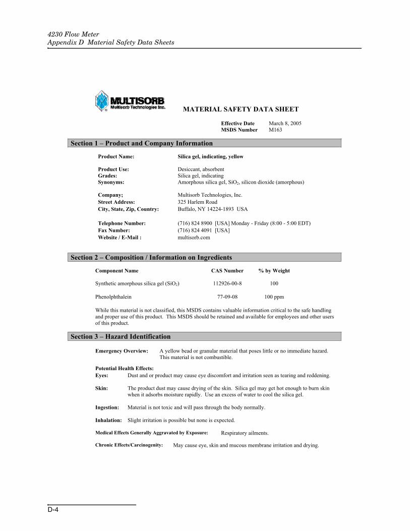
4230 Flow MeterAppendix D Material Safety Data Sheets
D-4
MATERIAL SAFETY DATA SHEET
Effective Date March 8, 2005 MSDS Number M163
Section 1 – Product and Company Information
Product Name: Silica gel, indicating, yellow
Product Use: Desiccant, absorbent Grades: Silica gel, indicating Synonyms: Amorphous silica gel, SiO2, silicon dioxide (amorphous)
Company; Multisorb Technologies, Inc.Street Address: 325 Harlem RoadCity, State, Zip, Country: Buffalo, NY 14224-1893 USA
Telephone Number: (716) 824 8900 [USA] Monday - Friday (8:00 - 5:00 EDT)Fax Number: (716) 824 4091 [USA]Website / E-Mail : multisorb.com
Section 2 – Composition / Information on Ingredients
Component Name CAS Number % by Weight Synthetic amorphous silica gel (SiO2) 112926-00-8 100
Phenolphthalein 77-09-08 100 ppm
While this material is not classified, this MSDS contains valuable information critical to the safe handling and proper use of this product. This MSDS should be retained and available for employees and other users of this product.
Section 3 – Hazard Identification
Emergency Overview: A yellow bead or granular material that poses little or no immediate hazard. This material is not combustible.
Potential Health Effects: Eyes: Dust and or product may cause eye discomfort and irritation seen as tearing and reddening.
Skin: The product dust may cause drying of the skin. Silica gel may get hot enough to burn skin when it adsorbs moisture rapidly. Use an excess of water to cool the silica gel.
Ingestion: Material is not toxic and will pass through the body normally.
Inhalation: Slight irritation is possible but none is expected.
Medical Effects Generally Aggravated by Exposure: Respiratory ailments.
Chronic Effects/Carcinogenity: May cause eye, skin and mucous membrane irritation and drying.

4230 Flow MeterAppendix D Material Safety Data Sheets
D-5
Section 4 – First Aid Measures
Eyes: Rinse the eyes well with water while lifting the eye lids. If irritation persists, consult a physician.
Skin: Wash affected area with soap and water.
Ingestion: Ingestion is unlikely, this material will pass through the body normally.
Inhalation: Remove the affected person to fresh air and get medical attention if necessary.
Notes to Physician: Not applicable
Section 5 – Fire Fighting Measures
Flammable Properties: Not flammable
Flash Point: Not applicable Method: Not applicable
Flammable Limits: Not flammable
Lower Flammability Limit: Not applicable
Upper Flammability Limit: Not applicable
Autoignition Temperature: Not applicable
Hazardous Combustion Products: Not applicable
Extinguishing Media: Use extinguishing media that is appropriate for the surrounding fire. Silica gel is not combustible.
Fire Fighting Instructions: Not combustible
Unusual Fire and Explosion Hazards: None
Section 6 – Accidental Release Measures
Spill: Sweep or vacuum up and place the spilled material in a waste disposal container. Avoid raising dust. Wash with soap and water after handling.
Section 7 – Handling and Storage
Handling: Avoid raising dust and minimize the contact between worker and the material. Practice good hygienic work practices.
Storage: Store in a cool, dry location. Keep in sealed containers away from moisture. The silica gel will readily adsorb moisture.

4230 Flow MeterAppendix D Material Safety Data Sheets
D-6
Section 8 – Exposure Controls/Personal Protection
Engineering Controls: Use exhaust ventilation to keep the airborne concentrations below the exposure limits.
Respiratory Protection: Use NIOSH approved respirator when the air quality levels exceed the TLV's.
Skin Protection: Light gloves will protect against abrasion and drying of the skin.
Eye Protection: Safety glasses.
Component Name Exposure Limits OSHA
PELACGIH
TLVOther
Recommended Limits
Silica gel TWA 20 mppcf (80 mg / m3 % SiO2)
TWA 10 mg / m3 NIOSH REL TWA 6 mg / m3
IDLH 3000 mg / m3
Phenolphthalein Not Applicable Not Applicable Not Applicable
Section 9 – Physical and Chemical Properties
Appearance: Yellow beads or granules Vapor Density: Not applicable
Odor: None Boiling Point: 4046 F (2230 C)
Physical State: Solid bead Melting Point: 3110 F (1710 C)
PH: Not applicable Solubility: Insoluble in water
Vapor Pressure: Not applicable Specific Gravity: 2.1
Section 10 – Stability and Reactivity
Stability: Stable
Conditions to avoid: Moisture and high humidity environments.
Incompatibility: Water, fluorine, oxygen difluoride, chlorine trifluoride
Hazardous Decomposition Products: None
Hazardous Polymerization: Will not occur

4230 Flow MeterAppendix D Material Safety Data Sheets
D-7
Section 11 – Toxicological Information
This product and its components are not listed on the NTP or OSHA Carcinogen lists.
Animal Toxicology Tests for DOT Hazard classification ( Tests Conducted on finely ground silica gel)
1 - hour LC50 (rat) > 2 mg / l 48 - hour oral LD50 (rat) est. > 31,600 mg / kg 48 - hour dermal LD50 (rabbit) est. > 2,000 mg / kg Considered an ocular irritant
Human Toxicology Silica gel is a synthetic amorphous silica not to be confused with crystalline silica. Epidemiological studies indicate low potential for adverse health effects. In the activated form, silica gel acts as a desiccant and can cause a drying irritation of the mucous membranes and skin in cases of severe exposure. Multisorb Technologies Inc. knows of no medical conditions that are abnormally aggravated by exposure to silica gel. The primary route of entry is inhalation of dust.
Section 12 – Ecological Information
Not known to have any adverse effect on the aquatic environment. Silica gel is insoluble and non-toxic.
Section 13 – Disposal Information
Disposal Information If this product as supplied becomes a waste, it does not meet the criteria of a hazardous waste as defined under the Resource Conservation and Recovery Act (RCRA) 40 CFR 261. Materials of a hazardous nature that contact the product during normal use may be retained on the product.The user of the product must identify the hazards associated with the retained material in order to assess the waste disposal options. Dispose according to federal, state and local regulations.
Section 14 – Transportation Information
U.S. Department of Transportation Shipping Name: Not classified as a hazardous material. Not regulated.
Section 15 – Regulatory Information (Not meant to be all inclusive - selected regulations represented)
TSCA Listed: Yes
DSL/NDSL (Canadian) Listed: Yes
OSHA: TWA 20 mppcf (80 mg / m3 % SiO2) for Silica gel
NIOSH: REL TWA 6 mg / m3 IDLH 3,000 mg / m3 for silica gel Animal tests conducted in 1976 - 1978. 18 month exposure at 15 mg / m3 showed silica deposition in respiratory macrophages and lymph nodes, minimum lung impairment, no silicosis.
ACGIH: TLV - 10 mg / m3 for Silica gel
DOT: Not classified as a hazardous material.

4230 Flow MeterAppendix D Material Safety Data Sheets
D-8
HMIS – Hazardous Materials Identification System
HMIS Rating HealthFlammabilityReactivity
000
0 - minimal hazard, 1 - slight hazard, 2 - moderate hazard, 3 - serious hazard, 4 - severe hazard
This MSDS was prepared by: George E. Mckedy Senior Applications Development Specialist Multisorb Technologies, Inc.
This data and recommendations presented in this data sheet concerning the use of our product and the materials contained therein are believed to be correct but does not purport to be all inclusive and shall be used only as a guide. However, the customer should determine the suitability of such materials for his purpose before adopting them on a commercial scale. Since the use of our products is beyond our control, no guarantee, expressed or implied, is made and no responsibility assumed for the use of this material or the results to be obtained therefrom. Information on this form is furnished for the purpose of compliance with Government Health and Safety Regulations and shall not be used for any other purposes. Moreover, the recommendations contained in this data sheet are not to be construed as a license to operate under, or a recommendation to infringe, any existing patents, nor should they be confused with state, municipal or insurance requirements, or with national safety codes.

Index-1
4230 Flow Meter
Index
Numerics4 to 20 mA Output Interface, 4-54-20 mA Output, 2-17, 2-37, 4-5
AAccessories List, A-8Alarm Box, 4-9Analog Output, 2-17, 2-37, 4-5
External, 4-5Internal, 4-6
BBattery Life Expectancy, 1-10Bubble Line, 3-10
Extensions, 3-15Flume Fittings, 3-15High-Velocity Flow Streams, 3-14Open Channel Installation, 3-16Stilling Wells, 3-15
Bubble Rate, 3-5Bubbler System Operation, 5-11Bubbler Tube Retainer Assembly, 3-18
CCMOS Circuitry, 5-15Compatible Equipment, 1-1Current Draw, 1-11
DDesiccant Canister, 3-1Desiccant Cartridge, 3-1
Venting, 3-1Display Functions, 2-1
FFLASH Update, 5-17Flow Conversion
Data Points, 2-35Equation, 2-33Flow Metering Inserts, 2-36Flume, 2-32Manning, 2-33Weir, 2-31
Flow Metering Inserts, 3-16Flowlink Software, 4-2, 4-9
HHysteresis, 2-15
IInstallation
Bubble Line, 3-12Flow Meter, 3-9Safety Considerations, 3-9
KKeypad Functions, 2-2
MMaintenance
Bubble Line, 5-4Case, 5-1CPU, 5-14Desiccators, 5-2Fuses, 5-9Getting Help, 5-14Printer
Ink Ribbon, 5-7Paper Roll, 5-5
Servicing CMOS Circuitry, 5-15System Reset, 5-10Troubleshooting Steps, 5-14
Material Safety Data Sheets, D-1Maximum Head, 2-37Modem, 4-1Mounting
Parameter Probes, 4-26Mounting Rings
Universal Mounting Ring, 4-27MSDS, D-1
OOperating Principles, 1-2
Bubbler System, 1-3, 5-11Drift Compensation, 1-3Pressure Transducer, 1-3
Optional Equipment4200T Modem, 4-1Dissolved Oxygen Probe, 4-19External Analog Output Interface, 4-5Flowlink Software, 4-9High-Low Alarm Relay Box, 4-9Internal Analog Output Board, 4-6Mechanical Totalizer, 4-31

4230 Flow MeterIndex
Index-2
pH Probe, 4-12Rain Gauge, 4-8Temperature Probe, 4-12YSI 600 Sonde, 4-28
Optional OutputsAnalog, 2-17, 2-37, 4-5Serial, 2-19, 4-4
PParameter Sensing, 4-11Power Consumption, 1-9, 1-10
Bubble Rate, 3-6Power Loss, 3-2Power Sources, 3-2
AC Power Supplies, 3-4Battery-Backed Power Pack, 3-4High Capacity Power Pack, 3-4
External 12 V Battery, 3-5Lead-Acid Battery, 3-4Nickel-Cadmium Battery, 3-3Sampler, 3-3
Program Steps - Description, 2-5Programming, 2-3Programming Steps
Step 1 - Operating Mode, 2-12Step 2 - Flow Conversion, 2-31Step 3 - Parameter to Adjust, 2-38Step 4 - Reset Totalizer, 2-45Step 5 - Sampler Pacing, 2-45Step 6 - Sampler Enable, 2-47Step 7 - Alarm Dialout, 2-51Step 8 - Printer, 2-53Step 9 - Reports/History, 2-55
Programming Worksheets, B-1Purge Interval, 2-13
RRain Gauge, 4-8Replacement Parts, A-1Reports, 2-23
SSafety, C-1
Hazardous Gases, C-6Lethal Atmospheres in Sewers, C-4Precautions, C-1
Sampler Connection, 3-18Scissors Ring, 4-27Serial Output, 2-19, 4-4
ASCII Codes, 2-20Software
Flowlink, 4-2, 4-9System Reset, 5-10Updating, 5-17
Specifications, 1-4Spring Rings, 4-26Super Bubble, 3-8
TTechnical Specifications, 1-4Tipping Bucket Rain Gauge, 4-8Troubleshooting Steps, 5-14
YYSI 600 Sonde, 4-28
Calibration, 2-41

Compliance Statements
Table Hazmat 4200 Series F/M 60-3213-371 Rev.
Name and amount of Hazardous Substances or Elements in the product
Hazardous Substances or Elements Component Name
(Pb) (Hg) (Cd) (Cr(VI)) (PBB) (PBDE)
Circuit Boards X O O O O O
X O O O O O
O O O O X O
O O O O X O
X O O O X O
O O X O O O
Name and amount of Hazardous Substances or Elements in the product O: ST/O: Represent the concentration of the hazardous substance in this component’s any homogeneous pieces is
lower than the ST/ standard limitation.
X ST/
( “X” )X: Represent the concentration of the hazardous substance in this component’s at least one homogeneous
piece is higher than the ST/ standard limitation. (Manufacturer may give technical reasons to the “X”marks)
The Environmentally Friendly Use Period (EFUP) was determined through experience.
(207 2007 )
A BThe date of Manufacture is in code within the serial number. The first three numbers are the year of manufacture (207 is year 2007) followed by a letter for the month. "A" is January, "B" is February and so on.


CE Dec
larat
ion o
f Con
form
ity
DECLARATION OF CONFORMITY
Application of Council Directive: 89/336/EEC – The EMC Directive 73/23/EEC – The Low Voltage Directive
Manufacturer's Name: Teledyne Isco, Inc.
Manufacturer's Address: 4700 Superior, Lincoln, Nebraska 68504 USA Mailing Address: P.O. Box 82531, Lincoln, NE 68501
Equipment Type/Environment: Laboratory Equipment for Light Industrial/Commercial Environments
Trade Name/Model No: Model 4230 Bubbler Flow Meter
Year of Issue: 2000
Standards to which Conformity is Declared: EN 50082-1 Generic Immunity for Commercial, Light Industrial Environment
EN 61010-1 Safety Requirements for Electrical Equipment for Measurement, Control, and Laboratory Use
Standard Description Severity Applied Performance Criteria
IEC 801.2 Electrostatic Discharge Level 2 - 4kV contact discharge Level 3 - 8kV air discharge
BB
IEC 801.3 Radiated RF Immunity 27 MHz to 500MHz *Level 2 - 3 V/m
A
IEC 801.4 Electrical Fast Transient Level 2 - 1kV on ac lines B
CISPR11/EN 55011
RF Emissions Group 1, Class A Industrial, Scientific, and Medical Equipment
*Instrument is susceptible to 3V/m between 105 mHz and 500 mHz. We, the undersigned, hereby declare that the design of the equipment specified above conforms to the above Directive(s) and Standards as of January 1, 1997
William Foster USA Representative
William Foster Director of Engineering Teledyne Isco, Inc. 4700 Superior Street Lincoln, Nebraska 68504 Phone: (402) 464-0231 Fax: (402) 464-4543
60-3232-023Rev. B


CE Dec
larat
ion o
f Con
form
ity
DECLARATION OF CONFORMITY
Application of Council Directive: 89/336/EEC – The EMC Directive 73/23/EEC – The Low Voltage Directive
Manufacturer's Name: Teledyne Isco, Inc. Manufacturer's Address: 4700 Superior, Lincoln, Nebraska 68504 USA
Mailing Address: P.O. Box 82531, Lincoln, NE 68501 Equipment Type/Environment: Laboratory Equipment for Light Industrial/Commercial Environments
Trade Name/Model No: 4200T Modem Year of Issue: 2001
Standards to which Conformity is Declared: EN 55024-1998 EMC Requirements for Information Technology Equipment EN 60950 Safety Requirements for Information Technology Equipment FCC Part 68
Standard Description Severity Applied Performance Criteria
EN61000-4-2 Electrostatic Discharge Level 2 - 4kV contact discharge Level 3 - 8kV air discharge
BB
EN61000-4-3 Radiated RF Immunity 80 MHz to 1000MHz 80% AM at 1kHz Level 1 – 10V/m
A
EN61000-4-4 Electrical Fast Transient Level 2 - 2kV on ac lines B
EN61000-4-5 Surge on AC Lines 2kV common mode, 1kV differential mode
B
EN61000-4-6 Conducted RF on AC lines 150 kHz to 80 MHz, 3V rms, 80% modulated
B
EN61000-4-11 Voltage Dips/Short Interruptions 0.5 cycle, each polarity/100% B
EN 55022 RF Emissions Group 1, Class A, Information Technology Equipment
EN61000-3-2, 3-3 Harmonic, Flicker
We, the undersigned, hereby declare that the design of the equipment specified above conforms to the above Directive(s) and Standards as of July 5, 2001.
William Foster USA Representative
William Foster Director of Engineering Teledyne Isco, Inc. 4700 Superior Street Lincoln, Nebraska 68504
Phone: (402) 464-0231 Fax: (402) 464-4543
60-3212-049 Rev. A

Warranty

Teledyne Isco One Year Limited Factory Service Warranty *
Teledyne Isco warrants covered products against failure due to faulty parts or workmanship for a period of one year (365 days) from their shipping date, or from the date of installation by an authorized Teledyne Isco Service Engineer, as may be appropriate.
This warranty does not cover loss, damage, or defects resulting from transportation between the customer’s facility and the repair facility.
Teledyne Isco specifically disclaims any warranty of merchantability or fitness for a particular purpose.During the warranty period, repairs,
replacements, and labor shall be provided at no charge. Teledyne Isco’s liability is strictly limited to repair and/or replacement, at Teledyne Isco’s sole discretion.
This warranty applies only to products sold under the Teledyne Isco trademark and is made in lieu of any other warranty, written or expressed.
Failure of expendable items (e.g., charts, ribbon, tubing, lamps, glassware, seals, filters, fittings, and wetted parts of valves), or from normal wear, accident, misuse, corrosion, or lack of proper maintenance, is not covered. Teledyne Isco assumes no liability for any consequential damages.
No items may be returned for warranty service without a return authorization number issued from Teledyne Isco.
The warrantor is Teledyne Isco, Inc. 4700 Superior, Lincoln, NE 68504, U.S.A.
* This warranty applies to the USA and countries where Teledyne Isco Inc. does not have an authorized dealer. Customers in countries outside the USA, where Teledyne Isco has an authorized dealer, should contact their Teledyne Isco dealer for warranty service.
In the event of instrument problems, always contact the Teledyne Isco Service Department, as problems can often be diagnosed and corrected without requiring an on-site visit. In the U.S.A., contact Teledyne Isco Service at the numbers listed below. International customers should contact their local Teledyne Isco agent or Teledyne Isco International Customer Service.
Return Authorization
A return authorization number must be issued prior to shipping. Following authorization, Teledyne Isco will pay for surface transportation (excluding packing/crating) both ways for 30 days from the beginning of the warranty period. After 30 days, expense for warranty shipments will be the responsibility of the customer.
Shipping Address: Teledyne Isco, Inc. - Attention Repair Service 4700 Superior Street Lincoln NE 68504 USA
Mailing address: Teledyne Isco, Inc. PO Box 82531 Lincoln NE 68501 USA
Phone: Repair service: (800)775-2965 (lab instruments)
(800)228-4373 (samplers & flow meters)
Sales & General Information (800)228-4373 (USA & Canada)
Fax: (402) 465-3001
Email: [email protected] Web site: www.isco.com
February 1, 2006 P/N 60-1002-040 Rev C