
Metering pumps Hydro/ 2 and Hydro/ 3 Operating instructions
120
Metering pumps Hydro/ 2 and Hydro/ 3 Operating instructions P_HY_0004_SW EN Original operating instructions (2006/42/EC) 984721 BA HY 018 05/19 EN Please carefully read these operating instructions before use. · Do not discard. The operator shall be liable for any damage caused by installation or operating errors. The latest version of the operating instructions are available on our homepage.
-
Upload
khangminh22 -
Category
Documents
-
view
0 -
download
0
Transcript of Metering pumps Hydro/ 2 and Hydro/ 3 Operating instructions

Metering pumpsHydro/ 2 and Hydro/ 3
Operating instructions
P_HY_0004_SW
EN
Original operating instructions (2006/42/EC)984721 BA HY 018 05/19 EN
Please carefully read these operating instructions before use. · Do not discard.The operator shall be liable for any damage caused by installation or operating errors.
The latest version of the operating instructions are available on our homepage.

Read the following supplementary information in its entirety! Should youalready know this information, you will benefit more from referring to theoperating instructions.
The following are highlighted separately in the document:
n Enumerated lists
Operating guidelines
ð Outcome of the operating guidelines
- see (reference)
Information
This provides important information relating to the cor‐rect operation of the unit or is intended to make yourwork easier.
Safety Information
Safety information is identified by pictograms - see Safety Chapter.
Refer to the precise designation of suppliers' components in the "TechnicalData" chapter for ease of finding the relevant information.
These operating instructions conform to current EU regulations applicableat the time of publication.
Please state identity code and serial number, which you can find on thenameplate when you contact us or order spare parts. This enables the unittype and material versions to be clearly identified.
The nameplate stuck on the cover page is identical to the pump suppliedso that there is a clear link between the operating instructions and thepump.
Supplementary information
Fig. 1: Please read!
Information in supplier instructions
Validity
State the identity code and serial number
EX pumps only
Supplemental directives
2

Table of contents1 Identity code.................................................................................... 5
2 Safety chapter............................................................................... 102.1 Safety information for ATEX designs.................................... 152.2 Explanation of the ATEX label.............................................. 26
3 Storage, transport and unpacking................................................. 29
4 Overview of equipment / control elements.................................... 31
5 Functional description.................................................................... 32
6 Assembly....................................................................................... 33
7 Installation..................................................................................... 377.1 Installation, hydraulic............................................................. 377.1.1 Basic installation notes....................................................... 407.2 Installation, electrical............................................................. 42
8 Start up and operation................................................................... 488.1 Bleeding the liquid end.......................................................... 518.2 Calibrate the stroke control drive (optional).......................... 52
9 Maintenance.................................................................................. 53
10 Repair............................................................................................ 5910.1 Cleaning valves................................................................... 6010.2 Replacing the diaphragm.................................................... 6210.3 Repairing the diaphragm rupture sensor............................. 6410.4 Calibrating the dosing rate.................................................. 6610.5 Replacing power end bearings............................................ 68
11 Troubleshooting............................................................................. 69
12 Decommissioning and disposal..................................................... 7312.1 Decommissioning................................................................ 7312.2 Disposal.............................................................................. 74
13 Technical data............................................................................... 7613.1 Performance data................................................................ 7713.2 Metering reproducibility....................................................... 8013.3 Viscosity.............................................................................. 8113.4 Weight................................................................................. 8113.5 Wetted materials................................................................. 8113.6 Ambient conditions.............................................................. 8213.6.1 Temperatures................................................................... 8213.6.2 Air humidity...................................................................... 8313.6.3 Installation height............................................................. 8313.7 Housing degree of protection.............................................. 8313.8 Motor data........................................................................... 8313.9 Diaphragm rupture sensor.................................................. 8513.10 Safety relief valve (HP2 and HP3).................................... 8613.11 Stroke sensor.................................................................... 8613.12 Heating cartridge............................................................... 8613.13 Protection temperature limiter (ATEX only)....................... 8713.14 Filling volumes.................................................................. 8713.14.1 Hydraulic oil.................................................................... 8713.15 Sound pressure level HP2a / Hp3a................................... 8713.16 Supplement for modified versions..................................... 87
14 Dimensional drawings................................................................... 89
15 Earthing drawing.......................................................................... 102
16 Diagrams for setting the metering capacity................................. 103
Table of contents
3

17 Ordering information.................................................................... 10517.1 Exploded view drawing..................................................... 10517.2 Spare parts kits................................................................. 10517.3 Diaphragms....................................................................... 10717.4 General............................................................................. 107
18 EU Declaration of Incorporation for Machines HP2..................... 109
19 EU Declaration of Incorporation for Machines HP3..................... 110
20 EC Declaration of Conformity for HP2 Machines........................ 111
21 EC Declaration of Conformity for HP3 Machines........................ 112
22 EC Declaration of Incorporation for ATEX HP2 Machines.......... 113
23 EC Declaration of Incorporation for ATEX HP3 Machines.......... 114
24 EC Declaration of Conformity for ATEX HP2 Machines.............. 115
25 EC Declaration of Conformity for ATEX HP3 Machines.............. 116
Table of contents
4

1 Identity codeHP2a Hydro/ 2, version a
Power end type
H Main power end
D Main power end, double head version
E Main power end for add-on power end
F Main power end double head version for add-on power end
A Add-on power end
B Add-on power end double head version
Type *
Capacity
_ _ __ _ _
Performance data at maximum back pressure and type: refer to nameplate on the pump housing
Dosing head material
SS Stainless steel
PV PVDF
HC Hastelloy C
TT PTFE + carbon
Seal material
T PTFE
Displacement body
0 Standard multi-layer safety diaphragm with rupture signalling
Dosing head design
0 no valve spring (standard)
1 with valve spring
D Double ball valve (only for SST and HCT)
H HV version for (only for 025019 ... 025060)
Hydraulic connector
0 Standard threaded connector (in line with technical data)
E with DIN ISO flange
F with ANSI flange
Design
0 with ProMinent® logo (standard)
1 without ProMinent® logo
M modified* * order-related design, refer to order paperworkfor pump features
Electric power supply
S 3-phase, 230 V/400 V 50/60 Hz, 0.37 kW
L 3-phase, 230 V/400 V, 50 Hz, (Exe, Exde), 0.37 kW
P 3-phase, 265 V/440 V, 60 Hz, (Exe, Exde), 0.37 kW
R 3-phase variable speed stroke control motor, 230/400 V, 0.37kW
Identity code
5

HP2a Hydro/ 2, version a
V(0) Variable stroke control motor with integrated frequency con‐verter 1-phase, 230 V, 50/60 Hz
V(2) Variable stroke control motor with integrated frequency con‐verter (Exd)
Z Speed control complete 1-phase, 230 V, 50/60 Hz (stroke con‐trol motor + frequency converter)
1 without motor, with flange 200/80
3 without motor, with flange 160/71
4 without motor, with 56C flange (NEMA)
0 Add-on power end
Degree of protection
0 IP 55 (standard) ISO class F
1 Exe design ATEX-T3 **
2 Exde design ATEX-T4 **
A ATEX power end **
Stroke sensor
0 no stroke sensor (standard)
1 Stroke sensor (suitable for use in areas at risk fromexplosion)
Stroke length adjustment
0 manual (standard)
1 with servomotor, 230 V, 50/60 Hz
2 with servomotor, 115 V, 60 Hz
A with stroke control motor 0...20 mA 230 V, 50/60Hz
B with stroke control motor 4...20 mA 230 V, 50/60Hz
C with stroke control motor 0...20 mA 115 V, 60 Hz
D with stroke control motor 4...20 mA 115 V, 60 Hz
Hydraulic oil
0 Standard
1 Food approval for oil
2 Low temperature to -25 ℃
3 Low temperature Zone 2
Tab. 1: * Type, power (at 50 Hz)Type Capacity Type Capacity Type Capacity
bar l/h bar l/h bar l/h
100003 1001 3 064007 641 7 025019 251 19
100006 1001 6 064015 641 15 025040 251 40
100007 1001 7 064018 641 18 025048 251 48
Identity code
6

Type Capacity Type Capacity Type Capacity
bar l/h bar l/h bar l/h
100009 1001 9 064022 641 22 025060 251 60
100010 1001 10 064025 641 25 025068 251 68
1 Maximum back pressure for TTT material version: 16 bar!
Maximum back pressure for PVT material version: 25 bar!
** ATEX specification - refer to the nameplate on the pump, correspondingEU Declaration of Conformity for ATEX Machinery and Ä Chapter 2.2‘Explanation of the ATEX label’ on page 26
Identity code
7
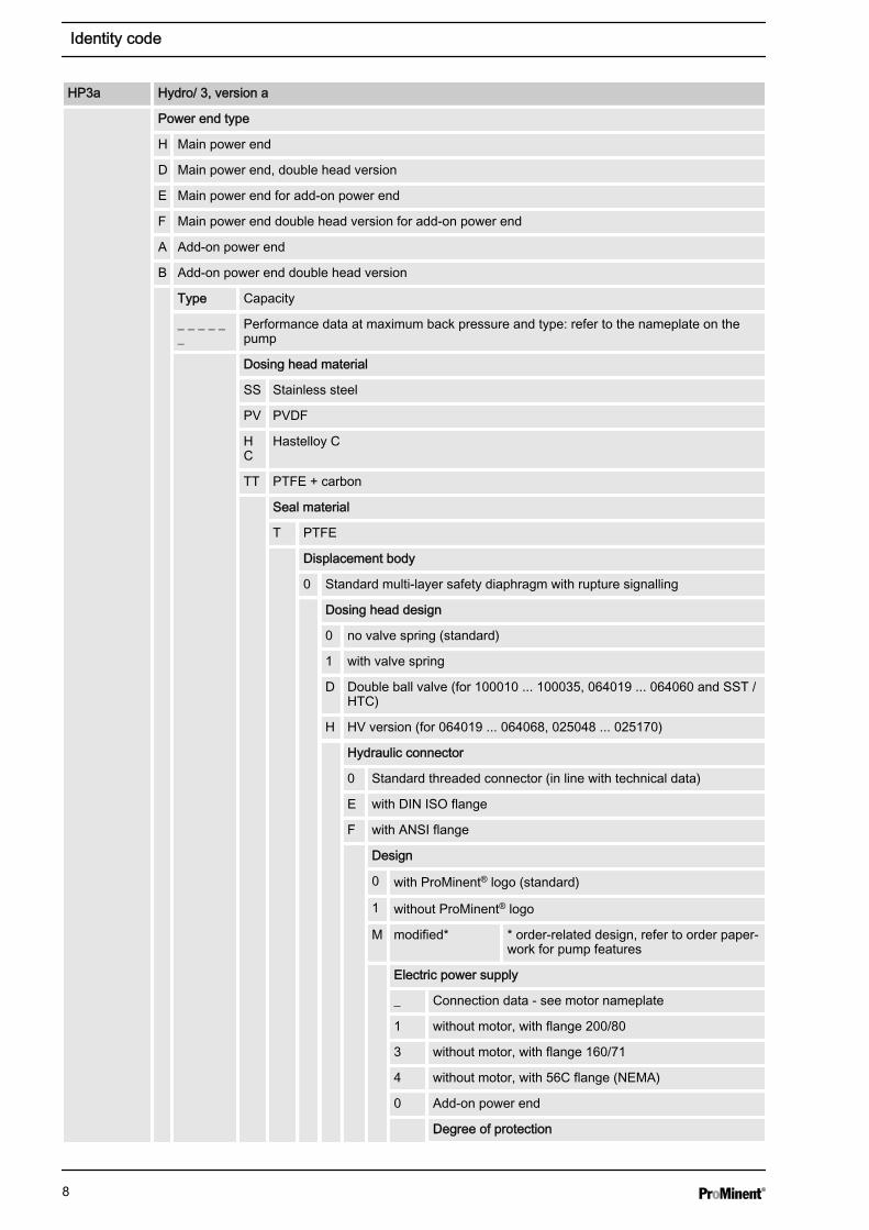
HP3a Hydro/ 3, version a
Power end type
H Main power end
D Main power end, double head version
E Main power end for add-on power end
F Main power end double head version for add-on power end
A Add-on power end
B Add-on power end double head version
Type Capacity
_ _ _ _ __
Performance data at maximum back pressure and type: refer to the nameplate on thepump
Dosing head material
SS Stainless steel
PV PVDF
HC
Hastelloy C
TT PTFE + carbon
Seal material
T PTFE
Displacement body
0 Standard multi-layer safety diaphragm with rupture signalling
Dosing head design
0 no valve spring (standard)
1 with valve spring
D Double ball valve (for 100010 ... 100035, 064019 ... 064060 and SST /HTC)
H HV version (for 064019 ... 064068, 025048 ... 025170)
Hydraulic connector
0 Standard threaded connector (in line with technical data)
E with DIN ISO flange
F with ANSI flange
Design
0 with ProMinent® logo (standard)
1 without ProMinent® logo
M modified* * order-related design, refer to order paper‐work for pump features
Electric power supply
_ Connection data - see motor nameplate
1 without motor, with flange 200/80
3 without motor, with flange 160/71
4 without motor, with 56C flange (NEMA)
0 Add-on power end
Degree of protection
Identity code
8

HP3a Hydro/ 3, version a
0 IP 55 (standard) ISO class F
1 Exe design ATEX-T3 **
2 Exde design ATEX-T4 **
A ATEX power end
Stroke sensor
0 no stroke sensor (standard)
1 Stroke sensor (suitable for use in areas at riskfrom explosion)
Stroke length adjustment
0 manual (standard)
1 with servomotor, 230 V, 50/60 Hz
2 with servomotor, 115 V, 60 Hz
A with stroke control motor 0...20 mA 230 V,50/60 Hz
B with stroke control motor 4...20 mA 230 V,50/60 Hz
C with stroke control motor 0...20 mA 115 V,60 Hz
D with stroke control motor 4...20 mA 115 V,60 Hz
Hydraulic oil
0 Standard
1 Food approval for oil
2 Low temperature to -25 ℃
3 Low temperature Zone 2
Tab. 2: * Type, power (at 50 Hz)Type Capacity Type Capacity Type Capacity
bar l/h bar l/h bar l/h
100010 1001 10 064019 641 19 025048 251 48
100021 1001 21 064040 641 40 025100 251 100
100025 1001 25 064048 641 48 025120 251 120
100031 1001 31 064060 641 60 025150 251 150
100035 1001 35 064068 641 68 025170 251 170
1 Maximum back pressure for TTT material version: 16 bar!
Maximum back pressure for PVT material version: 25 bar!
** ATEX specification - refer to the nameplate on the pump, correspondingEU Declaration of Conformity for ATEX Machinery and Ä Chapter 2.2‘Explanation of the ATEX label’ on page 26
Identity code
9

2 Safety chapter
The following signal words are used in these operating instructions toidentify different severities of a hazard:
Signal word Meaning
WARNING Denotes a possibly hazardous situation. If this is disre‐garded, you are in a life-threatening situation and thiscan result in serious injuries.
CAUTION Denotes a possibly hazardous situation. If this is disre‐garded, it could result in slight or minor injuries or mate‐rial damage.
The following warning signs are used in these operating instructions todenote different types of danger:
Warning signs Type of danger
Warning – hand injuries.
Warning – high-voltage.
Warning – flammable substances.
Warning – hot surface.
Warning – danger zone.
n Only use the pump to meter liquid feed chemicals.n The pump is only approved for use with flammable feed chemicals if it
has the identity code option "Standard multi-layer safety diaphragmwith rupture signalling", is operated at back pressures of over 2 barwith metal liquid ends and if the operator implements appropriatesafety measures.
n The pump may only be started up after it has been correctly installedand started up in accordance with the technical data and specifica‐tions contained in the operating instructions. When working at temper‐atures arising using a heating cartridge, bear in mind their effect.
n Observe the general limitations with regard to viscosity limits, chem‐ical resistance and density - see also the ProMinent Resistance List(in the Product Catalogue or at www.prominent.com)!
n All other uses or modifications are prohibited.n The pump is not intended for the metering of gaseous media and
solids.n The pump is not intended for the metering of explosive substances
and explosive mixtures.n The pump is not intended for unprotected use outdoors.n The pump is only intended for industrial use.n Only allow trained and authorised personnel to operate the pump -
see the following table.
Explanation of the safety information
Warning signs denoting different types ofdanger
Intended use
Safety chapter
10

n You have a responsibility to adhere to the information contained in theoperating instructions at the different phases of the unit's service life.
n You have a responsibility to observe the information contained in theoperating instructions for the auxiliary equipment at the differentphases of their respective service lives.
Task Qualification
Storage, transport, unpacking Instructed person
Assembly Technical personnel, service
Planning the hydraulic installation Qualified personnel who have athorough knowledge of oscillatingmetering pumps
Hydraulic installation Technical personnel, service
Electrical installation electrical technician,
Start up Technical personnel
Operation Instructed person
Maintenance, repair Technical personnel, service
Decommissioning, disposal Technical personnel, service
Troubleshooting Qualified person, electrical techni‐cian, instructed person, service -depending on the requirement
Explanation of the table:
Trained, qualified personnel
A trained, qualified employee is deemed to be a person who is able toassess the tasks assigned to him and recognise possible hazards basedon his training, knowledge and experience, as well as knowledge of perti‐nent regulations. A trained, qualified employee must be able to performthe tasks assigned to him/her independently with the assistance ofdrawing documentation and parts lists. The assessment of a person'stechnical training can also be based on several years of work in the rele‐vant field.
Electrical technician
An electrical technician is able to complete work on electrical systems andrecognise and avoid possible dangers independently based on his tech‐nical training and experience as well as knowledge of pertinent standardsand regulations. An electrical technician must be able to perform the tasksassigned to him/her independently with the assistance of drawing docu‐mentation, parts lists, terminal and circuit diagrams. The electrical techni‐cian must be specifically trained for the working environment in which theelectrical technician is employed and be conversant with the relevantstandards and regulations.
Electrical technician with knowledge of ATEX explosion protection
An electrical technician with an additional explosion protection qualificationshould be specifically trained for the field of work in which he is employedand be familiar with the relevant standards and regulations. An electricaltechnician with an additional explosion protection qualification can work onelectrical systems and independently recognise and avoid possible dan‐gers based on his technical training and experience.
The electrical technician with an additional explosion protection qualifica‐tion is familiar with all the standards and regulations applicable to explo‐sion protection, in particular, but not however exclusively, with all parts ofEN 60079 [Electrical equipment for areas at risk of a gas explosion].
An electrical technician with an additional explosion protection qualificationmust comply with the provisions of the applicable statutory directives onaccident prevention.
Qualification of personnel
Safety chapter
11

Recognised competent person
To carry out explosion hazard inspections the competent person musthave:
n Completed a relevant course of study orn Have a comparable technical qualification orn Another technical qualification combined with long-term experience of
safety technology.
Make sure that the person is familiar with the relevant body of standardsand regulations and has worked in the field for at least one year. Theperson needs to have opportunities for an exchange of experiences.
Specific requirements are placed on competent persons who perform testson repaired devices/parts. They must be recognised by the responsibleauthorities (e.g. district council) in this respect.
Instructed person
An instructed person is deemed to be a person who has been instructedand, if required, trained in the tasks assigned to him/her and possible dan‐gers that could result from improper behaviour, as well as having beeninstructed in the required protective equipment and protective measures.
Trained user
A trained user is a person who fulfils the requirements demanded of aninstructed person and who has also received additional training specific tothe system from ProMinent or another authorised distribution partner.
Service
Service refers to service technicians, who have received proven trainingand have been authorised by ProMinent to work on the system.
CAUTION!These operating instructions include notes and extractsfrom German regulations relating to the operator's scopeof responsibility. This information does not discharge theoperator from his responsibility as an operator and isintended only to remind him or make him aware of spe‐cific problem areas. This information does not lay claimto being complete, nor applicable to every country andevery type of application, nor to being unconditionallyup-to-date.
WARNING!Warning of hazardous feed chemicalShould a dangerous feed chemical be used: it mayescape from the hydraulic components when working onthe pump, material failure or incorrect handling of thepump.
– Take appropriate protective measures beforeworking on the pump (e.g. safety glasses, safetygloves, ...). Adhere to the material safety data sheetfor the feed chemical.
– Drain and flush the liquid end before working on thepump.
Safety information
Safety chapter
12

WARNING!Danger from hazardous substances!Possible consequence: Fatal or very serious injuries.
Please ensure when handling hazardous substancesthat you have read the latest safety data sheets providedby the manufacture of the hazardous substance. Theactions required are described in the safety data sheet.Check the safety data sheet regularly and replace, ifnecessary, as the hazard potential of a substance canbe re-evaluated at any time based on new findings.
The system operator is responsible for ensuring thatthese safety data sheets are available and that they arekept up to date, as well as for producing an associatedhazard assessment for the workstations affected.
CAUTION!Warning of feed chemical spraying aroundFeed chemical can spray out of the hydraulic compo‐nents if they are manipulated or opened due to pressurein the liquid end and adjacent parts of the system.
– Disconnect the pump from the mains power supplyand ensure that it cannot be switched on again byunauthorised persons.
– Depressurise the system before commencing anywork on hydraulic parts.
CAUTION!Warning of feed chemical spraying aroundAn unsuitable feed chemical can damage the parts ofthe pump that come into contact with the chemical.
– Take into account the resistance of the wetted mate‐rials and the ProMinent Resistance List whenselecting the feed chemical - see the ProMinentProduct Catalogue or visit ProMinent.
WARNING!Danger of injury to personnel and material damageThe pump must only be opened at those points requiredto be opened by these operating instructions.
It may only be opened in other positions upon receipt ofwritten authorisation from the ProMinent head office,Heidelberg.
CAUTION!Danger of personnel injury and material damageThe use of untested third party parts can result in per‐sonnel injuries and material damage.
– Only fit parts to metering pumps, which have beentested and recommended by ProMinent.
Safety chapter
13

CAUTION!Danger from incorrectly operated or inadequately main‐tained pumpsDanger can arise from a poorly accessible pump due toincorrect operation and poor maintenance.
– Ensure that the pump is accessible at all times.– Adhere to the maintenance intervals.
In the event of an electrical accident, disconnect the mains cable from themains or press the emergency cut-off switch fitted on the side of thesystem!
If feed chemical escapes, also depressurise the hydraulic system aroundthe pump as necessary. Adhere to the safety data sheet for the feedchemical.
Prior to commissioning the system or system component, it is the respon‐sibility of the system operator to obtain the latest safety data sheet for thechemicals / equipment to be used with the system from the supplier.Based on the information provided in the data sheets concerning healthand safety, water and environmental protection, and taking into considera‐tion the actual operating environment on site, it is the responsibility of theoperator to create the legal framework for the safe operation of the systemor system component, such as for example the preparation of operatinginstructions (operator's duties).
Secure all these parts in their place when using the pump.
Protective equipment May only be removed by*:
Motor terminal box cover Electrical technician, Service
Flange cover, side Service
Protective cowling over the motorfan
Service
Only with additional equipment:Their corresponding parts
Technical personnel, Service
* Only if required by the operating instructions and if the mains cableremains disconnected from the mains voltage.
The operator must be able to:
n Perform a risk assessmentn Produce and attach a nameplaten Issue a Declaration of Conformityn Adapt the operating instructions, if necessaryn Install the motor correctly
Sound pressure level LpA < 70 dB according to EN ISO 20361
at maximum stroke length, maximum stroke rate, maximum back pressure(water)
Information in the event of an emergency
Safety information for operating instruc‐tions
Safety equipment
Fixed, isolating protective equipment
Requirements if the motor is beinginstalled independently
Sound pressure level
Safety chapter
14

2.1 Safety information for ATEX designsThis chapter lists all safety information for ATEX designs. Safety informa‐tion is listed again at the relevant points in these operating instructions.
This safety information is supplementary to or replaces the safety informa‐tion for non-ATEX designs. If the safety information for ATEX designs con‐tradicts the other safety information, then the safety information in thischapter applies to ATEX designs.
n Only operate the pump in premises at risk from explosion in an ATEXdesigns in accordance with the applicable guidelines.
n Do not expose the ATEX design to any sources of ionising radiation orelectromagnetic high frequency radiation in the range 104 ... 3x10¹⁵ Hzor laser radiation or ultrasound or lightning without putting in placemeasures in line with EN 80079-38.
n The ATEX design is not intended for the metering of electrically non-conductive media (conductivity less than 50 pS/m).
n The ATEX design may not meter media, which tend to produce exo‐thermic reactions or self-ignite (examples of exothermic reactions:pyrophoric substances with air, alkali metal with water, decompositionof organic peroxides, polymerisation reactions), without taking effec‐tive measures in accordance with EN 80079-38.
Task Qualification
Planning the hydraulic installation ATEX qualified person, ATEX elec‐trical technician
Electrical installation ATEX electrical technician
Start up Skilled ATEX technician;
Checking the electrical installation:Recognised competent person
Maintenance, repair ATEX qualified person, ATEX elec‐trical technician
Troubleshooting Qualified ATEX technician or ATEXelectrical technician - depending onthe fault;
Checking the electrical installation:Recognised competent person
Explanation of the table:
Recognised competent person
To carry out explosion hazard inspections the competent person musthave:
n Completed a relevant course of study orn Have a comparable technical qualification orn Another technical qualification combined with long-term experience of
safety technology.
Make sure that the person is familiar with the relevant body of standardsand regulations and has worked in the field for at least one year. Theperson needs to have opportunities for an exchange of experiences.
Specific requirements are placed on competent persons who perform testson repaired devices/parts. They have to be recognised by the responsibleauthorities (e.g. district council) in this respect.
Skilled technician with knowledge of ATEX explosion protection
Intended use
Qualification of personnel
Safety chapter
15

The skilled technician with an additional explosion protection qualificationshould be specifically trained for the work area in which he is employedand be familiar with the relevant standards and regulations. The skilledtechnician with an additional explosion protection qualification can work onequipment and systems in areas protected from explosion and independ‐ently recognise and avoid possible dangers based on his technical trainingand experience.
The skilled technician with an additional explosion protection qualificationis familiar with all the standards and regulations applicable to explosionprotection.
The skilled technician with an additional explosion protection qualificationmust comply with the provisions of the applicable statutory directives onaccident prevention.
Electrical technician with knowledge of ATEX explosion protection
An electrical technician with an additional explosion protection qualificationshould be specifically trained for the field of work in which he is employedand be familiar with the relevant standards and regulations. An electricaltechnician with an additional explosion protection qualification can work onelectrical systems and independently recognise and avoid possible dan‐gers based on his technical training and experience.
The electrical technician with an additional explosion protection qualifica‐tion is familiar with all the standards and regulations applicable to explo‐sion protection.
An electrical technician with an additional explosion protection qualificationmust comply with the provisions of the applicable statutory directives onaccident prevention.
Recognised competent person
To carry out explosion hazard inspections the competent person musthave:
n Completed a relevant course of study orn Have a comparable technical qualification orn Another technical qualification combined with long-term experience of
safety technology.
Make sure that the person is familiar with the relevant body of standardsand regulations and has worked in the field for at least one year. Theperson needs to have opportunities for an exchange of experiences.
Specific requirements are placed on competent persons who perform testson repaired devices/parts. They must be recognised by the responsibleauthorities (e.g. district council) in this respect.
Ignition hazard Protective measures to be observed by the customer
Excessive surface pressure Limitation of the maximum temperature of the feed chem‐ical
Pump running hot Customer must monitor and maintain the pump in accord‐ance with the “Maintenance” chapter.
Customer must monitor the capacity.
Customer must fit a relief valve on the discharge side.
Mechanically generated sparks from the mechanism withlow oil
Customer must monitor and maintain the pump in accord‐ance with the “Maintenance” chapter.
Mechanically generated sparks from a faulty valve for thefeed chemical
Customer must monitor the capacity.
Electrical stray current in the event of a short circuit Customer must earth the pump and maintain the earthingof the individual components.
Summary of relevant ignition hazards andprotective measures put in place for theHydro in accordance with EN ISO80079-36
Safety chapter
16

Ignition hazard Protective measures to be observed by the customer
Electrical stray current in the event of a lightning strike Customer must implement suitable protective measuresoutdoors.
Static electricity Customer must earth the earthing points and maintain thepotential equalisation cables of the individual components.
Customer must pay attention to potential equalisationwhen dismantling.
Paint should not be applied too thickly.
Only with plastic dosing heads: Only use feed chemicalswith conductivities above 50 pS/m.
Customer must wire the diaphragm rupture indicator insuch a way that it immediately stops the pump.
Electromagnetic waves (also lasers), ionising radiationand ultra-sound have an impact on the pump
The customer must put in place measures in accordancewith EN 1127-1, if need be.
Adiabatic compression and shock waves Flammable feed chemicals: Do not allow the unit to rundry – even when filling and emptying the liquid end.
Exothermic reaction, including the self-combustion of dust The pump is not suitable for use with substances thathave a tendency towards exothermic reactions or self-combustion. Put in place measures in accordance with EN1127-1, if need be.
Feed chemicals that undergo an exothermic reaction withhydraulic oil: Customer must wire the diaphragm ruptureindicator in such a way that it immediately stops the pump.
Deposits of dust Regularly clean the outside of the pump with a dampcloth.
Flammable feed chemicals Customer must wire the diaphragm rupture indicator insuch a way that it immediately stops the pump.
Ignition hazard with bought-in motor components Refer to the documentation for the motor.
Comply with the monitoring intervals.
The insulation resistance needs to be greater then 5MOhm.
Provide a time-delay residual current device.
Provide overload protection by a motor protection switchor an equivalent protective device.
Observe the minimum spacing between the air inlet on thefan hood and any obstacles.
Avoid deposits of dust more then 5 mm deep.
Connect the earth wire.
Max. installation height: 1,000 m.a.s.l.
Ignition hazard with bought-in actuator or control drivecomponents
Refer to the documentation for the actuator.
Wait 3 minutes after switching off before opening thehousing.
Ignition hazard with bought-in Rotex coupling Refer to the documentation for the coupling (maintenance,alignment if necessary, ...).
Ignition hazard caused by bought-in heating cartridge withprotective temperature limiter
Refer to the documentation for the heating cartridge andthe protective temperature limiter (electrical installation,maintenance, ...).
Do not reprogram the protective temperature limiter.
Ignition hazard caused by bought-in proximity switchNJ1.5-8GM-N (stroke sensor, diaphragm rupture indicator)
Refer to the documentation for the proximity switch (elec‐trical installation, maintenance, ...).
Safety chapter
17

WARNING!Only use ATEX pumps in areas at risk from explosion– Observe the European Operator Directive, imple‐
mented in Germany by the Industrial Health andSafety Regulation, and the German Ordinance onHazardous Substances, for the installation and ope‐ration of equipment in areas at risk from explosion.
– Observe the European standards governing intrinsi‐cally safe power circuits. (In Germany these stand‐ards are partly implemented by VDE.)
– Adhere to the respective national regulations outsideof the EU.
– Ensure that installations in areas at risk of explosionare checked by a "recognised competent" person.This applies specifically to intrinsically safe powercircuits.
– The following information relates essentially to spe‐cifics in areas at risk from explosion and does notreplace the standard operating instructions.
– Only clean plastic parts carefully with a damp clothto avoid electrostatic charges and sparks.
WARNING!Motor may overheatIf the necessary cooling air supply is not guaranteed, themotor may overheat. In an area at risk from explosion, itcould trigger an explosion.
– Maintain sufficient clearance between the air intakeopening and the walls. The distance should begreater than 1/4 of the diameter of the air intakeopening.
– The fan must not suck in the exhaust air from otherdevices.
WARNING!ATEX pumps in areas at risk from explosion– Metering pumps in areas at risk of explosion are
provided, as a matter of course, with an appropriatesafety relief valve on the outlet side of the meteringpump (which is used to protect against excessiveheating due to overloading and impact sparkscaused by the breakage of power end parts trig‐gered by overloading.)
– Likewise a temperature monitor or a pressure sideflow control is to be fitting to metering pumps withhydraulic diaphragm control for T4. (Protectionagainst impermissible heating up in the event ofcontinuous operation by the internal relief valve).
– Should the various components have differing tem‐perature classes, scope for using the completepump depends on the component with the lowesttemperature class.
– Hydraulic diaphragm pumps are highly suitable,although the design with Ex "i" diaphragm rupturesensor and a pressure-side flow control is required.
– Ensure that installations in areas at risk of explosionare checked by a "recognised competent" person.
– Please note the relevant national regulations duringinstallation!
Safety information
Safety chapter
18

WARNING!ATEX pumps and flammable mediaThe ignition temperature is reduced significantly belowthe ignition temperature at atmospheric pressure due tocompression with the discharge stroke of the possiblyignitable vapour-air mixture.
– Do not allow it to run dry. Take appropriate protec‐tive measures.
– Immediately switch off the pump in the event of adiaphragm rupture.
WARNING!Risk of fire with flammable feed chemicals– Combustible media may only be transported using
stainless steel or Hastelloy C dosing heads.– Metering pumps can be used for metering combus‐
tible media, however as a matter of principle only ofa design including ATEX diaphragm rupture sensorsand a pressure-side flow control.
– During filling and draining of the liquid end, anexpert must ensure that feed chemical does notcome into contact with air.
– If necessary, the operator must implement furthermeasures.
WARNING!ATEX pumps in areas at risk from explosion– Make sure that a suitably competent person checks
whether the appropriate installation information fromthe "Installation " chapter has been implementedcorrectly.
– Make sure that a "recognised competent person"checks the electrical installation and in particular theintrinsically safe power circuits.
– Set the opening pressure of the relief valve at amaximum of no more than 1.5 times the rated pres‐sure of the pump.
WARNING!ATEX pumps in areas at risk from explosionIf feed chemicals are metered, which tend to produceexothermic reactions or self-ignite (examples of exo‐thermic reactions: pyrophoric substances with air, alkalimetal with water, decomposition of organic peroxides,polymerisation reactions), they can lead to high tempera‐tures and ignition.
– Put in place measures in accordance with EN80079-38.
WARNING!ATEX pumps in areas at risk from explosionIf abrasive media are being metered, they will escape assoon as all layers of the diaphragm have erodedthrough.
– Wire the electrical diaphragm rupture indicator tostop the pump in the event of a diaphragm rupture.
Safety chapter
19

WARNING!ATEX pumps in areas at risk from explosion– Electrically wire all electrical units cleanly and per‐
manently to an electrically clean earthing point, -e.g. with an earthing bar on your system.
– Electrically connect the electrical units fitted with apotential equalisation cable to each other, cleanlyand permanently, to an electrically clean potentialequalisation point - e.g. with a potential equalisationbar on your system.
– Note the enclosed documentation for the individualelectrical components.
WARNING!ATEX pumps in areas at risk from explosion– Use a suitable motor protection switch to protect
power end motors. Use motor protection approvedfor this application with Ex"e" motors. (Protectionagainst warming caused by overloading)
– Provide a time-delay residual current device.– Observe the enclosed operating instructions for the
Ex motor.
WARNING!The following applies in areas at risk from explosion:– Note the details of the type examination certificate
PTB 00 ATEX 2048 X for the Namur sensorNJ1.5-8GM-N as well.
WARNING!ATEX pumps in areas at risk from explosion– Make sure that a suitably competent person checks
whether the appropriate installation information fromthe "Installation " chapter has been implementedcorrectly.
– Make sure that a "recognised competent person"checks the electrical installation and in particular theintrinsically safe power circuits.
– Set the opening pressure of the relief valve to amaximum of no more than 1.5 times the nominalpressure of the pump.
Safety chapter
20
WARNING!ATEX pumps in areas at risk from explosion– Carry out a general check to ensure that the system
is working properly, particularly the power end andbearings, by regularly monitoring it (for leaks,noises, temperatures, smell, etc.).
– Do not allow the pump to run hot due to a lack of oil.With lubricated metering pumps, regularly check forthe presence of lubricant, for example by checkingthe liquid level, visual leak control etc. If oil isescaping, investigate the leak immediately and elim‐inate the cause.
– Check the correct operation of the relief valve down‐stream of the pump. In premises at risk from explo‐sion, the relief valve should prevent the gear frombecoming overloaded and becoming hot.
– Observe the enclosed operating instructions for theEx motor.
– Only with pumps with a motor flange: Check /replace worn gear ring etc. of the clutch.
– Only with add-on power end: Check / replace worngear ring/DZ element of the clutch.
– Check the seals of the pressure switch for leak-tight‐ness.
– When cleaning plastic components, ensure that noelectrostatic charges are generated by excessivefriction.
– Always earth the discharge line and the suction lineagainst the pump to prevent electrostatic chargebefore working on the pump.
– Have wear parts, such as bearings, replaced byProMinent Service when there is an identifiable inci‐dence of unacceptable wear.
– Check whether the potential equalisation lines areall sitting correctly with clean contacts.
– Check whether the earth lines are all sitting correctlywith clean contacts. Use the earthing drawings asan aid – see Appendix.
– Only use genuine spare parts as replacements.– Appropriate diagnostic equipment for bearing
damage is recommended for the premature detec‐tion of bearing damage.
– Carry out inspections and repair in compliance withDIN EN IEC 60079-17, as an example, and ensurethat they are only performed by "experienced per‐sonnel with the requisite knowledge".
– If re-painting, do not increase the layer thickness.– These measures are deemed to be minimum protec‐
tion measures by ProMinent. It is the duty of theoperator to take appropriate measures to eliminateany further hazards known to him.
WARNING!ATEX pumps in areas at risk from explosionStatic electricity can cause ignition sparks.
– Consider potential equalisation before you approachany pump equipment that could be at a differentelectrical potential (such as pipes or tools)
The entire installation supplied is provided ex works with the necessarypotential equalisation lines.
Potential equalisation line (prescribed inthe area at risk from explosion)
Safety chapter
21

Electrically wire an additional potential equalisation cable from the poten‐tial equalisation cables from this system cleanly and permanently to anelectrically clean potential equalisation point, e.g. to a potential equalisa‐tion bar on site.
Potential equalisation of frame
An earthing point for the customer is fitted on the frame.
When a frame is used, a motor screw is factory-connected by a protectiveearth cable to the earthing point.
5–25 V DC, in accordance with Namur or DIN 19234, potential-freedesign.
Data Value Unit
Rated voltage * 8 VDC
Power consumption - active surfaceuncovered
> 3 mA
Power consumption - active surface cov‐ered
< 1 mA
Rated switching distance 1.5 mm
* Ri ~ 1 kΩ
Cable colour Polarity
blue -
brown +
Install the sensor according to the chapter "Installation,electrical". Refer to its documentation.Sensor name: NJ1.5-8GM-N.
CAUTION!Observe the accompanying manual "HYDAC Operatingmanual pressure switch series EDS 4400 with ATEXapproval".
Tab. 3: Type identificationType iden‐tification
Feature Property
EDS 4 Designation of the pressureswitch
EDS 4
4 Precision: Thin film/relative pressure
4 Mechanical connection: G ¼ A DIN 3852, externalthread
8 Electrical connection: Device plug, M12x1, 5-pole
0060 Measuring range: specification in bar
P Control output: programmable
Namur sensor (Specified for EX zones)
ATEX pressure switch
Safety chapter
22

Type iden‐tification
Feature Property
A Certification: ATEX
N Electrical strength: 125 V AC relative to thehousing
3 Degrees of protection: II 2G Ex ia IIC T4
004 Modification number: 0.5 mm nozzle pressed inor integrated
including accessories ZBE08S-02 coupling socketM12x1, angled with 2 mwire, screened
F Sealing material: FPM
1 Connecting material: Stainless steel
200 Cable length: 2 m (standard)
size Value Unit
Voltage 14 ... 28 V
Check the seals at regular intervals - depending on theclimatic conditions and the feed chemical - in respect oftheir serviceability and replace if necessary.
Refer to its documentation.
Type: eBR6000
Tab. 4: Product identificationCode Property
e electronic device
B label for temperature limiter
R Controller
6 label for device generation
0 Type of ignition protection for measuring sensor input: notintrinsically safe
0 Pt100 3-wire
0 Relay
Technical data - see nameplate and enclosed operating instructions:
"ELMESS protective temperature limiter II (2) G [EEx ib] IIC/IIB II (2) D [Exib D] BVS 06 ATEX F 002 X".
Changing the motor voltage and pulse frequency is not permitted.
The motors can be operated within a frequency range of 2 Hz (limitedtorque) to 100 Hz.
The pulse frequency of the frequency converter is 4 kHz.
Rotex coupling
Protective temperature limiter
Motor design V2 (motor with integratedfrequency converter)
Safety chapter
23

Check the pump installation for:
n Leaksn Abnormal noises or squeaksn Abnormal temperaturesn Abnormal odoursn Abnormal vibrationsn Other anomalies
WARNING!Stop the pump immediately in the event of any anoma‐lies when inspecting the pump and rectify them immedi‐ately. ProMinent Service may be needed if required.
Interval Maintenance work
Check whether the seals of the overpressure signalling system are OKand replace in case of doubt.
Check the effectiveness of the protective temperature limiter for theheating cartridge.
Check the heating cartridge and the protective temperature limiter forexternal damage or corrosion to the housing and connecting parts.Immediately have damaged parts rectified with genuine spare parts bythe manufacturer.
After 20,000 or 26,000 operating hours (API) Adhere to the motor manufacturer's recommendations - see operatinginstructions for the motor.
Screw in the oil drainage plug (2) with a new seal.
WARNING!Check after 1 day whether the oil drainage plug (2) is stilltight.
Data Value Unit
Ambient temperature in operation(standard):
-10 ... +40 °C
Ambient temperature in operation ("Lowtemperature Zone 2" version, for drive):
-20 ... +40 °C
* Only with heating heating cartridge
Data Value Unit
Max. temperature, long-term at max. oper‐ating pressure
90 °C
Minimum temperature. -10 °C
Inspection, daily
Maintenance
Power end and motor – ATEX
SS, HC - ATEX liquid end
Safety chapter
24

Data Value Unit
Maximum installation height*: 1000 m abovestandardzero
* We urgently advise you to contact a specialist for ATEX motors withhigher intended installation heights!
WARNING!– The following safety information must be affixed to
pumps that contain parts made of electrically non-conducting plastic.
– Ensure that the label is always fitted and legible.– Do not allow other labels to be stuck over a label.
electrostat ic charging hazard
- see instruct ions
Potent ia lWarn ing
Fig. 2
Secure all these parts in their place when using the pump.
Protective equipment May only be removed by*:
Motor terminal box cover ATEX electrical technician, Service
only with ATEX version with add-on power end: Coupling flangeinspection cover
Service
only with ATEX version "withoutmotor": Motor connection inspec‐tion cover
Service
* Only if required by the operating instructions and if the mains cableremains disconnected from the mains voltage.
The operator must be able to:
n with ATEX motors: perform an ignition hazard assessment
1. Select a suitable motor - it must correspond to the data for one ofthe motors from the "Motor data" table - see Chapter "Technicaldata".
WARNING!EX is relevant in areas at risk from explosion!
Installation height
safety equipment
Other safety equipment - ATEX labels
Fixed, isolating protective equipment
Requirements if the motor is beinginstalled independently
Install the motor - with designs withoutmotor
Safety chapter
25

2. Fit the motor correctly on the flange (qualified personnel).
Observe the coupling operating instructions!
WARNING!EX is relevant in areas at risk from explosion!
With a claw coupling: The claw on the motor shaft must be fixed atthe correct height, see corresponding figure and table.
3. As you have converted an "incomplete machine" into a completemachine, you must perform a conformity assessment, risk assess‐ment, issue an EC Declaration of Conformity, fit your own companynameplate, ... .
4. With ATEX pumps: additionally perform an ignition hazard assess‐ment.
5. Complete the pump documentation / operating instructions.
The Declarations of Conformity can be found at the end of the operatinginstructions.
If there is an “X” at the end of the ATEX specification of a unit in a “Decla‐ration of Conformity for ATEX Machines” or a “Declaration of Incorporationfor ATEX Machines”, then special conditions apply for the safe operationof the equipment in areas at risk from explosion.
Please refer in this respect to the operating instructions, design test certifi‐cates and other documentation for the bought-in parts!
2.2 Explanation of the ATEX labelin accordance with Directive 2014/34/EU and standards EN ISO80079-36, -37
Explanation of the pump’s ATEX labelling Hydro
Unit group
II No mines or associated underground systems, which can be endangered by firedamp - Unit for use inother areas at risk from explosion
Other parameters
3G Ex h (Example)
Explosion group
IIC for explosion group IIC gas
- refer to your explosion protection document
IIB for explosion group IIB gas
- refer to your explosion protection document
Temperature class
T3 for Temperature class T3 gas
- refer to your explosion protection document
T4 for Temperature class T4 gas
- refer to your explosion protection document
Equipment protection level (EPL)
Declarations of Conformity for the pump
Special conditions X
Safety chapter
26

Explanation of the pump’s ATEX labelling Hydro
Gb high EPL
use possible in zones 1 and 2
- refer to your explosion protection document
Gc normal EPL
use possible in zone 2
- refer to your explosion protection document
Suffix X
X Special conditions - refer to the Declarations of Conformityand EC-type examination certificates
WARNING!Example of EX-designation: Where may I use the ATEXversion of the Hydro?The pump designation is:
" ... II 3G Ex h IIB T4 Gc".
The pump label corresponds to “Unit group” II: the pumpmay only be used in overground production systems,which are not at risk from firedamp.
The inserted pump label "3G Ex h" does not need to bediscussed here.
The additional pump label in the example states “Explo‐sion group” IIB and “Temperature class” T4:
The Ä Tab. 5 ‘Example of the division of gases intoexplosion groups and temperature classes’ on page 27is shown as an example: the pump can be used for ethylether or a comparable gas - refer to the material safetydata sheet for the gas or your explosion protection docu‐ment.
The pump in the example could also be suitable forgases that require only “Explosion group” IIA and “Tem‐perature class” T3, T2 or T1 - but not for T5 and T6.
"EPL" Gc is shown in the next example: Use only inzone 2 – but not in zone 1 or zone 0.
Tab. 5: Example of the division of gases into explosion groups and temperature classes T6
85 °C
T5
100 °C
T4
135 °C
T3
200 °C
T2
300 °C
T1
450 °C
IIC Carbon disulphide - Trichlorosilane - Ethyne Hydrogen
IIB - - Ethyl ether - Ethene Mains gas (coal gas)
IIA - - Acetaldehyde Benzine,
Diesel fuel,
Aircraft fuel,
Heating oils,
n-hexane
Ethanol,
n-butane,
n-butyl alcohol
Acetone,
Ammonia,
Benzene (pure),
Acetic acid,
Ethane,
Ethyl acetate,
Carbon oxide,
Methanol,
Propane,
Toluene
Safety chapter
27

WARNING!Example 2 - EX-designation: Where may I use the ATEXversion of the Hydro?The pump designation is " ... II 2G Ex h IIC T4 Gb X".
The pump label corresponds to “Unit group” II: the pumpmay only be used in overground production systems,which are not at risk from firedamp.
The inserted pump label "2G Ex h" does not need to bediscussed here.
The pump label is shown in the example “Explosiongroup” IIC and “Temperature class” T4:
The Ä Tab. 5 ‘Example of the division of gases intoexplosion groups and temperature classes’ on page 27shows the following: the pump can be used for all gasesof "Explosion group” IIC and “Temperature class” T4 -refer to your explosion protection document.
The pump in the example could also be suitable forgases that require only “Explosion group” IIB or IIA and“Temperature class” T3, T2 or T1 – but not for T5 andT6.
"EPL" Gb is shown in the next example: use is possiblein zone 1 and zone 2 – but not in zone 0.
“X” indicates “Special conditions” - see EU Declaration ofConformity or type test certification for the pump or addi‐tional assemblies. This might involve another lower limitfor the ambient temperature, e.g. -10 °C .
Safety chapter
28

3 Storage, transport and unpacking
WARNING!The transporting of pumps which have been used withradioactive feed chemicals is forbidden!
They will also not be accepted by ProMinent!
WARNING!Only return the metering pump for repair in a cleanedstate and with a flushed liquid end - refer to the chapter"Decommissioning"!
Only return metering pumps with a completed Decon‐tamination Declaration form. The Decontamination Dec‐laration constitutes an integral part of an inspection /repair order. A unit can only be inspected or repairedwhen a Declaration of Decontamination Form is sub‐mitted that has been completed correctly and in full byan authorised and qualified person on behalf of thepump operator.
The "Decontamination Declaration Form" can be foundat www.prominent.com.
WARNING!Slings can tearProMinent only supplies “non-reusable slings” in accord‐ance with DIN EN 60005. They can tear with repeateduse.
– Destroy and remove the slings as soon as the pumphas been lifted into its final position.
CAUTION!Danger of environmental and material damageThe unit can be damaged or oil may escape due toincorrect or improper storage or transportation!
– The unit should only be stored or transported in awell packaged state - preferably in its original pack‐aging.
– Only transport the unit with the locking screw - notthe bleed plug - fitted to the oil filling opening.
– The packaged unit should also only be stored ortransported in accordance with the stipulatedstorage conditions.
– The packaged unit should be protected from mois‐ture and the ingress of chemicals.
CAUTION!Danger of environmental damagePumps with a liquid end are supplied filled with oil.
– When transporting, take care that no oil escapes.
Safety information
Storage, transport and unpacking
29

Personnel: n Technical personnel
1. Plug the caps on the valves.
2. Check whether the sealing screw is in place on the oil filler neck.
3. Preferably place the pump standing vertically on a pallet and secureagainst falling over.
4. Cover the pump with a tarpaulin cover - allowing rear ventilation.
Store the pump in a dry, sealed place under the ambient conditionsaccording to chapter "Technical Data".
- refer to "Technical Data" chapter.
Storage
Ambient conditions
Storage, transport and unpacking
30

4 Overview of equipment / control elements
A AB B BC C C
2122 11
43
5 6 7P_HY_0005_SW
43
5 5 86 7
Fig. 3: Hydro, single head and double head versionsA Power endB Hydraulic endC Liquid end1 Stroke adjustment dial2 Safety relief valve3 Oil inspection window
4 Gearbox vent stopper5 Oil drain stopper6 Oil drainage plug7 Stroke sensor (optional)8 Diaphragm rupture sensor
P_HY_0006_SW
1
4
5
3
2
Fig. 4: Liquid end1 Discharge valve2 Diaphragm mounting plate3 Diaphragm rupture sensor4 Dosing head5 Suction valve
Overview of equipment / control elements
31

5 Functional descriptionThe metering pump is an oscillating diaphragm pump, the stroke length ofwhich can be adjusted. An electric motor drives the pump.
The hydraulic end has a fixed safety relief valve (5). The safety relief valveprovides protection for the pump power end and the diaphragm if the liquidfeed pressure becomes too high. If the discharge side of the liquid end isblocked, the safety relief valve (5) opens at a real opening pressure andallows the hydraulic oil to flow into the power end housing. The realopening pressure lies above the nominal pressure (the pressure stage) –see chap. “Technical Data”.
This does not guarantee protection of the system against overpressure!
Pump
Hydraulic end
Functional description
32

6 Assembly
– Compare the dimensions on the dimensionaldrawing with those of the pump.
1. Select a suitable motor - it must correspond to the data for one ofthe motors from the "Motor data" table - see Chapter "Technicaldata".
WARNING!EX is relevant in areas at risk from explosion!
2. Fit the motor correctly on the flange (qualified personnel).
Observe the coupling operating instructions!
WARNING!EX is relevant in areas at risk from explosion!
With a claw coupling: The claw on the motor shaft must be fixed atthe correct height, see corresponding figure and table.
3. As you have converted an "incomplete machine" into a completemachine, you must perform a conformity assessment, risk assess‐ment, issue an EC Declaration of Conformity, fit your own companynameplate, ... .
4. With ATEX pumps: additionally perform an ignition hazard assess‐ment.
5. Complete the pump documentation / operating instructions.
Install the motor - with designs withoutmotor
Assembly
33

QQP_HY_0060_SW
Fig. 5: Correct height of the clutch claw on the motor shaft
Tab. 6: Hydro HP2Size Motor flange Q
56C 2.06"
52.32
80 200 50
71 B5, 160 30
Dimensions in mm - unless otherwise indicated.
Tab. 7: Hydro HP3Size Motor flange Q
56C 2.06"
52.32
80 200 50
80* B 14, Ø 160 40
Dimensions in mm - unless otherwise indicated.
* The inner diameter of the shaft is 19 mm!
Assembly
34

WARNING!Danger of electric shockIf water or other electrically conducting liquids penetrateinto the drive housing, in any other manner than via thepump's suction connection, an electric shock may occur.
– Position the pump so that it cannot be flooded.
WARNING!The pump can break through the base or slide off it– Ensure that the base is horizontal, flat and perma‐
nently load-bearing.
Capacity too lowVibrations can disturb the liquid end valves.– Do not allow the base to vibrate.
WARNING!Motor may overheatIf the necessary cooling air supply is not guaranteed, themotor may overheat. In an area at risk from explosion, itcould trigger an explosion.
– Maintain sufficient clearance between the air intakeopening and the walls. The distance should begreater than 1/4 of the diameter of the air intakeopening.
– The fan must not suck in the exhaust air from otherdevices.
CAUTION!Danger from incorrectly operated or inadequately main‐tained pumpsDanger can arise from a poorly accessible pump due toincorrect operation and poor maintenance.
– Ensure that the pump is accessible at all times.– Adhere to the maintenance intervals.
WARNING!Risk of burns with hot feed chemicalsIf hot feed chemicals can heat the liquid ends above thepermissible surface temperatures, persons can sufferburns from them.
– Consider attaching a "Hot surface" label to the liquidend or ...
– fitting a guard plate.
Position the pump so that control elements, such as the stroke lengthadjustment knob, the indicating dial A or the oil inspection window, areaccessible.
Make sure that there is enough space to carry out an oil change (ventscrews, oil drainage plugs, oil trough ...).
Base
h
P_MOZ_0016_SW
Fig. 6
Space requirement
A
A
P_MOZ_0018_SW
Fig. 7
Assembly
35

1 Discharge valve2 Dosing head3 Suction valve
Ensure there is sufficient free space (f) around the dosing head as well asthe suction and discharge valve so that maintenance and repair work canbe carried out on these components.
Capacity too lowThe liquid end valves cannot close correctly if they arenot upright.– Ensure that the discharge valve is upright.
Capacity too lowVibrations can disturb the liquid end valves.– Secure the metering pump so that no vibrations can
occur.
1. Take the dimensions (m) for the fastening holes from the appro‐priate dimensional or data sheets.
2. Fix the pump base to the supporting floor with sufficient strongscrews.
With externally mounted pumps fix the frame to the supporting floorwith sufficient strong screws.
1
3
2f
ff
P_MOZ_0017_SW
Fig. 8
Liquid end alignment
Fastening
DNm
m
P_MOZ_0015_SW
Fig. 9
Assembly
36
7 Installation
CAUTION!Danger of injury to personnel and material damageDisregarding the technical data during installation canlead to personal injuries or damage to property.
– Observe the technical data - refer to the "Technicaldata" chapter and, where applicable, the operatinginstructions for the accessories.
7.1 Installation, hydraulic
WARNING!ATEX pumps in areas at risk from explosion– Metering pumps in areas at risk of explosion are
provided, as a matter of course, with an appropriatesafety relief valve on the outlet side of the meteringpump (which is used to protect against excessiveheating due to overloading and impact sparkscaused by the breakage of power end parts trig‐gered by overloading.)
– Likewise a temperature monitor or a pressure sideflow control is to be fitting to metering pumps withhydraulic diaphragm control for T4. (Protectionagainst impermissible heating up in the event ofcontinuous operation by the internal relief valve).
– Should the various components have differing tem‐perature classes, scope for using the completepump depends on the component with the lowesttemperature class.
– Hydraulic diaphragm pumps are highly suitable,although the design with Ex "i" diaphragm rupturesensor and a pressure-side flow control is required.
– Ensure that installations in areas at risk of explosionare checked by a "recognised competent" person.
– Please note the relevant national regulations duringinstallation!
WARNING!Risk of fire with flammable feed chemicals– Combustible media may only be transported using
stainless steel or Hastelloy C dosing heads.– Metering pumps can be used for metering combus‐
tible media, however as a matter of principle only ofa design including ATEX diaphragm rupture sensorsand a pressure-side flow control.
– During filling and draining of the liquid end, anexpert must ensure that feed chemical does notcome into contact with air.
– If necessary, the operator must implement furthermeasures.
Installation
37

WARNING!Warning of feed chemical reactions to waterFeed chemicals that should not come into contact withwater may react to residual water in the liquid end thatmay originate from works testing.
– Blow the liquid end dry with compressed air throughthe suction connector.
– Then flush the liquid end with a suitable mediumthrough the suction connector.
WARNING!The following measures are an advantage when workingwith highly aggressive or hazardous feed chemicals:
– Install a bleed valve with recirculation in the storagetank.
– Install an additional shut-off valve on the dischargeor suction ends.
CAUTION!Warning of backflowA back pressure valve or a spring-loaded injection valvedo not represent absolutely leak-tight closing elements.
– For this purpose use a shut-off valve, a solenoidvalve or a vacuum breaker.
CAUTION!Suction problems are possibleThe valves may no longer close properly with feedchemicals with a particle size of greater than 0.3 mm.
– Install a suitable filter in the suction line.
CAUTION!Warning of the discharge line rupturingWith a closed discharge line (e.g. due to a clogged dis‐charge line or by closing a valve), the pressure that themetering pump generates can reach several times morethan the permissible pressure of the system or themetering pump. This could lead to lines burstingresulting in dangerous consequences with aggressive orhazardous feed chemicals.
– Install a relief valve that limits the pressure of thepump to the maximum permissible operating pres‐sure of the system.
CAUTION!Warning of the discharge line rupturingHose lines with insufficient pressure rating may rupture.
– Only use hose lines with the required pressurerating.
Installation
38

CAUTION!Uncontrolled flow of feed chemicalFeed chemical may press through a stopped meteringpump if there is back pressure.
– Use an injection valve or a vacuum breaker.
CAUTION!Uncontrolled flow of feed chemicalFeed chemical may press through the metering pump inan uncontrolled manner in the event of excessive pri‐ming pressure on the suction side of the metering pump.
– Do not exceed the maximum permissible primingpressure for the metering pump or
– set up the installation properly.
CAUTION!Warning about lines coming looseSuction, discharge and relief lines installed incorrectlycan come loose from the pump connection.
– Only use original hoses with the specified hosediameter and wall thickness.
– Only use clamp rings and hose nozzles that fit therespective hose diameter.
– Always connect the lines without mechanical ten‐sion.Only connect steel piping via a flexible piping sec‐tion to a plastic valve body - see the following figure.
1
2
3
P_MOZ_0021_SW
Fig. 10: Connect the steel piping to the plastic pump body as shown1 Steel piping2 Flexible pipe section3 Plastic valve body
CAUTION!Warning of leaksLeaks can occur on the pump connection depending onthe insert used.
– The pump is supplied with PTFE moulded compo‐site seals with a flare, which are used for the pumpconnectors, which seal the connectors betweengrooved pump valves and ProMinent groovedinserts - see Fig. 11.
– However, in the event that a smooth insert is used(e.g. third party part), an elastomer flat seal must beused - see Fig. 12.
P_SI_0021
Fig. 11: Moulded composite seals withcorrugated insert
Installation
39

CAUTION!Warning of feed chemical spraying aroundPTFE seals, which have already been used / com‐pressed, can no longer reliably seal a hydraulic connec‐tion.
– New, unused PTFE seals must always be used.
CAUTION!Danger due to incorrect use of the pressure relief valveThe pressure relief valve can only protect the motor andthe gear, and then only against impermissible excesspressure caused by the metering pump itself. It cannotprotect the system from excess pressure.
– Use other mechanisms to protect the motor andgear from impermissible excess pressure from thesystem.
– Use other mechanisms to protect the system fromimpermissible excess pressure.
– Precise metering is only possible when the backpressure is maintained above 1 bar at all times.
– If metering at atmospheric pressure, a back pres‐sure valve should be used to create a back pressureof approx. 1.5 bar.
CAUTION!Warning of unnoticed diaphragm ruptureOnly above approximately 2 bar system back pressure isa signal generated in the event of diaphragm rupture.
– Only rely on the diaphragm rupture sensor with backpressures of greater than 2 bar.
7.1.1 Basic installation notes
CAUTION!Danger from rupturing hydraulic componentsHydraulic components can rupture if the maximum per‐missible operating pressure is exceeded.
– Never allow the metering pump to run against aclosed shut-off device.
– With metering pumps without integral relief valve:Install a relief valve in the discharge line.
CAUTION!Hazardous feed chemicals can escapeWith hazardous feed chemicals: Hazardous feed chem‐ical can leak out when using conventional bleeding pro‐cedures with metering pumps.
– Install a bleed line with return line into the storagetank.
P_SI_0022
Fig. 12: Elastomer flat seal for a smoothinsert
Diaphragm rupture sensor
Safety information
Installation
40

Shorten the return line so that it is not immersed in the feed chem‐ical in the storage tank.
P_MOZ_0043_SW
2
1
A) B)
*PD
1
2
Fig. 13: (A) standard installation, (B) with pulsation damper1 Main line2 Storage tank
Symbol Explanation Symbol Explanation
Metering pump Foot valve with filter mesh
Injection valve Level switch
Back pressure valve or safety valve Manometer
Legend for hydraulic diagram
Installation
41

7.2 Installation, electrical
WARNING!ATEX pumps in areas at risk from explosion– Only connect potential-free as well as non-isolating
low voltage switch accessories, such as diaphragmrupture indicators, stroke rate instruments etc., to anintrinsically safe power circuit in areas at risk fromexplosion.
– If several electrical components are connectedtogether, the safety of the entire connected systemhas to be tested and confirmed in terms of its safety.This can either be in the form of a Declaration ofConformity from the supplier (ProMinent) for theentire unit or, if individual components are supplied,in the form of the operator's explosion protectiondocument.
– Only motor protection switches, mains switches andfuses permitted for use in areas at risk of explosionin line with the manufacturer's information may beused as electrical components in areas at risk ofexplosion.
– Electrically connect the electrical units listed on theearthing diagram in the appendix, cleanly and per‐manently, to an electrically clean earthing point, -e.g. with an earthing bar on your system.
– Electrically connect the electrical units fitted with apotential equalisation cable to each other, cleanlyand permanently, to an electrically clean potentialequalisation point - e.g. with a potential equalisationbar on your system.
– Note the enclosed documentation for the individualelectrical components.
– Please note the relevant national regulations duringinstallation!
WARNING!Danger of electric shockUnprofessional installation may lead to electric shocks.
– Crimp cable end sleeves onto all shortened cablecores.
– Only technically trained personnel are authorised toundertake the electrical installation of the device.
WARNING!Danger of electric shockIn the event of an electrical accident, it must be possibleto quickly disconnect the pump, and any electrical ancil‐laries which may possibly be present, from the mains.
– Install an emergency cut-off switch in the mainssupply line to the pump and any electrical ancillarieswhich may be present or
– Integrate the pump and electrical ancillaries whichmay be present in the emergency cut-off manage‐ment of the system and inform personnel of the iso‐lating option.
Installation
42
WARNING!Danger of electric shockThis pump is equipped with a protective earth conductor,to reduce the risk arising from an electric shock.
– Connect the PE conductor to "earth" with a cleanand permanent electrical connection.
WARNING!Danger of electric shockA mains voltage may exist inside the motor or electricalancillaries.
– If the housing of the motor or electrical ancillarieshas been damaged, you must disconnect it from themains immediately. The pump must only be returnedto service after an authorised repair.
What requires electrical installation?:
n Motorn External fan (identity code option)n Frequency converter (identity code option)n Stroke control drive (identity code option)n Stroke actuator (identity code option)n Diaphragm rupture sensor (standard)n Stroke sensor (identity code option)n Heating cartridge (identity code option)n Protective temperature limiter (identity code option)n Earthing wires (to be installed by the site operator, compulsory in the
area at risk from explosion)n Potential equalisation line (to be provided on site, prescribed in the
area at risk from explosion)
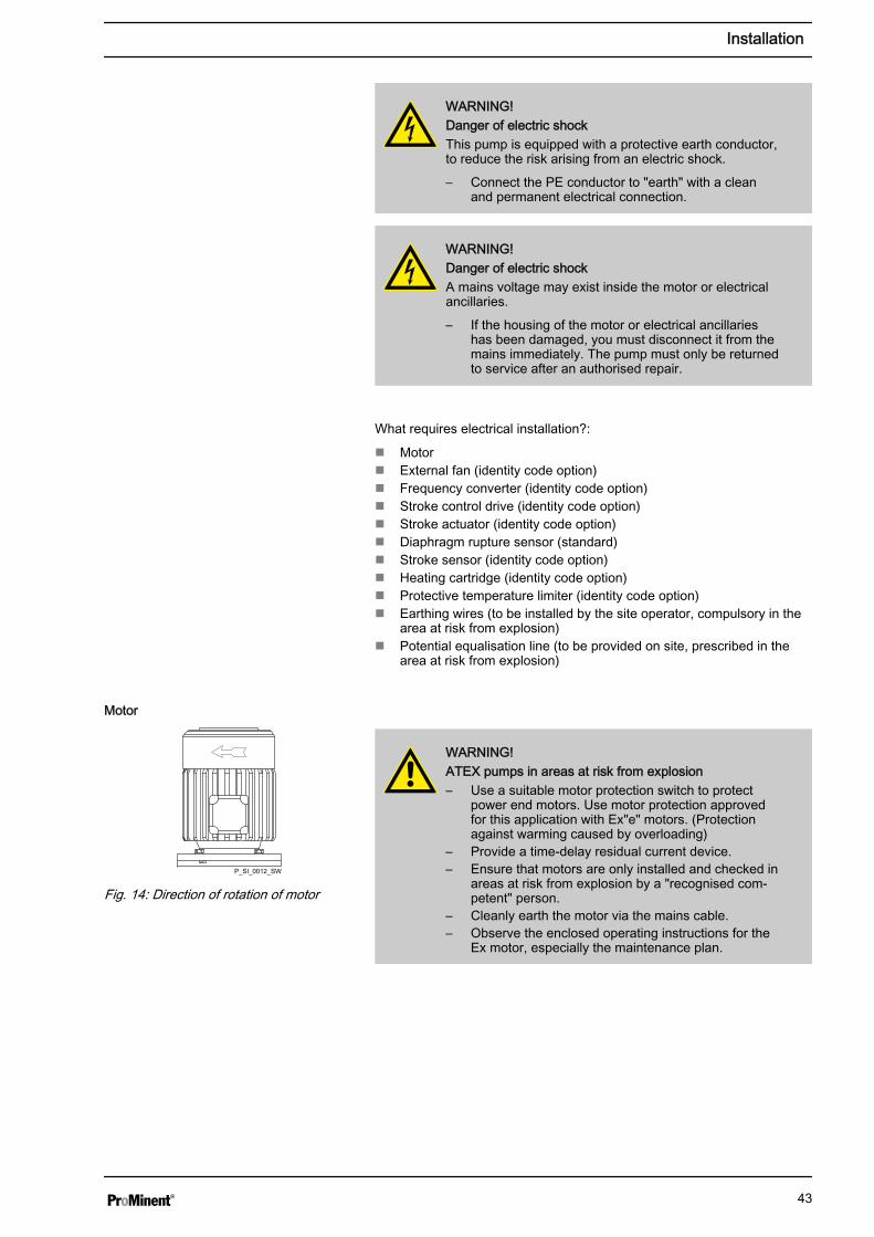
WARNING!ATEX pumps in areas at risk from explosion– Use a suitable motor protection switch to protect
power end motors. Use motor protection approvedfor this application with Ex"e" motors. (Protectionagainst warming caused by overloading)
– Provide a time-delay residual current device.– Ensure that motors are only installed and checked in
areas at risk from explosion by a "recognised com‐petent" person.
– Cleanly earth the motor via the mains cable.– Observe the enclosed operating instructions for the
Ex motor, especially the maintenance plan.
Motor
P_SI_0012_SW
Fig. 14: Direction of rotation of motor
Installation
43

WARNING!Only motors with a frequency converter: Danger of elec‐tric shockThe danger of electric shock remains for 3 minutes afterthe mains voltage has been switched off on conductingparts of the motor with an integrated frequency converterand on the lines themselves.
– After switching off, allow the device to stand for 3minutes before opening the terminal box.
CAUTION!The motor can be damagedProvide appropriate motor protection devices (e.g. motorprotection switch with thermal overcurrent trip) to protectthe motor from overloading. Fuses do not provide motorprotection.
CAUTION!Only motors with a frequency converter: The motor canbe damagedThe input current limiter could be damaged if a motorwith an integrated frequency converter is restarted within3 minutes of the mains voltage being switched off.
– After switching off, allow the device to stand for atleast 3 minutes before restarting.
– If the motor is controlled via a control, take this intoconsideration at the control.
CAUTION!Pump can be damagedThe pump can be damaged if the motor drives the pumpin the wrong direction.
– Note the correct direction of rotation indicated by thearrow on the fan cover when connecting the motor,as shown in Ä ‘Motor’ on page 43.
Use an electrical isolating device in the mains supplycable, such as a mains switch, to de-energise the pumpindependently of the entire installation (e.g. for repairs).
1. Install a motor protection switch, as the motors have no fuse.
2. Install an emergency cut-off switch or include the motor in the sys‐tem's emergency cut-off management scheme.
3. Only connect the motor to the power supply using a suitable cable.
– Key motor data can be found on the nameplate andin the "Technical data” chapter.
– The terminal wiring diagram is located in the ter‐minal box.
Installation
44

Motor data sheets, special motors, special motorflanges, external fan, temperature monitoring– Further information on motors can be found on our
website www.prominent.com.– Motor data sheets can also be requested for the
motors.– With motors other than those with identity code
specifications "S", "M" or "N": Pay special attentionto the operating instructions for the motors.
– Special motors or special motor flanges are avail‐able on request.
CAUTION!Provide a separate power supply for the external fan formotors with external fans (identity code specification "R"or "Z").
Connect the motor as per the wiring diagram for the controller, if it is con‐trolled by an electronic control unit (such as 3-phase AC motors by a fre‐quency converter).
Connect the motors in accordance with the enclosed wiring diagram or asper the wiring diagram fixed to the inside of the housing.
CAUTION!Only operate stroke length actuators / control driveswhen the pump is running.
Otherwise they will become damaged.
WARNING!Danger of electric shockIn the event of a defect, there is a danger of electricshock if conductive feed chemicals are present.
– For safety reasons, we recommend connecting toprotective low voltage, e.g. in accordance with EN60335-1 (SELV).
WARNING!Risk of fire after a diaphragm ruptureMake sure that the electric diaphragm rupture sensorswitches off the pump immediately after a diaphragmrupture.
– Connect the pump and the diaphragm rupturesensor to a control so that the pump stops immedi‐ately in the event of a diaphragm rupture.
External fan
Variable speed motors with frequencyconverter
Stroke length actuators / control powerends
Diaphragm rupture sensor (optional)
Installation
45

CAUTION!Danger resulting from unnoticed diaphragm ruptureIf the pump has been ordered with an electric diaphragmrupture sensor, it must also be electrically installed.
– Electrically wire the enclosed diaphragm rupturesensor to a suitable monitoring device.
CAUTION!Additional damage with a ruptured diaphragmNever allow the diaphragm to rupture fully if damage canbe caused by hydraulic oil mixing with the feed chemical.
– The diaphragm rupture sensor must switch off thepump immediately.Only restart the pump once the diaphragm has beenreplaced.
a) Diaphragm rupture sensor with switch contact
– The cable can be connected as required.
b) Namur sensor, inherently safe
Make sure that the monitoring/feed equipment installed by the customer iscapable of evaluating the current variations of the Namur sensor to indi‐cate a diaphragm rupture!
WARNING!The following applies in areas at risk from explosion:– Note the details of the type examination certificate
PTB 00 ATEX 2048 X for the Namur sensorNJ1.5-8GM-N as well.
When using flammable media:
WARNING!Risk of fire after a diaphragm ruptureMake sure that the electric diaphragm rupture sensorswitches off the pump immediately after a diaphragmrupture.
– Connect the pump and the diaphragm rupturesensor to a control so that the pump stops immedi‐ately in the event of a diaphragm rupture.
Connect the stroke sensor to a suitable monitoring device in linewith the details in the "Technical data" chapter - also refer to theirtechnical data!
Make sure that the monitoring/feed equipment installed by the cus‐tomer is capable of evaluating the current variations of the Namursensor to indicate a diaphragm rupture!
Stroke sensor (optional)
Installation
46

WARNING!The following applies in areas at risk from explosion:– Note the details of the type examination certificate
PTB 00 ATEX 2048 X for the Namur sensorNJ1.5-8GM-N as well.
Install the heating cartridge in line with its documentation. It mustonly be connected to the supplied power supply or the protectivetemperature limiter (for ATEX)!
Connect the electrical components of the entire installation suppliedcleanly and permanently to an electrically clean earthing point, e.g. with anearthing bar on site - see earthing diagrams in the appendix.
The entire installation supplied is provided ex works with the necessarypotential equalisation lines. Electrically connect an additional potentialequalisation cable from the potential equalisation cables from this systemcleanly and permanently to an electrically clean potential equalisationpoint, e.g. to a potential equalisation bar on site.
Install the other units in line with their documentation.
Heating cartridge
Earthing lines
Potential equalisation lines (mandatorywith ATEX)
Other units
Installation
47
8 Start up and operation
WARNING!ATEX pumps in areas at risk from explosion– Make sure that a suitably competent person checks
whether the appropriate installation information fromthe "Installation " chapter has been implementedcorrectly.
– Make sure that a "recognised competent person"checks the electrical installation and in particular theintrinsically safe power circuits.
– Set the opening pressure of the relief valve at amaximum of no more than 1.5 times the rated pres‐sure of the pump.
WARNING!Fire hazard with flammable mediaOnly with flammable media: They can be ignited byoxygen.
– The pump may not work if there is a mixture of feedchemical with oxygen in the liquid end. A specialistmay need to take appropriate actions (using inertgas, ...).
WARNING!Hot surfaceIn event the power end motor is loaded excessively, itssurface may become very hot.
– Avoid contact.– If necessary, mount a guard plate.
WARNING!Risk of burns with hot feed chemicalsIf hot feed chemicals can heat the liquid ends above thepermissible surface temperatures, persons can sufferburns from them.
– Consider attaching a "Hot surface" label to the liquidend or ...
– fitting a guard plate.
WARNING!Only motors with a frequency converter: Danger of elec‐tric shockThe danger of electric shock remains for 3 minutes afterthe mains voltage has been switched off on conductingparts of the motor with an integrated frequency converterand on the lines themselves.
– After switching off, allow the device to stand for 3minutes before opening the terminal box.
Safety information
Start up and operation
48

CAUTION!Only motors with a frequency converter: The motor canbe damagedThe input current limiter could be damaged if a motorwith an integrated frequency converter is restarted within3 minutes of the mains voltage being switched off.
– After switching off, allow the device to stand for atleast 3 minutes before restarting.
CAUTION!Feed chemical could escape– Check suction and discharge lines, and liquid end
with valves, for leak-tightness and tighten if neces‐sary.
– Check whether the necessary flushing pipes orbleed lines are connected.
CAUTION!Prior to commissioning, check that the power end motorand corresponding ancillary equipment is connected incompliance with the regulations!
CAUTION!Adhere to the instructions in the frequency converteroperating instructions when using pumps with speedcontrol
CAUTION!Danger of material damageObserve the details in the chapter "Technical data"(pressure, viscosity, resistance, etc.).
CAUTION!Feed chemical can escape unnoticedIf the diaphragm rupture sensor does not stop the pumpor no alarm is triggered, feed chemical can escapeunnoticed.
– Trigger the diaphragm rupture indicator - refer to the"Repair" chapter and, in so doing, check the reactionof the analysis unit and/or the pump.
CAUTION!The pump should only be restarted once the diaphragmhas been replaced after a diaphragm rupture, if damagecan be caused by hydraulic oil mixing with the feedchemical.
Observe the technical data
Test the diaphragm rupture sensor
Start up and operation
49
CAUTION!Never adjust the pressure relief valve.
When commissioning the unit, check whether the drive motor is rotatingcorrectly - check this against the arrow on the motor housing or the dia‐gram in the chapter entitled "Electrical Installation."
WARNING!Risk of injury from the fan impellerThe fan impeller beneath motor's fan cowling can causesevere injuries while it is turning.
– The pump must only be connected to the mainsvoltage with the fan cowling closed.
Replace the sealing screw at the oil filler neck with the vent screw supplied- refer to the chapter entitled "Overview of equipment and control ele‐ments".
Slight oil marks on the pump do not indicate leaks with anew product.– Wipe away and note down oil positions. Only con‐
tact the supplier if it reoccurs.
CAUTION!Danger due to incorrect use of the safety relief valveThe safety relief valve can only protect the motor and thegear, only against illegal positive pressure that is moni‐tored by the metering pump itself. It cannot protect thesystem against positive pressure.
– Protect the motor and gear of the system againstpositive pressure using other mechanisms.
– Protect the system against illegal positive pressureusing other mechanisms.
The actual opening pressure is above the nominal pressure (the pressurestage) - refer to the “Technical data” chapter.
When the pump is idle, check whether the oil level in the pump is in themiddle of the oil level indicator.
This will rule out the pump losing oil and suffering damage.
For chemicals with a particle size greater than 0.3 mm,the valves may no longer close properly.– Install a suitable filter in the suction line.
Only in areas at risk from explosion: Set the opening pressure of the reliefvalve at a maximum of no more than 1.5 times the rated pump pressure .
Pressure relief valve
Checking the direction of rotation
Installing a vent screw
Use a safety relief valve
Checking the oil level
Avoid particles
Setting the relief valve
Start up and operation
50

Check the heating action of the heating cartridge and the effectiveness ofthe protective temperature limiter. No overheating must occur, especiallyin the area at risk from explosion!
1. Switch on the heating cartridge, set the stroke length of the pump to"0" and start the pump.
2. Allow the pump to warm up for 5 minutes.
3. Set the stroke length of the pump to the required value.
Check whether the earthing lines in the pump's electrical units are cor‐rectly connected and connected to a clean earth wire - see earthing dia‐grams in the appendix.
Check whether the potential equalisation lines are sitting correctly on thepump and connected to a clean potential equalisation point.
8.1 Bleeding the liquid endWhen bleeding the liquid end or priming against pressure:
Depressurise the suction and discharge lines!
With dangerous or unknown feed chemicals, take suitable protectivemeasures according to the safety data sheet!
1. Loosen the discharge line.
2. Install a piece of translucent hose.
3. Run the pump slowly until the feed chemical appears in the sectionof hose.
4. Remove the piece of hose.
5. Assemble the discharge line.
Eliminating suction problems (only for single ball valveswith PTFE ball seat)For suction problems occurring during start up:– Exclude the possibility that there are foreign bodies
in the valve.– Place the valve on a stable surface.– Using a hammer (1) and a brass bar (2), gently tap
the PTFE ball seat above the valve ball - see figurebelow.
– Then with the valve in a damp condition allow it toprime.
Only with a heating cartridge: check theaction of the heating cartridge
Only at low temperatures: allow the pumpto warm up
Earthing lines
Potential equalisation lines (mandatorywith ATEX)
Fig. 15: Tapping the valve set disc
Start up and operation
51

8.2 Calibrate the stroke control drive (optional)The stroke control drive is calibrated to the capacity ordered ex-factory.Please contact ProMinent in the event that you want the stroke controldrive to be calibrated to another capacity.
Start up and operation
52

9 Maintenance
WARNING!ATEX pumps in areas at risk from explosion– Carry out a general check to ensure that the system
is working properly, particularly the power end andbearings, by regularly monitoring it (for leaks,noises, temperatures, smell, etc.).
– Do not allow the pump to run hot due to a lack of oil.With lubricated metering pumps, regularly check forthe presence of lubricant, for example by checkingthe liquid level, visual leak control etc. If oil isleaking, examine the leakage point immediately andeliminate the cause.
– Check the correct operation of the relief valve down‐stream of the pump. In premises at risk from explo‐sion, the relief valve should prevent the gear frombecoming overloaded and becoming hot.
– Observe the enclosed operating instructions for theEx motor.
– Only with pumps with a motor flange: replace worngear ring etc. of the clutch.
– Only with add-on power end: replace worn gearring/DZ element of the clutch.
– When cleaning plastic components, ensure that noelectrostatic charges are generated by excessivefriction. - see warning label.
– Always earth the discharge line and the suction lineagainst the pump to prevent electrostatic chargebefore working on the pump.
– Replace wear parts, such as bearings, when there isan identifiable incidence of unacceptable wear. (Thenominal service life cannot be calculated with lubri‐cated bearings.)
– Check whether the potential equalisation lines areall sitting correctly with clean contacts.
– Check whether the earth lines are all sitting correctlywith clean contacts. Use the earthing drawings asan aid – see Appendix.
– Only use genuine spare parts as replacements.– A diagnostic device for bearing damage is very
useful for the premature detection of bearingdamage.
– Carry out inspections and repair in compliance withDIN EN IEC 60079-17 and ensure that they are onlyperformed by "experienced personnel with the requi‐site knowledge".
– These measures are deemed to be minimum protec‐tion measures by ProMinent. It is the duty of theoperator to take appropriate measures to eliminateany further hazards known to him.
WARNING!ATEX pumps in areas at risk from explosionStatic electricity can cause ignition sparks.
– Consider potential equalisation before you approachany pump equipment that could be at a differentelectrical potential (such as pipes or tools)
Safety information
Maintenance
53
WARNING!Fire hazard with flammable mediaOnly with flammable media: They can be ignited byoxygen.
– The pump may not work if there is a mixture of feedchemical with oxygen in the liquid end. A specialistmay need to take appropriate actions (using inertgas, ...).
WARNING!It is mandatory that you read the safety information andspecifications in the "Storage, Transport and Unpacking"chapter prior to shipping the pump.
CAUTION!Warning of feed chemical spraying aroundFeed chemical can spray out of the hydraulic compo‐nents if they are manipulated or opened due to pressurein the liquid end and adjacent parts of the system.
– Disconnect the pump from the mains power supplyand ensure that it cannot be switched on again byunauthorised persons.
– Depressurise the system before commencing anywork on hydraulic parts.
WARNING!Warning of hazardous feed chemicalShould a dangerous feed chemical be used: it mayescape from the hydraulic components when working onthe pump, material failure or incorrect handling of thepump.
– Take appropriate protective measures beforeworking on the pump (e.g. safety glasses, safetygloves, ...). Adhere to the material safety data sheetfor the feed chemical.
– Drain and flush the liquid end before working on thepump.
WARNING!Danger of an electric shockWhen working on the motor or electrical auxiliary equip‐ment, there is a danger of an electric shock.
– Before working on the motor, take note of the safetyinstructions in its operating instructions!
– Should external fans, servomotors or other auxiliaryequipment be installed, these should also be discon‐nected and checked that they are voltage free.
Under heavy loading (e.g. continuous operation) shortermaintenance intervals are recommended than thosegiven.
Maintenance
54
Third-party spare parts for the pumps may result in prob‐lems when pumping.– Only use original spare parts.– Use the correct spare parts kits. In the event of
doubt, refer to the exploded views and orderinginformation in the appendix.
Check the pump installation for:
n Leaksn Abnormal noises or squeaksn Abnormal temperaturesn Abnormal odoursn Abnormal vibrationsn Other anomalies
WARNING!In the area at risk from explosion:stop the pump immediately and rectify these anomalies.ProMinent Service may be needed if required.
Inspection, daily
Maintenance
55

Interval Maintenance work Personnel
Quarterly* n ATEX pump only: Special maintenance work - refer to the"Safety information for ATEX pumps".
n Only pumps with add-on power end or "without motor" and/orwith motor flange: Check the gear ring/DZ element of theROTEX® coupling as per their manual. Open the inspectionwindow on the flange to check. Close it again!If the coupling is OK, the maintenance interval can be increasedto 4000 hours.
n If the coupling is not clearly OK: Call ProMinent Service.
Technical personnel
ATEX pump only: Check the seals of the EDS 4448 pressure switchat regular intervals (depending on the climatic conditions and thefeed chemical) in respect of their serviceability and replace if neces‐sary.
Technical personnel
Check the correct seating and state of the metering lines at both dis‐charge and suction ends.
Technical personnel
Check that the discharge valve and suction valve are fitted tightly. Technical personnel
Check whether the diaphragm rupture sensor stops the pump orgenerates an alarm after it is triggered, see the chapter "Repairs".
Technical personnel
Check that the diaphragm rupture sensor is firmly seated. Technical personnel
Check whether the overpressure signalling triggers when an over‐pressure exists.
Technical personnel
Check the secure seating of the overpressure signaller. Technical personnel
Check the secure seating of the pressure limitation valve (50 Nm). Technical personnel
With the pump running, check whether bubbles rise in the window ofthe bleed valve.
Technical personnel
Check that the flow is correct: Allow the pump to prime briefly. Technical personnel
Check the leak-tightness of the entire liquid end - particularly aroundthe leakage hole!
Technical personnel
Check that the dosing head screws are tight. Technical personnel
Check that the electrical connectors are intact. ElectricianElectrical technician withadditional explosion protec‐tion qualification
Check the tight, clean electrical connection of the earthing wires. ElectricianElectrical technician withadditional explosion protec‐tion qualification
Check the tight, clean electrical connection of the potential equalisa‐tion wires.
ElectricianElectrical technician withadditional explosion protec‐tion qualification
Check the oil level. Technical personnel
Maintenance work:
Maintenance
56

Interval Maintenance work Personnel
After approx. 4000operating hours
Check the gear ring/DZ element of the coupling as per their oper‐ating instructions.
Technical personnel
After approx.5,000 operatinghours
Change hydraulic oil - refer to "Changing hydraulic oil" in thischapter.
Instructed personnel
Check whether the seals of the overpressure signalling system areOK and replace in case of doubt.
Technical personnel
ATEX design only: Check the effectiveness of the protective tem‐perature limiter for the heating cartridge.
Technical personnel
ATEX design only: Arrange for immediate rectification of any out‐wardly apparent damage or corrosion on parts of the housing and onconnecting parts of the heating cartridge or protective temperaturelimiter by the manufacturer using original spare parts.
Customer Service depart‐ment
After approx.10,000 operatinghours **
Diaphragm change - refer to "Changing the diaphragm" in the"Repair” chapter.
Technical personnel
After approx.20,000 operatinghours
Follow the motor manufacturer's recommendations - see operatinginstructions for the motor.
* Under normal loading (approx. 30% of continuous operation).
Under heavy loading (e.g. continuous operation): Shorter intervals.
** under normal loading. With very unfavourable metering parameters:Shorter intervals.
WARNING!Risk of burns due to hot hydraulic oilThe hydraulic oil may become very hot when the pumpis exposed to extensive loading.
– When draining oil, avoid contact with the oil runningout.
WARNING!If the pump must be operated using hydraulic oil compat‐ible with foodstuffs, then only foodsafe hydraulic oil mustbe used.
Draining the hydraulic oil
For the double head versions, perform the following work simultaneouslyon both dosing heads.
1. Set the stroke adjustment dial (2) to "0".
2. Unscrew the gearbox vent stopper (3).
3. Place an oil trough under the oil drainage plug (5).
4. Unscrew the oil drainage plug (5) from the power end housing.
5. Allow the hydraulic oil to run out of the drive.
6. Place an oil trough under the hydraulic end.
7. Unscrew the oil drainage stopper (4) out of the hydraulic end.
8. Allow the hydraulic oil to run out of the hydraulic end.
9. Screw on the oil drainage plug (5).
10. Screw in the oil drainage stopper (4) with a new seal.
Changing the hydraulic oil
Maintenance
57

32
4 5 6
1
32 2
4 45 6
1 1
Fig. 16Fill with hydraulic oil
For the double head versions, perform the following work simultaneouslyon both dosing heads.
1. Set the stroke adjustment dial (2) to "100%" and open the safetyrelief valve (1) - tighten the knurled screw.
2. Slowly fill hydraulic oil through the opening for the gearbox ventstopper (3) until the oil inspection window (6) is covered:
Type Level of covering
HP2 1/3
HP3 1/3
3. Start the pump.
4. Allow the pump to run slowly for a further 1... 2 minutes.
5. Top up with hydraulic oil if necessary.
6. Screw the gearbox vent stopper (3) back in. Do not close the bleedvalve!
7. Close the safety relief valve (1) - loosen the knurled screw.
8. Check whether all openings are tightly sealed again – especially inthe area at risk from explosion!
WARNING!Only in areas at risk from explosion: Check after 1day whether the oil drainage stopper (4) and theoil drainage plug (5) are still tight.
Maintenance
58

10 Repair
WARNING!ATEX pumps in the ATEX area– Carry out a general check to ensure that the system
is functioning properly, particularly the power endand bearings, by regular monitoring (for leaks,noises, temperatures, smell, etc.).
WARNING!ATEX pumps in areas at risk from explosionStatic electricity can cause ignition sparks.
– Consider potential equalisation before you approachany pump equipment that could be at a differentelectrical potential (such as pipes or tools)
WARNING!Fire hazard with flammable mediaOnly with flammable media: They can be ignited byoxygen.
– The pump may not work if there is a mixture of feedchemical with oxygen in the liquid end. A specialistmay need to take appropriate actions (using inertgas, ...).
WARNING!It is mandatory that you read the safety information andspecifications in the "Storage, Transport and Unpacking"chapter prior to shipping the pump.
CAUTION!Warning of feed chemical spraying aroundFeed chemical can spray out of the hydraulic compo‐nents if they are manipulated or opened due to pressurein the liquid end and adjacent parts of the system.
– Disconnect the pump from the mains power supplyand ensure that it cannot be switched on again byunauthorised persons.
– Depressurise the system before commencing anywork on hydraulic parts.
WARNING!Warning of hazardous feed chemicalShould a dangerous feed chemical be used: it mayescape from the hydraulic components when working onthe pump, material failure or incorrect handling of thepump.
– Take appropriate protective measures beforeworking on the pump (e.g. safety glasses, safetygloves, ...). Adhere to the material safety data sheetfor the feed chemical.
– Drain and flush the liquid end before working on thepump.
Safety information
Repair
59

WARNING!Risk of fingers being crushedUnder unfavourable conditions, the stroke axle or dis‐placement body can cause crushing of the fingers.
– Disconnect the pump from the mains power supplyand ensure that it cannot be switched on again byunauthorised persons.
WARNING!Risk of injury from the fan impellerThe fan impeller beneath motor's fan cowling can causesevere injuries while it is turning.
– The pump must only be connected to the mainsvoltage with the fan cowling closed.
WARNING!Hot oil and hot componentsThe hydraulic oil and the hydraulic end may becomevery hot when the pump is exposed to heavy loading.
– Allow the pump to cool before starting work.
CAUTION!Never adjust the pressure relief valve.
Unsuitable spare parts for the valves may lead to prob‐lems for the pumps.– Only use new components that are especially
adapted to fit your valve (both in terms of shape andchemical resistance).
– Use the correct spare parts kits. If in doubt, refer tothe exploded views and ordering information on ourwebsite www.prominent.com.
Unsuitable spare parts for the valves may lead to prob‐lems for the pumps.– Only use new components that are especially
adapted to fit your valve (both in terms of shape andchemical resistance).
– Use the correct spare parts kits. In the event ofdoubt, refer to the exploded views and orderinginformation in the appendix.
10.1 Cleaning valves
Clean the discharge and suction valves only one afteranother as they cannot be differentiated using the arrowmarkings.For orientation: Should you have a dismantled liquid endin front of you, the suction valve is on the side of the dia‐phragm rupture sensor.
Repair
60
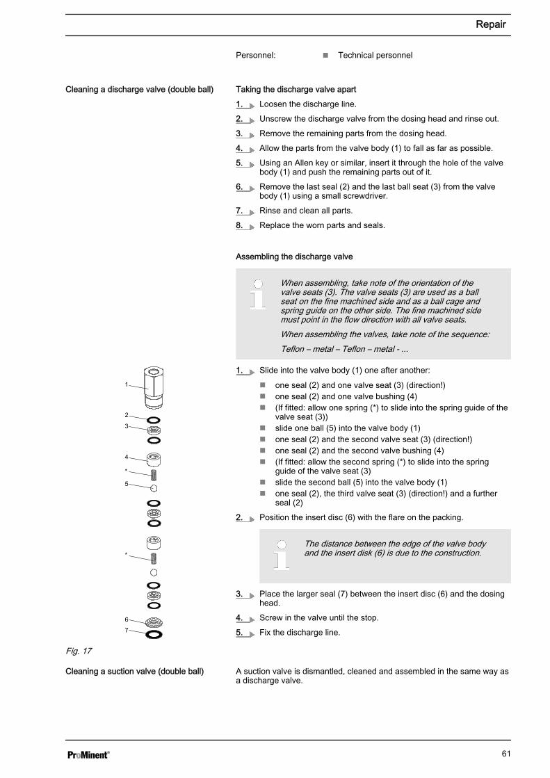
Personnel: n Technical personnel
Taking the discharge valve apart
1. Loosen the discharge line.
2. Unscrew the discharge valve from the dosing head and rinse out.
3. Remove the remaining parts from the dosing head.
4. Allow the parts from the valve body (1) to fall as far as possible.
5. Using an Allen key or similar, insert it through the hole of the valvebody (1) and push the remaining parts out of it.
6. Remove the last seal (2) and the last ball seat (3) from the valvebody (1) using a small screwdriver.
7. Rinse and clean all parts.
8. Replace the worn parts and seals.
Assembling the discharge valve
When assembling, take note of the orientation of thevalve seats (3). The valve seats (3) are used as a ballseat on the fine machined side and as a ball cage andspring guide on the other side. The fine machined sidemust point in the flow direction with all valve seats.When assembling the valves, take note of the sequence:Teflon – metal – Teflon – metal - ...
1. Slide into the valve body (1) one after another:
n one seal (2) and one valve seat (3) (direction!)n one seal (2) and one valve bushing (4)n (If fitted: allow one spring (*) to slide into the spring guide of the
valve seat (3))n slide one ball (5) into the valve body (1)n one seal (2) and the second valve seat (3) (direction!)n one seal (2) and the second valve bushing (4)n (If fitted: allow the second spring (*) to slide into the spring
guide of the valve seat (3)n slide the second ball (5) into the valve body (1)n one seal (2), the third valve seat (3) (direction!) and a further
seal (2)
2. Position the insert disc (6) with the flare on the packing.
The distance between the edge of the valve bodyand the insert disk (6) is due to the construction.
3. Place the larger seal (7) between the insert disc (6) and the dosinghead.
4. Screw in the valve until the stop.
5. Fix the discharge line.
A suction valve is dismantled, cleaned and assembled in the same way asa discharge valve.
Cleaning a discharge valve (double ball)
1
2
3
4
*
5
*
6
7
Fig. 17
Cleaning a suction valve (double ball)
Repair
61
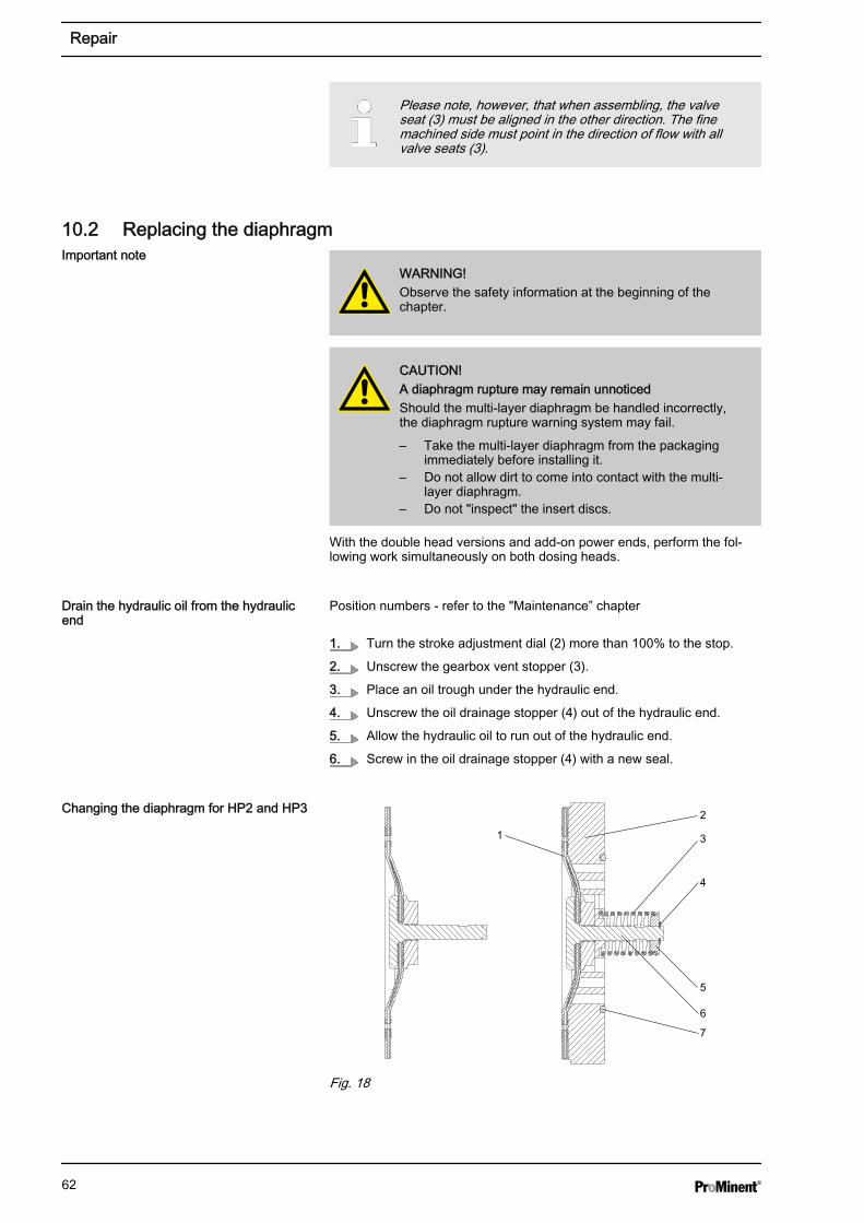
Please note, however, that when assembling, the valveseat (3) must be aligned in the other direction. The finemachined side must point in the direction of flow with allvalve seats (3).
10.2 Replacing the diaphragm
WARNING!Observe the safety information at the beginning of thechapter.
CAUTION!A diaphragm rupture may remain unnoticedShould the multi-layer diaphragm be handled incorrectly,the diaphragm rupture warning system may fail.
– Take the multi-layer diaphragm from the packagingimmediately before installing it.
– Do not allow dirt to come into contact with the multi-layer diaphragm.
– Do not "inspect" the insert discs.
With the double head versions and add-on power ends, perform the fol‐lowing work simultaneously on both dosing heads.
Position numbers - refer to the "Maintenance” chapter
1. Turn the stroke adjustment dial (2) more than 100% to the stop.
2. Unscrew the gearbox vent stopper (3).
3. Place an oil trough under the hydraulic end.
4. Unscrew the oil drainage stopper (4) out of the hydraulic end.
5. Allow the hydraulic oil to run out of the hydraulic end.
6. Screw in the oil drainage stopper (4) with a new seal.
1
2
3
4
5
6
7
Fig. 18
Important note
Drain the hydraulic oil from the hydraulicend
Changing the diaphragm for HP2 and HP3
Repair
62
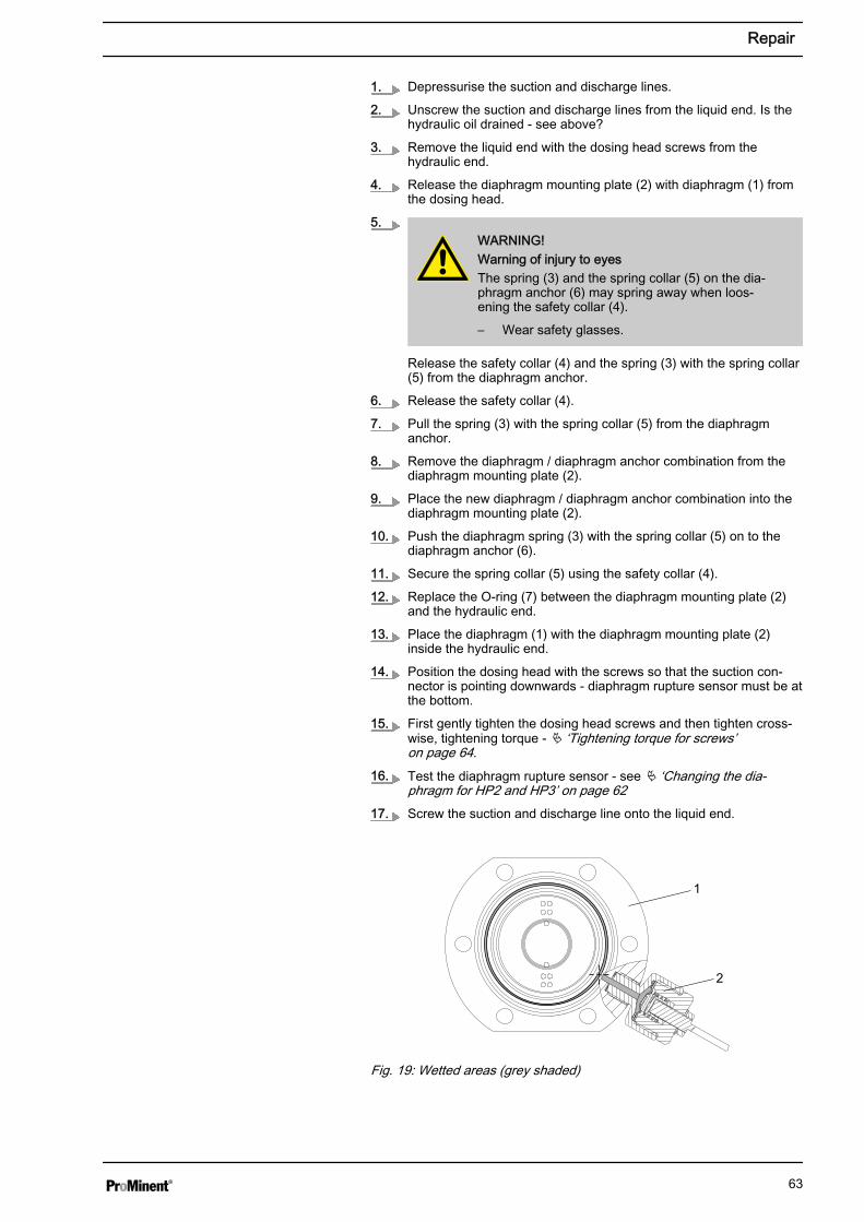
1. Depressurise the suction and discharge lines.
2. Unscrew the suction and discharge lines from the liquid end. Is thehydraulic oil drained - see above?
3. Remove the liquid end with the dosing head screws from thehydraulic end.
4. Release the diaphragm mounting plate (2) with diaphragm (1) fromthe dosing head.
5.WARNING!Warning of injury to eyesThe spring (3) and the spring collar (5) on the dia‐phragm anchor (6) may spring away when loos‐ening the safety collar (4).
– Wear safety glasses.
Release the safety collar (4) and the spring (3) with the spring collar(5) from the diaphragm anchor.
6. Release the safety collar (4).
7. Pull the spring (3) with the spring collar (5) from the diaphragmanchor.
8. Remove the diaphragm / diaphragm anchor combination from thediaphragm mounting plate (2).
9. Place the new diaphragm / diaphragm anchor combination into thediaphragm mounting plate (2).
10. Push the diaphragm spring (3) with the spring collar (5) on to thediaphragm anchor (6).
11. Secure the spring collar (5) using the safety collar (4).
12. Replace the O-ring (7) between the diaphragm mounting plate (2)and the hydraulic end.
13. Place the diaphragm (1) with the diaphragm mounting plate (2)inside the hydraulic end.
14. Position the dosing head with the screws so that the suction con‐nector is pointing downwards - diaphragm rupture sensor must be atthe bottom.
15. First gently tighten the dosing head screws and then tighten cross‐wise, tightening torque - Ä ‘Tightening torque for screws’on page 64.
16. Test the diaphragm rupture sensor - see Ä ‘Changing the dia‐phragm for HP2 and HP3’ on page 62
17. Screw the suction and discharge line onto the liquid end.
1
2
Fig. 19: Wetted areas (grey shaded)
Repair
63

Dosing head material 1st level 2nd level
PVT 6 Nm 12 Nm
TTT 6 Nm 12 Nm
HCT 8 Nm 20 Nm
SST 8 Nm 20 Nm
Fill hydraulic oil in the hydraulic end
For the double head versions, perform the following work simultaneouslyon both dosing heads.
1. Set the stroke adjustment dial (1) to "100%" and open the safetyrelief valve (2) - tighten the knurled screw.
2. Slowly fill hydraulic oil through the opening for the gearbox ventstopper (4) until the oil inspection window (3) is covered to 1/3.
3. Start the pump.
4. Allow the pump to run for 1... 2 minutes.
5. Screw the gearbox vent stopper (3) back in. Do not close the bleedvalve!
6. Close the safety relief valve (1) - loosen the knurled screw.
7. Check the pump for tightness by using maximum back pressure.
WARNING!Only in areas at risk from explosion: Check after 1 daywhether the oil drainage stopper (4) and the oil drainageplug (5) are still tight.
Check the starting torque of the dosing head screwsagain after 24-hours of operation!
10.3 Repairing the diaphragm rupture sensor
WARNING!Feed chemical warningAfter a diaphragm rupture, additional feed chemical willbe present in the diaphragm rupture sensor and the feedchannel in the dosing head.
– Protect yourself from the feed chemical if using haz‐ardous or unknown feed chemicals. Observe thematerial safety data sheet.
Check diaphragm rupture sensor
Tightening torque for screws
30 V version
Repair
64

1. When changing the diaphragm, unscrew the diaphragm rupturesensor from the dosing head.
2. Check for electrical continuity:
3. Using a blunt insulating probe (Ø 2 ... 3 mm, no sharp edges), pressinto the channel of the diaphragm rupture sensor.
ð Check that there is no electrical continuity
4. Release the pin again.
ð Electrical continuity must be re-established.
5. Repeat the test several times.
6. If everything is working correctly, screw the diaphragm rupturesensor into the dosing head with a new seal (1).
7. If not, go to the next section.
Replace separating diaphragm of the diaphragm rupture sensor
1. Disconnect the diaphragm rupture sensor from the power supply.
2. When changing the diaphragm, unscrew the diaphragm rupturesensor from the dosing head.
3. Grasp the upper section (2) of the diaphragm rupture sensor.
4. Hold the body (5) in place with an open-ended spanner.
5. Unscrew the top of the diaphragm rupture sensor.
6. Clean the soiled parts.
7. Lay the new separating diaphragm (3) with the light side (PTFE)down into the upper section (2).
8. Lay the plate (4) with the uneven side down into the upper section(2).
9. Screw the body (5) into the upper section and screw tighten.
10. Check the diaphragm rupture sensor as described in “Check dia‐phragm rupture sensor".
11. If the diaphragm rupture sensor does not operate clearly and reli‐ably, then a new diaphragm rupture sensor must be used withoutfail.
Checking the diaphragm rupture sensor
1
2
3
4
5
Fig. 20
ATEX version
Repair
65

1. When changing the diaphragm, unscrew the diaphragm rupturesensor from the dosing head.
2. Check that the monitor does not indicate a diaphragm rupture:
3. Using a blunt insulating probe (Ø 2 ... 3 mm, no sharp edges), pressinto the channel of the diaphragm rupture sensor.
ð The monitor device should indicate a diaphragm rupture.
4. Release the pin again.
ð The monitor device should no longer indicate a diaphragm rup‐ture.
5. Repeat the test several times.
6. If everything is working correctly, screw the diaphragm rupturesensor into the dosing head with a new seal (1).
7. If not, go to the next section.
Replace the separating diaphragm of the diaphragm rupture sensor
1. Disconnect the diaphragm rupture sensor from the monitor.
2. When changing the diaphragm, unscrew the diaphragm rupturesensor from the dosing head.
3. Grasp the top part (2) of the diaphragm rupture sensor.
Do not tamper with the lacquer-protected nut.
4. Hold the body (5) in place with an open-ended spanner.
5. Unscrew the top of the diaphragm rupture sensor.
6. Clean any dirty parts.
7. Lay the new separating diaphragm (3) with the light side (PTFE)down into the top part (2).
8. Place the disc (4) in the top part (2).
9. Place the spring into the body (5).
10. Move the body (5) close to the top part (2).
ð The spring (6) should sit correctly on the spring seat (3a).
11. Screw the body (5) into the top part and tighten.
12. Connect the diaphragm rupture sensor back to the monitor.
13. Check the diaphragm rupture sensor as described under “Checkingdiaphragm rupture sensor".
14. If the diaphragm rupture sensor does not operate clearly and reli‐ably, then definitively use a new diaphragm rupture sensor.
10.4 Calibrating the dosing rateIt is only worth calibrating the dosing rate if you wish to carry out particu‐larly precise metering at a completely different back pressure.
The dosing rate of the hydraulic diaphragm metering pump is onlydependent upon back pressure to a minimal extent. And the pumps arecalibrated on the factory premises to the maximum operating pressure.(Value of maximum operating pressure - see the pressure stage on theindicating dial or the safety relief valve.)
1
2
33a
4
56
P_HY_0015_SW
Fig. 21
Repair
66

The plant or production facility can calibrate each pump to a back pressurethat is lower than the nominal pressure ordered.
The following pressure stages (in bar) are available:
Pump 10 16 25 40 64 100
HP2,
HP3
X X X X X X
WARNING!ATEX pump only: Take suitable precautions in poten‐tially explosive atmospheres regarding the feed chemicalin the open measuring cylinder - see handling instruc‐tions below.
The dosing rate can only be calibrated when the dis‐charge line is connected and under normal operatingconditions. As the dosing rate is dependent upon theactual back pressure.
4
1
2
5
t1
t2
Q1
Q2
a) b)
Fig. 22: a) Adjust indicating dial, b) Schematic assembly for calibrationMaterials required:
n Measuring beakern Stop watch
1. Switch off the pump.
2. Turn the stroke adjustment dial to maximum, beyond 100% to thestop.
3. API versions only: Remove the metal cap from the stroke adjust‐ment dial.
4. Remove the cap (4) from the stroke adjustment dial and slacken offthe screw (3) beneath slightly.
5. Guide the suction line into the measuring beaker - see Fig. 22.
6. Fill the measuring beaker with feed chemical.
7. Start the pump.
8. As soon as the system back pressure of the system has beenreached, determine the fill level Q1 and start the stopwatch.
9. Run the pump for a while.
10. Simultaneously determine the fill level Q2 and stop the stopwatch.
11. Calculate the dosing rate value.
Repair
67

12. Reduce the dosing rate using the stroke adjustment dial and repeatsteps 7 to 10 until the required value is reached.
13. Turn the indicating dial (1) only until the 100% marking is preciselyabove the indicating slit (2).
14. Carefully tighten the screw (3) in the stroke adjustment dial andreplace the cap (4).
15. API versions only: Press the metal cap on to the stroke adjustmentdial.
10.5 Replacing power end bearingsOnly allow ProMinent Service to replace the power end bearings!
Repair
68

11 Troubleshooting
WARNING!ATEX pumps in the ATEX area– Generally ensure that the parts are working properly
(no leaks, unusual noises, high temperatures,unusual smell ...) especially the power end/drive andthe bearings.
– Do not allow the pump to heat up because of a lackof oil!With lubricated metering pumps, regularly check forthe presence of lubricant, for example by checkingthe liquid level, visual leak control etc. If oil isleaking, examine the leakage point immediately andeliminate the cause.
– When cleaning plastic components, ensure that noelectrostatic charges are generated by excessivefriction. - see warning label.
– Replace wear parts, such as bearings, when there isan identifiable incidence of unacceptable wear. (Thenominal service life cannot be calculated with lubri‐cated bearings.)
– Only use genuine spare parts as replacements.– Carry out inspections and repair in compliance with
DIN EN IEC 60079-17 and ensure that they are onlyperformed by "experienced personnel with the requi‐site knowledge".
– Make sure that a "recognised competent person"checks the electrical installation and in particular theintrinsically safe electric circuits.
WARNING!ATEX pumps in areas at risk from explosionStatic electricity can cause ignition sparks.
– Consider potential equalisation before you approachany pump equipment that could be at a differentelectrical potential (such as pipes or tools)
WARNING!Fire hazard with flammable mediaOnly with flammable media: They can be ignited byoxygen.
– The pump may not work if there is a mixture of feedchemical with oxygen in the liquid end. A specialistmay need to take appropriate actions (using inertgas, ...).
WARNING!Danger of an electric shockPersonnel working on electrical parts can be electro‐cuted if all electrical lines carrying current have not beendisconnected.
– Disconnect the supply cable before working on themotor and prevent it from being reconnected acci‐dentally.
– Any separately driven fans, servo motors, speedcontrollers or diaphragm rupture sensors fittedshould also be disconnected.
– Check that the supply cables are de-energised.
Safety information
Troubleshooting
69

WARNING!Warning of hazardous feed chemicalShould a dangerous feed chemical be used: it mayescape from the hydraulic components when working onthe pump, material failure or incorrect handling of thepump.
– Take appropriate protective measures beforeworking on the pump (e.g. safety glasses, safetygloves, ...). Adhere to the material safety data sheetfor the feed chemical.
– Drain and flush the liquid end before working on thepump.
WARNING!Risk of injury from the fan impellerThe fan impeller beneath motor's fan cowling can causesevere injuries while it is turning.
– The pump must only be connected to the mainsvoltage with the fan cowling closed.
WARNING!Only motors with a frequency converter: Danger of elec‐tric shockThe danger of electric shock remains for 3 minutes afterthe mains voltage has been switched off on conductingparts of the motor with an integrated frequency converterand on the lines themselves.
– After switching off, allow the device to stand for 3minutes before opening the terminal box.
CAUTION!Only motors with a frequency converter: The motor canbe damagedThe input current limiter could be damaged if a motorwith an integrated frequency converter is restarted within3 minutes of the mains voltage being switched off.
– After switching off, allow the device to stand for atleast 3 minutes before restarting.
CAUTION!Danger of personnel injury and material damageThe use of untested third party parts can result in per‐sonnel injuries and material damage.
– Only fit parts to metering pumps, which have beentested and recommended by ProMinent.
Troubleshooting
70

CAUTION!Warning of feed chemical spraying aroundFeed chemical can spray out of the hydraulic compo‐nents if they are manipulated or opened due to pressurein the liquid end and adjacent parts of the system.
– Disconnect the pump from the mains power supplyand ensure that it cannot be switched on again byunauthorised persons.
– Depressurise the system before commencing anywork on hydraulic parts.
Fault description Cause Remedy Personnel
Pump fails to pressurise ordoes not prime despite fullstroke motion and bleeding.
The valves are dirty orworn.
Repair the valves - see chapter entitled"Repair".
Technical per‐sonnel
The feed chemical hasparticles larger than0.3 mm.
Install a suitable filter in the suction line. Technical per‐sonnel
Safety relief valve isopen.
Unscrew knurled screw in safety reliefvalve.
Instructed per‐sonnel
Safety relief valve isheavily worn as dis‐charge line is greatlyconstricted.
Replace safety relief valve and removeblockage from discharge line
Technical per‐sonnel
Insufficient hydraulicoil in the power end.
Refill with hydraulic oil until the oil inspec‐tion window is 1/3 covered - see"Changing the diaphragm" in the "Repair”chapter.
Investigate and clear the cause of the oilloss.
Instructed per‐sonnel
The oil inspectionwindow is leaking.
Replace the oil inspection window as perthe operating instructions.
Technical per‐sonnel
Indicating dial is setincorrectly.
Set indicating dial - see "Calibratingcapacity" in the chapter "Repair".
Technical per‐sonnel
The motor is wiredincorrectly.
1. Check the mains voltage and mains fre‐quency.
2. Wire the motor correctly.
Electrician
The mains voltage hasfailed.
Eliminate the cause. Electrician
Operating diaphragmruptured and alarmhas not sounded.
n Replace multi-layer diaphragm imme‐diately - see "Diaphragm change" inthe chapter "Repair".
n Replace separating diaphragm of thediaphragm rupture sensor- see"Replacing the separating diaphragm,diaphragm rupture sensor" in thechapter "Repair".
Technical per‐sonnel
The overpressure sensor hastriggered.
There is a blockage inthe discharge line.
Clear the blockage. Technical per‐sonnel
The system back pres‐sure was momentarilytoo high.
Clear the cause of the back pressure. Technical per‐sonnel
Tasks
Troubleshooting
71

Fault description Cause Remedy Personnel
The diaphragm rupture sensorhas triggered.
The operating dia‐phragm has ruptured.
n Replace multi-layer diaphragm imme‐diately - see "Diaphragm change" inthe chapter "Repair".
n Replace separating diaphragm of thediaphragm rupture sensor- see"Replacing the separating diaphragm,diaphragm rupture sensor" in thechapter "Repair".
Technical per‐sonnel
The power end motor is veryhot.
The discharge line isseriously constricted.
n Rectify any constriction of the dis‐charge line.
n Have the safety relief valve checked.
Technical per‐sonnel
All other faults. Other causes. Call ProMinent Service.
Troubleshooting
72

12 Decommissioning and disposal12.1 Decommissioning
WARNING!Fire hazard with flammable mediaOnly with flammable media: They can be ignited byoxygen.
– The pump may not work if there is a mixture of feedchemical with oxygen in the liquid end. A specialistmay need to take appropriate actions (using inertgas, ...).
WARNING!Danger of an electric shockWhen working on the motor or electrical auxiliary equip‐ment, there is a danger of an electric shock.
– Before working on the motor, take note of the safetyinstructions in its operating instructions!
– Should external fans, servomotors or other auxiliaryequipment be installed, these should also be discon‐nected and checked that they are voltage free.
WARNING!Danger from chemical residueThere is normally chemical residue in the liquid end andon the housing after operation. This chemical residuecould be hazardous to people.
– It is mandatory that the safety information in the"Storage, transport and unpacking" chapter is readbefore shipping or transporting the unit.
– Thoroughly clean the liquid end and the housing ofchemicals and dirt. Adhere to the material safetydata sheet for the feed chemical.
WARNING!Warning of hazardous feed chemicalShould a dangerous feed chemical be used: it mayescape from the hydraulic components when working onthe pump, material failure or incorrect handling of thepump.
– Take appropriate protective measures beforeworking on the pump (e.g. safety glasses, safetygloves, ...). Adhere to the material safety data sheetfor the feed chemical.
– Drain and flush the liquid end before working on thepump.
WARNING!Hot oil and hot componentsThe hydraulic oil and the hydraulic end may becomevery hot when the pump is exposed to heavy loading.
– Allow the pump to cool before starting work.
Decommissioning and disposal
73

CAUTION!Warning of feed chemical spraying aroundFeed chemical can spray out of the hydraulic compo‐nents if they are manipulated or opened due to pressurein the liquid end and adjacent parts of the system.
– Disconnect the pump from the mains power supplyand ensure that it cannot be switched on again byunauthorised persons.
– Depressurise the system before commencing anywork on hydraulic parts.
CAUTION!Danger of damage to the deviceThe device may be damaged by incorrect and improperstorage and transport.
– Take into account the information in the "Storage,Transport and Unpacking" chapter if the system isdecommissioned for a temporary period.
Personnel: n Technical personnel
1. Disconnect the pump from the mains.
2. Depressurise and bleed the hydraulic system around the pump.
3. Flush the liquid end with a suitable medium - observe the materialsafety data sheet! Flush the dosing head thoroughly when usinghazardous feed chemicals!
4. Drain the hydraulic oil - refer to the "Maintenance” chapter.
5. Thoroughly clean the liquid end and the housing of chemicals anddirt.
6. Possible additional work - refer to the "Storage, transport andunpacking” chapter.
12.2 DisposalPersonnel: n Technical personnel
WARNING!Danger due to spring tensionThere is a spring under high tension between the dia‐phragm and the diaphragm mounting plate.
– Wear safety glasses.
WARNING!Danger due to spring tensionThere is a spring under high tension below the hydrauliccap under the diaphragm mounting plate.
– Only remove the hydraulic cap in line with the"Hydro repair and configuration instructions."
Decommissioning and disposal
74
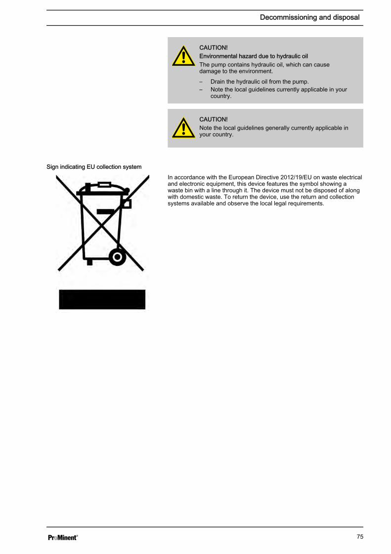
CAUTION!Environmental hazard due to hydraulic oilThe pump contains hydraulic oil, which can causedamage to the environment.
– Drain the hydraulic oil from the pump.– Note the local guidelines currently applicable in your
country.
CAUTION!Note the local guidelines generally currently applicable inyour country.
In accordance with the European Directive 2012/19/EU on waste electricaland electronic equipment, this device features the symbol showing awaste bin with a line through it. The device must not be disposed of alongwith domestic waste. To return the device, use the return and collectionsystems available and observe the local legal requirements.
Sign indicating EU collection system
Decommissioning and disposal
75

13 Technical data
WARNING!Risk of personal injuriesPlease observe the ”Supplement for modified version“ atthe end of the chapter!
It replaces and supplements the technical data!
Only with "M - modified" design:
Technical data
76

13.1 Performance data
Type Minimum pump capacity at maximumback pressure
Maximumstroke rate
Suctionlift
Permissiblepriming pres‐sure, suctionside
Connector size
bar l/h ml/stroke Strokes/min m watercolumn
bar G-DN
100003* 100 3 0.8 60 3 5 SST: Rp 1/4"
PVT: DN10
100006* 100 6 0.8 125 3 5 SST: Rp 1/4"
PVT: DN10
100007* 100 7 0.8 150 3 5 SST: Rp 1/4"
PVT: DN10
100009* 100 9 0.8 187 3 5 SST: Rp 1/4"
PVT: DN10
100010* 100 10 0.8 212 3 5 SST: Rp 1/4"
PVT: DN10
064007 64 7 2.0 60 3 5 G 3/4M - DN10
064015 64 15 2.0 125 3 5 G 3/4M - DN10
064018 64 18 2.0 150 3 5 G 3/4M - DN10
064022 64 22 2.0 187 3 5 G 3/4M - DN10
064025 64 25 2.0 214 3 5 G 3/4M - DN10
025019 25 19 5.3 60 3 5 G 3/4M - DN10**
025040 25 40 5.3 125 3 5 G 3/4M - DN10**
025048 25 48 5.3 150 3 5 G 3/4M - DN10**
025060 25 60 5.3 187 3 5 G 3/4M - DN10**
025068 25 68 5.3 214 3 5 G 3/4M - DN10**
* Material version SST / HCT with double ball valve
Alternatively double ball valve SST with RP 3/8
** HV version for G1-DN 15
Maximum back pressure for liquid ends in material version PVT: 25 bar!
Maximum back pressure for liquid ends in material version TTT: 16 bar!
The metering capacity can deviate from the details above with HV ver‐sions.
All figures refer to water at 20 °C.
Priming lift / priming pressure (dry) determined for empty suction line andempty liquid end and as well as clean and moistened valves (the figuresare lower with valve springs).
The suction lift / suction pressure applies to filled suction lines and filledliquid end - when installed correctly.
HP2a with 50 Hz operation
Technical data
77

Type Minimum pump capacity at maximum back pres‐sure
Maximumstroke rate
Suctionlift
Permissibleprimingpressure,suctionside
Connector size
bar psi l/h gph Strokes/min
mwatercolumn
bar G-DN
100003* 100 1,450 3.6 1.0 72 3 5 SST: Rp 1/4"
PVT: DN10
100006* 100 1,450 7 1.8 150 3 5 SST: Rp 1/4"
PVT: DN10
100007* 100 1,450 8 2.1 180 3 5 SST: Rp 1/4"
PVT: DN10
100009* 100 1,450 11 2.9 224 3 5 SST: Rp 1/4"
PVT: DN10
064007 64 928 8.4 2.2 72 3 5 G 3/4M - DN10
064015 64 928 18 4.8 150 3 5 G 3/4M - DN10
064018 64 928 21 5.5 180 3 5 G 3/4M - DN10
064022 64 928 26 6.9 224 3 5 G 3/4M - DN10
025019 25 362 23 6.1 72 3 5 G 3/4M - DN10**
025040 25 362 48 12.7 150 3 5 G 3/4M - DN10**
025048 25 362 58 15.3 180 3 5 G 3/4M - DN10**
025060 25 362 72 19.0 224 3 5 G 3/4M - DN10**
* Material version SST / HCT with double ball valve
Alternatively double ball valve SST with RP 3/8
** HV version for G1-DN 15
Maximum back pressure for liquid ends in material version PVT: 25 bar!
Maximum back pressure for liquid ends in material version TTT: 16 bar!
The metering capacity can deviate from the details above with HV ver‐sions.
All figures refer to water at 20 °C.
Priming lift / priming pressure (dry) determined for empty suction line andempty liquid end and as well as clean and moistened valves (the figuresare lower with valve springs).
The suction lift / suction pressure applies to filled suction lines and filledliquid end - when installed correctly.
HP2a with 60 Hz operation
Technical data
78

Type Minimum pump capacity at maximumback pressure
Maximumstroke rate
Suctionlift
Permissiblepriming pres‐sure, suctionside
Connector size
bar l/h ml/stroke Strokes/min m watercolumn
bar G-DN
100010* 100 10 2.8 60 3 5 G 3/4M - DN10**
100021* 100 21 2.8 125 3 5 G 3/4M - DN10**
100025* 100 25 2.8 150 3 5 G 3/4M - DN10**
100031* 100 31 2.8 187 3 5 G 3/4M - DN10**
100035* 100 35 2.8 212 3 5 G 3/4M - DN10**
064019 64 19 5.3 60 3 5 G 3/4M - DN10**
064040 64 40 5.3 125 3 5 G 3/4M - DN10**
064048 64 48 5.3 150 3 5 G 3/4M - DN10**
064060 64 60 5.3 187 3 5 G 3/4M - DN10**
064068 64 68 5.3 214 3 5 G 3/4M - DN10**
025048 25 48 13.4 60 3 5 G 1M - DN15 ***
025100 25 100 13.4 125 3 5 G 1M - DN15 ***
025120 25 120 13.4 150 3 5 G 1M - DN15 ***
025150 25 150 13.4 187 3 5 G 1M - DN15 ***
025170 25 170 13.4 214 3 5 G 1M - DN15 ***
* Material version SST / HCT with double ball valve
Alternatively double ball valve SST with RP 3/8
** HV version for G1M - DN 15
*** HV version G 1 1/4M - DN 20
Maximum back pressure for liquid ends in material version PVT: 25 bar!
Maximum back pressure for liquid ends in material version TTT: 16 bar!
The metering capacity can deviate from the details above with HV ver‐sions.
All figures refer to water at 20 °C.
Priming lift / priming pressure (dry) determined for empty suction line andempty liquid end and as well as clean and moistened valves (the figuresare lower with valve springs).
The suction lift / suction pressure applies to filled suction lines and filledliquid end - when installed correctly.
HP3a with 50 Hz operation
Technical data
79

Type Minimum pump capacity at maximum back pressure Maximumstrokerate
Suctionlift
Permissibleprimingpressure,suction side
Connectorsize
bar psi l/h gph Strokes/min
m watercolumn
bar G-DN
100010* 100 1,450 12 3.2 72 3 5 G 3/4M -DN10 **
100021* 100 1,450 25 6.6 150 3 5 G 3/4M -DN10 **
100025* 100 1,450 30 7.9 180 3 5 G 3/4M -DN10 **
100031* 100 1,450 37 9.8 224 3 5 G 3/4M -DN10 **
064019 64 928 23 6.1 72 3 5 G 3/4M -DN10 **
064040 64 928 48 12.7 150 3 5 G 3/4M -DN10 **
064048 64 928 58 15.3 180 3 5 G 3/4M -DN10 **
064060 64 928 72 19.0 224 3 5 G 3/4M -DN10 **
025048 25 362 58 15.3 72 3 5 G 1" - 10 ***
025100 25 362 120 31.7 150 3 5 G 1" - 10 ***
025120 25 362 144 38.0 180 3 5 G 1" - 10 ***
025150 25 362 180 47.6 224 3 5 G 1" - 10 ***
* Material version SST / HCT with double ball valve
Alternatively double ball valve SST with RP 3/8
*** HV version G 1M - DN 15
*** HV version G 1 1/4M - DN 20
Maximum back pressure for liquid ends in material version PVT: 25 bar!
Maximum back pressure for liquid ends in material version TTT: 16 bar!
The metering capacity can deviate from the details above with HV ver‐sions.
All figures refer to water at 20 °C.
Priming lift / priming pressure (dry) determined for empty suction line andempty liquid end and as well as clean and moistened valves (the figuresare lower with valve springs).
The suction lift / suction pressure applies to filled suction lines and filledliquid end - when installed correctly.
13.2 Metering reproducibility
Data Value Unit
Reproducibility ±1 % *
HP3a with 60 Hz operation
Technical data
80

* for measurements taken under constant conditions, minimum 20 %stroke rate and water at 20 °C - when installed correctly and with a backpressure of at least 1.5 bar
13.3 ViscosityThe liquid ends are generally suitable for the following viscosity ranges:
Design Range Unit
no valve springs 0 ... 200 mPas
with valve springs 200 ... 500 mPas
HV (for highly viscous feedchemicals)
500 ... approx. 3000 * mPas
* Only when the installation is correctly adjusted.
13.4 WeightFor SST material version pumps with standard motor.
Pump Design Weight
kg
HP2a Single head 31
Double head 41
Add-on power end 24
Add-on power end, doublehead
34
HP3a Single head 41
Double head 55
Add-on power end 34
Add-on power end, doublehead
48
13.5 Wetted materialsMaterial version Liquid end Suction/pressure
connectorSeals Ball seat Valve balls
SST Stainless steel1.4571//1.4404 /1.4404
Stainless steel1.4581
PTFE ZrO2 Ceramic
HCT Hastelloy C Hastelloy C PTFE Hastelloy C Ceramic
PVT PVDF PVDF PTFE PTFE Ceramic
TTT PTFE + carbon PVDF PTFE PTFE Ceramic
Technical data
81

13.6 Ambient conditions13.6.1 Temperatures
Data Value Unit
Storage and transport temperature -10 ... +50 °C
Ambient temperature in operation("Standard" version, for drive):
-10 ... +40 °C
Ambient temperature in operation ("Lowtemperature" version, for drive):
-25 ... +40 °C
Ambient temperature in operation ("Lowtemperature Zone 2" version, for drive):
-20 ... +40 °C
* Only with heating heating cartridge
Data Value Unit
Max. temperature, long-term at max. oper‐ating pressure
65 °C
Minimum temperature "Standard" -10 °C
Max. temperature, for 15 min at max. 2 bar 100 °C
Data Value Unit
Max. temperature, long-term at max. oper‐ating pressure
50 °C
Data Value Unit
Max. temperature, long-term at max. oper‐ating pressure
90 °C
Data Value Unit
Max. temperature, long-term at max. oper‐ating pressure
90 °C
Max. temperature, for 15 min at max. 2 bar 120 °C
Data Value Unit
Max. temperature, long-term at max. oper‐ating pressure
90 °C
Data Value Unit
Max. temperature, long-term at max. oper‐ating pressure
90 °C
Max. temperature, for 15 min at max. 2 bar 120 °C
Pump, compl.
PVT liquid end
TTT liquid end
HCT - ATEX liquid end
HCT liquid end
SST - ATEX liquid end
SST liquid end
Technical data
82
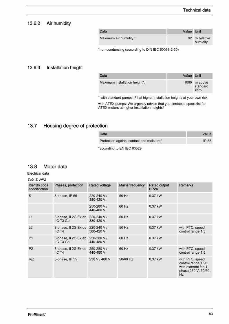
13.6.2 Air humidityData Value Unit
Maximum air humidity*: 92 % relativehumidity
*non-condensing (according to DIN IEC 60068-2-30)
13.6.3 Installation heightData Value Unit
Maximum installation height*: 1000 m abovestandardzero
* with standard pumps: Fit at higher installation heights at your own risk.
with ATEX pumps: We urgently advise that you contact a specialist forATEX motors at higher installation heights!
13.7 Housing degree of protectionData Value
Protection against contact and moisture* IP 55
*according to EN IEC 60529
13.8 Motor data
Tab. 8: HP2Identity codespecification
Phases, protection Rated voltage Mains frequency Rated outputHP2a
Remarks
S 3-phase, IP 55 220-240 V /380-420 V
50 Hz 0.37 kW
250-280 V /440-480 V
60 Hz 0.37 kW
L1 3-phase, II 2G Ex ebIIC T3 Gb
220-240 V /380-420 V
50 Hz 0.37 kW
L2 3-phase, II 2G Ex deIIC T4
220-240 V /380-420 V
50 Hz 0.37 kW with PTC, speedcontrol range 1:5
P1 3-phase, II 2G Ex ebIIC T3 Gb
250-280 V /440-480 V
60 Hz 0.37 kW
P2 3-phase, II 2G Ex deIIC T4
250-280 V /440-480 V
60 Hz 0.37 kW with PTC, speedcontrol range 1:5
R/Z 3-phase, IP 55 230 V / 400 V 50/60 Hz 0.37 kW with PTC, speedcontrol range 1:20with external fan 1-phase 230 V; 50/60Hz
Electrical data
Technical data
83

Identity codespecification
Phases, protection Rated voltage Mains frequency Rated outputHP2a
Remarks
V0 1-phase AC, IP 55 230 V ±10% 50/60 Hz 0.37 kW Variable speedmotor with inte‐grated frequencyconverter
V2 3 phase, II 2G EXdb IIC T3...T6 Gb
400 V ±10% 50/60 Hz 0.55 kW EX-variable speedmotor with inte‐grated frequencyconverter
Tab. 9: HP3Identity codespecification
Phases, protection Rated voltage Mains frequency Rated output Remarks
S 3-phase, IP 55 220-240 V /380-420 V
50 Hz 0.75 kW
250-280 V /440-480 V
60 Hz 0.75 kW
L1 3-phase, II 2G Ex ebIIC T3 Gb
220-240 V /380-420 V
50 Hz 0.75 kW
L2 3-phase, II 2G Ex deIIC T4
220-240 V /380-420 V
50 Hz 0.75 kW with PTC, speedcontrol range 1:5
P1 3-phase, II 2G Ex ebIIC T3 Gb
250-280 V /440-480 V
60 Hz 0.75 kW
P2 3-phase, II 2G Ex deIIC T4
250-280 V /440-480 V
60 Hz 0.75 kW with PTC, speedcontrol range 1:5
R/Z 3-phase, IP 55 230 V / 400 V 50/60 Hz 0.75 kW with PTC, speedcontrol range 1:20with external fan 1-phase 230 V; 50/60Hz
V0 1-phase AC, IP 55 230 V ±10% 50/60 Hz 0.75 kW Variable speedmotor with inte‐grated frequencyconverter
V2 3-phase, II 2G EX dIIC T3...T6 Gb
400 V ±10% 50/60 Hz EX-variable speedmotor with inte‐grated frequencyconverter
Motor data sheets, special motors, special motorflanges, external fan, temperature monitoring– For further information for the motor with identity
code specification "S", refer to the motor data sheetin the Appendix. Motor data sheets can berequested for all other motors.
– For other motors than those with identity code speci‐fication "S": Pay special attention to the operatinginstructions for the motors.
– Special motors or special motor flanges are avail‐able on request.
Technical data
84
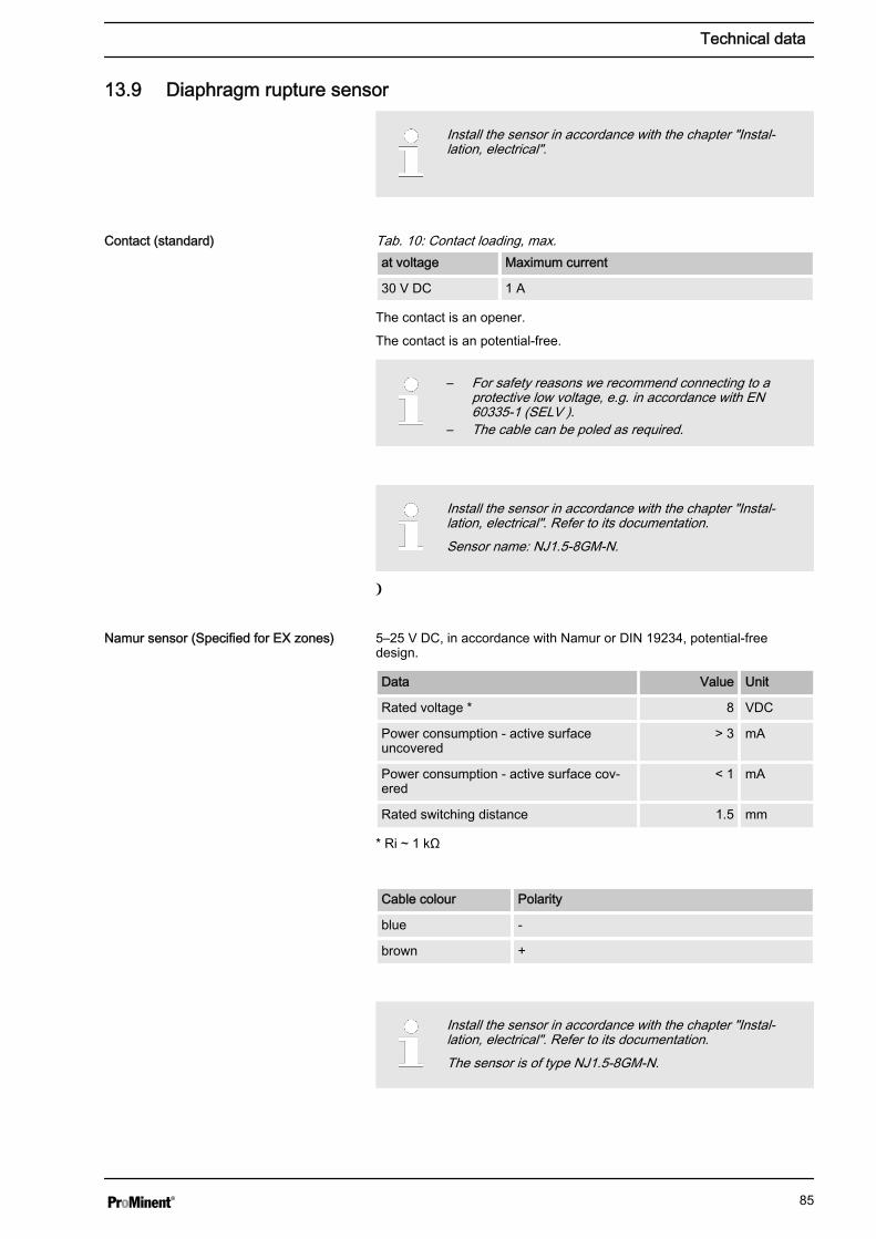
13.9 Diaphragm rupture sensor
Install the sensor in accordance with the chapter "Instal‐lation, electrical".
Tab. 10: Contact loading, max.at voltage Maximum current
30 V DC 1 A
The contact is an opener.
The contact is an potential-free.
– For safety reasons we recommend connecting to aprotective low voltage, e.g. in accordance with EN60335-1 (SELV ).
– The cable can be poled as required.
Install the sensor in accordance with the chapter "Instal‐lation, electrical". Refer to its documentation.Sensor name: NJ1.5-8GM-N.
5–25 V DC, in accordance with Namur or DIN 19234, potential-freedesign.
Data Value Unit
Rated voltage * 8 VDC
Power consumption - active surfaceuncovered
> 3 mA
Power consumption - active surface cov‐ered
< 1 mA
Rated switching distance 1.5 mm
* Ri ~ 1 kΩ
Cable colour Polarity
blue -
brown +
Install the sensor in accordance with the chapter "Instal‐lation, electrical". Refer to its documentation.The sensor is of type NJ1.5-8GM-N.
Contact (standard)
Namur sensor (Specified for EX zones)
Technical data
85

13.10 Safety relief valve (HP2 and HP3)Opening pressure of the respective pressure stages:
Pressurestage*
6 bar 10bar
16bar
25bar
40bar
64bar
100bar
Opening pres‐sure**
10bar
14bar
25bar
36bar
49bar
80bar
120bar
* Marking on the indicating scale without valve housing
** back pressure generated by the pump when discharge side is blocked ±3 bar
13.11 Stroke sensor
Install the sensor in accordance with the chapter "Instal‐lation, electrical".
5–25 V DC, in accordance with Namur or DIN 19234, potential-freedesign.
Data Value Unit
Rated voltage * 8 VDC
Power consumption - active surfaceuncovered
> 3 mA
Power consumption - active surface cov‐ered
< 1 mA
Rated switching distance 1.5 mm
* Ri ~ 1 kΩ
Cable colour Polarity
blue -
brown +
Install the sensor in accordance with the chapter "Instal‐lation, electrical". Refer to its documentation.The sensor is of type NJ1.5-8GM-N.
13.12 Heating cartridgeTechnical data - see enclosed operating instructions
Namur sensor (identity code characteristic"stroke sensor": 1)
Namur sensor (Specified for EX zones)
Technical data
86
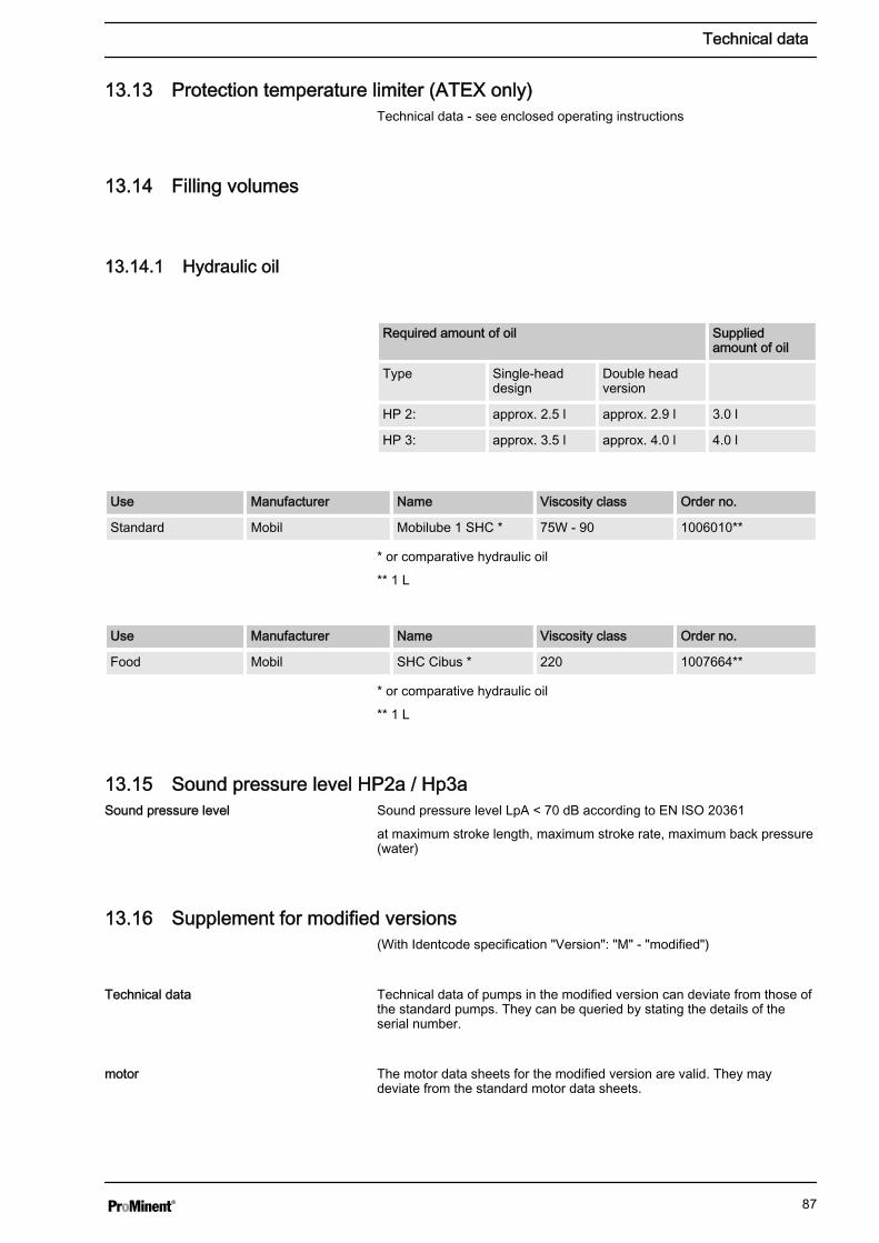
13.13 Protection temperature limiter (ATEX only)Technical data - see enclosed operating instructions
13.14 Filling volumes
13.14.1 Hydraulic oil
Required amount of oil Suppliedamount of oil
Type Single-headdesign
Double headversion
HP 2: approx. 2.5 l approx. 2.9 l 3.0 l
HP 3: approx. 3.5 l approx. 4.0 l 4.0 l
Use Manufacturer Name Viscosity class Order no.
Standard Mobil Mobilube 1 SHC * 75W - 90 1006010**
* or comparative hydraulic oil
** 1 L
Use Manufacturer Name Viscosity class Order no.
Food Mobil SHC Cibus * 220 1007664**
* or comparative hydraulic oil
** 1 L
13.15 Sound pressure level HP2a / Hp3aSound pressure level LpA < 70 dB according to EN ISO 20361
at maximum stroke length, maximum stroke rate, maximum back pressure(water)
13.16 Supplement for modified versions(With Identcode specification "Version": "M" - "modified")
Technical data of pumps in the modified version can deviate from those ofthe standard pumps. They can be queried by stating the details of theserial number.
The motor data sheets for the modified version are valid. They maydeviate from the standard motor data sheets.
Sound pressure level
Technical data
motor
Technical data
87

With a modified version, it is absolutely necessary to specify the details ofthe serial number requesting and ordering the spare and replacementparts.
Spare parts
Technical data
88

14 Dimensional drawings
– Compare the dimensions on the dimension sheetand pump.
– All dimensions are in mm.
FF
190
220
74 84
12
206
B
364
G
D
EL
A
C
61_02-101_00_01-73
P_HY_0019_SW
Fig. 23: Diagram is not strictly binding.
Liquid end A B C D E F G
HM 25 SST, HCT 152 239 7 50 DN10 G3/4 M 108x42 414
HM 60 SST, HCT 165 240 0.5 51 DN10 G3/4 M 108x57 415
HM 60 SST-HV 165 243.5 0.5 57 DN15G1A 108x57 421
HM 25 PVT, TTT 152 239 7 49 DN10 G3/4 M 108x42 413
HM 60 PVT, TTT 165 240 0.5 55 DN10 G3/4 M 108x57 419
"HM 25" for types 064007, 064015, 064018, 064022, 064025, 100003, 100006, 100007, 100009, 100010
"HM 60" for types 025019, 025040, 025048, 025060, 025068
Tab. 11: Dimension with double ball valveLiquid end A B C D E G
HM 25 SST, HCT 180 241 -7 54 DN10 Rp3/8" 418
HM 60 SST, HCT 195 242 20.5 55 DN10 Rp3/8" 419
Standard motor Motor, controllable EExe motor EExde motor Motor with fre‐quency converter
L 377 413 469 438 569
Dimensional drawing of Hydro HP2 (HP2aH)
Dimensional drawings
89
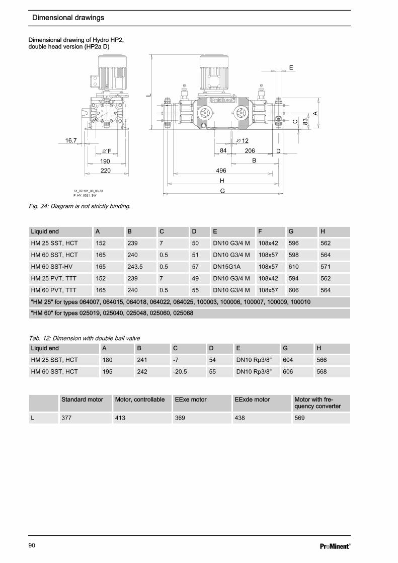
F
190
220
12
83
84 206
B
496
G
H
D
E
L
A
C
61_02-101_00_03-73
P_HY_0021_SW
16.7
Fig. 24: Diagram is not strictly binding.
Liquid end A B C D E F G H
HM 25 SST, HCT 152 239 7 50 DN10 G3/4 M 108x42 596 562
HM 60 SST, HCT 165 240 0.5 51 DN10 G3/4 M 108x57 598 564
HM 60 SST-HV 165 243.5 0.5 57 DN15G1A 108x57 610 571
HM 25 PVT, TTT 152 239 7 49 DN10 G3/4 M 108x42 594 562
HM 60 PVT, TTT 165 240 0.5 55 DN10 G3/4 M 108x57 606 564
"HM 25" for types 064007, 064015, 064018, 064022, 064025, 100003, 100006, 100007, 100009, 100010
"HM 60" for types 025019, 025040, 025048, 025060, 025068
Tab. 12: Dimension with double ball valveLiquid end A B C D E G H
HM 25 SST, HCT 180 241 -7 54 DN10 Rp3/8" 604 566
HM 60 SST, HCT 195 242 -20.5 55 DN10 Rp3/8" 606 568
Standard motor Motor, controllable EExe motor EExde motor Motor with fre‐quency converter
L 377 413 369 438 569
Dimensional drawing of Hydro HP2,double head version (HP2a D)
Dimensional drawings
90

F
449
485
18
1218
314
350
63
B
395
G
D
E
L
133
AC
61_02-101_00_09-74
P_HY_0023_SW
Fig. 25: Diagram is not strictly binding.
Liquid end A B C D E F G
HM 25 SST, HCT 152 95 59 50 DN10 G3/4 M 108x42 444
HM 60 SST, HCT 165 96 52 51 DN10 G3/4 M 108x57 445
HM 60 SST-HV 165 99 49 57 DN15G1A 108x57 451
HM 25 PVT, TTT 152 95 57 49 DN10 G3/4 M 108x42 443
HM 60 PVT, TTT 165 96 51 55 DN10 G3/4 M 108x57 449
"HM 25" for types 064007, 064015, 064018, 064022, 064025, 100003, 100006, 100007, 100009, 100010
"HM 60" for types 025019, 025040, 025048, 025060, 025068
Tab. 13: Dimension with double ball valveLiquid end A B C D E G
HM 25 SST, HCT 180 97 37 54 DN10 Rp3/8" 448
HM 60 SST, HCT 195 98 30 55 DN10 Rp3/8" 449
Standard motor Motor, controllable EExe motor EExde motor Motor with fre‐quency converter
L 427 463 419 488 619
Dimensional drawing of Hydro HP2 withadd-on power end (HP2a E + HP2a A)
Dimensional drawings
91

61_02-101_00_10-74
P_HY_0025_SW
Fig. 26: Diagram is not strictly binding.
Liquid end A B C D E F G H
HM 25 SST, HCT 152 92 59 50 DN10 G3/4 M 108x42 596 562
HM 60 SST, HCT 165 93 52 51 DN10 G3/4 M 108x57 598 564
HM 60 SST-HV 165 97 49 57 DN15G1A 108x57 610 571
HM 25 PVT, TTT 152 92 57 49 DN10 G3/4 M 108x42 594 562
HM 60 PVT, TTT 165 93 51 55 DN10 G3/4 M 108x57 606 564
"HM 25" for types 064007, 064015, 064018, 064022, 064025, 100003, 100006, 100007, 100009, 100010
"HM 60" for types 025019, 025040, 025048, 025060, 025068
Tab. 14: Dimension with double ball valveLiquid end A B C D E G H
HM 25 SST, HCT 180 94 37 54 DN10 Rp3/8" 604 566
HM 60 SST, HCT 195 95 30 55 DN10 Rp3/8" 606 568
Standard motor Motor, controllable EExe motor EExde motor Motor with fre‐quency converter
L 427 463 419 488 619
Dimensional drawing of Hydro HP2 withadd-on power end, double head versions(HP2a F + HP2a B)
Dimensional drawings
92
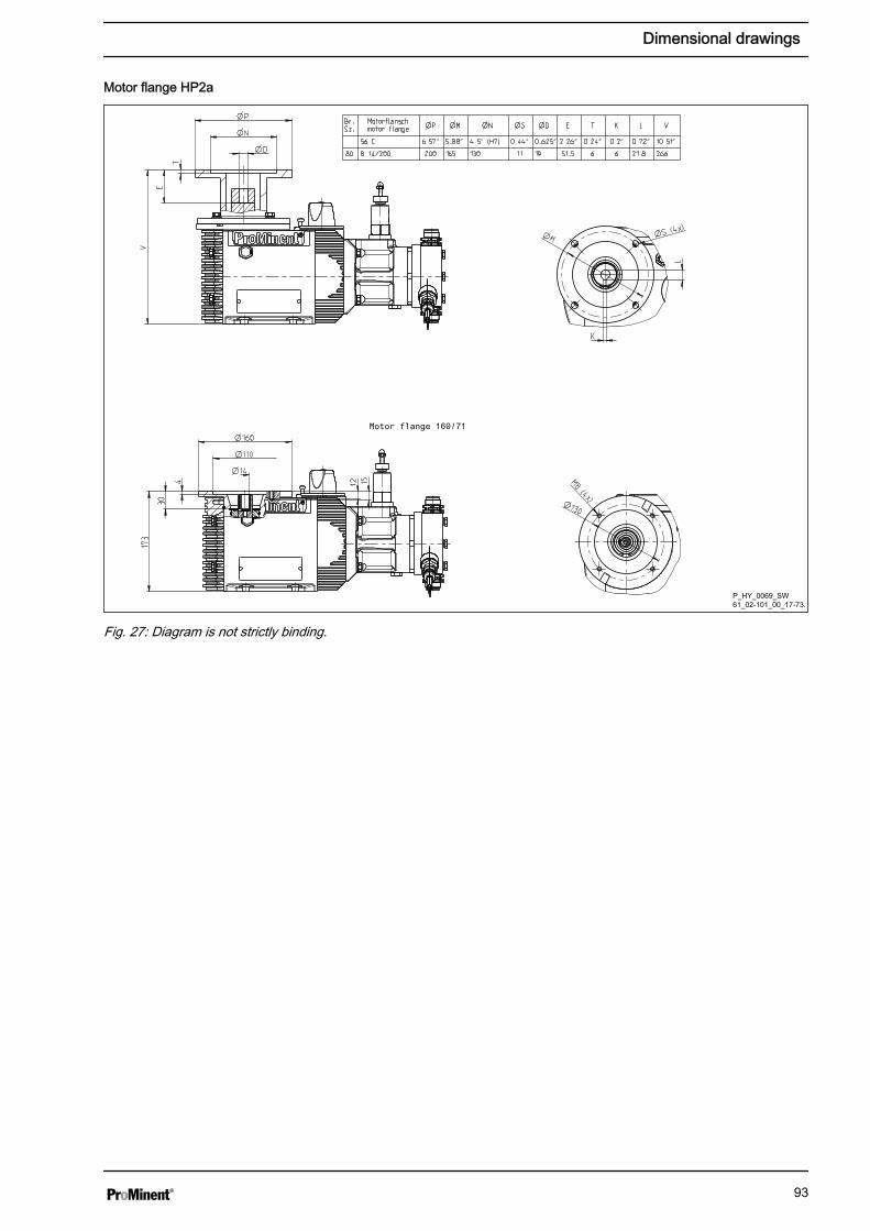
P_HY_0069_SW61_02-101_00_17-73.
Fig. 27: Diagram is not strictly binding.
Motor flange HP2a
Dimensional drawings
93

P_HY_0070_SW61_02-101_00_17-73
Fig. 28: Diagram is not strictly binding.
Type A Single-ball valveDIN
A Single ball valveANSI
A Double-ball valveDIN
A Double-ball valveANSI
SS 100003, 100006,100007, 100009,100010
- - 316 348
SS 064007, 064015,064018, 064022,064025
284 316 316 348
SS 025019, 025040,025048, 025060,025068
296 328 339 371
HC 100003, 100006,100007, 100009,100010
- 312 - -
HC 064007, 064015,064018, 064022,064025
- 312 - -
HC 025019, 025040,025048, 025060,025068
- 324 - -
HP2a single head version with actuator,base and connecting flanges
Dimensional drawings
94

P_HY_0071_SW61_02-101_00_19-73
Fig. 29: Diagram is not strictly binding.Dimension A - see Ä Table on page 94
F
214
244
81 110
12
215
B
406
G
D
E
L
A
C
61_02-101_00_02-73
P_HY_0020_SW
Fig. 30: Diagram is not strictly binding.
HP2a double head version with actuator,base and connecting flanges
Dimensional drawing of Hydro HP3 (HP3aH)
Dimensional drawings
95

Liquid end A B C D E F G
HM 60 SST, HCT 165 240 12.5 51 DN10 G3/4 M 108x57 457
HM 150 SST, HCT 191 247 -0.5 65 DN15G1A 128x76 471
HM 60 SST-HV 165 243.5 12.5 57 DN15G1A 108x57 463
HM 150 SST-HV 203 251 6.5 75 DN20G1 1/4 M 128x76 481
HM 60 PVT 165 240 12.5 57 DN10 G3/4 M 108x57 463
HM 150 PVT 191 247 -0.5 61 DN15G1A 128x76 467
"HM 60" for types 064019, 064040, 064048, 064060, 064068, 100010, 100021, 100025, 100031, 100035
"HM 150" for types 025048, 025100, 025120, 025150, 025170
Tab. 15: Dimension with double ball valveLiquid end A B C D E G
HM 60 SST, HCT 206 242 -2.5 55 DN10 Rp3/8" 461
Standard motor Motor, controllable EExe motor EExde motor Motor with fre‐quency converter
L 455 574 459 499 626
F
214
244
12
95
110 215
B
540
G
H
D
E
L
A
C
61_02-101_00_04-73
P_HY_0022_SW
16.7
Fig. 31: Diagram is not strictly binding.
Liquid end A B C D E F G H
HM 60 SST, HCT 165 240 12.5 51 DN10 G3/4 M 108x57 641 590
HM 150 SST, HCT 191 247 -0.5 65 DN15G1A 128x76 670 604
HM 60 SST-HV 165 243.5 12.5 57 DN15G1A 108x57 653 597
"HM 60" for types 064019, 064040, 064048, 064060, 064068, 100010, 100021, 100025, 100031, 100035
"HM 150" for types 025048, 025100, 025120, 025150, 025170
Dimensional drawing of Hydro HP3,double head version (HP3a D)
Dimensional drawings
96

Liquid end A B C D E F G H
HM 150 SST-HV 203 251 6.5 75 DN20G1 1/4M
128x76 690 612
HM 60 PVT, TTT 165 240 12.5 55 DN10 G3/4 M 108x57 654 590
HM 150 PVT, TTT 191 247 -0.5 61 DN15G1A 128x76 661 604
"HM 60" for types 064019, 064040, 064048, 064060, 064068, 100010, 100021, 100025, 100031, 100035
"HM 150" for types 025048, 025100, 025120, 025150, 025170
Tab. 16: Dimension with double ball valveLiquid end A B C D E G H
HM 60 SST, HCT 206 242 -2.5 55 DN10 Rp3/8" 650 594
Standard motor Motor, controllable EExe motor EExde motor Motor with fre‐quency converter
L 505 574 459 499 626
61_02-101_00_13-74
P_HY_0024_SW
Fig. 32: Diagram is not strictly binding.
Liquid end A B C D E F G
HM 60 SST, HCT 165 96 64 51 DN10 G3/4 M 108x57 495
HM 150 SST, HCT 191 104 50 65 DN15G1A 128x76 506
HM 60 SST-HV 165 100 61 57 DN15G1A 108x57 501
HM 150 SST-HV 203 108 40 75 DN20G1 1/4M
128x76 516
"HM 60" for types 064019, 064040, 064048, 064060, 064068, 100010, 100021, 100025, 100031, 100035
"HM 150" for types 025048, 025100, 025120, 025150, 025170
Dimensional drawing of Hydro HP3 withadd-on power end (HP3a E + HP3a A)
Dimensional drawings
97
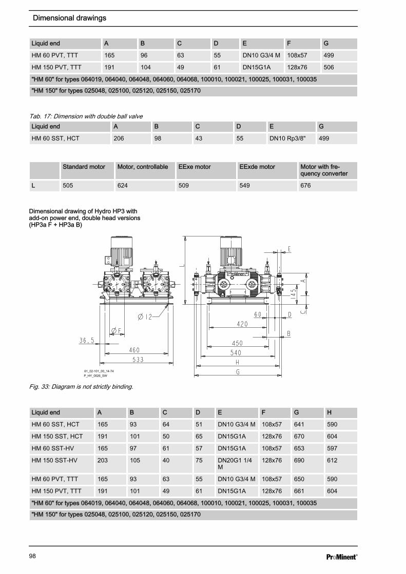
Liquid end A B C D E F G
HM 60 PVT, TTT 165 96 63 55 DN10 G3/4 M 108x57 499
HM 150 PVT, TTT 191 104 49 61 DN15G1A 128x76 506
"HM 60" for types 064019, 064040, 064048, 064060, 064068, 100010, 100021, 100025, 100031, 100035
"HM 150" for types 025048, 025100, 025120, 025150, 025170
Tab. 17: Dimension with double ball valveLiquid end A B C D E G
HM 60 SST, HCT 206 98 43 55 DN10 Rp3/8" 499
Standard motor Motor, controllable EExe motor EExde motor Motor with fre‐quency converter
L 505 624 509 549 676
61_02-101_00_14-74
P_HY_0026_SW
Fig. 33: Diagram is not strictly binding.
Liquid end A B C D E F G H
HM 60 SST, HCT 165 93 64 51 DN10 G3/4 M 108x57 641 590
HM 150 SST, HCT 191 101 50 65 DN15G1A 128x76 670 604
HM 60 SST-HV 165 97 61 57 DN15G1A 108x57 653 597
HM 150 SST-HV 203 105 40 75 DN20G1 1/4M
128x76 690 612
HM 60 PVT, TTT 165 93 63 55 DN10 G3/4 M 108x57 650 590
HM 150 PVT, TTT 191 101 49 61 DN15G1A 128x76 661 604
"HM 60" for types 064019, 064040, 064048, 064060, 064068, 100010, 100021, 100025, 100031, 100035
"HM 150" for types 025048, 025100, 025120, 025150, 025170
Dimensional drawing of Hydro HP3 withadd-on power end, double head versions(HP3a F + HP3a B)
Dimensional drawings
98
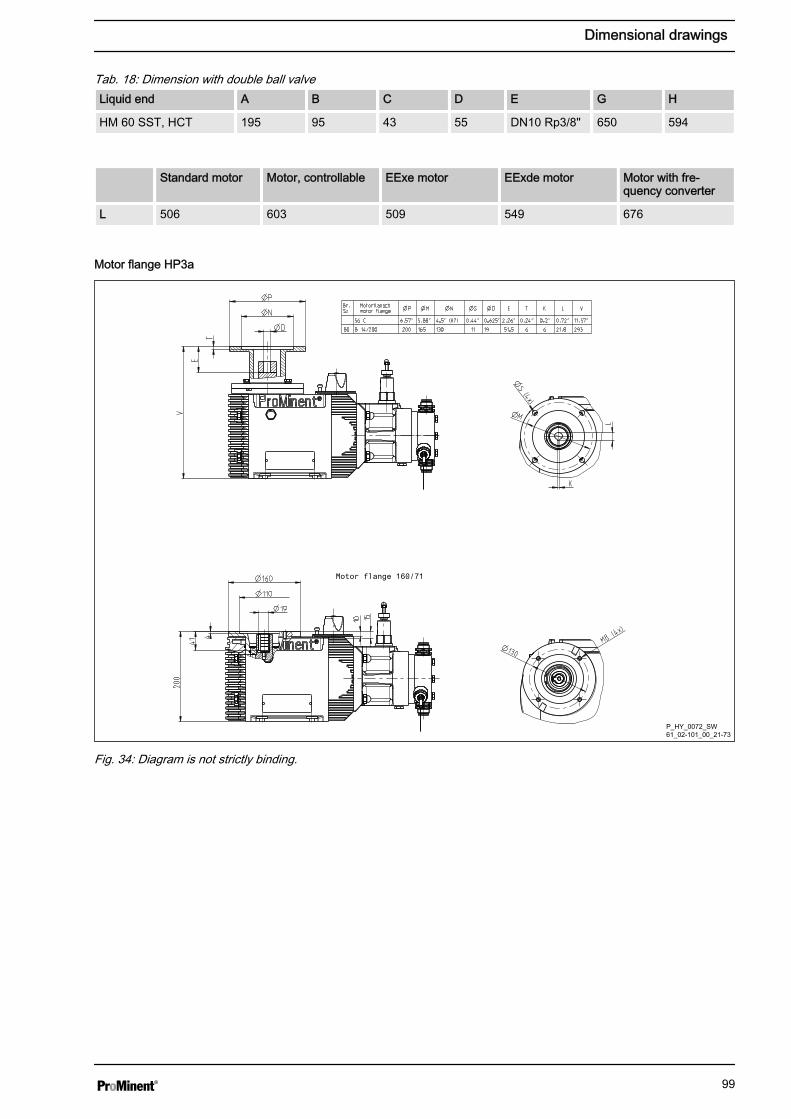
Tab. 18: Dimension with double ball valveLiquid end A B C D E G H
HM 60 SST, HCT 195 95 43 55 DN10 Rp3/8" 650 594
Standard motor Motor, controllable EExe motor EExde motor Motor with fre‐quency converter
L 506 603 509 549 676
P_HY_0072_SW61_02-101_00_21-73
Fig. 34: Diagram is not strictly binding.
Motor flange HP3a
Dimensional drawings
99

P_HY_0073_SW61_02-101_00_21-73
Fig. 35: Diagram is not strictly binding.
Type A Single-ball valve DIN A Single ball valve ANSI
SS 100010, 100021, 100025, 100031,100035
SS 064019, 064040, 064048, 064060,064068
296 327
SS 025048, 025100, 025120, 025150,025170
314 343
HP3a single head version with actuator,base and connecting flanges
Dimensional drawings
100

P_HY_0074_SW61_02-101_00_23-73
Fig. 36: Diagram is not strictly binding.
Type A Single-ball valveDIN
A Single ball valveANSI
A Double-ball valveDIN
A Double-ball valveANSI
SS 100010, 100021,100025, 100031,100035
292 337 339 385
SS 064019, 064040,064048, 064060,064068
292 337 339 385
SS 025048, 025100,025120, 025150,025170
314 355 - -
HP3a double head version with actuator,base and connecting flanges
Dimensional drawings
101
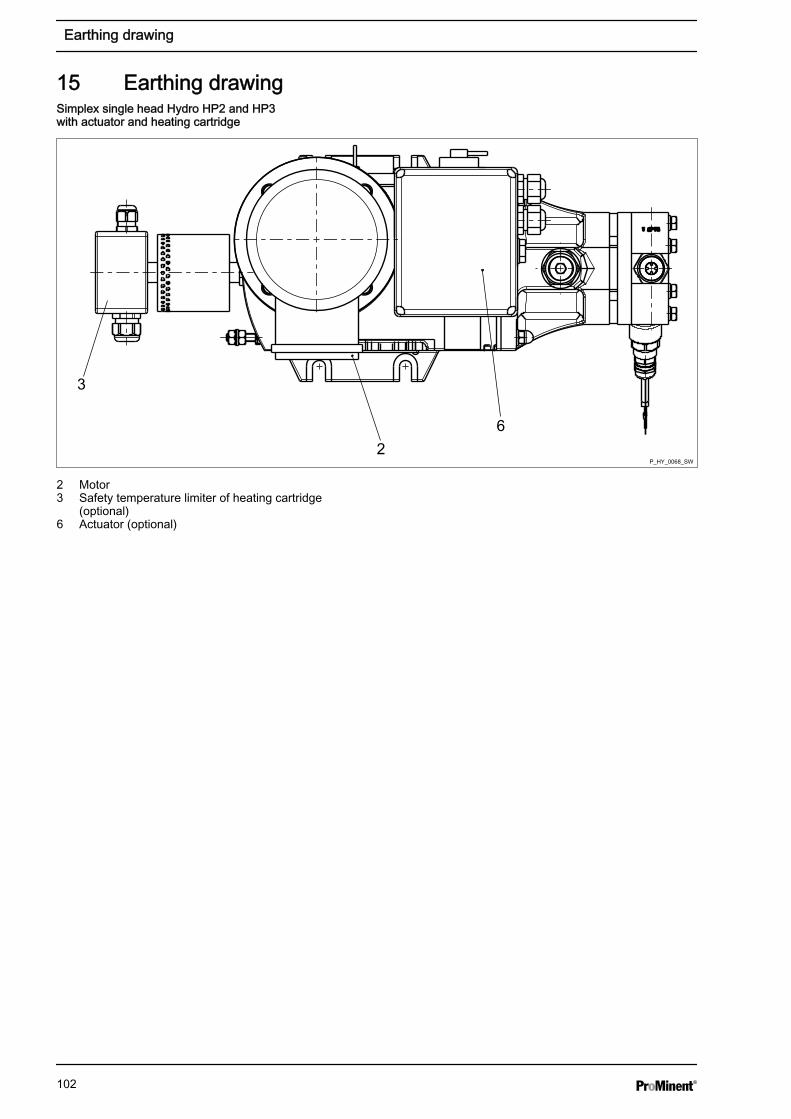
15 Earthing drawing
2
3
6
P_HY_0068_SW
2 Motor3 Safety temperature limiter of heating cartridge
(optional)6 Actuator (optional)
Simplex single head Hydro HP2 and HP3with actuator and heating cartridge
Earthing drawing
102
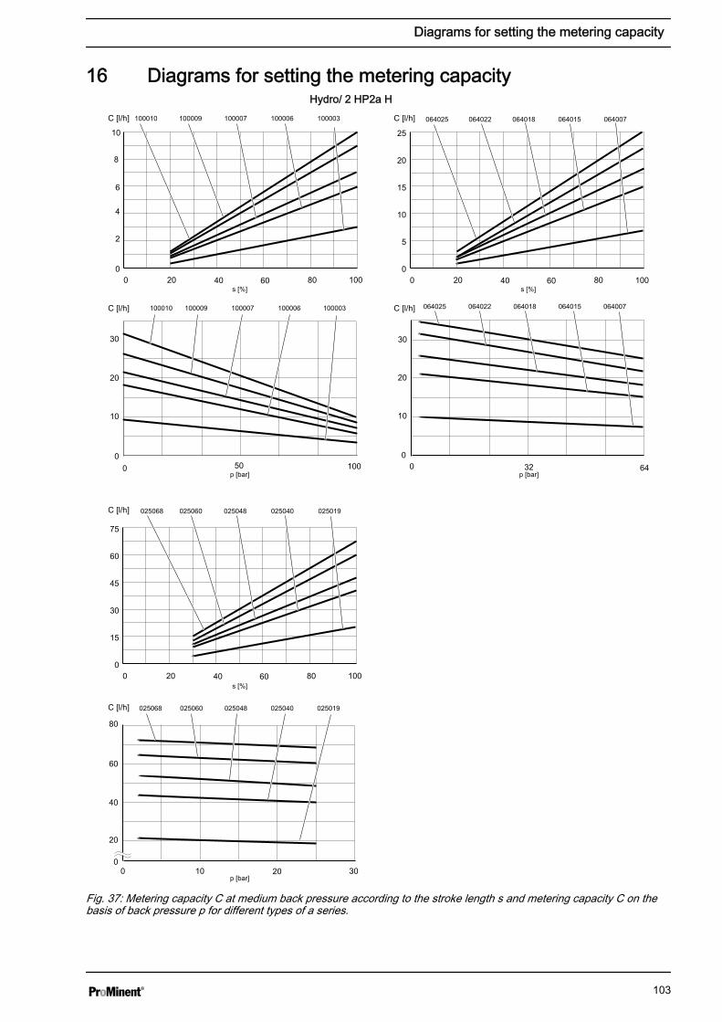
16 Diagrams for setting the metering capacityHydro/ 2 HP2a H
0
2
4
6
8
10
0 20 40 60 80 100s [%]
s [%]
s [%]
100009100010 100007 100006 100003C [l/h]
C [l/h]
C [l/h]
C [l/h]
C [l/h]
C [l/h]
0 50
30
0100
10
20
p [bar]
p [bar]
p [bar]
100009100010 100007 100006 100003
064022 064018 064015 064007
0
5
10
15
20
25
0 20 40 60 80 100
064025
0 6432
30
20
10
0
064022064025 064018 064015 064007
0
15
30
45
60
75
0 20 40 60 80 100
025060 025048 025040 025019025068
025060025068 025048 025040 025019
0 2010
20
30
60
80
40
0
Fig. 37: Metering capacity C at medium back pressure according to the stroke length s and metering capacity C on thebasis of back pressure p for different types of a series.
Diagrams for setting the metering capacity
103
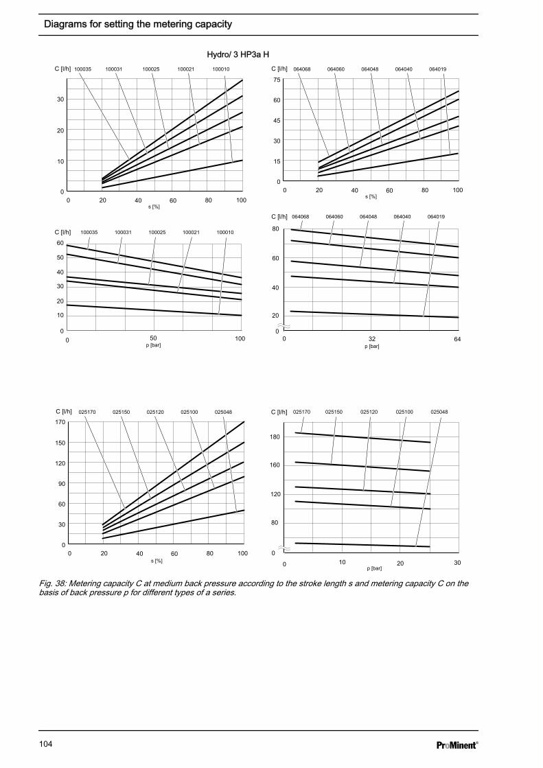
Hydro/ 3 HP3a H
0
10
20
30
0 20 40 60 80 100
100031100035 100025 100021 100010
15
30
45
60
75
0 20 40 60 80 1000
0 6432
60
80
20
40
0
064060064068 064048 064040 064019
064060064068 064048 064040 064019
0
30
60
90
120
150
170
0 20 40 60 80 100
025150025170 025120 025100 025048 025150025170 025120 025100 025048
0 2010
160
180
0
30
80
120
0 50
60
0100
10
20
30
50
40
100031100035 100025 100021 100010
s [%]
s [%]
s [%]
C [l/h]
C [l/h]
C [l/h]
C [l/h]
C [l/h]
C [l/h]
p [bar] p [bar]
p [bar]
Fig. 38: Metering capacity C at medium back pressure according to the stroke length s and metering capacity C on thebasis of back pressure p for different types of a series.
Diagrams for setting the metering capacity
104

17 Ordering information17.1 Exploded view drawing
1
2
2
1
*
5
3
4
P_HY_0017_SW
Fig. 39: Exploded view of Hydro liquid end. Numbered positions = scope of delivery of PVT spare parts kit. Technicalchanges reserved.1 Seals (Set)2 Valve balls3 Pressure connector assembly
4 Suction connection assembly5 Diaphragm* Reinforce plate - only with PVT
17.2 Spare parts kitsThe spare parts kit includes the replacement parts for the liquid ends.
Standard delivery for material version PVT
1 - Diaphragm
1 - Suction connection assembly.
1 - Pressure connector assembly
2 - Valve balls
1 - Set of seals, complete
Standard delivery for material version SST / HCT
1 - Diaphragm
2 - Valve balls
1 - Set of seals, complete
Ordering information
105

for types: 100010, 100009, 100007, 100006, 100003,
064025, 064022, 064018, 064015, 064007:
for liquid end Material version Order no.
FMH 25 - DN 10 PVT 1005548
SST 1005549
SST (for double ball valves) 1005551
HCT 1009571
SST (with valves, fully assembled) 1005550
.
for types: 025068, 025060, 025048, 025040, 025019:
for liquid end Material version Order no.
FMH 60 - DN 10 PVT 1005552
SST 1005553
SST (for double ball valves) 1005555
HCT 1009573
SST (with valves, fully assembled) 1005554
for types: 100035, 100031, 100025, 100021, 100010,
064068, 064060, 064048, 064040, 064019:
for liquid end Material version Order no.
FMH 60 - DN 10 PVT 1005552
SST 1005553
SST (for double ball valves) 1005555
HCT 1009573
SST (with valves, fully assembled) 1005554
.
for types: 025170, 025150, 025120, 025100, 025048:
for liquid end Material version Order no.
FMH 150 - DN 15 PVT 1005556
SST 1005557
HCT 1009575
SST (with valves, fully assembled) 1005558
Spare parts kits Hydro/ 2
Spare parts kits Hydro/ 3
Ordering information
106
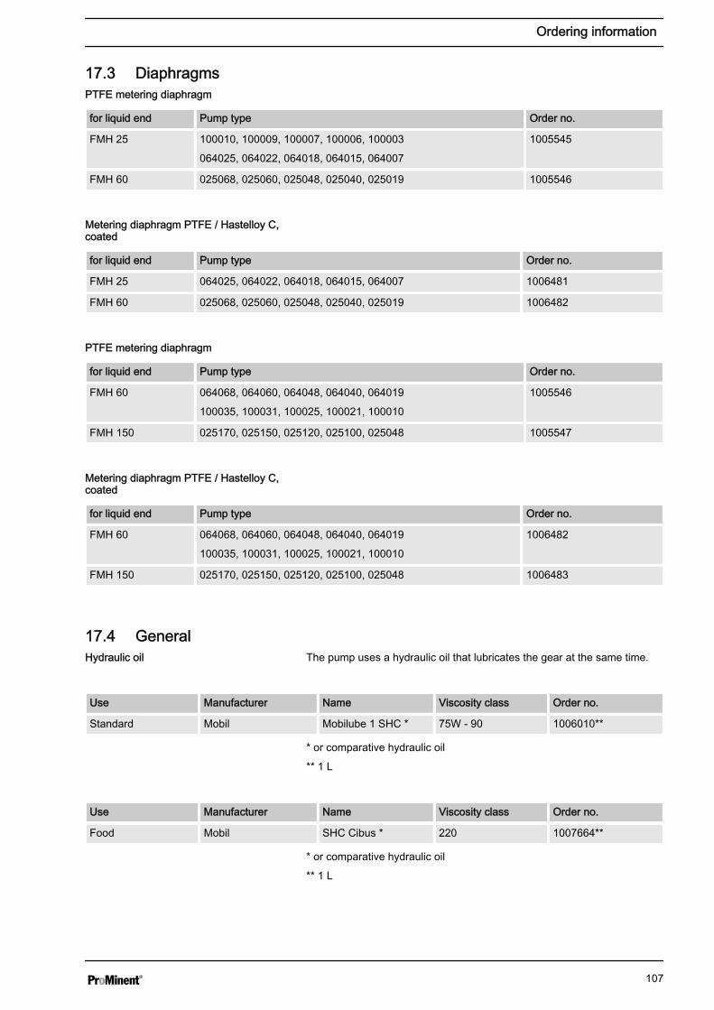
17.3 Diaphragms
for liquid end Pump type Order no.
FMH 25 100010, 100009, 100007, 100006, 100003
064025, 064022, 064018, 064015, 064007
1005545
FMH 60 025068, 025060, 025048, 025040, 025019 1005546
for liquid end Pump type Order no.
FMH 25 064025, 064022, 064018, 064015, 064007 1006481
FMH 60 025068, 025060, 025048, 025040, 025019 1006482
for liquid end Pump type Order no.
FMH 60 064068, 064060, 064048, 064040, 064019
100035, 100031, 100025, 100021, 100010
1005546
FMH 150 025170, 025150, 025120, 025100, 025048 1005547
for liquid end Pump type Order no.
FMH 60 064068, 064060, 064048, 064040, 064019
100035, 100031, 100025, 100021, 100010
1006482
FMH 150 025170, 025150, 025120, 025100, 025048 1006483
17.4 GeneralThe pump uses a hydraulic oil that lubricates the gear at the same time.
Use Manufacturer Name Viscosity class Order no.
Standard Mobil Mobilube 1 SHC * 75W - 90 1006010**
* or comparative hydraulic oil
** 1 L
Use Manufacturer Name Viscosity class Order no.
Food Mobil SHC Cibus * 220 1007664**
* or comparative hydraulic oil
** 1 L
PTFE metering diaphragm
Metering diaphragm PTFE / Hastelloy C,coated
PTFE metering diaphragm
Metering diaphragm PTFE / Hastelloy C,coated
Hydraulic oil
Ordering information
107

Required amount of oil Suppliedamount of oil
Type Single-headdesign
Double headversion
HP 2: approx. 2.5 l approx. 2.9 l 3.0 l
HP 3: approx. 3.5 l approx. 4.0 l 4.0 l
Spare part Order no.
Seal for the oil drainage stopper 1004803
Seal
Ordering information
108
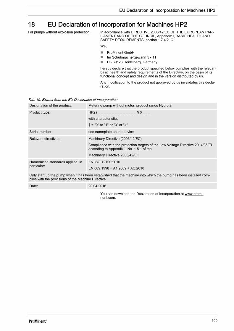
18 EU Declaration of Incorporation for Machines HP2In accordance with DIRECTIVE 2006/42/EC OF THE EUROPEAN PAR‐LIAMENT AND OF THE COUNCIL, Appendix I, BASIC HEALTH ANDSAFETY REQUIREMENTS, section 1.7.4.2. C.
We,
n ProMinent GmbHn Im Schuhmachergewann 5 - 11n D - 69123 Heidelberg, Germany,
hereby declare that the product specified below complies with the relevantbasic health and safety requirements of the Directive, on the basis of itsfunctional concept and design and in the version distributed by us.
Any modification to the product not approved by us invalidates this decla‐ration.
Tab. 19: Extract from the EU Declaration of IncorporationDesignation of the product: Metering pump without motor, product range Hydro 2
Product type: HP2a _ _ _ _ _ _ _ _ _ _ _ _ _ _ § 0 _ _ _
with characteristics
§ = "0" or "1" or "3" or "4"
Serial number: see nameplate on the device
Relevant directives: Machinery Directive (2006/42/EC)
Compliance with the protection targets of the Low Voltage Directive 2014/35/EUaccording to Appendix I, No. 1.5.1 of the
Machinery Directive 2006/42/EC
Harmonised standards applied, inparticular:
EN ISO 12100:2010
EN 809:1998 + A1:2009 + AC:2010
Only start up the pump when it has been established that the machine into which the pump has been installed com‐plies with the provisions of the Machine Directive.
Date: 20.04.2016
You can download the Declaration of Incorporation at www.promi‐nent.com.
For pumps without explosion protection:
EU Declaration of Incorporation for Machines HP2
109

19 EU Declaration of Incorporation for Machines HP3In accordance with DIRECTIVE 2006/42/EC OF THE EUROPEAN PAR‐LIAMENT AND OF THE COUNCIL, Appendix I, BASIC HEALTH ANDSAFETY REQUIREMENTS, section 1.7.4.2. C.
We,
n ProMinent GmbHn Im Schuhmachergewann 5 - 11n D - 69123 Heidelberg, Germany,
hereby declare that the product specified below complies with the relevantbasic health and safety requirements of the Directive, on the basis of itsfunctional concept and design and in the version distributed by us. Tech‐nical documents were produced in line with Appendix VII Part B.
Any modification to the product not approved by us invalidates this decla‐ration.
Tab. 20: Extract from the EU Declaration of IncorporationDesignation of the product: Metering pump without motor, product range Hydro 3
Product type: HP3a _ _ _ _ _ _ _ _ _ _ _ _ _ _ § 0 _ _ _
with characteristics
§ = "0" or "1" or "3" or "4"
Serial number: see nameplate on the device
Relevant directives: Machinery Directive (2006/42/EC)
Compliance with the protection targets of the Low Voltage Directive 2014/35/EUaccording to Appendix I, No. 1.5.1 of the
Machinery Directive 2006/42/EC
Harmonised standards applied, inparticular:
EN ISO 12100:2010
EN 809:1998 + A1:2009 + AC:2010
Only start up the pump when it has been established that the machine into which the pump has been installed com‐plies with the provisions of the Machine Directive.
Date: 20.04.2016
You can download the Declaration of Incorporation at www.promi‐nent.com.
For pumps without explosion protection:
EU Declaration of Incorporation for Machines HP3
110

20 EC Declaration of Conformity for HP2 MachinesIn accordance with DIRECTIVE 2006/42/EC OF THE EUROPEAN PAR‐LIAMENT AND OF THE COUNCIL, Appendix I, BASIC HEALTH ANDSAFETY REQUIREMENTS, section 1.7.4.2. C.
We,
n ProMinent GmbHn Im Schuhmachergewann 5 - 11n D - 69123 Heidelberg, Germany,
hereby declare that the product specified below complies with the relevantbasic health and safety requirements of the EC Directive on the basis of itsfunctional concept and design and in the version marketed by us.
Any modification to the product not approved by us invalidates this decla‐ration.
Tab. 21: Extract from the EU Declaration of ConformityDesignation of the product: Metering pump, product ranges Hydro 2
Product type: HP2a _ _ _ _ _ _ _ _ _ _ _ _ _ _ § 0 _ _ _
with characteristics
§ = "R" or "S" or "T" or "V" or "Z"
Serial number: see nameplate on the device
Relevant directives: EC Machinery Directive (2006/42/EC)
EU EMC Directive (2014/30/EU)
Compliance with the protection targets of the Low Voltage Directive 2014/35/EUaccording to Appendix I, No. 1.5.1 of the
Machinery Directive 2006/42/EC
Harmonised standards applied, inparticular:
EN ISO 12100:2010,
EN 809:1998 + A1:2009 + AC:2010
EN 61000-6-2:2005,
EN 61000-6-4:2007 + A1:2011
EN 60204-1:2006 + A1:2009
Date: 20.04.2016
You can download the Declaration of Conformity at www.prominent.com.
For pumps without explosion protection:
EC Declaration of Conformity for HP2 Machines
111

21 EC Declaration of Conformity for HP3 MachinesIn accordance with DIRECTIVE 2006/42/EC OF THE EUROPEAN PAR‐LIAMENT AND OF THE COUNCIL, Appendix I, BASIC HEALTH ANDSAFETY REQUIREMENTS, section 1.7.4.2. C.
We,
n ProMinent GmbHn Im Schuhmachergewann 5 - 11n D - 69123 Heidelberg, Germany,
hereby declare that the product specified below complies with the relevantbasic health and safety requirements of the EC Directive on the basis of itsfunctional concept and design and in the version marketed by us.
Any modification to the product not approved by us invalidates this decla‐ration.
Tab. 22: Extract from the EU Declaration of ConformityDesignation of the product: Metering pump, product ranges Hydro 3
Product type: HP3a _ _ _ _ _ _ _ _ _ _ _ _ _ _ § 0 _ _ _
with characteristics
§ = "R" or "S" or "T" or "V" or "Z"
Serial number: see nameplate on the device
Relevant directives: EC Machinery Directive (2006/42/EC)
EU EMC Directive (2014/30/EU)
Compliance with the protection targets of the Low Voltage Directive 2014/35/EUaccording to Appendix I, No. 1.5.1 of the
Machinery Directive 2006/42/EC
Harmonised standards applied, inparticular:
EN ISO 12100:2010
EN 809:1998 + A1:2009 + AC:2010
EN 61000-6-2:2005
EN 61000-6-4:2007 + A1:2011
EN 60204-1:2006 + A1:2009
Date: 20.04.2016
You can download the Declaration of Conformity at www.prominent.com.
For pumps without explosion protection:
EC Declaration of Conformity for HP3 Machines
112

22 EC Declaration of Incorporation for ATEX HP2 MachinesIn accordance with DIRECTIVE 2006/42/EC OF THE EUROPEAN PAR‐LIAMENT AND OF THE COUNCIL, Appendix I, BASIC HEALTH ANDSAFETY REQUIREMENTS, section 1.7.4.2. C.
We,
n ProMinent GmbHn Im Schuhmachergewann 5 - 11n D - 69123 Heidelberg, Germany,
hereby declare that the product specified below complies with the relevantbasic health and safety requirements of the EC Directive on the basis of itsfunctional concept and design and in the version marketed by us. Tech‐nical documents were produced in line with Appendix VII Part B.
Any modification to the product not approved by us invalidates this decla‐ration.
Tab. 23: Extract from the EU Declaration of IncorporationDesignation of the product: Metering pump without motor, product range Hydro 2
Design for use in areas at risk of explosion in accordance with the ATEX Direc‐tive (2014/34/EC)
Product type: HP2a - - - - - - - - - - - - - - § A - 0 &
with the characteristic
§ = "1" or "3" or "4"
& = "0" or "1" or "3"
Serial number: see nameplate on the device
Relevant directives: EU ATEX Directive (2014/34/EU)
EC Machinery Directive (2006/42/EC)
EU EMC Directive (2014/30/EU)
Compliance with the protection targets of the Low Voltage Directive 2014/35/EUaccording to Appendix I, No. 1.5.1 of the
Machinery Directive 2006/42/EC
Harmonised standards applied, inparticular:
EN ISO 80079-36:2016, EN ISO 80079-37:2016
EN ISO 12100:2010, EN 809:1998+A1:2009+AC:2010
EN 61000-6-2:2005, EN 61000-6-4:2007+A1:2011
EN 60204-1:2006+A1:2009
Only start up the pump when it has been established that the machine into which the pump has been installed com‐plies with the provisions of the Machine Directive.
EX-designation: II 2G Ex h IIC T4 Gb X for & = "0" or "1"
X: maximum medium temperature 90 °C, ambient temperature -10 ... +40 °C
II 3G Ex h IIB T4 Gc X for & = "3"
X: maximum medium temperature 90 °C
Assess the ignition risk when combining the pump and motor.
Date: 16.11.2018
You can download the Declaration of Incorporation at www.promi‐nent.com.
For pumps with explosion protection:
EC Declaration of Incorporation for ATEX HP2 Machines
113
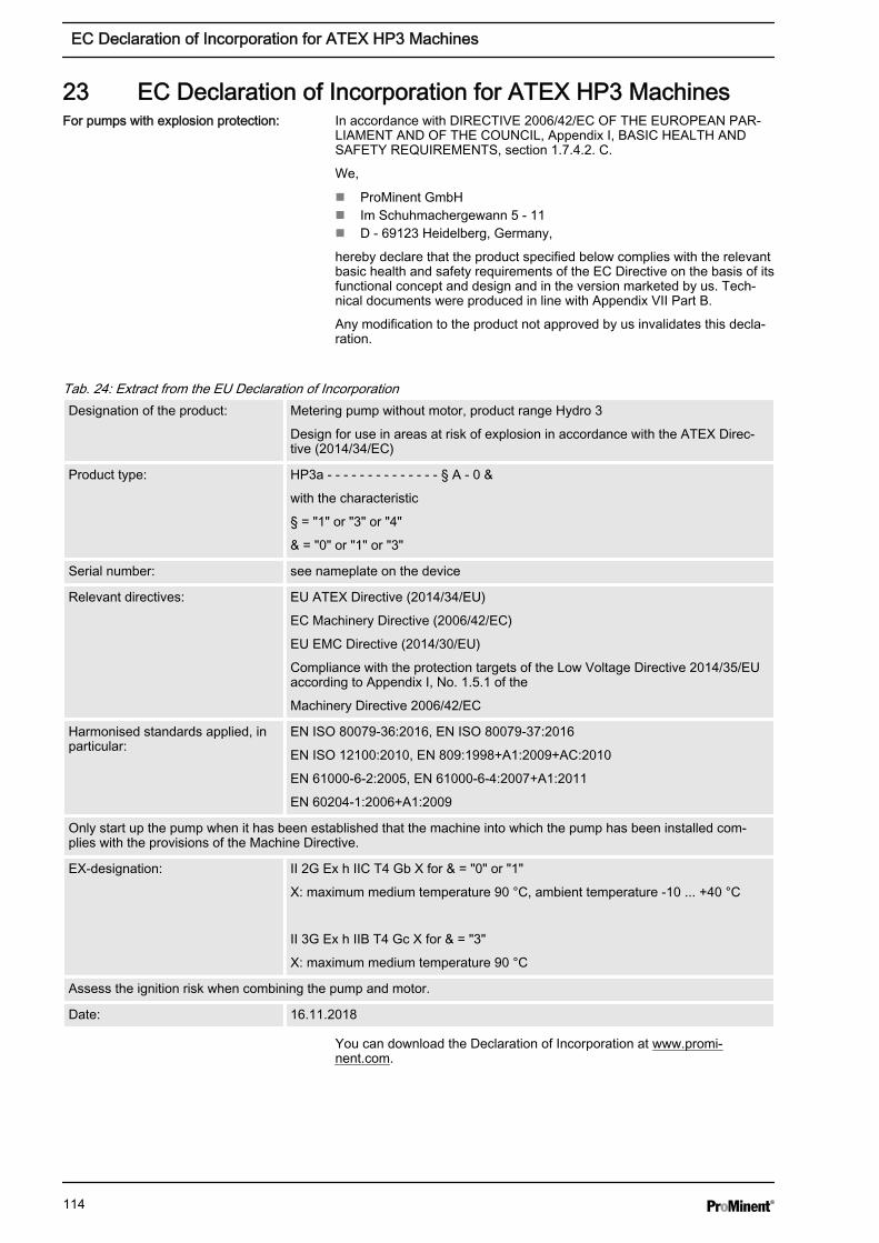
23 EC Declaration of Incorporation for ATEX HP3 MachinesIn accordance with DIRECTIVE 2006/42/EC OF THE EUROPEAN PAR‐LIAMENT AND OF THE COUNCIL, Appendix I, BASIC HEALTH ANDSAFETY REQUIREMENTS, section 1.7.4.2. C.
We,
n ProMinent GmbHn Im Schuhmachergewann 5 - 11n D - 69123 Heidelberg, Germany,
hereby declare that the product specified below complies with the relevantbasic health and safety requirements of the EC Directive on the basis of itsfunctional concept and design and in the version marketed by us. Tech‐nical documents were produced in line with Appendix VII Part B.
Any modification to the product not approved by us invalidates this decla‐ration.
Tab. 24: Extract from the EU Declaration of IncorporationDesignation of the product: Metering pump without motor, product range Hydro 3
Design for use in areas at risk of explosion in accordance with the ATEX Direc‐tive (2014/34/EC)
Product type: HP3a - - - - - - - - - - - - - - § A - 0 &
with the characteristic
§ = "1" or "3" or "4"
& = "0" or "1" or "3"
Serial number: see nameplate on the device
Relevant directives: EU ATEX Directive (2014/34/EU)
EC Machinery Directive (2006/42/EC)
EU EMC Directive (2014/30/EU)
Compliance with the protection targets of the Low Voltage Directive 2014/35/EUaccording to Appendix I, No. 1.5.1 of the
Machinery Directive 2006/42/EC
Harmonised standards applied, inparticular:
EN ISO 80079-36:2016, EN ISO 80079-37:2016
EN ISO 12100:2010, EN 809:1998+A1:2009+AC:2010
EN 61000-6-2:2005, EN 61000-6-4:2007+A1:2011
EN 60204-1:2006+A1:2009
Only start up the pump when it has been established that the machine into which the pump has been installed com‐plies with the provisions of the Machine Directive.
EX-designation: II 2G Ex h IIC T4 Gb X for & = "0" or "1"
X: maximum medium temperature 90 °C, ambient temperature -10 ... +40 °C
II 3G Ex h IIB T4 Gc X for & = "3"
X: maximum medium temperature 90 °C
Assess the ignition risk when combining the pump and motor.
Date: 16.11.2018
You can download the Declaration of Incorporation at www.promi‐nent.com.
For pumps with explosion protection:
EC Declaration of Incorporation for ATEX HP3 Machines
114

24 EC Declaration of Conformity for ATEX HP2 MachinesIn accordance with DIRECTIVE 2006/42/EC OF THE EUROPEAN PAR‐LIAMENT AND OF THE COUNCIL, Appendix I, BASIC HEALTH ANDSAFETY REQUIREMENTS, section 1.7.4.2. C.
We,
n ProMinent GmbHn Im Schuhmachergewann 5 - 11n D - 69123 Heidelberg, Germany,
hereby declare that the product specified below complies with the relevantbasic health and safety requirements of the EC Directive on the basis of itsfunctional concept and design and in the version marketed by us.
Any modification to the product not approved by us invalidates this decla‐ration.
Tab. 25: Extract from the EU Declaration of ConformityDesignation of the product: Metering pump, product range Hydro 2
Design for use in areas at risk of explosion in accordance with the ATEX Direc‐tive (2014/34/EC)
Product type: HP2a - - - - - - - - - - - - - - § $ - 0 &
with characteristics
§ = "L" or "P" and $ = "1" or "2"
or § = "V" and $ = "2"
& = "0" or "1" or "3"
Serial number: see nameplate on the device
Relevant directives: EU ATEX Directive (2014/34/EU)
EC Machinery Directive (2006/42/EC)
EU EMC Directive (2014/30/EU)
Compliance with the protection targets of the Low Voltage Directive (2014/35/EU)in accordance with Appendix I, No. 1.5.1 of the
Machinery Directive 2006/42/EC.
Harmonised standards applied, inparticular:
EN ISO 80079-36:2016, EN ISO 80079-37:2016
EN ISO 12100:2010, EN 809:1998+A1:2009+AC:2010
EN 61000-6-2:2005, EN 61000-6-4:2007+A1:2011
EN 60204-1:2006+A1:2009
EX specification of the entiresystem:
II 2G Ex h IIC T3 Gb X for $ = "1" and & = "0" or "1"
II 2G Ex h IIC T4 Gb X for $ = "2" and & = "0" or "1"
X: maximum medium temperature 90 °C, ambient temperature -10 ... +40 °C
II 3G Ex h IIB T3 Gc X for $ = "1" and & = "3"
II 3G Ex h IIB T4 Gc X for $ = "2" and & = "3"
X: maximum medium temperature 90 °C
Date: 16.11.2018
Download the Declaration of Conformity at www.prominent.com.
For pumps with explosion protection:
EC Declaration of Conformity for ATEX HP2 Machines
115
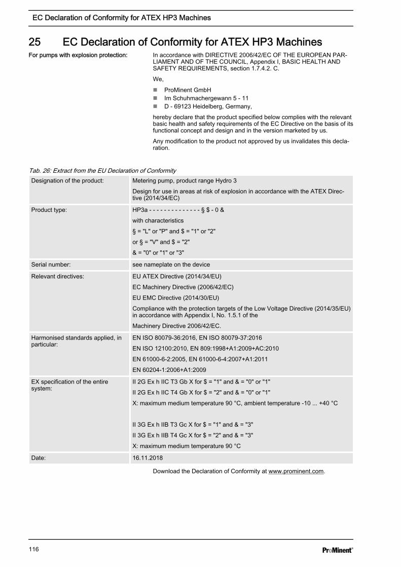
25 EC Declaration of Conformity for ATEX HP3 MachinesIn accordance with DIRECTIVE 2006/42/EC OF THE EUROPEAN PAR‐LIAMENT AND OF THE COUNCIL, Appendix I, BASIC HEALTH ANDSAFETY REQUIREMENTS, section 1.7.4.2. C.
We,
n ProMinent GmbHn Im Schuhmachergewann 5 - 11n D - 69123 Heidelberg, Germany,
hereby declare that the product specified below complies with the relevantbasic health and safety requirements of the EC Directive on the basis of itsfunctional concept and design and in the version marketed by us.
Any modification to the product not approved by us invalidates this decla‐ration.
Tab. 26: Extract from the EU Declaration of ConformityDesignation of the product: Metering pump, product range Hydro 3
Design for use in areas at risk of explosion in accordance with the ATEX Direc‐tive (2014/34/EC)
Product type: HP3a - - - - - - - - - - - - - - § $ - 0 &
with characteristics
§ = "L" or "P" and $ = "1" or "2"
or § = "V" and $ = "2"
& = "0" or "1" or "3"
Serial number: see nameplate on the device
Relevant directives: EU ATEX Directive (2014/34/EU)
EC Machinery Directive (2006/42/EC)
EU EMC Directive (2014/30/EU)
Compliance with the protection targets of the Low Voltage Directive (2014/35/EU)in accordance with Appendix I, No. 1.5.1 of the
Machinery Directive 2006/42/EC.
Harmonised standards applied, inparticular:
EN ISO 80079-36:2016, EN ISO 80079-37:2016
EN ISO 12100:2010, EN 809:1998+A1:2009+AC:2010
EN 61000-6-2:2005, EN 61000-6-4:2007+A1:2011
EN 60204-1:2006+A1:2009
EX specification of the entiresystem:
II 2G Ex h IIC T3 Gb X for $ = "1" and & = "0" or "1"
II 2G Ex h IIC T4 Gb X for $ = "2" and & = "0" or "1"
X: maximum medium temperature 90 °C, ambient temperature -10 ... +40 °C
II 3G Ex h IIB T3 Gc X for $ = "1" and & = "3"
II 3G Ex h IIB T4 Gc X for $ = "2" and & = "3"
X: maximum medium temperature 90 °C
Date: 16.11.2018
Download the Declaration of Conformity at www.prominent.com.
For pumps with explosion protection:
EC Declaration of Conformity for ATEX HP3 Machines
116

117

118

119

984721, 9, en_GB
© 2010
ProMinent GmbHIm Schuhmachergewann 5-1169123 Heidelberg, GermanyGermanyTelephone: ++49 6221 842-0Fax: ++49 6221 842-419Email: [email protected]: www.prominent.com