Hydro test
36
TOPICS • Introduction on SRMs 30 Min • Pre-test 30 Min • Information on Equipt. 2.0 Hrs • Demonstration 1.0 Hr • Practical 1.0 Hr • Skill test 2.0 Hrs • Post-test & Feedback 1 Hr Time Module : Use 0f Hydro Test Faculty : Course co-ordinators (KVR,BDP,SGC ) Demonstrator : Workmen from Shops Duration : Maximum 8 Hours Participants : Max. 06 / Module (Workmen from shops)
-
Upload
independent -
Category
Documents
-
view
3 -
download
0
Transcript of Hydro test

TOPICS• Introduction on SRMs 30 Min• Pre-test 30 Min• Information on Equipt. 2.0 Hrs• Demonstration 1.0 Hr• Practical 1.0 Hr• Skill test 2.0 Hrs• Post-test & Feedback 1 Hr
Time
Module : Use 0f Hydro TestFaculty : Course co-ordinators (KVR,BDP,SGC )Demonstrator : Workmen from ShopsDuration : Maximum 8 HoursParticipants : Max. 06 / Module (Workmen from shops)

Tests Destructive Tests Tensile, Impact, Bend,etc Non-destructive Tests Radiography, Ultrasonic, Dye-penetration, Magnetic Particle and leak testing like Hydrotest, Air Test, Helium Test etc..

Hydrotest-------why?
Recommended For pressure vessel operatingunder pressureEnsures the strength of weld joints &materialsEnsures nozzle-flange jointTest The strength of The pressure vessel at1.5 times the designed pressureEnsures safe & reliable performance duringthe operational life
To ensure the integrity of the vessel and system operation under pressure.
Requirements Of Materials , Tools & Equipments
TEST MEDIUM • WATER WITH ‘X’ PPM AS FREELY AVAILABLE• (PARTS PER MILLION---CHLORINE IMPURITIES)
• ‘X’ ---- 25 PPM OR LESS FOR SS VESSEL• ‘X’ ---- 80 PPM OR LESS FOR CS VESSEL
• CHLORINE PARTICLES AFFECT THE ANTICORROSIVE PROPERTIES OF VESSEL

REQUIREMENTS OF MATERIALS , TOOLS & EQUIPMENTS-(CONTD.)
WOODEN SADDLES (SOFT WOOD)• TO SUPPORT THE VESSEL & AVOID ANY DEFORMATION OR DENT AT CONTACT SURFACES
• CONTACT ANGLE---120 DEGREES
1200
Vessel
Wooden saddle

REQUIREMENTS OF MATERIALS , TOOLS & EQUIPMENTS-(CONTD.)
THERMOCOL SHEETS
• 20--30 MM THICKNESS• USED AS A SOFT PACKING BETWEEN VESSEL & SADDLE
REQUIREMENTS OF MATERIALS , TOOLS & EQUIPMENTS-(CONTD.)
COVER FLANGES
• NOZZLES WHICH HAVE ORIGINAL BLIND FLANGES TO BE BLANKED BY THOSE FLANGES
• OTHER NOZZLES TO BE BLANKED AS PER SPECIFIED DRAWING
REQUIREMENTS OF MATERIALS , TOOLS & EQUIPMENTS-(CONTD.)
HIGH TENSILE FASTNERS
• TO BE USED AS SPECIFIED IN THE DRAWING

REQUIREMENTS OF MATERIALS , TOOLS & EQUIPMENTS-(CONTD.)
PIPE FITTING
• HIGH PRESSURE (5000 TO 10000 PSI)• REQUIRED SIZES (BSP,NPT) TO BE USED FOR INLET & OUTLET EQUIPMENT, VALVES, GAUGES CONNECTIONS

PUMP ACCESSORIES• SQUARE BAR
• SHUT OFF VALVE
• COUPLER
• FLOW DIRECTION

REQUIREMENTS OF MATERIALS , TOOLS & EQUIPMENTS-(CONTD.)
GASKETS
• TO BE USED JOB GASKET UNLESS OTHERWISE SPECIFIED

REQUIREMENTS OF MATERIALS , TOOLS & EQUIPMENTS-(CONTD.)
PRESSURE GAUGES
• USE MINIMUM TWO CALIBRATED PRESSURE GAUGES• RANGE--- MIN. 1.5 TIMES THE TEST PRESSURE MAX. 4 TIMES THE TEST PRESSURE
• EXAMPLE: FOR TEST PRESSURE OF 60 KG/CM2 RANGE SHOULD BE 0-100 KG/CM2
(OR) 0-240 KG/CM2

• SQUARE BAR
• SHUT OFF VALVE
• COUPLER
• PRESSURE GAUGE
PUMP ACCESSORIES
REQUIREMENTS OF MATERIALS , TOOLS & EQUIPMENTS-(CONTD.)
WATERPUMP & HOSE ASSEMBLIES
• SUBMERSSIBLE OR ANY OTHER PUMP IS USED FOR FILLING THE VESSEL
• CONNECTED THROUGH FLEXIBLE HOSE PIPES TO TANK & VESSEL
REQUIREMENTS OF MATERIALS , TOOLS & EQUIPMENTS-(CONTD.)
HYDROTEST PUMP• REQUIRED FOR PRESSURIZING THE VESSEL TO THE TEST PRESSURE
• COMPRISES OF A HIGH PRESSURE PUMP B NON-RETURN VALVEC RELIEF VALVESD ATTACHMENTS LIKE HOSES, COUPLERS

PUMP ACCESSORIES
• PRESSURE GAUGE
• SUBMISSILE PUMP
• OUTLET HOSE

REQUIREMENTS OF MATERIALS , TOOLS & EQUIPMENTS-(CONTD.)
TORQUE WRENCH, GUN & STUD TENSIONER• ALL THE OPENINGS MUST BE CLOSED WITH BLIND FLANGES
• TIGHTENING TO BE ENSURED AT DESIRED TORQUE BY TORQUING WRENCH, TORQUING GUN OR STUD TENSIONER

TYPES OF HYDROTEST PUMP• HIGH DISCHARGE LOW PRESSURE PRESSURE RANGE : UP TO 100 KG/SQ.CM(g) QTY. : 02
• LOW DISCHARGE HIGH PRESSURE PRESSURE RANGE : UP TO 400 KG/SQ.CM(g) QTY. : 06

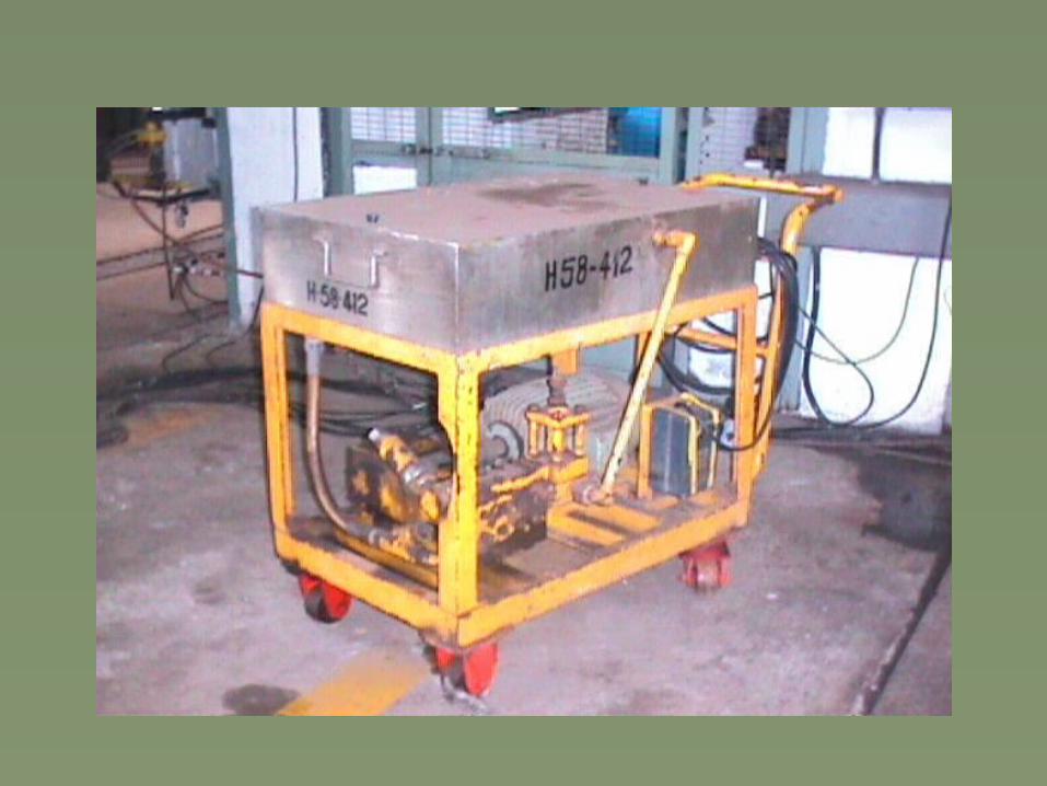
HYDROTEST PUMP DETAILS(HIGH PRESSURE, LOW DISCHARGE)
• INLET HOSE• TANK
• TROLLEY
• OUTLET HOSE

SEQUENCE OF OPERATIONS
SADDLE ARRANGEMENT• REQUIRED NO. OF SADDLES AS MENTIONED ON DRG. TO BE PLACED AT THE DISTANCES
• PUT THERMOCOL SHEETS ON SADDLES BEFORE KEEPING THE VESSEL

SEQUENCE OF OPERATIONS (CONTD.)
ORIENTATION• LONGSEAM, CIRCSEAM REMAIN EXPOSED FOR VISUAL INSPECTION & NOT COVERED UNDER SADDLE
• INLET NOZZLE FOR WATER IS AT THE TOP & DRAIN OUT AT THE BOTTOM OF VESSEL

SEQUENCE OF OPERATIONS (CONTD.)
AIR LOCK REMOVAL• ADEQUATE ARRANGEMENT TO BE MADE FOR VENTING THE AIR, TRAPPED INSIDE THE VESSEL
• FOUR DIFFERENT CASES TO BE STUDIED

AIR LOCK REMOVAL
1 VESSEL IN HORIZONTAL, INCLINED AT 5 DEG.

AIR LOCK REMOVAL2. WHEN INTERNALS LIKE TSRs PROVIDED INSIDE THE
VESSEL
VESSEL
SADDLE NOZZLE
D/E

AIR LOCK REMOVAL
3 FOR HORIZONTAL NOZZLE INSIDE THE D/E

AIR LOCK REMOVAL

TIGHTENING SEQUENCE
Bitmap Image
1
2
34
5
6 7
8

PRESSURE VALVE SETTING• VALVE SETTING FOR REQUIRED PRESSURE

GUIDELINES FOR HYDROTEST• Pump shaft should rotate clock wise looking from shaft side
• Ensure bypass line is open.
• Ensure that bypass line should not connect to the pump suction line.
(If discharge line is shut off, bypass water is diverted to the pump suction & as a result there is a rapid rise in temperature , which causes damage to piston plunger packing)

• Connect pump outlet to vessel inlet through standard hose pipe, with proper valve connections, square bar, couplers, etc.
• Ensure the pressure regulator valve,foot valve,should be in unloading position.
• Ensure the pressure gauge calibration validity
• Ensure water tank or suction line should be free from any foreign material

• Start hydrotest pump
• Ensure 100% removal of entrapped air ( monitor the tank into which the outlet hose pipe is dipped. As soon as bubbles stop showing up, close outlet valve)
• Monitor pressure gauge provided at outlet.
OPERATING PROCEDURES

•OPERATING PROCEDURES
(Contd.)• As soon as pressure reaches 50% of the test pressure , wait for 10 minutes
• Increase pressure by 10% in stages till the test pressure is achieved
• Observe pressure drop ( by marking line on pressure gauges)
• Hold the hydrotest pressure for specific time as mentioned in drawing
• Carry out thorough visual inspection of all joints & connections
(If any leakage is noticed, mark the point. The vessel is to be depressurized and then necessary repairs are to be carried out. Again the test procedure is to be repeated)
DOs & DON’Ts
• Ensure pressure gauge readability
• Working, design & test pressure to be displayed near the vessel
• Ensure all gasket surfaces are free from dent & scratches before blanking
• Do not apply paint, oil, grease on weld joints
• Do not weld on job blind flange

THANK YOU