Fully coupled hydro-mechanical numerical manifold modeling ...
Upload
khangminh22Category
view
0download
0
FINAL APPLICATION FOR LICENSE
OF MAJOR UNCONSTRUCTED PROJECT
APPLICANT PREPARED ENVIRONMENTAL IMPACT REPORT
CHAPTER 3 Project Description
LAKE ELSINORE ADVANCED PUMPED STORAGE PROJECT
FEDERAL ENERGY REGULATORY COMMISSION PROJECT NUMBER 14227
Applicant:
THE NEVADA HYDRO COMPANY, INC. 2416 Cades Way
Vista, California 92081 (760) 599-1813
(760) 599-1815 FAX
September 2017

This page intentionally left blank

Lake Elsinore Advanced Pumped Storage
Applicant Prepared EIR September 2017
Chapter 3: Project Description Page 3-i
Table of Contents
CHAPTER 3 PROJECT DESCRIPTION 3-1 3.1 Introduction 3-1
3.1.1 Background - Permit and Licensing 3-63 3.1.1.1 Licensing for Transmission (TE/VS Interconnect) 3-64
3.1.1.2 Licensing for Pumped Storage 3-64 3.1.1.3 California Environmental Quality Act 3-66 3.1.1.4 Discretionary Permits, Approvals, and Consultation Requirements3-67
3.1.2 Existing Agreements 3-71 3.2 Project Location 3-73
3.2.1 Geographic Location 3-73 3.2.2 General Description of Land Uses within the Proposed Project 3-76
3.2.2.1 Land Use Associated with the Transmission Alignment 3-76
3.2.2.2 Land Use Associated with Pumped Storage Facility 3-79
3.3 Existing Electrical System 3-80 3.3.1 Introduction 3-80
3.3.2 SCE System 3-82 3.3.3 SDG&E System 3-84 3.3.4 Changes Due to Project Implementation 3-85
3.3.4.1 Changes to the SCE System 3-86 3.3.4.2 Changes to SDG&E Transmission System 3-87
3.4 Project Objectives 3-87 3.5 Proposed Project Overview 3-88
3.5.1 Introduction to Whole of the Proposed Project 3-88
3.5.1.1 Components of the TE/VS Interconnect 3-89
3.5.1.2 Components of LEAPS 3-89 3.5.2 Fit into Regional System 3-90 3.5.3 Future phases 3-91
3.5.4 Capacity Increase 3-91 3.5.5 GIS Database 3-91
3.6 Project Components 3-91 3.6.1 Talega-Escondido/Valley-Serrano 500 kV Interconnect Facility 3-91
3.6.1.1 Transmission Lines 3-92 3.6.1.2 Towers 3-92 3.6.1.3 Conductor/Cable 3-93
3.6.1.4 Substations and Switchyards 3-103 3.6.1.5 Telecommunications 3-149
3.6.2 LEAPS 3-150 3.6.2.1 Decker Lake Upper Reservoir 3-152 3.6.2.2 Project Tunnels/Shaft 3-154 3.6.2.3 LEAPS Powerhouse 3-155 3.6.2.4 Lake Elsinore Intake/Outlet Structure 3-156
3.6.2.5 Lake Elsinore as the Lower Reservoir 3-157 3.6.2.6 Other Features as Pumped Storage Components 3-158 3.6.2.7 Black Start Capability 3-168

Lake Elsinore Advanced Pumped Storage
September 2017 Applicant Prepared EIR
Page 3-ii Chapter 3: Project Description
3.6.3 System Upgrades 3-169
3.6.3.1 SCE Upgrades 3-170
3.6.3.2 SDG&E Upgrades 3-172 3.7 Right-of-Way Requirements 3-190 3.8 Construction 3-190
3.8.1 General Approach for Project Construction 3-190 3.8.1.1 Primary Staging Areas 3-191
3.8.1.2 Work Areas 3-192 3.8.1.3 Access Roads and Spur Roads 3-192 3.8.1.4 Helicopter Use 3-193 3.8.1.5 Vegetation Clearance 3-194 3.8.1.6 Erosion and Sediment Control and Pollution Prevention during
Construction 3-194 3.8.2 Transmission Line Construction (Above Ground) 3-195
3.8.2.1 Pulling and Splicing Locations 3-195
3.8.2.2 Pole Installation and Removal 3-196
3.8.2.3 Conductor/Cable Installation 3-199 3.8.2.4 Guard Structure Installation 3-201
3.8.3 Transmission Line Construction (Below Ground) 3-202
3.8.3.1 General 3-202 3.8.3.2 Tunnels: General 3-203
3.8.3.3 Construction of Vertical Shafts for the Ridge Tunnel 3-203 3.8.3.4 Construction of the Ridge Tunnel 3-204 3.8.3.5 Construction of the Santa Rosa Tunnel 3-204
3.8.3.6 Disposal of Removed Material 3-205 3.8.4 Substation and Switchyard Construction 3-206
3.8.4.1 General Construction Considerations – All Sites 3-206 3.8.4.2 Lake Switchyard 3-208
3.8.4.3 Santa Rosa Substation 3-209 3.8.4.4 Case Springs Substation 3-210
3.8.5 Upgrade Construction 3-216 3.8.5.1 Talega-Escondido Line Upgrades 3-216 3.8.5.2 IT Facility Construction 3-216
3.8.6 Construction Workforce and Equipment 3-217 3.8.7 Construction Schedule 3-219 3.8.8 Excavation Volumes 3-220
3.9 Operation and Maintenance 3-221 3.9.1 Operation and Maintenance for the TE/VS Interconnect. 3-221
3.9.1.1 Substation Operation and Maintenance 3-221
3.9.1.2 Line Operation and Maintenance 3-223 3.9.2 Pumped Storage O & M 3-225
3.9.2.1 Santa Rosa Powerhouse 3-225 3.9.2.2 Decker Canyon Reservoir, Tunnels, and Lake Elsinore Inlet/Outlet3-226
3.10 Applicant Proposed Measures 3-226 3.10.1 Mandatory Conditions and Requirements 3-226
3.10.1.1 Federal Power Act 3-226
3.10.1.2 Federal Endangered Species Act 3-227

Lake Elsinore Advanced Pumped Storage
Applicant Prepared EIR September 2017
Chapter 3: Project Description Page 3-iii
3.10.1.3 National Historic Preservation Act 3-228
3.10.1.4 Federal Clean Water Act 3-228
3.10.2 Additional Articles, Conditions, and Measures Incorporated into the
Project 3-228 3.10.3 Applicant Proposed Mitigation Measures 3-229
3.11 Electric and Magnetic Fields Summary 3-229 3.12 Alternative Routing 3-231
3.13 Response to SONGS Outage 3-231
Table of Figures
Figure 3.1.1-1: Regional Vicinity Map 3-6
Figure 3.1.1-2: Project Facilities Location Map 3-7
Figure 3.1.1-3: Project Conceptual Single Line Diagram 3-8 Figure 3.1.1-4: Talega-Escondido/Valley-Serrano 500 kV Interconnect Project 3-9
Figure 3.1.1-6: LEAPS Pumped Storage Facility (1 of 2) 3-59 Figure 3.2.2-1: Land Use Near Pumped Storage Facilities 3-80 Figure 3.3.1-1: Southwestern U.S. Transmission System Schematic 3-81
Figure 3.3.1-2: Southern California System Schematic 3-82 Figure 3.3.2-1: SCE Service Territory 3-83
Figure 3.3.3-1: SDG&E Service Territory 3-85 Figure 3.6.1-1: GIL Cross Section 3-96 Figure 3.6.1-2: GIL Tunnel Illustration 3-97
Figure 3.6.1-3: North & South Transition Plan (Typical) 3-98
Figure 3.6.1-4: North & South Transition Elevations (Typical) 3-99 Figure 3.6.1-5: GIL Vault Elevations 3-102 Figure 3.6.1-6: Lake Switchyard Site 3-106
Figure 3.6.1-7: Lake 500 kV Switchyard – Conceptual Plan Layout 3-107 Figure 3.6.1-8: Lake 500 kV Switchyard – Conceptual Elevation Drawings 3-109
Figure 3.6.1-9: Lake 500 kV Switchyard – Single Line Diagram 3-115 Figure 3.6.1-10: Santa Rosa Substation Site 3-117 Figure 3.6.1-11: Santa Rosa Substation Site – Conceptual Site Plan 3-119 Figure 3.6.1-12: Santa Rosa Substation Site – Conceptual Elevation Drawings (1 of 3) 3-121 Figure 3.6.1-13: Santa Rosa Substation Single Line Diagram 3-127
Figure 3.6.1-14: Case Springs Substation – Conceptual Site Plan 3-133 Figure 3.6.1-15: Case Springs Substation – Single Line Diagram 3-135
Figure 3.6.1-16: Case Springs Substation Alternative Locations 3-140 Figure 3.6.1-17: Case Springs Site Plan 3-141 Figure 3.6.1-18: Fallbrook Alternative – Substitute Route Plates (1 of 2) 3-142 Figure 3.6.1-19: Fallbrook Alternative – Site Plan 3-144 Figure 3.6.1-20: Fern Creek Alternative – Substitute Route Plates (1 of 2) 3-145
Figure 3.6.1-21: Fern Creek Alternative – Site Plan 3-147 Figure 3.6.1-22: Representative Communication Tower 3-150 Figure 3.6.2-1: Water Treatment Facility Conceptual Site Plan 3-164

Lake Elsinore Advanced Pumped Storage
September 2017 Applicant Prepared EIR
Page 3-iv Chapter 3: Project Description
Figure 3.6.2-2: Conceptual Storage Tank Profile 3-164
Figure 3.6.3-1: Talega-Escondido 230 kV Line Upgrade 3-177
Figure 3.6.3-3: Typical Single Circuit 230 kV Steel Lattice Tower 3-187 Figure 3.6.3-4: Typical Double Circuit 230 kV Steel Pole Tower 3-187 Figure 3.6.3-5: Typical Single Circuit 69 kV Steel Cable Pole 3-189 Figure 3.8.2-1: Typical Benching on LST 3-197 Figure 3.8.4-1: Lake Switchyard Conceptual Grading Plan 3-211
Figure 3.8.4-2: Santa Rosa Substation Conceptual Grading Plan 3-212 Figure 3.8.4-3: Case Springs Substation Conceptual Grading Plan 3-213 Figure 3.8.4-4: Case Springs Fallbrook Alternative – Conceptual Grading Plan 3-214 Figure 3.8.4-5: Case Springs Fern Creek Alternative – Conceptual Grading Plan 3-215
List of Tables
Table 3.1.1-1: Discretionary Permits, Approvals, and Consultation 3-69
Table 3.6.1-1: Technical Data for the Proposed 500 kV GIL 3-96 Table 3.6.1-2: Santa Rosa Substation Design Parameters 3-116
Table 3.6.1-3: Power Flow Testing of System Conditions and Associated Angular Phase Shifts3-131 Table 3.6.2-1: Conceptual Design Criteria for Alum Feed Facilities 3-163 Table 3.8.2-1: Estimate of Land Disturbance for Substation Sites 3-196
Table 3.8.2-2: Tower Sections Marked for Helicopter Erection* 3-200 Table 3.8.6-1: TE/VS Interconnect Construction Equipment/Workforce 3-217
Table 3.8.6-2: LEAPS Construction Equipment/Workforce 3-218 Table 3.8.7-1: TE/VS Interconnect Construction Schedule 3-220 Table 3.8.7-2: LEAPS Construction Schedule 3-220
Table 3.8.8-1: Excavation Volumes 3-221

Lake Elsinore Advanced Pumped Storage
Applicant Prepared EIR September 2017
Chapter 3: Project Description Page 3-1
Chapter 3 Project Description
3.1 Introduction
For the purpose of this “Applicant Prepared Environmental Impact Report” (PEA) and any
environmental documentation prepared pursuant to the provisions of the California
Environmental Quality Act (CEQA) which may follow this document’s submittal, the Nevada
Hydro Company’s (Applicant) proposed project (Project), as now before the California Public
Utilities Commission (CPUC or Commission), is made up of two primary components: (1) a
Commission-licensed 500 kV transmission line for which an application has been submitted for a
“Certificate of Public Convenience and Necessity” (CPCN); and (2) a federally-licensed
hydroelectric generation (pumped storage) facility for which a federal hydropower application
has been submitted to the Federal Energy Regulatory Commission (FERC or Commission)
(FERC Project No. 14227) under the provisions of the Federal Power Act of 1920 (FPA).
The transmission component, identified herein as the Talega-Escondido/Valley-Serrano 500 kV
Interconnect (TE/VS Interconnect), is itself comprised of two subcomponents: (1) new
transmission components; and (2) additional network improvements and upgrades. With regards
to new transmission components, proposed is a new approximately 32 mile long, single-circuit
500 kV transmission line with a nominal design capacity of 1,500 MW linking Southern
California Edison Company’s (SCE) existing 500 kV Valley-Serrano transmission system in
western Riverside County and San Diego Gas & Electric Company’s (SDG&E) existing 230 kV
Talega-Escondido transmission line (TL23030) in northern San Diego County.
New facilities associated with the transmission line itself include, but are not limited to: (1) new
500 kV Lake Switchyard (Lake Switchyard) at Milepost (MP) 2.0, (2) new 500/230 kV Case
Springs Substation, including phase-shifting transformers (Case Springs Substation) at MP 31.5;
(3) new 500/115/20 kV Santa Rosa Substation (Santa Rosa Substation) looped down the hill 1
mile from MP 12.5; (4) system voltage support.
Other Commission-permitted network improvements and upgrades include improvements to
both SDG&E’s and SCE’s existing transmission systems. Improvements and associated
upgrades to SDG&E’s network include, but are not limited to: (1) the addition of an
approximately 52 mile long, second 230 kV circuit (Talega-Escondido No. 2) to SDG&E’s
existing 230 kV Talega-Escondido transmission line (TL23030) (TE Line)1; (2) improvements
and associated upgrades to SDG&E’s existing Talega Substation (33000 Avenida Pico, San
Clemente, San Diego County) and Escondido Substation (2037 Mission Avenue, City of
Escondido, San Diego County); and (3) rebuilding an approximately 8 mile long existing 69 kV
transmission line on new steel poles within SDG&E’s existing right-of-way.2 Other identified
1/ The Commission issued a CPCN to SDG&E for the construction of the existing Talega-Escondido 230 kV transmission line
in Decision No. 81069 on February 21, 1973. The 230 kV line was originally licensed and constructed using double-circuit
structures (each with three phases of electrical conductors), with only one circuit installed. As a result, there exists an open or
vacant 230 kV position. The line was constructed in 1981 and is comprised of lattice towers and tubular steel poles. 2/ The existing 69 kV circuit currently occupies an unused 230 kV circuit position on the existing transmission structures along
an approximately 8 mile long section of the existing Talega-Escondido transmission line that passes by SDG&E’s existing
Pala and Lilac Substations.

Lake Elsinore Advanced Pumped Storage
September 2017 Applicant Prepared EIR
Page 3-2 Chapter 3: Project Description
improvements to the SDG&E transmission system include improvements and associated
upgrades to the existing 230 kV Peñasquitos Substation (Southeast of Interstate 5 and Highway
56, Carmel Valley, City of San Diego, San Diego County).
SDG&E’s existing 230 kV TE line is located within a 300 foot transmission right-of-way. The
line is approximately 52 miles long and consists of approximately 213 structures, including 185
double-circuit lattice steel towers, 27 double-circuit steel poles, and one single-circuit 3 pole
wood structure. Steel pole locations are as follows: (1) 6 steel poles at the Interstate (I) 15
Freeway crossing; (2) 20 steel poles for approximately 3.6 miles beginning at the Escondido
Substation; and (3) one steel pole at Talega Substation. The 3 pole wood structure is located
approximately 2.5 miles east of the I-15 Freeway crossing. One side of 32 towers is occupied by
a 69 kV circuit (TL6932). This segment is approximately 8 miles in length and is generally
situated between State Route (SR) 76 and Old Castle Road. To accommodate a new 230 kV
circuit on the existing towers, TL6932 will need to be relocated to new poles located within the
existing right-of-way. All other steel structures have a vacant position that is available to
accommodate the Applicant’s proposed new 230 kV circuit.
The initial work required to install a new 230 kV circuit will consist of improving existing access
roads and construction of new spur roads and structure pads for the relocation of TL6932. It is
anticipated that all associated work will be completed within the existing right-of-way. New
steel pole structures will then be installed for the relocation of TL6932. Additionally, the 3 pole
wood structure will be replaced by a 230 kV double circuit steel pole Modifications to the
existing structures may be required. Insulators and hardware for the new transmission line will
be installed on approximately 213 structures followed by installation of new conductors.
In addition, existing substations will have to be upgraded in order to accommodate the new 230
kV circuit. SDG&E’s existing Talega and Escondido Substations will require new 230 kV
terminal positions. In addition, depending upon the rating of the new 230 kV circuit, there may
be overloaded breakers on the system that would have to be replaced.3
With regards to SCE’s network, improvements and upgrades are proposed to the Etiwanda
Generating Station (8996 Etiwanda Avenue, City of Rancho Cucamonga, San Bernardino
County), Valley Substation (Menifee Road and Highway 74, Romoland, Riverside County), and
Serrano Substation (East Carver Lane, Orange, Orange County). Additional upgrades have also
been identified along SCE’s existing Etiwanda-San Bernardino-Vista 220 kV transmission line at
SCE’s existing San Bernardino Substation (San Bernardino Avenue east of Mountain View
Avenue, City of Redlands, San Bernardino County), at SCE’s existing Vista Substation (22200
Newport Avenue, City of Grand Terrace, San Bernardino County) and at SCE’s existing 500 kV
Mira Loma Substation (13568 Milliken Avenue, City of Ontario, San Bernardino County).
The general location of the Project is shown on Figure 3.1.1-1: Regional Vicinity Map. The
location of the various components of the Project is shown on Figure 3.1.1-2: Project Facilities
Location Map. A single-line diagram showing the electrical configuration of the project is 3/ San Diego Gas & Electric Company, Sunrise Powerlink Project (A.06-08-010, SDG&E’s Response to CPUC Data Request
No. 6, February 12, 2007.

Lake Elsinore Advanced Pumped Storage
Applicant Prepared EIR September 2017
Chapter 3: Project Description Page 3-3
presented in Figure 3.1.1-3: Project Conceptual Single Line Diagram. More detailed views of
the TE/VS Interconnect are shown in Figure 3.1.1-4: Talega-Escondido/Valley-Serrano 500 kV
Interconnect Project. . The TE/VS Interconnect is located at MP 0.0 through MP 31.5.
The general location of the Talega-Escondido 230/69 kV Transmission and Substations
Upgrades is illustrated in Figure 3.6.3-1: Talega-Escondido 230 kV Line Upgrade. These last
three figures contain a series of map panels and an index map showing the location of each panel
in relation to the others and to the overall project. Except as otherwise identified herein, all
network improvements and upgrades to SCE’s transmission system would occur either within the
“fence line” of or affixed to existing SCE facilities. As a result, based on the already degraded
conditions of those sites, those facilities are not separately illustrated since no potential for
significant environmental impact would result from the proposed improvements and upgrades
thereto.
The Project’s transmission line (TL) components include all temporary and permanent spur and
access roads, construction staging areas, helicopter refueling sites, and pulling, splicing, and
tensioning stations and sites as may be required for the construction, operation, and maintenance
of transmission-related facilities. Any other sites and/or facilities resulting from agency-imposed
permit conditions and mitigation measures relating to the CPCN or such other discretionary
permits and approvals as may be associated therewith, in combination with other Applicant-
imposed actions, shall also be considered elements of Project’s transmission line component.
The Project’s pumped storage component, identified herein as the Lake Elsinore Advanced
Pumped Storage Project (LEAPS), will be an advanced pumped storage hydropower facility
located in southwestern Riverside County, southeastern Orange County, and northwestern San
Diego County. It will be located at the approximate midpoint of the TE/VS Interconnect line,
offset one mile to the southeast from roughly MP 12.5. Excluding any associated system
upgrades, the general configuration of LEAPS is illustrated in Figure 3.1.1-5: LEAPS Pumped
Storage .
During off-peak periods, LEAPS will pump surface waters from an existing inland lake (Lake
Elsinore) into a new water body to be constructed within the Decker Canyon area of the United
States Forest Services’ (USFS or Forest Service) Cleveland National Forest (CNF or National
Forest), Trabuco Ranger District (TRD). LEAPS includes: (1) existing Lake Elsinore (afterbay);
(2) new Decker Canyon Reservoir (forebay); (3) new underground LEAPS Powerhouse; (4)
associated electrical and water systems and conduits (e.g., power shafts, power tunnels,
penstocks, tailrace tunnels, and inlet/outlet structures); and (5) generation interconnection (gen-
tie) facilities.4
4/ “Interconnection facilities shall mean the transmission provider’s interconnection facilities and the interconnection
customer’s interconnection facilities. Collectively, interconnection facilities include all facilities and equipment between the
generating facility and the point of interconnection, including any modification, additions or upgrades that are necessary to
physically and electrically interconnect the generating facility to the transmission provider’s transmission system.
Interconnection facilities are sole use facilities and shall not include distribution upgrades, stand along network upgrades or
network upgrades” (Source: Federal Energy Regulatory Commission, Standardization of Generator Interconnection
Agreements and Procedures [18 CFR Part 35], Final Rule, Docket Nos. RM02-1-000, Order No. 2003, July 24, 2003, p. 224).

Lake Elsinore Advanced Pumped Storage
September 2017 Applicant Prepared EIR
Page 3-4 Chapter 3: Project Description
In addition, LEAPS includes all temporary and permanent spur and access roads, construction
staging areas, helicopter refueling sites, and pulling, splicing, and tensioning stations as may be
required for the construction, operation, and maintenance of LEAPS-related facilities. Any other
sites and/or facilities resulting from agency-imposed permit conditions and mitigation measures
relating to the federal hydropower license or such other discretionary permits and approvals as
may be associated therewith, in combination with other Applicant-imposed actions, shall also be
considered elements of LEAPS.
Operating at an efficiency of about 83 percent, LEAPS would create an impoundment of kinetic
energy allowing the storage power during slack demand periods for delivery during peak demand
periods. LEAPS will be a rapid response unit particularly well suited to managing intermittent
resources such as wind. In addition to a range of ancillary services, LEAPS would be capable of
providing 500 megawatts (MW) of electricity for up to twelve hours, and have a storage capacity
of 6,000 megawatt hours (MWh). The Applicant does not seek a CPCN for the generation
(pumped storage) facility which would be operated in accordance with a federal hydropower
license and subject to FERC jurisdiction.5
Although the TE/VS Interconnect and LEAPS are both addressed herein, in recognition of
separate permitting efforts, separate contractual arrangements, different financing and ownership
interests, and independent construction schedules, each of these primary components will be
constructed, operated, and maintained as “stand-alone” activities.
From an environmental compliance perspective, because CEQA is intended to be interpreted in
such a manner as to afford the fullest possible protection to the environment (14 CCR 15003[f]),
both the transmission line (TE/VS Interconnect) and the pumped storage (LEAPS) facilities
constitute a single “project” (14 CCR 15378) for CEQA purposes. Because the resulting CEQA
document will be used not only by the Commission for the issuance of the CPCN but also by
other State agencies, including the SWRCB, for other entitlements that may be required for the
construction, operation, and maintenance of the Project, the Commission’s upcoming
environmental impact report (EIR) needs to address the two primary components as part of a
larger undertaking that extends beyond the CPCN authorization.
By combining LEAPS and the TE/VS Interconnect as a single CEQA-based “project” herein, it
is not the intent of the Applicant to: (1) change or otherwise modify any jurisdictional authority
with regards thereto; (2) establish or otherwise modify the status of any party to these 5/ Under Section 4(e) of the FPA, FERC is empowered to authorize the development of all “project works.” Under Section
3(12) (16 U.S.C. 796[12]), such works are defined as the physical structures of a “project.” Under Section 3(11) (16 U.S.C.
796[11]), a project is a “complete unit of improvement or development” consisting of, among other things, “a power house,
all dams and appurtenant works and structures (including navigation structures). . .and all storage, diverting or forebay
reservoirs. . .all miscellaneous structures used and useful in connection with said unit or any part thereof, and all water rights,
rights-of-way, ditches, dams, reservoirs, lands, or interest in lands the use and occupancy of which are necessary or
appropriate in the maintenance and operation of such unit” (16 U.S.C. 96[11]-[12], 797[e]). With regards to any aspect of the
Project, the Applicant is unable to predetermine the precise nature of any subsequent actions and entitlements that may be
issued by FERC. As such, those federal actions and entitlements may alter the Applicant’s definition, characterization,
and/or categorization of any or all the facilities described herein, including the jurisdictional authority associated therewith.
Because the Applicant is subject to ex parte rules limiting the nature of communications, the Applicant encourages agency-
to-agency consultation between FERC and the Commission to ensure that the Applicant’s definition, characterization, and/or
categorization of the Project herein, including its component parts, accurately reflects FERC’s definition, characterization,
and/or categorization of those facilities.

Lake Elsinore Advanced Pumped Storage
Applicant Prepared EIR September 2017
Chapter 3: Project Description Page 3-5
proceedings; and/or (3) change or otherwise modify the physical, procedural, or regulatory
relationship between LEAPS and the TE/VS Interconnect with regards to either the
environmental review or the entitlement thereof.
As indicated in FERC’s and the Forest Service’s jointly prepared “Final Environmental Impact
Statement – Lake Elsinore Advanced Pumped Storage Project, FERC Project No. 11858,
FERC/FEIS-0191F”6 (FEIS), “the major elements” of the TE/VS Interconnect include: “A new
32 mile long 500 kV transmission line with an approximate 1,500 MW rating that
interconnecting a new SDGE Talega-Escondido substation (at MP 31.2) to a new SCE South
Valley substation (at MP 0.0); A new NTI [Near-Term Interconnection] substation that
interconnects the proposed TE/VS [Interconnect] transmission line with the SDG&E’s existing
230 kV and 69 kV [Talega-Escondido] transmission systems; A new South Valley substation
that interconnects the proposed TE/VS [Interconnect] transmission line with SCE’s existing
Serrano Valley 500 kV transmission line; A new Talega-Escondido 230 kV transmission line
that loops into the new NTI 500 kV substation; New 500 kV transformers at NTI substation; and
[6] Additional SDGE 230 kV and 69 kV system improvements.”7
Through the FERC licensing process under the former FERC application, the Forest Service
established proposed Section 4(e) conditions. As indicated in correspondence from Bernard
Weingardt, Regional Forester to Philis Posey, Acting FERC Secretary, dated March 29, 2007:
“We have no objection to a license being issued, subject to certain conditions necessary for the
protection and utilization of National Forest System lands and resources affected by the
[P]roject.”8
Together, the Projects provide the State with a variety of cost-effective enhancements, including
increased reliability and more efficient use of grid resources. Grid benefits include the full range
of ancillary services, shifting on-peak to off-peak hours, providing 500 MW of generation near
the load pocket and the storage of energy produced during off-peak hours for use during peak-
demand hours. Most importantly, these Projects will dramatically enhance the ability of the grid
to effectively integrate, and make much better overall use of, a large amount of the variable
energy production in Southern California.
In its draft 2012/2013 Transmission Plan, the CAISO showed that the absence of SONGS has a
major impact on the entire Southern California area. LEAPS and the TE/VS Interconnect are key
projects that will help alleviate the resource constraints that are posed by the loss of SONGS in a
more effective, more timely and less costly way than the other proposed resources that were
suggested in the CAISO draft plan.
6/ Federal Energy Regulatory Commission and United States Department of Agriculture, United States Forest Service, Trabuco
Ranger District, Final Environmental Impact Statement for Hydropower License – Lake Elsinore Advanced Pumped Storage
Project, FERC Project No. 11858, FERC/EIS-0191F, January 2007. 7 Ibid., p. B-13.
8/ Correspondence from Bernard Weingardt, Regional Forester to Philis J. Posey, Acting Secretary, Federal Energy Regulatory
Commission (Re: Forest Service Final 4[e] Conditions for the Lake Elsinore Advanced Pumped Storage Project, FERC
Project No. 11858), File Code 2770, March 29, 2007, p. 1.

Lake Elsinore Advanced Pumped Storage
September 2017 Applicant Prepared EIR
Page 3-6 Chapter 3: Project Description
LEAPS and the TE/VS interconnect will provide major reliability improvements at both their
north and south ends. However, the far more important value-added of LEAPS is its electrical
proximity to the existing SONGS transmission. Talega is only a few miles north of SONGS.
Thus, in terms of real power (megawatts) and reactive power (megavars), LEAPS and the TE/VS
Interconnect are THE replacement for SONGS.
Figure 3.1.1-1: Regional Vicinity Map Source: The Nevada Hydro Company

Lake Elsinore Advanced Pumped Storage
Applicant Prepared EIR September 2017
Chapter 3: Project Description Page 3-7
Figure 3.1.1-2: Project Facilities Location Map Source: The Nevada Hydro Company
SONGS

Lake Elsinore Advanced Pumped Storage
September 2017 Applicant Prepared EIR
Page 3-8 Chapter 3: Project Description
Figure 3.1.1-3: Project Conceptual Single Line Diagram Source: The Nevada Hydro Company
2.75 miles 2.75 miles

Lake Elsinore Advanced Pumped Storage
Applicant Prepared EIR September 2017
Chapter 3: Project Description Page 3-9
Figure 3.1.1-4: Talega-Escondido/Valley-Serrano 500 kV Interconnect Project (Index) Source: The Nevada Hydro Company

Lake Elsinore Advanced Pumped Storage
September 2017 Applicant Prepared EIR
Page 3-10 Chapter 3: Project Description

Lake Elsinore Advanced Pumped Storage
Applicant Prepared EIR September 2017
Chapter 3: Project Description Page 3-11
Figure 3.1.1-4: (1 of 24) Talega-Escondido/Valley-Serrano 500 kV Interconnect Project Source: The Nevada Hydro Company

Lake Elsinore Advanced Pumped Storage
September 2017 Applicant Prepared EIR
Page 3-12 Chapter 3: Project Description

Lake Elsinore Advanced Pumped Storage
Applicant Prepared EIR September 2017
Chapter 3: Project Description Page 3-13
Figure 3.1.1-4: (2 of 24) Talega-Escondido/Valley-Serrano 500 kV Interconnect Project Source: The Nevada Hydro Company

Lake Elsinore Advanced Pumped Storage
September 2017 Applicant Prepared EIR
Page 3-14 Chapter 3: Project Description
Lake Elsinore Advanced Pumped Storage
Applicant Prepared EIR September 2017
Chapter 3: Project Description Page 3-15
Figure 3.1.1-4: (3 of 24) Talega-Escondido/Valley-Serrano 500 kV Interconnect Project Source: The Nevada Hydro Company

Lake Elsinore Advanced Pumped Storage
September 2017 Applicant Prepared EIR
Page 3-16 Chapter 3: Project Description

Lake Elsinore Advanced Pumped Storage
Applicant Prepared EIR September 2017
Chapter 3: Project Description Page 3-17
Figure 3.1.1-4: (4 of 24) Talega-Escondido/Valley-Serrano 500 kV Interconnect Project Source: The Nevada Hydro Company

Lake Elsinore Advanced Pumped Storage
September 2017 Applicant Prepared EIR
Page 3-18 Chapter 3: Project Description

Lake Elsinore Advanced Pumped Storage
Applicant Prepared EIR September 2017
Chapter 3: Project Description Page 3-19
Figure 3.1.1-4: (5 of 24) Talega-Escondido/Valley-Serrano 500 kV Interconnect Project Source: The Nevada Hydro Company

Lake Elsinore Advanced Pumped Storage
September 2017 Applicant Prepared EIR
Page 3-20 Chapter 3: Project Description

Lake Elsinore Advanced Pumped Storage
Applicant Prepared EIR September 2017
Chapter 3: Project Description Page 3-21
Figure 3.1.1-4: (6 of 24) Talega-Escondido/Valley-Serrano 500 kV Interconnect Project Source: The Nevada Hydro Company

Lake Elsinore Advanced Pumped Storage
September 2017 Applicant Prepared EIR
Page 3-22 Chapter 3: Project Description

Lake Elsinore Advanced Pumped Storage
Applicant Prepared EIR September 2017
Chapter 3: Project Description Page 3-23
Figure 3.1.1-4: (7 of 24) Talega-Escondido/Valley-Serrano 500 kV Interconnect Project Source: The Nevada Hydro Company

Lake Elsinore Advanced Pumped Storage
September 2017 Applicant Prepared EIR
Page 3-24 Chapter 3: Project Description

Lake Elsinore Advanced Pumped Storage
Applicant Prepared EIR September 2017
Chapter 3: Project Description Page 3-25
Figure 3.1.1-4: (8 of 24) Talega-Escondido/Valley-Serrano 500 kV Interconnect Project Source: The Nevada Hydro Company

Lake Elsinore Advanced Pumped Storage
September 2017 Applicant Prepared EIR
Page 3-26 Chapter 3: Project Description

Lake Elsinore Advanced Pumped Storage
Applicant Prepared EIR September 2017
Chapter 3: Project Description Page 3-27
Figure 3.1.1-4: (9 of 24) Talega-Escondido/Valley-Serrano 500 kV Interconnect Project Source: The Nevada Hydro Company

Lake Elsinore Advanced Pumped Storage
September 2017 Applicant Prepared EIR
Page 3-28 Chapter 3: Project Description

Lake Elsinore Advanced Pumped Storage
Applicant Prepared EIR September 2017
Chapter 3: Project Description Page 3-29
Figure 3.1.1-4: (10 of 24) Talega-Escondido/Valley-Serrano 500 kV Interconnect Project Source: The Nevada Hydro Company

Lake Elsinore Advanced Pumped Storage
September 2017 Applicant Prepared EIR
Page 3-30 Chapter 3: Project Description

Lake Elsinore Advanced Pumped Storage
Applicant Prepared EIR September 2017
Chapter 3: Project Description Page 3-31
Figure 3.1.1-4: (11 of 24) Talega-Escondido/Valley-Serrano 500 kV Interconnect Project Source: The Nevada Hydro Company

Lake Elsinore Advanced Pumped Storage
September 2017 Applicant Prepared EIR
Page 3-32 Chapter 3: Project Description

Lake Elsinore Advanced Pumped Storage
Applicant Prepared EIR September 2017
Chapter 3: Project Description Page 3-33
Figure 3.1.1-4: (12 of 24) Talega-Escondido/Valley-Serrano 500 kV Interconnect Project Source: The Nevada Hydro Company

Lake Elsinore Advanced Pumped Storage
September 2017 Applicant Prepared EIR
Page 3-34 Chapter 3: Project Description

Lake Elsinore Advanced Pumped Storage
Applicant Prepared EIR September 2017
Chapter 3: Project Description Page 3-35
Figure 3.1.1-4: (13 of 24) Talega-Escondido/Valley-Serrano 500 kV Interconnect Project Source: The Nevada Hydro Company

Lake Elsinore Advanced Pumped Storage
September 2017 Applicant Prepared EIR
Page 3-36 Chapter 3: Project Description

Lake Elsinore Advanced Pumped Storage
Applicant Prepared EIR September 2017
Chapter 3: Project Description Page 3-37
Figure 3.1.1-4: (14 of 24) Talega-Escondido/Valley-Serrano 500 kV Interconnect Project Source: The Nevada Hydro Company

Lake Elsinore Advanced Pumped Storage
September 2017 Applicant Prepared EIR
Page 3-38 Chapter 3: Project Description

Lake Elsinore Advanced Pumped Storage
Applicant Prepared EIR September 2017
Chapter 3: Project Description Page 3-39
Figure 3.1.1-4: (15 of 24) Talega-Escondido/Valley-Serrano 500 kV Interconnect Project Source: The Nevada Hydro Company

Lake Elsinore Advanced Pumped Storage
September 2017 Applicant Prepared EIR
Page 3-40 Chapter 3: Project Description

Lake Elsinore Advanced Pumped Storage
Applicant Prepared EIR September 2017
Chapter 3: Project Description Page 3-41
Figure 3.1.1-4: (16 of 24) Talega-Escondido/Valley-Serrano 500 kV Interconnect Project Source: The Nevada Hydro Company

Lake Elsinore Advanced Pumped Storage
September 2017 Applicant Prepared EIR
Page 3-42 Chapter 3: Project Description

Lake Elsinore Advanced Pumped Storage
Applicant Prepared EIR September 2017
Chapter 3: Project Description Page 3-43
Figure 3.1.1-4: (17 of 24) Talega-Escondido/Valley-Serrano 500 kV Interconnect Project Source: The Nevada Hydro Company

Lake Elsinore Advanced Pumped Storage
September 2017 Applicant Prepared EIR
Page 3-44 Chapter 3: Project Description

Lake Elsinore Advanced Pumped Storage
Applicant Prepared EIR September 2017
Chapter 3: Project Description Page 3-45
Figure 3.1.1-4: (18 of 24) Talega-Escondido/Valley-Serrano 500 kV Interconnect Project Source: The Nevada Hydro Company

Lake Elsinore Advanced Pumped Storage
September 2017 Applicant Prepared EIR
Page 3-46 Chapter 3: Project Description

Lake Elsinore Advanced Pumped Storage
Applicant Prepared EIR September 2017
Chapter 3: Project Description Page 3-47
Figure 3.1.1-4: (19 of 24) Talega-Escondido/Valley-Serrano 500 kV Interconnect Project Source: The Nevada Hydro Company

Lake Elsinore Advanced Pumped Storage
September 2017 Applicant Prepared EIR
Page 3-48 Chapter 3: Project Description
Lake Elsinore Advanced Pumped Storage
Applicant Prepared EIR September 2017
Chapter 3: Project Description Page 3-49
Figure 3.1.1-4: (20 of 24) Talega-Escondido/Valley-Serrano 500 kV Interconnect Project Source: The Nevada Hydro Company

Lake Elsinore Advanced Pumped Storage
September 2017 Applicant Prepared EIR
Page 3-50 Chapter 3: Project Description

Lake Elsinore Advanced Pumped Storage
Applicant Prepared EIR September 2017
Chapter 3: Project Description Page 3-51
Figure 3.1.1-4: (21 of 24) Talega-Escondido/Valley-Serrano 500 kV Interconnect Project Source: The Nevada Hydro Company

Lake Elsinore Advanced Pumped Storage
September 2017 Applicant Prepared EIR
Page 3-52 Chapter 3: Project Description

Lake Elsinore Advanced Pumped Storage
Applicant Prepared EIR September 2017
Chapter 3: Project Description Page 3-53
Figure 3.1.1-4: (22 of 24) Talega-Escondido/Valley-Serrano 500 kV Interconnect Project Source: The Nevada Hydro Company

Lake Elsinore Advanced Pumped Storage
September 2017 Applicant Prepared EIR
Page 3-54 Chapter 3: Project Description

Lake Elsinore Advanced Pumped Storage
Applicant Prepared EIR September 2017
Chapter 3: Project Description Page 3-55
Figure 3.1.1-4: (23 of 24) Talega-Escondido/Valley-Serrano 500 kV Interconnect Project Source: The Nevada Hydro Company

Lake Elsinore Advanced Pumped Storage
September 2017 Applicant Prepared EIR
Page 3-56 Chapter 3: Project Description

Lake Elsinore Advanced Pumped Storage
Applicant Prepared EIR September 2017
Chapter 3: Project Description Page 3-57
Figure 3.1.1-4: (24 of 24) Talega-Escondido/Valley-Serrano 500 kV Interconnect Project Source: The Nevada Hydro Company

Lake Elsinore Advanced Pumped Storage
September 2017 Applicant Prepared EIR
Page 3-58 Chapter 3: Project Description

Lake Elsinore Advanced Pumped Storage
Applicant Prepared EIR September 2017
Chapter 3: Project Description Page 3-59
Figure 3.1.1-5: LEAPS Pumped Storage Facility (1 of 2) Source: The Nevada Hydro Company

Lake Elsinore Advanced Pumped Storage
September 2017 Applicant Prepared EIR
Page 3-60 Chapter 3: Project Description

Lake Elsinore Advanced Pumped Storage
Applicant Prepared EIR September 2017
Chapter 3: Project Description Page 3-61
Figure 3.1.1-5: LEAPS Pumped Storage Facility (2 of 2) Source: The Nevada Hydro Company

Lake Elsinore Advanced Pumped Storage
September 2017 Applicant Prepared EIR
Page 3-62 Chapter 3: Project Description

Lake Elsinore Advanced Pumped Storage
Applicant Prepared EIR September 2017
Chapter 3: Project Description Page 3-63
3.1.1 Background - Permit and Licensing
The Project has already undergone extensive environmental review. As far back as 2002, as part
of the separate Valley-Rainbow Interconnect proceedings, the Commission and the BLM, in
response to an application from SDG&E (A.01-03-036, filed March 23, 2001) to interconnect
SDG&E’s Talega-Escondido 230 kV transmission line and SCE’s Valley-Serrano 500 kV
transmission lines, prepared a detailed analysis of a broad range of alternative transmission
alignments meeting, in whole or in part, the stated objectives of SDG&E and the functionality of
the Valley-Rainbow Interconnect.
As indicated in the CPUC/BLM jointly prepared “Interim Preliminary Report on Alternatives
Screening for: San Diego Gas & Electric Company Valley - Rainbow 500 kV Interconnect
Project, CPCN Application No. 01-03-036, U.S. BLM Case No. CACA-43368” (CPUC/BLM
Alternatives Analysis) those objectives included: (1) “Providing a separate power transmission
path that meets National Electric Reliability Council (NERC) and Western Electric Coordinating
Council (WECC) reliability criteria”; (2) “Increasing import capacity into the SDG&E service
area by approximately 700 megawatts (MW)”; (3) “Increasing the region’s capacity to export in
basin generation to the rest of California by approximately 800 MW”; and (4) “Providing a link
for the California Independent System Operator’s long-term transmission grid enhancement
goals.”9 As indicated in that independent analysis, the Applicant’s TE/VS Interconnect was
identified as “electrically the same or similar to the proposed [Valley-Rainbow Interconnect]
project.”10
In January 2007, acting in compliance with the National Environmental Policy Act (NEPA),
FERC and the Forest Service released the federal FEIS addressing both LEAPS and a
“transmission line only project.” With regards to the TE/VS Interconnect, FERC concluded that
“the TE/VS [Interconnect] transmission line interconnection between the SCE and SDGE
transmission systems could be an appropriate long-term solution to Southern California’s
transmission congestion bottleneck as well as the transmission-constrained, generation-deficient
San Diego area.”11
From a water quality perspective, LEAPS was also included in and became a part of the Lake
Elsinore and San Jacinto Watershed Authority’s (LESJWA) “Final Program Environmental
Impact Report – Lake Elsinore Stabilization and Enhancement Project, SCH No. 2001071042.”12
As indicated therein, with respect to Lake Elsinore, LESJWA concluded that “no effect on the
ecology of the lake in terms of sediment mixing, nutrients or turbidity is expected” and “a large
9/ California Public Utilities Commission and Bureau of Land Management, Interim Preliminary Report on Alternatives
Screening for: San Diego Gas & Electric Company Valley - Rainbow 500kV Interconnect Project, CPCN Application No.
01-03036, U.S. BLM Case No. CACA-43368, November 2002, pp. ES-4 and ES-5. 10
/ Ibid., p. ES-30. 11
/ Ibid., pp. B-21 and B-22. 12
/ Lake Elsinore and San Jacinto Watershed Authority (MWH), Final Program Environmental Impact Report – Lake Elsinore
Stabilization and Enhancement Project, SCH No. 2001071042, September 2005.

Lake Elsinore Advanced Pumped Storage
September 2017 Applicant Prepared EIR
Page 3-64 Chapter 3: Project Description
improvement in lake quality is possible if the inflow and outflow of the pumped water is used
correctly.”13
3.1.1.1 Licensing for Transmission (TE/VS Interconnect)
In addition to the application for a CPCN for the TE/VS Interconnect, the Applicant is
concurrently processing applications for the following discretionary permits and approvals: (1)
FERC hydropower license for LEAPS, including associated interconnection and such other
ancillary facilities as may be licensed by FERC; (2) separate SUPs from the Forest Service for
the TE/VS Interconnect and for LEAPS (16 U.S.C. 797[b] and 823[b]; 63 FR 65950-65969); (3)
separate Section 401 water quality certifications or waivers from the SWRCB for the TE/VS
Interconnect and for LEAPS (33 U.S.C. 1341); and (4) separate Section 404 permits from the
United States Army Corps of Engineers (USACE) for the TE/VS Interconnect and for LEAPS
(33 U.S.C. 1344).
Except for those agencies that may operate under the authority of the FEIS only, the Applicant
seeks to utilize the Commission’s CEQA documentation, as augmented by the FEIS, as the
environmental basis for any and all discretionary and ministerial permits and approvals as may
be required from any State and local governmental entity with discretionary authority over or for
the approval, construction, operation, and maintenance of the TE/VS Interconnect and LEAPS.
For CEQA-compliance purposes, the TE/VS Interconnect constitutes a component of the larger
“project” identified herein. The TE/VS Interconnect, however, constitutes a “stand-alone” action
and activity (separate and distinct from LEAPS) which the Applicant seeks to separately entitle,
construct, operate, and maintain. Because the CPUC does or may not have the jurisdictional
authority to approve the pumped storage facility, Applicant is not concurrently processing a
CPCN from the Commission for that facility. Instead, unless otherwise authorized by the
Commission, the Applicant seeks a Commission-issued CPCN only for the TE/VS Interconnect.
3.1.1.2 Licensing for Pumped Storage
The Energy Policy Act of 2005 (PL 109-58) (EPAct 2005) “encourages deployment of
transmission technologies and other measures to increase the capacity and efficiency of existing
transmission facilities and improve the operation of the facilities.” Under Section 1223(11),
“pumped storage” is classified as an “advanced transmission technology,” defined as a
technology that increases the capacity, efficiency, or reliability of an existing or new
transmission facility.14
On November 17, 2006, FERC explicitly identified LEAPS as an
“advanced transmission technology.”15
That designation could potentially alter or modify permit
options available to FERC, the Commission, and/or the Applicant. As such, the Applicant seeks
to avail itself of all existing and evolving statutes, regulations, and agency policies and
procedures relating thereto.
13
/ Lake Elsinore and San Jacinto Watershed Authority (MWH), Draft Program Environmental Impact Report – Lake Elsinore
Stabilization and Enhancement Project, SCH No. 2001071042, March 2005, pp. 5-11 and 5-12. 14
/ Section 1223(11), Federal Energy Policy Act of 2005 (PL 109-58). 15
/ Federal Energy Regulatory Commission, Order on Rate Request, Issued November 17, 2006, Docket Nos. ER06-278-000 et
seq., p. 12.

Lake Elsinore Advanced Pumped Storage
Applicant Prepared EIR September 2017
Chapter 3: Project Description Page 3-65
Section 215 of EPAct 2005 requires federal agencies to expedite approvals that are necessary for
owners or operators of electrical transmission and distribution facilities to comply with
applicable reliability standards. FERC has already concluded that the “TE/VS Interconnect
project will ensure reliability, consistent with the requirements of Order No. 679.”16
With regards to the SUP application for LEAPS, in addition to those federal entitlements that
may be associated with the proposed pumped storage project, the SUP process was initiated, in
part, for the purpose of obtaining separate Forest Service authorization for any additional
transmission lines, larger wire sizes, modified tower designs and configurations, increased
electrical capacities, and other ancillary facilities as may be required to accommodate both the
pumped storage project and the increased power flows associated with the system
interconnection and/or system upgrades, above and beyond those flows and “project works”
associated with or authorized under the federal hydropower license.
With regards to the SUP, the Forest Service’s actions are governed by the provisions of the
Multiple Use-Sustained Yield Act and National Forest Management Act of 1976 (16 U.S.C.
472[a], 521[b], 1600, 1601-1614) and other applicable Forest Service statutes, manuals,
handbooks, and procedures. Since the Forest Service was a Cooperating Agency in the
preparation of the FEIS, the Forest Service has addressed, in whole or in part, its environmental
disclosure obligation under NEPA based on the environmental review record established by the
FEIS.
The environmental review record for LEAPS includes the following documents, each of which
are incorporated by reference herein: (1) “Initial Stage Consultation Document - Lake Elsinore
Advanced Pumped Storage Project, Federal Energy Regulatory Commission, Project Number
11858”17
; (2) “Final Application for Major Unconstructed Project - Lake Elsinore Advanced
Pumped Storage Project, FERC Project No. 11858”18
; (3) “Final Application for License of
Major Unconstructed Project - Response to FERC Deficiency Letter for the Lake Elsinore
Advanced Pumped Storage Project, Federal Energy Regulatory Commission, Project Number
11858”19
; (4) “Draft Environmental Impact Statement for Hydropower License - Lake Elsinore
Advanced Pumped Storage Project, FERC Project No. 11858, FERC/EIS-0191D”20
; and (5)
16
/ Federal Energy Regulatory Commission, Order on Rate Incentives and Compliance Filings, Issued March 24, 2008, Docket
Nos. ER06-278-000, p. 13. 17
/ Elsinore Valley Municipal Water District and The Nevada Hydro Company, Inc., Initial Stage Consultation Document-Lake
Elsinore Advanced Pumped Storage Project, Federal Energy Regulatory Commission, Project Number 11858, April 2001. 18
/ Elsinore Valley Municipal Water District and The Nevada Hydro Company, Inc., Final Application for Major Unconstructed
Project - Lake Elsinore Advanced Pumped Storage Project, FERC Project No. 11858, February 2004. 19
/ Elsinore Valley Municipal Water District and The Nevada Hydro Company, Inc., Final Application for License of Major
Unconstructed Project - Response to FERC Deficiency Letter for the Lake Elsinore Advanced Pumped Storage Project,
Federal Energy Regulatory Commission, Project Number 11858, November 2004; Elsinore Valley Municipal Water District
and The Nevada Hydro Company, Inc., Final Application for License of Major Unconstructed Project - Response to FERC
Deficiency Letter for the Lake Elsinore Advanced Pumped Storage Project, Federal Energy Regulatory Commission, Project
Number 11858, February 2005. 20
/ Federal Energy Regulatory Commission, Draft Environmental Impact Statement for Hydropower License - Lake Elsinore
Advanced Pumped Storage Project, FERC Project No. 11858, FERC/EIS-0191D, February 2006.
Lake Elsinore Advanced Pumped Storage
September 2017 Applicant Prepared EIR
Page 3-66 Chapter 3: Project Description
“Final Environmental Impact Statement for Hydropower License - Lake Elsinore Advanced
Pumped Storage Project, FERC Project No. 11858, FERC/EIS-0191 F.”21
3.1.1.3 California Environmental Quality Act
As authorized under Section 21083.5 of CEQA, when an environmental impact statement (EIS)
has been or will be prepared for the same project pursuant to the requirements of NEPA and its
implementing regulations or an EIR has been or will be prepared for the same project pursuant to
CEQA and its implementing regulations, any part of that EIS or EIR may be submitted in lieu of
all or any part of the EIR required by CEQA for a pending action. Section 21083.7 further notes
that in the event that a project requires both an EIR and an EIS, “the lead agency shall, whenever
possible, use the environmental impact statement as such environmental impact report as
provided in Section 21083.5.” As further indicated in the State CEQA Guidelines, when a project
will require compliance with both CEQA and NEPA, State and local agencies should use the EIS
rather than preparing an EIR if the following conditions occur: (1) an EIS will be prepared before
an EIR would otherwise be completed for the project; and (2) the EIS complies with the
provisions of the State CEQA Guidelines (14 CCR 15221).
Because the FEIS and the Sunrise FEIR/FEIS addressed LEAPS and the TE/VS Interconnect, the
Applicant requests that: (1) the Commission utilize those NEPA and CEQA documents to fulfill,
in whole or in part, the Commission’s obligations with regards to the requested CPCN; (2) the
CEQA documentation for both the TE/VS Interconnect and LEAPS avail itself, to the maximum
extend authorized under law, of the environmental analysis already conducted for the Project;
and (3) that the resulting CEQA documentation for the Project be sufficient to allow the SWRCB
and other State and local agency with discretionary authority over the TE/VS Interconnect and/or
LEAPS to utilize that documentation as the environmental basis for those discretionary actions,
without the need for any further augmentation thereto.
As indicated in Attachment 7 (Environmental Impact Assessment Summary Form) herein, the
Applicant has identified a number of State Responsible Agencies, including, but not necessarily
limited to: (1) State Water Resources Control Board (SWRCB); (2) California Regional Water
Quality Control Board, Santa Ana Region (SARWQCB); (3) California Regional Water Quality
Control Board, San Diego Region (SDRWQCB); (4) California Department of Fish and Game
(CDFG); (5) the California Department of Transportation (Caltrans); (6) South Coast Air Quality
Management District (SCAQMD); (7) San Diego Air Pollution Control District (SDAPCD); (8)
California Independent System Operator (CAISO); (9) Counties of Riverside, Orange, and San
Diego; and (10) Cities of Escondido, Lake Elsinore, Grand Terrace, Ontario, Rancho
Cucamonga, Redlands, and San Diego. The above list of agencies is presented for informational
purposes only. The inclusion of any agency herein does not create a discretionary action when
no such authority now exists under law.
In addition to FERC, discretionary actions may be required from the following additional federal
agencies: (1) United States Department of the Navy (DON) and United States Marine Corps
(USMC); (2) United States Department of Agriculture - United States Forest Service; (3) United 21
/ Federal Energy Regulatory Commission, Final Environmental Impact Statement for Hydropower License - Lake Elsinore
Advanced Pumped Storage Project, FERC Project No. 11858, FERC/EIS-0191F, January 2007.

Lake Elsinore Advanced Pumped Storage
Applicant Prepared EIR September 2017
Chapter 3: Project Description Page 3-67
States Department of the Interior – Bureau of Land Management (BLM); (4) United States Fish
and Wildlife Service (USFWS); (5) National Marine Fisheries Service (NMFS); (6) United
States Army Corps of Engineers; and (7) United States Department of Energy (DOE).
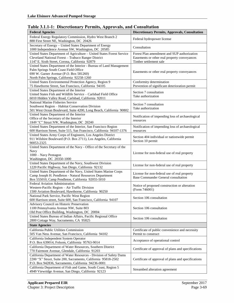
3.1.1.4 Discretionary Permits, Approvals, and Consultation Requirements
In addition to those agencies identified in Section 3.1.1.3 (California Environmental Quality Act)
and Attachment 7 (Environmental Impact Assessment Summary Form) herein, there may exist
other federal, State, and local agencies from whom permits and/or approvals will be required for
the effectuation of the Project. Presented in Table 3.3.1-1 (Discretionary Permits, Approvals,
and Consultation)22
is a list of agencies and tribal governments that may be required to take one
or more discretionary actions with regards to LEAPS and/or the TE/VS Interconnect. An
agency’s inclusion therein does not elevate that agency to Responsible Agency status if it is
subsequently determined that no discretionary permits or approvals are required for the approval,
construction, operation, and/or maintenance of the Project. The sequence in which those
agencies are presented does not imply any prioritization or imply any particular status or order.
If licensed by FERC, the FPA, the EPAct 2005, and/or other federal statutes, including the
Commerce and Supremacy Clauses of the United States Constitution, may preempt the need or
obligation for the Applicant to obtain, prepare, process, and receive some or all of the
entitlements, permits, and approvals identified Table 3.1.1-1 (Discretionary Permits, Approvals,
and Consultation) or otherwise required from State and local agencies. For example, the FPA
preempts State law that would otherwise apply to the federal hydropower project, except where
the FPA explicitly reserves State authority over a specific issue. Those exemptions include, but
may not be limited to, Section 401(a)(1) of the Federal Clean Water Act (CWA) which specifies
that FERC may not issue a license for a hydropower project unless the state water quality
certifying agency has issued a water quality certification or has waived certification. Section 401
(d) of the CWA (33 U.S.C. 1341 [d]) provides that state certification shall become a condition of
any federal license that is issued.
In accordance therewith, the Project shall conform to the applicable standards contained in the
following permits: (1) SWRCB’s “National Pollutant Discharge Elimination System General
Permit for Storm Water Discharges Associated with Construction Activities, Order 99-08-DWQ,
NPDES No. CAS000001” (General Construction Permit)23
; (2) SARWQCB’s “Waste Discharge
Requirements for the Riverside County Flood Control and Water Conservation District, the
County of Riverside, and the Incorporated Cities of Riverside County within the Santa Ana
Region Areawide Urban Runoff, Order No. R8-2002-0011, NPDES No. CAS 618033”
(Riverside County NPDES Permit)24
; (3) SDRWQCB’s “Waste Discharge Requirements for
22
/ Independent of any further CEQA documentation, certain federal entitlements may be authorized under the provisions of
NEPA and based, in whole or in part, on the information contained in FERC’s and the Forest Service’s “Final Environmental
Impact Statement for Hydropower License- Lake Elsinore Advanced Pumped Storage Project, FERC Project No. 11858,
FERC/EIS-019113” (FERC/USFS, January 2007). 23
/ State Water Resource Control Board, National Pollutant Discharge Elimination System General Permit for Storm Water
Discharges Associated with Construction Activities, Order 99-08-DWQ, NPDES No. CAS000001, August 19, 1999. 24
/ California Regional Water Quality Control Board, Santa Ana Region, Waste Discharge Requirements for the Riverside
County Flood Control and Water Conservation District, the County of Riverside, and the Incorporated Cities of Riverside

Lake Elsinore Advanced Pumped Storage
September 2017 Applicant Prepared EIR
Page 3-68 Chapter 3: Project Description
Discharges of Urban Runoff from the Municipal Separate Storm Sewer System (MS4s) Draining
the Watersheds of the County of San Diego, the Incorporated Cities of San Diego County, the
San Diego Unified Port District, and the San Diego County Regional Airport Authority, Order
No. R9-2007-0001, NPDES Permit No. CAS0108758” (San Diego County NPDES Permit)25
;
and (4) SDRWQCB’s “General Waste Discharge Requirements for Discharges of Hydrostatic
Test Water and Potable Water to Surface Waters and Storm Drains or other Conveyance
Systems, San Diego Region, Order No. R9-2002-0020, NPDES No. CAG679001.”26
Pursuant to Section 27 of the FPA (16 U.S.C. 821), “nothing contained herein shall be construed
as affecting or intending to affect or in any way to interfere with the laws of the respective states
relating to the control, appropriation, use, or distribution of water used in irrigation or for
municipal or other uses, or any vested right acquired therein.”
In California, the SWRCB is responsible for the issuance of water quality certification and
waivers (Section 13160, CWC) and for the administration of surface water rights (Sections
10005976, CWC). A water rights permit is not required for the use of purchased water,
groundwater, or reclaimed water. In addition to natural runoff from the San Jacinto River and
Lake Elsinore watersheds, waters discharged to Lake Elsinore by a number of parties for the
purpose of stabilize water levels in Lake Elsinore are from water purchases, groundwater wells,
and the authorized discharge of reclaimed waters. As a result, no known water rights issues are
associated with the filing of or the extraction of water from Lake Elsinore (afterbay) for the
operation of LEAPS, including the filing and operation of the proposed Decker Canyon
Reservoir (forebay).
In addition to those public agencies and discretionary actions listed herein, during the
environmental review process, other agencies and/or other permits and approval may be
identified. Conversely, the Commission and/or the Applicant may subsequently determine that
no discretionary actions are required from one or more of the listed agencies. The identification
(or lack of identification) of an agency herein does not alter the status of that agency, create a
discretionary action when one does not now exist, eliminate the need for any permits or
approvals which may be required for the Project’s effectuation, or prevent any State or local
agency from utilizing the Commission’s environmental documentation as the CEQA based for
any requisite discretionary action.
///
///
County within the Santa Ana Region Areawide Urban Runoff, Order No. R8-2002-0011, NPDES No. CAS 618033, October
25, 2002. 25
/ California Regional Water Quality Control Board, Santa Diego Region, Waste Discharge Requirements for Discharges of
Urban Runoff from the Municipal Separate Stonn Sewer System (MS4s) Draining the Watersheds of the County of San
Diego, the Incorporated Cities of San Diego County, the San Diego Unified Port District, and the San Diego County Regional
Airport Authority, Order No. R9-2007-0001, NPDES Permit No. CAS0108758, January 24, 2007. 26
/ California Regional Water Quality Control Board, San Diego Region, General Waste Discharge Requirements for Discharges
of Hydrostatic Test Water and Potable Water to Surface Waters and Storm Drains or other Conveyance Systems, San Diego
Region, Order No. R9-2002-0020, NPDES No. CAG679001, August 14, 2002.
Lake Elsinore Advanced Pumped Storage
Applicant Prepared EIR September 2017
Chapter 3: Project Description Page 3-69
Table 3.1.1-1: Discretionary Permits, Approvals, and Consultation Federal Agencies Discretionary Permits, Approvals, Consultation
Federal Energy Regulatory Commission, Hydro West Branch 2
888 First Street NE, Washington, DC 20426 Federal hydropower license
Secretary of Energy – United States Department of Energy
1000 Independence Avenue SW, Washington, DC 20585 Consultation
United States Department of Agriculture – United States Forest Service
Cleveland National Forest – Trabuco Ranger District
1147 E. Sixth Street, Corona, California 92879
Forest Plan amendment and SUP authorization
Easements or other real property conveyances
Timber settlement sale
United States Department of the Interior - Bureau of Land Management
Palm Springs South Coast Field Office
690 W. Garner Avenue (P.O. Box 581260)
North Palm Springs, California 92258-1260
Easements or other real property conveyances
United States Environmental Protection Agency, Region 9
75 Hawthorne Street, San Francisco, California 94105
Conformity determination
Prevention of significant deterioration permit
United States Department of the Interior
United States Fish and Wildlife Service – Carlsbad Field Office
6010 Hidden Valley Road, Carlsbad, California 92011
Section 7 consultation
Take authorization
National Marine Fisheries Service
Southwest Region – Habitat Conservation Division
501 West Ocean Boulevard, Suite 4200, Long Beach, California 90802
Section 7 consultation
Take authorization
United States Department of the Interior
Office of the Secretary of the Interior
1849 “C” Street NW, Washington, DC 20240
Notification of impending loss of archaeological
resources
United States Department of the Interior, San Francisco Region
600 Harrison Street, Suite 515, San Francisco, California 94107-1376
Notification of impending loss of archaeological
resources
United States Army Corps of Engineers, Los Angeles District
911 Wilshire Boulevard (P.O. Box 2711), Los Angeles, California
90053-2325
Section 404 individual or nationwide permit
Section 10 permit
United States Department of the Navy - Office of the Secretary of the
Navy
1000 – Navy Pentagon
Washington, DC 20350-1000
License for non-federal use of real property
United States Department of the Navy, Southwest Division
1220 Pacific Highway, San Diego, California 92132 License for non-federal use of real property
United States Department of the Navy, United States Marine Corps
Camp Joseph H. Pendleton - Natural Resources Department
Box 555010, Camp Pendleton, California 92055-5010
License for non-federal use of real property
Base Commander General consultation
Federal Aviation Administration
Western-Pacific Region – Air Traffic Division
1500 Aviation Boulevard, Hawthorne, California 90250
Notice of proposed construction or alteration
(Form 746001)
National Park Service, Pacific West Region
600 Harrison street, Suite 600, San Francisco, California 94107 Section 106 consultation
Advisory Council on Historic Preservation
1100 Pennsylvania Avenue NW, Suite 803
Old Post Office Building, Washington, DC 20004
Section 106 consultation
United States Bureau of Indian Affairs, Pacific Regional Office
2800 Cottage Way, Sacramento, CA 95825 Section 106 consultation
State Agencies
California Public Utilities Commission
505 Van Ness Avenue, San Francisco, California 94102
Certificate of public convenience and necessity
Permit to construct
California Independent System Operator
P.O. Box 639014, Folsom, California 95763-9014 Acceptance of operational control
California Department of Water Resources, Southern District
770 Fairmont Avenue, Glendale, California 91203 Certificate of approval of plans and specifications
California Department of Water Resources - Division of Safety Dams
2200 “X” Street, Suite 200, Sacramento, California 95818-2502
P.O. Box 942836, Sacramento, California 94236-0001
Certificate of approval of plans and specifications
California Department of Fish and Game, South Coast, Region 5
4949 Viewridge Avenue, San Diego, California 92123 Streambed alteration agreement

Lake Elsinore Advanced Pumped Storage
September 2017 Applicant Prepared EIR
Page 3-70 Chapter 3: Project Description
State Agencies (Continued) Discretionary Permits, Approvals, Consultation
California Fish and Game Commission
1416 9th Street, Room 1320, Sacramento, California 95814 Application for fishway
California Department of Parks and Recreation - Office of Historic
Preservation
1416 9th Street, Room 1442-7, Sacramento, California 95814
P.O. Box 942896, Sacramento, California 94296-0001
Section 106 consultation
State Water Resources Control Board, Division of Water Rights
1001 “I” Street (P.O. Box 2000), Sacramento, California 94814
Statement of water diversion and use
Permit to appropriate water
Section 401 water quality certification
California Regional Water Quality Control Board, Santa Ana Region
(8)
3737 Main Street, Suite 500, Riverside, California 92501
Section 401 water quality certification and NPDES
permit
Strom water pollution prevention plan
California Regional Water Quality Control Board, San Diego Region
(9)
9174 Sky Park Court, Suite 100, San Diego, California 92123-4340
Section 401 water quality certification and NPDES
permits
Storm water pollution prevention plan
California Department of Transportation, District 8
464 W. Fourth Street, 6th Floor, San Bernardino, California 92401-
1400
Highway crossing permit and right-of-way
easements
Encroachment permit
South Coast Air Quality Management District
21865 E. Copley Drive, Diamond Bar, California 91765
Permit to construct
Permit to operate
San Diego County Air Pollution Control District
9150 Chesapeake Drive, San Diego, California 92123-1096
Permit to construct
Permit to operate
California Department of Industrial Relations
Division of Occupational Safety and Health
1515 Clay Street, Suite 1901, Oakland, California 94612
Construction activities permit
Tower cranes permit
Helicopter operations permit and tunneling permit
California State Lands Commission
100 Howe Avenue, Suite 100 South, Sacramento, California 95825-
8202
Lease or permit for use of non-tidal navigable
waters
California Coastal Commission, San Diego Coast District Office
7575 Metropolitan Drive, Suite 103, San Diego, California 92108-
4402
Consultation
California State Universities – San Diego State University
Field Stations Program – College of Sciences
5500 Campanile Drive, San Diego, California 92182-4614
Encroachment permit
Local Agencies
County of Riverside – Planning Department
4080 Lemon Street (P.O. Box 1409), Riverside, California 92502-
01409
MSHCP permit
General plan amendment, zone change, CUP
Tentative map, easement, or lot line adjustment
County of Riverside – Flood Control and Water Conservation District
1995 Market Street, Riverside, California 92501
Development review and site plan review
Flood hazard report and conditions
Cooperative agreement and encroachment permit
Riverside County Health – Department Environmental Health Services
4065 County Circle Drive, Room 123, Riverside, California 92503 Drilling permit (water well)
County of Orange – Planning Department
300 North Flower Street, Room 122, Santa Ana, California 92705 Tentative map, easement, or lot line adjustment
County of San Diego – Planning and Land Use Department
5201 Ruffin Road, Suite B, San Diego, California 92123 Tentative map, easement, or lot line adjustment
County of San Diego – Department of Environmental Health
Land and Water Quality Division
P.O. Box 129261, San Diego, California 91221-9261
Drilling permit (water well)
General Plan amendment and zone change
Shoreline buffer zone
City of San Diego - City Planning & Community Investment
Community Planning & Urban Form Divisions
202 C Street, MS 5A, San Diego, California 92101
Design review
City of Escondido - Community Development Department, Planning
Division
201 North Broadway, Escondido, California 92025
Tentative map, easement, or lot line adjustment
Design review
City of Grand Terrace - Community and Economic Development
Department
22795 Barton Road, Grand Terrace, California 92313
Design review

Lake Elsinore Advanced Pumped Storage
Applicant Prepared EIR September 2017
Chapter 3: Project Description Page 3-71
Local Agencies (Continued) Discretionary Permits, Approvals, Consultation
City of Rancho Cucamonga – Planning Department
10500 Civic Center Drive, Rancho Cucamonga, California 91730 Design review
City of Redlands – Community Development Department
35 Cajon Street, Redlands, California 92373 Design review
City of Ontario – Planning Department
303 East “B” Street, Ontario, California 91764 Design review
Metropolitan Water District of Southern California
700 North Alameda Street, Los Angeles, California 90012-2944
P.O. Box 54153, Los Angeles, California 90054-0153
Encroachment permit
Water purchase agreement
Western Riverside County Regional Conservation Agency
4080 Lemon Street, Twelfth Floor, Riverside, California 92501
Encroachment permit
Joint project review
Lake Elsinore Unified School District
545 Chaney Street, Lake Elsinore, California 92530 School or facilities agreement
Tribal Governances Discretionary Permits, Approvals, Consultation
Agua Caliente Band of Cahuilla Indians
600 E. Tahquitz Canyon, Palm Springs, California 92262 Section 106 consultation
Juaneno Band of Mission Indians – Acjachemen Nation
31411-A La Matanza Street, San Juan Capistrano, California 92675 Section 106 consultation
La Jolla Band of Mission Indians
22000 Highway 76, Pauma Valley, California 92061 Section 106 consultation
Pala Band of Mission Indians
35008 Pala Temecula Road, PMB 50, Pala, California 92059 Section 106 consultation
Pauma/Yuima Band of Mission Indians
P.O. Box 369, Pauma Valley, California 92061 Section 106 consultation
Pechanga Band of Mission Indians
P.O. Box 1477, Temecula, California 92593 Section 106 consultation
Rincon Band of Mission Indians
P.O. Box 68, Valley Center, California 92082 Section 106 consultation
Gabrieleno/Tongva Tribal Council of San Gabriel
P.O. Box 693, San Gabriel, California 91776 Section 106 consultation
Juaneno Band of Mission Indians
31742 Via Belardes, San Juan Capistrano, California 92675 Section 106 consultation
Juaneno Band of Mission Indians
27001 La Paz Road, Suite 330, Mission Viejo, California 92691 Section 106 consultation
San Luis Rey Band of Mission Indians
1042 Highland Drive, Vista, California 92083 Section 106 consultation
Source: The Nevada Hydro Company, Inc.
3.1.2 Existing Agreements
The following agreements are now in place and may affect the Project, have potential bearing on
the Project’s design, and/or influence the Project’s operations.
• Five-Cities Agreement.27
In 1994, the EVMWD executed a letter agreement (Five-
Cities Agreement) with the Cities of Anaheim, Azusa, Banning, Colton, and Riverside
(Cities) which may remain applicable to LEAPS. Under the terms of that agreement and
subject to the provisions therein, the Cities agreed to surrender the Cities’ then existing
federal preliminary permit under now-expired FERC PN11261 and support the issuance
of any permit, license, or authorization relative to the development of the “Lake Elsinore
27
/ Elsinore Valley Municipal Water District and the Cities of Anaheim, Azusa, Banning, Colton, and Riverside, Letter
Agreement among the Elsinore Valley Municipal Water District and the Cities of Anaheim, Azusa, Banning, Colton and
Riverside, California, August 17, 1994.

Lake Elsinore Advanced Pumped Storage
September 2017 Applicant Prepared EIR
Page 3-72 Chapter 3: Project Description
Pumped Storage Project,” while retaining the right to intervene (either jointly or
individually) in any proceedings involving the issuance of a permit, license, or other
authorization necessary or relevant to the development thereof. In exchange, the
EVMWD’s agrees to: (1) “Sell to the Cities, collectively or individually, up to a total of
75 megawatts (MW) of capacity and provide associated peaking energy of at least 6
megawatt-hours of MW each week from the project under terms and at price to be
negotiated and set forth” in a “30 year power sales agreement”; and (2) “Design the
project in such a way so that it is capable of providing, subject to prudent utility practices
and the terms of EVMWD’s regulatory authorization, such capacity and associated
peaking energy.” In the event that the EVMWD and the Cities are unable to agree upon
the terms of such power sales agreement (PSA), the EVMWD agreed to give the Cities a
one time right-of-first refusal to purchase up to 75 MW of capacity from the “LEAPS
facility” under the same terms and conditions agreed to for the sale from that project to a
third party.
• Lake Elsinore Comprehensive Water Management Agreement.28
On March 1, 2003,
the EVMWD, the City of Lake Elsinore (City), and the Lake Elsinore Redevelopment
Agency executed a “Lake Elsinore Comprehensive Water Management Agreement” in
order to: (1) clarify and restate the rights and obligations of the EVMWD and the City
with respect to the use of San Jacinto River flows for domestic, municipal, and industrial
uses in the EVMWD’s service area and for recreational use of Lake Elsinore, and fish
and wildlife enhancement; and (2) provide the term and framework by which the
EVMWD and the City will work together to provide supplemental water supplies, when
available and within the resources of the community, to maintain the elevation of Lake
Elsinore, to the extent feasible, at a minimum level of 1240 feet above msl.
That agreement included the following provisions with regards to LEAPS: “The District
has explored and continues to explore the possible approval and implementation of the
Lake Elsinore Advanced Pumped Storage facility. This project envisions drawing water
from Lake Elsinore as part of the project. The City agrees to cooperate with the District
in analyzing and to discuss plans regarding the use of water stored in the lake to
implement the LEAPS facility. In no event shall the LEAPS facility result in the
permanent diversion or increased evaporation of water already in the lake without
providing for the introduction of suitable replacement water at the District’s or the project
proponent’s sole cost. Moreover, the LEAPS facility, if implemented, shall not interfere
with the recreational use of Lake Elsinore, adversely impact fish and wildlife
enhancement in and around Lake Elsinore, or in any way frustrate the ability of the
parties, or either of them, to accomplish the objectives and purpose of this agreement.”
As further noted therein: “Two prior agreements also affect Lake Elsinore. The first is
the so-called Tilley Agreement, dated October 29, 1927, between the Temescal Water
Company and a number of parties, including the City of Lake Elsinore. The Elsinore
Valley Municipal Water District is a successor-in-interest to the rights and obligations of
the Temescal Water Company under the Tilley Agreement. The second agreement is the 28
/ City of Lake Elsinore, Lake Elsinore Redevelopment Agency, and Elsinore Valley Municipal Water District, Lake Elsinore
Comprehensive Water Management Agreement, March 1, 2003.

Lake Elsinore Advanced Pumped Storage
Applicant Prepared EIR September 2017
Chapter 3: Project Description Page 3-73
`Agreement to Fill and Operate Lake Elsinore,’ dated December 19, 1991, between the
City of Lake Elsinore, the Community Redevelopment Agency of Lake Elsinore, and the
Elsinore Valley Municipal Water District.” The parties stipulated that the “Lake Elsinore
Comprehensive Water Management Agreement” “is intended to, and does, supersede and
replace the obligations of the Parties under both the Tilley Agreement and the Fill &
Operate Agreement. Upon execution of this Agreement, the Tilley Agreement and the
Fill & Operate Agreement shall have no further force or effect.”29
• Local Cooperation Agreement. Between 1989 and 1995, in order to prevent the lake
from drying out and to mitigate the flooding problem, the United States Bureau of
Reclamation (BOR), the USACE, and the Riverside County Flood Control and Water
Conservation District developed the “Lake Elsinore Management Project” (LEMP).
Three major projects were subsequently implemented through the LEMP: (1)
construction of a levee to separate the main lake (Main Basin) from the back basin (Back
Basin) to reduce the lake surface area and, thereby, prevent significant evaporative losses;
(2) realignment of the lake inlet channel to bring natural runoff from the San Jacinto
River; and (3) lowering of the lake outlet channel to increase outflow to Temescal Creek
when the lake level exceeds an elevation of 1255 feet above msl. As stipulated in the
March 1992 “Local Cooperation Agreement,” the LEMP called for the introduction of
supplemental makeup water to maintain lake levels at an adopted operation range of 1240
to 1249 feet above msl.30
Under the provisions of a stipulated judgment (City of Lake Elsinore v. Elsinore Valley
Municipal Water District),31
as indicated in the EVMWD’s “Urban Water Management
Plan, Final Report,” the “EVMWD must release water into Lake Elsinore when the water
surface elevation is less than 1,240 feet above msl. Lake replenishment is only necessary
in normal and dry years, as there is sufficient surface runoff in wet years to maintain
adequate lake levels.”32
3.2 Project Location
3.2.1 Geographic Location
29
/ Until the late 1920’s, rainwater runoff flowed freely down the San Jacinto River watershed and into Lake Elsinore. In 1928,
Railroad Canyon Dam was built, cutting off the flow of water into Lake Elsinore and creating Canyon Lake (Railroad
Canyon Reservoir). Before the dam’s construction, George Tilley filed a lawsuit in 1927, to stop the Railroad Canyon Dam
project. The terms of the resulting October 29, 1927 settlement, known as the “Tilley Agreement,” stipulated that Canyon
Lake was entitled to a maximum of 2,000 acre feet (AF) of watershed runoff. Lake Elsinore would receive any water over
that amount. After years of dispute over that agreement, the water district and the City of Lake Elsinore signed the
“Agreement to Fill & Operate Lake Elsinore” on December 19, 1991. 30
/ California Regional Water Quality Control Board, Santa Ana Region, Public Workshop: Proposed Basin Plan Amendment
Incorporation of Total Maximum Daily Loads (TMDLs) for Nutrients for Lake Elsinore and Canyon Lake, Item 14, June 4,
2004, p. 7. 31
/ Riverside County Superior Court, Stipulated Judgment - City of Lake Elsinore v. Elsinore Valley Municipal Water District,
Case No. 359671, March 1, 2003. 32
/ Elsinore Valley Municipal Water District (MWH), Urban Water Management Plan, Final Report, December 2005, p. 3-32.

Lake Elsinore Advanced Pumped Storage
September 2017 Applicant Prepared EIR
Page 3-74 Chapter 3: Project Description
The Project is comprised of two discreet component parts: the TE/VS Interconnect and LEAPS.
Project-related facilities include a new approximately 32 mile long 500 kV transmission line and
improvements and upgrades to an approximately 52 mile long segment of SDG&E’s existing
transmission system (including an approximately 8 mile long segment along which the existing
69 kV circuit will be rebuilt), construction of new and improvements to existing substations and
switchyards. The Project is located on lands within the Counties of Riverside, Orange, and San
Diego and includes network upgrades and/or other facilities located in the Counties of Riverside,
Orange, San Diego, and San Bernardino, in the Cities of Lake Elsinore, Escondido, Grand
Terrace, Ontario, Rancho Cucamonga, Redlands, and San Diego, and in a number of federal
reserves, including the Cleveland National Forest – Trabuco Ranger District and on the right-of-
way (ROW) for the existing TE line.
The section of existing 69 kV circuit (TL6932), currently installed on one side of the existing
double-circuit Talega-Escondido 230 kV transmission line structures and generally located
between State Route 76 and Old Castle Road (County of San Diego), would be rebuilt on new 69
kV steel structures located within the existing 300 foot wide Talega-Escondido right-of-way.33
The proposed 69 kV line would pass entirely through private lands under the jurisdiction of the
County of San Diego.34
It is the Applicant’s understanding that all network improvements and upgrades to the SDG&E’s
transmission system would occur either within the “fence line” of or affixed to existing facilities.
A portion of the FERC identified route for the TE/VS Interconnect is located on public lands
located near the Lake Mathews-Estelle Mountain Reserve, jointly or singularly owned by the
Riverside County Habitat Conservation Agency (RCHCA), the Metropolitan Water District of
Southern California (MWD), the BLM, and the California Department of Fish and Game
(CDFG). In this Application, the Applicant has avoided use of this Reserve area. In addition,
segments of the TE/VS Interconnect traverse State highways, subject to the jurisdiction of the
California Department of Transportation (Caltrans). Portions of LEAPS subsurface elements
may also extend across or be located within a Caltrans-administered right-of-way.
The existing TE line passes primarily through the County of San Diego, with a small portion of
the line located in the County of Riverside. The existing transmission line is within an easement
owned by SDG&E. The majority of land within the easement is private and under the
jurisdiction of the County of San Diego. Approximately 17 miles of the easement are within and
located in proximity to the northern boundaries of Camp Pendleton. The Santa Margarita
Ecological Reserve (SMER)35
and a BLM-designated “Area of Critical Environmental
Concern”36
(ACEC) are crossed by the existing TE line ROW.
33
/ San Diego Gas & Electric Company, Valley-Rainbow Interconnect, Proponent’s Environmental Assessment, Volume 1,
March 2001, pp. S-20, S-21, and 2-3. 34
/ Ibid., p. 4-57. 35
/ The Santa Margarita Ecological Reserve is located in the southwest corner of Riverside County and northern San Diego
County. The 4,344-acre SMER is a field station of the California State Universities, administered by San Diego State
University. 36
/ As indicated in the BLM’s “South Coast Resource Management Plan and Record of Decision” (United States Department of
the Interior, Bureau of Land Management, California Desert District, Palm Springs - South Coast Resource Area,” June
Lake Elsinore Advanced Pumped Storage
Applicant Prepared EIR September 2017
Chapter 3: Project Description Page 3-75
As indicated in BLM’s “South Coast Resource Management Plan and Record of Decision,”
ACECs were authorized in Section 202(c)(3) of the Federal Land Policy and Management Act of
1976 (FLPMA, P.L. 94-579). ACECs are areas where special management attention is needed to
protect, and prevent irreparable damage to, important historic, cultural, and scenic values, fish, or
wildlife resources or other natural systems or processes; or to protect human life and safety from
natural hazards. The ACEC designation indicates that BLM recognizes that an area has
significant values, and establishes special management measures to protect these values. In
addition, designation also serves as a reminder that significant value(s) or resource(s) exist which
must be accommodated when future management actions and land use proposals are considered
in or near an ACEC.37
The BLM further notes that “the Santa Margarita Ecological Reserve
ACEC is designated with the following management prescriptions: The ACEC is a right-of-way
avoidance area and is unavailable for mineral material sales and livestock grazing.”38
Lake Elsinore lies approximately 60 miles southeast of Los Angeles and about 22 miles
southwest of the City of Riverside. Lake Elsinore is located within the corporate boundaries of
the City of Lake Elsinore and is a natural low point of the San Jacinto River and its drainage
basin. Over 90 percent of that watershed drains first into Canyon Lake (Railroad Canyon
Reservoir) and then flows into Lake Elsinore. To the south and southwest of Lake Elsinore are
the steep slopes of the Elsinore Mountains of the Santa Ana Mountain Range which form the
northernmost range of the Peninsular Ranges Province.
Excluding privately owned lands and lands owned or under the control of SDG&E and SCE,
public lands upon which Project facilities are proposed include properties under the ownership
and/or control of the following governmental entities:
• United States Department of Agriculture, United States Forest Service, including lands
within the Cleveland National Forest, Trabuco Ranger District;
• United States Department of the Interior, Bureau of Land Management, including lands
within the Santa Margarita Ecological Reserve and potentially with regards to Riverside-
San Bernardino County Management Area BLM Parcel No. 188-041 and San Diego
County Management Area BLM Parcel Nos. 216-361, 217-261, 288-031, 219-291, and
229-041;39
• California Department of Fish and Game, including lands within the Lake Mathews-
Estelle Mountain Reserve;
1994), it is the policy directive of the BLM to “[d]esignate 1,260 acres within the Santa Margarita Ecological Reserve
(including 40 acres within San Diego County) as an ACEC and RNA [Research Natural Area] for protection for sensitive
species and natural values. Acquire 300 acres for addition to the ACEC. The ACEC is unavailable for mineral material sales
and livestock grazing. The ACEC is proposed for closure to mineral leasing and entry under the 1872 mining law (as
amended). The ACEC is a right-of-way avoidance area” (p. 28). 37
/ United States Department of the Interior, Bureau of Land Management, California Desert District, Palm Springs - South
Coast Resource Area, South Coast Resource Management Plan and Record of Decision, June 1994, p. 105. 38
/ Ibid., p. 105. 39
/ Ibid., Map 2A (Parcel Locations - BLM Public Lands).

Lake Elsinore Advanced Pumped Storage
September 2017 Applicant Prepared EIR
Page 3-76 Chapter 3: Project Description
• California Department of Transportation, including lands within the rights-of-way for the
Interstate 15 (Corona) Freeway, State Route 74 (Ortega Highway), State Route 76 (Pala
Road), and State Route 78 (Ronald Packard Parkway);
• California State University, including lands within the Santa Margarita Ecological
Reserve;
• Western Riverside County Regional Conservation Agency;
• Metropolitan Water District of Southern California, including lands near the Lake
Mathews-Estelle Mountain Reserve and the San Diego Aqueduct;
• County of Riverside, including flood control facilities and the Grand Avenue, South Main
Divide Truck Trail (Killen Trail), and other public rights-of-way crossed by Project
facilities;
• County of San Diego, including public rights-of-way crossed by Project facilities;
• City of Lake Elsinore, including lands within the ordinary high water mark of Lake
Elsinore, Skylark Substation, Elsinore Substation, and the Grand Avenue, Cordyon
Street, Riverside Drive, Collier Street, and Spring Street rights-of-way; and
• City of Escondido, including public rights-of-way crossed by Project facilities.
The Talega-Escondido 230 kV and 69 kV transmission lines are located to the west of the Pala
Indian Reservation and southwest of the Pechanga Indian Reservation. Since no portion of the
Project is located on tribal lands, no tribal lands will be directly or indirectly impacted by the
Project.
3.2.2 General Description of Land Uses within the Proposed Project
Please see Chapter 4.11 for a more detailed description of land uses with the Project’s vicinity.
Detailed land use maps may be found in Chapter 4.11 as well.
3.2.2.1 Land Use Associated with the Transmission Alignment
As may be seen in Figure 3.1.1-4: Talega-Escondido/Valley-Serrano 500 kV Interconnect
Project, most of the TE/VS Interconnect alignment is located within the CNF boundary. This
alignment crosses primarily CNF lands, with private land crossings at the northern portion of the
route. The following describes land uses along the proposed alignment proceeding from north to
south.
At the northern end of the alignment, at MP 2.0, located near the proposed Lake Switchyard is
Lee (Corona) Lake. Lee (Corona) Lake is owned by the EVMWD and is an approximately 27
acre man-made reservoir located approximately 10 miles north of Lake Elsinore along Temescal
Wash. Excluding the area upstream of Lake Elsinore, the Temescal Wash watershed that drains
to Lee (Corona) Lake covers approximately 33,000 acres. Water from this impoundment is
pumped out for agricultural and industrial (gravel wash) uses. The lake serves as a fishing area
for introduced species (e.g., catfish, bass, bluegill, tilapia, and trout) and includes both boat
rentals and picnic areas under a concession agreement. No camping facilities are available.

Lake Elsinore Advanced Pumped Storage
Applicant Prepared EIR September 2017
Chapter 3: Project Description Page 3-77
Discharges to the reach of Temescal Wash downstream of Lee (Corona) Lake historically only
occur during wet weather.
The Lake Switchyard, at MP 2.0, fronts along Temescal Canyon Road. For a portion of its
length, Temescal Canyon Road parallels the I-15 (Corona) Freeway and serves as the primary
access way to industrial and rural residential uses located along that road. Temescal Canyon
Road also provides direct access to Horsethief Ranch (a master planned community) and, via
Indian Truck Trail, to Sycamore Creek (a master planned community).
The Lake Mathews-Estelle Mountain Reserve is located to the north and west of the proposed
switchyard. As described by the United States Fish and Wildlife Service: “The Lake
Mathews/Estelle Mountain Reserve is located east of Interstate 15 near Lake Mathews in the
northwestern Riverside County. The Lake Mathews Multiple Species Habitat Conservation
Plan/Natural Communities Conservation Plan established a 2,544 acre mitigation bank adjacent
to the existing 2,565 acre State Ecological Reserve. RCHCA [Riverside County Habitat
Conservation Agency] owns about 6,296 acres, and BLM owns about 1,032 acres within this
habitat block. These lands all contributed to the establishment of a reserve for multiple species
use in western Riverside County encompassing over 12,000 acres. The combined reserve is
composed of the multiple species reserve that consists of the State Ecological Reserve and the
Lake Mathews HCP [Habitat Conservation Plan] Mitigation Bank, Lake Mathews/Estelle
Mountain Core Stephens’ kangaroo rat Reserve, the Estelle Mountain Ecological reserve owned
by the [United States] Department [of the Interior], and land owned by the BLM located within
the RCHCA’s proposed Stephens’ kangaroo rat Core Reserve.” North of the Lake Switchyard, a
segment of the TE/VS Interconnect is located within the “Stephens’ kangaroo rat Core
Reserve.”40
Along Temescal Canyon Road, a number of industrial uses exist in the general vicinity of the
Lake Switchyard. As the line travels southward toward the National Forest, east of Indian Truck
Trail, the transmission line crosses the I-15 (Corona) Freeway and De Palma Road at MP 2.4, in
the vicinity of Sycamore Creek (a master planned community) and the Glen Eden Sun Club
(25999 Glen Eden Road. Corona). The Glen Eden Sun Club is a private adult facility which
includes 37 full-service hookups and 28 electrical and water service hook-ups for mobile homes
and numerous tent sites. Riverside County’s Sycamore Creek Fire Station No. 64 (25310
Campbell Ranch Road, Corona) is located about one mile from the proposed switchyard. Single-
family detached residential dwelling and neighborhood-serving commercial uses are developing
within the Sycamore Creek area.
South of the Glen Eden Sun Club, the transmission line enters the National Forest at MP 2.7. A
substantial portion of the 500 kV transmission line, including both the overhead and underground
segments extending from the general area of the Glen Eden Sun Club to Camp Pendleton,
traverses the TRD. At times, the transmission line parallels North Main Divide Truck Trail
(8S04), South Main Divide Truck Trail (Killen Trail) (6S07), Wildomar Road (7S01), an
unnamed dirt road located to the south of the Tenaja Ranger Station (8S01), and the eastern and
40
/ United States Department of the Interior, Fish and Wildlife Service, Memorandum: Intra-Service Formal Section 7
Consultation/Conference for Issuance of an Endangered Species Act Section 10(a)(1)(B) Permit (TE-088609-0) for the
Western Riverside County Multiple Species Habitat Conservation Plan, Riverside County, California, June 22, 2004, p. 60.

Lake Elsinore Advanced Pumped Storage
September 2017 Applicant Prepared EIR
Page 3-78 Chapter 3: Project Description
southern National Forest boundary. All three transition stations (Northern GIL Transition
Station, Southern GIL Transition Station, and Middle GIL Transition Station) are located on
NFS lands.
Within the National Forest, the transmission line skirts a number of rural residential properties
(in-holdings), including the residential enclave of Rancho Capistrano (Morrell Potrero) and El
Cariso Village. El Cariso Village is a rural community that includes single-family homes,
highway commercial uses (e.g., Hells Kitchen, Kristi’s Korner, Ortega Country Cottage Candy
Store, The Lookout), the Forest Service’s El Cariso Fire Station (32353 Ortega Highway, Lake
Elsinore), and an adjacent Forest Service operated visitor center (El Cariso Ranger Station). In
addition, the transmission line passes in close proximity to a number of existing campgrounds
and trails, including the Morgan Trailhead, Tenaja Trailhead, Horsethief Trail, El Cariso Nature
Trail, El Cariso Campground, Fire Fighters Memorial Picnic Area, Wildomar Campground, and
the Wildomar Off-Highway Vehicle (OHV) area. At no point does the transmission line
encroach within the San Mateo Canyon Wilderness, the Agua Tibia Wilderness Area or the
Santa Rosa Plateau Ecological Reserve. Along the eastern border of the National Forest, the
transmission line abuts the unincorporated communities of La Cresta, Tenaja, and De Luz.
At the base of the Elsinore Mountains is the unincorporated area of Lakeland Village (Cleveland
Ridge). Existing land uses in the vicinity of the proposed Santa Rosa Substation include
undeveloped open space areas, as well as single-family homes (e.g., 16336 Union Avenue, Lake
Elsinore), multi-family complexes (e.g., Santa Rosa Mountain Villas [33071-33091 Santa Rosa,
Lake Elsinore] and Copper Canyon Villas [16341-16347 Grand Avenue, Lake Elsinore]), and
Butterfield Elementary Visual and Performing Arts Magnet School and the Ortega Trails Youth
Center (16275 Grand Avenue, Lake Elsinore). Riverside County’s Lakeland Village Fire Station
No. 11 (33020 Maiden Lane, Lake Elsinore) is located about one mile east of the proposed Santa
Rosa Substation site.
The proposed transmission line passes north and east of Elsinore Peak. The Forest Service has
granted a number of special use permits to operate telecommunication facilities (Santiago Peak
Communications Site) and electric tower sites at Elsinore Peak. Permit holders include
Riverside County, Spectrasite Communications, Inc., Comcast Corporation, and Elsinore Peak
Facility Corporation.
South of Elsinore Peak and northeast of Camp Pendleton, the transmission line passes near the
Forest Service’s Tenaja Ranger Station (Tenaja Guard Station) and will traverse existing grazing
allotments located within the TRD, including the Tenaja and Miller Mountain Allotments.
Additionally, the transmission line will pass in close proximity to an existing private airstrip
(Sky Ranch) located on private lands within the Congressional boundaries of the National Forest.
To the west of Sky Ranch is USFWS-designated critical habitat for the thread-leaved brodaea
(Subunit 5b). As indicated in the Federal Register: “This subunit consists of 249 acres (101
hectare) of federally managed land (Cleveland National Forest) in northeastern San Diego
County” (70 FR 73841, December 13, 2005).
The proposed Case Springs Substation is located adjacent to the TE line ROW, within National
Forest land at MP 31.5.

Lake Elsinore Advanced Pumped Storage
Applicant Prepared EIR September 2017
Chapter 3: Project Description Page 3-79
3.2.2.2 Land Use Associated with Pumped Storage Facility
Many of the LEAPS facilities are located in the CNF. The CNF is the southernmost of the
national forests in California. Its approximately 567,000 acres are located in Orange, Riverside,
and San Diego Counties, at elevations ranging from 460 to 6271 feet above msl. The CNF is
comprised of three non-contiguous ranger districts (Descanso, Palomar, and Trabuco). LEAPS
facilities are located in the TRD, may traverse privately-owned lands within the Congressional
boundaries of the CNF, and are located on public and privately-owned lands north of the TRD.
Land use generally within the vicinity of LEAPS was shown by FERC in the FEIS and is
reproduced as Figure 3.2.2-1: Land Use Near Pumped Storage Facilities.
The proposed Decker Canyon Reservoir and its associated construction lay-down areas are
located along South Main Divide Truck Trail (Killen Trail) (6S07). Those sites are located near
two USFS-permitted hang gliding launch areas (i.e., “Edward” and “E” launch sites), as
maintained by the Elsinore Hang Gliding Association (EHGA). Additionally, those sites are
located in proximity to the Morgan Trailhead which descends from South Main Divide Truck
Trail into Morrell Canyon and the San Mateo Canyon Wilderness.
To the east of the proposed upper reservoir sites is Elsinore Peak, where the Forest Service has
issued a number of special use permits for operation of telecommunications facilities (currently
comprising of six towers and five building). Northwest of the proposed upper reservoir sites,
nearby land uses include the Forest Service’s El Cariso Fire Station (32353 Ortega Highway,
Lake Elsinore), an adjacent visitor information facility (El Cariso Ranger Station), and the
USFS-operated El Cariso Campground.
The LEAPS Powerhouse will be located adjacent to the Santa Rosa Substation. Land uses in
proximity to the LEAPS Powerhouse are, therefore, as generally described for the Santa Rosa
Substation.
LEAPS also includes the construction of tailrace tunnels and inlet/outlet structures extending
northward from the LEAPS Powerhouse into Lake Elsinore. Those facilities will cross beneath
Grand Avenue and traverse property between Grand Avenue and the lakeshore containing one or
more single-family residences. No boat docks exist in the area of the proposed inlet/outlet
structures.
Lake Elsinore, which serves as the lower reservoir (afterbay), is the largest natural lake in
southern California and is considered hypereutrophic with characteristic high nutrient (nitrogen
and phosphorous) concentrations in the sediment and water column, algae blooms, low water
clarity, and large variations in dissolved oxygen (DO) levels. Between 1991 to 1998, fish kills
were recorded for every year, except one (1994). Lake Elsinore is a shallow, natural sink that
occupies the lowest portion of the Elsinore Valley. Lake Elsinore is a “terminal” water body
(one with no outlet under non-flood conditions) because it has no natural outflow until its
elevation exceeds 1255 feet above msl. A high evaporation rate (long-term average of 14,500
acre feet per year) contributes to low lake levels during periods with limited runoff. This
translates to a lake level reduction of approximately 4.7 feet per year (from elevation 1247 feet

Lake Elsinore Advanced Pumped Storage
September 2017 Applicant Prepared EIR
Page 3-80 Chapter 3: Project Description
above msl) from evaporation alone.41
Overflow conditions are rare and occur only when the lake
elevation exceeds that of the Wasson Sill, a natural topographic divide on Temescal Wash in the
City of Lake Elsinore.
Figure 3.2.2-1: Land Use Near Pumped Storage Facilities Source: Federal Energy Regulatory Commission
3.3 Existing Electrical System
3.3.1 Introduction
The Project sits between the SCE, at MP 0.0 and SDG&E service areas at MP 31.2, and connects
the two systems for the first time at a 500 kV level. These two existing systems are described in
the following sections.
From a national perspective, the Project resides in the Southwestern United States transmission
system. Figure 3.3.1-1: Southwestern U.S. Transmission System Schematic depicts graphically
the relevant portion of the national system with the addition of the Proposed Project. Figure
3.3.1-2: Southern California System Schematic, graphically depicts the southern California
system with the addition of the proposed Project.
41
/ Op. Cit., Draft Program Environmental Impact Report - Lake Elsinore Stabilization and Enhancement Project, SCH No.
2001071042, March 2005, p. 2-2.

Lake Elsinore Advanced Pumped Storage
Applicant Prepared EIR September 2017
Chapter 3: Project Description Page 3-81
In the CAISO Report titled, “2013 Local Capacity Technical Analysis, Addendum to the Final
Report and Study Results, Absence of San Onofre Nuclear Generating Station (SONGS)”, page
12 shows the CAISO’s understanding that SDG&E is 1,241 MW deficient of its Local Capacity
requirement in 2013. It also shows that SCE is deficient 83 MW if it has dispatchable control of
810 MW of QF capacity, 230 MW of wind capacity, and 1,166 MW of municipal generating
capacity. This puts the deficiency in the SCE area in the range of from 83 MW to 2,289 MW.
Since wind generation is not usually considered a “dispatchable” resource, the low end of the
deficiency is likely more than 300 MW in 2013.
Figure 3.3.1-1: Southwestern U.S. Transmission System Schematic Source: The Nevada Hydro Company
SUNCREST

Lake Elsinore Advanced Pumped Storage
September 2017 Applicant Prepared EIR
Page 3-82 Chapter 3: Project Description
Figure 3.3.1-2: Southern California System Schematic Source: The Nevada Hydro Company
3.3.2 SCE System
SCE is the largest electric utility in California, providing service to over 50,000 square mile area
within central, coastal, and southern California. SCE owns all of its electrical transmission
facilities and equipment, but since the deregulation of California's electricity market, the
company owns little generation, except for its hydroelectric plants, totaling about 1,200 MW,
and its 75% share of the 2,150 MW San Onofre Nuclear Generating Station. Most of the
generation in southern California is now owned by other companies.
SCE’s power grid is linked on the north to Pacific Gas & Electric's (PG&E) system by the 500
kV circuits of Path 26 that generally follow Interstate 5 over Tejon Pass to Midway Substation.
The interconnection flow is measured at Midway Substation. PG&E's and WAPA's Path 15 for
flows between southern and central California and Path 66 for flows between northern California
and Oregon, respectively, eventually connect to BPA's grid in the Pacific Northwest. There are
several other interconnections with local and out-of-state utilities, such as Path 46 (West of
Colorado River) and Path 49 (East of Colorado River).
The SCE transmission network consists of mainly 500 kV and 230 kV transmission lines with
multiple long corridors connecting remote generation or other utilities. The system consists of
roughly 1,183 miles of 500 kV, 3,574 miles of 230 kV and 1,846 miles of 115 kV high voltage
lines with the 115 kV system providing both main grid or distribution services. The SCE
TEVS/LEAPS Schematic
Miguel
SONGS
Vincent Lugo
Mira Loma Rancho Vista
Serrano
Telega
San Luis Ray
Devers
Valley
Alberhill
TEVS
Camp Pendleton
Escondido
South of Lugo
Path 43
Path 44
WOD
LEAPS Pumped Storage
Palo Verde
SDG&E Service Area
SCE Service Area
IV

Lake Elsinore Advanced Pumped Storage
Applicant Prepared EIR September 2017
Chapter 3: Project Description Page 3-83
transmission system connects the southern California load center with major generation sources
located in Arizona, Northern California, and the Pacific Northwest. A map showing SCE’s
service territory appears as Figure 3.3.2-1: SCE Service Territory.
Figure 3.3.2-1: SCE Service Territory Source: Southern California Edison
The SCE system is experiencing a significant degree of change in its reliability of service with
the shutdown of both SONGS units, a net loss of 2,150 MW, as well as the ability to manage
transmission voltage at the southern boundary of its system. While one of the two SONGS units
may return to partial operation, the effect of the significant reduction in capability to support the
Los Angeles Basin from the south puts heavy stress on the rest of the transmission system to the
north and east. This is a current fact. In addition, by 2018 it will be necessary to take
compliance action with the Once Through Cooling Mitigation requirements. This is likely to
reduce the generation within the L.A Basin by an additional approximately 2,000 to 2,500 MW.
The loss of all or a major portion of the output from SONGS makes the ability to depend on
support of the SCE system from the south essentially very limited at best. Path 43 (North of
SONGS) no longer has relevance as presently understood and must be completely reconsidered
as to its value. This rather drastic change to the system is further compounded by the prospective
shutdown of Alamitos Station (1,950 MW) by 2018. Also, with the shutdown processes for El
Segundo and Huntington Beach SCE will see a net reduction of an additional 540 MW by 2018
and a final improvement to only a net loss of 90 MW by 2022 when the second replacement
block of generation is completed at Huntington Beach. Nevertheless, this brings the net loss of
existing non-nuclear generation in the southern part of SCE to about 2,490 MW in 2018 and
2,040 MW in 2022. If SONGS does not restart one unit at partial load, then the total reduction in
Lake Elsinore Advanced Pumped Storage
September 2017 Applicant Prepared EIR
Page 3-84 Chapter 3: Project Description
generation in the southern part of the SCE system will amount to over 4,000 MW. All of this has
happened at a pace that makes finding totally new generation projects to replace this
disappearance very difficult. It will be very difficult to site new major generation projects in the
L.A. Basin.
3.3.3 SDG&E System
SDG&E provides energy service to 3.4 million consumers through 1.4 million electric meters in
San Diego County and 830,000 natural gas meters in San Diego and southern Orange counties.
SDG&E also has electrical transmission and generation properties in Imperial County, but no
electricity customers. The utility’s area spans 4,100 square miles.
SDG&E’s customer demand is served by the combination of internal resources and imported
capacity delivered into the local reliability area by imports through SDG&E’s existing 500 kV
Miguel and Sunrise Substations from the east and south, as well as a single 230 kV line between
Tijuana in Mexico and Otay Mesa in the southern part of the SDG&E system and through the
San Onofre (SONGS) 230 kV switchyard to the north. The SDG&E electric transmission system
is interconnected through SONGS by five 230 kV transmission lines (Path 44/South of SONGS)
with SCE. At its Imperial Valley Substation SDG&E interconnects with Arizona through the
500 kV SWPL transmission line, with the IID control area through two 230 kV transmission line,
and with CFE in Mexico through one 230 kV transmission line. It also has four 230 kV
interconnection lines to Imperial Valley Substation from generation it owns or controls that are
located in Mexico.
Existing local (on system) generating resources include the Palomar Energy Facility (connected
into SDG&E’s 230 kV grid), the Encina Power Plant (connected into SDG&E’s grid at 138 kV
and 230 kV), the Otay Mesa Power Plant (connected at 230 kV), a number of combustion turbine
facilities and Qualifying Facility generators connected at 69 kV and a 50 MW wind generation
facility connected to the 69 kV grid. The generation planned in the SDG&E service territory
(located in the San Diego County area but not Imperial County or Mexico) in 2015 totals about
3,060 MW. With the 4,865 MW peak demand for 2015 plus losses of the SDG&E system on
the transmission system at voltages of 230 kV and less of about 120 MW, the total supply need is
about 4,985 MW. Thus, the internal supply capability would be about 61% of the need. The
transmission system would be required to supply at least 1,925 MW.
By 2018 the impact of having to shut down Encina Station (949 MW) and the addition of the 540
MW Carlsbad Energy Center will cause a net drop of 399 MW. This will result in an internal
generation capability in San Diego of about 2,660 MW, increasing the import capability
requirement into San Diego to about 2,325 MW.
A map showing SDG&E’s service territory appears as Figure 3.3.3-1: SDG&E Service
Territory.

Lake Elsinore Advanced Pumped Storage
Applicant Prepared EIR September 2017
Chapter 3: Project Description Page 3-85
Figure 3.3.3-1: SDG&E Service Territory Source San Diego Gas & Electric Company
SDG&E system essentially has only 2 import paths. The first is through the north via the
SONGS facility along Path 44. The second is through the southeastern corner of its system.
This is the two 500 kV lines across the Southwest Powerlink and through the Sunrise Powerlink,
both emanating from the Imperial Valley Substation. The ability to transfer power from Imperial
Valley through the CFE system in Mexico to Otay Mesa is limited and has special protection
systems for loss of one or both of the 500 kV lines west from Imperial Valley.
Before the shutdown of the SONGS units, SDG&E could rely on the capability of flows over
WECC Path 44 (rated at 2,200 MW for normal conditions and 2,500 MW for loss of a Southwest
Power Link line) plus the capabilities of the SWPL lines and the Sunrise Project to sustain such
import capabilities. However, with SONGS not operating the capability of Path 44 is unknown,
but is assumed to be very much lower. This situation is further compounded by the fact that the
two 500 kV lines west of Imperial Valley (SWPL and Sunrise) into the San Diego County area
follow a common corridor for over 30 miles and have been judged by WECC to be considered
liable to a common corridor failure. In such an event the path through Mexico would also be
tripped to protect the CFE system equipment. This would leave the San Diego system totally
dependent on the capability of the now much reduced capability of Path 44.
As was identified in the analysis of the September 2011 blackout, the transmission system into
San Diego County requires both high levels of generation in the San Diego area and very careful
attention to operating conditions if another blackout is to be avoided. But even with such careful
attention, there does not appear to be enough import capability into San Diego for outage events
within the required testing protocols mandated by WECC and NERC or the CAISO’s criteria.
3.3.4 Changes Due to Project Implementation

Lake Elsinore Advanced Pumped Storage
September 2017 Applicant Prepared EIR
Page 3-86 Chapter 3: Project Description
The proposed transmission lines would have a nominal rating of 1,500 MW and will increase
import capability into the San Diego area by at least 1,000 MW, raising the total import capacity
into the San Diego area to approximately 4,000 MW. In addition, the proposed projects will
provide 500 MW of generation capacity, 600 MW of off-peak load for more consistent baseload
generation operation, 8,000 MWh of emergency generation, and all forms of ancillary services
(AS), including regulation services, spinning and non-spinning reserve, voltage support, and
black-start generation capacity.42
In addition, the line will provide a path for renewable resources
throughout California into the San Diego area and will provide a critical connection for San
Diego into the rest of the California Grid. Presently San Diego has 500 kV connection to the rest
of California only by looping back through Palo Verde.
3.3.4.1 Changes to the SCE System
The TE/VS Interconnect is located in proximity to SCE’s major Serrano and Valley Substations.
It will affect the flow on the South of Lugo and the Palo Verde – Devers – Valley-Serrano lines
to Mira Loma and Rancho Vista. It will affect WECC Path 49 (East of River) and Path 46 (West
of River). The TE/VS Interconnect southern terminal, located in the SDG&E system, is close to
the San Onofre Nuclear Generation Station (SONGS), which may be only a major 230 kV
substation rather than the generation linchpin it has been in the past. Thus, the TE/VS
Interconnect provides the only 500 kV interconnection between SDG&E and the SCE system.
The TE/VS Interconnect is parallel to Path 43 (North of SONGS) as well as Path 44 (South of
Songs) and will affect their flow as well. Without the phase-shifter transformers controlling the
power flow direction, the power flow will most likely move from North-to-South (from Lake to
Case Springs). The level of flows on the combined TE/VS and Path 44 will be a function of the
import level of SDG&E. Normally both SCE and SDG&E are importing. Under this condition,
the TE/VS Interconnect will shift the same total flow more toward the 500 kV in the eastern
portion of the SCE system, which will increase the power flow on South of Lugo, and on Palo
Verde – Devers – Valley – Alberhill paths. The significance of this negative impact will be
greatly reduced with the planned construction of Vincent – Mira Loma 500kV line to relieve
transmission constraints on the South of Lugo Path. With the phase shifting transformers at the
SDG&E end of the TE/VS line, the ability to manage flows in either direction will be enhanced,
although normally flows on TE/VS will be North-to-South.
As part of the TE/VS Interconnect, the construction of the Alberhill 500 kV Switchyard with its
attendant 500/115 kV transformers and 115 kV line extensions, will relieve transformer loading
(due to significant load growth in the area), and current operating issues relating to operation of
the Valley 115 kV bus and load balancing between the split 115 kV buses. Also, the TE/VS line
will provide a third 500 kV line into Alberhill, thus firming that bus for loss of two 500 kV lines
into the substation. See SCE Alberhill 115 kV reinforcement project, Chapter 6, Alternative 5.
42
/ Ancillary services are needed to maintain reliability within the CAISO-controlled grid. Ancillary services include
coordination and scheduling services (load following, energy imbalance service, control of transmission congestion),
automatic generation control (load frequency control and the economic dispatch of plants), and support of system integrity
and security (reactive power, spinning and operating reserves).
Lake Elsinore Advanced Pumped Storage
Applicant Prepared EIR September 2017
Chapter 3: Project Description Page 3-87
The TE/VS Interconnect and LEAPS will provide significant voltage support to the northern part
of the SDG&E 230kV system and southern part of the SCE system. Before its shutdown
SONGS operated under complex operating nomograms to maintain voltage support to SONGS
under Nuclear Regulatory Commission requirements. However, even with TE/VS greater
voltage support capability will likely be required in the southern part of SCE with SONGS
absent.
The TE/VS Interconnect and LEAPS will provide local and viable black-start capability to SCE
and SDG&E operations and to the grid.
3.3.4.2 Changes to SDG&E Transmission System
To interconnect the TE/VS Interconnect, a new Case Springs 500/230 kV Substation, at MP 31.2
will be built looping in the existing Talega – Escondido 230 kV lines. The existing line is a
single circuit on double circuit towers. The second line position on that circuit will be added.
The Talega – Case Springs portion of the existing line will be upgraded to handle up to 912
MVA to match the new second line, also to be rated 912 MVA rating. The existing and
additional circuit from Case Springs to Escondido line will be rated 456 MVA each circuit and
built using the existing tower structure. Those upgrades and ROW were previously permitted by
SDG&E and provide for reconductoring as proposed in this PEA & LGIA. In addition, 3M
ACCR conductors are proposed (see Attachment 2).
Considerable and prompt analysis of the combined impacts of the SONGS shutdown and Once
Through Cooling requirements shutdowns on the reliability of both the SCE and SDG&E
systems is imperative. TE/VS should be included in that analysis in a fully transparent process.
With upgrades to SDG&E’s internal transmission system (including the 230 kV and the 69 kV
systems and as further described herein), the TE/VS Interconnect will significantly increase
SDG&E operational flexibility and reliability.
• The TE/VS Interconnect will increase SDG&E import capability and reduce LCR and
RMR requirements.
• The TE/VS Interconnect provides a critical route to access renewable energy from
Tehachapi, the desert region, and Imperial Valley, among other renewable resources
currently under development.
• The TE/VS Interconnect phase shifting transformers can be operated to maximize
reliability by managing flows by biasing natural flow balance, and by inducing counter
flows. (Similar to WECC loop-flow control mechanism).
• The TE/VS Interconnect will increase voltage support to the SDG&E transmission
system under normal and contingency conditions. With increased voltage support, the
TE/VS Interconnect may also increase the SCIT import capability. Currently the SCIT
OTC is limited by the voltage instability in the area south of SONGS when both of the
SONGS units (G-2) were lost.
3.4 Project Objectives

Lake Elsinore Advanced Pumped Storage
September 2017 Applicant Prepared EIR
Page 3-88 Chapter 3: Project Description
Project Objectives are presented in detail in Chapter 2.
3.5 Proposed Project Overview
This section describes the configuration of the Project as an overview to familiarize the reader
with the Project’s components. The specific detailed description of the Project is presented in
Section 3.6 Project Components.
3.5.1 Introduction to Whole of the Proposed Project
The Project is an innovative, private sector solution designed to address a number of grid–related
issues including:
• Helping to solve the reliability needs of San Diego in a cost effective manner;
• Improving access to and transmission of renewable resources;
• Helping to effectively manage intermittent renewable resources;
• Helping to improve grid efficiency;
• Helping to rectify the situation created by the outage of SONGS; and,
• Effectuating distribution level improvements in southern Riverside County.
In order to perform these functions, the Project consists of two related components. First, the
TE/VS Interconnect will connect the San Diego basin with the rest of the California Grid at 500
kV for the first time. It will do so by connecting SCE’s Valley-Serrano 500 kV line with
SDG&E’s Talega-Escondido 230 kV transmission line over a newly constructed approximately
32 mile line through the Cleveland National Forest.
A second portion of the Project is the LEAPS 500 MW advanced pumped storage facility that
will be located at roughly midway along the TE/VS Interconnect adjacent to Lake Elsinore in
southern Riverside County, offset approximately 1 mile to the southeast, roughly from MP 12.5.
Together, and in response to such factors and real-time congestion and intermittent energy
projection (renewables), the Project can be used to take care of real-time ancillary services needs.
The superior dynamic capabilities of the pumped storage facility make it uniquely capable of
solving short-term reliability concerns and energy-balance issues. The facility can provide
ancillary services, including regulation and frequency response, regulation up, regulation down,
operating reserves including spinning and non-spinning reserves and operating reserves, and
supplemental reserves, up to its maximum pumping capacity, generating capacity, or both. In
addition, the pumped storage facility can provide black start as well as reactive support to help
the CAISO maintain voltages, particularly for post-contingency and black-start capabilities.
None of these services are currently available in this quantity in the region.
Depending upon a number of conditions, including receipt of all required approvals, execution of
contracts, and conditions in financial markets, among others, the TE/VS Interconnect and
LEAPS facilities may be constructed in phases, likely with construction of the TE/VS
Interconnect preceding that of LEAPS.

Lake Elsinore Advanced Pumped Storage
Applicant Prepared EIR September 2017
Chapter 3: Project Description Page 3-89
3.5.1.1 Components of the TE/VS Interconnect
The TE/VS Interconnect components are shown on Figure 3.1.1-3: Project Conceptual Single
Line Diagram, and include:
A new 500 kV transmission line from the new Lake 500 kV Switchyard, at MP 2.0, to the new
Case Springs 500/230 kV Substation, at MP 31.5, entering service in 2012 (depending upon
timing of Commission approval).
A portion of this transmission facility will be underground, and may include 500 kV gas
insulated line (GIL), oil filled line, or dielectric line, in the area above Lake Elsinore, at MP 11.5
through MP 13.2, and at MP 12.5, where there will be a “T” connection down to the Santa Rosa
substation.
The Case Springs Substation is located adjacent to the TE line ROW at MP 31.5, and will
include three 500/230 kV, 500/620 MVA (normal and emergency rating) transformers. Three
230 kV phase shifting transformers, each rated 500 MVA normal and 620 MVA emergency, will
be placed in series with the three 500/230 kV transformers.
The Santa Rosa Substation is located roughly midway between the Lake Switchyard and Case
Springs Substation, offset one mile to the southeast from roughly MP 12.3, and will provide
reliability enhancements to the local distribution system and later connect the pumped storage
facility to the grid.
The Lake Switchyard will be located in the area of Lee (Corona) Lake, at MP 2.0, and will
include a breaker and one-half configuration with four bays for the Valley-Serrano 500 kV
Loops. Two more bays for an optional SCE distribution substation, can feed two 560 MVA
500/115 kV transformers. See SCE Alberhill 115 kV reinforcement project, Chapter 6,
Alternative 5.
The existing Talega–Case Springs 230 kV line will be upgraded to provide a normal and
emergency rating of 912 MVA in each of two circuits. After relocating an existing 69 kV line
from the tower positions presently used on the portion of the line between Escondido and Case
Springs, a second 230 kV circuit will be added to the towers between Escondido and Case
Springs. This line will be rated at 456 MVA for each circuit, using the same conductor as the
existing line in that line section. It is proposed that 3M ACCR conductors be used (see
Attachment 2).
3.5.1.2 Components of LEAPS
LEAPS will be the first new large pumped storage facility to be constructed in the United States
in nearly 20 years. The main components of this development are shown on Figure 3.1.1-5:
LEAPS Pumped Storage . Beginning with the description of the higher elevations to the west,
the pumped storage facility will include a new reservoir to be constructed in Decker Canyon near
the ridgeline of the Elsinore Mountains immediately west of South Main Divide Road. This
reservoir will be filled and drained through a short approach tunnel to a vertical shaft that
penetrates into the mountain approximately 1,700 feet to a lower tunnel known as the headrace

Lake Elsinore Advanced Pumped Storage
September 2017 Applicant Prepared EIR
Page 3-90 Chapter 3: Project Description
tunnel. The headrace tunnel will proceed generally east to the location of an underground
powerhouse housing two reversible turbine-generators capable of producing 500 MW of
electricity during generation and requiring 600 MW of electricity during pumping. The
powerhouse exit tunnel, known as the tailrace tunnel, will then proceed from the powerhouse
eastward to the Lake Elsinore shoreline, where an inlet/outlet structure will be constructed at the
lake’s edge.
In the off-peak pumping cycle, the water will be withdrawn by gravity from Lake Elsinore
through the tailrace tunnel to the powerhouse, where it will be pumped through the headrace
tunnel, up the shaft, and into Decker Canyon Reservoir. In the generation cycle, the flow will
reverse through the turbines to produce electricity during peak demand periods. The storage
reservoir will hold up to an equivalent of approximately 6,000 MWh during normal daily cycling
and approximately 8,000 MWh available for emergency use. The cycle efficiency of the facility
(generation energy to pumping energy) will be approximately 83.3% at the primary level,
making it one of the most efficient facilities in the world. The fast response characteristics of the
operation in both generation and pumping mode will be considerable, as well as the reactive
power capability of the Project. Electricity will be supplied to and from the TE/VS Interconnect
system and will flow via the Santa Rosa Substation to and from the turbine-generator.
3.5.2 Fit into Regional System
The Project will:
• Increase reliability in the San Diego area;
• Provide a path for renewable resources throughout California into the San Diego area;
• Provide a critical connection for San Diego into the rest of the California Grid; and,
• Most critically, largely substitute for the loss or partial loss of SONGS.
In its studies a few years ago, Nevada Hydro found that the transmission line would have a
nominal rating of 1,500 MW and would increase import capability into the San Diego area by at
least 1,000 MW, raising the total import capacity into the San Diego area to approximately 4,000
MW. This was based upon the assumption that Path 44 would provide 2,500 MW. However,
the absence of SONGS will reduce the transfer capability between SCE and SDG&E via Path 44
to 1,000 MW, and perhaps less.
With SONGS not running, issues facing the Commission include:
• The present path rating of Path 44 is in jeopardy;
• A NERC violation is on the horizon;
• Significant operational issues;
• The burden of fixing SONGS is potentially on the ratepayer’s backs.
Based upon its preliminary modeling, Nevada Hydro can demonstrate that its two projects will:
1. Allow 1,800 MW to move into the San Diego system.

Lake Elsinore Advanced Pumped Storage
Applicant Prepared EIR September 2017
Chapter 3: Project Description Page 3-91
2. Prevent system collapse during usual NERC and CAISO testing requirements. Nevada
Hydro notes that its modeling shows that collapse will occur even if SONGS unit 2 is
operating.
3. Substitute for a significant portion of the output of SONGS at significantly less cost than is
likely needed to rehabilitate these two SONGS units.
The pumped storage facility will provide a variety of critical benefits to the system, including
500 MW of generation capacity, 600 MW of off-peak load for grid baseload generation stability,
8,000 MWh of emergency generation, and all forms of ancillary services (AS), including
regulation services, spinning and non-spinning reserve, voltage support, and black-start
generation capacity.
3.5.3 Future phases
As mentioned previously, although it is possible that the TE/VS Interconnect and LEAPS will
commence construction at roughly the same time, receipt of all required approvals, execution of
contracts, and conditions in financial markets, among other elements, may dictate that the TE/VS
Interconnect and LEAPS facilities may be constructed in phases, likely with construction of the
TE/VS Interconnect preceding that of LEAPS.
Other than this phased commencement of construction, there are no reasonable foreseeable
future phases or consequences of the Project.
3.5.4 Capacity Increase
As stated above in Section 3.5.2, before the SONGS outage, the TE/VS Interconnect would have
a nominal rating of 1,500 MW and will increase import capability into the San Diego area by at
least 1,000 MW, raising the total import capacity into the San Diego area to approximately 4,000
MW. Due to uncertainties surrounding the proper rating on Path 44, this import total may
change. Nonetheless, the project will allow 1,800 MW to move into the San Diego system.
3.5.5 GIS Database
The data is provided electronically for the Commission’s use.
3.6 Project Components
The Project would include facilities described in the following sections:
3.6.1 Talega-Escondido/Valley-Serrano 500 kV Interconnect Facility
The TE/VS Interconnect is a 1,500 megawatt (MW) rated 500 kV, three phase, alternating
current transmission line interconnecting SCE’s Valley-Serrano 500 kV line via a new Lake
Switchyard and SDG&E’s existing and upgraded Talega-Escondido 230 kV transmission line via
a new Case Springs Substation. As proposed, operational control of the TE/VS Interconnect
project would be turned over to the CAISO, pursuant to a transmission control agreement and a

Lake Elsinore Advanced Pumped Storage
September 2017 Applicant Prepared EIR
Page 3-92 Chapter 3: Project Description
participating transmission owner tariff. A conceptual single line diagram appears in Figure
3.1.1-3: Project Conceptual Single Line Diagram.
3.6.1.1 Transmission Lines
The new 500 kV transmission line will extend for about 32 miles, generally running north to
south through the Cleveland National Forest and linking SCE’s existing 500 kV Valley-Serrano
transmission line (via a new Lake Switchyard) to SDG&E’s existing and upgraded 230 kV
Talega-Escondido transmission line (via a new Case Springs Substation). The upgraded 230 kV
transmission line will extend for about 52 miles, generally running east to west between
SDG&E’s existing Talega Substation (33000 Avenida Pico, San Clemente, San Diego County)
and SDG&E’s existing Escondido Substation (2037 Mission Avenue, Escondido, San Diego
County). The proposed transmission lines will be designed, constructed, and operated in
accordance with the following standards and criteria:
• NERC/WECC’s reliability criteria.43
• CAISO’s reliability criteria44
and applicable planning standards.45
• CPUC’s “Construction and Operation of Power and Communication Lines” (General
Order [GO] 52), “Rules for Overhead Line Construction” (GO-95), "Rules for
Construction of Underground Electric Supply and Communications Systems" (GO-128),
and “Rules for Planning and Construction of Electric Generation, Line, and Substation
Facilities in California” (GO-131-D), current avian protection plan guidelines46
and
suggested practices.47
• SCE and SDG&E design standards, as applicable, and other applicable State and local
codes.
3.6.1.2 Towers
The complete technical package describing tower locations and types is included as Attachment
1, Tower Placement, Data Information Tables & Location Information. This attachment includes
Plan and Profile Drawings and Sheets, as well as unique structure numbers and locations.
43
/ Western Electricity Coordinating Council, Minimum Operating Reliability Criteria, April 6, 2005. 44
/ The CAISO’s reliability criteria, applicable to all existing and proposed facilities interconnecting to the CAISO-controlled
grid, constitutes the policies, standards, principles, and guides of the CAISO designed to assure the adequacy and security of
the electric transmission system. These criteria are similar to WSCC’s criteria for transmission system contingency
performance and the NERC’s planning standards. The CAISO’s reliability criteria, however, contains additional requirements
not found in WSCC’s criteria and/or the NERC’s standards. 45
/ California Independent System Operator, Planning Standards, February 7, 2002. 46
/ Edison Electric Institute Avian Power Line Interaction Committee and United States Fish and Wildlife Service, Avian
Protection Plan Guidelines, April 2005. 47
/ Edison Electric Institute Avian Power Line Interaction Committee and the California Energy Commission, Suggested
Practices for Avian Protection on Power Lines: The State of the Art in 2006, PEIR Final Project Report, CEC-500-2006-022,
2006.

Lake Elsinore Advanced Pumped Storage
Applicant Prepared EIR September 2017
Chapter 3: Project Description Page 3-93
Additional specific pole dimensions are also located in Attachment 1. Normally, the upper
bodies have similar dimension with specific legs selected to fit the specific tower site. Tower
loading controls the actual member sizes and weight of the towers, ground clearance is
maintained for each specific span, maximum operating temperature and the high side train as
depicted on plan and profile sheets. Specific line design is summarized in tabular format in this
Attachment.
The transmission structure family is shown in Attachment #1. There are a total of 138 structures
specified, and these structures are numbered 1 through 138. Of the structures specified, all 138
structures are non-specular lattice steel towers. These lattice steel structures can be erected, and
maintained by helicopters, if no other form of access is available.
Upgrades to the SDG&E Talega-Escondido 230 kV Line will be in accordance with SDG&E’s
design standards. Preliminary design investigations indicate that the structures were originally
designed for double bundled double circuit configurations. A joint design review team
consisting of SDG&E engineers, the applicant’s line design contractor, and engineers will review
the existing structures for the new load conditions.
Transmission towers will consist of tangent (suspended) type structures, where the conductors
approach and depart the structures in a straight line, and heavier structures, including both angle
structures that suspend the conductors and allow limited changes in line direction and dead-end
structures which allow for more substantial changes in line direction. Every mile, or
approximately five structures will be a communications catwalk mid-span on the towers. This
will be used as needed to provide line of sight communications, repeaters, tower lighting, and
provide UHF/VHF/GHz/WiFi antennae or dish. Typical tower structures are presented in
Attachment 1.
3.6.1.3 Conductor/Cable
3.6.1.3.1 Above-Ground Installation
The TE/VS Interconnect is a single circuit transmission line utilizing galvanized lattice
structures, with non-specular surface. The design specifications are detailed below. The path
rating of the TE/VS Interconnect line is expected to be 1,500 MW. The conductor size is
planned at 1.762 inches in diameter, 2,156 Kcmil (thousands of circular mils) aluminum
conductor steel reinforced (ACSR) with a spacing of 18 inches between conductor centers. The
connection will have a planned ampacity rating of at least 1,623 amps. All 500 kV air-insulated
circuits will be twin-bundled 2156 “Bluebird” ACSR, or equivalent. With this type of
conductor, the load flows through the aluminum strands that are formed in a helix around the
core of steel strands. The steel strands provide the mechanical tension strength to support the
aluminum strands.
The typical conductor phase spacing for the four-legged single circuit towers is 32 feet as shown
in Attachment 1. The overhead shield wires, employed to protect the electrical conductors from
lighting strikes, would be aluminum-coated steel-stranded wire with a fiber-optic core for
communication purposes. Some of the fibers in the fiber-optic core would be used for control
and monitoring of protective relaying and communication equipment between facilities. The

Lake Elsinore Advanced Pumped Storage
September 2017 Applicant Prepared EIR
Page 3-94 Chapter 3: Project Description
remaining static wire will be insulated at 4.16 kV for any required tower lighting. In addition,
the power will be used approximately every mile for communications equipment, and fiber
repeaters as required. The specifications for transmission equipment include:
• BIL: 1.2 x 50 microsecond wave: 1550 kV BIL
• Wet switching surge withstand: 1175 kV
• Ten-second wet 60 Hz withstand: 775 kV
• One-minute dry 60 Hz withstand: 860 kV
• Minimum creep distance 360 inches
• Corona and Radio Influence Voltage (RIV)
• Corona: When the total installation is viewed in complete darkness, there shall be no
visible corona at 350 kV, after the voltage has been brought down to 400 kV rms
• RIV: The substations or transmission lines RIV shall not exceed 500 micro volts at 1000
kH when tested at 350 kV
• SCE lattice design towers will be used for basic construction, EMS and EHT for tangent,
ELA for line angles and ELD for dead-end structures. (Where required, Forest Service
requirements will prevail)
• Polymer suspension insulators will be used in all cases
• Conductors are bundled (two per phase) Bluebird 1256 ASCR
• Safety Factor is 3:1 for insulators and hardware; 2:1 for foundations.
• Final unloaded conductor tension is 22% of ultimate; max working tension is 33.3% of
ultimate. Static wire is 33.3% of ultimate
• Minimum design clearance from conductor to ground is 14’ vertical, 11’3” horizontal,
32’ phase to phase horizontal and 37’ vertical
• One static wire will be OPGW
• Minimum clearance to surface for road crossing is 40’ normal and 35’ for overload
• No guyed structures are required
The Forest Service has provided a list of conditions for the Project as part of the licensing
process. These conditions are referred to as 4(e) conditions, and are presented as Attachment 2.
As specified by the Forest Service, on NFS lands:
1. Transmission lines shall be non-specular (non-reflective) and neutral in coloration.
2. Support towers shall be custom-colored to harmonize with the natural vegetation and sky.
3. Towers beyond 3/4 mile of sensitive viewpoints shall visually recede into the natural
appearing landscape.
4. Vegetation and ground clearing at the foot of each tower and between towers will be limited
to the clearing necessary to comply with electrical safety requirements.

Lake Elsinore Advanced Pumped Storage
Applicant Prepared EIR September 2017
Chapter 3: Project Description Page 3-95
In terms of seismic design requirements, all substation and transmission line apparatus shall
remain functional and operational during and subsequent to a seismic event having a ground
motion which is represented by the performance level defined as follows. The seismic design of
shall be in accordance with recommendations contained in IEEE Std. 693 1997. The In-service
configuration shall be qualified to the “High Seismic Performance Level.” The minimum ground
motion shall be 1.0 lateral acceleration and 1.5 vertical acceleration applied at the footing of the
apparatus.
3.6.1.3.2 Below-Ground Installation
The FERC has required that a roughly 1.7 mile segment of the proposed transmission line be
placed underground rather than on overhead structures. This section runs from roughly MP 11.5
to MP 13.2, with a T off at MP 12.3 and an approximately one-mile segment to the Santa Rosa
Substation.
Figure 3.6.1-3: North & South Transition Plan (Typical) presents a schematic illustration of a
transition station between the GIL and the overhead line (OHL), similar to what will be
constructed at the northern and southern terminus of the GIL vault. Three views contained in
Figure 3.6.1-4: North & South Transition Elevations (Typical) presents typical elevation views
of the transition structures. The general design concept for the underground portion and for
interface to the overhead lines is presented in Figure 3.6.1-5: GIL Vault Elevations.
The remaining line segments will be overhead lines (OHL). While the Applicant is proposing a
GIL system, other underground technologies and design options that may be available include
fluid-filled polypropylene paper laminate (PPL), cross-linked polyethylene (XLPE), high-
pressure fluid-filled (HPFF), and extruded-dielectric transmission cables. The underground
circuits will be rated at 4,000 amps (A) continuous and 63 kiloamps (kA) short circuit.
This 1.7 mile underground section will be located underground in an area adjacent to the upper
reservoir between structures T63, at MP 11.5 and T64 at MP 13.2, and a T off at MP 12.5
approximately 1,0 mile underground section from transition point to the Santa Rosa Substation.
The 1.7 mile horse shoe shaped underground tunnel has a cross section of about 12 x 12 feet with
a declination of 5% to the transition. A vertical shaft with a inner diameter of 16 ft will connect
the transition point with the 10% declining horse shoe type tunnel linking Santa Rosa Substation
with cross section of 13 x 13 feet. From Santa Rosa Substation up to transition point , 2 GIL
circuits will be installed which will split at the transition point to T 63 and T 64, as illustrated in
Figure 3.6.1-3: North & South Transition Plan (Typical), Figure 3.6.1-4: North & South
Transition Elevations (Typical) and Figure 3.6.1-5: GIL Vault Elevations. In addition, forced
air handling equipment is needed for cooling. Cable troughs for auxiliary power and alarm
circuits, (gas pressure, and smoke detection) are required.
The GIL construction involves two concentric pipe sections: the inner small diameter conductor
and the outer large diameter gas housing pipe. The conductor is energized at line to ground
voltage with the outer housing at ground potential. Each section is isolated from adjacent
sections so that a gas leak affects only that section and each section is fitted with a gas pressure
detection sensor for line trip prior to a line to ground fault. Technical information on the GIL
system is presented in Table 3.6.1-1 Technical Data for the Proposed 500 kV GIL. A

Lake Elsinore Advanced Pumped Storage
September 2017 Applicant Prepared EIR
Page 3-96 Chapter 3: Project Description
representative illustration of the GIL cross section may be found in Figure 3.6.1-1: GIL Cross
Section. A representative illustration of the GIL tunnel may be found in Figure 3.6.1-2: GIL
Tunnel Illustration.
Table 3.6.1-1: Technical Data for the Proposed 500 kV GIL
Technical Data for Proposed 500 kV GIL
Resistance per unit length: R' = 9.42 mOhm/km R' = 15.07 mOhm/mile
Reactance per unit length: X' = 67.5 mOhm/km X' = 108.0 mOhm/mile
Inductance per unit length: L' = 0.215 mH/km L' = 0.346 mH/mile
Capacitance per unit length: C' = 54.45 nF/km C' = 87.61 nF/mile
Surge impedance: Zw = 63.1 Ohm Source: Siemens Power Transmission & Distribution
The distance between the Lake Switchyard and the Northern GIL transition is about 9.5 miles
and the distance between the Northern GIL transition and the Santa Rosa Substation is about 1.7
SM. The new GIL will be located within the Congressional boundaries of the CNF.
Figure 3.6.1-1: GIL Cross Section Source: Siemens Power Transmission & Distribution

Lake Elsinore Advanced Pumped Storage
Applicant Prepared EIR September 2017
Chapter 3: Project Description Page 3-97
Figure 3.6.1-2: GIL Tunnel Illustration Source: Siemens Power Transmission & Distribution

Lake Elsinore Advanced Pumped Storage
September 2017 Applicant Prepared EIR
Page 3-98 Chapter 3: Project Description
Figure 3.6.1-3: North & South Transition Plan (Typical) Source: Siemens Power Transmission & Distribution

Lake Elsinore Advanced Pumped Storage
Applicant Prepared EIR September 2017
Chapter 3: Project Description Page 3-99
Figure 3.6.1-4: North & South Transition Elevations (Typical) (1 of 3) Source: Siemens Power Transmission & Distribution

Lake Elsinore Advanced Pumped Storage
September 2017 Applicant Prepared EIR
Page 3-100 Chapter 3: Project Description
Figure 3.6.1-4: North & South Transition Elevations (Typical) (2 of 3) Source: Siemens Power Transmission & Distribution
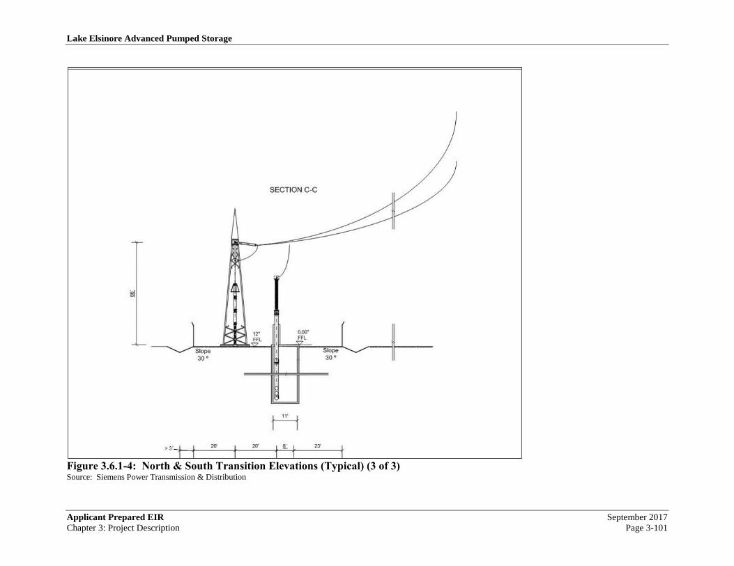
Lake Elsinore Advanced Pumped Storage
Applicant Prepared EIR September 2017
Chapter 3: Project Description Page 3-101
Figure 3.6.1-4: North & South Transition Elevations (Typical) (3 of 3) Source: Siemens Power Transmission & Distribution

Lake Elsinore Advanced Pumped Storage
September 2017 Applicant Prepared EIR
Page 3-102 Chapter 3: Project Description
Figure 3.6.1-5: GIL Vault Elevations Source: Siemens Power Transmission & Distribution

Lake Elsinore Advanced Pumped Storage
Applicant Prepared EIR September 2017
Chapter 3: Project Description Page 3-103
3.6.1.4 Substations and Switchyards
New substations and switchyards, identified as the Case Springs Substation and the Lake
Switchyard, will be constructed where the new transmission line will interconnect SDG&E’s
existing 230 kV transmission system on the south and with SCE’s existing 500 kV transmission
system on the north. In addition, the Santa Rosa substation will also be constructed. Each of the
proposed substations is described below.
3.6.1.4.1 Lake Switchyard
As illustrated in Figure 3.6.1-6: Lake Switchyard Site, the proposed northern connection to
SCE’s existing Valley-Serrano 500 kV transmission line and new 500 kV switchyard will be
located east of I-15 at Temescal Canyon Road, in an unincorporated portion of Riverside County
referred to as Alberhill, at MP 2.0.
The new switchyard will be located on the north-east side of the Interstate 15 (I-15) Freeway
near SCE’s existing 500 kV Valley-Serrano line. The property is presently privately owned and
would need to be acquired. This new switchyard will occupy about 6 acres on one pad, which
will define the fence line. The switchyard outline itself is approximately 300 ft wide by 300 ft
long. The new switchyard will consist of four new breaker-and-a-half configurations. The loop
in/out will be approximately half-way between SCE’s existing Serrano Substation (East Carver
Lane, Orange, Orange County) and Valley Substation (Menifee Road and Highway 74,
Romoland, Riverside County). A conceptual site plan of the new Lake 500 kV Switchyard is
presented in Figure 3.6.1-7: Lake 500 kV Switchyard – Conceptual Plan Layout. Conceptual
elevation drawings for that switchyard are presented in Figure 3.6.1-8: Lake 500 kV Switchyard
– Conceptual Elevation Drawings. The switchyard is electrically depicted in Figure 3.6.1-9:
Lake 500 kV Switchyard – Single Line Diagram.
The Switchyard will be split into the following three parts:
1. 500 kV connection to the Valley-Serrano line;
2. 500 kV connection to the TE/VS Interconnect system’s new OHL.
3. Spare taps for a potential SCE 115 kV Alberhill reinforcement project. (See Chapters 5 and
6.)
The extension of the Valley-Serrano line involves two single circuits extending between existing
structures on the existing right-of-way and the new northern “A” frame dead end in the Lake
Switchyard. The distance from the switchyard to the existing right-of-way is approximately 2.75
miles, for an estimated total of 5.5 miles of new transmission line. SCE requires that the line
extension be constructed on two separate single-circuit structures with about 150 foot separation
on the same right-of-way. The 500 kV switchyard systems will be built to SCE standards.
To be able to keep jurisdictions clear, a line of demarcation will be made between the SCE and
the Applicant’s portions of the switchyard using walls gates and fences, where appropriate. As
proposed, the building will be reinforced concrete block. The seismic requirements for the
equipment and building will be to IEEE 693 high-seismic level. Air conditioning and auxiliary

Lake Elsinore Advanced Pumped Storage
September 2017 Applicant Prepared EIR
Page 3-104 Chapter 3: Project Description
service requirements will be defined by the gas-insulated switchgear (GIS) equipment itself.
Each section of the switchyard (SCE and Applicant) will have its own dedicated control room.
The GIS building will be one structure with an internal wall which will serve as the line of
demarcation between the parties.
The proposed GIS configuration consists of four bays of 1½ CB 500 kV switchgear (Siemens
8DQ1). Bays 1 through 4 are for the connection to the Valley-Serrano line and LEAPS. The
500 kV GIS connection to the TE/VS Interconnect 500 kV OHL is done using the first breaker
and a half scheme. All equipment will be rated at 550 kV, 4000A, and 63kA. The new
switchyard will require a connection to SCE’s existing SCE 13.8 kV lines for station power.
As described in the Large Generator Interconnect Agreement now under negotiation between the
parties, the switchyard will include the following:
1. New light-wave and channel equipment, SCADA and applicable Participating TO voice and
data requirements.
2. Approximately six miles of new ADSS fiber optic cable to extend the existing fiber optic
cable from the Elsinore or Skylark Substations to the Santa Rosa Substation. The combined
(existing + new) fiber optic cable provides the required alternate route between Lake
Switchyard and the Santa Rosa Substation.
3. One RTU at to monitor the typical bulk power elements such as MW, MVAR, and phase
amps at each line and also kV at lines and busses and all circuit breaker status/control,
protection relays status and alarms. The RTU will transmit information to the Participating
TO’s Grid Control Center via the existing Mira Loma Regional Control Center System.
The Mechanical-Electrical Equipment Room (“MEER”) will consist of a new 30 ft. by 20 ft.
MEER building to house Batteries and battery charger, Light and power selector switch, Light
and power panel, A.C. distribution panel, and D.C. distribution pane. Relay protection devices
will include:
• Two GE C60 breaker management relays
• One SEL-311L line current differential (digital F.O. channel)
• One GE L90 line current differential (digital F. O. channel)
• One GE D60 directional comparison pilot relaying (digital F.O./MW channel)
• One RFL 9745 tele-protection channel DTT (digital F.O. channel)
• One RFL 9745 tele-protection channel DTT (M/W channel)
• One 32/64 digital fault recorder
• One Ethernet service drop
• One SEL-2030 relay
Other Station elements to be installed include:

Lake Elsinore Advanced Pumped Storage
Applicant Prepared EIR September 2017
Chapter 3: Project Description Page 3-105
• Dual communication channels on separate routes to support the Line Protection Relays.
One of the communication channels will be provided by installing OPGW.
• Perimeter fence with barbed wire and a double door 20 ft. gate around the switchyard.
• Grounding grid to cover the switchyard area and additional 10 ft. outside the perimeter
fence.
• A 25 ft. wide paved driveway around the switchyards and the transformer banks with a
branch of driveway to provide access to the relay room.
• Required control cable trenches from the relay room to the switchyards.
• Microwave antenna tower for VHF, UHF & WiFi communications. A typical
communications tower may be seen in Figure 3.6.1-22: Representative Communication
Tower.
• 750 kW Emergency diesel generator and day tank, (CARB Certified).
Lighting requirements for the facility fall within the following regulatory constraints.
• The location falls within the 45 mile radius of the Palomar Observatory. Due to ambient
light pollution, the County of Riverside has enacted Ordinance No. 655 on June 7, 1988.
This Ordinance provides limitations on nighttime lighting, to limit impacts on
observations from Palomar Observatory.
• The facility also falls into Class II, Zone B regulations as specified in Ordinance No. 655.
Due to these requirements, the switchyard lighting will be low-pressure sodium (LPS)
lighting. In addition the lighting levels are not to exceed 4050 Lumens. Under Class II,
Zone B, lighting is not limited to time of day.
Therefore low pressure sodium lights will be installed throughout the facility, for complete
exterior coverage, with lighting levels below 4050 Lumens. This lighting will be photocell
controlled for energy conservation.
Nevada Hydro notes that SCE has proposed a competing substation site less than 1 mile away
from this Lake site. It is being reviewed by the Commission in docket A. 09–09–022, known as
the “Alberhill System Project”. Because of the proximity of the two sites, Nevada Hydro
anticipates that the Commission will only one proposal to proceed to fill the purposes of both
projects. As described, herein, Nevada Hydro has included provisions for incorporating the
needs described in A. 09–09–022 within the proposed Lake site. Nevada Hydro anticipates that
if Commission approves Alberhill over Lake, that it will assure that the SCE facility
accommodates the needs of connecting both LEAPS and the TE/VS Interconnect to the Valley–
Serrano system.

Lake Elsinore Advanced Pumped Storage
September 2017 Applicant Prepared EIR
Page 3-106 Chapter 3: Project Description
Figure 3.6.1-6: Lake Switchyard Site Source: The Nevada Hydro Company

Lake Elsinore Advanced Pumped Storage
Applicant Prepared EIR September 2017
Chapter 3: Project Description Page 3-107
Figure 3.6.1-7: Lake 500 kV Switchyard – Conceptual Plan Layout Source: Siemens Power Transmission & Distribution

Lake Elsinore Advanced Pumped Storage
September 2017 Applicant Prepared EIR
Page 3-108 Chapter 3: Project Description

Lake Elsinore Advanced Pumped Storage
Applicant Prepared EIR September 2017
Chapter 3: Project Description Page 3-109
Figure 3.6.1-8: Lake 500 kV Switchyard – Conceptual Elevation Drawings (1 of 3) Source: Siemens Power Transmission & Distribution

Lake Elsinore Advanced Pumped Storage
September 2017 Applicant Prepared EIR
Page 3-110 Chapter 3: Project Description
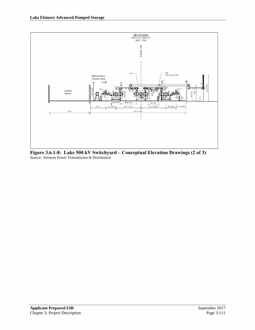
Lake Elsinore Advanced Pumped Storage
Applicant Prepared EIR September 2017
Chapter 3: Project Description Page 3-111
Figure 3.6.1-8: Lake 500 kV Switchyard – Conceptual Elevation Drawings (2 of 3) Source: Siemens Power Transmission & Distribution

Lake Elsinore Advanced Pumped Storage
September 2017 Applicant Prepared EIR
Page 3-112 Chapter 3: Project Description
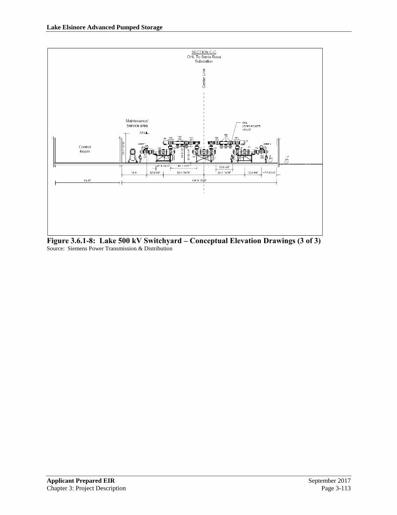
Lake Elsinore Advanced Pumped Storage
Applicant Prepared EIR September 2017
Chapter 3: Project Description Page 3-113
Figure 3.6.1-8: Lake 500 kV Switchyard – Conceptual Elevation Drawings (3 of 3) Source: Siemens Power Transmission & Distribution

Lake Elsinore Advanced Pumped Storage
September 2017 Applicant Prepared EIR
Page 3-114 Chapter 3: Project Description

Lake Elsinore Advanced Pumped Storage
Applicant Prepared EIR September 2017
Chapter 3: Project Description Page 3-115
Figure 3.6.1-9: Lake 500 kV Switchyard – Single Line Diagram Source: Siemens Power Transmission & Distribution
3.6.1.4.2 Santa Rosa Substation
The proposed Santa Rosa Substation is located within an unincorporated area (Lakeland Village)
of Riverside County, roughly midway between the Lake Switchyard and Case Springs
Substation, offset one mile to the southeast from roughly MP 12.3. The Substation will provide
reliability enhancements to the local distribution system48
and later connect the pumped storage
facility to the grid.
As illustrated in Figure 3.6.1-10: Santa Rosa Substation Site, the new Santa Rosa Substation will
be constructed above ground and may later be integrated into the design of the LEAPS
powerhouse. 115 kV circuits will supply starting and facilities power required by the LEAPS
project.
A conceptual site plan of the Santa Rosa Substation is presented in Figure 3.6.1-11: Santa Rosa
Substation Site – Conceptual Site Plan. Conceptual elevation drawings for that substation are
presented in Figure 3.6.1-12: Santa Rosa Substation Site – Conceptual Elevation Drawings. The
substation is electrically depicted in Figure 3.6.1-13: Santa Rosa Substation Single Line
Diagram.
While serving to reinforce local load, the Santa Rosa Substation may later provide for a
connection for the pumped storage facility’s powerhouse to connect to the high-voltage
48
/ Nevada Hydro notes that these enhancements are necessary only if the Commission does not approve SCE’s Alberhill
project. If approved, Nevada Hydro will withdraw these enhancements from the project description.

Lake Elsinore Advanced Pumped Storage
September 2017 Applicant Prepared EIR
Page 3-116 Chapter 3: Project Description
transmission system. The point of connection between the pumped storage facility and the high
voltage grid, will be the secondary side of the two 500/20 kV transformers rated at 375 MVA.
The generator voltage of the pumped turbine generator is 20kV.
The proposed Santa Rosa Substation will enclose a breaker and a half, 500 kV configuration.
The primary components of the substation include circuit breakers and disconnect switches,
switchyard buses and structures, and microwave/telecommunication facilities.
Design parameters are shown on Table 3.6.1-2: Santa Rosa Substation Design Parameters.
Table 3.6.1-2: Santa Rosa Substation Design Parameters
Like that for the Lake Switchyard, lighting requirements for the facility fall within the following
regulatory constraints.
• The location falls within the 45 mile radius of the Palomar Observatory. Due to ambient
light pollution, the County of Riverside has enacted Ordinance No. 655 on June 7, 1988.
This Ordinance provides limitations on nighttime lighting, to limit impacts on
observations from Palomar Observatory.
• The facility also falls into Class II, Zone B regulations as specified in Ordinance No. 655.
Due to these requirements, the switchyard lighting will be low-pressure sodium (LPS)
lighting. In addition the lighting levels are not to exceed 4050 Lumens. Under Class II,
Zone B, lighting is not limited to time of day.
Therefore low pressure sodium lights will be installed throughout the facility, for complete
exterior coverage, with lighting levels below 4050 Lumens. This lighting will be photocell
controlled for energy conservation.
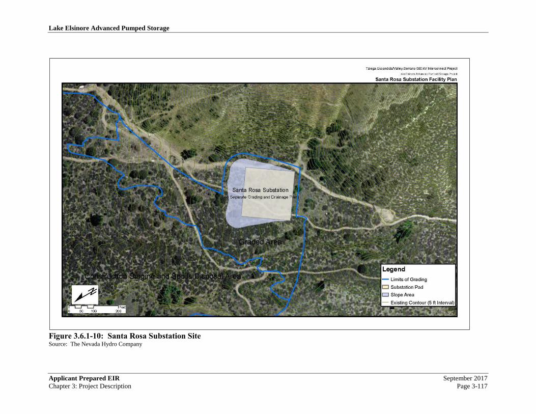
Lake Elsinore Advanced Pumped Storage
Applicant Prepared EIR September 2017
Chapter 3: Project Description Page 3-117
Figure 3.6.1-10: Santa Rosa Substation Site Source: The Nevada Hydro Company

Lake Elsinore Advanced Pumped Storage
September 2017 Applicant Prepared EIR
Page 3-118 Chapter 3: Project Description
This Page Intentionally Blank

Lake Elsinore Advanced Pumped Storage
Applicant Prepared EIR September 2017
Chapter 3: Project Description Page 3-119
34
3'
3'-3
3/8
"
ca.82'6"
13'-9 3/8"
Maintenance
/Service
Area
98
´9
8´
560 MVA
500/115/13,8 kV
15
5'-1
0 1
/16
"
Ca
50
'
GIL
To
LA
KE
Su
b
GIL
To
CA
SE
SP
RIN
G
Su
b
560 MVA
500/115/13,8 kV
Ca
ble
LE
AP
S P
um
pin
g
Ho
use
11'-10 1/8" 8'-2 7/16"
310'-8 3/8"
13'-9 3/8" 13'-9 3/8"
Ca 20'Ca 20' Ca 20' 114'-8 9/16" 135'-6"
Ca 23'
Ca
20
'
Slid
ing
Ga
teS
lidin
g G
ate
114'-8 9/16"
5'-6
15
/16
"
(Typ.)
7'-6 9/16"
(Typ.)
Maintenance
/Service
Area
66
'
Heavy transport
road (future)
Ce
nte
r L
ine
CB
A
A
B
B
Transport road
37
'-8
3/4
"2
7'-1
0 5
/8"
115 kV
GISControl Room
500/115 kV
66'-3 1/4"66'-5 1/4"
26
'-2
15
/16
"
34
'-5
3/8
"
40
8'-5
9/1
6"
Micro-
wave
29
'-6
5/1
6"
29'-6
5/1
6"
11
5K
V O
HL
Els
ino
re S
ub
11
5K
V O
HL
Skyla
rk S
ub
Figure 3.6.1-11: Santa Rosa Substation Site – Conceptual Site Plan Source: Siemens Power Transmission & Distribution

Lake Elsinore Advanced Pumped Storage
September 2017 Applicant Prepared EIR
Page 3-120 Chapter 3: Project Description

Lake Elsinore Advanced Pumped Storage
Applicant Prepared EIR September 2017
Chapter 3: Project Description Page 3-121
SE 1/3
Ca
50
'
FFL
0'
Ce
nte
r L
ine
12'-5 5/8"
30'-1 15/16"30'-1 15/16"
3.5 t
58943300
11'-5 13/16"12'-3 5/8"18'-5" 12'-3 5/8"
114'-9 15/16"
Maintenance/
Service area
FFL
- 1'
SECTION A-A
GIL to Lake
Substations
Control
Room
Ca 45'
14
'-8
1/2
"
GIL
To Lake
Substation
GIL
To Case Springs
TR1
21
'-7
13
/16
"
Busbar 1Busbar 2
-Q1/
-Q15/
-Q51
-T1 -Q0 -T2
-T5
-Q2/
-Q52/
-Q53
-Q8/
-Q9-Q1/
-Q51
-T1 -T2
-Q0
-Q2/
-Q52
-T5
-Q1/
-Q51/
-Q53
-Q8/
-Q9
-T1 -T2-Q0
-Q2/
-Q25/
-Q52
-Z1
GIL
To Lake
Substation
SECTION A-A
TR1
Figure 3.6.1-12: Santa Rosa Substation Site – Conceptual Elevation Drawings (1 of 3) Source: Siemens Power Transmission & Distribution

Lake Elsinore Advanced Pumped Storage
September 2017 Applicant Prepared EIR
Page 3-122 Chapter 3: Project Description

Lake Elsinore Advanced Pumped Storage
Applicant Prepared EIR September 2017
Chapter 3: Project Description Page 3-123
SE 2/3
FFL
0'
Ce
nte
r L
ine
12'-8 5/16"
30'-8 1/2"30'-8 7/16"
3.5 t
25'-2 3/8"11'-1/4"
11'-8 1/4"12'-6 5/16"18'-8 15/16" 12'-6 5/16"
116'-10 3/4"
Maintenance/
Service area
12
'-1
5/1
6"
SECTION B-B
TR2
Control
Room
FFL
- 1'
Ca 45'
14
'-1
1 1
1/1
6"
22
'-1
/2" Busbar 1
-Q1/
-Q51
-T5
-Q0
-Q1/
-Q51/
-Q53
-T2-T1-T1
-Q0
-T2-Q2/
-Q52
-Q2/
-Q52/
-Q53
-T1-T2
-Q0
-T5
-Q2/
-Q52
-Q8/
-Q9
-Q8/
-Q9
-Z1
OHL
To Lake SubstationTR2
14
'-1
1 1
1/1
6"
18
'-9
"
-Q1/
-Q51
Busbar 2
OHL
To Case Spring
Substation
GIL
To Case Spring
Substation
SECTION B-B
GIL to Case Springs
Substations
Figure 3.6.1-12: Santa Rosa Substation Site – Conceptual Elevation Drawings (2 of 3) Source: Siemens Power Transmission & Distribution

Lake Elsinore Advanced Pumped Storage
September 2017 Applicant Prepared EIR
Page 3-124 Chapter 3: Project Description

Lake Elsinore Advanced Pumped Storage
Applicant Prepared EIR September 2017
Chapter 3: Project Description Page 3-125
Figure 3.6.1-12: Santa Rosa Substation Site – Conceptual Elevation Drawings (3 of 3) Source: Siemens Power Transmission & Distribution
Lake Elsinore Advanced Pumped Storage
September 2017 Applicant Prepared EIR
Page 3-126 Chapter 3: Project Description
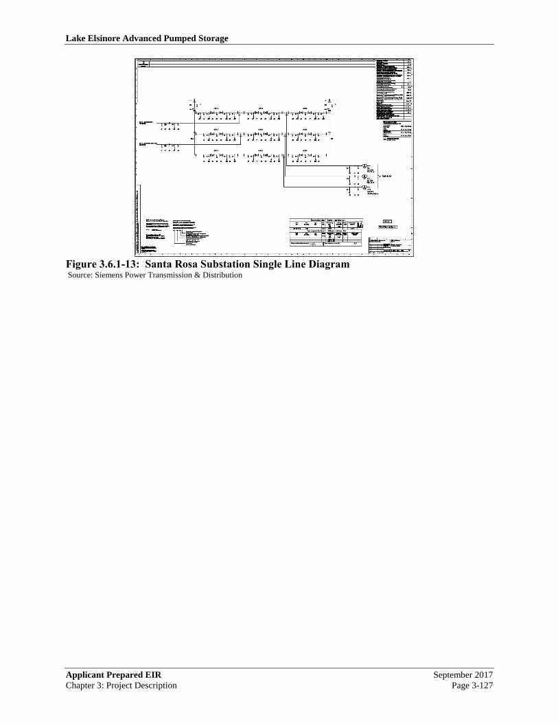
Lake Elsinore Advanced Pumped Storage
Applicant Prepared EIR September 2017
Chapter 3: Project Description Page 3-127
Figure 3.6.1-13: Santa Rosa Substation Single Line Diagram Source: Siemens Power Transmission & Distribution

Lake Elsinore Advanced Pumped Storage
September 2017 Applicant Prepared EIR
Page 3-128 Chapter 3: Project Description

Lake Elsinore Advanced Pumped Storage
Applicant Prepared EIR September 2017
Chapter 3: Project Description Page 3-129
3.6.1.4.3 Case Springs Substation
The proposed Case Springs 500 kV to 230 kV gas-insulated substation (GIS) serves as the
southern interconnection of the TE/VS Interconnect to the SDG&E system. SDG&E's existing
230 kV transmission lines extend between the existing Talega and Escondido Substations. The
loop-in consists of installation of four 230 kV anchor bolted dead-end tubular steel poles, and
hardware and conductor. A conceptual site plan is presented in Figure 3.6.1-14: Case Springs
Substation – Conceptual Site Plan. The Case Springs Substation is electrically depicted in Figure
3.6.1-15: Case Springs Substation – Single Line Diagram.
The Case Springs Substation will include:
4. Three bays, 500 kV GIS breaker and a half bus design
5. The initial 4-bay 230 kV arrangement of the GIS will accommodate four transmission line
positions, three bank positions, and one spare position; the ultimate arrangement will allow
space for a future fifth bay if needed
6. 12-230 kV circuit breakers and the associated disconnect switches, ground switches,
potential transformers, and gas-insulated bus
7. Two station service transformers
8. Three metering units
9. Required line synchronizing potential transformers
10. All structures & foundations, busses and equipment within switchyard fence
11. A dedicated block wall control house, substation below grade conduits and cables, protection
systems, supervisory control/telecommunications equipment, batteries and low voltage
circuits (all the required protection, metering, telemetering, SCADA and communication
equipment and systems), including a VHF communication tower. A typical communications
tower may be seen in Figure 3.6.1-22: Representative Communication Tower.
12. Ground grid
13. Lighting
14. Transmission line air-to-gas transitions into the GIS
15. Air-to-gas transitions for the phase shifting transformer leads and one 750 kW emergency
diesel engine /generator set including transfer switch and day tanks, (CARB Certified)
In relation to facility lighting, the facility is located within the Camp Pendleton. Federal Lands
are exempt from the San Diego County, Division 9 Light Pollution Ordinance, Sections 59.101
through 59.115. Voluntary compliance is encouraged, but not required.
Special lighting requirements are requested by the Camp Pendleton. Due to low level nighttime
flight operations, all lighting is to be infrared as specified, directed by their flight operations, and
as dictated by the Commanding Officer.

Lake Elsinore Advanced Pumped Storage
September 2017 Applicant Prepared EIR
Page 3-130 Chapter 3: Project Description
This means that special lighting will be specified and installed. At the same time, this type of
lighting would not impact the Palomar Observatory.
For emergency operations or service, only as allowed by the Commanding Officer, low-pressure
sodium (LPS) lighting will be installed, not to exceed 4050 Lumens. In this way voluntary
compliance per Division 9 Ordinance will be accomplished. This lighting is only to be used
when approved by the Camp Pendleton.
Similar lighting requirement will be applied to any new towers adjacent to, and required by the
Case Springs Substation. No standard FAA beacons will be utilized on new structures within
Camp Pendleton unless approved or directed by Camp officials.
The facility will also include flow control. Three phase-shifting transformers, sized for nominal
operation at approximately +16 to -32 degrees with a southern flow of 1,500 MW, are planned.
A detailed study was required to select the three 230 kV, 500 MVA phase shifting transformers
located at Case Springs Substation. Several major contingencies were studied, and the resulting
phase control angles examined. The phase shifting range is important to determine the tap-
changer specifications, and to provide good dynamic control. The results of this study are
contained within the Table 3.6.1-3: Power Flow Testing of System Conditions and Associated
Angular Phase Shifts.
The load served by the Case Springs 500/230 kV Substation is largely the SDG&E service
territory and San Diego County. This new substation and associated transmission upgrades will
provide a total, bi-directional nominal capacity of 1,500 MW to San Diego. In addition, it will
be able to provide 1,000 MW under contingency (G-1/N-1) conditions, and can be dispatched in
real-time by the CAISO.
The point of connection between SDGE and The TE/VS Interconnect is the 230 kV GIS and the
230 kV phase shifting transformers.

Lake Elsinore Advanced Pumped Storage
Applicant Prepared EIR September 2017
Chapter 3: Project Description Page 3-131
Table 3.6.1-3: Power Flow Testing of System Conditions and Associated Angular Phase Shifts
Source: Siemens Power Transmission & Distribution

Lake Elsinore Advanced Pumped Storage
September 2017 Applicant Prepared EIR
Page 3-132 Chapter 3: Project Description
This Page Intentionally Left Blank

Lake Elsinore Advanced Pumped Storage
Applicant Prepared EIR September 2017
Chapter 3: Project Description Page 3-133
Figure 3.6.1-14: Case Springs Substation – Conceptual Site Plan Source: Siemens Power Transmission & Distribution

Lake Elsinore Advanced Pumped Storage
September 2017 Applicant Prepared EIR
Page 3-134 Chapter 3: Project Description

Lake Elsinore Advanced Pumped Storage
Applicant Prepared EIR September 2017
Chapter 3: Project Description Page 3-135
Figure 3.6.1-15: Case Springs Substation – Single Line Diagram (1 of 2) Source: Siemens Power Transmission & Distribution

Lake Elsinore Advanced Pumped Storage
September 2017 Applicant Prepared EIR
Page 3-136 Chapter 3: Project Description

Lake Elsinore Advanced Pumped Storage
Applicant Prepared EIR September 2017
Chapter 3: Project Description Page 3-137
Figure 3.6.1-17: Case Springs Substation – Single Line Diagram (2 of 2) Source: Siemens Power Transmission & Distribution

Lake Elsinore Advanced Pumped Storage
September 2017 Applicant Prepared EIR
Page 3-138 Chapter 3: Project Description
This Page Intentionally Blank

Lake Elsinore Advanced Pumped Storage
Applicant Prepared EIR September 2017
Chapter 3: Project Description Page 3-139
3.6.1.4.3.1 Location
Nevada Hydro has identified a preferred location for this facility as well as two alternative
locations for the Commission’s consideration. All sites lie within the same general area, and are
adjacent to the ROW of SDG&E’s existing 230 kV transmission lines. All sites use the same
facility layout on an approximately six acre footprint. All three sites are shown in relation to
each other in Figure 3.6.1-16: Case Springs Substation Alternative Locations.
As shown on Figure 3.1.1-4: Talega-Escondido/Valley-Serrano 500 kV Interconnect Project,
this preferred location is immediately adjacent to the ROW of SDG&E’s existing 230 kV
transmission line within the Cleveland National Forest and is illustrated in Figure 3.6.1-17: Case
Springs Site.
3.6.1.4.3.1.1 Fallbrook Conservancy Alternate Site
This alternative site is adjacent to the ROW of SDG&E’s existing 230 kV transmission lines
within land owned by the Fallbrook Land Conservancy. Substitute plates for the project maps
shown in Figure 3.1.1–4 may be found in Figure 3.6.1-18: Fallbrook Alternative – Substitute
Route Plates. A detailed site graphic may be found in Figure 3.6.1-19: Fallbrook Alternative –
Site Plan.
3.6.1.4.3.1.2 Fern Creek Alternate Site
This alternative site is near the ROW of SDG&E’s existing 230 kV transmission lines within
privately–owned land. Substitute plates for the project maps shown in Figure 3.1.1–4 may be
found in Figure 3.6.1-20: Fern Creek Alternative – Substitute Route Plates. A detailed site
graphic may be found in Figure 3.6.1-21: Fern Creek Alternative – Site Plan.

Lake Elsinore Advanced Pumped Storage
September 2017 Applicant Prepared EIR
Page 3-140 Chapter 3: Project Description
Figure 3.6.1-16: Case Springs Substation Alternative Locations Source: The Nevada Hydro Company

Lake Elsinore Advanced Pumped Storage
Applicant Prepared EIR September 2017
Chapter 3: Project Description Page 3-141
Figure 3.6.1-17: Case Springs Site Plan Source: The Nevada Hydro Company

Lake Elsinore Advanced Pumped Storage
September 2017 Applicant Prepared EIR
Page 3-142 Chapter 3: Project Description
Figure 3.6.1-18: Fallbrook Alternative – Substitute Route Plates (1 of 2) Source: The Nevada Hydro Company

Lake Elsinore Advanced Pumped Storage
Applicant Prepared EIR September 2017
Chapter 3: Project Description Page 3-143
Figure 3.6.1–18: Fallbrook Alternative – Substitute Route Plates (2 of 2) Source: The Nevada Hydro Company

Lake Elsinore Advanced Pumped Storage
September 2017 Applicant Prepared EIR
Page 3-144 Chapter 3: Project Description
Figure 3.6.1-19: Fallbrook Alternative – Site Plan Source: The Nevada Hydro Company

Lake Elsinore Advanced Pumped Storage
Applicant Prepared EIR September 2017
Chapter 3: Project Description Page 3-145
Figure 3.6.1-20: Fern Creek Alternative – Substitute Route Plates (1 of 2) Source: The Nevada Hydro Company

Lake Elsinore Advanced Pumped Storage
September 2017 Applicant Prepared EIR
Page 3-146 Chapter 3: Project Description
Figure 3.6.1–20: Fern Creek Alternative – Substitute Route Plates (2 of 2) Source: The Nevada Hydro Company

Lake Elsinore Advanced Pumped Storage
Applicant Prepared EIR September 2017
Chapter 3: Project Description Page 3-147
Figure 3.6.1-21: Fern Creek Alternative – Site Plan Source: The Nevada Hydro Company
Lake Elsinore Advanced Pumped Storage
September 2017 Applicant Prepared EIR
Page 3-148 Chapter 3: Project Description
This Page Intentionally Blank

Lake Elsinore Advanced Pumped Storage
Applicant Prepared EIR September 2017
Chapter 3: Project Description Page 3-149
3.6.1.5 Telecommunications
Overhead shield wires will be used to protect the electrical conductors from lightning strikes.
These wires would be aluminum-coated steel-stranded wire with a fiber-optic core for
communication purposes. Some of the fibers in the fiber-optic core would be used for control
and monitoring of protective relaying and communication equipment between facilities. The
remaining static wire will be insulated at 4.16 kV for any required tower lighting. In addition,
the power will be used approximately every mile for communications equipment, and fiber
repeaters as required.
Fiber will be utilized throughout the project for communications. One static wire on all
transmission towers has a fiber core. Fiber is also used extensively underground, and in all
project works.
Microwave will be utilized throughout the project for control and telemetry. This is line of site
communications, and will require microwave towers at all substations, powerhouse and at major
project locations.
Telephone will be utilized throughout the project locations for communications and security.
Finally, radio will be utilized through the Project for radio line of sight communications,
telemetry, security, communications, and internet. UHF, VHF, Cell, GHz, and Wifi frequencies
are commonly used both dish & antenna. Communications towers will be required adjacent to
all major project facilities. It is anticipated that Case Springs Substation, Santa Rosa Substation,
Lake Switchyard, and the LEAPS Powerhouse will require 100 ft. to 300 ft. towers for line-of-
sight communications. The towers will be equipped with antenna platforms and anti-collision
lights. A representative communications tower may be seen in Figure 3.6.1-22: Representative
Communication Tower.

Lake Elsinore Advanced Pumped Storage
September 2017 Applicant Prepared EIR
Page 3-150 Chapter 3: Project Description
Figure 3.6.1-22: Representative Communication Tower Source: Siemens Power Transmission & Distribution
3.6.2 LEAPS
LEAPS will have an installed generating capacity of 500 MW and pumping capacity of 600
MW, provided by two single-stage reversible Francis-type pump turbine units operating under an
average net head of approximately 1,500 feet. The facility will firm up and store renewable
energy, primarily wind energy49
, and will be one of the most efficient storage facilities in the
world, rated at approximately 83.3% net at the 500 kV primary levels.
Modern pumped storage units produce all five ancillary services. In addition, the unit and
regulator designs provide fast response dynamics, tied directly to the intermittency of renewable
products. Grid operations and protection designs must take in to account these grid-enhancing
products, and make sure they are properly integrated into the CAISO controlled grid. Some
ancillary products can be provided simultaneously, and regulation is provided both directions, (in
generation and pumping modes). 49
/ Pumped storage can minimize the system impact of integrating large volumes of intermittent wind resources into the power
grid by absorbing electricity generation during high-wind periods that would otherwise cause operational problems for
system operators. Pumped storage can be used in tandem with wind resources to shift delivery of wind energy from off-peak
to on-peak period during the day and smooth out production spikes (Source: California Energy Commission, Integrated
Energy Policy Report, CEC-100-2-5-007CMF, November 2005, p. 146).

Lake Elsinore Advanced Pumped Storage
Applicant Prepared EIR September 2017
Chapter 3: Project Description Page 3-151
The facility currently consists of two 250 MW Voith Siemens Hydro Power Generation
synchronous generators, 600 MW of pump load, step-up transformers, and appurtenant facilities.
This federal hydroelectric project is being licensed by FERC50
(FERC P-14227) under the
provision of the FPA and is being permitted by the Forest Service under the provisions of the
National Forest Management Act (NFMA). Section 15(e) of the FPA (16 U.S.C. 808[e])
specifies that any license issued by FERC shall be for a term that FERC determines to be in the
public interest but not less than 30 years nor more than 50 years from the date of issuance. A 50
year federal hydropower license, with the potential for subsequent relicensing for an extended
term beyond 50 years, has been assumed herein.
The LEAPS facility will conform to and comply with FERC’s “Engineering Guidelines for the
Evaluation of Hydroelectric Projects.”51
As stipulated in Part 12 (Safety of Water Power Projects
and Project Works) therein, the licensee must use sound and prudent engineering practices in any
action relating to the design, construction, operation, maintenance, use, repair, or modification of
a water power project or project works (Section 12.5). Requirements include the preparation of
an “emergency action plan” (EAP) developed in consultation and cooperation with appropriate
federal, State, and local agencies responsible for public health and safety and designed to provide
early warning to upstream and downstream inhabitants, property owners, operators of water-
related facilities, recreational users, and other persons in the vicinity who might be affected by a
project emergency (Section 12.20). The EAP shall conform to FERC guidelines (Section 12.22)
and must be filed no later than 60 days before the initial filling of the upper reservoir begins
(Section 12.23).
Because the proposed upper reservoir’s impoundment would be classified as a “high hazard
dam” or “high hazard potential structure,”52
the EAP will be developed in accordance with
FERC53
and Federal Emergency Management Agency54
(FEMA) regulations, guideline, and
manuals. Final dam design and specification shall be subject to the findings of the design-level
50
/ FERC’s authority to license hydropower projects is found in Part 1 of the FPA. Section 4(e) of the FPA (16 U.S.C. 797[e])
empowers FERC to issue licenses for projects that: (1) are located on navigable waters; (2) located on non-navigable waters
over which Congress has Commerce Clause jurisdiction, were constructed after 1935, and affect the interests of interstate or
foreign commerce; (3) located on public lands or reservations of the United States (excluding national parks); and/or (4)
using surplus water or water power from a federal dam. Jurisdiction applies regardless of project size. Section 10(a)(1) of
the FPA (16 U.S.C. 803[a][1]) establishes the comprehensive development standard which each project must meet to be
licensed (Source: Federal Energy Regulatory Commission, Report on Hydroelectric Licensing Policies, Procedures, and
Regulations – Comprehensive Review and Recommendations Pursuant to Section 603 of the Energy Act of 2000, May 2001,
pp. 9-11). 51
/ Federal Energy Regulatory Commission, Engineering Guidelines for the Evaluation of Hydroelectric Projects, April 1991,
updated July 1, 2005. 52
/ Federal Emergency Management Agency, Federal Guidelines for Dam Safety – Hazard Potential Classification System for
Dams, April 2004. 53
/ Federal Energy Regulatory Commission, Guidelines for Preparation of Emergency Action Plans, November 1979, revised
September 1988. 54
/ Federal Emergency Management Agency, Federal Guidelines for Dam Safety, April 2004; Federal Emergency Management
Agency, Federal Guidelines for Dam Safety – Emergency Action Planning for Dam Owners, April 2004; Federal Emergency
Management Agency, Federal Guidelines for Dam Safety – Selecting and Accommodating Inflow Design Floods for Dams,
April 2004.

Lake Elsinore Advanced Pumped Storage
September 2017 Applicant Prepared EIR
Page 3-152 Chapter 3: Project Description
seismic investigation conforming to FERC,55
FEMA,56
and applicable California Department of
Water Resources - Division of Safety of Dams57
(DSOD) standards.
As required, the Applicant’s “standard technical information document” (STID) will include a
surveillance and monitoring plan (SMP) providing the details of how the owner will monitor and
evaluate the performance of the dam and project structures. The SMP will include the
requirement to periodically submit a surveillance and monitoring report (SMR) presenting,
evaluating, interpreting, and providing findings on the overall performance of the dam.58
Signage, conforming to FERC standards, will be placed at the hydropower facilities.59
Excluding
the afterbay, the project’s facilities will be landscaped to provide screening along abutting street
frontages. Final landscape plans for those facilities located on NFS lands will be developed in
coordination with the Forest Service.
Presented below is a brief discussion of the key facilities that collectively comprise the LEAPS,
including non-energy-related facilities that are associated with the project.
3.6.2.1 Decker Lake Upper Reservoir
Proposed is the creation of a new approximately 110-acre open reservoir (forebay), located in the
south fork of Decker Canyon (Sections 21 and 22, T6S, R5W, SBBM USGS 7.5-Minute
Alberhill Quadrangle),60
at the headwaters of San Juan Creek, at MP 11.7. The proposed upper
reservoir (forebay) is located within the TRD, at elevations 2440 to 2850 feet above msl, on land
under Forest Service jurisdiction. The proposed reservoir site is located adjacent to and south of
Killen Truck Trail/South Main Divide Truck Trail (Forest Route 6S07) (South Main Divide
Truck Trail), an all-weather, County-maintained two-lane road61
extending eastward from SR-74
(Ortega Highway).
The proposed upper reservoir is not intended for the storage of potable water and no water
treatment activities, other than as may be associated with vector control, are proposed therein.
No public access to the reservoir site and no recreational contact with the water within that
55
/ Op. Cit., Engineering Guidelines for the Evaluation of Hydropower Projects, April 1991, updated July 1, 2005; Federal
Energy Regulatory Commission, Guidelines for Public Safety at Hydropower Projects, March 1992. 56
/ Federal Emergency Management Agency, Federal Guidelines for Dam Safety – Earthquake Analysis and Design of Dams,
May 2005. 57
/ Parts 1 and 2 of Division 3 (Dams and Reservoirs) of the CWC; Chapter 1 of Division 2, Title 23 (Waters) of the CCR; and
Current Practices of the Department in Supervision of Dams and Reservoirs. Sections 6000-6004.5 of the CWC identify
dams and reservoirs that are in State jurisdiction. Dams and reservoirs owned by the United States are not subject to State
jurisdiction, except as otherwise provided by federal law. 58
/ An outline of the Applicant’s SMP is presented in “Supplement No. 1 to Geotechnical Feasibility Report – Preliminary
Guidelines for a Monitoring and Surveillance Program, Lake Elsinore Advanced Pumped Storage Project, Riverside County,
California” (GENTERRA Consultants, Inc., October 16, 2003), included in the FLA. 59
/ Federal Energy Regulatory Commission, Safety Signage at Hydropower Projects, October 2001. 60
/ Latitude: 33.37N; Longitude: 117.2532W. 61
/ South Main Divide Truck Trail (Killen Trail) links State Route 74 (SR-74 or Ortega Highway) to the residential area of
Rancho Capistrano (Morrell Potero) and to the eastern portion of the TRD. At its eastern terminus, South Main Divide Truck
Trail becomes Forest Route 7S04 which extends southward to Tenaja Road, near the southeastern border of the TRD.

Lake Elsinore Advanced Pumped Storage
Applicant Prepared EIR September 2017
Chapter 3: Project Description Page 3-153
reservoir would be authorized. Access to and waters stored within the upper reservoir will,
however, be made available for firefighting purposes.
The new upper reservoir capacity will be approximately 5,750 acre-feet (AF) (approximately
5,500 AF live storage and approximately 250 AF dead storage). A 20 foot wide crushed stone,
gravel, or asphalt-paved roadway will be provided around the embankment to allow access for
maintenance and inspection. Access will be restricted by signage and an approximately 8 foot
high chain-link fence located on the outer side of the crest roadway. Surface water channels will
be constructed within the perimeter access corridor. The sides and bottom of the upper reservoir
will be provided with an impermeable dual liner (i.e., clay and double geomembrane) system to
minimize water loss and seepage. The liner system will allow for steepened reservoir side slopes
by protecting the side slopes from rapid drawdown damage (e.g., sloughing, erosion, and
landsliding) and will protect the reservoir floor from erosion and scour.
In addition to the use of low-permeability soil for the impermeable layer of the floor and side
slopes, the upper reservoir will incorporate a double-liner system. The liner system will include
a high-density polyethylene (HDPE) liner, drainage layer under the primary geomembrane to
collect and convey leakage, secondary HDPE geomembrane under the drainage layer to separate
leakage from native groundwater, secondary seepage collection system under the secondary
geomembrane to relieve water pressures from under the liner system, and grading preparation as
needed to protect the liner system from sharp bedrock protrusions.
Redundant controls will be provided to protect against over-pumping. Three independent
systems will be installed to monitor and control the water level in the upper reservoir and to
ensure that all units operating in the pumping mode will be tripped before the water level
exceeds the final design capacity. These monitoring devices will be coordinated and interlocked
in operation to preclude the possibility that failure of a device or a combination of devices and/or
any human operating error will allow safe operating levels from being exceeded. For this reason,
and since the upper reservoir has no contributory drainage area, no reasonable possibility of
exceeding maximum water level will exist.
An intake/outlet structure located in the upper reservoir will interconnect the new upper reservoir
with the powerhouse through a single 25 foot diameter nominal conveyance channel and tunnel,
with a gated inlet structure. Radial gates, slide gates, or an emergency bulkhead will be installed
to shut off water flow from the upper reservoir in the event of an emergency or for inspection
and repair.
The proposed upper reservoir will be designed for and will accommodate access by firefighting
helicopters and other firefighting personnel. Helicopters will be able to utilize reservoir waters
to fill suspended “bambi buckets” or other devices for fire suppression. A wind sock or similar
device will be installed in a clearly visible location adjacent to the reservoir to assist pilots by
indicating wind conditions during fire fighting events. In addition, the reservoir’s waters can be
pumped from the upper reservoir by mobile water pumping equipment for other fire-response
purposes.

Lake Elsinore Advanced Pumped Storage
September 2017 Applicant Prepared EIR
Page 3-154 Chapter 3: Project Description
The proposed upper reservoir design includes: (1) an approximately 300 foot high main
embankment dam62
located on the southwest side of the reservoir; (2) maximum and minimum
pond elevation of approximately 2790 feet and 2660 feet above msl, respectively; (3) a crest
elevation of 2800 feet above msl; and (4) an inlet at elevation of approximately 2600 feet above
msl feet for the intake structure. The conceptual drawing for the proposed upper reservoir is
included in Figure 3.1.1-5: LEAPS Pumped Storage .
The required fill volume of the dam is about 3.0 million cubic yards (CY). Grading operations
will be conducted in compliance with applicable National Pollutant Discharge Elimination
System (NPDES) permit requirements.63
While most of the excavation will come from within the area of the reservoir itself, alternative
dam designs are presented in Section 6.2. Additional excavation materials may come from the
powerhouse, shafts, and penstock tunnels. Excavated and/or imported materials will be used to
construct the dam and other earth structures required for the impoundment. Materials may be
trucked to and from the upper reservoir site along SR-74, via Main Divide Truck Trail.
Embankment material would consist of silty sand and rock materials generated from excavated
granitic bedrock and weathered granite. Depending upon the conditions of the bedrock
foundation, the dam may be keyed into the foundation rock and the rock foundation may be
grouted. All slope inclinations of the dam’s slopes will be approximately 3:1 (horizontal to
vertical) but may be constructed flatter to accommodate ground motion criteria currently being
evaluated. A freeboard of 10 feet was used to estimate the height of the dam. The crest of the
dam will have a relatively narrow width (approximately 30 feet). The dam would include a
concrete-lined emergency spillway and a low-level outlet.
3.6.2.2 Project Tunnels/Shaft
Water will be transferred between the upper reservoir and the powerhouse through a single
approximately 25 foot diameter, primarily concrete-lined tunnel. The inlet elevation at the
proposed upper reservoir will be about 2600 feet above msl.
A tunnel-boring machine (TBM) or conventional hard-rock mining operation will be used to
excavate the headrace tunnels. It is anticipated that the high-head conductor will be excavated
into competent granitic bedrock. In general, the pipeline alignments will seek to follow the most
direct route between the upper reservoir and the powerhouse, taking into consideration the area’s
topography and subsurface geotechnical features.
62
/ Dams are defined according to 33 CFR 222.6(h) as all artificial barriers, together with appurtenant works, which impound or
divert water and which: (1) are 25 feet or more in height; or (2) have an impounding capacity of 50 acre feet or more.
Federal regulations define dams for the purpose of ensuring public safety (Source: United States Environmental Protection
Agency, National Management Measures to Control Nonpoint Source Pollution from Hydromodifications, July 2006, p. I-2). 63
/ California Regional Water Quality Control Board, San Diego Region, Order No. R9-2007-0001, NPDES No. CAS0108758,
Waste Discharge Requirements for Discharges of Urban Runoff from the Municipal Separate Storm Sewer Systems (MS4s)
Draining the Watersheds of the County of San Diego, the Incorporated Cities of San Diego County, the San Diego Unified
Port District, and the San Diego County Regional Airport Authority, January 24, 2007, Section D.2.c(1)(a)(vi).

Lake Elsinore Advanced Pumped Storage
Applicant Prepared EIR September 2017
Chapter 3: Project Description Page 3-155
A vertical tunnel will descend from a location northeast of the upper reservoir. The vertical
tunnel will connect to a lower sub-horizontal tunnel that would have a gradient of approximately
five percent downward toward the powerhouse. The horizontal tunnel will be unlined or
concrete-lined where there is adequate rock cover over the tunnel and steel lined where there is
inadequate rock cover. The horizontal tunnel would then split into a steel-lined manifold
immediately upstream of the powerhouse, directing the water flows to the turbines in the
powerhouse.
A double-seated spherical valve will be provided at the inlet for each pump-turbine spiral case.
The valves will be used to isolate the pump-turbine from the penstock for inspection and
maintenance and to close in an emergency. Draft tube bulkhead gates will be provided to be
used in conjunction with the penstock valves for dewatering the pump-turbine water passages.
3.6.2.3 LEAPS Powerhouse
As illustrated in Figure 3.1.1-5: LEAPS Pumped Storage , the proposed Santa Rosa Powerhouse
site (Section 14, T6S, R5W, SBBM, Lake Elsinore 7.5-Minute USGS Topographic Quadrangle)
is approximately located west of the terminus of Santa Rosa Drive, between Ponce Drive and
Grape Street, within unincorporated Lakeland Village area of Riverside County. The site is
located to the south of SR-74 and west of Grand Avenue.
The proposed underground powerhouse will be situated approximately 3,000 feet from Lake
Elsinore, with its roof located 330 feet below surface at elevation 1,170 msl, and with the
centerline of the pump/turbine spiral cases at 1,050 msl. The powerhouse will contain two
reversible Francis-type pump-turbine/motor generators, nominally rated at 300 MW each when
pumping. The elevation of the pump/turbines at 195 feet below the surface of the Lake is due to
their hydraulic characteristics, so as to provide sufficient suction pressure at the impellers. This
suction pressure ensures that the machines will operate without cavitation either in the pump
mode or in the turbine mode. The entire water conveyance system (that is the headrace tunnels,
the pump/turbine cases, and the tailrace tunnel) is a closed conduit system, so that, when
generating, the differential head drop from the upper reservoir (Decker Lake) to the lower
reservoir (Lake Elsinore) is the motive energy force and the elevation of the powerhouse,
whether above or below the surface of Lake Elsinore does not affect the gross head available to
drive the machines.
Each pump/turbine will have adjustable wicket gates controlled by an electronic governor
through oil-operated servomotors. Consistent with all Francis-type pump/turbines, the units will
operate at relatively constant flow rate while pumping. The pump/turbine runner and wicket
gates, as well as other components that may otherwise be susceptible to cavitation, will be of
solid stainless steel construction, to prevent cavitation damage.
A service bay will be provided at one end of the powerhouse. Equipment access by overhead
crane to the powerhouse will be via a vertical shaft extending from the land surface down to a
service bay and laydown area on the generator floor. Personnel will have access via an elevator.
Powerhouse equipment will include an over-head bridge crane supported on high-level beams
along the length of the powerhouse. The crane will be sized to handle the heaviest lift during

Lake Elsinore Advanced Pumped Storage
September 2017 Applicant Prepared EIR
Page 3-156 Chapter 3: Project Description
equipment installation and maintenance. The powerhouse cavern housing the pumping/
generating units will be approximately 175 feet long, 250 feet wide, and 160 feet high.
The main powerhouse cavity will contain local operating and control equipment for each unit.
The powerhouse roof will be supported by rock bolts or rock anchors with wire mesh and
shotcrete for support as needed. The powerhouse will accommodate spherical turbine inlet
valves to control flow into the units. The valves will be placed immediately upstream of the
spiral case so that they can be handled by the main powerhouse crane.
Galleries for electrical and mechanical services will be provided on the upstream and
downstream sides of the powerhouse, respectively. Discharge from the units in the generating
mode will pass through the draft tubes into the tailrace tunnel. This tunnel will be D-shaped and
concrete-lined.
The power plant’s mechanical systems will be designed to maintain suitable and safe conditions
for operators and maintenance personnel. Ventilation air in and out of the powerhouse access
tunnel will be provided. The major heat-producing units will be cooled by oil-water and air-
water heat-exchange systems. A system of ducting, bulkhead controls, and circulating fans will
be installed to ensure equitable distribution of air throughout the facility and prevent the
accumulation of carbon monoxide (CO) and other gases. Fire doors, incorporating air locks, will
be provided at key locations. Fire prevention systems in the underground plant will be
conventional deluge-type for the major items of equipment. Tied to these systems will be a
system of isolating dampers and bulkheads connected to the ventilation system for control of
smoke and fumes. In accordance with fire and building code standards, a high-pressure fire
system will supply water to fire hose stations located throughout the facility. Unit dewatering
will employ high-capacity pumps in pressurized pump pits.
Two 2,000 kW emergency diesel generators will run an air compressor and essential cooling
pumps for the powerhouse complex.
Although computer and programmable logic control (PLC) systems improve plant operation by
providing greater flexibility in control, alarming, and sequence of events recording, the essential
emergency shutdown controls shall remain hardwired. This will guarantee that a safe and
orderly shutdown of the plant can be accomplished in an emergency situation during which the
computer and PLC systems have failed.
3.6.2.4 Lake Elsinore Intake/Outlet Structure
Between the powerhouse and lower reservoir, the inlet/outfall structure and its associated conduit
(tailrace) will be located within an unincorporated County area. At the lakeshore, the inlet/outlet
and other associated improvements extending into Lake Elsinore (e.g., intake headwall structure,
reinforced dredged channel, and boat dock) will be constructed within the corporate boundaries
of the City.
As illustrated in Figure 3.1.1-5: LEAPS Pumped Storage , Sheets 1 and 2, the intake/outlet
(tailrace) structure for the lower reservoir will be located near the southwest shoreline of Lake
Elsinore. The structure will extend from the portal of the tailrace tunnel to a headwall structure

Lake Elsinore Advanced Pumped Storage
Applicant Prepared EIR September 2017
Chapter 3: Project Description Page 3-157
fitted with trashracks at the shoreline. The structure will be designed to provide a maximum
discharge velocity of 1.8 feet per second (fps) at the trashracks during generation and a
maximum intake velocity of 1.4 fps at the trashracks during pumping. Stoplogs will be provided
at the portal so that the tailrace tunnel can be isolated from Lake Elsinore.
A rip-rap lined, reinforced dredged channel at the inlet/outlet (tailrace) structure will be installed
to reduce velocities, provide a natural silt trap, and shape a velocity profile into the intake
screens, structure, and gates. Following construction, the cofferdam will be removed. A paved
maintenance road would provide shoreline access and a boat dock installed to allow for lake
access during facility maintenance. The area will be equipped with security cables, warning
signs, warning buoys, security cameras, and navigational warning lights.
The tailrace structure for the upper reservoir will consist of a gated inlet structure where the
water flows into a horizontal or sloping conduit. Radial gates, slide gates, or an emergency
bulkhead will be installed to shut off water flow from the upper reservoir in the event of an
emergency and for inspection and repair of the high-head conduit. The intake/outlet structures
will be equipped with trashracks to prevent large debris from entering the conduit system. The
structure will be located at sufficient depth below minimum operating level to prevent air
entrainment. The intake/outlet structure will be reinforced concrete with automated trashracks
and stoplogs and will incorporate fish excluders. Fish excluders can be changed seasonally but
not automated.
3.6.2.5 Lake Elsinore as the Lower Reservoir
Lake Elsinore will serve as the afterbay for LEAPS. Lake Elsinore is a relatively shallow lake
with a large surface area. The lake, a naturally occurring sink for the San Jacinto River
watershed, has been significantly modified for water control.64
At the current lake outlet sill
elevation of 1255 feet above msl, the lake has an average depth of 24.7 feet and the hypolimnetic
water volume and surface area are 54,504 AF and 3,606 acres, respectively.65
Waters within the
lake are owned by the EVMWD and the real property within the OHWM is owned by and
located within the corporate boundaries of the City. Public access to the lakeshore is limited to
locations along the lakeshore where property is publicly owned.
Water from Lake Elsinore will be used for the initial filling of the upper reservoir, for the
replenishment of evaporative losses from that reservoir, and for any supply waters that may be
required within either the Santa Ana River or San Juan Creek watersheds for the mitigation of
any project-related water-diminishment or habitat restoration impacts.66
64
/ Lichvar, Robert, Gustina, Gregory, Ericsson, Michael, Planning Level Delineation and Geospatial Characterization of
Aquatic Resources for San Jacinto and Portions of Santa Margarita Watershed, Riverside County, California, United States
Army Corps of Engineers, March 2003, p. 28. 65
/ Lake Elsinore and San Jacinto Watershed Authority (Montgomery Watson Harza), Final Program Environmental Impact
Report – Lake Elsinore Stabilization and Enhancement Project, SCH No. 2001071042, September 2005, p. 5-19. 66
/ All such waters shall be provided under the terms of the existing comprehensive water management agreement between the
City of Lake Elsinore and the Elsinore Valley Municipal Water District. Nevada Hydro expects to provide funds to the City
in order that it can meet its obligations under this purpose.

Lake Elsinore Advanced Pumped Storage
September 2017 Applicant Prepared EIR
Page 3-158 Chapter 3: Project Description
During the facility’s operation, waters will be cycled between the existing lower reservoir and
the new upper reservoir through a closed loop system.
Under normal operations, approximately 5,000 AF of water will cycle between the two
waterbodies, producing an approximately 20-inch maximum horizontal rise or fall of surface
water elevations in Lake Elsinore during a weekly cycle (at lake elevation of 1240 feet ABOVE
MSL). The maximum daily hydraulic drawdown for Lake Elsinore is projected to be about 0.98
feet per week and the maximum weekly hydraulic drawdown of Lake Elsinore is projected to be
about 1.72 feet per week. The maximum projected drawdown of 1.72 feet per week represents
5,340.3 AF (maximum hydraulic storage). Since much of the shoreline slopes between 4 and 8
percent, the resulting shoreline fluctuation through each cycle will be between approximately 12
and 38 feet. A greater shoreline withdrawal could occur in areas with extremely shallow slope or
if drawdown during the facility’s operation were to exceed these projections.
It is assumed that the starting elevation of water in Lake Elsinore is 1240 feet above msl. At an
elevation of 1240 feet above msl, Lake Elsinore contains 38,518 AF of water. At this elevation,
the lake will have its maximum level change based on a given water transfer. At elevation 1247
feet above msl, the capacity of Lake Elsinore is 61,201 AF. The rate of change at this elevation
is 37 percent less for the same water transfer.
3.6.2.6 Other Features as Pumped Storage Components
3.6.2.6.1 Water Supply
Water to keep Lake Elsinore at or above the prescribed level of 1240 feet MSL will potentially
come from a variety of sources as may be required under one or more water supply agreements
that will be negotiated with regional water supply agencies. These may include the Eastern
Municipal Water District (EMWD), the Elsinore Valley Municipal Water District (EVMWD),
and others. The primary source of this water is likely to be recycled water from these Districts.
These districts will be responsible for approval requirements for discharge into the lake. If used,
recycled water will likely require additional treatment to remove phosphorous before being
added to the lake.
Until the late 1920’s, rainwater runoff flowed freely down the San Jacinto River watershed and
into Lake Elsinore. In 1928, the Railroad Canyon Dam was built, cutting off the flow of water
into Lake Elsinore and creating Canyon Lake. Before the dam's construction, George Tilley
filed a lawsuit in 1927, to stop the Railroad Canyon Dam project. The terms of the resulting
October 29, 1927 settlement, known as the “Tilley Agreement,” stipulated that Canyon Lake was
entitled to a maximum of 2,000 acre-feet (AF) of watershed runoff. Lake Elsinore would receive
any water over that amount. After years of dispute over that agreement, the EVMWD and the
City of Lake Elsinore signed the “Agreement to Fill & Operate Lake Elsinore” on December 19,
1991. This stipulated that whenever the water level in Lake Elsinore fell below 1240 feet above
mean sea level (AMSL), the EVMWD would put water into the lake.
In July 2001, the Lake Elsinore and San Jacinto Watershed Authority (LESJWA) issued notice
of its intent to prepare a program EIR for the Lake Elsinore Stabilization and Enhancement
Project. The LESJWA project’s stated objectives included: (1) stabilization of Lake Elsinore’s

Lake Elsinore Advanced Pumped Storage
Applicant Prepared EIR September 2017
Chapter 3: Project Description Page 3-159
water level by maintaining lake elevation within a desirable operating range (1240 to 1247-feet
AMSL); (2) improving the lake’s water quality (reducing algae blooms, increasing water clarity
and DO concentrations throughout the water column, and reducing or eliminating fish kills); and
(3) enhancement of the lake as a regional aesthetic and recreational resource. The Final EIR was
certified and the Lake Elsinore Stabilization and Enhancement Project was approved in
September 2005.67
On March 1, 2003, the EVMWD, the City of Lake Elsinore (City), and the Lake Elsinore
Redevelopment Agency (Agency) executed a “Lake Elsinore Comprehensive Water
Management Agreement” (LECWMA) specifying, in part, that the parties will work together to
provide supplemental water supplies, to the extent feasible, to maintain water elevations in Lake
Elsinore at a minimum level of 1240 feet above mean sea level (AMSL).68
As stipulated therein,
subject to any permitted limits imposed by the Regional Water Quality Control Board, Santa Ana
Region (SARWQCB) and the State Water Resources Control Board (SWRCB), “whenever the
elevation of Lake Elsinore is below 1240 feet the District shall reserve all reclaimed water
produced by the District’s Regional Water Reclamation Plant, or any remodeling, rebuilding or
replacement of such facility, for replenishment of the Lake [Elsinore].”69
The LECWMA
contains an explicit reference to the LEAPS project.70
The primary source for Lake Elsinore make-up water is the EVMWD’s Regional Water
Reclamation Facility (RWRF), located adjacent to Lake Elsinore. The EVMWD relies on Water
Rights Permit No. 30520 for an exclusive right to all water discharged from the reclamation
plant. The EVMWD also can supplement make-up water with groundwater from its island wells.
As indicated in the EVMWD’s “Elsinore Basin Groundwater Management Plan”: “Maintenance
of water levels in Lake Elsinore would be accomplished with a combination of recycled water
and groundwater when the lake level drops below 1240-feet [A]MSL. Recycled water would be
used as the primary source of replenishment water up to 17.7 mgd. This is the projected capacity
of the Regional Plant in 2020 minus 0.5 mgd reserved for discharge to Temescal Wash. One of
the three Island Wells would be used as the secondary source when the recycled water supply is
not adequate to maintain the lake level at 1240-feet [A]MSL in year 2020, while all three wells
are required to maintain lake levels before year 2020 when less recycled water is available.
Based on lake balance calculations. . .replenishment with groundwater would occur twice in 41
years with an average of five acre-feet/year. . .The recommended plan limits the use of recycled
water to the use for lake replenishment as discussed above. However, the pipeline currently
under design from the EMWD [Eastern Municipal Water District] Temecula Regional Plant to
the Temescal discharge location near Wasson Sill in the Lake Outlet Channel, will bring
67
/ Lake Elsinore and San Jacinto Watershed Authority (Montgomery Watson Harza), Final Program Environmental Impact
Report – Lake Elsinore Stabilization and Enhancement Project, SCH No. 2001071042, September 2005. 68/
On March 13, 2003, the EVMWD approved an “Escrow Agreement” to handle the “Lake Maintenance Fund” established as
part of the LECWMA signed with the City of Lake Elsinore. This agreement provides for the collection and disbursement of
monies from the “Lake Maintenance Fund” delineated in LECWMA. The LECWMA outlines the obligations of
supplemental water additions to Lake Elsinore and covers ground water as well. 69
/ City of Lake Elsinore, Lake Elsinore Redevelopment Agency, and Elsinore Valley Municipal Water District, Lake Elsinore
Comprehensive Water Management Agreement, March 1, 2003, Paragraph 3.5(B). 70
/ Ibid., Paragraph 5.9.

Lake Elsinore Advanced Pumped Storage
September 2017 Applicant Prepared EIR
Page 3-160 Chapter 3: Project Description
additional recycled water to EVMWD’s service area when the production of recycled water
exceeds EMWD’s recycled water demand. This new recycled water source offers the potential
for the expansion of recycled water use within the District’s service area.”71
The discharge pilot program was subsequently extended until December 2004 (Order R8-2003-
0067) and, under the presumption that the revised waste discharge requirements (WDRs) would
include appropriate specifications for long-term recycled water discharges to Lake Elsinore, the
permit was subsequently extended until such time that renewed waste discharge requirements
were adopted by the SARWQCB (Order R8-2004-0099).
Non-potable water demands within the EVMWD service area are met through a combination of
groundwater, surface water, and tertiary-treated recycled water. EVMWD’s recycled water
comes from the Regional Water Reclamation Facility (Regional WRF), Railroad Canyon WRF,
and Horsethief WRF. The Regional WRF currently has a rated capacity of 8 mgd. As demands
increase, the EVMWD anticipates future expansions to an ultimate capacity of 30 mgd.72
Recycled water supplies do not vary significantly during dry years.73
The current NPDES permit for the Regional WRF requires that a minimum of 0.5 mgd of flow
be discharged to Temescal Wash for habitat needs. The total recycled water availability from the
Regional WRF is projected to be approximately 14.2 mgd in 2030. When necessary, the treated
effluent will be used to replenish Lake Elsinore to maintain a minimum lake level of 1240-feet
AMSL.74
Under the provisions of a stipulated judgment (City of Lake Elsinore v. Elsinore Valley
Municipal Water District),75
as indicated in the EVMWD’s “Urban Water Management Plan”
(UWMP): “EVMWD must release water into Lake Elsinore when the water surface elevation is
less than 1,240 feet. Lake replenishment is only necessary in normal and dry years, as there is
sufficient surface runoff in wet years to maintain adequate lake levels. Based on hydrologic
analysis prepared for EVMWD and the Lake Elsinore-San Jacinto Watershed Authority,
maintaining a level of Lake Elsinore requires an average of about 5,900 acre-feet/year of
replenishment water and up to 10,300 acre-feet/year during dry years. In March 2005, EVMWD
was issued a revised NPDES permit for the Regional WRF that allow it to treat up to 8 mgd and
discharge up to 7.5 mgd into Lake Elsinore for lake stabilization, 0.5 mgd to Temescal Wash for
wetland enhancement and any remaining effluent for non-potable use. . .Initially, EVMWD will
discharge all available Regional WRF effluent (less 0.5 mgd for wetlands maintenance in
Temescal Wash) along with Island Well water to Lake Elsinore. As the available recycled water
increases, the amount of Island Well water can gradually be decreased.”76
71
/ Elsinore Valley Municipal Water District (MWH), Elsinore Basin Groundwater Management Plan, June 2003, p. 8-5. 72
/ Elsinore Valley Municipal Water District (MWH), Urban Water Management Plan, Final Report, December 2005., p. 3-20. 73
/ Ibid., p. 6-5. 74
/ Ibid., p. 3-27. 75
/ Riverside County Superior Court, Stipulated Judgment – City of Lake Elsinore v. Elsinore Valley Municipal Water District,
Case No. 359671, March 1, 2003. 76
/ Op. Cit., Urban Water Management Plan, Final Report., pp. 3-33, 3-34, and 6-9.

Lake Elsinore Advanced Pumped Storage
Applicant Prepared EIR September 2017
Chapter 3: Project Description Page 3-161
By 2030, the recycled water demand in the EVMWD service area is expected to increase to
about 14,830 AFY in a normal demand year. During dry years, when the maximum amount of
water is required for Lake Elsinore and irrigation demand is high, recycled water usage could
increase to nearly 20,050 AFY. If EVMWD’s available recycled water supply is insufficient to
meet local demand, the District can purchase water from the EMWD or supply potable water to
meet these demands.77
The EMWD generates approximately 38 mgd of effluent at four active regional water
reclamation facilities. The amount of effluent is expected to grow to 48 mgd by 2013.
Approximately 60-70 percent of the effluent currently generated is sold to agricultural and
irrigation users. About 10-15 mgd (11,200 to 16,800 AFY) of effluent is available from
EVMWD on an annual basis.
From existing EVMWD and EMWD sources, sufficient water supplies exist to ensure the
availability of sufficient water supplies in Lake Elsinore to allow the continuous operation of
LEAPS into the foreseeable future. Since treated effluent represents the primary source of
existing make-up water in Lake Elsinore, under existing permit authorizations, discharge of
reclaimed waters into the lake, in quantities sufficient to maintain water levels at 1240-feet
AMSL (i.e., average of about 5,900 acre-feet/year) will continue independent of the outcome of
the LEAPS project.
The proposed inclusion of a water treatment facility (as discussed in Section 3.6.2.6.2) would
serve to facilitate the importation of tertiary treated effluent from the EMWD should water
quality standards between the two water districts vary or should supplemental treatment of
EMWD waters be needed to conform to the SARWQCB discharge standards.
LEAPS is not exempt from compliance with all applicable water quality standards, including
TMDL and waste discharge requirements. However, because LEAPS constitutes a closed-loop
system, no substantial changes to water quality, composition, or characteristics will occur as
water is cycled back and forth from the lower reservoir (afterbay) to the upper reservoir
(forebay). Numerous studies have been conducted by and for the SARWQCB which have
demonstrated that LEAPS will have a di minimus impact on Lake Elsinore. Those studies
include: (1) “Technical Analysis of the Potential Water Quality Impacts of the LEAPS Project on
Lake Elsinore” (Anderson, Michael A., January 31, 2006); (2) “Effects of LEAPS Operation on
Lake Elsinore Predictions from 3-D Hydrodynamic Modeling” (Anderson, Michael A., April 23,
2007); and (3) “Ecological Impacts form LEAPS Operation: Predictions using a Simple Linear
Food Chain Model” (Anderson, Michael A., May 29, 2007). Each of those studies are
incorporated herein by reference and, by reference, made a part hereof.
In addition, because of the isolated nature of a number of facility sites, the Applicant may elect
to drill and operate one or more groundwater wells in order to provide construction and
operational water. In compliance with California Department of Water Resource requirements78
77
/ Ibid., p. 6-9. 78
/ California Department of Water Resources, California Laws for Water Wells, Monitoring Wells, Cathodic Protection Wells,
Geothermal Heal Exchange Wells, March 2003.

Lake Elsinore Advanced Pumped Storage
September 2017 Applicant Prepared EIR
Page 3-162 Chapter 3: Project Description
and California Well Standards, 79 the water supply well will be contracted to parties possessing
C-57 water well contractor’s licenses, using a reverse circulation hydraulic rotary drilling rig.
Once operational, water quality samples would be collected for full Title 22 analysis, as specified
by the California Administrative Code. Additional wells may be required for dewatering
excavation during construction and/or stabilizing hillsides or earth embankments. All water
from construction dewatering will be monitored and treated, as appropriate, in compliance with
all site storm water or construction general discharge permits prior to discharge in compliance
with applicable regulations.
3.6.2.6.2 Water Treatment Facilities80
Phosphorous can be removed from recycled water by the addition of a chemical to form an
insoluble precipitate, with the subsequent removal of the precipitate by physical separation
processes, such as sedimentation or filtration. The chemicals commonly used are metal salts or
lime. The primary metal salts used are aluminum-based salts (most commonly aluminum sulfate
or alum) and iron-based salts (ferric chloride, ferric sulfate, ferrous chloride, and ferrous sulfate).
If required to treat additional sources of imported water, including water from the Eastern
Municipal Water District (EMWD), an approximately 10-acre alum-treatment facility would be
constructed in the vicinity of the San Jacinto River channel. If constructed, alum treatment of
approximately 175 AF per day of EVMWD and/or EMWD reclaimed water, up to a maximum of
16,000 AFY, would be provided to meet total phosphorus (TP) concentration of 0.5 mg/L in
effluent. A conceptual site plan for this facility may be seen as Figure 3.6.2-1: Water Treatment
Facility Conceptual Site Plan.
The facility will likely consist of one treatment train. Effluent is assumed to be typically 2.5 to 4
mg/L total phosphorus. Addition of alum to flows can enhance phosphorus removal. Chemical
phosphorus removal can reliably achieve total phosphorus concentrations below 0.5 mg/L. Alum
would be input into an open channel at a point of high turbulence where the chemical is mixed
into the flow.
Construction Characteristics. The total construction period for the facility would be
approximately 12 months or less. Disturbed soils would be balanced on site to the extent
feasible. An estimated 120 cubic yards of soil may be hauled to designated sites. The following
elements will be part of the facility:
• One storage tank (5,000 gallon tank is assumed). Containment walls approximately 4
feet high would be provided around the tank to contain the complete contents in the event
of a spill. A 2 foot sump would be provided in the corner of the containment area. A
four inch diameter ball valve in the sump would allow the area to be drained to a
chemical drain line. Normally closed, the ball valve would only be opened to allow
79
/ Lichvar, Robert, Gustina, Gregory, Ericsson, Michael, Planning Level Delineation and Geospatial Characterization of
Aquatic Resources for San Jacinto and Portions of Santa Margarita Watershed, Riverside County, California, United States
Army Corps of Engineers, March 2003, p. 28. 80
/ Much of the information in this section was extracted from the Lake Elsinore and San Jacinto Watersheds Authority, Lake
Elsinore Stabilization and Enhancement Project, Draft Program Environmental Impact Report, SCH no. 2001071042
(LESJWA Report).

Lake Elsinore Advanced Pumped Storage
Applicant Prepared EIR September 2017
Chapter 3: Project Description Page 3-163
accumulated rain or wash-down water to be drained. The tank would be provided with an
ultrasonic level sensor to monitor the level within the tank.
• Three hydraulic diaphragm metering pumps. The pumps would be installed in a curbed
containment area (with canopy) adjacent to the storage area.
• Associated yard piping within the plant site will be double wall pipe, since alum is
caustic.
• An emergency wash station will also be provided.
Approximately 30 to 40 tons of solids will be produced annually. This will be disposed of at a
permitted facility, likely a composting facility in Riverside County. Please see Figure 3.6.2-1:
Water Treatment Facility Conceptual Site Plan for a conceptual site plan. Please see Figure
3.6.2-2: Conceptual Storage Tank Profile for a profile of the tank storage area.
Table 3.6.2-1: Conceptual Design Criteria for Alum Feed Facilities
Parameter Units Value
Flows
Design Average mgd 4
Minimum mgd 1
Peak Flow mgd 7
Dosages
Design Average mg/l 15
Minimum (at minimum flow) mg/l 3
Peak Flow (at maximum flow) mg/l 30
Storage of Alum
Minimum storage time days 30
Minimum storage volume gal 5,000
Minimum containment freeboard ft 0.75
Alum Feed Pumps
Number of pumps -- 2+1
Maximum capacity (each) gal/hr 93
Minimum capacity (each) 4
Alum Storage Tanks
Number of tanks -- 1
Capacity (each) gal 5,000
Diameter ft 9
Liquid depth in tank ft 11
Containment Area
Containment wall height ft 4
Containment wall width ft 16
Containment area ft 16
Source: LESJWA Report

Lake Elsinore Advanced Pumped Storage
September 2017 Applicant Prepared EIR
Page 3-164 Chapter 3: Project Description
Figure 3.6.2-1: Water Treatment Facility Conceptual Site Plan Source: The Nevada Hydro Company
Figure 3.6.2-2: Conceptual Storage Tank Profile Source: LESJWA Report

Lake Elsinore Advanced Pumped Storage
Applicant Prepared EIR September 2017
Chapter 3: Project Description Page 3-165
3.6.2.6.3 Recreation Facilities
The following facilities are associated with LEAPS only and do not constitute elements of the
TE/VS Interconnect, as the Applicant has presented a recreational plan to FERC as part of the
Applicant’s hydropower licensing project.81
Components of that plan are outlined below.
Day-Use Area. As indicated in the Forest Service’ 4(e) conditions (Condition No. 27), the
Forest Service has requested that the Applicant develop a compensating recreational plan for
NFS lands that could include the construction of a day-use recreational facility as part of the
LEAPS project.82
Neither the location nor the nature of that use or compensating facilities have
been determined by the Forest Service, the facility will likely be located in the area generally
illustrated in Figure 3.1.1-5: LEAPS Pumped Storage , in one of the areas identified for
construction staging. As specified, within one year of the license’s issuance, the licensee will
file with FERC a “recreation facility development plan” for a recreation facility or alternative use
approved by the Forest Service.
For the purpose of CEQA compliance, it is assumed that the Applicant will design and develop,
for conveyance to the Forest Service, a minimum 10 acre day-use facility. Assumed uses include
a Type 1 helitanker helispot,83
fire equipment and personnel staging area, firefighter memorial,
interpretive center or kiosk, scenic overlook, picnic area, comfort facilities, and/or hang glider
launching site (including a windsock and anemometer). Recreational facilities operated by the
Applicant on NFS lands, if any, shall be in compliance with FSM 2340.
Neighborhood Park. As stipulated in PM&E Measure 19, the Applicant will develop and
implement a recreation plan that provides for transferring of land off NFS lands to a local entity
and promotes the development of recreational facilities at the powerhouse access tunnel location
and operation and maintenance (O&M) funding sufficient to operate the facilities.
Unless otherwise precluded under the federal hydropower license84
and unless an alternative
action is either required by the permitting agencies or undertaken by the Applicant (e.g., payment
81
/ FERC's mandate for providing recreational resources at hydropower projects is defined, in part, in FERC Order 313 (30 FR
16197), which states: “The Commission believes that irrespective of the requirements of their licenses, licensees whose
projects comprise land and water resources with outdoor recreational potential have a responsibility for the development of
those resources in accordance with area needs, to the extent that such development is not inconsistent with the primary
purpose of the project. All licensees will therefore be encouraged to submit for Commission approval and incorporation into
their licenses an appropriate recreational plan.” 82
/ As specified in Forest Service Handbook (FSH) 2709.15, the Forest Service shall “[c]ooperate with the applicant or licensee
in the development of project recreation plans when recreation facilities are necessary. The licensee is responsible for
construction, operation, maintenance, and replacement of project recreation facilities. Where it is in the Government's
interest, the Forest Service may perform the operation and maintenance of facilities on National Forest System land with
funds provided by the licensee in accordance with a collection agreement” (Section 23.4). 83
/ In conformance with the recommendations presented “Interagency Helicopter Operations Guide, NFES 1885” (Interagency
Aviation Management Council, March 2006) or such other standards as may be identified by the Forest Service. 84
/ As indicated in FERC: “Given that a project is primarily a water-based facility, it may not be hard to conclude that
construction of a boat ramp, a fishing pier, or a hiking trail along the reservoir perimeter could be an appropriate
environmental measure that serves a project purpose, if the need for that facility is established. These facilities would enable
the public to better use the project lands and waters. It may be more difficult to justify recreation that is more remote from the
project site (as in a campground located 20 miles away from any project works). Similarly, it may be hard to draw a public
interest connection between a project and a recreation feature that does not appear to be tied to the nature of the project. For

Lake Elsinore Advanced Pumped Storage
September 2017 Applicant Prepared EIR
Page 3-166 Chapter 3: Project Description
of in-lieu fees85
), as presently envisioned, the Applicant will improve and dedicate to the County
of Riverside or to the City of Lake Elsinore, subject to the jurisdiction authority of the receiving
agency, a minimum 5 acre neighborhood park. The proposed location of the park has not been
identified. As presently envisioned, park plans would include a multi-purpose field, a tot lot,
comfort facilities, on-site parking, and include a botanical garden or landscape plan incorporating
indigenous, drought-tolerate plants. No high-intensity sports lighting is proposed.
Alternatively, the Applicant has discussed with the City of Lake Elsinore the development of a
new and/or improvements to existing water-based recreational facilities in and around Lake
Elsinore. In addition, the “Final Fisheries Management Plan for Lake Elsinore, Riverside
County, California” identifies specific “fisheries enhancement measures” that could be
undertaken in-lieu of dedication and improvement of the proposed neighborhood park/botanical
garden. The Applicant, therefore, reserves the right, subject to further discussions with
applicable stakeholders, to modify the LEAPS proposed recreational plans undertake other
actions, at a comparable financial cost to the Applicant, with regards to alternative recreational
facilities, uses, and/or amenities within and adjacent to Lake Elsinore.
Within three years of commencement of operations, if required, park improvements or such
alternative actions as may be acceptable to FERC will be implemented by the Applicant. If, at
the time of FERC’s licensing, neither the County of Riverside nor the City of Lake Elsinore
agree to accept the proposed park or park improvements, inclusive of an agency commitment for
on-going maintenance obligations, the Applicant reserves the right to rescind its offer for real
property dedication and/or improvement and pay in-lieu park (Quimby Act) fees in accordance
with the applicable agency’s park ordinance.
With regards to any of the recreational facilities that may be associated with LEAPS, the
Applicant will retain an easement or other access or other rights for the operation and
maintenance of the hydropower project and/or any of the facilities associated therewith. No new
or modified recreational facilities or improvements are included as part of the TE/VS
Interconnect project.
3.6.2.6.4 Agency Imposed Facilities
Part I of the FPA directs FERC, when issuing a license for a hydroelectric project, to require the
licensee to undertake appropriate measures on behalf of both developmental and non-
example, a community near a project might consider itself to be in need of a public auditorium. It would be difficult to justify
inclusion of such a requirement in a license, unless the parties could demonstrate, not just why the proposed measure is
generally worthwhile, but, more specifically, how it is linked to the effects and purposes of the project” (71 FR 56523,
September 17, 2006). 85
/ Throughout the licensing process, the Applicant has included new neighborhood park facilities, as an adaptive reuse of a
portion of the proposed powerhouse construction site, as a key component of the project’s recreational element. Despite
extensive consultation, neither the County of Riverside nor the City of Lake Elsinore have expressed support for acceptance
of a new neighborhood park without the concurrent commitment for long-term maintenance. Similarly, the only comments
received from other stakeholders relative to the Applicant’s neighborhood park proposal were presented in opposition to that
proposal. Although the park proposal has been retained herein, absent agency and/or neighborhood support for such a facility
and absent a federal nexus, unless otherwise imposed by FERC under the federal hydropower license, the Applicant reserves
the option of eliminating the construction of a neighborhood park and the dedication of that facility to the County and/or to
the City. To the extent that Quimby Act fees are required by the permitting agency, the Applicant reserves the right to pay
applicable fees in-lieu of any real property dedication and improvement.

Lake Elsinore Advanced Pumped Storage
Applicant Prepared EIR September 2017
Chapter 3: Project Description Page 3-167
developmental public interest uses of the waterway, including fish, wildlife, and recreation. In
addition to such other requirements as may be established in or imposed by FERC’s licensing
articles, the Forest Service’ Section 4(e) and environmental protection plan (EPP) conditions,
and the Applicant’s environmental protection, mitigation, and enhancement (PM&E) measures,
the Applicant will undertake the following activities:
Shoreline buffer zone. While acknowledging that the operation of the pumped storage facility
will result in vertical variations in the elevation of water levels in Lake Elsinore, thus producing
horizontal variations to the liquid edge of the shoreline, as non-licensee owned lands, the
EVMWD lacks jurisdictional authority to establish a shoreline buffer zone or other land use
provisions encompassing the lands which might be so effected.86
Working in cooperation with the City of Lake Elsinore and the County of Riverside, unless
suitable provisions already exist (e.g., limitations on development within the 100 year
floodplain), the Applicant will request that the appropriate land-use entity establish a shoreline
buffer zone around Lake Elsinore, between elevations 1240 and 1255 feet above msl, in order to
promote public recreational development and use and so as not to impede the safe and efficient
operation of LEAPS. As proposed, the shoreline buffer zone would extend above the normal
maximum surface elevation of the pumped storage facility reservoir (1240 to 1255 feet above
msl) to allow public access to pumped storage facility lands and waters and to protect the scenic,
public recreational, cultural, and other environmental values of the reservoir’s shoreline.
It is the Applicant’s intent that the shoreline buffer zone be included within the LEAPS
boundaries. It is not, however, the Applicant’s intent to unreasonably restrict or adversely affect
the rights, if any, of individual property owners to reasonably use their lands for productive
purposes or to predicate a taking of private lands.
As part of the LEAPS recreational component or as an alternative thereto, the Applicant, in
coordination with the City, may seek to acquire lands or easements within the shoreline buffer
zone for preservation, recreation, and/or access purposes.
Striped bass and white bass hybrids stocking program. As described in the “Fisheries
Management Plan for Lake Elsinore, Riverside County, California,” as part of the LEAPS
project, the Applicant will conduct an annual or biannual fish stocking program, equivalent to
6,000 yearling nursery-raised fish,87
in compensation for any resulting fish entrainment, to
further multi-agency efforts to reduce the population of threadfin shad and carp, and to enhance
and help maintain the lake’s sports fishery.
86
/ As indicated by FERC: “The Federal Energy Regulatory Commission is responsible for issuing licenses for the construction,
operation, and maintenance of non-federal hydropower projects. Licensees are responsible for operating and maintaining
these projects in accordance with license requirements and project purposes. Consistent with these license responsibilities, a
licensee may, with Commission approval, authorize specific uses and occupancies of the project reservoir shoreline that are
not related to hydroelectric power production or other project purposes (non-project uses). . .Licensees have a responsibility
to ensure that shoreline development activities that occur within project boundaries are consistent with project license
requirements, purposes, and operations” (Source: Federal Energy Regulatory Commission, Guidance for Shoreline
Management Planning at Hydropower Projects, April 2001, pp. i-ii). 87
/ Lake Elsinore and San Jacinto Watershed Authority (EIP Associates), Final Fisheries Management Plan for Lake Elsinore,
Riverside County, California, August 2005, Appendix E, p. E-12.

Lake Elsinore Advanced Pumped Storage
September 2017 Applicant Prepared EIR
Page 3-168 Chapter 3: Project Description
The Applicant or other parties may elect to undertake additional related actions as may be
reasonable and appropriate for the approval, construction, operation, and maintenance of the
proposed projects, including such measures as may be imposed as permit conditions by any
governmental agency with jurisdiction over and authority to condition the proposed projects.
3.6.2.7 Black Start Capability
LEAPS will provide 500 MW of black start capability, without any external fuel source, at 500
kV for 18 hours of continuous full load operation, or provide 9,000 MWH of emergency
generation. This operational mode is provided with a full load dynamic of 10 seconds spinning,
and 10 minutes if the plant is at full rest, (completely black). There is no other form of
generation that can provide these benefits, and dynamic for black start operations.
The Applicant has integrated its black start requirements into substation designs. The following
provides brief descriptions of normal operations, and operations if either or both experience a
dead bus (power outage) as follows:
LEAPS Normal Day-to-Day Operations:
The LEAPS Project will operate normally in “Droop Mode”, parallel with the SCE 500 kV
system. The Voith reversible hydroelectric units will supply energy, and ancillary services as
contracted, and dispatched by other parties.
During normal operations, the LEAPS units will rotate to speed, and synchronize with the
CAISO controlled grid, at the Santa Rosa Substation. It will match voltage and phase angle; at
this point of common coupling. Telemetry is provided for both SCE and CAISO Operations.
Phase shifters at our Case Springs substation will be set by CAISO operations based on priority
of system conditions, (contingencies), and local area balancing. The phase shifter position will
ultimately control system flow from SCE to SDGE and from SDGE to the SCE control areas.
Dead Bus on SCE Valley-Serrano 500 kV Transmission Line at Lake Substation:
The LEAPS Project has a breaker and a half configuration of gas insulated 500 kV switchgear,
located at Lake Substation, automated for black start as follows:
• Real Time Phase Angle, Voltage, and Frequency Monitoring
• Real Time Dead Bus and Out of Sync Protection
• Real Time Breaker Automation; Remote Open, Close and Status
• SCE/CAISO Required Protection and Telemetry
• Utility Grade Metering for the LEAPS 500 kV Transmission Line
• Dual Fiber and Microwave Telemetry to LEAPS Master Control Facility
• Disconnects/Isolation Switches to SCE 500 kV System, (at POCC).
• Station Batteries, Emergency Generator and ATS Equipment
• FERC Required Security Equipment, Fencing, Gates, and Access
Lake Elsinore Advanced Pumped Storage
Applicant Prepared EIR September 2017
Chapter 3: Project Description Page 3-169
• When a dead bus is detected, the LEAPS 500 kV Breaker is pre-programmed to open,
(Pre-set Frequency and Voltage Settings).
• The LEAPS Control Facility will transfer the real time phase, frequency and voltage
monitoring from the Santa Rosa Substation, to the Lake Substation.
• The LEAPS Control Facility will keep our Lake 500 kV breaker position, at system
frequency, voltage, and at the ready for dead bus closure.
• If SCE and CAISO Operations want to utilize LEAPS Generation to provide black start
services at Lake 500 kV Substation; only SCE can close to a dead bus.
• Then SCE and CAISO Operations can add load; as long as LEAPS Generation and
Transmission remain stable.
The LEAPS Control Facility will be responsible for changeover of hydro generation governors
from droop to isochronous settings. Also, for prolonged islanding, the LEAPS control facility has
a master clock, to maintain long-term frequency and real time frequency corrections.
Dead Bus on SDGE Talega-Escondido 230 kV Transmission Line at Case Springs
Substation:
Identical to procedures above with SCE Lake Substation
Dead Bus on both the Case Springs and Lake Substations:
The LEAPS master control center will keep the LEAPS units on-line, and maintain system
frequency and voltage. Governors will be set in isochronous mode until a dead bus tie at either
substation. Long-term frequency control will be by a master time clock.
3.6.3 System Upgrades
Separately addressed below are upgrades and other modifications to the existing CAISO high
voltage system that have been identified as needed to accommodate power flows from the
Project through interconnection facilities studies (IFS). The Applicant understands that these
upgrades were identified in connection with operating the LEAPS facility, but will apply in the
event either the TE/VS Interconnect only or the combined TE/VS Interconnect and LEAPS
projects are built.
The Applicant notes that SCE and SDG&E, and the CAISO, have responsibility to identify
upgrades to the utilities’ respective existing systems that may be needed to accommodate the
Project. The applicant reports here the upgrades that these entities have identified to date.
It is the Applicant’s understanding that some of the upgrades identified below will require certain
improvements to existing substations and other facilities. Because these modifications would
occur in areas that are already graded and surfaced, only minimal additional disturbance to those
areas would be anticipated as a result of any project-related improvements.
These utility-identified upgrades and improvements to existing SCE and SDG&E facilities are
described below. The list of improvements may, however, be subsequently modified in
accordance with the provisions of the large-generator interconnection agreements (LGIAs) that
have been executed between the Applicant and SCE, SDG&E and the CAISO.

Lake Elsinore Advanced Pumped Storage
September 2017 Applicant Prepared EIR
Page 3-170 Chapter 3: Project Description
3.6.3.1 SCE Upgrades
3.6.3.1.1 Upgrades to High Voltage System
The new Lake Switchyard Plan will include one 500 kV GIS switchrack with four breaker–and–a
half positions with enough available space to allow the future installation of three additional
positions. The station should allow enough space for future installation of two 500 kV Capacitor
Banks. In addition, protection relays associated with the 500 kV system will be installed at each
of the two remaining line positions as follows:
• Two G.E. C60 breaker management relays
• One SEL-311L line current differential (digital F.O. channel)
• One G.E. L90 line current differential (digital F.O. channel)
• One G.E. D 60 directional comparison pilot relaying (digital F.O./MW channel)
• One RFL 9745 tele-protection channel DTT (digital F.O. channel)
• One RFL 9745 tele-protection channel DTT (M/W channel)
Other station elements will include:
• One 32/64 digital fault recorder
• One Ethernet service drop
• One SEL-2030 connected to all three SEL-311L relays
• Telecommunications tower and microwave dish antenna
• Perimeter fence with double barbed wire and a double door 20 ft. gate around the
substation
• Grounding grid to cover the substation area and additional 10 ft. outside the perimeter
fence
• Grading and site preparation for the substation area and additional 10 ft. outside the
perimeter fence
• A 25 foot wide paved driveway around the 500 kV switchyard to provide access to the
relay room
• All required control cable trenches from the relay room to the 500 kV switchyard
In addition, the Serrano Substation will be upgraded as follows:
1. Upgrade the Serrano-Valley 500 kV line protection as needed to change the line to a new
Lake-Serrano 500 kV transmission line
2. Replace the existing LFCB relay with a new SEL-311L line current differential relay and
modify the existing D60 and L90 relays to change the existing transfer trip schemes from
Valley Substation to Lake Switchyard
3. Reconfigure the existing digital channel from Valley Substation to Lake Switchyard and
modify the existing SEL 2030 telecommunications processor with Ethernet to provide
connection to the new SEL relay

Lake Elsinore Advanced Pumped Storage
Applicant Prepared EIR September 2017
Chapter 3: Project Description Page 3-171
Further, the Valley Substation will be upgraded as follows:
1. Upgrade the Serrano-Valley 500 kV line protection as needed to change the line to the new
Lake-Valley 500 kV transmission line
2. Replace the existing LFCB relay with a new SEL-311L line current differential relay and
modify the existing D60 and L90 relays to change the existing transfer trip schemes from
Serrano Substation to the Lake Switchyard
3. Reconfigure the existing digital channel from Serrano Substation to Lake Switchyard and
modify the existing SEL 2030 telecommunications processor with Ethernet to provide
connection to the new SEL relay
The Etiwanda Generating Station will be upgraded as follows:
1. Replace the 2000A wave trap on the Vista 220 kV line position with 3000A rated wave trap,
with N-2 contingency rating of 3210A to support the maximum N-2 line loading of 3071A
2. Replace twenty-four 63 kA 220 kV circuit breakers with new 80 kA rated circuit breakers
and upgrade the Etiwanda 220 kV switchyard to 80 kA rating. The scope of work for the
switchyard upgrade has not been completed at this time, but a scope of work and cost
estimate has been prepared for the upgrade of a similar facility. At this time it is expected
that the type of upgrades for this location would be very similar to those already scoped and
estimated for the similar facility.
Based on this assumption, it is expected that, in addition to the work herein, the following
additional upgrades would be required:
• Replace twenty-eight 220 kV disconnect switches
• Replace twenty-four 220 kV surge arresters
• Replace all line and bank vertical risers with tubular conductors;
• Replace all 4/0 CU connectors to the ground grid with new 350 kCMIL ACSR
• Install new sections of 350 kCMIL ACSR ground grid and connect to the existing 4/0 CU
grid
3.6.3.1.2 Telecommunication Upgrades
Telecommunication upgrades will include:
1. Dual communication channels on separate routes to support the line protection relays on the
new Lake-Serrano and Lake-Valley 500 kV transmission lines.
2. New microwave path from Lake Switchyard to the existing Santiago Peak Communication
Site. At the following substations, the noted changes will also be required:
a. At the Lake Switchyard, install new light wave, microwave (including dish antennas),
channel equipment for 500 kV line protection communications tower, fiber optic cable,

Lake Elsinore Advanced Pumped Storage
September 2017 Applicant Prepared EIR
Page 3-172 Chapter 3: Project Description
and DC system, plus new voice and data network infrastructure (operations phones,
modem lines, LAN connections to relays, etc.)
b. At the Serrano Substation, install new light wave and channel equipment for 500 kV line
protection, plus incremental addition of voice and data network infrastructure (rack
phones, modem lines, LAN connections to relays, etc.).
c. At the Valley Substation, install new light wave and channel equipment for 500 kV line
protection, plus incremental addition of voice and data network infrastructure (rack
phones, modem lines, LAN connections to relays, etc.).
d. At the Santiago Peak Communications Site, install new microwave and dish antennas to
link the Lake Switchyard to Serrano and Valley Substations for 500 kV line protection.
e. At the Mira Loma Substation, install new light wave equipment to link the Lake
Switchyard to Serrano Substation for 500 kV line protection.
f. Install dual communication channels and OPGW on separate routes to support the line
protection relays on the new line.
3.6.3.2 SDG&E Upgrades
The SDG&E-FIS short-circuit analysis indicated that the addition of LEAPS, without phase
shifting transformers, causes ten existing breakers to become over-dutied during fault conditions.
LEAPS, with phase shifting transformers, caused six existing breakers to become over-dutied
during fault conditions. The mitigation for the over-dutied breakers will be their replacement
with a higher-rated breaker. The thermal analysis indicated there are two facility overloads
caused solely by the addition of LEAPS that require mitigation: (1) the Case Springs-Talega 230
kV line segment, and (2) the Case Springs-Escondido 230 kV line segment. Maps of these
segments are shown in Figure 3.6.3-1: Talega-Escondido 230 kV Line Upgrade.
The following plan of service mitigates all project-related SDG&E facility overloads:
1. Add proposed Case Springs-Talega No. 2 230 kV line with about 14 SM of 2-1033 ACSR.
2. Reconductor proposed Case Springs-Talega No. 1 230 kV line with about 14 SM of 2-1033
ACSR.
3. Add proposed Case Spring-Escondido No. 2 230 kV line with about 37 SM of 1-1033 ACSR.
(The applicant is proposing 3M ACCR conductors, see Attachment 2.)
The following delivery network upgrades are needed to mitigate these overloads:
1. Bundle the existing line of the Talega-Case Springs 230 kV #1 line to provide 912 MVA
capacity.
2. Addition of a second Talega-Case Springs-Escondido 230 kV line with about 37 SM of 1-
1033 ACSR conductor, including the addition of the 230 kV bay positions at the Talega and
Escondido 230 kV Substations. The 230 kV portion of this line is to have a capacity of 912
MVA. The 230 kV #2 line’s capacity will be 456 MVA.
Lake Elsinore Advanced Pumped Storage
Applicant Prepared EIR September 2017
Chapter 3: Project Description Page 3-173
3. Looping the second Escondido-Talega tie-line into the Case Springs 230 kV switch rack will
require the following additional upgrades at Escondido and Talega Substations to
accommodate the new terminal additions:
• Relocation and replace Bank 71
• Modify the north and south buses to make room for a new bay addition
• Install a new 230 kV breaker and half bay to include 1-bank, 1-tie, and 1-line positions
and three lot-support structures as required
• Install 1-230/69 kV transformer
• Install 2-230 kV circuit breakers
• Install 5-230 kV disconnect switches
• Install power and control wiring
• Install tie-line protection
• Install metering
• Install SCADA and communication interface
• Re-route the existing 12 kV ducts to make room for Bank 71
Talega Substation upgrades include:
• Install a new 230 kV, breaker and half bay to include 1-line and 1-tie positions
• Install lot-support structures as required
• Install 2-230 kV breakers
• Install 4-230 kV disconnect switches
• Install power and control wiring
• Install tie-line protection; and
• Install SCADA and communication interface
Modifications to the Talega-Escondido 230 kV Line involve conductor upgrades and stringing a
second circuit on the existing structures. A general map showing the location of their upgraded
line is shown in Figure 3.6.3-1: Talega-Escondido 230 kV Line Upgrade.
The applicant will swing the existing Talega-Escondido 230 kV Line into the new 500/230 kV
substation at Case Springs, breaking the existing line into two sections: (1) Talega–Case Springs
and (2) Case Springs-Escondido. Both sections will be 230 kV double circuit lines on the
existing structures. Both circuits for Talega–Case Springs will be upgraded with double bundled
Curlew 1033.5 ACSR rated at 1047 amps per conductor with a capacity of 912 MVA per circuit.
The section between Case Springs and Escondido will be upgraded to double circuit single
conductor 1033.5 ASCR with 456 MVA per circuit rating. The Applicant is proposing the use of
3M Aluminum Conductor Composite Reinforced (ACCR), T13 or equivalent. Technical data on
the 3M ACCR system is presented in Attachment 2.
With the exception of four new transmission towers that will be constructed adjacent to the
proposed Case Springs Substation, an approximately 51 mile long second (double circuit) 230
kV transmission line (Talega-Escondido No. 2) will be installed along existing support structures
(already containing one 230 kV circuit) connecting the Talega and Escondido Substations.
Finally the existing Talega-Escondido No. 1 circuit will be reconductored as specified in the
SDG&E-IFS.

Lake Elsinore Advanced Pumped Storage
September 2017 Applicant Prepared EIR
Page 3-174 Chapter 3: Project Description
The Talega-Escondido 230 kV transmission line was originally licensed and constructed using
double-circuit structures with only one circuit installed.88
89
The existing 230 kV Talega-
Escondido circuit (Talega-Escondido No. 1) will be modified and upgraded to loop it in/out
(with the new, second conductor) of the proposed Case Springs Substation. The new 230 kV
circuit (Talega-Escondido No. 2) will be added to the existing spare tower steel pole supports.
This re-conductoring and added circuit will bring the Talega-Escondido path rating to 1,500
MW. SDG&E has indicated that information concerning the general arrangement pole type,
structure details, and structure stringing loads are “confidential.”
SDG&E’s typical four-legged single-circuit 230 kV steel-lattice tower is illustrated in Figure
3.6.3-2: Typical Single Circuit 230 kV Steel Lattice Tower and SDG&E’s typical double-circuit
230 kV tubular steel pole tower is illustrated in Figure 3.6.3-3: Typical Double Circuit 230 kV
Steel Pole Tower.
In order to accommodate the second conductor, it will be necessary to rebuild an approximately
7.8 mile section (interconnecting SDG&E’s existing Pala and Lilac Substations) of the existing
69 kV transmission circuit on new 69 kV steel poles adjacent to the existing 230 kV line within
the existing 300 foot wide Talega-Escondido right-of-way. Subject to SDG&E specifications,
the existing roughly 7.8 miles of conductors used in the 69 kV circuit may remain on the 230 kV
support structures and would be incorporated into the new 230 kV circuit.90
Typical single-circuit 69 kV steel poles are illustrated in Figure 3.6.3-4: Typical Single Circuit
69 kV Steel Cable Pole.
SDG&E identified the following reliability network upgrades on its system:
1. The Case Springs Substation. The loop-in consists of installation of four 230 kV anchor
bolted dead-end steel poles, and hardware and conductor.
2. The following Talega Substation upgrades have been identified:
• Install a new 230 kV, breaker and a half bay to include 1-line and 1-tie positions
• Lot-support structures as required
• Two 230 kV breakers
• Four 230 kV disconnect switches
• Power and control wiring
• Tie line protection
• SCADA and communication interface
88
/ California Public Utilities Commission and Bureau of Land Management (Dudek & Associates), Public Scoping Report –
San Diego Gas and Electric Company Valley-Rainbow 500 kV Interconnect Project, CPCN Application No. 01-03-036,
October 2001, p. 1. 89
/ The CPUC issued a Certificate of Public Convenience and Necessity (CPCN) for construction of the existing SDG&E
Talega-Escondido 230 kV transmission line in Decision No. 81069 (February 21, 1973). The 230 kV line was originally
licensed and constructed using double-circuit structures, with only one circuit installed (Source: San Diego Gas & Electric
Company [KEA Associates], Valley-Rainbow Interconnect Proponent’s Environmental Assessment, March 2001, p. 2-3). 90
/ Op. Cit., Valley-Rainbow Interconnect Proponent’s Environmental Assessment, p. 2-3.

Lake Elsinore Advanced Pumped Storage
Applicant Prepared EIR September 2017
Chapter 3: Project Description Page 3-175
3. With regards to the replacement of 69 kV over-stressed breakers at the Escondido and
Penasquitos Substations, the short-circuit analysis also shows that there are ten (10)
overstressed breakers that need to be upgraded from 40 kA to 50 kA. Short-circuit
constraints require the upgrading of the following breakers at the Penasquitos Substation: PQ
665, 666, 667, and 70. Short-circuit constraints require the upgrading of the following
breakers at the Escondido Substation: ES 50, 684, 688, 6908, and 696.
4. The following additional upgrades have been identified:
• Relocate Bank 71
• Modify the north and south buses to make room for a new bay addition
• Install a new 230 kV breaker and a half bay to include 1-bank, 1-tie, and 1-line positions
• Install lot-support structures as required
• Install two 230 kV circuit breakers
• Install five 230 kV disconnect switches
• Install power and control wiring
• Install tie line protection
• Install metering
• Install SCADA and communication interface
• Re-route the existing 12 kV ducts to make room for Bank 71
Due to scheduling concerns, under LGIA Section 5.1.3, The Applicant may self-perform
facilities and upgrades as required, to maintain the project schedule as set forth by the
Commission. In addition, as discussed above, some or all of the re-conductoring is proposed to
be 3M ACCR 1033 kmils. Under the Energy Policy Act of 2005, FERC specified certain
products that were new advanced transmission technologies. This conductor will give the TE/VS
Interconnect project a generous increase in energy transfer, as well as an overload rating. The
Applicant is specifically requesting the Commission allow use of this ACCR conductor.
Technical information is provided in Attachment 2.

Lake Elsinore Advanced Pumped Storage
September 2017 Applicant Prepared EIR
Page 3-176 Chapter 3: Project Description
This Page Intentionally Blank

Lake Elsinore Advanced Pumped Storage
Applicant Prepared EIR September 2017
Chapter 3: Project Description Page 3-177
Figure 3.6.3-1: Talega-Escondido 230 kV Line Upgrade (Index) Source: The Nevada Hydro Company

Lake Elsinore Advanced Pumped Storage
September 2017 Applicant Prepared EIR
Page 3-178 Chapter 3: Project Description
Figure 3.6.3-1: Talega-Escondido 230 kV Line Upgrade (1 of 8) Source: The Nevada Hydro Company
Lake Elsinore Advanced Pumped Storage
Applicant Prepared EIR September 2017
Chapter 3: Project Description Page 3-179
Figure 3.6.3-1: Talega-Escondido 230 kV Line Upgrade (2 of 8) Source: The Nevada Hydro Company

Lake Elsinore Advanced Pumped Storage
September 2017 Applicant Prepared EIR
Page 3-180 Chapter 3: Project Description
Figure 3.6.3-1: Talega-Escondido 230 kV Line Upgrade Map (3 of 8) Source: The Nevada Hydro Company

Lake Elsinore Advanced Pumped Storage
Applicant Prepared EIR September 2017
Chapter 3: Project Description Page 3-181
Figure 3.6.3-1: Talega-Escondido 230 kV Line Upgrade Map (4 of 8) Source: The Nevada Hydro Company

Lake Elsinore Advanced Pumped Storage
September 2017 Applicant Prepared EIR
Page 3-182 Chapter 3: Project Description
Figure 3.6.3-1: Talega-Escondido 230 kV Line Upgrade Map (5 of 8) Source: The Nevada Hydro Company

Lake Elsinore Advanced Pumped Storage
Applicant Prepared EIR September 2017
Chapter 3: Project Description Page 3-183
Figure 3.6.3-1: Talega-Escondido 230 kV Line Upgrade Map (6 of 8) Source: The Nevada Hydro Company

Lake Elsinore Advanced Pumped Storage
September 2017 Applicant Prepared EIR
Page 3-184 Chapter 3: Project Description
Figure 3.6.3-1: Talega-Escondido 230 kV Line Upgrade Map (7 of 8) Source: The Nevada Hydro Company
Lake Elsinore Advanced Pumped Storage
Applicant Prepared EIR September 2017
Chapter 3: Project Description Page 3-185
Figure 3.6.3-1: Talega-Escondido 230 kV Line Upgrade Map (8 of 8) Source: The Nevada Hydro Company

Lake Elsinore Advanced Pumped Storage
September 2017 Applicant Prepared EIR
Page 3-186 Chapter 3: Project Description
This Page Intentionally Blank

Lake Elsinore Advanced Pumped Storage
Applicant Prepared EIR September 2017
Chapter 3: Project Description Page 3-187
Figure 3.6.3-2: Typical Single Circuit 230 kV Steel Lattice Tower Source: Siemens Power Transmission & Distribution
Figure 3.6.3-3: Typical Double Circuit 230 kV Steel Pole Tower Source: Siemens Power Transmission & Distribution

Lake Elsinore Advanced Pumped Storage
September 2017 Applicant Prepared EIR
Page 3-188 Chapter 3: Project Description
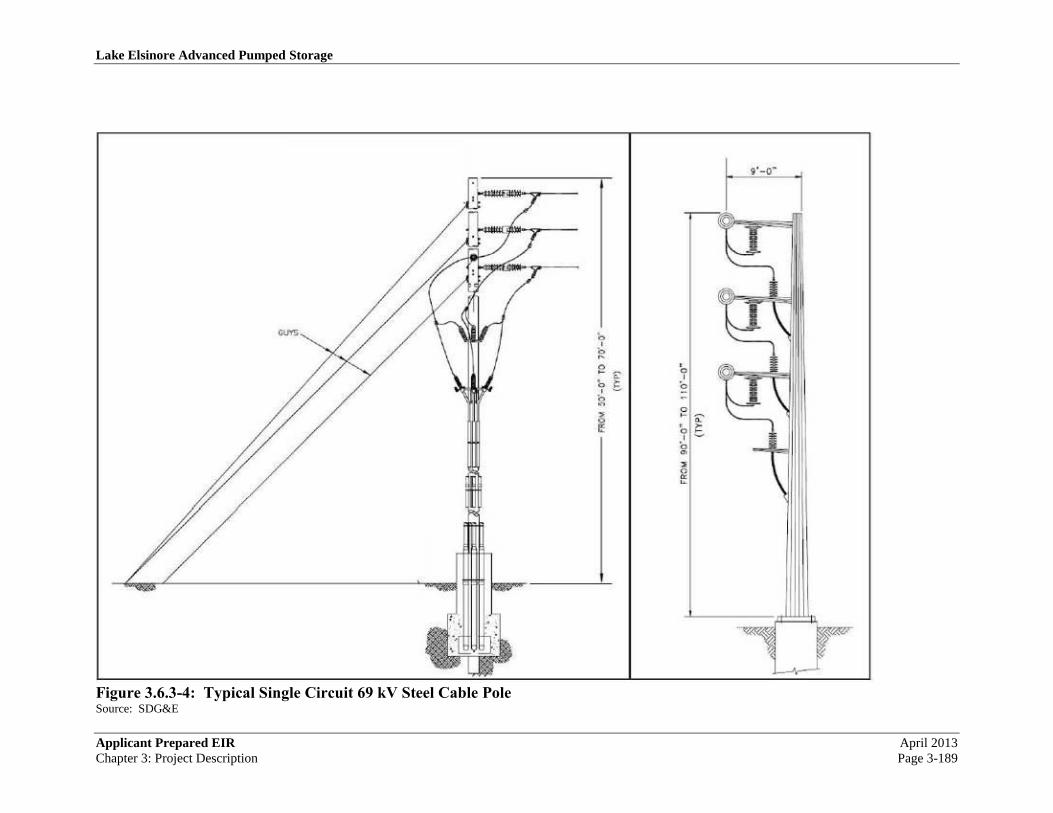
Lake Elsinore Advanced Pumped Storage
Applicant Prepared EIR April 2013
Chapter 3: Project Description Page 3-189
Figure 3.6.3-4: Typical Single Circuit 69 kV Steel Cable Pole Source: SDG&E
Lake Elsinore Advanced Pumped Storage
September 2017 Applicant Prepared EIR
Page 3-190 Chapter 3: Project Description
3.7 Right-of-Way Requirements
The right-of-way (ROW) requirements of the Project include approximately 32 miles of
transmission ROW along with two substations and one switchyard, powerhouse, upper reservoir
and other facilities. Roughly 90% of the ROW is on federal land, specifically within the Trabuco
Ranger District of the Cleveland National Forest. As described in Section 3.1, LEAPS is subject
to licensing through the FERC and is the subject of an FEIS issues by FERC and the US Forest
Service.
A detailed description of the ROW is contained in Chapter 4 and a listing of all parcels is
contained in Chapter 7.
As the Project is subject to permitting at both the Federal and state levels, the Applicant is unable
to discern with certainty if any particular parcel is required at this time.
3.8 Construction
For the purposes of this PEA, the Project consists of two components: TE/VS Interconnect and
LEAPS. Construction activities for each would include establishment of staging areas for
materials and equipment, development of access roads and spur roads to reach construction sites
and development of support staging areas. All construction activity areas are designated on
figures referenced individually in the following discussion.
3.8.1 General Approach for Project Construction
For the TE/VS Interconnect, new tower construction would include clearing of footing locations,
installation of foundations, tower assembly, and tower erection. After towers are in place, crews
would proceed with stringing of conductor and overhead ground wires. Construction would be
completed with clean-up of construction sites and demobilization of personnel and equipment.
The exact construction methods employed and the sequence with which construction tasks occur
would be dependent on final engineering, contract award, conditions of permits, and contractor
preference.
For LEAPS, construction activities would include clearing and laydown area preparation for
materials and equipment, excavation spoil temporary and permanent disposal area clearing,
grading and drainage construction, upper reservoir clearing and overburden stripping for the
reservoir and embankment foundations, and general construction trailer set-up with utilities,
temporary fencing, and parking areas. Areas for disposal or stockpile areas for natural earth
stripping materials would be identified or temporary stockpile areas would be designated in the
event that the stripping materials are re-used in the construction of the dam. Tunnel spoil
stockpile or disposal areas will also be cleared and graded to drain off and around the spoils.
Temporary construction support facilities such as temporary office trailers and parking areas
would be established. Temporary utilities would be established near the tunnel outlet area and at
the upper reservoir, with local sources of power, telephone, water, and sanitary facilities
provided. If local utilities are unavailable, all power will be provided by portable generators, and
all water and sanitary facilities would be supplied and serviced remotely.

Lake Elsinore Advanced Pumped Storage
Applicant Prepared EIR September 2017
Chapter 3: Project Description Page 3-191
In general, construction efforts would occur in accordance with accepted construction industry
standards. Construction activities above ground generally would be scheduled during daylight
hours (7:00 A.M. to 5:00 P.M.), Monday through Saturday. Underground construction may
proceed round-the-clock, Monday through Saturday or under an alternate extended schedule, if
permitted. When different hours or days are necessary, the Applicant would obtain variances, as
necessary, from the jurisdiction in which the work would take place. All materials associated
with construction efforts would be delivered by truck or helicopter to established staging and
material laydown areas. Delivery activities requiring major street use such as Grand Avenue or
Ortega Highway would be scheduled to occur during off-peak traffic hours.
Previously disturbed areas would be used during construction wherever possible. Once sites for
construction areas are proposed, biological and cultural resource reviews would be conducted
before final site selection. The size of individual construction areas would vary from a fraction
of an acre to up to as much as 10 acres, depending on its purpose for construction. In addition to
construction materials and equipment, these areas may contain trash and recycle bins.
Preparation of the construction areas will including site clearing and grubbing, site grading and
drainage preparation, and in all cases, the implementation of Storm Water Pollution Prevention
Plan (SWPPP) best management practices.
The following sections provide more detailed information about the construction tasks that
would be associated with the TE/VS Interconnect line and LEAPS.
3.8.1.1 Primary Staging Areas
Primary staging areas would be used to stage equipment and materials during the TE/VS
Interconnect and Talega-Escondido upgrade construction activities. Materials and equipment
typically staged at these staging areas would include, but would not be limited to, tower steel
bundles, tubular steel poles, spur angles, palletized bolts, rebar, wire reels, insulators and
hardware, heavy equipment, light trucks, construction trailers, and portable sanitation facilities.
Also, material that would be removed from existing transmission lines during work associated
with the Talega Escondido reconductoring efforts and new steel pole construction for the
relocation of the 69 kV line will require staging areas. Dismantled construction materials such as
conductor, steel, concrete, and other debris would be temporarily stored in designated areas as it
awaits salvage, recycling, or disposal or directly loaded into transport to selected permitted
facilities. All effort will be made to ensure that salvageable or recyclable materials will be
recovered in accordance with state waste management guidelines.
TE/VS Interconnect project would include several staging yards that would be selected based on
accessibility to construction locations and proximity to transmission line and substation access
roads, (4 of them are shown on Figure 3.1.1-4: Talega-Escondido/Valley-Serrano 500 kV
Interconnect Project).
Where possible, previously disturbed areas would be used. An area up to 5-10 acres in size and
within 5 or less air miles of the tower locations is required for each primary staging areas. In
addition to construction materials and equipment, these staging areas may contain trash and
recycle bins. Preparation of the primary staging areas would include the application of road
Lake Elsinore Advanced Pumped Storage
September 2017 Applicant Prepared EIR
Page 3-192 Chapter 3: Project Description
base, installation of perimeter fencing, and implementation of SWPPP best management
practices.
In addition to the primary staging areas, secondary staging areas would be established for short-
term utilization near construction sites. Where possible, the secondary staging areas would be
sited in areas of previous disturbance along the construction corridors. Final siting of these
staging areas would depend upon availability of appropriately zoned property that is suitable for
this purpose. The number and size of the secondary staging areas would be dependent upon a
detailed ROW inspection and would take into account, where practical, suggestions by the
successful bidder for the work. Typically, an area approximately 1 to 3 acres would be required.
Once sites for secondary staging areas are proposed, biological and cultural resource reviews
would be conducted before final site selection. Preparation of the secondary staging areas would
include installation of perimeter fencing, and implementation of SWPPP best management
practices. Application of road base may also occur, depending on existing ground conditions at
the yard site.
3.8.1.2 Work Areas
Working areas for foundation, erection and string works will be established on the tower
locations, and will be re-instated once the construction works are completed..
3.8.1.3 Access Roads and Spur Roads
Transmission line roads are classified into two groups: access roads and spur roads. Access
roads are through roads that run between tower sites along an ROW and serve as the main
transportation route along line ROWs. Spur roads are roads that lead from line access roads and
terminate at one or more tower sites.
The TE/VS Interconnect line will require approximately 75 new spur and access roads. The
majority of these features can be classified as spur roads, since they consist of short sections of
new or improved road that branch off existing roads and do not follow the transmission line
right-of-way. The locations of all spur and access roads are also shown on Figure 3.1.1-4:
Talega-Escondido/Valley-Serrano 500 kV Interconnect Project.
This project includes construction on both existing ROW and new ROW. Where construction
would take place on existing ROW, it is assumed that most of the existing access roads as well as
spur roads would be used. However, it is also assumed that rehabilitation work would be
necessary in some locations for existing roads to accommodate construction activities. This
work may include:
Existing access and spur roads may be re-graded and repaired. These roads would be cleared of
vegetation, blade-graded to remove potholes, ruts, and other surface irregularities, and re-
compacted to provide a smooth and dense riding surface capable of supporting heavy
construction equipment. The graded road would have a minimum drivable width of 12 feet and
preferably a shoulder width of an additional 2 feet.

Lake Elsinore Advanced Pumped Storage
Applicant Prepared EIR September 2017
Chapter 3: Project Description Page 3-193
Drainage structures such as wet crossings, water bars, overside drains and pipe culverts would be
installed to allow for construction traffic usage, as well as prevent road damage due to
uncontrolled water flow. Slides, washouts, and other slope failures would be repaired and
stabilized by installing retaining walls or other means necessary to prevent future failures. The
type of structure to be used would be based on specific site conditions.
Where construction would take place in new ROW, which is particularly applicable to the
TE/VS Interconnect line, new access and spur roads would be necessary to access the
transmission line structure locations, unless these sites are initially designated as helicopter-
access only sites. All proposed access roads will require review and approval by the Forest
Service prior to construction. Biological and cultural surveys have been performed for all the
proposed access roads as part of this PEA effort. Specific detailed environmental conditions are
presented in Attachment 4.
Similar to rehabilitation of existing roads, all new road alignments would first be cleared and
grubbed of vegetation. Roads would be blade-graded to remove potholes, ruts, and other surface
irregularities, and re-compacted to provide a smooth and dense riding surface capable of
supporting heavy construction equipment. The graded road would have a minimum drivable
width of 12 feet (preferably with 2 feet of shoulder on either side). In addition, drainage
structures (e.g., wet crossings, water bars, overside drains, pipe culverts, and energy dissipaters
would be installed along spur and access roads to allow for construction equipment usage as well
as to prevent erosion from uncontrolled water flow. Landslides, washouts, and other slope
failures would be repaired and stabilized along the roads by installing retaining walls or other
means necessary to prevent future failures. The type of mechanically stabilized earth-retaining
structure to be used would be based on site-specific conditions.
It is anticipated that most of the roads constructed to accommodate new construction would be
left in place to facilitate future access for operations and maintenance purposes. Gates would be
installed where required at fenced property lines to restrict general and recreational vehicular
access to road ROWs.
Construction roads across areas that are not required for future maintenance access would be
removed and restored after construction is completed. An example of this type of road would be
a road constructed to provide access to a splice location during wire-stringing operations. Splice
locations are used to remove temporary pulling splices and install permanent splices once the
conductor is strung through the stringing travelers located on transmission structures. Access
roads to splice locations are sometimes required when a splice location is not accessible from an
access or spur road.
3.8.1.4 Helicopter Use
In the event that there are no existing access roads, contractors would hike in or be shuttled to the
tower locations by helicopter. Helicopters would be used to transport equipment to tower sites.
Segments of LST towers will be preassembled in the staging areas and will be airlifted to the
tower location, and erected on to the already prepared foundations. It is estimated that the
helicopter would generally operate up to 8 hours per day, Monday through Friday. The
operating area of the helicopters would be limited to helicopter staging areas, material and

Lake Elsinore Advanced Pumped Storage
September 2017 Applicant Prepared EIR
Page 3-194 Chapter 3: Project Description
equipment staging areas, and positions along the utility corridors that have previously been used
for this purpose and are safe locations for landing.
Use of helicopters for installation eliminates land disturbance associated with crane pads,
structure laydown areas, and the trucks and tractors used for steel delivery to structure sites.
Figure 3.1.1-4: Talega-Escondido/Valley-Serrano 500 kV Interconnect Project designates the
tower sites anticipated for helicopter-only construction. All construction work in remote work
sites would be completed by hand with the assistance of portable compressors, portable hydraulic
accumulators, and portable concrete mixers that would be flown into the tower sites. The use of
helicopters for the erection of LSTs would be in accordance with the construction specifications
and would be similar to methods detailed in IEEE 951-1966, Guide to the Assembly and
Erection of Metal Transmission Structures, Section 9, Helicopter Methods of Construction.
During helicopter operations, public access to defined areas would be restricted. Temporary
road closures, traffic detours, and posted notices and signs would be used to restrict public access
to construction areas.
Final siting of staging areas for the TE/VS Interconnect line would be conducted with the input
of the helicopter contractor, and affected private landowners and land management agencies.
The size of each staging area would be dependent upon the size and number of towers to be
installed. Staging areas would likely change as work progresses.
Helicopter fueling would occur at staging areas or at local airports using the helicopter
contractor’s fuel truck, would be supervised by the helicopter fuel service provider, and SWPPP
measures would be followed, as applicable. The helicopter and fuel truck would stay overnight
at a local airport or at a staging area if adequate security is in place.
3.8.1.5 Vegetation Clearance
Minimal vegetation clearing will be performed as required for construction of the project
components. Care will be taken to minimize soil disturbance during construction and
restoration, plus for temporary construction disturbance, areas will be developed with agency
concurrence as part of the design and mitigation process.
3.8.1.6 Erosion and Sediment Control and Pollution Prevention during Construction
In compliance with the CWA, site construction activities would be consistent with National
Pollutant Discharge Elimination System (NPDES) program requirements, which would include
development of an SWPPP for the site before construction commences. The SWPPP would
focus on implementation of Best Management Practices and other actions during construction to
protect the quality of waters near the construction site.
Construction of new substations and associated access roads would require earthwork activities.
Construction sites would first be cleared of vegetation and loose rock and then graded to provide
a near-level surface with site slope designed to collect and control drainage that minimizes
surface erosion. Sites would be graded such that water would run toward the direction of the
natural drainage. In addition, drainage would be designed to prevent ponding and erosive water
flows that could cause damage to the tower footings.

Lake Elsinore Advanced Pumped Storage
Applicant Prepared EIR September 2017
Chapter 3: Project Description Page 3-195
Soils generated from the grading activities would be tested to determine if environmental
contamination is present before soil removal for disposal. During grading operations, dust would
be controlled by measures outlined in the SWPPP.
Construction debris from activities at each substation site would be placed in appropriate onsite
containers and periodically disposed of per applicable regulations.
3.8.2 Transmission Line Construction (Above Ground)
This section describes the specific plans for each of the construction area types and individual
components of the TE/VS Interconnect line above ground construction. This includes the
activities associated with the substations, the new TE/VS Interconnect overhead line
construction, and the Talega-Escondido (TE) reconductoring work.
3.8.2.1 Pulling and Splicing Locations
The dimensions of the area needed for the stringing setups associated with wire installation are
variable and depends upon terrain. On average, however, pulling and splicing equipment set-up
sites require an area of 200 feet by 200 feet (0.92 acre); however, crews can work from within a
slightly smaller area when space is limited. These locations require level areas to allow for
maneuvering of the equipment. When possible, pulling and splicing locations would be located
on existing level areas and existing roads to minimize the need for grading and cleanup.
Stringing set-up locations on Forest Service land that would be located outside the established
utility corridor would be authorized under a temporary Special Use Permit as necessary. All
stringing equipment & splicing locations are identified and shown in Figure 3.1.1-4: Talega-
Escondido/Valley-Serrano 500 kV Interconnect Project, defined as pulling sites, and identified in
the legend as Proposed Construction Work Area. Additional splicing locations may only be
known after final design is accomplished.
Each pulling location would include one puller positioned at one end and one tensioner and wire
reel stand truck positioned at the other end. Specialized support equipment such as skidders and
wire crimping equipment would be strategically positioned to support the operations. Pulling
and splicing set-up locations would be used to remove temporary pulling splices and install
permanent splices once the conductor is strung through the rollers located on each tower, and are
necessary as the permanent splices that join the conductor together cannot travel through the
rollers. For stringing equipment that cannot be positioned at either side of a dead-end
transmission tower, field snubs (i.e., anchoring and dead-end hardware) would be temporarily
installed to sag conductor wire to the correct tension.
The puller, tensioner, and splicing set-up locations associated with the construction are
anticipated to disturb a total of approximately 317 acres. These disturbances would be
temporary and the land would be restored to its previous condition following completion of
pulling and splicing activities. Estimates of the land disturbance associated with this activity for
each segment are provided in Table 3.8.2-1, Estimate of Land Disturbance for Substation Sites.

Lake Elsinore Advanced Pumped Storage
September 2017 Applicant Prepared EIR
Page 3-196 Chapter 3: Project Description
All pulling & splicing locations are indicated on Figure 3.1.1-4: Talega-Escondido/Valley-
Serrano 500 kV Interconnect Project, defined as Construction Work Area Polygons.
Table 3.8.2-1: Estimate of Land Disturbance for Substation Sites Lake Switchyard Santa Rosa Substation Case Springs Substation
Dimensions
(Ft)
Area of
Disturbance (Ac)
Dimensions
(Ft)
Area of
Disturbance (Ac)
Dimensions
(Ft)
Area of
Disturbance (Ac)
Substation
Pad
300 ft W
900 ft L 6.20 ac
310 ft W
407 ft L 2.90 ac
300 ft W
900 ft L 6.20 ac
Side Slope
Grading 0.14 ac. 2.11 ac.
Primary
Access Road
Temescal
Canyon Rd. County Rd.
Santa Rosa
Avenue County Rd.
SDG&E
Access Rd. Camp Pendleton
Total
Estimated 6.34 ac. 5.01 ac. 6.2 ac.
Source: The Nevada Hydro Company
3.8.2.2 Pole Installation and Removal
3.8.2.2.1 Grading and Excavation
For the construction tower pads, each location would first be graded and/or cleared to provide a
reasonably level and vegetation-free surface for footing construction. Sites would be graded
such that water would run toward the direction of the natural drainage. In addition, drainage
would be designed to prevent ponding and erosive water flows that could cause damage to the
tower footings. The graded area would be compacted to at least 90 percent relative density, and
would be capable of supporting heavy vehicular traffic.
An area of approximately 2,000 to 3,000 square feet would be required to accommodate the four
footings needed for each new lattice steel tower (LST).
In mountainous helicopter-access areas, benching may be required to provide access for footing
construction, assembly, erection, and wire-stringing activities during line construction. Benching
is a technique in which, either manually or by a tracked earth-moving vehicle, a terraced access
is excavated in extremely steep and rugged terrain. It would be used minimally and for two
purposes:
1. To help ensure the safety of personnel during construction activities.
2. To control costs in situations where potentially hazardous, manual excavations would be
required.
An illustration of this technique appears as Figure 3.8.2-1: Typical Benching on LST

Lake Elsinore Advanced Pumped Storage
Applicant Prepared EIR September 2017
Chapter 3: Project Description Page 3-197
Figure 3.8.2-1: Typical Benching on LST Source: Siemens Power Transmission & Distribution
3.8.2.2.2 Foundations
Foundation pits for structure foundations would typically be either excavated by (i) excavators
(foundation-type for good soil), (ii) rock excavation by means of drilling and blasting (rock
foundation) or (iii) rock anchors grouted into solid rock (rock anchor foundations). The
maximum augur depth below ground surface for the various types of towers, are expected to be
about 35 feet for a 500KV Four-legged Single Circuit Lattice Steel Tower.
Actual foundation depth & design would depend on the soil conditions and topography at each
site and would be determined after the soil-investigation during final engineering. However, it is
expected that the majority of towers would have foundation depth substantially less than the max
depth listed above.
For those tower locations marked with H (Helicopter access only) on Figure 3.1.1-4: Talega-
Escondido/Valley-Serrano 500 kV Interconnect Project, all necessary equipment for excavation
of the foundation pits, drilling rig for the rock anchors as well as auguring the holes for the
blasting will be flown in by helicopter. Blasting will be done in accordance with prevailing
blasting conditions and regulations of the State and the Forest Service.
A foundation set for each LST would include four footings.
Following excavation of the foundation pits, reinforcing steel and stub angles would be installed
and the concrete would then be placed. Steel reinforced cages and stub angles would be
assembled at lay-down areas and delivered to each tower location by flatbed truck or helicopter.
During construction, existing concrete supply facilities would be used where feasible, while in
more remote areas, temporary concrete batching plant may be set up on staging areas.
Lake Elsinore Advanced Pumped Storage
September 2017 Applicant Prepared EIR
Page 3-198 Chapter 3: Project Description
Equipment would include a central mixer unit (drum type), three silos for injecting concrete
additives, fly ash, and cement, a water tank; portable pumps; a pneumatic injector; and a wheel
loader for handling concrete additives (sand & crushed gravel) not in the silos. Dust emissions
would be controlled by watering the area and by sealing the silos and transferring the fine
particulates pneumatically between the silos and the mixer.
Concrete would be hauled to tower sites by standard or 4WD mixer truck’s and to tower
locations marked with (H) by helicopter. At any given lattice steel tower, no more than eight
concrete mixer trucks would be working to support the installation of the needed footings. A
second lattice steel tower footing project could be under way at the same time, thus doubling the
quantity of trucks working. One footing on a 500 kV lattice steel tower could require as much as
16 to 20 cubic yards of concrete, depending on the final foundation design.
Topsoil will be excavated and stored at a separate location and will be used after backfilling as
the final top layer. Suitable excavated material will be used for backfilling the foundation pits;
the excess material or material not suitable for backfilling will either be used for landscaping
around the tower location or be removed from the construction site and disposed at designated
sites as permitted.
Concrete samples would be drawn at time of pour and tested according to prevailing
specification after 7 and 28 days to ensure engineered strengths were achieved. Once the
required concrete compression strength has been achieved, crews would be permitted to
commence with the erection of the tower steel.
3.8.2.2.3 Tower and Pole Assembly
At the structure fabrication plant, structural members would be bundled and shipped by rail or
trucks to the construction yards, and then trucked to the accessible tower locations. At the tower
site, sections would be pre-assembled and erected by crane or derrick post.
At tower locations marked with (H), tower members or prefabricated tower sections will be
flown to the individual tower locations and erected by helicopter.
Assembly and erection of structure required would consist of four main activities.
1. Assembly of tower sections
2. Erection of the tower sections
3. Torque down bolts and nuts to the designed torque.
4. Final cleanup
Installation of insulators and sheaves and the final checkout and cleanup would then conclude
structure assembly and erection.
3.8.2.2.4 Tower and Pole Erection
The use of helicopters for the erection of LSTs would be in accordance with construction
specifications and would be similar to methods detailed in IEEE 951-1966, Guide to the
Assembly and Erection of Metal Transmission Structures, Section 9, Helicopter Methods of
Construction. During helicopter operations, public access to defined areas would be restricted.

Lake Elsinore Advanced Pumped Storage
Applicant Prepared EIR September 2017
Chapter 3: Project Description Page 3-199
Temporary road closures, traffic detours, and posted notices and signs would be used to restrict
public access to construction areas.
The operations area of the helicopters would be limited to helicopter staging areas and positions
near construction locations that have been designated for this purpose and are considered safe
locations for landing. Final sitting of staging areas for the TE/VS Interconnect line would be
conducted with the input of the helicopter contractor, and affected private landowners and land
management agencies. The size of each staging area would be dependent upon the size and
number of towers to be installed. Staging areas would likely change as work progresses.
Helicopter fueling would occur at staging areas or at a local airport using the helicopter
contractor’s fuel truck, would be supervised by the helicopter fuel service provider, and SWPPP
measures would be followed, as applicable. The helicopter and fuel truck would stay overnight
at a local airport or at a staging area if adequate security is in place.
3.8.2.3 Conductor/Cable Installation
Wire-stringing includes all activities associated with the installation of conductors onto the LSTs
and for the TE/VS Interconnect and for TE re-conductoring at the 230KV Talega – Escondido
transmission line. This activity includes the installation of primary conductor and ground wire,
vibration dampeners, weights, spacers, and suspension and dead-end hardware assemblies.
Insulators and stringing sheaves (rollers or travelers) are attached as part of the wire-stringing
activity if the work is a part of a re-conductoring effort; otherwise they are typically attached
during the steel erection process. Wire-stringing activities would be conducted in accordance
with the construction specifications, which is similar to process methods detailed in IEEE
Standard 524-1992, Guide to the Installation of Overhead Transmission Line Conductors. A
standard wire-stringing plan includes a sequenced program of events starting with determination
of wire pulls tension and wire pull equipment set-up positions. Advanced planning by
supervision determines circuit outages, pulling times, and safety protocols needed for ensuring
that safe and quick installation of wire is accomplished.
Prior to stringing activities, temporary protective netting systems or wood pole guard structures
would be erected at crossings for roads, streets, railroad, highways, or other transmission,
distribution or communication facilities, as required. On roads where traffic is light, guard
structures may not be necessary, however, the use of barriers, flagmen, and/or temporary
stopping of traffic would be required.
The stringing of conductor and overhead ground-wire including OPGW on new transmission
lines typically commence once a number of structures (sections between 2 tension towers) have
been erected, inspected and approved for stringing. Stringing equipment locations would be
temporarily set up adjacent to tension towers. These could be areas 200 feet to 300 foot in size
adjacent to access roads (within the ROW) and spaced approximately every three to fifteen
thousand feet, depending on the accessibility and topography of transmission line.
Due to the very mountainous terrain within the CNF, approximately 54% of the tower locations
will only be accessible by means of helicopter. For these, a helicopter would pull a lightweight
pilot line through the conductor sheaves. The lightweight pilot-line will be used to subsequently

Lake Elsinore Advanced Pumped Storage
September 2017 Applicant Prepared EIR
Page 3-200 Chapter 3: Project Description
pull larger pilot wires, which finally will pull the ground wire, OPGW and conductor into
position by the means of stringing equipment.
We have identified tower locations on which the setup of stringing equipment and conductor
reels could have an excessive impact. In order to avoid the environmental impact we have
worked out the following preliminary work program, which may be revised during the final line
design. The following example is based on tower locations shown on Figure 3.1.1-4: Talega-
Escondido/Valley-Serrano 500 kV Interconnect Project, page 4 of 23, Section T 26 to T30 &
T32
• T26 will be the staging area for the conductor reels and rolling machine, on T 32 will be
the staging area of the winch machine.
• The conductor will be pulled through from T 26 to T32, also having an angle tension
tower T30 in between.
• Once the conductor tension clamp is finally hooked to the insulator on T26, the winch
machine placed at T32 will pull the conductor into almost sag position.
• At T30 the stringing crew will place working clamps in both directions to T26 and T 32
and they will install chain hoists with adequate capacity, and sag the conductor in
accordance to temperature and sagging chard into final sag.
• The conductor on T30 will be cut to the required length and the compression dead end
clamps will be installed and attached to the insulator string.
• At T32 the crew after rechecking the sag will also install the compression dead end clamp
and attach it to the insulator string.
• The same method applies for the ground wire too.
• OPGW in anyway will have longer designed sections for splicing, but the stringing
method will be the same, however, instead of compression dead end clamp a preformed
helix grip will be used.
The same stringing method as described above applies for the following sections which are
marked “H” for helicopter erection, and identified in Table 3.8.2-2: Tower Sections Marked for
Helicopter Erection.
Table 3.8.2-2: Tower Sections Marked for Helicopter Erection* Page 4 of 23 T32 via T36 to T39
Page 5 of 23 T41 via T42 to T43
Page 6 & 7 of 23 T43 via T46 via T49 via T51 to T53
Page 7 of 23 T53 via T55 to T56
Page 7 & 8 of 23 T56 via T57 to T58
Page 10 & 11 of 23 T64 via T68 via T71 to 74
Page 11 & 12 of 23 T74 via T76 to T79
Page 12,13 & 14 of 23 T81 via T84 to T90
Page 14,15,16 & 17 of 23 T93 via T107 to T109
Page 18 of 23 T113 via T115 via 116 to T119
Page 19 & 20 of 23 T121 via T128 to T130
Page 21 & 22 of 23 T134 via T136 to T138 *All references are to pages appearing in Figure 3.1.1-4: Talega-Escondido/Valley-Serrano 500 kV Interconnect Project.
Source: The Nevada Hydro Company

Lake Elsinore Advanced Pumped Storage
Applicant Prepared EIR September 2017
Chapter 3: Project Description Page 3-201
To ensure the safety of workers and the public, safety devices such as traveling grounds, guard
structures, and radio-equipped public safety roving vehicles and linemen would be in place prior
to the initiation of wire-stringing activities.
The following four steps describe the wire installation activities proposed to be used:
Step 1: Sock Line; Threading: A helicopter would fly a lightweight sock pilot line from tower to
tower, which would be threaded through the wire rollers in order to engage a cam-lock device
that would secure the pulling sock in the roller. This threading process would continue between
all towers through the rollers of a particular set of spans selected for a conductor pull.
Step 2: Pulling: The sock lightweight pilot line would be used to pull in the conductor pulling
cable. The conductor pulling cable would be attached to the conductor using a special swivel
joint to prevent damage to the wire and to allow the wire to rotate freely to prevent complications
from twisting as the conductor unwinds off the reel. A piece of hardware known as a running
board would be installed to properly feed the conductor into the roller; this device keeps the
bundle conductor from wrapping during installation.
Step 3: Splicing, Sagging, and Dead-ending: After the conductor is pulled in, all mid-span
splicing would be performed. Once the splicing has been completed, the conductor would be
sagged to proper tension and dead-ended to towers.
Step 4: Clipping-in, Spacers: After conductor is dead-ended, the conductors would be attached
to all tangent towers; a process called clipping in. Once this is complete, spacers (in accordance
to an approved installation schedule) would be attached between the bundled conductors of each
phase to keep uniform separation between each conductor.
As noted above, the threading step of wire installation would require helicopter use. While only
one small helicopter is needed, two helicopters may be used to shorten the time for this phase.
On average, each helicopter would operate 4 hours per day during stringing operations. The
operations area of the small helicopter would be limited to helicopter staging areas and positions
along the utility corridor that have previously been sited for this purpose and are considered safe
locations for landing. Final sitting of staging areas for the TE/VS Interconnect transmission line
would be conducted with the input of the helicopter contractor, and affected private landowners
and land management agencies. The size of each staging area would be dependent upon the size
and number of towers to be removed and installed. Staging areas would likely change as work
progresses along the transmission lines?
Helicopter fueling would occur at staging areas or at local airports using the helicopter
contractor’s fuel truck, and would be supervised by the helicopter fuel service provider. The
helicopter and mobile fuel truck would stay overnight at a local airport or at a staging area if
adequate security is in place.
3.8.2.4 Guard Structure Installation

Lake Elsinore Advanced Pumped Storage
September 2017 Applicant Prepared EIR
Page 3-202 Chapter 3: Project Description
Guard poles or guard structures may be installed at transportation, flood control, and utility
crossings. Guard structures may also be installed at other locations such as parks or near
residences. These are temporary facilities designed to stop the travel of a conductor should it
momentarily drop below a conventional stringing height, and are removed after conductors are
installed. If required, temporary netting would be installed to protect some types of under-built
infrastructure. In some cases, guard structures can be specially equipped boom type trucks with
heavy outriggers. Typical guard structures are standard wood poles, 60 to 80 feet tall, arranged
in such a manner as to arrest the travel of conductor should it momentarily drop below a
conventional stringing height. Depending on the width of the line being constructed, the number
of guard poles installed on either side of a crossing would be between 2 and 4.
Public agencies differ on their policies for guard structures and their preferred methods for public
safety. For highway and open channel aqueduct crossings, the applicant would work closely
with the applicable jurisdiction to secure the necessary permits to string conductor across the
applicable infrastructure. For major roadway crossings, typically one of the following four
methods is employed to protect the public:
• Erection of a highway net guard structure system.
• Detour of all traffic off of the highway at the crossing position.
• Implementation of a controlled continuous traffic break while stringing operations are
performed.
• Establishment of special line trucks with extension booms onto the highway deck at
strategic positions.
3.8.3 Transmission Line Construction (Below Ground)
3.8.3.1 General
Depending upon final cost and engineering, any of the following four underground technologies
may be commercially available for 500 kV transmission: Gas Insulated Line (GIL); high-
pressure fluid-filled (HPFF) cables; self-contained fluid-filled (SCFF) and solid dielectric
(XLPE) transmission cables.
Below ground construction consists of two defined tunnels. The first is the Ridge Tunnel which
runs between towers 63 at MP 11.5 and 64 at MP 13.2, roughly in line with the South Main
Divide Road. The second is the Santa Rosa Tunnel which connects the Ridge Tunnel to the
Santa Rosa Substation. The arrangement of the tunnels is depicted in Figure 3.1.1-4: Talega-
Escondido/Valley-Serrano 500 kV Interconnect Project, sheets 9, 23 and 24, Figure 3.6.1-3:
North & South Transition Plan (Typical), sheet 2 of 3 and Figure 3.6.1-5: GIL Vault Elevations.
GIL (Gas Insulated Line): Installation of GIL would require an underground tunnel from Mile
Post 11.5 to MP 13.2 (the Ridge Tunnel), with a transition point to the OHL on each end. At MP
12.3 an underground tunnel will link the TE-VS interconnect to the Santa Rosa Substation (the
Santa Rosa Tunnel). In this tunnel the 2 GIL circuits will connect northward to Lake Switchyard
and southward to Case Spring Substation. These two circuits will turn into north and south
directions at MP 12.3. At the Santa Rosa Substation the GIL will be directly connected to the

Lake Elsinore Advanced Pumped Storage
Applicant Prepared EIR September 2017
Chapter 3: Project Description Page 3-203
500kV GIS Switch Gear. See Figure 3.6.1-3: North & South Transition Plan (Typical) for an
illustration of the transition structures.
Cable Link: Installation of HPFF, SCFF or XLPE transmission cables will require generally the
same underground tunnel already described for construction of the GIL system. In addition to
the tunnel on the north end (MP 11.5) and on the south end (MP 13.2), a 500 KV switch yard
would be required to accommodate the protection equipment (CB’s) for the cable solution, and
additional room would be required for the fluid pressurization equipment needed for the HPFF
Cable.
While HPFF and SCFF are feasible technologies, they have a potential to release dielectric fluid
into the environment. HPFF or SCFF cables installed in a tunnel bear a risk of a fire hazard
during a fault in the electrical system. If HPFF cable were installed, additional space would be
required at the transition station for the fluid pressurization equipment.
A small number of 500 kV XLPE systems have been installed worldwide to date.
Underground transmission cable manufacturing constraints limit the maximum cable size. In
many cases, it is not possible for underground transmission lines to match the capability of
overhead transmission lines without the installation of more underground cables than overhead
conductors. For example, a 500 kV overhead transmission line requires six conductors, whereas
under grounding would require a minimum of nine, and possibly up to twelve cables.
3.8.3.2 Tunnels: General
In mountainous terrain, the underground tunnel design will result in construction that will be
compatible with the mechanical restrictions associated with 500 kV underground cables. In
addition, the gravitational pull on the cables in terrain with significant uphill and downhill grades
would require the installation of anchoring facilities in order to minimize cable slippage. As
with any high-voltage facility, the design would include the installation of the cables and
associated underground infrastructure with proper access for maintenance. For all tunnels, the
anticipated construction method will be “Drill and Blast” which, being sub-surface, will cause
minimal disturbance to existing ground conditions. The configuration of all of the tunnels is
shown in Plate 24 of Figure 3.1.1-4: Talega-Escondido/Valley-Serrano 500 kV Interconnect
Project.
3.8.3.3 Construction of Vertical Shafts for the Ridge Tunnel
Construction of the Ridge Tunnel will begin with the installation of four vertical access shafts at
locations that, to the extent possible, match the existing terrain and topography, and that also are
able to minimize the depth of the shafts below the surface. One of these access shafts will be
located at each end of the Ridge Tunnel, that is near Towers 63 and 64. The other two vertical
access shafts will be placed approximately at the mid-point between the transition point to the
upper end of the Santa Rosa Tunnel and the towers, one on each side.
A fifth vertical access shaft will be located above the transition point of the Ridge Tunnel to the
top of the vertical section of the Santa Rosa Tunnel to provide access and a connection to the

Lake Elsinore Advanced Pumped Storage
September 2017 Applicant Prepared EIR
Page 3-204 Chapter 3: Project Description
transition point and will extend vertically down to meet up with lower section of the Santa Rosa
Tunnel. This shaft cannot be used as access for construction of the Ridge Tunnel because it will
be excavated much deeper than the Ridge Tunnel invert and tunnel crews cannot work above
crews on other tunnels.
The five vertical access shafts will be separated by approximately two thousand two hundred
feet.
All of the five vertical access shafts will be constructed simultaneously to minimize schedule
requirements.
3.8.3.4 Construction of the Ridge Tunnel
Excavation of the Ridge Tunnel will commence as soon as the access shafts have been
completed and load-out facilities have been assembled. The excavation of the tunnel will
proceed toward the east from the Tower 63 shaft for approximately 1,100 feet. Similarly, the
excavation of the tunnel will proceed simultaneously to the west from the Tower 64 shaft for
approximately 1,100 feet. At the same time, excavation will begin at the two mid-point access
shafts and will proceed in two directions from each: one approximately eleven hundred feet
1,100 feet toward the tower until it meets with the crew coming from the direction of the
respective tower, the other approximately 2,200 feet in the direction of the transition point to the
Santa Rosa Tunnel. Therefore, up to a maximum of six excavation crews will be deployed. The
east and west sections will converge together and with the vertical shaft of the Santa Rosa
Tunnel at a transition point at elevation approximately 2,508 msl.
Removed materials will be lifted out of the shaft and will be moved to the Decker Canyon
temporarily for use in the construction of the dam associated with the LEAPS upper reservoir.
The Ridge Tunnel will be approximately 12 feet x 12 feet and will be lined with shotcrete.
Further details are shown in Figure 3.6.1-5: GIL Vault Elevations.
3.8.3.5 Construction of the Santa Rosa Tunnel
The average slope of the Santa Rosa Tunnel directly from the substation to the transition point at
the Ridge Tunnel is around 25%. As this is too steep for excavation and mining equipment, the
Santa Rosa Tunnel will be constructed in two parts: one is a horse shoe-shaped lower section
beginning at the substation, which will incline upward at approximately 10%, and the other is a
cylindrical vertical access shaft section of around 872 feet extending from the surface elevation
of 2,813 msl down to the connection with the lower section at elevation 1,941 msl. which will
connect to the transition point.
3.8.3.5.1 Construction of the Lower Section of the Santa Rosa Tunnel
Excavation of the lower section will commence after a portal shaft has been installed for access
by equipment and crews. The excavation will proceed in a direction to coincide with the lower
end of the vertical shaft. The upward slope of the tunnel will be approximately 10%

Lake Elsinore Advanced Pumped Storage
Applicant Prepared EIR September 2017
Chapter 3: Project Description Page 3-205
The horseshoe-shaped Ridge Tunnel will be approximately 13 feet x 13 feet and will be lined
with shotcrete. Further details are shown in Figure 3.6.1-5: GIL Vault Elevations.
3.8.3.5.2 Construction of the Vertical Shaft for the Santa Rosa Tunnel
Construction of the Vertical Access Shaft for the Santa Rosa Tunnel will begin at the upper end
in the area of the transition point where the Ridge Tunnel will connect to the Santa Rosa Tunnel.
The exact location of the shaft has been optimized in consideration of the requirements of the
topography. The height of the shaft will be approximately 872 feet. As mentioned above, this
shaft will not be used for construction of the Ridge Tunnel.
Before excavation can begin, a large headworks and permanent elevator structure must be
installed for safe construction and also for providing access to the lower section of the tunnel.
Once the headworks and elevator structure have been completed, the excavation of the vertical
shaft can begin in a downward direction. Removed materials will be lifted out of the shaft by a
conveyor or similar equipment and will be moved to the nearby Decker Canyon area for use in
the construction of the LEAPS dam.
The vertical shaft will be circular in cross section, with a finished inside diameter of
approximately 16 feet. The walls will be lined with reinforced concrete to carry loads applied by
the suspended equipment. Access for maintenance and inspection to the equipment in the
vertical shaft will be by permanent elevator and a suitable system of permanent and removable
platforms. Further details are shown in Figure 3.6.1-5: GIL Vault Elevations.
3.8.3.6 Disposal of Removed Material
3.8.3.6.1 Material Removed during Mining Operations
The TE/VS construction schedule shown on Table 3.8.7-1: TE/VS Interconnect Construction
Schedule, calls for mobilization beginning November 2010, at which time the tunneling
operations would begin as critical path tasks. The LEAPS construction schedule (Table 3.8.6-2:
LEAPS Construction Schedule) calls for mobilization in March 2011, and the construction of the
Upper Reservoir at Decker Canyon is a first priority. At Decker Canyon, an area will be set
aside immediately for the temporary deposition of removed materials from tunneling associated
with the Ridge Tunnel and also the vertical access shaft and the upper part of the lower section of
the Santa Rosa Tunnel. These materials will eventually be used in the construction of the dam at
the Upper Reservoir in Decker Canyon.
The vertical access shaft at the upper end of the Santa Rosa Tunnel will progress downwards to
the designated lowest elevation (approximately 2,100 feet msl) and then the crew will move into
the lower section and progress in the direction of the Santa Rosa site. Work will also commence
as soon as possible after mobilization in the lower section of the Santa Rosa Tunnel at the Santa
Rosa Substation location, and the crew will move toward the vertical access shaft. The two crews
will meet up in the lower section. Materials removed from the vertical access shaft
(approximately 8,500 cubic yards) and from the lower section down to the meeting point
(approximately 13,000 cubic yards) will be taken to the top and will be deposited at the Decker
Canyon temporary site. The remaining approximately 19,000 cubic yards removed from the
Lake Elsinore Advanced Pumped Storage
September 2017 Applicant Prepared EIR
Page 3-206 Chapter 3: Project Description
Santa Rosa Tunnel from the Santa Rosa end will be utilized in the grading to a level condition of
the Santa Rosa Substation area, for which approximately 20,000-25,000 cubic yards are needed.
3.8.3.6.2 Material Removed during Tower Installation
Topsoil will be excavated and stored at a separate temporary location and will be used after
backfilling as the final top layer. Suitable excavated material will be used for backfilling the
foundation pits; the excess material or material not suitable for backfilling will either be used for
landscaping around the tower location or be removed from the construction site and disposed of
at designated sites as permitted.
3.8.4 Substation and Switchyard Construction
3.8.4.1 General Construction Considerations – All Sites
Substation and switchyard construction would include construction of three new facilities:
• The Lake Switchyard on the northern end of the project, at MP 2.0.
• The Santa Rosa Substation near the LEAPS Powerhouse, roughly midway between the
Lake Switchyard and Case Springs Substation, offset one mile to the southeast from
roughly MP 12.3.
• The Case Springs Substation at the southern end of the TE/VS Interconnect line, at MP
31.2.
Minor upgrades to protection and communications equipment at SCE’s Valley and Serrano
Substations, new line positions, and protection and communications equipment at SDG&E’s
Talega and Escondido Substations are also included in the project. In general, construction
efforts would occur in accordance with accepted construction industry standards. Work
generally would be scheduled during daylight hours (7:00 A.M. to 5:00 P.M.), Monday through
Saturday. When different hours or days are necessary, the Applicant would obtain variances, as
necessary, from the jurisdiction in which the work would take place. All materials associated
with construction efforts would be delivered by truck to the individual substation sites or by train
to the Camp Pendleton rail head and then trucked up to the Case Springs site. Delivery activities
requiring major street use would be scheduled to occur during off-peak traffic hours.
Construction of new substations, substation expansions, and associated access roads would
require earthwork activities. Construction sites would first be cleared of vegetation and loose
rock and then graded to provide a near-level surface. Soils generated from the grading activities
would be tested to determine if environmental contamination is present before soil removal for
disposal. During grading operations, dust would be controlled by measures outlined in the
SWPPP.
Installation of new equipment and structures at each substation requires excavation for major
reinforced concrete footings, GIS equipment slabs, transformer foundations oil containment pits
and water separators. In parallel with the foundation excavation cable duct trenches are dug.
Soil from these excavations would be redistributed on substation property.

Lake Elsinore Advanced Pumped Storage
Applicant Prepared EIR September 2017
Chapter 3: Project Description Page 3-207
Construction debris from activities at each substation site would be placed in appropriate onsite
containers and periodically disposed of per applicable regulations. All construction will be
performed by licensed experience substation construction contractors under the control of a
general site contractor. Major civil portions of the work including earth work, foundations cable
trenching, ground mat, drainage SWPPP, etc. will be performed by the civil contractor. The
electrical installation will be performed by qualified electrical contractor this work involves
equipment assembly, installation, cable and wiring terminations, etc.
The Applicant plans to enter into a turn-key project agreement with a major firm for overall
electrical system level design, high voltage equipment supply and substation construction. This
firm will develop overall EPC requirements incorporating design standards from SCE &
SDG&E. The general contractor or Engineer Procure and Construct (EPC) will select qualified
subcontractors including specialized contractors for fiber cable splicing, paving access roads
with in the switch yards, fencing, environmental screening and testing, painting, etc. This firm
will provide supervisory field engineers for equipment assembly and commissioning. System
level design has been performed by Siemens SPTI and PT&D with oversight from CAISO, SCE
and SDG&E during the CAISO CSRPT process. Detail design will be performed by a major
EPC contractor who will also serve as the general site contractor. Construction design and
construction drawings will be prepared by the EPC contractor, and all design will be prepared by
or under the supervision of a California Professional Engineer (PE). Commissioning and
energization will be conducted by a joint commissioning team consisting of Siemens, SCE and
SDG&E field engineers in cooperation with CAISO.
Drainage. The drainage for any site would be developed during final engineering design to
control surface runoff. Typical drainage improvements would consist of concrete swales,
ditches, and culverts. Surface runoff from existing upslope areas would be modified to direct the
flow around the substation facility. Surface runoff would be mitigated as needed through the use
of earthen berms and energy dissipation devices, such as filter cloths, slope drains, and riprap
placed near drain openings. All of these methods are designed to minimize the velocity of
surface water runoff and protect the landscape from erosion.
In compliance with the CWA, site construction activities would be consistent with NPDES
program requirements, which would include development of an SWPPP for the site before
construction commences. The SWPPP would focus on implementation of Best Management
Practices and other actions during construction to protect the quality of waters near the
construction site.
Access. The primary facility access would be via a new 30 foot wide asphalt concrete paved
road with 5 foot wide compacted dirt shoulders connecting the main substation entrance to the
exterior access roads.
Paving. For all sites, asphalt concrete paving would be applied to the facility access road and to
all designated internal driveways over an aggregate base material and a properly compacted sub-
grade, as recommended by the results of geotechnical investigation at the site.

Lake Elsinore Advanced Pumped Storage
September 2017 Applicant Prepared EIR
Page 3-208 Chapter 3: Project Description
Surfacing. For all sites, those areas within the substation perimeter that are not paved or
covered with concrete foundations or trenches would be surfaced with a 4-inch layer of
untreated, ¾-inch nominal crushed rock. The rock would be applied to the finished grade surface
after all grading and below grade construction has been completed.
Spill Control and Countermeasures (SPCC) Plan. A SPCC plan would be required for all
sites. Under United States Environmental Protection Agency (EPA) CWA regulations, the
owner of a substation facility is required to implement an SPCC plan if the facility meets the
following three criteria:
The facility is not related to transportation.
The oil containing equipment at the facility has an aggregate of at least 1,320 gallons (only
considering containers that are 55 gallons or more) or an underground oil storage capacity of at
least 42,000 gallons.
There is a reasonable expectation of discharge into or upon navigable waters of the United States
or adjoining shorelines. In addition, regulations by the State of California independently require
that an SPCC plan be implemented for any facility with an aboveground oil storage capacity of at
least 10,000 gallons. The total storage capacity of the oil containing equipment of the
interconnection facilities at the Lake Switchyard exceeds 1,320 gallons; therefore it would
trigger the threshold for the EPA requirement for an SPCC plan. The Applicant would proceed
with preparation of an SPCC plan in accordance with state and federal requirements.
Storm Water Pollution Prevention Plan (SWPPP). Storm water management measures would
be in place to ensure that contaminants are not discharged from the site. A SWPPP would be
developed that would define areas where hazardous materials would be stored; where trash
would be placed; where rolling equipment would be parked, fueled and serviced; and where
construction materials, such as reinforcing bars and structural steel members, would be stored.
Erosion control during grading of the unfinished site and during subsequent construction would
be in place and monitored as specified by the SWPPP. One or more basins would be established
to capture silt and other materials that might otherwise be carried from the site by rainwater
surface runoff. Site improvements may result in impervious areas from all concrete foundations
used for equipment and structures, and asphalt and concrete driveways. Management of
drainage from these areas would be addressed in the facility drainage plan.
Perimeter Security. All alternative sites would require 8 foot high chain link perimeter fence
with barbed wire and double drive gates.
The following sections describe the site-specific construction activities that would be associated
with the various substations and switchyards that are part of the proposed TE/VS Interconnect.
3.8.4.2 Lake Switchyard
The Lake Switchyard would be located north and east of Interstate 15 northwest of the city of
Lake Elsinore, at MP 2.0, as shown on Figure 3.1.1-4: Talega-Escondido/Valley-Serrano 500

Lake Elsinore Advanced Pumped Storage
Applicant Prepared EIR September 2017
Chapter 3: Project Description Page 3-209
kV Interconnect Project. The substation site is located just north of the junction of Temescal
Canyon Road and Lee (Corona) Lake.
Most activities supporting construction of the Lake Switchyard would be common to all sites,
although there would be some variation in the amounts of total disturbance required based on the
pad configuration on each site and road access to each site. A conceptual grading plant for the
Lake Switchyard site is presented in Figure 3.8.4-1: Lake Switchyard Conceptual Grading Plan.
Site Preparation. The following elements of site preparation would be required for the Lake
Switchyard:
• Clear and grub any vegetation and organic materials from the area.
• Grade the entire substation pad.
• Grade the cut and fill side slopes to blend the existing terrain with the new pad.
• Grade and install the substation access roads.
• Excavation for all subsurface features, primarily buried conduits and below-grade
construction for structure foundations.
Prior to the start of grading, the entire area to be graded would be stripped of all organic matter
and loose rocks. Any waste material encountered would be removed as required by the
environmental and geotechnical investigations. Waste collected from these stripping operations
would be tested for contamination.
The proposed Lake Switchyard would be located on previously disturbed land adjacent to Lee
Lake. For the purposes of determining environmental impacts, an average of 2 inches of
stripping is anticipated over the entire substation site resulting in an estimated quantity of 15,000
cubic yards of soil mixed with small stones and organic matter that would need to be transported
from the site and disposed of at an appropriate waste disposal facility.
Construction within the switchyard after site preparation involves footings up to 12 feet deep to
support equipment and steel structures. The major foundations include the 500 kV switch gear
pad. In addition, a network of partially buried concrete trenches, approximately 800 feet in total
length, would be installed. The estimated total volume of soil that would need to be excavated
for foundation and trenches is 1,200 cubic yards, and would be spread on a portion of the
switchyard property.
Guard Structure Installation. Foundations of various sizes would be constructed throughout
the switchyard pad to support equipment and steel structures. In addition, a network of partially
buried concrete trenches would be installed. Excavations of these foundations and trenches
would commence following the completion of grading and other yard improvements, and would
continue for several weeks. The estimated total volume of soil that would need to be excavated
for foundation and trenches will be determined in future design stages, but excess excavated soils
would be spread on a portion of the switchyard property.
3.8.4.3 Santa Rosa Substation

Lake Elsinore Advanced Pumped Storage
September 2017 Applicant Prepared EIR
Page 3-210 Chapter 3: Project Description
Site Preparation. The conceptual plan for the Santa Rosa Substation site, located roughly
midway between the Lake Switchyard and Case Springs Substation, offset one mile to the
southeast from roughly MP 12.3, is presented in Figure 3.8.4-2: Santa Rosa Substation
Conceptual Grading Plan. Prior to the start of grading, the entire area to be graded would be
stripped of all organic matter and loose rocks. Any waste material encountered would be
removed as required by the environmental and geotechnical investigations. Waste collected
from these stripping operations would be tested for contamination. Once the surface has been
cleared, the grading operations would begin. An estimated 15,000 cubic yards of material
removed from the Santa Rosa Tunnel would be added to the 5,000 cubic yards areas of material
cut from the higher elevation of the site and placed as fill over the lower elevation to match the
500 kV substation elevation. During grading operations, dust would be controlled by measures
outlined in the SWPPP.
Foundation Excavation. Foundations of various sizes would be constructed throughout the
substation pad to support equipment and steel structures. In addition, a network of partially
buried concrete trenches approximately 200 feet in total length would be installed. Excavations
of these foundations and trenches would commence following the completion of grading and
other yard improvements, and would continue for several weeks. The estimated total volume of
soil that would be excavated for foundation and trenches is about 1,800 cubic yards, and would
be spread on a portion of the substation property.
3.8.4.4 Case Springs Substation
Site Preparation. For the Case Springs Substation, at MP 31.5, the proposed 500/230 kV
substation would require an area approximately 363 feet wide by approximately 771 feet, and
would comprise approximately 7 acres. Construction would involve grading on a steep slope.
The conceptual grading plan for the Case Springs Substation is presented in Figure 3.8.4-3: Case
Springs Substation Conceptual Grading Plan. To limit significantly the quantity of earthwork
that would be needed to extend the area, a crib wall would be constructed along the majority of
the perimeter of the site. Most of the northerly and easterly sides of the site would be in cut, with
the crib wall height varying from 1 foot high at each end to approximately 160 feet high near the
center. Most of the southerly and westerly sides of the site would involve a fill situation, with
the crib wall varying from 1 foot high to approximately 75 feet high. The pad area of the
substation site would be over-excavated, backfilled, and compacted to recommended
requirements. The final crib wall design and the actual quantity of soil required for backfill
would be calculated during final engineering.
The 500/230 kV substation would require that an estimated 545,000 cubic yards of soil would be
cut from higher elevations and relocated to the lower elevations as fill to provide a level pad with
a slope between 1 and 2 percent. The amount of fill required would be about 70,000 cubic yards,
which would require approximately 475,000 cubic yards of soil to be exported from the site.
Conceptual grading plans for the alternate Case Springs Substation sites are presented in Figure
3.8.4-4: Case Springs Fallbrook Alternative – Conceptual Grading Plan and Figure 3.8.4-5:
Case Springs Fern Creek Alternative – Conceptual Grading Plan.

Lake Elsinore Advanced Pumped Storage
Applicant Prepared EIR September 2017
Chapter 3: Project Description Page 3-211
Figure 3.8.4-1: Lake Switchyard Conceptual Grading Plan Source: The Nevada Hydro Company

Lake Elsinore Advanced Pumped Storage
September 2017 Applicant Prepared EIR
Page 3-212 Chapter 3: Project Description
Figure 3.8.4-2: Santa Rosa Substation Conceptual Grading Plan Source: The Nevada Hydro Company

Lake Elsinore Advanced Pumped Storage
Applicant Prepared EIR September 2017
Chapter 3: Project Description Page 3-213
Figure 3.8.4-3: Case Springs Substation Conceptual Grading Plan Source: The Nevada Hydro Company

Lake Elsinore Advanced Pumped Storage
September 2017 Applicant Prepared EIR
Page 3-214 Chapter 3: Project Description
Figure 3.8.4-4: Case Springs Fallbrook Alternative – Conceptual Grading Plan Source: The Nevada Hydro Company

Lake Elsinore Advanced Pumped Storage
Applicant Prepared EIR September 2017
Chapter 3: Project Description Page 3-215
Figure 3.8.4-5: Case Springs Fern Creek Alternative – Conceptual Grading Plan Source: The Nevada Hydro Company

Lake Elsinore Advanced Pumped Storage
September 2017 Applicant Prepared EIR
Page 3-216 Chapter 3: Project Description
3.8.5 Upgrade Construction
3.8.5.1 Talega-Escondido Line Upgrades
The Appicant proposes to remove the existing 230 kV and 69 kV LSTs through the following
activities:
Grading: Existing access routes would be used to reach tower sites, but some rehabilitation
work on these routes may be necessary before removal activities begin. In addition, grading may
be necessary to establish crane pads for reconductoring work. Construction of most segments of
the TE line upgrades would require the removal and reconductoring of the existing transmission
line. Transmission line equipment to be removed includes existing 69 kV conductors. New 69
kV poles and associated hardware (i.e., insulators, vibration dampeners, suspension clamps,
ground wire clamps, shackles, links, nuts, bolts, washers, cotters pins, insulator weights, and
bond wires), as well as the transmission line primary conductor and ground wire will be installed
along a new route as designated on Figure 3.6.3-1: Talega-Escondido 230 kV Line Upgrade.
3.8.5.2 IT Facility Construction
New OPGW or optical fiber is typically installed in continuous segments of 5,000 feet or less,
depending upon various factors including line direction, inclination, and accessibility. Following
placement of fiber on the OHGW, the strands in each segment are spliced together to form a
continuous length from one end of a transmission line to the other. Splices occur near the foot of
transmission towers, and may be identified by the metal enclosures (3 feet by 3 feet by 1 foot)
that are mounted on the tower legs some distance above the ground. At a splice tower, the fiber
cables are routed down a tower leg and into the bottom of the metal enclosure where the splice
case is placed. On the last tower at each end of a transmission line, the overhead fiber is spliced
to another section of fiber cable that runs in underground conduit from the tower into the
communication room inside the adjacent substation.
Splicing activities are conducted by dedicated crews. Typically activities are conducted by two
crews per each segment, with three persons in each crew. Each crew is also accompanied by a
foreman. Both crews and foremen use pickup trucks for transport of materials along
transmission line segments. All materials are carried in vehicles; therefore, no staging areas are
needed to support OPGW installation. Crews typically complete four splices per 8 hour work
period.
The Applicant proposes to remove the existing 230 kV and 69 kV LSTs through the following
activities:
Grading: Existing access routes would be used to reach tower sites, but some rehabilitation work
on these routes may be necessary before removal activities begin. In addition, grading may be
necessary to establish crane pads for reconductoring work.
The Contractor anticipates a construction schedule of approximately 10 to 12 months for this
project, with steel assembly to take place while foundations are being installed along with the
legs and body extensions, structures to be flown in month six (6) or seven (7) and being ready to

Lake Elsinore Advanced Pumped Storage
Applicant Prepared EIR September 2017
Chapter 3: Project Description Page 3-217
start wire installation starting in month seven (7) or eight (8). Utilization of helicopters during
installation of legs and body extensions and especially during the wire installation greatly
improves efficiency, minimizes environmental impact and keeps the Project on schedule.
3.8.6 Construction Workforce and Equipment
The TE/VS Interconnect and LEAPS construction workforces for have been estimated. Table
3.8.6-1: TE/VS Construction Equipment/Workforce and Table 3.8.6-2: LEAPS Construction
Equipment/Workforce presents those estimates of workforce for the TE/VS Interconnect and
LEAPS.
Table 3.8.6-1: TE/VS Interconnect Construction Equipment/Workforce
TE/VS Construction
Equipment Type Number
Hrs/Day
No. of
shifts x
hrs/shift
No.
days/week
Duration
Needed
Personnel
Number
Above-Ground Transmission Lines
4x4 Pickups/Work Trucks 4 1 x 10 6 10 to 12 months Supervision 4
4x4 One-Ton Framers 4 1 x 10 6 10 to12 months Framers 12
Skycrane 1 1 x 10 6 3 to 4 month Pilots 2
1 1 x 10 6 3 to 4 month Ground Crew 2
Mid-Capacity Lift
Helicopter 2
1 x 10 6 2 to 3 months Pilots
2
1 x 10 6 2 to 3 months Ground Crew 2
Yard Crane (30-ton) 3 1 x 10 6 10 to 12 months Operator 1
D-8 Sag Cat 1 1 x 10 6 4 to 5 months Operator 1
Bundle Tensioner 1 1 x 10 6 4 to 5 months Operator 1
50-Thousand Pound Pulling
Rig 1
1 x 10 6 4 to 5 months Operator
1
3 Reel Wire Trailers 3 1 x 10 6 4 to 5 months Operator 3
4 Drum Pullers with 3/8”
Hardline 2
1 x 10 6 4 to 5 months Operator
2
Digger Derrick for Guard
Poles 1
1 x 10 6 4 to 5 months Teamster
1
Fifth Wheel Trucks 6x6 3 1 x 10 6 4 to 5 months Teamster 3
Extra Float Trailer 40’/60’ 1 1 x 10 6 10 to 12 months Operator 1
Hughes 500 helicopters 2 1 x 10 6 7 to 8 months Pilots 3
2 1 x 10 6 7 to 8 months Ground Crew 3
Office Trailer 1 1 x 10 6 10 to 12 months Secretary 1
Tool Van 1 1 x 10 6 10 to 12 months Warehouseman 1
Bundle Fly Travelers 200 1 x 10
6 7 to 8 months
OHGW and OPGW Fly
Travelers 150
1 x 10 6 7 to 8 months
Reel Jacks for OHGW and
OPGW 2
1 x 10 6 4 to 5 months Operator
2
Water Trucks 2 1 x 10 6 7 to 8 months Operator 2
Hydraulic Pole Jack 1 1 x 10 6 3 to 4 weeks Operator 1
Below-Ground Transmission Lines

Lake Elsinore Advanced Pumped Storage
September 2017 Applicant Prepared EIR
Page 3-218 Chapter 3: Project Description
TE/VS Construction
Equipment Type Number
Hrs/Day
No. of
shifts x
hrs/shift
No.
days/week
Duration
Needed
Personnel
Number
4 X 4 Pickup 12 2 x 12 7 16 to 18 months Operator 18
Yard Cranes 18 ton 6 2 x 12 7 10 to 12 months Operator 6
200 ton track crane 4 2 x 12 7 10 to 12 months Operator 4
Double Drum Mine Hoist 1 2 x 12 7 14 to 16 months Operator 2
Drill Jumbo- 2 boom 9 2 x 12 7 14 to 16 months Operator 18
3.5 CY Scoop Tram 16 2 x 12 7 10 to 12 months Operator 32
16-Ton Mine Truck 4 2 x 12 7 10 to 12 months Operator 8
Shotcrete Pump & Nozzle 7 2 x 12 7 3 to 5 months Operator 14
950 CAT Loader 6 2 x 12 7 10 to 12 months Operator 9
Small Motor Grader 1 2 x 12 7 10 to 12 months Operator 2
10 CY Dump truck 12 2 x 12 7 10 to 12 months Operator 18
1400 CFM Air Compressor 6 2 x 12 7 10 to 12 months
500kW Genset 6 2 x 12 7 10 to 12 months
1000kW Genset 2 2 x 12 7 10 to 12 months
Fuel truck 1 2 x 12 7 14 to 16 months Operator 2
Office Trailers 10 2 x 12 7 18 to 19 months Secretary 4
Tool Van 6 2 x 12 7 12 to 14 months Warehouseman 2
Superintendent 6
Engineers 10
Lead miner 28
Miner 96
Top Landers 22
Bottom
Landers
22
Surface
Laborers
44
* Note: Equipment and Personnel needs vary for the anticipated duration of the project.
Source: The Nevada Hydro Company
Table 3.8.6-2: LEAPS Construction Equipment/Workforce
LEAPS Construction Equipment Type Number
Hrs/Day
No. of shifts x
hrs/shift
No. days/week
CAT 436 Rubber Equipment Backhoe 1 2x10 5
Ready Mix Truck 3 2x10 5
150-Ton Crane 1 2x10 5
250-Ton Crane 1 2x10 5
25-Ton Crane 1 2x10 5
60-Ton Crane 1 2x10 5
CAT D10R Dozer 1 2x10 5
CAT D6 Dozers 5 2x10 5
CAT D8R Dozer 3 2x10 5

Lake Elsinore Advanced Pumped Storage
Applicant Prepared EIR September 2017
Chapter 3: Project Description Page 3-219
LEAPS Construction Equipment Type Number
Hrs/Day
No. of shifts x
hrs/shift
No. days/week
CAT Motor Graders 1 2x10 5
Misc. Compressors & Generators 20 2x10 5
Portable Light Plants 10 2x10 5
CAT Loaders 6 2x10 5
CAT Compactors 2 2x10 5
CAT Scrapers 4 2x10 5
CAT Rock Trucks 5 2x10 5
Crew & Supervisory Pickups 20 2x10 5
Grout Plant 1 2x10 5
Tunnel Drill Jumbos 4 2x10 5
Tunnel Scoop Trams 4 2x10 5
Water Trucks 5 2x10 5
Tunnel Boring Machine 1 2x10 5
Over the road Haul Trucks 20 2x10 5
Workforce Number
Laborers 40
Teamsters 25
Heavy Equipment Operators 60
Tunnel Personnel 70
Carpenters 10
Ironworkers 10
Mechanics & Welders 5
Supervisory 35
Note: Equipment and Personnel needs vary for the anticipate 5-year duration of the project.
Source: The Nevada Hydro Company
3.8.7 Construction Schedule
The TE/VS Interconnect and LEAPS may be bid to different construction contractors under
different work scopes. Based on the current understanding of sequencing, the TE/VS
interconnect will be constructed first, followed by the LEAPS construction. Table 3.8.7-1:
TE/VS Interconnect Construction Schedule, below, presents the anticipated development
schedule for the TE/VS Interconnect and Table 3.8.7-2: LEAPS Construction Schedule presents
the anticipated development schedule for LEAPS.

Lake Elsinore Advanced Pumped Storage
September 2017 Applicant Prepared EIR
Page 3-220 Chapter 3: Project Description
Table 3.8.7-1: TE/VS Interconnect Construction Schedule
Source: The Nevada Hydro Company
Table 3.8.7-2: LEAPS Construction Schedule
Source: The Nevada Hydro Company
3.8.8 Excavation Volumes
As shown in Table 3.8.8-1: Excavation Volumes, combined fill volumes of the upper dam at
Decker Canyon and the embankments at the intake works at Lake Elsinore are estimated to be
2,839,000 cubic yards. It is therefore expected that excavation and fill volumes will be
approximately balanced. Please also refer to FERC EIS Paragraph 2.3.2-Construction Sequence.
Event Days Expected Start Running Days
Re-submit PEA 11/1/13 0
Data Adequate/Schedule 14 11/15/13 14
Prehearing Conf 14 11/29/13 28
File Testimony 14 12/13/13 42
Rebuttal Testimony 14 12/27/13 56
Reply Testimony 14 1/10/14 70
Hearings Start 14 1/24/14 84
Hearings End 14 2/7/14 98
Initial Brief 21 2/28/14 119
Reply Brief 14 3/14/14 133
Proposed PUC Decision 21 4/4/14 154
Final CPCN -- CEQA Cert 30 5/4/14 184
Forest Service SUP 21 5/25/14 205
TE/VS Financial Close 7 6/1/14 212
NTP 0 6/1/14 212
Construction TE/VS 0 6/1/14 212
Mobilize 30 7/1/14 242
Start Construction 9 7/10/14 251
Complete Construction 480 11/2/15 731
Energize TEVS 5 11/7/15 736
Event Days Expected Start Running Days
SWRB 401 Permit 28 6/1/2014 212
FERC Hydro License 21 6/22/2014 233
Forest Service SUP 21 7/13/2014 254
LEAPS Financial Close 30 8/12/2014 284
NTP 0 8/12/2014 284
Construction LEAPS 14 8/26/2014 298
Mobilize 30 9/25/2014 328
Start Construction 9 10/4/2014 337
Complete Construction 1424 8/28/2018 1761
Energize LEAPS 5 9/2/2018 1766

Lake Elsinore Advanced Pumped Storage
Applicant Prepared EIR September 2017
Chapter 3: Project Description Page 3-221
Table 3.8.8-1: Excavation Volumes Project Component Excavation volume (cu yards)
Upper reservoir (will be re-used in dam where possible) 2,036,000
Penstock, (headrace, including adits, inlets etc)) 177,500
Powerhouse cavern 207,000
Powerhouse access shaft 53,000
Powerhouse draft tubes 6,000
Penstock (tailrace) 65,000
Ventilation shaft 500
Surge shaft 32,000
Lower reservoir intake 200,000
Santa Rosa Tunnel 33,000
Ridge Tunnel 56,000
Total volume 2,866,000 Source: The Nevada Hydro Company
3.9 Operation and Maintenance
3.9.1 Operation and Maintenance for the TE/VS Interconnect.
Operation and maintenance (O&M) functions are described in this section. The section
addresses O&M activities associated with the TE/VS Interconnect followed by a description of
O&M activities associated with the pumped hydro facility.
3.9.1.1 Substation Operation and Maintenance
The TE/VS Interconnect involves two operating segments. The northern interface with the SCE
main grid involves power flows on the existing Valley – Serrano 500 kV line, which will be
under the control of SCE, CAISO and the laws of physics. The southern interface with SDG&E
and power flows on the Talega – Escondido 230 kV line, are under control of SDG&E, CAISO
and the same laws physics. CAISO’s energy center dispatchers and schedulers will have
operational control of the breakers, transformer tap positions, generation schedules, power flow,
and phase shifting operations. Both SCE and SDG&E operation centers will have real time
monitoring of power flows, energy exchanges, reactive power flows, protection status,
equipment status via existing supervisory control and protection systems (SCADA). Protection,
control and communication interfaces with SCE and SDG&E will be in accordance with existing
WECC requirements and Good Utility Practice. SCE and SDG&E will furnish, operate, and
maintain the area wide RAS or SPS system in cooperation with CAISO.
Substation maintenance activities would include equipment testing, monitoring, and repair to
prevent service interruptions. It is anticipated that routine maintenance activities would require
approximately six trips per year to each 500/230 kV substation by a two to four person crew.
General substation monitoring and control functions are performed remotely from the operation
centers. Regular operation of the substation would require one or two workers in a light utility
truck to visit the substation on a weekly basis. Once per year, a major maintenance inspection
would be conducted that would require 20 personnel for approximately one week. To prevent

Lake Elsinore Advanced Pumped Storage
September 2017 Applicant Prepared EIR
Page 3-222 Chapter 3: Project Description
unauthorized entry, warning signs would be posted and fencing and locked gates would be
present at all substations sites. In addition, a remotely monitored security system will be
installed and monitored by the powerhouse staff. Portions of the stations maintained and
operated by SCE and SDG&E will be remotely alarmed to the respective utilities operations
centers.
The GIS would require only one visual inspection per year by 2 persons for approximately 2
days. Please also see the attached table for suggested maintenance requirements.
Maintenance activities fall into two categories: planed schedule maintenance and unplanned or
corrective maintenance. Schedule maintenance will be in accordance with the various
manufacturers’ recommended maintenance schedules. Schedule maintenance requiring
equipment outages will be coordinated with CAISO in advance. Corrective maintenance is
performed as required, generally when equipment monitoring devices connected to SCADA or
SER and routine operator equipment inspection trigger corrective actions. Both scheduled and
unscheduled maintenance will be performed without line or station outages when possible. If an
outage is required the maintenance will be performed during off load periods in accordance with
CAISO direction based on power system status. The substation and transmission lines will be
designed to meet or exceed the WECC reliability requirements.
3.9.1.1.1 Lake Switchyard and Santa Rosa Substation
Monitoring, control and communications with SCE at Lake Switchyard will be in accordance
with existing SCE design standards as defined in the LGIA and applicable requirements of
SCE’s Interconnection Handbook. SCE and the CAISO will have operational control over the
Serrano – Lake 500 kV line breakers at Serrano and Lake as well as the Lake – Valley 500 kV
line breakers at Valley. The Applicant and the CAISO will have control over the Lake – Santa
Rosa 500 kV breakers at Lake Switchyard, at the Santa Rosa Substation and Case Springs
Substation.
Prior to commercial operation the portion of the substation associated with the SCE breaker
positions, 500/13.8 kV auto transformers, control, protection and communications will be
transferred to SCE ownership in accordance with the LGIA. At that time, SCE will assume
operational control and maintenance responsibility. Both parties will comply with the applicable
Reliability Council requirements, and the Applicant will execute the Reliability Management
System Agreement for the Applicable Reliability Council. Each Party will provide to the other
Party all information that may reasonably be required by the other Party to comply with
Applicable Laws and Regulations and Applicable Reliability Standards.
The Applicant will use SCE monitoring, control and communication design standards at the
Santa Rosa Substation and for all of the 500 kV developments including the Case Springs
southern terminal. Further, the Applicant will contract with SCE or some other experienced
utility services origination for operation and maintenance services.
The maintenance contractor will be required to have qualified personal available for around the
clock call-outs to investigate equipment status as required by CAISO dispatchers. Based upon

Lake Elsinore Advanced Pumped Storage
Applicant Prepared EIR September 2017
Chapter 3: Project Description Page 3-223
such initial findings, the corrective action will be performed or scheduled when the power
system can accommodate possible outages or when required crews and equipment is available.
One of the advantages of the planed GIS system is the reduced maintenance schedules, compared
with air insulated equipment.
3.9.1.1.2 Case Springs Substation
At Case Springs, the 230 kV yard will be constructed using SDG&E design standards for
monitoring, control, and communications. Prior to commercial operations, a similar turnover to
SDG&E will occur with SDG&E taking over operational control of the Talega – Escondido 230
kV breaker positions, control, protection and communications. The Applicant will maintain
ownership of the 500 kV switchyard, and transformers up to 230 kV phase shifting transformer
disconnects. Both yards will utilize a common bus differential system.
Transition to commercial operations will be similar to the process described for SCE above. At
both points of interconnection, the control, protection and communications systems will be tested
and energized by a joint commissioning team. The team will include design and maintenance
engineers/technicians/craftsman from the Applicant and transmission operators from SCE or
SDG&E. The process will be performed in accordance with well established field test plans and
existing operating procedures. Tagging, clearance, and outage procedures will be implemented
prior to energization at a time when control of the facility is transferred from the construction
contractor to utility station operators. After successful commissioning including concurrence
from both parties that the facility is ready for commercial operation, operational control will
transferred to CAISO.
3.9.1.2 Line Operation and Maintenance
Operation and maintenance activities would include all operation and maintenance requirements
set forth by CAISO, and CPUC General Orders including activities such as patrol of the lines,
climbing inspections, tower and wire maintenance, routine line washing, and repairs of access
and spur roads. The Applicant would keep necessary work areas around all structures clear of
vegetation and, to the extent permitted by the Forest Service, would limit the height of vegetation
along the ROW. Lines will be inspected frequently and thoroughly for the purpose of insuring
that they are in good condition so as to conform to these rules. Lines temporarily out of service
shall be inspected and maintained in such condition as not to create a public hazard. The
following section provides details on the anticipated operation and maintenance requirements for
the Project.
3.9.1.2.1 Inspection Patrols
Regular ground and aerial inspections would be performed in accordance with the CAISO
requirements per the Transmission Control Agreement between CAISO and the Applicant
concerning transmission facility maintenance. Overhead transmission lines and substations
would be inspected for corrosion, equipment misalignment, loose fittings, and other mechanical
problems. The need for vegetation management would also be determined during inspection
patrols. As required by CAISO, aerial inspection (visual and infrared) of the entire system and

Lake Elsinore Advanced Pumped Storage
September 2017 Applicant Prepared EIR
Page 3-224 Chapter 3: Project Description
climbing inspections of transmission structures would be conducted annually. Aerial inspection
would be conducted by helicopter and would require two or three crewmembers, including the
pilot.
The lattice towers specified, can be climbed for visual inspections. Roughly 20% of the above
ground structures will be visually inspected per year. This would mean approximately 28 to 29
structures per year, would be physically climbed, and/or visually inspected.
Ground inspections, including underground system components within each GIL tunnel, would
be conducted by up to three crewmembers twice a year. The proposed GIL system includes gas
pressure alarm, ground current detection, and protective trip capability. If a cable system is
installed, the same inspections would take place.
3.9.1.2.2 Hardware Maintenance and Repairs
Electrical equipment located on transmission structures includes conductors, insulators, switches,
dampers, and other electrical equipment. Although under normal operating conditions 500 kV
lines are maintenance free, this equipment may require addition, replacement or repair over time.
Damage from gun fire during hunting seasons or abnormally severe weather are the probable
causes for line maintenance. Localizing faulted sections of the line is performed by operations
staff using the installed fault locater systems. Typically, equipment repair or replacement would
be conducted by a four-person crew with two or three trucks, a boom or line truck, an aerial truck
and an assist truck.
In the event of a brush fire under the transmission line, ionized smoke partials can cause line to
ground faults or phase to phase faults. Modern line protection relays will detect high impedance
faults and open line protection relays. Normally, mid line faults do not cause permanent damage
and the line can be returned to service when the fire has moved off of the right-of-way. Such an
event would be followed up with a visual inspection for possible resulting damage.
3.9.1.2.3 Insulator Washing
Arcing can occur when an electrical discharge is created from the combination of atmospheric
condensation, bird contamination on suspension insulators, salt water spray on coastal
installations and dust accumulation on porcelain insulators. Arcing may cause electrical outages,
but can be prevented by routinely washing the insulators to keep them free of dust. Insulator
washing on 500 kV lines is normally not necessary except in heavily contaminated areas, good
design and line location practices avoid line location adjacent to industrial contamination or
naturally occurring sources. If washing is required two crewmembers and a water truck are
required for insulator washing. Typically, insulator washing takes approximately 30 minutes per
transmission structure if access roads are available and requires line outage. Insulator washing is
not expected, but if required would involve 300 gallons of water per structure and 3,000 gallons
of water per day.
3.9.1.2.4 Right-of-Way Repair

Lake Elsinore Advanced Pumped Storage
Applicant Prepared EIR September 2017
Chapter 3: Project Description Page 3-225
ROW repairs will be coordinated with Forest Service requirements and would include grading or
repair of existing maintenance access roads and work areas, and spot repair of sites subject to
flooding or scouring. Activities related to ROW repair are usually conducted after the rainy
season, when water may have caused erosion damage. Required equipment may include a motor
grader, backhoe, four-wheel drive pickup truck, and a cat-loader. The cat-loader has steel tracks
whereas the grader, backhoe, and truck would typically have rubber tires.
3.9.1.2.5 Vegetation Management
Right-of-way requires a minimum clearance of 10 feet around the base or foundation of all
electrical transmission structures. In addition, maintenance work areas adjacent to access roads
and electric transmission structures for vehicle and equipment access necessary for operations,
maintenance, and repair are required. Shrubs, brush, and other obstructions would be regularly
removed near structures to facilitate inspection and maintenance of equipment and to ensure
system reliability. CPUC requires a minimum line to ground clearance of 25 feet in areas
accessible to pedestrians only and 40 feet for road crossings. In addition, vegetation with a
mature height of 15 feet or taller would not be allowed to grow within 15 vertical feet of any
overhead conductor in order to protect system reliability and public safety. Actual vegetation
management in the Cleveland National Forest will be in accordance with, Project Specific Forest
Service Conditions, Condition No. 32 -- Vegetation and Invasive Weed Management Plans
Sections:
3.9.2 Pumped Storage O & M
In accordance with Subpart D (Inspection by Independent Consultant), LEAPS will be
periodically inspected and evaluated by or under the responsibility and direction of at least one
independent consultant in order to identify any actual or potential deficiencies, whether in the
condition of those project works or in the quality or adequacy of project maintenance,
surveillance, or methods of operation, that might endanger public safety (Section 12.32).
The pumped storage facility powerhouse will be manned around the clock with operations staff
monitoring the pump storage operation in accordance with generation/pump schedule issued
from CAISO, eventually the facility may be operated from a remote location with the control
room manned on a single shift. Operation of the pump storage will be controlled and protected
with standard Voith-Siemens equipment and modern industry standards.
3.9.2.1 Santa Rosa Powerhouse
At least three months before Initial Synchronization Date, the Applicant shall notify the CAISO,
SCE, and SDG&E in writing of the Control Area in which the Large Generating Facility is
located. This is a standard process, since all parties have participated in extensive system studies
during the CSRPT of 2006 process. Operations will be performed in accordance with the
Remote Control Area Generator Interchange Agreements and applicable sections of the LGIAs.
The Applicant envisions that the TV/ES Interconnect portion of the project will be placed in
service several years before the LEAPS powerhouse is fully operational.

Lake Elsinore Advanced Pumped Storage
September 2017 Applicant Prepared EIR
Page 3-226 Chapter 3: Project Description
3.9.2.2 Decker Canyon Reservoir, Tunnels, and Lake Elsinore Inlet/Outlet
The Decker Canyon Reservoir, tunnel control features, and the Lake Elsinore inlet/outlet are
expected to operate relatively free of maintenance. General security inspections will be carried
out periodically for all these features. This includes assurance that all security fences are intact
and that no vandalism has occurred between inspection periods. All flow control features
(primarily gates and valves) will have redundant automated and manual controls. It is likely that
the gates and valves will be tested periodically in accordance with established protocols for
project operation, which will incorporate concerns from regulatory agencies. For example,
operation of Decker Canyon Reservoir will require period testing of gates and valves in
accordance with the Emergency Action Plan (EAP) anticipated to be required by the California
Division of Safety of Dams (DSOD). Specific maintenance and testing protocols will be
determined during later development of the project design.
3.10 Applicant Proposed Measures
The term “Applicant Proposed Measures (APMs) is assumed to be synonymous with
“Protection, Mitigation, and Enhancement Measures (PMEs),” as presented in the FEIS. To the
extent that the two terms are intended by the Commission to refer to other than the self-imposed
actions of individual project proponents to minimize or eliminate the potential environmental
effects of their respective projects, any reference to “APMs” the Project’s self-imposed
mitigation measures should be changed to “PMEs” therein;
This section describes the largely mandatory conditions imposed by agencies as part of the
FERC licensing process for the pumped storage facility. These may be modified as the licensing
process for LEAPS progresses. Following this is a discussion of APMs the Applicant is willing
to assume under this CPCN proceeding.
3.10.1 Mandatory Conditions and Requirements
As part of the FERC licensing and entitlement processes, various federal and State agencies are
empowered to and may elect to impose additional conditions upon LEAPS. Any mandatory
conditions identified and imposed by those agencies, whether specified herein or identified
subsequent to the publication of this document, are incorporated as elements of the proposed
project. Unless specifically identified as such, those permit conditions do not constitute
mitigation measures under CEQA.
3.10.1.1 Federal Power Act
Section 4(e) of the FPA (16 U.S.C. 797[e]) states that FERC, when considering whether or not to
issue a license (in addition to the power and development purposes) is required to give, “equal
consideration” to energy conservation, the protection, mitigation, and enhancement of fish and
wildlife, recreational opportunities, and other aspects of environmental quality. Section 4(e)
further states that FERC may issue a hydropower license for a project on a reservation91
of the
91
/ As defined in Section 3 of the FPA, the term “reservation” shall mean “national forests, tribal lands embraced within Indian
reservations, military reservations, and other lands and interests in lands owned by the United States, and withdrawn,

Lake Elsinore Advanced Pumped Storage
Applicant Prepared EIR September 2017
Chapter 3: Project Description Page 3-227
United States only if it finds that the license will not interfere or be inconsistent with the purpose
for which such reservation was created or acquired.
The Projects are located primarily on lands within the CNF and Camp Pendleton, which are
federal reservations.92
Under Section 4(e) of the FPA, FERC must include in any license issued
for a hydropower project located within a federal reservation all conditions that the managing
agency shall deem necessary for the adequate protection and utilization of that reservation. The
following additional provisions are stipulated under the FPA.
Section 4(e) and 10(a)(1) of the FPA (16 U.S.C. 797[e] and 803[a][1]) requires FERC, in acting
on license applications, to give equal consideration to the development and environmental uses
of the waterways on which a project is located. Any license issued shall be such as, in FERC’s
judgment, best adapted to a comprehensive plan for improving or developing a waterway for all
beneficial public uses.
Section 10(a)(2) (16 U.S.C. 803[a][2][A]) requires FERC to consider the extent to which a
hydroelectric project is consistent with federal and state comprehensive plans for improving,
developing, and conserving waterways affected by LEAPS.
Section 10(j)(1) of the FPA (16 U.S.C. 803[j][1]) requires FERC, when issuing a license, to
include conditions based on recommendations of federal and state fish and wildlife agencies
submitted pursuant to the Fish and Wildlife Coordination Act (16 U.S.C. 661 et seq.) to
“adequately and equitably protect, mitigate damages to, and enhance fish and wildlife” affected
by LEAPS.
Section 18 (16 U.S.C. 811) provides that FERC shall require a licensee to construct, operate, and
maintain such fishways as may be prescribed by the Secretary of the Interior (acting through the
National Marine Fisheries Service) or the Secretary of Commerce (acting through the United
States Fish and Wildlife Service), as appropriate.93
3.10.1.2 Federal Endangered Species Act
Section 7(a)(2) of the Federal Endangered Species Act of 1973 (FESA) (16 U.S.C. 1536[a][2])
require federal agencies to ensure that their actions are not likely to jeopardize the continued
existence of federally listed threatened and endangered species or result in the destruction or
adverse modification of designated critical habitat. Formal consultation with the United States
Fish and Wildlife Service (USFWS) and/or National Marine Fisheries Service (NMFS) shall be
initiated if the proposed agency action is likely to affect the listed species, unless through
reserved, or withheld from private appropriation and disposal under the public land laws; also lands and interests in lands
acquired and held for any public purposes; and shall not include national monuments or national parks.” 92
/ The Organic Administration Act of 1897 (16 U.S.C. 475) stipulates that national forest lands were established and
administered only for watershed protection and timber production. 93
/ As indicated in the Federal Register: “Fishways help mitigate the impact of hydropower dams on aquatic ecosystems by
providing fish passage. Fishways on dams serve a variety of public purposes and resource goals, including, but not limited
to, the safe and timely physical passage of fish past the project; the improvement/augmentation of existing populations within
a basin; the reunification of fragmented populations; and the reintroduction/reestablishment of viable fish runs in a basin or
watershed” (65 FR 80898, December 22, 2000).

Lake Elsinore Advanced Pumped Storage
September 2017 Applicant Prepared EIR
Page 3-228 Chapter 3: Project Description
informal consultation the action agencies and the USFWS and/or NMFS determine that there
will not likely be an adverse effect. Section 7(b)(3)(A) of the FESA (16 U.S.C. 1536[b][3][A])
requires the USFWS and/or NMFS to provide to the action agency a biological opinion detailing
how the agency action would affect the species or its critical habitat.
Section 7(b)(4) of the FESA provides that if, after consultation, the Secretary of Commerce or
the Interior concludes that the agency action will not jeopardize the continued existence of a
species, the Secretary shall provide the agency with a written statement that species the impact of
incidental taking on the species, specifies those reasonable and prudent measures that the
Secretary considers necessary or appropriate to minimize such impact, and set forth the terms
and conditions that must be complied with to implement those measures. Under Section 7(o)(2)
of the FESA, any incidental taking resulting from the Project’s construction or operation must be
in compliance with the terms and conditions of an incidental take statement to avoid being
considered a prohibited taking of the species.
3.10.1.3 National Historic Preservation Act
Section 106 of the National Historic Preservation Act of 1966 (NHPA), as amended (PL 89-665,
16 U.S.C. 470) requires that every federal agency “take into account” how each of its
undertakings could affect historic properties. Historic properties are districts, sites, buildings,
structures, traditional cultural properties, and objects significant in American history,
architecture, engineering, and culture that are eligible for inclusion in the National Register of
Historic Places.
3.10.1.4 Federal Clean Water Act
Section 401(a)(1) of the CWA (33 U.S.C. 1341[a][1]) requires the license applicant to obtain
from the state in which any project discharge into navigable waters originates, certification that
such discharge will comply with applicable water quality standards, or waiver of such
certification.94
Section 401(a)(1) requires state water quality certification conditions to be
included in the hydropower license. Section 401(d) of the CWA (33 U.S.C. 1341[d]), authorizes
state water quality agencies to impose discharge limits and other conditions on their Section
401(a) certifications and provides that all such conditions shall become conditions of the
associated FERC license.95
3.10.2 Additional Articles, Conditions, and Measures Incorporated into the Project
Specific articles, conditions, and PM&E measures have been identified by FERC, the Forest
Service, and by the Applicant. These articles, conditions, and PM&E measures, whether
94
/ Section 401 states, in part: “Any applicant for a Federal license or permit to conduct any activity including, but not limited to,
the construction or operation of facilities, which may result in any discharge into the navigable waters, shall provide the
licensing or permitting agency a certification from the state in which the discharge originates or will originate. . .that nay
such discharge will comply with the applicable provisions of Sections 1311, 1312, 1313, 1316, and 1317 of [the CWA]. . .No
license or permit shall be granted until the certification required by this section has been obtained.” 95
/ A state must take final action by issuing, waiving, or denying certification within one year of the date on which a license
applicant submits a written request (33 U.S.C. 1341[a][1]). Failure of a state to take action on a request for certification
within the one-year time period waives the requirement that the applicant obtain the certification.

Lake Elsinore Advanced Pumped Storage
Applicant Prepared EIR September 2017
Chapter 3: Project Description Page 3-229
identified by a public agency or self-imposed by the Applicant, are hereby incorporated into the
Projects and made a part thereof. As such, these articles, conditions, and PM&E measures do not
constitute separate mitigation measures under CEQA but instead are integral parts of the Project
itself as proposed.
A list of FERC’s standard license conditions (articles), environmental and other measures, the
Forest Service’s Section 4(e) and EPP conditions, and the Applicant’s proposed PM&E measures
applicable to the pumped storage facility is presented in Attachment 4 (Articles, Conditions, and
Measures).96
LEAPS will fully comply with all additional and/or alternative licensing conditions
as may be established by FERC.
Unless otherwise exempt, all projects undertaken in California must comply with the statutes,
regulations, rules, policies, plans, and standards of those applicable State and local agencies,
departments, divisions with jurisdiction over the Projects or the resources located on the Project
sites.97
Since compliance with those statutes, regulations, rules, policies, plans, and standards is
already mandated, compliance neither constitute mitigation under CEQA nor requires explicit
inclusion as a condition of the Projects’ approval.
3.10.3 Applicant Proposed Mitigation Measures
As modified, the revised “additional mitigation measures” identified in the Sunrise FEIR/FEIS
and relevant to the “LEAPS Transmission-Only Alternative” and the “LEAPS Generation and
Transmission Alternative” would appear to represent a reasonable set of conditions, acceptable
to the Applicant, that would serve to reduce the potential environmental impacts of those
alternatives to the maximum extent feasible. The applicant suggests that the mitigation measures
presented in the Sunrise FEIR/FEIS and assigned to the TE/VS Interconnect and LEAPS be
revised and brought forward as part of this proceeding in the manner described in Attachment 5.
3.11 Electric and Magnetic Fields Summary
CPUC General Order 131-D(X) requires applicants for a CPCN to “describe the measures taken
or proposed by the utility to reduce the potential exposure to electric and magnetic fields
generated by the proposed facility.” In accordance therewith, the Applicant will:
96
/ Section 241 of EPAct 2005 adds Section 33 to the FPA, allowing the license applicant or any other party to the license
proceeding to propose an alternative condition or prescription. The Secretary of the agency involved must accept the
proposed alternative if the Secretary determines, based on substantial evidence provided by a party to the license proceeding
or otherwise available to the Secretary: (a) that the alternative condition provides for the adequate protection and utilization
of the reservation, or that the alternative prescription will be no less protective than the fishway initially proposed by the
Secretary; and (b) that the alternative will either cost significantly less to implement or result in improved operation of the
project works for electricity production. 97
/ Section 312 of the CCR contains a set of “general terms” which apply to any approval of a dam safety application. Unless
otherwise preempted under the FPA, the following “general terms” are assumed to be integral components of the proposed
hydropower project: (1) construction work shall be started within one year from the date of approval; and (2) no foundations
or abutments shall be covered by the material of the dam until the Department of Water Resources – Division of Safety of
Dams (DSOD) has been given an opportunity to inspect and approve the same. In addition, the law required that a dam shall,
at all times, be designed, constructed, operated, and maintained so that it shall not or would not constitute a danger to life or
property and the DSOD may, at any time, exercise any discretion with which it is vested or take any action necessary to
prevent such danger.
Lake Elsinore Advanced Pumped Storage
September 2017 Applicant Prepared EIR
Page 3-230 Chapter 3: Project Description
1. Assist the CPUC and other appropriate local, State, and federal governmental agencies in the
development and implementation of reasonable, uniform regulatory guidelines.
2. Provide balanced, accurate information to employees and public agencies, including
providing electro-magnetic field (EMF) measurements and consultation as required.
3. Take appropriate “no-cost and low-cost” steps to minimize field exposures from facilities.
The Applicant has adopted, as the Applicant’s “best accepted practices” applicable to the TE/VS
Interconnect project, the methods and techniques outlined in SCE’s “EMF Design Guidelines for
New Electrical Facilities: Transmission, Substation, Distribution” manual.98
Using these
guidelines, “no-cost and low-cost” measures to reduce EMF fields will be implemented,
wherever available and practical, in accordance with CPUC regulations (Decision 93-11-013,
November 2, 1993).
Priority in the design of any electrical facility is public and employee safety. Without exception,
design and construction of the Applicant’s transmission facilities will comply with all federal,
State, and local regulations, applicable safety codes, and CPUC construction standards.
Furthermore, power lines and substations will be constructed so that they can operate reliably at
their design capacity. Their design will be compatible with other facilities in the area. The cost
to operate and maintain the facilities must, however, be reasonable.
These and other requirements are included in the existing CPUC regulations. As a supplement,
the CPUC has directed all investor-owned utilities in California to take “no-cost and low-cost”
magnetic field reduction measures for new and upgraded electrical facilities. Any possible “no-
cost and low-cost” magnetic field measures, therefore, must meet these requirements.
The Applicant defines “no-cost and low-cost” magnetic field reduction measures as follows:
1. “No-cost” measures include any design changes that reduce the magnetic field in public areas
without increasing the overall project cost.
2. “Low-cost” measures are those steps taken to reduce magnetic field levels at reasonable cost.
The 1993 CPUC decision states: "We direct the utilities to use 4 percent as a benchmark in
developing their EMF mitigation guidelines. We will not establish 4 percent as an absolute cap
at this time because we do not want to arbitrarily eliminate a potential measure that might be
available but costs more than the 4 percent figure. Conversely, the utilities are encouraged to use
effective measures that cost less than 4 percent.” The CPUC agreed that a “low-cost” measure
should achieve some noticeable reduction but declined to specify any numeric value.
The Applicant’s TE/VS Interconnect may use state-of-the-art technology called gas–insulated
switchgear (GIS) and gas-insulated transmission line (GIL) technologies, coupled with Siemens
concept of Flexible AC Transmission Systems (FACTS). FACTS provides fast voltage 98
/ Southern California Edison Company, EMF Design Guidelines for New Electrical Facilities: Transmission, Subtransmission,
Distribution, December 2003.

Lake Elsinore Advanced Pumped Storage
Applicant Prepared EIR September 2017
Chapter 3: Project Description Page 3-231
regulation, increased power transfer over long AC lines, dampening of active power oscillations,
and load flow control in meshed systems. The TE/VS Interconnect project will be the first
transmission line in the United States to run GIL for approximately two miles underground. GIL
results in much smaller electromagnetic fields than with conventional power transmission
systems. This technology can be used close to telecommunications equipment, hospitals,
residential areas, and flight monitoring systems since it meets the most stringent magnetic flux
density requirements. As indicated by the CEC: “GILs feature a relatively large-diameter tubular
conductor sized for the gas insulation and surrounded by a solid metal sleeve. This configuration
translates to lower resistive and capacitive losses, no external EMFs, good cooling properties,
and reduced total life-cycle costs compared with other types of cables.”99
3.12 Alternative Routing
In its Decision Number D12-05-022 dated May 24, 2012, the Commission set forth a number of
requirements as preconditions to the refiling of the present Application. One of those
requirements was that Nevada Hydro convene a technical workshop.
In august 2012, Nevada Hydro convened and hosted a public meeting at which the public was
able to provide suggestions and share their opinions on any facet of the proposed project.
Nevada Hydro heard suggestions from a number of parties pointing out that the Interstate 15
corridor could also serve as a corridor for the TE/VS Interconnect, as an alternative to the route
described herein. Nevada Hydro believes that the suggestion has merit, and realizes that
obtaining approval for this alternative routing will of necessity involve high lever inter–agency
discussions. Nevada Hydro requests that the Commission work with the California Department
of Transportation to develop an acceptable route for the TE/VS Interconnect along Interstate 15
rather than through the Cleveland National Forest, as described herein. Nevada Hydro would be
pleased to assist in this process
3.13 Response to SONGS Outage
Like other State residents, Nevada Hydro noted the decision by SCE to shutter the SONGS
facility thereby precipitating the loss of roughly 2,200 MW the facility formerly produced for
southern California. As LEAPS is roughly 20 miles from SONGS, and as the TE/VS
Interconnect connects LEAPS to the Talega-Escondido 230 kV line less than 10 miles from
SONGS, Nevada Hydro decided to determine whether it proposed facilities could help the state
address the loss of this facility.
While Nevada Hydro has demonstrated the value of its present project configuration to the grid,
Nevada Hydro realized that it had the unique opportunity to fix the damage done by the loss of
SONGS, and that this fix required only a relatively simple modification to the present project
design.
As proposed, the TE/VS Interconnect links into the TE line at the proposed Case Springs
substation at 230 kV. This proposal includes the addition of a second 230 kV circuit up to the
99
/ California Energy Commission, California’s Electricity System of the Future: Scenario Analysis in Support of Public-Interest
Transmission System R&D Planning, Consultant Report, P500-03-084F, October 2003.

Lake Elsinore Advanced Pumped Storage
September 2017 Applicant Prepared EIR
Page 3-232 Chapter 3: Project Description
Talega substation. The modified proposal extends 500 kV through Case Springs to the Talega
substation.
Copyright © 2022 FDOKUMEN