HLR and HSS (Lucent OMC-H) - Doc Center
320
Lucent Operations and Maintenance Center - HLR and HSS (Lucent OMC-H) Release 7.1 (in support of SDHLR 6.0 Software Update 1) Configuration Management 401-380-078R7.1 Issue 1 September 2006 Lucent Technologies - Proprietary This document contains proprietary information of Lucent Technologies and is not to be disclosed or used except in accordance with applicable agreements. Copyright © 2006 Lucent Technologies Unpublished and Not for Publication All Rights Reserved See notice on first age
-
Upload
khangminh22 -
Category
Documents
-
view
1 -
download
0
Transcript of HLR and HSS (Lucent OMC-H) - Doc Center

Lucent Operations and Maintenance Center- HLR and HSS (Lucent OMC-H)Release 7.1 (in support of SDHLR 6.0 SoftwareUpdate 1)
Configuration Management
401-380-078R7.1Issue 1
September 2006
Lucent Technologies - ProprietaryThis document contains proprietary information of Lucent Technologies and
is not to be disclosed or used except in accordance with applicable agreements.
Copyright © 2006 Lucent TechnologiesUnpublished and Not for Publication
All Rights Reserved
See notice on first age

This material is protected by the copyright and trade secret laws of the United States and other countries. It may not be reproduced,distributed, or altered in any fashion by any entity (either internal or external to Lucent Technologies), except in accordance with applicableagreements, contracts or licensing, without the express written consent of Lucent Technologies and the business management owner of thematerial.
Trademarks
All trademarks and service marks specified herein are owned by their respective companies.
Notice
Every effort was made to ensure that the information in this guide was complete and accurate, however, information is subject to change.
Interference information: Part 15 of FCC Rules
Note: This equipment has been tested and found to comply with the limits for a Class A digital device, pursuant to part 15 of the FCC Rules.These limits are designed to provide reasonable protection against harmful interference when the equipment is operated in a commercialenvironment. This equipment generates, uses, and can radiate radio frequency energy and, if not installed and used in accordance with theinstruction manual, may cause harmful interference to radio communications. Operation of this equipment in a residential area is likely tocause harmful interference in which case the user will be required to correct the interference at his own expense.
CE Conformity
Hereby, Lucent Technologies declares that the Lucent OMC-H is in compliance with the essential requirements and other relevant provisionsof the following directives:
• 89/336/EEC Electromagnetic Compatibility Directive
• 73/23/EEC Low Voltage Directive
• 1999/5/EC R&TTE Directive
Conformity is indicated by the marking affixed to the rack.
Conformity information
For more information regarding marking and Declaration of Conformity (DoC), please contact Lucent Technologies Technical Support.
Ordering information
The ordering information for this product is 401-380-078R7.1. To order, call:
1-888-582-3688 (Inside the continental U.S.)
+1-317-322-6416 (Outside the continental U.S.)
Technical support
Contact your Lucent Technologies Technical Support if you have questions about information not covered in this document.
Information product support
Customers in Europe, call: +353 1 692 24579 ICMC (International Customer Management Center). Web page:http://quickplace.emea.lucent.com/QuickPlace/icmc_dublin/main.nsf/h_Toc/f856c8360ab24728c1256ea80030efef/?OpenDocument. This linkalsocontains the toll free numbers by country. Customers in all other regions, call: CTAM: 1-866-Lucent8 (prompt #1) Outside of the US+1-630-224-4672 Web page: http://tssweb.wins.lucent.com/
See notice on first age
Lucent Technologies - ProprietarySee notice on first page

Contents
About this information product
Purpose................................................................................................................................................................................................................xixi
Reason for reissue.........................................................................................................................................................................................xixi
Intended audience.........................................................................................................................................................................................xixi
How to use this information product................................................................................................................................................xixi
Conventions used..........................................................................................................................................................................................xixi
Related documentation...........................................................................................................................................................................xiixii
Related training .........................................................................................................................................................................................xiiixiii
How to comment........................................................................................................................................................................................xiiixiii
1 Introduction to Configuration Management
Overview .........................................................................................................................................................................................................1-11-1
Configuration Management overview...........................................................................................................................................1-21-2
The Network Manager GUI................................................................................................................................................................1-41-4
Groups Management overview..........................................................................................................................................................1-51-5
2 Configuring network objects
Overview .........................................................................................................................................................................................................2-12-1
Network Elements and Objects.........................................................................................................................................................2-22-2
Network Element States.........................................................................................................................................................................2-42-4
SS7 Managed Object States................................................................................................................................................................2-92-9
Hardware View.........................................................................................................................................................................................2-112-11
.................................................................................................................................................................................................................................401-380-078R7.1Issue 1, September 2006
Lucent Technologies - ProprietarySee notice on first page
iii

Highest Severity Alarms.....................................................................................................................................................................2-122-12
Output Message (OP) Status............................................................................................................................................................2-132-13
Default Parameter Profile...................................................................................................................................................................2-142-14
Managing or unmanaging a network element.......................................................................................................................2-152-15
Retrieving SNMP Status using OP command.......................................................................................................................2-162-16
Working with profiles ...........................................................................................................................................................................2-172-17
3 Lucent OMC-H upgrade
Overview .........................................................................................................................................................................................................3-13-1
Lucent OMC-H upgrade......................................................................................................................................................................3-23-2
Network element MAS/SPA upgrade and downgrade use case scenarios..............................................................3-33-3
Performing MAS/SPA upgrade or downgrade operations on HCF and HDF......................................................3-53-5
4 Network element software administration
Overview .........................................................................................................................................................................................................4-14-1
Network Element Software Upgrade.............................................................................................................................................4-24-2
Downloading software on a network element..........................................................................................................................4-34-3
Importing software on a network element.................................................................................................................................. 4-54-5
5 Configuring an SDHLR
Overview .........................................................................................................................................................................................................5-15-1
SDHLR object description...................................................................................................................................................................5-25-2
Node Growth ................................................................................................................................................................................................5-45-4
Creating an SDHLR.................................................................................................................................................................................5-65-6
Read host entries........................................................................................................................................................................................5-85-8
Performing Node Growth...................................................................................................................................................................5-105-10
Clear host entries.....................................................................................................................................................................................5-145-14
Modifying the SDHLR group name............................................................................................................................................5-165-16
Contents
.................................................................................................................................................................................................................................
iv Lucent Technologies - ProprietarySee notice on first page
401-380-078R7.1Issue 1, September 2006
6 Configuring an HLR Control Function (HCF) network element
Overview .........................................................................................................................................................................................................6-16-1
Description of the HCF network element
Overview .........................................................................................................................................................................................................6-36-3
SDHLR and the HCF..............................................................................................................................................................................6-46-4
Fault Recovery on an HCF..................................................................................................................................................................6-56-5
HCF network element description...................................................................................................................................................6-66-6
Creating HCF network elements
Overview .......................................................................................................................................................................................................6-106-10
Creating an HCF Cluster....................................................................................................................................................................6-116-11
Creating an HCF in an HCF Cluster..........................................................................................................................................6-126-12
Creating an HCF in an HCFPool..................................................................................................................................................6-146-14
Deleting HCF network elements
Overview .......................................................................................................................................................................................................6-166-16
Deleting an HCF from an HCF Cluster.................................................................................................................................... 6-176-17
Deleting a HCF Cluster.......................................................................................................................................................................6-186-18
Deleting an HCF from an HCF Pool..........................................................................................................................................6-196-19
Moving HCF network elements
Overview .......................................................................................................................................................................................................6-206-20
Moving an HCF to an HCFPool....................................................................................................................................................6-216-21
Moving an HCF from an HCFPool to an HCFCluster....................................................................................................6-236-23
Moving all HCFs from a Cluster to an HCFPool...............................................................................................................6-256-25
Synchronizing HCF network elements
Overview .......................................................................................................................................................................................................6-266-26
Synchronizing an HCF network element.................................................................................................................................. 6-276-27
Synchronizing SS7 configuration for an HCF......................................................................................................................6-286-28
Contents
.................................................................................................................................................................................................................................401-380-078R7.1Issue 1, September 2006
Lucent Technologies - ProprietarySee notice on first page
v

Auditing an HCF.....................................................................................................................................................................................6-296-29
Performing other operations on the HCF
Overview .......................................................................................................................................................................................................6-306-30
Modifying HCF parameters..............................................................................................................................................................6-316-31
Managing SPA for an HCF...............................................................................................................................................................6-336-33
Performing object specific actions on a LocalSSN object............................................................................................6-356-35
7 Configuring a HLR Control Function (HCF) Group
Overview .........................................................................................................................................................................................................7-17-1
Description of the Diameter HCF
Overview .........................................................................................................................................................................................................7-37-3
Diameter Protocol......................................................................................................................................................................................7-47-4
DIAMETER object descriptions.......................................................................................................................................................7-57-5
Creating Diameter network elements
Overview .........................................................................................................................................................................................................7-87-8
Creating an HCF group..........................................................................................................................................................................7-97-9
Creating a Diameter HCF..................................................................................................................................................................7-117-11
Creating Diameter objects..................................................................................................................................................................7-137-13
Creating TCP IP objects......................................................................................................................................................................7-157-15
Modifying Diameter network elements
Overview .......................................................................................................................................................................................................7-177-17
Modifying HCF Group objects.......................................................................................................................................................7-187-18
Modifying TCP IP objects.................................................................................................................................................................7-207-20
Deleting Diameter network elements
Overview .......................................................................................................................................................................................................7-227-22
Deleting Diameter objects..................................................................................................................................................................7-237-23
Deleting TCP IP objects......................................................................................................................................................................7-257-25
Contents
.................................................................................................................................................................................................................................
vi Lucent Technologies - ProprietarySee notice on first page
401-380-078R7.1Issue 1, September 2006
Synchronizing Diameter network elements
Overview .......................................................................................................................................................................................................7-277-27
Performing audit on the Diameter HCF.................................................................................................................................... 7-287-28
Diameter Synchronization with NE (Reverse Synchronization)................................................................................7-307-30
Synchronizing an HCF.........................................................................................................................................................................7-327-32
Diameter Synchronization with Lucent OMC-H (Forward Synchronization).................................................7-347-34
8 Configuring an HLR Data Function (HDF) network element
Overview .........................................................................................................................................................................................................8-18-1
SDHLR and the HDF..............................................................................................................................................................................8-28-2
HDF Routing ................................................................................................................................................................................................8-48-4
HDF network element description...................................................................................................................................................8-58-5
Creating an HDF ......................................................................................................................................................................................8-78-7
Creating a HDF Mated Pair from the HDFs in the HDF Pool.....................................................................................8-98-9
Modifying HDF parameters..............................................................................................................................................................8-118-11
Selecting Routing type.........................................................................................................................................................................8-138-13
Deleting an HDF Mated Pair...........................................................................................................................................................8-158-15
Synchronizing HDF configuration data..................................................................................................................................... 8-168-16
Managing SPA for an HDF...............................................................................................................................................................8-178-17
9 Configuring the SS7 Network
Overview .........................................................................................................................................................................................................9-19-1
Description of the SS7 Network
Overview .........................................................................................................................................................................................................9-39-3
SDHLR and the SS7 Network...........................................................................................................................................................9-49-4
SS7 Objects in SDHLR..........................................................................................................................................................................9-69-6
Provision the SS7 network................................................................................................................................................................9-109-10
Contents
.................................................................................................................................................................................................................................401-380-078R7.1Issue 1, September 2006
Lucent Technologies - ProprietarySee notice on first page
vii
Configuring the M3UA object
Overview .......................................................................................................................................................................................................9-139-13
M3UA object descriptions.................................................................................................................................................................9-149-14
Creating an M3UA child Object....................................................................................................................................................9-199-19
Modifying an M3UA child object.................................................................................................................................................9-219-21
Deleting an M3UA child Object ..................................................................................................................................................9-239-23
Configuring the Overload object
Overview .......................................................................................................................................................................................................9-249-24
Overload object descriptions............................................................................................................................................................9-259-25
Creating Overload child objects.....................................................................................................................................................9-289-28
Modify the Overload child objects...............................................................................................................................................9-309-30
Configuring the SCCP object
Overview .......................................................................................................................................................................................................9-329-32
SCCP object descriptions...................................................................................................................................................................9-339-33
Creating a GTT child object.............................................................................................................................................................9-469-46
Modifying the GTT objects..............................................................................................................................................................9-489-48
Deleting a GTT child object.............................................................................................................................................................9-509-50
Configuring the SCP Office object
Overview .......................................................................................................................................................................................................9-529-52
SCP Office object description.........................................................................................................................................................9-539-53
Creating SCP Office objects.............................................................................................................................................................9-689-68
Modify the SCP Office Objects.....................................................................................................................................................9-719-71
Performing Object-Specific actions on SCP Office child objects.............................................................................9-739-73
Deleting SCP Office objects.............................................................................................................................................................9-789-78
Configuring the SCTP object
Overview .......................................................................................................................................................................................................9-809-80
Contents
.................................................................................................................................................................................................................................
viii Lucent Technologies - ProprietarySee notice on first page
401-380-078R7.1Issue 1, September 2006

SCTP object description......................................................................................................................................................................9-819-81
Creating an SCTP child object.......................................................................................................................................................9-849-84
Deleting an SCTP child object......................................................................................................................................................9-869-86
Modifying an SCTP Object.............................................................................................................................................................9-879-87
Performing Object-Specific actions............................................................................................................................................9-899-89
10 Configuring the Topological and Topographical Views
Overview .......................................................................................................................................................................................................10-110-1
Topological Views
Overview .......................................................................................................................................................................................................10-210-2
Topological view description...........................................................................................................................................................10-310-3
Filters for the Topological View....................................................................................................................................................10-510-5
Layers for the Topological View...................................................................................................................................................10-610-6
Viewing the Topological View........................................................................................................................................................10-710-7
Filtering the topological view..........................................................................................................................................................10-910-9
To select layers in the Topological View...............................................................................................................................10-1110-11
Topographical Views
Overview ....................................................................................................................................................................................................10-1210-12
Topographical View.............................................................................................................................................................................10-1310-13
SiteInfo Object .......................................................................................................................................................................................10-1510-15
Creating the SiteInfo object...........................................................................................................................................................10-1710-17
Viewing the Site Administration Data..................................................................................................................................... 10-1910-19
Modifying the location details......................................................................................................................................................10-2110-21
Selecting maps for the Topographical view.........................................................................................................................10-2310-23
Viewing the Topographical View................................................................................................................................................10-2410-24
To filter the Topographical View................................................................................................................................................10-2610-26
Selecting Layers in the Topographical View.......................................................................................................................10-2710-27
Contents
.................................................................................................................................................................................................................................401-380-078R7.1Issue 1, September 2006
Lucent Technologies - ProprietarySee notice on first page
ix

A Configuration Management Logs and Reports
Overview ........................................................................................................................................................................................................A-1A-1
Logs
Overview ........................................................................................................................................................................................................A-2A-2
Logs ...................................................................................................................................................................................................................A-3A-3
Configuration Management Logs....................................................................................................................................................A-5A-5
Aggregating SDHLR Logs..................................................................................................................................................................A-6A-6
Reports
Overview ........................................................................................................................................................................................................A-8A-8
Configuration reports..............................................................................................................................................................................A-9A-9
Summary by NE Type Report........................................................................................................................................................A-10A-10
Network Element Configuration Report.................................................................................................................................. A-11A-11
Network State Report..........................................................................................................................................................................A-12A-12
CM Operation Report..........................................................................................................................................................................A-13A-13
State Change Report.............................................................................................................................................................................A-14A-14
Attribute Value Change Report (AVCR)................................................................................................................................. A-15A-15
Audit Report ..............................................................................................................................................................................................A-16A-16
Glossary
Index
Contents
.................................................................................................................................................................................................................................
x Lucent Technologies - ProprietarySee notice on first page
401-380-078R7.1Issue 1, September 2006

About this information productAbout this information product
Purpose
This document is to provide the configuration management concepts and tasks for aLucent Operations and Maintenance Center - HLR and HSS (Lucent OMC-H).
Common user tasks such as scheduling of actions and viewing or managing reports andlogs are not of any specific relevance to the configuration management user of theLucent OMC-H. The Configuration Management Guide only provides configurationrelated information about these functions. For extensive details on these functions, referto theSystem Administration,401-380-075.
Reason for reissue
This is the first issue of this document for Lucent OMC-H Release 7.1.
Intended audience
This document is written for configuration management users. This document is writtenfor users who will configure the network data for the SDHLR, HCF and HDF networkelements. This document will assist these personnel in performing configurationmanagement activities from the Lucent OMC-H GUI.
This document is not intended to support network planners who may be planningNetwork Element configuration and will never log in to the Lucent OMC-H.
How to use this information product
There are no special instructions for using this document.
Conventions used
The following conventions are used in this document:
User Refers to any person who is performing a task.
Bold typeface Identifies menu selections and command names.
.................................................................................................................................................................................................................................401-380-078R7.1Issue 1, September 2006,
Lucent Technologies - ProprietarySee notice on first page
xi

Constant-width typeface Identifies keyboard input and system generatedresponses.
Italic typeface Identifies titles of documents, file names, anddirectories.
Esc+2 Implies that you pressEsc and then press2.
< > (Angle Brackets) Represents the variables that are not optional in acommand.
Related documentation
This section lists the documents that support the use of the Lucent OMC-H forinstallation, operation, administration, and maintenance activities.
Lucent OMC-H documentation
The following documents comprise the Lucent OMC-H documentation set:
• Command Line Interface,401-380-081
• Configuration Management,401-380-078
• Fault Management,401-380-077
• Graphical User Interface,401-380-082
• Object Descriptions,401-380-080
• Performance Management,401-380-079
• System Administration,401-380-075
• System Installation,401-380-084
• System Overview,401-380-083
• ASCII North Bound Interface,401-380-833
• Corba North Bound Interface,401-380-831
• SNMP North Bound Interface,401-380-832
Third-party documentation
The Lucent OMC-H document set refers to the following third-party documentation:
• Sun GigaSwift Ethernet Adapter Installation and User’s Guide,806-2989-10.
• Veritas Cluster Server 4.1 User’s guidefrom (http://support.veritas.com)
• VERITAS NetBackup User’s Guide, UNIXfrom (http://support.veritas.com)
• NetBackup Installation Guide for UNIXfrom (http://www.securityfocus.com/infocus/1741)
• Introduction to Nessusfrom (http://www.securityfocus.com/infocus/1741)
About this information product
.................................................................................................................................................................................................................................
xii Lucent Technologies - ProprietarySee notice on first page
401-380-078R7.1Issue 1, September 2006
,
• Internet Scannerfrom (http://www.securityfocus.com/infocus/1741)
• Nessus 3.0 Advanced User Guidefrom (http://www.securityfocus.com/infocus/1741)
Related training
Lucent Technologies provides a complete set of training courses to support the LucentTechnologies, UMTS and CDMA Systems.
For a complete description of Lucent Technologies, UMTS and CDMA system courses,see https://training.lucent.com
For course registration, seeContact Usat https://training.lucent.com
How to comment
To comment on this information product, go to theOnline Comment Form(http://www.lucent-info.com/comments/enus/) or email your comments to theComments Hotline ([email protected]).
About this information product
.................................................................................................................................................................................................................................401-380-078R7.1Issue 1, September 2006,
Lucent Technologies - ProprietarySee notice on first page
xiii


1 1Introduction to ConfigurationManagement
Overview.................................................................................................................................................................................................................................
Purpose
This chapter provides a basic overview of Lucent OMC-H Configuration Managementand explains how to access configuration management functions using the GUI.
Contents
Configuration Management overview 1-2
The Network Manager GUI 1-4
Groups Management overview 1-5
.................................................................................................................................................................................................................................401-380-078R7.1Issue 1, September 2006
Lucent Technologies - ProprietarySee notice on first page
1-1
Configuration Management overview.................................................................................................................................................................................................................................
About Configuration Management
Configuration management allows you to remotely manage SDHLR network elements.The tasks you can perform, depend upon the permissions assigned to you. Allpermissions are assigned by the Lucent OMC-H system administrator. For more detailsrefer toSystem Administration,401-380-075.
Benefits of remote configuration management
Lucent OMC-H Configuration Management provides the following benefits:
• You can configure all the network elements from one central location.
• If you want a common configuration for a set of network elements, you can createa group of NEs and configure this group once. Lucent OMC-H replicates. thisconfiguration onto every network element in that group.Example : To operate optimally, all HCF network elements in an HCF Cluster musthave identical SS7 data configuration. Use the Lucent OMC-H, to assign the dataonly once to the whole HCF Cluster, instead of assigning SS7 data to each HCFindividually.
User tasks
You can perform the following configuration management tasks from the LucentOMC-H :
• NE configurationAll the functions listed here are described in detail in various chapters of thisdocument.
– Creating, modifying and deleting
– Viewing and Provisioning
– Synchronizing
– State Administration
– Software updates
• Viewing and managing configuration management reports and logsThese functions are briefly described in this document. For details see theSystemAdministration,401-380-075.
• Viewing user and task informationThese functions are described in theSystem Administration,401-380-075.
• Managing and administering Default Parameter Profiles (DPPs)These functions are described in theSystem Administration,401-380-075.
Introduction to Configuration Management
.................................................................................................................................................................................................................................
1-2 Lucent Technologies - ProprietarySee notice on first page
401-380-078R7.1Issue 1, September 2006

Administrative tasks
You can perform the following tasks, as a user with configuration managementadministrative permissions :
• Scheduling tasksThese functions are described in theSystem Administration,401-380-075.
• Backing up data on objectsThese functions are described in theSystem Administration,401-380-075.
• Setting a default printer
Overview of the configuration management process
Configuration management on the Lucent OMC-H involves the following steps in thegiven order:
1. Configuring HCF cluster(s)
2. Configuring HCF network elements
3. Configuring SS7 data for the HCF Cluster(s)
4. Configuring HDF network elements
5. Configuring HDF mated pairs
Related information
For more information on permissions, refer to“The Network Manager GUI” (p. 1-4).
Introduction to Configuration Management Configuration Management overview
.................................................................................................................................................................................................................................401-380-078R7.1Issue 1, September 2006
Lucent Technologies - ProprietarySee notice on first page
1-3
The Network Manager GUI.................................................................................................................................................................................................................................
Overview
This topic explains how CM functions can be accessed from the GUI.
Network Manager
The Network Manager provides you with an interface for performing configurationactivities through the Lucent OMC-H. To access and use the Network Managerinterface, you must have CM permissions assigned by the Lucent OMC-H SystemAdministrator.
Access the Network Manager by selectingNetwork -> Network Manager from theLucent OMC-H Desktop menu bar, or by clicking theNetwork Manager icon on theDesktop tool bar.
Setting NM System Preferences
Network Management (NM) system preferences allow you to control the number ofNetwork Manager windows, and related reports that can be opened at once.
For permissions to set NM System Preferences, contact your System Administrator.
Related information
For more information on the Network Manager, refer to theLucent OMC-H GraphicalUser Interface,401-380-082.
For more information on permissions, refer to theLucent OMC-H SystemAdministration,401-380-075.
Introduction to Configuration Management
.................................................................................................................................................................................................................................
1-4 Lucent Technologies - ProprietarySee notice on first page
401-380-078R7.1Issue 1, September 2006

Groups Management overview.................................................................................................................................................................................................................................
Overview
This section defines Network Element (NE) groups and the tree hierarchy structure.
Lucent OMC-H group
The Lucent OMC-H manages a large number of NEs. Grouped NEs allow you toconfigure data identically on members of a group, when needed.
For example, HCF clusters require identical SS7 configuration on all HCFs in theCluster. You can create a group (the Cluster) to configure the SS7 data identically onall HCFs.
When the system first starts up, the OMC-H group is automatically created. Any othergroup will be created within this OMC-H group. An OMC-H group cannot be deleted.
Groups and the Hierarchy Structure
The tree hierarchy view in the Lucent OMC-H GUI displays the various groups, theNEs they contain and the hierarchical relationships between them. This enables you tosee the relationships between parent and child objects on the network.
Groups can be created, modified, and deleted.
Types of Groups
The Lucent OMC-H uses the following types of groups:
• HDF Mated Pairs
• HCF Clusters
• HCF Groups
Related information
For more information on groups and the tree hierarchy, refer to theLucent OMC-HGraphical User Interface,401-380-082.
Introduction to Configuration Management
.................................................................................................................................................................................................................................401-380-078R7.1Issue 1, September 2006
Lucent Technologies - ProprietarySee notice on first page
1-5


2 2Configuring network objects
Overview.................................................................................................................................................................................................................................
Purpose
This section introduces the concept of Objects and their states.
Contents
Network Elements and Objects 2-2
Network Element States 2-4
SS7 Managed Object States 2-9
Hardware View 2-11
Highest Severity Alarms 2-12
Output Message (OP) Status 2-13
Default Parameter Profile 2-14
Managing or unmanaging a network element 2-15
Retrieving SNMP Status using OP command 2-16
Working with profiles 2-17
.................................................................................................................................................................................................................................401-380-078R7.1Issue 1, September 2006
Lucent Technologies - ProprietarySee notice on first page
2-1

Network Elements and Objects.................................................................................................................................................................................................................................
Network Elements
A Network Element (NE) is a unique entity that provides switching, transport, ornetwork operations functionality. Each NE consists of multiple physical and logicalresources that can be configured and monitored separately or as a group.
Network Objects
All NEs and their physical and logical resources are recognized as objects by anelement or network management system. Objects represent manageable parts of anetwork element. Objects can be managed separately or grouped together for efficientmanagement.
Examples
An SS7 circuit board is a physical object. An SS7 link is a logical object. Objects canhave various states. For details on Network Element States refer to“Network ElementStates” (p. 2-4).
Object attributes
An object is defined by one or more attributes. These are properties associated with theobject. A property can define a condition, a value, or a set of values. The term attributeis used in reference to Graphical User Interface (GUI), and the term parameter is usedinstead of attribute when used in reference to the Command Line Interface (CLI).
Example
.
The HCF object can have various attributes such as the following:
• sDHLRId that identifies the SDHLR to which this HCF belongsOr
• clusterId that identifies the ID of the Cluster to which HCF belongs
Network Element Groups
Lucent OMC-H manages a large number of NEs. Grouping NEs allows LucentOMC-H to configure data identically on different NEs, if needed.
The HM tree view shows the hierarchical relationships between the objects and thegroups represented on it. You can create, modify, and delete groups.
When the system first starts up, the Lucent OMC-H group is automatically created.You can create other groups within this Lucent OMC-H group. A Lucent OMC-Hgroup cannot be deleted.
Configuring network objects
.................................................................................................................................................................................................................................
2-2 Lucent Technologies - ProprietarySee notice on first page
401-380-078R7.1Issue 1, September 2006

The Lucent OMC-H contains three types of groups:
• HDF Mated Pairs
• HCF Clusters
• HCF Groups
Configuring network objects Network Elements and Objects
.................................................................................................................................................................................................................................401-380-078R7.1Issue 1, September 2006
Lucent Technologies - ProprietarySee notice on first page
2-3

Network Element States.................................................................................................................................................................................................................................
Types of states
Lucent OMC-H tracks different state information of the SDHLR Network Elements(NE). The states that Lucent OMC-H displays are:
• Management
• Alarm
• Application
• SPA Major
• SS7 (Only HCF , does not apply to HDF)
• NE Config State
• Local SSN State
Management State
The management state indicates if the NEs is currently being managed by LucentOMC-H.
The Management state is shown for each NE on theNE Management window and theAll NEs table. The Management state is also shown inAll NEs Critical Indicators table
Important! On the All NEs table, an unmanaged state is indicated by a red Xsymbol.
Management States Descriptions
Managed Indicates that the NE is currently managed by Lucent OMC-H.When a network element is in the Managed state,communication between Lucent OMC-H and the networkelement is established or re-established.
Unmanaged Indicates that the NE is currently managed by Lucent OMC-H.When a network element is in the Unmanaged state,communication between Lucent OMC-H and the networkelement is stopped, but the network element continues toprovide service. Communication can be restored at any time.
Alarm State
The alarm state of the NE indicates the alarm of the highest severity being reported toLucent OMC-H by the NE. This is called the Highest Severity Alarm (HSA) of the
Configuring network objects
.................................................................................................................................................................................................................................
2-4 Lucent Technologies - ProprietarySee notice on first page
401-380-078R7.1Issue 1, September 2006

NE. An NE can have many alarms of different severities at one time, but only thehighest severity is displayed in the Network Manager.
Alarm States Descriptions
Indeterminate Indicates that the Lucent OMC-H is unaware of the alarmstate for the NE
Critical Indicates that the alarm impacts the functioning of the NEcritically.
Major Indicates that the alarm has a major impact on thefunctioning of the NE
Minor Indicates that the alarm has some minor impact on thefunctioning of the NE
Warning Indicates that the alarm is generated as a forewarningmeasure and does not impact the functioning of the NE yet
Cleared Indicates that the alarm is cleared for this NE
The alarm state is shown for each NE on the:
• NE Detail window (opened from the HM tree)
• HM tree, displayed as an icon
• NE tree, displayed as an icon
• All NEs table.
• Hardware view
• Topological View
• Topographical View
For more information on Alarm states, see theLucent OMC-H Fault Management,401-380-077.
Application State
The application state of the NE indicates the state of the HCF or HDF application onthe NE.
The application state is shown for each NE on theHDF Detail or HCF Detail window(opened from NE tab).
Configuring network objects Network Element States
.................................................................................................................................................................................................................................401-380-078R7.1Issue 1, September 2006
Lucent Technologies - ProprietarySee notice on first page
2-5

For more information on application states, see the SDHLR or MiLife ApplicationServer (MAS) documentation.
Application States Descriptions
In Service (IS) Indicates that the HCF or HDF is operating properly
Manually Out OfService (MOOS)
Indicates that the HCF or HDF’s process is running but cannotreceive call traffic, because a user removed the HCF or HDFfrom service
Not Running (NR) Indicates that the HCF or HDF process is not running andcannot receive call traffic.
Initializing (I) Indicates that the HCF or HDF processes are initializing
Shutting Down (SD) Indicates that the HCF or HDF is currently being shut downand will soon be out of service.
SPA Major State
The SPA Major state of the NE indicates the state of the HCF or HDF application onthe NE.
The SPA Major state is shown for each NE on theHDF Detail or HCF Detail window(opened from NE tab).
SPA Major States Descriptions
In Service (IS) Indicates that the HCF or HDF is operating properly
Out Of Service(OOS)
Indicates that the HCF or HDF is out of service
Manually Out OfService (MOOS)
Indicates that the HCF or HDF has been out of service manually
Disabled/Equipped Indicates that the HCF or HDF configuration data has beeninstalled on the network element.
SS7 State
The SS7 state of the NE indicates the state of the SS7 processes on the HCF
Configuring network objects Network Element States
.................................................................................................................................................................................................................................
2-6 Lucent Technologies - ProprietarySee notice on first page
401-380-078R7.1Issue 1, September 2006

The SS7 state is shown for each NE on theHCF Detail window (opened from NE tab).
SS7 States Descriptions
Unknown Indicates that the Lucent OMC-H is unaware of the status ofthe SS7 processes
Inactive Indicates that the HCF is not currently using it’s SS7processes
Unequipped Indicates that the HCF SS7 processes are not configured.
Active Indicates that the HCF is currently using it’s SS7 processes.
NE Config State
The NE Config State indicates the availability of the NE (HCF or HDF) to the user forconfiguration, regardless of any other state. The NE Config State determines whetheror not a certain Configuration Management operation can be performed on the NE.
NE Config States Descriptions
Not Available Indicates the default state when the NE is created and is in theunmanaged state
Available Indicates the state in which the user is permitted to configurethe NE
HB failure Indicates a heartbeat failure
Invalid SPA Indicates the SPA version on the NE is not the onecorresponding to the NE Software Version
Invalid Data Indicates an error in reading an NE specific table, say an outof range vale received from an NE.
ProtocolTypeMismatch
Indicates a dynamic change in the protocol type on the NE
GroupType Mismatch Indicates that the protocol type on the NE does not match withthe group type on the Lucent OMC-H
SS7 data Mismatch. Indicates a mismatch between the ParamScpTable data on theNE and the data under the SS7 VNE in Lucent OMC-H
Configuring network objects Network Element States
.................................................................................................................................................................................................................................401-380-078R7.1Issue 1, September 2006
Lucent Technologies - ProprietarySee notice on first page
2-7

Local SSN state
The state of a Local SSN is shown on theLocal SSN Detail window and theLocalSSN table.
Local SSN states Descriptions
Active Indicates that the Local SSN is active and running
Disabled Indicates that the Local SSN has been disabled
Out of service (OOS) Indicates that the Local SSN is Out of Service and disabled
Configuring network objects Network Element States
.................................................................................................................................................................................................................................
2-8 Lucent Technologies - ProprietarySee notice on first page
401-380-078R7.1Issue 1, September 2006

SS7 Managed Object States.................................................................................................................................................................................................................................
Types of states
Lucent OMC-H tracks different state information for some of the SS7 managedobjects. The SS7 managed objects that Lucent OMC-H displays state information are:
• Linkset
• S7 Link
• ATM Link
• S7 Board.
• Route
• SCTP Association States
Linkset state
The state of a linkset is shown on theLinkset Detail window and theLinkset table.
A linkset can have the following states:
• Normal
• Blocked
• Unequipped
Object states for S7 Links and ATM Links
Both ATM Links and S7 Links have a Major state. Both these SS7 objects exhibit thesame states.
An S7 Link or an ATM Link can have the following states:
• Active
• Blocked
• Inhibited
• Unequipped
• Manually out of service (MOOS)
• Out of service (OOS)
The state of an S7 link is shown on theS7 Link Detail window and theS7 Link table.
The state of an ATM link is shown on theATM Link Detail window.
S7 Board state
The state of a S7 Board is shown on theS7 Board Detail window and theS7 Boardtable.
Configuring network objects
.................................................................................................................................................................................................................................401-380-078R7.1Issue 1, September 2006
Lucent Technologies - ProprietarySee notice on first page
2-9

A S7 Link can have the following states:
• Unequipped
• Diagnose
• Active
• Manually out of service (MOOS)
Route state
The state of a SS7 Port is shown on theRoute Detail window and theRoute table.
The Route states are:
• Normal
• Blocked
SCTP Association States
The state of an SCTP Association is shown on theSCTP Association Detail window.
The SCTP Association states are:
• Unequippedl
• Active
• Manually out of service (MOOS)
• Out of service (OOS)
ATM Link States
The ATM Link state is visible from theATM Link Detail View.
ATM Link States Descriptions
Active Indicates that the ATM Link is active and running
Blocked Indicates that the ATM Link is blocked
Inhibited Indicates that the ATM Link is inhibited
Unequipped Indicates that the ATM Link is unequipped
MOOS Indicates that the ATM Link has been manually disabled
OOS Indicates that the ATM Link is Out of Service anddisabled
Configuring network objects SS7 Managed Object States
.................................................................................................................................................................................................................................
2-10 Lucent Technologies - ProprietarySee notice on first page
401-380-078R7.1Issue 1, September 2006
Hardware View.................................................................................................................................................................................................................................
Hardware View
The hardware view is a simplified schematic representation of the Rear View of theSDHLR Equipment (HCF/HDF). It depicts the object’s cards, ports and their nativestates.
Visible components
Hardware views only show hardware objects (such as disks, ethernet ports, S7 boardsetc.), from the Lucent OMC-H object mode. Software or logical objects are notdepicted.
A ToolTip for each visible component displays
• Object name (user label or Global Distinguished Name, that is, GDN)
• State values (Out of Service etc.)
Highest Severity Alarm (HSA), native and other states defined for display on thehardware view are updated dynamically. However, the physical changes in the objectspresent in the NE are not updated dynamically.
Accessing the Hardware view
You can access the Hardware View for a network element, from theHardware optionon theView Menu, of the NE tree View.
The Hardware view opens in the Network Manager window.
Tasks that can be performed
The following tasks can be performed from the hardware view.
• Viewing the NE Detail ViewDouble-click an NE or object in the hardware view to see the detail view.
• Performing Object-specific tasks on the NERight-click an NE or object to perform specific tasks, including viewing relevanttopological and topographical views, alarm tables, opening the detail view,managing or unmanaging the NE, and synchronization.
Related information
For more information on hardware views and information on how to invoke the NEdetail view, refer toGraphical User Interface,401-380-082.
Configuring network objects
.................................................................................................................................................................................................................................401-380-078R7.1Issue 1, September 2006
Lucent Technologies - ProprietarySee notice on first page
2-11

Highest Severity Alarms.................................................................................................................................................................................................................................
Alarms in the Network Manager
The Network Manager interface indicates when alarms are present on the differentNEs. The GUI will display the level of the highest severity alarm on each NE.
If an NE has no active alarm, the high severity indication is “cleared”.
High severity alarm indication
The high severity alarm is indicated on the:
• NE Detail window (opened from the HM tree)
• HM tree, displayed as an icon
• NE tree, displayed as an icon
• All NEs table.
• Topological View
• Topographical View
• Hardware View
Example
If a network element has a critical alarm on it, the Network Manager interface willindicate that the NE contains a critical alarm.
Related information
For more information on how high severity alarms are indicated in the HM tree view,refer toLucent OMC-H Graphical User Interface Guide,(401-380-082).
Configuring network objects
.................................................................................................................................................................................................................................
2-12 Lucent Technologies - ProprietarySee notice on first page
401-380-078R7.1Issue 1, September 2006

Output Message (OP) Status.................................................................................................................................................................................................................................
Output Message (OP) SNMP Status
Lucent OMC-H supports retrieval of SNMP agent states on all NEs in its managementdomain, on demand . The state of the master and its sub-agents are reported. Thisinformation allows you to exclusively administer and diagnose managed NEs .
Retrieved SNMP Agent information
On executing the OP command, Lucent OMC-H returns SNMP status for the followingAgents, in a tabled format.
• Master
• Host
• Platform
• MIB II
• NE agent (HCF or HDF)
Supported Agent Status
Lucent OMC-H displays the following status for the retrieved SNMP Agents.
• ACT: Active
• EQP: Equipped
• FAIL: Failed
• UNK: Unknown.
The Unknown Status
There may be a case that Lucent OMC-H shows NE Management state to be managed,but due to failed communication or other unknown causes, is unable to retrieve theNEs SNMP agents’ status.
In such a scenario, the SNMP status is reported as “UNK” (unknown) by the LucentOMC-H. As a workaround, you need to execute the OP command again.
The NE must be in a managed state. If the NE is in an unmanaged state, thecorresponding data for this NE is not presented in the table output.
Software Version
OP status is supported for NEs with software version 310 and above.
Configuring network objects
.................................................................................................................................................................................................................................401-380-078R7.1Issue 1, September 2006
Lucent Technologies - ProprietarySee notice on first page
2-13

Default Parameter Profile.................................................................................................................................................................................................................................
What is a Default Parameter Profile (DPP)?
DPPs are profiles that are used to load saved profile values on a window.
Most screens allow creation of customized profiles. You can save the values enteredinto a profile and reuse that profile to enter values while creating another object ofsame type. This reuse mechanism saves time while using the GUI screen actions.
You can use Customized DPPs provided by Lucent OMC-H to create profiles andperform specific tasks.
Saving a DPP
When you are creating or modifying attributes of an MO, you have the option ofsaving certain or all of the attribute values to be reused at a later stage. SelectMore ,thenSave profile option.
Loading a DPP
Reuse of the saved DPP is termed as ’loading a DPP’. From a new or existing form,selectMore , thenLoad profile to load a DPP.
Once you click that icon, you will be prompted to select from the existing list of DPPsin the Profile Browser . Select the DPP you want, and the attributes that were includedin that profile will be instantly loaded onto that screen.
Configuring network objects
.................................................................................................................................................................................................................................
2-14 Lucent Technologies - ProprietarySee notice on first page
401-380-078R7.1Issue 1, September 2006

Managing or unmanaging a network element.................................................................................................................................................................................................................................
Purpose
This procedure provides instructions for managing or unmanaging a network element(NE).
Related information
For more information, refer to.
Before you begin
Ensure that:
• You have the required permissions to carry out tasks in Network Manager.
• The NE should not already be in the state to which you are trying to change it. Forexample if you are unmanaging the NE it should not already be unmanaged.
To manage or unmanage a network element
Complete the steps below to manage or unmanage a network element.
.................................................................................................................................................................................................
1 From the Lucent OMC-H Desktop, go to theNetwork Manager . Expand All and inthe HM Tree View.
.................................................................................................................................................................................................
2 Right click the NE you want to manage, and selectManage or Unmanage .
Result: The NE state changes to Managed.
E N D O F S T E P S........................................................................................................................................................................................................................
Configuring network objects
.................................................................................................................................................................................................................................401-380-078R7.1Issue 1, September 2006
Lucent Technologies - ProprietarySee notice on first page
2-15

Retrieving SNMP Status using OP command.................................................................................................................................................................................................................................
Overview
This procedure allows you to retrieve the SNMP status of an individual networkelement (NE) or a group of NEs, by executing OP (Output message) command on:
• HCF, HDF, or Diameter HCF to retrieve the SNMP status of an individual NE
• HCFCluster, HDFPool, HDF Mated Pair, SDHLR Complex, HCF Group (currentlysupporting DIAMETER), to retrieve the SNMP status on a group of NEs.
Related Information
For more information on SNMP Agents, and the retrieved status, refer to“OutputMessage (OP) Status” (p. 2-13).
Before you begin
Ensure that:
• You have the required permissions to perform operations on the target NE
• The target NE is in the managed state
To retrieve SNMP status using OP command
Complete the following procedure to retrieve SNMP status using the OP command.
.................................................................................................................................................................................................
1 Invoke theLucent OMC-H - Network Manager window from theLucent OMC-H -Desktop window.
.................................................................................................................................................................................................
2 From the HM tree view, expand the OMC-H group.
.................................................................................................................................................................................................
3 Select either a group of NEs or an individual NE.
.................................................................................................................................................................................................
4 From the menu bar, clickView -> OP Status SNMP .
Result: The SNMP State table is displayed in theLucent OMC-H Desktop->Network Manager window.
E N D O F S T E P S........................................................................................................................................................................................................................
Configuring network objects
.................................................................................................................................................................................................................................
2-16 Lucent Technologies - ProprietarySee notice on first page
401-380-078R7.1Issue 1, September 2006

Working with profiles.................................................................................................................................................................................................................................
Purpose
This section describes the procedures for viewing, modifying, deleting or setting thedefault state of Default Parameter Profiles (DPPs), used to load the default values on aparticular screen.
Related information
For information on permissions, refer toSystem Administration,401-380-075.
Before you begin
Ensure that:
• You have the required permissions to work with network elements and managedobjects (MOs)
• You have saved DPPs for the target managed object (MO).
To perform operations on profiles
Complete the following procedure to perform operations on profiles.
.................................................................................................................................................................................................
1 From the menu bar of theLucent OMC-H Desktop , click Tools -> Profiles .
Result: The Lucent OMC-H Profile Browser window is displayed.
.................................................................................................................................................................................................
2 From theProfile Type drop-down list, select the profile type to be viewed.
Result: All the profiles corresponding to the selected profile type are listed.
.................................................................................................................................................................................................
3 From the Profile Type list, select the profile or profiles on which you want to performan operation.
.................................................................................................................................................................................................
4 If you want to... Then...
View a profile After Step 3, click the Details button of the selectedprofile.
The detail view for the selected profile is displayed.
Configuring network objects
.................................................................................................................................................................................................................................401-380-078R7.1Issue 1, September 2006
Lucent Technologies - ProprietarySee notice on first page
2-17

If you want to... Then...
Modify a profile 1. After Step 3, Right-click the selected profile, and clickDetails . or Double-click the profile
The Profile details window is displayed
2. From theProfile details window, modify theName,Description and Use by default checkbox values .
3. Click OK to submit the changes.
Set the default state of aprofile
After Step 3, right-click the selected profile, and clickSet/Unset as default .
This toggles the default state of the profile.
To verify the state of the profile, double-click the profileto display theCreate Modify window. If the Use by defaultcheckbox was previously selected, it will be cleared nowand vice versa.
Delete a profile AfterStep 3, right-click the selected profile or profiles,and click Delete .
Alternatively, click Delete on theLucent OMC-H ProfileBrowser .
A confirmation dialog box appears with the message, “Areyou sure you want to invoke action Delete?”. Select Yesto complete the action orNo to cancel the request.
E N D O F S T E P S........................................................................................................................................................................................................................
Configuring network objects Working with profiles
.................................................................................................................................................................................................................................
2-18 Lucent Technologies - ProprietarySee notice on first page
401-380-078R7.1Issue 1, September 2006

3 3Lucent OMC-H upgrade
Overview.................................................................................................................................................................................................................................
Purpose
This chapter explains the process of upgrading Lucent OMC-H from Release 7.0 toRelease 7.1.
Contents
Lucent OMC-H upgrade 3-2
Network element MAS/SPA upgrade and downgrade use case scenarios 3-3
Performing MAS/SPA upgrade or downgrade operations on HCF andHDF
3-5
.................................................................................................................................................................................................................................401-380-078R7.1Issue 1, September 2006
Lucent Technologies - ProprietarySee notice on first page
3-1
Lucent OMC-H upgrade.................................................................................................................................................................................................................................
Introduction
Lucent OMC-H upgrade is performed when Lucent OMC-H has already been installedon the server and it has to be upgraded to a newer version.
Lucent OMC-H upgrade from Release 7.0 to Release 7.1 is performed in two stages:
• Lucent OMC-H OS update : Refer theSystem Installation Guide,401-380-084 forthis procedure
• Lucent OMC-H upgrade from Release 7.0 to Release 7.1.Refer to theSystem Installation Guide,401-380-084 for this procedure.
• Support for NE level upgrade: See“To perform NE level upgrade” (p. 3-2).
To perform NE level upgrade
Performing NE level Upgrade from Release 7.0 to Release 7.1 involves the following:
.................................................................................................................................................................................................
1 MiLife Application Server (MAS) upgrade at the physical NE.
.................................................................................................................................................................................................
2 MAS upgrade on Lucent OMC-H to confirm that the MAS upgrade has beenperformed successfully for that NE, and to put the NE in managed state.
To perform this, clickAction -> Upgrade -> MAS, from the Lucent OMC-HNetwork Manager menu bar.
.................................................................................................................................................................................................
3 Service Package Application (SPA) upgrade at the physical NE.
.................................................................................................................................................................................................
4 SPA upgrade on Lucent OMC-H to confirm that the SPA upgrade has been performedsuccessfully for that NE, and to put the NE in managed state.
To perform this, clickAction ->Upgrade ->SPA, from the Lucent OMC-HNetwork Manager menu bar.
Related information
For comprehensive information on the upgrade process, refer toSystem Installation,401-380-084.
Lucent OMC-H upgrade
.................................................................................................................................................................................................................................
3-2 Lucent Technologies - ProprietarySee notice on first page
401-380-078R7.1Issue 1, September 2006

Network element MAS/SPA upgrade and downgrade use casescenarios.................................................................................................................................................................................................................................
Purpose
This topic details the various network element (NE) level upgrade and downgradescenarios on Lucent OMC-H.
The different HCF and HDF upgrade/downgrade scenarios are as follows.
1. Upgrading MiLife Application Server (MAS) on the HCF and HDF
2. Upgrading Service Package Application (SPA) on the HCF and HDF
3. Downgrading SPA on the HCF and HDF
4. Downgrading MAS on the HCF and HDF.
Some other upgrade use case scenarios available for Lucent OMC-H Release 7.1 ,HCF are :
1. SS7 protocol type HCF upgrade.
2. Diameter Protocol type HCF upgrade
3. SS7 and Diameter protocol types HCF upgrade
4. HDF type NE upgrade
Upgrading the HCF
To upgrade the HCF:
1. After physically upgrading the MAS on an HCF, perform Upgrade MAS on thatHCF, from the Lucent OMC-H GUI.In case it is the first HCF of the cluster, the [Y]_Upgrade cluster is created, whereY is the cluster name, and this HCF moves to the [Y]_Upgrade cluster. It is thenmanaged. If the [Y]_Upgrade cluster already exists, then it creates a new cluster,[Y]_Upgrade_[X], where X is the random number. On being upgraded, allsubsequent HCFs will be moved one at a time to the existing [Y]_Upgrade_[X]cluster.Once that is done, all the HCFs move to [Y]_Upgrade_[X] only.If the cluster contains more than one HCF and if you upgrade the first Master HCF(MAS upgrade), then this HCF will be moved to the new cluster ([Y]_Upgrade).Then if you want to perform LinkSet actions, you have to do it on the master HCF,which is present in the [Y]_Upgrade cluster. This state information will not beupdated in the old cluster. It will only be updated in the upgraded cluster. The link(ATM/S7link) state corresponding to that Linkset will get updated separately onboth clusters depending on HCF nodes present in the cluster. The remote PC statuswill also be updated only in the master HCF, which is present in upgraded cluster.
2. After physically upgrading the SPA on the first HCF in the upgraded cluster,perform Upgrade SPA on the that HCF from the Lucent OMC-H GUI.
Lucent OMC-H upgrade
.................................................................................................................................................................................................................................401-380-078R7.1Issue 1, September 2006
Lucent Technologies - ProprietarySee notice on first page
3-3

Important! When the last HCF in the cluster is upgraded successfully, the targetcluster is renamed to [Y], where Y is the cluster name.
Upgrading the HDF
To upgrade the HDF:
1. After physically upgrading the MAS on the HDF, perform Upgrade MAS on thatHDF from the Lucent OMC-H GUI.
2. After physically upgrading the SPA on that HDF, perform Upgrade SPA on thatHDF from the Lucent OMC-H GUI.
Downgrading the HCF
To downgrade the HCF:
1. After physically downgrading the SPA from the HCF, perform Downgrade SPA onthat HCF from the Lucent OMC-H GUI.
2. After physically downgrading the MAS from the HCF, perform Downgrade MASon that HCF, from the Lucent OMC-H GUI.In case it is the first HCF of the cluster, the [Y]_Downgrade cluster is created,where Y is the cluster name, and this HCF moves to the [Y]_Downgrade cluster. Itis then managed. If the [Y]_Downgrade cluster already exists, then it creates a newcluster, [Y]_Downgrade_[X], where X is the random number. On beingdowngraded, all subsequent HCFs will be moved one at a time to the existing[Y]_Downgrade_[X] cluster.Once that is done, all the HCFs move to [Y]_Downgrade_[X] only.
Important! When the last HCF in the cluster is downgraded successfully, the targetcluster is renamed to [Y], where Y is the cluster name.
Downgrading the HDF
To downgrade the HDF:
1. After physically downgrading the SPA on the HDF, perform Downgrade SPA onthat HDF from the Lucent OMC-H GUI.
2. After physically downgrading the MAS on that HDF, perform Downgrade MAS onthat HDF from the Lucent OMC-H GUI.
Related information
For more information on how to upgrade or downgrade MAS/SPA on an HCF andHDF, refer to“Performing MAS/SPA upgrade or downgrade operations on HCF andHDF” (p. 3-5).
Lucent OMC-H upgrade Network element MAS/SPA upgrade and downgrade usecase scenarios
.................................................................................................................................................................................................................................
3-4 Lucent Technologies - ProprietarySee notice on first page
401-380-078R7.1Issue 1, September 2006

Performing MAS/SPA upgrade or downgrade operations onHCF and HDF.................................................................................................................................................................................................................................
Purpose
This procedure allows you to perform an upgrade or downgrade of MAS/SPA on HCFand HDF network elements (NE).
Related information
For more information on the upgrade process, refer to“ Network element MAS/SPAupgrade and downgrade use case scenarios” (p. 3-3).
Before you begin
If you want to Then
Upgrade MiLifeApplication Server(MAS) on an HCF andHDF
Ensure that:
• You have the required permissions to work on the NE
• MAS platform is upgraded on the NE, i.e. the NE isphysically upgraded
• The NE should have already undergoneDowngradeMAS action or is a newly created NE ofSPA version 600.
For Lucent OMC-H upgrade from Release 7.0 to Release7.1 the NE’s MAS version should be R26SU1.
Upgrade Service PackageApplication (SPA) on anHCF and HDF
Ensure that:
• You have the required permissions to work on the NE
• SPA platform is upgraded on the NE, i.e. the NE isphysically upgraded
• The NE should have already undergone anUpgradeMAS or an DowngradeSPA action
For Lucent OMC-H upgrade from Release 7.0 to Release7.1, the NE SPA version should be 600
Downgrade ServicePackage Application(SPA) on an HCF andHDF
Ensure that:
• You have the required permissions to work on the targetNE
• The SPA platform is downgraded on the NE, that is, theNE is physically downgraded.
• The NE should have already undergone an UpgradeSPATo downgrade Lucent OMC-H SPA on an HCF andHDF, the NE version should be 610
Lucent OMC-H upgrade
.................................................................................................................................................................................................................................401-380-078R7.1Issue 1, September 2006
Lucent Technologies - ProprietarySee notice on first page
3-5

If you want to Then
Downgrade MiLifeApplication Server(MAS) on an HCF andHDF
Ensure that:
• You have the required permissions to work on the targetNE
• MAS platform is downgraded on the NE, that is, theNE is physically downgraded.
• The UpgradeMAS or DowngradeSPA operation shouldhave been completed successfully
To downgrade Lucent OMC-H MAS on an HCF andHDF, the NE version should be R26SU2
To perform an upgrade or downgrade of MAS/SPA on the HCF or HDF
Complete the following procedure to perform an upgrade or downgrade of MAS/SPAon HCF and HDF network elements.
.................................................................................................................................................................................................
1 Invoke theLucent OMC-H Network Manager from the Desktop.
.................................................................................................................................................................................................
2 Expand the OMC-H group and select the NE (HCF or HDF) whose MAS/SPA needs tobe upgraded or downgraded.
.................................................................................................................................................................................................
3 From the menu bar, clickAction -> Upgrade/Downgrade -> MAS or SPA.
Result: An Action Confirmation window is displayed.
.................................................................................................................................................................................................
4 Click Yes to perform the upgrade.
Lucent OMC-H upgrade Performing MAS/SPA upgrade or downgrade operationson HCF and HDF
.................................................................................................................................................................................................................................
3-6 Lucent Technologies - ProprietarySee notice on first page
401-380-078R7.1Issue 1, September 2006

Results
If Then
You have justperformed a MASupgrade on an NE
The MAS gets upgraded to the selected NE.
This action upgrades the MAS portion of the datamodel for thatNE in Lucent OMC-H. The Lucent OMC-H is now capable ofmanaging that NE with MAS R26SU2 and SPA 600
Two HCF scenarios:
• If the upgraded NE is an SS7 HCF, then it is moved to a newCluster (called the mate Cluster) with the <ClustereName>_Upgrade as a user label. If this is the first HCF in the newcluster, a SS7 reverse sync operation is triggered, else aforward sync is triggered.
Note : The reverse sync will copy the SS7 configuration datafrom NE to OMC-H and forward sync will do the reverse.
• If the upgraded NE is a Diameter HCF, then it is deleted andcreated in the same HCF group <ClustereName>
You have justperformed a SPAupgrade on an NE
The SPA gets upgraded to the selected NE.
This action upgrades the SDHLR portion of the datamodel forthat NE in Lucent OMC-H. The Lucent OMC-H is now capableof managing that HCF or HDF with MAS R26 SU2 and SPA 610or SPA 6.0SU1.
Two HCF scenarios :
• If the HCF is in Cluster and if the upgraded HCF containsboth SS7 and Diameter data, both SS7 and Diameter sync willbe performed .
• If the HCF is in HCF group and if the upgrade HCF containsboth SS7 and diameter data, the sync will not be performedon both SS7 and Diameter data. The user has to delete theHCF and create the same in another HCF cluster
You have justperformed a SPAdowngrade on anNE
The SPA gets downgraded to the selected NE.
This action shall downgrade the SDHLR portion of the HCF orHDF datamodel on Lucent OMC-H, so that the Lucent OMC-H isnow capable of managing NEs with MAS R26 SU2 and SPAversion 600.
If the HCF is in cluster (Dual-HCF) and if the downgraded HCFcontains only diameter data, the diameter sync shall not happen.If the downgraded HCF contains only SS7 data, SS7 sync shallbe performed.
Lucent OMC-H upgrade Performing MAS/SPA upgrade or downgrade operationson HCF and HDF
.................................................................................................................................................................................................................................401-380-078R7.1Issue 1, September 2006
Lucent Technologies - ProprietarySee notice on first page
3-7
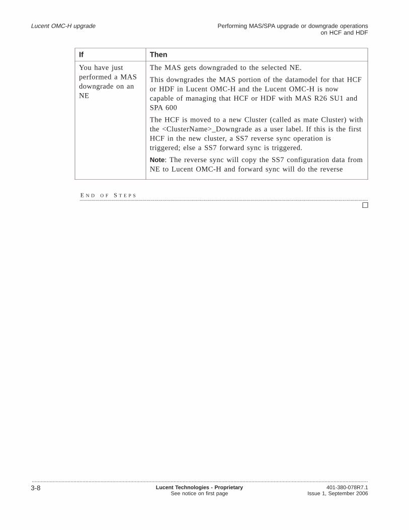
If Then
You have justperformed a MASdowngrade on anNE
The MAS gets downgraded to the selected NE.
This downgrades the MAS portion of the datamodel for that HCFor HDF in Lucent OMC-H and the Lucent OMC-H is nowcapable of managing that HCF or HDF with MAS R26 SU1 andSPA 600
The HCF is moved to a new Cluster (called as mate Cluster) withthe <ClusterName>_Downgrade as a user label. If this is the firstHCF in the new cluster, a SS7 reverse sync operation istriggered; else a SS7 forward sync is triggered.
Note : The reverse sync will copy the SS7 configuration data fromNE to Lucent OMC-H and forward sync will do the reverse
E N D O F S T E P S........................................................................................................................................................................................................................
Lucent OMC-H upgrade Performing MAS/SPA upgrade or downgrade operationson HCF and HDF
.................................................................................................................................................................................................................................
3-8 Lucent Technologies - ProprietarySee notice on first page
401-380-078R7.1Issue 1, September 2006
4 4Network element softwareadministration
Overview.................................................................................................................................................................................................................................
Purpose
This chapter provides the procedures for network element software administration.
Contents
Network Element Software Upgrade 4-2
Downloading software on a network element 4-3
Importing software on a network element 4-5
.................................................................................................................................................................................................................................401-380-078R7.1Issue 1, September 2006
Lucent Technologies - ProprietarySee notice on first page
4-1

Network Element Software Upgrade.................................................................................................................................................................................................................................
Two upgrades required
At times it is necessary to update the software on the HDF and HCF network elements.In the case of HCF two remote system are used to do this, Lucent OMC-H for theMiLife Application Server (MAS) platform software and eSM for the HCF software.
As Lucent OMC-H is only involved in the download of the MAS software, only thistopic is covered here. For information on updating the HCF software, see the HCFdocumentation and the eSM documentation.
MAS software upgrade process
The upgrade of MiLife Application Server (MAS) software is a 2 phase process:
1. Download the new software to the network element from Lucent OMC-H
2. Activate the new software on the network element either locally at the networkelement’s local maintenance terminal, or by SSH cut-through from the LucentOMC-H.Perform the following steps to access the SSH Cut Through window.
a. In the HM tree, select the HCF or HDF you wish to activate using the SSH CutThrough window.
b. From the menu bar, clickTools -> Cut Through -> SSH Cut Through . TheLogon window appears to enter the data for the SSH session.
c. Enter the user name and password details. ClickOK to connect to the SSHsession for the selected HCF or HDF.
Software download only
The information provided here only covers the download of software to the networkelement. For information on activating the software using SSH cut through, see theHCF documentation or the MAS documentation.
3 software versions
The Lucent OMC-H can contain up to three different software versions at the sametime for each network element type.
Network element software administration
.................................................................................................................................................................................................................................
4-2 Lucent Technologies - ProprietarySee notice on first page
401-380-078R7.1Issue 1, September 2006

Downloading software on a network element.................................................................................................................................................................................................................................
Purpose
This procedure allows you to download MiLife Application Server (MAS) platformsoftware to a network element.
Related information
For information on how to import software, refer to“Importing software on a networkelement” (p. 4-5).
Important! If you do not have the file to be downloaded on the NE, you need toimport the file first.
Before you begin
Ensure that:
• The new software to be downloaded is in the/omc/data/nefiles/ne_sw_downloaddirectory on the Lucent OMC-H server. The software will be delivered by SSH, orvia a DAT tape or CD-ROM
• The software download directory specified in Lucent OMC-H system preferencesexists on NEs. For more information on this seeLucent OMC-H SystemAdministration,401-380-075
• The software download directory is writable by the FTP user specified in thecommunication parameters, for the NEs to be upgraded.
To download software on a network element
Complete the following procedure to download software on a network element.
.................................................................................................................................................................................................
1 From the Lucent OMC-H Desktop, go to theNetwork Manager . Expand All and inthe HM tree, double-click the HCF or HDF you want to upgrade.
.................................................................................................................................................................................................
2 Right-click anywhere on the NE detail view, and selectShow on Tree .
Result: The selected NE gets displayed in the NE tree view.
.................................................................................................................................................................................................
3 From the menu bar, clickTools -> Software Administration -> Download .
Network element software administration
.................................................................................................................................................................................................................................401-380-078R7.1Issue 1, September 2006
Lucent Technologies - ProprietarySee notice on first page
4-3

Result: The Enter input parameters for Download window is displayed.
.................................................................................................................................................................................................
4 From theSoftware to download* list-box, select the software you want to downloadon the NE.
.................................................................................................................................................................................................
5 Click OK to start the software download now, or clickMore -> Schedule to downloadthe software later.
Result: The MAS software is downloaded to the selected NE.
.................................................................................................................................................................................................
6 Activate the downloaded software through a SSH Cut Through to the network element.
For more information on software activation, see the MAS platform documentation andthe Super D-HLR documentation.
E N D O F S T E P S........................................................................................................................................................................................................................
Network element software administration Downloading software on a network element
.................................................................................................................................................................................................................................
4-4 Lucent Technologies - ProprietarySee notice on first page
401-380-078R7.1Issue 1, September 2006
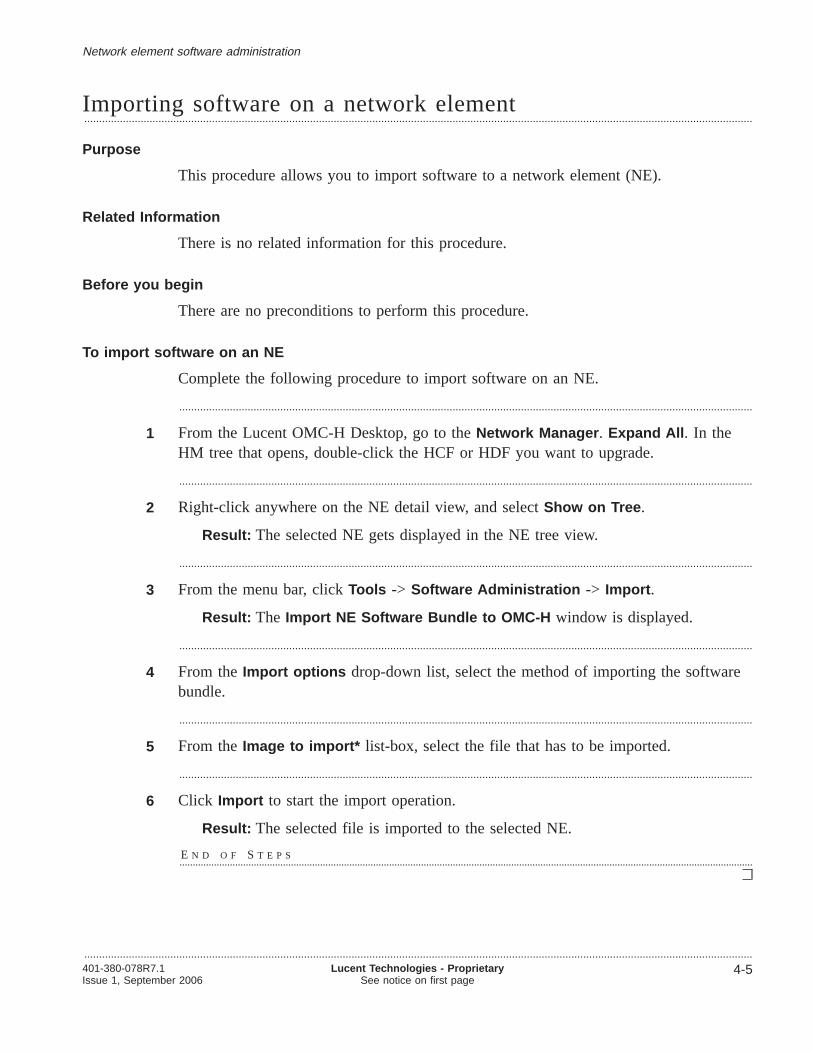
Importing software on a network element.................................................................................................................................................................................................................................
Purpose
This procedure allows you to import software to a network element (NE).
Related Information
There is no related information for this procedure.
Before you begin
There are no preconditions to perform this procedure.
To import software on an NE
Complete the following procedure to import software on an NE.
.................................................................................................................................................................................................
1 From the Lucent OMC-H Desktop, go to theNetwork Manager . Expand All . In theHM tree that opens, double-click the HCF or HDF you want to upgrade.
.................................................................................................................................................................................................
2 Right-click anywhere on the NE detail view, and selectShow on Tree .
Result: The selected NE gets displayed in the NE tree view.
.................................................................................................................................................................................................
3 From the menu bar, clickTools -> Software Administration -> Import .
Result: The Import NE Software Bundle to OMC-H window is displayed.
.................................................................................................................................................................................................
4 From theImport options drop-down list, select the method of importing the softwarebundle.
.................................................................................................................................................................................................
5 From theImage to import* list-box, select the file that has to be imported.
.................................................................................................................................................................................................
6 Click Import to start the import operation.
Result: The selected file is imported to the selected NE.
E N D O F S T E P S........................................................................................................................................................................................................................
Network element software administration
.................................................................................................................................................................................................................................401-380-078R7.1Issue 1, September 2006
Lucent Technologies - ProprietarySee notice on first page
4-5


5 5Configuring an SDHLR
Overview.................................................................................................................................................................................................................................
Purpose
This chapter describes the SDHLR object and provides a procedure to modify theSDHLR group name. You cannot modify any other variable on the SDHLR.
Contents
SDHLR object description 5-2
Node Growth 5-4
Creating an SDHLR 5-6
Read host entries 5-8
Performing Node Growth 5-10
Clear host entries 5-14
Modifying the SDHLR group name 5-16
.................................................................................................................................................................................................................................401-380-078R7.1Issue 1, September 2006
Lucent Technologies - ProprietarySee notice on first page
5-1

SDHLR object description.................................................................................................................................................................................................................................
SDHLR Complex
The SDHLR complex is a collection of servers, distributed over a TCP/IP network. TheOMC-H group on the Lucent OMC-H GUI contains all the supported SDHLRcomplexes. The Lucent OMC-H supports a maximum of 10 SDHLR complexes. EachSDHLR contains one or more HCF Clusters or HCF Groups, and a collection of HDFservers, along with their mate servers.
Each NE contains an SNMP (Simple Network Management Protocol) agent.Configuration management, fault management, and performance management tasks areperformed directly on that NE.
SDHLR Network elements and Groups
The SDHLR complex consists of the following child objects.
• One or more HCF Clusters
• One or more HCF Groups, currently supporting only DIAMETER protocol
• One HCF Pool
• One HDF Pool
• One or more HDF Mated Pair groups
• Child objects belonging to these groups
• SS7 connectivity
Rules for creating
The first SDHLR is created automatically, and subsequent SDHLRs are created on userinstruction. Lucent OMC-H also creates the HCF Cluster table, HCF Group table andthe HDF Pool table. The SS7 tree is created after the first HCF is put in a managedstate.
Rules for deleting and modifying
Only the last instance of the SDHLR cannot be deleted.
The HCF Cluster, HCF Pool, HDF Pool, and HCF Group should be empty, and noHDF Mated pair objects should exist. The Delete operation then deletes all childobjects of the SDHLR complex namely the HCF Clusters, HCF Pool, HDF Pool, HCFGroups, IP Connection VNE, and Logical Connection VNE.
You can only modify the user label of this object.
Configuring an SDHLR
.................................................................................................................................................................................................................................
5-2 Lucent Technologies - ProprietarySee notice on first page
401-380-078R7.1Issue 1, September 2006

SDHLR network element functions
The SDHLR HDF network elements store subscriber data and platform configurations.The HDFs do not communicate with the UMTS network directly but only through theHCF network elements. The HDF network elements can be viewed as the UMTSsubscriber database.
HCF network elements communicate subscriber and network configuration data to theUMTS network. The HCF network elements can be viewed as the access mechanismbetween the UMTS network and the subscriber database.
Each SDHLR complex is mutually exclusive. For example, it is not possible to createan HDF Mated Pair containing HDFs from different SDHLR complexes. It is notpossible to move NEs or any other data between complexes.
SDHLR internal network
An internal network exists between the HCF and HDF network elements. The SDHLRnetwork provides reliable transport for administrative, provisioning, recovery, andtransaction traffic.
The network can be a Local Area Network (LAN) or Wide Area Network (WAN),depending on the geographical location of the network elements.
SS7 management
An SS7 interface connects the SDHLR to the wireless operator’s networks. SS7 is achild of the HCF Cluster. SS7 is a containment object and has its own tree structure.
Attributes and values
For information on object attributes and values, refer toLucent OMC-H ObjectDescriptions,401-380-080.
Configuring an SDHLR SDHLR object description
.................................................................................................................................................................................................................................401-380-078R7.1Issue 1, September 2006
Lucent Technologies - ProprietarySee notice on first page
5-3

Node Growth.................................................................................................................................................................................................................................
Overview
Every NE in an SDHLR complex needs to be aware of the connectivity information ofall other NEs in the complex. The connectivity information for an NE is stored in theMSGHOSTSand /ETC/INET/HOSTSfiles.
Node growth enables you to expand the SDHLR network and update the MiLifeApplication Server (MAS) platform files,MSGHOSTSand /ETC/INET/HOSTS, on allthe network elements (NEs) in the SDHLR complex from one central location - theLucent OMC-H. This procedure also ensures that all NEs are aware of the connectivityinformation of all other NEs in the complex
This is done without disruption of call processing or configuration data on any of theexisting nodes.
The MSGHOSTSand /ETC/INET/HOSTS files
The MSGHOSTSfile contains the names and IDs of the hosts thatMSGHOSTScommunicates with. This file must be the same on all NEs in a network.
The /ETC/INET/HOSTSfile contains the IP address corresponding to the interfaces(Interface Name depends on the hardware type of the NE) and the corresponding HostName
Field Description
MSGHOSTS
Field 1 Host number
Field 2 Logical name of the processor that is sent to processes
Fields 3 and 4 Names of the two addresses that can be used to reach that host.These entries must exist in the/ETC/INET/HOSTSfile
A preferred path can be specified by placing an “*” before thename. If simplex networking is used, the same name can be usedtwice.
Field 5 Machine Name is the name of the port on the NE for a particularhardware type.
Field 6 The Port type of the NE
Field 7: The group ID of the NE.
/ETC/INET/HOSTS
Field 1 IP address is the IPV4 addresses of the corresponding interfaceson the NE.
Configuring an SDHLR
.................................................................................................................................................................................................................................
5-4 Lucent Technologies - ProprietarySee notice on first page
401-380-078R7.1Issue 1, September 2006

Field 2 Machine Name is the name of the port on the NE for a particularhardware type.
Field 3 Aliases of the ETC HOSTS entries
Tasks that cannot be performed while Node Growth is in progress
You cannot perform the following tasks during Node Growth:
• Creating an HCF or HDF
• Moving one or more HCFs (from the HCFPool to HCFCluster and vice versa)
• Moving HDFs from HDF Pool to a Mated Pair group and vice versa
• Deleting an HCF or HDF
• Adding or deleting a Mated pair
• Read host entries
• Clear host entries.
Constraints for performing Node Growth
The following factors must be considered before performing a Node Growth:
• Node Growth is available only at SDHLR, HCF and HDF levels.
• Node Growth cannot be performed on HDFs in the HDF Pool. They should beunmanaged when node growth is called on the complex.
• The NEs must be in the managed state, with the NE Config State being available,and must have the software version 600 and above.Note : Node Growth can be performed at the SDHLR complex level even if someNEs in that SDHLR complex are in the unmanaged state.
• At a time, only one Node Growth procedure per SDHLR complex can be executed
• The NE hardware types supported for Node Growth are NETRA440, NETRA1400,and NETRA1280. These can be with or without FibreGBE interfaces.
• NE de-growth is not possible. That is, once an NE is grown successfully, its entrieswill not be removed from theMSGHOSTSand /ETC/INET/HOSTSfiles on the NEsand from the IP Connection VNE in the SDHLR complex.
• During SDHLR upgrade the NE growth procedure shall not be available to you. Inthis case, you need to manually update theMSGHOSTSand /ETC/INET/HOSTSfiles on every NE.
Configuring an SDHLR Node Growth
.................................................................................................................................................................................................................................401-380-078R7.1Issue 1, September 2006
Lucent Technologies - ProprietarySee notice on first page
5-5

Creating an SDHLR.................................................................................................................................................................................................................................
Purpose
This procedure allows you to create an SDHLR group. The first SDHLR isauto-created when the Lucent OMC-Hsystem is installed. Subsequently, you can createup to a maximum of 10 SDHLRs.
Related information
For information on the SDHLR, refer to“SDHLR object description” (p. 5-2).
Before you begin
There are no preconditions to perform this procedure.
To create an SDHLR
Complete the following procedure to create an SDHLR.
.................................................................................................................................................................................................
1 Click on theNetwork Manager icon on theLucent OMC-H Desktop window, toinvoke theLucent OMC-H Network Manager window.
Alternatively, on theLucent OMC-H Desktop window menu bar, clickNetwork ->Network Manager .
.................................................................................................................................................................................................
2 From the Network Manager HM tree view, select the OMC-H group.
.................................................................................................................................................................................................
3 From the menu bar, clickAction -> Create -> SDHLR.
Alternatively, right-click the OMC-H group and clickCreate -> SDHLR.
Result: The Enter input parameters for SDHLR window is displayed.
.................................................................................................................................................................................................
4 Type the SDHLR name in theName text-box.
.................................................................................................................................................................................................
5 Click OK to create the SDHLR.
Result: The SDHLR is created and the following containment objects areauto-created:
• HCFCluster
• HCFPool
• HDFPool
Configuring an SDHLR
.................................................................................................................................................................................................................................
5-6 Lucent Technologies - ProprietarySee notice on first page
401-380-078R7.1Issue 1, September 2006

• IPConn
• LogicalConn.
E N D O F S T E P S........................................................................................................................................................................................................................
Configuring an SDHLR Creating an SDHLR
.................................................................................................................................................................................................................................401-380-078R7.1Issue 1, September 2006
Lucent Technologies - ProprietarySee notice on first page
5-7

Read host entries.................................................................................................................................................................................................................................
Purpose
This procedure allows you to read the host entries fromMSGHOSTSand/ETC/INET/HOSTSfiles.
The Lucent OMC-H reads and validates
• MSGHOSTSinformation from the SDHLR MIBs and MAS MIBs, and
• /ETC/INET/HOSTSinformation from the MAS MIBs.
You need to perform the read host entries procedure before performing node growth onan NE.
Related information
There is no related information for this procedure.
Before you begin
To perform this action successfully ensure that:
• You have the required permissions to work with network elements and managedobjects (MOs)
• You invoke Read Host entries only on managed NEs that have not already beengrown. This action is not supported on unmanaged NEs or NEs which have alreadybeen grown
To Read Host Entries for an NE
Complete the following procedure to Read Host Entries :
.................................................................................................................................................................................................
1 From the Lucent OMC-H Desktop, go to theNetwork Manager . .
.................................................................................................................................................................................................
2 From the HM TreeView, select the SDHLR Complex. and from theAction menu itemselectRead Host Entries option. This action can also be invoked from the NE.
Result: If you perform this action from the SDHLR, the Host Entries will be readand validated for each NE in the complex. If you perform this action on the NEdirectly, a dialog box is displayed for you to confirm your action. Once youconfirm this the Host Entries will be read and validated for each NE in thecomplex.
For both cases theEtcHostandMsgHostinstances will get created, for each NE inthe complex, under the IPConn VNE.
Configuring an SDHLR
.................................................................................................................................................................................................................................
5-8 Lucent Technologies - ProprietarySee notice on first page
401-380-078R7.1Issue 1, September 2006

This procedure will fail under the following circumstances:
• If a Node Growth operation is in progress for that complex
• If the NE is in the unmanaged state
• If the NE being read has already been grown into the network
E N D O F S T E P S........................................................................................................................................................................................................................
Configuring an SDHLR Read host entries
.................................................................................................................................................................................................................................401-380-078R7.1Issue 1, September 2006
Lucent Technologies - ProprietarySee notice on first page
5-9

Performing Node Growth.................................................................................................................................................................................................................................
Configuring an SDHLR
.................................................................................................................................................................................................................................
5-10 Lucent Technologies - ProprietarySee notice on first page
401-380-078R7.1Issue 1, September 2006

Node Growth process
This flow chart explains the Node Growth process.
Configuring an SDHLR Performing Node Growth
.................................................................................................................................................................................................................................401-380-078R7.1Issue 1, September 2006
Lucent Technologies - ProprietarySee notice on first page
5-11

Performing Node Growth from Lucent OMC-H GUI
To perform Node Growth:
1. In the HM tree view, select the SDHLR complex where Node Growth is to beperformed.
2. Perform the Read Host Entries or Clear Host Entries on NEs where applicable
3. From the menu bar, clickAction -> Node Growth -> Grow to update theMSGHOSTSand /ETC/INET/HOSTSfiles on all the NEs of that SDHLR complex.Note : During the Growth action, if any NE is in the unmanaged state, LucentOMC-H recalls unmanaged NEs’ information whenever the NE is managed againby displaying a warning message saying,“Node Growth is pending on the NE”
4. On successful completion of Grow, clickApply to apply changes to the NEs.However, if Grow fails on one or more NEs, select the NE where the failureoccurred, and clickAction -> Node Growth -> Synchronize with OMC .
5. On synchronizing, performApply on the failed NEs.All actions are context sensitive on a per NE basis. For example, once you performApply on an NE in the SDHLR complex, onlyRevert andCommit will beavailable for that NE. However, in the case ofApply , the NE does not notifyLucent OMC-H about the result of theApply action.Before proceeding with aRevert or Commit , you need to verify ifApply hassucceeded on all NEs of that SDHLR complex.To do so, check theOMlogs file (/snlog/OMlog0or /snlog/OMlog1) of each NE ofthe SDHLR complex for “INIT COMPLETE”, for the required timestamp. Thisindicates that theApply action has been completed successfully on all NEs of theSDHLR complex.
6. If you are dissatisfied with the current setup, clickAction -> Node Growth ->Revert , else go toStep 8.This helps you to recover the backed upMSGHOSTSand /ETC/INET/HOSTSfileson the NEs.
7. After suitably modifying the setup, again perform anApply on the SDHLRcomplex.
8. Click Action -> Node Growth -> Commit to confirm the updated data, andremove the backup files created on the NEs during Grow.If the commit fails on one or more NEs, repeat theCommit action on the failedNEs.The commit action is successful only if it was successful on all the NEs in theSDHLR complex.
Tracking the status of Node Growth
Node Growth can be performed at the SDHLR complex level even if some NE is inthat SDHLR complex are in the unmanaged state. All the actions are asynchronous. To
Configuring an SDHLR Performing Node Growth
.................................................................................................................................................................................................................................
5-12 Lucent Technologies - ProprietarySee notice on first page
401-380-078R7.1Issue 1, September 2006

track the status and result of the Node Growth operation, you have to refer to ActionHistory.
Accessing Action History
To invoke Action History, from theDesktop menu bar, clickTools -> Action History .
If the status is failed, you need to see the NE Error report for more information.
To know more about viewing reports, refer toSystem Administration,401-380-075.Check the timestamp and user name to identify the right NE Error report.
The NE Error report contains information on the NE for which the Node Growthfailed, and the description of the error.
Example of an NE Error report
Here are the contents of a typical NE Error report:
• Description : NE Error Report
• Date: Mon May 30 04:58:21 GMT 2006
• Author : omcadm
• NE: HCF=37
• Error message : Error Code OMCH1020: Grow failed on HCF=37This implies that the SDHLR Complex Node Growth COMMIT command hasfailed on this NE {37).
Accessing the Extended Error Table
If an action fails on an NE, you can open theExtended Error Table to know thereason for failure.
To invoke the Extended Error Table, from theNetwork Manager navigate to and selectthe NE, then go toView -> Extended Table .
Configuring an SDHLR Performing Node Growth
.................................................................................................................................................................................................................................401-380-078R7.1Issue 1, September 2006
Lucent Technologies - ProprietarySee notice on first page
5-13

Clear host entries.................................................................................................................................................................................................................................
Purpose
This procedure allows you to clear the host entries for an NE by deleting theMSGHOSTSand /ETC/INET/HOSTSfiles. You may want to perform this procedure ifyou do not want to use an existing NE for node growth but do not want to physicallydelete it either.
This action is only available to you at the NE level. You cannot invoke a Clear hostentries operation from the SDHLR complex.
Related information
There is no related information for this procedure.
Before you begin
Ensure that:
• You have the required permissions to work with network elements and managedobjects (MOs)
• You only invoke this operation on unmanaged NEs
To Clear Host Entries for an NE
Complete the following procedure to Clear Host Entries for an NE:
.................................................................................................................................................................................................
1 From the Lucent OMC-H Desktop, go to theNetwork Manager .
.................................................................................................................................................................................................
2 From the HM TreeView, navigate to the SDHLR Complex and select the NE for whichyou do not want to perform node growth.
.................................................................................................................................................................................................
3 Right-Click on the NE and click onClear Host Entries
Result: A dialog box is displayed for you to confirm your action. Once youconfirm this, the Host Entries will be deleted for that NE in the complex. TheEtcHostandMsgHostinstances will get deleted for that NE from the IPConn VNE
This procedure will fail under the following circumstances:
• If a Node Growth operation is in progress for that complex
• If the NE is in the Managed state
• If the NE has already been grown into the network
Configuring an SDHLR
.................................................................................................................................................................................................................................
5-14 Lucent Technologies - ProprietarySee notice on first page
401-380-078R7.1Issue 1, September 2006

E N D O F S T E P S........................................................................................................................................................................................................................
Configuring an SDHLR Clear host entries
.................................................................................................................................................................................................................................401-380-078R7.1Issue 1, September 2006
Lucent Technologies - ProprietarySee notice on first page
5-15
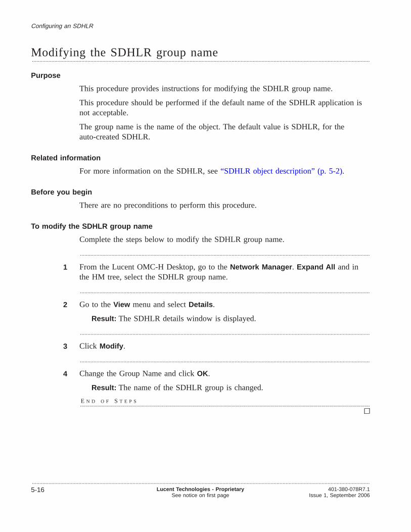
Modifying the SDHLR group name.................................................................................................................................................................................................................................
Purpose
This procedure provides instructions for modifying the SDHLR group name.
This procedure should be performed if the default name of the SDHLR application isnot acceptable.
The group name is the name of the object. The default value is SDHLR, for theauto-created SDHLR.
Related information
For more information on the SDHLR, see“SDHLR object description” (p. 5-2).
Before you begin
There are no preconditions to perform this procedure.
To modify the SDHLR group name
Complete the steps below to modify the SDHLR group name.
.................................................................................................................................................................................................
1 From the Lucent OMC-H Desktop, go to theNetwork Manager . Expand All and inthe HM tree, select the SDHLR group name.
.................................................................................................................................................................................................
2 Go to theView menu and selectDetails .
Result: The SDHLR details window is displayed.
.................................................................................................................................................................................................
3 Click Modify .
.................................................................................................................................................................................................
4 Change the Group Name and clickOK.
Result: The name of the SDHLR group is changed.
E N D O F S T E P S........................................................................................................................................................................................................................
Configuring an SDHLR
.................................................................................................................................................................................................................................
5-16 Lucent Technologies - ProprietarySee notice on first page
401-380-078R7.1Issue 1, September 2006

6 6Configuring an HLR ControlFunction (HCF) networkelement
Overview.................................................................................................................................................................................................................................
Purpose
This chapter defines the HCF and provides procedures to configure it.
Contents
Description of the HCF network element 6-3
SDHLR and the HCF 6-4
Fault Recovery on an HCF 6-5
HCF network element description 6-6
Creating HCF network elements 6-10
Creating an HCF Cluster 6-11
Creating an HCF in an HCF Cluster 6-12
Creating an HCF in an HCFPool 6-14
Deleting HCF network elements 6-16
Deleting an HCF from an HCF Cluster 6-17
Deleting a HCF Cluster 6-18
Deleting an HCF from an HCF Pool 6-19
Moving HCF network elements 6-20
Moving an HCF to an HCFPool 6-21
Moving an HCF from an HCFPool to an HCFCluster 6-23
Moving all HCFs from a Cluster to an HCFPool 6-25
Synchronizing HCF network elements 6-26
Synchronizing an HCF network element 6-27
.................................................................................................................................................................................................................................401-380-078R7.1Issue 1, September 2006
Lucent Technologies - ProprietarySee notice on first page
6-1

Synchronizing SS7 configuration for an HCF 6-28
Auditing an HCF 6-29
Performing other operations on the HCF 6-30
Modifying HCF parameters 6-31
Managing SPA for an HCF 6-33
Performing object specific actions on a LocalSSN object 6-35
Configuring an HLR Control Function (HCF) networkelement
Overview
.................................................................................................................................................................................................................................
6-2 Lucent Technologies - ProprietarySee notice on first page
401-380-078R7.1Issue 1, September 2006

Description of the HCF network element
Overview.................................................................................................................................................................................................................................
Purpose
This section describes the HCF.
Contents
SDHLR and the HCF 6-4
Fault Recovery on an HCF 6-5
HCF network element description 6-6
Configuring an HLR Control Function (HCF) networkelement
.................................................................................................................................................................................................................................401-380-078R7.1Issue 1, September 2006
Lucent Technologies - ProprietarySee notice on first page
6-3

SDHLR and the HCF.................................................................................................................................................................................................................................
HCF responsibilities
The HCF network element has a number of responsibilities including:
• Terminating the physical connections to the SS7 network
• Accepting Mobile Application Part (MAP) messages from the Mobile SwitchingCenters (MSC) and Visitor Location Registers (VLRs)
• Carrying out SS7 and HLR protocol processing
• Interacting with the HDF in order to update subscriber data
• Informing the network when subscriber data has been changed
HDF-HCF Connectivity
An HCF in the HCF Cluster must contain details of the HDFs within that SDHLR.Each HDF must also contain details of its corresponding HCF within that SDHLR.
HCF Pool
The purpose of the HCF Pool object is to hold the HCF Servers which are currentlyunassigned to any Cluster.
The HCF Pool is a child object of the SDHLR. It is automatically created by theLucent OMC-H when the SDHLR is created. There should be one instance of the HCFPool per SDHLR.
HCF audit and synchronization
To help ensure that the HCF data is always consistent between all HCFs in a cluster,occasionally an HCF audit should performed. The SS7 Audit action performs acomparison of the SS7 data on the Lucent OMC-H and that on the HCF Server. Themismatches detected are listed in an Audit Report. The operator can view thesediscrepancies from a report.
An SS7 configuration that is not in synchronization can be adjusted by the user byinvoking theHCF synchronize andSynchronize with OMC operations. This ensuresthat the SS7 data for each HCF is the same as the data stored in the Lucent OMC-Hdatabase.
Configuring an HLR Control Function (HCF) networkelement
.................................................................................................................................................................................................................................
6-4 Lucent Technologies - ProprietarySee notice on first page
401-380-078R7.1Issue 1, September 2006
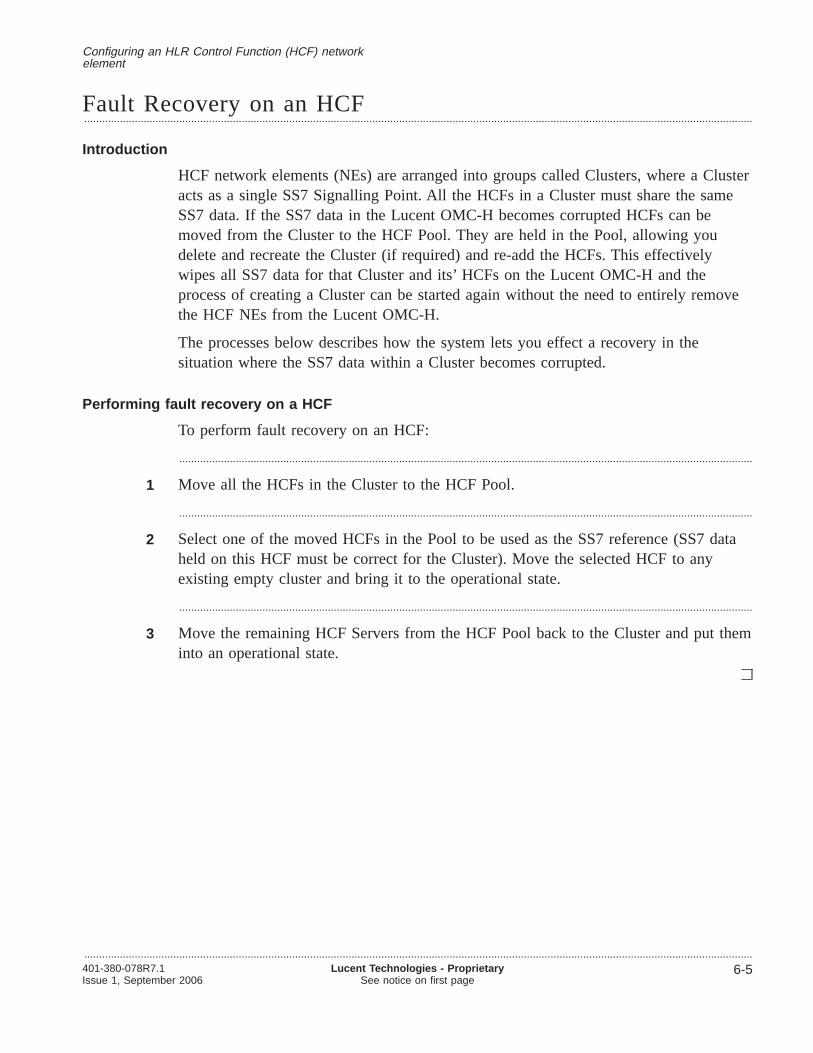
Fault Recovery on an HCF.................................................................................................................................................................................................................................
Introduction
HCF network elements (NEs) are arranged into groups called Clusters, where a Clusteracts as a single SS7 Signalling Point. All the HCFs in a Cluster must share the sameSS7 data. If the SS7 data in the Lucent OMC-H becomes corrupted HCFs can bemoved from the Cluster to the HCF Pool. They are held in the Pool, allowing youdelete and recreate the Cluster (if required) and re-add the HCFs. This effectivelywipes all SS7 data for that Cluster and its’ HCFs on the Lucent OMC-H and theprocess of creating a Cluster can be started again without the need to entirely removethe HCF NEs from the Lucent OMC-H.
The processes below describes how the system lets you effect a recovery in thesituation where the SS7 data within a Cluster becomes corrupted.
Performing fault recovery on a HCF
To perform fault recovery on an HCF:
.................................................................................................................................................................................................
1 Move all the HCFs in the Cluster to the HCF Pool.
.................................................................................................................................................................................................
2 Select one of the moved HCFs in the Pool to be used as the SS7 reference (SS7 dataheld on this HCF must be correct for the Cluster). Move the selected HCF to anyexisting empty cluster and bring it to the operational state.
.................................................................................................................................................................................................
3 Move the remaining HCF Servers from the HCF Pool back to the Cluster and put theminto an operational state.
Configuring an HLR Control Function (HCF) networkelement
.................................................................................................................................................................................................................................401-380-078R7.1Issue 1, September 2006
Lucent Technologies - ProprietarySee notice on first page
6-5

HCF network element description.................................................................................................................................................................................................................................
Description
This section describes the HCF network element as it is represented on the LucentOMC-H GUI.
An HCF network element (NE) can be created from its parent Cluster object, or fromthe HCF Pool object.
Structure of the HCF network element
The following figure shows the HCF network element representation on the LucentOMC-H GUI.
Rules for creating, modifying and deleting the HCF and related objects
Rules for creating Rules for modifying Rules for Deleting
HCF
The HCF network element (also known as the HCF or HCF Server) contains thefollowing child objects:
• SS7 Cluster Parameters
• HCF - HDF Connectivity
Configuring an HLR Control Function (HCF) networkelement
.................................................................................................................................................................................................................................
6-6 Lucent Technologies - ProprietarySee notice on first page
401-380-078R7.1Issue 1, September 2006
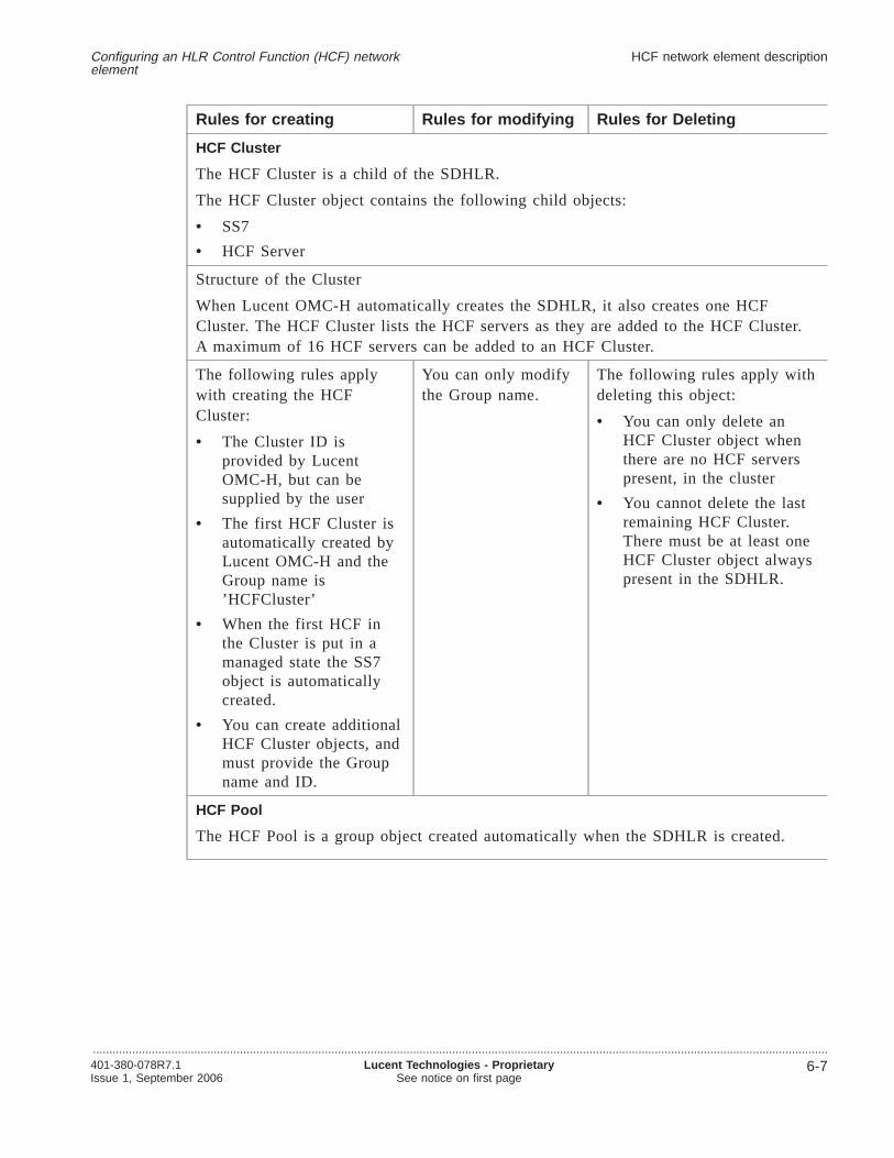
Rules for creating Rules for modifying Rules for Deleting
HCF Cluster
The HCF Cluster is a child of the SDHLR.
The HCF Cluster object contains the following child objects:
• SS7
• HCF Server
Structure of the Cluster
When Lucent OMC-H automatically creates the SDHLR, it also creates one HCFCluster. The HCF Cluster lists the HCF servers as they are added to the HCF Cluster.A maximum of 16 HCF servers can be added to an HCF Cluster.
The following rules applywith creating the HCFCluster:
• The Cluster ID isprovided by LucentOMC-H, but can besupplied by the user
• The first HCF Cluster isautomatically created byLucent OMC-H and theGroup name is’HCFCluster’
• When the first HCF inthe Cluster is put in amanaged state the SS7object is automaticallycreated.
• You can create additionalHCF Cluster objects, andmust provide the Groupname and ID.
You can only modifythe Group name.
The following rules apply withdeleting this object:
• You can only delete anHCF Cluster object whenthere are no HCF serverspresent, in the cluster
• You cannot delete the lastremaining HCF Cluster.There must be at least oneHCF Cluster object alwayspresent in the SDHLR.
HCF Pool
The HCF Pool is a group object created automatically when the SDHLR is created.
Configuring an HLR Control Function (HCF) networkelement
HCF network element description
.................................................................................................................................................................................................................................401-380-078R7.1Issue 1, September 2006
Lucent Technologies - ProprietarySee notice on first page
6-7

Rules for creating Rules for modifying Rules for Deleting
The following rules applywith creating the HCF Pool:
• The HCF Pool isautomatically createdwhen the SDHLR iscreated
• The maximum number ofinstances of the HCFPool is one.
You can only modifythe HCF Pool’sGroup name attribute.
You cannot delete the HCFPool.
Local SSN
The Local Subsystem Number (SSN) is a logical object and a child of the HCF object.
The Local SSN shall represent the SSNs declared against the Originating Point Code(OPC), as defined in the HCF Object, their status and their overload levels. Thedeclaration and availability of a subsystem define the capabilities of the SDHLR.
When a subsystem is unavailable, the SDHLR will be unable to process MAP messagesassociated with the unavailable subsystem type.
The overload level is defined by the number of active calls per SSN. When Max CallLevel 0 is reached the SSN is considered to be in Overload.
You can enter the OPC on the Lucent OMC-H GUI or CLI, or can reference the SS7User label attribute. If the User label is used, Lucent OMC-H retrieves the OPC fromthe SS7 object.
Mapping to the SDHLR network element
The Local SSN object contains a number of attributes that map to attributes on objectson the SDHLR network element.
These objects are:
• S7_LOCAL_SSN
• SSN_OVERLOAD_STATE
• SSN_STATUS
Note : An HCF with software version 310 does not support the SSN_OVERLOAD_STATE object.
A Local SSN object isautomatically created by thesystem when an SS7 HCF ismanaged, provided that theLocal SSN object exists atthe NE. You cannot createthis object.
You cannot modifythis object.
You cannot delete this object.
Configuring an HLR Control Function (HCF) networkelement
HCF network element description
.................................................................................................................................................................................................................................
6-8 Lucent Technologies - ProprietarySee notice on first page
401-380-078R7.1Issue 1, September 2006
Attributes and values
For information on object attributes and values, refer toLucent OMC-H ObjectDescriptions,401-380-080.
Configuring an HLR Control Function (HCF) networkelement
HCF network element description
.................................................................................................................................................................................................................................401-380-078R7.1Issue 1, September 2006
Lucent Technologies - ProprietarySee notice on first page
6-9

Creating HCF network elements
Overview.................................................................................................................................................................................................................................
Purpose
This section provides procedures for creating HCF network elements.
Contents
Creating an HCF Cluster 6-11
Creating an HCF in an HCF Cluster 6-12
Creating an HCF in an HCFPool 6-14
Configuring an HLR Control Function (HCF) networkelement
.................................................................................................................................................................................................................................
6-10 Lucent Technologies - ProprietarySee notice on first page
401-380-078R7.1Issue 1, September 2006
Creating an HCF Cluster.................................................................................................................................................................................................................................
Purpose
This procedure allows you to manually create an HCF Cluster, in addition to the onethat is automatically created by the system.
Related information
For more information, see“SDHLR and the HCF” (p. 6-4).
Before you begin
No additional information is required before you begin this procedure.
To create an HCF Cluster
Complete the following procedure to create an HCF Cluster.
.................................................................................................................................................................................................
1 From the Lucent OMC-H Desktop, go to theNetwork Manager . Expand All and inthe HM tree, select the SDHLR group where you want to create the HCF Cluster.
.................................................................................................................................................................................................
2 From the menu bar, clickAction -> Create -> Cluster .
Result: The Enter input parameters for Create Cluster window is displayed.
.................................................................................................................................................................................................
3 Type the Group Name and Group ID and clickOK.
Result: The new HCF Cluster is created.
E N D O F S T E P S........................................................................................................................................................................................................................
Configuring an HLR Control Function (HCF) networkelement
.................................................................................................................................................................................................................................401-380-078R7.1Issue 1, September 2006
Lucent Technologies - ProprietarySee notice on first page
6-11
Creating an HCF in an HCF Cluster.................................................................................................................................................................................................................................
Purpose
This procedure allows you to create HCF network elements in an HCF Cluster.
Related information
For information on object attributes and values, refer toLucent OMC-H ObjectDescriptions,401-380-080.
Before you begin
Ensure that:
• You have the required permissions to carry out tasks in the Network Manager
• The new HCF has been physically installed
• Basic configuration of the HCF has been performed from the enhanced ServicesManager (eSM) by running theinstall-config command. This installs the basicconfiguration necessary to support the HCF application, as well as the HDFconnectivity information.
• The HCF Cluster contains less than the maximum allowed HCFs, that is, 16
• The SiteInfo object has been created.
To create an HCF in an HCF Cluster
Complete the following procedure to create an HCF in an HCF Cluster.
.................................................................................................................................................................................................
1 From the Lucent OMC-H Desktop, go to theNetwork Manager . Expand All and inthe HM tree, select the HCF Cluster, where the HCF needs to be created.
.................................................................................................................................................................................................
2 From the menu bar, clickAction -> Create -> HCF.
Result: The Create HCF - General window is displayed.
.................................................................................................................................................................................................
3 Specify the NE name, software version, and overload priority.
.................................................................................................................................................................................................
4 You can also specify an NE ID. If you choose not to enter it, a system generated IDwill be assigned. Once the NE is created you cannot change the value of this ID. Thesystem generates the HCF ID to always assign the next available unique ID on creationof each instance of this object.
Configuring an HLR Control Function (HCF) networkelement
.................................................................................................................................................................................................................................
6-12 Lucent Technologies - ProprietarySee notice on first page
401-380-078R7.1Issue 1, September 2006
.................................................................................................................................................................................................
5 Click Next and populate information under the Communication, SNMP, SNMPSecurity, and SSH/SFTP tabs.
At this point you may want to configure key based SSH/SFTP authentication forthe new HCF. To do this you require administrative permissions. For details aboutthe procedure for configuring key-based SSH/SFTP authentication on the new HCFrefer toSystem Administration,401-380-075.
.................................................................................................................................................................................................
6 Click Next .
Result: The Communication Parameters for HCF NE window is displayed.
.................................................................................................................................................................................................
7 Provision all the required fields on the tabs.
.................................................................................................................................................................................................
8 Click Next .
Result: The Location window is displayed.
.................................................................................................................................................................................................
9 In the Geographical Location block, select the site from theSiteName drop-down list.
.................................................................................................................................................................................................
10 Select the frame in which NE is physically located from theFrame ID drop-down listand the position of the NE in the frame from thePosition ID drop-down lists.
.................................................................................................................................................................................................
11 Click Finish to create the HCF now or clickMore ->Save Profile to save yourchanges. You can load this profile on any NE later by clickingMore -> Load Profileon the HCF NE Tree.
Result: The HCF is created in the HCF Cluster.
E N D O F S T E P S........................................................................................................................................................................................................................
Configuring an HLR Control Function (HCF) networkelement
Creating an HCF in an HCF Cluster
.................................................................................................................................................................................................................................401-380-078R7.1Issue 1, September 2006
Lucent Technologies - ProprietarySee notice on first page
6-13

Creating an HCF in an HCFPool.................................................................................................................................................................................................................................
Purpose
This procedure provide instructions for creating HCF network elements in an HCFPool.
Related information
For information on object attributes and values, refer toLucent OMC-H ObjectDescriptions,401-380-080.
For information on how to schedule a task, refer to theSystem Administration,401-380-075.
Before you begin
Ensure that:
• You have the required permissions to carry out tasks in the Network Manager
• The new HCF has been physically installed
• Basic configuration of the HCF has been performed from the enhanced ServicesManager (eSM) by running theinstall-config command. This installs the basicconfiguration necessary to support the HCF application, as well as the HDFconnectivity information.
• eSM has run theinstall-proc command to bring up the HCF application. At thispoint, the Subsystem (SSN) should be inhibited.
• The HCF Pool contains less than the maximum allowed HCFs, that is, 32
To create an HCF in an HCFPool
Complete the following procedure to create an HCF in an HCFPool.
.................................................................................................................................................................................................
1 Click on theNetwork Manager icon on theLucent OMC-H - Desktop window, toinvoke theLucent OMC-H - Network Manager window.
Alternatively, on theLucent OMC-H - Desktop window, click Network -> NetworkManager .
.................................................................................................................................................................................................
2 In the HM tree, navigate to the HCFPool.
.................................................................................................................................................................................................
3 From the menu bar, clickAction -> Create -> HCF.
Alternatively, right-click the HCFPool and selectCreate -> HCF.
Configuring an HLR Control Function (HCF) networkelement
.................................................................................................................................................................................................................................
6-14 Lucent Technologies - ProprietarySee notice on first page
401-380-078R7.1Issue 1, September 2006

Result: The Create HCF: General window is displayed.
.................................................................................................................................................................................................
4 Specify the NE name, Software version, and Overload priority for the HCF.
.................................................................................................................................................................................................
5 You can also specify an NE ID. If you choose not to enter it, a system generated IDwill be assigned. Once the NE is created you cannot change the value of this ID. Thesystem generates the HCF ID to always assign the next available unique ID on creationof each instance of this object.
.................................................................................................................................................................................................
6 Click Next and populate information under the Communication, SNMP, SNMPSecurity, and SSH/SFTP tabs.
While populating the HCF SNMP security parameters, if you populate the privacypasswords with less than 8 characters or more than 30 characters, then Lucent OMC-Hgives an error. The length of the SNMP Privacy Password on the HCF must be thesame as on the Lucent OMC-H.
.................................................................................................................................................................................................
7 Click Next to proceed.
Result: The Communication Parameters for HCF NE window is displayed.
.................................................................................................................................................................................................
8 Provision all the required fields on the tabs.
.................................................................................................................................................................................................
9 Click Next to proceed.
Result: The Location window is displayed.
.................................................................................................................................................................................................
10 Select the site name from theSiteName drop-down list.
.................................................................................................................................................................................................
11 Click Finish to create the HCF now or clickMore ->Save Profile to save yourchanges. You can load this profile on any NE later by clickingMore -> Load Profileon the HCF NE Tree.
Result: The HCF is created in the HCFPool.
E N D O F S T E P S........................................................................................................................................................................................................................
Configuring an HLR Control Function (HCF) networkelement
Creating an HCF in an HCFPool
.................................................................................................................................................................................................................................401-380-078R7.1Issue 1, September 2006
Lucent Technologies - ProprietarySee notice on first page
6-15

Deleting HCF network elements
Overview.................................................................................................................................................................................................................................
Purpose
This section provides procedures for deleting HCF network elements.
Contents
Deleting an HCF from an HCF Cluster 6-17
Deleting a HCF Cluster 6-18
Deleting an HCF from an HCF Pool 6-19
Configuring an HLR Control Function (HCF) networkelement
.................................................................................................................................................................................................................................
6-16 Lucent Technologies - ProprietarySee notice on first page
401-380-078R7.1Issue 1, September 2006

Deleting an HCF from an HCF Cluster.................................................................................................................................................................................................................................
Purpose
This procedure allows you to delete an HCF from an HCF Cluster.
Related information
For more information, see“SDHLR and the HCF” (p. 6-4).
Before you begin
Ensure that the HCF exists in the HCF Cluster and is in communication with theLucent OMC-H.
To delete an HCF from an HCF Cluster
Complete the following procedure to delete an HCF from an HCF Cluster.
.................................................................................................................................................................................................
1 Unmanage the HCF you want to delete.
For information on how to unmanage the HCF, see“Managing or unmanaging anetwork element” (p. 2-15).
Result: The HCF becomes unmanaged.
.................................................................................................................................................................................................
2 In the HM tree, select the HCF you want to delete.
.................................................................................................................................................................................................
3 From the Action menu, selectDelete .
Result: A Confirmation window is displayed.
.................................................................................................................................................................................................
4 Click OK to delete the HCF.
Result: The HCF is removed from the HCF Cluster and from the database.
E N D O F S T E P S........................................................................................................................................................................................................................
Configuring an HLR Control Function (HCF) networkelement
.................................................................................................................................................................................................................................401-380-078R7.1Issue 1, September 2006
Lucent Technologies - ProprietarySee notice on first page
6-17

Deleting a HCF Cluster.................................................................................................................................................................................................................................
Purpose
This procedure provides instructions for deleting a HCF Cluster.
Related information
For more information, see“SDHLR and the HCF” (p. 6-4).
Before you begin
Ensure that:
• The HCF Cluster is empty (contains no HCF servers)
• There is more than one HCF Cluster in the SDHLR.
To delete an HCF Cluster
Complete the following procedure to delete an HCF Cluster.
.................................................................................................................................................................................................
1 From the Lucent OMC-H Desktop, go to theNetwork Manager . Expand All and inthe HM tree, select the HCF Cluster you want to delete.
.................................................................................................................................................................................................
2 From the menu bar, clickAction -> Delete .
Result: A Confirmation window is displayed.
.................................................................................................................................................................................................
3 Click Yes to delete the HCF Cluster.
Result: The HCF Cluster is removed from the database.
E N D O F S T E P S........................................................................................................................................................................................................................
Configuring an HLR Control Function (HCF) networkelement
.................................................................................................................................................................................................................................
6-18 Lucent Technologies - ProprietarySee notice on first page
401-380-078R7.1Issue 1, September 2006

Deleting an HCF from an HCF Pool.................................................................................................................................................................................................................................
Purpose
This procedure allows you to delete an HCF from an HCF Pool.
Related information
For more information, see“SDHLR and the HCF” (p. 6-4).
Before you begin
Ensure that the HCF you want to delete exists in the HCF Pool.
To delete an HCF from an HCF Pool
Complete the following procedure to delete an HCF from the an HCF Pool.
.................................................................................................................................................................................................
1 Invoke theLucent OMC-H - Network Manager window from theLucent OMC-H -Desktop .
For more information on accessing the Network Manager, refer to Graphical UserInterface, 401-380-082.
.................................................................................................................................................................................................
2 In the HM tree, navigate to the HCF that you want to delete, from an HCFPool.
.................................................................................................................................................................................................
3 From the menu bar, clickAction -> Delete to delete the selected HCF.
Alternatively:
• Right-click the HCF, and clickDelete .
• Click the Delete icon on the tool bar.
Result: An Action Confirmation window is displayed.
.................................................................................................................................................................................................
4 Click Yes to delete the HCF or clickNo to cancel the delete operation.
Result: The HCF is removed from the database.
E N D O F S T E P S........................................................................................................................................................................................................................
Configuring an HLR Control Function (HCF) networkelement
.................................................................................................................................................................................................................................401-380-078R7.1Issue 1, September 2006
Lucent Technologies - ProprietarySee notice on first page
6-19

Moving HCF network elements
Overview.................................................................................................................................................................................................................................
Purpose
This section provides procedures for moving HCF network elements.
Contents
Moving an HCF to an HCFPool 6-21
Moving an HCF from an HCFPool to an HCFCluster 6-23
Moving all HCFs from a Cluster to an HCFPool 6-25
Configuring an HLR Control Function (HCF) networkelement
.................................................................................................................................................................................................................................
6-20 Lucent Technologies - ProprietarySee notice on first page
401-380-078R7.1Issue 1, September 2006

Moving an HCF to an HCFPool.................................................................................................................................................................................................................................
Purpose
This procedure allows you to move an HCF to an HCFPool.
Related information
For information on object attributes and values, refer toObject Descriptions,401-380-080.
Before you begin
Important! You need Lucent OMC-H administrator permissions to move an HCFto an HCFPool.
Also ensure that:
• You have the required permissions to carry out tasks in the Network Manager
• The HCF exists in the HCFCluster.
• You ONLY attempt to move an HCF to Pool when the HCF is in the unmanagedstate. If you try to move a managed HCF, Lucent OMC-H shall display an errormessage asking you to unmanage the HCF first.
To move an HCF to an HCFPool
Complete the following procedure to move an HCF to an HCFPool.
.................................................................................................................................................................................................
1 Invoke theLucent OMC-H - Network Manager window from theLucent OMC-H -Desktop .
For more information on accessing the Network Manager, refer toGraphical UserInterface,401-380-082.
.................................................................................................................................................................................................
2 In the HM tree, navigate to the HCF in the HCFCluster that you want to move to theHCFPool.
.................................................................................................................................................................................................
3 From the menu bar, clickAction -> Move to Pool , to move the HCF.
Alternatively, right-click the HCF, and clickMove to Pool .
Result: The Action Confirmation window is displayed.
.................................................................................................................................................................................................
4 Click Yes to move the HCF, or clickNo to cancel the move operation.
Configuring an HLR Control Function (HCF) networkelement
.................................................................................................................................................................................................................................401-380-078R7.1Issue 1, September 2006
Lucent Technologies - ProprietarySee notice on first page
6-21

Important! If the HCFPool contains the maximum number of HCFs, it throws anerror and the HCF will remain in the HCFCluster.
Result: The HCF is moved from the selected HCFCluster to the target HCFPool.
E N D O F S T E P S........................................................................................................................................................................................................................
Configuring an HLR Control Function (HCF) networkelement
Moving an HCF to an HCFPool
.................................................................................................................................................................................................................................
6-22 Lucent Technologies - ProprietarySee notice on first page
401-380-078R7.1Issue 1, September 2006

Moving an HCF from an HCFPool to an HCFCluster.................................................................................................................................................................................................................................
Purpose
This procedure allows you to move an HCF, from an HCFPool to an HCFCluster.
Related information
For information on object attributes and values, refer toObject Descriptions,401-380-080.
Before you begin
Ensure that:
• You have the required permissions to carry out tasks in the Network Manager
• The HCF exists in the HCFPool
• The HCF to be moved has been updated locally with the correct, and requiredconnectivity information
• The existing HDF servers are updated to include the connectivity to the new HCFserver.
To move an HCF to an HCFCluster
.................................................................................................................................................................................................
1 Invoke theLucent OMC-H - Network Manager window from theLucent OMC-H -Desktop .
For more information on accessing the Network Manager, refer to Graphical UserInterface, 401-380-082.
.................................................................................................................................................................................................
2 In the HM tree, navigate to the HCF in the HCFPool that you want to move to theHCFCluster.
.................................................................................................................................................................................................
3 From the menu bar, clickAction -> Move HCF , to move the HCF.
Alternatively, right-click the HCF, and clickMove HCF .
Result: The Enter input parameters for Move HCF window is displayed.
.................................................................................................................................................................................................
4 From theAvailable Clusters drop-down list, select the HCFCluster you want to movethe HCF to.
Configuring an HLR Control Function (HCF) networkelement
.................................................................................................................................................................................................................................401-380-078R7.1Issue 1, September 2006
Lucent Technologies - ProprietarySee notice on first page
6-23
.................................................................................................................................................................................................
5 Click OK to move the HCF now, or clickMore -> Schedule to move the HCF later.
Result: The HCF is moved from the HCFPool to the HCFCluster.
E N D O F S T E P S........................................................................................................................................................................................................................
Configuring an HLR Control Function (HCF) networkelement
Moving an HCF from an HCFPool to an HCFCluster
.................................................................................................................................................................................................................................
6-24 Lucent Technologies - ProprietarySee notice on first page
401-380-078R7.1Issue 1, September 2006

Moving all HCFs from a Cluster to an HCFPool.................................................................................................................................................................................................................................
Purpose
This procedure allows you to move all HCFs from an HCFCluster to an HCFPool.
Related information
For information on object attributes and values, refer toObject Descriptions,401-380-080.
For information on assigning permissions and scheduling tasks, refer toSystemAdministration,401-380-075
Before you begin
Ensure that you have the required permissions to carry out tasks in the NetworkManager.
To move all HCFs from a Cluster to an HCFPool
.................................................................................................................................................................................................
1 Click on theNetwork Manager icon on theLucent OMC-H - Desktop window, toinvoke theLucent OMC-H - Network Manager window.
Alternatively, on theLucent OMC-H - Desktop window, click Network -> NetworkManager .
.................................................................................................................................................................................................
2 In the HM tree, navigate to the HCF Cluster containing the HCFs you want to move.
.................................................................................................................................................................................................
3 From the menu bar, clickAction -> HCFs to Pool , to move all the HCFs.
Alternatively, right-click the HCF, and clickHCFs to Pool .
Result: The Action Confirmation window is displayed.
.................................................................................................................................................................................................
4 Click Execute now to move all the HCFs now, or clickMore -> Schedule to moveall the HCFs later.
Result: All the HCFs are moved from the selected HCFCluster to the targetHCFPool.
E N D O F S T E P S........................................................................................................................................................................................................................
Configuring an HLR Control Function (HCF) networkelement
.................................................................................................................................................................................................................................401-380-078R7.1Issue 1, September 2006
Lucent Technologies - ProprietarySee notice on first page
6-25

Synchronizing HCF network elements
Overview.................................................................................................................................................................................................................................
Purpose
This section provides procedures for synchronizing HCF network elements.
Contents
Synchronizing an HCF network element 6-27
Synchronizing SS7 configuration for an HCF 6-28
Auditing an HCF 6-29
Configuring an HLR Control Function (HCF) networkelement
.................................................................................................................................................................................................................................
6-26 Lucent Technologies - ProprietarySee notice on first page
401-380-078R7.1Issue 1, September 2006
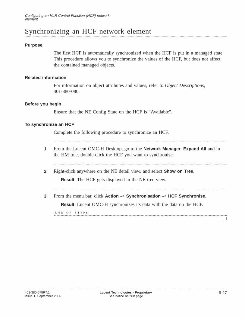
Synchronizing an HCF network element.................................................................................................................................................................................................................................
Purpose
The first HCF is automatically synchronized when the HCF is put in a managed state.This procedure allows you to synchronize the values of the HCF, but does not affectthe contained managed objects.
Related information
For information on object attributes and values, refer toObject Descriptions,401-380-080.
Before you begin
Ensure that the NE Config State on the HCF is “Available”.
To synchronize an HCF
Complete the following procedure to synchronize an HCF.
.................................................................................................................................................................................................
1 From the Lucent OMC-H Desktop, go to theNetwork Manager . Expand All and inthe HM tree, double-click the HCF you want to synchronize.
.................................................................................................................................................................................................
2 Right-click anywhere on the NE detail view, and selectShow on Tree .
Result: The HCF gets displayed in the NE tree view.
.................................................................................................................................................................................................
3 From the menu bar, clickAction -> Synchronisation -> HCF Synchronise .
Result: Lucent OMC-H synchronizes its data with the data on the HCF.
E N D O F S T E P S........................................................................................................................................................................................................................
Configuring an HLR Control Function (HCF) networkelement
.................................................................................................................................................................................................................................401-380-078R7.1Issue 1, September 2006
Lucent Technologies - ProprietarySee notice on first page
6-27

Synchronizing SS7 configuration for an HCF.................................................................................................................................................................................................................................
Purpose
This procedure allows you to synchronize SS7 configuration for an HCF. Perform thistask to ensure that the SS7 data is identical on the HCF and the Lucent OMC-Hdatabase.
The data on the HCF is overwritten by the data from Lucent OMC-H.
Related information
For more information, see“SDHLR and the HCF” (p. 6-4).
Before you begin
Ensure that the NE Config State on the HCF is “Available”. Also ensure that SPA stateshould be OOS for software version 310 of the HCF and SPA state should be MOOSfor the software versions 400 & 500 of the HCF.
To synchronize SS7 configuration for an HCF
Complete the following procedure to synchronize SS7 configuration for an HCF.
.................................................................................................................................................................................................
1 From the Lucent OMC-H Desktop, go to theNetwork Manager . Expand All and inthe HM Tree View, double-click the HCF you want to synchronize
.................................................................................................................................................................................................
2 Right-click anywhere on the NE detail view, and selectShow on Tree .
Result: The HCF gets displayed in the NE tree view.
.................................................................................................................................................................................................
3 From the menu bar, clickAction -> Synchronization , and thenSS7 Synchronizewith OMC .
Result: The Lucent OMC-H synchronizes its SS7 data with the SS7 data on theHCF network element.
To verify the status of the synchronization operation, invoke the detail view of thatHCF and check the SS7 synchronization Status attribute in the HCF tab.
Reference: For information on invoking the detail view of an HCF, refer toGraphical User Interface,401-380-082.
E N D O F S T E P S........................................................................................................................................................................................................................
Configuring an HLR Control Function (HCF) networkelement
.................................................................................................................................................................................................................................
6-28 Lucent Technologies - ProprietarySee notice on first page
401-380-078R7.1Issue 1, September 2006

Auditing an HCF.................................................................................................................................................................................................................................
Purpose
This procedure allows you to audit an HCF. An Audit is a check between the SS7configuration data in the Lucent OMC-H and the SS7 configuration data on the HCFnetwork element.
If there is a discrepancy in between the two databases, you should check the Audit login the Report Manager and then possibly synchronize the SS7 data.
Related information
For more information, see“SDHLR and the HCF” (p. 6-4).
Before you begin
Ensure that the HCF is in the Managed state.
To audit an HCF
Complete the following procedure to audit an HCF.
.................................................................................................................................................................................................
1 From the Lucent OMC-H Desktop, go to theNetwork Manager . Expand All and inthe HM tree, double-click the HCF you want to audit. The NE details are displayed inthe NE detail view.
.................................................................................................................................................................................................
2 Right-click anywhere on the NE detail view, and selectShow on Tree .
Result: The HCF gets displayed in the NE tree view.
.................................................................................................................................................................................................
3 From the Action menu, clickAudit and selectSS7.
Result: The Lucent OMC-H audits the SS7 configuration data in the database withthe data on the HCF.
.................................................................................................................................................................................................
4 If there is a discrepancy between the two databases, then synchronize the SS7 data.
For information on how to synchronize the SS7 data, refer to“Synchronizing SS7configuration for an HCF” (p. 6-28).
E N D O F S T E P S........................................................................................................................................................................................................................
Configuring an HLR Control Function (HCF) networkelement
.................................................................................................................................................................................................................................401-380-078R7.1Issue 1, September 2006
Lucent Technologies - ProprietarySee notice on first page
6-29
Performing other operations on the HCF
Overview.................................................................................................................................................................................................................................
Purpose
This section provides procedures for modifying HCF network elements, managing theSPA for the HCF and removing or restoring the HCF network element.
Contents
Modifying HCF parameters 6-31
Managing SPA for an HCF 6-33
Performing object specific actions on a LocalSSN object 6-35
Configuring an HLR Control Function (HCF) networkelement
.................................................................................................................................................................................................................................
6-30 Lucent Technologies - ProprietarySee notice on first page
401-380-078R7.1Issue 1, September 2006
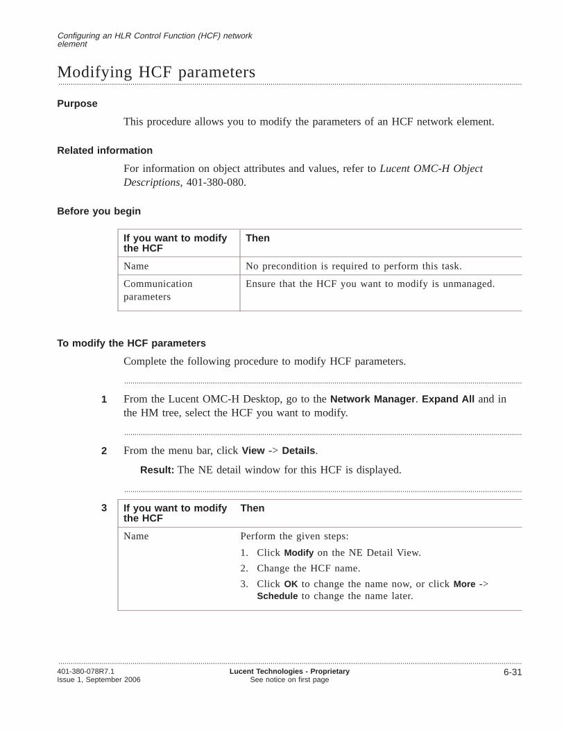
Modifying HCF parameters.................................................................................................................................................................................................................................
Purpose
This procedure allows you to modify the parameters of an HCF network element.
Related information
For information on object attributes and values, refer toLucent OMC-H ObjectDescriptions,401-380-080.
Before you begin
If you want to modifythe HCF
Then
Name No precondition is required to perform this task.
Communicationparameters
Ensure that the HCF you want to modify is unmanaged.
To modify the HCF parameters
Complete the following procedure to modify HCF parameters.
.................................................................................................................................................................................................
1 From the Lucent OMC-H Desktop, go to theNetwork Manager . Expand All and inthe HM tree, select the HCF you want to modify.
.................................................................................................................................................................................................
2 From the menu bar, clickView -> Details .
Result: The NE detail window for this HCF is displayed.
.................................................................................................................................................................................................
3 If you want to modifythe HCF
Then
Name Perform the given steps:
1. Click Modify on the NE Detail View.
2. Change the HCF name.
3. Click OK to change the name now, or clickMore ->Schedule to change the name later.
Configuring an HLR Control Function (HCF) networkelement
.................................................................................................................................................................................................................................401-380-078R7.1Issue 1, September 2006
Lucent Technologies - ProprietarySee notice on first page
6-31

If you want to modifythe HCF
Then
Communicationparameters
Perform the given steps:
1. Click NE Management... .
2. Click Modify .
3. Update the required communication parameters.While modifying HCF SNMP security parameters, if youpopulate the privacy passwords with less than 8 charactersor more than 30 characters, then Lucent OMC-H gives anerror. The length of the SNMP Privacy Password on theHCF must be the same as on the Lucent OMC-H.
4. Click OK to submit the changes now, or clickMore ->Schedule to modify the parameters later.If you click the NE Location... tab afterStep 2, theLatitude and Longitude fields cannot be modified (theyare greyed out), although there is aModify buttonavailable. However, you can modify these parametersfrom the SiteInfo object.
For more information on modifying the latitude and longitudefrom the SiteInfo object, refer toChapter 10, Configuring theTopological and Topographical Views.
E N D O F S T E P S........................................................................................................................................................................................................................
Configuring an HLR Control Function (HCF) networkelement
Modifying HCF parameters
.................................................................................................................................................................................................................................
6-32 Lucent Technologies - ProprietarySee notice on first page
401-380-078R7.1Issue 1, September 2006

Managing SPA for an HCF.................................................................................................................................................................................................................................
Purpose
This procedure allows you to manage Service Package Application (SPA) for an HCF.You can manage SPA for an HCF by enabling, disabling, removing or restoring SPAfor the HCF from the Lucent OMC-H.
Related information
For information on object attributes and values, refer toObject Descriptions,401-380-080.
Before you begin
If you want to Then
Enable SPA Ensure that the SPA is in thedisabledEquipped state and theApplication is in theNot_Running state.
Note : Lucent OMC-H Release 7.1 supports SPA versions 600and 610 only.
Disable SPA Ensure that the SPA and the Application are in theManuallyOut Of Service (MOOS) state
Remove SPA Ensure that SPA isIn Service (IS) and Application Stateshould beNot_running .
Restore SPA Ensure that SPA isManually Out Of Service (MOOS) .
To manage SPA for an HCF
Complete the following procedure to enable, disable, remove or restore SPA for anHCF.
.................................................................................................................................................................................................
1 Invoke theLucent OMC-H - Network Manager window from theLucent OMC-H -Desktop .
For more information on accessing the Network Manager, refer toGraphical UserInterface,401-380-082.
.................................................................................................................................................................................................
2 In the HM tree, double-click the HCF whose SPA you want to manage.
.................................................................................................................................................................................................
3 Right-click anywhere on the NE detail view, and selectShow on Tree .
Configuring an HLR Control Function (HCF) networkelement
.................................................................................................................................................................................................................................401-380-078R7.1Issue 1, September 2006
Lucent Technologies - ProprietarySee notice on first page
6-33

Result: The HCF gets displayed in the NE tree view.
.................................................................................................................................................................................................
4 From the menu bar, clickAction -> Object Specific -> <manage_action> .
Alternatively, right-click the target HCF and clickObject Specific -><manage_action> .
The Lucent OMC-H provides the following <manage_action> options to choose from:
• Enable
• Disable
• Remove
• Restore
Result: The Action Confirmation window is displayed.
.................................................................................................................................................................................................
5 Click Yes to perform the SPA manage operation on the HCF.
Result:
If you performed the Then you see the following results
Enable SPA operationon the HCF
If you are using SPA version 310 then the SPA gets enabledand the state of the SPA changes to Out of Service (OOS). Ifyou are using SPA version 400 or 500 then the SPA getsenabled and the state of the SPA changes to Manually Out ofService (MOOS).
Disable SPA operationon the HCF
The SPA gets disabled and the state of the SPA changes toEquipped.
Remove SPA operationon the HCF
If you are using SPA version 310 then the SPA gets enabledand the state of the SPA changes to Out of Service (OOS). Ifyou are using SPA version 400 or 500 then the SPA getsenabled and the state of the SPA changes to Manually Out ofService (MOOS).
Restore SPA operationon the HCF
The SPA is restored on the HCF network element.
E N D O F S T E P S........................................................................................................................................................................................................................
Configuring an HLR Control Function (HCF) networkelement
Managing SPA for an HCF
.................................................................................................................................................................................................................................
6-34 Lucent Technologies - ProprietarySee notice on first page
401-380-078R7.1Issue 1, September 2006

Performing object specific actions on a LocalSSN object.................................................................................................................................................................................................................................
Purpose
This procedure allows you to remove or restore a LocalSSN object.
Related information
For information on a LocalSSN object, refer to“HCF network element description”(p. 6-6).
Before you begin
If you want to Then ensure that
Remove the Local SSN The LocalSSN object state is In Service (IS).
Restore the Local SSN The LocalSSN object state is Manually Out Of Service(MOOS).
To remove or restore a LocalSSN object
Complete the following procedure to remove or restore a LocalSSN object.
.................................................................................................................................................................................................
1 From the Lucent OMC-H Desktop, go to theNetwork Manager . Expand All and inthe HM Tree View navigate to the HCF Cluster.
.................................................................................................................................................................................................
2 Right-click on the SS7 HCF object, and selectShow on Tree .
.................................................................................................................................................................................................
3 In the NE Tree View right-click the HCF object whose LocalSSN you want and clickExpand All .
.................................................................................................................................................................................................
4 Select the LocalSSN object.
.................................................................................................................................................................................................
5 From the menu bar, clickAction -> Object Specific -> <Object-Specific> action.
The available <Object-Specific> actions for the Local SSN object are
• Remove
• Restore
Configuring an HLR Control Function (HCF) networkelement
.................................................................................................................................................................................................................................401-380-078R7.1Issue 1, September 2006
Lucent Technologies - ProprietarySee notice on first page
6-35

Result: The LocalSSN object gets removed and the LocalSSN state changes from“IS” to “MOOS” (Manually Out Of Service). To verify the state of the LocalSSNobject, double-click to view the Detail View.
The State label displays the current state of the LocalSSN object.
E N D O F S T E P S........................................................................................................................................................................................................................
Configuring an HLR Control Function (HCF) networkelement
Performing object specific actions on a LocalSSN object
.................................................................................................................................................................................................................................
6-36 Lucent Technologies - ProprietarySee notice on first page
401-380-078R7.1Issue 1, September 2006
7 7Configuring a HLR ControlFunction (HCF) Group
Overview.................................................................................................................................................................................................................................
Purpose
This chapter describes the HCF Group and provides procedures to configure it.
Note: Though the SDHLR HCF can support multiple transport protocols, currently itonly provides DIAMETER and SS7 protocols. So all further references to an HCF inthe HCF Group here will mention it as the DIAMETER HCF.
Contents
Description of the Diameter HCF 7-3
Diameter Protocol 7-4
DIAMETER object descriptions 7-5
Creating Diameter network elements 7-8
Creating an HCF group 7-9
Creating a Diameter HCF 7-11
Creating Diameter objects 7-13
Creating TCP IP objects 7-15
Modifying Diameter network elements 7-17
Modifying HCF Group objects 7-18
Modifying TCP IP objects 7-20
Deleting Diameter network elements 7-22
Deleting Diameter objects 7-23
Deleting TCP IP objects 7-25
Synchronizing Diameter network elements 7-27
Performing audit on the Diameter HCF 7-28
.................................................................................................................................................................................................................................401-380-078R7.1Issue 1, September 2006
Lucent Technologies - ProprietarySee notice on first page
7-1

Diameter Synchronization with NE (Reverse Synchronization) 7-30
Synchronizing an HCF 7-32
Diameter Synchronization with Lucent OMC-H (ForwardSynchronization)
7-34
Configuring a HLR Control Function (HCF) Group Overview
.................................................................................................................................................................................................................................
7-2 Lucent Technologies - ProprietarySee notice on first page
401-380-078R7.1Issue 1, September 2006
Description of the Diameter HCF
Overview.................................................................................................................................................................................................................................
Purpose
This section describes a Diameter HCF.
Contents
Diameter Protocol 7-4
DIAMETER object descriptions 7-5
Configuring a HLR Control Function (HCF) Group
.................................................................................................................................................................................................................................401-380-078R7.1Issue 1, September 2006
Lucent Technologies - ProprietarySee notice on first page
7-3

Diameter Protocol.................................................................................................................................................................................................................................
Diameter Protocol Description
Diameter protocol is the next generation Accounting, Authentication, and Authorization(AAA) solution for networks where user authentication occurs in fixed and wirelessdomains.
Up to now, the most widely used AAA protocol has been Remote AuthenticationDial-In User Service (RADIUS), which is not suited for Mobile and Virtual PrivateNetwork (VPN) application requirements.
The Diameter protocol is defined in terms of a base protocol and a set of applications.This allows the protocol to be extended to new access technologies. The base protocolprovides basic mechanisms for reliable transport, message delivery, and error handling.However, the base protocol must be used in tandem with a Diameter Application.
Diameter Applications
The Diameter applications are:
• Mobile IPv4 [DIAMMIP]
• NASREQ (Network Access Service Requirements)
NASREQ is the working Group of the IETF for the next generation NAS AAArequirements. NASREQ application supports dial-in PPP/IP and is the intendedreplacement for RADIUS.
HCF Group
The HCF Group is a container object for the Diameter HCF. The parent group is theSDHLR group.
Configuring a HLR Control Function (HCF) Group
.................................................................................................................................................................................................................................
7-4 Lucent Technologies - ProprietarySee notice on first page
401-380-078R7.1Issue 1, September 2006
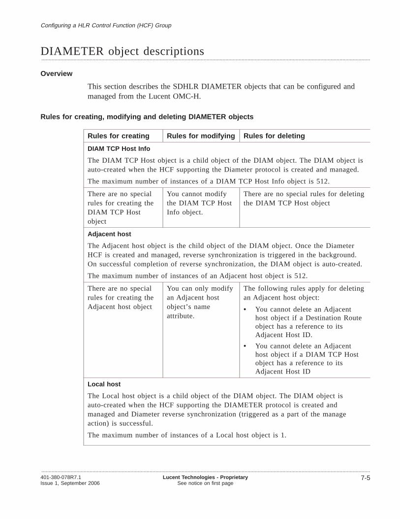
DIAMETER object descriptions.................................................................................................................................................................................................................................
Overview
This section describes the SDHLR DIAMETER objects that can be configured andmanaged from the Lucent OMC-H.
Rules for creating, modifying and deleting DIAMETER objects
Rules for creating Rules for modifying Rules for deleting
DIAM TCP Host Info
The DIAM TCP Host object is a child object of the DIAM object. The DIAM object isauto-created when the HCF supporting the Diameter protocol is created and managed.
The maximum number of instances of a DIAM TCP Host Info object is 512.
There are no specialrules for creating theDIAM TCP Hostobject
You cannot modifythe DIAM TCP HostInfo object.
There are no special rules for deletingthe DIAM TCP Host object
Adjacent host
The Adjacent host object is the child object of the DIAM object. Once the DiameterHCF is created and managed, reverse synchronization is triggered in the background.On successful completion of reverse synchronization, the DIAM object is auto-created.
The maximum number of instances of an Adjacent host object is 512.
There are no specialrules for creating theAdjacent host object
You can only modifyan Adjacent hostobject’s nameattribute.
The following rules apply for deletingan Adjacent host object:
• You cannot delete an Adjacenthost object if a Destination Routeobject has a reference to itsAdjacent Host ID.
• You cannot delete an Adjacenthost object if a DIAM TCP Hostobject has a reference to itsAdjacent Host ID
Local host
The Local host object is a child object of the DIAM object. The DIAM object isauto-created when the HCF supporting the DIAMETER protocol is created andmanaged and Diameter reverse synchronization (triggered as a part of the manageaction) is successful.
The maximum number of instances of a Local host object is 1.
Configuring a HLR Control Function (HCF) Group
.................................................................................................................................................................................................................................401-380-078R7.1Issue 1, September 2006
Lucent Technologies - ProprietarySee notice on first page
7-5

Rules for creating Rules for modifying Rules for deleting
There are no specialrules for creating theLocal host object
You can modify allLocal host object’sattributes, except theID.
You cannot delete a Local host object.
Destination Route
The Destination Route object is a child object of the DIAM object. The DIAM objectis auto-created when the HCF supporting the DIAMETER protocol is created andmanaged.
The maximum number of instances of a Destination Route object is 512.
There are no specialrules for creating theDestination Routeobject
You can modify allDestination Routeobject’s attributes,except HostConfiguration Indexand Host Realm.
There are no special rules for deletingthe Destination Route object
Diameter SSN
The Diameter SSN object is a child object of the DIAM object. The DIAM object isauto-created when the HCF supporting the DIAMETER protocol is created andmanaged.
The maximum number of instances of a Diameter SSN object is 50.
There are no specialrules for creating theDiameter SSN object
You cannot modifyany Diameter SSNobject attributes.
There are no special rules for deletingthe Diameter SSN object
Vendor
The Vendor object is a child object of the DIAM object. The DIAM object isauto-created when the HCF supporting the Diameter protocol is created and managed.
The maximum number of instances of a Vendor object is 1.
There are no specialrules for creating theVendor object
You can modify allVendor object’sattributes, except theIndex(DiamVsAppidIndex).
There are no special rules for deletingthe Vendor object
TCP IP Host
The TCP IP Host object is a child object of the TCPConnection object. TheTCPConnection object is auto-created when the HCF supporting the Diameter protocolis created and managed.
The maximum number of instances of a TCP IP Host object is 100.
Configuring a HLR Control Function (HCF) Group DIAMETER object descriptions
.................................................................................................................................................................................................................................
7-6 Lucent Technologies - ProprietarySee notice on first page
401-380-078R7.1Issue 1, September 2006

Rules for creating Rules for modifying Rules for deleting
There are no specialrules for creating theTCP IP Host object
You can modify TCPIP Host objectattributes, except forHost Name and HostConfiguration Index.
You cannot delete a TCP IP Hostobject if its host name is referenced ina TCP IP Listening Port object or aTCP IP Connecting Port object.
TCP IP Listening Port
The TCP IP Listening Port object is a child object of the TCPConnection object. TheTCPConnection object is auto-created when the HCF supporting the Diameter is createdand managed.
The maximum number of instances of a TCP IP Listening Port object is 100.
There are no specialrules for creating theTCP IP Listening Portobject
You cannot modifythis object.
There are no special rules for deletingthe TCP IP Listening Port object
TCP IP Connecting Port
The TCP IP Connecting Port object is a child object of the TCPConnection object. TheTCPConnection object is auto-created when the HCF supporting the Diameter protocolis created and managed.
The maximum number of instances of a TCP IP Connecting Port object is 100.
There are no specialrules for creating theTCP IP ConnectingPort object
You cannot modify aTCP IP ConnectingPort.
You can delete a TCP IP ConnectingPort object.
Attributes and values
For information on object attributes and values, refer toObject Descriptions,401-380-080.
Configuring a HLR Control Function (HCF) Group DIAMETER object descriptions
.................................................................................................................................................................................................................................401-380-078R7.1Issue 1, September 2006
Lucent Technologies - ProprietarySee notice on first page
7-7
Creating Diameter network elements
Overview.................................................................................................................................................................................................................................
Purpose
This section provides procedures for creating the HCF with Diameter support.
Contents
Creating an HCF group 7-9
Creating a Diameter HCF 7-11
Creating Diameter objects 7-13
Creating TCP IP objects 7-15
Configuring a HLR Control Function (HCF) Group
.................................................................................................................................................................................................................................
7-8 Lucent Technologies - ProprietarySee notice on first page
401-380-078R7.1Issue 1, September 2006
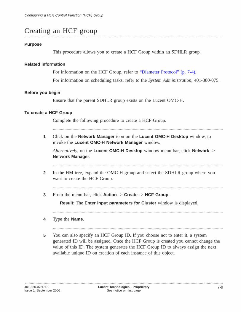
Creating an HCF group.................................................................................................................................................................................................................................
Purpose
This procedure allows you to create a HCF Group within an SDHLR group.
Related information
For information on the HCF Group, refer to“Diameter Protocol” (p. 7-4).
For information on scheduling tasks, refer to theSystem Administration,401-380-075.
Before you begin
Ensure that the parent SDHLR group exists on the Lucent OMC-H.
To create a HCF Group
Complete the following procedure to create a HCF Group.
.................................................................................................................................................................................................
1 Click on theNetwork Manager icon on theLucent OMC-H Desktop window, toinvoke theLucent OMC-H Network Manager window.
Alternatively, on theLucent OMC-H Desktop window menu bar, clickNetwork ->Network Manager .
.................................................................................................................................................................................................
2 In the HM tree, expand the OMC-H group and select the SDHLR group where youwant to create the HCF Group.
.................................................................................................................................................................................................
3 From the menu bar, clickAction -> Create -> HCF Group .
Result: The Enter input parameters for Cluster window is displayed.
.................................................................................................................................................................................................
4 Type theName.
.................................................................................................................................................................................................
5 You can also specify an HCF Group ID. If you choose not to enter it, a systemgenerated ID will be assigned. Once the HCF Group is created you cannot change thevalue of this ID. The system generates the HCF Group ID to always assign the nextavailable unique ID on creation of each instance of this object.
Configuring a HLR Control Function (HCF) Group
.................................................................................................................................................................................................................................401-380-078R7.1Issue 1, September 2006
Lucent Technologies - ProprietarySee notice on first page
7-9

.................................................................................................................................................................................................
6 Click OK to create the HCF Group now, or clickSchedule to create it later.
E N D O F S T E P S........................................................................................................................................................................................................................
Configuring a HLR Control Function (HCF) Group Creating an HCF group
.................................................................................................................................................................................................................................
7-10 Lucent Technologies - ProprietarySee notice on first page
401-380-078R7.1Issue 1, September 2006

Creating a Diameter HCF.................................................................................................................................................................................................................................
Purpose
This procedure allows you to create a Diameter HCF within a HCF Group.
Related information
For information on creating a HCF Group, refer to“Creating an HCF group” (p. 7-9).
Before you begin
Ensure that the parent HCF group exists.
To create a Diameter HCF
Complete the following procedure to create a Diameter HCF.
.................................................................................................................................................................................................
1 Click on theNetwork Manager icon on theLucent OMC-H Desktop window, toinvoke theLucent OMC-H Network Manager window.
Alternatively, on theLucent OMC-H Desktop window menu bar, clickNetwork ->Network Manager .
.................................................................................................................................................................................................
2 In the HM tree view, expand the OMC-H group.
.................................................................................................................................................................................................
3 Expand the SDHLR group that contains the parent HCF Group and select the parentHCF Group.
.................................................................................................................................................................................................
4 From the menu bar, clickAction -> Create -> HCF.
Result: The Create HCF - General window is displayed.
.................................................................................................................................................................................................
5 Type theName.
.................................................................................................................................................................................................
6 You can also specify an NE ID. If you choose not to enter it, a system generated IDwill be assigned. Once the NE is created you cannot change the value of this ID. Thesystem generates the HCF ID to always assign the next available unique ID on creationof each instance of this object.
Configuring a HLR Control Function (HCF) Group
.................................................................................................................................................................................................................................401-380-078R7.1Issue 1, September 2006
Lucent Technologies - ProprietarySee notice on first page
7-11

.................................................................................................................................................................................................
7 Click Next and populate information under the Communication, SNMP, SNMPSecurity, and SSH/FTP tabs.
At this point you may want to configure key based SSH/SFTP authentication forthe new NE. To do this you require administrative permissions. For details aboutthe procedure for configuring key-based SSH/SFTP authentication on the new HCFrefer toSystem Administration,401-380-075.
.................................................................................................................................................................................................
8 Click Finish to commit all the changes specified in the wizard and create the DiameterHCF now, or clickMore -> Save Profile to save your changes. You can later load thisprofile on any Diameter HCF by clicking onMore -> Load Profile in the NE DetailView of that HCF.
At any time during the creation process, clickBack to go to the previous wizardwindow, and clickCancel to cancel the creation operation.
Result
The Diameter HCF gets created. You need to manage the Diameter HCF, to bring it tothe operational state. Right-click the Diameter HCF, and clickManage . The DiameterHCF gets managed and reverse synchronization is triggered in the background. Oncethe reverse synchronization is completed successfully, the following objects getauto-created.
• DIAM object
• TCP Connection object.
Configuring a HLR Control Function (HCF) Group Creating a Diameter HCF
.................................................................................................................................................................................................................................
7-12 Lucent Technologies - ProprietarySee notice on first page
401-380-078R7.1Issue 1, September 2006
E N D O F S T E P S.................................................................................................................................................................................................

Creating Diameter objects.................................................................................................................................................................................................................................
Purpose
This procedure allows you to create the following Diameter objects.
• Diameter TCP Host
• Adjacent Host
• Local Host
• Destination Route
• Diameter SSN
• Vendor
Related information
For information on the Diameter objects, refer to“DIAMETER object descriptions”(p. 7-5), .
Before you begin
There are no preconditions to perform this procedure.
To create Diameter objects
Complete the following procedure to create Diameter objects.
.................................................................................................................................................................................................
1 From the Lucent OMC-H Desktop, go to theNetwork Manager . Expand All and inthe HM tree, double-click the parent HCF, supporting Diameter, of the DIAM objectwhose child objects need to be created.
.................................................................................................................................................................................................
2 Right-click anywhere on the NE detail view, and selectShow on Tree to display theselected Diameter HCF in the NE tree view.
.................................................................................................................................................................................................
3 Select the Diameter object .
.................................................................................................................................................................................................
4 From the menu bar, clickAction -> Create -> <DIAM object name> (Vendor, LocalHost, Adjacent Host, Destination Route, or Diam SSN).
Alternatively, you can right-click the Diameter object and clickCreate -> <DIAMobject name (Vendor, Local Host, Adjacent Host, Destination Route, or Diam SSN).
Configuring a HLR Control Function (HCF) Group
.................................................................................................................................................................................................................................401-380-078R7.1Issue 1, September 2006
Lucent Technologies - ProprietarySee notice on first page
7-13

Result: The Enter input parameters for Create <DIAM object name window isdisplayed.
The Adjacent Host, Destination Route, and Diam SSN objects can also be createdby right-clicking their parent table objects. For example, right-clickAdjacentHostTable to create an Adjacent Host object.
.................................................................................................................................................................................................
5 Specify values in the fields provided.
.................................................................................................................................................................................................
6 Click OK to create the object now or clickMore -> Schedule to create the objectlater.
Result: The Diameter object is created.
E N D O F S T E P S........................................................................................................................................................................................................................
Configuring a HLR Control Function (HCF) Group Creating Diameter objects
.................................................................................................................................................................................................................................
7-14 Lucent Technologies - ProprietarySee notice on first page
401-380-078R7.1Issue 1, September 2006

Creating TCP IP objects.................................................................................................................................................................................................................................
Purpose
This procedure allows you to create the following TCP IP objects.
• TCP IP Host
• TCP IP Listening Port
• TCP IP Connection Port
Related information
For information on the TCP IP objects, refer to“DIAMETER object descriptions”(p. 7-5).
Before you begin
There are no preconditions to perform this procedure.
To create TCP IP objects
Complete the following procedure to create the TCP IP objects.
.................................................................................................................................................................................................
1 From the Lucent OMC-H Desktop, go to theNetwork Manager . Expand All and inthe HM tree, double-click the parent Diameter HCF of the TCP IP object whose childobjects need to be created.
.................................................................................................................................................................................................
2 Right-click anywhere on the NE detail view, and selectShow on Tree to display theselected Diameter HCF in the NE tree view.
.................................................................................................................................................................................................
3 Select the TCP IP object.
.................................................................................................................................................................................................
4 From the menu bar, clickAction -> Create -> <TCP IP object name> (TCP IP Host,TCP IP Listening Port, TCP IP Connection Port).
Alternatively, you can right-click the TCP IP Connection object or the parent tableobject (for example, the TCPHostConfigTable) and clickCreate -> <TCP IP objectname> (TCP IP Host, TCP IP Listening Port, TCP IP Connection Port).
Configuring a HLR Control Function (HCF) Group
.................................................................................................................................................................................................................................401-380-078R7.1Issue 1, September 2006
Lucent Technologies - ProprietarySee notice on first page
7-15

Result: The Enter input parameters for Create <TCP IP object name> windowis displayed.
.................................................................................................................................................................................................
5 Specify values in the fields provided.
.................................................................................................................................................................................................
6 Click OK to create the object now or clickMore -> Schedule to create the objectlater.
Result: The TCP IP object is created.
E N D O F S T E P S........................................................................................................................................................................................................................
Configuring a HLR Control Function (HCF) Group Creating TCP IP objects
.................................................................................................................................................................................................................................
7-16 Lucent Technologies - ProprietarySee notice on first page
401-380-078R7.1Issue 1, September 2006

Modifying Diameter network elements
Overview.................................................................................................................................................................................................................................
Purpose
This section provides procedures for modifying HCF group objects.
Note: The HCF Group currently supports only the DIAMETER protocol
Contents
Modifying HCF Group objects 7-18
Modifying TCP IP objects 7-20
Configuring a HLR Control Function (HCF) Group
.................................................................................................................................................................................................................................401-380-078R7.1Issue 1, September 2006
Lucent Technologies - ProprietarySee notice on first page
7-17

Modifying HCF Group objects.................................................................................................................................................................................................................................
Purpose
This procedure allows you to modify the following HCF Group objects.
• Adjacent Host
• Local Host
• Destination Route
• Diameter SSN
• Vendor
Related information
For information on the modifiable attributes of the HCF Group objects, refer to“DIAMETER object descriptions” (p. 7-5).
Before you begin
There are no preconditions to perform this procedure.
To modify Diameter objects
Complete the following procedure to create the HCF Group objects.
.................................................................................................................................................................................................
1 From the Lucent OMC-H Desktop, go to theNetwork Manager . Expand All and inthe HM Tree View, double-click the parent HCF Group of the Diameter object whosechild objects need to be modified.
.................................................................................................................................................................................................
2 Right-click anywhere on the NE detail view, and selectShow on Tree to display theselected Diameter HCF in the NE tree view.
.................................................................................................................................................................................................
3 Select the DIAM object and expand it.
.................................................................................................................................................................................................
4 Select the Diameter object to be modified.
.................................................................................................................................................................................................
5 From the menu bar, clickView -> Details to open the detail view.
Alternatively, you can right-click the selected object and clickDetails or double-clickthe selected object.
Configuring a HLR Control Function (HCF) Group
.................................................................................................................................................................................................................................
7-18 Lucent Technologies - ProprietarySee notice on first page
401-380-078R7.1Issue 1, September 2006

.................................................................................................................................................................................................
6 Click Modify on the detail view.
.................................................................................................................................................................................................
7 Modify the editable fields, if required.
.................................................................................................................................................................................................
8 Click OK to submit the changes now or clickMore -> Schedule to submit the changeslater.
Result: The Diameter object gets modified.
E N D O F S T E P S........................................................................................................................................................................................................................
Configuring a HLR Control Function (HCF) Group Modifying HCF Group objects
.................................................................................................................................................................................................................................401-380-078R7.1Issue 1, September 2006
Lucent Technologies - ProprietarySee notice on first page
7-19

Modifying TCP IP objects.................................................................................................................................................................................................................................
Purpose
This procedure allows you to modify the following TCP IP objects.
• TCP IP Host
• TCP IP Listening Port
• TCP IP Connection Port
Related information
For information on the modifiable attributes of the TCP IP objects, refer to“DIAMETER object descriptions” (p. 7-5).
Before you begin
There are no preconditions to perform this procedure.
To modify TCP IP objects
Complete the following procedure to create the TCP IP objects.
.................................................................................................................................................................................................
1 From the Lucent OMC-H Desktop, go to theNetwork Manager . Expand All and inthe HM Tree View, double-click the HCF Group (currently supporting onlyDIAMETER Objects) of the TCP IP object whose child objects need to be created.
.................................................................................................................................................................................................
2 Right-click anywhere on the NE detail view, and selectShow on Tree to display theselected Diameter HCF in the NE tree view.
.................................................................................................................................................................................................
3 Select the TCP IP object and expand it.
.................................................................................................................................................................................................
4 Select the TCP IP object to be modified.
.................................................................................................................................................................................................
5 From the menu bar, clickView -> Details to open the detail view.
Alternatively, you can right-click the selected object and clickDetails or double-clickthe selected object.
.................................................................................................................................................................................................
6 Click Modify on the detail view.
Configuring a HLR Control Function (HCF) Group
.................................................................................................................................................................................................................................
7-20 Lucent Technologies - ProprietarySee notice on first page
401-380-078R7.1Issue 1, September 2006
.................................................................................................................................................................................................
7 Modify the editable fields, if required.
.................................................................................................................................................................................................
8 Click OK to submit the changes now or clickMore -> Schedule to submit the changeslater.
Result: The TCP IP object gets modified.
E N D O F S T E P S........................................................................................................................................................................................................................
Configuring a HLR Control Function (HCF) Group Modifying TCP IP objects
.................................................................................................................................................................................................................................401-380-078R7.1Issue 1, September 2006
Lucent Technologies - ProprietarySee notice on first page
7-21

Deleting Diameter network elements
Overview.................................................................................................................................................................................................................................
Purpose
This section provides procedures for deleting a Diameter HCF.
Contents
Deleting Diameter objects 7-23
Deleting TCP IP objects 7-25
Configuring a HLR Control Function (HCF) Group
.................................................................................................................................................................................................................................
7-22 Lucent Technologies - ProprietarySee notice on first page
401-380-078R7.1Issue 1, September 2006

Deleting Diameter objects.................................................................................................................................................................................................................................
Purpose
This procedure allows you to delete the following Diameter objects.
• Diameter TCP Host
• Adjacent Host
• Destination Route
• Diameter SSN
• Vendor
Related information
For information on the Diameter objects, refer to“DIAMETER object descriptions”(p. 7-5).
Before you begin
Ensure that:
• You have the required permissions to use Network Manager
• The Adjacent Host object is not being referenced by the Destination Route object,while it is being deleted.
To delete an object
Complete the following procedure to delete an object:
.................................................................................................................................................................................................
1 Invoke theLucent OMC-H Network Manager window through theLucent OMC-HDesktop .
.................................................................................................................................................................................................
2 In the HM tree, double-click the HCF Group of the Diameter object whose childobjects need to be deleted.
.................................................................................................................................................................................................
3 Right-click anywhere on the NE detail view, and selectShow on Tree to display theselected Diameter HCF in the NE tree view.
.................................................................................................................................................................................................
4 Select the DIAM object and expand it.
.................................................................................................................................................................................................
5 Select the Diameter object to be deleted.
Configuring a HLR Control Function (HCF) Group
.................................................................................................................................................................................................................................401-380-078R7.1Issue 1, September 2006
Lucent Technologies - ProprietarySee notice on first page
7-23
.................................................................................................................................................................................................
6 From the menu bar, clickAction -> Delete to delete the object now or clickMore ->Schedule -> Delete to delete the object later.
Alternatively, click the Delete icon on the tool bar, or right-click the object and clickDelete or Schedule -> Delete .
Result: The object is deleted.
E N D O F S T E P S........................................................................................................................................................................................................................
Configuring a HLR Control Function (HCF) Group Deleting Diameter objects
.................................................................................................................................................................................................................................
7-24 Lucent Technologies - ProprietarySee notice on first page
401-380-078R7.1Issue 1, September 2006
Deleting TCP IP objects.................................................................................................................................................................................................................................
Purpose
This procedure allows you to delete the following TCP IP objects.
• TCP IP Host
• TCP IP Listening Port
• TCP IP Connection Port
Related information
For information on the TCP IP objects, refer to“DIAMETER object descriptions”(p. 7-5).
Before you begin
There are no preconditions to perform this procedure.
To delete a TCP IP object
Complete the following procedure to delete a TCP IP object.
.................................................................................................................................................................................................
1 Invoke theLucent OMC-H Network Manager window through theLucent OMC-HDesktop .
.................................................................................................................................................................................................
2 In the HM tree, double-click the parent Diameter HCF of the TCP IP object whosechild objects need to be deleted.
.................................................................................................................................................................................................
3 Right-click anywhere on the NE detail view, and selectShow on Tree to display theselected Diameter HCF in the NE tree view.
.................................................................................................................................................................................................
4 Select the TCP IP object and expand it.
.................................................................................................................................................................................................
5 Select the TCP IP object to be deleted.
.................................................................................................................................................................................................
6 From the menu bar, clickAction -> Delete to delete the object now or clickMore ->Schedule -> Delete to delete the object later.
Alternatively, click the Delete icon on the tool bar, or right-click the object and clickDelete or Schedule -> Delete .
Configuring a HLR Control Function (HCF) Group
.................................................................................................................................................................................................................................401-380-078R7.1Issue 1, September 2006
Lucent Technologies - ProprietarySee notice on first page
7-25

Result: The object is deleted.
E N D O F S T E P S........................................................................................................................................................................................................................
Configuring a HLR Control Function (HCF) Group Deleting TCP IP objects
.................................................................................................................................................................................................................................
7-26 Lucent Technologies - ProprietarySee notice on first page
401-380-078R7.1Issue 1, September 2006

Synchronizing Diameter network elements
Overview.................................................................................................................................................................................................................................
Purpose
This section provides procedures for synchronizing a Diameter HCF.
Contents
Performing audit on the Diameter HCF 7-28
Diameter Synchronization with NE (Reverse Synchronization) 7-30
Synchronizing an HCF 7-32
Diameter Synchronization with Lucent OMC-H (ForwardSynchronization)
7-34
Configuring a HLR Control Function (HCF) Group
.................................................................................................................................................................................................................................401-380-078R7.1Issue 1, September 2006
Lucent Technologies - ProprietarySee notice on first page
7-27

Performing audit on the Diameter HCF.................................................................................................................................................................................................................................
Purpose
This procedure allows you to perform an audit of the Diameter and TCP/IP objects ofthe Diameter HCF. The audit operation compares the attribute values of the Diameterobjects and TCP/IP on the Lucent OMC-H with that on the actual NE.
In case of discrepancies found in the values, as a result of the audit operation, an Auditreport is generated.
Related information
For information on creating a Diameter HCF, refer to“Creating a Diameter HCF”(p. 7-11).
Before you begin
Ensure that the parent NE Config State on the Diameter HCF is set to “Available”
To perform an audit on a Diameter HCF
Complete the following procedure to perform an audit on a Diameter HCF.
.................................................................................................................................................................................................
1 Click on theNetwork Manager icon on theLucent OMC-H Desktop window, toinvoke theLucent OMC-H Network Manager window.
Alternatively, on theLucent OMC-H Desktop window menu bar, clickNetwork ->Network Manager .
.................................................................................................................................................................................................
2 In the HM tree view, expand the OMC-H group.
.................................................................................................................................................................................................
3 Expand the SDHLR group that contains the parent HCF group and select the parentHCF group.
.................................................................................................................................................................................................
4 Double-click the Diameter HCF. The Diameter HCF details are displayed in the NEdetail view.
Right-click anywhere on the NE detail view, and selectShow on tree to view it in theNE tree view.
.................................................................................................................................................................................................
5 From the menu bar, clickAction -> Audit -> Diameter to compare the attribute valueson the Lucent OMC-H and the actual NE.
Configuring a HLR Control Function (HCF) Group
.................................................................................................................................................................................................................................
7-28 Lucent Technologies - ProprietarySee notice on first page
401-380-078R7.1Issue 1, September 2006

Alternatively, right-click the Diameter HCF, and clickAudit .
Result: The status window displays the progress of the audit operation. Once theaudit operation is complete, aWarning window is displayed, suggesting that theaudit is complete and an audit report is generated.
.................................................................................................................................................................................................
6 To view the audit report:
1. Click theReports Manager icon on theLucent OMC-H Desktop window, toinvoke the Report Manager.
2. From the menu bar, clickView -> Configuration Reports -> Audit Reports .
3. From the list of audit reports displayed, scroll down to select the last audit reportgenerated and double-click the report. The Report Information block indicates thename of the report, and the date and time it was generated.
Result: The HCF Audit Report is displayed in a browser window, displaying themismatched values of Lucent OMC-H and the NE.
E N D O F S T E P S........................................................................................................................................................................................................................
Configuring a HLR Control Function (HCF) Group Performing audit on the Diameter HCF
.................................................................................................................................................................................................................................401-380-078R7.1Issue 1, September 2006
Lucent Technologies - ProprietarySee notice on first page
7-29

Diameter Synchronization with NE (Reverse Synchronization).................................................................................................................................................................................................................................
Purpose
This procedure allows you to synchronize the data on Diameter HCF and TCP/IPobjects with that on the actual NE. This is known as reverse synchronization.
As a result of this synchronization, current attribute values on the actual NE arereflected on the Lucent OMC-H GUI.
Related information
For information on how to create a Diameter HCF, refer to“Creating a Diameter HCF”(p. 7-11).
Before you begin
Ensure that the parent Diameter HCF is in the managed state.
To synchronize data on Diameter HCF with actual NE
Complete the following procedure to synchronize data on the Diameter HCF with theactual NE.
.................................................................................................................................................................................................
1 Click on theNetwork Manager icon on theLucent OMC-H Desktop window.
Alternatively, on theLucent OMC-H Desktop window menu bar, clickNetwork ->Network Manager .
.................................................................................................................................................................................................
2 In the HM tree view, expand the OMC-H group.
.................................................................................................................................................................................................
3 Expand the SDHLR group that contains the parent HCF group and select the parentHCF group.
.................................................................................................................................................................................................
4 Double-click the Diameter HCF, and right-click anywhere on the NE detail view, andselectShow on tree to view it in the NE tree view.
.................................................................................................................................................................................................
5 From the menu bar, clickAction -> Synchronisation -> Diameter Synchronise withNE to start the reverse synchronization process.
Alternatively, right-click the Diameter HCF, and clickSynchronisation -> DiameterSynchronise with NE .
Configuring a HLR Control Function (HCF) Group
.................................................................................................................................................................................................................................
7-30 Lucent Technologies - ProprietarySee notice on first page
401-380-078R7.1Issue 1, September 2006

Result: The status window displays the status of the operation, and the attributevalues of the selected Diameter HCF on the actual NE get reflected on the GUI.
E N D O F S T E P S........................................................................................................................................................................................................................
Configuring a HLR Control Function (HCF) Group Diameter Synchronization with NE (ReverseSynchronization)
.................................................................................................................................................................................................................................401-380-078R7.1Issue 1, September 2006
Lucent Technologies - ProprietarySee notice on first page
7-31

Synchronizing an HCF.................................................................................................................................................................................................................................
Purpose
This procedure allows you to synchronize the data on Diameter HCF and TCP/IPobjects with Lucent OMC-H.
Related information
For information on how to create a Diameter HCF, refer to“Creating a Diameter HCF”(p. 7-11).
This synchronization operation is the same as the HCF synchronization operationperformed for SS7 data. For more information on that operation, refer to“Synchronizing an HCF network element” (p. 6-27).
Before you begin
Ensure that NE Config State on the parent Diameter HCF is “Available”
To synchronize data on Diameter HCF with an HCF
Complete the following procedure to synchronize data on the Diameter HCF with HCF.
.................................................................................................................................................................................................
1 Click on theNetwork Manager icon on theLucent OMC-H Desktop window.
Alternatively, on theLucent OMC-H Desktop window menu bar, clickNetwork ->Network Manager .
.................................................................................................................................................................................................
2 In the HM tree view, expand the OMC-H group.
.................................................................................................................................................................................................
3 Expand the SDHLR group that contains the parent HCF group and select the parentHCF group.
.................................................................................................................................................................................................
4 Double-click the Diameter HCF, and right-click anywhere on the NE detail view, andselectShow on tree to view it in the NE tree view.
.................................................................................................................................................................................................
5 From the menu bar, clickAction -> Synchronisation -> HCF Synchronise to startthe synchronization process.
Alternatively, right-click the Diameter HCF, and clickSynchronisation -> HCFSynchronise .
Configuring a HLR Control Function (HCF) Group
.................................................................................................................................................................................................................................
7-32 Lucent Technologies - ProprietarySee notice on first page
401-380-078R7.1Issue 1, September 2006
Result: The status window displays the status of the operation. The existingDiameter data on Lucent OMC-H is cleared, and the data currently existing on theHCF is reflected on Lucent OMC-H as well.
E N D O F S T E P S........................................................................................................................................................................................................................
Configuring a HLR Control Function (HCF) Group Synchronizing an HCF
.................................................................................................................................................................................................................................401-380-078R7.1Issue 1, September 2006
Lucent Technologies - ProprietarySee notice on first page
7-33

Diameter Synchronization with Lucent OMC-H (ForwardSynchronization).................................................................................................................................................................................................................................
Purpose
This procedure allows you to synchronize the data on Diameter HCF and TCP/IPobjects with that on the Lucent OMC-H. This is known as forward synchronization.
As a result of this synchronization, current attribute values on the Lucent OMC-H arereflected on the NE.
Related information
For information on how to create a Diameter HCF, refer to“Creating a Diameter HCF”(p. 7-11).
Before you begin
Ensure that the parent Diameter HCF is in the managed state.
To synchronize data on Diameter HCF with Lucent OMC-H
Complete the following procedure to synchronize data on the Diameter HCF withLucent OMC-H.
.................................................................................................................................................................................................
1 Click on theNetwork Manager icon on theLucent OMC-H Desktop window, toinvoke theLucent OMC-H Network Manager window.
Alternatively, on theLucent OMC-H Desktop window menu bar, clickNetwork ->Network Manager .
.................................................................................................................................................................................................
2 In the HM tree view, expand the OMC-H group.
.................................................................................................................................................................................................
3 Expand the SDHLR group that contains the parent HCF group and select the parentHCF group.
.................................................................................................................................................................................................
4 Double-click the Diameter HCF, and right-click anywhere on the NE detail view, andselectShow on tree to view it in the NE tree view.
.................................................................................................................................................................................................
5 From the menu bar, clickAction -> Synchronisation -> Diameter Synchronise withOMC to start the forward synchronization process.
Configuring a HLR Control Function (HCF) Group
.................................................................................................................................................................................................................................
7-34 Lucent Technologies - ProprietarySee notice on first page
401-380-078R7.1Issue 1, September 2006

Alternatively, right-click the Diameter HCF, and clickSynchronisation -> DiameterSynchronise with OMC .
Result: The status window displays the status of the operation, and the attributevalues of the selected Diameter HCF on the Lucent OMC-H get reflected on theGUI.
E N D O F S T E P S........................................................................................................................................................................................................................
Configuring a HLR Control Function (HCF) Group Diameter Synchronization with Lucent OMC-H (ForwardSynchronization)
.................................................................................................................................................................................................................................401-380-078R7.1Issue 1, September 2006
Lucent Technologies - ProprietarySee notice on first page
7-35


8 8Configuring an HLR DataFunction (HDF) networkelement
Overview.................................................................................................................................................................................................................................
Purpose
This chapter defines an HDF and provides procedures that can be used to configure it.
Contents
SDHLR and the HDF 8-2
HDF Routing 8-4
HDF network element description 8-5
Creating an HDF 8-7
Creating a HDF Mated Pair from the HDFs in the HDF Pool 8-9
Modifying HDF parameters 8-11
Selecting Routing type 8-13
Deleting an HDF Mated Pair 8-15
Synchronizing HDF configuration data 8-16
Managing SPA for an HDF 8-17
.................................................................................................................................................................................................................................401-380-078R7.1Issue 1, September 2006
Lucent Technologies - ProprietarySee notice on first page
8-1

SDHLR and the HDF.................................................................................................................................................................................................................................
Purpose of the HDF
The purpose of the HDF is to store all the data about wireless devices in the network.Each piece of wireless equipment, be it a phone, PDA or laptop computer with awireless modem, needs a massive amount of data for the wireless network to functionproperly. The HDF stores this data for each piece of equipment, which is also a uniqueentity in the network.
Lucent OMC-H data responsibilities
The Lucent OMC-H is only responsible for the provisioning and tracking of the systemand global data. This includes settings that apply to the operation of the SDHLR in thenetwork. The Lucent OMC-H has no responsibility for, or knowledge of, subscriberdata. Subscriber data is stored on the HDF network elements, but the Lucent OMC-Hhas no connection with this data.
Subscriber data is provisioned and managed separately by a subscriber dataprovisioning system called the enhanced Service Manager (eSM).
HDF responsibilities
The HDF network element has the following responsibilities:
• Retrieval and storage of global and system data for call processing andprovisioning
• HCF-HDF synchronization when data has been updated. HCF has access to all thedata that is stored in the HDF.
• Retrieval and storage of end user equipment data
HDF and the mated pairs
To ensure that the HDF functionality is always available in the network, HDFs arealways deployed in redundant mated pairs. Each mate in the pair contains exactly thesame data configuration at all times. Until both HDFs of a mated pair are configuredthe HDFs remain in the HDF Pool.
The SDHLR network is composed of at least one HCF and at least one pair of matedHDFs. In a typical network, there are several clusters of HCFs and associated matedpairs of HDFs. Each HDF mated pair contains two HDF network elements childobjects.
Each HDF network element contains a HDF-HCF Connectivity table. The SDHLR datais stored on the two mates. If a failure occurs on an HDF then the mate takes over as abackup, and all traffic switches to the mate HDF.
Configuring an HLR Data Function (HDF) networkelement
.................................................................................................................................................................................................................................
8-2 Lucent Technologies - ProprietarySee notice on first page
401-380-078R7.1Issue 1, September 2006

Preferred HDF
For load balancing and optimal performance of subscribers’ database transactions, it isuseful to identify which HDF out of a mated pair is local (in terms of physicalco-location) to a given HCF, that is, which is thepreferred HDF.
Assuming normal operations, the HCF always accesses thispreferred HDFfordatabase transactions in preference to a remote HDF mate from the pair of HDFsavailable.
In the given figure for HCF1, HDF1 and HDF2 form one mated pair. Of these HDFs,HDF1 is proximate (local) to HCF1 and HDF2 is distant (remote) to HCF1 in terms ofphysical distance. Hence, HDF1 is the preferred HDF.
Similarly other HCF-preferred HDF combinations are:
• HCF1A(HDF1) and C(HDF3)
• HCF2C(HDF3) and A(HDF1)
• HCF3B(HDF2) and D(HDF4)
• HCF4D(HDF4) and B(HDF2)
Configuring an HLR Data Function (HDF) networkelement
SDHLR and the HDF
.................................................................................................................................................................................................................................401-380-078R7.1Issue 1, September 2006
Lucent Technologies - ProprietarySee notice on first page
8-3

HDF Routing.................................................................................................................................................................................................................................
Routing types
HDF Routing can be performed in two ways, namely:
• Round Robin Routing: The HCF selects the HDF alternately from the mated pairof HDFs.
• Preferred HDF Routing: The HCF selects the HDF that is physically local to thatHCF.
Routing scenarios
There are various scenarios in which the routing type is selected. They are:
• When the NE starts up with Round Robin routing, and Lucent OMC-H has aPreferred HDF list defined:
– The NE shall be updated to use the Lucent OMC-H list.
– The Info Changed flag shall be reset to 0 (hcfPreferredHdfInfoChanged MIBattribute).
• When the NE starts up with Preferred HDF routing, and Lucent OMC-H does nothave any list defined:
– the Lucent OMC-H shall copy the NE list and store it.
– The Info Changed flag shall be reset to 0 (hcfPreferredHdfInfoChanged MIBattribute).
• When the NE starts up with a Preferred HDF routing and Lucent OMC-H has anidentical list defined:
– Lucent OMC-H shall read the NE’s list and compare it with its own.
– If the Lucent OMC-H and NE’s list are identical, then no action shall be taken.
– the Info Changed flag shall be reset to 0 (hcfPreferredHdfInfoChanged MIBattribute).
• When the NE starts up with Preferred HDF routing, and Lucent OMC-H has adifferent list defined:
– The Lucent OMC-H shall read the NE’s list and compare it with its own.
– The NE shall be updated to use the Lucent OMC-H list, if different.
– The Info Changed flag shall be reset to 0 (hcfPreferredHdfInfoChanged MIBattribute).
• When the NE has an HDF list:
– Lucent OMC-H shall allow to change the routing to Round Robin.
– The Preferred HDF list at the NE is deleted and the routing is changed toRound Robin at the NE.
Configuring an HLR Data Function (HDF) networkelement
.................................................................................................................................................................................................................................
8-4 Lucent Technologies - ProprietarySee notice on first page
401-380-078R7.1Issue 1, September 2006

HDF network element description.................................................................................................................................................................................................................................
Description
This section describes the HDF network element as it is represented on the LucentOMC-H GUI.
An HDF network element (NE) can be created from the HDF Pool object.
Structure of the HDF network element
The following figure shows the HDF network element representation on the LucentOMC-H GUI.
Rules for creating, modifying and deleting HDF network elements
Rules for creating Rules for modifying Rules for deleting
HDF
You can create any number of HDF pairs for an HCF.
Configuring an HLR Data Function (HDF) networkelement
.................................................................................................................................................................................................................................401-380-078R7.1Issue 1, September 2006
Lucent Technologies - ProprietarySee notice on first page
8-5

Rules for creating Rules for modifying Rules for deleting
You must create the HDFfrom the HDF Pool object.
The following rules applywith modifying the HDF:
• You can only modify theHDF user label andOverload priority attributes
• You must unmanage theHDF before modifying thecommunication parameters.
The following rulesapply with deleting theHDF:
• You mustunmanage theHDF.
• You can select theHDF servers fromthe HDF Pool.
• You can delete theHDF mated pairbut not individualHDFs from thepair. When youdelete an HDFMated Pair theHDFs are moved tothe HDF Pool,from where theHDFs can bedeleted.
HDF Pool
The HDF Pool is a group object created automatically when the HCF is created.
The following rules applywith creating the HDF Pool:
• The HDF Pool isautomatically createdwhen the SDHLR iscreated
• The maximum numberof instances of a HDFPool is one.
You can only modify the HDFPool’s Group name attribute.
You cannot delete theHDF Pool.
Attributes and values
For information on object attributes and values, refer toLucent OMC-H ObjectDescriptions,401-380-080.
Configuring an HLR Data Function (HDF) networkelement
HDF network element description
.................................................................................................................................................................................................................................
8-6 Lucent Technologies - ProprietarySee notice on first page
401-380-078R7.1Issue 1, September 2006

Creating an HDF.................................................................................................................................................................................................................................
Purpose
This procedures allows you to create HDF network elements.
Related information
For information on object attributes and values, refer toLucent OMC-H ObjectDescriptions,401-380-080.
Before you begin
Ensure that:
• You have the required permissions to carry out tasks in Network Manager
• The SiteInfo object has been created.
To create an HDF and add it to the HDF Pool
Complete the following procedure to create an HDF and add it to the HDF Pool.
.................................................................................................................................................................................................
1 From the Lucent OMC-H Desktop, go to theNetwork Manager . Expand All and inthe HM tree, select the HDF Pool, where the HDF needs to be created.
.................................................................................................................................................................................................
2 From the menu bar, clickAction -> Create -> HDF.
Result: The Create HDF - General window is displayed.
.................................................................................................................................................................................................
3 Specify the NE name, software version, and overload priority for that HDF.
.................................................................................................................................................................................................
4 You can also specify an NE ID. If you choose not to enter it, a system generated IDwill be assigned. Once the NE is created you cannot change the value of this ID. Thesystem generates the HDF ID to always assign the next available unique ID oncreation of each instance of this object.
.................................................................................................................................................................................................
5 Click Next and populate information under the Communication, SNMP, SNMPSecurity, and SSH/SFTP tabs.
Configuring an HLR Data Function (HDF) networkelement
.................................................................................................................................................................................................................................401-380-078R7.1Issue 1, September 2006
Lucent Technologies - ProprietarySee notice on first page
8-7

At this point you may want to configure key based SSH/SFTP authentication forthe new NE. To do this you require administrative permissions. For details aboutthe procedure for configuring key-based SSH/SFTP authentication on the new HCFrefer toSystem Administration,401-380-075.
.................................................................................................................................................................................................
6 Click Next .
Result: The Communication Parameters for HDF NE window is displayed.
.................................................................................................................................................................................................
7 Provision all the required fields on the tabs.
.................................................................................................................................................................................................
8 Click Next .
Result: The Location window is displayed.
.................................................................................................................................................................................................
9 In the Geographical Location block, select the site from theSiteName drop-down list.
.................................................................................................................................................................................................
10 Select the frame in which NE is physically located from theFrame ID drop-down listand the position of the NE in the frame from thePosition ID drop-down lists.
.................................................................................................................................................................................................
11 Click Finish to create the HDF now or clickMore ->Save Profile to save yourchanges. You can load this profile on an HDF later by clickingMore -> Load Profileon the HCF NE Tree.
Result: The HDF is added to the HDF Pool, and can be added to an HDF MatedPair.
E N D O F S T E P S........................................................................................................................................................................................................................
Configuring an HLR Data Function (HDF) networkelement
Creating an HDF
.................................................................................................................................................................................................................................
8-8 Lucent Technologies - ProprietarySee notice on first page
401-380-078R7.1Issue 1, September 2006

Creating a HDF Mated Pair from the HDFs in the HDF Pool.................................................................................................................................................................................................................................
Purpose
This procedure provides instructions for creating a HDF Mated Pair from existingHDFs in the HDF pool.
Related information
For information on object attributes and values, refer toLucent OMC-H ObjectDescriptions,401-380-080.
Before you begin
Before performing this procedure, create the new HDF objects to be joined in a MatedPair by performing the procedure in“Creating an HDF ” (p. 8-7).
The following conditions must be met before performing the procedure:
• The SDHLR has been installed and is functional. It consists of a single Clusterwith contained HCFs and an unmated HDF network element held in the HDF Pool
• The new HDFs have been physically installed and all physical connections are inplace.
• The NE Config State on the HDFs are “Available” before a mated pair can becreated.
To create an HDF Mated Pair
Complete the steps below to create a Mated Pair.
.................................................................................................................................................................................................
1 From the Lucent OMC-H Desktop, go to theNetwork Manager . Expand All and inthe HM tree, select and expand theHDF Pool .
.................................................................................................................................................................................................
2 Select one of two HDFs to be included in a mated pair.
.................................................................................................................................................................................................
3 From the Action menu, selectCreate HDF Mated Pair .
Important! After adding or deleting a mated pair once all HCFs are managed,double-click the Preferred HDF tab on the NE detail view of the HCF, to view theupdated Preferred HDF data. However, it takes some time to retrieve the Preferreddata and display the same on the NE detail view.
Configuring an HLR Data Function (HDF) networkelement
.................................................................................................................................................................................................................................401-380-078R7.1Issue 1, September 2006
Lucent Technologies - ProprietarySee notice on first page
8-9

Result: Lucent OMC-H processes the request and searches for the mate for theHDF. Depending on the outcome of the search, one of the following occurs:
• If the mate is found in the HDF pool, the HDF Mated Pair is created.
• If no mate is found, then an error message is displayed communicating that themate is not found for that HDF
• If the mate is found in the HDF pool, but the mated pair cannot be created dueto data discrepancies, no action is taken. You should update each HDF’sconnectivity details so that each mate refers to the other mate.
E N D O F S T E P S........................................................................................................................................................................................................................
Configuring an HLR Data Function (HDF) networkelement
Creating a HDF Mated Pair from the HDFs in the HDFPool
.................................................................................................................................................................................................................................
8-10 Lucent Technologies - ProprietarySee notice on first page
401-380-078R7.1Issue 1, September 2006

Modifying HDF parameters.................................................................................................................................................................................................................................
Purpose
This procedure allows you to modify the parameters of an HDF network element.
Related information
For information on object attributes and values, refer toLucent OMC-H ObjectDescriptions,401-380-080.
Before you begin
If you want to modifythe HDF
Then
Name No precondition is required to perform this task.
Communicationparameters
Ensure that the HDF you want to modify is unmanaged.
To modify the HDF parameters
Complete the following procedure to modify HDF parameters.
.................................................................................................................................................................................................
1 From the Lucent OMC-H Desktop, go to theNetwork Manager . Expand All and inthe HM tree, select the HDF you want to modify.
.................................................................................................................................................................................................
2 From the menu bar, clickView -> Details .
Result: The NE detail window for this HDF is displayed.
.................................................................................................................................................................................................
3 If you want to modifythe HDF
Then
Name Perform the given steps:
1. Click Modify on the NE Detail View.
2. Change the HDF name.
3. Click OK to change the name now, or clickMore ->Schedule to change the name later.
Configuring an HLR Data Function (HDF) networkelement
.................................................................................................................................................................................................................................401-380-078R7.1Issue 1, September 2006
Lucent Technologies - ProprietarySee notice on first page
8-11

If you want to modifythe HDF
Then
Communicationparameters
Perform the given steps:
1. Click NE Management... .A window containing the HDF communication parametersis displayed.
2. Click Modify .
3. Update the required communication parameters.While modifying HDF SNMP security parameters, if youpopulate the privacy passwords with less than 8 charactersor more than 30 characters, then Lucent OMC-H gives anerror. The length of the SNMP Privacy Password on theHDF must be the same as on the Lucent OMC-H.
4. Click OK to submit the changes now, or clickMore ->Schedule to modify the parameters later.If you click the NE Location... tab afterStep 2, theLatitude and Longitude fields cannot be modified (theyare greyed out), although there is aModify buttonavailable. However, you can modify these parametersfrom the SiteInfo object.
For more information on modifying the latitude and longitudefrom the SiteInfo object, refer toChapter 10, Configuring theTopological and Topographical Views.
E N D O F S T E P S........................................................................................................................................................................................................................
Configuring an HLR Data Function (HDF) networkelement
Modifying HDF parameters
.................................................................................................................................................................................................................................
8-12 Lucent Technologies - ProprietarySee notice on first page
401-380-078R7.1Issue 1, September 2006

Selecting Routing type.................................................................................................................................................................................................................................
Purpose
This procedure allows you to select the HDF routing type (Round Robin or PreferredHDF).
Related Information
For more information on Preferred HDF, refer to“SDHLR and the HDF” (p. 8-2)and“HDF Routing” (p. 8-4).
For more information on routing types, refer to“HDF Routing” (p. 8-4).
Before you begin
Ensure that all the HDF Mated Pairs have already been created on Lucent OMC-H,before the HCF is created.
To select the routing type:
.................................................................................................................................................................................................
1 Invoke theLucent OMC-H - Network Manager window from theLucent OMC-H -Desktop window.
.................................................................................................................................................................................................
2 Navigate to the target HCF in the NE Tree view.
.................................................................................................................................................................................................
3 Double-click the HCF or right-click the HCF and clickDetail .
Result: The HCF NE Detail view is displayed in the right pane.
.................................................................................................................................................................................................
4 Select thePreferred HDF tab on the NE Detail view and clickModify to change therouting type.
.................................................................................................................................................................................................
5 From thePreferred HDF Routing drop-down list, selectOn to select the routing typeas Preferred HDF andOff to select routing type as Round Robin.
Important! If Preferred HDF Routing is set toOff , the value of all the HDFs inthe mated pair should beOff . However, ifPreferred HDF Routing is set toOn, thevalue of at least one HDF in each mated pair should beOn. If not, manually setthem toOn, to avoid an error in the application.
Configuring an HLR Data Function (HDF) networkelement
.................................................................................................................................................................................................................................401-380-078R7.1Issue 1, September 2006
Lucent Technologies - ProprietarySee notice on first page
8-13

.................................................................................................................................................................................................
6 If Preferred HDF Routing is set toOn , select the row from one of the mated pairs ofHDFs displayed in thePreferred HDF Routing Table .
.................................................................................................................................................................................................
7 Double-click the row in the table for that mated pair.
Result: The Preferred HDF Entry Detail View window is displayed.
.................................................................................................................................................................................................
8 Set the Preferred HDF toOn state.
The other HDF automatically gets set to theOff state.
You can click onPrevious to toggle to the previous row in the table, andNext togo to the next row in the table.
.................................................................................................................................................................................................
9 Click OK on thePreferred HDF Entry Detail View window to confirm the settingswhich get reflected in the table.
.................................................................................................................................................................................................
10 Click Apply or OK to reflect the changes on the HCF device.
E N D O F S T E P S........................................................................................................................................................................................................................
Configuring an HLR Data Function (HDF) networkelement
Selecting Routing type
.................................................................................................................................................................................................................................
8-14 Lucent Technologies - ProprietarySee notice on first page
401-380-078R7.1Issue 1, September 2006

Deleting an HDF Mated Pair.................................................................................................................................................................................................................................
Purpose
This procedure provides instructions for deleting an HDF Mated Pair object from aHCF, and therefore from service.
Related information
For more information, see“SDHLR and the HDF” (p. 8-2).
Before you begin
The following condition must be met before performing the procedure:
• The HDFs to be deleted must exist as a mated pair, and be part of a fullyfunctional HCF.
To Delete an HDF Mated Pair from the system
Complete the steps below to delete an HDF Mated Pair from the system.
.................................................................................................................................................................................................
1 From the Hierarchy Manager, highlight the HDF Mated Pair object to be deleted.
.................................................................................................................................................................................................
2 SelectDelete from the Actions list.
Result: The HDF mated pair is deleted and both HDF are returned to the HDFpool.
E N D O F S T E P S........................................................................................................................................................................................................................
Configuring an HLR Data Function (HDF) networkelement
.................................................................................................................................................................................................................................401-380-078R7.1Issue 1, September 2006
Lucent Technologies - ProprietarySee notice on first page
8-15

Synchronizing HDF configuration data.................................................................................................................................................................................................................................
Purpose
This procedure allows you to synchronize HDF configuration data on the LucentOMC-H with that on the HDF, to ensure that the configuration data is identical on boththe databases.
Related information
For more information, see“Creating a HDF Mated Pair from the HDFs in the HDFPool” (p. 8-9).
Before you begin
There are no preconditions to perform this procedure.
To synchronize HDF configuration data
Complete the following procedure to synchronize HDF configuration data.
.................................................................................................................................................................................................
1 Invoke theLucent OMC-H - Network Manager window from theLucent OMC-H -Desktop .
For more information on accessing the Network Manager, refer to Graphical UserInterface, 401-380-082.
.................................................................................................................................................................................................
2 Double-click the HDF you want to synchronize in the HM tree view.
.................................................................................................................................................................................................
3 Right-click anywhere on the NE detail view, and selectShow on Tree .
Result: The HDF gets displayed in the NE tree view.
.................................................................................................................................................................................................
4 From the menu bar, clickAction -> Synchronisation -> HDF Synchronise .
Alternatively, right-click the target HDF and clickSynchronisation -> HDFSynchronise .
Result: The Lucent OMC-H synchronizes its HDF configuration data with theconfiguration data on the HDF.
E N D O F S T E P S........................................................................................................................................................................................................................
Configuring an HLR Data Function (HDF) networkelement
.................................................................................................................................................................................................................................
8-16 Lucent Technologies - ProprietarySee notice on first page
401-380-078R7.1Issue 1, September 2006

Managing SPA for an HDF.................................................................................................................................................................................................................................
Purpose
This procedure allows you to manage Service Package Application (SPA) for an HDF.You can manage SPA for an HDF by enabling, disabling, removing or restoring SPAfor the HDF from the Lucent OMC-H.
Related information
For information on object attributes and values, refer toObject Descriptions,401-380-080.
Before you begin
If you want to Then
Enable SPA Ensure that the SPA is in thedisabledEquipped state and theApplication is in theNot_Running state.
Note : Lucent OMC-H Release 7.1 supports SPA versions 600and 610 only.
Disable SPA Ensure that the SPA and the Application are in theManuallyOut Of Service (MOOS) state
Remove SPA Ensure that the SPA isIn Service (IS) state and theApplication state isNot_Running
Restore SPA Ensure that the SPA isManually Out Of Service (MOOS)
To manage SPA for an HDF
Complete the following procedure to enable, disable, remove or restore SPA for anHDF.
.................................................................................................................................................................................................
1 Invoke theLucent OMC-H - Network Manager window from theLucent OMC-H -Desktop .
For more information on accessing the Network Manager, refer toGraphical UserInterface,401-380-082.
.................................................................................................................................................................................................
2 In the HM tree, double-click the HDF whose SPA you want to manage.
.................................................................................................................................................................................................
3 Right-click anywhere on the NE detail view, and selectShow on Tree .
Configuring an HLR Data Function (HDF) networkelement
.................................................................................................................................................................................................................................401-380-078R7.1Issue 1, September 2006
Lucent Technologies - ProprietarySee notice on first page
8-17

Result: The HDF gets displayed in the NE tree view.
.................................................................................................................................................................................................
4 From the menu bar, clickAction -> Object Specific -> <manage_action> .
Alternatively, right-click the target HDF and clickObject Specific -><manage_action> .
The Lucent OMC-H provides the following <manage_action> options to choose from:
• Enable
• Disable
• Remove
• Restore
Result: The Action Confirmation window is displayed.
.................................................................................................................................................................................................
5 Click Yes to perform the SPA manage operation on the HDF.
Result:
If you performed the Then
Enable SPA operationon the HDF
The state of the SPA gets enabled and the state of the SPAchanges toManually Out of Service (MOOS) .
Disable SPA operationon the HDF
The state of the SPA gets disabled and the state of the SPAchanges toEquipped .
Remove SPA operationon the HDF
The state of the SPA changes toManually Out of Service(MOOS).
Restore SPA operationon the HDF
The SPA is put back in service.
E N D O F S T E P S........................................................................................................................................................................................................................
Configuring an HLR Data Function (HDF) networkelement
Managing SPA for an HDF
.................................................................................................................................................................................................................................
8-18 Lucent Technologies - ProprietarySee notice on first page
401-380-078R7.1Issue 1, September 2006

9 9Configuring the SS7 Network
Overview.................................................................................................................................................................................................................................
Purpose
This chapter defines an SS7 network and its objects, and provides procedures toconfigure these objects.
Contents
Description of the SS7 Network 9-3
SDHLR and the SS7 Network 9-4
SS7 Objects in SDHLR 9-6
Provision the SS7 network 9-10
Configuring the M3UA object 9-13
M3UA object descriptions 9-14
Creating an M3UA child Object 9-19
Modifying an M3UA child object 9-21
Deleting an M3UA child Object 9-23
Configuring the Overload object 9-24
Overload object descriptions 9-25
Creating Overload child objects 9-28
Modify the Overload child objects 9-30
Configuring the SCCP object 9-32
SCCP object descriptions 9-33
Creating a GTT child object 9-46
Modifying the GTT objects 9-48
Deleting a GTT child object 9-50
.................................................................................................................................................................................................................................401-380-078R7.1Issue 1, September 2006
Lucent Technologies - ProprietarySee notice on first page
9-1

Configuring the SCP Office object 9-52
SCP Office object description 9-53
Creating SCP Office objects 9-68
Modify the SCP Office Objects 9-71
Performing Object-Specific actions on SCP Office child objects 9-73
Deleting SCP Office objects 9-78
Configuring the SCTP object 9-80
SCTP object description 9-81
Creating an SCTP child object 9-84
Deleting an SCTP child object 9-86
Modifying an SCTP Object 9-87
Performing Object-Specific actions 9-89
Configuring the SS7 Network Overview
.................................................................................................................................................................................................................................
9-2 Lucent Technologies - ProprietarySee notice on first page
401-380-078R7.1Issue 1, September 2006
Description of the SS7 Network
Overview.................................................................................................................................................................................................................................
Purpose
This section describes the SS7 network.
Contents
SDHLR and the SS7 Network 9-4
SS7 Objects in SDHLR 9-6
Provision the SS7 network 9-10
Configuring the SS7 Network
.................................................................................................................................................................................................................................401-380-078R7.1Issue 1, September 2006
Lucent Technologies - ProprietarySee notice on first page
9-3

SDHLR and the SS7 Network.................................................................................................................................................................................................................................
SS7 network
The Signaling System Number 7 (SS7) network is used to support bearer signalingservices and Intelligent Network services such as call waiting. The function of thebearer signaling services is to transport information in the most appropriate way for theuser application and subsystem.
The SS7 network provides a Common Channel Signaling (CCS) capability wheresignaling information is carried on physical channels as opposed to channels that carryvoice and data. The CCS method contains signaling links which transport signalmessages along signaling network elements, known as signaling points. Each signalingnetwork element is identified in the network by is unique Signaling Point Code (SPC).
SS7 network and SDHLR relationship
The SS7 network is the interface between the SDHLR network element and theWireless Operators’ networks. The SS7 network interacts with the HCF networkelements. It has no communication with the HDF network elements.
The SDHLR interacts with SS7 when sending and receiving messages to and fromother elements within the network. The message types could consist of mobileequipment locations, updates, and requests for authentication verification.
SS7 responsibilities
The SS7 network is responsible for the routing of query messages to and from theSDHLR. SS7 processes routing, timer, and threshold configurations that are requiredfor SS7 to function.
SS7 Synchronization status indicator
To ensure that SS7 data is identical on the HCF and the Lucent OMC-H database, SS7synchronization is performed. To verify the status of the synchronization operation,invoke the detail view of that HCF and check the SS7 synchronization Status attributein the HCF tab. The SS7 synchronization Status attribute assumes the following values:
• In Progress , if the synchronization is still going on
• Completed , if the synchronization has successfully completed
• Failed , if the synchronization has failed.
• Not applicable , if the HCF does not support SS7 data
• Out of synch , if the HCF is in the unmanaged state, or Lucent OMC-H cannotcommunicate with the HCF. This happens when some SS7 objects are not createdon the HCF. This status helps you to decide whether or not to perform an SS7synchronization.
Configuring the SS7 Network
.................................................................................................................................................................................................................................
9-4 Lucent Technologies - ProprietarySee notice on first page
401-380-078R7.1Issue 1, September 2006

SS7 and SDHLR connectivity
From the SS7 network perspective, one signaling network element is made up of amaximum of 16 HCF network elements. The HCF network elements form the cluster,which become the Single Point Code (SPC), or Signaling Point. All the HCF networkelements in the cluster use the same SPC.
An example of this is where an SDHLR contains 10 HCFs. These could be groupedinto three clusters, each with four, four, and two HCF nodes respectively. Each clustercontaining the HCF nodes supports millions of subscribers and forms a single SPC.
GTT objects
The Global Title Translation (GTT) object is a logical object and a child of the SCCPobject.
The GTT object is responsible for routing messages to its final destination, whereprocessing of messages can take place. The final destination is accessed by providingthe Point Code (PC) and Subsystem Number (SSN).
If the final destination is in a different network, unknown to the SDHLR, the messageis then sent to another GTT and finally on to its final destination.
GTT configuration is available for ITU and CHN network elements.
GTT is a containment object and contains the following child objects:
• Global Title Indicator (GTI)
• Global Title Translation Group (TG)
• Global Title Destination (GTD)
Configuring the SS7 Network SDHLR and the SS7 Network
.................................................................................................................................................................................................................................401-380-078R7.1Issue 1, September 2006
Lucent Technologies - ProprietarySee notice on first page
9-5

SS7 Objects in SDHLR.................................................................................................................................................................................................................................
SS7 Object Model
The following figure depicts the SS7 structure within the SDHLR.
SS7 object descriptions
A number of objects are mapped differently on the Lucent OMC-H and these mappingswill be indicated in each section that describes the SS7 objects in detail.
The following is an example of how different the mappings on the Lucent OMC-H canbe from that on the SDHLR. The SCP Office managed object on the Lucent OMC-H
Configuring the SS7 Network
.................................................................................................................................................................................................................................
9-6 Lucent Technologies - ProprietarySee notice on first page
401-380-078R7.1Issue 1, September 2006

SS7 object model is made up of attributes from three objects on the SDHLR networkelement.
The SCP Office object has a combination of attributes from the following objects atthe SDHLR.
• S7_Route_timer
• S7_LAN
• S7_M3_MSGPRI
• S7_MPR_Thresholds
• S7_SAAL_MPR
The Lucent OMC-H SS7 object model is made up of a number of logical components.For example the logical object Link which is used to carry messages to and from theSDHLR network element is transported by a physical carrier.
The SS7 object is a containment object and is a child of the HCF Cluster object. SS7configurations apply to all HCF network elements in the HCF Cluster.
The SS7 managed objects are grouped into two categories. Those objects that are partof the SS7 object model hierarchy, and the following list which make up the SS7protocol stage:
• Service Control Point (SCP) Office
• Signaling Connection Control Part (SCCP)
• Overload (OVLD)
• MTP 3 User Adaptation (M3UA)
• Signaling Control Transport Protocol (SCTP)
The following table shows the objects in alphabetical order, their relationship to otherobjects, and the number of object instances.
Object Parent object Child object / associatedobject
Number of instances perparent object
Global Title Destination(GTD)
GTT Not available 0 to 255 instances perGTT
Global Title Fixed(GTF)
Translation Group Not available 0 to 100 instances perTranslation Group
Global Title Indicator(GTI)
GTT Not available 0 to 500 instances perGTT
Global Title Translation(GTT)
Translation Group Not available 0 to 131071 instancesper Translation Group
GTT (containment) SCCP Global Title Destination
Global Title Indicator
Translation Group
1 per SCCP
Configuring the SS7 Network SS7 Objects in SDHLR
.................................................................................................................................................................................................................................401-380-078R7.1Issue 1, September 2006
Lucent Technologies - ProprietarySee notice on first page
9-7

Object Parent object Child object / associatedobject
Number of instances perparent object
S7 Link Linkset S7 Link Attributes
MTP3 Params
1 to 16 per Linkset
ATM Link Linkset S7 Link Attributes
MTP3 Params
1 to 16 per Linkset
Linkset SCP Office S7 Link
ATM Link
1 to 32 per SCP Office
SCP Office SS7 Remote STP
Adjacent SEP
Alias PC
S7 Board
Route
Routing Pattern
Linkset
ATM Link attributes
MTP3 Params
S7 Link attributes
1 per SS7
Remote STP SCP Office No child object
Remote SSN isassociated with thisobject
3 to 18 per SCP Office
Adjacent SEP SCP Office No child object 1 to 20 per SCP Office
Alias PC SCP Office No child object 1 to 8 per SCP Office
S7 Board SCP Office No child object 1 to 64 per SCP Office
Route SCP Office Routing Pattern isassociated with thisobject
1 to 1900 per SCPOffice
Routing Pattern SCP Office No child object
Route and Linkset areassociated with thisobject
1 to 32 per SCP Office
Linkset SCP Office S7 Link
ATM Link
1 to 32 per SCP Office
ATM Link Attributes SCP Office ATM Link is associatedwith this object
0 to15 per SCP Office
MTP3 Params SCP Office ATM Link and S7 Linkare associated with thisobject
1 to 32 per SCP Office
S7 Link Attributes SCP Office S7 Link is associatedwith this object
0 to 15 per SCP Office
SCCP SS7 GTT 1 per SS7
Configuring the SS7 Network SS7 Objects in SDHLR
.................................................................................................................................................................................................................................
9-8 Lucent Technologies - ProprietarySee notice on first page
401-380-078R7.1Issue 1, September 2006
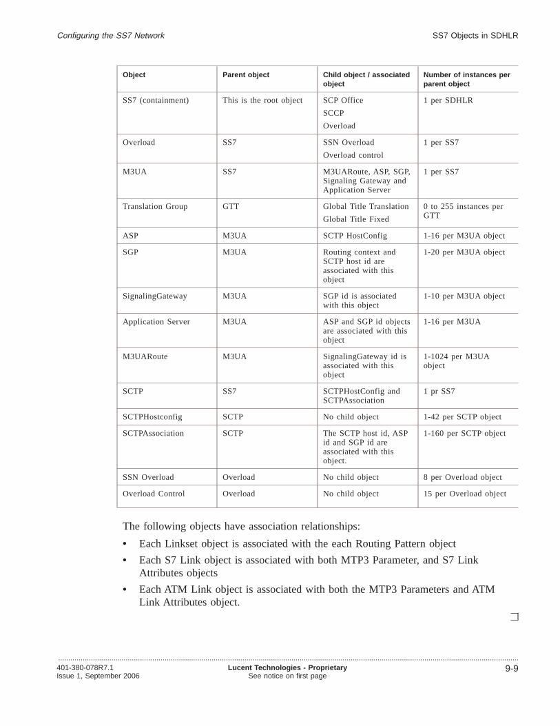
Object Parent object Child object / associatedobject
Number of instances perparent object
SS7 (containment) This is the root object SCP Office
SCCP
Overload
1 per SDHLR
Overload SS7 SSN Overload
Overload control
1 per SS7
M3UA SS7 M3UARoute, ASP, SGP,Signaling Gateway andApplication Server
1 per SS7
Translation Group GTT Global Title Translation
Global Title Fixed
0 to 255 instances perGTT
ASP M3UA SCTP HostConfig 1-16 per M3UA object
SGP M3UA Routing context andSCTP host id areassociated with thisobject
1-20 per M3UA object
SignalingGateway M3UA SGP id is associatedwith this object
1-10 per M3UA object
Application Server M3UA ASP and SGP id objectsare associated with thisobject
1-16 per M3UA
M3UARoute M3UA SignalingGateway id isassociated with thisobject
1-1024 per M3UAobject
SCTP SS7 SCTPHostConfig andSCTPAssociation
1 pr SS7
SCTPHostconfig SCTP No child object 1-42 per SCTP object
SCTPAssociation SCTP The SCTP host id, ASPid and SGP id areassociated with thisobject.
1-160 per SCTP object
SSN Overload Overload No child object 8 per Overload object
Overload Control Overload No child object 15 per Overload object
The following objects have association relationships:
• Each Linkset object is associated with the each Routing Pattern object
• Each S7 Link object is associated with both MTP3 Parameter, and S7 LinkAttributes objects
• Each ATM Link object is associated with both the MTP3 Parameters and ATMLink Attributes object.
Configuring the SS7 Network SS7 Objects in SDHLR
.................................................................................................................................................................................................................................401-380-078R7.1Issue 1, September 2006
Lucent Technologies - ProprietarySee notice on first page
9-9

Provision the SS7 network.................................................................................................................................................................................................................................
Introduction
The framework of the SS7 network is automatically for each HCF cluster. You have tocreate much of the SS7 network after the base structure has been created automatically.To customize your SS7 configuration, follow the process below.
Provision SS7 connectivity process
Follow this process to provision SS7 connectivity for each HCF cluster.
.................................................................................................................................................................................................
1 Create the Remote STP object.
See the following procedure to create the Remote STP object,“Creating SCP Officeobjects” (p. 9-68).
.................................................................................................................................................................................................
2 Create the Adjacent SEP object.
See the following procedure to create the Adjacent SEP attribute object,“Creating SCPOffice objects” (p. 9-68).
.................................................................................................................................................................................................
3 Create the Alias PC object.
See the following procedure to create the Alias PC object,“Creating SCP Officeobjects” (p. 9-68).
.................................................................................................................................................................................................
4 Create the S7 Board.
See the following procedure to create the S7 Board,“Creating SCP Office objects”(p. 9-68).
.................................................................................................................................................................................................
5 Create the Route object.
See the following procedure to create a Route object,“Creating SCP Office objects”(p. 9-68).
.................................................................................................................................................................................................
6 Create the Routing Pattern object.
See the following procedure to create the Routing Pattern object,“Creating SCP Officeobjects” (p. 9-68).
Configuring the SS7 Network
.................................................................................................................................................................................................................................
9-10 Lucent Technologies - ProprietarySee notice on first page
401-380-078R7.1Issue 1, September 2006
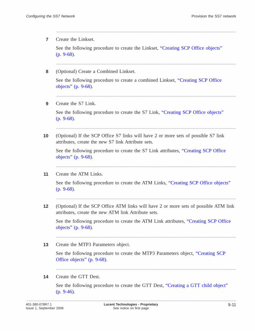
.................................................................................................................................................................................................
7 Create the Linkset.
See the following procedure to create the Linkset,“Creating SCP Office objects”(p. 9-68).
.................................................................................................................................................................................................
8 (Optional) Create a Combined Linkset.
See the following procedure to create a combined Linkset,“Creating SCP Officeobjects” (p. 9-68).
.................................................................................................................................................................................................
9 Create the S7 Link.
See the following procedure to create the S7 Link,“Creating SCP Office objects”(p. 9-68).
.................................................................................................................................................................................................
10 (Optional) If the SCP Office S7 links will have 2 or more sets of possible S7 linkattributes, create the new S7 link Attribute sets.
See the following procedure to create the S7 Link attributes,“Creating SCP Officeobjects” (p. 9-68).
.................................................................................................................................................................................................
11 Create the ATM Links.
See the following procedure to create the ATM Links,“Creating SCP Office objects”(p. 9-68).
.................................................................................................................................................................................................
12 (Optional) If the SCP Office ATM links will have 2 or more sets of possible ATM linkattributes, create the new ATM link Attribute sets.
See the following procedure to create the ATM Link attributes,“Creating SCP Officeobjects” (p. 9-68).
.................................................................................................................................................................................................
13 Create the MTP3 Parameters object.
See the following procedure to create the MTP3 Parameters object,“Creating SCPOffice objects” (p. 9-68).
.................................................................................................................................................................................................
14 Create the GTT Dest.
See the following procedure to create the GTT Dest,“Creating a GTT child object”(p. 9-46).
Configuring the SS7 Network Provision the SS7 network
.................................................................................................................................................................................................................................401-380-078R7.1Issue 1, September 2006
Lucent Technologies - ProprietarySee notice on first page
9-11

.................................................................................................................................................................................................
15 Create the GTT Trans Grp. You must create at least one of the three possible GTTTransgroup configurations
See the following procedure to create the GTT Trans Grp,“Creating a GTT childobject” (p. 9-46).
.................................................................................................................................................................................................
16 (Required if you set “Use External STP” to false in the GTT Trans Grp.) Create theGTT Fixed and GTT Trans.
See the following procedures to create the GTT Fixed and GTT Trans,“Creating aGTT child object” (p. 9-46). .
.................................................................................................................................................................................................
17 Create the GTT GTI.
See the following procedure to create the GTT GTI,“Creating a GTT child object”(p. 9-46). .
.................................................................................................................................................................................................
18 Create the SSN Overload.
See the following procedure to create the SSN Overload ,“Creating Overload childobjects” (p. 9-28).
.................................................................................................................................................................................................
19 (Optional) Modify the SSN Overload parameters.
See the following procedure to modify the SSN Overload parameters,“Modify theOverload child objects” (p. 9-30).
.................................................................................................................................................................................................
20 Create the Overload Control.
See the following procedure to create the Overload Control,“Creating Overload childobjects” (p. 9-28).
.................................................................................................................................................................................................
21 (Optional) Modify the Overload Control parameters.
See the following procedure to modify the Overload Control parameters,“Modify theOverload child objects” (p. 9-30).
Configuring the SS7 Network Provision the SS7 network
.................................................................................................................................................................................................................................
9-12 Lucent Technologies - ProprietarySee notice on first page
401-380-078R7.1Issue 1, September 2006
Configuring the M3UA object
Overview.................................................................................................................................................................................................................................
Purpose
This section provides the following details:
• Rules for creating, modifying and deleting M3UA, its child objects and attributes
• Procedures for creating, modifying and deleting the objects
You cannot create or configure the M3UA object. You can only view its details. Youcan, however, configure various M3UA child objects and their attributes.
Contents
M3UA object descriptions 9-14
Creating an M3UA child Object 9-19
Modifying an M3UA child object 9-21
Deleting an M3UA child Object 9-23
Configuring the SS7 Network
.................................................................................................................................................................................................................................401-380-078R7.1Issue 1, September 2006
Lucent Technologies - ProprietarySee notice on first page
9-13

M3UA object descriptions.................................................................................................................................................................................................................................
Summary of contents
This section describes the various M3UA objects and lists the rules that must befollowed to create, modify or delete these objects.
See the sections listed below for information on specific objects:
For details on ... See...
M3UA Rules for creating, modifying and deleting“M3UA” (p. 9-14)
Application Server Rules for creating, modifying and deleting“ApplicationServer” (p. 9-15)
ASP Rules for creating, modifying and deleting“ASP” (p. 9-16)
M3UA Route Rules for creating, modifying and deleting“M3UA Route”(p. 9-16)
Signaling Gateway Rules for creating, modifying and deleting“SignalingGateway” (p. 9-17)
SGP Rules for creating, modifying and deleting“SGP” (p. 9-17)
M3UA
M3UA is a container object and a child of the SS7 object. The M3UA protocolprovides a mechanism for the transport of SS7 MTP3 signaling over IP using SCTP.There can only be one M3UA object per SS7 cluster.
Rules Descriptions
Creation The M3UA object is auto created when you create the SS7cluster object
Modification You cannot modify this object.
Deletion You cannot delete this object.
Configuring the SS7 Network
.................................................................................................................................................................................................................................
9-14 Lucent Technologies - ProprietarySee notice on first page
401-380-078R7.1Issue 1, September 2006
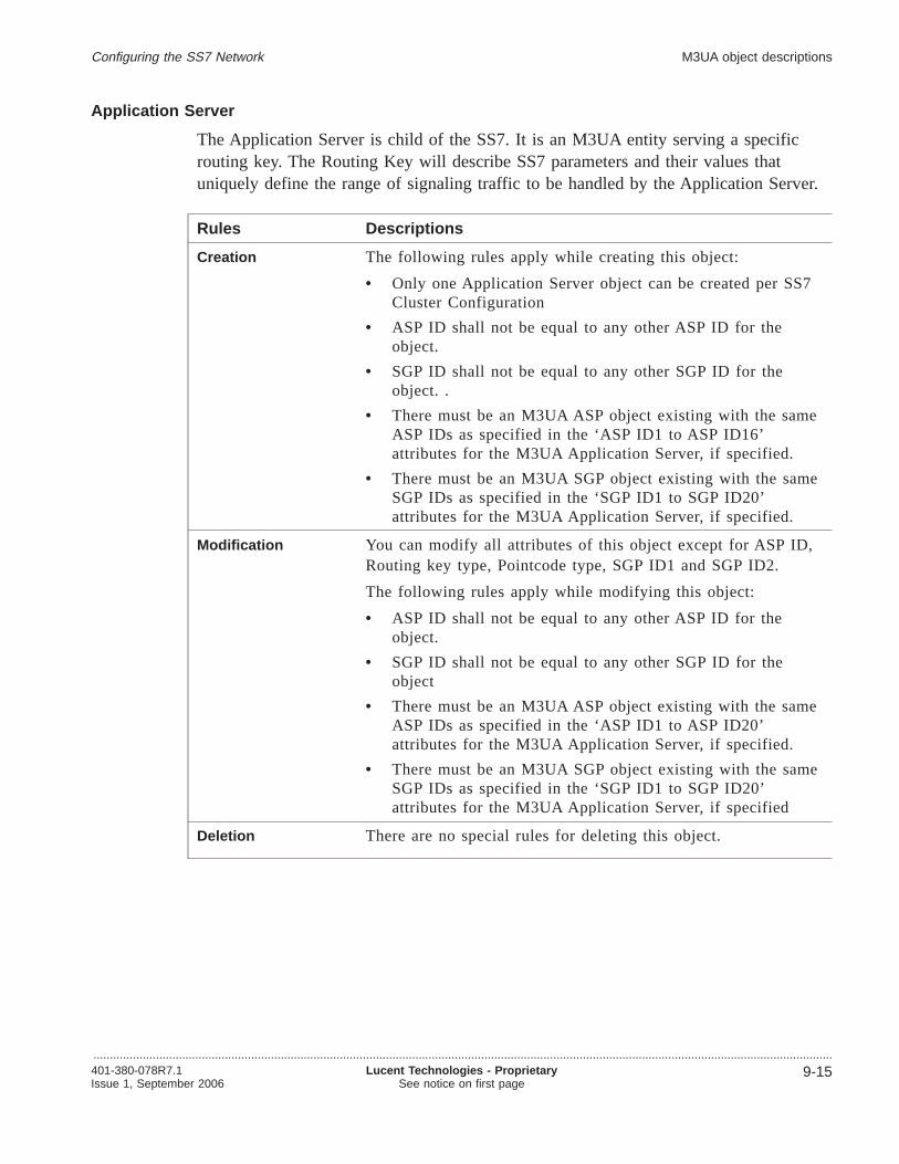
Application Server
The Application Server is child of the SS7. It is an M3UA entity serving a specificrouting key. The Routing Key will describe SS7 parameters and their values thatuniquely define the range of signaling traffic to be handled by the Application Server.
Rules Descriptions
Creation The following rules apply while creating this object:
• Only one Application Server object can be created per SS7Cluster Configuration
• ASP ID shall not be equal to any other ASP ID for theobject.
• SGP ID shall not be equal to any other SGP ID for theobject. .
• There must be an M3UA ASP object existing with the sameASP IDs as specified in the ‘ASP ID1 to ASP ID16’attributes for the M3UA Application Server, if specified.
• There must be an M3UA SGP object existing with the sameSGP IDs as specified in the ‘SGP ID1 to SGP ID20’attributes for the M3UA Application Server, if specified.
Modification You can modify all attributes of this object except for ASP ID,Routing key type, Pointcode type, SGP ID1 and SGP ID2.
The following rules apply while modifying this object:
• ASP ID shall not be equal to any other ASP ID for theobject.
• SGP ID shall not be equal to any other SGP ID for theobject
• There must be an M3UA ASP object existing with the sameASP IDs as specified in the ‘ASP ID1 to ASP ID20’attributes for the M3UA Application Server, if specified.
• There must be an M3UA SGP object existing with the sameSGP IDs as specified in the ‘SGP ID1 to SGP ID20’attributes for the M3UA Application Server, if specified
Deletion There are no special rules for deleting this object.
Configuring the SS7 Network M3UA object descriptions
.................................................................................................................................................................................................................................401-380-078R7.1Issue 1, September 2006
Lucent Technologies - ProprietarySee notice on first page
9-15

ASP
The M3UA Application Server Process is child of the SS7 M3UA object. An ASP is aprocess instance of an Application Server. An ASP contains an SCTP endpoint and maybe configured to process signaling traffic within more than one Application Server.
Rules Descriptions
Creation The following rules apply when creating this object:
• When creating, there must be an SCTPHostConfig objectexisting with same ‘Local SCTP host ID.
• When creating, there shall not be any other M3UA ASPobject existing with the same ’Network ASP ID’.
• When creating, there cannot be an entry in SG_ASP with this’Local SCTP host ID’ and ’local port’
Modification You can only modify the Network ASP ID.
Deletion The following rules apply when creating this object:
• When deleting, there cannot exist a SCTP Association objectwith same ASP ID.
• When deleting, there cannot exist a M3UA ApplServer objectwith same ASP ID.
M3UA Route
The M3UARoute is a child of the SS7 M3UA object.
Rules Descriptions
Creation The following rules apply when creating this object.
• When creating, there must be Signaling Gateway objectexisting with its ‘SG ID’ same as Normal SG ID
• When creating, there must be Signaling Gateway objectexisting with its ‘SG ID’ same as Alternate SG ID1
• When creating, there must be Signaling Gateway objectexisting with its ‘SG ID’ same as Alternate SG ID2
Modification You cannot modify this object.
Deletion There are no special rules for deleting this object.
Configuring the SS7 Network M3UA object descriptions
.................................................................................................................................................................................................................................
9-16 Lucent Technologies - ProprietarySee notice on first page
401-380-078R7.1Issue 1, September 2006
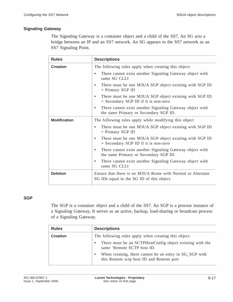
Signaling Gateway
The Signaling Gateway is a container object and a child of the SS7. An SG acts abridge between an IP and an SS7 network. An SG appears to the SS7 network as anSS7 Signaling Point.
Rules Descriptions
Creation The following rules apply when creating this object:
• There cannot exist another Signaling Gateway object withsame SG CLLI
• There must be one M3UA SGP object existing with SGP ID= Primary SGP ID
• There must be one M3UA SGP object existing with SGP ID= Secondary SGP ID if it is non-zero
• There cannot exist another Signaling Gateway object withthe same Primary or Secondary SGP ID.
Modification The following rules apply while modifying this object
• There must be one M3UA SGP object existing with SGP ID= Primary SGP ID
• There must be one M3UA SGP object existing with SGP ID= Secondary SGP ID if it is non-zero
• There cannot exist another Signaling Gateway object withthe same Primary or Secondary SGP ID.
• There cannot exist another Signaling Gateway object withsame SG CLLI
Deletion Ensure that there is no M3UA Route with Normal or AlternateSG IDs equal to the SG ID of this object.
SGP
The SGP is a container object and a child of the SS7. An SGP is a process instance ofa Signaling Gateway. It serves as an active, backup, load-sharing or broadcast processof a Signaling Gateway.
Rules Descriptions
Creation The following rules apply when creating this object.
• There must be an SCTPHostConfig object existing with thesame ‘Remote SCTP host ID.
• When creating, there cannot be an entry in SG_SGP withthis Remote sctp host ID and Remote port
Configuring the SS7 Network M3UA object descriptions
.................................................................................................................................................................................................................................401-380-078R7.1Issue 1, September 2006
Lucent Technologies - ProprietarySee notice on first page
9-17

Rules Descriptions
Modification You cannot modify this object.
Deletion The following rules apply while deleting this object
• There must not be a Signaling Gateway object existing withsame SGP ID.
• There must not be Application Server object existing withsame SGP ID
• There must not be SCTP Association object existing withsame SGP ID
Attributes and values
For information on object attributes and values, refer toLucent OMC-H ObjectDescriptions,401-380-080.
Configuring the SS7 Network M3UA object descriptions
.................................................................................................................................................................................................................................
9-18 Lucent Technologies - ProprietarySee notice on first page
401-380-078R7.1Issue 1, September 2006

Creating an M3UA child Object.................................................................................................................................................................................................................................
Purpose
This procedure allows you to create an M3UA child object.
Related information
For information on object attributes and values, refer toLucent OMC-H ObjectDescriptions,401-380-080.
Before you begin
Before you begin, no additional information is required.
To create an M3UA child Object
Complete the steps below to create an M3UA child object.
.................................................................................................................................................................................................
1 From the Lucent OMC-H Desktop, go to theNetwork Manager . Expand All and inthe HM tree, double-click the SS7 object from the HCF Cluster.
.................................................................................................................................................................................................
2 Right-click anywhere on the SS7 detail view, and selectShow on Tree to display theselected SS7 object in the NE tree view.
.................................................................................................................................................................................................
3 Expand the SS7 object and navigate to the M3UA object.
.................................................................................................................................................................................................
4 From the menu bar, clickAction -> Create -> <M3UA child object> .
The <M3UA child object> can assume the following values:
• ASP
• Application Server
• SGP
• M3UA Route
• Signaling Gateway
Result: The Enter input parameters for Create <M3UA child object> window isdisplayed.
.................................................................................................................................................................................................
5 Enter your values here.
Configuring the SS7 Network
.................................................................................................................................................................................................................................401-380-078R7.1Issue 1, September 2006
Lucent Technologies - ProprietarySee notice on first page
9-19

.................................................................................................................................................................................................
6 Click OK to create the object now or clickMore -> Schedule to create the objectlater.
Result: The new <M3UA child object> is created.
E N D O F S T E P S........................................................................................................................................................................................................................
Configuring the SS7 Network Creating an M3UA child Object
.................................................................................................................................................................................................................................
9-20 Lucent Technologies - ProprietarySee notice on first page
401-380-078R7.1Issue 1, September 2006
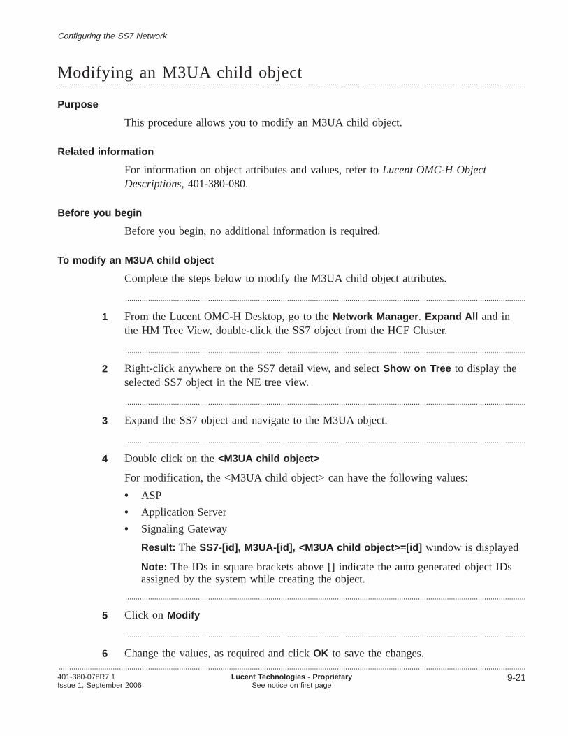
Modifying an M3UA child object.................................................................................................................................................................................................................................
Purpose
This procedure allows you to modify an M3UA child object.
Related information
For information on object attributes and values, refer toLucent OMC-H ObjectDescriptions,401-380-080.
Before you begin
Before you begin, no additional information is required.
To modify an M3UA child object
Complete the steps below to modify the M3UA child object attributes.
.................................................................................................................................................................................................
1 From the Lucent OMC-H Desktop, go to theNetwork Manager . Expand All and inthe HM Tree View, double-click the SS7 object from the HCF Cluster.
.................................................................................................................................................................................................
2 Right-click anywhere on the SS7 detail view, and selectShow on Tree to display theselected SS7 object in the NE tree view.
.................................................................................................................................................................................................
3 Expand the SS7 object and navigate to the M3UA object.
.................................................................................................................................................................................................
4 Double click on the<M3UA child object>
For modification, the <M3UA child object> can have the following values:
• ASP
• Application Server
• Signaling Gateway
Result: The SS7-[id], M3UA-[id], <M3UA child object>=[id] window is displayed
Note: The IDs in square brackets above [] indicate the auto generated object IDsassigned by the system while creating the object.
.................................................................................................................................................................................................
5 Click on Modify
.................................................................................................................................................................................................
6 Change the values, as required and clickOK to save the changes.
Configuring the SS7 Network
.................................................................................................................................................................................................................................401-380-078R7.1Issue 1, September 2006
Lucent Technologies - ProprietarySee notice on first page
9-21

Result: The modified <M3UA child object> is created
E N D O F S T E P S........................................................................................................................................................................................................................
Configuring the SS7 Network Modifying an M3UA child object
.................................................................................................................................................................................................................................
9-22 Lucent Technologies - ProprietarySee notice on first page
401-380-078R7.1Issue 1, September 2006

Deleting an M3UA child Object.................................................................................................................................................................................................................................
Purpose
This procedure allows you to delete an M3UA child Object.
Related information
For information on object attributes and values, refer toObject Descriptions,401-380-080.
Before you begin
No further information is required to perform this task.
To delete an M3UA child object
Complete the following procedure to delete an M3UA child Object.
.................................................................................................................................................................................................
1 From the Lucent OMC-H Desktop, go to theNetwork Manager . Expand All andinvoke the SS7 HCFClusterShow on tree . From here select the <M3UA child object>you want to delete.
For deleting , the <M3UA child object> can have the following values:
• ASP
• Application Server
• Signaling Gateway
• M3UA Route
• SGP
.................................................................................................................................................................................................
2 From the menu bar, clickAction -> Delete .
Result: An Action Confirmation window is displayed.
.................................................................................................................................................................................................
3 Click Yes to delete the <M3UA child object>.
Result: The <M3UA child object> is removed from the database.
Note: If the <M3UA child object> you are attempting to delete is the last one in the<M3UA child object> Table under the M3UA object then this delete action willdelete the <M3UA child object> table itself.
E N D O F S T E P S........................................................................................................................................................................................................................
Configuring the SS7 Network
.................................................................................................................................................................................................................................401-380-078R7.1Issue 1, September 2006
Lucent Technologies - ProprietarySee notice on first page
9-23

Configuring the Overload object
Overview.................................................................................................................................................................................................................................
Purpose
This section describes the Overload object and SSN Overload object and providesprocedures for configuring them.
Contents
Overload object descriptions 9-25
Creating Overload child objects 9-28
Modify the Overload child objects 9-30
Configuring the SS7 Network
.................................................................................................................................................................................................................................
9-24 Lucent Technologies - ProprietarySee notice on first page
401-380-078R7.1Issue 1, September 2006
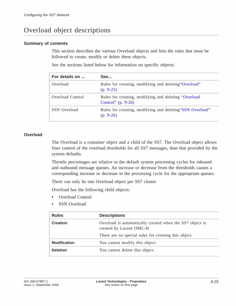
Overload object descriptions.................................................................................................................................................................................................................................
Summary of contents
This section describes the various Overload objects and lists the rules that must befollowed to create, modify or delete these objects.
See the sections listed below for information on specific objects:
For details on ... See...
Overload Rules for creating, modifying and deleting“Overload”(p. 9-25)
Overload Control Rules for creating, modifying and deleting“OverloadControl” (p. 9-26)
SSN Overload Rules for creating, modifying and deleting“SSN Overload”(p. 9-26)
Overload
The Overload is a container object and a child of the SS7. The Overload object allowsfiner control of the overload thresholds for all SS7 messages, than that provided by thesystem defaults.
Throttle percentages are relative to the default system processing cycles for inboundand outbound message queues. An increase or decrease from the thresholds causes acorresponding increase or decrease in the processing cycle for the appropriate queues.
There can only be one Overload object per SS7 cluster
Overload has the following child objects:
• Overload Control
• SSN Overload
Rules Descriptions
Creation Overload is automatically created when the SS7 object iscreated by Lucent OMC-H
There are no special rules for creating this object.
Modification You cannot modify this object.
Deletion You cannot delete this object.
Configuring the SS7 Network
.................................................................................................................................................................................................................................401-380-078R7.1Issue 1, September 2006
Lucent Technologies - ProprietarySee notice on first page
9-25

Overload Control
The Overload Control object allows finer control of the overload thresholds for all SS7messages, than that provided by the system defaults. The Overload Control defines theTransaction Capabilities Application Part (TCAP) automatic call gapping parametersfor the HCF Cluster.
There can be a maximum of 15 Overload Control per SS7.
Mapping to the SDHLR The Overload Control object contains a number of attributesthat map to attributes on an object on the SDHLR network element. The object isS7_OVLD_CTRL
Rules Descriptions
Creation The following rules apply when creating this object.
• The first instance of the Overload Control object iscreated from the Overload detail view
• Further instances are created from the Overload Controltable detail view
Modification For overload thresholds 1 to 15 the Gap Level, DurationLevel, Gap Value and Duration Value must not increase foreach threshold.
For example, for ANSI_GAP_LEVEL and ANSI_DUR_LEVEL: overload index 1 <= overload index 2 <= overloadindex 3 <=..... <= overload index 15
Deletion You cannot delete this object.
SSN Overload
The SSN Overload Control object allows finer control of the overload thresholds forall SS7 messages, than that provided by the system defaults. SSN Overload Controldefines the Transaction Capabilities Application Part (TCAP) automatic call gappingparameters for the overload thresholds. A maximum of eight thresholds can bemaintained for each SSN.
Configuring the SS7 Network Overload object descriptions
.................................................................................................................................................................................................................................
9-26 Lucent Technologies - ProprietarySee notice on first page
401-380-078R7.1Issue 1, September 2006
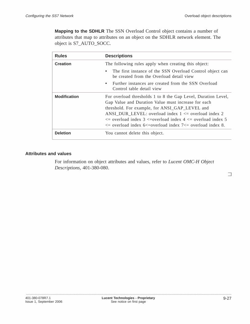
Mapping to the SDHLR The SSN Overload Control object contains a number ofattributes that map to attributes on an object on the SDHLR network element. Theobject is S7_AUTO_SOCC.
Rules Descriptions
Creation The following rules apply when creating this object:
• The first instance of the SSN Overload Control object canbe created from the Overload detail view
• Further instances are created from the SSN OverloadControl table detail view
Modification For overload thresholds 1 to 8 the Gap Level, Duration Level,Gap Value and Duration Value must increase for eachthreshold. For example, for ANSI_GAP_LEVEL andANSI_DUR_LEVEL: overload index 1 <= overload index 2<= overload index 3 <=overload index 4 <= overload index 5<= overload index 6<=overload index 7<= overload index 8.
Deletion You cannot delete this object.
Attributes and values
For information on object attributes and values, refer toLucent OMC-H ObjectDescriptions,401-380-080.
Configuring the SS7 Network Overload object descriptions
.................................................................................................................................................................................................................................401-380-078R7.1Issue 1, September 2006
Lucent Technologies - ProprietarySee notice on first page
9-27

Creating Overload child objects.................................................................................................................................................................................................................................
Purpose
This procedure allows you to create an Overload Control or SSN Overload object.
Related information
For information on object attributes and values, refer toLucent OMC-H ObjectDescriptions,401-380-080.
Before you begin
Before you begin, no additional information is required.
To create an Overload Child Object
Complete the following procedure to create an Overload Child Object.
.................................................................................................................................................................................................
1 From the Lucent OMC-H Desktop, go to theNetwork Manager . Expand All and inthe HM tree, double-click the SS7 object from the HCF Cluster.
.................................................................................................................................................................................................
2 Right-click anywhere on the SS7 detail view, and selectShow on Tree to display theselected SS7 object in the NE tree view.
.................................................................................................................................................................................................
3 Expand theSS7 object and navigate to theOverload object.
.................................................................................................................................................................................................
4 From the menu bar, clickAction -> Create -> <Overload child object> .
The <Overload child object> can be Overload Control or SSN Overload.
Result: The Enter input parameters for <Overload child object> window isdisplayed.
.................................................................................................................................................................................................
5 Change the default values, if required.
.................................................................................................................................................................................................
6 Click OK to create the object now or clickMore -> Schedule to create the objectlater.
Configuring the SS7 Network
.................................................................................................................................................................................................................................
9-28 Lucent Technologies - ProprietarySee notice on first page
401-380-078R7.1Issue 1, September 2006

Result: The new <Overload child object> is created.
E N D O F S T E P S........................................................................................................................................................................................................................
Configuring the SS7 Network Creating Overload child objects
.................................................................................................................................................................................................................................401-380-078R7.1Issue 1, September 2006
Lucent Technologies - ProprietarySee notice on first page
9-29

Modify the Overload child objects.................................................................................................................................................................................................................................
Purpose
This procedure provides instructions for modifying the Overload child objects.
Related information
For information on object attributes and values, refer toLucent OMC-H ObjectDescriptions,401-380-080.
Before you begin
Before you begin, no additional information is needed.
To modify the Overload child objects
Complete the steps below to modify the Overload child objects.
.................................................................................................................................................................................................
1 From the Lucent OMC-H Desktop, go to theNetwork Manager . Expand All and inthe HM Tree View, double-click the SS7 object from the HCF Cluster.
.................................................................................................................................................................................................
2 Right-click anywhere on the SS7 detail view, and selectShow on Tree to display theselected SS7 object in the NE tree view.
.................................................................................................................................................................................................
3 Expand theSS7 object and navigate to theOverload object.
.................................................................................................................................................................................................
4 Double-click the<Overload Child Object> that you want to modify.
The <Overload Child Object> can be Overload Control or SSN Overload
.................................................................................................................................................................................................
5 Click Modify .
Result: The modifiable fields become enabled.
.................................................................................................................................................................................................
6 Make any required changes to the <Overload Child Object> parameters.
.................................................................................................................................................................................................
7 Click OK or Apply to submit the operation now, or selectMore -> Schedule toschedule the operation to be submitted later.
Configuring the SS7 Network
.................................................................................................................................................................................................................................
9-30 Lucent Technologies - ProprietarySee notice on first page
401-380-078R7.1Issue 1, September 2006
Result: The <Overload Child Object> parameters are modified.
E N D O F S T E P S........................................................................................................................................................................................................................
Configuring the SS7 Network Modify the Overload child objects
.................................................................................................................................................................................................................................401-380-078R7.1Issue 1, September 2006
Lucent Technologies - ProprietarySee notice on first page
9-31

Configuring the SCCP object
Overview.................................................................................................................................................................................................................................
Purpose
This section describes the SCCP object and provides procedures for configuring it.
Contents
SCCP object descriptions 9-33
Creating a GTT child object 9-46
Modifying the GTT objects 9-48
Deleting a GTT child object 9-50
Configuring the SS7 Network
.................................................................................................................................................................................................................................
9-32 Lucent Technologies - ProprietarySee notice on first page
401-380-078R7.1Issue 1, September 2006

SCCP object descriptions.................................................................................................................................................................................................................................
Summary of contents
This section describes the various M3UA objects and lists the rules that must befollowed to create, modify or delete these objects.
See the sections listed below for information on specific objects:
For details on ... See...
SCCP Rules for creating, modifying and deleting“SCCP” (p. 9-33)
GTT Rules for creating, modifying and deleting“GTT” (p. 9-34)
GttGti Rules for creating, modifying and deleting“GttGti” (p. 9-34)
GttDest Rules for creating, modifying and deleting“GttDest”(p. 9-37)
GttTrans Rules for creating, modifying and deleting“GttTrans”(p. 9-41)
GttTransGroup Rules for creating, modifying and deleting“GttTransGroup”(p. 9-39)
GttFixed Rules for creating, modifying and deleting“GttFixed”(p. 9-43)
SCCP
There can only be one SCCP object per SS7 Cluster
The Signal Control Connection Protocol (SCCP) is a logical object and a child of theSS7 object.
Mapping to the SDHLR network element
The SCCP object contains a number of attributes that map to attributes on two objectson the SDHLR network element.
The two objects are:
• S7_SCCP_PARAM
• S7_SC_MSGPRI
Rules Descriptions
Creation The SCCP object is automatically created when the SS7object is created
Configuring the SS7 Network
.................................................................................................................................................................................................................................401-380-078R7.1Issue 1, September 2006
Lucent Technologies - ProprietarySee notice on first page
9-33

Rules Descriptions
Modification There are no special rules for modifying this object
Deletion You cannot delete this object
GTT
The Global Title Translation (GTT) is a logical object and a child of the Signal ControlConnection Protocol (SCCP) object.
The Global Title Translation object is responsible for routing messages to its finaldestination, where messages are process. The final destination is accessed by providingthe Destination Point Code (DPC) and Subsystem Number (SSN).
If the final destination is in a different network, unknown to the SDHLR, the messageis then sent to another GTT and finally on to its final destination.
GTT is a containment object, and contains the following child objects:
• GTT Global Title Indicator (GttGti)
• GTT Global Title Destination (GttDest)
• GTT Translation Group (GttTransGroup)GttTransGroup has the following child objects:
– GttTrans
– GttFixed
As this is a containment object, the only attribute available is the ID, which isautomatically created by Lucent OMC-H
Rules Descriptions
Creation The following rules apply when creating this object:
• The GTT object is created automatically on creation of theSCCP object
• There can only be one instance of the GTT containmentobject per SS7 object.
Modification You cannot modify this object.
Deletion You cannot delete this object.
GttGti
Global Title Translation (GTT) Global Title Indicator (Gti) is a logical object, and achild of the GTT containment object.
Configuring the SS7 Network SCCP object descriptions
.................................................................................................................................................................................................................................
9-34 Lucent Technologies - ProprietarySee notice on first page
401-380-078R7.1Issue 1, September 2006

The GttGti container object and table created when the first GttGti object is created isthe entry point into the global title translation. The table directs the contained globaltitle to a particular translation group, and determines the translation applied anddestination of that message.
Mapping to the SDHLR network element
The GttGti object contains a number of attributes that map to attributes on theSCCP_GTT_GTI object on the SDHLR network element.
Configuring the SS7 Network SCCP object descriptions
.................................................................................................................................................................................................................................401-380-078R7.1Issue 1, September 2006
Lucent Technologies - ProprietarySee notice on first page
9-35

The mapping structure is represented in the following figure:
Rules Descriptions
Creation The following rules apply when creating this object:
• The GttGti container and table are created when the firstGttGti object is created
• The maximum number of entries in the GttGti table is500 (1 through 500)
• If GTI equals 1, then only NAI (Nature of Address) ispresent
• If GTI equals 2, then only TT (Translation Type) ispresent
• If GTI equals 3, then only TT and NP (Numbering Plan)are present
• If GTI equals 4, then TT, NAI, and NP are all present.
Modification Only TG_ID can be modified.
There are no special rules for modifying this object
Deletion You can delete entries from the GttGti table. There are nospecial rules for deleting this object
GttGti object(Lucent OMC-H)
SCCP_GTT_GTIobject
SCCP_GTT_GTItable
Configuring the SS7 Network SCCP object descriptions
.................................................................................................................................................................................................................................
9-36 Lucent Technologies - ProprietarySee notice on first page
401-380-078R7.1Issue 1, September 2006
GttDest
The Global Title Destination (GttDest) is a logical object and a child of the GlobalTitle Translation (GTT) object.
The GttDest contains a table which provides final routing information which is appliedto incoming SCCP messages. It assigns a Destination Point Code (DPC) andSubsystem Number (SSN) to each Global Title. The destination could be an externalSTP, but this may not indicate the final destination of the message.
Mapping to the SDHLR network element
The GttDest object contains a number of attributes that map to attributes on theSCCP_GTT_DEST object on the SDHLR network element.
Configuring the SS7 Network SCCP object descriptions
.................................................................................................................................................................................................................................401-380-078R7.1Issue 1, September 2006
Lucent Technologies - ProprietarySee notice on first page
9-37

The following figure shows the mapping of the GttDest object to a correspondingobject on the SDHLR:
Rules Descriptions
Creation The following rules apply when creating this object:
• The GttDest container and table are automatically createdwhen the first GttDest object is created
• The maximum number of entries in the GttDest table is 255(0 through 255)
• If PTCODE_FORMAT is ITU then NID, CLU and MEM =0
• If PTCODE_FORMAT is CHN then PC = 0
• If you use the GttDest’s Backup Index attribute, it mustalready exist as the Destination Index, in a separate entry inthe GttDest container table.
Modification There are no special rules for modifying this object
Deletion The following rules apply when deleting this object:
• You can delete entries from the table but cannot delete thetable
• Ensure all referencing GttTransGroup or GttTrans objectsare deleted
• Ensure no GttDest entry refers to another GttDest entry as abackup SSN.
GttDest object(Lucent OMC-H)
SCCP_GTT_DESTobject
SCCP_GTT_DESTtable
Configuring the SS7 Network SCCP object descriptions
.................................................................................................................................................................................................................................
9-38 Lucent Technologies - ProprietarySee notice on first page
401-380-078R7.1Issue 1, September 2006

GttTransGroup
The GttTransGroup is a logical object of the GTT containment. It contains two childobjects, GttTrans and GttFixed.
The Global Title Translation Group table defines the Destination Indexes to be appliedto each Translation Group, and by doing so, the routing to be applied to thatTranslation Group.
It can do this in two basic ways:
• For a given Translation Group (as defined by the GTT Global Title Indicator table),it provides a Destination Index directly. The GTT DEST table then provides therouting details regardless of the Global Title content.
• It can direct the Global Title content to either the GTT FIXED or GTT TRANStables. These tables provide rules to analyze the Global Title and provide theDestination Index depending upon the content of the Global Title.
Mapping to the SDHLR network element
The GttTransGroup object contains a number of attributes that map to attributes on theSCCP_GTT_MASK and SCCP_EXT_STP objects on the SDHLR network element.
The following figure shows the mapping of the Translation Group object to thecorresponding object on the SDHLR
Each child object contains tables and it is important that the tables are updated whenadditions and deletions take place. If an entry is removed and the table is not updated,
GttTransGroupobject
(Lucent OMC-H)
SCCP_GTT_EXT_STPtable
SCCP_GTT_MASKtable
SCCP_GTT_EXT_STPobject
SCCP_GTT_MASKobject
Configuring the SS7 Network SCCP object descriptions
.................................................................................................................................................................................................................................401-380-078R7.1Issue 1, September 2006
Lucent Technologies - ProprietarySee notice on first page
9-39

the translation route may not be reached and a message may never get to itsdestination. Lucent OMC-H is responsible for carrying out checks on these tables.
Rules Description
Creation The following rules apply when creating this object:
• The TGID used is created in GttGti
• Add both cases for fixed = 0
• The GttTransGroup container and table are created whenthe first GttTransGroup object is created
• The total number of digits supplied by the Fixed digits,Primary digits, and Secondary digits attributes cannotexceed 10
• The maximum number of entries in the GttTransGrouptable is 255 (0 to 255).
• The Destination Index must exist in the SCCP_GTT_DEST table
• The user must enter a valid Translation Group ID (0through 255) and link that to any entry in the GttDest,GttTrans, or GttFixed tables.
Modification The following rules apply when modifying this object:
• You can only modify the Destination index attribute. TheDestination index attribute is only available formodification when the User external STP attribute is’True’.
• To update FIXED, check if there is an entry inGTT_FIXED for this TG_ID. If yes, then the fixed digitmask (GTT_FIXED) must be deleted first.
• To update FIXED, PRIMARY or SECONDARY ensurethat there is no an entry in GTT_TRANS for this TG_ID.If there is, then you must delete the mask is being used bythe GTT Trans first.
Deletion The following rules apply when deleting this object:
• Ensure there are no child objects before you delete entriesfrom the table
• If FIXE D = 0 there is no reference to this TG_ID in theGTT_Trans table
• You can delete entries from the GttTransGroup table.
Configuring the SS7 Network SCCP object descriptions
.................................................................................................................................................................................................................................
9-40 Lucent Technologies - ProprietarySee notice on first page
401-380-078R7.1Issue 1, September 2006

GttTrans
The Global Title Translation Group (GttTrans) is a logical object and a child of theGttTransGroup object.
The GttTrans object determines the destination for a defined number pattern.
The maximum number of entries in the GttTrans table is 131071 (1 through 131071)
Mapping to the SDHLR network element
The GttTrans object contains a number of attributes that map to attributes on theSCCP_GTT_TRANS object, on the SDHLR network element.
The GttTrans container and table are automatically created when the first GttTransobject is created
Configuring the SS7 Network SCCP object descriptions
.................................................................................................................................................................................................................................401-380-078R7.1Issue 1, September 2006
Lucent Technologies - ProprietarySee notice on first page
9-41
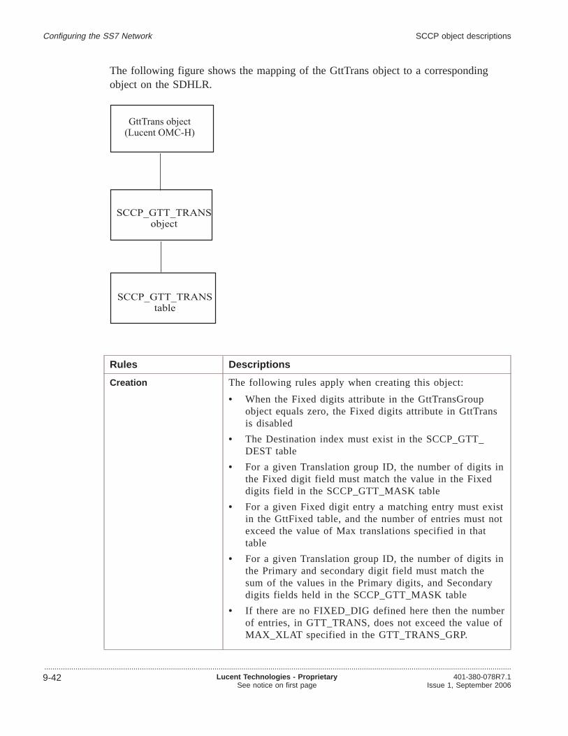
The following figure shows the mapping of the GttTrans object to a correspondingobject on the SDHLR.
Rules Descriptions
Creation The following rules apply when creating this object:
• When the Fixed digits attribute in the GttTransGroupobject equals zero, the Fixed digits attribute in GttTransis disabled
• The Destination index must exist in the SCCP_GTT_DEST table
• For a given Translation group ID, the number of digits inthe Fixed digit field must match the value in the Fixeddigits field in the SCCP_GTT_MASK table
• For a given Fixed digit entry a matching entry must existin the GttFixed table, and the number of entries must notexceed the value of Max translations specified in thattable
• For a given Translation group ID, the number of digits inthe Primary and secondary digit field must match thesum of the values in the Primary digits, and Secondarydigits fields held in the SCCP_GTT_MASK table
• If there are no FIXED_DIG defined here then the numberof entries, in GTT_TRANS, does not exceed the value ofMAX_XLAT specified in the GTT_TRANS_GRP.
GttTrans object(Lucent OMC-H)
SCCP_GTT_TRANSobject
SCCP_GTT_TRANStable
Configuring the SS7 Network SCCP object descriptions
.................................................................................................................................................................................................................................
9-42 Lucent Technologies - ProprietarySee notice on first page
401-380-078R7.1Issue 1, September 2006
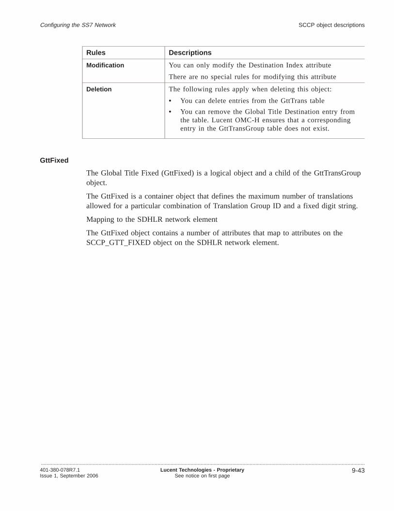
Rules Descriptions
Modification You can only modify the Destination Index attribute
There are no special rules for modifying this attribute
Deletion The following rules apply when deleting this object:
• You can delete entries from the GttTrans table
• You can remove the Global Title Destination entry fromthe table. Lucent OMC-H ensures that a correspondingentry in the GttTransGroup table does not exist.
GttFixed
The Global Title Fixed (GttFixed) is a logical object and a child of the GttTransGroupobject.
The GttFixed is a container object that defines the maximum number of translationsallowed for a particular combination of Translation Group ID and a fixed digit string.
Mapping to the SDHLR network element
The GttFixed object contains a number of attributes that map to attributes on theSCCP_GTT_FIXED object on the SDHLR network element.
Configuring the SS7 Network SCCP object descriptions
.................................................................................................................................................................................................................................401-380-078R7.1Issue 1, September 2006
Lucent Technologies - ProprietarySee notice on first page
9-43

The following figure shows the mapping of the GttFixed object to a correspondingobject on the SDHLR.
Rules Descriptions
Creation The following rules apply when creating this object:
• The GttFixed container and table are automatically createdwhen the first GttFixed object is created
• The maximum number of entries in the GttFixed table is 100(1 through 100)
• There are not more then MAX_XLAT entries inGTT_TRANS with this TG_ID and FIXED_DIG
• The number of digits specified in the Fixed digit attributemust match the number specified in the Fixed digits attributein the SCCP_GTT_MASK table.
Modification Only the MAX_XLAT field can be modified and the checksdefined on create must be adhered to.
Deletion The following rules apply when deleting this object:
• You can delete entries from the GttFixed table
• Firstly, all GTT Trans objects that reference the GttFixedobject are deleted.
Attributes and values
For information on object attributes and values, refer toLucent OMC-H ObjectDescriptions,401-380-080.
GttFixed object(Lucent OMC-H)
SCCP_GTT_FIXEDobject
SCCP_GTT_FIXEDtable
Configuring the SS7 Network SCCP object descriptions
.................................................................................................................................................................................................................................
9-44 Lucent Technologies - ProprietarySee notice on first page
401-380-078R7.1Issue 1, September 2006
Related information
There is no related information for this object.
Configuring the SS7 Network SCCP object descriptions
.................................................................................................................................................................................................................................401-380-078R7.1Issue 1, September 2006
Lucent Technologies - ProprietarySee notice on first page
9-45

Creating a GTT child object.................................................................................................................................................................................................................................
Purpose
This procedure allows you to create a GTT child object.
Related information
For information on object attributes and values, refer toLucent OMC-H ObjectDescriptions,401-380-080.
Before you begin
Before you begin, no additional information is required.
To create a GTT child object
Complete the following procedure to create a GTT child object.
.................................................................................................................................................................................................
1 From the Lucent OMC-H Desktop, go to theNetwork Manager . Expand All and inthe HM tree, double-click the SS7 object from the HCF Cluster.
.................................................................................................................................................................................................
2 Right-click anywhere on the SS7 detail view, and selectShow on Tree to display theselected SS7 object in the NE tree view.
.................................................................................................................................................................................................
3 Expand the SS7 object, navigate to the SCCP object and select the GTT object.
.................................................................................................................................................................................................
4 If you want tocreate a
Then
GTT child object Perform the following steps
1. From the menu bar, clickAction -> Create -> <Gtt childobject> .
The Enter input parameters for <Gtt child object> window isdisplayed.
The Gtt Child objects can be :• GttGti• GttDest• GttTransGrp
2. Go to Step 5
Configuring the SS7 Network
.................................................................................................................................................................................................................................
9-46 Lucent Technologies - ProprietarySee notice on first page
401-380-078R7.1Issue 1, September 2006

If you want tocreate a
Then
GttTransGrp ChildObject
Perform the following steps
1. From the Gtt object navigate to the GttTransGrp object.
2. From the menu bar, clickAction -> Create -><GttTransGrp child object> .
The Enter input parameters for <GttTransGrp child object>window is displayed.
The GttTransGrp child objects can be :• GttFixed• GttTrans
3. Go to Step 5
.................................................................................................................................................................................................
5 Change the default values, if required.
.................................................................................................................................................................................................
6 Click OK to create the object now or clickMore -> Schedule to create the objectlater.
Result: The new GTT object is created.
E N D O F S T E P S........................................................................................................................................................................................................................
Configuring the SS7 Network Creating a GTT child object
.................................................................................................................................................................................................................................401-380-078R7.1Issue 1, September 2006
Lucent Technologies - ProprietarySee notice on first page
9-47

Modifying the GTT objects.................................................................................................................................................................................................................................
Purpose
This procedure allows you to modify the Global Title Translation (GTT) parameters.
Related information
For information on object attributes and values, refer toLucent OMC-H ObjectDescriptions,401-380-080.
Before you begin
SeeRules for creating, modifying and deleting SCCP objectsfor checks and guidelines.
To modify the GTT objects
Complete the following procedure to modify the GTT objects.
.................................................................................................................................................................................................
1 From the Lucent OMC-H Desktop, go to theNetwork Manager . Expand All and inthe HM Tree View, double-click the SS7 object from the HCF Cluster.
.................................................................................................................................................................................................
2 Right-click anywhere on the SS7 detail view, and selectShow on Tree to display theselected SS7 object in the NE tree view.
.................................................................................................................................................................................................
3 Expand theSS7 object.
.................................................................................................................................................................................................
4 Expand theSCCP object.
.................................................................................................................................................................................................
5 Expand theGTT object.
Configuring the SS7 Network
.................................................................................................................................................................................................................................
9-48 Lucent Technologies - ProprietarySee notice on first page
401-380-078R7.1Issue 1, September 2006

.................................................................................................................................................................................................
6 If you want tomodify a
Then
Gtt Child object Perform the following steps:
• Double-click the<GTT Child Object> that you want to modifyResult : The <GTT Child Object> detail view appears.
The GTT Child Object can be:– GttTransGrp– GttGti– GttDest
• Go to Step 7
GttTransGrp Childobject
Perform the following steps:
• Expand theGTTTransGroup object.
• Double-click the<GTTTransGroup Child Object> that youwant to modify
Result : The <GTTTransGroup Child Object> detail viewappears.
The GTTTransGroup Child Object can be:– GttTrans– GttFixed
• Go to Step 7
.................................................................................................................................................................................................
7 Click Modify .
Result: The modifiable fields become enabled.
.................................................................................................................................................................................................
8 Make any required changes to the GTT child object parameters.
.................................................................................................................................................................................................
9 Click OK or Apply to submit the operation now, or selectMore -> Schedule toschedule the operation to be submitted later.
Result: The GTT objects are modified.
E N D O F S T E P S........................................................................................................................................................................................................................
Configuring the SS7 Network Modifying the GTT objects
.................................................................................................................................................................................................................................401-380-078R7.1Issue 1, September 2006
Lucent Technologies - ProprietarySee notice on first page
9-49

Deleting a GTT child object.................................................................................................................................................................................................................................
Purpose
This procedure provides instructions for deleting entries from the GTT child objecttables.
Related information
For more information, see“SCCP object descriptions” (p. 9-33).
Important! A GTTTrans entry with a fixed digit value cannot be deleted
Before you begin
Before you begin, no additional information is needed.
To delete a GTT child object
Complete the following procedure to delete a GTT child object from the database.
.................................................................................................................................................................................................
1 From the Lucent OMC-H Desktop, go to theNetwork Manager . Expand All and inthe HM Tree View double click on the HCF Cluster. From the HCF ClusterDetailView window that opens, right click and invoke theShow-on Tree . From the NE treethat opens, .
.................................................................................................................................................................................................
2 If you want todelete a
Then
Gtt Child Object Perform the following steps:
• Select the<GTT child object> you want to delete
The <GTT child object> can be:– GttDest– GttGti– GttTransGrp
• Go to Step 3
Configuring the SS7 Network
.................................................................................................................................................................................................................................
9-50 Lucent Technologies - ProprietarySee notice on first page
401-380-078R7.1Issue 1, September 2006

If you want todelete a
Then
GttTransGrp ChildObject
Perform the following steps:
• Expand the GTT object.
• Navigate to the<GttTransGrp Child Object> that you want todelete
The <GttTransGrp Child Object> can be:– GttTrans– GttFixed
• Go to Step 3
.................................................................................................................................................................................................
3 From the menu bar, clickAction -> Delete .
Result: An Action Confirmation window is displayed.
.................................................................................................................................................................................................
4 Click OK to delete the GTT child object.
Result: The GTT child object is removed from the database.
E N D O F S T E P S........................................................................................................................................................................................................................
Configuring the SS7 Network Deleting a GTT child object
.................................................................................................................................................................................................................................401-380-078R7.1Issue 1, September 2006
Lucent Technologies - ProprietarySee notice on first page
9-51

Configuring the SCP Office object
Overview.................................................................................................................................................................................................................................
Purpose
This section describes the SCP Office object and provides procedures for configuringit.
Contents
SCP Office object description 9-53
Creating SCP Office objects 9-68
Modify the SCP Office Objects 9-71
Performing Object-Specific actions on SCP Office child objects 9-73
Deleting SCP Office objects 9-78
Configuring the SS7 Network
.................................................................................................................................................................................................................................
9-52 Lucent Technologies - ProprietarySee notice on first page
401-380-078R7.1Issue 1, September 2006

SCP Office object description.................................................................................................................................................................................................................................
Summary of contents
This section describes the various SCP Office objects and lists the rules that must befollowed to create, modify or delete these objects.
See the sections listed below for information on specific objects:
For details on ... See...
SCP Office Rules for creating, modifying and deleting“SCP Office”(p. 9-53)
Remote STP Rules for creating, modifying and deleting“Remote STP”(p. 9-58)
Adjacent SEP Rules for creating, modifying and deleting“Adjacent SEP”(p. 9-55)
Alias PC Rules for creating, modifying and deleting“Alias Pointcode”(p. 9-55)
S7 Board Rules for creating, modifying and deleting“S7 Board”(p. 9-62)
Linkset Rules for creating, modifying and deleting“Linkset” (p. 9-63)
Route Rules for creating, modifying and deleting“Route” (p. 9-58)
Routing Pattern Rules for creating, modifying and deleting“Routing Pattern”(p. 9-61)
ATM Link Attributes Rules for creating, modifying and deleting“ATM LinkAttributes” (p. 9-56)
MTP3Params Rules for creating, modifying and deleting“MTP3Parameters” (p. 9-57)
S7 Link Attributes Rules for creating, modifying and deleting“S7 LinkAttributes” (p. 9-62)
SCP Office
The SCP Office is a logical object and a child of the SS7 object. The SCP Office andchild objects define the signaling network and link objects for the HCF cluster. Itdetails parameters that are common for all Links and Linksets.
The maximum number of SCP Office objects that can exist on a single SDHLR is one
Mapping to the SDHLR network element
Configuring the SS7 Network
.................................................................................................................................................................................................................................401-380-078R7.1Issue 1, September 2006
Lucent Technologies - ProprietarySee notice on first page
9-53

The SCP Office object contains a number of attributes that map to attributes on fiveobjects on the SDHLR network element.
These objects are:
• Route Timer (S7_Route_TMR)
• GTT Support SCCP Subsystem Management (GTT_SCMG)
• Lan (S7_LAN)
• MTP3 (S7_M3_MSGPRI)
• S7MPRThresholds (S7_MPR_THREASHOLDS)
• ATMMPRThresholds (S7_SAAL_MPR)
The SCP Office object contains the following child objects:
• Remote STP
• Adjacent SEP
• Alias PC
• S7 Board
• Linkset
• Route
• Routing Pattern
• ATM Link Attributes
• MTP3Params
• S7 Link Attributes
The Lucent OMC-H supports creation of one SCP Office object per HCF cluster. TheSCP Office is created as part of the NE synchronization operation performed beforeSS7 data provisioning.
Rules Descriptions
Creation The Lucent OMC-H supports creation of one SCP Office objectper HCF cluster. The SCP Office is created as part of the NEsynchronization operation performed before SS7 dataprovisioning.
Modification There are no special rules for modifying this object
Deletion The following rules apply when deleting this object:
• The SCP Office object cannot be deleted directly
• The SCP Office object is deleted when the last HCF in thecluster is deleted.
Configuring the SS7 Network SCP Office object description
.................................................................................................................................................................................................................................
9-54 Lucent Technologies - ProprietarySee notice on first page
401-380-078R7.1Issue 1, September 2006

Adjacent SEP
The Adjacent Signalling End Point (SEP) is a managed object and a child of the SCPOffice object.
The Adjacent SEP details signalling end points that are adjacent to this office. Thisobjects contains the parameters which map to the S7_ADJACENT_SEP object on theSDHLR.
Rules Descriptions
Creation The following rules apply when creating this object:
• The Adjacent SEP object is created on selection of the SCPOffice object
• The Adjacent SEP object can also be created from theAdjacent SEP Table view
• There is a maximum of 20 per SS7 network
• The pointcode cannot be defined as a Remote STP or as ahome STP or local / SCP pointcode in the SS7 object
• The pointcode can only be defined as an adjacent SEP once.
Modification You cannot modify this object.
Deletion You cannot delete a Adjacent SEP object if it is referenced by alinkset object.
Alias Pointcode
The Alias Pointcode is a managed object and a child of the SCP Office object.
Configuring the SS7 Network SCP Office object description
.................................................................................................................................................................................................................................401-380-078R7.1Issue 1, September 2006
Lucent Technologies - ProprietarySee notice on first page
9-55

The Alias Pointcode details signalling end points that are adjacent to this office. Thisobjects contains the parameters which map to the S7_ALIAS_PC object on the SuperD-HLR.
Rules Description
Creation The following rules apply when creating this object:
• The Alias Pointcode object is created on selection of theSCP Office object
• The Alias Pointcode object can also be created from theAlias Pointcode table view
• There is a maximum of 8 per SS7 network
• The pointcode format of the Alias Pointcodes must be ofthe same type as the pointcode in the SS7 parent object
• The Alias pointcode must not be the same as any otherAlias Pointcode or the Local Pointcode or Home STPs inthe SS7 object.
• For ANSI, the Alias Pointcode must not exist as aROUTE, where the protocol_type is SMEMBER.
Modification You cannot modify this object.
Deletion There are no special rules for deleting this object
ATM Link Attributes
The ATM Link Attributes is a logical object and a child of the SCP Office object. It isan Lucent OMC-H only object, and will reference the ATM Link Attributes object.
Congestion Threshold checks
The following rules apply to the dependencies between congestion thresholds:
• XMTDSCRD_1 -> XMTCONG_1 -> XMTABATE_1
• XMTDSCRD_2 -> XMTCONG_2 -> XMTABATE_2
• XMTDSCRD_3 -> XMTCONG_3 -> XMTABATE_3
• XMTABATE_2 -> XMTCONG_1
• XMTABATE_3 -> XMTCONG_2
Configuring the SS7 Network SCP Office object description
.................................................................................................................................................................................................................................
9-56 Lucent Technologies - ProprietarySee notice on first page
401-380-078R7.1Issue 1, September 2006

• XMTCONG_2 -> XMTDSCRD_1
• XMTCONG_3 -> XMTDSCRD_2
Rules Description
Creation The following rules apply with creating this object:
• The ATM Link Attributes container and table areautomatically created, containing an ATM Link Attributesentry with ID=0
• The parent SCP Office object must exist
• The attribute ID (ATM_LINK_PARAM_ID) is zero forthe first automatically created ATM Link Attributesobject. All other Link Attributes objects can have the ID1 through 15. The ID must also be unique in the SCPOffice object
• The maximum number of ATM Link Attributes objectsper SCP Office object is 16.
Modification There are no special rules for modifying this object.
Deletion The following rules apply with deleting this object:
• The Lucent OMC-H will support the modification of theATM Link Attributes object except ATMlinkAttributeID=0.
• Only the ATM_LINK_PARAM_ID cannot be changed.
MTP3 Parameters
The MTP3 Parameters is a logical object and a child of the SCP Office object.
When a Link is created referring to a particular MTP3Params object, the values fromthat MTP3Params object are used to populate the Link object.
Rules Descriptions
Creation The following rules apply when creating this object:
• The MTP3 Parameter object is automatically created whenthe SCP Office parent object is created
• The maximum number of MTP3Params objects perSCPOffice object is 32 (0 to 31)
• This automatically created MTP3 Parameters object has anMTP3_Parameter_Id of 0 and is populated with defaultvalues. It cannot be modified.
• Further MTP3 Parameters objects can be created from theSCP Office detail view
Configuring the SS7 Network SCP Office object description
.................................................................................................................................................................................................................................401-380-078R7.1Issue 1, September 2006
Lucent Technologies - ProprietarySee notice on first page
9-57

Rules Descriptions
Modification You can modify this object, except with MTP3ParamID=0.
You cannot modify the default instance of the object.
Deletion The following rules apply when deleting this object:
• You cannot delete the default instance of this object(MTP3_Parameter_Id=0)
• You can delete further instances of this object
• It is not possible to delete MTP3 Parameters object thatare referenced by S7_Link or ATM_LINK objects
Remote STP
The Remote Signalling Transfer Point (STP) is a managed object and a child of theSCP Office object.
The Remote STP details signalling transfer points that are connected to this office. Thisobject contains the parameters which map to the S7_REMOTE_STP object on theSDHLR.
Rules Descriptions
Creation The following rules apply when creating this object:
• The Remote STP object is created on selection of theSCP Office object
• The Remote STP object can also be created from theRemote STP table view
• There is a maximum of 18 per SS7 network.
Modification You cannot modify this object.
Deletion You cannot delete a Remote STP object if it is referenced bya linkset.object.
Route
The Route is a logical object and a child of the SCP Office object. The maximumnumber of Route objects per SCP Office is 1900.
The Route object identifies the destination point for a transaction. Each route isassociated with a network type (ANSI, or ITU) and contains the Destination PointCode (DPC) which identifies the network element’s destination (for example thelocation of the HCF Server).
Configuring the SS7 Network SCP Office object description
.................................................................................................................................................................................................................................
9-58 Lucent Technologies - ProprietarySee notice on first page
401-380-078R7.1Issue 1, September 2006

If the destination network element is an adjacent node, the Linkset’s attribute, Far EndPoint Code and the Route’s attribute, Destination Point Code (DPC) are the same.
Mapping to the SDHLR network element
The Route object contains a number of attributes that map to attributes on an the S7Pointcode (S7_POINTCODE) object on the SDHLR network element.
Rules Description
General rules forCreation andModification of theRoute object
The following general rules apply when creating and modifyingthis object:
• The DPC cannot be the same as the Local Point Code(LPC) entered for the SS7 object
• The same linkset cannot be reused within a single Routeobject
• The Routing Pattern Index must exist in the database beforethe Route instance is created
• The Route pointcode must not be the same pointcode forthis cluster (SS7 pointcode)
• You can modify the Routing Pattern index
• For China and ITU there must not be more than 1900Routes
• For ITU if a Route has a POINTCODE_TYPE of SEP orSTEP then the Route must not be defined as an AliasPointcode
Configuring the SS7 Network SCP Office object description
.................................................................................................................................................................................................................................401-380-078R7.1Issue 1, September 2006
Lucent Technologies - ProprietarySee notice on first page
9-59

Rules Description
Specific Creationand Modification ofthe Route object inan ANSI network
The following special rules apply when creating and modifyingthe Route object in the ANSI network:
• For each Route NID only one route can exist where thePOINTCODE_TYPE = NTWK_O.
• If the Route NID exists with a POINTCODE_TYPE =NTWK_O then there cannot be any other routes definedwith the same NID.
• If a Route exists with a POINTCODE_TYPE = NTWK_Othen CLU must = 0 and MEM must = 0.
• There cannot be more than 128 Routes with thePOINTCODE_TYPE = CLU_O.
• If the Route NID and Route CLU exists with aPOINTCODE_TYPE = CLU_O then there cannot be anyother routes with the same NID and CLU.
• If the Route exists with a POINTCODE_TYPE = CLU_Othen MEM must = 0.
• There cannot be more than 384 Routes with thePOINTCODE_TYPE = POP_CLU.
• If a Route exists with a POINTCODE_TYPE = POP_CLUthen MEM must = 0.
• There cannot be more than 1900 Routes with thePOINTCODE_TYPE = SMEMBER.
• If the POINTCODE_TYPE = SMEMBER then check thisRoute does not exist as an Alias Pointcode.
• If the POINTCODE_TYPE = SMEMBER then there mustalready exist a route with the same NID and CLU whosePOINTCODE_TYPE is set to POP_CLU.
• There cannot be more than 128 point codes aPOINTCODE_TYPE = UPOP_CLU.
• If this route.NID and route.CLU exists with aPOINTCODE_TYPE = UPOP_CLU then there cannot beany other routes with the same NID and CLU.
• It is not possible to create two Routes with the same NIDand CLU where one route’s POINTCODE_TYPE =UPOP_CLU and the other route’s POINTCODE_TYPE =POP_CLU.
Configuring the SS7 Network SCP Office object description
.................................................................................................................................................................................................................................
9-60 Lucent Technologies - ProprietarySee notice on first page
401-380-078R7.1Issue 1, September 2006

Rules Description
Deletion The following rules apply when deleting this object:
• It is not possible to delete a Route with a POINTCODE_TYPE = POP_CLU if there still exists some routes with thesame NID and CLU and POINTCODE_TYPE set toSMEMBER. This is specific to the ANSI network.
• For an ITU network, if the route is referring to a GTTDestobject, then that route cannot be deleted.
Routing Pattern
The Routing Pattern is a logical object and a child of the SCP Office object.
The Routing Pattern object defines a Linkset. It may contain information on a numberof Linkset objects used for routing to a destination. The Routing Pattern objectcontains references for up to 3 Linkset objects in order of preference. The selectedLinkset object provides the first step to the final destination.
Mapping to the SDHLR network element
The Routing Pattern object contains a number of attributes that map to attributes on theS7 RTG Pattern (S7_RPI) object on the SDHLR network element.
Rules Description
Creation The following rules apply when creating this object:
• The Chosen Linkset must exist, as a Linkset or as acombined Linkset.
• If the Alternate Linksets are not 0 then the Linkset mustexist in the Linkset object.
Modification You can modify the Chosen Linkset, First Alternate Linkset,and Second Alternate Linkset. The Index cannot be modified.
Deletion To delete this object ensure no Route objects reference theRouting Pattern.
Configuring the SS7 Network SCP Office object description
.................................................................................................................................................................................................................................401-380-078R7.1Issue 1, September 2006
Lucent Technologies - ProprietarySee notice on first page
9-61

S7 Board
The S7 Board is a managed object and a child of the SCP Office object. There is amaximum of 64 boards per SS7 network.
Rules Descriptions
Creation There are no special rules for modifying thisobject.
Modification The S7 Board cannot be modified.
Deletion You cannot delete a S7 board cannot be deleted ifit is used by the S7_Link, or ATM_Link.
S7 Link Attributes
The S7 Link Attributes is a logical object and a child of the SCP Office object. The S7Link Attributes object requires a set of timers and values that are associated with theMessage Transfer Protocol (MTP) layer. It is anticipated that the set of timers andvalues do not change from link to link. Lucent OMC-H supports a set of objects thatcontain these timers and values and each link can refer to these objects.
The maximum number of S7 Link Attributes objects per SCP Office object is 16. Theuser can create a maximum of 15 more S7 Link Attribute objects
Congestion Threshold checks
The following rules apply to the dependencies between congestion thresholds:
• XMTDSCRD_1 > XMTCONG_1 > XMTABATE_1
• XMTDSCRD_2 > XMTCONG_2 > XMTABATE_2
• XMTDSCRD_3 > XMTCONG_3 > XMTABATE_3
• XMTABATE_2 > XMTCONG_1
• XMTABATE_3 > XMTCONG_2
Configuring the SS7 Network SCP Office object description
.................................................................................................................................................................................................................................
9-62 Lucent Technologies - ProprietarySee notice on first page
401-380-078R7.1Issue 1, September 2006

• XMTCONG_2 > XMTDSCRD_1
• XMTCONG_3 > XMTDSCRD_2
Rules Descriptions
Creation The following rules apply with creating this object:
• One S7 Link Attributes container and table areautomatically created, and are empty until the first S7 LinkAttributes entry is made.
• The attribute ID (LKPARMID) is zero for the firstautomatically created S7 Link Attributes object. All otherLink Attributes objects can have the ID 1 through 15. TheID must also be unique in the Network object
Modification The Lucent OMC-H will support the modification of theS7Link Attributes object, except S7LinkAttributeID=0.
Only S7_LINK_PARAM_ID cannot be changed.
Deletion The following rules apply with deleting this object:
• Ensure that no other Link objects reference that ID(LKPARMID)
• You cannot delete a Link Attributes object when the ID(LKPARMID) is zero
• This object is automatically deleted when the SCP Officeobject is deleted.
Linkset
The Linkset is a logical object and a child of the SCP Office object. The Linkset hastwo child object called S7 Link and ATM Link. The Linkset object identifies adjacentnodes in the SS7 network. Multiple linksets can be defined for the same adjacent node.
A combined Linkset allows the user to extend the capacity of a Linkset. You can onlyhave two linksets for a combined Linkset. The maximum number of entries in theLinkset table is 32
Mapping to the HCF network element
The Linkset object contains a number of attributes that map to attributes on threeobjects on the HCF network element.
The two objects are:
• Link Set (S7_LINKSET)
• Link Set Status (LINK_SET_STATUS)
Configuring the SS7 Network SCP Office object description
.................................................................................................................................................................................................................................401-380-078R7.1Issue 1, September 2006
Lucent Technologies - ProprietarySee notice on first page
9-63

Note: LINK_SET_STATUS table contains Linkset specific state information.
Rules Descriptions
Creation The following rules apply when creating this object:
• The Linkset table is created when the first Linkset objectis created
• FECLLI should be the same for all Linksets with the samefar end pointcode
• There is a maximum of 2 Linksets with the same combinedLinkset ID
• The combined Linkset ID is not the same as the ID of anyexisting Linksets
• The ID must be unique
• All SS7 links in the Linkset must be in the out of servicestate before the Linkset table can up updated.
Modification Refer to the rules for creating the object
Deletion A Link can only be deleted when it is in the Manually Out OfService (MOOS) near-end state.
S7 Link
The S7 Link is a logical object and a child of the Linkset.
The Link object specifies the SS7 data link. The link carries messages, normallytransported over a single 64 kbps slot. A set of links, 1 through 16 (1 through 512 forthe SS7 tree) is defined for each Linkset object. Links within a linkset will loadshare,but messages in a single transaction shall use the same link to ensure sequentialdelivery.
Mapping to the SDHLR network element
The Link object contains a number of attributes that map to attributes on two objectson the SDHLR network element.
The two objects are:
• S7 LinkTable
• S7 LinkStatus Table
Configuring the SS7 Network SCP Office object description
.................................................................................................................................................................................................................................
9-64 Lucent Technologies - ProprietarySee notice on first page
401-380-078R7.1Issue 1, September 2006

The following figure shows the mapping of the S7 Link object to correspondingobjects on the HCF.
Rules Descriptions
Creation The following rules apply when creating this object:
• A maximum of 16 links can be created per S7 Board, that iseach combination of the SS7 Node ID and Slot attributes,belonging to the S7 Board can support up to 16 links.
• The maximum number of entries in the table is 512 (16 perLinkset)
• The Link attribute ref. attribute must exist
• The Link class of the referred board should be MTP2T1 forANSI, MTP2E1 for ITU, and MTP2AA for CHN
• The SS7 node ID, Slot, Port, and Channel attributes must beunique within a HCF cluster.
• You must create the Linkset prior to creating the Link
• The Signal link code (SLC) must be unique within aLinkset
• TS board must exist for the TS_NUMBER, LK_Group orLK_Number.
• The link number must be allowed range for the SS7_board.
• There must not be more than 512 links in total (S7_linksand ATM links).
S7 Link object(Lucent OMC-H)
S7 Link Table
S7 Link Status Table
Configuring the SS7 Network SCP Office object description
.................................................................................................................................................................................................................................401-380-078R7.1Issue 1, September 2006
Lucent Technologies - ProprietarySee notice on first page
9-65

Rules Descriptions
Modification There are no special rules for modifying this object.
Deletion You can only delete this object when the Link is in the“Manually Out Of Service (MOOS) near-end” state.
ATM Link
The ATM Link is a logical object and a child of the Linkset object. The ATM Linkcarries the messages. While links within a linkset will loadshare messages, singletransactions use the same link to ensure sequential delivery.
The ATM Link object requires a set of timers and values that are associated with theSAAL layer. It is anticipated that the set of timers and values do not change from linkto link. Lucent OMC-H supports a set of objects that contain these timers and valuesand each link can refer to these objects.
Mapping to the SDHLR network element
The ATM Link object contains a number of attributes that map to attributes on the S7SAAL (S7_SAAL) object on the SDHLR network element.
Rules Descriptions
Creation The following rules apply with creating this object:
• Another Link (ATM or S7 Link) must not exist with thesame ts_number, lk_member and lk_group
• A board must exist for the TS_NUMBER and LK_GROUPwith the link class SAAL
• There must not be more than 512 links in total (ATM andS7 Links), and not more than 128 ATMLinks across alllinksets.
• Link Attributes objects can have the ID 1 through 15. TheID must also be unique in the Linkset object
• The maximum number of ATM links and S7 links perLinkset is 32.
Modification There are no special rules for modifying this object.
Deletion This object can only be deleted when it is in it’s manually outof service (MOOS) near end state
Configuring the SS7 Network SCP Office object description
.................................................................................................................................................................................................................................
9-66 Lucent Technologies - ProprietarySee notice on first page
401-380-078R7.1Issue 1, September 2006

Attributes and values
For information on object attributes and values, refer toLucent OMC-H ObjectDescriptions,401-380-080.
Related information
There is no related information.
Configuring the SS7 Network SCP Office object description
.................................................................................................................................................................................................................................401-380-078R7.1Issue 1, September 2006
Lucent Technologies - ProprietarySee notice on first page
9-67

Creating SCP Office objects.................................................................................................................................................................................................................................
Purpose
This procedure allows you to create an SCP Office child object.
Related information
For information on object attributes and values, refer toObject Descriptions,401-380-080.
For information on scheduling tasks, refer to theSystem Administration,401-380-075.
Before you begin
Refer to the Rules for creating, modifying and deleting SCP Office objects in SCPOffice Object Descriptions.
To create an SCP Office child Object
Complete the following procedure to create an SCP Office child Object.
.................................................................................................................................................................................................
1 From the Lucent OMC-H Desktop, go to theNetwork Manager . Expand All and inthe HM tree, double-click the SS7 object from the HCF Cluster.
.................................................................................................................................................................................................
2 Right-click anywhere on the SS7 detail view, and selectShow on Tree to display theselected SS7 object in the NE tree view.
.................................................................................................................................................................................................
3 Expand theSS7 object.
Configuring the SS7 Network
.................................................................................................................................................................................................................................
9-68 Lucent Technologies - ProprietarySee notice on first page
401-380-078R7.1Issue 1, September 2006

.................................................................................................................................................................................................
4 If you want to create Then
An SCP Office childobject
Perform the following steps:
• Select theSCP Office object.
• From the menu bar, clickAction -> Create -> <SCPOffice child Object> .
The <SCP Office child Object> can be:– ATM Link Attributes– Adjacent SEP– Alias PC– MTP3Params– Remote STP– Route– Routing Pattern– S7 Board– S7 Link Attributes– Linkset
Note : To create aCombined Linkset , create the firstLinkset and set the Combined ID to a previouslyunused value between 1 and 32. 0 is not allowed.
Then create the second Linkset. The Combined IDmust be set to the same value used in the first Linkset.
• When theEnter input parameters for <SCP Office childObject> window is displayed, go toStep 5.
A Linkset child object Perform the following steps:
• Expand theSCP Office object.
• Select theLinkSet Table object.
• From the menu bar, clickAction -> Create -> <Linksetchild Object> .
The <Linkset child Object> can be:– S7 Link– ATM Link
• When theEnter input parameters for <Linkset childObject> window is displayed, go toStep 5.
.................................................................................................................................................................................................
5 Change the default values, if required.
.................................................................................................................................................................................................
6 Click OK to create the object now or clickMore -> Schedule to create the objectlater.
Configuring the SS7 Network Creating SCP Office objects
.................................................................................................................................................................................................................................401-380-078R7.1Issue 1, September 2006
Lucent Technologies - ProprietarySee notice on first page
9-69

Result: The new SCP Office object is created. The system generates the IDs toalways assign the next available unique ID on creation of each instance of anobject.
E N D O F S T E P S........................................................................................................................................................................................................................
Configuring the SS7 Network Creating SCP Office objects
.................................................................................................................................................................................................................................
9-70 Lucent Technologies - ProprietarySee notice on first page
401-380-078R7.1Issue 1, September 2006

Modify the SCP Office Objects.................................................................................................................................................................................................................................
Purpose
This procedure provides instructions for modifying the SCP Office objects.
Related information
For information on object attributes and values, refer toLucent OMC-H ObjectDescriptions,401-380-080.
Before you begin
Before you begin, no additional information is needed.
To modify the SCP Office objects
Complete the steps below to modify the SCP Office objects.
.................................................................................................................................................................................................
1 From the Lucent OMC-H Desktop, go to theNetwork Manager . Expand All and inthe HM Tree View double click, double-click the SS7 object from the HCF Cluster.
.................................................................................................................................................................................................
2 Right-click anywhere on the SS7 detail view, and selectShow on Tree to display theselected SS7 object in the NE tree view.
.................................................................................................................................................................................................
3 Expand theSS7 object.
.................................................................................................................................................................................................
4 If you want to modify Then
The SCP Office object Perform the following steps:
1. Double-click theSCP Office object.
2. Go to Step 5
Configuring the SS7 Network
.................................................................................................................................................................................................................................401-380-078R7.1Issue 1, September 2006
Lucent Technologies - ProprietarySee notice on first page
9-71
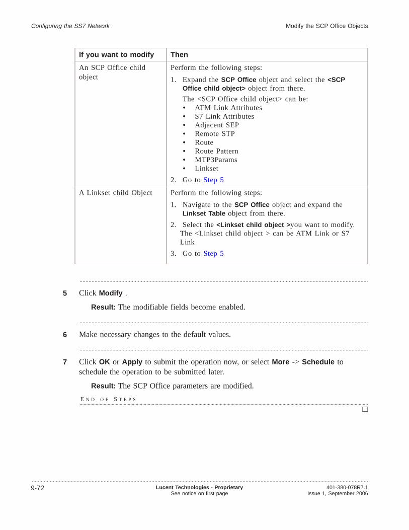
If you want to modify Then
An SCP Office childobject
Perform the following steps:
1. Expand theSCP Office object and select the<SCPOffice child object> object from there.
The <SCP Office child object> can be:• ATM Link Attributes• S7 Link Attributes• Adjacent SEP• Remote STP• Route• Route Pattern• MTP3Params• Linkset
2. Go to Step 5
A Linkset child Object Perform the following steps:
1. Navigate to theSCP Office object and expand theLinkset Table object from there.
2. Select the<Linkset child object > you want to modify.The <Linkset child object > can be ATM Link or S7Link
3. Go to Step 5
.................................................................................................................................................................................................
5 Click Modify .
Result: The modifiable fields become enabled.
.................................................................................................................................................................................................
6 Make necessary changes to the default values.
.................................................................................................................................................................................................
7 Click OK or Apply to submit the operation now, or selectMore -> Schedule toschedule the operation to be submitted later.
Result: The SCP Office parameters are modified.
E N D O F S T E P S........................................................................................................................................................................................................................
Configuring the SS7 Network Modify the SCP Office Objects
.................................................................................................................................................................................................................................
9-72 Lucent Technologies - ProprietarySee notice on first page
401-380-078R7.1Issue 1, September 2006

Performing Object-Specific actions on SCP Office child objects.................................................................................................................................................................................................................................
Purpose
The Lucent OMC-H allows you to perform various object-specific actions.Object-specific means that these operations are available to you for particular objectsonly.
The various object-specific actions available to you are described in the followingtable.
Action Availablefor thefollowingSCP Officeobjects
Before performing theprocedure
Result
Allow S7 Link
ATM Link
For S7 Link
Ensure that the selected S7link is in the ”blocked”,inhibited”, “MOOS”, or“OOS” state.
For ATM Link
Ensure that the selected ATMlink is in the “inhibited”,“MOOS”, or “OOS” state.
For S7 Link
The S7 Link is allowedand its state changes from“inhibited” to “active”.
For ATM Link
The ATM Link is allowedand its state changes from“inhibited” to “active”.
Inhibit S7 Link
ATM Link
For S7 Link
Ensure that the selected S7link is in the ”blocked”,“active”, “Manually Out OfService (MOOS)”, or “OOS”state.
For ATM Link
Ensure that the selected ATMLink is in the “active”,“MOOS”, or “OOS” state.
For S7 Link
The S7 link is inhibited,that is its state changesfrom “active” to“inhibited”.
For ATM Link
The ATM link isinhibited, that is its statechanges from “active” to“inhibited”.
Configuring the SS7 Network
.................................................................................................................................................................................................................................401-380-078R7.1Issue 1, September 2006
Lucent Technologies - ProprietarySee notice on first page
9-73

Action Availablefor thefollowingSCP Officeobjects
Before performing theprocedure
Result
Disable S7 Link
ATM Link
S7 Board
For S7 Link
Ensure that S7 Link’s majorstate is “blocked”, “inhibited”,or “Out Of Service (OOS)”.
For ATM Link
Ensure that ATM link’s majorstate is “inhibited” or “Out OfService (OOS)”.
For S7 Board
Ensure that the S7 Boardobject state is Active.
For S7 Link
The S7 Link is disabledand the state changesfrom “blocked”,“inhibited”, or “Out OfService (OOS)” state tothe “Manually OOS(MOOS)” state.
For ATM Link
The ATM link is disabledand the state changesfrom “inhibited” or “OutOf Service (OOS)” to“Manually OOS(MOOS)”.
For S7 Board
The S7 Board object getsdisabled and the S7Board state changes from“Active” to “MOOS”. Toverify the state of the S7Board object,double-click to view theDetail View.
The State label displaysthe current state of the S7Board object.
Configuring the SS7 Network Performing Object-Specific actions on SCP Office childobjects
.................................................................................................................................................................................................................................
9-74 Lucent Technologies - ProprietarySee notice on first page
401-380-078R7.1Issue 1, September 2006
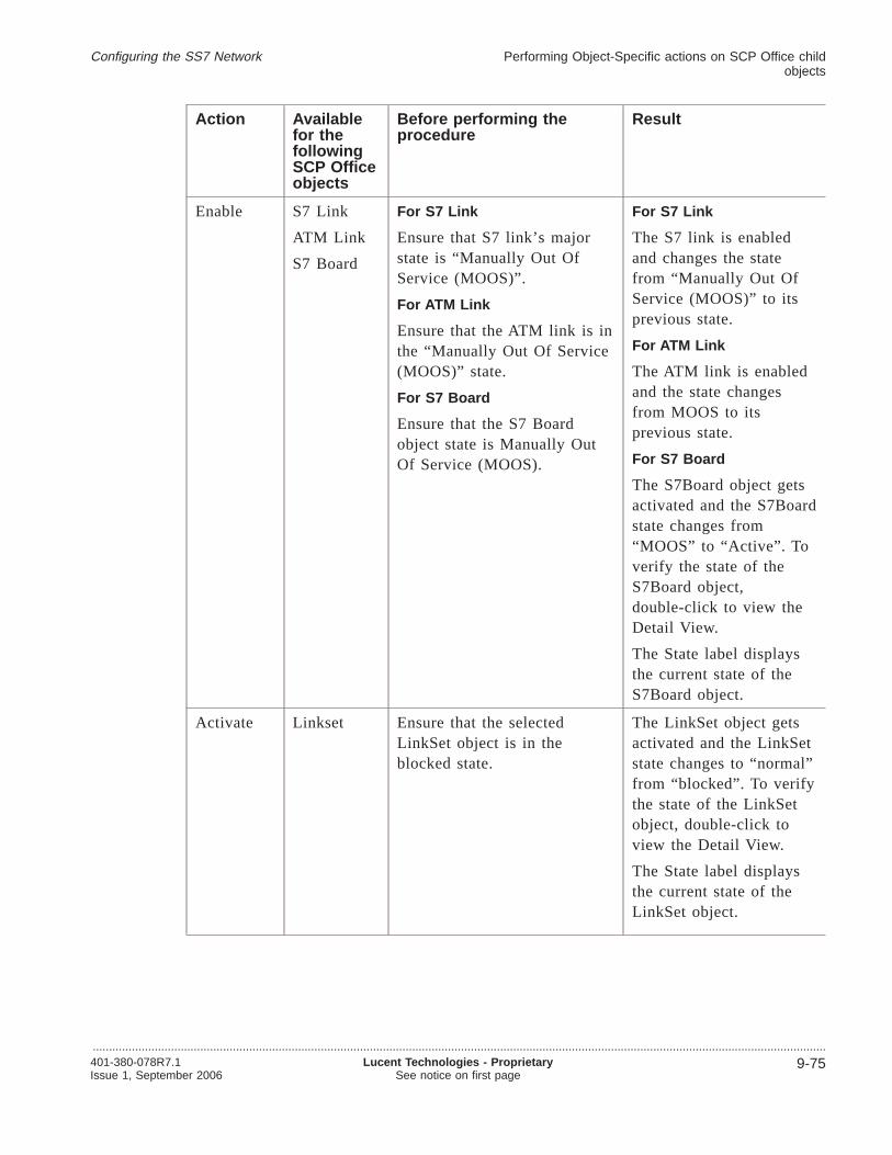
Action Availablefor thefollowingSCP Officeobjects
Before performing theprocedure
Result
Enable S7 Link
ATM Link
S7 Board
For S7 Link
Ensure that S7 link’s majorstate is “Manually Out OfService (MOOS)”.
For ATM Link
Ensure that the ATM link is inthe “Manually Out Of Service(MOOS)” state.
For S7 Board
Ensure that the S7 Boardobject state is Manually OutOf Service (MOOS).
For S7 Link
The S7 link is enabledand changes the statefrom “Manually Out OfService (MOOS)” to itsprevious state.
For ATM Link
The ATM link is enabledand the state changesfrom MOOS to itsprevious state.
For S7 Board
The S7Board object getsactivated and the S7Boardstate changes from“MOOS” to “Active”. Toverify the state of theS7Board object,double-click to view theDetail View.
The State label displaysthe current state of theS7Board object.
Activate Linkset Ensure that the selectedLinkSet object is in theblocked state.
The LinkSet object getsactivated and the LinkSetstate changes to “normal”from “blocked”. To verifythe state of the LinkSetobject, double-click toview the Detail View.
The State label displaysthe current state of theLinkSet object.
Configuring the SS7 Network Performing Object-Specific actions on SCP Office childobjects
.................................................................................................................................................................................................................................401-380-078R7.1Issue 1, September 2006
Lucent Technologies - ProprietarySee notice on first page
9-75

Action Availablefor thefollowingSCP Officeobjects
Before performing theprocedure
Result
Deactivate Linkset Ensure that the selectedLinkSet object is in thenormal state.
The LinkSet object getsdeactivated and theLinkSet state changes to“blocked” from “normal”.To verify the state of theLinkSet object,double-click to view theDetail View.
The State label displaysthe current state of theLinkSet object.
Block S7 Link Ensure that the selected S7link is in the “active”,“inhibited”, “Manually Out OfService (MOOS)”, or “OOS”state.
The S7 link is blocked,that is its state changesfrom “active” or“inhibited” to “blocked”.
Unblock S7 Link Ensure that the selected S7link is in the blocked,Manually Out Of Service(MOOS), or OOS state
The S7 link is unblocked,that is its state changesfrom ”blocked” to itsprevious state, that is,“active” or “inhibited”.
Related information
There is no related information for this procedure.
Before you begin
Refer to the table given in“Purpose” (p. 9-73)above.
To perform an object-specific action on an SCP Office object
Complete the following procedure to perform an object-specific action on an SCPOffice object.
.................................................................................................................................................................................................
1 From the Lucent OMC-H Desktop, go to theNetwork Manager . Expand All and inthe HM tree, double-click the SS7 object from the HCF Cluster.
Configuring the SS7 Network Performing Object-Specific actions on SCP Office childobjects
.................................................................................................................................................................................................................................
9-76 Lucent Technologies - ProprietarySee notice on first page
401-380-078R7.1Issue 1, September 2006

.................................................................................................................................................................................................
2 Right-click anywhere on the SS7 detail view, and selectShow on Tree to display theselected SS7 object in the NE tree view.
.................................................................................................................................................................................................
3 Expand theSS7 object.
.................................................................................................................................................................................................
4 Expand theSCP Office object.
.................................................................................................................................................................................................
5 If you want toperform
Then
The Enable orDisable action onthe S7 Boardobject
Perform the following steps
• Select theS7 Board object.
• Go to Step 6.
The Activate orDeactivate actionon the Linksetobject
Perform the following steps
• Select theLinkSetTable object.
• Go to Step 6.
Any otherobject-specificaction on aLinkset childobject
Perform the following steps
• Expand theLinkSetTable object.
• Select the<LinkSet child object> that you want.The <LinkSet child object> can be S7 link or ATM Link.
• Go to Step 6.
.................................................................................................................................................................................................
6 From the menu bar, clickAction -> Object Specific -> <Object-Specific action> .
The available <Object-Specific action> for each object is described in the table givenin the “Purpose” (p. 9-73)section. This table also describes the results of the variousobject-specific actions that can be performed.
E N D O F S T E P S........................................................................................................................................................................................................................
Configuring the SS7 Network Performing Object-Specific actions on SCP Office childobjects
.................................................................................................................................................................................................................................401-380-078R7.1Issue 1, September 2006
Lucent Technologies - ProprietarySee notice on first page
9-77
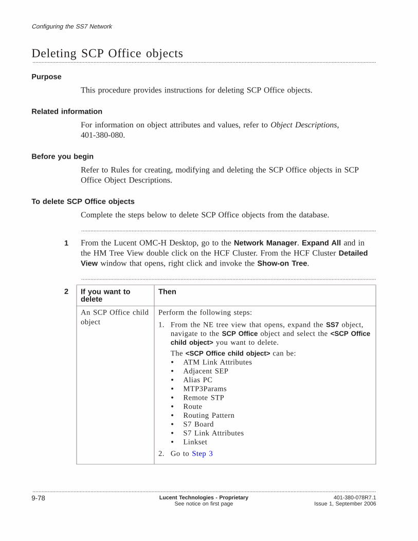
Deleting SCP Office objects.................................................................................................................................................................................................................................
Purpose
This procedure provides instructions for deleting SCP Office objects.
Related information
For information on object attributes and values, refer toObject Descriptions,401-380-080.
Before you begin
Refer to Rules for creating, modifying and deleting the SCP Office objects in SCPOffice Object Descriptions.
To delete SCP Office objects
Complete the steps below to delete SCP Office objects from the database.
.................................................................................................................................................................................................
1 From the Lucent OMC-H Desktop, go to theNetwork Manager . Expand All and inthe HM Tree View double click on the HCF Cluster. From the HCF ClusterDetailedView window that opens, right click and invoke theShow-on Tree .
.................................................................................................................................................................................................
2 If you want todelete
Then
An SCP Office childobject
Perform the following steps:
1. From the NE tree view that opens, expand theSS7 object,navigate to theSCP Office object and select the<SCP Officechild object> you want to delete.
The <SCP Office child object> can be:• ATM Link Attributes• Adjacent SEP• Alias PC• MTP3Params• Remote STP• Route• Routing Pattern• S7 Board• S7 Link Attributes• Linkset
2. Go to Step 3
Configuring the SS7 Network
.................................................................................................................................................................................................................................
9-78 Lucent Technologies - ProprietarySee notice on first page
401-380-078R7.1Issue 1, September 2006

If you want todelete
Then
A Linkset childobject
Perform the following steps:
1. From the NE tree view that opens, navigate to theSS7object and expand theSCP Office object.
2. Expand theLinkset Table and select the<Linkset childobject> you want to delete.
The <Linkset child object> can be:• S7 Link• ATM Link
3. Go to Step 3
.................................................................................................................................................................................................
3 From the menu bar, clickAction -> Delete .
Result: An Action Confirmation window is displayed.
.................................................................................................................................................................................................
4 Click Yes to delete the SCP Office child object.
Result: The SCP Office child is removed from the database.
E N D O F S T E P S........................................................................................................................................................................................................................
Configuring the SS7 Network Deleting SCP Office objects
.................................................................................................................................................................................................................................401-380-078R7.1Issue 1, September 2006
Lucent Technologies - ProprietarySee notice on first page
9-79

Configuring the SCTP object
Overview.................................................................................................................................................................................................................................
Purpose
This section describes the SCTP object and its child objects. You cannot create orconfigure this object. You can only view its details. You can, however, configure theSCTP child objects and their attributes
Contents
SCTP object description 9-81
Creating an SCTP child object 9-84
Deleting an SCTP child object 9-86
Modifying an SCTP Object 9-87
Performing Object-Specific actions 9-89
Configuring the SS7 Network
.................................................................................................................................................................................................................................
9-80 Lucent Technologies - ProprietarySee notice on first page
401-380-078R7.1Issue 1, September 2006
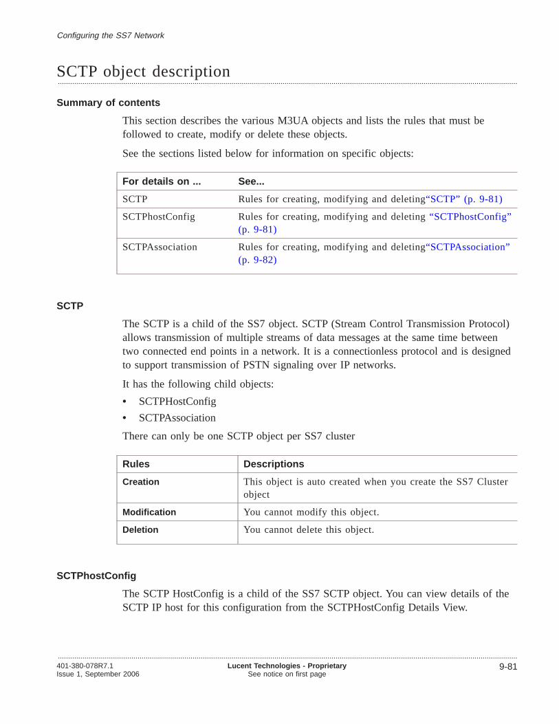
SCTP object description.................................................................................................................................................................................................................................
Summary of contents
This section describes the various M3UA objects and lists the rules that must befollowed to create, modify or delete these objects.
See the sections listed below for information on specific objects:
For details on ... See...
SCTP Rules for creating, modifying and deleting“SCTP” (p. 9-81)
SCTPhostConfig Rules for creating, modifying and deleting“SCTPhostConfig”(p. 9-81)
SCTPAssociation Rules for creating, modifying and deleting“SCTPAssociation”(p. 9-82)
SCTP
The SCTP is a child of the SS7 object. SCTP (Stream Control Transmission Protocol)allows transmission of multiple streams of data messages at the same time betweentwo connected end points in a network. It is a connectionless protocol and is designedto support transmission of PSTN signaling over IP networks.
It has the following child objects:
• SCTPHostConfig
• SCTPAssociation
There can only be one SCTP object per SS7 cluster
Rules Descriptions
Creation This object is auto created when you create the SS7 Clusterobject
Modification You cannot modify this object.
Deletion You cannot delete this object.
SCTPhostConfig
The SCTP HostConfig is a child of the SS7 SCTP object. You can view details of theSCTP IP host for this configuration from the SCTPHostConfig Details View.
Configuring the SS7 Network
.................................................................................................................................................................................................................................401-380-078R7.1Issue 1, September 2006
Lucent Technologies - ProprietarySee notice on first page
9-81

There can only be one SCTP object per SS7 cluster
Rules Description
Creation Lucent OMC-H does not allow more than 36 instances with“Localhost” having a value “Y”.
Modification You cannot modify this object. To change parameters youneed to delete the configuration and create a new one again.
Deletion You can only delete this object if the SCTPHostConfig IDdoes not exist as
• Local/Remote SCTP host ID in SCTP Association
• Local SCTP host ID in ASP
• Remote SCTP host ID in SGP
SCTPAssociation
The SCTPAssociation is a child of the SS7 object. This object represents a protocolrelationship between two SCTP endpoints. An association can be uniquely identified bythe transport addresses used by the endpoints in the association.
Configuring the SS7 Network SCTP object description
.................................................................................................................................................................................................................................
9-82 Lucent Technologies - ProprietarySee notice on first page
401-380-078R7.1Issue 1, September 2006
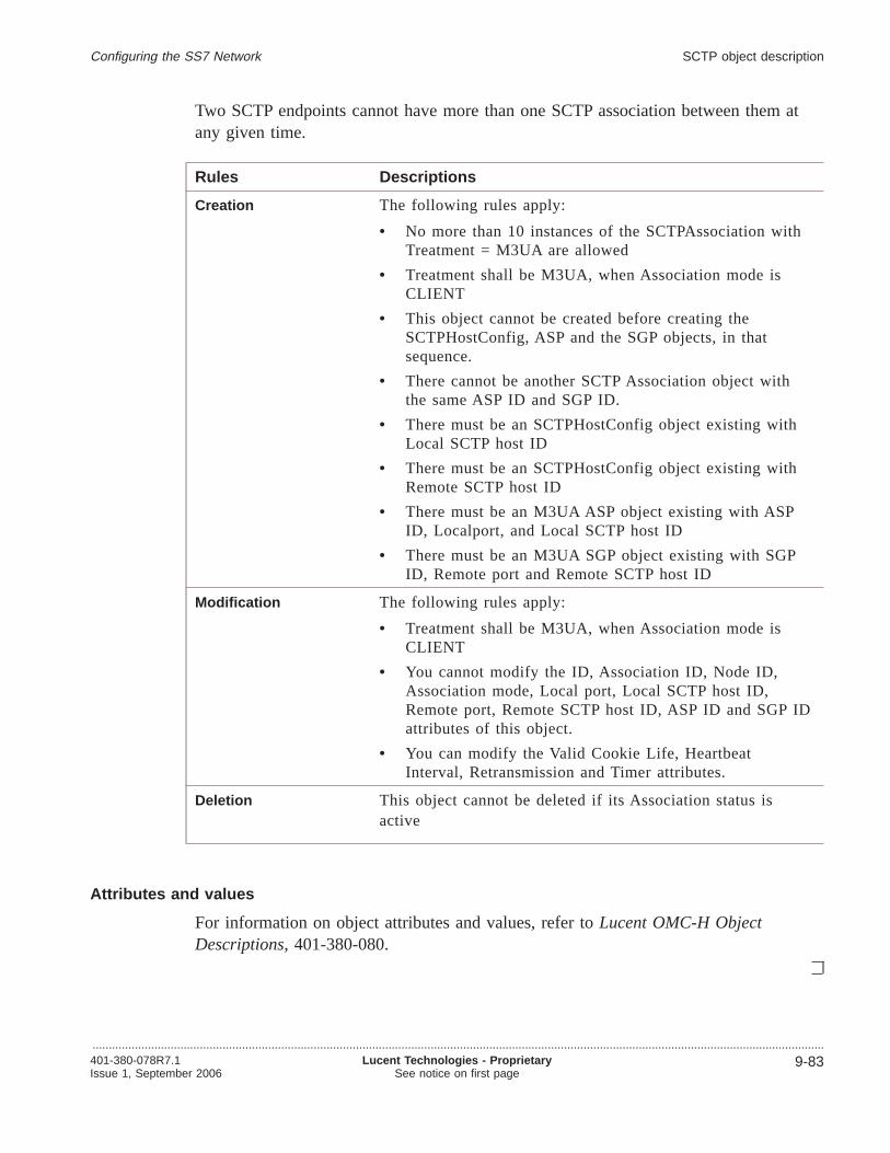
Two SCTP endpoints cannot have more than one SCTP association between them atany given time.
Rules Descriptions
Creation The following rules apply:
• No more than 10 instances of the SCTPAssociation withTreatment = M3UA are allowed
• Treatment shall be M3UA, when Association mode isCLIENT
• This object cannot be created before creating theSCTPHostConfig, ASP and the SGP objects, in thatsequence.
• There cannot be another SCTP Association object withthe same ASP ID and SGP ID.
• There must be an SCTPHostConfig object existing withLocal SCTP host ID
• There must be an SCTPHostConfig object existing withRemote SCTP host ID
• There must be an M3UA ASP object existing with ASPID, Localport, and Local SCTP host ID
• There must be an M3UA SGP object existing with SGPID, Remote port and Remote SCTP host ID
Modification The following rules apply:
• Treatment shall be M3UA, when Association mode isCLIENT
• You cannot modify the ID, Association ID, Node ID,Association mode, Local port, Local SCTP host ID,Remote port, Remote SCTP host ID, ASP ID and SGP IDattributes of this object.
• You can modify the Valid Cookie Life, HeartbeatInterval, Retransmission and Timer attributes.
Deletion This object cannot be deleted if its Association status isactive
Attributes and values
For information on object attributes and values, refer toLucent OMC-H ObjectDescriptions,401-380-080.
Configuring the SS7 Network SCTP object description
.................................................................................................................................................................................................................................401-380-078R7.1Issue 1, September 2006
Lucent Technologies - ProprietarySee notice on first page
9-83
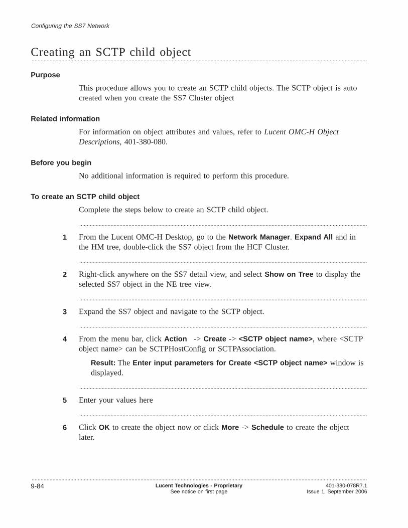
Creating an SCTP child object.................................................................................................................................................................................................................................
Purpose
This procedure allows you to create an SCTP child objects. The SCTP object is autocreated when you create the SS7 Cluster object
Related information
For information on object attributes and values, refer toLucent OMC-H ObjectDescriptions,401-380-080.
Before you begin
No additional information is required to perform this procedure.
To create an SCTP child object
Complete the steps below to create an SCTP child object.
.................................................................................................................................................................................................
1 From the Lucent OMC-H Desktop, go to theNetwork Manager . Expand All and inthe HM tree, double-click the SS7 object from the HCF Cluster.
.................................................................................................................................................................................................
2 Right-click anywhere on the SS7 detail view, and selectShow on Tree to display theselected SS7 object in the NE tree view.
.................................................................................................................................................................................................
3 Expand the SS7 object and navigate to the SCTP object.
.................................................................................................................................................................................................
4 From the menu bar, clickAction -> Create -> <SCTP object name> , where <SCTPobject name> can be SCTPHostConfig or SCTPAssociation.
Result: The Enter input parameters for Create <SCTP object name> window isdisplayed.
.................................................................................................................................................................................................
5 Enter your values here
.................................................................................................................................................................................................
6 Click OK to create the object now or clickMore -> Schedule to create the objectlater.
Configuring the SS7 Network
.................................................................................................................................................................................................................................
9-84 Lucent Technologies - ProprietarySee notice on first page
401-380-078R7.1Issue 1, September 2006

Result: The new SCTP child object is created.
E N D O F S T E P S........................................................................................................................................................................................................................
Configuring the SS7 Network Creating an SCTP child object
.................................................................................................................................................................................................................................401-380-078R7.1Issue 1, September 2006
Lucent Technologies - ProprietarySee notice on first page
9-85
Deleting an SCTP child object.................................................................................................................................................................................................................................
Purpose
This procedure helps you to delete an SCTP child object.
Related information
For information on object attributes and values, refer toObject Descriptions,401-380-080.
Before you begin
If you are deleting an SCTPHostConfig object, make sure that this SCTPHostConfigIndex is not referred in any of the association objects in the SS7 HCF Cluster
To delete an SCTP child object
Complete the following procedure to delete an SCTP child object.
.................................................................................................................................................................................................
1 From the Lucent OMC-H Desktop, go to theNetwork Manager . Expand All and inthe HM Tree View double click on the HCF Cluster. From the HCF ClusterDetailedView window that opens, right click and invoke theShow-on Tree .
.................................................................................................................................................................................................
2 From the SS7 HCFClusterShow on tree , expand theSCTP object and select the<SCTP child object> that you want to delete. These can be the SCTPHostConfig orthe SCTPAssociation object.
.................................................................................................................................................................................................
3 From the menu bar, clickAction -> Delete .
Result: An Action Confirmation window is displayed.
.................................................................................................................................................................................................
4 Click Yes to delete the SCTP child object .
Result: The SCTP child object is removed from the database.
Note: If the SCTP child object you are attempting to delete is the last one in theSCTP child object Table under the SCTP then this delete action will delete theSCTP child object table itself.
E N D O F S T E P S........................................................................................................................................................................................................................
Configuring the SS7 Network
.................................................................................................................................................................................................................................
9-86 Lucent Technologies - ProprietarySee notice on first page
401-380-078R7.1Issue 1, September 2006
Modifying an SCTP Object.................................................................................................................................................................................................................................
Purpose
This procedure allows you to modify an SCTPAssociation object.
Important! The SCTPHostConfig object cannot be modified.
Related information
For information on object attributes and values, refer toLucent OMC-H ObjectDescriptions,401-380-080.
Before you begin
Before you begin, no additional information is required.
To modify an SCTPAssociation
Complete the steps below to modify the SCTPAssociation attributes.
.................................................................................................................................................................................................
1 From the Lucent OMC-H Desktop, go to theNetwork Manager . Expand All and inthe HM Tree View, double-click the SS7 object from the HCF Cluster.
.................................................................................................................................................................................................
2 Right-click anywhere on the SS7 detail view, and selectShow on Tree to display theselected SS7 object in the NE tree view.
.................................................................................................................................................................................................
3 Expand the SS7 object and navigate to the SCTP object.
.................................................................................................................................................................................................
4 Double click on theSCTPAssociation object
Result: The SS7-[id], SCTP-[id], SCTPAssociation=[id] window is displayed
Note: The SCTPAssociation ID in square brackets above [] indicates the object IDassigned by the system while creating the object.
.................................................................................................................................................................................................
5 Click on Modify
.................................................................................................................................................................................................
6 Change the values, as required and clickOK to save the changes.
Configuring the SS7 Network
.................................................................................................................................................................................................................................401-380-078R7.1Issue 1, September 2006
Lucent Technologies - ProprietarySee notice on first page
9-87
Result: The modified SCTPAssociation object is created
E N D O F S T E P S........................................................................................................................................................................................................................
Configuring the SS7 Network Modifying an SCTP Object
.................................................................................................................................................................................................................................
9-88 Lucent Technologies - ProprietarySee notice on first page
401-380-078R7.1Issue 1, September 2006
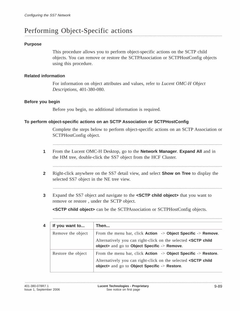
Performing Object-Specific actions.................................................................................................................................................................................................................................
Purpose
This procedure allows you to perform object-specific actions on the SCTP childobjects. You can remove or restore the SCTPAssociation or SCTPHostConfig objectsusing this procedure.
Related information
For information on object attributes and values, refer toLucent OMC-H ObjectDescriptions,401-380-080.
Before you begin
Before you begin, no additional information is required.
To perform object-specific actions on an SCTP Association or SCTPHostConfig
Complete the steps below to perform object-specific actions on an SCTP Association orSCTPHostConfig object.
.................................................................................................................................................................................................
1 From the Lucent OMC-H Desktop, go to theNetwork Manager . Expand All and inthe HM tree, double-click the SS7 object from the HCF Cluster.
.................................................................................................................................................................................................
2 Right-click anywhere on the SS7 detail view, and selectShow on Tree to display theselected SS7 object in the NE tree view.
.................................................................................................................................................................................................
3 Expand the SS7 object and navigate to the<SCTP child object> that you want toremove or restore , under the SCTP object.
<SCTP child object> can be the SCTPAssociation or SCTPHostConfig objects.
.................................................................................................................................................................................................
4 If you want to... Then...
Remove the object From the menu bar, clickAction -> Object Specific -> Remove .
Alternatively you can right-click on the selected<SCTP childobject> and go toObject Specific -> Remove .
Restore the object From the menu bar, clickAction -> Object Specific -> Restore .
Alternatively you can right-click on the selected<SCTP childobject> and go toObject Specific -> Restore .
Configuring the SS7 Network
.................................................................................................................................................................................................................................401-380-078R7.1Issue 1, September 2006
Lucent Technologies - ProprietarySee notice on first page
9-89

Result: The <SCTP child object> will be removed or restored from theSCTPAssociation Table.
E N D O F S T E P S........................................................................................................................................................................................................................
Configuring the SS7 Network Performing Object-Specific actions
.................................................................................................................................................................................................................................
9-90 Lucent Technologies - ProprietarySee notice on first page
401-380-078R7.1Issue 1, September 2006

10 10Configuring the Topological andTopographical Views
Overview.................................................................................................................................................................................................................................
Purpose
This chapter provides information on the Topological and Topographical Views andexplains how to configure them.
Contents
Topological Views 10-2
Topological view description 10-3
Filters for the Topological View 10-5
Layers for the Topological View 10-6
Viewing the Topological View 10-7
Filtering the topological view 10-9
To select layers in the Topological View 10-11
Topographical Views 10-12
Topographical View 10-13
SiteInfo Object 10-15
Creating the SiteInfo object 10-17
Viewing the Site Administration Data 10-19
Modifying the location details 10-21
Selecting maps for the Topographical view 10-23
Viewing the Topographical View 10-24
To filter the Topographical View 10-26
Selecting Layers in the Topographical View 10-27
.................................................................................................................................................................................................................................401-380-078R7.1Issue 1, September 2006
Lucent Technologies - ProprietarySee notice on first page
10-1
Topological Views
Overview.................................................................................................................................................................................................................................
Purpose
This section describes the topological view available from Lucent OMC-H.
Contents
Topological view description 10-3
Filters for the Topological View 10-5
Layers for the Topological View 10-6
Viewing the Topological View 10-7
Filtering the topological view 10-9
To select layers in the Topological View 10-11
Configuring the Topological and Topographical Views
.................................................................................................................................................................................................................................
10-2 Lucent Technologies - ProprietarySee notice on first page
401-380-078R7.1Issue 1, September 2006
Topological view description.................................................................................................................................................................................................................................
Topological view
The topological view is a logical representation of the network elements (NEs), virtualNEs (VNEs), and the connection objects. They are:
• NEs: HCF and HDF servers within a Cluster group
• VNEs: IP connection and Logical connection
• Connection objects:
– HcfHdfConnection
– HdfHcfConnection
– HdfHdfConnection
Topological view layout description
The layout of the topological view will be displayed as per the following conditions:
• The Logical connection VNE will be displayed in the centre of the view.
• The HCF will be positioned below and the HDF will be above the Logicalconnection.
• The HDFs will be grouped into HDF mated pairs. This is to avoid clutter on theview, such that the HDF Pair link does not overlap with any NEs.
• The HCFs will be grouped into HCFClusters, with a space between each cluster.
• HDFs in the HDFPool, and the HCFs in the HCFPool, if shown, will be displayedon the right side of the view.There will not be any links shown to these HCFs or HDFs because the connectionobjects do not exist for these NEs.
• The HdfHcfConnection is shown as a link from an HDF to the Logical connection.
• The HcfHdfConnection is shown as a link from an HCF to the Logical connection.
• The HdfHdfConnection is shown as a link between the two HDFs.
IP connection
The IP connection represents the logical connection between two NEs (HCF and HDFservers) within the SDHLR and is a container for all connection objects.
The IP connection is the child of SDHLR and is auto created when you create aSDHLR object.
Logical connection
The Logical connection represents the IP network between the HCFs and HDFs fordisplay on the topological view. It is auto created when you create an SDHLR.
Configuring the Topological and Topographical Views
.................................................................................................................................................................................................................................401-380-078R7.1Issue 1, September 2006
Lucent Technologies - ProprietarySee notice on first page
10-3
HcfHdf connection
The HcfHdfConnection object represents the bidirectional logical connections betweenan HCF and all HDFs.
HdfHcf connection
The HdfHcfConnection object represents the bidirectional logical connections betweenan HDF and all HCFs.
HdfHdf connection
The HdfHdfConnection (HdfPairConnection) object represents the bIdirectional logicalconnection between the two HDFs in a pair.
Important! An HdfPairConnection will exist only when an HDF Pair exists.
Configuring the Topological and Topographical Views Topological view description
.................................................................................................................................................................................................................................
10-4 Lucent Technologies - ProprietarySee notice on first page
401-380-078R7.1Issue 1, September 2006

Filters for the Topological View.................................................................................................................................................................................................................................
Filter for the Topological Views
The Topological View supports filters such as Connection type, Node type, Group type,etc., which turn on and off, the display of the objects selected in the view.
Example
If the Managed NEs only filter is turned ON, only the Managed NEs will be displayedin the view and vice versa.
Related Information
For more information on filtering objects in the topological view, refer to“Filtering thetopological view” (p. 10-9).
Configuring the Topological and Topographical Views
.................................................................................................................................................................................................................................401-380-078R7.1Issue 1, September 2006
Lucent Technologies - ProprietarySee notice on first page
10-5

Layers for the Topological View.................................................................................................................................................................................................................................
Layers for the Topological Views
The Topological View supports filters such as Reflected HSA, Node Names,Connections, etc., which turn on and off, the display of the attributes of the objectsselected in the view.
Example
If the Reflected HSA layer is turned OFF, the Reflected HSA alarm status attribute willnot displayed in the view and vice versa.
Related Information
For more information on selecting layers in the topological view, refer to“To selectlayers in the Topological View” (p. 10-11).
Configuring the Topological and Topographical Views
.................................................................................................................................................................................................................................
10-6 Lucent Technologies - ProprietarySee notice on first page
401-380-078R7.1Issue 1, September 2006

Viewing the Topological View.................................................................................................................................................................................................................................
Purpose
This procedure allows you to view the logical representation of the NEs, VNEs, andthe connection objects in a single layout. This view can be invoked by selecting any ofthe following in the HM Tree:
• SDHLR
• HCF Cluster
• HCF Pool
• HDF Pool
• Mated Pair
The topological view can also be invoked at NE level (HCF and HDF), from both, theHM tree and NE tree view.
Related Information
For more information on the Topological view, refer to“Topological view description”(p. 10-3).
Before you begin
Ensure that at least one NE exists within the group that you select for the topologicalview.
To view the Topological View
Complete the following procedure to view the Topological View:
.................................................................................................................................................................................................
1 Invoke theLucent OMC-H - Network Manager window from theLucent OMC-H -Desktop .
For more information on accessing the Network Manager, refer to Graphical UserInterface, 401-380-082.
.................................................................................................................................................................................................
2 In the HM Tree view, expand the OMC-H group, and navigate to the group whosetopological view you want to see.
.................................................................................................................................................................................................
3 From the menu bar, clickView -> Topological -> Details .
Configuring the Topological and Topographical Views
.................................................................................................................................................................................................................................401-380-078R7.1Issue 1, September 2006
Lucent Technologies - ProprietarySee notice on first page
10-7

Result: The Topological View - <Group name> window is displayed in the rightpane of the Network Manager window.
Expand All and Collapse All options
When the Topological view is invoked, only the groups (HCF Cluster, HDF Matedpair, HCF Pool and HDF Pool) are displayed. Right-click the groups and clickExpandAll to see the NEs along with their connections (if any), within that group. ClickCollapse All to collapse the NEs into their corresponding groups and only the groupswill be displayed.
Configuring the Topological and Topographical Views Viewing the Topological View
.................................................................................................................................................................................................................................
10-8 Lucent Technologies - ProprietarySee notice on first page
401-380-078R7.1Issue 1, September 2006
E N D O F S T E P S.................................................................................................................................................................................................

Filtering the topological view.................................................................................................................................................................................................................................
Purpose
This procedure allows you to filter the objects of the topological view to display onlythe required objects.
Related Information
For more information on the filter types, refer to“Filters for the Topological View”(p. 10-5).
Before you begin
There are no preconditions to perform this procedure.
To filter the topological view
Complete the following procedure to filter the topological view.
.................................................................................................................................................................................................
1 Invoke the topological view on theLucent OMC-H - Network Manager window.
.................................................................................................................................................................................................
2 Right-click anywhere within the topological view window.
.................................................................................................................................................................................................
3 Click Filters in the pop-up menu that is displayed.
Result: The Configure Filters... window is displayed.
.................................................................................................................................................................................................
4 Select or clear the filter options to turn their display ON or OFF respectively, asrequired.
Note
Configuring the Topological and Topographical Views
.................................................................................................................................................................................................................................401-380-078R7.1Issue 1, September 2006
Lucent Technologies - ProprietarySee notice on first page
10-9

You need to be aware of the following information while making the filter selections:
• If you select a particular node type to be filtered, you must also select the grouptype for it.For example if you select the HCF node type, you must select a group type, sayHCF Cluster, HCF Pool or HCF group, for it. The topological view for a node typeis only displayed for the corresponding group type that you select.
• If you select a particular group type without selecting a node type, the topologicalview displays only group information.For example if you select the HCF cluster group type, the topological view displaysthe HCF Cluster view. You cannot obtain the topological information for the nodes,say the HCFs, within the HCF Clusters, from this view.
.................................................................................................................................................................................................
5 Click OK to confirm the changes.
Result: The topological view will now display only those objects whose filteroption is set to ON.
E N D O F S T E P S........................................................................................................................................................................................................................
Configuring the Topological and Topographical Views Filtering the topological view
.................................................................................................................................................................................................................................
10-10 Lucent Technologies - ProprietarySee notice on first page
401-380-078R7.1Issue 1, September 2006
To select layers in the Topological View.................................................................................................................................................................................................................................
Purpose
This procedure allows you to display the required attributes for the objects of theTopological View.
Related Information
For more information on layers, refer to“Layers for the Topological View” (p. 10-6).
Before you begin
There are no preconditions for this procedure.
Procedure
Perform the following steps to select layers in the Topological View.
.................................................................................................................................................................................................
1 Open the Topological View on theLucent OMC-H - Network Manager window.
.................................................................................................................................................................................................
2 Right-click anywhere within the topological view window.
.................................................................................................................................................................................................
3 Click Layers in the pop-up menu that is displayed.
Result: The Layers window is displayed.
.................................................................................................................................................................................................
4 Select or clear the layer options to turn their display ON or OFF respectively, asrequired.
.................................................................................................................................................................................................
5 Click OK to confirm the changes.
Result: The Topological View will now display only those object attributes whoselayer option is set to ON.
E N D O F S T E P S........................................................................................................................................................................................................................
Configuring the Topological and Topographical Views
.................................................................................................................................................................................................................................401-380-078R7.1Issue 1, September 2006
Lucent Technologies - ProprietarySee notice on first page
10-11

Topographical Views
Overview.................................................................................................................................................................................................................................
Purpose
This section describes the topographical view available from Lucent OMC-H.
Contents
Topographical View 10-13
SiteInfo Object 10-15
Creating the SiteInfo object 10-17
Viewing the Site Administration Data 10-19
Modifying the location details 10-21
Selecting maps for the Topographical view 10-23
Viewing the Topographical View 10-24
To filter the Topographical View 10-26
Selecting Layers in the Topographical View 10-27
Configuring the Topological and Topographical Views
.................................................................................................................................................................................................................................
10-12 Lucent Technologies - ProprietarySee notice on first page
401-380-078R7.1Issue 1, September 2006

Topographical View.................................................................................................................................................................................................................................
Topographical view
A Topographical view displays objects that have longitude and latitude attributes,displayed in a geographical background, in their correct locations. It depicts thenetwork elements (NEs) on a map based on the physical location of the NE in the realnetwork . It also allows you to monitor the state of each managed object (MO) in thenetwork.
The view is capable of covering an area of at least 600 network elements.
Components of the Topographical View
The Topographical view displays only those NEs whose site name has been configured,either during creation, or during modification.
Co-located Nodes
In case two or more nodes (NEs/VNEs), for which you have permissions, have beenconfigured with the same location parameters, that is, the same longitude and latitude,they are grouped under a single co-located node icon on the Topographical view.
This icon will be displayed at the longitude and latitude location for those nodes.
The co-located node displays the reflected HSA and the site name associated to theindividual NEs/VNEs represented by this icon.
Important! The co-located table is not updated dynamically. Also, you cannotupdate it with the “Refresh” command. To view the changes, you have to close itand reopen.
Layers
The Topographical view supports layers, which turn on and off, the display of theattributes of the objects selected in the view. For example, political data, physicallandmarks, infrastructure data etc. The available layers are:
• Background layers: They are layers retrieved from the Geographical InformationSystem (GIS) data files.The supported background layers are:
– Environmental Systems Research Institute (ESRI) layers
• Foreground layers: They are node and connection layers and they superimposethe background layers.The supported foreground layers are:
– Node and connection layers (Node names, NE Type, NE Managed, ReflectedHSA)
Configuring the Topological and Topographical Views
.................................................................................................................................................................................................................................401-380-078R7.1Issue 1, September 2006
Lucent Technologies - ProprietarySee notice on first page
10-13

Filters
The Topographical view supports filters, which turn on and off the display of theobjects selected in the view. The available filters are:
• Node type: HCF, HDF
Zooming the view
You can enlarge or minimize or focus on a certain section of the view. The availablezoom options are:
• Zoom In to enlarge
• Zoom Out to minimize
• Zoom To to zoom to a specific size
• Zoom to full extent to view the entire map
• Zoom by area to view only a certain section of the map
• Zoom back to last extent to revert to the last view
Related information
For more information on the Topographical View, refer toLucent OMC-H GraphicalUser Interface,401-380-082.
Configuring the Topological and Topographical Views Topographical View
.................................................................................................................................................................................................................................
10-14 Lucent Technologies - ProprietarySee notice on first page
401-380-078R7.1Issue 1, September 2006
SiteInfo Object.................................................................................................................................................................................................................................
SiteInfo object
The SiteInfo object details the information pertaining to a given site, including thelocation information. With appropriate permissions (read/write), you can configure thesite information from the Lucent OMC-H GUI.
The information stored under this object is used while creating the NE (HCF andHDF), to configure the location details and contact information.
The SiteInfo object is an OMC only Managed Object Class (MOC) and can be indexedon the site name attribute. The SiteInfo is stored in one location containing the SiteInfofor all the SDHLR complexes managed by the one Lucent OMC-H.
SiteInfo object attributes
The attributes that the SiteInfo object supports are:
• Site name
• Address
• Contact person
• Phone number
• Pager number
• Mobile number
• E-mail address
• Latitude and Longitude in degrees, minutes, seconds, and hemisphere formats.
Creating a SiteInfo object
The SiteInfo object can be created using batch scripts from the Command LineInterface (CLI) console as well as from the GUI.
For more information on creating a SiteInfo object using the GUI, refer to“Creatingthe SiteInfo object” (p. 10-17).
For more information on creating a SiteInfo object using the CLI, refer to theConfiguration Management chapter, CREATESITEINFO section, inCommand LineInterface,401-380-081.
Maximum allowed SiteInfo objects
A single Lucent OMC-H can support up to a maximum of 200 SiteInfo objects.
Deleting a SiteInfo object
The SiteInfo object can be deleted from the SiteInfo object Table View, in the NE tree.
Configuring the Topological and Topographical Views
.................................................................................................................................................................................................................................401-380-078R7.1Issue 1, September 2006
Lucent Technologies - ProprietarySee notice on first page
10-15

This can be done either from theAction menu bar by clickingDelete , or byright-clicking the selected SiteInfo object and clickingDelete .
Important! You cannot delete a SiteInfo object whose site name is in use.
Related information
For more information on viewing the SiteInfo object Table View, refer to“Viewing theSite Administration Data” (p. 10-19).
For more information on creating a SiteInfo object, refer to“Creating the SiteInfoobject” (p. 10-17).
Configuring the Topological and Topographical Views SiteInfo Object
.................................................................................................................................................................................................................................
10-16 Lucent Technologies - ProprietarySee notice on first page
401-380-078R7.1Issue 1, September 2006

Creating the SiteInfo object.................................................................................................................................................................................................................................
Purpose
This procedure allows you to create the SiteInfo object.
The parent object is the SiteAdmin object, which is auto-created under the EMS group,and can be viewed only in the NE tree view.
Related information
For information on Site Data object, refer to“SiteInfo Object” (p. 10-15).
Before you begin
There are no preconditions to this procedure.
To create the SiteInfo object
Complete the following procedure to create the SiteInfo object.
.................................................................................................................................................................................................
1 Invoke theLucent OMC-H - Network Manager window from theLucent OMC-H -Desktop .
For more information on accessing the Network Manager, refer to Graphical UserInterface, 401-380-082.
.................................................................................................................................................................................................
2 In the HM tree, double-click the SiteAdmin object under the EMS group.
.................................................................................................................................................................................................
3 Right-click anywhere on the SiteAdmin detail view, and selectShow on Tree .
Result: The SiteAdmin object gets displayed in the NE tree view.
.................................................................................................................................................................................................
4 From the menu bar, clickAction -> Create -> SiteInfo .
Alternatively, right-click the SiteAdmin object and clickCreate -> SiteInfo .
Result: The Enter input parameters for Create SiteInfo window is displayed.
.................................................................................................................................................................................................
5 Specify the Name, and contact information in the fields provided.
.................................................................................................................................................................................................
6 The system generates an ID to always assign the next available unique ID on creationof each instance of this object. Overwrite this ID if you want.
Configuring the Topological and Topographical Views
.................................................................................................................................................................................................................................401-380-078R7.1Issue 1, September 2006
Lucent Technologies - ProprietarySee notice on first page
10-17

.................................................................................................................................................................................................
7 Specify the Latitude and Longitude details in the fields provided.
Important! Ensure that the index, site name, longitude, and latitude are unique forevery SiteInfo object.
.................................................................................................................................................................................................
8 Click OK to create the SiteInfo object now or clickMore -> Schedule to create theSiteInfo object later.
E N D O F S T E P S........................................................................................................................................................................................................................
Configuring the Topological and Topographical Views Creating the SiteInfo object
.................................................................................................................................................................................................................................
10-18 Lucent Technologies - ProprietarySee notice on first page
401-380-078R7.1Issue 1, September 2006
Viewing the Site Administration Data.................................................................................................................................................................................................................................
Purpose
This procedure allows you to view the Site Administration Data in the SiteInfo Table.
Related information
For information on Site Data object, refer to“SiteInfo Object” (p. 10-15).
Before you begin
There are no preconditions to perform this procedure.
To view the Site Administration Data in the SiteInfo Table
Complete the following procedure to view the Site Administration Data in the SiteInfoTable.
.................................................................................................................................................................................................
1 Invoke theLucent OMC-H - Network Manager window from theLucent OMC-H -Desktop .
For more information on accessing the Network Manager, refer to Graphical UserInterface, 401-380-082.
.................................................................................................................................................................................................
2 In the HM tree, double-click the SiteAdmin object under the EMS group.
.................................................................................................................................................................................................
3 Right-click anywhere on the SiteAdmin detail view, and selectShow on Tree .
Result: The SiteAdmin object gets displayed in the NE tree view.
.................................................................................................................................................................................................
4 Select either the SiteAdmin object or the SiteInfoTable object in the NE tree view.
.................................................................................................................................................................................................
5 From the menu bar, clickTools -> Location details .
Configuring the Topological and Topographical Views
.................................................................................................................................................................................................................................401-380-078R7.1Issue 1, September 2006
Lucent Technologies - ProprietarySee notice on first page
10-19

Result: The Site administration data is displayed in the SiteInfo Table in theNetwork Manager window.
Right-clicking any listed site row in the SiteInfo Table allows you to open thedetail view for that site. ClickModify to change the attributes.
You can also single-select or multi-select the site rows and right-click toDeleteany site.
E N D O F S T E P S........................................................................................................................................................................................................................
Configuring the Topological and Topographical Views Viewing the Site Administration Data
.................................................................................................................................................................................................................................
10-20 Lucent Technologies - ProprietarySee notice on first page
401-380-078R7.1Issue 1, September 2006
Modifying the location details.................................................................................................................................................................................................................................
Purpose
This procedure allows you to modify the location details for network elements (NEs),both HCF and HDF.
You can modify the site name only from the NE detail view or the NE CommunicationParameters window of the NE detail view, for a specific NE.
Related information
For information on SiteInfo object, refer to“SiteInfo Object” (p. 10-15).
Important! Contact information displayed in the NE detail view is not based on agiven NE, but is also coupled with the site name where NE is located. Hence,modifying the site name would also modify the contact information.
Before you begin
Ensure that the site name has been configured for the selected HCF or HDF.
Modify details for an NE only when it is in the managed state.
To modify the site name for network elements from the NE detail view
Complete the following procedure to modify the site name for network elements fromthe NE detail view.
.................................................................................................................................................................................................
1 From the Lucent OMC-H Desktop, go to theNetwork Manager . Expand All and inthe HM Tree View , double-click the NE whose site name has to be configured.
.................................................................................................................................................................................................
2 Right-click anywhere on the NE detail view, and selectShow on Tree .
Result: The selected NE gets displayed in the NE tree view.
.................................................................................................................................................................................................
3 From the menu bar, clickView -> Details to open the detail view for that NE.
Alternatively, double-click the NE to open the detail view.
Result: The NE detail view gets displayed.
.................................................................................................................................................................................................
4 Select theLocation tab and clickModify on the NE detail view.
Configuring the Topological and Topographical Views
.................................................................................................................................................................................................................................401-380-078R7.1Issue 1, September 2006
Lucent Technologies - ProprietarySee notice on first page
10-21

.................................................................................................................................................................................................
5 Change the site name from theSite name drop-down list.
.................................................................................................................................................................................................
6 Click OK to confirm the change.
Result: The site name changes to reflect the new name and the attributes related tothe modified site name also get populated accordingly.
To modify the site name for network elements from the HM detail view
Complete the following procedure to modify the site name for network elements fromthe NE detail view.
.................................................................................................................................................................................................
1 In the HM tree, double-click the NE whose site name has to be configured.
.................................................................................................................................................................................................
2 From the menu bar, clickAction -> Details to open the detail view for that NE.
Alternatively, double-click the NE to open the detail view.
Result: The NE detail view gets displayed.
.................................................................................................................................................................................................
3 Click NE Management... .
.................................................................................................................................................................................................
4 Select theLocation tab and clickModify on the NE detail view.
.................................................................................................................................................................................................
5 Change the site name from theSite name drop-down list.
.................................................................................................................................................................................................
6 Click OK to confirm the change.
Result: The site name changes to reflect the new name and the attributes related tothe modified site name also get populated accordingly.
E N D O F S T E P S........................................................................................................................................................................................................................
Configuring the Topological and Topographical Views Modifying the location details
.................................................................................................................................................................................................................................
10-22 Lucent Technologies - ProprietarySee notice on first page
401-380-078R7.1Issue 1, September 2006
E N D O F S T E P S.................................................................................................................................................................................................

Selecting maps for the Topographical view.................................................................................................................................................................................................................................
Purpose
This procedure allows you to select the map of the location whose Topographical viewyou want to see.
Related Information
For information on installing maps for the view, refer toSystem Installation,401-380-084.
Before you begin
Ensure that the map you want to view is installed in the Lucent OMC-H server.
To select a map for the view
Complete the following procedure to select a map for the view:
.................................................................................................................................................................................................
1 From the Lucent OMC-H Desktop, go to theNetwork Manager . Expand All and inthe HM or NE Tree view, select the object whose Topographical view you want to see.
.................................................................................................................................................................................................
2 From the menu bar, clickView -> Topographical
Result: The Select Map window is displayed.
.................................................................................................................................................................................................
3 From theName drop-down list, select the location whose map you want to view.
Select theShould re-transfer files from server option if you want to specificallyre-download the map from the server and not get them from the cache memory onthe client.
.................................................................................................................................................................................................
4 Click Ok to confirm the selection.
Result: The Topographical view for that location is displayed.
E N D O F S T E P S........................................................................................................................................................................................................................
Configuring the Topological and Topographical Views
.................................................................................................................................................................................................................................401-380-078R7.1Issue 1, September 2006
Lucent Technologies - ProprietarySee notice on first page
10-23

Viewing the Topographical View.................................................................................................................................................................................................................................
Purpose
This procedure allows you to view the logical representation of the network elements(NEs).
This view can be invoked by selecting at Group (OMC-H group, SDHLR, HCFCluster, HCF Pool, HDF Pool, HCF group, Mated pair etc.) level, or at NE (HCF,HDF) level.
Related Information
For more information on the Topographical view, refer to“Topographical View”(p. 10-13).
For information on selecting maps for the view, refer to“Selecting maps for theTopographical view” (p. 10-23).
Before you begin
Ensure that:
• At least one NE exists within the group that you select for the Topographical view
• The managed object’s (MO’s) NE Location parameters (latitude and longitude), andsite name are defined for them to be visible on the map.
To view the Topographical View
Complete the following procedure to view the Topographical View.
.................................................................................................................................................................................................
1 From the Lucent OMC-H Desktop, go to theNetwork Manager . Expand All and inthe HM Tree view, expand the OMC-H Group, and navigate to the group or NE whoseTopographical view you want to see.
.................................................................................................................................................................................................
2 Select any Group or NE in the HM or NE tree view, and from the menu bar, clickView -> Topographical to open theSelect Map pop up window for a particularregion.
Result: The Select Map window is displayed.
.................................................................................................................................................................................................
3 From theName drop-down list, select the location whose map you want to view.
Configuring the Topological and Topographical Views
.................................................................................................................................................................................................................................
10-24 Lucent Technologies - ProprietarySee notice on first page
401-380-078R7.1Issue 1, September 2006

Select theShould re-transfer files from server option if you want to specificallyre-download the map from the server and not get them from the cache memory onthe client.
.................................................................................................................................................................................................
4 Click Ok to confirm the selection.
Result: The Topographical view for that location is displayed.
E N D O F S T E P S........................................................................................................................................................................................................................
Configuring the Topological and Topographical Views Viewing the Topographical View
.................................................................................................................................................................................................................................401-380-078R7.1Issue 1, September 2006
Lucent Technologies - ProprietarySee notice on first page
10-25

To filter the Topographical View.................................................................................................................................................................................................................................
Purpose
This procedure allows you to filter the components of the Topographical View todisplay only the required objects.
Related Information
There is no related information.
Before you begin
There are no preconditions to perform this procedure.
Procedure
Perform the following steps to filter the Topographical View.
.................................................................................................................................................................................................
1 Open the Topographical View on theLucent OMC-H → Network Manager window.
.................................................................................................................................................................................................
2 From the icons displayed on the topographical map, selectShow Filters .
Note: The icon context will be displayed as a tool tip on mouse-over
Alternatively, right-click anywhere within the Topographical View window and clickFilters .
Result: The Configure filters pop-up menu is displayed.
.................................................................................................................................................................................................
3 Select or clear the filter options to turn their display ON or OFF respectively, asrequired.
.................................................................................................................................................................................................
4 Click OK to confirm the changes.
Result: The Topographical View will now display only those objects whose filteroption is set to ON.
E N D O F S T E P S........................................................................................................................................................................................................................
Configuring the Topological and Topographical Views
.................................................................................................................................................................................................................................
10-26 Lucent Technologies - ProprietarySee notice on first page
401-380-078R7.1Issue 1, September 2006

Selecting Layers in the Topographical View.................................................................................................................................................................................................................................
Purpose
This procedure allows you to display the required attributes for the objects of theTopographical view.
Related Information
There is no related information.
Before you begin
There are no preconditions for this procedure.
To select layers in the Topographical View
Complete the following procedure to select layers in the Topographical View.
.................................................................................................................................................................................................
1 Open the Topographical View on theLucent OMC-H Network Manager window.
.................................................................................................................................................................................................
2 From the icons displayed on the topographical map, selectShow Layers .
Note: The icon context will be displayed as a tool tip on mouse-over.
Alternatively, right-click anywhere within the Topographical View window and clickLayers .
Result: The Layers pop-up menu is displayed.
.................................................................................................................................................................................................
3 Select or clear the layer options to turn their display ON or OFF respectively, asrequired.
.................................................................................................................................................................................................
4 Click OK to confirm the changes.
Result: The Topographical View will now display only those object attributeswhose layer option is set to ON.
E N D O F S T E P S........................................................................................................................................................................................................................
Configuring the Topological and Topographical Views
.................................................................................................................................................................................................................................401-380-078R7.1Issue 1, September 2006
Lucent Technologies - ProprietarySee notice on first page
10-27

Appendix A: ConfigurationManagement Logs and Reports
Overview.................................................................................................................................................................................................................................
Purpose
This appendix provides information related to configuration management logs andreports. For detailed descriptions and procedures on the Lucent OMC-H logs andreports functionality, refer to theSystem Administration,401-380-075.
Contents
Logs A-2
Logs A-3
Configuration Management Logs A-5
Aggregating SDHLR Logs A-6
Reports A-8
Configuration reports A-9
Summary by NE Type Report A-10
Network Element Configuration Report A-11
Network State Report A-12
CM Operation Report A-13
State Change Report A-14
Attribute Value Change Report (AVCR) A-15
Audit Report A-16
.................................................................................................................................................................................................................................401-380-078R7.1Issue 1, September 2006
Lucent Technologies - ProprietarySee notice on first page
A-1

Logs
Overview.................................................................................................................................................................................................................................
Purpose
This appendix provides information on the logs and reports that are generated forConfiguration Management (CM) and procedures required to manage them. Fordetailed descriptions and procedures on the Lucent OMC-H logs functionality, refer tothe System Administration,401-380-075.
Contents
Logs A-3
Configuration Management Logs A-5
Aggregating SDHLR Logs A-6
Configuration Management Logs and Reports
.................................................................................................................................................................................................................................
A-2 Lucent Technologies - ProprietarySee notice on first page
401-380-078R7.1Issue 1, September 2006
Logs.................................................................................................................................................................................................................................
Introduction to logs
Logs are files containing records of actions performed on the server
Types of logs
The different types of logs are:
• Action Logs
• Security logs
• Event logs.
Log file description
Logs are files containing records of actions performed for a specific date and they areregistered as actions.
Logs record the following information:
• Date: the date and time of the action
• login: the user who performed the action
• System: the system on which the action was performed
• Object: the managed object on which the action was performed
• Action: the operation performed on the managed object
• Status: the result of the operations (Start, Success, or Error)
• Cause: reason for failure of the action (status=Error), if any
• Severity: severity of the error (Fatal, or Non-fatal).
Follow these steps to print the logs to file in a Windows environment:
1. In the log manager window, select the log entries you want to print.
2. Select eitherPrint to print all the logs orPrint selection to print selected logsfrom the log viewer to invoke the Print dialog box.
3. Select thePrint to file to generate a postscript file.
4. For information on printing from a windows environment, referhttp://support.microsoft.com/default.aspx?scid=kb;EN-US;Q158081. You can alsoselectWindows Help , Printing , thenConnect to a printer on a network forinformation on how to connect to a network printer.
Follow these steps to print the logs to file in a Solaris environment:
1. In the log manager window, select the log entries you want to print.
2. Select eitherPrint to print all the logs orPrint selection to print selected logsfrom the log viewer to invoke the Print dialog box.
Configuration Management Logs and Reports
.................................................................................................................................................................................................................................401-380-078R7.1Issue 1, September 2006
Lucent Technologies - ProprietarySee notice on first page
A-3

3. Select thePrint to file to generate a postscript file in a UNIX environment.
4. Execute the commandlpr to print the .ps file. For more information on printcommands in a Solaris environment, refer (http://developers.sun.com/solaris/articles/basicprinting.html).
Tasks you can perform
You can perform the following tasks related to logs from the Lucent OMC-H:
• Select and display logs
• Store and archive logs
For details about these procedures on logs seeSystem Administration,401-380-075
Configuration Management Logs and Reports Logs
.................................................................................................................................................................................................................................
A-4 Lucent Technologies - ProprietarySee notice on first page
401-380-078R7.1Issue 1, September 2006
Configuration Management Logs.................................................................................................................................................................................................................................
About Configuration Management logs
Lucent OMC-H administrators can view logs to see actions that have taken place onthe Lucent OMC-H.
The following Configuration Management logs exist:
• Audit logs
• User action logs
• Attribute value change logs
• Object creation and deletion logs.
Accessing log files
You can view a log file on the Log Viewer window. To access this window, selectTools , thenLog Manager on the Lucent OMC-H GUI desktop menu bar.
For more information on the Log Viewer window, see theSystem Administration,401-380-075.
Permissions
This window is only available if you have administrative permissions.
Configuration Management Logs and Reports
.................................................................................................................................................................................................................................401-380-078R7.1Issue 1, September 2006
Lucent Technologies - ProprietarySee notice on first page
A-5

Aggregating SDHLR Logs.................................................................................................................................................................................................................................
Purpose
This procedure allows you to aggregate SDHLR Logs from the Network Manager.
Related information
There is no related information for this procedure.
Before you begin
Make sure that the individual Network Element (NE) log files are available at LucentOMC-H for aggregation. You cannot aggregate SDHLR log files across different logtypes.
You can aggregate logs for the following network element groups or managed objects:
• SS7 HCF, Diameter HCF, HDF
• HDF mated pairs, HCF SS7 Cluster, HCF Group or within a single SDHLRComplex (composed of HDF mated pairs, HCF SS7 Clusters, HCF Groups).
The following table lists the naming convention for the aggregated log directories:
When invoked from ... the logs are placed at ...
NE (HCF or HDF) /data/aggregatedlogs/<LOGTYPE./<SDHLRNAME>_<CLUSTER/MATEDPAIR/DIAMETERNAME>_<NEUSERLABEL>_<NETYPE>_<NEID>
Cluster or Mated pair orHCF group
/data/aggregatedlogs/<LOGTYPE>/<SDHLRNAME>_<CLUSTER/MATEDPAIR/DIAMETERNAME>_<GROUPTYPE>_<GROUPID>
SDHLR group /data/aggregatedlogs/<LOGTYPE>/SDHLRNAME>_<GROUPTYPE>_<GROUPID>
To aggregate SDHLR Logs
Complete the following procedure to aggregate SDHLR Logs.
.................................................................................................................................................................................................
1 Invoke theLucent OMC-H - Network Manager window from theLucent OMC-H -Desktop .
For more information on accessing the Network Manager, referGraphical UserInterface,401-380-082.
Configuration Management Logs and Reports
.................................................................................................................................................................................................................................
A-6 Lucent Technologies - ProprietarySee notice on first page
401-380-078R7.1Issue 1, September 2006

.................................................................................................................................................................................................
2 In the HM tree, select one of the SDHLR Complex, Mated HDF or HCF Cluster, HDFor HCF, or HCF Group.
.................................................................................................................................................................................................
3 From the menu bar, selectTools -> SDHLR Logs -> Aggregate SDHLR Logs .
Result: Enter input parameters for Aggregate SDHLR Logs window isdisplayed.
.................................................................................................................................................................................................
4 In the Log Types field, select any of the log typesOm Log , Debug Log orSubscriber trace Log from the drop-down list. In theStart Date andEnd Date field,use the drop-down calender to specify the date range for aggregating the logs. In theTime field, select the start date time and the end date time from the drop-down list. Ifthe Lucent OMC-H application time and server time are different, you shouldsynchronize the application and the server time.
Important! The timestamp in the Lucent OMC-H log files is based on the LucentOMC-H local time zone settings that may differ from the time zone settings ofSDHLR NEs. If SDHLRs HCF or HDF nodes reside in different time zones,Lucent OMC-H will not synchronize time format of SDHLR NEs to the UniversalStandard Time (used by Lucent OMC-H) before compiling the log files.
Result: Lucent OMC-H generates a single text file for the SDHLR aggregated logdata containing individual SDHLR NE log file information.
.................................................................................................................................................................................................
5 To view the aggregated logs, selectTools -> SDHLR -> View aggregated logs .
Result: Lucent OMC-H displays an index of all the aggregated SDHLR logs in ainternet browser. These logs are stored for seven days. You can configure thestorage period from one to seven days. The default storage limit is three days. Formore information on configuring the log storage period, referSystemAdministration,401-380-075.
E N D O F S T E P S........................................................................................................................................................................................................................
Configuration Management Logs and Reports Aggregating SDHLR Logs
.................................................................................................................................................................................................................................401-380-078R7.1Issue 1, September 2006
Lucent Technologies - ProprietarySee notice on first page
A-7

Reports
Overview.................................................................................................................................................................................................................................
Purpose
This chapter provides information on the various types of Configuration Management(CM) reports and procedures required to manage them.
For detailed descriptions and procedures on the Lucent OMC-H reports functionality,refer to theSystem Administration,401-380-075.
Contents
Configuration reports A-9
Summary by NE Type Report A-10
Network Element Configuration Report A-11
Network State Report A-12
CM Operation Report A-13
State Change Report A-14
Attribute Value Change Report (AVCR) A-15
Audit Report A-16
Configuration Management Logs and Reports
.................................................................................................................................................................................................................................
A-8 Lucent Technologies - ProprietarySee notice on first page
401-380-078R7.1Issue 1, September 2006

Configuration reports.................................................................................................................................................................................................................................
Report Manager
The Report Manager feature on Lucent OMC-H allows you to view or generateconfiguration reports in different formats, namely Comma Separated Values (CSV) andHTML.
Permissions
You need Lucent OMC-H administrator permissions to generate reports. Other userscan view reports on Report Manager.
Supported report formats
The report formats that are supported are:
• Comma Separated Values (CSV)
• HTML.
Report formats not supported
The report formats that are not supported are:
• DMFlexConfigto3GPP
• DMFlexToSessionlog3GPP
• INVENTORY.
Important! If you transform any report to these formats that are not supported, thesystem throws an exception.
Tasks you can perform
You can perform the following tasks related to reports from the Lucent OMC-H:
• Generate a report
• View a report
• Transform a report to a specific format
• Delete a report
For details about these procedures seeSystem Administration,401-380-075
Configuration Management Logs and Reports
.................................................................................................................................................................................................................................401-380-078R7.1Issue 1, September 2006
Lucent Technologies - ProprietarySee notice on first page
A-9

Summary by NE Type Report.................................................................................................................................................................................................................................
Report description
The Summary by NE Type report shows by network element (NE) Type and NEsoftware version:
• All instances of that type and version with a counter of all visible Managed Objects(logical MOs) and MOs below that NE instance
• Below each NE instance, all the end-user visible Managed Object Classes (logicalMOCs) belonging to that NE instance with a counter of number of MOs.
Configuration Management Logs and Reports
.................................................................................................................................................................................................................................
A-10 Lucent Technologies - ProprietarySee notice on first page
401-380-078R7.1Issue 1, September 2006

Network Element Configuration Report.................................................................................................................................................................................................................................
Report description
The Network Element (NE) Configuration report shows:
• DN: All attribute names and values for the object identified by the DistinguishedName (DN) (including those that are not kept in the database, but directly in theNE) .
• All objects below the identified DN until the given depth is reached.
Configuration Management Logs and Reports
.................................................................................................................................................................................................................................401-380-078R7.1Issue 1, September 2006
Lucent Technologies - ProprietarySee notice on first page
A-11

Network State Report.................................................................................................................................................................................................................................
Report description
The Network State report shows:
• DN: All state attribute names and values for the object identified by theDistinguished Name (DN).
• All objects below the identified DN, until the given depth is reached.
Important
If any object does not have state attributes, it shall not be shown.
Configuration Management Logs and Reports
.................................................................................................................................................................................................................................
A-12 Lucent Technologies - ProprietarySee notice on first page
401-380-078R7.1Issue 1, September 2006

CM Operation Report.................................................................................................................................................................................................................................
Report description
The CM Operation report shows all configuration management operations that wereperformed in a given day, in descending order (last operation first). The followinginformation is displayed:
• logDate: Date and time at which the operation was performed.
• Login: Operator who performed the operation.
• Object: Object on which the operation was performed.
• Action: Operation performed.
• Status: Status of the operation (START, SUCCESS, or ERROR).
• Cause: Cause of the error that occurred during the operation.
• Severity: Severity of the error that occurred during the operation.
• Parameters: Parameters passed for performing the operation.
Configuration Management Logs and Reports
.................................................................................................................................................................................................................................401-380-078R7.1Issue 1, September 2006
Lucent Technologies - ProprietarySee notice on first page
A-13

State Change Report.................................................................................................................................................................................................................................
Report description
The State Change report shows all Event logs specifying a change in state on a givenday. The following information is displayed:
• logDate: Date and time when the state change event was received.
• Object: NE/Managed object on which the state change event was received.
• Event: State change event.
• Description: Old values of the changed attributes.
Configuration Management Logs and Reports
.................................................................................................................................................................................................................................
A-14 Lucent Technologies - ProprietarySee notice on first page
401-380-078R7.1Issue 1, September 2006

Attribute Value Change Report (AVCR).................................................................................................................................................................................................................................
Report description
The AVCR shows all Event logs specifying attribute value changes (other than stateattribute changes) for a specific day. The following information is displayed.
• logDate: Date and time at which the attribute change was received.
• Object: NE/Managed object for which the attribute change was received.
• Event: Attribute change event.
• Description: Old values of the changed attributes.
Configuration Management Logs and Reports
.................................................................................................................................................................................................................................401-380-078R7.1Issue 1, September 2006
Lucent Technologies - ProprietarySee notice on first page
A-15

Audit Report.................................................................................................................................................................................................................................
Report description
The Audit report shows for the selected network element:
• All the active Boards, LinkSets, Links, and LocalSSNs
• All the undeleted and uncreated Objects.
• All the mismatched values for (undeleted) LocalSSNs of Lucent OMC-H and theNE
Important
This report can be only viewed through the report manager window of the LucentOMC-H. For details about generating this report see“Performing audit on the DiameterHCF” (p. 7-28)and“Auditing an HCF” (p. 6-29)
Configuration Management Logs and Reports
.................................................................................................................................................................................................................................
A-16 Lucent Technologies - ProprietarySee notice on first page
401-380-078R7.1Issue 1, September 2006
Glossary
.................................................................................................................................................................................................................................
Numerics
3GThird Generationis a mobile telecommunications technology that supports high-speed,high-bandwidth wireless services for advanced applications.
3GPPThird Generation Partnership Projectis a project set up to expedite the development oftechnical specifications for 3G.
3GPP2Third Generation Partnership Project 2is a collaborative 3G telecommunicationsstandards-setting project comprising North American and Asian interests on thedevelopment of the next generation CDMA 2000 wireless communication.
100 Base-T100 Base-Tis a networking standard that supports data transfer rates that are 10 timesfaster than Ethernet, also known as Fast Ethernet.
.................................................................................................................................................................................................................................
A A-InterfaceGSM interface between BSS and MSC
AALATM Adaptation Layeris a layer in theB-ISDN protocol hierarchy that adapts usertraffic to a cell format.
ACCHAssociated Control Channel
ACKAcknowledgementis a message that acknowledges the reception of a transmitted packet.
.................................................................................................................................................................................................................................401-380-078R7.1Issue 1, September 2006
Lucent Technologies - ProprietarySee notice on first page
GL-1

ALCAPAccess Link Control Application Protocol
AMRAdaptive Multi Rateis a high-data rate service and transmission principle for 3G cellphones and networks.
ANThe UE is directly connected to theAccess Networkto give access to the core network.
ANSI SS7The American National Standards Institute SS7protocol is the standard SS7 signalingprotocol used in the North AmericanGSM 1900 market.
ASCAccess Service Class
ASCIIAmerican Standard Code for Information Interchangeis the world-wide standard for thecode numbers used by computers to represent all characters.
ATMAsynchronous Transfer Mode (ATM) is a dedicated-connection switching technology thattransmits data in 53-byte units over a physical medium using digital signal technology.
AuCAuthentication Centeris a component of theGSM network’s infrastructure equipment,which stores information for authenticating mobiles and encrypting their voice and datatransmissions.
AVCRAttribute Value Change Record- a configuration report.
.................................................................................................................................................................................................................................
B B-ISDNBroadband Integrated Services Digital Networkis a packet switching technique whichuses packets of fixed length, resulting in lower processing and higher speeds.
BCCHBroadcast Control Channelis a logical channel within aGSM frequency range.
BCHBroadcast Channel
BECBit Error Correction
Glossary
.................................................................................................................................................................................................................................
GL-2 Lucent Technologies - ProprietarySee notice on first page
401-380-078R7.1Issue 1, September 2006
BERBit Error Rate represents the percentage of bits that have errors relative to the totalnumber of bits received in a transmission, usually expressed as ten to a negative power.For example, a transmission might have a BER of 10 to the minus 6, which means outof 1,000,000 bits transmitted, one bit was in error.
BLERBlock Error Rate
BSCBase Station Controlleris the network node that connects theBTSand theMSC.
BSSBase Station System, consists ofBSCand BTSs.
BTSBase Transceiver Stationhandles the radio interface with the mobile phone and iscomposed of an antenna and transceiver.
.................................................................................................................................................................................................................................
C CACorrelation Asset
CAMELCustomized Applications for Mobile networks Enhanced Logicis a GSM standard forWireless Intelligent Network capabilities that support roaming between countries anddifferent networks.
CAPCAMEL Application Part
CBCell Broadcast
CCCall Control
CCCConsistency and Comparison Checker
CCCHCommon Control Channel
CCHControl Channel
CCPCHCommon Control Physical Channel
Glossary
.................................................................................................................................................................................................................................401-380-078R7.1Issue 1, September 2006
Lucent Technologies - ProprietarySee notice on first page
GL-3

CCSCommon Channel Signalingis a form signaling in which a group of circuits share asignaling channel. Refer toSS7.
CCSS7Common Channel Signaling System No. 7is a signaling standard - the ANSI SS7protocol is used in the North American market and theITU-T SS7 protocol is used inother markets.
CDMACode Division Multiple Accessis a technique for spread-spectrum, multiple-access digitalcommunications that creates channels through the use of unique code sequences.
CFControl Function
CFNConnection Frame Number
CGICommon Gateway Interface
CLICommand line interfaceis a text-based interface that enables you to type executableinstructions at a user prompt.
CMConfiguration Management
CMIPCommon Management Information Protocolis the OSI protocol for networkmanagement.
CMISECommon Management Information Service Element
CNCore Network
CORBACommon Object Request Broker Architectureis an architecture and specification forcreating, distributing, and managing distributed program objects in a network.
CPCHCommon Packet Channel
CPICHCommon Pilot Channel
Glossary
.................................................................................................................................................................................................................................
GL-4 Lucent Technologies - ProprietarySee notice on first page
401-380-078R7.1Issue 1, September 2006

CPIOCopy file archives In and Outis a command that copies files into and out of acpioarchive. Thecpio archive may span multiple volumes.
CPUCentral Processing Unit
CSCircuit Switched
CSUChannel Service Unitis a piece of hardware that converts digital data frames used on aLAN into a frame appropriate to aWAN and vice versa.
CSVComma Separated Valueis the simplest form of file for holding scientific, or other data.Data is listed in columns in a text file, each value being separated by a comma.
CTCHCommon Traffic Channel
.................................................................................................................................................................................................................................
D DCADynamic Channel Allocation
DCCHDedicated Control Channel
DCHDedicated Channel
DCNData Communications Networkis used to convey Network Management commands andreports around a communications network infrastructure.
DHCPThe Dynamic Host Configuration Protocolis a communications protocol that letsnetwork administrators manage centrally and automate the assignment of IP addresses inan organization’s network.
DLDownlink
DNSDomain Name Systemtranslates alphabetic domain names into numeric IP addresses.
DPCCHDedicated Physical Control Channel
Glossary
.................................................................................................................................................................................................................................401-380-078R7.1Issue 1, September 2006
Lucent Technologies - ProprietarySee notice on first page
GL-5

DPCHDedicated Physical Channel
DPDCHDedicated Physical Data Channel
DRNCDrift Radio Network Controller
DRNSDrift Radio Network Subsystem
DSXDigital Signal Cross-Connectswitch permits cross-connections by patch cords and plugsand is used with E1/T1 lines.
DTCHDedicated Traffic Channel
DTXDiscontinuous Transmissionis a battery-saving feature in which, while the phone isswitched on, the power is conserved by turning off transmission during pauses in speech.However, it impairs sound quality.
.................................................................................................................................................................................................................................
E E1Wide-area digital transmission scheme used predominantly in Europe that carries data ata rate of 2.048 Mbps.
EDGEEnhanced Data Rates for GSM Evolutionis an enhanced modulation technique designedto increase network capacity and data rates inGSM networks.EDGE provides data ratesup to 384 Kbps.
EIREquipment Identity Registeris a database used to verify the validity of equipment beingused in mobile networks.
EIRPEquivalent Isotropic Radiated Powerevaluates the strength of receive signals.
EMLElement Management Layeris an abstraction of the functions provided by systems thatmanage each network element on an individual basis.
EMSElement Management Systemis a management system that provides functions at theEML.
Glossary
.................................................................................................................................................................................................................................
GL-6 Lucent Technologies - ProprietarySee notice on first page
401-380-078R7.1Issue 1, September 2006

ETSIEuropean Telecommunications Standards Instituteis the primary telecommunicationsstandards organization that produces European standards and technical reports.
.................................................................................................................................................................................................................................
F FACHForward Access Channel
FAUSCHFast Uplink Signaling Channel
FCSFrame Check Sequenceis a 16-bit field, usually appended to the end of a frame, whichcontains error checking information.
FDDIn a Frequency Division Duplexsystem, it is possible for simultaneous transmission andreception of radio signal. The mode of communication is facilitated by having afrequency channel with two separate operating frequencies, one for transmission and theother for reception.
FDMAFrequency Division Multiple Accessis a digital transmission technology that combineselements ofTDMA and spread spectrum.
FECForward Error Correction is a technique for detection and correction of errors in adigital data stream.
FERFrame Error Rate
FMFault management
FMSFlexent™ Mobility Server
FNFrame Number
FPFrame Protocol
FRUField Replaceable Unitis a component, which upon failure, can be removed from anetwork device and replaced in the field.
Glossary
.................................................................................................................................................................................................................................401-380-078R7.1Issue 1, September 2006
Lucent Technologies - ProprietarySee notice on first page
GL-7
FSFault Synchronization
FTAMFile Transfer, Access and Managementis an OSI remote file service and protocol.
FTPFile Transfer Protocolis a protocol used on the Internet for exchanging files.
FWRFlexent™ Wireless Router
.................................................................................................................................................................................................................................
G GDFGeneric Descript File
GDNGlobal Distinguished Name
GGSNGateway GPRS Support Node
GISGeographical Information Systemis a specialized database for storing and manipulatinggeographic information.
GMSCGateway Mobile Switching Centeracts as a gateway for incoming calls in aGSMnetwork.
GMSKGaussian Minimum Shift Keyingis a method of modulation used byGSM, which shapespulses to minimize spectral leakage.
GPRSGeneral Packet Radio Systemis a GSM data transmission technique that does not set upa continuous channel for the transmission and reception of data, but transmits andreceives data in packets. It makes very efficient use of available radio spectrum.
GSMGlobal System for Mobile Communicationsis a standard for digital cellularcommunications used by second generation mobile phones to connect to the mobilenetworks.
GSNGPRS Support Node
Glossary
.................................................................................................................................................................................................................................
GL-8 Lucent Technologies - ProprietarySee notice on first page
401-380-078R7.1Issue 1, September 2006

GTPGPRS Tunneling Protocolis a protocol that transports IP packets between anSGSNanda GGSN.
GTTGlobal Title Transaction
GUIGraphical User Interfaceis a visual interface to an application with graphical elements,such as icons, menu bars, buttons, toolbars, and dialogs to interact with the application.
.................................................................................................................................................................................................................................
H HCFHome Location Register Control Function
HCSHierarchical Cell Structure
HDFHome Location Register Data Function
HLRHome Location Registeris the location register databases to which subscriber identity isassigned for record and billing purposes.
HMHierarchy Manager of Lucent OMC-H Network Manager.
HOHandover
HSCSDHigh Speed Circuit Switched Datais a dedicated circuit-switched data communicationstechnology forGSM that increases data throughput up to 14.4 Kbps in a single channel,and up to 57.6 Kbps in aggregated channels.
HVACHeating, ventilation, and air conditioning.
.................................................................................................................................................................................................................................
I IDInventory Data
IFMIntegrated Fault Management
Glossary
.................................................................................................................................................................................................................................401-380-078R7.1Issue 1, September 2006
Lucent Technologies - ProprietarySee notice on first page
GL-9
IMEIInternational Mobile Equipment Identityis a unique identifier assigned to all GSMdevices.
IMSIInternational Mobile Subscriber Identityuniquely identifies mobile subscribers to amobile network.
IMT-2000International Mobile Telecommunications 2000is a general term for technologiesplanned to be included in theITU’s world standards for third generation mobilecommunication.
INIntelligent Networkis a sophisticated network capable of recognizing the profile of itsusers or subscribers.
INAPIntelligent Network Application Partwas developed byITU. INAP is a parallel definitionof IN standards based on the American AIN 0.1.
IPThe Internet Protocolis the protocol by which data is sent from one computer to anotheron the Internet.
IPv6Internet Protocol Version 6provides 128-bit IP addresses.
ISDNIntegrated Services Digital Networkis a digital telephony scheme that allows users toconnect to the Internet over standard phone lines at speeds higher than a 56K modemallows.
ISOInternational Standards Organizationis an international organization responsible forsetting international standards, such as the ISO Latin-1 character set.
ISUPISDN User Partis a portion of the signaling system that manages the telephone call,including calling party number information, call status checking, trunk management,system messaging.
ITUInternational Telecommunication Unionis an international organization that setsstandards for data communication.
Glossary
.................................................................................................................................................................................................................................
GL-10 Lucent Technologies - ProprietarySee notice on first page
401-380-078R7.1Issue 1, September 2006

ITU-TInternational Telecommunication Union — Telecommunication Standardization Sector, anadvisory organization that is part ofITU, is responsible for communications,telecommunications, and networking standards throughout the world.
IuInterface between the core network and the UTRAN
Iu-CSInterface — Circuit Switched
Iu-PSInterface — Packet Switched
IubInterface between an RNC and a Node B
IurLogical interface between two RNCs
IWUInter Working Unit
.................................................................................................................................................................................................................................
J JVMJava Virtual Machine
.................................................................................................................................................................................................................................
K KbpsKilobits per secondis a unit of measurement of the transmission speed of data measuredin 1,024 bits per second.
.................................................................................................................................................................................................................................
L L1Layer 1 (L1) refers to the physical layer of cache memory in a computer. For example,the Intel MMX microprocessor comes with 32 thousand bytes of L1.
L2Layer 2 (L2) refers to the Data Link layer of the commonly-referenced multi-layeredcommunication model, Open Systems Interconnection (OSI). The Data Link layer isconcerned with moving data across the physical links in the network.
L3Layer 3 (L3) refers to the Network layer of the commonly-referenced multi-layeredcommunication model, Open Systems Interconnection (OSI). The Internet Protocol (IP)address is a layer 3 address.
Glossary
.................................................................................................................................................................................................................................401-380-078R7.1Issue 1, September 2006
Lucent Technologies - ProprietarySee notice on first page
GL-11

LALocation Area
LAILocation Area Identity
LANLocal Area Networkis a short-haul communications system that connects data processingdevices in a building or group of buildings within a few square kilometers, includingworkstations, front-end processors, controllers, switches, and gateways.
LAPDLink Access Procedure type Dis an X.25 point-to-point link Layer 2 link protocoldefined by ITU-T to transfer blocks of information across a single Layer 1 link andsupports multiplexing of different connections at Layer 2.
LAPDmLink Access Procedure type D (mobile)
LLCLogical Link Control
LMTLocal Maintenance Terminal
LOMThe Lights Out Managementprompt provides the Command Line Interface for theSystem Controller. It provides configuration control, environmental status, the ability topower on and off the system, the ability to change the System Controller password andaccess to other System Controller functions.
LSALocalized Service Area
LTELine Transmission Equipment
Lucent OMC-HLucent OMC-H is a software that maintains the logical structure and administrative dataof Super Distributed Home Location Register.
LUNLogical Unit Numberis used to identify SCSI devices so the host can address and accessthe data on each disk drive in an array
LVMLogical Volume Managerallows several physical partitions to be represented as a singleblock device, amongst other things.
Glossary
.................................................................................................................................................................................................................................
GL-12 Lucent Technologies - ProprietarySee notice on first page
401-380-078R7.1Issue 1, September 2006
.................................................................................................................................................................................................................................
M MAC addressMedia Access Control addressis the unique physical address of each device’s networkinterface card.
MAPMobile Application Part
MASMiLife Application Server
MBMegabyte
MbpsMegabits per secondis a unit of measurement of the transmission speed of datameasured in 1,048,576 bits per second.
MCCMobile Country Code
MCCMMobile Communication Configuration Management
MEMobile Equipment
MIBManagement Information Baseis a data store for management information.
MIMManagement Information Model
MISManagement Information Serveris the Solstice EM software process that serves networkmanagement clients. The process running on a network workstation or server thatmaintains network management information in a database according to the definitions inits MIT, provides polling, filtering, logging, and other services to Solstice EM servicesand various other applications.
MITManagement Information Treeis a naming tree for anMIS or a set ofMISs. Thestructure that organizes access to all information stored in the Solstice EMMIS.
MMLMan-Machine Language
Glossary
.................................................................................................................................................................................................................................401-380-078R7.1Issue 1, September 2006
Lucent Technologies - ProprietarySee notice on first page
GL-13

MNCMobile Network Code
MOManaged Objectis a conceptual view of a logical or physical resource that needs to bemonitored and controlled to avoid network failure and performance degradation.
MSMobile Station
MSCMobile Switching Centeris an interface between the base station system and theswitching subsystem of the mobile phone network.
MSIDMobile Station Identifier
MSINMobile Station Identification Number
MSISDNMobile Subscriber International Standards Digital Networkis the number used to call amobile subscriber. It consists of a country code, a national destination code, and asubscriber number.
MTBFMean Time Between Failuresis a measure of reliability. The longer the time spanbetween failures, the more reliable the device.
MTPMessage Transfer Partrefers to Level 1 through 3 protocols of theSS7protocol stack.
.................................................................................................................................................................................................................................
N NBAPNode B Application Part
NBINorth Bound Interfaceis a collection of interfaces used for communication between theTelecommunications Management Network definedEMS and NMS layers .
NDCNational Destination Code
NENetwork Elementis an equipment deployed in a telecommunications network that carriesvoice, data, or video traffic.
Glossary
.................................................................................................................................................................................................................................
GL-14 Lucent Technologies - ProprietarySee notice on first page
401-380-078R7.1Issue 1, September 2006

NEMNetwork Element Manager
NMCNetwork Maintenance Centerprovides 24-hour monitoring of public networks.
NMLNetwork Management Layeris an abstraction of the functions provided by systemswhich manageNEs on a collective basis, so as to monitor and control the networkend-to-end.
NMSNetwork Management Systemis an entity that implements functions at theNML andEML.
NRMNetwork Resource Model
NSAPNetwork Service Access Pointis a form of addressing used withinISO’s network layerprotocols.
NTPNetwork Time Protocol, defined in IETF RFC 1305, is used for synchronizing theinternal clock of the computers to a common time source.
.................................................................................................................................................................................................................................
O OAM&POperations, Administration, Maintenance, and Provisioning
OSIOpen Systems Interconnectionis a set of internationally accepted and openly developedstandards that meet the needs of network resource administration and integrated networkutility.
OSSOperations Support Systemis a network management system supporting a specificmanagement function, such as alarm surveillance and provisioning.
.................................................................................................................................................................................................................................
P PADPacket Assembler/Disassemblerassembles packets of asynchronous data and emits thesebuffers in a burst to a packet switch network. It also disassembles packets from thenetwork and emits the data to the non-packet device.
PCCHPaging Control Channel
Glossary
.................................................................................................................................................................................................................................401-380-078R7.1Issue 1, September 2006
Lucent Technologies - ProprietarySee notice on first page
GL-15

PCCPCHPrimary Common Control Physical Channel
PCGPacket Charging Gateway
PCHPaging Channel, a logical channel within oneGSM frequency range, is used for pagingor alerting mobile terminals to an incoming call.
PCNPacket Core Network
PCPCHPhysical Common Packet Channel
PDCPPacket Data Convergence Protocol
PDNPacket Data Network
PIDPacket Identification
PLMNPublic Land Mobile Networkis another name for aGSM network.
PMPerformance Management
PM GUIProcess Manager Graphic User Interface
PMOProcess Management Object
PPPPoint-to-Point Protocolis the most common Internet protocol for connection toTCP/IPnetworks through conventional andISDN modems.
PPSPost Processing System
PRACHPhysical Random Access Channel
PSPacket switched
Glossary
.................................................................................................................................................................................................................................
GL-16 Lucent Technologies - ProprietarySee notice on first page
401-380-078R7.1Issue 1, September 2006

PSPDNPacket Switched Public Data Networkis a packet-oriented public network usually basedon X.25.
PSTNPublic Switched Telephone Network, generic term for public dial-up telephone networks,is a collection of interconnected voice-oriented public telephone networks.
PTMPoint to Multipoint is a network configuration that connects one point to multiple pointson the network.
PTPPoint to Point is a radio system in which two sites on a radio channel communicate onlybetween themselves and with no other site. This is typically employed when the twosites exchange large amounts of information.
.................................................................................................................................................................................................................................
Q QoSQuality of Serviceis a measure of the service quality for a telecommunications service.
QPSKQuaternary Phase Shift Keyingis a code that allows two bits per signal element.
.................................................................................................................................................................................................................................
R RARouting Area
RABRadio Access Bearer
RACRouting Area Code
RACHRandom Access Channel
RAIDRedundant Array of Independent Disksprovides a method of distributing data across aset of physical disks to prevent the loss of all data if a disk fails.
RANRadio Access Network
RANAPRadio Access Network Application Part
Glossary
.................................................................................................................................................................................................................................401-380-078R7.1Issue 1, September 2006
Lucent Technologies - ProprietarySee notice on first page
GL-17

RFRadio Frequencyis a range of electromagnetic frequencies above sound and belowvisible light, used for broadcast transmission.
RIPRouting Information Protocolis a simple routing protocol that is part of the TCP/IPprotocol suite. It determines a route based on the smallest hop count between source anddestination.
RJ-45Registered Jack-45is an 8-pin connector used to attach data transmission devices tostandard telephone wiring and is commonly used in100 Base-Tconnections.
RLCRadio Link Control
RLCPRadio Link Control Protocol
RMIRemote Method Invocation
RNCRadio Network Controlleris a logical collective network entity consisting of TCS, PCFapplications, and TPUs. The RNC provides high-speed cell and packet processingcapabilities, and supports multiple packet transport protocols, such as ATM, IP, andMPLS.
RNSRadio Network Subsystem
RNSAPRadio Network Subsystem Application Part
RNTIRadio Network Temporary Identifier
RRARadio Resource Allocation
RRCRadio Resource Control
RRMRadio Resource Management
Glossary
.................................................................................................................................................................................................................................
GL-18 Lucent Technologies - ProprietarySee notice on first page
401-380-078R7.1Issue 1, September 2006
RS-232CRS-232Cis a standard that describes the physical interface and protocol for serial datacommunication between computers and serial devices, such as modems.
RSCPReceived Signal Code Power
RSSIReceived Signal Strength Indicator
RXReceive
.................................................................................................................................................................................................................................
S SACCHSlow Associated Control Channel
SAPService Access Pointis the point at which the services of anOSI layer are madeavailable to the next higher layer.
SBISouth Bound Interface
SCCHSynchronization Control Channel
SCCPSignaling Connection Control Partis a SS7protocol that provides additional functions tothe MTP. It typically supportsTCAP.
SCHSynchronization Channelis a special channel broadcast by the base station to enable themobile terminals within its cell synchronize themselves with the network.
SCPSS7 consists of a set of reserved or dedicated channels known as signaling links and thenetwork points that they interconnect. The three types of network points (also calledsignaling points) are Service Control Points (SCPs), Service Switching Points (SSPs),and Signal Transfer Points (STPs).
SCSISmall Computer System Interface
SDCCHStandalone Dedicated Control Channelis logical channel with oneGSM frequencyrange.
Glossary
.................................................................................................................................................................................................................................401-380-078R7.1Issue 1, September 2006
Lucent Technologies - ProprietarySee notice on first page
GL-19

SEMSolstice Enterprise Manager
SFTPSecure File Transfer Protocolperforms operations over an encryptedSSHtransport, thusgaining the features of public key encryption and compression.
SGSNServing GPRS Support Node
SIMSubscriber Identity Module, a card commonly used inGSM phones, stores data thatidentifies the caller to the network service provider and encrypts voice and datatransmissions.
SMSShort Message Serviceis a feature available with phones to allow users to send and/orreceive short alphanumeric messages.
SMS-CBSMS Cell Broadcast
SNMSub-Network Management function
SNMPSimple Network Management Protocol
SPCSignaling Point Code
SRNCServing Radio Network Controller
SRNSServing Radio Network Subsystem
SS7Signaling System No. 7is an internationally standardized general purpose signalingsystem that provides a means of signaling and transferring information between networkprocessors.SS7uses two protocol types;ITU-T and ANSI. SS7 consists of a set ofreserved or dedicated channels known as signaling links and the network points that theyinterconnect. The three types of network points (also called signaling points) areSCPs,SSPs, and STPs.
SSHSecure Shellis a command line interface used to securely access a remote computer.
Glossary
.................................................................................................................................................................................................................................
GL-20 Lucent Technologies - ProprietarySee notice on first page
401-380-078R7.1Issue 1, September 2006

SSNSubSystem Number
SSPService Switching Pointsoriginate or terminate a call and communicate withSCPsonthe SS7 network to determine how to route a call or set up and manage some specialfeature.
STCSignaling Transport Converter
STPSignal Transfer Pointsare nodes in an SS7 network that route messages betweenexchanges and databases that hold subscriber and routing information.
System ControllerThe System controlleris responsible for providing theLOM functions, which includepower on sequencing, environmental monitoring, fault indication, and alarms.
.................................................................................................................................................................................................................................
T T1Basic rate for digital trunks in North America (rate 1.544 Mbps)
TCAPTransaction Capabilities Application Partprovides the signaling function of networkdatabases.TCAP is an application protocol that provides the platform to supportnon-circuit related, transaction-based information exchange between network entities, asused by ISDN.
TCHTraffic Channelis a channel used by the network to transmit coded voice packets.
TCP/IPTransmission Control Protocol/Internet Protocolis a combined set of protocols thatperforms the transfer of data between two computers.TCP monitors and ensures correcttransfer of data andIP receives the data fromTCP, breaks it up into packets, and shipsit off to the network.
TDDTime Division Duplex
TDMATime Division Multiple Accessuses a time-slice technique on a radio channel to deliverdigitized packets of speech or data.
TFCTransport Format Combination
Glossary
.................................................................................................................................................................................................................................401-380-078R7.1Issue 1, September 2006
Lucent Technologies - ProprietarySee notice on first page
GL-21

TFCITransport Format Combination Indicator
TFCSTransport Format Combination Set
TMNTelecommunications Management Networkarchitecture is a reference model for ahierarchical telecommunications management approach. Its purpose is to divide thefunctional areas of management into layers.
TMSITemporary Mobile Subscriber Identity
TPUTraffic Processing Unit is an adjunct unit that provides a network interface function,transport protocol processing, application traffic processing, and transport plane resourcemanagement.
TxTx is a common abbreviation used forTransmit.
.................................................................................................................................................................................................................................
U U-RNTIUTRAN Radio Network Temporary Identity
UARFCNUTRA Absolute Radio Frequency Channel Number
UARFNUTRA Absolute Radio Frequency Number
UDPUser Datagram Protocolis the Transport layer protocol in theTCP/IP suite. UDP isused at the two ends of a data transfer. However, it does not establish a connection orprovide reliable data transfer like TCP.
UDTUnit Data is an error message type of class type 0. See alsoXUDT.
UEUser Equipment
UMTSUniversal Mobile Telecommunications Systemprovides broadband, packet-basedtransmission of text, digitized voice, video, and multimedia at data transmission rates upto 2 Mbps.
Glossary
.................................................................................................................................................................................................................................
GL-22 Lucent Technologies - ProprietarySee notice on first page
401-380-078R7.1Issue 1, September 2006

UNIUser Network Interfaceis a protocol that defines howATM end users connect to privateand public networks. TheUNI defines the available capabilities for ATM transport.
UPSUninterruptible Power Supply
URAUser Registration Area
USIMUniversal Subscriber Identity Module
UTCUniversal Time Coordinatedis the mean solar time along the Earth’s prime meridian (0°longitude).UTC was formerly known as Greenwich Mean Time (GMT).
UTRANUniversal Terrestrial Radio Access Network
UuRadio interface between the UTRAN and the User Equipment
.................................................................................................................................................................................................................................
V VBRVariable Bit Rate
VCVirtual Circuit
VHEVirtual Home Environment
VLANA virtual (or logical) LAN is a local area network with a definition that mapsworkstations on some other basis than geographic location (for example, by department,type of user, or primary application).
VLRVisitor Location Register
VNEVirtual Network Element
VoIPVoice Over IP
Glossary
.................................................................................................................................................................................................................................401-380-078R7.1Issue 1, September 2006
Lucent Technologies - ProprietarySee notice on first page
GL-23

.................................................................................................................................................................................................................................
W WAGWireless Access Gateway
WANWide Area Network
WAPWireless Application Protocol
WDPWireless Datagram Protocol
WorkstationA desktop computer with a graphics monitor running the UNIX operating system
.................................................................................................................................................................................................................................
X X.25A CCITT (ITU-T) protocol specification covering OSI layers 1, 2, and 3.
X.733An ITU-T stamdard specification covering alarm reporting function.
XUDTAn Extended Unit Data (XUDT) message is an error message type of class type 1. Seealso UDT.
Glossary
.................................................................................................................................................................................................................................
GL-24 Lucent Technologies - ProprietarySee notice on first page
401-380-078R7.1Issue 1, September 2006

Index
A Aggregating SDHLR Logs
Aggregating,A-6
Alarm Table for VNEs,10-1
All HCFs to Pool
Moving, 6-25
Attribute Value Change Report,A-15
Audit Report,A-16
Auditing
HCF, 6-29
.............................................................
C child objects
HCF, 5-2
HCF - HDF Connectivity,6-6
HDF, 5-2
S7 Board,6-6
SS7,5-2
CM Operation Report,A-13
Configuration Management
GUI access,1-4
Introduction,1-1
Overview, 1-2
Reports,A-9
Configuring
HCF Groups,7-1
HLR Control Function,6-1
Configuring Objects,2-1
Configuring the TopologicalView
Filters, 10-1Also see: Filtering the
Topological View
Layers,10-1Also see: Selecting
layers in theTopological View
conventions used in this guide,xi
Creating
HCF, 6-12, 6-14
HCF Cluster,6-11
HDF, 8-7
HDF Mated Pair,8-9
M3UA, 9-19
Overload objects,9-28
SCP Office,9-68
SCTP,9-84
.............................................................
D Default Parameter Profile
Loading, 2-14
Saving,2-14
Working with profiles,2-17
Deleting
Diameter Objects,7-23
HCF Cluster,6-18
HCF from HCF Pool,6-19
HDF Mated Pair,8-15
M3UA child Object, 9-23
SCP Office objects,9-78
SCTP Object,9-86
TCP IP objects,7-25
Diameter HCF
Audit, 7-28
Configuring, 7-1
Creating,7-11
Diameter Protocol,7-3
Forward synchronization,7-34
Reverse synchronization,7-30
Synchronize with HCF,7-32
Synchronize with NE,7-30
Synchronize with OMC,7-34
Diameter objects
Creating,7-13
Diameter Objects
Deleting, 7-23
.................................................................................................................................................................................................................................401-380-078R7.1Issue 1, September 2006
Lucent Technologies - ProprietarySee notice on first page
IN-1

DIAMETER objects
Description,7-5
Diameter protocol
Applications,7-4
Description,7-4
HCF Group,7-4
.............................................................
G Groups
overview, 1-5
GTT
Creating,9-46
Deleting, 9-50
modifying parameters,9-48
.............................................................
H Hardware view
Description,2-11
Tasks,2-11
Viewing, 2-11
Visible components,2-11
HCF
About, 6-4
Auditing, 6-29
Creating,6-12, 6-14
description,6-6
Fault Recovery process,6-5
Manage SPA,6-33
modifying parameters,6-31
Moving to HCFCluster,6-23
States,2-4
Synchronizing,6-27
HCF Cluster
Creating,6-11
Deleting, 6-17
deleting,6-18
HCF Group
Creating,7-9
HCF Group objects
Modifying, 7-18
HCF network element
description,6-6
HCF responsibilities,6-4
HCF to HCFPool
Moving, 6-21
HDF
About, 8-2
Configuring, 8-1
Creating,8-7
creating Mated Pair,8-9
deleting Mated Pair,8-15
description,8-5
Manage SPA,8-17
modifying parameters,8-11
States,2-4
Synchronize,8-16
HDF Mated Pair
creating,8-9
deleting,8-15
HDF Routing
Preferred HDF,8-4
Round Robin,8-4
Highest Severity Alarms,2-12
HLR Control Function
Configuring, 6-1
how to use this document,xi
.............................................................
I intended audience,xi
.............................................................
L LocalSSN
Remove, Restore,6-35
Location details
Modify, 10-21
Logs
Configuration Management,A-5
Lucent OMC-H Upgrade,3-1
Lucent OMC-H upgrade,3-2
.............................................................
M M3UA
deleting,9-23
Managing or unmanaging
Network Element,2-15
MAS
Upgrade,3-5
Modifying
GTT parameters,9-48
HCF parameters,6-31
HDF parameters,8-11
<M3UA child object>,9-21
Overload,9-30
SCP Office objects,9-71
SCTP Association,9-87
SDHLR group name,5-16
Moving
HCF to HCFCluster,6-23
HCF to HCFPool,6-21
.............................................................
N NE Level Lucent OMC-HUpgrade,3-1
Index
.................................................................................................................................................................................................................................
IN-2 Lucent Technologies - ProprietarySee notice on first page
401-380-078R7.1Issue 1, September 2006

Network Element
managing and unmanaging,2-15
Network element
Software upgrade,4-1
Network Element
Software Upgrade overview,4-2
States,2-4
Network Element ConfigurationReport,A-11
Network Elements and Objects
Overview, 2-2
Network Manager
interface,1-4
Network State Report,A-12
Node Growth
Clear host entries,5-14
Constraints,5-10, 5-10
Performing,5-10
Process,5-10
Read host entries,5-8
Tracking status,5-10
.............................................................
O Object
Configuring, 2-1
object
Creating,10-15
Object description
M3UA, 9-14
Overload,9-25
object description
SCP Office,9-53
Object description
SCTP,9-81
object description
Signal Control ConnectionProtocol (SCCP),9-33
Object Specific Tasks
SCP Office,9-73
object-specific actions
SCTP,9-89
OP SNMP Status
Retrieving SNMP Status,2-16
SNMP Agents,2-13
SNMP Agents’ Status,2-13
Unknown Status,2-13
Overload
modifying parameters,9-30
.............................................................
P purpose of this guide,xi
.............................................................
R reason for reissue,xi
related documentation,xii
Related Information,9-44
Reports
Audit, A-16
AVCR, A-15
CM Operation,A-13
reports
logs, A-3
Reports
Network ElementConfiguration,A-11
Network State,A-12
State Change,A-14
Summary by NE Type,A-10
types,A-9
Routing type
Selecting,8-13
.............................................................
S SCP Office
child objects,9-53
Creating,9-68
modifying child objects,9-71
object description,9-53
Object Specific Tasks,9-73
SCP Office objects
Deleting, 9-78
SDHLR
Creating,5-6
description,5-2
group name,5-16
Modifying group name,5-16
Node Growth,5-4
SS7 Network,9-4
SDHLR and the HCF,6-4
SDHLR and the HDF,8-2
SDHLR internal network,5-3
Site Administration Data
SiteInfo Table,10-19
Site name
Modify, 10-21
SiteInfo object
Create,10-17
Deleting, 10-15
Maximum objects,10-15
Supported attributes,10-15
Index
.................................................................................................................................................................................................................................401-380-078R7.1Issue 1, September 2006
Lucent Technologies - ProprietarySee notice on first page
IN-3

Software Upgrade
Download,4-3
Import, 4-5
Software upgrade
Network element,4-1
SS7
About, 9-4
Descriptions,9-6
Process,9-10
Provision network,9-10
States,2-9
SS7 Managed Object
States,2-9
SS7 Network
Configuration,9-1
State Change Report,A-14
Summary by NE Type Report,A-10
Super D-HLR
configuration,5-1
Synchronize HDFConfiguration,8-16
Synchronize SS7 Configuration
HCF, 6-28
Synchronizing
HCF, 6-27
.............................................................
T TCP IP objects
Creating,7-15
Deleting, 7-25
Modifying, 7-20
Topographical view
Co-located nodes,10-13
Topographical View
Filtering, 10-26
Topographical view
Filters, 10-13
Layers,10-13
Topographical View
Selecting layers,10-27
Viewing, 10-23, 10-24
Topographical view
Zoom, 10-13
Topological View
Collapse All, 10-7
Expand All, 10-7
Topological view
Filtering, 10-9
Filters, 10-5
HcfHdf Connection,10-3
HdfHcf Connection,10-3
HdfHdf Connection,10-3
IP connection,10-3
Layers,10-6
Logical connection,10-3
Selecting layers,10-11
Topological View
Viewing, 10-7
Tree hierarchy,1-5
.............................................................
U Upgrade
Lucent OMC-H,3-2
MAS, 3-5
Upgrade/Downgrade
Use case scenarios,3-3
Index
.................................................................................................................................................................................................................................
IN-4 Lucent Technologies - ProprietarySee notice on first page
401-380-078R7.1Issue 1, September 2006