HSS-008 - Refinery Contractor Responsibilities
47
LOS ANGELES REFINERY SAFETY STANDARD HSS-008 Control of Hazardous Energy Page 1 of 47 REVIEW DATE: 03/26/19 Revision: Prepared by: Approved by: A11 Rinaldo Edmonson Mike Kulakowski NOTICE: The information contained herein is the confidential property of Tesoro Refining & Marketing Company unless another source is indicated. This material is subject to return on demand and must not be disclosed or reproduced without prior written consent by a duly authorized representative of Tesoro Refining & Marketing Company. Control of Hazardous Energy Page 1 of 47 Contents 1.0 Introduction................................. 2 1.1 Purpose ..................................... 2 1.2 Scope ........................................ 2 2.0 References ................................... 3 2.1 Tesoro Standards ....................... 3 2.2 Industry Codes and Standards .... 3 2.3 Government Regulations ............ 3 3.0 Definitions ................................... 3 4.0 Exceptions.................................... 9 4.1 Maintenance activities that are exempt: .................................... 9 4.2 Isolation exceptions for Operation 9 5.0 Assesing and Managing isolation health Hazards ............................. 9 5.1 Steps to Assess and Manage Isolation Health Hazards: ......................... 9 6.0 Roles and Responsibilities ......... 10 6.1 Qualified Isolation Authority shall:10 6.2 Permit Receiver shall. (Lead/Foreman) ............................................. 11 6.3 Primary Authorized Employee when using a Master Tag shall:.......... 12 6.4 Affected Workers shall .............. 12 6.5 Affected/Authorized Employees when using a Master Tag acknowledge:13 7.0 Energy Isolation Devices ........... 13 7.1 Isolation devices examples are the following: ................................ 13 8.0 Lockout / Tagout Devices .......... 13 8.1 Lockout devices shall: .............. 13 8.2 Types of Locks (when in use; all locks shall be securely fastened): ...... 14 8.3 Types of Tags: ......................... 14 8.4 Types of Streamers: ................. 15 9.0 Tagout System ........................... 15 9.1 Tagout device Use ................... 15 10.0 Developing an Isolation Plan ..... 16 10.1 Isolation Plan Development; ..... 16 10.2 An isolation plan shall contain the following: ................................ 16 10.3 Reinstatement sign off and verification of a second Qualified Isolation Authority is required................. 17 11.0 Isolation Standards and approvals Matrix......................................... 17 11.1 Minimum Isolation Standard Requirements and Approvers; ... 17 11.2 Meeting or exceeding the Minimum Isolation Standard Approval:..... 17 11.3 Short Duration Tasks ................ 17 • The job must be completed within a single shift. .............................. 17 • The job/equipment shall never be left open and unattended (including breaks and lunch). .............................. 17 11.4 Approvals for a deviation, whats the difference? .............................. 17 11.5 Required Vlve Isolation in order to Achieve Positive Isolation ......... 18 11.6 Required Isolation to perform Maintenance Activities. ............. 19 12.0 Isolation Execution .................... 21 12.1 Qualified Isolation Authority (Operations) shall perform the following: ................................ 21 12.2 Using a Lockbox to Secure an Isolation 23 12.3 Electrical Sources ..................... 24 12.4 Radiation Sources .................... 24 12.5 Breaking Containment: ............. 24 12.6 Installing Blinds: ...................... 25 12.7 Removing a Blind. .................... 26 12.8 Blinds in Normal Run Operations/Maintenance:.......... 27 12.9 Qualified Isolation Authority signs the third section of the Blind Tag (red striped) and issues the work permit 27 12.10 Once the blind is removed the Craft shall ........................................ 27
-
Upload
khangminh22 -
Category
Documents
-
view
4 -
download
0
Transcript of HSS-008 - Refinery Contractor Responsibilities

LOS ANGELES REFINERY SAFETY STANDARD HSS-008
Control of Hazardous Energy Page 1 of 47 REVIEW DATE:
03/26/19
Revision: Prepared by: Approved by:
A11 Rinaldo Edmonson Mike Kulakowski
NOTICE: The information contained herein is the confidential property of Tesoro Refining & Marketing Company unless
another source is indicated. This material is subject to return on demand and must not be disclosed or reproduced without prior written consent by a duly authorized representative of Tesoro Refining & Marketing Company.
Control of Hazardous Energy Page 1 of 47
Contents
1.0 Introduction ................................. 2
1.1 Purpose ..................................... 2
1.2 Scope ........................................ 2
2.0 References ................................... 3
2.1 Tesoro Standards ....................... 3
2.2 Industry Codes and Standards .... 3
2.3 Government Regulations ............ 3
3.0 Definitions ................................... 3
4.0 Exceptions.................................... 9
4.1 Maintenance activities that are exempt: .................................... 9
4.2 Isolation exceptions for Operation 9
5.0 Assesing and Managing isolation health Hazards ............................. 9
5.1 Steps to Assess and Manage Isolation Health Hazards: ......................... 9
6.0 Roles and Responsibilities ......... 10
6.1 Qualified Isolation Authority shall:10
6.2 Permit Receiver shall. (Lead/Foreman)
............................................. 11
6.3 Primary Authorized Employee when
using a Master Tag shall: .......... 12
6.4 Affected Workers shall .............. 12
6.5 Affected/Authorized Employees when
using a Master Tag acknowledge:13
7.0 Energy Isolation Devices ........... 13
7.1 Isolation devices examples are the following: ................................ 13
8.0 Lockout / Tagout Devices .......... 13
8.1 Lockout devices shall: .............. 13
8.2 Types of Locks (when in use; all locks
shall be securely fastened): ...... 14
8.3 Types of Tags: ......................... 14
8.4 Types of Streamers: ................. 15
9.0 Tagout System ........................... 15
9.1 Tagout device Use ................... 15
10.0 Developing an Isolation Plan ..... 16
10.1 Isolation Plan Development; ..... 16
10.2 An isolation plan shall contain the following: ................................ 16
10.3 Reinstatement sign off and verification of a second Qualified Isolation
Authority is required. ................ 17
11.0 Isolation Standards and approvals Matrix ......................................... 17
11.1 Minimum Isolation Standard Requirements and Approvers; ... 17
11.2 Meeting or exceeding the Minimum
Isolation Standard Approval: ..... 17
11.3 Short Duration Tasks ................ 17
• The job must be completed within a
single shift. .............................. 17
• The job/equipment shall never be left
open and unattended (including breaks and lunch). .............................. 17
11.4 Approvals for a deviation, whats the difference? .............................. 17
11.5 Required Vlve Isolation in order to Achieve Positive Isolation ......... 18
11.6 Required Isolation to perform
Maintenance Activities. ............. 19
12.0 Isolation Execution .................... 21
12.1 Qualified Isolation Authority (Operations) shall perform the
following: ................................ 21
12.2 Using a Lockbox to Secure an Isolation 23
12.3 Electrical Sources ..................... 24
12.4 Radiation Sources .................... 24
12.5 Breaking Containment: ............. 24
12.6 Installing Blinds: ...................... 25
12.7 Removing a Blind. .................... 26
12.8 Blinds in Normal Run Operations/Maintenance: .......... 27
12.9 Qualified Isolation Authority signs the third section of the Blind Tag (red
striped) and issues the work permit 27
12.10 Once the blind is removed the Craft shall ........................................ 27

Control of Hazardous Energy HSS-008 Rev A8.4 Page 2 of 47
12.11 Qualified Isolation Authority shall
............................................. 27
12.12 Isolation for a Confined Space Entry
and Hot Work activity. .............. 28
12.13 Isolation Points Listed on Multiple
Isolation Plans ......................... 30
12.14 Isolation outside of Unit Boundaries.
31
12.15 Rotating Equipment and Driver Isolations. ............................... 31
12.16 Long Term Isolation ............... 31
12.17 Mothballed (idled) .................. 32
12.18 Isolation ChangesError! Bookmark not defined.
12.19 Returning Equipment to Service32
12.20 Non-Standard Removal of Isolation Locks. ...... Error! Bookmark not
defined.
13.0 Lockout / Tagout for Turnarounds (TAR).......................................... 33
13.1 Turnaround (TAR) .................... 33
14.0 Turnaround Responsibilities ...... 33
14.1 Qualified Isolation Authority (Primary Authorized Employee) is responsible
for the following: ..................... 33
14.2 The LOTO Coordinator(s) is responsible for the following: .... 34
14.3 Permit Receiver (Principal Authorized Employee) is responsible for the
following: ................................ 34
14.4 Affected Employee /Authorized Employees when using a Master Tag
acknowledge: .......................... 35
15.0 Tar Isolation Procedure ............. 36
15.1 General ................................... 36
15.2 Isolation Prep .......................... 36
15.3 Completion of the job ............... 38
15.4 Shift Change (hand over to on-coming
shift) ....................................... 38
15.5 Shift Change (no hand over) ..... 38
15.6 Change in isolationError! Bookmark
not defined.
16.0 TAR blind Removal ..................... 39
16.1 Qualified Isolation Authority shall39
16.2 The Qualified Isolation Authority shall
39
17.0 Training ...................................... 43
17.1 General Requirements .............. 43
17.2 Training Program Requirements 43
17.3 Authorized Employee Training .. 43
17.4 Affected Employee Training ...... 44
17.5 Contractor Training .................. 44
17.6 Refresher Training ................... 44
18.0 Procedure Changes .................... 45
18.1 Revisions ................................. 45
19.0 Auditing...................................... 45
19.1 LOTO procedures: .................... 45
19.2 Periodic Inspection ................... 45
19.3 Annual Audit ............................ 46
20.0 Revision Log ............................... 47
1.0 INTRODUCTION
1.1 Purpose
The purpose of this instruction is to establish a process that is to be used when
isolating hazardous energy sources that could cause injury to personnel, damage
equipment or result in an environmental release while cleaning, repairing,
servicing, entering and/or adjusting equipment, machinery, tanks and/or vessels.
1.2 Scope
This Standing Instruction is applicable to all isolations conducted in Andeavor,
Los Angeles Refinery (LAR) including routine maintenance and shutdowns, and
applies to Andeavor and contract employees that perform work at the all LAR
locations (i.e. Blue Barn, Calciner, Carson, Sulfur Recovery Plant (SRP), Watson
Cogen, and Wilmington).

Control of Hazardous Energy HSS-008 Rev A8.4 Page 3 of 47
2.0 REFERENCES
2.1 Tesoro Standards
HSS-008 Control of Hazardous Energy
HSS-201 Permit To Work
HSS-202 Stop Work Authority
HSS-302 Radiation Handling
HSS-306 Respiratory Protection Program
HSS-305 Hazard Communication
SAF-007 Inert Entry Safety Procedures
SAF-046 Hot Taps & In-Service Welding
MNT-PIPE-004 Blinds (Installation and Removal)
2.2 Industry Codes and Standards
ANSI/ASSE Z244.1-2016 (R2008) Control of Hazardous Energy Lockout/Tagout and Alternative Methods
ISO 14118:2017(E) Safety of machinery – Prevention of unexpected start-up
2.3 Government Regulations
OSHA 29 CFR 1910.147 Control of Hazardous Energy Sources
OSHA 29 CFR 1910 Subpart O – Machinery and Machine Guarding
OSHA Directive CPL 02-00-147 Control of Hazardous Energy
Cal-OSHA §3312, §3314, §2320.4, §2320.5, §6815, §6816
3.0 DEFINITIONS
Table 1 Definitions
Term Description
Affected Employee An employee whose job requires him/her to operate or use a machine or equipment on which servicing or maintenance equipment isolation is being performed..
Control of Hazardous Energy HSS-008 Rev A8.4 Page 4 of 47
Term Description
Authorized Employee
A worker who locks out or tags out machines or equipment in order to perform servicing or maintenance on a machine or piece of equipment, which has a source(s) of energy that can cause injury to the employee. Furthermore, Affected employees become Authorized employees when perfoming servicing and/or maintenance on isolated equipment. This includes employees who: 1) perform energy source isolation; 2) implement lockout and/or tagout on machines or equipment; 3) dissipate potential (stored) energy; 4) verify energy isolation; 5) implement actions to release LOTO; or 6) test or position machines or equipment.
Blinding/Blanking Inserting a solid barrier across the open end of a pipe, or in between two flanges, and securing the barrier in such a way to prevent leakage.
Operations Blinds in Normal Run
aka Permanent Blind/Ops Blind.
Blinds that are installed in a process system located on a unit that are not actively being used in Operations or Maintenance activities but NOT considered Out of Service.
Breaking Containment Anytime the system is opened to atmosphere, e.g. opening flanges, cutting pipe, drilling holes etc.
Corrosive A substance or a mixture which by chemical action will materially damage, or even destroy, metals. Skin Corrosion is the production of irreversible damage to the skin. Most corrosives are either acids or bases, examples are but not limited to: Hydrochloric acid, Sulfuric acid, Nitric acid, Chromic acid, Acetic acid and Hydrofluoric acid or Ammonium hydroxide, Potassium hydroxide (Caustic potash) and Sodium hydroxide (Caustic soda). Review section five of this document for more details.
Daisy-Chaining To link cables or chains together in series for multiple valves. Not allowed in the refinery.
Double Block and Bleed A non-positive isolation that consists of closing two in-line valves on a piping system and opening a vent or a bleeder between them. To qualify as a double block and bleed, there shall be no valves or obstructions between the isolation valve and the bleed. There also cannot be any lines that tie in between the two closed block valves, unless they are isolated properly according to the requirements of this procedure.
Work Area

Control of Hazardous Energy HSS-008 Rev A8.4 Page 5 of 47
Term Description
Energized Connected to an energy source or containing residual or stored energy.
Energy Isolating Device Mechanical devices that physically prevents the transmission or release of energy.
Energy Control Procedures (ECPs)
Site documents that specify the process to be followed in the shutdown, de-energization, isolation, and application of LOTO devices. These documents include energy isolation lists, shutdown procedures, work authorization permits, etc.
Energy Isolation List (EIL) Identifies locations where an energy isolation device is used for LOTO (mechanical and/or electrical).
Equipment Equipment defined includes the following: Machinery, Piping, Electrical, Instrumentation, Vessels, Tanks, Heat Exchangers, etc..
Group Lockout/Tagout (LOTO)
Two or more craft workers applying their LOTO Devices to equipment or a system to isolate a hazardous energy source to perform maintenance activities.
Group Lockout/Tagout Mechanism
Any device or mechanism that, when used as part of a group LOTO system, permits each individual employee to use their personal LOTO devices to secure an energy isolating device(s) during maintenance activity. Examples are the use of group lockout hasps, lockboxes or similar group mechanisms.
Hasp or Osborne A device that is hung on an energy isolating device allowing the placement of multiple locks on equipment, machines, systems, apparatus, group lockboxes, etc.
Hazard Chemical or physical conditions that have the potential for causing harm to people, property, or the environment.
Hazardous Energy Any source of electrical, mechanical, hydraulic, pneumatic, chemical, thermal, radioactive, or any other energy source that could cause injury to personnel.
Health Hazard A chemical that is classified as posing one of the following hazardous effects: Acute toxicity; skin corrosion or irritation; serious eye damage or eye irritation; respiratory or skin sensitization; germ cell mutagenicity; carcinogenetic; reproductive toxicity; specific target organ toxicity (single or repeated exposure); aspiration hazard. The criteria for determining whether a chemical is classified as a health hazard are detailed in GHS: Globally Harmonized System of Classification and Labelling of Chemicals.
Higher Level Approver (HLA)
Are individuals that are authorized to approve an isolation plan that has deviations (e.g. Manager Area Operations, Health & Safety Coordinator, Operations Specialist, Operations Shift Supervisor).

Control of Hazardous Energy HSS-008 Rev A8.4 Page 6 of 47
Term Description
Hot Tap A procedure used in the repair, maintenance and services activities which involves welding on a piece of equipment (pipelines, vessels or tanks) under pressure, in order to install connections.
Isolation Plan A documented plan that identifies the type of energy, isolation steps & method, verification method, and reinstatement steps for equipment isolation for the purpose of maintenance activities.
Lockbox A container in which all of the keys and/or tabs from the LOTO devices securing the equipment or system are inserted. This container shall then be secured by the Qualified Isolation Authority by the use of a job lock.
Lockout The placement of a lock, either key or combination type, on an energy isolating device, in accordance with an established procedure, ensuring that the energy isolating device and the equipment being controlled cannot be operated until the lock is removed.
Lockout Device A device that utilizes a positive means to hold an energy isolating device in the safe position and prevent the energizing of a machine or equipment. Included are blank flanges and bolted slip blinds.
Long Term Isolation Any isolation that is longer than 6 months but less than 12 months, with the intention to reinstate equipment. Not air gapped (still connected to process)
Mothballed (Idled) Isolation
Any isolation that is longer than one (1) year, with the intention to possible reinstate equipment. Not air gapped (still connected to process)
Positive Isolation Positive Isolation is installing blinds or disconnection (e.g. spool removal/air gap) of tubing, piping and electrical.
Pressure Rated Blind A blind engineered to withstand the pressure that the piping is rated for or the potential system pressure.

Control of Hazardous Energy HSS-008 Rev A8.4 Page 7 of 47
Term Description
Primary Authorized Employee-Operations
The authorized employee who exercises overall responsibility for adherence to the Andeavor LOTO procedure. (e.g. Permit Issuer)
Principal Authorized Employee Craftsperson
The authorized employee who oversees or leads a group of servicing/maintenance employees (e.g., plumbers, carpenters, electricians, metal workers, Mechanics-Permit Receiver)
Qualified Isolation Authority
A competent individual, who is qualified in the job duty station being isolated, shall beresponsible for creating, approving, and executing isolation plans for equipment/systems (e.g. Operator or Electrician).
Rendered Safe When the energy source does not have the capability of causing injury to employees, it is not energy sour is no longer hazardous energy.
Servicing and/or Maintenance Activities
Workplace activities such as construction, installation, setting up, adjusting, inspecting, modifying, and maintaining and/or servicing machinery or equipment. These activities include lubricating, cleaning of machines or equipment, repairing pumps or compressors, replacing valves, and vessel work where the employee may be exposed to the unexpected energization or startup of the equipment or release of hazardous energy.
Short Duration Tasks Are those tasks where the expected exposure time to persons performing the task would not be more than the exposure time to persons installing and removing positive isolation.
Single Valve Isolation (SVI)
Non-positive isolation consisting of the closure of a single block valve with a bleed downstream to verify energy isolation. Verification point cannot be used if an obstruction is between the bleed or vent and the isolation device (i.e. control valves, strainers, check valves, line tie ins, etc.)
Work Area
Tag A prominent warning device such as a tag, which can be securely fastened to an energy isolation device indicating that it cannot be operated until it is removed. The means to attach the tag will be of a non-reusable type, attachable by hand, self-locking, and non-releasable with a minimum unlocking strength of no less than 50 lbs.
Toxic There are generally four types of toxic entities; chemical, biological, physical and radiation; toxic material is poisonous material which are capable of causing serious injury or death, some examples are: Amine, H2S, Benzene, Mercury, Hydrofluoric Acid, Chlorine gas, Nitrogen dioxide, Methyl Mercaptan and Ammonia. Review section five of this document for more details

Control of Hazardous Energy HSS-008 Rev A8.4 Page 8 of 47
Term Description
Turnaround (TAR) Is a planned shutdown of an area or group of equipment that is more extensive than routine maintenance activities:
• Routine shutdowns, Outages, Non-Routine Expenses (NRE) or similar type activities may be included in the TAR permitting and isolation standards.
Turnaround (TAR) Condition
Is the condition of a process unit that has been shut down, de-pressured, has achieved positive isolation from hazardous process streams.
Turnaround Isolation Record
Is comprised of three (3) documents that identify and control isolation devices.
• An Energy Isolation List (EIL): that identifies the name of the equipment, location of the equipment, type of energy, type of isolation, tag number and position of the isolation
• The Craft Verification and Isolation Acceptance form • Isolation Change Log form
Turnaround Lockout/Tagout (LOTO) Coordinator(s)
Are the Qualified Isolation Authority (s) that track all energy isolation activity on the unit and coordinates work activity against those isolations. Also coordinates the isolation change process.
Unverified Single Valve Isolation (USVI)
Non-positive isolation consisting of the closure of a single block valve with no means of verifying energy isolation (leaking, no bleed or vent).
Work Area
Work Permit A control document that authorizes specific tasks and procedures to be accomplished.
Zero Energy State Is achieved when it has been proven to be rendered safe of all hazardous energy sources. This is verified by the Qualified Isolation Authority by opening bleeders & vents, using voltage meters, testing start/stop switch, etc.

Control of Hazardous Energy HSS-008 Rev A8.4 Page 9 of 47
4.0 EXCEPTIONS
4.1 Maintenance activities that are exempt:
4.1.1 These activities do not require locks, tags or an isolation plan.
Note: Instrument air connections are not considered a form hazardous energy, but due to the process safety implications these isolations must be recorded as a step in the isolation plan.
4.2 Isolation exceptions for Operations
4.2.1 The Qualified Isolation Authority must perform the isolation, the task, and must remain in direct control of the isolation points for the duration of the activity, and
4.2.2 The number of isolation points must be limited to no more than four (4) isolation points, with no electrical isolation points.
5.0 ASSESING AND MANAGING ISOLATION HEALTH HAZARDS
5.1 Steps to Assess and Manage Isolation Health Hazards:
5.1.1 Ensure all isolation of hazardous energy must be permitted and managed in accordance with the HSS 201 Permit to Work Standard.
5.1.2 Prior to conducting any work that will require isolation of energy the Qualified Isolation Authority must assess the potential health hazards associated with the isolation and determine the controls necessary to ensure that isolation equipment can be performed safely.
Note: Isolation Hazard e.g.: Pressure, Temperature, Material Type, Time of exposure, Valve history, Frequency of task and Experience with task
• Routine instrumentation testing, calibration, troubleshooting and repair procedures which require to be in service
• Minor tool changes, adjustments, and other minor service during normal production operations if there are controls in place to provide effective protection from hazards.
• Cleaning sight glasses in place • Replacing pressure indicators
• Replacing kit-style steam trap capsules for systems below 290 psig
• Electrical equipment with a cord and plug (No Procedure Required)
• Adjusting governors. • Blowing down transmitters
• Changing out small sample valves or other tubing that leads to the atmosphere that can be isolated and verified.
• Electrical circuits and equipment less than 50 volts; only when performed by a qualified Instrument or Electrical Technicians.
• Lubricating equipment • Electrical troubleshooting
• Filters and strainers for streams other than toxic and flammable
• Changing light bulbs / ballast inside of buildings
• Tank Foam Chambers •

Control of Hazardous Energy HSS-008
Rev A8.4 Page 10 of 47
5.1.3 LAR currently has three methods of determining which chemicals streams
present a health hazard and which ones do not. The three identified methods are as follows:
Review the Hazard Communication Standards (HSS 305 Hazard Communication Program)
Review the Safety Data Sheet (SDS - Safety Data Sheets Search) for the chemical (may also use SDS icon on company desktop)
Review the (CAL) PSM List of Acutely Hazardous Chemicals list in DMS
5.1.4 The Hazard Communication Program also identifies additional tools in the document to aid in assessing chemical hazard:
Pictograms- Graphic symbols used to communicate specific information about the hazards of a chemical
Hazard Class- Standardized and specific wording list designed to communicate the hazards associated with a particular product
Incompatible Chemicals- a chart identifies the incompatible chemicals and the effects if they are mixed.
6.0 ROLES AND RESPONSIBILITIES
6.1 Qualified Isolation Authority shall:
6.1.1 Ensure the equipment/process is properly prepared for maintenance (including mitigating mechanical, chemical, thermal and pressure hazards).
6.1.2 Properly generate and maintain an Isolation Plan, Energy Isolation List (EIL) and the Isolation Change Log when servicing/maintenance equipment for isolations.
6.1.3 Obtaining proper approval levels if the isolation does not meet the minimum isolation standard (deviation/variance approval) prior to permitting the work
6.1.4 Inform all Affected Workers of any known special or unique hazards related to the machinery, equipment, or process to which employees could be exposed
6.1.5 Ensure that the proper Permit to Work (PTW) process is followed
6.1.6 Properly manage the lockbox throughout the job (if applicable)
6.1.7 Ensure that the isolations points on the EIL are properly locked and/or tagged

Control of Hazardous Energy HSS-008
Rev A8.4 Page 11 of 47
6.1.8 Ensure that the Operations lock (and tag) is the first lock on and the last
lock off of the energy isolation devices/lockbox
6.1.9 Ensure that only a Qualified Electrician isolates electrical equipment and places an Electrical Department lock on the isolation device.
6.1.10 Review the isolation points with the maintenance crew’s representative and prove the system has achieved a “zero energy state” using vents, bleeders, drains, start/stop buttons, etc.
6.1.11 Inform all Affected Workers that they have the option to review the isolation points prior to starting their work
6.1.12 Ensure work has been completed on the equipment prior to removing the isolation locks
6.1.13 Operations lock must remain in place during off shift hours or when work is suspended to ensure the integrity of the isolation.
6.2 Permit Receiver shall. (Lead/Foreman)
6.2.1 Ensure Affected Workers understand and comply with the requirements of the facility’s control of hazardous energy program.
6.2.2 Verify, with the Qualified Isolation Authority, that all energy isolation devices identified on the energy isolation list are in the proper position and have the proper LOTO device attached.
6.2.3 Verify, with the Qualified Isolation Authority, that the equipment/process is in a zero-energy state prior to beginning work.
6.2.4 Show the work crew that is to perform the work that the system has reached a zero-energy state.
6.2.5 Shall apply and close their personal lock on the energy source(s), or lockout box prior to starting work (ensure lock applied is secured)
6.2.6 Ensure that all Affected Workers have applied their personal lock to the energy source(s), or lockout box prior to starting work
6.2.7 Maintain locks on equipment or lockbox until work is complete or until the end of their shift, whichever occurs first.
6.2.8 Inform Qualified Isolation Authority when their personal locks & tags are removed (e.g. at the end of the shift or when the job is complete).

Control of Hazardous Energy HSS-008
Rev A8.4 Page 12 of 47
6.3 Primary Authorized Employee when using a Master Tag shall:
6.3.1 Implement the energy control procedures and
6.3.2 Coordination the LOTO with Qualified Isolation Authority
6.3.3 Perform isolation verification steps with operations
6.3.4 Verify that the machine or equipment is isolated (de-energized) effectively from hazardous energy sources and rendered safe and
6.3.5 Communicate these steps with Affected/Authorized Employees.
6.3.6 Ensure that all procedural steps have been properly completed.
6.4 Affected Workers shall
6.4.1 All Affected Workers have the option to verify that all energy isolation devices identified on the energy isolation list are in the proper position and have the proper LOTO device attached.
6.4.2 Inform Qualified Isolation Authority of any activities or conditions that may adversely affect the normal operation of machines, equipment, or processes.
6.4.3 Shall apply and close their personal lock on the energy source(s), or lockout box.
6.4.4 All Affected Workers shall be in possession of the key to their personal lock at all times while the lock is “in use”.
6.4.5 Verify, with the Permit Receiver, that the equipment/process is in a zero-energy state prior to beginning work.
6.4.6 Ensure that the job site is left in a safe condition at the end of the shift or when the job complete.
6.4.7 Ensure their LOTO devices are removed when work is complete or at the end of their shift, whichever occurs first.
6.4.8 Maintain awareness of the various sources of hazardous energy in their work area and the methods used to isolate equipment from that energy.
6.4.9 If unsecured hazardous energy source (s) or energy isolation device is discovered when equipment is being serviced or maintained, Use Stop Work Obligation, notify Qualified Isolation Authority and the Affected Workers direct supervisor of the issue.

Control of Hazardous Energy HSS-008
Rev A8.4 Page 13 of 47
6.5 Affected/Authorized Employees when using a Master Tag acknowledge:
6.5.1 They are aware and accept, using their signature and initials as personal locks and.
6.5.2 They fully comprehend the details of the job and the energy isolation devices that are actuated or put in place and
6.5.3 They fully understand and agree that the hazardous energy sources have been isolated and rendered safe and
6.5.4 They fully understand their right to verify isolation effectiveness of the hazardous energy source isolation and if they choose to verify each hazardous energy source it must be done prior to signing of the master tag and before performing servicing or maintenance
Note: Authorized employees participating in the group LOTO must print their own name on the master tag, legibly and write time in before performing servicing or maintenance and time out once they leave the job site. .
7.0 ENERGY ISOLATION DEVICES
7.1 Isolation devices examples are the following:
7.1.1 A manually operated electrical circuit breaker that can be locked in the open position (de-energized), a disconnect switch etc. (See LAR Electrical Field Isolation-001 Isolation Standard for details).
7.1.2 A manually operated switch by which the conductors of a circuit can be disconnected from all ungrounded supply conductors.
7.1.3 A line valve, bolted blank flange and bolted slip blinds.
7.1.4 Air gapping i.e.:
• Removal of equipment such as Rolling a Spool, Valves or Installing Blind Flange.
7.1.5 Block valves secured with locks and cables/chains or other devices which prevent the opening or closing of the valve
a. Each block valve will be secured with one cable (available sizes are 12”, 18” and 22”), lock and tag. No Daisy-Chaining.
7.1.6 Chocks and blocks (e.g. a safety block), and any similar device used to block to prevent movement or isolate energy.
Note: Push-buttons, selector switches, safety interlocks and other control circuit type devices are NOT energy isolating devices.
8.0 LOCKOUT / TAGOUT DEVICES
8.1 Lockout devices shall:
8.1.1 Be substantial enough to prevent removal without the use of excessive force or unusual techniques, such as with the use of bolt cutters or other

Control of Hazardous Energy HSS-008
Rev A8.4 Page 14 of 47
metal cutting tools. This requirement eliminates the use of yellow chains, zip-ties (except for tagout), rope, twine or string.
a. Tags shall be used in conjunction with each Lockout device
8.2 Types of Locks (when in use; all locks shall be securely fastened):
8.2.1 Department / Unit Locks (i.e. continuity lock) are used for isolations involving maintenance activity.
8.2.2 Equipment lock is the lock that is applied directly to the isolation device
8.2.3 Operations lock is used to secure the key to the equipment locks inside the lockbox. This is also the continuity lock to ensure the integrity of the isolation when no work is actively being conducted. This is the first lock on the lockbox and the last one off.
8.2.4 Personal lock is the lock each Affected Worker applies to the isolation device or lockbox to ensure the isolation remains in a safe condition while conducting work on that system.
a. Non Tesoro employees may utilize any color lock as their personal lock, but they must be uniquely keyed for their personal safety.
8.2.5 Electrical Department lock is the lock applied by an Electrician to an electrical source to ensure that only a qualified electrician can operate the electrical isolation device.
8.2.6 Radiation Safety Officer is the lock applied by the Radiation Safety Officer (RSO) or their Alternate to a radiation source to ensure that only a qualified person can operate the isolation device.
8.3 Types of Tags:
8.3.1 Isolation Tags are applied to the equipment isolation devices.
a. Bleeders shall be identified using isolation tag on bleeders and vents.
8.3.2 Electrical Tags are applied to the electric isolation devices (e.g. breakers)
along with the Isolation Tags, (See LAR Electrical Field Isolation-001 Isolation Standard for details).
8.3.3 Personal Tags shall be applied to the Affected Worker’s personal lock. The tag shall contain the following information:
a. Affected Worker’s name
b. Affected Worker’s company name
c. Contact information

Control of Hazardous Energy HSS-008
Rev A8.4 Page 15 of 47
8.3.4 Blind Tags are Multi-Colored, 5 section, non-perforated tag used for the
blinding process.
8.3.5 Master Tag is a group tag, used as an administrative control and accountability device which must be attached to the group lockout deivce.
a. This tag may not be used with work crews <2 (i.e. less than two workers).
Note: Master Tags can only be used for Turnaround (TAR) or similar events.
8.3.6 Blinds in Normal Run
a. This tag will be engraved and the made from the hard plastic and are uniformed to each department. These tags can be ordered from the tool room LAR-C
8.4 Types of Streamers:
8.4.1 Isolation streamer are used for visual aids to identify blind locations and or tasks (e.g. Confined Space or Hot Work).
8.4.2 Battery Limits (also know as Plot Edge) streamers are used for visual aids to identify blind locations at the boundary limits of a process unit.
Note: If streamers used they must be used in conjunction with an Isolation Tag..
9.0 TAGOUT SYSTEM
9.1 Tagout device Use
9.1.1 May ONLY be used, when the following conditions are met;
a. When there is no physical means to attach a lock to an isolation device.
b. Equivalent protection is provided by using a tag and tagout device consisting of a nylon tieback or zip tie (heavy-duty type plastic which can withstand 50lbs. of force).
• A notation shall be made on the work permit and Energy Isolation List (EIL) identifying that a tagout system is in use.
9.1.2 When Tagout devices are in use;
a. The tag shall be affixed in such a manner to clearly indicate that the operation or movement of energy isolating devices from the ‘‘safe’’ or ‘‘off’’ position is prohibited.
9.1.3 When a tagout system is used, an additional level of safety shall be used to provide “full employee protection”.
9.1.4 Examples of additional safety measures would be:
a. removal of an isolating circuit element
b. blocking of a controlling switch

Control of Hazardous Energy HSS-008
Rev A8.4 Page 16 of 47
c. opening of an extra disconnecting device
d. removal of a valve handle, to reduce the likelihood of inadvertent energization.
10.0 DEVELOPING AN ISOLATION PLAN
10.1 Isolation Plan Development;
10.1.1 The isolation plan shall ONLY be generated by a Qualified Isolation Authority.
10.1.2 If positive isolation is not achievable refer to the Isolation Standards and Approval Matrix, (Section 11).
10.1.3 When using a valve(s) as the isolation point, verification of isolation must occur with the system at the normal expected operating pressure and temperature.
10.1.4 Systems with cyclic or batch operations subject to significant variation in operating temperature and pressure require verification of isolation at the expected extremes while the system will be isolated. If isolation cannot be verified at the expected operating conditions positive isolation (such as blinding) must occur or measures taken to ensure the batch/cyclic operation does not change while the system is isolated.
10.2 An isolation plan shall contain the following:
10.2.1 Stream/Product type (i.e. steam, fire water, fuel gas etc.),
10.2.2 Isolation point/location
10.2.3 Medium/Energy type (i.e. flammability, toxicity, corrosivity, pressures and temperatures)
10.2.4 Type of Energy Isolation Devices (blind, air gap, double block valve & bleed, etc.)
10.2.5 List of deviation points (points not meeting the minimum isolation standard)
10.2.6 An isolation plan Risk Assessment Checklist
10.2.7 Blind Lists (when required)
10.2.8 Plan is verified by a second Qualified Isolation Authority for that unit shall review and approve the plan.
10.2.9 Higher Level Approvals are obtained, if deviation exist in the isolation plan.
10.2.10 Isolation drawings, (i.e. P&ID’s etc.) maybe required if the isolation is connected to Confined Space, Hotwork or any Deviation to the standard.

Control of Hazardous Energy HSS-008
Rev A8.4 Page 17 of 47
10.3 Reinstatement sign off and verification of a second Qualified Isolation Authority
is required.
Note: Special precautions during iso plan development: Additional controls and mitigations may be required depending on location, the amount and quantities of product/material (toxicity or corrosivity), high pressures and temperatures (see section 5-Assessing and Managing Isolation Health Hazards)
11.0 ISOLATION STANDARDS AND APPROVALS MATRIX
11.1 Minimum Isolation Standard Requirements and Approvers;
11.1.1 Positive Isolation
a. Setting Blinds where flanges exit (set closet to the vessel is required
for confined space and hot work).
b. Disconnection i.e. Air Gap
11.1.2 A Higher Level Approver (HLA) must:
a. Approve the isolation plan if there are any deviations from the
standard (cannot obtain zero energy verification e.g. a leaking valve)
or if obstructions (e.g. valves, check valves, control valves, strainers,
additional piping tie-ins, etc.) are between the isolation point and the
zero energy verification point (i.e. bleeder, vents etc.).
11.2 Meeting or exceeding the Minimum Isolation Standard Approval:
11.2.1 Only requires a Qualified Isolation Authority , a second Qualified Isolation Authority and if necessary a Qualified Electrician/Instrument Technician and a second Qualified Electrician/Instrument Technician.
If alternative isolation are identified see section 11.5 for deviation approvals.
11.3 Short Duration Tasks
11.3.1 To perform a Short Duration task/s, the task must meet the following:
• The job must be completed within a single shift.
• The job/equipment shall never be left open and unattended (including breaks and lunch).
11.3.2 Valve isolation may be appropriate for some tasks. When valve isolation is used in lieu of positive isolation, Higher Level Approval (per Table 11.5) is required.
11.4 Approvals for a deviation, whats the difference?
11.4.1 Which approvals do you need, you need both.
HLA (Isolation Matrix) approves a deviation for the isolation planning and

Control of Hazardous Energy HSS-008
Rev A8.4 Page 18 of 47
PTW/WCT (MRA or TRA) identifies the risk level in order to
perform the task.
Note: However, the approval process could require multiple variations of approval depending on the complexty of the isolation and task.
11.5 Required Valve Isolation in order to Achieve Positive Isolation
Task Minimum
Isolation Type
Minimum Isolation not achievable
Alternative 1
HLA-Deviation Approval Alternative 2
Alternative Other
Achieving Positive Isolation on
Systems ≤ 725 psig
Verified Single
Valve Isolation
(SVI)
Unverified Single Valve
Isolation (USVI) Operations Shift Supervisor
Valve not holding (≤2psig) Operations Specialist
No Isolation point or
Alternative isolating device
(e.g. stopple, plug, balloon,
etc…)
Team Risk Assessment: MAO &
Safety Manager
Achieving Positive Isolation on
Systems > 725 psig
Verified double
Block & Bleed
(DBB)
Verified Single Valve Isolation
(SVI) Operations Shift Supervisor
Unverified Single Valve
Isolation (USVI) Operations Specialist
Valve Not holding (≤2psig) or
No Isolation point or
Alternative isolating device
(e.g. stopple, plug, balloon,
etc…)
Team Risk Assessment: MAO &
Safety Manager
Achieving Positive Isolation on
Vapor recovery or other vacuum
systems
Verified Single
Valve Isolation
(SVI)
Unverified Single Valve
Isolation (USVI) Operations Shift Supervisor
Valve Not Holding (≤2psig) Operations Specialist
No isolation or Alternative
isolating device (e.g. stopple,
plug, balloon, etc…)
Team Risk Assessment: MAO &
Safety Manager

Control of Hazardous Energy HSS-008
Rev A8.4 Page 19 of 47
11.6 Required Isolation to perform Maintenance Activities.
Task
Minimum
Isolation
Type
Minimum Isolation not achievable
Alternative 1
HLA-Deviation Approval Alternative 2
Alternative Other
Breaking Containment
Utility and instrument air,
water (<140°) or fire water
Verified
Single Valve
Isolation
(SVI)
Unverified Single Valve Isolation (USVI) Operations Shift Supervisor
Valve not holding Operations Specialist
No Isolation Point Alternative isolating
device (e.g. stopple, plug, balloon, etc…)
Team Risk Assessment,
Manager, Area Operations &
Safety Manager
Operation Manager
Breaking Containment
Toxic and Corrosive
systems
Positive
Isolation
Verified Double Block & Bleed (DBB) Operations Shift Supervisor
Any Single Valve Isolation (SVI or USVI) Operations Specialist
Valve Not holding (≤2psig) or Alternative
isolating device (e.g. stopple, plug, balloon
etc…)
Team Risk Assessment,
Manager, Area Operations &
Safety Manager
Operation Manager
Breaking Containment
With Active Steam or
Nitrogen Purge
Verified
Double Block
& Bleed
(DBB)
Verified Single Valve Isolation (SVI) Operations Shift Supervisor
Unverified Single Valve Isolation (USVI) Operations Specialist
Valve Not holding (≤2psig) or Alternative
isolating device (e.g. stopple, plug, balloon,
etc…)
Team Risk Assessment, Manager,
Area Operations & Safety Manager
Operation Manager
Breaking Containment
Non-Toxic Hydrocarbons,
Steam and all other
Streams ≤290 psig
Verified Double Block
& Bleed (DBB)
Verified Single Valve Isolation (SVI) Operations Shift Supervisor
Unverified Single Valve Isolation (USVI) Operations Specialist
Valve Not holding (≤2psig) or Alternative
isolating device (e.g. stopple, plug, balloon,
etc…)
Team Risk Assessment, Manager,
Area Operations & Safety Manager
Operation Manager
Breaking Containment
Non-Toxic Hydrocarbons,
Steam and all other
Streams >290 psig.
Positive Isolation
Verified Double Block & Bleed (DBB) Operations Shift Supervisor
Any Single Valve Isolation (SVI or USVI) Operations Specialist
Valve Not holding (≤2psig) or Alternative
isolating device (e.g. stopple, plug, balloon,
etc…)
Team Risk Assessment, Manager,
Area Operations & Safety Manager
Operation Manager

Control of Hazardous Energy HSS-008
Rev A8.4 Page 20 of 47
Task
Minimum
Isolation
Type
Minimum Isolation not achievable
Alternative 1
HLA-Deviation Approval Alternative 2
Alternative Other
Hot Work Activity
Other than air, water,
steam, condensate
Positive
Isolation (set at
the closest
flange to the
hot work)
Relocate Positive Isolation when it cannot be set
at the closest flange to the hot work
Operations and Maintenance
Foreman
Engineered plug
(Hot Work Isolation by Engineered Plug
Approval Form- Attachment 7)
OMC
Alternative isolating device (e.g. stopple, plug,
balloon, etc…)
Team Risk Assessment, Manager,
Area Operations & Safety Manager
Operation Manager
Hot Work Activity
Air, Condensate, Steam, Water – Cooling/Process,
Water – Utility/Fire
Verified Double Block &
Bleed (DBB)
Any single valve isolation
(USVI or SVI), Valve Not holding (≤2psig)
Operations Shift Supervisor and
Health & Safety Coordinator
Engineered plug
(Hot Work Isolation by Engineered Plug
Approval Form- Attachment 7)
OMC
Alternative isolating device (e.g. stopple,
plug, balloon, etc.)
Team Risk Assessment, Manager,
Area Operations & Safety Manager
Operation Manager
Confined Space Entry
(General - Not specifically
identified)
Positive
Isolation (set at
the closest
flange to the
vessel)
Relocation of Positive Isolation must meet
requirements in Sec. 12.12.2, a
Operations and Maintenance
Foreman
Alternative isolating device (e.g. stopple,
plug, balloon, etc.)
(MPC-REFINING
STANDARD PRACTICE
WAIVER Attachment 8)
Team Risk Assessment, Manager,
Area Operations & Safety Manager
Operation Manager
Confined Space Entry
Cooling Tower Basin/Cell
Verified Single
Valve Isolation
(SVI)
Unverified Single Valve Isolation (USVI) Operations Shift Supervisor and
Health & Safety Coordinator
Valve Not holding Operations Specialist and
Health & Safety Coordinator
No Isolation available or Alternative isolating
device (e.g. stopple, plug, balloon, etc.)
Team Risk Assessment, Manager,
Area Operations & Safety Manager
Operation Manager
Entry onto Tank Roofs
Floating or Fixed Roof Tank Unverified
Single Valve No Isolation available
Team Risk Assessment, Manager,
Area Operations & Safety Manager
Operation Manager

Control of Hazardous Energy HSS-008
Rev A8.4 Page 21 of 47
Task
Minimum
Isolation
Type
Minimum Isolation not achievable
Alternative 1
HLA-Deviation Approval Alternative 2
Alternative Other
Isolation
(USVI)
Long Term Isolation
(6 months - 12 months)
Positive
Isolation
Verified Double Block & Bleed (DBB) Operations Shift Supervisor and
Health & Safety Coordinator
Any Single Valve Isolation (SVI or USVI) Operations Specialist and Health &
Safety Coordinator
Valve Not holding (≤2psig) or Alternative
isolating device (e.g. stopple, plug, balloon, etc.)
Team Risk Assessment, Manager,
Area Operations & Safety Manager
Operation Manager
12.0 ISOLATION EXECUTION
12.1 Qualified Isolation Authority (Operations) shall perform the following:
12.1.1 Isolate all of the hazardous energy sources as outlined in the approved Isolation Plan for the equipment that has been taken out of service.
12.1.2 A controlled copy of the isolation plan (with signatures) shall be kept in an isolation book/binder and stored in a secure location (i.e. control room, operations shelter, Blast Resistant Module [BRM]).
a. A copy of the isolation documentation (e.g. isolation plan and Energy Isolation List (EIL) shall be kept at the job site during the execution of the task.
12.1.3 Once the isolation is complete via the isolation plan the isolation devices must be secured and labeled and the following is required:
a. Each isolation device shall be secured to ensure its position cannot be inadvertently changed, i.e. cables and locks, (daisy chaining is not allowed).
b. Each isolation point according to the plan must have an equipment isolation lock and tag attached to it.
c. Tags are required for blinds and when air gapping a system.
The Equipment Isolation Change Log does not need to be updated with bleed /vent position changes.
Note: Bleeds and vents in hydrocarbon or toxic service must not be left in the open position when there isn’t an active permit for a task in place unless the system is positively isolated (example: blind, spool removal), this shall be documented on the permit (including TAR work).

Control of Hazardous Energy HSS-008
Rev A8.4 Page 22 of 47
d. Qualified Isolation Authority , as part of the preparation of
equipment for Maintenance, must safely open these bleeds and vents that have been closed in order to demonstrate zero energy.
e. Isolation tags must have a unique identification number that is referenced on the EIL.
f. The Isolation Plan must be followed and the Qualified Isolations Authority shall initial each step of the isolation plan verifying the isolation as complete.
Note: Motor Operated Valves (MOV) may be used as isolation valves provided that once they are
closed, the valve actuator is isolated at the energy source and hand wheel locked.
Emergency Isolation Valves (EIV) will not be recognized as isolation valves unless a Team Risk Assessment (TRA) is conducted to ensure that the valve is designed to hold normal operating pressure.
g. When misalignment (air gapping) or equipment removal is used as a means of isolation (for example - removing a section of pipe or dropping a spool piece, etc.), place tags on the open ended flange.
Note: Ensure that all electrical sources are de-energized by a Qualified Electrician.
h. All isolations of energy sources must have zero energy demonstrated and verified, as documented on the isolation plan. If zero energy cannot be verified, then refer to section 11-Isolation Standard and Approval Matrix.
i. When more than one Isolation Plan share an Isolation Point, then each Plan shall have its own lock and tag affixed to the isolation point to prevent inadvertent de-isolation.
j. A second Qualified Isolation Authority shall physically verify that the isolation has been completed as described in the Isolation Plan and sign off on the verification step.
k. The OSS’s are expected to review all new EILs issued in their area since their last shift worked.
l. The Permit Receiver shall be shown each isolation device that comprises the isolation for the equipment/system.
m. Each affected worker shall be given the opportunity to walk these isolation points as well.
n. The Qualified Isolation Authority shall prove zero energy to the Permit Receiver.
o. The Permit Receiver shall show each affected Worker that the equipment / system has achieved a zero energy state.

Control of Hazardous Energy HSS-008
Rev A8.4 Page 23 of 47
Note: In situations where a zero energy state is not achievable, (e.g. valve leaking by) a risk assessment (s) is required. This risk assessment must reflect the appropriate hazards mitigation controls associated with the activity, additional PPE concerns and any other controls necessary decrease incident potential. Review the required a Higher Level of Approval to continue the job activities (see section 11.5).
p. Once the isolation is complete, each affected worker shall apply
and lock a personal lock and tag to each isolation device or lockbox.
12.1.4 Team Risk Assessment (TRA) is required, if a zero energy state cannot be reached prior to proceeding with work.
12.2 Using a Lockbox to Secure an Isolation
12.2.1 If more than one (1) isolation point is used to isolate a system or equipment then a lockbox shall be used.
12.2.2 The Qualified Isolation Authority shall de-energize the system and place the LOTO devices from the lockbox on each isolation point identified on the Energy Isolation List (EIL).
Note: Blinds, air gapping, bleeds and vents need only an isolation tag
12.2.3 The Qualified Isolation Authority shall place the key to the equipment locks into the Lockbox that the locks came from and apply and lock an Operations Unit Lock and tag to the Lockbox.
12.2.4 The Operation unit lock shall be the Continuity Lock to ensure that the isolation is not compromised when there is no activity (e.g. during off shift hours).
12.2.5 The Operations Unit Lock shall be the first lock on and the last lock off of the lockbox.
12.2.6 Lockboxes that are in use shall be stored;
a. In the control room or
b. In a central location determined by Operations or
c. Secured as close to the job location as possible
Note: Lockboxes stored outside of the controlled area shall be secured to a permanent
fixture using a cable and an Operations Unit lock. TAR lockboxes are to be stored in the Unit Permit Tent
12.2.7 If the lockbox is moved from the original position then it is the responsibility of the Qualified Isolation Authority to communicate the move to the Permit Receiver.
a. The Permit Receiver shall communicate the move to the Affected Workers assigned to the job.

Control of Hazardous Energy HSS-008
Rev A8.4 Page 24 of 47
12.2.8 The Qualified Isolation Authority shall show the Permit Receiver assigned to the job that all isolation points have been secured and that the hazardous energy sources have been rendered safe.
12.2.9 Each Affected Worker assigned to the job shall be given the opportunity to walk the isolation points.
12.2.10 All Affected Workers assigned to the job shall then apply and lock their personal lock and tag to the Lockbox.
12.2.11 The Principal Authorized Employee shall communicate to all of the Affected Workers assigned to the job that the hazardous energy associated with the task has been rendered safe (i.e. shown zero energy).
12.2.12 If multiple crafts / companies are working on the same equipment / system each Affected Worker shall apply and lock their own personal lock and tag onto the Lockbox for that equipment / system.
12.3 Electrical Sources
12.3.1 Refer to LAR Field Electrical Isolation - 001.
12.4 Radiation Sources
12.4.1 Only a Tesoro Radiation Safety Officer (RSO) or their alternate can isolate a Tesoro owned radiation source
12.4.2 Once isolated the RSO shall apply their Department Lock and tag directly on the source in addition to the Qualified Isolation Authority’s equipment lock and tag.
12.4.3 If there is not a place to apply the RSO lock then the RSO will determine the safest method for securing the isolation device and ensuring its continuous protection.
12.4.4 The key to the RSO’s isolation lock shall be secured by the RSO or their alternate at all times while the isolation is active.
12.5 Breaking Containment:
12.5.1 Prior to opening lines or equipment:
a. Gases, oils or chemicals must be drained, washed, steamed or purged as applicable
b. Pressure shall be relieved
c. When using vents or bleeders, pressure shall be relieved by opening high-point vents or bleeders and ensuring that vents and bleeders are not plugged
d. Pressure shall be reduced to atmospheric or as near to atmospheric as is practical. However, it may be necessary to open flanges and insert a blind against slight leakage or pressure (see section 11.5)

Control of Hazardous Energy HSS-008
Rev A8.4 Page 25 of 47
Note: Bleeders or vents maybe left in the open position for the prevention of buildup of
hazardous energy during isolation (Bleeder Reamer use is allowed).
12.5.2 Equipment that last contained product that would require respiratory protection shall always require the appropriate PPE protection, see (HSS 306 Respiratory Protection Program)
a. Ignition sources shall be eliminated or controlled within 50 feet of any breaking containment task that the equipment had flammable material unless air testing confirms the absence of flammable material.
12.5.3 Verify that the system to be worked on is drained and de-energized prior to breaking containment.
12.5.4 Demonstrate and verify isolation integrity and zero energy state as identified on the EIL prior to breaking containment.
12.5.5 The Qualified Isolation Authority shall field verify the correct flange with the Permit Receiver to identify the correct side of the valve.
12.5.6 The Qualified Isolation Authority shall be positioned up wind, remain at a safe distance from the work, and be present at the job site during the first flange break.
12.5.7 When an isolation valve is determined to be leaking during the initial first break then craft shall re-tighten the bolts, to prevent further leakage, and notify the Qualified Isolation Authority .
12.5.8 The Qualified Isolation Authority will contact the OSS to develop a plan to reach zero energy.
12.5.9 If a zero energy state cannot be reached, then the appropriate risk assessment is required. Review isolation with the required Subject Matter Experts:
a. Higher Level Approval shall be obtained to continue job activities (see section 11.5).
b. Depending on the process a TRA may be required in order to proceed with the task.
12.5.10 The Job Hazard Analysis (JHA) must be updated with additional hazards and controls before proceeding with the work.
12.6 Installing Blinds:
12.6.1 The Qualified Isolation Authority shall develop a Blind List for all locations that blinds are to be installed
a. The craft shall verify the blind list with the assistance of operations; including, identifying the size, pressure rating and gasket type.

Control of Hazardous Energy HSS-008
Rev A8.4 Page 26 of 47
12.6.2 The Qualified Isolation Authority shall ensure that the blind tag number for each tag has been recorded on the Blind List.
12.6.3 The Qualified Isolation Authority shall apply a Blind Tag to each location to where a blind is to be installed.
12.6.4 The Qualified Isolation Authority shall verify the flange where the blind is to be installed with the craft.
12.6.5 The Qualified Isolation Authority shall use the method on the isolation plan to demonstrate and verify isolation integrity and zero energy with the Permit Receiver prior to issuing the work permit.
12.6.6 If an isolation valve is determined to be leaking, Qualified Isolation Authority shall contact the OSS to develop a plan to reach zero energy.
a. If a zero energy state cannot be reached, then the appropriate risk assessment is required. Review isolation with the required Subject Matter Experts
b. Higher Level Approval shall be obtained to continue job activities (see section 11.5).
12.6.7 Depending on the process a TRA may be required in order to proceed with the task.
Note: If a MRA does not exist then a TRA is required
12.6.8 Qualified Isolation Authority signs the first section of the Blind Tag (solid red) and issues the work permit
a. The Qualified Isolation Authority shall stay at the job site until the first flange is broken (first break) and the system is proven to be absent of any hazardous energy.
12.6.9 Once the blind is installed, the craft shall complete the second (solid blue) section of the Blind Tag and sign off the Blind List identifying that the blind is in the proper position for maintenance activity.
Note: Operation shall verify each job completion, especially when there are multiple jobs, to ensure the correct tag is removed if another craft is still working on the isolated system.
12.7 Removing a Blind.
12.7.1 The Qualified Isolation Authority shall:
a. Verify with the craft exactly which blind is to be removed.
12.7.2 The Qualified Isolation Authority shall
a. Use the method on the isolation plan to demonstrate and verify isolation integrity and zero energy prior to breaking containment, sign off on the Red Striped section of the Blind Tag.

Control of Hazardous Energy HSS-008
Rev A8.4 Page 27 of 47
12.7.3 Additionally, the Authorized Employee (s) (Craftsperson) shall perform a
controlled line break (see MNT-PIPE-004 Blinds-Installation and Removal).
12.8 Blinds in Normal Run Operations/Maintenance:
12.8.1 The final position of ALL isolation points are recorded in the reinstatement column of the Isolation Plan, including any Locked Valves and Blinds (i.e. Spec., Slip, or Blank/Boiler Maker Flanges). These isolation points will be recorded by the Qualified Isolation Authority on the Operations Blinds in Normal Run Template (located in DMS).
12.8.2 Qualified Isolation Authority shall ensure that the durable plastic tags is added to Blinds in during Normal Operations.
12.9 Qualified Isolation Authority signs the third section of the Blind Tag (red striped) and issues the work permit
12.9.1 The Qualified Isolation Authority shall stay at the job site until the first flange is broken and the system is proven to be absent of any hazardous energy.
12.10 Once the blind is removed the Craft shall
12.10.1 Complete the fourth (blue striped) section of the Blind Tag and sign off the Blind List identifying that the blind is in the proper position and or removed.
12.11 Qualified Isolation Authority shall
12.11.1 Perform a system walk to ensure the blinds have been removed, gaskets are in place and perform a flange integrity test (i.e. hammer test).
12.11.2 The Qualified Isolation Authority shall complete the last section of the blind tag (yellow striped) and place the completed tag in the LOTO book with the completed isolation plan.
Note: During Blind removal, if blinds are left in for normal operations or maintenance activities, the blinds left in the system shall be listed on Blind in Normal Run form located on DMS.
12.11.3 Valve Isolations associated with the Removal of Blinds or other Isolation Devices shall require integrity confirmation prior to blind removal;
a. It is a requirement to check the local bleed before the blind is removed or use a controlled break method if zero energy cannot be proven (i.e. no available bleeds or vents).
b. If the check identifies that the valve isolation has failed, then the bleed should be closed and the blind not removed until the proper review and deviation approval process takes place.

Control of Hazardous Energy HSS-008
Rev A8.4 Page 28 of 47
12.11.4 As isolation points & blinds are removed, the Qualified Isolation
Authority must
a. Document this on the Isolation Plan by marking their initials by the appropriate steps.
12.11.5 Do not remove blinds or de-isolate Isolation Points that have more than one LOTO Device.
a. Qualified Isolation Authority must resolve the other affected system before taking out the blind.
12.11.6 Following blind removal, the Qualified Isolation Authority will
b. De-isolate the system according to the Reinstatement Procedure in the Isolation Plan.
12.12 Isolation for a Confined Space Entry and Hot Work activity.
12.12.1 Valve isolation shall not be used on any work involving hot work or confined space if the service to be isolated is Toxic, Hydrocarbon, Corrosive or Hazardous Waste.
12.12.2 Blind Isolation For Confined Space
a. Blinds shall be installed on the flanges closest to the equipment for all Confined Space Entry. Where this is not feasible, the following procedure shall be followed:
• Operations and Maintenance must agree to the alternate location.
• The piping between the vessel and the blind shall undergo the same preparation as the vessel (i.e., wash, steam, etc.).
• Spacers must be installed on the vessel side of the blind, unless there is another means (bleeder) situated close to the blind which allows proper piping preparation and internal gas detection.
• The Authorized Gas Tester shall check the opening of the piping at the blind with a gas detector.
• The atmosphere must meet the same minimum requirements as the vessel prior to confined space entry permit being issued.
12.12.3 Blind Isoaltion for Hot Work
a) Blinds shall be installed on the flanges closest to the hot work for all Hot Work Activity, review section 11.6 Hot Work. If blinding at the closest flange creates additional risk, exceptions must be reviewed and approved by the Operations and Maintenance Foremen.
Control of Hazardous Energy HSS-008
Rev A8.4 Page 29 of 47
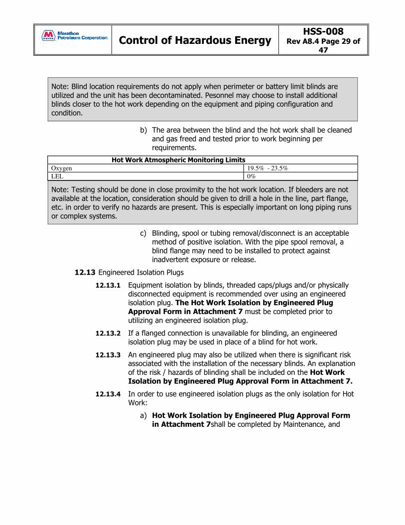
Note: Blind location requirements do not apply when perimeter or battery limit blinds are utilized and the unit has been decontaminated. Pesonnel may choose to install additional blinds closer to the hot work depending on the equipment and piping configuration and condition.
b) The area between the blind and the hot work shall be cleaned and gas freed and tested prior to work beginning per requirements.
Hot Work Atmospheric Monitoring Limits
Oxygen 19.5% - 23.5%
LEL 0%
Note: Testing should be done in close proximity to the hot work location. If bleeders are not available at the location, consideration should be given to drill a hole in the line, part flange, etc. in order to verify no hazards are present. This is especially important on long piping runs or complex systems.
c) Blinding, spool or tubing removal/disconnect is an acceptable method of positive isolation. With the pipe spool removal, a blind flange may need to be installed to protect against inadvertent exposure or release.
12.13 Engineered Isolation Plugs
12.13.1 Equipment isolation by blinds, threaded caps/plugs and/or physically disconnected equipment is recommended over using an engineered isolation plug. The Hot Work Isolation by Engineered Plug Approval Form in Attachment 7 must be completed prior to utilizing an engineered isolation plug.
12.13.2 If a flanged connection is unavailable for blinding, an engineered isolation plug may be used in place of a blind for hot work.
12.13.3 An engineered plug may also be utilized when there is significant risk associated with the installation of the necessary blinds. An explanation of the risk / hazards of blinding shall be included on the Hot Work Isolation by Engineered Plug Approval Form in Attachment 7.
12.13.4 In order to use engineered isolation plugs as the only isolation for Hot Work:
a) Hot Work Isolation by Engineered Plug Approval Form in Attachment 7shall be completed by Maintenance, and

Control of Hazardous Energy HSS-008
Rev A8.4 Page 30 of 47
b) Engineered isolation plugs must have two seals, and be designed and pressure rated for the potential pressure of the line (Important: The plug must also be applicable to the equipment service (e.g., liquid, vapor, corrosive, etc.)).
Note: Single sealing, sewer/plumbers plugs shall not be used for hot work
12.13.5 If a line cannot be made hydrocarbon free, the end of the line on which the hot work is to be performed shall be sealed with an Engineered plug.
12.13.6 The following precautions shall be in place before hot work begins:
a) The open end must be made hydrocarbon free and scale removed.
b) The engineered isolation plug shall be installed past the heat-affected zone to ensure that the hot work will not burn or melt the sealing surfaces of the plug.
c) Provisions shall be made for the continuous venting of any accumulation of gases or vapors to a safe location away from the hot work.
Note: When it is deemed necessary to establish a purge through the engineered isolation plug, the vent line shall be safely vented to assure a flow is maintained. The method of venting the purge shall be indicated on the Hot Work Isolation by Engineered Plug Approval Form in Attachment 7.
d) If applicable, the Engineered Isolation Plug shall be equipped with a means to monitor and verify the sealing pressure to ensure maintenance of the 100% positive pressure vapor barrier. Also, a means to monitor the buildup of pressure behind the plug is required to not exceed the plug specifications.
e) A flammable gas test shall be made around the plug as part of the permit
f) The location of the engineered isolation plug must be tagged with a blind tag and entered into the corresponding energy isolation and blind lists for the job.
g) The potential exists for engineered isolation plugs to be blown out of lines due to the buildup of pressure. Always work to one side of an inserted plug, never work in front of the plug.
h) Engineered isolation plugs used on lines containing flammable vapors shall not be left unattended past the end of the maintenance shift (work will continue until completed and system is sealed or blinded).

Control of Hazardous Energy HSS-008
Rev A8.4 Page 31 of 47
12.14 Isolation Points Listed on Multiple Isolation Plans
12.14.1 If an isolation point is listed on multiple isolation plans, then a separate lock from each isolation plan must be placed on the duplicate isolation point:
a. Only the lock for the completed task can be removed while leaving the active task’s isolation lock(s) in place.
b. When the final isolation plan is complete the final lock can be removed
Note: SIMOPS can occur when isolation points are shared.
12.15 Isolation outside of Unit Boundaries.
12.15.1 The department that “owns” the equipment shall assign a Qualified Isolation Authority to generate an isolation plan.
12.15.2 The equipment owner shall notify all affected areas.
12.16 Rotating Equipment and Driver Isolations.
12.16.1 In situations where rotating equipment (e.g. pumps, compressors, etc.) needs to be uncoupled, it shall have the driver and pump side isolated during the uncoupling task (see Isolation Requirements for Pumps and Turbines attachment)
12.17 Long Term Isolation
12.17.1 When placing equipment in long term isolation status (longer than 6 months but less than 12 months) the following shall be reviewed:
The person responsible for the planning (e.g. Operation Specialist, Project Planner etc.) of the LTI shall email [email protected] listing the name of the person responsible for the work and notify the unit OMC
The unit Qualified Isolation Authority shall complete the following action items:
a. Review of equipment isolation and assure isolation integrity/safety or decide to air gap or demolish
b. Ensure relief valves still needs to be serviced routinely (same as if in service) and
c. Consult PEI on inspection frequency and
d. PSI and PSM documents may require updates reflective of status (if applicable contact PSM)

Control of Hazardous Energy HSS-008
Rev A8.4 Page 32 of 47
12.18 Mothballed (idled)
12.18.1 When placing Equipment isolations systems in mothballed status isolation lasting longer than twelve (12) months the following is required:
The person responsible for the planning (e.g. Operation Specialist, Project Planner etc.) of the LTI shall email [email protected] listing the name of the person responsible for the work and notify the unit OMC
Complete MOC
The unit Qualified Isolation Authority shall complete the following action items:
a. Set review every 5 years to revalidate the equipment isolation and assure integrity/safety or decide to air gap or demolish.
b. Ensure all relief valves maintain routine service (same as if in service).
c. Consult PEI on inspection frequency.
d. Ensure the PSI/PSM documents are updated to reflect the current equipment status.
12.19 Returning Equipment to Service
12.19.1 When the task is completed on isolated equipment, the Permit Receiver shall have all the Affected Workers remove their personal locks from the LOTO device and terminate the work permit with the Qualified Isolation Authority.
12.19.2 The Qualified Isolation Authority will verify:
a. That tasks are completed and that no permits are active for the isolated equipment.
b. The Affected Worker’s lock have been removed.
Equipment cannot be returned to service while any Affected Workers lock is still on the LOTO device.
Note: If personnel have failed to remove their lock a Non-Standard Removal of Locks
form shall be completed.
c. During de-isolation, ensure that all locked open and closed valves are returned to their normal state and any plant safety-critical systems that were bypassed or disabled have been restored to their normal condition.
d. When the system is back in service, the Qualified Isolation Authority and another Qualified Isolation Authority shall sign the isolation plan as complete.
e. The completed EIL and Isolation Plan must then be placed in
the permit package for delivery to the OMC so that they can be
retained.
Control of Hazardous Energy HSS-008
Rev A8.4 Page 33 of 47
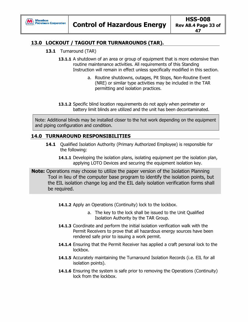
13.0 LOCKOUT / TAGOUT FOR TURNAROUNDS (TAR).
13.1 Turnaround (TAR)
13.1.1 A shutdown of an area or group of equipment that is more extensive than routine maintenance activities. All requirements of this Standing Instruction will remain in effect unless specifically modified in this section.
a. Routine shutdowns, outages, Pit Stops, Non-Routine Event (NRE) or similar type activities may be included in the TAR permitting and isolation practices.
13.1.2 Specific blind location requirements do not apply when perimeter or battery limit blinds are utilized and the unit has been decontaminated.
Note: Additional blinds may be installed closer to the hot work depending on the equipment and piping configuration and condition.
14.0 TURNAROUND RESPONSIBILITIES
14.1 Qualified Isolation Authority (Primary Authorized Employee) is responsible for the following:
14.1.1 Developing the isolation plans, isolating equipment per the isolation plan, applying LOTO Devices and securing the equipment isolation key.
Note: Operations may choose to utilize the paper version of the Isolation Planning Tool in lieu of the computer base program to identify the isolation points, but the EIL isolation change log and the EIL daily isolation verification forms shall be required.
14.1.2 Apply an Operations (Continuity) lock to the lockbox.
a. The key to the lock shall be issued to the Unit Qualified Isolation Authority by the TAR Group.
14.1.3 Coordinate and perform the initial isolation verification walk with the Permit Receivers to prove that all hazardous energy sources have been rendered safe prior to issuing a work permit.
14.1.4 Ensuring that the Permit Receiver has applied a craft personal lock to the lockbox.
14.1.5 Accurately maintaining the Turnaround Isolation Records (i.e. EIL for all isolation points).
14.1.6 Ensuring the system is safe prior to removing the Operations (Continuity) lock from the lockbox.

Control of Hazardous Energy HSS-008
Rev A8.4 Page 34 of 47
14.1.7 For in-test procedures, ensuring that no other work on the unit is
depending on the energy isolation devices to be removed or disabled during the procedure.
14.1.8 Ensuring that Affected/Authorized Employees maintain safe LOTO status throughout each job.
14.1.9 Reviewing the work for completion and verify the job site is in a clean and safe condition before signing the work permit as “Task Complete”.
14.1.10 Coordinating and documenting when the isolation needs to be changed / modified by completing the Isolation Change Log.
14.1.11 Participate in the Pre-Startup Safety Review (PSSR) process. This includes using a systematic method to verify all valves are in the proper position and all blinds have been removed/reinstalled as necessary before re-commissioning a system.
14.1.12 Ensure that all personnel are safely positioned or removed from the area prior to reinstating the equipment.
14.2 The LOTO Coordinator(s) is responsible for the following:
Note: If no LOTO Coordinator is assigned to the event then the Unit Qualified Isolation
Authority shall fulfill this role.
14.2.1 Maintains and controls work permits (active and closed)
14.2.2 Maintains the isolations lockboxes for their assigned areas.
14.2.3 Maintains a record of the installation and removal of energy isolation devices
14.2.4 Coordinates isolation changes with the Qualified Isolation Authority and maintenance personnel
14.3 Permit Receiver (Principal Authorized Employee) is responsible for the following:
14.3.1 Implement and Coordinate the energy control procedures with Qualified Isolation Authority
14.3.2 Perform isolation verification steps with Qualified Isolation Authority and verify that the machine or equipment is isolated (de-energized) effectively from hazardous energy sources and rendered safe and
14.3.3 Communicate these steps with Affected/Authorized Employees and ensure they clearly understand the energy isolation for the work to be performed.
14.3.4 Sign the initial Shift Isolation Verification-form accepting the isolation for the equipment / system before work begins.
a. Signing the EIL is to be done after the initial isolation walk with Qualified Isolation Authority.
b. Once the initial sign off is complete the Permit Receiver is to verify that there has been no isolation change (via the

Control of Hazardous Energy HSS-008
Rev A8.4 Page 35 of 47
isolation change log and discussions with operations) and initial the EIL each shift prior to starting work.
14.3.5 Apply a craft lock to the lockbox that will represent the personal lock.
14.3.6 Obtain the signatures and initials of the Affected Worker(s) on the Master Tag “Accept” column and apply it to the craft personal lock.
14.3.7 Upon completion of the task or at the completion of their shift, ensure that each Affected Worker signsand intials the “Release” column of the Master Tag and have the crews personal lock removed from the lockbox, when the release column is not signed then a Non-Standard LOTO Removal form must be completed.
14.3.8 Reviewing the work for completion and verify the job site is in a clean and safe condition before signing the work permit as “Task Complete”.
14.3.9 Notifying the Permit Coordinator of the status of the task when it is completed or at the end of their shift.
a. If a Permit Coordinator is not assigned to the event then report the job status to the Unit Qualified Isolation Authority.
14.3.10 Affected Workers that choose to apply their own personal lock and individual lockout tags in lieu of signing the Master Tag are responsible for the following:
a. Removing individual locks and tags at the end of each shift or when the task is complete.
14.4 Affected Employee /Authorized Employees when using a Master Tag acknowledge:
14.4.1 They are fully aware and accept, using their signature and initials as personal locks and.
14.4.2 They fully comprehend the details of the job and the energy isolation devices that are actuated or put in place and
14.4.3 They fully understand and agree that the hazardous energy sources have been isolated and rendered safe and
14.4.4 They fully understand their right to verify isolation effectiveness of the hazardous energy source isolation and if they choose to verify each

Control of Hazardous Energy HSS-008
Rev A8.4 Page 36 of 47
hazardous energy source it must be done prior to signing of the master tag and before performing servicing or maintenance
15.0 TAR ISOLATION PROCEDURE
15.1 General
15.1.1 A lockbox isolation method is required for all TAR isolations unless the work that is to be performed has only one source of energy (i.e. one isolation point).
15.1.2 For a single energy source isolation the Qualified Isolation Authority and Affected Worker can apply their locks and tags directly on the isolation device.
15.1.3 Affected Worker become Authorized Employee if they are work on the isolated equipment.
15.2 Isolation Prep
15.2.1 Prior to the turnaround, Qualified Isolation Authority will prepare isolation records for all planned work. An EIL must be created for Plot Edge blinds, which will indicate isolation of energy sources from the unit.
15.2.2 Once the unit is in TAR conditions, the Operation Specialist (Ops Spec) shall verify these conditions exist before implementing the TAR Permit To Work (PTW) Process and TAR Lockbox methodology.
15.2.3 A Turnaround Isolation Record , must be developed for the Plot Edge lockboxes.Cold Work and Low Energy Hot Work tasks that requires an isolation may be permitted against the isolation record.
a. The permit shall reflect the EIL number as well as the number of the lockbox being used.
b. Although the Plot Edge isolation may be used for these activities, zero energy must still be demonstrated at the location of each job.
15.2.4 Each piece of equipment or system where a High Energy Hot Work or Confined Space Entry (CSE) task is to be performed shall have an EIL.
15.2.5 The EIL shall identify isolation devices that will be used to isolate the equipment or system.
15.2.6 The Qualified Isolation Authority shall isolate and ensure that the equipment or system has been rendered safe.
15.2.7 Place equipment isolation locks and tags on each isolation point identified on the EIL.
a. Bleeders and vents do not require locks but must be tagged.
Control of Hazardous Energy HSS-008
Rev A8.4 Page 37 of 47
15.2.8 The Qualified Isolation Authority shall place the key to the equipment lock
into a lockbox and apply a Operations (Continuity) lock and an Isolation Tag on the Lockbox.
a. The Qualified Isolation Authority may delegate the application of the Operations lock to the Permit Coordinator.
Note: The Operations lock shall be the first lock on the lockbox and the last lock off to ensure the integrity of the isolation.
15.2.9 The Permit Receiver shall ensure that a crew lock has been applied to the lockbox for the equipment that work is to be performed on or in.
15.2.10 The Qualified Isolation Authority shall perform an isolation walk with the Permit Receiver and prove that all hazardous energy sources have been rendered safe.
15.2.11 The Permit Receiver shall complete the TAR Shift Isolation Verification-form (located in DMS as an HSS 008 attachment).
a. This form is to be updated every shift.
15.2.12 The Qualified Isolation Authority shall authorize the Shift Isolation Verification form, via initialing next to the craft.
b. This is to be performed for each craft identified on the Shift Isolation Verification log.
15.2.13 Each Authorized Employee will be shown that the system that is to be worked on has achieved a zero energy state at their job location.
a. Each Authorized Employee assigned to the job shall be given the opportunity to walk the isolation points.
15.2.14 The Authorized Employee shall sign (or print) their name and initial the “Accept” column of the Master Tag.
Note: The Master Tag can only be used during a TAR Event.
a. By initialing the Master Tag the Affected Workers are agreeing that the isolation for the equipment and/or system they are to work on has been rendered safe of all hazardous energy sources.
b. The signature will serve as the personal LOTO device for all the Authorized Employees on the job and cannot be removed until all Authorized Employees, via initialing the “Release” column on the Master Tag.
15.2.15 The Permit Receiver shall attach a completed Master Tag on the Lockbox for the equipment or system they are to perform work on or in.

Control of Hazardous Energy HSS-008
Rev A8.4 Page 38 of 47
The Master Tag shall be secured to the lockbox via the crew’s personal lock.
15.3 Completion of the job
15.3.1 The Affected Workers shall release the equipment to the Permit Receiver by initialing the “Release” column on the Master Tag.
15.3.2 Once the Master Tag is signed by the Affected Workers then the craft personal lock can be removed from the Lockbox. This will release the equipment back to the Unit Qualified Isolation Authority.
15.3.3 Only when all of the work on equipment is completed and it is released by all Affected/Authorized Employees (via signatures on the EIL(s) and removal of personal lock(s) can the Qualified Isolation Authority open the lockbox and begin to remove their LOTO devices from the equipment or system.
15.4 Shift Change (hand over to on-coming shift)
15.4.1 The outgoing Affected Workers shall remove their LOTO devices prior to leaving the facility.
15.4.2 The oncoming Permit Receiver shall verify that no isolation changes have taken place during the last shift and sign off on the EIL isolation verification form.
15.4.3 The Affected Workers shall sign (or print) their name and initial the “Accept” column of the Master tag.
a. By initialing the Master Tag the Affected Workers are agreeing that zero energy has been proven and the isolation for the equipment and/or system they are to work on has been rendered safe of all hazardous energy sources.
15.4.4 The Permit Receiver shall ensure that a craft lock representing the Affected Workers and the Master Tag has been applied to the lockbox in order to isolate the key to the isolation locks.
a. This lock will serve as the Affected Workers LOTO device and cannot be removed until authorized by all of the Affected Workers, via initialing the “Release” column on the Master tag.
15.5 Shift Change (no hand over)
15.5.1 The Affected Workers shall sign/initial the release column on the Master Tag releasing the isolation to the Permit Receiver.
15.5.2 The Permit Receiver shall ensure that the crew’s personal lock and the Master Tag has been removed from the lockbox at the end of the shift.
15.5.3 The Operations lock must stay on the lockbox as it will be used to ensure the integrity of the isolation when no work is actively being performed.

Control of Hazardous Energy HSS-008
Rev A8.4 Page 39 of 47
16.0 TAR BLIND REMOVAL
16.1 Qualified Isolation Authority shall
16.1.1 Verify that all the work on the system /equipment is complete and there are no active work permits prior to authorizing the removal of a blind.
16.2 The Qualified Isolation Authority shall
16.2.1 Document the tag numbers on the work permit for the blinds that are to be removed.
a. For large isolations, the work permit may state “refer to EIL XXXX to identify blind tag number” and a copy of the EIL must be attached to the work permit.
The word “COPY” shall be written on the field EIL and initialed by the Qualified Isolation Authority.
A blind list may be used in lieu of the EIL as long as description, location and tag number are accurate.
16.2.2 Qualified Isolation Authority shall maintain the official EIL in the Permitting area (e.g. permit tent)
16.2.3 The Permit Receiver shall apply the crew’s personal lock and Master Tag to the Plot Edge lockboxes for this system prior to removing the blinds, as this is the isolation points for Cold Work and Low Energy Hot Work.
16.2.4 After the craft has completed maintenance and has removed the blind they shall submit the work permit, EIL (if applicable)
16.2.5 The Permit Receiver shall release the system to Qualified Isolation Authority by removing the crew’s LOTO devices once the crew has signed off of the Master Tag.
16.2.6 Operation shall perform a system walk to ensure the blinds have been removed, gaskets are in place and perform a flange integrity test (i.e. hammer test) complete the last section of the blind tag (yellow striped) and place the completed tag in the LOTO book with the completed isolation plan.
16.2.7 Once Qualified Isolation Authority has walked out the system, cancelled all TAR Shift Isolation Verification-form and terminated all work permits on that system/equipment then the Qualified Isolation Authority shall initial the reinstatement column on the EIL. This initial will indicate that the system has been returned to its normal status.
16.2.8 The TAR Group shall retain these documents for the LAR Safety Department for future auditing purposes.
17.0 ISOLATION CHANGES (TAR & ROUTINE)
17.1.1 A change in isolation is when there is any deviation in the system from what is written in the approved isolation plan. In the event of a change in the system or plan the following is required.

Control of Hazardous Energy HSS-008
Rev A8.4 Page 40 of 47
17.1.2 Any changes to the isolation must be coordinated through the unit
Qualified Isolation Authority and a second Qualified Isolation Authority or OSS.
17.1.3 Changes made to isolation points must be documented on the EIL Change Log.
17.1.4 The Qualified Isolation Authority and a second Qualified Isolation Authority or OSS are responsible for approving changes, via the EIL Change Log.
a. If the change in isolation requires a higher level of approval (example: change in Isolation Standard), approvals must be obtained and documented in the EIL Change Log in the Isolation Deviation Higher Level Approval section.
b. If an electrical isolation point needs to be changed then a Qualified Electrician shall change the electrical isolation points and shall note the change on the EIL Change Log
17.1.5 The Qualified Isolation Authority will notify all affected personnel in the area of the isolation change by temporarily suspending work and physically pulling all permits associated with the system where potential exposure exists.
a. The Affected Workers personal locks must be removed prior to making the change.
b. TAR: The Qualified Isolation Authority shall cancel all Shift Isolation Verification approvals by lining out the last available row and initialing and dating the “Cancel” column.
17.1.6 After the change is complete the Qualified Isolation Authority and the Permit Receiver shall walk out the isolation change(s) before reinstating work permits.
a. All Affected Workers shall apply their personal locks to the LOTO device and be shown zero energy on the equipment or system they are to work on. TAR: can utilize the Master Tag system
b. TAR: The Qualified Isolaton Authority shall resume the Shift Isolation Verification form by conducting a field verification walk with each craft.
18.0 TEMPORARY RELEASE OF LOTO
18.1 A temporary release shall be used when a piece of equipment that is being serviced under lockout/tagout must be temporarily energized for testing, positioning, steaming, rinsing, purging, etc.
18.1.1 The Qualified Isolation Authority shall:
Ensure all affected employees are aware of the temporary release and clear of the area by suspending their permits,
Ensure all Affected Worker’s locks/tags shall be removed from

Control of Hazardous Energy HSS-008
Rev A8.4 Page 41 of 47
all of the applicable lockboxes,
Ensure any item or equipment that could present a hazard during the re-energization is removed from the area.
Complete a Temporary Release Form and document the reason for the Temporary Release
Note: The Temporary Release Log shall be maintained with the Energy Isolation List
Remove Department locks, tags and keys from master lockbox,
Remove equipment isolation locks/tags from those devices necessary for re-energization,
Apply a Temporary Release of LOTO tag with the operator lock after the isolation change providing a visual warning on the lockbox.
Work against the Temporay Release of LOTO may now commence.
After the task is complete, ensure the enery isolation devices are returned to their isolated position, and reapply equipment isolation locks and tags.
Test to verify that the equipment is isolated and de-energized by confirming zero energy status.
Sign the Temporary Release of LOTO tag and reapply the Operations Department lock to the lockbox, and
Sign and date the Isolation Restored section of the Status Change/Temporary Release Log.
18.1.2 The Operations Shift Foreman shall:
Verify the condition of the isolation and co-sign the Temporary Release of LOTO for and tag.
18.1.2.a.1 This is for pre and post isolation change.
18.1.3 After the temporary release has been performed, the Qualified Isolation Authority and the Permit Reciever shall:
Verify that equipment is isolated and de-energized, and
Install required personal locks and tags on the appropriate lockboxes.
18.1.4 Exceptions:
Temporary release requirements do not apply to the hot alignment of pumps when the warm up lines are used and all other energy sources for the pump remain isolated.
Control of Hazardous Energy HSS-008
Rev A8.4 Page 42 of 47
An operating procedure may be used in lieu of the temporary release form to document actions followed during the testing of equipment. The operating procedure must contain the following steps:
18.1.4.a.1 Prior to testing:
o Verify equipment is intact and non-essential items have been removed from the work area, and
o Verify all workers have removed their lock and tag and are clear of the equipment.
18.1.4.a.2 After testing is complete and prior to allowing work to resume:
o Re-apply and verify proper energy isolation, and
o Verify the equipment is adequately de-energized and de-pressured.
19.0 NON-STANDARD REMOVAL OF ISOLATION LOCKS
19.1.1 If the need to forcefully remove an isolation lock is a result of an emergency then the Incident Commander and Safety Officer shall document the decision to remove the isolation lock on the Non-Standard Lock Removal Form (located in DMS as an HSS 008 attachment).
19.1.2 During a non-emergency event; the OSS is the only person authorized to forcefully remove locks that were applied by another person or unit (e.g. equipment, unit or personal locks).
a. If there is a specific hazard present (e.g. electrical hazard) then the OSS shall have the appropriate / qualified individual perform this task, after it has been risk assessed and deemed safe.
19.1.3 Prior to the removal of any isolation lock the Operations Shift Supervisor (OSS) and the Maintenance Supervisor or if the lock is owned by a contractor then a contractor Foreman (for that company and craft) shall complete the Non-Standard Lock Removal form.
a. In the event that the lock that is to be cut has been applied to a system or lockbox that maintenance has not worked on (e.g. isolated but then the job was postponed) then the Maintenance Supervisor /Contractor Foreman’s signature is not required after OSS has verified no work has been performed.

Control of Hazardous Energy HSS-008
Rev A8.4 Page 43 of 47
19.1.4 The OSS shall distribute the copies of the Non-Standard Lock Removal
form to the other signers and keep the original for a minimum of 1 year to date.
19.1.5 It is the responsibility of the OSS, Maintenance Supervisor or the contractor’s foreman to notify the individual that their lock has been forcefully removed.
a. In the event that it is a department lock or an equipment lock then the OSS / Maintenance Supervisor shall communicate this action to their department.
20.0 TRAINING
20.1 General Requirements
20.1.1 Only trained personnel are authorized to lockout/tagout machines, equipment or processes to perform servicing or maintenance activities on that system.
20.1.2 Training shall be provided prior to assignment to ensure that the knowledge and skills required for the safe application, use, and removal of energy controls are acquired.
20.1.3 Competency requirements shall include a hands-on component or demonstration of LOTO application and testing.
20.2 Training Program Requirements
20.2.1 The LOTO training program shall address, at a minimum, the following:
20.2.2 The purpose and function of the energy control program;
20.2.3 The elements of the energy control procedures relevant to the employee duties; and
20.2.4 The pertinent requirements and prohibitions of this and other applicable LOTO procedures.
20.3 Authorized Employee Training
20.3.1 Authorized employees shall receive training in the applicable aspects of the energy control procedures and its proper utilization, together with

Control of Hazardous Energy HSS-008
Rev A8.4 Page 44 of 47
training in the recognition and understanding of all applicable hazardous energy sources;
20.3.2 Type and magnitude of the hazardous energy sources associated with machinery or equipment on which they will perform servicing or maintenance; and
20.3.3 Energy control procedures, including the methods and means to isolate and control relevant energy sources.
20.4 Affected Employee Training
20.4.1 Affected employees shall be trained to:
20.4.2 Recognize LOTO devices immediately;
20.4.3 Recognize when the energy control procedure is being used;
20.4.4 Understand the purpose and use of the procedure; and
20.4.5 Understand the importance of not tampering with LOTO devices.
20.5 Contractor Training
20.5.1 The responsibility of training outside contractor employees of the requirements of the hazardous energy control program lies with the contractor employer.
20.6 Refresher Training
20.6.1 Refresher training will be required every 3 years and whenever:
a. There is a significant change in job assignments, machines, equipment, or processes that presents a new hazard;
b. There is a significant change in the energy control program;
c. There is a significant change in the energy control procedures or revision of control methods; or
d. Periodic audits reveal there are deviations from the procedures or inadequacies in the employee’s knowledge or use of energy control procedures.
Control of Hazardous Energy HSS-008
Rev A8.4 Page 45 of 47
e. Refresher training shall include a hands-on component or
demonstration of LOTO application and testing if employee’s knowledge or auditing of LOTO program demonstrates deficiencies in these areas.
20.6.2 Training Records shall be retained for the current year plus 10 years.
21.0 PROCEDURE CHANGES
21.1 Revisions
21.1.1 Any modification of the Control of Hazardous Energy Procedure or the applicable forms or tags constitutes a change and the Management of Change Policy and initiated.
22.0 AUDITING
22.1 LOTO procedures:
22.1.1 Shall be audited at least annually by the Safety Department via Active Task Hazard Assessments during the TAR. Additional reviews may be done by Operating and Maintenance supervision during their Active Task Hazard Assessments.
22.2 Periodic Inspection
22.2.1 On a quarterly basis, the energy control procedures (isolation lists, shutdown procedures, lockout/tagout checklists) shall be inspected to determine:
a. Effectiveness of the energy control procedure for complete isolation of the equipment
b. Compliance with the requirements of this standard and the applicable regulations
c. Understanding and comprehension of the employees utilizing the lockout/tagout and energy isolation methods
22.2.2 Periodic inspections must include a demonstration of the procedures and must be performed while work is being performed on machines or equipment.
22.2.3 The periodic inspection may be satisfied if based upon a statistically-representative sample of energy control procedures.
22.2.4 The periodic inspection will be conducted by the area safety coordinators; OSS’s, MTL’s, Qualified Isolation Authority and/or safety teams may conduct additional audits as needed. Periodic inspections may be done more frequently as needed.

Control of Hazardous Energy HSS-008
Rev A8.4 Page 46 of 47
22.2.5 The periodic inspection shall be documented submitted to LAR Safety
Department for review and filing.
22.2.6 Audit results shall be retained for the current year plus 3 years.
22.3 Annual Audit
22.3.1 On an annual basis, a representative or team of representatives from the EH&S department shall audit this process to determine if the program, and elements of the program are effective and compliant with the requirements of the applicable regulations and standards.
22.3.2 This audit shall be documented as applicable (report or checklist form), but the audit must review the following elements:
a. Training & Communications
b. Applicable procedures
c. Lockout/Tagout devices and hardware
d. Energy Isolation devices
e. Contractor compliance
22.3.3 The completed audit report shall be reviewed by the LAR EH&S Manager
22.3.4 All employees and contractors that are required to work under energy isolation or participate in lockout/tagout procedures shall receive training to include the contents of this procedure. Training will include the purpose and use of LAR forms, tags and locks used for lockout/tagout. Specific TAR LOTO Refresher training will be done with effected workers prior to a unit utilizing the TAR LOTO procedure. Contract employees will receive TAR LOTO training as part of TAR HSE Training.
22.3.5 A record of LAR personnel trained must be submitted to the Learning and Development Group along with a copy of the training material.

Control of Hazardous Energy HSS-008
Rev A8.4 Page 47 of 47
23.0 REVISION LOG
Title & Procedure Number:
HSS-008 Control of Hazardous Energy
Author/Owner: Rinaldo Edmonson/
Brian Quinn Approver: Mike Kulakowski
Reviewed By: Policy & Procedure
Committee Document Administrator:
D. R. Cannon
Issuing Department:
Safety Issue Date: 3/26/2019
Revision Date: 04/28/2020 Next Review Date: 3/26/2022
Revision (s)
The following procedure is an integration of LAR–W SAF 008 Control of Hazardous Energy & SAF Blinding
064 and LAR-C Equipment Isolation 800 series and all associated child documents into the new standing instruction HSS 008 Control of Hazardous Energy and has been updated in DMS., this instruction
complies with OSHA, Cal OSHA regulations, Tesoro Corporate Policy and industry standard.