
Cram goes to trial next year for 2011 murder - Internet Archive
Upload
khangminh22Category
view
1download
0

CompTIA® Network+ N10-008
Exam Cram
Emmett Dulaney
A01_Dulaney_FM_pi-xxxiv.indd 1 17/07/21 3:10 PM

CompTIA® Network+ N10-008 Exam CramCopyright © 2022 by Pearson Education, Inc.All rights reserved. No part of this book shall be reproduced, stored in a retrieval system, or transmitted by any means, electronic, mechanical, photocopying, recording, or otherwise, without written permission from the publisher. No patent liability is assumed with respect to the use of the infor-mation contained herein. Although every precaution has been taken in the preparation of this book, the publisher and author assume no responsibility for errors or omissions. Nor is any liability assumed for damages resulting from the use of the information contained herein.
ISBN-13: 978-0-13-737576-9ISBN-10: 0-13-737576-X
ScoutAutomatedPrintCode
TrademarksAll terms mentioned in this book that are known to be trademarks or service marks have been appropriately capitalized. Pearson IT Certification cannot attest to the accuracy of this information. Use of a term in this book should not be regarded as affecting the validity of any trademark or service mark.
Warning and DisclaimerEvery effort has been made to make this book as complete and as accurate as possible, but no warranty or fitness is implied. The information provided is on an “as is” basis. The author and the publisher shall have neither liability nor responsibility to any person or entity with respect to any loss or dam-ages arising from the information contained in this book.
Special SalesFor information about buying this title in bulk quantities, or for special sales opportunities (which may include electronic versions; custom cover designs; and content particular to your business, training goals, marketing focus, or branding interests), please contact our corporate sales department at [email protected] or (800) 382-3419.For government sales inquiries, please contact [email protected] questions about sales outside the U.S., please contact [email protected].
Editor-in-ChiefMark Taub
Director ITP Production ManagementBrett Bartow
Executive EditorNancy Davis
Development EditorEllie Bru
Managing EditorSandra Schroeder
Senior Project EditorTonya Simpson
Copy EditorChuck Hutchinson
IndexerTimothy Wright
ProofreaderAbigail Manheim
Technical EditorChris Crayton
Publishing CoordinatorCindy Teeters
Cover DesignerChuti Prasertsith
CompositorcodeMantra
A01_Dulaney_FM_pi-xxxiv.indd 2 17/07/21 3:10 PM

Contents at a Glance Introduction xxiii
CHAPTER 1 Network Technologies, Topologies, and Types 1
CHAPTER 2 Models, Ports, Protocols, and Network Services 41
CHAPTER 3 Addressing, Routing, and Switching 93
CHAPTER 4 Network Implementations 151
CHAPTER 5 Cabling Solutions and Issues 183
CHAPTER 6 Wireless Solutions and Issues 235
CHAPTER 7 Cloud Computing Concepts and Options 269
CHAPTER 8 Network Operations 283
CHAPTER 9 Network Security 343
CHAPTER 10 Network Troubleshooting 403
Glossary 461
Index 511
A01_Dulaney_FM_pi-xxxiv_new.indd 3 19/07/21 2:20 PM

Table of ContentsIntroduction . . . . . . . . . . . . . . . . . . . . . . . . . . . . . . . . . . . . . . . . . . . . xxiii
CHAPTER 1: Network Technologies, Topologies, and Types . . . . . . . . . . . . . . . . . . . . . 1
Wired and Wireless Network Topologies . . . . . . . . . . . . . . . . . . . . . . . 2Bus Topology . . . . . . . . . . . . . . . . . . . . . . . . . . . . . . . . . . . . . . 2Ring Topology . . . . . . . . . . . . . . . . . . . . . . . . . . . . . . . . . . . . . 3Star Topology (Hub-and-Spoke) . . . . . . . . . . . . . . . . . . . . . . . . . 5Mesh Topology . . . . . . . . . . . . . . . . . . . . . . . . . . . . . . . . . . . . 6Hybrid Topology . . . . . . . . . . . . . . . . . . . . . . . . . . . . . . . . . . . 7Bringing Wireless to a Topology . . . . . . . . . . . . . . . . . . . . . . . . 8
Infrastructure Wireless Topology . . . . . . . . . . . . . . . . . . . . 8Ad Hoc Wireless Topology . . . . . . . . . . . . . . . . . . . . . . . . 9Wireless Mesh Topology . . . . . . . . . . . . . . . . . . . . . . . . . 10
Network Types and Characteristics . . . . . . . . . . . . . . . . . . . . . . . . . . 14To Server or Not . . . . . . . . . . . . . . . . . . . . . . . . . . . . . . . . . . 14LANs . . . . . . . . . . . . . . . . . . . . . . . . . . . . . . . . . . . . . . . . . . 15WLANs . . . . . . . . . . . . . . . . . . . . . . . . . . . . . . . . . . . . . . . . 15WANs . . . . . . . . . . . . . . . . . . . . . . . . . . . . . . . . . . . . . . . . . 16MANs . . . . . . . . . . . . . . . . . . . . . . . . . . . . . . . . . . . . . . . . . 16CANs . . . . . . . . . . . . . . . . . . . . . . . . . . . . . . . . . . . . . . . . . . 17SANs . . . . . . . . . . . . . . . . . . . . . . . . . . . . . . . . . . . . . . . . . . 17PANs . . . . . . . . . . . . . . . . . . . . . . . . . . . . . . . . . . . . . . . . . . 17SDWANs . . . . . . . . . . . . . . . . . . . . . . . . . . . . . . . . . . . . . . . 18MPLS . . . . . . . . . . . . . . . . . . . . . . . . . . . . . . . . . . . . . . . . . . 18mGRE . . . . . . . . . . . . . . . . . . . . . . . . . . . . . . . . . . . . . . . . . 19
Network Links and Concepts . . . . . . . . . . . . . . . . . . . . . . . . . . . . . . 22DSL Internet Access . . . . . . . . . . . . . . . . . . . . . . . . . . . . . . . . 23Cable Broadband . . . . . . . . . . . . . . . . . . . . . . . . . . . . . . . . . . 25The Public Switched Telephone Network . . . . . . . . . . . . . . . . . 26Leased Lines . . . . . . . . . . . . . . . . . . . . . . . . . . . . . . . . . . . . . 27
T3 Lines . . . . . . . . . . . . . . . . . . . . . . . . . . . . . . . . . . . . 28Metro-Optical . . . . . . . . . . . . . . . . . . . . . . . . . . . . . . . . . . . . 29Satellite Internet Access . . . . . . . . . . . . . . . . . . . . . . . . . . . . . 31Termination Points . . . . . . . . . . . . . . . . . . . . . . . . . . . . . . . . . 32
Demarc, Demarc Extension, and Smart Jacks . . . . . . . . . . . 32CSUs/DSUs . . . . . . . . . . . . . . . . . . . . . . . . . . . . . . . . . 34
A01_Dulaney_FM_pi-xxxiv_new.indd 4 19/07/21 2:20 PM

Contentsv
Verify Wiring Installation and Termination . . . . . . . . . . . . 34Virtual Networking . . . . . . . . . . . . . . . . . . . . . . . . . . . . . . . . 34
What’s Next? . . . . . . . . . . . . . . . . . . . . . . . . . . . . . . . . . . . . . . . . . 39
CHAPTER 2: Models, Ports, Protocols, and Network Services . . . . . . . . . . . . . . . . . . . 41
The OSI Networking Model . . . . . . . . . . . . . . . . . . . . . . . . . . . . . . 42The OSI Seven-Layer Model . . . . . . . . . . . . . . . . . . . . . . . . . . 42
Physical Layer (Layer 1) . . . . . . . . . . . . . . . . . . . . . . . . . 43Data Link Layer (Layer 2). . . . . . . . . . . . . . . . . . . . . . . . 44Network Layer (Layer 3) . . . . . . . . . . . . . . . . . . . . . . . . 44Transport Layer (Layer 4) . . . . . . . . . . . . . . . . . . . . . . . . 45Session Layer (Layer 5) . . . . . . . . . . . . . . . . . . . . . . . . . . 46Presentation Layer (Layer 6) . . . . . . . . . . . . . . . . . . . . . . 46Application Layer (Layer 7) . . . . . . . . . . . . . . . . . . . . . . . 47OSI Model Summary . . . . . . . . . . . . . . . . . . . . . . . . . . . 47
Comparing OSI to the Four-Layer TCP/IP Model . . . . . . . . . . . 48Identifying the OSI Layers at Which Various Network
Components Operate . . . . . . . . . . . . . . . . . . . . . . . . . . . . . . 49Data Encapsulation/Decapsulation and OSI . . . . . . . . . . . . . . . . 49
Ports and Protocols . . . . . . . . . . . . . . . . . . . . . . . . . . . . . . . . . . . . . 53Connection-Oriented Protocols Versus Connectionless
Protocols. . . . . . . . . . . . . . . . . . . . . . . . . . . . . . . . . . . . . . . 54Internet Protocol . . . . . . . . . . . . . . . . . . . . . . . . . . . . . . . . . . 54Transmission Control Protocol . . . . . . . . . . . . . . . . . . . . . . . . 55
How TCP Works . . . . . . . . . . . . . . . . . . . . . . . . . . . . . . 56User Datagram Protocol . . . . . . . . . . . . . . . . . . . . . . . . . . . . . 56Internet Control Message Protocol . . . . . . . . . . . . . . . . . . . . . . 57IPSec . . . . . . . . . . . . . . . . . . . . . . . . . . . . . . . . . . . . . . . . . . 57Generic Routing Encapsulation . . . . . . . . . . . . . . . . . . . . . . . . 58File Transfer Protocol . . . . . . . . . . . . . . . . . . . . . . . . . . . . . . . 58Secure Shell . . . . . . . . . . . . . . . . . . . . . . . . . . . . . . . . . . . . . . 60Secure File Transfer Protocol . . . . . . . . . . . . . . . . . . . . . . . . . . 61Telnet . . . . . . . . . . . . . . . . . . . . . . . . . . . . . . . . . . . . . . . . . . 61Simple Mail Transfer Protocol . . . . . . . . . . . . . . . . . . . . . . . . . 62Domain Name System (DNS) . . . . . . . . . . . . . . . . . . . . . . . . . 62Dynamic Host Configuration Protocol (DHCP) . . . . . . . . . . . . 62Trivial File Transfer Protocol . . . . . . . . . . . . . . . . . . . . . . . . . . 63Hypertext Transfer Protocol . . . . . . . . . . . . . . . . . . . . . . . . . . 64
A01_Dulaney_FM_pi-xxxiv.indd 5 17/07/21 3:10 PM

vi
CompTIA Network+ N10-008 Exam Cram
Network Time Protocol (NTP) . . . . . . . . . . . . . . . . . . . . . . . . 64Post Office Protocol Version 3/Internet Message
Access Protocol Version 4 . . . . . . . . . . . . . . . . . . . . . . . . . . . 65Simple Network Management Protocol. . . . . . . . . . . . . . . . . . . 66
Components of SNMP . . . . . . . . . . . . . . . . . . . . . . . . . . 66SNMP Management Systems . . . . . . . . . . . . . . . . . . . . . 67SNMP Agents . . . . . . . . . . . . . . . . . . . . . . . . . . . . . . . . 67Management Information Bases . . . . . . . . . . . . . . . . . . . . 68SNMP Communities . . . . . . . . . . . . . . . . . . . . . . . . . . . 69SNMPv3 . . . . . . . . . . . . . . . . . . . . . . . . . . . . . . . . . . . 69
Lightweight Directory Access Protocol . . . . . . . . . . . . . . . . . . . 69Hypertext Transfer Protocol Secure . . . . . . . . . . . . . . . . . . . . . 70Server Message Block . . . . . . . . . . . . . . . . . . . . . . . . . . . . . . . 70Syslog . . . . . . . . . . . . . . . . . . . . . . . . . . . . . . . . . . . . . . . . . . 70SMTP TLS . . . . . . . . . . . . . . . . . . . . . . . . . . . . . . . . . . . . . . 71LDAPS . . . . . . . . . . . . . . . . . . . . . . . . . . . . . . . . . . . . . . . . . 71IMAP over SSL . . . . . . . . . . . . . . . . . . . . . . . . . . . . . . . . . . . 71POP3 over SSL . . . . . . . . . . . . . . . . . . . . . . . . . . . . . . . . . . . 71SQL, SQLnet, and MySQL . . . . . . . . . . . . . . . . . . . . . . . . . . . 71Remote Desktop Protocol . . . . . . . . . . . . . . . . . . . . . . . . . . . . 72Session Initiation Protocol . . . . . . . . . . . . . . . . . . . . . . . . . . . . 72Understanding Port Functions . . . . . . . . . . . . . . . . . . . . . . . . . 73
Network Services . . . . . . . . . . . . . . . . . . . . . . . . . . . . . . . . . . . . . . 78Domain Name Service (DNS) . . . . . . . . . . . . . . . . . . . . . . . . . 78The DNS Namespace . . . . . . . . . . . . . . . . . . . . . . . . . . . . . . . 81Types of DNS Entries . . . . . . . . . . . . . . . . . . . . . . . . . . . . . . . 83DNS Records . . . . . . . . . . . . . . . . . . . . . . . . . . . . . . . . . . . . 83DNS in a Practical Implementation . . . . . . . . . . . . . . . . . . . . . 85Dynamic Host Configuration Protocol . . . . . . . . . . . . . . . . . . . 86The DHCP Process . . . . . . . . . . . . . . . . . . . . . . . . . . . . . . . . 88DHCP and DNS Suffixes . . . . . . . . . . . . . . . . . . . . . . . . . . . . 89DHCP Relays and IP Helpers . . . . . . . . . . . . . . . . . . . . . . . . . 89Network Time Protocol . . . . . . . . . . . . . . . . . . . . . . . . . . . . . 89
What’s Next? . . . . . . . . . . . . . . . . . . . . . . . . . . . . . . . . . . . . . . . . . 92
CHAPTER 3: Addressing, Routing, and Switching . . . . . . . . . . . . . . . . . . . . . . . . . . . . 93
IP Addressing . . . . . . . . . . . . . . . . . . . . . . . . . . . . . . . . . . . . . . . . . 94IPv4 . . . . . . . . . . . . . . . . . . . . . . . . . . . . . . . . . . . . . . . . . . . 95IP Address Classes . . . . . . . . . . . . . . . . . . . . . . . . . . . . . . . . . 95
A01_Dulaney_FM_pi-xxxiv.indd 6 17/07/21 3:10 PM

Contentsvii
Subnet Mask Assignment . . . . . . . . . . . . . . . . . . . . . . . . . . . . . 97Subnetting . . . . . . . . . . . . . . . . . . . . . . . . . . . . . . . . . . . . . . . 97Identifying the Differences Between IPv4 Public and
Private Networks . . . . . . . . . . . . . . . . . . . . . . . . . . . . . . . . . 98Private Address Ranges . . . . . . . . . . . . . . . . . . . . . . . . . . 99
Classless Interdomain Routing . . . . . . . . . . . . . . . . . . . . . . . . . 100Default Gateways . . . . . . . . . . . . . . . . . . . . . . . . . . . . . . . . . . 100Virtual IP . . . . . . . . . . . . . . . . . . . . . . . . . . . . . . . . . . . . . . . 102IPv4 Address Types . . . . . . . . . . . . . . . . . . . . . . . . . . . . . . . . . 102
Unicast Address . . . . . . . . . . . . . . . . . . . . . . . . . . . . . . . 102Broadcast Address . . . . . . . . . . . . . . . . . . . . . . . . . . . . . 102Multicast . . . . . . . . . . . . . . . . . . . . . . . . . . . . . . . . . . . . 102
IPv6 Addressing . . . . . . . . . . . . . . . . . . . . . . . . . . . . . . . . . . . 103Where Have All the IPv4 Addresses Gone? . . . . . . . . . . . . 103Identifying IPv6 Addresses . . . . . . . . . . . . . . . . . . . . . . . 103IPv6 Address Types . . . . . . . . . . . . . . . . . . . . . . . . . . . . 105Global Unicast Addresses . . . . . . . . . . . . . . . . . . . . . . . . 105Link-Local Addresses . . . . . . . . . . . . . . . . . . . . . . . . . . . 106Site-Local Addresses . . . . . . . . . . . . . . . . . . . . . . . . . . . . 106Neighbor Discovery . . . . . . . . . . . . . . . . . . . . . . . . . . . . 107
Comparing IPv4 and IPv6 Addressing . . . . . . . . . . . . . . . . . . . . 107Assigning IP Addresses . . . . . . . . . . . . . . . . . . . . . . . . . . . . . . 108
Static Addressing . . . . . . . . . . . . . . . . . . . . . . . . . . . . . . 108Dynamic Addressing . . . . . . . . . . . . . . . . . . . . . . . . . . . . 108BOOT Protocol (BOOTP) . . . . . . . . . . . . . . . . . . . . . . . 111Automatic Private IP Addressing . . . . . . . . . . . . . . . . . . . 111
Identifying MAC Addresses . . . . . . . . . . . . . . . . . . . . . . . . . . . 112NAT and PAT . . . . . . . . . . . . . . . . . . . . . . . . . . . . . . . . . . . . 114
NAT . . . . . . . . . . . . . . . . . . . . . . . . . . . . . . . . . . . . . . 114PAT . . . . . . . . . . . . . . . . . . . . . . . . . . . . . . . . . . . . . . . 115SNAT. . . . . . . . . . . . . . . . . . . . . . . . . . . . . . . . . . . . . . 116DNAT . . . . . . . . . . . . . . . . . . . . . . . . . . . . . . . . . . . . . 116
Managing Routing and Switching . . . . . . . . . . . . . . . . . . . . . . . . . . . 120The Default Gateway . . . . . . . . . . . . . . . . . . . . . . . . . . . . . . . 120Routing Tables . . . . . . . . . . . . . . . . . . . . . . . . . . . . . . . . . . . . 121Static Routing . . . . . . . . . . . . . . . . . . . . . . . . . . . . . . . . . . . . 122Default Route . . . . . . . . . . . . . . . . . . . . . . . . . . . . . . . . . . . . 123Switching Methods . . . . . . . . . . . . . . . . . . . . . . . . . . . . . . . . . 123
A01_Dulaney_FM_pi-xxxiv.indd 7 17/07/21 3:10 PM

viii
CompTIA Network+ N10-008 Exam Cram
Packet Switching . . . . . . . . . . . . . . . . . . . . . . . . . . . . . . 123Circuit Switching . . . . . . . . . . . . . . . . . . . . . . . . . . . . . . 124Comparing Switching Methods . . . . . . . . . . . . . . . . . . . . 125
Dynamic Routing . . . . . . . . . . . . . . . . . . . . . . . . . . . . . . . . . . 126Distance-Vector Routing . . . . . . . . . . . . . . . . . . . . . . . . . 126Link-State Routing . . . . . . . . . . . . . . . . . . . . . . . . . . . . 129Hybrid Routing Protocols . . . . . . . . . . . . . . . . . . . . . . . . 130
Network Traffic . . . . . . . . . . . . . . . . . . . . . . . . . . . . . . . . . . . 130Routing Metrics . . . . . . . . . . . . . . . . . . . . . . . . . . . . . . . . . . . 133Virtual Local-Area Networks . . . . . . . . . . . . . . . . . . . . . . . . . . 133
VLAN Membership . . . . . . . . . . . . . . . . . . . . . . . . . . . . 135VLAN Segmentation . . . . . . . . . . . . . . . . . . . . . . . . . . . 137
The Spanning Tree Protocol . . . . . . . . . . . . . . . . . . . . . . . . . . 138Interface Configuration and Switch Management . . . . . . . . . . . . 140MDI-X . . . . . . . . . . . . . . . . . . . . . . . . . . . . . . . . . . . . . . . . . 142Trunking . . . . . . . . . . . . . . . . . . . . . . . . . . . . . . . . . . . . . . . . 142Port Mirroring . . . . . . . . . . . . . . . . . . . . . . . . . . . . . . . . . . . . 142Port Authentication . . . . . . . . . . . . . . . . . . . . . . . . . . . . . . . . 143Power over Ethernet (PoE and PoE+) . . . . . . . . . . . . . . . . . . . . 143MAC Address Table . . . . . . . . . . . . . . . . . . . . . . . . . . . . . . . . 144Switch Management . . . . . . . . . . . . . . . . . . . . . . . . . . . . . . . . 144Managed and Unmanaged . . . . . . . . . . . . . . . . . . . . . . . . . . . . 144Quality of Service . . . . . . . . . . . . . . . . . . . . . . . . . . . . . . . . . . 145Traffic Shaping . . . . . . . . . . . . . . . . . . . . . . . . . . . . . . . . . . . 146Access Control Lists . . . . . . . . . . . . . . . . . . . . . . . . . . . . . . . . 146ARP and RARP . . . . . . . . . . . . . . . . . . . . . . . . . . . . . . . . . . . 147
What’s Next? . . . . . . . . . . . . . . . . . . . . . . . . . . . . . . . . . . . . . . . . . 150
CHAPTER 4: Network Implementations . . . . . . . . . . . . . . . . . . . . . . . . . . . . . . . . . . . 151
Common Networking Devices . . . . . . . . . . . . . . . . . . . . . . . . . . . . . 152Firewall . . . . . . . . . . . . . . . . . . . . . . . . . . . . . . . . . . . . . . . . . 153IDS/IPS . . . . . . . . . . . . . . . . . . . . . . . . . . . . . . . . . . . . . . . . 154Router . . . . . . . . . . . . . . . . . . . . . . . . . . . . . . . . . . . . . . . . . 155Switch . . . . . . . . . . . . . . . . . . . . . . . . . . . . . . . . . . . . . . . . . 157
Hub and Switch Cabling . . . . . . . . . . . . . . . . . . . . . . . . . 158Multilayer Switch . . . . . . . . . . . . . . . . . . . . . . . . . . . . . . . . . . 159Hub . . . . . . . . . . . . . . . . . . . . . . . . . . . . . . . . . . . . . . . . . . . 160
A01_Dulaney_FM_pi-xxxiv.indd 8 17/07/21 3:10 PM

Contentsix
Bridge . . . . . . . . . . . . . . . . . . . . . . . . . . . . . . . . . . . . . . . . . . 161DSL and Cable Modems . . . . . . . . . . . . . . . . . . . . . . . . . . . . . 161Access Point . . . . . . . . . . . . . . . . . . . . . . . . . . . . . . . . . . . . . 162Media Converter . . . . . . . . . . . . . . . . . . . . . . . . . . . . . . . . . . 163Voice Gateway . . . . . . . . . . . . . . . . . . . . . . . . . . . . . . . . . . . . 164Repeater . . . . . . . . . . . . . . . . . . . . . . . . . . . . . . . . . . . . . . . . 165Wireless LAN Controller . . . . . . . . . . . . . . . . . . . . . . . . . . . . 165Load Balancer . . . . . . . . . . . . . . . . . . . . . . . . . . . . . . . . . . . . 165Proxy Server . . . . . . . . . . . . . . . . . . . . . . . . . . . . . . . . . . . . . 166VPN Concentrators and Headends . . . . . . . . . . . . . . . . . . . . . . 168Networked Devices . . . . . . . . . . . . . . . . . . . . . . . . . . . . . . . . 168
Networking Architecture . . . . . . . . . . . . . . . . . . . . . . . . . . . . . . . . . 172Three-Tiered Architecture . . . . . . . . . . . . . . . . . . . . . . . . . . . 172
Core Layer . . . . . . . . . . . . . . . . . . . . . . . . . . . . . . . . . . 173Distribution/Aggregation Layer . . . . . . . . . . . . . . . . . . . . 173Access/Edge Layer . . . . . . . . . . . . . . . . . . . . . . . . . . . . . 174
Software-Defined Networking . . . . . . . . . . . . . . . . . . . . . . . . . 174Application Layer. . . . . . . . . . . . . . . . . . . . . . . . . . . . . . 174Control Layer . . . . . . . . . . . . . . . . . . . . . . . . . . . . . . . . 175Infrastructure Layer . . . . . . . . . . . . . . . . . . . . . . . . . . . . 175Management Plane . . . . . . . . . . . . . . . . . . . . . . . . . . . . . 175
Spine and Leaf . . . . . . . . . . . . . . . . . . . . . . . . . . . . . . . . . . . . 175Traffic Flows . . . . . . . . . . . . . . . . . . . . . . . . . . . . . . . . . . . . . 176Datacenter Location Types . . . . . . . . . . . . . . . . . . . . . . . . . . . 176Storage-Area Networks . . . . . . . . . . . . . . . . . . . . . . . . . . . . . . 177
iSCSI . . . . . . . . . . . . . . . . . . . . . . . . . . . . . . . . . . . . . . 178Fibre Channel and FCoE . . . . . . . . . . . . . . . . . . . . . . . . 178Network-Attached Storage . . . . . . . . . . . . . . . . . . . . . . . 179
What’s Next? . . . . . . . . . . . . . . . . . . . . . . . . . . . . . . . . . . . . . . . . . 181
CHAPTER 5: Cabling Solutions and Issues . . . . . . . . . . . . . . . . . . . . . . . . . . . . . . . . . 183
General Media Considerations . . . . . . . . . . . . . . . . . . . . . . . . . . . . . 184Broadband Versus Baseband Transmissions . . . . . . . . . . . . . . . . 185Simplex, Half-Duplex, and Full-Duplex Modes . . . . . . . . . . . . . 185Data Transmission Rates . . . . . . . . . . . . . . . . . . . . . . . . . . . . . 186Types of Network Media . . . . . . . . . . . . . . . . . . . . . . . . . . . . . 186
Twisted-Pair Cabling (Copper) . . . . . . . . . . . . . . . . . . . . 187Coaxial Cables . . . . . . . . . . . . . . . . . . . . . . . . . . . . . . . . 190
A01_Dulaney_FM_pi-xxxiv.indd 9 17/07/21 3:10 PM
x
CompTIA Network+ N10-008 Exam Cram
Twinaxial Cables . . . . . . . . . . . . . . . . . . . . . . . . . . . . . . 191Fiber-Optic Cables . . . . . . . . . . . . . . . . . . . . . . . . . . . . . 192Plenum Versus PVC Cables . . . . . . . . . . . . . . . . . . . . . . . 194
Types of Media Connectors . . . . . . . . . . . . . . . . . . . . . . . . . . . 194BNC Connectors . . . . . . . . . . . . . . . . . . . . . . . . . . . . . . 194RJ-11 Connectors . . . . . . . . . . . . . . . . . . . . . . . . . . . . . 195RJ-45 Connectors . . . . . . . . . . . . . . . . . . . . . . . . . . . . . 196F-Type Connectors and RG-59 and RG-6 Cables . . . . . . . 197Fiber Connectors . . . . . . . . . . . . . . . . . . . . . . . . . . . . . . 197Transceivers . . . . . . . . . . . . . . . . . . . . . . . . . . . . . . . . . 199
Media Couplers/Converters . . . . . . . . . . . . . . . . . . . . . . . . . . . 200TIA/EIA 568A and 568B Wiring Standards . . . . . . . . . . . . . . . . 200Straight-Through Versus Crossover Cables . . . . . . . . . . . . . . . . 201Rollover and Loopback Cables . . . . . . . . . . . . . . . . . . . . . . . . . 203Components of Wiring Distribution . . . . . . . . . . . . . . . . . . . . . 204
Network Cross-Connects . . . . . . . . . . . . . . . . . . . . . . . . 204Horizontal Cabling . . . . . . . . . . . . . . . . . . . . . . . . . . . . 205Vertical Cables . . . . . . . . . . . . . . . . . . . . . . . . . . . . . . . . 206Patch Panels . . . . . . . . . . . . . . . . . . . . . . . . . . . . . . . . . 207Fiber Distribution Panels . . . . . . . . . . . . . . . . . . . . . . . . 20866 and 110 Blocks (T568A, T568B) . . . . . . . . . . . . . . . . . 208MDF and IDF Wiring Closets . . . . . . . . . . . . . . . . . . . . . 209
Ethernet Copper and Fiber Standards . . . . . . . . . . . . . . . . . . . . 21010BASE-T . . . . . . . . . . . . . . . . . . . . . . . . . . . . . . . . . . 210100BASE-TX . . . . . . . . . . . . . . . . . . . . . . . . . . . . . . . . 2111000BASE-T . . . . . . . . . . . . . . . . . . . . . . . . . . . . . . . . . 21210GBASE-T . . . . . . . . . . . . . . . . . . . . . . . . . . . . . . . . . 21240GBASE-T . . . . . . . . . . . . . . . . . . . . . . . . . . . . . . . . . 2131000BASE-LX and 1000BASE-SX . . . . . . . . . . . . . . . . . . 21310GBASE-LR and 10GBASE-SR . . . . . . . . . . . . . . . . . . 214
Multiplexing Options . . . . . . . . . . . . . . . . . . . . . . . . . . . . . . . 214Troubleshooting Common Cable Connectivity Issues . . . . . . . . . . . . . 217Limitations, Considerations, and Issues . . . . . . . . . . . . . . . . . . . . . . . 218
Throughput, Speed, and Distance . . . . . . . . . . . . . . . . . . . . . . . 218Cabling Specifications/Limitations . . . . . . . . . . . . . . . . . . . . . . 220Cabling Considerations . . . . . . . . . . . . . . . . . . . . . . . . . . . . . . 220Cabling Applications . . . . . . . . . . . . . . . . . . . . . . . . . . . . . . . . 221Attenuation and dB Loss . . . . . . . . . . . . . . . . . . . . . . . . . . . . . 221Interference . . . . . . . . . . . . . . . . . . . . . . . . . . . . . . . . . . . . . . 222
A01_Dulaney_FM_pi-xxxiv.indd 10 17/07/21 3:10 PM
Contentsxi
Incorrect Pinout . . . . . . . . . . . . . . . . . . . . . . . . . . . . . . . . . . . 222Bad Ports . . . . . . . . . . . . . . . . . . . . . . . . . . . . . . . . . . . . . . . 223Open/Short . . . . . . . . . . . . . . . . . . . . . . . . . . . . . . . . . . . . . . 223LED Status Indicators . . . . . . . . . . . . . . . . . . . . . . . . . . . . . . 224Incorrect Transceivers . . . . . . . . . . . . . . . . . . . . . . . . . . . . . . . 224Duplexing Issues . . . . . . . . . . . . . . . . . . . . . . . . . . . . . . . . . . 224TX/RX Reversed . . . . . . . . . . . . . . . . . . . . . . . . . . . . . . . . . . 225Dirty Optical Cables . . . . . . . . . . . . . . . . . . . . . . . . . . . . . . . . 225
Common Tools . . . . . . . . . . . . . . . . . . . . . . . . . . . . . . . . . . . . . . . 226Cable Crimpers, Strippers, and Snips/Cutters . . . . . . . . . . . . . . 226Punchdown Tools . . . . . . . . . . . . . . . . . . . . . . . . . . . . . . . . . . 227Tone Generator . . . . . . . . . . . . . . . . . . . . . . . . . . . . . . . . . . . 228Loopback Adapter . . . . . . . . . . . . . . . . . . . . . . . . . . . . . . . . . 228OTDR . . . . . . . . . . . . . . . . . . . . . . . . . . . . . . . . . . . . . . . . . 229Multimeter . . . . . . . . . . . . . . . . . . . . . . . . . . . . . . . . . . . . . . 230Cable Tester . . . . . . . . . . . . . . . . . . . . . . . . . . . . . . . . . . . . . 230Wire Map . . . . . . . . . . . . . . . . . . . . . . . . . . . . . . . . . . . . . . . 231Tap . . . . . . . . . . . . . . . . . . . . . . . . . . . . . . . . . . . . . . . . . . . . 231Fusion Splicer . . . . . . . . . . . . . . . . . . . . . . . . . . . . . . . . . . . . 231Spectrum Analyzer . . . . . . . . . . . . . . . . . . . . . . . . . . . . . . . . . 231Fiber Light Meter . . . . . . . . . . . . . . . . . . . . . . . . . . . . . . . . . 232
What’s Next? . . . . . . . . . . . . . . . . . . . . . . . . . . . . . . . . . . . . . . . . . 234
CHAPTER 6: Wireless Solutions and Issues . . . . . . . . . . . . . . . . . . . . . . . . . . . . . . . . 235
Understanding Wireless Basics . . . . . . . . . . . . . . . . . . . . . . . . . . . . . 236Wireless Channels and Frequencies . . . . . . . . . . . . . . . . . . . . . 236Cellular Technology Access . . . . . . . . . . . . . . . . . . . . . . . . . . . 241Speed, Distance, and Bandwidth . . . . . . . . . . . . . . . . . . . . . . . . 241Channel Bonding . . . . . . . . . . . . . . . . . . . . . . . . . . . . . . . . . . 242MIMO/MU-MIMO/Directional/Omnidirectional . . . . . . . . . . . 243
Antenna Ratings . . . . . . . . . . . . . . . . . . . . . . . . . . . . . . 244Antenna Coverage . . . . . . . . . . . . . . . . . . . . . . . . . . . . . 244
Establishing Communications Between Wireless Devices . . . . . . 246Configuring the Wireless Connection . . . . . . . . . . . . . . . . . . . . 248
Troubleshooting Wireless Issues . . . . . . . . . . . . . . . . . . . . . . . . . . . . 257Site Surveys . . . . . . . . . . . . . . . . . . . . . . . . . . . . . . . . . . . . . . 262Factors Affecting Wireless Signals . . . . . . . . . . . . . . . . . . . . . . 262
A01_Dulaney_FM_pi-xxxiv.indd 11 17/07/21 3:10 PM

xii
CompTIA Network+ N10-008 Exam Cram
Interference. . . . . . . . . . . . . . . . . . . . . . . . . . . . . . . . . . 262Reflection, Refraction, and Absorption . . . . . . . . . . . . . . . 263
Troubleshooting AP Coverage . . . . . . . . . . . . . . . . . . . . . . . . . 264What’s Next? . . . . . . . . . . . . . . . . . . . . . . . . . . . . . . . . . . . . . . . . . 267
CHAPTER 7: Cloud Computing Concepts and Options . . . . . . . . . . . . . . . . . . . . . . . . 269
Cloud Concepts . . . . . . . . . . . . . . . . . . . . . . . . . . . . . . . . . . . . . . . 270Service Models . . . . . . . . . . . . . . . . . . . . . . . . . . . . . . . . . . . . 271Software as a Service . . . . . . . . . . . . . . . . . . . . . . . . . . . . . . . . 271Platform as a Service . . . . . . . . . . . . . . . . . . . . . . . . . . . . . . . . 272Infrastructure as a Service . . . . . . . . . . . . . . . . . . . . . . . . . . . . 273Desktop as a Service . . . . . . . . . . . . . . . . . . . . . . . . . . . . . . . . 274Deployment Models . . . . . . . . . . . . . . . . . . . . . . . . . . . . . . . . 275Private Cloud . . . . . . . . . . . . . . . . . . . . . . . . . . . . . . . . . . . . 275Public Cloud . . . . . . . . . . . . . . . . . . . . . . . . . . . . . . . . . . . . . 275Hybrid and Community Clouds . . . . . . . . . . . . . . . . . . . . . . . . 276Infrastructure as Code . . . . . . . . . . . . . . . . . . . . . . . . . . . . . . . 276Connectivity Options . . . . . . . . . . . . . . . . . . . . . . . . . . . . . . . 277Multitenancy . . . . . . . . . . . . . . . . . . . . . . . . . . . . . . . . . . . . . 278Elasticity . . . . . . . . . . . . . . . . . . . . . . . . . . . . . . . . . . . . . . . . 278Scalability . . . . . . . . . . . . . . . . . . . . . . . . . . . . . . . . . . . . . . . 278Security Implications . . . . . . . . . . . . . . . . . . . . . . . . . . . . . . . 278The Relationship Between Resources . . . . . . . . . . . . . . . . . . . . 279
What’s Next? . . . . . . . . . . . . . . . . . . . . . . . . . . . . . . . . . . . . . . . . . 281
CHAPTER 8: Network Operations. . . . . . . . . . . . . . . . . . . . . . . . . . . . . . . . . . . . . . . . 283
Organizational Documents and Policies . . . . . . . . . . . . . . . . . . . . . . . 284Wiring and Port Locations . . . . . . . . . . . . . . . . . . . . . . . . . . . 287
Troubleshooting Using Wiring Schematics . . . . . . . . . . . . 289Physical and Logical Network Diagrams . . . . . . . . . . . . . . . . . . 290Baseline Configurations . . . . . . . . . . . . . . . . . . . . . . . . . . . . . 293Policies, Procedures, Configurations, and Regulations . . . . . . . . . 295
Policies . . . . . . . . . . . . . . . . . . . . . . . . . . . . . . . . . . . . . 295Password-Related Policies . . . . . . . . . . . . . . . . . . . . . . . . 298Procedures . . . . . . . . . . . . . . . . . . . . . . . . . . . . . . . . . . 301Change Management Documentation . . . . . . . . . . . . . . . . 302Configuration Documentation . . . . . . . . . . . . . . . . . . . . . 303Regulations . . . . . . . . . . . . . . . . . . . . . . . . . . . . . . . . . . 303
A01_Dulaney_FM_pi-xxxiv.indd 12 17/07/21 3:10 PM

Contentsxiii
Labeling . . . . . . . . . . . . . . . . . . . . . . . . . . . . . . . . . . . . . . . . 304High Availability and Disaster Recovery . . . . . . . . . . . . . . . . . . . . . . 308
Backups . . . . . . . . . . . . . . . . . . . . . . . . . . . . . . . . . . . . . . . . 309Full Backups . . . . . . . . . . . . . . . . . . . . . . . . . . . . . . . . . 309Differential Backups . . . . . . . . . . . . . . . . . . . . . . . . . . . . 310Incremental Backups . . . . . . . . . . . . . . . . . . . . . . . . . . . 310Snapshots . . . . . . . . . . . . . . . . . . . . . . . . . . . . . . . . . . . 312
Backup Best Practices . . . . . . . . . . . . . . . . . . . . . . . . . . . . . . . 312Using Uninterruptible Power Supplies . . . . . . . . . . . . . . . . . . . 313
Why Use a UPS? . . . . . . . . . . . . . . . . . . . . . . . . . . . . . . 313Power Threats . . . . . . . . . . . . . . . . . . . . . . . . . . . . . . . . 313
Beyond the UPS . . . . . . . . . . . . . . . . . . . . . . . . . . . . . . . . . . 314Cold, Warm, Hot, and Cloud Sites . . . . . . . . . . . . . . . . . . . . . . 315High Availability and Recovery Concepts . . . . . . . . . . . . . . . . . 316Active-Active Versus Active-Passive . . . . . . . . . . . . . . . . . . . . . . 318
Monitoring Network Performance . . . . . . . . . . . . . . . . . . . . . . . . . . 323Common Performance Metrics . . . . . . . . . . . . . . . . . . . . . . . . 324SNMP Monitors . . . . . . . . . . . . . . . . . . . . . . . . . . . . . . . . . . 328
Management Information Base (MIB) . . . . . . . . . . . . . . . . 329Network Performance, Load, and Stress Testing . . . . . . . . . . . . . 329
Performance Tests . . . . . . . . . . . . . . . . . . . . . . . . . . . . . 330Load Tests and Send/Receive Traffic . . . . . . . . . . . . . . . . . 330Stress Tests . . . . . . . . . . . . . . . . . . . . . . . . . . . . . . . . . . 331Performance Metrics . . . . . . . . . . . . . . . . . . . . . . . . . . . 331
Network Device Logs . . . . . . . . . . . . . . . . . . . . . . . . . . . . . . . 332Security Logs . . . . . . . . . . . . . . . . . . . . . . . . . . . . . . . . 332Application Log . . . . . . . . . . . . . . . . . . . . . . . . . . . . . . . 334System Logs . . . . . . . . . . . . . . . . . . . . . . . . . . . . . . . . . 334History Logs . . . . . . . . . . . . . . . . . . . . . . . . . . . . . . . . . 335Log Management . . . . . . . . . . . . . . . . . . . . . . . . . . . . . . 335Patch Management . . . . . . . . . . . . . . . . . . . . . . . . . . . . 336
Environmental Factors . . . . . . . . . . . . . . . . . . . . . . . . . . . . . . 339What’s Next? . . . . . . . . . . . . . . . . . . . . . . . . . . . . . . . . . . . . . . . . . 342
CHAPTER 9: Network Security . . . . . . . . . . . . . . . . . . . . . . . . . . . . . . . . . . . . . . . . . . 343
Common Security Concepts . . . . . . . . . . . . . . . . . . . . . . . . . . . . . . 344Access Control . . . . . . . . . . . . . . . . . . . . . . . . . . . . . . . . . . . . 346Mandatory Access Control . . . . . . . . . . . . . . . . . . . . . . . . . . . . 346
A01_Dulaney_FM_pi-xxxiv.indd 13 17/07/21 3:10 PM

xiv
CompTIA Network+ N10-008 Exam Cram
Discretionary Access Control . . . . . . . . . . . . . . . . . . . . . . . . . . 346Rule-Based Access Control . . . . . . . . . . . . . . . . . . . . . . . . . . . 347Role-Based Access Control . . . . . . . . . . . . . . . . . . . . . . . . . . . 348Defense in Depth . . . . . . . . . . . . . . . . . . . . . . . . . . . . . . . . . . 349
Network Segmentation . . . . . . . . . . . . . . . . . . . . . . . . . . 349Screened Subnet . . . . . . . . . . . . . . . . . . . . . . . . . . . . . . 349
Separation of Duties . . . . . . . . . . . . . . . . . . . . . . . . . . . . . . . . 351Honeypots. . . . . . . . . . . . . . . . . . . . . . . . . . . . . . . . . . . . . . . 351RADIUS and TACACS+ . . . . . . . . . . . . . . . . . . . . . . . . . . . . . 352Kerberos Authentication . . . . . . . . . . . . . . . . . . . . . . . . . . . . . 353Local Authentication. . . . . . . . . . . . . . . . . . . . . . . . . . . . . . . . 355Lightweight Directory Access Protocol . . . . . . . . . . . . . . . . . . . 356Using Certificates . . . . . . . . . . . . . . . . . . . . . . . . . . . . . . . . . . 356Auditing and Logging . . . . . . . . . . . . . . . . . . . . . . . . . . . . . . . 357Multifactor Authentication Factors . . . . . . . . . . . . . . . . . . . . . . 357Additional Access Control Methods . . . . . . . . . . . . . . . . . . . . . 358
802.1X . . . . . . . . . . . . . . . . . . . . . . . . . . . . . . . . . . . . . 358Extensible Authentication Protocol (EAP) . . . . . . . . . . . . . 358Network Access Control (NAC) . . . . . . . . . . . . . . . . . . . . 359MAC Filtering . . . . . . . . . . . . . . . . . . . . . . . . . . . . . . . . 360
Risk Management . . . . . . . . . . . . . . . . . . . . . . . . . . . . . . . . . . 361Penetration Testing . . . . . . . . . . . . . . . . . . . . . . . . . . . . . . . . 361Security Information and Event Management . . . . . . . . . . . . . . 362
Common Networking Attacks . . . . . . . . . . . . . . . . . . . . . . . . . . . . . 365Denial-of-Service and Distributed Denial-of-Service Attacks . . . . 365
Types of DoS Attacks . . . . . . . . . . . . . . . . . . . . . . . . . . . 366Other Common Attacks . . . . . . . . . . . . . . . . . . . . . . . . . . . . . 368
Social Engineering . . . . . . . . . . . . . . . . . . . . . . . . . . . . . 368Logic Bomb . . . . . . . . . . . . . . . . . . . . . . . . . . . . . . . . . 368Rogue DHCP . . . . . . . . . . . . . . . . . . . . . . . . . . . . . . . . 369Rogue Access Points and Evil Twins . . . . . . . . . . . . . . . . . 369Advertising Wireless Weaknesses . . . . . . . . . . . . . . . . . . . 369Phishing . . . . . . . . . . . . . . . . . . . . . . . . . . . . . . . . . . . . 369Ransomware . . . . . . . . . . . . . . . . . . . . . . . . . . . . . . . . . 370DNS Poisoning . . . . . . . . . . . . . . . . . . . . . . . . . . . . . . . 370ARP Cache Poisoning . . . . . . . . . . . . . . . . . . . . . . . . . . 370Spoofing . . . . . . . . . . . . . . . . . . . . . . . . . . . . . . . . . . . . 370
A01_Dulaney_FM_pi-xxxiv.indd 14 17/07/21 3:10 PM
Contentsxv
Deauthentication . . . . . . . . . . . . . . . . . . . . . . . . . . . . . . 370Brute Force . . . . . . . . . . . . . . . . . . . . . . . . . . . . . . . . . . 371On-Path Attack . . . . . . . . . . . . . . . . . . . . . . . . . . . . . . . 371VLAN Hopping . . . . . . . . . . . . . . . . . . . . . . . . . . . . . . 371ARP Spoofing . . . . . . . . . . . . . . . . . . . . . . . . . . . . . . . . 372
Vulnerabilities and Prevention . . . . . . . . . . . . . . . . . . . . . . . . . 372Network Hardening and Physical Security . . . . . . . . . . . . . . . . . . . . . 377
Disposing of Assets . . . . . . . . . . . . . . . . . . . . . . . . . . . . . . . . . 379Implementing Physical Security . . . . . . . . . . . . . . . . . . . . . . . . 379
Lock and Key . . . . . . . . . . . . . . . . . . . . . . . . . . . . . . . . 380Swipe Card and PIN Access . . . . . . . . . . . . . . . . . . . . . . 381Biometrics . . . . . . . . . . . . . . . . . . . . . . . . . . . . . . . . . . . 381
Two-Factor and Multifactor Authentication . . . . . . . . . . . . . . . . 382Secured Versus Unsecured Protocols . . . . . . . . . . . . . . . . . . . . . 382Hardening Best Practices . . . . . . . . . . . . . . . . . . . . . . . . . . . . 384Wireless Security . . . . . . . . . . . . . . . . . . . . . . . . . . . . . . . . . . 387
MAC Filtering . . . . . . . . . . . . . . . . . . . . . . . . . . . . . . . . 388Antenna Placement and Power Levels . . . . . . . . . . . . . . . . 388Isolation . . . . . . . . . . . . . . . . . . . . . . . . . . . . . . . . . . . . 388Preshared Keys . . . . . . . . . . . . . . . . . . . . . . . . . . . . . . . 388Geofencing . . . . . . . . . . . . . . . . . . . . . . . . . . . . . . . . . . 389Captive Portal . . . . . . . . . . . . . . . . . . . . . . . . . . . . . . . . 390
IoT Access Considerations. . . . . . . . . . . . . . . . . . . . . . . . . . . . 390Remote-Access Methods . . . . . . . . . . . . . . . . . . . . . . . . . . . . . . . . . 392
Remote File Access . . . . . . . . . . . . . . . . . . . . . . . . . . . . . . . . . 394VPNs . . . . . . . . . . . . . . . . . . . . . . . . . . . . . . . . . . . . . . . . . . 394
Components of the VPN Connection . . . . . . . . . . . . . . . . 395VPN Connection Types . . . . . . . . . . . . . . . . . . . . . . . . . 396VPN Pros and Cons . . . . . . . . . . . . . . . . . . . . . . . . . . . . 396IPSec . . . . . . . . . . . . . . . . . . . . . . . . . . . . . . . . . . . . . . 397SSL/TLS/DTLS . . . . . . . . . . . . . . . . . . . . . . . . . . . . . . 398
Site-to-Site and Client-to-Site . . . . . . . . . . . . . . . . . . . . . . . . . 399Virtual Desktops . . . . . . . . . . . . . . . . . . . . . . . . . . . . . . . . . . 399HTTPS/Management URL . . . . . . . . . . . . . . . . . . . . . . . . . . 400Authentication and Authorization Considerations . . . . . . . . . . . . 400Out-of-Band Management. . . . . . . . . . . . . . . . . . . . . . . . . . . . 400
What’s Next? . . . . . . . . . . . . . . . . . . . . . . . . . . . . . . . . . . . . . . . . . 402
A01_Dulaney_FM_pi-xxxiv.indd 15 17/07/21 3:10 PM

xvi
CompTIA Network+ N10-008 Exam Cram
CHAPTER 10: Network Troubleshooting . . . . . . . . . . . . . . . . . . . . . . . . . . . . . . . . . . . . 403
Troubleshooting Steps and Procedures . . . . . . . . . . . . . . . . . . . . . . . 404Identify the Problem . . . . . . . . . . . . . . . . . . . . . . . . . . . . . . . . 405
Identify Symptoms . . . . . . . . . . . . . . . . . . . . . . . . . . . . . 406Determine Whether Anything Has Changed . . . . . . . . . . . 406Duplicate the Problem if Possible . . . . . . . . . . . . . . . . . . 407Approach Multiple Problems Individually . . . . . . . . . . . . . 407
Establish a Theory of Probable Cause . . . . . . . . . . . . . . . . . . . . 407Test the Theory to Determine the Cause . . . . . . . . . . . . . . . . . . 408Establish a Plan of Action . . . . . . . . . . . . . . . . . . . . . . . . . . . . 408Implement the Solution or Escalate . . . . . . . . . . . . . . . . . . . . . 409
Determine Whether Escalation Is Necessary . . . . . . . . . . . 409Verify Full System Functionality . . . . . . . . . . . . . . . . . . . . . . . 410Document Findings, Actions, Outcomes, and Lessons . . . . . . . . . 411
Software Troubleshooting Tools . . . . . . . . . . . . . . . . . . . . . . . . . . . . 414Wi-Fi Analyzer . . . . . . . . . . . . . . . . . . . . . . . . . . . . . . . . . . . 415Protocol Analyzer . . . . . . . . . . . . . . . . . . . . . . . . . . . . . . . . . . 415Bandwidth Speed Tester . . . . . . . . . . . . . . . . . . . . . . . . . . . . . 416Port Scanner . . . . . . . . . . . . . . . . . . . . . . . . . . . . . . . . . . . . . 416iperf . . . . . . . . . . . . . . . . . . . . . . . . . . . . . . . . . . . . . . . . . . . 418NetFlow Analyzer . . . . . . . . . . . . . . . . . . . . . . . . . . . . . . . . . 419TFTP Server . . . . . . . . . . . . . . . . . . . . . . . . . . . . . . . . . . . . . 419Terminal Emulator . . . . . . . . . . . . . . . . . . . . . . . . . . . . . . . . . 419IP Scanner . . . . . . . . . . . . . . . . . . . . . . . . . . . . . . . . . . . . . . 419Command-Line Tools . . . . . . . . . . . . . . . . . . . . . . . . . . . . . . . 420The Trace Route Utility (tracert/traceroute) . . . . . . . . . . . . . . . 421ping . . . . . . . . . . . . . . . . . . . . . . . . . . . . . . . . . . . . . . . . . . . 425
The Destination Host Unreachable Message . . . . . . . . . . . 426The Request Timed Out Message . . . . . . . . . . . . . . . . . . 426The Unknown Host Message . . . . . . . . . . . . . . . . . . . . . 427The Expired TTL Message . . . . . . . . . . . . . . . . . . . . . . . 428Troubleshooting with ping . . . . . . . . . . . . . . . . . . . . . . . 428hostname . . . . . . . . . . . . . . . . . . . . . . . . . . . . . . . . . . . 430
ARP . . . . . . . . . . . . . . . . . . . . . . . . . . . . . . . . . . . . . . . . . . . 430arp ping . . . . . . . . . . . . . . . . . . . . . . . . . . . . . . . . . . . . 431
The netstat Command . . . . . . . . . . . . . . . . . . . . . . . . . . . . . . 432netstat -e . . . . . . . . . . . . . . . . . . . . . . . . . . . . . . . . . . . . 434netstat -a . . . . . . . . . . . . . . . . . . . . . . . . . . . . . . . . . . . . 434
A01_Dulaney_FM_pi-xxxiv.indd 16 17/07/21 3:10 PM

Contentsxvii
netstat -r . . . . . . . . . . . . . . . . . . . . . . . . . . . . . . . . . . . . 435netstat -s . . . . . . . . . . . . . . . . . . . . . . . . . . . . . . . . . . . . 436telnet . . . . . . . . . . . . . . . . . . . . . . . . . . . . . . . . . . . . . . 437
ipconfig . . . . . . . . . . . . . . . . . . . . . . . . . . . . . . . . . . . . . . . . . 437ifconfig . . . . . . . . . . . . . . . . . . . . . . . . . . . . . . . . . . . . . . . . . 440nslookup . . . . . . . . . . . . . . . . . . . . . . . . . . . . . . . . . . . . . . . . 441dig . . . . . . . . . . . . . . . . . . . . . . . . . . . . . . . . . . . . . . . . . . . . 442The tcpdump Command . . . . . . . . . . . . . . . . . . . . . . . . . . . . . 443The route Utility . . . . . . . . . . . . . . . . . . . . . . . . . . . . . . . . . . 443nmap . . . . . . . . . . . . . . . . . . . . . . . . . . . . . . . . . . . . . . . . . . 445Basic Network Platform Commands . . . . . . . . . . . . . . . . . . . . . 445
Troubleshooting General Networking Issues . . . . . . . . . . . . . . . . . . . 448Common Considerations . . . . . . . . . . . . . . . . . . . . . . . . . . . . . 449Common Problems to Be Aware Of . . . . . . . . . . . . . . . . . . . . . 449
Collisions . . . . . . . . . . . . . . . . . . . . . . . . . . . . . . . . . . . 450Broadcast Storm . . . . . . . . . . . . . . . . . . . . . . . . . . . . . . 450Multicast Flooding . . . . . . . . . . . . . . . . . . . . . . . . . . . . . 450Asymmetrical Routing . . . . . . . . . . . . . . . . . . . . . . . . . . 450Switching Loops . . . . . . . . . . . . . . . . . . . . . . . . . . . . . . 450Routing Loops. . . . . . . . . . . . . . . . . . . . . . . . . . . . . . . . 451Missing Route . . . . . . . . . . . . . . . . . . . . . . . . . . . . . . . . 451Low Optical Link Budget . . . . . . . . . . . . . . . . . . . . . . . . 451Incorrect VLAN . . . . . . . . . . . . . . . . . . . . . . . . . . . . . . 451DNS Issues . . . . . . . . . . . . . . . . . . . . . . . . . . . . . . . . . . 451Incorrect Gateway . . . . . . . . . . . . . . . . . . . . . . . . . . . . . 452Incorrect Subnet Mask . . . . . . . . . . . . . . . . . . . . . . . . . . 452Duplicate or Incorrect IP Address . . . . . . . . . . . . . . . . . . 452Duplicate MAC Addresses . . . . . . . . . . . . . . . . . . . . . . . . 453Expired IP Address . . . . . . . . . . . . . . . . . . . . . . . . . . . . . 453Rogue DHCP Server . . . . . . . . . . . . . . . . . . . . . . . . . . . 454Certificate Issues . . . . . . . . . . . . . . . . . . . . . . . . . . . . . . 454NTP Issues/Incorrect Time . . . . . . . . . . . . . . . . . . . . . . 454DHCP Scope Exhaustion . . . . . . . . . . . . . . . . . . . . . . . . 454Blocked Ports, Services, or Addresses . . . . . . . . . . . . . . . . 454Incorrect Firewall Settings . . . . . . . . . . . . . . . . . . . . . . . 455Incorrect ACL Settings . . . . . . . . . . . . . . . . . . . . . . . . . . 455Unresponsive Service . . . . . . . . . . . . . . . . . . . . . . . . . . . 455BYOD Challenges . . . . . . . . . . . . . . . . . . . . . . . . . . . . . 455Licensed Feature Issues . . . . . . . . . . . . . . . . . . . . . . . . . 456
A01_Dulaney_FM_pi-xxxiv.indd 17 17/07/21 3:10 PM

xviii
CompTIA Network+ N10-008 Exam Cram
Hardware Failure . . . . . . . . . . . . . . . . . . . . . . . . . . . . . . . . . . 456Network Performance Issues . . . . . . . . . . . . . . . . . . . . . . . . . . 457
What’s Next? . . . . . . . . . . . . . . . . . . . . . . . . . . . . . . . . . . . . . . . . . 459
Glossary . . . . . . . . . . . . . . . . . . . . . . . . . . . . . . . . . . . . . . . . . . . . . . . . 461
Index . . . . . . . . . . . . . . . . . . . . . . . . . . . . . . . . . . . . . . . . . . . . . . . . . . 511
A01_Dulaney_FM_pi-xxxiv.indd 18 17/07/21 3:10 PM

About the AuthorEmmett Dulaney (CompTIA Network+, Cloud+, Security+, A+, and others) has been the author of several books on certifications and operating systems over the past 20 years. He is a columnist for Certification Magazine and a pro-fessor at a small university in Indiana. He is currently the editor of a journal devoted to business education (and the business of education).
A01_Dulaney_FM_pi-xxxiv.indd 19 17/07/21 3:10 PM

DedicationFor Elijah, Wolfgang, Teresa, and Harrison: the second round
—Emmett Dulaney
AcknowledgmentsThanks are due to Eleanor (Ellie) Bru for working on this title once more and making it as strong as it can be. An enormous amount of credit for this book goes to Chris Crayton, without whom this edition would be only a shadow of what it is. It was an honor to work with him again, and I owe him enormous gratitude. Thanks continue to be due to Mike Harwood, who wrote the first few editions, and to the team of talented individuals at Pearson who work behind the scenes and make each title the best it can be.
A01_Dulaney_FM_pi-xxxiv.indd 20 17/07/21 3:10 PM

About the Technical ReviewerChris Crayton is a technical consultant, trainer, author, and industry-leading technical editor. He has worked as a computer technology and networking instructor, information security director, network administrator, network engineer, and PC specialist. Chris has authored several print and online books on PC repair, CompTIA A+, CompTIA Security+, and Microsoft Windows. He has also served as technical editor and content contributor on numerous technical titles for several leading publishing companies. He holds numerous industry certifications, has been recognized with many professional and teach-ing awards, and has served as a state-level SkillsUSA final competition judge.
A01_Dulaney_FM_pi-xxxiv.indd 21 17/07/21 3:10 PM

We Want to Hear from You!As the reader of this book, you are our most important critic and commenta-tor. We value your opinion and want to know what we’re doing right, what we could do better, what areas you’d like to see us publish in, and any other words of wisdom you’re willing to pass our way.
We welcome your comments. You can email or write to let us know what you did or didn’t like about this book—as well as what we can do to make our books better.
Please note that we cannot help you with technical problems related to the topic of this book.
When you write, please be sure to include this book’s title and author as well as your name and email address. We will carefully review your comments and share them with the author and editors who worked on the book.
Email: [email protected]
A01_Dulaney_FM_pi-xxxiv.indd 22 17/07/21 3:10 PM

IntroductionWelcome to CompTIA Network+ N10-008 Exam Cram. This book is designed to prepare you to take—and pass—the CompTIA Network+ exam. The Network+ exam has become the leading introductory-level network certifica-tion available today. It is recognized by both employers and industry giants as providing candidates with a solid foundation of networking concepts, termi-nology, and skills. The Network+ exam covers a broad range of networking concepts to prepare candidates for the technologies they are likely to work with in today’s network environments.
About Network+ Exam CramExam Crams are designed to give you the information you need to know to prepare for a certification exam. They cut through the extra information, focusing on the areas you need to get through the exam. With this in mind, the elements within the Exam Cram titles are aimed at providing the exam information you need in the most succinct and accessible manner.
In this light, this book is organized to closely follow the actual CompTIA objectives for exam N10-008. As such, it is easy to find the information required for each of the specified CompTIA Network+ objectives. The objec-tive focus design used by this Exam Cram is an important feature because the information you need to know is easily identifiable and accessible. To see what we mean, compare the CompTIA objectives to the book’s layout, and you can see that the facts are right where you would expect them to be.
Within the chapters, potential exam hotspots are clearly highlighted with Exam Alerts. They have been carefully placed to let you know that the surround-ing discussion is an important area for the exam. To further help you prepare for the exam, a Cram Sheet is included that you can use in the final stages of test preparation. Be sure to pay close attention to the bulleted points on the Cram Sheet because they pinpoint the technologies and facts you probably will encounter on the test.
Finally, great effort has gone into the questions that appear throughout the chapter and the practice tests to ensure that they accurately represent the look and feel of the ones you will see on the real Network+ exam. Be sure, before taking the exam, that you are comfortable with both the format and content of the questions provided in this book.
A01_Dulaney_FM_pi-xxxiv.indd 23 17/07/21 3:10 PM

xxiv
CompTIA Network+ N10-008 Exam Cram
About the Network+ ExamThe Network+ (N10-008 Edition) exam is the newest iteration of several ver-sions of the exam. The new Network+ objectives are aimed toward those who have at least nine months of experience in network support or administration. CompTIA believes that new Network+ candidates should have A+ certification (or its equivalent), but it is not required, and this should not discourage those who do not.
You will have a maximum of 90 minutes to answer the 90 questions on the exam. The allotted time is quite generous, so when you finish, you probably will have time to double-check a few of the answers you were unsure of.
By the time the dust settles, you need a minimum score of 720 to pass the Network+ exam. This is on a scale of 100 to 900. For more information on the specifics of the Network+ exam, refer to CompTIA’s main website at http://certification.comptia.org/.
CompTIA Network+ Exam TopicsTable I-1 lists general exam topics (that is, objectives) and specific topics under each general topic (that is, subobjectives) for the CompTIA Network+ N10-008 exam. This table also lists the chapter in which each exam topic is covered.
TABLE I-1 CompTIA Network+ Exam Topics
Chapter N10-008 Exam Objective
N10-008 Exam Subobjective
1 (Network Tech-nologies, Topolo-gies, and Types)
1.0 Networking Fundamentals
1.2 Explain the characteristics of network topologies and network types.
2 (Models, Ports, Protocols, and Network Services)
1.0 Networking Fundamentals
1.1 Compare and contrast the Open Systems Interconnection (OSI) model layers and encapsulation concepts.
1.5 Explain common ports and proto-cols, their application, and encrypted alternatives.
1.6 Explain the use and purpose of network services.
3 (Addressing, Routing, and Switching)
1.0 Networking Fundamentals
2.0 Network Implementations
1.4 Given a scenario, configure a subnet and use appropriate IP addressing schemes.
2.2 Compare and contrast routing technolo-gies and bandwidth management concepts.
2.3 Given a scenario, configure and deploy common Ethernet switching features.
A01_Dulaney_FM_pi-xxxiv.indd 24 17/07/21 3:10 PM

xxv
Introduction
Chapter N10-008 Exam Objective
N10-008 Exam Subobjective
4 (Network Implementations)
1.0 Networking Fundamentals
2.0 Network Implementations
1.7 Explain basic corporate and datacenter network architecture.
2.1 Compare and contrast various devices, their features, and their appropriate place-ment on the network.
5 (Cabling Solutions and Issues)
1.0 Networking Fundamentals
5.0 Network Troubleshooting
1.3 Summarize the types of cables and connectors and explain which is the appropriate type for a solution.
5.2 Given a scenario, troubleshoot common cable connectivity issues and select the appropriate tool.
6 (Wireless Solutions and Issues)
2.0 Network Implementations
5.0 Network Troubleshooting
2.4 Given a scenario, install and configure the appropriate wireless standards and technologies.
5.4 Given a scenario, troubleshoot common wireless connectivity issues.
7 (Cloud Comput-ing Concepts and Options)
1.0 Networking Fundamentals
1.8 Summarize cloud concepts and connectivity options.
8 (Network Operations)
3.0 Network Operations
3.1 Given a scenario, use the appropriate statistics and sensors to ensure network availability.
3.2 Explain the purpose of organizational documents and policies.
3.3 Explain high availability and disaster recovery concepts and summarize which is the best solution.
9 (Network Security)
4.0 Network Security 4.1 Explain common security concepts.
4.2 Compare and contrast common types of attacks.
4.3 Given a scenario, apply network hardening techniques.
4.4 Compare and contrast remote access methods and security implications.
4.5 Explain the importance of physical security.
10 (Network Troubleshooting)
5.0 Network Troubleshooting
5.1 Explain the network troubleshooting methodology.
5.3 Given a scenario, use the appropriate network software tools and commands.
5.5 Given a scenario, troubleshoot general networking issues.
A01_Dulaney_FM_pi-xxxiv.indd 25 17/07/21 3:10 PM

xxvi
CompTIA Network+ N10-008 Exam Cram
Booking and Taking the Network+ Certification ExamUnfortunately, testing is not free. You’re charged for each test you take, whether you pass or fail. In the United States and Canada, tests are adminis-tered by Pearson VUE testing services. To access the VUE contact information and book an exam, refer to the website at http://www.pearsonvue.com or call 1-877-551-7587. When booking an exam, you need to provide the following information:
▶ Your name as you would like it to appear on your certificate.
▶ Your Social Security or Social Insurance number.
▶ Contact phone numbers (to be called in case of a problem).
▶ Mailing address, which identifies the address to which you want your certificate mailed.
▶ Exam number and title.
▶ Email address for contact purposes. This often is the fastest and most effective means to contact you. Test vendors require it for registration.
▶ Credit card information so that you can pay online. You can redeem vouchers by calling the respective testing center.
What to Expect from the ExamIf you haven’t taken a certification test, the process can be a little unnerv-ing. Even if you’ve taken numerous tests, it is not much better. Mastering the inner mental game often can be as much of a battle as knowing the material. Knowing what to expect before heading in can make the process a little more comfortable.
Certification tests are administered on a computer system at a VUE authorized testing center. The format of the exams is straightforward: each question has several possible answers to choose from. The questions in this book provide a good example of the types of questions you can expect on the exam. If you are comfortable with them, the test should hold few surprises. Many of the questions vary in length. Some of them are longer scenario questions, whereas others are short and to the point. Carefully read the questions; the longer questions often have a key point that will lead you to the correct answer.
A01_Dulaney_FM_pi-xxxiv.indd 26 17/07/21 3:10 PM

xxvii
Introduction
Most of the questions on the Network+ exam require you to choose a single correct answer, but a few require multiple answers. When there are multiple correct answers, a message at the bottom of the screen prompts you to “Choose all that apply.” Be sure to read these messages.
A Few Exam-Day DetailsIt is recommended that you arrive at the examination room at least 15 minutes early, although a few minutes earlier certainly would not hurt. This will give you time to prepare and will give the test administrator time to answer any questions you might have before the test begins. Many people suggest that you review the most critical information about the test you’re taking just before the test. (Exam Cram books provide a reference—the Cram Sheet, located inside the front of this book—that lists the essential information from the book in distilled form.) Arriving a few minutes early will give you some time to com-pose yourself and mentally review this critical information.
You will be asked to provide two forms of ID, one of which must be a photo ID. Both of the identifications you choose should have a signature. You also might need to sign in when you arrive and sign out when you leave.
Be warned: The rules are clear about what you can and cannot take into the examination room. Books, laptops, note sheets, and so on are not allowed in the examination room. The test administrator will hold these items, to be returned after you complete the exam. You might receive either a wipe board or a pen and a single piece of paper for making notes during the exam. The test admin-istrator will ensure that no paper is removed from the examination room.
After the TestWhether you want it or not, as soon as you finish your test, your score displays on the computer screen. In addition to the results appearing on the computer screen, a hard copy of the report prints for you. Like the onscreen report, the hard copy displays the results of your exam and provides a summary of how you did on each section and on each technology. If you were unsuccessful, this summary can help you determine the areas you need to brush up on.
When you pass the Network+ exam, you will have earned the Network+ certi-fication, and your certificate will be mailed to you within a few weeks. Should you not receive your certificate and information packet within five weeks of passing your exam, contact CompTIA at [email protected], or call 1-630-678-8300 and ask for the fulfillment department.
A01_Dulaney_FM_pi-xxxiv.indd 27 17/07/21 3:10 PM
xxviii
CompTIA Network+ N10-008 Exam Cram
Last-Minute Exam TipsStudying for a certification exam is no different than studying for any other exam, but a few hints and tips can give you the edge on exam day:
▶ Read all the material: CompTIA has been known to include material not expressly specified in the objectives. This book has included addi-tional information not reflected in the objectives to give you the best possible preparation for the examination.
▶ Watch for the Exam Tips and Notes: The Network+ objectives include a wide range of technologies. Exam Tips and Notes found throughout each chapter are designed to pull out exam-related hotspots. These can be your best friends when preparing for the exam.
▶ Use the questions to assess your knowledge: Don’t just read the chapter content; use the exam questions to find out what you know and what you don’t. If you struggle, study some more, review, and then assess your knowledge again.
▶ Review the exam objectives: Develop your own questions and examples for each topic listed. If you can develop and answer several questions for each topic, you should not find it difficult to pass the exam.
Good luck!
Companion WebsiteRegister this book to get access to the Pearson Test Prep practice test software and other study materials plus additional bonus content. Check this site regu-larly for new and updated postings written by the author that provide further insight into the more troublesome topics on the exams. Be sure to check the box that you would like to hear from us to receive updates and exclusive discounts on future editions of this product or related products.
To access this companion website, follow these steps:
1. Go to www.pearsonITcertification.com/register and log in or create a new account.
2. Enter the ISBN: 9780137375769.
3. Answer the challenge question as proof of purchase.
4. Click the Access Bonus Content link in the Registered Products section of your account page, to be taken to the page where your downloadable content is available.
A01_Dulaney_FM_pi-xxxiv.indd 28 17/07/21 3:10 PM

xxix
Introduction
Please note that many of our companion content files can be very large, especially image and video files.
If you are unable to locate the files for this title by following these steps, please visit www.pearsonITcertification.com/contact and select the Site Problems/Comments option. Our customer service representatives will assist you.
Pearson Test Prep Practice Test SoftwareAs noted previously, the print book comes with the Pearson Test Prep practice test software containing two full exams. (The ebook edition of the CompTIA Network+ N10-008 Exam Cram does not include access to the Pearson Test Prep practice exams that come with the print edition.) These practice tests are available to you either online or as an offline Windows application. To access the practice exams that were developed with this book, please see the instruc-tions in the card inserted in the sleeve in the back of the book. This card includes a unique access code that enables you to activate your exams in the Pearson Test Prep practice test software.
The cardboard sleeve in the back of this book includes a piece of paper. The paper lists the activation code for the practice exams associated with this book. Do not lose the activation code. On the opposite side of the paper from the activation code is a unique, one-time-use coupon code for the purchase of the Premium Edition eBook and Practice Test.
Note
Accessing the Pearson Test Prep Software OnlineThe online version of this software can be used on any device with a browser and connectivity to the Internet, including desktop machines, tablets, and smartphones. To start using your practice exams online, follow these steps:
1. Go to www.PearsonTestPrep.com.
2. Select Pearson IT Certification as your product group.
3. Enter your email/password for your account. If you don’t have an account on PearsonITCertification.com, you will need to establish one by going to PearsonITCertification.com/join.
A01_Dulaney_FM_pi-xxxiv.indd 29 17/07/21 3:10 PM

xxx
CompTIA Network+ N10-008 Exam Cram
4. In the My Products tab, click the Activate New Product button.
5. Enter the access code printed on the insert card in the back of your book to activate your product.
6. The product will now be listed in your My Products page. Click the Exams button to launch the exam settings screen and start your exam.
Accessing the Pearson Test Prep Software OfflineIf you want to study offline, you can download and install the Windows version of the Pearson Test Prep software. There is a download link for this software on the book’s companion website, or you can enter the following link in your browser:
www.pearsonitcertification.com/content/downloads/pcpt/engine.zip
To access the book’s companion website and the software, follow these steps:
1. Register your book by going to PearsonITCertification.com/register and entering the ISBN: 9780137375769.
2. Respond to the challenge questions.
3. Go to your account page and select the Registered Products tab.
4. Click the Access Bonus Content link under the product listing.
5. Click the Install Pearson Test Prep Desktop Version link under the Practice Exams section of the page to download the software.
6. After the software downloads, unzip all the files on your computer.
7. Double-click the application file to start the installation, and follow the onscreen instructions to complete the registration.
8. When the installation is complete, launch the application and select the Activate Exam button on the My Products tab.
9. Click the Activate a Product button in the Activate Product Wizard.
10. Enter the unique access code found on the card in the sleeve in the back of your book, and click the Activate button.
11. Click Next and then Finish to download the exam data to your application.
12. You can now start using the practice exams by selecting the product and clicking the Open Exam button to open the exam settings screen.
A01_Dulaney_FM_pi-xxxiv.indd 30 17/07/21 3:10 PM

xxxi
Introduction
Note that the offline and online versions will sync together, so saved exams and grade results recorded on one version will be available to you on the other as well.
Customizing Your ExamsAfter you are in the exam settings screen, you can choose to take exams in one of three modes:
▶ Study Mode
▶ Practice Exam Mode
▶ Flash Card Mode
Study Mode enables you to fully customize your exams and review answers as you are taking the exam. This is typically the mode you would use first to assess your knowledge and identify information gaps. Practice Exam Mode locks cer-tain customization options because it is presenting a realistic exam experience. Use this mode when you are preparing to test your exam readiness. Flash Card Mode strips out the answers and presents you with only the question stem. This mode is great for late-stage preparation when you really want to challenge your-self to provide answers without the benefit of seeing multiple-choice options. This mode will not provide the detailed score reports that the other two modes will, so it should not be used if you are trying to identify knowledge gaps.
In addition to these three modes, you will be able to select the source of your questions. You can choose to take exams that cover all the chapters, or you can narrow your selection to a single chapter or the chapters that make up specific parts in the book. All chapters are selected by default. If you want to narrow your focus to individual chapters, first deselect all the chapters; then select only those on which you want to focus in the Objectives area.
You can also select the exam banks on which to focus. Each exam bank comes complete with a full exam of questions that cover topics in every chapter. The two exams printed in the book are available to you as well as two additional exams of unique questions. You can have the test engine serve up exams from all four banks or just from one individual bank by selecting the desired banks in the exam bank area.
You can make several other customizations to your exam from the exam set-tings screen, such as the time of the exam, the number of questions, whether to randomize questions and answers, whether to show the number of correct answers for multiple answer questions, or whether to serve up only specific types of questions. You can also create custom test banks by selecting only questions that you have marked or questions on which you have added notes.
A01_Dulaney_FM_pi-xxxiv.indd 31 17/07/21 3:10 PM

xxxii
CompTIA Network+ N10-008 Exam Cram
Updating Your ExamsIf you are using the online version of the Pearson Test Prep software, you should always have access to the latest version of the software as well as the exam data. If you are using the Windows desktop version, every time you launch the software, it will check to see if there are any updates to your exam data and automatically download any changes that were made since the last time you used the software. This requires that you are connected to the Internet at the time you launch the software.
Sometimes, due to many factors, the exam data may not fully download when you activate your exam. If you find that figures or exhibits are missing, you may need to manually update your exams.
To update a particular exam you have already activated and downloaded, select the Tools tab and then click the Update Products button. Again, this is an issue only with the desktop Windows application.
If you want to check for updates to the Pearson Test Prep exam engine soft-ware, Windows desktop version, select the Tools tab and click the Update Application button. This will ensure that you are running the latest version of the software engine.
Assessing Exam ReadinessExam candidates never really know whether they are adequately prepared for the exam until they have completed about 30 percent of the questions. At that point, if you are not prepared, it is too late. The best way to determine your readiness is to work through the CramSaver quizzes at the beginning of each chapter and review the exam objectives and Exam Alerts presented in each chapter. It is best to work your way through the entire book unless you can complete each subject without having to do any research or look up any answers.
Premium Edition eBook and Practice TestsThe print book also includes an exclusive offer for 80 percent off the Premium Edition eBook and Practice Tests edition of this title. Please see the coupon code included with the cardboard sleeve for information on how to purchase the Premium Edition.
A01_Dulaney_FM_pi-xxxiv.indd 32 17/07/21 3:10 PM
CHAPTER 4
Network Implementations
This chapter covers the following official Network+ objectives:
▶ Explain basic corporate and datacenter network architecture.
▶ Compare and contrast various devices, their features, and their appropriate placement on the network.
This chapter covers CompTIA Network+ objectives 1.7 and 2.1. For more information on the official Network+ exam topics, see the “About the Network+ Exam” section in the Introduction.
All but the most basic of networks require devices to provide connectivity and functionality. Understanding how these networking devices operate and identifying the functions they perform are essential skills for any network administrator and are requirements for a Network+ candidate.
This chapter introduces commonly used networking devices, and that is followed by a discussion of basic corporate and datacenter network architecture later in the chapter. You are not likely to encounter all the devices mentioned in this chapter on the exam, but you can expect to work with at least some of them.
9780137375769_print.indb 151 12/07/21 3:01 PM

152
CHAPTER 4: Network Implementations
Common Networking Devices ▶ Compare and contrast various devices, their features, and their appropriate
placement on a network.
If you can correctly answer these questions before going through this section, save time by skimming the Exam Alerts in this section and then completing the Cram Quiz at the end of the section.
1. What is the difference between an active and a passive hub?
2. What is the major difference between a hub and a switch?
3. What are the types of ports found on hubs and switches?
4. What can distribute incoming data to specific application servers and help distribute the load?
5. True or false: A multilayer switch operates as both a router and a switch.
6. Your company is looking to add a hardware device to the network that can increase redundancy and data availability as it increases performance by distributing the workload. What use case might this sample technology apply to?
Answers
1. Hubs can be either active or passive. Hubs are considered active when they regenerate a signal before forwarding it to all the ports on the device.
2. Rather than forwarding data to all the connected ports, a switch forwards data only to the port on which the destination system is connected.
3. Hubs and switches have two types of ports: medium-dependent interface (MDI) and medium-dependent interface crossed (MDI-X).
4. A content switch can distribute incoming data to specific application servers and help distribute the load.
5. True. A multilayer switch operates as both a router and a switch.
6. A load balancer can be either a software or hardware component, and it increases redundancy and data availability as it increases performance by distributing the workload.
CramSaver
The best way to think about this chapter is as a catalog of networking devices. The first half looks at devices that you can commonly find in a network of any substantial size. The devices are discussed in objective order to simplify study and include everything from simple access points to VPN concentrators.
9780137375769_print.indb 152 12/07/21 3:01 PM

Common Networking Devices153
Remember this objective begins with “Compare and contrast various devices.” This means that you need to be able to distinguish one networking or networked device from another and know its appropriate placement on the network. What does it do? Where does it belong?
ExamAlert
FirewallA firewall is a networking device, either hardware or software based, that controls access to your organization’s network. This controlled access is designed to protect data and resources from an outside threat. To provide this protection, firewalls typically are placed at a network’s entry/exit points—for example, between an internal network and the Internet. After it is in place, a firewall can control access into and out of that point.
Although firewalls typically protect internal networks from public networks, they are also used to control access between specific network segments within a network. An example is placing a firewall between the Accounts and Sales departments.
As mentioned, firewalls can be implemented through software or through a dedicated hardware device. Organizations implement software firewalls through network operating systems (NOSs) such as Linux/UNIX, Windows servers, and macOS servers. The firewall is configured on the server to allow or block certain types of network traffic. In small offices and for regular home use, a firewall is commonly installed on the local system and is configured to control traffic. Many third-party firewalls are available.
Hardware firewalls are used in networks of all sizes today. Hardware firewalls are often dedicated network devices that can be implemented with little configuration. They protect all systems behind the firewall from outside sources. Hardware firewalls are readily available and often are combined with other devices today. For example, many broadband routers and wireless access points have firewall functionality built in. In such a case, the router or AP might have a number of ports available to plug systems into. Figure 4.1 shows Windows Defender Firewall and the configured inbound and outbound rules.
9780137375769_print.indb 153 12/07/21 3:01 PM

154
CHAPTER 4: Network Implementations
FIGURE 4.1 Configuration of Windows Defender Firewall
Remember that a firewall uses inbound and outbound rules and can protect internal networks from public networks and control access between specific network segments.
ExamAlert
IDS/IPSAn intrusion detection system (IDS) is a passive detection system. The IDS can detect the presence of an attack and then log that information. It also can alert an administrator to the potential threat. The administrator then analyzes the situation and takes corrective measures if needed.
A variation on the IDS is the intrusion prevention system (IPS), which is an active detection system. With IPS, the device continually scans the network, looking for inappropriate activity. It can shut down any potential threats. The IPS looks for any known signatures of common attacks and automatically tries to prevent those attacks. An IPS is considered an active/reactive security measure because it actively monitors and can take steps to correct a potential security threat.
9780137375769_print.indb 154 12/07/21 3:01 PM

Common Networking Devices155
Following are several variations on IDSs/IPSs:
▶ Behavior based: A behavior-based system looks for variations in behavior such as unusually high traffic, policy violations, and so on. By looking for deviations in behavior, it can recognize potential threats and quickly respond.
▶ Signature based: A signature-based system, also commonly known as misuse-detection system (MD-IDS/MD-IPS), is primarily focused on evaluating attacks based on attack signatures and audit trails. Attack signatures describe a generally established method of attacking a system. For example, a TCP flood attack begins with a large number of incomplete TCP sessions. If the MD-IDS knows what a TCP flood attack looks like, it can make an appropriate report or response to thwart the attack. This IDS uses an extensive database to determine the signature of the traffic.
▶ Network-based intrusion detection/prevention system (NIDS or NIPS): The system examines all network traffic to and from network systems. If it is software, it is installed on servers or other systems that can monitor inbound traffic. If it is hardware, it may be connected to a hub or switch to monitor traffic.
▶ Host-based intrusion detection/prevention system (HIDS or HIPS): These applications are spyware or virus applications that are installed on individual network systems. The system monitors and creates logs on the local system.
An intrusion detection system (IDS) can detect malicious activity and send alerting messages, but it does not prevent attacks. An intrusion prevention system (IPS) protects hosts and prevents against malicious attacks from the network layer up through the application layer.
ExamAlert
RouterIn a common configuration, routers create larger networks by joining two network segments. A small office/home office (SOHO) router connects a user to the Internet. A SOHO router typically serves 1 to 10 users on the system. A router can be a dedicated hardware device or a computer system with more than one network interface and the appropriate routing software. All modern network operating systems include the functionality to act as a router.
9780137375769_print.indb 155 12/07/21 3:01 PM

156
CHAPTER 4: Network Implementations
Routers normally create, add, or divide networks or network segments at the network layer of the OSI reference model because they normally are IP-based devices. Chapter 2, “Models, Ports, Protocols, and Network Services,” covers the OSI reference model in greater detail.
Note
A router derives its name from the fact that it can route data it receives from one network to another. When a router receives a packet of data, it reads the packet’s header to determine the destination address. After the router has determined the address, it looks in its routing table to determine whether it knows how to reach the destination; if it does, it forwards the packet to the next hop on the route. The next hop might be the final destination, or it might be another router. Figure 4.2 shows, in basic terms, how a router works.
You can find more information on network routing in Chapter 3, “Addressing, Routing, and Switching.”
Note
A router works at Layer 3 (the network layer) of the OSI model.
1
1
Workstation
Workstation
Workstation
Workstation
Workstation
Server
Router
2
2
3
Router
Router Data is sent to the router
2 The router determines the destination address andforwards it to the next stepin the journey
3 The data reaches itsdestination
FIGURE 4.2 How a router works
M04_Dulaney_C04_p151-182.indd 156 20/07/21 4:45 PM

Common Networking Devices157
SwitchLike hubs, switches are the connectivity points of an Ethernet network. Devices connect to switches via twisted-pair cabling, one cable for each device. The difference between hubs and switches is in how the devices deal with the data they receive. Whereas a hub forwards the data it receives to all the ports on the device, a switch forwards it to only the port that connects to the destination device. It does this by the MAC address of the devices attached to it and then by matching the destination MAC address in the data it receives. Figure 4.3 shows how a switch works. In this case, it has learned the MAC addresses of the devices attached to it; when the workstation sends a message intended for another workstation, it forwards the message on and ignores all the other workstations.
Data sent by
one node
Data is forwardedonly to the
destination node
Switch
FIGURE 4.3 How a switch works
By forwarding data to only the connection that should receive it, the switch can greatly improve network performance. By creating a direct path between two devices and controlling their communication, the switch can greatly reduce the traffic on the network and therefore the number of collisions. As you might recall, collisions occur on Ethernet networks when two devices attempt to transmit at the same time. In addition, the lack of collisions enables switches to communicate with devices in full-duplex mode. In a full-duplex configuration, devices can send data to and receive data from the switch at the same time. Contrast this with half-duplex communication, in which communication can occur in only one direction at a time. Full-duplex transmission speeds are double that of a standard half-duplex connection. So, a 100 Mbps connection becomes 200 Mbps, and a 1000 Mbps connection becomes 2000 Mbps, and so on.
The net result of these measures is that switches can offer significant performance improvements over hub-based networks, particularly when network use is high.
9780137375769_print.indb 157 12/07/21 3:01 PM

158
CHAPTER 4: Network Implementations
Irrespective of whether a connection is at full or half duplex, the method of switching dictates how the switch deals with the data it receives. The following is a brief explanation of each method:
▶ Cut-through: In a cut-through switching environment, the packet begins to be forwarded as soon as it is received. This method is fast, but it creates the possibility of errors being propagated through the network because no error checking occurs.
▶ Store-and-forward: Unlike cut-through, in a store-and-forward switching environment, the entire packet is received and error-checked before being forwarded. The upside of this method is that errors are not propagated through the network. The downside is that the error-checking process takes a relatively long time, and store-and-forward switching is considerably slower as a result.
▶ Fragment-free: To take advantage of the error checking of store-and-forward switching, but still offer performance levels nearing that of cut-through switching, fragment-free switching can be used. In a fragment-free switching environment, enough of the packet is read so that the switch can determine whether the packet has been involved in a collision. As soon as the collision status has been determined, the packet is forwarded.
Hub and Switch CablingIn addition to acting as a connection point for network devices, hubs and switches can be connected to create larger networks. This connection can be achieved through standard ports with a special cable or by using special ports with a standard cable.
As you learned in Chapter 3, the ports on a hub, switch, or router to which computer systems are attached are called medium-dependent interface crossed (MDI-X). The crossed designation is derived from the fact that two of the wires within the connection are crossed so that the send signal wire on one device becomes the receive signal of the other. Because the ports are crossed internally, a standard or straight-through cable can be used to connect devices.
Another type of port, called a medium-dependent interface (MDI) port, is often included on a hub or switch to facilitate the connection of two switches or hubs. Because the hubs or switches are designed to see each other as an extension of the network, there is no need for the signal to be crossed. If a hub or switch does not have an MDI port, hubs or switches can be connected
9780137375769_print.indb 158 12/07/21 3:01 PM

Common Networking Devices159
by using a cable between two MDI-X ports. The crossover cable uncrosses the internal crossing. Auto MDI-X ports on more modern network device interfaces can detect whether the connection would require a crossover, and automatically choose the MDI or MDI-X configuration to properly match the other end of the link.
In a crossover cable, wires 1 and 3 and wires 2 and 6 are crossed.
ExamAlert
A switch can work at either Layer 2 (the data link layer) or Layer 3 (the network layer) of the OSI model. When it filters traffic based on the MAC address, it is called a Layer 2 switch since MAC addresses exist at Layer 2 of the OSI model (if it operated only with IP traffic, it would be a Layer 3 switch).
Multilayer SwitchIt used to be that networking devices and the functions they performed were separate. Bridges, routers, hubs, and more existed but were separate devices. Over time, the functions of some individual network devices became integrated into a single device. This is true of multilayer switches.
A multilayer switch is one that can operate at both Layer 2 and Layer 3 of the OSI model, which means that the multilayer device can operate as both a switch and a router (by operating at more than one layer, it is living up to the name of being “multilayer”). Also called a Layer 3 switch, the multilayer switch is a high-performance device that supports the same routing protocols that routers do. It is a regular switch directing traffic within the LAN; in addition, it can forward packets between subnets.
A multilayer switch operates as both a router (Layer 3 capable device) and a switch (Layer 2 switch).
ExamAlert
A content switch is another specialized device. A content switch is not as common on today’s networks, mostly due to cost. A content switch examines the network data it receives, decides where the content is intended to go, and forwards it. The content switch can identify the application that data is tar-geted for by associating it with a port. For example, if data uses the Simple Mail Transfer Protocol (SMTP) port, it could be forwarded to an SMTP server.
9780137375769_print.indb 159 12/07/21 3:01 PM

160
CHAPTER 4: Network Implementations
Content servers can help with load balancing because they can distribute requests across servers and target data to only the servers that need it, or dis-tribute data between application servers. For example, if multiple mail serv-ers are used, the content switch can distribute requests between the servers, thereby sharing the load evenly. This is why the content switch is sometimes called a load-balancing switch.
A content switch can distribute incoming data to specific application servers and help distribute the load.
ExamAlert
HubAt the bottom of the networking devices food chain, so to speak, are hubs. Hubs are used in networks that use Ethernet twisted-pair cabling to connect devices. Hubs also can be joined to create larger networks. Hubs are simple devices that direct data packets to all devices connected to the hub, regardless of whether the data package is destined for the device. This makes them inef-ficient devices and can create a performance bottleneck on busy networks.
In its most basic form, a hub does nothing except provide a pathway for the electrical signals to travel along. Such a device is called a passive hub. Far more common nowadays is an active hub, which, as well as providing a path for the data signals, regenerates the signal before it forwards it to all the connected devices. In addition, an active hub can buffer data before forwarding it. How-ever, a hub does not perform any processing on the data it forwards, nor does it perform any error checking.
Hubs come in a variety of shapes and sizes. Small hubs with five or eight con-nection ports are commonly called workgroup hubs. Others can accommodate larger numbers of devices (normally up to 32). These are called high-density devices.
Because hubs don’t perform any processing, they do little except enable communi-cation between connected devices. For today’s high-demand network applications, something with a little more intelligence is required. That’s where switches come in.
ExamAlert
A basic hub works at Layer 1 (the physical layer) of the OSI model.
M04_Dulaney_C04_p151-182.indd 160 17/07/21 2:24 PM
Common Networking Devices161
BridgeA bridge, as the name implies, connects two networks. Bridging is done at the first two layers (physical and data link layer) of the OSI model and differs from routing in its simplicity. With routing, a packet is sent to where it is intended to go, whereas with bridging, it is sent away from this network. In other words, if a packet does not belong on this network, it is sent across the bridge with the assumption that it belongs there rather than here.
If one or more segments of the bridged network are wireless, the device is known as a wireless bridge.
DSL and Cable ModemsA traditional modem (short for modulator/demodulator) is a device that con-verts the digital signals generated by a computer into analog signals that can travel over conventional phone lines. The modem at the receiving end converts the signal back into a format that the computer can understand. While modems can be used as a means to connect to an ISP or as a mechanism for dialing up a LAN, they have faded in use in recent years in favor of faster technologies.
Modems can be internal add-in expansion cards or integrated with the moth-erboard, external devices that connect to a system’s serial or USB port, or proprietary devices designed for use on other devices, such as portables and handhelds.
A DSL modem makes it possible for telephone lines to be used for high-speed Internet connections. Much faster than the old dial-up modems, DSL modems use the subscriber (dedicated) lines and send the data back and forth across them—translating them into signals the devices can use.
Similarly, a cable modem has a coaxial connection for connecting to the pro-vider’s outlet and an unshielded twisted-pair (UTP) connection for connecting directly to a system or to a hub, switch, or router. Cable providers often supply the cable modem, with a monthly rental agreement. Many cable providers offer free or low-cost installation of cable Internet service, which includes installing a network card in a PC. Some providers also do not charge for the network card. Figure 4.4 shows the results of a speed test from a cable modem.
9780137375769_print.indb 161 12/07/21 3:01 PM
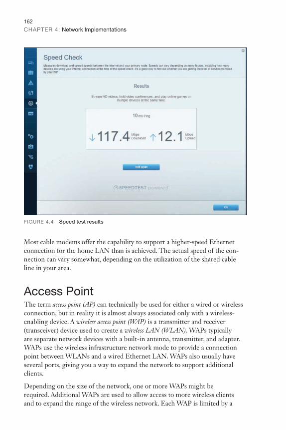
162
CHAPTER 4: Network Implementations
FIGURE 4.4 Speed test results
Most cable modems offer the capability to support a higher-speed Ethernet connection for the home LAN than is achieved. The actual speed of the con-nection can vary somewhat, depending on the utilization of the shared cable line in your area.
Access PointThe term access point (AP) can technically be used for either a wired or wireless connection, but in reality it is almost always associated only with a wireless-enabling device. A wireless access point (WAP) is a transmitter and receiver (transceiver) device used to create a wireless LAN (WLAN). WAPs typically are separate network devices with a built-in antenna, transmitter, and adapter. WAPs use the wireless infrastructure network mode to provide a connection point between WLANs and a wired Ethernet LAN. WAPs also usually have several ports, giving you a way to expand the network to support additional clients.
Depending on the size of the network, one or more WAPs might be required. Additional WAPs are used to allow access to more wireless clients and to expand the range of the wireless network. Each WAP is limited by a
9780137375769_print.indb 162 12/07/21 3:01 PM

Common Networking Devices163
transmission range—the distance a client can be from a WAP and still obtain a usable signal. The actual distance depends on the wireless standard used and the obstructions and environmental conditions between the client and the WAP.
An AP or WAP can operate as a bridge connecting a standard wired network to wireless devices or as a router passing data transmissions from one access point to another.
ExamAlert
Saying that a WAP is used to extend a wired LAN to wireless clients does not give you the complete picture. A wireless AP today can provide different services in addition to just an access point. Today, the APs might provide many ports that can be used to easily increase the network’s size. Systems can be added to and removed from the network with no effect on other systems on the network. Also, many APs provide firewall capabilities and Dynamic Host Configuration Protocol (DHCP) service. When they are hooked up, they give client systems a private IP address and then prevent Internet traffic from accessing those sys-tems. So, in effect, the AP is a switch, DHCP server, router, and firewall.
APs come in all shapes and sizes. Many are cheaper and are designed strictly for home or small office use. Such APs have low-powered antennas and limited expansion ports. Higher-end APs used for commercial purposes have high-powered antennas, enabling them to extend how far the wireless signal can travel.
APs are used to create a wireless LAN and to extend a wired network. APs are used in the infrastructure wireless topology.
Note
An AP works at Layer 2 (the data link layer) of the OSI model.
Media ConverterWhen you have two dissimilar types of network media, a media converter is used to allow them to connect. They are sometimes referred to as couplers. Depending on the conversion being done, the converter can be a small device, barely larger than the connectors themselves, or a large device within a sizable chassis.
9780137375769_print.indb 163 12/07/21 3:01 PM

164
CHAPTER 4: Network Implementations
Reasons for not using the same media throughout the network, and thus rea-sons for needing a converter, can range from cost (gradually moving from coax to fiber), disparate segments (connecting the office to the factory), or the need to run particular media in a setting (the need for fiber to reduce EMI problems in a small part of the building).
Figure 4.5 shows an example of a media converter. The one shown converts between 10/100/1000TX and 1000LX (with an SC-type connector).
FIGURE 4.5 A common media converter
The following converters are commonly implemented and are ones that CompTIA has previously included on the Network+ exam.
Make sure you know that the possibilities listed here exist:
▶ Single mode fiber to Ethernet
▶ Single mode to multimode fiber
▶ Multimode fiber to Ethernet
▶ Fiber to coaxial
ExamAlert
Voice GatewayWhen telephone technology is married with information technology, the result is called telephony. There has been a massive move from landlines to voice over IP (VoIP) for companies to save money. One of the biggest issues with the administration of this is security. When both data and VoIP are on the same line, they are both vulnerable in the case of an attack. Standard telephone systems should be replaced with a securable PBX.
9780137375769_print.indb 164 12/07/21 3:01 PM

Common Networking Devices165
A VoIP gateway, also sometimes called a PBX gateway, can be used to convert between the legacy telephony connection and a VoIP connection using Session Initiation Protocol (SIP). This is referred to as a “digital gateway” because the voice media are converted in the process.
Be sure that you know that by having both data and VoIP on the same line, they are both vulnerable in the case of an attack.
ExamAlert
RepeaterA repeater (also called a booster or wireless range extender) can amplify a wire-less signal to make it stronger. This increases the distance that the client system can be placed from the access point and still be on the network. The extender needs to be set to the same channel as the AP for the repeater to take the trans-mission and repeat it. This is an effective strategy to increase wireless transmis-sion distances.
Carefully read troubleshooting question scenarios to be sure the transmission from the AP is getting to the repeater first, and then the repeater is duplicating the signal and passing it on.
ExamAlert
Wireless LAN ControllerWireless LAN controllers are often used with branch/remote office deployments for wireless authentication. When an AP boots, it authenticates with a control-ler before it can start working as an AP. This is often used with VLAN pooling, in which multiple interfaces are treated as a single entity (usually for load balancing).
Load BalancerNetwork servers are the workhorses of the network. They are relied on to hold and distribute data, maintain backups, secure network communications, and more. The load of servers is often a lot for a single server to maintain. This is where load balancing comes into play. Load balancing is a technique in which the workload is distributed among several servers. This feature can take networks to the next level; it increases network performance, reliability, and availability.
9780137375769_print.indb 165 12/07/21 3:01 PM
166
CHAPTER 4: Network Implementations
Remember that load balancing increases redundancy and therefore data availability. Also, load balancing increases performance by distributing the workload.
ExamAlert
A load balancer can be either a hardware device or software specially configured to balance the load.
Multilayer switches and DNS servers can serve as load balancers.
Note
Proxy ServerProxy servers typically are part of a firewall system. They have become so integrated with firewalls that the distinction between the two can sometimes be lost.
However, proxy servers perform a unique role in the network environment—a role that is separate from that of a firewall. For the purposes of this book, a proxy server is defined as a server that sits between a client computer and the Internet and looks at the web page requests the client sends. For example, if a client computer wants to access a web page, the request is sent to the proxy server rather than directly to the Internet. The proxy server first determines whether the request is intended for the Internet or for a web server locally. If the request is intended for the Internet, the proxy server sends the request as if it originated the request. When the Internet web server returns the information, the proxy server returns the information to the client. Although a delay might be induced by the extra step of going through the proxy server, the process is largely transparent to the client that originated the request. Because each request a client sends to the Internet is channeled through the proxy server, the proxy server can provide certain functionality over and above just forwarding requests.
One of the most notable extra features is that proxy servers can greatly improve network performance through a process called caching. When a caching proxy server answers a request for a web page, the server makes a copy of all or part of that page in its cache. Then, when the page is requested again, the proxy server answers the request from the cache rather than going back to the Internet. For example, if a client on a network requests the web page www.comptia.org, the proxy server can cache the contents of that web page. When a second client computer on the network attempts to access the same site, that client can grab
9780137375769_print.indb 166 12/07/21 3:01 PM

Common Networking Devices167
it from the proxy server cache, and accessing the Internet is unnecessary. This greatly increases the response time to the client and can significantly reduce the bandwidth needed to fulfill client requests.
Nowadays, speed is everything, and the capability to quickly access information from the Internet is a crucial concern for some organizations. Proxy servers and their capability to cache web content accommodate this need for speed.
An example of this speed might be found in a classroom. If a teacher asks 30 students to access a specific Uniform Resource Locator (URL) without a proxy server, all 30 requests would be sent into cyberspace and subjected to delays or other issues that could arise. The classroom scene with a proxy server is quite different. Only one request of the 30 finds its way to the Internet; the other 29 are filled by the proxy server’s cache. Web page retrieval can be almost instantaneous.
However, this caching has a potential drawback. When you log on to the Internet, you get the latest information, but this is not always so when information is retrieved from a cache. For some web pages, it is necessary to go directly to the Internet to ensure that the information is up to date. Some proxy servers can update and renew web pages, but they are always one step behind.
The second key feature of proxy servers is allowing network administrators to filter client requests. If a server administrator wants to block access to certain websites, a proxy server enables this control, making it easy to completely disallow access to some websites. This is okay, but what if it were necessary to block numerous websites? In this case, maintaining proxy servers gets a bit more complicated.
Determining which websites users can or cannot access is usually done through something called an access control list (ACL). Chapter 3 discussed how an ACL can be used to provide rules for which port numbers or IP addresses are allowed access. An ACL can also be a list of allowed or nonallowed websites; as you might imagine, compiling such a list can be a monumental task. Given that millions of websites exist, and new ones are created daily, how can you target and disallow access to the “questionable” ones? One approach is to reverse the situation and deny access to all pages except those that appear in an “allowed” list. This approach has high administrative overhead and can greatly limit the productive benefits available from Internet access.
Understandably, it is impossible to maintain a list that contains the locations of all sites with questionable content. In fairness, that is not what proxy servers were designed to do. However, by maintaining a list, proxy servers can better provide a greater level of control than an open system. Along the way, proxy servers can make the retrieval of web pages far more efficient.
9780137375769_print.indb 167 12/07/21 3:01 PM
168
CHAPTER 4: Network Implementations
A reverse proxy server is one that resides near the web servers and responds to requests. These are often used for load-balancing purposes because each proxy can cache information from a number of servers.
VPN Concentrators and HeadendsA VPN concentrator can be used to increase remote-access security. This device can establish a secure connection (tunnel) between the sending and receiving network devices. VPN concentrators add an additional level to VPN security. They not only can create the tunnel but also can authenticate users, encrypt the data, regulate the data transfer, and control traffic.
The concentrator sits between the VPN client and the VPN server, creates the tunnel, authenticates users using the tunnel, and encrypts data traveling through the tunnel. When the VPN concentrator is in place, it can establish a secure connection (tunnel) between the sending and receiving network devices.
VPN concentrators add an additional level to VPN security. Depending on the exact concentrator, they can do the following:
▶ Create the tunnel.
▶ Authenticate users who want to use the tunnel.
▶ Encrypt and decrypt data.
▶ Regulate and monitor data transfer across the tunnel.
▶ Control inbound and outbound traffic as a tunnel endpoint or router.
The VPN concentrator invokes various standard protocols to accomplish these functions.
A VPN headend (or head-end) is a server that receives the incoming signal and then decodes/encodes it and sends it on.
Networked DevicesOne of the fastest areas of growth in networking isn’t necessarily in adding more users, but in adding more devices. Each “smart” device has the ability to monitor or perform some task and report the status of the data it has collected, or itself, back. Most of these devices require IP addresses and function like nor-mal nodes, but some network only through Bluetooth or NFC. Table 4.1 lists some of the devices commonly being added to the network today.
9780137375769_print.indb 168 12/07/21 3:01 PM
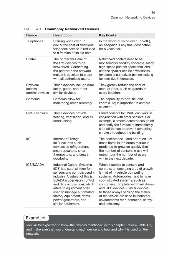
Common Networking Devices169
TABLE 4.1 Commonly Networked Devices
Device Description Key Points
Telephones Utilizing voice over IP (VoIP), the cost of traditional telephone service is reduced to a fraction of its old cost.
In the world of voice over IP (VoIP), an endpoint is any final destination for a voice call.
Printer The printer was one of the first devices to be networked. Connecting the printer to the network makes it possible to share with all authorized users.
Networked printers need to be monitored for security concerns. Many high-speed printers spool print jobs, and the spooler can be a weakness for some unauthorized person looking for sensitive information.
Physical access control devices
These devices include door locks, gates, and other similar devices.
They greatly reduce the cost of manual labor, such as guards at every location.
Cameras Cameras allow for monitoring areas remotely.
The capability to pan, tilt, and zoom (PTZ) is important in camera selection.
HVAC sensors These devices provide heating, ventilation, and air conditioning.
Smart sensors for HVAC can work in conjunction with other sensors. For example, a smoke detector can go off and notify the furnace to immediately shut off the fan to prevent spreading smoke throughout the building.
IoT Internet of Things (IoT) includes such devices as refrigerators, smart speakers, smart thermostats, and smart doorbells.
The acceptance—and adoption—of these items in the home market is predicted to grow so quickly that the number of sensors in use will outnumber the number of users within the next decade.
ICS/SCADA Industrial Control Systems (ICS) is a catchall term for sensors and controls used in industry. A subset of this is SCADA (supervisory control and data acquisition), which refers to equipment often used to manage automated factory equipment, dams, power generators, and similar equipment.
When it comes to sensors and controls, an emerging area of growth is that of in-vehicle computing systems. Automobiles tend to have sophisticated systems, such as computers complete with hard drives and GPS devices. Similar devices to those always sensing the status of the vehicle are used in industrial environments for automation, safety, and efficiency.
You will be expected to know the devices mentioned in this chapter. Review Table 4.1, and make sure that you understand each device and how and why it is used on the network.
ExamAlert
9780137375769_print.indb 169 12/07/21 3:01 PM

CramQuiz Network Implementations
Cram Quiz 1. Users are complaining that the network’s performance is unsatisfactory. It takes
a long time to pull files from the server, and, under heavy loads, workstations can become disconnected from the server. The network is heavily used, and a new videoconferencing application is about to be installed. The network is a 1000BASE-T system created with Ethernet hubs. Which device are you most likely to install to alleviate the performance problems?
❍ A. Switch
❍ B. Router
❍ C. Media converter
❍ D. Firewall
2. Which of the following devices forwards data packets to all connected ports?
❍ A. Router
❍ B. Switch
❍ C. Content filter
❍ D. Hub
3. Which of the following devices passes data based on the MAC address?
❍ A. Hub
❍ B. Switch
❍ C. MSAU
❍ D. Router
4. Which of the following can serve as load balancers?
❍ A. IDS and DNS servers
❍ B. Multilayer switches and IPS
❍ C. Multilayer switches and DNS servers
❍ D. VoIP PBXs and UTM appliances
5. Which of the following is the best answer for a device that continually scans the network, looking for inappropriate activity?
❍ A. IPS
❍ B. NGFW
❍ C. VCPN
❍ D. AAA
9780137375769_print.indb 170 12/07/21 3:01 PM

CramQuizCommon Networking Devices
Cram Quiz Answers 1. A. Replacing Ethernet hubs with switches can yield significant performance
improvements. Of the devices listed, switches are also the only ones that can be substituted for hubs. A router is used to separate networks, not as a connectivity point for workstations. A media converter is used to connect two dissimilar types of network media. A firewall is not a solution to the problem presented.
2. D. Hubs are inefficient devices that send data packets to all connected devices. Switches pass data packets to the specific destination device. This method significantly increases network performance.
3. B. When determining the destination for a data packet, the switch learns the MAC address of all devices attached to it and then matches the destination MAC address in the data it receives. None of the other devices listed passes data based solely on the MAC address.
4. C. Multilayer switches and DNS servers can serve as load balancers.
5. A. An intrusion prevention system (IPS) is a device that continually scans the network, looking for inappropriate activity.
9780137375769_print.indb 171 12/07/21 3:01 PM

172
CHAPTER 4: Network Implementations
Networking Architecture ▶ Explain basic corporate and datacenter network architecture.
If you can correctly answer these questions before going through this section, save time by skimming the Exam Alerts in this section and then complete the Cram Quiz at the end of the section.
1. What is the term for the network architecture design in which servers, appliances, and other switches located within the same rack are connected to an in-rack network switch?
2. True or false: Traffic flows entering and leaving a datacenter are known as East-West traffic.
3. True or false: In the three-tiered architecture, the access/edge layer ensures data is delivered to edge/end devices.
Answers
1. This is known as top-of-rack (ToR) switching.
2. False. Traffic flows entering and leaving a datacenter are known as North-South traffic.
3. True. The access/edge layer is the place where switches connect to and ensure data is delivered to edge/end devices.
CramSaver
The networking devices discussed previously in this chapter are used to build networks. For this particular objective, CompTIA wants you to be aware of some of the architecture and design elements of the network. Whether you’re putting together a datacenter or a corporate office, planning should be involved, and no network should be allowed to haphazardly sprout without management and oversight.
Three-Tiered ArchitectureTo improve system performance, as well as to improve security, it is possible to implement a tiered systems model. This is often referred to as an n-tiered model because the n- can be one of several different numbers.
If we were looking at database, for example, with a one-tier model, or single-tier environment, the database and the application exist on a single system. This is common on desktop systems running a standalone database. Early UNIX
9780137375769_print.indb 172 12/07/21 3:01 PM

Networking Architecture173
implementations also worked in this manner; each user would sign on to a terminal and run a dedicated application that accessed the data. With two-tier architecture, the client workstation or system runs an application that com-municates with the database that is running on a different server. This common implementation works well for many applications. With three-tiered architecture, security is enhanced. In this model, the end user is effectively isolated from the database by the introduction of a middle-tier server. This server accepts requests from clients, evaluates them, and then sends them on to the database server for processing. The database server sends the data back to the middle-tier server, which then sends the data to the client system. Becoming common in business today, this approach adds both capability and complexity.
While the examples are of database tiering, this same approach can be taken with devices such as routers, switches, and other servers. In a three-tiered model of routing and switching, the three tiers would be the core, the distribu-tion/aggregation layer, and the access/edge. We walk through each of the layers present in this scenario.
Core LayerThe core layer is the backbone: the place where switching and routing meet (switching ends, routing begins). It provides high-speed, highly redundant forwarding services to move packets between distribution-layer devices in different regions of the network. The core switches and routers would be the most powerful in the enterprise (in terms of their raw forwarding power,) and would be used to manage the highest-speed connections (such as 100 Gigabit Ethernet). Core switches also incorporate internal firewall capability as part of their features, helping with segmentation and control of traffic moving from one part of the network to another.
Distribution/Aggregation LayerThe distribution layer, or aggregation layer (sometimes called the workgroup layer), is the layer in which management takes place. This is the place where QoS policies are managed, filtering is done, and routing takes place. Distribution layer devices can be used to manage individual branch-office WAN connections, and this is considered to be smart (usually offering a larger feature set than switches used at the access/edge layer). Lower latency and larger MAC address table sizes are important features for switches used at this level because they aggregate traffic from thousands of users rather than hundreds (as access/edge switches do).
9780137375769_print.indb 173 12/07/21 3:01 PM

174
CHAPTER 4: Network Implementations
Access/Edge LayerSwitches that allow end users and servers to connect to the enterprise are called access switches or edge switches, and the layer where they operate in the three-tiered model is known as the access layer, or edge layer. Devices at this layer may or may not provide Layer 3 switching services; the traditional focus is on mini-mizing the cost of each provisioned Ethernet port (known as “cost-per-port”) and providing high port density. Because the focus is on connecting client nodes, such as workstations to the network, this is sometimes called the desktop layer.
Remember: The core layer is the backbone of the network (where the fastest routers and switches operate to manage separate networks), whereas the distribution/aggregation layer (between the access/edge and core layers) is the “boundary” layer where ACLs and Layer 3 switches operate to properly manage data between VLANs and subnetworks. The access/edge layer is the place where switches connect to and ensure data is delivered to edge/end devices, such as computers and servers.
ExamAlert
Software-Defined NetworkingSoftware-defined networking (SDN) is a dynamic approach to computer networking intended to allow administrators to get around the static limitations of physical architecture associated with traditional networks. They can do so through the implementation of technologies such as the Cisco Systems Open Network Environment.
The goal of SDN is not only to add dynamic capabilities to the network but also to reduce IT costs through implementation of cloud architectures. SDN combines network and application services into centralized platforms that can automate provisioning and configuration of the entire infrastructure.
The SDN architecture, from the top down, consists of the application layer, control layer, and infrastructure layer. CompTIA also adds the management plane as an objective, and a discussion of each of these components follows.
Application LayerThe application layer is the top of the SDN stack, and this is where load balancers, firewalls, intrusion detection, and other standard network applications are located. While a standard (non-SDN) network would use a specialized appliance for each of these functions, with an SDN network, an application is used in place of a physical appliance.
9780137375769_print.indb 174 12/07/21 3:01 PM

Networking Architecture175
Control LayerThe control layer is the place where the SDN controller resides; the controller is software that manages policies and the flow of traffic throughout the network. This controller can be thought of as the brains behind SDN, making it all possible. Applications communicate with the controller through a northbound interface, and the controller communicates with switching using southbound interfaces.
Infrastructure LayerThe physical switch devices themselves reside at the infrastructure layer. This is also known as the control plane when breaking the architecture into “planes” because this is the component that defines the traffic routing and network topology.
Management PlaneWith SDN, the management plane allows administrators to see their devices and traffic flows and react as needed to manage data plane behavior. This can be done automatically through configuration apps that can, for example, add more bandwidth if it looks as if edge components are getting congested. The management plane manages and monitors processes across all layers of the network stack.
A major benefit of SDN is that it replaces traditional dedicated hardware/services with virtual.
ExamAlert
Spine and LeafIn an earlier section, we discussed the possibility of tiered models. A two-tier model that Cisco promotes for switches is the spine and leaf model. In this model, the spine is the backbone of the network, just as it would be in a skeleton and is responsible for interconnecting all the leaf switches in a full-mesh topology. Thanks to the mesh, every leaf is connected to every spine, and the path is randomly chosen so that the traffic load is evenly distributed among the top-tier switches. If one of the switches at the top tier were to fail, there would only be a slight degradation in performance throughout the datacenter.
9780137375769_print.indb 175 12/07/21 3:01 PM

176
CHAPTER 4: Network Implementations
Because of the design of this model, no matter which leaf switch is connected to a server, the traffic always has to cross the same number of devices to get to another server. This keeps latency at a steady level.
When top-of-rack (ToR) switching is incorporated into the network architecture, switches located within the same rack are connected to an in-rack network switch, which is connected to aggregation switches (usually via fiber cabling). The big advantage of this setup is that the switches within each rack can be connected with cheaper copper cabling and the cables to each rack are all that need be fiber.
Remember that in a spine and leaf model the spine is the backbone of the network and is responsible for interconnecting all the leaf switches in a full-mesh topology.
ExamAlert
Traffic FlowsTraffic flows within a datacenter typically occur within the framework of one of two models: East-West or North-South. The names may not be the most intuitive, but the East-West traffic model means that data is flowing among devices within a specific datacenter while North-South means that data is flowing into the datacenter (from a system physically outside the datacenter) or out of it (to a system physically outside the datacenter).
The naming convention comes from the way diagrams are drawn: data staying within the datacenter is traditionally drawn on the same horizontal line (East-to-West), while data leaving or entering is typically drawn on a vertical line (North-to-South). With the increase in virtualization being implemented at so many levels, the East-West traffic has increased in recent years.
East-West traffic is a concept referring to network traffic flow within a datacenter between servers. North-South refers to data transfers between the datacenter and that outside of the network.
ExamAlert
Datacenter Location TypesOne of the biggest questions a network administrator today can face is where to store the data. At one point in time, this question was a no-brainer: servers
9780137375769_print.indb 176 12/07/21 3:01 PM

Networking Architecture177
were kept close at hand so they could be rebooted and serviced regularly. Today, however, that choice is not such an easy one. The cloud, virtualization, software-defined networking, and many other factors have combined to offer several options in which cost often becomes one of the biggest components.
An on-premises datacenter can be thought of as the old, traditional approach: the data and the servers are kept in house. One alternative to this is to share a colocation. In this arrangement, several companies put their “servers” in a shared space. The advantage to this approach is that by renting space in a third-party facility, it is often possible to gain advantages associated with connectivity speed, and possibly technical support. When describing this approach, we placed “servers” in quotation marks because the provider will often offer virtual servers rather than dedicated machines for each client, thus enabling companies to grow without a reliance on physical hardware.
Incidentally, any remote and autonomous office, regardless of the number of users who may work from it, is known as a branch office. This point is important because it may be an easy decision to keep the datacenter on-premises at headquarters, but network administrators need to factor in how to best support branch offices as well. The situation could easily be that while on-premises works best at headquarters, all branch offices are supported by colocation sites.
Storage-Area NetworksWhen it comes to data storage in the cloud, encryption is one of the best ways to protect it (keeping it from being of value to unauthorized parties), and VPN routing and forwarding can help. Backups should be performed regularly (and encrypted and stored in safe locations), and access control should be a priority.
The consumer retains the ultimate responsibility for compliance. Per NIST SP 800-144,
The main issue centers on the risks associated with moving important applications or data from within the confines of the organization’s comput-ing center to that of another organization (i.e., a public cloud), which is readily available for use by the general public. The responsibilities of both the organization and the cloud provider vary depending on the service model. Reducing cost and increasing efficiency are primary motivations for moving towards a public cloud, but relinquishing responsibility for security should not be. Ultimately, the organization is accountable for the choice of public cloud and the security and privacy of the outsourced service.
For more information, see http://nvlpubs.nist.gov/nistpubs/Legacy/SP/nistspecialpublication800-144.pdf.
9780137375769_print.indb 177 12/07/21 3:01 PM
178
CHAPTER 4: Network Implementations
Shared storage can be done on storage-area networks (SANs), network-attached storage (NAS), and so on; the virtual machine sees only a “physical disk.” With clustered storage, you can use multiple devices to increase performance. A handful of technologies exist in this realm, and the following are those that you need to know for the Network+ exam.
Look to CompTIA’s Cloud+ certification for more specialization in cloud and virtualization technologies.
Tip
iSCSIThe Small Computer Systems Interface (SCSI) standard has long been the language of storage. Internet Small Computer Systems Interface (iSCSI) expands this through Ethernet, allowing IP to be used to send SCSI commands.
Logical unit numbers (LUNs) came from the SCSI world and carry over, acting as unique identifiers for devices. Both NAS and SAN use “targets” that hold up to eight devices.
Using iSCSI for a virtual environment gives users the benefits of a file system without the difficulty of setting up Fibre Channel. Because iSCSI works both at the hypervisor level and in the guest operating system, the rules that govern the size of the partition in the OS are used rather than those of the virtual OS (which are usually more restrictive).
The disadvantage of iSCSI is that users can run into IP-related problems if configuration is not carefully monitored.
Fibre Channel and FCoEInstead of using an older technology and trying to adhere to legacy standards, Fibre Channel (FC) is an option providing a higher level of performance than anything else. It utilizes FCP, the Fiber Channel Protocol, to do what needs to be done, and Fibre Channel over Ethernet (FCoE) can be used in high-speed (10 GB and higher) implementations.
The big advantage of Fibre Channel is its scalability. FCoE encapsulates FC over the Ethernet portions of connectivity, making it easy to add into an existing network. As such, FCoE is an extension to FC intended to extend the scalability and efficiency associated with Fibre Channel.
9780137375769_print.indb 178 12/07/21 3:01 PM
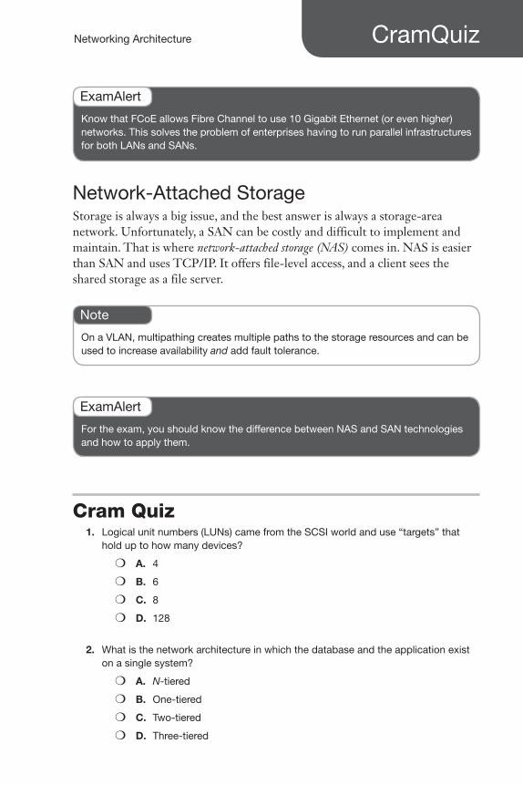
CramQuizNetworking Architecture
Know that FCoE allows Fibre Channel to use 10 Gigabit Ethernet (or even higher) networks. This solves the problem of enterprises having to run parallel infrastructures for both LANs and SANs.
ExamAlert
Network-Attached StorageStorage is always a big issue, and the best answer is always a storage-area network. Unfortunately, a SAN can be costly and difficult to implement and maintain. That is where network-attached storage (NAS) comes in. NAS is easier than SAN and uses TCP/IP. It offers file-level access, and a client sees the shared storage as a file server.
On a VLAN, multipathing creates multiple paths to the storage resources and can be used to increase availability and add fault tolerance.
Note
For the exam, you should know the difference between NAS and SAN technologies and how to apply them.
ExamAlert
Cram Quiz 1. Logical unit numbers (LUNs) came from the SCSI world and use “targets” that
hold up to how many devices?
❍ A. 4
❍ B. 6
❍ C. 8
❍ D. 128
2. What is the network architecture in which the database and the application exist on a single system?
❍ A. N-tiered
❍ B. One-tiered
❍ C. Two-tiered
❍ D. Three-tiered
9780137375769_print.indb 179 12/07/21 3:01 PM

CramQuiz Network Implementations
3. On a VLAN, what creates multiple paths to the storage resources and can be used to increase availability and add fault tolerance?
❍ A. FCoE
❍ B. Adding a management plane
❍ C. Colocating
❍ D. Multipathing
4. What traffic pattern refers to data that travels outside the datacenter or enterprise?
❍ A. East-to-West
❍ B. North-to-South
❍ C. On-premises
❍ D. West-to-South
5. What layer in three-tiered network architecture is considered the backbone of a network?
❍ A. Core layer
❍ B. Distribution/aggregation layer
❍ C. Access/edge layer
❍ D. Application layer
Cram Quiz Answers 1. C. LUNs came from the SCSI world and carry over, acting as unique identifiers for
devices. Both NAS and SAN use “targets” that hold up to eight devices.
2. B. The network architecture in which the database and the application exist on a single system is called a one-tiered model.
3. D. On a VLAN, multipathing creates multiple paths to the storage resources and can be used to increase availability and add fault tolerance.
4. B. North-South refers to data transfers between the datacenter and that outside of the network. East-West traffic is a concept referring to network traffic flow within a datacenter between servers. On-premises can be thought of as the old, traditional approach: the data and the servers are kept in house. Although West-to-South is a direction, it is not a valid specified data path.
5. A. The core layer is the backbone of the network where the fastest routers and switches operate to manage separate networks. The distribution/aggregation layer is between the access/edge and core layers. This is the “boundary” layer where ACLs and Layer 3 switches operate. The access/edge layer is the place where switches connect to and ensure data is delivered to edge/end devices. The application layer is the seventh and top layer of the OSI reference model.
9780137375769_print.indb 180 12/07/21 3:01 PM

What’s Next?181
What’s Next?For the Network+ exam, and for routinely working with an existing network or implementing a new one, you need to identify the characteristics of network media and their associated cabling. Chapter 5, “Cabling Solutions and Issues,” focuses on the media and connectors used in today’s networks and what you are likely to find in wiring closets.
9780137375769_print.indb 181 12/07/21 3:01 PM

Index
Numerics10Base-T, 210–211
10GBASE-LR, 214
10GBASE-SR, 214
10GBASE-T, 212–213
40GBASE-T, 213
100Base-T, 211–212
568A/568B wiring standards, 200–201
802.1Q, 134, 135
802.1x, EAP (Extensible Authentication Protocol), 417
1000BASE-LX, 213
1000BASE-SX, 213
1000Base-T, 212
Aabsorption, 263–264
access control, 405. See also security
802.1x, 416defense in depth, 408discretionary, 405–406MAC filtering, 418mandatory, 405NAC (network access control), 417network segmentation, 408RADIUS (Remote Authentication
Dial-In User Service), 411–412role-based, 406–408rule-based, 406screened subnet, 408–409TACACS (Terminal Access
Controller Access Control System), 412
access/edge layer, 174
ACLs (access control lists), 146, 167, 405–406
ad hoc topology, 9
9780137375769_print.indb 511 12/07/21 3:02 PM
aggregation
512
aggregation, 142
AH (Authentication Header), 57
antennas, 243–244, 432
coverage, 244–245ratings, 244
antimalware software, 423
antivirus software, 423
anycast addresses, 106–107
APIPA (Automatic Private IP Addressing), 111–112
application layer, 47
applications, patch management, 336–339
APs (access points), 8, 162–163, 247, 259
authentication, 251–252rogue, 422troubleshooting, 264–265WPA (Wi-Fi Protected Access),
252–254WPA-PSK (Wi-Fi Protected Access
with Pre-Shared Key), 251–252architecture, 172
SDN (software-defined networking), 174
application layer, 174control layer, 175infrastructure layer, 175management plane, 175
spine and leaf, 175–176three-tiered, 172–173
access/edge layer, 174core layer, 173distribution/aggregation layer, 173
ARP (Address Resolution Protocol), 147–148, 430–431
arp ping command, 431–432
attacks, 420
advertising wireless weaknesses, 422ARP cache poisoning, 422ARP spoofing, 423brute force, 422
deauthentication, 422DNS poisoning, 422DoS (denial-of-service), 420–421logic bombs, 422on-path, 422phishing, 422ransomware, 422rogue APs, 422rogue DHCP servers, 422social engineering, 421–422spoofing, 422VLAN hopping, 422
attenuation, 221–222
auditing, 415
authentication, 137
Kerberos, 412–414local, 414multifactor, 426
authorization, 137
availability, 317–319
MTBF (mean time between failures), 316
MTTR (mean time to recovery), 316RTO (recovery time objective), 317
AWS (Amazon Web Services), 289
Bbackups, 309, 311–312
best practices, 312–313differential, 310full, 309–310incremental, 310–311
bandwidth, 26, 219
baselines, 293–294
biometrics, 426
BNC connectors, 194–195
BOOTP (BOOT Protocol), 111
bridges, 161
broadband, 22, 25–26
broadcast addresses, 102
9780137375769_print.indb 512 12/07/21 3:02 PM

cloud computing
513
brute force attacks, 422
buffer overflow attacks, 420
buffering, 45–46
bus topology, 2–3
BYOD (bring-your-own-device), 254, 455
Ccable broadband, 25–26
cable modems, 161
cabling, 158–159, 186–187, 217–218, 220–221. See also connectors; Ethernet; tools
568A/568B wiring standards, 200–201
applications, 221attenuation, 221–222bandwidth, 219baseband transmissions, 185coaxial, 190–191cross-over, 201–203, 225dB loss, 221–222fiber distribution panels, 208fiber-optic, 192–193, 225full-duplex mode, 185–186general media considerations, 184half-duplex mode, 185–186horizontal, 205–206interference, 222loopback, 204network cross-connects, 204–205open/short faults, 223–224patch panels, 207–208plenum, 194PVC-based, 194RG-6, 197RG-59, 197rollover, 203simplex mode, 185–186specifications/limitations, 220splits, 222–223
STP (shielded twisted-pair), 187straight-through, 201–203throughput testing, 218–219transmission rates, 186twinaxial, 191–192twisted-pair, 187–190UTP (unshielded twisted-pair), 187vertical, 206
caching, 166–167
CANs (campus-area networks), 17
captive portals, 261, 432
CAs (certificate authorities), 414
CASB (Cloud Access Security Broker), 284
cellular technology access, 241
certificates, 414
change management documentation, 302–303
CIDR (classess interdomain routing), 100
circuit switching, 124–125
client/server networks, 14–15
client-to-site VPNs, 438
cloud computing, 35, 283, 284
connectivity options, 289DaaS (Desktop as a Service),
288–289deployment models
hybrid and community clouds, 289
IaC (Infrastructure as Code), 289private cloud, 289public cloud, 289
elasticity, 289IaaS (Infrastructure as a Service),
284, 287–288multitenancy, 289PaaS (Platform as a Service), 284,
286–287relationship between resources, 290SaaS (Software as a Service), 284,
285–286
9780137375769_print.indb 513 12/07/21 3:02 PM

514
cloud computing
scalability, 289–290security, 290VPC (virtual private cloud), 289
cloud sites, 316
clustering, 318
coaxial cable, 190–191
cold sites, 315
commands
arp ping, 431–432dig, 442–443FTP, 60hostname, 430ipconfig, 437–440netstat, 432–437nslookup, 441–442ping, 425–426, 428–430. See also ping
commandshow, 445tcpdump, 443tracert, 126–127, 421–422
configuration-related documentation, 303
connectionless protocols, 54
connection-oriented protocols, 54
connectors
BNC, 194–195fiber, 197–199F-type, 197RJ-11, 195–196RJ-45, 196
convergence, 127–128
core layer, 173
cross-over cable, 201–203, 225
cryptography, 412
CSMA/CA (Carrier Sense Multiple Access/Collision Avoidance), 132–133
CSMA/CD (Carrier Sense Multiple Access/Collision Detection), 130–132
CSU/DSU (channel service unit/data service unit), 34
cut-through switching, 158
CWDM (coarse wavelength-division multiplexing), 31
DDaaS (Desktop as a Service), 288–289
DAC (discretionary access control), 405–406
data link layer, 44
datacenters
location types, 176–177traffic flows, 176
deauthentication, 422
decapsulation, 49–50
default gateway, 100–102, 120–122
default route, 123
defense in depth, 408
demarcation point, 32–33
DHCP (Dynamic Host Configuration Protocol), 62–63, 86–88, 109
DNS suffixes and, 89relays and IP helpers, 89rogue servers, 422
differential backups, 310
dig command, 442–443
disaster recovery, 308, 309. See also power management
backups, 309, 311–312best practices, 312–313differential, 310full, 309–310incremental, 310–311
cloud sites, 316cold sites, 315environmental concerns, 339hot sites, 315–316MTBF (mean time between failures),
316MTTR (mean time to recovery), 316RTO (recovery time objective), 317snapshots, 312SPOF (single point of failure), 316UPSs (uninterruptible power
supplies), 313–314warm sites, 316
disposal of assets policies, 425
9780137375769_print.indb 514 12/07/21 3:02 PM

fusion splicer
515
distance-vector routing, 126–128
distributed switching, 123
distribution/aggregation layer, 173
DNS (Domain Name System), 62, 78–79, 85–86
HOSTS file resolution, 79–80namespace, 81–83poisoning, 422records, 83–84types of entries, 83
documentation, 285–287
baselines, 293–294change management, 302–303configuration, 303labeling, 304network wiring schematics, 287–289,
305–307troubleshooting and, 289–290
physical and logical network diagrams, 290–293
policies, 295–301procedures, 301–302regulations, 303–304
DoS (denial-of-service) attacks, 420–421
DRDoS (distributed reflective DoS) attacks, 420–421
DSL (digital subscriber line), 23
modems, 161speeds, 24variations, 23–24
DTLS (Datagram Transport Layer Security), 438
duplexing, 224–225
DWDM (dense wavelength-division multiplexing), 30
dynamic addressing, 108–110
dynamic routing, 45
EEAP (Extensible Authentication
Protocol), 417
EIGRP (Enhanced IGRP), 127
elasticity, 289
EMI (electromagnetic interference), 222
encapsulation, 49–50
error checking, 45
ESP (Encapsulating Security Payload), 57
Ethernet
10Base-T, 210–21110GBASE-LR, 21410GBASE-SR, 21410GBASE-T, 212–21340GBASE-T, 213100Base-T, 211–2121000BASE-LX, 2131000BASE-SX, 2131000Base-T, 212
FFast Ethernet, 211–212
fault tolerance, 317
FC (Fibre Channel), 178–179
FCoE (Fibre Channel over Ethernet), 178–179
FHRP (First Hop Redundancy Protocol), 319
fiber connectors, 197–199
fiber distribution panels, 208
fiber-optic cable, 192–193, 225
firewalls, 153–154
screened subnet, 408–409firmware updates, 337
flow control, 45–46
fractional T, 27
Fraggle attacks, 420
fragment-free switching, 158
FTP (File Transfer Protocol), 58–60, 435
F-type connectors, 197
full backups, 309–310
full-duplex mode, 185–186
fusion splicer, 231
9780137375769_print.indb 515 12/07/21 3:02 PM

geofencing
516
Ggeofencing, 432
Gigabit Ethernet, 212
Global System for Mobile Communications (GSM), 241
GPS (Global Positioning System), 90
GRE (Generic Routing Encapsulation), 58
Hhalf-duplex mode, 185–186
headends, 168
high availability, 318–319
honeypots, 410–411
horizontal cables, 205–206
hostname command, 430
HOSTS file resolution, 79–81
hot sites, 315–316
HTTP (Hypertext Transfer Protocol), 64
HTTPS (Hypertext Transfer Protocol Secure), 70, 439
hub-and-spoke topology, 5–6. See also star topology
hubs, 160
hybrid routing protocols, 130
hybrid topology, 7
hypervisor, 34–35
IIaaS (Infrastructure as a Service),
287–288
IANA (Internet Assigned Numbers Authority), 98
ICMP (Internet Control Message Protocol), 57
ICMP flood attacks, 421
IDS (intrusion detection system), 154–155
IMAP4 (Internet Message Access Protocol version 4), 65
over SSL, 71
incremental backups, 310–311
infrastructure topology, 8
Internet access
cable broadband, 25–26DSL (digital subscriber line), 23–25
speeds, 24variations, 23–24
leased lines, 27–29metro-optical networks, 29
CWDM (coarse wavelength-division multiplexing), 31
DWDM (dense wavelength-division multiplexing), 30
PON (passive optical network), 30SDH (Synchronous Digital
Hierarchy), 30SONET (Synchronous Optical
Network), 29PSTN (public switched telephone
network), 26satellite, 31–32
IoT (Internet of Things), 432
IP (Internet Protocol), 54–55
IP addressing, 94
APIPA (Automatic Private IP Addressing), 111–112
BOOTP (BOOT Protocol), 111DNAT (Destination Network
Address Translation), 116dynamic addressing, 108–110IPv4, 95, 98–99
address types, 102–103CIDR (classess interdomain
routing), 100classes, 95–96default gateways, 100–102private address ranges, 99–100subnet mask assigment, 97subnetting, 97–98VIP (virtual IP address), 102
IPv6, 103address types, 105–107distinguishing from IPv4,
103–105
9780137375769_print.indb 516 12/07/21 3:02 PM

metro-optical networks
517
IPv4 and, 107–108neighbor discovery, 107
MAC addresses, 112–114, 144NAT (Network Address Translation),
114–115nodes, 94PAT (Port Address Translation),
115–116SNAT (Static Network Address
Translation), 116static addressing, 108subnet mask, 95
ipconfig command, 437–440
iperf, 418–419
IPS (intrusion prevention system), 154–155
IPSec (IP Security), 57–58, 437–438
IPv4, 95, 98–99
address types, 102–103CIDR (classess interdomain routing),
100classes, 95–96default gateways, 100–102distinguishing from IPv6, 103–105IPv6 and, 107–108private address ranges, 99–100subnet mask assigment, 97subnetting, 97–98VIP (virtual IP address), 102
IPv6, 103
address types, 105–107distinguishing from IPv4, 103–105IPv4 and, 107–108neighbor discovery, 107
iSCSI, 178
IS-IS (Intermediate System-to-Intermediate System), 129
ISO (International Organization for Standardization), 41
J-Kjumbo frames, 141
Kerberos, 412–414
LLACP (Link Aggregation Control
Protocol), 135
LANs (local-area networks), 15
LDAP (Lightweight Directory Access Protocol), 69–70, 414
LDAPS (Lightweight Directory Access Protocol over SSL), 71
leased lines, 27–28
link-local addresses, 106
link-state routing, 129
load balancers, 165–166, 317
load tests, 330–331
local authentication, 414
logic bombs, 422
logical link control (LLC) layer, 44
logical network diagrams, 290–293
logs, 415
application, 334history, 335management, 335–336security, 332–333system, 334–335
loopback adapter, 228
loopback cable, 204
MMAC (mandatory access control), 405
MAC (media access control) layer, 44
MAC addresses, 112–114, 144
MANs (metropolitan-area networks), 16–17
MDI-X (medium-dependent interface crossed) port, 25, 142
media converter, 163–164
media couplers/converters, 200
mesh topology, 6, 10–12
metro-optical networks, 29
CWDM (coarse wavelength-division multiplexing), 31
DWDM (dense wavelength-division multiplexing), 30
9780137375769_print.indb 517 12/07/21 3:02 PM
518
metro-optical networks
OCx (optical carrier) levels, 29–30PON (passive optical network), 30SDH (Synchronous Digital
Hierarchy), 30SONET (Synchronous Optical
Network), 29mGRE (Multipoint Generic Routing
Encapsulation), 19
MIBs (management information bases), 68
modems, 161–162
monitoring network performance, 323, 324
network device logs, 332application logs, 334history logs, 335management, 335–336security logs, 332–333system logs, 334–335
performance metrics, 324–328SNMP monitors, 328–329
MIBs (management information bases), 329
MPLS (Multiprotocol Label Switching), 18–19
MSAU (multistation access unit), 4
MTBF (mean time between failures), 316
MTTR (mean time to recovery), 316
MTU (maximum transmission unit), 55, 223
multicast addresses, 106
multicasting, 102–103
multifactor authentication, 426
multilayer switches, 159–160
multipathing, 317
multiplexing, 21214, 224–225
multitenancy, 289
NNAS (network-attached storage), 179
NAT (Network Address Translation), 114–115
NetFlow, 419
netstat command, 432–437
network layer, 44–45
networked devices, 168–169
networking devices
bridges, 161firewalls, 153–154headends, 168hubs, 160IDS (intrusion detection system),
154–155IPS (intrusion prevention system),
154–155LED status indicators, 224load balancer, 165–166media converter, 163–164media couplers/converters, 200modems, 161–162proxy server, 166–168repeaters, 165routers, 155–156switches, 157–159
cabling, 158–159multilayer, 159–160
transceivers, 199voice gateway, 164–165VPN concentrators, 168wireless LAN controller, 165
networks, 14. See also architecture; documentation; Internet access; monitoring networkperformance; performance; topology(ies); VLANs (virtual local-area networks); wireless networks
APs (access points), 162–163CANs (campus-area networks), 17client/server, 14–15CSU/DSU (channel service unit/data
service unit), 34diagrams, 290–293documentation, 285–287hardening, 431–432LANs (local-area networks), 15
9780137375769_print.indb 518 12/07/21 3:02 PM

PIN access
519
MANs (metropolitan-area networks), 16–17
PANs (personal-area networks), 17peer-to-peer, 14–15performance metrics, 324–328performance monitoring, 324SANs (storage-area networks), 17,
177–178SDWANs (software-defined wide
area networks), 18segmentation, 408termination points, 32
demarc, 32–33smart jacks, 33verifying, 34
troubleshootingcommon issues, 449–456performance, 457
virtual, 34cloud computing, 35hypervisor, 34–35NFV (network function
virtualization), 35virtual router, 36
virtual local-area, 133WANs (wide-area networks), 16WLANs (wireless LANs), 15
NFV (network function virtualization), 35
NIC teaming, 318
nmap utility, 445
nslookup command, 441–442
NTP (Network Time Protocol), 64, 89–90
OOCx (optical carrier) levels, 29–30
OSI (Open Systems Interconnection) model, 41, 42–43,47–48
application layer, 47data link layer, 44encapsulation/decapsulation, 49–50network layer, 44–45
physical layer, 43–44presentation layer, 46session layer, 46TCP/IP model and, 48transport layer, 45–46
OSPF (Open Shortest Path First) protocol, 45, 129
out-of-band management, 400–401
PPaaS (Platform as a Service), 286–287
packet switching, 123–124
PANs (personal-area networks), 17
partial mesh topology, 7
passwords
policies and, 298–300strength, 300–301
PAT (Port Address Translation), 115–116
patch management, 336–339
patch panels, 207–208
on-path attacks, 422
PDU (protocol data unit), 50
peer-to-peer networks, 14–15
penetration testing, 418
performance
load tests, 330–331metrics, 324–328, 331monitoring, 324stress tests, 331testing, 330troubleshooting, 457
phishing attacks, 422
physical layer, 43–44
physical network diagrams, 290–293
physical security, 425
biometrics, 426lock and key, 425multifactor authentication, 426swipe card and PIN access, 425–426
PIN access, 425–426
9780137375769_print.indb 519 12/07/21 3:02 PM
ping command
520
ping command, 425–426, 428–430
results, 426“Destination Unreachable”
message, 426expired TTL message, 427–428“Request Timed Out” message,
426–427“Unknown Host” message,
427–428ping of death attacks, 420
plenum, 194
PoE (Power over Ethernet), 143
poison reverse, 128
policies, 295–298, 318
disposal of assets, 425separation of duties, 409–410
PON (passive optical network), 30
POP3 (Post Office Protocol version 3), 65, 71
port aggregation, 318
port binding, 135
port forwarding, 116
port mirroring, 142–143
port(s), 73–75, 223
authentication, 143mirroring, 142–143well-known, 75
power management, 314
UPSs (uninterruptible power supplies), 313–314
presentation layer, 46
preshared keys, 432
private address ranges, 99–100
procedures, 301–302
propagation time, 32
protocol analyzer, 415–416
protocols, 53
BOOTP (BOOT Protocol), 111connection oriented vs.
connectionless, 54DHCP (Dynamic Host
Configuration Protocol), 62–63, 86–88,88, 109
DNS suffixes and, 89relays and IP helpers, 89
DNS (Domain Name System), 62, 78–79
HOSTS file resolution, 79–81namespace, 81–83records, 83–84types of entries, 83
FTP (File Transfer Protocol), 58–60, 435
GRE (Generic Routing Encapsulation), 58
HTTP (Hypertext Transfer Protocol), 64
HTTPS (Hypertext Transfer Protocol Secure), 70
ICMP (Internet Control Message Protocol), 57
IP (Internet Protocol), 54–55IPSec (IP Security), 57–58LDAP (Lightweight Directory
Access Protocol), 69–70LDAPS (Lightweight Directory
Access Protocol over SSL), 71NTP (Network Time Protocol), 64,
89–90POP3 (Post Office Protocol version
3), 65ports and, 73–75RDP (Remote Desktop Protocol), 72secured vs. unsecured, 427–431SFTP (Secure File Transfer
Protocol), 61SIP (Session Initiation Protocol),
72–73SMB (Server Message Block), 70SMTP (Simple Mail Transfer
Protocol), 62SMTPS (Simple Mail Transfer
Protocol Secure), 71SNMP (Simple Network
Management Protocol), 66agents, 67–68communities, 69components, 66–67
9780137375769_print.indb 520 12/07/21 3:02 PM
SDN (software-defined networking)
521
management systems, 67MIBs (management information
bases), 68version 3, 69
SSH (Secure Shell), 60–61TCP (Transmission Control
Protocol), 55–56Telnet, 61–62TFTP (Trivial File Transfer
Protocol), 63–64UDP (User Datagram Protocol),
56–57proxy servers, 166–168
PSTN (public switched telephone network), 26
punchdown blocks, 208–209
PVC-based cable, 194
Q-RQoS (Quality of Service), 145
RADIUS (Remote Authentication Dial-In User Service), 411–412
ransomware, 422
RARP (Reverse Address Resolution Protocol), 148
RBAC (rule-based access control), 406
RDP (Remote Desktop Protocol), 72
redundancy, 6, 318–319
reflection, 263–264
refraction, 263–264
regulations, 303–304
remote access, 434–435
repeaters, 165
RFCs (requests for comments), 55
RG-6 cable, 197
RG-59 cable, 197
ring topology, 3–4
RIP (Routing Information Protocol), 127
risk management, 418
RJ-11 connectors, 195–196
RJ-45 connectors, 196
RO (ring-out) port, 4
rogue APs, 422
rogue DHCP servers, 422
role-based access control, 406–408
rollover cable, 203
route utility, 443–445
routers, 155–156
default gateway, 120–122routing table, 122show command, 445for wireless networks, 250–254
routing
default route, 123distance-vector, 126–128dynamic, 126hybrid protocols, 130link-state, 129metrics, 133poison reverse, 128split horizon, 128static, 122–123
RTO (recovery time objective), 317
SSaaS (Software as a Service), 285–286
SANs (storage-area networks), 17, 177–178
satellite Internet access, 31–32
schematics, 287–289, 305–307
troubleshooting and, 289–290screened subnet, 408–409
SCSI (Small Computer Systems Interface), 178
SDH (Synchronous Digital Hierarchy), 30
SDN (software-defined networking), 18, 174
application layer, 174control layer, 175infrastructure layer, 175management plane, 175
9780137375769_print.indb 521 12/07/21 3:02 PM

SDWANs (software-defined wide area networks)
522
SDWANs (software-defined wide area networks), 18
security. See also attacks; VPNs (virtual private networks)
access control, 405discretionary, 405–406MAC filtering, 418mandatory, 405NAC (network access control),
417role-based, 406–408rule-based, 406
auditing, 415authentication, 137authorization, 137certificates, 414CIA triad, 405cloud computing and, 290defense in depth, 408DTLS (Datagram Transport Layer
Security), 438honeypots, 410–411IPSec (IP Security), 437–438Kerberos, 412–414LDAP (Lightweight Directory
Access Protocol), 414local authentication, 414multifactor authentication, 415–416network hardening, 431–432network segmentation, 408penetration testing, 418physical, 425
biometrics, 426lock and key, 425multifactor authentication, 426swipe card and PIN access,
425–426RADIUS (Remote Authentication
Dial-In User Service), 411–412remote access, 434–435risk management, 418screened subnet, 408–409separation of duty policies, 409–410
TACACS (Terminal Access Controller Access Control System), 412
TLS (Transport Layer Security), 438vulnerabilities, 405, 423wireless
antenna placement and power levels, 432
captive portals, 432geofencing, 432isolation, 432MAC filtering, 432preshared keys, 432
segmentation, 45
VLAN, 137–138self-healing, 11
session layer, 46
SFP (small form-factor pluggable) modules, 199
SFTP (Secure File Transfer Protocol), 61
SIEM (security information and event management), 418
simplex mode, 185–186
SIP (Session Initiation Protocol), 72–73
site surveys, 262
site-local addresses, 106
smart jacks, 33
SMB (Server Message Block), 70
SMTP (Simple Mail Transfer Protocol), 62
SMTPS (Simple Mail Transfer Protocol Secure), 71
Smurf attacks, 420
snapshots, 312
SNAT (Static Network Address Translation), 116
SNMP (Simple Network Management Protocol), 66, 328–329
agents, 67–68communities, 69components, 66–67management systems, 67
9780137375769_print.indb 522 12/07/21 3:02 PM

tools
523
MIBs (management information bases), 68, 329
version 3, 69social engineering, 421–422
SONET (Synchronous Optical Network), 29
spectrum analyzer, 231–232
spine and leaf architecture, 175–176
split horizon, 128
SPOF (single point of failure), 316
spoofing attacks, 422
SQL (Structured Query Language), 71–72
SSH (Secure Shell), 60–61
SSID (service set identifier), 247, 248
SSL (Secure Sockets Layer), 438
star topology, 5–6
static addressing, 108
static routing, 45, 122–123
storage, network-attached, 179
store-and-forward switching, 158
STP (shielded twisted-pair), 187
STP (Spanning Tree Protocol), 138–140
straight-through cable, 201–203
stratum, 90
stress tests, 331
subnet mask, 95
subnetting, 97–98
swipe cards, 425–426
switches, 5, 157–159
cabling, 158–159interface configuration, 140–141management, 144multilayer, 159–160
switching, 123
circuit, 124–125comparing methods, 125distributed, 123packet, 123–124
SYN flood attacks, 420
TT connectors, 2
T3 lines, 28–29
TACACS (Terminal Access Controller Access Control System), 412
T-carrier lines
fractional T, 27T3, 28–29
TCP (Transmission Control Protocol), 55–56
tcpdump command, 443
TCP/IP model, 41. See also IP addressing
OSI model and, 48TDM (time-division multiplexing), 185
TDR (time-domain reflectometer), 229
Telnet, 61–62
terminal emulator, 419
termination points, 32
demarc, 32–33smart jacks, 33verifying, 34
TFTP (Trivial File Transfer Protocol), 63–64, 419
three-tiered architecture, 172–173
access/edge layer, 174core layer, 173distribution/aggregation layer, 173
throughput testing, 218–219
TIA/EIA 568A/568B wiring standards, 200–201
TLS (Transport Layer Security), 46, 438
tone generator, 228
tools
cable crimpers, 226–227cable tester, 230–231fiber light meter, 232fusion splicer, 231loopback adapter, 228multimeter, 230
9780137375769_print.indb 523 12/07/21 3:02 PM

524
tools
OTDR (optical time-domain reflectometer), 229
punchdown, 227spectrum analyzer, 231–232tap, 231TDR (time-domain reflectometer),
229tone generator, 228wire map, 231
topology(ies), 2
bus, 2–3convergence, 127–128hybrid, 7mesh, 6ring, 3–4star, 5–6wireless
ad hoc, 9infrastructure, 8mesh, 10–12
tracert command, 126–127, 421–422
traffic flows, 176
traffic shaping, 146
transceivers, 199, 224
transport layer, 45–46
troubleshooting
document findings, actions, outcomes, and lessons, 411
establish a plan of action, 408–409establish a theory of probably cause,
407–408hardware failure, 456–457identifying the problem, 405–406
approach multiple problems individually, 407
determine whether anything has changed, 406
duplicate the problem, 407symptoms, 406
implement the solution, 409–410networks
common issues, 449–456performance, 457
tools, 420ARP (Address Resolution
Protocol), 430–431arp ping, 431–432bandwidth speed tester, 416command-line, 420dig command, 442–443hostname command, 430IP scanner, 419ipconfig command, 437–440iperf, 418–419NetFlow, 419netstat command, 432–437nmap utility, 445nslookup command, 441–442ping command, 425–426, 428–
430. See also ping commandport scanner, 416–418protocol analyzer, 415–416route utility, 443–445show command, 445tcpdump command, 443terminal emulator, 419TFTP server, 419tracert/traceroute command,
421–422Wi-Fi analyzer, 415
verify full system functionality, 410wireless networks, 258–261
APs (access points), 264–265signal loss, 258
trunking, 135, 142
TTL (time to live), 427–428
twinaxial cable, 191–192
twisted-pair cabling, 187–190
UUDP (User Datagram Protocol),
56–57
unicast addresses, 102
unshielded twisted-pair (UTP), 25
updates, 337–338
9780137375769_print.indb 524 12/07/21 3:02 PM

wireless networks
525
URL (uniform resource locator), 167
UTP (unshielded twisted-pair), 187
Vvertical cables, 206
VIP (virtual IP address), 102
virtual desktops, 438
virtual networks, 34
cloud computing, 35hypervisor, 34–35NFV (network function
virtualization), 35virtual router, 36
VLANs (virtual local-area networks), 133, 134
802.1Q, 134advantages of, 134hopping, 422membership, 135–137port binding, 135segmentation, 137–138
VLSM (Variable Length Subnet Masking), 98
voice gateway, 164–165
VPNs (virtual private networks), 435, 438
client-to-site, 438components, 436concentrators, 168connection types, 436pros and cons, 436–437
VRRP (Virtual Router Redundancy Protocol), 319
VTP (VLAN Trunking Protocol), 135
vulnerabilities, 423
W-X-Y-ZWANs (wide-area networks), 16
MPLS (Multiprotocol Label Switching), 18–19
WAPs (wireless access points), 162
warm sites, 316
WDM (wavelength-division multiplexing), 212–214
well-known ports, 75
Wi-Fi 6e, 240
Wi-Fi analyzer, 415
windowing, 46
wired mesh topology, 6. See also mesh topology
wireless networks
802.11a standard, 236–237802.11ac, 240802.11ax, 240802.11b/g standard, 237, 238ad hoc topology, 9antennas, 243–244
coverage, 244–245ratings, 244
APs (access points), 8, 162–163, 246–248, 259
troubleshooting, 264–265BYOD (bring-your-own-device), 254captive portals, 261, 432cellular technology access, 241channel bonding, 242–243collisions, 242configuring the wireless connection,
248MAC address filtering, 249–250routers, 248–249, 250–254
data rate, 241–242establishing communication between
devices, 246–248IDF, 209–210infrastructure topology, 8mesh topology, 10–12RF (radio frequency) channels, 15,
236–237, 239802.11a/ac/ax, 239802.11b/g/n/ax, 239overlapping, 237–238
securityantenna placement and power
levels, 432
9780137375769_print.indb 525 12/07/21 3:02 PM

526
wireless networks
geofencing, 432isolation, 432MAC filtering, 432preshared keys, 432
signal lossabsorption and, 263–264interference and, 262–263reflection and, 263–264refraction and, 263–264troubleshooting, 258
site surveys, 262speed, 241–242SSID (service set identifier), 247, 248throughput, 242troubleshooting, 258–261
Wi-Fi 6e, 240wireless LAN controller, 165WPA (Wi-Fi Protected Access),
252–254wiring
closets. See also cablingfiber distribution panels, 208MDF, 209–210patch panels, 207–208punchdown blocks, 208–209
schematics, 287–289, 305–307troubleshooting and, 289–290
WLANs (wireless LANs). See also wireless networks
WPA (Wi-Fi Protected Access), 252–254
9780137375769_print.indb 526 12/07/21 3:02 PM
Copyright © 2022 FDOKUMEN