Vendor Manual Festo A090-070431-008 CPX_EN
181
QUU Regional Lagoons Upgrade Project – Manuals Index | i Page Queensland Urban Utilities Regional Lagoons Upgrade Project Manual
-
Upload
khangminh22 -
Category
Documents
-
view
0 -
download
0
Transcript of Vendor Manual Festo A090-070431-008 CPX_EN
QUU Regional Lagoons Upgrade Project – Manuals Index
| i P a g e
Queensland Urban Utilities
Regional Lagoons Upgrade Project
Manual

QUU Regional Lagoons Upgrade Project – Manuals Index
| ii P a g e
Manuals Index
O&M Manuals QPDocId Region Function Title Link
TMS311 Scenic Rim General Boonah STP ST56 Microfiltration (A090-0320-002 Pall Base Operations & Maintenance Manual OM Manual) General TMS311
TMS312 Scenic Rim General Boonah STP ST56 Microfiltration (A090-0402-001 HMI Software Screens Appendix B) General TMS312
TMS313 Scenic Rim General Boonah STP ST56 Microfiltration (A090-0321-001 System Functional Description Appendix C) General TMS313
TMS314 Scenic Rim General Boonah STP ST56 Microfiltration (A090-0305-001 AP3 Installation Manual - Boonah Appendix D) General TMS314
TMS315 Scenic Rim General Kalbar STP ST59 Microfiltration (A090-0320-002 Pall Base Operations & Maintenance Manual OM Manual) General TMS315
TMS316 Scenic Rim General Kalbar STP ST59 Microfiltration (A090-0402-001 HMI Software Screens Appendix B) General TMS316
TMS317 Scenic Rim General Kalbar STP ST59 Microfiltration (A090-0321-001 System Functional Description Appendix C) General TMS317
TMS318 Scenic Rim General Kalbar STP ST59 Microfiltration (A090-0305-001 AP3 Installation Manual - Boonah Appendix D) General TMS318
TMS319 Lockyer Valley General Forest Hill STP ST52 Microfiltration (A090-0320-002 Pall Base Operations & Maintenance Manual OM Manual) TMS319
TMS320 Lockyer Valley General Forest Hill STP ST52 Microfiltration (A090-0402-001 HMI Software Screens Appendix B) TMS320
TMS321 Lockyer Valley General Forest Hill STP ST52 Microfiltration (A090-0321-001 System Functional Description Appendix C) TMS321
TMS322 Lockyer Valley General Forest Hill STP ST52 Microfiltration (A090-0305-001 AP3 Installation Manual - Boonah Appendix D) TMS322
TMS323 Lockyer Valley General LaidleySTP ST53 Microfiltration (A090-0320-002 Pall Base Operations & Maintenance Manual OM Manual) TMS323
TMS324 Lockyer Valley General LaidleySTP ST53 Microfiltration (A090-0402-001 HMI Software Screens Appendix B) TMS324
TMS325 Lockyer Valley General LaidleySTP ST53 Microfiltration (A090-0321-001 System Functional Description Appendix C) TMS325
TMS326 Lockyer Valley General LaidleySTP ST53 Microfiltration (A090-0305-001 AP3 Installation Manual - Boonah Appendix D) TMS326
QUU Regional Lagoons Upgrade Project – Manuals Index
| iii P a g e
Manuals Index
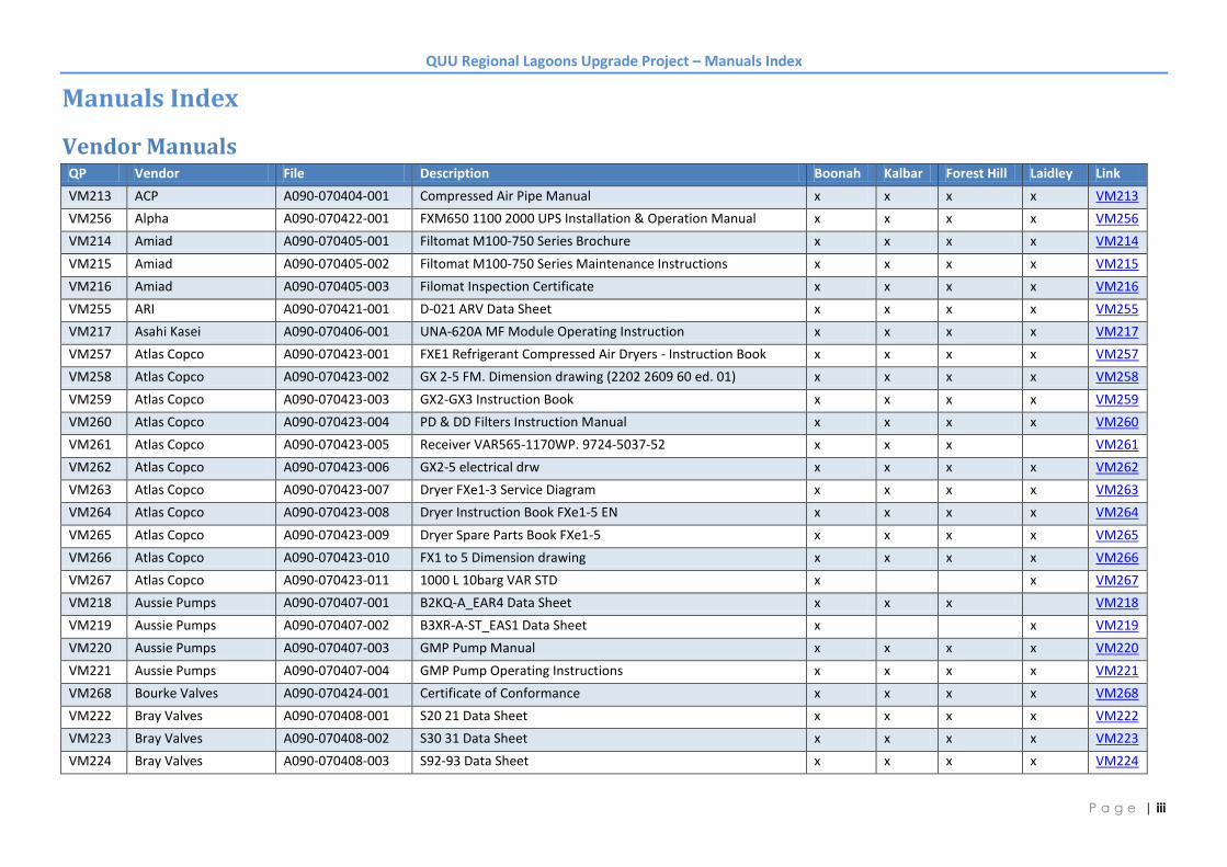
Vendor Manuals QP Vendor File Description Boonah Kalbar Forest Hill Laidley Link
VM213 ACP A090-070404-001 Compressed Air Pipe Manual x x x x VM213
VM256 Alpha A090-070422-001 FXM650 1100 2000 UPS Installation & Operation Manual x x x x VM256
VM214 Amiad A090-070405-001 Filtomat M100-750 Series Brochure x x x x VM214
VM215 Amiad A090-070405-002 Filtomat M100-750 Series Maintenance Instructions x x x x VM215
VM216 Amiad A090-070405-003 Filomat Inspection Certificate x x x x VM216
VM255 ARI A090-070421-001 D-021 ARV Data Sheet x x x x VM255
VM217 Asahi Kasei A090-070406-001 UNA-620A MF Module Operating Instruction x x x x VM217
VM257 Atlas Copco A090-070423-001 FXE1 Refrigerant Compressed Air Dryers - Instruction Book x x x x VM257
VM258 Atlas Copco A090-070423-002 GX 2-5 FM. Dimension drawing (2202 2609 60 ed. 01) x x x x VM258
VM259 Atlas Copco A090-070423-003 GX2-GX3 Instruction Book x x x x VM259
VM260 Atlas Copco A090-070423-004 PD & DD Filters Instruction Manual x x x x VM260
VM261 Atlas Copco A090-070423-005 Receiver VAR565-1170WP. 9724-5037-52 x x x VM261
VM262 Atlas Copco A090-070423-006 GX2-5 electrical drw x x x x VM262
VM263 Atlas Copco A090-070423-007 Dryer FXe1-3 Service Diagram x x x x VM263
VM264 Atlas Copco A090-070423-008 Dryer Instruction Book FXe1-5 EN x x x x VM264
VM265 Atlas Copco A090-070423-009 Dryer Spare Parts Book FXe1-5 x x x x VM265
VM266 Atlas Copco A090-070423-010 FX1 to 5 Dimension drawing x x x x VM266
VM267 Atlas Copco A090-070423-011 1000 L 10barg VAR STD x x VM267
VM218 Aussie Pumps A090-070407-001 B2KQ-A_EAR4 Data Sheet x x x VM218
VM219 Aussie Pumps A090-070407-002 B3XR-A-ST_EAS1 Data Sheet x x VM219
VM220 Aussie Pumps A090-070407-003 GMP Pump Manual x x x x VM220
VM221 Aussie Pumps A090-070407-004 GMP Pump Operating Instructions x x x x VM221
VM268 Bourke Valves A090-070424-001 Certificate of Conformance x x x x VM268
VM222 Bray Valves A090-070408-001 S20 21 Data Sheet x x x x VM222
VM223 Bray Valves A090-070408-002 S30 31 Data Sheet x x x x VM223
VM224 Bray Valves A090-070408-003 S92-93 Data Sheet x x x x VM224

QUU Regional Lagoons Upgrade Project – Manuals Index
| iv P a g e
QP Vendor File Description Boonah Kalbar Forest Hill Laidley Link
VM225 Bray Valves A090-070408-004 S6A Dimensional Drawing x x x x VM225
VM226 Bray Valves A090-070408-005 S30-S92-S50 Dimensional Drawing x x x x VM226
VM227 Bray Valves A090-070408-006 S31-S92-S50 Dimensional Drawing x x x x VM227
VM228 Bray Valves A090-070408-007 Pneumatic Actuators Product Guide x x x x VM228
VM229 Bray Valves A090-070408-008 RSBV Product Guide x x x x VM229
VM230 BVCI A090-070409-001 2500L Round Squat Corrugated Tank x x x x VM230
VM231 BVCI A090-070409-002 5000L Round Corrugated Tank x VM231
VM232 Caps A090-070410-001 SRV390 Conrader DataSheet x VM232
VM233 Caps A090-070410-002 Equip - Air receiver -GA drawing x VM233
VM328 Cashco A090-070439-001 Cashco - Installation Manual - Pressure Reducing Regulators - Models D & DL
x x x x VM328
VM330 Condamine Electric A090-070441-002 Electrical Safety Compliance Certificate - Boonah x VM330
VM331 Condamine Electric A090-070441-003 Electrical Safety Compliance Certificate - Kalbar x VM331
VM329 Condamine Electrical A090-070441-001 Electrical Safety Compliance Certificate - Forest Hill x VM329
VM332 Condamine Electrical A090-070441-004 Forrest Hill Electrical Certificate x VM332
VM333 Condamine Electrical A090-070441-005 Laidley Electrical Certificate x VM333
VM209 Control IT A090-070401-009 ITP x x x x VM209
VM325 Danfos A090-070436-001 VLT Aqua Drive Operating Instructions x x x x VM325
VM269 Emerson A090-070425-001 Calibration Certificate - Serial 02813759 x VM269
VM270 Emerson A090-070425-002 Calibration Certificate - Serial 02813760 x VM270
VM271 Emerson A090-070425-003 Calibration Certificate - Serial 02832612 x VM271
VM272 Emerson A090-070425-004 Calibration Certificate - Serial 02832616 x VM272
VM273 Emerson A090-070425-005 3900 Manual x x x x VM273
VM234 EzyStrut A090-070411-001 ET3_ET5 Cable Tray Assembly Guide x x x x VM234
VM294 Festo A090-070431-001 Analog Modules x x x x VM294
VM295 Festo A090-070431-002 CPX - Pin Assignment Instructions x x x x VM295
VM296 Festo A090-070431-003 CPX IO and valve blocks - Analogue IO Modules x x x x VM296
VM297 Festo A090-070431-004 CPX IO and valve blocks - Digital IO Modules x x x x VM297
VM298 Festo A090-070431-005 CPX IO and valve blocks - Install & Commisisoning Manual x x x x VM298
VM299 Festo A090-070431-006 CPX IO and valve blocks - Manual x x x x VM299

QUU Regional Lagoons Upgrade Project – Manuals Index
| v P a g e
QP Vendor File Description Boonah Kalbar Forest Hill Laidley Link
VM300 Festo A090-070431-007 CPX Mounting - Data Sheet x x x x VM300
VM301 Festo A090-070431-008 CPX_EN x x x x VM301
VM302 Festo A090-070431-009 CPX-BG-RW-10X Assembly Instructions x x x x VM302
VM303 Festo A090-070431-010 CPX-FB32 IO and valve blocks - Electronics Manual x x x x VM303
VM304 Festo A090-070431-011 CPX-FEC IO and valve blocks - Electronics Manual x x x x VM304
VM305 Festo A090-070431-012 MSB Operating Instructions x x x x VM305
VM306 Festo A090-070431-013 MSF - MS6 Operating Instructions x x x x VM306
VM307 Festo A090-070431-014 MS-LFR Accessories - Data Sheet x x x x VM307
VM308 Festo A090-070431-015 MS-LFR Filter Regulator - Data Sheet x x x x VM308
VM309 Festo A090-070431-016 MS-W Operating Instructions x x x x VM309
VM310 Festo A090-070431-017 SDE1 Pressure Switch - Data Sheet x x x x VM310
VM311 Festo A090-070431-018 SDE1 Pressure Switch - Install Manual x x x x VM311
VM312 Festo A090-070431-019 SDE1 Pressure Switch - Manual x x x x VM312
VM313 Festo A090-070431-020 SDE1-SH Pressure Switch Protective Hood - Data Sheet x x x x VM313
VM314 Festo A090-070431-021 Universal Connecting Cables - Data sheet x x x x VM314
VM315 Festo A090-070431-022 VTSA Valve Terminal - Manual x x x x VM315
VM316 Festo A090-070431-023 QS Series Pneumatic Fittings x x x x VM316
VM317 Festo A090-070431-024 Silencers x x x x VM317
VM274 GMP A090-070426-001 Self Priming End Centrifugal Electric Pumps Installation Instructions
x x x x VM274
VM235 Grundfos A090-070412-001 522 Injection Valve - Operation Manual x x x x VM235
VM236 Grundfos A090-070412-002 DD Chemical Tanks x x x x VM236
VM237 Grundfos A090-070412-003 Foot Valve IOM x x x x VM237
VM238 Gruvlok A090-070413-001 Fig 7305 HDPE Coupling x x x x VM238
VM239 Gruvlok A090-070413-002 Fig 7307 HDPE Transition Coupling x x x x VM239
VM240 Gruvlok A090-070413-003 HDPE Coupling Manual x x x x VM240
VM275 Hach A090-070427-001 Calibration Test Certificate - SC200 Controller - 1206C0043665 x VM275
VM276 Hach A090-070427-002 Calibration Test Certificate - SC200 Controller - 1210C0049992 x VM276
VM277 Hach A090-070427-003 FT660 SC User Manual x x x x VM277
VM278 Hach A090-070427-004 sc200 Controller User Manual x x x x VM278
QUU Regional Lagoons Upgrade Project – Manuals Index
| vi P a g e
QP Vendor File Description Boonah Kalbar Forest Hill Laidley Link
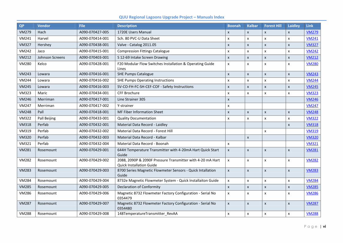
VM279 Hach A090-070427-005 1720E Users Manual x x x x VM279
VM241 Harvel A090-070414-001 Sch. 80 PVC-U Data Sheet x x x x VM241
VM327 Hershey A090-070438-001 Valve - Catalog 2011.05 x x x x VM327
VM242 Jaco A090-070415-001 Compression Fittings Catalogue x x x x VM242
VM212 Johnson Screens A090-070403-001 S 12-69 Intake Screen Drawing x x x x VM212
VM280 Kelco A090-070428-001 F20 Modular Flow Switches Installation & Operating Guide Lines
x x x x VM280
VM243 Lowara A090-070416-001 SHE Pumps Catalogue x x x x VM243
VM244 Lowara A090-070416-002 SHE Pumps Operating Instructions x x x x VM244
VM245 Lowara A090-070416-003 SV-CO-FH-FC-SH-CEF-COF - Safety Instructions x x x x VM245
VM323 Maric A090-070434-001 CFF Brochure x x x x VM323
VM246 Merriman A090-070417-001 Line Strainer 305 x VM246
VM247 Merriman A090-070417-002 Y-strainer x VM247
VM248 Pall A090-070418-001 MF Fiber Information Sheet x x x x VM248
VM322 Pall Beijing A090-070433-001 Quality Documentation x x x x VM322
VM318 Perfab A090-070432-001 Material Data Record - Laidley x VM318
VM319 Perfab A090-070432-002 Material Data Record - Forest Hill x VM319
VM320 Perfab A090-070432-003 Material Data Record - Kalbar x VM320
VM321 Perfab A090-070432-004 Material Data Record - Boonah x VM321
VM281 Rosemount A090-070429-001 644H Temperature Transmitter with 4-20mA Hart Quick Start Guide
x x x x VM281
VM282 Rosemount A090-070429-002 2088, 2090P & 2090F Pressure Transmitter with 4-20 mA Hart Quick Installation Guide
x x x x VM282
VM283 Rosemount A090-070429-003 8700 Series Magnetic Flowmeter Sensors - Quick Intallation Guide
x x x x VM283
VM284 Rosemount A090-070429-004 8732e Magnetic Flowmeter System - Quick Installaiton Guide x x x x VM284
VM285 Rosemount A090-070429-005 Declaration of Conformity x x x x VM285
VM286 Rosemount A090-070429-006 Magnetic 8732 Flowmeter Factory Configuration - Serial No 0354479
x x x x VM286
VM287 Rosemount A090-070429-007 Magnetic 8732 Flowmeter Factory Configuration - Serial No 0354480
x x x x VM287
VM288 Rosemount A090-070429-008 148TemperatureTransmitter_RevAA x x x x VM288

QUU Regional Lagoons Upgrade Project – Manuals Index
| vii P a g e
QP Vendor File Description Boonah Kalbar Forest Hill Laidley Link
VM289 Rosemount A090-070429-009 644HeadandRailMountTemperatureTransmitters_RevJA x x x x VM289
VM290 Rosemount A090-070429-010 RTD&ThermcoupleAssemblies_RevBA x x x VM290
VM324 Solberg A090-070435-001 F Series Filters x x x x VM324
VM249 Spears A090-070419-001 Saddle x x x x VM249
VM250 Spears A090-070419-002 Sch.80 Fittings x x x x VM250
VM251 Spears A090-070419-003 True Union Valves x x x x VM251
VM252 Spears A090-070419-004 Y-strainer x x x x VM252
VM326 Spill Station Australia A090-070437-001 Bunding Information x x x x VM326
VM210 TEE A090-070402-001 CIP Tank Heater - General Arrangement - TIH1001500 x x VM210
VM211 TEE A090-070402-002 CIP Tank Heater - General Arrangement - TIH1001200 x x x VM211
VM291 Vega A090-070430-001 PLICCOM Operating instructions x x x x VM291
VM292 Vega A090-070430-002 Vegason 61 Operating Instructions x x x x VM292
VM293 Vega A090-070430-003 Vegason 61 Product Info x x x x VM293
VM253 Wilden A090-070420-001 P25 Manual x x x x VM253
VM254 Wilden A090-070420-002 Declaration of Conformity x x x x VM254
VM334 Control IT A0901-070401-001 Checklist MCP - Boonah x VM334
VM335 Control IT A0901-070401-005 Commissioning MCP - Boonah x VM335
VM336 Control IT A0901-070401-010 Compliance Certificate - Boonah x VM336
VM337 Control IT A0902-070401-002 Checklist MCP - Kalbar x VM337
VM338 Control IT A0902-070401-006 Commissioning MCP - Kalbar x VM338
VM339 Control IT A0902-070401-011 Compliance Certificate - Kalbar x VM339
VM340 Control IT A0903-070401-003 Checklist - MCP - Laidley x VM340
VM341 Control IT A0903-070401-007 Commissioning MCP - Laidley x VM341
VM342 Control IT A0903-070401-012 Compliance Certifiate - Laidley x VM342
VM343 Control IT A0903-070401-013 Cabinet & Panel Checklist - MCP - Laidley x VM343
VM344 Control IT A0903-070401-014 Commissioning Checklist - MCP - Laidley x VM344
VM345 Control IT A0904-070401-004 Checklist MCP - Forest Hill x VM345
VM346 Control IT A0904-070401-008 Commissioning MCP - Forest Hill x VM346
VM347 Control IT A0904-070401-015 Compliance Certificate - Forest Hill x VM347
Modular electrical terminal CPX
Vendor Manual Festo A090-070431-008 CPX_EN
Q-Pulse Id VM301 Active 09/09/2013 Page 1 of 174
LeeR
Text Box
A090-070431-008

Subject to change – 2009/052 Internet: www.festo.com/catalogue/...
Terminal CPXKey features
Key features
Installation concept Electrical Mounting Operation
• Choice of multiple valve terminal
types for different applications:
– Type 03 MIDI/MAXI
– Type 12 CPA
– Type 32 MPA
– Type 44/45 VTSA/VTSA-F
• Economical from the smallest
configuration up to the maximum
number of modules
• Up to 9 electrical input/output
modules plus bus nodes and pneu-
matic interface/electronics modules
for valves
• Extensive range of functions and
connection options for the electrical
modules
• Selectable connection technology
for technically and economically
optimised connections
• Can be used as a dedicated remote
I/O module
• High operating voltage tolerance
(±25%)
• Choice of M18, 7/8’’ or AIDA push-
pull connection for power supply
• Open to all common fieldbus
protocols and Ethernet
• Optional function and technology
modules for pre-processing
• IT services and TCP/IP such as
remote maintenance, remote
diagnostics, web server, SMS and
e-mail alert
• Digital inputs and outputs,
4-fold/8-fold/16-fold, optionally
available with individual channel
diagnostics
• Analogue inputs and outputs,
2-fold/4-fold
• Temperature inputs
• IP65 and IP67 or IP20
• Wall or H-rail mounting, also on
mobile systems
• Conversions/extensions are
possible at any time, individual
linking with CPX metal design
• Modular system offering a range of
configuration options
• Fully assembled and tested unit
• Lower costs for selection, ordering,
assembly and commissioning
thanks to the central CPX terminal
• Design of optimised control loop
systems thanks to selectable
pneumatic components
• Decentralised, subordinate
installation system CPI improves
cycle times by up to 30%
• Safe and convenient earthing
thanks to earthing plate
• Fast troubleshooting thanks to an
extensive selection of LEDs (some of
which are multi-coloured) on the
bus node and on all I/O modules
• Supports module and channel-
oriented diagnostics
• On-the-spot diagnostics in plain
text via handheld device
• Fieldbus/Ethernet remote
diagnostics
• Innovative diagnostic support with
integrated web server/web monitor
or maintenance tool with USB
adapter for PC
• Optimised commissioning thanks
to parameterisable functions
• Reliability of service with connec-
tion blocks and modules that are
quick to replace without changing
the wiring
-V- NewAIDA push-pull
Vendor Manual Festo A090-070431-008 CPX_EN
Q-Pulse Id VM301 Active 09/09/2013 Page 2 of 174

2009/05 – Subject to change 3 Internet: www.festo.com/catalogue/...
Terminal CPXKey features
Pneumatic variants of the CPX terminal
The electrical CPX terminal is a
modular peripheral system for valve
terminals.
The system is specifically designed so
that the valve terminal can be
adapted to suit different applications.
The modular system design lets you
configure the correct number of
valves, inputs and additional outputs
to suit the application.
With valve terminal – decentralised With valve terminal MPA – centralised
With valve terminal VTSA – centralised In metal version with valve terminal VTSA – centralised
With valve terminal MIDI/MAXI – centralised With valve terminal CPA – centralised
Vendor Manual Festo A090-070431-008 CPX_EN
Q-Pulse Id VM301 Active 09/09/2013 Page 3 of 174

Subject to change – 2009/054 Internet: www.festo.com/catalogue/...
Terminal CPXKey features
Variants of the CPX terminal controller (with fieldbus node, without pre-processing)
Fieldbus node
Different bus nodes are used for
integration in the control systems of
various manufacturers.
The CPX terminal can therefore be
operated on over 90% of the most
commonly used fieldbus systems:
• Profibus-DP
• Interbus
• DeviceNet
• CANopen
• CC-Link
Integration in universal networks
based on Ethernet opens up new
possibilities. Faster data trans-
mission, real-time capability and
above all additional IT services such
as file transfer, web servers, web
monitor as integrated website inside
the CPX terminal, SMS/e-mail alerts,
etc. are opening up a wide range of
synergies.
This incorporates standardised and
universal communications technology
across all areas, including operating
level, control level and field level with
protection to IP 65/67.
The following protocols are supported:
• Ethernet/IP
• Modbus/TCP
• Profinet
• EtherCAT
Fieldbus node Fieldbus node Industrial Ethernet
PLC
Fieldbus
Web
IT services:
File transfer
PLC
Industrial Ethernet
• Communication with higher-order
controller via fieldbus
• No pre-processing
• Fieldbus protocol depending on
CPX fieldbus node used
• Up to 512 I/Os, depending on the
fieldbus node used
• Connection to a higher-order
controller directly via Ethernet/IP,
Modbus/TCP or ProfiNet
• No pre-processing
• Monitoring via Ethernet and web
applications
• Up to 512 I/Os
-H- Note
Every electrical connection can be
combined with an appropriate
number of I/O modules and/or
pneumatic components, depending
on its address capacity.
Likewise, every pneumatic variant of
the CPX terminal can be operated
with every electrical connection
variant.
Vendor Manual Festo A090-070431-008 CPX_EN
Q-Pulse Id VM301 Active 09/09/2013 Page 4 of 174

2009/05 – Subject to change 5 Internet: www.festo.com/catalogue/...
Terminal CPXKey features
Variants of the CPX terminal controller (with pre-processing in the FEC)
Control block
The optional Front End Controller
CPX-FEC, in parallel with a fieldbus
node, permits simultaneous access
via Ethernet and an integrated web
server, as well as autonomous pre-
processing. Access via Modbus/TCP
and EasyIP is also possible.
• Commissioning, programming
and diagnostics using the Festo
software tool FST 4.1 with
hardware configurator.
With FEC in standalone mode With FEC in Festo EasyIP mode
FSTFED
Web
IT services:
File transfer
Industrial Ethernet
• Decentralised controller with
direct machine mounting
• Interaction options via CPX-MMI
or Front End Display (FED)
• Possibility of downloading
programs via Ethernet (or via the
programming interface)
• Supports full expansion of all CPX
peripherals
• More than 300 I/Os
Beneficial application areas:
• Autonomous single workstations
• Interlinked, standalone
subsystems
• Automation using IT technology
• Fast pre-processing of the CPX
peripherals in the FEC
• Any data can be exchanged
between the FEC via EasyIP
• Several FECs can be operated and
monitored via one FED
• Remote diagnostics via an FED
and CPX Web Monitor
• No higher-order controller is
required
• More than 300 I/Os per CPX-FEC
Vendor Manual Festo A090-070431-008 CPX_EN
Q-Pulse Id VM301 Active 09/09/2013 Page 5 of 174

Subject to change – 2009/056 Internet: www.festo.com/catalogue/...
Terminal CPXKey features
Variants of the CPX terminal controller (with pre-processing in the FEC)
With FEC as remote controller on Ethernet With FEC as remote controller on fieldbus
Remote controller on Ethernet as the
pre-processing unit for decentralised,
standalone subsystems using IT
technology.
Fieldbus remote controller (combina-
tion with fieldbus nodes for Interbus,
Profibus-DP, Profinet, CANopen,
DeviceNet, CC-Link or EtherCAT) as
the pre-processing unit for distrib-
uted, standalone subsystems.
PLC
Web
IT services:
File transfer
Industrial Ethernet
Fieldbus
PLC
Web
IT services:
File transfer
Industrial Ethernet
• Connection to a higher-order
controller directly via Ethernet, no
further fieldbus nodes are
required
• Monitoring via Ethernet and web
applications
• Pre-processing of the CPX
peripherals through CPX-FEC
• More than 300 I/Os
• Fast pre-processing of the CPX
peripherals in the FEC
• Communication with higher-order
controller via fieldbus
• Optional additional monitoring
via Ethernet and web applications
• Downloading of programs via
programming interface
• More than 300 I/Os, fieldbus
nodes are only used for communi-
cation with the higher-order PLC
• Two fieldbus nodes for redundant
communication configuration
Vendor Manual Festo A090-070431-008 CPX_EN
Q-Pulse Id VM301 Active 09/09/2013 Page 6 of 174

2009/05 – Subject to change 7 Internet: www.festo.com/catalogue/...
Terminal CPXKey features
CPX Web Monitor – Online diagnostics for the CPX terminal 58
What is a CPX Web Monitor? What can a CPX Web Monitor do?
The CPX Web Monitor is a software
tool from Festo for all CPX modules
with integrated web server and
Ethernet connection:
• Supplied on CD-ROM
• Installation on PC
• Adaptable to application
• Loading via Ethernet to the web
server of the CPX module
The Web Monitor dynamically vi-
sualises information about the CPX
system and its modules via Ethernet
in the browser of a PC:
• Status and diagnostics of the CPX
system via modules and channels
• Status of the channels/valves
• SMS or e-mail alerts can be set
• Reading of CPX error memory
(fault trace)
• Setting of outputs (force mode)
Three password-protected access
levels protect access to the CPX
terminal.
How does the CPX Web Monitor communicate? What advantages does a CPX Web Monitor have?
An IP address is assigned to the
integrated web server. Depending
on the performance of the con-
nected Ethernet network, the CPX
web server can be accessed from
any PC.
Controllers or intelligent display
and operating units can communi-
cate with the CPX terminal.
• Expensive servicing is avoided
• Remote maintenance and moni-
toring of important device func-
tions (counters) for the prevention
of unjustified rights of recourse
• Preventive maintenance for
reduced downtimes
• No engineering/no development
of web applications
CPX Web Monitor – Application examples
Channel-oriented diagnostics Monitoring of analogue values
• Channel-specific status and error
message of an I/O module
• Error message in ”plain text”
describing the type of error
• Exact error identified and
appropriate service tasks
available
Possible error messages:
• Short circuit
• Overload
• Open load
• Supply voltage below the
tolerance limit
• Channel-specific status and error
message of an analogue I/O
module
• Display in plain text
• Dynamic display of the current
values at the inputs/outputs
Possible error messages:
• Open load
• Upper or lower limit value
exceeded
Error memory (fault trace) Plug and work with FEDs
Quick access to the last 40 diagnos-
tic results with timestamp.
Assistance in finding sporadic er-
rors and statistical accumulations.
The CPX Web Monitor can be
implemented directly on all Festo
touchpanels with the Windows CE
operating system
• FED 710 with 7.5’’ TFT display
• FED 1010 with 10.4’’ TFT display
• FED 2010 with 12.1’’ TFT display
• FED 5010 with 15’’ TFT display
Convenient remote maintenance via
Ethernet (TCP or Easy IP) is thus
possible.
Vendor Manual Festo A090-070431-008 CPX_EN
Q-Pulse Id VM301 Active 09/09/2013 Page 7 of 174

Subject to change – 2009/058 Internet: www.festo.com/catalogue/...
Terminal CPXKey features
Connection of inputs and outputs to the CPX terminal
Digital and analogue CPX I/O modules Electrical connection
The connection technology for the
sensors and additional actuators
offers a wide range of digital and
analogue input and output modules
and is freely selectable – depending
on your standards or application.
Connection blocks in plastic or
metal can be freely combined:
• Metal version
– M12-5-PIN
• Plastic version
– M12-5-PIN
– M12-5-PIN with quick lock and
metal thread
– M12-8-PIN
– M8-3-PIN
– M8-4-PIN
– Sub-D
– Harax®
– CageClamp®
(with cover also for IP65/67)
With CPX-CP interface
• Up to 4 strings per CP interface
possible
• Up to 4 subordinate CP modules
can be combined in a string
• Up to 32 I/Os can be connected
per string
• Modules with M8, M12 and
terminal connection
Several CP interface modules can be
combined in one CPX terminal
(depending on the controller used).
Combination of central CPX I/O mod-
ules and decentrally mounted I/O
modules of the CPI installation
system.
Combined centralised and decentralised connection (valve terminal with CP interface/output module)
• Can be scaled to different
requirements within a system
• One control interface in the system,
reduces installation complexity with
concentrated and widely dispersed
actuators
• Enables the implementation of an
optimum electrical and pneumatic
control loop system
Vendor Manual Festo A090-070431-008 CPX_EN
Q-Pulse Id VM301 Active 09/09/2013 Page 8 of 174

2009/05 – Subject to change 9 Internet: www.festo.com/catalogue/...
Terminal CPXKey features
Connection of inputs and outputs to the CPX terminal
With CPX-CMXX multi-axis interface
• Per CPX-CMXX 2 axis groups each
with up to 4 axes
• Up to 1024 positioning records
per axis group
• 2-axis gantries
• 3-axis gantries
Several CP interface modules can be
combined in one CPX terminal
(depending on the controller used).
Combination of central CPX I/O mod-
ules and decentrally mounted I/O
modules of the CPI installation
system.
Ordering
The CPX terminal with valve terminal
is fully assembled according to order
specifications and individually tested.
The finished valve terminal consists of
the electrical peripherals including
the desired actuation and the selected
components of the VTSA (ISO), VTSA-F,
CPA, MPA or MIDI/MAXI modules.
The CPX terminal with valve terminal
is ordered using two separate order
codes. One order code defines the
electrical peripherals type CPX, while
the other specifies the pneumatic
components of the valve terminal.
The electrical peripherals type CPX can
also be configured without a valve ter-
minal and can be used on a fieldbus.
For this order, only the order code for
the electrical peripherals is required.
The order lists for the pneumatic
components can be found in
Internet: type 44
(Valve terminal type 44 VTSA)
Internet: type 45
(Valve terminal type 45 VTSA-F)
Internet: type 12
(Valve terminal type 12 CPA)
Internet: type 32
(Valve terminal type 32 MPA)
Internet: type 03
(Valve terminal type 03
VIMP-/VIFB-03)
The order lists for the CP/CPI
components can be found in
Internet: ctec
(Installation system CPI)
Vendor Manual Festo A090-070431-008 CPX_EN
Q-Pulse Id VM301 Active 09/09/2013 Page 9 of 174
Subject to change – 2009/0510 Internet: www.festo.com/catalogue/...
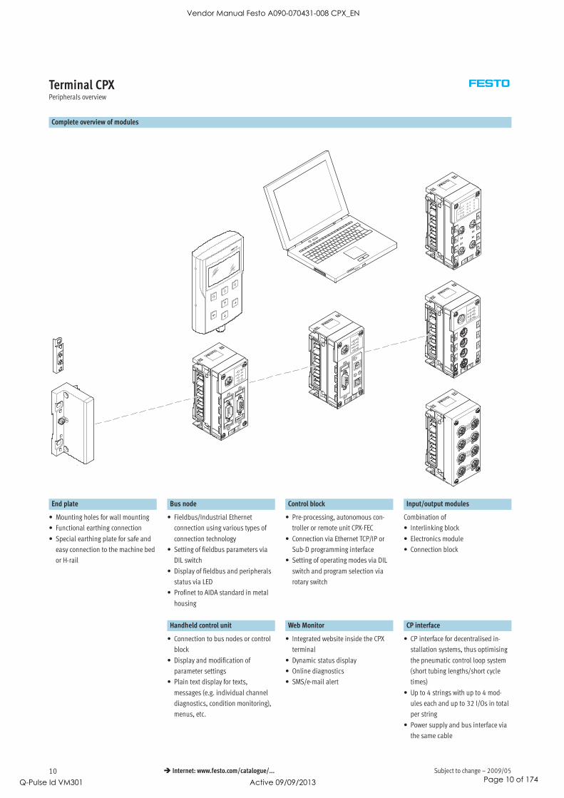
Terminal CPXPeripherals overview
Complete overview of modules
End plate Bus node Control block Input/output modules
• Mounting holes for wall mounting
• Functional earthing connection
• Special earthing plate for safe and
easy connection to the machine bed
or H-rail
• Fieldbus/Industrial Ethernet
connection using various types of
connection technology
• Setting of fieldbus parameters via
DIL switch
• Display of fieldbus and peripherals
status via LED
• Profinet to AIDA standard in metal
housing
• Pre-processing, autonomous con-
troller or remote unit CPX-FEC
• Connection via Ethernet TCP/IP or
Sub-D programming interface
• Setting of operating modes via DIL
switch and program selection via
rotary switch
Combination of
• Interlinking block
• Electronics module
• Connection block
Handheld control unit Web Monitor CP interface
• Connection to bus nodes or control
block
• Display and modification of
parameter settings
• Plain text display for texts,
messages (e.g. individual channel
diagnostics, condition monitoring),
menus, etc.
• Integrated website inside the CPX
terminal
• Dynamic status display
• Online diagnostics
• SMS/e-mail alert
• CP interface for decentralised in-
stallation systems, thus optimising
the pneumatic control loop system
(short tubing lengths/short cycle
times)
• Up to 4 strings with up to 4 mod-
ules each and up to 32 I/Os in total
per string
• Power supply and bus interface via
the same cable
Vendor Manual Festo A090-070431-008 CPX_EN
Q-Pulse Id VM301 Active 09/09/2013 Page 10 of 174

2009/05 – Subject to change 11 Internet: www.festo.com/catalogue/...
Terminal CPXPeripherals overview
Complete overview of modules
1
2
3
Input/output modules Pneumatic interface
1 Interlinking block 2 Electronics module 3 Connection block
• Internal linking of the power supply
and serial communication
• External power supply for the entire
system
• Additional power supply for outputs
or valves
• M18, 7/8’’ or AIDA push-pull
connection accessories
• Plastic version: Linking with tie
rods
• Metal version: Individual linking
with M6 screws, individually
expandable
• Digital inputs for connecting the
sensors
• Digital outputs for activation of
additional actuators
• Analogue inputs
• Temperature inputs (analogue)
• Analogue outputs
• Selectable connection technology
with 8 variants
• Protection class IP65/IP67 or IP20
• Freely combinable with the
electronics modules
• M8/M12/Sub-D/quick connector
• M8/M12/Sub-D, etc. connecting
cables
• Modular system for M8/M12
connecting cables
• M12 connection technology for the
metal version
• MPA1/2
• VTSA/VTSA-F
• MIDI/MAXI
• CPA10/14
-V- NewAIDA push-pull
Vendor Manual Festo A090-070431-008 CPX_EN
Q-Pulse Id VM301 Active 09/09/2013 Page 11 of 174

Subject to change – 2009/0512 Internet: www.festo.com/catalogue/...
Terminal CPXPeripherals overview
Individual overview of modules
Bus node
Bus node for
• Profibus-DP
• Interbus
• DeviceNet
• CANopen
• CC-Link
• Ethernet/IP
(integrated web server)
• Profinet
(integrated web server)
Control block for controlling valves
Control block
• Ethernet interface
• Modbus/TCP
• EasyIP
• Integrated web server
• Sub-D programming interface
CP interface
CP interface
• 4 CP strings
• Max. 4 modules per string
• 32 I/O per string
• CPI functionality
Control block for controlling electric drive units
Multi-axis interface
• Ethernet interface
• 2 axis groups with max. 4 axes per
group
• Per axis group max. 1024 position-
ing records
Vendor Manual Festo A090-070431-008 CPX_EN
Q-Pulse Id VM301 Active 09/09/2013 Page 12 of 174
2009/05 – Subject to change 13 Internet: www.festo.com/catalogue/...
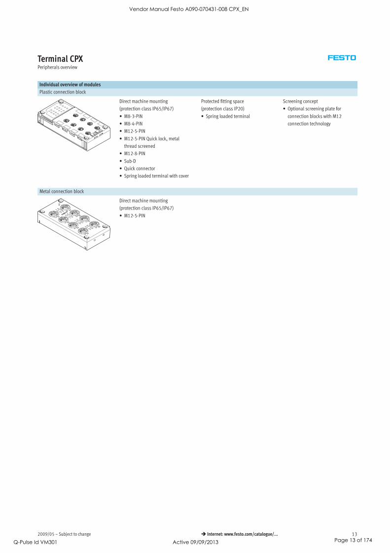
Terminal CPXPeripherals overview
Individual overview of modules
Plastic connection block
Direct machine mounting
(protection class IP65/IP67)
• M8-3-PIN
• M8-4-PIN
• M12-5-PIN
• M12-5-PIN Quick lock, metal
thread screened
• M12-8-PIN
• Sub-D
• Quick connector
• Spring loaded terminal with cover
Protected fitting space
(protection class IP20)
• Spring loaded terminal
Screening concept
• Optional screening plate for
connection blocks with M12
connection technology
Metal connection block
Direct machine mounting
(protection class IP65/IP67)
• M12-5-PIN
Vendor Manual Festo A090-070431-008 CPX_EN
Q-Pulse Id VM301 Active 09/09/2013 Page 13 of 174

Subject to change – 2009/0514 Internet: www.festo.com/catalogue/...
Terminal CPXPeripherals overview
Individual overview of modules
Digital electronics module for inputs/outputs
Digital inputs and outputs
• 4 digital inputs
• 8 digital inputs NPN
• 8 digital inputs PNP
• 8 digital inputs PNP with individual
channel diagnostics
• 16 digital inputs
• 16 digital inputs with individual
channel diagnostics
• 4 digital outputs (1 A per channel,
individual channel diagnostics)
• 8 digital outputs (0.5 A per chan-
nel, individual channel diagnostics)
• 8 digital outputs (2.1 A/50 W lamp
load per channel pair, individual
channel diagnostics)
Multi I/O modules
• 8 digital inputs and 8 digital
outputs
Analogue electronics module for inputs/outputs
Analogue inputs
• 2 analogue inputs (0 … 10 V DC,
0 … 20 mA, 4 … 20 mA)
• 4 analogue inputs (0 … 20 mA,
4 … 20 mA)
Analogue temperature inputs
• 4 analogue inputs for measuring
temperature (Pt100, Pt200, Pt500,
Pt1000, Ni100, Ni120, Ni500,
Ni1000)
• 4 analogue inputs for temperature
sensing (thermocoupler and
Pt1000 sensor for cold-position
compensation)
Analogue outputs
• 2 analogue outputs (0 … 10 V DC,
0 … 20 mA, 4 … 20 mA)
Vendor Manual Festo A090-070431-008 CPX_EN
Q-Pulse Id VM301 Active 09/09/2013 Page 14 of 174

2009/05 – Subject to change 15 Internet: www.festo.com/catalogue/...
Terminal CPXPeripherals overview
Individual overview of modules
Plastic interlinking block – Linking using tie rods
System linking
• Different voltage values for
supplying the modules
• Serial communication between the
modules
System supply
• M18, 4-pin
• 7/8” 4 or 5 pin
Additional power supply
In addition to system linking, power
supply for the
• actuators (16 A per supply)
Power supply for the
• valves (16 A per supply)
Expandability
-H- Note
The max. current is limited to 12 A
with the 7/8” system supply.
When using a conventional pre-
assembled cable, the max. current
is limited to 8 A.
• 7/8” 4- or 5-pin
In addition to system linking, power
supply for the
• electronics plus sensors (16 A)
• valves plus actuators (16 A)
Expandability
• Can be expanded to include an
interlinking block with tie rod
expansion CPX-ZA-1-E
Metal interlinking block – Individual linking
System linking
• Different voltage values for
supplying the modules
• Serial communication between the
modules
System supply
• 7/8” 5-pin
Additional power supply
In addition to system linking, power
supply for the
• actuators (16 A per supply)
Power supply for the
• valves (16 A per supply)
-H- Note
The max. current is limited to 12 A
with the 7/8” system supply.
When using a conventional pre-
assembled cable, the max. current
is limited to 8 A.
7/8 5 pin
• AIDA push-pull
In addition to system linking, power
supply for the
• electronics plus sensors (16 A)
• valves plus actuators (16 A)
Expandability
• Can be expanded up to
10 interlinking blocks
-H- Note
Interlinking blocks made from
plastic (tie rods) and from metal
(individual linking) cannot be
combined due to the fact that they
have different types of linking.
-V- NewAIDA push-pull
Vendor Manual Festo A090-070431-008 CPX_EN
Q-Pulse Id VM301 Active 09/09/2013 Page 15 of 174

Subject to change – 2009/0516 Internet: www.festo.com/catalogue/...
Terminal CPXPeripherals overview
Individual overview of modules
Pneumatic interface MPA 158 Pneumatic interface VTSA/VTSA-F 159
Valve terminal
• MPA1 (360 l/min)
• MPA2 (700 l/min)
• Up to 128 solenoid coils
• Up to 16 modules can be
configured
• For CPX plastic version
• For CPX metal version
Valve terminal
• 18 mm: Valve flow rate up to
700 l/min
• 26 mm: Valve flow rate up
to 1,400 l/min
• 42 mm: Valve flow rate up
to 1,500 l/min
• Max. 32 valve positions/
max. 32 solenoid coils
• For CPX plastic version
• For CPX metal version
Pneumatic interface MIDI/MAXI 160 Pneumatic interface CPA 162
Valve terminal
• MIDI valves (500 l/min)
and/or
MAXI valves (1,250 l/min)
• Up to 26 solenoid coils
• Setting of the number of valves via
DIL switch
• For CPX plastic version
• For CPX metal version
Valve terminal
• CPA10 (300 l/min)
• CPA14 (600 l/min)
• Up to 22 solenoid coils
• Setting of the number of valves via
DIL switch
• For CPX plastic version
Plastic end plate Metal end plate
End plate
• Left-hand
• Right-hand (for use without valves)
End plate
• Left-hand
• Right-hand (for use without valves)
Earthing plate (for plastic end plate)
Earthing plate
• For safe and easy connection to the
machine bed or H-rail, suitable for
right-hand and left-hand end plate
• Assembly and earthing in a single
processing step, which means:
– 50% time saving
– No additional material required
Vendor Manual Festo A090-070431-008 CPX_EN
Q-Pulse Id VM301 Active 09/09/2013 Page 16 of 174

2009/05 – Subject to change 17 Internet: www.festo.com/catalogue/...
Terminal CPXPeripherals overview
General basic data and guidelines
Max. 11 modules in total:
• One bus node and/or one control
block, freely positionable
• Up to 9 further input/output
modules, freely positionable
• An additional pneumatic interface,
always positioned as the last
module on the right-hand side
– For VTSA, VTSA-F, CPA and
MIDI/MAXI:
fixed operating range, set using
DIL switch
– For MPA:
16 MPA modules can be
configured
• Address capacity max. 512 inputs
and 512 outputs, depending on
bus node or control block
• One interlinking block with system
supply, freely positionable
• Multiple interlinking blocks with
additional power supply, always
positioned to the right of the inter-
linking block with system supply
• The connection blocks can, with
just a small number of exceptions,
be freely combined with the elec-
tronics modules for inputs/outputs,
also metal with plastic version
( table below)
• All electronics modules for inputs/
outputs can be combined with any
interlinking block
• Interlinking blocks made from plastic
(tie rods) and from metal (individual
linking) cannot be combined due to the
fact that they have different types of
linking
Vendor Manual Festo A090-070431-008 CPX_EN
Q-Pulse Id VM301 Active 09/09/2013 Page 17 of 174

Subject to change – 2009/0518 Internet: www.festo.com/catalogue/...
Terminal CPXPeripherals overview
Combinations of connection blocks with digital input modules
Connection blocks Digital electronics modules
CPX-4DE CPX-8DE CPX-16DE CPX-M-16DE-D CPX-8DE-D CPX-8NDE
Plastic version with mounting screws for mounting on plastic interlinking blocks
CPX-AB-8-M8-3POL – –
CPX-AB-8-M8X2-4POL – – – – –
CPX-AB-4-M12x2-5POL – –
CPX-AB-4-M12x2-5POL-R – –
CPX-AB-4-M12-8POL – – – – – –
CPX-AB-8-KL-4POL –
CPX-AB-1-SUB-BU-25POL –
CPX-AB-4-HAR-4POL – –
Plastic version with mounting screws for mounting on metal interlinking blocks
CPX-AB-8-M8x2-4P-M3 – – – – –
CPX-AB-4-M12-8P-M3 – – – – – –
CPX-AB-4-M12x2-5P-R-M3 – –
Metal version with mounting screws for mounting on metal and plastic interlinking blocks
CPX-M-4-M12x2-5POL – –
CPX-M-8-M12x2-5POL – – – – –
Combinations of connection blocks with digital output modules and multi I/O modules
Connection blocks Digital electronics modules
CPX-4DA CPX-8DA CPX-8DA-H CPX-8DE-8DA
Plastic version with mounting screws for mounting on plastic interlinking blocks
CPX-AB-8-M8-3POL – –
CPX-AB-8-M8X2-4POL –
CPX-AB-4-M12x2-5POL – –
CPX-AB-4-M12x2-5POL-R –
CPX-AB-4-M12-8POL – – –
CPX-AB-8-KL-4POL
CPX-AB-1-SUB-BU-25POL
CPX-AB-4-HAR-4POL – –
Plastic version with mounting screws for mounting on metal interlinking blocks
CPX-AB-8-M8x2-4P-M3 –
CPX-AB-4-M12-8P-M3 – – –
CPX-AB-4-M12x2-5P-R-M3 –
Metal version with mounting screws for mounting on metal and plastic interlinking blocks
CPX-M-4-M12x2-5POL –
CPX-M-8-M12x2-5POL – – – –
Vendor Manual Festo A090-070431-008 CPX_EN
Q-Pulse Id VM301 Active 09/09/2013 Page 18 of 174

2009/05 – Subject to change 19 Internet: www.festo.com/catalogue/...
Terminal CPXPeripherals overview
Combinations of connection blocks with analogue electronics modules for inputs and outputs
Connection blocks Analogue electronics modules
CPX-2AE-U-I CPX-4AE-I CPX-4AE-T CPX-4AE-TC CPX-2AA-U-I
Plastic version with mounting screws for mounting on plastic interlinking blocks
CPX-AB-4-M12x2-5POL
CPX-AB-4-M12x2-5POL-R
CPX-AB-8-KL-4POL
CPX-AB-1-SUB-BU-25POL – –
CPX-AB-4-HAR-4POL – – – –
Plastic version with mounting screws for mounting on metal interlinking blocks
CPX-AB-4-M12x2-5P-R-M3
Metal version with mounting screws for mounting on metal and plastic interlinking blocks
CPX-M-4-M12x2-5POL
Vendor Manual Festo A090-070431-008 CPX_EN
Q-Pulse Id VM301 Active 09/09/2013 Page 19 of 174

Subject to change – 2009/0520 Internet: www.festo.com/catalogue/...
Terminal CPXKey features – Electrical components
Electrical connection – Connection block
CPX-AB-8-M8-3POL with M8-3POL connection
2
• Compact for pre-assembled
individual connection
• 8 sockets
• 3-pin design for connection of
1 channel per socket
-H- Note
Festo delivers pre-assembled
M8/M12 connecting cables
(NEBU modular system) on customer
request:
• Individual
• Fits perfectly
• Installation-saving
1
2
3
Combination of connection block with electrical connection technology
Connection block Connection technology Plug connector/connecting cable Selectable connection technology
1 CPX-AB-8-M8-3POL Socket, M8, 3-pin 2 SEA-GS-M8 Solderable lugs1 3 , , 3 p
2 SEA-3GS-M8-S Screw terminals
3 KM8-M8-GSGD-…
(pre-assembled connecting cable)
Socket, M8, 3-pin
3 NEBU-…-M8G3 Socket, M5, 3-pin3 3
(modular system for choice of connecting cables) Socket, M8, 3-pin( y g )
Socket, M8, 4-pin
Socket, M12, 5-pin
Open cable end
Vendor Manual Festo A090-070431-008 CPX_EN
Q-Pulse Id VM301 Active 09/09/2013 Page 20 of 174
2009/05 – Subject to change 21 Internet: www.festo.com/catalogue/...
Terminal CPXKey features – Electrical components
Electrical connection – Connection block
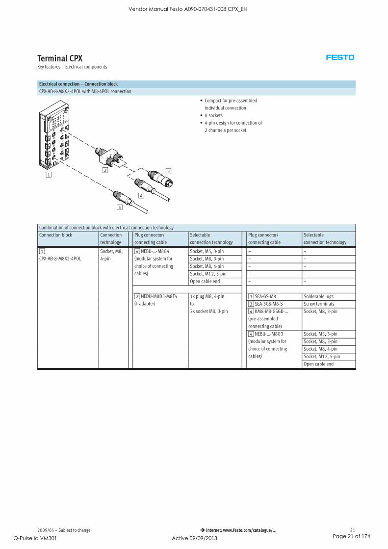
CPX-AB-8-M8X2-4POL with M8-4POL connection
12 3
4
5
• Compact for pre-assembled
individual connection
• 8 sockets
• 4-pin design for connection of
2 channels per socket
Combination of connection block with electrical connection technology
Connection block Connection
technology
Plug connector/
connecting cable
Selectable
connection technology
Plug connector/
connecting cable
Selectable
connection technology
1 Socket, M8, 4 NEBU-…-M8G4 Socket, M5, 3-pin – –1
CPX-AB-8-M8X2-4POL
, ,
4-pin
4
(modular system for Socket, M8, 3-pin – –p ( y
choice of connecting Socket, M8, 4-pin – –g
cables) Socket, M12, 5-pin – –)
Open cable end – –
2 NEDU-M8D3-M8T4 1x plug M8, 4-pin 3 SEA-GS-M8 Solderable lugs2 3
(T-adapter)
p g , p
to 3 SEA-3GS-M8-S Screw terminals( p )
2x socket M8, 3-pin 4 KM8-M8-GSGD-…
(pre-assembled
connecting cable)
Socket, M8, 3-pin
4 NEBU-…-M8G3 Socket, M5, 3-pin4 3
(modular system for Socket, M8, 3-pin( y
choice of connecting Socket, M8, 4-ping
cables) Socket, M12, 5-pin)
Open cable end
Vendor Manual Festo A090-070431-008 CPX_EN
Q-Pulse Id VM301 Active 09/09/2013 Page 21 of 174

Subject to change – 2009/0522 Internet: www.festo.com/catalogue/...
Terminal CPXKey features – Electrical components
Electrical connection – Connection block
CPX-AB-4-M12x2-5POL and CPX-AB-4-M12x2-5POL-R with M12-5POL connection
1
2
3
4
5 6
7
• Sturdy and pre-assembled with
2 channels per socket
• 4 sockets
• 5-pin design per socket
• Version …-R with quick-lock techno-
logy and metal thread for screening
• With two channels per socket, the
corresponding input signals can be
easily connected via a T-adapter
and conventional cable with M8
connection
Vendor Manual Festo A090-070431-008 CPX_EN
Q-Pulse Id VM301 Active 09/09/2013 Page 22 of 174

2009/05 – Subject to change 23 Internet: www.festo.com/catalogue/...
Terminal CPXKey features – Electrical components
Combination of connection block with electrical connection technology
Connection block Connection
technology
Plug connector/connecting
cable
Connection technology Plug connector/
connecting cable
Connection technology
1 Socket, M12, 2 SEA-GS-7 Screw terminals – –1
CPX-AB-4-M12x2-5POL
, ,
5-pin 2 SEA-4GS-7-2,5 Screw terminals – –
CPX-AB-4-M12x2-5POL-R
p
2 SEA-GS-9 Screw terminals – –
2 SEA-M12-5GS-PG7 Screw terminals – –
2 SEA-GS-11-DUO Screw terminals, for two
cables
– –
2 SEA-5GS-11-DUO Screw terminals, for two
cables
– –
3 KM12-M12-…
(pre-assembled connecting
cable)
Socket, M12, 4-pin – –
3 NEBU-…-M12G4 Socket, M5, 4-pin – –
3 NEBU-…-M12G5 Socket, M8, 4-pin – –3 5
Socket, M12, 5-pin – –
Open cable end – –
4 KM12-DUO-M8-… Plug M12, 4-pin 6 SEA-GS-M8 Solderable lugs4
(pre-assembled connecting
g , p
to 6 SEA-3GS-M8-S Screw terminals(p g
cable) 2x socket M8, 3-pin 7 KM8-M8-GSGD-…
(pre-assembled
connecting cable)
Socket, M8, 3-pin
5 NEDU-M8D3-M12T4 7 NEBU-…-M8G3 Socket, M5, 3-pin5 3
(T-adapter)
7 3
(modular system for Socket, M8, 3-pin( p ) ( y
choice of connecting Socket, M8, 4-ping
cables) Socket, M12, 5-pin)
Open cable end
5 NEDU-M12D5-M12T4 Plug M12, 4-pin 6 SEA-GS-7 Screw terminals5 5
(T-adapter)
g , p
to 6 SEA-4GS-7-2,5 Screw terminals( p )
2x socket M12, 5-pin 6 SEA-GS-9 Screw terminals, p
6 SEA-M12-5GS-PG7 Screw terminals
6 SEA-GS-11-DUO Screw terminals, for two
cables
6 SEA-5GS-11-DUO Screw terminals, for two
cables
7 KM12-M12-…
(pre-assembled
connecting cable)
Socket, M12, 4-pin
7 NEBU-…-M12G4
(modular system for
choice of connecting
cables)
Socket, M5, 4-pin
7 NEBU-…-M12G5
( d l t f
Socket, M8, 4-pin
(modular system for
choice of connectingSocket, M12, 5-pin
choice of connecting
cables) Open cable end
Vendor Manual Festo A090-070431-008 CPX_EN
Q-Pulse Id VM301 Active 09/09/2013 Page 23 of 174

Subject to change – 2009/0524 Internet: www.festo.com/catalogue/...
Terminal CPXKey features – Electrical components
Electrical connection – Connection block (metal version)
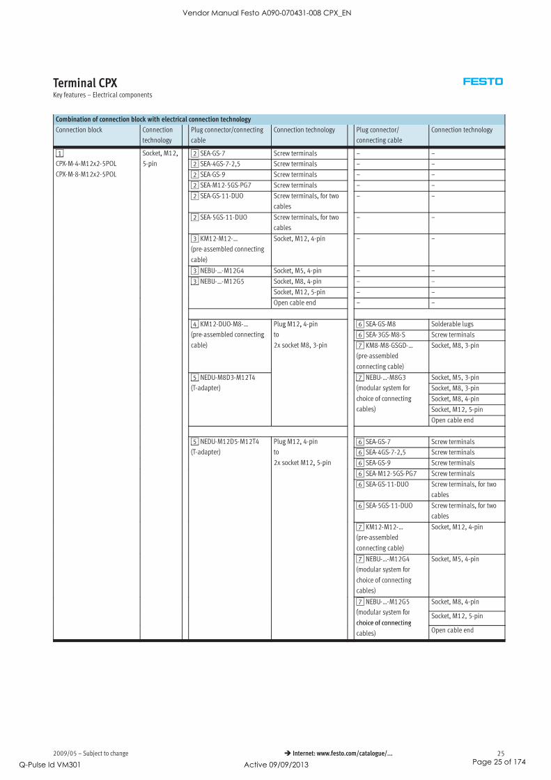
CPX-M-4-M12x2-5POL with M12-5POL connection
1
2
3
4
5 6
7
• Sturdy and for pre-assembly with
2 channels per socket
• 4 sockets
• 5-pin design per socket
• With two channels per socket, the
corresponding input signals can be
easily connected via a T-adapter
and conventional cable with M8
connection
CPX-M-8-M12x2-5POL with M12-5POL connection
1
2
3
4
5 6
7
• Sturdy and for pre-assembly with
2 channels per socket
• 8 sockets
• 5-pin design per socket
• With two channels per socket, the
corresponding input signals can be
easily connected via a T-adapter
and conventional cable with M8
connection
Vendor Manual Festo A090-070431-008 CPX_EN
Q-Pulse Id VM301 Active 09/09/2013 Page 24 of 174
2009/05 – Subject to change 25 Internet: www.festo.com/catalogue/...
Terminal CPXKey features – Electrical components
Combination of connection block with electrical connection technology
Connection block Connection
technology
Plug connector/connecting
cable
Connection technology Plug connector/
connecting cable
Connection technology
1 Socket, M12, 2 SEA-GS-7 Screw terminals – –1
CPX-M-4-M12x2-5POL
, ,
5-pin 2 SEA-4GS-7-2,5 Screw terminals – –
CPX-M-8-M12x2-5POL
p
2 SEA-GS-9 Screw terminals – –
2 SEA-M12-5GS-PG7 Screw terminals – –
2 SEA-GS-11-DUO Screw terminals, for two
cables
– –
2 SEA-5GS-11-DUO Screw terminals, for two
cables
– –
3 KM12-M12-…
(pre-assembled connecting
cable)
Socket, M12, 4-pin – –
3 NEBU-…-M12G4 Socket, M5, 4-pin – –
3 NEBU-…-M12G5 Socket, M8, 4-pin – –3 5
Socket, M12, 5-pin – –
Open cable end – –
4 KM12-DUO-M8-… Plug M12, 4-pin 6 SEA-GS-M8 Solderable lugs4
(pre-assembled connecting
g , p
to 6 SEA-3GS-M8-S Screw terminals(p g
cable) 2x socket M8, 3-pin 7 KM8-M8-GSGD-…
(pre-assembled
connecting cable)
Socket, M8, 3-pin
5 NEDU-M8D3-M12T4 7 NEBU-…-M8G3 Socket, M5, 3-pin5 3
(T-adapter)
7 3
(modular system for Socket, M8, 3-pin( p ) ( y
choice of connecting Socket, M8, 4-ping
cables) Socket, M12, 5-pin)
Open cable end
5 NEDU-M12D5-M12T4 Plug M12, 4-pin 6 SEA-GS-7 Screw terminals5 5
(T-adapter)
g , p
to 6 SEA-4GS-7-2,5 Screw terminals( p )
2x socket M12, 5-pin 6 SEA-GS-9 Screw terminals, p
6 SEA-M12-5GS-PG7 Screw terminals
6 SEA-GS-11-DUO Screw terminals, for two
cables
6 SEA-5GS-11-DUO Screw terminals, for two
cables
7 KM12-M12-…
(pre-assembled
connecting cable)
Socket, M12, 4-pin
7 NEBU-…-M12G4
(modular system for
choice of connecting
cables)
Socket, M5, 4-pin
7 NEBU-…-M12G5
( d l t f
Socket, M8, 4-pin
(modular system for
choice of connectingSocket, M12, 5-pin
choice of connecting
cables) Open cable end
Vendor Manual Festo A090-070431-008 CPX_EN
Q-Pulse Id VM301 Active 09/09/2013 Page 25 of 174

Subject to change – 2009/0526 Internet: www.festo.com/catalogue/...
Terminal CPXKey features – Electrical components
Electrical connection – Connection block
CPX-AB-4-M12-8POL with M12-8POL connection
1
2
• Connection to cylinder-valve
combinations with max. 3 inputs
and 2 outputs
• 4 sockets
• 8-pin design per socket
Combination of connection block with electrical connection technology
Connection block Connection technology Plug connector/connecting cable Selectable connection technology
1 CPX-AB-4-M12-8POL Socket, M12, 8-pin 2 KM12-8GD8GS-2-PU (pre-assembled connecting
cable)
Socket, M12, 8-pin
CPX-AB-8-KL-4POL with spring loaded terminal connection
1
2
• Fast connection technology for use
in control cabinets
• 32 spring-loaded terminals
• 4 terminals per channel
• Wire cross sections
0.05 … 1.5 mm2
• Optional cover with fittings for
IP65/67 connection
– 8 through-holes M9
– 1 through-hole M16
– Blanking plug
– For I/O distributors, consoles or
individual sensors/actuators
Combination of connection block with electrical connection technology
Connection block Connection technology Plug connector/connecting cable Selectable connection technology
1 CPX-AB-8-KL-4POL spring loaded terminals, 32-pin 2 AK-8KL (cover) –
Vendor Manual Festo A090-070431-008 CPX_EN
Q-Pulse Id VM301 Active 09/09/2013 Page 26 of 174

2009/05 – Subject to change 27 Internet: www.festo.com/catalogue/...
Terminal CPXKey features – Electrical components
Electrical connection – Connection block
CPX-AB-1-SUB-BU-25POL with Sub-D connection
12
• Multi-pin plug connection for I/O
distributor or console
• One socket
• 25-pin design
Combination of connection block with electrical connection technology
Connection block Connection technology Plug connector/connecting cable Selectable connection technology
1 CPX-AB-1-SUB-BU-25POL Socket, Sub-D, 25-pin 2 SD-SUB-D-ST25 Crimp contacts
CPX-AB-4-HARx2-4POL with HARAX connection
1
2
• Sturdy, fast connection technology
for individual connections
• 4 sockets
• 4-pin design per socket
Combination of connection block with electrical connection technology
Connection block Connection technology Plug connector/connecting cable Selectable connection technology
1 CPX-AB-4-HAR-4POL Socket, HARAX, 4-pin 2 SEA-GS-HAR-4POL Insulation displacement
connectors
Vendor Manual Festo A090-070431-008 CPX_EN
Q-Pulse Id VM301 Active 09/09/2013 Page 27 of 174

Subject to change – 2009/0528 Internet: www.festo.com/catalogue/...
Terminal CPXKey features – Mounting types
Mounting options
Valve terminals with CPX terminal
support different mounting methods
for direct machine mounting with high
protection and control cabinet
installation.
H-rail mounting
A
B
The H-rail mounting is formed in the
reverse profile of the CPX interlinking
blocks. The CPX terminal can be
attached to the H-rail using the H-rail
mounting kit.
The CPX terminal is attached to the
H-rail as follows (see arrow A).
It is first swivelled on the H-rail and
then secured in place with the
clamping component (see arrow B).
The optional earthing plate allows a
convenient working connection to be
established to the machine potential/
earth.
The following mounting kit is required
for H-rail mounting:
• CPA-BG-NRH
This enables mounting of the CPX on
H-rails to EN 60715.
An additional mounting kit is required
for combination with valve terminals.
Wall mounting for plastic version
The end plates of the CPX terminal,
the valve terminal and the pneumatic
interface include mounting holes for
wall mounting. For longer valve ter-
minals, there are additional mount-
ings for the CPX terminal. These
mountings vary depending on the CPX
terminal version (plastic or metal).
Wall mounting for metal version
Vendor Manual Festo A090-070431-008 CPX_EN
Q-Pulse Id VM301 Active 09/09/2013 Page 28 of 174

2009/05 – Subject to change 29 Internet: www.festo.com/catalogue/...
Terminal CPXKey features – Mounting types
CPX terminal in plastic version
Additional mountings
For longer valve terminals, there are
additional mountings for the CPX
terminal that can be fitted between
two modules.
-H- Note
In the case of CPX terminals with
4 and more interlinking blocks,
additional mountings of type
CPX-BG-RW-… must be used approx.
every 100 or 150 mm. These are
supplied pre-assembled.
Linking with tie rods
2
3
1
The mechanical connection between
the CPX modules is created using
special tie rods2. Two screws in the
end plates are all that are needed to
assemble the entire unit.
The tie rod ensures that the unit with-
stands high mechanical loads and is
therefore the “mechanical backbone”
of the CPX terminal.
The open design allows interlinking
blocks1 to be replaced in the
assembled state.
The tie rod expansion kit3 enables
an extra module to be added to the
CPX terminal.
CPX terminal in metal version
Additional mounting parts
For longer valve terminals, there are
additional mounting brackets for the
CPX terminal that can be fitted to the
interlinking blocks.
-H- Note
In the case of CPX terminals with
4 and more interlinking blocks,
additional mounting brackets of type
CPX-M-BG-RW-… must be used
approx. every 100 or 150 mm. These
are supplied pre-assembled.
Linking with screws
The mechanical connection between
the CPX modules is created using a
splayed screw connection.
The CPX terminal is thus flexibly
expandable at any time.
Vendor Manual Festo A090-070431-008 CPX_EN
Q-Pulse Id VM301 Active 09/09/2013 Page 29 of 174

Subject to change – 2009/0530 Internet: www.festo.com/catalogue/...
Terminal CPXKey features – Power supply
Power supply concept
General information
The use of decentralised devices on
the fieldbus – particularly with high
protection for direct machine mount-
ing – demands a flexible power supply
concept. A valve terminal with CPX can
be supplied with all voltages using a
single socket.
A distinction is made between supply
for
• electronics plus sensors
• valves plus actuators
in this case. The following connecting
thread can be selected:
• M18
• 7/8”
Interlinking blocks
Interlinking blocks represent the
backbone of the CPX terminal with all
supply lines. They provide the power
supply for the modules used on them
as well as the bus connection.
Many applications require the CPX
terminal to be segmented into voltage
zones. This applies in particular to the
separate disconnection of solenoid
coils and outputs.
The interlinking blocks provide either
a space-saving central power supply
for the entire CPX terminal or galvani-
cally isolated, all-pin disconnectable
potential groups/voltage segments.
Vendor Manual Festo A090-070431-008 CPX_EN
Q-Pulse Id VM301 Active 09/09/2013 Page 30 of 174

2009/05 – Subject to change 31 Internet: www.festo.com/catalogue/...
Terminal CPXKey features – Power supply
Interlinking blocks
With system supply
Type – plastic version
• CPX-GE-EV-S
• CPX-GE-EV-S-7/8-5POL
• CPX-GE-EV-S-7/8-4POL
Type – metal version
• CPX-M-GE-EV-S-7/8-5POL
• CPX-M-GE-EV-S-PP-5POL
Connection technology
• M18
• 7/8” 5-pin
• 7/8” 4-pin
Connection technology
• 7/8” 5-pin
• AIDA push-pull 5-pin
Power supply
• For CPX terminal modules and
connected sensors
• For valves that are connected to the
CPX terminal via a pneumatic
interface
• For actuators that are connected to
CPX terminal output modules
Without power supply
Type – plastic version
• CPX-GE-EV
Type – metal version
• CPX-M-GE-EV
–
–
–
With additional power supply for outputs
Type – plastic version
• CPX-GE-EV-Z
• CPX-GE-EV-Z-7/8-5POL
• CPX-GE-EV-Z-7/8-4POL
Type – metal version
• CPX-M-GE-EV-Z-7/8-5POL
• CPX-M-GE-EV-Z-PP-5POL
Connection technology
• M18
• 7/8” 5-pin
• 7/8” 4-pin
Connection technology
• 7/8” 5-pin
• AIDA push-pull 5-pin
Power supply
• For actuators that are connected to
CPX terminal output modules
With additional power supply for valves
Type – plastic version
• CPX-GE-EV-V
• CPX-GE-EV-V-7/8-4POL
Connection technology
• M18
• 7/8” 4-pin
Power supply
• For valves that are connected to the
CPX terminal via a pneumatic
interface
-H- Note -H- Note
For 7/8”:
– Commercially available
accessories are often limited
to max. 8 A
Valve terminal type 32 MPA has
either a 7/8”, 5-pin, 7/8”, 4-pin or
M18, 3-pin power supply for one or
more voltage zones of the valves.
Galvanically isolated, all-pin discon-
nectable with voltage monitoring in
the following MPA module.
-V- NewAIDA push-pull
Vendor Manual Festo A090-070431-008 CPX_EN
Q-Pulse Id VM301 Active 09/09/2013 Page 31 of 174
Subject to change – 2009/0532 Internet: www.festo.com/catalogue/...
Terminal CPXKey features – Diagnostics
Diagnostics
System performance
3 4
1 2 5 6
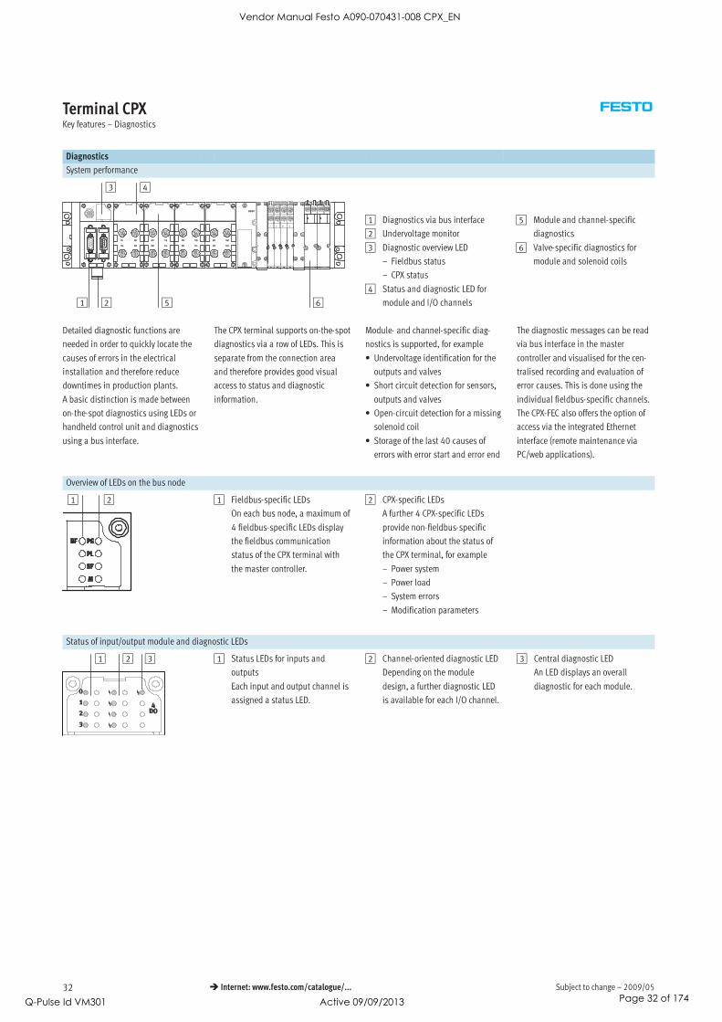
1 Diagnostics via bus interface
2 Undervoltage monitor
3 Diagnostic overview LED
– Fieldbus status
– CPX status
4 Status and diagnostic LED for
module and I/O channels
5 Module and channel-specific
diagnostics
6 Valve-specific diagnostics for
module and solenoid coils
Detailed diagnostic functions are
needed in order to quickly locate the
causes of errors in the electrical
installation and therefore reduce
downtimes in production plants.
A basic distinction is made between
on-the-spot diagnostics using LEDs or
handheld control unit and diagnostics
using a bus interface.
The CPX terminal supports on-the-spot
diagnostics via a row of LEDs. This is
separate from the connection area
and therefore provides good visual
access to status and diagnostic
information.
Module- and channel-specific diag-
nostics is supported, for example
• Undervoltage identification for the
outputs and valves
• Short circuit detection for sensors,
outputs and valves
• Open-circuit detection for a missing
solenoid coil
• Storage of the last 40 causes of
errors with error start and error end
The diagnostic messages can be read
via bus interface in the master
controller and visualised for the cen-
tralised recording and evaluation of
error causes. This is done using the
individual fieldbus-specific channels.
The CPX-FEC also offers the option of
access via the integrated Ethernet
interface (remote maintenance via
PC/web applications).
Overview of LEDs on the bus node
1 2 1 Fieldbus-specific LEDs
On each bus node, a maximum of
4 fieldbus-specific LEDs display
the fieldbus communication
status of the CPX terminal with
the master controller.
2 CPX-specific LEDs
A further 4 CPX-specific LEDs
provide non-fieldbus-specific
information about the status of
the CPX terminal, for example
– Power system
– Power load
– System errors
– Modification parameters
Status of input/output module and diagnostic LEDs
1 2 3 1 Status LEDs for inputs and
outputs
Each input and output channel is
assigned a status LED.
2 Channel-oriented diagnostic LED
Depending on the module
design, a further diagnostic LED
is available for each I/O channel.
3 Central diagnostic LED
An LED displays an overall
diagnostic for each module.
Vendor Manual Festo A090-070431-008 CPX_EN
Q-Pulse Id VM301 Active 09/09/2013 Page 32 of 174

2009/05 – Subject to change 33 Internet: www.festo.com/catalogue/...
Terminal CPXKey features – Parameterisation
Diagnostics
Display on handheld control unit
1
1 LCD graphical display for
plain text diagnostics on the spot
– Location and type of fault
– No programming
Display on PC
2
3
1
1 CPX terminal with valve terminal
2 Adapter cable for USB diagnostic
interface
3 Laptop/handheld device with
USB interface and installed
FMT soft
– Fault location and type
– Without programming
– Saving the configuration
– Producing screen shots
Display on Web Monitor
The Web Monitor displays all static
and dynamic information on a CPX
terminal via Ethernet online – in the
web browser of the PC.
This facility is optionally available via
intranet and Internet. Everything is
plug & work – without the need for
web programming such as HTML or
CPX Web Monitor overview Analogue module, channel-oriented
diagnostics
Error memory (fault trace)
web programming such as HTML or
JAVA.
Parameterisation
Changes to the application are often
required during commissioning.
Thanks to the parameterisable char-
acteristics of CPX modules, functions
can be very easily changed by means
of configuration software. This reduces
the number of modules needed and,
consequently, the amount of storage
space required.
It is therefore possible for example to
reduce the input debounce time for an
input module – normally 3 ms – to
0.1 ms on a “fast” input module for
faster processes, or to set the re-
sponse of a valve following a fieldbus
failure.
Depending on the modules used,
parameterisation can be performed
via the following interfaces:
• Ethernet
• Fieldbus
• FEC direct interface (programming
interface)
• Handheld control unit CPX-MMI
1
21 Input debounce time 3 ms
2 Input debounce time 0.1 ms
Vendor Manual Festo A090-070431-008 CPX_EN
Q-Pulse Id VM301 Active 09/09/2013 Page 33 of 174

Subject to change – 2009/0534 Internet: www.festo.com/catalogue/...
Terminal CPXKey features – Addressing
Addressing
General information on addressing
The various CPX modules occupy a
different number of I/O addresses
within the CPX system. The maximum
address space for bus nodes depends
on the performance of the fieldbus
system.
Maximum system extension:
• 1 bus node or control block
• 9 I/O modules
• 1 pneumatic interface
(e.g. pneumatic interface MPA with
up to 16 MPA manifold sub-bases)
The maximum system extension can
be limited in individual cases by
exceeding the address space.
-H- Note
Please refer to the detailed descrip-
tion of the configuration/addressing
rules in the technical data for CPX
bus nodes.
Overview – Allocated addresses for CPX modules
Inputs [bit] Outputs [bit]
CPX-CMXX 2 x 64 2 x 64
CPX-4DE 4 –
CPX-8DE 8 –
CPX-16DE 16 –
CPX-M-16DE-D 16 –
CPX-8DE-D 8 –
CPX-8NDE 8 –
CPX-4DA – 4
CPX-8DA – 8
CPX-8DA-H – 8
CPX-8DE-8DA 8 8
CPX-2AE 2 x 16 –
CPX-4AE-I 4 x 16 –
CPX-4AE-T 4 x 16 –
CPX-4AE-TC 4 x 16 –
CPX-2AA – 2 x 16
VABA-S6-1-X1 – 8, 16, 24, 321)
VABA-S6-1-X2 – 8, 16, 24, 321)
CPX-GP-CPA-10 – 8, 16, 241)
CPX-GP-CPA-14 – 8, 16, 241)
CPX-GP-03-4,0 – 8, 16, 24, 321)
CPX-M-GP-03-4,0 – 8, 16, 24, 321)
VMPA1-FB-EMS-8 – 8
VMPA1-FB-EMG-8 – 8
VMPA2-FB-EMS-4 – 4
VMPA2-FB-EMG-4 – 4
VMPA1-FB-EMS-D2-8 – 8
VMPA1-FB-EMG-D2-8 – 8
VMPA2-FB-EMS-D2-4 – 4
VMPA2-FB-EMG-D2-4 – 4
VMPA-FB-PS-1 16 –
VMPA-FB-PS-3/5 16 –
VMPA-FB-PS-P1 16 –
VMPA-FB-EMG-P1 16 16
1) Depends on the DIL switch setting on the pneumatic interface
Vendor Manual Festo A090-070431-008 CPX_EN
Q-Pulse Id VM301 Active 09/09/2013 Page 34 of 174
2009/05 – Subject to change 35 Internet: www.festo.com/catalogue/...
Terminal CPXKey features – Addressing
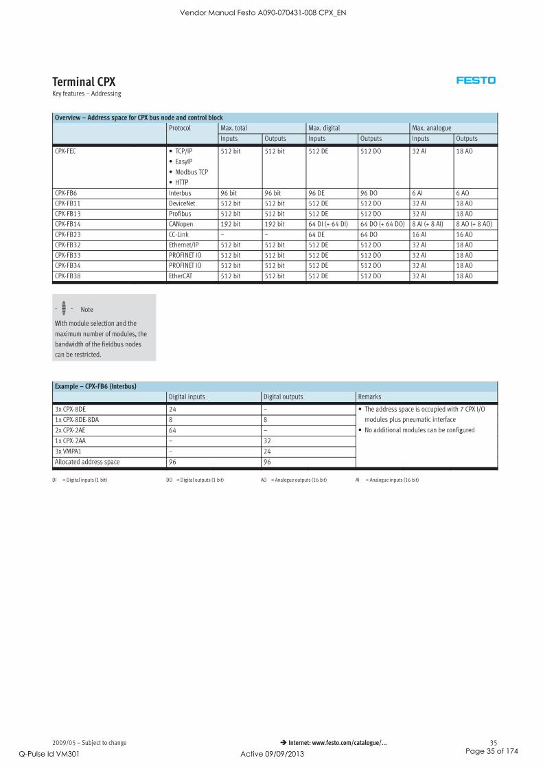
Overview – Address space for CPX bus node and control block
Protocol Max. total Max. digital Max. analogue
Inputs Outputs Inputs Outputs Inputs Outputs
CPX-FEC • TCP/IP
• EasyIP
• Modbus TCP
• HTTP
512 bit 512 bit 512 DE 512 DO 32 AI 18 AO
CPX-FB6 Interbus 96 bit 96 bit 96 DE 96 DO 6 AI 6 AO
CPX-FB11 DeviceNet 512 bit 512 bit 512 DE 512 DO 32 AI 18 AO
CPX-FB13 Profibus 512 bit 512 bit 512 DE 512 DO 32 AI 18 AO
CPX-FB14 CANopen 192 bit 192 bit 64 DI (+ 64 DI) 64 DO (+ 64 DO) 8 AI (+ 8 AI) 8 AO (+ 8 AO)
CPX-FB23 CC-Link – – 64 DE 64 DO 16 AI 16 AO
CPX-FB32 Ethernet/IP 512 bit 512 bit 512 DE 512 DO 32 AI 18 AO
CPX-FB33 PROFINET IO 512 bit 512 bit 512 DE 512 DO 32 AI 18 AO
CPX-FB34 PROFINET IO 512 bit 512 bit 512 DE 512 DO 32 AI 18 AO
CPX-FB38 EtherCAT 512 bit 512 bit 512 DE 512 DO 32 AI 18 AO
-H- Note
With module selection and the
maximum number of modules, the
bandwidth of the fieldbus nodes
can be restricted.
Example – CPX-FB6 (Interbus)
Digital inputs Digital outputs Remarks
3x CPX-8DE 24 – • The address space is occupied with 7 CPX I/O
1x CPX-8DE-8DA 8 8
p p 7 /
modules plus pneumatic interface
2x CPX-2AE 64 –
p p
• No additional modules can be configured
1x CPX-2AA – 32
g
3x VMPA1 – 24
Allocated address space 96 96
DI = Digital inputs (1 bit) DO = Digital outputs (1 bit) AO = Analogue outputs (16 bit) AI = Analogue inputs (16 bit)
Vendor Manual Festo A090-070431-008 CPX_EN
Q-Pulse Id VM301 Active 09/09/2013 Page 35 of 174

Subject to change – 2009/0536 Internet: www.festo.com/catalogue/...
Terminal CPXKey features – Type codes for connection technology
SEA — GS — HAR — 4POL
Type
SEA Plug connector for inputs/outputs, M12x1
connection
Design
GS Straight plug connector
Connection
HAR Quick connector
Number of pins
4POL 4-pin
SD — SUB–D — ST25
Type
SD Plug connector for inputs/outputs
Design
SUB-D SUB-D
Cable connection
ST25 Connector pin, 25-pin
FBA — 1 — SL — 5POL —
Type
FBA Bus connection, Sub-D socket, 9-pin
Number of cable connections
1 1 connection
2 2 connections
Cable connection
M12 2x threaded connections M12x1, 5-pin
(1x pin, 1x socket)
SL 5-pin row
Number of pins
5POL 5-pin
Coding
RK Reverse Key coded (B-coded)
Vendor Manual Festo A090-070431-008 CPX_EN
Q-Pulse Id VM301 Active 09/09/2013 Page 36 of 174

2009/05 – Subject to change 37 Internet: www.festo.com/catalogue/...
Terminal CPXKey features – Type codes for connection technology
FBS — SUB — 9 — GS — 1X9POL — B
Type
FBS Plug connector for bus connection
Design
SUB SUB-D
Number of pins
9 9-pin
Cable connection design
BU Socket
GS Straight plug connector
Cable connection
2X4POL 2x PG connector (2x terminal block, 4-pin)
1X9POL PG9 connector (2x terminal block, 4-pin)
IB For Interbus
Generation
B B series
SEA — GS — 7 —
Type
SEA Plug connector for inputs/outputs
Design
GS Straight plug connector
Cable connection
7 PG7 connector (cable opening 4 … 6 mm)
9 PG9 connector (cable opening 6 … 8 mm)
11 PG11 connector (cable opening 3 … 5 mm)
No. of outputs
DUO For 2 cables
Vendor Manual Festo A090-070431-008 CPX_EN
Q-Pulse Id VM301 Active 09/09/2013 Page 37 of 174

Subject to change – 2009/0538 Internet: www.festo.com/catalogue/...
Terminal CPXKey features – Type codes for connection technology
SEA — 3GS — M8 — S
Type
SEA Plug connector for inputs/outputs
Design
GS Straight plug connector, 3-pin
3GS Straight plug connector, 3-pin
Connection
M8 Threaded connection M8x1
Cable connection
S With screw terminals
(cable opening 2.5 … 5 mm)
SEA — 4GS — 7 — 2,5
Type
SEA Plug connector for inputs/outputs
Design
4GS Straight plug connector, 4-pin
Cable connection
7 PG7 connector
Cable opening
2,5 2.5 … 2.9 mm
SEA — M12 — 5GS — PG7
Type
SEA Plug connector for inputs/outputs
Connection
M12 Threaded connection M12x1
Design
5GS Straight plug connector, 5-pin
Cable connection
PG7 PG7 connector
Vendor Manual Festo A090-070431-008 CPX_EN
Q-Pulse Id VM301 Active 09/09/2013 Page 38 of 174

2009/05 – Subject to change 39 Internet: www.festo.com/catalogue/...
Terminal CPXKey features – Type codes for connection technology
NTSD — GD — 13,5
Type
NTSD Plug socket for mains connection
Design
GD Straight socket, 4-pin
Cable connection
9 PG9 connector (cable opening 6 … 8 mm)
13,5 PG13.5 connector
NTSD — WD — 9
Type
NTSD Plug socket for mains connection
Design
WD Angled plug socket, 4-pin
Cable connection
9 Cable opening 6 … 11 mm
11 Cable opening 5 … 11 mm
CPX–AB — 2 — M12 — RK — IB
Type
CPX-AB Connector block for CPX Profibus node
Number of cable connections
2 2 connections
Connection
M12 Threaded connection M12x1
Coding
RK Reverse Key coded (B-coded)
Cable connection
IB For Interbus
DP For Profibus
Vendor Manual Festo A090-070431-008 CPX_EN
Q-Pulse Id VM301 Active 09/09/2013 Page 39 of 174

Subject to change – 2009/0540 Internet: www.festo.com/catalogue/...
Terminal CPXKey features – Type codes for connection technology
FBS — RJ45 — — GS
Type
FBS Fieldbus plug
Connection
RJ45 RJ45 push-in connector
Number of pins
8 8-pin
PP Push Pull
Design
GS Straight plug connector
NECU — M — S — D12 G 4 — — ET
Type
NECU Plug connector
Design
– Standard
M Primarily from metal
Type of connection
– Socket
S Plug
Connection
D12 M12, D-coded
G78 7/8” round plug connector
Design
G Straight
Number of pins
4 4-pin
5 5-pin
Cable connection
– Standard
C2 Cable terminal
Bus protocol
– Standard
ET Ethernet
Vendor Manual Festo A090-070431-008 CPX_EN
Q-Pulse Id VM301 Active 09/09/2013 Page 40 of 174

2009/05 – Subject to change 41 Internet: www.festo.com/catalogue/...
Terminal CPXKey features – Type codes for connection technology
NEBU — M12 W 5 P — K — 2.5 — — LE 3
Function
NEBU Connecting cable
Connection, left
M5 Socket with connecting thread
M8 Socket with connecting thread
M12 Socket with connecting thread, A-coded
Socket design
G Straight
W Angled
Number of pins/wires (left)
3 3-pin (suitable for M8 plug)
4 4-pin (suitable for M8 plug)
5 5-pin (suitable for 3-, 4- and 5-pin M12
plug)
Display
– Without LED, DC (standard)
P LED, PNP
N LED, NPN
Cable attribute
K Standard
E Suitable for chain link trunking
R Suitable for robot applications
Cable length
0.1 … 25 0.1 … 25 m
Alternative wire cross section
– 0.25 mm2 (standard)
Q3 0.14 mm2
Cable designation
– With inscription label holder (standard)
N Without inscription label holder
Connection, right
LE Open end
M8 Socket with connecting thread
M12 Socket with connecting thread, A-coded
Plug design
G Straight
W Angled
Number of pins/wires (right)
3 3-pin (suitable for M8/M12 socket)
4 4-pin (suitable for M8/M12 socket)
5 5-pin (suitable for M12 socket)
Vendor Manual Festo A090-070431-008 CPX_EN
Q-Pulse Id VM301 Active 09/09/2013 Page 41 of 174
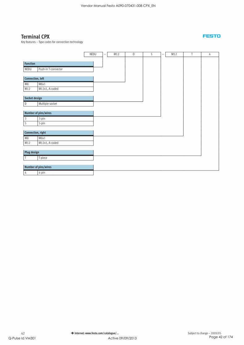
Subject to change – 2009/0542 Internet: www.festo.com/catalogue/...
Terminal CPXKey features – Type codes for connection technology
NEDU — M12 D 5 — M12 T 4
Function
NEDU Push-in T-connector
Connection, left
M8 M8x1
M12 M12x1, A-coded
Socket design
D Multiple socket
Number of pins/wires
3 3-pin
5 5-pin
Connection, right
M8 M8x1
M12 M12x1, A-coded
Plug design
T T-piece
Number of pins/wires
4 4-pin
Vendor Manual Festo A090-070431-008 CPX_EN
Q-Pulse Id VM301 Active 09/09/2013 Page 42 of 174

2009/05 – Subject to change 43 Internet: www.festo.com/catalogue/...
Terminal CPXTechnical data
-K- Module width
50 mm
-H- Note
The data given here applies to the
CPX system. If components that
conform to lower values are used in
the system, the specification for the
entire system is reduced to the
values of those components used.
Example
Protection class IP65/IP67 applies
only to the fully assembled system
with fitted plugs or covers (which must
also conform to IP65/67). If compo-
nents with a lower protection class are
used, the protection level of the entire
system is reduced to the protection
class of the component with the
lowest protection level, e.g. Cage-
Clamp connection block with IP20
protection or MPA pneumatics with
IP65 protection.
General technical data
Module No. 197330
Max. no. of modules1) Control block 1
Bus node 1
I/O module/CP interface
Multi-axis interface
9
Max. no. of modules1) Pneumatic interface 1
Max. address capacity Inputs [Byte] 64p y
Outputs [Byte] 64
Internal cycle time [ms] < 1
Configuration support Fieldbus-specific
LED displays Bus node/control block Up to 4 LEDs, bus-specific
4 LEDs, CPX-specific
• PS = Power system
• PL = Power load
• SF = System error
• M = Modify parameter/forcing active
I/O modules Min. one centralised diagnostic LED
Channel-oriented status and diagnostic LED, depending on module
Pneumatic interface One centralised diagnostic LED
Valve status LED on valve
Diagnostics • Channel and module-oriented diagnostics for inputs/outputs and valves
• Detection of module undervoltage for the different voltage potential values
• Storage of the last 40 errors with timestamp (aynchronous access)
1) A maximum of 11 modules in total can be combined
(e.g. 1 control block + 9 I/O modules + 1 pneumatic interface, or 1 control block + 1 bus node + 8 I/O modules + 1 pneumatic interface)
Vendor Manual Festo A090-070431-008 CPX_EN
Q-Pulse Id VM301 Active 09/09/2013 Page 43 of 174

Subject to change – 2009/0544 Internet: www.festo.com/catalogue/...
Terminal CPXTechnical data
General technical data
Module No. 197330
Parameterisation Module-specific and entire system, for example:
• Diagnostic behaviour
• Condition monitoring
• Profile of inputs
• Fail-safe response of outputs and valves
Commissioning support Forcing of inputs and outputs
Protection class to EN 60529 IP65/IP67
Nominal operating voltage [V DC] 24
Operating voltage range [V DC] 18 … 30
Power supply Interlinking block with system
supply
Electronics plus sensors
Actuators plus valves
[A]
[A]
Max. 16 A (M18 supply), max. 12 A (7/8” supply)
Max. 16 A (M18 supply), max. 12 A (7/8” supply)
Additional power supply
Actuators [A] Max. 16 A per M18 supply, max. 12 A per 7/8” supply
Additional power supply for
valves
[A] Max. 16 A per M18 supply
Current consumption Depending on system configuration
Power failure bridging (bus electronics only) [ms] 10
Voltage supply connection M18, 4-ping pp y
7/8” 5-pin
7/8” 4-pin
AIDA push-pull 5-pin
Fuse concept Per module with electronic fuses
Tests Vibration test
To DIN/IEC 68/EN 60068 Part 2 – 6
• For wall mounting: severity level 2
• For H-rail mounting: severity level 1
Shock test
To DIN/IEC 68/EN 60068 Part 2 – 27
• For wall mounting: severity level 2
• For H-rail mounting: severity level 1
PWIS classification Free of paint wetting impairment substances
Interference immunity EN 61000-6-2 (industry)
Interference emission EN 61000-6-4 (industry)
Isolation test for galvanically isolated circuits to IEC 1131 Part 2 [V] 500 DC
Galvanic isolation of electrical voltages [V] 80 DC
Protection against direct and indirect contact PELV (Protected Extra-Low Voltage)
Materials End plates: die-cast aluminium
Grid dimension [mm] 50
Operating and environmental conditions
Module No. 197330
Ambient temperature [°C] –5 … +50
Storage temperature [°C] –20 … +70
Relative air humidity (non-condensing) [%] 5 … 90
Explosion protection class In accordance with EU explosion protection directive (ATEX)p p
ATEX symbol II 3D Ex tD A 22 IP65 T90°C Xy
II 3D Ex nA II T 4 X
ATEX ambient temperature –5 ≤ Ta ≤ +50
Certification c UL us - Recognized (OL)
Vendor Manual Festo A090-070431-008 CPX_EN
Q-Pulse Id VM301 Active 09/09/2013 Page 44 of 174

2009/05 – Subject to change 45 Internet: www.festo.com/catalogue/...
Terminal CPXTechnical data
Weight [g]
Control block FEC 140.0 Interlinking block, Without power supply 80.0
Bus node FB6 125.0
g ,
plastic With system supply 100.0
FB11 120.0 Interlinking block, Without power supply 162
FB13 115.0
g ,
metal With system supply 187
FB14 115.0 Tie rod 1-fold 19.0 ±2.5
FB23 115.0 2-fold 32.5 ±2.5
FB32 125.0 3-fold 46.0 ±2.5
FB33 280.0 4-fold 59.5 ±2.5
FB34 280.0 5-fold 73.0 ±2.5
FB38 125.0 6-fold 86.5 ±2.5
I/O module 38.0 7-fold 100.0 ±2.5
CP interface 140 Tie rod 8-fold 113.5 ±2.5
Multi-axis interface CMXX 155.0 9-fold 127.0 ±2.5
Pneumatic interface MPA 238.4 10-fold 140.5 ±2.5
VTSA/VTSA-F 485.0 End plate, plastic Left-hand 77.0
MIDI/MAXI 390.0
p , p
Right-hand 70.0
CPA 150.0 End plate, metal Left-hand 113
Connection block Plastic 70.0
p ,
Right-hand 113
Metal 175.0
Vendor Manual Festo A090-070431-008 CPX_EN
Q-Pulse Id VM301 Active 09/09/2013 Page 45 of 174

Subject to change – 2009/0546 Internet: www.festo.com/catalogue/...
Terminal CPXAccessories
Ordering data – Accessories
Designation Type Part No.
Mounting set
Attachment for wall mounting (for long valve terminals, 10 pieces), version for plastic
interlinking plates
CPX-BG-RW-10x 529040
Attachment for wall mounting (for long valve terminals, 2 mounting brackets and
4 screws), version for metal interlinking plates
CPX-M-BG-RW-2x 550217
Mounting for H-rail CPX without pneumatic
components
CPA-BG-NRH 173498
CPX-VTSA CPX-CPA-BG-NRH 526032
CPX-VTSA-F
CPX-MPA
CPX-CPA
CPX-MIDI CPX-03-4,0 526033
CPX-MAXI CPX-03-7,0 526034
Tie rod
Tie rod CPX Extension 1-fold CPX-ZA-1-E 525418
1-fold CPX-ZA-1 195718
2-fold CPX-ZA-2 195720
3-fold CPX-ZA-3 195722
4-fold CPX-ZA-4 195724
5-fold CPX-ZA-5 195726
6-fold CPX-ZA-6 195728
7-fold CPX-ZA-7 195730
8-fold CPX-ZA-8 195732
9-fold CPX-ZA-9 195734
10-fold CPX-ZA-10 195736
Interlinking block, plastic
Without power supply – CPX-GE-EV 195742
With system supply M18 CPX-GE-EV-S 195746y pp y
7/8” – 5-pin CPX-GE-EV-S-7/8-5POL 541244
7/8” – 4-pin CPX-GE-EV-S-7/8-4POL 541248
With additional power supply for outputs M18 CPX-GE-EV-Z 195744p pp y p
7/8” – 5-pin CPX-GE-EV-Z-7/8-5POL 541248
7/8” – 4-pin CPX-GE-EV-Z-7/8-4POL 541250
With additional power supply for valves M18 CPX-GE-EV-V 533577p pp y
7/8” – 4-pin CPX-GE-EV-V-7/8-4POL 541252
Interlinking block, metal
Without power supply – CPX-M-GE-EV 550206
With system supply 7/8” – 5-pin CPX-M-GE-EV-S-7/8-5POL 550208
Push-pull – 5-pin CPX-M-GE-EV-S-PP-5POL 563057
With additional power supply for outputs 7/8” – 5-pin CPX-M-GE-EV-Z-7/8-5POL 550210
Push-pull – 5-pin CPX-M-GE-EV-Z-PP-5POL 563058
Vendor Manual Festo A090-070431-008 CPX_EN
Q-Pulse Id VM301 Active 09/09/2013 Page 46 of 174

2009/05 – Subject to change 47 Internet: www.festo.com/catalogue/...
Terminal CPXAccessories
Ordering data – Accessories
Designation Type Part No.
Mounting accessories
Screws for mounting the bus node/connection block on
the plastic interlinking block
Metal bus node/connection
block
CPX-DPT-30X32-S-4X 550218
Screws for mounting the bus node/connection block on
the metal interlinking block
Plastic bus node/connection
block
CPX-M-M3x22-4x 550219
g
Metal bus node/connection
block
CPX-M-M3x22-S-4x 550216
End plates, plastic
End plate Right-hand CPX-EPR-EV 195714
Left-hand CPX-EPL-EV 195716
Earthing element for right-hand/left-hand end plates 5 pieces CPX-EPFE-EV 538892
End plates, metal
End plate Right-hand CPX-M-EPR-EV 550214
Left-hand CPX-M-EPL-EV 550212
Power supply
Plug socket for mains connection M18, straight, 4-pin for 1.5 mm2 NTSD-GD-9 18493g , g , p
for 2.5 mm2 NTSD-GD-13,5 18526
Plug socket for mains connection M18, angled, 4-pin for 1.5 mm2 NTSD-WD-9 18527g , g , p
for 2.5 mm2 NTSD-WD-11 533119
Plug socket for mains connection 7/8 , straight, 5-pin 0.25 … 2.0 mm2 NECU-G78G5-C2 543107
Plug socket for mains connection 7/8 , straight, 4-pin 0.25 … 2.0 mm2 NECU-G78G4-C2 543108
Inscription labels
Inscription labels, 6x10, 64 pieces, in frames IBS-6x10 18576
User documentation
CPX System Manual German P.BE-CPX-SYS-DE 526445y
English P.BE-CPX-SYS-EN 526446
Spanish P.BE-CPX-SYS-ES 526447
French P.BE-CPX-SYS-FR 526448
Italian P.BE-CPX-SYS-IT 526449
Swedish P.BE-CPX-SYS-SV 526450
Operator unit CPX-MMI-1 German P.BE-CPX-MMI-1-DE 534824p
English P.BE-CPX-MMI-1-EN 534825
French P.BE-CPX-MMI-1-FR 534827
Italian P.BE-CPX-MMI-1-IT 534828
Swedish P.BE-CPX-MMI-1-SV 534829
Spanish P.BE-CPX-MMI-1-ES 534826
Vendor Manual Festo A090-070431-008 CPX_EN
Q-Pulse Id VM301 Active 09/09/2013 Page 47 of 174

Subject to change – 2009/0548 Internet: www.festo.com/catalogue/...
Terminal CPXAccessories
User documentation – General information
Comprehensive user documentation
is vital for the fast and consistent
implementation of fieldbus
components.
The documentation provided by
Festo contains step-by-step
instructions for using CPX terminals:
1. Installation
2. Commissioning and
parameterisation
3. Diagnostics
Application-oriented explanations
are provided for integration of the
CPX terminal in the programming
and configuration software of the
various controller manufacturers.
Use the order code to select the
language you want.
The manual for the configuration
you have ordered is supplied
automatically.
Manuals are available on the Festo
website:
www.festo.com
User documentation overview
Type Title Description
Electronics
P.BE-CPX-SYS-… System description, installing and
commissioning
Overview of the design, components and mode of operation of the CPX ter-
minal; installation and commissioning instructions as well as basic principles
of parameterisation.
P.BE-CPX-EA-… CPX-EA modules, digital Connection technology and assembly, installation and commissioning
instructions for digital input and output modules of type CPX-… as well as CPA,
MIDI/MAXI, VTSA/VTSA-F and MPA pneumatic interface.
P.BE-CPX-AX-… CPX-EA modules, analogue Connection technology and assembly, installation and commissioning
instructions for digital input and output modules of type CPX-…
as well as pressure sensors and proportional pressure regulators.
P.BE-CPX-CP… CPX CP interface Instructions on assembly, installation, commissioning and diagnostics of the
CP interface.
P.BE-CPX-CMXX… CPX multi-axis interface Instructions on assembly, installation, commissioning and diagnostics of the
CPX multi-axis interface (CMXX).
P.BE-CPX-FB… CPX fieldbus node Instructions on assembly, installation, commissioning and diagnostics of the
relevant bus nodes.
P.BE-CPX-PNIO… CPX fieldbus node for Profinet Instructions on assembly, installation, commissioning and diagnostics of the
relevant bus nodes.
P.BE-CPX-FEC… CPX control block Instructions on assembly, installation, commissioning and diagnostics of the
relevant control block.
P.BE-CPX-MMI-1-… Universal handheld type CPX-MMI-1 Instructions on assembly, installation, commissioning and diagnostics of the
CPX operator unit.
Vendor Manual Festo A090-070431-008 CPX_EN
Q-Pulse Id VM301 Active 09/09/2013 Page 48 of 174

2009/05 – Subject to change 49 Internet: www.festo.com/catalogue/...
Terminal CPXAccessories
User documentation overview
Type Title Description
Pneumatics
P.BE-VTSA-44-… Valve terminals with VTSA and VTSA-F
pneumatics
Instructions on assembly, installation, commissioning and diagnostics of the
VTSA and VTSA-F pneumatic components.
P.BE-CPA-… Valve terminals with CPA pneumatics Instructions on assembly, installation, commissioning and diagnostics of the
CPA pneumatic components.
P.BE-Midi/Maxi-03-… Valve terminals with MIDI/MAXI
pneumatics
Instructions on assembly, installation, commissioning and diagnostics of the
MIDI/MAXI pneumatic components.
P.BE-MPA-… Valve terminals with MPA pneumatics Instructions on assembly, installation, commissioning and diagnostics of the
MPA pneumatic components.
User documentation – GSD, EDS, …
Device description files and icons are
used to explain the integration of the
CPX terminal in the configuration
software of the various controller
manufacturers.
These can be downloaded quickly and
conveniently from www.festo.com.
Vendor Manual Festo A090-070431-008 CPX_EN
Q-Pulse Id VM301 Active 09/09/2013 Page 49 of 174

Subject to change – 2009/0550 Internet: www.festo.com/catalogue/...
Terminal CPXAccessories
CPX macro library for ePLAN
Type GSWC-TE-EP-LA
Part No. 537 041
Project planning – pure service: Systematically more reliable: Simply practical: Design example:
ePLan macros for fast and reliable
planning of electrical projects in
combination with valve terminals.
Available in German and English.
The CPX macro library contains
symbols, graphics and master data.
Result: a fast, reliable and standar-
dised system for designing and
High level of planning reliability,
standardisation of documentation, no
need to create symbols, graphics and
master data since everything is stored
From an idea to a functional solution
– quickly and reliably
Project planning, design, production,
assembly, commissioning, servicey g g
documenting your circuits.
y g
in the CPX macro library.
Problem definition/
planning of electrical project
Key technical data
• CD with CPX macro library ePLAN 5
and P8 for CPX terminal (supports
• Creation and editing of circuit
diagrams, terminal and cable
• Automatic protective contact
mirroringEfficient PC-based design system
( pp
the planning of bus nodes, inter-
g ,
plans, cross-reference lists,
g
• Generation of documents in paper p g ,
linking blocks, I/O modules, con-
nection blocks, pneumatic interface
p , ,
assembly drawings, parts lists and
maintenance plans
p p
format and HTML format for viewing
in browsers, etc. Library in DXFCPX macro
, p
and valves)
p
• Connection to programmable logic
, y
format for use with AutoCad or )
• Creation and administration of
projects
p g g
controllers
• Generation of the contact and
other CAD programs ePLAN CAE software for electrical
applicationsp j
potential cross-references p
PC
Documentation
Circuit diagrams
parts lists in paper format, optional
representation in browsers (HTML)
fluidPLAN from ePLAN and FluidDRAW from Festo
ePLAN and Festo also work together in
the creation of pneumatic circuit
diagrams:
The Engineering Tool ePLAN fluid has a
direct interface to the Festo electronic
catalogue (DKI). All of the relevant
data for the parts lists as well as the
pneumatic circuit symbols for Festo
products are transferred using this
import function.
The FluidDRAW software from Festo
makes the creation of circuit diagrams
for the pneumatic part on the PC both
simple and intuitive.
Vendor Manual Festo A090-070431-008 CPX_EN
Q-Pulse Id VM301 Active 09/09/2013 Page 50 of 174

2009/05 – Subject to change 51 Internet: www.festo.com/catalogue/...
Terminal CPXTechnical data – Operator unit
-K- Width
81 mm
The operator unit is a small, conveni-
ent commissioning and service device
for the CPX terminal. It provides data
requisition, configuration and diag-
nostics functions for CPX terminals. Its
extremely flexible application range
means that data can be read in or out
at any location. IP65 compatibility
makes it suitable for use in harsh
industrial environments.
Application
Functions
• Advance commissioning through
the monitoring/forcing of inputs
and outputs without fieldbus
master/PLC
• Test function for parameter set-
tings, e.g. fail-safe of the outputs or
switch-on delay of the inputs
• Plain text diagnostics of module
and channel-oriented errors
• Condition monitoring:
preselection/loading of counters,
activation of the channels to be
monitored
• Display of the last 40 error
occurrences with timestamp
• Identification of sporadic causes of
errors through display of the
diagnostic history
• Password protection
Connection
The operator unit is connected to the
CPX bus nodes or control block, as
appropriate, using a pre-assembled
M12 cable.
The voltage for the operator unit is
supplied through the CPX bus node.
Plug &Work.
Communication
Once connected to the CPX terminal,
the operator unit loads the available
configuration for the I/O modules,
valves, etc.
This ensures the availability of
up-to-date texts, messages, menus
and displays.
Status information, diagnostic
messages and parameter bits are
exchanged during operation.
Mounting
A mounting bracket for the operator
unit offers the option of wall or H-rail
mounting.
The mounting bracket also has an
option for temporary mounting using
a hanging device.
Vendor Manual Festo A090-070431-008 CPX_EN
Q-Pulse Id VM301 Active 09/09/2013 Page 51 of 174

Subject to change – 2009/0552 Internet: www.festo.com/catalogue/...
Terminal CPXTechnical data – Operator unit
Connection
The operator unit is connected to the
CPX terminal using pre-assembled
cables.
Function examples
System overview
• Overview of configured modules
and current diagnostic messages
Diagnostics
• Fast access to the diagnostic history
and the modules with diagnostic
messaging
• Display of the last 40 diagnostic
messages with timestamp
• Display of the current diagnostic
message for a module
Commissioning
• Selection of module-specific data
and parameters
• Display and modification of the
current status of the inputs and
outputs of a module
• Display and modification of the
current settings for module-specific
parameters
Setup
• Setting of access permission
(password)
• Contrast setting of the display
Vendor Manual Festo A090-070431-008 CPX_EN
Q-Pulse Id VM301 Active 09/09/2013 Page 52 of 174

2009/05 – Subject to change 53 Internet: www.festo.com/catalogue/...
Terminal CPXTechnical data – Operator unit
General technical data
Type CPX-MMI-1
Part No. 529043
Interface data RS 232 interface, 57.6 Kbaud, M12 socket, 4-pin
Display elements LCD graphical display with background illumination (128 x 64 pixels)
Control elements 7 keys:
4 arrow keys and 3 function keys, touch-sensitive keypad
Interface M12-5-pin
Electromagnetic compatibility Interference emission tested to DIN EN 61000-6-4, industryg p y
Interference immunity tested to DIN EN 61000-6-2, industry
Normal operating voltage [V DC] 24, supplied from the connected device
Operating voltage range [V DC] 18 … 30
Current consumption [mA] 50 … 60
Protection class to IEC 60529 IP65, IP67
Relative air humidity [%] 90, non-condensing
Vibration resistance Tested to DIN/IEC 68/EN 60068, Part 2-6
• For wall mounting: severity level 2
• For H-rail mounting: severity level 1
Shock resistance Tested to DIN/IEC 68/EN 60068, Part 2-27
• For wall mounting: severity level 2
• For H-rail mounting: severity level 1
Temperature range Operation [°C] 0 … +50p g
Storage/transport [°C] –20 … +70
Materials Reinforced polyamide
Dimensions (W x H x D) [mm] 81 x 137 x 28
Weight [g] 150
Operating and environmental conditions
Ambient temperature [°C] 0 … 50
CE mark (see declaration of conformity) In accordance with EU explosion protection directive (ATEX)
ATEX category II 3 Gg y
II 3 D
ATEX symbol II 3D Ex tD A22 IP65 T60 °C Xy
II 3G Ex nA II T6 X
ATEX ambient temperature [°C] 0 <= Ta <= +50
-H- Note
If device combinations are operated
in potentially explosive areas, the lo-
west common zone, the temperature
class as well as the ambient tempera-
ture of the individual devices deter-
mine the possible use of the complete
module.
Connection and display components
2
3
1
4
1 Display (LCD display)
2 Function keys
3 Arrow keys
4 M12 interface
Vendor Manual Festo A090-070431-008 CPX_EN
Q-Pulse Id VM301 Active 09/09/2013 Page 53 of 174

Subject to change – 2009/0554 Internet: www.festo.com/catalogue/...
Terminal CPXAccessories – Operator unit
Ordering data
Designation Type Part No.
Connecting cable
Connecting cable M12-M12, specially designed for
CPX-MMI
1.5 m KV-M12-M12-1,5 529044
CPX-MMI3.5 m KV-M12-M12-3,5 530901
Mounting
Bracket CPX-MMI-1-H 534705
Mounting for H-rail CPX-MMI-1-NRH 536689
User documentation
User manual for operator unit CPX-MMI-1 German P.BE-CPX-MMI-1-DE 534824p
English P.BE-CPX-MMI-1-EN 534825
French P.BE-CPX-MMI-1-FR 534827
Italian P.BE-CPX-MMI-1-IT 534828
Swedish P.BE-CPX-MMI-1-SV 534829
Spanish P.BE-CPX-MMI-1-ES 534826
Vendor Manual Festo A090-070431-008 CPX_EN
Q-Pulse Id VM301 Active 09/09/2013 Page 54 of 174
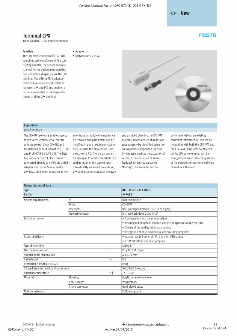
2009/05 – Subject to change 55 Internet: www.festo.com/catalogue/...
Terminal CPXTechnical data – CPX maintenance tool
Function
The CPX maintenance tool (CPX-FMT)
combines service software with a con-
necting adapter. The service software
is a tool for the design, parameterisa-
tion and online diagnostics of the CPX
terminal. The USB-to-M12 adapter
features built-in electrical isolation
(between CPX and PC) and enables a
PC to be connected to the diagnostic
interface of the CPX terminal.
• Adapter
• Software on CD-ROM
Application
Only from Festo
The CPX-FMT software enables access
to CPX valve terminals via Ethernet
with the control block CPX-FEC and
the fieldbus nodes Ethernet IP (FB 32)
and ProfiNET (FB 33, FB 34). The field-
bus nodes or control block can be
connected directly to the PC via a USB
adapter from Festo. Similar to the
CPX-MMI, diagnostic data such as the
error trace or module diagnostics can
be read out and parameters can be
modified in plain text. In contrast to
the CPX-MMI, the data can be used
directly on a PC. There is an option,
for example, to send screenshots of a
configuration or the current error
trace directly via e-mail. In addition,
CPX configurations can also be saved
and archived directly as a CPX-FMT
project. Undocumented changes can
subsequently be identified using the
online/offline comparison function.
On-site tests such as the actuation of
valves or the emulation of sensor
feedback (in both cases called
“forcing”), for example, can be
performed without an existing
controller infrastructure. It must be
noted that with both the CPX-FMT and
the CPX-MMI, only local parameters
on the CPX valve terminal can be
changed and saved. The configuration
of the networks or controller software
cannot be influenced.
General technical data
Type NEFC-M12G5-0.3-U1G5
Part No. 547432
System requirements PC IBM-compatibley q
Drive CD-ROM
Interfaces USB port (specification USB 1.1 or higher)
Operating system Microsoft Windows 2000 or XP
Functional range • Configuration and parameterisation
• Reading out of system, module, channel diagnostics and error trace
• Saving of the configuration as a project
• Integration of plug-ins/links to self-executing programs
Scope of delivery • Adapter cable from 5-pin M12 to mini USB socket
• CD-ROM with installation program
Type of mounting Screw-in
Electrical connection Plug M12x1, 5-pin
Adapter cable composition 4 x 0.34 mm2
Cable length [m] 0.3
Protection class to EN 60529 IP20
CE mark (see declaration of conformity) To EU EMC Directive
Ambient temperature [°C] –5 … +50
Material Housing Acrylic butadiene styrene
Cable sheath Polyurethane
Crimp connector Gold-plated brass
Note on materials RoHS-compliant
-V- New
Vendor Manual Festo A090-070431-008 CPX_EN
Q-Pulse Id VM301 Active 09/09/2013 Page 55 of 174

Subject to change – 2009/0556 Internet: www.festo.com/catalogue/...
Terminal CPXTechnical data – CPX maintenance tool
Display components
Creating a device configuration using the editor
1
2
The device configuration can be con-
veniently generated, parameterised
and saved using the drag & drop
feature. You can insert and move
modules.
1 Module numbers from the
graphic system overview
2 Catalogue for selecting
required modules
Module overview for a selected module
Displays important module data as
well as the number of allocated
inputs and outputs.
Diagnostic memory
Faults which occur during operation
are entered in a diagnostic memory.
The first or the last 40 entries are
saved, as well as the relevant time
measured from the moment the
power supply was switched on.
-V- New
Vendor Manual Festo A090-070431-008 CPX_EN
Q-Pulse Id VM301 Active 09/09/2013 Page 56 of 174

2009/05 – Subject to change 57 Internet: www.festo.com/catalogue/...
Terminal CPXTechnical data – CPX maintenance tool
Dimensions Download CAD data www.festo.com
Adapter
1 Mini B 5P USB port
2 Plug M12x1, 5-pin
-V- New
Vendor Manual Festo A090-070431-008 CPX_EN
Q-Pulse Id VM301 Active 09/09/2013 Page 57 of 174
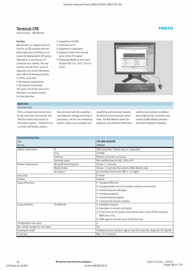
Subject to change – 2009/0558 Internet: www.festo.com/catalogue/...
Terminal CPXTechnical data – Web Monitor
Function
Web Monitor is a software tool from
Festo for all CPX modules with inte-
grated web server and Ethernet con-
nection for displaying the CPX service
information in real time on a PC
connected via a network. This tool
provides virtually ”free” access to
diagnostic and service information,
which offers the following benefits:
• Online, up-to-date
• No separate programming
• No separate visualisation
This saves a lot of time and means
that there is no need to acquire
in-house expertise.
• Supplied on CD-ROM
• Installation on PC
• Adaptation to application
• Loading via Ethernet to the web
server of the CPX module
• Display possibility via local touch
displays (FED 710, 1010, 2010 or
5010)
Application
Only from Festo
CPX is a modular electrical terminal
for the connection of pneumatic and
electrical control loop systems to
automation systems – suitable for all
currently used fieldbus systems.
Valve terminals with the comprehen-
sive diagnostic package consisting of
pneumatics, electrics and networking
systems create unique synergies and
simplify the communication between
the electrical and pneumatic control
levels. The Web Monitor makes this
diagnostic and additional information
visible at every station and without
extra programming. Convenient error
analysis by Web Monitor provides
permanent diagnostic reliability.
General technical data
Type CPX-WEB-MONITOR
Part No. 545413
System requirements PC IBM-compatible, Pentium class or comparabley q
Drive CD-ROM
Interfaces Network connection and access
Operating system Microsoft Windows 98, ME, 2000 or XP
Browser requirements Microsoft Internet Explorer Version 5.5 and laterq
Mozilla Firefox Version 1.0 and later (full version of Web Monitor only)
Java plug-in Java Runtime Environment (JRE) 1.3 or higher
Java script Enabled
Cookies Enabled
Scope of functions • Changing HTML links
• Changing symbol names for systems, modules and channels
• Incorporating own web pages
• Changing passwords
• Incorporating Java applets
• Commands for dynamic contents
Scope of delivery CD-ROM with • Installation program
• Description in German and English
• E-mail driver for FST projects (only relevant when using CPX-FEC modules):
SMTP-Driver V0.5
• HTML pages for the web server of CPX terminals
Configurable e-mail alerts 8
Non-volatile storage of e-mail alerts Yes
Sending of e-mails Initiated by events (positive edge at input bit, output bit, diagnostic bit, flag bit)
E-mail text Max. 255 characters
Vendor Manual Festo A090-070431-008 CPX_EN
Q-Pulse Id VM301 Active 09/09/2013 Page 58 of 174

2009/05 – Subject to change 59 Internet: www.festo.com/catalogue/...
Terminal CPXTechnical data – Web Monitor
Display elements
System overview of CPX terminal
1
2
3
4
5
6
1 Module numbers from the
graphic system overview
2 Signalling of fault messages
via yellow warning triangle
analogous to graphic system
overview opposite
3 Signalling of activated Force
mode via exclamation mark on
blue background
4 Status information in plain text
5 Module designations
6 Monitoring display for data
communication
Module overview of a selected module
1
2
3
4
5
1 General information about the
module
2 Copy of the module display
elements
3 Table with status information
on all channels of the module
4 Graphic representation of the
channel values plotted on a
time axis
5 Graphic representation of the
module status plotted on a
time axis
Error log of the CPX Web Monitor
1
2
3
4
5
1 Sequence number of the
entries
2 Link for updating the log
(”Update trace”)
3 Start/end time of the message
4 Text message
5 Module affected (module
code/M. number/channel)
Vendor Manual Festo A090-070431-008 CPX_EN
Q-Pulse Id VM301 Active 09/09/2013 Page 59 of 174
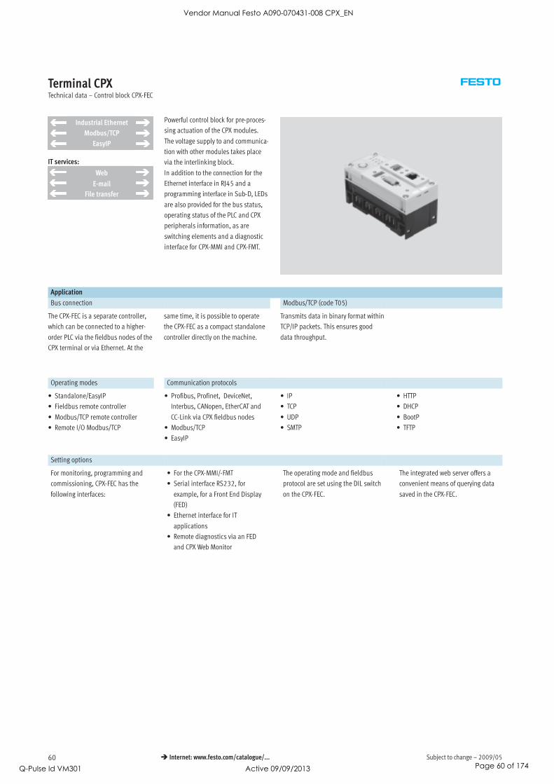
Subject to change – 2009/0560 Internet: www.festo.com/catalogue/...
Terminal CPXTechnical data – Control block CPX-FEC
IT services:
Industrial Ethernet
Modbus/TCP
EasyIP
Web
File transfer
Powerful control block for pre-proces-
sing actuation of the CPX modules.
The voltage supply to and communica-
tion with other modules takes place
via the interlinking block.
In addition to the connection for the
Ethernet interface in RJ45 and a
programming interface in Sub-D, LEDs
are also provided for the bus status,
operating status of the PLC and CPX
peripherals information, as are
switching elements and a diagnostic
interface for CPX-MMI and CPX-FMT.
Application
Bus connection Modbus/TCP (code T05)
The CPX-FEC is a separate controller,
which can be connected to a higher-
order PLC via the fieldbus nodes of the
CPX terminal or via Ethernet. At the
same time, it is possible to operate
the CPX-FEC as a compact standalone
controller directly on the machine.
Transmits data in binary format within
TCP/IP packets. This ensures good
data throughput.
Operating modes Communication protocols
• Standalone/EasyIP
• Fieldbus remote controller
• Modbus/TCP remote controller
• Remote I/O Modbus/TCP
• Profibus, Profinet, DeviceNet,
Interbus, CANopen, EtherCAT and
CC-Link via CPX fieldbus nodes
• Modbus/TCP
• EasyIP
• IP
• TCP
• UDP
• SMTP
• HTTP
• DHCP
• BootP
• TFTP
Setting options
For monitoring, programming and
commissioning, CPX-FEC has the
following interfaces:
• For the CPX-MMI/-FMT
• Serial interface RS232, for
example, for a Front End Display
(FED)
• Ethernet interface for IT
applications
• Remote diagnostics via an FED
and CPX Web Monitor
The operating mode and fieldbus
protocol are set using the DIL switch
on the CPX-FEC.
The integrated web server offers a
convenient means of querying data
saved in the CPX-FEC.
Vendor Manual Festo A090-070431-008 CPX_EN
Q-Pulse Id VM301 Active 09/09/2013 Page 60 of 174

2009/05 – Subject to change 61 Internet: www.festo.com/catalogue/...
Terminal CPXTechnical data – Control block CPX-FEC
General technical data
Type CPX-FEC-1-IE
Part No. 529041
Ethernet interface RJ45 (8-pin, socket)
Data interface RS232 (Sub-D, 9-pin, socket)
MMI interface M12, 5-pin, socket
Baud rates Ethernet interface [Mbps] 10/100 (acc. to IEEE802.3, 10BaseT)
Data interface [kbps] 9.6 … 115.2
MMI interface [kbps] 56.6
Protocol • TCP/IP
• EasyIP
• Modbus TCP
• HTTP
Processing time for 1,024 binary instructions [ms] Approx. 1
Flags M0.0 … M9999, addressable as bits or wordsg
No. of time flags T0 … T255
Time range [s] 0.01 to 655.35
No. of counting flags Z0 … Z255
Counting range 0 to 65535
Register R0 … R255, addressable as words
Special FE FE 0 … 255, init flag
IP address setting BOOTP/DHCP via FST or via MMI/FMT
Max. address capacity Inputs [Byte] 64p y
Outputs [Byte] 64
Program memory User program [kB] 250g y
WEB applications [kB] 550
Programming language • STL
• LDR
Arithmetic functions +, -, *, :, further functions via functional modules
Functional modules • CPX diagnostic status
• Copy CPX diagnostic trace
• Read CPX module diagnostics
• Write CPX module parameter
• …
No. of programs/tasks P0 ... P63
LED displays (FEC-specific) RUN = Program is being executed/Modbus connection active
STOP = Program is stopped/no Modbus connection
ERR = Error in the program execution
TP = Status of the Ethernet connection
Device-specific diagnostics Module and channel-specific diagnostics via peripherals error
Parameterisation • Start-up parameterisation via FST
• Parameterisation of the operating time via the functional module
Control elements • DIL switch for setting the operating mode
• Rotary switch for program selection/program start
Additional functions • Storage of the last 40 errors with timestamp (access via PCP)
• 8 bit system status in image table for inputs
• 2 byte inputs and 2 byte outputs, system diagnostics in image table
Vendor Manual Festo A090-070431-008 CPX_EN
Q-Pulse Id VM301 Active 09/09/2013 Page 61 of 174

Subject to change – 2009/0562 Internet: www.festo.com/catalogue/...
Terminal CPXTechnical data – Control block CPX-FEC
General technical data
Type CPX-FEC-1-IE
Part No. 529041
Operating voltage Nominal value [V DC] 24 (reverse polarity protected)p g g
Permissible range [V DC] 18 … 30
Power failure bridging [ms] 10
Residual ripple [Vss] 4
Current consumption [mA] Max. 200
Interference emission To EN 61000-6-4 (industry)
Interference immunity To EN 61000-6-2 (industry)
Protection class to EN 60529 IP65/IP67
Temperature range Operation [°C] –5 … +50p g
Storage/transport [°C] –20 … +70
Materials Polymer
Grid dimension [mm] 50
Dimensions (including interlinking block) W x L x H [mm] 50 x 107 x 55
Weight Without interlinking block [g] 140g
Including interlinking block
without power supply
[g] 220
Including interlinking block with
system supply
[g] 240
-H- Note
Please observe the general limits and
guidelines for the system when
configuring the electrical modules.
Overview of the operating modes
Standalone Remote controller Remote I/O
Ethernet Fieldbus Modbus/TCP
CPX-FEC function Controller Controller and communication Ethernet slave
CPX module controlled by CPX-FEC CPX-FEC Higher-order controller
Pre-processing of data in the FEC Yes Yes No
Communication with higher-order
controller
No Via Ethernet
• EasyIP
• Modbus/TCP
Via fieldbus Via Ethernet
• EasyIP
• Modbus/TCP
Web server Possible Possible Possible
Configuration FST 4.1 or higher FST 4.1 or higher Higher-order controller
Parameterisation Via FST/CPX-MMI/-FMT Via FST/CPX-MMI/-FMT Via CPX-MMI//-FMT, Modbus
Order code T03 T03 T05
Addressing Changeable Changeable Prescribed
Memory • 250 kB for user program
• 550 kB for WEB
applications
• 250 kB for user program
• 550 kB for WEB applications
• 800 kB for WEB
applications
CPX-MMI/-FMT Can be connected to CPX-FEC Can be connected to CPX-FEC Can be connected to CPX-FEC
Vendor Manual Festo A090-070431-008 CPX_EN
Q-Pulse Id VM301 Active 09/09/2013 Page 62 of 174

2009/05 – Subject to change 63 Internet: www.festo.com/catalogue/...
Terminal CPXTechnical data – Control block CPX-FEC
Connection and display components
4
5
6
1
2
3
1 Controller and Ethernet LEDs
2 DIL switch for operating mode
3 Programming interface
(9-pin Sub-D, socket)
4 CPX-specific status LEDs
5 16-fold rotary switch
(program selection)
6 Ethernet connection
(8-pin RJ45, socket)
Pin allocation for the programming interface (RS232)
Pin allocation Pin Signal Description
Sub-D plug
1 n.c. Not connected
2 RxD Received data
3 TxD-P Transmitted data
4 n.c. Not connected
5 GND Data reference potential
6 n.c. Not connected
7 n.c. Not connected
8 n.c. Not connected
9 n.c. Not connected
Hous-
ing
Screened Connection to (FE) functional earth
Pin allocation for the Ethernet interface
Pin allocation Pin Signal Description
Plug RJ45
1 TD+ Transmitted data+
2 TD- Transmitted data-
3 RD+ Received data+
4 n.c. Not connected
5 n.c. Not connected
6 RD- Received data-
7 n.c. Not connected
8 n.c. Not connected
Hous-
ing
Screened Screening
Vendor Manual Festo A090-070431-008 CPX_EN
Q-Pulse Id VM301 Active 09/09/2013 Page 63 of 174
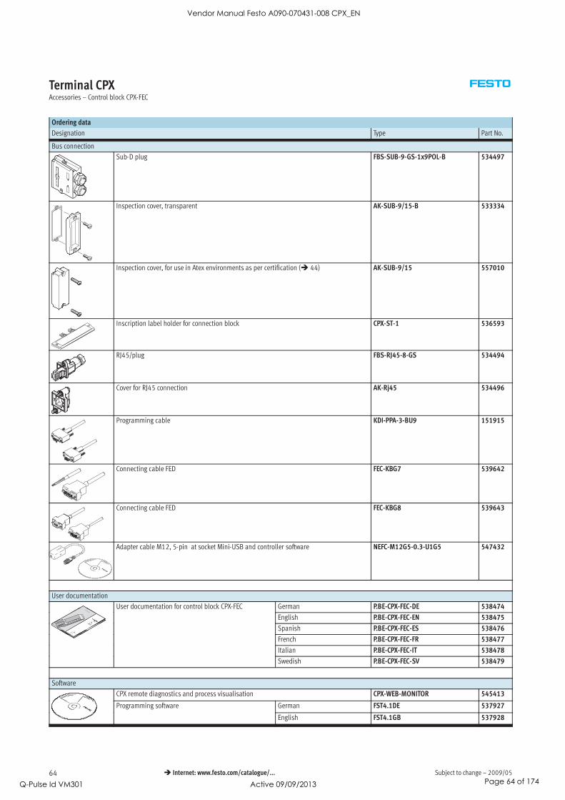
Subject to change – 2009/0564 Internet: www.festo.com/catalogue/...
Terminal CPXAccessories – Control block CPX-FEC
Ordering data
Designation Type Part No.
Bus connection
Sub-D plug FBS-SUB-9-GS-1x9POL-B 534497
Inspection cover, transparent AK-SUB-9/15-B 533334
Inspection cover, for use in Atex environments as per certification ( 44) AK-SUB-9/15 557010
Inscription label holder for connection block CPX-ST-1 536593
RJ45/plug FBS-RJ45-8-GS 534494
Cover for RJ45 connection AK-Rj45 534496
Programming cable KDI-PPA-3-BU9 151915
Connecting cable FED FEC-KBG7 539642
Connecting cable FED FEC-KBG8 539643
Adapter cable M12, 5-pin at socket Mini-USB and controller software NEFC-M12G5-0.3-U1G5 547432
User documentation
User documentation for control block CPX-FEC German P.BE-CPX-FEC-DE 538474
English P.BE-CPX-FEC-EN 538475
Spanish P.BE-CPX-FEC-ES 538476
French P.BE-CPX-FEC-FR 538477
Italian P.BE-CPX-FEC-IT 538478
Swedish P.BE-CPX-FEC-SV 538479
Software
CPX remote diagnostics and process visualisation CPX-WEB-MONITOR 545413
Programming software German FST4.1DE 537927g g
English FST4.1GB 537928
Vendor Manual Festo A090-070431-008 CPX_EN
Q-Pulse Id VM301 Active 09/09/2013 Page 64 of 174

2009/05 – Subject to change 65 Internet: www.festo.com/catalogue/...
Terminal CPXTechnical data – Bus node CPX-FB6
Bus node for handling communication
between the electrical CPX terminal
and a higher-order master via
INTERBUS.
The bus node receives system supply
from the interlinking block and
processes communication via the I/O
modules.
The status of the CPX terminal is
displayed as a common message via
4 CPX-specific LEDs.
The fieldbus communication status is
displayed via 4 INTERBUS-specific
LEDs.
Application
Bus connection
The bus connection is established via
a 9-pin Sub-D socket and a 9-pin
Sub-D plug with a typical INTERBUS
pin allocation.
The bus connector plugs (with protec-
tion class IP65/IP67 from Festo or
IP20 from other manufacturers) facili-
tate the connection of the incoming
and outgoing bus cable.
The outgoing bus plug contains the
typical INTERBUS RBST bridge for
identification of the outgoing bus
connection.
The Sub-D interfaces are designed for
the control of network components
with a fibre optic cable connection.
INTERBUS implementation
The CPX-FB6 supports the INTERBUS
protocol to EN 50254.
In addition to synchronous I/O
exchange, the optional PCP channel
can be used for parameterisation and
diagnostic functions
An example of this is access to the in-
tegrated diagnostic memory function,
i.e. storage of the last 40 errors with
timestamp, module, channel and
error type.
With its address capacity of 96 inputs
and 96 outputs, the CPX-FB6 supports
a large number of I/O module
configurations, including pneumatic
interface.
-H- Note
If the PCP channel is used, the
maximum number of possible
process data bits is reduced by 16.diagnostic functions.
The PCP channel provides access to
advanced system information and
assigns operation parameters while
the controller is running via the user
program.
Special features in combination with CPX-FEC
When a fieldbus node is combined
with a CPX-FEC (in the fieldbus remote
controller operating mode), the con-
nected I/Os and/or valves, sensors
and actuators are actuated via the
CPX-FEC.
In this case, the fieldbus node only
provides the communication interface
to the PLC.
Communication between CPX-FEC and
CPX fieldbus node takes place via
interlinking of the CPX modules.
The CPX-FEC occupies an address
capacity of the CPX fieldbus node of:
• 8 byte outputs
• 8 byte inputs
As no other components (e.g. I/O mod-
ules) are actuated via the CPX fieldbus
node, its address capacity is thus
reduced effectively to an 8 byte I/O.
The full address capacity of the
CPX-FEC is available for actuation of
the peripherals:
• 64 byte inputs
• 64 byte outputs
Vendor Manual Festo A090-070431-008 CPX_EN
Q-Pulse Id VM301 Active 09/09/2013 Page 65 of 174

Subject to change – 2009/0566 Internet: www.festo.com/catalogue/...
Terminal CPXTechnical data – Bus node CPX-FB6
General technical data
Type CPX-FB6
Part No. 195748
Fieldbus interface Sub-D, 9-pin, socket and pin
Baud rates [Mbps] 0.5 and 2
Bus type Remote bus
Ident. code 1, 2 or 3 (configuration-specific)
243 (PCP channel activated)
Profile 12 (I/O device)
PCP channel Yes, 16 bit (optional via DIL switch)
Configuration support Icons for CMD software
Max. no. of process data bits Inputs [Bit] 96p
Outputs [Bit] 96
LED displays (bus-specific) UL = Operating voltage for INTERBUS interface
RC = Remotebus check
BA = Bus active
RD = Remotebus disable
TR = Transmit/receive
Device-specific diagnostics Via peripherals errors
Parameterisation • Start-up parameterisation via user functions (CMD)
• Via PCP communication
Additional functions • Storage of the last 40 errors with timestamp (access via PCP)
• 8 bit system status in image table for inputs
• 2 byte inputs and 2 byte outputs, system diagnostics in image table
Operating voltage Nominal value [V DC] 24 (reverse polarity protected)p g g
Permissible range [V DC] 18 … 30
Power failure bridging [ms] 10
Current consumption [mA] Max. 200
Protection class to EN 60529 IP65/IP67
Temperature range Operation [°C] –5 … +50p g
Storage/transport [°C] –20 … +70
Materials Polymer
Grid dimension [mm] 50
Dimensions (including interlinking block) W x L x H [mm] 50 x 107 x 50
Weight Without interlinking block [g] 125g
Including interlinking block
without power supply
[g] 205
Including interlinking block with
system supply
[g] 225
-H- Note
Please observe the general limits and
guidelines for the system when
configuring the electrical modules.
Vendor Manual Festo A090-070431-008 CPX_EN
Q-Pulse Id VM301 Active 09/09/2013 Page 66 of 174
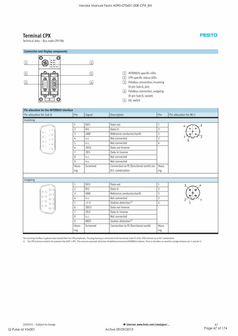
2009/05 – Subject to change 67 Internet: www.festo.com/catalogue/...
Terminal CPXTechnical data – Bus node CPX-FB6
Connection and display components
2
5
4
1
5
3
1 INTERBUS-specific LEDs
2 CPX-specific status LEDs
3 Fieldbus connection, incoming
(9-pin Sub-D, pin)
4 Fieldbus connection, outgoing
(9-pin Sub-D, socket)
5 DIL switch
Pin allocation for the INTERBUS interface
Pin allocation for Sub-D Pin Signal Description Pin Pin allocation for M12
Incoming
1 DO1 Data out 1
2 DI1 Data in 3
3 GND Reference conductor/earth 5
4 n.c. Not connected 2
5 n.c. Not connected 4
6 /DO1 Data out inverse
7 /DI1 Data in inverse
8 n.c. Not connected
9 n.c. Not connected
Hous-
ing
Screened Connection to FE (functional earth) via
R/C combination
Hous-
ing
Outgoing
1 DO2 Data out 1
2 DI2 Data in 3
3 GND Reference conductor/earth 5
4 n.c. Not connected 2
5 +5 V Station detection1) 4
6 /DO2 Data out inverse
7 /DI2 Data in inverse
8 n.c. Not connected
9 RBST Station detection1)
Hous-
ing
Screened Connection to FE (functional earth) Hous-
ing
The incoming interface is galvanically isolated from the CPX peripherals. The plug housing is connected to the functional earth FE of the CPX terminal via an R/C combination.
1) The CPX terminal contains the protocol chip SUPI 3 OPC. This ensures automatic detection of additional connected INTERBUS stations. There is therefore no need for a bridge between pin 5 and pin 9.
Vendor Manual Festo A090-070431-008 CPX_EN
Q-Pulse Id VM301 Active 09/09/2013 Page 67 of 174

Subject to change – 2009/0568 Internet: www.festo.com/catalogue/...
Terminal CPXAccessories – Bus node CPX-FB6
Ordering data
Designation Type Part No.
Bus connection
Sub-D plug Incoming FBS-SUB-9-BU-IB-B 532218
Outgoing FBS-SUB-9-GS-IB-B 532217
Connection block M12 adapter plug (B-coded) CPX-AB-2-M12-RK-IB 534505
Inspection cover, transparent AK-SUB-9/15-B 533334
Inspection cover, for use in Atex environments as per certification ( 44) AK-SUB-9/15 557010
Inscription label holder for connection block CPX-ST-1 536593
Threaded sleeve, 4 pieces UNC4-40/M3x6 533000
Adapter cable M12, 5-pin at socket Mini-USB and controller software NEFC-M12G5-0.3-U1G5 547432
User documentation
User documentation for bus node CPX-FB6 German P.BE-CPX-FB6-DE 526433
English P.BE-CPX-FB6-EN 526434
Spanish P.BE-CPX-FB6-ES 526435
French P.BE-CPX-FB6-FR 526436
Italian P.BE-CPX-FB6-IT 526437
Swedish P.BE-CPX-FB6-SV 526438
Vendor Manual Festo A090-070431-008 CPX_EN
Q-Pulse Id VM301 Active 09/09/2013 Page 68 of 174

2009/05 – Subject to change 69 Internet: www.festo.com/catalogue/...
Terminal CPXTechnical data – Bus node CPX-FB11
Bus node for handling communication
between the electrical CPX terminal
and a DeviceNet network.
The bus node receives system supply
from the interlinking block and
processes communication via the I/O
modules.
The status of the CPX terminal is
displayed as a common message via
4 CPX-specific LEDs.
The fieldbus communication status is
displayed via the 3 DeviceNet-specific
LEDs.
Application
Bus connection
The bus connection can be selected
when ordering, either Micro Style as
2xM12 round connectors or
OpenStyle as a terminal strip with
IP20 protection.
Both connection types have the func-
tion of an integrated T-distributor with
incoming and outgoing bus line.
DeviceNet implementation
The CPX-FB11 operates with the
“Predefined Master/Slave connection
set” as a “Group 2 only Server”.
The polled I/O, change of state or
synchronous method is used for the
transmission of synchronous I/O data.
The type of transmission can be selec-
ted in the network configuration.
The device diagnostics for all bus no-
des CPX-FB11 is effectively gathered
via strobed I/O and displayed in the
input table of the controller.
In addition to synchronous data trans-
mission, asynchronous communica-
tion is supported through explicit
messaging, which enables detailed
device diagnostics and
parameterisation.
A comprehensive EDS file supports the
display of asynchronous data. It is
also possible to display system infor-
mation and assign parameters while
the controller is running via the user
program or the configuration software.
An example of this is access to the in-
tegrated diagnostic memory function,
i.e. storage of the last 40 errors with
timestamp, module, channel and
error type.
With its address capacity of 64 byte
inputs and 64 byte outputs, the
CPX-FB11 supports any configuration
of I/O modules, including pneumatic
interface.
Special features in combination with CPX-FEC
When a fieldbus node is combined
with a CPX-FEC (in the fieldbus remote
controller operating mode), the con-
nected I/Os and/or valves, sensors
and actuators are actuated via the
CPX-FEC.
In this case, the fieldbus node only
provides the communication interface
to the PLC.
Communication between CPX-FEC and
CPX fieldbus node takes place via
interlinking of the CPX modules.
The CPX-FEC occupies an address
capacity of the CPX fieldbus node of:
• 8 byte outputs
• 8 byte inputs
As no other components (e.g. I/O mod-
ules) are actuated via the CPX fieldbus
node, its address capacity is thus
reduced effectively to an 8 byte I/O.
The full address capacity of the
CPX-FEC is available for control of the
peripherals:
• 64 byte inputs
• 64 byte outputs
Vendor Manual Festo A090-070431-008 CPX_EN
Q-Pulse Id VM301 Active 09/09/2013 Page 69 of 174
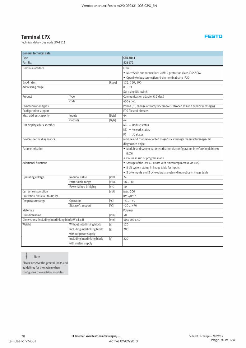
Subject to change – 2009/0570 Internet: www.festo.com/catalogue/...
Terminal CPXTechnical data – Bus node CPX-FB11
General technical data
Type CPX-FB11
Part No. 526172
Fieldbus interface Either
• MicroStyle bus connection: 2xM12 protection class IP65/IP67
• OpenStyle bus connection: 5-pin terminal strip IP20
Baud rates [kbps] 125, 250, 500
Addressing range 0 … 63
Set using DIL switch
Product Type Communication adapter (12 dec.)
Code 4554 dec.
Communication types Polled I/O, change of state/synchronous, strobed I/O and explicit messaging
Configuration support EDS file and bitmaps
Max. address capacity Inputs [Byte] 64p y
Outputs [Byte] 64
LED displays (bus-specific) MS = Module status
NS = Network status
IO = I/O status
Device-specific diagnostics Module and channel-oriented diagnostics through manufacturer-specific
diagnostics object
Parameterisation • Module and system parameterisation via configuration interface in plain text
(EDS)
• Online in run or program mode
Additional functions • Storage of the last 40 errors with timestamp (access via EDS)
• 8 bit system status in image table for inputs
• 2 byte inputs and 2 byte outputs, system diagnostics in image table
Operating voltage Nominal value [V DC] 24p g g
Permissible range [V DC] 18 … 30
Power failure bridging [ms] 10
Current consumption [mA] Max. 200
Protection class to EN 60529 IP65/IP67
Temperature range Operation [°C] –5 … +50p g
Storage/transport [°C] –20 … +70
Materials Polymer
Grid dimension [mm] 50
Dimensions (including interlinking block) W x L x H [mm] 50 x 107 x 50
Weight Without interlinking block [g] 120g
Including interlinking block
without power supply
[g] 200
Including interlinking block
with system supply
[g] 220
-H- Note
Please observe the general limits and
guidelines for the system when
configuring the electrical modules.
Vendor Manual Festo A090-070431-008 CPX_EN
Q-Pulse Id VM301 Active 09/09/2013 Page 70 of 174

2009/05 – Subject to change 71 Internet: www.festo.com/catalogue/...
Terminal CPXTechnical data – Bus node CPX-FB11
Connection and display components
1 2
4 3 1 Bus-specific LEDs
2 CPX-specific status LEDs
3 Selectable fieldbus connection
Micro Style
Open Style
4 DIL switch cover
Pin allocation for the DeviceNet interface
Pin allocation Pin Signal-specific
core colour1)Signal Description
Sub-D plug
1 – n.c. Not connected
2 Blue CAN_L Received/transmitted data low
3 Black 0 V bus 0 V CAN interface
4 – n.c. Not connected
5 Blank Screened Connection to housing
6 – n.c. Not connected
7 White CAN_H Received/transmitted data high
8 – n.c. Not connected
9 Red 24 V DC bus 24 V DC supply CAN interface
Bus connection Micro Style (M12) incoming/outgoing
Incoming 1 Blank Screened Connection to housing
2 Red 24 V DC bus 24 V DC supply CAN interface
3 Black 0 V bus 0 V CAN interface
4 White CAN_H Received/transmitted data high
5 Blue CAN_L Received/transmitted data low
Outgoing 1 Blank Screened Connection to housing
2 Red 24 V DC bus 24 V DC supply CAN interface
3 Black 0 V bus 0 V CAN interface
4 White CAN_H Received/transmitted data high
5 Blue CAN_L Received/transmitted data low
Bus connection Open Style
1 Black 0 V bus 0 V CAN interface
2 Blue CAN_L Received/transmitted data low
3 Blank Screened Connection to housing
4 White CAN_H Received/transmitted data high
5 Red 24 V DC bus 24 V DC supply CAN interface
1) Typical for DeviceNet cables
Vendor Manual Festo A090-070431-008 CPX_EN
Q-Pulse Id VM301 Active 09/09/2013 Page 71 of 174

Subject to change – 2009/0572 Internet: www.festo.com/catalogue/...
Terminal CPXAccessories – Bus node CPX-FB11
Ordering data
Designation Type Part No.
Bus connection
Sub-D plug FBS-SUB-9-BU-2x5POL-B 532219
Bus connection Micro Style, 2xM12 FBA-2-M12-5POL 525632
Socket for Micro Style connection, M12 FBSD-GD-9-5POL 18324
Plug for Micro Style connection, M12 FBS-M12-5GS-PG9 175380
Fieldbus connection Open Style for 5-pin terminal strip FBA-1-SL-5POL 525634
Terminal strip connector for Open Style connection, 5-pin FBSD-KL-2x5POL 525635
Inspection cover, transparent AK-SUB-9/15-B 533334
Inspection cover, for use in Atex environments as per certification ( 44) AK-SUB-9/15 557010
Inscription label holder for connection block CPX-ST-1 536593
Adapter cable M12, 5-pin at socket Mini-USB and controller software NEFC-M12G5-0.3-U1G5 547432
User documentation
User documentation for bus node CPX-FB11 German P.BE-CPX-FB11-DE 526421
English P.BE-CPX-FB11-EN 526422
Spanish P.BE-CPX-FB11-ES 526423
French P.BE-CPX-FB11-FR 526424
Italian P.BE-CPX-FB11-IT 526425
Swedish P.BE-CPX-FB11-SV 526426
Vendor Manual Festo A090-070431-008 CPX_EN
Q-Pulse Id VM301 Active 09/09/2013 Page 72 of 174

2009/05 – Subject to change 73 Internet: www.festo.com/catalogue/...
Terminal CPXTechnical data – Bus node CPX-FB13
Bus node for handling communication
between the electrical CPX terminal
and a higher-order master via
Profibus-DP.
The bus node receives system supply
from the interlinking block and
processes communication via the I/O
modules.
The status of the CPX terminal is
displayed as a common message via
4 CPX-specific LEDs.
The fieldbus communication status is
displayed via the Profibus-specific
fault LED.
Application
Bus connection
The bus connection is established via
a 9-pin Sub-D socket with a typical
Profibus allocation (to EN 50170).
The bus connector plug (with protec-
tion class IP65/IP67 from Festo or
IP20 from other manufacturers) facili-
tates the connection of an incoming
and an outgoing bus cable.
An active bus terminal can be connec-
ted using the DIL switch integrated in
the plug.
The Sub-D interface is designed for
the control of network components
with a fibre optic cable connection.
Profibus-DP implementation
The CPX-FB13 supports the Profibus-
DP protocol to EN 50170 Volume 2 for
synchronous I/O exchange, paramete-
risation and diagnostic functions
(DPV0).
In addition to DPV0, asynchronous
communication to the advanced
specification DPV1 is supported.
DPV1 provides asynchronous access
to advanced system information and
assigns operation parameters while
the controller is running via the user
program.
An example of this is access to the in-
tegrated diagnostic memory function,
i.e. storage of the last 40 errors with
timestamp, module, channel and
error type.
With its address capacity of 64 byte
inputs and 64 byte outputs, the
CPX-FB13 supports any configura-
tion of I/O modules, including
pneumatic interface.
Special features in combination with CPX-FEC
When a fieldbus node is combined
with a CPX-FEC (in the fieldbus remote
controller operating mode), the con-
nected I/Os and/or valves, sensors
and actuators are actuated via the
CPX-FEC.
In this case, the fieldbus node only
provides the communication interface
to the PLC.
Communication between CPX-FEC and
CPX fieldbus node takes place via
interlinking of the CPX modules.
The CPX-FEC occupies an address
capacity of the CPX fieldbus node of:
• 8 byte outputs
• 8 byte inputs
As no other components (e.g. I/O mod-
ules) are actuated via the CPX fieldbus
node, its address capacity is thus
reduced effectively to an 8 byte I/O.
The full address capacity of the
CPX-FEC is available for actuation of
the peripherals:
• 64 byte inputs
• 64 byte outputs
Vendor Manual Festo A090-070431-008 CPX_EN
Q-Pulse Id VM301 Active 09/09/2013 Page 73 of 174

Subject to change – 2009/0574 Internet: www.festo.com/catalogue/...
Terminal CPXTechnical data – Bus node CPX-FB13
General technical data
Type CPX-FB13
Part No. 195740
Fieldbus interface Sub-D socket, 9-pin (EN 50 170)
Galvanically isolated 5 V
Baud rates [Mbps] 0.0096 … 12
Addressing range 1 … 125
Set using DIL switch
Product family 4: Valves
Ident. number 0x059E
Communication types DPV0: Synchronous communication
DPV1: Asynchronous communication
Configuration support GSD file and bitmaps
Max. address capacity Inputs [Byte] 64p y
Outputs [Byte] 64
LED displays (bus-specific) BF: Bus Fault
Device-specific diagnostics Identifier and channel-specific diagnostics to EN 50170 (Profibus standard)
Parameterisation • Start-up parameterisation via configuration interface in plain text (GSD)
• Asynchronous parameterisation via DPV1
Additional functions • Storage of the last 40 errors with timestamp (access via DPV1)
• 8 bit system status in image table for inputs
• 2 byte inputs and 2 byte outputs, system diagnostics in image table
Operating voltage Nominal value [V DC] 24p g g
Permissible range [V DC] 18 … 30
Power failure bridging [ms] 10
Current consumption [mA] Max. 200
Protection class to EN 60529 IP65/IP67
Temperature range Operation [°C] –5 … +50p g
Storage/transport [°C] –20 … +70
Materials Polymer
Grid dimension [mm] 50
Dimensions (including interlinking block) W x L x H [mm] 50 x 107 x 50
Weight Without interlinking block [g] 115g
Including interlinking block
without power supply
[g] 195
Including interlinking block
with system supply
[g] 215
-H- Note
Please observe the general limits and
guidelines for the system when
configuring the electrical modules.
Vendor Manual Festo A090-070431-008 CPX_EN
Q-Pulse Id VM301 Active 09/09/2013 Page 74 of 174

2009/05 – Subject to change 75 Internet: www.festo.com/catalogue/...
Terminal CPXTechnical data – Bus node CPX-FB13
Connection and display components
1 2
4 3 1 Bus status LEDs / Bus Fault
2 CPX-specific status LEDs
3 Fieldbus connection
(9-pin Sub-D, socket)
4 DIL switch cover
Pin allocation for Profibus-DP interface
Pin allocation Pin Signal Description
Sub-D plug
1 n.c. Not connected
2 n.c. Not connected
3 RxD/TxD-P Received/transmitted data P
4 CNTR-P1) Repeater control signal
5 DGND Data reference potential (M5V)
6 VP Supply voltage (P5V)
7 n.c. Not connected
8 RxD/TxD-N Received/transmitted data N
9 n.c. Not connected
Hous-
ing
Screened Connection to housing
Bus connection M12 adapter plug (B-coded)
Incoming 1 n.c. Not connected
2 RxD/TxD-N Received/transmitted data N
3 n.c. Not connected
4 RxD/TxD-P Received/transmitted data P
5 and
M12
Screened Connection to FE (functional earth)
Outgoing 1 VP Supply voltage (P5V)
2 RxD/TxD-N Received/transmitted data N
3 DGND Data reference potential (M5V)
4 RxD/TxD-P Received/transmitted data P
5 and
M12
Screened Connection to FE (functional earth)
1) The repeater control signal CNTR-P is realised as a TTL signal.
Vendor Manual Festo A090-070431-008 CPX_EN
Q-Pulse Id VM301 Active 09/09/2013 Page 75 of 174

Subject to change – 2009/0576 Internet: www.festo.com/catalogue/...
Terminal CPXAccessories – Bus node CPX-FB13
Ordering data
Designation Type Part No.
Bus connection
Sub-D plug FBS-SUB-9-GS-DP-B 532216
Bus connection M12 adapter plug (B-coded) FBA-2-M12-5POL-RK 533118
Connection block M12 adapter plug (B-coded) CPX-AB-2-M12-RK-DP 541519
Inscription label holder for connection block M12 CPX-ST-1 536593
Inspection cover, transparent AK-SUB-9/15-B 533334
Inspection cover, for use in Atex environments as per certification ( 44) AK-SUB-9/15 557010
Threaded sleeve, 4 pieces UNC4-40/M3x6 533000
Adapter cable M12, 5-pin at socket Mini-USB and controller software NEFC-M12G5-0.3-U1G5 547432
User documentation
User documentation for bus node CPX-FB13 German P.BE-CPX-FB13-DE 5264273
English P.BE-CPX-FB13-EN 526428
Spanish P.BE-CPX-FB13-ES 526429
French P.BE-CPX-FB13-FR 526430
Italian P.BE-CPX-FB13-IT 526431
Swedish P.BE-CPX-FB13-SV 526432
Vendor Manual Festo A090-070431-008 CPX_EN
Q-Pulse Id VM301 Active 09/09/2013 Page 76 of 174

2009/05 – Subject to change 77 Internet: www.festo.com/catalogue/...
Terminal CPXTechnical data – Bus node CPX-FB14
Bus node for handling communication
between the electrical CPX terminal
and a CANopen network master or
CANopen network.
The bus node receives system supply
from the interlinking block and
processes communication via the I/O
modules.
The status of the CPX terminal is
displayed as a common message via
4 CPX-specific LEDs.
The different CANopen statuses and
the fieldbus communication status
are displayed via 3 additional LEDs.
Application
Bus connection
The bus connection is established via
a 9-pin Sub-D plug (pin) as per the
CAN in Automation (CiA) specification
DS 102 with additional 24 V CAN
transceiver supply (option as per
DS 102).
The bus connector plug (with protec-
tion class IP65/IP67 from Festo or
IP20 from other manufacturers) facili-
tates the connection of an incoming
and an outgoing bus cable.
There are 4 contacts available for the
4 wires (CAN_L, CAN_H, 24 V, 0 V) of
the incoming and outgoing bus
cables.
CANopen implementation
The CPX-FB14 supports the CANopen
protocol in accordance with the speci-
fications DS 301 V4.01 and DS 401
V2.0.
Implementation is based on the CiA
Pre-defined Connection Set.
There are 4 PDOs available for fast I/O
data exchange.
Advanced system information can also
be accessed by means of SDO commu-
nication. SDO communication also
facilitates parameterisation before
network startup or while the controller
is running via the user program.
An example of this is access to the in-
tegrated diagnostic memory function,
i.e. storage of the last 40 errors with
timestamp, module, channel and
error type.
With its address capacity, the
CPX-FB14 supports a large number of
I/O module configurations, including
pneumatic interface.
By default, 8 byte digital inputs and
8 byte digital outputs can be addres-
sed via PDO 1.
8 analogue input channels and 8 ana-
logue output channels can be addres-
sed via PDO 2 and 3. Status and dia-
gnostic information can be evaluated
via PDO 4.
Additional 8 byte digital inputs and
outputs as well as 8 analogue input
and output channels can be
addressed via mapping.
Special features in combination with CPX-FEC
When a fieldbus node is combined
with a CPX-FEC (in the fieldbus remote
controller operating mode), the con-
nected I/Os and/or valves, sensors
and actuators are actuated via the
CPX-FEC.
In this case, the fieldbus node only
provides the communication interface
to the PLC.
Communication between CPX-FEC and
CPX fieldbus node takes place via
interlinking of the CPX modules.
The CPX-FEC occupies an address
capacity of the CPX fieldbus node of:
• 8 byte outputs
• 8 byte inputs
As no other components (e.g. I/O mod-
ules) are actuated via the CPX fieldbus
node, its address capacity is thus
reduced effectively to an 8 byte I/O.
The full address capacity of the
CPX-FEC is available for actuation of
the peripherals:
• 64 byte inputs
• 64 byte outputs
Vendor Manual Festo A090-070431-008 CPX_EN
Q-Pulse Id VM301 Active 09/09/2013 Page 77 of 174

Subject to change – 2009/0578 Internet: www.festo.com/catalogue/...
Terminal CPXTechnical data – Bus node CPX-FB14
General technical data
Type CPX-FB14
Part No. 526174
Fieldbus interface Sub-D pin, 9-pin (to DS 102)
Bus interface galvanically isolated via optocoupler 24 V supply CAN interface
via bus
Baud rates [kbps] 125, 250, 500 and 1000 can be set via DIL switch
Addressing range Node ID 1 … 127
Set using DIL switch
Product family Digital inputs and outputs
Communication profile DS 301, V4.01
Device profile DS 401, V2.0
Number PDO 4 Tx/4 Rx
SDO 1 server SDO
Configuration support EDS file and bitmaps
Max. address capacity Inputs [Byte] 16 digital, 16 analogue channelsp y
Outputs [Byte] 16 digital, 16 analogue channels
LED displays (bus-specific) MS = Module status
NS = Network status
IO = I/O status
Device-specific diagnostics Via emergency message
Object 1001, 1002 and 1003
Parameterisation Via SDO
Additional functions • Storage of the last 40 errors with timestamp (access via SDO)
• 8 bit system status via transmit PDO 4 (default)
• 2 byte inputs and 2 byte outputs, system diagnostics via PDO 4
• Minimum boot-up
• Variable PDO mapping
• Emergency message
• Node guarding
• Heart beat
Operating voltage Nominal value [V DC] 24p g g
Permissible range [V DC] 18 … 30
Power failure bridging [ms] 10
Current consumption [mA] Max. 200
Protection class to EN 60529 IP65/IP67
Temperature range Operation [°C] –5 … +50p g
Storage/transport [°C] –20 … +70
Materials Polymer
Grid dimension [mm] 50
Dimensions (including interlinking block) W x L x H [mm] 50 x 107 x 50
Weight Without interlinking block [g] 115g
Including interlinking block
without power supply
[g] 195
Including interlinking block
with system supply
[g] 215
-H- Note
Please observe the general limits and
guidelines for the system when
configuring the electrical modules.
Vendor Manual Festo A090-070431-008 CPX_EN
Q-Pulse Id VM301 Active 09/09/2013 Page 78 of 174

2009/05 – Subject to change 79 Internet: www.festo.com/catalogue/...
Terminal CPXTechnical data – Bus node CPX-FB14
Connection and display components
1 2
34 1 Bus-specific LEDs
2 CPX-specific status LED
3 Fieldbus connection
(9-pin Sub-D, pin)
4 DIL switch cover
Pin allocation for the CANopen interface
Pin allocation Pin Signal Description
Sub-D plug
1 n.c. Not connected
2 CAN_L Received/transmitted data low
3 CAN_GND 0 V CAN interface
4 n.c. Not connected
5 CAN_Shld Optional screened connection
6 GND Ground1)
7 CAN_H Received/transmitted data high
8 n.c. Not connected
9 CAN_V+ 24 V DC supply CAN interface
Hous-
ing
Screened Connection to FE (functional earth)
Bus connection Micro Style (M12)
Incoming 1 Screened Connection to FE (functional earth)
2 CAN_V+ 24 V DC supply CAN interface
3 CAN_GND 0 V CAN interface
4 CAN_H Received/transmitted data high
5 CAN_L Received/transmitted data low
Outgoing 1 Screened Connection to FE (functional earth)
2 CAN_V+ 24 V DC supply CAN interface
3 CAN_GND 0 V CAN interface
4 CAN_H Received/transmitted data high
5 CAN_L Received/transmitted data low
Bus connection Open Style
1 CAN_GND 0 V CAN interface
2 CAN_L Received/transmitted data low
3 Screened Connection to FE (functional earth)
4 CAN_H Received/transmitted data high
5 CAN_V+ 24 V DC supply CAN interface
1) Connected internally via Pin 3
Vendor Manual Festo A090-070431-008 CPX_EN
Q-Pulse Id VM301 Active 09/09/2013 Page 79 of 174

Subject to change – 2009/0580 Internet: www.festo.com/catalogue/...
Terminal CPXAccessories – Bus node CPX-FB14
Ordering data
Designation Type Part No.
Bus connection
Sub-D plug FBS-SUB-9-BU-2x5POL-B 532219
Bus connection Micro Style, 2xM12, 5-pin FBA-2-M12-5POL 525632
Fieldbus socket for Micro Style connection, M12, 5-pin FBSD-GD-9-5POL 18324
Plug for Micro Style connection, M12, 5-pin FBS-M12-5GS-PG9 175380
Bus connection Open Style FBA-1-SL-5POL 525634
Terminal strip connector for Open Style connection, 5-pin FBSD-KL-2x5POL 525635
Inspection cover, transparent AK-SUB-9/15-B 533334
Inspection cover, for use in Atex environments as per certification ( 44) AK-SUB-9/15 557010
Inscription label holder for connection block CPX-ST-1 536593
Threaded sleeve, 4 pieces UNC4-40/M3x6 533000
Adapter cable M12, 5-pin at socket Mini-USB and controller software NEFC-M12G5-0.3-U1G5 547432
User documentation
User documentation for bus node CPX-FB14 German P.BE-CPX-FB14-DE 526409
English P.BE-CPX-FB14-EN 526410
Spanish P.BE-CPX-FB14-ES 526411
French P.BE-CPX-FB14-FR 526412
Italian P.BE-CPX-FB14-IT 526413
Swedish P.BE-CPX-FB14-SV 526414
Vendor Manual Festo A090-070431-008 CPX_EN
Q-Pulse Id VM301 Active 09/09/2013 Page 80 of 174

2009/05 – Subject to change 81 Internet: www.festo.com/catalogue/...
Terminal CPXTechnical data – Bus node CPX-FB23
Bus node for handling communication
between the electrical CPX terminal
and a higher-order master for Control
& Communication-Link (CC-Link) from
Mitsubishi.
The bus node receives system supply
from the interlinking block and
processes communication via the I/O
modules.
The status of the CPX terminal is
displayed as a common message via
4 CPX-specific LEDs.
The fieldbus communication status is
displayed via 4 CC-Link-specific LEDs.
Application
Bus connection
The bus connection can be selected
when ordering and is established by
means of a screw terminal with IP20
protection, a Sub-D plug with
IP65/IP67 protection from Festo or
IP20 protection from other
manufacturers.
Both connection types have the func-
tion of an integrated T-distributor and
thus support the connection of an
incoming and outgoing bus cable.
The integrated interface with RS 485
transmission technology is designed
for the typical CC-Link 3-wire connec-
tion technology (in accordance with
CLPA CC-Link Spec. V1.1).
CC-Link implementation
The CPX-FB23 supports max. 4 sta-
tions per slave. The number of sta-
tions used can be set by means of DIL
switch. Synchronous data transmis-
sion for digital and analogue I/Os is
conducted using the bit and word
ranges (Rx/Ry/RWr/RWw).
The CPX-FB23 supports an address
space of max. 64 digital inputs and
64 digital outputs (Rx/Ry) or up to
16 analogue inputs and 16 analogue
outputs (RWr/RWw). Mixed operation
of digital and analogue inputs/
outputs is possible.
Example:
Station 1 + 2 = 32 digital inputs and
32 digital outputs,
Station 3 = 4 analogue inputs and
4 analogue outputs
Special features in combination with CPX-FEC
When a fieldbus node is combined
with a CPX-FEC (in the fieldbus remote
controller operating mode), the con-
nected I/Os and/or valves, sensors
and actuators are actuated via the
CPX-FEC.
In this case, the fieldbus node only
provides the communication interface
to the PLC.
Communication between CPX-FEC and
CPX fieldbus node takes place via
interlinking of the CPX modules.
The CPX-FEC occupies an address
capacity of the CPX fieldbus node of:
• 8 byte outputs
• 8 byte inputs
As no other components (e.g. I/O mod-
ules) are actuated via the CPX fieldbus
node, its address capacity is thus
reduced effectively to an 8 byte I/O.
The full address capacity of the
CPX-FEC is available for actuation of
the peripherals:
• 64 byte inputs
• 64 byte outputs
Vendor Manual Festo A090-070431-008 CPX_EN
Q-Pulse Id VM301 Active 09/09/2013 Page 81 of 174

Subject to change – 2009/0582 Internet: www.festo.com/catalogue/...
Terminal CPXTechnical data – Bus node CPX-FB23
General technical data
Type CPX-FB23
Part No. 526176
Fieldbus interface Either
• Sub-D socket, 9-pin
• Bus connection screw terminal, IP20
Baud rates [kbps] 156 … 10,000
Addressing range 1 … 64
Set using DIL switch
No. of stations per slave 1, 2, 3 or 4 stations
Set using DIL switch
Vendor code 0x0177
Machine type 0x3C
Communication types Synchronous communication
Configuration support –
Max. address capacity, inputs digital Station 1, 2, 3, 4 = 64 Rxp y, p
analogue Station 1, 2, 3, 4 = 16 RWr
Max. address capacity, outputs digital Station 1, 2, 3, 4 = 64 Ryp y, p
analogue Station 1, 2, 3, 4 = 16 RWw
LED displays (bus-specific) RUN = Data communication OK
ERROR = CRC error or data communication error
SD = Send data
RD = Receive data
Device-specific diagnostics • 8 bit system status in image table for inputs
• 2 byte inputs and 2 byte outputs, system diagnostics in image table
Parameterisation Hold/clear by means of DIL switch
Additional functions Storage of the last 40 errors with timestamp (access via system diagnostics)
Operating voltage Nominal value [V DC] 24p g g
Permissible range [V DC] 18 … 30
Power failure bridging [ms] 10
Current consumption [mA] Max. 200
Protection class to EN 60529 IP65/IP67
Temperature range Operation [°C] –5 … +50p g
Storage/transport [°C] –20 … +70
Materials Polymer
Grid dimension [mm] 50
Dimensions (including interlinking block) W x L x H [mm] 50 x 107 x 50
Weight Without interlinking block [g] 115g
Including interlinking block
without power supply
[g] 195
Including interlinking block
with system supply
[g] 215
-H- Note
Please observe the general limits
and guidelines for the system when
configuring the electrical modules.
Vendor Manual Festo A090-070431-008 CPX_EN
Q-Pulse Id VM301 Active 09/09/2013 Page 82 of 174

2009/05 – Subject to change 83 Internet: www.festo.com/catalogue/...
Terminal CPXTechnical data – Bus node CPX-FB23
Connection and display components
1 2
34 1 Bus-specific status LEDs
2 CPX-specific status LEDs
3 Fieldbus connection
(9-pin Sub-D, socket)
4 DIL switch cover
Pin allocation for the CC-Link interface
Pin allocation Pin Signal Description
Sub-D plug
1 n.c. Not connected
2 DA Data A
3 DG Data reference potential
4 n.c. Not connected
5 FE1) Functional earth
6 n.c. Not connected
7 DB Data B
8 n.c. Not connected
9 n.c. Not connected
Hous-
ing
SLD Screening
Bus connection screw terminal
1 FG Functional earth/housing
2 SLD Screening
3 DG Data reference potential
4 DB Data B
5 DA Data A
1) Via RC element on housing
Vendor Manual Festo A090-070431-008 CPX_EN
Q-Pulse Id VM301 Active 09/09/2013 Page 83 of 174

Subject to change – 2009/0584 Internet: www.festo.com/catalogue/...
Terminal CPXAccessories – Bus node CPX-FB23
Ordering data
Designation Type Part No.
Bus connection
Sub-D plug FBS-SUB-9-GS-2x4POL-B 532220
Bus connection screw terminal FBA-1-KL-5POL 197962
Inspection cover, transparent AK-SUB-9/15-B 533334
Inscription label holder for connection block CPX-ST-1 536593
Inspection cover, for use in Atex environments as per certification ( 44) AK-SUB-9/15 557010
Threaded sleeve, 4 pieces UNC4-40/M3x6 533000
Adapter cable M12, 5-pin at socket Mini-USB and controller software NEFC-M12G5-0.3-U1G5 547432
User documentation
User documentation for bus node CPX-FB23 German P.BE-CPX-FB23-DE 526403
English P.BE-CPX-FB23-EN 526404
Vendor Manual Festo A090-070431-008 CPX_EN
Q-Pulse Id VM301 Active 09/09/2013 Page 84 of 174

2009/05 – Subject to change 85 Internet: www.festo.com/catalogue/...
Terminal CPXTechnical data – Bus node CPX-FB32
IT services:
Industrial Ethernet
Ethernet/IP
EasyIP
Web
File transfer
Bus node for handling communication
between the electrical CPX terminal
and the Ethernet/IP network.
The bus node receives system supply
from the interlinking block and
processes communication via the I/O
modules.
The status of the CPX terminal is
displayed as a common message via
4 CPX-specific LEDs.
Application
Bus connection
The bus connection is established via
an M12 plug, D-coded to IEC947-5-2
with protection class IP65/67.
Ethernet/IP is an open bus system
based on the Ethernet standard and
TCP/IP technology (IEEE802.3).
Ethernet/IP implementation
The CPX-FB32 supports the two
remote I/O and remote controller
operating modes.
In remote I/O operating mode, all
functions of the CPX valve terminal are
directly controlled by the Ethernet/IP
master (host).
In addition to having control via a bus
system, it is possible to use IT technol-
ogies. An integrated web server en-
ables diagnostic data to be visualised
via HTML. Various programs support
direct access to the data of the device
from the automation network.
The Ethernet/IP node for CPX supports
the transmission technology that
conforms to DIN EN 50173/CAT 5.
Special features in combination with CPX-FEC
When a fieldbus node is combined
with a CPX-FEC (in the fieldbus remote
controller operating mode), the con-
nected I/Os and/or valves, sensors
and actuators are actuated via the
CPX-FEC.
In this case, the fieldbus node only
provides the communication interface
to the PLC.
Communication between CPX-FEC and
CPX fieldbus node takes place via
interlinking of the CPX modules.
The CPX-FEC occupies an address
capacity of the CPX fieldbus node of:
• 8 byte inputs/outputs or
• 16 byte inputs/outputs
Vendor Manual Festo A090-070431-008 CPX_EN
Q-Pulse Id VM301 Active 09/09/2013 Page 85 of 174

Subject to change – 2009/0586 Internet: www.festo.com/catalogue/...
Terminal CPXTechnical data – Bus node CPX-FB32
General technical data
Type CPX-FB32
Part No. 541302
Fieldbus interface Plug connector, M12, D-coded, 4-pin
Baud rates [Mbps] 10/100, full/half duplex
IP addressing Via DHCP, DIL switch or network software
Max. address capacity, inputs [Byte] 64
Max. address capacity, outputs [Byte] 64
LED displays (bus-specific) MS = Module status
NS = Network status
IO = I/O status
TP = Link/Traffic
Device-specific diagnostics System, module and channel oriented diagnostics
Parameterisation • Start-up parameterisation
• Asynchronous parameterisation via Explicit Messaging
Additional functions • Storage of the last 40 errors with timestamp (access via system diagnostics)
• 8 bit system status in image table for inputs
• 2 byte I/O, system diagnostics via image table
Operating voltage Nominal value [V DC] 24p g g
Permissible range [V DC] 18 … 30
Power failure bridging [ms] 10
Current consumption [mA] Typically 65
Protection class to EN 60529 IP65/IP67
Temperature range Operation [°C] – 5… +50p g
Storage/transport [°C] –20 … +70
Materials Polymer
Grid dimension [mm] 50
Dimensions (including interlinking block) W x L x H [mm] 50 x 107 x 50
Weight Without interlinking block [g] 125g
Including interlinking block
without power supply
[g] 215
Including interlinking block
with system supply
[g] 225
-H- Note
Please observe the general limits
and guidelines for the system when
configuring the electrical modules.
Vendor Manual Festo A090-070431-008 CPX_EN
Q-Pulse Id VM301 Active 09/09/2013 Page 86 of 174

2009/05 – Subject to change 87 Internet: www.festo.com/catalogue/...
Terminal CPXTechnical data – Bus node CPX-FB32
Connection and display components
1 2
3
4 1 Bus-specific status LEDs
2 CPX-specific status LEDs
3 Fieldbus connection
(4-pin socket, M12, D-coded)
4 Transparent DIL switch cover
Pin allocation for the fieldbus interface
Pin allocation Pin Signal Description
M12 socket, D-coded
1 TD+ Transmitted data+
2 RD+ Received data+
3 TD- Transmitted data-
4 RD- Received data-
Hous-
ing
Screening
Vendor Manual Festo A090-070431-008 CPX_EN
Q-Pulse Id VM301 Active 09/09/2013 Page 87 of 174

Subject to change – 2009/0588 Internet: www.festo.com/catalogue/...
Terminal CPXAccessories – Bus node CPX-FB32
Ordering data
Designation Type Part No.
Bus connection
Plug, M12x1, 4-pin, D-coded NECU-M-S-D12G4-C2-ET 543109
Inspection cover, transparent AK-SUB-9/15-B 533334
Inspection cover, for use in Atex environments as per certification ( 44) AK-SUB-9/15 557010
Inscription label holder for connection block CPX-ST-1 536593
Adapter cable M12, 5-pin at socket Mini-USB and controller software NEFC-M12G5-0.3-U1G5 547432
User documentation
User documentation for bus node CPX-FB32 German P.BE-CPX-FB32-DE 6931343
English P.BE-CPX-FB32-EN 693135
Spanish P.BE-CPX-FB32-ES 693136
French P.BE-CPX-FB32-FR 693137
Italian P.BE-CPX-FB32-IT 693138
Swedish P.BE-CPX-FB32-SV 693139
Software
CPX remote diagnostics and process visualisation CPX-WEB-MONITOR 545413
Vendor Manual Festo A090-070431-008 CPX_EN
Q-Pulse Id VM301 Active 09/09/2013 Page 88 of 174

2009/05 – Subject to change 89 Internet: www.festo.com/catalogue/...
Terminal CPXTechnical data – Bus node CPX-FB33
Bus node for operating the CPX valve
terminal on PROFINET IO.
The bus node receives system supply
from the interlinking block and
processes communication via the I/O
modules.
The status of the CPX terminal is
displayed as a common message via
4 CPX-specific LEDs.
The fieldbus communication status is
displayed via three bus-specific LEDs.
Application
Bus connection
The bus connection is established via
two M12 sockets, D-coded to
IEC61076-2-101 with protection class
IP65/67.
Both connections are equivalent
100BaseTX Ethernet ports with
integrated Auto-MDI functionality
(crossover and patch cables can be
used), which are merged via an
internal switch.
• Maximum segment length 100 m
• Baud rate 100 Mbps
PROFINET implementation
The CPX-FB33 supports the
PROFINET IO protocol on the basis of
the Ethernet standard and TCP/IP
technology to IEEE802.3.
This ensures data transfer with a high
baud rate, e.g. IO data of sensors,
actuators or robot controllers, PLCs or
process equipment. In addition,
non-real time critical information such
as diagnostic information, configura-
tion information, etc. can be trans-
ferred. The Ethernet bandwidth is
sufficient to transfer both data types
(real-time and non-real-time) in
parallel.
The bus node features LEDs for the
bus status and CPX peripherals
information, as well as switching el-
ements, memory stick and a diagnos-
tic interface. The memory stick helps
to ensure that the fieldbus node can
be replaced quickly in the event of an
error. With PROFINET the user has
access to all peripherals, diagnostic
data and parameter data of the CPX
valve terminal. The fieldbus node can
be used as a remote I/O or remote
controller. All information relevant to
the CPX can be read out and changed
depending on the function via an
MMI.
Special features in combination with CPX-FEC
When a fieldbus node is combined
with a CPX-FEC (in the fieldbus remote
controller operating mode), the con-
nected I/Os and/or valves, sensors
and actuators are actuated via the
CPX-FEC.
In this case, the fieldbus node only
provides the communication interface
to the PLC.
Communication between CPX-FEC and
CPX fieldbus node takes place via
interlinking of the CPX modules.
The CPX-FEC occupies an address
capacity of the CPX fieldbus node of:
• 8 byte inputs/outputs
-V- New
Vendor Manual Festo A090-070431-008 CPX_EN
Q-Pulse Id VM301 Active 09/09/2013 Page 89 of 174
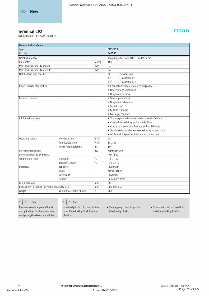
Subject to change – 2009/0590 Internet: www.festo.com/catalogue/...
Terminal CPXTechnical data – Bus node CPX-FB33
General technical data
Type CPX-FB33
Part No. 548755
Fieldbus interface Two plug connectors, M12, D-coded, 4-pin
Baud rates [Mbps] 100
Max. address capacity, inputs [Byte] 64
Max. address capacity, outputs [Byte] 64
LED displays (bus-specific) NF = Network fault
TP1 = Link/Traffic TP1
TP2 = Link/Traffic TP2
Device-specific diagnostics • Channel and module-oriented diagnostics
• Undervoltage of modules
• Diagnostic memory
Parameterisation • System parameters
• Diagnostic behaviour
• Signal setup
• Failsafe response
• Forcing of channels
Additional functions • Start-up parameterisation in clear text via fieldbus
• Channel-related diagnostics via fieldbus
• Acyclic data access via fieldbus and via Ethernet
• System status can be represented using process data
• Additional diagnostics interface for contror unit
Operating voltage Nominal value [V DC] 24p g g
Permissible range [V DC] 18 … 30
Power failure bridging [ms] 10
Current consumption [mA] Maximum 150
Protection class to EN 60529 IP65/IP67
Temperature range Operation [°C] – 5 … +50p g
Storage/transport [°C] –20 … +70
Materials Top cover Aluminium
Seals Nitrile rubber
Cover caps Polyamide
Screws Galvanised steel
Grid dimension [mm] 50
Dimensions (including interlinking block) W x L x H [mm] 50 x 107 x 50
Weight Without interlinking block [g] 280
-H- Note -H- Note
Please observe the general limits
and guidelines for the system when
configuring the electrical modules.
Use the right kind of screws for the
type of interlinking block (metal or
plastic):
• Self-tapping screws for plastic
interlinking blocks
• Screws with metric thread for
metal interlinking blocks
-V- New
Vendor Manual Festo A090-070431-008 CPX_EN
Q-Pulse Id VM301 Active 09/09/2013 Page 90 of 174

2009/05 – Subject to change 91 Internet: www.festo.com/catalogue/...
Terminal CPXTechnical data – Bus node CPX-FB33
Connection and display components
1 2
3
4
3
1 Bus-specific status LEDs
2 CPX-specific status LEDs
3 Fieldbus connection
(4-pin socket, M12, D-coded)
4 Transparent cover for DIL switch
and memory card
Pin allocation for the fieldbus interface
Pin allocation Pin Signal Description
M12 socket, D-coded
1 TD+ Transmitted data+
2 RD+ Received data+
3 TD- Transmitted data-
4 RD- Received data-
Housing Screening
-V- New
Vendor Manual Festo A090-070431-008 CPX_EN
Q-Pulse Id VM301 Active 09/09/2013 Page 91 of 174

Subject to change – 2009/0592 Internet: www.festo.com/catalogue/...
Terminal CPXAccessories – Bus node CPX-FB33
Ordering data
Designation Type Part No.
Bus connection
Plug, M12x1, 4-pin, D-coded NECU-M-S-D12G4-C2-ET 543109
Transparent cover for DIL switch and memory card CPX-AK-P 548757
Memory card CPX-SK 549526
Cover cap for sealing unused bus connections (10 pieces) ISK-M12 352059
Screws for mounting an inscription label on fieldbus node (12 pieces) CPX-M-M2,5X6-12X 550222
Adapter cable M12, 5-pin at socket Mini-USB and controller software NEFC-M12G5-0.3-U1G5 547432
User documentation
User documentation for bus node CPX-FB33 German P.BE-CPX-PNIO-DE 54875933
English P.BE-CPX-PNIO-EN 548760
Spanish P.BE-CPX-PNIO-ES 548761
French P.BE-CPX-PNIO-FR 548762
Italian P.BE-CPX-PNIO-IT 548763
Swedish P.BE-CPX-PNIO-SV 548764
-V- New
Vendor Manual Festo A090-070431-008 CPX_EN
Q-Pulse Id VM301 Active 09/09/2013 Page 92 of 174
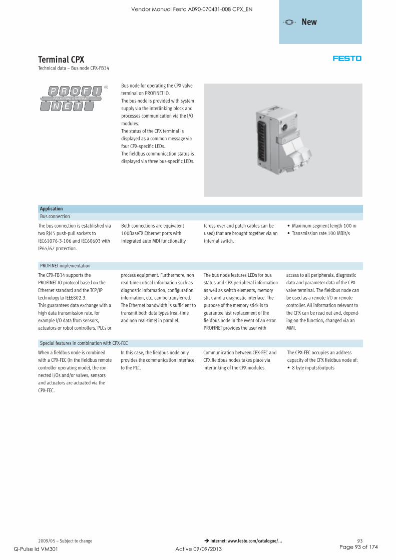
2009/05 – Subject to change 93 Internet: www.festo.com/catalogue/...
Terminal CPXTechnical data – Bus node CPX-FB34
Bus node for operating the CPX valve
terminal on PROFINET IO.
The bus node is provided with system
supply via the interlinking block and
processes communication via the I/O
modules.
The status of the CPX terminal is
displayed as a common message via
four CPX-specific LEDs.
The fieldbus communication status is
displayed via three bus-specific LEDs.
Application
Bus connection
The bus connection is established via
two RJ45 push-pull sockets to
IEC61076-3-106 and IEC60603 with
IP65/67 protection.
Both connections are equivalent
100BaseTX Ethernet ports with
integrated auto MDI functionality
(cross-over and patch cables can be
used) that are brought together via an
internal switch.
• Maximum segment length 100 m
• Transmission rate 100 MBit/s
PROFINET implementation
The CPX-FB34 supports the
PROFINET IO protocol based on the
Ethernet standard and the TCP/IP
technology to IEEE802.3.
This guarantees data exchange with a
high data transmission rate, for
example I/O data from sensors,
actuators or robot controllers, PLCs or
process equipment. Furthermore, non
real-time critical information such as
diagnostic information, configuration
information, etc. can be transferred.
The Ethernet bandwidth is sufficient to
transmit both data types (real-time
and non real-time) in parallel.
The bus node features LEDs for bus
status and CPX peripheral information
as well as switch elements, memory
stick and a diagnostic interface. The
purpose of the memory stick is to
guarantee fast replacement of the
fieldbus node in the event of an error.
PROFINET provides the user with
access to all peripherals, diagnostic
data and parameter data of the CPX
valve terminal. The fieldbus node can
be used as a remote I/O or remote
controller. All information relevant to
the CPX can be read out and, depend-
ing on the function, changed via an
MMI.
Special features in combination with CPX-FEC
When a fieldbus node is combined
with a CPX-FEC (in the fieldbus remote
controller operating mode), the con-
nected I/Os and/or valves, sensors
and actuators are actuated via the
CPX-FEC.
In this case, the fieldbus node only
provides the communication interface
to the PLC.
Communication between CPX-FEC and
CPX fieldbus nodes takes place via
interlinking of the CPX modules.
The CPX-FEC occupies an address
capacity of the CPX fieldbus node of:
• 8 byte inputs/outputs
-V- New
Vendor Manual Festo A090-070431-008 CPX_EN
Q-Pulse Id VM301 Active 09/09/2013 Page 93 of 174

Subject to change – 2009/0594 Internet: www.festo.com/catalogue/...
Terminal CPXTechnical data – Bus node CPX-FB34
General technical data
Type CPX-FB34
Part No. 548751
Fieldbus interface 2x RJ45 push-pull socket, AIDA
Baud rates [MBit/s] 100
Protocol ProfiNet RT
Max. address capacity Inputs [Byte] 64p y
Outputs [Byte] 64
LED displays (bus-specific) NF = Network fault
TP1 = Network active port 1
TP2 = Network active port 2
(product-specific) M = Modify, parameterisation
PL = Load supply
PS = Electronic supply, sensor supply
SF = System fault
Device-specific diagnostics • Channel and module-oriented diagnostics
• Undervoltage of modules
• Diagnostic memory
Configuration support GSDML file
Parameterisation • System parameters
• Diagnostic behaviour
• Signal setup
• Failsafe response
• Forcing of channels
Additional functions • Start-up parameterisation in clear text via fieldbus
• Channel-related diagnostics via fieldbus
• Acyclic data access via fieldbus and via Ethernet
• System status can be represented using process data
• Additional diagnostics interface for contror unit
Control elements DIL switch, optional memory card
Operating voltage Nominal value [V DC] 24p g g
Permissible range [V DC] 18 … 30
Intrinsic current consumption at nominal operating voltage [mA] Typically 120
Protection class to EN 60529 IP65, IP67
CE mark (see declaration of conformity) In accordance with EU-EMC directive
Temperature range Operation [°C] – 5 … +50p g
Storage/transport [°C] –20 … +70
Material of housing (see declaration of conformity)
Grid dimension [mm] 50
Dimensions (incl. interlinking block) W x L x H [mm] 50 x 107x 80
Weight Without interlinking block [g] 280
-H- Note -H- Note
Please observe the general limits
and guidelines for the system when
configuring the electrical modules.
Always use screws appropriate to the
interlinking block (metal or plastic):
• Self-tapping screws for plastic
interlinking blocks
• Screws with metric thread for metal
interlinking blocks
-V- New
Vendor Manual Festo A090-070431-008 CPX_EN
Q-Pulse Id VM301 Active 09/09/2013 Page 94 of 174

2009/05 – Subject to change 95 Internet: www.festo.com/catalogue/...
Terminal CPXTechnical data – Bus node CPX-FB34
Connection and display components
1 2
3
4
3
1 Bus-specific status LEDs
2 CPX-specific status LEDs
3 Fieldbus connection
(8-pin RJ45 socket)
4 DIL switch and memory card
Pin allocation for the fieldbus interface
Pin allocation Pin Signal Description
Plug RJ45
1 TD+ Transmitted data+
2 TD- Transmitted data-
3 RD+ Received data+
4 n.c. Not connected
5 n.c. Not connected
6 RD- Received data-
7 n.c. Not connected
8 n.c. Not connected
Housing Screen Screened
-V- New
Vendor Manual Festo A090-070431-008 CPX_EN
Q-Pulse Id VM301 Active 09/09/2013 Page 95 of 174

Subject to change – 2009/0596 Internet: www.festo.com/catalogue/...
Terminal CPXAccessories – Bus node CPX-FB34
Ordering data
Designation Type Part No.
Bus connection
Plug RJ45, 8-pin, push-pull FBS-RJ45-PP-GS 552000
Cover cap for bus connection CPX-M-AK-C 548753
Cover plate for DIL switch and memory card CPX-M-AK-M 548754
Memory card CPX-SK 549526
Screws for attaching an inscription label holder to the fieldbus node (12 pieces) CPX-M-M2,5X6-12X 550222
Adapter cable M12, 5-pin at socket Mini-USB and controller software NEFC-M12G5-0.3-U1G5 547432
User documentation
Electronics manual, CPX bus node, type CPX-FB34 German P.BE-CPX-PNIO-DE 548759, , yp 3
English P.BE-CPX-PNIO-EN 548760
Spanish P.BE-CPX-PNIO-ES 548761
French P.BE-CPX-PNIO-FR 548762
Italian P.BE-CPX-PNIO-IT 548763
Swedish P.BE-CPX-PNIO-SV 548764
-V- New
Vendor Manual Festo A090-070431-008 CPX_EN
Q-Pulse Id VM301 Active 09/09/2013 Page 96 of 174

2009/05 – Subject to change 97 Internet: www.festo.com/catalogue/...
Terminal CPXTechnical data – Bus node CPX-FB38
Bus node for operating the CPX valve
terminal on EtherCAT.
The bus node is provided with system
supply via the interlinking block and
processes communication with the I/O
modules.
The status of the CPX terminal is
displayed as a common message via
four CPX-specific LEDs.
The fieldbus communication status is
displayed via four bus-specific LEDs.
Application
Bus connection
The bus connection is established via
two M12 sockets, D-coded to
IEC61076-2-101 with protection class
IP65/67.
Both connections are equivalent
100BaseTX Ethernet ports with
integrated auto MDI functionality
(cross-over and patch cables can be
used) that are brought together via an
internal switch.
• Maximum segment length 100 m
• Transmission rate 100 Mbps
EtherCAT implementation
The CPX-FB38 supports the EtherCAT
protocol based on the Ethernet
standard and the TCP/IP technology to
IEEE802.3.
This guarantees data exchange with a
high data transmission rate, for
example I/O data from sensors,
actuators or robot controllers, PLCs or
process equipment. Furthermore, non
real-time critical information such as
diagnostic information, configuration
information, etc. can be transferred.
The data bandwidth is sufficient to
transmit both data types (real-time
and non real-time) in parallel.
The bus node features LEDs for bus
status and CPX peripheral information
as well as switch elements and a
diagnostic interface. The fieldbus
node can be used as a remote I/O or
remote controller. All information
relevant to the CPX can be read out
and, dependent on the function,
changed via an MMI/FMT.
Special features in combination with CPX-FEC
When a fieldbus node is combined
with a CPX-FEC (in the fieldbus remote
controller operating mode), the
connected I/Os and/or valves, sensors
and actuators are actuated via the
CPX-FEC.
In this case, the fieldbus node only
provides the communication interface
to the PLC.
Communication between CPX-FEC and
CPX fieldbus nodes takes place via
interlinking of the CPX modules.
The CPX-FEC occupies an address
capacity of the CPX fieldbus node of:
• 8 byte inputs/outputs
-V- New
Vendor Manual Festo A090-070431-008 CPX_EN
Q-Pulse Id VM301 Active 09/09/2013 Page 97 of 174

Subject to change – 2009/0598 Internet: www.festo.com/catalogue/...
Terminal CPXTechnical data – Bus node CPX-FB38
General technical data
Type CPX-FB38
Part No. 552046
Fieldbus interface Two plug connectors M12, D-coded, 4-pin
Baud rates [Mbps] 100
Max. address capacity, inputs [byte] 64
Max. address capacity, outputs [byte] 64
LED displays bus-specific Error = Communication error
L/A1 = Network active port 1
L/A2 = Network active port 2
Run = Communication status
product-specific M = Modify, parameterisation
PL = Load supply
PS = Electronic supply, sensor supply
SF = System fault
Device-specific diagnostics • Channel and module-oriented diagnostics
• Undervoltage of modules
• Diagnostic memory
Configuration support XML file
Parameterisation • System parameters
• Diagnostic behaviour
• Signal setup
• Fail-safe response
• Forcing of channels
Additional functions • System status can be represented using process data
• Additional diagnostic interface for operator units
Control elements DIL switch
Operating voltage Nominal value [V DC] 24p g g
Permissible range [V DC] 18 … 30
Power failure bridging [ms] 10
Current consumption [mA] Typically 100
Protection class to EN 60529 IP65/IP67
CE mark (see declaration of conformity) To EU EMC Directive
Temperature range Operation [°C] – 5 … +50p g
Storage/transport [°C] –20 … +70
Materials Housing Reinforced polyamide
Grid dimension [mm] 50
Dimensions (incl. interlinking block) W x L x H [mm] 50 x 107 x 50
Weight without interlinking block [g] 125
-H- Note -H- Note
Please observe the general limits
and guidelines for the system when
configuring the electrical modules.
Always use screws appropriate to
the interlinking block (metal or
plastic):
• Self-tapping screws for plastic
interlinking blocks
• Screws with metric thread for
metal interlinking blocks
-V- New
Vendor Manual Festo A090-070431-008 CPX_EN
Q-Pulse Id VM301 Active 09/09/2013 Page 98 of 174

2009/05 – Subject to change 99 Internet: www.festo.com/catalogue/...
Terminal CPXTechnical data – Bus node CPX-FB38
Connection and display components
1 2
4
53 1 Bus-specific status LEDs
2 CPX-specific status LEDs
3 Fieldbus connection, output
(4-pin socket, M12, D-coded)
4 Fieldbus connection, input
(4-pin socket, M12, D-coded)
5 Transparent DIL switch cover
Pin allocation for the fieldbus interface
Pin allocation Pin Signal Description
M12 socket, D-coded
1 TD+ Transmitted data+
2 RD+ Received data+
3 TD- Transmitted data-
4 RD- Received data-
Housing Screened
-V- New
Vendor Manual Festo A090-070431-008 CPX_EN
Q-Pulse Id VM301 Active 09/09/2013 Page 99 of 174

Subject to change – 2009/05100 Internet: www.festo.com/catalogue/...
Terminal CPXAccessories – Bus node CPX-FB38
Ordering data
Designation Type Part No.
Bus connection
Plug M12x1, 4-pin, D-coded NECU-M-S-D12G4-C2-ET 543109
Inspection cover, transparent AK-SUB-9/15-B 533334
Cover cap for sealing unused bus connections (10 pieces) ISK-M12 165592
Inscription label holder for connection block CPX-ST-1 536593
Adapter cable from 5-pin M12 to mini USB socket and controller software NEFC-M12G5-0.3-U1G5 547432
User manual
Electronics manual, CPX bus node, type CPX-FB38 German P.BE-CPX-FB38-DE 562524, , yp 3
English P.BE-CPX-FB38-EN 562525
Spanish P.BE-CPX-FB38-ES 562526
French P.BE-CPX-FB38-FR 562527
Italian P.BE-CPX-FB38-IT 562528
Swedish P.BE-CPX-FB38-SV 562529
-V- New
Vendor Manual Festo A090-070431-008 CPX_EN
Q-Pulse Id VM301 Active 09/09/2013 Page 100 of 174

2009/05 – Subject to change 101 Internet: www.festo.com/catalogue/...
Terminal CPXTechnical data – CPX-CP interface
The CPX-CP electrical interface esta-
blishes the connection to CP modules
of the CPI installation system via
prefabricated cables. The I/O data of
the connected valve terminals with CP
string extension and CP input and
output modules is transferred to the
connected CPX bus node and thus via
fieldbus to the higher-order controller.
This enables the establishment of
modular centralised and compact de-
centralised concepts with one system.
The CP electrical interface is sup-
ported by all CPX fieldbus nodes and
the CPX-FEC.
Application
CP connection
As well as transmitting the communi-
cation data, the max. 4 CP strings of a
CPX-CP interface also transmit the
supply voltage to the connected sen-
sors and the load supply to the valves
(or outputs). Both circuits are
supplied with 24 V separately from
one another, but with a common refer-
ence potential. The valve terminals
with CP string extension (or outputs)
are supplied with voltage for the elec-
tronics and valves by the interlinking
block.
The following combinations are made
possible by the CP interface:
• Centralised analogue and digital in-
puts and outputs of the CPX
terminal
• Decentralised digital inputs and
outputs of the CP installation
system
• Valve/valve terminals that can be
connected both centrally and
decentrally
Configuration example – CP interface with CP modules
Vendor Manual Festo A090-070431-008 CPX_EN
Q-Pulse Id VM301 Active 09/09/2013 Page 101 of 174

Subject to change – 2009/05102 Internet: www.festo.com/catalogue/...
Terminal CPXTechnical data – CPX-CP interface
Implementation
The CPX-CP interface supports the CPI
system:
• Max. 4 individual electronically
protected CP strings
• Max. 4 CP modules per string
• Max. 32 inputs/32 outputs per
string
• The maximum length of a string is
10 m. If the CP interface is posi-
tioned centrally, the CP system can
cover an area of 20 m in diameter
• Modules with CPI functionality
The following CP module variants are
available:
• Input modules with 8 or 16 digital
inputs (connection technology M8,
M12 and CageClamp)
• Output modules with 4 or 8 digital
outputs (connection technology
M12)
• Valve terminals with CP string
extension (up to 32 solenoid coils,
different valve functions)
CPI modules support the following
functions:
• Module-oriented diagnostics
• Module/channel-oriented
parameterisation
• Support of all functions by the
CPX-MMI operator unit
• Module can be positioned
anywhere within the string
Several CP interface modules can be
combined in one CPX terminal,
depending on the address capacity of
the bus node.
Example:
• CPX-FB13 (512 I/O)
• Max. 4 CP interface modules
(128 I/O each) possible
-H- Note
When arranging the CP modules it
should be taken into consideration
that CP input modules without CPI
functionality should always be
placed at the end of a string.
Configuration
The following rules apply for a string
of a CPX-CP interface:
• Max. one output module or one
valve terminal without CPI
functionality
• Max. one output module without
CPI functionality or one valve
terminal with CP string extension
• Any number of CP modules with CPI
functionality, up to the maximum
limit of 4 modules and/or 32 in-
puts/32 outputs per string
Maximum extension:
• 4 input modules and 4 valve
terminals/output modules without
CPI functionality
• 16 CP modules with CPI
functionality
The configuration of the strings with
respect to the module type and posi-
tion of the modules in the string is
entered by activating the SAVE key in
the CPX-CP interface and saved there
remanently (plug and work).
Saved data is retained even when the
CP interface is isolated from the
voltage supply.
The representation of the CP inter-
face within a CPX terminal and thus
at the fieldbus is dependent on the
characteristics of the relevant field-
bus system. In addition to input and
output addressing, this also applies
to the representation of the diag-
nostics and parameterisation of the
CP module and the characteristics
of the CPI system.
-H- Note
The remanent saving of configur-
ation data means that changes in
the configuration or faulty modules
are still displayed even after a
voltage failure.
Vendor Manual Festo A090-070431-008 CPX_EN
Q-Pulse Id VM301 Active 09/09/2013 Page 102 of 174

2009/05 – Subject to change 103 Internet: www.festo.com/catalogue/...
Terminal CPXTechnical data – CPX-CP interface
General technical data
Type CPX-CP-4-FB
Part No. 526705
Brief description CP interface
Max. number of CP strings 4
CP modules per string 4
outputs per string 32
inputs per string 32
CP connection Socket M9, 5-pin
Baud rate [kbps] 1000
Cycle time CP modules without CPI
functionality
[ms] 4
CP modules with CPI
functionality
[ms] 2
LED displays L1 … 4 = Status of the CP string 1 … 4
PS = Electronic supply, sensor supply
PL = Load supply
RN = Status of the CP system
SF = System error
Device-specific diagnostics Via bus node
Operating voltage Nominal value [V] 24 DC (reverse polarity protected)p g g
Permissible range [V] 18 … 30 DC
Power failure bridging [ms] 20
Supply voltage of sensors [V] 24 DC ±25% coming from bus node
Load voltage of actuators [V] 24 DC ±10% coming from bus node
Current consumption without CP modules [A] Max. 0.2p
per CP string [A] Max. 1.6
Protection class to EN 60529 IP65/IP67
Temperature range Operation [°C] –5 … +50p g
Storage/transport [°C] –20 … +70
Materials Polyamide
Grid dimension [mm] 50
Dimensions (including interlinking block) W x L x H [mm] 50 x 107 x 45
Weight Without interlinking block [g] 140g
Including interlinking block
without power supply
[g] 220
Including interlinking block with
system supply
[g] 240
-H- Note
Please observe the general limits and
guidelines for the system when
configuring the electrical modules.
Vendor Manual Festo A090-070431-008 CPX_EN
Q-Pulse Id VM301 Active 09/09/2013 Page 103 of 174

Subject to change – 2009/05104 Internet: www.festo.com/catalogue/...
Terminal CPXAccessories – CPX-CP interface
Connection and display components
4
5
1
3
2
1 CP string LEDs
2 SAVE key
3 Holders for inscription labels
(IBS 6x10)
4 CPX-specific status LEDs
5 CP connections for up to
4 strings (0 … 3)
Ordering data
Designation Type Part No.
Bus connection
Cover cap M9 FLANSCHDOSE SER.712 356684p
M12 ISK-M12 165592
Connecting cable WS-WD 0.25 m KVI-CP-3-WS-WD-0,25 540327g
0.5 m KVI-CP-3-WS-WD-0,5 540328
2 m KVI-CP-3-WS-WD-2 540329
5 m KVI-CP-3-WS-WD-5 540330
8 m KVI-CP-3-WS-WD-8 540331
Connecting cable GS-GD 2 m KVI-CP-3-GS-GD-2 540332g
5 m KVI-CP-3-GS-GD-5 540333
8 m KVI-CP-3-GS-GD-8 540334
Inscription label holder for connection block CPX-ST-1 536593
User documentation
User documentation for CPX-CP interface German P.BE-CPX-CP-DE 539293
English P.BE-CPX-CP-EN 539294
Spanish P.BE-CPX-CP-ES 539295
French P.BE-CPX-CP-FR 539296
Italian P.BE-CPX-CP-IT 539297
Swedish P.BE-CPX-CP-SV 539298
Vendor Manual Festo A090-070431-008 CPX_EN
Q-Pulse Id VM301 Active 09/09/2013 Page 104 of 174

2009/05 – Subject to change 105 Internet: www.festo.com/catalogue/...
Control block CPX-CMXXTechnical data
The control block CPX-CMXX is an
intelligent module in the CPX terminal
for controlling electric drive units.
Individual axis and simple multi-axis
applications can easily be implem-
ented. Programming is not necessary.
Configuration, parameterisation and
commissioning of the application is
easily achieved with the Festo
Configuration Tool (FCT).
• Configuration of two axes groups
with up to four axes each is
possible
• There are 1024 position sets
available per axes group
• Input or Teach-In of positions in
specified set structure
• Parameterisation via Ethernet
• Communication protocol:
FHPP-MAX, Festo handling and
positioning profile for multi-axis
movements.
• Control of drive units via CANopen
General technical data
Protocol FHPP-Max
Maximum address volume for inputs [byte] 16
Maximum address volume for outputs [byte] 16
LED displays (bus-specific) RUN: Program is executedp y ( p )
STOP: Program is stopped
ERR: Error in the program execution
TP: Status of Ethernet connection
LED displays (product-specific) M: Modify, parameterisationp y (p p )
PS: Electronic supply, sensor supply
Device-specific diagnostics Diagnostic memoryp g
Channel and module-oriented diagnostics
Undervoltage/short circuit of modules
Parameterisation System parameters
Operating elements Rotary switch for RUN/STOP
Configuration support Festo Configuration Tool (FCT)
Additional functions System status can be displayed using process data
Additional diagnostic interface for FCT
Supported kinematic system 2-axis gantries (X-Z / Y-Z / X-Y)pp y
3-axis gantries (X-Y-Z)
Total number of axes 8
Distribution of axes 2 groups with max. 4 axes
Nominal operating voltage [V DC] 24
Operating voltage range [V DC] 18 … 30
Power failure bridging [ms] 10
Intrinsic current consumption
at nominal operating voltage
[mA] Typ. 85
Protection class to EN 60529 IP65/IP67
Dimensions W x L x H
(including interlinking block)
[mm] 50 x 107 x 55
Product weight [g] 155
Materials
Housing Reinforced polyamide, polycarbonate
Note on materials RoHS-compliant
-V- New
Vendor Manual Festo A090-070431-008 CPX_EN
Q-Pulse Id VM301 Active 09/09/2013 Page 105 of 174

Subject to change – 2009/05106 Internet: www.festo.com/catalogue/...
Control block CPX-CMXXTechnical data
Technical data – Interfaces
Ethernet
Ethernet interface Socket RJ45, 8-pin, for configuration only
Baud rate [Mbit/s] 10/100
Interface
Control interface CAN bus
Baud rate [Mbit/s] 1
Operating and environmental conditions
Ambient temperature [°C] –5 … +50
Storage temperature [°C] –20 … +70
Certification cULus listed (OL)
CE mark (see declaration of conformity) To EU Low Voltage Directive
Connection and display components
4
5
6
1
2
3
1 LED display, bus-specific
2 DIL switch
3 Control interface
(plug, Sub-D, 9-pin)
4 LED display, product-specific
5 16-position rotary switch
(RUN/STOP)
6 Ethernet interface
(RJ45, socket, 8-pin)
Pin allocation – Control interface
Pin Signal Meaning
Sub-D plug
1 n.c. Not connected
2 CAN_L CAN low
3 CAN_GND CAN ground
4 n.c. Not connected
5 CAN_SHLD Connection to functional earth (FE)
6 CAN_GND CAN ground (optional)1)
7 CAN_H CAN high
8 n.c. Not connected
9 n.c. Not connected
Housing Screened Plug housing must be connected to FE
1) If a drive controller is connected to an external power supply, CAN ground (optional), pin 6, cannot be used on the CPX-CMXX.
-V- New
Vendor Manual Festo A090-070431-008 CPX_EN
Q-Pulse Id VM301 Active 09/09/2013 Page 106 of 174

2009/05 – Subject to change 107 Internet: www.festo.com/catalogue/...
Control block CPX-CMXXTechnical data
Pin allocation – Ethernet interface
Pin Signal Meaning
Plug RJ45
1 TD+ Transmitted data+
2 TD– Transmitted data–
3 RD+ Received data+
4 n.c. Not connected
5 n.c. Not connected
6 RD– Received data–
7 n.c. Not connected
8 n.c. Not connected
Housing Screened Screened
Ordering data
Designation Part No. Type
Control block 555667 CPX-CMXX
-V- New
Vendor Manual Festo A090-070431-008 CPX_EN
Q-Pulse Id VM301 Active 09/09/2013 Page 107 of 174

Subject to change – 2009/05108 Internet: www.festo.com/catalogue/...
Control block CPX-CMXXAccessories
Ordering data – Bus connection
Designation Part No. Type
Sub-D plug, 9-pin 532219 FBS-SUB-9-BU-2x5POL-B
Bus connection, plug 2xM12, 5-pin 525632 FBA-2-M12-5POL
Plug socket for fieldbus connection, M12, 5-pin 18324 FBSD-GD-9-5POL
Plug M12, 5-pin 175380 FBS-M12-5GS-PG9
Bus connection, 5-pin 525634 FBA-1-SL-5POL
Bus connection, screw terminal, 5-pin 525635 FBSD-KL-2x5POL
Plug RJ45, 8-pin 534494 FBS-RJ45-8-GS
Cover for RJ45 connection 534496 AK-RJ45
Inspection cover, transparent for plug/socket Sub-D 533334 AK-SUB-9/15-B
Cover for plug/socket Sub-D 557010 AK-SUB-9/15
Inscription label holder for connection block 536593 CPX-ST-1
Documentation
Designation Language Part No. Type
Description of control block CPX-CMXX German 564221 P.BE-CPX-CMXX-DEp
English 564222 P.BE-CPX-CMXX-EN
Description of Festo handling and positioning profile German 564223 P.BE-CMXX-FHPP-SW-DEp g p g p
for multi-axis movements FHPP-MAX English 564224 P.BE-CMXX-FHPP-SW-EN
-V- New
Vendor Manual Festo A090-070431-008 CPX_EN
Q-Pulse Id VM301 Active 09/09/2013 Page 108 of 174

2009/05 – Subject to change 109 Internet: www.festo.com/catalogue/...
Terminal CPXTechnical data – Input module, digital
Function
Digital input modules enable the
connection of two-wire and three-wire
sensors (proximity sensors, inductive
or capacitive sensors, etc).
Depending on the connection block
selected, the module supports various
connection concepts with different
numbers of sockets (single or double
allocation).
Application
• Input modules for 24 V DC sensor
voltage supply
• PNP or NPN logic
• Supports connection blocks with
M12, M8, Sub-D, Harax and
terminal connection
• Module features can be
parameterised
• The input module receives the volt-
age supply for the electronics and
the sensors from the interlinking
block
• Module protection and diagnostics
through integrated electronic fuse
protection
General technical data
Type CPX-4DE CPX-8DE CPX-8DE-D CPX-8NDE
Part No. 195752 195750 541480 543813
No. of inputs 4 8 8 8
Max. power supply of inputs per module [A] 0.7 1 0.7 0.7
Fuse protection Internal electronic
fuse protection for
each module
Internal electronic
fuse protection for
each module
Internal electronic
fuse protection for
each channel
Internal electronic
fuse protection for
each module
Intrinsic current consumption at operating voltage [mA] Typ. 15
Operating voltage Nominal value [V DC] 24p g g
Permissible range [V DC] 18 … 30
Galvanic isolation Channel – Channel No
Channel – Internal bus No
Switching level Signal 0 [V DC] ≤ 5 ≥ 11g
Signal 1 [V DC] ≥ 11 ≤ 5
Switch-on debounce time [ms] 3 (0.1 ms, 10, 20 parameterisable)
Input characteristic curve IEC 1131-2
Switching logic Positive logic (PNP) Negative logic
(NPN)
LED displays Group diagnostics 1 1 1 1p y
Channel diagnostics – – 8 –
Channel status 4 8 8 8
Diagnostics Short circuit/overload, per channel
Parameterisation • Module monitoring
• Behaviour after short circuit
• Switch-on debounce time
• Signal stretching time
Protection class to EN 60529 Depending on connection block
Temperature range Operation [°C] –5 … +50p g
Storage/transport [°C] –20 … +70
Materials Reinforced polyamide, polycarbonate
Grid dimension [mm] 50
Dimensions (including interlinking block and connection block)
W x L x H
[mm] 50 x 107 x 50
Weight [g] 38
Vendor Manual Festo A090-070431-008 CPX_EN
Q-Pulse Id VM301 Active 09/09/2013 Page 109 of 174

Subject to change – 2009/05110 Internet: www.festo.com/catalogue/...
Terminal CPXTechnical data – Input module, digital
Connection and display components
CPX-4DE CPX-8DE CPX-8DE-D CPX-8NDE
2
1 1
2
31
2 2
1
1 Status LEDs (green) 2 Error LED (red, module error) 3 Channel-oriented error LEDs
(red)
Allocation to inputs
Pin allocation for module
Connection block/digital input module combinations
Connection blocks Part No. Digital input modules
CPX-4DE CPX-8DE CPX-8DE-D CPX-8NDE
CPX-AB-8-M8-3POL 195706
CPX-AB-4-M12X2-5POL 195704
CPX-AB-4-M12X2-5POL-R 541254
CPX-AB-8-KL-4POL 195708
CPX-AB-1-SUB-BU-25POL 525676
CPX-AB-4-HAR-4POL 525636
CPX-M-4-M12x2-5POL 549367
CPX-AB-4-M12x2-5P-R-M3 546997
Pin allocation
Connection block inputs CPX-4DE CPX-8DE, CPX-8DE-D and CPX-8NDE
CPX-AB-8-M8-3POL
X1.1: 24 VSEN
X1.3: 0 VSEN
X1.4: Input x
X5.1: 24 VSEN
X5.3: 0 VSEN
X5.4: Input x+2
X1.1: 24 VSEN x
X1.3: 0 VSEN x
X1.4: Input x
X5.1: 24 VSEN x+4
X5.3: 0 VSEN x+4
X5.4: Input x+4
X2.1: 24 VSEN
X2.3: 0 VSEN
X2.4: Input x+1
X6.1: 24 VSEN
X6.3: 0 VSEN
X6.4: Input x+3
X2.1: 24 VSEN x+1
X2.3: 0 VSEN x+1
X2.4: Input x+1
X6.1: 24 VSEN x+5
X6.3: 0 VSEN x+5
X6.4: Input x+5
X3.1: 24 VSEN
X3.3: 0 VSEN
X3.4: Input x+1
X7.1: 24 VSEN
X7.3: 0 VSEN
X7.4: Input x+3
X3.1: 24 VSEN x+2
X3.3: 0 VSEN x+2
X3.4: Input x+2
X7.1: 24 VSEN x+6
X7.3: 0 VSEN x+6
X7.4: Input x+6
X4.1: 24 VSEN
X4.3: 0 VSEN
X4.4: n.c.
X8.1: 24 VSEN
X8.3: 0 VSEN
X8.4: n.c.
X4.1: 24 VSEN x+3
X4.3: 0 VSEN x+3
X4.4: Input x+3
X8.1: 24 VSEN x+7
X8.3: 0 VSEN x+7
X8.4: Input x+7
CPX-AB-4-M12X2-5POL and CPX-AB-4-M12X2-5POL-R1)
X1.1: 24 VSEN
X1.2: Input x+1
X1.3: 0 VSEN
X1.4: Input x
X1.5: FE
X3.1: 24 VSEN
X3.2: Input x+3
X3.3: 0 VSEN
X3.4: Input x+2
X3.5: FE
X1.1: 24 VSEN x
X1.2: Input x+1
X1.3: 0 VSEN x
X1.4: Input x
X1.5: FE
X3.1: 24 VSEN x+4
X3.2: Input x+5
X3.3: 0 VSEN x+4
X3.4: Input x+4
X3.5: FE
X2.1: 24 VSEN
X2.2: n.c.
X2.3: 0 VSEN
X2.4: Input x+1
X2.5: FE
X4.1: 24 VSEN
X4.2: n.c.
X4.3: 0 VSEN
X4.4: Input x+3
X4.5: FE
X2.1: 24 VSEN x+2
X2.2: Input x+3
X2.3: 0 VSENx+2
X2.4: Input x+2
X2.5: FE
X4.1: 24 VSEN x+6
X4.2: Input x+7
X4.3: 0 VSEN x+6
X4.4: Input x+6
X4.5: FE
1) Speedcon quick lock, metal thread with additional screening
Vendor Manual Festo A090-070431-008 CPX_EN
Q-Pulse Id VM301 Active 09/09/2013 Page 110 of 174

2009/05 – Subject to change 111 Internet: www.festo.com/catalogue/...
Terminal CPXTechnical data – Input module, digital
Pin allocation
Connection block inputs CPX-4DE CPX-8DE, CPX-8DE-D and CPX-8NDE
CPX-AB-8-KL-4POL
X1.0: 24 VSEN
X1.1: 0 VSEN
X1.2: Input x
X1.3: FE
X5.0: 24 VSEN
X5.1: 0 VSEN
X5.2: Input x+2
X5.3: FE
X1.0: 24 VSEN x
X1.1: 0 VSEN x
X1.2: Input x
X1.3: FE
X5.0: 24 VSEN x+4
X5.1: 0 VSEN x+4
X5.2: Input x+4
X5.3: FE
X2.0: 24 VSEN
X2.1: 0 VSEN
X2.2: Input x+1
X2.3: FE
X6.0: 24 VSEN
X6.1: 0 VSEN
X6.2: Input x+3
X6.3: FE
X2.0: 24 VSEN x+1
X2.1: 0 VSEN x+1
X2.2: Input x+1
X2.3: FE
X6.0: 24 VSEN x+5
X6.1: 0 VSEN x+5
X6.2: Input x+5
X6.3: FE
X3.0: 24 VSEN
X3.1: 0 VSEN
X3.2: Input x+1
X3.3: FE
X7.0: 24 VSEN
X7.1: 0 VSEN
X7.2: Input x+3
X7.3: FE
X3.0: 24 VSEN x+2
X3.1: 0 VSEN x+2
X3.2: Input x+2
X3.3: FE
X7.0: 24 VSEN x+6
X7.1: 0 VSEN x+6
X7.2: Input x+6
X7.3: FE
X4.0: 24 VSEN
X4.1: 0 VSEN
X4.2: n.c.
X4.3: FE
X8.0: 24 VSEN
X8.1: 0 VSEN
X8.2: n.c.
X8.3: FE
X4.0: 24 VSEN x+3
X4.1: 0 VSEN x+3
X4.2: Input x+3
X4.3: FE
X8.0: 24 VSEN x+7
X8.1: 0 VSEN x+7
X8.2: Input x+7
X8.3: FE
CPX-AB-1-SUB-BU-25POL
1: Input x
2: Input x+1
3: Input x+1
4: n.c.
5: 24 VSEN
6: 0 VSEN
7: 24 VSEN
8: 0 VSEN
9: 24 VSEN
10: 24 VSEN
11: 0 VSEN
12: 0 VSEN
13: FE
14: Input x+2
15: Input x+3
16: Input x+3
17: n.c.
18: 24 VSEN
19: 24 VSEN
20: 24 VSEN
21: 24 VSEN
22: 0 VSEN
23: 0 VSEN
24: 0 VSEN
25: FE
Socket: FE
1: Input x
2: Input x+1
3: Input x+2
4: Input x+3
5: 24 VSEN x+1
6: 0 VSEN x+1
7: 24 VSEN x+3
8: 0 VSEN x+3
9: 24 VSEN x
10: 24 VSEN x+2
11: 0 VSEN x
12: 0 VSEN x+2
13: FE
14: Input x+4
15: Input x+5
16: Input x+6
17: Input x+7
18: 24 VSEN x+4
19: 24 VSEN x+5
20: 24 VSEN x+6
21: 24 VSEN x+7
22: 0 VSEN x+2 and 3
23: 0 VSEN x+2 and 3
24: 0 VSEN x+2 and 3
25: FE
Socket: FE
CPX-AB-4-HAR-4POL
X1.1: 24 VSEN
X1.2: Input x+1
X1.3: 0 VSEN
X1.4: Input x
X3.1: 24 VSEN
X3.2: Input x+3
X3.3: 0 VSEN
X3.4: Input x+2
X1.1: 24 VSEN x
X1.2: Input x+1
X1.3: 0 VSEN x
X1.4: Input x
X3.1: 24 VSEN x+4
X3.2: Input x+5
X3.3: 0 VSEN x+4
X3.4: Input x+4
X2.1: 24 VSEN
X2.2: n.c.
X2.3: 0 VSEN
X2.4: Input x+1
X4.1: 24 VSEN
X4.2: n.c.
X4.3: 0 VSEN
X4.4: Input x+3
X2.1: 24 VSEN x+2
X2.2: Input x+3
X2.3: 0 VSEN x+2
X2.4: Input x+2
X4.1: 24 VSEN x+6
X4.2: Input x+7
X4.3: 0 VSEN x+6
X4.4: Input x+6
Vendor Manual Festo A090-070431-008 CPX_EN
Q-Pulse Id VM301 Active 09/09/2013 Page 111 of 174

Subject to change – 2009/05112 Internet: www.festo.com/catalogue/...
Terminal CPXAccessories – Input module, digital
Ordering data
Designation Type Part No.
Plug
Push-in T-connector 2x socket M12, 5-pin
1x plug M12, 4-pin
NEDU-M12D5-M12T4 541596
2x socket M8, 3-pin
1x plug M12, 4-pin
NEDU-M8D3-M12T4 541597
Plug M8, 3-pin, solderable SEA-GS-M8 18696g
M8, 3-pin, screw-in SEA-3GS-M8-S 192009
M12, 4-pin, PG7 SEA-GS-7 18666
M12, PG7, 4-pin
for cable∅ 2.5 mm
SEA-4GS-7-2,5 192008
M12, 4-pin, PG9 SEA-GS-9 18778
M12, 4-pin for 2 cables SEA-GS-11-DUO 18779
M12 for 2 cables, 5-pin SEA-5GS-11-DUO 192010
M12, 5-pin SEA-M12-5GS-PG7 175487
HARAX plug, 4-pin SEA-GS-HAR-4POL 525928
Sub-D plug, 25-pin SD-SUB-D-ST25 527522
Connecting cable
Connecting cable M8-M8 0.5 m KM8-M8-GSGD-0,5 175488g
1.0 m KM8-M8-GSGD-1 175489
2.5 m KM8-M8-GSGD-2,5 165610
5.0 m KM8-M8-GSGD-5 165611
Connecting cable M12-M12 2.5 m KM12-M12-GSGD-2,5 18684g
5.0 m KM12-M12-GSGD-5 18686
1.0 m KM12-M12-GSWD-1-4 185499
Modular system for connecting cables NEBU-…
Internet: nebu
–
DUO cable M12 2x straight socket KM12-DUO-M8-GDGD 18685
2x straight/angled socket KM12-DUO-M8-GDWD 18688
2x angled socket KM12-DUO-M8-WDWD 18687
Cover
Cover for CPX-AB-8-KL-4POL (IP65/67)
– 8 cable through-feeds M9
– 1 cable through-feed for multi-pin plug
AK-8KL 538219
Fittings kit VG-K-M9 538220
Screening plate
Screening plate for M12 connections CPX-AB-S-4-M12 526184
Vendor Manual Festo A090-070431-008 CPX_EN
Q-Pulse Id VM301 Active 09/09/2013 Page 112 of 174

2009/05 – Subject to change 113 Internet: www.festo.com/catalogue/...
Terminal CPXAccessories – Input module, digital
Ordering data
Designation Type Part No.
User documentation
User documentation German P.BE-CPX-EA-DE 526439
English P.BE-CPX-EA-EN 526440
Spanish P.BE-CPX-EA-ES 526441
French P.BE-CPX-EA-FR 526442
Italian P.BE-CPX-EA-IT 526443
Swedish P.BE-CPX-EA-SV 526444
Vendor Manual Festo A090-070431-008 CPX_EN
Q-Pulse Id VM301 Active 09/09/2013 Page 113 of 174
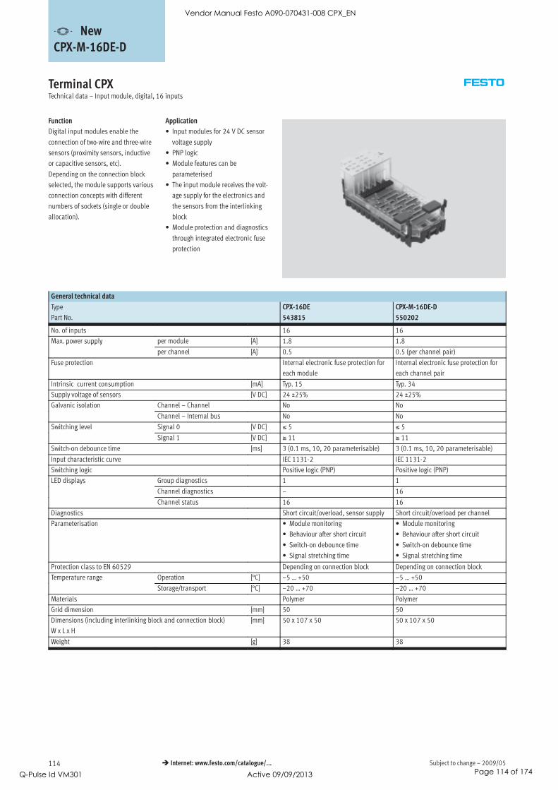
Subject to change – 2009/05114 Internet: www.festo.com/catalogue/...
Terminal CPXTechnical data – Input module, digital, 16 inputs
Function
Digital input modules enable the
connection of two-wire and three-wire
sensors (proximity sensors, inductive
or capacitive sensors, etc).
Depending on the connection block
selected, the module supports various
connection concepts with different
numbers of sockets (single or double
allocation).
Application
• Input modules for 24 V DC sensor
voltage supply
• PNP logic
• Module features can be
parameterised
• The input module receives the volt-
age supply for the electronics and
the sensors from the interlinking
block
• Module protection and diagnostics
through integrated electronic fuse
protection
General technical data
Type CPX-16DE CPX-M-16DE-D
Part No. 543815 550202
No. of inputs 16 16
Max. power supply per module [A] 1.8 1.8p pp y
per channel [A] 0.5 0.5 (per channel pair)
Fuse protection Internal electronic fuse protection for
each module
Internal electronic fuse protection for
each channel pair
Intrinsic current consumption [mA] Typ. 15 Typ. 34
Supply voltage of sensors [V DC] 24 ±25% 24 ±25%
Galvanic isolation Channel – Channel No No
Channel – Internal bus No No
Switching level Signal 0 [V DC] ≤ 5 ≤ 5g
Signal 1 [V DC] ≥ 11 ≥ 11
Switch-on debounce time [ms] 3 (0.1 ms, 10, 20 parameterisable) 3 (0.1 ms, 10, 20 parameterisable)
Input characteristic curve IEC 1131-2 IEC 1131-2
Switching logic Positive logic (PNP) Positive logic (PNP)
LED displays Group diagnostics 1 1p y
Channel diagnostics – 16
Channel status 16 16
Diagnostics Short circuit/overload, sensor supply Short circuit/overload per channel
Parameterisation • Module monitoring
• Behaviour after short circuit
• Switch-on debounce time
• Signal stretching time
• Module monitoring
• Behaviour after short circuit
• Switch-on debounce time
• Signal stretching time
Protection class to EN 60529 Depending on connection block Depending on connection block
Temperature range Operation [°C] –5 … +50 –5 … +50p g
Storage/transport [°C] –20 … +70 –20 … +70
Materials Polymer Polymer
Grid dimension [mm] 50 50
Dimensions (including interlinking block and connection block)
W x L x H
[mm] 50 x 107 x 50 50 x 107 x 50
Weight [g] 38 38
-V- NewCPX-M-16DE-D
Vendor Manual Festo A090-070431-008 CPX_EN
Q-Pulse Id VM301 Active 09/09/2013 Page 114 of 174

2009/05 – Subject to change 115 Internet: www.festo.com/catalogue/...
Terminal CPXTechnical data – Input module, digital, 16 inputs
Connection and display components
CPX-16DE
2
1 1
1 Status LEDs (green)
Allocation to inputs
Pin allocation for module
2 Error LED (red, module error)
Connection block/digital input module combinations
Connection blocks Part No. Digital input modules
CPX-16DE CPX-M-16DE-D
CPX-AB-8-M8X2-4POL 541256 –
CPX-AB-8-KL-4POL 195708 –
CPX-AB-1-SUB-BU-25POL 525676 –
CPX-M-8-M12x2-5POL 549335 –
CPX-AB-8-M8x2-4P-M3 556166 –
Pin allocation
Connection block inputs CPX-16DE
CPX-AB-8-M8x2-4POL
X1.1: 24 VSEN
X1.2: Input x+1
X1.3: 0 VSEN
X1.4: Input x
X5.1: 24 VSEN
X5.2: Input x+9
X5.3: 0 VSEN
X5.4: Input x+8
X2.1: 24 VSEN
X2.2: Input x+3
X2.3: 0 VSEN
X2.4: Input x+2
X6.1: 24 VSEN
X6.2: Input x+11
X6.3: 0 VSEN
X6.4: Input x+10
X3.1: 24 VSEN
X3.2: Input x+5
X3.3: 0 VSEN
X3.4: Input x+4
X7.1: 24 VSEN
X7.2: Input x+13
X7.3: 0 VSEN
X7.4: Input x+12
X4.1: 24 VSEN
X4.2: Input x+7
X4.3: 0 VSEN
X4.4: Input x+6
X8.1: 24 VSEN
X8.1: Input x+15
X8.3: 0 VSEN
X8.4: Input x+14
-V- NewCPX-M-16DE-D
Vendor Manual Festo A090-070431-008 CPX_EN
Q-Pulse Id VM301 Active 09/09/2013 Page 115 of 174

Subject to change – 2009/05116 Internet: www.festo.com/catalogue/...
Terminal CPXTechnical data – Input module, digital, 16 inputs
Pin allocation
Connection block inputs CPX-M-16DE-D
CPX-M-8-M12x2-5POL
X1.1: 24 VSx
X1.2: Input x+1
X1.3: 0 VSx
X1.4: Input x
X1.5: FE
X5.1: 24 VSx+8
X5.2: Input x+9
X5.3: 0 VSx+8
X5.4: Input x+8
X5.5: FE
X2.1: 24 VSx+2
X2.2: Input x+3
X2.3: 0 VSx+2
X2.4: Input x+2
X2.5: FE
X6.1: 24 VSx+10
X6.2: Input x+11
X6.3: 0 VSx+10
X6.4: Input x+10
X6.5: FE
X3.1: 24 VSx+4
X3.2: Input x+5
X3.3: 0 VSx+4
X3.4: Input x+4
X3.5: FE
X7.1: 24 VSx+12
X7.2: Input x+13
X7.3: 0 VSx+12
X7.4: Input x+12
X7.5: FE
X4.1: 24 VSx+6
X4.2: Input x+7
X4.3: 0 VSx+6
X4.4: Input x+6
X4.5: FE
X8.1: 24 VSx+14
X8.2: Input x+15
X8.3: 0 VSx+14
X8.4: Input x+14
X8.5: FE
-V- NewCPX-M-16DE-D
Vendor Manual Festo A090-070431-008 CPX_EN
Q-Pulse Id VM301 Active 09/09/2013 Page 116 of 174

2009/05 – Subject to change 117 Internet: www.festo.com/catalogue/...
Terminal CPXTechnical data – Input module, digital, 16 inputs
Pin allocation
Connection block inputs CPX-16DE
CPX-AB-8-KL-4POL
X1.0: Input x+8
X1.1: 24 VSEN
X1.2: Input x
X1.3: FE (earth)
X5.0: Input x+12
X5.1: 0 VSEN
X5.2: Input x+4
X5.3: FE (earth)
X2.0: Input x+9
X2.1: 24 VSEN
X2.2: Input x+1
X2.3: FE (earth)
X6.0: Input x+13
X6.1: 0 VSEN
X6.2: Input x+5
X6.3: FE (earth)
X3.0: Input x+10
X3.1: 24 VSEN
X3.2: Input x+2
X3.3: FE (earth)
X7.0: Input x+14
X7.1: 0 VSEN
X7.2: Input x+6
X7.3: FE (earth)
X4.0: Input x+11
X4.1: 24 VSEN
X4.2: Input x+3
X4.3: FE (earth)
X8.0: Input x+15
X8.1: 0 VSEN
X8.2: Input x+7
X8.3: FE (earth)
CPX-AB-1-SUB-BU-25POL
1: Input x
2: Input x+1
3: Input x+2
4: Input x+3
5: Input x+9
6: 24 VSEN
7: Input x+11
8: 24 VSEN
9: Input x+8
10: Input x+10
11: 24 VSEN
12: 24 VSEN
13: FE (earth)
14: Input x+4
15: Input x+5
16: Input x+6
17: Input x+7
18: Input x+12
19: Input x+13
20: Input x+14
21: Input x+15
22: 0 VSEN
23: 0 VSEN
24: 0 VSEN
25: FE (earth)
Housing: FE
-V- NewCPX-M-16DE-D
Vendor Manual Festo A090-070431-008 CPX_EN
Q-Pulse Id VM301 Active 09/09/2013 Page 117 of 174

Subject to change – 2009/05118 Internet: www.festo.com/catalogue/...
Terminal CPXAccessories – Input module, digital, 16 inputs
Ordering data
Designation Type Part No.
Plug
Push-in T-connector 2x socket M8, 3-pin
1x plug M8, 4-pin
NEDU-M8D3-M8T4 544391
M8 plug, 3-pin Solderable SEA-GS-M8 18696
Screw-in SEA-3GS-M8-S 192009
Sub-D plug, 25-pin SD-SUB-D-ST25 527522
Connecting cable
Connecting cable M8-M8 0.5 m KM8-M8-GSGD-0,5 175488g
1.0 m KM8-M8-GSGD-1 175489
2.5 m KM8-M8-GSGD-2,5 165610
5.0 m KM8-M8-GSGD-5 165611
Modular system for connecting cables NEBU-…
Internet: nebu
–
Cover
Cover for CPX-AB-8-KL-4POL (IP65/67)
– 8 cable through-feeds M9
– 1 cable through-feed for multi-pin plug
AK-8KL 538219
Fittings kit VG-K-M9 538220
User documentation
User documentation German P.BE-CPX-EA-DE 526439
English P.BE-CPX-EA-EN 526440
Spanish P.BE-CPX-EA-ES 526441
French P.BE-CPX-EA-FR 526442
Italian P.BE-CPX-EA-IT 526443
Swedish P.BE-CPX-EA-SV 526444
-V- NewCPX-M-16DE-D
Vendor Manual Festo A090-070431-008 CPX_EN
Q-Pulse Id VM301 Active 09/09/2013 Page 118 of 174

2009/05 – Subject to change 119 Internet: www.festo.com/catalogue/...
Terminal CPXTechnical data – Output module, digital
Function
Digital outputs control actuators such
as individual valves, hydraulic valves,
heating controllers and many more.
Separate circuits are created using an
additional power supply. Parallel
connection of the outputs of a module
enables consuming devices to be
controlled with up to 4 A.
Application
• Output module for 24 V DC supply
voltage
• PNP logic
• Module features can be
parameterised
• The output module receives the
voltage supply for the electronics
and the outputs from the interlink-
ing block
• Module protection and diagnostics
through integrated electronic fuse
protection in each channel
General technical data
Type CPX-4DA CPX-8DA CPX-8DA-H
Part No. 195754 541482 550204
No. of outputs 4 8 8
Max. power supply per module [A] 4 8.4p pp y
per channel [A] 1 (24 W lamp load,
4 channels can be
connected in parallel)
0.5 (12 W lamp load,
8 channels can be
connected in parallel)
2.1 (50 W lamp load),
per channel pair
Protection (short circuit) Internal electronic fuse protection for each channel
Module current consumption (voltage supply for electronics) [mA] Typ. 16 Typ. 34
Operating voltage Nominal value [V DC] 24p g g
Permissible range [V DC] 18 … 30
Galvanic isolation Channel – Channel No
Channel – Internal bus Yes, using an intermediate supply
Output characteristic curve To IEC 1131-2
Switching logic Positive logic (PNP)
LED displays Group diagnostics 1 1 1p y
Channel diagnostics 4 8 8
Channel status 4 8 8
Diagnostics • Short circuit/overload, per channel
• Load voltage of outputs
Parameterisation • Module monitoring
• Behaviour after short circuit
• Fail-safe channel x
• Forcing channel x
• Idle mode channel x
Protection class to EN 60529 Depending on connection block
Temperature range Operation [°C] –5 … +50p g
Storage/transport [°C] –20 … +70
Materials Reinforced polyamide, polycarbonate
Grid dimension [mm] 50
Dimensions (including interlinking block and connection block)
W x L x H
[mm] 50 x 107 x 50
Weight [g] 38
-V- NewCPX-8DA-H
Vendor Manual Festo A090-070431-008 CPX_EN
Q-Pulse Id VM301 Active 09/09/2013 Page 119 of 174
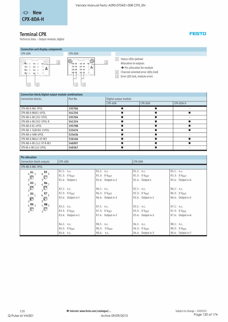
Subject to change – 2009/05120 Internet: www.festo.com/catalogue/...
Terminal CPXTechnical data – Output module, digital
Connection and display components
CPX-4DA CPX-8DA
3
21
3
21
1 Status LEDs (yellow)
Allocation to outputs
Pin allocation for module
2 Channel-oriented error LEDs (red)
3 Error LED (red, module error)
Connection block/digital output module combinations
Connection blocks Part No. Digital output module
CPX-4DA CPX-8DA CPX-8DA-H
CPX-AB-8-M8-3POL 195706 –
CPX-AB-8-M8X2-4POL 541256
CPX-AB-4-M12X2-5POL 195704 –
CPX-AB-4-M12X2-5POL-R 541254
CPX-AB-8-KL-4POL 195708
CPX-AB-1-SUB-BU-25POL 525676
CPX-AB-4-HAR-4POL 525636 –
CPX-AB-8-M8x2-4P-M3 556166
CPX-AB-4-M12x2-5P-R-M3 546997
CPX-M-4-M12x2-5POL 549367 –
Pin allocation
Connection block outputs CPX-4DA CPX-8DA
CPX-AB-8-M8-3POL
X1.1: n.c.
X1.3: 0 VOUT
X1.4: Output x
X5.1: n.c.
X5.3: 0 VOUT
X5.4: Output x+2
X1.1: n.c.
X1.3: 0 VOUT
X1.4: Output x
X5.1: n.c.
X5.3: 0 VOUT
X5.4: Output x+4
X2.1: n.c.
X2.3: 0 VOUT
X2.4: Output x+1
X6.1: n.c.
X6.3: 0 VOUT
X6.4: Output x+3
X2.1: n.c.
X2.3: 0 VOUT
X2.4: Output x+1
X6.1: n.c.
X6.3: 0 VOUT
X6.4: Output x+5
X3.1: n.c.
X3.3: 0 VOUT
X3.4: Output x+1
X7.1: n.c.
X7.3: 0 VOUT
X7.4: Output x+3
X3.1: n.c.
X3.3: 0 VOUT
X3.4: Output x+2
X7.1: n.c.
X7.3: 0 VOUT
X7.4: Output x+6
X4.1: n.c.
X4.3: 0 VOUT
X4.4: n.c.
X8.1: n.c.
X8.3: 0 VOUT
X8.4: n.c.
X4.1: n.c.
X4.3: 0 VOUT
X4.4: Output x+3
X8.1: n.c.
X8.3: 0 VOUT
X8.4: Output x+7
-V- NewCPX-8DA-H
Vendor Manual Festo A090-070431-008 CPX_EN
Q-Pulse Id VM301 Active 09/09/2013 Page 120 of 174

2009/05 – Subject to change 121 Internet: www.festo.com/catalogue/...
Terminal CPXTechnical data – Output module, digital
Pin allocation
Connection block outputs CPX-4DA CPX-8DA and CPX-8DA-H
CPX-AB-8-M8X2-4POL and CPX-AB-8-M8x2-4P-M3
X1.1: 0 VOUT
X1.2: Output x+1
X1.3: 0 VOUT
X1.4: Output x
X5.1: 0 VOUT
X5.2: n.c.
X5.3: 0 VOUT
X5.4: n.c.
X1.1: 0 VOUT
X1.2: Output x+1
X1.3: 0 VOUT
X1.4: Output x
X5.1: 0 VOUT
X5.2: n.c.
X5.3: 0 VOUT
X5.4: n.c.
X2.1: 0 VOUT
X2.2: n.c.
X2.3: 0 VOUT
X2.4: Output x+1
X6.1: 0 VOUT
X6.2: n.c.
X6.3: 0 VOUT
X6.4: n.c.
X2.1: 0 VOUT
X2.2: Output x+3
X2.3: 0 VOUT
X2.4: Output x+2
X6.1: 0 VOUT
X6.2: n.c.
X6.3: 0 VOUT
X6.4: n.c.
X3.1: 0 VOUT
X3.2: Output x+3
X3.3: 0 VOUT
X3.4: Output x+2
X7.1: 0 VOUT
X7.2: n.c.
X7.3: 0 VOUT
X7.4: n.c.
X3.1: 0 VOUT
X3.2: Output x+5
X3.3: 0 VOUT
X3.4: Output x+4
X7.1: 0 VOUT
X7.2: n.c.
X7.3: 0 VOUT
X7.4: n.c.
X4.1: 0 VOUT
X4.2: n.c.
X4.3: 0 VOUT
X4.4: Output x+3
X8.1: 0 VOUT x+1
X8.2: n.c.
X8.3: 0 VOUT x+3
X8.4: n.c.
X4.1: 0 VOUT
X4.2: Output x+7
X4.3: 0 VOUT
X4.4: Output x+6
X8.1: 0 VOUT
X8.2: n.c.
X8.3: 0 VOUT
X8.4: n.c.
CPX-AB-4-M12X2-5POL1), CPX-AB-4-M12X2-5POL-R2) and CPX-AB-4-M12x2-5P-R-M32)
X1.1: n.c.
X1.2: Output x+1
X1.3: 0 VOUT
X1.4: Output x
X1.5: FE
X3.1: n.c.
X3.2: Output x+3
X3.3: 0 VOUT
X3.4: Output x+2
X3.5: FE
X1.1: n.c.
X1.2: Output x+1
X1.3: 0 VOUT
X1.4: Output x
X1.5: FE
X3.1: n.c.
X3.2: Output x+5
X3.3: 0 VOUT
X3.4: Output x+4
X3.5: FE
X2.1: n.c.
X2.2: n.c.
X2.3: 0 VOUT
X2.4: Output x+1
X2.5: FE
X4.1: n.c.
X4.2: n.c.
X4.3: 0 VOUT
X4.4: Output x+3
X4.5: FE
X2.1: n.c.
X2.2: Output x+3
X2.3: 0 VOUT
X2.4: Output x+2
X2.5: FE
X4.1: n.c.
X4.2: Output x+7
X4.3: 0 VOUT
X4.4: Output x+6
X4.5: FE
CPX-AB-8-KL-4POL
X1.0: n.c.
X1.1: 0 VOUT
X1.2: Output x
X1.3: FE
X5.0: n.c.
X5.1: 0 VOUT
X5.2: Output x+2
X5.3: FE
X1.0: n.c.
X1.1: 0 VOUT
X1.2: Output x
X1.3: FE
X5.0: n.c.
X5.1: 0 VOUT
X5.2: Output x+4
X5.3: FE
X2.0: n.c.
X2.1: 0 VOUT
X2.2: Output x+1
X2.3: FE
X6.0: n.c.
X6.1: 0 VOUT
X6.2: Output x+3
X6.3: FE
X2.0: n.c.
X2.1: 0 VOUT
X2.2: Output x+1
X2.3: FE
X6.0: n.c.
X6.1: 0 VOUT
X6.2: Output x+5
X6.3: FE
X3.0: n.c.
X3.1: 0 VOUT
X3.2: Output x+1
X3.3: FE
X7.0: n.c.
X7.1: 0 VOUT
X7.2: Output x+3
X7.3: FE
X3.0: n.c.
X3.1: 0 VOUT
X3.2: Output x+2
X3.3: FE
X7.0: n.c.
X7.1: 0 VOUT
X7.2: Output x+6
X7.3: FE
X4.0: n.c.
X4.1: 0 VOUT
X4.2: n.c.
X4.3: FE
X8.0: n.c.
X8.1: 0 VOUT
X8.2: n.c.
X8.3: FE
X4.0: n.c.
X4.1: 0 VOUT
X4.2: Output x+3
X4.3: FE
X8.0: n.c.
X8.1: 0 VOUT
X8.2: Output x+7
X8.3: FE
1) Not suitable for CPX-8DA-H.
2) Speedcon quick lock, metal thread with additional screening
-V- NewCPX-8DA-H
Vendor Manual Festo A090-070431-008 CPX_EN
Q-Pulse Id VM301 Active 09/09/2013 Page 121 of 174

Subject to change – 2009/05122 Internet: www.festo.com/catalogue/...
Terminal CPXTechnical data – Output module, digital
Pin allocation
Connection block outputs CPX-4DA CPX-8DA and CPX-8DA-H
CPX-AB-1-SUB-BU-25POL
1: Output x
2: Output x+1
3: Output x+1
4: n.c.
5: n.c.
6: 0 VOUT
7: n.c.
8: 0 VOUT
9: n.c.
10: n.c.
11: 0 VOUT
12: 0 VOUT
13: FE
14: Output x+2
15: Output x+3
16: Output x+3
17: n.c.
18: n.c.
19: n.c.
20: n.c.
21: n.c.
22: 0 VOUT
23: 0 VOUT
24: 0 VOUT
25: FE
Socket: FE
1: Output x
2: Output x+1
3: Output x+2
4: Output x+3
5: n.c.
6: 0 VOUT
7: n.c.
8: 0 VOUT
9: n.c.
10: n.c.
11: 0 VOUT
12: 0 VOUT
13: FE
14: Output x+4
15: Output x+5
16: Output x+6
17: Output x+7
18: n.c.
19: n.c.
20: n.c.
21: n.c.
22: 0 VOUT
23: 0 VOUT
24: 0 VOUT
25: FE
Socket: FE
CPX-AB-4-HAR-4POL1)
X1.1: n.c.
X1.2: Output x+1
X1.3: 0 VOUT
X1.4: Output x
X3.1: n.c.
X3.2: Output x+3
X3.3: 0 VOUT
X3.4: Output x+2
X1.1: n.c.
X1.2: Output x+1
X1.3: 0 VOUT
X1.4: Output x
X3.1: n.c.
X3.2: Output x+5
X3.3: 0 VOUT
X3.4: Output x+4
X2.1: n.c.
X2.2: n.c.
X2.3: 0 VOUT
X2.4: Output x+1
X4.1: n.c.
X4.2: n.c.
X4.3: 0 VOUT
X4.4: Output x+3
X2.1: n.c.
X2.2: Output x+3
X2.3: 0 VOUT
X2.4: Output x+2
X4.1: n.c.
X4.2: Output x+7
X4.3: 0 VOUT
X4.4: Output x+6
1) Not suitable for CPX-8DA-H.
-V- NewCPX-8DA-H
Vendor Manual Festo A090-070431-008 CPX_EN
Q-Pulse Id VM301 Active 09/09/2013 Page 122 of 174

2009/05 – Subject to change 123 Internet: www.festo.com/catalogue/...
Terminal CPXAccessories – Output module, digital
Ordering data
Designation Type Part No.
Plug
Push-in T-connector 2x socket M8, 3-pin
1x plug M8, 4-pin
NEDU-M8D3-M8T4 544391
Push-in T-connector 2x socket M12, 5-pin
1x plug M12, 4-pin
NEDU-M12D5-M12T4 541596
2x socket M8, 3-pin
1x plug M12, 4-pin
NEDU-M8D3-M12T4 541597
Plug M8, 3-pin, solderable SEA-GS-M8 18696g
M8, 3-pin, screw-in SEA-3GS-M8-S 192009
M12, PG7 SEA-GS-7 18666
M12, PG7, 4-pin
for cable∅ 2.5 mm
SEA-4GS-7-2,5 192008
M12, PG9 SEA-GS-9 18778
M12 for 2 cables SEA-GS-11-DUO 18779
M12 for 2 cables, 5-pin SEA-5GS-11-DUO 192010
M12, 5-pin SEA-M12-5GS-PG7 175487
HARAX plug, 4-pin SEA-GS-HAR-4POL 525928
Sub-D plug, 25-pin SD-SUB-D-ST25 527522
Connecting cable
Connecting cable M8-M8 0.5 m KM8-M8-GSGD-0,5 175488g
1.0 m KM8-M8-GSGD-1 175489
2.5 m KM8-M8-GSGD-2,5 165610
5.0 m KM8-M8-GSGD-5 165611
Connecting cable M12-M12 2.5 m KM12-M12-GSGD-2,5 18684g
5.0 m KM12-M12-GSGD-5 18686
1.0 m KM12-M12-GSWD-1-4 185499
Modular system for connecting cables NEBU-…
Internet: nebu
–
DUO cable M12 2x straight socket KM12-DUO-M8-GDGD 18685
2x straight/angled socket KM12-DUO-M8-GDWD 18688
2x angled socket KM12-DUO-M8-WDWD 18687
Cover
Cover for CPX-AB-8-KL-4POL (IP65/67)
– 8 cable through-feeds M9
– 1 cable through-feed for multi-pin plug
AK-8KL 538219
Fittings kit VG-K-M9 538220
-V- NewCPX-8DA-H
Vendor Manual Festo A090-070431-008 CPX_EN
Q-Pulse Id VM301 Active 09/09/2013 Page 123 of 174
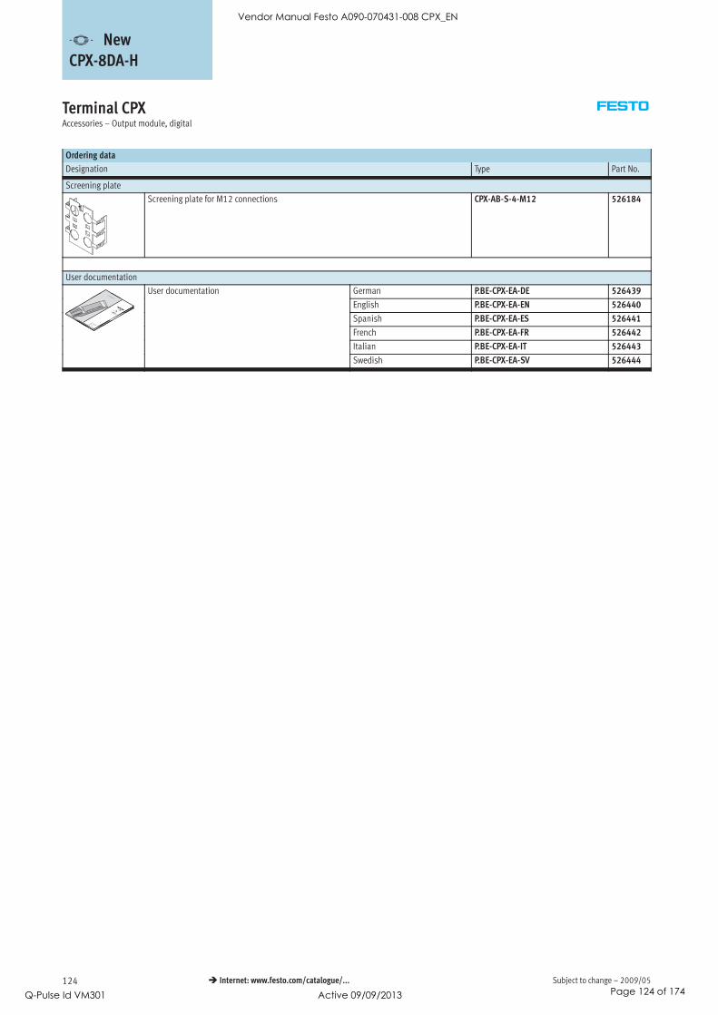
Subject to change – 2009/05124 Internet: www.festo.com/catalogue/...
Terminal CPXAccessories – Output module, digital
Ordering data
Designation Type Part No.
Screening plate
Screening plate for M12 connections CPX-AB-S-4-M12 526184
User documentation
User documentation German P.BE-CPX-EA-DE 526439
English P.BE-CPX-EA-EN 526440
Spanish P.BE-CPX-EA-ES 526441
French P.BE-CPX-EA-FR 526442
Italian P.BE-CPX-EA-IT 526443
Swedish P.BE-CPX-EA-SV 526444
-V- NewCPX-8DA-H
Vendor Manual Festo A090-070431-008 CPX_EN
Q-Pulse Id VM301 Active 09/09/2013 Page 124 of 174

2009/05 – Subject to change 125 Internet: www.festo.com/catalogue/...
Terminal CPXTechnical data – Input/output module, digital
Application
• Digital multi I/O module for
24 V DC supply voltage
• Supports connection blocks with
Sub-D, terminal connection and
M12 connection (8-pin)
• Module features can be
parameterised
• The inputs receive the voltage
supply for the electronics and the
sensors from the interlinking block
• The outputs receive the voltage
supply for the electronics and
outputs from the interlinking block
• Module protection and diagnostics
through integrated electronic fuse
protection for the sensor power
supply and integrated electronic
fuse protection in each output
channel
Function
The multi I/O module controls devices
with a high number of inputs and
outputs per connection point.
Because the module supports Sub-D
connection blocks, consoles with
pushbuttons and lamps can be
connected to the CPX terminal using a
minimal amount of installation space.
Up to 8 inputs and outputs can be
connected to a connection point with
IP65 protection.
Support for the M12 connection block
(8-pin) means that up to 4 cylinder-
valve combinations with integrated
sensors can be connected. Each cylin-
der-valve combination is supported by
2 inputs and 2 outputs per socket. It
is therefore possible to control max. 2
solenoid coils and operate 2 sensors
with a pre-assembled cable.
Two inputs on two sockets are bridged
to provide support for the diagnostic
module of the cylinder-valve combina-
tion. This effectively means that there
are 3 inputs and 2 outputs available
on 2 sockets.
As an alternative to the Sub-D and
M12 connection block (8-pin) for in-
stallation with higher protection class
IP65, the terminal connection block
produces an identical result for
installation with IP20 protection – or
with IP65/67 protection with
additional cover.
Subordinate I/O modules with multi-
pin plug connection (Sub-D plug or
multi-pin cable for self-assembly)
support the cost-effective and space-
saving integration of critical installa-
tion areas such as chain link trunking
or upstream functions.
Vendor Manual Festo A090-070431-008 CPX_EN
Q-Pulse Id VM301 Active 09/09/2013 Page 125 of 174
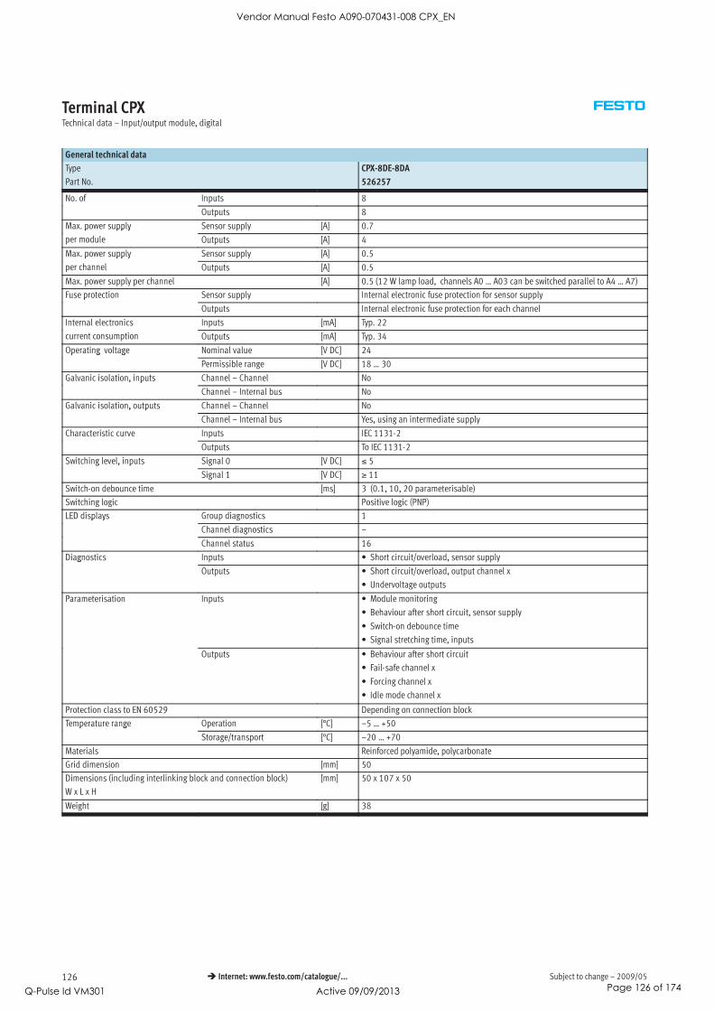
Subject to change – 2009/05126 Internet: www.festo.com/catalogue/...
Terminal CPXTechnical data – Input/output module, digital
General technical data
Type CPX-8DE-8DA
Part No. 526257
No. of Inputs 8
Outputs 8
Max. power supply Sensor supply [A] 0.7p pp y
per module Outputs [A] 4
Max. power supply Sensor supply [A] 0.5p pp y
per channel Outputs [A] 0.5
Max. power supply per channel [A] 0.5 (12 W lamp load, channels A0 … A03 can be switched parallel to A4 … A7)
Fuse protection Sensor supply Internal electronic fuse protection for sensor supplyp
Outputs Internal electronic fuse protection for each channel
Internal electronics Inputs [mA] Typ. 22
current consumption Outputs [mA] Typ. 34
Operating voltage Nominal value [V DC] 24p g g
Permissible range [V DC] 18 … 30
Galvanic isolation, inputs Channel – Channel No, p
Channel – Internal bus No
Galvanic isolation, outputs Channel – Channel No, p
Channel – Internal bus Yes, using an intermediate supply
Characteristic curve Inputs IEC 1131-2
Outputs To IEC 1131-2
Switching level, inputs Signal 0 [V DC] ≤ 5g , p
Signal 1 [V DC] ≥ 11
Switch-on debounce time [ms] 3 (0.1, 10, 20 parameterisable)
Switching logic Positive logic (PNP)
LED displays Group diagnostics 1p y
Channel diagnostics –
Channel status 16
Diagnostics Inputs • Short circuit/overload, sensor supplyg
Outputs • Short circuit/overload, output channel x
• Undervoltage outputs
Parameterisation Inputs • Module monitoring
• Behaviour after short circuit, sensor supply
• Switch-on debounce time
• Signal stretching time, inputs
Outputs • Behaviour after short circuit
• Fail-safe channel x
• Forcing channel x
• Idle mode channel x
Protection class to EN 60529 Depending on connection block
Temperature range Operation [°C] –5 … +50p g
Storage/transport [°C] –20 … +70
Materials Reinforced polyamide, polycarbonate
Grid dimension [mm] 50
Dimensions (including interlinking block and connection block)
W x L x H
[mm] 50 x 107 x 50
Weight [g] 38
Vendor Manual Festo A090-070431-008 CPX_EN
Q-Pulse Id VM301 Active 09/09/2013 Page 126 of 174

2009/05 – Subject to change 127 Internet: www.festo.com/catalogue/...
Terminal CPXTechnical data – Input/output module, digital
Connection and display components
CPX-8DE-8DA
3
1 2
1 Status LEDs (green)
Allocation to inputs
Pin allocation for module
2 Status LEDs (yellow)
Allocation to outputs
Pin allocation for module
3 Error LED (red)
(module error)
Connection block/digital input/output module combinations
Connection blocks Part No. Digital I/O module
CPX-8DE-8DA
CPX-AB-4-M12-8POL 526178
CPX-AB-8-KL-4POL 195708
CPX-AB-1-SUB-BU-25POL 525676
CPX-AB-4-M12-8P-M3 556168
Pin allocation
Connection block inputs/outputs CPX-8DE-8DA
CPX-AB-4-M12-8POL and CPX-AB-4-M12-8P-M3
X1.1: 24 VSEN
X1.2: Input x
X1.3: Input x+1
X1.4: 0 VSEN
X1.5: Output x
X1.6: Output x+1
X1.7: Input x+4
X1.8: 0 VOUT
X3.1: 24 VSEN
X3.2: Input x+4
X3.3: Input x+5
X3.4: 0 VSEN
X3.5: Output x+4
X3.6: Output x+5
X3.7: n.c.
X3.8: 0 VOUT
X2.1: 24 VSEN
X2.2: Input x+2
X2.3: Input x+3
X2.4: 0 VSEN
X2.5: Output x+2
X2.6: Output x+3
X2.7: Input x+6
X2.8: 0 VOUT
X4.1: 24 VSEN
X4.2: Input x+6
X4.3: Input x+7
X4.4: 0 VSEN
X4.5: Output x+6
X4.6: Output x+7
X4.7: n.c.
X4.8: 0 VOUT
Vendor Manual Festo A090-070431-008 CPX_EN
Q-Pulse Id VM301 Active 09/09/2013 Page 127 of 174

Subject to change – 2009/05128 Internet: www.festo.com/catalogue/...
Terminal CPXTechnical data – Input/output module, digital
Pin allocation
Connection block inputs/outputs CPX-8DE-8DA
CPX-AB-8-KL-4POL
X1.0: 24 VSEN
X1.1: 0 VSEN
X1.2: Input x
X1.3: FE
X5.0: Output x+4
X5.1: 0 VOUT
X5.2: Output x
X5.3: FE
X2.0: Input x+4
X2.1: Input x+5
X2.2: Input x+1
X2.3: FE
X6.0: Output x+5
X6.1: 0 VOUT
X6.2: Output x+1
X6.3: FE
X3.0: 24 VSEN
X3.1: 0 VSEN
X3.2: Input x+2
X3.3: FE
X7.0: Output x+6
X7.1: 0 VOUT
X7.2: Output x+2
X7.3: FE
X4.0: Input x+6
X4.1: Input x+7
X4.2: Input x+3
X4.3: FE
X8.0: Output x+7
X8.1: 0 VOUT
X8.2: Output x+3
X8.3: FE
CPX-AB-1-SUB-BU-25POL
1: Input x
2: Input x+1
3: Input x+2
4: Input x+3
5: Input x+4
6: Input x+5
7: Input x+6
8: Input x+7
9: 24 VSEN
10: 24 VSEN
11: 0 VSEN
12: 0 VSEN
13: FE
14: Output x
15: Output x+1
16: Output x+2
17: Output x+3
18: Output x+4
19: Output x+5
20: Output x+6
21: Output x+7
22: 0 VOUT
23: 0 VOUT
24: 0 VOUT
25: FE
Socket: FE
Vendor Manual Festo A090-070431-008 CPX_EN
Q-Pulse Id VM301 Active 09/09/2013 Page 128 of 174

2009/05 – Subject to change 129 Internet: www.festo.com/catalogue/...
Terminal CPXAccessories – Input/output module, digital
Ordering data
Designation Type Part No.
Plug
Sub-D plug, 25-pin SD-SUB-D-ST25 527522
Connecting cable
Connecting cable M12 KM12-8GD8GS-2-PU 525617
Cover
Cover for CPX-AB-8-KL-4POL (IP65/67)
– 8 cable through-feeds M9
– 1 cable through-feed for multi-pin plug
AK-8KL 538219
Fittings kit VG-K-M9 538220
Screening plate
Screening plate for M12 connections CPX-AB-S-4-M12 526184
User documentation
User documentation German P.BE-CPX-EA-DE 526439
English P.BE-CPX-EA-EN 526440
Spanish P.BE-CPX-EA-ES 526441
French P.BE-CPX-EA-FR 526442
Italian P.BE-CPX-EA-IT 526443
Swedish P.BE-CPX-EA-SV 526444
Vendor Manual Festo A090-070431-008 CPX_EN
Q-Pulse Id VM301 Active 09/09/2013 Page 129 of 174

Subject to change – 2009/05130 Internet: www.festo.com/catalogue/...
Terminal CPXTechnical data – Analogue module for inputs
Function
Analogue modules control devices
with a standardised analogue inter-
face such as pressure switches, tem-
perature, flow rate, filling level, etc.
Depending on the connection block
selected, the analogue module
supports various connection concepts
with different numbers of sockets or
terminals.
Application
• Analogue module for 0 … 10 V,
0 … 20 mA or 4 … 20 mA
• Supports connection blocks with
M12, Sub-D and terminal
connection
• Analogue module features can be
parameterised
• Different data formats available
• Operation with and without
galvanic isolation possible
• The analogue module receives the
voltage supply for the electronics
and the sensors from the
interlinking block
• Analogue module protection and
diagnostics through integrated
electronic fuse protection
General technical data
Type CPX-2AE-U-I CPX-4AE-I
Part No. 526168 541484
Voltage input Current input Current input
No. of analogue inputs 2 Choice of 2 or 4
Max. power supply per module [A] 0.7
Fuse protection Internal electronic fuse protection for sensor supply
Current consumption from 24 V sensor supply (quiescent current) [mA] Typically 50
Current consumption from 24 V sensor supply (at full load) [A] Max. 0.7
Supply voltage of sensors [V DC] 24 ±25%
Signal range (parameterisable for each channel by means of DIL
switch or software)
0 … 10 V DC 0 … 20 mA
4 … 20 mA
0 … 20 mA
4 … 20 mA
Resolution [bit] 12
No. of units 4096
Absolute accuracy [%] ±0.5 ±0.6 ±0.6
Linearity errors (no software scaling) [%] ±0.05 ±0.05 ±0.05
Repetition accuracy (at 25 °C) [%] 0.15 0.15 0.15
Input resistance [kΩ] 100 ≤ 0,1 ≤ 0,1
Max. permissible input voltage [V DC] 30 – –
Max. permissible input current [mA] – 40 40
Conversion time per channel [ μs] Typically 150
Cycle time (module) [ms] ≤ 4 ≤ 10
Vendor Manual Festo A090-070431-008 CPX_EN
Q-Pulse Id VM301 Active 09/09/2013 Page 130 of 174

2009/05 – Subject to change 131 Internet: www.festo.com/catalogue/...
Terminal CPXTechnical data – Analogue module for inputs
General technical data
Type CPX-2AE-U-I CPX-4AE-I
Part No. 526168 541484
Data format Prefix + 15 bit, linear scaling
Prefix + 12 bit right-justified, type 03 compatible
Prefix + 15 bit left-aligned, S7 compatible
Prefix + 12 bit left-aligned + diagnostics, S5 compatible
Cable length Max. 30 m (screened)
Galvanic isolation Channel – Channel No
Channel – Internal bus Yes, with external sensor supply
Channel – Sensor supply Yes, with external sensor supply
LED displays Group diagnostics 1p y
Channel diagnostics Yes, by means of flashing frequency of group diagnostics
Diagnostics • Short circuit/overload, sensor supply
• Parameterisation errors
• Value falling below nominal range/full-scale value
• Value exceeding nominal range/full-scale value
• Wire break (with measuring range 4 … 20 mA)
Parameterisation • Short circuit monitoring, sensor supply
• Behaviour after short circuit, sensor supply
• Data format
• Lower limit value/full-scale value
• Upper limit value/full-scale value
• Monitoring of value falling below nominal range/full-scale value
• Monitoring of value exceeding nominal range/full-scale value
• Monitoring of wire break (with measuring range 4 … 20 mA)
• Signal range
• Measured value smoothing
Protection class to EN 60529 Depending on connection block
Temperature range Operation [°C] –5 … +50p g
Storage/transport [°C] –20 … +70
Materials Polymer
Grid dimension [mm] 50
Dimensions (including interlinking block and connection block)
W x L x H
[mm] 50 x 107 x 50
Weight [g] 38
Internal structure, basic representation
24 VSEN
Inputx-
0 VSEN
FE
24 V ± 25% (UEL/SEN )
0 V (UEL/SEN )
Inputx+
1
2
3
4
5
6
7
1 Diagnostics
2 Inputx = Input x
(PLC/IPC via fieldbus)
3 Logic
4 Monitoring/disconnection of
sensor supply
5 D/A conversion
6 Error LED (red, module error)
7 Connections on connection block
Vendor Manual Festo A090-070431-008 CPX_EN
Q-Pulse Id VM301 Active 09/09/2013 Page 131 of 174

Subject to change – 2009/05132 Internet: www.festo.com/catalogue/...
Terminal CPXTechnical data – Analogue module for inputs
Connection and display components
CPX-2AE-U-I and CPX-4AE-I
11 Error LED (red, module error)
Connection block/analogue module combinations
Connection blocks Part No. Analogue module
CPX-2AE-U-I CPX-4AE-I
CPX-AB-4-M12X2-5POL 195704
CPX-AB-4-M12X2-5POL-R 541254
CPX-AB-8-KL-4POL 195708
CPX-AB-1-SUB-BU-25POL 525676
CPX-AB-4-M12x2-5P-R-M3 546997
CPX-M-4-M12x2-5POL 549367
Pin allocation
Connection block inputs CPX-2AE-U-I CPX-4AE-I
CPX-AB-4-M12X2-5POL, CPX-AB-4-M12X2-5POL-R1), CPX-M-4-M12x2-5POL and CPX-AB-4-M12x2-5P-R-M31)
X1.1: 24 VSEN
X1.2: Input U0+
X1.3: 0 VSEN
X1.4: Input U0–
X1.5: FE2)
X3.1: 24 VSEN
X3.2: Input U1+
X3.3: 0 VSEN
X3.4: Input U1–
X3.5: FE2)
X1.1: 24 VSEN
X1.2: Input I0+
X1.3: 0 VSEN
X1.4: Input I0–
X1.5: FE2)
X3.1: 24 VSEN
X3.2: Input I2+
X3.3: 0 VSEN
X3.4: Input I2–
X3.5: FE2)
X2.1: 24 VSEN
X2.2: Input I0+
X2.3: 0 VSEN
X2.4: Input I0–
X2.5: FE2)
X4.1: 24 VSEN
X4.2: Input I1+
X4.3: 0 VSEN
X4.4: Input I1–
X4.5: FE2)
X2.1: 24 VSEN
X2.2: Input I1+
X2.3: 0 VSEN
X2.4: Input I1–
X2.5: FE2)
X4.1: 24 VSEN
X4.2: Input I3+
X4.3: 0 VSEN
X4.4: Input I3–
X4.5: FE2)
CPX-AB-8-KL-4POL
X1.0: 24 VSEN
X1.1: 0 VSEN
X1.2: Input U0–
X1.3: FE
X5.0: 24 VSEN
X5.1: 0 VSEN
X5.2: Input U1–
X5.3: FE
X1.0: 24 VSEN
X1.1: 0 VSEN
X1.2: Input I0–
X1.3: FE
X5.0: 24 VSEN
X5.1: 0 VSEN
X5.2: Input I2–
X5.3: FE
X2.0: n.c.
X2.1: n.c.
X2.2: Input U0+
X2.3: FE
X6.0: n.c.
X6.1: n.c.
X6.2: Input U1+
X6.3: FE
X2.0: n.c.
X2.1: n.c.
X2.2: Input I0+
X2.3: FE
X6.0: n.c.
X6.1: n.c.
X6.2: Input I2+
X6.3: FE
X3.0: 24 VSEN
X3.1: 0 VSEN
X3.2: Input I0–
X3.3: FE
X7.0: 24 VSEN
X7.1: 0 VSEN
X7.2: Input I1–
X7.3: FE
X3.0: 24 VSEN
X3.1: 0 VSEN
X3.2: Input I1–
X3.3: FE
X7.0: 24 VSEN
X7.1: 0 VSEN
X7.2: Input I3–
X7.3: FE
X4.0: n.c.
X4.1: n.c.
X4.2: Input I0+
X4.3: FE
X8.0: n.c.
X8.1: n.c.
X8.2: Input I1+
X8.3: FE
X4.0: n.c.
X4.1: n.c.
X4.2: Input I1+
X4.3: FE
X8.0: n.c.
X8.1: n.c.
X8.2: Input I3+
X8.3: FE
1) Speedcon quick lock, metal thread with additional screening
2) FE/metal thread with additional screening
Vendor Manual Festo A090-070431-008 CPX_EN
Q-Pulse Id VM301 Active 09/09/2013 Page 132 of 174

2009/05 – Subject to change 133 Internet: www.festo.com/catalogue/...
Terminal CPXAccessories – Analogue module for inputs
Pin allocation
Connection block inputs CPX-2AE-U-I CPX-4AE-I
CPX-AB-1-SUB-BU-25POL
1: Input U0–
2: Input U0+
3: Input I0–
4: Input I1+
5: n.c.
6: n.c.
7: n.c.
8: n.c.
9: 24 VSEN
10: 24 VSEN
11: 0 VSEN
12: 0 VSEN
13: Screening1)
14: Input U1–
15: Input U1+
16: Input I1–
17: Input I1+
18: 24 VSEN
19: n.c.
20: 24 VSEN
21: n.c.
22: 0 VSEN
23: 0 VSEN
24: 0 VSEN
25: FE
Socket: FE
1: Input I0–
2: Input I0+
3: Input I1–
4: Input I1+
5: n.c.
6: n.c.
7: n.c.
8: n.c.
9: 24 VSEN
10: 24 VSEN
11: 0 VSEN
12: 0 VSEN
13: Screening1)
14: Input I2–
15: Input I2+
16: Input I3–
17: Input I3+
18: 24 VSEN
19: n.c.
20: 24 VSEN
21: n.c.
22: 0 VSEN
23: 0 VSEN
24: 0 VSEN
25: FE
Socket: FE
1) Connect screening to functional earth FE
Ordering data
Designation Type Part No.
Plug
M12 plug, 5-pin SEA-M12-5GS-PG7 175487
Sub-D plug, 25-pin SD-SUB-D-ST25 527522
Cover
Cover for CPX-AB-8-KL-4POL (IP65/67)
– 8 cable through-feeds M9
– 1 cable through-feed for multi-pin plug
AK-8KL 538219
Fittings kit VG-K-M9 538220
Screening plate
Screening plate for M12 connections CPX-AB-S-4-M12 526184
User documentation
User documentation German P.BE-CPX-AX-DE 526415
English P.BE-CPX-AX-EN 526416
Spanish P.BE-CPX-AX-ES 526417
French P.BE-CPX-AX-FR 526418
Italian P.BE-CPX-AX-IT 526419
Swedish P.BE-CPX-AX-SV 526420
Vendor Manual Festo A090-070431-008 CPX_EN
Q-Pulse Id VM301 Active 09/09/2013 Page 133 of 174
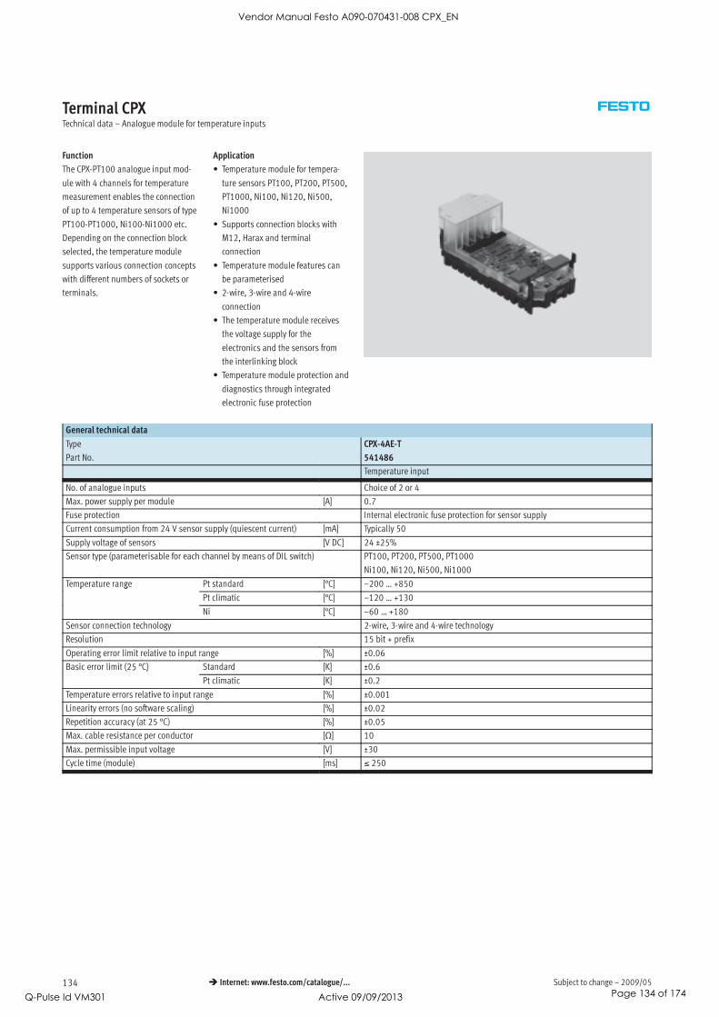
Subject to change – 2009/05134 Internet: www.festo.com/catalogue/...
Terminal CPXTechnical data – Analogue module for temperature inputs
Function
The CPX-PT100 analogue input mod-
ule with 4 channels for temperature
measurement enables the connection
of up to 4 temperature sensors of type
PT100-PT1000, Ni100-Ni1000 etc.
Depending on the connection block
selected, the temperature module
supports various connection concepts
with different numbers of sockets or
terminals.
Application
• Temperature module for tempera-
ture sensors PT100, PT200, PT500,
PT1000, Ni100, Ni120, Ni500,
Ni1000
• Supports connection blocks with
M12, Harax and terminal
connection
• Temperature module features can
be parameterised
• 2-wire, 3-wire and 4-wire
connection
• The temperature module receives
the voltage supply for the
electronics and the sensors from
the interlinking block
• Temperature module protection and
diagnostics through integrated
electronic fuse protection
General technical data
Type CPX-4AE-T
Part No. 541486
Temperature input
No. of analogue inputs Choice of 2 or 4
Max. power supply per module [A] 0.7
Fuse protection Internal electronic fuse protection for sensor supply
Current consumption from 24 V sensor supply (quiescent current) [mA] Typically 50
Supply voltage of sensors [V DC] 24 ±25%
Sensor type (parameterisable for each channel by means of DIL switch) PT100, PT200, PT500, PT1000
Ni100, Ni120, Ni500, Ni1000
Temperature range Pt standard [°C] –200 … +850p g
Pt climatic [°C] –120 … +130
Ni [°C] –60 … +180
Sensor connection technology 2-wire, 3-wire and 4-wire technology
Resolution 15 bit + prefix
Operating error limit relative to input range [%] ±0.06
Basic error limit (25 °C) Standard [K] ±0.6( 5 )
Pt climatic [K] ±0.2
Temperature errors relative to input range [%] ±0.001
Linearity errors (no software scaling) [%] ±0.02
Repetition accuracy (at 25 °C) [%] ±0.05
Max. cable resistance per conductor [Ω] 10
Max. permissible input voltage [V] ±30
Cycle time (module) [ms] ≤ 250
Vendor Manual Festo A090-070431-008 CPX_EN
Q-Pulse Id VM301 Active 09/09/2013 Page 134 of 174

2009/05 – Subject to change 135 Internet: www.festo.com/catalogue/...
Terminal CPXTechnical data – Analogue module for temperature inputs
General technical data
Type CPX-4AE-T
Part No. 541486
Data format 15 bit + prefix, complement of two, binary notation in tenths of a degree
Cable length [m] Max. 200 (screened)
Galvanic isolation Channel – Channel No
Channel – Internal bus Yes
LED displays Group diagnostics 1p y
Channel diagnostics 4
Diagnostics • Short circuit/overload channel
• Parameterisation errors
• Value falling below nominal range/full-scale value
• Value exceeding nominal range/full-scale value
• Wire break
Parameterisation • Unit of measurement and interference frequency suppression
• Diagnostic message in the event of a wire break or short circuit
• Limit monitoring per channel
• Sensor connection technology
• Sensor type/temperature coefficient, temperature range
• Limit value per channel
• Measured value smoothing
Protection class to EN 60529 Depending on connection block
Temperature range Operation [°C] –5 … +50p g
Storage/transport [°C] –20 … +70
Materials Polymer
Grid dimension [mm] 50
Dimensions (including interlinking block and connection block)
W x L x H
[mm] 50 x 107 x 50
Weight [g] 38
Connection and display components
CPX-4AE-T
1
4AI-T
1
1 Error LED (red)
2 Channel-oriented error LEDs (red)
Connection block/analogue module combinations
Connection blocks Part No. Temperature module
CPX-4AE-T
CPX-AB-4-M12X2-5POL 195704
CPX-AB-4-M12X2-5POL-R 541254
CPX-AB-8-KL-4POL 195708
CPX-AB-4-HAR-4POL 525636
CPX-AB-4-M12x2-5P-R-M3 546997
CPX-M-4-M12x2-5POL 549367
Vendor Manual Festo A090-070431-008 CPX_EN
Q-Pulse Id VM301 Active 09/09/2013 Page 135 of 174

Subject to change – 2009/05136 Internet: www.festo.com/catalogue/...
Terminal CPXTechnical data – Analogue module for temperature inputs
Pin allocation
Connection block inputs CPX-4AE-T
CPX-AB-4-M12X2-5POL, CPX-AB-4-M12X2-5POL-R1), CPX-AB-4-M12x2-5P-R-M31) and CPX-M-4-M12x2-5POL
X1.1: Input I0+
X1.2: Input U0+
X1.3: Input I0–
X1.4: Input U0–
X1.5: FE2)
X3.1: Input I2+
X3.2: Input U2+
X3.3: Input I2–
X3.4: Input U2–
X3.5: FE2)
X2.1: Input I1+
X2.2: Input U1+
X2.3: Input I1–
X2.4: Input U1–
X2.5: FE2)
X4.1: Input I3+
X4.2: Input U3+
X4.3: Input I3–
X4.4: Input U3–
X4.5: FE2)
CPX-AB-8-KL-4POL
X1.0: Input I0+
X1.1: Input I0–
X1.2: Input U0–
X1.3: FE
X5.0: Input I2+
X5.1: Input I2–
X5.2: Input U2–
X5.3: FE
X2.0: n.c.
X2.1: n.c.
X2.2: Input U0+
X2.3: FE
X6.0: n.c.
X6.1: n.c.
X6.2: InputUI2+
X6.3: FE
X3.0: Input I1+
X3.1: Input I1–
X3.2: Input U1–
X3.3: FE
X7.0: Input I3+
X7.1: Input I3–
X7.2: Input U3–
X7.3: FE
X4.0: n.c.
X4.1: n.c.
X4.2: Input U1+
X4.3: FE
X8.0: n.c.
X8.1: n.c.
X8.2: Input U3+
X8.3: FE
CPX-AB-4-HAR-4POL
X1.1: Input I0+
X1.2: Input U0+
X1.3: Input I0–
X1.4: Input U0–
X3.1: Input I2+
X3.2: Input U2+
X3.3: Input I2–
X3.4: Input U2–
X2.1: Input I1+
X2.2: Input U1+
X2.3: Input I1–
X2.4: Input U1–
X4.1: Input I3+
X4.2: Input U3+
X4.3: Input I3–
X4.4: Input U3–
1) Speedcon quick lock, metal thread with additional screening
2) FE/metal thread with additional screening
Vendor Manual Festo A090-070431-008 CPX_EN
Q-Pulse Id VM301 Active 09/09/2013 Page 136 of 174

2009/05 – Subject to change 137 Internet: www.festo.com/catalogue/...
Terminal CPXAccessories – Analogue module for temperature inputs
Ordering data
Designation Type Part No.
Plug
M12 plug, 5-pin SEA-M12-5GS-PG7 175487
HARAX plug, 4-pin SEA-GS-HAR-4POL 525928
Cover
Cover for CPX-AB-8-KL-4POL (IP65/67)
– 8 cable through-feeds M9
– 1 cable through-feed for multi-pin plug
AK-8KL 538219
Fittings kit VG-K-M9 538220
Screening plate
Screening plate for M12 connections CPX-AB-S-4-M12 526184
User documentation
User documentation German P.BE-CPX-AX-DE 526415
English P.BE-CPX-AX-EN 526416
Spanish P.BE-CPX-AX-ES 526417
French P.BE-CPX-AX-FR 526418
Italian P.BE-CPX-AX-IT 526419
Swedish P.BE-CPX-AX-SV 526420
Vendor Manual Festo A090-070431-008 CPX_EN
Q-Pulse Id VM301 Active 09/09/2013 Page 137 of 174

Subject to change – 2009/05138 Internet: www.festo.com/catalogue/...
Terminal CPXTechnical data – Analogue module for thermocoupler
Function
The CPX-4AE-TC analogue input mod-
ule with four channels for temperature
measurement enables up to four ther-
mocoupler sensors to be connected.
The channels feature wire break and
short circuit detection.
If no cold junction compensation
sensor is being used, an internal
theoretical value of 25 °C can be used
(accuracy is impaired).
Application
• Supports connection blocks with
M12 and terminal connection
• Temperature module features can
be parameterised
• 2-wire connection
• 2-wire connection for a PT1000
sensor for cold junction
compensation
• The temperature module is
provided with voltage supply for the
electronics and the sensors via the
interlinking block
• Temperature module protection and
diagnostics through integrated
electronic fuse protection
General technical data
Type CPX-4AE-TC
Part No. 553594
Temperature input
No. of analogue inputs 4
Fuse protection (short circuit) Internal electronic fuse for each channel
Nominal operating voltage [V DC] 24
Operating voltage range [V DC] 18 … 30
Sensor type (parameterisable for each channel by means of software) • Type B +400 … +1820 °C, 8 ìV/°C
• Type E –270 … +900 °C, 60 ìV/°C
• Type J –200 … +1200 °C, 51 ìV/°C
• Type K –200 … +1370 °C, 40 ìV/°C
• Type N –200 … +1300 °C, 38 ìV/°C
• Type R 0 … +1760 °C, 12 ìV/°C
• Type S 0 … +1760 °C, 11 ìV/°C
• Type T –200 … +400 °C, 40 ìV/°C
Sensor connection technology 2-wire technology
Operating error limit relative to ambient temperature [%] Max. ±0.6
Basic error limit (at 25 °C) [%] Max. ±0.4
Repetition accuracy (at 25 °C) [%] ±0.05
Max. line resistance per conductor [Ω] 10
Max. residual current per module [mA] 30
Max. permissible input voltage [V] ±30
Internal cycle time (module) [ms] 250
-V- New
Vendor Manual Festo A090-070431-008 CPX_EN
Q-Pulse Id VM301 Active 09/09/2013 Page 138 of 174

2009/05 – Subject to change 139 Internet: www.festo.com/catalogue/...
Terminal CPXTechnical data – Analogue module for thermocoupler
General technical data
Type CPX-4AE-TC
Part No. 553594
Data format • 15 bit + prefix, complement of two
• Binary notation in tenths of a degree
Cable length [m] Max. 50 (screened)
Electrical isolation Channel – channel No
Channel – Internal bus Yes
LED displays Group diagnosis 1p y
Channel diagnosis 4
Diagnostics • Parameterisation error
• Wire break per channel
• Limit value violation per channel
Parameterisation • Wire break monitoring per channel
• Unit of measurement
• Cold junction compensation
• Sensor type per channel
• Limit value monitoring per channel
• Measured value smoothing
Protection class to EN 60529 Depending on connection block
Temperature range Operation [°C] –5 … +50p g
Storage/transport [°C] –20 … +70
Materials Reinforced polyamide, polycarbonate
Grid dimension [mm] 50
Dimensions (incl. interlinking block and connection block) W x L x H [mm] 50 x 107 x 50
Weight [g] 38
Connection and display components
CPX-4AE-TC
1
1
1 Fault LED (red, module error)
2 Channel-specific error LEDs (red)
Connection block/analogue module combinations
Connection blocks Part No. Temperature module
CPX-4AE-TC
CPX-AB-4-M12X2-5POL 195704
CPX-AB-4-M12X2-5POL-R 541254
CPX-AB-8-KL-4POL 195708
CPX-AB-4-M12x2-5P-R-M3 546997
CPX-M-4-M12x2-5POL 549367
-V- New
Vendor Manual Festo A090-070431-008 CPX_EN
Q-Pulse Id VM301 Active 09/09/2013 Page 139 of 174

Subject to change – 2009/05140 Internet: www.festo.com/catalogue/...
Terminal CPXTechnical data – Analogue module for thermocoupler
Pin allocation
Connection block inputs CPX-4AE-TC
CPX-AB-4-M12X2-5POL, CPX-AB-4-M12X2-5POL-R1), CPX-AB-4-M12x2-5P-R-M31) and CPX-M-4-M12x2-5POL
X1.1: Input I0+
X1.2: Input U0+
X1.3: Input I0–
X1.4: Input U0–
X1.5: FE (earth)2)
X3.1: Input I2+
X3.2: Input U2+
X3.3: Input I2–
X3.4: Input U2–
X3.5: FE (earth)2)
X2.1: Input I1+
X2.2: Input U1+
X2.3: Input I1–
X2.4: Input U1–
X2.5: FE (earth)2)
X4.1: Input I3+
X4.2: Input U3+
X4.3: Input I3–
X4.4: Input U3–
X4.5: FE (earth)2)
CPX-AB-8-KL-4POL
X1.0: Input I0+
X1.1: Input I0–
X1.2: Input U0–
X1.3: FE (earth)
X5.0: Input I2+
X5.1: Input I2–
X5.2: Input U2–
X5.3: FE (earth)
X2.0: n.c.
X2.1: n.c.
X2.2: Input U0+
X2.3: FE (earth)
X6.0: n.c.
X6.1: n.c.
X6.2: InputUI2+
X6.3: FE (earth)
X3.0: Input I1+
X3.1: Input I1–
X3.2: Input U1–
X3.3: FE (earth)
X7.0: Input I3+
X7.1: Input I3–
X7.2: Input U3–
X7.3: FE (earth)
X4.0: n.c.
X4.1: n.c.
X4.2: Input U1+
X4.3: FE (earth)
X8.0: n.c.
X8.1: n.c.
X8.2: Input U3+
X8.3: FE (earth)
1) Speedcon quick lock, screening additionally on metal thread
2) FE/screening additionally on metal thread
-V- New
Vendor Manual Festo A090-070431-008 CPX_EN
Q-Pulse Id VM301 Active 09/09/2013 Page 140 of 174
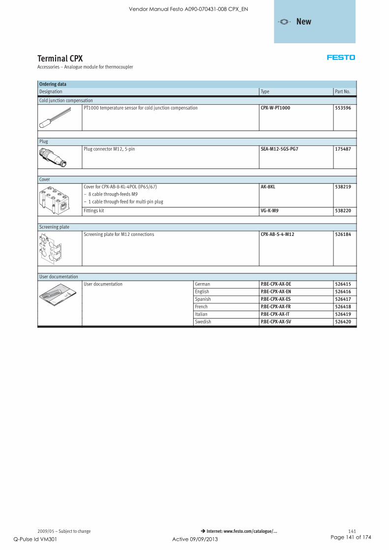
2009/05 – Subject to change 141 Internet: www.festo.com/catalogue/...
Terminal CPXAccessories – Analogue module for thermocoupler
Ordering data
Designation Type Part No.
Cold junction compensation
PT1000 temperature sensor for cold junction compensation CPX-W-PT1000 553596
Plug
Plug connector M12, 5-pin SEA-M12-5GS-PG7 175487
Cover
Cover for CPX-AB-8-KL-4POL (IP65/67)
– 8 cable through-feeds M9
– 1 cable through-feed for multi-pin plug
AK-8KL 538219
Fittings kit VG-K-M9 538220
Screening plate
Screening plate for M12 connections CPX-AB-S-4-M12 526184
User documentation
User documentation German P.BE-CPX-AX-DE 526415
English P.BE-CPX-AX-EN 526416
Spanish P.BE-CPX-AX-ES 526417
French P.BE-CPX-AX-FR 526418
Italian P.BE-CPX-AX-IT 526419
Swedish P.BE-CPX-AX-SV 526420
-V- New
Vendor Manual Festo A090-070431-008 CPX_EN
Q-Pulse Id VM301 Active 09/09/2013 Page 141 of 174
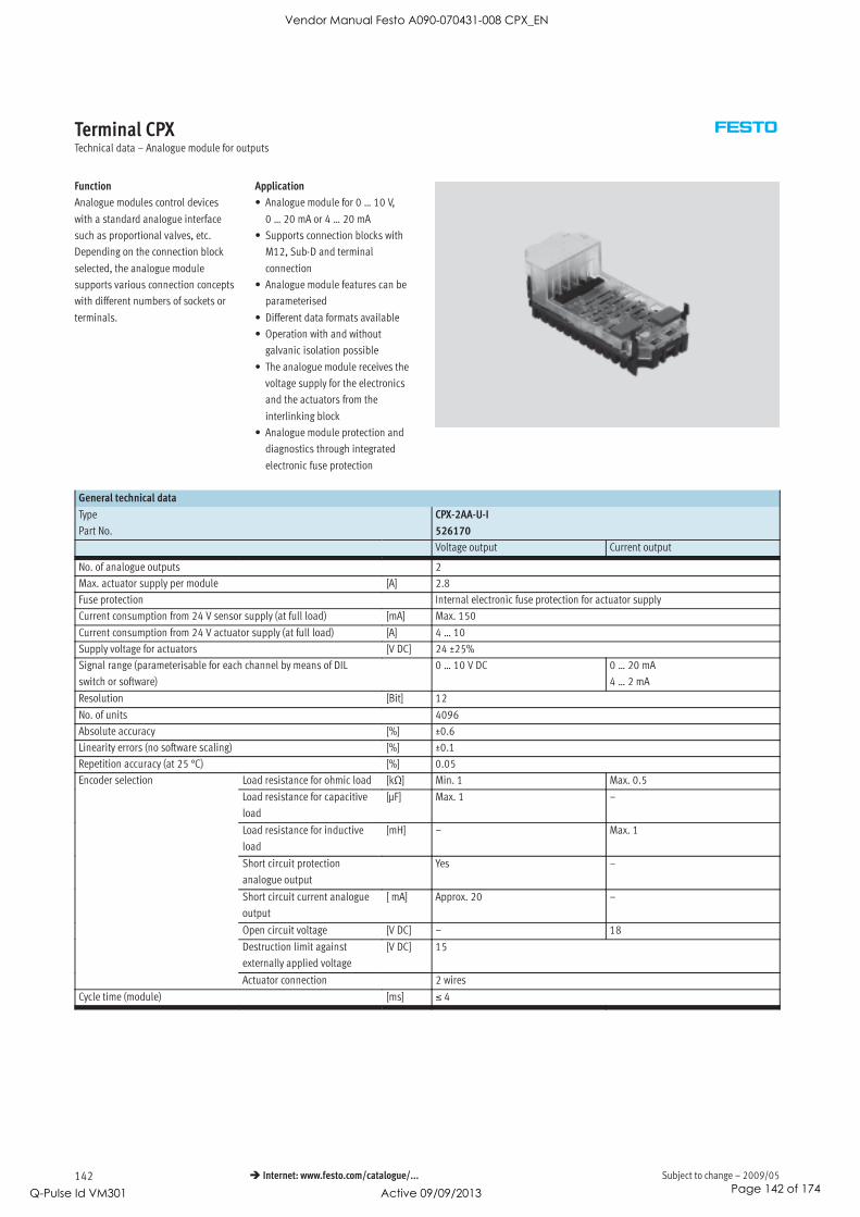
Subject to change – 2009/05142 Internet: www.festo.com/catalogue/...
Terminal CPXTechnical data – Analogue module for outputs
Function
Analogue modules control devices
with a standard analogue interface
such as proportional valves, etc.
Depending on the connection block
selected, the analogue module
supports various connection concepts
with different numbers of sockets or
terminals.
Application
• Analogue module for 0 … 10 V,
0 … 20 mA or 4 … 20 mA
• Supports connection blocks with
M12, Sub-D and terminal
connection
• Analogue module features can be
parameterised
• Different data formats available
• Operation with and without
galvanic isolation possible
• The analogue module receives the
voltage supply for the electronics
and the actuators from the
interlinking block
• Analogue module protection and
diagnostics through integrated
electronic fuse protection
General technical data
Type CPX-2AA-U-I
Part No. 526170
Voltage output Current output
No. of analogue outputs 2
Max. actuator supply per module [A] 2.8
Fuse protection Internal electronic fuse protection for actuator supply
Current consumption from 24 V sensor supply (at full load) [mA] Max. 150
Current consumption from 24 V actuator supply (at full load) [A] 4 … 10
Supply voltage for actuators [V DC] 24 ±25%
Signal range (parameterisable for each channel by means of DIL
switch or software)
0 … 10 V DC 0 … 20 mA
4 … 2 mA
Resolution [Bit] 12
No. of units 4096
Absolute accuracy [%] ±0.6
Linearity errors (no software scaling) [%] ±0.1
Repetition accuracy (at 25 °C) [%] 0.05
Encoder selection Load resistance for ohmic load [kΩ] Min. 1 Max. 0.5
Load resistance for capacitive
load
[μF] Max. 1 –
Load resistance for inductive
load
[mH] – Max. 1
Short circuit protection
analogue output
Yes –
Short circuit current analogue
output
[ mA] Approx. 20 –
Open circuit voltage [V DC] – 18
Destruction limit against
externally applied voltage
[V DC] 15
Actuator connection 2 wires
Cycle time (module) [ms] ≤ 4
Vendor Manual Festo A090-070431-008 CPX_EN
Q-Pulse Id VM301 Active 09/09/2013 Page 142 of 174

2009/05 – Subject to change 143 Internet: www.festo.com/catalogue/...
Terminal CPXTechnical data – Analogue module for outputs
General technical data
Type CPX-2AA-U-I
Part No. 526170
Voltage output Current output
Response time for ohmic load [ms] 0.1p
for capacitive load [ms] 0.7 –
for inductive load [ms] – 0.5
Data format 15 bit + prefix, linear scaling
12 bit right-justified, type 03 compatible
12 bit left-aligned, S7 compatible
12 bit left-aligned, S5 compatible
Cable length [m] Max. 30 (screened)
LED displays Group diagnostics 1p y
Channel diagnostics Yes, by means of flashing frequency of group diagnostics
Diagnostics • Short circuit/overload, actuator supply
• Parameterisation errors
• Value falling below nominal range/full-scale value
• Value exceeding nominal range/full-scale value
• Wire break
Parameterisation • Short circuit monitoring, actuator supply
• Short circuit monitoring, analogue output
• Behaviour after short circuit, actuator supply
• Data format
• Lower limit value/full-scale value
• Upper limit value/full-scale value
• Monitoring of value falling below nominal range/full-scale value
• Monitoring of value exceeding nominal range/full-scale value
• Monitoring of wire break
• Signal range
Protection class to EN 60529 Depending on connection block
Temperature range Operation [°C] –5 … +50p g
Storage/transport [°C] –20 … +70
Materials Polymer
Grid dimension [mm] 50
Dimensions (including interlinking block and connection block)
W x L x H
[mm] 50 x 107 x 50
Weight [g] 38
Connection and display components
CPX-2AA-U-I
11 Error LED (red;
module error)
Connection block/analogue module combinations
Connection blocks Part No. Analogue module
CPX-2AA-U-I
CPX-AB-4-M12X2-5POL 195704
CPX-AB-4-M12X2-5POL-R 541254
CPX-AB-8-KL-4POL 195708
CPX-AB-1-SUB-BU-25POL 525676
CPX-AB-4-M12x2-5P-R-M3 546997
CPX-M-4-M12x2-5POL 549367
Vendor Manual Festo A090-070431-008 CPX_EN
Q-Pulse Id VM301 Active 09/09/2013 Page 143 of 174

Subject to change – 2009/05144 Internet: www.festo.com/catalogue/...
Terminal CPXTechnical data – Analogue module for outputs
Pin allocation
Connection block outputs CPX-2AA-U-I
CPX-AB-4-M12X2-5POL, CPX-AB-4-M12X2-5POL-R1), CPX-AB-4-M12x2-5P-R-M31), CPX-M-4-M12x2-5POL
X1.1: 24 VOUT
X1.2: Output U0+
X1.3: 0 VOUT
X1.4: Output GND
X1.5: FE2)
X3.1: 24 VOUT
X3.2: Output U1+
X3.3: 0 VOUT
X3.4: Output GND
X3.5: FE2)
X2.1: 24 VOUT
X2.2: Output I0+
X2.3: 0 VOUT
X2.4: Output GND
X2.5: FE2)
X4.1: 24 VOUT
X4.2: Output I1+
X4.3: 0 VOUT
X4.4: Output GND
X4.5: FE2)
CPX-AB-8-KL-4POL
X1.0: 24 VOUT
X1.1: 0 VOUT
X1.2: Output GND
X1.3: FE
X5.0: 24 VOUT
X5.1: 0 VOUT
X5.2: Output GND
X5.3: FE
X2.0: n.c.
X2.1: n.c.
X2.2: Output U0+
X2.3: FE
X6.0: n.c.
X6.1: n.c.
X6.2: Output U1+
X6.3: FE
X3.0: 24 VOUT
X3.1: 0 VOUT
X3.2: Output GDN
X3.3: FE
X7.0: 24 VOUT
X7.1: 0 VOUT
X7.2: Output GND
X7.3: FE
X4.0: n.c.
X4.1: n.c.
X4.2: Output I0+
X4.3: FE
X8.0: n.c.
X8.1: n.c.
X8.2: Output I1+
X8.3: FE
CPX-AB-1-SUB-BU-25POL
1: Output GND
2: Output U0+
3: Output GND
4: Output I0+
5: n.c.
6: n.c.
7: n.c.
8: n.c.
9: 24 VOUT
10: 24 VOUT
11: 0 VOUT
12: 0 VOUT
13: Screening3)
14: Output GND
15: Output U1+
16: Output GND
17: Output I1+
18: 24 VOUT
19: n.c.
20: 24 VOUT
21: n.c.
22: 0 VOUT
23: 0 VOUT
24: 0 VOUT
25: FE
Socket: FE
1) Speedcon quick lock, metal thread with additional screening
2) FE/metal thread with additional screening
3) Connect screening to functional earth FE
Vendor Manual Festo A090-070431-008 CPX_EN
Q-Pulse Id VM301 Active 09/09/2013 Page 144 of 174

2009/05 – Subject to change 145 Internet: www.festo.com/catalogue/...
Terminal CPXAccessories – Analogue module for outputs
Ordering data
Designation Type Part No.
Plug
M12 plug, 5-pin SEA-M12-5GS-PG7 175487
Sub-D plug, 25-pin SD-SUB-D-ST25 527522
Connecting cable
Modular system for connecting cables NEBU-…
Internet: nebu
–
Cover
Cover for CPX-AB-8-KL-4POL (IP65/67)
– 8 cable through-feeds M9
– 1 cable through-feed for multi-pin plug
AK-8KL 538219
Fittings kit VG-K-M9 538220
Screening plate
Screening plate for M12 connections CPX-AB-S-4-M12 526184
User documentation
User documentation German P.BE-CPX-AX-DE 526415
English P.BE-CPX-AX-EN 526416
Spanish P.BE-CPX-AX-ES 526417
French P.BE-CPX-AX-FR 526418
Italian P.BE-CPX-AX-IT 526419
Swedish P.BE-CPX-AX-SV 526420
Vendor Manual Festo A090-070431-008 CPX_EN
Q-Pulse Id VM301 Active 09/09/2013 Page 145 of 174

Subject to change – 2009/05146 Internet: www.festo.com/catalogue/...
Terminal CPXTechnical data – Interlinking block with system supply
Function
Interlinking blocks ensure the electri-
cal supply of all other CPX modules.
They have contact rails, from which
the other CPX components using the
interlinking modules are supplied
with current.
Internal division of the power supply
makes it possible to switch off specific
areas of the sensors and actuators
individually.
Application
• 24 V DC supply voltage for
electronics of the CPX terminal
• 24 V DC supply voltage for inputs
• 24 V DC supply voltage for valves
• 24 V DC supply voltage for outputs
General technical data – Interlinking blocks made from plastic
Type CPX-GE-EV-S CPX-GE-EV-S-7/8-4POL CPX-GE-EV-S-7/8-5POL
Part No. 195746 541248 541244
Electrical connection M18 7/8”, 4-pin 7/8”, 5-pin
Nominal operating voltage [V DC] 24
Current supply Sensors and electronics [A] Max. 16 Max. 12pp y
Valves and outputs [A] Max. 16 Max. 12
Protection class to EN 60529 Depending on connection block
Ambient temperature [°C] –5 … +50
Corrosion resistance class CRC1) 2
Material declaration Conforms to RoHS
Materials Polymer
Grid dimension [mm] 50
Dimensions W x L x H [mm] 50 x 107 x 35
1) Corrosion resistance class 2 to Festo standard 940 070
Components subject to moderate corrosion stress. Externally visible parts with primarily decorative surface requirements which are in direct contact with a normal industrial environment or media such as coolants or
lubricating agents.
General technical data – Interlinking blocks made from metal
Type CPX-M-GE-EV-S-7/8-5POL CPX-M-GE-EV-S-PP-5POL
Part No. 550208 563057
Electrical connection 7/8”, 5-pin AIDA push-pull, 5-pin
Nominal operating voltage [V DC] 24
Current supply Sensors and electronics [A] Max. 8 Max. 16pp y
Valves and outputs [A] Max. 8 Max. 16
Protection class to EN 60529 Depending on connection block
Ambient temperature [°C] –5 … +50
Material declaration – Conforms to RoHS
Materials Aluminium
Grid dimension [mm] 50
Dimensions W x L x H [mm] 50 x 107 x 35
-V- NewAIDA push-pull
Vendor Manual Festo A090-070431-008 CPX_EN
Q-Pulse Id VM301 Active 09/09/2013 Page 146 of 174

2009/05 – Subject to change 147 Internet: www.festo.com/catalogue/...
Terminal CPXTechnical data – Interlinking block with system supply
Pin allocation
Wiring allocation Pin Allocation
M18 – 4-pin
1 24 V DC supply voltage for electronics and sensors
2 24 V DC load voltage supply for valves and outputs
3 0 V
4 FE
7/8” – 4-pin
A 24 V DC supply voltage for electronics and sensors
B 24 V DC load voltage supply for valves and outputs
C FE
D 0V
Pin allocation
Wiring allocation Pin Allocation
7/8” – 5-pin
1 0 V valves and outputs
2 0 V electronics and sensors
3 FE
4 24 V DC supply voltage for electronics and sensors
5 24 V DC load voltage supply for valves and outputs
Vendor Manual Festo A090-070431-008 CPX_EN
Q-Pulse Id VM301 Active 09/09/2013 Page 147 of 174

Subject to change – 2009/05148 Internet: www.festo.com/catalogue/...
Terminal CPXTechnical data – Interlinking block with system supply
Pin allocation
Wiring allocation Pin Allocation
Push-pull – 5-pin (AIDA)
1 24 V DC supply voltage for electronics and sensors
2 0 V electronics and sensors
3 24 V DC load voltage supply for valves and outputs
4 0 V valves and outputs
5 FE
-V- NewAIDA push-pull
Vendor Manual Festo A090-070431-008 CPX_EN
Q-Pulse Id VM301 Active 09/09/2013 Page 148 of 174
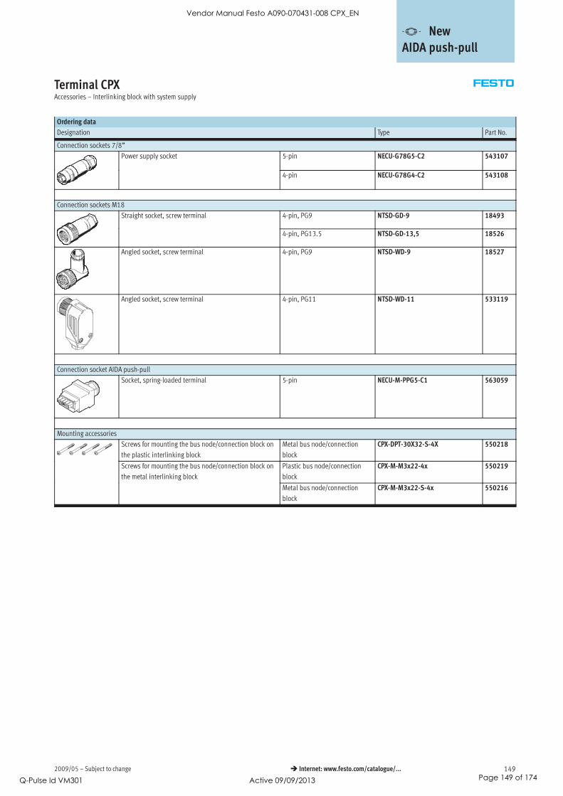
2009/05 – Subject to change 149 Internet: www.festo.com/catalogue/...
Terminal CPXAccessories – Interlinking block with system supply
Ordering data
Designation Type Part No.
Connection sockets 7/8”
Power supply socket 5-pin NECU-G78G5-C2 543107
4-pin NECU-G78G4-C2 543108
Connection sockets M18
Straight socket, screw terminal 4-pin, PG9 NTSD-GD-9 18493
4-pin, PG13.5 NTSD-GD-13,5 18526
Angled socket, screw terminal 4-pin, PG9 NTSD-WD-9 18527
Angled socket, screw terminal 4-pin, PG11 NTSD-WD-11 533119
Connection socket AIDA push-pull
Socket, spring-loaded terminal 5-pin NECU-M-PPG5-C1 563059
Mounting accessories
Screws for mounting the bus node/connection block on
the plastic interlinking block
Metal bus node/connection
block
CPX-DPT-30X32-S-4X 550218
Screws for mounting the bus node/connection block on
the metal interlinking block
Plastic bus node/connection
block
CPX-M-M3x22-4x 550219
g
Metal bus node/connection
block
CPX-M-M3x22-S-4x 550216
-V- NewAIDA push-pull
Vendor Manual Festo A090-070431-008 CPX_EN
Q-Pulse Id VM301 Active 09/09/2013 Page 149 of 174

Subject to change – 2009/05150 Internet: www.festo.com/catalogue/...
Terminal CPXTechnical data – Interlinking block
Function
Interlinking blocks ensure the electri-
cal supply of all other CPX modules.
They have contact rails, from which
the other CPX components using the
interlinking modules are supplied
with current.
Internal division of the power supply
makes it possible to switch off specific
areas of the sensors and actuators
individually.
Application
• All voltages are fed through to the
next module by means of system
linking.
• The connected electronics module
for inputs/outputs or bus nodes
taps off the required voltage.
General technical data
Type CPX-GE-EV CPX-M-GE-EV
Part No. 195742 550206
Electrical connection – –
Nominal operating voltage [V DC] 24 24
Acceptable current load (per contact/contact rail) [A] 16 8
Protection class to EN 60529 Depending on connection block
Ambient temperature [°C] –5 … +50
Corrosion resistance class CRC1) 2 –
Material declaration Conforms to RoHS
Materials Polymer Aluminium
Grid dimension [mm] 50
Dimensions W x L x H [mm] 50 x 107 x 35
1) Corrosion resistance class 2 to Festo standard 940 070
Components subject to moderate corrosion stress. Externally visible parts with primarily decorative surface requirements which are in direct contact with a normal industrial environment or media such as coolants or
lubricating agents.
Pin allocation
Wiring allocation Pin Allocation
– –
– –
– –
– –
Vendor Manual Festo A090-070431-008 CPX_EN
Q-Pulse Id VM301 Active 09/09/2013 Page 150 of 174

2009/05 – Subject to change 151 Internet: www.festo.com/catalogue/...
Terminal CPXTechnical data – Interlinking block
Ordering data – Mounting accessories
Designation Type Part No.
Screws for mounting the bus node/connection block on
the plastic interlinking block
Metal bus node/connection
block
CPX-DPT-30X32-S-4X 550218
Screws for mounting the bus node/connection block on
the metal interlinking block
Plastic bus node/connection
block
CPX-M-M3x22-4x 550219
g
Metal bus node/connection
block
CPX-M-M3x22-S-4x 550216
Vendor Manual Festo A090-070431-008 CPX_EN
Q-Pulse Id VM301 Active 09/09/2013 Page 151 of 174
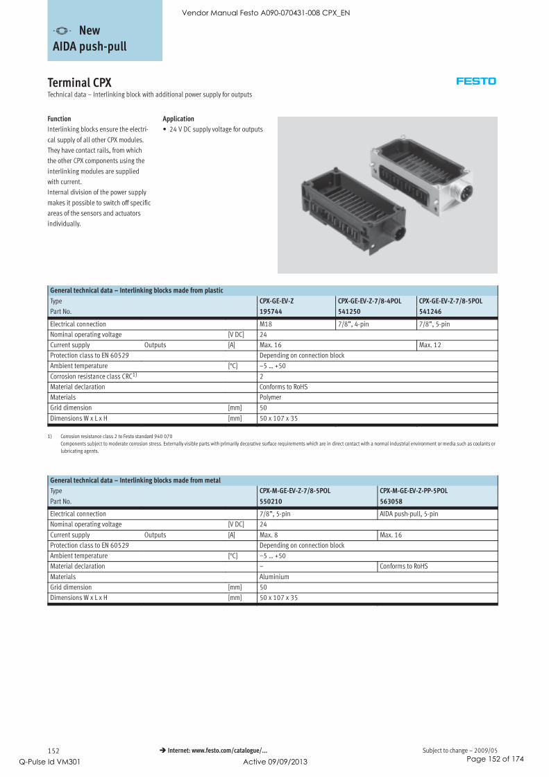
Subject to change – 2009/05152 Internet: www.festo.com/catalogue/...
Terminal CPXTechnical data – Interlinking block with additional power supply for outputs
Function
Interlinking blocks ensure the electri-
cal supply of all other CPX modules.
They have contact rails, from which
the other CPX components using the
interlinking modules are supplied
with current.
Internal division of the power supply
makes it possible to switch off specific
areas of the sensors and actuators
individually.
Application
• 24 V DC supply voltage for outputs
General technical data – Interlinking blocks made from plastic
Type CPX-GE-EV-Z CPX-GE-EV-Z-7/8-4POL CPX-GE-EV-Z-7/8-5POL
Part No. 195744 541250 541246
Electrical connection M18 7/8”, 4-pin 7/8”, 5-pin
Nominal operating voltage [V DC] 24
Current supply Outputs [A] Max. 16 Max. 12
Protection class to EN 60529 Depending on connection block
Ambient temperature [°C] –5 … +50
Corrosion resistance class CRC1) 2
Material declaration Conforms to RoHS
Materials Polymer
Grid dimension [mm] 50
Dimensions W x L x H [mm] 50 x 107 x 35
1) Corrosion resistance class 2 to Festo standard 940 070
Components subject to moderate corrosion stress. Externally visible parts with primarily decorative surface requirements which are in direct contact with a normal industrial environment or media such as coolants or
lubricating agents.
General technical data – Interlinking blocks made from metal
Type CPX-M-GE-EV-Z-7/8-5POL CPX-M-GE-EV-Z-PP-5POL
Part No. 550210 563058
Electrical connection 7/8”, 5-pin AIDA push-pull, 5-pin
Nominal operating voltage [V DC] 24
Current supply Outputs [A] Max. 8 Max. 16
Protection class to EN 60529 Depending on connection block
Ambient temperature [°C] –5 … +50
Material declaration – Conforms to RoHS
Materials Aluminium
Grid dimension [mm] 50
Dimensions W x L x H [mm] 50 x 107 x 35
-V- NewAIDA push-pull
Vendor Manual Festo A090-070431-008 CPX_EN
Q-Pulse Id VM301 Active 09/09/2013 Page 152 of 174

2009/05 – Subject to change 153 Internet: www.festo.com/catalogue/...
Terminal CPXTechnical data – Interlinking block with additional power supply for outputs
Pin allocation
Wiring allocation Pin Allocation
M18 – 4-pin
1 n.c.
2 24 V DC load voltage supply for outputs
3 0 V
4 FE
7/8” – 4-pin
A n.c.
B 24 V DC load voltage supply for outputs
C FE
D 0V
Pin allocation
Wiring allocation Pin Allocation
7/8” – 5-pin
1 0 V outputs
2 n.c.
3 FE
4 n.c.
5 24 V DC load voltage supply for outputs
Vendor Manual Festo A090-070431-008 CPX_EN
Q-Pulse Id VM301 Active 09/09/2013 Page 153 of 174

Subject to change – 2009/05154 Internet: www.festo.com/catalogue/...
Terminal CPXTechnical data – Interlinking block with additional power supply for outputs
Pin allocation
Wiring allocation Pin Allocation
Push-pull – 5-pin (AIDA)
1 n.c.
2 n.c.
3 24 V DC load voltage supply for outputs
4 0 V outputs
5 FE
-V- NewAIDA push-pull
Vendor Manual Festo A090-070431-008 CPX_EN
Q-Pulse Id VM301 Active 09/09/2013 Page 154 of 174

2009/05 – Subject to change 155 Internet: www.festo.com/catalogue/...
Terminal CPXAccessories – Interlinking block with additional power supply for outputs
Ordering data
Designation Type Part No.
Connection sockets 7/8”
Power supply socket 5-pin NECU-G78G5-C2 543107
4-pin NECU-G78G4-C2 543108
Connection sockets M18
Straight socket, screw terminal 4-pin, PG9 NTSD-GD-9 18493
4-pin, PG13.5 NTSD-GD-13,5 18526
Angled socket, screw terminal 4-pin, PG9 NTSD-WD-9 18527
Angled socket, screw terminal 4-pin, PG11 NTSD-WD-11 533119
Connection socket AIDA push-pull
Socket, spring-loaded terminal 5-pin NECU-M-PPG5-C1 563059
Mounting accessories
Screws for mounting the bus node/connection block on
the plastic interlinking block
Metal bus node/connection
block
CPX-DPT-30X32-S-4X 550218
Screws for mounting the bus node/connection block on
the metal interlinking block
Plastic bus node/connection
block
CPX-M-M3x22-4x 550219
g
Metal bus node/connection
block
CPX-M-M3x22-S-4x 550216
-V- NewAIDA push-pull
Vendor Manual Festo A090-070431-008 CPX_EN
Q-Pulse Id VM301 Active 09/09/2013 Page 155 of 174

Subject to change – 2009/05156 Internet: www.festo.com/catalogue/...
Terminal CPXTechnical data – Interlinking block with additional power supply for valves
Function
Interlinking blocks ensure the electri-
cal supply of all other CPX modules.
They have contact rails, from which
the other CPX components using the
interlinking modules are supplied
with current.
Internal division of the power supply
makes it possible to switch off specific
areas of the sensors and actuators
individually.
Application
• 24 V DC supply voltage for valves
General technical data
Type CPX-GE-EV-V CPX-GE-EV-V-7/8-4POL
Part No. 533577 541252
Electrical connection M18 7/8 , 4-pin
Nominal operating voltage [V DC] 24
Acceptable current load (per contact/contact rail) [A] 16
Protection class to EN 60529 Depending on connection block
Ambient temperature [°C] –5 … +50
Corrosion resistance class CRC1) 2
Material declaration Conforms to RoHS
Materials Polymer
Grid dimension [mm] 50
Dimensions W x L x H [mm] 50 x 107 x 35
1) Corrosion resistance class 2 to Festo standard 940 070
Components subject to moderate corrosion stress. Externally visible parts with primarily decorative surface requirements which are in direct contact with a normal industrial environment or media such as coolants or
lubricating agents.
Vendor Manual Festo A090-070431-008 CPX_EN
Q-Pulse Id VM301 Active 09/09/2013 Page 156 of 174

2009/05 – Subject to change 157 Internet: www.festo.com/catalogue/...
Terminal CPXAccessories – Interlinking block with additional power supply for valves
Pin allocation
Wiring allocation Pin Allocation
M18 – 4-pin
1 n.c.
2 24 V DC load voltage supply for valves
3 0 V
4 FE
7/8 – 4-pin
A n.c.
B 24 V DC load voltage supply for valves
C FE
D 0V
Ordering data
Designation Type Part No.
Connection sockets 7/8
Power supply socket 5-pin NECU-G78G5-C2 543107
4-pin NECU-G78G4-C2 543108
Connection sockets M18
Straight socket, screw terminal 4-pin, PG9 NTSD-GD-9 18493
4-pin, PG13.5 NTSD-GD-13,5 18526
Angled socket, screw terminal 4-pin, PG9 NTSD-WD-9 18527
Angled socket, screw terminal 4-pin, PG11 NTSD-WD-11 533119
Mounting accessories
Screws for mounting the bus node/connection block on
the plastic interlinking block
Metal bus node/connection
block
CPX-DPT-30X32-S-4X 550218
Vendor Manual Festo A090-070431-008 CPX_EN
Q-Pulse Id VM301 Active 09/09/2013 Page 157 of 174

Subject to change – 2009/05158 Internet: www.festo.com/catalogue/...
Terminal CPXTechnical data – Pneumatic interface MPA
Function
The pneumatic interface MPA esta-
blishes the electromechanical connec-
tion between the terminal CPX and the
valve terminal MPA.
The signals from the bus node are
forwarded to the control electronics in
the electrical modules of the valve
terminal MPA via the integrated CPX
bus. The bus signal for activation of
the solenoid coils is converted in the
electronics module for 4 valves
(max. 8 coils).
From a technical point of view, the
individual MPA pneumatic modules
each represent a separate electrical
module with digital outputs. Valves,
which are galvanically isolated, can
be supplied with power via the
interlinking block CPX-GE-EV-V.
Application
• Interface to the valve terminal MPA
• Max. 128 solenoid coils
• Max. 16 electronic modules
• Features of the electronics module
of the valve terminal MPA can be
parameterised, e.g. status of the
solenoid coils in the event of field-
bus communication being inter-
rupted (fail-safe), individual chan-
nel diagnostics can be activated,
condition monitoring can be
activated individually for each valve
• The pneumatic interface receives
the voltage for the electronics and
the supply voltage for the valves
from the left-hand interlinking
block and feeds them through to
the electronics modules of the valve
terminal MPA
• Electronics modules of the valve
terminal MPA:
– Undervoltage of valves
– Short circuit of valves
– Open load of valves
– Counter preset reached in
condition monitoring
Overview of pneumatic interface MPA and valve terminal MPA
1
23
5
6
7
8 8
1
4
91 LEDs
– Outputs (yellow)
– Error (red)
– Module error (all LEDs red)
2 Valves
3 Blanking plate
4 Electronics module
5 Pneumatic interface MPA
6 Power supply and bus
connection
7 Manifold block
8 Inscription fields
9 Valve power supply (creation of
zones with power supply that
can be activated separately)
Vendor Manual Festo A090-070431-008 CPX_EN
Q-Pulse Id VM301 Active 09/09/2013 Page 158 of 174

2009/05 – Subject to change 159 Internet: www.festo.com/catalogue/...
Terminal CPXTechnical data – Pneumatic interface VTSA/VTSA-F
Function
The pneumatic interface VTSA esta-
blishes the electromechanical connec-
tion between the terminal CPX and the
valve terminal type 44 VTSA/
type 45 VTSA-F.
A complete pneumatic control loop
system (FB-valve-drive-sensor-FB) can
therefore be connected to the fieldbus
using the input modules of the CPX
terminal.
Different circuits for valves and elec-
trical outputs are created using an
additional power supply. The inte-
grated valve diagnostic functions en-
able the causes of errors to be found
quickly, therefore increasing system
availability.
Application
• Interface for valve terminal VTSA
and VTSA-F
• Max. 32 solenoid coils
• Address space allocation (configur-
ation) of valve terminals can be set
using integrated DIL switches
• Pneumatic interface features can be
parameterised, e.g. status of the
solenoid coils in the event of field-
bus communication being
interrupted (fail-safe)
• The pneumatic interface receives
the voltage for the electronics and
the supply voltage for the valves
from the left-hand interlinking
block
• Detection of missing solenoid coils
and short circuit monitoring for the
valves
General technical data
Type VABA-S6-1-X1 VABA-S6-1-X2
Part No. 543416 550663
Connection for CPX interlinking blocks Plastic Metal
No. of solenoid coils 32
Electrical actuation Fieldbus
Electrical connection Via CPX
Nominal operating voltage [V DC] 24
Permissible voltage fluctuations [%] 10
Protection class to EN 60529 IP65
Ambient temperature [°C] –5 … +50
Mounting position Any
Materials Housing Die-cast aluminium
Top cover Polyamide
Weight [g] 485
Vendor Manual Festo A090-070431-008 CPX_EN
Q-Pulse Id VM301 Active 09/09/2013 Page 159 of 174

Subject to change – 2009/05160 Internet: www.festo.com/catalogue/...
Terminal CPXTechnical data – Pneumatic interface MIDI/MAXI
Function
The pneumatic interface MIDI/MAXI
connects the valve terminal MIDI/
MAXI to the supported fieldbus proto-
cols of the terminal CPX. A complete
pneumatic control loop system
(FB-valve-drive-sensor-FB) can there-
fore be connected to the fieldbus
using the input modules of the
terminal CPX.
Different circuits for valves and elec-
trical outputs are created using an
additional power supply. The inte-
grated valve diagnostic functions en-
able the causes of errors to be found
quickly, therefore increasing system
availability.
Application
• Interface to valve terminals MIDI/
MAXI
• Max. 26 solenoid coils
• Address space allocation (configur-
ation) of valve terminals can be set
using integrated DIL switches
• Pneumatic interface features can be
parameterised, e.g. status of the
solenoid coils in the event of field-
bus communication being
interrupted (fail-safe)
• The pneumatic interface receives
the voltage for the electronics and
the supply voltage for the valves
from the left-hand interlinking
block
General technical data
Type CPX-GP-03-4,0 CPX-M-GP-03-4,0
Part No. 195738 556775
Connection for CPX interlinking blocks Plastic Metal
No. of solenoid coils 26
Max. power supply per module [A] 4p pp y
per channel [A] 0.2
Fuse protection Internal electronic fuse protection for each valve output
Current consumption of modules for electronics [mA] Typ. 15
Current consumption of modules for valves [mA] Typ. 30
Nominal operating voltage [V DC] 24
Operating voltage range [V DC] 21.6 … 26.4
Galvanic isolation Channel – Channel No
Channel – Internal bus Yes, using an additional power supply for valves
LED displays Group diagnostics 1p y
Channel diagnostics –
Channel status – (on valves)
Diagnostics • Undervoltage of valves
Parameterisation • Module monitoring
• Fail-safe behaviour, channel x
Protection class to EN 60529 IP65
Ambient temperature [°C] –5 … +50
Materials Top cover Steel
Die-cast aluminium
Grid dimension [mm] 50
Dimensions W x L x H [mm] 50 x 132 x 55
Weight [g] 390
Vendor Manual Festo A090-070431-008 CPX_EN
Q-Pulse Id VM301 Active 09/09/2013 Page 160 of 174

2009/05 – Subject to change 161 Internet: www.festo.com/catalogue/...
Terminal CPXAccessories – Pneumatic interface MIDI/MAXI
Connection and display components
CPX-GP-03-4,0
1
3
2
1 Connecting plug to valves
2 Error LED (red)
3 DIL switch under transparent
cover
Ordering data
Designation Type Part No.
H-rail mounting
For mounting CPX terminal and valve terminal MIDI on H-rail CPX-03-4,0 526033
For mounting CPX terminal and valve terminal MAXI on H-rail CPX-03-7,0 526034
Vendor Manual Festo A090-070431-008 CPX_EN
Q-Pulse Id VM301 Active 09/09/2013 Page 161 of 174

Subject to change – 2009/05162 Internet: www.festo.com/catalogue/...
Terminal CPXTechnical data – Pneumatic interface CPA
Function
The pneumatic interface CPA connects
the valve terminal CPA to the
supported fieldbus protocols of the
CPX terminal. A complete pneumatic
control loop system (FB-valve-drive-
sensor-FB) can therefore be connected
to the fieldbus using the input
modules of the CPX terminal.
Different circuits for valves and elec-
trical outputs are implemented using
an additional power supply. The inte-
grated valve diagnostic functions en-
able the causes of errors to be found
quickly, therefore increasing system
availability.
Application
• Interface to CPA10 and CPA14 valve
terminals
• Max. 22 solenoid coils
• Address space allocation (configur-
ation) of valve terminals can be set
using integrated DIL switches
• Pneumatic interface features can be
parameterised, e.g. status of the
solenoid coils in the event of field-
bus communication being
interrupted (fail-safe)
• The pneumatic interface receives
the voltage for the electronics and
the supply voltage for the valves
from the left-hand interlinking
block
• Detection of missing solenoid coils
and short circuit monitoring for the
valves
General technical data
Type CPX-GP-CPA-10 CPX-GP-CPA-14
Part No. 195710 195712
No. of solenoid coils 22 22
Max. power supply per module [A] 4p pp y
per channel [A] 0.2
Fuse protection Internal electronic fuse protection for each valve output
Current consumption of module from electronics/sensor supply [mA] Typ. 15
Supply voltage for valves [V DC] 24 +10% –15%
Galvanic isolation Channel – Channel No
Channel – Internal bus Yes, using an additional power supply for valves (in preparation)
LED displays Group diagnostics 1p y
Channel diagnostics –
Channel status – (on valves)
Diagnostics • Load voltage of valves
• Short circuit solenoid coils (channel-oriented)
• Wire break solenoid coils (channel-oriented quiescent current detection for
valve solenoid coils)
Parameterisation • Module monitoring
• Wire break monitoring, channel x
• Fail-safe behaviour, channel x
Protection class to EN 60529 IP65
Temperature range Operation [°C] –5 … +50p g
Storage/transport [°C] –20 … +70
Materials Polymer
Grid dimension [mm] 50
Dimensions W x L x H [mm] 50 x 110 x 58
Weight [g] 150
Vendor Manual Festo A090-070431-008 CPX_EN
Q-Pulse Id VM301 Active 09/09/2013 Page 162 of 174

2009/05 – Subject to change 163 Internet: www.festo.com/catalogue/...
Terminal CPXAccessories – Pneumatic interface CPA
Connection and display components
CPX-GP-CPA-…
12
4
3
1 Connecting plug to valves
2 Error LED (red)
3 DIL switch under transparent
cover
4 Inscription fields for addresses
Ordering data
Designation Type Part No.
H-rail mounting
For mounting CPX terminal and valve terminal CPA on H-rail CPX-CPA-BG-NRH 526032
Vendor Manual Festo A090-070431-008 CPX_EN
Q-Pulse Id VM301 Active 09/09/2013 Page 163 of 174
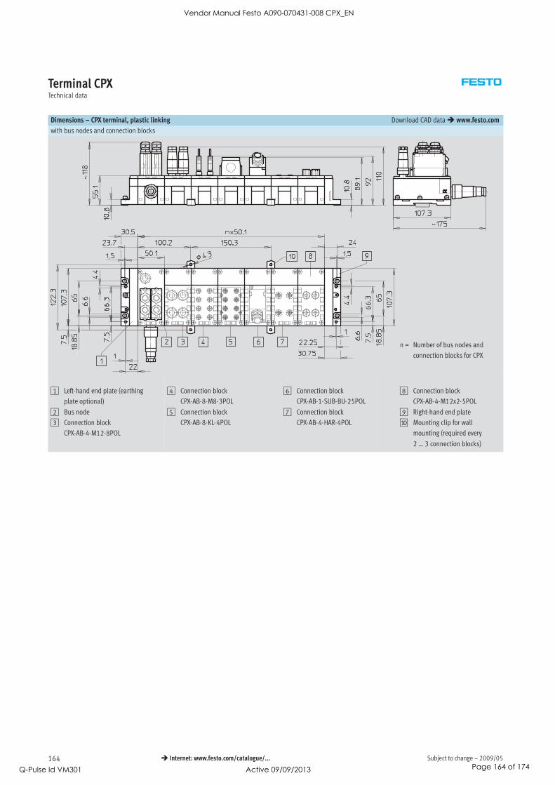
Subject to change – 2009/05164 Internet: www.festo.com/catalogue/...
Terminal CPXTechnical data
Dimensions – CPX terminal, plastic linking Download CAD data www.festo.com
with bus nodes and connection blocks
n = Number of bus nodes and
connection blocks for CPX
1 Left-hand end plate (earthing
plate optional)
2 Bus node
3 Connection block
CPX-AB-4-M12-8POL
4 Connection block
CPX-AB-8-M8-3POL
5 Connection block
CPX-AB-8-KL-4POL
6 Connection block
CPX-AB-1-SUB-BU-25POL
7 Connection block
CPX-AB-4-HAR-4POL
8 Connection block
CPX-AB-4-M12x2-5POL
9 Right-hand end plate
aJ Mounting clip for wall
mounting (required every
2 … 3 connection blocks)
Vendor Manual Festo A090-070431-008 CPX_EN
Q-Pulse Id VM301 Active 09/09/2013 Page 164 of 174

2009/05 – Subject to change 165 Internet: www.festo.com/catalogue/...
Terminal CPXTechnical data
Dimensions – CPX terminal, metal linking Download CAD data www.festo.com
with bus nodes and connection blocks
n = Number of bus nodes and
connection blocks for CPX
1 Left-hand end plate
2 Bus node
3 Connection block
CPX-M-8-M12x2-5POL
4 Connection block
CPX-M-8-M12x2-5POL
5 Connection block
CPX-M-4-M12x2-5POL
6 Connection block
CPX-AB-1-SUB-BU-25POL
7 Connection block
CPX AB-4-M12-8POL
8 Connection block
CPX-AB-4-HAR-4POL
9 Right-hand end plate
aJ Mounting bracket for wall
fitting
aA Hole for self-tapping screw
M2.5
Vendor Manual Festo A090-070431-008 CPX_EN
Q-Pulse Id VM301 Active 09/09/2013 Page 165 of 174

Subject to change – 2009/05166 Internet: www.festo.com/catalogue/...
Terminal CPXTechnical data
Dimensions – CPX terminal Download CAD data www.festo.com
with bus nodes and valve terminal type 44 VTSA
1 Solenoid valve 18 mm
2 Solenoid valve 26 mm
3 Solenoid valve 42 mm
4 Cover cap/manual override
5 Threaded connection G½ or
½NPT
6 Threaded connection Gy or
yNPT
7 Threaded connection G¼ or
¼NPT
8 Threaded connection Gx or
xNPT
9 H-rail
aJ H-rail mounting
aA Mounting hole
aB Additional mounting bracket
aC Inscription label holder
aD Pneumatic interface VTSA
aE End plate
aF CPX module/fieldbus node
aG 90° connection plate, width
42 mm, Gy
aH 90° connection plate, width
18 mm, Gx,
width 26 mm, G¼
n02 Number of manifold blocks
18 mm
n01 Number of manifold blocks
26 mm
n1 Number of manifold blocks
42 mm
n Number of supply plates
(only with end plate with
selector plate)
m Number of CPX modules
Width L1
18 mm 30.4 + m x 50.1 + 50 + n02 x 38 + n x 38 + 37.3
26 mm 30.4 + m x 50.1 + 50 + n01 x 54 + n x 38 + 37.3
42 mm 30.4 + m x 50.1 + 50 + n1 x 43 + n x 38 + 37.3
Mixture of 18 mm, 26 mm and 42 mm 30.4 m x 50.1 + 50 + n02 x 38 + n01 x 54 + n1 x 43 + n x 38 + 37.3
Vendor Manual Festo A090-070431-008 CPX_EN
Q-Pulse Id VM301 Active 09/09/2013 Page 166 of 174
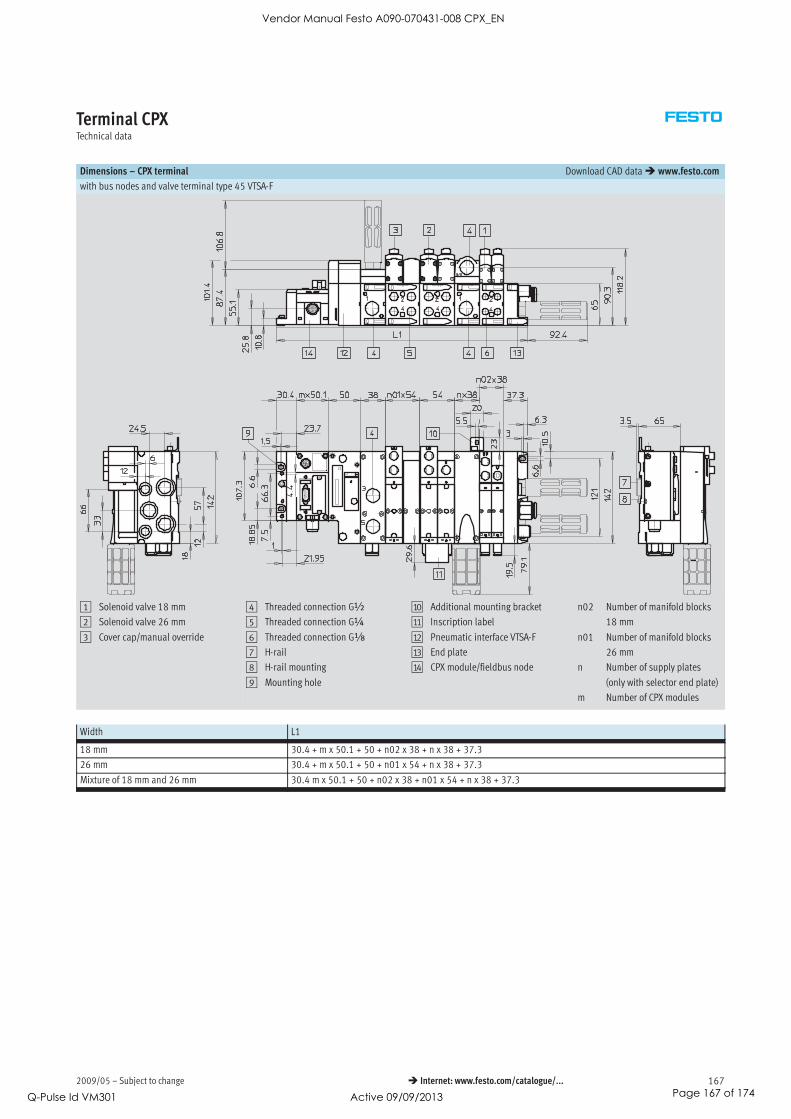
2009/05 – Subject to change 167 Internet: www.festo.com/catalogue/...
Terminal CPXTechnical data
Dimensions – CPX terminal Download CAD data www.festo.com
with bus nodes and valve terminal type 45 VTSA-F
1 Solenoid valve 18 mm
2 Solenoid valve 26 mm
3 Cover cap/manual override
4 Threaded connection G½
5 Threaded connection G¼
6 Threaded connection Gx
7 H-rail
8 H-rail mounting
9 Mounting hole
aJ Additional mounting bracket
aA Inscription label
aB Pneumatic interface VTSA-F
aC End plate
aD CPX module/fieldbus node
n02 Number of manifold blocks
18 mm
n01 Number of manifold blocks
26 mm
n Number of supply plates
(only with selector end plate)
m Number of CPX modules
Width L1
18 mm 30.4 + m x 50.1 + 50 + n02 x 38 + n x 38 + 37.3
26 mm 30.4 + m x 50.1 + 50 + n01 x 54 + n x 38 + 37.3
Mixture of 18 mm and 26 mm 30.4 m x 50.1 + 50 + n02 x 38 + n01 x 54 + n x 38 + 37.3
Vendor Manual Festo A090-070431-008 CPX_EN
Q-Pulse Id VM301 Active 09/09/2013 Page 167 of 174
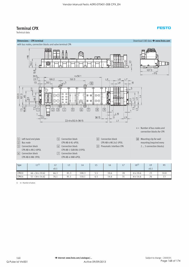
Subject to change – 2009/05168 Internet: www.festo.com/catalogue/...
Terminal CPXTechnical data
Dimensions – CPX terminal Download CAD data www.festo.com
with bus nodes, connection blocks and valve terminal CPA
n = Number of bus nodes and
connection blocks for CPX
1 Left-hand end plate
2 Bus node
3 Connection block
CPX-AB-4-M12-8POL
4 Connection block
CPX-AB-8-M8-3POL
5 Connection block
CPX-AB-8-KL-4POL
6 Connection block
CPX-AB-1-SUB-BU-25POL
7 Connection block
CPX-AB-4-HAR-4POL
8 Connection block
CPX-AB-4-M12x2-5POL
9 Pneumatic interface CPA
aJ Mounting clip for wall
mounting (required every
2 … 3 connection blocks)
Type L11) L2
±0.1
L3 L4 L5 L6 L7 L81) L9
±0.1
H1
CPA10 46 + (m x 10.6) 66.3 81.3 108.3 5.5 10.6 28 m x 10.6 23 10.8
CPA14 51 + (m x 14.6) 76.1 91.1 118.1 6.5 14.6 31 m x 14.6 26 13
1) m = Number of valves
Vendor Manual Festo A090-070431-008 CPX_EN
Q-Pulse Id VM301 Active 09/09/2013 Page 168 of 174

2009/05 – Subject to change 169 Internet: www.festo.com/catalogue/...
Terminal CPXTechnical data
Dimensions – CPX terminal Download CAD data www.festo.com
with bus nodes and valve terminal MPA
1 Solenoid valve MPA1
2 Solenoid valve MPA2
3 Manual override
4 Supply/exhaust ports
5 Working ports
6 H-rail
7 H-rail mounting
8 Mounting holes
9 Pneumatic interface MPA
aJ CPX module
aA Earthing screw
aB Additional power supply
n Number of sub-bases in a grid
of 4 MPA1 or 2 MPA2 valves
m Number of CPX modules
Vendor Manual Festo A090-070431-008 CPX_EN
Q-Pulse Id VM301 Active 09/09/2013 Page 169 of 174

Subject to change – 2009/05170 Internet: www.festo.com/catalogue/...
Terminal CPXTechnical data
Dimensions – CPX terminal Download CAD data www.festo.com
with bus nodes, connection blocks and valve terminal MIDI/MAXI
n=
Num
berofbusnodesand
connection
blocks
forCPX
1Left-hand
endplate
2Bus
node
3Connection
block
CPX-AB-4-M12-8PO
L
4Connection
block
CPX-AB-8-M8-3PO
L
5Connection
block
CPX-AB-8-KL-4PO
L
6Connection
block
CPX-AB-1-SUB-BU-25PO
L
7Connection
block
CPX-AB-4-HAR-4PO
L
8Connection
block
CPX-AB-4-M12x2-5PO
L
9Pneumaticinterface
MIDI/MAXI
aJMountingclipforwall
mounting(requiredevery
2…3connection
blocks)
Vendor Manual Festo A090-070431-008 CPX_EN
Q-Pulse Id VM301 Active 09/09/2013 Page 170 of 174

2009/05 – Subject to change 171 Internet: www.festo.com/catalogue/...
Terminal CPXAccessories
Ordering data – Accessories
Designation Type Part No.
Plug connectors and accessories
Sub-D plug for INTERBUS Incoming FBS-SUB-9-BU-IB-B 532218p g
Outgoing FBS-SUB-9-GS-IB-B 532217
Sub-D plug for DeviceNet/CANopen FBS-SUB-9-BU-2x5POL-B 532219
Sub-D plug for Profibus DP FBS-SUB-9-GS-DP-B 532216
Sub-D plug for CC-Link FBS-SUB-9-GS-2x4POL-B 532220
Sub-D plug FBS-SUB-9-GS-1x9POL-B 534497
Bus connection M12 adapter (B-coded) for Profibus DP FBA-2-M12-5POL-RK 533118
Bus connection Micro Style 2xM12 for DeviceNet/CANopen FBA-2-M12-5POL 525632
Plug socket for Micro Style connection, M12 FBSD-GD-9-5POL 18324
Plug connector for Micro Style connection, M12 FBS-M12-5GS-PG9 175380
Bus connector M12x1, 4-pin (D-coded) for Ethernet NECU-M-S-D12G4-C2-ET 543109
Connection block M12 adapter (B-coded) for Profibus DP CPX-AB-2-M12-RK-DP 541519
Connection block M12 adapter (B-coded) for INTERBUS CPX-AB-2-M12-RK-IB 534505
Fieldbus connector Open Style for 5-pin terminal strip for DeviceNet/CANopen FBA-1-SL-5POL 525634
Terminal strip connector for Open Style connection, 5-pin FBSD-KL-2x5POL 525635
Bus connector screw terminal for CC-Link FBA-1-KL-5POL 197962
RJ45/plug FBS-RJ45-8-GS 534494
Plug RJ45, 8-pin, push-pull FBS-RJ45-PP-GS 552000
Socket/spring-loaded terminal, 5-pin, AIDA push-pull NECU-M-PPG5-C1 563059
Threaded sleeve, 4 pieces UNC4-40/M3x6 533000
Vendor Manual Festo A090-070431-008 CPX_EN
Q-Pulse Id VM301 Active 09/09/2013 Page 171 of 174

Subject to change – 2009/05172 Internet: www.festo.com/catalogue/...
Terminal CPXAccessories
Ordering data – Accessories
Designation Type Part No.
Connecting cables
DUO cable M12-2xM8, 4-pin/2x3-pin 2x straight socket KM12-DUO-M8-GDGD 18685
2x straight/angled socket KM12-DUO-M8-GDWD 18688
2x angled socket KM12-DUO-M8-WDWD 18687
T-plug connector 2x socket M8, 3-pin
1x plug M8, 4-pin
NEDU-M8D3-M8T4 544391
T-plug connector 2x socket M12, 5-pin
1x plug M12, 4-pin
NEDU-M12D5-M12T4 541596
2x socket M8, 3-pin
1x plug M12, 4-pin
NEDU-M8D3-M12T4 541597
Connecting cable M8-M8, between straight plug and 0.5 m KM8-M8-GSGD-0,5 175488g , g p g
straight socket 1.0 m KM8-M8-GSGD-1 175489g
2.5 m KM8-M8-GSGD-2,5 165610
5.0 m KM8-M8-GSGD-5 165611
Extension cable M12-M12, 5-pin, between straight 1.5 m KV-M12-M12-1,5 529044, 5 p , g
plug and straight socket 3.5 m KV-M12-M12-3,5 530901
Connecting cable M12-M12, 4-pin, between straight 2.5 m KM12-M12-GSGD-2,5 18684g , p , g
plug and straight socket 5.0 m KM12-M12-GSGD-5 18686
Connecting cable M12-M12, 8-pin, between straight
plug and straight socket
2.0 m KM12-8GD8GS-2-PU 525617
Connecting cable M12-M12, 4-pin, between straight
plug and angled socket
1.0 m KM12-M12-GSWD-1-4 185499
Connecting cable M9, between angled plug and angled 0.25 m KVI-CP-3-WS-WD-0,25 540327g 9, g p g g
socket 0.5 m KVI-CP-3-WS-WD-0,5 540328
2 m KVI-CP-3-WS-WD-2 540329
5 m KVI-CP-3-WS-WD-5 540330
8 m KVI-CP-3-WS-WD-8 540331
Connecting cable M9, between straight plug and 2 m KVI-CP-3-GS-GD-2 540332g 9, g p g
straight socket 5 m KVI-CP-3-GS-GD-5 540333g
8 m KVI-CP-3-GS-GD-8 540334
Modular system for connecting cables NEBU-…
Internet: nebu
–
Programming cable KDI-PPA-3-BU9 151915
Connecting cable FED FEC-KBG7 539642
Connecting cable FED FEC-KBG8 539643
Vendor Manual Festo A090-070431-008 CPX_EN
Q-Pulse Id VM301 Active 09/09/2013 Page 172 of 174

2009/05 – Subject to change 173 Internet: www.festo.com/catalogue/...
Terminal CPXAccessories
Ordering data – Accessories
Designation Type Part No.
Plug connectors and accessories – Power supply
Plug socket for mains connection M18, straight for 1.5 mm2 NTSD-GD-9 18493g , g
for 2.5 mm2 NTSD-GD-13,5 18526
Plug socket for mains connection M18, angled for 1.5 mm2 NTSD-WD-9 18527g , g
for 2.5 mm2 NTSD-WD-11 533119
Power supply socket 7/8’’ connection, 5-pin NECU-G78G5-C2 543107
7/8’’ connection, 4-pin NECU-G78G4-C2 543108
Covers and attachments
Cover for CPX-AB-8-KL-4POL (IP65/67)
– 8 cable through-feeds M9
– 1 cable through-feed for multi-pin plug
AK-8KL 538219
Fittings kit VG-K-M9 538220
Screening plate for M12 connections CPX-AB-S-4-M12 526184
Earthing component (5 pieces), for right-hand/left-hand plastic end plate CPX-EPFE-EV 538892
Inspection cover, transparent AK-SUB-9/15-B 533334
Inspection cover, for use in Atex environments as per certification ( 44) AK-SUB-9/15 557010
Transparent cover for DIL switch and memory card CPX-AK-P 548757
Cover plate for DIL switch and memory card CPX-M-AK-M 548754
Cover for RJ45 connection AK-Rj45 534496
Cover for RJ45 push-pull connection CPX-M-AK-C 548753
Protective cap for sealing unused sockets (10 pieces) for M8 connections ISK-M8 177672p g ( p )
M9 FLANSCHDOSE SER.712 356684
for M12 connections ISK-M12 165592
Vendor Manual Festo A090-070431-008 CPX_EN
Q-Pulse Id VM301 Active 09/09/2013 Page 173 of 174

Subject to change – 2009/05174 Internet: www.festo.com/catalogue/...
Terminal CPXAccessories
Ordering data – Accessories
Designation Type Part No.
Screws
Screws for mounting the bus node/connection block on
the plastic interlinking block
Bus node/metal connection
block
CPX-DPT-30X32-S-4X 550218
Screws for mounting the bus node/connection block on
the metal interlinking block
Bus node/plastic connection
block
CPX-M-M3x22-4x 550219
g
Bus node/metal connection
block
CPX-M-M3x22-S-4x 550216
Screws for attaching an inscription label holder to the fieldbus node FB33, FB34
(12 pieces)
CPX-M-M2,5X6-12X 550222
Functional modules
Memory card for PROFINET fieldbus node CPX-SK 549526
PT1000 temperature sensor for cold junction compensation CPX-W-PT1000 553596
Adapter cable M12, 5-pin at socket Mini-USB and controller software NEFC-M12G5-0.3-U1G5 547432
Inscription labels
Inscription labels, 6x10, 64 pieces, in frames IBS-6x10 18576
Inscription label holder for connection block CPX-ST-1 536593
Mounting
Attachment for wall mounting (for long valve terminals, 10 pieces), design for plastic
manifold sub-bases
CPX-BG-RW-10x 529040
Attachment for wall mounting (for long valve terminals, 2 mounting brackets and
4 screws), design for metal manifold sub-bases
CPX-M-BG-RW-2x 550217
Software
CPX remote diagnosis and process visualisation CPX-WEB-MONITOR 545413
Programming software German FST4.1DE 537927g g
English FST4.1GB 537928
ePlan macro library GSWC-TE-EP-LA 537041
Vendor Manual Festo A090-070431-008 CPX_EN
Q-Pulse Id VM301 Active 09/09/2013 Page 174 of 174