
FASTTM Program Festo Assured Shipping Time
266
FAST TM Program Festo Assured Shipping Time A complete line of automation components available when you need them!
-
Upload
khangminh22 -
Category
Documents
-
view
0 -
download
0
Transcript of FASTTM Program Festo Assured Shipping Time

FASTTM Program Festo Assured Shipping Time
A complete line of automation components available when you need them!


We all face the same challenge. And we all know that for companies to be successful on the global market it is crucial that they systematically sharpen their competitive edge. That is why we support you and work with you to pursue one great goal: boosting your productivity.
We are a leading manufacturer of pneumatic and electromechanical systems, components, and controls for process control and factory automation solutions. Celebrating over 40 years of innovation in the United States and over 80 years globally, Festo continuously elevates the state of manufacturing with innovations and optimized motion control solutions.
Maximum productivity for you and your customers - this is our mission.

• Piston Rod Cylinders• Guided Piston Rod Actuators• Rodless Actuators• Rotary Actuators
• Manual/Mechanical Valves• Stand Alone Valves• Valve Terminals
• Filter/Regulator - Lubricators• Filter Regulators• Pressure Regulators
and accessories• Lubricators• On/Off Valves and• Soft-start Valves• Distribution Blocks
FASTTM ProgramFesto Assured Shipping Time
A complete line of automation componentsavailable when you need them
With “Same Day” ,“3 Day” and “5 Day” availability of thousands of Festo automation components, the FAST program enables designers and manufacturers to:• gain access to a wide selection of inch and metric components• lower inventory costs• reduce “time-to-market” for prototype and production equipment• invest inventory savings and time savings in growing your business
It’s on time or it’s shipped freeFesto will reimburse the shipping charges for qualifying orders which do not meet the shipment times specified by the FAST Program.
For program details including complete catalog documentation, visit:www.festo.us/fast
FAST Program Conditions: Quantity limit to qualify for the FAST Program“It’s on time, or it’s shipped free” promise is 5 pieces per item, exceptfor fittings/flow controls (100 pcs.), tubing (100 meters), and mountingaccessories (10 pcs).
Pneumatic Cylinders and Actuators
Pneumatic Valves and Valve Terminals/Manifolds
Sensors and Actuators Feedback
Air Preparation Units
Fittings / Flow Controls / Tubing / Silencers
• Pressure Sensors• Vacuum Sensors• Actuator Feedback
• Fittings• Flow Controls• Tubing• Silencers
Online or offline—Internet or DVD
Festo products and services provide solutionsfor greater productivity in industrial and processautomation.
Define your optimal solution from over 12,000products in thousands of variants offline on DVD,or on the Internet with our user-friendly digitalcatalog, and Online Shop.
For customer service 24 hours a day, visit ourOnline Shop at www. festo.us/onlineshop.Once registered, download 2D and 3D CADmodels, view pricing and availability, placeorders and track the status of all your onlineand offline orders.
Electromechanical Actuators/Servo Motors and Drives
• Toothed Belt Axis• Servo Motors• Servo Drives

2014/06 – Subject to change – FAST Program Catalog 1� Internet: www.festo.com/catalog/...
FAST Program Products
1 – Pneumatic Cylinders and Actuators Overview � 2
Piston Rod Cylinders
� 5
Guided Piston Rod Cylinders
� 42
Rodless Actuators
� 54
Rotary Actuators
� 78
2 – Electromechanical Actuators, Motors and Servo Drives Overview � 83
Toothed Belt Axes
� 84
Servo Motors
� 91
Servo Drives
� 95
3 – Valves and Valve Manifolds Overview � 100
Manual and Mechanical Valves
� 104
Stand-alone Valves and Manifold
Blocks � 114
Valve Manifolds
� 120
4 – Sensors Overview � 152
Pressure and Vacuum Sensors
� 154
Actuator Feedback
� 168
5 – Air Preparation Units Overview � 185
Filter Regulators � 188, 205
Pressure Regulators � 192, 209
Manual On/Off Valves � 195, 218
Electric On/Off Valves � 198, 221
Branching Modules, Distributor
Blocks � 201, 227
Pressure Gauges
� 233
6 – Fittings / Flow Controls / Silencers / Tubing Overview � 236
Push-in Fittings and Connectors
� 245
Flow Control Valves
� 253
Silencers
� 256
Tubing
� 258
Cont
ents
A
� Detailed product information on DVD and
www.festo.com/catalog/<type> or <order code>

FAST Program Catalog – Subject to change – 2014/062 � Internet: www.festo.com/catalog/...
Pneumatic Cylinders and Actuators – OverviewPiston Rod Cylinders
Piston Rod Cylinders
Inch Series Piston �
[in]1)
Cushio-
ning
Position
Sensing
Lead Time � Page
Same Day/Next Day 3 Days
Standard Stroke [in] Standard Stroke [in] Custom
Stroke [in]½ 1 2 3 4 5 6 8 10 12
DSNU Double Acting Round Cylinder
Ä, y P A � � � – – – – – – – – 0.04 … 4 5
½ P A � � � – – – – – – – – 0.04 … 8
Æ PPV A – � � � � – – – – – – 0.04 … 8
¾ PPV A – � � � � � � � � � – 0.04 … 12
1 PPV A – � � � � � � � � � – 0.04 … 20
DNC Double Acting Cylinder
1¼ PPV A – – – – – – – – – – 1, 1Æ, 2, 3, 4, 5, 6, 8,
10, 12
0.4 … 80 10
1Æ PPV A – – – – – – – – – –
2 PPV A – – – – – – – – – –
2½ PPV A – – – – – – – – – –
ADN Double Acting Compact Cylinder2)
½ P A – – – – – – – – – – ¼, ½, ¾, 1, 1¼, 1½ 0.04 … 12 16
Æ P A– – – – – – – – – –
¼, ½, ¾, 1, 1¼, 1½,
2
0.04 … 12
¾, 1 P A– – – – – – – – – –
¼, ½, ¾, 1, 1¼, 1½,
2, 2½
0.04 … 12
1¼, 1Æ,
2
P A– – – – – – – – – –
¼, ½, ¾, 1, 1¼, 1½,
2, 2½, 3
0.04 … 16
Piston Rod Cylinders
Metric Series Piston �
[mm]
Cushio-
ning
Position
Sensing
Lead Time � Page
Same Day/Next Day 3 Days
Standard Stroke [mm] Standard Stroke [mm] Custom
Stroke [mm]10 25 40 50 80 100 125 160 200 250 300
DSNU Double Acting Standard Cylinder to ISO 6432
8, 10 P A � � � � – – – – – – – – 1 … 100 23
12 P A � � � � – – – – – – – – 1 … 200
16 PPS, PPV A – � � � � � – – – – – – 1 … 320
20 PPS, PPV A – � � � � � � � � � � – 1 … 320
25 PPS, PPV A – � � � � � � � � � � – 1 … 500
DSBC Double Acting Cylinder to ISO 15552
32, 40,
50, 63
PPS
PPV
A
– – – – – – – – – – –
25, 40, 50, 80, 100,
125, 160, 200, 250,
320, 400, 500
1 … 2,800 28
ADN Double Acting Compact Cylinder2)
12 P A – – – – – – – – – – – 5, 10, 15, 20, 25, 30, 40 1 … 300 35
16 P A– – – – – – – – – – –
5, 10, 15, 20, 25, 30,
40, 50
1 … 300
20, 25 P A– – – – – – – – – – –
5, 10, 15, 20, 25, 30,
40, 50, 60
1 … 400
32, 40,
50
P A– – – – – – – – – –
5, 10, 15, 20, 25, 30,
40, 50, 60, 80
1 … 400
1) Approximated values; for reference only.
2) The piston rod of the ADN is available with either male or female thread.
Legend
A Includes magnet for position
sensing
P Fixed pneumatic cushioning, both
ends
PPS Pneumatic cushioning,
self-adjusting at both ends
PPV Adjustable pneumatic cushioning,
both ends
Pneu
mat
ic C
ylin
ders
and
Act
uato
rs
1
Note: All metric products can be used within inch tubing systems via hybrid fittings (� Overview on page 240)

2014/06 – Subject to change – FAST Program Catalog 3� Internet: www.festo.com/catalog/...
Pneumatic Cylinders and Actuators – OverviewGuided Piston Rod Cylinders
Guided Piston Rod Cylinders
Metric Series Piston �
[mm]
Cushio-
ning
Position
Sensing
Lead Time � Page
Same Day/Next Day (P cushioning) / 3 Days (P1, Y3 cushioning)
Standard Stroke [mm]
10 20 25 30 40 50 80 100 125 150 160 200
DGSL Double Acting Ball Bearing Guided Mini Slide
4 P, P1 A � � – � – – – – – – – – 42
6 P, P1 A � � – � � � – – – – – –
8 P, P1, Y3 A � � – � � � � – – – – –
10 P, P1, Y3 A � � – � � � � � – – – –
12, 16 P, P1, Y3 A � � – � � � � � – � – –
20, 25 P, P1, Y3 A � � – � � � � � – � – �
DFM-GF Double Acting Plain Bearing Guided Cylinder
12, 16 P A � – � – – � � � – – – – 49
20, 25 P A – – � – – � � � – – – –
32 P A – – � – – � � � � – � �
40, 50, 63 P A – – � – – � � � � – � �
1) Approximated values; for reference only.
Legend
A Includes magnet for position sensing
P Fixed pneumatic cushioning, both ends
P1 Fixed pneumatic cushioning with metallic end position, both ends
PPV Adjustable pneumatic cushioning, both ends
Y3 Progressive shock absorbers, both ends
Pneu
mat
ic C
ylin
ders
and
Act
uato
rs
1
Note: All metric products can be used within inch tubing systems via hybrid fittings (� Overview on page 240)

FAST Program Catalog – Subject to change – 2014/064 � Internet: www.festo.com/catalog/...
Pneumatic Cylinders and Actuators – OverviewRodless Actuators, Rotary Actuators
Rodless Actuators
Inch Series Piston �
[in]1)
Cushio-
ning
Position
Sensing
Lead Time � Page Metric Series Piston �
[mm]
Cushio-
ning
Position
Sensing
Lead Time � Page
3 Days 3 Days
Custom
Stroke [in]
Custom
Stroke [mm]
DGC-K Linear Actuator, Basic Design DGC-K Linear Actuator, Basic Design
Ç, 1,
1¼, 1Æ,
2, 2½
PPV A 0.04 … 118 55 18, 25,
32, 40,
50, 63
PPV A 1 … 3,000 67
DGC-GF Plain Bearing Guided Actuator DGC-GF Plain Bearing Guided Actuator
Ç, 1,
1¼, 1Æ,
2, 2½
PPV,
YSR,
YSRW
A 0.04 … 118 58 18, 25,
32, 40,
50, 63
PPV,
YSR,
YSRW
A 1 … 3,000 70
DGC-KF Recirculating Ball Bearing Guided Actuator DGC-KF Recirculating Ball Bearing Guided Actuator
Ç, 1,
1¼, 1Æ,
2, 2½
PPV,
YSR,
YSRW
A 0.04 … 118 61 18, 25,
32, 40,
50, 63
PPV,
YSR,
YSRW
A 1 … 3,000 73
Rotary Actuators
Metric Series Piston � [mm] Cushioning Shaft2) Position
Sensing
Lead Time: Same Day/Next Day � Page
Swivel Angle Torque at 6 bar
[Nm]Cushioning
None P CC
DSM-B Double Acting Adjustable Angle Vane Actuator
12 None, P, CC FW A 270° 254° 238° 1.25 78
16 None, P, CC FW A 270° 254° 238° 2.5
25 None, P, CC FW A 270° 258° 246° 5
32 None, P, CC FW A 270° 258° 246° 10
40 None, P, CC FW A 270° 255° 240° 20
1) Approximated values; for reference only.
2) The shaft of the DSM-B is supplied with a woodruff key unless option ”FW” is selected.
Legend
A Includes magnet for position sensing
CC Shock absorbers, both ends
P Fixed pneumatic cushioning, both ends
P1 Fixed pneumatic cushioning with metallic end position, both ends
PPV Adjustable pneumatic cushioning, both ends
Y3 Progressive shock absorbers, both ends
YSR Self-adjusting shock absorber
YSRW Self-adjusting progressive shock absorber
Pneu
mat
ic C
ylin
ders
and
Act
uato
rs
1
Note: All metric products can be used within inch tubing systems via hybrid fittings (� Overview on page 240)

2014/06 – Subject to change – FAST Program Catalog 5� Internet: www.festo.com/catalog/...
Round Cylinders DSNU – Inch SeriesOverview
� Piston 5/16“ to 1”
� Stroke lengths up to 20”
� Double-acting
� Meets the highest requirements for running characteristics,
service life and load carrying ability
� Extensive range of accessories
Product Range Overview
Function Type Piston Stroke Force Variants
[in] [in] [lbf] P PPV A
Double-acting DSNU 5/16, 3/8, 1/2, 5/8, 3/4, 1 0.04 … 20 5.2 … 66.3 � �1) �
1) Adjustable as of Piston 5/8”
Variants
P Flexible cushioning
at both ends
PPV Adjustable air cushioning
at both ends
A Magnet for position sensing
Type Piston � Standard Stroke Variable Stroke1)
[in] [in] [in]
DSNU 5/16, 3/8 1/2, 1, 2, 3, 4 0.04 … 4
1/2, 5/8 1/2, 1, 2, 3, 4, 5, 6, 8 0.04 … 8
3/4 1/2, 1, 2, 3, 4, 5, 6, 8, 10, 12 0.04 … 12
1 1/2, 1, 2, 3, 4, 5, 6, 8, 10, 12 0.04 … 20
1) Reliable position sensing requires a minimum stroke of 0.4 inch.
Contents
– Technical Data � 6
– Ordering Data � 7
– Accessories Overview � 8
– Accessories � 9
Pneu
mat
ic C
ylin
ders
and
Act
uato
rs
1
Detailed product information � www.festo.com/catalog/dsnu

FAST Program Catalog – Subject to change – 2014/066 � Internet: www.festo.com/catalog/...
Round Cylinders DSNU – Inch SeriesTechnical Data
Diameter
5/16 … 1 in
Stroke length
0.04 … 20in
Double-acting
General Technical Data
Piston [in] 5/16 3/8 1/2 5/8 3/4 1
Pneumatic connection 10-32 UNF 10-32 UNF 10-32 UNF 10-32 UNF 1/8˝ NPT 1/8˝ NPT
Piston rod thread 6-32 UNC 6-32 UNC 10-32 UNF 10-32 UNF 5/16-24 UNF 3/8-24 UNF
Constructional design Piston
Piston rod
Cylinder barrel
Cushioning Flexible cushioning rings at both ends (P) Adjustable air cushioning at both ends (PPV)
Cushioning length (PPV) [in] – 0.47 0.59 0.67
Magnet for position sensing1) Optional
1) Position sensing via magnetic proximity sensor (ordered separately, see accessories).
Operating Pressure [psi]
Piston [in] 5/16 3/8 1/2 5/8 3/4 1
Operating medium Compressed air in accordance with ISO 8573-1:2010 [7:4:4]
Note on operating/pilot medium Operation with lubricated medium possible (in which case lubricated operation will always be required)
Operating pressure 22.1 … 147.0 14.7 … 147.0
Ambient Conditions
Ambient temperature1) [°F] –4 … +176
Corrosion resistance class CRC2) 2
1) Note operating range of proximity sensors
2) Corrosion resistance class 2 according to Festo standard 940 070
Components with moderate corrosion resistance for use in normal industrial environments subjected to contact with coolants or lubricating agents.
Forces [lbf] and Impact Energy [ft-lbf]
Piston [in] 5/16 3/8 1/2 5/8 3/4 1
Theoretical force at 90 psi, extending 6.7 10.6 15.3 27.2 42.5 66.3
Theoretical force at 90 psi, retracting 5.2 9.0 11.5 23.4 35.5 55.5
Max. impact energy at the end positions 0.02 0.04 0.05 0.11 0.15 0.22
Weights [oz]
Piston [in] 5/16 3/8 1/2 5/8 3/4 1
Product weight with 0 inch stroke 1.22 1.32 2.65 3.17 6.59 8.40
Additional weight per 1 inch stroke 0.20 0.25 0.36 0.41 0.64 0.99
Pneu
mat
ic C
ylin
ders
and
Act
uato
rs
1

2014/06 – Subject to change – FAST Program Catalog 7� Internet: www.festo.com/catalog/...
Round Cylinders DSNU – Inch SeriesTechnical Data, Ordering Data
Materials
Sectional view
2 31 4
DSNU
1 Piston rod High-alloy stainless steel
2 Bearing cap Wrought aluminum alloy
3 Cylinder barrel High-alloy stainless steel
4 End cap Wrought aluminum alloy
– Seals Polyurethane, nitrile rubber
Ordering Data
Piston Stroke Piston Stroke
[in] [in] Part No. Type LT [in] [in] Part No. Type LT
Ä ½ 546394 DSNU-5/16”-1/2”-P-A 1D
1 546393 DSNU-5/16”-1”-P-A 1D
2 546395 DSNU-5/16”-2”-P-A 1D
3 546396 DSNU-5/16”-3”-P-A 3D
4 546397 DSNU-5/16”-4”-P-A 3D
0.04 … 4 548482 DSNU-5/16”-…-P-A 3D
y ½ 546399 DSNU-3/8”-1/2”-P-A 1D
1 546398 DSNU-3/8”-1”-P-A 1D
2 546400 DSNU-3/8”-2”-P-A 1D
3 546401 DSNU-3/8”-3”-P-A 3D
0.04 … 4 548483 DSNU-3/8”-…-P-A 3D
½ ½ 546387 DSNU-1/2”-1/2”-P-A-B 1D
1 546386 DSNU-1/2”-1”-P-A-B 1D
2 546388 DSNU-1/2”-2”-P-A-B 1D
0.04 … 8 548484 DSNU-1/2”-…-P-A 3D
Æ 1 546389 DSNU-5/8”-1”-PPV-A-B 1D
2 546390 DSNU-5/8”-2”-PPV-A-B 1D
3 546391 DSNU-5/8”-3”-PPV-A-B 1D
4 546392 DSNU-5/8”-4”-PPV-A-B 1D
0.04 … 8 548501 DSNU-5/8”-…-PPV-A 3D
¾ 1 546403 DSNU-3/4”-1”-PPV-A 1D
2 546406 DSNU-3/4”-2”-PPV-A 1D
3 546407 DSNU-3/4”-3”-PPV-A 1D
4 546408 DSNU-3/4”-4”-PPV-A 1D
5 546409 DSNU-3/4”-5”-PPV-A 1D
6 546410 DSNU-3/4”-6”-PPV-A 1D
8 546411 DSNU-3/4”-8”-PPV-A 1D
10 546404 DSNU-3/4”-10”-PPV-A 1D
12 546405 DSNU-3/4”-12”-PPV-A 1D
0.04 … 12 548536 DSNU-3/4”-…-PPV-A 3D
1 ½ 546413 DSNU-1”-1/2”-PPV-A 3D
1 546412 DSNU-1”-1”-PPV-A 1D
2 546416 DSNU-1”-2”-PPV-A 1D
3 546421 DSNU-1”-3”-PPV-A 1D
4 546417 DSNU-1”-4”-PPV-A 1D
5 546418 DSNU-1”-5”-PPV-A 1D
6 546419 DSNU-1”-6”-PPV-A 1D
8 546420 DSNU-1”-8”-PPV-A 1D
10 546414 DSNU-1”-10”-PPV-A 1D
12 546415 DSNU-1”-12”-PPV-A 1D
0.04 … 20 548437 DSNU-1”-…-PPV-A 3D
LT = Lead time 1D typically ships same day/next day 3D typically ships within 3 days
Pneu
mat
ic C
ylin
ders
and
Act
uato
rs
1

FAST Program Catalog – Subject to change – 2014/068 � Internet: www.festo.com/catalog/...
Round Cylinders DSNU – Inch SeriesAccessories
1
2
3
45
6
7
8
6
5
7
9
aJ
aA
aB
aC
aD
aE
aF
aG
8
aH
Mounting Attachments and Accessories
� Page/Internet
1 Rod eye SGS 9
2 Coupling piece KSZ ksz
3 Rod clevis SG 9
4 Self-aligning rod coupler FK 9
5 Flange mounting FBN 9
6 Foot mounting HBN/HF 9
7 Swivel mounting WBN 9
8 Swivel mounting SBN sbn
9 Clevis foot LBN 9
Mounting Attachments and Accessories
� Page/Internet
aJ One-way flow control valve GRLA 9
aA Push-in fitting QB 9
aB Sensor mounting kit SMBR smbr
aC Proximity switch SMEO/SMTO smto
aD Sensor mounting kit SMBR-8 9
aE Proximity switch SME/SMT-8 9
aF Sensor mounting kit SMBR-10 smbr-10
aG Proximity switch SME/SMT-10 9
aH Guide unit FEN fen
Pneu
mat
ic C
ylin
ders
and
Act
uato
rs
1

2014/06 – Subject to change – FAST Program Catalog 9� Internet: www.festo.com/catalog/...
Round Cylinders DSNU – Inch SeriesAccessories
Ordering Data – Mounting Attachments
Technical Data � www.festo.com/catalog/<type> or <order code>
For [in] Part No. Type
Foot mounting HBN
5/16, 3/8 5123 HBN-8/10x1
1/2, 5/8 5125 HBN-12/16x1
3/4, 1 5127 HBN-20/25x1
5/16, 3/8 5124 HBN-8/10x2
1/2, 5/8 5126 HBN-12/16x2
3/4, 1 5128 HBN-20/25x2
Foot mounting HF
5/16, 3/8 11243 HF-5/16”-3/8”-A
1/2, 5/8 11244 HF-1/2”-5/8”-A
3/4, 1 11245 HF-3/4”-1”-A
Flange mounting
5/16, 3/8 5129 FBN-8/10
1/2, 5/8 5130 FBN-12/16
3/4, 1 5131 FBN-20/25
Swivel mounting
5/16, 3/8 8608 WBN-8/10
1/2, 5/8 8609 WBN-12/16
3/4, 1 8610 WBN-20/25
Clevis foot
5/16, 3/8 6057 LBN-8/10
1/2, 5/8 6058 LBN-12/16
3/4, 1 6059 LBN-20/25
Ordering Data – Piston Rod Attachments
Technical Data � www.festo.com/catalog/<type> or <order code>
For [in] Part No. Type
Rod eye
5/16, 3/8 532693 SGS-6-32
1/2, 5/8 532694 SGS-10-32
3/4 532695 SGS-5/16-24
1 532696 SGS-3/8-24
Rod clevis
5/16, 3/8 11127 SG-6-32
1/2, 5/8 546552 SG-UNF10-32-B
3/4 546574 SG-UNF5/16”-24-B
1 546540 SG-UNF3/8”-24-B
Self-aligning rod coupler
5/16, 3/8 532702 FK-6-32
1/2, 5/8 532703 FK-10-32
3/4 532704 FK-5/16-24
1 532705 FK-3/8-24
Ordering Data – Proximity Sensors and Connecting Cables
Description Part No. Type
Proximity sensor for C-slot, magneto-resistive – N/O contactTechnical data � 173
PNP, cable, 8 ft 551373 SMT-10M-PS-24V-E-2,5-L-OE
PNP, plug 551375 SMT-10M-PS-24V-E-0,3-L-M8D
Magnetic reed – N/O contact Technical data � 174
Cable, 8 ft 551369 SME-10M-ZS-24V-E-2,5-L-OE
Plug 551367 SME-10M-DS-24V-E-0,3-L-M8D
Proximity sensor for T-slot, magneto-resistive – N/O contact Technical data � 169
PNP, cable, 8 ft 574335 SMT-8M-A-PS-24V-E-2,5-OE
PNP, plug 574334 SMT-8M-A-PS-24V-E-0,3-M8D
NPN, cable, 8 ft 574338 SMT-8M-A-NS-24V-E-2,5-OE
NPN, plug 574339 SMT-8M-A-NS-24V-E-0,3-M8D
Magnetic reed – N/O contact Technical data � 170
Cable, 8 ft 543862 SME-8M-ZS-24V-K-2,5-OE
Plug 543861 SME-8M-DS-24V-K-0,3-M8D
Connecting cable, straight socket
8 ft 541333 NEBU-M8G3-K-2.5-LE3
Ordering Data – Mounting Kits for Proximity Sensors SMT/SME-8
For [in] Part No. Type
5/16 175091 SMBR-8-8
3/8 175092 SMBR-8-10
1/2 175093 SMBR-8-12
5/8 175094 SMBR-8-16
3/4 175095 SMBR-8-20
1 175096 SMBR-8-25
Ordering Data – One-way Flow Control Valves for Exhaust Air Flow Control
Technical Data � 253
Function For [in] Tubing
O.D. [in]
Part No. Type
5/16, 3/8,
1/2, 5/8
5/32 564840 GRLA-10-32-UNF-QB-5/32-U
1/4 564842 GRLA-10-32-UNF-QB-1/4-U
3/4, 1 5/32 534656 GRLA-1/8-QB-5/32-U
1/4 534658 GRLA-1/8-QB-1/4-U
Ordering Data – Push-in Fittings QB Technical Data � 245
Function For [in] Tubing
O.D. [in]
Part No. Type
5/16, 3/8,
1/2, 5/8
3/16 533268 QB-10-32-UNF-3/16-U
1/4 533269 QB-10-32-UNF-1/4-U
3/4, 1 3/16 533272 QB-1/8-3/16-U
1/4 533273 QB-1/8-1/4-U
Pneu
mat
ic C
ylin
ders
and
Act
uato
rs
1
Lead Time LT for all products on this page: 1D typically ships same day/next day

FAST Program Catalog – Subject to change – 2014/0610 � Internet: www.festo.com/catalog/...
Standard Cylinders DNC – Inch Series, to ISO 15552
DNC Standard Cylinders meet ISO 15552 mounting, rod, bore and
thread dimension specifications for easy interchangeability.
� Piston 1¼” to 2½“
� Strokes of up to 80”
� Profile slot for proximity sensor on 3 sides
� Numerous variants for customized applications
� Repairable
Product Range Overview
Function Version Piston Stroke Force Variants
[in] [in] [lbf] PPV A
Basic version
Double-acting DNC 1¼, 1Æ, 2, 2½ 0.4 … 80 15.3 … 420 � �
Variants
PPV Pneumatic cushioning
adjustable at both ends
A Position sensing
Contents
– Technical Data � 11
– Ordering Data � 12
– Accessories Overview � 13
– Accessories � 14
Pneu
mat
ic C
ylin
ders
and
Act
uato
rs
1
Detailed product information � www.festo.com/catalog/dnc

2014/06 – Subject to change – FAST Program Catalog 11� Internet: www.festo.com/catalog/...
Standard Cylinders DNC – Inch Series, to ISO 15552Technical Data
Materials
Bearing and end caps:
Die-cast aluminum
Profile barrel: Anodized aluminum
Piston rod: High-alloy steel
Seals: Polyurethane
Technical Data
Piston 1¼ 1Æ 2 2½
Pneumatic connection xNPT ¼NPT ¼NPT yNPT
End of piston rod Male thread
Piston rod thread 3/8-24 UNF 1/2-20 UNF 5/8-18 UNF 5/8-18 UNF
Cushioning Pneumatic cushioning adjustable at both ends
Cushioning length [in] 0.8 0.8 0.9 0.9
Theoretical force at 90 psi,
advancing
[lbf] 108.6 169.5 264.8 420.4
Theoretical force at 90 psi,
retracting
[lbf] 93.3 142.3 222.6 378.1
Length at 0 in stroke [in] 5.75 6.42 7.05 7.64
Width [in] 1.77 2.13 2.52 2.95
Height [in] 1.77 2.13 2.52 2.95
Operating Conditions
Operating medium Compressed air in accordance with ISO 8573-1:2010 [7:4:4]
Note on operating/pilot medium Operation with lubricated medium possible (in which case lubricated operation will always be required)
Operating pressure [psi] 8.7 … 174
Ambient temperature1) [°F] –4 … +176
1) Note operating range of proximity sensors.
Pneu
mat
ic C
ylin
ders
and
Act
uato
rs
1

FAST Program Catalog – Subject to change – 2014/0612 � Internet: www.festo.com/catalog/...
Standard Cylinders DNC – Inch Series, to ISO 15552Ordering Data
Ordering Data
Piston Stroke Piston Stroke
[in] [in] Part No. Type [in] [in] Part No. Type
1¼ 1 177815 DNC-1 1/4”-1”-PPV-A
1Æ 177816 DNC-1 1/4”-1 5/8”-PPV-A
2 177817 DNC-1 1/4”-2”-PPV-A
3 177818 DNC-1 1/4”-3”-PPV-A
4 177819 DNC-1 1/4”-4”-PPV-A
5 177820 DNC-1 1/4”-5”-PPV-A
6 177821 DNC-1 1/4”-6“-PPV-A
8 177822 DNC-1 1/4”-8”-PPV-A
10 177823 DNC-1 1/4”-10”-PPV-A
12 177824 DNC-1 1/4”-12”-PPV-A
16 177825 DNC-1 1/4”-16”-PPV-A
20 177826 DNC-1 1/4”-20”-PPV-A
0.4 … 80 177814 DNC-1 1/4”- -PPV-A
1Æ 1 177867 DNC-1 5/8”-1”-PPV-A
1Æ 177868 DNC-1 5/8”-1 5/8”-PPV-A
2 177869 DNC-1 5/8”-2”-PPV-A
3 177870 DNC-1 5/8”-3”-PPV-A
4 177871 DNC-1 5/8”-4”-PPV-A
5 177872 DNC-1 5/8”-5”-PPV-A
6 177873 DNC-1 5/8”-6“-PPV-A
8 177874 DNC-1 5/8”-8”-PPV-A
10 177875 DNC-1 5/8”-10”-PPV-A
12 177876 DNC-1 5/8”-12”-PPV-A
16 177877 DNC-1 5/8”-16”-PPV-A
20 177878 DNC-1 5/8”-20”-PPV-A
0.4 … 80 177866 DNC-1 5/8”- -PPV-A
2 1 177919 DNC-2”-1”-PPV-A
1Æ 177920 DNC-2”-1 5/8”-PPV-A
2 177921 DNC-2”-2”-PPV-A
3 177922 DNC-2”-3”-PPV-A
4 177923 DNC-2”-4”-PPV-A
5 177924 DNC-2”-5”-PPV-A
6 177925 DNC-2”-6“-PPV-A
8 177926 DNC-2”-8”-PPV-A
10 177927 DNC-2”-10”-PPV-A
12 177928 DNC-2”-12”-PPV-A
16 177929 DNC-2”-16”-PPV-A
20 177930 DNC-2”-20”-PPV-A
0.4 … 80 177918 DNC-2”- -PPV-A
2½ 1 177971 DNC-2 1/2”-1”-PPV-A
1Æ 177972 DNC-2 1/2”-1 5/8”-PPV-A
2 177973 DNC-2 1/2”-2”-PPV-A
3 177974 DNC-2 1/2”-3”-PPV-A
4 177975 DNC-2 1/2”-4”-PPV-A
5 177976 DNC-2 1/2”-5”-PPV-A
6 177977 DNC-2 1/2”-6“-PPV-A
8 177978 DNC-2 1/2”-8”-PPV-A
10 177979 DNC-2 1/2”-10”-PPV-A
12 177980 DNC-2 1/2”-12”-PPV-A
16 177981 DNC-2 1/2”-16”-PPV-A
20 177982 DNC-2 1/2”-20”-PPV-A
0.4 … 80 177970 DNC-2 1/2”- -PPV-A
Pneu
mat
ic C
ylin
ders
and
Act
uato
rs
1
Lead Time LT for all products on this page: 3D typically shipswithin 3 days

2014/06 – Subject to change – FAST Program Catalog 13� Internet: www.festo.com/catalog/...
Standard Cylinders DNC – Inch Series, to ISO 15552Accessories
Peripherals Overview
1
23
4
5
6
78
9
aJ
aA
aB
aB
aC
aD
aEaF
aF
aG
aH
aJ
aI
bJ
bA
bB
2
3 4
bC
bD
bE
bF
bG
bH
5
5
Accessories � Page/Internet
1 Multi-position kit DPNC dpnc
2 Foot mounting HNC 14
3 Flange mounting FNC 14
4 Trunnion flange ZNCF 14
5 Trunnion support LNZG 14
6 Swivel flange SNC 14
7 Clevis foot LSNG 14
8 Clevis foot LSNSG lsnsg
9 Swivel flange SNCS 14
aJ Clevis foot LBG 14
aA Swivel flange SNCL 14
aB Swivel flange SNCB 14
aC Clevis foot LNG 14
aD Clevis foot LSN 14
Accessories � Page/Internet
aE Trunnion mounting kit ZNCM 14
aF Rod eye SGS 15
aG Right-angle clevis foot LQG lqg
aH Rod clevis SGA sga
aI Coupling piece KSZ ksz
bJ Rod clevis SG 15
bA Self-aligning rod coupler FK 15
bB Adapter AD ad
bC Guide unit FENG feng
bD Mounting kit SMB-8-FENG feng
bE Slot cover ABP-5-S abp
bF Proximity sensor SME/SMT-8 15
bG One-way flow control valve GRLA 15
bH Push-in fitting QS 15
Pneu
mat
ic C
ylin
ders
and
Act
uato
rs
1

FAST Program Catalog – Subject to change – 2014/0614 � Internet: www.festo.com/catalog/...
Standard Cylinders DNC – Inch Series, to ISO 15552Accessories
Ordering Data – Mounting Attachments
Technical Data � www.festo.com/catalog/<type> or <order code>
For [in] Part No. Type
Foot mounting HNC
1¼ 174369 HNC-32
1Æ 174370 HNC-40
50 174371 HNC-50
2½ 174372 HNC-63
Flange mounting FNC
1¼ 174376 FNC-32
1Æ 174377 FNC-40
2 174378 FNC-50
2½ 174379 FNC-63
Trunnion flange ZNCF
1¼ 174411 ZNCF-32
1Æ 174412 ZNCF-40
2 174413 ZNCF-50
2½ 174414 ZNCF-63
Trunnion mounting kit ZNCM
1¼ 2213233 DAMT-V1-32-A
1Æ 2214899 DAMT-V1-40-A
2 2214909 DAMT-V1-50-A
2½ 2214971 DAMT-V1-63-A
Trunnion support LNZG
1¼ 32959 LNZG-32
1Æ, 2 32960 LNZG-40/50
2½ 32961 LNZG-63/80
Swivel flange SNC
1¼ 174383 SNC-32
1Æ 174384 SNC-40
2 174385 SNC-50
2½ 174386 SNC-63
Swivel flange SNCB
1¼ 174390 SNCB-32
1Æ 174391 SNCB-40
2 174392 SNCB-50
2½ 174393 SNCB-63
Ordering Data – Mounting Attachments
Technical Data � www.festo.com/catalog/<type> or <order code>
For [in] Part No. Type
Swivel flange SNCS
1¼ 174397 SNCS-32
1Æ 174398 SNCS-40
2 174399 SNCS-50
2½ 174400 SNCS-63
Swivel flange SNCL
1¼ 174404 SNCL-32
1Æ 174405 SNCL-40
2 174406 SNCL-50
2½ 174407 SNCL-63
Clevis foot LSNG
1¼ 31740 LSNG-32
1Æ 31741 LSNG-40
2 31742 LSNG-50
2½ 31743 LSNG-63
Clevis foot LBG
1¼ 31761 LBG-32
1Æ 31762 LBG-40
2 31763 LBG-50
2½ 31764 LBG-63
Clevis foot LSN
1¼ 5561 LSN-32
1Æ 5562 LSN-40
2 5563 LSN-50
2½ 5564 LSN-63
Clevis foot LNG
1¼ 33890 LNG-32
1Æ 33891 LNG-40
2 33892 LNG-50
2½ 33893 LNG-63
Pneu
mat
ic C
ylin
ders
and
Act
uato
rs
1
Lead Time LT for all products on this page: 1D typically ships same day/next day

2014/06 – Subject to change – FAST Program Catalog 15� Internet: www.festo.com/catalog/...
Standard Cylinders DNC – Inch Series, to ISO 15552Accessories
Ordering Data – Piston Rod Attachments
Technical Data � www.festo.com/catalog/<type> or <order code>
For Part No. Type
Rod eye SGS
1¼ 546540 SGS-3/8-24
1Æ 546545 SGS-1/2-20
2, 2½ 546552 SGS-5/8-18
Rod clevis SG
1¼ 546540 SG-UNF3/8"-24-B
1Æ 546545 SG-UNF1/2"-20-B
2, 2½ 546575 SG-UNF5/8"-18-B
Self-aligning rod coupler FK
1¼ 532705 FK-3/8-24
1Æ 532706 FK-1/2-20
2, 2½ 532707 FK-5/8-18
Ordering Data – One-way Flow Control Valves for Exhaust Air Flow Control
Technical Data � 253
Function For [in] Tubing
O.D. [in]
Part No. Type
1¼ Â 534656 GRLA-1/8-QB-5/32-U
¼ 534658 GRLA-1/8-QB-1/4-U
1Æ, 2 ¼ 534661 GRLA-1/4-QB-1/4-U
y 534663 GRLA-1/4-QB-3/8-U
2½ ¼ 534664 GRLA-3/8-QB-1/4-U
y 534666 GRLA-3/8-QB-3/8-U
Ordering Data – Proximity Sensors and Connecting Cables
Description Part No. Type
Proximity sensor for T-slot, magneto-resistive – N/O contact Technical data � 169
PNP, cable, 8 ft 574335 SMT-8M-A-PS-24V-E-2,5-OE
PNP, plug 574334 SMT-8M-A-PS-24V-E-0,3-M8D
NPN, cable, 8 ft 574338 SMT-8M-A-NS-24V-E-2,5-OE
NPN, plug 574339 SMT-8M-A-NS-24V-E-0,3-M8D
Magnetic reed – N/O contact Technical data � 170
Cable, 8 ft 543862 SME-8M-ZS-24V-K-2,5-OE
Plug 543861 SME-8M-DS-24V-K-0,3-M8D
Connecting cable, straight socket
8 ft 541333 NEBU-M8G3-K-2.5-LE3
Ordering Data – Push-in Fittings QB
Technical Data � 245
Function For [in] Tubing
O.D. [in]
Part No. Type
1¼ Â 533271 QB-1/8-5/32-U
¼ 533273 QB-1/8-1/4-U
1Æ, 2 ¼ 533276 QB-1/4-1/4-U
y 533278 QB-1/4-3/8-U
2½ ¼ 533279 QB-3/8-1/4-U
y 533281 QB-3/8-3/8-U
Pneu
mat
ic C
ylin
ders
and
Act
uato
rs
1
Lead Time LT for all products on this page: 1D typically ships same day/next day

FAST Program Catalog – Subject to change – 2014/0616 � Internet: www.festo.com/catalog/...
Compact Cylinders ADN – Inch Series, Based on ISO 21287Overview
Compact cylinders for maximum productivity in confined spaces,
combining innovative technology, high performance and reduced
installation space requirements
� Compact cylinder with standard dimensions
� More than the standard: Piston- ½˝ to 2˝
� Innovative technology for maximum speeds
� Flexible in use thanks to customized variants
� Spare parts service
Product Range Overview
Function Version Piston Stroke Force Variants
[in] [in] [lbf] A I P A
Basic version
Double-acting ADN ½, Æ, ¾, 1, 1¼, 1Æ, 2 0.04 … 12 15.3 … 265 � � � �
Variants
A Male thread I Female thread P Flexible cushioning rings/pads
at both ends
A Position sensing
Features Contents
� Sensor slots on three sides for flush
mounting of proximity sensors
� Integrated cushioning rings for
absorbing residual energy at high
speeds and machine cycles
� Centering holes in the end cap match
centering pins ZBS
Basic Version, Double-acting
– Technical Data � 17
– Ordering Data � 18
– Accessories Overview � 20
– Accessories � 40
Pneu
mat
ic C
ylin
ders
and
Act
uato
rs
1
Detailed product information � www.festo.com/catalog/adn

2014/06 – Subject to change – FAST Program Catalog 17� Internet: www.festo.com/catalog/...
Compact Cylinders ADN – Inch Series, Based on ISO 21287Technical Data
Materials
End caps, cylinder barrel:
Anodized aluminum
Piston rod, flange screws:
High-alloy steel
Seals: Polyurethane
Technical Data
Piston [in] ½ Æ ¾ 1 1¼ 1Æ 2
Pneumatic connection 10-32 UNF-2B 10-32 UNF-2B 10-32 UNF-2B 10-32 UNF-2B x-27 NPT x-27 NPT x-27 NPT
Piston rod thread Female 4-48 UNF-2B M4 10-32 UNF-2B 10-32 UNF-2B Ä-24 UNF-2B Ä-24 UNF-2B Å-24 UNF-2B
Male 10-32 UNF-2B 10-32 UNF-2B Ä-24 UNF-2B Ä-24 UNF-2B Å-24 UNF-2B Å-24 UNF-2B ½-20 UNF-2B
Cushioning Flexible cushioning rings/pads at both ends
Theoretical force
at 90 psi, advancing
[lbf] 15.3 27.2 42.3 66.3 108.6 169.5 264.8
Theoretical force
at 90 psi, retracting
[lbf] 11.5 20.2 31.7 55.5 93.3 154.2 237.6
Length at 0 in stroke [in] 1.57 1.57 1.69 1.77 1.97 2.01 2.09
Width [in] 1.1 1.14 1.42 1.57 1.85 2.17 2.6
Height [in] 1.1 1.14 1.42 1.57 1.85 2.17 2.6
Operating Conditions
Piston [in] ½ Æ ¾ 1 1¼ 1Æ 2
Operating medium Compressed air in accordance with ISO 8573-1:2010 [7:4:4]
Note on operating/pilot medium Operation with lubricated medium possible (in which case lubricated operation will always be required)
Operating pressure [psi] 14.5 … 145 8.7 … 145
Ambient temperature1) [°F] –4 … +176
1) Note operating range of proximity sensors.
Pneu
mat
ic C
ylin
ders
and
Act
uato
rs
1

FAST Program Catalog – Subject to change – 2014/0618 � Internet: www.festo.com/catalog/...
Compact Cylinders ADN – Inch Series, Based on ISO 21287Technical Data
Ordering Data – Male Piston Rod Thread
Piston Stroke Piston Stroke
[in] [in] Part No. Type [in] [in] Part No. Type
½ ¼ 557019 ADN-1/2”-1/4”-A-P-A
½ 557020 ADN-1/2”-1/2”-A-P-A
¾ 557021 ADN-1/2”-3/4”-A-P-A
1 557022 ADN-1/2”-1”-A-P-A
1¼ 557023 ADN-1/2”-1 1/4”-A-P-A
1½ 557024 ADN-1/2”-1 1/2”-A-P-A
0.04 … 8 557018 ADN-1/2”-…”-A-P-A
Æ ¼ 557032 ADN-5/8”-1/4”-A-P-A
½ 557033 ADN-5/8”-1/2”-A-P-A
¾ 557034 ADN-5/8”-3/4”-A-P-A
1 557035 ADN-5/8”-1”-A-P-A
1¼ 557036 ADN-5/8”-1 1/4”-A-P-A
1½ 557037 ADN-5/8”-1 1/2”-A-P-A
2 557038 ADN-5/8”-2”-A-P-A
0.04 … 8 557031 ADN-5/8”-…”-A-P-A
¾ ¼ 557047 ADN-3/4”-1/4”-A-P-A
½ 557048 ADN-3/4”-1/2”-A-P-A
¾ 557049 ADN-3/4”-3/4”-A-P-A
1 557050 ADN-3/4”-1”-A-P-A
1¼ 557051 ADN-3/4”-1 1/4”-A-P-A
1½ 557052 ADN-3/4”-1 1/2”-A-P-A
2 557053 ADN-3/4”-2”-A-P-A
2½ 557054 ADN-3/4”-2 1/2”-A-P-A
0.04 … 8 557046 ADN-3/4”-…”-A-P-A
1 ¼ 557064 ADN-1”-1/4”-A-P-A
½ 557065 ADN-1”-1/2”-A-P-A
¾ 557066 ADN-1”-3/4”-A-P-A
1 557067 ADN-1”-1”-A-P-A
1¼ 557068 ADN-1”-1 1/4”-A-P-A
1½ 557069 ADN-1”-1 1/2”-A-P-A
2 557070 ADN-1”-2”-A-P-A
2½ 557071 ADN-1”-2 1/2”-A-P-A
0.04 … 8 557063 ADN-1”-…”-A-P-A
1¼ ¼ 557081 ADN-1 1/4”-1/4”-A-P-A
½ 557082 ADN-1 1/4”-1/2”-A-P-A
¾ 557083 ADN-1 1/4”-3/4”-A-P-A
1 557084 ADN-1 1/4”-1”-A-P-A
1¼ 557085 ADN-1 1/4”-1 1/4”-A-P-A
1½ 557086 ADN-1 1/4”-1 1/2”-A-P-A
2 557087 ADN-1 1/4”-2”-A-P-A
2½ 557088 ADN-1 1/4”-2 1/2”-A-P-A
3 557089 ADN-1 1/4”-3”-A-P-A
0.04 … 12 557080 ADN-1 1/4”-…”-A-P-A
1Æ ¼ 557100 ADN-1 5/8”-1/4”-A-P-A
½ 557101 ADN-1 5/8”-1/2”-A-P-A
¾ 557102 ADN-1 5/8”-3/4”-A-P-A
1 557103 ADN-1 5/8”-1”-A-P-A
1¼ 557104 ADN-1 5/8”-1 1/4”-A-P-A
1½ 557105 ADN-1 5/8”-1 1/2”-A-P-A
2 557106 ADN-1 5/8”-2”-A-P-A
2½ 557107 ADN-1 5/8”-2 1/2”-A-P-A
3 557108 ADN-1 5/8”-3”-A-P-A
0.04 … 12 557099 ADN-1 5/8”-…”-A-P-A
2 ¼ 557119 ADN-2”-1/4”-A-P-A
½ 557120 ADN-2”-1/2”-A-P-A
¾ 557121 ADN-2”-3/4”-A-P-A
1 557122 ADN-2”-1”-A-P-A
1¼ 557123 ADN-2”-1 1/4”-A-P-A
1½ 557124 ADN-2”-1 1/2”-A-P-A
2 557125 ADN-2”-2”-A-P-A
2½ 557126 ADN-2”-2 1/2”-A-P-A
3 557127 ADN-2”-3”-A-P-A
0.04 … 12 557118 ADN-2”-…”-A-P-A
Pneu
mat
ic C
ylin
ders
and
Act
uato
rs
1
Lead Time LT for all products on this page: 3D typically ships within 3 days

2014/06 – Subject to change – FAST Program Catalog 19� Internet: www.festo.com/catalog/...
Compact Cylinders ADN – Inch Series, Based on ISO 21287Technical Data
Ordering Data – Female Piston Rod Thread
Piston Stroke Piston Stroke
[in] [in] Part No. Type [in] [in] Part No. Type
½ ¼ 557025 ADN-1/2”-1/4”-I-P-A
½ 557026 ADN-1/2”-1/2”-I-P-A
¾ 557027 ADN-1/2”-3/4”-I-P-A
1 557028 ADN-1/2”-1”-I-P-A
1¼ 557029 ADN-1/2”-1 1/4”-I-P-A
1½ 557030 ADN-1/2”-1 1/2”-I-P-A
0.04 … 8 557018 ADN-1/2”-…”-I-P-A
Æ ¼ 557039 ADN-5/8”-1/4”-I-P-A
½ 557040 ADN-5/8”-1/2”-I-P-A
¾ 557041 ADN-5/8”-3/4”-I-P-A
1 557042 ADN-5/8”-1”-I-P-A
1¼ 557043 ADN-5/8”-1 1/4”-I-P-A
1½ 557044 ADN-5/8”-1 1/2”-I-P-A
2 557045 ADN-5/8”-2”-I-P-A
0.04 … 8 557031 ADN-5/8”-…”-I-P-A
¾ ¼ 557055 ADN-3/4”-1/4”-I-P-A
½ 557056 ADN-3/4”-1/2”-I-P-A
¾ 557057 ADN-3/4”-3/4”-I-P-A
1 557058 ADN-3/4”-1”-I-P-A
1¼ 557059 ADN-3/4”-1 1/4”-I-P-A
1½ 557060 ADN-3/4”-1 1/2”-I-P-A
2 557061 ADN-3/4”-2”-I-P-A
2½ 557062 ADN-3/4”-2 1/2”-I-P-A
0.04 … 8 557046 ADN-3/4”-…”-I-P-A
1 ¼ 557072 ADN-1”-1/4”-I-P-A
½ 557073 ADN-1”-1/2”-I-P-A
¾ 557074 ADN-1”-3/4”-I-P-A
1 557075 ADN-1”-1”-I-P-A
1¼ 557076 ADN-1”-1 1/4”-I-P-A
1½ 557077 ADN-1”-1 1/2”-I-P-A
2 557078 ADN-1”-2”-I-P-A
2½ 557079 ADN-1”-2 1/2”-I-P-A
0.04 … 8 557063 ADN-1”-…”-I-P-A
1¼ ¼ 557090 ADN-1 1/4”-1/4”-I-P-A
½ 557091 ADN-1 1/4”-1/2”-I-P-A
¾ 557092 ADN-1 1/4”-3/4”-I-P-A
1 557093 ADN-1 1/4”-1”-I-P-A
1¼ 557094 ADN-1 1/4”-1 1/4”-I-P-A
1½ 557095 ADN-1 1/4”-1 1/2”-I-P-A
2 557096 ADN-1 1/4”-2”-I-P-A
2½ 557097 ADN-1 1/4”-2 1/2”-I-P-A
3 557098 ADN-1 1/4”-3”-I-P-A
0.04 … 12 557080 ADN-1 1/4”-…”-I-P-A
1Æ ¼ 557109 ADN-1 5/8”-1/4”-I-P-A
½ 557110 ADN-1 5/8”-1/2”-I-P-A
¾ 557111 ADN-1 5/8”-3/4”-I-P-A
1 557112 ADN-1 5/8”-1”-I-P-A
1¼ 557113 ADN-1 5/8”-1 1/4”-I-P-A
1½ 557114 ADN-1 5/8”-1 1/2”-I-P-A
2 557115 ADN-1 5/8”-2”-I-P-A
2½ 557116 ADN-1 5/8”-2 1/2”-I-P-A
3 557117 ADN-1 5/8”-3”-I-P-A
0.04 … 12 557099 ADN-1 5/8”-…”-I-P-A
2 ¼ 557128 ADN-2”-1/4”-I-P-A
½ 557129 ADN-2”-1/2”-I-P-A
¾ 557130 ADN-2”-3/4”-I-P-A
1 557131 ADN-2”-1”-I-P-A
1¼ 557132 ADN-2”-1 1/4”-I-P-A
1½ 557133 ADN-2”-1 1/2”-I-P-A
2 557134 ADN-2”-2”-I-P-A
2½ 557135 ADN-2”-2 1/2”-I-P-A
3 557136 ADN-2”-3”-I-P-A
0.04 … 12 557118 ADN-2”-…”-I-P-A
Pneu
mat
ic C
ylin
ders
and
Act
uato
rs
1
Lead Time LT for all products on this page: 3D typically ships within 3 days

FAST Program Catalog – Subject to change – 2014/0620 � Internet: www.festo.com/catalog/...
Compact Cylinders ADN – Inch Series, Based on ISO 21287Accessories Overview
Peripherals Overview
1
2
3
4
5
6
8
bJ
7
9
aJ
aA
aB
aC
aD
aE
aF
aG
aH
aI
1
2
bC
bD
aJ
bB bA
7
8
� Page/Internet
1 Foot mounting HNA 21
2 Flange mounting FNC 21
3 Swivel flange SNCL 21
4 Swivel flange SNCB 21
5 Clevis foot LBN 21
6 Multi-position kit DPNA 21
7 Trunnion flange ZNCF 21
8 Trunnion support LNZG 21
9 Swivel flange SNCS 21
aJ Clevis foot LBG 21
aA Rod eye SGS 22
aB Coupling piece KSG/KSZ ksg, ksz
� Page/Internet
aC Adapter AD ad
aD Rod clevis SG 22
aE Self-aligning rod coupler FK 22
aF Right-angle clevis foot LQG lqg
aG Rod clevis SGA sga
aH Proximity sensor SME-/SMT-8 22
aI Proximity sensor SME-/SMT-8M 22
bJ Slot cover ABP-5-S abp
bA Proximity sensor SMPO-8E smpo
bB Mounting kit SMB-8E smb
bC One-way flow control valve GRLA 22
bD Push-in fitting QB 22
Pneu
mat
ic C
ylin
ders
and
Act
uato
rs
1

2014/06 – Subject to change – FAST Program Catalog 21� Internet: www.festo.com/catalog/...
Compact Cylinders ADN – Inch Series, Based on ISO 21287Accessories
Ordering Data – Mounting Attachments
Technical Data � www.festo.com/catalog/<type> or <order code>
For Part No. Type
Foot mounting
12 537237 HNA-12
16 537238 HNA-16
20 537239 HNA-20
25 537240 HNA-25
32 537241 HNA-32
40 537242 HNA-40
50 537243 HNA-50
Flange mounting
12 537245 FNC-12
16 537246 FNC-16
20 537247 FNC-20
25 537248 FNC-25
32 174376 FNC-32
40 174377 FNC-40
50 174378 FNC-50
Swivel flange
12 537790 SNCL-12
16 537791 SNCL-16
20 537792 SNCL-20
25 537793 SNCL-25
32 174404 SNCL-32
40 174405 SNCL-40
50 174406 SNCL-50
Swivel flange
32 174397 SNCS-32
40 174398 SNCS-40
50 174399 SNCS-50
Swivel flange
32 174390 SNCB-32
40 174391 SNCB-40
50 174392 SNCB-50
Ordering Data – Mounting Attachments
Technical Data � www.festo.com/catalog/<type> or <order code>
For Part No. Type
Trunnion flange
32 174411 ZNCF-32
40 174412 ZNCF-40
50 174413 ZNCF-50
Trunnion support
32 32959 LNZG-32
40, 50 32960 LNZG-40/50
Clevis foot
8, 10 6057 LBN-8/10
12, 16 6058 LBN-12/16
20, 25 6059 LBN-20/25
Clevis foot
32 31761 LBG-32
40 31762 LBG-40
50 31763 LBG-50
Multi-position kit
12 537263 DPNA-12
16 537264 DPNA-16
20 537265 DPNA-20
25 537266 DPNA-25
32 537267 DPNA-32
40 537268 DPNA-40
50 537269 DPNA-50
Pneu
mat
ic C
ylin
ders
and
Act
uato
rs
1
Lead Time LT for all products on this page: 1D typically ships same day/next day

FAST Program Catalog – Subject to change – 2014/0622 � Internet: www.festo.com/catalog/...
Compact Cylinders ADN – Inch Series, Based on ISO 21287Accessories
Ordering Data – Piston Rod Attachments
Technical Data � www.festo.com/catalog/<type> or <order code>
Designation For [in] Part No. Type
Rod eye SGS
1/2, 5/8 532694 SGS-10-32
3/4 532695 SGS-5/16-24
1, 1-1/4 532696 SGS-3/8-24
1-5/8 532697 SGS-1/2-20
2 532698 SGS-5/8-18
Rod clevis SG
1/2, 5/8 546552 SG-UNF10-32-B
3/4 546574 SG-UNF5/16-24-B
1, 1-1/4 546540 SG-UNF3/8-24-B
1-5/8 546545 SG-UNF1/2-20-B
2 546575 SG-UNF5/8-18-B
Self-aligning rod coupler FK
1/2, 5/8 532703 FK-10-32
3/4 532704 FK-5/16-24
1, 1-1/4 532705 FK-3/8-24
1-5/8 532706 FK-1/2-20
2 532707 FK-5/8-18
Ordering Data – Proximity Sensors and Connecting Cables
Description Part No. Type
Proximity sensor for T-slot, magneto-resistive – N/O contact Technical data � 169
PNP, cable, 8 ft 574335 SMT-8M-A-PS-24V-E-2,5-OE
PNP, plug 574334 SMT-8M-A-PS-24V-E-0,3-M8D
NPN, cable, 8 ft 574338 SMT-8M-A-NS-24V-E-2,5-OE
NPN, plug 574339 SMT-8M-A-NS-24V-E-0,3-M8D
Magnetic reed – N/O contact Technical data � 170
Cable, 8 ft 543862 SME-8M-ZS-24V-K-2,5-OE
Plug 543861 SME-8M-DS-24V-K-0,3-M8D
Connecting cable, straight socket
8 ft 541333 NEBU-M8G3-K-2.5-LE3
Ordering Data – One-way Flow Control Valves for Exhaust Air Flow Control
Technical Data � 253
Function For [in] Tubing
O.D. [in]
Part No. Type
1/2, 5/8,
3/4, 1
 564840 GRLA-10-32-UNF-QB-5/32-U
¼ 564842 GRLA-10-32-UNF-QB-1/4-U
1-1/4,
1-5/8, 2
 534656 GRLA-1/8-QB-5/32-U
¼ 534658 GRLA-1/8-QB-1/4-U
Ordering Data – Push-in Fittings QB
Technical Data � 245
Function For [in] Tubing
O.D. [in]
Part No. Type
1/2, 5/8,
3/4, 1
 533267 QB-10-32-UNF-5/32-U
¼ 533269 QB-10-32-UNF-1/4-U
1-1/4,
1-5/8, 2
 533271 QB-1/8-5/32-U
¼ 533273 QB-1/8-1/4-U
Pneu
mat
ic C
ylin
ders
and
Act
uato
rs
1
Lead Time LT for all products on this page: 1D typically ships same day/next day

2014/06 – Subject to change – FAST Program Catalog 23� Internet: www.festo.com/catalog/...
Standard Cylinders DSNU – Metric Series, to ISO 6432Overview
DSNU Standard Cylinders meet ISO 6432 mounting, rod, bore and
thread dimension specifications for easy interchangeability.
� Piston 8 to 25 mm
� Stroke lengths up to 500 mm
� Double-acting
� Meets the highest requirements for running characteristics,
service life and load carrying ability
� Extensive range of accessories
Product Range Overview
Function Version Piston Stroke Force Variants
[mm] [mm] [N] P PPS PPV A
Double-acting DSNU
Basic version 8, 10, 12 1 … 500 30 … 68 � – – �
16, 20, 25 121 … 295 – � � �
Variants
P Flexible cushioning rings/pads
at both ends
PPS Pneumatic cushioning,
self-adjusting at both ends
PPV Pneumatic cushioning,
adjustable at both ends
A Position sensing
Contents
– Technical Data � 24
– Ordering Data � 25
– Accessories Overview � 26
– Accessories � 27
Pneu
mat
ic C
ylin
ders
and
Act
uato
rs
1
Detailed product information � www.festo.com/catalog/dsnu
Note: All metric products can be used within inch tubing systems via hybrid fittings (� Overview on page 240)

FAST Program Catalog – Subject to change – 2014/0624 � Internet: www.festo.com/catalog/...
Standard Cylinders DSNU – Metric Series, to ISO 6432Technical Data, Ordering Data
Materials
End caps: Wrought aluminum alloy
Housing: High-alloy stainless steel
Piston rod: High-alloy steel
Seals: Polyurethane, nitrile rubber
Technical Data
Piston 8 10 12 16 20 25
Pneumatic connection M5 M5 M5 M5 Gx Gx
End of piston rod Male thread
Piston rod thread M4 M4 M6 M6 M8 M10x1.25
Cushioning Flexible cushioning rings/pads at both ends Pneumatic cushioning, adjustable at both ends
Pneumatic cushioning, self-adjusting at both ends
Cushioning length1) [mm] – 9 12 15 17
Theoretical force at 6 bar, advancing [N] 30 47 68 121 189 295
Theoretical force at 6 bar, retracting [N] 23 40 51 104 158 247
Max. torque at the piston rod2) [Nm] – – 0.10 0.10 0.20 0.45
/length at 0 mm stroke [mm] 19/86 19/86 24/105 24/111 32/132 32/141
1) Applies exclusively to pneumatic cushioning adjustable at both ends (PPV).
2) Applies exclusively to variants with protection against rotation (Q).
Operating Conditions
Piston 8 10 … 25
Operating medium Compressed air in accordance with ISO 8573-1:2010 [7:4:4]
Note on operating/pilot medium Operation with lubricated medium possible (in which case lubricated operation will always be required)
Operating pressure [bar] 1.5 … 10 1 … 101)
Ambient temperature2) [°C] –20 … +80
1) Piston 12 mm, pneumatic cushioning adjustable at both ends: 2 … 10 bar.
2) Note operating range of proximity sensors.
Ordering Data – P Variant
Piston Stroke Piston Stroke
[mm] [mm] Part No. Type LT [mm] [mm] Part No. Type LT
8 10 19177 DSNU-8-10-P-A 1D
25 19178 DSNU-8-25-P-A 1D
40 19179 DSNU-8-40-P-A 1D
50 19180 DSNU-8-50-P-A 1D
80 19181 DSNU-8-80-P-A 3D
100 19182 DSNU-8-100-P-A 3D
1 … 200 14326 DSNU-8-…-P-A 3D
10 10 19183 DSNU-10-10-P-A 1D
25 19184 DSNU-10-25-P-A 1D
40 19185 DSNU-10-40-P-A 1D
50 19186 DSNU-10-50-P-A 1D
80 19187 DSNU-10-80-P-A 3D
100 19188 DSNU-10-100-P-A 3D
1 … 200 14325 DSNU-10-…-P-A 3D
12 10 19189 DSNU-12-10-P-A 1D
25 19190 DSNU-12-25-P-A 1D
40 19191 DSNU-12-40-P-A 1D
50 19192 DSNU-12-50-P-A 1D
80 19193 DSNU-12-80-P-A 3D
100 19194 DSNU-12-100-P-A 3D
125 19195 DSNU-12-125-P-A 3D
160 19196 DSNU-12-160-P-A 3D
200 19197 DSNU-12-200-P-A 3D
1 … 200 14324 DSNU-12-…-P-A 3D
LT = Lead time 1D typically ships same day/next day 3D typically ships within 3 days
Pneu
mat
ic C
ylin
ders
and
Act
uato
rs
1

2014/06 – Subject to change – FAST Program Catalog 25� Internet: www.festo.com/catalog/...
Standard Cylinders DSNU – Metric Series, to ISO 6432Ordering Data
Ordering Data – PPS and PPV Variant
Piston Stroke Piston Stroke
[mm] [mm] Part No. Type LT [mm] [mm] Part No. Type LT
16 25 559263 DSNU-16-25-PPS-A 1D
40 559264 DSNU-16-40-PPS-A 1D
50 559265 DSNU-16-50-PPS-A 1D
80 559266 DSNU-16-80-PPS-A 1D
100 559267 DSNU-16-100-PPS-A 1D
125 559268 DSNU-16-125-PPS-A 1D
160 559269 DSNU-16-160-PPS-A 1D
200 559270 DSNU-16-200-PPS-A 1D
20 25 559271 DSNU-20-25-PPS-A 1D
40 559272 DSNU-20-40-PPS-A 1D
50 559273 DSNU-20-50-PPS-A 1D
80 559274 DSNU-20-80-PPS-A 1D
100 559275 DSNU-20-100-PPS-A 1D
125 559276 DSNU-20-125-PPS-A 1D
160 559277 DSNU-20-160-PPS-A 1D
200 559278 DSNU-20-200-PPS-A 1D
250 559279 DSNU-20-250-PPS-A 1D
300 559280 DSNU-20-300-PPS-A 1D
320 559281 DSNU-20-320-PPS-A 3D
25 25 559282 DSNU-25-25-PPS-A 1D
40 559283 DSNU-25-40-PPS-A 1D
50 559284 DSNU-25-50-PPS-A 1D
80 559285 DSNU-25-80-PPS-A 1D
100 559286 DSNU-25-100-PPS-A 1D
125 559287 DSNU-25-125-PPS-A 1D
160 559288 DSNU-25-160-PPS-A 1D
200 559289 DSNU-25-200-PPS-A 1D
250 559290 DSNU-25-250-PPS-A 1D
300 559291 DSNU-25-300-PPS-A 1D
320 559292 DSNU-25-320-PPS-A 3D
400 559293 DSNU-25-400-PPS-A 3D
500 559294 DSNU-25-500-PPS-A 3D
16 25 33973 DSNU-16-25-PPV-A 1D
40 19229 DSNU-16-40-PPV-A 1D
50 19230 DSNU-16-50-PPV-A 1D
80 19231 DSNU-16-80-PPV-A 3D
100 19232 DSNU-16-100-PPV-A 3D
125 19233 DSNU-16-125-PPV-A 3D
160 19234 DSNU-16-160-PPV-A 3D
200 19235 DSNU-16-200-PPV-A 3D
1 … 320 14320 DSNU-16-…-PPV-A 3D
20 25 33974 DSNU-20-25-PPV-A 1D
40 19236 DSNU-20-40-PPV-A 1D
50 19237 DSNU-20-50-PPV-A 1D
80 19238 DSNU-20-80-PPV-A 1D
100 19239 DSNU-20-100-PPV-A 1D
125 19240 DSNU-20-125-PPV-A 1D
160 19241 DSNU-20-160-PPV-A 1D
200 19242 DSNU-20-200-PPV-A 1D
250 19243 DSNU-20-250-PPV-A 1D
300 19244 DSNU-20-300-PPV-A 1D
320 34720 DSNU-20-320-PPV-A 3D
1 … 320 14321 DSNU-20-…-PPV-A 3D
25 25 33975 DSNU-25-25-PPV-A 1D
40 19245 DSNU-25-40-PPV-A 1D
50 19246 DSNU-25-50-PPV-A 1D
80 19247 DSNU-25-80-PPV-A 1D
100 19248 DSNU-25-100-PPV-A 1D
125 19249 DSNU-25-125-PPV-A 1D
160 19250 DSNU-25-160-PPV-A 1D
200 19251 DSNU-25-200-PPV-A 1D
250 19252 DSNU-25-250-PPV-A 1D
300 19253 DSNU-25-300-PPV-A 1D
320 34721 DSNU-25-320-PPV-A 3D
400 35193 DSNU-25-400-PPV-A 3D
500 35194 DSNU-25-500-PPV-A 3D
1 … 500 14322 DSNU-25-…-PPV-A 3D
LT = Lead time 1D typically ships same day/next day 3D typically ships within 3 days
Pneu
mat
ic C
ylin
ders
and
Act
uato
rs
1

FAST Program Catalog – Subject to change – 2014/0626 � Internet: www.festo.com/catalog/...
Standard Cylinders DSNU – Metric Series, to ISO 6432Accessories
Peripherals Overview
1
2
3
4 5
6
7
8
6
5
7
9
aJ
aA
aB
aC
aD
aE
aF
aG
8
aH
Accessories
� Page/Internet
1 Rod eye SGS 27
2 Coupling piece KSG/KSZ ksg, ksz
3 Rod clevis SG 27
4 Self-aligning rod coupler FK 27
5 Flange mounting FBN 27
6 Foot mounting HBN 27
7 Swivel mounting WBN 27
8 Swivel mounting SBN sbn
9 Clevis foot LBN 27
Accessories
� Page/Internet
aJ One-way flow control valve GRLA 27
aA Push-in fitting QS 27
aB Mounting kit SMBR smbr
aC Proximity sensor SMEO/SMTO-4 smto
aD Mounting kit SMBR-8 27
aE Proximity sensor SME/SMT-8 27
aF Mounting kit SMBR-10 smbr-10
aG Proximity sensor SME/SMT-10 27
aH Guide unit FEN fen
Pneu
mat
ic C
ylin
ders
and
Act
uato
rs
1

2014/06 – Subject to change – FAST Program Catalog 27� Internet: www.festo.com/catalog/...
Standard Cylinders DSNU – Metric Series, to ISO 6432Accessories
Ordering Data – Mounting Attachments
Technical Data � www.festo.com/catalog/<type> or <order code>
Designation For [mm] Part No. Type
Foot mounting
8, 10 5123 HBN-8/10x1
12, 16 5125 HBN-12/16x1
20, 25 5127 HBN-20/25x1
8, 10 5124 HBN-8/10x2
12, 16 5126 HBN-12/16x2
20, 25 5128 HBN-20/25x2
Flange mounting
8, 10 5129 FBN-8/10
12, 16 5130 FBN-12/16
20, 25 5131 FBN-20/25
Swivel mounting
8, 10 8608 WBN-8/10
12, 16 8609 WBN-12/16
20, 25 8610 WBN-20/25
Clevis foot
8, 10 6057 LBN-8/10
12, 16 6058 LBN-12/16
20, 25 6059 LBN-20/25
Ordering Data – Piston Rod Attachments
Technical Data � www.festo.com/catalog/<type> or <order code>
Designation For [mm] Part No. Type
Rod eye
8, 10 9253 SGS-M4
12, 16 9254 SGS-M6
20 9255 SGS-M8
25 9261 SGS-M10x1,25
Rod clevis
8, 10 6532 SG-M4
12, 16 3110 SG-M6
20 3111 SG-M8
25 6144 SG-M10x1,25
Self-aligning rod coupler
8, 10 6528 FK-M4
12, 16 2061 FK-M6
20 2062 FK-M8
25 6140 FK-M10x1,25
Ordering Data – Proximity Sensors and Connecting Cables
Description Part No. Type
Proximity sensor for C-slot, magneto-resistive – N/O contactTechnical data � 173
PNP, cable, 2.5 m 551373 SMT-10M-PS-24V-E-2,5-L-OE
PNP, plug 551375 SMT-10M-PS-24V-E-0,3-L-M8D
Magnetic reed – N/O contact Technical data � 174
Cable, 2.5 m 551369 SME-10M-ZS-24V-E-2,5-L-OE
Plug 551367 SME-10M-DS-24V-E-0,3-L-M8D
Proximity sensor for T-slot, magneto-resistive – N/O contact Technical data � 169
PNP, cable, 2.5 m 574335 SMT-8M-A-PS-24V-E-2,5-OE
PNP, plug 574334 SMT-8M-A-PS-24V-E-0,3-M8D
NPN, cable, 2.5 m 574338 SMT-8M-A-NS-24V-E-2,5-OE
NPN, plug 574339 SMT-8M-A-NS-24V-E-0,3-M8D
Magnetic reed – N/O contact Technical data � 170
Cable, 2.5 m 543862 SME-8M-ZS-24V-K-2,5-OE
Plug 543861 SME-8M-DS-24V-K-0,3-M8D
Connecting cable, straight socket
2.5 m 541333 NEBU-M8G3-K-2.5-LE3
Ordering Data – Mounting Kits for Proximity Sensors SMT/SME-8
For [mm] Part No. Type
8 175091 SMBR-8-8
10 175092 SMBR-8-10
12 175093 SMBR-8-12
16 175094 SMBR-8-16
20 175095 SMBR-8-20
25 175096 SMBR-8-25
Ordering Data – One-way Flow Control Valves for Exhaust Air Flow Control
Technical Data � 253
Function For
[mm]
Tubing
O.D. [mm]
Part No. Type
8, 10,
12, 16
4 197577 GRLA-M5-QS-4-RS-D
6 197578 GRLA-M5-QS-6-RS-D
20, 25 4 197580 GRLA-1/8-QS-4-RS-D
6 197581 GRLA-1/8-QS-6-RS-D
Ordering Data – Push-in Fittings QB Technical Data � 245
Function For
[mm]
Tubing
O.D. [mm]
Part No. Type
8, 10,
12, 16
4 153304 QSM-M5-4
6 153306 QSM-M5-6
20, 25 4 153001 QS-1/8-4
6 153002 QS-1/8-6
Pneu
mat
ic C
ylin
ders
and
Act
uato
rs
1
Lead Time LT for all products on this page: 1D typically ships same day/next day

FAST Program Catalog – Subject to change – 2014/0628 � Internet: www.festo.com/catalog/...
Standard Cylinders DSBC – Metric Series, to ISO 15552Overview
DSBC Standard Cylinders meet ISO 15552 mounting, rod, bore and
thread dimension specifications for easy interchangeability.
� Piston 32 to 63 mm
� Strokes of up to 2,800 mm
� PPS cushioning with ample cushioning capacity
� Profile slots for proximity sensor
� Wide range of variants for customized applications
� Comprehensive range of mounting accessories for just about
every type of installation
� Spare parts service
Product Range Overview
Function Piston Stroke Force Variants
[mm] [mm] [N] PPS PPV A N3
Double-acting 32, 40, 50, 63 10 … 2,800 483 … 1,870 � � � �
Variants
PPS Pneumatic cushioning,
self-adjusting at both ends
PPV Pneumatic cushioning
adjustable at both ends
A Position sensing N3 Standard conforms to ISO 15552
Contents
– Technical Data � 29
– Ordering Data � 30
– Accessories Overview � 32
– Accessories � 33
Pneu
mat
ic C
ylin
ders
and
Act
uato
rs
1
Detailed product information � www.festo.com/catalog/dsbc
Note: All metric products can be used within inch tubing systems via hybrid fittings (� Overview on page 240)

2014/06 – Subject to change – FAST Program Catalog 29� Internet: www.festo.com/catalog/...
Standard Cylinders DSBC – Metric Series, to ISO 15552Technical Data
Materials
Bearing and end caps:
Coated die-cast aluminum
Profile barrel: Anodized aluminum
Piston rod: High-alloy steel
Seals: Polyurethane
Technical Data
Piston 32 40 50 63
Pneumatic connection Gx G¼ G¼ Gy
End of piston rod Male thread
Piston rod thread M10x1.25 M12x1.25 M16x1.5 M16x1.5
Cushioning PPS Pneumatic cushioning, self-adjusting at both ends
PPV Pneumatic cushioning, adjustable at both ends
Cushioning length [mm] 20 20 22 22
Theoretical force at
6 bar, advancing
[N] 483 754 1,178 1,870
Theoretical force at
6 bar, retracting
[N] 415 633 990 1,682
Length at 0 mm stroke [mm] 145 162 178 193
Width [mm] 45 54 64 75
Height [mm] 45 54 64 75
Operating Conditions
Piston 32 40 50 63
Operating medium Compressed air in accordance with ISO 8573-1:2010 [7:4:4]
Note on operating/pilot medium Operation with lubricated medium possible (in which case lubricated operation will always be required)
Operating pressure [bar] 0.6 … 12 0.4 … 12
Ambient temperature1) [°C] –20 … +80
1) Note operating range of proximity sensors.
Pneu
mat
ic C
ylin
ders
and
Act
uato
rs
1

FAST Program Catalog – Subject to change – 2014/0630 � Internet: www.festo.com/catalog/...
Standard Cylinders DSBC – Metric Series, to ISO 15552Ordering Data
Ordering Data – PPS – Pneumatic cushioning, self-adjusting at both ends
Piston Stroke Piston Stroke
[mm] [mm] Part No. Type LT [mm] [mm] Part No. Type LT
32 25 1376467 DSBC-32-25-PPSA-N3 3D
40 1376468 DSBC-32-40-PPSA-N3 3D
50 1376469 DSBC-32-50-PPSA-N3 3D
80 1376470 DSBC-32-80-PPSA-N3 3D
100 1376471 DSBC-32-100-PPSA-N3 3D
125 1376472 DSBC-32-125-PPSA-N3 3D
160 1376473 DSBC-32-160-PPSA-N3 3D
200 1376474 DSBC-32-200-PPSA-N3 3D
250 1376475 DSBC-32-250-PPSA-N3 3D
320 1376476 DSBC-32-320-PPSA-N3 3D
400 1376477 DSBC-32-400-PPSA-N3 3D
500 1376478 DSBC-32-500-PPSA-N3 3D
1 … 2,800 1463252 DSBC-32- -PPSA-N3 3D
40 25 1376903 DSBC-40-25-PPSA-N3 3D
40 1376904 DSBC-40-40-PPSA-N3 3D
50 1376905 DSBC-40-50-PPSA-N3 3D
80 1376906 DSBC-40-80-PPSA-N3 3D
100 1376907 DSBC-40-100-PPSA-N3 3D
125 1376908 DSBC-40-125-PPSA-N3 3D
160 1376909 DSBC-40-160-PPSA-N3 3D
200 1376910 DSBC-40-200-PPSA-N3 3D
250 1376911 DSBC-40-250-PPSA-N3 3D
320 1376912 DSBC-40-320-PPSA-N3 3D
400 1376913 DSBC-40-400-PPSA-N3 3D
500 1376914 DSBC-40-500-PPSA-N3 3D
1 … 2,800 1462835 DSBC-40- -PPSA-N3 3D
50 25 1376301 DSBC-50-25-PPSA-N3 3D
40 1376304 DSBC-50-40-PPSA-N3 3D
50 1376305 DSBC-50-50-PPSA-N3 3D
80 1376306 DSBC-50-80-PPSA-N3 3D
100 1376307 DSBC-50-100-PPSA-N3 3D
125 1376308 DSBC-50-125-PPSA-N3 3D
160 1376309 DSBC-50-160-PPSA-N3 3D
200 1376310 DSBC-50-200-PPSA-N3 3D
250 1376311 DSBC-50-250-PPSA-N3 3D
320 1376312 DSBC-50-320-PPSA-N3 3D
400 1376313 DSBC-50-400-PPSA-N3 3D
500 1376314 DSBC-50-500-PPSA-N3 3D
1 … 2,800 1463768 DSBC-50- -PPSA-N3 3D
63 25 1383632 DSBC-63-25-PPSA-N3 3D
40 1383633 DSBC-63-40-PPSA-N3 3D
50 1383634 DSBC-63-50-PPSA-N3 3D
80 1383635 DSBC-63-80-PPSA-N3 3D
100 1383636 DSBC-63-100-PPSA-N3 3D
125 1383637 DSBC-63-125-PPSA-N3 3D
160 1383638 DSBC-63-160-PPSA-N3 3D
200 1383639 DSBC-63-200-PPSA-N3 3D
250 1383640 DSBC-63-250-PPSA-N3 3D
320 1383641 DSBC-63-320-PPSA-N3 3D
400 1383642 DSBC-63-400-PPSA-N3 3D
500 1383643 DSBC-63-500-PPSA-N3 3D
1 … 2,800 1463481 DSBC-63- -PPSA-N3 3D
LT = Lead time 1D typically ships same day/next day 3D typically ships within 3 days
Pneu
mat
ic C
ylin
ders
and
Act
uato
rs
1

2014/06 – Subject to change – FAST Program Catalog 31� Internet: www.festo.com/catalog/...
Standard Cylinders DSBC – Metric Series, to ISO 15552Ordering Data
Ordering Data – PPV – Pneumatic cushioning, adjustable at both ends
Piston Stroke Piston Stroke
[mm] [mm] Part No. Type LT [mm] [mm] Part No. Type LT
32 25 1376422 DSBC-32-25-PPVA-N3 3D
40 1376423 DSBC-32-40-PPVA-N3 3D
50 1376424 DSBC-32-50-PPVA-N3 3D
80 1376425 DSBC-32-80-PPVA-N3 3D
100 1376426 DSBC-32-100-PPVA-N3 3D
125 1376427 DSBC-32-125-PPVA-N3 3D
160 1376428 DSBC-32-160-PPVA-N3 3D
200 1376429 DSBC-32-200-PPVA-N3 3D
250 1376430 DSBC-32-250-PPVA-N3 3D
320 1376431 DSBC-32-320-PPVA-N3 3D
400 1376432 DSBC-32-400-PPVA-N3 3D
500 1376433 DSBC-32-500-PPVA-N3 3D
1 … 2,800 1463254 DSBC-32- -PPVA-N3 3D
40 25 1376656 DSBC-40-25-PPVA-N3 3D
40 1376657 DSBC-40-40-PPVA-N3 3D
50 1376658 DSBC-40-50-PPVA-N3 3D
80 1376659 DSBC-40-80-PPVA-N3 3D
100 1376660 DSBC-40-100-PPVA-N3 3D
125 1376661 DSBC-40-125-PPVA-N3 3D
160 1376662 DSBC-40-160-PPVA-N3 3D
200 1376663 DSBC-40-200-PPVA-N3 3D
250 1376664 DSBC-40-250-PPVA-N3 3D
320 1376665 DSBC-40-320-PPVA-N3 3D
400 1376666 DSBC-40-400-PPVA-N3 3D
500 1376667 DSBC-40-500-PPVA-N3 3D
1 … 2,800 1462834 DSBC-40- -PPVA-N3 3D
50 25 1366948 DSBC-50-25-PPVA-N3 3D
40 1366949 DSBC-50-40-PPVA-N3 3D
50 1366950 DSBC-50-50-PPVA-N3 3D
80 1366951 DSBC-50-80-PPVA-N3 3D
100 1366952 DSBC-50-100-PPVA-N3 3D
125 1366953 DSBC-50-125-PPVA-N3 3D
160 1366954 DSBC-50-160-PPVA-N3 3D
200 1366955 DSBC-50-200-PPVA-N3 3D
250 1366956 DSBC-50-250-PPVA-N3 3D
320 1366957 DSBC-50-320-PPVA-N3 3D
400 1366958 DSBC-50-400-PPVA-N3 3D
500 1366959 DSBC-50-500-PPVA-N3 3D
1 … 2,800 1463766 DSBC-50- -PPVA-N3 3D
63 25 1383578 DSBC-63-25-PPVA-N3 3D
40 1383579 DSBC-63-40-PPVA-N3 3D
50 1383580 DSBC-63-50-PPVA-N3 3D
80 1383581 DSBC-63-80-PPVA-N3 3D
100 1383582 DSBC-63-100-PPVA-N3 3D
125 1383583 DSBC-63-125-PPVA-N3 3D
160 1383584 DSBC-63-160-PPVA-N3 3D
200 1383585 DSBC-63-200-PPVA-N3 3D
250 1383586 DSBC-63-250-PPVA-N3 3D
320 1383587 DSBC-63-320-PPVA-N3 3D
400 1383588 DSBC-63-400-PPVA-N3 3D
500 1383589 DSBC-63-500-PPVA-N3 3D
1 … 2,800 1463483 DSBC-63- -PPVA-N3 3D
LT = Lead time 1D typically ships same day/next day 3D typically ships within 3 days
Pneu
mat
ic C
ylin
ders
and
Act
uato
rs
1

FAST Program Catalog – Subject to change – 2014/0632 � Internet: www.festo.com/catalog/...
Standard Cylinders DSBC – Metric Series, to ISO 15552Accessories
Peripherals Overview
1
2
3
4
5
6
7
8
9
aJ
aA
aB
aA
aC
aD
aE
aF
aE
aG
9
aH
bB
bC
23
4
bD
bE
bF
aI
bA
4
bJ
1
bG
� Page/Internet
1 Foot mounting HNC 32
2 Flange mounting FNC 32
3 Trunnion flange ZNCF 32
4 Trunnion support LNZG 32
5 Swivel flange SNC 32
6 Clevis foot LSNG 32
7 Clevis foot LSNSG lsnsg
8 Swivel flange SNCS 32
9 Clevis foot LBG 32
aJ Swivel flange SNCL 32
aA Swivel flange SNCB 32
aB Clevis foot LNG 32
aC Clevis foot LSN 32
aD Trunnion mounting kit DAMT
aE Rod eye SGS/CRSGS 33
� Page/Internet
aF Right-angle clevis foot LQG lqg
aG Rod clevis SGA sga
aH Coupling piece KSG ksg
Coupling piece KSZ ksz
aI Rod clevis SG 33
bJ Self-aligning rod coupler FK 33
bA Guide unit FENG feng
bB Slot cover ABP-5-S abp-s
bC Proximity sensor SME/SMT-8M
and connecting cable NEBU
33
bD One-way flow control valve GRLA 33
bE Push-in fitting QS 33
bF Protective bellows kit DADB dadb
bG Multi-position kit DPNC dpnc
Pneu
mat
ic C
ylin
ders
and
Act
uato
rs
1

2014/06 – Subject to change – FAST Program Catalog 33� Internet: www.festo.com/catalog/...
Standard Cylinders DSBC – Metric Series, to ISO 15552Accessories
Ordering Data – Mounting Attachments
Technical Data � www.festo.com/catalog/<type> or <order code>
For Part No. Type
Foot mounting HNC
32 174369 HNC-32
40 174370 HNC-40
50 174371 HNC-50
63 174372 HNC-63
Flange mounting FNC
32 174376 FNC-32
40 174377 FNC-40
50 174378 FNC-50
63 174379 FNC-63
Trunnion flange ZNCF
32 174411 ZNCF-32
40 174412 ZNCF-40
50 174413 ZNCF-50
63 174414 ZNCF-63
Trunnion mounting kit DAMT
32 2213233 DAMT-V1-32-A
40 2214899 DAMT-V1-40-A
50 2214909 DAMT-V1-50-A
63 2214971 DAMT-V1-63-A
Trunnion support LNZG
32 32959 LNZG-32
40, 50 32960 LNZG-40/50
63 32961 LNZG-63/80
Swivel flange SNC
32 174383 SNC-32
40 174384 SNC-40
50 174385 SNC-50
63 174386 SNC-63
Swivel flange SNCB
32 174390 SNCB-32
40 174391 SNCB-40
50 174392 SNCB-50
63 174393 SNCB-63
Ordering Data – Mounting Attachments
Technical Data � www.festo.com/catalog/<type> or <order code>
For Part No. Type
Swivel flange SNCS
32 174397 SNCS-32
40 174398 SNCS-40
50 174399 SNCS-50
63 174400 SNCS-63
Swivel flange SNCL
32 174404 SNCL-32
40 174405 SNCL-40
50 174406 SNCL-50
63 174407 SNCL-63
Clevis foot LSNG
32 31740 LSNG-32
40 31741 LSNG-40
50 31742 LSNG-50
63 31743 LSNG-63
Clevis foot LBG
32 31761 LBG-32
40 31762 LBG-40
50 31763 LBG-50
63 31764 LBG-63
Clevis foot LSN
32 5561 LSN-32
40 5562 LSN-40
50 5563 LSN-50
63 5564 LSN-63
Clevis foot LNG
32 33890 LNG-32
40 33891 LNG-40
50 33892 LNG-50
63 33893 LNG-63
Pneu
mat
ic C
ylin
ders
and
Act
uato
rs
1
Lead Time LT for all products on this page: 1D typically ships same day/next day

FAST Program Catalog – Subject to change – 2014/0634 � Internet: www.festo.com/catalog/...
Standard Cylinders DSBC – Metric Series, to ISO 15552Accessories
Ordering Data – Piston Rod Attachments
Technical Data � www.festo.com/catalog/<type> or <order code>
For Part No. Type
Rod eye SGS
32 9261 SGS-M10x1,25
40 9262 SGS-M12x1,25
50, 63 9263 SGS-M16x1,5
Rod clevis SG
32 6144 SG-M10x1,25
40 6145 SG-M12x1,25
50, 63 6146 SG-M16x1,5
Self-aligning rod coupler FK
32 6140 FK-M10x1,25
40 6141 FK-M12x1,25
50, 63 6142 FK-M16x1,5
Ordering Data – One-way Flow Control Valves for Exhaust Air Flow Control
Technical Data � 253
Function For [mm] Tubing
O.D. [mm]
Part No. Type
32 4 197580 GRLA-1/8-QS-4-RS-D
6 197581 GRLA-1/8-QS-6-RS-D
40, 50 6 162967 GRLA-1/4-QS-6-RS-B
8 162968 GRLA-1/4-QS-8-RS-B
63 6 162969 GRLA-3/8-QS-6-RS-B
8 162970 GRLA-3/8-QS-8-RS-B
Ordering Data – Proximity Sensors and Connecting Cables
Description Part No. Type
Proximity sensor for T-slot, magneto-resistive – N/O contact Technical data � 169
PNP, cable, 2.5 m 574335 SMT-8M-A-PS-24V-E-2,5-OE
PNP, plug 574334 SMT-8M-A-PS-24V-E-0,3-M8D
NPN, cable, 2.5 m 574338 SMT-8M-A-NS-24V-E-2,5-OE
NPN, plug 574339 SMT-8M-A-NS-24V-E-0,3-M8D
Magnetic reed – N/O contact Technical data � 170
Cable, 2.5 m 543862 SME-8M-ZS-24V-K-2,5-OE
Plug 543861 SME-8M-DS-24V-K-0,3-M8D
Connecting cable, straight socket
2.5 m 541333 NEBU-M8G3-K-2.5-LE3
Ordering Data – Push-in Fittings QB
Technical Data � 245
Function For
[mm]
Tubing
O.D. [mm]
Part No. Type
32 4 153001 QS-1/8-4
6 153002 QS-1/8-6
40, 50 6 153003 QS-1/4-6
8 153005 QS-1/4-8
63 6 190645 QS-3/8-6
8 153006 QS-3/8-8
Pneu
mat
ic C
ylin
ders
and
Act
uato
rs
1
Lead Time LT for all products on this page: 1D typically ships same day/next day

2014/06 – Subject to change – FAST Program Catalog 35� Internet: www.festo.com/catalog/...
Compact Cylinders ADN – Metric Series, to ISO 21287Overview
Compact cylinders for maximum productivity in confined spaces,
combining innovative technology, high performance and reduced
installation space requirements
� Compact cylinder with standard dimensions
� More than the standard: 12 to 50 mm
� Innovative technology for maximum speeds
� Flexible in use thanks to customized variants
� Spare parts service
Product Range Overview
Function Version Piston Stroke Force Variants
[mm] [mm] [N] A I P A
Basic version
Double-acting ADN 12, 16, 20, 25, 32, 40, 50 1 … 300 68 … 1,178 � � � �
Variants
A Male thread I Female thread P Flexible cushioning rings/pads
at both ends
A Position sensing
Features Contents
� Sensor slots on three sides for flush
mounting of proximity sensors
� Integrated cushioning rings for
absorbing residual energy at high
speeds and machine cycles
� Centering holes in the end cap match
centering pins ZBS
Basic Version, Double-acting
– Technical Data � 36
– Ordering Data � 37
– Accessories Overview � 39
– Accessories � 40
Pneu
mat
ic C
ylin
ders
and
Act
uato
rs
1
Detailed product information � www.festo.com/catalog/adn
Note: All metric products can be used within inch tubing systems via hybrid fittings (� Overview on page 240)

FAST Program Catalog – Subject to change – 2014/0636 � Internet: www.festo.com/catalog/...
Compact Cylinders ADN – Metric Series, to ISO 21287Technical Data
Materials
End caps, cylinder barrel:
Anodized aluminum
Piston rod, flange screws:
High-alloy steel
Seals: Polyurethane
Technical Data
Piston 12 16 20 25 32 40 50
Pneumatic connection M5 M5 M5 M5 Gx Gx Gx
Piston rod thread Female M3 M4 M6 M6 M8 M8 M10x1.25
Male M5 M6 M8 M8 M10x1.25 M10x1.25 M12x1.25
Cushioning Flexible cushioning rings/pads at both ends
Theoretical force
at 6 bar, advancing
[N] 68 121 188 295 483 754 1,178
Theoretical force
at 6 bar, retracting
[N] 51 90 141 247 415 686 1,057
Length at 0 mm stroke [mm] 40 40 43 45 50 51 53
Width [mm] 28 29 36 40 47 55 66
Height [mm] 28 29 36 40 47 55 66
Operating Conditions
Piston 12 16 20 25 32 40 50
Operating medium Compressed air in accordance with ISO 8573-1:2010 [7:4:4]
Note on operating/pilot medium Operation with lubricated medium possible (in which case lubricated operation will always be required)
Operating pressure [bar] 1 … 10 0.6 … 10
Ambient temperature1) [°C] –20 … +80
1) Note operating range of proximity sensors.
Pneu
mat
ic C
ylin
ders
and
Act
uato
rs
1

2014/06 – Subject to change – FAST Program Catalog 37� Internet: www.festo.com/catalog/...
Compact Cylinders ADN – Metric Series, to ISO 21287Ordering Data
Ordering Data – Male Piston Rod Thread
Piston Stroke Piston Stroke
[mm] [mm] Part No. Type [mm] [mm] Part No. Type
12 5 536204 ADN-12-5-A-P-A
10 536205 ADN-12-10-A-P-A
15 536206 ADN-12-15-A-P-A
20 536207 ADN-12-20-A-P-A
25 536208 ADN-12-25-A-P-A
30 536209 ADN-12-30-A-P-A
40 536210 ADN-12-40-A-P-A
1 … 200 536203 ADN-12-…-A-P-A
16 5 536219 ADN-16-5-A-P-A
10 536220 ADN-16-10-A-P-A
15 536221 ADN-16-15-A-P-A
20 536222 ADN-16-20-A-P-A
25 536223 ADN-16-25-A-P-A
30 536224 ADN-16-30-A-P-A
40 536225 ADN-16-40-A-P-A
50 536331 ADN-16-50-A-P-A
1 … 200 536218 ADN-16-…-A-P-A
20 5 536234 ADN-20-5-A-P-A
10 536235 ADN-20-10-A-P-A
15 536236 ADN-20-15-A-P-A
20 536237 ADN-20-20-A-P-A
25 536238 ADN-20-25-A-P-A
30 536239 ADN-20-30-A-P-A
40 536240 ADN-20-40-A-P-A
50 536241 ADN-20-50-A-P-A
60 536352 ADN-20-60-A-P-A
1 … 200 536233 ADN-20-…-A-P-A
25 5 536251 ADN-25-5-A-P-A
10 536252 ADN-25-10-A-P-A
15 536253 ADN-25-15-A-P-A
20 536254 ADN-25-20-A-P-A
25 536255 ADN-25-25-A-P-A
30 536256 ADN-25-30-A-P-A
40 536257 ADN-25-40-A-P-A
50 536258 ADN-25-50-A-P-A
60 536373 ADN-25-60-A-P-A
1 … 200 536250 ADN-25-…-A-P-A
32 5 536268 ADN-32-5-A-P-A
10 536269 ADN-32-10-A-P-A
15 536270 ADN-32-15-A-P-A
20 536271 ADN-32-20-A-P-A
25 536272 ADN-32-25-A-P-A
30 536273 ADN-32-30-A-P-A
40 536274 ADN-32-40-A-P-A
50 536275 ADN-32-50-A-P-A
60 536276 ADN-32-60-A-P-A
80 536277 ADN-32-80-A-P-A
1 … 300 536267 ADN-32-…-A-P-A
40 5 536289 ADN-40-5-A-P-A
10 536290 ADN-40-10-A-P-A
15 536291 ADN-40-15-A-P-A
20 536292 ADN-40-20-A-P-A
25 536293 ADN-40-25-A-P-A
30 536294 ADN-40-30-A-P-A
40 536295 ADN-40-40-A-P-A
50 536296 ADN-40-50-A-P-A
60 536297 ADN-40-60-A-P-A
80 536298 ADN-40-80-A-P-A
1 … 300 536288 ADN-40-…-A-P-A
50 5 536310 ADN-50-5-A-P-A
10 536311 ADN-50-10-A-P-A
15 536312 ADN-50-15-A-P-A
20 536313 ADN-50-20-A-P-A
25 536314 ADN-50-25-A-P-A
30 536315 ADN-50-30-A-P-A
40 536316 ADN-50-40-A-P-A
50 536317 ADN-50-50-A-P-A
60 536318 ADN-50-60-A-P-A
80 536319 ADN-50-80-A-P-A
1 … 300 536309 ADN-50-…-A-P-A
Pneu
mat
ic C
ylin
ders
and
Act
uato
rs
1
Lead Time LT for all products on this page: 3D typically ships within 3 days

FAST Program Catalog – Subject to change – 2014/0638 � Internet: www.festo.com/catalog/...
Compact Cylinders ADN – Metric Series, to ISO 21287Ordering Data
Ordering Data – Female Piston Rod Thread
Piston Stroke Piston Stroke
[mm] [mm] Part No. Type [mm] [mm] Part No. Type
12 5 536211 ADN-12-5-I-P-A
10 536212 ADN-12-10-I-P-A
15 536213 ADN-12-15-I-P-A
20 536214 ADN-12-20-I-P-A
25 536215 ADN-12-25-I-P-A
30 536216 ADN-12-30-I-P-A
40 536217 ADN-12-40-I-P-A
1 … 200 536203 ADN-12-…-I-P-A
16 5 536226 ADN-16-5-I-P-A
10 536227 ADN-16-10-I-P-A
15 536228 ADN-16-15-I-P-A
20 536229 ADN-16-20-I-P-A
25 536230 ADN-16-25-I-P-A
30 536231 ADN-16-30-I-P-A
40 536232 ADN-16-40-I-P-A
50 536341 ADN-16-50-I-P-A
1 … 200 536218 ADN-16-…-I-P-A
20 5 536242 ADN-20-5-I-P-A
10 536243 ADN-20-10-I-P-A
15 536244 ADN-20-15-I-P-A
20 536245 ADN-20-20-I-P-A
25 536246 ADN-20-25-I-P-A
30 536247 ADN-20-30-I-P-A
40 536248 ADN-20-40-I-P-A
50 536249 ADN-20-50-I-P-A
60 536362 ADN-20-60-I-P-A
1 … 200 536233 ADN-20-…-I-P-A
25 5 536259 ADN-25-5-I-P-A
10 536260 ADN-25-10-I-P-A
15 536261 ADN-25-15-I-P-A
20 536262 ADN-25-20-I-P-A
25 536263 ADN-25-25-I-P-A
30 536264 ADN-25-30-I-P-A
40 536265 ADN-25-40-I-P-A
50 536266 ADN-25-50-I-P-A
60 536383 ADN-25-60-I-P-A
1 … 200 536250 ADN-25-…-I-P-A
32 5 536278 ADN-32-5-I-P-A
10 536279 ADN-32-10-I-P-A
15 536280 ADN-32-15-I-P-A
20 536281 ADN-32-20-I-P-A
25 536282 ADN-32-25-I-P-A
30 536283 ADN-32-30-I-P-A
40 536284 ADN-32-40-I-P-A
50 536285 ADN-32-50-I-P-A
60 536286 ADN-32-60-I-P-A
80 536287 ADN-32-80-I-P-A
1 … 300 536267 ADN-32-…-I-P-A
40 5 536299 ADN-40-5-I-P-A
10 536300 ADN-40-10-I-P-A
15 536301 ADN-40-15-I-P-A
20 536302 ADN-40-20-I-P-A
25 536303 ADN-40-25-I-P-A
30 536304 ADN-40-30-I-P-A
40 536305 ADN-40-40-I-P-A
50 536306 ADN-40-50-I-P-A
60 536307 ADN-40-60-I-P-A
80 536308 ADN-40-80-I-P-A
1 … 300 536288 ADN-40-…-I-P-A
50 5 536320 ADN-50-5-I-P-A
10 536321 ADN-50-10-I-P-A
15 536322 ADN-50-15-I-P-A
20 536323 ADN-50-20-I-P-A
25 536324 ADN-50-25-I-P-A
30 536325 ADN-50-30-I-P-A
40 536326 ADN-50-40-I-P-A
50 536327 ADN-50-50-I-P-A
60 536328 ADN-50-60-I-P-A
80 536329 ADN-50-80-I-P-A
1 … 300 536309 ADN-50-…-I-P-A
Pneu
mat
ic C
ylin
ders
and
Act
uato
rs
1
Lead Time LT for all products on this page: 3D typically ships within 3 days

2014/06 – Subject to change – FAST Program Catalog 39� Internet: www.festo.com/catalog/...
Compact Cylinders ADN, to ISO 21287Accessories Overview
Peripherals Overview
1
2
3
4
5
6
8
bJ
7
9
aJ
aA
aB
aC
aD
aE
aF
aG
aH
aI
1
2
bC
bD
aJ
bB bA
7
8
Variants and Accessories
� Page/Internet
1 Foot mounting HNA 40
2 Flange mounting FNC 40
3 Swivel flange SNCL 40
4 Swivel flange SNCB 40
5 Clevis foot LBN 40
6 Multi-position kit DPNA 40
7 Trunnion flange ZNCF 40
8 Trunnion support LNZG 40
9 Swivel flange SNCS 40
aJ Clevis foot LBG 40
aA Rod eye SGS 41
aB Coupling piece KSG ksg
Variants and Accessories
� Page/Internet
aC Adapter AD ad
aD Rod clevis SG 41
aE Self-aligning rod coupler FK 41
aF Right-angle clevis foot LQG lqg
aG Rod clevis SGA sga
aH Proximity sensor SME-/SMT-8 41
aI Proximity sensor SME-/SMT-8M 41
bJ Slot cover ABP-5-S abp
bA Proximity sensor SMPO-8E smpo
bB Mounting kit SMB-8E smb
bC One-way flow control valve GRLA/GRLZ 41
bD Push-in fitting QS 41
Pneu
mat
ic C
ylin
ders
and
Act
uato
rs
1

FAST Program Catalog – Subject to change – 2014/0640 � Internet: www.festo.com/catalog/...
Compact Cylinders ADN, to ISO 21287Accessories
Ordering Data – Mounting Attachments
Technical Data � www.festo.com/catalog/<type> or <order code>
For Part No. Type
Foot mounting
12 537237 HNA-12
16 537238 HNA-16
20 537239 HNA-20
25 537240 HNA-25
32 537241 HNA-32
40 537242 HNA-40
50 537243 HNA-50
Flange mounting
12 537245 FNC-12
16 537246 FNC-16
20 537247 FNC-20
25 537248 FNC-25
32 174376 FNC-32
40 174377 FNC-40
50 174378 FNC-50
Swivel flange
12 537790 SNCL-12
16 537791 SNCL-16
20 537792 SNCL-20
25 537793 SNCL-25
32 174404 SNCL-32
40 174405 SNCL-40
50 174406 SNCL-50
Swivel flange
32 174397 SNCS-32
40 174398 SNCS-40
50 174399 SNCS-50
Swivel flange
32 174390 SNCB-32
40 174391 SNCB-40
50 174392 SNCB-50
Ordering Data – Mounting Attachments
Technical Data � www.festo.com/catalog/<type> or <order code>
For Part No. Type
Trunnion flange
32 174411 ZNCF-32
40 174412 ZNCF-40
50 174413 ZNCF-50
Trunnion support
32 32959 LNZG-32
40, 50 32960 LNZG-40/50
Clevis foot
8, 10 6057 LBN-8/10
12, 16 6058 LBN-12/16
20, 25 6059 LBN-20/25
Clevis foot
32 31761 LBG-32
40 31762 LBG-40
50 31763 LBG-50
Multi-position kit
12 537263 DPNA-12
16 537264 DPNA-16
20 537265 DPNA-20
25 537266 DPNA-25
32 537267 DPNA-32
40 537268 DPNA-40
50 537269 DPNA-50
Pneu
mat
ic C
ylin
ders
and
Act
uato
rs
1
Lead Time LT for all products on this page: 1D typically ships same day/next day

2014/06 – Subject to change – FAST Program Catalog 41� Internet: www.festo.com/catalog/...
Compact Cylinders ADN, to ISO 21287Accessories
Ordering Data – Piston Rod Attachments
Technical Data � www.festo.com/catalog/<type> or <order code>
For Part No. Type
Rod eye SGS
12 532694 SGS-10-32
16 9254 SGS-M6
20, 25 9255 SGS-M8
32, 40 9261 SGS-M10x1,25
50 9262 SGS-M12x1,25
Rod clevis SG
12 546552 SG-UNF10-32-B
16 3110 SG-M6
20, 25 3111 SG-M8
32, 40 3110 SG-M10x1,25
50 3111 SG-M12x1,25
Self-aligning rod coupler FK
12 532703 FK-10-32
16 2061 FK-M6
20, 25 2062 FK-M8
32, 40 6140 FK-M10x1,25
50 6141 FK-M12x1,25
Ordering Data – Proximity Sensors and Connecting Cables
Description Part No. Type
Proximity sensor for T-slot, magneto-resistive – N/O contact Technical data � 169
PNP, cable, 2.5 m 574335 SMT-8M-A-PS-24V-E-2,5-OE
PNP, plug 574334 SMT-8M-A-PS-24V-E-0,3-M8D
NPN, cable, 2.5 m 574338 SMT-8M-A-NS-24V-E-2,5-OE
NPN, plug 574339 SMT-8M-A-NS-24V-E-0,3-M8D
Magnetic reed – N/O contact Technical data � 170
Cable, 2.5 m 543862 SME-8M-ZS-24V-K-2,5-OE
Plug 543861 SME-8M-DS-24V-K-0,3-M8D
Connecting cable, straight socket
2.5 m 541333 NEBU-M8G3-K-2.5-LE3
Ordering Data – One-way Flow Control Valves for Exhaust Air Flow Control
Technical Data � 253
Function For
[mm]
Tubing
O.D. [mm]
Part No. Type
12, 16, 20,
25
4 197577 GRLA-M5-QS-4-RS-D
6 197578 GRLA-M5-QS-6-RS-D
32, 40,
50
4 197580 GRLA-1/8-QS-4-RS-D
6 197581 GRLA-1/8-QS-6-RS-D
Ordering Data – Push-in Fittings QB
Technical Data � 245
Function For
[mm]
Tubing
O.D. [mm]
Part No. Type
12, 16, 20,
25
4 153304 QSM-M5-4
6 153306 QSM-M5-6
32, 40, 50 4 153001 QS-1/8-4
6 153002 QS-1/8-6
Pneu
mat
ic C
ylin
ders
and
Act
uato
rs
1
Lead Time LT for all products on this page: 1D typically ships same day/next day

FAST Program Catalog – Subject to change – 2014/0642 � Internet: www.festo.com/catalog/...
Mini Slides DGSL – Metric SeriesOverview
� High load capacity and positioning accuracy
� Maximum flexibility thanks to eight sizes
� Guide unit with high linear and parallel precision
� Simple coarse adjustment and precision fine adjustment
of the end positions
Product Range Overview
Function Size Stroke Force Variants
[mm] [N] P P1 Y3 A
Double-acting 4, 6, 8, 10, 12,
16, 20, 25
10 … 200 17 … 483� � � �
Variants
P Flexible cushioning, without
metallic end position, both ends
P1 Flexible cushioning, with
metallic end position, both ends
Y3 Progressive shock absorber,
both ends
A Position sensing
Contents
– Technical Data � 43
– Ordering Data � 44
– Accessories Overview � 47
– Accessories � 48
Pneu
mat
ic C
ylin
ders
and
Act
uato
rs
1
Detailed product information � www.festo.com/catalog/dgsl
Note: All metric products can be used within inch tubing systems via hybrid fittings (� Overview on page 240)

2014/06 – Subject to change – FAST Program Catalog 43� Internet: www.festo.com/catalog/...
Mini slides DGSL – Metric SeriesTechnical Data
Materials
Housing, end caps:
Anodized aluminum
Guide: Tempered steel
Piston rod: High-alloy steel
Technical Data Download CAD data � www.festo.com/us/engineering
Size 4 6 8 10 12 16 20 25
Pneumatic connection M3 M5 Gx
Cushioning P Flexible cushioning, without metallic end position, both ends
P1 Flexible cushioning, with metallic end position, both ends, adjustable
Y3 – With progressive shock absorber, both ends
Theoretical force at 6 bar, advancing [N] 17 30 47 68 121 188 295 483
Theoretical force at 6 bar, retracting [N] 13 23 40 51 104 158 247 415
Length [mm] 72 … 91 81 … 121 90 … 172 103 … 209 106 … 267 124 … 293 141 … 383 157 … 388
Width [mm] 28 35 42 49 59 65 83 103
Height [mm] 16 20 24 29 36 40 49 60
Operating Conditions
Size 4 6 8 10 12 16 20 25
Operating medium Compressed air in accordance with ISO 8573-1:2010 [7:4:4]
Note on operating/pilot medium Operation with lubricated medium possible (in which case lubricated operation will always be required)
Min. operating pressure [bar] 2.5 1.5 1
Max. operating pressure [bar] 8
Ambient temperature1) [°C] 0 … +60
1) Note operating range of proximity sensors.
Pneu
mat
ic C
ylin
ders
and
Act
uato
rs
1

FAST Program Catalog – Subject to change – 2014/0644 � Internet: www.festo.com/catalog/...
Mini slides DGSL – Metric SeriesOrdering Data
Ordering Data – Flexible Cushioning, without Metallic End Position
Piston Stroke Piston Stroke
[mm] [mm] Part No. Type LT [mm] [mm] Part No. Type LT
4 10 543910 DGSL-4-10-PA 1D
20 543911 DGSL-4-20-PA 1D
30 543912 DGSL-4-30-PA 1D
6 10 543916 DGSL-6-10-PA 1D
20 543917 DGSL-6-20-PA 1D
30 543918 DGSL-6-30-PA 1D
40 543919 DGSL-6-40-PA 1D
50 543920 DGSL-6-50-PA 1D
8 10 543926 DGSL-8-10-PA 1D
20 543927 DGSL-8-20-PA 1D
30 543928 DGSL-8-30-PA 1D
40 543929 DGSL-8-40-PA 1D
50 543930 DGSL-8-50-PA 1D
80 543931 DGSL-8-80-PA 1D
10 10 543942 DGSL-10-10-PA 1D
20 543943 DGSL-10-20-PA 1D
30 543944 DGSL-10-30-PA 1D
40 543945 DGSL-10-40-PA 1D
50 543946 DGSL-10-50-PA 1D
80 543947 DGSL-10-80-PA 1D
100 543948 DGSL-10-100-PA 1D
12 10 543961 DGSL-12-10-PA 1D
20 543962 DGSL-12-20-PA 1D
30 543963 DGSL-12-30-PA 1D
40 543964 DGSL-12-40-PA 1D
50 543965 DGSL-12-50-PA 1D
80 543966 DGSL-12-80-PA 1D
100 543967 DGSL-12-100-PA 1D
150 543968 DGSL-12-150-PA 1D
16 10 543983 DGSL-16-10-PA 1D
20 543984 DGSL-16-20-PA 1D
30 543985 DGSL-16-30-PA 1D
40 543986 DGSL-16-40-PA 1D
50 543987 DGSL-16-50-PA 1D
80 543988 DGSL-16-80-PA 1D
100 543989 DGSL-16-100-PA 1D
150 543990 DGSL-16-150-PA 1D
20 10 544005 DGSL-20-10-PA 1D
20 544006 DGSL-20-20-PA 1D
30 544007 DGSL-20-30-PA 1D
40 544008 DGSL-20-40-PA 1D
50 544009 DGSL-20-50-PA 1D
80 544010 DGSL-20-80-PA 1D
100 544011 DGSL-20-100-PA 1D
150 544012 DGSL-20-150-PA 1D
200 544013 DGSL-20-200-PA 1D
25 10 544030 DGSL-25-10-PA 1D
20 544031 DGSL-25-20-PA 1D
30 544032 DGSL-25-30-PA 1D
40 544033 DGSL-25-40-PA 1D
50 544034 DGSL-25-50-PA 1D
80 544035 DGSL-25-80-PA 1D
100 544036 DGSL-25-100-PA 1D
150 544037 DGSL-25-150-PA 1D
200 544038 DGSL-25-200-PA 1D
LT = Lead time 1D typically ships same day/next day 3D typically ships within 3 days
Pneu
mat
ic C
ylin
ders
and
Act
uato
rs
1

2014/06 – Subject to change – FAST Program Catalog 45� Internet: www.festo.com/catalog/...
Mini slides DGSL – Metric SeriesOrdering Data
Ordering Data – Flexible Cushioning, with Metallic End Position
Piston Stroke Piston Stroke
[mm] [mm] Part No. Type LT [mm] [mm] Part No. Type LT
4 10 543913 DGSL-4-10-P1A 3D
20 543914 DGSL-4-20-P1A 3D
30 543915 DGSL-4-30-P1A 3D
6 10 543921 DGSL-6-10-P1A 3D
20 543922 DGSL-6-20-P1A 3D
30 543923 DGSL-6-30-P1A 3D
40 543924 DGSL-6-40-P1A 3D
50 543925 DGSL-6-50-P1A 3D
8 10 543932 DGSL-8-10-P1A 3D
20 543933 DGSL-8-20-P1A 3D
30 543934 DGSL-8-30-P1A 3D
40 543935 DGSL-8-40-P1A 3D
50 543936 DGSL-8-50-P1A 3D
80 543937 DGSL-8-80-P1A 3D
10 10 543949 DGSL-10-10-P1A 3D
20 543950 DGSL-10-20-P1A 3D
30 543951 DGSL-10-30-P1A 3D
40 543952 DGSL-10-40-P1A 3D
50 543953 DGSL-10-50-P1A 3D
80 543954 DGSL-10-80-P1A 3D
100 543955 DGSL-10-100-P1A 3D
12 10 543969 DGSL-12-10-P1A 3D
20 543970 DGSL-12-20-P1A 3D
30 543971 DGSL-12-30-P1A 3D
40 543972 DGSL-12-40-P1A 3D
50 543973 DGSL-12-50-P1A 3D
80 543974 DGSL-12-80-P1A 3D
100 543975 DGSL-12-100-P1A 3D
150 543976 DGSL-12-150-P1A 3D
16 10 543991 DGSL-16-10-P1A 3D
20 543992 DGSL-16-20-P1A 3D
30 543993 DGSL-16-30-P1A 3D
40 543994 DGSL-16-40-P1A 3D
50 543995 DGSL-16-50-P1A 3D
80 543996 DGSL-16-80-P1A 3D
100 543997 DGSL-16-100-P1A 3D
150 543998 DGSL-16-150-P1A 3D
20 10 544014 DGSL-20-10-P1A 3D
20 544015 DGSL-20-20-P1A 3D
30 544016 DGSL-20-30-P1A 3D
40 544017 DGSL-20-40-P1A 3D
50 544018 DGSL-20-50-P1A 3D
80 544019 DGSL-20-80-P1A 3D
100 544020 DGSL-20-100-P1A 3D
150 544021 DGSL-20-150-P1A 3D
200 544022 DGSL-20-200-P1A 3D
25 10 544039 DGSL-25-10-P1A 3D
20 544040 DGSL-25-20-P1A 3D
30 544041 DGSL-25-30-P1A 3D
40 544042 DGSL-25-40-P1A 3D
50 544043 DGSL-25-50-P1A 3D
80 544044 DGSL-25-80-P1A 3D
100 544045 DGSL-25-100-P1A 3D
150 544046 DGSL-25-150-P1A 3D
200 544047 DGSL-25-200-P1A 3D
LT = Lead time 1D typically ships same day/next day 3D typically ships within 3 days
Pneu
mat
ic C
ylin
ders
and
Act
uato
rs
1

FAST Program Catalog – Subject to change – 2014/0646 � Internet: www.festo.com/catalog/...
Mini slides DGSL – Metric SeriesOrdering Data
Ordering Data – Progressive Shock Absorber
Piston Stroke Piston Stroke
[mm] [mm] Part No. Type LT [mm] [mm] Part No. Type LT
8 30 543938 DGSL-8-30-Y3A 3D
40 543939 DGSL-8-40-Y3A 3D
50 543940 DGSL-8-50-Y3A 3D
80 543941 DGSL-8-80-Y3A 3D
10 30 543956 DGSL-10-30-Y3A 3D
40 543957 DGSL-10-40-Y3A 3D
50 543958 DGSL-10-50-Y3A 3D
80 543959 DGSL-10-80-Y3A 3D
100 543960 DGSL-10-100-Y3A 3D
12 30 543977 DGSL-12-30-Y3A 3D
40 543978 DGSL-12-40-Y3A 3D
50 543979 DGSL-12-50-Y3A 3D
80 543980 DGSL-12-80-Y3A 3D
100 543981 DGSL-12-100-Y3A 3D
150 543982 DGSL-12-150-Y3A 3D
16 30 543999 DGSL-16-30-Y3A 3D
40 544000 DGSL-16-40-Y3A 3D
50 544001 DGSL-16-50-Y3A 3D
80 544002 DGSL-16-80-Y3A 3D
100 544003 DGSL-16-100-Y3A 3D
150 544004 DGSL-16-150-Y3A 3D
20 30 544023 DGSL-20-30-Y3A 3D
40 544024 DGSL-20-40-Y3A 3D
50 544025 DGSL-20-50-Y3A 3D
80 544026 DGSL-20-80-Y3A 3D
100 544027 DGSL-20-100-Y3A 3D
150 544028 DGSL-20-150-Y3A 3D
200 544029 DGSL-20-200-Y3A 3D
25 30 544048 DGSL-25-30-Y3A 3D
40 544049 DGSL-25-40-Y3A 3D
50 544050 DGSL-25-50-Y3A 3D
80 544051 DGSL-25-80-Y3A 3D
100 544052 DGSL-25-100-Y3A 3D
150 544053 DGSL-25-150-Y3A 3D
200 544054 DGSL-25-200-Y3A 3D
LT = Lead time 1D typically ships same day/next day 3D typically ships within 3 days
Pneu
mat
ic C
ylin
ders
and
Act
uato
rs
1

2014/06 – Subject to change – FAST Program Catalog 47� Internet: www.festo.com/catalog/...
Mini Slides DGSL – Metric SeriesAccessories
Peripherals Overview
Note
End stops must not be removed.
3 45
1 2 2
6 7
Accessories � Page/Internet
1 Proximity sensor SME-/SMT-10 48
2 Centering sleeve ZBH 48
3 One-way flow control valve GRLA 48
4 Push-in fitting QS 48
5 Cushioning with shock absorber Y3 48
6 Cushioning with stop P1 48
7 Cushioning P –
Pneu
mat
ic C
ylin
ders
and
Act
uato
rs
1

FAST Program Catalog – Subject to change – 2014/0648 � Internet: www.festo.com/catalog/...
Mini Slides DGSL – Metric SeriesAccessories
Ordering Data
Technical Data � www.festo.com/catalog/<type> or <order code>
For size Part No. Type
Centering sleeve1)
4, 6 189652 ZBH-5
10, 12, 16 186717 ZBH-7
20, 25 150927 ZBH-9
Connector sleeve2)
8, 10 548802 ZBV-M4-7
12, 16 548803 ZBV-M5-7
20, 25 548804 ZBV-M6-9
Shock absorber P1
4 548370 DYEF-M4-Y1F
6 548371 DYEF-M5-Y1F
8 548372 DYEF-M6-Y1F
10 548373 DYEF-M8-Y1F
12 548374 DYEF-M10-Y1F
16 548375 DYEF-M12-Y1F
20 548376 DYEF-M14-Y1F
25 548377 DYEF-M16-Y1F
Shock absorber Y3
8 548070 DYSW-4-6-Y1F
10 548071 DYSW-5-8-Y1F
12 548072 DYSW-7-10-Y1F
16 548073 DYSW-8-14-Y1F
20 548074 DYSW-10-17-Y1F
25 548075 DYSW-12-20-Y1F
1) Packaging unit quantity 10 pieces.
2) Packaging unit quantity 3 pieces.
Ordering Data – Proximity Sensors and Connecting Cables
Description Part No. Type
Proximity sensor for C-slot, magneto-resistive – N/O contactTechnical data � 173
PNP, cable, 2.5 m 551373 SMT-10M-PS-24V-E-2,5-L-OE
PNP, plug 551375 SMT-10M-PS-24V-E-0,3-L-M8D
Magnetic reed – N/O contact Technical data � 174
Cable, 2.5 m 551369 SME-10M-ZS-24V-E-2,5-L-OE
Plug 551367 SME-10M-DS-24V-E-0,3-L-M8D
Connecting cable, straight socket
2.5 m 541333 NEBU-M8G3-K-2.5-LE3
Ordering Data – One-way Flow Control Valves for Exhaust Air Flow Control
Technical Data � 253
Function For
[mm]
Tubing
O.D. [mm]
Part No. Type
4, 6, 8 3 175041 GRLA-M3-QS-31)
10, 12, 16 4 197577 GRLA-M5-QS-4-RS-D
6 197578 GRLA-M5-QS-6-RS-D
20, 25 4 197580 GRLA-1/8-QS-4-RS-D
6 197581 GRLA-1/8-QS-6-RS-D
1) Only one GRLA-M3-QS-3 can be mounted onto the front of size 4 slides
Ordering Data – Push-in Fittings QB
Technical Data � 245
Function For
[mm]
Tubing
O.D. [mm]
Part No. Type
4, 6, 8 3 153312 QSM-M3-3-I
4 153314 QSM-M3-4-I
10, 12, 16 4 153304 QSM-M5-4
6 153306 QSM-M5-6
20, 25 4 153001 QS-1/8-4
6 153002 QS-1/8-6
Pneu
mat
ic C
ylin
ders
and
Act
uato
rs
1
Lead Time LT for all products on this page: 1D typically ships same day/next day

2014/06 – Subject to change – FAST Program Catalog 49� Internet: www.festo.com/catalog/...
Guided Drives DFMOverview
� Sturdy and accurate
� With plain-bearing or recirculating ball bearing guide
� High resistance to torques and lateral forces
� Wide range of applications
� Spare parts service
� Repair service
Product Range Overview
Function Version Piston Stroke Force Variants
[mm] [mm] [N] P A
Double-acting Plain-bearing guide (GF) 12, 16, 20, 25, 32, 40, 50, 63 10 … 200 68 … 1,870 � �
Variants
P Flexible cushioning rings/pads
at both ends
A Position sensing
General Technical Data
Piston 12 16 20 25 32 40 50 63
Pneumatic connection M5 M5 M5 Gx Gx Gx G¼ G¼
Protection against rotation Guide rods with yoke, with plain-bearing or recirculating ball bearing guide
Contents
– Technical Data � 50
– Ordering Data � 51
– Accessories Overview � 52
– Accessories � 53Pn
eum
atic
Cyl
inde
rs a
nd A
ctua
tors
1
Detailed product information � www.festo.com/catalog/dfm
Note: All metric products can be used within inch tubing systems via hybrid fittings (� Overview on page 240)

FAST Program Catalog – Subject to change – 2014/0650 � Internet: www.festo.com/catalog/...
Guided Drives DFMTechnical Data
Materials
Housing, end caps:
Anodized aluminum
Yoke plate: Galvanized steel
Piston rod, guide rods:
High-alloy steel
Seals: Nitrile rubber
Technical Data
Piston 12 16 20 25
Cushioning Flexible cushioning rings/pads at both ends
Theoretical force at 6 bar,
advancing
[N] 68 121 188 295
Theoretical force at 6 bar,
retracting
[N] 51 90 141 247
Max. effective load1) [N] 19 … 28 24 … 73 35 … 110 84 … 123
Torque load2) [Nm] 0.38 … 0.65 0.55 … 1.68 1.01 … 3 2.85 … 4.2
Length at min. stroke [mm] 59 60 75 93
Width [mm] 60 67 83 95
Height [mm] 28 32 36 44
Piston 32 40 50 63
Cushioning Flexible cushioning rings/pads at both ends
Theoretical force at 6 bar,
advancing
[N] 482 754 1,178 1,870
Theoretical force at 6 bar,
retracting
[N] 415 686 1,057 1,750
Max. effective load1) [N] 112 … 188 109 … 180 168 … 257 168 … 257
Torque load2) [Nm] 4.25 … 7.3 4.80 … 7.90 9.30 … 14.15 10.50 … 15.90
Length at 0 mm stroke [mm] 101 106 118 118
Width [mm] 110 120 148 162
Height [mm] 49 54 64 78
1) Dependent on stroke and distance xs.
2) Dependent on stroke.
Operating Conditions
Piston 12 16 20 25 32 40 50 63
Operating medium Compressed air in accordance with ISO 8573-1:2010 [7:4:4]
Note on operating/pilot medium Operation with lubricated medium possible (in which case lubricated operation will always be required)
Operating pressure [bar] 2 … 10 1.5 … 10 1 … 10
Ambient temperature1) [°C] –20 … +80
1) Note operating range of proximity sensors.
Pneu
mat
ic C
ylin
ders
and
Act
uato
rs
1
1 Centre of gravity of effective load
MTorque

2014/06 – Subject to change – FAST Program Catalog 51� Internet: www.festo.com/catalog/...
Guided Drives DFMOrdering Data
Ordering Data – Progressive Shock Absorber
Piston Stroke Piston Stroke
[mm] [mm] Part No. Type LT [mm] [mm] Part No. Type LT
12 10 170824 DFM-12-10-P-A-GF 1D
25 170826 DFM-12-25-P-A-GF 1D
50 170829 DFM-12-50-P-A-GF 1D
80 170830 DFM-12-80-P-A-GF 1D
100 170831 DFM-12-100-P-A-GF 1D
16 10 170832 DFM-16-10-P-A-GF 1D
25 170834 DFM-16-25-P-A-GF 1D
50 170837 DFM-16-50-P-A-GF 1D
80 170838 DFM-16-80-P-A-GF 1D
100 170839 DFM-16-100-P-A-GF 1D
20 25 170841 DFM-20-25-P-A-GF 1D
50 170844 DFM-20-50-P-A-GF 1D
80 170845 DFM-20-80-P-A-GF 1D
100 170846 DFM-20-100-P-A-GF 1D
25 25 170848 DFM-25-25-P-A-GF 1D
50 170851 DFM-25-50-P-A-GF 1D
80 170852 DFM-25-80-P-A-GF 1D
100 170853 DFM-25-100-P-A-GF 1D
32 25 170855 DFM-32-25-P-A-GF 1D
50 170858 DFM-32-50-P-A-GF 1D
80 170859 DFM-32-80-P-A-GF 1D
100 170860 DFM-32-100-P-A-GF 1D
125 170861 DFM-32-125-P-A-GF 1D
160 170862 DFM-32-160-P-A-GF 1D
200 170863 DFM-32-200-P-A-GF 1D
40 25 170864 DFM-40-25-P-A-GF 1D
50 170865 DFM-40-50-P-A-GF 1D
80 170866 DFM-40-80-P-A-GF 1D
100 170867 DFM-40-100-P-A-GF 1D
125 170868 DFM-40-125-P-A-GF 1D
160 170869 DFM-40-160-P-A-GF 1D
200 170870 DFM-40-200-P-A-GF 1D
50 25 170871 DFM-50-25-P-A-GF 1D
50 170872 DFM-50-50-P-A-GF 1D
80 170873 DFM-50-80-P-A-GF 1D
100 170874 DFM-50-100-P-A-GF 1D
125 170875 DFM-50-125-P-A-GF 1D
160 170876 DFM-50-160-P-A-GF 1D
200 170877 DFM-50-200-P-A-GF 1D
63 25 170878 DFM-63-25-P-A-GF 1D
50 170879 DFM-63-50-P-A-GF 1D
80 170880 DFM-63-80-P-A-GF 1D
100 170881 DFM-63-100-P-A-GF 1D
125 170882 DFM-63-125-P-A-GF 1D
160 170883 DFM-63-160-P-A-GF 1D
200 170884 DFM-63-200-P-A-GF 1D
LT = Lead time 1D typically ships same day/next day 3D typically ships within 3 days
Pneu
mat
ic C
ylin
ders
and
Act
uato
rs
1

FAST Program Catalog – Subject to change – 2014/0652 � Internet: www.festo.com/catalog/...
Guided Drives DFMAccessories
Peripherals Overview
1
1
2
3
4
4
Accessories � Page/Internet
1 Push-in fitting QS 53
2 Proximity sensor SME-/SMT-8 53
3 Slot cover ABP-5-S abp
4 One-way flow control valve GRLA 53
– Centering sleeve ZBH 53
Pneu
mat
ic C
ylin
ders
and
Act
uato
rs
1

2014/06 – Subject to change – FAST Program Catalog 53� Internet: www.festo.com/catalog/...
Guided Drives DFMAccessories
Centering Sleeves Included in Scope of Delivery
For Centering sleeves1)
For housing For yoke plate
12 2x ZBH-5, 2x ZBH-9 2x ZBH-5
16 2x ZBH-5, 2x ZBH-9 2x ZBH-5
20 2x ZBH-7, 2x ZBH-9 2x ZBH-9
25 2x ZBH-7, 2x ZBH-9 2x ZBH-9
32 2x ZBH-9, 2x ZBH-12 2x ZBH-9
40 2x ZBH-9, 2x ZBH-12 2x ZBH-9
50 2x ZBH-12 2x ZBH-12
63 2x ZBH-12 2x ZBH-12
1) Supplied in packs of 10 for repeat orders.
Ordering Data – Centering Sleeves1)
Technical Data � www.festo.com/catalog/<type> or <order code>
For Part No. Type
See table above 189652 ZBH-5
186717 ZBH-7
150927 ZBH-9
189653 ZBH-12
1) Packaging unit quantity 10 pieces.
Ordering Data – One-way Flow Control Valves for Exhaust Air Flow Control
Technical Data � 253
Function For
[mm]
Tubing
O.D. [mm]
Part No. Type
12, 16, 20 4 197577 GRLA-M5-QS-4-RS-D
6 197578 GRLA-M5-QS-6-RS-D
25, 32, 40 4 197580 GRLA-1/8-QS-4-RS-D
6 197581 GRLA-1/8-QS-6-RS-D
50, 63 6 162965 GRLA-1/4-QS-6-RS-B
8 162966 GRLA-1/4-QS-8-RS-B
Ordering Data – Push-in Fittings QB
Technical Data � 245
Function For
[mm]
Tubing
O.D. [mm]
Part No. Type
12, 16, 20 4 153304 QSM-M5-4
6 153306 QSM-M5-6
25, 32, 40 4 153001 QS-1/8-4
6 153002 QS-1/8-6
50,63 6 153003 QS-1/4-6
8 153005 QS-1/4-8
Ordering Data – Proximity Sensors and Connecting Cables
Description Part No. Type
Proximity sensor for T-slot, magneto-resistive – N/O contact Technical data � 169
PNP, cable, 2.5 m 574335 SMT-8M-A-PS-24V-E-2,5-OE
PNP, plug 574334 SMT-8M-A-PS-24V-E-0,3-M8D
NPN, cable, 2.5 m 574338 SMT-8M-A-NS-24V-E-2,5-OE
NPN, plug 574339 SMT-8M-A-NS-24V-E-0,3-M8D
Magnetic reed – N/O contact Technical data � 170
Cable, 2.5 m 543862 SME-8M-ZS-24V-K-2,5-OE
Plug 543861 SME-8M-DS-24V-K-0,3-M8D
Connecting cable, straight socket
2.5 m 541333 NEBU-M8G3-K-2.5-LE3 Pneu
mat
ic C
ylin
ders
and
Act
uato
rs
1
Lead Time LT for all products on this page: 1D typically ships same day/next day

FAST Program Catalog – Subject to change – 2014/0654 � Internet: www.festo.com/catalog/...
Linear Actuators DGC – Inch SeriesOverview
� Compact dimensions
� Quick and sturdy installation and mounting
� High precision and load carrying ability
� Excellent running characteristics and low air consumption
� Precision interfaces
� Spare parts service
� Repair service
Product Range Overview
Version Piston Stroke
[in]
Force
[lbf]
Variants � Page/Internet
[mm] [in] (approximated) P PPV YSR YSRW A
Linear actuators DGC, double-acting
Compact design K 18, 25, 32, 40, 50, 63, 80 11/16, 1, 1 1/4, 1 5/8, 2,
2 1/2, 3
0.04 … 1181) 34 … 678– � – – � 55
Plain-bearing guide GF 18, 25, 32, 40, 50, 63 11/16, 1, 1 1/4, 1 5/8, 2,
2 1/2
0.04 … 1182) 34 … 420– � � � � 58
Recirculating ball bearing
guide KF
18, 25, 32, 40, 50, 63 11/16, 1, 1 1/4, 1 5/8, 2,
2 1/2
0.04 … 1182) 34 … 420– � � � � 61
1) Size 25, 32, 40: Strokes up to 335 in available upon request
Size 50: Strokes up to 236 in available upon request
Size 63: Strokes up to 197 in available upon request
2) Size 25, 32, 40: Strokes up to 335 in available upon request
Size 50, 63: Strokes up to 197 in available upon request
Variants
N NPT thread
PPV Pneumatic cushioning,
adjustable at both ends
YSR Self-adjusting shock absorber
YSRW Self-adjusting progressive shock
absorber
A Position sensing
GP Protected recirculating ball
bearing guide
KL Additional slide on left
KR Additional slide on right
Contents
DGC-K DGC-GF DGC-KF
– Technical Data � 55 – Technical Data � 58 – Technical Data � 61
– Ordering Data � 56 – Ordering Data � 59 – Ordering Data � 62
– Accessories Overview � 57 – Accessories Overview � 60 – Accessories Overview � 63
– Accessories � 64 – Accessories � 64 – Accessories � 64
Pneu
mat
ic C
ylin
ders
and
Act
uato
rs
1
Detailed product information � www.festo.com/catalog/dgc

2014/06 – Subject to change – FAST Program Catalog 55� Internet: www.festo.com/catalog/...
Linear Actuators DGC-K, Compact Design – Inch SeriesTechnical Data
Technical Data
Materials
Guide rail, slide, end caps,
cylinder barrel: Anodized aluminum
Piston seal, sealing tape/cover strip:
Polyurethane
Slide elements: Polyacetal
Size 18 25 32 40 50 63 80
Piston [mm] 18 25 32 40 50 63 80
[in]1) 11/16 1 1 1/4 1 5/8 2 2 1/2 3
Pneumatic connection M5, suitable
for 10-32 UNF
xNPT ¼NPT yNPT ½NPT
Stroke [in] 0.04 … 118
Cushioning PPV Pneumatic cushioning, adjustable at both ends
YSR… –
Cushioning length2) [in] 0.65 0.61 0.69 1.16 1.17 1.22
Theoretical force at 6 bar [lbf] 34.4 66.3 109 170 265 420 678
Fzmax.
DGC-…-GK [lbf] 27 74.2 107.9 179.8 269.8 359.7 562
DGC-…-GV [lbf] 27 74.2 107.9 179.8 269.8 359.7 –
Mxmax.
DGC-…-GK [lbf-in] 7 11 17 34 53 50 271
DGC-…-GV [lbf-in] 14 21 34 67 106 101 –
Mymax.
DGC-…-GK [lbf-in] 97 177 354 531 1062 1328 3540
DGC-…-GV [lbf-in] 195 354 708 1062 2124 2655 –
Mzmax.
DGC-…-GK [lbf-in] 9 27 44 71 133 212 885
DGC-…-GV [lbf-in] 18 53 89 142 266 425 –
1) Approximated values; for reference only.
2) With PPV cushioning.
Operating Conditions
Size 18 25 32 40 50 63
Operating medium Compressed air in accordance with ISO 8573-1:2010 [7:–:–]
Note on operating/pilot medium Operation with lubricated medium possible (in which case lubricated operation will always be required)
Operating pressure [psi] 29 … 118 22 … 118
Ambient temperature3) [°F] 14 … 140
3) Note operating range of proximity sensors.
Pneu
mat
ic C
ylin
ders
and
Act
uato
rs
1
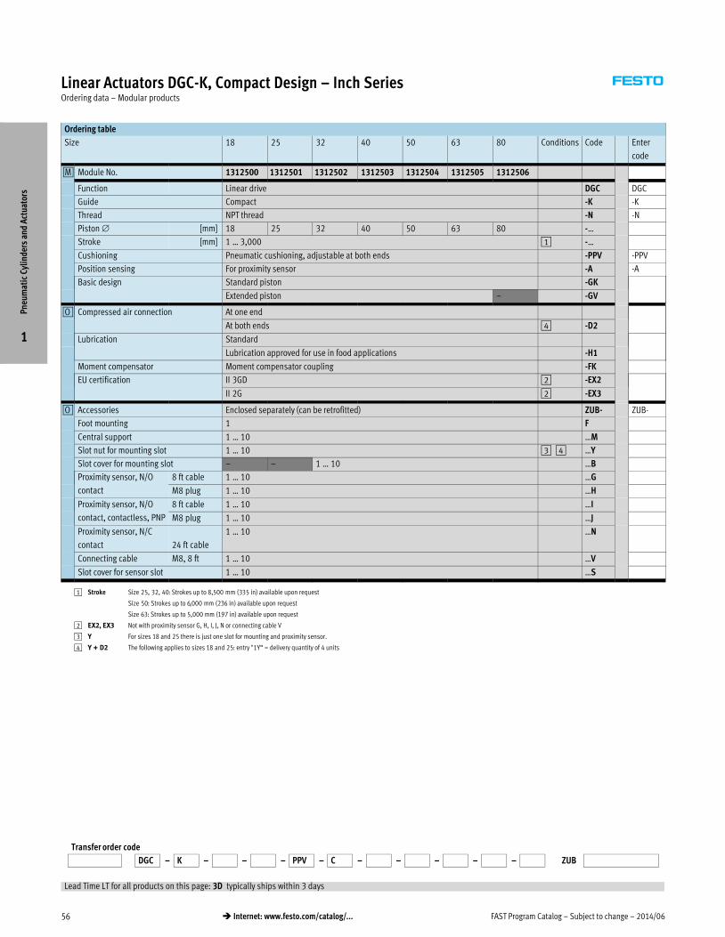
FAST Program Catalog – Subject to change – 2014/0656 � Internet: www.festo.com/catalog/...
Linear Actuators DGC-K, Compact Design – Inch SeriesOrdering data – Modular products
Ordering table
Size 18 25 32 40 50 63 80 Conditions Code Enter
code
0M Module No. 1312500 1312501 1312502 1312503 1312504 1312505 1312506
Function Linear drive DGC DGC
Guide Compact -K -K
Thread NPT thread -N -N
Piston [mm] 18 25 32 40 50 63 80 -…
Stroke [mm] 1 … 3,000 1 -…
Cushioning Pneumatic cushioning, adjustable at both ends -PPV -PPV
Position sensing For proximity sensor -A -A
Basic design Standard piston -GK
Extended piston – -GV
0O Compressed air connection At one end
At both ends 4 -D2
Lubrication Standard
Lubrication approved for use in food applications -H1
Moment compensator Moment compensator coupling -FK
EU certification II 3GD 2 -EX2
II 2G 2 -EX3
0O Accessories Enclosed separately (can be retrofitted) ZUB- ZUB-
Foot mounting 1 F
Central support 1 … 10 …M
Slot nut for mounting slot 1 … 10 3 4 …Y
Slot cover for mounting slot – – 1 … 10 …B
Proximity sensor, N/O
contact
8 ft cable 1 … 10 …G
M8 plug 1 … 10 …H
Proximity sensor, N/O
contact, contactless, PNP
8 ft cable 1 … 10 …I
M8 plug 1 … 10 …J
Proximity sensor, N/C
contact 24 ft cable
1 … 10 …N
Connecting cable M8, 8 ft 1 … 10 …V
Slot cover for sensor slot 1 … 10 …S
1 Stroke Size 25, 32, 40: Strokes up to 8,500 mm (335 in) available upon request
Size 50: Strokes up to 6,000 mm (236 in) available upon request
Size 63: Strokes up to 5,000 mm (197 in) available upon request
2 EX2, EX3 Not with proximity sensor G, H, I, J, N or connecting cable V
3 Y For sizes 18 and 25 there is just one slot for mounting and proximity sensor.
4 Y + D2 The following applies to sizes 18 and 25: entry "1Y“ = delivery quantity of 4 units
Transfer order code
DGC – K – – – PPV – C – – – – – ZUB
Pneu
mat
ic C
ylin
ders
and
Act
uato
rs
1
Lead Time LT for all products on this page: 3D typically ships within 3 days

2014/06 – Subject to change – FAST Program Catalog 57� Internet: www.festo.com/catalog/...
Linear Actuators DGC-K, Compact Design – Inch SeriesAccessories
Accessories Overview
DGC-K-18 … 80
4
5
6
7
8
9
aJ
aA
1
aB
2
3
Accessories � Page/Internet
1 Linear drive DGC-K 55
2 Adapter plate DAMF damf
3 Moment compensator DARD-…-M dard
4 Moment compensator FK (type: DARD-…-S) dard
5 Slot cover B/S abp
6 Proximity sensor G/H/I/J/N smt, sme
Accessories � Page/Internet
7 Connecting cable V nebu
8 Slot nut for mounting slot Y (type: NST) nst
9 Slot nut for mounting slot Y (type: ABAN) aban
aJ Central support M mup
aA One-way flow control valve GRLA grla
aB Foot mounting F hp
Pneu
mat
ic C
ylin
ders
and
Act
uato
rs
1

FAST Program Catalog – Subject to change – 2014/0658 � Internet: www.festo.com/catalog/...
Linear Actuators DGC-GF, with Plain-bearing Guide – Inch SeriesTechnical Data
Technical Data
Materials
Guide rail, slide, end caps,
cylinder barrel: Anodized aluminum
Piston seal, sealing band/cover strip:
Polyurethane
Slide elements: Polyacetal
Size 18 25 32 40 50 63
Piston [mm] 18 25 32 40 50 63
[in]1) 11/16 1 1 1/4 1 5/8 2 2 1/2
Pneumatic connection M5, suitable for
10-32 UNF
xNPT ¼NPT yNPT
Stroke [in] 0.04 … 118
Cushioning PPV Pneumatic cushioning, adjustable at both ends
YSR… Self-adjusting shock absorbers at both ends
Cushioning length2) [in] 0.65 0.61 0.69 1.16 1.17 1.22
Theoretical force at 6 bar [lbf] 34.4 66.3 109 170 265 420
Max. permissible force Fy [lbf] 99 144 202 310 337 517
Max. permissible force Fz [lbf] 121 292 405 450 645 1003
Max. permissible torque Mx [ft-lbf] 2.5 6.3 11.1 20.7 39.8 70.8
Max. permissible torque My [ft-lbf] 14.8 29.5 51.6 81.1 199 332
Max. permissible torque Mz [ft-lbf] 6.3 14.8 24.3 39.8 76 138
1) Approximated values; for reference only.
2) With PPV cushioning.
Operating Conditions
Size 18 25 32 40 50 63
Operating medium Compressed air in accordance with ISO 8573-1:2010 [7:–:–]
Note on operating/pilot medium Operation with lubricated medium possible (in which case lubricated operation will always be required)
Operating pressure [psi] 29 … 118 22 … 118
Ambient temperature3) [°F] 14 … 140
3) Note operating range of proximity sensors.
Pneu
mat
ic C
ylin
ders
and
Act
uato
rs
1

2014/06 – Subject to change – FAST Program Catalog 59� Internet: www.festo.com/catalog/...
Linear Actuators DGC-GF, with Plain-bearing Guide – Inch SeriesOrdering data – Modular products
Ordering Table
Size 18 25 32 40 50 63 Condi-
tions
Code Enter
code
0M Module No. 532 446 532 447 532 448 532 449 532 450 532 451
Function Linear drive DGC DGC
Thread NPT thread -N -N
Piston [mm] 18 25 32 40 50 63 -…
Stroke [mm] 1 … 3,000 1 -…
Guide Plain-bearing guide -GF -GF
Cushioning Pneumatic cushioning, adjustable at both ends -PPV
Shock absorber, self-adjusting -YSR
Shock absorber, self-adjusting, progressive -YSRW
Position sensing Via proximity sensor -A -A
0O Accessories Enclosed separately (can be retrofitted) ZUB- ZUB-
Foot mounting 1 F
Profile mounting 1 … 9 …M
Slot nut for mounting slot – 1 … 9 …B
Proximity sensor Cable 8 ft 1 … 9 …G
Plug M8 1 … 9 …H
Proximity sensor,
contactless, PNP
Cable 8 ft 1 … 9 …I
Plug M8 1 … 9 …J
Plug socket with cable M8, 8 ft 1 … 9 …V
Slot cover for sensor slot 1 … 9 …L
Mechanical end-position limiter Variable end position, at one end 2 YWZ1
Variable end position, at both ends 2 YWZ2
Manual Express waiver – no operating instructions to be included (already available) -O
1 Stroke Size 25, 32, 40: Strokes up to 8,500 mm (335 in) available upon request
Size 50, 63: Strokes up to 5,000 mm (197 in) available upon request
2 YWZ1, YWZ2 Only with cushioning YSR or YSRW
Transfer order code
DGC – N – – – GF – – A ZUB – –
Pneu
mat
ic C
ylin
ders
and
Act
uato
rs
1
Lead Time LT for all products on this page: 3D typically ships within 3 days

FAST Program Catalog – Subject to change – 2014/0660 � Internet: www.festo.com/catalog/...
Linear Actuators DGC-GF, with Plain-bearing Guide – Inch SeriesAccessories
Accessories Overview
1
2
3
4
5
6
7
8
9
aJ
Note
End stops or shock absorbers must
not be removed.
Accessories � Page/Internet
1 Centering pin/sleeve ZBS/ZBH1) 64
2 Shock absorber YSR 64
3 Shock absorber YSRW-DGC 64
4 One-way flow control valve GRLA 64
5 Proximity sensor SME-/SMT-8 64
1) Included in the scope of delivery of the axis.
Accessories � Page/Internet
6 Connecting cable NEBU 64
7 Slot cover ABP-S abp
8 Profile mounting MUC 65
9 Slot nut HMBN 65
aJ Foot mounting HPC 65
Pneu
mat
ic C
ylin
ders
and
Act
uato
rs
1

2014/06 – Subject to change – FAST Program Catalog 61� Internet: www.festo.com/catalog/...
Linear Actuators DGC-KF, with Recirculating Ball Bearing Guide – Inch SeriesTechnical Data
Technical Data
Materials
Guide rail, slide: High-alloy steel
End caps, cylinder barrel:
Anodized aluminum
Piston seal, sealing band/cover strip:
Polyurethane
Slide elements: Polyacetal
Size 18 25 32 40 50 63
Piston [mm] 18 25 32 40 50 63
[in]1) 11/16 1 1 1/4 1 5/8 2 2 1/2
Pneumatic connection M5, suitable for
10-32 UNF
xNPT ¼NPT yNPT
Stroke [in] 0.04 … 118
Cushioning PPV Pneumatic cushioning, adjustable at both ends
YSR… Self-adjusting shock absorbers at both ends
Cushioning length2) [in] 0.65 0.61 0.69 1.16 1.17 1.22
Theoretical force at 6 bar [lbf] 34.4 66.3 109 170 265 420
Max. permissible force Fy [lbf] 416 686 744 1549 1549 3417
Max. permissible force Fz [lbf] 416 686 744 1549 1549 3417
Max. permissible torque Mx [ft-lbf] 11.8 26.5 39.8 106 106 390
Max. permissible torque My [ft-lbf] 37.6 71.5 110.6 280 468 853
Max. permissible torque Mz [ft-lbf] 37.6 71.5 110.6 280 468 853
1) Approximated values; for reference only.
2) With PPV cushioning.
Operating Conditions
Size 18 25 32 40 50 63
Operating medium Compressed air in accordance with ISO 8573-1:2010 [7:–:–]
Note on operating/pilot medium Operation with lubricated medium possible (in which case lubricated operation will always be required)
Operating pressure [psi] 29 … 118 22 … 118
Ambient temperature3) [°F] 14 … 140
3) Note operating range of proximity sensors.
Pneu
mat
ic C
ylin
ders
and
Act
uato
rs
1

FAST Program Catalog – Subject to change – 2014/0662 � Internet: www.festo.com/catalog/...
Linear Actuators DGC-KF, with Recirculating Ball Bearing Guide – Inch SeriesOrdering data – Modular products
Ordering Table
Size 18 25 32 40 50 63 Condi-
tions
Code Enter
code
0M Module No. 532 446 532 447 532 448 532 449 532 450 532 451
Function Linear drive DGC DGC
Thread NPT thread -N -N
Piston [mm] 18 25 32 40 50 63 -…
Stroke [mm] 1 … 3,000 1 -…
Guide Recirculating ball bearing guide -KF -KF
Cushioning Pneumatic cushioning, adjustable at both ends -PPV
Shock absorber, self-adjusting -YSR
Shock absorber, self-adjusting, progressive -YSRW
Position sensing Via proximity sensor -A -A
0O Slide Protected recirculating ball bearing guide – – 2 -GP
Additional slide at left Additional slide, standard, at left 3 -KL
Additional slide at right Additional slide, standard, at right 3 -KR
Accessories Enclosed separately (can be retrofitted) ZUB- ZUB-
Foot mounting 1 F
Profile mounting 1 … 9 …M
Slot nut for mounting slot – 1 … 9 …B
Proximity sensor Cable 8 ft 1 … 9 …G
Plug M8 1 … 9 …H
Proximity sensor,
contactless, PNP
Cable 8 ft 1 … 9 …I
Plug M8 1 … 9 …J
Plug socket with cable M8, 8 ft 1 … 9 …V
Slot cover for sensor slot 1 … 9 …L
Mechanical end-position limiter Variable end position, at one end 4 YWZ1
Variable end position, at both ends 4 YWZ2
Intermediate position module – 1 intermediate position – – 5 -Z1
– 2 intermediate positions – – 5 -Z2
– 3 intermediate positions – – 5 -Z3
Manual Express waiver – no operating instructions to be included (already available) -O
1 Stroke Size 25, 32, 40: Strokes up to 8,500 mm available upon request
Size 50, 63: Strokes up to 5,000 mm available upon request
2 GP Not with cushioning YSR and YSRW
Not with additional slide left (-KL) or additional slide right (-KR)
3 KL, KR For a linear drive DGC with additional slide, the effective stroke is reduced by the length of the additional slide
and the distance between both slides.
Not with cushioning PPV
4 YWZ1, YWZ2 Only with cushioning YSR or YSRW
5 Z1, Z2, Z3 Only with cushioning YSR or YSRW and mechanical end position limiter YWZ1 or YWZ2
Transfer order code
DGC – N – – – KF – – A – – – ZUB – – –
Pneu
mat
ic C
ylin
ders
and
Act
uato
rs
1
Lead Time LT for all products on this page: 3D typically ships within 3 days

2014/06 – Subject to change – FAST Program Catalog 63� Internet: www.festo.com/catalog/...
Linear Actuators DGC-KF, with Recirculating Ball Bearing Guide – Inch SeriesAccessories
Accessories Overview
1
2
3
4
5
6
7
8
9
aJ
aA
Note
End stops or shock absorbers must
not be removed.
Accessories � Page/Internet
1 Centering pin/sleeve ZBS/ZBH1) 64
2 Shock absorber YSR 64
3 Shock absorber YSRW-DGC 64
4 One-way flow control valve GRLA 64
5 Proximity sensor SME-/SMT-8 64
6 Connecting cable NEBU 64
7 Slot cover ABP-S abp
8 Profile mounting MUC 65
9 Slot nut HMBN 65
aJ Foot mounting HPC 65
aA Centering pin/sleeve ZBS/ZBH1) 64
1) Included in the scope of delivery of the axis.
Pneu
mat
ic C
ylin
ders
and
Act
uato
rs
1

FAST Program Catalog – Subject to change – 2014/0664 � Internet: www.festo.com/catalog/...
Linear Actuators DGC – Inch SeriesAccessories
Ordering Data
For Size Part No. Type
1 Centering pin1)
For slide
18 150928 ZBS-5
For end cap
18 150928 ZBS-5
1 Centering sleeve1)
For slide
25, 32, 40, 50, 63 150927 ZBH-9
For end cap
25, 32, 40, 50, 63 150927 ZBH-9
3 Shock absorber
For DGC-FA
18 540347 YSRW-DGC-18-KF
25 540349 YSRW-DGC-25-KF
32 540351 YSRW-DGC-32-KF
For DGC-GF
18 540346 YSRW-DGC-18-GF
25 540348 YSRW-DGC-25-GF
32 540350 YSRW-DGC-32-GF
40 540352 YSRW-DGC-40-GF
50 1232870 YSRW-DGC-40/50-B
63 543069 YSRW-DGC-63
For DGC-KF
18 540347 YSRW-DGC-18-KF
25 540349 YSRW-DGC-25-KF
32 540351 YSRW-DGC-32-KF
40, 50 1232870 YSRW-DGC-40/50-B
63 543069 YSRW-DGC-63
1) Packaging unit 10 pieces.
Ordering Data – Proximity Sensors and Connecting Cables
Description Part No. Type
5 Proximity sensor for C-slot,
magneto-resistive – N/O contact Technical data � 173
PNP, cable, 8 ft 551373 SMT-10M-PS-24V-E-2,5-L-OE
PNP, plug 551375 SMT-10M-PS-24V-E-0,3-L-M8D
Magnetic reed – N/O contact Technical data � 174
Cable, 8 ft 551369 SME-10M-ZS-24V-E-2,5-L-OE
Plug 551367 SME-10M-DS-24V-E-0,3-L-M8D
5 Proximity sensor for T-slot for piston 18 … 63,
magneto-resistive – N/O contact Technical data � 169
PNP, cable, 8 ft 574335 SMT-8M-A-PS-24V-E-2,5-OE
PNP, plug 574334 SMT-8M-A-PS-24V-E-0,3-M8D
NPN, cable, 8 ft 574338 SMT-8M-A-NS-24V-E-2,5-OE
NPN, plug 574339 SMT-8M-A-NS-24V-E-0,3-M8D
Magnetic reed – N/O contact Technical data � 170
Cable, 8 ft 543862 SME-8M-ZS-24V-K-2,5-OE
Plug 543861 SME-8M-DS-24V-K-0,3-M8D
Connecting cable, straight socket
8 ft 541333 NEBU-M8G3-K-2.5-LE3
Ordering Data – One-way Flow Control Valves for Exhaust Air Flow Control
Technical Data � 253
Function For Size Tubing
O.D. [in]
Part No. Type
4 One-way flow control valve with slotted head screw, metal2)
8, 12 Â 564840 GRLA-10-32-UNF-QB-5/32-U
18 ¼ 564842 GRLA-10-32-UNF-QB-1/4-U
25, 32 ¼ 534658 GRLA-1/8-QB-1/4-U
40, 50 Ä 534662 GRLA-1/4-QB-5/16-U
63 Ä 534665 GRLA-3/8-QB-5/16-U
2) The recommended flow control valves are based on a tubing length to the valve of 1 m. For deviations of
±50%, flow control valves with a bigger or smaller flow rate must be selected to guarantee the optimum
flow control function and cylinder speed.
Pneu
mat
ic C
ylin
ders
and
Act
uato
rs
1
Lead Time LT for all products on this page: 1D typically ships same day/next day

2014/06 – Subject to change – FAST Program Catalog 65� Internet: www.festo.com/catalog/...
Linear drives DGC – Inch SeriesAccessories
Ordering Data
For Size Part No. Type
8 Profile mounting
18 531752 MUC-18
25 531753 MUC-25
32 531754 MUC-32
40 531755 MUC-40
50 531756 MUC-50
63 531757 MUC-63
9 Slot nut2)
25, 32, 40 547264 HMBN-5-1M5
50, 63 186566 HMBN-5-2M5
aJ Foot mounting
18 533667 HPC-18
25 533668 HPC-25
32 533669 HPC-32
40 533670 HPC-40
50 545236 HPC-50
63 545237 HPC-63
1) Packaging unit 2x 0.5 m.
2) Packaging unit 10 pieces.
Ordering Data
For Size Part No. Type
aB Moment compensator
18 538714 FKC-18
25 538715 FKC-25
32 538961 FKC-32-G
40 538962 FKC-40-G
50 545240 FKC-50/63
63 545240 FKC-50/63
Pneu
mat
ic C
ylin
ders
and
Act
uato
rs
1
Lead Time LT for all products on this page: 1D typically ships same day/next day

FAST Program Catalog – Subject to change – 2014/0666 � Internet: www.festo.com/catalog/...
Linear Actuators DGC – Metric SeriesOverview
� Compact dimensions
� Quick and sturdy installation and mounting
� High precision and load carrying ability
� Excellent running characteristics and low air consumption
� Precision interfaces
� Spare parts service
� Repair service
Product Range Overview
Version Piston
[mm]
Stroke
[mm]
Force
[N]
Variants � Page/Internet
PPV YSR YSRW A
Linear actuators DGC, double-acting
Compact design K 18, 25, 32, 40, 50, 63, 80 1 … 3,000 1) 153 … 3,016� – – � 67
Plain-bearing guide GF 18, 25, 32, 40, 50, 63 1 … 3,000 2) 153 … 1,870 � � � � 70
Recirculating ball bearing
guide KF
18, 25, 32, 40, 50, 63 1 … 3,000 2) 153 … 1,870 � � � � 73
1) Size 25, 32, 40: Strokes up to 8,500 mm available upon request
Size 50: Strokes up to 6,000 mm available upon request
Size 63: Strokes up to 5,000 mm available upon request
2) Size 25, 32, 40: Strokes up to 8,500 mm available upon request
Size 50, 63: Strokes up to 5,000 mm available upon request
Variants
N NPT thread
PPV Pneumatic cushioning,
adjustable at both ends
YSR Self-adjusting shock absorber
YSRW Self-adjusting progressive shock
absorber
A Position sensing
GP Protected recirculating ball
bearing guide
KL Additional slide on left
KR Additional slide on right
Contents
DGC-K DGC-GF DGC-KF
– Technical Data � 67 – Technical Data � 70 – Technical Data � 73
– Ordering Data � 68 – Ordering Data � 71 – Ordering Data � 74
– Accessories Overview � 69 – Accessories Overview � 72 – Accessories Overview � 75
– Accessories � 76 – Accessories � 76 – Accessories � 76
Pneu
mat
ic C
ylin
ders
and
Act
uato
rs
1
Detailed product information � www.festo.com/catalog/dgc

2014/06 – Subject to change – FAST Program Catalog 67� Internet: www.festo.com/catalog/...
Linear Actuators DGC-K, Compact Design – Metric SeriesTechnical Data
Technical Data
Materials
Guide rail, slide, end caps,
cylinder barrel: Anodized aluminum
Piston seal, sealing tape/cover strip:
Polyurethane
Slide elements: Polyacetal
Piston 18 25 32 40 50 63 80
Pneumatic connection M5 Gx G¼ Gy G½
Stroke [mm] 1 … 3,000
Cushioning PPV Pneumatic cushioning, adjustable at both ends
YSR… –
Cushioning length1) [mm] 16 18 20 30 30 30 83
Theoretical force at 6 bar [N] 153 295 483 754 1,178 1,870 3,016
Fzmax.
DGC-…-GK [N] 120 330 480 800 1,200 1,600 2,500
DGC-…-GV [N] 120 330 480 800 1,200 1,600 –
Mxmax.
DGC-…-GK [Nm] 0.8 1.2 1.9 3.8 6 5.7 30.6
DGC-…-GV [Nm] 1.6 2.4 3.8 7.6 12 11.4 –
Mymax.
DGC-…-GK [Nm] 11 20 40 60 120 150 400
DGC-…-GV [Nm] 22 40 80 120 240 300 –
Mzmax.
DGC-…-GK [Nm] 1 3 5 8 15 24 100
DGC-…-GV [Nm] 2 6 10 16 30 48 –
1) With PPV cushioning.
Operating Conditions
Piston 18 25 32 40 50 63 80
Operating medium Compressed air in accordance with ISO 8573-1:2010 [7:–:–]
Note on operating/pilot medium Operation with lubricated medium possible (in which case lubricated operation will always be required)
Operating pressure [bar] 2 … 8 1.5 … 8
Ambient temperature2) [°C] –10 … +60
2) Note operating range of proximity sensors.
Pneu
mat
ic C
ylin
ders
and
Act
uato
rs
1

FAST Program Catalog – Subject to change – 2014/0668 � Internet: www.festo.com/catalog/...
Linear Actuators DGC-K, Compact Design – Metric SeriesOrdering data – Modular products
Ordering table
Size 18 25 32 40 50 63 80 Conditions Code Enter
code
0M Module No. 1312500 1312501 1312502 1312503 1312504 1312505 1312506
Function Linear drive DGC DGC
Guide Compact -K -K
Piston [mm] 18 25 32 40 50 63 80 -…
Stroke [mm] 1 … 3,000 1 -…
Cushioning Pneumatic cushioning, adjustable at both ends -PPV -PPV
Position sensing For proximity sensor -A -A
Basic design Standard piston -GK
Extended piston – -GV
0O Compressed air connection At one end
At both ends 4 -D2
Lubrication Standard
Lubrication approved for use in food applications -H1
Moment compensator Moment compensator coupling -FK
EU certification II 3GD 2 -EX2
II 2G 2 -EX3
0O Accessories Enclosed separately (can be retrofitted) ZUB- ZUB-
Foot mounting 1 F
Central support 1 … 10 …M
Slot nut for mounting slot 1 … 10 3 4 …Y
Slot cover for mounting slot – – 1 … 10 …B
Proximity sensor, N/O
contact
2.5 m cable 1 … 10 …G
M8 plug 1 … 10 …H
Proximity sensor, N/O
contact, contactless, PNP
2.5 m cable 1 … 10 …I
M8 plug 1 … 10 …J
Proximity sensor, N/C
contact 7.5 m cable
1 … 10 …N
Connecting cable M8, 2.5 m 1 … 10 …V
Slot cover for sensor slot 1 … 10 …S
1 Stroke Size 25, 32, 40: Strokes up to 8,500 mm available upon request
Size 50: Strokes up to 6,000 mm available upon request
Size 63: Strokes up to 5,000 mm available upon request
2 EX2, EX3 Not with proximity sensor G, H, I, J, N or connecting cable V
3 Y For sizes 18 and 25 there is just one slot for mounting and proximity sensor.
4 Y + D2 The following applies to sizes 18 and 25: entry "1Y“ = delivery quantity of 4 units
Transfer order code
DGC – K – – – PPV – C – – – – – ZUB
Pneu
mat
ic C
ylin
ders
and
Act
uato
rs
1
Lead Time LT for all products on this page: 3D typically ships within 3 days

2014/06 – Subject to change – FAST Program Catalog 69� Internet: www.festo.com/catalog/...
Linear Actuators DGC-K, Compact Design – Metric SeriesAccessories
Accessories Overview
DGC-K-18 … 80
4
5
6
7
8
9
aJ
aA
1
aB
2
3
Accessories � Page/Internet
1 Linear drive DGC-K 67
2 Adapter plate DAMF damf
3 Moment compensator DARD-…-M dard
4 Moment compensator FK (type: DARD-…-S) dard
5 Slot cover B/S abp
6 Proximity sensor G/H/I/J/N smt, sme
Accessories � Page/Internet
7 Connecting cable V nebu
8 Slot nut for mounting slot Y (type: NST) nst
9 Slot nut for mounting slot Y (type: ABAN) aban
aJ Central support M mup
aA One-way flow control valve GRLA grla
aB Foot mounting F hp
Pneu
mat
ic C
ylin
ders
and
Act
uato
rs
1

FAST Program Catalog – Subject to change – 2014/0670 � Internet: www.festo.com/catalog/...
Linear Actuators DGC-GF, with Plain-bearing Guide – Metric SeriesTechnical Data
Technical Data
Materials
Guide rail, slide, end caps,
cylinder barrel: Anodized aluminum
Piston seal, sealing band/cover strip:
Polyurethane
Slide elements: Polyacetal
Piston 18 25 32 40 50 63
Pneumatic connection M5 Gx G¼ Gy
Stroke [mm] 1 … 3,000
Cushioning PPV Pneumatic cushioning, adjustable at both ends
YSR… Self-adjusting shock absorbers at both ends
Cushioning length1) [mm] 16.5 15.5 17.5 29.5 29.8 31.1
Theoretical force at 6 bar [N] 153 295 483 754 1,178 1,870
Max. permissible force Fy [N] 440 640 900 1,380 1,500 2,300
Max. permissible force Fz [N] 540 1,300 1,800 2,000 2,870 4,460
Max. permissible torque Mx [Nm] 3.4 8.5 15 28 54 96
Max. permissible torque My [Nm] 20 40 70 110 270 450
Max. permissible torque Mz [Nm] 8.5 20 33 54 103 187
1) With PPV cushioning.
Operating Conditions
Piston 18 25 32 40 50 63
Operating medium Compressed air in accordance with ISO 8573-1:2010 [7:–:–]
Note on operating/pilot medium Operation with lubricated medium possible (in which case lubricated operation will always be required)
Operating pressure [bar] 2 … 8 1.5 … 8
Ambient temperature2) [°C] –10 … +60
2) Note operating range of proximity sensors.
Pneu
mat
ic C
ylin
ders
and
Act
uato
rs
1
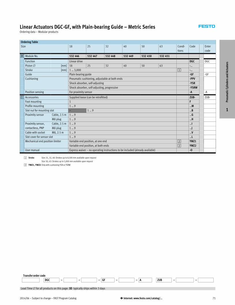
2014/06 – Subject to change – FAST Program Catalog 71� Internet: www.festo.com/catalog/...
Linear Actuators DGC-GF, with Plain-bearing Guide – Metric SeriesOrdering data – Modular products
Ordering Table
Size 18 25 32 40 50 63 Condi-
tions
Code Enter
code
0M Module No. 532 446 532 447 532 448 532 449 532 450 532 451
Function Linear drive DGC DGC
Piston [mm] 18 25 32 40 50 63 -…
Stroke [mm] 1 … 3,000 1 -…
Guide Plain-bearing guide -GF -GF
Cushioning Pneumatic cushioning, adjustable at both ends -PPV
Shock absorber, self-adjusting -YSR
Shock absorber, self-adjusting, progressive -YSRW
Position sensing For proximity sensor -A -A
0O Accessories Supplied loose (can be retrofitted) ZUB- ZUB-
Foot mounting 1 F
Profile mounting 1 … 9 …M
Slot nut for mounting slot – 1 … 9 …B
Proximity sensor Cable, 2.5 m 1 … 9 …G
M8 plug 1 … 9 …H
Proximity sensor,
contactless, PNP
Cable, 2.5 m 1 … 9 …I
M8 plug 1 … 9 …J
Cable with socket M8, 2.5 m 1 … 9 …V
Slot cover for sensor slot 1 … 9 …L
Mechanical end position limiter Variable end position, at one end 2 YWZ1
Variable end position, at both ends 2 YWZ2
User manual Express waiver – no operating instructions to be included (already available) -O
1 Stroke Size 25, 32, 40: Strokes up to 8,500 mm available upon request
Size 50, 63: Strokes up to 5,000 mm available upon request
2 YWZ1, YWZ2 Only with cushioning YSR or YSRW
Transfer order code
DGC – – – GF – – A ZUB – –
Pneu
mat
ic C
ylin
ders
and
Act
uato
rs
1
Lead Time LT for all products on this page: 3D typically ships within 3 days

FAST Program Catalog – Subject to change – 2014/0672 � Internet: www.festo.com/catalog/...
Linear Actuators DGC-GF, with Plain-bearing Guide – Metric SeriesAccessories
Accessories Overview
1
2
3
4
5
6
7
8
9
aJ
Note
End stops or shock absorbers must
not be removed.
Accessories � Page/Internet
1 Centering pin/sleeve ZBS/ZBH1) 76
2 Shock absorber YSR 76
3 Shock absorber YSRW-DGC 76
4 One-way flow control valve GRLA 76
5 Proximity sensor SME-/SMT-8 76
1) Included in the scope of delivery of the axis.
Accessories � Page/Internet
6 Connecting cable NEBU 76
7 Slot cover ABP-S 76
8 Profile mounting MUC 77
9 Slot nut HMBN 77
aJ Foot mounting HPC 77
Pneu
mat
ic C
ylin
ders
and
Act
uato
rs
1

2014/06 – Subject to change – FAST Program Catalog 73� Internet: www.festo.com/catalog/...
Linear Actuators DGC-KF, with Recirculating Ball Bearing Guide – Metric SeriesTechnical Data
Technical Data
Materials
Guide rail, slide: High-alloy steel
End caps, cylinder barrel:
Anodized aluminum
Piston seal, sealing band/cover strip:
Polyurethane
Slide elements: Polyacetal
Piston 18 25 32 40 50 63
Pneumatic connection M5 Gx G¼ Gy
Stroke [mm] 1 … 3,000
Cushioning PPV Pneumatic cushioning, adjustable at both ends
YSR… Self-adjusting shock absorbers at both ends
Cushioning length1) [mm] 16.5 15.5 17.5 29.5 29.8 31.1
Theoretical force at 6 bar [N] 153 295 483 754 1,178 1,870
Max. permissible force Fy [N] 1,850 3,050 3,310 6,890 6,890 15,200
Max. permissible force Fz [N] 1,850 3,050 3,310 6,890 6,890 15,200
Max. permissible torque Mx [Nm] 16 36 54 144 144 529
Max. permissible torque My [Nm] 51 97 150 380 634 1,157
Max. permissible torque Mz [Nm] 51 97 150 380 634 1,157
1) With PPV cushioning.
Operating Conditions
Piston 18 25 32 40 50 63
Operating medium Compressed air in accordance with ISO 8573-1:2010 [7:–:–]
Note on operating/pilot medium Operation with lubricated medium possible (in which case lubricated operation will always be required)
Operating pressure [bar] 2 … 8 1.5 … 8
Ambient temperature2) [°C] –10 … +60
2) Note operating range of proximity sensors.
Pneu
mat
ic C
ylin
ders
and
Act
uato
rs
1

FAST Program Catalog – Subject to change – 2014/0674 � Internet: www.festo.com/catalog/...
Linear Actuators DGC-KF, with Recirculating Ball Bearing Guide – Metric SeriesOrdering data – Modular products
Ordering Table
Size 18 25 32 40 50 63 Condi-
tions
Code Enter
code
0M Module No. 532 446 532 447 532 448 532 449 532 450 532 451
Function Linear drive DGC DGC
Piston [mm] 18 25 32 40 50 63 -…
Stroke [mm] 1 … 3,000 1 -…
Guide Recirculating ball bearing guide -KF -KF
Cushioning Pneumatic cushioning, adjustable at both ends -PPV
Shock absorber, self-adjusting -YSR
Shock absorber, self-adjusting, progressive -YSRW
Position sensing For proximity sensor -A -A
0O Slide Protected recirculating ball bearing guide – – 2 -GP
Additional slide at left Additional slide, standard, left 3 -KL
Additional slide at right Additional slide, standard, right 3 -KR
Accessories Supplied loose (can be retrofitted) ZUB- ZUB-
Foot mounting 1 F
Profile mounting 1 … 9 …M
Slot nut for mounting slot – 1 … 9 …B
Proximity sensor Cable, 2.5 m 1 … 9 …G
M8 plug 1 … 9 …H
Proximity sensor,
contactless, PNP
Cable, 2.5 m 1 … 9 …I
M8 plug 1 … 9 …J
Cable with socket M8, 2.5 m 1 … 9 …V
Slot cover for sensor slot 1 … 9 …L
Mechanical end position limiter Variable end position, at one end 4 YWZ1
Variable end position, at both ends 4 YWZ2
Intermediate position – 1 intermediate position – – 5 -Z1
– 2 intermediate positions – – 5 -Z2
– 3 intermediate positions – – 5 -Z3
User manual Express waiver – no operating instructions to be included (already available) -O
1 Stroke Size 25, 32, 40: Strokes up to 8,500 mm (335 in) available upon request
Size 50, 63: Strokes up to 5,000 mm (197 in) available upon request
2 GP Not with cushioning YSR and YSRW
Not with additional slide left (-KL) or additional slide right (-KR)
3 KL, KR For a linear drive DGC with additional slide, the effective stroke is reduced by the length of the additional
slide and the distance between both slides.
Not with cushioning PPV
4 YWZ1, YWZ2 Only with cushioning YSR or YSRW
5 Z1, Z2, Z3 Only with cushioning YSR or YSRW and mechanical end position limiter YWZ1 or YWZ2
Transfer order code
DGC – – – KF – – A – – – ZUB – – –
Pneu
mat
ic C
ylin
ders
and
Act
uato
rs
1
Lead Time LT for all products on this page: 3D typically ships within 3 days

2014/06 – Subject to change – FAST Program Catalog 75� Internet: www.festo.com/catalog/...
Linear Actuators DGC-KF, with Recirculating Ball Bearing Guide – Metric SeriesAccessories
Accessories Overview
1
2
3
4
5
6
7
8
9
aJ
aA
Note
End stops or shock absorbers must
not be removed.
Accessories � Page/Internet
1 Centering pin/sleeve ZBS/ZBH1) 76
2 Shock absorber YSR 76
3 Shock absorber YSRW-DGC 76
4 One-way flow control valve GRLA 76
5 Proximity sensor SME-/SMT-8 76
6 Connecting cable NEBU 76
7 Slot cover ABP-S 76
8 Profile mounting MUC 77
9 Slot nut HMBN 77
aJ Foot mounting HPC 77
aA Centering pin/sleeve ZBS/ZBH1) 76
1) Included in the scope of delivery of the axis.
Pneu
mat
ic C
ylin
ders
and
Act
uato
rs
1

FAST Program Catalog – Subject to change – 2014/0676 � Internet: www.festo.com/catalog/...
Linear Actuators DGC – Metric SeriesAccessories
Ordering Data
For Size Part No. Type
1 Centering pin1)
For slide
18 150928 ZBS-5
For end cap
18 150928 ZBS-5
1 Centering sleeve1)
For slide
25, 32, 40, 50, 63 150927 ZBH-9
For end cap
25, 32, 40, 50, 63 150927 ZBH-9
3 Shock absorber
For DGC-FA
18 540347 YSRW-DGC-18-KF
25 540349 YSRW-DGC-25-KF
32 540351 YSRW-DGC-32-KF
For DGC-GF
18 540346 YSRW-DGC-18-GF
25 540348 YSRW-DGC-25-GF
32 540350 YSRW-DGC-32-GF
40 540352 YSRW-DGC-40-GF
50 1232870 YSRW-DGC-40/50-B
63 543069 YSRW-DGC-63
For DGC-KF
18 540347 YSRW-DGC-18-KF
25 540349 YSRW-DGC-25-KF
32 540351 YSRW-DGC-32-KF
40, 50 1232870 YSRW-DGC-40/50-B
63 543069 YSRW-DGC-63
1) Packaging unit 10 pieces.
Ordering Data – Proximity Sensors and Connecting Cables
Description Part No. Type
5 Proximity sensor for C-slot,
magneto-resistive – N/O contact Technical data � 173
PNP, cable, 2.5 m 551373 SMT-10M-PS-24V-E-2,5-L-OE
PNP, plug 551375 SMT-10M-PS-24V-E-0,3-L-M8D
Magnetic reed – N/O contact Technical data � 174
Cable, 2.5 m 551369 SME-10M-ZS-24V-E-2,5-L-OE
Plug 551367 SME-10M-DS-24V-E-0,3-L-M8D
5 Proximity sensor for T-slot for piston 18 … 63,
magneto-resistive – N/O contact Technical data � 169
PNP, cable, 2.5 m 574335 SMT-8M-A-PS-24V-E-2,5-OE
PNP, plug 574334 SMT-8M-A-PS-24V-E-0,3-M8D
NPN, cable, 2.5 m 574338 SMT-8M-A-NS-24V-E-2,5-OE
NPN, plug 574339 SMT-8M-A-NS-24V-E-0,3-M8D
Magnetic reed – N/O contact Technical data � 170
Cable, 2.5 m 543862 SME-8M-ZS-24V-K-2,5-OE
Plug 543861 SME-8M-DS-24V-K-0,3-M8D
Connecting cable, straight socket
2.5 m 541333 NEBU-M8G3-K-2.5-LE3
Ordering Data – One-way Flow Control Valves for Exhaust Air Flow Control
Technical Data � 253
Function For Size Tubing
O.D. [in]
Part No. Type
4 One-way flow control valve with slotted head screw, metal2)
8, 12 4 197577 GRLA-M5-QS-4-RS-D
18 6 197578 GRLA-M5-QS-6-RS-D
25, 32 4 197580 GRLA-1/8-QS-4-RS-D
6 197581 GRLA-1/8-QS-6-RS-D
40, 50 6 162967 GRLA-1/4-QS-6-RS-B
8 162968 GRLA-1/4-QS-8-RS-B
63 6 162969 GRLA-3/8-QS-6-RS-B
8 162970 GRLA-3/8-QS-8-RS-B
2) The recommended flow control valves are based on a tubing length to the valve of 1 m. For deviations of
±50%, flow control valves with a bigger or smaller flow rate must be selected to guarantee the optimum
flow control function and cylinder speed.
Pneu
mat
ic C
ylin
ders
and
Act
uato
rs
1
Lead Time LT for all products on this page: 1D typically ships same day/next day

2014/06 – Subject to change – FAST Program Catalog 77� Internet: www.festo.com/catalog/...
Linear drives DGC – Metric SeriesAccessories
Ordering Data
For Size Part No. Type
8 Profile mounting
18 531752 MUC-18
25 531753 MUC-25
32 531754 MUC-32
40 531755 MUC-40
50 531756 MUC-50
63 531757 MUC-63
9 Slot nut2)
25, 32, 40 547264 HMBN-5-1M5
50, 63 186566 HMBN-5-2M5
aJ Foot mounting
18 533667 HPC-18
25 533668 HPC-25
32 533669 HPC-32
40 533670 HPC-40
50 545236 HPC-50
63 545237 HPC-63
1) Packaging unit 2x 0.5 m.
2) Packaging unit 10 pieces.
Ordering Data
For Size Part No. Type
aB Moment compensator
18 538714 FKC-18
25 538715 FKC-25
32 538961 FKC-32-G
40 538962 FKC-40-G
50 545240 FKC-50/63
63 545240 FKC-50/63
Pneu
mat
ic C
ylin
ders
and
Act
uato
rs
1
Lead Time LT for all products on this page: 1D typically ships same day/next day

FAST Program Catalog – Subject to change – 2014/0678 � Internet: www.festo.com/catalog/...
Swivel modules DSM-12 … 40-BOverview
� Semi-rotary drives with minimum space requirement
� Simple coarse and precision adjustment of the swivel angle
� High-performance cushioning
� Compact, low-cost sensing
Product Range Overview
Function Version Size Swivel angle Torque Variants
[°] [Nm] P CC – FW A
Double-acting With adjustable swivel angle 12, 16, 25, 32, 40 270 1.25 … 20 � – � � �
12, 16, 25, 32 246 1.25 … 10 – � � � �
40 240 20 – � � � �
Variants
P Flexible cushioning rings/pads
on both sides
CC Shock absorber at both ends
– Shaft with woodruff key
FW Flanged shaft
A Position sensing
Contents
– Technical Data � 79
– Ordering Data � 80
– Accessories Overview � 81
– Accessories � 82
Pneu
mat
ic C
ylin
ders
and
Act
uato
rs
1
Detailed product information � www.festo.com/catalog/dsm
Note: All metric products can be used within inch tubing systems via hybrid fittings (� Overview on page 240)

2014/06 – Subject to change – FAST Program Catalog 79� Internet: www.festo.com/catalog/...
Swivel modules DSM-12 … 40-BTechnical Data
Materials
Housing, flange, stop lever:
Anodized aluminum
Shaft: Nickel plated steel
Rotary vane: Fibreglass-reinforced
plastic
Fixed stops: Galvanized steel
Seals: Polyurethane
Technical Data
Size 12 16 25 32 40
Pneumatic connection M5 Gx
Cushioning Fixed (P) Flexible cushioning rings/pads at both ends
Adjustable (CC) Self-adjusting at both ends
Torque at 6 bar [Nm] 1.25 2.5 5 10 20
Swivel angle Fixed (P) [°] 270
Adjustable (CC) [°] 246 240
Max. perm. swivelling
frequency
Fixed (P) [Hz] 2
Adjustable (CC) 1.5 1 0.7
Max. perm. radial load1) [N] 45 75 120 200 350
Max. perm. axial load1) [N] 1.25 2.5 5 10 20
Max. cushioning angle [°] 15 12 10 12 16
/length [mm] 60/69 71/83 84/98 106/128 131/156
1) On the drive shaft.
Operating Conditions
Size 12 16 25 32 40
Operating medium Compressed air in accordance with ISO 8573-1:2010 [7:–:–]
Operating pressure [bar] 2 … 10 1.5 … 10
Temperature range1) [°C] –10 … +60
1) Note operating range of proximity sensors.
Pneu
mat
ic C
ylin
ders
and
Act
uato
rs
1

FAST Program Catalog – Subject to change – 2014/0680 � Internet: www.festo.com/catalog/...
Swivel modules DSM-12 … 40-BOrdering Data
Ordering Data – with Spigot Shaft
Piston Swivel Angle
[mm] Part No. Type LT
with flexible cushioning rings/pads at both ends, adjustable swivel angle
12 270° 547570 DSM-12-270-P-A-B 1D
16 547574 DSM-16-270-P-A-B 1D
25 547578 DSM-25-270-P-A-B 1D
32 547582 DSM-32-270-P-A-B 1D
40 547586 DSM-40-270-P-A-B 1D
with self-adjusting shock-absorbers at both ends, adjustable swivel angle
12 246° 547572 DSM-12-270-CC-A-B 1D
16 547576 DSM-16-270-CC-A-B 1D
25 547580 DSM-25-270-CC-A-B 1D
32 547584 DSM-32-270-CC-A-B 1D
40 240° 547588 DSM-40-270-CC-A-B 1D
Ordering Data – with Flanged Shaft
Piston Swivel Angle
[mm] Part No. Type LT
with flexible cushioning rings/pads at both ends, adjustable swivel angle
12 270° 547571 DSM-12-270-P-FW-A-B 1D
16 547575 DSM-16-270-P-FW-A-B 1D
25 547579 DSM-25-270-P-FW-A-B 1D
32 547583 DSM-32-270-P-FW-A-B 1D
40 547587 DSM-40-270-P-FW-A-B 1D
with self-adjusting shock-absorbers at both ends, adjustable swivel angle
12 246° 547573 DSM-12-270-CC-FW-A-B 1D
16 547577 DSM-16-270-CC-FW-A-B 1D
25 547581 DSM-25-270-CC-FW-A-B 1D
32 547585 DSM-32-270-CC-FW-A-B 1D
40 240° 547589 DSM-40-270-CC-FW-A-B 1D
LT = Lead time 1D typically ships same day/next day 3D typically ships within 3 days
Pneu
mat
ic C
ylin
ders
and
Act
uato
rs
1

2014/06 – Subject to change – FAST Program Catalog 81� Internet: www.festo.com/catalog/...
Swivel modules DSM-12 … 40-BAccessories
Peripherals Overview
1
2
3
4
5
6
7
8
9
9 aJ
4
5
6
7
8
Accessories � Page/Internet
1 Freewheel unit FLSM flsm
2 Push-on flange FWSR 82
3 Mounting plate HSM hsm
4 Push-in fitting QS 82
5 One-way flow control valve GRLA 82
6 Shock absorber retainer DSM-B dsm
7 Shock absorber DYSC 82
8 Cushioning kit DSM-…-P-B, with flexible fixed stop dsm
9 Sensor retainer SL-DSM-B 82
aJ Proximity sensor SME-/SMT-10 82
Pneu
mat
ic C
ylin
ders
and
Act
uato
rs
1

FAST Program Catalog – Subject to change – 2014/0682 � Internet: www.festo.com/catalog/...
Swivel modules DSM-12 … 40-BAccessories
Ordering Data
For size Part No. Type
Sensor retainer SL
12, 16, 25, 32, 40 550661 SL-DSM-B
Shock absorber DYSC
12 548011 DYSC-5-5-Y1F
16/25 548012 DYSC-7-5-Y1F
32 548013 DYSC-8-8-Y1F
40 548014 DYSC-12-12-Y1F
Ordering Data
For size Part No. Type
Push-on flange FWSR
12 14659 FWSR-12
16 13239 FWSR-16
170153 FWSR-16-M5
25 13240 FWSR-25
170154 FWSR-25-M5
32 13241 FWSR-32
40 14656 FWSR-40
Ordering Data – Proximity Sensors and Connecting Cables
Description Part No. Type
Proximity sensor for C-slot, magneto-resistive – N/O contactTechnical data � 173
PNP, cable, 2.5 m 551373 SMT-10M-PS-24V-E-2,5-L-OE
PNP, plug 551375 SMT-10M-PS-24V-E-0,3-L-M8D
Magnetic reed – N/O contact Technical data � 174
Cable, 2.5 m 551369 SME-10M-ZS-24V-E-2,5-L-OE
Plug 551367 SME-10M-DS-24V-E-0,3-L-M8D
Connecting cable, straight socket
2.5 m 541333 NEBU-M8G3-K-2.5-LE3
Ordering Data – One-way Flow Control Valves for Exhaust Air Flow Control
Technical Data � 253
Function For
[mm]
Tubing
O.D. [mm]
Part No. Type
12, 16, 25 4 197577 GRLA-M5-QS-4-RS-D
6 197578 GRLA-M5-QS-6-RS-D
32, 40 4 197580 GRLA-1/8-QS-4-RS-D
6 197581 GRLA-1/8-QS-6-RS-D
Ordering Data – Push-in Fittings QB
Technical Data � 245
Function For
[mm]
Tubing
O.D. [mm]
Part No. Type
12, 16, 25 4 153304 QSM-M5-4
6 153306 QSM-M5-6
32, 40 4 153001 QS-1/8-4
6 153002 QS-1/8-6
Pneu
mat
ic C
ylin
ders
and
Act
uato
rs
1
Lead Time LT for all products on this page: 1D typically ships same day/next day

2014/06 – Subject to change – FAST Program Catalog 83� Internet: www.festo.com/catalog/...
Electromechanical Actuators, Motors and Servo Drives – Overview
Electromechanical Actuators
Type Size Stroke Feed Force Lead Time � Page
[mm] [N] Same Day/Next
Day
3 Days 5 Days
Toothed Belt Axes EGC-TB-KF, with Recirculating Ball Bearing Guide
50, 70, 80, 120, 185 50 … 8,500 50 … 2,500
– – �
84
Motors
Type Motor Flange Size Nominal Voltage Max. Nominal Torque Lead Time � Page
[V AC] [Nm] Same Day/Next
Day
3 Days 5 Days
Servo Motors EMMS-AS
40, 55, 70, 100, 140,
190
360, 565 0.22 … 22.6
� – –
91
Drives
Type Nominal Voltage (Load) Nominal Voltage (Logic) Lead Time � Page
[V AC] [V DC] Same Day/Next
Day
3 Days 5 Days
Servo Drives CMMP-AS
1-phase 100 … 230,
3-phase 230 … 480
24 50 … 2,500
� – –
95
Elec
trom
echa
nica
l Act
uato
rs, M
otor
s an
d S
ervo
Dri
ves
2

FAST Program Catalog – Subject to change – 2014/0684 � Internet: www.festo.com/catalog/...
Toothed belt axes EGC-TB, with recirculating ball bearing guideOverview
� High speeds and feed forces
� Recirculating ball bearing guide and rigid profile
� Large loads and torques
� Free choice of motor assembly
� Spare parts service
Product Range Overview
Type/version Size Stroke Feed force Product options
[mm] [N] GK
EGC-TB
KF – Recirculating ball bearing guide 50, 70, 80, 120, 185 50 … 8,500 50 … 2,500 �
Product Options
GK Standard slide
GV Extended slide
GP Standard slide, protected
GQ Extended slide, protected
KL Additional slide on left
KR Additional slide on right
Product Options
Powerful Economical Versatile
� Generously sized profiles with an
optimised cross section afford
maximum rigidity and load capacity
� Speed, acceleration and torque
resistance set a new standard
� In addition to the technical data, the
toothed belt axis impresses with its
excellent price/performance ratio
� Due to the EGC's high performance it
is often possible to use a smaller size
� Numerous sizes and variants such as
protected guides open up a broad
range of applications
� Space-saving position sensing with
proximity sensor in the profile slot is
possible
� Wide range of options for mounting
on drives
� Comprehensive range of mounting
accessories for multi-axis
combinations
Flexible motor mounting
The motor position can be freely
selected on 4 sides and can be changed
at any time.
Elec
trom
echa
nica
l Act
uato
rs, M
otor
s an
d S
ervo
Dri
ves
2
Detailed product information � www.festo.com/catalog/egc-tb

2014/06 – Subject to change – FAST Program Catalog 85� Internet: www.festo.com/catalog/...
Toothed belt axes EGC-TB, with recirculating ball bearing guideTechnical Data
Materials
Profile, end caps and slide: Anodized
wrought aluminum alloy
Guide rail: High-alloy steel
Pulleys: Stainless steel
Toothed belt seals: Polychloroprene
with glass cord and nylon coating
Technical data
Size 50 70 80 120 185
Working stroke1) [mm] 50 … 1,900 50 … 5,000 50 … 8,500 50 … 8,500 50 … 8,500
Max. feed force Fx [N] 50 100 350 800 2,500
Max. no-load torque2) [Nm] 0.072 0.18 0.4 1.4 4.05
Max. no-load resistance to shifting1) [N] 8 14.5 28 70 110
Max. driving torque [Nm] 0.46 1.24 5 16 93
Max. speed [m/s] 3 5
Max. acceleration [m/s2] 50
Repetition accuracy [mm] ±0.08 ±0.1
Max. permissible force Fy [N] 650 1,850 3,050 6,890 15,200
Max. permissible force Fz [N] 650 1,850 3,050 6,890 15,200
Max. permissible torque Mx [Nm] 3.5 16 36 144 529
Max. permissible torque My [Nm] 10 51 97 380 1,157
Max. permissible torque Mz [Nm] 10 51 97 380 1,157
1) Total stroke = working stroke + 2x stroke reserve.
2) At 0.2 m/s, with variant GK.
Operating conditions
Ambient temperature3) [°C] –10 … +60
Protection class IP40
3) Note operating range of proximity sensors.
Toothed belt
Size 50 70 80 120 185
Pitch [mm] 2 3 3 5 8
Expansion4) [%] 0.094 0.08 0.24 0.13 0.29
Width [mm] 10 15 19.3 30.3 50.5
Effective diameter [mm] 18.46 24.83 28.65 39.79 73.85
Feed constant [mm/rev.] 58 78 90 125 232
4) At max. feed force.
Mass moment of inertia
Size 50 70 80 120 185
JO [kg mm2] 16.94 83.34 205.9 1,241 17,976
JS per metre stroke [kg mm2/m] 2.6 10.6 18.8 93 760
JL per kg effective load [kg mm2/kg] 85 154 205 396 1,363.5
The mass moment of inertia JA of the
entire axis is calculated as follows:
JA = JO + JS x working stroke [m] + JL x meffective load [kg]
Elec
trom
echa
nica
l Act
uato
rs, M
otor
s an
d S
ervo
Dri
ves
2
Note
PositioningDrives
sizing software
� www.festo.com

FAST Program Catalog – Subject to change – 2014/0686 � Internet: www.festo.com/catalog/...
Toothed belt axes EGC-TB, with recirculating ball bearing guideOrdering data – Modular products
Order code
Mandatory data
Slot for
proximity sensor
O top
U underneath
R right
L left
V front
H rear
Accessories
A
C
X, Z, O, P, W, R
O, P, W, R
O, P, W, R
Axial kit
� 90
K
B, S
X, Z
V
Y
M
F
Servo motor EMMS-AS
� 90
CL
1H…-PN, 2H-PN
(Options not included in the FAST program –
Lead Times upon request)
Elec
trom
echa
nica
l Act
uato
rs, M
otor
s an
d S
ervo
Dri
ves
2

2014/06 – Subject to change – FAST Program Catalog 87� Internet: www.festo.com/catalog/...
Toothed belt axes EGC-TB, with recirculating ball bearing guideOrdering data – Modular products
Ordering table
Size 50 70 80 120 185 Condi
tions
Code Enter
code
0M Module No. 556812 556813 556814 556815 556817
Design Linear axis EGC EGC
Size 50 70 80 120 185 -… -…
Stroke length [mm] 50 … 1,900 50 … 3,300 50 … 4,500 50 … 5,000 50 … 5,000 1, 2 -… -…
Function Toothed belt -TB -TB
Guide Recirculating ball bearing guide -KF -KF
Stroke reserve [mm] 0 … 999 (0 = no stroke reserve) 2 -…H
Slide Standard slide -GK
– Extended slide, protected – -GQ
– Standard slide, protected – -GP
– Extended slide -GV
0O Additional slide Left Additional slide, standard, on left 3 -KL
Right Additional slide, standard, on right 3 -KR
1 Stroke Size 70: Strokes up to 5,000 mm available upon request
Size 80, 120, 185: Strokes up to 8,500 mm available upon request
2 -… The sum of the stroke length and 2x stroke reserve must not exceed the maximum
stroke length
3 KL, KR If the protected slide variant (GQ, GP) is selected, then the additional slide (KL, KR) is
also protected
If the extended slide variant (GQ, GV) is selected, then the additional slide (KL, KR) is
not extended
If the slide with lubrication adapter (GK-C) is selected, the additional slide (KL, KR) is
also supplied with lubrication adapter
Working stroke reduction in combination with additional slide (KL, KR)
Order code
EGC – – – TB – KF – – – – – – – –
Elec
trom
echa
nica
l Act
uato
rs, M
otor
s an
d S
ervo
Dri
ves
2
Lead Time LT for all products on this page: 5D typically ships within 5 days

FAST Program Catalog – Subject to change – 2014/0688 � Internet: www.festo.com/catalog/...
Toothed belt axes EGC-TB, with recirculating ball bearing guideAccessories
1
2
3
4
5
6
7
8
9
aJ
aA
aB
aC
aD
aE
aF
aG
� Page/Internet
1 Emergency buffer NPE/shock absorber retainer KYE 89
2 Shock absorber YSRW/shock absorber retainer KYE 89
3 Centring pin ZBS/centring sleeve ZBH 89
4 Clamping unit 1H…-PN, 2H-PN
(Options not included in the FAST program – Lead
Times upon request)
egc-tb
5 Switch lug SF-EGC 89
6 Sensor bracket HWS-EGC 89
7 Inductive proximity sensor SIEN sien
8 Axial kit EAMM-A 90
� Page/Internet
9 Motor EMMS 90, 91
aJ Drive shaft EAMB 89
aA Slot cover ABP/ABP-S 89
aB Inductive proximity sensor SIES sies
aC Connecting cable NEBU 89
aD Clip SMBK 89
aE Slot nut NST 89
aF Profile mounting MUE 89
aG Foot mounting HPE 89
Elec
trom
echa
nica
l Act
uato
rs, M
otor
s an
d S
ervo
Dri
ves
2

2014/06 – Subject to change – FAST Program Catalog 89� Internet: www.festo.com/catalog/...
Toothed belt axes EGC-TB, with recirculating ball bearing guideAccessories – Ordering Data
For size Part No. Type
1 Emergency buffer
50 564897 NPE-50
70 562581 NPE-70
80 562582 NPE-80
120 562583 NPE-120
185 562584 NPE-185
1 Shock absorber retainer Dimensions online: � egc-tb
50 557583 KYE-50
70 557584 KYE-70
80 557585 KYE-80
120 557586 KYE-120
185 557587 KYE-185
2 Shock absorber Technical data online: � ysrw
50 191192 YSRW-5-8
70 191194 YSRW-8-14
80 191196 YSRW-12-20
120 191197 YSRW-16-26
185 191198 YSRW-20-34
3 Centring pin1)2) Technical data online: � zbs
50, 70 150928 ZBS-5
3 Centring sleeve1)2) Technical data online: � zbh
80, 120, 185 150927 ZBH-9
5 Switch lug3) Dimensions online: � egc-tb
50 558046 SF-EGC-1-50
70 558047 SF-EGC-1-70
80 558048 SF-EGC-1-80
120 558049 SF-EGC-1-120
185 558051 SF-EGC-1-185
5 Switch lug4) Dimensions online: � egc-tb
70 558052 SF-EGC-2-70
80 558353 SF-EGC-2-80
120 558054 SF-EGC-2-120
185 558056 SF-EGC-2-185
6 Sensor bracket5) Dimensions online: � egc-tb
70, 80 558057 HWS-EGC-M5
120 570365 HWS-EGC-M8-B
185 560517 HWS-EGC-M8:KURZ
For size Part No. Type
aJ Drive shaft
50 558034 EAMB-16-7-8X15-8X10
70 558035 EAMB-18-9-8X16-10X12
80 558036 EAMB-24-6-15X21-16X20
120 558037 EAMB-34-6-25X26-23X27
185 558038 EAMB-44-7-35X30-32X32
aA Slot cover6)
For mounting slot
70, 80 151681 ABP-5
120, 185 151682 ABP-8
For sensor slot
50 … 185 563360 ABP-5-S1
aC Connecting cable, straight socket
2.5 m 541333 NEBU-M8G3-K-2.5-LE3
aD Clip
50 … 185 534254 SMBK-8
aE Slot nut Technical data online: � nst
50 558045 NST-3-M3
70, 80 150914 NST-5-M5
120, 185 150915 NST-8-M6
aF Profile mounting Dimensions online: � egc-tb
50 558042 MUE-50
70 558043 MUE-70/80
80 558043 MUE-70/80
120 558044 MUE-120/185
185 558044 MUE-120/185
aG Foot mounting Dimensions online: � egc-tb
50 558320 HPE-50
70 558321 HPE-70
80 558322 HPE-80
120 558323 HPE-120
185 558325 HPE-185
1) Packaging unit 10 pieces.
2) 2 centring pins/sleeves included in the scope of delivery of the axis.
3) For sensing via proximity sensor SIES-8M.
4) For sensing via proximity sensor SIEN-M8B or SIES-8M.
5) For proximity sensor SIEN-M8B.
6) Packaging unit 2x 0.5 m.
Elec
trom
echa
nica
l Act
uato
rs, M
otor
s an
d S
ervo
Dri
ves
2
Lead Time LT for all products on this page: 1D typically ships same day/next day

FAST Program Catalog – Subject to change – 2014/0690 � Internet: www.festo.com/catalog/...
Toothed belt axes EGC-TB, with recirculating ball bearing guideAccessories – Ordering Data
8/9 Permissible axis/motor combination with axial kit Technical data online: � eamm-a
Servo motor Axial kit
Part No. Type
EGC-50
EMMS-AS-55-… 557975 EAMM-A-L27-55A
EGC-70
EMMS-AS-70-… 557979 EAMM-A-L38-70A
EGC-80
EMMS-AS-70-… 557982 EAMM-A-L48-70A
EMMS-AS-100-… 557984 EAMM-A-L48-100A
EGC-120
EMMS-AS-100-… 557988 EAMM-A-L62-100A
EMMS-AS-140-… 557990 EAMM-A-L62-140A
EGC-185
EMMS-AS-140-… 557994 EAMM-A-L95-140A
8/9 Permissible axis/motor combination with axial kit – Technical data online: � eamm-a
Gear unit Servo motor Axial kit
Part No. Type
EGC-50
552186 EMGA-40-P-G3-SAS-40 EMMS-AS-40-… 557974 EAMM-A-L27-40G
EGC-70
552188 EMGA-60-P-G3-SAS-55 EMMS-AS-55-… 557978 EAMM-A-L38-60G
EGC-80
552190 EMGA-60-P-G3-SAS-70 EMMS-AS-70-… 557983 EAMM-A-L48-60G
EGC-120
552194 EMGA-80-P-G3-SAS-100 EMMS-AS-100-… 557989 EAMM-A-L62-80G
EGC-185
552198 EMGA-120-P-G3-SAS-140 EMMS-AS-140-… 557995 EAMM-A-L95-120G
Elec
trom
echa
nica
l Act
uato
rs, M
otor
s an
d S
ervo
Dri
ves
2
Lead Time LT for all products on this page: 1D typically ships same day/next day

2014/06 – Subject to change – FAST Program Catalog 91� Internet: www.festo.com/catalog/...
Servo motors EMMS-ASOverview
� Suitable for servo drive CMMP-AS
� Digital absolute displacement encoder with single turn
(standard), multi-turn (optional)
� No homing after voltage failure
� Optional gearbox 3:1 and 5:1
Product Range Overview
Motor flange size Nominal voltage Nominal torque With gear unit With brake
[V AC] [Nm]
40 360 0.14 … 0.22 � �
55 360, 565 0.31 … 0.68 � �
70 360, 565 1.37 … 2.29 � �
100 565 3.24 … 7.51 � �
140 565 9.55 … 21.12 � �
190 565 17.47 … 22.63 � �
Product Options
Length Winding Electrical Connection Measuring Unit, Brake
S Short
M Medium
LS Low-voltage, standard
HS High-voltage, standard
R Angled plug, rotatable
T Terminal box
S Absolute encoder, single turn
M Absolute encoder, multi-turn
B Brake
Contents
– Technical Data � 92
– Ordering Data � 93
– Accessories � 94El
ectr
omec
hani
cal A
ctua
tors
, Mot
ors
and
Ser
vo D
rive
s
2
Detailed product information � www.festo.com/catalog/emms-as

FAST Program Catalog – Subject to change – 2014/0692 � Internet: www.festo.com/catalog/...
Servo motors EMMS-ASTechnical Data
Technical data
Motor flange size 40 55 70 100
Length M M S M S M
Winding LS LS LS LS HS HS
Nominal voltage [V AC] 360 360 360 360 565 565
Nominal current [A] 0.63 1.19 2.20 2.60 3.30 3.40
Peak current [A] 3.3 5 5 10 15 15
Rated output [W] 232 461 866 1,061 1,560 2,000
Nominal torque [Nm] 0.22 0.67 1.43 2.29 3.24 5.63
Peak torque [Nm] 1 2.7 3.10 7.75 12.50 22.10
Torque at standstill [Nm] 0.26 0.97 1.64 2.56 4.71 8.01
Nominal rotational speed [rpm] 10,300 6,600 5,300 4,100 4,600 3,400
Max. rotational speed [rpm] 11,520 7,330 6,450 4,880 6,680 4,030
Brake
Operating voltage [V DC] 24 +6 … –10%
Holding torque [Nm] 0.4 0.8 2 2 9
Technical data – Encoder
Type EMMS-AS-…-…S…
Absolute, single turn
EMMS-AS-…-…M…
Absolute, multi-turn
Operating voltage [V DC] 5
Protocol EnDat 2.1, digital channel only, max. cycle rate (CLOCK) 2 MHz
Position values per revolution 262,144
Version Standard Optional
Resolution 18 bits
– – 4,096 revolutions, 12 bits
Operating conditions – Encoder
Ambient temperature [°C] –10 … +40 (up to 100 °C with derating)
Protection class
Motor shaft IP54
Motor housing incl. connection technology IP65
With rotary shaft seal IP65
Insulation protection class F
Rated class to EN 60034-1 S1
Thermal class to EN 60034-1 F
Elec
trom
echa
nica
l Act
uato
rs, M
otor
s an
d S
ervo
Dri
ves
2

2014/06 – Subject to change – FAST Program Catalog 93� Internet: www.festo.com/catalog/...
Servo motors EMMS-ASOrdering Data
Ordering Data
Part No. Type
Flange size 40, medium length
550106 EMMS-AS-40-M-LS-TS
550107 EMMS-AS-40-M-LS-TM
550108 EMMS-AS-40-M-LS-TSB
550109 EMMS-AS-40-M-LS-TMB
Flange size 55, medium length
550110 EMMS-AS-55-M-LS-TS
550111 EMMS-AS-55-M-LS-TM
550112 EMMS-AS-55-M-LS-TSB
550113 EMMS-AS-55-M-LS-TMB
Flange size 70, short length
550114 EMMS-AS-70-S-LS-RS
550115 EMMS-AS-70-S-LS-RM
550116 EMMS-AS-70-S-LS-RSB
550117 EMMS-AS-70-S-LS-RMB
Flange size 70, medium length
550118 EMMS-AS-70-M-LS-RS
550119 EMMS-AS-70-M-LS-RM
550120 EMMS-AS-70-M-LS-RSB
550121 EMMS-AS-70-M-LS-RMB
Ordering Data
Part No. Type
Flange size 100, short length
550122 EMMS-AS-100-S-HS-RS
550123 EMMS-AS-100-S-HS-RM
550124 EMMS-AS-100-S-HS-RSB
550125 EMMS-AS-100-S-HS-RMB
Flange size 100, medium length
550127 EMMS-AS-100-M-HS-RS
550128 EMMS-AS-100-M-HS-RM
550129 EMMS-AS-100-M-HS-RSB
550130 EMMS-AS-100-M-HS-RMB
Product Options
Length Winding Electrical Connection Measuring Unit, Brake
S Short
M Medium
LS Low-voltage, standard
HS High-voltage, standard
R Angled plug, rotatable
T Terminal box
S Absolute encoder, single turn
M Absolute encoder, multi-turn
B Brake
Elec
trom
echa
nica
l Act
uato
rs, M
otor
s an
d S
ervo
Dri
ves
2
Lead Time LT for all products on this page: 1D typically ships same day/next day

FAST Program Catalog – Subject to change – 2014/0694 � Internet: www.festo.com/catalog/...
Servo motors EMMS-ASAccessories
Ordering Data – Motor Cable
Cable length Part No. Type
For EMMS-AS-40/55 with encoder
5 m 550306 NEBM-T1G7-E-5-N-LE7
10 m 550307 NEBM-T1G7-E-10-N-LE7
For EMMS-AS-70/100
5 m 550310 NEBM-M23G6-E-5-N-LE7
10 m 550311 NEBM-M23G6-E-10-N-LE7
Ordering Data – Encoder Cable
Cable length Part No. Type
For EMMS-AS-40/55
5 m 550314 NEBM-T1G8-E-5-N-S1G15
10 m 550315 NEBM-T1G8-E-10-N-S1G15
For EMMS-AS-70/100
5 m 550318 NEBM-M12W8-E-5-N-S1G15
10 m 550319 NEBM-M12W8-E-10-N-S1G15
Ordering Data – Gear Unit
For motor
flange size
Gear ratio
[i]
Continuous
output torque1)
[Nm]
Part No. Type
40 5 14 552187 EMGA-40-P-G5-SAS-40
55 5 22 552189 EMGA-60-P-G5-SAS-55
70 5 22 552191 EMGA-60-P-G5-SAS-70
3 85 552192 EMGA-80-P-G3-SAS-70
5 110 552193 EMGA-80-P-G5-SAS-70
100 5 110 552195 EMGA-80-P-G5-SAS-100
3 115 552196 EMGA-120-P-G3-SAS-100
5 195 552197 EMGA-120-P-G5-SAS-100
1) At the output shaft
Elec
trom
echa
nica
l Act
uato
rs, M
otor
s an
d S
ervo
Dri
ves
2
Lead Time LT for all products on this page: 1D typically ships same day/next day

2014/06 – Subject to change – FAST Program Catalog 95� Internet: www.festo.com/catalog/...
Servo drive CMMP-ASOverview
� Compatible with motor EMMS-AS
� Supports EtherNet/IP, Profinet and EtherCAT fieldbuses
(CMMP-AS-…-M3 with optional CAMC module)
� Integrated CANopen interface
� Optional safety modules (STO)
� Easy configuration with free FCT software
Product range overview
Type Nominal voltage
Load
Nominal voltage
Logic
Interfaces
Integrated Optional
Type [V AC] [V DC] I/O interface CANopen PROFIBUS DP DeviceNet EtherCAT EtherNet/IP PROFINET RT
CMMP-AS-C2-… 100 … 230 24 � � � � � � �
CMMP-AS-C5-3A-… 100 … 230 24 � � � � � � �
CMMP-AS-C5-11A-… 3x 230 … 480 24 � � � � � � �
CMMP-AS-C10-… 3x 230 … 480 24 � � � � � � �
Features
Compactness Motion control
� Small dimensions
� Full integration of all components for
the controller and power section,
including RS232 and CANopen
interface
� Integrated brake chopper
� Integrated EMC filters
� Automatic actuation for a holding
brake
� Complies with the current CE and EN
standards without additional external
measures (motor cable length of up to
25 m)
� Evaluation of digital absolute encoder
(EnDat/HIPERFACE) in single-turn or
multi-turn versions
� Can be operated as a torque, speed
or position controller
� Integrated position controller
� Time-optimised (trapezoidal) or
jerk-free (S-shaped) positioning
� Absolute and relative movements
� Point-to-point positioning with and
without motion path smoothing
� Position synchronisation
� Electronic gear unit
� 255 positioning records
� Wide range of homing methods
Fieldbus interfaces Input/output Integrated sequence control
Integrated:
Optional:
Optional: � Freely programmable I/Os
� High-resolution 16-bit analogue
input
� Jog/teach mode
� Simple connection to a higher-order
controller via I/O or fieldbus
� Synchronous operation
� Master/slave mode
� Additional I/Os with the plug-in card
CAMC-D-8E8A � 99
� Automatic sequence of positioning
records without a higher-order
controller
� Linear and cyclical position
sequences
� Adjustable delay times
� Branches and wait positions
� Overlapping restart possible during
the movement
Elec
trom
echa
nica
l Act
uato
rs, M
otor
s an
d S
ervo
Dri
ves
2
Detailed product information � www.festo.com/catalog/cmmp-as

FAST Program Catalog – Subject to change – 2014/0696 � Internet: www.festo.com/catalog/...
Servo drive CMMP-ASOverview
Features (continued)
Integrated safety functions Interpolating multi-axis movement Library for EPLAN
� The servo drive CMMP-AS supports
the "Safe Torque Off (STO)" safety
function and, by providing a reliable
time delay, also supports "Safe Stop
1 (SS1)" with protection against
unexpected start-up in accordance
with EN 61800-5-2
� Protection against unexpected
start-up
� Two-channel disconnection of the
output stage
� Less external circuitry
� Shorter response times in the event of
an error
� Faster restart, intermediate circuit
remains charged
� With a suitable controller, the
CMMP-AS can perform path
movements with interpolation via
CANopen or Sercos. The controller
specifies setpoint position values in a
fixed time pattern to this end. In
between, the servo drive
independently interpolates the data
values between two data points.
EPLAN macros for fast and reliable
planning of electrical projects in
combination with servo drive, motors
and cables. This enables a high level of
planning reliability, standardisation of
documentation, no need to create
symbols, graphics and master data.
Travel program
� Linking of any number of position
sets into a travel program
� Step criteria for the travel program
possible via digital inputs, for
example
MC – motion complete
I/O – digital inputs
MC
I/O
Cam disc functionality
The "electronic cam disc" application
type creates optimised motion profiles
that generate less vibration and
acceleration force at the machine. In
addition, the motion of the motor is
always synchronous in position with a
master axis, which enables easy
definition of overlapping,
time-optimised motion sequences.
To be able to use the cam disc function,
you will need the Festo Configuration
Tool (FCT) and also the curve editor
� online: cmmp.
Key features:
� High flexibility of the system. The
mechanism does not need to be
modified if the requirements for the
curve shapes change.
� User-friendly motion plan editor. All
limits for position, speed and
acceleration are immediately
displayed in the editor.
� Up to 16 cam discs with a total of up
to 2,048 data points can be
managed. The data points can be
randomly distributed along the cam
discs.
� There are four digital trip cams
coupled with each cam disc.
� Each cam disc can be offset by a
certain amount from the master axis.
1
2
3
4
7
5
6
8
9
aJ
1 Power switch
2 Circuit breaker
3 24 V DC power supply unit
4 External braking resistor (optional)
5 Servo drive CMMP-AS
6 Motor EMMS-AS
7 PC
8 Encoder cable
9 Motor cable
aJ Programming cable
Elec
trom
echa
nica
l Act
uato
rs, M
otor
s an
d S
ervo
Dri
ves
2

2014/06 – Subject to change – FAST Program Catalog 97� Internet: www.festo.com/catalog/...
Servo drive CMMP-ASTechnical Data
Fieldbus interfaces
Technical data Download CAD data � www.festo.com/us/engineering
CMMP-AS- C2-3A-… C5-3A-… C5-11A-P3-… C10-11A-P3-…
Parameterisation interface USB, Ethernet
Active PFC Yes –
Encoder interface input Resolver
Incremental encoder with analogue or digital tracking signals
Absolute encoder with EnDat V2.1 serial/V2.2
Absolute encoder with HIPERFACE
Additional input for synchronous/cam disc operation
Encoder interface output Actual value feedback via encoder signals in speed control mode
Setpoint specification for downstream slave drive
Resolution up to 16,384 ppr
Braking resistor, integrated [] 60 68
Pulse power of braking resistor [kVA] 2.8 8.5
Number of analogue outputs 2
Operating range of analogue outputs [V] 10
Resolution of analogue outputs 9 bits
Number of analogue inputs 3
Operating range of analogue inputs [V] 10
Mains filter Integrated
Safety function CMMP-AS-...-M0 Integrated
CMMP-AS-...-M3 Optional � 99
Electrical data
CMMP-AS- C2-3A-… C5-3A-… C5-11A-P3-… C10-11A-P3-…
Load supply
Input voltage range [V AC] 100 … 230 _10% 3x 230 … 480 _10%
Max. nominal input current [A] 3 6 5.5 11
Rated output [VA] 500 1,000 3,000 6,000
Peak power [VA] 1,000 2,000 6,000 12,000
Mains frequency [Hz] 50 … 60
Logic supply
Nominal voltage [V DC] 24 20%
Nominal current [A] 0.55/2.051) 0.65/2.151) 1/3.51)
1) Max. current with brake and I/Os.
Operating conditions
CMMP-AS- C2-3A-… C5-3A-… C5-11A-P3-… C10-11A-P3-…
Ambient temperature [°C] 0 … +40
Protection class IP20
Certificate issuing authority TÜV 01/205/5165/11
Safety function Safe Torque Off (STO)
Safety integrity level (SIL) SIL 3/SILCL 3
Performance Level (PL) Safe Torque Off (STO)/category 4, Performance Level e
Elec
trom
echa
nica
l Act
uato
rs, M
otor
s an
d S
ervo
Dri
ves
2

FAST Program Catalog – Subject to change – 2014/0698 � Internet: www.festo.com/catalog/...
Servo drive CMMP-ASTechnical Data, Ordering Data
Technical data – Fieldbus interface
Interfaces I/O CANopen PROFIBUS DP DeviceNet EtherCAT EtherNet/IP PROFINET RT
Number of digital logic outputs 5
Characteristics of digital logic outputs Freely configurable
Number of digital logic inputs 10
Operating range of logic inputs [V] 8 … 30
Characteristics of logic inputs Freely configurable
Process coupling 16 positioning records –
255 positioning
records1)
250 positioning records
Communication profile – DS301,
FHPP+
DP-V0/FHPP
+
FHPP+ DS301,
FHPP+
FHPP+ FHPP+
DS301,
DSP402
CoE:
DS301,
DSP402
Max. fieldbus transmission rate [Mbps] – 1 12 0.5 100 100 100
Interface CMMP-AS-...-M0 Integrated � � – – –
Interface CMMP-AS-...-M3 Integrated � � – – –
Optional – – �
� 99
�
� 99
�
� 99
�
� 99
�
� 99
1) With additional I/O plug-in card CAMC-D8E8A � 99.
Ordering data
Brief description Part No. Type
CMMP-AS-…-M0 – Without slot
The plug assortment NEKM (� 99) is included
in the scope of delivery of the servo drive.
1622901 CMMP-AS-C2-3A-M0
1622902 CMMP-AS-C5-3A-M0
1622903 CMMP-AS-C5-11A-P3-M0
1622904 CMMP-AS-C10-11A-P3-M0
CMMP-AS-…-M3 – With 3 slots
A plug-in card in slot 3 � 99 is mandatory for
operation.
Possible plug-in cards:
� Safety module CAMC-G-S1
� Switch module CAMC-DS-M1
The plug assortment NEKM (� 99) is included
in the scope of delivery of the servo drive.
1501325 CMMP-AS-C2-3A-M3
1501326 CMMP-AS-C5-3A-M3
1501327 CMMP-AS-C5-11A-P3-M3
1501328 CMMP-AS-C10-11A-P3-M3
Elec
trom
echa
nica
l Act
uato
rs, M
otor
s an
d S
ervo
Dri
ves
2
Lead Time LT for all products on this page: 1D typically ships same day/next day

2014/06 – Subject to change – FAST Program Catalog 99� Internet: www.festo.com/catalog/...
Servo drive CMMP-ASAccessories
Ordering Data – Cable and plug
Part No. Type
Control cable, for I/O interface to any servo drive
552254 NEBC-S1G25-K-2.5N-LE26
Programming cable
For CMMP-AS-C2/C5/C10-...
1501332 NEBC-U1G-K-1.8-N-U2G
Encoder plug
564264 NECC-A-S-S1G9-C2M
Plug assortment
For CMMP-AS-C2-3A-..., CMMP-AS-C5-3A-...
1659228 NEKM-C-71)
For CMMP-AS-C5-11A-P3-..., CMMP-AS-C10-11A-P3-...
552256 NEKM-C-31)
For interface CAMC-D-8E8A
569959 NEKM-C-52)
For safety module CAMC-G-S1
1660640 NEKM-C-83)
1) Plugs are included in the scope of delivery of the servo drive CMMP-AS-…-M3.
2) Plugs are included in the scope of delivery of the plug-in card CAMC-D-8E8A.
3) Plug is included in the scope of delivery of the plug-in card CAMC-G-S1.
Ordering Data – Plug-in card
Part No. Type
For PROFIBUS interface
547450 CAMC-PB
For DeviceNet interface
547451 CAMC-DN
For EtherCAT interface
567856 CAMC-EC
For EtherNet/IP interface
1911917 CAMC-F-EP
For PROFINET RT interface
1911916 CAMC-F-PN
Interface, for extending the digital I/Os1)
567855 CAMC-D-8E8A
1) 8 digital input/outputs.
Ordering Data – Plug-in card for slot 3 1)
Part No. Type
Safety module
1501330 CAMC-G-S1
Switch module
1501329 CAMC-DS-M1
1) The plugs are included in the scope of delivery.
Ordering Data – memory card
Part No. Type
Memory card, for data backup and firmware downloads
1436343 CAMC-M-S-F10-V1
Ordering Data – Braking resistor
Part No. Type
For CMMP-AS-C2-3A, CMMP-AS-C5-3A
1336615 CACR-LE2-100-W500
For CMMP-AS-C5-11A-P3, CMMP-AS-C10-11A-P3
1336617 CACR-KL2-67-W1800
Ordering Data – Documentation and software
Ordering data � online: cmmp
Elec
trom
echa
nica
l Act
uato
rs, M
otor
s an
d S
ervo
Dri
ves
2
Lead Time LT for all products on this page: 1D typically ships same day/next day
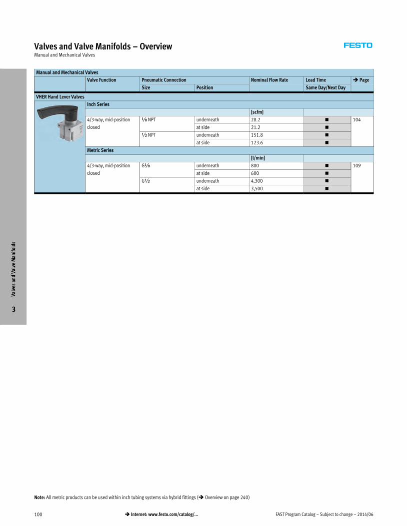
FAST Program Catalog – Subject to change – 2014/06100 � Internet: www.festo.com/catalog/...
Valves and Valve Manifolds – OverviewManual and Mechanical Valves
Manual and Mechanical Valves
Valve Function Pneumatic Connection Nominal Flow Rate Lead Time � Page
Size Position Same Day/Next Day
VHER Hand Lever Valves
Inch Series
[scfm]
4/3-way, mid-position
closed
x NPT underneath 28.2 � 104
at side 21.2 �
½ NPT underneath 151.8 �
at side 123.6 �
Metric Series
[l/min]
4/3-way, mid-position
closed
Gx underneath 800 � 109
at side 600 �
G½ underneath 4,300 �
at side 3,500 �
Valv
es a
nd V
alve
Man
ifol
ds
3
Note: All metric products can be used within inch tubing systems via hybrid fittings (� Overview on page 240)

2014/06 – Subject to change – FAST Program Catalog 101� Internet: www.festo.com/catalog/...
Valves and Valve Manifolds – OverviewStand-alone and In-line Valves
Stand-alone and In-line Valves
Valve Function Nominal Flow
Rate [l/min]
Valve Width Pneumatic
Connection
Lead Time � Page
[mm] Same Day/Next Day 3 Days
VUVG Solenoid Valves
Metric Series
3/2-way Normally open
Normally closed
190 10 M7 � – 114
600 … 650 14 Gx � –
2x 3/2-way 1x normally open
1x normally closed
190 10 M7 � –
650 14 Gx � –
5/2-way Single-solenoid
Double-solenoid
380 10 M7 � –
780 14 Gx � –
5/3-way Normally closed
Normally exhausted
Normally pressurized
320 10 M7� –
600 … 650 14 Gx � –
Manifold Blocks
Valve Function Nominal Flow
Rate
[l/min]
Valve Width Pneumatic Connection Number of Valves Lead Time � Page
[mm] 1, 3, 5 2, 4 Same Day/
Next Day
for VUVG Solenoid Valves
Metric Series
3/2-way,
2x 3/2-way,
5/2-way,
5/3-way
190 … 650
(depending on
the valve used)
10 Gx M7 2, 4, 6, 8, 10, 12�
117
14 G¼ Gx�
Valv
es a
nd V
alve
Man
ifol
ds
3
Note: All metric products can be used within inch tubing systems via hybrid fittings (� Overview on page 240)

FAST Program Catalog – Subject to change – 2014/06102 � Internet: www.festo.com/catalog/...
Valves and Valve Manifolds – OverviewValve Manifolds
MPA Valve Manifolds
Pneumatic Connection Nominal Flow Rate Valve Width Number of Valves Interface Options Lead Time � Page
1, 3, 5 2, 4 [l/min] [mm] 3 Days
Metric Series
G¼ M7 230 … 360 10.5 1 … 64 Multi-pin connection � 120
Fieldbus connection via CPX �
G¼ Gx 350 … 700 21 1 … 64 Multi-pin connection �
Fieldbus connection via CPX �
MPA Features
MPA offers a comprehensive range of
valve functions. All valves are equipped
with piston spool and patented sealing
system which facilitates efficient
sealing, a broad pressure range and
long service life. To increase power they
have a pneumatic pilot control. Supply
takes place via a pilot air supply.
The MPA valve manifold is available
with the following valve functions:
· 5/2-way valve, single solenoid
· 5/2-way valve, double solenoid
· 2x 3/2-way valve, normally open
· 2x 3/2-way valve, normally closed
· 2x 3/2-way valve, 1x normally open,
1x normally closed
· 5/3-way valve, mid-position
pressurized
· 5/3-way valve, mid-position closed
· 5/3-way valve, mid-position
exhausted
· 2x 2/2-way valve, normally closed
2 pressure supply ports
· 2x 2/2-way valve, normally closed
· 1x 3/2-way valve, normally closed,
external compressed air supply
· 1x 3/2-way valve, normally open,
external compressed air supply
· Manual pressure regulators
· Proportional pressure regulators
· Pressure sensor
· Electronics module for fieldbus with
extended diagnostic function
Multi-pin plug terminal
· Max. 24 valve positions/
max. 24 solenoid coils
· Parallel modular valve linking via
circuit boards
· Electronics module with integrated
reduction of holding current
· Any compressed air supply
· Any number of pressure zones
Fieldbus terminal/control block
· Max. 64 valve positions/
max. 128 solenoid coils
· Internal CPX bus system for valve
activation
· Module for electrical valve activation,
with or without electrical isolation
· Any compressed air supply
· Any number of pressure zones
Combinable
· MPA1 flow rate up to 360 l/min
· MPA2 flow rate up to 700 l/min
· MPA1 and MPA2 can be combined on
one valve terminal
CPV Valve Manifolds
Pneumatic Connection Nominal Flow Rate Valve Width Number
of Valves
Interface Options Lead Time � Page
1 2, 4 3, 5 [l/min] [mm] 3 Days
Metric Series
Gx M7 Gy 400 10 1 … 16 Individual connection � 127
Multi-pin connection �
Fieldbus connection: DeviceNet, Profibus �
G¼ Gx G½ 800 14 1 … 16 Individual connection �
Multi-pin connection �
Fieldbus connection: DeviceNet, Profibus �
CPV Features
CPV valves are series manifold valves,
i.e. in addition to the valve function
they contain all of the pneumatic ducts
for supply, exhaust and the working
lines. The supply ducts are a central
component of the valve slices and
allow a direct flow of air through the
valve slices.
The CPV valve manifold is available with
the following valve functions:
· 2x 2/2-way, open and closed
· 2x 2/2-way, closed
· 2x 3/2-way, open
· 2x 3/2-way, closed
· 2x 3/2-way, open and closed
· 5/2-way, single solenoid
· 5/2-way, double solenoid
· 5/3-way valve, mid-position
pressurized
· 5/3-way valve, mid-position
exhausted
· 5/3-way valve, mid-position closed
· Vacuum generator and 2/2-way valve
for ejector pulse
· Vacuum generator
· One-way flow control valve, 2x supply
air
· One-way flow control valve, 2x
exhaust air
· One-way flow control valve for
vacuum
Valv
es a
nd V
alve
Man
ifol
ds
3
Note: All metric products can be used within inch tubing systems via hybrid fittings (� Overview on page 240)

2014/06 – Subject to change – FAST Program Catalog 103� Internet: www.festo.com/catalog/...
Valves and Valve Manifolds – OverviewValve Manifolds
VTSA/VTSA-F Valve Manifolds
Pneumatic Connection Nominal Flow Rate Valve Width Number
of Valves
Interface Options Lead Time � Page
1 2, 4 3, 5 3 Days
Inch Series
[scfm] [in]
½ NPT x NPT ½ NPT up to 24.7 0.71 1 … 32 Multi-pin connection � 134
Fieldbus connection via CPX �
½ NPT ¼ NPT ½ NPT up to 49.4 1.02 1 … 32 Multi-pin connection �
Fieldbus connection via CPX �
½ NPT y NPT ½ NPT up to 53 1.65 1 … 32 Multi-pin connection �
Fieldbus connection via CPX �
¾NPT ½NPT ¾NPT up to 102 2.05 1 … 32 Multi-pin connection �
Fieldbus connection via CPX �
Metric Series
[l/min] [mm]
G½ Gx G½ up to 700 18 1 … 32 Multi-pin connection � 141
Fieldbus connection via CPX �
G½ G¼ G½ up to 1,400 26 1 … 32 Multi-pin connection �
Fieldbus connection via CPX �
G½ Gy G½ up to 1,500 42 1 … 32 Multi-pin connection �
Fieldbus connection via CPX �
G¾ G½ G¾ up to 2,900 52 1 … 32 Multi-pin connection �
Fieldbus connection via CPX �
VTSA/VTSA-F Features
The flexible combination of 4 different
valve sizes on a single valve terminal
allows adaptation to different flow
requirements.
Adjustment of regulators without tools.
And with the standardized operating
direction from above for regulators and
valves, this terminal offers the solution
to just about every requirement in terms
of functionality.
What about fieldbus and modular I/Os?
Connection to the modern CPX terminal
is an added benefit. This level of
freedom, modularity, and versatility is
unmatched in any valve manifold
solution.
The CPX-MMI-1 hand-held device
explains errors in plain text and helps
expedite troubleshooting, reducing
downtimes. Remote maintenance via
Ethernet/Internet eliminates the need
for servicing at night and over long
distances, which can often be very
expensive. The on-site intelligence
permits CMS (Condition Monitoring
Systems) for each valve and statistical
error logging with history and
timestamp.
The VTSA valve manifold is available
with the following valve functions:
· 5/2-way valve
– Single solenoid valve,
pneumatic/spring return
– Double solenoid valve
– Double solenoid valve with
dominant signal
· 2x 3/2-way valve, single solenoid
– Normally open
– Normally open, reversible
– Normally closed
– Normally closed, reversible
– 1x normally open,
1x normally closed
– 1x normally open,
1x normally closed, reversible
· 5/3-way valve
– Mid-position pressurized
– Mid-position closed
– Mid-position exhausted
· Soft-start valve
– with internal or external pilot air
– without proximity sensor
– with proximity sensor PNP or NPNVa
lves
and
Val
ve M
anif
olds
3
Note: All metric products can be used within inch tubing systems via hybrid fittings (� Overview on page 240)

FAST Program Catalog – Subject to change – 2014/06104 � Internet: www.festo.com/catalog/...
Hand Lever Valves VHER – Inch SeriesOverview
Hand lever valves VHER are used to manually control the motion of
cylinders within the stroke range.
� 4/3-way valve, mid-position closed
� Flow rate: 21.2 … 151.8 scfm
� Operating pressure: –14.0 … +150 psi
� Pneumatic connection: x NPT, ½ NPT
Product Range Overview
Valve function Pneumatic connection Nominal diameter Flow rate
Position Size [in] [scfm]
4/3-way valve, mid-position
closed
underneath x NPT 0.24 28.2
½ NPT 0.47 151.8
at side x NPT 0.24 21.2
½ NPT 0.47 123.6
Features Contents
Versatile
� 4/3-way valve:
mid-position closed
� Pneumatic connection
x NPT, ½ NPT
� 3/3-way valve:
VHER valves an be used as 3/3-way
valves by sealing port 2
Practical
� With these valves it is possible to
stop single-acting cylinders
(3/3-way valve) or double-acting
cylinders (4/3-way valve) within the
stroke range.
� In mid-position closed, the drive
piston moves until the forces are
balanced.
Technical Data � 105
Ordering Data � 105
Accessories � 107
Valv
es a
nd V
alve
Man
ifol
ds
3
Detailed product information � www.festo.com/catalog/vher

2014/06 – Subject to change – FAST Program Catalog 105� Internet: www.festo.com/catalog/...
Hand Lever Valves VHER – Inch SeriesTechnical Data
ISO Symbol
Mid-position closed
General Technical Data
Pneumatic connection 1,2,3,4 x NPT ½ NPT
Valve function 4/3-way, closed or exhausted
Design Rotary slide valve
Sealing principle Sliding disk
Type of mounting Option of front panel mounting or through-holes
Pilot control mode Direct
Actuation type Manual
Actuating lever Metal
Switching position display Via accessories
Assembly position Any
Direction of flow Reversible
Overlapping No
Standard nominal flow rate Ports underneath [scfm] 28.2 151.8
Ports at side [scfm] 21.2 123.6
Nominal diameter [in] 0.24 0.47
Actuating torque at 10 bar [lbf-in] 9.74 44.25
Operating and Environmental Conditions
Operating medium Compressed air in accordance with ISO 8573-1:2010 [7:4:4]
Note on operating/pilot medium Operation with lubricated medium possible (in which case lubricated operation will always be
required)
Filtration grade [μm] 40
Operating pressure [psi] –14 … +150
Ambient temperature [°F] –4 … +176
Corrosion resistance class CRC1) 2*
1) Corrosion resistance class 2 according to Festo standard 940 070
Components requiring moderate corrosion resistance. Externally visible parts with primarily decorative
surface requirements which are in direct contact with a normal industrial environment or media such as
coolants or lubricating agents.
Valv
es a
nd V
alve
Man
ifol
ds
3

FAST Program Catalog – Subject to change – 2014/06106 � Internet: www.festo.com/catalog/...
Hand Lever Valves VHER – Inch SeriesTechnical Data, Ordering Data
Sectional View
Ports underneath Ports at side
1
1
Materials
1 Housing Die-cast aluminum
– Seals Nitrile rubber
– Contains PWIS (paint wetting impairment substances)
– Free of copper and PTFE
Ordering Data
Valve function Pneumatic connection Weight Part No. Type LT
Position Size [lb]
Mid-position closed Underneath Á NPT 0.44 545261 VHER-AH-M04C-N18-UD 1D
½ NPT 1.72 545269 VHER-AH-M04C-N12-UD 1D
Side Á NPT 0.52 545260 VHER-AH-M04C-N18-LD 1D
½ NPT 2.02 545268 VHER-AH-M04C-N12-LD 1D
LT = Lead time 1D typically ships same day/next day 3D typically ships within 3 days
Valv
es a
nd V
alve
Man
ifol
ds
3

2014/06 – Subject to change – FAST Program Catalog 107� Internet: www.festo.com/catalog/...
Hand Lever Valves VHER – Inch SeriesAccessories
Assembled Valves with Accessories
12
Component parts and accessories Brief description � Page/Internet
1 Hand lever valves VHER Connection size x NPT with metal lever 105
2 Hand lever valves VHER Connection size ½ NPT with metal lever 105
– Proximity sensors SME-10…1) Not included in scope of delivery 108, sme
Connecting cables Not included in scope of delivery 108
Blanking plugs For use of hand lever valves VHER as 3/3-way valves; plugs not included in scope of delivery b
Push-in fittings QB/QS Not included in scope of delivery 108, qs
Silencers Not included in scope of delivery 108
1) For valves with pneumatic connection at side, only proximity sensors SME-10… with lateral connection direction are permissible.
Valv
es a
nd V
alve
Man
ifol
ds
3

FAST Program Catalog – Subject to change – 2014/06108 � Internet: www.festo.com/catalog/...
Hand Lever Valves VHER – Inch SeriesAccessories
Ordering data
Switching output Electrical connection Cable
length
[m]
Weight
[g]
Part No. Type
Cable Cable with plug, rotatable
thread
N/O contact
Contacting,
bipolar
2-wire – 2.5 14.6 551369 SME-10M-ZS-24V-E-2,5-L-OE
– M8x1, 3-pin 0.3 6.7 551367 SME-10M-DS-24V-E-0,3-L-M8D
Ordering Data – Connecting Cables Technical Data � www.festo.com/catalog/nebu
Electrical connection, left Electrical connection, right Cable length Part No. Type
[ft]
Straight socket, M8x1, 3-pin Cable, open end, 3-wire 8.2 541333 NEBU-M8G3-K-2.5-LE3
Ordering Data – Permissible Push-in Fittings QB/QS1)
x NPT ½ NPT
Part No. Type Part No. Type
Pneumatic connection underneath
533271 QB-x-5/32-U 533283 QB-½-3/8-U
533274 QB-x-5/16-U 533284 QB-½-½-U
1) Scope of delivery 10 pieces
Ordering Data – Permissible Silencers
x NPT ½ NPT
Part No. Type Part No. Type
12638 U-x-B-NPT 12741 U-½-B-NPT
Valv
es a
nd V
alve
Man
ifol
ds
3
Lead Time LT for all products on this page: 1D typically ships same day/next day

2014/06 – Subject to change – FAST Program Catalog 109� Internet: www.festo.com/catalog/...
Hand Lever Valves VHER – Metric SeriesOverview
Hand lever valves VHER are used to manually control the motion of
cylinders within the stroke range.
� 4/3-way valve, mid-position closed
� Flow rate: 600 … 4,300 l/min
� Operating pressure: –0.95 … +10 bar
� Pneumatic connection: Gx, G½
� With rugged metal lever
Product Range Overview
Valve function Pneumatic connection Nominal diameter Flow rate
Position Size [mm] [l/min]
4/3-way valve, mid-position
closed
underneath Gx 6 800
G½ 12 4,300
at side Gx 6 600
G½ 12 3,500
Features Contents
Versatile
� 4/3-way valve:
mid-position closed
� Pneumatic connection
Gx, G½
� 3/3-way valve:
VHER valves can be used as 3/3-way
valves by sealing port 2
Practical
� With these valves it is possible to
stop single-acting cylinders
(3/3-way valve) or double-acting
cylinders (4/3-way valve) within the
stroke range.
� In mid-position closed, the drive
piston moves until the forces are
balanced.
Technical Data � 110
Ordering Data � 110
Accessories � 112
Valv
es a
nd V
alve
Man
ifol
ds
3
Detailed product information � www.festo.com/catalog/vher
Note: All metric products can be used within inch tubing systems via hybrid fittings (� Overview on page 240)

FAST Program Catalog – Subject to change – 2014/06110 � Internet: www.festo.com/catalog/...
Hand Lever Valves VHER – Metric SeriesTechnical Data
ISO Symbol
Mid-position closed
General Technical Data
Pneumatic connection 1,2,3,4 Gx G½
Actuator lock – –
Valve function 4/3-way, closed or exhausted
Design Rotary slide valve
Sealing principle Sliding disk
Type of mounting Option of front panel mounting or through-holes
Pilot control mode Direct
Actuation type Manual
Switching position display Via accessories
Assembly position Any
Direction of flow Reversible
Overlapping No
Standard nominal flow rate Ports underneath [l/min] 800 4,300
Ports at side [l/min] 600 3,500
Nominal diameter [mm] 6 12
Actuating torque at 10 bar [Nm] 1.1 5
Operating and Environmental Conditions
Operating medium Compressed air in accordance with ISO 8573-1:2010 [7:4:4]
Note on operating/pilot medium Operation with lubricated medium possible (in which case lubricated operation will always be
required)
Filtration grade [μm] 40
Operating pressure [bar] –0.95 … +10
Ambient temperature [°C] –20 … +80
Corrosion resistance class CRC1) 2*
1) Corrosion resistance class 2 according to Festo standard 940 070
Components requiring moderate corrosion resistance. Externally visible parts with primarily decorative
surface requirements which are in direct contact with a normal industrial environment or media such as
coolants or lubricating agents.
Valv
es a
nd V
alve
Man
ifol
ds
3

2014/06 – Subject to change – FAST Program Catalog 111� Internet: www.festo.com/catalog/...
Hand Lever Valves VHER – Metric SeriesTechnical Data, Ordering Data
Sectional View
Ports underneath Ports at side
1
1
Materials
1 Housing Die-cast aluminum
– Seals Nitrile rubber
– Contains PWIS (paint wetting impairment substances)
– Free of copper and PTFE
Ordering Data
Valve function Pneumatic connection Weight Part No. Type LT
Position Size [g]
Mid-position closed Underneath GÁ 220 538179 VHER-AH-M04C-G18-UD 1D
G½ 860 538183 VHER-AH-M04C-G12-UD 1D
Side GÁ 260 538178 VHER-AH-M04C-G18-LD 1D
G½ 1,010 538182 VHER-AH-M04C-G12-LD 1D
LT = Lead time 1D typically ships same day/next day 3D typically ships within 3 days
Valv
es a
nd V
alve
Man
ifol
ds
3

FAST Program Catalog – Subject to change – 2014/06112 � Internet: www.festo.com/catalog/...
Hand Lever Valves VHER – Metric SeriesAccessories
Assembled Valves with Accessories
12
Component parts and accessories Brief description � Page/Internet
1 Hand lever valves VHER Connection size Gx with metal lever 110
2 Hand lever valves VHER Connection size G¼ and G½ with metal lever 110
– Proximity sensors SME-10…1) Not included in scope of delivery 113, sme
Connecting cables Not included in scope of delivery 113
Blanking plugs For use of hand lever valves VHER as 3/3-way valves; plugs not included in scope of delivery 113
Push-in fittings QS Not included in scope of delivery 113, qs
Silencers Not included in scope of delivery 113
1) For valves with pneumatic connection at side, only proximity sensors SME-10… with lateral connection direction are permissible.
Valv
es a
nd V
alve
Man
ifol
ds
3

2014/06 – Subject to change – FAST Program Catalog 113� Internet: www.festo.com/catalog/...
Hand Lever Valves VHER – Metric SeriesAccessories
Ordering data
Switching output Electrical connection Cable
length
[m]
Weight
[g]
Part No. Type
Cable Cable with plug, rotatable
thread
N/O contact
Contacting,
bipolar
2-wire – 2.5 14.6 551369 SME-10M-ZS-24V-E-2,5-L-OE
– M8x1, 3-pin 0.3 6.7 551367 SME-10M-DS-24V-E-0,3-L-M8D
Ordering Data – Connecting Cables Technical Data � www.festo.com/catalog/nebu
Electrical connection, left Electrical connection, right Cable length Part No. Type
[ft]
Straight socket, M8x1, 3-pin Cable, open end, 3-wire 8.2 541333 NEBU-M8G3-K-2.5-LE3
Ordering Data – Blanking Plugs1)
Gx G½
Part No. Type Part No. Type
3568 B-x 3571 B-½
1) Scope of delivery 10 pieces
Ordering Data – Permissible Push-in Fittings QS1)
Gx G½
Part No. Type Part No. Type
Pneumatic connection underneath
153001 QS-x-4 153010 QS-½-12
153002 QS-x-6 153011 QS-½-16
153012 QS-x-4-I
153013 QS-x-6-I
Pneumatic connection at side
153012 QS-x-4-I –
153013 QS-x-6-I
1) Scope of delivery 10 pieces
Ordering Data – Permissible Silencers
Gx G½
Part No. Type Part No. Type
Pneumatic connection underneath
6841 U-x-B 6844 U-½-B
161419 UC-x 2310 U-½
2307 U-x
Pneumatic connection at side
161419 UC-x 6844 U-½-B
Valv
es a
nd V
alve
Man
ifol
ds
3
Lead Time LT for all products on this page: 1D typically ships same day/next day

FAST Program Catalog – Subject to change – 2014/06114 � Internet: www.festo.com/catalog/...
Solenoid Valves VUVGOverview
� Universal valve
� Combination of basic valve and E-boxes
� Width 10 mm and 14 mm
� In-line valves VUVG-L and VUVG-S
� Sub-base valves VUVG-B
� Internal or external pilot air supply
� Can be mounted as individual valve or sub-base valve on sturdy
aluminum manifold rail
� Operating voltage 5, 12 and 24 V DC
Product Range Overview
Type Design Working line Width Valve functions and flow rates [l/min] � Page/
InternetT32C T32U T32H M52 B52 P53C P53U P53E
Lead Time LT: 1D typically ships same day/next day
VUVG-L In-line valve M7 on valve 10 190 190 190 380 380 320 320 320 115
Gx on valve 14 650 600 650 780 780 650 600 600 116
Lead Time LT for all following variants: 3D typically ships within 3 days
VUVG-L In-line valve M3 on valve 10 – – – 100 100 90 90 90 vuvg
M5 on valve 10 150 150 150 220 220 210 210 210
VUVG-S In-line valve for manifold
assembly
M3 on valve 10 – – – 100 100 90 90 90
M5 on valve 10 150 150 150 220 220 210 210 210
M7 on valve 10 170 170 170 340 340 300 300 300
Gx on valve 14 580 580 580 700 700 600 600 600
VUVG-B Sub-base valve M3 on manifold rail 10 – – – 100 100 100 90 90
M5 on manifold rail 10 150 150 150 210 210 200 200 200
M7 on manifold rail 10 160 160 160 270 270 250 250 250
Gx on manifold rail 14 510 510 510 580 580 540 540 540
Valve functions:
T32C 2x3/2-way valve, normally closed
T32U 2x3/2-way valve, normally open
T32H 2x3/2-way valve, 1x normally closed,
1x normally open
M52 5/2-way valve, single solenoid
B52 5/2-way valve, double solenoid
P53C 5/3-way valve, mid-position closed
P53U 5/3-way valve, mid-position pressurised
P53E 5/3-way valve, mid-position exhausted
Features Contents–
Innovative
� Both internal and external pilot air
supply can be used for manifolds
with sub-base valves
� Connection technology easy to
change via the E-box
� Max. pressure 10 bar
Versatile
� Wide range of valve functions
� Choice of quick plug connectors
� In-line valves can be used as
individual valves or manifold valves
� M5 and M7 in-line valves can be
combined on one manifold rail
� Identical sub-base valves for M5 or
M7 manifold rail
� Manifolds with pressure zones
Reliable
� Sturdy and durable metal
components
� Fast troubleshooting thanks to
360° LED display
� Convenient servicing thanks to valves
that can be replaced quickly and
easily
� Choice of manual override:
non-detenting, detenting or covered
VUVG-L10
– Technical Data � 115
– Ordering Data � 115
– Accessories � 117
VUVG-L14
– Technical Data � 116
– Ordering Data � 116
– Accessories � 117–
Valv
es a
nd V
alve
Man
ifol
ds
3
Detailed product information � www.festo.com/catalog/vuvg
Note: All metric products can be used within inch tubing systems via hybrid fittings (� Overview on page 240)

2014/06 – Subject to change – FAST Program Catalog 115� Internet: www.festo.com/catalog/...
Solenoid Valves VUVG-L10, In-line Valves M7Technical Data
General Technical Data Download CAD data � www.festo.com/us/engineering
Valve function 2x3/2-way 5/2-way 5/2-way 5/3-way
single solenoid single solenoid double solenoid single solenoid
Connection: In-line valve 1, 2, 3, 4, 5 M7
12, 14 M3
Connection: Manifold rail 1, 3, 5 GÁ
Vacuum operation at port 1 No Only with external pilot air supply
Design Piston spool valve
Type of mounting Via through-holes1)
Length/width/height [mm] 98/10/33 75/10/33 98/10/33
Electrical connection Via E-box
Operating voltage [V DC] 5, 12 and 24 ±10%
Power [W] 1, reduced to 0.35 with holding current reduction
Switching time on/off / Changeover time [ms] 6/16; – 7/19; – –/–; 7 10/30; 16
Duty cycle [%] 100
Protection class to EN 60529 IP40 (with plug socket), IP65 (with M8)
1) If several valves are to be screwed together via the through-holes to form a block, a minimum gap of 0.3 mm must be ensured by placing spacer discs between them.
Operating and Environmental Conditions
Valve function 2x3/2-way 5/2-way 5/2-way 5/3-way
single solenoid single solenoid double solenoid single solenoid
Operating medium Compressed air to ISO 8573-1:2010 [7:4:4]
Note on operating/pilot medium Operation with lubricated medium possible (in which case lubricated operation will always be required)
Operating pressure at port 1
with pilot air supply
Internal [bar] 1.5 … 8 2.5 … 8 1.5 … 8 3 … 8
External [bar] 1.5 … 10 –0.9 … 10 –0.9 … 10 –0.9 … 10
Operating pressure at port 3 or 5
with pilot air supply
Internal or
external
[bar] –0.9 … 10
Pilot pressure1) [bar] 1.5 … 8 2.5 … 8 1.5 … 8 3 … 8
Ambient temperature [°C] –5 … +50, –5 … +60 with holding current reduction
Temperature of medium [°C] –5 … +50, –5 … +60 with holding current reduction
1) Minimum pilot pressure 50% of operating pressure.
Note on Materials
Housing Wrought aluminum alloy
Seals HNBR, NBR
Ordering Data
Code Valve function Internal pilot air supply LT External pilot air supply LT
Part No. Type Part No. Type
T32C 2x3/2-way valve, normally closed 566471 VUVG-L10-T32C-AT-M7-1P3 1D 566479 VUVG-L10-T32C-AZT-M7-1P3 1D
T32U 2x3/2-way valve, normally open 566472 VUVG-L10-T32U-AT-M7-1P3 1D 566480 VUVG-L10-T32U-AZT-M7-1P3 1D
T32H 2x3/2-way valve, 1x normally closed, 1x normally open – – 566481 VUVG-L10-T32H-AZT-M7-1P3 1D
M52 5/2-way valve, single solenoid 566474 VUVG-L10-M52-RT-M7-1P3 1D 566482 VUVG-L10-M52-RZT-M7-1P3 1D
B52 5/2-way valve, double solenoid 566475 VUVG-L10-B52-T-M7-1P3 1D 566483 VUVG-L10-B52-ZT-M7-1P3 1D
P53C 5/3-way valve, mid-position closed 566476 VUVG-L10-P53C-T-M7-1P3 1D 566484 VUVG-L10-P53C-ZT-M7-1P3 1D
P53U 5/3-way valve, mid-position pressurised 566478 VUVG-L10-P53U-T-M7-1P3 1D 566486 VUVG-L10-P53U-ZT-M7-1P3 1D
P53E 5/3-way valve, mid-position exhausted 566477 VUVG-L10-P53E-T-M7-1P3 1D 566485 VUVG-L10-P53E-ZT-M7-1P3 1D
Valve and Valve Terminal Configurator Download CAD Data � www.festo.com/us/cad
A valve terminal configurator is available to help you select further valves VUVG or a suitable
valve terminal VTUG. This makes it much easier to order the right product. Valve terminals type
26 VTUG are ordered via an identcode.
All valve terminals are supplied fully assembled and individually tested. This reduces assembly
and installation time to a minimum
Ordering system for valve VUVG
� Internet: vuvg
Ordering system for valve terminal type 26 VTUG
� Individual electrical connection
� Internet: vtug
Please note: Lead Time LT for configurable variants and options: 3D
LT = Lead time 1D typically ships same day/next day 3D typically ships within 3 days
Valv
es a
nd V
alve
Man
ifol
ds
3

FAST Program Catalog – Subject to change – 2014/06116 � Internet: www.festo.com/catalog/...
Solenoid Valves VUVG-L14, In-line Valves GxTechnical Data
General Technical Data Download CAD data � www.festo.com/us/engineering
Valve function 2x3/2-way 5/2-way 5/2-way 5/3-way
single solenoid single solenoid double solenoid single solenoid
Connection: In-line valve 1, 2, 3, 4, 5 Gx
14 M5
Connection: Manifold rail 1, 3, 5 GÁ
Vacuum operation at port 1 No Only with external pilot air supply
Design Piston spool valve
Type of mounting Optionally via through-holes or on manifold rail
Length/width/height [mm] 118/14/35 95/14/35 118/14/35
Electrical connection Via E-box
Operating voltage [V DC] 5, 12 and 24 ±10%
Power [W] 1, reduced to 0.35 with holding current reduction
Switching time on/off / Changeover time [ms] 8/23; – 14/28; – –/–; 8 12/40; 20
Duty cycle [%] 100
Protection class to EN 60529 IP40 (with plug socket), IP65 (with M8)
1) If several valves are to be screwed together via the through-holes to form a block, a minimum gap of 0.3 mm must be ensured by placing spacer discs between them.
Operating and Environmental Conditions
Valve function 2x3/2-way 5/2-way 5/2-way 5/3-way
single solenoid single solenoid double solenoid single solenoid
Operating medium Compressed air to ISO 8573-1:2010 [7:4:4]
Note on operating/pilot medium Operation with lubricated medium possible (in which case lubricated operation will always be required)
Operating pressure at port 1
with pilot air supply
Internal [bar] 1.5 … 8 2.5 … 8 1.5 … 8 3 … 8
External [bar] 1.5 … 10 –0.9 … 10 –0.9 … 10 –0.9 … 10
Operating pressure at port 3 or 5
with pilot air supply
Internal or
external
[bar] –0.9 … 10
Pilot pressure1) [bar] 1.5 … 8 2.5 … 8 1.5 … 8 3 … 8
Ambient temperature [°C] –5 … +50, –5 … +60 with holding current reduction
Temperature of medium [°C] –5 … +50, –5 … +60 with holding current reduction
1) Minimum pilot pressure 50% of operating pressure.
Note on Materials
Housing Wrought aluminum alloy
Seals HNBR, NBR
Ordering Data
Code Valve function Internal pilot air supply LT External pilot air supply LT
Part No. Type Part No. Type
T32C 2x3/2-way valve, normally closed 566496 VUVG-L14-T32C-AT-G18-1P3 1D 566505 VUVG-L14-T32C-AZT-G18-1P3 1D
T32U 2x3/2-way valve, normally open – – 566506 VUVG-L14-T32U-AZT-G18-1P3 1D
T32H 2x3/2-way valve, 1x normally closed, 1x normally open – – 566507 VUVG-L14-T32H-AZT-G18-1P3 1D
M52 5/2-way valve, single solenoid 566499 VUVG-L14-M52-AT-G18-1P3 1D 566508 VUVG-L14-M52-AZT-G18-1P3 1D
B52 5/2-way valve, double solenoid 566500 VUVG-L14-B52-T-G18-1P3 1D 566509 VUVG-L14-B52-ZT-G18-1P3 1D
P53C 5/3-way valve, mid-position closed 566501 VUVG-L14-P53C-T-G18-1P3 1D 566510 VUVG-L14-P53C-ZT-G18-1P3 1D
P53U 5/3-way valve, mid-position pressurised 566503 VUVG-L14-P53U-T-G18-1P3 1D 566512 VUVG-L14-P53U-ZT-G18-1P3 1D
P53E 5/3-way valve, mid-position exhausted 566502 VUVG-L14-P53E-T-G18-1P3 1D 566511 VUVG-L14-P53E-ZT-G18-1P3 1D
Valve and Valve Terminal Configurator Download CAD Data � www.festo.com/us/cad
A valve terminal configurator is available to help you select further valves VUVG or a suitable
valve terminal VTUG. This makes it much easier to order the right product. Valve terminals type
26 VTUG are ordered via an identcode.
All valve terminals are supplied fully assembled and individually tested. This reduces assembly
and installation time to a minimum
Ordering system for valve VUVG
� Internet: vuvg
Ordering system for valve terminal type 26 VTUG
� Individual electrical connection
� Internet: vtug
Please note: Lead Time LT for all configurable variants and options: 3D
LT = Lead time 1D typically ships same day/next day 3D typically ships within 3 days
Valv
es a
nd V
alve
Man
ifol
ds
3

2014/06 – Subject to change – FAST Program Catalog 117� Internet: www.festo.com/catalog/...
Solenoid Valves VUVG-S10/14, In-line Valves M5/M7/GxAccessories
Manifold Assembly
1
24
3
Ordering Data – Accessories
Part No. Type
1 Manifold rail GÁ
2 valve positions 566558 VABM-L1-10S-G18-2
4 valve positions 566560 VABM-L1-10S-G18-4
6 valve positions 566562 VABM-L1-10S-G18-6
8 valve positions 566564 VABM-L1-10S-G18-8
12 valve positions 566567 VABM-L1-10S-G18-12
1 Manifold rail G¼
2 valve positions 566618 VABM-L1-14S-G14-2
4 valve positions 566620 VABM-L1-14S-G14-4
6 valve positions 566622 VABM-L1-14S-G14-6
8 valve positions 566624 VABM-L1-14S-G14-8
12 valve positions 566627 VABM-L1-14S-G14-12
2 Blanking plate for manifold rail
in-line valves M7 incl.
screws and seal
566462 VABB-L1-10-S
in-line valves Gx incl.
screws and seal
569989 VABB-L1-14
3 Blanking plug for manifold rail
in-line valves M7,
separator for pressure
zones
569995 VABD-8-B
in-line valves Gx,
separator for pressure
zones
569996 VABD-10-B
4 Supply plate for manifold rail
in-line valves M7 incl.
screws and seal
569992 VABF-L1-10-P3A4-M7
in-line valves Gx incl.
screws and seal
569993 VABF-L1-14-P3A4-G18
Seals for in-line valves
M7, 10 seals and
20 screws
566673 VABD-L1-10X-S-M7
Gx, 10 seals and
20 screws
566675 VABD-L1-14X-S-G18
Valv
es a
nd V
alve
Man
ifol
ds
3
Lead Time LT for all products on this page: 1D typically ships same day/next day

FAST Program Catalog – Subject to change – 2014/06118 � Internet: www.festo.com/catalog/...
Solenoid Valves VUVGAccessories
E-boxes
1
System Overview
Accessories Overview
5
5
5
Valv
es a
nd V
alve
Man
ifol
ds
3

2014/06 – Subject to change – FAST Program Catalog 119� Internet: www.festo.com/catalog/...
Solenoid Valves VUVGAccessories
Ordering Data
Part No. Type
1 E-boxes,
connection pattern H, horizontal plug
Bipolar 1 W 12/24 V DC 566714 VAVE-L1-1VH2-LP
Holding current reduction 1 W
0.35� W
24 V DC 566716 VAVE-L1-1H2-LR
Connection pattern H, vertical plug
Bipolar 1 W 12/24 V DC 566715 VAVE-L1-1VH3-LP
Holding current reduction 1 W
0.35� W
24 V DC 566717 VAVE-L1-1H3-LR
5 Plug socket with cable, open end
Straight socket, 2-pin,
cable not sheathed
0.5 m 566654 NEBV-H1G2-KN-0.5-LE2
1 m 566655 NEBV-H1G2-KN-1-LE2
2.5 m 566656 NEBV-H1G2-KN-2.5-LE2
5 m 566657 NEBV-H1G2-KN-5-LE2
Straight socket, 2-pin,
cable sheathed
0.5 m 566658 NEBV-H1G2-P-0.5-N-LE2
1 m 566659 NEBV-H1G2-P-1-N-LE2
2.5 m 566660 NEBV-H1G2-P-2.5-N-LE2
5 m 566661 NEBV-H1G2-P-5-N-LE2
Straight socket, M8, 3-pin 2.5 m 541333 NEBU-M8G3-K-2.5-LE3
Inscription label holder
Holder for an inscription label, cover for manual override mounting screw 10 pieces 570818 ASLR-D-L1
Valv
es a
nd V
alve
Man
ifol
ds
3
Lead Time LT for all products on this page: 1D typically ships same day/next day

FAST Program Catalog – Subject to change – 2014/06120 � Internet: www.festo.com/catalog/...
Valve Manifolds Type 32 MPAOverview
� Width 10/20 mm, flow rate up to 700 l/min
� Modular valve terminal with internal communication system for
up to 128 valves
� Extensive functional integration: pressure sensors, pressure
regulators, proportional pressure regulators, electrical voltage
zones
� Mixture of valve sizes possible, simple valve replacement
� Design optimized for electrical peripherals CPX, extensive
electrical networking possible
� Extensive channel-oriented diagnostics down to the individual
valve, integrated condition monitoring and coil current
monitoring
Key Features
Innovative Flexible Reliable Easy to mount
� Low-profile, high-performance valves
in sturdy metal housing
� MPA1 flow rate up to 360 l/min
� MPA2 flow rate up to 700 l/min
� Standardized from the individual
valve up to multi-pin plug and
fieldbus connections and control
block
� Dream team: fieldbus valve terminal
suitable for electrical peripherals
CPX. This means
– Advanced internal communication
system for activation of the valves
and CPX modules
– Diagnosis down to the individual
valve
– Valves can either be activated via
electrical isolation or without
(standard)
� Modular system offering a range of
configuration options
� Expandable up to 128 solenoid coils
� Up to 24 valve positions with
multi-pin plug connection, and up to
64 valve positions with fieldbus
connection (CPX terminal)
� Can be easily modified in the field
� Manifold sub-bases can be expanded
using just three screws and sturdy
separating seals on metal separator
plates
� Integration of innovative function
modules possible
� Supply plates permit a flexible air
supply and variable pressure zones
� High pressure range
–0.9 … 10 bar
� Wide range of valve functions
� Sturdy and durable metal
components
– Valves
– Manifold sub-bases
– Seals
� Fast troubleshooting thanks to LEDs
on the valves and diagnosis via
fieldbus
� High operating voltage tolerance
25%
� Reliable servicing through
replaceable valves and electronics
modules
� Manual override either pushing,
detenting or secured against
unauthorized activation (covered)
� Durable thanks to the use of
tried-and-tested piston spool valves
� Large and durable labelling system,
suitable for barcodes
� Ready-to-install unit, already
assembled and tested
� Lower costs for selection, ordering,
assembly and commissioning
� Secure wall mounting or H-rail
mounting
Contents
– Options Overview � 121
– Technical Data � 123
– Ordering Data � 125
– Accessories Overview � 126
Valv
es a
nd V
alve
Man
ifol
ds
3
Detailed product information � www.festo.com/catalog/mpa
Note: All metric products can be used within inch tubing systems via hybrid fittings (� Overview on page 240)

2014/06 – Subject to change – FAST Program Catalog 121� Internet: www.festo.com/catalog/...
Valve Manifolds Type 32 MPAOverview
Valve Types
M 5/2-way valve, single solenoid
J 5/2-way valve, double solenoid
N 2x 3/2-way valve, normally open
K 2x 3/2-way valve, normally closed
H 2x 3/2-way valve,
– 1x normally open,
– 1x normally closed
B 5/3-way valve,
mid-position pressurized
G 5/3-way valve, mid-position closed
E 5/3-way valve,
mid-position exhausted
D 2x 2/2-way valve, normally closed
I 2x 2/2-way valve,
– 1x normally closed,
– 1x normally closed, reversible
X 1x 3/2-way valve, normally closed,
external compressed air supply
W 1x 3/2-way valve, normally open,
external compressed air supply
P Manual pressure regulators
Q Proportional pressure regulators
PG External pressure sensor
L Blanking plate for vacant valve
position
A, B, H Electronics module for fieldbus
with extended diagnostic function
Electrical Connection Options
Multi-pin plug connection
Control signals from the controller to
the valve terminal are transmitted via a
pre-assembled multi-wire cable or a
self-assembly multi-pin plug
connection, which substantially reduces
installation time.
The valve manifolds can be fitted with
max. 24 solenoid coils. This
corresponds to 4 to 24 MPA1 or 2 to 24
MPA2 valves, or a combination of both.
Variants
� Sub-D connection
� Multi-pin cable, pre-assembled
� Multi-pin plug connection,
for self-assembly
Fieldbus connection from the CPX system Fieldbus Variants
An integrated fieldbus node manages
the communication connection to a
higher-order PLC. This enables a
space-saving pneumatic and electronic
solution.
Valve manifolds with fieldbus interfaces
can be configured with up to 16
manifold sub-bases. In conjunction with
MPA1 and 8 solenoid coils per manifold
sub-base, up to 128 solenoid coils can
thus be activated. In conjunction with
MPA2, 2 to 64 valves can be actuated.
� Profibus-DP
� ProfiNet
� Interbus
� DeviceNet connection
� CANopen
� CC-Link
� Ethernet/IP
� EtherCAT
� Front End Controller Remote
� Front End Controller
� Remote I/O
� Modbus/TCP
� Profinet IO
� CPX-Terminal
Control block connection from the CPX system
Controllers integrated in the Festo valve
manifolds permit the construction of
stand-alone control units to IP65,
without control cabinets.
Using the slave operation mode, these
valve manifolds can be used for
intelligent pre-processing and are
therefore ideal modules for designing
decentralized intelligence.
In the master operation mode, terminal
groups can be designed with many
options and functions, which can
autonomously control a medium-sized
machine/system.
Special features
Multi-pin terminal
� Max. 24 valve positions/
max. 24 solenoid coils
� Parallel modular valve linking via
circuit boards
� Electronics module with integrated
holding current reduction
� Any compressed air supply
� Any number of pressure zones
Fieldbus terminal/control block
� Max. 64 valve positions/
max. 128 solenoid coils
� Internal CPX bus system for valve
activation
� Module for electrical valve activation,
with or without electrical isolation
� Any compressed air supply
� Any number of pressure zones
Individual valve
� Electrical M8 connection, 4-pin with
screw connection
� Detachable electronics module with
integrated holding current reduction
Combinable
� MPA1 flow rate up to 360 l/min
� MPA2 flow rate up to 700 l/min
� MPA1 and MPA2 can be combined on
one valve terminal
Valv
es a
nd V
alve
Man
ifol
ds
3

FAST Program Catalog – Subject to change – 2014/06122 � Internet: www.festo.com/catalog/...
Valve Manifolds Type 32 MPAOverview
Modular Pneumatic Components
The modular design of the MPA
facilitates maximum flexibility right from
the planning stage and offers maximum
ease of service in operation.
The system consists of manifold
sub-bases and valves.
The manifold sub-bases are screwed
together and thus form the support
system for the valves.
Contained inside these sub-bases are
the connection ducts for supplying
compressed air to and venting from the
valve terminal as well as the working
ports to the pneumatic cylinders from
each valve.
Each manifold sub-base is connected to
the next using three screws.
Individual terminal sections can be
isolated and further sub-bases inserted
by loosening these screws. This ensures
that the valve terminal can be rapidly
and reliably expanded.
Modular Electrical Peripherals
The manner in which the valves are
activated differs according to whether
you are using a multi-pin terminal,
fieldbus terminal or individual valve.
The MPA with CPX interface is based on
the internal bus system of the CPX and
uses this serial communication system
for all solenoid coils and a range of
electrical input and output functions.
Serial linking facilitates the following:
� Transmission of switching
information
� High valve density
� Compact design
� Position-based diagnosis
� Separate voltage supply for valves
� Flexible conversion without address
shifting
� Transmission of status, parameter
and diagnostic data
� Option of CP interface
� CPX-FEC as autonomous controller
with access via Ethernet and web
server
MPA with Electrical Peripherals CPX Modularity with Electrical Peripherals CPX
Valv
es a
nd V
alve
Man
ifol
ds
3

2014/06 – Subject to change – FAST Program Catalog 123� Internet: www.festo.com/catalog/...
Valve Manifolds Type 32 MPATechnical Data
Valve Terminal with Multi-pin Plug or Fieldbus Connection
Flow rate:
� MPA1: up to 360 l/min
� MPA2: up to 700 l/min
Valve width:
� MPA1: 10 mm
� MPA2: 20 mm
Voltage:
� 24 V DC
Materials
Connection block, valve, supply plate,
right-hand end plate, left-hand
pneumatic interface:
Die-cast aluminum
Seals: NBR, elastomer
Exhaust plate: Polyamide
Flat plate silencer: Polyethylene
Electronics module: Polycarbonate
Electrical manifold module:
Bronze/polybutylene terephthalate
General Technical Data
MPA1 MPA2
Constructional design Electromagnetically actuated piston spool valve
Nominal size [mm] 2.5
Lubrication Lubrication for life, PWIS-free (free of paint-wetting impairment substances)
Type of mounting Wall mounting
On H-rail to EN 60715
Standard nominal flow rate [l/min] Max. 360 Max. 700
Manual override Non-detenting, rotary/detenting, covered
Pneumatic connections
Pneumatic connection Via manifold sub-base
Supply port 1 G¼
Exhaust port 3/5 QS-10
Working ports 2/4 Depending on the connection type selected
M7 Gx
QS4 QS6
QS6 QS8
Pilot air supply port 12/14 M7
Pilot exhaust air port 82/84 M7
Pressure relieving port With ducted exhaust air: via port 82/84 (M5 with individual sub-base)
With flat plate silencer: venting to atmosphere
Valve Switching Times [ms]
Valve function order code M J N K H B G E X W D I KS DS
MPA1
Switching times on 10 10 10 10 10 10 10 10 10 10 10 10 14 14
off 20 – 20 20 20 35 35 35 20 20 20 20 16 16
changeover – 15 – – – – – – – – – – – –
MPA2
Switching times on 15 9 8 8 8 11 10 11 13 13 7 7 – –
off 28 – 28 28 28 46 40 47 22 22 25 25 – –
changeover – 22 – – – 23 21 23 – – – – – –
Valv
es a
nd V
alve
Man
ifol
ds
3

FAST Program Catalog – Subject to change – 2014/06124 � Internet: www.festo.com/catalog/...
Valve Manifolds Type 32 MPATechnical Data
Operating and Environmental Conditions
Valve function order code M J N K H B G E X W D I KS DS
Operating medium Compressed air in accordance with ISO 8573-1:2010 [7:4:4]
Note on operating/pilot medium Operation with lubricated medium possible (in which case lubricated operation will always be
required)
Grade of filtration [μm] 40
Operating pressure [bar] –0.9 … +10 3 … 10 –0.9 … +10 3 … 10 –0.9 … +8
Operating pressure for valve terminal with
internal pilot air supply
[bar] 3 … 8
Pilot pressure [bar] 3 … 8
Ambient temperature [°C] –5 … +50
Temperature of medium [°C] –5 … +50
Storage temperature1) [°C] –20 … +40
Relative air humidity at 40 °C [%] 90
1) Long-term storage
Electrical Data – MPA with CPX Terminal
Voltage supply for electronics (UEL/SEN)
Nominal voltage [V] 24 DC
Operating voltage range [V] 18 … 30 DC
Steady state current consumption at 24 V DC [mA] 20
Load voltage supply for valves (Uval)
Nominal voltage [V] 24 DC
Operating voltage range [V] 18 … 30 DC
Max. intrinsic current consumption at 24 V
(regardless of the switching status of the valves)
per electronics module
VMPA1-FB-EMS-8 or VMPA2-FB-EMS-4
VMPA1-FB-EMG-8 or VMPA2-FB-EMG-4
[mA]
[mA]
8 not electrically isolated (max. signal line length 10 m)
25 electrically isolated
Diagnostic message on undervoltage UOFF Load voltage outside
function range
[V] 17.5 … 16
Protection class to EN 60529 IP65 (for all types of signal transmission in assembled state)
Max. current consumption per solenoid coil at nominal voltage MPA1 MPA2
Nominal pull current/duration [mA] 45/20 ms 90/20 ms
Nominal current with current reduction [mA] 8 after 20 ms 18 after 20 ms
Calculation example
Current consumption with two solenoid coils MPA2 switched in
parallel and one electronics module without electrical isolation
[mA] IEl/SEN = 20
Nominal pull current [mA] IVAL = 8 + 2 x 90 = 188
Nominal current with current reduction [mA] IVAL = 8 + 2 x 18 = 44
Electrical Data – MPA with Multi-pin Plug Connection
Nominal voltage [V] 24 DC
Operating voltage range [V] 18 … 30 DC
Residual ripple 4 Vss
Current consumption at Sub-D multi-pin plug connection
per solenoid coil at nominal voltage
MPA1 MPA2
Nominal pull current/duration [mA] 80/25 ms 100/50 ms
Nominal current with current reduction [mA] 25 after 25 ms 20 after 50 ms
Valv
es a
nd V
alve
Man
ifol
ds
3

2014/06 – Subject to change – FAST Program Catalog 125� Internet: www.festo.com/catalog/...
Valve Manifolds Type 32 MPAOrdering Data
Valve Terminal Configurator
The appropriate MPA valve terminal can
be chosen quickly and easily using the
online catalog. This includes an
easy-to-use valve terminal configurator,
which makes it much easier for you to
find the right product.
The valve manifolds are fully assembled
according to your order specifications
and are individually tested. This reduces
assembly and installation time to a
minimum.
You order a valve terminal type 32 using
the order code.
Ordering system for type 32
� Internet: mpa
Ordering system, CPX
� Internet: cpx
The illustration above provides an
example of a valve terminal
configuration.
The following steps explain how you
arrive at the order code:
Once you have called up
www.festo.com/us, click on “Products”
tab and then select the “Catalog” tab on
the left hand side of the “Products”
page.
Now select “Valve Manifolds” and then
“Valve Manifolds”. Select your desired
valve terminal (in this case MPA-S) and
then finally click on link of the product
with the desired actuation methodology.
You can then configure the valve
terminal step by step (from left to right)
according to your requirements.
Now click on the “Add to basket” option
to save the selected configuration (this
will not trigger an order).
2D/3D CAD Data
You can request the CAD data for a
valve terminal you have configured by
selecting the “2D/3D view” option
under the “Add to basket option” in the
valve terminal configurator. You can
generate a 3D preview or request an
email or download of a CAD model in
the format of your choice.Va
lves
and
Val
ve M
anif
olds
3
Lead Time LT for all configurable options on this page: 3D typically ships within 3 days
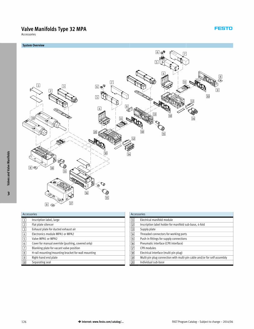
FAST Program Catalog – Subject to change – 2014/06126 � Internet: www.festo.com/catalog/...
Valve Manifolds Type 32 MPAAccessories
System Overview
2
3
5
1 67
9
5
76
aJ
aD
aE
aA
aD
aB
aF
aG8
aH8
aB
aC
aA
8
aI
4
4
aJ
aJ
aJ
aE
aE
bJ
8
Accessories
1 Inscription label, large
2 Flat plate silencer
3 Exhaust plate for ducted exhaust air
4 Electronics module MPA1 or MPA2
5 Valve MPA1 or MPA2
6 Cover for manual override (pushing, covered only)
7 Blanking plate for vacant valve position
8 H-rail mounting/mounting bracket for wall mounting
9 Right-hand end plate
aJ Separating seal
Accessories
aA Electrical manifold module
aB Inscription label holder for manifold sub-base, 4-fold
aC Supply plate
aD Threaded connectors for working ports
aE Push-in fittings for supply connections
aF Pneumatic interface (CPX interface)
aG CPX modules
aH Electrical interface (multi-pin plug)
aI Multi-pin plug connection with multi-pin cable and/or for self-assembly
bJ Individual sub-base
Valv
es a
nd V
alve
Man
ifol
ds
3

2014/06 – Subject to change – FAST Program Catalog 127� Internet: www.festo.com/catalog/...
Valve Manifolds Type 10 CPV, Compact PerformanceOverview
� Width 10/14 mm, flow rate up to 800 l/min
� Maximum flow with minimum space requirement
� Mounting on site: short tubing lengths, short cycle times
� Extensive range of valve functions, comprehensive electrical
connection concept, extensive electrical networking possible
� Pneumatic multiple connector plate for machine mounting and
control cabinet
Key Features
Innovative Flexible Reliable Easy to mount
� Cubic design for exceptional
performance and low weight
� Low installation and bus connection
costs
� Decentralized machines and system
structures, for example
– in handling technology
– in conveyor technology
– in the packaging industry
– in sorting systems
– in upstream machine functions
� Integrated diagnosis, condition
monitoring (Fieldbus Direct)
� Flexible and cost-effective connection
of 2 to 8 valve slices
� Highly flexible thanks to:
– various pneumatic functions (valve
variants)
– different pressure ranges
– vacuum switches
– integrated vacuum generation
– relay plates with floating electrical
outputs
� Separator plates for the formation of
pressure zones
� Blanking plates for future expansion
� LED displays
� Manual valve overrides
� Protection class to IP65
� CE, UL symbol
� Ready-to-install unit, already
assembled and tested
� Lower costs for selection, ordering,
assembly and commissioning
� Secure wall mounting or H-rail
mounting
� Pneumatic multi-connector plate –
fast assembly without the need to
replace fitted tubing
� Assembly optimized for control
cabinets
Valve Types
M 5/2-way single solenoid valve
J 5/2-way valve, double solenoid
N 2x 3/2-way valve, normally open
C 2x 3/2-way valve, normally closed
H 2x 3/2-way valve,
– 1x normally open,
– 1x normally closed
G 5/3-way valve, mid-position closed
D 2x 2/2-way valve, normally closed
I 2x 2/2-way valve,
– 1x normally open,
– 1x normally closed
F 5/2-way single solenoid valve,
fast-switching
A Vacuum generator
E Vacuum generator with
ejector pulse
P One-way flow control valve,
2x supply air
Q One-way flow control valve,
2x exhaust air
V One-way flow control valve
for vacuum
T Plate with duct separation 1/11
closed
S Plate with duct separation 1/11
and 3/5 closed
L Vacant position
R Relay plate
Contents
– Options Overview � 128
– Technical Data � 130
– Ordering Data � 132
– Accessories Overview � 133
Valv
es a
nd V
alve
Man
ifol
ds
3
Detailed product information � www.festo.com/catalog/cpv
Note: All metric products can be used within inch tubing systems via hybrid fittings (� Overview on page 240)

FAST Program Catalog – Subject to change – 2014/06128 � Internet: www.festo.com/catalog/...
Valve Manifolds Type 10 CPV, Compact PerformanceOverview
Advantages at a Glance
The CPV valve terminal is of unique
design. It permits the flexible
combination of pneumatic performance,
electrical connection technologies and a
wide range of mounting options. The
generously sized flow ducts and
powerful flat plate silencers ensure high
flow rates. This means that even
comparatively large pneumatic cylinders
can be driven with ease.
All valves are in the form of valve slices.
They are optimized for flow performance
and are also extremely compact. Two
functions per valve slice
(e.g. 2x 3/2-way valves) mean that twice
the component density can be achieved.
This saves space and reduces costs.
The cubic design permits exceptional
performance yet a comparatively low
weight. The benefits of this design are
obvious when the valve terminal is used
on a moving installation.
However robustness must not be
sacrificed in favor of compactness. The
connecting thread and mounting
attachments are metallic.
The manual override for the valves can
be adapted for different operating
situations. If, for example, a detenting
manual override is required for
setting-up mode, the manual override
can be easily converted for that
application in a way that rules out
operational errors. The clear, large
labelling system also contributes to the
safe operation of the valve terminal.
A particular plus is the range of
electrical connection technologies
supported. All types of valve activation
are possible, from individual valve
connections up to bus systems with
versatile expansion options. The
integration of electrical input and
output modules permits cost-effective
solutions within the different
installation concepts.
Made-to-measure pneumatics Variable compressed air supply Easy assembly technology
� Exceptional performance and low
weight
� Blanking plates for future expansion
� LED displays
� Manual valve overrides
� Low installation and bus connection
costs
� Protection class to IP65
� Variable compressed air supply that
can be adapted to the relevant
requirements
� Modules for additional compressed
air supply and exhaust
� Choice of assembly on H-rail or
profile/backwall
� Adaptable assembly with connectors
for different tubing diameters
Design Principle
The cubic design provides a clearly
assigned function on each side. Thus,
for example, the electrical connection is
mounted on the top surface. An optional
inscription label holder can be placed
on the front of the valve terminal. The
different combination options ensure
the optimum solution for the task at
hand.
� Pneumatic supply connections on the
left, right or underneath
� Pneumatic working ports and
functional modules (vertical stacking)
underneath
� Manual operation/identification on
the front
� Electrical connection surface on the
top
� Mounting surface at the back or even
at the front via a pneumatic
multi-connector plate
Valves
CPV valves are integrated sub-base
valves, i.e. in addition to the valve
function they contain all of the
pneumatic ducts for supply, exhaust
and the working ports. The supply ducts
are a central component of the valve
slices and allow a direct flow of air
through the valve slices.
This helps achieve maximum flow rates.
All valves have pneumatic pilot control
for optimising performance. The valve
function is based on a piston spool
system with a patented sealing principle
that guarantees its suitability for a wide
range of applications as well as a long
service life.
The pneumatic components and
functions are always identical for all
actuator types. Most functions are also
available in the various valve sizes
(spacing). Restrictions are noted where
applicable.
Pressure zones
Different pressures at port 1 and 11
result in two pressure levels per valve.
This means, for example, that a cylinder
drive can be extended with high
pressure and retracted with low
pressure to save energy.
The maximum number of pressure
zones possible is determined by the
combination of the following
components:
� Use of a separator plate
� End plate pair type
� Valve slice type
You can divide the CPV valve terminal
into 2 to 4 pressure zones by using
separator plates.
Valv
es a
nd V
alve
Man
ifol
ds
3

2014/06 – Subject to change – FAST Program Catalog 129� Internet: www.festo.com/catalog/...
Valve Manifolds Type 10 CPV, Compact PerformanceOverview
Electrical Connection Options
General Current reduction
Contacts which are fitted on the top of
the valve slice form the interface for
various electrical connection options.
The electrical connection is attached
from above using four screws.
This means that the valve terminal can
be adapted to different electrical
requirements or fieldbus protocols
using the same pneumatic part.
CPV10/14 valves are activated by
means of an integrated current
reduction circuit, which reduces power
consumption and heat build-up. This
current reduction circuit is integrated in
the electrical interface unit (multi-pin
plug or fieldbus connection) or in the
individual connecting cable.
During switch-off, the voltage peaks are
limited to 38 V DC.t [ms]
I [m
A]
Multi-pin plug connection
Control signals from the controller to
the valve terminal are transmitted via a
pre-assembled multi-wire cable, which
substantially reduces installation time.
This valve terminal can be equipped
with 4 to 16 solenoid coils (4, 6 or
8 valve slices).
Fieldbus Direct
Fieldbus Fieldbus Direct is a system for the
compact connection of a CPV, CPV-SC,
CPA-SC or CDVI valve terminal to
different fieldbus standards such as
Profibus and DeviceNet.
The fieldbus node is directly integrated
in the electrical actuation of the valve
terminal and therefore takes up only a
minimal amount of space.
The CP string extension option allows
the functions and components of the
CPI installation system to be used.
Instead of an output module with
8 digital outputs, a valve terminal with
4, 6 or 8 valve slices (4 to 16 solenoid
coils per terminal) can be used.
Pneumatic Connection
The working ports are located directly in
the valve slices. Threaded connections
and Quick Star push-in fittings (QS) are
available for different tubing sizes.
The supply ports are located in the end
plates or in the pneumatic
multi-connector plate.
Push-in fittings are available fully
assembled.
The following working ports can be
selected (values in brackets apply for
CPV 14):
– QS-6(8) push-in fittings: Code A
– QS-4(6) push-in fittings: Code B
– Threaded connections M7(GÁ):
Code C
– QS ¼(Ä) Push-in fittings: Code D
– QS Â(¼) Push-in fittings: Code E
Valv
es a
nd V
alve
Man
ifol
ds
3

FAST Program Catalog – Subject to change – 2014/06130 � Internet: www.festo.com/catalog/...
Valve Manifolds Type 10 CPV, Compact PerformanceTechnical Data
Valve Terminal with Multi-pin Plug or Fieldbus Connection
Flow rate:
� CPV10: 400 l/min
� CPV14: 800 l/min
Valve width:
� CPV10: 10 mm
� CPV14: 14 mm
Voltage:
� 24 V DC
Materials
Basic electrical unit: Die-cast
aluminum, polyamide, nitrile rubber
Valve slices: Die-cast aluminum
Valve module 5/3G: Cast aluminum,
polyacetate
Blanking plate/separator plate:
Polyamide
End plates: Die-cast aluminum
Flat plate silencer: Die-cast aluminum,
polyethylene
Pneumatic multi-connector plate:
Wrought aluminum alloy
Inscription label holder: Polyacetate,
polyvinyl chloride
Seal: Nitrile rubber
General Technical Data
Size
10 14
Constructional design Piston slide
Width [mm] 10 14
Nominal size [mm] 4 6
Lubrication Lubrication for life, PWIS-free (free of paint-wetting impairment substances)
Type of mounting Via pneumatic multi-connector plate
Via backwall
On H-rail
Standard nominal flow rate [l/min] 400 800
Pneumatic connections
Pneumatic connection Via end plate
Supply port 1/11 Gx G¼
Exhaust port 3/5 Gy (G¼)1) G½ (Gy)1)
Working ports 2/4 M7 Gx
Pilot air port 12/14 M5 (M7)1) G¼
Pilot exhaust air port 82/84 M5 (M7)1) Gx
Electrical connection
Operating voltage [V] 24 DC (+10/–15%) 24 DC (+10/–15%)
Electrical power
consumption
[W] 0.6 (0.45 at 21 V);
(0.65 with CPV10-M11H-…)
0.9 (0.65 at 21 V)
1) Connection dimensions in brackets for pneumatic multi-connector plate
Valv
es a
nd V
alve
Man
ifol
ds
3

2014/06 – Subject to change – FAST Program Catalog 131� Internet: www.festo.com/catalog/...
Valve Manifolds Type 10 CPV, Compact PerformanceTechnical Data
Valve Response Times [ms]
Valve function order code M F J N C CY H G D I A E
CPV10
Switching times on 17 13 – 17 17 17 17 20 15 15 – 15
off 27 17 – 25 25 25 25 30 17 17 – 17
changeover – – 10 – – – – – – – – –
CPV14
Switching times on 25 – – 24 24 – 24 22 13 13 – 13
off 35 – – 30 30 – 30 30 16 16 – 16
changeover – – 12 – – – – – – – – –
Operating and Environmental Conditions
Valve function order code M F J N C CY H G D I A E
Operating medium Compressed air in accordance with ISO 8573-1:2010 [7:4:4]
Note on operating/pilot medium Operation with lubricated medium possible (in which case lubricated operation will always be required)
Grade of filtration [μm] 40 (average pore size)
Operating pressure [bar] –0.9 … +10 +0.1 … +10 –0.9 … +10
Operating pressure
for valve terminal with internal
pilot air supply
[bar] 3 … 8
Pilot pressure [bar] 3 … 8
Ambient temperature [°C] –5 … +50 (vacuum generators: 0 … +50)
Storage temperature [°C] –20 … +40
Relative air humidity at 25 °C [%] 95 with no condensation
Corrosion resistance class CRC1) 2 1
1) Corrosion resistance class 2 as per Festo standard 940 070
Components subject to moderate corrosion stress. Externally visible parts with primarily decorative surface requirements which are in direct contact with a normal industrial environment or media such as coolants or lubricat
ing agents.
Valv
es a
nd V
alve
Man
ifol
ds
3

FAST Program Catalog – Subject to change – 2014/06132 � Internet: www.festo.com/catalog/...
Valve Manifolds Type 10 CPV, Compact PerformanceOrdering Data
Valve Terminal Configurator
A valve terminal configurator is
available to help you select a suitable
valve terminal CPV. This makes it much
easier for you to find the right product.
The valve manifolds are fully assembled
according to your order specifications
and individually tested. This reduces
assembly and installation time to a
minimum.
You order a valve terminal type 10 using
the order code.
Ordering system for type 10
� Internet: cpv
Ordering system, CPX
� Internet: cpx
The illustration above provides an
example of a valve terminal
configuration.
The following steps explain how you
arrive at the order code:
Once you have called up
www.festo.com/us, click on “Products”
tab and then select the “Catalog” tab on
the left hand side of the “Products”
page.
Now select “Valve Manifolds” and then
“Valve Manifolds”. Select your desired
valve terminal (in this case CPV) and
then finally click on link of the product
with the desired actuation methodology.
You can then configure the valve
terminal step by step (from left to right)
according to your requirements.
Now click on the “Add to basket” option
to save the selected configuration (this
will not trigger an order).
2D/3D CAD Data
You can request the CAD data for a
valve terminal you have configured by
selecting the “2D/3D view” option
under the “Add to basket option” in the
valve terminal configurator. You can
generate a 3D preview or request an
email or download of a CAD model in
the format of your choice.
Valv
es a
nd V
alve
Man
ifol
ds
3
Lead Time LT for all configurable options on this page: 3D typically ships within 3 days

2014/06 – Subject to change – FAST Program Catalog 133� Internet: www.festo.com/catalog/...
Valve Manifolds Type 10 CPV, Compact PerformanceAccessories
System Overview
9
2
5
4
6
7
8
3
1
aJ
aA
aB
aC
Accessories
1 Basic electrical unit (Fieldbus Direct, CPI installation system, AS-interface,
multi-pin plug connection)
2 Right-hand end plate with flat plate silencer
3 Comprehensive valve functions
4 Right-hand end plate (threaded connections not in combination with
pneumatic multi-connector plate)
5 Inscription label holder
6 QS push-in fittings
Accessories
7 Functional module (vertical stacking)
8 Pneumatic multi-connector plate
9 Left-hand end plate (threaded connections not in combination with
pneumatic multi-connector plate)
aJ Left-hand end plate with flat plate silencer
aA Attachment for H-rail
aB Attachment for wall mounting
aC Plug for electrical connection
Valv
es a
nd V
alve
Man
ifol
ds
3

FAST Program Catalog – Subject to change – 2014/06134 � Internet: www.festo.com/catalog/...
Valve Manifolds Type 44 VTSA, Type 45 VTSA-F – Inch SeriesOverview
� Modular multi-functional valve manifold for up to 32 valves:
– Type 44 VTSA, ISO 15407-2/ISO 5599-2
– Type 45 VTSA-F with optimized flow
� Different valve sizes on one valve manifold:
– 0.71 in (ISO 02)
– 1.02 in (ISO 01)
– 1.65 in (IS0 1), type 44 VTSA only
– 2.05 in (IS0 2), type 44 VTSA only
� Flow rate: up to 102 scfm
� Pneumatic connections with threaded connector or QS fitting
� Design optimized for electrical peripherals CPX
Product Range Overview
Electrical connection Valve types
5/2-
way
val
ve, s
ingl
e so
leno
id
with
pne
umat
ic s
prin
g re
turn
5/2-
way
val
ve, s
ingl
e so
leno
id
with
spr
ing
retu
rn
5/2-
way
val
ve, d
oubl
e
sole
noid
5/2-
way
val
ve, d
oubl
e so
leno
id
dom
inan
t sw
itchi
ng
2x 3
/2-w
ay v
alve
,
norm
ally
ope
n
2x 3
/2-w
ay v
alve
,
norm
ally
clo
sed
2x 3
/2-w
ay v
alve
: 1x
norm
ally
open
, 1x
norm
ally
clo
sed
5/3-
way
val
ve,
mid
-pos
ition
pre
ssur
ized
5/3-
way
val
ve,
mid
-pos
ition
clo
sed
5/3-
way
val
ve,
mid
-pos
ition
exh
aust
ed
2x 3
/2-w
ay v
alve
, nor
mal
ly
open
, rev
erse
ope
ratio
n
2x 3
/2-w
ay v
alve
, nor
mal
ly
clos
ed, r
ever
se o
pera
tion
2x 3
/2-w
ay v
alve
:
1x n
orm
ally
ope
n, 1
x no
rmal
ly
clos
ed, r
ever
se o
pera
tion
Blan
king
pla
te fo
r vac
ant
posi
tion
M O J D N K H B G E P Q R L
Electrical multi-pin plug connection,
CageClamp� � � � � � � � � � � � � �
Electrical multi-pin plug connection,
Sub-D (37-pin)� � � � � � � � � � � � � �
Fieldbus connection/control block� � � � � � � � � � � � � �
Key Features
Multi-pin plug manifold Fieldbus manifold/control block Comprehensive Combinable
� Max. 32 valve positions/
max. 32 solenoid coils
� Parallel modular valve linking via
circuit boards
� Any compressed-air supply
� Any number of pressure zones
� Max. 32 valve positions/
max. 32 solenoid coils
� Any compressed-air supply
� Any number of pressure zones
� Width 0.71 in (ISO Size 02):
valve flow rate up to 24.7 scfm
� Width 1.02 in (ISO Size 01):
valve flow rate up to 49.4 scfm
� Width 1.65 in (ISO Size 1):
valve flow rate up to 53 scfm
� Width 2.05 in (ISO Size 2):
valve flow rate up to 102 scfm
� Width 0.71 in (Size 02), 1.02 in
(Size 01), 1.65 in (Size 1) and 2.05 in
(Size 2) can be combined on a single
valve manifold
Contents
– Options Overview � 135
– Technical Data � 137
– Ordering Data � 140
– Accessories Overview � 148
Valv
es a
nd V
alve
Man
ifol
ds
3
Detailed product information � www.festo.com/catalog/vtsa

2014/06 – Subject to change – FAST Program Catalog 135� Internet: www.festo.com/catalog/...
Valve Manifolds Type 44 VTSA, Type 45 VTSA-F – Inch SeriesOverview
Flexible Easily Integrated Comprehensive Installation and Maintenance
� Easy modification and expansion due
to high degree of modularity. Fast
connection of the subbases by means
of four screws.
� Fully modular system allows the
combination of 0.71 in (Size 02), 1.02
in (Size 01), 1.65 in (Size 1) and
2.05 in (Size 2) valves on the same
manifold without the need for any
transition/adapter plate.
� Change direction of working ports
with easy-to-install angle plate.
� Fieldbus valve manifold suitable for
CPX electrical peripherals.
� Fieldbus nodes: Interbus, DeviceNet,
Profibus DP, CANopen, CC-Link via
CPX terminal
� Ethernet: Modbus/TCP, EtherNet/IP,
TCP/IP via CPX terminal
� Full complement of CPX I/O modules
� Expandable up to 32 solenoid coils
� Integration of a wide range of function
modules possible
� Supply plates permit a flexible air
supply and variable pressure zones
� High-performance valves in a sturdy
metal housing
� Complete range of vertical sandwich
components such as pressure
regulators, flow control valve,
individual pressure supply, shutoff
plate (hot swap).
� Standard air qualities: 40 micron
filtration grade. Can be used with
lubricated or non-lubricated air, and
inert gases.
� Manual override available, with
momentary, locking, or hidden
(non-accessible) options.
� Ready-to-install unit, preassembled
and tested
� Durable, low cost identification by
label holder on the valve or label
holder on the subbase.
� Secure wall mounting or DIN rail
mounting
� Fast troubleshooting thanks to LEDs
on the valves and diagnosis via
fieldbus.
� Reliability of service thanks to valves
that can be replaced easily and
quickly.
� Easy fault identification using
CPX-MMI handheld diagnostic unit.
Electrical Connection Options
Multi-pin plug connection
Control signals from the controller to
the valve manifold are transmitted via
a pre-assembled multi-core cable or a
self-assembled multi-pin plug
connection (Cage Clamp), which
substantially reduces installation time.
The valve manifolds can be fitted with
max. 32 valves and max. 32 solenoid
coils.
Variants
� Multi-pin plug connection with
manifold strip (Cage Clamp)
24 V DC or 110 V AC
� Pre-assembled connecting cable
24 V DC
� Sub-D plug connector for fitting
by users, 37-pin
Fieldbus connection via the CPX system Fieldbus Variants
An integrated fieldbus node manages
the communication connection to a
higher-order PLC. This enables a
space-saving pneumatic and electronic
solution.
Valve manifolds with fieldbus interfaces
can be configured with up to 16
manifold subbases. With 2 solenoid
coils per connection, up to 32 solenoid
coils can thus be actuated.
� Profibus-DP
� ProfiNet
� Interbus
� DeviceNet connection
� CANopen
� CC-Link
� Ethernet/IP
� EtherCAT
� Front End Controller Remote
� Front End Controller
� Remote I/O
� Modbus/TCP
� Profinet IO
� CPX-Terminal
� www.festo.com/catalog/cpx
Control block connection via the CPX system
Controllers integrated in the Festo
valve manifolds permit the construction
of stand-alone control units to IP65,
without control cabinets.
Using the slave operation mode,
these valve manifolds can be used for
intelligent pre-processing and are
therefore ideal modules for designing
decentralized intelligence.
In the master operation mode, manifold
groups can be designed with many
options and functions, which can
autonomously control a medium-sized
machine/system.
� CPX manifold
� www.festo.com/catalog/cpx
Valv
es a
nd V
alve
Man
ifol
ds
3

FAST Program Catalog – Subject to change – 2014/06136 � Internet: www.festo.com/catalog/...
Valve Manifolds Type 44 VTSA, Type 45 VTSA-F – Inch SeriesOverview
Modular Pneumatic Components
The modular design of the VTSA/VTSA-F
facilitates maximum flexibility right
from the planning stage and offers
maximum ease of service in operation.
The system consists of manifold
subbases and valves.
The manifold subbases are screwed
together and thus form the support
system for the valves.
Inside, the manifold subbases contain
the connection ducts for supplying
compressed air to and venting from the
valve manifold as well as the working
ports for the pneumatic cylinders from
each valve.
Each manifold subbase is connected to
the next using four screws.
Individual manifold sections can be
isolated and further blocks inserted by
loosening these screws. This ensures
that the valve manifold can be rapidly
and reliably expanded.
Modularity in the basic system Modularity in the valves
Modular Electrical Peripherals
The manner in which the valves are
actuated differs according to whether
you are using a multi-pin manifold or
fieldbus manifold.
The VTSA/-VTSA-F with CPX interface is
based on the internal bus system of the
CPX and uses this communication
system for all solenoid coils and a range
of electrical input and output functions.
Parallel linking facilitates the following:
� Transmission of switching
information
� High valve density
� Compact design
� Position-based diagnosis
� Separate voltage supply for valves
� Flexible conversion without address
shifting
� Transmission of status, parameter
and diagnostic data
VTSA with electrical peripherals CPX Modularity with electrical peripherals CPX
Valv
es a
nd V
alve
Man
ifol
ds
3

2014/06 – Subject to change – FAST Program Catalog 137� Internet: www.festo.com/catalog/...
Valve Manifolds Type 44 VTSA, Type 45 VTSA-F – Inch SeriesTechnical Data
Flow rate
� Width 0.71 in: Up to 24.7 scfm
� Width 1.02 in: Up to 49.4 scfm
� Width 1.65 in: Up to 53 scfm
� Width 2.05 in: Up to 102 scfm
Valve width
� ISO Size 02: 0.71 in (18 mm)
� ISO Size 01: 1.02 in (26 mm)
� ISO Size 1: 1.65 in (42 mm)
� ISO Size 2: 2.05 in (52 mm)
Voltage
� 24 V DC
� 110 V AC
General Technical Data
Width 0.71 in 1.02 in 1.65 in (type 44 VTSA only) 2.05 in (type 44 VTSA only)
Design Electromagnetically actuated piston spool valve
Lubrication Lubrication for life
Type of mounting Wall mounting
On DIN H-rail to EN 60715
Mounting position Any
Manual override Pushing, pushing/detenting, covered
Pneumatic connections NPT thread
Pneumatic connection Via manifold subbase
Supply port 1 ½ NPT, QS-½-½-U, QS-½-Æ-U ¾NPT, N-¾-P-19-NPT
Exhaust port 3/5 ½ NPT, QS-½-½-U, QS-½-Æ-U ¾NPT, N-¾-P-19-NPT
Working ports 2/4 x NPT,
QS-x-¼-U,
QS-x-Ä-U
¼ NPT,
QS-¼-Ä-U,
QS-¼-y-U
y NPT,
QS-y-y-U,
QS-y-½-U
½ NPT,
QS-½-½-U
Port for external pilot
supply air
14 ¼ NPT
Pilot exhaust air port 12 ¼ NPT
Certification •
Operating and Environmental Conditions
Valve function order code M O J D N K H B G E P Q R
Operating medium Compressed air in accordance with ISO 8573-1:2010 [7:4:4]
Note on operating/pilot medium Operation with lubricated medium possible (in which case lubricated operation will always be required)
Grade of filtration [μm] 40 (average pore size)
Operating pressure Pilot pressure [psi] 44 … 147
With internal pilot air [psi] 44 … 147
With external pilot air [psi] –13.2 … +147 44 … 147 –13.2 … +147
Ambient temperature [°F] 23 … 122
Temperature of medium [°F] 23 … 122
Storage temperature1) [°F] –4 … +104
Relative air humidity [%] 90
1) Long-term storage
Valv
es a
nd V
alve
Man
ifol
ds
3

FAST Program Catalog – Subject to change – 2014/06138 � Internet: www.festo.com/catalog/...
Valve Manifolds Type 44 VTSA, Type 45 VTSA-F – Inch SeriesTechnical Data
Standard Nominal Flow Rate [scfm] – Type 44 VTSA
Valve function order code M O J D N K H B G E P Q R
Width 0.71 in
Flow rate of valve 26.5 21.2 24.71), 15.22) 21.2
Flow rate of valve on individual subbase 21.2 17.7 19.41), 12.72) 17.7
Flow rate of valve on valve manifold 19.4 14.1 15.91), 10.62) 14.1
Width 1.02 in
Flow rate of valve 49.4 44.1 49.41), 35.32) 44.1
Flow rate of valve on individual subbase 42.4 38.8 42.41), 30.02) 35.3
Flow rate of valve on valve manifold 38.8 31.8 35.31), 24.72) 31.8
Width 1.65 in
Flow rate of valve 63.5 49.4 60.01), 26.52) 49.4
Flow rate of valve on individual subbase 45.9 42.4 42.41), 28.22) 42.4
Flow rate of valve on valve manifold 53.0 42.4 49.41), 28.22) 42.4
Width 2.05 in
Flow rate of valve 141.2 105.9 1271), 602) 105.9
Flow rate of valve on individual subbase 113 88.3 105.91), 602) 88.3
Flow rate of valve on valve manifold 102.4 84.7 98.81), 602) 84.7
1) Switching position
2) Mid-position
Standard Nominal Flow Rate [scfm] – Type 45 VTSA-F
Valve function order code M O J D N K H B G E P Q R
Width 0.71 in
Flow rate of valve 26.5 21.2 17.71), 11.62) 21.2
Flow rate of valve on valve manifold 24.7 19.4 17.71), 11.62) 19.4
Width 1.02 in
Flow rate of valve 49.4 44.1 49.41), 24.72) 44.1
Flow rate of valve on valve manifold 47.7 40.6 47.71), 24.72) 40.6
1) Switching position
2) Mid-position
Valve Response Times [ms]
Valve function order code M O J D N K H B G E P Q R
Width 0.71 in
Response times on 22 12 – – 12 12 12 15 15 15 25 25 25
off 28 38 – – 30 30 30 44 44 44 12 12 12
changeover – – 11 11 – – – 22 22 22 – – –
Width 1.02 in
Response times on 25 20 – – 20 20 20 22 22 22 32 32 32
off 45 65 – – 38 38 38 65 65 65 30 30 30
changeover – – 18 18 – – – 33 33 33 – – –
Width 1.65 in (type 44 VTSA only)
Response times on 27 22 – – 20 20 20 22 22 22 34 34 34
off 45 60 – – 38 38 38 65 65 65 28 28 28
changeover – – 16 16 – – – – – – – – –
Width 2.05 in (type 44 VTSA only)
Response times on 40 20 – – 20 20 20 30 30 30 50 50 50
off 45 60 – – 35 35 35 100 100 100 65 65 65
changeover – – 18 18 – – – – – – – – –
Valv
es a
nd V
alve
Man
ifol
ds
3

2014/06 – Subject to change – FAST Program Catalog 139� Internet: www.festo.com/catalog/...
Valve Manifolds Type 44 VTSA, Type 45 VTSA-F – Inch SeriesTechnical Data
Electrical Data – VTSA/VTSA-F with CPX Manifold
0.71 in 1.02 in 1.65 in (Type 44 VTSA only) 2.5 in (Type 44 VTSA only)
Voltage supply for electronics/sensors (pin 1)
Operating voltage [V] 24 DC ±10%
Steady state current
consumption at 24 V DC
[mA] 20
Duty cycle 100%
Load voltage supply for valves (pin 2)
Operating voltage [V] 24 DC ±10%
Diagnostic message
undervoltage VOFF, load
voltage outside function range
[V] 21.6 … 21.5
Protection class to EN 60529 IP65 (for all types of signal transmission in assembled state)
Power consumption at 24 V DC
2x 3/2-way valve [W] 1.3 4.6
5/2-way valve, 5/3-way valve [W] 1.6 4.6
Electrical Data – VTSA/VTSA-F with Multi-pin Plug Connection
0.71 in 1.02 in 1.65 in (Type 44 VTSA only) 2.05 in (Type 44 VTSA only)
Load voltage supply for valves
Operating voltage [V] 24 DC ±10%
110 AC ±10% (50 … 60 Hz)
Duty cycle 100%
Protection class to EN 60529 IP65 (for all types of signal transmission in assembled state), NEMA 4
Power consumption at 24 V DC
2x 3/2-way valve [W] 1.3 4.6
5/2-way valve, 5/3-way valve [W] 1.6 4.6
Power consumption at 110 V AC
2x 3/2-way valve [VA] 1
5/2-way valve, 5/3-way valve [VA] 1.6
Materials
0.71 in 1.02 in 1.65 in (Type 44 VTSA only) 2.05 in (Type 44 VTSA only)
Manifold subbase Die-cast aluminum
Valve Die-cast aluminum, reinforced polyamide
Seals Nitrile rubber, elastomer (support made of steel)
Supply plate Die-cast aluminum
Right-hand end plate Die-cast aluminum
Left-hand pneumatic interface Die-cast aluminum
Flow control plate Die-cast aluminum
Pressure regulator plate Die-cast aluminum, reinforced polyamide
Multi-pin connection block Die-cast aluminum
Cover for the pneumatic interface and
multi-pin plug connection
Wellamid, reinforced polyamideVa
lves
and
Val
ve M
anif
olds
3

FAST Program Catalog – Subject to change – 2014/06140 � Internet: www.festo.com/catalog/...
Valve Manifolds Type 44 VTSA, Type 45 VTSA-F – Inch SeriesOrdering Data
Valve Manifold Configurator
A valve manifold configurator is
available to help you select a suitable
VTSA/VTSA-F valve manifold. This makes
it much easier for you to find the right
product.
The valve manifolds are fully assembled
according to your order specifications
and are individually tested. This reduces
the amount of assembly and installation
to a minimum.
You order a valve terminal type 44/45
using the order code.
Ordering system for type 44/45
� Internet: type 44, type 45
Ordering system, CPX
� Internet: cpx
The illustration above provides an
example of a valve terminal
configuration.
The following steps explain how you
arrive at the order code:
Once you have called up
www.festo.com/us, click on “Products”
tab and then select the “Catalog” tab on
the left hand side of the “Products”
page.
Now select “Valve Manifolds” and then
“Industry Standard Valve Manifolds”.
Select your desired valve terminal (in
this case VTSA) and then finally click on
link of the product with the desired
actuation methodology.
You can then configure the valve
terminal step by step (from left to right)
according to your requirements. Now
click on the “Add to basket” option to
save the selected configuration (this will
not trigger an order).
2D/3D CAD Data
You can request the CAD data for a
valve terminal you have configured by
selecting the “2D/3D view” option
under the “Add to basket option” in the
valve terminal configurator. You can
generate a 3D preview or request an
email or download of a CAD model in
the format of your choice.
Valv
es a
nd V
alve
Man
ifol
ds
3
Lead Time LT for all configurable options on this page: 3D typically ships within 3 days

2014/06 – Subject to change – FAST Program Catalog 141� Internet: www.festo.com/catalog/...
Valve Manifolds Type 44 VTSA, Type 45 VTSA-F – Metric SeriesOverview
� Modular multi-functional valve manifold for up to 32 valves:
– Type 44 VTSA, ISO 15407-2/ISO 5599-2
– Type 45 VTSA-F with optimized flow
� Different valve sizes on one valve manifold:
– 18 mm (ISO 02)
– 26 mm (ISO 01)
– 42 mm (IS0 1), type 44 VTSA only
– 52 mm (IS0 2), type 44 VTSA only
� Flow rate: up to 2,900 l/min
� Pneumatic connections with threaded connector or QS fitting
� Design suitable for electrical peripherals CPX
Product Range Overview
Electrical connection Valve types
5/2-
way
val
ve, s
ingl
e so
leno
id
with
pne
umat
ic s
prin
g re
turn
5/2-
way
val
ve, s
ingl
e so
leno
id
with
spr
ing
retu
rn
5/2-
way
val
ve, d
oubl
e
sole
noid
5/2-
way
val
ve, d
oubl
e so
leno
id
dom
inan
t sw
itchi
ng
2x 3
/2-w
ay v
alve
,
norm
ally
ope
n
2x 3
/2-w
ay v
alve
,
norm
ally
clo
sed
2x 3
/2-w
ay v
alve
: 1x
norm
ally
open
, 1x
norm
ally
clo
sed
5/3-
way
val
ve,
mid
-pos
ition
pre
ssur
ized
5/3-
way
val
ve,
mid
-pos
ition
clo
sed
5/3-
way
val
ve,
mid
-pos
ition
exh
aust
ed
2x 3
/2-w
ay v
alve
, nor
mal
ly
open
, rev
erse
ope
ratio
n
2x 3
/2-w
ay v
alve
, nor
mal
ly
clos
ed, r
ever
se o
pera
tion
2x 3
/2-w
ay v
alve
:
1x n
orm
ally
ope
n, 1
x no
rmal
ly
clos
ed, r
ever
se o
pera
tion
Blan
king
pla
te fo
r vac
ant
posi
tion
M O J D N K H B G E P Q R L
Electrical multi-pin plug connection,
CageClamp� � � � � � � � � � � � � �
Electrical multi-pin plug connection,
Sub-D (37-pin)� � � � � � � � � � � � � �
Fieldbus connection/control block� � � � � � � � � � � � � �
Key features
Multi-pin plug manifold Fieldbus manifold/control block Comprehensive Combinable
� Max. 32 valve positions/
max. 32 solenoid coils
� Parallel modular valve linking via
circuit boards
� Any compressed-air supply
� Any number of pressure zones
� Max. 32 valve positions/
max. 32 solenoid coils
� Any compressed-air supply
� Any number of pressure zones
� 18 mm (ISO Size 02): Valve flow rate
up to 550 l/min
� 26 mm (ISO Size 01): Valve flow rate
up to 1,100 l/min
� 42 mm (ISO Size 1):
valve flow rate up to 1,500 l/min
� 52 mm (ISO Size 2):
valve flow rate up to 2,900 l/min
� Width 18 mm (Size 02), 26 mm
(Size 01), 42 mm (Size 1) and 52 mm
(Size 2) can be combined on a single
valve manifold
Contents
– Options Overview � 142
– Technical Data � 144
– Ordering Data � 147
– Accessories Overview � 148
Valv
es a
nd V
alve
Man
ifol
ds
3
Detailed product information � www.festo.com/catalog/vtsa
Note: All metric products can be used within inch tubing systems via hybrid fittings (� Overview on page 240)

FAST Program Catalog – Subject to change – 2014/06142 � Internet: www.festo.com/catalog/...
Valve Manifolds Type 44 VTSA, Type 45 VTSA-F – Metric SeriesOverview
Flexible Easily integrated Comprehensive Installation and maintenance
� Easy modification and expansion due
to high degree of modularity. Fast
connection of the subbases by means
of four screws.
� Fully modular system allows the
combination of 18 mm (Size 02),
26 mm (Size 01), 42 mm (Size 1) and
52 mm (Size 2) valves on the same
manifold without the need for any
transition/adapter plate.
� Change direction of working ports
with easy-to-install angle plate.
� Fieldbus valve manifold suitable for
CPX electrical peripherals.
� Fieldbus nodes: Interbus, DeviceNet,
Profibus DP, CANopen, CC-Link via
CPX terminal
� Ethernet: Modbus/TCP, EtherNet/IP,
TCP/IP via CPX terminal
� Full complement of CPX I/O modules
� Expandable up to 32 solenoid coils
� Integration of a wide range of function
modules possible
� Supply plates permit a flexible air
supply and variable pressure zones
� High-performance valves in a sturdy
metal housing
� Complete range of vertical sandwich
components such as pressure
regulators, flow control valve,
individual pressure supply, shutoff
plate (hot swap).
� Standard air qualities: 40 micron
filtration grade. Can be used with
lubricated or non-lubricated air, and
inert gases.
� Manual override available, with
momentary, locking, or hidden
(non-accessible) options.
� Ready-to-install unit, preassembled
and tested
� Durable, low cost identification by
label holder on the valve or label
holder on the subbase.
� Secure wall mounting or DIN rail
mounting
� Fast troubleshooting thanks to LEDs
on the valves and diagnosis via
fieldbus.
� Reliability of service thanks to valves
that can be replaced easily and
quickly.
� Easy fault identification using
CPX-MMI handheld diagnostic unit.
Electrical connection options
Multi-pin plug connection
Control signals from the controller to
the valve manifold are transmitted via
a pre-assembled multi-core cable or a
self-assembled multi-pin plug
connection (Cage Clamp), which
substantially reduces installation time.
The valve manifolds can be fitted with
max. 32 valves and max. 32 solenoid
coils.
Variants
� Multi-pin plug connection with
manifold strip (Cage Clamp)
24 V DC or 110 V AC
� Pre-assembled connecting cable
24 V DC
� Sub-D plug connector for fitting
by users, 37-pin
Fieldbus connection via the CPX system Fieldbus Variants
An integrated fieldbus node manages
the communication connection to a
higher-order PLC. This enables a
space-saving pneumatic and electronic
solution.
Valve manifolds with fieldbus interfaces
can be configured with up to 16
manifold subbases. With 2 solenoid
coils per connection, up to 32 solenoid
coils can thus be actuated.
� Profibus-DP
� ProfiNet
� Interbus
� DeviceNet connection
� CANopen
� CC-Link
� Ethernet/IP
� EtherCAT
� Front End Controller Remote
� Front End Controller
� Remote I/O
� Modbus/TCP
� Profinet IO
� CPX-Terminal
� www.festo.com/catalog/cpx
Control block connection via the CPX system
Controllers integrated in the Festo
valve manifolds permit the construction
of stand-alone control units to IP65,
without control cabinets.
Using the slave operation mode,
these valve manifolds can be used for
intelligent pre-processing and are
therefore ideal modules for designing
decentralized intelligence.
In the master operation mode, manifold
groups can be designed with many
options and functions, which can
autonomously control a medium-sized
machine/system.
� CPX manifold
� www.festo.com/catalog/cpx
Valv
es a
nd V
alve
Man
ifol
ds
3

2014/06 – Subject to change – FAST Program Catalog 143� Internet: www.festo.com/catalog/...
Valve Manifolds Type 44 VTSA, Type 45 VTSA-F – Metric SeriesOverview
Modular Pneumatic Components
The modular design of the VTSA/VTSA-F
facilitates maximum flexibility right
from the planning stage and offers
maximum ease of service in operation.
The system consists of manifold
subbases and valves.
The manifold subbases are screwed
together and thus form the support
system for the valves.
Inside, the manifold subbases contain
the connection ducts for supplying
compressed air to and venting from the
valve manifold as well as the working
ports for the pneumatic cylinders from
each valve.
Each manifold subbase is connected to
the next using four screws.
Individual manifold sections can be
isolated and further blocks inserted by
loosening these screws. This ensures
that the valve manifold can be rapidly
and reliably expanded.
Modularity in the basic system Modularity in the valves
Modular Electrical Peripherals
The manner in which the valves are
actuated differs according to whether
you are using a multi-pin manifold or
fieldbus manifold.
The VTSA/VTSA-F with CPX interface is
based on the internal bus system of the
CPX and uses this communication
system for all solenoid coils and a range
of electrical input and output functions.
Parallel linking facilitates the following:
� Transmission of switching
information
� High valve density
� Compact design
� Position-based diagnosis
� Separate voltage supply for valves
� Flexible conversion without address
shifting
� Transmission of status, parameter
and diagnostic data
VTSA with electrical peripherals CPX Modularity with electrical peripherals CPX
Valv
es a
nd V
alve
Man
ifol
ds
3

FAST Program Catalog – Subject to change – 2014/06144 � Internet: www.festo.com/catalog/...
Valve Manifolds Type 44 VTSA, Type 45 VTSA-F – Metric SeriesTechnical Data
Flow rate
� Width 18 mm: Up to 700 l/min
� Width 26 mm: Up to 1,400 l/min
� Width 42 mm: Up to 1,500 l/min
� Width 52 mm: Up to 2,900 l/min
Valve width
� ISO Size 02: 18 mm
� ISO Size 01: 26 mm
� ISO Size 1: 42 mm
� ISO Size 2: 52 mm
Voltage
� 24 V DC
� 110 V AC
General Technical Data
Width 18 mm 26 mm 42 mm (type 44 VTSA only) 52 mm (type 44 VTSA only)
Design Electromagnetically actuated piston spool valve
Lubrication Lubrication for life
Type of mounting Wall mounting
On DIN H-rail to EN 60715
Mounting position Any
Manual override Pushing, pushing/detenting, covered
Pneumatic connections Metric threaded connection
Pneumatic connection Via manifold subbase
Supply port 1 G½, QS-G½-12, QS-G½-16 G¾, N-¾-P-19
Exhaust port 3/5 G½, QS-G½-12, QS-G½-16 G¾, N-¾-P-19
Working ports 2/4 Gx, QS-Gx-6, QS-Gx-8 G¼, QS-G¼-8, QS-G¼-10 Gy, QS-Gy-12, QS-Gy-10 G½ , QS-½-12, QS-½-16
Port for external pilot supply air 14 G¼ G¼ G¼ G¼
Pilot exhaust air port 12 G¼ G¼ G¼ G¼
Certification —
Note: This product conforms to ISO 1179-1 and ISO 228-1
Operating and Environmental Conditions
Valve function order code M O J D N K H B G E P Q R
Operating medium Compressed air in accordance with ISO 8573-1:2010 [7:4:4]
Note on operating/pilot medium Operation with lubricated medium possible (in which case lubricated operation will always be required)
Grade of filtration [μm] 40 (average pore size)
Operating pressure Pilot pressure [bar] 3 … 10
With internal pilot air [bar] 3 … 10
With external pilot air [bar] –0.9 … +10 3 … 10 –0.9 … +10
Ambient temperature [°C] –5 … +50
Temperature of medium [°C] –5 … +50
Storage temperature1) [°C] –20 … +40
Relative air humidity [%] 90
1) Long-term storage
Valv
es a
nd V
alve
Man
ifol
ds
3

2014/06 – Subject to change – FAST Program Catalog 145� Internet: www.festo.com/catalog/...
Valve Manifolds Type 44 VTSA, Type 45 VTSA-F – Metric SeriesTechnical Data
Standard Nominal Flow Rate [l/min] – Type 44 VTSA
Valve function order code M O J D N K H B G E P Q R
Width 18 mm
Flow rate of valve 750 600 7001), 4302) 600
Flow rate of valve on individual subbase 600 500 5501), 3602) 500
Flow rate of valve on valve manifold 550 400 4501), 3002) 400
Width 26 mm
Flow rate of valve 1 400 1 250 1 4001), 1 0002) 1 250
Flow rate of valve on individual subbase 1 200 1 100 1 2001), 8502) 1 000
Flow rate of valve on valve manifold 1 100 900 1 0001), 7002) 900
Width 42 mm
Flow rate of valve 1 800 1 400 1 7001), 7502) 1 400
Flow rate of valve on individual subbase 1 300 1 200 1 2001), 8002) 1 200
Flow rate of valve on valve manifold 1 500 1 200 1 4001), 8002) 1 200
Width 52 mm
Flow rate of valve 4 000 3 000 3 6001), 1 7002) 3 000
Flow rate of valve on individual subbase 3 200 2 500 1 2001), 8002) 2 500
Flow rate of valve on valve manifold 2 900 2 400 2 8001), 1 7002) 2 400
1) Switching position
2) Mid-position
Standard Nominal Flow Rate [l/min] – Type 45 VTSA-F
Valve function order code M O J D N K H B G E P Q R
Width 18 mm
Flow rate of valve 750 600 5001), 3302) 600
Flow rate of valve on valve manifold 700 550 5001), 3302) 550
Width 26 mm
Flow rate of valve 1 400 1 250 1 4001), 7002) 1 250
Flow rate of valve on valve manifold 1 350 1 150 1 3501), 7002) 1 150
1) Switching position
2) Mid-position
Valve Response Times [ms]
Valve function order code M O J D N K H B G E P Q R
18 mm
Response times on 22 12 – – 12 12 12 15 15 15 25 25 25
off 28 38 – – 30 30 30 44 44 44 12 12 12
changeover – – 11 11 – – – 22 22 22 – – –
26 mm
Response times on 25 20 – – 20 20 20 22 22 22 32 32 32
off 45 65 – – 38 38 38 65 65 65 30 30 30
changeover – – 18 18 – – – 33 33 33 – – –
42 mm (type 44 VTSA only)
Response times on 27 22 – – 20 20 20 22 22 22 34 34 34
off 45 60 – – 38 38 38 65 65 65 28 28 28
changeover – – 16 16 – – – – – – – – –
52 mm (type 44 VTSA only)
Response times on 70 25 – – 35 35 35 30 30 30 50 50 50
off 90 110 – – 70 70 70 100 100 100 65 65 65
changeover – – 18 18 – – – – – – – – –
Valv
es a
nd V
alve
Man
ifol
ds
3

FAST Program Catalog – Subject to change – 2014/06146 � Internet: www.festo.com/catalog/...
Valve Manifolds Type 44 VTSA, Type 45 VTSA-F – Metric SeriesTechnical Data
Electrical Data – VTSA/VTSA-F with CPX Manifold
18 mm 26 mm 42 mm (Type 44 VTSA only) 52 mm (Type 44 VTSA only)
Voltage supply for electronics/sensors (pin 1)
Operating voltage [V] 24 DC ±10%
Steady state current consumption at
24 V DC
[mA] 20
Duty cycle 100%
Load voltage supply for valves (pin 2)
Operating voltage [V] 24 DC ±10%
Diagnostic message undervoltage VOFF,
load voltage outside function range
[V] 21.6 … 21.5
Protection class to EN 60529 IP65 (for all types of signal transmission in assembled state)
Power consumption at 24 V DC
2x 3/2-way valve [W] 1.3 4.6
5/2-way valve, 5/3-way valve [W] 1.6 4.6
Electrical Data – VTSA/VTSA-F with Multi-pin Plug Connection
18 mm 26 mm 42 mm (Type 44 VTSA only) 52 mm (Type 44 VTSA only)
Load voltage supply for valves
Operating voltage [V] 24 DC ±10%
110 AC ±10% (50 … 60 Hz)
Duty cycle 100%
Protection class to EN 60529 IP65 (for all types of signal transmission in assembled state), NEMA 4
Power consumption at 24 V DC
2x 3/2-way valve [W] 1.3 4.6
5/2-way valve, 5/3-way valve [W] 1.6 4.6
Power consumption at 110 V AC
2x 3/2-way valve [VA] 1
5/2-way valve, 5/3-way valve [VA] 1.6
Materials
18 mm 26 mm 42 mm (Type 44 VTSA only) 52 mm (Type 44 VTSA only)
Manifold subbase Die-cast aluminum
Valve Die-cast aluminum, reinforced polyamide
Seals Nitrile rubber, elastomer (support made of steel)
Supply plate Die-cast aluminum
Right-hand end plate Die-cast aluminum
Left-hand pneumatic interface Die-cast aluminum
Flow control plate Die-cast aluminum
Pressure regulator plate Die-cast aluminum, reinforced polyamide
Multi-pin connection block Die-cast aluminum
Cover for the pneumatic interface and
multi-pin plug connection
Wellamid, reinforced polyamide
Valv
es a
nd V
alve
Man
ifol
ds
3

2014/06 – Subject to change – FAST Program Catalog 147� Internet: www.festo.com/catalog/...
Valve Manifolds Type 44 VTSA, Type 45 VTSA-F – Metric SeriesOrdering Data
Valve manifold configurator
A valve manifold configurator is
available to help you select a suitable
VTSA/VTSA-F valve manifold. This makes
it much easier for you to find the right
product.
The valve manifolds are fully assembled
according to your order specifications
and are individually tested. This reduces
the amount of assembly and installation
to a minimum.
You order a valve terminal type 44/45
using the order code.
Ordering system for type 44/45
� Internet: type 44, type 45
Ordering system, CPX
� Internet: cpx
The illustration above provides an
example of a valve terminal
configuration.
The following steps explain how you
arrive at the order code:
Once you have called up
www.festo.com/us, click on “Products”
tab and then select the “Catalog” tab on
the left hand side of the “Products”
page.
Now select “Valve Manifolds” and then
“Industry Standard Valve Manifolds”.
Select your desired valve terminal (in
this case VTSA) and then finally click on
link of the product with the desired
actuation methodology.
You can then configure the valve
terminal step by step (from left to right)
according to your requirements. Now
click on the “Add to basket” option to
save the selected configuration (this will
not trigger an order).
2D/3D CAD Data
You can request the CAD data for a
valve terminal you have configured by
selecting the “2D/3D view” option
under the “Add to basket option” in the
valve terminal configurator. You can
generate a 3D preview or request an
email or download of a CAD model in
the format of your choice.Va
lves
and
Val
ve M
anif
olds
3
Lead Time LT for all configurable options on this page: 3D typically ships within 3 days

FAST Program Catalog – Subject to change – 2014/06148 � Internet: www.festo.com/catalog/...
Valve Manifolds Type 44 VTSA, Type 45 VTSA-FAccessories
System Overview – Valve Manifold with Multi-pin Plug Connection
Order code:
� 44E for the electrical components
� 44P for the pneumatic components
� 45P… for the pneumatic components.
High flow rate with optimized
manifold subbases.
Valve manifolds with multi-pin plug
connection can be expanded with up to
32 valves with max. 32 solenoid coils.
The manifold subbases width 18 and
26 mm are prepared for:
� 2 single solenoid valves
� 2 double solenoid valves
The manifold subbases width 42 mm
are prepared for:
� 1 single solenoid valve
� 1 double solenoid valve
depending on the size.
� Double solenoid valve positions can
be equipped with any valve or a
blanking plate.
� Single solenoid valve positions can
only be equipped with single solenoid
valves or a blanking plate.
The following multi-pin plug
connections to IP65 are available:
� 37-pin Sub-D connection (24 V DC):
The connecting cable can be ordered
in lengths of 2.5 m, 5 m and 10 m for
max. 8, 22 or 32 solenoid coils.
� Manifold strip
(24 V DC or 110 V AC)
2
1
aC
34
5
6
aB aEaD
78
9aJ
aA
aF
aCaG
aE
aH
aI
bJ bA bB
bC
bA
7
bD
bF
bE
bB
bB
bF
bB
bG
bHbB
bFbB
bI
cJcAcB
Valv
es a
nd V
alve
Man
ifol
ds
3

2014/06 – Subject to change – FAST Program Catalog 149� Internet: www.festo.com/catalog/...
Valve Manifolds Type 44 VTSA, Type 45 VTSA-FAccessories
System Overview – Valve Manifold with Multi-pin Plug Connection
Brief description
1 Inscription labels Large, for multi-pin plug connection
2 Multi-core cable –
3 Exhaust plate Ports 3 and 5 separated
4 Fittings For supply plate
5 Silencer For supply plate
6 Exhaust port cover For ducted exhaust air (ports 3 and 5
combined)
7 Duct separation/seal –
8 Manifold subbase For valves with a width of 26 mm
9 Flow control plate –
aJ Vertical supply plate –
aA Vertical shut-off plate –
aB Pressure regulator plate –
aC Cover cap For manual override, pushing, covered
aD Valve Width 26 mm
aE Inscription label holder For valve
aF Blanking plate For unused valve position (vacant position)
aG Valve Width 18 mm
Brief description
aH Valve Width 42 mm (type 44 only)
aI Right-hand end plate –
bJ Silencer For end plate
bA Blanking plugs –
bB Fittings –
bC End plate with pilot air selector –
bD Manifold subbase For valves with a width of 42 mm (type 44
only)
bE Manifold subbase For valves with a width of 18 mm
bF Inscription label holder For supply plate, subbase, 90°
connection plate
bG 90° connection plate –
bH Seals –
bI Silencer –
cJ Supply plate –
cA Multi-pin plug connection Via manifold strip (CageClamp) 24 V DC or110 V AC
cB Multi-pin plug connection With multi-core cable 24 V DC
Valv
es a
nd V
alve
Man
ifol
ds
3

FAST Program Catalog – Subject to change – 2014/06150 � Internet: www.festo.com/catalog/...
Valve Manifolds Type 44 VTSA, Type 45 VTSA-FSystem Overview
System Overview – Valve Manifold with Fieldbus Connection, Control Block (Electrical Peripherals CPX)
Order code:
� 50E-… for the electrical peripherals
� 44P for the pneumatic components
� 45P… for the pneumatic components.
High flow rate with optimized
manifold subbases.
Valve manifolds with fieldbus interface
can be expanded with up to 32 valves
with max. 32 solenoid coils.
Each valve position can be fitted with
any valve or a blanking plate.
The rules for CPX apply to the
equipment that can be used in
combination with the electrical
peripherals CPX.
In general:
� Max. 10 electrical modules
� Digital inputs/outputs
� Analog inputs/outputs
� Parameterisation of inputs and
outputs
� Integrated feature-rich diagnostic
system
� Preventive maintenance concepts
1
aB
23
4
5
aA aDaC
67
89
aJ
aE
aBaF
aD
aG
aH
aI bJ bA
bB
bJ
6
bC
bE
bD
bA
bA
bE
bA
bF
bGbA
bFbA
bH
bI6cJcA
Valv
es a
nd V
alve
Man
ifol
ds
3

2014/06 – Subject to change – FAST Program Catalog 151� Internet: www.festo.com/catalog/...
Valve Manifolds Type 44 VTSA, Type 45 VTSA-FSystem Overview
System Overview – Valve Manifold with Fieldbus Connection, Control Block (Electrical Peripherals CPX)
Brief description
1 Inscription labels Large, for pneumatic interface CPX
2 Exhaust plate Ports 3 and 5 separated
3 Fittings For supply plate
4 Silencer For supply plate
5 Exhaust port cover For ducted exhaust air (ports 3 and 5
combined)
6 Duct separation/seal –
7 Manifold subbase For valves with a width of 26 mm
8 Flow control plate –
9 Vertical supply plate –
aJ Vertical shut-off plate –
aA Pressure regulator plate –
aB Cover cap For manual override, pushing, covered
aC Valve Width 26 mm
aD Inscription label holder For valve
aE Blanking plate For unused valve position (vacant position)
aF Valve Width 18 mm
Brief description
aG Valve Width 42 mm (type 44 only)
aH Right-hand end plate –
aI Silencer For end plate
bJ Blanking plugs –
bA Fittings –
bB End plate with pilot air selector –
bC Manifold subbase For valves with a width of 42 mm (type 44
only)
bD Manifold subbase For valves with a width of 18 mm
bE Inscription label holder For supply plate/subbase/90° connection
plate
bF 90° connection plate –
bG Seals –
bH Silencer –
bI Supply plate –
cJ Pneumatic interface –
cA Fieldbus interface –
Valv
es a
nd V
alve
Man
ifol
ds
3

FAST Program Catalog – Subject to change – 2014/06152 � Internet: www.festo.com/catalog/...
Sensors – OverviewPressure and Vacuum Sensors
Pressure and Vacuum Sensors
Type Operating Pressure Switching Element
Function
Switching Function Electrical Output Pneumatic Connection Lead Time � Page
[bar] Same Day/Next Day
Pressure Switches PEV
1 … 12 N/O Contact – – G¼
�
154
Pressure and Vacuum Switches SDE5
0 … –1 N/O
Switchable
Threshold value with
fixed hysteresis
Window comparator
with fixed hysteresis
Freely programmable
PNP Push-in fitting for
tubing O.D. 4 or 6 mm �
157
0 … 10
�
Pressure Sensors SDE1
0 … 10 Switchable Freely
programmable
PNP
0 … 10 V analog
Male thread Rx, R¼
Female thread Gx
Push-in fitting for
tubing O.D. 4 mm�
160
Pressure Sensors SPAB
–1 … +1 Switchable Freely
programmable
PNP
NPN
1 … 5 V analog
Male thread NPTx-27
and
Female Thread M5
�
164
0 … 10�
Sen
sors
4
Note: All metric products can be used within inch tubing systems via hybrid fittings (� Overview on page 240)

2014/06 – Subject to change – FAST Program Catalog 153� Internet: www.festo.com/catalog/...
Sensors – OverviewActuator Feedback
Actuator Feedback
Type Type of Mounting Measuring Principle Electrical Output Operating Voltage Range Lead Time � Page
Same Day/Next Day
Proximity Switches for T-slot SMT/SME-8M Overview � 168
Insertable from above,
flush with cylinder profile
Magneto-resistive PNP/NPN 10 … 30 V DC
�
169
Magnetic Reed Contacting 5 … 30 V AC/DC
�
170
Proximity Switches for C-slot SMT/SME-10 Overview � 168
Insertable from above,
flush with cylinder profile
Magneto-resistive PNP/NPN 10 … 30 V DC
�
173
Magnetic Reed Contacting 5 … 30 V AC/DC
�
174
Position Transmitter SMAT-8E
Insertable lengthwise Magnetic 0 … 10 V and
0 … 20 mA
15 … 30 V DC
�
176
Position Transmitter SMAT-8M
Insertable lengthwise Magnetic 0 … 10 V 15 … 30 V DC
�
181
Sen
sors
4

FAST Program Catalog – Subject to change – 2014/06154 � Internet: www.festo.com/catalog/...
Pressure Switch PEVOverview
� Mechanical pressure and vacuum switch
with adjustable switching point
� Designs with adjustable hysteresis
� Designs with switching status display
� Variant with scale for pressure adjustment
� Wide range of mounting options
Overview
Method of measurement Operating pressure Type Pneumatic
connection
Type of mounting Operating voltage range
[bar] [V DC] [V AC]
Pneumatic/electrical pressure
transducer
1 … 12 PEV-¼ G¼ With through-holes 0 … 250 0 … 250
Contents
– Technical Data � 155
– Ordering Data � 155
– Accessories � 156
Sen
sors
4
Detailed product information � www.festo.com/catalog/pev
Note: All metric products can be used within inch tubing systems via hybrid fittings (� Overview on page 240)

2014/06 – Subject to change – FAST Program Catalog 155� Internet: www.festo.com/catalog/...
Pressure Switch PEVTechnical Data
Technical Data – Mounting via Through-holes
Materials
Housing: Wrought aluminum alloy
Variants free of copper and PTFE
Technical Data
Type PEV-¼
Design
Pneumatic connection G¼
Electrical data
Operating voltage range [V DC] 0 … 250
[V AC] 0 … 125
Switching element function Changeover switch
Max. output current [mA] 5,000
Protection against short circuit No
Protection against polarity reversal Yes
Protection class IP65
Operating and environmental conditions
Operating medium Compressed air in accordance with ISO 8573-1:2010 [7:–:–]
Water
Mineral oil
Note on operating/pilot medium Operation with lubricated medium possible (in which case lubricated operation will always be required)
Operating pressure [bar] 1 … 12
Ambient temperature [°C] –20 … +80
CE mark (see declaration of conformity) In accordance with EU Low Voltage Directive
Certification CCC
Materials
Housing Wrought aluminum alloy
Ordering Data
Description Electrical connection Adjustable
hysteresis
Visual scale for
pressure adjustment
Plug socket in
scope of delivery
Part No. Type LT
Plug, square design to
DIN 43650, type A� – �
10773 PEV-¼-B 1D
1) Free of copper and PTFE
LT = Lead time 1D typically ships same day/next day 3D typically ships within 3 days
Sen
sors
4

FAST Program Catalog – Subject to change – 2014/06156 � Internet: www.festo.com/catalog/...
Pressure Switch PEVAccessories
Peripherals Overview
3
1
4
2
8
5
aJ
7
6
9
Accessories
1 Pressure switch PEV-¼-B-…, vacuum switch VPEV-Á
2 Pressure switch PEV-¼-B-OD-…
3 Pressure switch PEV-¼-SC-OD-… with scale for pressure adjustment
4 Pressure switch PEV-¼-B-M12, vacuum switch VPEV-Á-M12
5 Plug socket PEV-¼-WD-LED-… with switching status display
Plug socket MSSD-C-4P without switching status display
6 Connecting cable NEBU-M12G5-… with straight socket
7 Connecting cable NEBU-M12W5-… with angled socket
8 Push-in fitting QS-…
9 Mounting plate APL-2N-PEV
aJ Mounting frame NRRQ-2N
Ordering Data – Push-in Fittings
Technical Data � 251
Part No. Type
153003 QS-¼-6
153005 QS-¼-8
Sen
sors
4
Lead Time LT for all products on this page: 1D typically ships same day/next day

2014/06 – Subject to change – FAST Program Catalog 157� Internet: www.festo.com/catalog/...
Pressure Switches SDE5Overview
� Programmable and configurable pressure switch for simple
pressure sensing tasks
� Teach-in function for programming
� Integrated microprocessor
� Operating status indicated by an LED visible from all sides
Overview
Method of
measurement
Pressure measuring
range [bar]
Type Switching function Switching
element function
Pneumatic
connection
Electrical
connection
Piezoresistive
pressure switch
0 … –1 SDE5-V1 Threshold value with fixed hysteresis
Window comparator
Freely programmable
N/O contact
Selectable
QS-4
QS-6
Plug M8x1,
3-pin;
cable, 3-wire0 … 10 SDE5-D10
Contents
– Technical Data � 158
– Ordering Data � 158
– Accessories � 159
Sen
sors
4
Detailed product information � www.festo.com/catalog/sde5
Note: All metric products can be used within inch tubing systems via hybrid fittings (� Overview on page 240)

FAST Program Catalog – Subject to change – 2014/06158 � Internet: www.festo.com/catalog/...
Pressure Switches SDE5Technical Data
Technical Data
e.g. N/O contact, PNP, with plug
Materials
Housing: Polyamide, polyacetate,
reinforced polyphenylene sulphide
General Technical Data
Operating voltage range [V DC] 15 … 30
Max. output current [mA] 100
Switch output PNP
Protection against short circuit Pulsed
Protection against polarity reversal For all electrical connections
Protection class IP40
Operating medium Compressed air in accordance with ISO 8573-1:2010 [7:4:4]
Note on operating/pilot medium Operation with lubricated medium possible (in which case lubricated operation will always be required)
Ambient temperature [°C] 0 … 50
CE mark In accordance with EU EMC directive
Certification c UL us - Recognized (OL)
C-Tick
Information on housing materials Polyacetate, reinforced; polyamide; polyphenylene sulphide, reinforced
Ordering Data
Variant Pressure measuring
range [bar]
Switching
element function
Electrical connection Pneumatic connection Part No. Type LT
At one end At both ends
Threshold value with fixed hysteresis, 1 teach-in pressure
0 … –1 N/O contact Plug, M8x1, 3-pin – QS-4 527457 SDE5-V1-O-Q4-P-M8 1D
– QS-6 527458 SDE5-V1-O-Q6-P-M8 1D
0 … 10 N/O contact Plug, M8x1, 3-pin QS-6 – 527467 SDE5-D10-O-Q6E-P-M8 1D
– QS-6 527464 SDE5-D10-O-Q6-P-M8 1D
Window comparator with fixed hysteresis, 2 teach-in pressures
0 … 10 N/O contact Cable, 3-wire, 1.0 m QS-4 – 547010 SDE5-D10-O3-Q4E-P-K-1.0 1D
Freely programmable
0 … –1 Selectable Plug, M8x1, 3-pin – QS-6 542887 SDE5-V1-FP-Q6-P-M8 1D
LT = Lead time 1D typically ships same day/next day 3D typically ships within 3 days
Sen
sors
4

2014/06 – Subject to change – FAST Program Catalog 159� Internet: www.festo.com/catalog/...
Pressure Switches SDE5Accessories
1
4
3
2
Accessories
1 Pressure switch SDE-5-…-M8 with plug M8x1
2 Pressure switch SDE-5-…-K with cable
3 Linkable wall bracket with clip-in facility for switches (included in the scope
of delivery)
4 Connecting cable NEBU-M8
Ordering Data – Connecting Cables
Technical data � Internet: nebu
Number
of wires
Cable
length [m]
Part No. Type
M8x1, straight socket
3 2.5 541333 NEBU-M8G3-K-2.5-LE3
Sen
sors
4
Lead Time LT for all products on this page: 1D typically ships same day/next day

FAST Program Catalog – Subject to change – 2014/06160 � Internet: www.festo.com/catalog/...
Pressure Sensors SDE1, with DisplayOverview
� Five pressure measuring ranges
� Measurement of relative or differential pressure
� Switch outputs PNP, NPN
and with analog current or voltage output
� LCD or illuminated LCD display
� Wide range of connection and mounting options
Overview
Method of
measurement
Measured variable Pressure measuring
range [bar]
Switching function Pneumatic connection Type of mounting Electrical output
Digital Analog
Piezoresistive
pressure sensor with
display
Relative pressure
Differential and
relative pressure
0 … –1
–1 … +1
0 … 2
0 … 6
0 … 10
Freely programmable Male thread Rx, R¼
Female thread Gx
Push-in fitting for
tubing OD 4 mm
On DIN H-rail
Via wall/surface
bracket
On service unit
Front panel mounting
PNP –
2x PNP –
PNP 0 … 10 V
PNP 4 … 20 mA
2x PNP 4 … 20 mA
NPN –
2x NPN –
NPN 0 … 10 V
NPN 4 … 20 mA
Contents
– Technical Data � 161
– Ordering Data � 162
– Accessories � 163
Sen
sors
4
Detailed product information � www.festo.com/catalog/sde1
Note: All metric products can be used within inch tubing systems via hybrid fittings (� Overview on page 240)

2014/06 – Subject to change – FAST Program Catalog 161� Internet: www.festo.com/catalog/...
Pressure Sensors SDE1, with DisplayTechnical Data
Technical Data
e.g. with 2 switch outputs PNP
Materials
Housing: Polyamide, reinforced
polyacetate
General Technical Data
Design
Pressure measuring range [bar] 0 … 10
Measured variable Relative pressure
Differential pressure
Pneumatic connection Rx
R¼
Gx
QS-4
Type of display Back illuminated LCD
Illuminated LCD
Accuracy FS1) ±2%
Setting options Teach-in
Type of mounting Via DIN H-rail
Via wall/surface bracket
Electrical data
Switch output PNP
NPN
Analog output [V] 0 … 10
Switching element function Switchable
Switching function Freely programmable
Operating voltage range DC [V] 15 … 30
Max. output current [mA] 150
Electrical connection Plug M8x1, round design to EN 60 947-5-2
Protection against short circuit Pulsed
Protection against polarity reversal For all electrical connections
Operating and environmental conditions
Operating medium Compressed air in accordance with ISO 8573-1:2010 [7:4:4]
Note on operating/pilot medium Operation with lubricated medium possible (in which case lubricated operation will always be required)
Ambient temperature [°C] 0 … 50
CE mark (see declaration of conformity) In accordance with EU EMC directive
Protection class IP65
Certification c UL us - Recognized (OL)
C-Tick
Materials
Housing Polyacetate, reinforced, polyamide
1) % FS = % of measuring range’s final value (full scale)
Note: This product conforms to ISO 1179-1 and ISO 228-1
Sen
sors
4

FAST Program Catalog – Subject to change – 2014/06162 � Internet: www.festo.com/catalog/...
Pressure Sensors SDE1, with DisplayTechnical Data
Ordering Data
Variant Pressure
measuring range
[bar]
Switch
output
Analog
output
Electrical connection Type of display Part No. Type LT
Push-in connector QS-4, for DIN H-rail mounting, differential pressure and relative pressure measurement
0 … 10 2x PNP – Plug, M8x1, 4-pin LCD1) 192033 SDE1-D10-G2-HQ4-C-P2-M8 1D
Female thread Gx, for wall or surface mounting, relative pressure measurement2)
0 … 10 PNP 0 … 10 V Plug, M8x1, 4-pin Illuminated LCD 530900 SDE1-D10-G2-W18-L-PU-M8 1D
Male thread Rx, mounting on service unit (D series), relative pressure measurement
0 … 10 PNP – Plug, M8x1, 3-pin LCD1) 192026 SDE1-D10-G2-R18-C-P1-M8 1D
Male thread R¼, mounting on service unit (D series), relative pressure measurement
0 … 10 PNP – Plug, M8x1, 3-pin LCD1) 192028 SDE1-D10-G2-R14-C-P1-M8 1D
1) Back illuminated
2) Adapter plate SDE1-…-W… included in the scope of delivery.
LT = Lead time 1D typically ships same day/next day 3D typically ships within 3 days
Sen
sors
4

2014/06 – Subject to change – FAST Program Catalog 163� Internet: www.festo.com/catalog/...
Pressure Sensors SDE1, with DisplayPeripherals Overview
3
1
5
2
8
4
aJ
7
6
9
aA
3 4
5 6
Accessories
1 Pressure sensor SDE1-…-R14
2 Pressure sensor SDE1-…-H18, SDE1-…-W18
3 Connecting cable NEBU-M12G… with straight socket
4 Connecting cable NEBU-M8G… with straight socket
5 Connecting cable NEBU-M12W… with angled socket
Accessories
6 Connecting cable NEBU-M8W… with angled socket
7 Adapter plate SDE1-…-W-…
8 Mounting rail to DIN EN 60715
9 Safety guard SDE1-SH
aJ Push-in fitting QS-x
Ordering Data – Connecting Cables
Technical data � Internet: nebu
Number
of wires
Cable
length [m]
Part No. Type
M8x1, straight socket
3 2.5 541333 NEBU-M8G3-K-2.5-LE3
4 2.5 541342 NEBU-M8G4-K-2.5-LE4
Ordering Data – Push-in Fittings
Technical data � Internet: quick star
For tubing O.D. [mm] Part No. Type
4 153001 QS-x-4
6 153002 QS-x-6
8 153004 QS-x-8
Sen
sors
4
Lead Time LT for all products on this page: 1D typically ships same day/next day

FAST Program Catalog – Subject to change – 2014/06164 � Internet: www.festo.com/catalog/...
Pressure Sensors SPAB, with DisplayOverview
� Pressure measuring range –1 … +1 or 0 … 10 bar
� Relative pressure measurement
� Pressure supply port NPTÁ-27
� Switch output PNP, NPN and analog output
� Two-part, multi-colored display
� Copy function (settings can be transferred from device to device)
� Simple commissioning thanks to intuitive operation
� Compact design 30x30 mm
Product Range Overview
Method of
measurement
Measured variable Pressure measuring
range [bar]
Switching function Pneumatic connection Electrical output
Male thread Female thread Digital Analog
Piezoresistive
pressure sensor with
display
1x relative pressure –1 … +1 or
0 … 10
Freely programmable NPTx-27 M5 1x PNP 1 … 5 V
2x PNP –
1x NPN 1 … 5 V
2x NPN –
Contents
– Technical Data � 165
– Ordering Data � 165
– Accessories � 166
Sen
sors
4
Detailed product information � www.festo.com/catalog/spab
Note: All metric products can be used within inch tubing systems via hybrid fittings (� Overview on page 240)

2014/06 – Subject to change – FAST Program Catalog 165� Internet: www.festo.com/catalog/...
Pressure Sensors SPAB, with DisplayTechnical Data
e.g. with 1 or 2 switching outputs PNP,
switchable, with cable
Materials
Housing: Reinforced acrylic butadiene
styrene, reinforced polybutylene
terephthalate
General Technical Data
Design
Pressure measuring range [bar] –1 … +1 0 … 10
Measured variable Relative pressure
Pneumatic connection Male thread NPTx-27, Female thread M5
Type of display Multi-colored illuminated LCD
Accuracy FS1) ±1% ±2%
Setting options Via display and buttons; Teach-in
Type of mounting Screw-in; Via accessories
Electrical data
Switch output 2x PNP or 2x NPN 1x PNP or 1x NPN 2x PNP or 2x NPN 1x PNP or 1x NPN
Analog output [V] – 1 … 5 – 1 … 5
Switching element function Switchable
Switching function Freely programmable
Operating voltage range [V DC] 12 … 24
Max. output current [mA] 100
Electrical connection Cable, 4-wire
Protection class IP40
Operating and environmental conditions
Operating medium Compressed air in accordance with ISO 8573-1:2010 [7:4:4]
Note on operating/pilot medium Operation with lubricated medium not possible
Ambient temperature [°C] –10 … +50
CE mark (see declaration of conformity) In accordance with EU EMC directive
Certification UL - Recognized (OL)
C tick
Materials
Housing Reinforced acrylic butadiene styrene, reinforced polybutylene terephthalate
Note on materials Conforms to RoHS
Contains paint wetting impairment substances
1) % FS = % of measuring range (full scale)
Ordering Data
Version Electrical connection Electrical output Pressure measuring range [bar] LT
–1 … +1 0 … 10
Digital Analog Part No. Type Part No. Type
Cable1) 1x PNP 1 … 5 V – – 8000065 SPAB-P10R-N18-PB-L1 1D
2x PNP – – – 8000059 SPAB-P10R-N18-2P-L1 1D
1x NPN 1 … 5 V 8000056 SPAB-B2R-N18-NB-L1 8000068 SPAB-P10R-N18-NB-L1 1D
2x NPN – – – 8000062 SPAB-P10R-N18-2N-L1 1D
1) Connecting cable NEBU-L1… (2.5 m long) included in scope of delivery.
LT = Lead time 1D typically ships same day/next day 3D typically ships within 3 days
Sen
sors
4

FAST Program Catalog – Subject to change – 2014/06166 � Internet: www.festo.com/catalog/...
Pressure Sensors SPAB, with DisplayPeripherals Overview
1
76
5
3
2
4
3
4
8
6
Accessories
1 Mounting bracket SAMH-…-A
2 Adapter plate SASF for sensor SPAB-…-F (Note: not part of the FAST program)
3 Electric adapter SASC-…-A
4 Front panel installation kit SAMH-…-F
Accessories
5 Protective cover SACC
6 Connecting cable NEBU-M8
7 Connecting cable NEBS-L1G4
8 Push-in fitting QSM-M5
Sen
sors
4
Lead Time LT for all products on this page: 1D typically ships same day/next day

2014/06 – Subject to change – FAST Program Catalog 167� Internet: www.festo.com/catalog/...
Pressure Sensors SPAB, with DisplayPeripherals Overview
Ordering Data – Connecting Cables
Technical data � Internet: nebu
Number of
wires
Cable length
[m]
Part No. Type
1 M8x1, straight socket
4 2.5 541342 NEBU-M8G4-K-2.5-LE4
2 Square, straight socket
4 5 572577 NEBS-L1G4-K-5-LE4
1) Included in the scope of delivery with SPAB-…-K1
Ordering Data – Push-in Fittings
Technical Data � 251
Pneumatic
connection
For tubing O.D. Part No. Type
[mm]
3
M5 4 153304 QSM-M5-4
6 153306 QSM-M5-6
Ordering Data – Accessories
Description Part No. Type
4 Mounting bracket
552376 SAMH-P4-A
5 Front panel installation kit
552377 SAMH-P4-F
6 Safety guard
552378 SACC-P4-G
8 Electric adapter
8000326 SASC-P4-A-M8-S
8000326 SASC-P4-A-M8-A
Sen
sors
4
Lead Time LT for all products on this page: 1D typically ships same day/next day

FAST Program Catalog – Subject to change – 2014/06168 � Internet: www.festo.com/catalog/...
Proximity Sensors SMT/SMEOverview
� Versions for T-slot and C-slot
� Switch output contactless or via reed contacts
� Secured with screw or clamped, insertable in the slot from
above or lengthwise
� Suitable for use with energy chains and robots
� Wide range of mounting and connection options
� Free of copper and PTFE
Overview
Design Type of mounting Measuring principle Type Operating voltage
range
Switch output Switching
element function
� Page/
Internet
For T slot Insertable in the slot from above,
flush with the cylinder profile
Magneto-resistive SMT-8M 10 … 30 V DC PNP/NPN N/O contact
N/C contact
169
Magnetic reed SME-8M 5 … 30 V AC/DC Contacting N/O contact 170
For C-slot Insertable in the slot from above,
flush with the cylinder profile
Magneto-resistive SMT-10M 10 … 30 V DC PNP N/O contact 173
Magnetic reed SME-10M 5 … 30 V AC/DC Contacting, bipolar N/O contact 174
Contents
Sensors for T-slot Sensors for C-slot
– SMT-8M � 169 – SMT-10M � 173
– SME-8M � 170 – SME-10M � 174
– Accessories � 171 – Accessories � 175
Sen
sors
4
Detailed product information � www.festo.com/catalog/sm

2014/06 – Subject to change – FAST Program Catalog 169� Internet: www.festo.com/catalog/...
Proximity Sensors SMT-8M, for T-slotTechnical Data – Magneto-resistive
Technical Data – SMT-8M
e.g. N/O contact, PNP, with cable
e.g. N/O contact, NPN, with cable
Materials
Housing: Polyamide
Cable sheath: Polyurethane
Technical Data
Type of mounting Screwed in slot, insertable from above, flush with cylinder profile
Electrical connection Cable, 3-wire Cable with plug, turnable, M8x1, 3-pin
Cable length [m] 0.2 … 30
Cable attribute Standard + Drag chain
Test conditions Standard + Drag Chain Drag chain: 5 million cycles, bending radius 75 mm
Resistance to bending: To Festo standard; test conditions on request
Operating voltage range DC [V] 10 … 30
Max. output current [mA] 100
Max. switching capacity DC [W] 3.0
Protection against short circuit Pulsed
Protection against overloading Yes
Protection against polarity reversal For all electrical connections
Protection class IP65, IP68
Operating and Environmental Conditions
Ambient temperature [°C] –20 … +70
Ambient temperature with flexible
cable installation
[°C] –5 … +70
CE mark (see declaration of conformity) In accordance with EU EMC directive
Certification c UL us - Listed (OL)
C-Tick
Materials
Housing Polyamide; polyurethane; high-alloy stainless steel
Cable sheath Polyurethane
Ordering Data
Switch output Electrical connection Cable length Part No. Type LT
Cable Cable with plug, turnable
M8x1 [m]
N/O contact
PNP 3-wire – 2.5 574335 SMT-8M-A-PS-24V-E-2,5-OE 1D
– 3-pin 0.3 574334 SMT-8M-A-PS-24V-E-0,3-M8D 1D
NPN 3-wire – 2.5 574338 SMT-8M-A-NS-24V-E-2,5-OE 1D
– 3-pin 0.3 574339 SMT-8M-A-NS-24V-E-0,3-M8D 1D
LT = Lead time 1D typically ships same day/next day 3D typically ships within 3 days
Sen
sors
4

FAST Program Catalog – Subject to change – 2014/06170 � Internet: www.festo.com/catalog/...
Proximity Sensors SME-8M, for T-slotTechnical Data – Magnetic reed
Technical Data – SME-8M
e.g. N/O contact, 3-wire, with cable
e.g. N/O contact, 3-wire, with plug
Materials
Housing: Polyamide
Cable sheath: Polyurethane
Technical Data
Type of mounting Screwed in slot, insertable from above, flush with cylinder profile
Electrical connection Cable, 3-wire Cable with plug, turnable, M8x1, 3-pin
Cable length [m] 0.2 … 10
Cable attribute Standard + Drag chain
Test conditions Standard + Drag Chain Drag chain: 5 million cycles, bending radius 75 mm
Resistance to bending: To Festo standard; test conditions on request
Operating voltage range DC [V] 5 … 30
Operating voltage range AC [V] 5 … 30
Max. output current [mA] 500
Max. output current in mounting kits [mA] 80
Max. switching capacity DC [W] 10.0
Max. switching capacity AC [VA] 10.0
Max. switching capacity DC
in mounting kits
[W] 2.4
Max. switching capacity AC
in mounting kits
[VA] 2.4
Protection against short circuit No
Protection against overloading Not available
Protection against polarity reversal No
Protection class IP65, IP68
Operating and Environmental Conditions
Ambient temperature [°C] –20 … +70
Ambient temperature with flexible
cable installation
[°C] –5 … +70
CE mark (see declaration of conformity) In accordance with EU EMC directive
Certification c UL us - Listed (OL)
C-Tick
Materials
Housing Polyamide; polyurethane; high-alloy stainless steel
Cable sheath Polyurethane
Ordering Data
Switch output Electrical connection Cable length Part No. Type LT
Cable Cable with plug, turnable
M8x1 [m]
N/O contact
Contacting, bipolar 3-wire – 2.5 543862 SME-8M-DS-24V-K-2,5-OE 1D
– 3-pin 0.3 543861 SME-8M-DS-24V-K-0,3-M8D 1D
LT = Lead time 1D typically ships same day/next day 3D typically ships within 3 days
Sen
sors
4

2014/06 – Subject to change – FAST Program Catalog 171� Internet: www.festo.com/catalog/...
Proximity Sensors SMT/SME-8, for T-slotPeripherals Overview
aJ
9
2
8
7
3
1
5
4
aC
aB
aG
bA
bE
aD
aF
aEbD
aH
bC
bB
bF
aA
aJ
aA
Mounting Attachments and Accessories
Proximity sensors
1 SMT/SME-8M-…-OE, with cable
2 SMT/SME-8M-…-M…, with cable and plug
3 SMT/SME-8-SL-…, with plug
4 SMT/SME-8-S-…, with cable and plug
5 SMT/SME-8-K-…, with cable
CRSMT-8-K-…, with cable, corrosion-resistant
Connecting cables
7 NEBU-M5…-5-Q3-LE3
8 NEBU-M5…-1-Q3-M8G3
9 NEBU-M5…-1-Q3-M12G4
aJ NEBU-M8G3, SIM-M8-3GD
aA NEBU-M8W3, SIM-M8-3WD
aB NEBU-M12G5, SIM-M12-3GD
aC NEBU-M12W5, SIM-M12-3WD
Mounting Attachments and Accessories
Mounting kits and accessories
aD Mounting kit SMBR-8-8/100-S6, heat-resistant
aE Mounting kit SMBR
aF Mounting kit CRSMB, corrosion-resistant
aG Mounting kit SMB-8-FENG
aH Mounting SMBZ-8-…
– Clip SMBK-8
Drive units
bA Drives with T-slot
bB Round cylinders
bC Round cylinders
bD Round cylinders
bE Standard cylinders DNC, DNCB, DNCKE
bF Drives with tie or mounting rod
Sen
sors
4

FAST Program Catalog – Subject to change – 2014/06172 � Internet: www.festo.com/catalog/...
Proximity Sensors SMT/SME-8, for T-slotAccessories
Ordering Data – Connecting Cables
Technical data � Internet: nebu
Number
of wires
Cable
length [m]
Part No. Type
M8x1, straight socket
3 2.5 541333 NEBU-M8G3-K-2.5-LE3
4 2.5 541342 NEBU-M8G4-K-2.5-LE4
Ordering Data – Mounting Attachments
Technical data � Internet: smbr
For Part No. Type
8 175091 SMBR-8-8
10 175092 SMBR-8-10
12 175093 SMBR-8-12
16 175094 SMBR-8-16
20 175095 SMBR-8-20
25 175096 SMBR-8-25
Sen
sors
4
Lead Time LT for all products on this page: 1D typically ships same day/next day

2014/06 – Subject to change – FAST Program Catalog 173� Internet: www.festo.com/catalog/...
Proximity sensors SMT-10M, for C-slotTechnical Data
Technical data
E.g. PNP, N/O contact, with cable
Materials
Housing: Reinforced polyamide,
high-alloy stainless steel
Cable sheath: Thermoplastic
polyurethane elastomer
Technical data Download CAD data � www.festo.com/us/engineering
Measuring principle Magneto-resistive
Switching output PNP
Switching element function N/O contact
Operating voltage range [V DC] 10 … 30
Max. output current [mA] 100
Type of mounting Secured with screw, insertable in the slot from above
Connection direction In-line
Cable length [m] 0.2 … 30
Max. connecting cable length [m] 30
Length/width/height [mm] 23/3/5
Pin allocation to EN 60947-5-2
M8x1
3-pin Pin Wire colour Allocation
1 Brown +
3 Blue –
4 Black Output
Operating conditions
Ambient temperature [°C] –20 … +70
Ambient temperature with
flexible cable installation
[°C] –20 … +70
Ordering data
Switching output Electrical connection Cable
length
[m]
Weight
[g]
Part No. Type LT
Cable Cable with plug,
rotatable thread
N/O contact
PNP 3-wire – 2.5 16.8 551373 SMT-10M-PS-24V-E-2,5-L-OE 1D
– M8x1, 3-pin 0.3 6.7 551375 SMT-10M-PS-24V-E-0,3-L-M8D 1D
LT = Lead time 1D typically ships same day/next day 3D typically ships within 3 days
Sen
sors
4

FAST Program Catalog – Subject to change – 2014/06174 � Internet: www.festo.com/catalog/...
Proximity sensors SME-10M, for C-slotTechnical Data
Technical data
E.g. N/O contact, 3-wire, with plug
Materials
Housing: Reinforced polyamide,
high-alloy stainless steel
Cable sheath: Polyurethane
Technical data Download CAD data � www.festo.com/us/engineering
SME-10M- DS ZS
Measuring principle Magnetic reed
Switching output Contacting, bipolar
Switching element function N/O contact
Operating voltage range [V DC] 5 … 30
Operating voltage range [V AC] 5 … 30
Max. output current [mA] 300 100
Type of mounting Secured with screw, insertable in the slot from above
Connection direction In-line
Cable length [m] 0.2 … 10
Max. connecting cable length [m] 10
Length/width/height [mm] 27/3/5
Pin allocation to EN 60947-5-2
M8x1
3-pin Pin Wire colour Allocation
1 Brown +
3 Blue –
4 Black Output
Operating conditions
Ambient temperature [°C] –40 … +70
Ambient temperature with
flexible cable installation
[°C] –20 … +70
Ordering data
Switching output Electrical connection Cable
length
[m]
Weight
[g]
Part No. Type LT
Cable Cable with plug,
rotatable thread
N/O contact
Contacting,
bipolar
2-wire – 2.5 14.6 551369 SME-10M-ZS-24V-E-2,5-L-OE 1D
– M8x1, 3-pin 0.3 6.7 551367 SME-10M-DS-24V-E-0,3-L-M8D 1D
LT = Lead time 1D typically ships same day/next day 3D typically ships within 3 days
Sen
sors
4

2014/06 – Subject to change – FAST Program Catalog 175� Internet: www.festo.com/catalog/...
Proximity sensors SMT/SME-10, for C-slotPeripherals Overview
9
aD
aJ
6
5
4
3
2
1
aF
aE
8
7
aB
aA
aC
Mounting attachments and accessories � Page/
Internet
Proximity sensor
1 SMT-10M-…-OE, with cable 173
SME-10M-…-OE, with cable 174
2 SME-10-…-K, with cable sme-10
3 SMT-10G-…-OE, with cable smt-10g
4 SMT-10M-…-M…, with cable and plug 173
SME-10M-…-M…, with cable and plug 174
5 SME-10-…-S…, with cable and plug sme-10
6 SMT-10G-…-M…, with cable and plug smt-10g
Mounting attachments and accessories � Page/
Internet
Accessories
7 Connecting cable NEBU-M8G3 172
8 Connecting cable NEBU-M8W3 nebu
9 Mounting SMBN-10 smbn
aJ Mounting kit SMBR-10 smbr
aA Mounting kit WSM-…-SME-10 wsm
aB Sensor tester SM-TEST-1 sm-test-1
– Positioning component SMM-10 smm
Inscription label ASLR aslr
Safety clip NEAU neau
Clip SMBK-8 smbk
Drive units
aC Drives with C-slot –
aD Drives with T-slot
aE Round cylinders
aF Swivel module DSM
Sen
sors
4

FAST Program Catalog – Subject to change – 2014/06176 � Internet: www.festo.com/catalog/...
Position Transmitters SMAT-8E, for T-slotOverview
� Position measuring range 50 mm
� Analog output 0 … 10 V and 0 … 20 mA
� Integrated out-of-range detection
� Repeat accuracy ± 0,064 mm
� Direct mounting in T-slot
Overview
Design Type of mounting Measuring principle Operating voltage range Analog output Switch output Switching element
function
For T-slot Insertable in slot
lengthwise
Magnetic 15 … 30 V DC 0 … 10 V
0 … 20 mA
– –
Contents
– Features � 177
– Selection Aid � 178
– Technical Data � 179
– Ordering Data � 179
– Accessories Overview � 180
Sen
sors
4
Detailed product information � www.festo.com/catalog/smat

2014/06 – Subject to change – FAST Program Catalog 177� Internet: www.festo.com/catalog/...
Position Transmitters SMAT-8E, for T-slotKey features
Design
The SMAT-8E is a sturdy magnetic
measuring system with a 50 mm
working range, regardless of the drive
unit used. It provides a standardized
analog current and voltage signal via
an M8x1 plug connection. The
transmitter can thus be connected
directly to the analog input of a
programmable logic controller. The
piston position of the pneumatic
cylinder is detected by contactless
sensing and the travel distance can be
measured between any set switching
points with typical repeatability of
0.1 mm.
Analog Output as a Function of the Piston Position
Analog output Description Area
[V] [mA]
0 0 No valid signal, e.g. no operating voltage –
1 2 Piston outside of measuring range after operating
voltage is switched on
A, C
2 4 Piston has left the measuring range in the negative
direction
A
10 20 Piston has left the measuring range in the positive
direction
C
2 … 10 4 … 20 Piston within the measuring range at the relevant
position
B
Note
Sensors that detect magnetic fields,
such as the position transmitter SMAT,
must not be secured onto the drive
using mountings made from ferritic
materials, as this can lead to
malfunction.
Sen
sors
4
0 mm 50 mm
0 mA2 mA4 mA
20 mA
0 V1 V2 V
10 V
A B C

FAST Program Catalog – Subject to change – 2014/06178 � Internet: www.festo.com/catalog/...
Position Transmitters SMAT-8E, for T-slotSelection Aid
Drive Piston � Suitability
Standards-based cylinders
Standard cylinders DSBC 32, 40, 50, 63, 80 ++1)
100, 125 ++1)
Standard cylinders DSBG 125 ++
Standard cylinders DSNU/ESNU o
Standard cylinders DSN/ESN –
Standard cylinders DNCB ++
Standard cylinders DNC ++
Standard cylinders CDN-…-R with sensor strip –
Standard cylinders DNU –
Compact cylinders ADN ++
Cylinders with piston rod
Compact cylinders ADVU/AEVU ++
Short-stroke cylinders ADVC/AEVC 6 … 25 –
32 … 100 ++
Flat cylinders EZH-10/40-40-A-B +
Flat cylinders DZF 12, 25, 32, 40, 63 +
18, 50 ++
Flat cylinders DZH 16 … 25 +
32 … 63 –
Round cylinders DSNU/ESNU o
Round cylinders DSEU/ESEU o
Compact cylinders DMM/EMM +
Standard cylinders CRHD o
Standard cylinders CRDSNU o
Standard cylinders CRDNG –
Standard cylinders CRDNGS –
Rodless cylinders
Linear drives DGC –
Linear drives DGP/DGPL –
Linear drives SLG –
Linear drives DGO –
Linear drives SLM 12, 40 ++
16 … 32 o
Semi-rotary drives
Semi-rotary drives DSM 6 … 10 –
Semi-rotary drives DRQ –
Semi-rotary drives DRQD 6, 8, 12, 40, 50 –
16 … 32 ++
Function-oriented drives
Stopper cylinders STA/STAF –
Linear/swivel clamps CLR o
Swivel/linear units DSL –
1) Only with key feature D3, with slot that can be accessed from the side
Drive Piston � Suitability
Drives with linear guide
Mini slides SLS/SLF/SLT –
Slide units SPZ 10, 25 o
16 ++
32 –
Guided drives DFP 10 … 16 –
25 … 80 o
Mini guided cylinders DFC –
Guided drives DFM 12, 25, 50 ++
16, 20, 32, 40, 63, 80 +
100 –
Guided drives DFM-B 12, 16, 25, 32 –
20 +
40, 50 ++
63 –
Linear units SLE –
Twin-piston cylinders DPZ ++
Handling units
Linear modules HMP –
Handling modules HSP –
Feed separators HPV –
Three-point grippers DHDS –
Three-point grippers HGDD –
Parallel grippers DHPS –
Parallel grippers HGPD –
Parallel grippers HGPT –
Angle gripper DHWS –
Radial grippers DHRS –
Radial grippers HGRT –
Cushioning components
Stop elements YSRWJ –
Electrical positioning systems
Toothed belt axes DGE-ZR –
Spindle axes DGE-SP –
System components
Heavy-duty guides HD –
Valve actuators
Copac linear actuators DLP-A –
++ Unrestricted use
+ Sensor function guaranteed without restriction; installation direction and clamping are drive-specific
o On request
– Not suitable
Sen
sors
4

2014/06 – Subject to change – FAST Program Catalog 179� Internet: www.festo.com/catalog/...
Position Transmitters SMAT-8E, for T-slotTechnical Data
Technical Data
Materials
Housing: Reinforced polyamide,
polycarbonate
Technical Data
Design
Design For T-slot
Type of mounting Clamped, insertable in slot lengthwise
Status display Red LED = outside measuring range
Electrical data
Analog output [V] 0 … 10
[mA] 0 … 20
Typical scanning interval [ms] 2.85
Displacement resolution [mm] 0.064
Electrical connection Plug, M8x1, 4-pin
Operating voltage range [V DC] 15 … 30
Protection against short circuit Yes
Protection against overloading Yes
Protection against polarity reversal For all electrical connections
Measuring principle Magnetic
Position measuring range [mm] 48 … 52
Repetition accuracy, analog value [mm] ±0.064
Typical linearity error [mm] 0.25
Max. speed of travel [m/s] 3
Protection class IP65, IP67
Operating and environmental conditions
Ambient temperature [°C] –20 … +501)
CE mark (see declaration of conformity) In accordance with EU EMC directive
Certification c UL us - Listed (OL)
C-Tick
Materials
Housing Reinforced polyamide
Polycarbonate
1) Extended ambient temperature range on request
Ordering Data
Analog output Electrical connection Part No. Type LT
0 … 10 V
0 … 20 mA
Plug, M8x1, 4-pin 540191 SMAT-8E-S50-IU-M8 1D
LT = Lead time 1D typically ships same day/next day 3D typically ships within 3 days
Sen
sors
4

FAST Program Catalog – Subject to change – 2014/06180 � Internet: www.festo.com/catalog/...
Position Transmitters SMAT-8E, for T-slotPeripherals Overview
32
1
Accessories � Page/Internet
1 Connecting cable NEBU-M8G4 180
2 Connecting cable NEBU-M8W4 nebu
3 Fitted to drive with T-slot 178
Ordering Data – Connecting Cables
Technical data � Internet: nebu
Number
of wires
Cable
length [m]
Part No. Type
M8x1, straight socket
4 2.5 541342 NEBU-M8G4-K-2.5-LE4
Sen
sors
4
Lead Time LT for all products on this page: 1D typically ships same day/next day

2014/06 – Subject to change – FAST Program Catalog 181� Internet: www.festo.com/catalog/...
Position Transmitter SMAT-8M, for T-slotOverview
� Position measuring range up to 40 mm
� Analog output 0 … 10 V
� Integrated out-of-range sensor
� Repetition accuracy
on grippers ± 0.025 mm
on drives ± 0.1 mm
� Direct mounting in T-slot
Product Range Overview
Measuring principle Analog output Operating voltage range Position measuring range Electrical connection
[V] [V DC] [mm]
Magnetic 0 … 10 15 … 30 40 Cable with plug M8x1, 4-pin
Contents
– Features � 182
– Technical Data � 183
– Ordering Data � 183
– Accessories Overview � 184
Sen
sors
4
Detailed product information � www.festo.com/catalog/smat

FAST Program Catalog – Subject to change – 2014/06182 � Internet: www.festo.com/catalog/...
Position Transmitter SMAT-8M, for T-slotKey features
Position Measuring Range
The SMAT-8M supplies a
displacement-proportional analog
output signal of 0 … 10 V in the position
measuring range of up to 40 mm
(depending on the drive used). In other
words, the output voltage increases
when the piston moves in the direction
of the piston rod. When the piston
retracts, the output voltage drops.
The installation direction of the
SMAT-8M is irrelevant in this case.
To achieve the best possible function
on the drive in question, the position
measuring range must be initialised
on the drive during installation.
As a visual aid, the green LED lights up
within the position measuring range (B)
and the red LED lights up outside of the
measuring range (A)/(C) in normal
operation.
Repetition Accuracy
The repetition accuracy is _0.025 mm
on grippers and _0.1 mm on standard
drives.
With standard drives, the repetition
accuracy in the centre of measuring
range is lower than at the edge. It is
_0.06 mm at a distance of _5 mm from
the centre, for example. For critical
applications, it is recommended that
the SMAT-8M be mounted so as to have
the relevant measuring points close to
5.5 V.
Repetition accuracy as a function of position measuring range S
Sen
sors
4

2014/06 – Subject to change – FAST Program Catalog 183� Internet: www.festo.com/catalog/...
Position Transmitter SMAT-8M, for T-slotTechnical Data
Technical Data
Materials
Housing: Reinforced polyamide
Cable sheath:
Thermoplastic polyurethane elastomer,
halogen-free, oil-resistant
Technical Data Download CAD data � www.festo.com/us/engineering
Input signal/measuring element
Measuring principle Magnetic
Position measuring range [mm] 401)
Max. travel speed [m/s] 3
Output, general
Distance resolution [mm] 0.051)
Repetition accuracy [mm] ±0.11) on cylinders
±0.0251) on grippers
Analog output
Typical linearity error [mm] ±11) on cylinders
±0.21) on grippers
Electrical outputs
Analog output [V] 0 … 10
Protection against short circuit Yes
Protection against overloading Yes
Output signal Analog
Electronic components
Operating voltage range [V DC] 15 … 30
Typical sampling interval [ms] 3.4
Electromechanical components
Electrical connection Cable with plug, M8x1, rotatable thread, 4-pin
Cable length [m] 0.3
Cable properties Energy chain + robot applications
Mechanical components
Type of mounting Screw-clamped in slot, insertable from above
Immissions/emissions
Protection class IP65, IP68
1) Depending on drive/gripper used.
Operating Conditions
Ambient temperature [°C] –25 … +75
Ambient temperature
with flexible cable installation
[°C] –5 … +70
Ordering Data
Analog output Electrical connection Part No. Type LT
0 … 10 V Cable with plug, M8x1, rotatable thread, 4-pin 553744 SMAT-8M-U-E-0,3-M8D 1D
LT = Lead time 1D typically ships same day/next day 3D typically ships within 3 days
Sen
sors
4

FAST Program Catalog – Subject to change – 2014/06184 � Internet: www.festo.com/catalog/...
Position Transmitter SMAT-8M, for T-slotAccessories Overview
1
2
7
4
5
6
3
8
9
aJ
aA
aB
Mounting Attachments and Accessories
� Page/Internet
1 Connecting cable NEBU-M8G4 184
2 Connecting cable NEBU-M8W4 nebu
3 Connecting cable NEBU-M8G4 nebu
4 Mounting kit SMBR-8-8/100-S6, heat-resistant smbr
5 Mounting kit SMBR 184
6 Mounting SMBZ-8 smbz
7 Inscription label ASLR aslr
Ordering Data
Part No. Type
1 Connecting cables M8x1, straight socket, open end
2.5 m 541333 NEBU-M8G4-K-2.5-LE4
Mounting Attachments and Accessories
� Page/Internet
Grippers
8 Parallel grippers HGP grippers
Three-point grippers HGD
Angle grippers HGW
Radial grippers HGR
Drives
9 Drives with T-slot –
aJ Round cylinders
aA Drives with tie or mounting rod
aB Signal converters SVE4 sve4
Ordering Data
For piston diameter Part No. Type
5 Mounting kit SMBR
8 175091 SMBR-8-8
10 175092 SMBR-8-10
12 175093 SMBR-8-12
16 175094 SMBR-8-16
20 175095 SMBR-8-20
25 175096 SMBR-8-25
Sen
sors
4
Lead Time LT for all products on this page: 1D typically ships same day/next day

2014/06 – Subject to change – FAST Program Catalog 185� Internet: www.festo.com/catalog/...
Air Preparation Units, MS Series – Overview
Filter Regulators MS-LFR
Flow Rate Pneumatic Connection Operating Pressure Filtration Grade Lead Time1) � Page
Same Day/Next Day 3 Days
Inch Series
[scfm] ¼ NPT ½ NPT [psi] [μm]
42 … 60 � – 7 … 103,
7 … 176
5, 40 – � 188
141 … 219 – � – �
Metric Series
[l/min] G¼ G½ [bar] [μm]
1,200 … 1,700 � – 0.5 … 7,
0.5 … 12
5, 40 � – 205
4,000 … 6,200 – � � –
Pressure Regulators MS-LR
Flow Rate Pneumatic Connection Operating Pressure Lead Time1) � Page
Same Day/Next Day 3 Days
Inch Series
[scfm] ¼ NPT ½ NPT [psi]
60 … 74 � – 12 … 206 – � 192
194 … 265 – � 12 … 294 – �
Metric Series
[l/min] G¼ G½ [bar]
1,700 … 2,100 � – 0.8 … 14 � – 209
5,500… 7,500 – � 0.8 … 20 � –
Pressure Regulators MS-LRB (Manifold Assembly)
Flow Rate Pneumatic Connection Operating Pressure Lead Time1) � Page
[l/min] G¼ G½ [bar] Same Day/Next Day 3 Days
Metric Series
1,500… 1,900� –
0.8 … 14– �
212
5,500… 7,300– �
0.8 … 20– �
Precision Pressure Regulators MS-LRP
Flow Rate Pneumatic Connection Operating Pressure Lead Time1) � Page
[l/min] G¼ G½ [bar] Same Day/Next Day 3 Days
Metric Series
800… 3,000� –
1 … 14– �
215
1,600… 5,000– � – �
Manual On/Off Valves MS-EM
Flow Rate Pneumatic Connection Operating Pressure Lead Time1) � Page
Same Day/Next Day 3 Days
Inch Series
[scfm] ¼ NPT ½ NPT [psi]
60 … 78 � – 0 … 206 – � 195
219 … 307 – � 0 … 265 – �
Metric Series
[l/min] G¼ G½ [bar]
1,700 … 2,200 � – 0 … 14 � – 218
6,200 … 8,700 – � 0 … 18 � –
1) Same day lead time when product is purchased with port blocks, seals, and screws as separate items. 3 day lead time when product is purchased with port blocks mounted.
The lead time, from order placement until the item will ship, is approximate only. Actual shipping date to be confirmed upon order placement.
Air
Pre
para
tion
Uni
ts
5

FAST Program Catalog – Subject to change – 2014/06186 � Internet: www.festo.com/catalog/...
Air Preparation Units, D Series – Overview
Soft-start Valves MS-DL
Flow Rate Pneumatic Connection Operating Pressure Lead Time1) � Page
Same Day/Next Day 3 Days
Metric Series
[l/min] G¼ G½ [bar]
2,000� –
4 … 14� –
215
6,450– �
4 … 18– �
Electric On/Off Valves MS-EE
Flow Rate Pneumatic Connection Operating Pressure Supply Voltage Lead Time1) � Page
Same Day/Next Day 3 Days
Inch Series
[scfm] ¼ NPT ½ NPT [psi]
57 … 71 � – 59 … 147 24 V DC – � 198
194 … 247 – � – �
Metric Series
[l/min] G¼ G½ [bar]
1,600 … 2,000 � – 4 … 14 24 V DC,
110 V AC
� � 218
5,500 … 7,000 – � 4 … 18 � �
Distributor Blocks MS-FRM/FRZ
Flow Rate Pneumatic Connection Operating Pressure Lead Time1) � Page
Same Day/Next Day 3 Days
Inch Series
[scfm] ¼ NPT ½ NPT [psi]
53 … 162 � – 0 … 206 – � 201
162 … 519 – � 0 … 294 – �
Metric Series
[l/min] G¼ G½ [bar]
1,500 … 4,600 � – 0 … 14 � – 227
4,400 … 14,700 – � 0 … 20 � –
Pressure Gauges MA
Display units Pneumatic Connection Operating Pressure / Indicating Range Lead Time � Page
Rx R¼ G¼ [psi] [bar] Same Day/Next Day 3 Days
Metric Series
psi and bar� � �
0 … 87
0 … 145
0 … 6
0 … 10� –
233
psi, with
red/green range � � –
0 … 36
0 … 145
0 … 232
–
� –
234
bar, with
red/green range � � –
– 0 … 2.5
0 … 10
0 … 16
� –
234
bar (precision
pressure gauge)� – –
0 … 15
0 … 58
0 … 87
0 … 232
0 … 1
0 … 4
0 … 6
0 … 16
� –
235
1) Same day lead time when product is purchased with port blocks, seals, and screws as separate items. 3 day lead time when product is purchased with port blocks mounted.
The lead time, from order placement until the item will ship, is approximate only. Actual shipping date to be confirmed upon order placement.
Air
Pre
para
tion
Uni
ts
5

2014/06 – Subject to change – FAST Program Catalog 187� Internet: www.festo.com/catalog/...
MS Series Air Preparation Units – Inch and Metric SeriesOverview
� Easy to assemble thanks to a modular structure
� 2 sizes (¼NPT or G¼, ½NPT or G½):
MS4 – grid dimension 1.6 in/40 mm,
MS6 – grid dimension 2.4 in/62 mm
� Compact with high flow rates
� Integrated safety functions
� Broad range of functions: individual components, pre-
assembled combinations ex-stock, application-specific
combinations or complete turnkey solutions
Features
� Solutions for every application from
individual components through
pre-assembled combinations
ex-stock and application-specific
combinations to complete turnkey
solutions
� Wealth of options ensures the right
solution for every task
� Reliable compressed air supply
thanks to ultra-modern functional
modules with integrated sensors and
remote adjustment function
� Maximum flow rates with minimum
space requirement
� CAD models and configurator for easy
selection of application-specific
individual devices
� www.festo.com/catalog
� Simple connection system saves time
when replacing individual modules
without dismantling the entire unit
� Locking filter bowls and lockable
valves fitted as standard for
maximum control of the operating
pressure offer maximum safety
� With soft-start valves, filter
contamination indicator and fully
automatic condensate drain for
reliable operation of your system
Contents
Inch Series Metric Series
– Filter Regulators
MSN-LFR
� 188 – Branching Modules
MSN-FRM
� 201 – Filter Regulators
MS-LFR
� 205 – Soft-start Valves
MS-DL
� 224
– Pressure Regulators
MSN-LR
� 192 – Distributor Blocks
MSN-FRM-FRZ
� 201 – Pressure Regulators
MS-LR
� 209 – Branching Modules
MS-FRM
� 227
– Manual On/Off Valves
MSN-EM
� 195 – Pressure Gauges
MA
� 186 – Pressure Regulators
MS-LRB
� 212 – Distributor Blocks
MS-FRM-FRZ
� 227
– Electric On/Off Valves
MSN-EE
� 198 – Accessories � 231 – Precision Pressure
Regulators MS-LRP
� 215 – Pressure Gauges
MA
� 186
– Manual On/Off Valves
MS-EM
� 218 – Accessories � 231
– Electric On/Off Valves
MS-EE
� 221
Air
Pre
para
tion
Uni
ts
5
Detailed product information � www.festo.com/catalog/<type>
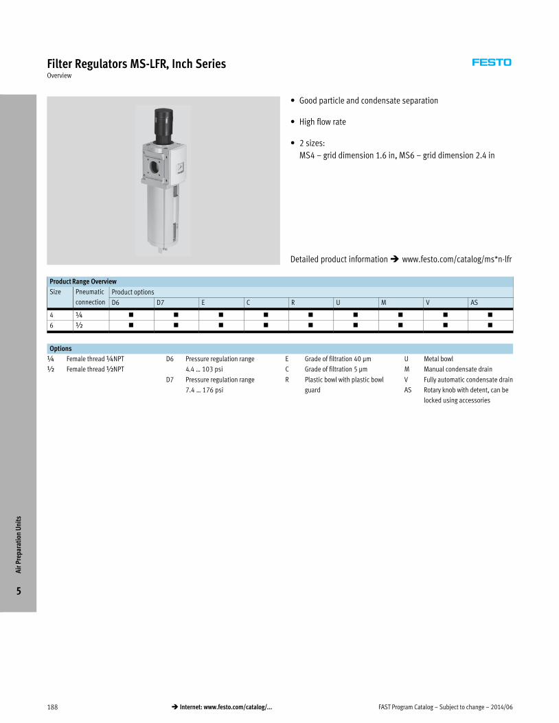
FAST Program Catalog – Subject to change – 2014/06188 � Internet: www.festo.com/catalog/...
Filter Regulators MS-LFR, Inch SeriesOverview
� Good particle and condensate separation
� High flow rate
� 2 sizes:
MS4 – grid dimension 1.6 in, MS6 – grid dimension 2.4 in
Product Range Overview
Size Pneumatic
connection
Product options
D6 D7 E C R U M V AS
4 ¼ � � � � � � � � �
6 ½ � � � � � � � � �
Options
¼ Female thread ¼NPT
½ Female thread ½NPT
D6 Pressure regulation range
4.4 … 103 psi
D7 Pressure regulation range
7.4 … 176 psi
E Grade of filtration 40 μm
C Grade of filtration 5 μm
R Plastic bowl with plastic bowl
guard
U Metal bowl
M Manual condensate drain
V Fully automatic condensate drain
AS Rotary knob with detent, can be
locked using accessories
Air
Pre
para
tion
Uni
ts
5
Detailed product information � www.festo.com/catalog/ms*n-lfr

2014/06 – Subject to change – FAST Program Catalog 189� Internet: www.festo.com/catalog/...
Filter Regulators MS-LFR, Inch SeriesTechnical Data
Materials
Housing: Die-cast aluminum
Rotary knob: PA, POM
Plastic bowl guard: PC
Metal bowl: Wrought aluminum alloy,
die-cast aluminum
Seals: NBR
Technical data Download CAD data � www.festo.com/us/engineering
Size MS4 MS6
Pneumatic connection 1, 2 ¼NPT ½NPT
Design Directly actuated diaphragm regulator
Regulator function With return flow action, with secondary venting, with primary pressure compensation
Type of mounting Via accessories
In-line installation
Mounting position Vertical ±5°
Grade of filtration [μm] 40
5
Air purity class at the output Compressed air to ISO 8573-1:2010 [7:4:4] (grade of filtration 40 μm)
Compressed air to ISO 8573-1:2010 [6:4:4] (grade of filtration 5 μm)
Bowl guard Plastic bowl guard
Integrated as metal bowl
Condensate drain Manual rotary
Fully automatic
Actuation security Rotary knob with detent
Rotary knob with detent, can be locked using accessories
Pressure regulation range [psi] D6 7.4 … 103
D7 7.4 … 176
Pressure indication Via pressure gauge for displaying output pressure
Length [in] Standard 2.2 3
With cover plate VS 2.1 3
Width [in] 1.6 2.4
Height [in]1) Plastic bowl guard 8.6 … 8.82) + 13) 11.8 … 122) + 13)
Metal bowl 9.3 … 9.42) + 2.73) 12.2 … 12.32) + 2.73)
1) Height applies to filter regulator with detenting rotary knob, can be locked using accessories. The filter regulator without lockable rotary knob is approx. 0 4 in smaller.
2) Value is dependent on the condensate drain.
3) Installation dimension for removing the filter bowl.
Standard nominal flow rate qnN
Size MS4 MS6
Grade of filtration 40 μm
qnN [scfm] With pressure regulation range D61) 60 219
With pressure regulation range D71) 53 159
Grade of filtration 5 μm
qnN [scfm] With pressure regulation range D61) 53 198
With pressure regulation range D71) 42 141
1) MS4/MS6: Measured at p1 = 176 psi and p2 = 88 psi, Δp = 15 psi.
Air
Pre
para
tion
Uni
ts
5

FAST Program Catalog – Subject to change – 2014/06190 � Internet: www.festo.com/catalog/...
Filter Regulators MS-LFR, Inch SeriesTechnical Data, Ordering Data
Operating conditions
Condensate drain Manual rotary Fully automatic
Size MS4 MS6 MS4/MS6
Operating medium Compressed air to ISO 8573-1:2010 [–:4:–] Compressed air to
ISO 8573-1:2010 [7:4:–]
Inert gases
Operating pressure [psi] 11.8 … 206 11.8 … 294 29.4 … 176
Ambient temperature [°F] 14 … 140 41 … 140
Ordering Data
Part No. Type Part No. Type
MS4
531229 MS4N-LFR-1/4-D6-CRM-AS
531233 MS4N-LFR-1/4-D6-CRV-AS
531221 MS4N-LFR-1/4-D6-ERM-AS
531225 MS4N-LFR-1/4-D6-ERV-AS
531213 MS4N-LFR-1/4-D7-CRM-AS
531217 MS4N-LFR-1/4-D7-CRV-AS
535750 MS4N-LFR-1/4-D7-CUM-AS
535752 MS4N-LFR-1/4-D7-CUV-AS
531205 MS4N-LFR-1/4-D7-ERM-AS
531209 MS4N-LFR-1/4-D7-ERV-AS
535756 MS4N-LFR-1/4-D7-EUM-AS
535754 MS4N-LFR-1/4-D7-EUV-AS
MS6
531306 MS6N-LFR-1/2-D6-CRM-AS
531312 MS6N-LFR-1/2-D6-CRV-AS
531294 MS6N-LFR-1/2-D6-ERM-AS
531300 MS6N-LFR-1/2-D6-ERV-AS
531282 MS6N-LFR-1/2-D7-CRM-AS
531288 MS6N-LFR-1/2-D7-CRV-AS
531318 MS6N-LFR-1/2-D7-CUM-AS
531324 MS6N-LFR-1/2-D7-CUV-AS
531270 MS6N-LFR-1/2-D7-ERM-AS
531276 MS6N-LFR-1/2-D7-ERV-AS
531330 MS6N-LFR-1/2-D7-EUM-AS
531336 MS6N-LFR-1/2-D7-EUV-AS
Air
Pre
para
tion
Uni
ts
5
Lead Time LT for all products on this page: 3D typically shipswithin 3 days

2014/06 – Subject to change – FAST Program Catalog 191� Internet: www.festo.com/catalog/...
Filter Regulators MS-LFR, Inch SeriesAccessories Overview
1
1
3
3
8
8
8
8
5
6
4
bH
aI
7
bI
aG
aG
aH
cA
cB
cC
cD
ter
Accessories � Page/Internet
1 Cover cap MS4/6-END 231
3 Connecting plate MS4/6-AG… 231
4 Mounting bracket MS4/6-WB1) 231
5 Mounting bracket MS4-WBM1) 231
6 Mounting bracket MS4/6-WR1) 231
7 Hex nut MS4/6-WRS1) 231
8 Module connector MS4/6-MV 231
aG Connecting cable NEBU-M8…-LE3 232
aH Connecting cable NEBU-M12…-LE4 nebu
aI Pressure gauge MA 186
bH Padlock LRVS-D 232
1) Mounting component for individual device.
Accessories � Page/Internet
bI Cover plate VS ms6-lfr
cA Adapter plate A8/A4 for EN pressure gauge x/¼ ms6-lfr
cB Pressure sensor with operational status indicator
AD7/AD9
ms6-lfr
cC Pressure sensor with LCD display AD1/AD3 ms6-lfr
cD Fully automatic condensate drain, electrically actuated
(for MS6 only)
ms6-lfr
– Mounting bracket MS4/6-WP2) 231
– Mounting bracket MS4/6-WPB2) 231
– Mounting bracket MS4/6-WPM2) 231
2) Mounting and connecting component for combination or for individual device with connecting plate
MS4/6-AG… 3/with mounting plate MS4/6-AEND.
Air
Pre
para
tion
Uni
ts
5

FAST Program Catalog – Subject to change – 2014/06192 � Internet: www.festo.com/catalog/...
Pressure Regulators MS-LR, Inch SeriesOverview
� High flow rate with minimal pressure drop
� Suitable for front panel mounting
� 2 sizes:
MS4 – grid dimension 1.6 in, MS6 – grid dimension 2.4 in
Product Range Overview
Size Pneumatic
connection
Product options
D5 D6 D7 AS
4 ¼ � � � �
6 ½ � � � �
Options
¼ Female thread ¼NPT
½ Female thread ½NPT
D5 Pressure regulation range
4.4 … 59 psi, manually operated
D6 Pressure regulation range
4.4 … 103 psi, manually operated
D7 Pressure regulation range
7.4 … 176 psi, manually operated
AS Rotary knob with detent, can be
locked using accessories
Air
Pre
para
tion
Uni
ts
5
Detailed product information � www.festo.com/catalog/ms*n-lr

2014/06 – Subject to change – FAST Program Catalog 193� Internet: www.festo.com/catalog/...
Pressure Regulators MS-LR, Inch SeriesTechnical Data
Manually operated D5/D6/D7 Materials
Housing: Die-cast aluminum
Rotary knob: PA, POM
Seals: NBR
Technical data Download CAD data � www.festo.com/us/engineering
Size MS4 MS6
Pneumatic connection 1, 2 ¼NPT ½NPT
Design Directly actuated diaphragm regulator
Regulator function With return flow action, with secondary venting, with primary pressure compensation
Type of mounting Via accessories
In-line installation
Front panel mounting
Mounting position Any
Actuation security Rotary knob with detent
Rotary knob with detent, can be locked using accessories
Pressure regulation range/operation [psi] D5 4.4 … 59, manually operated
D6 4.4 … 103, manually operated
D7 7.4 … 176, manually operated
Pressure indicator Via pressure gauge for displaying output pressure
Length [in] With cover plate VS 2.1 3
Width [in] Standard 1.6 2.4
Height [in] With rotary knob with detent, can be
locked using accessories AS1)
4.9 7.4
1) The pressure regulator without lockable rotary knob is approx. 0.4 in smaller.
Standard nominal flow rate qnN
Size MS4 MS6
qnN [scfm] With pressure regulation range D51) 74 265
With pressure regulation range D62) 64 230
With pressure regulation range D72) 60 194
1) MS4/MS6: Measured at p1 = 176 psi and p2 = 44 psi, Δp = 15 psi.
2) MS4/MS6: Measured at p1 = 176 psi and p2 = 88 psi, Δp = 15 psi.
Operating conditions
Size MS4 MS6
Operating medium Compressed air to ISO 8573-1:2010 [7:4:4]
Inert gases
Note on operating/pilot medium Lubricated operation possible (in which case lubricated operation will always be required)
Operating pressure [psi] 11.8 … 206 11.8 … 294
Ambient temperature [°F] 14 … 140
Air
Pre
para
tion
Uni
ts
5

FAST Program Catalog – Subject to change – 2014/06194 � Internet: www.festo.com/catalog/...
Pressure Regulators MS-LR, Inch SeriesOrdering Data, Accessories Overview
Ordering Data
Part No. Type LT Part No. Type LT
MS4
531418 MS4N-LR-1/4-D5-AS 3D
531422 MS4N-LR-1/4-D6-AS 3D
531426 MS4N-LR-1/4-D7-AS 3D
MS6
531443 MS6N-LR-1/2-D5-AS 3D
531449 MS6N-LR-1/2-D6-AS 3D
531455 MS6N-LR-1/2-D7-AS 3D
LT = Lead time 1D typically ships same day/next day 3D typically ships within 3 days
1
1
3
3
8
8
8
8
5
6
4
bH
bI
cA
cB
cE
aI
aG
aG
aH
cC
Accessories � Page/Internet
1 Cover cap MS4/6-END 231
3 Connecting plate MS4/6-AG… 231
4 Mounting bracket MS4/6-WB1) 231
5 Mounting bracket MS4-WBM1) 231
6 Mounting bracket MS4/6-WR1) 231
8 Module connector MS4/6-MV 231
aG Connecting cable NEBU-M8…-LE3 232
aH Connecting cable NEBU-M12…-LE4 nebu
aI Pressure gauge MA 186
bH Padlock LRVS-D 232
1) Mounting component for individual device.
Accessories � Page/Internet
bI Cover plate VS ms*-lr
cA Adapter plate A8/A4 for EN pressure gauge x/¼ ms*-lr
cB Pressure sensor with operational status indicator
AD7/AD9
ms*-lr
cC Pressure sensor with LCD display AD1/AD3 ms*-lr
cE Knurled nut MS-LR (included in the scope of delivery) –
– Mounting bracket MS4/6-WP2) 231
– Mounting bracket MS4/6-WPB2) 231
– Mounting bracket MS4/6-WPM2) 231
2) Mounting and connecting component for combination or for individual device with connecting plate
MS4/6-AG… 3/with mounting plate MS4/6-AEND.
Air
Pre
para
tion
Uni
ts
5

2014/06 – Subject to change – FAST Program Catalog 195� Internet: www.festo.com/catalog/...
On-off Valves MS-EM, Inch SeriesOverview
� Manually operated on-off valve for pressurising and exhausting
pneumatic systems
� 2 sizes:
MS4 – grid dimension 1.6 in, MS6 – grid dimension 2.4 in
Product Range Overview
Size Pneumatic
connection
Product options
S
4 ¼ �
6 ½ �
Options
¼ Female thread ¼NPT
½ Female thread ½NPT
S Silencer
Air
Pre
para
tion
Uni
ts
5
Detailed product information � www.festo.com/catalog/ms*n-em

FAST Program Catalog – Subject to change – 2014/06196 � Internet: www.festo.com/catalog/...
On-off Valves MS-EM, Inch SeriesTechnical Data, Ordering Data
Materials
Housing: Die-cast aluminum
Rotary knob: PA, POM
Seals: NBR
Technical data Download CAD data � www.festo.com/us/engineering
Size MS4 MS6
Pneumatic connection 1, 2 ¼NPT ½NPT
Pneumatic connection 3 ¼NPT ½NPT
Design Rotary slide valve
Type of mounting Via accessories
In-line installation
Mounting position Any
Actuation type Manual
Valve function 3/2-way valve
Exhaust function No flow control
Type of control Direct
Direction of flow Non-reversible
Length [in] 2.1 3
Width [in] 1.6 2.4
Height [in] Without silencer 4.1 5.9
With silencer 5.9 10.1
Standard nominal flow rate qnN
Size MS4 MS6
qnN1}2 [scfm] In main flow direction1) 78 307
qnN2}3 [scfm] In relief direction1) 60 219
1) Measured at p1 = 88 psi and p2 = 74 psi, Δp = 15 psi.
Operating conditions
Size MS4 MS6
Operating medium Compressed air to ISO 8573-1:2010 [7:4:4]
Inert gases
Note on operating/pilot medium Lubricated operation possible (in which case lubricated operation will always be required)
Operating pressure [psi] 0 … 206 0 … 265
Ambient temperature [°F] 14 … 140
Ordering Data
Part No. Type Part No. Type
MS4
541280 MS4N-EM1-1/4
541281 MS4N-EM1-1/4-S
MS6
541289 MS6N-EM1-1/2
541290 MS6N-EM1-1/2-S
Air
Pre
para
tion
Uni
ts
5
Lead Time LT for all products on this page: 3D typically shipswithin 3 days

2014/06 – Subject to change – FAST Program Catalog 197� Internet: www.festo.com/catalog/...
On-off Valves MS-EM, Inch SeriesAccessories Overview
1
1
3
3
8
8
8
8
4
5
bC
cJ
bH
cA
aI
cB
aG
aG
aH
cC
Accessories � Page/Internet
1 Cover cap MS4/6-END 231
3 Connecting plate MS4/6-AG… 231
4 Mounting bracket MS4/6-WB1) 231
5 Mounting bracket MS4-WBM1) 231
8 Module connector MS4/6-MV 231
aG Connecting cable NEBU-M8…-LE3 232
aH Connecting cable NEBU-M12…-LE4 nebu
aI Pressure gauge MA 186
bC Silencer U 232
1) Mounting component for individual device.
Accessories � Page/Internet
bH Padlock LRVS-D 232
cJ MS pressure gauge AG ms*-em
cA Adapter plate A8/A4 for EN pressure gauge x/¼ ms*-em
cB Pressure sensor with operational status indicator
AD7/AD9
ms*-em
cC Pressure sensor with LCD display AD1/AD3 ms*-em
– Mounting bracket MS4/6-WP2) 231
– Mounting bracket MS4/6-WPB2) 231
– Mounting bracket MS4/6-WPM2) 231
Air
Pre
para
tion
Uni
ts
5

FAST Program Catalog – Subject to change – 2014/06198 � Internet: www.festo.com/catalog/...
On-off Valves MS-EE, Inch SeriesOverview
� Electrically actuated on-off valve for pressurising and exhausting
pneumatic systems
� Choice of three voltage ranges
� 2 sizes:
MS4 – grid dimension 1.6 in, MS6 – grid dimension 2.4 in
Product Range Overview
Size Pneumatic
connection
Product options
10V24 V110 S
4 ¼ � � �
6 ½ � � �
Options
¼ Female thread ¼NPT
½ Female thread ½NPT
10V24 Supply voltage 24 V DC
(pin allocation to EN 175301),
59 … 147 psi
V110 Supply voltage 110 V AC
(pin allocation to EN 175301),
44 … 265 psi
S Silencer
Air
Pre
para
tion
Uni
ts
5
Detailed product information � www.festo.com/catalog/ms*n-ee

2014/06 – Subject to change – FAST Program Catalog 199� Internet: www.festo.com/catalog/...
On-off Valves MS-EE, Inch SeriesTechnical Data
Materials
Housing: Die-cast aluminum
Seals: NBR
Technical data Download CAD data � www.festo.com/us/engineering
Size MS4 MS6
Pneumatic connection 1, 2 ¼NPT ½NPT
Pneumatic connection 3 ¼NPT ½NPT
Design Piston spool valve
Type of mounting Via accessories
In-line installation
Mounting position Any
Actuation type Electric
Valve function 3/2-way valve, closed, single solenoid
Exhaust function No flow control
Manual override Non-detenting (supply voltage 10V24)
Reset method Mechanical spring
Switching position display Via accessories
Type of control Piloted
Pilot air supply Internal
Direction of flow Non-reversible
Length [in] With cover plate 75 (63)1) 97 (83)1)
Width [in] 1.6 2.4
Height [in] Without silencer 5.6 7.3
With silencer 7.5 11.5
1) Value in brackets with repositioned solenoid head (180°), i.e. solenoid points to the front.
Standard nominal flow rate qnN
Size MS4 MS6
qnN1}2 [scfm] In main flow direction2) 71 247
qnN2}3 [scfm] In relief direction2) 57 194
2) Measured at p1 = 88 psi and p2 = 74 psi, Δp = 15 psi.
Electrical data
Coil characteristics 24 V DC: 2.5 W
Electrical connection Plug, square design to EN 175301-803, type C
Protection class for solenoid coil IP65
Duty cycle [%] 100
Operating conditions
Operating medium Compressed air to ISO 8573-1:2010 [7:4:4]
Inert gases
Note on operating/pilot medium Lubricated operation possible (in which case lubricated operation will always be required)
Operating pressure [psi] 59 … 147
Ambient temperature [°F] 14 … 122
Air
Pre
para
tion
Uni
ts
5

FAST Program Catalog – Subject to change – 2014/06200 � Internet: www.festo.com/catalog/...
On-off Valves MS-EE, Inch SeriesOrdering Data, Accessories Overview
Ordering Data
Part No. Type LT Part No. Type LT
MS4
542588 MS4N-EE-1/4-10V24 3D
MS6
542593 MS6N-EE-1/2-10V24 3D
LT = Lead time 1D typically ships same day/next day 3D typically ships within 3 days
1
1
3
3
8
8
8
8
5
4
cA
cB
aD
bF
aI
bC
cJ
aF
aG
aE
aGaH
cC
Accessories � Page/Internet
1 Cover cap MS4/6-END 231
3 Connecting plate MS4/6-AG… 231
4 Mounting bracket MS4/6-WB1) 231
5 Mounting bracket MS4-WBM1) 231
8 Module connector MS4/6-MV 231
aD Plug socket MSSD-EB mssd-eb
aE Plug socket with cable KMEB 232
aF Illuminating seal MEB-LD meb-ld
aG Connecting cable NEBU-M8…-LE3 232
aH Connecting cable NEBU-M12…-LE4 nebu
aI Pressure gauge MA 186
1) Mounting component for individual device.
Accessories � Page/Internet
bC Silencer U 232
bF Locking clip CPV18-HV cpv18-hv
cJ MS pressure gauge AG ms*-ee
cA Adapter plate A8/A4 for EN pressure gauge x/¼ ms*-ee
cB Pressure sensor with operational status indicator
AD7/AD9
ms*-ee
cC Pressure sensor with LCD display AD1/AD3 ms*-ee
– Mounting bracket MS4/6-WP2) 231
– Mounting bracket MS4/6-WPB2) 231
– Mounting bracket MS4/6-WPM2) 231
2) Mounting and connecting component for combination or for individual device with connecting plate
MS4/6-AG… 3/with mounting plate MS4/6-AEND.
Air
Pre
para
tion
Uni
ts
5

2014/06 – Subject to change – FAST Program Catalog 201� Internet: www.festo.com/catalog/...
Branching Modules MS-FRM, Distributor Blocks MS-FRM-FRZ, Inch SeriesOverview
� Pneumatic manifold with 4 connections
� Can be used as an intermediate distributor for varying air
qualities
� 2 sizes:
MS4 – grid dimension 1.6 in, MS6 – grid dimension 2.4 in
Product Range Overview
Size Pneumatic connection
4 ¼
6 ½
Options
¼ Female thread ¼NPT ½ Female thread ½NPT
Features
Branching module MS-FRM Distributor Block MS-FRM-FRZ
� Pneumatic manifold with 4
connections
� Outlet top and bottom
� Can be used as an intermediate
distributor for varying air qualities
� Attachment facility for auxiliary
modules
� An integrated non-return valve
prevents the return flow e.g. of
lubricated compressed air
� Pneumatic manifold with 4
connections
� Outlet top and bottom
� Can be used as an intermediate
distributor for varying air qualities
� Can be used as an intermediate
distributor between two pressure
regulators with large rotary knob
with pressure gauge on size MS4
Air
Pre
para
tion
Uni
ts
5
Detailed product information � www.festo.com/catalog/ms*n-frm

FAST Program Catalog – Subject to change – 2014/06202 � Internet: www.festo.com/catalog/...
Branching Modules MS-FRM, Inch SeriesTechnical Data, Ordering Data
1
3
2
4
Materials
Housing: Die-cast aluminum
Seals: NBR
Technical data Download CAD data � www.festo.com/us/engineering
Size MS4 MS6
Pneumatic connection 1, 2 ¼NPT ½NPT
Pneumatic connection 3 ¼NPT ½NPT
Pneumatic connection 4 ¼NPT ½NPT
Design Branching module
Type of mounting Via accessories
In-line installation
Mounting position Any
Length [in] 2.1 3
Width [in] 1.6 2.4
Height [in] 2.4 3.4
Standard nominal flow rate qnN
Size MS4 MS6
qnN1}2 [scfm] In main flow direction1) 162 519
qnN1}3 [scfm] Outlet at top1) 53 155
qnN1}4 [scfm] Outlet at bottom1) 53 162
1) Measured at p1 = 88 psi and p2 = 74 psi, Δp = 15 psi.
Operating conditions
Size MS4 MS6
Operating medium Compressed air to ISO 8573-1:2010 [7:4:4]
Inert gases
Note on operating/pilot medium Lubricated operation possible (in which case lubricated operation will always be required)
Operating pressure [psi] 0 … 206 0 … 294
Ambient temperature [°F] 14 … 140
Ordering Data
Part No. Type Part No. Type
MS4
531949 MS4N-FRM-1/4
MS6
531966 MS6N-FRM-1/2
Air
Pre
para
tion
Uni
ts
5
Lead Time LT for all products on this page: 3D typically shipswithin 3 days

2014/06 – Subject to change – FAST Program Catalog 203� Internet: www.festo.com/catalog/...
Distributor Blocks MS4/MS6-FRM-FRZ, Inch SeriesTechnical Data, Ordering Data
3
4
Materials:
Housing: Die-cast aluminum
Note
The distributor block MS4/6-FRM-FRZ
has a half grid dimension width.
� Pneumatic manifold
with 4 connections
� Outlet top and bottom
� Can be used as an intermediate
distributor for varying air qualities
� Can be used as an intermediate
distributor between two pressure
regulators with large rotary knob with
pressure gauge on size MS4
General technical data
Size MS4 MS6
Pneumatic connection 3, 4 ¼NPT ½NPT
Design Branching module
Type of mounting Via accessories
In-line installation
Standard nominal flow rate qnN1) [scfm]
Size MS4 MS6
In main flow direction 1 > 2 143 515
Outlet at top 115 367
Outlet at bottom 102 348
1) Measured at p1 = 88 psi and p2 = 74 psi, Δp = 15 psi.
Operating and environmental conditions
Size MS4 MS6
Operating pressure [psi] 0 … 206 0 … 294
Operating medium Compressed air in accordance with ISO 85731:2010 [7:4:4]
Inert gases
Note on operating/pilot medium Operation with lubricated medium possible (in which case lubricated operation will always be required)
Ambient temperature [°F] 14 … 140
Ordering Data
Part No. Type Part No. Type
MS4
554101 MS4N-FRM-FRZ
MS6
554102 MS6N-FRM-FRZ
Air
Pre
para
tion
Uni
ts
5
Lead Time LT for all products on this page: 3D typically shipswithin 3 days

FAST Program Catalog – Subject to change – 2014/06204 � Internet: www.festo.com/catalog/...
Branching Modules MS-FRM, Inch SeriesAccessories Overview
1
1
3
3
4
5
8
9
aIcGaD
aC
aH
aG
aGaH
cJ
cA
cB
cC
2
2
8/9
cH
Accessories � Page/Internet
1 Cover cap MS4/6-END 231
2 Mounting plate MS4/6-AEND ms*-frm
3 Connecting plate MS4/6-AG… 231
4 Mounting bracket MS4/6-WB1) 231
5 Mounting bracket MS4-WBM1) 231
8 Module connector MS4/6-MV 231
9 Mounting bracket MS4/6-WP2) 231
aC Angled plug socket PEV-¼-WD-LED pev-1/4-wd-led
aD Plug socket MSSD-C-4P mssd-c-4p
aG Connecting cable NEBU-M8…-LE3 232
1) Mounting component for individual device.
Accessories � Page/Internet
aH Connecting cable NEBU-M12…-LE4 nebu
aI Pressure gauge MA 186
cJ MS pressure gauge AG ms*-frm
cA Adapter plate A8/A4 for EN pressure gauge x/¼ ms*-frm
cB Pressure sensor without display AD7/AD9 ms*-frm
cC Pressure sensor with display AD1/AD3 ms*-frm
cG Pressure switch M12 ms*-frm
cH Pressure switch X/Y ms*-frm
– Mounting bracket MS4/6-WPB2) 231
– Mounting bracket MS4/6-WPM2) 231
2) Mounting and connecting component for combination or for individual device with connecting plate
MS4/6-AG… 3/with mounting plate MS4/6-AEND 2.
Air
Pre
para
tion
Uni
ts
5

2014/06 – Subject to change – FAST Program Catalog 205� Internet: www.festo.com/catalog/...
Filter Regulators MS-LFR, Metric SeriesOverview
� Good particle and condensate separation
� High flow rate
� 2 sizes:
MS4 – grid dimension 40 mm, MS6 – grid dimension 62 mm
Product Range Overview
Size Pneumatic
connection
Product options
D6 D7 E C R U M V AS
4 ¼ � � � � � � � � �
6 ½ � � � � � � � � �
Options
¼ Female thread G¼
½ Female thread G½
D6 Pressure regulation range
0.3 … 7 bar
D7 Pressure regulation range
0.5 … 12 bar
E Grade of filtration 40 μm
C Grade of filtration 5 μm
R Plastic bowl with plastic bowl
guard
U Metal bowl
M Manual condensate drain
V Fully automatic condensate drain
AS Rotary knob with detent, can be
locked using accessories
Air
Pre
para
tion
Uni
ts
5
Detailed product information � www.festo.com/catalog/ms*-lfr

FAST Program Catalog – Subject to change – 2014/06206 � Internet: www.festo.com/catalog/...
Filter Regulators MS-LFR, Metric SeriesTechnical Data
Materials
Housing: Die-cast aluminum
Rotary knob: PA, POM
Plastic bowl guard: PC
Metal bowl: Wrought aluminum alloy,
die-cast aluminum
Seals: NBR
Technical data Download CAD data � www.festo.com/us/engineering
Size MS4 MS6
Pneumatic connection 1, 2 G¼ G½
Design Directly actuated diaphragm regulator
Regulator function With return flow action, with secondary venting, with primary pressure compensation
Type of mounting Via accessories
In-line installation
Mounting position Vertical ±5°
Grade of filtration [μm] 40
5
Air purity class at the output Compressed air to ISO 8573-1:2010 [7:4:4] (grade of filtration 40 μm)
Compressed air to ISO 8573-1:2010 [6:4:4] (grade of filtration 5 μm)
Bowl guard Plastic bowl guard
Integrated as metal bowl
Condensate drain Manual rotary
Fully automatic
Actuation security Rotary knob with detent
Rotary knob with detent, can be locked using accessories
Pressure regulation range [bar] D6 0.5 … 7
D7 0.5 … 12
Pressure indication Via pressure gauge for displaying output pressure
Length [mm] Standard 57 77
With cover plate VS 54 76
Width [mm] 40 62
Height [mm]1) Plastic bowl guard 219 … 2232) + 253) 300 … 3052) + 253)
Metal bowl 236 … 2402) + 683) 309 … 3132) + 683)
1) Height applies to filter regulator with detenting rotary knob, can be locked using accessories. The filter regulator without lockable rotary knob is approx. 9 mm smaller.
2) Value is dependent on the condensate drain.
3) Installation dimension for removing the filter bowl.
Standard nominal flow rate qnN
Size MS4 MS6
Grade of filtration 40 μm
qnN [l/min] With pressure regulation range D61) 1,700 6,200
With pressure regulation range D71) 1,500 4,500
Grade of filtration 5 μm
qnN [l/min] With pressure regulation range D61) 1,500 5,600
With pressure regulation range D71) 1,200 4,000
1) MS4/MS6: Measured at p1 = 10 bar and p2 = 6 bar, Δp = 1 bar.
Air
Pre
para
tion
Uni
ts
5

2014/06 – Subject to change – FAST Program Catalog 207� Internet: www.festo.com/catalog/...
Filter Regulators MS-LFR, Metric SeriesTechnical Data, Ordering Data
Operating conditions
Condensate drain Manual rotary Fully automatic
Size MS4 MS6 MS4/MS6
Operating medium Compressed air to ISO 8573-1:2010 [–:4:–] Compressed air to
ISO 8573-1:2010 [7:4:–]
Inert gases
Operating pressure [bar] 0.8 … 14 0.8 … 20 2 … 12
Ambient temperature [°C] –10 … +60 +5 … +60
Ordering Data
Part No. Type Part No. Type
MS4
529144 MS4-LFR-¼-D6-CRM-AS
529146 MS4-LFR-¼-D6-CRV-AS
529148 MS4-LFR-¼-D6-ERM-AS
529150 MS4-LFR-¼-D6-ERV-AS
529152 MS4-LFR-¼-D7-CRM-AS
529154 MS4-LFR-¼-D7-CRV-AS
535718 MS4-LFR-¼-D7-CUM-AS
535720 MS4-LFR-¼-D7-CUV-AS
529156 MS4-LFR-¼-D7-ERM-AS
529158 MS4-LFR-¼-D7-ERV-AS
535724 MS4-LFR-¼-D7-EUM-AS
535722 MS4-LFR-¼-D7-EUV-AS
MS6
529176 MS6-LFR-½-D6-CRM-AS
529178 MS6-LFR-½-D6-CRV-AS
529180 MS6-LFR-½-D6-ERM-AS
529182 MS6-LFR-½-D6-ERV-AS
529184 MS6-LFR-½-D7-CRM-AS
529186 MS6-LFR-½-D7-CRV-AS
530338 MS6-LFR-½-D7-CUM-AS
530340 MS6-LFR-½-D7-CUV-AS
529188 MS6-LFR-½-D7-ERM-AS
529190 MS6-LFR-½-D7-ERV-AS
529192 MS6-LFR-½-D7-EUM-AS
529194 MS6-LFR-½-D7-EUV-AS
Air
Pre
para
tion
Uni
ts
5
Lead Time LT for all products on this page: 1D typically ships same day/next day

FAST Program Catalog – Subject to change – 2014/06208 � Internet: www.festo.com/catalog/...
Filter Regulators MS-LFR, Metric SeriesAccessories Overview
1
1
3
3
8
8
8
8
5
6
4
bH
aI
7
bI
aG
aG
aH
cA
cB
cC
cD
ter
Accessories � Page/Internet
1 Cover cap MS4/6-END 231
3 Connecting plate MS4/6-AG… 231
4 Mounting bracket MS4/6-WB1) 231
5 Mounting bracket MS4-WBM1) 231
6 Mounting bracket MS4/6-WR1) 231
7 Hex nut MS4/6-WRS1) 231
8 Module connector MS4/6-MV 231
aG Connecting cable NEBU-M8…-LE3 232
aH Connecting cable NEBU-M12…-LE4 nebu
aI Pressure gauge MA 186
bH Padlock LRVS-D 232
1) Mounting component for individual device.
Accessories � Page/Internet
bI Cover plate VS ms6-lfr
cA Adapter plate A8/A4 for EN pressure gauge x/¼ ms6-lfr
cB Pressure sensor with operational status indicator
AD7/AD9
ms6-lfr
cC Pressure sensor with LCD display AD1/AD3 ms6-lfr
cD Fully automatic condensate drain, electrically actuated
(for MS6 only)
ms6-lfr
– Mounting bracket MS4/6-WP2) 231
– Mounting bracket MS4/6-WPB2) 231
– Mounting bracket MS4/6-WPM2) 231
2) Mounting and connecting component for combination or for individual device with connecting plate
MS4/6-AG… 3/with mounting plate MS4/6-AEND.
Air
Pre
para
tion
Uni
ts
5

2014/06 – Subject to change – FAST Program Catalog 209� Internet: www.festo.com/catalog/...
Pressure Regulators MS-LR, Metric SeriesOverview
� High flow rate with minimal pressure drop
� Suitable for front panel mounting
� 2 sizes:
MS4 – grid dimension 40 mm, MS6 – grid dimension 62 mm
Product Range Overview
Size Pneumatic
connection
Product options
D5 D6 D7 AS
4 ¼ � � � �
6 ½ � � � �
Options
¼ Female thread G¼
½ Female thread G½
D5 Pressure regulation range
0.3 … 4 bar, manually operated
D6 Pressure regulation range
0.3 … 7 bar, manually operated
D7 Pressure regulation range
0.5 … 12 bar, manually operated
AS Rotary knob with detent, can be
locked using accessories
Air
Pre
para
tion
Uni
ts
5
Detailed product information � www.festo.com/catalog/ms*-lr

FAST Program Catalog – Subject to change – 2014/06210 � Internet: www.festo.com/catalog/...
Pressure Regulators MS-LR, Metric SeriesTechnical Data
Manually operated D5/D6/D7 Materials
Housing: Die-cast aluminum
Rotary knob: PA, POM
Seals: NBR
Technical data Download CAD data � www.festo.com/us/engineering
Size MS4 MS6
Pneumatic connection 1, 2 G¼ G½
Design Directly actuated diaphragm regulator
Regulator function With return flow action, with secondary venting, with primary pressure compensation
Type of mounting Via accessories
In-line installation
Front panel mounting
Mounting position Any
Actuation security Rotary knob with detent
Rotary knob with detent, can be locked using accessories
Pressure regulation range/operation [bar] D5 0.5 … 4, manually operated
D6 0.5 … 7, manually operated
D7 0.5 … 12, manually operated
Pressure indicator Via pressure gauge for displaying output pressure
Length [mm] With cover plate VS 54 76
Width [mm] Standard 40 62
Height [mm] With rotary knob with detent, can be
locked using accessories AS1)
125 189
1) The pressure regulator without lockable rotary knob is approx. 9 mm smaller.
Standard nominal flow rate qnN
Size MS4 MS6
Pneumatic connection 1, 2 G¼ G½
qnN [l/min] With pressure regulation range D51) 2,100 7,500
With pressure regulation range D62) 1,800 6,500
With pressure regulation range D72) 1,700 5,500
1) MS4/MS6: Measured at p1 = 10 bar and p2 = 3 bar, Δp = 1 bar.
2) MS4/MS6: Measured at p1 = 10 bar and p2 = 6 bar, Δp = 1 bar.
Operating conditions
Size MS4 MS6
Operating medium Compressed air to ISO 8573-1:2010 [7:4:4]
Inert gases
Note on operating/pilot medium Lubricated operation possible (in which case lubricated operation will always be required)
Operating pressure [bar] 0.8 … 14 0.8 … 20
Ambient temperature [°C] –10 … +60
Air
Pre
para
tion
Uni
ts
5

2014/06 – Subject to change – FAST Program Catalog 211� Internet: www.festo.com/catalog/...
Pressure Regulators MS-LR, Metric SeriesOrdering Data, Accessories Overview
Ordering Data
Part No. Type LT Part No. Type LT
MS4
529415 MS4-LR-¼-D5-AS 1D
529417 MS4-LR-¼-D6-AS 1D
529419 MS4-LR-¼-D7-AS 1D
MS6
529989 MS6-LR-½-D5-AS 1D
529991 MS6-LR-½-D6-AS 1D
529993 MS6-LR-½-D7-AS 1D
LT = Lead time 1D typically ships same day/next day 3D typically ships within 3 days
1
1
3
3
8
8
8
8
5
6
4
bH
bI
cA
cB
cE
aI
aG
aG
aH
cC
Accessories � Page/Internet
1 Cover cap MS4/6-END 231
3 Connecting plate MS4/6-AG… 231
4 Mounting bracket MS4/6-WB1) 231
5 Mounting bracket MS4-WBM1) 231
6 Mounting bracket MS4/6-WR1) 231
8 Module connector MS4/6-MV 231
aG Connecting cable NEBU-M8…-LE3 232
aH Connecting cable NEBU-M12…-LE4 nebu
aI Pressure gauge MA 186
bH Padlock LRVS-D 232
1) Mounting component for individual device.
Accessories � Page/Internet
bI Cover plate VS ms*-lr
cA Adapter plate A8/A4 for EN pressure gauge x/¼ ms*-lr
cB Pressure sensor with operational status indicator
AD7/AD9
ms*-lr
cC Pressure sensor with LCD display AD1/AD3 ms*-lr
cE Knurled nut MS-LR (included in the scope of delivery) –
– Mounting bracket MS4/6-WP2) 231
– Mounting bracket MS4/6-WPB2) 231
– Mounting bracket MS4/6-WPM2) 231
2) Mounting and connecting component for combination or for individual device with connecting plate
MS4/6-AG… 3/with mounting plate MS4/6-AEND.
Air
Pre
para
tion
Uni
ts
5

FAST Program Catalog – Subject to change – 2014/06212 � Internet: www.festo.com/catalog/...
Pressure Regulators MS-LRB, Metric SeriesOverview
� For manifold assembly with through air supply
� For configuring a regulator manifold with independent
pressure regulation ranges
� 2 sizes:
MS4 – grid dimension 40 mm, MS6 – grid dimension 62 mm
Product Range Overview
Size Pneumatic
connection
Product options
D5 D6 D7 A8 A4 AS
4 ¼ � � � � � �
6 ½ � � � – � �
Options
¼ Female thread G¼
½ Female thread G½
D5 Pressure regulation range
0.3 … 4 bar, manually operated
D6 Pressure regulation range
0.3 … 7 bar, manually operated
D7 Pressure regulation range
0.5 … 12 bar, manually operated
A8 Adapter plate for EN pressure
gauge x, without pressure
gauge
A4 Adapter plate for EN pressure
gauge ¼, without pressure
gauge
AS Rotary knob with detent, can be
locked using accessories
Air
Pre
para
tion
Uni
ts
5
Detailed product information � www.festo.com/catalog/ms*-lrb

2014/06 – Subject to change – FAST Program Catalog 213� Internet: www.festo.com/catalog/...
Pressure Regulators MS-LRB, Metric SeriesTechnical Data
Materials
Housing: Die-cast aluminum
Rotary knob: PA, POM
Seals: NBR
Technical data Download CAD data � www.festo.com/us/engineering
Size MS4 MS6
Pneumatic connection 1 G¼ G½
Pneumatic connection 2 G¼ G½
Design Directly actuated diaphragm regulator with through compressed air supply
Regulator function With return flow action, with secondary venting, with primary pressure compensation
Type of mounting Via accessories
In-line installation
Front panel mounting
Mounting position Any
Actuation security Rotary knob with detent
Rotary knob with detent, can be locked using accessories
Pressure regulation range/operation [bar] D5 0.3 … 4, manually operated
D6 0.3 … 7, manually operated
D7 0.5 … 12, manually operated
Pressure indicator Via pressure gauge for displaying output pressure
Length [mm] With adapter plate A8/A4 59 79
Width [mm] 40 62
Height [mm] With rotary knob with detent, can be
locked using accessories AS1)
125 189
1) The pressure regulator without lockable rotary knob is approx. 9 mm smaller.
Standard nominal flow rate qnN
Size MS4 MS6
qnN [l/min] With pressure regulation range D52) 1,900 7,300
With pressure regulation range D63) 1,700 6,300
With pressure regulation range D73) 1,500 5,500
2) Measured at p1 = 10 bar and p2 = 3 bar, Δp = 1 bar.
3) Measured at p1 = 10 bar and p2 = 6 bar, Δp = 1 bar.
Operating conditions
Size MS4 MS6
Operating medium Compressed air to ISO 8573-1:2010 [7:4:4]
Inert gases
Note on operating/pilot medium Lubricated operation possible (in which case lubricated operation will always be required)
Operating pressure [bar] 0.8 … 14 0.8 … 20
Ambient temperature [°C] –10 … +60 (0 … +50)1) –10 … +60 (0 … +50)1)
1) Value in brackets applies to MS4/MS6-LRB with pressure sensor AD…
Air
Pre
para
tion
Uni
ts
5

FAST Program Catalog – Subject to change – 2014/06214 � Internet: www.festo.com/catalog/...
Pressure Regulators MS-LRB, Metric SeriesOrdering Data, Accessories Overview
Ordering Data
Part No. Type LT Part No. Type LT
MS4
529473 MS4-LRB-1/4-D5-AS 3D
529477 MS4-LRB-1/4-D6-A8-AS 3D
529479 MS4-LRB-1/4-D6-AS 3D
MS6
530320 MS6-LRB-1/2-D5-A4-AS 3D
530328 MS6-LRB-1/2-D6-AS 3D
530332 MS6-LRB-1/2-D7-A4-AS 3D
530334 MS6-LRB-1/2-D7-AS 3D
LT = Lead time 1D typically ships same day/next day 3D typically ships within 3 days
3
3
8
8
8
8
9
aG
9/aJ/aA/aBcC
aJ
aA
aB
1
1
cB
aIbI
cA
aG aH
bH
cF
Accessories � Page/Internet
1 Cover cap MS4/6-END 231
3 Connecting plate MS4/6-AG… 231
4 Mounting bracket MS4/6-WB1) 231
5 Mounting bracket MS4-WBM1) 231
6 Mounting bracket MS4/6-WR1) 231
8 Module connector MS4/6-MV 231
9 Mounting bracket MS4/6-WP2)4) 231
aJ Mounting bracket MS4/6-WPB3)4) 231
aA Mounting bracket MS4/6-WPE3)4) ms*-lrb
aB Mounting bracket MS4/6-WPM4) 231
aG Connecting cable NEBU-M8…-LE3 232
1) Mounting component for individual device.
2) Only with alternative flow direction Z and/or only with pressure output BC, BD, BE.
Accessories � Page/Internet
aH Connecting cable NEBU-M12…-LE4 nebu
aI Pressure gauge MA 186
bH Padlock LRVS-D 232
bI Cover plate VS ms*-lrb
cA Adapter plate A8/A4 for EN pressure gauge x/¼ ms*-lrb
cB Pressure sensor with operational status indicator
AD7/AD9
ms*-lrb
cC Pressure sensor with LCD display AD1/AD3 ms*-lrb
cE Knurled nut MS-LR (included in the scope of delivery) –
cF Angled outlet block B… ms*-lrb
3) Not in combination with alternative flow direction Z and pressure output BC, BD, BE.
4) Mounting and connecting component for combination or for individual device with connecting plate
MS4/6-AG… 3/with mounting plate MS4/6-AEND.Air
Pre
para
tion
Uni
ts
5

2014/06 – Subject to change – FAST Program Catalog 215� Internet: www.festo.com/catalog/...
Precision Pressure Regulators MS6-LRP, Metric SeriesOverview
� For manifold assembly with through air supply
� Good regulation characteristics with low hysteresis and
primary pressure compensation
� High flow rate with minimal pressure drop
� High secondary venting for fast response times
Product Range Overview
Size Pneumatic
connection
Product options
D2 D4 D5 D7 A8
6 ¼, ½ � � � � �
Options
¼ Female thread G¼
½ Female thread G½
D2 Pressure regulation range
0.05 … 0.7 bar, manually operated
D4 Pressure regulation range
0.05 … 2.5 bar, manually operated
D5 Pressure regulation range
0.3 … 4 bar, manually operated
D7 Pressure regulation range
0.5 … 12 bar, manually operated
A8 Adapter plate for EN pressure gauge
x, without pressure gauge
Air
Pre
para
tion
Uni
ts
5
Detailed product information � www.festo.com/catalog/ms*-lrp

FAST Program Catalog – Subject to change – 2014/06216 � Internet: www.festo.com/catalog/...
Precision Pressure Regulators MS6-LRP, Metric SeriesTechnical Data
Materials
Housing: Die-cast aluminum
Rotary knob: PA, POM
Seals: NBR
General technical data
Size MS6
Pneumatic connection 1, 2 G¼ G½
Pneumatic connection 3
(secondary venting)
G¼
Constructional design Piloted precision diaphragm regulator
Regulating function Output pressure constant, via secondary venting
Type of mounting Via accessories
In-line installation
Front panel mounting
Regulator lock Rotary knob with detent
Pressure regulation
range/operation1)
D2 [bar] 0.05 … 0.7, manually operated
D4 [bar] 0.05 … 2.5, manually operated
D5 [bar] 0.1 … 4, manually operated
D7 [bar] 0.1 … 12, manually operated (0.1 … 10 with pressure sensor AD… or with UL certification)
Max. hysteresis [bar] 0.02
Pressure indication Gx prepared
G¼ prepared
1) Variant D2/D4/D5/D7: Supply pressure p1 output pressure p2 + 1 bar. Variant PO: Output pressure p2 = pilot pressure p12 + max. 0.5 bar.
Flow rates
Pressure regulation range D2 (0.05 … 0.7 bar) D4 (0.05 … 2.5 bar) D5 (0.1 … 4 bar) D7/PO (0.1 … 12 bar)
Standard nominal flow rate qnN [l/min]
qnN 1 } 2 G¼ 8001) 1,1002) 1,4003) 3,0004)
G½ 1,6001) 2,3002) 3,0003) 5,0004)
Secondary venting flow rate [l/min]
qn 2 } 3 2205) 4506) 6507) 9008)
1) Measured at p1 = 10 bar and p2 = 0.5 bar, Δp = 0.1 bar
2) Measured at p1 = 10 bar and p2 = 1.5 bar, Δp = 0.1 bar
3) Measured at p1 = 10 bar and p2 = 2.5 bar, Δp = 0.1 bar
4) Measured at p1 = 10 bar and p2 = 6.0 bar, Δp = 0.1 bar
5) Measured at p1 = 10 bar and p2 = 0.7 bar, Δp2 = 0.1 bar
6) Measured at p1 = 10 bar and p2 = 2.5 bar, Δp2 = 0.1 bar
7) Measured at p1 = 10 bar and p2 = 4.0 bar, Δp2 = 0.1 bar
8) Measured at p1 = 10 bar and p2 = 6.0 bar, Δp2 = 0.1 bar
Operating conditions
Operating medium Compressed air to ISO 8573-1:2010 [7:4:4]
Inert gases
Note on operating/pilot medium Operation with lubricated medium not possible
Operating pressure [bar] 1 … 14
Ambient temperature [°C] –10 … +60
Air
Pre
para
tion
Uni
ts
5

2014/06 – Subject to change – FAST Program Catalog 217� Internet: www.festo.com/catalog/...
Precision Pressure Regulators MS6-LRP, Metric SeriesOrdering Data, Accessories Overview
Ordering data
Adapter plate for EN pressure gauge x, standard rotary knob with detent
Size Pressure regulation range Connection Part No. Type LT
MS6 0.05 … 0.7 bar G¼ 538004 MS6-LRP-¼-D2-A8 3D
0.05 … 2.5 bar G¼ 538006 MS6-LRP-¼-D4-A8 3D
G½ 538022 MS6-LRP-½-D4-A8 3D
0.1 … 4 bar G¼ 538008 MS6-LRP-¼-D5-A8 3D
G½ 538024 MS6-LRP-½-D5-A8 3D
0.1 … 12 bar G½ 538026 MS6-LRP-½-D7-A8 3D
LT = Lead time 1D typically ships same day/next day 3D typically ships within 3 days
1
1
8
8
3
4
cA
cB
aH
aI
bI aG
cC
8
8
3
6
cE
bH
Accessories � Page/Internet
1 Cover cap MS4/6-END 231
3 Connecting plate MS4/6-AG… 231
4 Mounting bracket MS4/6-WB1) 231
6 Mounting bracket MS4/6-WR1) 231
8 Module connector MS4/6-MV 231
aG Connecting cable NEBU-M8…-LE3 232
aH Connecting cable NEBU-M12…-LE4 nebu
aI Pressure gauge MA 186
1) Mounting component for individual device.
Accessories � Page/Internet
bH Padlock LRVS-D 232
bI Cover plate VS ms6-lrp
cA Adapter plate A8/A4 for EN pressure gauge x/¼ ms6-lrp
cB Pressure sensor with operational status indicator
AD7/AD9
ms6-lrp
cC Pressure sensor with LCD display AD1/AD3 ms6-lrp
cE Knurled nut MS-LR (included in the scope of delivery) –
cF Angled outlet block B… ms6-lrp
Air
Pre
para
tion
Uni
ts
5

FAST Program Catalog – Subject to change – 2014/06218 � Internet: www.festo.com/catalog/...
On-off Valves MS-EM, Metric SeriesOverview
� Manually operated on-off valve for pressurising and exhausting
pneumatic systems
� 2 sizes:
MS4 – grid dimension 40 mm, MS6 – grid dimension 62 mm
Product Range Overview
Size Pneumatic
connection
Product options
S
4 ¼ �
6 ½ �
Options
¼ Female thread G¼
½ Female thread G½
S Silencer
Air
Pre
para
tion
Uni
ts
5
Detailed product information � www.festo.com/catalog/ms*-em

2014/06 – Subject to change – FAST Program Catalog 219� Internet: www.festo.com/catalog/...
On-off Valves MS-EM, Metric SeriesTechnical Data, Ordering Data
Materials
Housing: Die-cast aluminum
Rotary knob: PA, POM
Seals: NBR
Technical data Download CAD data � www.festo.com/us/engineering
Size MS4 MS6
Pneumatic connection 1, 2 G¼ G½
Pneumatic connection 3 G¼ G½
Design Rotary slide valve
Type of mounting Via accessories
In-line installation
Mounting position Any
Actuation type Manual
Valve function 3/2-way valve
Exhaust function No flow control
Type of control Direct
Direction of flow Non-reversible
Length [mm] 54 76
Width [mm] 40 62
Height [mm] Without silencer 104 151
With silencer 151 257
Standard nominal flow rate qnN
Size MS4 MS6
qnN1}2 [l/min] In main flow direction1) 2,200 8,700
qnN2}3 [l/min] In relief direction1) 1,700 6,200
1) Measured at p1 = 6 bar and p2 = 5 bar, Δp = 1 bar.
Operating conditions
Size MS4 MS6
Operating medium Compressed air to ISO 8573-1:2010 [7:4:4]
Inert gases
Note on operating/pilot medium Lubricated operation possible (in which case lubricated operation will always be required)
Operating pressure [bar] 0 … 14 0 … 18
Ambient temperature [°C] –10 … +60 –10 … +60
Ordering Data
Part No. Type Part No. Type
MS4
541258 MS4-EM1-¼
541259 MS4-EM1-¼-S
MS6
541267 MS6-EM1-½
541268 MS6-EM1-½-S
Air
Pre
para
tion
Uni
ts
5
Lead Time LT for all products on this page: 1D typically ships same day/next day

FAST Program Catalog – Subject to change – 2014/06220 � Internet: www.festo.com/catalog/...
On-off Valves MS-EM, Metric SeriesAccessories Overview
1
1
3
3
8
8
8
8
4
5
bC
cJ
bH
cA
aI
cB
aG
aG
aH
cC
Accessories � Page/Internet
1 Cover cap MS4/6-END 231
3 Connecting plate MS4/6-AG… 231
4 Mounting bracket MS4/6-WB1) 231
5 Mounting bracket MS4-WBM1) 231
8 Module connector MS4/6-MV 231
aG Connecting cable NEBU-M8…-LE3 232
aH Connecting cable NEBU-M12…-LE4 nebu
aI Pressure gauge MA 186
bC Silencer U 232
1) Mounting component for individual device.
Accessories � Page/Internet
bH Padlock LRVS-D 232
cJ MS pressure gauge AG ms*-em
cA Adapter plate A8/A4 for EN pressure gauge x/¼ ms*-em
cB Pressure sensor with operational status indicator
AD7/AD9
ms*-em
cC Pressure sensor with LCD display AD1/AD3 ms*-em
– Mounting bracket MS4/6-WP2) 231
– Mounting bracket MS4/6-WPB2) 231
– Mounting bracket MS4/6-WPM2) 231
Air
Pre
para
tion
Uni
ts
5

2014/06 – Subject to change – FAST Program Catalog 221� Internet: www.festo.com/catalog/...
On-off Valves MS-EE, Metric SeriesOverview
� Electrically actuated on-off valve for pressurising and exhausting
pneumatic systems
� Choice of three voltage ranges
� 2 sizes:
MS4 – grid dimension 40 mm, MS6 – grid dimension 62 mm
Product Range Overview
Size Pneumatic
connection
Product options
10V24 V110 S
4 ¼ � � �
6 ½ � � �
Options
¼ Female thread G¼
½ Female thread G½
10V24 Supply voltage 24 V DC
(pin allocation to EN 175301),
4 … 10 bar
V110 Supply voltage 110 V AC
(pin allocation to EN 175301),
3 … 18 bar
S Silencer
Air
Pre
para
tion
Uni
ts
5
Detailed product information � www.festo.com/catalog/ms*-ee

FAST Program Catalog – Subject to change – 2014/06222 � Internet: www.festo.com/catalog/...
On-off Valves MS-EE, Metric SeriesTechnical Data
Materials
Housing: Die-cast aluminum
Seals: NBR
Technical data Download CAD data � www.festo.com/us/engineering
Size MS4 MS6
Pneumatic connection 1, 2 G¼ G½
Pneumatic connection 3 G¼ G½
Design Piston spool valve
Type of mounting Via accessories
In-line installation
Mounting position Any
Actuation type Electric
Valve function 3/2-way valve, closed, single solenoid
Exhaust function No flow control
Manual override Non-detenting/detenting (supply voltage V110)
Non-detenting (supply voltage 10V24)
Reset method Mechanical spring
Switching position display Via accessories
Type of control Piloted
Pilot air supply Internal
Direction of flow Non-reversible
Length [mm] With cover plate 75 (63)1) 97 (83)1)
Width [mm] 40 62
Height [mm] Without silencer 143 186
With silencer 191 292
1) Value in brackets with repositioned solenoid head (180°), i.e. solenoid points to the front.
Standard nominal flow rate qnN
Size MS4 MS6
qnN1}2 [l/min] In main flow direction2) 2,000 7,000
qnN2}3 [l/min] In relief direction2) 1,600 5,500
2) Measured at p1 = 6 bar and p2 = 5 bar, Δp = 1 bar.
Electrical data
Size MS4 MS6
Supply voltage 10V24 V110 10V24 V110
Coil characteristics 24 V DC: 2.5 W 110 V AC: 50/60 Hz;
pick-up power 3.0 W;
holding power 2.4 W
24 V DC: 2.5 W 110 V AC: 50/60 Hz;
pick-up power 3.0 W;
holding power 2.4 W
Electrical connection Plug, square design to EN 175301-803, type C
Protection class for solenoid coil IP65
Duty cycle [%] 100
Air
Pre
para
tion
Uni
ts
5

2014/06 – Subject to change – FAST Program Catalog 223� Internet: www.festo.com/catalog/...
On-off Valves MS-EE, Metric SeriesTechnical Data, Ordering Data, Accessories Overview
Operating conditions
Size MS4 MS6
Supply voltage 10V24 V110 10V24 V110
Operating medium Compressed air to ISO 8573-1:2010 [7:4:4]
Inert gases
Note on operating/pilot medium Lubricated operation possible (in which case lubricated operation will always be required)
Operating pressure [bar] 4 … 10 4 … 14 4 … 10 4 … 18
Ambient temperature [°C] –10 … +50 –10 … +60 –10 … +50 –10 … +60
Ordering Data
Part No. Type LT Part No. Type LT
MS4
542578 MS4-EE-¼-10V24 1D
542598 MS4-EE-¼-10V24-S 1D
529535 MS4-EE-1/4-V110 1D
538719 MS4-EE-1/4-V110-S 1D
MS6
542582 MS6-EE-½-10V24 1D
542602 MS6-EE-½-10V24-S 1D
529823 MS6-EE-1/2-V110 3D
538731 MS6-EE-1/2-V110-S 3D
LT = Lead time 1D typically ships same day/next day 3D typically ships within 3 days
1
1
3
3
8
8
8
8
5
4
cA
cB
aD
bF
aI
bC
cJ
aF
aG
aE
aGaH
cC
Accessories � Page/Internet
1 Cover cap MS4/6-END 231
3 Connecting plate MS4/6-AG… 231
4 Mounting bracket MS4/6-WB1) 231
5 Mounting bracket MS4-WBM1) 231
8 Module connector MS4/6-MV 231
aD Plug socket MSSD-EB mssd-eb
aE Plug socket with cable KMEB 232
aF Illuminating seal MEB-LD meb-ld
aG Connecting cable NEBU-M8…-LE3 232
aH Connecting cable NEBU-M12…-LE4 nebu
aI Pressure gauge MA 186
1) Mounting component for individual device.
Accessories � Page/Internet
bC Silencer U 232
bF Locking clip CPV18-HV cpv18-hv
cJ MS pressure gauge AG ms*-ee
cA Adapter plate A8/A4 for EN pressure gauge x/¼ ms*-ee
cB Pressure sensor with operational status indicator
AD7/AD9
ms*-ee
cC Pressure sensor with LCD display AD1/AD3 ms*-ee
– Mounting bracket MS4/6-WP2) 231
– Mounting bracket MS4/6-WPB2) 231
– Mounting bracket MS4/6-WPM2) 231
2) Mounting and connecting component for combination or for individual device with connecting plate
MS4/6-AG… 3/with mounting plate MS4/6-AEND.
Air
Pre
para
tion
Uni
ts
5

FAST Program Catalog – Subject to change – 2014/06224 � Internet: www.festo.com/catalog/...
Soft-start Valves MS-DL, Metric Series
� Pneumatically actuated soft-start valve for slowly pressurising
and exhausting pneumatic systems
� Adjustable switching time delay
� 2 sizes:
MS4 – grid dimension 40 mm, MS6 – grid dimension 62 mm
Product Range Overview
Size Pneumatic connection
4 ¼
6 ½
Options
¼ Female thread G¼ ½ Female thread G½
Air
Pre
para
tion
Uni
ts
5
Detailed product information � www.festo.com/catalog/ms*-dl

2014/06 – Subject to change – FAST Program Catalog 225� Internet: www.festo.com/catalog/...
Soft-start Valves MS-DL, Metric SeriesTechnical Data, Ordering Data
Materials
Housing: Die-cast aluminum
Seals: NBR
Technical data Download CAD data � www.festo.com/us/engineering
Size MS4 MS6
Pneumatic connection 1, 2 G¼ G½
Design Piston seat
Type of mounting Via accessories
In-line installation
Mounting position Any
Actuation type Pneumatic
Valve function 2/2-way valve
Exhaust function With flow control
Reset method Mechanical spring
Type of control Direct
Pilot air supply External
Direction of flow Non-reversible
Length [mm] With cover plate 54 76
Width [mm] 40 62
Height [mm] 83 108
Standard nominal flow rate qnN
Size MS4 MS6
qnN1}2 [l/min] In main flow direction1) 2,000 6,450
qnN2}1 [l/min] In relief direction1) 2,000 6,400
1) Measured at p1 = 6 bar and p2 = 5 bar, Δp = 1 bar.
Operating conditions
Size MS4 MS6
Operating medium Compressed air to ISO 8573-1:2010 [7:4:4]
Inert gases
Note on operating/pilot medium Lubricated operation possible (in which case lubricated operation will always be required)
Operating pressure [bar] 4 … 14 4 … 18
Ambient temperature [°C] –10 … +60 –10 … +60
Ordering Data
Part No. Type LT Part No. Type LT
MS4
529531 MS4-DL-¼ 1D
MS6
529817 MS6-DL-½ 3D
LT = Lead time 1D typically ships same day/next day 3D typically ships within 3 days
Air
Pre
para
tion
Uni
ts
5

FAST Program Catalog – Subject to change – 2014/06226 � Internet: www.festo.com/catalog/...
Soft-start Valves MS-DL, Metric SeriesAccessories Overview
1
1
3
3
8
8
8
8
5
4
aG
cJ
cA
aI
aH
cBcC
aG
Accessories � Page/Internet
1 Cover cap MS4/6-END 231
3 Connecting plate MS4/6-AG… 231
4 Mounting bracket MS4/6-WB1) 231
5 Mounting bracket MS4-WBM1) 231
8 Module connector MS4/6-MV 231
aG Connecting cable NEBU-M8…-LE3 232
aH Connecting cable NEBU-M12…-LE4 nebu
aI Pressure gauge MA 186
1) Mounting component for individual device.
Accessories � Page/Internet
cJ MS pressure gauge AG ms*-dl
cA Adapter plate A8/A4 for EN pressure gauge x/¼ ms*-dl
cB Pressure sensor with operational status indicator
AD7/AD9
ms*-dl
cC Pressure sensor with LCD display AD1/AD3 ms*-dl
– Mounting bracket MS4/6-WP2) 231
– Mounting bracket MS4/6-WPB2) 231
– Mounting bracket MS4/6-WPM2) 231
2) Mounting and connecting component for combination or for individual device with connecting plate
MS4/6-AG… 3/with mounting plate MS4/6-AEND.
Air
Pre
para
tion
Uni
ts
5

2014/06 – Subject to change – FAST Program Catalog 227� Internet: www.festo.com/catalog/...
Branching Modules MS-FRM, Distributor Blocks MS-FRM-FRZ, Metric SeriesOverview
� Pneumatic manifold with 4 connections
� Can be used as an intermediate distributor for varying air
qualities
� 2 sizes:
MS4 – grid dimension 40 mm, MS6 – grid dimension 62 mm
Product Range Overview
Size Pneumatic connection
4 ¼
6 ½
Options
¼ Female thread G¼ ½ Female thread G½
Features
Branching module MS-FRM Distributor Block MS-FRM-FRZ
� Pneumatic manifold with 4
connections
� Outlet top and bottom
� Can be used as an intermediate
distributor for varying air qualities
� Attachment facility for auxiliary
modules
� An integrated non-return valve
prevents the return flow e.g. of
lubricated compressed air
� Pneumatic manifold with 4
connections
� Outlet top and bottom
� Can be used as an intermediate
distributor for varying air qualities
� Can be used as an intermediate
distributor between two pressure
regulators with large rotary knob
with pressure gauge on size MS4
Air
Pre
para
tion
Uni
ts
5
Detailed product information � www.festo.com/catalog/ms*-frm

FAST Program Catalog – Subject to change – 2014/06228 � Internet: www.festo.com/catalog/...
Branching Modules MS-FRM, Metric SeriesTechnical Data, Ordering Data
1
3
2
4
Materials
Housing: Die-cast aluminum
Seals: NBR
Technical data Download CAD data � www.festo.com/us/engineering
Size MS4 MS6
Pneumatic connection 1, 2 G¼ G½
Pneumatic connection 3 G¼ G½
Pneumatic connection 4 G¼ G½
Design Branching module
Type of mounting Via accessories
In-line installation
Mounting position Any
Length [mm] 54 76
Width [mm] 40 62
Height [mm] 60 87
Standard nominal flow rate qnN
Size MS4 MS6
qnN1}2 [l/min] In main flow direction1) 4,600 14,700
qnN1}3 [l/min] Outlet at top1) 1,500 4,400
qnN1}4 [l/min] Outlet at bottom1) 1,500 4,600
1) Measured at p1 = 6 bar and p2 = 5 bar, Δp = 1 bar.
Operating conditions
Size MS4 MS6
Operating medium Compressed air to ISO 8573-1:2010 [7:4:4]
Inert gases
Note on operating/pilot medium Lubricated operation possible (in which case lubricated operation will always be required)
Operating pressure [bar] 0 … 14 0 … 20
Ambient temperature [°C] –10 … +60
Ordering Data
Part No. Type Part No. Type
MS4
529555 MS4-FRM-1/4
MS6
529853 MS6-FRM-1/2
Air
Pre
para
tion
Uni
ts
5
Lead Time LT for all products on this page: 1D typically ships same day/next day

2014/06 – Subject to change – FAST Program Catalog 229� Internet: www.festo.com/catalog/...
Distributor Blocks MS4/MS6-FRM-FRZ, Metric SeriesTechnical Data, Ordering Data
3
4
Materials:
Housing: Die-cast aluminum
Note
The distributor block MS4/6-FRM-FRZ
has a half grid dimension width.
� Pneumatic manifold
with 4 connections
� Outlet top and bottom
� Can be used as an intermediate
distributor for varying air qualities
� Can be used as an intermediate
distributor between two pressure
regulators with large rotary knob with
pressure gauge on size MS4
General technical data
Size MS4 MS6
Pneumatic connection 3, 4 G¼ G½
Design Branching module
Type of mounting Via accessories
In-line installation
Standard nominal flow rate qnN1) [l/min]
Size MS4 MS6
In main flow direction 1 > 2 4,050 14,600
Outlet at top 3,250 10,400
Outlet at bottom 2,900 9,850
1) Measured at p1 = 6 bar and p2 = 5 bar, Δp = 1 bar
Operating and environmental conditions
Size MS4 MS6
Operating pressure [bar] 0 … 14 0 … 20
Operating medium Compressed air in accordance with ISO 85731:2010 [7:4:4]
Inert gases
Note on operating/pilot medium Operation with lubricated medium possible (in which case lubricated operation will always be required)
Ambient temperature [°C] –10 … +60
Ordering Data
Part No. Type Part No. Type
MS4
549336 MS4-FRM-FRZ
MS6
549337 MS6-FRM-FRZ
Air
Pre
para
tion
Uni
ts
5
Lead Time LT for all products on this page: 1D typically ships same day/next day

FAST Program Catalog – Subject to change – 2014/06230 � Internet: www.festo.com/catalog/...
Branching Modules MS-FRM, Metric SeriesAccessories Overview
1
1
3
3
4
5
8
9
aIcGaD
aC
aH
aG
aGaH
cJ
cA
cB
cC
2
2
8/9
cH
Accessories � Page/Internet
1 Cover cap MS4/6-END 231
2 Mounting plate MS4/6-AEND ms*-frm
3 Connecting plate MS4/6-AG… 231
4 Mounting bracket MS4/6-WB1) 231
5 Mounting bracket MS4-WBM1) 231
8 Module connector MS4/6-MV 231
9 Mounting bracket MS4/6-WP2) 231
aC Angled plug socket PEV-¼-WD-LED pev-1/4-wd-led
aD Plug socket MSSD-C-4P mssd-c-4p
aG Connecting cable NEBU-M8…-LE3 232
1) Mounting component for individual device.
Accessories � Page/Internet
aH Connecting cable NEBU-M12…-LE4 nebu
aI Pressure gauge MA 186
cJ MS pressure gauge AG ms*-frm
cA Adapter plate A8/A4 for EN pressure gauge x/¼ ms*-frm
cB Pressure sensor without display AD7/AD9 ms*-frm
cC Pressure sensor with display AD1/AD3 ms*-frm
cG Pressure switch M12 ms*-frm
cH Pressure switch X/Y ms*-frm
– Mounting bracket MS4/6-WPB2) 231
– Mounting bracket MS4/6-WPM2) 231
2) Mounting and connecting component for combination or for individual device with connecting plate
MS4/6-AG… 3/with mounting plate MS4/6-AEND 2.
Air
Pre
para
tion
Uni
ts
5

2014/06 – Subject to change – FAST Program Catalog 231� Internet: www.festo.com/catalog/...
Accessories, Inch and Metric SeriesOrdering Data
Ordering Data
Size Part No. Type Size Part No. Type
1 Cover cap MS-END
MS4 538779 MS4-END
MS6 538780 MS6-END
3 Connecting plate MSN-AQ
Inch series
MS6 ¼NPT 526076 MS6N-AQN
yNPT 526077 MS6N-AQP
½NPT 526078 MS6N-AQR
¾NPT 526079 MS6N-AQS
Metric series
MS4 Gx 526068 MS4-AGA
G¼ 526069 MS4-AGB
Gy 526070 MS4-AGC
MS6 G¼ 526080 MS6-AGB
Gy 526081 MS6-AGC
G½ 526082 MS6-AGD
G¾ 526083 MS6-AGE
4 Mounting bracket MS-WB
MS4 532185 MS4-WB
MS6 532196 MS6-WB
5 Mounting bracket MS-WBM
MS4 526062 MS4-WBM
6 Mounting bracket MS-WR
MS4 526064 MS4-WR
MS6 526075 MS6-WR
7 Hex nut MS-WRS
MS4 532187 MS4-WRS
MS6 532188 MS6-WRS
8 Module connector MS-MV
For connecting modules
MS4 532798 MS4-MV
MS6 532799 MS6-MV
Module connector MS-MVM
For connecting the modules with rotary knob underneath
MS4 532800 MS4-MVM
MS6 532801 MS6-MVM
9 Mounting bracket MS-WP
MS4 532184 MS4-WP
MS6 532195 MS6-WP
aJ Mounting bracket MS-WPB
MS4 For large wall gap 526063 MS4-WPB
MS6 For large wall gap 526074 MS6-WPB
aB Mounting bracket MS-WPM
MS4 For clearance 40 mm 526060 MS4-WPM-D
MS6 For clearance 62
mm
526073 MS6-WPM-D
Air
Pre
para
tion
Uni
ts
5
Lead Time LT for all products on this page: 1D typically ships same day/next day

FAST Program Catalog – Subject to change – 2014/06232 � Internet: www.festo.com/catalog/...
Accessories, Inch and Metric SeriesOrdering Data
Ordering Data
Description Part No. Type
aE Plug socket with cable KMEB/KMC
For MS4/6-EE and MS6-SV-C 3-pin, 24 V DC LED 2.5 m 151688 KMEB-1-24-2,5-LED
5 m 151689 KMEB-1-24-5-LED
aG Connecting cable NEBU-M8
M8x1, 3-pin 2.5 m 541333 NEBU-M8G3-K-2.5-LE3
M8x1, 4-pin 2.5 m 541342 NEBU-M8G4-K-2.5-LE4
Ordering Data
Size Part No. Type
bC Silencer U
G¼ 6842 U-¼-B
G½ 6844 U-½-B
G¾ 6845 U-¾-B
G1 151990 U-1-B
bH Padlock LRVS-D
– 193786 LRVS-D
Module connector MS-AMV
For connecting MS4 and MS6 service units into one unit
MS4/MS6 543489 MS4-6-AMV
Ordering Data
Size Color Part No. Type
Filter cartridge MS-LFP-C, grade of filtration 5 μm
MS4 blue 534501 MS4-LFP-C
MS6 blue 534499 MS6-LFP-C
Filter cartridge MS-LFP-E, grade of filtration 40 μm
MS4 white 534502 MS4-LFP-E
MS6 white 534500 MS6-LFP-E
Air
Pre
para
tion
Uni
ts
5
Lead Time LT for all products on this page: 1D typically ships same day/next day

2014/06 – Subject to change – FAST Program Catalog 233� Internet: www.festo.com/catalog/...
Pressure gauges MA-ENTechnical data
Function Materials:
Housing: Acrylic butadiene styrene
Inspection window: Polystyrene
Thread/Materials in contact with the
medium: Brass
RoHS-compliant
Temperature range: –20 … +60 °C
Technical data
Nominal size 40
Pneumatic connection Rx R¼ G¼
Operating medium Inert gases
Neutral liquids
Note on operating/pilot medium No oxygen
No acetylene
Design Bourdon tube pressure gauge
Conforms to EN 837-1
Type of mounting Inline installation
Connection position Centred, rear side
Ambient temperature [°C] –20 … +60
Temperature of medium [°C] –20 … +601)
Measurement accuracy class 2.5
Continuous load factor 0.75
Intermittent load factor 0.66
Protection class IP43
For MS series service units MS4 MS4/MS6/MS9/MS12
Weight [g] 60 70 70
1) With a media temperature below 0 °C, the operating medium should be dry.
Ordering data
Nominal size Pneumatic
connection
Operating pressure Display range Part No. Type
[bar] [psi]
40 Rx 0 … 10 bar 0 … 10 0 … 145 162835 MA-40-10-x-EN
R¼ 0 … 6 bar 0 … 6 0 … 87 187078 MA-40-6-R¼-EN
0 … 10 bar 0 … 10 0 … 145 187079 MA-40-10-R¼-EN
G¼ 0 … 6 bar 0 … 6 0 … 87 183899 MA-40-6-G¼-EN
0 … 10 bar 0 … 10 0 … 145 183900 MA-40-10-G¼-EN
Air
Pre
para
tion
Uni
ts
5
Lead Time LT for all products on this page: 1D typically ships same day/next day

FAST Program Catalog – Subject to change – 2014/06234 � Internet: www.festo.com/catalog/...
Pressure gauges MA-RG, with red/green rangeTechnical data
Function Housing: Acrylic butadiene styrene
Inspection window: Polymethyl
methacrylate
Thread/materials in contact with the
medium: Brass
RoHS-compliant
Temperature range: –20 … +60 °C
The adjustable red/green range provides
additional safety when monitoring
compressed air.
With the two red segments above the
pressure gauge scale along with the
printed green segment it is possible to
individually limit the desired pressure
range. This coloured demarcation
enables you to recognise immediately
whether or not the pressure is in the
permitted tolerance range.
Technical data
Nominal size 40 50
Pneumatic connection Rx R¼
Operating medium Inert gases
Neutral liquids
Note on operating/pilot medium No oxygen
No acetylene
Design Bourdon tube pressure gauge
Conforms to EN 837-1
Type of mounting Inline installation
Connection position Centred, rear side
Ambient temperature [°C] –20 … +60
Temperature of medium [°C] –20 … +601)
Measurement accuracy class 2.5
Continuous load factor 0.75
Intermittent load factor 0.66
Protection class IP43
For MS series service units MS4 MS4/MS6/MS9/MS12
Weight [g] 60 75
1) With a media temperature below 0 °C, the operating medium should be dry.
Ordering data
Nominal size Pneumatic
connection
Operating
pressure
Display range Part No. Type
Display unit [bar]
40 Rx 0 … 2.5 bar 0 … 2.5 546963 MA-40-2,5-Rx-E-RG
0 … 10 bar 0 … 10 525725 MA-40-10-Rx-E-RG
0 … 16 bar 0 … 16 525726 MA-40-16-Rx-E-RG
50 R¼ 0 … 2.5 bar 0 … 2.5 525727 MA-50-2,5-R¼-E-RG
0 … 10 bar 0 … 10 525728 MA-50-10-R¼-E-RG
0 … 16 bar 0 … 16 525729 MA-50-16-R¼-E-RG
Display unit [psi]
40 Rx 0 … 145 psi 0 … 145 526786 MA-40-145-Rx‐PSI-E-RG
0 … 232 psi 0 … 232 526787 MA-40-232-Rx‐PSI-E-RG
50 R¼ 0 …36 psi 0 …36 526788 MA-50-36-R¼‐PSI-E-RG
0 … 145 psi 0 … 145 526789 MA-50-145-R¼‐PSI-E-RG
0 … 232 psi 0 … 232 526790 MA-50-232-R¼‐PSI-E-RG
Air
Pre
para
tion
Uni
ts
5
Lead Time LT for all products on this page: 1D typically ships same day/next day

2014/06 – Subject to change – FAST Program Catalog 235� Internet: www.festo.com/catalog/...
Precision pressure gauges MAPTechnical data
Function Housing: Acrylic butadiene styrene
Inspection window: Polystyrene
Thread/materials in contact with the
medium: Brass
RoHS-compliant
Temperature range: –20 … +60 °C
Technical data
Nominal size 40
Pneumatic connection Rx
Operating medium Inert gases
Neutral liquids
Note on operating/pilot medium No oxygen
No acetylene
Design Bourdon tube pressure gauge
Conforms to EN 837-1
Type of mounting Inline installation
Connection position Centred, rear side
Ambient temperature [°C] –20 … +60
Temperature of medium [°C] –20 … +601)
Measurement accuracy class 1.6
Continuous load factor 0.75
Intermittent load factor 0.66
Protection class IP43
Weight [g] 60
1) With a media temperature below 0 °C, the operating medium should be dry.
Ordering data
Nominal size Pneumatic
connection
Operating
pressure
Display range Part No. Type
[bar] [psi]
40 Rx 0 … 1 bar 0 … 1 0 … 15 161126 MAP-40-1-x-EN
0 … 4 bar 0 … 4 0 … 58 162842 MAP-40-4-x-EN
0 … 6 bar 0 … 6 0 … 87 161127 MAP-40-6-x-EN
0 … 16 bar 0 … 16 0 … 232 161128 MAP-40-16-x-EN
Air
Pre
para
tion
Uni
ts
5
Lead Time LT for all products on this page: 1D typically ships same day/next day

FAST Program Catalog – Subject to change – 2014/06236 � Internet: www.festo.com/catalog/...
Fittings / Flow Controls / Silencers / Tubing – Inch Series OverviewPush-in Fittings QB (Quick Basic)
Push-in Straight Fittings
Type Threaded Connection Tubing O. D. [in] Lead Time � Page
x  à ¼ Ä y ½ Same Day/ Next Day
QB
10-32-UNF � � � � – – – � 247
x NPT � � � � � � – �
¼ NPT – � � � � � � �
y NPT – – – � � � � �
½ NPT – – – – � � � �
Push-in Elbow Fittings
Type Threaded Connection Tubing O. D. [in] Lead Time � Page
x  à ¼ Ä y ½ Same Day/ Next Day
QBL
10-32-UNF � � � � – – – � 247
x NPT � � � � � � – �
¼ NPT – � � � � � � �
y NPT – – � � � � � �
½ NPT – – – – – � � �
Push-in T Fittings
Type Threaded Connection Tubing O. D. [in] Lead Time � Page
x  à ¼ Ä y ½ Same Day/ Next Day
QBT
10-32-UNF � � � � – – – � 248
x NPT � � � � � � – �
¼ NPT – � � � � � � �
y NPT – – � � � � � �
½ NPT – – – – – � � �
Push-in Y Fittings
Type Threaded Connection Tubing O. D. [in] Lead Time � Page
x  à ¼ Ä y ½ Same Day/ Next Day
QBY
10-32-UNF – � � � – – – � 248
x NPT – � � � � � – �
¼ NPT – � � � � � � �
y NPT – – � � � � � �
½ NPT – – – – � � � �
Fitt
ings
/ F
low
Con
trol
s /
Sile
ncer
s /
Tubi
ng
6

2014/06 – Subject to change – FAST Program Catalog 237� Internet: www.festo.com/catalog/...
Fittings / Flow Controls / Silencers / Tubing – Inch Series OverviewPush-in Connectors QB (Quick Basic)
Push-in Connectors QB
Type Tubing O. D. D1 [in] Tubing O. D. D2 [in] Lead Time � Page
x  à ¼ Ä y ½ Same Day/ Next Day
 – � – – – – – � 249
à – �1) � – – – – �
¼ – �1) �1) � – – – �
Ä – �1) – �1) � – – �
y – – – �1) �1) � – �
½ – – – – – �1) � �
Push-in Elbow Connectors QBL
Type Tubing O. D. D1 [in] Tubing O. D. D2 [in] Lead Time � Page
x  à ¼ Ä y ½ Same Day/ Next Day
 – � – – – – – � 249
à – – � – – – – �
¼ – – – � – – – �
Ä – – – – � – – �
y – – – – – � – �
½ – – – – – – � �
Push-in T Connectors QBT/QBT3
Type Tubing O. D. D1 [in] Tubing O. D. D2 [in] Lead Time � Page
x  à ¼ Ä y ½ Same Day/ Next Day
D1
D1D2
 – � – – – – – � 249
à – – � – – – – �
¼ – �1) – � – – – �
Ä – – – �1) � – – �
y – – – �1) �1) � – �
½ – – – – – �1) � �
Push-in Y/X Connectors QBY/QBX
Type Tubing O. D. D1 [in] Tubing O. D. D2 [in] Lead Time � Page
x  à ¼ Ä y ½ Same Day/ Next Day
D1
D2D2
 – � – – – – – � 249
à – �1) � – – – – �
¼ – �1) �1) � – – – �
Ä – �1) – �1) � – – �
y – – – �1) �1) � – �
½ – – – – �1) �1) � �
1) Reducing Connector
Plug-in Cartridges QSP
Type Tubing O. D. D1 [in] Tubing O. D. D2 [in] Lead Time � Page
Same Day/ Next Day
¼ – � 249
Ä – �
y – �
¼ – �
Ä – �
y – �
¼ – �
Ä – �
y – �
Fitt
ings
/ F
low
Con
trol
s /
Sile
ncer
s /
Tubi
ng
6

FAST Program Catalog – Subject to change – 2014/06238 � Internet: www.festo.com/catalog/...
Fittings / Flow Controls / Silencers / Tubing – Inch Series OverviewFlow Control Valves, Inline and Banjo Style
Flow Control Valves GRLA with QS Push-in Connector
Type Screw-in Thread Tubing O. D. [in] Lead Time � Page
 ¼ Ä y ½ Same Day/ Next Day
10-32-UNF � � – – – � 254
x NPT � � – – – �
y NPT – � � � � �
½ NPT – – – � � �
Flow Control Valves with QB Push-in Connector, Quick Basic
Type Screw-in Thread or
Tubing O.D. [in]
Tubing O. D. [in] Lead Time � Page
x  à ¼ Ä y ½ Same Day/ Next Day
GRLA
10-32-UNF � � � � – – – � 254
x NPT – � � � � – – �
¼ NPT – � � � � � – �
y NPT – – � � � � � �
½ NPT – – – – � � � �
GR
 – � – – – – – � 254
à – – � – – – – �
¼ – – – � – – – �
Ä – – – – � – – �
y – – – – – � – �
½ – – – – – – � �
Flow Control Valves GRLA with Female Thread
Type Screw-in Thread Connecting Thread Lead Time � Page
x ¼ y ½ Same Day/ Next Day
Á NPT � – – – � 254
¼ NPT – � – – �
y NPT – – � – � 254
½ NPT – – – � �
Fitt
ings
/ F
low
Con
trol
s /
Sile
ncer
s /
Tubi
ng
6

2014/06 – Subject to change – FAST Program Catalog 239� Internet: www.festo.com/catalog/...
Fittings / Flow Controls / Silencers / Tubing – Inch Series OverviewSilencers, Tubing
Silencers U-B, Die-cast Version
Type Pneumatic Connection Standard Nominal Flow Rate Noise Level Lead Time � Page
[scfm] [dB (A)] Same Day/ Next Day
x NPT 51 74 � 256
¼ NPT 106 80 �
y NPT 159 80 �
½ NPT 229 80 �
Plastic Tubing PUN (Polyurethane), Standard O. D.
Type Outer Diameter Inner Diameter Color Lead Time � Page
[in] [in] Same Day/ Next Day
x 1/16 blue, black � 258
 3/32 �
à 1/8 �
¼ 5/32 �
Ä 3/16 �
y 1/4 �
½ 21/64 �
Fitt
ings
/ F
low
Con
trol
s /
Sile
ncer
s /
Tubi
ng
6

FAST Program Catalog – Subject to change – 2014/06240 � Internet: www.festo.com/catalog/...
Fittings / Flow Controls / Silencers / Tubing – Hybrid Series OverviewPush-in Fittings QS-M/QSM-M (Quick Star), QS-H-M (Quick Basic)
Push-in Straight Fittings QS-M/QSM-M, Internal Hex
Type Threaded Connection Tubing O. D. [in] Lead Time � Page
x  à ¼ Ä y ½ Same Day/ Next Day
M3 � � � – – – – � 250
M5 � � � � – – – �
M7 � – � � – – – �
Rx – – – � � – – �
R¼ – – – � � � – �
Ry – – – – � � – �
R½ – – – – � � �
Push-in Straight Fittings QS-H-M, External Hex
Type Threaded Connection Tubing O. D. [in] Lead Time � Page
x  à ¼ Ä y ½ Same Day/ Next Day
M5 � � � � – – – � 250
Rx � � � � � – – �
R¼ – – � � � � – �
Ry – – – � � � � �
R½ – – – – – � � �
Push-in Elbow Fittings QBL-U-M
Type Threaded Connection Tubing O. D. [in] Lead Time � Page
x  à ¼ Ä y ½ Same Day/ Next Day
M5 � � � � – – – � 250
Rx � � � � � – – �
R¼ – – � � � � – �
Ry – – – � � � � �
R½ – – – – – � � �
Push-in T Fittings QBT-U-M
Type Threaded Connection Tubing O. D. [in] Lead Time � Page
x  à ¼ Ä y ½ Same Day/ Next Day
M5 � � � � – – – � 250
Rx � � � � � – – �
R¼ – – � � � � – �
Ry – – – � � � � �
R½ – – – – – � � �
Fitt
ings
/ F
low
Con
trol
s /
Sile
ncer
s /
Tubi
ng
6

2014/06 – Subject to change – FAST Program Catalog 241� Internet: www.festo.com/catalog/...
Fittings / Flow Controls / Silencers / Tubing – Metric Series OverviewPush-in Fittings QS/QSM (Quick Star)
Push-in Straight Fittings QS/QSM, Internal Hex
Type Threaded Connection Tubing O. D. [mm] Lead Time � Page
3 4 6 8 10 12 16 Same Day/ Next Day
M3 � � – – – – – � 251
M5 � � � – – – – �
M7 – � � – – – – �
Gx – � � � – – – �
G¼ – – – – � – – �
Push-in Straight Fittings QS/QSM, External Hex
Type Threaded Connection Tubing O. D. [mm] Lead Time � Page
4 6 8 10 12 16 Same Day/ Next Day
M5 � � – – – – � 251
Rx � � � � – – �
R¼ � � � � � – �
Ry – � � � � � �
R½ – – – � � � �
Push-in Elbow Fittings QSL
Type Threaded Connection Tubing O. D. [mm] Lead Time � Page
4 6 8 10 12 16 Same Day/ Next Day
Rx � � � � – – � 251
R¼ � � � � � – �
Ry – � � � � � �
R½ – – – � � � �
Push-in T Fittings QST
Type Threaded Connection Tubing O. D. [mm] Lead Time � Page
4 6 8 10 12 16 Same Day/ Next Day
Rx � � � � – – � 251
R¼ � � � � � – �
Ry – � � � � � �
R½ – – – � � � �
Blanking Plugs B, QSC-F
Type Threaded Connection Tubing O. D. D2 [mm] Lead Time � Page
Same Day/ Next Day
M5 – � 251
M7 – �
Gx – �
G¼ – �
G½ – �
Fitt
ings
/ F
low
Con
trol
s /
Sile
ncer
s /
Tubi
ng
6
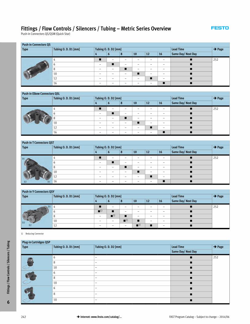
FAST Program Catalog – Subject to change – 2014/06242 � Internet: www.festo.com/catalog/...
Fittings / Flow Controls / Silencers / Tubing – Metric Series OverviewPush-in Connectors QS/QSM (Quick Star)
Push-in Connectors QS
Type Tubing O. D. D1 [mm] Tubing O. D. D2 [mm] Lead Time � Page
4 6 8 10 12 16 Same Day/ Next Day
4 � – – – – – � 252
6 – � – – – – �
8 – – � – – – �
10 – – – � – – �
12 – – – – � – �
16 – – – – – � �
Push-in Elbow Connectors QSL
Type Tubing O. D. D1 [mm] Tubing O. D. D2 [mm] Lead Time � Page
4 6 8 10 12 16 Same Day/ Next Day
4 � – – – – – � 252
6 – � – – – – �
8 – – � – – – �
10 – – – � – – �
12 – – – – � – �
16 – – – – – � �
Push-in T Connectors QST
Type Tubing O. D. D1 [mm] Tubing O. D. D2 [mm] Lead Time � Page
4 6 8 10 12 16 Same Day/ Next Day
D1
D1D2
4 � – – – – – � 252
6 – � – – – – �
8 – – � – – – �
10 – – – � – – �
12 – – – – � – �
16 – – – – – � �
Push-in Y Connectors QSY
Type Tubing O. D. D1 [mm] Tubing O. D. D2 [mm] Lead Time � Page
4 6 8 10 12 16 Same Day/ Next Day
D1
D2D2
4 � – – – – – � 252
6 �1) � – – – – �
8 – �1) � – – – �
10 – – �1) � – – �
12 – – – �1) � – �
1) Reducing Connector
Plug-in Cartridges QSP
Type Tubing O. D. D1 [mm] Tubing O. D. D2 [mm] Lead Time � Page
Same Day/ Next Day
6 – � 252
8 – �
10 – �
6 – �
8 – �
10 – �
6 – �
8 – �
10 – �
Fitt
ings
/ F
low
Con
trol
s /
Sile
ncer
s /
Tubi
ng
6

2014/06 – Subject to change – FAST Program Catalog 243� Internet: www.festo.com/catalog/...
Fittings / Flow Controls / Silencers / Tubing – Metric Series OverviewFlow Control Valves, Banjo Style
Flow Control Valves GRLA with QS Push-in Connector
Type Threaded
Connection
Tubing O. D. [mm] Lead Time � Page
3 4 6 8 12 Same Day/ Next Day
M5 – � � – – � 255
Gx – � � � – �
G¼ – – � � – �
Gy – – � � – �
G½ – – – – � �
Flow Control Valves GRLA with Female Thread
Type Screw-in Thread Connecting Thread Lead Time � Page
Gx G¼ Gy G½ Same Day/ Next Day
Gx � – – – � 255
G¼ – � – – �
Gy – – � – �
G½ – – – � �
Fitt
ings
/ F
low
Con
trol
s /
Sile
ncer
s /
Tubi
ng
6
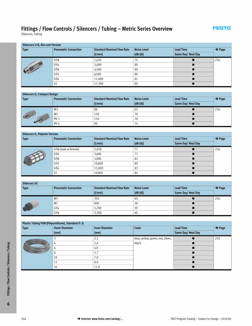
FAST Program Catalog – Subject to change – 2014/06244 � Internet: www.festo.com/catalog/...
Fittings / Flow Controls / Silencers / Tubing – Metric Series OverviewSilencers, Tubing
Silencers U-B, Die-cast Version
Type Pneumatic Connection Standard Nominal Flow Rate Noise Level Lead Time � Page
[l/min] [dB (A)] Same Day/ Next Day
Gx 1,450 74 � 256
G¼ 3,000 80 �
Gy 4,500 80 �
G½ 6,500 80 �
G¾ 11,000 81 �
G1 17,300 80 �
Silencers U, Compact Design
Type Pneumatic Connection Standard Nominal Flow Rate Noise Level Lead Time � Page
[l/min] [dB (A)] Same Day/ Next Day
M3 80 65 � 256
M5 150 70 �
PK-3 110 70 �
PK-4 90 74 �
Silencers U, Polymer Version
Type Pneumatic Connection Standard Nominal Flow Rate Noise Level Lead Time � Page
[l/min] [dB (A)] Same Day/ Next Day
Gx (male or female) 2,050 77 � 256
G¼ 3,400 77 �
Gy 5,900 82 �
G½ 10,600 80 �
G¾ 15,000 83 �
G1 19,900 84 �
Silencers UC
Type Pneumatic Connection Standard Nominal Flow Rate Noise Level Lead Time � Page
[l/min] [dB (A)] Same Day/ Next Day
M5 350 60 � 256
M7 800 58 �
G¼ 1,700 59 �
Gx 3,200 60 �
Plastic Tubing PUN (Polyurethane), Standard O. D.
Type Outer Diameter Inner Diameter Color Lead Time � Page
[mm] [mm] Same Day/ Next Day
3 2.1 blue, yellow, green, red, silver,
black
� 259
4 2.6 �
6 4.0 �
8 5.7 �
10 7.0 �
12 8.0 �
16 11.0 �
Fitt
ings
/ F
low
Con
trol
s /
Sile
ncer
s /
Tubi
ng
6

2014/06 – Subject to change – FAST Program Catalog 245� Internet: www.festo.com/catalog/...
Push-in Fittings and ConnectorsOverview
� Simple and reliable connection and release
� With R, G, NPT and metric thread
� Wide range of variants
� Many more push-in fittings, connectors, variants and
accessories available via www.festo.com/catalog/qs or /qb
Operating Conditions
Mini Standard Quick Basic
QSM QS QB, QS-H
Operating medium Compressed air in accordance with ISO 8573-1:2010 [7:–:–]
Note on operating/pilot medium Operation with lubricated medium possible
Operating pressure –0.95 … +14 bar –0.95 … +8 bar
28.5 in Hg … 206 psi 28.5 in Hg … 147 psi
Operating temperature –10 … +80 °C 0 … 60 °C
14 … 176 °F 32 … 140 °F
Contents
– Overview � 246
Inch Series Hybrid Series Metric Series
– Quick Basic – Quick Star – Quick Star
– Push-in Fittings � 247 – Push-in Fittings � 250 – Push-in Fittings � 251
– Push-in Connectors � 249 – Push-in Connectors � 252
– Quick Basic
– Push-in Fittings � 250
Fitt
ings
/ F
low
Con
trol
s /
Sile
ncer
s /
Tubi
ng
6
Detailed product information � www.festo.com/catalog/<type>

FAST Program Catalog – Subject to change – 2014/06246 � Internet: www.festo.com/catalog/...
Push-in Fittings and ConnectorsOverview
Inch Series
Design Connection
Thread For tubing O.D. [in]
Push-in Fittings
Straight Male thread 10-32 UNF, ÁNPT, ¼NPT, ÅNPT, ½NPT Á, Â, Ã, ¼, Ä, Å, ½
L-shape Male thread 10-32 UNF, ÁNPT, ¼NPT, ÅNPT, ½NPT Á, Â, Ã, ¼, Ä, Å, ½
T-shape 10-32 UNF, ÁNPT, ¼NPT, ÅNPT, ½NPT Á, Â, Ã, ¼, Ä, Å, ½
Y-shape 10-32 UNF, ÁNPT, ¼NPT, ÅNPT, ½NPT Â, Ã, ¼, Ä, Å, ½
Push-in Connectors
Straight – Â, Ã, ¼, Ä, Å, ½
L-shape – Â, Ã, ¼, Ä, Å, ½
T-shape – Â, Ã, ¼, Ä, Å, ½
Y-shape – Â, Ã, ¼, Ä, Å, ½
Plug-in Cartridges – ¼, Ä, Å
Hybrid Series
Design Connection
Thread For tubing O.D. [in]
Push-in Fittings
Straight M3, M5, M7, RÁ, R¼, RÅ, R½ Á, Â, Ã, ¼, Ä, Å, ½
L-shape M5, M7, RÁ, R¼, RÅ, R½ Á, Â, Ã, ¼, Ä, Å, ½
T-shape M5, RÁ, R¼, RÅ, R½ Á, Â, Ã, ¼, Ä, Å, ½
Metric Series
Design Connection
Thread For tubing O.D. [mm]
Push-in Fittings
Straight M3, M5, M7, RÁ, R¼, RÅ, R½ 3, 4, 6, 8, 10, 12, 16
L-shape RÁ, R¼, RÅ, R½ 4, 6, 8, 10, 12, 16
T-shape RÁ, R¼, RÅ, R½ 4, 6, 8, 10, 12, 16
Push-in Connectors
Straight – 4, 6, 8, 10, 12, 16
L-shape – 4, 6, 8, 10, 12, 16
T-shape – 4, 6, 8, 10, 12, 16
Y-shape – 4, 6, 8, 10, 12
Plug-in Cartridges – 6, 8, 10
Accessories
Blanking Plugs M5, M7, GÁ, G¼, G½ –
Fitt
ings
/ F
low
Con
trol
s /
Sile
ncer
s /
Tubi
ng
6

2014/06 – Subject to change – FAST Program Catalog 247� Internet: www.festo.com/catalog/...
Push-in Fittings QB, Quick Basic – Inch SeriesOrdering Data
Push-in Fitting QB-…-U
Male thread with external hex
Thread Tubing
O.D. [in]
Part No. Type PU1)
UNF thread with sealing ring
10-32
UNF
x 533266 QBM-10-32-UNF-x-U 10
 533267 QB-10-32-UNF-Â-U 10
à 533268 QB-10-32-UNF-Ã-U 10
¼ 533269 QB-10-32-UNF-¼-U 10
NPT thread
xNPT x 533270 QBM-x-x-U 10
 533271 QB-x-Â-U 10
à 533272 QB-x-Ã-U 10
¼ 533273 QB-x-¼-U 10
Ä 533274 QB-x-Ä-U 10
Å 567773 QB-x-Å-U 10
¼NPT Â 567772 QB-¼-Â-U 10
à 533275 QB-¼-Ã-U 10
¼ 533276 QB-¼-¼-U 10
Ä 533277 QB-¼-Ä-U 10
y 533278 QB-¼-y-U 10
½ 567771 QB-¼-½-U 5
yNPT ¼ 533279 QB-y-¼-U 10
Ä 533280 QB-y-Ä-U 10
y 533281 QB-y-y-U 5
½ 533282 QB-y-½-U 5
½NPT Ä 567770 QB-½-Ä-U 10
y 533283 QB-½-y-U 5
½ 533284 QB-½-½-U 5
Push-in L-fitting QBL-…-U
Rotatable 360°, male thread with external hex
Thread Tubing
O.D. [in]
Part No. Type PU1)
UNF thread with sealing ring
10-32
UNF
x 533285 QBML-10-32-UNF-x-U 10
 533286 QBL-10-32-UNF-Â-U 10
à 533287 QBL-10-32-UNF-Ã-U 10
¼ 533288 QBL-10-32-UNF-¼-U 10
NPT thread
xNPT x 533289 QBML-x-x-U 10
 533290 QBL-x-Â-U 10
à 533291 QBL-x-Ã-U 10
¼ 533292 QBL-x-¼-U 10
Ä 533293 QBL-x-Ä-U 10
Å 567777 QBL-x-Å-U 10
¼NPT Â 567776 QBL-¼-Â-U 10
à 533294 QBL-¼-Ã-U 10
¼ 533295 QBL-¼-¼-U 10
Ä 533296 QBL-¼-Ä-U 5
y 533297 QBL-¼-y-U 5
½ 567775 QBL-¼-½-U 5
yNPT Ã 567763 QBL-y-Ã-U 10
¼ 533298 QBL-y-¼-U 5
Ä 533299 QBL-y-Ä-U 5
y 533300 QBL-y-y-U 5
½ 533301 QBL-y-½-U 5
½NPT y 533302 QBL-½-y-U 5
½ 533303 QBL-½-½-U 5
Fitt
ings
/ F
low
Con
trol
s /
Sile
ncer
s /
Tubi
ng
6Lead Time LT for all products on this page: 1D typically ships same day/next day
1) Packaging unit per part (minimum ordering quantity).

FAST Program Catalog – Subject to change – 2014/06248 � Internet: www.festo.com/catalog/...
Push-in Fittings QB, Quick Basic – Inch SeriesOrdering Data
Push-in T-fitting QBT-…-U
Rotatable 360°, male thread with external hex
Thread Tubing
O.D. [in]
Part No. Type PU1)
UNF thread with sealing ring
10-32
UNF
x 533304 QBMT-10-32-UNF-x-U 10
 533305 QBT-10-32-UNF-Â-U 10
à 533304 QBT-10-32-UNF-Ã-U 10
¼ 533307 QBT-10-32-UNF-¼-U 10
NPT thread
xNPT x 533308 QBMT-x-x-U 10
 533309 QBT-x-Â-U 10
à 533310 QBT-x-Ã-U 10
¼ 533311 QBT-x-¼-U 10
Ä 533312 QBT-x-Ä-U 10
Å 567767 QBT-x-Å-U 5
¼NPT Â 567778 QBT-¼-Â-U 10
à 533313 QBT-¼-Ã-U 10
¼ 533314 QBT-¼-¼-U 10
Ä 533315 QBT-¼-Ä-U 5
y 533316 QBT-¼-y-U 5
y 567768 QBT-¼-½-U 5
yNPT Ã 567769 QBT-y-Ã-U 10
¼ 533317 QBT-y-¼-U 5
Ä 533318 QBT-y-Ä-U 5
y 533319 QBT-y-y-U 5
½ 533320 QBT-y-½-U 5
½NPT y 533321 QBT-½-y-U 5
½ 533322 QBT-½-½-U 5
Push-in T-fitting QBY-…-U
Rotatable 360°, male thread with external hex
Thread Tubing
O.D. [in]
Part No. Type PU1)
UNF thread with sealing ring
10-32
UNF
 564684 QBY-10-32-UNF-Â-U 10
à 564685 QBY-10-32-UNF-Ã-U 10
¼ 564686 QBY-10-32-UNF-¼-U 10
NPT thread
xNPT Â 564687 QBY-x-Â-U 10
à 564688 QBY-x-Ã-U 10
¼ 564689 QBY-x-¼-U 10
Ä 564690 QBY-x-Ä-U 10
Å 564691 QBY-x-Å-U 5
¼NPT Â 564692 QBY-¼-Â-U 10
à 564693 QBY-¼-Ã-U 10
¼ 564694 QBY-¼-¼-U 10
Ä 564695 QBY-¼-Ä-U 10
y 564696 QBY-¼-y-U 5
½ 564697 QBY-¼-½-U 5
yNPT Ã 564698 QBY-y-Ã-U 10
¼ 564698 QBY-y-¼-U 10
Ä 564700 QBY-y-Ä-U 10
y 564701 QBY-y-y-U 5
½ 564702 QBY-y-½-U 5
½NPT Ä 564703 QBY-½-Ä-U 5
y 564704 QBY-½-y-U 5
½ 564705 QBY-½-½-U 5
Fitt
ings
/ F
low
Con
trol
s /
Sile
ncer
s /
Tubi
ng
6Lead Time LT for all products on this page: 1D typically ships same day/next day
1) Packaging unit per part (minimum ordering quantity).

2014/06 – Subject to change – FAST Program Catalog 249� Internet: www.festo.com/catalog/...
Push-in Connectors QB, Quick Basic, Plug-in Cartridges QSPK, Quick Star – Inch SeriesOrdering Data
Push-in Connector QB
Tubing O.D. [in] Part No. Type PU1)
  564754 QB-ÂT-U 10
à à 564755 QB-ÃT-U 10
¼ ¼ 564756 QB-¼T-U 10
Ä Ä 564757 QB-ÄT-U 10
y y 564758 QB-yT-U 10
½ ½ 564759 QB-½T-U 5
Reducing
à  564797 QB-ÃT-Â-U 10
¼ Â 564798 QB-¼T-Â-U 10
à 564799 QB-¼T-Ã-U 10
Ä Â 564800 QB-ÄT-ÂU 10
¼ 564801 QB-ÄT-¼-U 10
y Ä 564802 QB-ÅT-Ä-U 10
¼ 564803 QB-ÄT-¼-U 10
½ y 564804 QB-½T-y-U 5
Push-in L-connector QBL
Tubing O.D. [in] Part No. Type PU1)
  564760 QBL-ÂT-U 10
à à 564761 QBL-ÃT-U 10
¼ ¼ 564762 QBL-¼T-U 10
Ä Ä 564763 QBL-ÄT-U 10
y y 564764 QBL-yT-U 10
½ ½ 564765 QBL-½T-U 5
Push-in T-connector QBT
Tubing O.D. [in] Part No. Type PU1)
  564766 QBT-ÂT-U 10
à à 564767 QBT-ÃT-U 10
¼ ¼ 564768 QBT-¼T-U 10
Ä Ä 564769 QBT-ÄT-U 10
y y 564770 QBT-yT-U 5
½ ½ 564771 QBT-½T-U 5
1 reducing outlet D2
¼ Â 564805 QBT-¼T-Â-U 10
Ä ¼ 564806 QBT-ÄT-¼-U 10
y ¼ 564807 QBT-yT-¼-U 10
Ä 564808 QBT-yT-Ä-U 10
½ y 564809 QBT-½T-y-U 5
Push-in Y-connector QBY
Tubing O.D. [in] Part No. Type PU1)
  564772 QBY-ÂT-U 10
à à 564773 QBY-ÃT-U 10
¼ ¼ 564774 QBY-¼T-U 10
Ä Ä 564775 QBY-ÄT-U 10
y y 564776 QBY-yT-U 5
½ ½ 564777 QBY-½T-U 5
2 reducing outlets D2
à  564818 QBY-ÃT-Â-U 10
¼ Â 564819 QBY-¼T-Â-U 10
à 564820 QBY-¼T-Ã-U 10
Ä Â 564821 QBY-ÄT-Â-U 10
¼ 564822 QBY-ÄT-¼-U 10
y ¼ 564823 QBY-yT-¼-U 10
Ä 564824 QBY-yT-Ä-U 10
½ Ä 564823 QBY-½T-Ä-U 5
y 564825 QBY-½T-y-U 5
Plug-in Cartridge QSPK
Tubing O.D. [in] Part No. Type PU1)
¼ 132172 QSPK18-¼-U 10
Ä 132173 QSPK18-Ä-U 10
y 132174 QSPK18-Å-U 10
Plug-in L-Cartridge QSPKL
Tubing O.D. [in] Part No. Type PU1)
¼ 132176 QSPLK18-¼-U 10
Ä 132177 QSPLK18-Ä-U 10
y 132641 QSPLK18-Å-U 10
Long Plug-in L-Cartridge QSPKLL
Tubing O.D. [in] Part No. Type PU1)
¼ 132179 QSPLLK18-¼-U 10
Ä 132180 QSPLLK18-Ä-U 10
y 132642 QSPLLK18-Å-U 10Fi
ttin
gs /
Flo
w C
ontr
ols
/ S
ilenc
ers
/ Tu
bing
6Lead Time LT for all products on this page: 1D typically ships same day/next day
1) Packaging unit per part (minimum ordering quantity).
D1
D1D2
D1
D2

FAST Program Catalog – Subject to change – 2014/06250 � Internet: www.festo.com/catalog/...
Push-in Fittings QS, Quick Star / QB, Quick Basic – Hybrid SeriesOrdering Data
Push-in Fitting QS-…-I-U-M
Male thread with internal hex
Thread Tubing
O.D. [in]
Part No. Type PU1)
Metric thread with sealing ring
M3 x 183751 QSM-M3-x-I-U-M 1
 130592 QSM-M3-Â-I-U-M 1
à 183752 QSM-M3-Ã-I-U-M 1
M5 x 183749 QSM-M5-x-I-U-M 1
 130593 QSM-M5-Â-I-U-M 1
à 183750 QSM-M5-Ã-I-U-M 1
¼ 130591 QSM-M5-¼-I-U-M 1
192808 QS-M5-¼-I-U-M 1
M7 x 183738 QSM-M7-x-I-U-M 1
à 183739 QSM-M7-Ã-I-U-M 1
¼ 183740 QSM-M7-¼-I-U-M 1
R thread
Rx ¼ 183741 QS-x-¼-I-U-M 1
Ä 183742 QS-x-Ä-I-U-M 1
R¼ ¼ 192809 QS-¼-¼-I-U-M 1
Ä 183743 QS-¼-Ä-I-U-M 1
y 183744 QS-¼-y-I-U-M 1
Ry Ä 183745 QS-y-Ä-I-U-M 1
y 183746 QS-y-y-I-U-M 1
R½ y 183747 QS-½-y-I-U-M 1
½ 183748 QS-½-½-I-U-M 1
Push-in Fitting QB-…-U-M
Male thread with external hex
Thread Tubing
O.D. [in]
Part No. Type PU1)
Metric thread with sealing ring
M5 x 533209 QBM-M5-x-U-M 10
 533210 QB-M5-Â-U-M 10
à 533211 QB-M5-Ã-U-M 10
¼ 533212 QB-M5-¼-U-M 10
R thread
Rx x 533213 QBM-x-x-U-M 10
 533214 QB-x-Â-U-M 10
à 533215 QB-x-Ã-U-M 10
¼ 533216 QB-x-¼-U-M 10
Ä 533217 QB-x-Ä-U-M 10
R¼ Ã 533218 QB-¼-Ã-U-M 10
¼ 533219 QB-¼-¼-U-M 10
Ä 533220 QB-¼-Ä-U-M 10
y 533221 QB-¼-y-U-M 10
Ry ¼ 533222 QB-y-¼-U-M 10
Ä 533223 QB-y-Ä-U-M 10
y 533224 QB-y-y-U-M 5
½ 533225 QB-y-½-U-M 5
R½ y 533226 QB-½-y-U-M 5
½ 533227 QB-½-½-U-M 5
Push-in L-fitting QBL-…-U-M
Rotatable 360°, male thread with external hex
Thread Tubing
O.D. [in]
Part No. Type PU1)
Metric thread with sealing ring
M5 x 533228 QBML-M5-x-U-M 10
 533229 QBL-M5-Â-U-M 10
à 533230 QBL-M5-Ã-U-M 10
¼ 533231 QBL-M5-¼-U-M 10
R thread
Rx x 533232 QBML-x-x-U-M 10
 533233 QBL-x-Â-U-M 10
à 533234 QBL-x-Ã-U-M 10
¼ 533235 QBL-x-¼-U-M 10
Ä 533236 QBL-x-Ä-U-M 10
R¼ Ã 533237 QBL-¼-Ã-U-M 10
¼ 533238 QBL-¼-¼-U-M 10
Ä 533239 QBL-¼-Ä-U-M 10
y 533240 QBL-¼-y-U-M 5
Ry ¼ 533241 QBL-y-¼-U-M 5
Ä 533242 QBL-y-Ä-U-M 5
y 533243 QBL-y-y-U-M 5
½ 533244 QBL-y-½-U-M 5
R½ y 533245 QBL-½-y-U-M 5
½ 533246 QBL-½-½-U-M 5
Push-in T-fitting QBT-…-U-M
Rotatable 360°, male thread with external hex
Thread Tubing
O.D. [in]
Part No. Type PU1)
Metric thread with sealing ring
M5 x 533247 QBMT-M5-x-U-M 10
 533248 QBT-M5-Â-U-M 10
à 533249 QBT-M5-Ã-U-M 10
¼ 533250 QBT-M5-¼-U-M 10
R thread
Rx x 533251 QBMT-x-x-U-M 10
 533252 QBT-x-Â-U-M 10
à 533253 QBT-x-Ã-U-M 10
¼ 533254 QBT-x-¼-U-M 10
Ä 533255 QBT-x-Ä-U-M 5
R¼ Ã 533256 QBT-¼-Ã-U-M 10
¼ 533257 QBT-¼-¼-U-M 5
Ä 533258 QBT-¼-Ä-U-M 5
y 533259 QBT-¼-y-U-M 5
Ry ¼ 533260 QBT-y-¼-U-M 5
Ä 533261 QBT-y-Ä-U-M 5
y 533262 QBT-y-y-U-M 5
½ 533263 QBT-y-½-U-M 5
R½ y 533264 QBT-½-y-U-M 5
½ 533265 QBT-½-½-U-M 5
Fitt
ings
/ F
low
Con
trol
s /
Sile
ncer
s /
Tubi
ng
6Lead Time LT for all products on this page: 1D typically ships same day/next day
1) Packaging unit per part (minimum ordering quantity).

2014/06 – Subject to change – FAST Program Catalog 251� Internet: www.festo.com/catalog/...
Push-in Fittings QS, Quick Star – Metric SeriesOrdering Data
Push-in fitting QS-…-I
Male thread with internal hex
Thread Tubing
O.D. [mm]
Part No. Type PU1)
Metric thread with sealing ring
M3 3 153312 QSM-M3-3-I 1
4 153314 QSM-M3-4-I 1
M5 3 153313 QSM-M5-3-I 1
4 153315 QSM-M5-4-I 1
6 153317 QSM-M5-6-I 1
M7 4 153319 QSM-M7-4-I 1
6 153321 QSM-M7-6-I 1
R thread
Rx 4 153012 QS-x-4-I 1
6 153013 QS-x-6-I 1
8 153015 QS-x-8-I 1
R¼ 10 153018 QS-¼-10-I 1
G thread
Gx 6 186107 QS-Gx-6-I 1
8 186109 QS-Gx-8-I 1
G¼ 8 186110 QS-G¼-8-I 1
10 186112 QS-G¼-10-I 1
Push-in fitting QS
Male thread with external hex
Thread Tubing
O.D. [mm]
Part No. Type PU1)
Metric thread with sealing ring
M5 4 153304 QSM-M5-4 1
6 153306 QSM-M5-6 1
R thread
Rx 4 153001 QS-x-4 1
6 153002 QS-x-6 1
8 153004 QS-x-8 1
10 190643 QS-x-10 1
R¼ 4 190644 QS-¼-4 1
6 153003 QS-¼-6 1
8 153005 QS-¼-8 1
10 153007 QS-¼-10 1
12 164980 QS-¼-12 1
Ry 6 190645 QS-y-6 1
8 153006 QS-y-8 1
10 153008 QS-y-10 1
12 153009 QS-y-12 1
16 164957 QS-y-16 1
R½ 10 190646 QS-½-10 1
12 153010 QS-½-12 1
16 153011 QS-½-16 1
Push-in L-fitting QSL
Rotatable 360°, male R thread with external hex
Thread Tubing
O.D. [mm]
Part No. Type PU1)
Rx 4 153045 QSL-x-4 1
6 153046 QSL-x-6 1
8 153048 QSL-x-8 1
10 190658 QSL-x-10 1
R¼ 4 190659 QSL-¼-4 1
6 153047 QSL-¼-6 1
8 153049 QSL-¼-8 1
10 153051 QSL-¼-10 1
12 164981 QSL-¼-12 1
Ry 6 190660 QSL-y-6 1
8 153050 QSL-y-8 1
10 153052 QSL-y-10 1
12 153053 QSL-y-12 1
16 164958 QSL-y-16 1
R½ 10 190661 QSL-½-10 1
12 153054 QSL-½-12 1
16 153055 QSL-½-16 1
Push-in T-fitting QST
Rotatable 360°, male R thread with external hex
Thread Tubing
O.D. [mm]
Part No. Type PU1)
Rx 4 153106 QST-x-4 1
6 153107 QST-x-6 1
8 153109 QST-x-8 1
10 190667 QST-x-10 1
R¼ 4 190668 QST-¼-4 1
6 153108 QST-¼-6 1
8 153110 QST-¼-8 1
10 153112 QST-¼-10 1
12 190669 QST-¼-12 1
Ry 6 190670 QST-y-6 1
8 153111 QST-y-8 1
10 153113 QST-y-10 1
12 153114 QST-y-12 1
16 164959 QST-y-16 1
R½ 10 190672 QST-½-10 1
12 153115 QST-½-12 1
16 153116 QST-½-16 1
Blanking plugs
Thread ß Part No. Type PU1)
M5 External
hex
174308 B-M5-B 10
M7 174309 B-M7 10
Gx Internal
hex
3568 B-x 10
556857 QSC-F-Gx-I 10
G¼ 3569 B-¼ 10
G½ 3571 B-½ 10 Fitt
ings
/ F
low
Con
trol
s /
Sile
ncer
s /
Tubi
ng
6Lead Time LT for all products on this page: 1D typically ships same day/next day
1) Packaging unit per part (minimum ordering quantity).

FAST Program Catalog – Subject to change – 2014/06252 � Internet: www.festo.com/catalog/...
Push-in Connectors QS, Plug-in Cartridges QSPK, Quick Star – Metric SeriesOrdering Data
Push-in Connector QS
Tubing O.D. [mm] Part No. Type PU1)
4 4 153031 QS-4 1
6 6 153032 QS-6 1
8 8 153033 QS-8 1
10 10 153034 QS-10 1
12 12 153035 QS-12 1
16 16 153036 QS-16 1
Push-in L-connector QSL
Tubing O.D. [mm] Part No. Type PU1)
4 4 153070 QSL-4 1
6 6 153071 QSL-6 1
8 8 153072 QSL-8 1
10 10 153073 QSL-10 1
12 12 153074 QSL-12 1
16 16 153075 QSL-16 1
Push-in T-connector QST
Tubing O.D. [mm] Part No. Type PU1)
4 4 153128 QST-4 1
6 6 153129 QST-6 1
8 8 153130 QST-8 1
10 10 153131 QST-10 1
12 12 153132 QST-12 1
16 16 153133 QST-16 1
Reducing D2
6 4 153134 QST-6-4 1
8 6 153135 QST-8-6 1
10 8 153136 QST-10-8 1
12 10 153137 QST-12-10 1
Push-in Y-connector QSY
Tubing O.D. [mm] Part No. Type PU1)
4 4 153148 QSY-4 1
6 6 153149 QSY-6 1
8 8 153150 QSY-8 1
10 10 153151 QSY-10 1
12 12 153152 QSY-12 1
2 reducing outlets D2
6 4 153153 QSY-6-4 1
8 6 153154 QSY-8-6 1
10 8 153155 QSY-10-8 1
12 10 153156 QSY-12-10 1
Plug-in Cartridge QSPK
Tubing O.D. [mm] Part No. Type PU1)
6 130840 QSPK18-6 10
8 130841 QSPK18-8 10
10 130842 QSPK18-10 10
Plug-in L-Cartridge QSPKL
Tubing O.D. [mm] Part No. Type PU1)
6 130844 QSPLK18-6 10
8 130845 QSPLK18-8 10
10 132639 QSPLK18-10 10
Long Plug-in L-Cartridge QSPKLL
Tubing O.D. [mm] Part No. Type PU1)
6 130847 QSPLLK18-6 10
8 130848 QSPLLK18-8 10
10 132640 QSPLLK18-10 10
Fitt
ings
/ F
low
Con
trol
s /
Sile
ncer
s /
Tubi
ng
6Lead Time LT for all products on this page: 1D typically ships same day/next day
1) Packaging unit per part (minimum ordering quantity).
D1
D1D2
D1
D2

2014/06 – Subject to change – FAST Program Catalog 253� Internet: www.festo.com/catalog/...
Flow Control ValvesOverview
� One-way flow control valves for exhaust air flow control
� With male thread M5 … G½, 10-32 UNF … ½NPT
and push-in connector 4 … 12 mm and  … ½”
� With male and female thread Gx … G½, yNPT … ½NPT
� Polymer and metal designs
� Many more variants and dimensions available via
www.festo.com/catalog/grla
Product Range Overview – Inch Series
Type Adjustment Material Connection
Thread For tubing O.D. [in]2)
Flow control valve with QB Quick Basic push-in connector1)
GRLA-…-QB-…-U via knurled head screw Polymer 10-32 UNF, xNPT, ¼NPT, yNPT, ½NPT x, Â, ¼, Ä, Å, ½
Flow control valve with 2 QB Quick Basic push-in connectors1)
GR-…-QB-…-U via knurled head screw Polymer – Â, Ã, ¼, Ä, Å, ½
Flow control valve with female thread connection
GRLA-…-NPT-B via slotted head screw Metal xNPT, ¼NPT, yNPT, ½NPT –
Product Range Overview – Metric Series
Type Adjustment Material Connection
Thread For tubing O.D. [mm]2)
Flow control valve with QS push-in connector1)
GRLA-…-QS-…-RS-D via knurled screw Metal M5, Gx 4, 6
GRLA-…-QS-…-RS-B via knurled screw Polymer Gx, G¼, Gy 6, 8
GRLA-…-QS-…-D via slotted head screw Metal G½ 12
Flow control valve with female thread connection
GRLA-…-RS-B via knurled screw Metal Gx, G¼ –
GRLA-…-B via slotted head screw Metal Gx, G¼, Gy, G½ –
1) Rotatable 360° around the screw-in axis after installation.
2) Different threaded connections are assigned more than one QS push-in connector size.
Fitt
ings
/ F
low
Con
trol
s /
Sile
ncer
s /
Tubi
ng
6
Detailed product information � www.festo.com/catalog/grla

FAST Program Catalog – Subject to change – 2014/06254 � Internet: www.festo.com/catalog/...
Flow Control Valves – Inch SeriesOrdering Data
Ordering Data – Flow Control Valves with QB Quick Basic Push-in Connector
Thread QS push-in
connector
[in]
Part No. Type PU1)
Exhaust air flow control via knurled screw
10-32
UNF
Á 564839 GRLA-10-32-UNF-QB-Á-U 10
 564840 GRLA-10-32-UNF-QB-Â-U 1
¼ 564842 GRLA-10-32-UNF-QB-¼-U 1
xNPT Â 534656 GRLA-Á-QB-Â-U 1
¼ 534658 GRLA-Á-QB-¼-U 1
Ä 534659 GRLA-Á-QB-Ä-U 1
¼NPT Â 564843 GRLA-¼-QB-Â-U 1
¼ 534661 GRLA-¼-QB-¼-U 1
Ä 534662 GRLA-¼-QB-Ä-U 1
Å 534663 GRLA-¼-QB-Å-U 1
yNPT ¼ 534664 GRLA-Å-QB-¼-U 1
Ä 534665 GRLA-Å-QB-Ä-U 1
Å 534666 GRLA-Å-QB-Å-U 1
½ 534667 GRLA-Å-QB-½-U 1
½NPT Ä 564845 GRLA-½-QB-Ä-U 1
Å 564846 GRLA-½-QB-Å-U 1
½ 564847 GRLA-½-QB-½-U 1
Ordering Data – Flow Control Valves with QB Quick Basic Push-in Connector
QS push-in
connector [in]
Part No. Type PU1)
Exhaust air flow control via knurled screw
 534680 GR-QB-Â-U 1
¼ 534682 GR-QB-¼-U 1
Ä 534683 GR-QB-Ä-U 1
Å 534684 GR-QB-Å-U 1
½ 534685 GR-QB-½-U 1
Ordering Data – Flow Control Valves with Female Thread
Screw-in
thread
Con
necting
thread
Part No. Type PU1)
Exhaust air flow control via slotted head screw
ÁNPT ÁNPT 151539 GRLA-Á-NPT-B 1
¼NPT ¼NPT 151547 GRLA-¼-NPT-B 1
yNPT yNPT 151555 GRLA-Å-NPT-B 1
½NPT ½NPT 151559 GRLA-½-NPT-B 1
Fitt
ings
/ F
low
Con
trol
s /
Sile
ncer
s /
Tubi
ng
6Lead Time LT for all products on this page: 1D typically ships same day/next day
1) Packaging unit per part (minimum ordering quantity).

2014/06 – Subject to change – FAST Program Catalog 255� Internet: www.festo.com/catalog/...
Flow Control Valves – Metric SeriesOrdering Data
Ordering Data – Flow Control Valves with QS Push-in Connector
Thread QS push-in
connector
[mm]
Part No. Type PU1)
Exhaust air flow control via knurled screw, low flow
M5 4 197577 GRLA-M5-QS-4-RS-D 1
6 197578 GRLA-M5-QS-6-RS-D 1
Gx 4 197580 GRLA-x-QS-4-RS-D 1
6 197581 GRLA-x-QS-6-RS-D 1
Exhaust air flow control via knurled screw
Gx 6 162965 GRLA-x-QS-6-RS-B 1
8 162966 GRLA-x-QS-8-RS-B 1
G¼ 6 162967 GRLA-¼-QS-6-RS-B 1
8 162968 GRLA-¼-QS-8-RS-B 1
Gy 6 162969 GRLA-y-QS-6-RS-B 1
8 162970 GRLA-y-QS-8-RS-B 1
Exhaust air flow control via slotted head screw, low flow
G½ 12 193152 GRLA-½-QS-12-D 1
Ordering Data – Flow Control Valves with Female Thread
Screw-in
thread
Connect
ing thread
Part No. Type PU1)
Exhaust air flow control via slotted head screw
Gx Gx 151165 GRLA-Á-B 1
G¼ G¼ 151172 GRLA-¼-B 1
Gy Gy 151178 GRLA-Å-B 1
G½ G½ 151179 GRLA-½-B 1
Exhaust air flow control via knurled screw
Gx Gx 151169 GRLA-Á-RS-B 1
G¼ G¼ 151175 GRLA-¼-RS-B 1
Fitt
ings
/ F
low
Con
trol
s /
Sile
ncer
s /
Tubi
ng
6Lead Time LT for all products on this page: 1D typically ships same day/next day
1) Packaging unit per part (minimum ordering quantity).

FAST Program Catalog – Subject to change – 2014/06256 � Internet: www.festo.com/catalog/...
SilencersOverview
� Compact design
� High flow rates up to 19,900 l/min (700 scfm)
� Wide range of variants:
M3 to M7, Gx to G1, xNPT to ½NPT and barbed connector
Product Range Overview
Function Type Version Pneumatic connection � Page
Silencer U Sintered metal M3, M5 257
Polymer Gx, G¼, Gy, G½, G¾, G1
Die-cast metal Gx, G¼, Gy, G½, G¾, G1
Die-cast metal xNPT, ¼NPT, yNPT, ½NPT
UC Polyethylene M5, M7
Gx, G¼
U-PK Brass / bronze Barbed connector PK-3, PK-4
Operating Conditions
Operating medium Compressed air in accordance with ISO 8573-1:2010 [7:–:–]
Note on operating/pilot medium Operation with lubricated medium possible
Operating pressure [bar] 0 … 10
[psi] 0 … 147
Ambient temperature1) [°C] –10 … +70
[°F] 14 … 158
1) Note operating range of tubing used.
Note
Clean silencers with kerosene or
benzene (not with trichloroethylene).
Fitt
ings
/ F
low
Con
trol
s /
Sile
ncer
s /
Tubi
ng
6
Detailed product information � www.festo.com/catalog/u
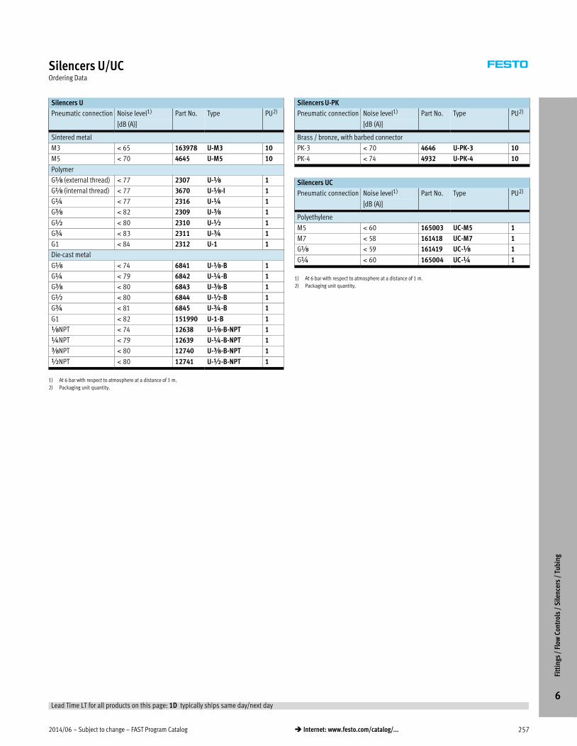
2014/06 – Subject to change – FAST Program Catalog 257� Internet: www.festo.com/catalog/...
Silencers U/UCOrdering Data
Silencers U
Pneumatic connection Noise level1) Part No. Type PU2)
[dB (A)]
Sintered metal
M3 65 163978 U-M3 10
M5 70 4645 U-M5 10
Polymer
Gx (external thread) 77 2307 U-x 1
Gx (internal thread) 77 3670 U-x-I 1
G¼ 77 2316 U-¼ 1
Gy 82 2309 U-y 1
G½ 80 2310 U-½ 1
G¾ 83 2311 U-¾ 1
G1 84 2312 U-1 1
Die-cast metal
Gx 74 6841 U-x-B 1
G¼ 79 6842 U-¼-B 1
Gy 80 6843 U-y-B 1
G½ 80 6844 U-½-B 1
G¾ 81 6845 U-¾-B 1
G1 82 151990 U-1-B 1
xNPT 74 12638 U-x-B-NPT 1
¼NPT 79 12639 U-¼-B-NPT 1
yNPT 80 12740 U-y-B-NPT 1
½NPT 80 12741 U-½-B-NPT 1
1) At 6 bar with respect to atmosphere at a distance of 1 m.
2) Packaging unit quantity.
Silencers U-PK
Pneumatic connection Noise level1) Part No. Type PU2)
[dB (A)]
Brass / bronze, with barbed connector
PK-3 70 4646 U-PK-3 10
PK-4 74 4932 U-PK-4 10
Silencers UC
Pneumatic connection Noise level1) Part No. Type PU2)
[dB (A)]
Polyethylene
M5 60 165003 UC-M5 1
M7 58 161418 UC-M7 1
Gx 59 161419 UC-x 1
G¼ 60 165004 UC-¼ 1
1) At 6 bar with respect to atmosphere at a distance of 1 m.
2) Packaging unit quantity.
Fitt
ings
/ F
low
Con
trol
s /
Sile
ncer
s /
Tubi
ng
6Lead Time LT for all products on this page: 1D typically ships same day/next day

FAST Program Catalog – Subject to change – 2014/06258 � Internet: www.festo.com/catalog/...
Plastic Tubing PUN, Standard O.D. – Inch SeriesOverview, Ordering Data
� Standard O.D. tubing, suitable for QS and QB push-in fittings
� Wide range of diameters
� Wide range of colors
� Flexible and kink resistant
� Excellent hydrolysis, oil and cold resistance
� Conforms to NSF requirements
Product Range Overview
Type Material Outer
[in]
Inner
[in]
Color
PUN Polyurethane,
ester-based
1/8, 5/32, 3/16, 1/4,
5/16, 3/8, 1/2
1/16, 3/32, 1/8, 5/32,
3/16, 1/4, 21/64
blue, yellow, green,
clear, red, black, white
Operating Conditions
Operating medium Compressed air in accordance with ISO 8573-1:2010 [7:–:–]
Note on operating/pilot medium Operation with lubricated medium possible
Temperature-dependent
operating pressure
[bar] –0.95 … +10
[psi] 28.5 in Hg … +150
Ambient temperature [°C] –35 … +60
[°F] –68 … +140
Hardness Shore D 52 +/-3
Ordering Data
PUN
O.D. [in] I.D. [in] Color Part No. Type1)
1/8 1/16 Blue 567945 PUN-H-1/8-BL-150-CB
Black 567953 PUN-H-1/8-SW-150-CB
5/32 3/32 Blue 567946 PUN-H-5/32-BL-150-CB
Black 567954 PUN-H-5/32-SW-150-CB
3/16 1/8 Blue 567947 PUN-H-3/16-BL-150-CB
Black 567955 PUN-H-3/16-SW-150-CB
1/4 5/32 Blue 567948 PUN-H-1/4-BL-150-CB
Black 567956 PUN-H-1/4-SW-150-CB
1) Packaging quantity is 50 meters / 150 ft
PUN
O.D. [in] I.D. [in] Color Part No. Type1)
5/16 3/16 Blue 567949 PUN-H-5/16-BL-150-CB
Black 567957 PUN-H-5/16-SW-150-CB
3/8 1/4 Blue 567950 PUN-H-3/8-BL-150-CB
Black 567958 PUN-H-3/8-SW-150-CB
1/2 21/64 Blue 567951 PUN-H-1/2-BL-150-CB
Black 567959 PUN-H-1/2-SW-150-CB
1) Packaging quantity is 50 meters / 150 ft
Fitt
ings
/ F
low
Con
trol
s /
Sile
ncer
s /
Tubi
ng
6
Detailed product information � www.festo.com/catalog/tubing
Lead Time LT for all products on this page: 1D typically ships same day/next day

2014/06 – Subject to change – FAST Program Catalog 259� Internet: www.festo.com/catalog/...
Plastic Tubing PUN, Standard O.D. – Metric SeriesOverview
� Standard O.D. tubing, suitable for QS and QB push-in fittings
� Wide range of diameters
� Wide range of colors
� Flexible and kink resistant
� Free of copper and PTFE
� Conforms to RoHS
Product Range Overview
Type Material Outer
[mm]
Inner
[mm]
Color
PUN Polyurethane,
ester-based
3, 4, 6, 8,
10, 12, 16
2.1, 2.6, 4.0, 5.7,
7.0, 8.0, 11.0
blue, yellow, green,
red, silver, black
Operating Conditions
Operating medium Compressed air in accordance with ISO 8573-1:2010 [7:–:–]
Note on operating/pilot medium Operation with lubricated medium possible
Operating medium Compressed air
Vacuum
Temperature-dependent
operating pressure
[bar] –0.95 … +10
[psi] 28.5 in Hg … +150
Ambient temperature [°C] –35 … +60
[°F] –68 … +140
Hardness Shore D 52 +/-3
Fitt
ings
/ F
low
Con
trol
s /
Sile
ncer
s /
Tubi
ng
6
Detailed product information � www.festo.com/catalog/tubing

FAST Program Catalog – Subject to change – 2014/06260 � Internet: www.festo.com/catalog/...
Plastic Tubing PUN, Standard O.D. – Metric SeriesOrdering Data
PUN
O.D. [mm] I.D. [mm] Color Part No. Type1)
3.0 2.1 Blue 159660 PUN-3X0,5-BL
Yellow 178416 PUN-3X0,5-GE
Green 178423 PUN-3X0,5-GN
Red 178409 PUN-3X0,5-RT
Silver 152583 PUN-3X0,5-SI
Black 159661 PUN-3X0,5-SW
4.0 2.6 Blue 159662 PUN-4X0,75-BL
Yellow 178417 PUN-4X0,75-GE
Green 178424 PUN-4X0,75-GN
Red 178410 PUN-4X0,75-RT
Silver 152584 PUN-4X0,75-SI
Black 159663 PUN-4X0,75-SW
6.0 4.0 Blue 159664 PUN-6X1-BL
Yellow 178418 PUN-6X1-GE
Green 178425 PUN-6X1-GN
Red 178411 PUN-6X1-RT
Silver 152586 PUN-6X1-SI
Black 159665 PUN-6X1-SW
8.0 5.7 Blue 159666 PUN-8X1,25-BL
Yellow 178419 PUN-8X1,25-GE
Green 178426 PUN-8X1,25-GN
Red 178412 PUN-8X1,25-RT
Silver 152587 PUN-8X1,25-SI
Black 159667 PUN-8X1,25-SW
1) Packaging quantity is 50 meters / 150 ft
PUN
O.D. [mm] I.D. [mm] Color Part No. Type1)
10.0 7.0 Blue 159668 PUN-10X1,5-BL
Yellow 178420 PUN-10X1,5-GE
Green 178427 PUN-10X1,5-GN
Red 178413 PUN-10X1,5-RT
Silver 152588 PUN-10X1,5-SI
Black 159669 PUN-10X1,5-SW
12.0 8.0 Blue 159670 PUN-12X2-BL
Yellow 178421 PUN-12X2-GE
Green 178428 PUN-12X2-GN
Red 178414 PUN-12X2-RT
Silver 152589 PUN-12X2-SI
Black 159671 PUN-12X2-SW
16.0 11.0 Blue 159672 PUN-16X2,5-BL
Yellow 178422 PUN-16X2,5-GE
Green 178429 PUN-16X2,5-GN
Red 178415 PUN-16X2,5-RT
Silver 152590 PUN-16X2,5-SI
Black 159673 PUN-16X2,5-SW
1) Packaging quantity is 50 meters / 150 ft
Fitt
ings
/ F
low
Con
trol
s /
Sile
ncer
s /
Tubi
ng
6Lead Time LT for all products on this page: 1D typically ships same day/next day

Supporting Advanced Automation… As No One Else Can!Festo is a leading global manufacturer of pneumatic and electromechanical systems, components and controls for industrial automation, with more than 16,000 employees in 60 national headquarters serving more than 180 countries. For more than 80 years, Festo has continuously elevated the state of manufacturing with innovations and optimized motion control solutions that deliver higher performing, more profitable automated manufacturing and processing equipment. Our dedication to the advancement of automation extends beyond technology to the education and development of current and future automation and robotics designers with simulation tools, teaching programs, and on-site services.
Quality Assurance, ISO 9001 and ISO 14001 CertificationsFesto Corporation is committed to supply all Festo products and services that will meet or exceed our customers’ requirements in product quality, delivery, customer service and satisfaction.
To meet this commitment, we strive to ensure a consistent, integrated, and systematic approach to management that will meet or exceed the requirements of the ISO 9001 standard for Quality Management and the ISO 14001 standard for Environmental Management.
© Copyright 2014, Festo Corporation. While every effort is made to ensure that all dimensions and specifications are correct, Festo cannot guarantee that publications are completely free of any error, in particular typing or printing errors. Accordingly, Festo cannot be held responsible for the same. For Liability and Warranty conditions, refer to our “Terms and Conditions of Sale”, available from your local Festo office. All rights reserved. No part of this publication may be reproduced, distributed, or transmitted in any form or by any means, electronic, mechanical, photocopying or otherwise, without the prior written permission of Festo. All technical data subject to change according to technical update.
Product Range and Company Overview
A Complete Suite and Company Overview
The Broadest Range of Automation Components
Our experienced engineers provide complete support at every stage of your development process, including: conceptualization,analysis, engineering, design, assembly, documentation, validation, and production.
With a comprehensive line of more than 30,000 automation components, Festo is capable of solving the most complexautomation requirements.
Custom Automation ComponentsComplete custom engineered solutions
Custom Control CabinetsComprehensive engineering supportand on-site services
Complete SystemsShipment, stocking and storage services
ElectromechanicalElectromechanical actuators, motors, controllers & drivers
PneumaticsPneumatic linear and rotary actuators,valves, and air supply
PLCs and I/O DevicesPLC’s, operator interfaces, sensorsand I/O devices
Printed on recycled paper at New Horizon Graphic, Inc., FSC certified as an environmental friendly printing plant.

Festo North America
Festo Regional Contact Center
Canadian CustomersCommercial Support:Tel: 1 877 GO FESTO (1 877 463 3786)Fax: 1 877 FX FESTO (1 877 393 3786)Email: [email protected]
USA CustomersCommercial Support:Tel:1 800 99 FESTO (1 800 993 3786)Fax:1 800 96 FESTO (1 800 963 3786)Email: [email protected]
Technical Support:Tel:1 866 GO FESTO (1 866 463 3786)Fax:1 877 FX FESTO(1 877 393 3786)Email: [email protected]
Technical Support:Tel:1 866 GO FESTO (1 866 463 3786)Fax:1800 96 FESTO(1 800 963 3786)Email: [email protected]
Cata
log
No.
131
0572
9
09.1
4
Festo Canada HeadquartersFesto Inc.5300 Explorer DriveMississauga, ONL4W 5G4
Montréal5600, Trans-CanadaPointe-Claire, QCH9R 1B6
Québec City2930, rue Watt#117Québec, QCG1X 4G3
Festo United StatesHeadquarters Festo Corporation395 Moreland RoadHauppauge, NY11788
Detroit1441 West Long Lake RoadTroy, MI48098
Silicon Valley4935 Southfront Road, Suite FLivermore, CA94550
AppletonNorth 922 Tower View Drive, Suite 200Greenville, WI54942
Chicago85 W Algonquin - Suite 340Arlington Heights, IL60005
6
1 2 3
4 5 7
8
Subject to change www.festo.us www.festo.ca