Electrohydraulics Basic Level - Festo Didactic
52
Workbook TP 601 With CD-ROM Festo Didactic 551150 en Electrohydraulics Basic Level -QM1 -XM1PG1 -QM2 A T P B -MB1 -MM1 -PG2 -RZ1 A B -PG1 -MB1 24 V 1 2 0V -KF1 -SF1 13 14 14 11 A1 A2 12 -KF1 12 22 32 .2 14 24 11 21
-
Upload
khangminh22 -
Category
Documents
-
view
2 -
download
0
Transcript of Electrohydraulics Basic Level - Festo Didactic

WorkbookTP 601
With CD-ROM
Festo Didactic
551150 en
ElectrohydraulicsBasic Level
-QM1
-XM1PG1
-QM2 A
TP
B
-MB1
-MM1
-PG2
-RZ1
A
B
-PG1
-MB1
24 V 1 2
0 V
-KF1
-SF1
13
14
14
11
A1
A2
12
-KF1
12
22
32
42
.214
24
34
44
11
21
31
41

Order no.: 551150
Revision level: 08/2015
Authors: Renate Aheimer, Eberhard Bauer, Frank Ebel,
Christine Löffler, Dieter Merkle, Helmut Werner
Graphics: Doris Schwarzenberger
Layout: 01/2017, Susanne Durz, Frank Ebel, Beatrice Huber
© Festo Didactic SE, Rechbergstr. 3, D-73770 Denkendorf, Germany, 2017
All rights reserved.
+49 711 3467-0 www.festo-didactic.com
+49 711 34754-88500 [email protected]
The purchaser shall receive a single right of use which is non-exclusive, non-time-limited and limited
geographically to the purchaser’s site/location as follows.
• The purchaser shall be entitled to use the contents of the documentation to train his staff at the
purchaser’s location and shall also be entitled to use parts of the contents of the documentation to
create his own training documentation for the training of his staff at the purchaser’s location with
acknowledgement of source, and to make copies for this purpose. In the case of schools/technical
colleges and training centers, the right of use shall also include use by school pupils, college students
and trainees at the purchaser’s location for teaching purposes.
• The right of use shall in all cases exclude the right to publish any content or make it available for use on
intranet, Internet and LMS platforms and databases such as Moodle, which allow access by a wide
variety of users, including those outside of the purchaser’s location.
• Entitlement to other rights relating to duplication, copies, adaptations, translations, microfilming and
transfer to, as well as storage and processing in electronic systems, either in whole or in part, shall
require the prior consent of Festo Didactic.
Notice
Wherever teachers, trainees etc. are referred to in the masculine form in this manual, the feminine
form is, of course, also implied. The use of a single gender form is not intended as gender-specific
discrimination, but simply to aid readability and comprehension of the document and the
formulations used.

© Festo Didactic 551150 III
Table of contents
Use for intended purpose ____________________________________________________________________ V
Preface ___________________________________________________________________________________ VI
Introduction ______________________________________________________________________________ IX
Work and safety instructions _________________________________________________________________ X
Training package for electrohydraulics, basic level (TP 601) ____________________________________ XIII
Learning objectives, basic level (TP 601) ______________________________________________________ XIV
Allocation of learning objectives to exercises __________________________________________________ XVI
Equipment set for the basic level (TP 601) _____________________________________________________ XIX
Allocation of components to exercises _______________________________________________________ XXIII
Notes for the teacher/instructor ____________________________________________________________ XXIV
Structure of the exercises __________________________________________________________________ XXV
Reference designations of the devices _______________________________________________________ XXVI
Contents of the CD-ROM __________________________________________________________________ XXVI
Exercises and solutions
Exercise 1: Setting up a hydraulic workstation ________________________________________________ 3
Exercise 2: Commissioning a two-column hydraulic press ______________________________________ 13
Exercise 3: Feeding pressings _____________________________________________________________ 21
Exercise 4: Sorting out crates _____________________________________________________________ 37
Exercise 5: Actuating a lifting platform ______________________________________________________ 53
Exercise 6: Clamping valve blocks__________________________________________________________ 67
Exercise 7: Clamping engine blocks ________________________________________________________ 87
Exercise 8: Bending metal tubing _________________________________________________________ 101
Exercise 9: Press fitting a gear unit bearing _________________________________________________ 113
Exercise 10: Chamfering workpieces _______________________________________________________ 131
Exercise 11: Opening and closing a hardening furnace door ____________________________________ 145
Exercise 12: Deep drawing sheet metal parts ________________________________________________ 161
Exercise 13: Opening and closing a hardening furnace door ____________________________________ 175
Exercise 14: Transporting containers _______________________________________________________ 189
Exercise 15: Eliminating a malfunction at a container handling unit ______________________________ 203

Table of contents
IV © Festo Didactic 551150
Exercises and worksheets
Exercise 1: Setting up a hydraulic workstation ________________________________________________ 3
Exercise 2: Commissioning a two-column hydraulic press ______________________________________ 13
Exercise 3: Feeding pressings _____________________________________________________________ 21
Exercise 4: Sorting out crates _____________________________________________________________ 37
Exercise 5: Actuating a lifting platform ______________________________________________________ 53
Exercise 6: Clamping valve blocks__________________________________________________________ 67
Exercise 7: Clamping engine blocks ________________________________________________________ 87
Exercise 8: Bending metal tubing _________________________________________________________ 101
Exercise 9: Press fitting a gear unit bearing _________________________________________________ 113
Exercise 10: Chamfering workpieces _______________________________________________________ 131
Exercise 11: Opening and closing a hardening furnace door ____________________________________ 145
Exercise 12: Deep drawing sheet metal parts ________________________________________________ 161
Exercise 13: Opening and closing a hardening furnace door ____________________________________ 175
Exercise 14: Transporting containers _______________________________________________________ 189
Exercise 15: Eliminating a malfunction at a container handling unit ______________________________ 203

© Festo Didactic 551150 V
Use for intended purpose
The training package for “Electrohydraulics, basic level” may only be used:
• For its intended purpose in teaching and training applications
• When its safety functions are in perfect condition
The components included in the training package are designed in accordance with the latest technology as
well as recognized safety rules. However, life and limb of the user and third parties may be endangered, and
the components may be impaired, if it’s used incorrectly.
The learning system from Festo Didactic has been developed and produced exclusively for basic and further
training in the field of automation technology. The training company and/or instructors must ensure that all
trainees observe the safety precautions described in this workbook.
Festo Didactic hereby excludes any and all liability for damages suffered by trainees, the training company
and/or any third parties, which occur during use of the equipment sets in situations that serve any purpose
other than training and/or vocational education, unless such damages have been caused by Festo Didactic
due to malicious intent or gross negligence.

VI © Festo Didactic 551150
Preface
Festo Didactic’s learning system for automation and technology is geared towards various educational
backgrounds and vocational requirements. The training system is therefore broken down as follows:
• Technology-oriented training packages
• Mechatronics and factory automation
• Process automation and closed-loop control technology
• Mobile robotics
• Hybrid training factories
The training system for automation and technology is continuously updated and expanded in accordance
with developments in the field of education, as well as actual professional practice.
The training packages deal with various technologies including pneumatics, electropneumatics,
servopneumatics, hydraulics, electrohydraulics, proportional hydraulics, servohydraulics, mobile hydraulics,
programmable logic controllers, sensor technology, electrical engineering, electronics and electric drives.
The modular design of the training system allows for applications which go above and beyond the
limitations of the individual training packages. For example, PLC control of pneumatic, hydraulic and electric
drives is possible.

© Festo Didactic 551150 VII
All training packages feature the following elements:
• Hardware
• Media
• Seminars
Hardware
The hardware in the training packages is comprised of industrial components and systems that are specially
designed for training purposes. The components contained in the training packages are specifically
designed and selected for the projects in the accompanying media.
Media
The media provided for the individual topics consist of a mixture of teachware and software. The teachware
includes:
• Technical literature and textbooks (standard works for teaching basic knowledge)
• Workbooks (practical exercises with supplementary instructions and sample solutions)
• Dictionaries, manuals and technical books (which provide technical information on groups of topics for
further exploration)
• Transparencies and videos (for easy-to-follow, dynamic instruction)
• Posters (for presenting information in a clear-cut way)
The following software programs are available:
• Digital training programs (learning content specifically designed for virtual training)
• Simulation software
• Visualization software
• Software for acquiring measurement data
• Project engineering and design engineering software
• Programming software for programmable logic controllers
The teaching and learning media are available in several languages. They’re intended for use in classroom
instruction, but are also suitable for self-study.
Workbook license types
We offer the following three license types for workbooks:
• Home use license
For personal use. You order the workbook online as a PDF file. All of the workbook’s pages are
watermarked. You can store the PDF file to your PC, print it out and edit it. The multimedia CD-ROM is
not included.
• Campus license
This is the standard option for commercial use. You order a printed version of the workbook with
multimedia CD-ROM in the language of your choice. The files included on the multimedia CD-ROM can
be stored to your PC, printed out and edited.

VIII © Festo Didactic 551150
• Enterprise license
For large companies and educational institutions with multiple locations. You order either:
– A printed version of the workbook in the language of your choice including a multimedia CD-ROM
with multilingual content
or
– A multimedia CD-ROM with multilingual content.
The files included on the multimedia CD-ROM can be stored to your PC, printed out and edited.
Note
The full rights of use are in compliance with the stipulations included in the legal notice of the
purchased workbook.
Seminars
A wide range of seminars covering the contents of the training packages round off the system for training
and vocational education.
Do you have tips or suggestions for improving this workbook?
If so, please inform us by e-mail at [email protected].
The authors and Festo Didactic look forward to your comments.

© Festo Didactic 551150 IX
Introduction
This workbook is part of the learning system for automation technology from Festo Didactic. The system
provides a solid basis for practice-oriented basic and further training. Training packages TP 601 and TP 602
include electrohydraulic controllers only.
The TP 601 basic level is suitable for fundamental training in the field of electrohydraulic control technology.
On the basis of practically oriented problems, the workbook imparts knowledge regarding the basic physical
principles of electrohydraulics, function and use of electrohydraulic components and typical, basic electrical
circuits. Simple electrohydraulic controllers can be set up with the equipment set. Basic knowledge of
hydraulic device technology is a prerequisite.
The TP 602 advanced level is targeted at vocational training in the field of electrohydraulic control
technology. More advanced electrohydraulic circuits can be set up with this equipment set.
Technical prerequisites for setting up the controllers include:
• A Learnline or Learntop-S workstation equipped with a Festo Didactic slotted profile plate. The slotted
profile plate has 14 parallel T-slots at 50 mm intervals.
• A hydraulic unit (operating voltage: 230 V, 50 Hz, operating pressure: 6 MPa (60 bar),
volumetric flow rate: 2 l/min)
• A power pack with short-circuit protection (input: 230 V, 50 Hz, output: 24 V, max. 5 A).
• Laboratory safety cables
Each of the circuits for all 15 exercises is set up using the TP 601 basic level equipment set. The theoretical
fundamentals for understanding the exercises listed in this workbook are included in the textbook entitled:
• Fundamentals of hydraulics and electrohydraulics.
Data sheets for the individual components are also available (cylinders, valves, sensors etc.).

X © Festo Didactic 551150
Work and safety instructions
General
• Trainees should only work with the circuits under the supervision of an instructor.
• Electrical devices (e.g. power packs, compressors and hydraulic units) may only be operated in training
rooms that are equipped with residual current devices (RCDs).
• Observe the specifications included in the data sheets and operating instructions for the individual
components, and in particular all safety instructions!
• Malfunctions which may impair safety must not be generated.
• Wear personal safety equipment (safety glasses, hearing protection, safety shoes) when working on
circuits.
Mechanical safety
• Switch off the power supply!
– Switch off working and control power before working on the circuit.
– Only reach into the setup when it’s at a complete standstill.
– Be aware of potential overtravel times for the drives.
• Mount all of the components on the profile plate securely.
• Make sure that limit switches are not actuated from the front.
• Risk of injury during troubleshooting!
Use a tool such as a screwdriver to actuate the limit switches.
• Set all components up in a way that makes it easy to activate the switches and disconnectors.
• Follow the instructions regarding positioning of the components.
Electrical safety
• Disconnect from all sources of electrical power!
– Switch off the power supply before working on the circuit.
– Please note that electrical energy may be stored in individual components.
Further information on this issue is available in the data sheets and operating
instructions included with the components.
• Use protective extra-low voltage only: max. 24 V DC.
• Establishing and disconnecting electrical connections
– Electrical connections may only be established in the absence of voltage.
– Electrical connections may only be disconnected in the absence of voltage.

© Festo Didactic 551150 XI
• Use only connecting cables with safety plugs for electrical connections.
• When laying connecting cables, make sure they’re not kinked or pinched.
• Do not lay cables over hot surfaces.
– Hot surfaces are identified with a corresponding warning symbol.
• Make sure that connecting cables are not subjected to continuous tensile loads.
• Always pull on the plug when disconnecting connecting cables; never pull the cable.
Hydraulic safety
• Depressurize the system!
– Switch off the hydraulic unit before working on the circuit.
– Check the system with pressure gauges to make sure that the entire circuit is fully depressurized.
– Please note that energy may be stored in reservoirs.
Further information on this issue is available in the data sheets and operating
instructions included with the components.
• Limit system pressure to 6 MPa (60 bar).
• Maximum permissible pressure for all devices included in the training package is 12 MPa (120 bar).
In the case of double-acting cylinders, pressure could be increased relative to the surface area ratio due
to pressure boosting. With a surface area ratio of 1:1.7 and a system pressure of 6 MPa (60 bar), it may
amount to more than 10 MPa (100 bar).
• Risk of injury due to oil temperatures of greater than 50° C!
Escaping hydraulic fluid with a temperature of greater than 50° C may result in burns or scalding.
• As a rule, the components (devices, valves, hoses) are equipped with self-sealing quick-release
couplings.
– Exceptions include connections on components which are not designed for full operating pressure.
For safety reasons, these components have open couplings.
• Risk of injury when switching the hydraulic unit on!
Cylinders may advance and retract automatically.
• Connecting the hoses
– Never connect or disconnect the hoses when the hydraulic unit is running, or while under pressure!
Couplings must be connected in the pressure-free state.
– Place the coupling socket vertically onto the coupling nipple.
The coupling socket and the coupling nipple must not be fitted askew.
– After each disconnection, make sure that the couplings have closed themselves!
• Observe a maximum tightening torque of 20 Nm when fitting coupling nipples or coupling sockets.

XII © Festo Didactic 551150
• Setting up the hydraulic circuit
– The hydraulic unit and the electrical power pack must be switched
off while setting up the circuit.
– Before commissioning, make sure that all tank lines and leakage oil lines have been connected
and that all couplings have been fitted securely.
– Make sure that hosing lines connected to the cylinder are rinsed with hydraulic fluid,
if the volume of oil accommodated by the cylinder is less than the volume which can
be contained by the hose line.
• Commissioning
– Cylinders may only be commissioned with their covers in place.
– Switch on the electrical power supply first, and then the hydraulic unit.
• Dismantling hydraulic circuits
– Make sure that pressure has been relieved before dismantling the circuit.
– Switch off the hydraulic unit first, and then the electrical power pack.
• If connections are decoupled while under pressure, pressure is trapped in the device by the check valve
in the coupling. This pressure can be vented with the pressure relief unit.
Mounting technology
The mounting boards for the devices are equipped with mounting variant A, B, C or D:
• Variant A, snap-in system
Lightweight devices that cannot be subjected to loads (e.g. directional control valves). Simply clip the
components into the slots on the slotted profile plate. Release the components by turning the blue
lever.
• Variant B, rotary system
Devices with medium load capacity (e.g. drives). These components are clamped to the slotted profile
plate with T-head bolts. The blue knurled nut is used for clamping and loosening.
• Version C, screw system
For devices that will be subject to heavy loads and that will rarely need to be taken off the slotted profile
plate (e.g. shutoff valve with filter regulator). These devices are fastened with socket head screws and
T-head nuts.
• Variant D, plug-in system
Lightweight devices with lock pins that cannot be subjected to loads (e.g. indicator units). These are
secured with plug adapters.
Required accessories
A digital multimeter is required in order to ascertain the contact ratings of pushbuttons.
Current is measured with the digital multimeter.

© Festo Didactic 551150 XIII
Training package for electrohydraulics, basic level (TP 601)
The TP 601 training package consists of a multitude of individual training materials. The subject matter of
this package is electrohydraulic controllers. Individual components included in training package TP 601 may
also be included in other packages.
Important TP 601 components
• Permanent workstation with Festo Didactic slotted profile plate
• Equipment sets or individual components (e.g. cylinders, valves and pressure gauges)
• Complete set of laboratory equipment
Media
The teachware for the TP 601 training package consists of a textbook and a workbook. The textbook imparts
fundamental electrical and hydraulics knowledge regarding electrohydraulic controllers in a vivid, clear-cut
fashion. The workbook includes exercise sheets and worksheets for each of the 15 exercises, the solutions
to each individual worksheet and a CD-ROM. A set of ready-to-use exercise sheets and worksheets is
included in each workbook for all of the exercises.
Data sheets for the hardware components are made available along with the equipment set.
Media
Textbook Basic principles of hydraulics and electrohydraulics
Workbooks Electrohydraulics, basic level (TP 601)
Electrohydraulics, advanced level (TP 602))
DVD Electropneumatics and electrohydraulics, basic level
Software Simulation software FluidSIM® Hydraulik
Web-based training, hydraulics – basic hydraulics principles
Web-based training, electrohydraulics – basic electrohydraulics principles
Web-based training, electrical engineering 1 – basic electrical engineering principles
Web-based training, GRAFCET – introduction to GRAFCET
FluidSIM® H and digital training programs including Hydraulics, Electrohydraulics and Electrical
engineering 1 are available as software for training package TP 601. These training programs concern
themselves in detail with the basic principles of hydraulics, electrohydraulics and electrical engineering. The
GRAFCET training program provides a comprehensive introduction to the new GRAFCET standard. Training
content is elucidated on the basis of practical case studies in a systematic, applications-oriented fashion.
FluidSIM® H supports preparation of the lessons. Hydraulic controllers can be set up and simulated.
Further training materials can be found in our catalogs and on the Internet. The learning system for
automation and technology is continuously updated and expanded. Transparency sets, videos, CD-ROMs
and DVDs, as well as textbooks, are available in several languages.

XIV © Festo Didactic 551150
Learning objectives for the basic level (TP 601)
Components
• Become familiar with the setup and function of a hydraulic pump.
• Become familiar with the most important characteristics of a hydraulic pump.
• Be able to select a hydraulic unit on the basis of specified requirements.
• Become familiar with the various types and possible uses of pressure relief valves.
• Become familiar with the setup and function of a double-acting cylinder.
• Become familiar with the setup and function of a 4/2-way solenoid valve.
• Become familiar with the setup and function of electrical pushbuttons and switches.
• Become familiar with the setup and function of a relay.
• Become familiar with the setup and function of 2/2 and 3/2-way solenoid valves.
• Become familiar with the setup and function of a 4/2-way double solenoid valve.
• Become familiar with the setup and function of a limit switch.
• Become familiar with the setup and function of an electronic pressure switch.
• Become familiar with the setup and function of a 4/2-way double solenoid valve.
Circuits
• Be able to safely commission hydraulic controllers.
• Be able to explain and set up direct actuation.
• Be able to plan and set up load-dependent speed controllers.
• Be able to make use of indirect actuation.
• Be able to select and make use of hydraulic and electrical components in accordance with economic
considerations.
• Become familiar with two ways of storing signals: with double solenoid valves and by means of
electrical self-latching loops.
• Be able to explain and set up signal storage in the hydraulic power section.
• Be able to select solenoid valves based on control technology requirements.
• Be able to depict the motion sequence of a controller as a function diagram.
• Be able to make use of a limit switch for end position monitoring.
• Become familiar with basic logic functions, and be able to make use of them and set them up.
• Be able to create and make use of a sequence table.
• Be able to plan and set up load-independent speed controllers.
• Learn to explain and set up an electrical latching circuit with dominant breaking signal.
• Become familiar with latching circuits with varying performance features.
• Be able to plan and set up pressure-dependent speed controllers.

© Festo Didactic 551150 XV
• Be able to plan and set up bypass circuits.
• Be able to lock relay controller signals electrically and mechanically.
• Be able to plan and set up circuits for pulling loads.
• Be able to plan and set up a pressure level controller for two levels.
• Become familiar with various types of end position control for cylinders and be able to select the
appropriate type.
• Be able to reduce a system’s energy consumption by means of pressure-free pump circulation.
• Become familiar with simple operating modes and be able to take them into consideration in the
controller.
• Be able to expand existing controllers and revise the respective documentation accordingly.
• Learn to implement sequence control with two cylinders.
• Be able to represent a simple sequence in GRAFCET.
• Be able to detect and eliminate errors in simple electrohydraulic controllers.
Measurements and calculations
• Be able to measure and calculate electrical current in an electrohydraulic system.
• Become familiar with contact ratings of electrical signal generators and be able to take them into
consideration in the electrical circuit.

XVI © Festo Didactic 551150
Allocation of learning objectives to exercises
Exercise 1 2 3 4 5 6 7 8 9 10 11 12 13 14 15
Learning objective
Become familiar with the setup and function of a
hydraulic pump. •
Become familiar with the most important
characteristics of a hydraulic pump. •
Be able to select a hydraulic unit on the basis of
specified requirements. •
Become familiar with the various types and
possible uses of pressure relief valves. •
Be able to safely commission hydraulic
controllers. •
Become familiar with the setup and function of a
double-acting cylinder. •
Become familiar with the setup and function of a
4/2-way solenoid valve. •
Become familiar with the setup and function of
electrical pushbuttons and switches. •
Be able to explain and set up direct actuation. •
Be able to plan and set up load-dependent speed
controllers. •
Become familiar with the setup and function of a
relay. •
Be able to make use of indirect actuation. • •
Be able to measure and calculate electrical
current in an electrohydraulic system. •
Become familiar with contact ratings of electrical
signal generators and be able to take them into
consideration in the electrical circuit.
•
Become familiar with the setup and function of
2/2 and 3/2-way solenoid valves. •
Be able to select and make use of hydraulic and
electrical components in accordance with
economic considerations.
•

© Festo Didactic 551150 XVII
Exercise 1 2 3 4 5 6 7 8 9 10 11 12 13 14 15
Learning objective
Become familiar with the setup and function of a
4/2-way double solenoid valve. •
Become familiar with two ways of storing
signals: with double solenoid valves and by
means of electrical self-latching loops.
•
Be able to explain and set up signal storage in
the hydraulic power section. •
Be able to select solenoid valves based on
control technology requirements. •
Be able to depict the motion sequence of a
controller as a function diagram. •
Become familiar with the setup and function of a
limit switch. •
Be able to make use of a limit switch for end
position monitoring. • •
Become familiar with basic logic functions, and
be able to make use of them and set them up. • •
Be able to create and make use of a sequence
table. •
Be able to plan and set up load-independent
speed controllers. •
Learn to explain and set up an electrical latching
circuit with dominant breaking signal. • •
Become familiar with latching circuits with
varying performance features. •
Become familiar with the setup and function of
an electronic pressure switch. •
Be able to plan and set up pressure-dependent
speed controllers. •
Be able to plan and set up bypass circuits. •

XVIII © Festo Didactic 551150
Exercise 1 2 3 4 5 6 7 8 9 10 11 12 13 14 15
Learning objective
Become familiar with the setup and function of
various 4/3-way solenoid valves. •
Be able to lock relay controller signals
electrically and mechanically. •
Be able to plan and set up circuits for pulling
loads. •
Be able to plan and set up a pressure level
controller for two levels. •
Become familiar with various types of end
position control for cylinders and be able to
select the appropriate type.
•
Be able to reduce a system’s energy
consumption by means of pressure-free pump
circulation.
•
Become familiar with simple operating modes
and be able to take them into consideration in
the controller.
•
Be able to expand existing controllers and revise
the respective documentation accordingly. •
Learn to implement sequence control with two
cylinders. •
Be able to represent a simple sequence in
GRAFCET. •
Be able to detect and eliminate errors in simple
electrohydraulic controllers. •

© Festo Didactic 551150 XIX
Equipment set for the basic level (TP 601)
The equipment set has been put together for basic training in the field of electrohydraulic control
technology. It includes all of the components which are necessary for mastering the specified learning
objectives, and can be supplemented with any other equipment sets.
A profile plate, hose lines with quick connection couplings and a hydraulic unit are also required in order to
set up functional controllers.
Equipment set for electrohydraulics, basic level (TP 601), order no. 573037
Quantity Designation Order number
1 2-way flow control valve 544338
1 4/2-way solenoid valve, spring return 544346
1 4/2-way double solenoid valve, detenting 544352
1 4/3-way solenoid valve, mid-position closed 544347
1 Shutoff valve 152844
1 Mounting kit for cylinders 544371
2 Double-acting cylinder, 16/10/200, with cover 572746
1 One-way flow control valve 152843
1 Pressure relief valve 544335
2 Pressure gauge 152841
1 Pressure switch, electronic 548612
1 9 kg weight for cylinder 152972
1 Limit switch, electrical, actuated from the left 183322
1 Limit switch, electrical, actuated from the right 183345
2 Proximity sensor, electronic 2342009
2 Relay, 3-way 162241
1 Check valve with hose, opening pressure: 0.6 MPa (6 bar) 548618
1 Signal input, electrical 162242
2 T-distributor 152847
2 4-way distributor plate with pressure gauge 159395

XX © Festo Didactic 551150
Equipment set symbols
Component Symbol
2-way flow control valve
4/2-way solenoid valve,
spring return
4/2-way double solenoid valve,
detenting
4/3-way solenoid valve,
mid-position closed
Shutoff valve
Double-acting cylinder, 16/10/200,
with cover

© Festo Didactic 551150 XXI
Component Symbol
One-way flow control valve
Pressure relief valve
Pressure gauge
Pressure switch, electronic EN 60617-7 ISO 1219-1
9 kg weight for cylinder
Electrical limit switch
Proximity sensor, electronic

XXII © Festo Didactic 551150
Component Symbol
Relay, 3-way
Check valve with hose,
opening pressure: 0.6 MPa (6 bar)
Signal input, electrical
T-distributor
4-way distributor plate
with pressure gauge

© Festo Didactic 551150 XXIII
Allocation of components to exercises
TP 601 equipment set
Exercise 1 2 3 4 5 6 7 8 9 10 11 12 13 14 15
Component
2-way flow control valve 1 1 1 1 1
4/2-way solenoid valve, spring return 1 1 1 1 1 1 1 1
4/2-way double solenoid valve, detenting 1 1 1 1 1
4/3-way solenoid valve, normally closed 1 1 1 1 1
Shutoff valve 1 1 1 1 1 1 1 1 1 1 1 1 1 1
Mounting kit for cylinders 1 1 1 1
Double-acting cylinder with cover 1 1 1 1 1 1 1 1 1 1 1 2 2
One-way flow control valve 1 1 1 1 1 1 1 1 1 1
Pressure relief valve 1 1 1 1 1 1
Pressure gauge 2 2 1 2 2 2 1 2 2 2 2 2 2
Pressure switch, electronic 1 1
9 kg weight for cylinder 1 1 1
Electrical limit switch 1 2 2 2
Proximity sensor, electronic 1 2 2 2
Relay, 3-way 1 1 1 1 1 1 2 1 2 2 2 2
Check valve, 0.6 MPa (6 bar) 1 1 1
Signal input, electrical 1 1 1 1 1 1 1 1 1 1 1 1 1
T-distributor 2 1 2 2 2 2 2
4-way distributor plate with pressure gauge 2 2 2 2 2 2 2 2 2 2 2 2 2

XXIV © Festo Didactic 551150
Required accessories
Exercise 1 2 3 4 5 6 7 8 9 10 11 12 13 14 15
Component
Cover for weight 1 1 1
Digital multimeter 1
Hydraulic unit 1 1 1 1 1 1 1 1 1 1 1 1 1 1
Power pack, 24 V DC 1 1 1 1 1 1 1 1 1 1 1 1 1
Hose line, 600 mm 3 3 3 2 3 3 4 2 6 4 6 6 7 7
Hose line, 1000 mm 2 2 2 2 2 2 2 2 2 2
Hose line, 1500 mm 2 2 4 2 2 2 2 2 4 4 4 4 4
Notes for the teacher/trainer
Learning objectives
The fundamental learning objective of this workbook is to understand, plan, set up and safely commission
basic electrohydraulic circuits. This knowledge is gained by means of theoretical questions and by actually
setting up the circuits on the slotted profile plate. This direct interaction involving both theory and practice
ensures faster progress and longer-lasting learning. The more specific learning objectives are documented
in the matrix. Concrete, individual learning objectives are assigned to each exercise.
Required time
The time required for working through the exercises depends on the learner’s previous knowledge of the
subject matter. Each exercise should take approximately 1 to 1½ hours.
Equipment set components
The textbook, the workbook and the equipment set are designed to be used together. All 15 exercises can
be completed using components from one TP 601 equipment set.
Each exercise can be set up on a slotted profile plate with a width of 1100 mm.
Standards
The following standards apply to this workbook:
ISO 1219-1 Fluid power systems and components – Graphic symbols and circuit
diagrams
EN 60617-2 to EN 60617-8. Graphic symbols for diagrams
EN 81346-2 Industrial systems, installations and equipment and industrial products –
Structuring principles and reference designations

© Festo Didactic 551150 XXV
Identification of solutions
Solutions and supplements in graphics or diagrams appear in red.
Identification in the worksheets
Texts which require completion are identified with blank lines or grey table cells.
Graphics and diagrams which require completion include a grid.
Training notes
Additional information is provided here regarding the didactic-methodological procedure, the individual
components and the completed controllers. These notes are not included in the worksheets.
Solutions
The solutions provided in this workbook result from test measurements. The results of your measurements
may deviate from these.
Learning topics
The table below contains an overview of the learning topics offered by educational institutions for selected
professions on the subject matter of “basic electro-hydraulic circuits”.
Vocation Topic
Mechatronics technician Examination of the flow of energy and information in electrical, pneumatic and
hydraulic assemblies
Implementation of mechatronic subsystems
Industrial mechanic Installation and commissioning of technical control systems
Electronics engineer for
automation technology
Analyzing and adapting control systems
Systems implementation and safety testing
Structure of the exercises
All 15 exercises have the same structure and are broken down into:
• Title
• Learning objectives
• Description of the problem
• Layout
• Work assignments
• Work aids
• Worksheets
The workbook includes the solutions for all of the worksheets for all 15 exercises.

XXVI © Festo Didactic 551150
Reference designations of the components
The reference designations in the circuit diagrams are in compliance with DIN EN 81346-2:2010-05,
Industrial systems, installations and equipment and industrial products – Structuring principles and
reference designations – Part 2, Classification of objects and codes for classes. The product-related aspect
of the components is taken into consideration, for which reason all reference designations begin with a
dash. Identification letters are assigned depending on the component. If several components within a circuit
have the same identification letter, consecutive numbers are assigned to them as well.
Cylinders: -MM1, -MM2 ...
Valves: -QM1, -QM2, -KH1, -KH2, -RM1, -RZ1, …
Sensors: -BG1, -BG2, -BF1, -BP1...
Signal inputs: -SF1, -SF2, -SJ1, -SJ2...
Accessories: -AZ1, -AZ2, -XM1, -XM2, -PG1, …
Contents of the CD-ROM
In the case of the Campus and Enterprise license types, a multimedia CD-ROM is supplied with the
workbook. The entire workbook is included on the CD-ROM as a PDF file. The CD-ROM also provides you
with additional media.
The CD-ROM includes the following folders:
• Operating instructions
• Images
• Data sheets
• FluidSIM® circuit diagrams
• Presentations
Operating instructions
Operating instructions are provided for the various components included in the training package. These
instructions are helpful when using and commissioning the components.
Images
Photos and graphics of components and industrial applications are made available. These can be used to
illustrate individual tasks or to supplement project presentations.

© Festo Didactic 551150 XXVII
Data sheets
The data sheets for the components included in the training package are supplied along with the equipment
set, and are additionally available as PDF files.
FluidSIM® circuit diagrams
The FluidSIM® circuit diagrams for all 15 exercises included in the technology package are contained in this
directory.
Presentations
Short presentations for components included in the training package are included in this directory. They can
be used, for example, for the creation of project presentations.

XXVIII © Festo Didactic 551150

Table of contents
Exercises and solutions
Exercise 1: Setting up a hydraulic workstation ________________________________________________ 3
Exercise 2: Commissioning a two-column hydraulic press ______________________________________ 13
Exercise 3: Feeding pressings _____________________________________________________________ 21
Exercise 4: Sorting out crates _____________________________________________________________ 37
Exercise 5: Actuating a lifting platform ______________________________________________________ 53
Exercise 6: Clamping valve blocks__________________________________________________________ 67
Exercise 7: Clamping engine blocks ________________________________________________________ 87
Exercise 8: Bending metal tubing _________________________________________________________ 101
Exercise 9: Press fitting a gear unit bearing _________________________________________________ 113
Exercise 10: Chamfering workpieces _______________________________________________________ 131
Exercise 11: Opening and closing a hardening furnace door ____________________________________ 145
Exercise 12: Deep drawing sheet metal parts ________________________________________________ 161
Exercise 13: Opening and closing a hardening furnace door ____________________________________ 175
Exercise 14: Transporting containers _______________________________________________________ 189
Exercise 15: Eliminating a malfunction at a container handling unit ______________________________ 203

Table of contents
2 © Festo Didactic 551150

Exercise 1: Setting up a hydraulic workstation
Learning objectives
After completing this exercise:
• You’ll be familiar with the setup and function of a hydro pump.
• You’ll be familiar with the most important characteristics of a hydro pump.
• You’ll be able to select a hydraulic unit on the basis of specified requirements.
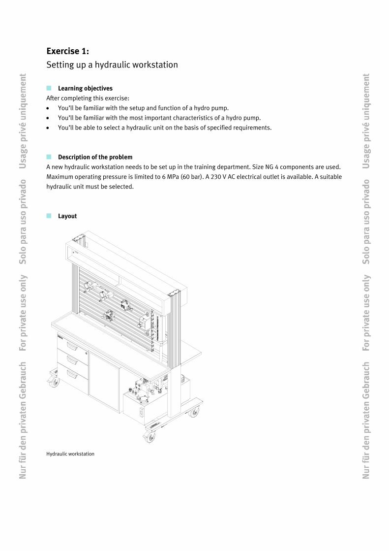
Description of the problem
A new hydraulic workstation needs to be set up in the training department. Size NG 4 components are used.
Maximum operating pressure is limited to 6 MPa (60 bar). A 230 V AC electrical outlet is available. A suitable
hydraulic unit must be selected.
Layout
Hydraulic workstation
Exercise 1 – Setting up a hydraulic workstation
4 © Festo Didactic 551150
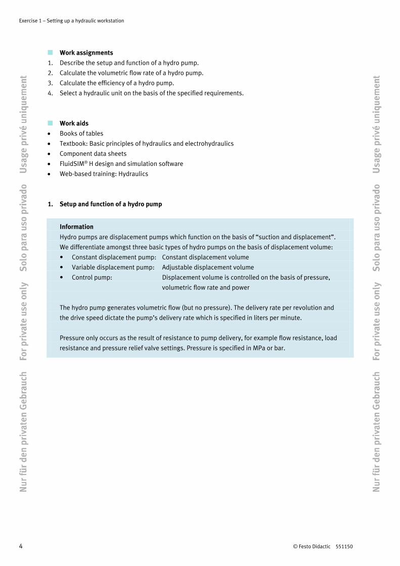
Work assignments
1. Describe the setup and function of a hydro pump.
2. Calculate the volumetric flow rate of a hydro pump.
3. Calculate the efficiency of a hydro pump.
4. Select a hydraulic unit on the basis of the specified requirements.
Work aids
• Books of tables
• Textbook: Basic principles of hydraulics and electrohydraulics
• Component data sheets
• FluidSIM® H design and simulation software
• Web-based training: Hydraulics
1. Setup and function of a hydro pump
Information
Hydro pumps are displacement pumps which function on the basis of “suction and displacement”.
We differentiate amongst three basic types of hydro pumps on the basis of displacement volume:
• Constant displacement pump: Constant displacement volume
• Variable displacement pump: Adjustable displacement volume
• Control pump: Displacement volume is controlled on the basis of pressure,
volumetric flow rate and power
The hydro pump generates volumetric flow (but no pressure). The delivery rate per revolution and
the drive speed dictate the pump’s delivery rate which is specified in liters per minute.
Pressure only occurs as the result of resistance to pump delivery, for example flow resistance, load
resistance and pressure relief valve settings. Pressure is specified in MPa or bar.
Exercise 1 – Setting up a hydraulic workstation
© Festo Didactic 551150 5
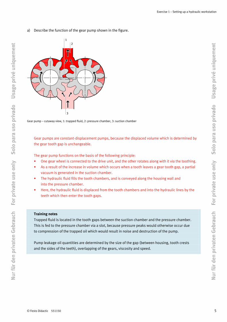
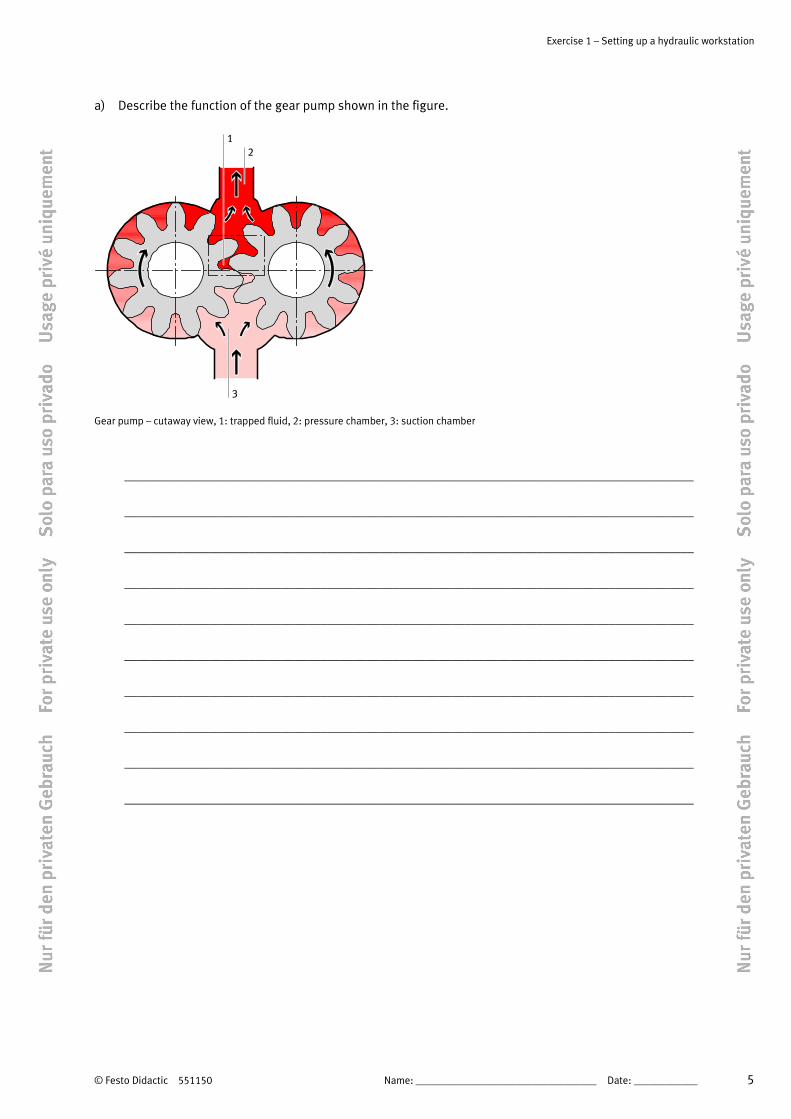
a) Describe the function of the gear pump shown in the figure.
Gear pump – cutaway view, 1: trapped fluid, 2: pressure chamber, 3: suction chamber
Gear pumps are constant-displacement pumps, because the displaced volume which is determined by
the gear tooth gap is unchangeable.
The gear pump functions on the basis of the following principle:
• One gear wheel is connected to the drive unit, and the other rotates along with it via the toothing.
• As a result of the increase in volume which occurs when a tooth leaves a gear tooth gap, a partial
vacuum is generated in the suction chamber.
• The hydraulic fluid fills the tooth chambers, and is conveyed along the housing wall and
into the pressure chamber.
• Here, the hydraulic fluid is displaced from the tooth chambers and into the hydraulic lines by the
teeth which then enter the tooth gaps.
Training notes
Trapped fluid is located in the tooth gaps between the suction chamber and the pressure chamber.
This is fed to the pressure chamber via a slot, because pressure peaks would otherwise occur due
to compression of the trapped oil which would result in noise and destruction of the pump.
Pump leakage oil quantities are determined by the size of the gap (between housing, tooth crests
and the sides of the teeth), overlapping of the gears, viscosity and speed.

Exercise 1 – Setting up a hydraulic workstation
6 © Festo Didactic 551150
b) Name the circuit symbol shown below and briefly describe the function of the components.
Hydraulic unit – circuit symbol
1. Electric motor with single direction of rotation
Drive for hydro pumps.
2. Hydraulic pump
Pump with constant delivery rate. The volumetric flow rate is dictated by motor speed
and displacement volume per revolution.
3. Pressure gauge
Indicates prevailing pressure with a specified tolerance.
4. Pressure relief valve
Adjustable pressure relief valve without oil return port. The valve begins to open when an
adjustable pressure level is reached.

Exercise 1 – Setting up a hydraulic workstation
© Festo Didactic 551150 7
c) Match up the individual components of the hydraulic unit with the corresponding numbers in the
drawing.
Hydraulic unit – schematic diagram
Component no. Component (designation)
6 Drain screw
3 Suction chamber
2 Suction tube
10 Vent with air filter
4 Moderating plate
8 Filling filter
9 Fill-level indicator, maximum fill-level
7 Fill-level indicator, minimum fill-level
1 Motor and pump
11 Return
5 Return chamber

Exercise 1 – Setting up a hydraulic workstation
8 © Festo Didactic 551150
2. Calculating the volumetric flow rate of a hydro pump
Information Displacement volume V (also known as delivery rate or pump capacity) is a measure of the pump’s
size. It designates the liquid volume which is delivered by the pump per revolution (or stroke).
The volume of liquid delivered per minute is referred to as volumetric flow rate q (delivery rate).
This results from displacement volume V and speed in RPM n:
q n V= ⋅
– Calculate the delivery rate of a gear pump.
Given
Speed n = 1450 rpm
Displacement volume V = 2.8 cubic cm (per revolution)
Sought
Delivery rate q in l/min
Calculation
3 3
-1 3 cm dm1450 min 2.8 cm = 4060 = 4.06 = 4.06 l/minmin min
q n V ⋅= ⋅ =

Exercise 1 – Setting up a hydraulic workstation
© Festo Didactic 551150 9
3. Calculating the efficiency of a hydro pump
Information
Pumps convert mechanical power into hydraulic power, which always involves power loss that’s
expressed in terms of efficiency.
Effective power Phyd generated by the pump depends upon operating pressure p and effective
delivery rate qeff. Effective power is calculated with the equation:
hyd effP p q= ⋅
Volumetric efficiency is the relationship between the pump’s effective delivery rate and its
theoretically calculated delivery rate.
effvol
th
η =
th thq V n= ⋅
eff th volq V n= ⋅ ⋅η
– Calculate the efficiency of a hydro pump.
Given
Speed n = 1450 rpm
Displacement volume V = 6.5 cubic cm (per revolution)
Effective delivery rate effl8.6
minq = at 100 bar
Sought
Efficiency ηvol
Calculation
3 -1th
l6.5 cm 1450 min = 9.4min
q = ⋅
effvol
th
l8.6min = 0.92 = 92 %
l9.4min
η = =

Exercise 1 – Setting up a hydraulic workstation
10 © Festo Didactic 551150
4. Selecting a hydraulic unit
Information
Excerpts from three data sheets for hydraulic units are included below. Select the power unit which
fulfills the following conditions:
• Drive motor with 230 V nominal voltage
• Frequency: 50 Hz
• Delivery rate at nominal speed: 2.2 l/min
• Weight without oil: max. 20 kg
General HA-5L-230-50 HA-5L-110-60 HA-20L-400-50
Dimensions
Length
Width
Height
580 mm
300 mm
180 mm
580 mm
300 mm
180 mm
580
300
180 mm
Weight
Empty
Filled with oil
19 kg
24 kg
19 kg
24 kg
19 kg
29 kg
Electrical data HA-5L-230-50 HA-5L-110-60 HA-20L-400-50
Motor Alternating current, single-
phase
Alternating current, single-
phase
Alternating current, 3-phase
Nominal power 650 W 550 W 550 W
Nominal voltage 230 V 110 V 400 V
Frequency 50 Hz 60 Hz 50 Hz
Nominal speed 1390 rpm 1680 rpm 1390 rpm
Protection IP 20 IP 20 IP 20
Duty cycle 50% 50% 100%

Exercise 1 – Setting up a hydraulic workstation
© Festo Didactic 551150 11
Hydraulic data HA-5L-230-50 HA-5L-110-60 HA-20L-400-50
Medium Mineral oil, recommended: 22 cSt (sq. mm/s)
Pump design External gear pump
Geometric delivery rate 1.6 cubic cm 1.6 cubic cm 1.6 cubic cm
Delivery rate at nominal speed 2.2 l/min 2.7 l/min 2.2 l/min
Operating pressure 0.5 to 6 MPa (5 to 60 bar)
Settings Manual
Pressure gauge indicating range 0 to 10 MPa (0 to 100 bar)
Pressure gauge quality class 1.6
Oil tank capacity Approx. 5 l Approx. 5 l Approx. 10 l
Return filter filtration grade 90 µm
Connection One quick coupling socket each for P and T, one coupling for the line to the storage tank, one
connection for the discharge measuring receptacle
– Which hydraulic unit have you chosen? Give reasons for your selection.
The hydraulic unit with the designation HA-5L-230-50 was selected. It fulfills the following specified
conditions:
• Drive motor with 230 V nominal voltage
• Frequency: 50 Hz
• Delivery rate at nominal speed: 2.2 l/min
• Weight without oil: max. 20 kg

Exercise 1 – Setting up a hydraulic workstation
12 © Festo Didactic 551150

© Festo Didactic 551150 1
Table of contents
Exercises and worksheets
Exercise 1: Setting up a hydraulic workstation ________________________________________________ 3
Exercise 2: Commissioning a two-column hydraulic press ______________________________________ 13
Exercise 3: Feeding pressings _____________________________________________________________ 21
Exercise 4: Sorting out crates _____________________________________________________________ 37
Exercise 5: Actuating a lifting platform ______________________________________________________ 53
Exercise 6: Clamping valve blocks__________________________________________________________ 67
Exercise 7: Clamping engine blocks ________________________________________________________ 87
Exercise 8: Bending metal tubing _________________________________________________________ 101
Exercise 9: Press fitting a gear unit bearing _________________________________________________ 113
Exercise 10: Chamfering workpieces _______________________________________________________ 131
Exercise 11: Opening and closing a hardening furnace door ____________________________________ 145
Exercise 12: Deep drawing sheet metal parts ________________________________________________ 161
Exercise 13: Opening and closing a hardening furnace door ____________________________________ 175
Exercise 14: Transporting containers _______________________________________________________ 189
Exercise 15: Eliminating a malfunction at a container handling unit ______________________________ 203

Table of contents
2 © Festo Didactic 551150
Exercise 1: Setting up a hydraulic workstation
Learning objectives
After completing this exercise:
• You’ll be familiar with the setup and function of a hydro pump.
• You’ll be familiar with the most important characteristics of a hydro pump.
• You’ll be able to select a hydraulic unit on the basis of specified requirements.
Description of the problem
A new hydraulic workstation needs to be set up in the training department. Size NG 4 components are used.
Maximum operating pressure is limited to 6 MPa (60 bar). A 230 V AC electrical outlet is available. A suitable
hydraulic unit must be selected.
Layout
Hydraulic workstation

Exercise 1 – Setting up a hydraulic workstation
4 Name: __________________________________ Date: ____________ © Festo Didactic 551150
Work assignments
1. Describe the setup and function of a hydro pump.
2. Calculate the volumetric flow rate of a hydro pump.
3. Calculate the efficiency of a hydro pump.
4. Select a hydraulic unit on the basis of the specified requirements.
Work aids
• Books of tables
• Textbook: Basic principles of hydraulics and electrohydraulics
• Component data sheets
• FluidSIM® H design and simulation software
• Web-based training: Hydraulics
1. Setup and function of a hydro pump
Information
Hydro pumps are displacement pumps which function on the basis of “suction and displacement”.
We differentiate amongst three basic types of hydro pumps on the basis of displacement volume:
• Constant displacement pump: Constant displacement volume
• Variable displacement pump: Adjustable displacement volume
• Control pump: Displacement volume is controlled on the basis of pressure,
volumetric flow rate and power
The hydro pump generates volumetric flow (but no pressure). The delivery rate per revolution and
the drive speed dictate the pump’s delivery rate which is specified in liters per minute.
Pressure only occurs as the result of resistance to pump delivery, for example flow resistance, load
resistance and pressure relief valve settings. Pressure is specified in MPa or bar.
Exercise 1 – Setting up a hydraulic workstation
© Festo Didactic 551150 Name: __________________________________ Date: ____________ 5
a) Describe the function of the gear pump shown in the figure.
Gear pump – cutaway view, 1: trapped fluid, 2: pressure chamber, 3: suction chamber
_______________________________________________________________________________________
_______________________________________________________________________________________
_______________________________________________________________________________________
_______________________________________________________________________________________
_______________________________________________________________________________________
_______________________________________________________________________________________
_______________________________________________________________________________________
_______________________________________________________________________________________
_______________________________________________________________________________________
_______________________________________________________________________________________

Exercise 1 – Setting up a hydraulic workstation
6 Name: __________________________________ Date: ____________ © Festo Didactic 551150
b) Name the circuit symbol shown below and briefly describe the function of the components.
Hydraulic unit – circuit symbol
_______________________________________________________________________________________
_______________________________________________________________________________________
_______________________________________________________________________________________
_______________________________________________________________________________________
_______________________________________________________________________________________
_______________________________________________________________________________________
_______________________________________________________________________________________
_______________________________________________________________________________________
_______________________________________________________________________________________
_______________________________________________________________________________________

Exercise 1 – Setting up a hydraulic workstation
© Festo Didactic 551150 Name: __________________________________ Date: ____________ 7
c) Match up the individual components of the hydraulic unit with the corresponding numbers in the
drawing.
Hydraulic unit – schematic diagram
Component no. Component (designation)
Drain screw
Suction chamber
Suction tube
Vent with air filter
Moderating plate
Filling filter
Fill-level indicator, maximum fill-level
Fill-level indicator, minimum fill-level
Motor and pump
Return
Return chamber

Exercise 1 – Setting up a hydraulic workstation
8 Name: __________________________________ Date: ____________ © Festo Didactic 551150
2. Calculating the volumetric flow rate of a hydro pump
Information Displacement volume V (also known as delivery rate or pump capacity) is a measure of the pump’s
size. It designates the liquid volume which is delivered by the pump per revolution (or stroke).
The volume of liquid delivered per minute is referred to as volumetric flow rate q (delivery rate).
This results from displacement volume V and speed in RPM n:
q n V= ⋅
– Calculate the delivery rate of a gear pump.
Given
Speed n = 1450 rpm
Displacement volume V = 2.8 cubic cm (per revolution)
Sought
Delivery rate q in l/min
Calculation

Exercise 1 – Setting up a hydraulic workstation
© Festo Didactic 551150 Name: __________________________________ Date: ____________ 9
3. Calculating the efficiency of a hydro pump
Information
Pumps convert mechanical power into hydraulic power, which always involves power loss that’s
expressed in terms of efficiency.
Effective power Phyd generated by the pump depends upon operating pressure p and effective
delivery rate qeff. Effective power is calculated with the equation:
hyd effP p q= ⋅
Volumetric efficiency is the relationship between the pump’s effective delivery rate and its
theoretically calculated delivery rate.
effvol
th
η =
th thq V n= ⋅
eff th volq V n= ⋅ ⋅η
– Calculate the efficiency of a hydro pump.
Given
Speed n = 1450 rpm
Displacement volume V = 6.5 cubic cm (per revolution)
Effective delivery rate effl8.6
minq = at 100 bar
Sought
Efficiency ηvol
Calculation

Exercise 1 – Setting up a hydraulic workstation
10 Name: __________________________________ Date: ____________ © Festo Didactic 551150
4. Selecting a hydraulic unit
Information
Excerpts from three data sheets for hydraulic units are included below. Select the power unit which
fulfills the following conditions:
• Drive motor with 230 V nominal voltage
• Frequency: 50 Hz
• Delivery rate at nominal speed: 2.2 l/min
• Weight without oil: max. 20 kg
General HA-5L-230-50 HA-5L-110-60 HA-20L-400-50
Dimensions
Length
Width
Height
580 mm
300 mm
180 mm
580 mm
300 mm
180 mm
580
300
180 mm
Weight
Empty
Filled with oil
19 kg
24 kg
19 kg
24 kg
19 kg
29 kg
Electrical data HA-5L-230-50 HA-5L-110-60 HA-20L-400-50
Motor Alternating current, single-
phase
Alternating current, single-
phase
Alternating current, 3-phase
Nominal power 650 W 550 W 550 W
Nominal voltage 230 V 110 V 400 V
Frequency 50 Hz 60 Hz 50 Hz
Nominal speed 1390 rpm 1680 rpm 1390 rpm
Protection IP 20 IP 20 IP 20
Duty cycle 50% 50% 100%

Exercise 1 – Setting up a hydraulic workstation
© Festo Didactic 551150 Name: __________________________________ Date: ____________ 11
Hydraulic data HA-5L-230-50 HA-5L-110-60 HA-20L-400-50
Medium Mineral oil, recommended: 22 cSt (sq. mm/s)
Pump design External gear pump
Geometric delivery rate 1.6 cubic cm 1.6 cubic cm 1.6 cubic cm
Delivery rate at nominal speed 2.2 l/min 2.7 l/min 2.2 l/min
Operating pressure 0.5 to 6 MPa (5 to 60 bar)
Settings Manual
Pressure gauge indicating range 0 to 10 MPa (0 to 100 bar)
Pressure gauge quality class 1.6
Oil tank capacity Approx. 5 l Approx. 5 l Approx. 10 l
Return filter filtration grade 90 µm
Connection One quick coupling socket each for P and T, one coupling for the line to the storage tank, one
connection for the discharge measuring receptacle
– Which hydraulic unit have you chosen? Give reasons for your selection.
_______________________________________________________________________________________
_______________________________________________________________________________________
_______________________________________________________________________________________
_______________________________________________________________________________________
_______________________________________________________________________________________
_______________________________________________________________________________________
Exercise 1 – Setting up a hydraulic workstation
12 Name: __________________________________ Date: ____________ © Festo Didactic 551150