Motor controller SFC−DC - Festo
314
Manual Type SFC−DC−VC−...−DN Manual 555 880 en 0801NH [721 123] Motor controller SFC−DC
-
Upload
khangminh22 -
Category
Documents
-
view
2 -
download
0
Transcript of Motor controller SFC−DC - Festo
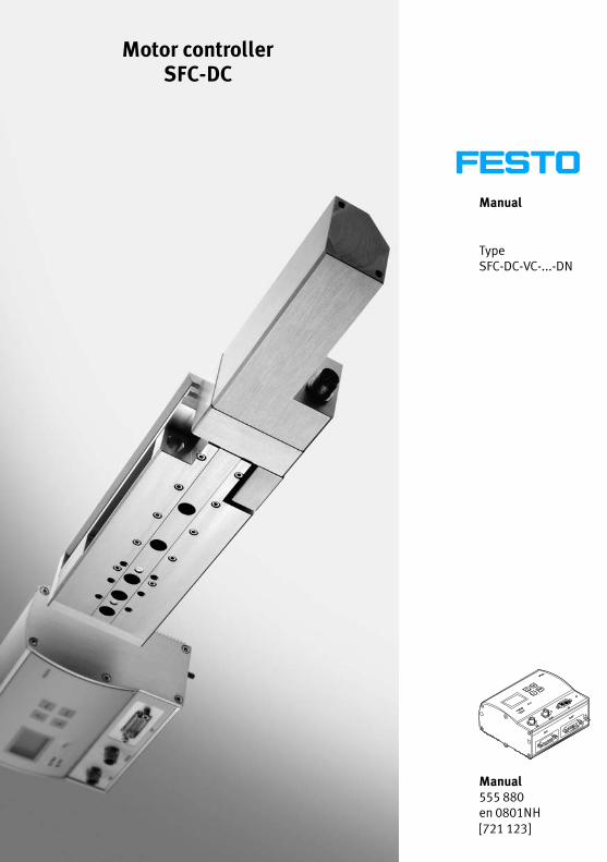
Manual
Type SFC−DC−VC−...−DN
Manual555 880en 0801NH[721 123]
Motor controllerSFC−DC

Contents and general instructions
IFesto P.BE−SFC−DC−DN−EN en 0801NH
Original de. . . . . . . . . . . . . . . . . . . . . . . . . . . . . . . . . . . . . . .
Edition en 0801NH. . . . . . . . . . . . . . . . . . . . . . . . . . . . . . . . .
Designation P.BE−SFC−DC−DN−EN. . . . . . . . . . . . . . . . . . . . . .
Order no. 555 880. . . . . . . . . . . . . . . . . . . . . . . . . . . . . . . . .
© (Festo AG�&�Co. KG, D�73726 Esslingen, Germany, 2008)Internet: http://www.festo.comE−Mail: [email protected]
The reproduction, distribution and utilization of this docu−ment as well as the comunication of its contents to otherswithout express authorization is prohibited. Offenders willbe held liable for the payment of damages. All rights re−served in the event of the grant of a patent, utility moduleor design.

Contents and general instructions
II Festo P.BE−SFC−DC−DN−EN en 0801NH
TORX® is a registered trade name of CAMCAR TEXTRON INC.,Rockford, Ill., USA
DeviceNet® is a registered trademark of the Open DeviceNet VendorsAssociation (ODVA)
Allen−Bradley�® is a registered trademark of Rockwell Automation
Contents and general instructions
IIIFesto P.BE−SFC−DC−DN−EN en 0801NH
Contents
Designated use IX . . . . . . . . . . . . . . . . . . . . . . . . . . . . . . . . . . . . . . . . . . . . . . . . . . . . . . . .
Safety instructions X . . . . . . . . . . . . . . . . . . . . . . . . . . . . . . . . . . . . . . . . . . . . . . . . . . . . .
Target group XI . . . . . . . . . . . . . . . . . . . . . . . . . . . . . . . . . . . . . . . . . . . . . . . . . . . . . . . . . .
Service XI . . . . . . . . . . . . . . . . . . . . . . . . . . . . . . . . . . . . . . . . . . . . . . . . . . . . . . . . . . . . . . .
Scope of delivery XI . . . . . . . . . . . . . . . . . . . . . . . . . . . . . . . . . . . . . . . . . . . . . . . . . . . . . . .
Important user instructions XII . . . . . . . . . . . . . . . . . . . . . . . . . . . . . . . . . . . . . . . . . . . . . .
Manuals for motor controller type SFC−DC XIV . . . . . . . . . . . . . . . . . . . . . . . . . . . . . . . . . .
Information on the version XV . . . . . . . . . . . . . . . . . . . . . . . . . . . . . . . . . . . . . . . . . . . . . . .
Product−specific terms and abbreviations XVI . . . . . . . . . . . . . . . . . . . . . . . . . . . . . . . . . . .
1. System summary 1−1 . . . . . . . . . . . . . . . . . . . . . . . . . . . . . . . . . . . . . . . . . . . . . . .
1.1 Positioning with electric drives 1−3 . . . . . . . . . . . . . . . . . . . . . . . . . . . . . . . . . . . .
1.2 Components 1−7 . . . . . . . . . . . . . . . . . . . . . . . . . . . . . . . . . . . . . . . . . . . . . . . . . . .
1.3 Control and regulating functions 1−9 . . . . . . . . . . . . . . . . . . . . . . . . . . . . . . . . . . .
1.4 Operational safety 1−11 . . . . . . . . . . . . . . . . . . . . . . . . . . . . . . . . . . . . . . . . . . . . . .
1.5 Structure of the SFC−DC 1−12 . . . . . . . . . . . . . . . . . . . . . . . . . . . . . . . . . . . . . . . . . .
1.6 Measuring reference system 1−14 . . . . . . . . . . . . . . . . . . . . . . . . . . . . . . . . . . . . . .
1.6.1 Basis points and work range 1−14 . . . . . . . . . . . . . . . . . . . . . . . . . . . . . .
1.6.2 Signs and directions 1−17 . . . . . . . . . . . . . . . . . . . . . . . . . . . . . . . . . . . . .
1.6.3 Homing run 1−18 . . . . . . . . . . . . . . . . . . . . . . . . . . . . . . . . . . . . . . . . . . . .
1.7 Field bus communication 1−22 . . . . . . . . . . . . . . . . . . . . . . . . . . . . . . . . . . . . . . . . .
1.7.1 Data exchange in DeviceNet 1−22 . . . . . . . . . . . . . . . . . . . . . . . . . . . . . . .
1.7.2 Festo profile for handling and positioning (FHPP) 1−27 . . . . . . . . . . . . . .
2. Fitting 2−1 . . . . . . . . . . . . . . . . . . . . . . . . . . . . . . . . . . . . . . . . . . . . . . . . . . . . . . . .
2.1 General information 2−3 . . . . . . . . . . . . . . . . . . . . . . . . . . . . . . . . . . . . . . . . . . . . .
2.2 Dimensions of the controller 2−3 . . . . . . . . . . . . . . . . . . . . . . . . . . . . . . . . . . . . . .
2.3 Mounting the controller 2−4 . . . . . . . . . . . . . . . . . . . . . . . . . . . . . . . . . . . . . . . . . .
2.4 Notes on fitting electric axes 2−6 . . . . . . . . . . . . . . . . . . . . . . . . . . . . . . . . . . . . . .

Contents and general instructions
IV Festo P.BE−SFC−DC−DN−EN en 0801NH
3. Installation 3−1 . . . . . . . . . . . . . . . . . . . . . . . . . . . . . . . . . . . . . . . . . . . . . . . . . . .
3.1 Overview of installation 3−3 . . . . . . . . . . . . . . . . . . . . . . . . . . . . . . . . . . . . . . . . . .
3.2 Voltage supply 3−6 . . . . . . . . . . . . . . . . . . . . . . . . . . . . . . . . . . . . . . . . . . . . . . . . .
3.3 Earthing 3−9 . . . . . . . . . . . . . . . . . . . . . . . . . . . . . . . . . . . . . . . . . . . . . . . . . . . . . . .
3.4 Motor connection 3−10 . . . . . . . . . . . . . . . . . . . . . . . . . . . . . . . . . . . . . . . . . . . . . . .
3.5 Serial interface 3−11 . . . . . . . . . . . . . . . . . . . . . . . . . . . . . . . . . . . . . . . . . . . . . . . . .
3.6 Input for external reference switch 3−13 . . . . . . . . . . . . . . . . . . . . . . . . . . . . . . . . .
3.7 Control 3−15 . . . . . . . . . . . . . . . . . . . . . . . . . . . . . . . . . . . . . . . . . . . . . . . . . . . . . . .
3.8 Connecting the field bus 3−17 . . . . . . . . . . . . . . . . . . . . . . . . . . . . . . . . . . . . . . . . .
3.8.1 Field bus cable 3−17 . . . . . . . . . . . . . . . . . . . . . . . . . . . . . . . . . . . . . . . . . .
3.8.2 Field bus baud rate and field bus length 3−18 . . . . . . . . . . . . . . . . . . . . .
3.8.3 Information on connecting the field bus 3−18 . . . . . . . . . . . . . . . . . . . . .
3.8.4 Connection with field bus plugs from Festo 3−20 . . . . . . . . . . . . . . . . . . .
3.8.5 Connection to other Sub−D plugs 3−24 . . . . . . . . . . . . . . . . . . . . . . . . . . .
3.9 Bus termination with terminating resistors 3−25 . . . . . . . . . . . . . . . . . . . . . . . . . .
3.9.1 Install a terminating resistor using the adapters 3−26 . . . . . . . . . . . . . . .
4. Control panel (only type SFC−DC−...−H2−...) 4−1 . . . . . . . . . . . . . . . . . . . . . . . . . .
4.1 Composition and function of the control panel 4−4 . . . . . . . . . . . . . . . . . . . . . . .
4.2 The menu system 4−6 . . . . . . . . . . . . . . . . . . . . . . . . . . . . . . . . . . . . . . . . . . . . . . .
4.2.1 Accessing the main menu 4−6 . . . . . . . . . . . . . . . . . . . . . . . . . . . . . . . . .
4.2.2 Selecting a menu command 4−6 . . . . . . . . . . . . . . . . . . . . . . . . . . . . . . .
4.3 [Diagnostic] menu 4−8 . . . . . . . . . . . . . . . . . . . . . . . . . . . . . . . . . . . . . . . . . . . . . .
4.4 [Positioning] menu 4−12 . . . . . . . . . . . . . . . . . . . . . . . . . . . . . . . . . . . . . . . . . . . . . .
4.4.1 [Positioning] [Homing] 4−13 . . . . . . . . . . . . . . . . . . . . . . . . . . . . . . . . . . . .
4.4.2 [Positioning] [Move posit. set] / [Demo posit. tab] 4−14 . . . . . . . . . . . . .
4.5 Menu [Settings] 4−16 . . . . . . . . . . . . . . . . . . . . . . . . . . . . . . . . . . . . . . . . . . . . . . . .
4.5.1 [Settings] [Axis type] 4−16 . . . . . . . . . . . . . . . . . . . . . . . . . . . . . . . . . . . . .
4.5.2 [Settings] [Axis parameter] 4−18 . . . . . . . . . . . . . . . . . . . . . . . . . . . . . . . .
4.5.3 [Settings] [Homing paramet.] 4−19 . . . . . . . . . . . . . . . . . . . . . . . . . . . . . .
4.5.4 [Settings] [Position set] 4−20 . . . . . . . . . . . . . . . . . . . . . . . . . . . . . . . . . . .
4.5.5 [Settings] [Password edit] 4−21 . . . . . . . . . . . . . . . . . . . . . . . . . . . . . . . . .
4.5.6 [Settings] [BUS parameter] 4−23 . . . . . . . . . . . . . . . . . . . . . . . . . . . . . . . .
4.6 Menu command [HMI control] 4−24 . . . . . . . . . . . . . . . . . . . . . . . . . . . . . . . . . . . . .
Contents and general instructions
VFesto P.BE−SFC−DC−DN−EN en 0801NH
5. Commissioning 5−1 . . . . . . . . . . . . . . . . . . . . . . . . . . . . . . . . . . . . . . . . . . . . . . . .
5.1 Preparations for commissioning 5−4 . . . . . . . . . . . . . . . . . . . . . . . . . . . . . . . . . . .
5.1.1 Check the connection to the mains power supply 5−4 . . . . . . . . . . . . . .
5.1.2 Check the drive 5−4 . . . . . . . . . . . . . . . . . . . . . . . . . . . . . . . . . . . . . . . . .
5.1.3 General instructions on commissioning 5−5 . . . . . . . . . . . . . . . . . . . . . .
5.2 Commissioning with the control panel (only type SFC−DC−...−H2−...) 5−8 . . . . . . .
5.2.1 Setting the axis type 5−10 . . . . . . . . . . . . . . . . . . . . . . . . . . . . . . . . . . . . .
5.2.2 Setting the reference run parameters 5−10 . . . . . . . . . . . . . . . . . . . . . . .
5.2.3 Starting a reference run 5−14 . . . . . . . . . . . . . . . . . . . . . . . . . . . . . . . . . .
5.2.4 Teach the axis zero point and the software end positions 5−15 . . . . . . .
5.2.5 Positioning with position sets 5−16 . . . . . . . . . . . . . . . . . . . . . . . . . . . . . .
5.2.6 Teach position records 5−17 . . . . . . . . . . . . . . . . . . . . . . . . . . . . . . . . . . .
5.2.7 Test run 5−19 . . . . . . . . . . . . . . . . . . . . . . . . . . . . . . . . . . . . . . . . . . . . . . .
5.2.8 Setting bus parameters 5−20 . . . . . . . . . . . . . . . . . . . . . . . . . . . . . . . . . . .
5.3 Commissioning with the Festo Configuration Tool 5−23 . . . . . . . . . . . . . . . . . . . . .
5.3.1 Installing and starting the Festo Configuration Tool 5−23 . . . . . . . . . . . .
5.3.2 Procedure for commissioning with the Festo Configuration Tool 5−24 . . . . . . . . . . . . . . . . . . . . . . . . . . . . . . . . . .
5.4 Commissioning on a DeviceNet master 5−26 . . . . . . . . . . . . . . . . . . . . . . . . . . . . . .
5.4.1 Overview of commissioning on the field bus 5−26 . . . . . . . . . . . . . . . . . .
5.4.2 Configuration of the DeviceNet master (�I/O configuration") 5−27 . . . .
5.5 Festo profile for handling and positioning (FHPP) 5−29 . . . . . . . . . . . . . . . . . . . . .
5.5.1 Supported operating modes 5−29 . . . . . . . . . . . . . . . . . . . . . . . . . . . . . . .
5.5.2 Composition of the cyclic I/O data (FHPP standard) 5−31 . . . . . . . . . . . .
5.5.3 Description of the I/O data (Record select) 5−33 . . . . . . . . . . . . . . . . . . .
5.5.4 Description of the I/O data (Direct mode) 5−34 . . . . . . . . . . . . . . . . . . . .
5.5.5 Description of the control bytes CCON, CPOS, CDIR 5−35 . . . . . . . . . . . .
5.5.6 Description of the status bytes SCON, SPOS, SDIR (RSB) 5−38 . . . . . . .
5.5.7 Examples of the I/O data 5−41 . . . . . . . . . . . . . . . . . . . . . . . . . . . . . . . . .
5.6 Sequence control as per FHPP standard 5−54 . . . . . . . . . . . . . . . . . . . . . . . . . . . .
5.6.1 Homing run 5−54 . . . . . . . . . . . . . . . . . . . . . . . . . . . . . . . . . . . . . . . . . . . .
5.6.2 Jog mode 5−56 . . . . . . . . . . . . . . . . . . . . . . . . . . . . . . . . . . . . . . . . . . . . . .
5.6.3 Teaching via the field bus 5−58 . . . . . . . . . . . . . . . . . . . . . . . . . . . . . . . . .
5.6.4 Record select (positioning mode) 5−60 . . . . . . . . . . . . . . . . . . . . . . . . . . .
Contents and general instructions
VI Festo P.BE−SFC−DC−DN−EN en 0801NH
5.6.5 Direct mode (positioning mode, force control) 5−65 . . . . . . . . . . . . . . . .
5.6.6 Standstill monitoring 5−72 . . . . . . . . . . . . . . . . . . . . . . . . . . . . . . . . . . . . .
5.7 The Festo Parameter Channel (FPC) 5−74 . . . . . . . . . . . . . . . . . . . . . . . . . . . . . . . .
5.7.1 Composition of the cyclic I/O data (FHPP−FPC) 5−74 . . . . . . . . . . . . . . . .
5.7.2 Task identifiers, Response identifiers and fault numbers 5−76 . . . . . . . .
5.7.3 Rules for task−reply processing 5−79 . . . . . . . . . . . . . . . . . . . . . . . . . . . .
5.7.4 Example of parametrizing 5−81 . . . . . . . . . . . . . . . . . . . . . . . . . . . . . . . . .
5.8 Finite state machine FHPP 5−83 . . . . . . . . . . . . . . . . . . . . . . . . . . . . . . . . . . . . . . . .
5.8.1 Create readiness to operate 5−85 . . . . . . . . . . . . . . . . . . . . . . . . . . . . . . .
5.8.2 Positioning 5−86 . . . . . . . . . . . . . . . . . . . . . . . . . . . . . . . . . . . . . . . . . . . . .
5.9 Notes on operation 5−88 . . . . . . . . . . . . . . . . . . . . . . . . . . . . . . . . . . . . . . . . . . . . . .
6. Diagnosis and fault display 6−1 . . . . . . . . . . . . . . . . . . . . . . . . . . . . . . . . . . . . . .
6.1 Overview of diagnostic possibilities 6−3 . . . . . . . . . . . . . . . . . . . . . . . . . . . . . . . .
6.2 LED status displays 6−5 . . . . . . . . . . . . . . . . . . . . . . . . . . . . . . . . . . . . . . . . . . . . .
6.3 Fault messages 6−7 . . . . . . . . . . . . . . . . . . . . . . . . . . . . . . . . . . . . . . . . . . . . . . . . .
6.3.1 Overview 6−7 . . . . . . . . . . . . . . . . . . . . . . . . . . . . . . . . . . . . . . . . . . . . . .
6.3.2 Description of faults and warnings 6−9 . . . . . . . . . . . . . . . . . . . . . . . . . .
6.4 Diagnosis via field bus 6−13 . . . . . . . . . . . . . . . . . . . . . . . . . . . . . . . . . . . . . . . . . . .
6.4.1 Overview 6−13 . . . . . . . . . . . . . . . . . . . . . . . . . . . . . . . . . . . . . . . . . . . . . .
6.4.2 Diagnostic memory 6−14 . . . . . . . . . . . . . . . . . . . . . . . . . . . . . . . . . . . . . .

Contents and general instructions
VIIFesto P.BE−SFC−DC−DN−EN en 0801NH
A. Technical appendix A−1 . . . . . . . . . . . . . . . . . . . . . . . . . . . . . . . . . . . . . . . . . . . . .
A.1 Technical specifications A−3 . . . . . . . . . . . . . . . . . . . . . . . . . . . . . . . . . . . . . . . . . .
A.2 Accessories A−5 . . . . . . . . . . . . . . . . . . . . . . . . . . . . . . . . . . . . . . . . . . . . . . . . . . . .
A.3 Converting the units of measurement A−7 . . . . . . . . . . . . . . . . . . . . . . . . . . . . . . .
B. Reference DeviceNet and FHPP B−1 . . . . . . . . . . . . . . . . . . . . . . . . . . . . . . . . . . .
B.1 Reference: DeviceNet (Explicit Messaging) B−3 . . . . . . . . . . . . . . . . . . . . . . . . . .
B.1.1 Parameter classes B−3 . . . . . . . . . . . . . . . . . . . . . . . . . . . . . . . . . . . . . . .
B.1.2 Object overview (Class, Attribute, Instance) B−4 . . . . . . . . . . . . . . . . . .
B.2 Reference: FHPP (I/O Messaging) B−10 . . . . . . . . . . . . . . . . . . . . . . . . . . . . . . . . . .
B.2.1 Parameter groups B−10 . . . . . . . . . . . . . . . . . . . . . . . . . . . . . . . . . . . . . . .
B.2.2 Object overview (Parameter number PNU) B−11 . . . . . . . . . . . . . . . . . . .
B.2.3 Representing the parameter entries B−15 . . . . . . . . . . . . . . . . . . . . . . . .
B.2.4 Device data � Standard parameters B−16 . . . . . . . . . . . . . . . . . . . . . . . . .
B.2.5 Device data � Extended parameters B−17 . . . . . . . . . . . . . . . . . . . . . . . . .
B.2.6 Diagnostics B−20 . . . . . . . . . . . . . . . . . . . . . . . . . . . . . . . . . . . . . . . . . . . .
B.2.7 Processing data B−24 . . . . . . . . . . . . . . . . . . . . . . . . . . . . . . . . . . . . . . . . .
B.2.8 Record list B−25 . . . . . . . . . . . . . . . . . . . . . . . . . . . . . . . . . . . . . . . . . . . . .
B.2.9 Project data � General B−30 . . . . . . . . . . . . . . . . . . . . . . . . . . . . . . . . . . . .
B.2.10 Project data � Force control B−32 . . . . . . . . . . . . . . . . . . . . . . . . . . . . . . .
B.2.11 Project data � Teach B−33 . . . . . . . . . . . . . . . . . . . . . . . . . . . . . . . . . . . . .
B.2.12 Project data � Jog mode B−34 . . . . . . . . . . . . . . . . . . . . . . . . . . . . . . . . . .
B.2.13 Project data � Direct mode (positioning mode) B−36 . . . . . . . . . . . . . . . .
B.2.14 Project data � Direct mode (force control) B−37 . . . . . . . . . . . . . . . . . . . .
B.2.15 Axis parameters electric drives 1 � mechanical B−38 . . . . . . . . . . . . . . . .
B.2.16 Axis parameters electric drives 1 � Reference travel (Homing) B−42 . . .
B.2.17 Axis parameters electric drives 1 � Controller parameters B−44 . . . . . . .
B.2.18 Axis parameters electric drives 1 � Electronics rating plate B−50 . . . . . .
B.2.19 Axis parameters electric drives 1 � Standstill monitoring B−52 . . . . . . . .
Contents and general instructions
VIII Festo P.BE−SFC−DC−DN−EN en 0801NH
C. Reference CI objects C−1 . . . . . . . . . . . . . . . . . . . . . . . . . . . . . . . . . . . . . . . . . . . .
C.1 Data transmission C−3 . . . . . . . . . . . . . . . . . . . . . . . . . . . . . . . . . . . . . . . . . . . . . .
C.1.1 Procedure C−3 . . . . . . . . . . . . . . . . . . . . . . . . . . . . . . . . . . . . . . . . . . . . .
C.1.2 Composition of the CI commands C−5 . . . . . . . . . . . . . . . . . . . . . . . . . . .
C.1.3 Check of the data C−9 . . . . . . . . . . . . . . . . . . . . . . . . . . . . . . . . . . . . . . . .
C.2 Reference CI C−11 . . . . . . . . . . . . . . . . . . . . . . . . . . . . . . . . . . . . . . . . . . . . . . . . . . .
C.2.1 Object overview (Index, Subindex) C−11 . . . . . . . . . . . . . . . . . . . . . . . . . .
C.2.2 Representing the parameter entries C−16 . . . . . . . . . . . . . . . . . . . . . . . .
C.2.3 Communication Profile Area (1xxxh) C−17 . . . . . . . . . . . . . . . . . . . . . . . .
C.2.4 Manufacturer Specific Profile Area (2xxxh) C−18 . . . . . . . . . . . . . . . . . . .
C.2.5 Standardised Device Profile Area (6xxxh) C−23 . . . . . . . . . . . . . . . . . . . .
D. Index D−1 . . . . . . . . . . . . . . . . . . . . . . . . . . . . . . . . . . . . . . . . . . . . . . . . . . . . . . . . .
Contents and general instructions
IXFesto P.BE−SFC−DC−DN−EN en 0801NH
Designated use
The Motor Controller (Single Field Controller, single axis fieldcontroller) type SFC−DC−...−DN serves as a position controllerand position servo with control via the DeviceNet field bus.
The field bus interface supports the Festo field bus profile forhandling and positioning (FHPP).
It is absolutely necessary to observe the �Safety instructions"as well as the designated use of the relevant components andmodules. Please observe also the safety instructions in theoperating instructions for the components used.
The SFC−DC and the connectable modules and cables mayonly be used as follows:
� as designated
� only in industrial applications
� without any modifications by the user. Only the conver�sions or modifications described in the documentationsupplied with the product are permitted
� in perfect technical condition.
If additional commercially available components such assensors and actuators are connected, the specified limits forpressures, temperatures, electrical data, torques, etc. mustnot be exceeded.
Please observe the standards specified in the relevantchapters and comply with technical regulations, as well aswith national and local regulations.
Contents and general instructions
X Festo P.BE−SFC−DC−DN−EN en 0801NH
Safety instructions
When commissioning and programming positioning systems,you must observe the safety regulations in this manual aswell as those in the operating instructions for the other com�ponents used.
The user must make sure that nobody is in the operatingrange of the connected actuators or axis system. Access tothe possible danger area must be prevented by suitablemeasures such as protective screens and warning signs.
WarningElectric axes can move suddenly with high force and athigh speed. Collisions can lead to serious injury to humanbeings and damage to components.
Make sure that nobody can reach into the operating rangeof the axes or other connected actuators and that no ob�jects lie in the positioning range while the system is stillconnected to a power supply.
WarningFaults in parameterisation can cause injury to humanbeings and damage to property.
Enable the controller only if the axis system has beencorrectly installed and parameterised.

Contents and general instructions
XIFesto P.BE−SFC−DC−DN−EN en 0801NH
Target group
This manual is intended exclusively for technicians trained incontrol and automation technology, who have experience ininstalling, commissioning, programming and diagnosingpositioning systems.
Service
Please consult your local Festo Service or write to thefollowing e−mail address if you have any technical problems:
Scope of delivery
The scope of delivery of the motor controller type SFC−DCincludes the following:
� Motor controller, optionally with control panel
� Operator control package on CD−ROM:
� User documentation (descriptions)
� Festo Configuration Tool with SFC−DC PlugIn
� User documentation (descriptions)
The following are available as accessories (see appendix A.2):
� Connecting cables and field bus plugs
� Mounting attachments
� User documentation in paper form
Contents and general instructions
XII Festo P.BE−SFC−DC−DN−EN en 0801NH
Important user instructions
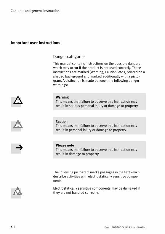
Danger categories
This manual contains instructions on the possible dangerswhich may occur if the product is not used correctly. Theseinstructions are marked (Warning, Caution, etc.), printed on ashaded background and marked additionally with a picto�gram. A distinction is made between the following dangerwarnings:
WarningThis means that failure to observe this instruction mayresult in serious personal injury or damage to property.
CautionThis means that failure to observe this instruction mayresult in personal injury or damage to property.
Please noteThis means that failure to observe this instruction mayresult in damage to property.
The following pictogram marks passages in the text whichdescribe activities with electrostatically sensitive compo�nents.
Electrostatically sensitive components may be damaged ifthey are not handled correctly.
Contents and general instructions
XIIIFesto P.BE−SFC−DC−DN−EN en 0801NH
Marking special information
The following pictograms mark passages in the textcontaining special information.
Pictograms
Information:Recommendations, tips and references to other sources ofinformation.
Accessories:Information on necessary or sensible accessories for theFesto product.
Environment:Information on environment−friendly use of Festo products.
Text markings
· The bullet indicates activities which may be carried out inany order.
1. Figures denote activities which must be carried out in thenumerical order specified.
� Hyphens indicate general activities.
Contents and general instructions
XIV Festo P.BE−SFC−DC−DN−EN en 0801NH
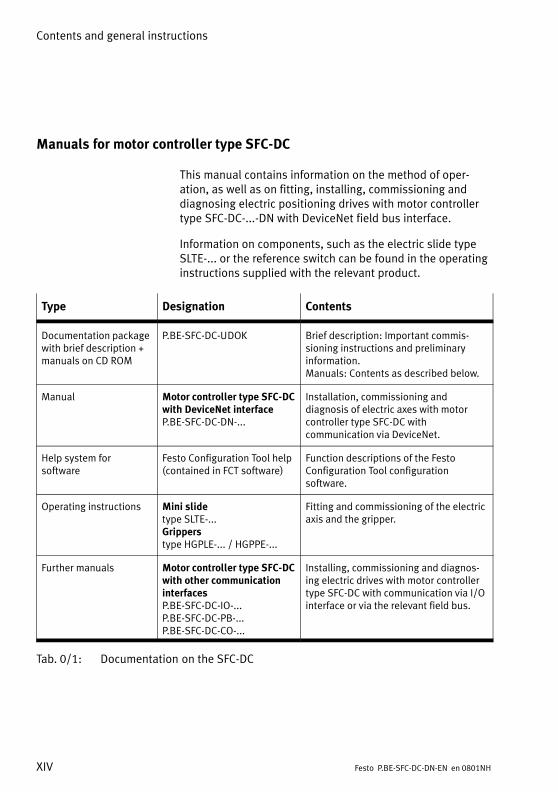
Manuals for motor controller type SFC−DC
This manual contains information on the method of oper�ation, as well as on fitting, installing, commissioning anddiagnosing electric positioning drives with motor controllertype SFC−DC−...−DN with DeviceNet field bus interface.
Information on components, such as the electric slide typeSLTE−... or the reference switch can be found in the operatinginstructions supplied with the relevant product.
Type Designation Contents
Documentation packagewith brief description +manuals on CD ROM
P.BE−SFC−DC−UDOK Brief description: Important commis�sioning instructions and preliminary information.Manuals: Contents as described below.
Manual Motor controller type SFC−DCwith DeviceNet interfaceP.BE−SFC−DC−DN−...
Installation, commissioning anddiagnosis of electric axes with motorcontroller type SFC−DC withcommunication via DeviceNet.
Help system forsoftware
Festo Configuration Tool help(contained in FCT software)
Function descriptions of the FestoConfiguration Tool configurationsoftware.
Operating instructions Mini slidetype SLTE−...Gripperstype HGPLE−... / HGPPE−...
Fitting and commissioning of the electricaxis and the gripper.
Further manuals Motor controller type SFC−DCwith other communicationinterfacesP.BE−SFC−DC−IO−...P.BE−SFC−DC−PB−...P.BE−SFC−DC−CO−...
Installing, commissioning and diagnos�ing electric drives with motor controllertype SFC−DC with communication via I/Ointerface or via the relevant field bus.
Tab.�0/1: Documentation on the SFC−DC
Contents and general instructions
XVFesto P.BE−SFC−DC−DN−EN en 0801NH
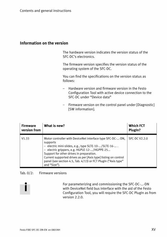
Information on the version
The hardware version indicates the version status of theSFC−DC’s electronics.
The firmware version specifies the version status of theoperating system of the SFC−DC.
You can find the specifications on the version status asfollows:
� Hardware version and firmware version in the FestoConfiguration Tool with active device connection to theSFC−DC under �Device data"
� Firmware version on the control panel under [Diagnostic][SW information].
Firmwareversion from
What is new? Which FCTPlugIn?
V1.33 Motor controller with DeviceNet interface type SFC−DC−...−DN,supports� electric mini−slides, e.g., type SLTE−10−.../SLTE−16−... .� electric grippers, e.g. HGPLE−12−.../HGPPE−25...Support for other drives in preparation.Current supported drives as per [Axis type] listing on controlpanel (see section 4.5, Tab.�4/13) or FCT PlugIn (�Axis type"and �Size").
SFC−DC V2.2.0
Tab.�0/2: Firmware versions
For parameterizing and commissioning the SFC−DC−...−DNwith DeviceNet field bus interface with the aid of the FestoConfiguration Tool, you will require the SFC−DC PlugIn as fromversion 2.2.0.
Contents and general instructions
XVI Festo P.BE−SFC−DC−DN−EN en 0801NH
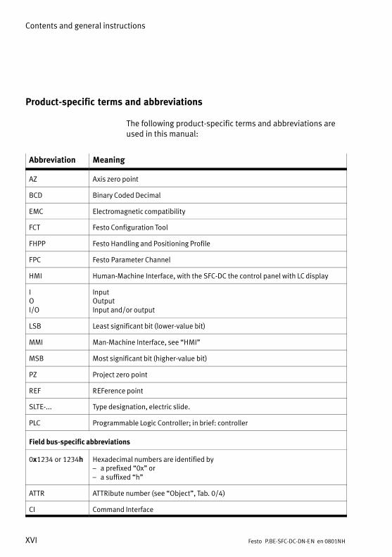
Product−specific terms and abbreviations
The following product−specific terms and abbreviations areused in this manual:
Abbreviation Meaning
AZ Axis zero point
BCD Binary Coded Decimal
EMC Electromagnetic compatibility
FCT Festo Configuration Tool
FHPP Festo Handling and Positioning Profile
FPC Festo Parameter Channel
HMI Human−Machine Interface, with the SFC−DC the control panel with LC display
IOI/O
InputOutputInput and/or output
LSB Least significant bit (lower−value bit)
MMI Man−Machine Interface, see �HMI"
MSB Most significant bit (higher−value bit)
PZ Project zero point
REF REFerence point
SLTE−... Type designation, electric slide.
PLC Programmable Logic Controller; in brief: controller
Field bus−specific abbreviations
0x1234 or 1234h Hexadecimal numbers are identified by� a prefixed �0x" or� a suffixed �h"
ATTR ATTRibute number (see �Object", Tab.�0/4)
CI Command Interface
Contents and general instructions
XVIIFesto P.BE−SFC−DC−DN−EN en 0801NH
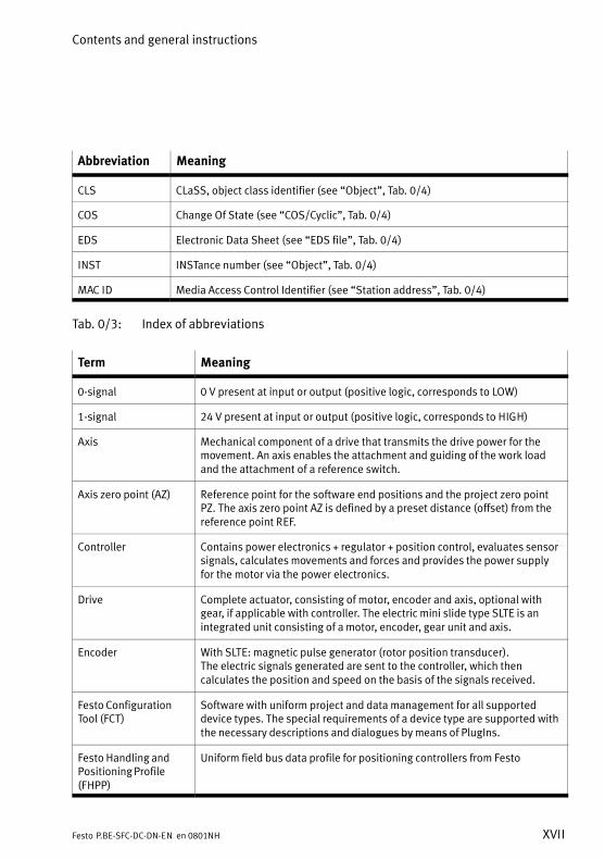
Abbreviation Meaning
CLS CLaSS, object class identifier (see �Object", Tab.�0/4)
COS Change Of State (see �COS/Cyclic", Tab.�0/4)
EDS Electronic Data Sheet (see �EDS file", Tab.�0/4)
INST INSTance number (see �Object", Tab.�0/4)
MAC ID Media Access Control Identifier (see �Station address", Tab.�0/4)
Tab.�0/3: Index of abbreviations
Term Meaning
0−signal 0 V present at input or output (positive logic, corresponds to LOW)
1−signal 24 V present at input or output (positive logic, corresponds to HIGH)
Axis Mechanical component of a drive that transmits the drive power for themovement. An axis enables the attachment and guiding of the work loadand the attachment of a reference switch.
Axis zero point (AZ) Reference point for the software end positions and the project zero pointPZ. The axis zero point AZ is defined by a preset distance (offset) from thereference point REF.
Controller Contains power electronics + regulator + position control, evaluates sensorsignals, calculates movements and forces and provides the power supplyfor the motor via the power electronics.
Drive Complete actuator, consisting of motor, encoder and axis, optional withgear, if applicable with controller. The electric mini slide type SLTE is anintegrated unit consisting of a motor, encoder, gear unit and axis.
Encoder With SLTE: magnetic pulse generator (rotor position transducer). The electric signals generated are sent to the controller, which thencalculates the position and speed on the basis of the signals received.
Festo ConfigurationTool (FCT)
Software with uniform project and data management for all supporteddevice types. The special requirements of a device type are supported withthe necessary descriptions and dialogues by means of PlugIns.
Festo Handling andPositioning Profile(FHPP)
Uniform field bus data profile for positioning controllers from Festo
Contents and general instructions
XVIII Festo P.BE−SFC−DC−DN−EN en 0801NH
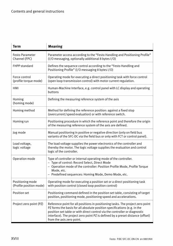
Term Meaning
Festo ParameterChannel (FPC)
Parameter access according to the �Festo Handling and Positioning Profile"(I/O messaging, optionally additional 8 bytes I/O)
FHPP standard Defines the sequence control according to the �Festo Handling andPositioning Profile" (I/O messaging 8 bytes I/O)
Force control(profile torque mode)
Operating mode for executing a direct positioning task with force control(open loop transmission control) with motor current regulation.
HMI Human−Machine Interface, e.g. control panel with LC display and operatingbuttons
Homing (homing mode)
Defining the measuring reference system of the axis
Homing method Method for defining the reference position: against a fixed stop(overcurrent/speed evaluation) or with reference switch.
Homing run Positioning procedure in which the reference point and therefore the originof the measuring reference system of the axis are defined.
Jog mode Manual positioning in positive or negative direction (only on field busvariants of the SFC−DC via the field bus or only with FCT or control panel).
Load voltage,logic�voltage
The load voltage supplies the power electronics of the controller andthereby the motor. The logic voltage supplies the evaluation and controllogic of the controller.
Operation mode Type of controller or internal operating mode of the controller.� Type of control: Record Select, Direct Mode� Operation mode of the controller: Position Profile Mode, Profile Torque
Mode, etc.� Predefined sequences: Homing Mode, Demo Mode, etc.
Positioning mode(Profile position mode)
Operating mode for executing a position set or a direct positioning taskwith position control (closed loop position control)
Position set Positioning command defined in the position set table, consisting of targetposition, positioning mode, positioning speed and accelerations.
Project zero point (PZ) Reference point for all positions in positioning tasks. The project zero pointPZ forms the basis for all absolute position specifications (e.g. in theposition set table or with direct control via the controller or diagnosticinterface). The project zero point PZ is defined by a preset distance (offset)from the axis zero point.
Contents and general instructions
XIXFesto P.BE−SFC−DC−DN−EN en 0801NH
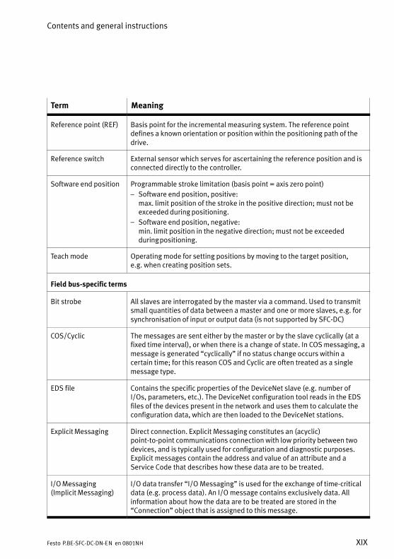
Term Meaning
Reference point (REF) Basis point for the incremental measuring system. The reference pointdefines a known orientation or position within the positioning path of thedrive.
Reference switch External sensor which serves for ascertaining the reference position and isconnected directly to the controller.
Software end position Programmable stroke limitation (basis point = axis zero point)
� Software end position, positive:max. limit position of the stroke in the positive direction; must not beexceeded during positioning.
� Software end position, negative:min. limit position in the negative direction; must not be exceededduring positioning.
Teach mode Operating mode for setting positions by moving to the target position, e.g. when creating position sets.
Field bus−specific terms
Bit strobe All slaves are interrogated by the master via a command. Used to transmitsmall quantities of data between a master and one or more slaves, e.g. forsynchronisation of input or output data (is not supported by SFC−DC)
COS/Cyclic The messages are sent either by the master or by the slave cyclically (at afixed time interval), or when there is a change of state. In COS messaging, amessage is generated �cyclically" if no status change occurs within acertain time; for this reason COS and Cyclic are often treated as a singlemessage type.
EDS file Contains the specific properties of the DeviceNet slave (e.g. number ofI/Os, parameters, etc.). The DeviceNet configuration tool reads in the EDSfiles of the devices present in the network and uses them to calculate theconfiguration data, which are then loaded to the DeviceNet stations.
Explicit Messaging Direct connection. Explicit Messaging constitutes an (acyclic)point−to−point communications connection with low priority between twodevices, and is typically used for configuration and diagnostic purposes.Explicit messages contain the address and value of an attribute and aService Code that describes how these data are to be treated.
I/O Messaging(Implicit Messaging)
I/O data transfer �I/O Messaging" is used for the exchange of time−criticaldata (e.g. process data). An I/O message contains exclusively data. Allinformation about how the data are to be treated are stored in the�Connection" object that is assigned to this message.
Contents and general instructions
XX Festo P.BE−SFC−DC−DN−EN en 0801NH
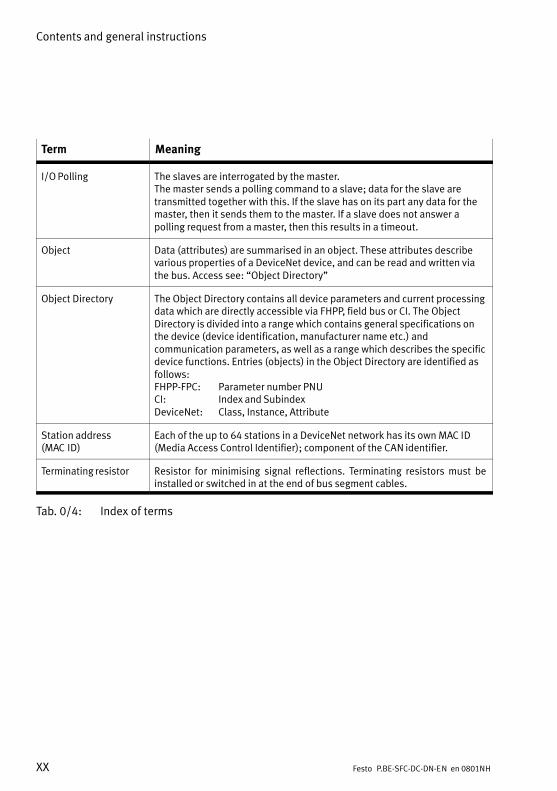
Term Meaning
I/O Polling The slaves are interrogated by the master. The master sends a polling command to a slave; data for the slave aretransmitted together with this. If the slave has on its part any data for themaster, then it sends them to the master. If a slave does not answer apolling request from a master, then this results in a timeout.
Object Data (attributes) are summarised in an object. These attributes describevarious properties of a DeviceNet device, and can be read and written viathe bus. Access see: �Object Directory"
Object Directory The Object Directory contains all device parameters and current processingdata which are directly accessible via FHPP, field bus or CI. The ObjectDirectory is divided into a range which contains general specifications onthe device (device identification, manufacturer name etc.) andcommunication parameters, as well as a range which describes the specificdevice functions. Entries (objects) in the Object Directory are identified asfollows:FHPP−FPC�: Parameter number PNUCI�: Index and SubindexDeviceNet: Class, Instance, Attribute
Station address(MAC�ID)
Each of the up to 64 stations in a DeviceNet network has its own MAC ID(Media Access Control Identifier); component of the CAN identifier.
Terminating resistor Resistor for minimising signal reflections. Terminating resistors must beinstalled or switched in at the end of bus segment cables.
Tab.�0/4: Index of terms

System summary
1−1Festo P.BE−SFC−DC−DN−EN en 0801NH
Chapter 1
1. System summary
1−2 Festo P.BE−SFC−DC−DN−EN en 0801NH
Contents
1. System summary 1−1 . . . . . . . . . . . . . . . . . . . . . . . . . . . . . . . . . . . . . . . . . . . . . . .
1.1 Positioning with electric drives 1−3 . . . . . . . . . . . . . . . . . . . . . . . . . . . . . . . . . . . .
1.2 Components 1−7 . . . . . . . . . . . . . . . . . . . . . . . . . . . . . . . . . . . . . . . . . . . . . . . . . . .
1.3 Control and regulating functions 1−9 . . . . . . . . . . . . . . . . . . . . . . . . . . . . . . . . . . .
1.4 Operational safety 1−11 . . . . . . . . . . . . . . . . . . . . . . . . . . . . . . . . . . . . . . . . . . . . . .
1.5 Structure of the SFC−DC 1−12 . . . . . . . . . . . . . . . . . . . . . . . . . . . . . . . . . . . . . . . . . .
1.6 Measuring reference system 1−14 . . . . . . . . . . . . . . . . . . . . . . . . . . . . . . . . . . . . . .
1.6.1 Basis points and work range 1−14 . . . . . . . . . . . . . . . . . . . . . . . . . . . . . .
1.6.2 Signs and directions 1−17 . . . . . . . . . . . . . . . . . . . . . . . . . . . . . . . . . . . . .
1.6.3 Homing run 1−18 . . . . . . . . . . . . . . . . . . . . . . . . . . . . . . . . . . . . . . . . . . . .
1.7 Field bus communication 1−22 . . . . . . . . . . . . . . . . . . . . . . . . . . . . . . . . . . . . . . . . .
1.7.1 Data exchange in DeviceNet 1−22 . . . . . . . . . . . . . . . . . . . . . . . . . . . . . . .
1.7.2 Festo profile for handling and positioning (FHPP) 1−27 . . . . . . . . . . . . . .
1. System summary
1−3Festo P.BE−SFC−DC−DN−EN en 0801NH
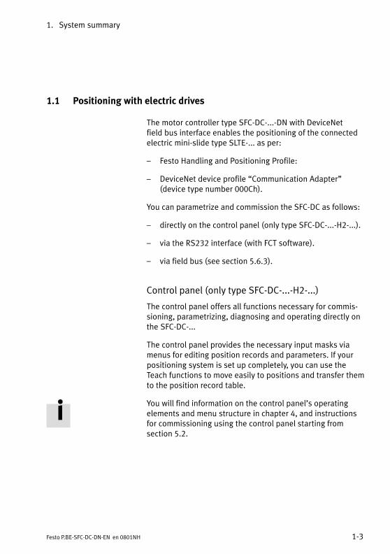
1.1 Positioning with electric drives
The motor controller type SFC−DC−...−DN with DeviceNetfield�bus interface enables the positioning of the connectedelectric mini−slide type SLTE−... as per:
� Festo Handling and Positioning Profile:
� DeviceNet device profile �Communication Adapter"(device type number 000Ch).
You can parametrize and commission the SFC−DC as follows:
� directly on the control panel (only type SFC−DC−...−H2−...).
� via the RS232 interface (with FCT software).
� via field bus (see section 5.6.3).
Control panel (only type SFC−DC−...−H2−...)
The control panel offers all functions necessary for commis�sioning, parametrizing, diagnosing and operating directly onthe SFC−DC−...
The control panel provides the necessary input masks viamenus for editing position records and parameters. If yourpositioning system is set up completely, you can use theTeach functions to move easily to positions and transfer themto the position record table.
You will find information on the control panel’s operatingelements and menu structure in chapter 4, and instructionsfor commissioning using the control panel starting fromsection 5.2.
1. System summary
1−4 Festo P.BE−SFC−DC−DN−EN en 0801NH
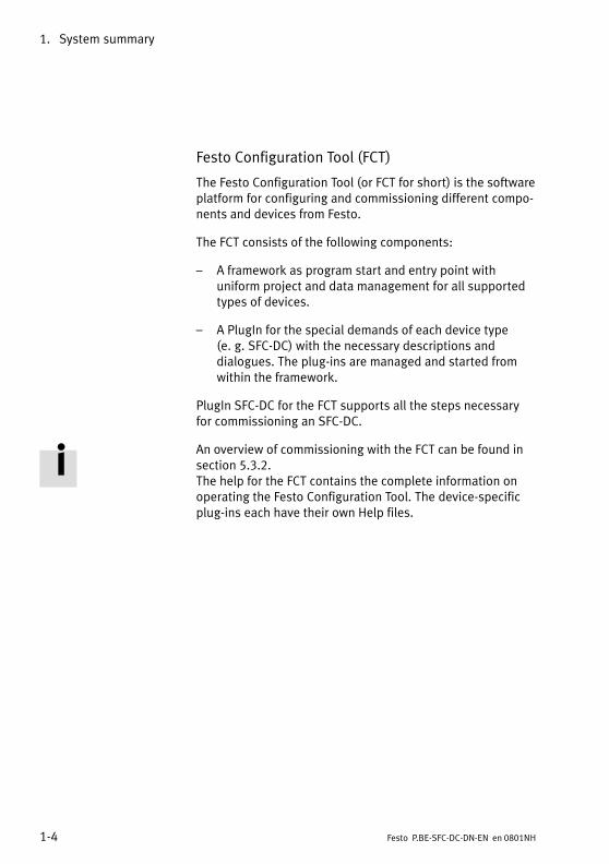
Festo Configuration Tool (FCT)
The Festo Configuration Tool (or FCT for short) is the softwareplatform for configuring and commissioning different compo�nents and devices from Festo.
The FCT consists of the following components:
� A framework as program start and entry point withuniform project and data management for all supportedtypes of devices.
� A PlugIn for the special demands of each device type(e.�g.�SFC−DC) with the necessary descriptions anddialogues. The plug−ins are managed and started fromwithin the framework.
PlugIn SFC−DC for the FCT supports all the steps necessaryfor commissioning an SFC−DC.
An overview of commissioning with the FCT can be found insection 5.3.2. The help for the FCT contains the complete information onoperating the Festo Configuration Tool. The device−specificplug−ins each have their own Help files.

1. System summary
1−5Festo P.BE−SFC−DC−DN−EN en 0801NH
Functions Controlpanel
FCT Fieldbus
Parameterisation � Selection of the axis type of the SLTE and theassociated axis parameters
� Uploading/downloading configuration data� Saving different configurations in projects
x
��
x
xx
x
x�
Position sets � Compiling a position set table with setnumber, target position, positioning mode,positioning speed, acceleration, deceleration
x x x
Commissioning � Homing run� Jog mode� Teaching positions� Moving in individual steps� Starting and stopping positioning procedures
while commissioning� Extended test functions, e.g. status displays� Testing or demonstrating the position records
x(x)x�x
(x)x
xxxxx
xx
xxxxx
xx
Diagnostics/Service
� Reading and displaying diagnostic data� Read and display fault buffer
x�
xx
xx
1. System summary
1−6 Festo P.BE−SFC−DC−DN−EN en 0801NH
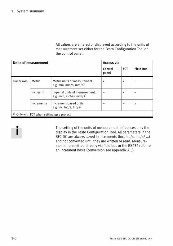
All values are entered or displayed according to the units ofmeasurement set either for the Festo Configuration Tool orthe control panel.
Units of measurement Access via
Controlpanel
FCT Field bus
Linear axis Metric Metric units of measurement: e.g. mm, mm/s, mm/s2
x x �
Inches 1) Imperial units of measurement: e.g. inch, inch/s, inch/s2
� x �
Increments Increment−based units, e.g. Inc, Inc/s, Inc/s2
� � x
1) Only with FCT when setting up a project
The setting of the units of measurement influences only thedisplay in the Festo Configuration Tool. All parameters in theSFC−DC are always saved in increments (Inc, Inc/s, Inc/s2 ...)and not converted until they are written or read. Measure�ments transmitted directly via field bus or the RS232 refer toan increment basis (conversion see appendix A.3)
1. System summary
1−7Festo P.BE−SFC−DC−DN−EN en 0801NH
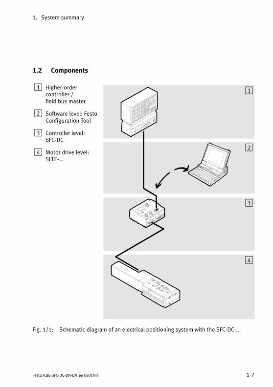
1.2 Components
1 Higher−ordercontroller / field bus master
2 Software level: FestoConfiguration Tool
3 Controller level:SFC−DC
4 Motor drive level:SLTE−...
1
2
3
4
Fig.�1/1: Schematic diagram of an electrical positioning system with the SFC−DC−...
1. System summary
1−8 Festo P.BE−SFC−DC−DN−EN en 0801NH
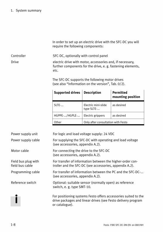
In order to set up an electric drive with the SFC−DC you willrequire the following components:
Controller SFC−DC, optionally with control panel
Drive electric drive with motor, accessories and, if necessary,further components for the drive,�e. g. fastening elements,etc.
The SFC−DC supports the following motor drives (see also �Information on the version", Tab.�0/2).
Supported drives Description Permittedmounting position
SLTE−... Electric mini−slidetype SLTE−...
as desired
HGPPE−.../HGPLE−... Electric grippers as desired
Other Only after consultation with Festo
Power supply unit For logic and load voltage supply: 24 VDC
Power supply cable For supplying the SFC−DC with operating and load voltage(see accessories, appendix A.2).
Motor cable For connecting the drive to the SFC−DC (see accessories, appendix A.2).
Field bus plug withfield�bus cable
For transfer of information between the higher−order con�troller and the SFC−DC (see accessories, appendix A.2).
Programming cable For transfer of information between the PC and the SFC−DC−...(see accessories, appendix A.2).
Reference switch Optional: suitable sensor (normally open) as referenceswitch, e.�g. type SMT−10.
For positioning systems Festo offers accessories suited to thedrive packages and linear drives (see Festo delivery programor catalogue).
1. System summary
1−9Festo P.BE−SFC−DC−DN−EN en 0801NH
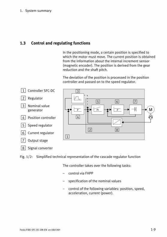
1.3 Control and regulating functions
In the positioning mode, a certain position is specified towhich the motor must move. The current position is obtainedfrom the information about the internal increment sensor(magnetic encoder). The position is derived from the gearreduction and the shaft pitch.
The deviation of the position is processed in the positioncontroller and passed on to the speed regulator.
1 Controller SFC−DC
2 Regulator
3 Nominal valuegenerator
4 Position controller
5 Speed regulator
6 Current regulator
7 Output stage
8 Signal converter
MP PI
3
8
4
5 6 7
1
2
P
Fig.�1/2: Simplified technical representation of the cascade regulator function
The controller takes over the following tasks:
� control via FHPP
� specification of the nominal values
� control of the following variables: position, speed,acceleration, current (power).
1. System summary
1−10 Festo P.BE−SFC−DC−DN−EN en 0801NH
Profile Position mode Positioning modeOperating mode for executing a position set or a directpositioning task with position control (closed loop positioncontrol). The target position defines the position to which the driveregulator is to move. The target position is interpreted eitheras an absolute or relative specification. The set targetposition is transferred to the nominal value generator. Thisgenerates a nominal position value for the position controller.For position control the current settings for speed,acceleration, braking deceleration, etc− are taken intoaccount.
Profile Torque mode Force control.Force control (open loop transmission control) with motorcurrent regulation. This operating mode enables an externalnominal torque value (relative to the rated motor current) tobe specified to the controller. Power control takes place in�directly via the regulation of the motor current. All specifica�tions on forces/torques refer to the rated motor torque orcurrent.
Homing mode Positioning travel for referencing the mechanical basissystem.
For commissioning, testing or demonstration the followingfunctions are also available via the control panel of theSFC−DC−...−H2−...�:
� Positioning travel for defining the target position of aposition set (Teach mode)
� Positioning travel for testing all position sets in theposition set table (Demo posit. tab).
� Positioning travel for testing a certain position set in theposition set table (Move posit. set).

1. System summary
1−11Festo P.BE−SFC−DC−DN−EN en 0801NH
1.4 Operational safety
An extensive system of sensors and monitoring functionsensure operational safety:
� temperature monitoring (measurement of the power endstage temperature),
� voltage monitoring, detection of:
� faults in the logic voltage supply,
� undervoltages in the load voltage supply,
� I2t−monitoring / overload protection,
� following error monitoring,
� software end position detection.
Please noteCheck your machine/system in order to ascertain themeasures necessary for switching it into a safe state in theevent of an EMERGENCY STOP (e. g. switching off the loadvoltage).
The SFC−DC has a separate logic voltage supply.
· If an EMERGENCY STOP circuit is required for your ap�plication, use additional separate safety limit switches(e.�g. as a normally closed series−connected switch).
· Use software end positions and, if necessary, externalsafety limit switches as well as additional appropriatemechanical stops in order to make sure that the axisalways lies within the permitted positioning range.
1. System summary
1−12 Festo P.BE−SFC−DC−DN−EN en 0801NH
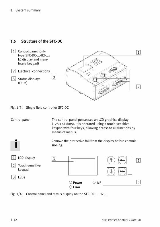
1.5 Structure of the SFC−DC
1 Control panel (onlytype SFC−DC−...−H2−...�:LC display and mem�brane keypad)
2 Electrical connections
3 Status displays(LEDs)
1
2
3
Fig.�1/3: Single field controller SFC−DC
Control panel The control panel possesses an LCD graphics display (128 x 64 dots). It is operated using a touch−sensitivekeypad with four keys, allowing access to all functions bymeans of menus.
Remove the protective foil from the display before commis�sioning.
1 LCD display
2 Touch−sensitivekeypad
3 LEDs
1 2
3
Fig.�1/4: Control panel and status display on the SFC−DC−...−H2−...
1. System summary
1−13Festo P.BE−SFC−DC−DN−EN en 0801NH
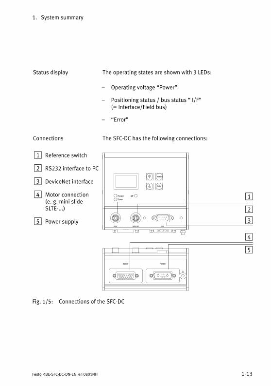
Status display The operating states are shown with 3 LEDs:
� Operating voltage �Power"
� Positioning status / bus status � I/F" (= Interface/Field bus)
� �Error"
Connections The SFC−DC has the following connections:
1 Reference switch
2 RS232 interface to PC
3 DeviceNet interface
4 Motor connection(e.�g. mini slideSLTE−...)
5 Power supply
1
2
3
4
5
Fig.�1/5: Connections of the SFC−DC
1. System summary
1−14 Festo P.BE−SFC−DC−DN−EN en 0801NH
1.6 Measuring reference system
All basis points are defined and the work range is limited inthe measuring reference system.
The measuring reference system of the SFC−DC is based onthe axis zero point which is defined via the offset to the refer�ence point. The position of the reference point is ascertainedduring homing. The homing method defines the way in whichthe axis ascertains the reference point.
1.6.1 Basis points and work range
Reference point REF forms the mechanical basis point of the axis coordinate sys�tem and is defined during homing travel by a reference switchor a fixed stop, depending on the homing method. It is thebasis point of the axis zero point.
Axis zero point AZ is set to a defined distance from the reference point (the axiszero point offset) and is the basis point of the software endpositions and the project zero point.
Project zero PZ is a basis point freely selectable by the user to which theactual position and the target positions from the positioningset table relate. The point of reference for the project zeropoint is the axis zero point.
Software end positions The permitted positioning range (effective stroke) is limitedby the settings of the software end positions. The softwareend positions refer to the axis zero point. If the target posi�tion of a positioning command lies outside the software endpositions, the positioning command will not be processedand an error status will be set.
All values are entered or displayed according to the measur�ing system set either for the Festo Configuration Tool or thecontrol panel (see appendix A.3).
1. System summary
1−15Festo P.BE−SFC−DC−DN−EN en 0801NH
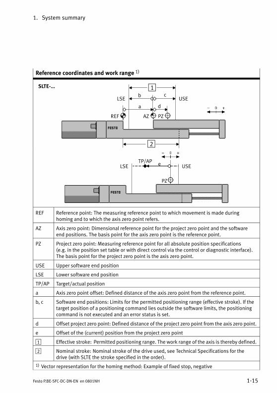
Reference coordinates and work range 1)
a d
b c
REF AZ PZ
LSE USE
2
1SLTE−...
USELSE eTP/AP
PZ
REF Reference point: The measuring reference point to which movement is made duringhoming and to which the axis zero point refers.
AZ Axis zero point: Dimensional reference point for the project zero point and the softwareend positions. The basis point for the axis zero point is the reference point.
PZ Project zero point: Measuring reference point for all absolute position specifications (e.g. in the position set table or with direct control via the control or diagnostic interface).The basis point for the project zero point is the axis zero point.
USE Upper software end position
LSE Lower software end position
TP/AP Target/actual position
a Axis zero point offset: Defined distance of the axis zero point from the reference point.
b, c Software end positions: Limits for the permitted positioning range (effective stroke). If thetarget position of a positioning command lies outside the software limits, the positioningcommand is not executed and an error status is set.
d Offset project zero point: Defined distance of the project zero point from the axis zero point.
e Offset of the (current) position from the project zero point
1 Effective stroke: Permitted positioning range. The work range of the axis is thereby defined.
2 Nominal stroke: Nominal stroke of the drive used, see Technical Specifications for thedrive (with SLTE the stroke specified in the order).
1) Vector representation for the homing method: Example of fixed stop, negative
1. System summary
1−16 Festo P.BE−SFC−DC−DN−EN en 0801NH
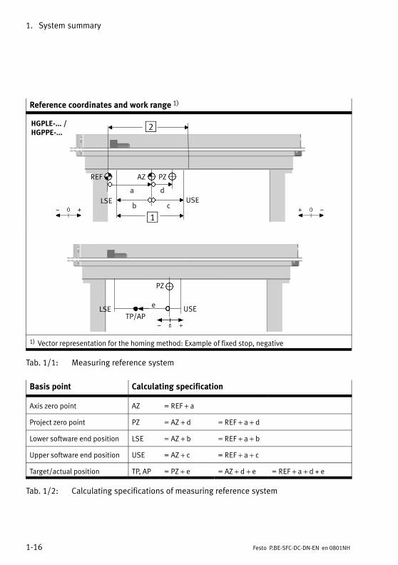
Reference coordinates and work range 1)
a
b c
d
REF AZ PZ
1
2
LSE USE
HGPLE−... /HGPPE−...
PZ
LSE USEe
TP/AP
1) Vector representation for the homing method: Example of fixed stop, negative
Tab.�1/1: Measuring reference system
Basis point Calculating specification
Axis zero point AZ = REF + a
Project zero point PZ = AZ + d = REF + a + d
Lower software end position LSE = AZ + b = REF + a + b
Upper software end position USE = AZ + c = REF + a + c
Target/actual position TP, AP = PZ + e = AZ + d + e = REF + a + d + e
Tab.�1/2: Calculating specifications of measuring reference system
1. System summary
1−17Festo P.BE−SFC−DC−DN−EN en 0801NH
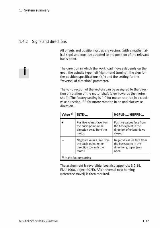
1.6.2 Signs and directions
All offsets and position values are vectors (with a mathemat�ical sign) and must be adapted to the position of the relevantbasis point.
The direction in which the work load moves depends on thegear, the spindle type (left/right−hand turning), the sign forthe position specifications (+/−) and the setting for the�reversal of direction" parameter.
The +/− direction of the vectors can be assigned to the direc�tion of rotation of the motor shaft (view towards the motorshaft). The factory setting is �+" for motor rotation in a clock�wise direction; �−" for motor rotation in an anti−clockwisedirection.
Value 1) SLTE−... HGPLE−...�/�HGPPE−...
+ Positive values face fromthe basis point in thedirection away from themotor.
Positive values face fromthe basis point in thedirection of gripper jawsclosed.
� Negative values face fromthe basis point in thedirection towards themotor.
Negative values face fromthe basis point in thedirection gripper jawsopen.
1) in the factory setting
The assignment is reversible (see also appendix B.2.15,PNU�1000, object 607E). After reversal new homing(reference travel) is then required.
1. System summary
1−18 Festo P.BE−SFC−DC−DN−EN en 0801NH
1.6.3 Homing run
In the case of drives with incremental measuring system,homing must always be carried out when the device isswitched on. This is defined drive−specifically with theparameter �Homing (reference travel) required" (PNU 1014,CI�23F6h).
The following homing modes are permitted:
� search for stop in a negative direction
� search for stop in a positive direction
� search for reference switch in a positive direction
� search for reference switch in a negative direction.
In order to search for the reference point and for positioningthe drive in the axis zero point, you can set two differentspeeds.
Homing sequence:
1. Search for the reference point in accordance with theconfigured method with speed v_rp
2. Move from reference point to axis zero point AZ(offset�axis zero point) with speed v_zp
3. Set current position = 0 � project zero offset PZ
After successful homing the drive stands at the axis zeropoint AZ. On initial commissioning or following a change ofhoming method the axis zero offset is = 0; after homing thedrive is then positioned at the reference point (REF).
1. System summary
1−19Festo P.BE−SFC−DC−DN−EN en 0801NH
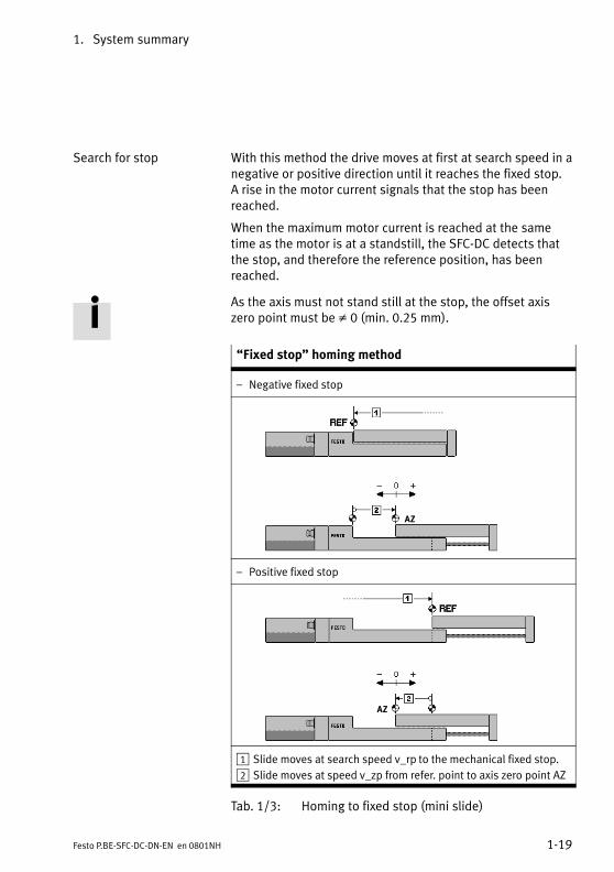
Search for stop With this method the drive moves at first at search speed in anegative or positive direction until it reaches the fixed stop. A rise in the motor current signals that the stop has beenreached.
When the maximum motor current is reached at the sametime as the motor is at a standstill, the SFC−DC detects thatthe stop, and therefore the reference position, has beenreached.
As the axis must not stand still at the stop, the offset axiszero point must be � 0 (min. 0.25 mm).
�Fixed stop" homing method
� Negative fixed stop
AZ
� Positive fixed stop
AZ
1 Slide moves at search speed v_rp to the mechanical fixed stop.
2 Slide moves at speed v_zp from refer. point to axis zero point AZ
Tab.�1/3: Homing to fixed stop (mini slide)

1. System summary
1−20 Festo P.BE−SFC−DC−DN−EN en 0801NH
�Fixed stop" homing method
� Negative fixed stop (= gripper jaws open)
AZ
� Positive fixed stop (= gripper jaws closed)
AZ
1 Gripper moves at search speed v_rp to the mechanical fixed stop.
2 Gripper moves at speed v_zp from reference point to axis zeropoint AZ
Tab.�1/4: Homing to fixed stop (gripper)
1. System summary
1−21Festo P.BE−SFC−DC−DN−EN en 0801NH
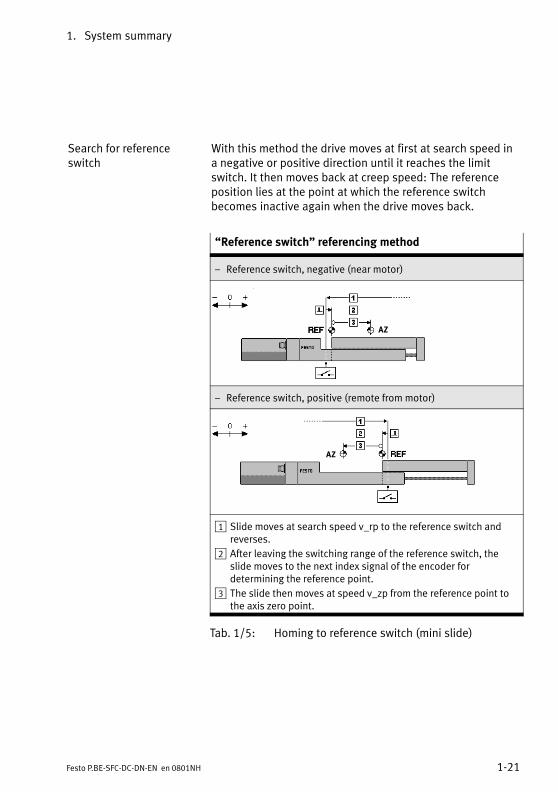
Search for referenceswitch
With this method the drive moves at first at search speed ina negative or positive direction until it reaches the limitswitch. It then moves back at creep speed: The referenceposition lies at the point at which the reference switchbecomes inactive again when the drive moves back.
�Reference switch" referencing method
� Reference switch, negative (near motor)
AZ
� Reference switch, positive (remote from motor)
AZ
1 Slide moves at search speed v_rp to the reference switch andreverses.
2 After leaving the switching range of the reference switch, theslide moves to the next index signal of the encoder fordetermining the reference point.
3 The slide then moves at speed v_zp from the reference point tothe axis zero point.
Tab.�1/5: Homing to reference switch (mini slide)
1. System summary
1−22 Festo P.BE−SFC−DC−DN−EN en 0801NH
1.7 Field bus communication
1.7.1 Data exchange in DeviceNet
DeviceNet was developed by Rockwell Automation and theODVA (Open DeviceNet Vendor Association) as an open fieldbus standard based on the CAN protocol.
The Open DeviceNet Vendor Association (ODVA) is the userorganisation for DeviceNet. Publications concerning the Devi�ceNet/CIP specification are available from:
� ODVA (Open DeviceNet Vendor Association) http://www.odva.org
� CI (ControlNet International ) http://www.controlnet.org.
DeviceNet is a CIP−based network. CIP (Common IndustrialProtocol) forms the application layer of DeviceNet anddefines the exchange of:
� explicit messages with low priority, e.�g. for configurationor diagnosis.
� I/O messages, e.�g. time−critical process data.
Explicit messages (Explicit Messaging)
Explicit messages consist of a request and an answer. Thisway services can be directly requested from or executed bya station.
Explicit messages contain the (destination) address, class,instance, attribute and value of the attribute, and a ServiceCode for data use.
1. System summary
1−23Festo P.BE−SFC−DC−DN−EN en 0801NH
I/O messages(I/O Messaging)
I/O messages are sent by a station, and can be received andprocessed by one or more stations. For I/O messages, thefollowing dialogues are possible between the stations:
� the slaves are interrogated cyclically by the master(Polled I/O), or.
� the messages are sent either by the master or by theslave cyclically, or when there is a change of state(COS/Cyclic), or
� all slaves are interrogated by the master via a command(bit strobe; not supported by the SFC−DC).
The data field contains exclusively user data; no protocoldata are specified. All information on the use of the data isstored in the assigned �Connection Object".
Communication In a DeviceNet network, up to 64 field bus nodes can beoperated via the serial CAN bus. The extent of the networkdepends on the baud rate selected (125 kBaud, 250 kBaud or500 kBaud). DeviceNet telegrams contain up to 8 bytes ofuser data. If it is necessary to exchange larger amounts ofdata, then before sending the data have to be broken downby means of fragmentation, transmitted sequentially, andthen put together again in the recipient.
Unlike in other field bus systems, it is not the bus stations,but rather the messages that are identified. If the bus is free,the stations can send messages. Each bus station decideswhen it would like to send data or request that other busstations send data. Bus conflicts are solved by giving themessages a certain priority (Connection ID). The smaller theidentifier, the higher the priority. Before DeviceNet devicescan exchange messages that uses these IDs, they have to beconfigured accordingly.
The configuration data contain the source and the destina�tion address of the data for the sender and recipient of themessages.

1. System summary
1−24 Festo P.BE−SFC−DC−DN−EN en 0801NH
Object model In DeviceNet, data are accessed via objects. Each DeviceNetstation has one or more objects of various classes. An objectis an instance of a class:
� Standard classes describe, for example, fundamentalproperties, the communication behaviour or parametersof individual channels of a station.
� Manufacturer−specific classes describe device−specificproperties or parameters.
Device profile Device profiles define the minimum available objects andcommunication functions for the specific device types. TheSFC−DC−DN corresponds to the DeviceNet specification forthe device profile �Communication Adapter" (device typenumber 000Ch).
Predefined connection For simple slave devices, predefined master/slave connec�tions (�Predefined Master/Slave Connection Sets") can beused; these simplify the transmission of tI/O data betweenthe higher−order controller (master) and the decentralisedperipheral devices (slaves). The SFC−DC−DN operates accord�ing to the specification �Predefined connection set, Group 2slave only".
1. System summary
1−25Festo P.BE−SFC−DC−DN−EN en 0801NH
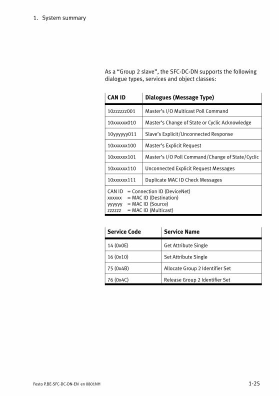
As a �Group 2 slave", the SFC−DC−DN supports the followingdialogue types, services and object classes:
CAN ID Dialogues (Message Type)
10zzzzzz001 Master’s I/O Multicast Poll Command
10xxxxxx010 Master’s Change of State or Cyclic Acknowledge
10yyyyyy011 Slave’s Explicit/Unconnected Response
10xxxxxx100 Master’s Explicit Request
10xxxxxx101 Master’s I/O Poll Command/Change of State/Cyclic
10xxxxxx110 Unconnected Explicit Request Messages
10xxxxxx111 Duplicate MAC ID Check Messages
CAN ID = Connection ID (DeviceNet)xxxxxx = MAC ID (Destination)yyyyyy = MAC ID (Source)zzzzzz = MAC ID (Multicast)
Service Code Service Name
14 (0x0E) Get Attribute Single
16 (0x10) Set Attribute Single
75 (0x4B) Allocate Group 2 Identifier Set
76 (0x4C) Release Group 2 Identifier Set
1. System summary
1−26 Festo P.BE−SFC−DC−DN−EN en 0801NH
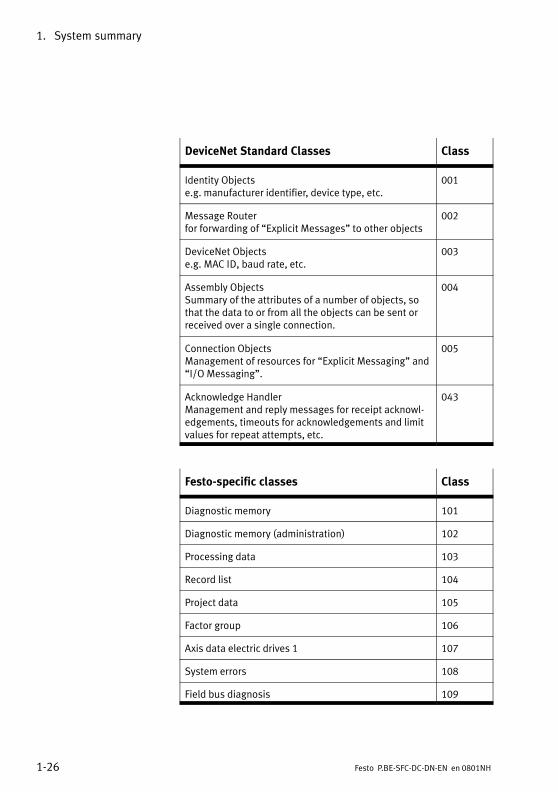
DeviceNet Standard Classes Class
Identity Objects e.g. manufacturer identifier, device type, etc.
001
Message Router for forwarding of �Explicit Messages" to other objects
002
DeviceNet Objects e.g. MAC ID, baud rate, etc.
003
Assembly ObjectsSummary of the attributes of a number of objects, sothat the data to or from all the objects can be sent orreceived over a single connection.
004
Connection ObjectsManagement of resources for �Explicit Messaging" and�I/O Messaging".
005
Acknowledge HandlerManagement and reply messages for receipt acknowl�edgements, timeouts for acknowledgements and limitvalues for repeat attempts, etc.
043
Festo−specific classes Class
Diagnostic memory 101
Diagnostic memory (administration) 102
Processing data 103
Record list 104
Project data 105
Factor group 106
Axis data electric drives 1 107
System errors 108
Field bus diagnosis 109
1. System summary
1−27Festo P.BE−SFC−DC−DN−EN en 0801NH
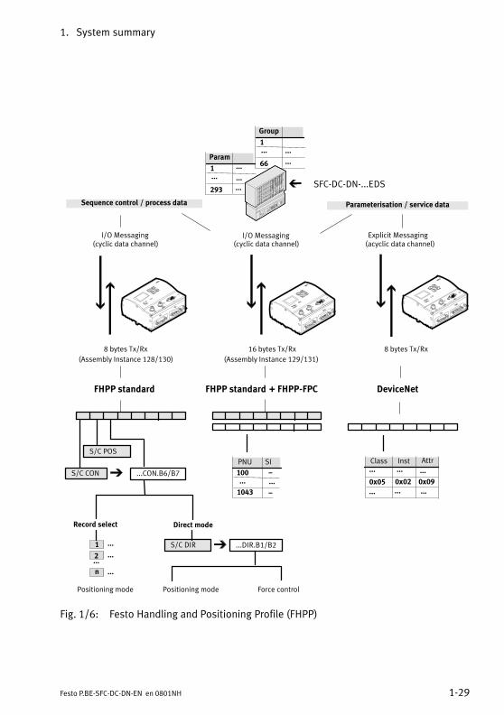
1.7.2 Festo profile for handling and positioning (FHPP)
Festo has developed an optimised data profile, the �FestoHandling and Positioning Profile (FHPP)" tailored to handlingand positioning tasks. The FHPP enables uniform sequencecontrol and programming for the various field bus systemsand controllers from Festo. Parameter values, control andstatus bytes required during operation can be written andread via the Object Directory and a structure description.
Communication via the field bus can be either cyclic(�I/O�Messaging") or acyclic (�Explicit Messaging"). Mixed operation is typical:
� commissioning and application parameters aretransmitted via �Explicit Messaging"
� time−critical sequence control uses the FHPP standard(�I/O Messaging", 8 bytes I/O).
� parameter access during operation is by means of�Explicit Messaging" or optionally using FHPP−FPC(I/O�Messaging, further 8 bytes I/O).
FHPP standard The contents and the meaning of the cyclic I/O data and ofthe functions which can be accessed in the SFC−DC differaccording to the operation mode.
Direct mode
Tasks in positioning or force control can be executed as Directmode. The task is transferred directly in the cyclic I/O data(FHPP standard). The most important nominal values (posi�tion, velocity, force/torque, etc.) are thereby defined.
1. System summary
1−28 Festo P.BE−SFC−DC−DN−EN en 0801NH
Record select
Tasks in positioning mode can be executed using Record se�lect. The positioning data (target positions, speed, etc.) areset indirectly via positioning sets which are taught via FCT,the control panel or field bus and saved in the controller.31�position sets can be saved in the SFC−DC. A record con�tains all the parameters which are specified for a positioningtask (positioning mode). The record number is transferred tothe cyclic I/O data as the nominal or actual value (FHPP stan�dard).
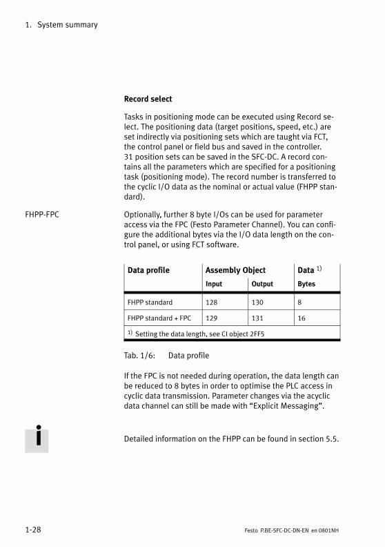
FHPP−FPC Optionally, further 8 byte I/Os can be used for parameteraccess via the FPC (Festo Parameter Channel). You can confi�gure the additional bytes via the I/O data length on the con�trol panel, or using FCT software.
Data profile Assembly Object Data 1)
Input Output Bytes
FHPP standard 128 130 8
FHPP standard + FPC 129 131 16
1) Setting the data length, see CI object 2FF5
Tab.�1/6: Data profile
If the FPC is not needed during operation, the data length canbe reduced to 8 bytes in order to optimise the PLC access incyclic data transmission. Parameter changes via the acyclicdata channel can still be made with �Explicit Messaging".
Detailed information on the FHPP can be found in section 5.5.
1. System summary
1−29Festo P.BE−SFC−DC−DN−EN en 0801NH
Param
...
293 ...
1 ...
...
Direct mode
1
2...
n
Record select
PNU SI
...DIR.B1/B2
Force controlPositioning modePositioning mode
S/C POS
SFC−DC−DN−...EDS
100...
1043
(cyclic data channel)I/O Messaging
Parameterisation / service data
(Assembly Instance 129/131)
�...
�
(Assembly Instance 128/130)
16 bytes Tx/Rx
Sequence control / process data
Explicit Messaging(acyclic data channel)
Class
...0x05 0x02
...
Group
...
66
...
...
1
AttrInst
8 bytes Tx/Rx
...CON.B6/B7S/C CON
S/C DIR
8 bytes Tx/Rx
...
... ...
0x09
...
...
...
...
(cyclic data channel)I/O Messaging
+ FHPP−FPC DeviceNetFHPP standard FHPP standard
Fig.�1/6: Festo Handling and Positioning Profile (FHPP)

1. System summary
1−30 Festo P.BE−SFC−DC−DN−EN en 0801NH

Fitting
2−1Festo P.BE−SFC−DC−DN−EN en 0801NH
Chapter 2
2. Fitting
2−2 Festo P.BE−SFC−DC−DN−EN en 0801NH
Contents
2. Fitting 2−1 . . . . . . . . . . . . . . . . . . . . . . . . . . . . . . . . . . . . . . . . . . . . . . . . . . . . . . . .
2.1 General information 2−3 . . . . . . . . . . . . . . . . . . . . . . . . . . . . . . . . . . . . . . . . . . . . .
2.2 Dimensions of the controller 2−3 . . . . . . . . . . . . . . . . . . . . . . . . . . . . . . . . . . . . . .
2.3 Mounting the controller 2−4 . . . . . . . . . . . . . . . . . . . . . . . . . . . . . . . . . . . . . . . . . .
2.4 Notes on fitting electric axes 2−6 . . . . . . . . . . . . . . . . . . . . . . . . . . . . . . . . . . . . . .
2. Fitting
2−3Festo P.BE−SFC−DC−DN−EN en 0801NH
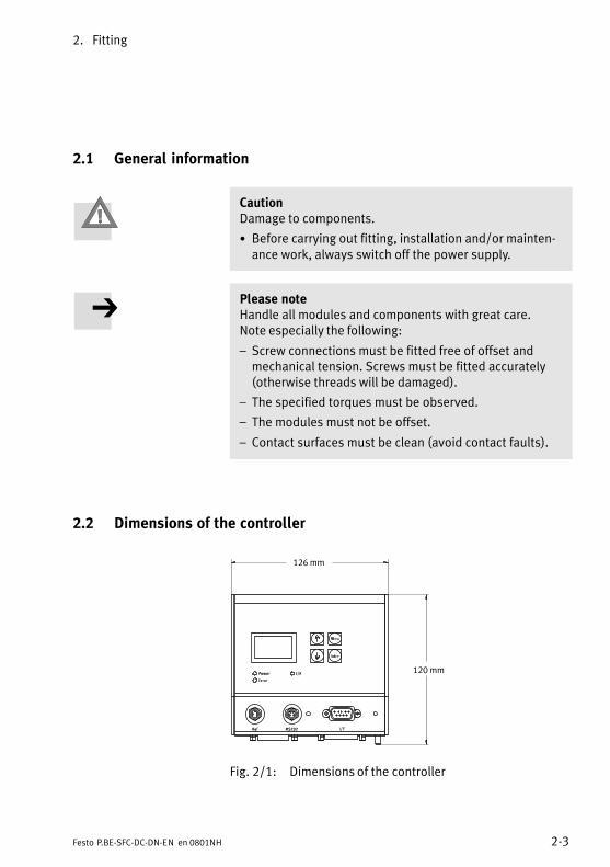
2.1 General information
CautionDamage to components.
· Before carrying out fitting, installation and/or mainten�ance work, always switch off the power supply.
Please noteHandle all modules and components with great care. Note especially the following:
� Screw connections must be fitted free of offset andmechanical tension. Screws must be fitted accurately(otherwise threads will be damaged).
� The specified torques must be observed.
� The modules must not be offset.
� Contact surfaces must be clean (avoid contact faults).
2.2 Dimensions of the controller
120 mm
126 mm
Fig.�2/1: Dimensions of the controller

2. Fitting
2−4 Festo P.BE−SFC−DC−DN−EN en 0801NH
2.3 Mounting the controller
You can fit the SFC−DC in one of two ways:
� Wall mounting on a flat surface,
� Hat rail mounting
Please noteFit the SFC−DC or the Hat rail so that there is sufficientspace for heat dissipation (above and below at least40�mm).
Wall mounting
You will require:
� a mounting surface of approximately 120 x 160 mm.
� 2 sets of central supports, type MUP−18/25 (accessories)The four brackets are clipped into the edge of the housing(see Fig.�2/2).
� 4 threaded holes for screw size M3 (for dimensions seeFig.�2/2) with suitable screws.
120 mm
approx. 105
Fig.�2/2: Screwing the SFC−LAC to the wall
2. Fitting
2−5Festo P.BE−SFC−DC−DN−EN en 0801NH
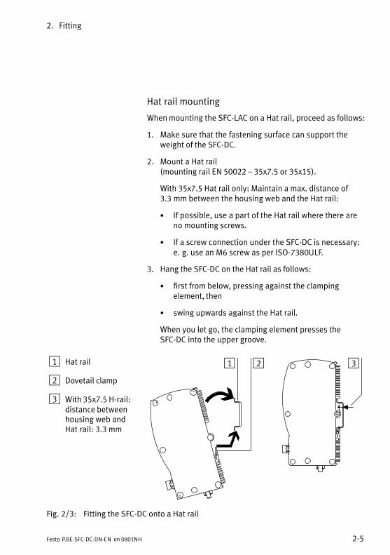
Hat rail mounting
When mounting the SFC−LAC on a Hat rail, proceed as follows:
1. Make sure that the fastening surface can support theweight of the SFC−DC.
2. Mount a Hat rail (mounting rail EN 50022 � 35x7.5 or 35x15).
With 35x7.5 Hat rail only: Maintain a max. distance of3.3�mm between the housing web and the Hat rail:
· If possible, use a part of the Hat rail where there areno mounting screws.
· If a screw connection under the SFC−DC is necessary:e.�g.�use an M6 screw as per ISO−7380ULF.
3. Hang the SFC−DC on the Hat rail as follows:
· first from below, pressing against the clampingelement, then
· swing upwards against the Hat rail.
When you let go, the clamping element presses theSFC−DC into the upper groove.
1 Hat rail
2 Dovetail clamp
3 With 35x7.5 H−rail:distance betweenhousing web andHat�rail: 3.3 mm
1 2 3
Fig.�2/3: Fitting the SFC−DC onto a Hat rail
2. Fitting
2−6 Festo P.BE−SFC−DC−DN−EN en 0801NH
2.4 Notes on fitting electric axes
Refer to the following documentation when fitting the electricaxis:
� Operating instructions for the electric mini−slides orgrippers used.
� Instructions for the components used.
WarningIf a drive is mounted in a sloping or vertical position, loadsmay fall down and cause injury to persons.
· Check whether additional external safety measures arenecessary (e. g. toothed latches or moveable bolts).
You can then prevent the working load sliding downsuddenly if there is a power failure.
Make sure that:
· the drive is fitted securely and is correctly aligned
· the working space in which the drive and effective loadwill move is of sufficient size for operation with a load
· the work load does not collide with any component of theaxis when the slide moves into the end position.

Installation
3−1Festo P.BE−SFC−DC−DN−EN en 0801NH
Chapter 3
3. Installation
3−2 Festo P.BE−SFC−DC−DN−EN en 0801NH
Contents
3. Installation 3−1 . . . . . . . . . . . . . . . . . . . . . . . . . . . . . . . . . . . . . . . . . . . . . . . . . . .
3.1 Overview of installation 3−3 . . . . . . . . . . . . . . . . . . . . . . . . . . . . . . . . . . . . . . . . . .
3.2 Voltage supply 3−6 . . . . . . . . . . . . . . . . . . . . . . . . . . . . . . . . . . . . . . . . . . . . . . . . .
3.3 Earthing 3−9 . . . . . . . . . . . . . . . . . . . . . . . . . . . . . . . . . . . . . . . . . . . . . . . . . . . . . . .
3.4 Motor connection 3−10 . . . . . . . . . . . . . . . . . . . . . . . . . . . . . . . . . . . . . . . . . . . . . . .
3.5 Serial interface 3−11 . . . . . . . . . . . . . . . . . . . . . . . . . . . . . . . . . . . . . . . . . . . . . . . . .
3.6 Input for external reference switch 3−13 . . . . . . . . . . . . . . . . . . . . . . . . . . . . . . . . .
3.7 Control 3−15 . . . . . . . . . . . . . . . . . . . . . . . . . . . . . . . . . . . . . . . . . . . . . . . . . . . . . . .
3.8 Connecting the field bus 3−17 . . . . . . . . . . . . . . . . . . . . . . . . . . . . . . . . . . . . . . . . .
3.8.1 Field bus cable 3−17 . . . . . . . . . . . . . . . . . . . . . . . . . . . . . . . . . . . . . . . . . .
3.8.2 Field bus baud rate and field bus length 3−18 . . . . . . . . . . . . . . . . . . . . .
3.8.3 Information on connecting the field bus 3−18 . . . . . . . . . . . . . . . . . . . . .
3.8.4 Connection with field bus plugs from Festo 3−20 . . . . . . . . . . . . . . . . . . .
3.8.5 Connection to other Sub−D plugs 3−24 . . . . . . . . . . . . . . . . . . . . . . . . . . .
3.9 Bus termination with terminating resistors 3−25 . . . . . . . . . . . . . . . . . . . . . . . . . .
3.9.1 Install a terminating resistor using the adapters 3−26 . . . . . . . . . . . . . . .
3. Installation
3−3Festo P.BE−SFC−DC−DN−EN en 0801NH
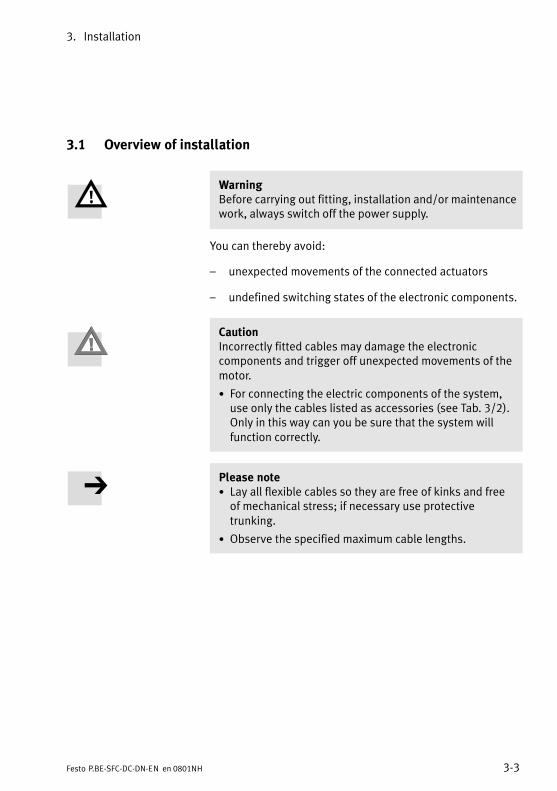
3.1 Overview of installation
WarningBefore carrying out fitting, installation and/or maintenancework, always switch off the power supply.
You can thereby avoid:
� unexpected movements of the connected actuators
� undefined switching states of the electronic components.
CautionIncorrectly fitted cables may damage the electroniccomponents and trigger off unexpected movements of themotor.
· For connecting the electric components of the system,use only the cables listed as accessories (see Tab.�3/2).Only in this way can you be sure that the system willfunction correctly.
Please note· Lay all flexible cables so they are free of kinks and freeof mechanical stress; if necessary use protectivetrunking.
· Observe the specified maximum cable lengths.
3. Installation
3−4 Festo P.BE−SFC−DC−DN−EN en 0801NH
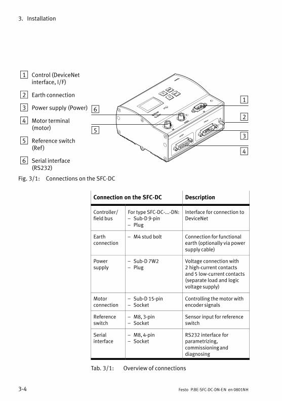
1 Control (DeviceNetinterface, I/F)
2 Earth connection
3 Power supply (Power)
4 Motor terminal(motor)
5 Reference switch(Ref)
6 Serial interface(RS232)
1
2
3
4
5
6
Fig.�3/1: Connections on the SFC−DC
Connection on the SFC−DC Description
Controller/field bus
For type SFC−DC−...−DN:� Sub−D 9−pin� Plug
Interface for connection toDeviceNet
Earthconnection
� M4 stud bolt Connection for functionalearth (optionally via powersupply cable)
Powersupply
� Sub−D 7W2� Plug
Voltage connection with2�high−current contactsand 5�low−current contacts(separate load and logicvoltage supply)
Motorconnection
� Sub−D 15−pin� Socket
Controlling the motor withencoder signals
Referenceswitch
� M8, 3−pin� Socket
Sensor input for referenceswitch
Serialinterface
� M8, 4−pin� Socket
RS232 interface forparametrizing,commissioning anddiagnosing
Tab.�3/1: Overview of connections
3. Installation
3−5Festo P.BE−SFC−DC−DN−EN en 0801NH
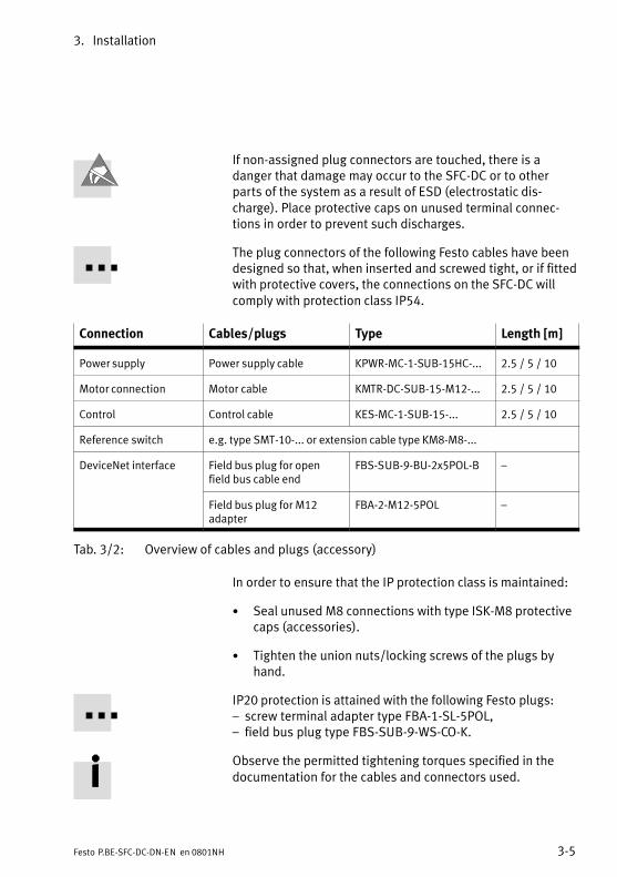
If non−assigned plug connectors are touched, there is adanger that damage may occur to the SFC−DC or to otherparts of the system as a result of ESD (electrostatic dis�charge). Place protective caps on unused terminal connec�tions in order to prevent such discharges.
The plug connectors of the following Festo cables have beendesigned so that, when inserted and screwed tight, or if fittedwith protective covers, the connections on the SFC−DC willcomply with protection class IP54.
Connection Cables/plugs Type Length [m]
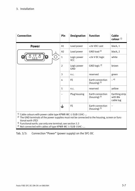
Power supply Power supply cable KPWR−MC−1−SUB−15HC−... 2.5 / 5 / 10
Motor connection Motor cable KMTR−DC−SUB−15−M12−... 2.5 / 5 / 10
Control Control cable KES−MC−1−SUB−15−... 2.5 / 5 / 10
Reference switch e.g. type SMT−10−... or extension cable type KM8−M8−...
DeviceNet interface Field bus plug for openfield bus cable end
FBS−SUB−9−BU−2x5POL−B �
Field bus plug for M12adapter
FBA−2−M12−5POL �
Tab.�3/2: Overview of cables and plugs (accessory)
In order to ensure that the IP protection class is maintained:
· Seal unused M8 connections with type ISK−M8 protectivecaps (accessories).
· Tighten the union nuts/locking screws of the plugs byhand.
IP20 protection is attained with the following Festo plugs: � screw terminal adapter type FBA−1−SL−5POL, � field bus plug type FBS−SUB−9−WS−CO−K.
Observe the permitted tightening torques specified in thedocumentation for the cables and connectors used.

3. Installation
3−6 Festo P.BE−SFC−DC−DN−EN en 0801NH
3.2 Voltage supply
Warning· In order to provide the electric power supply, use onlyPELV circuits as per IEC/DIN EN 60204−1 (ProtectiveExtra−Low Voltage, PELV).Also take into account the general requirements for PELVcircuits according to IEC/DIN EN 60204−1.
· Only use power packs which guarantee reliableelectrical isolation of the operating voltage according toIEC/DIN EN 60204−1.
By the use of PELV power units, protection against electricshock (protection against direct and indirect contact) isguaranteed in accordance with IEC/DIN EN 60204−1(electrical equipment of machines, general requirements).
The internal power and controller electronics are suppliedwith DC voltage via the power supply connection.
Please noteNote that the tolerances for the power supplies must beobserved; see Tab.�3/4. The tolerance must be observeddirectly at the power connection of the SFC−DC.
· For the power supply use one of the following cablesfrom Festo:
� power supply cable KPWR−MC−1−SUB−15HC−...
� max. cable length 10 m.
· Use a closed−loop power unit with:
� at least 5 A peak current.
CautionDamage to the device
The 24 V DC power supplies of the SFC−DC have no specialprotection against overvoltage.
· Make sure that the permitted voltage tolerance is neverexceeded; see Tab.�3/4.
3. Installation
3−7Festo P.BE−SFC−DC−DN−EN en 0801NH
Connection Pin Designation Function Cablecolour�1)
A1 Load power +24 VDC Last black, 1
A2 Load power GND load 2) black, 2
1 Logic powerVCC
+24 V DC logic white
2 Logic powerGND
GND logic 2) brown
3 n.c. reserved green
4 FE Earth connection(housing) 3)
� 4)
5 n.c. reserved yellow
� Plug housing Earth connection(housing) 3)
Earthing stripwith M4cable lug
FE Earth connection(housing) 3)
�
1) Cable colours with power cable type KPWR−MC−1−SUB−15HC−...2) The GND terminals of the power supplies must not be connected to the housing, screen or func�
tional earth (FE)!3) Functional earth; use only one terminal; see section 3.32) Not connected with cables of type KPWR−MC−1−SUB−15HC−....
Tab.�3/3: Connection �Power" (power supply) on the SFC−DC
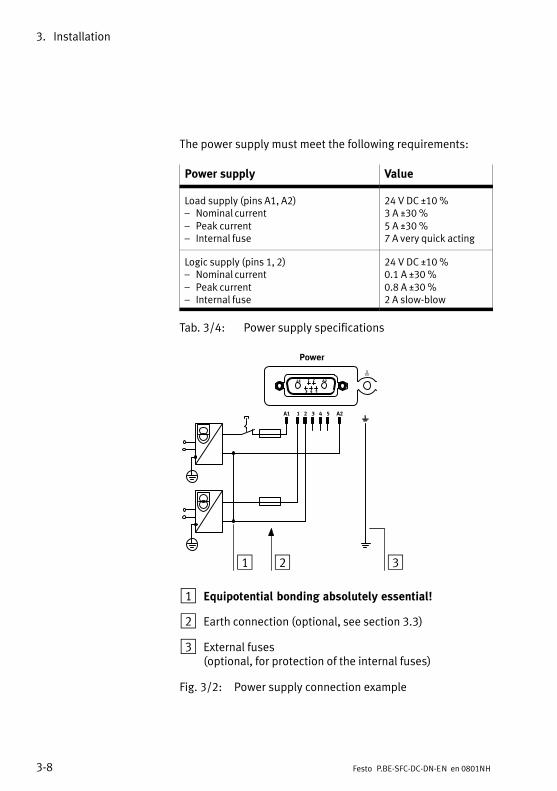
3. Installation
3−8 Festo P.BE−SFC−DC−DN−EN en 0801NH
The power supply must meet the following requirements:
Power supply Value
Load supply (pins A1, A2)� Nominal current� Peak current� Internal fuse
24 V DC ±10 %3 A ±30 %5 A ±30 %7 A very quick acting
Logic supply (pins 1, 2)� Nominal current� Peak current� Internal fuse
24 V DC ±10 %0.1 A ±30 %0.8 A ±30 %2 A slow−blow
Tab.�3/4: Power supply specifications
1 2 3 4A1 5 A2
1 2 3
1 Equipotential bonding absolutely essential!
2 Earth connection (optional, see section 3.3)
3 External fuses (optional, for protection of the internal fuses)
Fig.�3/2: Power supply connection example
3. Installation
3−9Festo P.BE−SFC−DC−DN−EN en 0801NH
3.3 Earthing
Please note· Connect one of the earth cables of the SFC−DC with lowimpedance (short cable with large cross−sectional area)to the earth potential.
You can thereby avoid faults due to electromagneticinfluences and ensure electromagnetic compatibility inaccordance with EMC guidelines.
To connect the SFC−DC to the earth potential, use one of thefollowing earth connections:
� earthing strip at the free end of the power supply cable,see assembly instructions for cable typeKPWR−MC−1−SUB−15HC−..., or
� earth connection on the housing of the SFC−DC,see�Tab.�3/3.
CautionDamage to the device
Never connect one of the power supply connections(Tab.�3/3, pin 1, 2, A1, A2) to FE or to the housing. This willavoid damaging the device and impairing protectionagainst electromagnetic interference (EMC).
Please noteNote that only one of the two earth connections may beused (to avoid earth loops).
When using the earth connection on the housing of theSFC−DC:
· Use a suitable earthing cable with an M4 cable lug andthe supplied nut with toothed lock washer.
· Tighten the nut with max. 1.7 Nm.
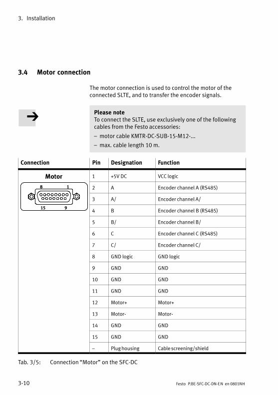
3. Installation
3−10 Festo P.BE−SFC−DC−DN−EN en 0801NH
3.4 Motor connection
The motor connection is used to control the motor of theconnected SLTE, and to transfer the encoder signals.
Please noteTo connect the SLTE, use exclusively one of the followingcables from the Festo accessories:
� motor cable KMTR−DC−SUB−15−M12−...
� max. cable length 10 m.
Connection Pin Designation Function
1 +5V DC VCC logic
8 1 2 A Encoder channel A (RS485)
3 A/ Encoder channel A/
15 94 B Encoder channel B (RS485)
5 B/ Encoder channel B/
6 C Encoder channel C (RS485)
7 C/ Encoder channel C/
8 GND logic GND logic
9 GND GND
10 GND GND
11 GND GND
12 Motor+ Motor+
13 Motor− Motor−
14 GND GND
15 GND GND
� Plug housing Cable screening/shield
Tab.�3/5: Connection �Motor" on the SFC−DC
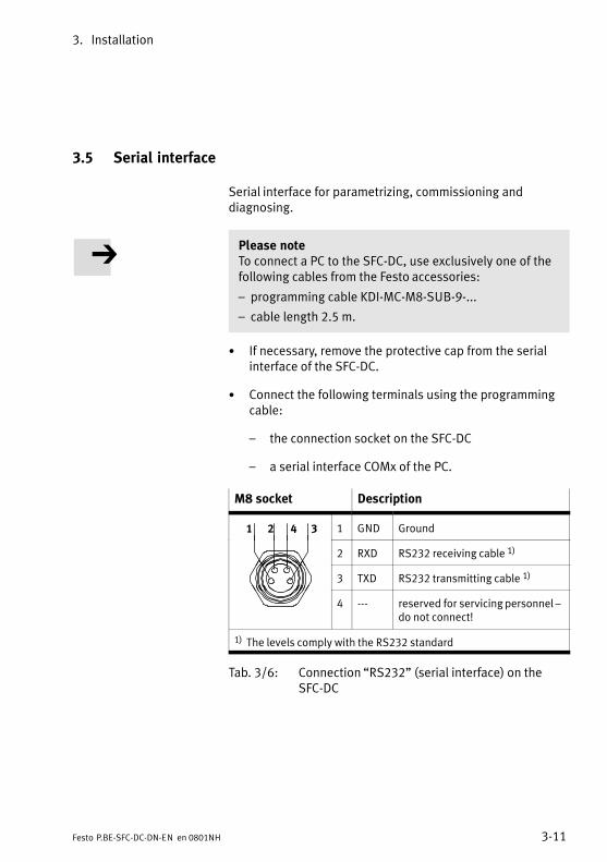
3. Installation
3−11Festo P.BE−SFC−DC−DN−EN en 0801NH
3.5 Serial interface
Serial interface for parametrizing, commissioning anddiagnosing.
Please noteTo connect a PC to the SFC−DC, use exclusively one of thefollowing cables from the Festo accessories:
� programming cable KDI−MC−M8−SUB−9−...
� cable length 2.5 m.
· If necessary, remove the protective cap from the serialinterface of the SFC−DC.
· Connect the following terminals using the programmingcable:
� the connection socket on the SFC−DC
� a serial interface COMx of the PC.
M8 socket Description
1 2 4 3 1 GND Ground
2 RXD RS232 receiving cable 1)
3 TXD RS232 transmitting cable 1)
4 −−− reserved for servicing personnel �do not connect!
1) The levels comply with the RS232 standard
Tab.�3/6: Connection �RS232" (serial interface) on theSFC−DC
3. Installation
3−12 Festo P.BE−SFC−DC−DN−EN en 0801NH
Information on commissioning and parametrizing the SFC−DCvia the serial interface can be found in chapter 5.3.2 and inthe help system for the Festo Configuration Tool softwarepackage. Information on transmitting CI commands via the serialinterface can be found in chapter 7.
Please noteThe RS232 interface is not electrically isolated. It is notsuitable for permanent connection to PC systems, nor as acontrol interface.
· Use this terminal only for commissioning.
· Disconnect the diagnostic cable during continuousoperation.
· Seal the connection with the protective cap supplied(type ISK−M8).

3. Installation
3−13Festo P.BE−SFC−DC−DN−EN en 0801NH
3.6 Input for external reference switch
If you are not using a reference switch:
· Seal the terminal with the protective cap supplied(type�ISK−M8).
Use e.g. the following proximity switches from Festo:
� electric proximity switch type SMT−10F−... (mountable insensor bays on the drive unit).
If necessary, use an extension cable type KM8−M8−...
Connecting the reference switch:
· Use the correct switch type �normally−open contact" inthe PNP variant for the reference switch.
· For connecting the reference switch use a cable withrotating thread sleeve on the end of the cable,e.�g.�type�SMT−10F−... or extension cable type KM8−M8−...
· When selecting the sensor, note that the accuracy of theswitchover point of the sensor can affect the accuracy ofthe reference point.
· During installation, observe the position of the sensorrelative to the index pulse; shift the sensor if necessary(see warning �INDEX PULSE WARNING", section 6.3).
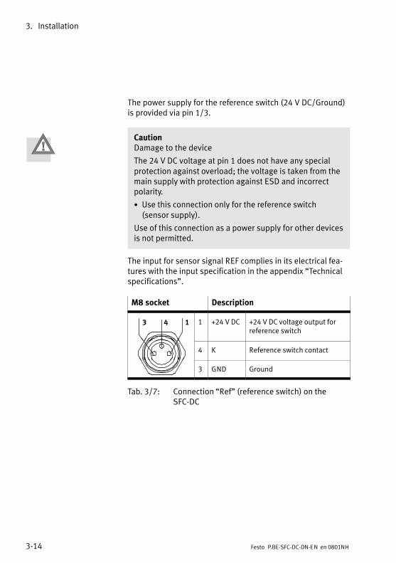
3. Installation
3−14 Festo P.BE−SFC−DC−DN−EN en 0801NH
The power supply for the reference switch (24 V DC/Ground)is provided via pin 1/3.
CautionDamage to the device
The 24 V DC voltage at pin 1 does not have any specialprotection against overload; the voltage is taken from themain supply with protection against ESD and incorrectpolarity.
· Use this connection only for the reference switch (sensor supply).
Use of this connection as a power supply for other devicesis not permitted.
The input for sensor signal REF complies in its electrical fea�tures with the input specification in the appendix �Technicalspecifications".
M8 socket Description
143 1 +24 V DC +24 V DC voltage output forreference switch
4 K Reference switch contact
3 GND Ground
Tab.�3/7: Connection �Ref" (reference switch) on theSFC−DC
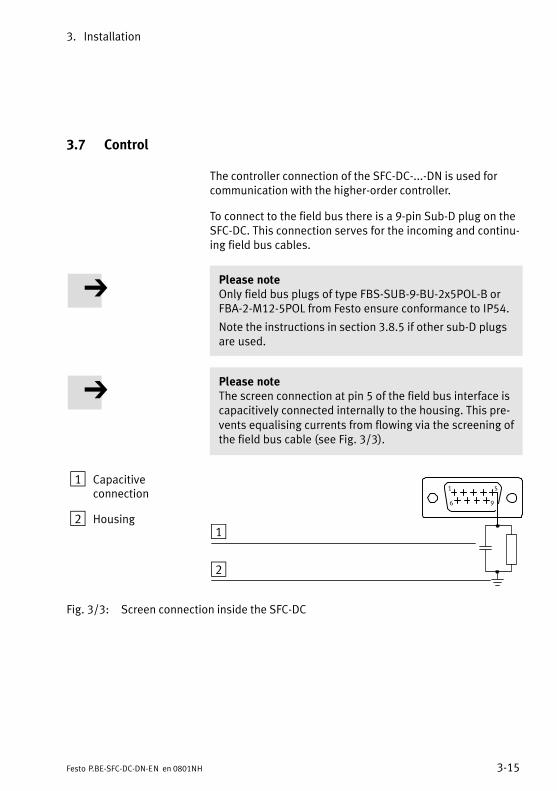
3. Installation
3−15Festo P.BE−SFC−DC−DN−EN en 0801NH
3.7 Control
The controller connection of the SFC−DC−...−DN is used forcommunication with the higher−order controller.
To connect to the field bus there is a 9−pin Sub−D plug on theSFC−DC. This connection serves for the incoming and continu�ing field bus cables.
Please noteOnly field bus plugs of type FBS−SUB−9−BU−2x5POL−B orFBA−2−M12−5POL from Festo ensure conformance to IP54.
Note the instructions in section 3.8.5 if other sub−D plugsare used.
Please noteThe screen connection at pin 5 of the field bus interface iscapacitively connected internally to the housing. This pre�vents equalising currents from flowing via the screening ofthe field bus cable (see Fig.�3/3).
1 Capacitiveconnection
2 Housing
51
96
1
2
Fig.�3/3: Screen connection inside the SFC−DC
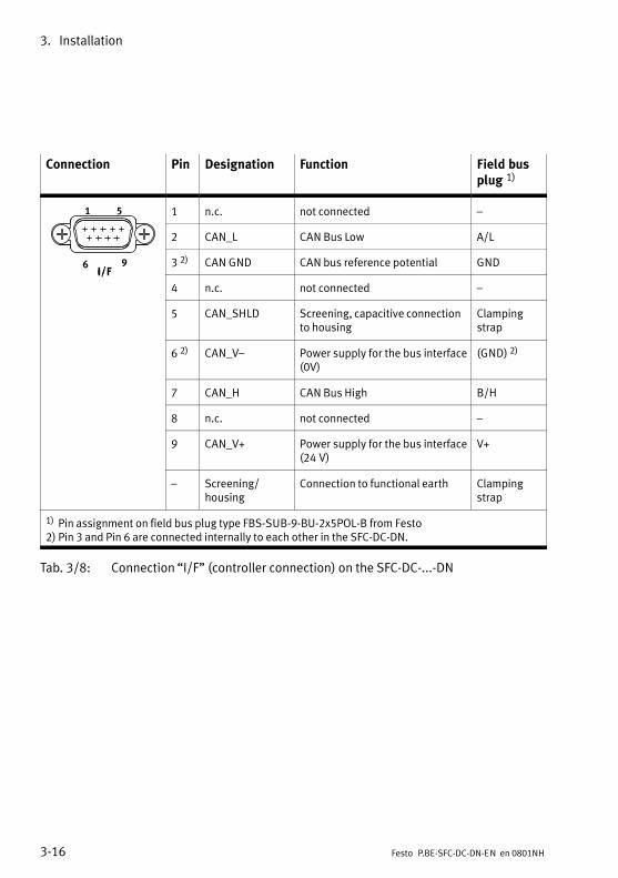
3. Installation
3−16 Festo P.BE−SFC−DC−DN−EN en 0801NH
Connection Pin Designation Function Field busplug 1)
1 5 1 n.c. not connected �
2 CAN_L CAN Bus Low A/L
6 9 3 2) CAN GND CAN bus reference potential GND
4 n.c. not connected �
5 CAN_SHLD Screening, capacitive connectionto housing
Clampingstrap
6 2) CAN_V� Power supply for the bus interface(0V)
(GND) 2)
7 CAN_H CAN Bus High B/H
8 n.c. not connected �
9 CAN_V+ Power supply for the bus interface(24 V)
V+
� Screening/ housing
Connection to functional earth Clampingstrap
1) Pin assignment on field bus plug type FBS−SUB−9−BU−2x5POL−B from Festo2) Pin 3 and Pin 6 are connected internally to each other in the SFC−DC−DN.
Tab.�3/8: Connection �I/F" (controller connection) on the SFC−DC−...−DN
3. Installation
3−17Festo P.BE−SFC−DC−DN−EN en 0801NH
3.8 Connecting the field bus
3.8.1 Field bus cable
Please noteIf installation has not been carried out correctly and if highbaud rates are used, data transmission errors may occuras a result of signal reflections and attenuation. Causes of the transmission faults can be:
� missing or incorrect terminating resistor
� incorrect screening/shield connection
� branches
� transmission over long distances
� unsuitable cables.
Observe the cable specifications. Refer to your controllermanual for information on the type of cable to be used.
Please noteIf the SFC−DC is fitted onto the moving part of a machine,the field bus cable on the moving part must be providedwith strain relief. Please also observe the relevant regula�tions in EN�60204 part 1.
Use a twisted−pair screened 4−wire cable as the field buscable.
When using a Festo field bus a cable diameter of 5 � 8 or7���10 mm is permitted.
3. Installation
3−18 Festo P.BE−SFC−DC−DN−EN en 0801NH
3.8.2 Field bus baud rate and field bus length
The maximum permitted field bus length and the length ofthe branch lines depend on the baud rate used. Detailedspecifications can be found in the manuals for the yourcontrol system or bus interface.
Please note· Refer to the manuals for your control system or businterface in order to ascertain which T−adapter youshould use and the maximum branch line length whichis permitted for your controller.
· Take into account also the sum of the branch line lengthswhen calculating the maximum permitted length of thefield bus cable.
3.8.3 Information on connecting the field bus
Bus supply Avoid excessively long distances between the bus interface/logic supply and the SFC−DC.
Caution· Make sure the polarity is correct when you connect thefield bus interface and the power supply for the businterface.
· Connect the screening/shield.
· Protect the power supply for the bus interface with anexternal fuse, in accordance with the number of busslaves.

3. Installation
3−19Festo P.BE−SFC−DC−DN−EN en 0801NH
You can implement a T−adapter with the Festo field bus plug(see figure).
Ö
2 31
4
5
6
1 Field bus
2 Power supply
3 Screening/shield
4 T−adapter (T−tap)
5 Branch line
6 Field bus plug with T−adapter function
Fig.�3/4: Structure of the bus interface and example of connection
Please noteBus slaves have different tolerances in respect of theinterface supply, depending on the manufacturer. Note thiswhen planning the bus length and placing the power unit.
3. Installation
3−20 Festo P.BE−SFC−DC−DN−EN en 0801NH
For the SFC−DC the following tolerance applies to the businterface supply (pin 9 on the Sub−D plug): Vmax = 30.0 VVmin = 11.0 V
Recommendation:Place the power unit approximately in the centre of the bus.
3.8.4 Connection with field bus plugs from Festo
Connection with Festo field bus plugs (IP54)
· Observe the fitting instructions for the field bus plug.Tighten the two fastening screws at first by hand and thenwith max. 0.4 Nm.
With Festo field bus plugs type FBA−2−M12−5POL orFBS−SUB−9−BU−2x5POL−B you can connect the SFC−DC to thefield bus in a user−friendly manner. You can disconnect theplug from the SFC−DC without interrupting the bus cable(T−TAP function).
Please noteThe clamp strap in the field bus plug from Festo is con�nected internally only capacitively with the metallic hous�ing of the Sub−D plug. This is to prevent equalising cur�rents flowing through the screening of the field bus cable.
· Clamp the screening of the field bus cable under theclamp strap in the field bus plug. The �SLD" terminal inthe field bus plug is optional.
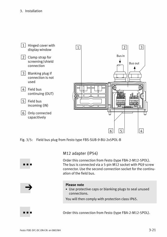
3. Installation
3−21Festo P.BE−SFC−DC−DN−EN en 0801NH
1 Hinged cover withdisplay window
2 Clamp strap forscreening/shieldconnection
3 Blanking plug ifconnection is notused
4 Field buscontinuing (OUT)
5 Field busincoming (IN)
6 Only connectedcapacitively
V+
GND H L
SLD
V+
GND H L
SLD
21 3
456
Bus in
Bus out
Fig.�3/5: Field bus plug from Festo type FBS−SUB−9−BU−2x5POL−B
M12 adapter (IP54)
Order this connection from Festo (type FBA−2−M12−5POL). The bus is connected via a 5−pin M12 socket with PG9 screwconnector. Use the second connection socket for the continu�ation of the field bus.
Please note· Use protective caps or blanking plugs to seal unusedconnections.
You will then comply with protection class IP65.
Order this connection from Festo (type FBA−2−M12−5POL).
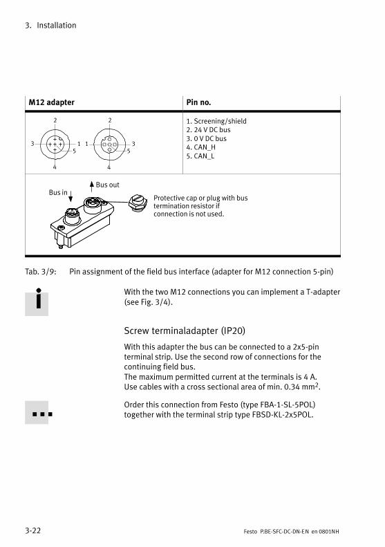
3. Installation
3−22 Festo P.BE−SFC−DC−DN−EN en 0801NH
M12 adapter Pin no.
5
2
3
4
15
1
4
3
2 1. Screening/shield2. 24 V DC bus3. 0 V DC bus4. CAN_H5. CAN_L
Protective cap or plug with bustermination resistor ifconnection is not used.
Bus inBus out
Tab.�3/9: Pin assignment of the field bus interface (adapter for M12 connection 5−pin)
With the two M12 connections you can implement a T−adapter(see Fig.�3/4).
Screw terminaladapter (IP20)
With this adapter the bus can be connected to a 2x5−pinterminal strip. Use the second row of connections for thecontinuing field bus.The maximum permitted current at the terminals is 4 A. Use cables with a cross sectional area of min. 0.34 mm2.
Order this connection from Festo (type FBA−1−SL−5POL)together with the terminal strip type FBSD−KL−2x5POL.
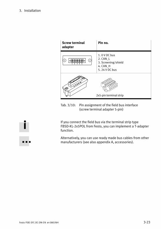
3. Installation
3−23Festo P.BE−SFC−DC−DN−EN en 0801NH
Screw terminaladapter
Pin no.
1 2 3 4 5
1. 0 V DC bus2. CAN_L3. Screening/shield4. CAN_H5. 24 V DC bus
2x5−pin terminal strip
Tab.�3/10: Pin assignment of the field bus interface (screw terminal adapter 5−pin)
If you connect the field bus via the terminal strip typeFBSD−KL−2x5POL from Festo, you can implement a T−adapterfunction.
Alternatively, you can use ready made bus cables from othermanufacturers (see also appendix A, accessories).

3. Installation
3−24 Festo P.BE−SFC−DC−DN−EN en 0801NH
3.8.5 Connection to other Sub−D plugs
If you are using the Festo type FBS−SUB−9−WS−CO−K plug orSub−D plugs from other manufacturers, you must replace thetwo flat screws by which the field bus plug is fitted in theSFC−DC by a bolt of type UNC 4−40/M3x5 (supplied).
Please noteIf both screws or bolts are dismantled simultaneously,there is a danger that the plug with the printed circuitboard will be pressed into the housing of the SFC−DC.
· During conversion always leave one of the screws or thebolt in position.
Proceed as follows:
1. First loosen one of the fastening screws and remove it.
2. Screw one of the fastening bolts into the empty hole andtighten it. Maximum tightening torque: 0.48 Nm.
3. Repeat steps 1 and 2 for the other screw.
Please notePlease note that if Sub−D plugs of other manufacturers areused, only protection class IP20 will be fulfilled.
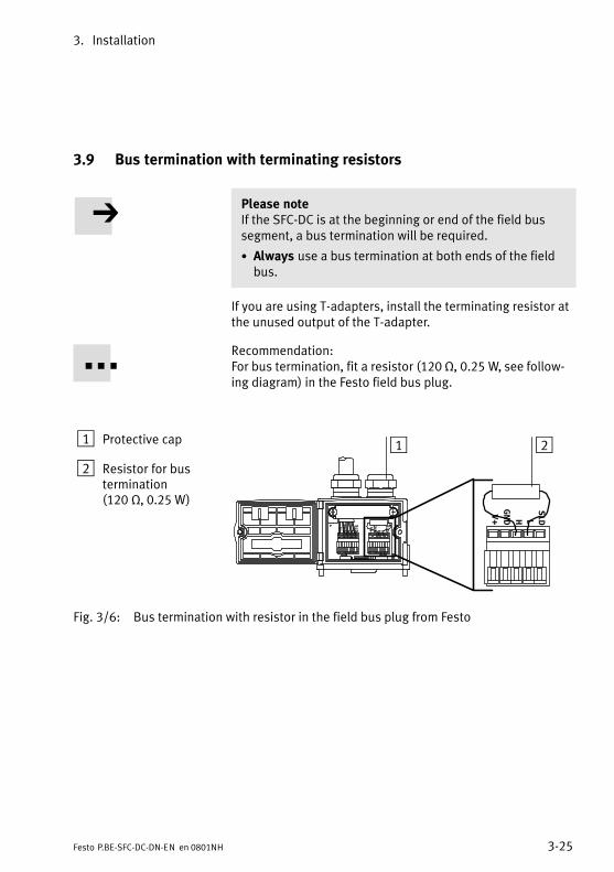
3. Installation
3−25Festo P.BE−SFC−DC−DN−EN en 0801NH
3.9 Bus termination with terminating resistors
Please noteIf the SFC−DC is at the beginning or end of the field bussegment, a bus termination will be required.
· Always use a bus termination at both ends of the fieldbus.
If you are using T−adapters, install the terminating resistor atthe unused output of the T−adapter.
Recommendation:For bus termination, fit a resistor (120 , 0.25 W, see follow�ing diagram) in the Festo field bus plug.
1 Protective cap
2 Resistor for bustermination(120�, 0.25 W)
V+
GND H L
SLD
V+
GND H L
SLD
V+
GND H L
SLD
1 2
Fig.�3/6: Bus termination with resistor in the field bus plug from Festo
3. Installation
3−26 Festo P.BE−SFC−DC−DN−EN en 0801NH
3.9.1 Install a terminating resistor using the adapters
If the SFC−DC you are connecting to is at the end of a fieldbus, install a terminating resistor (120 , 0.25 W) in thefield�bus socket:
· Connect the terminating resistor between the cores forCAN_H and CAN_L.
Control panel (only type SFC−DC−...−H2−...)
4−1Festo P.BE−SFC−DC−DN−EN en 0801NH
Chapter 4
4. Control panel (only type SFC−DC−...−H2−...)
4−2 Festo P.BE−SFC−DC−DN−EN en 0801NH
Contents
4. Control panel (only type SFC−DC−...−H2−...) 4−1 . . . . . . . . . . . . . . . . . . . . . . . . . .
4.1 Composition and function of the control panel 4−4 . . . . . . . . . . . . . . . . . . . . . . .
4.2 The menu system 4−6 . . . . . . . . . . . . . . . . . . . . . . . . . . . . . . . . . . . . . . . . . . . . . . .
4.2.1 Accessing the main menu 4−6 . . . . . . . . . . . . . . . . . . . . . . . . . . . . . . . . .
4.2.2 Selecting a menu command 4−6 . . . . . . . . . . . . . . . . . . . . . . . . . . . . . . .
4.3 [Diagnostic] menu 4−8 . . . . . . . . . . . . . . . . . . . . . . . . . . . . . . . . . . . . . . . . . . . . . .
4.4 [Positioning] menu 4−12 . . . . . . . . . . . . . . . . . . . . . . . . . . . . . . . . . . . . . . . . . . . . . .
4.4.1 [Positioning] [Homing] 4−13 . . . . . . . . . . . . . . . . . . . . . . . . . . . . . . . . . . . .
4.4.2 [Positioning] [Move posit. set] / [Demo posit. tab] 4−14 . . . . . . . . . . . . .
4.5 Menu [Settings] 4−16 . . . . . . . . . . . . . . . . . . . . . . . . . . . . . . . . . . . . . . . . . . . . . . . .
4.5.1 [Settings] [Axis type] 4−16 . . . . . . . . . . . . . . . . . . . . . . . . . . . . . . . . . . . . .
4.5.2 [Settings] [Axis parameter] 4−18 . . . . . . . . . . . . . . . . . . . . . . . . . . . . . . . .
4.5.3 [Settings] [Homing paramet.] 4−19 . . . . . . . . . . . . . . . . . . . . . . . . . . . . . .
4.5.4 [Settings] [Position set] 4−20 . . . . . . . . . . . . . . . . . . . . . . . . . . . . . . . . . . .
4.5.5 [Settings] [Password edit] 4−21 . . . . . . . . . . . . . . . . . . . . . . . . . . . . . . . . .
4.5.6 [Settings] [BUS parameter] 4−23 . . . . . . . . . . . . . . . . . . . . . . . . . . . . . . . .
4.6 Menu command [HMI control] 4−24 . . . . . . . . . . . . . . . . . . . . . . . . . . . . . . . . . . . . .

4. Control panel (only type SFC−DC−...−H2−...)
4−3Festo P.BE−SFC−DC−DN−EN en 0801NH
Motor controller type SFC−DC−...−H2−... offers on the controlpanel all functions necessary for commissioning, program�ming and diagnosing. An overview of the button and menu functions can be foundin this chapter. Commissioning with the control panel isdescribed starting from section 5.2.
With the SFC−DC−...−H0−... (without control panel) you cancarry out commissioning of the SFC−DC via the RS232 inter�face with the Festo Configuration Tool. Instructions on thiscan be found in section 5.3.2.
CautionErrors may occur if you attempt to access control andoperating functions via the FCT and the control panel at thesame time.
· Make sure that the FCT, the control panel and the controlinterface of the SFC−DC are not used at the same time.
· If necessary, use the possibility of blocking parametriz�ing and positioning functions via the control panel(HMI�access, see section 5.5.2)
Please noteIf applicable, remove any protective foil on the displaybefore commissioning.
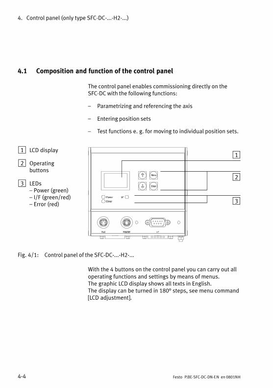
4. Control panel (only type SFC−DC−...−H2−...)
4−4 Festo P.BE−SFC−DC−DN−EN en 0801NH
4.1 Composition and function of the control panel
The control panel enables commissioning directly on theSFC−DC with the following functions:
� Parametrizing and referencing the axis
� Entering position sets
� Test functions e.�g.�for moving to individual position sets.
1 LCD display
2 Operatingbuttons
3 LEDs� Power (green)� I/F (green/red)� Error (red)
1
2
3
Fig.�4/1: Control panel of the SFC−DC−...−H2−...
With the 4 buttons on the control panel you can carry out alloperating functions and settings by means of menus. The graphic LCD display shows all texts in English. The display can be turned in 180° steps, see menu command[LCD adjustment].
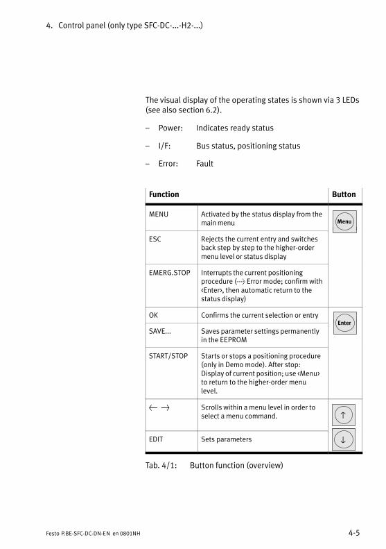
4. Control panel (only type SFC−DC−...−H2−...)
4−5Festo P.BE−SFC−DC−DN−EN en 0801NH
The visual display of the operating states is shown via 3 LEDs(see also section 6.2).
� Power: Indicates ready status
� I/F: Bus status, positioning status
� Error: Fault
Function Button
MENU Activated by the status display from themain menu Menu
ESC Rejects the current entry and switchesback step by step to the higher−ordermenu level or status display
EMERG.STOP Interrupts the current positioningprocedure (> Error mode; confirm with<Enter>, then automatic return to thestatus display)
OK Confirms the current selection or entryEnter
SAVE... Saves parameter settings permanentlyin the EEPROM
Enter
START/STOP Starts or stops a positioning procedure(only in Demo mode). After stop:Display of current position; use <Menu>to return to the higher−order menulevel.
{ } Scrolls within a menu level in order toselect a menu command. v
EDIT Sets parameters V
Tab.�4/1: Button function (overview)
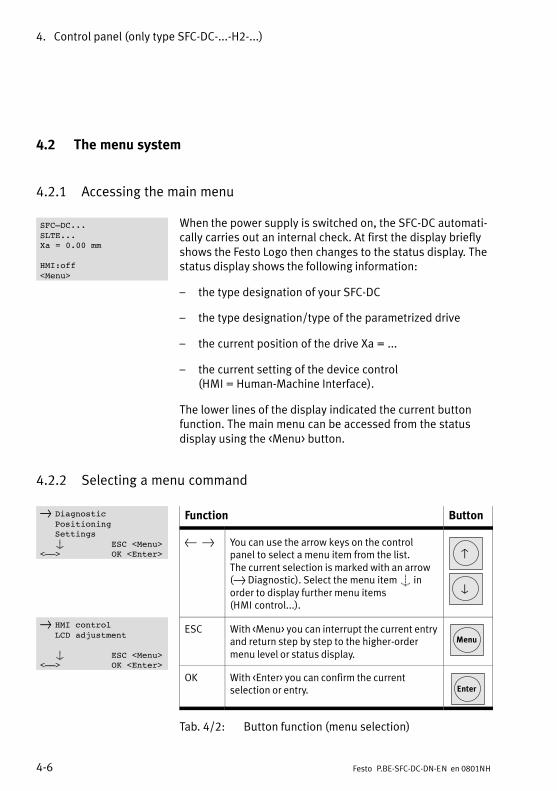
4. Control panel (only type SFC−DC−...−H2−...)
4−6 Festo P.BE−SFC−DC−DN−EN en 0801NH
4.2 The menu system
4.2.1 Accessing the main menu
When the power supply is switched on, the SFC−DC automati�cally carries out an internal check. At first the display brieflyshows the Festo Logo then changes to the status display. Thestatus display shows the following information:
� the type designation of your SFC−DC
� the type designation/type of the parametrized drive
� the current position of the drive Xa = ...
� the current setting of the device control (HMI = Human−Machine Interface).
The lower lines of the display indicated the current buttonfunction. The main menu can be accessed from the statusdisplay using the <Menu> button.
4.2.2 Selecting a menu command
Function Button
{ } You can use the arrow keys on the controlpanel to select a menu item from the list. The current selection is marked with an arrow(} Diagnostic). Select the menu item S inorder to display further menu items(HMI�control...).
v
V
ESC With <Menu> you can interrupt the current entryand return step by step to the higher−ordermenu level or status display.
Menu
OK With <Enter> you can confirm the currentselection or entry. Enter
Tab.�4/2: Button function (menu selection)
SFC–DC...SLTE...Xa = 0.00 mm
HMI:off<Menu>
} DiagnosticPositioningSettingsS ESC <Menu>
<––> OK <Enter>
} HMI controlLCD adjustment
S ESC <Menu><––> OK <Enter>
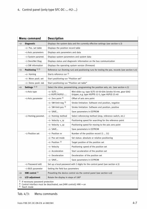
4. Control panel (only type SFC−DC−...−H2−...)
4−7Festo P.BE−SFC−DC−DN−EN en 0801NH
Menu command Description
} Diagnostic Displays the system data and the currently effective settings (see section 4.3)
} Pos. set table Displays the position record table
} Axis parameters Displays axis parameters and data
} System paramet. Displays system parameters and system data
} DevicNet Diag Displays status and diagnostic information on the bus communication
} SW information Displays the operating system version (firmware)
} Positioning 1) 2) Reference run (homing run) and positioning runs for testing the pos. records (see section 4.4)
} Homing Starts reference run 1)
} Move posit. set Start positioning run �Position set"
} Demo posit. tab Start positioning run �Position set table"
} Settings 1) 2) Select the drive, parametrizing, programming the position sets, etc. (see section 4.5)
} Axis type } SLTE−...} HGPP/HGPLE−....
Mini−slide e.g. type SLTE−10−50−G04 (stroke 50 mm, gear G04)Gripper, e.g. type HGPPE−12−5, type HGPLE−25−40
} Axis parameter } Zero point 3) Offset of axis zero point} p
} SW−limit−neg 3) Stroke limitation: Software end position, negative
} SW−limit−pos 3) Stroke limitation: Software end position, positive
} SAVE... Save parameters in EEPROM
} Homing paramet. } Homing method Select referencing method (stop, reference switch, etc.)} g p
} Velocity v_rp Positioning speed for searching for the reference point
} Velocity v_zp Positioning speed for moving to the axis zero point
} SAVE... Save parameters in EEPROM
} Position set } Position nr Number of the position record (1 � 31)}
} Pos set mode Set status: absolute or relative positioning
} Position 3) Target position of the position set
} Velocity Positioning speed of the position set
} Acceleration Start acceleration of the position set
} Deceleration Deceleration of the position set
} SAVE... Save parameters in EEPROM
} Password edit Set up a local password with 3 digits for the control panel (see section 4.5)
} BUS parameter Setting the field bus parameters
} HMI control 1) Presetting the device control via the control panel (see section 4.6)
} LCD adjustment Rotate the display in steps of 180°
1) If necessary password protection2) Control interface must be deactivated, see [HMI control]�: HMI = on3) Teach mode
Tab.�4/3: Menu commands
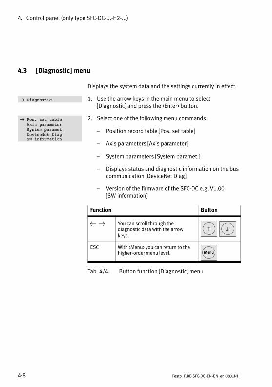
4. Control panel (only type SFC−DC−...−H2−...)
4−8 Festo P.BE−SFC−DC−DN−EN en 0801NH
4.3 [Diagnostic] menu
Displays the system data and the settings currently in effect.
1. Use the arrow keys in the main menu to select[Diagnostic] and press the <Enter> button.
2. Select one of the following menu commands:
� Position record table [Pos. set table]
� Axis parameters [Axis parameter]
� System parameters [System paramet.]
� Displays status and diagnostic information on the buscommunication [DeviceNet Diag]
� Version of the firmware of the SFC−DC e.g.�V1.00[SW�information]
Function Button
{ } You can scroll through thediagnostic data with the arrowkeys.
v V
ESC With <Menu> you can return to thehigher−order menu level. Menu
Tab.�4/4: Button function [Diagnostic] menu
} Diagnostic
} Pos. set tableAxis parameterSystem paramet.DeviceNet DiagSW information
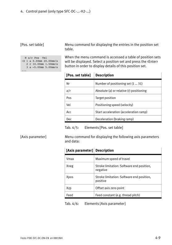
4. Control panel (only type SFC−DC−...−H2−...)
4−9Festo P.BE−SFC−DC−DN−EN en 0801NH
[Pos. set table] Menu command for displaying the entries in the position settable.
When the menu command is accessed a table of position setswill be displayed. Select a position set and press the <Enter>button in order to display details of this position set.
[Pos. set table] Description
Nr Number of positioning set (1 � 31)
a/r Absolute (a) or relative (r) positioning
Pos Target position
Vel Positioning speed (velocity)
Acc Start acceleration (acceleration ramp)
Dec Deceleration (braking ramp)
Tab.�4/5: Elements [Pos. set table]
[Axis parameter] Menu command for displaying the following axis parametersand data:
[Axis parameter] Description
Vmax Maximum speed of travel
Xneg Stroke limitation: Software end position,negative
Xpos Stroke limitation: Software end position,positive
Xzp Offset axis zero point
Feed Feed constant (e.g.�thread pitch)
Tab.�4/6: Elements [Axis parameter]
N a/r Pos Vel} 1 a 0.00mm 20.00mm/s
2 r 10.00mm 1.50mm/s3 a –5.00mm 5.00mm/s
...
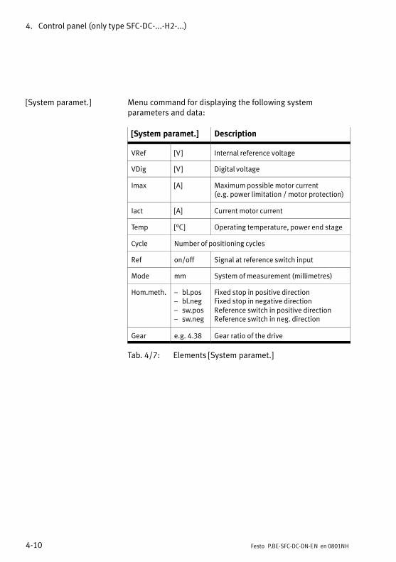
4. Control panel (only type SFC−DC−...−H2−...)
4−10 Festo P.BE−SFC−DC−DN−EN en 0801NH
[System paramet.] Menu command for displaying the following systemparameters and data:
[System paramet.] Description
VRef [V] Internal reference voltage
VDig [V] Digital voltage
Imax [A] Maximum possible motor current (e.g. power limitation / motor protection)
Iact [A] Current motor current
Temp [°C] Operating temperature, power end stage
Cycle Number of positioning cycles
Ref on/off Signal at reference switch input
Mode mm System of measurement (millimetres)
Hom.meth. � bl.pos� bl.neg� sw.pos� sw.neg
Fixed stop in positive directionFixed stop in negative directionReference switch in positive directionReference switch in neg. direction
Gear e.g.�4.38 Gear ratio of the drive
Tab.�4/7: Elements [System paramet.]
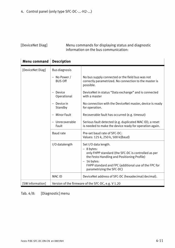
4. Control panel (only type SFC−DC−...−H2−...)
4−11Festo P.BE−SFC−DC−DN−EN en 0801NH
[DeviceNet Diag] Menu commands for displaying status and diagnosticinformation on the bus communication:
Menu command Description
[DeviceNet Diag] Bus diagnosis
� No Power /BUS�Off
No bus supply connected or the field bus was notcorrectly parametrized. No connection to the master ispossible.
� DeviceOperational
DeviceNet in status �Data exchange" and is connectedwith a master
� Device inStandby
No connection with the DeviceNet master, device is readyfor operation.
� Minor Fault Recoverable fault has occurred (e.g. timeout)
� UnrecoverableFault
Serious fault detected (e.g. duplicated MAC ID); a resetis needed to make the device ready for operation again.
Baud rate Pre−set baud rate of SFC−DC:Values: 125 k, 250 k, 500 k(Baud)
I/O datalength Set I/O data length.
� 8 bytes: only FHPP standard (the SFC−DC is controlled as perthe Festo Handling and Positioning Profile)
� 16 bytes: FHPP standard and FPC (additional use of the FPC forparametrizing the SFC−DC)
MAC ID DeviceNet address of SFC−DC (hexadecimal/decimal).
[SW information] Version of the firmware of the SFC−DC, e.g.�V 1.20
Tab.�4/8: [Diagnostic] menu
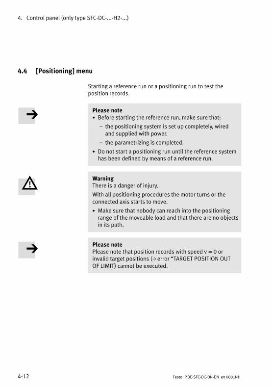
4. Control panel (only type SFC−DC−...−H2−...)
4−12 Festo P.BE−SFC−DC−DN−EN en 0801NH
4.4 [Positioning] menu
Starting a reference run or a positioning run to test theposition records.
Please note· Before starting the reference run, make sure that:
� the positioning system is set up completely, wiredand supplied with power.
� the parametrizing is completed.
· Do not start a positioning run until the reference systemhas been defined by means of a reference run.
WarningThere is a danger of injury.
With all positioning procedures the motor turns or theconnected axis starts to move.
· Make sure that nobody can reach into the positioningrange of the moveable load and that there are no objectsin its path.
Please notePlease note that position records with speed v = 0 orinvalid target positions (−> error �TARGET POSITION OUTOF�LIMIT) cannot be executed.
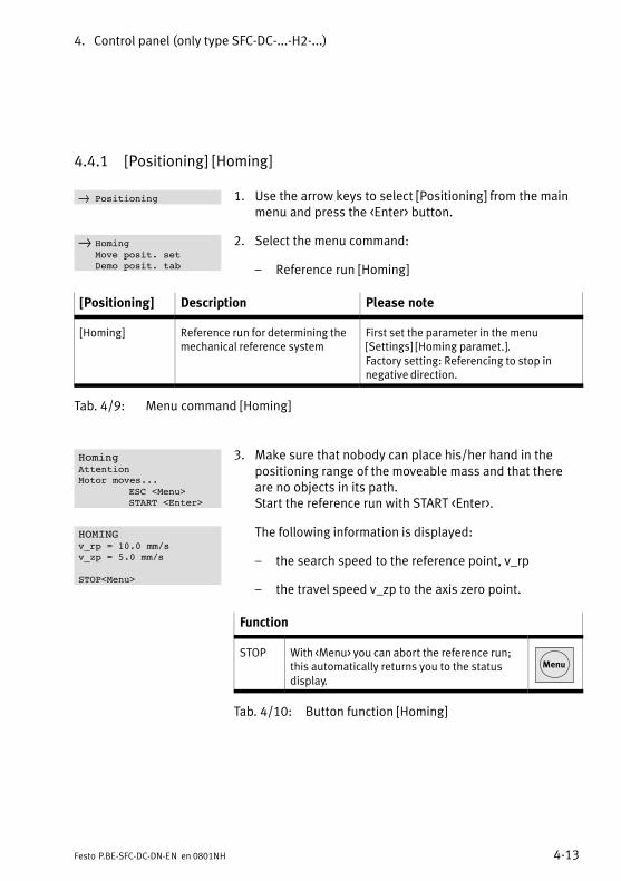
4. Control panel (only type SFC−DC−...−H2−...)
4−13Festo P.BE−SFC−DC−DN−EN en 0801NH
4.4.1 [Positioning] [Homing]
1. Use the arrow keys to select [Positioning] from the mainmenu and press the <Enter> button.
2. Select the menu command:
� Reference run [Homing]
[Positioning] Description Please note
[Homing] Reference run for determining themechanical reference system
First set the parameter in the menu[Settings] [Homing paramet.].Factory setting: Referencing to stop innegative direction.
Tab.�4/9: Menu command [Homing]
3. Make sure that nobody can place his/her hand in thepositioning range of the moveable mass and that thereare no objects in its path. Start the reference run with START <Enter>.
The following information is displayed:
� the search speed to the reference point, v_rp
� the travel speed v_zp to the axis zero point.
Function
STOP With <Menu> you can abort the reference run;this automatically returns you to the statusdisplay.
Menu
Tab.�4/10: Button function [Homing]
} Positioning
} HomingMove posit. setDemo posit. tab
HomingAttentionMotor moves...
ESC <Menu>START <Enter>
HOMINGv_rp = 10.0 mm/sv_zp = 5.0 mm/s
STOP<Menu>
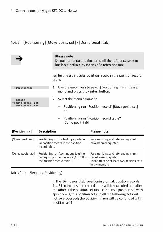
4. Control panel (only type SFC−DC−...−H2−...)
4−14 Festo P.BE−SFC−DC−DN−EN en 0801NH
4.4.2 [Positioning] [Move posit. set] / [Demo posit. tab]
Please noteDo not start a positioning run until the reference systemhas been defined by means of a reference run.
For testing a particular position record in the position recordtable.
1. Use the arrow keys to select [Positioning] from the mainmenu and press the <Enter> button.
2. Select the menu command:
� Positioning run �Position record" [Move posit. set] or
� Positioning run �Position record table" [Demo posit. tab]
[Positioning] Description Please note
[Move posit. set] Positioning run for testing a particu�lar position record in the positionrecord table.
Parametrizing and referencing musthave been completed.
[Demo posit. tab] Positioning run (continuous loop) fortesting all position records (1 � 31) inthe position record table.
Parametrizing and referencing musthave been completed.There must be at least two position setsin the memory.
Tab.�4/11: Elements [Positioning]
In the [Demo posit tab] positioning run, all position records1���31 in the position record table will be executed one afterthe other. If the position set table contains a position set withspeed v = 0, this position set and all the following sets willnot be processed; the positioning run will be continued withposition set 1.
} Positioning
Homing} Move posit. set
Demo posit. tab
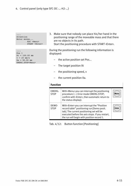
4. Control panel (only type SFC−DC−...−H2−...)
4−15Festo P.BE−SFC−DC−DN−EN en 0801NH
3. Make sure that nobody can place his/her hand in thepositioning range of the moveable mass and that thereare no objects in its path. Start the positioning procedure with START <Enter>.
During the positioning run the following information isdisplayed:
� the active position set Pos...
� The target position Xt
� the positioning speed, v
� the current position Xa.
Function
EMERG.STOP
With <Menu> you can interrupt the positioningprocedure (> Error mode EMERG.STOP;confirm with <Enter>, then automatic return tothe status display).
Menu
DEMO�STOP
With <Enter> you can interrupt the �Positionrecord table" positioning run [Demo posit.tab]�. The current positioning set will beexecuted before the axis stops. If you restart,the run will begin with position record 1.
Enter
Tab.�4/12: Button function [Positioning]
...AttentionMotor moves...
ESC <Menu>START <Enter>
...Pos 1Xt = 100.00 mmv = 20 mm/sXa = 90.00 mmEMERG.STOP<Menu>
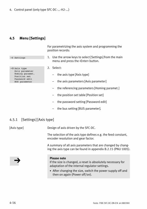
4. Control panel (only type SFC−DC−...−H2−...)
4−16 Festo P.BE−SFC−DC−DN−EN en 0801NH
4.5 Menu [Settings]
For parametrizing the axis system and programming theposition records:
1. Use the arrow keys to select [Settings] from the mainmenu and press the <Enter> button.
2. Select:
� the axis type [Axis type]
� the axis parameters [Axis parameter]
� the referencing parameters [Homing paramet.]
� the position set table [Position set]
� the password setting [Password edit]
� the bus setting [BUS parameter].
4.5.1 [Settings] [Axis type]
[Axis type] Design of axis driven by the SFC−DC.
The selection of the axis type defines e.g. the feed constant,encoder resolution and gear factor.
A summary of all axis parameters that are changed by chang�ing the axis type can be found in appendix B.2.15 (PNU 1005).
Please noteIf the size is changed, a reset is absolutely necessary foradaptation of the internal regulator settings.
· After changing the size, switch the power supply off andthen on again (Power off/on).
} Settings
} Axis typeAxis parameterHoming paramet.Position setPassword editBUS parameter
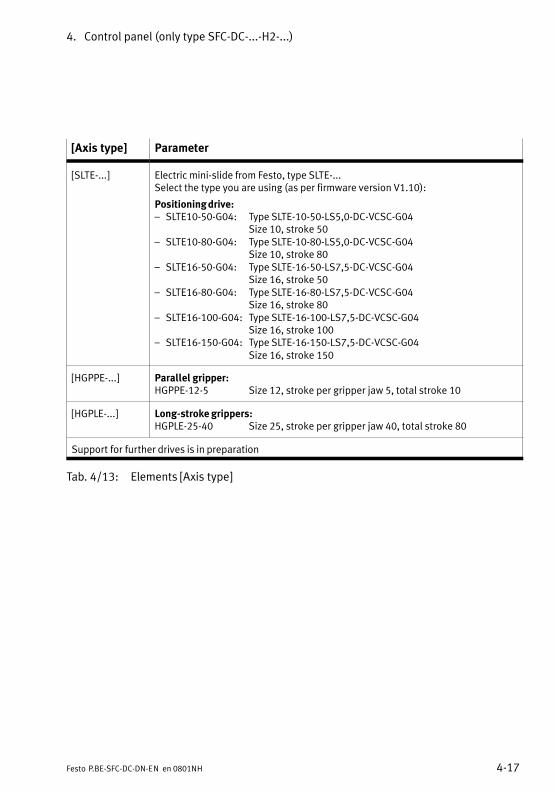
4. Control panel (only type SFC−DC−...−H2−...)
4−17Festo P.BE−SFC−DC−DN−EN en 0801NH
[Axis type] Parameter
[SLTE−...] Electric mini−slide from Festo, type SLTE−...Select the type you are using (as per firmware version V1.10):
Positioning drive:� SLTE10−50−G04: Type SLTE−10−50−LS5,0−DC−VCSC−G04
Size 10, stroke 50� SLTE10−80−G04: Type SLTE−10−80−LS5,0−DC−VCSC−G04
Size 10, stroke 80� SLTE16−50−G04: Type SLTE−16−50−LS7,5−DC−VCSC−G04
Size 16, stroke 50� SLTE16−80−G04: Type SLTE−16−80−LS7,5−DC−VCSC−G04
Size 16, stroke 80� SLTE16−100−G04: Type SLTE−16−100−LS7,5−DC−VCSC−G04
Size 16, stroke 100� SLTE16−150−G04: Type SLTE−16−150−LS7,5−DC−VCSC−G04
Size 16, stroke 150
[HGPPE−...] Parallel gripper:HGPPE−12−5 Size 12, stroke per gripper jaw 5, total stroke 10
[HGPLE−...] Long−stroke grippers:HGPLE−25−40 Size 25, stroke per gripper jaw 40, total stroke 80
Support for further drives is in preparation
Tab.�4/13: Elements [Axis type]
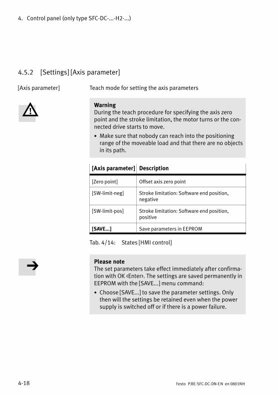
4. Control panel (only type SFC−DC−...−H2−...)
4−18 Festo P.BE−SFC−DC−DN−EN en 0801NH
4.5.2 [Settings] [Axis parameter]
[Axis parameter] Teach mode for setting the axis parameters
WarningDuring the teach procedure for specifying the axis zeropoint and the stroke limitation, the motor turns or the con�nected drive starts to move.
· Make sure that nobody can reach into the positioningrange of the moveable load and that there are no objectsin its path.
[Axis parameter] Description
[Zero point] Offset axis zero point
[SW−limit−neg] Stroke limitation: Software end position,negative
[SW−limit−pos] Stroke limitation: Software end position,positive
[SAVE...] Save parameters in EEPROM
Tab.�4/14: States [HMI control]
Please noteThe set parameters take effect immediately after confirma�tion with OK <Enter>. The settings are saved permanently inEEPROM with the [SAVE...] menu command:
· Choose [SAVE...] to save the parameter settings. Onlythen will the settings be retained even when the powersupply is switched off or if there is a power failure.
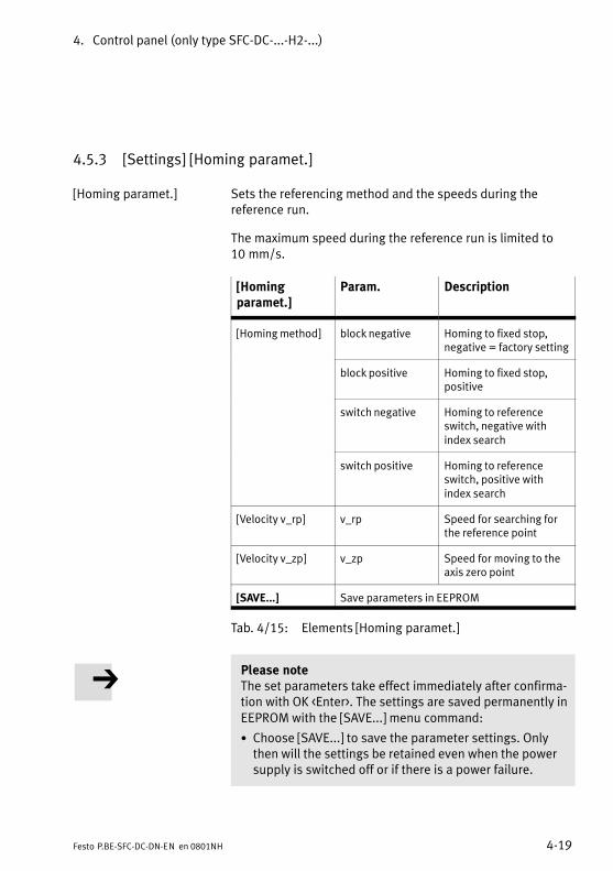
4. Control panel (only type SFC−DC−...−H2−...)
4−19Festo P.BE−SFC−DC−DN−EN en 0801NH
4.5.3 [Settings] [Homing paramet.]
[Homing paramet.] Sets the referencing method and the speeds during thereference run.
The maximum speed during the reference run is limited to10�mm/s.
[Homingparamet.]
Param. Description
[Homing method] block negative Homing to fixed stop,negative = factory setting
block positive Homing to fixed stop,positive
switch negative Homing to referenceswitch, negative withindex search
switch positive Homing to referenceswitch, positive withindex search
[Velocity v_rp] v_rp Speed for searching forthe reference point
[Velocity v_zp] v_zp Speed for moving to theaxis zero point
[SAVE...] Save parameters in EEPROM
Tab.�4/15: Elements [Homing paramet.]
Please noteThe set parameters take effect immediately after confirma�tion with OK <Enter>. The settings are saved permanently inEEPROM with the [SAVE...] menu command:
· Choose [SAVE...] to save the parameter settings. Onlythen will the settings be retained even when the powersupply is switched off or if there is a power failure.
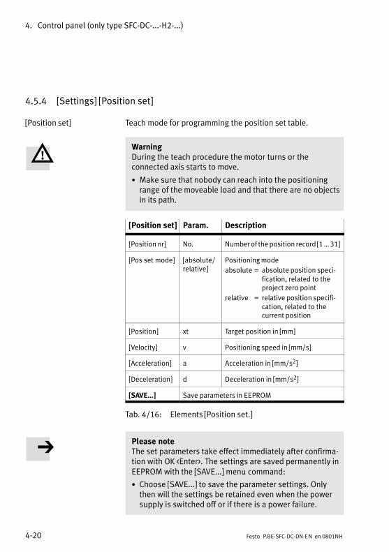
4. Control panel (only type SFC−DC−...−H2−...)
4−20 Festo P.BE−SFC−DC−DN−EN en 0801NH
4.5.4 [Settings] [Position set]
[Position set] Teach mode for programming the position set table.
WarningDuring the teach procedure the motor turns or theconnected axis starts to move.
· Make sure that nobody can reach into the positioningrange of the moveable load and that there are no objectsin its path.
[Position set] Param. Description
[Position nr] No. Number of the position record [1 � 31]
[Pos set mode] [absolute/relative]
Positioning mode
absolute = absolute position speci−fication, related to the project zero point
relative = relative position specifi−cation, related to the current position
[Position] xt Target position in [mm]
[Velocity] v Positioning speed in [mm/s]
[Acceleration] a Acceleration in [mm/s2]
[Deceleration] d Deceleration in [mm/s2]
[SAVE...] Save parameters in EEPROM
Tab.�4/16: Elements [Position set.]
Please noteThe set parameters take effect immediately after confirma�tion with OK <Enter>. The settings are saved permanently inEEPROM with the [SAVE...] menu command:
· Choose [SAVE...] to save the parameter settings. Onlythen will the settings be retained even when the powersupply is switched off or if there is a power failure.
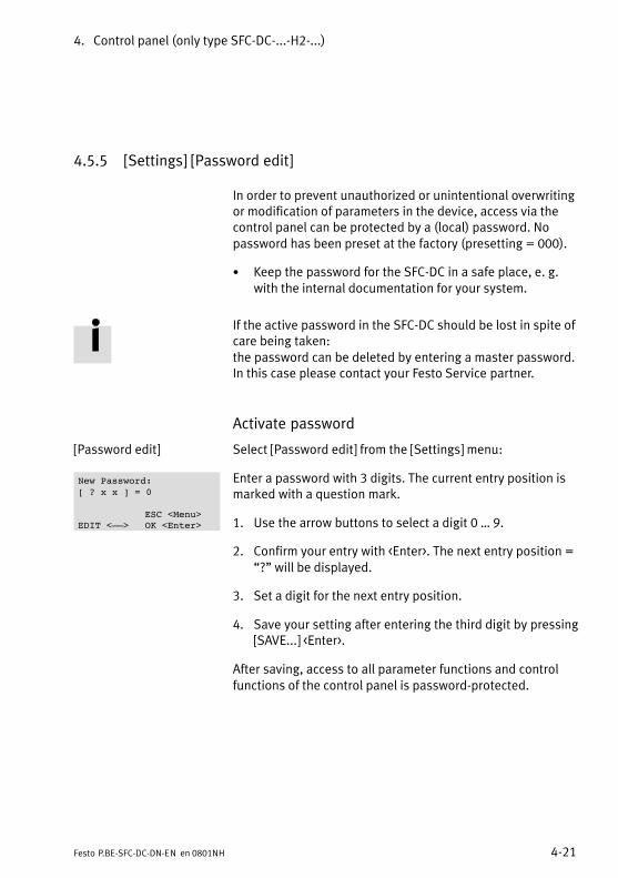
4. Control panel (only type SFC−DC−...−H2−...)
4−21Festo P.BE−SFC−DC−DN−EN en 0801NH
4.5.5 [Settings] [Password edit]
In order to prevent unauthorized or unintentional overwritingor modification of parameters in the device, access via thecontrol panel can be protected by a (local) password. Nopassword has been preset at the factory (presetting = 000).
· Keep the password for the SFC−DC in a safe place, e. g.with the internal documentation for your system.
If the active password in the SFC−DC should be lost in spite ofcare being taken:the password can be deleted by entering a master password.In this case please contact your Festo Service partner.
Activate password
[Password edit] Select [Password edit] from the [Settings] menu:
Enter a password with 3 digits. The current entry position ismarked with a question mark.
1. Use the arrow buttons to select a digit 0 � 9.
2. Confirm your entry with <Enter>. The next entry position =�?" will be displayed.
3. Set a digit for the next entry position.
4. Save your setting after entering the third digit by pressing[SAVE...] <Enter>.
After saving, access to all parameter functions and controlfunctions of the control panel is password−protected.
New Password:[ ? x x ] = 0
ESC <Menu>EDIT <––> OK <Enter>
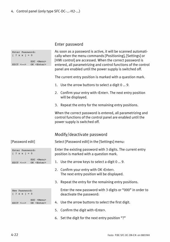
4. Control panel (only type SFC−DC−...−H2−...)
4−22 Festo P.BE−SFC−DC−DN−EN en 0801NH
Enter password
As soon as a password is active, it will be scanned automati�cally when the menu commands [Positioning], [Settings] or[HMI control] are accessed. When the correct password isentered, all parametrizing and control functions of the controlpanel are enabled until the power supply is switched off.
The current entry position is marked with a question mark.
1. Use the arrow buttons to select a digit 0 � 9.
2. Confirm your entry with <Enter>. The next entry positionwill be displayed.
3. Repeat the entry for the remaining entry positions.
When the correct password is entered, all parametrizing andcontrol functions of the control panel are enabled until thepower supply is switched off.
Modify/deactivate password
[Password edit] Select [Password edit] in the [Settings] menu:
Enter the existing password with 3 digits. The current entryposition is marked with a question mark.
1. Use the arrow keys to select a digit 0 � 9.
2. Confirm your entry with OK <Enter>. The next entry position will be displayed.
3. Repeat the entry for the remaining entry positions.
Enter the new password with 3 digits or �000" in order todeactivate the password:
4. Use the arrow buttons to select the first digit.
5. Confirm the digit with <Enter>.
6. Set the digit for the next entry position �?"
Enter Password:[ ? x x ] = 0
ESC <Menu>EDIT <––> OK <Enter>
Enter Password:[ ? x x ] = 0
ESC <Menu>EDIT <––> OK <Enter>
New Password:[ ? x x ] = 0
ESC <Menu>EDIT <––> OK <Enter>
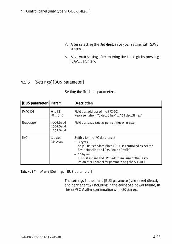
4. Control panel (only type SFC−DC−...−H2−...)
4−23Festo P.BE−SFC−DC−DN−EN en 0801NH
7. After selecting the 3rd digit, save your setting with SAVE<Enter>.
8. Save your setting after entering the last digit by pressing[SAVE...] <Enter>.
4.5.6 [Settings] [BUS parameter]
Setting the field bus parameters.
[BUS parameter] Param. Description
[MAC ID] 0 � 63(0 � 3fh)
Field bus address of the SFC−DC.Representation: �0 dec, 0 hex" � �63 dec, 3f hex"
[Baudrate] 500 kBaud250 kBaud125 kBaud
Field bus baud rate as per settings on master
[I/O] 8 bytes16 bytes
Setting for the I/O data length
� 8 bytes: only FHPP standard (the SFC−DC is controlled as per theFesto Handling and Positioning Profile)
� 16 bytes: FHPP standard and FPC (additional use of the FestoParameter Channel for parametrizing the SFC−DC)
Tab.�4/17: Menu [Settings] [BUS parameter]
The settings in the menu [BUS parameter] are saved directlyand permanently (including in the event of a power failure) inthe EEPROM after confirmation with OK <Enter>.
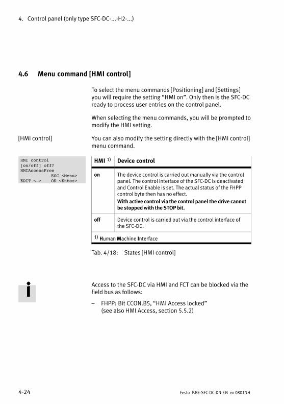
4. Control panel (only type SFC−DC−...−H2−...)
4−24 Festo P.BE−SFC−DC−DN−EN en 0801NH
4.6 Menu command [HMI control]
To select the menu commands [Positioning] and [Settings]you will require the setting �HMI on". Only then is the SFC−DCready to process user entries on the control panel.
When selecting the menu commands, you will be prompted tomodify the HMI setting.
[HMI control] You can also modify the setting directly with the [HMI control]menu command.
HMI 1) Device control
on The device control is carried out manually via the controlpanel. The control interface of the SFC−DC is deactivatedand Control Enable is set. The actual status of the FHPPcontrol byte then has no effect.
With active control via the control panel the drive cannotbe stopped with the STOP bit.
off Device control is carried out via the control interface ofthe SFC−DC.
1) Human Machine Interface
Tab.�4/18: States [HMI control]
Access to the SFC−DC via HMI and FCT can be blocked via thefield bus as follows:
� FHPP: Bit CCON.B5, �HMI Access locked" (see also HMI Access, section 5.5.2)
HMI control[on/off] off?HMIAccessFree
ESC <Menu>EDIT <–> OK <Enter>

Commissioning
5−1Festo P.BE−SFC−DC−DN−EN en 0801NH
Chapter 5
5. Commissioning
5−2 Festo P.BE−SFC−DC−DN−EN en 0801NH
Contents
5. Commissioning 5−1 . . . . . . . . . . . . . . . . . . . . . . . . . . . . . . . . . . . . . . . . . . . . . . . .
5.1 Preparations for commissioning 5−4 . . . . . . . . . . . . . . . . . . . . . . . . . . . . . . . . . . .
5.1.1 Check the connection to the mains power supply 5−4 . . . . . . . . . . . . . .
5.1.2 Check the drive 5−4 . . . . . . . . . . . . . . . . . . . . . . . . . . . . . . . . . . . . . . . . .
5.1.3 General instructions on commissioning 5−5 . . . . . . . . . . . . . . . . . . . . . .
5.2 Commissioning with the control panel (only type SFC−DC−...−H2−...) 5−8 . . . . . . .
5.2.1 Setting the axis type 5−10 . . . . . . . . . . . . . . . . . . . . . . . . . . . . . . . . . . . . .
5.2.2 Setting the reference run parameters 5−10 . . . . . . . . . . . . . . . . . . . . . . .
5.2.3 Starting a reference run 5−14 . . . . . . . . . . . . . . . . . . . . . . . . . . . . . . . . . .
5.2.4 Teach the axis zero point and the software end positions 5−15 . . . . . . .
5.2.5 Positioning with position sets 5−16 . . . . . . . . . . . . . . . . . . . . . . . . . . . . . .
5.2.6 Teach position records 5−17 . . . . . . . . . . . . . . . . . . . . . . . . . . . . . . . . . . .
5.2.7 Test run 5−19 . . . . . . . . . . . . . . . . . . . . . . . . . . . . . . . . . . . . . . . . . . . . . . .
5.2.8 Setting bus parameters 5−20 . . . . . . . . . . . . . . . . . . . . . . . . . . . . . . . . . . .
5.3 Commissioning with the Festo Configuration Tool 5−23 . . . . . . . . . . . . . . . . . . . . .
5.3.1 Installing and starting the Festo Configuration Tool 5−23 . . . . . . . . . . . .
5.3.2 Procedure for commissioning with the Festo Configuration Tool 5−24 . . . . . . . . . . . . . . . . . . . . . . . . . . . . . . . . . .
5.4 Commissioning on a DeviceNet master 5−26 . . . . . . . . . . . . . . . . . . . . . . . . . . . . . .
5.4.1 Overview of commissioning on the field bus 5−26 . . . . . . . . . . . . . . . . . .
5.4.2 Configuration of the DeviceNet master (�I/O configuration") 5−27 . . . . . . . . . . . . . . . . . . . . . . . . . . . . . . . . . . . . .
5.5 Festo profile for handling and positioning (FHPP) 5−29 . . . . . . . . . . . . . . . . . . . . .
5.5.1 Supported operating modes 5−29 . . . . . . . . . . . . . . . . . . . . . . . . . . . . . . .
5.5.2 Composition of the cyclic I/O data (FHPP standard) 5−31 . . . . . . . . . . . .
5.5.3 Description of the I/O data (Record select) 5−33 . . . . . . . . . . . . . . . . . . .
5.5.4 Description of the I/O data (Direct mode) 5−34 . . . . . . . . . . . . . . . . . . . .
5.5.5 Description of the control bytes CCON, CPOS, CDIR 5−35 . . . . . . . . . . . .
5.5.6 Description of the status bytes SCON, SPOS, SDIR (RSB) 5−38 . . . . . . .
5.5.7 Examples of the I/O data 5−41 . . . . . . . . . . . . . . . . . . . . . . . . . . . . . . . . .
5. Commissioning
5−3Festo P.BE−SFC−DC−DN−EN en 0801NH
5.6 Sequence control as per FHPP standard 5−54 . . . . . . . . . . . . . . . . . . . . . . . . . . . .
5.6.1 Homing run 5−54 . . . . . . . . . . . . . . . . . . . . . . . . . . . . . . . . . . . . . . . . . . . .
5.6.2 Jog mode 5−56 . . . . . . . . . . . . . . . . . . . . . . . . . . . . . . . . . . . . . . . . . . . . . .
5.6.3 Teaching via the field bus 5−58 . . . . . . . . . . . . . . . . . . . . . . . . . . . . . . . . .
5.6.4 Record select (positioning mode) 5−60 . . . . . . . . . . . . . . . . . . . . . . . . . . .
5.6.5 Direct mode (positioning mode, force control) 5−65 . . . . . . . . . . . . . . . .
5.6.6 Standstill monitoring 5−72 . . . . . . . . . . . . . . . . . . . . . . . . . . . . . . . . . . . . .
5.7 The Festo Parameter Channel (FPC) 5−74 . . . . . . . . . . . . . . . . . . . . . . . . . . . . . . . .
5.7.1 Composition of the cyclic I/O data (FHPP−FPC) 5−74 . . . . . . . . . . . . . . . .
5.7.2 Task identifiers, Response identifiers and fault numbers 5−76 . . . . . . . .
5.7.3 Rules for task−reply processing 5−79 . . . . . . . . . . . . . . . . . . . . . . . . . . . .
5.7.4 Example of parametrizing 5−81 . . . . . . . . . . . . . . . . . . . . . . . . . . . . . . . . .
5.8 Finite state machine FHPP 5−83 . . . . . . . . . . . . . . . . . . . . . . . . . . . . . . . . . . . . . . . .
5.8.1 Create readiness to operate 5−85 . . . . . . . . . . . . . . . . . . . . . . . . . . . . . . .
5.8.2 Positioning 5−86 . . . . . . . . . . . . . . . . . . . . . . . . . . . . . . . . . . . . . . . . . . . . .
5.9 Notes on operation 5−88 . . . . . . . . . . . . . . . . . . . . . . . . . . . . . . . . . . . . . . . . . . . . . .
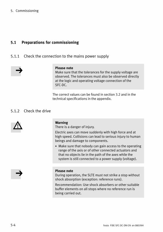
5. Commissioning
5−4 Festo P.BE−SFC−DC−DN−EN en 0801NH
5.1 Preparations for commissioning
5.1.1 Check the connection to the mains power supply
Please noteMake sure that the tolerances for the supply voltage areobserved. The tolerances must also be observed directlyat the logic and operating voltage connection of theSFC−DC.
The correct values can be found in section 3.2 and in thetechnical specifications in the appendix.
5.1.2 Check the drive
WarningThere is a danger of injury.
Electric axes can move suddenly with high force and athigh speed. Collisions can lead to serious injury to humanbeings and damage to components.
· Make sure that nobody can gain access to the operatingrange of the axis or of other connected actuators andthat no objects lie in the path of the axes while thesystem is still connected to a power supply (voltage).
Please noteDuring operation, the SLTE must not strike a stop withoutshock absorption (exception: reference runs).
Recommendation: Use shock absorbers or other suitablebuffer elements on all stops where no reference run isbeing carried out.
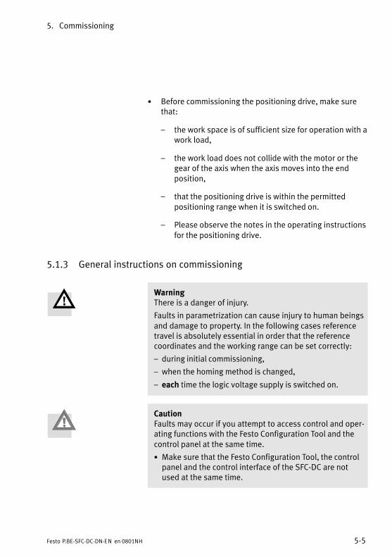
5. Commissioning
5−5Festo P.BE−SFC−DC−DN−EN en 0801NH
· Before commissioning the positioning drive, make surethat:
� the work space is of sufficient size for operation with awork load,
� the work load does not collide with the motor or thegear of the axis when the axis moves into the endposition,
� that the positioning drive is within the permittedpositioning range when it is switched on.
� Please observe the notes in the operating instructionsfor the positioning drive.
5.1.3 General instructions on commissioning
WarningThere is a danger of injury.
Faults in parametrization can cause injury to human beingsand damage to property. In the following cases referencetravel is absolutely essential in order that the referencecoordinates and the working range can be set correctly:
� during initial commissioning,
� when the homing method is changed,
� each time the logic voltage supply is switched on.
CautionFaults may occur if you attempt to access control and oper�ating functions with the Festo Configuration Tool and thecontrol panel at the same time.
· Make sure that the Festo Configuration Tool, the controlpanel and the control interface of the SFC−DC are notused at the same time.
5. Commissioning
5−6 Festo P.BE−SFC−DC−DN−EN en 0801NH
Please noteIn the following cases it is not permitted to write−accessthe SFC−DC with the Festo Configuration Tool (e.�g.downloading parameters) or controlling (e.�g.�with�Move�manually" or when starting reference travel):
� When the SFC−DC is currently performing a positioningmovement or when a movement is started during access(e.�g. via the control interface or via the control panel).
� When parametrizing or operation with the control paneltakes place on the SFC−DC.
Please note the following:
· The device connection in the Festo Configuration Toolmust not be activated when the control panel is beingused for control (�HMI control = on").
· Control with the control panel (�HMI control = on") mustnot be activated when the device connection in the FestoConfiguration Tool is activated.
· Control by the Festo Configuration Tool must not beactivated while the drive is in motion or when control isbeing carried out via the controller interface.
5. Commissioning
5−7Festo P.BE−SFC−DC−DN−EN en 0801NH
First steps in commissioning
· Switch on the power supply for the SFC−DC.
· Check (if your drive has been configured at the factory)the settings in the menu [Diagnostic].
· Carry out parametrizing and commissioning with the con�trol panel or the Festo Configuration Tool, as described inthe following sections and in the Festo Configuration Tool/PlugIn help.For commissioning the mechanical structure must beconfigured and a reference system for the coordinatesmust be defined (referencing). By means of the referencesystem all positions are defined and movement can bemade to them. Explanations of reference coordinates andthe working area can be found in section 1.6.
· In order to complete commissioning note the instructionsfor operation in the Festo Configuration Tool/PlugIn helpand in section 5.9.
Please noteTo restore the default settings, the EEPROM can be deletedif necessary with CI object 20F1 (Data memory control)directly via the serial interface (see section B.2.5).User−specific settings will then be lost.
· Use CI commands only if you already have experience ofService Data Objects.
· If necessary consult Festo.
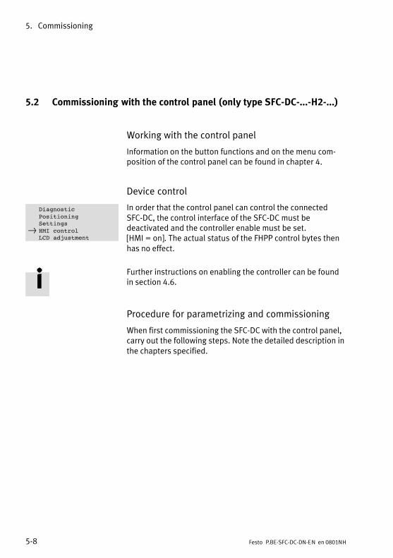
5. Commissioning
5−8 Festo P.BE−SFC−DC−DN−EN en 0801NH
5.2 Commissioning with the control panel (only type SFC−DC−...−H2−...)
Working with the control panel
Information on the button functions and on the menu com�position of the control panel can be found in chapter 4.
Device control
In order that the control panel can control the connectedSFC−DC, the control interface of the SFC−DC must bedeactivated and the controller enable must be set. [HMI = on]. The actual status of the FHPP control bytes thenhas no effect.
Further instructions on enabling the controller can be foundin section 4.6.
Procedure for parametrizing and commissioning
When first commissioning the SFC−DC with the control panel,carry out the following steps. Note the detailed description inthe chapters specified.
DiagnosticPositioningSettings
} HMI controlLCD adjustment
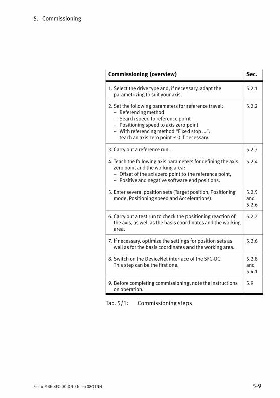
5. Commissioning
5−9Festo P.BE−SFC−DC−DN−EN en 0801NH
Commissioning (overview) Sec.
1. Select the drive type and, if necessary, adapt theparametrizing to suit your axis.
5.2.1
2. Set the following parameters for reference travel:� Referencing method� Search speed to reference point� Positioning speed to axis zero point� With referencing method �Fixed stop ...":
teach an axis zero point � 0 if necessary.
5.2.2
3. Carry out a reference run. 5.2.3
4. Teach the following axis parameters for defining the axiszero point and the working area:� Offset of the axis zero point to the reference point,� Positive and negative software end positions.
5.2.4
5. Enter several position sets (Target position, Positioningmode, Positioning speed and Accelerations).
5.2.5and5.2.6
6. Carry out a test run to check the positioning reaction ofthe axis, as well as the basis coordinates and the workingarea.
5.2.7
7. If necessary, optimize the settings for position sets aswell as for the basis coordinates and the working area.
5.2.6
8. Switch on the DeviceNet interface of the SFC−DC. This step can be the first one.
5.2.8and5.4.1
9. Before completing commissioning, note the instructionson operation.
5.9
Tab.�5/1: Commissioning steps
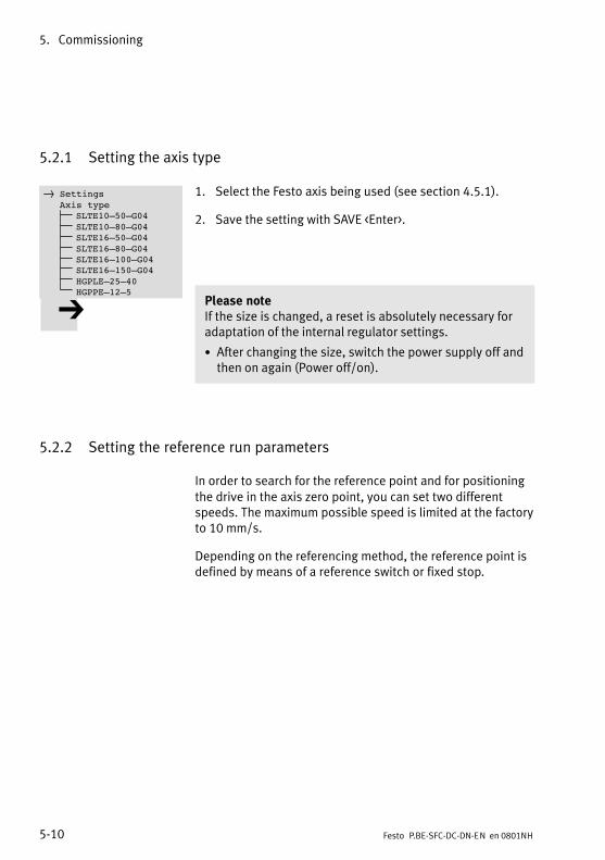
5. Commissioning
5−10 Festo P.BE−SFC−DC−DN−EN en 0801NH
5.2.1 Setting the axis type
1. Select the Festo axis being used (see section 4.5.1).
2. Save the setting with SAVE <Enter>.
Please noteIf the size is changed, a reset is absolutely necessary foradaptation of the internal regulator settings.
· After changing the size, switch the power supply off andthen on again (Power off/on).
5.2.2 Setting the reference run parameters
In order to search for the reference point and for positioningthe drive in the axis zero point, you can set two differentspeeds. The maximum possible speed is limited at the factoryto 10 mm/s.
Depending on the referencing method, the reference point isdefined by means of a reference switch or fixed stop.
} SettingsAxis type
SLTE10–50–G04SLTE10–80–G04SLTE16–50–G04SLTE16–80–G04SLTE16–100–G04SLTE16–150–G04HGPLE–25–40HGPPE–12–5
5. Commissioning
5−11Festo P.BE−SFC−DC−DN−EN en 0801NH
Notes on referencing to the fixed stop
Please noteHoming may only be take place directly against the fixedstop if the permitted impact pulse is not exceeded.
· Operate the positioning drive only with the permittedmass.
CautionDamage to components.
The SLTE with positioning controller SFC−DC moves duringhoming to a block with adjustable nominal motor torque(default: 100 % of nominal current).
· Limit the maximum current during the reference run bymeans of
� the Festo Configuration Tool (see help for PlugIn SFC−DC)
� the CI command �Object 6073 max. current"(see�appendix B.2.18).
CautionDamage to components.
The mechanical end positions (blocks) must not be movedto during operation. When movement is made to the endpositions with a heavy load, blockage may occur in the endpositions.
· Set the offset of the axis zero point � 0, e.�g. +1.00 for referencing to the negative fixed stop, or−1.00 for referencing to the positive fixed stop.
· Limit the positioning range by defining valid softwareend positions during commissioning (see section 1.6).
· Specify target positions only within the permittedpositioning range.
5. Commissioning
5−12 Festo P.BE−SFC−DC−DN−EN en 0801NH
Notes on referencing to the reference switch(only�mini�slides)
If reference travel to a mechanical end position in the applica�tion is not possible, an external sensor (reference switch) canbe used as reference signal (see also section 1.6).
Special case 1: At the start of reference travel, the axis stands on the reference switch
If the axis stands on the reference switch at the start of refer�ence travel, it will move in the opposite direction to the refer�ence switch (compare 2 in Tab.�1/5).
The axis then moves as usual to the axis zero point (compare 2 in Tab.�1/5).
Special case 2: The axis cannot find a reference switch during reference travel
If the axis cannot find a reference switch during reference travel,it will move until it strikes a stop. It will then remain at the stopuntil the fault HOMING ERROR is displayed (see section 6.3).
The causes of this can be:
� at the start of reference travel, the axis already standsbehind the reference switch
� the reference switch is defective
� the axis is defective or fitted incorrectly, e.�g. the coupling�does not grip".
The reference run must be repeated after the error messagehas been acknowledged:
· Acknowledge the error message with <Enter>.
· If necessary, check the function of the reference switch.
· Check the settings of the parameters.
· If necessary, position the drive in Teach mode so that atthe start it stands in the search direction in front of thestop or reference switch.
· Repeat the reference run.
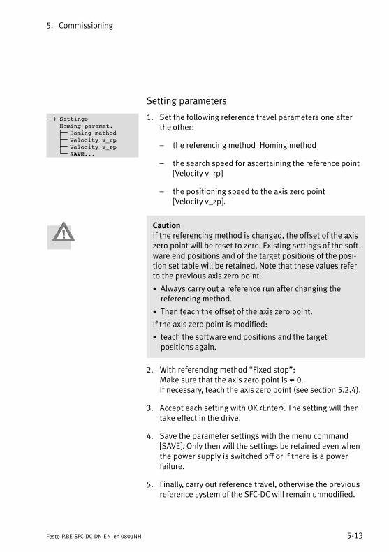
5. Commissioning
5−13Festo P.BE−SFC−DC−DN−EN en 0801NH
Setting parameters
1. Set the following reference travel parameters one afterthe other:
� the referencing method [Homing method]
� the search speed for ascertaining the reference point[Velocity v_rp]
� the positioning speed to the axis zero point [Velocity v_zp].
CautionIf the referencing method is changed, the offset of the axiszero point will be reset to zero. Existing settings of the soft�ware end positions and of the target positions of the posi�tion set table will be retained. Note that these values referto the previous axis zero point.
· Always carry out a reference run after changing thereferencing method.
· Then teach the offset of the axis zero point.
If the axis zero point is modified:
· teach the software end positions and the targetpositions again.
2. With referencing method �Fixed stop": Make sure that the axis zero point is � 0.If necessary, teach the axis zero point (see section 5.2.4).
3. Accept each setting with OK <Enter>. The setting will thentake effect in the drive.
4. Save the parameter settings with the menu command[SAVE]. Only then will the settings be retained even whenthe power supply is switched off or if there is a powerfailure.
5. Finally, carry out reference travel, otherwise the previousreference system of the SFC−DC will remain unmodified.
} SettingsHoming paramet.
Homing methodVelocity v_rpVelocity v_zpSAVE...
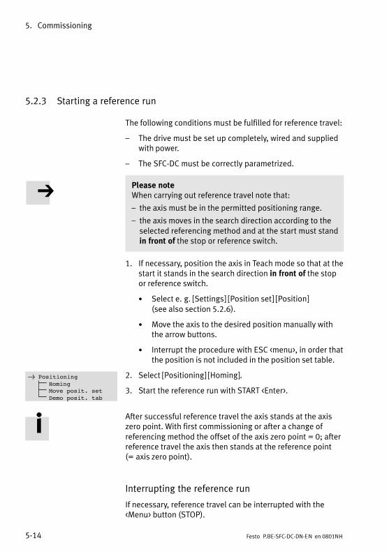
5. Commissioning
5−14 Festo P.BE−SFC−DC−DN−EN en 0801NH
5.2.3 Starting a reference run
The following conditions must be fulfilled for reference travel:
� The drive must be set up completely, wired and suppliedwith power.
� The SFC−DC must be correctly parametrized.
Please noteWhen carrying out reference travel note that:
� the axis must be in the permitted positioning range.
� the axis moves in the search direction according to theselected referencing method and at the start must standin front of the stop or reference switch.
1. If necessary, position the axis in Teach mode so that at thestart it stands in the search direction in front of the stopor reference switch.
· Select e.�g. [Settings] [Position set] [Position] (see also section 5.2.6).
· Move the axis to the desired position manually withthe arrow buttons.
· Interrupt the procedure with ESC <menu>, in order thatthe position is not included in the position set table.
2. Select [Positioning] [Homing].
3. Start the reference run with START <Enter>.
After successful reference travel the axis stands at the axiszero point. With first commissioning or after a change ofreferencing method the offset of the axis zero point = 0; afterreference travel the axis then stands at the reference point(=�axis zero point).
Interrupting the reference run
If necessary, reference travel can be interrupted with the<Menu> button (STOP).
} PositioningHomingMove posit. setDemo posit. tab
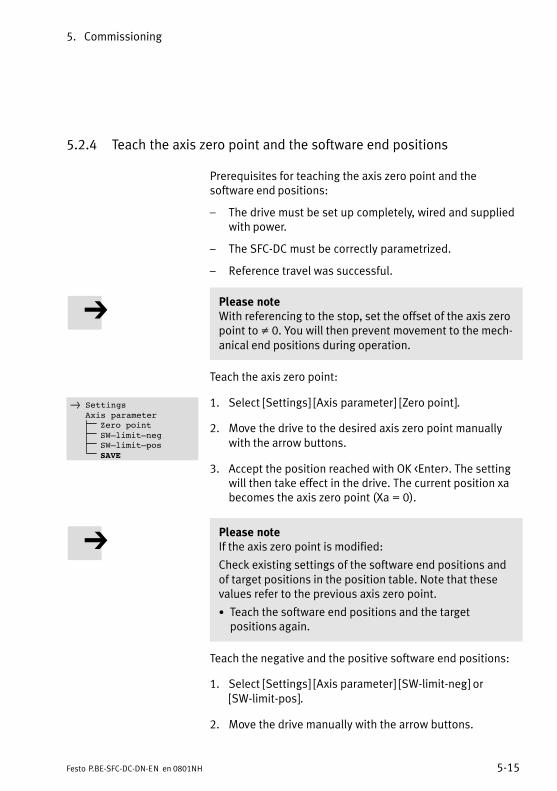
5. Commissioning
5−15Festo P.BE−SFC−DC−DN−EN en 0801NH
5.2.4 Teach the axis zero point and the software end positions
Prerequisites for teaching the axis zero point and thesoftware end positions:
� The drive must be set up completely, wired and suppliedwith power.
� The SFC−DC must be correctly parametrized.
� Reference travel was successful.
Please noteWith referencing to the stop, set the offset of the axis zeropoint to � 0. You will then prevent movement to the mech�anical end positions during operation.
Teach the axis zero point:
1. Select [Settings] [Axis parameter] [Zero point].
2. Move the drive to the desired axis zero point manuallywith the arrow buttons.
3. Accept the position reached with OK <Enter>. The settingwill then take effect in the drive. The current position xabecomes the axis zero point (Xa = 0).
Please noteIf the axis zero point is modified:
Check existing settings of the software end positions andof target positions in the position table. Note that thesevalues refer to the previous axis zero point.
· Teach the software end positions and the targetpositions again.
Teach the negative and the positive software end positions:
1. Select [Settings] [Axis parameter] [SW−limit−neg] or[SW−limit−pos].
2. Move the drive manually with the arrow buttons.
} SettingsAxis parameter
Zero pointSW–limit–negSW–limit–posSAVE
5. Commissioning
5−16 Festo P.BE−SFC−DC−DN−EN en 0801NH
3. Accept the position reached with OK <Enter>. The settingwill then take effect in the drive.
4. Save the parameter settings with [SAVE]. Only then willthe settings be retained even when the power supply isswitched off or if there is a power failure.
5.2.5 Positioning with position sets
The following conditions must be fulfilled:
� The drive must be set up completely, wired and suppliedwith power.
� The SFC−DC must be correctly parametrized.
� The reference run has been carried out successfully.
� The axis zero point and the software end positions havebeen set correctly.
Please notePlease note that position records with speed v = 0 orinvalid target positions (−> error TARGET POSITION OUT OFLIMIT) cannot be executed.
· After successful reference travel carry out a test run, ifnecessary, without a work load (see section 5.2.7).
· If necessary, optimize the settings for position sets as wellas for the reference coordinates and the working area(see section 1.6).
· After a successful test run you can teach the positions inthe position set table to which movement must be made(see section 5.2.6).
WarningDuring the teach procedure the motor turns or theconnected axis starts to move.
· Make sure that nobody can place his/her hand in thepositioning range of the moveable mass and that noobjects lie in its path.
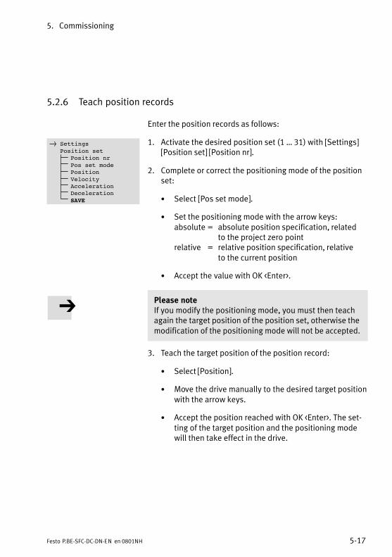
5. Commissioning
5−17Festo P.BE−SFC−DC−DN−EN en 0801NH
5.2.6 Teach position records
Enter the position records as follows:
1. Activate the desired position set (1 � 31) with [Settings][Position set] [Position nr].
2. Complete or correct the positioning mode of the positionset:
· Select [Pos set mode].
· Set the positioning mode with the arrow keys: absolute = absolute position specification, related
to the project zero pointrelative = relative position specification, relative
to the current position
· Accept the value with OK <Enter>.
Please noteIf you modify the positioning mode, you must then teachagain the target position of the position set, otherwise themodification of the positioning mode will not be accepted.
3. Teach the target position of the position record:
· Select [Position].
· Move the drive manually to the desired target positionwith the arrow keys.
· Accept the position reached with OK <Enter>. The set�ting of the target position and the positioning modewill then take effect in the drive.
} SettingsPosition set
Position nrPos set modePositionVelocityAccelerationDecelerationSAVE
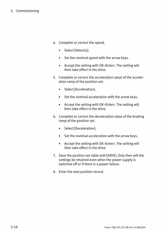
5. Commissioning
5−18 Festo P.BE−SFC−DC−DN−EN en 0801NH
4. Complete or correct the speed.
· Select [Velocity].
· Set the nominal speed with the arrow keys.
· Accept the setting with OK <Enter>. The setting willthen take effect in the drive.
5. Complete or correct the acceleration value of the acceler�ation ramp of the position set.
· Select [Acceleration].
· Set the nominal acceleration with the arrow keys.
· Accept the setting with OK <Enter>. The setting willthen take effect in the drive.
6. Complete or correct the deceleration value of the brakingramp of the position set.
· Select [Deceleration].
· Set the nominal acceleration with the arrow keys.
· Accept the setting with OK <Enter>. The setting willthen take effect in the drive.
7. Save the position set table with [SAVE]. Only then will thesettings be retained even when the power supply isswitched off or if there is a power failure.
8. Enter the next position record.

5. Commissioning
5−19Festo P.BE−SFC−DC−DN−EN en 0801NH
5.2.7 Test run
1. Enter several position sets in order to check the position�ing behaviour (see section 5.2.6).
· Set the target positions at the limits of the positioningrange, for example, in order to check the software endpositions.
· Set different speeds, for example.
2. Select [Positioning] [Move posit. set] in order to execute aparticular position record.
or
3. Select [Positioning] [Demo posit. tab] in order to executeall position records. At least two position records must beentered in the position record table in order that thisfunction can be used.
In the [Demo posit. tab] positioning run, all positionrecords 1 � 31 in the position record table will beexecuted one after the other. If the position set tablecontains a position set with speed v = 0, this position setand all the following sets will not be processed;positioning travel will be continued with position set 1.
With DEMO STOP <Enter> you can interrupt the [Demoposit. tab] positioning run. The current position record willbe executed before the drive stops.
4. Start the test run.
· Check the positioning behaviour.
· Check the displayed coordinates of the axis.
With EMERG.STOP <Menu> you can interrupt the currentpositioning procedure.
5. If necessary, optimize the settings for position sets as wellas for the basis coordinates and the working area.
} PositioningHomingMove posit. setDemo posit. tab
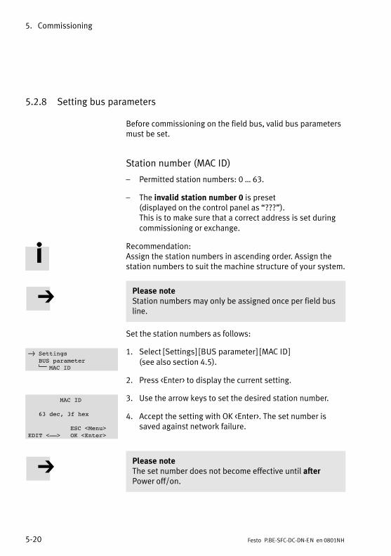
5. Commissioning
5−20 Festo P.BE−SFC−DC−DN−EN en 0801NH
5.2.8 Setting bus parameters
Before commissioning on the field bus, valid bus parametersmust be set.
Station number (MAC ID)
� Permitted station numbers: 0 � 63.
� The invalid station number 0 is preset (displayed on the control panel as �???").This is to make sure that a correct address is set duringcommissioning or exchange.
Recommendation:Assign the station numbers in ascending order. Assign thestation numbers to suit the machine structure of your system.
Please noteStation numbers may only be assigned once per field busline.
Set the station numbers as follows:
1. Select [Settings] [BUS parameter] [MAC ID] (see also section 4.5).
2. Press <Enter> to display the current setting.
3. Use the arrow keys to set the desired station number.
4. Accept the setting with OK <Enter>. The set number issaved against network failure.
Please noteThe set number does not become effective until afterPower off/on.
} SettingsBUS parameter
MAC ID
MAC ID
63 dec, 3f hex
ESC <Menu>EDIT <––> OK <Enter>
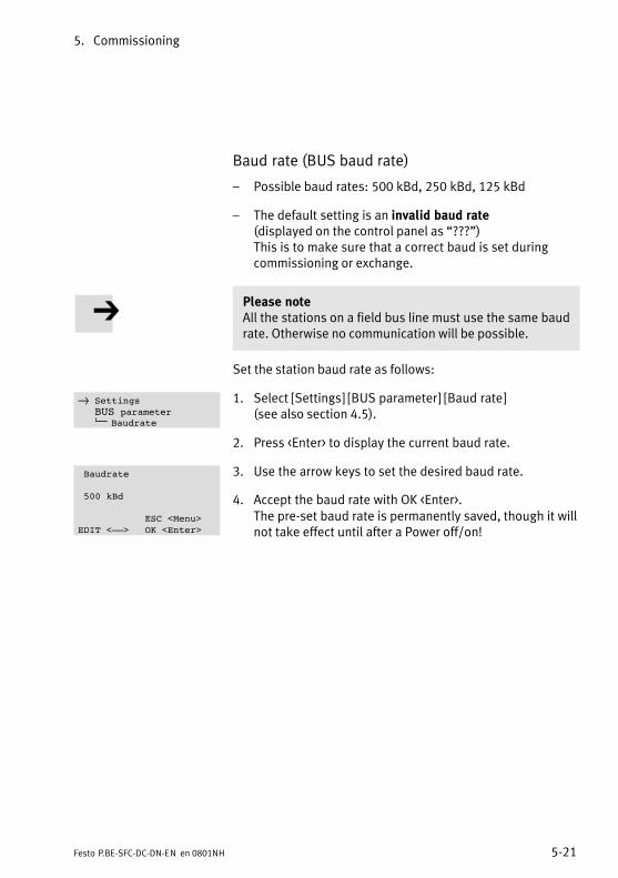
5. Commissioning
5−21Festo P.BE−SFC−DC−DN−EN en 0801NH
Baud rate (BUS baud rate)
� Possible baud rates: 500 kBd, 250 kBd, 125�kBd
� The default setting is an invalid baud rate (displayed on the control panel as �???")This is to make sure that a correct baud is set duringcommissioning or exchange.
Please noteAll the stations on a field bus line must use the same baudrate. Otherwise no communication will be possible.
Set the station baud rate as follows:
1. Select [Settings] [BUS parameter] [Baud rate] (see also section 4.5).
2. Press <Enter> to display the current baud rate.
3. Use the arrow keys to set the desired baud rate.
4. Accept the baud rate with OK <Enter>. The pre−set baud rate is permanently saved, though it willnot take effect until after a Power off/on!
} SettingsBUS parameter
Baudrate
Baudrate
500 kBd
ESC <Menu>EDIT <––> OK <Enter>
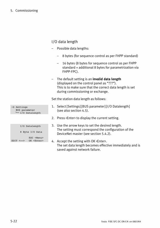
5. Commissioning
5−22 Festo P.BE−SFC−DC−DN−EN en 0801NH
I/O data length
� Possible data lengths:
� 8 bytes (for sequence control as per FHPP standard)
� 16 bytes (8 bytes for sequence control as per FHPPstandard + additional 8 bytes for parametrization viaFHPP−FPC).
� The default setting is an invalid data length (displayed on the control panel as �???").This is to make sure that the correct data length is setduring commissioning or exchange.
Set the station data length as follows:
1. Select [Settings] [BUS parameter] [I/O Datalength] (see also section 4.5).
2. Press <Enter> to display the current setting.
3. Use the arrow keys to set the desired length. The setting must correspond the configuration of theDeviceNet master (see section 5.4.2).
4. Accept the setting with OK <Enter>. The set data length becomes effective immediately and issaved against network failure.
} SettingsBUS parameter
I/O Datalength
I/O Datalength
8 Byte I/O Data
ESC <Menu>EDIT <––> OK <Enter>
5. Commissioning
5−23Festo P.BE−SFC−DC−DN−EN en 0801NH
5.3 Commissioning with the Festo Configuration Tool
5.3.1 Installing and starting the Festo Configuration Tool
The Festo Configuration Tool (FCT) and the PlugIn SFC−DC areinstalled on your PC with an installation program.
Please noteThe PlugIn SFC−DC version V2.2.0 supports the followingmotor units of type SFC−DC−...−DN:
� Hardware version as from V1.00
� Firmware version V1.33 or higher
Check with later versions of the SFC−DC, whether anupdated PlugIn is provided. If necessary consult Festo.
Please noteAdministrator rights are required for installing the FestoConfiguration Tool.
You can install the Festo Configuration Tool from the CD ROMas follows:
1. Close all programs.
2. Place the Festo Configuration Tool CD in your CD ROMdrive. If Auto Run is activated on your system, theinstallation will start automatically and you can omitsteps�3 and 4.
3. Select [Run] in the Start menu.
4. Enter D:\setup (if necessary replace D by the letter of yourCD ROM drive).
5. Follow the instructions on the screen.
5. Commissioning
5−24 Festo P.BE−SFC−DC−DN−EN en 0801NH
5.3.2 Procedure for commissioning with the Festo Configuration Tool
Starting the Festo Configuration Tool
In order to commission the SFC−DC with the FestoConfiguration Tool, carry out the following steps:
1. Connect the SFC−DC to your PC via the RS232 interface.Observe here the instructions in section 3.5.
2. Start the Festo Configuration Tool: Double−click on theFesto Configuration Tool icon on the desktop � or switch to the Windows menu [Start] and select the entry[Festo Software] [Festo Configuration Tool].
3. Create a project in the Festo Configuration Tool or open anexisting project. Add a device to the project with thePlugIn SFC−DC.
4. Create the device connection (online connection) betweenthe PC and the SFC−DC via the tool bar of the FestoConfiguration Tool.It may be necessary here to adapt the controller type, thedevice name or the axis type.
Device control
In order that the Festo Configuration Tool can control the con�nected SFC−DC, the control interface of the SFC−DC must bedeactivated and the controller enable must be set. The actualstatus of the FHPP control bytes then has no effect.
· Access the window �General output", register �Operate",then under �Device control" activate first the box �FCTcontrol" and then the box �Enable". The control interfaceof the SFC−DC will then be deactivated and the controlenable of the Festo Configuration Tool will be set.
Access to the SFC−DC by means of the Festo ConfigurationTool can be blocked via the DeviceNet interface (see section5.5.2, FHPP control bit CCON.B5). In this case the boxes�FCT�control" and �Enable" are blocked (inactive).
5. Commissioning
5−25Festo P.BE−SFC−DC−DN−EN en 0801NH
Instructions on parametrizing and commissioning
Further information can be found in the help function for theFesto Configuration Tool, using the command [Help] [ContentsFCT general]; e.g.
� help on working with projects and on adding a device to aproject
� on defining the reference system (referencing and refer�ence coordinates)
� help on setting the field bus address.
The PlugIn SFC−DC for the Festo Configuration Tool supportsall the steps necessary for commissioning an SFC−DC.
With the PlugIn SFC−DC for the Festo Configuration Tool thenecessary parametrizings can be carried out offline, i.e.without the SFC−DC being connected to the PC. This enablesthe actual commissioning to be prepared, e.�g. in the designoffice when a system is being planned.
Further information can be found in the PlugIn help:Command [Help] [Contents of installed PlugIns] [Festo(manufacturer name)] [SFC−DC (PlugIn name)], e.�g.:
� for describing the dialogues of the PlugIn SFC−DC
� for describing the work steps for commissioning
� for the basic functions: Device connection, Device names,Device control and for password protection.
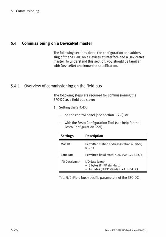
5. Commissioning
5−26 Festo P.BE−SFC−DC−DN−EN en 0801NH
5.4 Commissioning on a DeviceNet master
The following sections detail the configuration and addres�sing of the SFC−DC on a DeviceNet interface and a DeviceNetmaster. To understand this section, you should be familiarwith DeviceNet and know the specification.
5.4.1 Overview of commissioning on the field bus
The following steps are required for commissioning theSFC−DC as a field bus slave:
1. Setting the SFC−DC:
� on the control panel (see section 5.2.8), or
� with the Festo Configuration Tool (see help for theFesto Configuration Tool).
Settings Description
MAC ID Permitted station address (station number) 0 � 63
Baud rate Permitted baud rates: 500, 250, 125 kBit/s
I/O Datalength I/O data length� 8 bytes (FHPP standard)� 16 bytes (FHPP standard + FHPP−FPC)
Tab.�5/2: Field bus−specific parameters of the SFC−DC
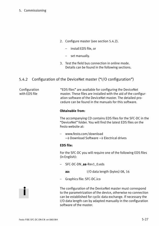
5. Commissioning
5−27Festo P.BE−SFC−DC−DN−EN en 0801NH
2. Configure master (see section 5.4.2).
� install EDS file, or
� set manually.
3. Test the field bus connection in online mode. Details can be found in the following sections.
5.4.2 Configuration of the DeviceNet master (�I/O configuration")
Configuration with EDS file
�EDS files" are available for configuring the DeviceNetmaster. These files are installed with the aid of the configur�ation software of the DeviceNet master. The detailed pro�cedure can be found in the manuals for this software.
Obtainable from:
The accompanying CD contains EDS files for the SFC−DC in the�DeviceNet" folder. You will find the latest EDS files on theFesto website at:
� www.festo.com/download} Download Software } Electrical drives
EDS file:
For the SFC−DC you will require one of the following EDS files(in English):
� SFC−DC−DN_aa−Rev1_0.eds
aa: I/O data length (bytes) 08, 16
� Graphics file: SFC−DC.ico
The configuration of the DeviceNet master must correspondto the parametrization of the device, otherwise no connectioncan be established for cyclic data exchange. If necessary theI/O data length can by adapted manually in the configurationsoftware of the master.
5. Commissioning
5−28 Festo P.BE−SFC−DC−DN−EN en 0801NH
Manual configuration Vendor Code 26 (= 1Ah)Product Type 12 (= 0Ch)Product Code 9020 (decimal)
The corresponding device information can also be found inthe EDS file under [Device].
Allen−Bradley Support for the Auto Device Replacement (ADR) from Allen−Bradley.In its master controllers, Rockwell Automation offers aspecial function that supports the slave stations with auto�matic parameter setting when a device is exchanged duringservicing. All of the parameters with write access addressedin the EDS file are uploaded by the master after commission�ing and saved in the scanner of the controller. Upon networkstartup, the parameter values are automatically downloadedto the slave via Explicit Messaging. This means that devicescan be exchanged in the system without an FCT project.
Omron Support for the autoconfig mode of Omron controllers. With Omron controllers the DeviceNet stations are confi�gured via an autoconfig mode. A nominal configuration viathe DeviceNet Configurator software is not necessary. Thecurrent network configuration automatically becomes thenominal configuration. In addition, the scanner automati�cally performs an I/O mapping.
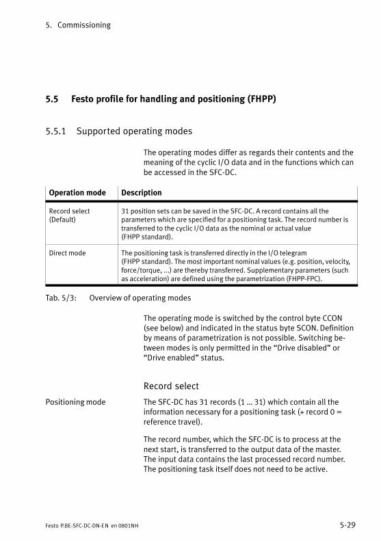
5. Commissioning
5−29Festo P.BE−SFC−DC−DN−EN en 0801NH
5.5 Festo profile for handling and positioning (FHPP)
5.5.1 Supported operating modes
The operating modes differ as regards their contents and themeaning of the cyclic I/O data and in the functions which canbe accessed in the SFC−DC.
Operation mode Description
Record select(Default)
31 position sets can be saved in the SFC−DC. A record contains all theparameters which are specified for a positioning task. The record number istransferred to the cyclic I/O data as the nominal or actual value(FHPP�standard).
Direct mode The positioning task is transferred directly in the I/O telegram(FHPP�standard). The most important nominal values (e.g. position, velocity,force/torque, ...) are thereby transferred. Supplementary parameters (suchas acceleration) are defined using the parametrization (FHPP−FPC).
Tab.�5/3: Overview of operating modes
The operating mode is switched by the control byte CCON(see below) and indicated in the status byte SCON. Definitionby means of parametrization is not possible. Switching be�tween modes is only permitted in the �Drive disabled" or�Drive enabled" status.
Record select
Positioning mode The SFC−DC has 31 records (1 � 31) which contain all theinformation necessary for a positioning task (+ record 0 =reference travel).
The record number, which the SFC−DC is to process at thenext start, is transferred to the output data of the master. The input data contains the last processed record number.The positioning task itself does not need to be active.

5. Commissioning
5−30 Festo P.BE−SFC−DC−DN−EN en 0801NH
The SFC−DC cannot function independently, i.e.�it does nothave its own user program. Records cannot be processedautomatically with a programmed logic. The drive cannotaccomplish any tasks sensibly with Stand Alone; closecoupling to the PLC is necessary.
There are also three records with special functions (whichcannot be executed in Record Select mode):
� Record 32 contains the parameters for the Jog mode.
� Set 33 contains the parameters for Direct mode.
� Record 34 is the direct record for the FCT software.
Direct mode
In the direct mode positioning tasks are formulated directly inthe output data of the master.
Positioning mode The typical application calculates dynamically the nominaltarget values for each task or just for some tasks. Adaptationto different work item sizes is therefore possible. It is not sen�sible here to parametrize the record list again each time. Thepositioning data are managed completely in the PLC and sentto the SFC−DC. Here also, close coupling between the PLC andthe SFC−DC is necessary.
Force control Alternatively, nominal values relative to the rated motor cur�rent can be specified as direct mode. This results in a rotarytorque and with linear drives in a force (power control).
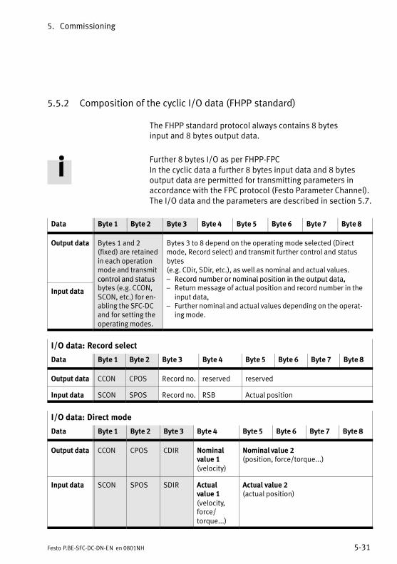
5. Commissioning
5−31Festo P.BE−SFC−DC−DN−EN en 0801NH
5.5.2 Composition of the cyclic I/O data (FHPP standard)
The FHPP standard protocol always contains 8 bytesinput�and 8 bytes output data.
Further 8 bytes I/O as per FHPP−FPC In the cyclic data a further 8 bytes input data and 8 bytesoutput data are permitted for transmitting parameters inaccordance with the FPC protocol (Festo Parameter Channel).The I/O data and the parameters are described in section 5.7.
Data Byte 1 Byte 2 Byte 3 Byte 4 Byte 5 Byte 6 Byte 7 Byte 8
Output data Bytes 1 and 2(fixed) are retainedin each operationmode and transmitcontrol and status
Bytes 3 to 8 depend on the operating mode selected (Directmode, Record select) and transmit further control and statusbytes (e.g. CDir, SDir, etc.), as well as nominal and actual values.� Record number or nominal position in the output data,
Input data
control and statusbytes (e.g. CCON,SCON, etc.) for en�abling the SFC−DCand for setting theoperating modes.
� Record number or nominal position in the output data,� Return message of actual position and record number in the
input data,� Further nominal and actual values depending on the operat�
ing mode.
I/O data: Record select
Data Byte 1 Byte 2 Byte 3 Byte 4 Byte 5 Byte 6 Byte 7 Byte 8
Output data CCON CPOS Record no. reserved reserved
Input data SCON SPOS Record no. RSB Actual position
I/O data: Direct mode
Data Byte 1 Byte 2 Byte 3 Byte 4 Byte 5 Byte 6 Byte 7 Byte 8
Output data CCON CPOS CDIR Nominalvalue 1(velocity)
Nominal value 2(position, force/torque...)
Input data SCON SPOS SDIR Actualvalue 1(velocity,force/torque...)
Actual value 2(actual position)
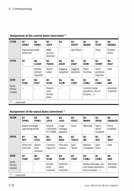
5. Commissioning
5−32 Festo P.BE−SFC−DC−DN−EN en 0801NH
Assignment of the control bytes (overview) 1)
CCON B7OPM2
B6OPM1
B5LOCK
B4�
B3RESET
B2BRAKE
B1STOP
B0ENABLE
Operating modeselection
MMI accessblocked
� Quit fault � Stop Enabledrive
CPOS B7�
B6CLEAR
B5TEACH
B4JOGN
B3JOGP
B2HOM
B1START
B0HALT
� Deleteremain�ing path
Teachvalue
Joggingnegative
Joggingpositive
Starthoming
Startposition�ing task
Halt
CDIR
(only
B7FUNC
B6FAST
B5XLIM
B4VLIM
B3CONT
B2COM2
B1COM1
B0ABS
(onlyDirectmode)
� � Deacti�vatestrokelimit
� � Control mode (position, force/torque, ...)
absolute/relative
1) � : reserved
Assignment of the status bytes (overview) 1)
SCON B7OPM2
B6OPM1
B5LOCK
B424VL
B3FAULT
B2WARN
B1OPEN
B0ENABLED
Reply messageoperating mode
DevicecontrollerFCT/MMI
Loadvoltageapplied
Fault Warning Oper�ation enabled
Driveenabled
SPOS B7REF
B6STILL
B5DEV
B4MOV
B3TEACH
B2MC
B1ACK
B0HALT
Drive ref�erenced
Down�timemonitor.
Contour�ing error
The axismoves
QuitTeach
MotionComplete
QuitStart
Halt
SDIR
(only
B7FUNC
B6FAST
B5XLIM
B4VLIM
B3CONT
B2COM2
B1COM1
B0ABS
(onlyDirectmode)
� � Strokelimitreached
Velocitylimitreached
� Reply message con�trol mode (position,force/torque, ...)
absolute/relative
1) � : reserved
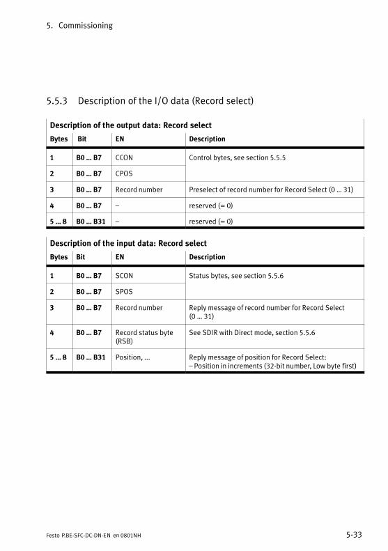
5. Commissioning
5−33Festo P.BE−SFC−DC−DN−EN en 0801NH
5.5.3 Description of the I/O data (Record select)
Description of the output data: Record select
Bytes Bit EN Description
1 B0 � B7 CCON Control bytes, see section 5.5.5
2 B0 � B7 CPOS
3 B0 � B7 Record number Preselect of record number for Record Select (0 � 31)
4 B0 � B7 � reserved (= 0)
5 � 8 B0 � B31 � reserved (= 0)
Description of the input data: Record select
Bytes Bit EN Description
1 B0 � B7 SCON Status bytes, see section 5.5.6
2 B0 � B7 SPOS
3 B0 � B7 Record number Reply message of record number for Record Select (0 � 31)
4 B0 � B7 Record status byte(RSB)
See SDIR with Direct mode, section 5.5.6
5 � 8 B0 � B31 Position, ... Reply message of position for Record Select: � Position in increments (32−bit number, Low byte first)

5. Commissioning
5−34 Festo P.BE−SFC−DC−DN−EN en 0801NH
5.5.4 Description of the I/O data (Direct mode)
Output data: Direct mode
Bytes Bit EN Description
1 B0 � B7 CCON Control bytes, see section 5.5.5
2 B0 � B7 CPOS
3 B0 � B7 CDIR
4 B0 � B7 Velocity Nominal value 1: Velocity in % of the maximum speed
5 � 8 B0 � B31 Position Force, ...
Nominal value 2: Specification depends on the controlleroperating mode (see control byte 3 CDIR)� positioning mode: Position in increments� Force control: Force/torque in % of the rated current
Input data: Direct mode
Bytes Bit EN Description
1 B0 � B7 SCON Status bytes, see section 5.5.6
2 B0 � B7 SPOS
3 B0 � B7 SDIR
4 B0 � B7 Velocity
Force/torque
Actual value 1: Reply message depends on the controller oper�ating mode (see control byte 3 CDIR)� positioning mode: Velocity in % of the maximum speed� Force control: Force/torque in % of the rated current
5 � 8 B0 � B31 Position Actual value 2: Reply message position in increments
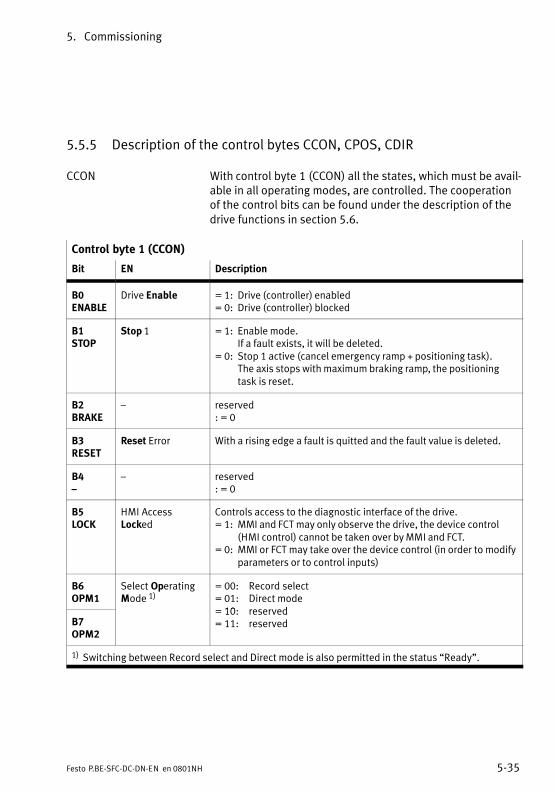
5. Commissioning
5−35Festo P.BE−SFC−DC−DN−EN en 0801NH
5.5.5 Description of the control bytes CCON, CPOS, CDIR
CCON With control byte 1 (CCON) all the states, which must be avail�able in all operating modes, are controlled. The cooperationof the control bits can be found under the description of thedrive functions in section 5.6.
Control byte 1 (CCON)
Bit EN Description
B0ENABLE
Drive Enable = 1: Drive (controller) enabled= 0: Drive (controller) blocked
B1STOP
Stop 1 = 1: Enable mode. If a fault exists, it will be deleted.
= 0: Stop 1 active (cancel emergency ramp + positioning task). The axis stops with maximum braking ramp, the positioningtask is reset.
B2BRAKE
� reserved: = 0
B3RESET
Reset Error With a rising edge a fault is quitted and the fault value is deleted.
B4�
� reserved: = 0
B5LOCK
HMI AccessLocked
Controls access to the diagnostic interface of the drive.= 1: MMI and FCT may only observe the drive, the device control
(HMI control) cannot be taken over by MMI and FCT.= 0: MMI or FCT may take over the device control (in order to modify
parameters or to control inputs)
B6OPM1
Select OperatingMode 1)
= 00: Record select= 01: Direct mode10 reserved
B7OPM2
= 10: reserved= 11: reserved
1) Switching between Record select and Direct mode is also permitted in the status �Ready".
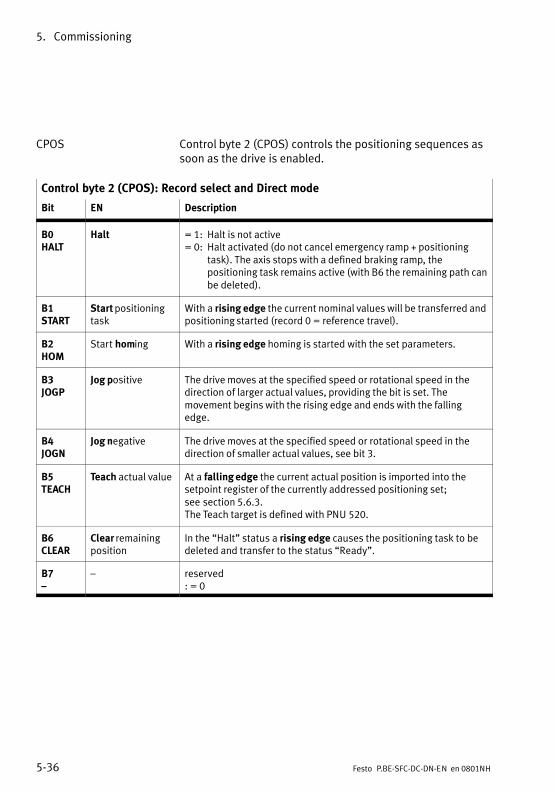
5. Commissioning
5−36 Festo P.BE−SFC−DC−DN−EN en 0801NH
CPOS Control byte 2 (CPOS) controls the positioning sequences assoon as the drive is enabled.
Control byte 2 (CPOS): Record select and Direct mode
Bit EN Description
B0HALT
Halt = 1: Halt is not active= 0: Halt activated (do not cancel emergency ramp + positioning
task). The axis stops with a defined braking ramp, thepositioning task remains active (with B6 the remaining path canbe deleted).
B1START
Start positioningtask
With a rising edge the current nominal values will be transferred andpositioning started (record 0 = reference travel).
B2HOM
Start homing With a rising edge homing is started with the set parameters.
B3JOGP
Jog positive The drive moves at the specified speed or rotational speed in thedirection of larger actual values, providing the bit is set. Themovement begins with the rising edge and ends with the fallingedge.
B4JOGN
Jog negative The drive moves at the specified speed or rotational speed in thedirection of smaller actual values, see bit 3.
B5TEACH
Teach actual value At a falling edge the current actual position is imported into thesetpoint register of the currently addressed positioning set;see�section 5.6.3.The Teach target is defined with PNU 520.
B6CLEAR
Clear remainingposition
In the �Halt" status a rising edge causes the positioning task to bedeleted and transfer to the status �Ready".
B7�
� reserved: = 0

5. Commissioning
5−37Festo P.BE−SFC−DC−DN−EN en 0801NH
CDIR Control byte CDIR is a special control byte for the operating
mode �Direct mode".
Control byte 3 (CDIR): only Direct mode
Bit EN Description
B0ABS
Absolute/Relative = 0: Nominal value is absolute= 1: Nominal value is relative to last nominal value
B1COM1
Control mode = 00: Positioning mode (see also section 5.5.7 point 6)= 01: Force control (see also section 5.5.7 point 7)10 reserved
B2COM2
= 10: reserved= 11: reserved
B3CONT
� reserved:= 0
B4VLIM
� reserved:= 0
B5XLIM
Stroke (X−) limit notactive
Power control= 0: Stroke monitoring active= 1: Stroke monitoring not active
B6FAST
� reserved:= 0
B7FUNC
� reserved:= 0
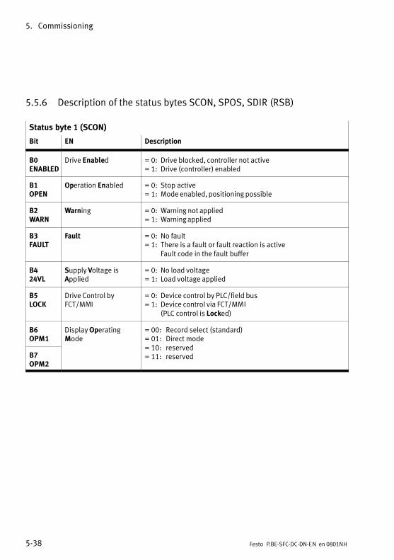
5. Commissioning
5−38 Festo P.BE−SFC−DC−DN−EN en 0801NH
5.5.6 Description of the status bytes SCON, SPOS, SDIR (RSB)
Status byte 1 (SCON)
Bit EN Description
B0ENABLED
Drive Enabled = 0: Drive blocked, controller not active= 1: Drive (controller) enabled
B1OPEN
Operation Enabled = 0: Stop active= 1: Mode enabled, positioning possible
B2WARN
Warning = 0: Warning not applied= 1: Warning applied
B3FAULT
Fault = 0: No fault= 1: There is a fault or fault reaction is active
Fault code in the fault buffer
B424VL
Supply Voltage isApplied
= 0: No load voltage= 1: Load voltage applied
B5LOCK
Drive Control byFCT/MMI
= 0: Device control by PLC/field bus= 1: Device control via FCT/MMI
(PLC control is Locked)
B6OPM1
Display OperatingMode
= 00: Record select (standard)= 01: Direct mode10 reserved
B7OPM2
= 10: reserved= 11: reserved
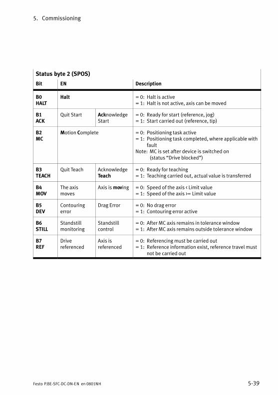
5. Commissioning
5−39Festo P.BE−SFC−DC−DN−EN en 0801NH
Status byte 2 (SPOS)
Bit EN Description
B0HALT
Halt = 0: Halt is active= 1: Halt is not active, axis can be moved
B1ACK
Quit Start AcknowledgeStart
= 0: Ready for start (reference, jog)= 1: Start carried out (reference, tip)
B2MC
Motion Complete = 0: Positioning task active= 1: Positioning task completed, where applicable with
faultNote: MC is set after device is switched on
(status �Drive blocked")
B3TEACH
Quit Teach AcknowledgeTeach
= 0: Ready for teaching= 1: Teaching carried out, actual value is transferred
B4MOV
The axismoves
Axis is moving = 0: Speed of the axis < Limit value= 1: Speed of the axis >= Limit value
B5DEV
Contouringerror
Drag Error = 0: No drag error= 1: Contouring error active
B6STILL
Standstillmonitoring
Standstillcontrol
= 0: After MC axis remains in tolerance window= 1: After MC axis remains outside tolerance window
B7REF
Drivereferenced
Axis isreferenced
= 0: Referencing must be carried out= 1: Reference information exist, reference travel must
not be carried out
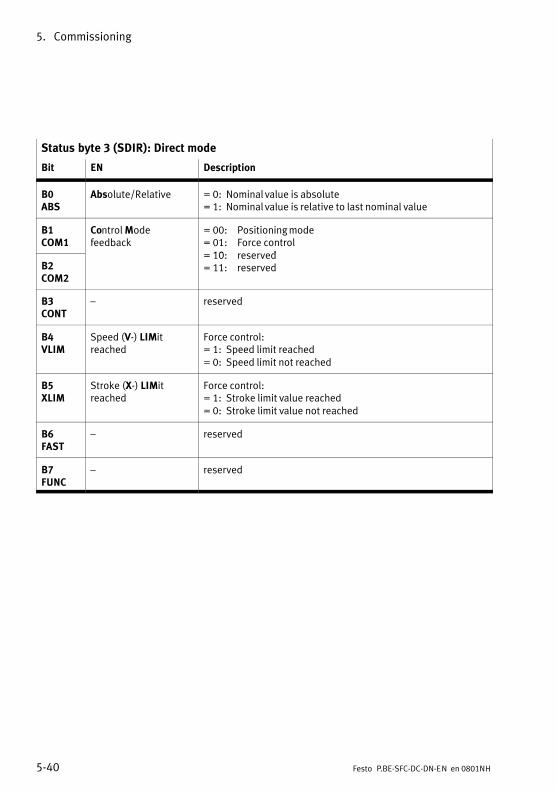
5. Commissioning
5−40 Festo P.BE−SFC−DC−DN−EN en 0801NH
Status byte 3 (SDIR): Direct mode
Bit EN Description
B0ABS
Absolute/Relative = 0: Nominal value is absolute= 1: Nominal value is relative to last nominal value
B1COM1
Control Modefeedback
= 00: Positioning mode= 01: Force control10 reserved
B2COM2
= 10: reserved= 11: reserved
B3CONT
� reserved
B4VLIM
Speed (V−) LIMitreached
Force control:= 1: Speed limit reached= 0: Speed limit not reached
B5XLIM
Stroke (X−) LIMitreached
Force control:= 1: Stroke limit value reached= 0: Stroke limit value not reached
B6FAST
� reserved
B7FUNC
� reserved
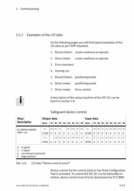
5. Commissioning
5−41Festo P.BE−SFC−DC−DN−EN en 0801NH
5.5.7 Examples of the I/O data
On the following pages you will find typical examples of theI/O data as per FHPP Standard.
1. Record Select: create readiness to operate
2. Direct mode: create readiness to operate
3. Error treatment
4. Homing run
5. Record Select: positioning mode
6. Direct mode: positioning mode
7. Direct mode: Force control
A description of the status machine of the SFC−DC can befound in section 5.8.
Safeguard device control
Step/D i ti
Output data Input dataDescription Bytes B7 B6 B5 B4 B3 B2 B1 B0 Bytes B7 B6 B5 B4 B3 B2 B1 B0
0.1 device control Byte 1 OPM2 OPM1 LOCK � RESET BRAKE STOP ENABL Byte 1 OPM2 OPM1 LOCK 24VL FAULT WARN OPEN ENABL0.1 device controlHMI = on CCON 0 0 0 0 0 x 0 0 SCON 0 0 1 1 0 0 0 0
Byte 2 � CLEAR TEACH JOGN JOGP HOM START HALT Byte 2 REF STILL DEV MOV TEACH MC ACK HALT
CPOS 0 0 0 0 0 0 0 0 SPOS 0 0 0 0 0 1 0 0
0: 0−signal1: 1−signalx: not relevant (optional)F: Edge positive
Tab.�5/4: I/O data �Device control active"
Device control via the control panel or the Festo ConfigurationTool is activated. To control the SFC−DC via the DeviceNet in�terface, device control must first be deactivated by FCT/MMI.
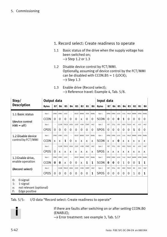
5. Commissioning
5−42 Festo P.BE−SFC−DC−DN−EN en 0801NH
1. Record select: Create readiness to operate
1.1 Basic status of the drive when the supply voltage hasbeen switched on; } Step 1.2 or 1.3
1.2 Disable device control by FCT/MMI.Optionally, assuming of device control by the FCT/MMIcan be disabled with CCON.B5 = 1 (LOCK); } Step 1.3
1.3 Enable drive (Record select); } Reference travel: Example 4, Tab.�5/8.
Step/D i ti
Output data Input dataDescription Bytes B7 B6 B5 B4 B3 B2 B1 B0 Bytes B7 B6 B5 B4 B3 B2 B1 B0
1.1 Basic status Byte 1 OPM2 OPM1 LOCK � RESET BRAKE STOP ENABL Byte 1 OPM2 OPM1 LOCK 24VL FAULT WARN OPEN ENABL1.1 Basic status
(device controlCCON 0 0 0 0 0 x 0 0 SCON 0 0 0 1 0 0 0 0
(device control HMI = off ) Byte 2 � CLEAR TEACH JOGN JOGP HOM START HALT Byte 2 REF STILL DEV MOV TEACH MC ACK HALTHMI = off )
CPOS 0 0 0 0 0 0 0 0 SPOS 0 0 0 0 0 1 0 0
1.2 Disable device Byte 1 OPM2 OPM1 LOCK � RESET BRAKE STOP ENABL Byte 1 OPM2 OPM1 LOCK 24VL FAULT WARN OPEN ENABL1.2 Disable devicecontrol by FCT/MMI CCON x x 1 0 x x x x SCON x x 0 x x x x x
Byte 2 � CLEAR TEACH JOGN JOGP HOM START HALT Byte 2 REF STILL DEV MOV TEACH MC ACK HALT
CPOS 0 x x x x x x x SPOS x x x x x x x x
1.3 Enable drive, Byte 1 OPM2 OPM1 LOCK � RESET BRAKE STOP ENABL Byte 1 OPM2 OPM1 LOCK 24VL FAULT WARN OPEN ENABL1.3 Enable drive,enable operation CCON 0 0 x 0 0 x 1 1 SCON 0 0 0 1 0 0 1 1
(Record select) Byte 2 � CLEAR TEACH JOGN JOGP HOM START HALT Byte 2 REF STILL DEV MOV TEACH MC ACK HALT(Record select)
CPOS 0 0 0 0 0 0 0 1 SPOS 0 0 0 0 0 1 0 1
0: 0−signal1: 1−signalx: not relevant (optional)F: Edge positive
Tab.�5/5: I/O data �Record select: Create readiness to operate"
If there are faults after switching on or after setting CCON.B0(ENABLE); } Error treatment: see example 3, Tab.�5/7
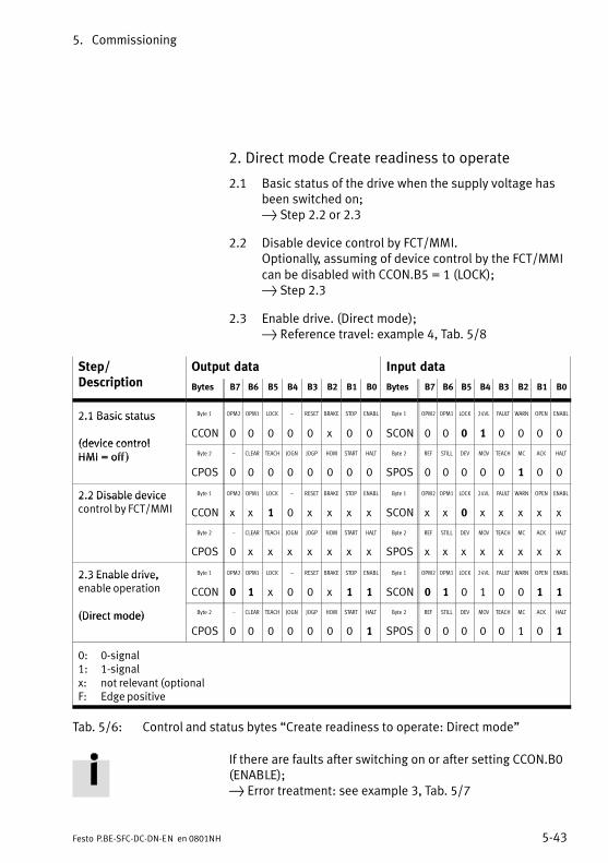
5. Commissioning
5−43Festo P.BE−SFC−DC−DN−EN en 0801NH
2. Direct mode Create readiness to operate
2.1 Basic status of the drive when the supply voltage hasbeen switched on; } Step 2.2 or 2.3
2.2 Disable device control by FCT/MMI.Optionally, assuming of device control by the FCT/MMIcan be disabled with CCON.B5 = 1 (LOCK); } Step 2.3
2.3 Enable drive. (Direct mode); } Reference travel: example 4, Tab.�5/8
Step/D i ti
Output data Input dataDescription Bytes B7 B6 B5 B4 B3 B2 B1 B0 Bytes B7 B6 B5 B4 B3 B2 B1 B0
2.1 Basic status Byte 1 OPM2 OPM1 LOCK � RESET BRAKE STOP ENABL Byte 1 OPM2 OPM1 LOCK 24VL FAULT WARN OPEN ENABL2.1 Basic status
(device controlCCON 0 0 0 0 0 x 0 0 SCON 0 0 0 1 0 0 0 0
(device control HMI = off ) Byte 2 � CLEAR TEACH JOGN JOGP HOM START HALT Byte 2 REF STILL DEV MOV TEACH MC ACK HALTHMI = off )
CPOS 0 0 0 0 0 0 0 0 SPOS 0 0 0 0 0 1 0 0
2.2 Disable device Byte 1 OPM2 OPM1 LOCK � RESET BRAKE STOP ENABL Byte 1 OPM2 OPM1 LOCK 24VL FAULT WARN OPEN ENABL2.2 Disable devicecontrol by FCT/MMI CCON x x 1 0 x x x x SCON x x 0 x x x x x
Byte 2 � CLEAR TEACH JOGN JOGP HOM START HALT Byte 2 REF STILL DEV MOV TEACH MC ACK HALT
CPOS 0 x x x x x x x SPOS x x x x x x x x
2.3 Enable drive, Byte 1 OPM2 OPM1 LOCK � RESET BRAKE STOP ENABL Byte 1 OPM2 OPM1 LOCK 24VL FAULT WARN OPEN ENABL2.3 Enable drive,enable operation CCON 0 1 x 0 0 x 1 1 SCON 0 1 0 1 0 0 1 1
(Direct mode) Byte 2 � CLEAR TEACH JOGN JOGP HOM START HALT Byte 2 REF STILL DEV MOV TEACH MC ACK HALT(Direct mode)
CPOS 0 0 0 0 0 0 0 1 SPOS 0 0 0 0 0 1 0 1
0: 0−signal1: 1−signalx: not relevant (optionalF: Edge positive
Tab.�5/6: Control and status bytes �Create readiness to operate: Direct mode"
If there are faults after switching on or after setting CCON.B0(ENABLE); } Error treatment: see example 3, Tab.�5/7

5. Commissioning
5−44 Festo P.BE−SFC−DC−DN−EN en 0801NH
3. Error treatment
Description of faults and warnings see section 6.4
3.1 A fault is shown with SCON.B3 (FAULT); } Positioning can no longer be undertaken.
3.2 A warning is shown with SCON.B2 (WARN); } Positioning can still be undertaken.
3.3 Quit fault with positive edge at CCON.B3 (RESET);
} Fault bit SCON.B2 (FAULT) or SCON.B3 (WARN) isreset
} SPOS.B2 (MC) will be set
} Drive is ready to operate
3.4 Quit fault with negative edge at CCON.B0 (ENABLE);
} Fault bit SCON.B2 (FAULT) or SCON.B3 (WARN) isreset
} SPOS.B2 (MC) will be set
} Create readiness to operate again (see examples 1, Tab.�5/5 and 2, Tab.�5/6).
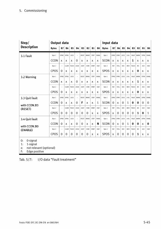
5. Commissioning
5−45Festo P.BE−SFC−DC−DN−EN en 0801NH
Step/D i ti
Output data Input dataDescription Bytes B7 B6 B5 B4 B3 B2 B1 B0 Bytes B7 B6 B5 B4 B3 B2 B1 B0
3.1 Fault Byte 1 OPM2 OPM1 LOCK � RESET BRAKE STOP ENABL Byte 1 OPM2 OPM1 LOCK 24VL FAULT WARN OPEN ENABL3.1 Fault
CCON x x x 0 x x x x SCON x x x x 1 x x x
Byte 2 � CLEAR TEACH JOGN JOGP HOM START HALT Byte 2 REF STILL DEV MOV TEACH MC ACK HALT
CPOS 0 x x x x x x x SPOS x x x x x 0 x x
3.2 Warning Byte 1 OPM2 OPM1 LOCK � RESET BRAKE STOP ENABL Byte 1 OPM2 OPM1 LOCK 24VL FAULT WARN OPEN ENABL3.2 Warning
CCON x x x 0 x x x x SCON x x x x x 1 x x
Byte 2 � CLEAR TEACH JOGN JOGP HOM START HALT Byte 2 REF STILL DEV MOV TEACH MC ACK HALT
CPOS 0 x x x x x x x SPOS x x x x x 0 x x
3.3 Quit fault Byte 1 OPM2 OPM1 LOCK � RESET BRAKE STOP ENABL Byte 1 OPM2 OPM1 LOCK 24VL FAULT WARN OPEN ENABL3.3 Quit fault
with CCON B3CCON 0 x x 0 F x x 1 SCON 0 x 0 1 0 0 0 0
with CCON.B3 (RESET) Byte 2 � CLEAR TEACH JOGN JOGP HOM START HALT Byte 2 REF STILL DEV MOV TEACH MC ACK HALT(RESET)
CPOS 0 0 0 0 0 0 x x SPOS x 0 0 0 0 1 0 1
3.4 Quit fault Byte 1 OPM2 OPM1 LOCK � RESET BRAKE STOP ENABL Byte 1 OPM2 OPM1 LOCK 24VL FAULT WARN OPEN ENABL3.4 Quit fault
with CCON B0CCON 0 x x 0 0 x x N SCON 0 x 0 1 0 0 x 0
with CCON.B0 (ENABLE) Byte 2 � CLEAR TEACH JOGN JOGP HOM START HALT Byte 2 REF STILL DEV MOV TEACH MC ACK HALT(ENABLE)
CPOS 0 0 0 0 0 0 x x SPOS x 0 0 0 0 1 x x
0: 0−signal1: 1−signalx: not relevant (optional)F: Edge positive
Tab.�5/7: I/O data �Fault treatment"
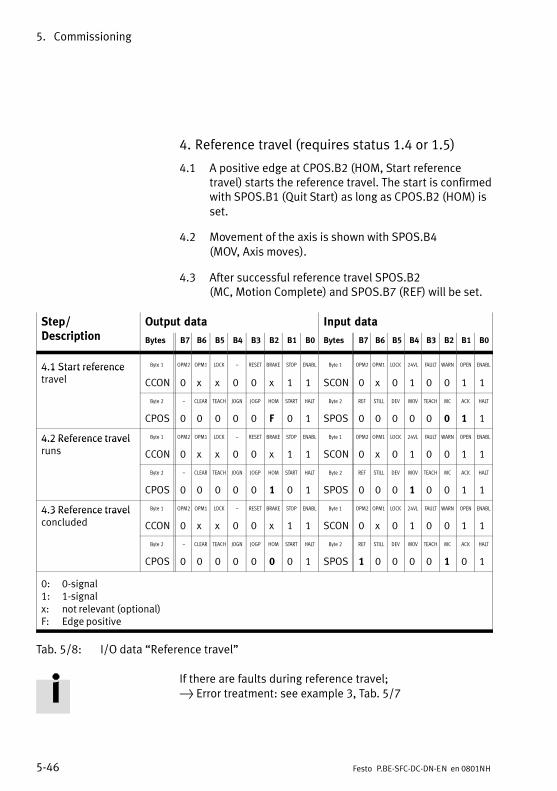
5. Commissioning
5−46 Festo P.BE−SFC−DC−DN−EN en 0801NH
4. Reference travel (requires status 1.4 or 1.5)
4.1 A positive edge at CPOS.B2 (HOM, Start referencetravel) starts the reference travel. The start is confirmedwith SPOS.B1 (Quit Start) as long as CPOS.B2 (HOM) isset.
4.2 Movement of the axis is shown with SPOS.B4 (MOV, Axis moves).
4.3 After successful reference travel SPOS.B2 (MC, Motion Complete) and SPOS.B7 (REF) will be set.
Step/D i ti
Output data Input dataDescription Bytes B7 B6 B5 B4 B3 B2 B1 B0 Bytes B7 B6 B5 B4 B3 B2 B1 B0
4.1 Start reference Byte 1 OPM2 OPM1 LOCK � RESET BRAKE STOP ENABL Byte 1 OPM2 OPM1 LOCK 24VL FAULT WARN OPEN ENABL4.1 Start referencetravel CCON 0 x x 0 0 x 1 1 SCON 0 x 0 1 0 0 1 1
Byte 2 � CLEAR TEACH JOGN JOGP HOM START HALT Byte 2 REF STILL DEV MOV TEACH MC ACK HALT
CPOS 0 0 0 0 0 F 0 1 SPOS 0 0 0 0 0 0 1 1
4.2 Reference travel Byte 1 OPM2 OPM1 LOCK � RESET BRAKE STOP ENABL Byte 1 OPM2 OPM1 LOCK 24VL FAULT WARN OPEN ENABL4.2 Reference travelruns CCON 0 x x 0 0 x 1 1 SCON 0 x 0 1 0 0 1 1
Byte 2 � CLEAR TEACH JOGN JOGP HOM START HALT Byte 2 REF STILL DEV MOV TEACH MC ACK HALT
CPOS 0 0 0 0 0 1 0 1 SPOS 0 0 0 1 0 0 1 1
4.3 Reference travel Byte 1 OPM2 OPM1 LOCK � RESET BRAKE STOP ENABL Byte 1 OPM2 OPM1 LOCK 24VL FAULT WARN OPEN ENABL4.3 Reference travelconcluded CCON 0 x x 0 0 x 1 1 SCON 0 x 0 1 0 0 1 1
Byte 2 � CLEAR TEACH JOGN JOGP HOM START HALT Byte 2 REF STILL DEV MOV TEACH MC ACK HALT
CPOS 0 0 0 0 0 0 0 1 SPOS 1 0 0 0 0 1 0 1
0: 0−signal1: 1−signalx: not relevant (optional)F: Edge positive
Tab.�5/8: I/O data �Reference travel"
If there are faults during reference travel; } Error treatment: see example 3, Tab.�5/7
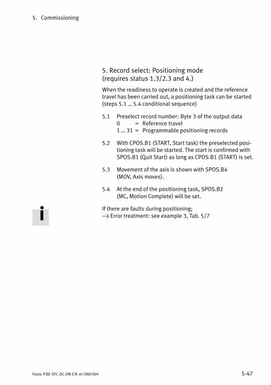
5. Commissioning
5−47Festo P.BE−SFC−DC−DN−EN en 0801NH
5. Record select: Positioning mode (requires status 1.3/2.3 and 4.)
When the readiness to operate is created and the referencetravel has been carried out, a positioning task can be started(steps 5.1 � 5.4 conditional sequence)
5.1 Preselect record number: Byte 3 of the output data0 = Reference travel1 � 31 = Programmable positioning records
5.2 With CPOS.B1 (START, Start task) the preselected posi�tioning task will be started. The start is confirmed withSPOS.B1 (Quit Start) as long as CPOS.B1 (START) is set.
5.3 Movement of the axis is shown with SPOS.B4 (MOV, Axis moves).
5.4 At the end of the positioning task, SPOS.B2 (MC, Motion Complete) will be set.
If there are faults during positioning; } Error treatment: see example 3, Tab.�5/7

5. Commissioning
5−48 Festo P.BE−SFC−DC−DN−EN en 0801NH
Step/D i ti
Output data Input dataDescription Bytes B7 B6 B5 B4 B3 B2 B1 B0 Bytes B7 B6 B5 B4 B3 B2 B1 B0
5.1 Preselect Byte3 Record number Byte 3 Record number5.1 Preselectrecord number(byte 3)
Recordno.
Record no. (0 � 31) Recordno.
Previous record no. (0 � 31)
5.2 Start order Byte 1 OPM2 OPM1 LOCK � RESET BRAKE STOP ENABL Byte 1 OPM2 OPM1 LOCK 24VL FAULT WARN OPEN ENABL5.2 Start order
CCON 0 0 x 0 0 x 1 1 SCON 0 0 0 1 0 0 1 1
Byte 2 � CLEAR TEACH JOGN JOGP HOM START HALT Byte 2 REF STILL DEV MOV TEACH MC ACK HALT
CPOS 0 0 0 0 0 0 F 1 SPOS 1 0 0 0 0 0 1 1
5.3 Order runs Byte 1 OPM2 OPM1 LOCK � RESET BRAKE STOP ENABL Byte 1 OPM2 OPM1 LOCK 24VL FAULT WARN OPEN ENABL5.3 Order runs
CCON 0 0 x 0 0 x 1 1 SCON 0 0 0 1 0 0 1 1
Byte 2 � CLEAR TEACH JOGN JOGP HOM START HALT Byte 2 REF STILL DEV MOV TEACH MC ACK HALT
CPOS 0 0 0 0 0 0 1 1 SPOS 1 0 0 1 0 0 1 1
Byte3 Record number Byte 3 Record number
Recordno.
Record no. (0 � 31) Recordno.
Current record no. (0 � 31)
5.4 Order Byte 1 OPM2 OPM1 LOCK � RESET BRAKE STOP ENABL Byte 1 OPM2 OPM1 LOCK 24VL FAULT WARN OPEN ENABL5.4 Orderconcluded CCON 0 0 x 0 0 x 1 1 SCON 0 0 0 1 0 0 1 1
Byte 2 � CLEAR TEACH JOGN JOGP HOM START HALT Byte 2 REF STILL DEV MOV TEACH MC ACK HALT
CPOS 0 0 0 0 0 0 0 1 SPOS 1 0 0 0 0 1 0 1
Byte 5...8 reserved Byte 5...8 Position
� reserved Actualposi�tion
Actual position (increments)
0: 0−signal1: 1−signalx: not relevant (optional)F: Edge positive
Tab.�5/9: I/O data �Record Select: positioning mode"
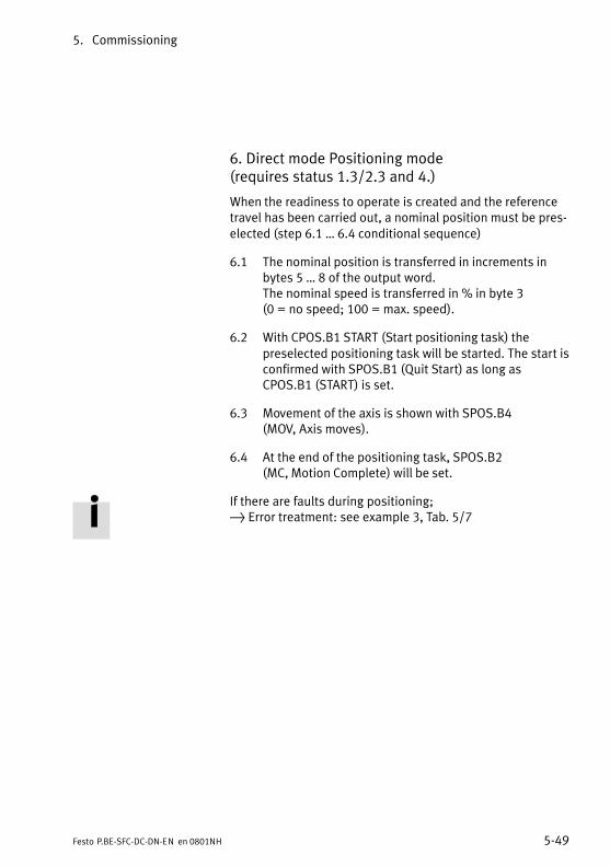
5. Commissioning
5−49Festo P.BE−SFC−DC−DN−EN en 0801NH
6. Direct mode Positioning mode (requires status 1.3/2.3 and 4.)
When the readiness to operate is created and the referencetravel has been carried out, a nominal position must be pres�elected (step 6.1 � 6.4 conditional sequence)
6.1 The nominal position is transferred in increments inbytes 5 � 8 of the output word.The nominal speed is transferred in % in byte 3 (0 = no speed; 100 = max. speed).
6.2 With CPOS.B1 START (Start positioning task) thepreselected positioning task will be started. The start isconfirmed with SPOS.B1 (Quit Start) as long asCPOS.B1 (START) is set.
6.3 Movement of the axis is shown with SPOS.B4 (MOV, Axis moves).
6.4 At the end of the positioning task, SPOS.B2 (MC, Motion Complete) will be set.
If there are faults during positioning; } Error treatment: see example 3, Tab.�5/7

5. Commissioning
5−50 Festo P.BE−SFC−DC−DN−EN en 0801NH
Step/D i ti
Output data Input dataDescription Bytes B7 B6 B5 B4 B3 B2 B1 B0 Bytes B7 B6 B5 B4 B3 B2 B1 B0
6.1 Preselect Byte 4 Velocity Byte 4 Velocity6.1 Preselectposition andspeed (bytes 4 and
Velo−city
Velocity preselect (0 � 100 %)
Velo−city
Velocity reply message (0 � 100 %)
(bytes 4 and 5 � 8) Byte 5...8 Position Byte 5...8 Position5 � 8)
Nominal(target)position
Target position (increments),see section 5.5.2
Actualposition
Actual position (increments),see section 5.5.2
6.2 Start order Byte 1 OPM2 OPM1 LOCK � RESET BRAKE STOP ENABL Byte 1 OPM2 OPM1 LOCK 24VL FAULT WARN OPEN ENABL6.2 Start order
CCON 0 1 x 0 0 x 1 1 SCON 0 1 0 1 0 0 1 1
Byte 2 � CLEAR TEACH JOGN JOGP HOM START HALT Byte 2 REF STILL DEV MOV TEACH MC ACK HALT
CPOS 0 0 0 0 0 0 F 1 SPOS 1 0 0 0 0 0 1 1
Byte 3 FUNC FAST XLIM VLIM CONT COM2 COM1 ABS Byte 3 FUNC FAST XLIM VLIM CONT COM2 COM1 ABS
CDIR 0 0 0 0 0 0 0 S SDIR 0 0 0 0 0 0 0 S
6.3. Order runs Byte 1 OPM2 OPM1 LOCK � RESET BRAKE STOP ENABL Byte 1 OPM2 OPM1 LOCK 24VL FAULT WARN OPEN ENABL6.3. Order runs
CCON 0 1 x 0 0 x 1 1 SCON 0 1 0 1 0 0 1 1
Byte 2 � CLEAR TEACH JOGN JOGP HOM START HALT Byte 2 REF STILL DEV MOV TEACH MC ACK HALT
CPOS 0 0 0 0 0 0 1 1 SPOS 1 0 0 1 0 0 1 1
6.4 Order Byte 1 OPM2 OPM1 LOCK � RESET BRAKE STOP ENABL Byte 1 OPM2 OPM1 LOCK 24VL FAULT WARN OPEN ENABL6.4 Orderconcluded CCON 0 1 x 0 0 x 1 1 SCON 0 1 0 1 0 0 1 1
Byte 2 � CLEAR TEACH JOGN JOGP HOM START HALT Byte 2 REF STILL DEV MOV TEACH MC ACK HALT
CPOS 0 0 0 0 0 0 0 1 SPOS 1 0 0 0 0 1 0 1
0: 0−signal1: 1−signalx: not relevant (optional)F: Edge positiveS: Positioning condition: 0 = absolute
1 = relative
Tab.�5/10: I/O data �Direct mode: positioning mode"

5. Commissioning
5−51Festo P.BE−SFC−DC−DN−EN en 0801NH
7. Direct mode Force control (requires status 1.3/2.3 and 4.)
When the readiness to operate is created and the referencetravel has been carried out, a nominal position must bepreselected and the force control must be prepared.
7.1 Specify the nominal value in % of the rated motorcurrent. (Note frictional influences of the connectedaxis.)
7.2 Prepare force control Set bit CDIR.B1 COM1 and ifdesired set bit CDIR.B5 XLIM for the stroke limitation.
7.3 Start the task with CPOS.B1 START. The start is con�firmed with SPOS.B1 (Quit Start) as long as CPOS.B1(START) is set.
7.4 or 7.5 The relevant bits in the status will be set depending onwhether the nominal value is reached or not.
7.6 The task will be finished automatically when the strokelimit or software end position is reached. Switching ismade again to position control.
7.7 The task can be discontinued by the controller e.�g.with STOP.
Please noteModification of the nominal value with force control is onlypossible with a new starting edge when the last specifiedposition (MC) has been reached.
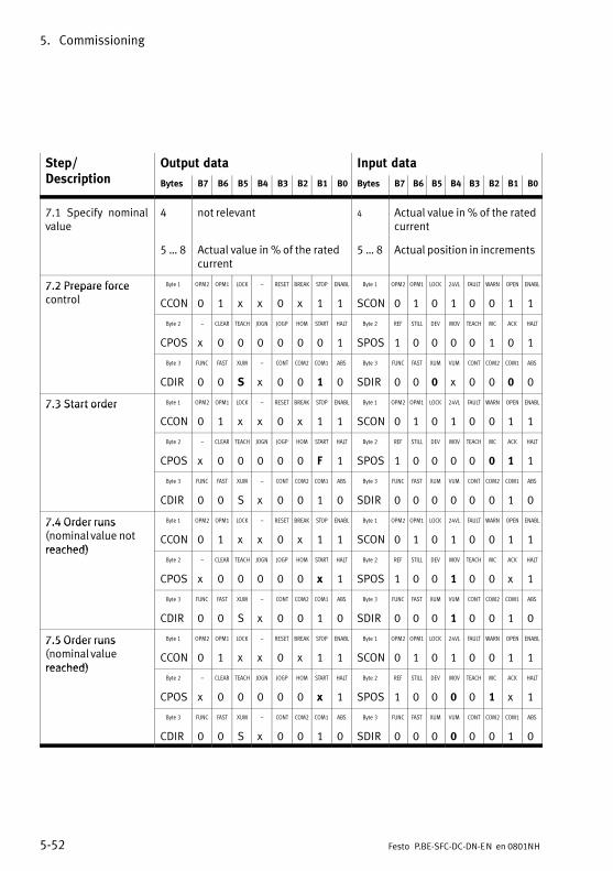
5. Commissioning
5−52 Festo P.BE−SFC−DC−DN−EN en 0801NH
Step/D i ti
Output data Input dataDescription Bytes B7 B6 B5 B4 B3 B2 B1 B0 Bytes B7 B6 B5 B4 B3 B2 B1 B0
7.1 Specify nominalvalue
4 not relevant 4 Actual value in % of the ratedcurrent
5 � 8 Actual value in % of the ratedcurrent
5 � 8 Actual position in increments
7.2 Prepare force Byte 1 OPM2 OPM1 LOCK � RESET BREAK STOP ENABL Byte 1 OPM2 OPM1 LOCK 24VL FAULT WARN OPEN ENABL7.2 Prepare forcecontrol CCON 0 1 x x 0 x 1 1 SCON 0 1 0 1 0 0 1 1
Byte 2 � CLEAR TEACH JOGN JOGP HOM START HALT Byte 2 REF STILL DEV MOV TEACH MC ACK HALT
CPOS x 0 0 0 0 0 0 1 SPOS 1 0 0 0 0 1 0 1
Byte 3 FUNC FAST XUM � CONT COM2 COM1 ABS Byte 3 FUNC FAST XUM VUM CONT COM2 COM1 ABS
CDIR 0 0 S x 0 0 1 0 SDIR 0 0 0 x 0 0 0 0
7.3 Start order Byte 1 OPM2 OPM1 LOCK � RESET BREAK STOP ENABL Byte 1 OPM2 OPM1 LOCK 24VL FAULT WARN OPEN ENABL7.3 Start order
CCON 0 1 x x 0 x 1 1 SCON 0 1 0 1 0 0 1 1
Byte 2 � CLEAR TEACH JOGN JOGP HOM START HALT Byte 2 REF STILL DEV MOV TEACH MC ACK HALT
CPOS x 0 0 0 0 0 F 1 SPOS 1 0 0 0 0 0 1 1
Byte 3 FUNC FAST XUM � CONT COM2 COM1 ABS Byte 3 FUNC FAST XUM VUM CONT COM2 COM1 ABS
CDIR 0 0 S x 0 0 1 0 SDIR 0 0 0 0 0 0 1 0
7.4 Order runs Byte 1 OPM2 OPM1 LOCK � RESET BREAK STOP ENABL Byte 1 OPM2 OPM1 LOCK 24VL FAULT WARN OPEN ENABL7.4 Order runs (nominal value notreached)
CCON 0 1 x x 0 x 1 1 SCON 0 1 0 1 0 0 1 1reached)
Byte 2 � CLEAR TEACH JOGN JOGP HOM START HALT Byte 2 REF STILL DEV MOV TEACH MC ACK HALT
CPOS x 0 0 0 0 0 x 1 SPOS 1 0 0 1 0 0 x 1
Byte 3 FUNC FAST XUM � CONT COM2 COM1 ABS Byte 3 FUNC FAST XUM VUM CONT COM2 COM1 ABS
CDIR 0 0 S x 0 0 1 0 SDIR 0 0 0 1 0 0 1 0
7.5 Order runs Byte 1 OPM2 OPM1 LOCK � RESET BREAK STOP ENABL Byte 1 OPM2 OPM1 LOCK 24VL FAULT WARN OPEN ENABL7.5 Order runs (nominal valuereached)
CCON 0 1 x x 0 x 1 1 SCON 0 1 0 1 0 0 1 1reached)
Byte 2 � CLEAR TEACH JOGN JOGP HOM START HALT Byte 2 REF STILL DEV MOV TEACH MC ACK HALT
CPOS x 0 0 0 0 0 x 1 SPOS 1 0 0 0 0 1 x 1
Byte 3 FUNC FAST XUM � CONT COM2 COM1 ABS Byte 3 FUNC FAST XUM VUM CONT COM2 COM1 ABS
CDIR 0 0 S x 0 0 1 0 SDIR 0 0 0 0 0 0 1 0
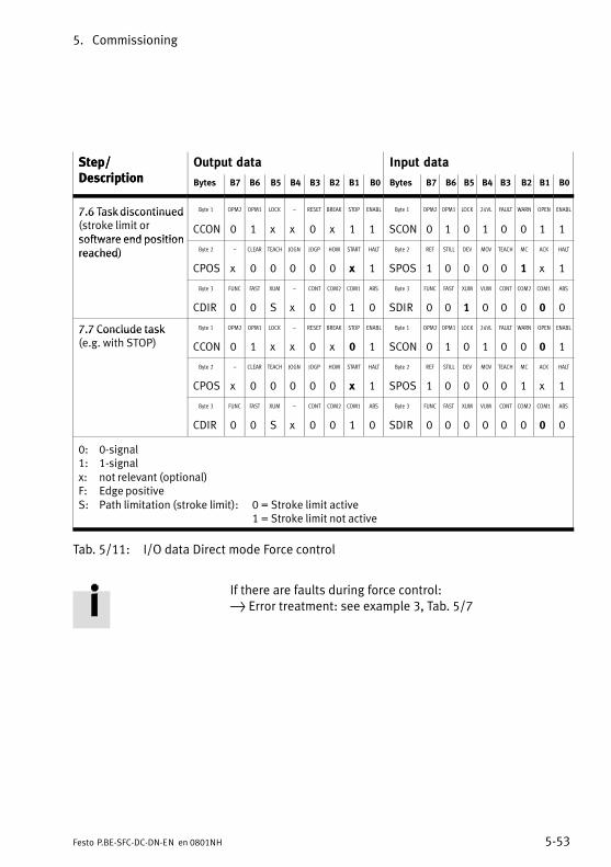
5. Commissioning
5−53Festo P.BE−SFC−DC−DN−EN en 0801NH
Step/Description
Input dataOutput dataStep/Description B0B1B2B3B4B5B6B7BytesB0B1B2B3B4B5B6B7Bytes
7.6 Task discontinued Byte 1 OPM2 OPM1 LOCK � RESET BREAK STOP ENABL Byte 1 OPM2 OPM1 LOCK 24VL FAULT WARN OPEN ENABL7.6 Task discontinued(stroke limit orsoftware end position
CCON 0 1 x x 0 x 1 1 SCON 0 1 0 1 0 0 1 1software end positionreached) Byte 2 � CLEAR TEACH JOGN JOGP HOM START HALT Byte 2 REF STILL DEV MOV TEACH MC ACK HALTreached)
CPOS x 0 0 0 0 0 x 1 SPOS 1 0 0 0 0 1 x 1
Byte 3 FUNC FAST XUM � CONT COM2 COM1 ABS Byte 3 FUNC FAST XUM VUM CONT COM2 COM1 ABS
CDIR 0 0 S x 0 0 1 0 SDIR 0 0 1 0 0 0 0 0
7.7 Conclude task Byte 1 OPM2 OPM1 LOCK � RESET BREAK STOP ENABL Byte 1 OPM2 OPM1 LOCK 24VL FAULT WARN OPEN ENABL7.7 Conclude task(e.g. with STOP) CCON 0 1 x x 0 x 0 1 SCON 0 1 0 1 0 0 0 1
Byte 2 � CLEAR TEACH JOGN JOGP HOM START HALT Byte 2 REF STILL DEV MOV TEACH MC ACK HALT
CPOS x 0 0 0 0 0 x 1 SPOS 1 0 0 0 0 1 x 1
Byte 3 FUNC FAST XUM � CONT COM2 COM1 ABS Byte 3 FUNC FAST XUM VUM CONT COM2 COM1 ABS
CDIR 0 0 S x 0 0 1 0 SDIR 0 0 0 0 0 0 0 0
0: 0−signal1: 1−signalx: not relevant (optional)F: Edge positiveS: Path limitation (stroke limit): 0 = Stroke limit active
1 = Stroke limit not active
Tab.�5/11: I/O data Direct mode Force control
If there are faults during force control: } Error treatment: see example 3, Tab.�5/7
5. Commissioning
5−54 Festo P.BE−SFC−DC−DN−EN en 0801NH
5.6 Sequence control as per FHPP standard
5.6.1 Homing run
Information on homing runs, reference coordinates and andcalculating specifications in the reference system can befound under section 1.6.
When the operating voltage is switched on, it is a prerequisitewith electric mini slide SLTE that reference travel is completedbefore a positioning task can be carried out (the parameter�Homimg Required" � PNU 1014 � must = 1).
The drive references against a stop or a reference switch. Anincrease in the motor current indicates that a stop has beenreached. As the drive must not continuously referenceagainst the stop, it must move at least one millimetre backinto the stroke range.
Sequence
1. Search for the reference point in accordance with theconfigured method.
2. Move relative to the reference point around the�Offset�Axis Zero Point".
3. Set at axis zero point: Current position = 0 � project zero offset
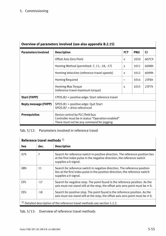
5. Commissioning
5−55Festo P.BE−SFC−DC−DN−EN en 0801NH
Overview of parameters involved (see also appendix B.2.15)
Parameters involved Description FCT PNU CI
Offset Axis Zero Point x 1010 607Ch
Homing Method (permitted: 7, 11, −18, −17) x 1011 6098h
Homimg Velocities (reference travel speeds) x 1012 6099h
Homing Required � 1014 23F6h
Homimg Max Torque (reference travel maximum torque)
x 1015 23F7h
Start (FHPP) CPOS.B2 = positive edge: Start reference travel
Reply message (FHPP) SPOS.B1 = positive edge: Quit StartSPOS.B7 = drive referenced
Prerequisites Device control by PLC/field busController must be in status �Operation enabled"There must not be any command for jogging
Tab.�5/12: Parameters involved in reference travel
Reference travel methods 1)
hex dec. Description
07h 7 Search for reference switch in positive direction. The reference position liesat the first index pulse in the negative direction; the reference switchsupplies a 0−signal.
0Bh 11 Search for reference switch in negative direction. The reference positionlies at the first index pulse in the positive direction; the reference switchsupplies a 0−signal.
EFh −17 Search for negative stop. The point found is the reference position. As theaxis must not stand still at the stop, the offset axis zero point must be � 0.
EEh −18 Search for positive stop. The point found is the reference position. As theaxis must not stand still at the stop, the offset axis zero point must be � 0.
1) Detailed description of the reference travel methods see section 5.2.2.
Tab.�5/13: Overview of reference travel methods
5. Commissioning
5−56 Festo P.BE−SFC−DC−DN−EN en 0801NH
5.6.2 Jog mode
In the status �Enable operation" the drive can be moved tothe left/right by typing. This function is usually used for:
� moving to teach positions.
� moving the drive out of the way (e. g. after a system fault)
� manual positioning as normal operating mode (hand−operated feed).
Sequence
1. When one of the signals �Jog left/Jog right" is set, thedrive starts to move slowly. Due to the slow speed, aposition can be defined very accurately.
2. If the signal remains set for longer than the configured�Time Phase 1", the speed is increased until theconfigured maximum speed is reached. In this way largestrokes can be traversed quickly.
3. If the signal changes to 0, the drive is braked with thepre−set maximum deceleration.
4. If the drive reaches a software end position, it will stopautomatically. The software end position is not exceeded,the path for stopping depends on the ramp set. The jogmode can be exited here with Jogging = 0.
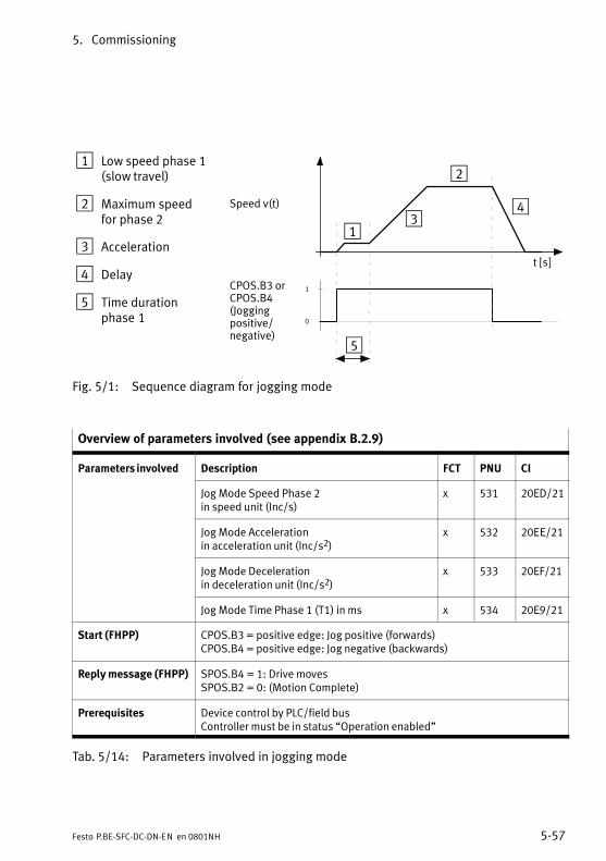
5. Commissioning
5−57Festo P.BE−SFC−DC−DN−EN en 0801NH
1 Low speed phase 1(slow travel)
2 Maximum speed for phase 2
3 Acceleration
4 Delay
5 Time durationphase�1
CPOS.B3 orCPOS.B4 (Jogging positive/negative)
Speed v(t)
t [s]
1
0
1
2
34
5
Fig.�5/1: Sequence diagram for jogging mode
Overview of parameters involved (see appendix B.2.9)
Parameters involved Description FCT PNU CI
Jog Mode Speed Phase 2 in speed unit (Inc/s)
x 531 20ED/21
Jog Mode Acceleration in acceleration unit (Inc/s2)
x 532 20EE/21
Jog Mode Deceleration in deceleration unit (Inc/s2)
x 533 20EF/21
Jog Mode Time Phase 1 (T1) in ms x 534 20E9/21
Start (FHPP) CPOS.B3 = positive edge: Jog positive (forwards)CPOS.B4 = positive edge: Jog negative (backwards)
Reply message (FHPP) SPOS.B4 = 1: Drive movesSPOS.B2 = 0: (Motion Complete)
Prerequisites Device control by PLC/field busController must be in status �Operation enabled"
Tab.�5/14: Parameters involved in jogging mode
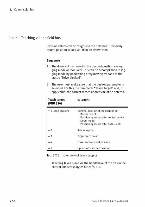
5. Commissioning
5−58 Festo P.BE−SFC−DC−DN−EN en 0801NH
5.6.3 Teaching via the field bus
Position values can be taught via the field bus. Previouslytaught position values will then be overwritten.
Sequence
1. The drive will be moved to the desired position via jog�ging mode or manually. This can be accomplished in jog�ging mode by positioning or by moving by hand in thestatus �Drive blocked".
2. The user must make sure that the desired parameter isselected. For this the parameter �Teach Target" and, ifapplicable, the correct record address must be entered.
Teach target (PNU 520)
is taught
= 1 (specification) Nominal position of the position set� Record select:
Positioning record after control byte 3� Direct mode:
Positioning record after PNU = 400
= 2 Axis zero point
= 3 Project zero point
= 4 Lower software end position
= 5 Upper software end position
Tab.�5/15: Overview of teach targets
3. Teaching takes place via the handshake of the bits in thecontrol and status bytes CPOS/SPOS.
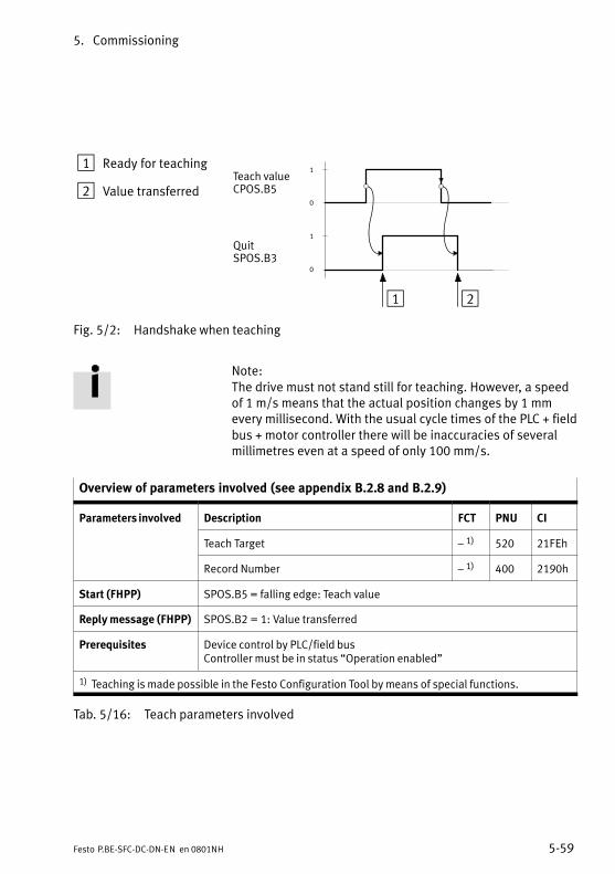
5. Commissioning
5−59Festo P.BE−SFC−DC−DN−EN en 0801NH
1 Ready for teaching
2 Value transferred
1
0
QuitSPOS.B3
Teach valueCPOS.B5
1 2
1
0
Fig.�5/2: Handshake when teaching
Note: The drive must not stand still for teaching. However, a speedof 1 m/s means that the actual position changes by 1 mmevery millisecond. With the usual cycle times of the PLC + fieldbus + motor controller there will be inaccuracies of severalmillimetres even at a speed of only 100 mm/s.
Overview of parameters involved (see appendix B.2.8 and B.2.9)
Parameters involved Description FCT PNU CI
Teach Target � 1) 520 21FEh
Record Number � 1) 400 2190h
Start (FHPP) SPOS.B5 = falling edge: Teach value
Reply message (FHPP) SPOS.B2 = 1: Value transferred
Prerequisites Device control by PLC/field busController must be in status �Operation enabled"
1) Teaching is made possible in the Festo Configuration Tool by means of special functions.
Tab.�5/16: Teach parameters involved
5. Commissioning
5−60 Festo P.BE−SFC−DC−DN−EN en 0801NH
5.6.4 Record select (positioning mode)
A record can be started in the status �Operation enabled". This function is usually used for:
� moving to any position in the record list by the PLC
� processing a positioning profile by linking records,
� known target positions which seldom change (formulation change).
Sequence
1. Set the desired record number in the output data of themaster. Up till the start the controller replies with thenumber of the record last processed.
2. With a rising edge at START (CPOS.B1) the controller ac�cepts the record number and starts the positioning task.
3. The controller signalizes with the rising edge at Quit Startthat the PLC output data have been accepted and that thepositioning task is now active. The positioning commandwill be processed irrespective of whether Start (CPOS.B1)has been reset to zero or not.
4. When the record is concluded, MC (SPOS.B2) is set.
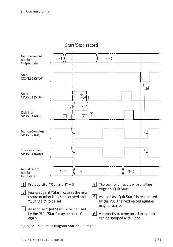
5. Commissioning
5−61Festo P.BE−SFC−DC−DN−EN en 0801NH
Start/Stop record
Nominal recordnumber Output data
StopCCON.B1 (STOP)
Quit StartSPOS.B1 (ACK)
Motion CompleteSPOS.B2 (MC)
Actual recordnumberInput data
N − 1 N N + 1
N − 1 N
1
0
1
0
1
0
1
0
1
0
1
2
3
4
6
1
0
1
0
The axis movesSPOS.B4 (MOV)
StartCPOS.B1 (START)
N + 1
5
1 Prerequisite: �Quit Start" = 0
2 Rising edge at �Start" causes the newrecord number N to be accepted and�Quit Start" to be set
3 As soon as �Quit Start" is recognisedby the PLC, �Start" may be set to 0again
4 The controller reacts with a fallingedge at �Quit Start"
5 As soon as �Quit Start" is recognisedby the PLC, the next record numbermay be started
6 A currently running positioning taskcan be stopped with �Stop"
Fig.�5/3: Sequence diagram Start/Stop record
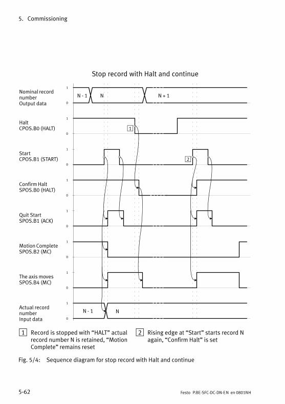
5. Commissioning
5−62 Festo P.BE−SFC−DC−DN−EN en 0801NH
Stop record with Halt and continue
Nominal recordnumber Output data
Quit StartSPOS.B1 (ACK)
Motion CompleteSPOS.B2 (MC)
Actual recordnumberInput data
N − 1 N N + 1
N − 1 N
1
0
1
0
1
0
1
0
1
0
1
0
The axis movesSPOS.B4 (MC)
HaltCPOS.B0 (HALT)
1
0
StartCPOS.B1 (START)
1
0
Confirm HaltSPOS.B0 (HALT)
1
2
1 Record is stopped with �HALT" actualrecord number N is retained, �MotionComplete" remains reset
2 Rising edge at �Start" starts record Nagain, �Confirm Halt" is set
Fig.�5/4: Sequence diagram for stop record with Halt and continue
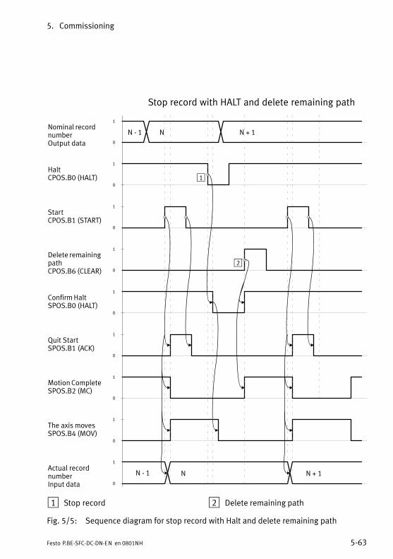
5. Commissioning
5−63Festo P.BE−SFC−DC−DN−EN en 0801NH
Stop record with HALT and delete remaining path
Nominal recordnumber Output data
Quit StartSPOS.B1 (ACK)
Motion CompleteSPOS.B2 (MC)
Actual recordnumberInput data
N − 1 N N + 1
N − 1 N
1
0
1
0
1
0
1
0
1
0
1
0
The axis movesSPOS.B4 (MOV)
HaltCPOS.B0 (HALT)
N + 1
1
0
StartCPOS.B1 (START)
Delete remainingpathCPOS.B6 (CLEAR)
1
0
1
0
Confirm HaltSPOS.B0 (HALT)
1
2
1 Stop record 2 Delete remaining path
Fig.�5/5: Sequence diagram for stop record with Halt and delete remaining path
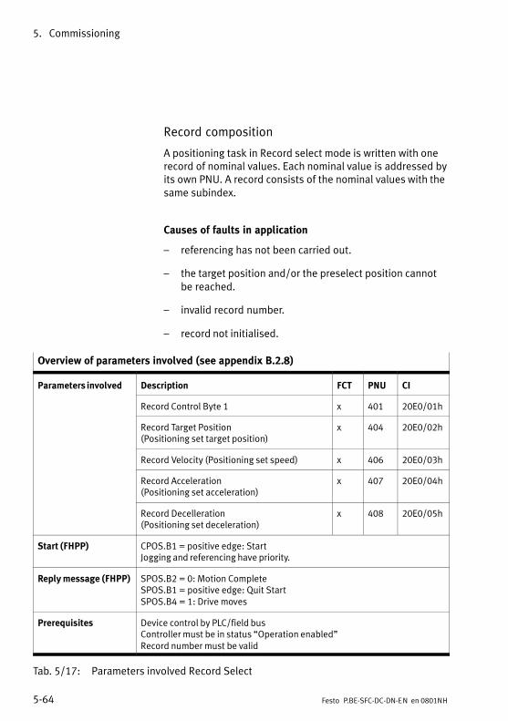
5. Commissioning
5−64 Festo P.BE−SFC−DC−DN−EN en 0801NH
Record composition
A positioning task in Record select mode is written with onerecord of nominal values. Each nominal value is addressed byits own PNU. A record consists of the nominal values with thesame subindex.
Causes of faults in application
� referencing has not been carried out.
� the target position and/or the preselect position cannotbe reached.
� invalid record number.
� record not initialised.
Overview of parameters involved (see appendix B.2.8)
Parameters involved Description FCT PNU CI
Record Control Byte 1 x 401 20E0/01h
Record Target Position (Positioning set target position)
x 404 20E0/02h
Record Velocity (Positioning set speed) x 406 20E0/03h
Record Acceleration (Positioning set acceleration)
x 407 20E0/04h
Record Decelleration (Positioning set deceleration)
x 408 20E0/05h
Start (FHPP) CPOS.B1 = positive edge: StartJogging and referencing have priority.
Reply message (FHPP) SPOS.B2 = 0: Motion CompleteSPOS.B1 = positive edge: Quit StartSPOS.B4 = 1: Drive moves
Prerequisites Device control by PLC/field busController must be in status �Operation enabled"Record number must be valid
Tab.�5/17: Parameters involved Record Select
5. Commissioning
5−65Festo P.BE−SFC−DC−DN−EN en 0801NH
5.6.5 Direct mode (positioning mode, force control)
In the status �Operation enabled" (Direct mode) a positioningtask is formulated directly in the I/O data which are trans�mitted via the field bus. The nominal values for the positionare therefore held in the PLC. The function is used in the fol�lowing situations:
� moving to any position within the work stroke.
� the target positions are unknown during planning orchange frequently (several different work item positions).
A positioning profile formed by linking records can be im�plemented externally controlled by the master.
Sequence of discrete nominal value
1. The user sets the desired nominal value (position) and thepositioning condition (absolute/relative) in his outputdata.
2. With a rising edge at START (CPOS.B1) the controller ac�cepts the nominal position and starts the positioning task.
3. After the start you must wait for MC before a new startcan be made.
4. When the nominal position is reached, MC (SPOS.B2)is�set.
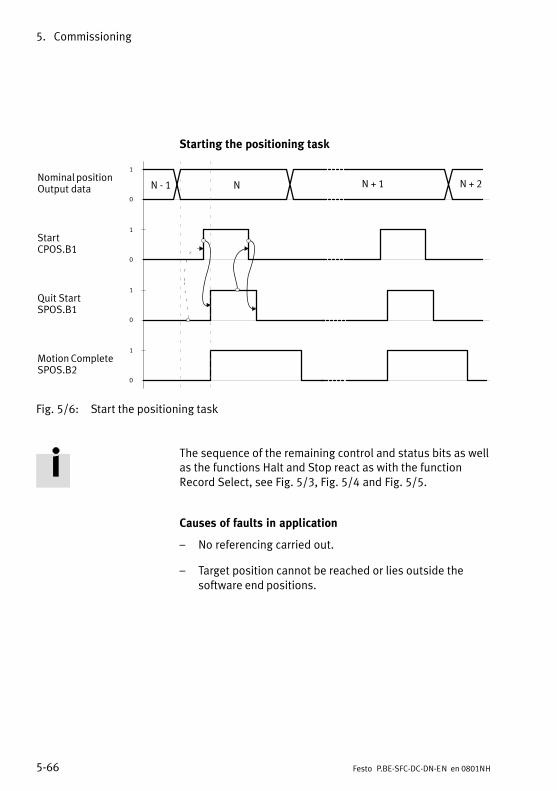
5. Commissioning
5−66 Festo P.BE−SFC−DC−DN−EN en 0801NH
Starting the positioning task
Nominal position Output data
StartCPOS.B1
Quit StartSPOS.B1
Motion CompleteSPOS.B2
N − 1 N N + 1
1
0
1
0
1
0
1
0
N + 2
Fig.�5/6: Start the positioning task
The sequence of the remaining control and status bits as wellas the functions Halt and Stop react as with the functionRecord Select, see Fig.�5/3, Fig.�5/4 and Fig.�5/5.
Causes of faults in application
� No referencing carried out.
� Target position cannot be reached or lies outside thesoftware end positions.
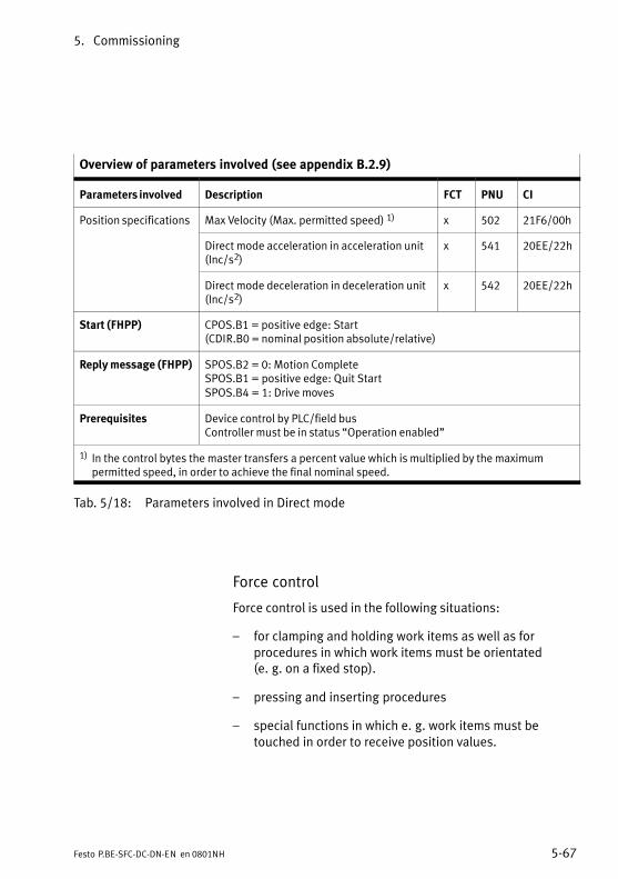
5. Commissioning
5−67Festo P.BE−SFC−DC−DN−EN en 0801NH
Overview of parameters involved (see appendix B.2.9)
Parameters involved Description FCT PNU CI
Position specifications Max Velocity (Max. permitted speed) 1) x 502 21F6/00h
Direct mode acceleration in acceleration unit(Inc/s2)
x 541 20EE/22h
Direct mode deceleration in deceleration unit(Inc/s2)
x 542 20EE/22h
Start (FHPP) CPOS.B1 = positive edge: Start(CDIR.B0 = nominal position absolute/relative)
Reply message (FHPP) SPOS.B2 = 0: Motion CompleteSPOS.B1 = positive edge: Quit StartSPOS.B4 = 1: Drive moves
Prerequisites Device control by PLC/field busController must be in status �Operation enabled"
1) In the control bytes the master transfers a percent value which is multiplied by the maximumpermitted speed, in order to achieve the final nominal speed.
Tab.�5/18: Parameters involved in Direct mode
Force control
Force control is used in the following situations:
� for clamping and holding work items as well as forprocedures in which work items must be orientated (e.�g. on a fixed stop).
� pressing and inserting procedures
� special functions in which e.�g. work items must betouched in order to receive position values.
5. Commissioning
5−68 Festo P.BE−SFC−DC−DN−EN en 0801NH
Notes on force controlControl of the motor torque takes place indirectly bymeans of the current regulation. All specifications onforces/torques refer to the rated motor torque (relative tothe rated motor current). The actual force at the axisshould be calculated/checked and then set with externalmeasuring devices during commissioning.
Please noteThe following settings are required for parametrizing theforce control (see Tab.�5/19):
� power window (permitted deviation from the nominalvalue ascertained by the field bus).
� speed limitation (maximum speed which the driveshould reach). Without this specification the drive wouldaccelerate unbraked if there is no counter force (e.�g. work item missing).
� rest time (time during which the nominal force must beapplied, before �Motion Complete" is triggered).
· Extend the rest time if the nominal force is alreadyachieved briefly due to the increased torque whenstarting (before reaching the work item).
Force control is prepared when the control mode is switchedover. The drive stands with the position controlled.

5. Commissioning
5−69Festo P.BE−SFC−DC−DN−EN en 0801NH
Sequence
1. The user sets the desired nominal value (in % of the ratedmotor torque) and the speed limitation in his output data.
2. With the rising edge at Start (CPOS.B1) the controller accepts the nominal torque and builds up the force/torque in the direction of the sign of the nominal value.
� When this speed has been reached, the bit�Speed�limit reached" is set (status byte SDIR).
� When the nominal value has been reached, taking intoaccount the target window and the time window, the�MC" signal is set. The motor current will still be con�trolled.
� If there is a resistance e.�g. by a work item in the posi�tioning range, the drive will press against the obstruc�tion with a defined force (see Fig.�5/7).
� If the path set in the path/stroke monitoring (relativeto the starting position) is exceeded, the bit �Strokelimit reached" will be set in the status byte SDIR. Thedrive is braked with the emergency stop ramp, heldwith the position controlled at the current position,and the �MC signal" is set.
Causes of faults
� No referencing carried out.
� Axis stands at the start of the positioning task in thesoftware end position.
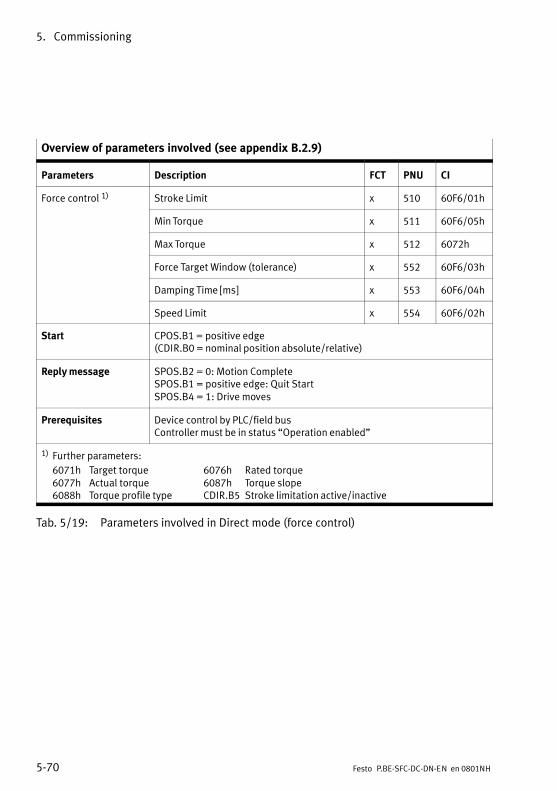
5. Commissioning
5−70 Festo P.BE−SFC−DC−DN−EN en 0801NH
Overview of parameters involved (see appendix B.2.9)
Parameters Description FCT PNU CI
Force control 1) Stroke Limit x 510 60F6/01h
Min Torque x 511 60F6/05h
Max Torque x 512 6072h
Force Target Window (tolerance) x 552 60F6/03h
Damping Time [ms] x 553 60F6/04h
Speed Limit x 554 60F6/02h
Start CPOS.B1 = positive edge(CDIR.B0 = nominal position absolute/relative)
Reply message SPOS.B2 = 0: Motion CompleteSPOS.B1 = positive edge: Quit StartSPOS.B4 = 1: Drive moves
Prerequisites Device control by PLC/field busController must be in status �Operation enabled"
1) Further parameters:
6071h Target torque 6076h Rated torque6077h Actual torque 6087h Torque slope6088h Torque profile type CDIR.B5 Stroke limitation active/inactive
Tab.�5/19: Parameters involved in Direct mode (force control)
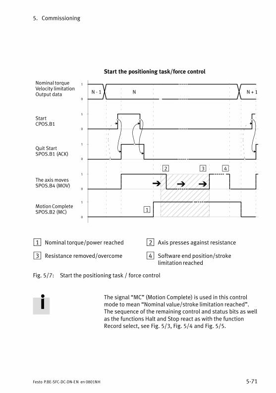
5. Commissioning
5−71Festo P.BE−SFC−DC−DN−EN en 0801NH
Start the positioning task/force control
ÏÏÏÏÏÏÏÏÏÏÏÏÏÏÏÏÏÏÏÏÏÏÏÏÏÏÏÏÏÏ
Nominal torqueVelocity limitation Output data
StartCPOS.B1
Quit StartSPOS.B1 (ACK)
Motion CompleteSPOS.B2 (MC)
N − 1 N N + 1
1
0
1
0
1
0
1
0
1
0
The axis movesSPOS.B4 (MOV)
1
2 3 4
1 Nominal torque/power reached 2 Axis presses against resistance
3 Resistance removed/overcome 4 Software end position/strokelimitation reached
Fig.�5/7: Start the positioning task / force control
The signal �MC" (Motion Complete) is used in this controlmode to mean �Nominal value/stroke limitation reached".The sequence of the remaining control and status bits as wellas the functions Halt and Stop react as with the functionRecord select, see Fig.�5/3, Fig.�5/4 and Fig.�5/5.
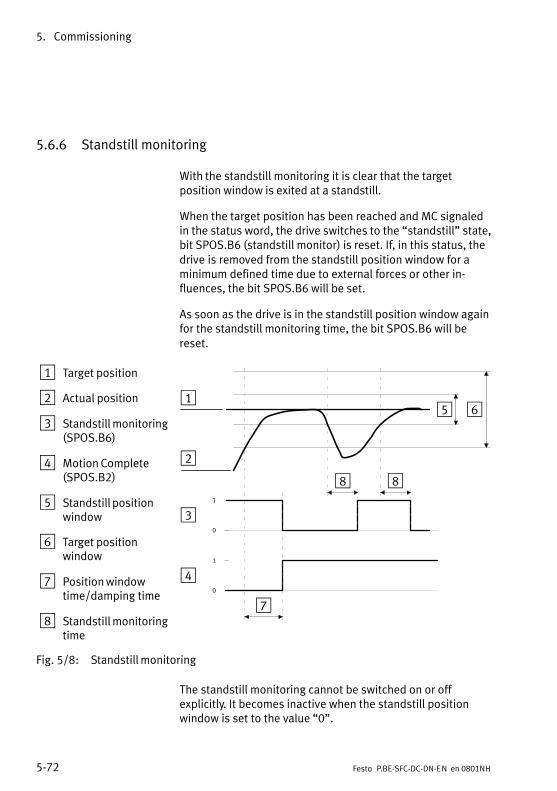
5. Commissioning
5−72 Festo P.BE−SFC−DC−DN−EN en 0801NH
5.6.6 Standstill monitoring
With the standstill monitoring it is clear that the targetposition window is exited at a standstill.
When the target position has been reached and MC signaledin the status word, the drive switches to the �standstill" state,bit SPOS.B6 (standstill monitor) is reset. If, in this status, thedrive is removed from the standstill position window for aminimum defined time due to external forces or other in�fluences, the bit SPOS.B6 will be set.
As soon as the drive is in the standstill position window againfor the standstill monitoring time, the bit SPOS.B6 will bereset.
1 Target position
2 Actual position
3 Standstill monitoring(SPOS.B6)
4 Motion Complete(SPOS.B2)
5 Standstill positionwindow
6 Target positionwindow
7 Position windowtime/damping time
8 Standstill monitoringtime
1
0
1
0
1
2
3
4
5 6
7
88
Fig.�5/8: Standstill monitoring
The standstill monitoring cannot be switched on or offexplicitly. It becomes inactive when the standstill positionwindow is set to the value �0".

5. Commissioning
5−73Festo P.BE−SFC−DC−DN−EN en 0801NH
Overview of parameters involved (see appendix B.2.15)
Parameters involved Description FCT PNU CI
Position Demand Value (Nominal position) � 1040 6062h
Position Actual Value (Current position) � 1041 6064h
Standstill Position Window � 1042 2040h
Standstill Timeout (standstill monitoring time) � 1043 2041h
Position Window Time (positioning mode) � 1023 6068h
Damping Time (force control) � 553 60F6h
Start (FHPP) SPOS.B2 = positive edge: Motion Complete
Reply message (FHPP) SPOS.B6 = 1: Drive has moved out of standstill position window
Prerequisites Device control by PLC/field busController must be in status �Operation enabled"
Tab.�5/20: Parameters involved in standstill monitoring
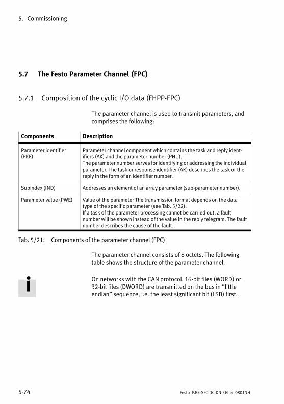
5. Commissioning
5−74 Festo P.BE−SFC−DC−DN−EN en 0801NH
5.7 The Festo Parameter Channel (FPC)
5.7.1 Composition of the cyclic I/O data (FHPP−FPC)
The parameter channel is used to transmit parameters, andcomprises the following:
Components Description
Parameter identifier(PKE)
Parameter channel component which contains the task and reply ident�ifiers (AK) and the parameter number (PNU).The parameter number serves for identifying or addressing the individualparameter. The task or response identifier (AK) describes the task or thereply in the form of an identifier number.
Subindex (IND) Addresses an element of an array parameter (sub−parameter number).
Parameter value (PWE) Value of the parameter The transmission format depends on the datatype of the specific parameter (see Tab.�5/22).If a task of the parameter processing cannot be carried out, a faultnumber will be shown instead of the value in the reply telegram. The faultnumber describes the cause of the fault.
Tab.�5/21: Components of the parameter channel (FPC)
The parameter channel consists of 8 octets. The followingtable shows the structure of the parameter channel.
On networks with the CAN protocol. 16−bit files (WORD) or32−bit files (DWORD) are transmitted on the bus in �littleendian" sequence, i.e. the least significant bit (LSB) first.

5. Commissioning
5−75Festo P.BE−SFC−DC−DN−EN en 0801NH
FPC
Byte 1 Byte 2 Byte 3 Byte 4 Byte 5 Byte 6 Byte 7 Byte 8
MSB/LSB MSB LSB MSB ... ... LSB
Format Byte Byte WORD DWORD 1)
Output data 0 IND ParID (PKE) Value (PWE)
Input data 0 IND ParID (PKE) Value (PWE)
MSB:LSB:IND:
ParID:
Most significant byte
Least significant byte
Subindex − for addressing an array element
Parameter Identifier −
consisting of ReqID / ResID and PNU
1) Value
(PWE)
Parameter Value.
� with double word: bytes 5 ... 8
� with word: bytes 7, 8
� with byte: Byte 8
Tab.�5/22: Structure of parameter channel (FPC)
Parameter identifier (PKE)
The parameter identifier contains the task or response ident�ifier (AK) and the parameter number (PNU).
PKE
Byte 3 Byte 4
Bit 15 14 13 12 11 10 9 8 7 6 5 4 3 2 1 0
Task ReqID (AK) res. Parameter number (PNU)
Reply ResID (AK) res. Parameter number (PNU)
ReqID (AK) Request Identifier � task identifier (read, write, ...)
ResID (AK) Response identifier � response identifier (transfer value, fault, ...)
Value (PNU) Parameter Number � serves to identify or address the respective
parameter (see section 5.7). The task or response identifier distinguishes
the type of task or response (see section 5.7.2).
Tab.�5/23: Structure of parameter identifier (PKE)
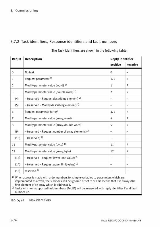
5. Commissioning
5−76 Festo P.BE−SFC−DC−DN−EN en 0801NH
5.7.2 Task identifiers, Response identifiers and fault numbers
The Task identifiers are shown in the following table:
ReqID Description Reply identifier
positive negative
0 No task 0 �
1 Request parameter 1) 1, 2 7
2 Modify parameter value (word) 1) 1 7
3 Modify parameter value (double word) 1) 2 7
(4) � (reserved � Request describing element) 2) � �
(5) � (reserved � Modify describing element) 2) � �
6 Request parameter (array) 4, 5 7
7 Modify parameter value (array, word) 4 7
8 Modify parameter value (array, double word) 5 7
(9) � (reserved � Request number of array elements) 2) � �
(10) � (reserved) 2) � �
11 Modify parameter value (byte) 1) 11 7
12 Modify parameter value (array, byte) 12 7
(13) � (reserved � Request lower limit value) 2) � �
(14) � (reserved � Request upper limit value) 2) � �
(15) reserved 2) � �
1) When access is made with order numbers for simple variables to parameters which areimplemented as arrays, the subindex will be ignored or set to 0. This means that it is always thefirst element of an array which is addressed.
2) Tasks with non−supported task numbers (ReqID) will be answered with reply identifier 7 and faultnumber 22.
Tab.�5/24: Task identifiers
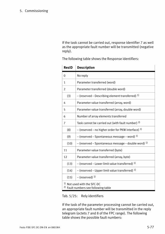
5. Commissioning
5−77Festo P.BE−SFC−DC−DN−EN en 0801NH
If the task cannot be carried out, response identifier 7 as wellas the appropriate fault number will be transmitted (negativereply).
The following table shows the Response identifiers:
ResID Description
0 No reply
1 Parameter transferred (word)
2 Parameter transferred (double word)
(3) � (reserved � Describing element transferred) 1)
4 Parameter value transferred (array, word)
5 Parameter value transferred (array, double word)
6 Number of array elements transferred
7 Task cannot be carried out (with fault number) 2)
(8) � (reserved � no higher order for PKW interface) 1)
(9) � (reserved � Spontaneous message � word) 1)
(10) � (reserved � Spontaneous message � double word) 1)
11 Parameter value transferred (byte)
12 Parameter value transferred (array, byte)
(13) � (reserved � Lower limit value transferred) 1)
(14) � (reserved � Upper limit value transferred) 1)
(15) � (reserved) 1)
1) Not used with the SFC−DC2) Fault numbers see following table
Tab.�5/25: Rely identifiers
If the task of the parameter processing cannot be carried out,an appropriate fault number will be transmitted in the replytelegram (octets 7 and 8 of the FPC range). The followingtable shows the possible fault numbers:

5. Commissioning
5−78 Festo P.BE−SFC−DC−DN−EN en 0801NH
Fault numbers Description
0 0x00 Non−permitted PNU The parameter does not exist.
1 0x01 Parameter value cannot be modified (read only)
(2) 0x02 � (reserved � lower or upper limit value exceeded) 1)
3 0x03 Faulty subindex
4 0x04 No array
5 0x05 Incorrect data type
(6) 0x06 � (reserved � setting not permitted � can only be reset) 1)
(7) 0x07 � (reserved � describing element cannot be modified) 1)
(8) 0x08 � (reserved � PPO−Write requested in IR does not exist) 1)
9 0x09 Description data do not exist
(10) 0x10 � (reserved � access group incorrect) 1)
11 0x0A No higher−order
(12) 0x0B � (reserved � password incorrect) 1)
13 0x0C Text not legible in cyclic exchange
(14) 0x0D � (reserved � name not legible in cyclic exchange) 1)
(15) 0x0E � (reserved � text array does not exist) 1)
(16) 0x10 � (reserved � PPO−Write missing) 1)
(17) 0x11 � (reserved � order cannot be processed because of operating status) 1)
(18) 0x12 � (reserved � other faults) 1)
(19) 0x13 � (reserved � date not legible in cyclic exchange) 1)
(20) 0x14 � (reserved � non−permitted value) 1)
(21) 0x15 � (reserved � reply too long) 1)
22 0x16 Non−permitted: Attributes, number of elements, PNU or IND
(23) 0x17 � (reserved � Write request: non−permitted format) 1)
24 0x18 Write request: number of values not permitted
(...99) 0x64 � (reserved � PROFIBUS)
100 0x65 � (reserved � Festo: ReqID is not supported) 1)
(...255) 0xFF � (reserved � Festo)
1) These fault numbers are not used
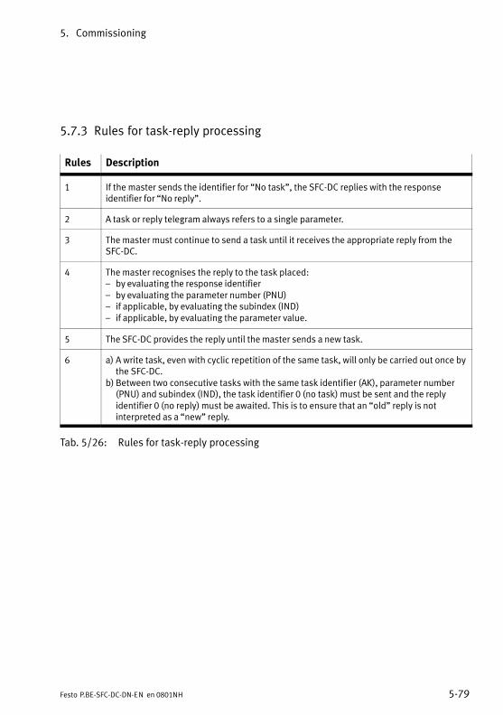
5. Commissioning
5−79Festo P.BE−SFC−DC−DN−EN en 0801NH
5.7.3 Rules for task−reply processing
Rules Description
1 If the master sends the identifier for �No task", the SFC−DC replies with the responseidentifier for �No reply".
2 A task or reply telegram always refers to a single parameter.
3 The master must continue to send a task until it receives the appropriate reply from theSFC−DC.
4 The master recognises the reply to the task placed:� by evaluating the response identifier� by evaluating the parameter number (PNU)� if applicable, by evaluating the subindex (IND)� if applicable, by evaluating the parameter value.
5 The SFC−DC provides the reply until the master sends a new task.
6 a) A write task, even with cyclic repetition of the same task, will only be carried out once bythe SFC−DC.
b) Between two consecutive tasks with the same task identifier (AK), parameter number(PNU) and subindex (IND), the task identifier 0 (no task) must be sent and the replyidentifier 0 (no reply) must be awaited. This is to ensure that an �old" reply is notinterpreted as a �new" reply.
Tab.�5/26: Rules for task−reply processing
5. Commissioning
5−80 Festo P.BE−SFC−DC−DN−EN en 0801NH
Sequence of parameter processing
CautionObserve the following when modifying parameters: An FHPP control signal, which is to refer to a modifiedparameter, may only follow when the response identifier�Parameter value transferred" is received for the relevantparameter and if applicable for the index.
If, e.g. a position value in a position register is to be modifiedand if movement is then to be made to this position, the posi�tioning command must not be given until the SFC−DC hascompleted and confirmed the modification of the positionregister.
CautionIn order to be sure that an �old" reply cannot be inter�preted as a �new" reply, the task identifier 0 (no task) mustbe sent and the reply identifier 0 (no reply) must beawaited between two consecutive tasks with the same taskidentifier (AK), parameter number (PNU) and subindex(IND).
Evaluating faults
In the case of tasks which cannot be carried out, the slavereplies as follows:
� Output reply identifier = 7
� Output a fault number in bytes 7 and 8 of the parameterchannel (FPC).
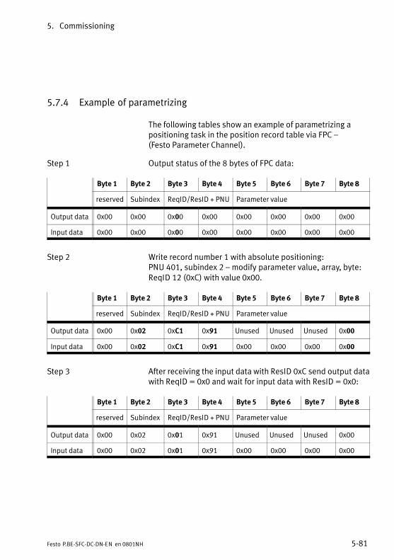
5. Commissioning
5−81Festo P.BE−SFC−DC−DN−EN en 0801NH
5.7.4 Example of parametrizing
The following tables show an example of parametrizing apositioning task in the position record table via FPC � (Festo Parameter Channel).
Step 1 Output status of the 8 bytes of FPC data:
Byte 1 Byte 2 Byte 3 Byte 4 Byte 5 Byte 6 Byte 7 Byte 8
reserved Subindex ReqID/ResID + PNU Parameter value
Output data 0x00 0x00 0x00 0x00 0x00 0x00 0x00 0x00
Input data 0x00 0x00 0x00 0x00 0x00 0x00 0x00 0x00
Step 2 Write record number 1 with absolute positioning:PNU 401, subindex 2 � modify parameter value, array, byte:ReqID 12 (0xC) with value 0x00.
Byte 1 Byte 2 Byte 3 Byte 4 Byte 5 Byte 6 Byte 7 Byte 8
reserved Subindex ReqID/ResID + PNU Parameter value
Output data 0x00 0x02 0xC1 0x91 Unused Unused Unused 0x00
Input data 0x00 0x02 0xC1 0x91 0x00 0x00 0x00 0x00
Step 3 After receiving the input data with ResID 0xC send output datawith ReqID = 0x0 and wait for input data with ResID = 0x0:
Byte 1 Byte 2 Byte 3 Byte 4 Byte 5 Byte 6 Byte 7 Byte 8
reserved Subindex ReqID/ResID + PNU Parameter value
Output data 0x00 0x02 0x01 0x91 Unused Unused Unused 0x00
Input data 0x00 0x02 0x01 0x91 0x00 0x00 0x00 0x00
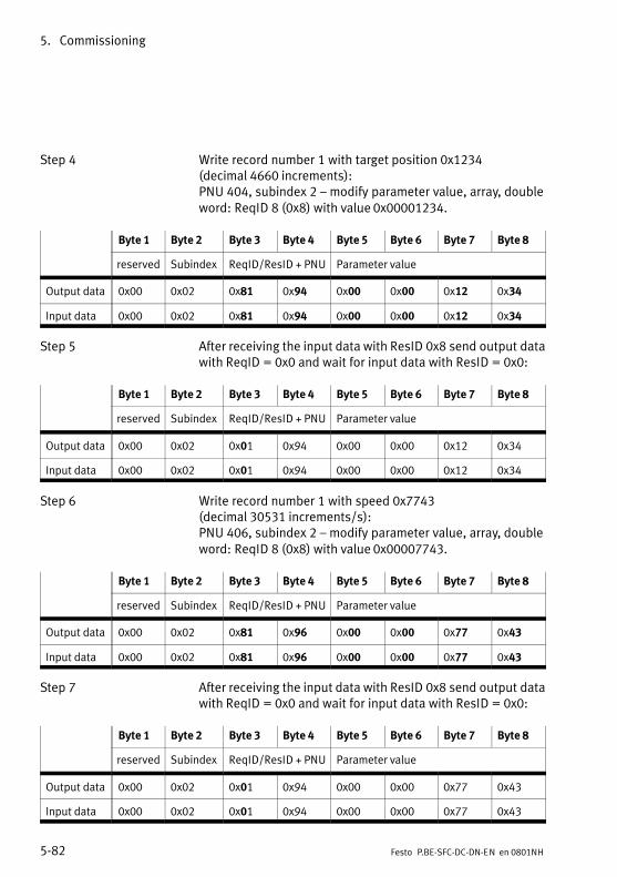
5. Commissioning
5−82 Festo P.BE−SFC−DC−DN−EN en 0801NH
Step 4 Write record number 1 with target position 0x1234 (decimal 4660 increments):PNU 404, subindex 2 � modify parameter value, array, doubleword: ReqID 8 (0x8) with value 0x00001234.
Byte 1 Byte 2 Byte 3 Byte 4 Byte 5 Byte 6 Byte 7 Byte 8
reserved Subindex ReqID/ResID + PNU Parameter value
Output data 0x00 0x02 0x81 0x94 0x00 0x00 0x12 0x34
Input data 0x00 0x02 0x81 0x94 0x00 0x00 0x12 0x34
Step 5 After receiving the input data with ResID 0x8 send output datawith ReqID = 0x0 and wait for input data with ResID = 0x0:
Byte 1 Byte 2 Byte 3 Byte 4 Byte 5 Byte 6 Byte 7 Byte 8
reserved Subindex ReqID/ResID + PNU Parameter value
Output data 0x00 0x02 0x01 0x94 0x00 0x00 0x12 0x34
Input data 0x00 0x02 0x01 0x94 0x00 0x00 0x12 0x34
Step 6 Write record number 1 with speed 0x7743 (decimal 30531 increments/s): PNU 406, subindex 2 � modify parameter value, array, doubleword: ReqID 8 (0x8) with value 0x00007743.
Byte 1 Byte 2 Byte 3 Byte 4 Byte 5 Byte 6 Byte 7 Byte 8
reserved Subindex ReqID/ResID + PNU Parameter value
Output data 0x00 0x02 0x81 0x96 0x00 0x00 0x77 0x43
Input data 0x00 0x02 0x81 0x96 0x00 0x00 0x77 0x43
Step 7 After receiving the input data with ResID 0x8 send output datawith ReqID = 0x0 and wait for input data with ResID = 0x0:
Byte 1 Byte 2 Byte 3 Byte 4 Byte 5 Byte 6 Byte 7 Byte 8
reserved Subindex ReqID/ResID + PNU Parameter value
Output data 0x00 0x02 0x01 0x94 0x00 0x00 0x77 0x43
Input data 0x00 0x02 0x01 0x94 0x00 0x00 0x77 0x43
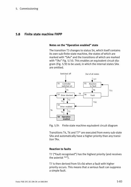
5. Commissioning
5−83Festo P.BE−SFC−DC−DN−EN en 0801NH
5.8 Finite state machine FHPP
Notes on the �Operation enabled" state
The transition T3 changes to status S4, which itself containsits own sub−finite state machine, the states of which aremarked with �SAx" and the transitions of which are markedwith �TAx" Fig.�5/10. This enables an equivalent circuit dia�gram (Fig.�5/9) to be used, in which the internal states SAxare omitted.
Switched off
S1 Controller switched on
S3Drive enabled
S2 Drive blocked
S5 Reaction to fault
S6 Fault
Out of all states
Operation enabled
T6
T2T5
T3T4
T1
T7*
T8
T10
T9
S5
T11
S3
Fig.�5/9: Finite state machine equivalent circuit diagram
Transitions T4, T6 and T7* are executed from every sub−stateSAx and automatically have a higher priority than any transi�tion TAx.
Reaction to faults
T7 (�Fault recognised") has the highest priority (and receivesthe asterisk ��*�").
T7 is then derived from S5+S6 when a fault with higherpriority occurs. This means that a serious fault can suppressa simple fault.
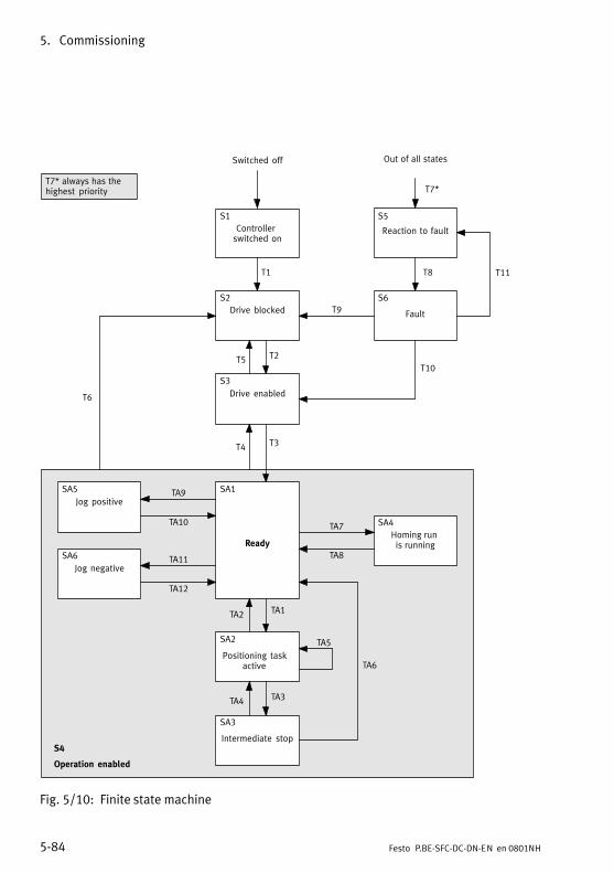
5. Commissioning
5−84 Festo P.BE−SFC−DC−DN−EN en 0801NH
T7* always has thehighest priority
Switched off
S1
Controller switched on
S3
Drive enabled
S2
Drive blocked
SA1
Ready
SA5
Jog positive
SA6
Jog negative
SA4
Homing run is running
SA2
Positioning taskactive
SA3
Intermediate stop
S5
Reaction to fault
S6
Fault
Out of all states
S4
Operation enabled
T6
TA11
TA12
TA9
TA10
TA3
TA6
TA4
TA5
TA7
TA8
TA1TA2
T2T5
T3T4
T1
T7*
T8
T10
T9
S5
T11
Fig.�5/10: Finite state machine

5. Commissioning
5−85Festo P.BE−SFC−DC−DN−EN en 0801NH
5.8.1 Create readiness to operate
T Internal conditions Activities of the user
T1 Drive is switched on.A fault cannot be ascertained.
T2 Load voltage applied.Field bus master must be higher−order controller.
�Enable drive" = 1CCON = xxx0.xxx1
T3 �Stop" = 1CCON = xxx0.xx11
T4 �Stop" = 0CCON = xxx0.xx01
T5 �Enable drive" = 0CCON = xxx0.xxx0
T6 �Enable drive" = 0CCON = xxx0.xxx0
T7* Fault recognised.
T8 Reaction to fault completed, drive stopped.
T9 There is no longer a fault.It was a serious fault.
�Quit fault" = 0 } 1CCON = xxx0.Pxxx
T10 There is no longer a fault.It was a simple fault.
�Quit fault" = 0 } 1CCON = xxx0.Pxx1
T11 Fault still exists. �Quit fault" = 0 } 1CCON = xxx0.Pxx1
Key: P = positive edgeN = negative edgex = any
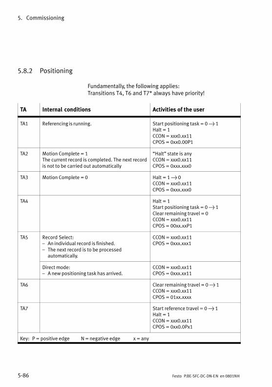
5. Commissioning
5−86 Festo P.BE−SFC−DC−DN−EN en 0801NH
5.8.2 Positioning
Fundamentally, the following applies: Transitions T4, T6 and T7* always have priority!
TA Internal conditions Activities of the user
TA1 Referencing is running. Start positioning task = 0 } 1Halt = 1CCON = xxx0.xx11CPOS = 0xx0.00P1
TA2 Motion Complete = 1The current record is completed. The next recordis not to be carried out automatically
�Halt" state is anyCCON = xxx0.xx11CPOS = 0xxx.xxx0
TA3 Motion Complete = 0 Halt = 1 } 0CCON = xxx0.xx11CPOS = 0xxx.xxx0
TA4 Halt = 1Start positioning task = 0 } 1Clear remaining travel = 0CCON = xxx0.xx11CPOS = 00xx.xxP1
TA5 Record Select:� An individual record is finished.� The next record is to be processed
automatically.
CCON = xxx0.xx11CPOS = 0xxx.xxx1
Direct mode:� A new positioning task has arrived.
CCON = xxx0.xx11CPOS = 0xxx.xx11
TA6 Clear remaining travel = 0 } 1CCON = xxx0.xx11CPOS = 01xx.xxxx
TA7 Start reference travel = 0 } 1Halt = 1CCON = xxx0.xx11CPOS = 0xx0.0Px1
Key: P = positive edge N = negative edge x = any

5. Commissioning
5−87Festo P.BE−SFC−DC−DN−EN en 0801NH
TA Activities of the userInternal conditions
TA8 Referencing finished or stopped. Only for Halt:Halt = 1 } 0CCON = xxx0.xx11CPOS = 0xxx.xxxN
TA9 Jog positive = 0 } 1Halt = 1CCON = xxx0.xx11CPOS = 0xx0.Pxx1
TA10 Either� Jog positive = 1 } 0� CCON = xxx0.xx11� CPOS = 0xxx.0xx1or� Halt = 1 } 0� CCON = xxx0.xx11� CPOS = 0xxx.xxxN
TA11 Jog negative = 0 } 1Halt = 1CCON = xxx0.xx11CPOS = 0xxP.xxx1
TA12 Either� Jog negative = 1 } 0� CCON = xxx0.xx11� CPOS = 0xxN.xxx1or� Halt = 1 } 0� CCON = xxx0.xx11� CPOS = 0xxx.xxxN
Key: P = positive edge N = negative edge x = any
Operating mode special features
Operation mode Notes on specific features
Record select No restrictions
Direct mode TA2: The condition that no new record may be processed no longer applies.TA5: A new record can be started at any time.

5. Commissioning
5−88 Festo P.BE−SFC−DC−DN−EN en 0801NH
5.9 Notes on operation
Take the following instructions and recommendations intoaccount when programming positioning systems with electricaxes:
Password protection
The factory setting does not offer active protection with apassword. In order to prevent unauthorized or unintentionaloverwriting or modification of parameters in the device, alldownload and control functions can be blocked.
· Recommendation:Protect the settings of your axis against undesiredmodifications with a password:
� FCT password protection (8 characters, see PlugIn help SFC−DC)
� HMI password protection for SFC−DC−...−H2−... (3 characters, see section 4.5)
WarningThere is a danger of injury.
Faults in parametrization can cause injury to human beingsand damage to property. In the following cases referencetravel is absolutely essential in order that the referencecoordinates and the working range can be set correctly:
� when commissioning the first time,
� when the homing method is changed,
� each time the logic voltage supply is switched on.
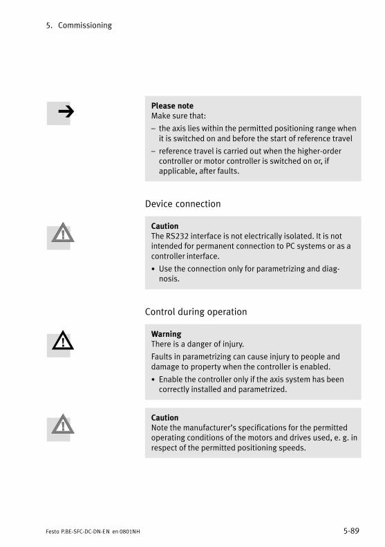
5. Commissioning
5−89Festo P.BE−SFC−DC−DN−EN en 0801NH
Please noteMake sure that:
� the axis lies within the permitted positioning range whenit is switched on and before the start of reference travel
� reference travel is carried out when the higher−ordercontroller or motor controller is switched on or, ifapplicable, after faults.
Device connection
CautionThe RS232 interface is not electrically isolated. It is notintended for permanent connection to PC systems or as acontroller interface.
· Use the connection only for parametrizing and diag�nosis.
Control during operation
WarningThere is a danger of injury.
Faults in parametrizing can cause injury to people anddamage to property when the controller is enabled.
· Enable the controller only if the axis system has beencorrectly installed and parametrized.
CautionNote the manufacturer’s specifications for the permittedoperating conditions of the motors and drives used, e. g. inrespect of the permitted positioning speeds.
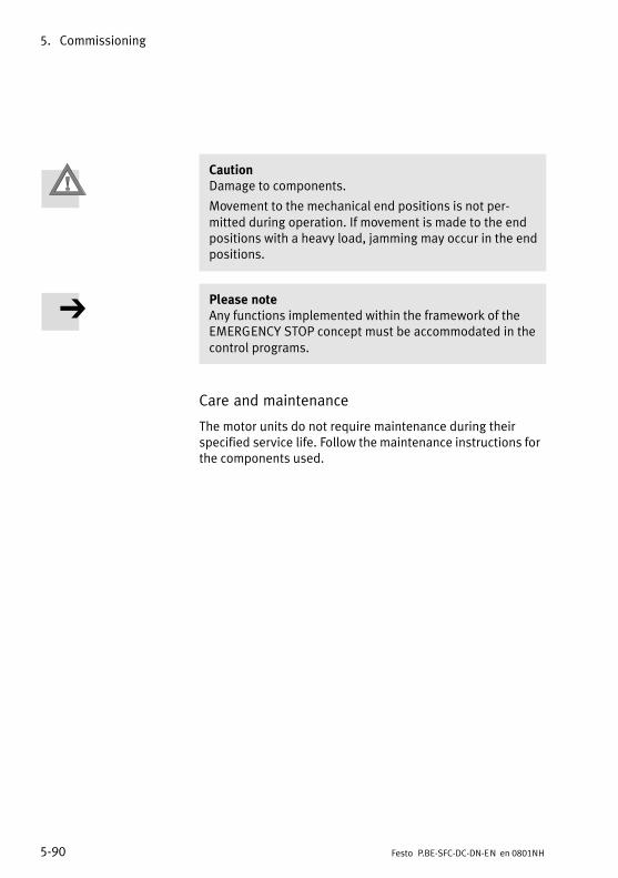
5. Commissioning
5−90 Festo P.BE−SFC−DC−DN−EN en 0801NH
CautionDamage to components.
Movement to the mechanical end positions is not per�mitted during operation. If movement is made to the endpositions with a heavy load, jamming may occur in the endpositions.
Please noteAny functions implemented within the framework of theEMERGENCY STOP concept must be accommodated in thecontrol programs.
Care and maintenance
The motor units do not require maintenance during theirspecified service life. Follow the maintenance instructions forthe components used.

Diagnosis and fault display
6−1Festo P.BE−SFC−DC−DN−EN en 0801NH
Chapter 6
6. Diagnosis and fault display
6−2 Festo P.BE−SFC−DC−DN−EN en 0801NH
Contents
6. Diagnosis and fault display 6−1 . . . . . . . . . . . . . . . . . . . . . . . . . . . . . . . . . . . . . .
6.1 Overview of diagnostic possibilities 6−3 . . . . . . . . . . . . . . . . . . . . . . . . . . . . . . . .
6.2 LED status displays 6−5 . . . . . . . . . . . . . . . . . . . . . . . . . . . . . . . . . . . . . . . . . . . . .
6.3 Fault messages 6−7 . . . . . . . . . . . . . . . . . . . . . . . . . . . . . . . . . . . . . . . . . . . . . . . . .
6.3.1 Overview 6−7 . . . . . . . . . . . . . . . . . . . . . . . . . . . . . . . . . . . . . . . . . . . . . .
6.3.2 Description of faults and warnings 6−9 . . . . . . . . . . . . . . . . . . . . . . . . . .
6.4 Diagnosis via field bus 6−13 . . . . . . . . . . . . . . . . . . . . . . . . . . . . . . . . . . . . . . . . . . .
6.4.1 Overview 6−13 . . . . . . . . . . . . . . . . . . . . . . . . . . . . . . . . . . . . . . . . . . . . . .
6.4.2 Diagnostic memory 6−14 . . . . . . . . . . . . . . . . . . . . . . . . . . . . . . . . . . . . . .

6. Diagnosis and fault display
6−3Festo P.BE−SFC−DC−DN−EN en 0801NH
6.1 Overview of diagnostic possibilities
The SFC−DC offers the following possibilities of diagnosis andfault treatment:
Type of diagnosticinformation
Access via ... see ...
General status display LED status displays on the SFC−DC Section 6.2
FCT: Virtual LEDs in the �Device status" window Help for PlugIn
Status bytes SCON and SPOS Section 5.5.2 / 6.4
Bus status LED �I/F" on SFC−DC Section 6.2
DeviceNet class 109 Section 6.4
Display of the SFC−DC in the menu [Diagnosis] Section 4.3
Current fault message(text display)
Display of the SFC−DC Section 6.3(text display)
FCT: Text field in the �Device status" window Help for PlugIn
DeviceNet class 108 Section 4.3
Diagnostic messages FCT in the �Diagnosis" window (with existing device connection)
Help for PlugIn
DeviceNet classes 101/102 (diagnostic memory) Section 6.4.2 / 5.7.1
Display of the SFC−DC in the menu [Diagnosis] Section 4.3
Tab.�6/1: Diagnostic information according to type
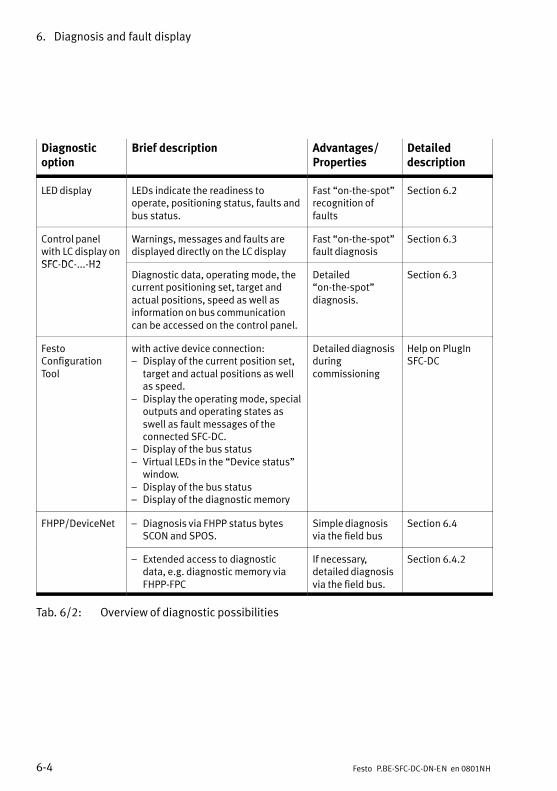
6. Diagnosis and fault display
6−4 Festo P.BE−SFC−DC−DN−EN en 0801NH
Diagnosticoption
Brief description Advantages/Properties
Detaileddescription
LED display LEDs indicate the readiness tooperate, positioning status, faults andbus status.
Fast �on−the−spot"recognition offaults
Section 6.2
Control panelwith LC display onSFC DC H2
Warnings, messages and faults aredisplayed directly on the LC display
Fast �on−the−spot"fault diagnosis
Section 6.3
SFC−DC−...−H2Diagnostic data, operating mode, thecurrent positioning set, target andactual positions, speed as well asinformation on bus communicationcan be accessed on the control panel.
Detailed�on−the−spot"diagnosis.
Section 6.3
FestoConfigurationTool
with active device connection:� Display of the current position set,
target and actual positions as wellas speed.
� Display the operating mode, specialoutputs and operating states asswell as fault messages of theconnected SFC−DC.
� Display of the bus status� Virtual LEDs in the �Device status"
window.� Display of the bus status� Display of the diagnostic memory
Detailed diagnosisduringcommissioning
Help on PlugInSFC−DC
FHPP/DeviceNet � Diagnosis via FHPP status bytesSCON and SPOS.
Simple diagnosisvia the field bus
Section 6.4
� Extended access to diagnosticdata, e.g. diagnostic memory viaFHPP−FPC
If necessary,detailed diagnosisvia the field bus.
Section 6.4.2
Tab.�6/2: Overview of diagnostic possibilities
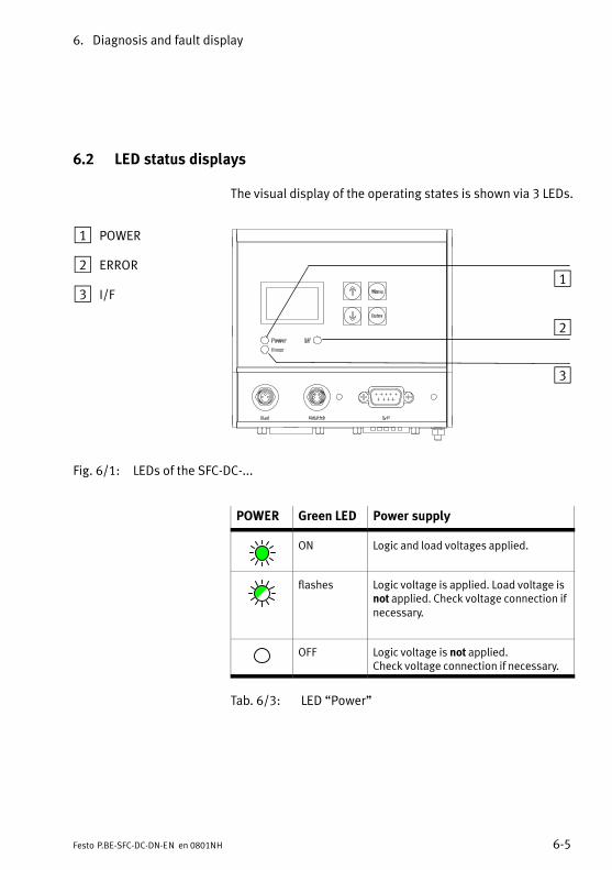
6. Diagnosis and fault display
6−5Festo P.BE−SFC−DC−DN−EN en 0801NH
6.2 LED status displays
The visual display of the operating states is shown via 3 LEDs.
1 POWER
2 ERROR
3 I/F1
2
3
Fig.�6/1: LEDs of the SFC−DC−...
POWER Green LED Power supply
ON Logic and load voltages applied.
flashes Logic voltage is applied. Load voltage isnot applied. Check voltage connection ifnecessary.
OFF Logic voltage is not applied. Check voltage connection if necessary.
Tab.�6/3: LED �Power"
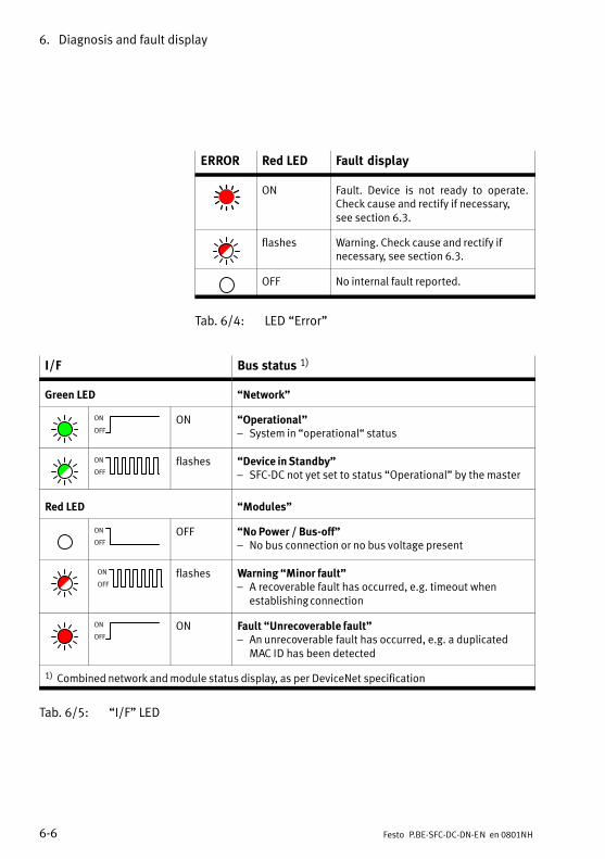
6. Diagnosis and fault display
6−6 Festo P.BE−SFC−DC−DN−EN en 0801NH
ERROR Red LED Fault display
ON Fault. Device is not ready to operate.Check cause and rectify if necessary, see section 6.3.
flashes Warning. Check cause and rectify ifnecessary, see section 6.3.
OFF No internal fault reported.
Tab.�6/4: LED �Error"
I/F Bus status 1)
Green LED �Network"
ON
OFF
ON �Operational"� System in �operational� status
ON
OFF
flashes �Device in Standby"� SFC−DC not yet set to status �Operational" by the master
Red LED �Modules"
ON
OFF
OFF �No Power / Bus−off"� No bus connection or no bus voltage present
ON
OFF
flashes Warning �Minor fault"� A recoverable fault has occurred, e.g. timeout when
establishing connection
ON
OFF
ON Fault �Unrecoverable fault"� An unrecoverable fault has occurred, e.g. a duplicated
MAC ID has been detected
1) Combined network and module status display, as per DeviceNet specification
Tab.�6/5: �I/F" LED
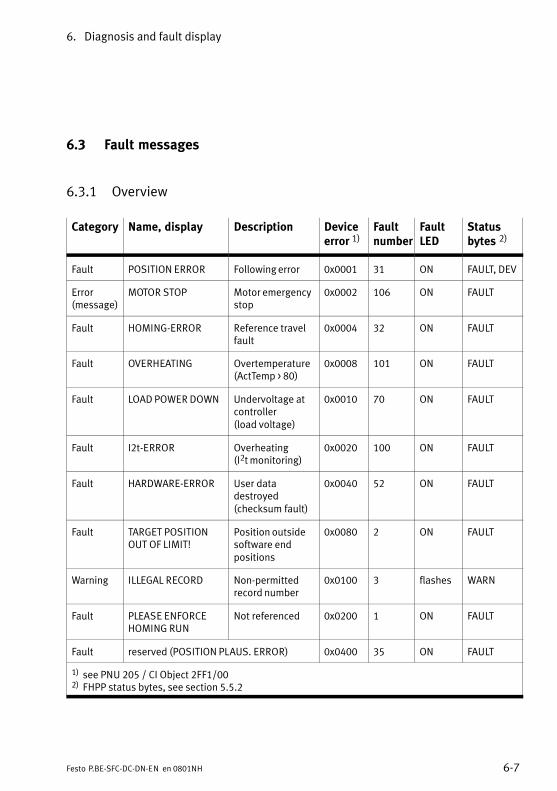
6. Diagnosis and fault display
6−7Festo P.BE−SFC−DC−DN−EN en 0801NH
6.3 Fault messages
6.3.1 Overview
Category Name, display Description Deviceerror 1)
Faultnumber
FaultLED
Statusbytes 2)
Fault POSITION ERROR Following error 0x0001 31 ON FAULT, DEV
Error(message)
MOTOR STOP Motor emergencystop
0x0002 106 ON FAULT
Fault HOMING−ERROR Reference travelfault
0x0004 32 ON FAULT
Fault OVERHEATING Overtemperature(ActTemp > 80)
0x0008 101 ON FAULT
Fault LOAD POWER DOWN Undervoltage atcontroller (load voltage)
0x0010 70 ON FAULT
Fault I2t−ERROR Overheating (I2t monitoring)
0x0020 100 ON FAULT
Fault HARDWARE−ERROR User datadestroyed (checksum fault)
0x0040 52 ON FAULT
Fault TARGET POSITIONOUT OF LIMIT!
Position outsidesoftware endpositions
0x0080 2 ON FAULT
Warning ILLEGAL RECORD Non−permittedrecord number
0x0100 3 flashes WARN
Fault PLEASE ENFORCEHOMING RUN
Not referenced 0x0200 1 ON FAULT
Fault reserved (POSITION PLAUS. ERROR) 0x0400 35 ON FAULT
1) see PNU 205 / CI Object 2FF1/002) FHPP status bytes, see section 5.5.2

6. Diagnosis and fault display
6−8 Festo P.BE−SFC−DC−DN−EN en 0801NH
Category Statusbytes 2)
FaultLED
Faultnumber
Deviceerror 1)
DescriptionName, display
Fault DIGITAL POWERDOWN
Undervoltage atcontroller (load voltage)
0x0800 71 ON FAULT
Warning INDEX PULSEWARNING
Index PulseWarning
0x1000 � flashes WARN
Fault MOTOR ERROR Phase failure (no motorcurrent)
0x2000 103 ON FAULT
Warning STANDSTILL Standstillmonitoring
0x4000 � flashes WARN,STILL
Fault DEVICENET INIT NOPARAMETER
Essential busparameters notset
0x8000 51 ON FAULT
Warning HOT TEMPERATURE Overheating � � flashes WARN
Warning COLD TEMPERATURE Undertemperature
� � flashes WARN
1) see PNU 205 / CI Object 2FF1/002) FHPP status bytes, see section 5.5.2
Tab.�6/6: Faults and warnings with fault numbers and fault bits
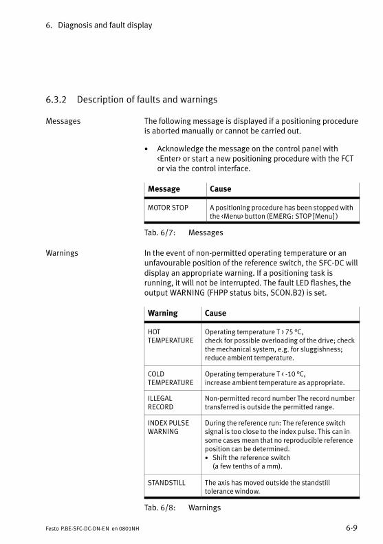
6. Diagnosis and fault display
6−9Festo P.BE−SFC−DC−DN−EN en 0801NH
6.3.2 Description of faults and warnings
Messages The following message is displayed if a positioning procedureis aborted manually or cannot be carried out.
· Acknowledge the message on the control panel with<Enter> or start a new positioning procedure with the FCTor via the control interface.
Message Cause
MOTOR STOP A positioning procedure has been stopped withthe <Menu> button (EMERG: STOP [Menu] )
Tab.�6/7: Messages
Warnings In the event of non−permitted operating temperature or anunfavourable position of the reference switch, the SFC−DC willdisplay an appropriate warning. If a positioning task isrunning, it will not be interrupted. The fault LED flashes, theoutput WARNING (FHPP status bits, SCON.B2) is set.
Warning Cause
HOT TEMPERATURE
Operating temperature T > 75 °C,check for possible overloading of the drive; checkthe mechanical system, e.g. for sluggishness;reduce ambient temperature.
COLD TEMPERATURE
Operating temperature T < −10 °C,increase ambient temperature as appropriate.
ILLEGALRECORD
Non−permitted record number The record numbertransferred is outside the permitted range.
INDEX PULSEWARNING
During the reference run: The reference switchsignal is too close to the index pulse. This can insome cases mean that no reproducible referenceposition can be determined.· Shift the reference switch
(a few tenths of a mm).
STANDSTILL The axis has moved outside the standstilltolerance window.
Tab.�6/8: Warnings
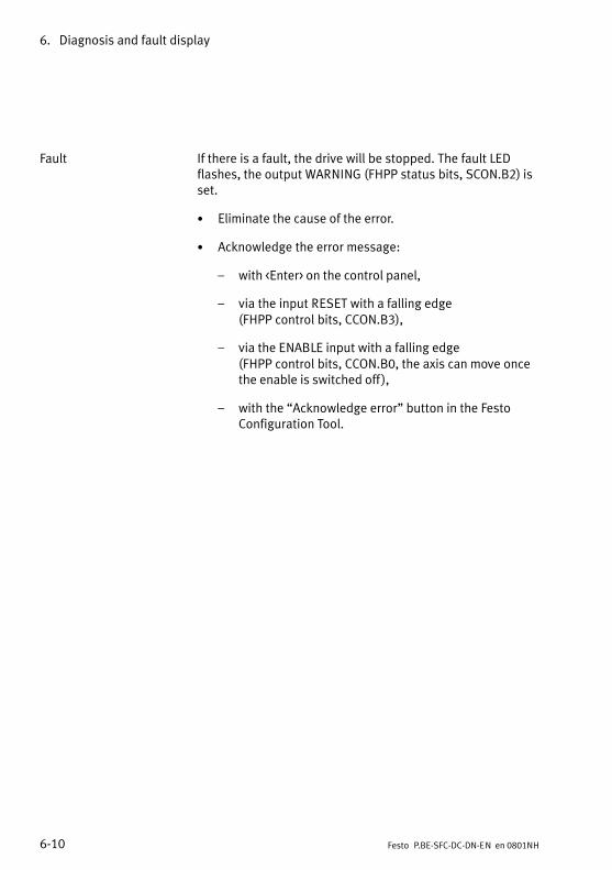
6. Diagnosis and fault display
6−10 Festo P.BE−SFC−DC−DN−EN en 0801NH
Fault If there is a fault, the drive will be stopped. The fault LEDflashes, the output WARNING (FHPP status bits, SCON.B2) isset.
· Eliminate the cause of the error.
· Acknowledge the error message:
� with <Enter> on the control panel,
� via the input RESET with a falling edge (FHPP control bits, CCON.B3),
� via the ENABLE input with a falling edge (FHPP control bits, CCON.B0, the axis can move oncethe enable is switched off ),
� with the �Acknowledge error" button in the FestoConfiguration Tool.
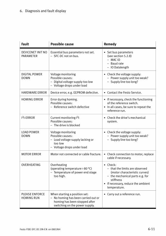
6. Diagnosis and fault display
6−11Festo P.BE−SFC−DC−DN−EN en 0801NH
Fault Possible cause Remedy
DEVICENET INIT NOPARAMETER
Essential bus parameters not set.� SFC−DC not on bus.
· Set bus parameters (see section 5.2.8)� MAC ID� Baud rate� IO Datalength
DIGITAL POWERDOWN
Voltage monitoringPossible causes:� Digital voltage supply too low� Voltage drops under load
· Check the voltage supply:� Power supply unit too weak?� Supply line too long?
HARDWARE ERROR Device error, e.g. EEPROM defective. · Contact the Festo Service.
HOMING ERROR Error during homing. Possible causes:� Reference switch defective
· If necessary, check the functioningof the reference switch.
· In all cases, be sure to repeat thereference run.
I2t−ERROR Current monitoring I2tPossible causes:� The drive is blocked
· Check the drive’s mechanicalsystem.
LOAD POWERDOWN
Voltage monitoringPossible causes:� Load voltage supply lacking or
too�low� Voltage drops under load
· Check the voltage supply:� Power supply unit too weak?� Supply line too long?
MOTOR ERROR Motor not connected or cable fracture. · Check connection to motor, replacecable if necessary.
OVERHEATING Overheating (operating temperature > 80 °C)� Temperature of power end stage
too high.
· Check:� that the limits are observed
(motor characteristic curves)� the mechanical parts e.g. for
stiffness· If necessary, reduce the ambient
temperature.
PLEASE ENFORCEHOMING RUN
When starting a position set:� No homing has been carried out or
homing has been stopped afterswitching on the power supply.
· Carry out a reference run.
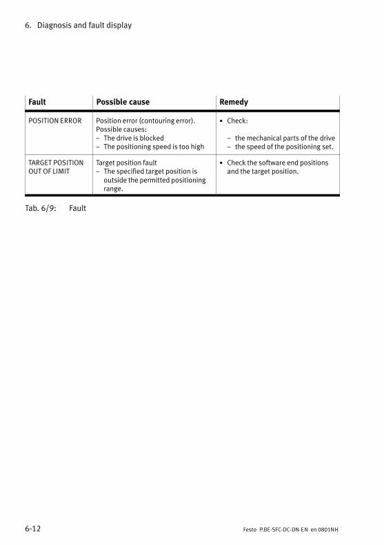
6. Diagnosis and fault display
6−12 Festo P.BE−SFC−DC−DN−EN en 0801NH
Fault RemedyPossible cause
POSITION ERROR Position error (contouring error).Possible causes:� The drive is blocked� The positioning speed is too high
· Check:
� the mechanical parts of the drive� the speed of the positioning set.
TARGET POSITIONOUT OF LIMIT
Target position fault� The specified target position is
outside the permitted positioningrange.
· Check the software end positionsand the target position.
Tab.�6/9: Fault
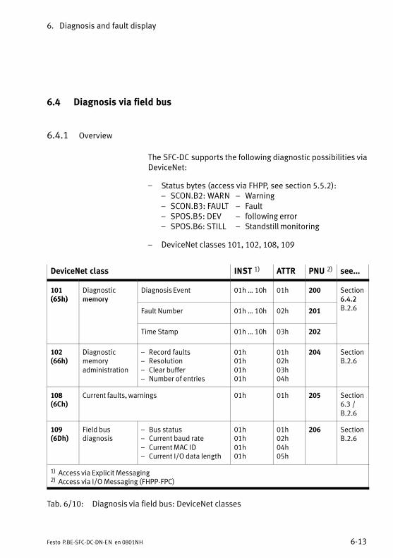
6. Diagnosis and fault display
6−13Festo P.BE−SFC−DC−DN−EN en 0801NH
6.4 Diagnosis via field bus
6.4.1 Overview
The SFC−DC supports the following diagnostic possibilities viaDeviceNet:
� Status bytes (access via FHPP, see section 5.5.2):� SCON.B2: WARN � Warning� SCON.B3: FAULT � Fault� SPOS.B5: DEV � following error� SPOS.B6: STILL � Standstill monitoring
� DeviceNet classes 101, 102, 108, 109
DeviceNet class INST 1) ATTR PNU 2) see...
101(65h)
Diagnosticmemory
Diagnosis Event 01h � 10h 01h 200 Section6.4.2(65h) memory
Fault Number 01h � 10h 02h 201
6.4.2B.2.6
Time Stamp 01h � 10h 03h 202
102(66h)
Diagnosticmemoryadministration
� Record faults� Resolution� Clear buffer� Number of entries
01h01h01h01h
01h02h03h04h
204 SectionB.2.6
108(6Ch)
Current faults, warnings 01h 01h 205 Section6.3 /B.2.6
109(6Dh)
Field busdiagnosis
� Bus status� Current baud rate� Current MAC ID� Current I/O data length
01h01h01h01h
01h02h04h05h
206 SectionB.2.6
1) Access via Explicit Messaging2) Access via I/O Messaging (FHPP−FPC)
Tab.�6/10: Diagnosis via field bus: DeviceNet classes
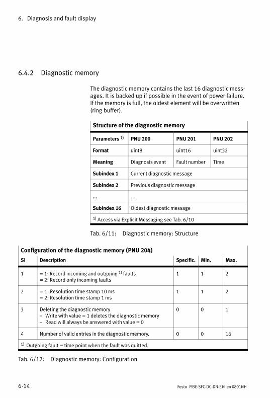
6. Diagnosis and fault display
6−14 Festo P.BE−SFC−DC−DN−EN en 0801NH
6.4.2 Diagnostic memory
The diagnostic memory contains the last 16 diagnostic mess�ages. It is backed up if possible in the event of power failure.If the memory is full, the oldest element will be overwritten(ring buffer).
Structure of the diagnostic memory
Parameters 1) PNU 200 PNU 201 PNU 202
Format uint8 uint16 uint32
Meaning Diagnosis event Fault number Time
Subindex 1 Current diagnostic message
Subindex 2 Previous diagnostic message
... ...
Subindex 16 Oldest diagnostic message
1) Access via Explicit Messaging see Tab.�6/10
Tab.�6/11: Diagnostic memory: Structure
Configuration of the diagnostic memory (PNU 204)
SI Description Specific. Min. Max.
1 = 1: Record incoming and outgoing 1) faults= 2: Record only incoming faults
1 1 2
2 = 1: Resolution time stamp 10 ms= 2: Resolution time stamp 1 ms
1 1 2
3 Deleting the diagnostic memory� Write with value = 1 deletes the diagnostic memory� Read will always be answered with value = 0
0 0 1
4 Number of valid entries in the diagnostic memory. 0 0 16
1) Outgoing fault = time point when the fault was quitted.
Tab.�6/12: Diagnostic memory: Configuration
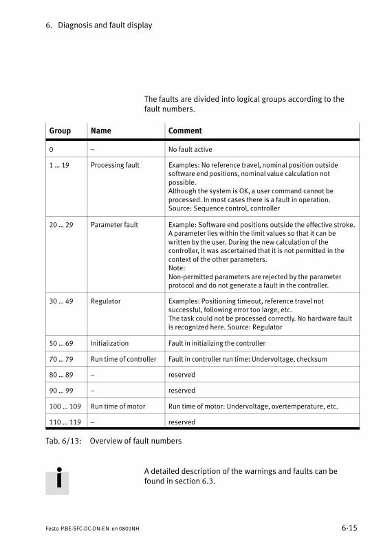
6. Diagnosis and fault display
6−15Festo P.BE−SFC−DC−DN−EN en 0801NH
The faults are divided into logical groups according to thefault numbers.
Group Name Comment
0 � No fault active
1 � 19 Processing fault Examples: No reference travel, nominal position outsidesoftware end positions, nominal value calculation notpossible.Although the system is OK, a user command cannot beprocessed. In most cases there is a fault in operation.Source: Sequence control, controller
20 � 29 Parameter fault Example: Software end positions outside the effective stroke.A parameter lies within the limit values so that it can bewritten by the user. During the new calculation of thecontroller, it was ascertained that it is not permitted in thecontext of the other parameters.Note: Non−permitted parameters are rejected by the parameterprotocol and do not generate a fault in the controller.
30 � 49 Regulator Examples: Positioning timeout, reference travel notsuccessful, following error too large, etc.The task could not be processed correctly. No hardware faultis recognized here. Source: Regulator
50 � 69 Initialization Fault in initializing the controller
70 � 79 Run time of controller Fault in controller run time: Undervoltage, checksum
80 � 89 � reserved
90 � 99 � reserved
100 � 109 Run time of motor Run time of motor: Undervoltage, overtemperature, etc.
110 � 119 � reserved
Tab.�6/13: Overview of fault numbers
A detailed description of the warnings and faults can befound in section 6.3.

6. Diagnosis and fault display
6−16 Festo P.BE−SFC−DC−DN−EN en 0801NH

Technical appendix
A−1Festo P.BE−SFC−DC−DN−EN en 0801NH
Appendix A
A. Technical appendix
A−2 Festo P.BE−SFC−DC−DN−EN en 0801NH
Contents
A. Technical appendix A−1 . . . . . . . . . . . . . . . . . . . . . . . . . . . . . . . . . . . . . . . . . . . . .
A.1 Technical specifications A−3 . . . . . . . . . . . . . . . . . . . . . . . . . . . . . . . . . . . . . . . . . .
A.2 Accessories A−5 . . . . . . . . . . . . . . . . . . . . . . . . . . . . . . . . . . . . . . . . . . . . . . . . . . . .
A.3 Converting the units of measurement A−7 . . . . . . . . . . . . . . . . . . . . . . . . . . . . . . .
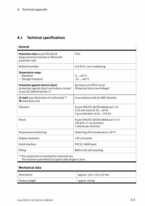
A. Technical appendix
A−3Festo P.BE−SFC−DC−DN−EN en 0801NH
A.1 Technical specifications
General
Protection class as per EN�60529 (plug connector inserted or fitted withprotective cap)
IP54
Relative humidity 0 to 95 %, non−condensing
Temperature range� Operation� Storage/transport
0 � +40�°C−25 � +60�°C
Protection against electric shock(protection against direct and indirect contactas per IEC/DIN EN 60204−1)
By means of a PELV circuit (Protected�Extra−Low Voltage)
CE mark (see declaration of conformity) 1)
è www.festo.comIn accordance with EU EMC directive
Vibration As per DIN/IEC 68/EN�60068 part 2−6:0.35�mm travel at 10 � 60 Hz5�g acceleration at 60 � 150�Hz
Shock As per DIN/IEC 68/EN�60068 part 2−27:±30�g for 11�ms duration;5 shocks per direction
Temperature monitoring Switching off at temperature > 80 °C
Display resolution 128 x 64 pixels
Serial interface RS232, 9600 baud
Fitting Wall or hat rail mounting
1) This component is intended for industrial use.The maximum permitted I/O signal cable length is 30 m.
Mechanical data
Dimensions approx. 126 x 120 x 62 mm
Product weight approx. 0.6 kg
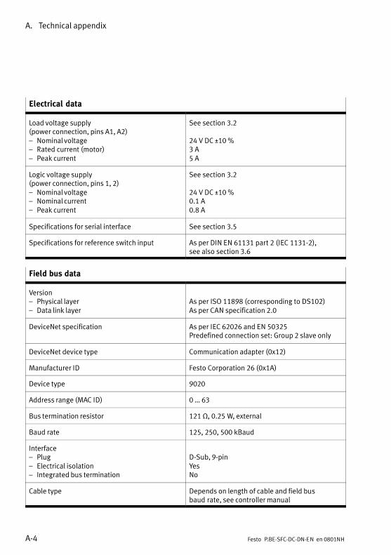
A. Technical appendix
A−4 Festo P.BE−SFC−DC−DN−EN en 0801NH
Electrical data
Load voltage supply (power connection, pins A1, A2)� Nominal voltage� Rated current (motor)� Peak current
See section 3.2
24 V DC ±10 %3 A5 A
Logic voltage supply (power connection, pins 1, 2)� Nominal voltage� Nominal current� Peak current
See section 3.2
24 V DC ±10 %0.1 A0.8 A
Specifications for serial interface See section 3.5
Specifications for reference switch input As per DIN EN 61131 part 2 (IEC 1131−2), see also section 3.6
Field bus data
Version� Physical layer� Data link layer
As per ISO 11898 (corresponding to DS102)As per CAN specification 2.0
DeviceNet specification As per IEC 62026 and EN 50325Predefined connection set: Group 2 slave only
DeviceNet device type Communication adapter (0x12)
Manufacturer ID Festo Corporation 26 (0x1A)
Device type 9020
Address range (MAC ID) 0 � 63
Bus termination resistor 121 , 0.25 W, external
Baud rate 125, 250, 500 kBaud
Interface� Plug� Electrical isolation� Integrated bus termination
D−Sub, 9−pinYesNo
Cable type Depends on length of cable and field busbaud�rate, see controller manual
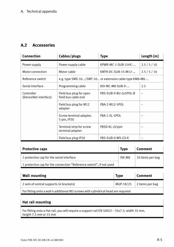
A. Technical appendix
A−5Festo P.BE−SFC−DC−DN−EN en 0801NH
A.2 Accessories
Connection Cables/plugs Type Length [m]
Power supply Power supply cable KPWR−MC−1−SUB−15HC−... 2.5 / 5 / 10
Motor connection Motor cable KMTR−DC−SUB−15−M12−... 2.5 / 5 / 10
Reference switch e.g. type SME−10.../SMT−10... or extension cable type KM8−M8−...
Serial interface Programming cable KDI−MC−M8−SUB−9−... 2.5
Controller (DeviceNet interface)
Field bus plug for openfield bus cable end
FBS−SUB−9−BU−2x5POL−B �
Field bus plug for M12adapter
FBA−2−M12−5POL �
Screw terminal adapter,5−pin, IP20
FBA−1−SL−5POL �
Terminal strip for screwterminal adapter
FBSD−KL−2x5pin �
Field bus plug IP20 FBS−SUB−9−WS−CO−K �
Protective caps Type Comment
1 protective cap for the serial interface ISK−M8 10 items per bag
1 protective cap for the connection �Reference switch", if not used
Wall mounting Type Comment
2 sets of central supports (4 brackets) MUP−18/25 2 items per bag
For fitting onto a wall 4 additional M3 screws with cylindrical head are required
Hat rail mounting
For fitting onto a Hat rail, you will require a support rail EN 50022 � 35�x�7.5; width 35 mm, height 7.5 mm or 15 mm

A. Technical appendix
A−6 Festo P.BE−SFC−DC−DN−EN en 0801NH
User documentation in paper form
German P.BE−SFC−DC−DN−DE
English P.BE−SFC−DC−DN−EN
French P.BE−SFC−DC−DN−FR
Italian P.BE−SFC−DC−DN−IT
Spanish P.BE−SFC−DC−DN−ES
Swedish P.BE−SFC−DC−DN−SV
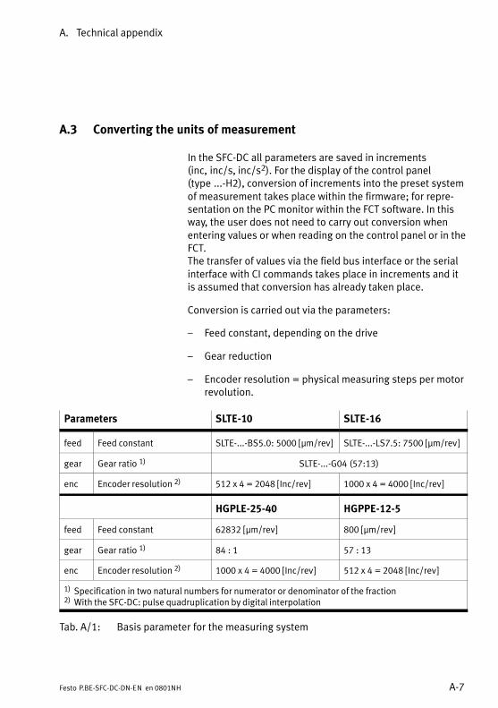
A. Technical appendix
A−7Festo P.BE−SFC−DC−DN−EN en 0801NH
A.3 Converting the units of measurement
In the SFC−DC all parameters are saved in increments(inc,�inc/s, inc/s2). For the display of the control panel(type�...−H2), conversion of increments into the preset systemof measurement takes place within the firmware; for repre�sentation on the PC monitor within the FCT software. In thisway, the user does not need to carry out conversion whenentering values or when reading on the control panel or in theFCT. The transfer of values via the field bus interface or the serialinterface with CI commands takes place in increments and itis assumed that conversion has already taken place.
Conversion is carried out via the parameters:
� Feed constant, depending on the drive
� Gear reduction
� Encoder resolution = physical measuring steps per motorrevolution.
Parameters SLTE−10 SLTE−16
feed Feed constant SLTE−...−BS5.0: 5000 [�m/rev] SLTE−...−LS7.5: 7500 [�m/rev]
gear Gear ratio 1) SLTE−...−G04 (57:13)
enc Encoder resolution 2) 512 x 4 = 2048 [Inc/rev] 1000 x 4 = 4000 [Inc/rev]
HGPLE−25−40 HGPPE−12−5
feed Feed constant 62832 [�m/rev] 800 [�m/rev]
gear Gear ratio 1) 84 : 1 57 : 13
enc Encoder resolution 2) 1000 x 4 = 4000 [Inc/rev] 512 x 4 = 2048 [Inc/rev]
1) Specification in two natural numbers for numerator or denominator of the fraction2) With the SFC−DC: pulse quadruplication by digital interpolation
Tab.�A/1: Basis parameter for the measuring system
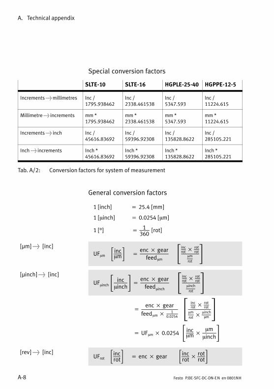
A. Technical appendix
A−8 Festo P.BE−SFC−DC−DN−EN en 0801NH
Special conversion factors
SLTE−10 SLTE−16 HGPLE−25−40 HGPPE−12−5
Increments > millimetres Inc /1795.938462
Inc /2338.461538
Inc / 5347.593
Inc /11224.615
Millimetre > increments mm *1795.938462
mm *2338.461538
mm * 5347.593
mm *11224.615
Increments > inch Inc /45616.83692
Inc /59396.92308
Inc /135828.8622
Inc /285105.221
Inch > increments Inch *45616.83692
Inch *59396.92308
Inch *135828.8622
Inch *285105.221
Tab.�A/2: Conversion factors for system of measurement
General conversion factors
1�[inch]���� � 25.4�[mm]
1�[minch]�� � 0.0254�[mm]
1�[°]���� � 1360
� [rot]
[�m] > [inc]UFmm��incmm�� � enc� gear
feedmm���incrot �
rotrot
mmrot
�[�inch] > [inc]
UFminch�� incminch� � enc� gear
feedminch���incrot �
rotrot
minchrot
�������� � enc� gear
feedmm � 10.0254
��� incrot �
rotrot
mmrot �
minchmm
������� �� UFmm � 0.0254���incmm� mm
minch�
[rev] > [inc]UFrot��incrot�� � enc� gear���inc
rot� rot
rot�
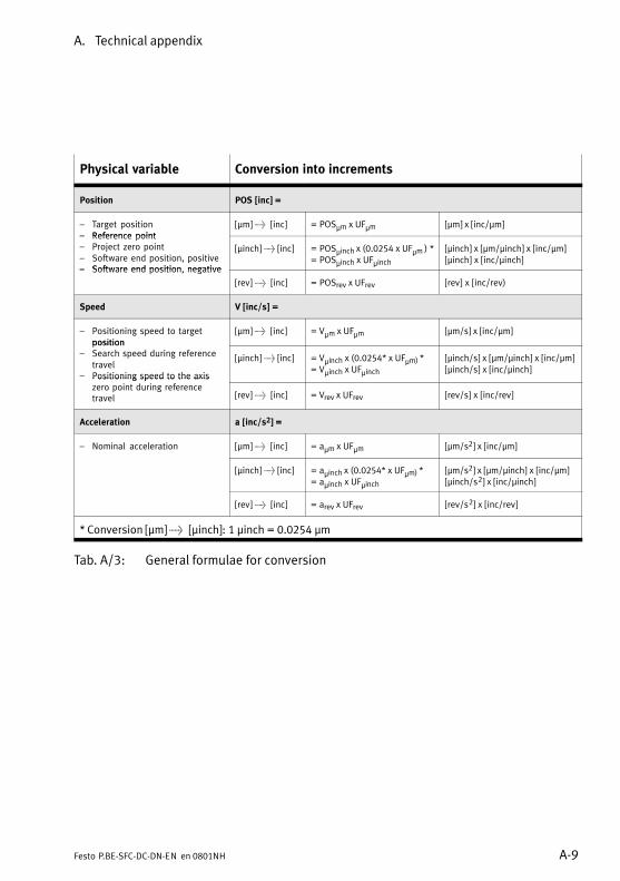
A. Technical appendix
A−9Festo P.BE−SFC−DC−DN−EN en 0801NH
Physical variable Conversion into increments
Position POS [inc] =
� Target position� Reference point
[�m] > [inc] = POSìm x UFìm [�m] x [inc/�m]� Reference point� Project zero point� Software end position, positive� Software end position negative
[�inch] > [inc] = POSìinch x (0.0254 x UFìm ) *= POSìinch x UFìinch
[�inch] x [�m/�inch] x [inc/�m][�inch] x [inc/�inch]
� Software end position, negative
[rev] > [inc] = POSrev x UFrev [rev] x [inc/rev)
Speed V [inc/s] =
� Positioning speed to targetposition
[�m] > [inc] = Vìm x UFìm [ìm/s] x [inc/ìm]position
� Search speed during referencetravel
� Positioning speed to the axis
[�inch] > [inc] = Vìinch x (0.0254* x UFìm) *= Vìinch x UFìinch
[ìinch/s] x [ìm/ìinch] x [inc/ìm][ìinch/s] x [inc/ìinch]
Positioning speed to the axiszero point during referencetravel [rev] > [inc] = Vrev x UFrev [rev/s] x [inc/rev]
Acceleration a [inc/s2] =
� Nominal acceleration [�m] > [inc] = aìm x UFìm [ìm/s2] x [inc/ìm]
[�inch] > [inc] = aìinch x (0.0254* x UFìm) *= aìinch x UFìinch
[ìm/s2] x [ìm/ìinch] x [inc/ìm][ìinch/s2] x [inc/ìinch]
[rev] > [inc] = arev x UFrev [rev/s2] x [inc/rev]
* Conversion [�m] > [�inch]�: 1 ìinch = 0.0254 ìm
Tab.�A/3: General formulae for conversion

A. Technical appendix
A−10 Festo P.BE−SFC−DC−DN−EN en 0801NH

Reference DeviceNet and FHPP
B−1Festo P.BE−SFC−DC−DN−EN en 0801NH
Appendix B
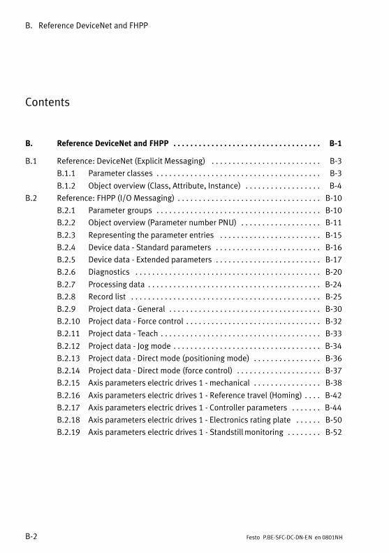
B. Reference DeviceNet and FHPP
B−2 Festo P.BE−SFC−DC−DN−EN en 0801NH
Contents
B. Reference DeviceNet and FHPP B−1 . . . . . . . . . . . . . . . . . . . . . . . . . . . . . . . . . . .
B.1 Reference: DeviceNet (Explicit Messaging) B−3 . . . . . . . . . . . . . . . . . . . . . . . . . .
B.1.1 Parameter classes B−3 . . . . . . . . . . . . . . . . . . . . . . . . . . . . . . . . . . . . . . .
B.1.2 Object overview (Class, Attribute, Instance) B−4 . . . . . . . . . . . . . . . . . .
B.2 Reference: FHPP (I/O Messaging) B−10 . . . . . . . . . . . . . . . . . . . . . . . . . . . . . . . . . .
B.2.1 Parameter groups B−10 . . . . . . . . . . . . . . . . . . . . . . . . . . . . . . . . . . . . . . .
B.2.2 Object overview (Parameter number PNU) B−11 . . . . . . . . . . . . . . . . . . .
B.2.3 Representing the parameter entries B−15 . . . . . . . . . . . . . . . . . . . . . . . .
B.2.4 Device data − Standard parameters B−16 . . . . . . . . . . . . . . . . . . . . . . . . .
B.2.5 Device data − Extended parameters B−17 . . . . . . . . . . . . . . . . . . . . . . . . .
B.2.6 Diagnostics B−20 . . . . . . . . . . . . . . . . . . . . . . . . . . . . . . . . . . . . . . . . . . . .
B.2.7 Processing data B−24 . . . . . . . . . . . . . . . . . . . . . . . . . . . . . . . . . . . . . . . . .
B.2.8 Record list B−25 . . . . . . . . . . . . . . . . . . . . . . . . . . . . . . . . . . . . . . . . . . . . .
B.2.9 Project data − General B−30 . . . . . . . . . . . . . . . . . . . . . . . . . . . . . . . . . . . .
B.2.10 Project data − Force control B−32 . . . . . . . . . . . . . . . . . . . . . . . . . . . . . . . .
B.2.11 Project data − Teach B−33 . . . . . . . . . . . . . . . . . . . . . . . . . . . . . . . . . . . . . .
B.2.12 Project data − Jog mode B−34 . . . . . . . . . . . . . . . . . . . . . . . . . . . . . . . . . . .
B.2.13 Project data − Direct mode (positioning mode) B−36 . . . . . . . . . . . . . . . .
B.2.14 Project data − Direct mode (force control) B−37 . . . . . . . . . . . . . . . . . . . .
B.2.15 Axis parameters electric drives 1 − mechanical B−38 . . . . . . . . . . . . . . . .
B.2.16 Axis parameters electric drives 1 − Reference travel (Homing) B−42 . . . .
B.2.17 Axis parameters electric drives 1 − Controller parameters B−44 . . . . . . .
B.2.18 Axis parameters electric drives 1 − Electronics rating plate B−50 . . . . . .
B.2.19 Axis parameters electric drives 1 − Standstill monitoring B−52 . . . . . . . .
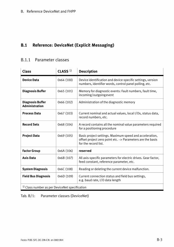
B. Reference DeviceNet and FHPP
B−3Festo P.BE−SFC−DC−DN−EN en 0801NH
B.1 Reference: DeviceNet (Explicit Messaging)
B.1.1 Parameter classes
Class CLASS 1) Description
Device Data 0x64 (100) Device identification and device−specific settings, versionnumbers, identifier words, control panel polling, etc.
Diagnosis Buffer 0x65 (101) Memory for diagnostic events: Fault numbers, fault time,incoming/outgoing event
Diagnosis BufferAdministration
0x66 (102) Administration of the diagnostic memory
Process Data 0x67 (103) Current nominal and actual values, local I/Os, status data,record numbers, etc.
Record Sets 0x68 (104) A record contains all the nominal value parameters requiredfor a positioning procedure
Project Data 0x69 (105) Basic project settings. Maximum speed and acceleration,offset project zero point etc. –> Parameters are the basisfor the record list.
Factor Group 0x6A (106) reserved
Axis Data 0x6B (107) All axis−specific parameters for electric drives. Gear factor,feed constant, reference parameter, etc.
System Diagnosis 0x6C (108) Reading or deleting the current device malfunction.
Field Bus Diagnosis 0x6D (109) Current connection status and field bus settings, e.g. baud rate, I/O data length
1) Class number as per DeviceNet specification
Tab.�B/1: Parameter classes (DeviceNet)
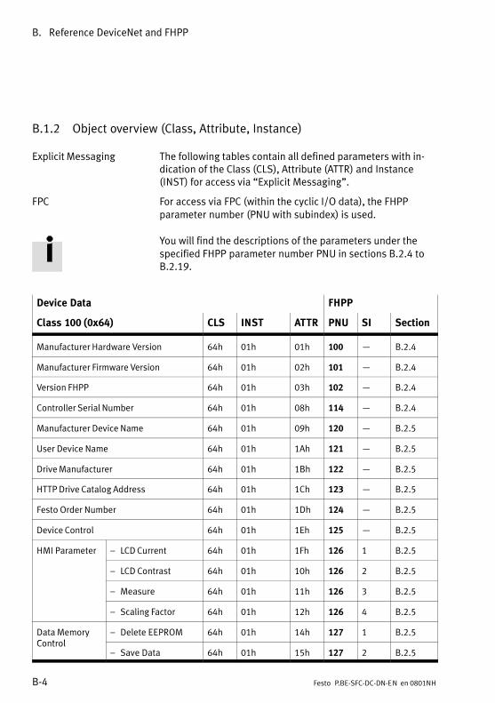
B. Reference DeviceNet and FHPP
B−4 Festo P.BE−SFC−DC−DN−EN en 0801NH
B.1.2 Object overview (Class, Attribute, Instance)
Explicit Messaging The following tables contain all defined parameters with in�dication of the Class (CLS), Attribute (ATTR) and Instance(INST) for access via �Explicit Messaging".
FPC For access via FPC (within the cyclic I/O data), the FHPPparameter number (PNU with subindex) is used.
You will find the descriptions of the parameters under thespecified FHPP parameter number PNU in sections B.2.4 toB.2.19.
Device Data FHPP
Class 100 (0x64) CLS INST ATTR PNU SI Section
Manufacturer Hardware Version 64h 01h 01h 100 B.2.4
Manufacturer Firmware Version 64h 01h 02h 101 B.2.4
Version FHPP 64h 01h 03h 102 B.2.4
Controller Serial Number 64h 01h 08h 114 B.2.4
Manufacturer Device Name 64h 01h 09h 120 B.2.5
User Device Name 64h 01h 1Ah 121 B.2.5
Drive Manufacturer 64h 01h 1Bh 122 B.2.5
HTTP Drive Catalog Address 64h 01h 1Ch 123 B.2.5
Festo Order Number 64h 01h 1Dh 124 B.2.5
Device Control 64h 01h 1Eh 125 B.2.5
HMI Parameter � LCD Current 64h 01h 1Fh 126 1 B.2.5
� LCD Contrast 64h 01h 10h 126 2 B.2.5
� Measure 64h 01h 11h 126 3 B.2.5
� Scaling Factor 64h 01h 12h 126 4 B.2.5
Data MemoryControl
� Delete EEPROM 64h 01h 14h 127 1 B.2.5Control
� Save Data 64h 01h 15h 127 2 B.2.5
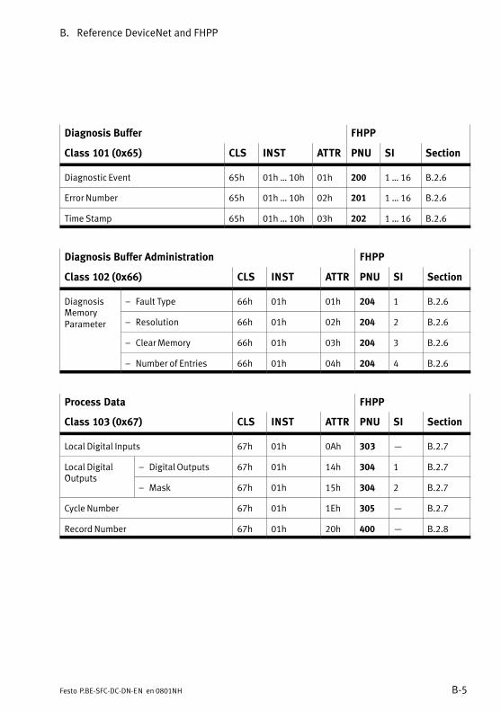
B. Reference DeviceNet and FHPP
B−5Festo P.BE−SFC−DC−DN−EN en 0801NH
Diagnosis Buffer FHPP
Class 101 (0x65) CLS INST ATTR PNU SI Section
Diagnostic Event 65h 01h � 10h 01h 200 1 � 16 B.2.6
Error Number 65h 01h � 10h 02h 201 1 � 16 B.2.6
Time Stamp 65h 01h � 10h 03h 202 1 � 16 B.2.6
Diagnosis Buffer Administration FHPP
Class 102 (0x66) CLS INST ATTR PNU SI Section
DiagnosisMemory
� Fault Type 66h 01h 01h 204 1 B.2.6MemoryParameter � Resolution 66h 01h 02h 204 2 B.2.6
� Clear Memory 66h 01h 03h 204 3 B.2.6
� Number of Entries 66h 01h 04h 204 4 B.2.6
Process Data FHPP
Class 103 (0x67) CLS INST ATTR PNU SI Section
Local Digital Inputs 67h 01h 0Ah 303 B.2.7
Local DigitalOutputs
� Digital Outputs 67h 01h 14h 304 1 B.2.7Outputs
� Mask 67h 01h 15h 304 2 B.2.7
Cycle Number 67h 01h 1Eh 305 B.2.7
Record Number 67h 01h 20h 400 B.2.8

B. Reference DeviceNet and FHPP
B−6 Festo P.BE−SFC−DC−DN−EN en 0801NH
Record Sets FHPP
Class 104 (0x68) CLS INST ATTR PNU SI Section
Record Control Byte 1 68h 01h � 20h 01h 401 1 � 32 B.2.8
Record Target Position 68h 01h � 20h 04h 404 1 � 32 B.2.8
Record Velocity 68h 01h � 20h 06h 406 1 � 32 B.2.8
Record Acceleration 68h 01h � 20h 07h 407 1 � 32 B.2.8
Record Deceleration 68h 01h � 20h 08h 408 1 � 32 B.2.8
Project Data FHPP
Class 105 (0x69) CLS INST ATTR PNU SI Section
Project Zero Point 69h 01h 01h 500 B.2.9
Software End Position � Lower Limit 69h 01h 02h 501 1 B.2.9
� Upper Limit 69h 01h 03h 501 2 B.2.9
Max Velocity 69h 01h 04h 502 B.2.9
Max Acceleration 69h 01h 05h 503 B.2.9
Stroke Limit 69h 01h 0Ah 510 B.2.10
Min Torque/Force 69h 01h 0Bh 511 B.2.10
Max Torque/Force 69h 01h 0Ch 512 B.2.10
Teach Target 69h 01h 14h 520 B.2.11
Jog Mode Velocity Phase 2 69h 01h 1Fh 531 B.2.11
Jog Mode Acceleration 69h 01h 20h 532 B.2.11
Jog Mode Deceleration 69h 01h 21h 533 B.2.11
Jog Mode Time Phase 1 69h 01h 22h 534 B.2.11
Direct Mode Acceleration 69h 01h 29h 541 B.2.13
Direct Mode Deceleration 69h 01h 30h 542 B.2.13
Force Target Window 69h 01h 34h 552 B.2.14
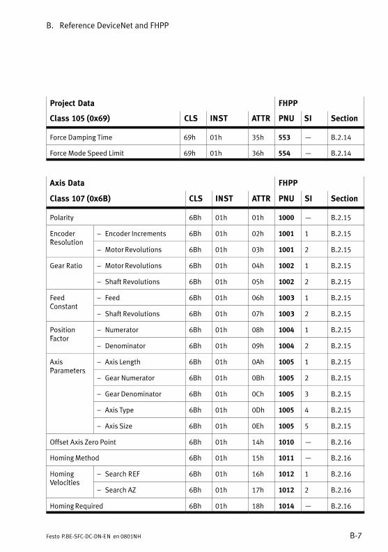
B. Reference DeviceNet and FHPP
B−7Festo P.BE−SFC−DC−DN−EN en 0801NH
Project Data FHPP
Class 105 (0x69) SectionSIPNUATTRINSTCLS
Force Damping Time 69h 01h 35h 553 B.2.14
Force Mode Speed Limit 69h 01h 36h 554 B.2.14
Axis Data FHPP
Class 107 (0x6B) CLS INST ATTR PNU SI Section
Polarity 6Bh 01h 01h 1000 B.2.15
EncoderResolution
� Encoder Increments 6Bh 01h 02h 1001 1 B.2.15Resolution
� Motor Revolutions 6Bh 01h 03h 1001 2 B.2.15
Gear Ratio � Motor Revolutions 6Bh 01h 04h 1002 1 B.2.15
� Shaft Revolutions 6Bh 01h 05h 1002 2 B.2.15
FeedConstant
� Feed 6Bh 01h 06h 1003 1 B.2.15Constant
� Shaft Revolutions 6Bh 01h 07h 1003 2 B.2.15
PositionFactor
� Numerator 6Bh 01h 08h 1004 1 B.2.15Factor
� Denominator 6Bh 01h 09h 1004 2 B.2.15
AxisParameters
� Axis Length 6Bh 01h 0Ah 1005 1 B.2.15Parameters
� Gear Numerator 6Bh 01h 0Bh 1005 2 B.2.15
� Gear Denominator 6Bh 01h 0Ch 1005 3 B.2.15
� Axis Type 6Bh 01h 0Dh 1005 4 B.2.15
� Axis Size 6Bh 01h 0Eh 1005 5 B.2.15
Offset Axis Zero Point 6Bh 01h 14h 1010 B.2.16
Homing Method 6Bh 01h 15h 1011 B.2.16
HomingVelocities
� Search REF 6Bh 01h 16h 1012 1 B.2.16Velocities
� Search AZ 6Bh 01h 17h 1012 2 B.2.16
Homing Required 6Bh 01h 18h 1014 B.2.16
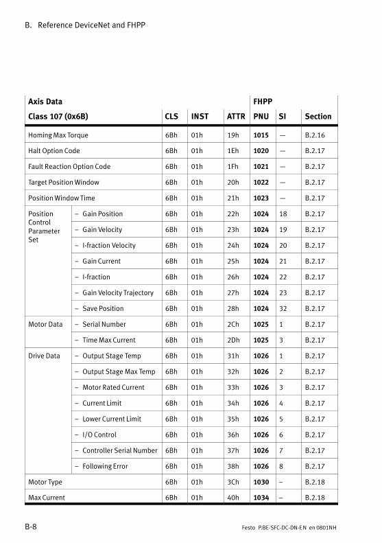
B. Reference DeviceNet and FHPP
B−8 Festo P.BE−SFC−DC−DN−EN en 0801NH
Axis Data FHPP
Class 107 (0x6B) SectionSIPNUATTRINSTCLS
Homing Max Torque 6Bh 01h 19h 1015 B.2.16
Halt Option Code 6Bh 01h 1Eh 1020 B.2.17
Fault Reaction Option Code 6Bh 01h 1Fh 1021 B.2.17
Target Position Window 6Bh 01h 20h 1022 B.2.17
Position Window Time 6Bh 01h 21h 1023 B.2.17
PositionControl
� Gain Position 6Bh 01h 22h 1024 18 B.2.17ControlParameterS
� Gain Velocity 6Bh 01h 23h 1024 19 B.2.17
Set� I−fraction Velocity 6Bh 01h 24h 1024 20 B.2.17
� Gain Current 6Bh 01h 25h 1024 21 B.2.17
� I−fraction 6Bh 01h 26h 1024 22 B.2.17
� Gain Velocity Trajectory 6Bh 01h 27h 1024 23 B.2.17
� Save Position 6Bh 01h 28h 1024 32 B.2.17
Motor Data � Serial Number 6Bh 01h 2Ch 1025 1 B.2.17
� Time Max Current 6Bh 01h 2Dh 1025 3 B.2.17
Drive Data � Output Stage Temp 6Bh 01h 31h 1026 1 B.2.17
� Output Stage Max Temp 6Bh 01h 32h 1026 2 B.2.17
� Motor Rated Current 6Bh 01h 33h 1026 3 B.2.17
� Current Limit 6Bh 01h 34h 1026 4 B.2.17
� Lower Current Limit 6Bh 01h 35h 1026 5 B.2.17
� I/O Control 6Bh 01h 36h 1026 6 B.2.17
� Controller Serial Number 6Bh 01h 37h 1026 7 B.2.17
� Following Error 6Bh 01h 38h 1026 8 B.2.17
Motor Type 6Bh 01h 3Ch 1030 � B.2.18
Max Current 6Bh 01h 40h 1034 � B.2.18
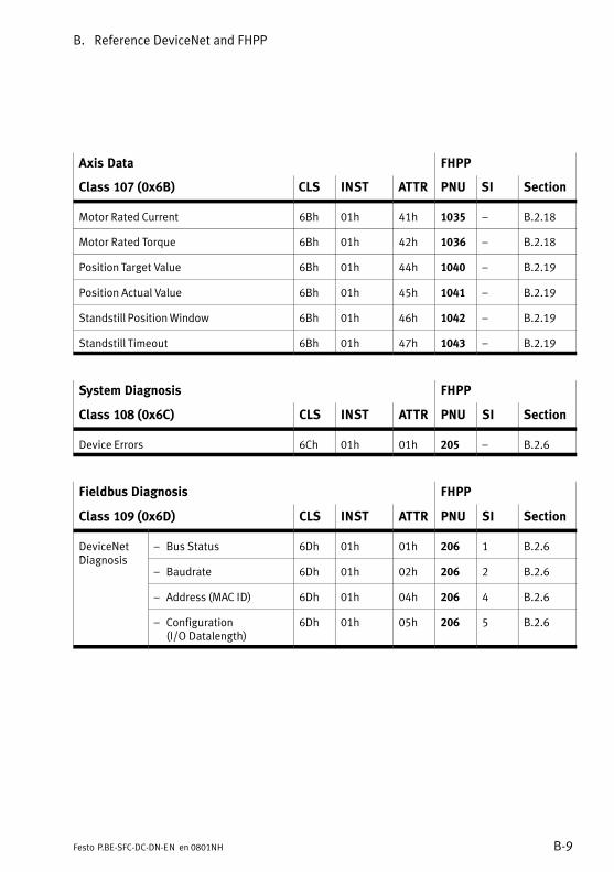
B. Reference DeviceNet and FHPP
B−9Festo P.BE−SFC−DC−DN−EN en 0801NH
Axis Data FHPP
Class 107 (0x6B) SectionSIPNUATTRINSTCLS
Motor Rated Current 6Bh 01h 41h 1035 � B.2.18
Motor Rated Torque 6Bh 01h 42h 1036 � B.2.18
Position Target Value 6Bh 01h 44h 1040 � B.2.19
Position Actual Value 6Bh 01h 45h 1041 � B.2.19
Standstill Position Window 6Bh 01h 46h 1042 � B.2.19
Standstill Timeout 6Bh 01h 47h 1043 � B.2.19
System Diagnosis FHPP
Class 108 (0x6C) CLS INST ATTR PNU SI Section
Device Errors 6Ch 01h 01h 205 � B.2.6
Fieldbus Diagnosis FHPP
Class 109 (0x6D) CLS INST ATTR PNU SI Section
DeviceNetDiagnosis
� Bus Status 6Dh 01h 01h 206 1 B.2.6Diagnosis
� Baudrate 6Dh 01h 02h 206 2 B.2.6
� Address (MAC ID) 6Dh 01h 04h 206 4 B.2.6
� Configuration (I/O Datalength)
6Dh 01h 05h 206 5 B.2.6
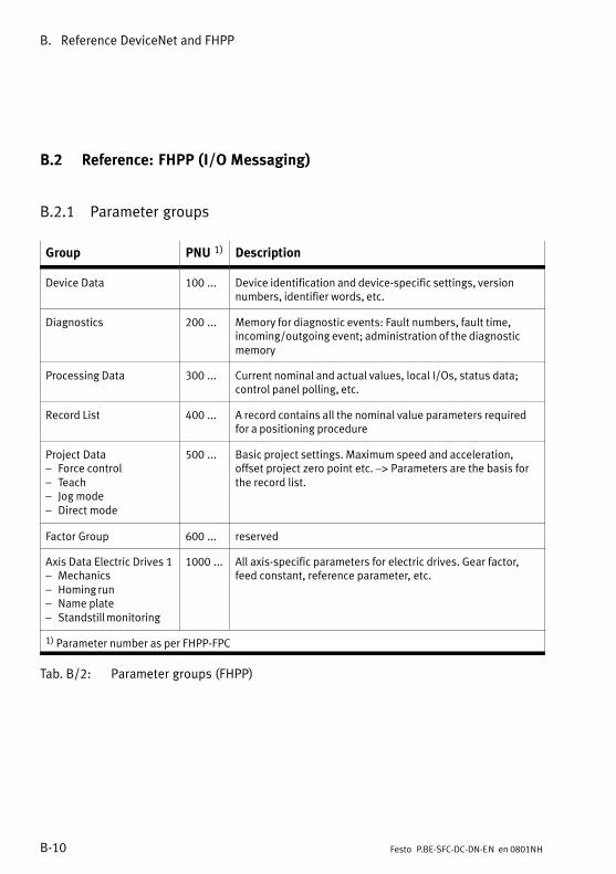
B. Reference DeviceNet and FHPP
B−10 Festo P.BE−SFC−DC−DN−EN en 0801NH
B.2 Reference: FHPP (I/O Messaging)
B.2.1 Parameter groups
Group PNU 1) Description
Device Data 100 ... Device identification and device−specific settings, versionnumbers, identifier words, etc.
Diagnostics 200 ... Memory for diagnostic events: Fault numbers, fault time,incoming/outgoing event; administration of the diagnosticmemory
Processing Data 300 ... Current nominal and actual values, local I/Os, status data;control panel polling, etc.
Record List 400 ... A record contains all the nominal value parameters requiredfor a positioning procedure
Project Data� Force control� Teach� Jog mode� Direct mode
500 ... Basic project settings. Maximum speed and acceleration,offset project zero point etc. –> Parameters are the basis forthe record list.
Factor Group 600 ... reserved
Axis Data Electric Drives 1� Mechanics� Homing run� Name plate� Standstill monitoring
1000 ... All axis−specific parameters for electric drives. Gear factor,feed constant, reference parameter, etc.
1) Parameter number as per FHPP−FPC
Tab.�B/2: Parameter groups (FHPP)
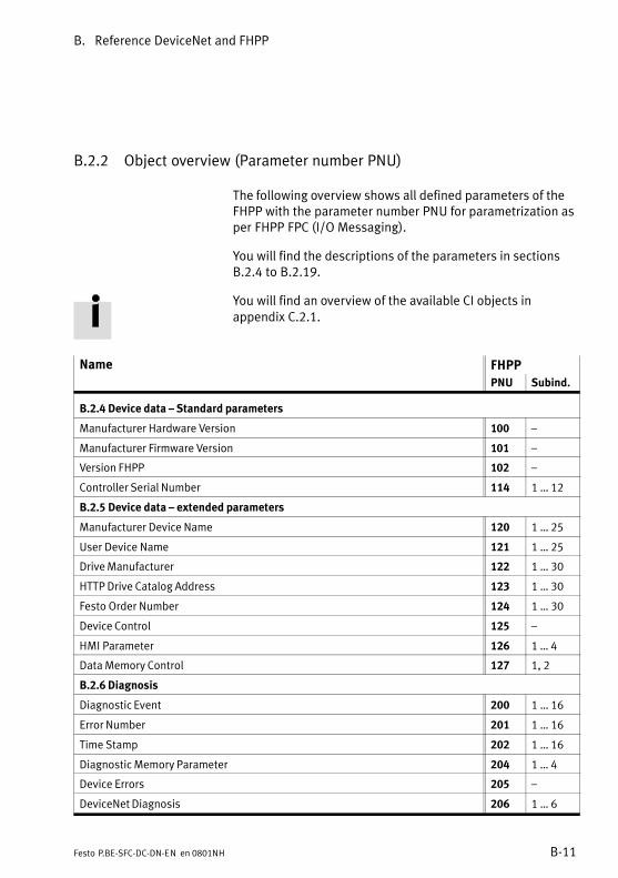
B. Reference DeviceNet and FHPP
B−11Festo P.BE−SFC−DC−DN−EN en 0801NH
B.2.2 Object overview (Parameter number PNU)
The following overview shows all defined parameters of theFHPP with the parameter number PNU for parametrization asper FHPP FPC (I/O Messaging).
You will find the descriptions of the parameters in sectionsB.2.4 to B.2.19.
You will find an overview of the available CI objects inappendix C.2.1.
Name FHPP
PNU Subind.
B.2.4 Device data � Standard parameters
Manufacturer Hardware Version 100 �
Manufacturer Firmware Version 101 �
Version FHPP 102 �
Controller Serial Number 114 1 � 12
B.2.5 Device data � extended parameters
Manufacturer Device Name 120 1 � 25
User Device Name 121 1 � 25
Drive Manufacturer 122 1 � 30
HTTP Drive Catalog Address 123 1 � 30
Festo Order Number 124 1 � 30
Device Control 125 �
HMI Parameter 126 1 � 4
Data Memory Control 127 1, 2
B.2.6 Diagnosis
Diagnostic Event 200 1 � 16
Error Number 201 1 � 16
Time Stamp 202 1 � 16
Diagnostic Memory Parameter 204 1 � 4
Device Errors 205 �
DeviceNet Diagnosis 206 1 � 6
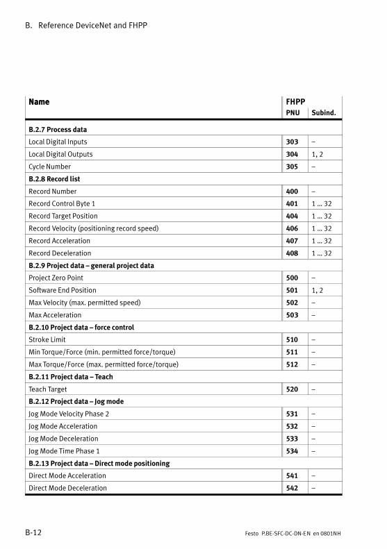
B. Reference DeviceNet and FHPP
B−12 Festo P.BE−SFC−DC−DN−EN en 0801NH
Name FHPPName
Subind.PNU
B.2.7 Process data
Local Digital Inputs 303 �
Local Digital Outputs 304 1, 2
Cycle Number 305 �
B.2.8 Record list
Record Number 400 �
Record Control Byte 1 401 1 � 32
Record Target Position 404 1 � 32
Record Velocity (positioning record speed) 406 1 � 32
Record Acceleration 407 1 � 32
Record Deceleration 408 1 � 32
B.2.9 Project data � general project data
Project Zero Point 500 �
Software End Position 501 1, 2
Max Velocity (max. permitted speed) 502 �
Max Acceleration 503 �
B.2.10 Project data � force control
Stroke Limit 510 �
Min Torque/Force (min. permitted force/torque) 511 �
Max Torque/Force (max. permitted force/torque) 512 �
B.2.11 Project data � Teach
Teach Target 520 �
B.2.12 Project data � Jog mode
Jog Mode Velocity Phase 2 531 �
Jog Mode Acceleration 532 �
Jog Mode Deceleration 533 �
Jog Mode Time Phase 1 534 �
B.2.13 Project data � Direct mode positioning
Direct Mode Acceleration 541 �
Direct Mode Deceleration 542 �
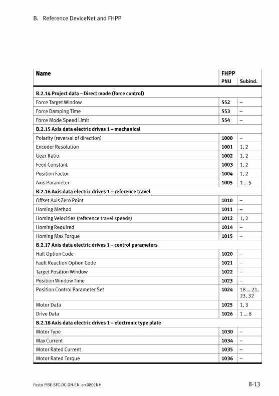
B. Reference DeviceNet and FHPP
B−13Festo P.BE−SFC−DC−DN−EN en 0801NH
Name FHPPName
Subind.PNU
B.2.14 Project data � Direct mode (force control)
Force Target Window 552 �
Force Damping Time 553 �
Force Mode Speed Limit 554 �
B.2.15 Axis data electric drives 1 � mechanical
Polarity (reversal of direction) 1000 �
Encoder Resolution 1001 1, 2
Gear Ratio 1002 1, 2
Feed Constant 1003 1, 2
Position Factor 1004 1, 2
Axis Parameter 1005 1 � 5
B.2.16 Axis data electric drives 1 � reference travel
Offset Axis Zero Point 1010 �
Homing Method 1011 �
Homing Velocities (reference travel speeds) 1012 1, 2
Homing Required 1014 �
Homing Max Torque 1015 �
B.2.17 Axis data electric drives 1 � control parameters
Halt Option Code 1020 �
Fault Reaction Option Code 1021 �
Target Position Window 1022 �
Position Window Time 1023 �
Position Control Parameter Set 1024 18 � 21,23, 32
Motor Data 1025 1, 3
Drive Data 1026 1 � 8
B.2.18 Axis data electric drives 1 � electronic type plate
Motor Type 1030 �
Max Current 1034 �
Motor Rated Current 1035 �
Motor Rated Torque 1036 �
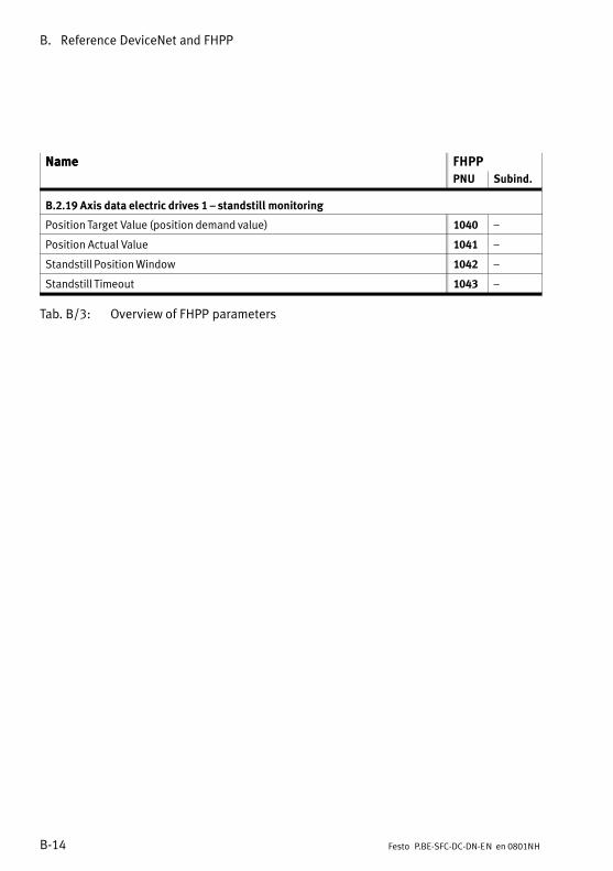
B. Reference DeviceNet and FHPP
B−14 Festo P.BE−SFC−DC−DN−EN en 0801NH
Name FHPPName
Subind.PNU
B.2.19 Axis data electric drives 1 � standstill monitoring
Position Target Value (position demand value) 1040 �
Position Actual Value 1041 �
Standstill Position Window 1042 �
Standstill Timeout 1043 �
Tab.�B/3: Overview of FHPP parameters

B. Reference DeviceNet and FHPP
B−15Festo P.BE−SFC−DC−DN−EN en 0801NH
B.2.3 Representing the parameter entries
Encoder resolution
FHPP 1001 1 ... 2 Array uint32 rw
Description Encoder resolution in increments / revolutionsThe encoder resolution is fixed and cannot be modified by the user. The calculated value is derived from the fraction (encoder−increments/motor revolution).
Encoder increments 1001 1 uint32 rw
Value range: 0 ... 232 − 1Default: 500
Motor revolutions 1001 2 uint32 rw
Fix = 1
CI 608Fh 01h ... 02h Array uint32 rw
DeviceNet 107 2 ... 3 1 uint32 rw
1 Name of the parameter
2 PNU (parameter number)
3 Subindices of parameter, if present
4 Variable type of the element
5 File type of the element
6 Read/write permission: ro = read onlywo = write onlyrw = read and write
7 Description of the parameter
8 Name and description of the subindices, if available (specification related to FHPP, if available)
9 Corresponding objects (if present)CI: Column: 2 Obj.number 3 Subindex (hex)DeviceNet: Column: 2 Class 3 Instance 4 Attribute
Fig.�B/1: Representing the parameter entries
1 2 3 4 5 6
7
8
9
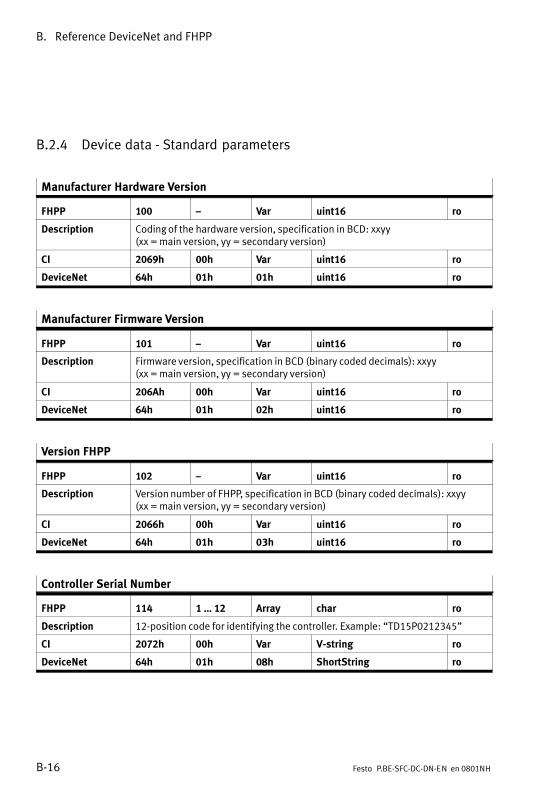
B. Reference DeviceNet and FHPP
B−16 Festo P.BE−SFC−DC−DN−EN en 0801NH
B.2.4 Device data − Standard parameters
Manufacturer Hardware Version
FHPP 100 � Var uint16 ro
Description Coding of the hardware version, specification in BCD: xxyy(xx = main version, yy = secondary version)
CI 2069h 00h Var uint16 ro
DeviceNet 64h 01h 01h uint16 ro
Manufacturer Firmware Version
FHPP 101 � Var uint16 ro
Description Firmware version, specification in BCD (binary coded decimals): xxyy(xx = main version, yy = secondary version)
CI 206Ah 00h Var uint16 ro
DeviceNet 64h 01h 02h uint16 ro
Version FHPP
FHPP 102 � Var uint16 ro
Description Version number of FHPP, specification in BCD (binary coded decimals): xxyy(xx = main version, yy = secondary version)
CI 2066h 00h Var uint16 ro
DeviceNet 64h 01h 03h uint16 ro
Controller Serial Number
FHPP 114 1 � 12 Array char ro
Description 12−position code for identifying the controller. Example: �TD15P0212345"
CI 2072h 00h Var V−string ro
DeviceNet 64h 01h 08h ShortString ro
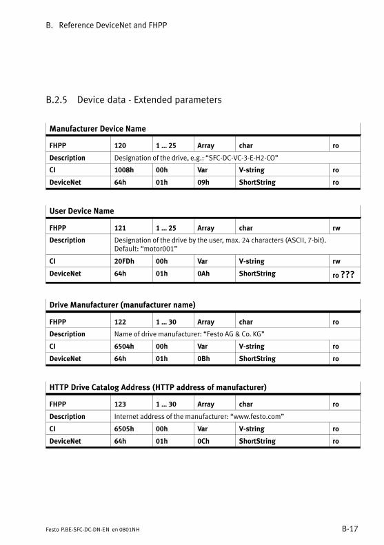
B. Reference DeviceNet and FHPP
B−17Festo P.BE−SFC−DC−DN−EN en 0801NH
B.2.5 Device data − Extended parameters
Manufacturer Device Name
FHPP 120 1 � 25 Array char ro
Description Designation of the drive, e.g.: �SFC−DC−VC−3−E−H2−CO"
CI 1008h 00h Var V−string ro
DeviceNet 64h 01h 09h ShortString ro
User Device Name
FHPP 121 1 � 25 Array char rw
Description Designation of the drive by the user, max. 24 characters (ASCII, 7−bit).Default: �motor001"
CI 20FDh 00h Var V−string rw
DeviceNet 64h 01h 0Ah ShortString ro ???
Drive Manufacturer (manufacturer name)
FHPP 122 1 � 30 Array char ro
Description Name of drive manufacturer: �Festo AG & Co. KG"
CI 6504h 00h Var V−string ro
DeviceNet 64h 01h 0Bh ShortString ro
HTTP Drive Catalog Address (HTTP address of manufacturer)
FHPP 123 1 � 30 Array char ro
Description Internet address of the manufacturer: �www.festo.com"
CI 6505h 00h Var V−string ro
DeviceNet 64h 01h 0Ch ShortString ro
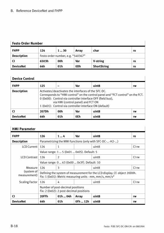
B. Reference DeviceNet and FHPP
B−18 Festo P.BE−SFC−DC−DN−EN en 0801NH
Festo Order Number
FHPP 124 1 � 30 Array char ro
Description Festo order number, e.g. �540367"
CI 6503h 00h Var V−string ro
DeviceNet 64h 01h 0Dh ShortString ro
Device Control
FHPP 125 � Var uint8 rw
Description Activates/deactivates the interfaces of the SFC−DC.Corresponds to �HMI control" on the control panel and �FCT control" on the FCT.0 (0x00): Control via controller interface OFF (field bus),
via HMI (control panel) and FCT ON1 (0x01): Control via controller interface ON (default)
CI 207Dh 00h Var uint8 rw
DeviceNet 64h 01h 0Eh uint8 rw
HMI Parameter
FHPP 126 1 � 4 Var uint8 ro
Description Parametrizing the MMI functions (only with SFC−DC−...−H2−...)
LCD Current 126 1 uint8 CI rw
Value range: 1 � 5 (0x01 � 0x05). Default: 5
LCD Contrast 126 2 uint8 CI rw
Value range: 0 � 63 (0x00 � 0x3F). Default: 10
Measure( f
126 3 uint8 CI rw(system of
measurement)Defining the system of measurement for the LCD display. Cf. object 20D0h.Fix: 1 (0x01): Metric measuring units − mm, mm/s, mm/s2
Scaling Factor 126 4 uint8 CI rwg
Number of post−decimal positionsFix: 2 (0x02): 2 post−decimal positions
CI 20FFh 01h � 04h Array uint8 rw
DeviceNet 64h 01h 0Fh � 12h uint8 rw
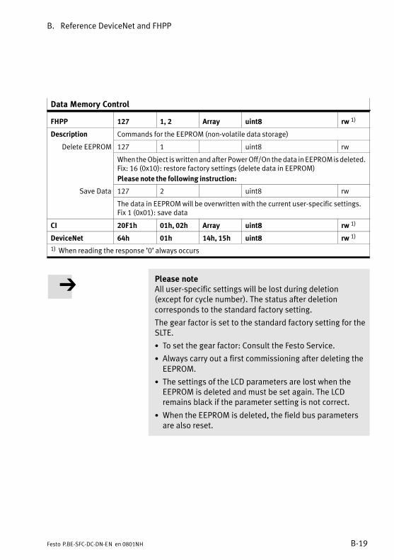
B. Reference DeviceNet and FHPP
B−19Festo P.BE−SFC−DC−DN−EN en 0801NH
Data Memory Control
FHPP 127 1, 2 Array uint8 rw 1)
Description Commands for the EEPROM (non−volatile data storage)
Delete EEPROM 127 1 uint8 rw
When the Object is written and after Power Off/On the data in EEPROM is deleted.Fix: 16 (0x10): restore factory settings (delete data in EEPROM)
Please note the following instruction:
Save Data 127 2 uint8 rw
The data in EEPROM will be overwritten with the current user−specific settings.Fix 1 (0x01): save data
CI 20F1h 01h, 02h Array uint8 rw 1)
DeviceNet 64h 01h 14h, 15h uint8 rw 1)
1) When reading the response ’0’ always occurs
Please noteAll user−specific settings will be lost during deletion(except for cycle number). The status after deletioncorresponds to the standard factory setting.
The gear factor is set to the standard factory setting for theSLTE.
· To set the gear factor: Consult the Festo Service.
· Always carry out a first commissioning after deleting theEEPROM.
· The settings of the LCD parameters are lost when theEEPROM is deleted and must be set again. The LCDremains black if the parameter setting is not correct.
· When the EEPROM is deleted, the field bus parametersare also reset.
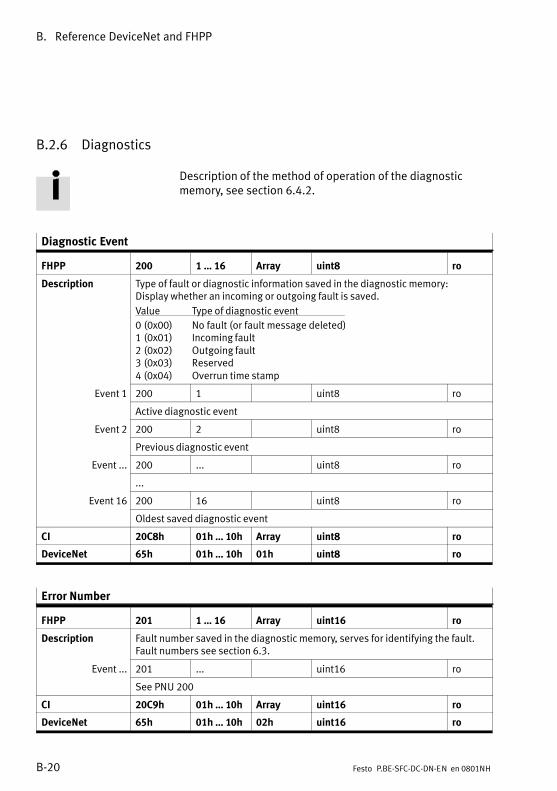
B. Reference DeviceNet and FHPP
B−20 Festo P.BE−SFC−DC−DN−EN en 0801NH
B.2.6 Diagnostics
Description of the method of operation of the diagnosticmemory, see section 6.4.2.
Diagnostic Event
FHPP 200 1 � 16 Array uint8 ro
Description Type of fault or diagnostic information saved in the diagnostic memory: Display whether an incoming or outgoing fault is saved.
Value Type of diagnostic event
0 (0x00) No fault (or fault message deleted)1 (0x01) Incoming fault2 (0x02) Outgoing fault3 (0x03) Reserved4 (0x04) Overrun time stamp
Event 1 200 1 uint8 ro
Active diagnostic event
Event 2 200 2 uint8 ro
Previous diagnostic event
Event ... 200 ... uint8 ro
...
Event 16 200 16 uint8 ro
Oldest saved diagnostic event
CI 20C8h 01h � 10h Array uint8 ro
DeviceNet 65h 01h � 10h 01h uint8 ro
Error Number
FHPP 201 1 � 16 Array uint16 ro
Description Fault number saved in the diagnostic memory, serves for identifying the fault.Fault numbers see section 6.3.
Event ... 201 ... uint16 ro
See PNU 200
CI 20C9h 01h � 10h Array uint16 ro
DeviceNet 65h 01h � 10h 02h uint16 ro
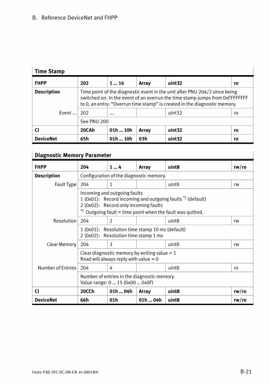
B. Reference DeviceNet and FHPP
B−21Festo P.BE−SFC−DC−DN−EN en 0801NH
Time Stamp
FHPP 202 1 � 16 Array uint32 ro
Description Time point of the diagnostic event in the unit after PNU 204/2 since beingswitched on. In the event of an overrun the time stamp jumps from 0xFFFFFFFFto 0, an entry: �Overrun time stamp" is created in the diagnostic memory.
Event ... 202 ... uint32 ro
See PNU 200
CI 20CAh 01h � 10h Array uint32 ro
DeviceNet 65h 01h � 10h 03h uint32 ro
Diagnostic Memory Parameter
FHPP 204 1 � 4 Array uint8 rw/ro
Description Configuration of the diagnostic memory.
Fault Type 204 1 uint8 rwyp
Incoming and outgoing faults1 (0x01): Record incoming and outgoing faults *) (default)2 (0x02): Record only incoming faults*) Outgoing fault = time point when the fault was quitted.
Resolution 204 2 uint8 rw
1 (0x01): Resolution time stamp 10 ms (default)2 (0x02): Resolution time stamp 1 ms
Clear Memory 204 3 uint8 rwy
Clear diagnostic memory by writing value = 1Read will always reply with value = 0
Number of Entries 204 4 uint8 ro
Number of entries in the diagnostic memory.Value range: 0 � 15 (0x00 � 0x0F)
CI 20CCh 01h � 04h Array uint8 rw/ro
DeviceNet 66h 01h 01h � 04h uint8 rw/ro
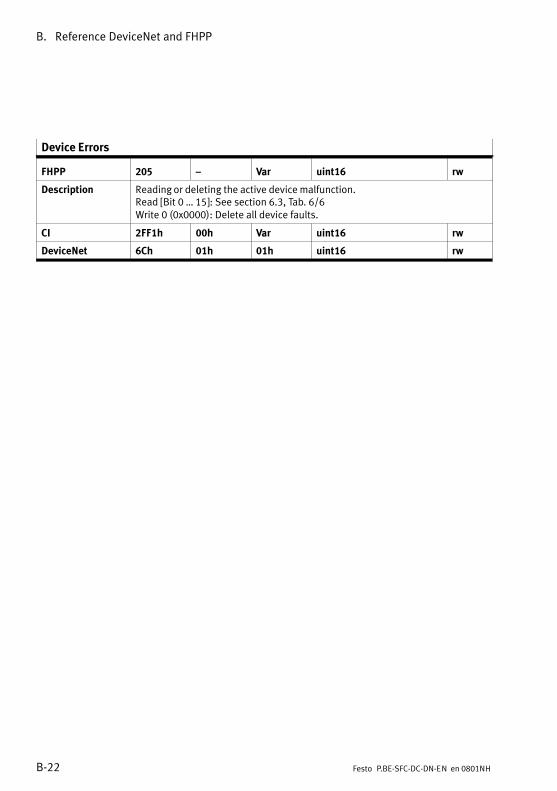
B. Reference DeviceNet and FHPP
B−22 Festo P.BE−SFC−DC−DN−EN en 0801NH
Device Errors
FHPP 205 � Var uint16 rw
Description Reading or deleting the active device malfunction.Read [Bit 0 � 15]�: See section 6.3, Tab.�6/6Write 0 (0x0000): Delete all device faults.
CI 2FF1h 00h Var uint16 rw
DeviceNet 6Ch 01h 01h uint16 rw

B. Reference DeviceNet and FHPP
B−23Festo P.BE−SFC−DC−DN−EN en 0801NH
DeviceNet Diagnosis
FHPP 206 1 � 6 Array uint8 ro
Description Read out the diagnostic data
Bus Status 206 1 uint8 ro
Current bus status of the DeviceNet device:0x00: �No Power/BUS−OFF"0x01: �Unrecoverable Fault"0x04, 0x05: �Minor Fault"0x10: �Operational"0x40, 0x50: �Device in Standby"
Baud rate 206 2 uint8 ro
Current baud rate0 (0x00): 125 kBaud 1 (0x01): 250 kBaud 2 (0x02): 500 kBaud 255 (0xFF): invalid baud rate (default)
� 206 3 uint8 ro
reservedFix: 0 (0x00)
Address 206 4 uint8 ro
Station address (MAC ID)Value range: 0 � 63 (0x00 � 0x3F)Default: 255 (0xff ) � invalid address
Configuration 206 5 uint8 rog
Current configuration:16 (0x10): Festo FHPP Standard (8 bytes I/O)17 (0x11): Festo FHPP Standard + FPC (2 x 8 bytes I/O)255 (0xff ): Invalid value (default)
� 206 6 uint8 ro
reserved
CI 2FF2h 01h � 06h Array uint8 ro
DeviceNet 6Dh 01h 01h � 05h uint8 ro
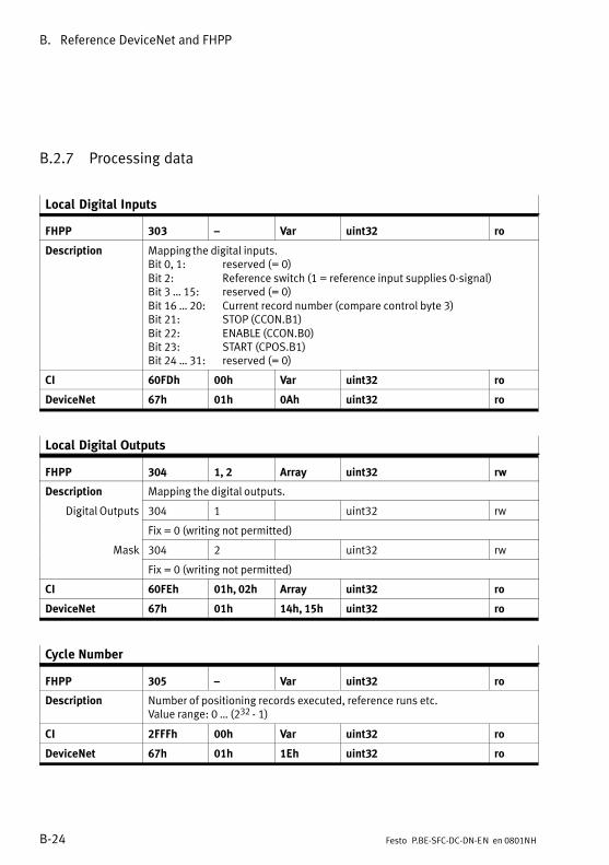
B. Reference DeviceNet and FHPP
B−24 Festo P.BE−SFC−DC−DN−EN en 0801NH
B.2.7 Processing data
Local Digital Inputs
FHPP 303 � Var uint32 ro
Description Mapping the digital inputs.Bit 0, 1: reserved (= 0)Bit 2: Reference switch (1 = reference input supplies 0−signal)Bit 3 � 15: reserved (= 0)Bit 16 � 20: Current record number (compare control byte 3)Bit 21: STOP (CCON.B1)Bit 22: ENABLE (CCON.B0)Bit 23: START (CPOS.B1)Bit 24 � 31: reserved (= 0)
CI 60FDh 00h Var uint32 ro
DeviceNet 67h 01h 0Ah uint32 ro
Local Digital Outputs
FHPP 304 1, 2 Array uint32 rw
Description Mapping the digital outputs.
Digital Outputs 304 1 uint32 rwg p
Fix = 0 (writing not permitted)
Mask 304 2 uint32 rw
Fix = 0 (writing not permitted)
CI 60FEh 01h, 02h Array uint32 ro
DeviceNet 67h 01h 14h, 15h uint32 ro
Cycle Number
FHPP 305 � Var uint32 ro
Description Number of positioning records executed, reference runs etc.Value range: 0 � (232 − 1)
CI 2FFFh 00h Var uint32 ro
DeviceNet 67h 01h 1Eh uint32 ro

B. Reference DeviceNet and FHPP
B−25Festo P.BE−SFC−DC−DN−EN en 0801NH
B.2.8 Record list
Record no. RCB1 Nominalposition
Speed Accelerat.move�ment to
Accelerat.brake
FHPP PNU 400 401 404 406 407 408
DeviceNet 67h/01h/20h 68h/01h � 68h/04 � 68h/06h � 68h/07h � 68h/08h �
Type uint8 uint8 int32 uint32 uint32 uint32
Data Record no. 0 Homing run
Record no. 1 ... Nominalvalue(record 0)
Nominalvalue(record 0)
Nominalvalue(record 0)
Nominalvalue(record 0)
... ... Nominalvalue(record 1)
Nominalvalue(record 1)
Nominalvalue(record 1)
Nominalvalue(record 1)
... ... ... ... ... ...
Record no. 30 ... Nominalvalue(record 30)
Nominalvalue(record 30)
Nominalvalue(record 30)
Nominalvalue(record 30)
31 (254) Jog mode
32 (255) Direct mode
Tab.�B/4: Structure of FHPP record list
FHPP In FHPP record selection for reading and writing is made viathe subindex of the PNUs 401 � 408. Above PNU 400 theactive record for positioning or teaching is selected.
Record Number
FHPP 400 � Var uint8 rw
Description The active / selected record Is also valid when the drive is not in Record selectmode (e.g. during teaching). In Record select mode this parameter istransferred to the cyclic I/O data.Value range: 0 � 31 (0x00 � 0x1F)
CI 2033h � / 00h Var uint8 rw
DeviceNet 67h 01h 20h uint8 rw

B. Reference DeviceNet and FHPP
B−26 Festo P.BE−SFC−DC−DN−EN en 0801NH
Record Control Byte 1
FHPP 401 1 � 32 Array uint8 rw
Description Record control byte 1 (RCB1) controls important settings for the positioningtask in Record Select mode. The record control byte is bit−orientated:Bit 0: Nominal value absolute/relativeBit 1 � 7: reserved (= 0)Values:0 (0x00): Nominal value is absolute (default)1 (0x01): Nominal value is relative to the last nominal value/switch further
value
Record 0( d )
401 1 uint8 rw(position. record 0)
Do not use (reference travel)
Record ...( d )
401 ... uint8 rw(position. record ...)
Record control byte of positioning record 1 � 30
Record 31(positioning
401 32 uint8 rw(positioningrecord 31) Record control byte of positioning record 31
CI 20EAh 01h � 20h Array uint8 rw
DeviceNet 68h 01h � 20h 01h uint8 rw
Record Target Position
FHPP 404 1 � 32 Array int32 rw
Description Target positions of the positioning record table.As per PNU 401 / RCB1 absolute or relative in increments.Value range: −231 � +(231 − 1) (0x80000000 � 0x7FFFFFFF)Default: 0
Record 0( d )
404 1 int32 rw(position. record 0)
Do not use (reference travel)
Record ...( d )
404 ... int32 rw(position. record ...)
Target position of positioning record 1 � 30
Record 31(position record
404 32 int32 rw(position. record
31) Target position of positioning record 31
CI 20ECh 01h � 20h Array int32 rw
DeviceNet 68h 01h � 20h 04h int32 rw
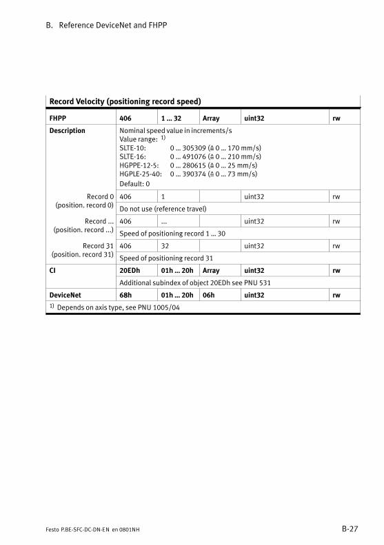
B. Reference DeviceNet and FHPP
B−27Festo P.BE−SFC−DC−DN−EN en 0801NH
Record Velocity (positioning record speed)
FHPP 406 1 � 32 Array uint32 rw
Description Nominal speed value in increments/sValue range: 1)
SLTE−10: 0 � 305309 (Z 0 � 170 mm/s)SLTE−16: 0 � 491076 (Z 0 � 210 mm/s)HGPPE−12−5: 0 � 280615 (Z 0 � 25 mm/s)HGPLE−25−40: 0 � 390374 (Z 0 � 73 mm/s)
Default: 0
Record 0( d )
406 1 uint32 rw(position. record 0)
Do not use (reference travel)
Record ...( d )
406 ... uint32 rw(position. record ...)
Speed of positioning record 1 � 30
Record 31( d )
406 32 uint32 rw3(position. record 31)
Speed of positioning record 31
CI 20EDh 01h � 20h Array uint32 rw
Additional subindex of object 20EDh see PNU 531
DeviceNet 68h 01h � 20h 06h uint32 rw
1) Depends on axis type, see PNU 1005/04
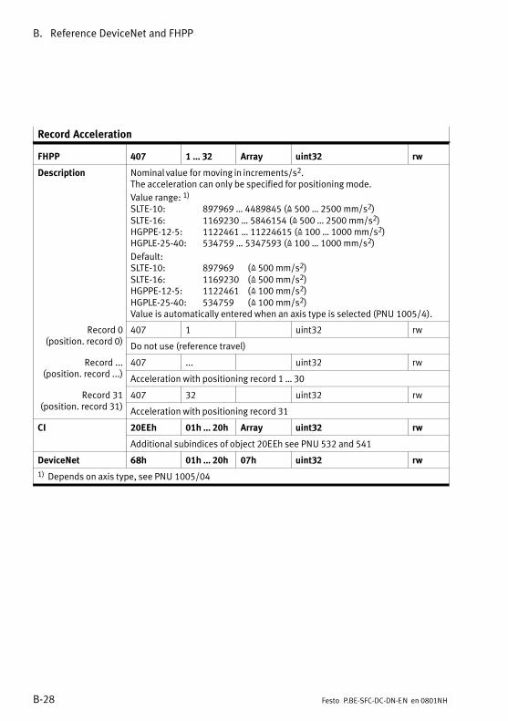
B. Reference DeviceNet and FHPP
B−28 Festo P.BE−SFC−DC−DN−EN en 0801NH
Record Acceleration
FHPP 407 1 � 32 Array uint32 rw
Description Nominal value for moving in increments/s2.The acceleration can only be specified for positioning mode.
Value range: 1)
SLTE−10: 897969 � 4489845 (Z 500 � 2500 mm/s2)SLTE−16: 1169230 � 5846154 (Z 500 � 2500 mm/s2)HGPPE−12−5: 1122461 � 11224615 (Z 100 � 1000 mm/s2)HGPLE−25−40: 534759 � 5347593 (Z 100 � 1000 mm/s2)
Default:SLTE−10: 897969 (Z 500 mm/s2)SLTE−16: 1169230 (Z 500 mm/s2)HGPPE−12−5: 1122461 (Z 100 mm/s2)HGPLE−25−40: 534759 (Z 100 mm/s2)Value is automatically entered when an axis type is selected (PNU 1005/4).
Record 0( d )
407 1 uint32 rw(position. record 0)
Do not use (reference travel)
Record ...( d )
407 ... uint32 rw(position. record ...)
Acceleration with positioning record 1 � 30
Record 31( d )
407 32 uint32 rw3(position. record 31)
Acceleration with positioning record 31
CI 20EEh 01h � 20h Array uint32 rw
Additional subindices of object 20EEh see PNU 532 and 541
DeviceNet 68h 01h � 20h 07h uint32 rw
1) Depends on axis type, see PNU 1005/04

B. Reference DeviceNet and FHPP
B−29Festo P.BE−SFC−DC−DN−EN en 0801NH
Record Deceleration
FHPP 408 1 � 32 Array uint32 rw
Description Nominal value for braking in increments/s2.The deceleration can only be specified for positioning mode.Value is automatically entered when an axis type is selected (PNU 1005/4).Values and default: see PNU 407.
Record 0( d )
408 1 uint32 rw(position. record 0)
Do not use (reference travel)
Record ...( d )
408 ... uint32 rw(position. record ...)
Braking with positioning record 1 � 30
Record 31( d )
408 32 uint32 rw3(position. record 31)
Braking with positioning record 31
CI 20EEh 01h � 20h Array uint32 rw
Additional subindices of object 20EFh see PNU 533 and 542
DeviceNet 68h 01h � 20h 07h uint32 rw
1) Depends on axis type, see PNU 1005/04
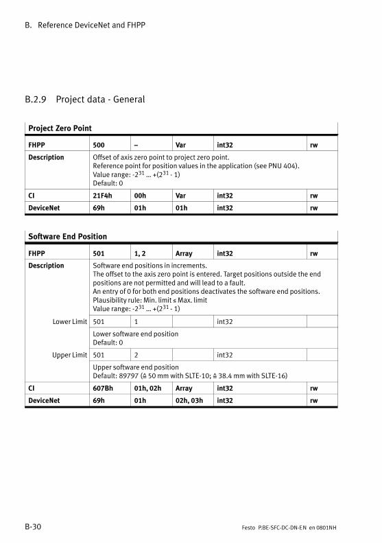
B. Reference DeviceNet and FHPP
B−30 Festo P.BE−SFC−DC−DN−EN en 0801NH
B.2.9 Project data − General
Project Zero Point
FHPP 500 � Var int32 rw
Description Offset of axis zero point to project zero point.Reference point for position values in the application (see PNU 404).Value range: −231 � +(231 − 1)Default: 0
CI 21F4h 00h Var int32 rw
DeviceNet 69h 01h 01h int32 rw
Software End Position
FHPP 501 1, 2 Array int32 rw
Description Software end positions in increments.The offset to the axis zero point is entered. Target positions outside the endpositions are not permitted and will lead to a fault.An entry of 0 for both end positions deactivates the software end positions.Plausibility rule: Min. limit � Max. limitValue range: −231 � +(231 − 1)
Lower Limit 501 1 int32
Lower software end positionDefault: 0
Upper Limit 501 2 int32pp
Upper software end positionDefault: 89797 (Z 50 mm with SLTE−10; Z 38.4 mm with SLTE−16)
CI 607Bh 01h, 02h Array int32 rw
DeviceNet 69h 01h 02h, 03h int32 rw
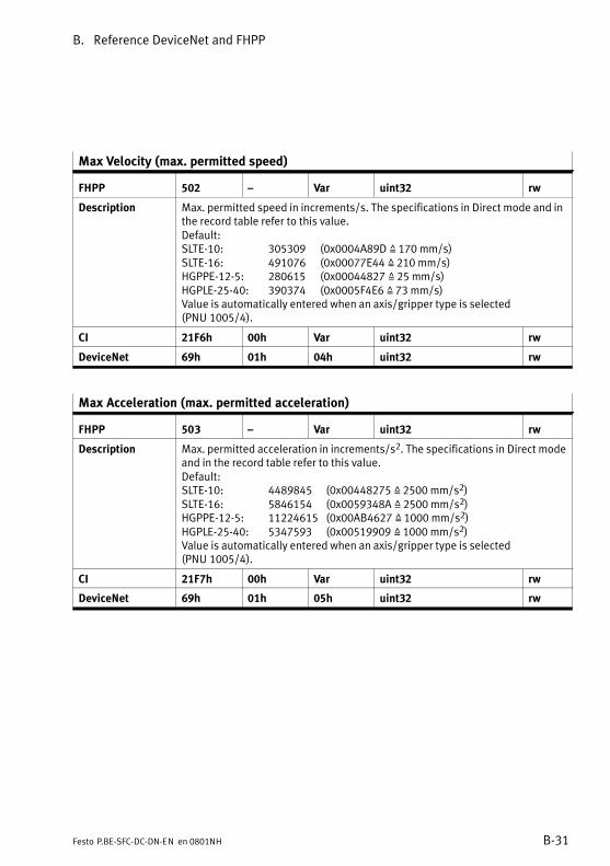
B. Reference DeviceNet and FHPP
B−31Festo P.BE−SFC−DC−DN−EN en 0801NH
Max Velocity (max. permitted speed)
FHPP 502 � Var uint32 rw
Description Max. permitted speed in increments/s. The specifications in Direct mode and inthe record table refer to this value.Default:SLTE−10: 305309 (0x0004A89D Z 170 mm/s)SLTE−16: 491076 (0x00077E44 Z 210 mm/s)HGPPE−12−5: 280615 (0x00044827 Z 25 mm/s)HGPLE−25−40: 390374 (0x0005F4E6 Z 73 mm/s)Value is automatically entered when an axis/gripper type is selected (PNU 1005/4).
CI 21F6h 00h Var uint32 rw
DeviceNet 69h 01h 04h uint32 rw
Max Acceleration (max. permitted acceleration)
FHPP 503 � Var uint32 rw
Description Max. permitted acceleration in increments/s2. The specifications in Direct modeand in the record table refer to this value.Default:SLTE−10: 4489845 (0x00448275 Z 2500 mm/s2)SLTE−16: 5846154 (0x0059348A Z 2500 mm/s2)HGPPE−12−5: 11224615 (0x00AB4627 Z 1000 mm/s2)HGPLE−25−40: 5347593 (0x00519909 Z 1000 mm/s2)Value is automatically entered when an axis/gripper type is selected (PNU 1005/4).
CI 21F7h 00h Var uint32 rw
DeviceNet 69h 01h 05h uint32 rw
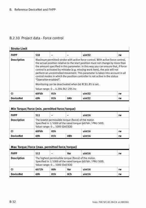
B. Reference DeviceNet and FHPP
B−32 Festo P.BE−SFC−DC−DN−EN en 0801NH
B.2.10 Project data − Force control
Stroke Limit
FHPP 510 � � uint32 rw
Description Maximum permitted stroke with active force control. With active force control,the actual position relative to the start position must not change by more thanthe amount specified in this parameter. In this way you can ensure that, if forcecontrol is activated by mistake (e.g. missing work item), the axis will notperform an uncontrolled movement. This parameter is taken into account in allcontrol modes in which the position controller is not active in the status�Operation enabled".
Monitoring can be deactivated when bit RCB1.B5 is set.
Value range: 0 � 4.294.967.295 Inc
CI 60F6h 01h uint32 rw
DeviceNet 69h 01h 0Ah uint32 rw
Min Torque/Force (min. permitted force/torque)
FHPP 511 � � uint16 rw
Description The lowest permissible torque (force) of the motor.Specified in 1/1000 of the rated torque (6076h / PNU 509).Value range: 0 � 1000 (0x03E8)
CI 60F6h 05h uint16 rw
DeviceNet 69h 01h 0Bh uint16 rw
Max Torque/Force (max. permitted force/torque)
FHPP 512 � Var uint16 rw
Description The highest permissible torque (force) of the motor.Specified in 1/1000 of the rated torque (6076h / PNU 509).Value range: 0 � 1000 (0x03E8)
CI 6072h 00h Var uint16 rw
DeviceNet 69h 01h 0Ch uint16 rw
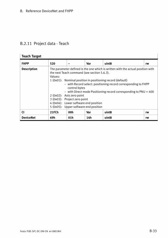
B. Reference DeviceNet and FHPP
B−33Festo P.BE−SFC−DC−DN−EN en 0801NH
B.2.11 Project data − Teach
Teach Target
FHPP 520 � Var uint8 rw
Description The parameter defined is the one which is written with the actual position withthe next Teach command (see section 5.6.3).Values:1 (0x01): Nominal position in positioning record (default)
� with Record select: positioning record corresponding to FHPP control bytes
� with Direct mode Positioning record corresponding to PNU = 4002 (0x02): Axis zero point3 (0x03): Project zero point4 (0x04): Lower software end position5 (0x05): Upper software end position
CI 21FCh 00h Var uint8 rw
DeviceNet 69h 01h 14h uint8 rw
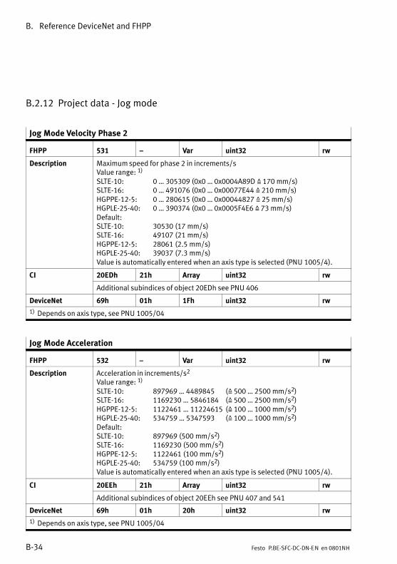
B. Reference DeviceNet and FHPP
B−34 Festo P.BE−SFC−DC−DN−EN en 0801NH
B.2.12 Project data − Jog mode
Jog Mode Velocity Phase 2
FHPP 531 � Var uint32 rw
Description Maximum speed for phase 2 in increments/sValue range: 1)
SLTE−10: 0 � 305309 (0x0 � 0x0004A89D Z 170 mm/s)SLTE−16: 0 � 491076 (0x0 � 0x00077E44 Z 210 mm/s)HGPPE−12−5: 0 � 280615 (0x0 � 0x00044827 Z 25 mm/s)HGPLE−25−40: 0 � 390374 (0x0 � 0x0005F4E6 Z 73 mm/s)Default:SLTE−10: 30530 (17 mm/s)SLTE−16: 49107 (21 mm/s)HGPPE−12−5: 28061 (2.5 mm/s)HGPLE−25−40: 39037 (7.3 mm/s)Value is automatically entered when an axis type is selected (PNU 1005/4).
CI 20EDh 21h Array uint32 rw
Additional subindices of object 20EDh see PNU 406
DeviceNet 69h 01h 1Fh uint32 rw
1) Depends on axis type, see PNU 1005/04
Jog Mode Acceleration
FHPP 532 � Var uint32 rw
Description Acceleration in increments/s2
Value range: 1)
SLTE−10: 897969 � 4489845 (Z 500 � 2500 mm/s2)SLTE−16: 1169230 � 5846184 (Z 500 � 2500 mm/s2)HGPPE−12−5: 1122461 � 11224615 (Z 100 � 1000 mm/s2)HGPLE−25−40: 534759 � 5347593 (Z 100 � 1000 mm/s2)Default:SLTE−10: 897969 (500 mm/s2)SLTE−16: 1169230 (500 mm/s2)HGPPE−12−5: 1122461 (100 mm/s2)HGPLE−25−40: 534759 (100 mm/s2)Value is automatically entered when an axis type is selected (PNU 1005/4).
CI 20EEh 21h Array uint32 rw
Additional subindices of object 20EEh see PNU 407 and 541
DeviceNet 69h 01h 20h uint32 rw
1) Depends on axis type, see PNU 1005/04

B. Reference DeviceNet and FHPP
B−35Festo P.BE−SFC−DC−DN−EN en 0801NH
Jog Mode Deceleration
FHPP 533 � Var uint32 rw2
Description Deceleration in increments/s2
Values and default: see PNU 532
CI 20EFh 21h Array uint32 rw
Additional subindices of object 20EFh see PNU 408 and 542
DeviceNet 69h 01h 21h uint32 rw
Jog Mode Time Phase 1
FHPP 534 � Var uint32 rw
Description Time duration of phase 1 (T1) in msValue range: 0 � +(232 − 1)Default: 2000 (0x000007D0)
CI 20E9h 21h Array uint32 rw
DeviceNet 69h 01h 22h uint32 rw
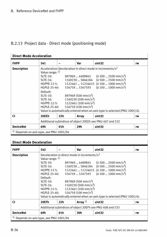
B. Reference DeviceNet and FHPP
B−36 Festo P.BE−SFC−DC−DN−EN en 0801NH
B.2.13 Project data − Direct mode (positioning mode)
Direct Mode Acceleration
FHPP 541 � Var uint32 rw
Description Acceleration/deceleration in direct mode in increments/s2
Value range: 1)
SLTE−10: 897969 � 4489845 (Z 500 � 2500 mm/s2)SLTE−16: 1169230 � 5846184 (Z 500 � 2500 mm/s2)HGPPE−12−5: 1122461 � 11224615 (Z 100 � 1000 mm/s2)HGPLE−25−40: 534759 � 5347593 (Z 100 � 1000 mm/s2)
Default:SLTE−10: 897969 (500 mm/s2)SLTE−16: 1169230 (500 mm/s2)HGPPE−12−5: 1122461 (100 mm/s2)HGPLE−25−40: 534759 (100 mm/s2)Value is automatically entered when an axis type is selected (PNU 1005/4).
CI 20EEh 22h Array uint32 rw
Additional subindices of object 20EEh see PNU 407 and 532
DeviceNet 69h 01h 29h uint32 rw
1) Depends on axis type, see PNU 1005/04
Direct Mode Deceleration
FHPP 542 � Var uint32 rw
Description Deceleration in direct mode in increments/s2
Value range: 1)
SLTE−10: 897969 � 4489845 (Z 500 � 2500 mm/s2)SLTE−16: 1169230 � 5846184 (Z 500 � 2500 mm/s2)HGPPE−12−5: 1122461 � 11224615 (Z 100 � 1000 mm/s2)HGPLE−25−40: 534759 � 5347593 (Z 100 � 1000 mm/s2)Default:SLTE−10: 897969 (500 mm/s2)SLTE−16: 1169230 (500 mm/s2)HGPPE−12−5: 1122461 (100 mm/s2)HGPLE−25−40: 534759 (100 mm/s2)Value is automatically entered when an axis type is selected (PNU 1005/4).
CI 20EFh 22h Array 1) uint32 rw
Additional subindices of object 20EFh see PNU 408 and 533
DeviceNet 69h 01h 30h uint32 rw
1) Depends on axis type, see PNU 1005/04
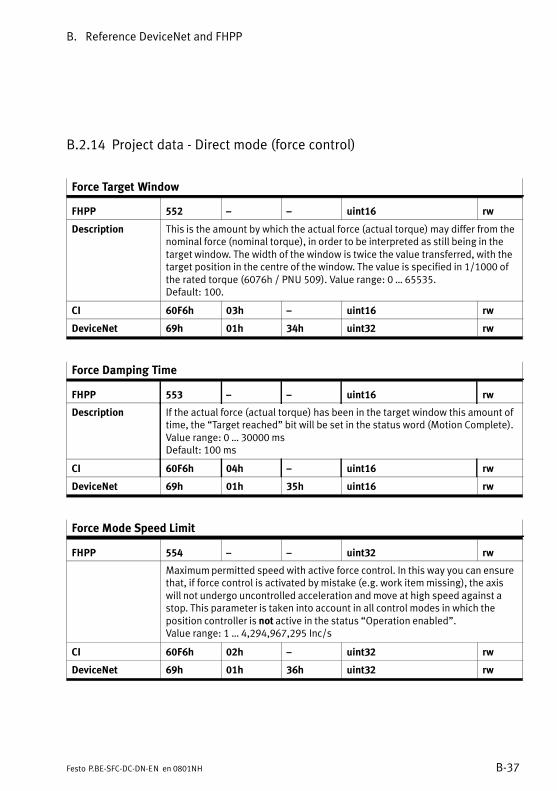
B. Reference DeviceNet and FHPP
B−37Festo P.BE−SFC−DC−DN−EN en 0801NH
B.2.14 Project data − Direct mode (force control)
Force Target Window
FHPP 552 � � uint16 rw
Description This is the amount by which the actual force (actual torque) may differ from thenominal force (nominal torque), in order to be interpreted as still being in thetarget window. The width of the window is twice the value transferred, with thetarget position in the centre of the window. The value is specified in 1/1000 ofthe rated torque (6076h / PNU 509). Value range: 0 � 65535.Default: 100.
CI 60F6h 03h � uint16 rw
DeviceNet 69h 01h 34h uint32 rw
Force Damping Time
FHPP 553 � � uint16 rw
Description If the actual force (actual torque) has been in the target window this amount oftime, the �Target reached" bit will be set in the status word (Motion Complete). Value range: 0 � 30000 msDefault: 100 ms
CI 60F6h 04h � uint16 rw
DeviceNet 69h 01h 35h uint16 rw
Force Mode Speed Limit
FHPP 554 � � uint32 rw
Maximum permitted speed with active force control. In this way you can ensurethat, if force control is activated by mistake (e.g. work item missing), the axiswill not undergo uncontrolled acceleration and move at high speed against astop. This parameter is taken into account in all control modes in which theposition controller is not active in the status �Operation enabled".Value range: 1 � 4,294,967,295 Inc/s
CI 60F6h 02h � uint32 rw
DeviceNet 69h 01h 36h uint32 rw
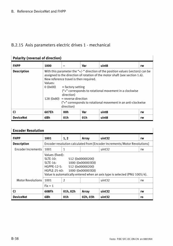
B. Reference DeviceNet and FHPP
B−38 Festo P.BE−SFC−DC−DN−EN en 0801NH
B.2.15 Axis parameters electric drives 1 − mechanical
Polarity (reversal of direction)
FHPP 1000 � Var uint8 rw
Description With this parameter the �+/−" direction of the position values (vectors) can beassigned to the direction of rotation of the motor shaft (see section 1.6). New reference travel is then required.Values:0 (0x00) = factory setting
(�+" corresponds to rotational movement in a clockwise direction)
128 (0x80) = reverse direction(�+" corresponds to rotational movement in an anti−clockwise direction)
CI 607Eh 00h Var uint8 rw
DeviceNet 6Bh 01h 01h uint8 rw
Encoder Resolution
FHPP 1001 1, 2 Array uint32 rw
Description Encoder resolution calculated from [Encoder Increments/Motor Revolutions]
Encoder Increments 1001 1 uint32 rw
Values (fixed):SLTE−10: 512 (0x00000200)SLTE−16: 1000 (0x000003E8)HGPPE−12−5: 512 (0x00000200)HGPLE−25−40: 1000 (0x000003E8)Value is automatically entered when an axis type is selected (PNU 1005/4).
Motor Revolutions 1001 2 uint32 rw
Fix = 1
CI 608Fh 01h, 02h Array uint32 rw
DeviceNet 6Bh 01h 02h, 03h uint32 ro

B. Reference DeviceNet and FHPP
B−39Festo P.BE−SFC−DC−DN−EN en 0801NH
Gear Ratio
FHPP 1002 1, 2 Array uint32 rw
Description Ratio of internal motor revolutions to external revolutions of the drive shaft ofthe motor.gear ratio = motor revolutions / spindle revolutions.Depends on axis type (PNU 1005/4):� SLTE−...: Value setting is fixed by selecting an axis type.� HGP...: Value is automatically entered by selecting an axis type.
Motor Revolutions 1002 1 uint32 rw
Internal motor revolutions (gear ratio � numerator)SLTE: 57 (0x00000039)HGPPE−12−5: 57 (0x00000039)HGPLE−25−40: 84 (0x00000054)
Shaft Revolutions 1002 2 uint32 rw
External revolutions of the drive shaft of the motor (gear ratio � denominator).SLTE: 13 (0x0000000D)HGPPE−12−5: 13 (0x0000000D)HGPLE−25−40: 1 (0x00000001)
CI 6091h 01h, 02h Array uint32 rw
DeviceNet 6Bh 01h 04h, 05h uint32 ro
Feed Constant
FHPP 1003 1, 2 Array uint32 rw
Description The feed constant specifies the path (= feed) which the slide traverses whenthe drive shaft of the linear axis makes one revolution (feed constant = shaftrevolution).
Feed 1003 1 uint32 rw
Specification of feed (feed constant � numerator) in [�m]SLTE−10: 5000 (0x00001388)SLTE−16: 7500 (0x00001D4C)HGPPE−12−5: 800 (0x00000320)HGPLE−25−40: 62832 (0x0000F570)Value is automatically entered when an axis type is selected (PNU 1005/4).
Shaft Revolutions 1003 2 uint32 rw
Feed constant � denominator.Fix: 1 (0x00000001)
CI 6092h 01h, 02h Array uint32 rw
DeviceNet 6Bh 01h 06h, 07h uint32 rw
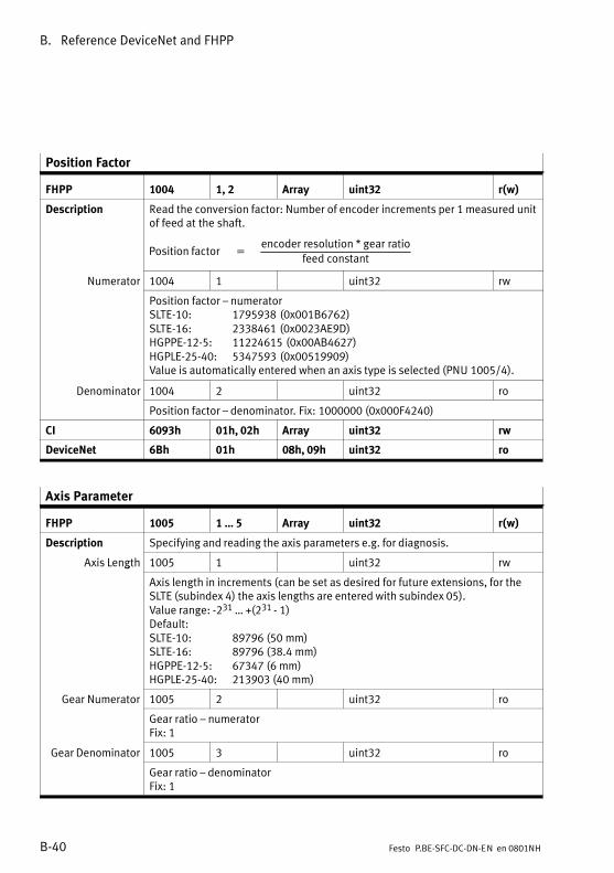
B. Reference DeviceNet and FHPP
B−40 Festo P.BE−SFC−DC−DN−EN en 0801NH
Position Factor
FHPP 1004 1, 2 Array uint32 r(w)
Description Read the conversion factor: Number of encoder increments per 1 measured unitof feed at the shaft.
Position�factor� ��encoder�resolution�*�gear�ratio
feed�constant
Numerator 1004 1 uint32 rw
Position factor � numeratorSLTE−10: 1795938 (0x001B6762)SLTE−16: 2338461 (0x0023AE9D)HGPPE−12−5: 11224615 (0x00AB4627)HGPLE−25−40: 5347593 (0x00519909)Value is automatically entered when an axis type is selected (PNU 1005/4).
Denominator 1004 2 uint32 ro
Position factor � denominator. Fix: 1000000 (0x000F4240)
CI 6093h 01h, 02h Array uint32 rw
DeviceNet 6Bh 01h 08h, 09h uint32 ro
Axis Parameter
FHPP 1005 1 � 5 Array uint32 r(w)
Description Specifying and reading the axis parameters e.g. for diagnosis.
Axis Length 1005 1 uint32 rwg
Axis length in increments (can be set as desired for future extensions, for theSLTE (subindex 4) the axis lengths are entered with subindex 05).Value range: −231 � +(231 − 1)Default:SLTE−10: 89796 (50 mm)SLTE−16: 89796 (38.4 mm)HGPPE−12−5: 67347 (6 mm)HGPLE−25−40: 213903 (40 mm)
Gear Numerator 1005 2 uint32 ro
Gear ratio � numeratorFix: 1
Gear Denominator 1005 3 uint32 ro
Gear ratio � denominatorFix: 1
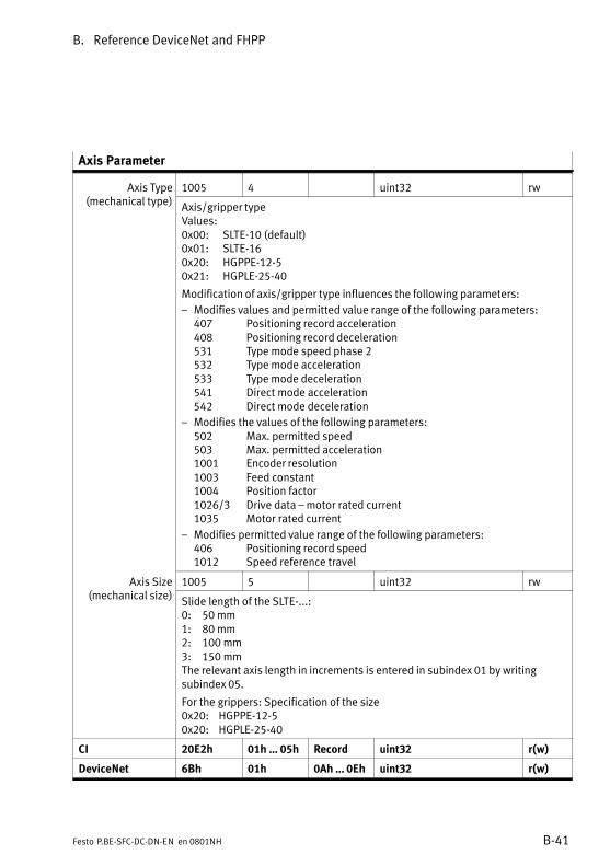
B. Reference DeviceNet and FHPP
B−41Festo P.BE−SFC−DC−DN−EN en 0801NH
Axis Parameter
Axis Type( h l )
1005 4 uint32 rwyp(mechanical type)
Axis/gripper typeValues:0x00: SLTE−10 (default)0x01: SLTE−160x20: HGPPE−12−50x21: HGPLE−25−40
Modification of axis/gripper type influences the following parameters:
� Modifies values and permitted value range of the following parameters:407 Positioning record acceleration408 Positioning record deceleration531 Type mode speed phase 2532 Type mode acceleration533 Type mode deceleration541 Direct mode acceleration542 Direct mode deceleration
� Modifies the values of the following parameters:502 Max. permitted speed503 Max. permitted acceleration1001 Encoder resolution1003 Feed constant1004 Position factor1026/3 Drive data � motor rated current1035 Motor rated current
� Modifies permitted value range of the following parameters:406 Positioning record speed1012 Speed reference travel
Axis Size( h l )
1005 5 uint32 rw(mechanical size)
Slide length of the SLTE−...�:0: 50 mm1: 80 mm2: 100 mm3: 150 mmThe relevant axis length in increments is entered in subindex 01 by writing subindex 05.
For the grippers: Specification of the size0x20: HGPPE−12−50x20: HGPLE−25−40
CI 20E2h 01h � 05h Record uint32 r(w)
DeviceNet 6Bh 01h 0Ah � 0Eh uint32 r(w)
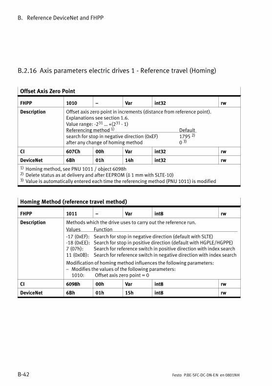
B. Reference DeviceNet and FHPP
B−42 Festo P.BE−SFC−DC−DN−EN en 0801NH
B.2.16 Axis parameters electric drives 1 − Reference travel (Homing)
Offset Axis Zero Point
FHPP 1010 � Var int32 rw
Description Offset axis zero point in increments (distance from reference point).Explanations see section 1.6.Value range: −231 � +(231 − 1)Referencing method 1) Defaultsearch for stop in negative direction (0xEF) 1795 2)
after any change of homing method 0 3)
CI 607Ch 00h Var int32 rw
DeviceNet 6Bh 01h 14h int32 rw
1) Homing method, see PNU 1011 / object 6098h2) Delete status as at delivery and after EEPROM (Z 1 mm with SLTE−10)3) Value is automatically entered each time the referencing method (PNU 1011) is modified
Homing Method (reference travel method)
FHPP 1011 � Var int8 rw
Description Methods which the drive uses to carry out the reference run.
Values Function
−17 (0xEF): Search for stop in negative direction (default with SLTE)−18 (0xEE): Search for stop in positive direction (default with HGPLE/HGPPE)7 (07h): Search for reference switch in positive direction with index search11 (0x0B): Search for reference switch in negative direction with index search
Modification of homing method influences the following parameters:� Modifies the values of the following parameters:
1010: Offset axis zero point = 0
CI 6098h 00h Var int8 rw
DeviceNet 6Bh 01h 15h int8 rw
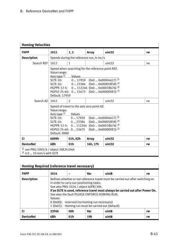
B. Reference DeviceNet and FHPP
B−43Festo P.BE−SFC−DC−DN−EN en 0801NH
Homing Velocities
FHPP 1012 1, 2 Array uint32 rw
Description Speeds during the reference run, in Inc/s
Search REF 1012 1 uint32 rw
Speed when searching for the reference point REF.Value range:Axis type 1) ValuesSLTE−10: 0 � 17959 (0x0 � 0x00004627) 2)
SLTE−16: 0 � 23384 (0x0 � 0x00005B58) 2)
HGPPE−12−5: 0 � 112246 (0x0 � 0x0001B676) 2)
HGPLE−25−40: 0 � 53475 (0x0 � 0x0000D0E3) 2)
Default: 17959
Search AZ 1012 2 uint32 rw
Speed of travel to the axis zero point AZ.Value range:Axis type 1) ValuesSLTE−10: 0 � 17959 (0x0 � 0x00004627) 2)
SLTE−16: 0 � 23384 (0x0 � 0x00005B58) 2)
HGPPE−12−5: 0 � 112246 (0x0 � 0x0001B676) 2)
HGPLE−25−40: 0 � 53475 (0x0 � 0x0000D0E3) 2)
Default: 8980
CI 6099h 01h, 02h Array uint32 rw
DeviceNet 6Bh 01h 16h, 17h uint32 rw
1) see PNU 1005/4 / object 20E2h/04h2) Z 0 � 10 mm/s with SLTE
Homing Required (reference travel necessary)
FHPP 1014 � Var uint8 rw
Description Defines whether or not reference travel must be carried out after switching onin order to carry out positioning tasks.See also PNU 1024 / object 60FB/20h.If an SLTE is used, reference travel must always be carried out after Power On.See also the fault PLEASE ENFORCE HOMING RUN.Values:0 (0x00): reserved (no homing run necessary)1 (0x01): Homing run must be carried out (default)
CI 23F6h 00h Var uint8 rw
DeviceNet 6Bh 01h 19h uint8 rw
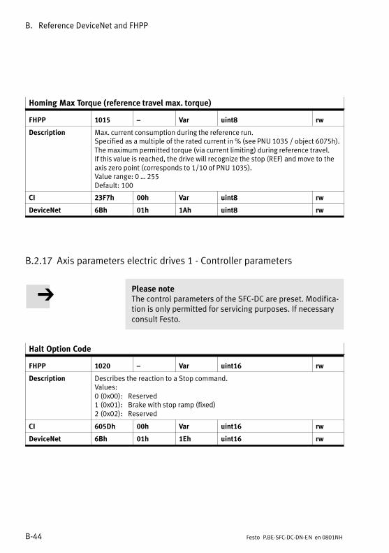
B. Reference DeviceNet and FHPP
B−44 Festo P.BE−SFC−DC−DN−EN en 0801NH
Homing Max Torque (reference travel max. torque)
FHPP 1015 � Var uint8 rw
Description Max. current consumption during the reference run.Specified as a multiple of the rated current in % (see PNU 1035 / object 6075h).The maximum permitted torque (via current limiting) during reference travel. If this value is reached, the drive will recognize the stop (REF) and move to theaxis zero point (corresponds to 1/10 of PNU 1035).Value range: 0 � 255Default: 100
CI 23F7h 00h Var uint8 rw
DeviceNet 6Bh 01h 1Ah uint8 rw
B.2.17 Axis parameters electric drives 1 − Controller parameters
Please noteThe control parameters of the SFC−DC are preset. Modifica�tion is only permitted for servicing purposes. If necessaryconsult Festo.
Halt Option Code
FHPP 1020 � Var uint16 rw
Description Describes the reaction to a Stop command.Values:0 (0x00): Reserved1 (0x01): Brake with stop ramp (fixed)2 (0x02): Reserved
CI 605Dh 00h Var uint16 rw
DeviceNet 6Bh 01h 1Eh uint16 rw

B. Reference DeviceNet and FHPP
B−45Festo P.BE−SFC−DC−DN−EN en 0801NH
Fault Reaction Option Code
FHPP 1021 � Var uint16 rw
Description Describes the reaction to a fault.Values:0 (0x00): Reserved1 (0x01): Reserved2 (0x02): Brake with emergency stop ramp (fixed)3 (0x03): Reserved
CI 605Eh 00h Var uint16 rw
DeviceNet 6Bh 01h 1Fh uint16 rw
Target Position Window (tolerance window position)
FHPP 1022 � Var uint32 rw
Description Tolerance window in increments.Amount by which the current position may deviate from the target position, inorder that it may still be regarded as being within the target window.The width of the window is twice the value transferred, with the target positionin the centre of the window.Value range: 0 � +(232 − 1)Default: 750 (Z 0.42 mm with SLTE−10, Z 0.32 mm with SLTE−16)
CI 6067h 00h Var uint32 rw
DeviceNet 6Bh 01h 20h uint32 rw
Position Window Time (adjustment time position)
FHPP 1023 � Var uint16 rw
Description Adjustment time in milliseconds.If the actual position has been in the target position window this amount oftime, the bit �Target reached" will be set in the status word.Value range: 1 � 30000 (Write only for service purposes)Specification: 100
CI 6068h 00h Var uint16 rw
DeviceNet 6Bh 01h 21h uint16 rw
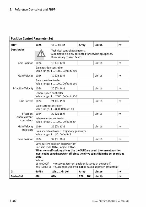
B. Reference DeviceNet and FHPP
B−46 Festo P.BE−SFC−DC−DN−EN en 0801NH
Position Control Parameter Set
FHPP 1024 18 � 23, 32 Array uint16 rw
Description Technical control parameters.Modification is only permitted for servicing purposes.If necessary consult Festo.
Gain Position 1024 18 (CI: 12h) uint16 rw
Gain position controllerValue range: 1 � 1000. Default: 200
Gain Velocity 1024 19 (CI: 13h) uint16 rwy
Gain speed controllerValue range: 1 � 1000. Default: 150
I−fraction Velocity 1024 20 (CI: 14h) uint16 rwy
I−share speed controllerValue range: 1 � 2000. Default: 550
Gain Current 1024 21 (CI: 15h) uint16 rw
Gain current controllerValue range: 1 � 800. Default: 80
I−fraction( h
1024 22 (CI: 16h) uint16 rw(I−share current
controller)I−share current controllerValue range: 0 � 1000. Default: 20
Gain Velocity 1024 23 (CI: 17h) uint16 rwyTrajectory
Gain speed controller � trajectory generator.Value range: 1 � 50. Default: 3
Save Position 1024 32 (CI: 20h) uint16 rw
Save current position on power−offSee also PNU 1014 / object 23F6h.When non−self−locking drives like the SLTE are used, the current positionmust not be saved at power−off, since the drive can shift in the de−energizedstate.Values:15 (0x000F) = reserved (current position is saved at power−off )240 (0x00F0) = Current position will not be saved at power−off (default)
CI 60FBh 12h � 17h, 20h Array uint16 rw
DeviceNet 6Bh 01h 22h � 28h uint16 rw
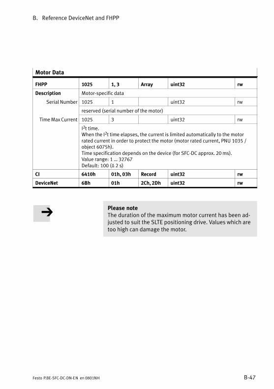
B. Reference DeviceNet and FHPP
B−47Festo P.BE−SFC−DC−DN−EN en 0801NH
Motor Data
FHPP 1025 1, 3 Array uint32 rw
Description Motor−specific data
Serial Number 1025 1 uint32 rw
reserved (serial number of the motor)
Time Max Current 1025 3 uint32 rw
I2t time.When the I2t time elapses, the current is limited automatically to the motorrated current in order to protect the motor (motor rated current, PNU 1035 /object 6075h).Time specification depends on the device (for SFC−DC approx. 20 ms).Value range: 1 � 32767Default: 100 (Z 2 s)
CI 6410h 01h, 03h Record uint32 rw
DeviceNet 6Bh 01h 2Ch, 2Dh uint32 rw
Please noteThe duration of the maximum motor current has been ad�justed to suit the SLTE positioning drive. Values which aretoo high can damage the motor.
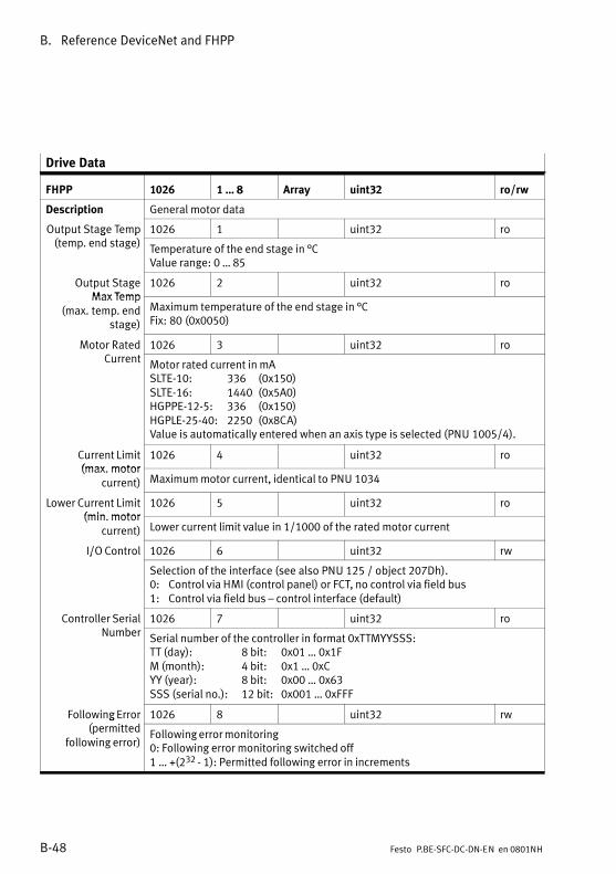
B. Reference DeviceNet and FHPP
B−48 Festo P.BE−SFC−DC−DN−EN en 0801NH
Drive Data
FHPP 1026 1 � 8 Array uint32 ro/rw
Description General motor data
Output Stage Temp( d )
1026 1 uint32 rop g p(temp. end stage)
Temperature of the end stage in °CValue range: 0 � 85
Output StageMax Temp
1026 2 uint32 roMax Temp
(max. temp. endstage)
Maximum temperature of the end stage in °CFix: 80 (0x0050)
Motor Rated 1026 3 uint32 roCurrent
Motor rated current in mASLTE−10: 336 (0x150)SLTE−16: 1440 (0x5A0)HGPPE−12−5: 336 (0x150)HGPLE−25−40: 2250 (0x8CA)Value is automatically entered when an axis type is selected (PNU 1005/4).
Current Limit(max motor
1026 4 uint32 ro(max. motor
current) Maximum motor current, identical to PNU 1034
Lower Current Limit(min motor
1026 5 uint32 ro(min. motor
current) Lower current limit value in 1/1000 of the rated motor current
I/O Control 1026 6 uint32 rw/
Selection of the interface (see also PNU 125 / object 207Dh).0: Control via HMI (control panel) or FCT, no control via field bus1: Control via field bus � control interface (default)
Controller Serialb
1026 7 uint32 roNumber
Serial number of the controller in format 0xTTMYYSSS:TT (day): 8 bit: 0x01 � 0x1FM (month): 4 bit: 0x1 � 0xCYY (year): 8 bit: 0x00 � 0x63SSS (serial no.): 12 bit: 0x001 � 0xFFF
Following Error( d
1026 8 uint32 rwg(permitted
following error)Following error monitoring0: Following error monitoring switched off1 � +(232 − 1): Permitted following error in increments

B. Reference DeviceNet and FHPP
B−49Festo P.BE−SFC−DC−DN−EN en 0801NH
Drive Data
CI 6510h 01h � Record ro/rw
Drive Data 1) 6510h 01h � 08h � uint32 ro/rw
6510h 31h, 32h,40h, 41h,42h, 43h,A0h, 22h
� uint16, uint16,uint32, uint16,int16, uint16,uint32, uint32
ro, roro, roro, rwro, ro
Current Actuall
6510 45h int 16 roValue
Current actual value of the current.Note: not available via FHPP.
Firmware Version 6510 A1h � uint32 ro
Firmware version, specification in BCD (binary coded decimals): xxyy(xx = main version, yy = secondary version)Note: identical to FHPP object PNU 101 (CI 206Ah)
DeviceNet 6Bh 01h 31h � 38h uint32 ro/rw
1) Description analogue to FHPP 1026/1 � 8.Subindices 31h � A0h not available via FHPP
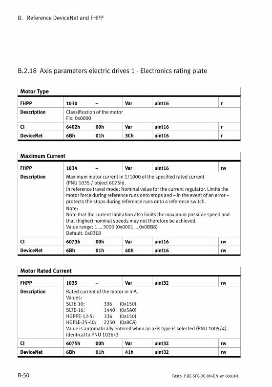
B. Reference DeviceNet and FHPP
B−50 Festo P.BE−SFC−DC−DN−EN en 0801NH
B.2.18 Axis parameters electric drives 1 − Electronics rating plate
Motor Type
FHPP 1030 � Var uint16 r
Description Classification of the motorFix: 0x0000
CI 6402h 00h Var uint16 r
DeviceNet 6Bh 01h 3Ch uint16 r
Maximum Current
FHPP 1034 � Var uint16 rw
Description Maximum motor current in 1/1000 of the specified rated current (PNU 1035 / object 6075h).In reference travel mode: Nominal value for the current regulator. Limits themotor force during reference runs onto stops and � in the event of an error �protects the stops during reference runs onto a reference switch.
Note:Note that the current limitation also limits the maximum possible speed andthat (higher) nominal speeds may not therefore be achieved.Value range: 1 � 3000 (0x0001 � 0x0BB8)Default: 0x03E8
CI 6073h 00h Var uint16 rw
DeviceNet 6Bh 01h 40h uint16 rw
Motor Rated Current
FHPP 1035 � Var uint32 rw
Description Rated current of the motor in mA.Values:SLTE−10: 336 (0x150)SLTE−16: 1440 (0x5A0)HGPPE−12−5: 336 (0x150)HGPLE−25−40: 2250 (0x8CA)Value is automatically entered when an axis type is selected (PNU 1005/4).Identical to PNU 1026/3
CI 6075h 00h Var uint32 rw
DeviceNet 6Bh 01h 41h uint32 rw
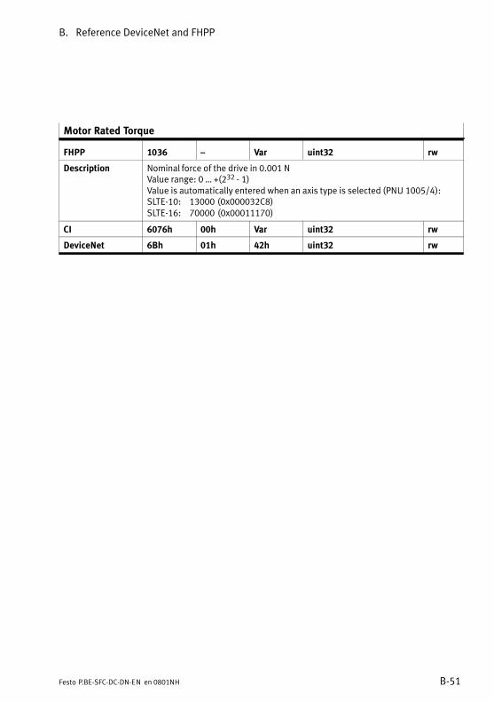
B. Reference DeviceNet and FHPP
B−51Festo P.BE−SFC−DC−DN−EN en 0801NH
Motor Rated Torque
FHPP 1036 � Var uint32 rw
Description Nominal force of the drive in 0.001 NValue range: 0 � +(232 − 1)Value is automatically entered when an axis type is selected (PNU 1005/4):SLTE−10: 13000 (0x000032C8)SLTE−16: 70000 (0x00011170)
CI 6076h 00h Var uint32 rw
DeviceNet 6Bh 01h 42h uint32 rw
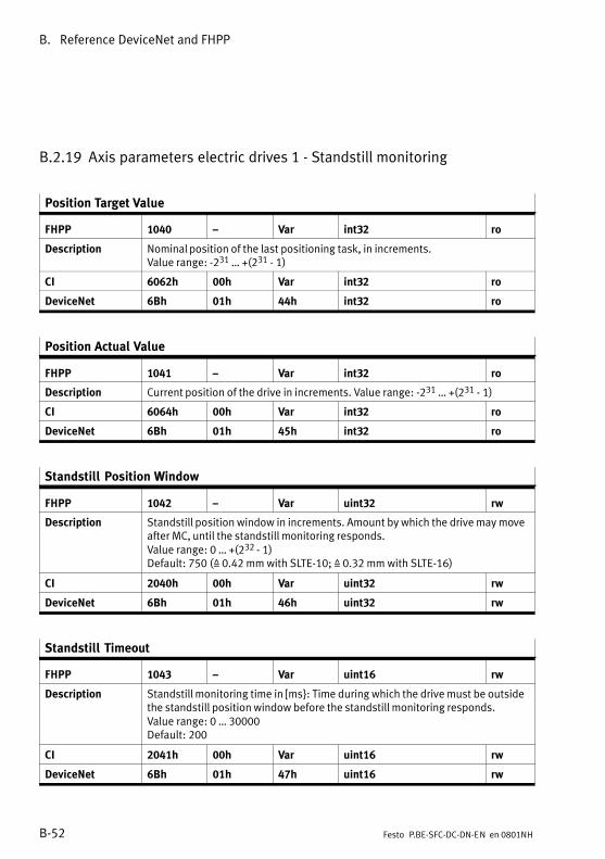
B. Reference DeviceNet and FHPP
B−52 Festo P.BE−SFC−DC−DN−EN en 0801NH
B.2.19 Axis parameters electric drives 1 − Standstill monitoring
Position Target Value
FHPP 1040 � Var int32 ro
Description Nominal position of the last positioning task, in increments.Value range: −231 � +(231 − 1)
CI 6062h 00h Var int32 ro
DeviceNet 6Bh 01h 44h int32 ro
Position Actual Value
FHPP 1041 � Var int32 ro
Description Current position of the drive in increments. Value range: −231 � +(231 − 1)
CI 6064h 00h Var int32 ro
DeviceNet 6Bh 01h 45h int32 ro
Standstill Position Window
FHPP 1042 � Var uint32 rw
Description Standstill position window in increments. Amount by which the drive may moveafter MC, until the standstill monitoring responds.Value range: 0 � +(232 − 1)Default: 750 (Z 0.42 mm with SLTE−10; Z 0.32 mm with SLTE−16)
CI 2040h 00h Var uint32 rw
DeviceNet 6Bh 01h 46h uint32 rw
Standstill Timeout
FHPP 1043 � Var uint16 rw
Description Standstill monitoring time in [ms}: Time during which the drive must be outsidethe standstill position window before the standstill monitoring responds.Value range: 0 � 30000Default: 200
CI 2041h 00h Var uint16 rw
DeviceNet 6Bh 01h 47h uint16 rw

Reference CI objects
C−1Festo P.BE−SFC−DC−DN−EN en 0801NH
Appendix C

C. Reference CI objects
C−2 Festo P.BE−SFC−DC−DN−EN en 0801NH
Contents
C. Reference CI objects C−1 . . . . . . . . . . . . . . . . . . . . . . . . . . . . . . . . . . . . . . . . . . . .
C.1 Data transmission C−3 . . . . . . . . . . . . . . . . . . . . . . . . . . . . . . . . . . . . . . . . . . . . . .
C.1.1 Procedure C−3 . . . . . . . . . . . . . . . . . . . . . . . . . . . . . . . . . . . . . . . . . . . . .
C.1.2 Composition of the CI commands C−5 . . . . . . . . . . . . . . . . . . . . . . . . . . .
C.1.3 Check of the data C−9 . . . . . . . . . . . . . . . . . . . . . . . . . . . . . . . . . . . . . . . .
C.2 Reference CI C−11 . . . . . . . . . . . . . . . . . . . . . . . . . . . . . . . . . . . . . . . . . . . . . . . . . . .
C.2.1 Object overview (Index, Subindex) C−11 . . . . . . . . . . . . . . . . . . . . . . . . . .
C.2.2 Representing the parameter entries C−16 . . . . . . . . . . . . . . . . . . . . . . . .
C.2.3 Communication Profile Area (1xxxh) C−17 . . . . . . . . . . . . . . . . . . . . . . . .
C.2.4 Manufacturer Specific Profile Area (2xxxh) C−18 . . . . . . . . . . . . . . . . . . .
C.2.5 Standardised Device Profile Area (6xxxh) C−23 . . . . . . . . . . . . . . . . . . . .
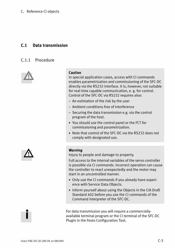
C. Reference CI objects
C−3Festo P.BE−SFC−DC−DN−EN en 0801NH
C.1 Data transmission
C.1.1 Procedure
CautionIn special application cases, access with CI commandsenables parametrization and commissioning of the SFC−DCdirectly via the RS232 interface. It is, however, not suitablefor real−time capable communication, e. g. for control.Control of the SFC−DC via RS232 requires also:
� An estimation of the risk by the user
� Ambient conditions free of interference
� Securing the data transmission e.g. via the controlprogram of the host.
· You should use the control panel or the FCT forcommissioning and parametrization.
· Note that control of the SFC−DC via the RS232 does notcomply with designated use.
WarningInjury to people and damage to property.
Full access to the internal variables of the servo controlleris possible via CI commands. Incorrect operation can causethe controller to react unexpectedly and the motor maystart in an uncontrolled manner.
· Only use the CI commands if you already have experi�ence with Service Data Objects.
· Inform yourself about using the Objects in the CiA DraftStandard 402 before you use the CI commands of theCommand Interpreter of the SFC−DC.
For data transmission you will require a commercially−available terminal program or the CI terminal of the SFC−DCPlugIn in the Festo Configuration Tool.
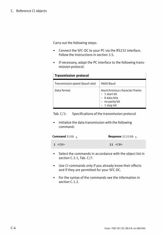
C. Reference CI objects
C−4 Festo P.BE−SFC−DC−DN−EN en 0801NH
Carry out the following steps:
· Connect the SFC−DC to your PC via the RS232 interface.Follow the instructions in section 3.5.
· If necessary, adapt the PC interface to the following trans�mission protocol.
Transmission protocol
Transmission speed (baud rate) 9600 Baud
Data format Asynchronous character frame:� 1 start bit� 8 data bits� no parity bit� 1 stop bit
Tab.�C/1: Specifications of the transmission protocol
· Initialize the data transmission with the followingcommand:
Command 310D h Response 31310D h
1 <CR> 11 <CR>
· Select the commands in accordance with the object list insection C.2.1, Tab.�C/7.
· Use CI commands only if you already know their effectsand if they are permitted for your SFC−DC.
· For the syntax of the commands see the information insection C.1.2.
C. Reference CI objects
C−5Festo P.BE−SFC−DC−DN−EN en 0801NH
C.1.2 Composition of the CI commands
The commands implemented in the Command Interpreter ofthe SFC−DC are based in respect of their content on theObjects standardized by CANopen (CiA Draft Standard 402):Group 1xxx Device descriptionGroup 2xxx Festo commandsGroup 6xxx Commands as per CANopen
The totality of all parametrizing and control options is calledan object directory. A unique number (index, subindex) isassigned to each object which has access to the object.
CautionLoss of data.
The Command Interpreter (CI) contains commands whichreorganise or delete parts of the memory. Existing data aretherefore destroyed:
· It is preferable to use the FCT or the control panel forcommissioning and parametrizing.
· Use the CI commands only in special cases which requiredirect access to the controller.
· Use CI commands only if you already know their effectsand if they are permitted for your SFC−DC.
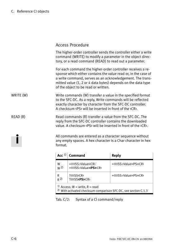
C. Reference CI objects
C−6 Festo P.BE−SFC−DC−DN−EN en 0801NH
Access Procedure
The higher−order controller sends the controller either a writecommand (WRITE) to modify a parameter in the object direc�tory, or a read command (READ) to read out a parameter.
For each command the higher−order controller receives a re�sponse which either contains the value read or, in the case ofa write command, serves as an acknowledgement. The trans�mitted value (1, 2 or 4 data bytes) depends on the data typeof the object to be read or written.
WRITE (W) Write commands (W) transfer a value in the specified formatto the SFC−DC. As a reply, Write commands will be reflectedexactly character by character from the SFC−DC controller. A checksum <PS> will be inserted in front of the <CR>.
READ (R) Read commands (R) transfer a value from the SFC−DC. Thereply from the SFC−DC controller contains the downloadedvalue. A checksum <PS> will be inserted in front of the <CR>.
All commands are entered as a character sequence withoutany empty spaces. A hex character is a Char character in hexformat.
Acc 1) Command Reply
W
W 2)=IIIISS:<Value><CR>=IIIISS:<Value><PS><CR>
=IIIISS:<Value><PS><CR>
R
R 2)?IIIISS<CR>?IIIISS<PS><CR>
=IIIISS:<Value><PS><CR>
1) Access: W = write, R = read2) With activated checksum comparison SFC−DC, see section C.1.3
Tab.�C/2: Syntax of a CI command/reply

C. Reference CI objects
C−7Festo P.BE−SFC−DC−DN−EN en 0801NH
Syntax Explanation
�=", �?" Initial character for write or read commands
IIII Index in 4 hexadecimal digits
SS Subindex in 2 hexadecimal digitsIf the addressed object does not have an indexedparameter, subindex <00> will be specified.
�:" Separating character
<Value> Data in a format depending on data type
<PS> Checksum in 2 hexadecimal digits (see section C.1.3)
<CR> End character <Carriage Return> ($0D)
Tab.�C/3: Elements of syntax of a CI command/reply
Data type
The transmitted value (1, 2 or 4 data bytes as hex digit)depends on the data type of the object to be read or written.The following data types are supported:
Type Hex Format
UINT8 2H 8 bits without sign: 0 � 255
INT8 8 bits with sign: −128 � 127
UINT16 4H 16 bits without sign: 0 � 65535
INT16 16 bits with sign: −32768 � 32767
UINT32 8H 32 bits without sign: 0 � (232 −1)
INT32 32 bits with sign: −231 � +(231 − 1)
V−string Corresponds to the preset string
Tab.�C/4: Data types
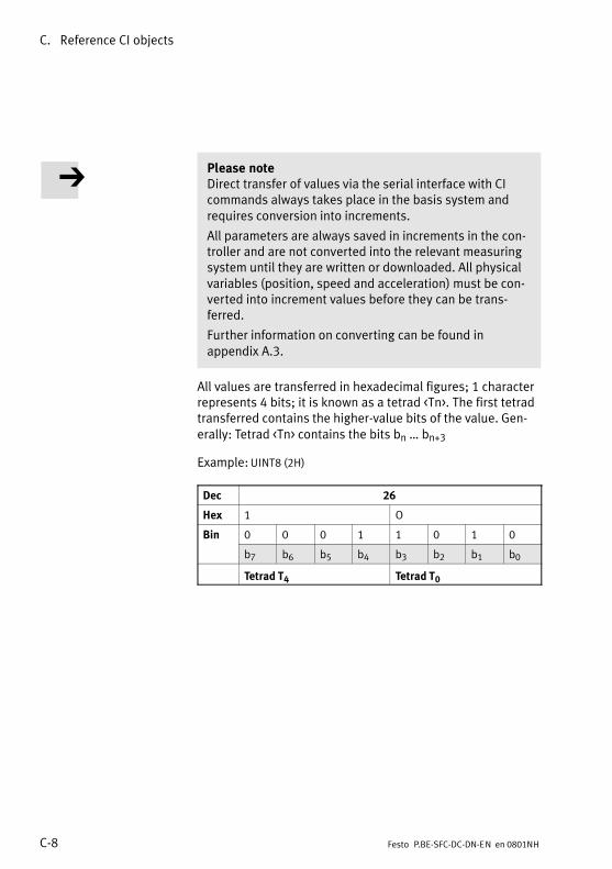
C. Reference CI objects
C−8 Festo P.BE−SFC−DC−DN−EN en 0801NH
Please noteDirect transfer of values via the serial interface with CIcommands always takes place in the basis system andrequires conversion into increments.
All parameters are always saved in increments in the con�troller and are not converted into the relevant measuringsystem until they are written or downloaded. All physicalvariables (position, speed and acceleration) must be con�verted into increment values before they can be trans�ferred.
Further information on converting can be found inappendix A.3.
All values are transferred in hexadecimal figures; 1 characterrepresents 4 bits; it is known as a tetrad <Tn>. The first tetradtransferred contains the higher−value bits of the value. Gen�erally: Tetrad <Tn> contains the bits bn � bn+3
Example: UINT8 (2H)
Dec 26
Hex 1 O
Bin 0 0 0 1 1 0 1 0
b7 b6 b5 b4 b3 b2 b1 b0
Tetrad T4 Tetrad T0
C. Reference CI objects
C−9Festo P.BE−SFC−DC−DN−EN en 0801NH
C.1.3 Check of the data
Non−permitted values Transferred parameters and values are checked by theSFC−DC before being accepted. In the case of invalidparameters or values, an error message will not appear inthe response; rather, the transferred value will always bereturned.
Please noteThe following applies when writing the objects:
� Discrete values (values from a value list):A non−permitted value will not be accepted, thepreviously valid value will be retained.
� Continuous values (values from a continuous interval): A non−permitted value will be limited up to the nextpermitted minimum or maximum value.
RecommendationCheck that values and parameters have been written correctlyby downloading the current contents of the parameter orvalue with one of the following Read commands:
Transmission error In the case of a transmission error between the higher−ordercontroller and the SFC−DC, instead of the regular answer thevalue <0x00FF> will be transferred (see object 2FF0).
Possible causes:
� incorrect initial character, separating character or emptycharacter
� incorrect hex digit
� incorrect value type.
Checksum <PS> The higher−order controller must compare the command sentwith the answer (�echo") of the SFC−DC and evaluate itschecksum. Optionally an additional checksum comparison bythe SFC−DC for received commands can be activated (CI ob�ject 20F3h). The higher−order controller must then insert achecksum in front of the final character (CR = Carriage return).

C. Reference CI objects
C−10 Festo P.BE−SFC−DC−DN−EN en 0801NH
If the SFC−DC detects a deviation of the checksum, then in�stead of the regular answer the value <0xFFFF> is transmitted(see object 2FF0h).
The checksum is determined according to the notation(upper/lower case) of the command; the checksum of thereply always corresponds to the notation in upper−caseletters.
Checksum <PS> W/R Command Reply
Default (CI object 20F300 00)
W =IIIISS:<Value><CR> =IIIISS:<Value><PS><CR>(CI object 20F300:00)
R ?IIIISS<CR> =IIIISS:<Value><PS><CR>
Optional (CI object 20F300 01)
W =IIIISS:<Value><PS><CR> =IIIISS:<Value><PS><CR>(CI object 20F300:01)
R ?IIIISS><PS><CR> =IIIISS:<Value><PS><CR>
W = writeR = read
Tab.�C/5: Syntax command/reply (optionally with checksum comparison by the SFC−DC)
Checksum <PS>
Calculation Sum of all ASCII characters, sent, shortened to 1�byte.W: <PS> = �=IIIISS:<value>" modulo 256R: <PS> = �?IIIISS" modulo 256
ExampleCommand =IIIISS:<value><CR>
=20F300:00ASCII−> = 2 0 F 3 0 0 : 0 0HEX 3D+32+30+46+33+30+30+3A+30+30Sum 212hMod 256 212h mod 100h = 12hReply =20F300:0012
Format 2 hexadecimal digits UINT8
Tab.�C/6: Checksum
C. Reference CI objects
C−11Festo P.BE−SFC−DC−DN−EN en 0801NH
C.2 Reference CI
C.2.1 Object overview (Index, Subindex)
The following overview shows all CI objects, where appropri�ate with the corresponding FHPP parameter numbers.
Please noteThe table contains an overview of the CI objects. The ob�jects may be used only for certain product variants or onlywith limitations (e.g. writing only for service purposes).Observe the detailed description of the objects.
You will find the descriptions of the CI objects in the followingsections (se the column �Section"):
� descriptions of the CI objects with corresponding PNUs asper FHPP in sections B.2.4 to B.2.19
� descriptions of the additional CI objects starting fromsection C.2.3.
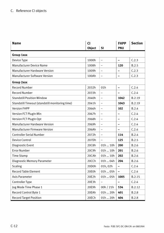
C. Reference CI objects
C−12 Festo P.BE−SFC−DC−DN−EN en 0801NH
Name CI FHPP Section
Object SI PNU
Group 1xxx
Device Type 1000h � � C.2.3
Manufacturer Device Name 1008h � 120 B.2.5
Manufacturer Hardware Version 1009h � � C.2.3
Manufacturer Software Version 100Ah � � C.2.3
Group 2xxx
Record Number 2032h 01h � C.2.4
Record Number 2033h � � C.2.4
Standstill Position Window 2040h � 1042 B.2.19
Standstill Timeout (standstill monitoring time) 2041h � 1043 B.2.19
Version FHPP 2066h � 102 B.2.4
Version FCT PlugIn Min 2067h � � C.2.4
Version FCT PlugIn Opt 2068h � � C.2.4
Manufacturer Hardware Version 2069h � � C.2.4
Manufacturer Firmware Version 206Ah � � C.2.4
Controller Serial Number 2072h � 114 B.2.4
Device Control 207Dh � 125 B.2.5
Diagnostic Event 20C8h 01h � 10h 200 B.2.6
Error Number 20C9h 01h � 10h 201 B.2.6
Time Stamp 20CAh 01h � 10h 202 B.2.6
Diagnostic Memory Parameter 20CCh 01h � 04h 204 B.2.6
Scaling 20D0h 01h, 02h � C.2.4
Record Table Element 20E0h 01h � 05h � C.2.4
Axis Parameter 20E2h 01h � 05h 1005 B.2.15
Controller Type 20E3h � � C.2.4
Jog Mode Time Phase 1 20E9h 00h / 21h 534 B.2.12
Record Control Byte 1 20EAh 01h � 20h 401 B.2.8
Record Target Position 20ECh 01h � 20h 404 B.2.8
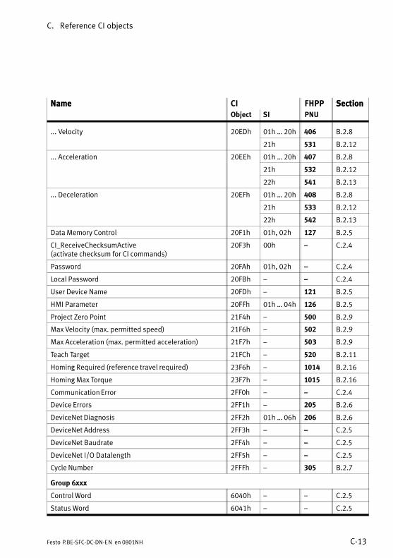
C. Reference CI objects
C−13Festo P.BE−SFC−DC−DN−EN en 0801NH
Name SectionFHPPCIName Section
PNUSIObject
... Velocity 20EDh 01h � 20h 406 B.2.8y
21h 531 B.2.12
... Acceleration 20EEh 01h � 20h 407 B.2.8
21h 532 B.2.12
22h 541 B.2.13
... Deceleration 20EFh 01h � 20h 408 B.2.8
21h 533 B.2.12
22h 542 B.2.13
Data Memory Control 20F1h 01h, 02h 127 B.2.5
CI_ReceiveChecksumActive (activate checksum for CI commands)
20F3h 00h � C.2.4
Password 20FAh 01h, 02h � C.2.4
Local Password 20FBh � � C.2.4
User Device Name 20FDh � 121 B.2.5
HMI Parameter 20FFh 01h � 04h 126 B.2.5
Project Zero Point 21F4h � 500 B.2.9
Max Velocity (max. permitted speed) 21F6h � 502 B.2.9
Max Acceleration (max. permitted acceleration) 21F7h � 503 B.2.9
Teach Target 21FCh � 520 B.2.11
Homing Required (reference travel required) 23F6h � 1014 B.2.16
Homing Max Torque 23F7h � 1015 B.2.16
Communication Error 2FF0h � � C.2.4
Device Errors 2FF1h � 205 B.2.6
DeviceNet Diagnosis 2FF2h 01h � 06h 206 B.2.6
DeviceNet Address 2FF3h � � C.2.5
DeviceNet Baudrate 2FF4h � � C.2.5
DeviceNet I/O Datalength 2FF5h � � C.2.5
Cycle Number 2FFFh � 305 B.2.7
Group 6xxx
Control Word 6040h � � C.2.5
Status Word 6041h � � C.2.5
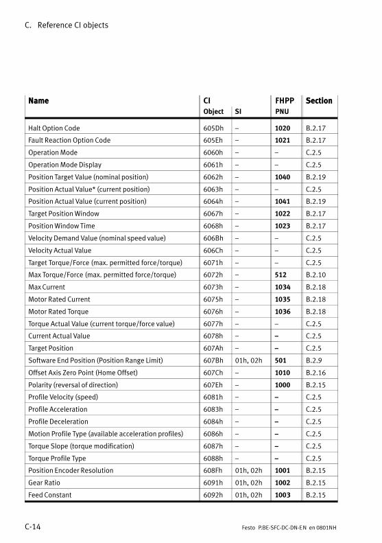
C. Reference CI objects
C−14 Festo P.BE−SFC−DC−DN−EN en 0801NH
Name SectionFHPPCIName Section
PNUSIObject
Halt Option Code 605Dh � 1020 B.2.17
Fault Reaction Option Code 605Eh � 1021 B.2.17
Operation Mode 6060h � � C.2.5
Operation Mode Display 6061h � � C.2.5
Position Target Value (nominal position) 6062h � 1040 B.2.19
Position Actual Value* (current position) 6063h � � C.2.5
Position Actual Value (current position) 6064h � 1041 B.2.19
Target Position Window 6067h � 1022 B.2.17
Position Window Time 6068h � 1023 B.2.17
Velocity Demand Value (nominal speed value) 606Bh � � C.2.5
Velocity Actual Value 606Ch � � C.2.5
Target Torque/Force (max. permitted force/torque) 6071h � � C.2.5
Max Torque/Force (max. permitted force/torque) 6072h � 512 B.2.10
Max Current 6073h � 1034 B.2.18
Motor Rated Current 6075h � 1035 B.2.18
Motor Rated Torque 6076h � 1036 B.2.18
Torque Actual Value (current torque/force value) 6077h � � C.2.5
Current Actual Value 6078h � � C.2.5
Target Position 607Ah � � C.2.5
Software End Position (Position Range Limit) 607Bh 01h, 02h 501 B.2.9
Offset Axis Zero Point (Home Offset) 607Ch � 1010 B.2.16
Polarity (reversal of direction) 607Eh � 1000 B.2.15
Profile Velocity (speed) 6081h � � C.2.5
Profile Acceleration 6083h � � C.2.5
Profile Deceleration 6084h � � C.2.5
Motion Profile Type (available acceleration profiles) 6086h � � C.2.5
Torque Slope (torque modification) 6087h � � C.2.5
Torque Profile Type 6088h � � C.2.5
Position Encoder Resolution 608Fh 01h, 02h 1001 B.2.15
Gear Ratio 6091h 01h, 02h 1002 B.2.15
Feed Constant 6092h 01h, 02h 1003 B.2.15
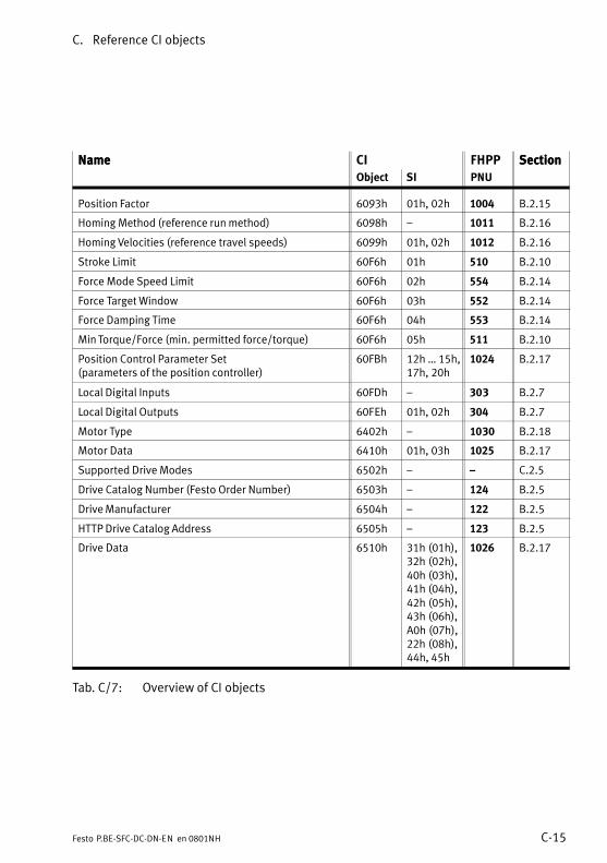
C. Reference CI objects
C−15Festo P.BE−SFC−DC−DN−EN en 0801NH
Name SectionFHPPCIName Section
PNUSIObject
Position Factor 6093h 01h, 02h 1004 B.2.15
Homing Method (reference run method) 6098h � 1011 B.2.16
Homing Velocities (reference travel speeds) 6099h 01h, 02h 1012 B.2.16
Stroke Limit 60F6h 01h 510 B.2.10
Force Mode Speed Limit 60F6h 02h 554 B.2.14
Force Target Window 60F6h 03h 552 B.2.14
Force Damping Time 60F6h 04h 553 B.2.14
Min Torque/Force (min. permitted force/torque) 60F6h 05h 511 B.2.10
Position Control Parameter Set (parameters of the position controller)
60FBh 12h � 15h,17h, 20h
1024 B.2.17
Local Digital Inputs 60FDh � 303 B.2.7
Local Digital Outputs 60FEh 01h, 02h 304 B.2.7
Motor Type 6402h � 1030 B.2.18
Motor Data 6410h 01h, 03h 1025 B.2.17
Supported Drive Modes 6502h � � C.2.5
Drive Catalog Number (Festo Order Number) 6503h � 124 B.2.5
Drive Manufacturer 6504h � 122 B.2.5
HTTP Drive Catalog Address 6505h � 123 B.2.5
Drive Data 6510h 31h (01h),32h (02h),40h (03h),41h (04h),42h (05h),43h (06h),A0h (07h),22h (08h),44h, 45h
1026 B.2.17
Tab.�C/7: Overview of CI objects

C. Reference CI objects
C−16 Festo P.BE−SFC−DC−DN−EN en 0801NH
C.2.2 Representing the parameter entries
Encoder resolution
CI 608Fh 01h ... 02h Array uint32 rw2
Description Encoder resolution in increments / revolutionsThe encoder resolution is fixed and cannot be modified by the user. Thecalculated value is derived from the fraction (encoder−increments/motorrevolution).
Encoder increments 1001 1 uint32 rw2
Value range: 0 ... 232−1Default: 500
Motor revolutions 1001 2 uint32 rw2
Fix = 1
1 Name of the parameter
2 Object number
3 Subindices of parameter, if present (��: no subindex, simple variable)
4 Element class
5 Element variable type
6 Read/write permission: ro = read onlywo = write onlyrw = read and write
7 Description of the parameter
8 Name and description of subindices, if present
Fig.�C/1: Representing the parameter entries
1 2 3 4 5 6
7
8
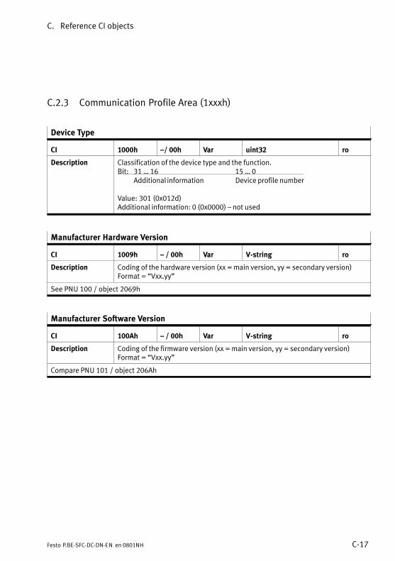
C. Reference CI objects
C−17Festo P.BE−SFC−DC−DN−EN en 0801NH
C.2.3 Communication Profile Area (1xxxh)
Device Type
CI 1000h �/ 00h Var uint32 ro
Description Classification of the device type and the function.Bit: 31 � 16 15 � 0
Additional information Device profile number
Value: 301 (0x012d)Additional information: 0 (0x0000) � not used
Manufacturer Hardware Version
CI 1009h � / 00h Var V−string ro
Description Coding of the hardware version (xx = main version, yy = secondary version)Format = �Vxx.yy"
See PNU 100 / object 2069h
Manufacturer Software Version
CI 100Ah � / 00h Var V−string ro
Description Coding of the firmware version (xx = main version, yy = secondary version)Format = �Vxx.yy"
Compare PNU 101 / object 206Ah
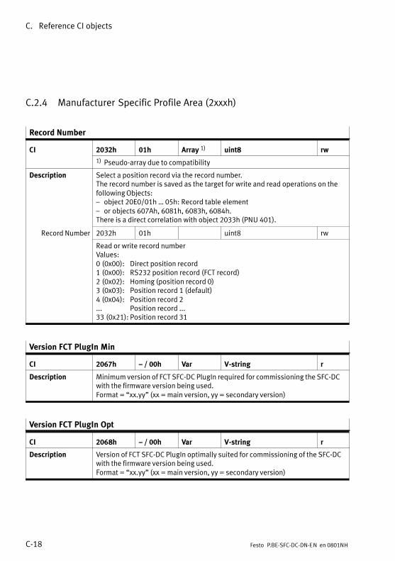
C. Reference CI objects
C−18 Festo P.BE−SFC−DC−DN−EN en 0801NH
C.2.4 Manufacturer Specific Profile Area (2xxxh)
Record Number
CI 2032h 01h Array 1) uint8 rw
1) Pseudo−array due to compatibility
Description Select a position record via the record number.The record number is saved as the target for write and read operations on thefollowing Objects:� object 20E0/01h � 05h: Record table element� or objects 607Ah, 6081h, 6083h, 6084h.There is a direct correlation with object 2033h (PNU 401).
Record Number 2032h 01h uint8 rw
Read or write record numberValues:0 (0x00): Direct position record1 (0x00): RS232 position record (FCT record)2 (0x02): Homing (position record 0)3 (0x03): Position record 1 (default)4 (0x04): Position record 2... Position record ...33 (0x21): Position record 31
Version FCT PlugIn Min
CI 2067h � / 00h Var V−string r
Description Minimum version of FCT SFC−DC PlugIn required for commissioning the SFC−DCwith the firmware version being used.Format = �xx.yy" (xx = main version, yy = secondary version)
Version FCT PlugIn Opt
CI 2068h � / 00h Var V−string r
Description Version of FCT SFC−DC PlugIn optimally suited for commissioning of the SFC−DCwith the firmware version being used.Format = �xx.yy" (xx = main version, yy = secondary version)

C. Reference CI objects
C−19Festo P.BE−SFC−DC−DN−EN en 0801NH
Scaling
CI 20D0h 01h, 02h Array uint8 ro
Description Dimensions and decimal positions on the display of the control panel.
Measuring Unit 20D0h 01h uint8 rog
Definition of unit of measurement.The setting for the system of measurement only affects the display. All para�meters are always saved in increments in the controller and are not convertedinto the relevant measuring system until they are written or downloaded.Fix = 1: metric units of measurement, e.g. mm, mm/s, mm/s2
Scaling Factor 20D0h 02h uint8 ro
Scaling Factor Number of places after the decimal point.Fix = 2
Record Table Element
CI 20E0h 01h � 05h Record uint16, int32 rw
Description Editing the entries in the position record table:1. Select line (= position number) with object 2032h.2. Select column under subindex 20E0h: 01 � 05
20E0/01 20E0/02V
20E0/03 20E0/04 20E0/05
Recordnumber
Pos setmode
Targetposition
Profilevelocity
ProfileAcc.
ProfileDec.
02
2032h} 03 <1> <...> ... ... ...
...
The values are only saved in the position table with this command; nomovement is made.
Positioning Mode 20E0h 01h uint16 rwg
Positioning mode (record control word). Values:0 (0x0000): absolute positioning (default)1 (0x0001): relative positioning
Target Position 20E0h 02h int32 rwg
Target position in increments (compare Target Position, object 607A).Value range: −231 � +(231 − 1) (0x80000000 � 0x7FFFFFFF)Default: 0
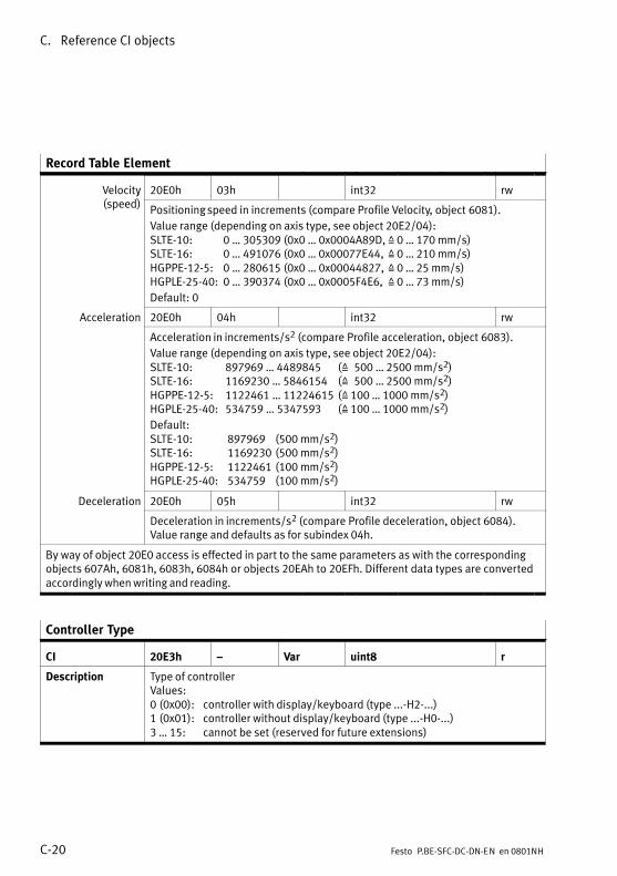
C. Reference CI objects
C−20 Festo P.BE−SFC−DC−DN−EN en 0801NH
Record Table Element
Velocity( d)
20E0h 03h int32 rwy(speed)
Positioning speed in increments (compare Profile Velocity, object 6081).
Value range (depending on axis type, see object 20E2/04):SLTE−10: 0 � 305309 (0x0 � 0x0004A89D, Z 0 � 170 mm/s)SLTE−16: 0 � 491076 (0x0 � 0x00077E44, Z 0 � 210 mm/s)HGPPE−12−5: 0 � 280615 (0x0 � 0x00044827, Z 0 � 25 mm/s)HGPLE−25−40: 0 � 390374 (0x0 � 0x0005F4E6, Z 0 � 73 mm/s)
Default: 0
Acceleration 20E0h 04h int32 rw
Acceleration in increments/s2 (compare Profile acceleration, object 6083).
Value range (depending on axis type, see object 20E2/04):SLTE−10: 897969 � 4489845 (Z 500 � 2500 mm/s2)SLTE−16: 1169230 � 5846154 (Z 500 � 2500 mm/s2)HGPPE−12−5: 1122461 � 11224615 (Z 100 � 1000 mm/s2)HGPLE−25−40: 534759 � 5347593 (Z 100 � 1000 mm/s2)
Default:SLTE−10: 897969 (500 mm/s2)SLTE−16: 1169230 (500 mm/s2)HGPPE−12−5: 1122461 (100 mm/s2)HGPLE−25−40: 534759 (100 mm/s2)
Deceleration 20E0h 05h int32 rw
Deceleration in increments/s2 (compare Profile deceleration, object 6084).Value range and defaults as for subindex 04h.
By way of object 20E0 access is effected in part to the same parameters as with the correspondingobjects 607Ah, 6081h, 6083h, 6084h or objects 20EAh to 20EFh. Different data types are convertedaccordingly when writing and reading.
Controller Type
CI 20E3h � Var uint8 r
Description Type of controllerValues:0 (0x00): controller with display/keyboard (type ...−H2−...)1 (0x01): controller without display/keyboard (type ...−H0−...)3 � 15: cannot be set (reserved for future extensions)
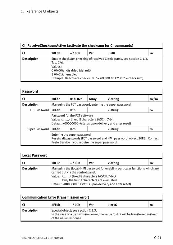
C. Reference CI objects
C−21Festo P.BE−SFC−DC−DN−EN en 0801NH
CI_ReceiveChecksumActive (activate the checksum for CI commands)
CI 20F3h � / 00h Var uint8 rw
Description Enable checksum checking of received CI telegrams, see section C.1.3,Tab.�C/6.Values:0 (0x00): disabled (default)1 (0x01): enabledExample: Deactivate checksum: �=20F300:0012" (12 = checksum)
Password
CI 20FAh 01h, 02h Array V−string rw/ro
Description Managing the FCT password, entering the super password
FCT Password 20FAh 01h V−string rw
Password for the FCT softwareValue: <........> (fixed 8 characters (ASCII, 7−bit)Default: <00000000> (status upon delivery and after reset)
Super Password 20FAh 02h V−string rop
Entering the super passwordResets all passwords (FCT password and HMI password, object 20FB). ContactFesto Service if you require the super password.
Local Password
CI 20FBh � / 00h Var V−string rw
Description Managing the (local) HMI password for enabling particular functions which arecarried out via the control panel.Value: <........> (fixed 8 characters (ASCII, 7−bit)
Only the first 3 characters are evaluated.Default: <00000000> (status upon delivery and after reset)
Communication Error (transmission error)
CI 2FF0h � / 00h Var uint16 ro
Description Special object; see section C.1.3.In the case of a transmission error, the value <0xFF> will be transferred insteadof the usual response.
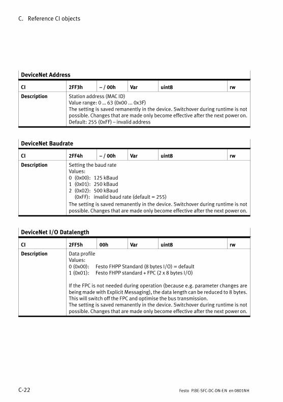
C. Reference CI objects
C−22 Festo P.BE−SFC−DC−DN−EN en 0801NH
DeviceNet Address
CI 2FF3h � / 00h Var uint8 rw
Description Station address (MAC ID)Value range: 0 � 63 (0x00 ... 0x3F)The setting is saved remanently in the device. Switchover during runtime is notpossible. Changes that are made only become effective after the next power on.Default: 255 (0xFF) � invalid address
DeviceNet Baudrate
CI 2FF4h � / 00h Var uint8 rw
Description Setting the baud rateValues:0 (0x00): 125 kBaud1 (0x01): 250 kBaud2 (0x02): 500 kBaud
(0xFF): invalid baud rate (default = 255)
The setting is saved remanently in the device. Switchover during runtime is notpossible. Changes that are made only become effective after the next power on.
DeviceNet I/O Datalength
CI 2FF5h 00h Var uint8 rw
Description Data profileValues:0 (0x00): Festo FHPP Standard (8 bytes I/O) = default1 (0x01): Festo FHPP standard + FPC (2 x 8 bytes I/O)
If the FPC is not needed during operation (because e.g. parameter changes arebeing made with Explicit Messaging), the data length can be reduced to 8�bytes.This will switch off the FPC and optimise the bus transmission. The setting is saved remanently in the device. Switchover during runtime is notpossible. Changes that are made only become effective after the next power on.
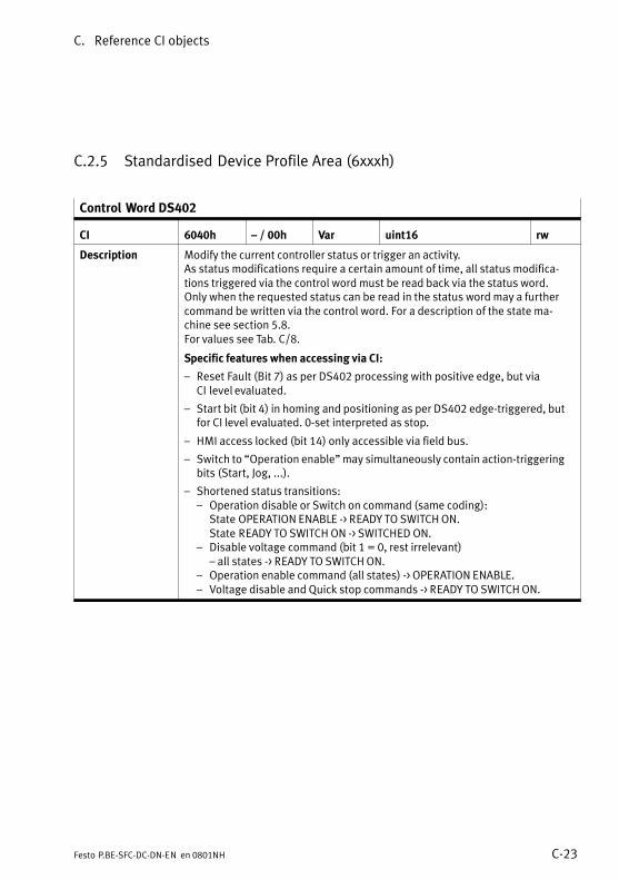
C. Reference CI objects
C−23Festo P.BE−SFC−DC−DN−EN en 0801NH
C.2.5 Standardised Device Profile Area (6xxxh)
Control Word DS402
CI 6040h � / 00h Var uint16 rw
Description Modify the current controller status or trigger an activity.As status modifications require a certain amount of time, all status modifica�tions triggered via the control word must be read back via the status word. Only when the requested status can be read in the status word may a furthercommand be written via the control word. For a description of the state ma�chine see section 5.8.For values see Tab.�C/8.
Specific features when accessing via CI:
� Reset Fault (Bit 7) as per DS402 processing with positive edge, but viaCI�level evaluated.
� Start bit (bit 4) in homing and positioning as per DS402 edge−triggered, butfor CI level evaluated. 0−set interpreted as stop.
� HMI access locked (bit 14) only accessible via field bus.
� Switch to �Operation enable" may simultaneously contain action−triggeringbits (Start, Jog, ...).
� Shortened status transitions:� Operation disable or Switch on command (same coding):
State OPERATION ENABLE −> READY TO SWITCH ON.State READY TO SWITCH ON −> SWITCHED ON.
� Disable voltage command (bit 1 = 0, rest irrelevant) � all states −> READY TO SWITCH ON.
� Operation enable command (all states) −> OPERATION ENABLE.� Voltage disable and Quick stop commands −> READY TO SWITCH ON.
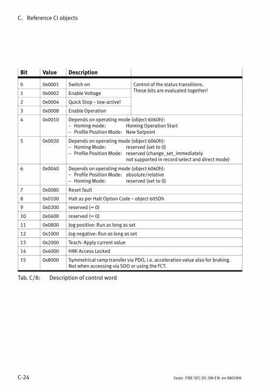
C. Reference CI objects
C−24 Festo P.BE−SFC−DC−DN−EN en 0801NH
Bit Value Description
0 0x0001 Switch on Control of the status transitions.h bi l d h !
1 0x0002 Enable VoltageThese bits are evaluated together!
2 0x0004 Quick Stop � low−active!
3 0x0008 Enable Operation
4 0x0010 Depends on operating mode (object 6060h):� Homing mode: Homing Operation Start� Profile Position Mode: New Setpoint
5 0x0020 Depends on operating mode (object 6060h):� Homing Mode: reserved (set to 0)� Profile Position Mode: reserved (change_set_immediately
not supported in record select and direct mode)
6 0x0040 Depends on operating mode (object 6060h):� Profile Position Mode: absolute/relative� Homing Mode: reserved (set to 0)
7 0x0080 Reset fault
8 0x0100 Halt as per Halt Option Code � object 605Dh
9 0x0200 reserved (= 0)
10 0x0400 reserved (= 0)
11 0x0800 Jog positive: Run as long as set
12 0x1000 Jog negative: Run as long as set
13 0x2000 Teach: Apply current value
14 0x4000 HMI Access Locked
15 0x8000 Symmetrical ramp transfer via PDO, i.e. acceleration value also for braking. Not when accessing via SDO or using the FCT.
Tab.�C/8: Description of control word
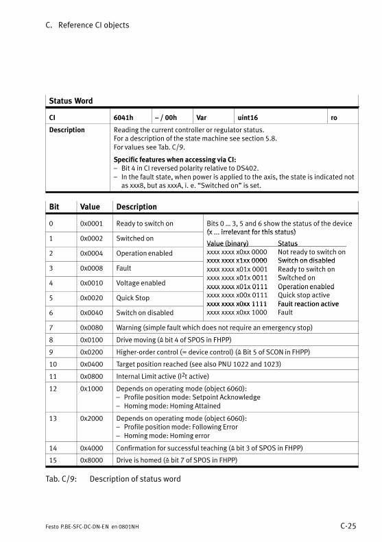
C. Reference CI objects
C−25Festo P.BE−SFC−DC−DN−EN en 0801NH
Status Word
CI 6041h � / 00h Var uint16 ro
Description Reading the current controller or regulator status. For a description of the state machine see section 5.8.For values see Tab.�C/9.
Specific features when accessing via CI:� Bit 4 in CI reversed polarity relative to DS402.� In the fault state, when power is applied to the axis, the state is indicated not
as xxx8, but as xxxA, i.�e. �Switched on" is set.
Bit Value Description
0 0x0001 Ready to switch on Bits 0 � 3, 5 and 6 show the status of the device(x irrelevant for this status)
1 0x0002 Switched on(x ... irrelevant for this status)
Value (binary) Status
2 0x0004 Operation enabled
Value (binary) Statusxxxx xxxx x0xx 0000 Not ready to switch onxxxx xxxx x1xx 0000 Switch on disabled
3 0x0008 Faultxxxx xxxx x1xx 0000 Switch on disabledxxxx xxxx x01x 0001 Ready to switch on
01 0011 Switched o4 0x0010 Voltage enabled
xxxx xxxx x01x 0011 Switched onxxxx xxxx x01x 0111 Operation enabled
5 0x0020 Quick Stop
xxxx xxxx x01x 0111 Operation enabledxxxx xxxx x00x 0111 Quick stop activexxxx xxxx x0xx 1111 Fault reaction active
6 0x0040 Switch on disabledxxxx xxxx x0xx 1111 Fault reaction activexxxx xxxx x0xx 1000 Fault
7 0x0080 Warning (simple fault which does not require an emergency stop)
8 0x0100 Drive moving (Z bit 4 of SPOS in FHPP)
9 0x0200 Higher−order control (= device control) (Z Bit 5 of SCON in FHPP)
10 0x0400 Target position reached (see also PNU 1022 and 1023)
11 0x0800 Internal Limit active (I2t active)
12 0x1000 Depends on operating mode (object 6060):� Profile position mode: Setpoint Acknowledge� Homing mode: Homing Attained
13 0x2000 Depends on operating mode (object 6060):� Profile position mode: Following Error� Homing mode: Homing error
14 0x4000 Confirmation for successful teaching (Z bit 3 of SPOS in FHPP)
15 0x8000 Drive is homed (Z bit 7 of SPOS in FHPP)
Tab.�C/9: Description of status word
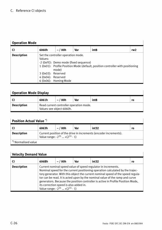
C. Reference CI objects
C−26 Festo P.BE−SFC−DC−DN−EN en 0801NH
Operation Mode
CI 6060h � / 00h Var int8 rw2
Description Set the controller operation mode.Values:−2 (0xFE): Demo mode (fixed sequence)1 (0x01): Profile Position Mode (default, position controller with positioning
mode)3 (0x03): Reserved4 (0x04): Reserved6 (0x06): Homing Mode
Operation Mode Display
CI 6061h � / 00h Var int8 ro
Description Read current controller operation mode.Values see object 6060h.
Position Actual Value *)
CI 6063h � / 00h Var int32 ro
Description Current position of the drive in increments (encoder increments).Value range: −231 � +(231 − 1)
*) Normalised value
Velocity Demand Value
CI 606Bh � / 00h Var int32 ro
Description Current nominal speed value of speed regulator in increments.Nominal speed for the current positioning operation calculated by the trajec�tory generator. With this object the current nominal speed of the speed regula�tor can be read. It is acted upon by the nominal value of the ramp and curvegenerators. Because the position controller is active in Profile Position Mode,its correction speed is also added in.Value range: −231 � +(231 − 1)
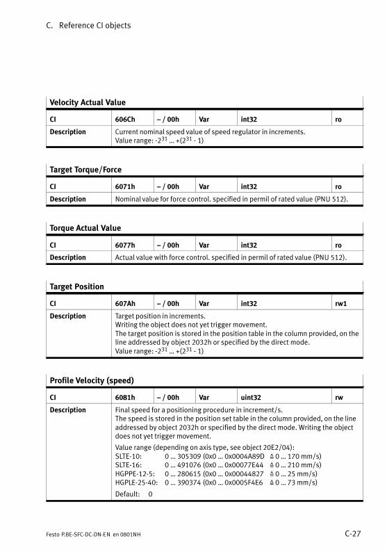
C. Reference CI objects
C−27Festo P.BE−SFC−DC−DN−EN en 0801NH
Velocity Actual Value
CI 606Ch � / 00h Var int32 ro
Description Current nominal speed value of speed regulator in increments.Value range: −231 � +(231 − 1)
Target Torque/Force
CI 6071h � / 00h Var int32 ro
Description Nominal value for force control. specified in permil of rated value (PNU 512).
Torque Actual Value
CI 6077h � / 00h Var int32 ro
Description Actual value with force control. specified in permil of rated value (PNU 512).
Target Position
CI 607Ah � / 00h Var int32 rw1
Description Target position in increments.Writing the object does not yet trigger movement.The target position is stored in the position table in the column provided, on theline addressed by object 2032h or specified by the direct mode.Value range: −231 � +(231 − 1)
Profile Velocity (speed)
CI 6081h � / 00h Var uint32 rw
Description Final speed for a positioning procedure in increment/s.The speed is stored in the position set table in the column provided, on the lineaddressed by object 2032h or specified by the direct mode. Writing the objectdoes not yet trigger movement.
Value range (depending on axis type, see object 20E2/04):SLTE−10: 0 � 305309 (0x0 � 0x0004A89D Z 0 � 170 mm/s)SLTE−16: 0 � 491076 (0x0 � 0x00077E44 Z 0 � 210 mm/s)HGPPE−12−5: 0 � 280615 (0x0 � 0x00044827 Z 0 � 25 mm/s)HGPLE−25−40: 0 � 390374 (0x0 � 0x0005F4E6 Z 0 � 73 mm/s)
Default: 0
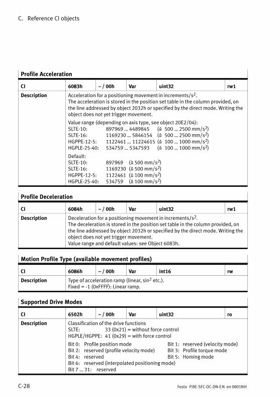
C. Reference CI objects
C−28 Festo P.BE−SFC−DC−DN−EN en 0801NH
Profile Acceleration
CI 6083h � / 00h Var uint32 rw1
Description Acceleration for a positioning movement in increments/s2.The acceleration is stored in the position set table in the column provided, onthe line addressed by object 2032h or specified by the direct mode. Writing theobject does not yet trigger movement.
Value range (depending on axis type, see object 20E2/04):SLTE−10: 897969 � 4489845 (Z 500 � 2500 mm/s2)SLTE−16: 1169230 � 5846154 (Z 500 � 2500 mm/s2)HGPPE−12−5: 1122461 � 11224615 (Z 100 � 1000 mm/s2)HGPLE−25−40: 534759 � 5347593 (Z 100 � 1000 mm/s2)
Default:SLTE−10: 897969 (Z 500 mm/s2) SLTE−16: 1169230 (Z 500 mm/s2) HGPPE−12−5: 1122461 (Z 100 mm/s2) HGPLE−25−40: 534759 (Z 100 mm/s2)
Profile Deceleration
CI 6084h � / 00h Var uint32 rw1
Description Deceleration for a positioning movement in increments/s2.The deceleration is stored in the position set table in the column provided, onthe line addressed by object 2032h or specified by the direct mode. Writing theobject does not yet trigger movement.Value range and default values: see Object 6083h.
Motion Profile Type (available movement profiles)
CI 6086h � / 00h Var int16 rw
Description Type of acceleration ramp (linear, sin2 etc.).Fixed = −1 (0xFFFF): Linear ramp.
Supported Drive Modes
CI 6502h � / 00h Var uint32 ro
Description Classification of the drive functionsSLTE: 33 (0x21) = without force controlHGPLE/HGPPE: 41 (0x29) = with force control
Bit 0: Profile position mode Bit 1: reserved (velocity mode)Bit 2: reserved (profile velocity mode) Bit 3: Profile torque modeBit 4: reserved Bit 5: Homing modeBit 6: reserved (interpolated positioning mode)Bit 7 � 31: reserved

Index
D−1Festo P.BE−SFC−DC−DN−EN en 0801NH
Appendix D

D. Index
D−2 Festo P.BE−SFC−DC−DN−EN en 0801NH
Contents
D. Index D−1 . . . . . . . . . . . . . . . . . . . . . . . . . . . . . . . . . . . . . . . . . . . . . . . . . . . . . . . . .
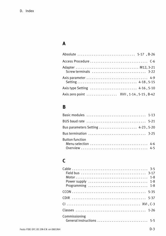
D. Index
D−3Festo P.BE−SFC−DC−DN−EN en 0801NH
A
Absolute 5−17 , B−26 . . . . . . . . . . . . . . . . . . . . . . . . . . . . . . . .
Access Procedure C−6 . . . . . . . . . . . . . . . . . . . . . . . . . . . . . . . .
Adapter M12, 3−21 . . . . . . . . . . . . . . . . . . . . . . . . . . . . . . . . . . . Screw terminals 3−22 . . . . . . . . . . . . . . . . . . . . . . . . . . . . . .
Axis parameter 4−9 . . . . . . . . . . . . . . . . . . . . . . . . . . . . . . . . . . Setting 4−18 , 5−15 . . . . . . . . . . . . . . . . . . . . . . . . . . . . . . . . .
Axis type Setting 4−16 , 5−10 . . . . . . . . . . . . . . . . . . . . . . . . . .
Axis zero point XVII , 1−14 , 5−15 , B−42 . . . . . . . . . . . . . . . . .
B
Basic modules 1−13 . . . . . . . . . . . . . . . . . . . . . . . . . . . . . . . . .
BUS baud rate 5−21 . . . . . . . . . . . . . . . . . . . . . . . . . . . . . . . . .
Bus parameters Setting 4−23 , 5−20 . . . . . . . . . . . . . . . . . . . . .
Bus termination 3−25 . . . . . . . . . . . . . . . . . . . . . . . . . . . . . . . .
Button functionMenu selection 4−6 . . . . . . . . . . . . . . . . . . . . . . . . . . . . . . . . Overview 4−5 . . . . . . . . . . . . . . . . . . . . . . . . . . . . . . . . . . . . .
C
Cable 3−5 . . . . . . . . . . . . . . . . . . . . . . . . . . . . . . . . . . . . . . . . . . Field bus 3−17 . . . . . . . . . . . . . . . . . . . . . . . . . . . . . . . . . . . . Motor 1−8 . . . . . . . . . . . . . . . . . . . . . . . . . . . . . . . . . . . . . . . . Power supply 1−8 . . . . . . . . . . . . . . . . . . . . . . . . . . . . . . . . . Programming 1−8 . . . . . . . . . . . . . . . . . . . . . . . . . . . . . . . . .
CCON 5−35 . . . . . . . . . . . . . . . . . . . . . . . . . . . . . . . . . . . . . . . . .
CDIR 5−37 . . . . . . . . . . . . . . . . . . . . . . . . . . . . . . . . . . . . . . . . .
CI XVI , C−3 . . . . . . . . . . . . . . . . . . . . . . . . . . . . . . . . . . . . . . . . .
Classes 1−26 . . . . . . . . . . . . . . . . . . . . . . . . . . . . . . . . . . . . . . .
CommissioningGeneral instructions 5−5 . . . . . . . . . . . . . . . . . . . . . . . . . . . .
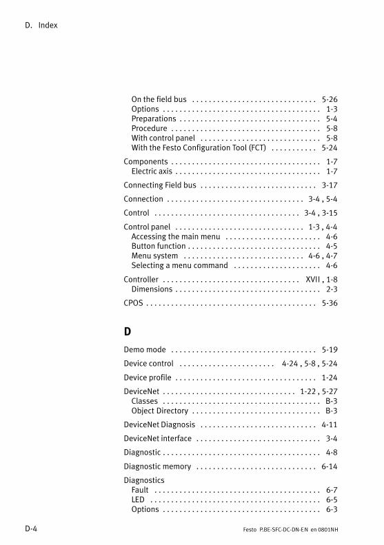
D. Index
D−4 Festo P.BE−SFC−DC−DN−EN en 0801NH
On the field bus 5−26 . . . . . . . . . . . . . . . . . . . . . . . . . . . . . . Options 1−3 . . . . . . . . . . . . . . . . . . . . . . . . . . . . . . . . . . . . . . Preparations 5−4 . . . . . . . . . . . . . . . . . . . . . . . . . . . . . . . . . . Procedure 5−8 . . . . . . . . . . . . . . . . . . . . . . . . . . . . . . . . . . . . With control panel 5−8 . . . . . . . . . . . . . . . . . . . . . . . . . . . . . With the Festo Configuration Tool (FCT) 5−24 . . . . . . . . . . .
Components 1−7 . . . . . . . . . . . . . . . . . . . . . . . . . . . . . . . . . . . . Electric axis 1−7 . . . . . . . . . . . . . . . . . . . . . . . . . . . . . . . . . . .
Connecting Field bus 3−17 . . . . . . . . . . . . . . . . . . . . . . . . . . . .
Connection 3−4 , 5−4 . . . . . . . . . . . . . . . . . . . . . . . . . . . . . . . . .
Control 3−4 , 3−15 . . . . . . . . . . . . . . . . . . . . . . . . . . . . . . . . . . .
Control panel 1−3 , 4−4 . . . . . . . . . . . . . . . . . . . . . . . . . . . . . . . Accessing the main menu 4−6 . . . . . . . . . . . . . . . . . . . . . . . Button function 4−5 . . . . . . . . . . . . . . . . . . . . . . . . . . . . . . . . Menu system 4−6 , 4−7 . . . . . . . . . . . . . . . . . . . . . . . . . . . . . Selecting a menu command 4−6 . . . . . . . . . . . . . . . . . . . . .
Controller XVII , 1−8 . . . . . . . . . . . . . . . . . . . . . . . . . . . . . . . . . Dimensions 2−3 . . . . . . . . . . . . . . . . . . . . . . . . . . . . . . . . . . .
CPOS 5−36 . . . . . . . . . . . . . . . . . . . . . . . . . . . . . . . . . . . . . . . . .
D
Demo mode 5−19 . . . . . . . . . . . . . . . . . . . . . . . . . . . . . . . . . . .
Device control 4−24 , 5−8 , 5−24 . . . . . . . . . . . . . . . . . . . . . . .
Device profile 1−24 . . . . . . . . . . . . . . . . . . . . . . . . . . . . . . . . . .
DeviceNet 1−22 , 5−27 . . . . . . . . . . . . . . . . . . . . . . . . . . . . . . . . Classes B−3 . . . . . . . . . . . . . . . . . . . . . . . . . . . . . . . . . . . . . . Object Directory B−3 . . . . . . . . . . . . . . . . . . . . . . . . . . . . . . .
DeviceNet Diagnosis 4−11 . . . . . . . . . . . . . . . . . . . . . . . . . . . .
DeviceNet interface 3−4 . . . . . . . . . . . . . . . . . . . . . . . . . . . . . .
Diagnostic 4−8 . . . . . . . . . . . . . . . . . . . . . . . . . . . . . . . . . . . . . .
Diagnostic memory 6−14 . . . . . . . . . . . . . . . . . . . . . . . . . . . . .
DiagnosticsFault 6−7 . . . . . . . . . . . . . . . . . . . . . . . . . . . . . . . . . . . . . . . . LED 6−5 . . . . . . . . . . . . . . . . . . . . . . . . . . . . . . . . . . . . . . . . . Options 6−3 . . . . . . . . . . . . . . . . . . . . . . . . . . . . . . . . . . . . . .
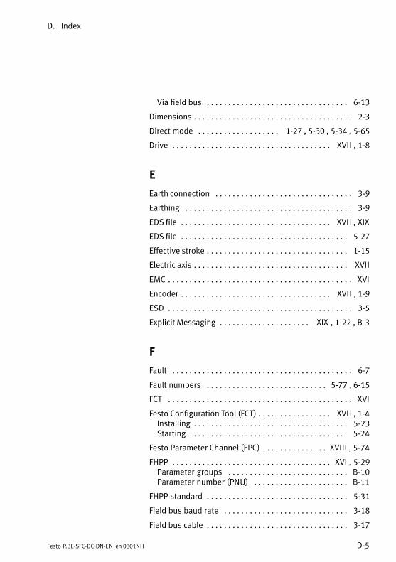
D. Index
D−5Festo P.BE−SFC−DC−DN−EN en 0801NH
Via field bus 6−13 . . . . . . . . . . . . . . . . . . . . . . . . . . . . . . . . .
Dimensions 2−3 . . . . . . . . . . . . . . . . . . . . . . . . . . . . . . . . . . . . .
Direct mode 1−27 , 5−30 , 5−34 , 5−65 . . . . . . . . . . . . . . . . . . .
Drive XVII , 1−8 . . . . . . . . . . . . . . . . . . . . . . . . . . . . . . . . . . . . .
E
Earth connection 3−9 . . . . . . . . . . . . . . . . . . . . . . . . . . . . . . . .
Earthing 3−9 . . . . . . . . . . . . . . . . . . . . . . . . . . . . . . . . . . . . . . .
EDS file XVII , XIX . . . . . . . . . . . . . . . . . . . . . . . . . . . . . . . . . . .
EDS file 5−27 . . . . . . . . . . . . . . . . . . . . . . . . . . . . . . . . . . . . . . .
Effective stroke 1−15 . . . . . . . . . . . . . . . . . . . . . . . . . . . . . . . . .
Electric axis XVII . . . . . . . . . . . . . . . . . . . . . . . . . . . . . . . . . . . .
EMC XVI . . . . . . . . . . . . . . . . . . . . . . . . . . . . . . . . . . . . . . . . . . .
Encoder XVII , 1−9 . . . . . . . . . . . . . . . . . . . . . . . . . . . . . . . . . . .
ESD 3−5 . . . . . . . . . . . . . . . . . . . . . . . . . . . . . . . . . . . . . . . . . . .
Explicit Messaging XIX , 1−22 , B−3 . . . . . . . . . . . . . . . . . . . . .
F
Fault 6−7 . . . . . . . . . . . . . . . . . . . . . . . . . . . . . . . . . . . . . . . . . .
Fault numbers 5−77 , 6−15 . . . . . . . . . . . . . . . . . . . . . . . . . . . .
FCT XVI . . . . . . . . . . . . . . . . . . . . . . . . . . . . . . . . . . . . . . . . . . .
Festo Configuration Tool (FCT) XVII , 1−4 . . . . . . . . . . . . . . . . . Installing 5−23 . . . . . . . . . . . . . . . . . . . . . . . . . . . . . . . . . . . . Starting 5−24 . . . . . . . . . . . . . . . . . . . . . . . . . . . . . . . . . . . . .
Festo Parameter Channel (FPC) XVIII , 5−74 . . . . . . . . . . . . . . .
FHPP XVI , 5−29 . . . . . . . . . . . . . . . . . . . . . . . . . . . . . . . . . . . . . Parameter groups B−10 . . . . . . . . . . . . . . . . . . . . . . . . . . . . Parameter number (PNU) B−11 . . . . . . . . . . . . . . . . . . . . . .
FHPP standard 5−31 . . . . . . . . . . . . . . . . . . . . . . . . . . . . . . . . .
Field bus baud rate 3−18 . . . . . . . . . . . . . . . . . . . . . . . . . . . . .
Field bus cable 3−17 . . . . . . . . . . . . . . . . . . . . . . . . . . . . . . . . .
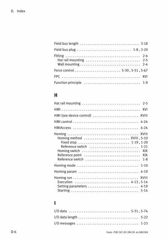
D. Index
D−6 Festo P.BE−SFC−DC−DN−EN en 0801NH
Field bus length 3−18 . . . . . . . . . . . . . . . . . . . . . . . . . . . . . . . .
Field bus plug 1−8 , 3−20 . . . . . . . . . . . . . . . . . . . . . . . . . . . . . .
Fitting 2−6 . . . . . . . . . . . . . . . . . . . . . . . . . . . . . . . . . . . . . . . . . Hat rail mounting 2−5 . . . . . . . . . . . . . . . . . . . . . . . . . . . . . . Wall mounting 2−4 . . . . . . . . . . . . . . . . . . . . . . . . . . . . . . . . .
Force control 5−30 , 5−51 , 5−67 . . . . . . . . . . . . . . . . . . . . . . . . .
FPC XVI . . . . . . . . . . . . . . . . . . . . . . . . . . . . . . . . . . . . . . . . . . .
Function principle 1−9 . . . . . . . . . . . . . . . . . . . . . . . . . . . . . . .
H
Hat rail mounting 2−5 . . . . . . . . . . . . . . . . . . . . . . . . . . . . . . . .
HMI XVI . . . . . . . . . . . . . . . . . . . . . . . . . . . . . . . . . . . . . . . . . . .
HMI (see device control) XVIII . . . . . . . . . . . . . . . . . . . . . . . . .
HMI control 4−24 . . . . . . . . . . . . . . . . . . . . . . . . . . . . . . . . . . . .
HMIAccess 4−24 . . . . . . . . . . . . . . . . . . . . . . . . . . . . . . . . . . . .
Homing XVIII . . . . . . . . . . . . . . . . . . . . . . . . . . . . . . . . . . . . . . . Homing method XVIII , 5−10 . . . . . . . . . . . . . . . . . . . . . . . . . Fixed stop 1−19 , 1−20 . . . . . . . . . . . . . . . . . . . . . . . . . . . . Reference switch 1−21 . . . . . . . . . . . . . . . . . . . . . . . . . . .
Homing switch XIX . . . . . . . . . . . . . . . . . . . . . . . . . . . . . . . . Reference point XIX . . . . . . . . . . . . . . . . . . . . . . . . . . . . . . . Reference switch 1−8 . . . . . . . . . . . . . . . . . . . . . . . . . . . . . .
Homing mode 1−10 . . . . . . . . . . . . . . . . . . . . . . . . . . . . . . . . . .
Homing param 4−19 . . . . . . . . . . . . . . . . . . . . . . . . . . . . . . . . .
Homing run XVIII . . . . . . . . . . . . . . . . . . . . . . . . . . . . . . . . . . . . Execution 4−13 , 5−14 . . . . . . . . . . . . . . . . . . . . . . . . . . . . . . Setting parameters 4−19 . . . . . . . . . . . . . . . . . . . . . . . . . . . . Starting 5−14 . . . . . . . . . . . . . . . . . . . . . . . . . . . . . . . . . . . . .
I
I/O data 5−31 , 5−74 . . . . . . . . . . . . . . . . . . . . . . . . . . . . . . . . .
I/O data length 5−22 . . . . . . . . . . . . . . . . . . . . . . . . . . . . . . . . .
I/O messages 1−23 . . . . . . . . . . . . . . . . . . . . . . . . . . . . . . . . . .
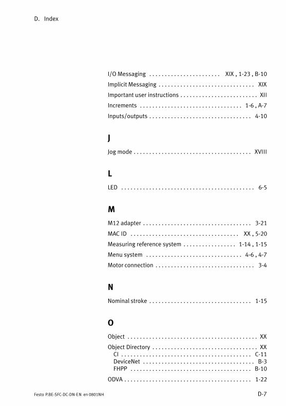
D. Index
D−7Festo P.BE−SFC−DC−DN−EN en 0801NH
I/O Messaging XIX , 1−23 , B−10 . . . . . . . . . . . . . . . . . . . . . . .
Implicit Messaging XIX . . . . . . . . . . . . . . . . . . . . . . . . . . . . . . .
Important user instructions XII . . . . . . . . . . . . . . . . . . . . . . . . .
Increments 1−6 , A−7 . . . . . . . . . . . . . . . . . . . . . . . . . . . . . . . . .
Inputs/outputs 4−10 . . . . . . . . . . . . . . . . . . . . . . . . . . . . . . . . .
J
Jog mode XVIII . . . . . . . . . . . . . . . . . . . . . . . . . . . . . . . . . . . . . .
L
LED 6−5 . . . . . . . . . . . . . . . . . . . . . . . . . . . . . . . . . . . . . . . . . . .
M
M12 adapter 3−21 . . . . . . . . . . . . . . . . . . . . . . . . . . . . . . . . . . .
MAC ID XX , 5−20 . . . . . . . . . . . . . . . . . . . . . . . . . . . . . . . . . . .
Measuring reference system 1−14 , 1−15 . . . . . . . . . . . . . . . . .
Menu system 4−6 , 4−7 . . . . . . . . . . . . . . . . . . . . . . . . . . . . . . .
Motor connection 3−4 . . . . . . . . . . . . . . . . . . . . . . . . . . . . . . . .
N
Nominal stroke 1−15 . . . . . . . . . . . . . . . . . . . . . . . . . . . . . . . . .
O
Object XX . . . . . . . . . . . . . . . . . . . . . . . . . . . . . . . . . . . . . . . . . .
Object Directory XX . . . . . . . . . . . . . . . . . . . . . . . . . . . . . . . . . . CI C−11 . . . . . . . . . . . . . . . . . . . . . . . . . . . . . . . . . . . . . . . . . . DeviceNet B−3 . . . . . . . . . . . . . . . . . . . . . . . . . . . . . . . . . . . . FHPP B−10 . . . . . . . . . . . . . . . . . . . . . . . . . . . . . . . . . . . . . . .
ODVA 1−22 . . . . . . . . . . . . . . . . . . . . . . . . . . . . . . . . . . . . . . . . .

D. Index
D−8 Festo P.BE−SFC−DC−DN−EN en 0801NH
Operation mode XVIII . . . . . . . . . . . . . . . . . . . . . . . . . . . . . . . . Homing XVIII , 5−14 . . . . . . . . . . . . . . . . . . . . . . . . . . . . . . . . Positioning mode XVIII . . . . . . . . . . . . . . . . . . . . . . . . . . . . . Profile Position mode (see positioning mode) 1−10 . . . . . . Profile Torque mode (see force control) XVIII , 1−10 . . . . . . Teach mode XIX . . . . . . . . . . . . . . . . . . . . . . . . . . . . . . . . . . .
Operational safety 1−11 . . . . . . . . . . . . . . . . . . . . . . . . . . . . . .
P
ParameterAxis type 5−10 . . . . . . . . . . . . . . . . . . . . . . . . . . . . . . . . . . . . Display 4−8 . . . . . . . . . . . . . . . . . . . . . . . . . . . . . . . . . . . . . .
Parameter channel (FPC) 5−74 . . . . . . . . . . . . . . . . . . . . . . . . .
Parameter identifier (PKE) 5−74 , 5−75 . . . . . . . . . . . . . . . . . . .
Parameter number (PNU) 5−75 . . . . . . . . . . . . . . . . . . . . . . . .
Parameter value (PWE) 5−74 . . . . . . . . . . . . . . . . . . . . . . . . . .
Parameterisation 1−5 . . . . . . . . . . . . . . . . . . . . . . . . . . . . . . . . System of measurement units 1−6 . . . . . . . . . . . . . . . . . . . .
Parameters Reference run (homing) 5−10 . . . . . . . . . . . . . . .
Parametrization with FHPP B−10 . . . . . . . . . . . . . . . . . . . . . . .
Password 4−21 , 5−88 . . . . . . . . . . . . . . . . . . . . . . . . . . . . . . . . Entry 4−22 . . . . . . . . . . . . . . . . . . . . . . . . . . . . . . . . . . . . . . . Modification/deactivation 4−22 . . . . . . . . . . . . . . . . . . . . . . Setup 4−21 . . . . . . . . . . . . . . . . . . . . . . . . . . . . . . . . . . . . . . .
Pictograms XIII . . . . . . . . . . . . . . . . . . . . . . . . . . . . . . . . . . . . .
Plug 3−5 . . . . . . . . . . . . . . . . . . . . . . . . . . . . . . . . . . . . . . . . . . .
Plugs Field bus 1−8 . . . . . . . . . . . . . . . . . . . . . . . . . . . . . . . . . .
PNU B−11 . . . . . . . . . . . . . . . . . . . . . . . . . . . . . . . . . . . . . . . . . .
Position set XVIII , 1−5 . . . . . . . . . . . . . . . . . . . . . . . . . . . . . . . . Execution 4−12 . . . . . . . . . . . . . . . . . . . . . . . . . . . . . . . . . . .
Position set tableCreation 4−20 , 5−17 . . . . . . . . . . . . . . . . . . . . . . . . . . . . . . . . Display 4−9 . . . . . . . . . . . . . . . . . . . . . . . . . . . . . . . . . . . . . . Execution 4−14 . . . . . . . . . . . . . . . . . . . . . . . . . . . . . . . . . . .
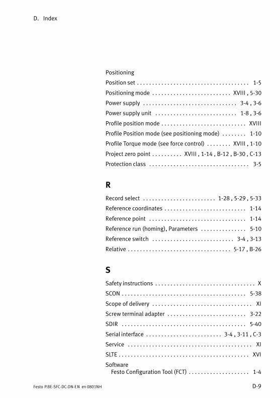
D. Index
D−9Festo P.BE−SFC−DC−DN−EN en 0801NH
Positioning
Position set 1−5 . . . . . . . . . . . . . . . . . . . . . . . . . . . . . . . . . . . . .
Positioning mode XVIII , 5−30 . . . . . . . . . . . . . . . . . . . . . . . . . .
Power supply 3−4 , 3−6 . . . . . . . . . . . . . . . . . . . . . . . . . . . . . . .
Power supply unit 1−8 , 3−6 . . . . . . . . . . . . . . . . . . . . . . . . . . .
Profile position mode XVIII . . . . . . . . . . . . . . . . . . . . . . . . . . . .
Profile Position mode (see positioning mode) 1−10 . . . . . . . .
Profile Torque mode (see force control) XVIII , 1−10 . . . . . . . .
Project zero point XVIII , 1−14 , B−12 , B−30 , C−13 . . . . . . . . . .
Protection class 3−5 . . . . . . . . . . . . . . . . . . . . . . . . . . . . . . . . .
R
Record select 1−28 , 5−29 , 5−33 . . . . . . . . . . . . . . . . . . . . . . . .
Reference coordinates 1−14 . . . . . . . . . . . . . . . . . . . . . . . . . . .
Reference point 1−14 . . . . . . . . . . . . . . . . . . . . . . . . . . . . . . . .
Reference run (homing), Parameters 5−10 . . . . . . . . . . . . . . .
Reference switch 3−4 , 3−13 . . . . . . . . . . . . . . . . . . . . . . . . . . .
Relative 5−17 , B−26 . . . . . . . . . . . . . . . . . . . . . . . . . . . . . . . . . .
S
Safety instructions X . . . . . . . . . . . . . . . . . . . . . . . . . . . . . . . . .
SCON 5−38 . . . . . . . . . . . . . . . . . . . . . . . . . . . . . . . . . . . . . . . . .
Scope of delivery XI . . . . . . . . . . . . . . . . . . . . . . . . . . . . . . . . .
Screw terminal adapter 3−22 . . . . . . . . . . . . . . . . . . . . . . . . . .
SDIR 5−40 . . . . . . . . . . . . . . . . . . . . . . . . . . . . . . . . . . . . . . . . .
Serial interface 3−4 , 3−11 , C−3 . . . . . . . . . . . . . . . . . . . . . . . . .
Service XI . . . . . . . . . . . . . . . . . . . . . . . . . . . . . . . . . . . . . . . . .
SLTE XVI . . . . . . . . . . . . . . . . . . . . . . . . . . . . . . . . . . . . . . . . . . .
SoftwareFesto Configuration Tool (FCT) 1−4 . . . . . . . . . . . . . . . . . . . .
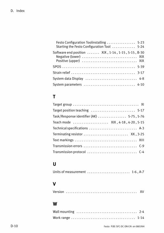
D. Index
D−10 Festo P.BE−SFC−DC−DN−EN en 0801NH
Festo Configuration Toolinstalling 5−23 . . . . . . . . . . . . . . . . Starting the Festo Configuration Tool 5−24 . . . . . . . . . . . . .
Software end position XIX , 1−14 , 1−15 , 5−15 , B−30 . . . . . . . Negative (lower) XIX . . . . . . . . . . . . . . . . . . . . . . . . . . . . . . . Positive (upper) XIX . . . . . . . . . . . . . . . . . . . . . . . . . . . . . . .
SPOS 5−39 . . . . . . . . . . . . . . . . . . . . . . . . . . . . . . . . . . . . . . . . .
Strain relief 3−17 . . . . . . . . . . . . . . . . . . . . . . . . . . . . . . . . . . . .
System data Display 4−8 . . . . . . . . . . . . . . . . . . . . . . . . . . . . .
System parameters 4−10 . . . . . . . . . . . . . . . . . . . . . . . . . . . . .
T
Target group XI . . . . . . . . . . . . . . . . . . . . . . . . . . . . . . . . . . . . .
Target position teaching 5−17 . . . . . . . . . . . . . . . . . . . . . . . . .
Task/Response identifier (AK) 5−75 , 5−76 . . . . . . . . . . . . . . . .
Teach mode XIX , 4−18 , 4−20 , 5−15 . . . . . . . . . . . . . . . . . . . .
Technical specifications A−3 . . . . . . . . . . . . . . . . . . . . . . . . . . .
Terminating resistor XX , 3−25 . . . . . . . . . . . . . . . . . . . . . . . . .
Text markings XIII . . . . . . . . . . . . . . . . . . . . . . . . . . . . . . . . . . .
Transmission errors C−9 . . . . . . . . . . . . . . . . . . . . . . . . . . . . . .
Transmission protocol C−4 . . . . . . . . . . . . . . . . . . . . . . . . . . . .
U
Units of measurement 1−6 , A−7 . . . . . . . . . . . . . . . . . . . . . . . .
V
Version XV . . . . . . . . . . . . . . . . . . . . . . . . . . . . . . . . . . . . . . . .
W
Wall mounting 2−4 . . . . . . . . . . . . . . . . . . . . . . . . . . . . . . . . . .
Work range 1−14 . . . . . . . . . . . . . . . . . . . . . . . . . . . . . . . . . . . .