BRACING CONNECTIONS TO RECTANGULAR HSS ...
10
372 INTRODUCTION In recent years, the use of Rectangular Hollow Sections (RHS) as columns has become increasingly popular. In many instances, RHS column members are replacing customary I-section members due to their superior column performance. In turn, welded longitudinal plates have been a traditional and convenient method for the connection of brace members and other attachments to I-section, and now RHS, columns. Figure 1 shows these two cases of longitudinal plate connections. For the case of the I- section column, the plate is welded along the center of the column flange so the load from the plate is transferred to the web of the column directly. The situation is different for the case of the RHS column because the load from the brace plate must be carried indirectly through the flexible column face into the adjacent column webs. A conventional longitudinal plate-to-RHS member connection tends to result in excessive distortion or plastification of the RHS connecting face. Such a connection results in a low design resistance that is governed by the formation of a yield line mechanism and this design resistance ought to satisfy an ultimate deformation limit and a serviceability deformation limit for the RHS connecting face. An extensive experimental and analytical study on longitudinal plate-to-RHS connections by Cao et al. (1 ) has resulted in published limit states design procedures for these types of connections. In an effort to reduce the inherent flexibility of longitudinal plate connections, stiffening plates or structural tees are sometimes welded to the RHS connecting face. Also, a "through-plate" connection can be used to potentially double the strength of a standard longitudinal plate connection. Another method of reducing the out-of-plane deformation of the RHS connecting face involves simply welding the connecting plate transversely to the RHS member axis. Figure 2 shows these "alternative" plate connections. BRACING CONNECTIONS TO RECTANGULAR HSS COLUMNS N. KOSTESKI 1 AND J.A. PACKER 2 ABSTRACT: Bracing members are frequently site-bolted to a plate welded longitudinally to a column member. For Hollow Structural Section (HSS) columns, and particularly for square or rectangular HSS members, this mode of application produces a very flexible connection with the resistance typically governed by a deformation limit. Many structural designers are unfamiliar with this type of connection behavior and corresponding design models. This paper presents an overview of recent research at the University of Toronto on this connection type and related stiffened connections. (a) Plate to I-section (b) Plate-to-RHS Figure 1: Longitudinal brace plate connections 1 Doctoral Candidate, Dept. of Civil Engineering, Univ. of Toronto. 2 Prof., Dept. of Civ. Engrg., Univ. of Toronto, 35 St. George St., Toronto, ON, M5S 1A4 Canada, E-mail: [email protected]
-
Upload
khangminh22 -
Category
Documents
-
view
1 -
download
0
Transcript of BRACING CONNECTIONS TO RECTANGULAR HSS ...

372
INTRODUCTION
In recent years, the use of Rectangular Hollow Sections (RHS) as columns has become increasingly popular. In many instances, RHS column members are replacing customary I-section members due to their superior column performance. In turn, welded longitudinal plates have been a traditional and convenient method for the connection of brace members and other attachments to I-section, and now RHS, columns. Figure 1 shows these two cases of longitudinal plate connections. For the case of the I-section column, the plate is welded along the center of the column flange so the load from the plate is transferred to the web of the column directly. The situation is different for the case of the RHS column because the load from the brace plate must be carried indirectly through the flexible column face into the adjacent column webs. A conventional longitudinal plate-to-RHS member connection tends to result in excessive distortion or plastification of the RHS connecting face. Such a connection results in a low design resistance that is governed by the formation of a yield line mechanism and this design resistance ought to satisfy an ultimate deformation limit and a serviceability deformation limit for the RHS connecting face. An extensive experimental and analytical study on longitudinal plate-to-RHS connections by Cao et al. (1) has resulted in published limit states design procedures for these types of connections.
In an effort to reduce the inherent flexibility of longitudinal plate connections, stiffening plates or structural tees are sometimes welded to the RHS connecting face. Also, a "through-plate" connection can be used to potentially double the strength of a standard longitudinal plate connection. Another method of reducing the out-of-plane deformation of the RHS connecting face involves simply welding the connecting plate transversely to the RHS member axis. Figure 2 shows these "alternative" plate connections.
BRACING CONNECTIONS TO RECTANGULAR HSS COLUMNSN. KOSTESKI1 AND J.A. PACKER2
ABSTRACT: Bracing members are frequently site-bolted to a plate welded longitudinally to a column member. For Hollow Structural Section (HSS) columns, and particularly for square or rectangular HSS members, this mode of application produces a very flexible connection with the resistance typically governed by a deformation limit. Many structural designers are unfamiliar with this type of connection behavior and corresponding design models. This paper presents an overview of recent research at the University of Toronto on this connection type and related stiffened connections.
(a) Plate to I-section (b) Plate-to-RHS
Figure 1: Longitudinal brace plate connections
1Doctoral Candidate, Dept. of Civil Engineering, Univ. of Toronto.2Prof., Dept. of Civ. Engrg., Univ. of Toronto, 35 St. George St., Toronto, ON, M5S 1A4 Canada, E-mail: [email protected]
373
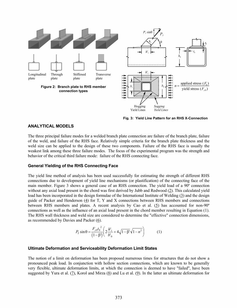
ANALYTICAL MODELS
The three principal failure modes for a welded branch plate connection are failure of the branch plate, failure of the weld, and failure of the RHS face. Relatively simple criteria for the branch plate thickness and the weld size can be applied to the design of these two components. Failure of the RHS face is usually the weakest link among these three failure modes. The focus of the experimental program was the strength and behavior of the critical third failure mode: failure of the RHS connecting face.
General Yielding of the RHS Connecting Face
The yield line method of analysis has been used successfully for estimating the strength of different RHS connections due to development of yield line mechanisms (or plastification) of the connecting face of the main member. Figure 3 shows a general case of an RHS connection. The yield load of a 90º connection without any axial load present in the chord was first derived by Jubb and Redwood (2). This calculated yield load has been incorporated in the design formulae of the International Institute of Welding (3) and the design guide of Packer and Henderson (4) for T, Y and X connections between RHS members and connections between RHS members and plates. A recent analysis by Cao et al. (5) has accounted for non-90º connections as well as the influence of an axial load present in the chord member resulting in Equation (1). The RHS wall thickness and weld size are considered to determine the "effective" connection dimensions, as recommended by Davies and Packer (6).
PF t h
bnY
ysin'
''
'0 02
1
0
2
12 4 1 1 (1)
Ultimate Deformation and Serviceability Deformation Limit States
The notion of a limit on deformation has been proposed numerous times for structures that do not show a pronounced peak load. In conjunction with hollow section connections, which are known to be generally very flexible, ultimate deformation limits, at which the connection is deemed to have "failed", have been suggested by Yura et al. (7), Korol and Mirza (8) and Lu et al. (9). In the latter an ultimate deformation for
Longitudinal plate
Through plate
Stiffened plate
Transverse plate
Figure 2: Branch plate to RHS member connection types
Hogging Yield Lines
Sagging Yield Lines
PYPY sin
h0
t0
b0b1
h1
h'1
h'1
nF
Fy
applied stressyield stress
( )( )
0
0
Fig. 3: Yield Line Pattern for an RHS X-Connection
374
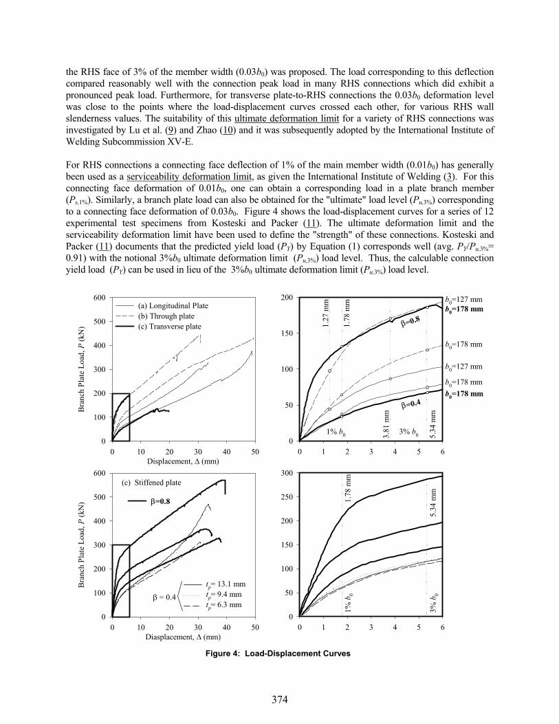
the RHS face of 3% of the member width (0.03b0) was proposed. The load corresponding to this deflection compared reasonably well with the connection peak load in many RHS connections which did exhibit a pronounced peak load. Furthermore, for transverse plate-to-RHS connections the 0.03b0 deformation level was close to the points where the load-displacement curves crossed each other, for various RHS wall slenderness values. The suitability of this ultimate deformation limit for a variety of RHS connections was investigated by Lu et al. (9) and Zhao (10) and it was subsequently adopted by the International Institute of Welding Subcommission XV-E.
For RHS connections a connecting face deflection of 1% of the main member width (0.01b0) has generally been used as a serviceability deformation limit, as given the International Institute of Welding (3). For this connecting face deformation of 0.01b0, one can obtain a corresponding load in a plate branch member (Ps,1%). Similarly, a branch plate load can also be obtained for the "ultimate" load level (Pu,3%) corresponding to a connecting face deformation of 0.03b0. Figure 4 shows the load-displacement curves for a series of 12 experimental test specimens from Kosteski and Packer (11). The ultimate deformation limit and the serviceability deformation limit have been used to define the "strength" of these connections. Kosteski and Packer (11) documents that the predicted yield load (PY) by Equation (1) corresponds well (avg. PY/Pu,3%=0.91) with the notional 3%b0 ultimate deformation limit (Pu,3%) load level. Thus, the calculable connection yield load (PY) can be used in lieu of the 3%b0 ultimate deformation limit (Pu,3%) load level.
Displacement, (mm)0 10 20 30 40 50
Bra
nch
Plat
e Lo
ad, P
(kN
)
0
100
200
300
400
500
600(a) Longitudinal Plate(b) Through plate(c) Transverse plate
0 1 2 3 4 5 60
50
100
150
200
=0.4
=0.8
1% b0
1.78
mm
1.27
mm
3% b03.81
mm
5.34
mm
b0=178 mm
b0=127 mm
b0=178 mm
b0=127 mm
b0=178 mm
b0=178 mm
Diasplacement, (mm)0 10 20 30 40 50
Bra
nch
Plat
e Lo
ad, P
(kN
)
0
100
200
300
400
500
600(c) Stiffened plate
=0.8
tp= 13.1 mmtp= 9.4 mmtp= 6.3 mm
= 0.4
0 1 2 3 4 5 60
50
100
150
200
250
300
1.78
mm
5.34
mm
1% b
0
3% b
0
Figure 4: Load-Displacement Curves

375
Governing Strength or Serviceability Condition
Based on a ratio of factored to unfactored loads of 1.5, Lu et al. (9) suggested using the ratio Pu,3%Ps,1% to decide whether the ultimate deformation limit state or the serviceability deformation limit state governs as demonstrated by Equation (2).
for, serviceability limit governs (2a)
for, ultimate limit governs (2b)
3%P
P
P
P
u
s
u
s
,
,
,
,
. ,
. ,
1%
3%
1%
15
15
In our case, we have replaced the notional (Pu,3%)ultimate deformation limit state with an actual connection yield load limit state (PY) calculated using Equation (1).
Zhao (10) proposed that the governing deformation limit states expressed in Equation (2) could be predicted by the geometric properties of the connection using Equation (3).
0 6 15
0 6 15
. ,
. ,
and serviceability governs (3a)
or strength governs (3b)
0
0
0
0
btbt
Figure 5 is a comprehensive plot of experimental test results and FEM-generated numerical data showing the governing strength or serviceability limit state for various connection types. In Figure 5 the calculable connection yield load (PY) is used to replace the notional 3%b0 ultimate deformation limit (Pu,3%) load level. The actual governing limit states of branch plate to RHS connections can then be compared with the recommended limit state partitions set forth by Lu et al. (9) and Zhao (10). The ratio of factored to unfactored loads of 1.5 recommended by Lu et al. (9) was plotted as a horizontal reference line using the (yield load /serviceability load) axis in Figure 5. The region above this reference line represents a governing serviceability condition (Ps,1%). Likewise, the region below this line represents a governing strength condition (PY).
Class 2/32
b t0o
Class 3/40
bt0o
Yie
ldlo
ad/S
ervi
ceab
ility
loa d
(/
)P
PY
s,1%
stre
ngth
gov
erns
serv
icea
bilit
y go
vern
s
Class 1/ 26b t0 o
0.0 0.1 0.2 0.3 0.4 0.5 0.6 0.7 0.8 0.90.5
1.0
1.5
2.0
2.5
FEM RESULTS EXPERIMENTAL RESULTS
Stiffened plate
Longitudinal plate
b0 /t0=23.4b0 /t0=15.6
Through plateb0 /t0=37.1b0 /t0=26.5
Longitudinal plateb0 /t0=37.1b0 /t0=26.5
b0 /t0=37.1Stiffened plate
b0 /t0=37.1Transverse Plate
(Branch plate width) / (RHS connecting face width), '
Cao et. al. ( )1
Kosteski and Packer ( )15
from Kosteski and Packer ( )11
b0 /t0=48.0 b0 /t0=40.0b0 /t0=32.0b0 /t0=28.0b0 /t0=20.0b0 /t0=16.1b0 /t0=14.0b0 /t0=12.0
Fig. 5: Governing strength versus serviceability
376
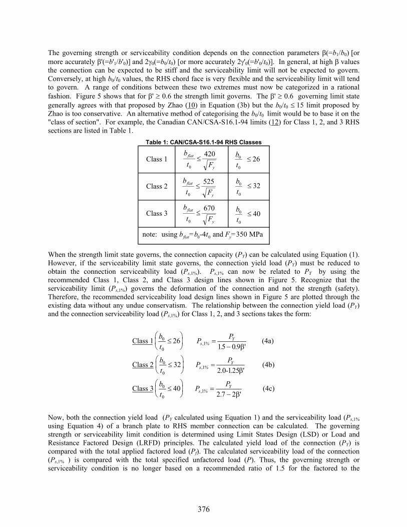
The governing strength or serviceability condition depends on the connection parameters (=b1/b0) ormore accurately '(=b'1/b'0)] and 2 0(=b0/t0) [or more accurately 2 '0(=b'0/t0)]. In general, at high values the connection can be expected to be stiff and the serviceability limit will not be expected to govern. Conversely, at high b0/t0 values, the RHS chord face is very flexible and the serviceability limit will tend to govern. A range of conditions between these two extremes must now be categorized in a rational fashion. Figure 5 shows that for ' 0.6 the strength limit governs. The ' 0.6 governing limit state generally agrees with that proposed by Zhao (10) in Equation (3b) but the b0/t0 15 limit proposed by Zhao is too conservative. An alternative method of categorising the b0/t0 limit would be to base it on the "class of section". For example, the Canadian CAN/CSA-S16.1-94 limits (12) for Class 1, 2, and 3 RHS sections are listed in Table 1.
When the strength limit state governs, the connection capacity (PY) can be calculated using Equation (1). However, if the serviceability limit state governs, the connection yield load (PY) must be reduced to obtain the connection serviceability load (Ps,1%). Ps,1% can now be related to PY by using the recommended Class 1, Class 2, and Class 3 design lines shown in Figure 5. Recognize that the serviceability limit (Ps,1%) governs the deformation of the connection and not the strength (safety). Therefore, the recommended serviceability load design lines shown in Figure 5 are plotted through the existing data without any undue conservatism. The relationship between the connection yield load (PY)and the connection serviceability load (Ps,1%) for Class 1, 2, and 3 sections takes the form:
Class 1 (4a)
Class 2 (4b)
Class 3 (4c)
bt
PP
. .
bt
PP
. - .
bt
PP
.
s %Y
s %Y
s %Y
0
01
0
01
0
01
2615 0 9
322 0 125
402 7 2
,
,
,
'
'
'
Now, both the connection yield load (PY calculated using Equation 1) and the serviceability load (Ps,1%using Equation 4) of a branch plate to RHS member connection can be calculated. The governing strength or serviceability limit condition is determined using Limit States Design (LSD) or Load and Resistance Factored Design (LRFD) principles. The calculated yield load of the connection (PY) is compared with the total applied factored load (Pf). The calculated serviceability load of the connection (Ps,1% ) is compared with the total specified unfactored load (P). Thus, the governing strength or serviceability condition is no longer based on a recommended ratio of 1.5 for the factored to the
Table 1: CAN/CSA-S16.1-94 RHS Classes
Class 1
Class 2
Class 3
bt
0
0
26
note: using and MPa b =b - t F = flat y0 04 350
b
t Fflat
y0
670 bt
0
0
40
b
t Fflat
y0
420
b
t Fflat
y0
525 bt
0
0
32
377
unfactored load level. Instead, the strength or serviceability governing condition is determined using the actual factored and unfactored loads. The ratio of PY to Pf (Eq. 5a) determines the extent to which the yield load condition has been met. The ratio of Ps,1% to P (Eq. 5b) determines the extent to which the serviceability condition has been met.
Ultimate Load Ratio (5a)PP
Y
f
Serviceability Load Ratio (5b)P
Ps,1%
The lower of the two load ratios determines whether the strength or serviceability condition governs. For design purposes, both ratios must be 1.0 to satisfy both the strength and serviceability conditions (limit states). The "design loop" would consist of initially designing the connection for the strength condition (PY) and then checking to see if the serviceability condition (Ps,1%) is met, as is customary with a Limit States Design (LSD) procedure.
OVERALL DESIGN OF BRANCH PLATE TO RHS MEMBER CONNECTIONS
The design and fabrication of connections for RHS members has often been perceived as complicated and expensive. Rational design methods are needed to encompass, and wherever possible to consolidate, the multitude of connections available to the designer. The yield line method has been incorporated in the design formulae of the International Institute of Welding (3), the design guide of Packer and Henderson (5),and the AISC HSS Connections Manual (13), for T, Y and X connections between RHS members and connections between RHS members and plates.
A recent analysis by Cao et al. (5) has accounted for the influence of an axial load present in the main (column) member resulting in Equation (1) and is recommended to be adopted. The results of the experimental program by Kosteski and Packer (11) indicate that the "alternative" longitudinal through plate, stiffened longitudinal plate, and transverse plate-to-RHS member connections can be grouped under the general case of an RHS T-connection and designed using Equation (1).
Longitudinal and Through Plate Connections
The calculated yield load (PY using Equation 1) of a general RHS T-connection is based on an idealized yield line pattern forming around the footprint of the connecting branch plate causing plastification of the connecting RHS chord face. This represents a simplified but effective isolation and approximation of the actual plastification mechanism. Within these limits of idealisation, a through plate connection can be expected to have approximately double the strength of a single plate connection by causing plastification of two RHS chord (column) faces rather than one. Experimental results from Kosteski and Packer (11) confirm that a through plate connection can be reasonably approximated as having double the strength of a corresponding single plate connection for design purposes.
Transverse Plate Connections
A transverse branch plate to RHS member connection is significantly stiffer (due to a higher ratio) and hence has a higher design resistance than a longitudinally-oriented branch plate. However, aside from the behavior of the RHS connecting face, the design strength of transverse plate connections may also be governed by an "effective width" criterion applied to the branch plate, which accommodates the highly non-uniform stress distribution in the plate. Moreover, it has been shown by de Koning and Wardenier (14) that the branch plate effective width criterion is the governing limit state for transverse plate connections up to 0.85.

378
Stiffened Longitudinal Plate Connections
A stiffened longitudinal branch plate connection can ultimately achieve a much higher design resistance equivalent to the enlarged "footprint" of the stiffening plate as opposed to the modest footprint of the branch plate itself. In order to achieve this load, the stiffening plate must be "effectively-rigid" with respect to the RHS connecting face such that a plastification mechanism does not occur in the stiffening plate itself. In summary, the branch plate connection strength increases with an increasing stiffening plate thickness until an upper bound plate thickness is reached. Beyond this thickness, the stiffening plate is essentially "rigid" (i.e. achieving a 100% connection efficiency). For design purposes, a more practical "effectively-rigid" stiffening plate thickness was chosen by Kosteski and Packer (15) to be a 95% connection efficiency threshold.
Figure 6 presents the results of a comprehensive FEM study by Kosteski and Packer (15) related to the minimum required "effectively-rigid" stiffening plate thickness to achieve a 95% connection efficiency threshold. The "best-fit" exponential curve in Figure 6 is an empirical equation used to determine the minimum required "effectively-rigid" stiffening plate thickness tp(min) to satisfy both the (PY) strength condition and the (Ps,1%) serviceability condition. The ratio of the stiffening plate thickness tp(min) to the RHS connecting face wall thickness (t0) is a function of the "unrestrained" stiffening plate width (b1
*) to the RHS width (b'0) ratio ( *). The "unrestrained" stiffening plate width (b1*)
is equal to the nominal stiffening plate width (b1) minus the branch plate width (tb) and both branch plate welds (2w).
Practical Limits of Applicability
Design equations for HSS connections are often governed by limits of applicability related to the two dimensionless parameters 2 0(=b0/t0) and (=b1/b0). Yield line mechanism-based formulas are usually valid from low to moderately high ratios. Different modes of failure such as punching shear or local failure of the HSS side walls tend to govern at higher ratios approaching unity. Likewise the governing strength or serviceability limit state condition is also generally related to the dimensionless parameters 2 0
and .
Practical limits of applicability also arise from a fabrication standpoint. In general, it is preferred to connect to the "flat width" (bflat width) of an RHS member. Welding in the corner region of an RHS member is more difficult than welding along a preferred flat surface and therefore introduces additional fabrication costs. Also, the corners of a cold-formed RHS member represent regions of lower ductility. Notwithstanding an increased cost of fabrication, welding in this region of lower ductility may undermine
Unrestrained stiffening plate-to-RHS width ratio ( *)
0.0 0.2 0.4 0.6 0.8Stiff
enin
g pl
ate-
to-R
HS
wal
l thi
ckne
ss ra
tio (
t p(m
in)/t
0)
0.0
0.5
1.0
1.5
2.0
2.5
3.0
3.5
4.0
2 '0 range of validity = 11.0 to 47.0
best-fit exponential curve
t
tp(min) *. exp
0
0 5 3
if strength (PY) governs if serviceability (Ps,1%) governs
w
b1
½ b1*
b0
b'0
tp
tb
t0
"unrestrained"widthb b w t
bb
b1 1
1
0
2*
**
'
Figure 6: Required stiffening plate thickness

379
the integrity of the welded joint and may lead to premature weld/base metal fractures. Figure 7 shows the practical limits of applicability for branch plate to RHS member connections.
Referring to Figure 7, longitudinal and through plate connections are characterized by low ' ratios ( 0.1 to 0.25). Next, stiffened plate connections may be used to increase the ' ratio up until '=0.8. From Equation (1) it can be seen that the strength of the connection increases as ' increases. For '> 0.8 the strength of the connection increases rapidly and a prohibitively thick and impractical stiffening plate would be required. Also, as 'approaches unity the strength of the RHS connecting face tends towards infinity and punching shear around the branch, or local failure of the RHS side wall becomes the critical failure mode for 0.85 [Packer and Henderson (4)]. Hence, in the upper range of ' > 0.8, a transverse branch plate connection is recommended since it is much stiffer.
Figure 7 also shows the likely governing strength or serviceability regions for a common ratio of a factored to unfactored load level of 1.5. The actualstrength or serviceability governing condition is calculated using the actual factored and unfactored loads and is explicitly determined using a Limit States Design (LSD) procedure [Kosteski and Packer (15)]. Other failure modes relating to a general T-type connection must also be checked. Design criteria for punching shear, chord side wall failure, branch plate effective width, etc., can be found in current HSS design manuals and specifications.
Connection Costs
A rational and efficient design of RHS connections must be coupled with economical fabrication. A study of the relative costs of shear connections to RHS members was presented by Sherman (16) and the applicable results are listed in Table 2. The simple "shear tab" is one of the most economical connection types. A shear tab is oriented parallel to the axis of a column in order to frame directly into the web of a connecting beam. However, when a simple shear tab is used as a branch plate for an RHS member, the tab (or plate) may be oriented
0.0 0.1 0.2 0.3 0.4 0.5 0.6 0.7 0.8 0.9 1.0
0
5
10
15
20
25
30
35
40
45
50
PunchingShearChord Face Yielding < 0.85
(a) long. plate (b) through plate
(c) stiffened plate ' < 0.8 n e(d) tra sv rse plate
Class 1
Class 2
Class 3 ' > 0
.6
' > 0
.4STRENGTH
GOVERNSSERVIC
EABILIT
Y
GOVERNS
(a) Longitudinal plate
(c) Stiffened plate
(d) Transverse plate
(b) Through plate
Slen
dern
ess o
f RH
S co
nnec
ting
chor
d fa
ce,
/b
t0
0
side
wal
l fai
lure
=1
.0Branch to RHS width ratio, (or ')
flat width lower bound
b0
blower bound
bflat width
t tb typical 0
radiust2 0
2 0twtypical
lower boundlower boundb
b0
bt
380
0
.
APPROXIMATE UPPER AND LOWER BOUNDS
flat widthflat widthb
b0
bt
1 40
0
t0
Figure 7: Practical limits of applicability
Table 2: Relative Connection Costsadapted from Sherman (16)
Shear Connection Equivalent Brace Plate RelativeType Connection Type Cost
Single Angle, n/a 1.00L-shaped Welds
Shear Tab Longitudinal Plate, 1.05Transverse Plate
Tee, Stiffened 1.50Vertical Welds Longitudinal PlateThrough-Plate Through-Plate 2.25
380
either longitudinally or transversely. A single longitudinal plate can accommodate multiple connecting branches (e.g. a KT-type connection) framing along the axis of an RHS member. However, three separate transverse plates would be required to connect each branch of a longitudinally-oriented KT-type connection. Thus, a single longitudinally-oriented branch plate is to be preferred for multiple branches (in one plane) framing along the axis of an RHS member. A transverse branch plate-to-RHS member connection, on the other hand, is significantly stiffer and hence has a much higher design resistance than a longitudinally-oriented branch plate but is more suitable for a single branch framing into an RHS member.
A stiffened longitudinal plate is often necessary to increase the design capacity of a longitudinally-oriented branch plate. A through plate connection will also result in a higher design capacity but is considerably more expensive than a stiffened branch plate. Also, a through plate connection is limited to "doubling" the strength of a longitudinal plate connection. Increasing the effective width of a longitudinal branch plate by using a stiffening plate is a far more effective method of increasing, doubling, or more than doubling the design resistance of a longitudinal plate connection.
CONCLUSIONS
Four different welded connection types, namely longitudinal plate, through plate, transverse plate, and stiffened plate to Rectangular Hollow Section (RHS) members have been studied experimentally, by means of tests on 22 isolated connections. This data was supplemented by yield line analysis plus comprehensive numerical modeling to enable a broader parametric study to be performed. The latter involved non-linear Finite Element Analysis using 20-noded solid elements with realistic modeling of RHS corner radii and weld geometry. The results of the study indicate that these connection types can be grouped under the general case of an RHS T-connection and designed as such. A simplified design approach has been presented to consolidate the various branch plate to RHS member connection types. This design philosophy accounts for a strength and a serviceability limit state.
ACKNOWLEDGEMENTS
Financial support for this project was provided by the Steel Structures Education Foundation, the Steel Tube Institute of North America, the Comité International pour le Développement et l’Étude de la Construction Tubulaire (CIDECT), the Natural Sciences and Engineering Research Council of Canada (NSERC), and the Canadian Institute of Steel Construction (CISC) through a Kellerman Fellowship.
NOTATION
b0, b'0 = outside width of main member, effective width (= b0 - t0)b1, b'1, b1
*= outside width of connecting member, effective width (= b1 + 2w), unrestrained width (=b1 - 2w - tb) bflat width = flat width of RHS member face blower bound = approximate minimum practical connection width F0 = main member axial stress Fy, Fy0 = yield stress of material, yield stress of main RHS member h1, h'1 = outside depth or length of connecting member, effective outside depth or length of connecting member (= h1/sin + 2w) n = main member "preload" ratio (=F0/Fy0)
P, Pf = specified load, factored load PY = yield load of connection
Ps,1% = 1% b0 serviceability deformation limit connection load level Pu,3% = 3% b0 ultimate deformation limit connection load level
381
t0, tp, tp(min)= wall thickness of RHS main member, thickness of stiffening plate, minimum required "effectively- rigid" stiffening plate thickness tb, tb(typical)= branch plate width, typical branch plate width w, wtypical = weld size (leg length), typical weld size (leg length)
, ', * = nominal beta ratio (= b1/b0), effective beta ratio (= b'1/b'0), unrestrained beta ratio (= b1*/b'0)
flat width = flat width beta ratio (= bflat width / b0)lower bound = approx. min. beta ratio (=blower bound / b0)
0 '0 = width to thickness ratio of main RHS member (=b0/t0, b'0/t0) = angle of inclination with respect to RHS member axis
REFERENCES
(1) Cao, J.J., Packer, J.A., Kosteski, N. (1998). "Design guidelines for longitudinal plate to HSS connections," Journal of Structural Engineering, ASCE, Vol.124, No.7, pp.784-791.
(2) Jubb, J. E. M. and Redwood, R .G. (1966). "Design of joints to box sections." Conference on Industrial Building and the Structural Engineer, Institution of Structural Engineers, UK.
(3) International Institute of Welding (IIW). (1989). "Design recommendations for hollow section joints - predominantly statically loaded." IIW Doc. XV-701-89, 2nd ed, IIW Subcommission XV-E, Helsinki, Finland.
(4) Packer, J. A. and Henderson, J. E. (1997). "Hollow structural section connections and trusses - A design guide", 2nd Edition, Canadian Institute of Steel Construction, Toronto, Canada.
(5) Cao, J. J., Packer, J. A. and Yang, G. J. (1998). "Yield line analysis of RHS connections with axial loads." J. Constructional Steel Research, Vol. 48, pp. 1-25.
(6) Davies, G. and Packer, J. A. (1982). "Predicting the strength of branch plate - RHS connections for punching shear." Canadian Journal of Civil Engineering, Vol. 9, pp. 458-467.
(7) Yura, J. A., Zettlemoyer, N. and Edwards, I. F. (1980). "Ultimate capacity equations for tubular joints." Proc. Offshore Technology Conference, Vol. 1, Paper No. 3690.
(8) Korol, R. M. and Mirza, F. A. (1982). "Finite element analysis of RHS T-joints." Journal of the Structural Division, ASCE, Vol. 108, No. 9, pp. 2081-2098.
(9) Lu, L. H., de Winkel, G. D., Yu, Y. and Wardenier, J. (1994). "Deformation limit for the ultimate strength of hollow section joints." Proc. Sixth International Symposium on Tubular Structures,Melbourne, Australia, pp. 341-347.
(10) Zhao, X. L. (1996). "Verification of the deformation limit for T-joints in cold-formed RHS sections." Proc. Seventh International Symposium on Tubular Structures, Miskolc, Hungary, pp. 213-220.
(11) Kosteski, N. and Packer, J.A. (2001). "Experimental examination of branch plate to RHS member connection types." Proc. Ninth International Symposium on Tubular Structures, Düsseldorf, Germany.
(12) CAN/CSA-S16.1-94 (1994). "Limit states design of steel structures," Canadian Standards Association, Rexdale, Canada.
(13) AISC (1997). "Hollow structural section connections manual," AISC, Chicago, Illinois. (14) de Koning, C. H. M. and Wardenier, J. (1985). "The static strength of welded joints between structural
hollow sections or between structural hollow sections and H-sections. Part 2: joints between rectangular hollow sections." Stevin Report 6-84-19, Delft University of Technology, Delft, The Netherlands.
(15) Kosteski, N. and Packer, J.A. (2001). "FEM evaluation of stiffened branch plate to RHS member connections." Proc. 9th International Symposium on Tubular Structures, Düsseldorf, Germany.
(16) Sherman, D. R. (1996). "Designing with structural tubing." Engineering Journal, AISC, Vol. 33, No. 3, pp. 101-109.