Stiffness-Based Sizing of Bracing Systems for Tall and Slender Buildings
10
Stiffness-Based Sizing of Bracing Systems for Tall and Slender Buildings Guillermo Coeto Alonso y Asociados, Mexico Amador Teran-Gilmore Universidad Autonoma Metropolitana, Mexico SUMMARY A stiffness-based methodology for the preliminary sizing of the braces and support columns of a steel bracing system is discussed. The methodology applies to the case of tall earthquake-resistant buildings, whose dynamic response is significantly influenced by global flexural drifts and higher modes of vibration. The preliminary sizing of the structural members of several versions of a bracing system for a twenty four-story building is carried out. From the evaluation of the dynamic characteristics of the different versions of the bracing system, it is concluded that the proposed methodology results in adequate stiffness-based sizing during the performance- based preliminary design of tall braced buildings. Keywords: Stiffness-based sizing, Displacement-based design, Bracing system, Tall buildings 1. INTRODUCTION Structural design of tall buildings under lateral forces is usually governed by drift control. Within this context, it has been considered that the most important property of a structural system is its lateral stiffness and that rigid frame systems alone are not an efficient solution for tall steel buildings. Not surprisingly, steel bracing has been usually provided to this type of buildings to efficiently control their lateral drifts within acceptable limits. In the last two decades, various sizing methods have been developed for the structural elements of tall buildings. The majority of these methods are evolutionary or iterative in nature, in such a manner that an initial solution is refined in search of an optimal solution that satisfies a series of drift and strength constraints. In many cases, a structural or performance parameter is used to formulate an optimization problem that often requires complicate analytical tools and the careful formulation of extra constraints. Initially, sizing methods for braced frames aimed at optimizing the weight or a performance parameter within the structural system of a building (Baker 1990, Chan and Grierson 1993). In time, the lateral stiffness of tall buildings was identified as their most relevant structural property; and this lead to several stiffness-based sizing methods aimed at elastic structural systems subjected to constant lateral loading and various strength and drift constraints (Kim et al. 1998, Kameshki and Saka 2001). At some point, researchers went beyond sizing structural elements for a given structural configuration, and proposed performance-based evolutionary methods to establish the optimal topology of bracing systems (Liang et al. 2000, Baldock and Shea 2006). Furthermore, drift-based methodologies that account for the interaction between the dynamic properties of the structural system and ground motion have been proposed (Park and Kwon 2003, Zou and Chan 2005). Complicate mathematics and a large computational effort or excessive simplification of the structural model usually result in difficulty in interpreting the final results of the optimization process and the need for formulating convergence and sizing constraints. In terms of earthquake-resistance of tall braced frames many issues have not been dealt with
Transcript of Stiffness-Based Sizing of Bracing Systems for Tall and Slender Buildings

Stiffness-Based Sizing of Bracing Systems for Tall and
Slender Buildings
Guillermo Coeto Alonso y Asociados, Mexico
Amador Teran-Gilmore Universidad Autonoma Metropolitana, Mexico
SUMMARY
A stiffness-based methodology for the preliminary sizing of the braces and support columns of a steel bracing
system is discussed. The methodology applies to the case of tall earthquake-resistant buildings, whose dynamic
response is significantly influenced by global flexural drifts and higher modes of vibration. The preliminary
sizing of the structural members of several versions of a bracing system for a twenty four-story building is
carried out. From the evaluation of the dynamic characteristics of the different versions of the bracing system, it
is concluded that the proposed methodology results in adequate stiffness-based sizing during the performance-
based preliminary design of tall braced buildings.
Keywords: Stiffness-based sizing, Displacement-based design, Bracing system, Tall buildings
1. INTRODUCTION
Structural design of tall buildings under lateral forces is usually governed by drift control. Within this
context, it has been considered that the most important property of a structural system is its lateral
stiffness and that rigid frame systems alone are not an efficient solution for tall steel buildings. Not
surprisingly, steel bracing has been usually provided to this type of buildings to efficiently control
their lateral drifts within acceptable limits.
In the last two decades, various sizing methods have been developed for the structural elements of tall
buildings. The majority of these methods are evolutionary or iterative in nature, in such a manner that
an initial solution is refined in search of an optimal solution that satisfies a series of drift and strength
constraints. In many cases, a structural or performance parameter is used to formulate an optimization
problem that often requires complicate analytical tools and the careful formulation of extra constraints.
Initially, sizing methods for braced frames aimed at optimizing the weight or a performance parameter
within the structural system of a building (Baker 1990, Chan and Grierson 1993). In time, the lateral
stiffness of tall buildings was identified as their most relevant structural property; and this lead to
several stiffness-based sizing methods aimed at elastic structural systems subjected to constant lateral
loading and various strength and drift constraints (Kim et al. 1998, Kameshki and Saka 2001). At
some point, researchers went beyond sizing structural elements for a given structural configuration,
and proposed performance-based evolutionary methods to establish the optimal topology of bracing
systems (Liang et al. 2000, Baldock and Shea 2006). Furthermore, drift-based methodologies that
account for the interaction between the dynamic properties of the structural system and ground motion
have been proposed (Park and Kwon 2003, Zou and Chan 2005). Complicate mathematics and a large
computational effort or excessive simplification of the structural model usually result in difficulty in
interpreting the final results of the optimization process and the need for formulating convergence and
sizing constraints.
In terms of earthquake-resistance of tall braced frames many issues have not been dealt with

appropriately by previous stiffness-based sizing techniques. Firstly, braces do not only provide lateral
stiffness to earthquake-resistant buildings, but in many cases, energy dissipating capacity. While in
some cases energy dissipation may be provided through viscous dampers, other cases demand yielding
devices. It should be noticed within this context that a bracing system essentially behaves as a vertical
cantilever truss (Kim et al. 1998). While the columns that support the braces act as the truss chords,
the braces, with the aid of the beams, act as web members that carry axially the horizontal shear forces
in such a manner that, the total drift of a bracing system can be adequately estimated by summing the
global flexural drift produced by the axial deformation of the columns that support the braces and the
global shear drift associated to the axial deformation of the braces (Teran and Coeto 2011). Within
this context, it is important to point out that the energy dissipation capacity of the majority of tall
earthquake-resistant systems depends exclusively on the global shear behavior of the bracing system.
Secondly, drift-based design is a more challenging task than strength design because lateral drift is a
system design criterion that requires simultaneous consideration of all structural members of the
building. Although some valuable information can be obtained from refined optimization techniques,
earthquake engineering requires sound structural systems that incorporate the designer’s insight and
knowledge. Highly efficient bracing topologies could result in highly unstable earthquake resistance if
they do not follow basic rules in terms of redundancy and structural layout. Iterative or evolutionary
adjustment of sizes of the structural members of an ill-conceived initial solution may easily lead to
inadequate earthquake-resistant systems in such a manner that methodologies need to be developed for
the conceptual development of preliminary sound solutions that may lead through few and
understandable iterations to the optimum sizing of the structural elements.
This paper presents a simple conceptual methodology for the preliminary stiffness-based sizing of the
structural members (braces and their support columns) of a bracing system for tall earthquake-resistant
buildings. Based on basic concepts of mechanics and dynamics, the methodology yields sizes for the
braces and support columns that promote an adequate structural performance through the explicit
control of the lateral displacement demand in the building. The methodology yields highly efficient
structural systems that may be used directly to obtain the final design of the building, or used as initial
solutions that are able to promote a rational use of analytical schemes aimed at optimizing earthquake-
resistant tall steel buildings.
2. DISPLACEMENT-BASED DESIGN
After analyzing the reasons why several recent seismic events have resulted in excessive economic loss,
the international community of seismic engineering has concluded that the level of structural and
nonstructural damage in a building is a direct consequence of excessive levels of deformation. Innovation
in earthquake-resistant design has been directed towards the conception, design and construction of
structural systems, either traditional or innovative, that are capable of adequately limiting their level of
seismic damage through the explicit control of their lateral deformation during ground motions of
different intensity. This has lead to the formulation of displacement-based methodologies for
earthquake-resistant design that aim at explicitly controlling the level of lateral deformation in
buildings. Countries that lead the worldwide advancement of earthquake-resistant design (such as the
United States and Japan) have started changing their design paradigms through the formulation of
displacement-based design formats and codes (e.g., Federal Emergency Management Agency 2000).
3. DAMAGE-TOLERANT STRUCTURES
A promising approach to achieve safer and lighter buildings is that of damage-tolerant structural systems
(Wada et al. 2003, Teran and Coeto 2011). In one such system, structural damage induced by
earthquake concentrates in specific structural devices, known as sacrificial elements. Their role is to
act as structural fuses that protect the main or gravitational sub-system of the building, as well as the
nonstructural sub-system against excessive damage. Because of this, the structural rehabilitation of the
earthquake-resistant sub-system after severe ground motion is reduced to substituting the damaged

fuses. The use of this type of system in Japan has not only resulted in lighter buildings, but promises
large savings in terms of cost and time of structural rehabilitation. Teran-Gilmore and Coeto (2011)
have proposed, within the context of displacement-based design and the concept of damage-tolerant
structures, a performance-based methodology for the conception and preliminary design of tall
earthquake-resistant buildings. This methodology requires that the vertical loads are fully supported by
flexible gravitational moment-resisting frames, and that the earthquake-resistance of the building is
fully provided by a bracing system. In terms of modeling, the methodology assumes: A) The slabs of
the floor system act as rigid diaphragms; B) The total lateral stiffness of the building can be estimated
by adding the lateral stiffnesses provided by the gravitational and bracing sub-systems; and C) The
drifts due to global shear and flexural modes of the bracing sub-system are independent and produced,
respectively, by the axial deformation of its braces and support columns. Under these three
assumptions, it is possible to formulate, as Figure 1 illustrates, a simple model that considers that the
structural system of the building can be modeled by means of two parallel sub-systems. In turn, the
bracing sub-system can be modeled as two sub-systems working in series: one that represents the
global shear stiffness provided by the braces, and another one that represents the global flexural
stiffness provided by their support columns.
Vb
δroof
Vb
δroof
Vb
δroofGravitational system Braces
Support
columns
Gravitational system
(GS)
Braces
(S)
Bracing system
(BR)
Entire system
(T)
Support
Columns (B)
Vb
δroof
Support
beams
Figure 1. Modeling assumptions for tall buildings stiffened with a bracing system
Teran-Gilmore and Coeto (2011) discuss, within a format that explicitly considers the structural
performance of the braces, support columns and the gravitational sub-system, the estimation of the
target fundamental period of vibration for tall buildings (TT). They explain that under the assumption
that the gravitational and bracing sub-systems work in parallel, the fundamental period of vibration
that defines the stiffness requirements for the bracing sub-system (TBR) can be determined as:
222
111
GSTBR TTT (1)
where TGS is the period the building would have if only the gravitational system would contribute to its
lateral stiffness.
4. STIFFNESS-BASED SIZING
As a complement to the methodology discussed by Teran-Gilmore and Coeto (2011), this paper
discusses in detail a stiffness-based methodology for the stiffness-based sizing of a bracing system.
Within this context, it should be mentioned that although the value of TBR derived from Equation 1
provides information about the local stiffness requirements that should be met by the sizes of the
braces and their support columns, it is first necessary to define the relative shear and flexural global
lateral stiffnesses required by the bracing sub-system. The methodology proposed by Teran-Gilmore
and Coeto solves this issue by defining independent periods for the global shear and flexural drift
modes (TS and TB, respectively) of the bracing sub-system, which need to satisfy the following relation: 222
BSBR TTT
(2)
The stiffness-based sizing of the braces and their support columns should result in that the actual
fundamental periods of vibration of the bracing sub-system due to global shear and flexural drift
modes are close to TS and TB, respectively. This should result in turn in that the overall fundamental
period of vibration of the bracing sub-system is close to TBR. Note that a smaller value of TS with
respect to TB implies a larger lateral stiffness associated to the global shear drift mode relative to that
associated to the global flexural drift mode.
An alternative for the sizing of braces and support columns starts by establishing a preliminary
distribution through height of lateral forces:
n
j
k
jj
k
iibi
hw
hwVF
1
(3)
where Vb is the base shear; wi and hi the reactive weight and height with respect to the ground level,
respectively, of the slab corresponding to the ith level; and n the number of stories. According to
FEMA 356 (Federal Emergency Management Agency 2000), k should be equal to 2 for tall buildings.
At some point, some decisions need to be made about the structural materials and overall geometry for
the bracing system. These decisions should conform to a solid and conceptual understanding of
earthquake-resistance of bracing systems, and should include the definition of the number of braces in
each story (N), the total length of each brace (L), and the modulus of elasticity for the braces and their
support columns (EBR and ECOL, respectively). Once the values of TBR, TS and TB, are established for the
building (an example on how to determine them can be found in Teran and Coeto 2011), the sizes of
braces and support columns can be determined as follows:
1) Establish a lateral force distribution along height, and obtain the corresponding story shear and
overturning moment distribution
n
ijji FV
(4)
n
ijjj
S
Bi hV
m
mM
(5)
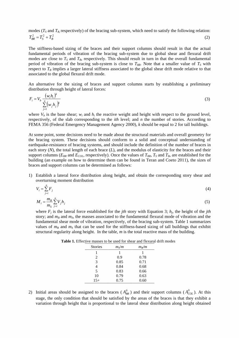
where Fj is the lateral force established for the jth story with Equation 3; hj, the height of the jth
story; and mB and mS, the masses associated to the fundamental flexural mode of vibration and the
fundamental shear mode of vibration, respectively, of the bracing sub-system. Table 1 summarizes
values of mB and mS that can be used for the stiffness-based sizing of tall buildings that exhibit
structural regularity along height. In the table, m is the total reactive mass of the building.
Table 1. Effective masses to be used for shear and flexural drift modes
Stories mS/m mB/m
1
2
3
4
5
10
15+
1
0.9
0.85
0.84
0.83
0.79
0.75
1
0.78
0.71
0.68
0.66
0.63
0.60
2) Initial areas should be assigned to the braces (0BRA ) and their support columns (
0COLA ). At this
stage, the only condition that should be satisfied by the areas of the braces is that they exhibit a
variation through height that is proportional to the lateral shear distribution along height obtained

from Equation 4. In the case of the columns, their areas should exhibit a variation through height
that is proportional to the respective overturning moment distribution obtained from Equation 5.
3) Once the braces have been sized, the drifts of the bracing system due to global shear drift mode
can be estimated. For this purpose, it is reasonable to assume that this drift mode is exclusively a
consequence of the axial deformation of braces. Within this context, the lateral shear stiffness
provided by the braces to the ith story can be estimated as:
RFi
i
i
BRiBRiSi
LL
AENK
20 cos
(6)
where Ni is the total number of braces located at the ith story, 0BRiA is the area initially proposed for
each one of these braces, θi their inclination angle, Li their total length (distance that separates the
two nodes that delimit the ends of one brace in the analytical model), and LRFi a stiffness adjusting
factor that takes into account the zones of larger stiffness at the end of the braces:
)1( RFL
(7)
where γ is the ratio of the length of the brace core segment (Lc) to the total brace length L, and η
the ratio of the average axial stress in the brace outside the brace core to the stress in the brace
core. The lateral drift at the ith story can be obtained as:
Si
iSi
K
V (8)
and the lateral displacement at the ith story as:
i
jSjSi
1
(9)
4) Once the support columns have been sized, the drifts of the bracing sub-system due to its global
flexural drift mode should be estimated. It is reasonable to assume that the bracing sub-system
behaves globally like a beam; and thus, that the global flexural drifts are a consequence of the
axial deformation of the support columns. Within this context, the global flexural stiffness of the
bracing system can be estimated in the ith story (IBi) through the exclusive consideration of the
axial areas of the support columns and the distances that separates them.
5) The curvature in the top and bottom ends of the portion of the bracing system located within the
ith story can be estimated as:
BiCOL
iupi
IE
M 1
(10a)
BiCOL
idowni
IE
M
(10b)
Integrating the curvature diagrams, the rotations at the top and bottom ends of the portion of the
bracing system located within the ith story can be estimated as:
i
downi
upiup
i h
6
2
(11a)
i
downi
upidown
i h
6
2
(11b)
The total increment in global flexural rotation in the slab located at ith level can be established by
adding the contributions of the portions of the bracing system located above and below it: downi
upi
toti (12)
The total rotation at the ith level can be established by adding the contributions of all the stories

below it:
i
j
toti
toti
1
(13)
Finally, the inter-story drift index in the ith story due to global flexural drift mode can be
established as:
itotiBi h (14)
and the lateral displacement in that story as:
i
jBjBi
1
(15)
6) Once the global shear and flexural drifts in the bracing sub-system have been established, initial
estimates for TS and TB can be estimated as follows:
n
iSii
n
iSii
S
Fg
w
T
1
1
2
0 2
(16a)
n
iBii
n
iBii
B
Fg
w
T
1
1
2
0 2
(16b)
where g is the acceleration due to gravity. Note that δSi and δBi are estimated from the lateral force
distribution established according to Equation 3, and that for that purpose an arbitrary value can be
assigned to the base shear.
7) Once 0
ST and 0
BT are estimated, the definitive areas for braces (ABR) and support columns (ACOL)
can be established as: 2
00
S
SBRBR
T
TAA (17a)
20
0
B
BCOLCOL
T
TAA (17b)
5. SAMPLE BRACING SYSTEM
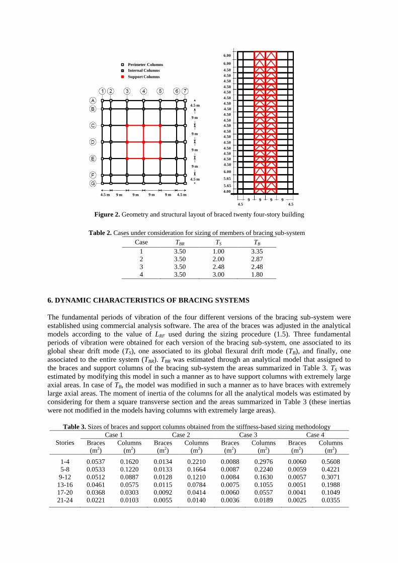
To illustrate the application of the methodology, the twenty four-story steel building shown in Figure 2
is considered. Overall, the building has a total height of 114.8 meters. The building has four central
bays of 9 meters, two lateral bays of 4.5 meters and seven frames in each one of its principal
directions. With the exception of the first three stories and the roof story, whose weights are equal to
1916 and 1355 tons, respectively, the stories of the building exhibit a weight of 1340 tons. As shown,
the sample building requires for earthquake-resistance a steel bracing sub-system that includes the two
central bays of the three central frames in each direction of analysis. To illustrate the potential of the
stiffness-based sizing methodology introduced herein, the four cases summarized in Table 2 are
considered for the bracing sub-system. As a restriction, the methodology is applied in a “practical
setting”, in such a manner that the area of braces and support columns are varied every four stories.
Table 3 summarizes the sizes for each brace and support column for all the different versions of the
bracing sub-system. The brace sizes shown in the table correspond to LRF = 1.5 (see Equations 6 and
7).
4.5 m 9 m 9 m 9 m 9 m 4.5 m
4.5 m
4.5 m
9 m
9 m
9 m
9 m
Perimeter Columns
Internal Columns
Support Columns
4.5 4.59 9 9 9
4.00
5.65
5.65
6.00
4.50
4.50
4.50
4.50
4.50
4.50
4.50
4.50
4.50
4.50
4.50
4.50
4.50
4.50
4.50
4.50
4.50
4.50
6.00
6.00
Figure 2. Geometry and structural layout of braced twenty four-story building
Table 2. Cases under consideration for sizing of members of bracing sub-system
Case TBR TS
TB
1
2
3
4
3.50
3.50
3.50
3.50
1.00
2.00
2.48
3.00
3.35
2.87
2.48
1.80
6. DYNAMIC CHARACTERISTICS OF BRACING SYSTEMS
The fundamental periods of vibration of the four different versions of the bracing sub-system were
established using commercial analysis software. The area of the braces was adjusted in the analytical
models according to the value of LRF used during the sizing procedure (1.5). Three fundamental
periods of vibration were obtained for each version of the bracing sub-system, one associated to its
global shear drift mode (TS), one associated to its global flexural drift mode (TB), and finally, one
associated to the entire system (TBR). TBR was estimated through an analytical model that assigned to
the braces and support columns of the bracing sub-system the areas summarized in Table 3. TS was
estimated by modifying this model in such a manner as to have support columns with extremely large
axial areas. In case of TB, the model was modified in such a manner as to have braces with extremely
large axial areas. The moment of inertia of the columns for all the analytical models was estimated by
considering for them a square transverse section and the areas summarized in Table 3 (these inertias
were not modified in the models having columns with extremely large areas).
Table 3. Sizes of braces and support columns obtained from the stiffness-based sizing methodology
Stories
Case 1 Case 2 Case 3 Case 4
Braces
(m2)
Columns
(m2)
Braces
(m2)
Columns
(m2)
Braces
(m2)
Columns
(m2)
Braces
(m2)
Columns
(m2)
1-4
5-8
9-12
13-16
17-20
21-24
0.0537
0.0533
0.0512
0.0461
0.0368
0.0221
0.1620
0.1220
0.0887
0.0575
0.0303
0.0103
0.0134
0.0133
0.0128
0.0115
0.0092
0.0055
0.2210
0.1664
0.1210
0.0784
0.0414
0.0140
0.0088
0.0087
0.0084
0.0075
0.0060
0.0036
0.2976
0.2240
0.1630
0.1055
0.0557
0.0189
0.0060
0.0059
0.0057
0.0051
0.0041
0.0025
0.5608
0.4221
0.3071
0.1988
0.1049
0.0355

Table 4 summarizes and compares the target and actual fundamental periods of vibration for the
different versions of the bracing sub-system. A smaller value of TS with respect to TB implies larger
sizes for the braces with respect to those of their support columns. Note that the proposed methodology
yields good estimates of TB for all the different versions of the bracing sub-system. In the case of TS,
the methodology yields better estimates as the target value for this period decreases (i.e, the estimate
of TS for Case 1 is better than that for Case 4). This can be explained by the fact that the methodology
neglects the lateral shear stiffness provided by the support columns, and that the moment of inertia of
the columns increase with an increase in the value of TS. Overall, the methodology yields bracing sub-
systems that adequately reflect the design requirements in terms of lateral stiffness. Figure 3 shows the
fundamental modes of vibration for the four versions of the bracing sub-system. Note the growing
influence of the global flexural drift mode as the value of TS decreases.
Table 4. Target and actual fundamental periods of vibration for all versions of bracing sub-system
Case Target Actual Ratio
TBR TS
TB TBR
TS TB
TBR TS
TB
1
2
3
4
3.5
3.5
3.5
3.5
1.00
2.00
2.48
3.00
3.35
2.87
2.48
1.80
3.60
3.53
3.45
3.23
1.00
1.95
2.34
2.65
3.47
2.97
2.56
1.87
1.03
1.01
0.99
0.92
1.00
0.98
0.94
0.88
1.03
1.03
1.04
1.04
a) Case 1 b) Case 2 c) Case 3 d) Case 4
TS = 1.00 s
TB = 3.47 s
TS = 1.95 s
TB = 2.97 s
TS = 2.34 s
TB = 2.56 s
TS = 2.65 s
TB = 1.87 s
Figure 3. Fundamental mode of vibration for all versions of bracing sub-system
While Figure 4 shows the fundamental modes of vibration associated to the global shear drift mode of
all versions the bracing sub-system, Figure 5 does the same for the fundamental modes of vibration
associated to their global flexural drift mode. Independently of the relative sizes of braces and support
columns, all fundamental modes of vibration due to global shear behavior are practically equal. A
similar observation can be made for the fundamental modes of vibration due to global flexural
behavior. Figures 5 and 6 provide graphic support for the condition of independence implicit in Figure
1 and Equation 2 for the global shear and flexural drift modes of the bracing sub-system. This implies
that a stiffness-based sizing methodology, such as that introduced herein, can establish sizes for the
braces and columns through independent numerical formulations.
7. DISCUSSION
The methodology introduced in this paper has been applied successfully to the sizing of the structural
members of a bracing sub-system that has the same number of braces (with similar length and
structural configuration) in all its stories, and that can be idealized as a global steel cantilever beam. In
this respect, the methodology can be easily adapted so that it can be applied to bracing systems with

other characteristics. The existence of outrigger trusses in some stories would significantly modify the
global flexural behavior of a bracing system. While under these circumstances, the sizing of the braces
would follow the same considerations made in this paper; the sizing of their support columns would
need to consider the global rotation restrictions induced in the bracing system by the outrigger trusses.
In terms of the effects of higher modes, an improved sizing for braces and support columns can be
obtained if Equation 3 is adjusted to better reflect a variation along height of lateral forces that
explicitly reflects the influence of these modes of vibration.
a) Case 1 b) Case 2 c) Case 3 d) Case 4
TS = 1.00 s TS = 1.95 s TS = 2.34 s TS = 2.65 s
Figure 4. Fundamental mode of vibration due to global shear drift mode for all versions of bracing system
a) Case 1 b) Case 2 c) Case 3 d) Case 4
TB = 3.47 s TB = 2.97 s TB = 2.56 s TB = 1.87 s
Figure 5. Fundamental mode of vibration due to global flexural drift mode for all versions of bracing system
Table 5 summarizes the weight of the structural members of the four versions of the bracing sub-
system. While the weight of the columns was estimated as the product of their area and length times
the specific weight of the steel; in the case of the braces this triple product was multiplied by 1.5 to
consider the existence of end plate connections. Note that in terms of weight, the most efficient
solutions are those in which TS is similar or slightly less than TB. Of all the cases summarized in the
table, Cases 1 and 4 may be considered inadequate. While in the former case, the axial forces
developed by the braces can’t be accommodated adequately by the support columns; the latter case
requires very large sizes for the columns.
Besides the stiffness considerations made so far in this paper for the sizing of the braces and their
support columns, the designer may want to include strength-based considerations. Particularly, it may
be decided, within a capacity design context, that it is desirable for the columns to have a larger

strength in relative terms, in such a manner that any nonlinear behavior in the bracing sub-system
concentrates in the braces.
Finally, it should be mentioned that the sizing derived from the conceptual methodology presented in
this paper can be used directly by the structural engineer to establish the final design of the structural
system, or can be used as an initial solution for methodologies aimed at optimizing the seismic
performance of the building.
Table 5. Weight of different versions of bracing sub-system
Case Weight (ton) Relative
Weight Observation
Braces Columns Total
1
2
3
4
320.94
80.24
52.39
35.66
211.67
288.67
388.71
732.46
532.61
368.91
441.10
768.12
1.44
1.00
1.20
2.08
Weak column/strong brace
Inefficient
8. CONCLUSIONS
A simple methodology for the stiffness-based sizing of the structural members of a bracing system for
tall earthquake-resistant buildings has been introduced. Based on basic concepts of mechanics and
dynamics, and by assuming total independence of the global shear and flexural drift modes of the
bracing system, the methodology formulates simple steps that allow for an independent stiffness-based
sizing of the braces and their support columns.
The application of the methodology to the sizing of the braces and their support columns for four
versions of a twenty four-story bracing system has yielded adequate design in terms of lateral stiffness.
Methodologies such as that developed and discussed in this paper constitute themselves in essential
and useful tools for the conception and preliminary sizing of structural systems for tall buildings,
which can lead to efficient design within the context of a performance-based approach.
REFERENCES
Baker W. (1990), “Sizing technique for lateral systems in multi-story steel building”, 4th World Congress on Tall
Buildings, 868-875, Hong Kong, China.
Baldock R. and Shea K. (2006), “Structural topology optimization of braced steel frameworks using genetic
programming”, Intelligent Computing in Engineering and Architecture, Lecture Notes in Computer Science,
Volume 4200/2006, 54-61. Chan C.M. and Grierson D.E. (1993), “An efficient resizing technique for the design of tall buildings subject to
multiple drift constraints”, The Structural Design of Tall and Special Buildings, 2 (1), 17-32.
Federal Emergency Management Agency (2000), “FEMA 356, Prestandard and commentary for the seismic
rehabilitation of buildings”.
Kameshki E.S. and Saka M.P. (2001), “Genetic algorithm based optimum bracing design of non-swaying tall
plane frames”, Journal of Constructional Steel Research, 57, 1081-1097.
Kim C.K., Kim H.S., Hwang J.S. and Hong S.M. (1998), “Stiffness-based optimal design of tall steel
frameworks subject to lateral loading”, Structural Optimization, 15, 180-186.
Liang Q.Q., Xie Y.M. and Steven G.P. (2000), “Optimal topology design of bracing systems for multi-story steel
frames”, ASCE Journal of Structural Engineering, 126 (7), 823-829.
Park H.S. and Kwon J.H. (2003), “Optimal drift design model for multi-story buildings subjected to dynamic
lateral forces”, The Structural Design of Tall and Special Buildings, 12, 317-333.
Teran-Gilmore A. and Coeto G. (2011), “Displacement-Based Preliminary Design of Tall Buildings Stiffened
with a System of Buckling-Restrained Braces”, Earthquake Spectra, 27 (1), 153-182.
Wada A., Huang Y. and Bertero V.V. (2003), “Innovative strategies in earthquake engineering”, Earthquake
Engineering: Recent Advances and Applications, Chapter 10, CRC Press.
Zou X-K. and Chan C-M. (2005), “An optimal resizing technique for seismic drift design of concrete buildings
subjected to response spectrum and time history loadings”, Computers and Structures, 83, 1689-1704.