
Effects of backfill on seismic behavior of rectangular tanks
14
This article appeared in a journal published by Elsevier. The attached copy is furnished to the author for internal non-commercial research and education use, including for instruction at the authors institution and sharing with colleagues. Other uses, including reproduction and distribution, or selling or licensing copies, or posting to personal, institutional or third party websites are prohibited. In most cases authors are permitted to post their version of the article (e.g. in Word or Tex form) to their personal website or institutional repository. Authors requiring further information regarding Elsevier’s archiving and manuscript policies are encouraged to visit: http://www.elsevier.com/copyright
Transcript of Effects of backfill on seismic behavior of rectangular tanks

This article appeared in a journal published by Elsevier. The attachedcopy is furnished to the author for internal non-commercial researchand education use, including for instruction at the authors institution
and sharing with colleagues.
Other uses, including reproduction and distribution, or selling orlicensing copies, or posting to personal, institutional or third party
websites are prohibited.
In most cases authors are permitted to post their version of thearticle (e.g. in Word or Tex form) to their personal website orinstitutional repository. Authors requiring further information
regarding Elsevier’s archiving and manuscript policies areencouraged to visit:
http://www.elsevier.com/copyright
Author's personal copy
Effects of backfill on seismic behavior of rectangular tanks
Ramazan Livaoglu a,n, Tufan Cakir b, Adem Dogangun a, Mustafa Aytekin c
a Department of Civil Engineering, Uludag University, 16059 Bursa, Turkeyb Department of Civil Engineering, Gumus-hane University, 29000 Gumus-hane, Turkeyc Department of Civil Engineering and Architecture, University of Bahrain, Kingdom of Bahrain
a r t i c l e i n f o
Article history:
Received 13 July 2010
Accepted 15 May 2011
Editor-in-Chief: A.I. IncecikAvailable online 8 June 2011
Keywords:
Rectangular tanks
Fluid–tank wall–backfill interaction
Internal friction angle
Dynamic response
a b s t r a c t
The reliability and/or stability of the lifeline structures against failure under seismic loads are of critical
concern, and must be studied carefully. Therefore, the main objective of this paper is to demonstrate
the commonly encountered backfill effects on the dynamic response of rectangular tanks. However,
only the exterior wall of the tank which interacts with both the backfill and fluid is tackled, as each part
of the structure shows considerable differences in terms of both the load bearing mechanisms and the
geometrical and positional differences. Finite element analyses are employed, taking into consideration
the fluid–wall–backfill interaction. The analyses are conducted to observe whether or not both backfill
and wall behavior can be affected by variation of the internal friction angle. For that purpose, some
comparisons are made on vertical displacements of the backfill, roof displacements, stress responses,
etc., by means of internal friction angle variations of the backfill from 251 to 401. Consequently, it is
observed that the variations on maximum vertical displacements are affected considerably. In contrast,
the maximum stress responses are affected partially. However, the inertial effects of the backfill show
that pseudo-static approximations may be insufficient to understand the dynamic behavior of the
backfill–wall–fluid system.
& 2011 Elsevier Ltd. All rights reserved.
1. Introduction
Liquid storage tanks are extensively used across the world andthe design of these structures is an important topic of research forcivil engineers. Again, the devastating effects of the earthquakesmake the problem more complicated compared to the staticdesign procedure for liquid storage tanks. Therefore, the stabilityof the liquid storage tanks under earthquake conditions must bestudied carefully. The wall movement causes distortion or evencollapse of the system. Although this form of failure is not asdramatic as other types of earthquake damages, the seismicbehavior of these types of structures is an important designproblem in the seismic regions. Otherwise, earthquake damageto tanks may take place in several forms and result in a variety ofunwanted consequences, such as, shortage of drinking water,large fires, and substantial economical losses (Livaoglu, 2008). Therecent earthquakes in Turkey, like the 1999, Mw¼7.4 Kocaeli andthe 1999 Mw¼7.2 Duzce earthquakes, have added importantdimensions to this problem. As seen in city centers, the drinkingwater tanks are of utmost importance.
A multitude of studies have been carried out on the seismicbehavior of liquid storage tanks, most of them are concerned withground level cylindrical tanks. However, the behavior of rectan-gular tanks during seismic loading has been studied by very fewresearchers. The first report on the analytical and experimentalobservations of rigid rectangular tanks under simulated horizon-tal earthquake excitation was given by Hoskins and Jacobsen(1934). Subsequently, the spring–mass analogy was used tomodel the fluid in a rectangular container by Graham andRodriguez (1952). Housner (1963) proposed a widely acceptedanalytical model, wherein the hydrodynamic pressures wereseparated into impulsive and convective components. This modelwas mostly used for the horizontal motion. An extended applica-tion of Housner’s procedure, in the sense of a practical design rule,was given by Epstein (1976). From various backfill geometriesencountered in practice, Livaoglu et al. (2007), investigated to seewhether the dynamic behavior of the rectangular tank walls wasaffected or not, and they emphasized that the backfill system,based on elastic FEM, had considerable effects on the dynamicbehavior of tank walls. Livaoglu (2008), evaluated the dynamicbehavior of a rectangular tank considering the fluid–structure–soil/foundation interaction altogether by means of changing soil/foundation conditions, and concluded that the displacements andbase shear forces were affected by soil stiffness. Hashemi et al.(2010) conducted a free vibration analysis of vertical rectangular
Contents lists available at ScienceDirect
journal homepage: www.elsevier.com/locate/oceaneng
Ocean Engineering
0029-8018/$ - see front matter & 2011 Elsevier Ltd. All rights reserved.
doi:10.1016/j.oceaneng.2011.05.017
n Corresponding author. Tel.: þ902242941961; fax: þ902242941903.
E-mail addresses: [email protected] (R. Livaoglu),
[email protected] (T. Cakir), [email protected] (A. Dogangun),
[email protected] (M. Aytekin).
Ocean Engineering 38 (2011) 1161–1173

Author's personal copy
Mindlin plates resting on Pasternak elastic foundation, whichwere fully or partially in contact with fluid on one of their sides,and investigated them for different combinations of boundaryconditions. They also purposed a numerical approximation havinghigh accuracy and small computational cost. Dynamic analyses ofrectangular tanks were carried out using a Lagrangian fluid finiteelement (Dogangun et al., 1996). Chen and Kianoush (2005)conducted a parametric study stating that flexibility of a tankwall should be considered when calculating hydrodynamic pres-sure. Kianoush and Chen (2006) also studied the importance ofthe vertical component of ground motion on the overall seismicbehavior of the rectangular tank, and they suggested that thevertical component of ground motion should be consideredespecially for tanks close to the field zone, for not experiencingthe earlier mentioned unwanted events. Flexibility of the tankwalls and hydrodynamic pressure acting on the wall wereconsidered by some researchers (Chen and Kianoush, 2005;Kianoush and Chen, 2006; Dogangun et al., 1997; Kim et al.,1998; Dogangun and Livaoglu, 2004). Similarly, Kim et al. (1996)carried out a study including wall flexibility and they stated thatdue to comparisons made with the 3D hybrid boundary element-finite element method, a two-dimensional model may representthe fluid–structure interaction effect of the rectangular tank.
To determine the dynamic characteristics of rectangular tanks,experimental studies were conducted by Minowa (1984),Koh et al. (1998), Faltinsen et al. (2003), and Akyildiz and Unal(2005, 2006). The influence of the direction of the earthquakemotions on the hydrodynamic loads of a fluid-filled rectangulartank and elevation of the associated amplitudes of the watersurface were investigated by Isaacson and Ryu (1998). Park et al.(2000) investigated the dynamic behavior and seismic designconsideration of base isolated pool-type tanks for the storage ofnuclear spent fuel assemblies using numerical analysis andshaking table experiments. In addition, there were no recordedstudies of rectangular tank uplift behavior, but Priestley et al.(1986) suggested a procedure, which was based on the principlesfor cylindrical tanks.
The problem of earth pressure on a retaining structure iscommonly encountered in the design process. In technical litera-ture, the design trend can basically be broadly divided into threecategories based on the approach and the theory used by variousinvestigators: (1) fully plastic (static) solution; (2) solution basedon elastic wave theory; and (3) solution based on elastoplasticand nonlinear theory. Almost all the investigations in these fieldsup to the early 80 s were widely evaluated on state-of-the-art, byNazarian and Hadjian (1979). The pioneering work, whichwas commonly used and known as the Mononobe–Okabe method(M–O) (see Kramer, 1996) was developed by Okabe (1924) andMononobe and Matsuo (1929), in which they used an extension ofthe Coulomb wedge theory in dry cohesionless soil by consideringthe pseudo-static seismic accelerations that included additionalvertical and horizontal seismic inertial forces of the soil. Sincethen, a great deal of research has been performed to evaluate itsadequacy and to improve it. Seed and Whitman (1970) focused ona limit-state design and they used the modified Mononobe–Okabeanalysis, an extension of the Coulomb–Rankine sliding wedgetheory. Mylonakis et al. (2007) proposed a solution that wasessentially an approximate yield-line approach, based on thetheory of discontinuous stress fields and took into accountdifferent parameters from the others. However, these methodsof analysis only gave satisfactory results if the wall displacementswere sufficient to fully mobilize the shear strength. Therefore,Richards and Elms (1979) suggested a new design approach,based on the initial choice of specified limiting wall displacement,for a displacement-governed wall, like gravity walls. They showedthat for gravity walls, the Mononobe–Okabe analysis thus
appeared to be satisfactory provided the inertia of the wall wastaken into account.
Experiences from damage to soil-retaining structures showedthat few cases of damage or collapse to soil-retaining walls hadbeen reported and the retaining systems supporting unsaturatedsoils had performed well during many recent earthquakes exceptto quay walls and bridge abutments (Nazarian and Hadjian,1979). Waterfront structures, especially quay walls, seemed tohave been more susceptible to failures because of the addedeffects of hydrodynamic pressures (Nazarian and Hadjian, 1979).In the Duzce Earthquake (1999) with a magnitude of 7.2(Mw¼7.2), a rectangular-drinking water tank, with a volume of10,000 m3, failed moderately and lost its container capability.
Most of the earth-retaining structures can be classified intotwo groups—displacement-governed walls and force-governedwalls. However, the exterior walls of drinking water structuresare neither displacement-governed nor force-governed walls,because of the displacement sensitivity at the construction pointof the wall and force sensitivity at the design process of the wall.The problem investigated here is also quite specific, as the wall isan imposed finite medium of the backfill, different from thatgiven in literature and the other type of retaining structures. Onthe other hand, there is no literature that proposed the analysis ofa backfill–rectangular drinking water storage tank’s wall–fluidsystem under the combined actions of forces induced by fluid andsoil interactions. The mentioned studies so far also show thatrelatively little work has been done on rectangular storage tanks.Some studies for waterfront retaining walls were carried out,considering both hydrodynamic pressures and seismic forcesacting simultaneously on the wall, in which pseudo-static meth-ods were proposed (Ahmad and Choudhury, 2008; Choudhuryand Ahmad, 2007). The present studies on the design purpose ofdrinking water tanks given in the literature are not satisfactory, sonew studies with different approaches to the problem areextremely essential to understand the seismic behavior of thesystem under consideration. Therefore, to appreciate the signifi-cance of a backfill and the variation of its friction angle, finiteelement analyses that cover backfill–tank wall–fluid system havebeen performed by considering both the backfill and fluidinteraction.
2. Description of the rectangular tank system underconsideration
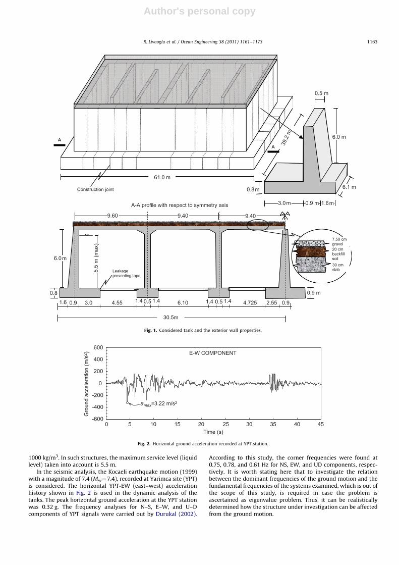
In this study, the structural properties of the prismatic rein-forced concrete rectangular storage tank, with a container capa-city of 10,000 m3, which is frequently constructed in Turkey, areconsidered, as shown in Fig. 1. For that purpose, a Kokc- uoglutypical drinking water tank constructed in Samsun, Turkey, hasbeen selected as a reference structure. The rectangular tank underconsideration has two main divisions. The length and the width ofthe structure are 61 and 39.2 m, respectively. The total height ofthe reference tank is 7.4 m from the bottom of the foundation.The other characteristics such as the dimensions of the tank andthe foundation system are shown in Fig. 1. Here, it is suitable tosay that for the other tanks with different capacities, the exteriorwall geometry and structural properties may be approximatelyidentical; however, the fluid container geometry may vary fromeach other due to container capacity and design differences.Therefore, the dynamic behavior of another tank with differentcontainer capacity constructed in another place may differ both interms of the local soil and design properties. In the analyses,Young’s modulus, Poisson’s ratio, and the weight of concrete perunit volume are taken to be 28,000 MPa, 0.2 and 25 kN/m3,respectively. The container is filled with water, with a density of
R. Livaoglu et al. / Ocean Engineering 38 (2011) 1161–11731162
Author's personal copy
1000 kg/m3. In such structures, the maximum service level (liquidlevel) taken into account is 5.5 m.
In the seismic analysis, the Kocaeli earthquake motion (1999)with a magnitude of 7.4 (Mw¼7.4), recorded at Yarimca site (YPT)is considered. The horizontal YPT-EW (east–west) accelerationhistory shown in Fig. 2 is used in the dynamic analysis of thetanks. The peak horizontal ground acceleration at the YPT stationwas 0.32 g. The frequency analyses for N–S, E–W, and U–Dcomponents of YPT signals were carried out by Durukal (2002).
According to this study, the corner frequencies were found at0.75, 0.78, and 0.61 Hz for NS, EW, and UD components, respec-tively. It is worth stating here that to investigate the relationbetween the dominant frequencies of the ground motion and thefundamental frequencies of the systems examined, which is out ofthe scope of this study, is required in case the problem isascertained as eigenvalue problem. Thus, it can be realisticallydetermined how the structure under investigation can be affectedfrom the ground motion.
-600
-400
-200
0
200
400
600
0 5 10 15 20 25 30 35 40 45
Gro
und
acce
lera
tion
(m/s
2 )
Time (s)
amax=3.22 m/s2
E-W COMPONENT
Fig. 2. Horizontal ground acceleration recorded at YPT station.
AA
A-A profile with respect to symmetry axis 0.9 m 3.0m 1.6m
61.0 m
0.8m
0.5 m
6.0 m
30.5m
1.6 0.9 3.0 4.55 0.5 1.41.4 0.5 1.41.46.10 4.725 2.55 0.9
6.0m
0.9 m 0.8
9.60 9.40 9.40
5.5
m (m
ax)
7.50 cm gravel20 cm backfillsoil30 cm slab Leakage
preventing tape
Construction joint 6.1 m
39.2
m
Fig. 1. Considered tank and the exterior wall properties.
R. Livaoglu et al. / Ocean Engineering 38 (2011) 1161–1173 1163
Author's personal copy
The exterior wall of the rectangular tank considered in thisstudy interacted with the various soil types encountered inpractice. To evaluate the dynamic response of the system, drycohesionless, silty, sand soil type (SM) with four different internalfriction angles, as shown in Table 1, was considered.
The nonlinear time history analyses were carried out by using theabove-mentioned system. Rayleigh damping was used in the ana-lyses. The seismic analysis of the system was carried out for each ofthe four internal friction angles in case of, ‘‘full of fluid’’ and ‘‘withoutfluid’’. Similar analyses were also carried out for no backfill in case of‘‘full of fluid’’ and ‘‘no fluid’’. All these models and their propertiesthat are considered during the analysis are given in Table 1.
3. Backfill–exterior wall–fluid interaction model
Currently there is no Turkish code available that is directlyrelated to the design of tanks. The Turkish Earthquake Code
(2007) is developed mainly for building structures, so its basicprovisions could be used to design or evaluate the adequacy of thebuildings. According to almost all the codes about tanks and/orearth-retaining structures, the stability and design of the wallsare estimated based on pseudo-static approaches: The IndianStandard code of practice uses the M–O method of analysis anddoes not consider permissible displacement. Contrary to this, theEurocode 8, 1993 version had used the Richards-Elms displace-ment based model (Choudhury et al., 2004). However, the presentversion of EC-8 part-5 (2003) includes the M–O method. Further-more, EC-8 part-4 (2006) requires that in partially backfilled orburied tanks, permanent loads include, in addition to the weightof the structure, the weight of the earth cover and any permanentexternal pressures due to groundwater. Similarly ACI 350.3(2001) suggests that dynamic earth pressures will be taken intoaccount when computing the base shear of a partially or fullyburied liquid-containing structure, and when designing the walls,the dynamic backfill forces will not be relied upon to reduce the
Table 1Properties and abbreviations of the considered model and the specifications.
Name of the model F BF25 BF30 BF35 BF40 W B25 B30 B35 B40Backfill � ’ ’ ’ ’ � ’ ’ ’ ’
Fluid ’ ’ ’ ’ ’ � � � � �
Soil properties
f � 25 30 35 40 � 25 30 35 40
E (MPa) � 20 20 20 20 � 20 20 20 20u � 0.3 0.3 0.3 0.3 � 0.3 0.3 0.3 0.3g (kN/m3) 19 19 19 19 19 � 19 19 19 19
E: Young’s modulus, f: internal friction angle; u: Poisson’s ratio, � : symbolize nonexistence, ’: symbolize existence.
F
D
(Dn; Fn)
Nonlinear-Unidirectional Element Unidirectional-coupled nodes between structural and fluid elements
Fluid Finite Element
Structural Finite Element Soil Finite Element
3D - Artificial Boundary
-σ1-σ2
-σ3
3 cotc φ
σ1 =σ2 =σ3Drucker-Prager
0φ >
x
y z 12 m
1.6 m
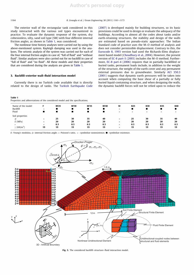
Fig. 3. The considered backfill–structure–fluid interaction model.
R. Livaoglu et al. / Ocean Engineering 38 (2011) 1161–11731164
Author's personal copy
dynamic effects of the stored liquid or vice versa. However, thecodes of the tanks do not address the specific methods on how theeffect of backfill can be taken into account.
Modeling the backfill–structure–fluid system, the finite elementmethod is used as shown in Fig. 3. The considered system is assumedto be supported on a rock foundation. The structural wall is modeledwith the solid elements having three degrees-of-freedom at everynode for a roof system with quadrilateral shell element (four nodes,six degrees-of-freedom per node), also with an additional mass ofcover. To model a backfill–wall interaction, a unidirectional elementwith nonlinear generalized force-deflection capabilities is used in theanalysis. The element has a longitudinal or torsional capability in1-D, 2-D, or 3-D applications. The longitudinal option is a uniaxialtension–compression element with up to three degrees of freedom ateach node: with translations in the nodal x, y, and z directions(ANSYS, 1994). Natural backfill behind the exterior wall of thestructure interacts with the wall in compression, but no interactionis assumed in tension. Therefore, an attempt has been made tomodel this interaction in this scope, through the study. Next, theunidirectional nonlinear element is used, having very rigid compres-sion characteristics, tensionless on the interaction face of thebackfill–wall system. It is also seen that no bending and torsion areassumed. It must be emphasized here that the vertical frictionbetween the wall and backfill is ignored. In order to characterizethe fluid–rectangular tank–backfill model and determine the seismicbehavior of the system, a transient dynamic analysis was carried outby means of the ANSYS commercial package program. All theelements mentioned above are available in ANSYS; the fluid ele-ments are specially formulated to model fluid contained within acontainer having no net flow rate. Mathematical details on themodeling of a fluid and the bounded media can be found in anotherstudy of the authors (Livaoglu and Dogangun, 2007).
As is known, the simulation of the infinite medium in thenumerical method is a very important topic for the dynamic soil–structure interaction problems. In some cases, the backfill underconsideration may also be finite, and for the other circumstance thedimension perpendicular to the wall may be larger than the dimen-sion of the wall. Therefore, the general method of treating thisproblem is to divide the infinite medium into the near field(truncated layer), which includes the irregularity as well as thenon-homogeneity of the soil adjacent to the structure, and the farfield, which is simplified as an isotropic homogeneous elasticmedium (Wolf and Song, 1996). The near field is modeled usingfinite elements and the far field is treated by adding some specialartificial boundaries or connecting some special elements. The moreappropriate approximations include utilization of the artificial and/ortransmitting boundaries. Furthermore, the reflecting and radiationeffects of the propagating waves from the structure-foundation layermay be avoided by means of these types of boundaries. There aredifferent types in frequency or time domain, with different sensitiv-ities. First, Lysmer and Kuhlemeyer (1969) developed a viscousboundary, using the one-dimensional beam theory and this theoryhas been commonly used with FEM (Livaoglu and Dogangun, 2007).In this study, the viscous boundary is used for three dimensions, toconsider the radiational effect of the seismic waves through the soilmedium in a direction perpendicular to the normal of wall (Fig. 3).
To analyze all the aspects of the seismic response from thebackfill–wall–fluid system is currently impossible due to the complexinteracting phenomena and the inherent variability and uncertaintiesof the soil properties. In addition, soil behavior is very sensitive ingeneral when it is exposed to earthquake-induced motion. Thus, theelastoplastic and/or perfectly plastic behavior of the backfill soil arefrequently observed in the soil–structure interaction (SSI), especiallyfor a system subjected to the lateral force or a system excited by
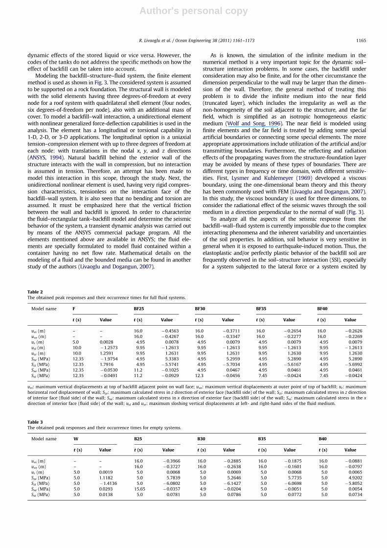
Table 2The obtained peak responses and their occurrence times for full fluid systems.
Model name F BF25 BF30 BF35 BF40
t (s) Value t (s) Value t (s) Value t (s) Value t (s) Value
uvi (m) – – 16.0 �0.4563 16.0 �0.3711 16.0 �0.2654 16.0 �0.2626
uve (m) – – 16.0 �0.4267 16.0 �0.3347 16.0 �0.2277 16.0 �0.2269
ur (m) 5.0 0.0028 4.95 0.0078 4.95 0.0079 4.95 0.0079 4.95 0.0079
usl (m) 10.0 �1.2573 9.95 �1.2613 9.95 �1.2613 9.95 �1.2613 9.95 �1.2613
usr (m) 10.0 1.2591 9.95 1.2631 9.95 1.2631 9.95 1.2630 9.95 1.2630
Sze (MPa) 12.35 �1.9754 4.95 5.3383 4.95 5.2959 4.95 5.2890 4.95 5.2890
Szi (MPa) 12.35 1.7916 4.95 �5.5741 4.95 �5.7034 4.95 �5.6167 4.95 �5.6992
Sxe (MPa) 12.35 �0.0530 11.2 �0.1025 4.95 0.0467 4.95 0.0461 4.95 0.0461
Sxi (MPa) 12.35 �0.0491 11.2 �0.0929 12.3 �0.0456 7.45 �0.0424 7.45 �0.0424
uvi: maximum vertical displacements at top of backfill adjacent point on wall face; uve: maximum vertical displacements at outer point of top of backfill; ur: maximum
horizontal roof displacement of wall; Sze: maximum calculated stress in z direction of exterior face (backfill side) of the wall; Szi: maximum calculated stress in z direction
of interior face (fluid side) of the wall; Sxe: maximum calculated stress in x direction of exterior face (backfill side) of the wall; Sxi: maximum calculated stress in the x
direction of interior face (fluid side) of the wall; usl and usr: maximum sloshing vertical displacements at left- and right-hand sides of the fluid medium.
Table 3The obtained peak responses and their occurrence times for empty systems.
Model name W B25 B30 B35 B40
t (s) Value t (s) Value t (s) Value t (s) Value t (s) Value
uvi (m) – – 16.0 �0.3966 16.0 �0.2885 16.0 �0.1875 16.0 �0.0881
uve (m) – – 16.0 �0.3727 16.0 �0.2638 16.0 �0.1601 16.0 �0.0797
ur (m) 5.0 0.0019 5.0 0.0068 5.0 0.0069 5.0 0.0068 5.0 0.0065
Sze (MPa) 5.0 1.1182 5.0 5.7839 5.0 5.2646 5.0 5.7735 5.0 4.9202
Szi (MPa) 5.0 �1.4136 5.0 �6.0802 5.0 �6.1427 5.0 �6.0698 5.0 �5.8052
Sxe (MPa) 5.0 0.0293 15.65 �0.0357 4.9 �0.0204 5.0 �0.0051 5.0 0.0054
Sxi (MPa) 5.0 0.0138 5.0 0.0781 5.0 0.0786 5.0 0.0772 5.0 0.0734
R. Livaoglu et al. / Ocean Engineering 38 (2011) 1161–1173 1165
Author's personal copy
seismic actions. Lateral responses are generally the most significantparts of the SSI interaction. In view of all the reasons mentionedherein, the Drucker–Prager material model is used in the modeling ofthe backfill soil medium in this study.
4. Discussion of the results
Tables 2 and 3 report the maximum vertical displacements, roofdisplacements, and stress values at both the exterior and interiorfaces of the rectangular tank wall and their occurrence timesobtained from the analyses of empty and full containers, taking intoconsideration the variation of the internal friction angle of thebackfill soil. For the tanks that are full of water at the service level,the maximum sloshing vertical displacements and their occurrencetime are given for both the left- and right-hand sides. Theirimplications are discussed a little later in this text. To design thissystem and to obtain the results, the effect of the fluid and backfillare included in the models, which in turn result in time consumingand computationally expensive dynamic analysis.
4.1. Vertical displacements of the backfill
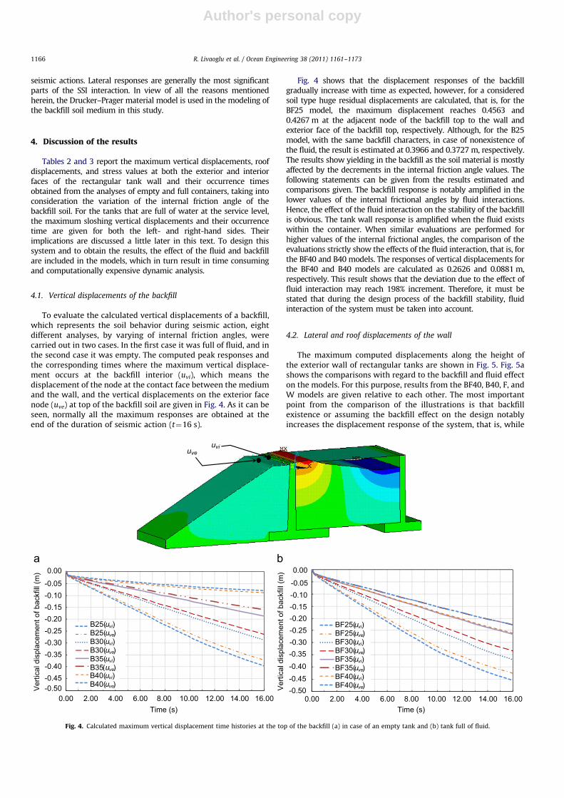
To evaluate the calculated vertical displacements of a backfill,which represents the soil behavior during seismic action, eightdifferent analyses, by varying of internal friction angles, werecarried out in two cases. In the first case it was full of fluid, and inthe second case it was empty. The computed peak responses andthe corresponding times where the maximum vertical displace-ment occurs at the backfill interior (uvi), which means thedisplacement of the node at the contact face between the mediumand the wall, and the vertical displacements on the exterior facenode (uve) at top of the backfill soil are given in Fig. 4. As it can beseen, normally all the maximum responses are obtained at theend of the duration of seismic action (t¼16 s).
Fig. 4 shows that the displacement responses of the backfillgradually increase with time as expected, however, for a consideredsoil type huge residual displacements are calculated, that is, for theBF25 model, the maximum displacement reaches 0.4563 and0.4267 m at the adjacent node of the backfill top to the wall andexterior face of the backfill top, respectively. Although, for the B25model, with the same backfill characters, in case of nonexistence ofthe fluid, the result is estimated at 0.3966 and 0.3727 m, respectively.The results show yielding in the backfill as the soil material is mostlyaffected by the decrements in the internal friction angle values. Thefollowing statements can be given from the results estimated andcomparisons given. The backfill response is notably amplified in thelower values of the internal frictional angles by fluid interactions.Hence, the effect of the fluid interaction on the stability of the backfillis obvious. The tank wall response is amplified when the fluid existswithin the container. When similar evaluations are performed forhigher values of the internal frictional angles, the comparison of theevaluations strictly show the effects of the fluid interaction, that is, forthe BF40 and B40 models. The responses of vertical displacements forthe BF40 and B40 models are calculated as 0.2626 and 0.0881 m,respectively. This result shows that the deviation due to the effect offluid interaction may reach 198% increment. Therefore, it must bestated that during the design process of the backfill stability, fluidinteraction of the system must be taken into account.
4.2. Lateral and roof displacements of the wall
The maximum computed displacements along the height ofthe exterior wall of rectangular tanks are shown in Fig. 5. Fig. 5ashows the comparisons with regard to the backfill and fluid effecton the models. For this purpose, results from the BF40, B40, F, andW models are given relative to each other. The most importantpoint from the comparison of the illustrations is that backfillexistence or assuming the backfill effect on the design notablyincreases the displacement response of the system, that is, while
uveuvi
BF25(uvi)BF25(uve)BF30(uvi)BF30(uve)BF35(uvi)BF35(uve)BF40(uvi)BF40(uve)
B25(uvi)B25(uve)B30(uvi)B30(uve)B35(uvi)B35(uve)
0.00 2.00 4.00 6.00 8.00 10.00 12.00 14.00 16.00Time (s)
Ver
tical
dis
plac
emen
t of b
ackf
ill (m
)
0.00 2.00 4.00 6.00 8.00 10.00 12.00 14.00 16.00Time (s)
-0.50-0.45-0.40-0.35-0.30-0.25-0.20-0.15-0.10-0.05
0.00
-0.50-0.45-0.40-0.35-0.30-0.25-0.20-0.15-0.10-0.05
0.00
Ver
tical
dis
plac
emen
t of b
ackf
ill (m
)
B40(uvi)B40(uve)
Fig. 4. Calculated maximum vertical displacement time histories at the top of the backfill (a) in case of an empty tank and (b) tank full of fluid.
R. Livaoglu et al. / Ocean Engineering 38 (2011) 1161–11731166

Author's personal copy
the maximum roof displacement is estimated as 1.9 mm formodel W, where only the wall is modeled in case of nonexistenceof both fluid and backfill, for model BF25, where both fluid andbackfill are included, the response is estimated as 7.8 mm. It isobserved that when the interaction effects of both fluid andbackfill are taken into account, a dramatic increase of almost310% takes place. In case of only the existence of fluid for theF model, this response is calculated as 2.8 mm. As can be seenfrom these comparisons, not properly taking into account thefluid and/or, especially, the backfill causes one to underestimatethe response and this highly affects the design process. Thereason for this conclusion is that the tanks are displacement-sensitive-structures, especially during the design processes, as thetank sites are in areas having strong ground motion risks.
However, when the internal friction angle increases from251 to 401, maximum lateral displacements of the wall are notconsiderably affected as seen in the given illustrations (Fig. 5b andc). It is worth stating here that in case of a tank full of fluid, thebackfill effect variations on the wall due to the internal friction angleare mostly absorbed by the fluid. However, some deviations for theother case occur in the displacements of the wall. For instance, themaximum roof displacement for the wall modeled in case ofnonexistence of fluid is estimated as 6.8 and 6.9 mm for models
B25 and B30, respectively. This displacement is decreased to 6.5 mmfor model B40. For the empty tank, this decrement may be ignored, sothe deviation in the model investigated here reaches 5% only. As thetop value of the friction angle considered in this investigation is 401,which is a very high value for soils used as backfill, in practice, it israrely possible to meet such a soil type. Thus, from the engineeringpoint of view, these variations can be accepted with no influence onthe design.
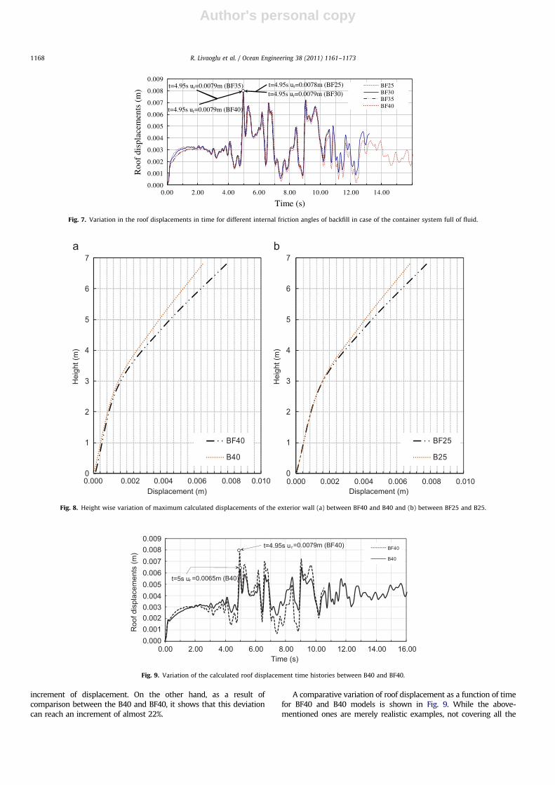
Similarly, the time history responses of the system for non-existence of fluid (Fig. 6), and for the existence of it (Fig. 7) arecompared due to the internal friction angle. It seems that almostall the responses coincide during excitation. Maximum roofdisplacement deviations also show that their maximum valuesand occurring times are almost same (Figs. 6 and 7).
In order to evaluate the fluid interaction effect on the lateraldisplacement of the wall system, the lateral displacement’s height-wise variation can be compared as shown in Fig. 8. The existence offluid appears to cause an increment in the lateral displacement of thesystem with resulting higher displacements especially for the lowervalues of the internal frictional angle (Fig. 8b). While the maximumroof displacement is estimated as 6.8 mm for the B25 model, for theBF25 model, considering the fluid interaction, this value reachesapproximately 7.8 mm. The fluid interaction causes up to 15%
0
1
2
3
4
5
6
7
BF40B40FW
Hei
ght (
m)
0
1
2
3
4
5
6
7
B25B30B35B40
0
1
2
3
4
5
6
7
BF25BF30BF35BF40
0.000 0.002 0.004Displacement (m)
0.006 0.008 0.010 0.000 0.002 0.004 0.006 0.008 0.010 0.000 0.002 0.004 0.006 0.008 0.010Displacement (m) Displacement (m)
Fig. 5. Heightwise variation of maximum calculated displacements of the exterior wall of the rectangular tank (a) in the case of four different models (b) deviations due to
internal friction angle for the empty tanks (c) deviations due to internal friction angle for the tanks full of fluid.
B25B30B35B40
Roo
f dis
plac
emen
ts (m
)
Time (s)
t=5s ur=0.0068m (B25) t=5s ur=0.0069m (B30)
t=5s ur=0.0068m (B35) t=5s ur=0.0065m (B40)
0.00 2.00 4.00 6.00 8.00 10.00 12.00 14.00 16.00
0.0080.009
0.0070.006
0.005
0.0040.003
0.002
0.0010.000
Fig. 6. Variation in the roof displacements in time for different internal friction angles of backfill in case of the empty container system.
R. Livaoglu et al. / Ocean Engineering 38 (2011) 1161–1173 1167
Author's personal copy
increment of displacement. On the other hand, as a result ofcomparison between the B40 and BF40, it shows that this deviationcan reach an increment of almost 22%.
A comparative variation of roof displacement as a function of timefor BF40 and B40 models is shown in Fig. 9. While the above-mentioned ones are merely realistic examples, not covering all the
0
1
2
3
4
5
6
7
BF40
B40
Displacement (m)
Hei
ght (
m)
0
1
2
3
4
5
6
7
BF25
B25
Displacement (m)
Hei
ght (
m)
0.000 0.002 0.004 0.006 0.008 0.010 0.000 0.002 0.004 0.006 0.008 0.010
Fig. 8. Height wise variation of maximum calculated displacements of the exterior wall (a) between BF40 and B40 and (b) between BF25 and B25.
BF40
B40
Roo
f dis
plac
emen
ts (m
)
Time (s)
t=5s ur =0.0065m (B40)
t=4.95s u r=0.0079m (BF40)
0.00 2.00 4.00 6.00 8.00 10.00 12.00 14.00 16.00
0.0080.009
0.0070.0060.0050.0040.0030.0020.0010.000
Fig. 9. Variation of the calculated roof displacement time histories between B40 and BF40.
0.000
0.001
0.002
0.003
0.004
0.005
0.006
0.007
0.008
0.009
0.00 2.00 4.00 6.00 8.00 10.00 12.00 14.00
BF25BF30BF35BF40
Roo
f di
spla
cem
ents
(m
)
Time (s)
t=4.95s ur=0.0079m (BF40)
t=4.95s ur=0.0079m (BF35) t=4.95s ur=0.0079m (BF30) t=4.95s ur=0.0078m (BF25)
Fig. 7. Variation in the roof displacements in time for different internal friction angles of backfill in case of the container system full of fluid.
R. Livaoglu et al. / Ocean Engineering 38 (2011) 1161–11731168
Author's personal copy
possible cases, their trend is clear: fluid action on the wall tends toincrease the wall displacement considerably. There are differentparameters of the system that explain amplification on displacement.For example, when the fluid within the container is included, with theimpulsive mass of fluid simultaneously acting on the wall and system,the fundamental period is increased. Furthermore, fluid sloshingcauses extra hydrodynamic pressure adding to the impulsive ones,
and their effect amplifies the response of the system. In some casesthis may not be an increase in the amplification. However, for thesystem having relatively short fundamental periods such as the wallsconsidered here, dynamic reactions are mostly amplified during theseismic action due to fluid interaction. However, it is not alwayspossible to say so. Increments in the fundamental periods of thesystem may cause decrements in the system displacement response,
BF25BF30BF35BF40
Slo
shin
g di
spla
cem
ents
(m)
Time (s)
t=9.95s uS=1.26m (BF25,BF30,BF35,BF40)
0.00 2.00 4.00 6.00 8.00 10.00 12.00 14.00 16.00
1.5
2.0
1.0
0.5
0.0
-0.5
-1.0
-1.5
-2.0
Fig. 10. Calculated vertical sloshing displacement time histories of the fluid within the container.
-7000000
-6000000
-5000000
-4000000
-3000000
-2000000
-1000000
0
1000000B25B30B35B40
-7000000
-6000000
-5000000
-4000000
-3000000
-2000000
-1000000
0
1000000
BF25BF30BF35BF40
Szi (N
/m2 )
Szi (N
/m2 )
Time (s)
t=4.95s Szi=5.57MPa (BF25)
t=5s Szi=6.08MPa (B25)
t=5s Szi=6.14MPa (B30)t=5s Szi=6.07MPa (B35)
t=5s Szi=5.81MPa (B40)
t=4.95s Szi=5.70MPa (BF30)t=4.95s Szi=5.62MPa (BF35)
t=4.95s Szi=5.70MPa (BF40)
0.00 2.00 4.00 6.00 8.00 10.00 12.00 14.00 16.00
Time (s) 0.00 2.00 4.00 6.00 8.00 10.00 12.00 14.00 16.00
Fig. 11. Comparative variations of the calculated stress histories at interior nodes of the wall in case of (a) empty tanks and (b) full of fluid.
R. Livaoglu et al. / Ocean Engineering 38 (2011) 1161–1173 1169

Author's personal copy
especially for long-period systems, due to the frequency contents ofthe seismic actions and flexibility of the foundation soil.
Many codes estimate the dynamic earth pressures according tothe potential of the wall to deform. For example, for the seismicanalysis of bridge abutments, the Regulatory Guide E39/93proposes three different cases for the calculation of the dynamicearth pressures, depending on the ratio between the expected(or allowable) displacement at the top of the wall U to its height H
(Gazetas et al., 2004). These allowable displacement ratios aregenerally between 0.05% and 0.10%. In the present study, thecalculated maximum response for the BF40 model is 7.9 mm andthe ratio is estimated as 0.13%. However, for the B40 model thedisplacement and its ratio are 6.5 mm and 0.108%, respectively.This result shows that when the fluid interaction is considered,the estimated maximum value for the considered excitationexceeds allowable displacements. Indeed, the displacements arealmost in the boundary of the maximum displacement level forthe system in an empty condition. Similarly if one investigates theresult from the nonexistence of the backfill for tanks full of fluid,these ratios maximally reach the 0.04% that are left; lower thanthe minimal ratio limit for ground motion is taken into account inthis study. Naturally it is possible to say that for the differentground motion having more peak response and high frequencycontent, these displacements can potentially increase and thenthe limiting values of the displacements again can be exceeded
more clearly. Therefore, these results, to some extent, show thatproperly considering the backfill and fluid interaction effect onthe design of such a structure is crucial.
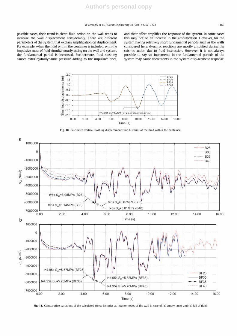
4.3. Sloshing displacement of fluid
As a result of the analyses of five different models, almost thesame results are obtained, where deviations in the internalfriction angle of the backfill system do not change the maximumsloshing response of the fluid inside the container. Sloshingresponse time histories are shown in Fig. 10. As can be seen fromit, the time histories coincide. The predicted maximum sloshingdisplacements are 1.26 m (at 9.95 s) for both the left- and right-hand sides for the fluid, in all the systems analyzed in theseinvestigations. As the designer tends to leave only a gap of 0.5 mfrom the maximum liquid level in the tank investigated here, thesloshing of fluid may cause the sloshing pressure on the roof. Thissloshing pressure, however, can be evaluated as ignorable forsuch a roof system which have a stiff and heavy reinforced platesupporting gravity effects of very thick roof coverings.
4.4. Stresses in the wall
The computed stress responses and their variations in time atboth the exterior and the interior face of the rectangular tank wall
-1000000
0
1000000
2000000
3000000
4000000
5000000
6000000
7000000BF25BF30BF35BF40
-1000000
0
1000000
2000000
3000000
4000000
5000000
6000000
7000000B25B30B35B40
Sze
(N/m
2 )Sze
(N/m
2 )
Time (s)
t=5sSze=5.77MPa (B35)
t=5sSze=5.26MPa (B30)
t=5sSze=4.92MPa (B40)t=5sSze=5.78MPa (B25)
t=4.95s Sze=5.34MPa (BF25)t=4.95s Sze=5.29MPa (BF35)
t=4.95s Sze=5.29MPa (BF40)t=4.95s Sze=5.30MPa (BF30)
Time (s)
0.00 2.00 4.00 6.00 8.00 10.00 12.00 14.00 16.00
0.00 2.00 4.00 6.00 8.00 10.00 12.00 14.00 16.00
Fig. 12. Comparative variations of the calculated stress histories at the exterior node of the wall in case of (a) empty tanks and (b) full of fluid.
R. Livaoglu et al. / Ocean Engineering 38 (2011) 1161–11731170
Author's personal copy
are given in the subtitle. The maximum stress values obtained atthe exterior face of the tank wall in the z direction generally tendto decrease with increasing of the internal friction angle from 251to 401. Fig. 11 shows that the obtained maximal stresses of theinterior node of the wall in the z direction, due to internal frictionangle, are almost the same in the time of occurrence andamplitude of the stresses. Estimated stresses in the z direction(Szi) take place at the interior nodes of the wall, at the level of0.9 m from the top of the foundation, as tension. Maximumstresses obtained for the B25 and BF30 models, are with �6.08and �5.70 MPa pressures, respectively. Depending on the inter-nal frictional angle, maximal deviation between B25 and B40 iscalculated as 4.6%. From the engineering point of view, thismaximal decrease can be practically ignored. Furthermore, theamplitude of the stresses calculated in the pressure shows thatthis does not have an important value, so it does not exceed thecompressive design strength of the concrete used in practice.
Fig. 12 shows comparative variations of the stress histories at theexterior nodes of the wall for tanks that are empty and full of fluid.
Maximum response value of the stresses, similar to the interior ones,generally tends to decrease when the internal friction angle increases.This decrease between the B25 to B40 is calculated as 15% approxi-mately. In theory, the concrete that is accepted has no tensionstrength. However tension strength is approximately 10% of thecompressive strength. Hence, for concrete, such a tension amplitudemay cause it to crack on the tension side of the section, but reinforcedconcrete bearing capacity is fully sufficient for almost all materialclasses used in practice in the other side, because the C20 concreteclass, which has 20 MPa compressive strength (fc) and S420 steel,which has 420 MPa yield strength (fy), are generally used in practicefor such a type of structure. Furthermore, it means that the tensilecrack would be growing in the side of the backfill due to the effect ofearth pressure, as the maximum tensile strength for this concreteclass can reach 2 MPa (fct). On the other hand in the design processesthis value is assumed to be 1.33 MPa, which is the tensile designstrength of concrete (fctd). Although this situation does not threatenthe stability of the wall, some measures must be taken to prevent theleakage of fluid. Still the wall section bearing capacity is without
-7000000
-6000000
-5000000
-4000000
-3000000
-2000000
-1000000
0
1000000
B25
BF25
-7000000
-6000000
-5000000
-4000000
-3000000
-2000000
-1000000
0
1000000
2000000
3000000
WFB25
Szi (N
/m2 )
Szi (N
/m2 )
Time (s)
t=12.35s Szi=1.79MPa (F)t=5s Szi=1.41MPa (W)
t=5s Szi=6.08MPa (B25)
t=5s Szi=6.08MPa (B25)
t=4.95s Szi=5.57MPa (BF25)
0.00 2.00 4.00 6.00 8.00 10.00 12.00 14.00 16.00
Time (s) 0.00 2.00 4.00 6.00 8.00 10.00 12.00 14.00 16.00
a
b
Fig. 13. Comparative variations of the calculated stress histories at the interior node of the wall for the models (a) between W, F, and B25 and (b) between B25 and BF25.
R. Livaoglu et al. / Ocean Engineering 38 (2011) 1161–1173 1171
Author's personal copy
doubt sufficient to carry the earthquake-induced force considered inthis investigation.
Both Figs. 11 and 12 show that when the fluid within thecontainer is taken into account, the amplitude deviations of thestress histories differ from the ones obtained from empty tanks.While the maximal values of the stress response are close to eachother for the exterior and interior nodes of B systems their maximalvalues are obtained on the tensile and pressure sides, respectively.On the other hand in BF systems, it can be clearly seen that stressescalculated for the exterior node pass through the pressure side andfor the interior nodes pass through the tensile side in the same timeinterval (i.e., between 7 and 8 s). These reversible stresses andincreases on its amplitude prove that fluid interaction amplifies thewall vibration during seismic action.
The maximum stress values obtained at both the exteriorcorner face and exterior mid face of the tank wall, in thex direction, decrease with an increase in the internal frictionangle, as an absolute value. Furthermore, their occurrence timesare almost the same for the empty (B) and full tank (BF) systems.It is worth stating that the calculated stresses are very small whencompared with the bearing capacity of the tank wall material intension. When the pressure strength is not exceeded due to theexcitations considered here, the shear capacity of the system issufficient, as the stresses estimated are almost 10% or more, thatis, less than their pressure ones. Moreover, when it is taken intoaccount that the shear strength of the concrete system hasgenerally 35–80% capacity of the compressive strength, theabove-mentioned idea would be more verifiable.
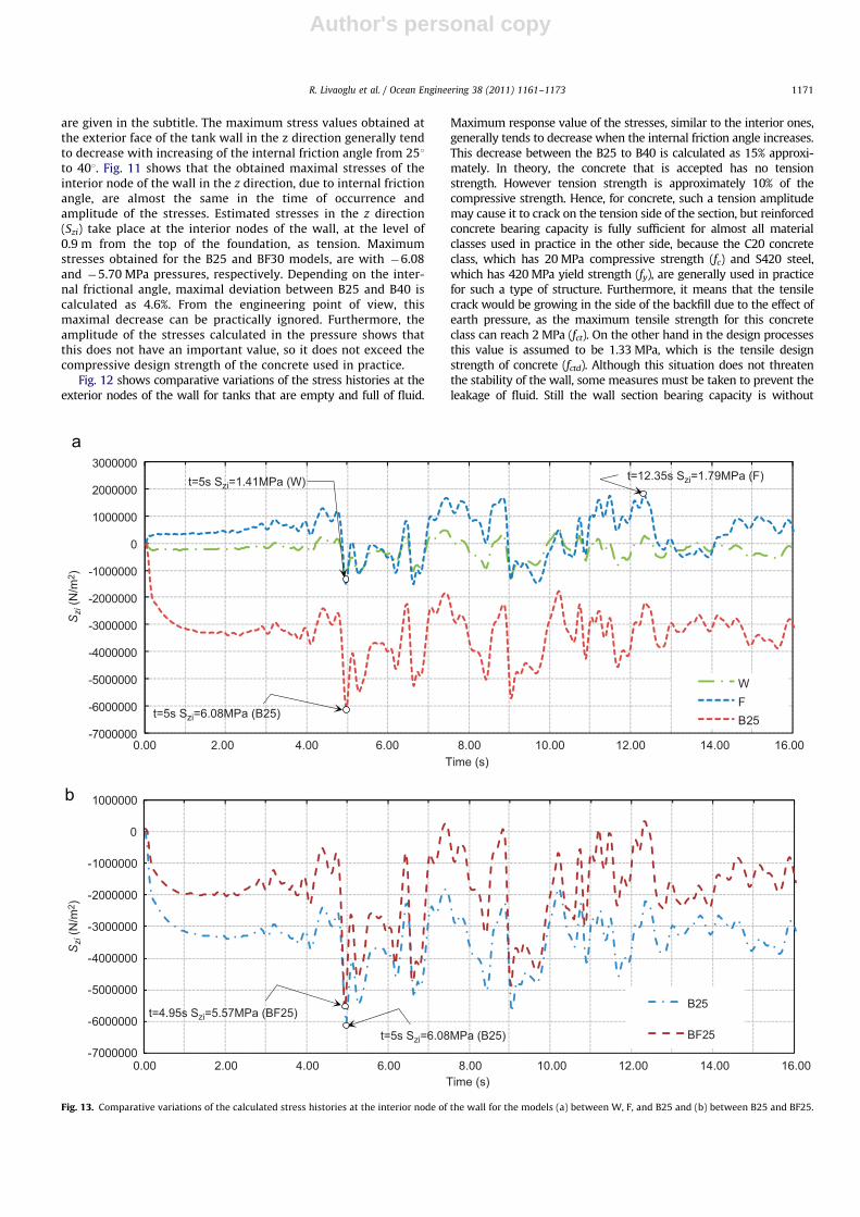
As expressed earlier, well-known codes suggest that dynamicearth pressures will be taken into account when computing the baseshear of a partially or fully buried liquid-containing structure andwhen designing the walls, the dynamic backfill forces will not berelied upon to reduce the dynamic effects of the stored liquid or viceversa. If designers model the system in a static condition or use thepseudo-static model for the dynamic effects, as proposed by most ofthe literature about the earth retaining structure, only then wouldthey add the earth pressure to the wall at a different level. IndeedFig. 13 proves that these approaches, considering the backfill effect,are not adequate for the walls subjected to both backfill and fluidinteractions. Inertial effects of the backfill are most pronounced oncomparative variations of the model given in Fig. 13. For example ifthe designer ignores the backfill inertial effects and their dynamiccharacteristics and assumes the wall subjected to a pseudo-staticforce, then the response of the W model or F model with the fluidinteraction effect, is more amplified. However, the response of thesystem stresses may take place more differently, as shown in Fig. 13a,and the stresses reverse, that is, while the maximum response of Sze is1.12 MPa for model W, the maximum response for the B25 and BF25models are calculated as 5.78 and 5.34 MPa, respectively.
5. Conclusions
To evaluate the seismic behavior of the backfill–rectangulartank–fluid system, a finite element model, including both thefluid–structure and soil–structure interaction effects and non-linear interaction effect of the soil and contact nodes between thesoil and the wall, is proposed. The proposed model can be used fordetermining the internal forces, sloshing effect, and inertialeffects of the backfill behind the wall in the design process.However, FEM analysis with this procedure needs relatively morecomputer memory capacity and CPU time. As a consequence ofthis study, the following results must be given:
1. The sloshing response is not affected by the backfill interactionconsidered in this study. Therefore, the effect of the backfill
interaction on the sloshing response can be ignored in theevaluation of the seismic behavior of the system.
2. The soil interaction effect is clearly more visible in the case ofnonexistence of the fluid. According to the results of theanalyses performed, the internal friction angle affects thesystem (the backfill–wall–fluid model), as the displacementresponse generally decreases to some extent, while the inter-nal friction angle has higher values. This also shows that bytaking into account fluid interaction, the response of the wholesystem is absorbed.
3. To consider the tank is empty, full of fluid or to evaluate thesituation of nonexistence of backfill causes a completelydifferent seismic behavior of the wall. While both exist, theirinertial effect amplifies the system response considerably.When one only considers both the ‘‘full of fluid’’ and ‘‘emptycase’’ (with no backfill) comparatively, the response of thesystem is reversible and its response values are lower than inother circumstances; however, the system displacementresponse and stress deviations are one side of the response,that is, the pressure or tension side for stresses, when thebackfill is considered, as backfill prevents the reversibleresponse of the system and pushes the wall toward the fluidor empty medium.
4. There are similar backfills having likely material and geome-trical properties for almost all tanks in practice; the allowabledisplacements are exceeded for the systems imposed withseismic motion considered in this study. This shows that nottaking into account the backfill effects causes the systemresponse to be underestimated, and misleads the results inthe design process of the tank wall.
5. When static or pseudo-static methods are used, misleadingresults may be obtained, as these approximations amplify theresponse of the empty reference system, with no interactioneffect. However, based upon these approximations, the systembehavior with interactions is completely different from thereference system.
Acknowledgment
The present work is supported by Grant-in-Aid for ScientificResearch (Project no. 105M252) from the Scientific and Techno-logical Research Council of Turkey (TUB_ITAK).
References
Ahmad, S.M., Choudhury, D., 2008. Pseudo-dynamic approach of seismic design forwaterfront reinforced soil–wall. Geotextiles and Geomembranes 26, 291–301.
Akyildiz, H., Unal, E., 2005. Experimental investigation of pressure distribution ona rectangular tank due to the liquid sloshing. Ocean Engineering 32,1503–1516.
Akyildiz, H., Unal, E., 2006. Sloshing in a three-dimensional rectangular tank:numerical simulation and experimental validation. Ocean Engineering 33,2135–2149.
American Concrete Institute (ACI 350.3-01/350.3R-01), 2001. Seismic Design ofLiquid-Containing Concrete Structures (ACI 350.3-01) and Commentary(350.3R-01). ACI Committee 350, Environmental Engineering Concrete Struc-tures, December.
ANSYS, 1994. In: Peter, K. (Ed.), Theory Manual 12th ed. SAS IP, Inc. 1266.Chen, J.Z., Kianoush, M.R., 2005. Seismic response of concrete rectangular tanks for
liquid containing structures. Canadian Journal of Civil Engineering 32,739–752.
Choudhury, D., Sitharam, T.G., Subba Rao, K.S., 2004. Seismic design of earth-retaining structures and foundations. Special section: geotechnics and earth-quake hazards. Current Science 87, 1417–1425.
Choudhury, D., Ahmad, S.M., 2007. Stability of waterfront retaining wall subjectedto pseudo-static earthquake forces. Ocean Engineering 34, 1947–1954.
Dogangun, A., Durmus, A., Ayvaz, Y., 1996. Static and dynamic analysis ofrectangular tanks by using the Lagrangian fluid finite element. Computersand Structures 59, 547–552.
R. Livaoglu et al. / Ocean Engineering 38 (2011) 1161–11731172

Author's personal copy
Dogangun, A., Durmus, A., Ayvaz, Y., 1997. Earthquake analysis of flexiblerectangular tanks by using the Lagrangian fluid finite element. EuropeanJournal of Mechanics A—Solids 16, 165–182.
Dogangun, A., Livaoglu, R., 2004. Hydrodynamic pressures acting on the walls ofrectangular fluid containers. Structural Engineering and Mechanics—An Inter-national Journal 17 (2), 203–214.
Durukal, E., 2002. Critical evaluation of strong motion in Kocaeli and Duzce(Turkey) earthquakes. Soil Dynamics and Earthquake Engineering 22,589–609.
Epstein, H.I., 1976. Seismic design of liquid storage tanks. Journal of the StructuralDivision—ASCE 102, 1659–1673.
Eurocode 8, 2003. Design of structures for earthquake resistance—Part 5:foundations, retaining structures and geotechnical aspects. Final Draft, Eur-opean Committee for Standardization, Brussels, Belgium, December.
Eurocode 8, 2006. Design of structures for earthquake resistance—Part 4: silos,tanks and pipelines. Final Draft, European Committee for Standardization,Brussels, Belgium, January.
Faltinsen, O.M., Rognebakke, O.F., Timokha, A.N., 2003. Resonant three-dimen-sional nonlinear sloshing in a square-base basin. Journal of Fluid Mechanics487, 1–42.
Gazetas, G., Psarropoulos, P.N., Anastasopoulos, I., Gerolymos, N., 2004. Seismicbehaviour of flexible retaining systems subjected to short-duration moder-ately strong excitation. Soil Dynamics and Earthquake Engineering 24,537–550.
Graham, E.W., Rodriguez, A.M., 1952. Characteristics of fuel motion which affectairplane dynamics. Journal of Applied Mechanics 19, 381–388.
Hashemi, H.S.H., Karimi, M., Taher, H.R.D., 2010. Vibration analysis of rectangularMindlin plates on elastic foundation sand vertically in contact with stationaryfluid by the Ritz method. Ocean Engineering 37, 174–185.
Hoskins, L.M., Jacobsen, L.S., 1934. Water pressure in a tank caused by simulatedearthquake. Bulletin of the Seismological Society of America 24, 1–32.
Housner, G.W., 1963. Dynamic behavior of water tanks. Bulletin of the Seismolo-gical Society of America 53, 381–387.
Isaacson, M., Ryu, C.S., 1998. Directional effects of earthquake-induced sloshing inrectangular tanks. Canadian Journal of Civil Engineering 25, 376–382.
Kianoush, M.R., Chen, J.Z., 2006. Effect of vertical acceleration on response ofconcrete rectangular liquid storage tanks. Engineering Structures 28, 704–715.
Kim, J.K., Koh, H.M., Kwahk, I.J., 1996. Dynamic response of rectangular flexiblefluid containers. Journal of Engineering Mechanics—ASCE 122 (9), 807–817.
Kim, J.K., Park, J.Y., Jin, B.M., 1998. The effects of soil structure interaction on thedynamics of 3-D flexible rectangular tanks. In: Proceedings of the Sixth EastAsia-Pacific Conference on Structural Engineering and Construction, Taipei,Taiwan, January 14–16.
Koh, H.M., Kim, J.K., Park, J.H., 1998. Fluid–structure interaction analysis of 3-Drectangular tanks by a variationally coupled BEM–FEM and comparison withtest results. Earthquake Engineering and Structural Dynamics 27, 109–124.
Kramer, S.L., 1996. Geotechnical Earthquake Engineering. Prentice-Hall, Engle-wood Cliffs, NJ.
Livaoglu, R., Dogangun, A., 2007. Effect of foundation embedment on seismicbehavior of elevated tanks considering fluid–structure–soil interaction. SoilDynamics and Earthquake Engineering 27, 855–863.
Livaoglu, R., Cakir, T., Dogangun, A., 2007. Investigation of backfill effects onseismic behavior of rectangular tanks. In: International Symposium onAdvances in Earthquake and Structural Engineering, Isparta, Turkey, October24–26, pp. 478–490 (in Turkish).
Livaoglu, R., 2008. Investigation of seismic behavior of fluid–rectangular tank–soil/foundation systems in frequency domain. Soil Dynamics and EarthquakeEngineering 28, 132–146.
Lysmer, J., Kuhlemeyer, R.L., 1969. Finite dynamic model for infinite media.Engineering Mechanics Division Journal—ASCE 95, 859–877.
Minowa, C., 1984. Experimental studies of seismic properties of various type watertanks. In: Proceedings of the Eighth WCEE, San Francisco, pp. 945–952.
Mononobe, N., Matsuo, H., 1929. On the determination of earth pressures duringearthquakes. In: Proceedings of the World Engineering Congress, vol. 9, Tokyo,Japan, pp. 179–187.
Mylonakis, G., Kloukinas, P., Papantonopoulos, C., 2007. An alternative to theMononobe–Okabe equations for seismic earth pressures. Soil Dynamics andEarthquake Engineering 27, 957–969.
Nazarian, H.N., Hadjian, A.H., 1979. Earthquake-induced lateral soil pressures onstructures. Journal of the Geotechnical Engineering Division—ASCE 105,1049–1066.
Okabe, S., 1924. General theory of earth pressure and seismic stability of retainingwall and dam. Journal of the Japan Society of Civil Engineers 10 (6),1277–1323.
Park, J.H., Koh, H.M., Kim, J.K., 2000. Seismic isolation of pool-type tanks for thestorage of nuclear spent fuel assemblies. Nuclear Engineering and Design 199,143–154.
Priestley, M.J.N., Davidson, B.J., Honey, G.D., Hopkins, D.C., Martin, R.J., Ramsay, G.,1986. Seismic Design of Storage Tanks: Recommendation of a Study Group.The New Zealand Society for Earthquake Engineering, New Zealand.
Richards, R., Elms, D.G., 1979. Seismic behavior of gravity retaining walls. Journalof the Geotechnical Engineering Division—ASCE 105 (GT4), 449–464.
Seed, H.B., Whitman, R.V., 1970. Design of earth retaining structures for dynamicloads, Proceedings of the Speciality Conference on Lateral Stresses in theGround and Design of Earth Retaining Structures. ASCE, Ithaca, New York, pp.103–147.
Turkish Earthquake Code (TEC), 2007. Specification for Structures to be built inDisaster Areas. Ministry of Public Works and Settlement Government ofRepublic of Turkey.
Wolf, J.P., Song, C.H., 1996. Finite-element Modelling of Unbounded Media. JohnWiley & Sons, Chichester.
R. Livaoglu et al. / Ocean Engineering 38 (2011) 1161–1173 1173