Chemical factors that influence the performance of mine sulphidic paste backfill
12
Chemical factors that inf luence the performance of mine sulphidic paste backfill Mostafa Benzaazoua * , Tikou Belem, Bruno Bussie `re Unite ´ de recherche et de service en technologie mine ´rale (URSTM), Universite ´ du Que ´bec en Abitibi-Te ´miscamingue (UQAT), 445 Boulevard de l’Universite ´, Rouyn-Noranda, Que ´bec, Canada J9X 5E4 Received 28 August 2001; accepted 28 January 2002 Abstract Sulphide-rich tailings from four Canadian mines were sampled (Mines A1, A2, B and C) to prepare several different paste backfill mixtures. The sulphur grade within these tailings samples range from 5 to 32 wt.%. The binders used were Portland-cement-based binders, fly-ash-based binders and slag-based binders with proportions ranging from 3 to 6 wt.%. The study was carried out in two stages. Stage I allowed us to understand the effects of binder type, binder proportion and tailings properties on compressive strength development of paste backfill during the course of curing time. It was pointed out that for high sulphide tailings, neither the slag-based binders nor the fly-ash- based binders were effective, whereas the sulphate-resistant-based binder (mix of Type I [TI] and Type V [TV] Portland cements) gave good long-term strength. However, the slag-based binders gave the best strength for low and medium sulphide-bearing tailings for which the Portland- and the fly-ash-based mixtures have a relatively low strength. Stage II allowed us to study the early stage strength acquisition of the various mixtures. It was found that the chemical composition of the mixing water plays a role on the mechanical behavior of certain cemented backfills. D 2002 Elsevier Science Ltd. All rights reserved. Keywords: Paste backfill; Hydration products; Compressive strength; Sulfate; Waste management 1. Introduction Mine backfill refers to waste materials, such as waste development rock, deslimed and whole mill tailings, quar- ried and crushed aggregate, and alluvial or an eolian sand, which is placed into underground mined voids for the purposes of either disposal and/or to perform some engin- eering function. The disposal of mine tailings underground reduces the environmental impact [1,2] and provides a material that can be used to improve both ground conditions and the economics of mining. The waste materials are often mixed with very lean cement or other pozzolanic binders to improve their strength properties. Among the three existing backfill types (hydraulic fill, rock fill, paste backfill), the use of paste backfill is becoming an increasingly important component of underground mining operations worldwide, and especially in Canada [3–9]. Paste backfill consists of total mill tailings (full size fraction of the tailings) thickened and/or filtered to around 80 wt.% to which binder and water are then added to achieve the desired rheological and strength characteristics (Fig. 1). By far the most common hydraulic binder added to backfill is ordinary Portland cement (TI). There has been continuous research around the world into alternative binders and the most common solution has been to use pozzolanic products such as fly ash (FA) and blast furnace slags (BFS). Typical binder propor- tion additions are 3% to 7% by weight into paste fill. The mechanical and rheological properties of cemented paste backfill depend on physical, chemical and minera- logical properties of the mine tailings, binder types and their proportions [10–14,16,19–24]. It is also common know- ledge that sulphide mine tailings generate acid in the presence of water and oxygen, which may lead to possible chemical weathering [25] and others. The presence of sulphide minerals within cemented composites as well as the soluble sulphates has a deleterious effect on the strength of paste backfill due to sulphate attack [26–29]. Other recent works [3,15,17,18,30,31] highlighted the possibility of backfill strength loss during the curing time due to a chemical weathering caused by the presence of an aggress- ive medium (presence of sulphates and production of acid). 0008-8846/02/$ – see front matter D 2002 Elsevier Science Ltd. All rights reserved. PII:S0008-8846(02)00752-4 * Corresponding author. Tel.: +1-819-762-0971x2404; fax: +1-819- 797-4727. E-mail address: [email protected] (M. Benzaazoua). Cement and Concrete Research 32 (2002) 1133 – 1144
Transcript of Chemical factors that influence the performance of mine sulphidic paste backfill
Chemical factors that inf luence the performance of mine
sulphidic paste backfill
Mostafa Benzaazoua*, Tikou Belem, Bruno Bussiere
Unite de recherche et de service en technologie minerale (URSTM), Universite du Quebec en Abitibi-Temiscamingue (UQAT),
445 Boulevard de l’Universite, Rouyn-Noranda, Quebec, Canada J9X 5E4
Received 28 August 2001; accepted 28 January 2002
Abstract
Sulphide-rich tailings from four Canadian mines were sampled (Mines A1, A2, B and C) to prepare several different paste backfill
mixtures. The sulphur grade within these tailings samples range from 5 to 32 wt.%. The binders used were Portland-cement-based binders,
fly-ash-based binders and slag-based binders with proportions ranging from 3 to 6 wt.%. The study was carried out in two stages. Stage I
allowed us to understand the effects of binder type, binder proportion and tailings properties on compressive strength development of paste
backfill during the course of curing time. It was pointed out that for high sulphide tailings, neither the slag-based binders nor the fly-ash-
based binders were effective, whereas the sulphate-resistant-based binder (mix of Type I [TI] and Type V [TV] Portland cements) gave good
long-term strength. However, the slag-based binders gave the best strength for low and medium sulphide-bearing tailings for which the
Portland- and the fly-ash-based mixtures have a relatively low strength. Stage II allowed us to study the early stage strength acquisition of the
various mixtures. It was found that the chemical composition of the mixing water plays a role on the mechanical behavior of certain cemented
backfills. D 2002 Elsevier Science Ltd. All rights reserved.
Keywords: Paste backfill; Hydration products; Compressive strength; Sulfate; Waste management
1. Introduction
Mine backfill refers to waste materials, such as waste
development rock, deslimed and whole mill tailings, quar-
ried and crushed aggregate, and alluvial or an eolian sand,
which is placed into underground mined voids for the
purposes of either disposal and/or to perform some engin-
eering function. The disposal of mine tailings underground
reduces the environmental impact [1,2] and provides a
material that can be used to improve both ground conditions
and the economics of mining. The waste materials are often
mixed with very lean cement or other pozzolanic binders to
improve their strength properties. Among the three existing
backfill types (hydraulic fill, rock fill, paste backfill), the use
of paste backfill is becoming an increasingly important
component of underground mining operations worldwide,
and especially in Canada [3–9]. Paste backfill consists of
total mill tailings (full size fraction of the tailings) thickened
and/or filtered to around 80 wt.% to which binder and water
are then added to achieve the desired rheological and
strength characteristics (Fig. 1). By far the most common
hydraulic binder added to backfill is ordinary Portland
cement (TI). There has been continuous research around
the world into alternative binders and the most common
solution has been to use pozzolanic products such as fly ash
(FA) and blast furnace slags (BFS). Typical binder propor-
tion additions are 3% to 7% by weight into paste fill.
The mechanical and rheological properties of cemented
paste backfill depend on physical, chemical and minera-
logical properties of the mine tailings, binder types and their
proportions [10–14,16,19–24]. It is also common know-
ledge that sulphide mine tailings generate acid in the
presence of water and oxygen, which may lead to possible
chemical weathering [25] and others. The presence of
sulphide minerals within cemented composites as well as
the soluble sulphates has a deleterious effect on the strength
of paste backfill due to sulphate attack [26–29]. Other
recent works [3,15,17,18,30,31] highlighted the possibility
of backfill strength loss during the curing time due to a
chemical weathering caused by the presence of an aggress-
ive medium (presence of sulphates and production of acid).
0008-8846/02/$ – see front matter D 2002 Elsevier Science Ltd. All rights reserved.
PII: S0008 -8846 (02 )00752 -4
* Corresponding author. Tel.: +1-819-762-0971x2404; fax: +1-819-
797-4727.
E-mail address: [email protected] (M. Benzaazoua).
Cement and Concrete Research 32 (2002) 1133–1144
The cohesive strength, density and solid percentage are the
determining factors in the use of paste backfill. The backfill
cohesion is directly dependent on the binder quality and its
potential to resist possible harmful chemical reactions (such
as hydration inhibition and sulphate attack) that can occur
within a sulphide- and/or sulphate-rich backfill. So, to ensure
the maximum safety of the underground mine workers, the
challenge is to use a cemented backfill that is able to stabilize
underground stopes without being affected by the potential
of long-term strength loss due to chemical weathering.
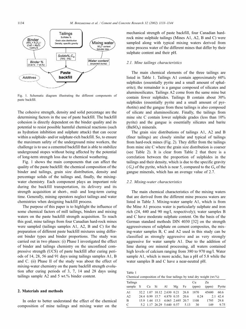
Fig. 1 shows the main components that can affect the
quality of the paste backfill: the chemical composition of the
binder and tailings, grain size distribution, density and
percentage solids of the tailings and, finally, the mixing-
water chemistry. Each component plays an important role
during the backfill transportation, its delivery and its
strength acquisition at short-, mid- and long-term curing
time. Generally, mining operators neglect tailings and water
chemistries when designing backfill process.
The purpose of this paper is to highlight the influence of
some chemical factors of mill tailings, binders and mixing
waters on the paste backfill strength acquisition. To reach
this goal, mine tailings from four Canadian hard-rock mines
were sampled (tailings samples A1, A2, B and C) for the
preparation of different paste backfill mixtures using differ-
ent binder types and binder proportions. The study was
carried out in two phases: (i) Phase I investigated the effect
of binder and tailings chemistry on the unconfined com-
pressive strength (UCS) of paste backfill after curing peri-
ods of 14, 28, 56 and 91 days using tailings samples A1, B
and C. (ii) Phase II of the study was about the effect of
mixing-water chemistry on the paste backfill strength evolu-
tion after curing periods of 3, 7, 14 and 28 days using
tailings sample A2 and 5 wt.% binder content.
2. Materials and methods
In order to better understand the effect of the chemical
composition of mine tailings and mixing water on the
mechanical strength of paste backfill, four Canadian hard-
rock mine sulphide tailings (Mines A1, A2, B and C) were
sampled along with typical mixing waters derived from
mine process water of the different mines that differ by their
sulphate content and their pH.
2.1. Mine tailings characteristics
The main chemical elements of the three tailings are
listed in Table 1. Tailings A1 contain approximately 60%
sulphides (essentially pyrite and a small amount of sphal-
erite); the remainder is a gangue composed of silicates and
aluminosilicates. Tailings A2 come from the same mine but
contain fewer sulphides. Tailings B contain about 30%
sulphides (essentially pyrite and a small amount of pyr-
rhotite) and the gangue from these tailings is also composed
of silicate and aluminosilicate. Finally, the tailings from
mine site C contain lower sulphide grades (less than 10%
pyrite) and the gangue is essentially silicates and barite
(BaSO4) minerals.
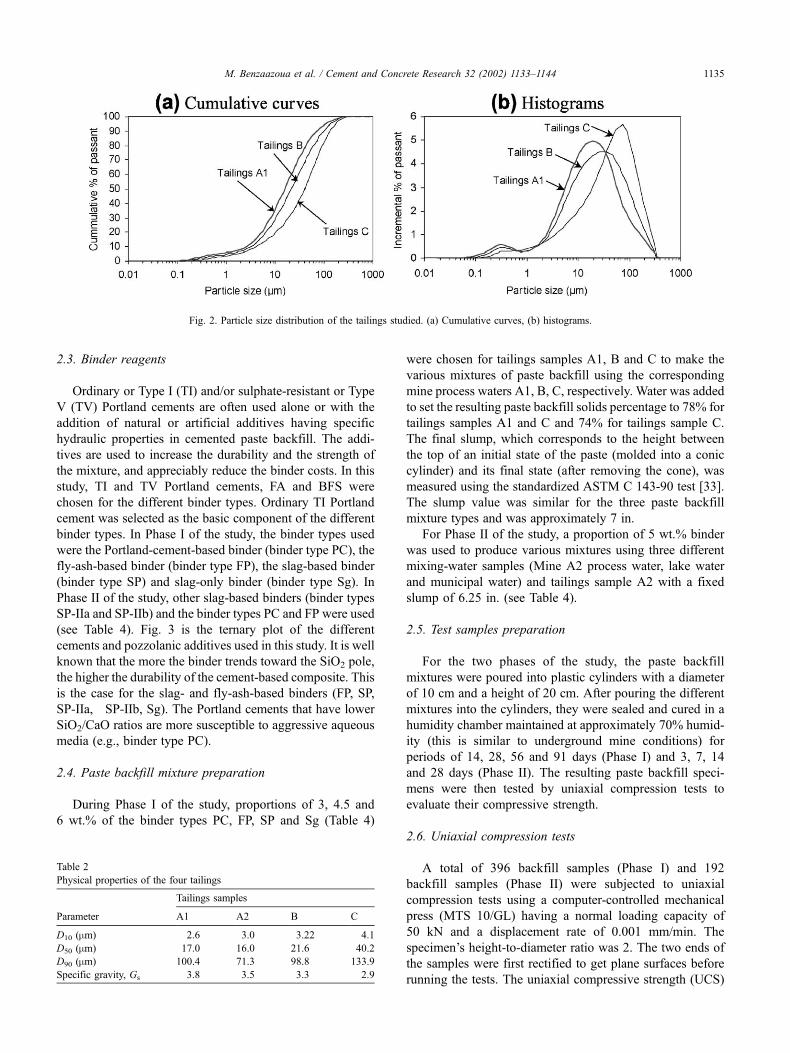
The grain size distributions of tailings A1, A2 and B
(finer tailings) are closely similar and typical of tailings
from hard-rock mines (Fig. 2). They differ from the tailings
from mine site C where the grain size distribution is coarser
(see Table 2). It is clear from Table 2 that there is a
correlation between the proportion of sulphides in the
tailings and their density, which is due to the specific gravity
(Gs) of the pyrite, which is near 5, compared to the Gs of the
gangue minerals, which has an average value of 2.7.
2.2. Mixing-water characteristics
The main chemical characteristics of the mixing waters
that are derived from the different mine process waters are
listed in Table 3. Mixing-water sample A1, which is from
the Mine A1 process water is particularly sulphate and iron
rich (24, 440 and 90 mg/l, respectively); water samples B
and C have moderate sulphate content. On the basis of the
German standard methods DIN 4030 [32] on the strength
aggressiveness of sulphate on cement composites, the mix-
ing-water samples B, C and A2 used in this study can be
classified as strongly aggressive and as very strongly
aggressive for water sample A1. Due to the addition of
lime during ore mineral processing, all waters contained
high levels of calcium ranging from 380 to 970 mg/l. Water
sample A1, which is more acidic, has a pH of 5.8 while the
water samples B and C have a near-neutral pH.
Fig. 1. Schematic diagram illustrating the different components of
paste backfill.
Table 1
Chemical composition of the four tailings by total dry weight (wt.%)
Tailings
sample S Ca Si Al Mg Fe
Cu
(ppm)
Zn
(ppm) Pyrite
A1 32.2 1.07 10.12 2.630 0.21 26.8 1870 45600 60.6
A2 24.4 0.99 15.7 4.870 0.35 20.6 0.24 2.1 42.4
B 15.9 1.44 15.3 4.065 2.695 20.7 1108 1795 29.8
C 5.2 1.17 26.29 5.640 0.57 5.13 30 149 9.75
M. Benzaazoua et al. / Cement and Concrete Research 32 (2002) 1133–11441134
2.3. Binder reagents
Ordinary or Type I (TI) and/or sulphate-resistant or Type
V (TV) Portland cements are often used alone or with the
addition of natural or artificial additives having specific
hydraulic properties in cemented paste backfill. The addi-
tives are used to increase the durability and the strength of
the mixture, and appreciably reduce the binder costs. In this
study, TI and TV Portland cements, FA and BFS were
chosen for the different binder types. Ordinary TI Portland
cement was selected as the basic component of the different
binder types. In Phase I of the study, the binder types used
were the Portland-cement-based binder (binder type PC), the
fly-ash-based binder (binder type FP), the slag-based binder
(binder type SP) and slag-only binder (binder type Sg). In
Phase II of the study, other slag-based binders (binder types
SP-IIa and SP-IIb) and the binder types PC and FP were used
(see Table 4). Fig. 3 is the ternary plot of the different
cements and pozzolanic additives used in this study. It is well
known that the more the binder trends toward the SiO2 pole,
the higher the durability of the cement-based composite. This
is the case for the slag- and fly-ash-based binders (FP, SP,
SP-IIa, SP-IIb, Sg). The Portland cements that have lower
SiO2/CaO ratios are more susceptible to aggressive aqueous
media (e.g., binder type PC).
2.4. Paste backfill mixture preparation
During Phase I of the study, proportions of 3, 4.5 and
6 wt.% of the binder types PC, FP, SP and Sg (Table 4)
were chosen for tailings samples A1, B and C to make the
various mixtures of paste backfill using the corresponding
mine process waters A1, B, C, respectively. Water was added
to set the resulting paste backfill solids percentage to 78% for
tailings samples A1 and C and 74% for tailings sample C.
The final slump, which corresponds to the height between
the top of an initial state of the paste (molded into a conic
cylinder) and its final state (after removing the cone), was
measured using the standardized ASTM C 143-90 test [33].
The slump value was similar for the three paste backfill
mixture types and was approximately 7 in.
For Phase II of the study, a proportion of 5 wt.% binder
was used to produce various mixtures using three different
mixing-water samples (Mine A2 process water, lake water
and municipal water) and tailings sample A2 with a fixed
slump of 6.25 in. (see Table 4).
2.5. Test samples preparation
For the two phases of the study, the paste backfill
mixtures were poured into plastic cylinders with a diameter
of 10 cm and a height of 20 cm. After pouring the different
mixtures into the cylinders, they were sealed and cured in a
humidity chamber maintained at approximately 70% humid-
ity (this is similar to underground mine conditions) for
periods of 14, 28, 56 and 91 days (Phase I) and 3, 7, 14
and 28 days (Phase II). The resulting paste backfill speci-
mens were then tested by uniaxial compression tests to
evaluate their compressive strength.
2.6. Uniaxial compression tests
A total of 396 backfill samples (Phase I) and 192
backfill samples (Phase II) were subjected to uniaxial
compression tests using a computer-controlled mechanical
press (MTS 10/GL) having a normal loading capacity of
50 kN and a displacement rate of 0.001 mm/min. The
specimen’s height-to-diameter ratio was 2. The two ends of
the samples were first rectified to get plane surfaces before
running the tests. The uniaxial compressive strength (UCS)
Table 2
Physical properties of the four tailings
Tailings samples
Parameter A1 A2 B C
D10 (mm) 2.6 3.0 3.22 4.1
D50 (mm) 17.0 16.0 21.6 40.2
D90 (mm) 100.4 71.3 98.8 133.9
Specific gravity, Gs 3.8 3.5 3.3 2.9
Fig. 2. Particle size distribution of the tailings studied. (a) Cumulative curves, (b) histograms.
M. Benzaazoua et al. / Cement and Concrete Research 32 (2002) 1133–1144 1135

corresponds to the maximum stress value observed during
the compression test.
2.7. Scanning electron microscope investigations and
chemical analyses
A Hitachi1 3500-N scanning electron microscope (SEM)
was used to characterize the microstructure and texture of
the various backfill samples. The backscattered electron
(BSE) imaging mode was used because it produces images
with the chemical contrast superimposed upon the relief
contrast. All chemical analyses were done using an ICP ES
spectrometer for all elements except for total sulphur and
sulphates, which were determined with a Leco oven. The
solid samples were digested entirely using aqua regia and
hydrofluoric acids.
3. Results
3.1. Results of Phase I of the study
Figs. 4 and 5 show the effect of the sulphur grade of the
tailings on the compressive strength of the different backfill
Table 3
Chemical characteristics of the mixing waters
Phase I of the study Phase II of the study
Mine A1,
process water
Mine B,
process water
Mine C,
process water
Mine A2, process
water (PW)
Lake
water (LW)
Municipal
water (MW)
pH 5.8 6.65 7.37 6.08 7.16 7.22
Eh (ENH) 86.7 349 459.5 400.4 547.5 544.7
Conductivity 8550 2000 3180 8730 1590 2200
SO4, mg/l 24444 1303 1944 1650.6 3.0 53.9
Ca, mg/l 842 387 518 969 21.7 35.9
Cu, mg/l nd nd nd 0.281 0 0.462
Fe, mg/l 89.8 0.16 2.96 2.24 0.177 0
Zn, mg/l nd nd nd 59.2 0.988 0.362
Al, mg/l 0.09 0.17 1.85 0.23 0.371 0.137
Na, mg/l 764 40.2 191 1080 4.54 4.95
Si, mg/l 4.57 1.25 9.26 12.7 4.38 0.876
Mg, mg/l 21.3 12.1 15.5 62.8 4.15 2.72
nd: not determined.
Table 4
Paste backfill mixtures characteristics
Binder
type
Binder
mix
Binder
(%)
TI
(%)
TV
(%)
FA
(%)
Slag
(% BFS) W/c
Part of
the study
Tailings
sample
PC TI:TV 3 1.5 1.5 0 0 12 Phase I A1, B, C
PC TI:TV 4.5 2.25 2.25 0 0 8 Phase I A1, B, C
PC TI:TV 5 2.5 2.5 0 0 7 Phase II A2
PC TI:TV 6 3 3 0 0 6 Phase I A1, B, C
FP TI:FA 3 1.5 0 1.5 0 12 Phase I A1, B, C
FP TI:FA 4.5 2.25 0 2.25 0 8 Phase I A1, B, C
FP TI:FA 5 2.5 0 2.5 0 7 Phase II A2
FP TI:FA 6 3 0 3 0 6 Phase I A1, B, C
SP TI:BFS 3 0.6 0 0 2.4 12 Phase I A1, B, C
SP TI:BFS 4.5 0.9 0 0 3.6 8 Phase I A1, B, C
SP TI:BFS 6 1.2 0 0 4.8 6 Phase I A1, B, C
SP-IIa TI:BFS 5 1.5 0 0 3.5 7 Phase II A2
SP-IIb TV:BFS 5 0 1.5 0 3.5 7 Phase II A2
Sg BFS 3 0 0 0 3 12 Phase I B, C
Sg BFS 4.5 0 0 0 4.5 8 Phase I B, C
Sg BFS 6 0 0 0 6 6 Phase I B, C
Fig. 3. Ternary plot of TI and TV Portland cements and pozzolans (slag
and FA).
M. Benzaazoua et al. / Cement and Concrete Research 32 (2002) 1133–11441136
samples. These figures also show the evolution of the UCS
as a function of curing time for the mines A1, B and C paste
backfill samples. Each UCS value represents an average
value obtained from three uniaxial compressive tests; the
standard deviation of these three tests was usually between
10 and 50 kPa. The UCS evolution is shown in Fig. 4 for the
binder types PC and FP and in Fig. 5 for the binder types SP
and slag only (Sg). These figures clearly show the difference
in the mode of strength acquisition of the paste backfill
mixtures (binders hydration mode). This means that the four
binder types used (PC, FP, SP, Sg) do not solidify the
tailings samples A1, B and C in the same manner. For a
given binder type, these differences concern both the
magnitude of UCS and the effect of binder proportion.
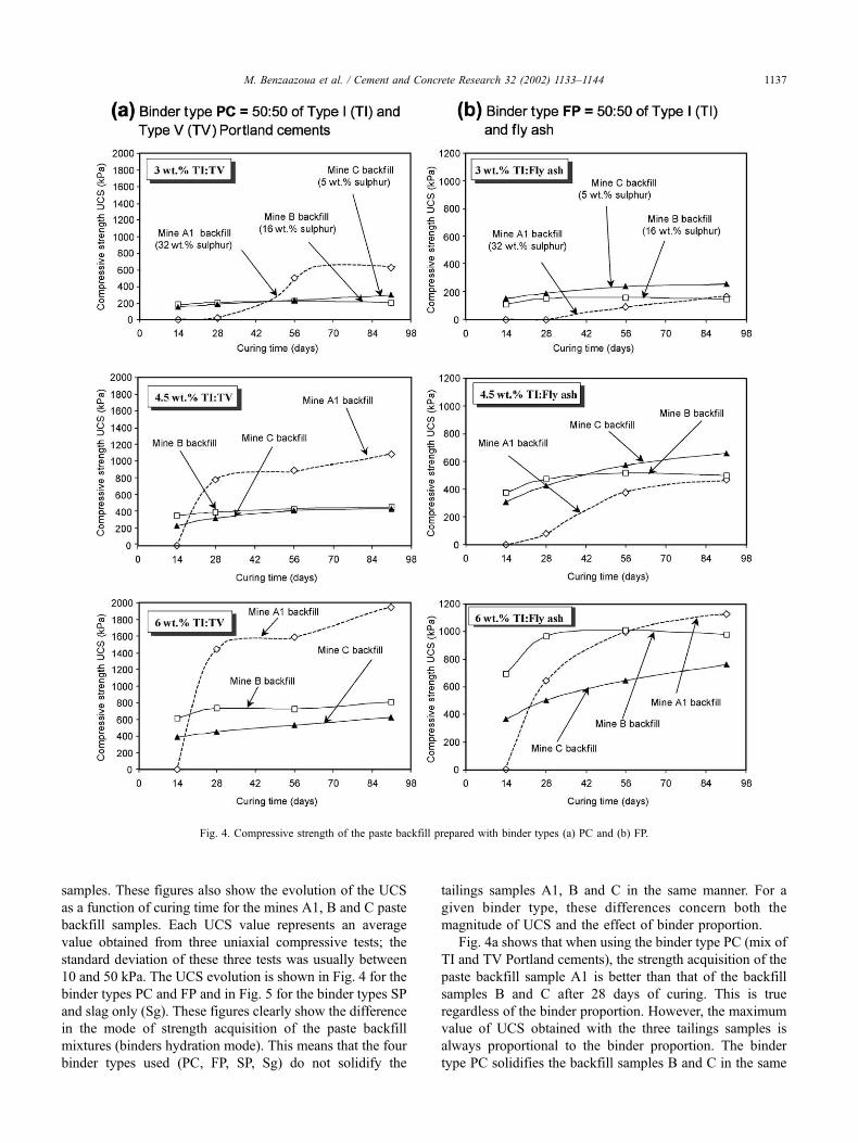
Fig. 4a shows that when using the binder type PC (mix of
TI and TV Portland cements), the strength acquisition of the
paste backfill sample A1 is better than that of the backfill
samples B and C after 28 days of curing. This is true
regardless of the binder proportion. However, the maximum
value of UCS obtained with the three tailings samples is
always proportional to the binder proportion. The binder
type PC solidifies the backfill samples B and C in the same
Fig. 4. Compressive strength of the paste backfill prepared with binder types (a) PC and (b) FP.
M. Benzaazoua et al. / Cement and Concrete Research 32 (2002) 1133–1144 1137

manner and gives relatively low strength that increases
slightly with curing time unlike backfill sample A1.
Fig. 4b shows that when using the binder type FP (mix of
TI Portland cement and FA) within the same tailings samples
A1, B and C, the strength acquisition of the backfill samples
differs from that of the binder type PC (cf. Fig. 4a). With 3
and 4.5 wt.% binder proportion the backfill sample A1
exhibits the lowest strength when compared to the backfill
samples B and C. With 6 wt.% binder, the strength of the
backfill sample B is always higher than that of the backfill
sample B, but backfill sample A1 seems to have the highest
strength after 91 days of curing time (long term strength).
Fig. 5 shows that of the slag-based binder types SP,
SP-IIa, SP-IIb (mix of TI Portland cement and slag) and Sg,
only binder type Sg gave a similar performance to that of
backfill samples A1 and B. Hence, the backfill sample A1
does not exhibit any strength until 91 days of curing time,
while the backfill sample B exhibits a good strength from 14
to 91 days curing age regardless of the binder proportion
(see Fig. 5a and b). The strength of the backfill sample C
obtained with the binder type SP is between those of the
backfill samples A1 and B. With 6 wt.% binder the strength
of the backfill sample B is slightly higher using the binder
type Sg than that using the binder type SP.
Fig. 5. Compressive strength of the paste backfill prepared with binder types (a) SP and (b) Sg.
M. Benzaazoua et al. / Cement and Concrete Research 32 (2002) 1133–11441138
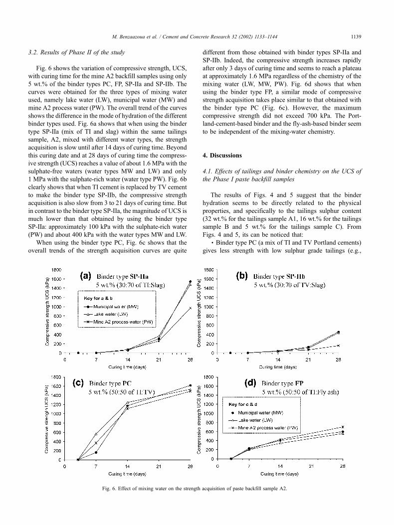
3.2. Results of Phase II of the study
Fig. 6 shows the variation of compressive strength, UCS,
with curing time for the mine A2 backfill samples using only
5 wt.% of the binder types PC, FP, SP-IIa and SP-IIb. The
curves were obtained for the three types of mixing water
used, namely lake water (LW), municipal water (MW) and
mine A2 process water (PW). The overall trend of the curves
shows the difference in the mode of hydration of the different
binder types used. Fig. 6a shows that when using the binder
type SP-IIa (mix of TI and slag) within the same tailings
sample, A2, mixed with different water types, the strength
acquisition is slow until after 14 days of curing time. Beyond
this curing date and at 28 days of curing time the compress-
ive strength (UCS) reaches a value of about 1.6 MPa with the
sulphate-free waters (water types MW and LW) and only
1 MPa with the sulphate-rich water (water type PW). Fig. 6b
clearly shows that when TI cement is replaced by TV cement
to make the binder type SP-IIb, the compressive strength
acquisition is also slow from 3 to 21 days of curing time. But
in contrast to the binder type SP-IIa, the magnitude of UCS is
much lower than that obtained by using the binder type
SP-IIa: approximately 100 kPa with the sulphate-rich water
(PW) and about 400 kPa with the water types MW and LW.
When using the binder type PC, Fig. 6c shows that the
overall trends of the strength acquisition curves are quite
different from those obtained with binder types SP-IIa and
SP-IIb. Indeed, the compressive strength increases rapidly
after only 3 days of curing time and seems to reach a plateau
at approximately 1.6 MPa regardless of the chemistry of the
mixing water (LW, MW, PW). Fig. 6d shows that when
using the binder type FP, a similar mode of compressive
strength acquisition takes place similar to that obtained with
the binder type PC (Fig. 6c). However, the maximum
compressive strength did not exceed 700 kPa. The Port-
land-cement-based binder and the fly-ash-based binder seem
to be independent of the mixing-water chemistry.
4. Discussions
4.1. Effects of tailings and binder chemistry on the UCS of
the Phase I paste backfill samples
The results of Figs. 4 and 5 suggest that the binder
hydration seems to be directly related to the physical
properties, and specifically to the tailings sulphur content
(32 wt.% for the tailings sample A1, 16 wt.% for the tailings
sample B and 5 wt.% for the tailings sample C). From
Figs. 4 and 5, its can be noticed that:� Binder type PC (a mix of TI and TV Portland cements)
gives less strength with low sulphur grade tailings (e.g.,
Fig. 6. Effect of mixing water on the strength acquisition of paste backfill sample A2.
M. Benzaazoua et al. / Cement and Concrete Research 32 (2002) 1133–1144 1139
tailings sample C), or medium sulphur grade tailings (e.g.,
Mine B). However, the binder type PC gives good strength
with sulphur-rich tailings (e.g., tailings sample A1).� Binder FP (a mix of TI Portland cement and FA)
is more suitable with lower sulphur grade tailings such
as tailings samples B and C than binder type PC. With
the same binder proportions, the compressive strength
gained with the binder type FP is always higher than the
one obtained with binder type PC, except for tailings sam-
ple A1.� Binder type SP (a mix of TI Portland cement and
slag) is not suitable for sulphide-rich tailings such as
tailings sample A1, but can be highly recommended for
low to medium sulphur grade tailings such as tailings
samples B and C. Also, this binder gives more strength
to the backfill samples B and C than the binder types PC
and FP.� Finally, binder type Sg (slag only) is not recommended
for sulphide-rich tailings such as tailings sample A1. How-
ever, it could be used for low and medium sulphur grade
tailings such as tailings samples B and C. Moreover, the
binder type Sg confers the highest compressive strength to
the backfill sample B regardless of the binder proportion.
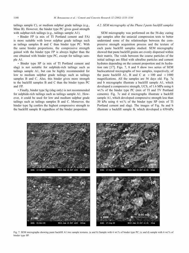
4.2. SEM micrography of the Phase I paste backfill samples
SEM micrography was performed on the 56-day curing
age samples after the uniaxial compression tests to better
understand some of the relationships between the com-
pressive strength acquisition process and the texture of
each paste backfill samples studied. SEM micrography
showed that paste backfill grains are evenly dispersed within
their matrix. The voids between the coarse particles of the
initial tailings are filled with ultrafine particles and cement
hydrates depending on the cement proportion and its hydra-
tion rate [17]. Figs. 7, 8 and 9 show two series of SEM
backscattered micrographs of two samples, respectively, of
the paste backfill A1, B and C at � 100 and � 1000
magnifications. All the samples are 56 days old. Fig. 7a
and b micrographs illustrate a backfill sample A1, which
developed a compressive strength, UCS, of 1.6 MPa using 6
wt.% of the binder type PC (mix of TI and TV Portland
cements). Fig. 7c and d micrographs illustrate a backfill
sample A1, which developed compressive strength less than
50 kPa using 6 wt.% of the binder type SP (mix of TI
Portland cement and slag). The images of Fig. 8a and b
illustrate a backfill sample B, which developed a 650-kPa
Fig. 7. SEM micrographs showing paste backfill A1 two sample textures. (a and b) Sample with 6 wt.% of binder type PC; (c and d) sample with 6 wt.% of
binder type SP.
M. Benzaazoua et al. / Cement and Concrete Research 32 (2002) 1133–11441140
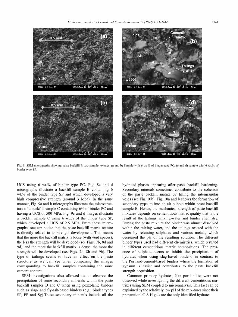
UCS using 6 wt.% of binder type PC. Fig. 8c and d
micrographs illustrate a backfill sample B containing 6
wt.% of the binder type SP and which developed a very
high compressive strength (around 3 Mpa). In the same
manner, Fig. 9a and b micrographs illustrate the microstruc-
ture of a backfill sample C containing 6% of binder PC and
having a UCS of 500 MPa. Fig. 9c and d images illustrate
a backfill sample C using 6 wt.% of the binder type SP,
which developed a UCS of 2.5 MPa. From these micro-
graphs, one can notice that the paste backfill matrix texture
is directly related to its strength development. This means
that the more the backfill matrix is loose (with void spaces),
the less the strength will be developed (see Figs. 7b, 8d and
9d), and the more the backfill matrix is dense, the more the
strength will be developed (see Figs. 7d, 8b and 9b). The
type of tailings seems to have an effect on the paste
structure as we can see when comparing the images
corresponding to backfill samples containing the same
cement content.
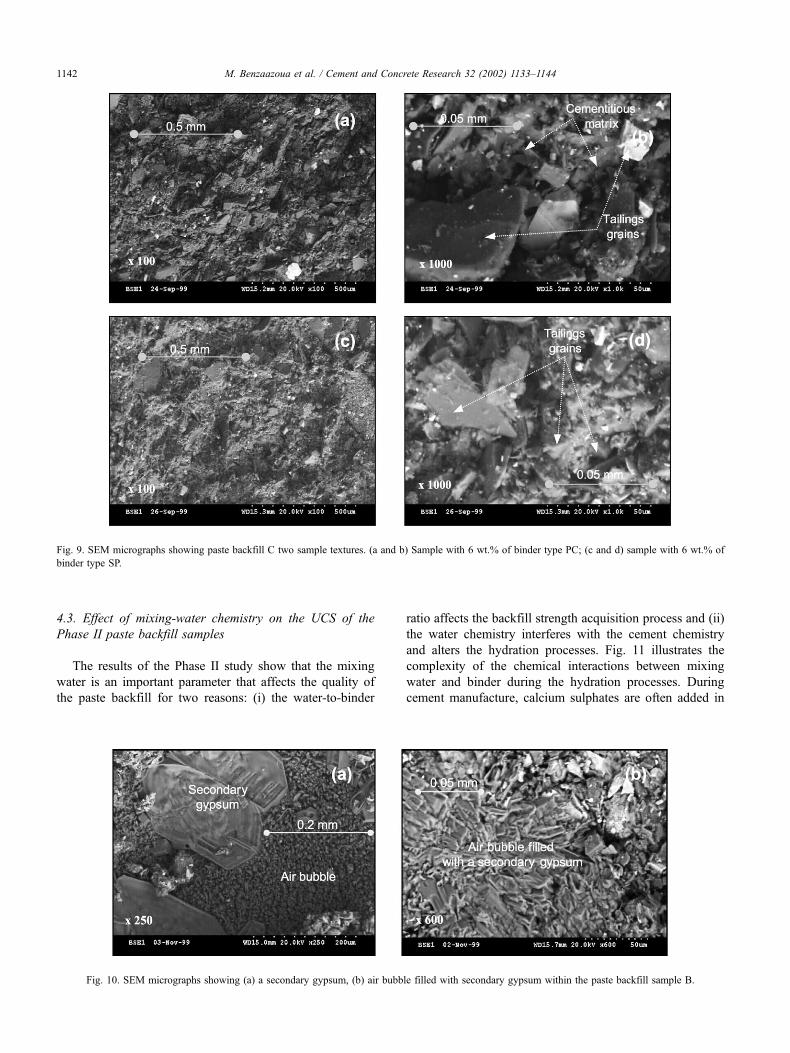
SEM investigations also allowed us to observe the
precipitation of some secondary minerals within the paste
backfill samples B and C when using pozzolanic binders
such as slag- and fly-ash-based binders (e.g., binder types
SP, FP and Sg).These secondary minerals include all the
hydrated phases appearing after paste backfill hardening.
Secondary minerals sometimes contribute to the cohesion
of the paste backfill matrix by filling the intergranular
voids (see Fig. 10b). Fig. 10a and b shows the formation of
secondary gypsum into an air bubble within paste backfill
sample B. Hence, the mechanical strength of paste backfill
mixtures depends on cementitious matrix quality that is the
result of the tailings, mixing-water and binder chemistry.
During the paste mixture the binder was almost dissolved
within the mixing water, and the tailings reacted with the
water by releasing sulphates and various metals, which
decreased the pH of the resulting solution. The different
binder types used had different chemistries, which resulted
in different cementitious matrix compositions. The pres-
ence of sulphate seems to inhibit the precipitation of
hydrates when using slag-based binders, in contrast to
the Portland-cement-based binders where the formation of
gypsum is easier and contributes to the paste backfill
strength acquisition.
Common primary hydrates, like portlandite, were not
observed while investigating the different cementitious ma-
trixes using SEM coupled to microanalysis. This fact can be
explained by the relatively low pH of the mix-tures since their
preparation. C-S-H gels are the only identified hydrates.
Fig. 8. SEM micrographs showing paste backfill B two sample textures. (a and b) Sample with 6 wt.% of binder type PC; (c and d) sample with 6 wt.% of
binder type SP.
M. Benzaazoua et al. / Cement and Concrete Research 32 (2002) 1133–1144 1141
4.3. Effect of mixing-water chemistry on the UCS of the
Phase II paste backfill samples
The results of the Phase II study show that the mixing
water is an important parameter that affects the quality of
the paste backfill for two reasons: (i) the water-to-binder
ratio affects the backfill strength acquisition process and (ii)
the water chemistry interferes with the cement chemistry
and alters the hydration processes. Fig. 11 illustrates the
complexity of the chemical interactions between mixing
water and binder during the hydration processes. During
cement manufacture, calcium sulphates are often added in
Fig. 9. SEM micrographs showing paste backfill C two sample textures. (a and b) Sample with 6 wt.% of binder type PC; (c and d) sample with 6 wt.% of
binder type SP.
Fig. 10. SEM micrographs showing (a) a secondary gypsum, (b) air bubble filled with secondary gypsum within the paste backfill sample B.
M. Benzaazoua et al. / Cement and Concrete Research 32 (2002) 1133–11441142

the form of gypsum (CaSO4�2H2O) or anhydrite (CaSO4).
The role of this additive is to set the cement hydration rate
as a hydration regulator [34]. The calcium and silicon
content of the cement greatly contribute to the formation
of hydrate phases. The ratio (SiO2 +Al2O3)/(CaO +MgO) is
an important parameter that affects the durability of the
backfill against sulphate attack [35]. After cement dissolu-
tion, calcium and silicon availability becomes so high that
various hydrates can form rapidly. These are mainly portlan-
dite (Ca(OH)2) and calcium silicon hydrated gels (C-S-H).
Other elements also contribute to the hydration processes but
are of lesser importance.
The results of this Phase II study suggest that Portland
cements- and fly-ash-based binders have fast hydration
rates compared to slag-based binders. The harmful effects
of the presence of sulphate in the mixing water on cement
hydration was demonstrated for the slag-based binders
backfill mixtures (cf. Fig. 6a and b). Indeed, the slag-
based binders hydrate more slowly when the mine process
water was used (sulphate-rich water) compared to sulphate-
free waters (e.g., lake and municipal waters). The results
also clearly show that the water chemistry plays an
important role in the binder hydration within the backfill.
One should remember that the total mixing water is made
up of tailings residual water (water remaining after the
filtration process) and the water added to set the desired
slump (either process water or fresh water). The residual
water is often soluble sulphate rich when the tailings are
sulphide rich. Thus, depending on the sulphate content, the
added water will simply dilute more or less than the
residual water.
5. Conclusions
Six binder types and six mixing-water types were used
to produce various paste backfill mixtures with four
different sulphide tailings from three Canadian hard-rock
mines (tailings samples A1, A2, B and C). The tailings
samples A1 and A2 are sulphur rich (32% wt and 24% wt
sulphur, respectively), tailings sample B is medium grade
for sulphur (16% wt) and tailings sample C is low grade
for sulphur (5% wt). The six binder types are Portland-
cement-based binders (PC), fly-ash-based binder (FP) and
slag-based binders (SP, SP-IIa, SP-IIb and Sg). The six
mixing-water types are lake water (LW), municipal water
(MW) and mine A2 sulphate-rich process water (PW).
The resulting paste backfill curing-time-dependent com-
pressive strengths were investigated with uniaxial com-
pression testing. At early-stage curing times (i.e., from 0
to 14 days) the cement hydration is weak, indicating little
or no compressive strength for all backfill samples
studied. This is particularly true concerning backfill
sample A1 (sulphide-rich backfill), which did not exhibit
any strength until after 14 days of curing time regardless
of the binder type. Only binder types PC and FP are
suitable for this backfill, which developed good com-
pressive strength after 28, 56 and 91 days of curing time.
The pozzolanic binders such as the slag-based binders
exhibit hydration inhibition until after 120 days of curing
time. The slag-based binders are appropriate for low and
medium sulphur-rich tailings and result in high strength
acquisition of the paste backfill.
The mixing-water sulphate contents strongly affect the
hydration processes depending on the binder type and the
curing time. Also, the slag-based binder hydration seems
to be inhibited by the presence of soluble sulphates in
contrast to the Portland-cement-based binder.
The results of this study clearly demonstrate the ineffici-
ency of choosing paste backfill mixtures without testing first
the tailings and mixing-water characteristics. The binder
chemistry combined with the mixing-water chemistry
affects the formation of primary and secondary hydrates
during paste backfill strengthening. The cohesion of the
paste backfill matrix is directly dependent on the nature of
the precipitated hydrates. This study particularly highlighted
the complexity of paste backfill materials for which the
compressive strength acquisition depends on three main
components (tailings, binder and mixing-water character-
istics). There is no typical recipe for all paste backfill
mixtures. Each type of tailing and each type of mixing
water requires laboratory optimization for choice of binder.
The chemical properties of the three main components of
paste backfill play an important role in its compressive
strength acquisition and must be considered when designing
and operating a paste backfill plant. This is because low
compressive strength of the resultant paste backfill can
directly affect the operation of a mine.
Acknowledgments
The authors acknowledge the financial support given by
the Institut de Recherche Robert-Sauve en Sante et en
Securite du Travail du Quebec (IRSST) and its scientific
adviser Louis Bousquet. The authors also express their
sincere gratitude to the mine operators for their assistance.
Finally, acknowledgement for their technical support also
goes to Darcy Jolette and Hugues Bordeleau.
Fig. 11. Schematic diagram illustrating interactions between mixing water
and binder during hydration processes.
M. Benzaazoua et al. / Cement and Concrete Research 32 (2002) 1133–1144 1143
References
[1] W.S. Weaver, R. Luka, Laboratory studies of cement-stabilized mine
tailings, Can. Min. Metall. Bull. 64 (701) (1970) 988–1001.
[2] B. Stromberg, 1997. Weathering kinetics of sulphidic mining waste:
an assessment of geochemical process in the Aitik mining waste
rock deposits. AFR-Report 159, Department of Chemistry, Inor-
ganic Chemistry, Royal Institute of Technology, Stockholm, Swe-
den, 1997.
[3] R.F. Viles, R.T.H. Davis, M.S. Boily, New material technologies
applied in mining with backfill, in: F. Hassani, et al. (Ed.), Innovation
in Mining Backfill Technology, A.A. Balkema, Rotterdam, 1989,
pp. 95–101.
[4] D.A. Landriault, Paste fill at Inco, Proceedings of the Fifth Interna-
tional Symposium on Mining with Backfill, Johannesburg, South
Africa, A.A. Balkema, Rotterdam, 1992.
[5] D.A. Landriault, Paste backfill mix design for Canadian underground
hard rock mining, in: F.P. Hassani, P. Mottahed (Eds.), Proceedings of
the 97th Annual General Meeting of the CIM Rock Mechanics and
Strata Control Session, Halifax, Nova Scotia, CIM, 1995.
[6] D.A. Landriault, W. Lidkea, Paste fill and high density slurry fill, in:
W.F. Bawden, J.F. Archibald (Eds.), Proceedings of the International
Congress on Mine Design, Queens University, Canada, A.A. Balke-
ma, Rotterdam, 1993, pp. 229–238.
[7] D.A. Landriault, R. Tenbergen, The present state of paste fill in
Canadian underground mining, Proceedings of the 97th Annual
Meeting of the CIM Rock Mechanics and Strata Control Session,
Halifax, Nova Scotia, 1995.
[8] D. Landriault, R. Verburg, W. Cincilla, D. Welch, Paste technology for
underground backfill and surface tailings disposal applications, Short
Course Notes, CIM Technical Workshop—April 27, Vancouver, Brit-
ish Columbia, Canada, 1997, p. 120.
[9] J. Naylor, R.A. Farmery, R.A. Tenbergen, Paste backfill at the Mac-
assa mine with flash paste production in a paste production and stor-
age mechanism, Proceedings of the 29th Annual Meeting of the
Canadian Mineral Processors, Ottawa, Ontario, 21 – 23 January,
CIM, 1997, pp. 408–420.
[10] R.J. Mitchell, Stability of cemented tailings mine backfill, in: Bala-
subramaniam, et al. (Ed.), Proceedings Computer and Physical Mod-
elling in Geotechnical Engineering, A.A. Balkema, Rotterdam, 1989,
pp. 501–507.
[11] R.J. Mitchell, Model studies on the stability of confined fills, Can.
Geotech. J. 26 (1989) 210–216.
[12] A.W. Lamos, I.H. Clark, The influence of material composition and
sample geometry on the strength of cemented backfill, in: F.P. Hassa-
ni, M.J. Scoble, T.R. Yu (Eds.), Innovation in Mining Backfill Tech-
nology, A.A. Balkema, Rotterdam, 1989, pp. 89–94.
[13] C.D. Lawrence, The influence of binder type on sulfate resistance,
Cem. Concr. Res. 22 (1992) 1047–1058.
[14] J. Petrolito, R.M. Anderson, S.P. Pigdon, The strength of backfills
stabilised with calcined gypsum, in: M. Bloss (Ed.), Minefill’98,
Proceedings of the Sixth International Symposium on Mining with
Backfill, Australian Institute of Mining and Metallurgy, Brisbane,
Australia, 1998, pp. 83–85.
[15] J. Ouellet, M. Benzaazoua, S. Servant, Mechanical, mineralogical
and chemical characterization of a paste backfill, Tailings and
Mine Waste’98, Colorado, A.A. Balkema, Rotterdam, 1998,
pp. 139–146.
[16] J. Ouellet, T.J. Bidwell, S. Servant, Physical and mechanical charac-
terisation of paste backfill by laboratory and in situ testing, in: M.
Bloss (Ed.), Proceedings of the Sixth International Symposium on
Mining with Backfill, MINEFILL’98, Australian Institute of Mining
and Metallurgy, Brisbane, Australia, 1998, pp. 249–1253.
[17] M. Benzaazoua, J. Ouellet, S. Servant, Ph. Newman, R. Verburg,
Cementitious backfill with high sulfur content: Physical, chemical
and mineralogical characterization, Cem. Concr. Res. 29 (1999)
719–725.
[18] R.L. Bernier, M.G. Li, A. Moerman, Effects of tailings and binder
geochemistry on the physical strength of paste backfill, D. Goldsack,
N. Belzile, P. Yearwood, G. Hall (Eds.), Sudburry’99, Mining and the
Environment II, vol. 3, Laurentian University, Sudbury, Canada, 1999,
pp. 1113–1122.
[19] M. Benzaazoua, T. Belem, D. Jolette, Investigation de la stabilite
chimique et son impact sur la resistance mecanique des remblais
cimentes. Rapport final IRSST, 2000.
[20] T. Belem, M. Benzaazoua, B. Bussiere, Mechanical behaviour of
cemented paste backfill, in: D. Lebeauf (Ed.), Proceedings of the
Canadian Geotechnical Society Conference Geotechnical Engineering
at the Dawn of the Third Millennium, 15–18 Oct., CGS Montreal,
vol. 1, 2000 pp. 373–380.
[21] F.P. Hassani, D. Bois, Economic and technical feasibility for backfill
design in Quebec underground mines. Final report 1/2, Canada—
Quebec Mineral Development Agreement, Research and Develop-
ment in Quebec Mines. Contract No. EADM 1989–1992, File No.
71226002, 1992.
[22] F. Hassani, J. Archibald, Mine Backfill, CD-ROM, Canadian Institute
of Mine, Metallurgy and Petroleum, 1998.
[23] R.J. Mitchell, B.C. Wong, Behavior of cemented tailings sands, Can.
Geotech. J. 19 (1982) 289–295.
[24] D.M.R. Stone, The optimization of mix designs for cemented rock-
fill, in: H.N. Glen (Ed.), MINEFILL’93, Proceedings of the Fifth
International Symposium on Mining with Backfill, Johannesburg,
SAIMM, 1993, pp. 249–253.
[25] R.T. Lowson, Aqueous oxidation of pyrite by molecular oxygen,
Chem. Rev. 82 (5) (1982) 461–497.
[26] M. Regourd, H. Hornain, P. Levy, B. Mortureux, Resistance du beton
aux attaques physico-chimiques, C.E.R.I.L.H., France II, vol. II
(1980) 104–109.
[27] M. Regourd, Corrosion chimique des materiaux de construction min-
eraux, Chantier Suisse 15 (1984) 115–120.
[28] F.X. Deloye, Action conjuguee du soufre et des alcalins dans les
reactions Liant-granulats au sein du beton, Bull. Liaison Lab. Ponts.
Chaussees 161 (3393) (1989) 41–49.
[29] C. Ftikos, J. Marinos, C. Matami, Durability of hydrated cements
containing various Greek pozzolans in aggressive media, Cim., Be-
tons, Platres Chaux 799 (6/92) (1992) 397–400.
[30] I. Picquet, M. Benzaazoua, Ph. Marion, G. Videau, Inertage de steriles
miniers arseno-sulfures dans des liants hydrauliques, in: J.M. Cases, F.
Thomas (Eds.), International Congress Wastes SSP, Nancy, Societe
Alpine de Bublication, Grenoble, France, 1995, pp. 311–318.
[31] L.M. Amaratunga, G.G. Hein, Development of a high strength total
tailings paste fill using fine sulfide mill tailings, Proceedings of the
29th Annual Conference of the Canadian Mineral Processors (CIM-
CMP), 1997, pp 293–305.
[32] DIN 4030, Beurteilung betonangreifender Wasser, Boden und Gase,
German Standard, AAA 008, 1991.
[33] ASTM C143-90, Standard test method for slump of hydraulic cement
concrete. Annual book of ASTM Standards, vol. 04.02.
[34] H.F.W. Taylor, Cement Chemistry, third ed., Academic Press, New
York, 1990, 475 pp.
[35] G. Dreux, Nouveau guide du beton, sixth ed., Editions Eyrolles,
Paris, 1990.
M. Benzaazoua et al. / Cement and Concrete Research 32 (2002) 1133–11441144