TILABONI UG MINE
48
SUBSIDENCE PREDICTION REPORT (THROUGH 3-D NUMERICAL MODEL) TILABONI UG MINE BANKOLA AREA EASTERN COALFIELDS LIMITED WEST BENGAL (INDIA) DEPARTMENT OF MINING ENGINEERING INDIAN INSTITUTE OF TECHNOLOGY (BANARAS HINDU UNIVERSITY) VARANASI 221 005 UP (INDIA) MARCH 2020
-
Upload
khangminh22 -
Category
Documents
-
view
0 -
download
0
Transcript of TILABONI UG MINE
SUBSIDENCE PREDICTION REPORT (THROUGH 3-D NUMERICAL MODEL)
TILABONI UG MINEBANKOLA AREA
EASTERN COALFIELDS LIMITEDWEST BENGAL (INDIA)
DEPARTMENT OF MINING ENGINEERINGINDIAN INSTITUTE OF TECHNOLOGY
(BANARAS HINDU UNIVERSITY)VARANASI 221 005
UP (INDIA)
MARCH 2020

3/11/2020 Certificate.JPG
https://mail.google.com/mail/u/0/?tab=rm0&ogbl#inbox/WhctKJVqqqnVKRtGfvqhfRQjbVgLRmdNXqdTJdKSnrXWHQkBPwGmWfvbfPgXRrQhbD… 1/1

REPORT ON THE SUBSIDENCE PREDICTION OF TILABONI UG MINE BY THREE DIMENSIONAL FEM
1
1.0 INTRODUCTION
Tilaboni mine is located in the north eastern side of Raniganj Coalfield. It
is situated in Bankola Area, Eastern Coalfields Limited, Burdwan district of
West Bengal. It lies between latitude 230 37’ 48” and 230 40’ 14” N and
Longitude 870 16’ 05” and 870 18’ 25” E. The total area of Combined Tilaboni
and Tilaboni Extension geological blocks is 10.83 sq. km.
Boundary of Tilaboni UG project is as under:
North West : Kumardih A Colliery
North East : Jhanjra Block
South East : Tilaboni Extension Block/Fault F9-F9 (throw-15 to 95m)
South West : Shyamsundarpur Colliery/Fault F1-F1 (throw- 65m)
1.1 COMMUNICATION
The mine is well connected by both road and rail. The Andal-Madhaiganj
road which joins the G.T Road at Andal traverses through the northern part of
the block. The distance to G.T. Road from the southern boundary of block is
about 14 km. Ukhra Railway Station on the Andal-Sainthia branch line of the
Eastern Railway is situated about 3 km away from the block.
The Durgapur Industrial Complex situated to the South-East of the block is
about 28 km by road from the block. The Raniganj township, is about 30 km by
road.
The nearest airport is at Dumdum (Kolkata), about 200 km from the project.
The nearest railway station is Ukhra on Andal-Sainthia branch line of Eastern
Railways.

REPORT ON THE SUBSIDENCE PREDICTION OF TILABONI UG MINE BY THREE DIMENSIONAL FEM
2
1.2 CLIMATE AND RAINFALL
Humid tropical climate prevails over the area. During the summer
months lasting from March to May, the temperature generally varies from 300C
to 400C. In winter November to February) it drops down to about 100C during
the night. The relative humidity varies from 45% to 98%. The average annual
rainfall is about 1400 mm, the major part of which precipitates during the
period from June to October. The area is often subjected to a cyclonic storm
locally known as “Kal Baisakhi” during the month of April to June.
1.3 PHYSIOGRAPHY AND DRAINAGE
The area forms an alluvial plain with very gently undulating topography.
The elevation varies from 80m to 106m above M.S.L. The area is drained by
two small nalas which originate within the block. They join the Tumni nala
beyond the confines of the block, which finally drain into the river Ajoy which is
the main drainage channel of the coalfield.
1.4 LAND USE PATTERN
Most of the land overlying the project area is tenancy land and used for
agricultural purpose. Paddy is the main crop of the area which is harvested
during late November and early December. There is about 65.8 ha of forest
land within the block, which includes 21.1 ha of plantation. About 72.6 ha land
has been acquired for construction of mine infrastructure and residential
buildings.
2.0 GEOLOGY

REPORT ON THE SUBSIDENCE PREDICTION OF TILABONI UG MINE BY THREE DIMENSIONAL FEM
3
Raniganj formation occupies the Tilaboni Combined Block. The general
statigraphic sequence of Raniganj Coalfield (after Geological Survey of India) is as
follows :
General Stratigraphic Sequence of Tilaboni Combined Block
StratigraphicUnits
Formation L i t h o l o g y
Recent Alluvium/soil
Sub-recent & Quaternary
Laterite, lateritic gravel, clays, running sand etc.
----------------------------------------------- Unconformity --------------------------------------Intrusives (Dykes & Sills)
Dolerite, mica peridotite and lamprophyre
Supra Panchet Coarse grained quartzose sandstone with bands of dark red silty shale
Supra Panchet Coarse grained quartzose sandstone with bands of dark red silty shale
------------------------------------------------ Unconformity ------------------------------------Early Triassic Panchet Formation Coarse grained greenish
grey sandstone bands of red silty shale
Damuda Group Raniganj Formation Fine to coarse grained micaceous sandstone, shale, carbonaceous shale and coal seams
Barren Measures Black laminated fissile shales with clays and ironstone bands
Barakar Formation Coarse grained feldspathic sandstone, shale and coal seams
------------------------------------------------- Unconformity ------------------------------------Archaeans Gneiss, granites &

REPORT ON THE SUBSIDENCE PREDICTION OF TILABONI UG MINE BY THREE DIMENSIONAL FEM
4
schists, shales and coal seams
The entire block is covered either by soil or laterite. The stratigraphic
sequence, thickness of different formations and occurrence of different seams
have been deciphered on the basis of sub-surface data obtained from
exploratory drilling.
The sequence of coal seam with their thickness, parting, depth and reserves in
the proposed project area have been shown in the following table:
Seam ThicknessRange
(m)
Depth(m)
TotalGeologica
lReserves
(Mt)
Nos. ofBH
intersection
R-X A 0.84-2.22 65.69-90.72 0.6325 5Parting 26.76-32.95R-IX Top 0.98-2.73 23.70-125.30 3.0631 16Parting 1.63-21.81R-IX Bot 0.36-2.23 18.0-128.28 4.6733 22Parting with R-VIII T1 28.35-80.85Parting with R-VIII Top 99.63-100.59R-VIII Top 1.07-1.32 77.09-154.18 - 4R-VIII T1 0.10-1.01 37.73-190.67 - 53Parting 14.30-31.88R-VIII T2 0.50-2.01 20.35-222.91 12.5810 69Parting with R-VIII B1 (Top)
6.00-27.73
Parting with R-VIII B1 (Comb)
23.76-27.50
R-VIII B1 (Top) 0.30-1.47 82.22-231.04 7.5236 54Parting 1.12-8.95R-VIII B1 (Bot) 0.90-2.59 84.85-237.30 13.0029 52R-VIII B1 3.10-4.82 19.10-104.05 20.5636 22Parting 8.20-21.77R-VIII B2 0.30-1.45 29.56-251.15 4.8036 68R-VIII Bot 1.65-1.84 135.64-
159.332
Parting with R-VII Top 27.14-42.45Parting with R-VII Comb 26.84-53.35R-VII Top 0.70-2.26 153.10-
279.053.7302 17

REPORT ON THE SUBSIDENCE PREDICTION OF TILABONI UG MINE BY THREE DIMENSIONAL FEM
5
Parting 1.14-14.09R-VII Bot 1.95-2.95 156.50-
294.168.6470 17
R-VII 1.95-6.18 75.93-211.98 41.9954 50Parting with R-VII A 23.85-48.74Parting with R-VII A/B Comb
39.00-54.55
R-VII A 1.37-3.33 110.52-243.20
20.1713 34
Parting 3.85-27.20R-VII B 0.21-3.40 126.80-
260.5021.0555 35
R-VII A/B Comb 3.23-5.18 201.93-335.55
16.0614 21
Parting 12.96-27.50R-VII C 0.12-2.20 149.40-
355.0319.8299 48
Parting 18.13-51.08R-VI 1.98-6.58 187.75-
391.1563.8800 46
Parting 19.70-63.17R-V 1.20-6.30 216.75-
341.2561.9739 32
Parting 0.92-49.24R-IV 1.52-11.45 242.60-
366.24111.3215 34
Parting 24.12-35.34R-III 2.05-3.59 270.78-
401.0037.1007 32
Parting 9.42-45.52R-II 0.45-2.32 283.25-
440.6421.9464 28
Total 494.5568
3.0 METHOD OF WORK
It is proposed to extract the coal by underground Bord and Pillar method
of mining with Continuous Miner technology along with SDL. The Maximum
extraction thickness will be 4.8m.
4.0 PERIOD OF PREDICTION
REPORT ON THE SUBSIDENCE PREDICTION OF TILABONI UG MINE BY THREE DIMENSIONAL FEM
6
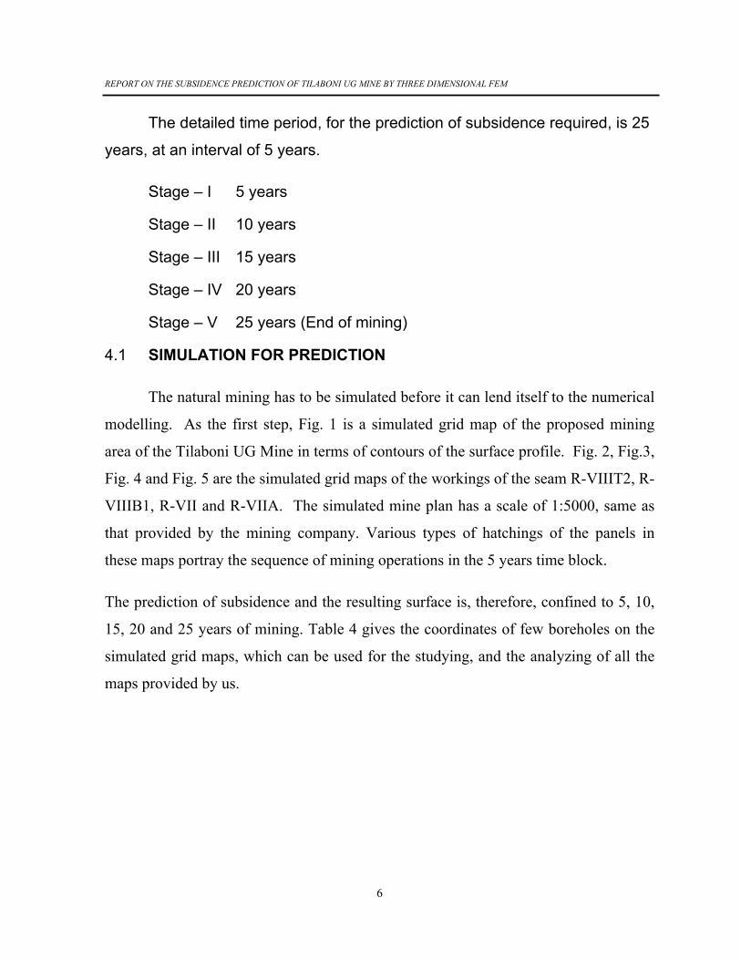
The detailed time period, for the prediction of subsidence required, is 25
years, at an interval of 5 years.
Stage – I 5 years
Stage – II 10 years
Stage – III 15 years
Stage – IV 20 years
Stage – V 25 years (End of mining)
4.1 SIMULATION FOR PREDICTION
The natural mining has to be simulated before it can lend itself to the numerical
modelling. As the first step, Fig. 1 is a simulated grid map of the proposed mining
area of the Tilaboni UG Mine in terms of contours of the surface profile. Fig. 2, Fig.3,
Fig. 4 and Fig. 5 are the simulated grid maps of the workings of the seam R-VIIIT2, R-
VIIIB1, R-VII and R-VIIA. The simulated mine plan has a scale of 1:5000, same as
that provided by the mining company. Various types of hatchings of the panels in
these maps portray the sequence of mining operations in the 5 years time block.
The prediction of subsidence and the resulting surface is, therefore, confined to 5, 10,
15, 20 and 25 years of mining. Table 4 gives the coordinates of few boreholes on the
simulated grid maps, which can be used for the studying, and the analyzing of all the
maps provided by us.

REPORT ON THE SUBSIDENCE PREDICTION OF TILABONI UG MINE BY THREE DIMENSIONAL FEM
7

REPORT ON THE SUBSIDENCE PREDICTION OF TILABONI UG MINE BY THREE DIMENSIONAL FEM
8

REPORT ON THE SUBSIDENCE PREDICTION OF TILABONI UG MINE BY THREE DIMENSIONAL FEM
9
Table 4 : Coordinates of boreholes on the simulated grip map
Sl. No. Borehole No. X-Coordinate Y-Coordinate
1. TLB-5 1168 2313
2. TLB-10 1784 2820
3 TLB-18 2869 2370
4. NCRJ-3 2748 1766
5. CMRT-11 2304 2420
6. CMRT-1 1860 3479
4.2 REQUISITE GEOTECHNICAL PARAMETERS FOR THE PREDICTION
The numerical prediction of subsidence requires following basic data:

REPORT ON THE SUBSIDENCE PREDICTION OF TILABONI UG MINE BY THREE DIMENSIONAL FEM
10
1) Geotechnical parameters of the seam and surrounding rock mass upto the surface,
2) Mathematical model and computer programs (software)
3) Major structural features of the strata,
4) Details of the mine excavation
5) Sequence of extraction and size of panels, and
6) Important features on the surface.
The information on the above mentioned parameters were provided by the
company. The company also provided the data for the physico-mechanical properties
used in the simulation. The above properties were taken for various panels as per their
proximity to the above boreholes in the block. The boreholes nearest to the panels
were considered to be representative one and hence selected for the simulation.
4.3 PREDICTION TECHNIQUE
The computer-simulated model was developed for the prediction of subsidence
and alterations in the resulting profile of the surface, keeping in mind the total area, the
mining sequence and geo-technical properties and above all, depth of each mining
panel, which varies significantly from panel to panel and seam to seam. The grid map
for simulation is based on 25 m grid on the surface having about 45241 points for
calculation process using finite element method (FEM) – a numerical simulation
technique. The computation for prediction of subsidence of the area is based on the
grid pattern. The 3-D mathematical model, thus simulated was subjected to the finite
element analysis. The model also takes care of the non-linear behaviour of the rock
mass (if any), bed separation and its recontact.

REPORT ON THE SUBSIDENCE PREDICTION OF TILABONI UG MINE BY THREE DIMENSIONAL FEM
11
5.0 RESULT
5.1 PREDICTED SUBSIDENCE CONTOURS
Fig. 6 shows the subsidence contours after 5 years of mining. Similarly, Fig. 7,
Fig. 8, Fig. 9 and Fig. 10 give the subsidence contours at the end of 10 year, 15 year,
20 year and 25 years of mining respectively. The maximum values of the subsidence
predicted at the end of each time blocks are given in Table 5.
Table 5: Maximum values of predicted subsidence at the various time blocks
Sl. No. Year Subsidence values, m
1. 5 -2.871
2. 10 -2.930
3. 15 -4.543
4. 20 -5.651
5. 25 -5.717
To illustrate an overall picture, a few subsidence values along with coordinates
on the simulated grid maps for various time blocks of mining have also been
summarized in the Appendix in the Table I.
5.2 THREE DIMENSIONAL PROJECTIONS OF SUBSIDENCE
To give a 3-dimensional impact of the subsidence, the predicted subsidence has
been projected on the surface for each of the mining periods based on x and y
coordinate defining the horizontal plane and ‘Z’ coordinate, the depth of the surface.
It may be noted that the ‘Z’ coordinate has been exaggerated (25 times) to have a
better visual appreciation of the impact of subsidence.

REPORT ON THE SUBSIDENCE PREDICTION OF TILABONI UG MINE BY THREE DIMENSIONAL FEM
12
Figs. 6 through 10 give prediction of the subsidence at the end of 5, 10, 15, 20
years and 25 years of mining respectively, considering the surface to be horizontal,
before mining. These figures give a real feel of the impact of subsidence as a result of
the multi seam mining and the progression of mining with time. Two sets of
subsidence figures are provided for each stage. These are having opposite viewing
directions, i.e. 45o and 225o. It may be pointed out at this stage that the 3-dimensional
projections shown in the figures 11 through 15 should not be used to pin point the
maximum subsidence area because all the points may not be visible on the map.
However, these drawings provide fairly accurate idea about ground behavior after
mining.
It is worth noting that the troughs shown in the figures should be viewed in the
proper perspective as the scale in ‘Z’ direction has been enlarged to 20 times to have
appreciable viewing impact.

REPORT ON THE SUBSIDENCE PREDICTION OF TILABONI UG MINE BY THREE DIMENSIONAL FEM
13

REPORT ON THE SUBSIDENCE PREDICTION OF TILABONI UG MINE BY THREE DIMENSIONAL FEM
14

REPORT ON THE SUBSIDENCE PREDICTION OF TILABONI UG MINE BY THREE DIMENSIONAL FEM
15

REPORT ON THE SUBSIDENCE PREDICTION OF TILABONI UG MINE BY THREE DIMENSIONAL FEM
16

REPORT ON THE SUBSIDENCE PREDICTION OF TILABONI UG MINE BY THREE DIMENSIONAL FEM
17

REPORT ON THE SUBSIDENCE PREDICTION OF TILABONI UG MINE BY THREE DIMENSIONAL FEM
18
5.3 SURFACE PROFILE
The surface profiles of the mining block after each stage of mining have been
predicted. These profiles have been obtained by superimposing subsidence with pre-
mining surface profile after each mining sequence for different time blocks. Fig. 1
gives the surface profile of the mining block before mining. The contour maps which

REPORT ON THE SUBSIDENCE PREDICTION OF TILABONI UG MINE BY THREE DIMENSIONAL FEM
19
would finally emerge as a result of mining after 5, 10, 15, 20 and 25 years of mining
have been predicted and is shown in Figs. 16 through 20.
Fig. 21 shows the 3-dimensional prediction of subsidence before mining for the
Tilaboni UG Mine. Figs. 21 through 26 gives the 3-dimensional prediction of surface
at the end of each mining sequence (the ‘Z’ axis has been exaggerated to 10 times for
having better visual appearance of the impact of subsidence). A set of figures showing
surface subsidence and surface profile at the end of 5, 10, 15 20 and 25 years of
mining is also being provided in larger sizes at a scale of 1: 5000. The surface
contours along with the panels of the (seam-R-VIII T2, R-VIII B1, R-VII and R-VIIA)
are also being provided in larger sizes i.e., at a scale of 1:5000.

REPORT ON THE SUBSIDENCE PREDICTION OF TILABONI UG MINE BY THREE DIMENSIONAL FEM
20

REPORT ON THE SUBSIDENCE PREDICTION OF TILABONI UG MINE BY THREE DIMENSIONAL FEM
21

REPORT ON THE SUBSIDENCE PREDICTION OF TILABONI UG MINE BY THREE DIMENSIONAL FEM
22

REPORT ON THE SUBSIDENCE PREDICTION OF TILABONI UG MINE BY THREE DIMENSIONAL FEM
23

REPORT ON THE SUBSIDENCE PREDICTION OF TILABONI UG MINE BY THREE DIMENSIONAL FEM
24

REPORT ON THE SUBSIDENCE PREDICTION OF TILABONI UG MINE BY THREE DIMENSIONAL FEM
25

REPORT ON THE SUBSIDENCE PREDICTION OF TILABONI UG MINE BY THREE DIMENSIONAL FEM
26
6.0 Tensile Strain and Crack Width
6.1 Maximum Tensile Strain
Maximum predicted tensile strain for Tilaboni UG Mine at various time blocks has
been given in the table 6.
Table 6. Predicted value for the maximum tensile strain in forest area for Tilaboni UG
Mine at various time block
Sl. No. Time Block Tensile Strain mm/m
1. 5 27.19
2. 10 61.93
3. 15 63.44

REPORT ON THE SUBSIDENCE PREDICTION OF TILABONI UG MINE BY THREE DIMENSIONAL FEM
27
4. 20 67.75
5. 25 91.77
The predicted maximum tensile strain at the end of 5 years of mining is 27.19 mm/m
and it sharply increases at the end of 10 year of mining (61.93 mm/.) It further slightly
increases to 63.44 mm/m at end of 15 years of mining and 67.75 mm/m at the end of
20 years of mining. It further increases sharply to 91.77 mm/m at the end of 25 years
of mining.
6.2 Crack Width
It is well known from the field experience that the cracks may occur
under the condition of high tension and weak rocks. The prediction of crack
width is associated with high degree of uncertainty. Zones of possible cracks
will lie in the vicinity of weak rocks and near fault planes under large tensile
strain. To have accurate predictions, the strain maps should be superimposed
over the detailed geological plan and geotechnical data. Cracks of significant
width are likely to be formed at the end of mining.
Cracks width of approximately 300 mm/m is likely to occur at the end of
5 year of mining. It will increase sharply to more than 600 mm/m at the end of
10, 15, and 20 years of mining. Approximately 900 mm/m wide cracks are
likely to be formed at the end of 25 year of mining.
7.0 DISCUSSION
Mining of underground panels results into subsidence at the surface.
The prediction of subsidence have been carried out at 5 years time interval.
Therefore, the prediction have made for different time blocks i.e. at end of 5
years of mining, 10 years of mining, 15years of mining, 20 years of mining and
25 years of mining. Resulting horizontal tensile strain and crack width due to

REPORT ON THE SUBSIDENCE PREDICTION OF TILABONI UG MINE BY THREE DIMENSIONAL FEM
28
mining subsidence has also become very important for subsidence
management plan.
Table 5 summarises the predicted peak subsidence at the surface at
various time blocks. It shows that the predicted peak subsidence at end of 5
year of mining is 2.871 m, 2.930 m at end of 10 years of mining, 4.543 m at
the end of 15 years of mining, 5.651 m at end of 20 years of mining and 5.717
m at end of 25 years of mining. The subsidence manifests itself in cracks and
high horizontal tensile strain on the surface (major reason of damage to
surface structure).
Table 6 summarises the predicted peak horizontal tensile strain on the
surface. It shows that the peak horizontal tensile strain at the surface in 27.19
mm/m at the end of 5 years of mining. It sharply increases to 61.93 mm/m at
the end of 10 years of mining, 63.44 mm/m at the end of 15 years of mining,
67.75 mm/m at the end of 20 years of mining and 91.77 mm/m at the end of 25
years of mining.
Wide cracks are also likely to occur in the surface.
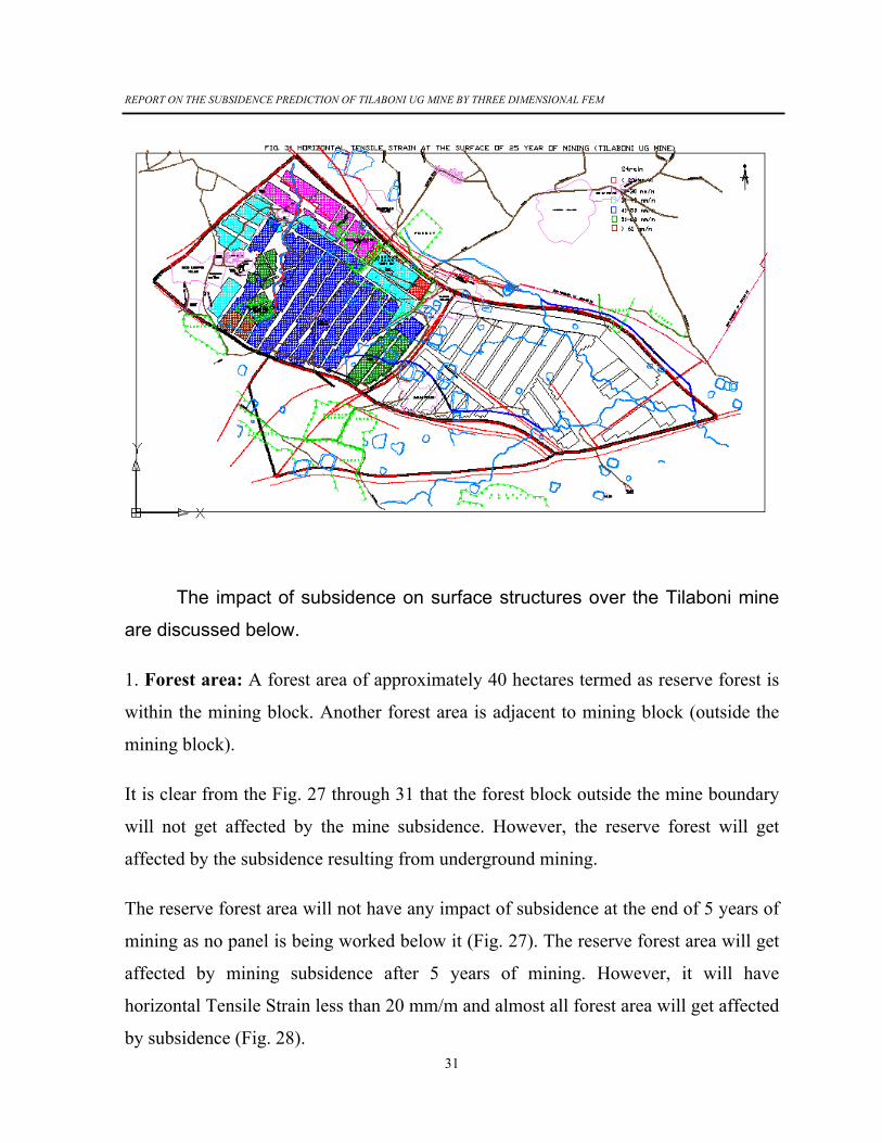
There are many surface features located over the surface of Tilaboni
mine. The major surface features are forest, road, ponds (water bodies),
villages, mining colony, nalas etc. The surface features have been
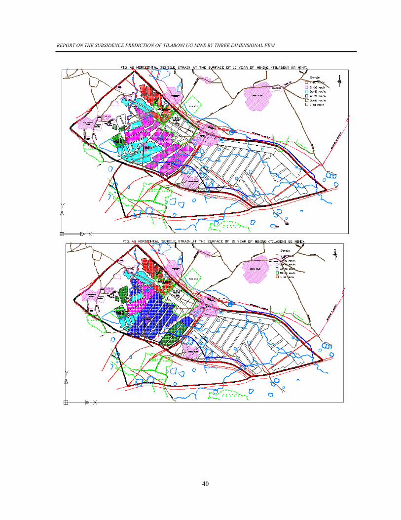
superimposed with horizontal tensile strain areas for various time blocks. Fig.
27 to Fig. 31 shows the peak high horizontal tensile strain superimposed with
surface at end of 5 years, 10 years, 15 years, 20 years, and 25 years of
mining. The various hatching colours are depicting the zone of high horizontal
tensile strain. The high horizontal tensile strain have been depicted in the
range of 20 mm/m, 21 mm/m to 30 mm/m, 31 mm/m to 40 mm/m, 41 mm/m to
50 mm/m, 51 mm/m to 60 mm/m and more than 60 mm/m.

REPORT ON THE SUBSIDENCE PREDICTION OF TILABONI UG MINE BY THREE DIMENSIONAL FEM
29

REPORT ON THE SUBSIDENCE PREDICTION OF TILABONI UG MINE BY THREE DIMENSIONAL FEM
30
REPORT ON THE SUBSIDENCE PREDICTION OF TILABONI UG MINE BY THREE DIMENSIONAL FEM
31
The impact of subsidence on surface structures over the Tilaboni mine
are discussed below.
1. Forest area: A forest area of approximately 40 hectares termed as reserve forest is
within the mining block. Another forest area is adjacent to mining block (outside the
mining block).
It is clear from the Fig. 27 through 31 that the forest block outside the mine boundary
will not get affected by the mine subsidence. However, the reserve forest will get
affected by the subsidence resulting from underground mining.
The reserve forest area will not have any impact of subsidence at the end of 5 years of
mining as no panel is being worked below it (Fig. 27). The reserve forest area will get
affected by mining subsidence after 5 years of mining. However, it will have
horizontal Tensile Strain less than 20 mm/m and almost all forest area will get affected
by subsidence (Fig. 28).

REPORT ON THE SUBSIDENCE PREDICTION OF TILABONI UG MINE BY THREE DIMENSIONAL FEM
32
The reserve forest will experience horizontal tensile strain more than 30 mm/m (30-40
mm/m) at the end of 15 years of mining (Fig. 29). We may conclude that the forest
cover will be damaged at end of 15 years of mining
2. Social Plantation: A small patch of land adjacent to reserve forest has social
plantation i.e. plantation done by mining company.
The social plantation will not have any impact of subsidence at the end of 5 years of
mining as no panel is being worked below these (Fig. 27).
The social plantation area will experience horizontal tensile strain less than 20 mm/m
at the end of 15 years of mining (Fig. 29).
Fig 30 and 31 shows that these social plantation will have horizontal tensile strain
more than 30 mm/m at the end 20 years of mining and 25 years of mining.
3. Road : A road is passing through mine boundary (Ukhara-Landoha DB Road). This
road will not experience any horizontal tensile strain up to 5 years of mining (Fig. 27).
However, this road will experience upto 50 mm/m of horizontal tensile strain at end of
10 years of mining resulting in wide cracks and damage to the road.
Mine officials are planning to divert the road and taking it outside the mine boundary.
4. Pond: There are some ponds on the surface of mine boundary. They will not
experience any horizontal tensile strain at the end of 5 years of mining. These ponds
will experience high horizontal tensile strain at the end of 10 years of mining (Fig. 28).
It will get damaged. It is suggested that these ponds must be relocated after 5 years of
mining.
5. Village: There are several villages on the surface within mining boundary or
adjacent to it.

REPORT ON THE SUBSIDENCE PREDICTION OF TILABONI UG MINE BY THREE DIMENSIONAL FEM
33
Nabaghanapur, Tilaboni, Jhanjra and Shyam Sunderpur villages are adjacent to mine
boundary, where as Maji Para Basti is within the mine boundary. Fig 27 to Fig. 31
shows that the adjacent villages (Nabaghanapur, Tilaboni, Jhanjra and Shyam
Sunderpur) will not get affected by mine subsidence. However, Maji Para Basti will
not be affected by mine subsidence only upto 5 years of mining. The structures in Maji
Para Basti will experience horizontal tensile strain up to 30-40 mm/m after 5 years of
mining. The structures will get damaged.
Mine officials are planning to shift Maji Para Basti.
6.. Staff Quarter : The staff quarter built over mine surface will not get damaged by
subsidence (Fig. 27 to Fig. 31).
7. Nala : There are many seasonal Nalas flowing on the surface. These are likely to
get affected by mine subsidence and wide cracks are likes to occur.
It is suggested that these should be diverted before depillaring.
OPTION-I
Discussion was held with mine officials regarding this matter. They requested to
suggest the measures so that the reserve forest could be protected. The following
suggestions are being made.
(a) Barrier pillars to be left in all panels that are passing through forest area. It will
results in having sub panel completely within the forest area.
(b) No depillaring operations should be carried out in panels and sub panels lying
within reserve forest area. Partial extraction of these panels may be carried out
such that all surface and underground strictures are stable.

REPORT ON THE SUBSIDENCE PREDICTION OF TILABONI UG MINE BY THREE DIMENSIONAL FEM
34
Based on above discussion a set of strategy was carried out option-I Fig. 32,
Fig. 33, Fig. 34 and Fig. 35 are simulated grid maps of the working of seam R-
VIIIT2, R-VIIIB1, R-VII and R-VIIA. Subsidence was predicted as shown at
the end of 5 years, 10 years, 15 years, 20 years and 25 years we shown in Fig.
36, Fig. 37, Fig. 38, Fig. 39 and Fig. 40. It shown that there will not be any
subsidence in reserve forest area.
Fig. 41 through Fig. 45 shown the peak horizontal tensile strain areas.
It clearly shows that reserve forest area will have horizontal tensile strain less
than 5 mm/m. One can safely conclude that following the suggestion of option-
I, there will not be any impact of subsidence reserve forest area.

REPORT ON THE SUBSIDENCE PREDICTION OF TILABONI UG MINE BY THREE DIMENSIONAL FEM
35

REPORT ON THE SUBSIDENCE PREDICTION OF TILABONI UG MINE BY THREE DIMENSIONAL FEM
36

REPORT ON THE SUBSIDENCE PREDICTION OF TILABONI UG MINE BY THREE DIMENSIONAL FEM
37

REPORT ON THE SUBSIDENCE PREDICTION OF TILABONI UG MINE BY THREE DIMENSIONAL FEM
38

REPORT ON THE SUBSIDENCE PREDICTION OF TILABONI UG MINE BY THREE DIMENSIONAL FEM
39
REPORT ON THE SUBSIDENCE PREDICTION OF TILABONI UG MINE BY THREE DIMENSIONAL FEM
40

REPORT ON THE SUBSIDENCE PREDICTION OF TILABONI UG MINE BY THREE DIMENSIONAL FEM
41

REPORT ON THE SUBSIDENCE PREDICTION OF TILABONI UG MINE BY THREE DIMENSIONAL FEM
42
8.0 SUBSIDENCE MANAGEMENT PLAN
Extraction of panels underground will lead to high horizontal tensile strain at
the surface. It will affect forest cover, Maji Para Basti, Road, Ponds, Nalas and general
surface in particular.
1. Reserve Forest: The extraction of panels will lead to high horizontal tensile
strain in Reserve forest. However, by following option-I, there will not be any
significant impact of subsidence on forest area.
2. Social Plantation : The extraction of panels will lead to high horizontal tensile
strain in social plantation. Remedial measures should be taken.
3. Maji Para Basti : Maji para Basti will get affected by mine subsidence.
Adjusted villages around main boundary will not get affected. Mine officials
are planning to relocate Maji Para Basti.
4. Road : Road passing though mine boundary (Ukhara-Landoha DB Road) will
get severely damaged due to mine subsidence. Mine official are planning to
divert this road.
5. Ponds : Ponds located within mine boundary will get damaged due to mine
subsidence. It is advised to relocate these ponds. Water should not be allowed
to accumulate in these ponds.
6. Staff quarter: It is not likely to get affected by mine subsidence. Hence,
management plan is not required.
7. Nalas: The nalas over surface within block boundary should be diverted before
the depillaring operations.

REPORT ON THE SUBSIDENCE PREDICTION OF TILABONI UG MINE BY THREE DIMENSIONAL FEM
43
8. General Surface: The general surface will experience high horizontal tensile
strain. It has been predicted that wide cracks (upto 900 mm wide cracks) are
likely to be formed on the surface. These cracks may endanger the underground
workings. Underground workings may breathe air through these cracks leading
to spontaneous heating and fire. Surface water also may enter through these
cracks.
It is suggested that Special effort should be made to fill the cracks on the
surface as soon they are formed. The surface should be inspected daily above
the active working zone. A record should also be maintained of the crack
formation, its widening and subsequent filling.
9.0 CONCLUSION
Tilaboni mine is located in the north eastern side of Raniganj Coalfield. It
is situated in Bankola Area, Eastern Coalfields Limited, Burdwan district of
West Bengal. The surface area has forest cover of 65.8 Ha. Continuous miner
operation will be carried along with LHDs and SDLs. The life of the mine is 25
years. Thickness of the seams is varying from 2.0m to 5.5m within the
property. The maximum thickness of extraction is limited to 4.8m for this mine.
The predicted maximum subsidence is 2.871 m at the end of 5 years of
mining. It increases to 2.930 m at the end of 10 years of mining and 4.543 m at
the 15 years of mining. It further increases to 5.651 m at end of 20 years of
mining and 5.171 m at end of 25 years of mining.
The peak horizontal tensile strain at surface is predicted as 27.19 mm/m
at the end of 5 years of mining, 61.63 mm/m at the end of 10 years of mining,
63.44 mm/m at end of 15 years of mining, 67.75 mm/m at the end of 20 years
of mining and 91.77 mm/m at the end of 25 years of mining.

REPORT ON THE SUBSIDENCE PREDICTION OF TILABONI UG MINE BY THREE DIMENSIONAL FEM
44
Wide cracks upto 900 mm are likely to occur on the surface . The
structure on the surface is like to get damaged by mine subsidence.
(a) The reserve forest is likely to get damaged as horizontal tensile strain
up to 40 mm/m is likely to occur. However, following option-I there
will not be any significant impact of subsidence on reserve forest and no horizontal strain will be generated.
(b) The extraction of panels will lead to high horizontal tensile strain in
social plantation. Remedial measures should be taken.
(c) Maji Para Basti is also likely to be affected by mine subsidence. Mine
officials plan to relocate it before depillaring operations.
(d) Ukhra-Laudoha D.B Road is also likely to get affected by mine
subsidence. It will be damaged. However, mine officials are planning
to divert it before depillaring operation.
(e) There are seasonal water bodies on the surface, such as ponds and
seasonal nalas. These are likely to get damaged due to mine
subsidence. It is suggested that water should not be allowed to
accumulate in these ponds and the nalas should be diverted before
depillaring operation.
(f) It has been predicted that wide cracks (upto 900 mm wide cracks)
are likely to be formed on the surface. These cracks may endanger
the underground workings. Underground workings may breathe air
through these cracks leading to spontaneous heating and fire.
Surface water also may enter through these cracks. It is suggested
that Special effort should be made to fill the cracks on the surface as
soon they are formed. The surface should be inspected daily above

REPORT ON THE SUBSIDENCE PREDICTION OF TILABONI UG MINE BY THREE DIMENSIONAL FEM
45
the active working zone. A record should also be maintained of the
crack formation, its widening and subsequent filling.