Lottermoser, 2007-Mine Waste
311
Bernd G. Lottermoser Mine Wastes Characterization, Treatment, Environmental Impacts
Transcript of Lottermoser, 2007-Mine Waste

Bernd G. Lottermoser
Mine Wastes
Characterization, Treatment, Environmental Impacts
Bernd G. Lottermoser
Mine Wastes
Characterization, Treatment,Environmental Impacts
Second Edition
With 70 Figures and 43 Tables
Author
Bernd G. Lottermoser
School of Earth and Environmental SciencesJames Cook UniversityP.O. Box 6811Cairns, Queensland 4870, AustraliaE-Mail: [email protected]
Library of Congress Control Number: 2007924819
ISBN-10 3-540-48629-1 Springer Berlin Heidelberg New York
ISBN-13 978-3-540-48629-9 Springer Berlin Heidelberg New York
2. Edition 20071. Edition 2003
This work is subject to copyright. All rights are reserved, whether the whole or part of the mate-rial is concerned, specifically the rights of translation, reprinting, reuse of illustrations, recitations,broadcasting, reproduction on microfilm or in any other way, and storage in data banks. Duplica-tion of this publication or parts thereof is permitted only under the provisions of the GermanCopyright Law of September 9, 1965, in its current version, and permission for use must always beobtained from Springer. Violations are liable to prosecution under the German Copyright Law.
Springer is a part of Springer Science+Business Mediaspringer.com© Springer-Verlag Berlin Heidelberg 2007
The use of general descriptive names, registered names, trademarks, etc. in this publication doesnot imply, even in the absence of a specific statement, that such names are exempt from the rel-evant protective laws and regulations and therefore free for general use.
Cover design: WMXDesign, HeidelbergTypesetting: Uwe Imbrock, Stasch · Verlagsservice, Bayreuth ([email protected])Production: Agata Oelschläger
Printed on acid-free paper 30/2132/AO – 5 4 3 2 1 0
Preface
This book is not designed to be an exhaustive work on mine wastes. It aims to serveundergraduate students who wish to gain an overview and an understanding of wastesproduced in the mineral industry. An introductory textbook addressing the science ofsuch wastes is not available to students despite the importance of the mineral industryas a resource, wealth and job provider. Also, the growing importance of the topics “minewastes”, “mine site pollution” and “mine site rehabilitation” in universities, research or-ganizations and industry requires a textbook suitable for undergraduate students. Un-til recently, undergraduate earth science courses tended to follow rather classical lines,focused on the teaching of palaeontology, crystallography, mineralogy, petrology,stratigraphy, sedimentology, structural geology, and ore deposit geology. However, to-day and in the future, earth science teachers and students also need to be familiar withother subject areas. In particular, earth science curriculums need to address land andwater degradation as well as rehabilitation issues. These topics are becoming moreimportant to society, and an increasing number of earth science students are pursuingcareer paths in this sector. Mine site rehabilitation and mine waste science are exam-ples of newly emerging disciplines.
This book has arisen out of teaching mine waste science to undergraduate andgraduate science students and the frustration at having no appropriate text whichdocuments the scientific fundamentals of such wastes. There are books which coverthe principles and practices of environmental management at mine sites (Hutchisonand Ellison 1992; Mulligan 1996) and the environmental impacts of mining (Ripleyet al. 1996). There are also a number of books and reports addressing particular minewaste topics such as tailings (Ritcey 1989), sulfide oxidation (Alpers and Blowes 1994;Evangelou 1995), mine waters (Morin and Hutt 1997; Younger et al. 2002; Younger andRobins 2002), acid mine drainage (Skousen and Ziemkiewicz 1996), mine water treat-ment (Brown et al. 2002), and cyanide-bearing wastes (Mudder et al. 2001). Some ofthese books and reports, written for researchers or industry practitioners, contain alot of useful theoretical or practical information. However, a single introductory textexplaining the scientific principles of problematic mine wastes is still missing. Thisbook aims to fill this gap and will thereby complement the existing literature. It hasbeen written with undergraduate science, environmental science and engineeringstudents in mind who have already gained a basic knowledge in chemistry and theearth sciences. Details of mineralogical and geochemical aspects have been deliber-ately omitted from this work as these are already covered by the existing literature.This book will be particularly of use to those students with a preliminary under-standing of inorganic chemistry, hydrology, mineralogy, and geochemistry. Postgradu-
PrefaceVI
ate students working on mine wastes are advised to consult the specialized litera-ture.
I would like to express my appreciation to the many colleagues and students whofuelled my interest in wastes. Of all my colleagues I am most grateful to AssociateProfessor Paul Ashley (University of New England, Armidale, Australia) whose coop-eration over the years has been so enjoyable and most stimulating. The funding andtechnical support for my research programs and those of my students came over theyears from the Australian Research Council, Australian Institute of Nuclear Scienceand Engineering, Australasian Institute of Mining and Metallurgy Bicentennial Gold’88 Endowment Fund, Environment Australia, Deutsche Forschungsgemeinschaft,Alexander von Humboldt Foundation, University of New England, James Cook Uni-versity, State Government agencies of New South Wales, South Australia and Queens-land, and various private companies. An Alexander von Humboldt Fellowship madethis book possible. Special thanks to Johanna for her professional editing, encour-agement and understanding. To my family, especially my mother, Gisela and Hella –thank you for being there! To Gisela, thank you for an amazing trip to Greenland(Case Study 4.2). Finally, this book would not have happened at all without the initialsuggestion by my father – dieses Buch ist für Dich.
Contents
1 Introduction to Mine Wastes . . . . . . . . . . . . . . . . . . . . . . . . . . . . . . . . . . . . . . . . . . . . . . . . . . . . . . . . . . 11.1 Scope of the Book . . . . . . . . . . . . . . . . . . . . . . . . . . . . . . . . . . . . . . . . . . . . . . . . . . . . . . . . . . . . . . . . . . . . . . . . . 11.2 Definitions . . . . . . . . . . . . . . . . . . . . . . . . . . . . . . . . . . . . . . . . . . . . . . . . . . . . . . . . . . . . . . . . . . . . . . . . . . . . . . . . . 3
1.2.1 Mining Activities . . . . . . . . . . . . . . . . . . . . . . . . . . . . . . . . . . . . . . . . . . . . . . . . . . . . . . . . . . . . . . . . . . 31.2.2 Metals, Ores and Industrial Minerals . . . . . . . . . . . . . . . . . . . . . . . . . . . . . . . . . . . . . . . . . . 31.2.3 Mine Wastes . . . . . . . . . . . . . . . . . . . . . . . . . . . . . . . . . . . . . . . . . . . . . . . . . . . . . . . . . . . . . . . . . . . . . . . . 4
1.3 Mine Waste Production . . . . . . . . . . . . . . . . . . . . . . . . . . . . . . . . . . . . . . . . . . . . . . . . . . . . . . . . . . . . . . . . . . 91.4 Mine Wastes: Unwanted By-Products or Valuable Resources? . . . . . . . . . . . . . . . . . . . . 111.5 Mining and Environmental Impacts . . . . . . . . . . . . . . . . . . . . . . . . . . . . . . . . . . . . . . . . . . . . . . . . . . 13
1.5.1 Contamination and Pollution . . . . . . . . . . . . . . . . . . . . . . . . . . . . . . . . . . . . . . . . . . . . . . . . . 161.5.2 Historic Mining . . . . . . . . . . . . . . . . . . . . . . . . . . . . . . . . . . . . . . . . . . . . . . . . . . . . . . . . . . . . . . . . . . 181.5.3 Present-Day Unregulated Mining . . . . . . . . . . . . . . . . . . . . . . . . . . . . . . . . . . . . . . . . . . . . 201.5.4 Regulation of Modern Mining . . . . . . . . . . . . . . . . . . . . . . . . . . . . . . . . . . . . . . . . . . . . . . . . 23
1.6 Rehabilitation of Mine Wastes and Mine Sites . . . . . . . . . . . . . . . . . . . . . . . . . . . . . . . . . . . . 261.7 Sources of Information . . . . . . . . . . . . . . . . . . . . . . . . . . . . . . . . . . . . . . . . . . . . . . . . . . . . . . . . . . . . . . . . . 291.8 Summary . . . . . . . . . . . . . . . . . . . . . . . . . . . . . . . . . . . . . . . . . . . . . . . . . . . . . . . . . . . . . . . . . . . . . . . . . . . . . . . . . . 29
2 Sulfidic Mine Wastes . . . . . . . . . . . . . . . . . . . . . . . . . . . . . . . . . . . . . . . . . . . . . . . . . . . . . . . . . . . . . . . . . . 332.1 Introduction . . . . . . . . . . . . . . . . . . . . . . . . . . . . . . . . . . . . . . . . . . . . . . . . . . . . . . . . . . . . . . . . . . . . . . . . . . . . . 332.2 Weathering of Sulfidic Mine Wastes . . . . . . . . . . . . . . . . . . . . . . . . . . . . . . . . . . . . . . . . . . . . . . . . 332.3 Acid Producing Reactions . . . . . . . . . . . . . . . . . . . . . . . . . . . . . . . . . . . . . . . . . . . . . . . . . . . . . . . . . . . . 34
2.3.1 Pyrite . . . . . . . . . . . . . . . . . . . . . . . . . . . . . . . . . . . . . . . . . . . . . . . . . . . . . . . . . . . . . . . . . . . . . . . . . . . . . . 342.3.2 Other Sulfides . . . . . . . . . . . . . . . . . . . . . . . . . . . . . . . . . . . . . . . . . . . . . . . . . . . . . . . . . . . . . . . . . . . 432.3.3 Other Minerals . . . . . . . . . . . . . . . . . . . . . . . . . . . . . . . . . . . . . . . . . . . . . . . . . . . . . . . . . . . . . . . . . . 45
2.4 Acid Buffering Reactions . . . . . . . . . . . . . . . . . . . . . . . . . . . . . . . . . . . . . . . . . . . . . . . . . . . . . . . . . . . . . 452.4.1 Silicates . . . . . . . . . . . . . . . . . . . . . . . . . . . . . . . . . . . . . . . . . . . . . . . . . . . . . . . . . . . . . . . . . . . . . . . . . . . 462.4.2 Carbonates . . . . . . . . . . . . . . . . . . . . . . . . . . . . . . . . . . . . . . . . . . . . . . . . . . . . . . . . . . . . . . . . . . . . . . . 472.4.3 Exchangeable Cations . . . . . . . . . . . . . . . . . . . . . . . . . . . . . . . . . . . . . . . . . . . . . . . . . . . . . . . . . 492.4.4 Reaction Rates . . . . . . . . . . . . . . . . . . . . . . . . . . . . . . . . . . . . . . . . . . . . . . . . . . . . . . . . . . . . . . . . . . 49
2.5 Coal Mine Wastes . . . . . . . . . . . . . . . . . . . . . . . . . . . . . . . . . . . . . . . . . . . . . . . . . . . . . . . . . . . . . . . . . . . . . . . 512.5.1 Spontaneous Combustion of Pyritic Wastes . . . . . . . . . . . . . . . . . . . . . . . . . . . . . . 52
2.6 Formation and Dissolution of Secondary Minerals . . . . . . . . . . . . . . . . . . . . . . . . . . . . . 542.6.1 Pre-Mining and Post-Mining Secondary Minerals . . . . . . . . . . . . . . . . . . . . . . 552.6.2 Solubility of Secondary Minerals . . . . . . . . . . . . . . . . . . . . . . . . . . . . . . . . . . . . . . . . . . . . 582.6.3 Acid Consumption and Production . . . . . . . . . . . . . . . . . . . . . . . . . . . . . . . . . . . . . . . . 602.6.4 Coatings and Hardpans . . . . . . . . . . . . . . . . . . . . . . . . . . . . . . . . . . . . . . . . . . . . . . . . . . . . . . . 60
ContentsVIII
2.7 Acid Generation Prediction . . . . . . . . . . . . . . . . . . . . . . . . . . . . . . . . . . . . . . . . . . . . . . . . . . . . . . . . . . 622.7.1 Geological Modeling . . . . . . . . . . . . . . . . . . . . . . . . . . . . . . . . . . . . . . . . . . . . . . . . . . . . . . . . . . . 632.7.2 Geological, Petrographic, Geochemical and
Mineralogical Descriptions . . . . . . . . . . . . . . . . . . . . . . . . . . . . . . . . . . . . . . . . . . . . . . . . . . . 632.7.3 Sampling . . . . . . . . . . . . . . . . . . . . . . . . . . . . . . . . . . . . . . . . . . . . . . . . . . . . . . . . . . . . . . . . . . . . . . . . . 642.7.4 Geochemical Tests . . . . . . . . . . . . . . . . . . . . . . . . . . . . . . . . . . . . . . . . . . . . . . . . . . . . . . . . . . . . . 652.7.5 Modeling the Oxidation of Sulfidic Waste Dumps . . . . . . . . . . . . . . . . . . . . . . . 71
2.8 Monitoring Sulfidic Wastes . . . . . . . . . . . . . . . . . . . . . . . . . . . . . . . . . . . . . . . . . . . . . . . . . . . . . . . . . . . 722.9 Environmental Impacts . . . . . . . . . . . . . . . . . . . . . . . . . . . . . . . . . . . . . . . . . . . . . . . . . . . . . . . . . . . . . . . 732.10 Control of Sulfide Oxidation . . . . . . . . . . . . . . . . . . . . . . . . . . . . . . . . . . . . . . . . . . . . . . . . . . . . . . . . . 74
2.10.1 Wet Covers . . . . . . . . . . . . . . . . . . . . . . . . . . . . . . . . . . . . . . . . . . . . . . . . . . . . . . . . . . . . . . . . . . . . . . . 752.10.2 Dry Covers . . . . . . . . . . . . . . . . . . . . . . . . . . . . . . . . . . . . . . . . . . . . . . . . . . . . . . . . . . . . . . . . . . . . . . . 792.10.3 Encapsulation, In-Pit Disposal and Mixing . . . . . . . . . . . . . . . . . . . . . . . . . . . . . . . . 832.10.4 Co-Disposal and Blending . . . . . . . . . . . . . . . . . . . . . . . . . . . . . . . . . . . . . . . . . . . . . . . . . . . . 852.10.5 Addition of Organic Wastes . . . . . . . . . . . . . . . . . . . . . . . . . . . . . . . . . . . . . . . . . . . . . . . . . . 862.10.6 Bactericides . . . . . . . . . . . . . . . . . . . . . . . . . . . . . . . . . . . . . . . . . . . . . . . . . . . . . . . . . . . . . . . . . . . . . 87
2.11 Summary . . . . . . . . . . . . . . . . . . . . . . . . . . . . . . . . . . . . . . . . . . . . . . . . . . . . . . . . . . . . . . . . . . . . . . . . . . . . . . . . . 87
3 Mine Water . . . . . . . . . . . . . . . . . . . . . . . . . . . . . . . . . . . . . . . . . . . . . . . . . . . . . . . . . . . . . . . . . . . . . . . . . . . . . . 913.1 Introduction . . . . . . . . . . . . . . . . . . . . . . . . . . . . . . . . . . . . . . . . . . . . . . . . . . . . . . . . . . . . . . . . . . . . . . . . . . . . . 913.2 Sources of AMD . . . . . . . . . . . . . . . . . . . . . . . . . . . . . . . . . . . . . . . . . . . . . . . . . . . . . . . . . . . . . . . . . . . . . . . . 933.3 Characterization . . . . . . . . . . . . . . . . . . . . . . . . . . . . . . . . . . . . . . . . . . . . . . . . . . . . . . . . . . . . . . . . . . . . . . . . 95
3.3.1 Sampling and Analysis . . . . . . . . . . . . . . . . . . . . . . . . . . . . . . . . . . . . . . . . . . . . . . . . . . . . . . . . 953.4 Classification . . . . . . . . . . . . . . . . . . . . . . . . . . . . . . . . . . . . . . . . . . . . . . . . . . . . . . . . . . . . . . . . . . . . . . . . . . . . 97
3.4.1 Acid Waters . . . . . . . . . . . . . . . . . . . . . . . . . . . . . . . . . . . . . . . . . . . . . . . . . . . . . . . . . . . . . . . . . . . . . . 983.4.2 Extremely Acid Waters . . . . . . . . . . . . . . . . . . . . . . . . . . . . . . . . . . . . . . . . . . . . . . . . . . . . . . . . 993.4.3 Neutral to Alkaline Waters . . . . . . . . . . . . . . . . . . . . . . . . . . . . . . . . . . . . . . . . . . . . . . . . . . 1003.4.4 Coal Mine Waters . . . . . . . . . . . . . . . . . . . . . . . . . . . . . . . . . . . . . . . . . . . . . . . . . . . . . . . . . . . . . . 100
3.5 Processes . . . . . . . . . . . . . . . . . . . . . . . . . . . . . . . . . . . . . . . . . . . . . . . . . . . . . . . . . . . . . . . . . . . . . . . . . . . . . . . . 1013.5.1 Microbiological Activity . . . . . . . . . . . . . . . . . . . . . . . . . . . . . . . . . . . . . . . . . . . . . . . . . . . . . 1013.5.2 Precipitation and Dissolution of Secondary Minerals . . . . . . . . . . . . . . . . . 1033.5.3 Coprecipitation . . . . . . . . . . . . . . . . . . . . . . . . . . . . . . . . . . . . . . . . . . . . . . . . . . . . . . . . . . . . . . . . 1073.5.4 Adsorption and Desorption . . . . . . . . . . . . . . . . . . . . . . . . . . . . . . . . . . . . . . . . . . . . . . . . . 1073.5.5 Eh-pH Conditions . . . . . . . . . . . . . . . . . . . . . . . . . . . . . . . . . . . . . . . . . . . . . . . . . . . . . . . . . . . . . 1083.5.6 Heavy Metals . . . . . . . . . . . . . . . . . . . . . . . . . . . . . . . . . . . . . . . . . . . . . . . . . . . . . . . . . . . . . . . . . . . 1093.5.7 The Iron System . . . . . . . . . . . . . . . . . . . . . . . . . . . . . . . . . . . . . . . . . . . . . . . . . . . . . . . . . . . . . . . 1103.5.8 The Aluminium System . . . . . . . . . . . . . . . . . . . . . . . . . . . . . . . . . . . . . . . . . . . . . . . . . . . . . . 1123.5.9 The Arsenic System . . . . . . . . . . . . . . . . . . . . . . . . . . . . . . . . . . . . . . . . . . . . . . . . . . . . . . . . . . . 1133.5.10 The Mercury System . . . . . . . . . . . . . . . . . . . . . . . . . . . . . . . . . . . . . . . . . . . . . . . . . . . . . . . . . . 1153.5.11 The Sulfate System . . . . . . . . . . . . . . . . . . . . . . . . . . . . . . . . . . . . . . . . . . . . . . . . . . . . . . . . . . . . 1153.5.12 The Carbonate System . . . . . . . . . . . . . . . . . . . . . . . . . . . . . . . . . . . . . . . . . . . . . . . . . . . . . . . 1163.5.13 pH Buffering . . . . . . . . . . . . . . . . . . . . . . . . . . . . . . . . . . . . . . . . . . . . . . . . . . . . . . . . . . . . . . . . . . . 1183.5.14 Turbidity . . . . . . . . . . . . . . . . . . . . . . . . . . . . . . . . . . . . . . . . . . . . . . . . . . . . . . . . . . . . . . . . . . . . . . . . 119
3.6 Prediction of Mine Water Composition . . . . . . . . . . . . . . . . . . . . . . . . . . . . . . . . . . . . . . . . . . 1203.6.1 Geological Modeling . . . . . . . . . . . . . . . . . . . . . . . . . . . . . . . . . . . . . . . . . . . . . . . . . . . . . . . . . . 1203.6.2 Mathematical and Computational Modeling . . . . . . . . . . . . . . . . . . . . . . . . . . . . 120
3.7 Field Indicators of AMD . . . . . . . . . . . . . . . . . . . . . . . . . . . . . . . . . . . . . . . . . . . . . . . . . . . . . . . . . . . . . 122
IXContents
3.8 Monitoring AMD . . . . . . . . . . . . . . . . . . . . . . . . . . . . . . . . . . . . . . . . . . . . . . . . . . . . . . . . . . . . . . . . . . . . . . 1223.9 AMD from Sulfidic Waste Rock Dumps . . . . . . . . . . . . . . . . . . . . . . . . . . . . . . . . . . . . . . . . . . 126
3.9.1 Hydrology of Waste Rock Dumps . . . . . . . . . . . . . . . . . . . . . . . . . . . . . . . . . . . . . . . . . . 1273.9.2 Weathering of Waste Rock Dumps . . . . . . . . . . . . . . . . . . . . . . . . . . . . . . . . . . . . . . . . 1293.9.3 Temporal Changes to Dump Seepages . . . . . . . . . . . . . . . . . . . . . . . . . . . . . . . . . . . . 130
3.10 Environmental Impacts of AMD . . . . . . . . . . . . . . . . . . . . . . . . . . . . . . . . . . . . . . . . . . . . . . . . . . . 1323.11 AMD Management Strategies . . . . . . . . . . . . . . . . . . . . . . . . . . . . . . . . . . . . . . . . . . . . . . . . . . . . . . . 1353.12 Treatment of AMD . . . . . . . . . . . . . . . . . . . . . . . . . . . . . . . . . . . . . . . . . . . . . . . . . . . . . . . . . . . . . . . . . . . . 136
3.12.1 Neutralization . . . . . . . . . . . . . . . . . . . . . . . . . . . . . . . . . . . . . . . . . . . . . . . . . . . . . . . . . . . . . . . . . . 1383.12.2 Other Chemical Treatments . . . . . . . . . . . . . . . . . . . . . . . . . . . . . . . . . . . . . . . . . . . . . . . . . 1413.12.3 Anoxic Limestone Drains . . . . . . . . . . . . . . . . . . . . . . . . . . . . . . . . . . . . . . . . . . . . . . . . . . . 1423.12.4 Wetlands . . . . . . . . . . . . . . . . . . . . . . . . . . . . . . . . . . . . . . . . . . . . . . . . . . . . . . . . . . . . . . . . . . . . . . . . . 1433.12.5 Adit Plugging . . . . . . . . . . . . . . . . . . . . . . . . . . . . . . . . . . . . . . . . . . . . . . . . . . . . . . . . . . . . . . . . . . . 1483.12.6 Ground Water Treatment . . . . . . . . . . . . . . . . . . . . . . . . . . . . . . . . . . . . . . . . . . . . . . . . . . . . 148
3.13 Summary . . . . . . . . . . . . . . . . . . . . . . . . . . . . . . . . . . . . . . . . . . . . . . . . . . . . . . . . . . . . . . . . . . . . . . . . . . . . . . . . 150
4 Tailings . . . . . . . . . . . . . . . . . . . . . . . . . . . . . . . . . . . . . . . . . . . . . . . . . . . . . . . . . . . . . . . . . . . . . . . . . . . . . . . . . . . 1534.1 Introduction . . . . . . . . . . . . . . . . . . . . . . . . . . . . . . . . . . . . . . . . . . . . . . . . . . . . . . . . . . . . . . . . . . . . . . . . . . . . 1534.2 Tailings Characteristics . . . . . . . . . . . . . . . . . . . . . . . . . . . . . . . . . . . . . . . . . . . . . . . . . . . . . . . . . . . . . . 154
4.2.1 Process Chemicals . . . . . . . . . . . . . . . . . . . . . . . . . . . . . . . . . . . . . . . . . . . . . . . . . . . . . . . . . . . . 1544.2.2 Tailings Liquids . . . . . . . . . . . . . . . . . . . . . . . . . . . . . . . . . . . . . . . . . . . . . . . . . . . . . . . . . . . . . . . . 1554.2.3 Tailings Solids . . . . . . . . . . . . . . . . . . . . . . . . . . . . . . . . . . . . . . . . . . . . . . . . . . . . . . . . . . . . . . . . . . 156
4.3 Tailings Dams . . . . . . . . . . . . . . . . . . . . . . . . . . . . . . . . . . . . . . . . . . . . . . . . . . . . . . . . . . . . . . . . . . . . . . . . . . 1574.3.1 Tailings Hydrogeology . . . . . . . . . . . . . . . . . . . . . . . . . . . . . . . . . . . . . . . . . . . . . . . . . . . . . . . 1594.3.2 AMD Generation . . . . . . . . . . . . . . . . . . . . . . . . . . . . . . . . . . . . . . . . . . . . . . . . . . . . . . . . . . . . . . 1604.3.3 Tailings Dam Failures . . . . . . . . . . . . . . . . . . . . . . . . . . . . . . . . . . . . . . . . . . . . . . . . . . . . . . . . 1634.3.4 Monitoring . . . . . . . . . . . . . . . . . . . . . . . . . . . . . . . . . . . . . . . . . . . . . . . . . . . . . . . . . . . . . . . . . . . . . . 1644.3.5 Wet and Dry Covers . . . . . . . . . . . . . . . . . . . . . . . . . . . . . . . . . . . . . . . . . . . . . . . . . . . . . . . . . . . 170
4.4 Thickened Discharge and Paste Technologies . . . . . . . . . . . . . . . . . . . . . . . . . . . . . . . . . . . 1714.5 Backfilling . . . . . . . . . . . . . . . . . . . . . . . . . . . . . . . . . . . . . . . . . . . . . . . . . . . . . . . . . . . . . . . . . . . . . . . . . . . . . . . 1724.6 Riverine and Lacustrine Disposal . . . . . . . . . . . . . . . . . . . . . . . . . . . . . . . . . . . . . . . . . . . . . . . . . . 1734.7 Marine Disposal . . . . . . . . . . . . . . . . . . . . . . . . . . . . . . . . . . . . . . . . . . . . . . . . . . . . . . . . . . . . . . . . . . . . . . . 1754.8 Recycling . . . . . . . . . . . . . . . . . . . . . . . . . . . . . . . . . . . . . . . . . . . . . . . . . . . . . . . . . . . . . . . . . . . . . . . . . . . . . . . . 1784.9 Summary . . . . . . . . . . . . . . . . . . . . . . . . . . . . . . . . . . . . . . . . . . . . . . . . . . . . . . . . . . . . . . . . . . . . . . . . . . . . . . . . 178
5 Cyanidation Wastes of Gold-Silver Ores . . . . . . . . . . . . . . . . . . . . . . . . . . . . . . . . . . . . . . . . 1835.1 Introduction . . . . . . . . . . . . . . . . . . . . . . . . . . . . . . . . . . . . . . . . . . . . . . . . . . . . . . . . . . . . . . . . . . . . . . . . . . . . 1835.2 Occurrences and Uses of Cyanide . . . . . . . . . . . . . . . . . . . . . . . . . . . . . . . . . . . . . . . . . . . . . . . . . . 1835.3 Cyanide Chemistry . . . . . . . . . . . . . . . . . . . . . . . . . . . . . . . . . . . . . . . . . . . . . . . . . . . . . . . . . . . . . . . . . . . . 184
5.3.1 Free Cyanide . . . . . . . . . . . . . . . . . . . . . . . . . . . . . . . . . . . . . . . . . . . . . . . . . . . . . . . . . . . . . . . . . . . 1845.3.2 Simple Cyanide Compounds . . . . . . . . . . . . . . . . . . . . . . . . . . . . . . . . . . . . . . . . . . . . . . . . 1865.3.3 Complexed Cyanide . . . . . . . . . . . . . . . . . . . . . . . . . . . . . . . . . . . . . . . . . . . . . . . . . . . . . . . . . . . 186
5.4 Gold Extraction . . . . . . . . . . . . . . . . . . . . . . . . . . . . . . . . . . . . . . . . . . . . . . . . . . . . . . . . . . . . . . . . . . . . . . . . 1875.4.1 Heap Leach Process . . . . . . . . . . . . . . . . . . . . . . . . . . . . . . . . . . . . . . . . . . . . . . . . . . . . . . . . . . . 1875.4.2 Vat/Tank Leach Process . . . . . . . . . . . . . . . . . . . . . . . . . . . . . . . . . . . . . . . . . . . . . . . . . . . . . . 188
5.5 Hydrometallurgical Wastes . . . . . . . . . . . . . . . . . . . . . . . . . . . . . . . . . . . . . . . . . . . . . . . . . . . . . . . . . . 1895.6 Cyanide Analysis and Monitoring . . . . . . . . . . . . . . . . . . . . . . . . . . . . . . . . . . . . . . . . . . . . . . . . . . 190
ContentsX
5.7 Environmental Impacts . . . . . . . . . . . . . . . . . . . . . . . . . . . . . . . . . . . . . . . . . . . . . . . . . . . . . . . . . . . . . . 1915.8 Cyanide Destruction . . . . . . . . . . . . . . . . . . . . . . . . . . . . . . . . . . . . . . . . . . . . . . . . . . . . . . . . . . . . . . . . . . 193
5.8.1 Natural Attenuation . . . . . . . . . . . . . . . . . . . . . . . . . . . . . . . . . . . . . . . . . . . . . . . . . . . . . . . . . . . 1945.8.2 Enhanced Natural Attenuation . . . . . . . . . . . . . . . . . . . . . . . . . . . . . . . . . . . . . . . . . . . . . 1965.8.3 Engineered Attentuation . . . . . . . . . . . . . . . . . . . . . . . . . . . . . . . . . . . . . . . . . . . . . . . . . . . . . 197
5.9 Summary . . . . . . . . . . . . . . . . . . . . . . . . . . . . . . . . . . . . . . . . . . . . . . . . . . . . . . . . . . . . . . . . . . . . . . . . . . . . . . . . 198
6 Radioactive Wastes of Uranium Ores . . . . . . . . . . . . . . . . . . . . . . . . . . . . . . . . . . . . . . . . . . . . 2016.1 Introduction . . . . . . . . . . . . . . . . . . . . . . . . . . . . . . . . . . . . . . . . . . . . . . . . . . . . . . . . . . . . . . . . . . . . . . . . . . . . 2016.2 Mineralogy and Geochemistry of Uranium . . . . . . . . . . . . . . . . . . . . . . . . . . . . . . . . . . . . . . 201
6.2.1 Uranium Ores . . . . . . . . . . . . . . . . . . . . . . . . . . . . . . . . . . . . . . . . . . . . . . . . . . . . . . . . . . . . . . . . . . 2016.2.2 Placer and Beach Sands . . . . . . . . . . . . . . . . . . . . . . . . . . . . . . . . . . . . . . . . . . . . . . . . . . . . . . 202
6.3 Aqueous Chemistry of Uranium . . . . . . . . . . . . . . . . . . . . . . . . . . . . . . . . . . . . . . . . . . . . . . . . . . . 2036.3.1 Oxidative Dissolution of Uranium Minerals . . . . . . . . . . . . . . . . . . . . . . . . . . . . . 2036.3.2 Uranium Solubility . . . . . . . . . . . . . . . . . . . . . . . . . . . . . . . . . . . . . . . . . . . . . . . . . . . . . . . . . . . . 2046.3.3 Uranium Precipitation . . . . . . . . . . . . . . . . . . . . . . . . . . . . . . . . . . . . . . . . . . . . . . . . . . . . . . . 205
6.4 Radioactivity . . . . . . . . . . . . . . . . . . . . . . . . . . . . . . . . . . . . . . . . . . . . . . . . . . . . . . . . . . . . . . . . . . . . . . . . . . . 2066.4.1 Principles of Radioactivity . . . . . . . . . . . . . . . . . . . . . . . . . . . . . . . . . . . . . . . . . . . . . . . . . . 2066.4.2 Radioactive Decay of Uranium and Thorium . . . . . . . . . . . . . . . . . . . . . . . . . . . 2086.4.3 Units and Measurements of Radioactivity and Radiation Dose . . . . . 2106.4.4 Radioactive Equilibrium and Disequilibrium . . . . . . . . . . . . . . . . . . . . . . . . . . . 212
6.5 Uranium Mining and Extraction . . . . . . . . . . . . . . . . . . . . . . . . . . . . . . . . . . . . . . . . . . . . . . . . . . . 2136.5.1 Conventional Mining and Extraction . . . . . . . . . . . . . . . . . . . . . . . . . . . . . . . . . . . . . . 2136.5.2 In Situ Leach (ISL) Operations . . . . . . . . . . . . . . . . . . . . . . . . . . . . . . . . . . . . . . . . . . . . . 215
6.6 Mining, Processing and Hydrometallurgical Wastes . . . . . . . . . . . . . . . . . . . . . . . . . . . 2176.7 Tailings . . . . . . . . . . . . . . . . . . . . . . . . . . . . . . . . . . . . . . . . . . . . . . . . . . . . . . . . . . . . . . . . . . . . . . . . . . . . . . . . . . 219
6.7.1 Tailings Radioactivity . . . . . . . . . . . . . . . . . . . . . . . . . . . . . . . . . . . . . . . . . . . . . . . . . . . . . . . . 2206.7.2 Tailings Solids . . . . . . . . . . . . . . . . . . . . . . . . . . . . . . . . . . . . . . . . . . . . . . . . . . . . . . . . . . . . . . . . . . 2216.7.3 Tailings Liquids . . . . . . . . . . . . . . . . . . . . . . . . . . . . . . . . . . . . . . . . . . . . . . . . . . . . . . . . . . . . . . . . 2226.7.4 Tailings Disposal . . . . . . . . . . . . . . . . . . . . . . . . . . . . . . . . . . . . . . . . . . . . . . . . . . . . . . . . . . . . . . . 2236.7.5 Long-term Stability of Tailings Dams . . . . . . . . . . . . . . . . . . . . . . . . . . . . . . . . . . . . . 225
6.8 Mine Water . . . . . . . . . . . . . . . . . . . . . . . . . . . . . . . . . . . . . . . . . . . . . . . . . . . . . . . . . . . . . . . . . . . . . . . . . . . . . 2276.8.1 Constituents . . . . . . . . . . . . . . . . . . . . . . . . . . . . . . . . . . . . . . . . . . . . . . . . . . . . . . . . . . . . . . . . . . . . 2276.8.2 Treatment . . . . . . . . . . . . . . . . . . . . . . . . . . . . . . . . . . . . . . . . . . . . . . . . . . . . . . . . . . . . . . . . . . . . . . . 228
6.9 Monitoring . . . . . . . . . . . . . . . . . . . . . . . . . . . . . . . . . . . . . . . . . . . . . . . . . . . . . . . . . . . . . . . . . . . . . . . . . . . . . . 2306.10 Radiation Hazards . . . . . . . . . . . . . . . . . . . . . . . . . . . . . . . . . . . . . . . . . . . . . . . . . . . . . . . . . . . . . . . . . . . . 231
6.10.1 Radiation Dose and Human Health . . . . . . . . . . . . . . . . . . . . . . . . . . . . . . . . . . . . . . . . 2326.10.2 Occupational Radiation Exposure . . . . . . . . . . . . . . . . . . . . . . . . . . . . . . . . . . . . . . . . . 232
6.11 Environmental Impacts . . . . . . . . . . . . . . . . . . . . . . . . . . . . . . . . . . . . . . . . . . . . . . . . . . . . . . . . . . . . . . 2356.12 Summary . . . . . . . . . . . . . . . . . . . . . . . . . . . . . . . . . . . . . . . . . . . . . . . . . . . . . . . . . . . . . . . . . . . . . . . . . . . . . . . . 241
7 Wastes of Phosphate and Potash Ores . . . . . . . . . . . . . . . . . . . . . . . . . . . . . . . . . . . . . . . . . . 2457.1 Introduction . . . . . . . . . . . . . . . . . . . . . . . . . . . . . . . . . . . . . . . . . . . . . . . . . . . . . . . . . . . . . . . . . . . . . . . . . . . . 2457.2 Potash Mine Wastes . . . . . . . . . . . . . . . . . . . . . . . . . . . . . . . . . . . . . . . . . . . . . . . . . . . . . . . . . . . . . . . . . . . 245
7.2.1 Potash Ores . . . . . . . . . . . . . . . . . . . . . . . . . . . . . . . . . . . . . . . . . . . . . . . . . . . . . . . . . . . . . . . . . . . . . 2467.2.2 Mining and Processing Wastes . . . . . . . . . . . . . . . . . . . . . . . . . . . . . . . . . . . . . . . . . . . . . 246

XIContents
7.3 Phosphate Mine Wastes . . . . . . . . . . . . . . . . . . . . . . . . . . . . . . . . . . . . . . . . . . . . . . . . . . . . . . . . . . . . . . 2477.3.1 Phosphate Rock . . . . . . . . . . . . . . . . . . . . . . . . . . . . . . . . . . . . . . . . . . . . . . . . . . . . . . . . . . . . . . . . 2477.3.2 Mining, Processing and Hydrometallurgical Wastes . . . . . . . . . . . . . . . . . . . 2497.3.3 Phosphogypsum . . . . . . . . . . . . . . . . . . . . . . . . . . . . . . . . . . . . . . . . . . . . . . . . . . . . . . . . . . . . . . . 2527.3.4 Disposal of Phosphogypsum . . . . . . . . . . . . . . . . . . . . . . . . . . . . . . . . . . . . . . . . . . . . . . . . 2557.3.5 Potential Hazards and Environmental Impacts . . . . . . . . . . . . . . . . . . . . . . . . . 260
7.4 Summary . . . . . . . . . . . . . . . . . . . . . . . . . . . . . . . . . . . . . . . . . . . . . . . . . . . . . . . . . . . . . . . . . . . . . . . . . . . . . . . . 263
References . . . . . . . . . . . . . . . . . . . . . . . . . . . . . . . . . . . . . . . . . . . . . . . . . . . . . . . . . . . . . . . . . . . . . . . . . . . . . . 265
Subject Index . . . . . . . . . . . . . . . . . . . . . . . . . . . . . . . . . . . . . . . . . . . . . . . . . . . . . . . . . . . . . . . . . . . . . . . . . . 297
Glossary
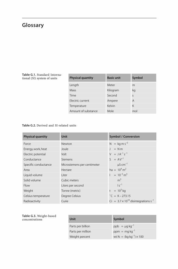
Physical quantity Basic unit Symbol
Length Meter m
Mass Kilogram kg
Time Second s
Electric current Ampere A
Temperature Kelvin K
Amount of substance Mole mol
Physical quantity Unit Symbol / Conversion
Force Newton N = kg m s–2
Energy, work, heat Joule J = N m
Electric potential Volt V = J A–1 s–1
Conductance Siemens S = A V–1
Specific conductance Microsiemens per centimeter µS cm–1
Area Hectare ha = 104 m2
Liquid volume Liter l = 10–3 m3
Solid volume Cubic meters m3
Flow Liters per second l s–1
Weight Tonne (metric) t = 103 kg
Celsius temperature Degree Celsius ˚C = K – 273.15
Radioactivity Curie Ci = 3.7 × 10¹⁰ disintegrations s–1
Unit Symbol
Parts per billion ppb = µg kg–1
Parts per million ppm = mg kg–1
Weight percent wt.% = (kg kg–1) × 100
Table G.1. Standard Interna-tional (SI) system of units
Table G.2. Derived and SI-related units
Table G.3. Weight-basedconcentrations
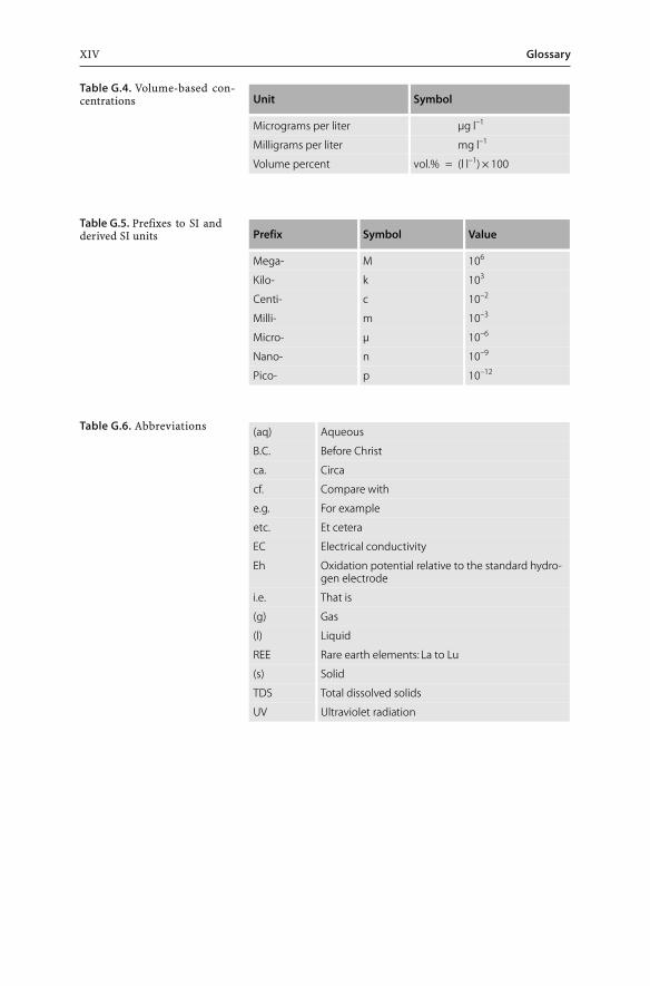
GlossaryXIV
Unit Symbol
Micrograms per liter µg l–1
Milligrams per liter mg l–1
Volume percent vol.% = (l l–1) × 100
Prefix Symbol Value
Mega- M 106
Kilo- k 103
Centi- c 10–2
Milli- m 10–3
Micro- µ 10–6
Nano- n 10–9
Pico- p 10–12
(aq) Aqueous
B.C. Before Christ
ca. Circa
cf. Compare with
e.g. For example
etc. Et cetera
EC Electrical conductivity
Eh Oxidation potential relative to the standard hydro-gen electrode
i.e. That is
(g) Gas
(l) Liquid
REE Rare earth elements: La to Lu
(s) Solid
TDS Total dissolved solids
UV Ultraviolet radiation
Table G.4. Volume-based con-centrations
Table G.5. Prefixes to SI andderived SI units
Table G.6. Abbreviations
Chapter 1
Introduction to Mine Wastes
1.1Scope of the Book
This book focuses on “problematic” solid wastes and waste waters produced and dis-posed of at modern mine sites. They are problematic because they contain hazardoussubstances (e.g. heavy metals, metalloids, radioactivity, acids, process chemicals), andrequire monitoring, treatment, and secure disposal. However, not all mine wastes areproblematic wastes and require monitoring or even treatment. Many mine wastes donot contain or release contaminants, are “inert” or “benign”, and pose no environmentalthreat. In fact, some waste rocks, soils or sediments can be used for landform recon-struction, others are valuable resources for road and dam construction, and a few aresuitable substrates for vegetation covers and similar rehabilitation measures upon mineclosure. Such materials cannot be referred to as wastes by definition as they representvaluable by-products of mining operations.
This books attempts to gather the scientific knowledge on problematic wastes ac-cumulating at modern mine sites. Wastes are also produced at mineral processingplants and smelter sites and include effluents, sludges, leached ore residues, slags, fur-nace dusts, filter cakes, and smelting residues. Such wastes are not mine wastes bydefinition as they generally do not accumulate at mine sites. Thus, this book largelyfocuses on mining wastes. It limits the presentation of mineral processing and metal-lurgical wastes to those waste types accumulating at or near mine sites. Readers inter-ested in the general areas of mineral processing and metallurgical wastes are advisedto consult the relevant literature (e.g. Petruk 1998).
Mine wastes are commonly classified according to their physical and chemical prop-erties and according to their source. Such a classification scheme is followed in thiswork. The book attempts to cover the major sources of mine wastes including themining of metal, energy and industrial mineral resources. Wastes of the petroleumindustry, in particular, wastes of the oil shale and oil sand industry, have been excludedas they are beyond the scope of this book. The book has been organized into sevenchapters which document the different sources and properties of mine wastes. Thecontents of Chapters Two (Sulfidic Mine Wastes), Three (Mine Water), Four (Tailings),and Five (Cyanidation Wastes of Gold-Silver Ores) are inherent to most metal and/orcoal mines. The contents of Chapter Six (Radioactive Wastes of Uranium Ores) are ofimportance to uranium mining operations, whereas Chapter Seven (Wastes of Phos-phate and Potash Ores) discusses topics that are relevant to the fertilizer producingindustry.
2 CHAPTER 1 · Introduction to Mine Wastes
1. Chapter 1 sets the scene as introduction. It gives important definitions, describes theenvironmental impacts of mine wastes in human history, presents the nature andscope of waste production in the mining industry, and lists the general resourcesavailable to acquire knowledge on mine wastes.
2. Chapter 2 provides an insight into sulfidic mine wastes. Mining of many metal oresand coal exposes and uncovers sulfide minerals to oxidizing conditions. This chap-ter documents the oxidation and weathering processes of sulfides which cause andinfluence acid mine drainage. This is followed by discussions of the available toolsto predict and to monitor the behaviour of acid generating wastes. The chapter alsolists the various technologies available for the control and prevention of sulfide oxi-dation.
3. Chapter 3 covers the fundamentals of acid mine waters. It explains important proc-esses occuring within such acid waters and documents predictive and monitoringtechniques. A documentation of technologies applied for the treatment of acid minedrainage completes the chapter.
4. Chapter 4 addresses the wastes of mineral processing operations (i.e. tailings). Thechapter presents the characteristics of tailings solids and liquids. It also gives de-tails on the disposal options of tailings whereby most tailings are stored in engineeredstructures, so-called “tailings storage facilities” or “tailings dams”.
5. Chapter 5 covers the characteristics of cyanide-bearing wastes which are producedduring the extraction of gold and silver. The chemistry of cyanide is explained be-fore the use of cyanide in the mineral industry is shown. A documentation of treat-ment options for cyanidation wastes concludes the chapter.
6. Chapter 6 summarizes radioactive wastes of uranium ores. It provides the minera-logical and geochemical characteristics of uranium ores and gives the principles ofradioactivity. The chapter describes uranium mine wastes and the techniques avail-able for their disposal and treatment. The potential hazards and environmental im-pacts of uranium mining have been discussed in some detail.
7. Chapter 7 describes wastes of the phosphate and potash mining and fertilizer pro-ducing industry. Phosphogypsum is the major waste product of fertilizer produc-tion. The characteristics, storage and disposal practices, and recycling options of thiswaste material are documented to some extent.
Sulfidic wastes and acid mine waters have been studied extensively from all scien-tific angles, and there is a vast literature on the subjects including books, reviews, tech-nical papers, conference proceedings, and web sites. On the other hand, wastes of pot-ash ores have received in comparison only limited attention. Such a disproportionateknowledge has influenced the presentation of this work and is reflected in the lengthof individual chapters.
Several chapters contain case studies and scientific issues which demonstrate par-ticular aspects of chapter topics in greater detail. Some case studies highlight the suc-cesses in handling mine wastes, others point to future opportunities, whereas somedocument the environmental impacts associated with them. The reasoning behind thisis that we have to learn not only from our successes but also from our mistakes in han-dling mine wastes. Most of all, we have to pursue alternative waste treatment, disposal,use and rehabilitation options.
31.2 · Definitions
1.2Definitions
1.2.1Mining Activities
Definitions are essential for clear communication especially when discussing techni-cal issues. Therefore, important and relevant terms have been defined in the follow-ing sections. Operations of the mining industry include mining, mineral processing,and metallurgical extraction. “Mining” is the first operation in the commercial exploi-tation of a mineral or energy resource. It is defined as the extraction of material fromthe ground in order to recover one or more component parts of the mined material.“Mineral processing” or “beneficiation” aims to physically separate and concentrate theore mineral(s), whereas “metallurgical extraction” aims to destroy the crystallographicbonds in the ore mineral in order to recover the sought after element or compound.At mine sites, mining is always associated with mineral processing of some form(e.g. crushing; grinding; gravity, magnetic or electrostatic separation; flotation). It issometimes accompanied by the metallurgical extraction of commodities such as gold,copper, nickel, uranium or phosphate (e.g. heap leaching; vat leaching; in situ leach-ing).
All three principal activities of the mining industry – mining, mineral processing,and metallurgical extraction – produce wastes. “Mine wastes” are defined herein assolid, liquid or gaseous by-products of mining, mineral processing, and metallurgicalextraction. They are unwanted, have no current economic value and accumulate at minesites.
1.2.2Metals, Ores and Industrial Minerals
Many mine wastes, especially those of the metal mining industry, contain metals and/ormetalloids at elevated concentrations. There is some confusion in the literature overthe use of the terms “metals”, “metalloids”, “semi-metals”, “heavy metals” and “basemetals”. Metals are defined as those elements which have characteristic chemical andphysical properties (e.g. elements with the ability to lose one or more electrons; abil-ity to conduct heat and electricity; ductility; malleability). In contrast, metalloids orsemi-metals are elements with metallic and non-metallic properties; that is, arsenic,antimony, bismuth, selenium, and tellurium (e.g. elements with the ability to gain oneor more electrons; lower ability to conduct heat and electricity than metals). Heavymetals are those metals with a density greater than 6 g cm–3 (i.e. Fe, Cu, Pb, Zn, Sn, Ni,Co, Mo, W, Hg, Cd, In, Tl) (Thornton et al. 1995). The term “heavy metals” is used inthis work reluctantly because there are alternative, scientifically rigorous definitions(Hodson 2004). Base metals are those metals used in industry by themselves ratherthan alloyed with other metals (i.e. Cu, Pb, Zn, Sn).
In most metal ores, the metals are found in chemical combination with other ele-ments forming metal-bearing “ore minerals” such as oxides or sulfides. Ore mineralsare defined as minerals from which elements can be extracted at a reasonable profit.
4 CHAPTER 1 · Introduction to Mine Wastes
In contrast, “industrial minerals” are defined as any rock or mineral of economic valueexcluding metallic ores, mineral fuels, and gemstones. The mineral or rock itself or acompound derived from the mineral or rock has an industrial use. Ore and industrialminerals are commonly intergrown on a microscopic or even sub-microscopic scalewith valueless minerals, so-called “gangue minerals”. The aggregate of ore mineralsor industrial minerals and gangue minerals is referred to as “ore”. Thus, ore is a rock,soil or sediment that contains economically recoverable levels of metals or minerals.Mining results in the extraction of ore/industrial minerals and gangue minerals. Min-eral processing enriches the ore/industrial mineral and rejects unwanted gangue min-erals. Finally, metallurgical extraction destroys the crystallographic bonds of miner-als and rejects unwanted elements.
1.2.3Mine Wastes
Mining, mineral processing, and metallurgical extraction produce solid, liquid andgaseous wastes. Mine wastes can be further classified as solid mining, processing andmetallurgical wastes and mine waters (Table 1.1):
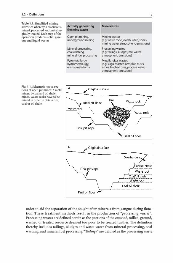
� Mining wastes. Mining wastes either do not contain ore minerals, industrial miner-als, metals, coal or mineral fuels, or the concentration of the minerals, metals, coalor mineral fuels is subeconomic. For example, the criterion for the separation of wasterock from metalliferous ore and for the classification of materials as economic orsubeconomic is the so-called “cut-off grade”. It is based on the concentration of theore element in each unit of mined rock and on the cost of mining that unit. As a re-sult, every mine has a different criterion for separating mining waste from ore.Mining wastes include overburden and waste rocks excavated and mined from sur-face and underground operations. Waste rock is essentially wall rock material re-moved to access and mine ore (Fig. 1.1). In coal mining, waste rocks are referred toas “spoils”.
Mining wastes are heterogeneous geological materials and may consist of sedi-mentary, metamorphic or igneous rocks, soils, and loose sediments. As a conse-quence, the particle sizes range from clay size particles to boulder size fragments.The physical and chemical characteristics of mining wastes vary according to theirmineralogy and geochemistry, type of mining equipment, particle size of the minedmaterial, and moisture content. The primary sources for these materials are rock,soil, and sediment from surface mining operations, especially open pits, and to alesser degree rock removed from shafts, haulageways, and underground workings(Hassinger 1997).
Once the metalliferous ore, coal, industrial minerals or mineral fuels are mined,they are processed to extract the valuable commodity. In contrast, mining wastesare placed in large heaps on the mining lease. Nearly all mining operations gener-ate mining wastes, often in very large amounts.
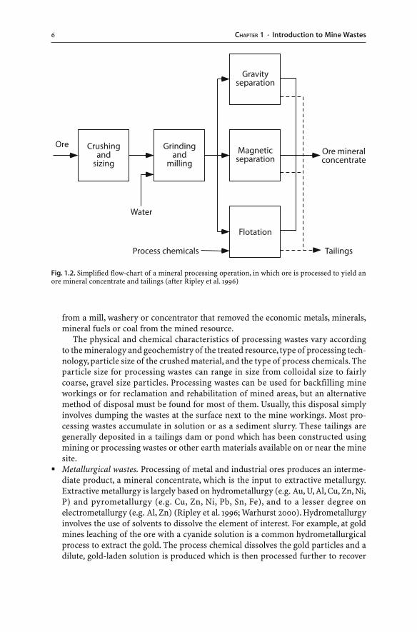
� Processing wastes. Ore is usually treated in a physical process called beneficiation ormineral processing prior to any metallurgical extraction (Fig. 1.2). Mineral process-ing techniques may include: simple washing of the ore; gravity, magnetic, electricalor optical sorting; and the addition of process chemicals to crushed and sized ore in
51.2 · Definitions
order to aid the separation of the sought after minerals from gangue during flota-tion. These treatment methods result in the production of “processing wastes”.Processing wastes are defined herein as the portions of the crushed, milled, ground,washed or treated resource deemed too poor to be treated further. The definitionthereby includes tailings, sludges and waste water from mineral processing, coalwashing, and mineral fuel processing. “Tailings” are defined as the processing waste
Fig. 1.1. Schematic cross-sec-tions of open pit mines: a metalmines; b coal and oil shalemines. Waste rocks have to bemined in order to obtain ore,coal or oil shale
Table 1.1. Simplified miningactivities whereby a resource ismined, processed and metallur-gically treated. Each step of theoperation produces solid, gase-ous and liquid wastes
6 CHAPTER 1 · Introduction to Mine Wastes
from a mill, washery or concentrator that removed the economic metals, minerals,mineral fuels or coal from the mined resource.
The physical and chemical characteristics of processing wastes vary accordingto the mineralogy and geochemistry of the treated resource, type of processing tech-nology, particle size of the crushed material, and the type of process chemicals. Theparticle size for processing wastes can range in size from colloidal size to fairlycoarse, gravel size particles. Processing wastes can be used for backfilling mineworkings or for reclamation and rehabilitation of mined areas, but an alternativemethod of disposal must be found for most of them. Usually, this disposal simplyinvolves dumping the wastes at the surface next to the mine workings. Most pro-cessing wastes accumulate in solution or as a sediment slurry. These tailings aregenerally deposited in a tailings dam or pond which has been constructed usingmining or processing wastes or other earth materials available on or near the minesite.
� Metallurgical wastes. Processing of metal and industrial ores produces an interme-diate product, a mineral concentrate, which is the input to extractive metallurgy.Extractive metallurgy is largely based on hydrometallurgy (e.g. Au, U, Al, Cu, Zn, Ni,P) and pyrometallurgy (e.g. Cu, Zn, Ni, Pb, Sn, Fe), and to a lesser degree onelectrometallurgy (e.g. Al, Zn) (Ripley et al. 1996; Warhurst 2000). Hydrometallurgyinvolves the use of solvents to dissolve the element of interest. For example, at goldmines leaching of the ore with a cyanide solution is a common hydrometallurgicalprocess to extract the gold. The process chemical dissolves the gold particles and adilute, gold-laden solution is produced which is then processed further to recover
Fig. 1.2. Simplified flow-chart of a mineral processing operation, in which ore is processed to yield anore mineral concentrate and tailings (after Ripley et al. 1996)
71.2 · Definitions
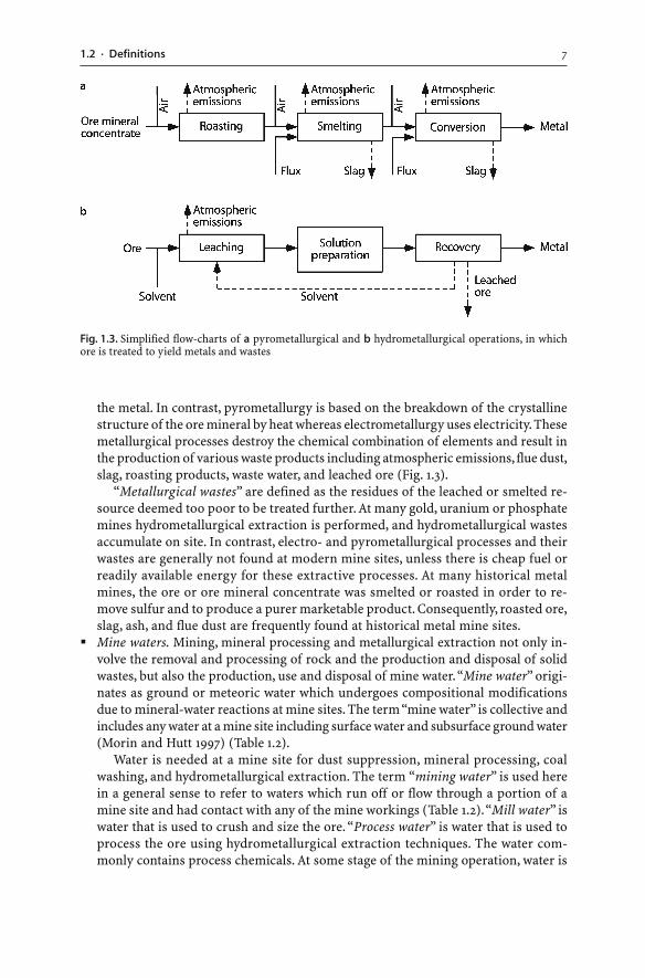
the metal. In contrast, pyrometallurgy is based on the breakdown of the crystallinestructure of the ore mineral by heat whereas electrometallurgy uses electricity. Thesemetallurgical processes destroy the chemical combination of elements and result inthe production of various waste products including atmospheric emissions, flue dust,slag, roasting products, waste water, and leached ore (Fig. 1.3).
“Metallurgical wastes” are defined as the residues of the leached or smelted re-source deemed too poor to be treated further. At many gold, uranium or phosphatemines hydrometallurgical extraction is performed, and hydrometallurgical wastesaccumulate on site. In contrast, electro- and pyrometallurgical processes and theirwastes are generally not found at modern mine sites, unless there is cheap fuel orreadily available energy for these extractive processes. At many historical metalmines, the ore or ore mineral concentrate was smelted or roasted in order to re-move sulfur and to produce a purer marketable product. Consequently, roasted ore,slag, ash, and flue dust are frequently found at historical metal mine sites.
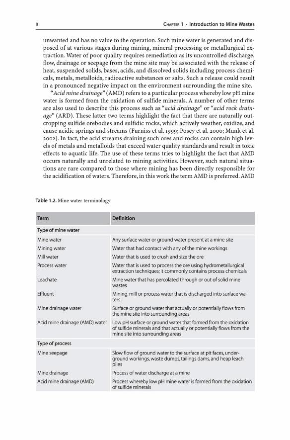
� Mine waters. Mining, mineral processing and metallurgical extraction not only in-volve the removal and processing of rock and the production and disposal of solidwastes, but also the production, use and disposal of mine water. “Mine water” origi-nates as ground or meteoric water which undergoes compositional modificationsdue to mineral-water reactions at mine sites. The term “mine water” is collective andincludes any water at a mine site including surface water and subsurface ground water(Morin and Hutt 1997) (Table 1.2).
Water is needed at a mine site for dust suppression, mineral processing, coalwashing, and hydrometallurgical extraction. The term “mining water” is used herein a general sense to refer to waters which run off or flow through a portion of amine site and had contact with any of the mine workings (Table 1.2). “Mill water” iswater that is used to crush and size the ore. “Process water” is water that is used toprocess the ore using hydrometallurgical extraction techniques. The water com-monly contains process chemicals. At some stage of the mining operation, water is
Fig. 1.3. Simplified flow-charts of a pyrometallurgical and b hydrometallurgical operations, in whichore is treated to yield metals and wastes
8 CHAPTER 1 · Introduction to Mine Wastes
unwanted and has no value to the operation. Such mine water is generated and dis-posed of at various stages during mining, mineral processing or metallurgical ex-traction. Water of poor quality requires remediation as its uncontrolled discharge,flow, drainage or seepage from the mine site may be associated with the release ofheat, suspended solids, bases, acids, and dissolved solids including process chemi-cals, metals, metalloids, radioactive substances or salts. Such a release could resultin a pronounced negative impact on the environment surrounding the mine site.
“Acid mine drainage” (AMD) refers to a particular process whereby low pH minewater is formed from the oxidation of sulfide minerals. A number of other termsare also used to describe this process such as “acid drainage” or “acid rock drain-age” (ARD). These latter two terms highlight the fact that there are naturally out-cropping sulfide orebodies and sulfidic rocks, which actively weather, oxidize, andcause acidic springs and streams (Furniss et al. 1999; Posey et al. 2000; Munk et al.2002). In fact, the acid streams draining such ores and rocks can contain high lev-els of metals and metalloids that exceed water quality standards and result in toxiceffects to aquatic life. The use of these terms tries to highlight the fact that AMDoccurs naturally and unrelated to mining activities. However, such natural situa-tions are rare compared to those where mining has been directly responsible forthe acidification of waters. Therefore, in this work the term AMD is preferred. AMD
Table 1.2. Mine water terminology
91.3 · Mine Waste Production
is still an unfortunate term since AMD impacts more frequently on ground waterquality than on the surface drainage from a mine (Bennett and Ritchie 1993). Suchimpacted ground water has also been named “acid ground water” (AG). Finally, thewaters generated by the oxidation of sulfide minerals are also referred to by someauthors as “acid sulfate waters” (ASW).
1.3Mine Waste Production
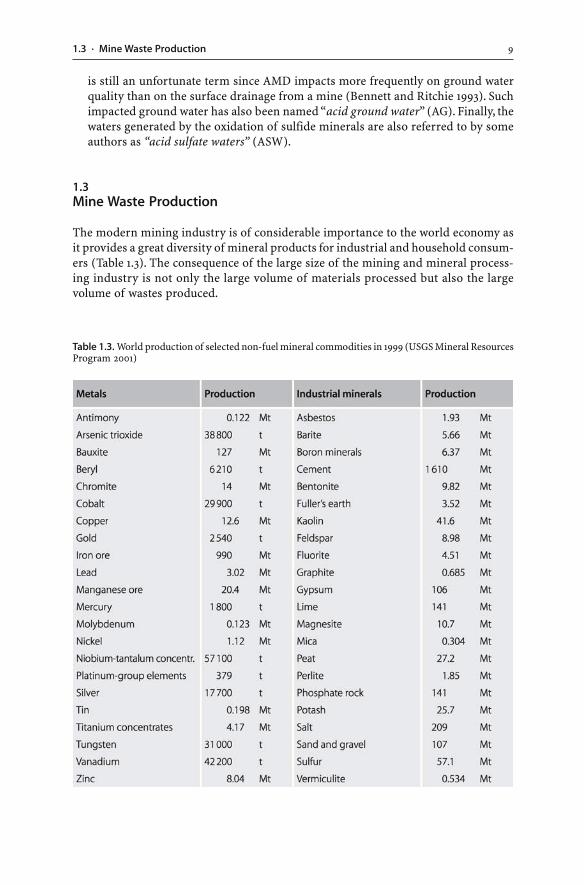
The modern mining industry is of considerable importance to the world economy asit provides a great diversity of mineral products for industrial and household consum-ers (Table 1.3). The consequence of the large size of the mining and mineral process-ing industry is not only the large volume of materials processed but also the largevolume of wastes produced.
Table 1.3. World production of selected non-fuel mineral commodities in 1999 (USGS Mineral ResourcesProgram 2001)
10 CHAPTER 1 · Introduction to Mine Wastes
The exploitation of mineral resources results in the production of large volumes ofwaste rocks as they have to be removed to access the resource. Once the resource hasbeen extracted from the Earth, it is processed for its valuable components. These valu-able components vary in mass from 100% to a few parts per million of the originalresource. For instance, extraction and production of clay, sand and gravel generallydo not produce any waste. Operators extract and process the entire mined material.Also, crushing, washing and sizing of rock aggregates generate only minor amountsof unwanted fine-grained slimes and dust particles. These slimes and dust particlescan be put to good use as mineral fertilizer. In contrast, exploitation of a metallifer-ous mineral resource aims to extract only a few percent concentrations of copper, leador zinc or even parts per million values of gold. Only a very small valuable componentis extracted from metalliferous ores during processing and metallurgical extraction.The great majority of the total mined material is gangue which is generally rejectedas processing and metallurgical waste. Therefore, mining, mineral processing, andmetallurgical extraction result in the production of a high volume of unwanted mate-rial.
In general, coal mining and processing generate the largest quantity of waste fol-lowed by non-ferrous and ferrous ores and industrial minerals. Waste production variesgreatly from nation to nation. For example, more than 4 700 Mt of mining waste and1 200 Mt of tailings are stored all over the European Union, most of the mine waste inFinland, Germany, Greece, Ireland, Portugal, Spain, Sweden, and the United Kingdom(BRGM 2000). The production of mine wastes is particularly significant in nationswith a major mining industry. In Australia, the mining industry produces 1 750 Mt ofmine wastes per year. It is by far the largest producer of solid, liquid and gaseous wasteand exceeds municipal waste production by at least 450 Mt. Of the 2 100 Mt of solidwaste generated annually in Australia, 80% is produced by the mining sector (Connoret al. 1995; cited by Boger 1998). In South Africa, over 1 100 mines contribute to 72.3%of the country’s total solid waste stream, with approximately 25 000 ha of land utilizedas dumping areas in the form of tailings storage facilities (Maboeta and Rensburg2003).
The global quantity of non-fuel mineral commodities removed from the Earth’scrust each year by mining is now of the order of 3 700 Mt (Table 1.3). While the con-sumption of mineral commodities is well documented, there is no data available onthe global production of mine wastes. Therefore, an estimation of the annual quantityof mine waste produced globally has to be based on several assumptions. In 1999, ap-proximately 40 Mt of metals (As, Be, Co, Cr, Cu, Hg, Nb, Ni, Pb, Sb, Sn, Ta, V, W, Zn)were produced worldwide (Table 1.3). Assuming that the average ore grade of the metaldeposits was 0.5%, mining, processing and extraction of the ores generated 8 000 Mtof solid wastes. Similarly, the production of 2 540 t of gold generated about 1 250 Mt ofsolid wastes, assuming an average gold ore grade of 2 ppm. In addition, every yearapproximately 4 500 Mt of coal, 990 Mt of iron ore, 127 Mt of bauxite, and 2 500 Mt ofindustrial minerals are consumed globally. For every tonne of these ores consumed,there will be at least the same amount of solid waste generated (i.e. waste rocks, tail-ings). Such calculations indicate that approximately 15 000 to 20 000 Mt of solid minewastes are being produced annually around the world.
These calculations and statistics represent approximations and can only serve asan indication of the magnitude of waste production. Furthermore, every mine site has
111.4 · Mine Wastes: Unwanted By-Products or Valuable Resources?
its own unique waste because there are compositional differences in the mined ore,and there is a great diversity of applied mining and mineral processing methods. Wastesgenerated at different mines vary considerably in their properties. While certain sci-entific principles apply to particular commodities, every mine requires its very ownwaste characterization, prediction, monitoring, control, and treatment.
Mine wastes represent the greatest proportion of waste produced by industrial ac-tivity. In fact, the quantity of solid mine waste and the quantity of Earth’s materialsmoved by fundamental global geological processes are of the same order of magni-tude – approximately several thousand million tonnes per year (Fyfe 1981; Förstner1999). Fundamental global geological processes such as oceanic crust formation, soilerosion, sediment discharge to the oceans, and mountain building naturally moveEarth’s materials around the Earth’s crust and shape our planet. In contrast, mankindextracts material from the Earth during mining and discards most of the extractedcrust as waste. As a result, the Earth is getting increasingly shaped by mine wastes ratherthan by natural geological processes. In addition, metal ores of increasingly lowergrades are being exploited, and more wastes are being produced as a result of it. Theproduction of mine wastes may even double within a period of 20 to 30 years (Förstner1999). Today and in the future, commercial exploitation of a mineral resource is aboutwaste production and waste disposal as well as resource production and provision.
1.4Mine Wastes: Unwanted By-Products or Valuable Resources?
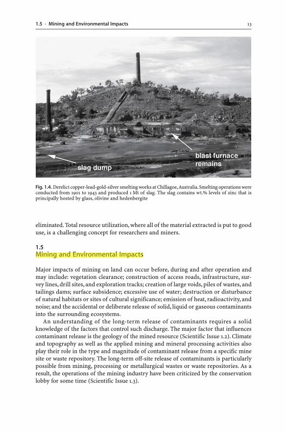
The term “mine waste” implies that the material has no current economic value and isan unwanted by-product of mining. However, some mine wastes can be useful and thishas been recognized since the beginning of mining and smelting. For example, theuse of slag in road construction can be traced back to the very early days when theRomans used iron slag as a pavement material for their roads. Also, while wastes ofthe mineral industry are generally useless at the time of production, they can still berich in resource ingredients. Unfavourable economics, inefficient processing, techno-logical limitations or mineralogical factors may not have allowed the complete extrac-tion of resource ingredients at the time of mining. In the past, inefficient mineral pro-cessing techniques and poor metal recoveries produced wastes with relatively highmetal concentrations (Scientific Issue 1.1; Fig. 1.4). In some cases, old tailings and wasterock piles that were considered worthless years ago are now “re-mined”, feeding mod-ern mining operations. This approach is widely used in the mining industry.
Hence, changing circumstances may turn a particular waste into a valuable com-modity, either because the economic extraction of resource ingredients may now bepossible using improved technology, or a market has been found for the previouslyunwanted material. What may be waste to some miners, can be a very important, use-ful resource to other mining operations, either now or in the future. Yesterday’s wastecan become today’s resource.
Recycling today’s waste is similarly possible. Manganese tailings may be used inagro-forestry, building and construction materials, coatings, resin cast products, glass,ceramics, and glazes (Verlaan and Wiltshire 2000). Tailings can also be suitable fertil-izers for golf courses; phosphogypsum can be used in the agricultural and the build-ing industry; clay-rich wastes can improve sandy soils or are the raw material for brick
12 CHAPTER 1 · Introduction to Mine Wastes
manufacturing; mine waters can be converted into drinking water (Schwartz andPloethner 2000; Smit 2000; Varnell et al. 2004); mine water can be used for heating orcooling purposes (Banks et al. 2004; Watzlaf and Ackman 2006); mine drainage slud-ges can be a resource for pigment (Kirby et al. 1999); and pyritic waste rock can be anexcellent soil amendment to neutralize infertile alkaline agricultural soils (Castelo-Branco et al. 1999). If such innovative alternatives to current waste disposal practicesare pursued and if wastes are used as raw materials, then waste disposal problems are
131.5 · Mining and Environmental Impacts
eliminated. Total resource utilization, where all of the material extracted is put to gooduse, is a challenging concept for researchers and miners.
1.5Mining and Environmental Impacts
Major impacts of mining on land can occur before, during and after operation andmay include: vegetation clearance; construction of access roads, infrastructure, sur-vey lines, drill sites, and exploration tracks; creation of large voids, piles of wastes, andtailings dams; surface subsidence; excessive use of water; destruction or disturbanceof natural habitats or sites of cultural significance; emission of heat, radioactivity, andnoise; and the accidental or deliberate release of solid, liquid or gaseous contaminantsinto the surrounding ecosystems.
An understanding of the long-term release of contaminants requires a solidknowledge of the factors that control such discharge. The major factor that influencescontaminant release is the geology of the mined resource (Scientific Issue 1.2). Climateand topography as well as the applied mining and mineral processing activities alsoplay their role in the type and magnitude of contaminant release from a specific minesite or waste repository. The long-term off-site release of contaminants is particularlypossible from mining, processing or metallurgical wastes or waste repositories. As aresult, the operations of the mining industry have been criticized by the conservationlobby for some time (Scientific Issue 1.3).
Fig. 1.4. Derelict copper-lead-gold-silver smelting works at Chillagoe, Australia. Smelting operations wereconducted from 1901 to 1943 and produced 1 Mt of slag. The slag contains wt.% levels of zinc that isprincipally hosted by glass, olivine and hedenbergite
14 CHAPTER 1 · Introduction to Mine Wastes
151.5 · Mining and Environmental Impacts
16 CHAPTER 1 · Introduction to Mine Wastes
1.5.1Contamination and Pollution
Much of the environmental impacts of mining are associated with the release of harm-ful elements from mine wastes. Mine wastes pose a problem not just because of their
171.5 · Mining and Environmental Impacts
sheer volume and aerial extent, but because some of them may impact on local eco-systems. As a result, in many cases mine wastes must be isolated or treated to reduceoxidation, toxicity, erosion or unsightliness and to allow the waste repositories to beused for other purposes after mining ceases. If uncontrolled disposal of mine wastesoccurs, it can be associated with increased turbidity in receiving waters or with therelease of significant quantities of potentially harmful elements, acidity or radioac-tivity. These contaminants may spread to the pedosphere, biosphere, atmosphere, andhydrosphere and cause environmental effects. For example, anthropogenic inputs ofmetals and metalloids to atmospheric, terrestrial and aquatic ecosystems as a resultof mining have been estimated to be at several million kilograms per year (Nriaguand Pacyna 1988; Smith and Huyck 1999).
However, it is important to understand that releases of elements or compounds frommine wastes do not necessarily result in damage to the environment. Even if stronglyelevated metal and metalloid concentrations are present in mine wastes, the elementsmay not be readily bioavailable (i.e. available for uptake into the organism) (Williamset al. 1999). Furthermore, even if the elements are bioavailable, they are not necessar-ily taken up by plants and animals. In cases where the elements are taken up, they donot necessarily lead to toxicity. Many metals are essential for cellular functions andare required by organisms at low concentrations (Smith and Huyck 1999). It is onlywhen these bioavailable concentrations are excessively high that they have a negative
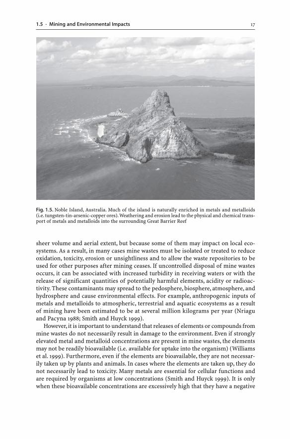
Fig. 1.5. Noble Island, Australia. Much of the island is naturally enriched in metals and metalloids(i.e. tungsten-tin-arsenic-copper ores). Weathering and erosion lead to the physical and chemical trans-port of metals and metalloids into the surrounding Great Barrier Reef
18 CHAPTER 1 · Introduction to Mine Wastes
impact on the health of the organism and toxicity might be seen. Processes that causetoxicity, disrupt ecological processes, inflict damage to infrastructure, or pose a haz-ard to human health are referred to as pollution (Thornton et al. 1995). In contrast,contamination refers to processes which do not cause harmful effects (Thornton et al.1995).
Environmental contamination and pollution as a result of improper mining, smelt-ing and waste disposal practices have occurred and still occur around the world. Prob-lems encountered are as diverse as the emissions from smelters, or the environmentalclean-up of collapsed mining ventures which have to be paid for by the taxpayer. Thisis unacceptable to those of us who believe that technologies can be used to preventpollution and regulations should be enforced to ensure that the environmental per-formance of companies is adequate. Regardless of this debate, the challenges for themodern mining industry will remain the same:
� To continue to improve its environmental operations� To operate in a sustainable manner� To prove its critics wrong
1.5.2Historic Mining
Mining has been with us for thousands of years. Even the earliest mining operationsduring the Copper, Bronze and Iron Ages resulted in the production of gaseous, liquidand solid wastes. In historic times, mine wastes were released into the environmentwith some of them causing contamination or even pollution on a local or regional scale.Environmental contamination as a result of mining is not new to the industrialized world.
Air contamination as a result of smelting has been detected as far back as 5 000 yearsago. Stratigraphic and physicochemical investigations of numerous European peat bogshave confirmed that smelting of sulfide minerals led to metal contamination of theenvironment (Shotyk et al. 1996; Ernst 1998). For example, the smelting of lead-richsilver ore in Spain by the Romans 2 000 years ago quadrupled the levels of lead in theatmosphere as far away as Greenland (Rosman et al. 1997). Generally, the smelting ofsulfide ore in open air furnaces by the Greeks and Romans resulted in a vast area ofthe Northern Hemisphere being showered with metal-rich dust (Hong et al. 1996;Shotyk et al. 1996; Rosman et al. 1997). Human contamination of the atmosphere witharsenic, antimony, copper, mercury, lead and zinc, at least in the Northern Hemisphere,began well before the Industrial Revolution.
Water and sediment contamination and pollution are similarly not a by-productof industrialization. For example, soil erosion began with clearing of land and primi-tive agricultural practices 5 000 years ago (Lottermoser et al. 1997a), and metal min-ing in the northern Harz province of Germany resulted in metal pollution of regionalstream sediments as far back as 3 500 years ago (Monna et al. 2000). Similarly, exploita-tion of the Rio Tinto ores in Spain has caused massive metal contamination of streamand estuary sediments since the Copper Age 5 000 years ago (Leblanc et al. 2000; Daviset al. 2000).
Acid mine drainage resulting from the oxidation of sulfides in mine wastes is a majorenvironmental issue facing the mining industry today. This pollution process has a
191.5 · Mining and Environmental Impacts
long history dating back thousands of years when the Rio Tinto mining district of Spainexperienced periods of intense mining and the associated production of pyrite-richwastes and AMD waters. AMD production must have been occurring at least since thefirst exploitation of the Rio Tinto ores 5 000 years ago, which highlights the long-termnature of AMD.
The knowledge that mining and smelting may lead to environmental impacts is notnew to modern science either. The Greek philosopher Theophrastus (ca. 325 B.C.) rec-ognized the oxidation of pyrite, the formation of metal salts and the production ofacid. During the Middle Ages, AMD in central Europe was documented by Agricolawho wrote the first systematic book on mining and metallurgy. In this 16th centuryclassic, Agricola (1556) also recognized the environmental effects of ubiquitous min-ing in central Europe and described mining pollution:
“The fields are devastated by mining operations … Further, when the ores are washed, the waterwhich has been used poisons the brooks and streams, and either destroys the fish or drives themaway. Therefore the inhabitants of these regions, on account of the devastation of their fields, woods,groves, brooks and rivers, find great difficulty in procuring the necessaries of life, and by reasonof the destruction of the timber they are forced to greater expense in erecting buildings. Thus itis said, it is clear to all that there is greater detriment from mining than the value of the metalswhich the mining produces.” (Reprinted from Agricola 1556, De re metallica, p. 8. Translated byHoover HC, Hoover LH, 1950, Dover Publications, New York, with permission of the publisher)
As the scale of mining increased during the Middle Ages, so did the degree of con-tamination and pollution (Ernst 1998). Coupled with this increase in scale camechanges in smelting and processing techniques, including the use of chemicals andthe transport of ores and concentrates over greater distances. However, it was not un-til the Industrial Revolution, with the event of major technological changes includingthe introduction of blast furnaces, that base metal smelter operations throughout theworld became one of the primary sources of metal contamination (Ernst 1998). Whenthis large-scale smelting technique was developed, contamination became even largerin scale. The smelting process released massive amounts of sulfur dioxide and metalsinto the atmosphere (Fig. 1.6). These activities resulted in ever-increasing environmen-tal impacts which largely went unchecked until the second half of the 19th century(Case Study 1.1). Until then environmental impacts of mining and mineral processingwere poorly understood, not regulated, or viewed as secondary in importance to re-source extraction and profit maximization. The advent of environmental laws and regu-lations in the 20th century made the mining industry more accountable and enforcedenvironmental protection (Fig. 1.7).
The concern for the health of miners has evolved in parallel with mining develop-ment, particularly in respect to the exposure of humans to mercury and arsenic. Mer-cury deposits in the Mediterranean were first worked by the Phoenicians, Carthaginians,Etruscans and Romans, who used the ore as a red pigment for paint and cosmetics. Toprotect local workers and the environment, the Italian mines were closed by the Ro-mans (Ferrara 1999). The mercury was then mined by slaves in occupied Spain.
Mercury has also been used for nearly 3 000 years to concentrate and extract goldand silver from geological ores (Lacerda and Salomons 1997). The use of mercury ingold mining is associated with significant releases of mercury into the environmentand with an uptake of mercury by humans during the mining and roasting processes(Lacerda and Salomons 1997). Around 2 100 years ago, Roman authorities were import-
20 CHAPTER 1 · Introduction to Mine Wastes
ing mercury from Spain to be used in gold mining in Italy. Curiously, after less than100 years, the use of mercury in gold mining was forbidden in mainland Italy andcontinued in the occupied territories. It is quite possible that this prohibition was al-ready a response to environmental health problems caused by the mercury process(Lacerda and Salomons 1997).
The above mentioned practice to enforce mining operations in occupied territo-ries with no environmental management and no regard for the health of local minershas continued into modern times. For example, the former Soviet Union conductedmining in occupied East Germany from 1946 to 1990. Environmental management ofmining and proper waste disposal did not occur, local uranium miners were exposedto deadly radiation levels, and poor regard for the environment left an environmentaldisaster on a massive scale (Case Study 6.1).
1.5.3Present-Day Unregulated Mining
Today, mines wastes are produced around the world in nearly all countries. In manydeveloping countries, the exploitation of mineral resources is of considerable impor-tance for economic growth, employment and infrastructure development. In these
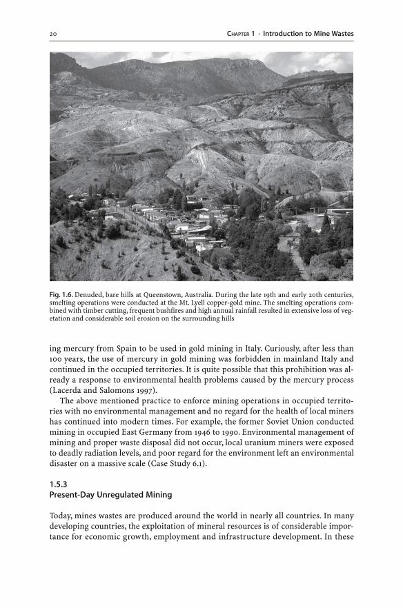
Fig. 1.6. Denuded, bare hills at Queenstown, Australia. During the late 19th and early 20th centuries,smelting operations were conducted at the Mt. Lyell copper-gold mine. The smelting operations com-bined with timber cutting, frequent bushfires and high annual rainfall resulted in extensive loss of veg-etation and considerable soil erosion on the surrounding hills
211.5 · Mining and Environmental Impacts
developing nations and in former communist states the environmental managementof municipal, industrial and mine wastes is often unregulated, lax, not enforced oroverruled for economic reasons. Strict environmental management of wastes and regu-lation of mining still remains a luxury of wealthy industrialized nations.
Many of the world’s poorest countries and communities are effected by artisanmining and the associated uncontrolled release of mine wastes. Operations are referredto as artisan when the applied mining techniques are primitive and do not employmodern technology. Such small-scale mining has been estimated to account for 15 to20% of the world’s non-fuel mineral production (Kafwembe and Veasey 2001). Arti-san mining is highly labour intensive and employs 11.5 to 13 million people worldwide,and up to 100 million people are estimated to depend on small-scale mining for theirlivelihood (Kafwembe and Veasey 2001). The largely unregulated mining practices andassociated uncontrolled release of mine wastes cause environmental harm. One ex-ample is the use of mercury in gold mining.
Gold mining and extraction have been with us for over 3 000 years. In the past muchof the gold has been exploited either by physically concentrating the gold particlesand/or by applying mercury. From the late 19th century onwards, mercury was nolonger used since cyanide leaching was invented which allowed large-scale gold min-ing operations. In the 1970s, the mercury process was reintroduced in developing coun-tries like Brazil, Bolivia, Venezuela, Peru, Ecuador, Colombia, French Guyana, Indone-
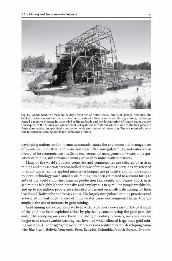
Fig. 1.7. Abandoned tin dredge in the dry stream bed of Nettle Creek, Innot Hot Springs, Australia. Thebucket dredge was used in the 20th century to extract alluvial cassiterite. During mining, the dredgecaused a massive increase in suspended sediment loads and the deterioration of stream water quality.Consequently, the Mining Act Amendment Act 1948 was introduced which is one of the first pieces ofAustralian legislation specifically concerned with environmental protection. The act required opera-tors to construct settling ponds for turbid mine waters
22 CHAPTER 1 · Introduction to Mine Wastes
sia, Ghana, and the Philippines. Here, individual artisanal miners use mercury becauseits application is cheap, reliable and simple (Salomons 1995; Lacerda and Salomons
231.5 · Mining and Environmental Impacts
1997). However, the unregulated mining practices have caused mercury contamina-tion of rivers such as the Amazon on a massive scale (Case Study 1.2).
1.5.4Regulation of Modern Mining
The present-day worldwide utilization of mercury by individual miners is a good ex-ample of how unregulated mining by non-professionals causes harm to humans andthe environment. In contrast, many modern mines particularly in industrialized na-
24 CHAPTER 1 · Introduction to Mine Wastes
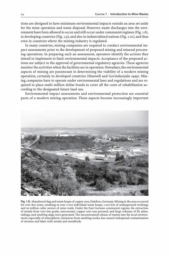
tions are designed to have minimum environmental impacts outside an area set asidefor the mine operation and waste disposal. However, waste discharges into the envi-ronment have been allowed to occur and still occur under communist regimes (Fig. 1.8),in developing countries (Fig. 1.9), and also in industrialized nations (Fig. 1.10), and thuseven in countries where the mining industry is regulated.
In many countries, mining companies are required to conduct environmental im-pact assessments prior to the development of proposed mining and mineral process-ing operations. In preparing such an assessment, operators identify the actions theyintend to implement to limit environmental impacts. Acceptance of the proposed ac-tions are subject to the approval of governmental regulatory agencies. These agenciesmonitor the activities when the facilities are in operation. Nowadays, the environmentalaspects of mining are paramount in determining the viability of a modern miningoperation, certainly in developed countries (Maxwell and Govindarajalu 1999). Min-ing companies have to operate under environmental laws and regulations and are re-quired to place multi million dollar bonds to cover all the costs of rehabilitation ac-cording to the designated future land use.
Environmental impact assessments and environmental protection are essentialparts of a modern mining operation. These aspects become increasingly important
Fig. 1.8. Abandoned slag and waste heaps of copper ores, Eisleben, Germany. Mining in the area occurredfor over 800 years, resulting in over 2 000 individual waste heaps, 1 000 km of underground workingsand 56 million cubic metere of mine voids. Under the East German communist regime, the extractionof metals from very low grade, uneconomic copper ores was pursued, and large volumes of fly ashes,tailings, and smelting slags were generated. The unconstrained release of wastes into the local environ-ment, especially of atmospheric emissions from smelting works, has caused widespread contaminationof streams and lakes with metals and metalloids
251.5 · Mining and Environmental Impacts
as waste production in the mining industry is significant in volume and diverse incomposition when compared to other industries. However, the demands on the min-ing industry are the same as they are for all industries producing waste:
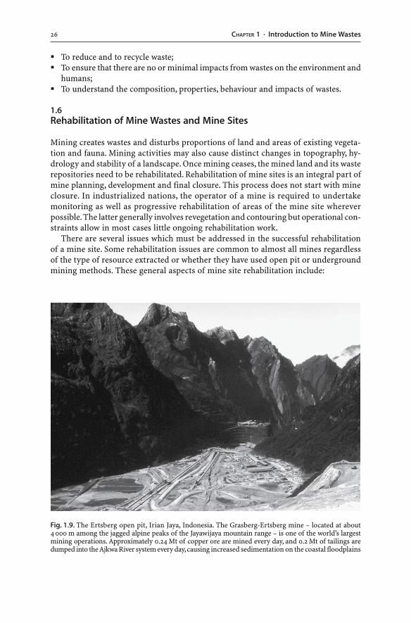
26 CHAPTER 1 · Introduction to Mine Wastes
� To reduce and to recycle waste;� To ensure that there are no or minimal impacts from wastes on the environment and
humans;� To understand the composition, properties, behaviour and impacts of wastes.
1.6Rehabilitation of Mine Wastes and Mine Sites
Mining creates wastes and disturbs proportions of land and areas of existing vegeta-tion and fauna. Mining activities may also cause distinct changes in topography, hy-drology and stability of a landscape. Once mining ceases, the mined land and its wasterepositories need to be rehabilitated. Rehabilitation of mine sites is an integral part ofmine planning, development and final closure. This process does not start with mineclosure. In industrialized nations, the operator of a mine is required to undertakemonitoring as well as progressive rehabilitation of areas of the mine site whereverpossible. The latter generally involves revegetation and contouring but operational con-straints allow in most cases little ongoing rehabilitation work.
There are several issues which must be addressed in the successful rehabilitationof a mine site. Some rehabilitation issues are common to almost all mines regardlessof the type of resource extracted or whether they have used open pit or undergroundmining methods. These general aspects of mine site rehabilitation include:
Fig. 1.9. The Ertsberg open pit, Irian Jaya, Indonesia. The Grasberg-Ertsberg mine – located at about4 000 m among the jagged alpine peaks of the Jayawijaya mountain range – is one of the world’s largestmining operations. Approximately 0.24 Mt of copper ore are mined every day, and 0.2 Mt of tailings aredumped into the Ajkwa River system every day, causing increased sedimentation on the coastal floodplains
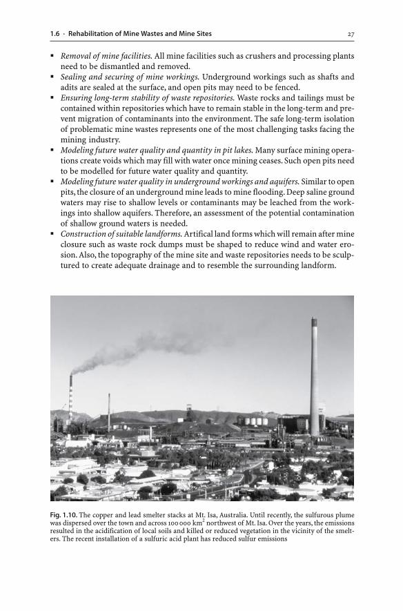
271.6 · Rehabilitation of Mine Wastes and Mine Sites
� Removal of mine facilities. All mine facilities such as crushers and processing plantsneed to be dismantled and removed.
� Sealing and securing of mine workings. Underground workings such as shafts andadits are sealed at the surface, and open pits may need to be fenced.
� Ensuring long-term stability of waste repositories. Waste rocks and tailings must becontained within repositories which have to remain stable in the long-term and pre-vent migration of contaminants into the environment. The safe long-term isolationof problematic mine wastes represents one of the most challenging tasks facing themining industry.
� Modeling future water quality and quantity in pit lakes. Many surface mining opera-tions create voids which may fill with water once mining ceases. Such open pits needto be modelled for future water quality and quantity.
� Modeling future water quality in underground workings and aquifers. Similar to openpits, the closure of an underground mine leads to mine flooding. Deep saline groundwaters may rise to shallow levels or contaminants may be leached from the work-ings into shallow aquifers. Therefore, an assessment of the potential contaminationof shallow ground waters is needed.
� Construction of suitable landforms. Artifical land forms which will remain after mineclosure such as waste rock dumps must be shaped to reduce wind and water ero-sion. Also, the topography of the mine site and waste repositories needs to be sculp-tured to create adequate drainage and to resemble the surrounding landform.
Fig. 1.10. The copper and lead smelter stacks at Mt. Isa, Australia. Until recently, the sulfurous plumewas dispersed over the town and across 100000 km2 northwest of Mt. Isa. Over the years, the emissionsresulted in the acidification of local soils and killed or reduced vegetation in the vicinity of the smelt-ers. The recent installation of a sulfuric acid plant has reduced sulfur emissions
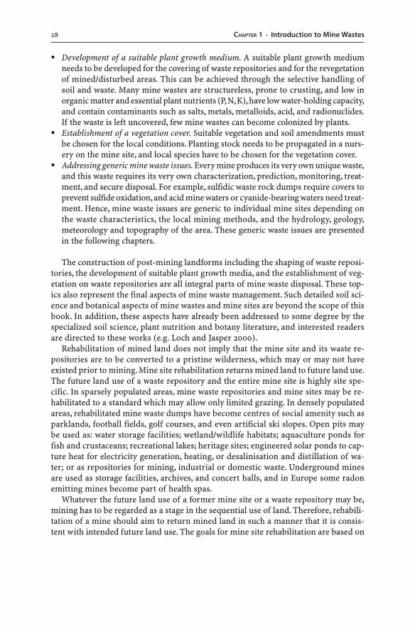
28 CHAPTER 1 · Introduction to Mine Wastes
� Development of a suitable plant growth medium. A suitable plant growth mediumneeds to be developed for the covering of waste repositories and for the revegetationof mined/disturbed areas. This can be achieved through the selective handling ofsoil and waste. Many mine wastes are structureless, prone to crusting, and low inorganic matter and essential plant nutrients (P, N, K), have low water-holding capacity,and contain contaminants such as salts, metals, metalloids, acid, and radionuclides.If the waste is left uncovered, few mine wastes can become colonized by plants.
� Establishment of a vegetation cover. Suitable vegetation and soil amendments mustbe chosen for the local conditions. Planting stock needs to be propagated in a nurs-ery on the mine site, and local species have to be chosen for the vegetation cover.
� Addressing generic mine waste issues. Every mine produces its very own unique waste,and this waste requires its very own characterization, prediction, monitoring, treat-ment, and secure disposal. For example, sulfidic waste rock dumps require covers toprevent sulfide oxidation, and acid mine waters or cyanide-bearing waters need treat-ment. Hence, mine waste issues are generic to individual mine sites depending onthe waste characteristics, the local mining methods, and the hydrology, geology,meteorology and topography of the area. These generic waste issues are presentedin the following chapters.
The construction of post-mining landforms including the shaping of waste reposi-tories, the development of suitable plant growth media, and the establishment of veg-etation on waste repositories are all integral parts of mine waste disposal. These top-ics also represent the final aspects of mine waste management. Such detailed soil sci-ence and botanical aspects of mine wastes and mine sites are beyond the scope of thisbook. In addition, these aspects have already been addressed to some degree by thespecialized soil science, plant nutrition and botany literature, and interested readersare directed to these works (e.g. Loch and Jasper 2000).
Rehabilitation of mined land does not imply that the mine site and its waste re-positories are to be converted to a pristine wilderness, which may or may not haveexisted prior to mining. Mine site rehabilitation returns mined land to future land use.The future land use of a waste repository and the entire mine site is highly site spe-cific. In sparsely populated areas, mine waste repositories and mine sites may be re-habilitated to a standard which may allow only limited grazing. In densely populatedareas, rehabilitated mine waste dumps have become centres of social amenity such asparklands, football fields, golf courses, and even artificial ski slopes. Open pits maybe used as: water storage facilities; wetland/wildlife habitats; aquaculture ponds forfish and crustaceans; recreational lakes; heritage sites; engineered solar ponds to cap-ture heat for electricity generation, heating, or desalinisation and distillation of wa-ter; or as repositories for mining, industrial or domestic waste. Underground minesare used as storage facilities, archives, and concert halls, and in Europe some radonemitting mines become part of health spas.
Whatever the future land use of a former mine site or a waste repository may be,mining has to be regarded as a stage in the sequential use of land. Therefore, rehabili-tation of a mine should aim to return mined land in such a manner that it is consis-tent with intended future land use. The goals for mine site rehabilitation are based on
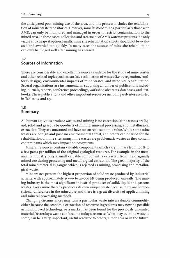
291.8 · Summary
the anticipated post-mining use of the area, and this process includes the rehabilita-tion of mine waste repositories. However, some historic mines, particularly those withAMD, can only be monitored and managed in order to restrict contamination to themined area. In these cases, collection and treatment of AMD waters represents the onlyviable and cheapest option. Finally, mine site rehabilitation efforts should not be evalu-ated and awarded too quickly. In many cases the success of mine site rehabilitationcan only be judged well after mining has ceased.
1.7Sources of Information
There are considerable and excellent resources available for the study of mine wastesand other related topics such as surface reclamation of wastes (i.e. revegetation, land-form design), environmental impacts of mine wastes, and mine site rehabilitation.Several organizations are instrumental in supplying a number of publications includ-ing journals, reports, conference proceedings, workshop abstracts, databases, and text-books. These publications and other important resources including web sites are listedin Tables 1.4 and 1.5.
1.8Summary
All human activities produce wastes and mining is no exception. Mine wastes are liq-uid, solid and gaseous by-products of mining, mineral processing, and metallurgicalextraction. They are unwanted and have no current economic value. While some minewastes are benign and pose no environmental threat, and others can be used for therehabilitation of mine sites, many mine wastes are problematic wastes as they containcontaminants which may impact on ecosystems.
Mineral resources contain valuable components which vary in mass from 100% toa few parts per million of the original geological resource. For example, in the metalmining industry only a small valuable component is extracted from the originallymined ore during processing and metallurgical extraction. The great majority of thetotal mined material is gangue which is rejected as mining, processing and metallur-gical waste.
Mine wastes present the highest proportion of solid waste produced by industrialactivity, with approximately 15 000 to 20 000 Mt being produced annually. The min-ing industry is the most significant industrial producer of solid, liquid and gaseouswastes. Every mine thereby produces its own unique waste because there are compo-sitional differences in the mined ore and there is a great diversity of applied miningand mineral processing methods.
Changing circumstances may turn a particular waste into a valuable commodity,either because the economic extraction of resource ingredients may now be possibleusing improved technology, or a market has been found for the previously unwantedmaterial. Yesterday’s waste can become today’s resource. What may be mine waste tosome, can be a very important, useful resource to others, either now or in the future.
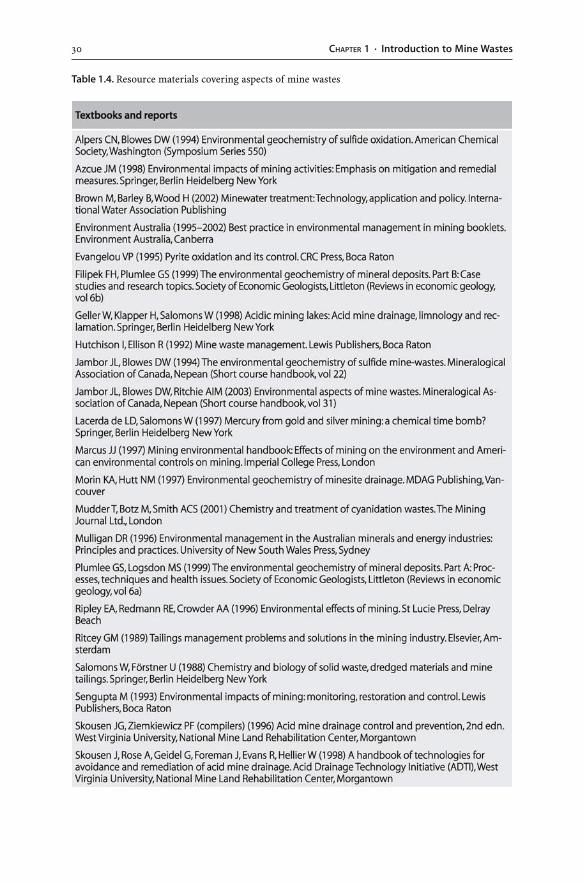
30 CHAPTER 1 · Introduction to Mine Wastes
Table 1.4. Resource materials covering aspects of mine wastes
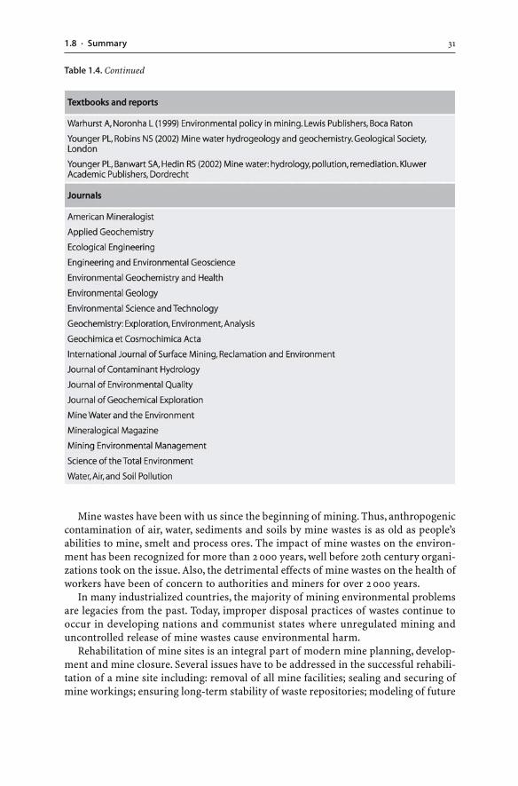
311.8 · Summary
Mine wastes have been with us since the beginning of mining. Thus, anthropogeniccontamination of air, water, sediments and soils by mine wastes is as old as people’sabilities to mine, smelt and process ores. The impact of mine wastes on the environ-ment has been recognized for more than 2 000 years, well before 20th century organi-zations took on the issue. Also, the detrimental effects of mine wastes on the health ofworkers have been of concern to authorities and miners for over 2 000 years.
In many industrialized countries, the majority of mining environmental problemsare legacies from the past. Today, improper disposal practices of wastes continue tooccur in developing nations and communist states where unregulated mining anduncontrolled release of mine wastes cause environmental harm.
Rehabilitation of mine sites is an integral part of modern mine planning, develop-ment and mine closure. Several issues have to be addressed in the successful rehabili-tation of a mine site including: removal of all mine facilities; sealing and securing ofmine workings; ensuring long-term stability of waste repositories; modeling of future
Table 1.4. Continued
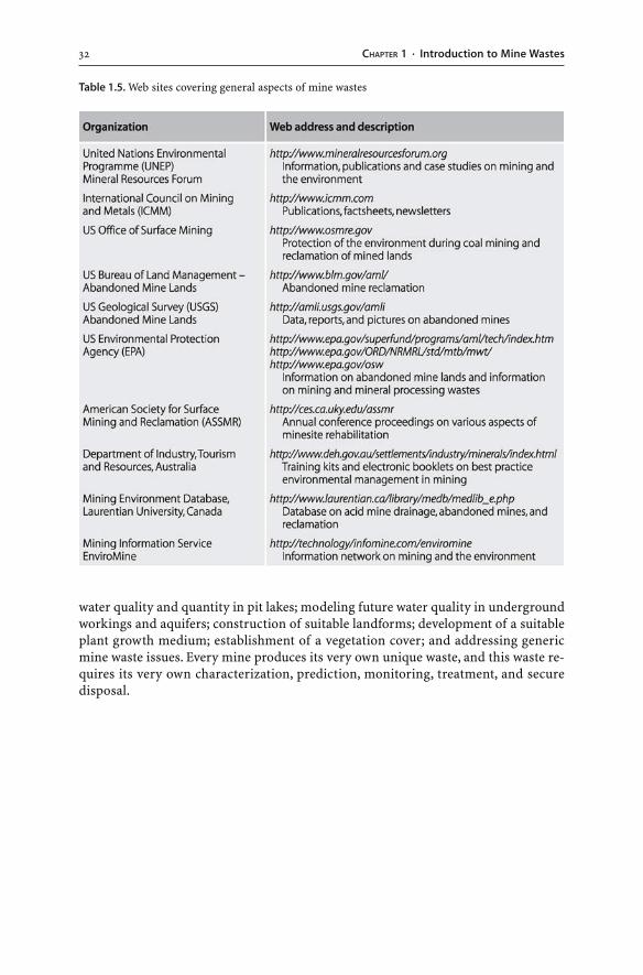
32 CHAPTER 1 · Introduction to Mine Wastes
water quality and quantity in pit lakes; modeling future water quality in undergroundworkings and aquifers; construction of suitable landforms; development of a suitableplant growth medium; establishment of a vegetation cover; and addressing genericmine waste issues. Every mine produces its very own unique waste, and this waste re-quires its very own characterization, prediction, monitoring, treatment, and securedisposal.
Table 1.5. Web sites covering general aspects of mine wastes
Chapter 2
Sulfidic Mine Wastes
2.1Introduction
Sulfide minerals are common minor constituents of the Earth’s crust. In some geo-logical environments, sulfides constitute a major proportion of rocks. In particular,metallic ore deposits (Cu, Pb, Zn, Au, Ni, U, Fe), phosphate ores, coal seams, oil shales,and mineral sands may contain abundant sulfides. Mining of these resources can ex-pose the sulfides to an oxygenated environment. In fact, large volumes of sulfide min-erals can be exposed in: tailings dams; waste rock dumps; coal spoil heaps; heap leachpiles; run-of-mine and low-grade ore stockpiles; waste repository embankments; openpit floors and faces; underground workings; haul roads; road cuts; quarries; and otherrock excavations. When the sulfides are exposed to the atmosphere or oxygenatedground water, the sulfides will oxidize to produce an acid water laden with sulfate, heavymetals and metalloids. The mineral pyrite (FeS2) tends to be the most common sul-fide mineral present. The weathering of this mineral at mine sites causes the largest,and most testing, environmental problem facing the industry today – acid mine drain-age (AMD).
This chapter documents the weathering processes occurring in sulfidic wastes. Anunderstanding of the complex chemical reactions within sulfidic wastes is essentialas the reactions can cause and influence AMD. Discussions of the various techniquesused to predict and monitor such acid generating wastes follow. A documentation ofenvironmental impacts of sulfidic wastes and a review of the technologies availablefor the control and prevention of sulfide oxidation complete the chapter.
2.2Weathering of Sulfidic Mine Wastes
Sulfidic mine wastes are in most cases polymineralic aggregates. The aggregates con-tain, apart from sulfides, a wide range of possible minerals including silicates, oxides,hydroxides, phosphates, halides, and carbonates. Silicates are the most common gangueminerals, and the sulfides may represent ore or gangue phases. Thus, the mineralogyof sulfidic wastes and ores is highly heterogeneous and deposit specific.
When mining exposes sulfidic materials to an oxidizing environment, the materi-als become chemically unstable. A series of complex chemical weathering reactionsare spontaneously initiated. This occurs because the mineral assemblages containedin the waste are not in equilibrium with the oxidizing environment. Weathering of theminerals proceeds with the help of atmospheric gases, meteoric water and microor-ganisms.
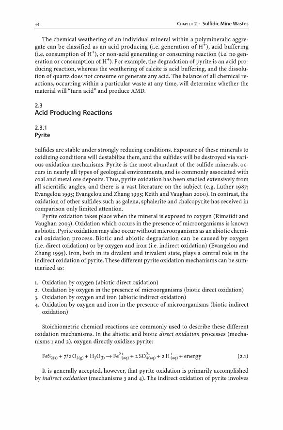
34 CHAPTER 2 · Sulfidic Mine Wastes
The chemical weathering of an individual mineral within a polymineralic aggre-gate can be classified as an acid producing (i.e. generation of H+), acid buffering(i.e. consumption of H+), or non-acid generating or consuming reaction (i.e. no gen-eration or consumption of H+). For example, the degradation of pyrite is an acid pro-ducing reaction, whereas the weathering of calcite is acid buffering, and the dissolu-tion of quartz does not consume or generate any acid. The balance of all chemical re-actions, occurring within a particular waste at any time, will determine whether thematerial will “turn acid” and produce AMD.
2.3Acid Producing Reactions
2.3.1Pyrite
Sulfides are stable under strongly reducing conditions. Exposure of these minerals tooxidizing conditions will destabilize them, and the sulfides will be destroyed via vari-ous oxidation mechanisms. Pyrite is the most abundant of the sulfide minerals, oc-curs in nearly all types of geological environments, and is commonly associated withcoal and metal ore deposits. Thus, pyrite oxidation has been studied extensively fromall scientific angles, and there is a vast literature on the subject (e.g. Luther 1987;Evangelou 1995; Evangelou and Zhang 1995; Keith and Vaughan 2000). In contrast, theoxidation of other sulfides such as galena, sphalerite and chalcopyrite has received incomparison only limited attention.
Pyrite oxidation takes place when the mineral is exposed to oxygen (Rimstidt andVaughan 2003). Oxidation which occurs in the presence of microorganisms is knownas biotic. Pyrite oxidation may also occur without microorganisms as an abiotic chemi-cal oxidation process. Biotic and abiotic degradation can be caused by oxygen(i.e. direct oxidation) or by oxygen and iron (i.e. indirect oxidation) (Evangelou andZhang 1995). Iron, both in its divalent and trivalent state, plays a central role in theindirect oxidation of pyrite. These different pyrite oxidation mechanisms can be sum-marized as:
1. Oxidation by oxygen (abiotic direct oxidation)2. Oxidation by oxygen in the presence of microorganisms (biotic direct oxidation)3. Oxidation by oxygen and iron (abiotic indirect oxidation)4. Oxidation by oxygen and iron in the presence of microorganisms (biotic indirect
oxidation)
Stoichiometric chemical reactions are commonly used to describe these differentoxidation mechanisms. In the abiotic and biotic direct oxidation processes (mecha-nisms 1 and 2), oxygen directly oxidizes pyrite:
FeS2(s) + 7/2 O2(g) + H2O(l) → Fe2+(aq) + 2 SO4
2–(aq) + 2 H+
(aq) + energy (2.1)
It is generally accepted, however, that pyrite oxidation is primarily accomplishedby indirect oxidation (mechanisms 3 and 4). The indirect oxidation of pyrite involves
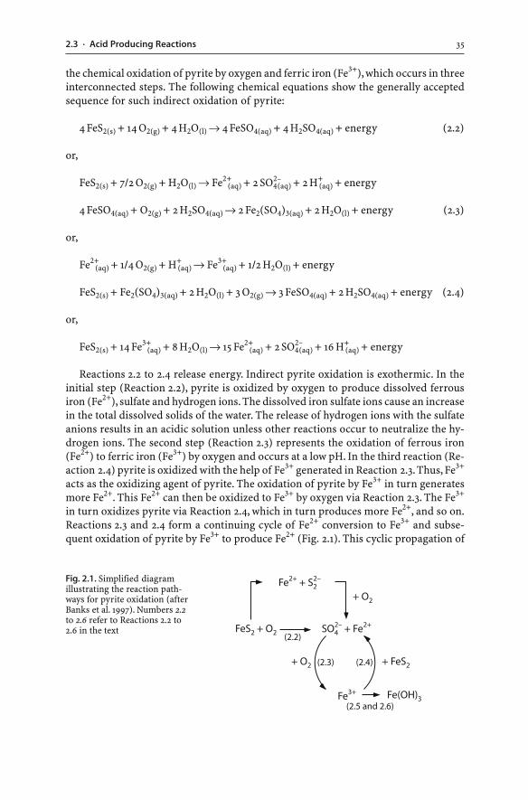
352.3 · Acid Producing Reactions
the chemical oxidation of pyrite by oxygen and ferric iron (Fe3+), which occurs in threeinterconnected steps. The following chemical equations show the generally acceptedsequence for such indirect oxidation of pyrite:
4 FeS2(s) + 14 O2(g) + 4 H2O(l) → 4 FeSO4(aq) + 4 H2SO4(aq) + energy (2.2)
or,
FeS2(s) + 7/2 O2(g) + H2O(l) → Fe2+(aq) + 2 SO4
2–(aq) + 2 H+
(aq) + energy
4 FeSO4(aq) + O2(g) + 2 H2SO4(aq) → 2 Fe2(SO4)3(aq) + 2 H2O(l) + energy (2.3)
or,
Fe2+(aq) + 1/4 O2(g) + H+
(aq) → Fe3+(aq) + 1/2 H2O(l) + energy
FeS2(s) + Fe2(SO4)3(aq) + 2 H2O(l) + 3 O2(g) → 3 FeSO4(aq) + 2 H2SO4(aq) + energy (2.4)
or,
FeS2(s) + 14 Fe3+(aq) + 8 H2O(l) → 15 Fe2+
(aq) + 2 SO42–(aq) + 16 H+
(aq) + energy
Reactions 2.2 to 2.4 release energy. Indirect pyrite oxidation is exothermic. In theinitial step (Reaction 2.2), pyrite is oxidized by oxygen to produce dissolved ferrousiron (Fe2+), sulfate and hydrogen ions. The dissolved iron sulfate ions cause an increasein the total dissolved solids of the water. The release of hydrogen ions with the sulfateanions results in an acidic solution unless other reactions occur to neutralize the hy-drogen ions. The second step (Reaction 2.3) represents the oxidation of ferrous iron(Fe2+) to ferric iron (Fe3+) by oxygen and occurs at a low pH. In the third reaction (Re-action 2.4) pyrite is oxidized with the help of Fe3+ generated in Reaction 2.3. Thus, Fe3+
acts as the oxidizing agent of pyrite. The oxidation of pyrite by Fe3+ in turn generatesmore Fe2+. This Fe2+ can then be oxidized to Fe3+ by oxygen via Reaction 2.3. The Fe3+
in turn oxidizes pyrite via Reaction 2.4, which in turn produces more Fe2+, and so on.Reactions 2.3 and 2.4 form a continuing cycle of Fe2+ conversion to Fe3+ and subse-quent oxidation of pyrite by Fe3+ to produce Fe2+ (Fig. 2.1). This cyclic propagation of
Fig. 2.1. Simplified diagramillustrating the reaction path-ways for pyrite oxidation (afterBanks et al. 1997). Numbers 2.2to 2.6 refer to Reactions 2.2 to2.6 in the text
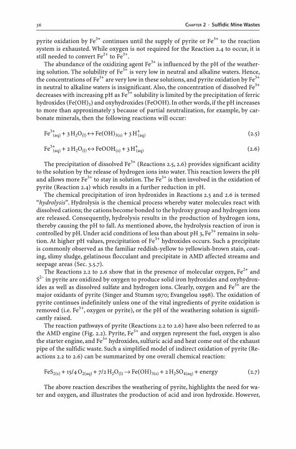
36 CHAPTER 2 · Sulfidic Mine Wastes
pyrite oxidation by Fe3+ continues until the supply of pyrite or Fe3+ to the reactionsystem is exhausted. While oxygen is not required for the Reaction 2.4 to occur, it isstill needed to convert Fe2+ to Fe3+.
The abundance of the oxidizing agent Fe3+ is influenced by the pH of the weather-ing solution. The solubility of Fe3+ is very low in neutral and alkaline waters. Hence,the concentrations of Fe3+ are very low in these solutions, and pyrite oxidation by Fe3+
in neutral to alkaline waters is insignificant. Also, the concentration of dissolved Fe3+
decreases with increasing pH as Fe3+ solubility is limited by the precipitation of ferrichydroxides (Fe(OH)3) and oxyhydroxides (FeOOH). In other words, if the pH increasesto more than approximately 3 because of partial neutralization, for example, by car-bonate minerals, then the following reactions will occur:
Fe3+(aq) + 3 H2O(l) ↔ Fe(OH)3(s) + 3 H+
(aq) (2.5)
Fe3+(aq) + 2 H2O(l) ↔ FeOOH(s) + 3 H+
(aq) (2.6)
The precipitation of dissolved Fe3+ (Reactions 2.5, 2.6) provides significant acidityto the solution by the release of hydrogen ions into water. This reaction lowers the pHand allows more Fe3+ to stay in solution. The Fe3+ is then involved in the oxidation ofpyrite (Reaction 2.4) which results in a further reduction in pH.
The chemical precipitation of iron hydroxides in Reactions 2.5 and 2.6 is termed“hydrolysis”. Hydrolysis is the chemical process whereby water molecules react withdissolved cations; the cations become bonded to the hydroxy group and hydrogen ionsare released. Consequently, hydrolysis results in the production of hydrogen ions,thereby causing the pH to fall. As mentioned above, the hydrolysis reaction of iron iscontrolled by pH. Under acid conditions of less than about pH 3, Fe3+ remains in solu-tion. At higher pH values, precipitation of Fe3+ hydroxides occurs. Such a precipitateis commonly observed as the familiar reddish-yellow to yellowish-brown stain, coat-ing, slimy sludge, gelatinous flocculant and precipitate in AMD affected streams andseepage areas (Sec. 3.5.7).
The Reactions 2.2 to 2.6 show that in the presence of molecular oxygen, Fe2+ andS2– in pyrite are oxidized by oxygen to produce solid iron hydroxides and oxyhydrox-ides as well as dissolved sulfate and hydrogen ions. Clearly, oxygen and Fe3+ are themajor oxidants of pyrite (Singer and Stumm 1970; Evangelou 1998). The oxidation ofpyrite continues indefinitely unless one of the vital ingredients of pyrite oxidation isremoved (i.e. Fe3+, oxygen or pyrite), or the pH of the weathering solution is signifi-cantly raised.
The reaction pathways of pyrite (Reactions 2.2 to 2.6) have also been referred to asthe AMD engine (Fig. 2.2). Pyrite, Fe3+ and oxygen represent the fuel, oxygen is alsothe starter engine, and Fe3+ hydroxides, sulfuric acid and heat come out of the exhaustpipe of the sulfidic waste. Such a simplified model of indirect oxidation of pyrite (Re-actions 2.2 to 2.6) can be summarized by one overall chemical reaction:
FeS2(s) + 15/4 O2(aq) + 7/2 H2O(l) → Fe(OH)3(s) + 2 H2SO4(aq) + energy (2.7)
The above reaction describes the weathering of pyrite, highlights the need for wa-ter and oxygen, and illustrates the production of acid and iron hydroxide. However,
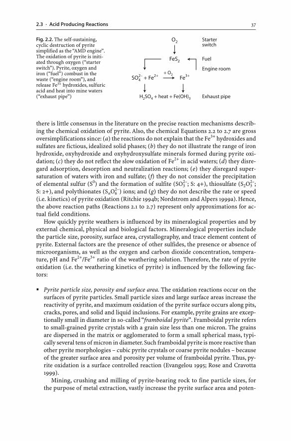
372.3 · Acid Producing Reactions
there is little consensus in the literature on the precise reaction mechanisms describ-ing the chemical oxidation of pyrite. Also, the chemical Equations 2.2 to 2.7 are grossoversimplifications since: (a) the reactions do not explain that the Fe3+ hydroxides andsulfates are fictious, idealized solid phases; (b) they do not illustrate the range of ironhydroxide, oxyhydroxide and oxyhydroxysulfate minerals formed during pyrite oxi-dation; (c) they do not reflect the slow oxidation of Fe2+ in acid waters; (d) they disre-gard adsorption, desorption and neutralization reactions; (e) they disregard super-saturation of waters with iron and sulfate; (f) they do not consider the precipitationof elemental sulfur (S0) and the formation of sulfite (SO3
2–; S: 4+), thiosulfate (S2O32–;
S: 2+), and polythionates (SnO62–) ions; and (g) they do not describe the rate or speed
(i.e. kinetics) of pyrite oxidation (Ritchie 1994b; Nordstrom and Alpers 1999a). Hence,the above reaction paths (Reactions 2.1 to 2.7) represent only approximations for ac-tual field conditions.
How quickly pyrite weathers is influenced by its mineralogical properties and byexternal chemical, physical and biological factors. Mineralogical properties includethe particle size, porosity, surface area, crystallography, and trace element content ofpyrite. External factors are the presence of other sulfides, the presence or absence ofmicroorganisms, as well as the oxygen and carbon dioxide concentration, tempera-ture, pH and Fe2+/Fe3+ ratio of the weathering solution. Therefore, the rate of pyriteoxidation (i.e. the weathering kinetics of pyrite) is influenced by the following fac-tors:
� Pyrite particle size, porosity and surface area. The oxidation reactions occur on thesurfaces of pyrite particles. Small particle sizes and large surface areas increase thereactivity of pyrite, and maximum oxidation of the pyrite surface occurs along pits,cracks, pores, and solid and liquid inclusions. For example, pyrite grains are excep-tionally small in diameter in so-called “framboidal pyrite”. Framboidal pyrite refersto small-grained pyrite crystals with a grain size less than one micron. The grainsare dispersed in the matrix or agglomerated to form a small spherical mass, typi-cally several tens of micron in diameter. Such framboidal pyrite is more reactive thanother pyrite morphologies – cubic pyrite crystals or coarse pyrite nodules – becauseof the greater surface area and porosity per volume of framboidal pyrite. Thus, py-rite oxidation is a surface controlled reaction (Evangelou 1995; Rose and Cravotta1999).
Mining, crushing and milling of pyrite-bearing rock to fine particle sizes, forthe purpose of metal extraction, vastly increase the pyrite surface area and poten-
Fig. 2.2. The self-sustaining,cyclic destruction of pyritesimplified as the “AMD engine”.The oxidation of pyrite is initi-ated through oxygen (“starterswitch”). Pyrite, oxygen andiron (“fuel”) combust in thewaste (“engine room”), andrelease Fe3+ hydroxides, sulfuricacid and heat into mine waters(“exhaust pipe”)
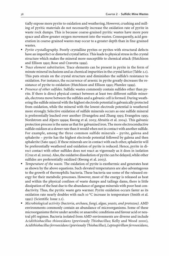
38 CHAPTER 2 · Sulfidic Mine Wastes
tially expose more pyrite to oxidation and weathering. However, crushing and mill-ing of pyritic materials do not necessarily increase the oxidation rate of pyrite inwaste rock dumps. This is because coarse-grained pyritic wastes have more porespace and allow greater oxygen movement into the wastes. Consequently, acid gen-eration in coarse-grained wastes may occur to a greater depth than in fine-grainedwastes.
� Pyrite crystallography. Poorly crystalline pyrites or pyrites with structural defectshave an imperfect or distorted crystal lattice. This leads to physical stress in the crystalstructure which makes the mineral more susceptible to chemical attack (Hutchisonand Ellison 1992; Rose and Cravotta 1999).
� Trace element substitution. Trace elements can be present in pyrite in the form ofminute mineral inclusions and as chemical impurities in the crystal lattice (Table 2.1).This puts strain on the crystal structure and diminishes the sulfide’s resistance tooxidation. For instance, the occurrence of arsenic in pyrite greatly decreases the re-sistance of pyrite to oxidation (Hutchison and Ellison 1992; Plumlee 1999).
� Presence of other sulfides. Sulfidic wastes commonly contain sulfides other than py-rite. If there is direct physical contact between at least two different sulfide miner-als, electrons move between the sulfides and a galvanic cell is formed. During weath-ering the sulfide mineral with the highest electrode potential is galvanically protectedfrom oxidation, while the mineral with the lowest electrode potential is weatheredmore strongly. Selective oxidation of sulfide minerals occurs as one sulfide mineralis preferentially leached over another (Evangelou and Zhang 1995; Evangelou 1995;Nordstrom and Alpers 1999a; Kwong et al. 2003; Abraitis et al. 2004). This galvanicprotection process is the same as that for galvanized iron. The more electroconductivesulfide oxidizes at a slower rate than it would when not in contact with another sulfide.For example, among the three common sulfide minerals – pyrite, galena andsphalerite – pyrite has the highest electrode potential followed by galena and thensphalerite (Sato 1992). If these minerals are in contact with each other, sphalerite willbe preferentially weathered and oxidation of pyrite is reduced. Hence, pyrite in di-rect contact with other sulfides does not react as vigorously as it does in isolation(Cruz et al. 2001a). Also, the oxidative dissolution of pyrite can be delayed, while othersulfides are preferentially oxidized (Kwong et al. 2003).
� Temperature of the waste. The oxidation of pyrite is exothermic and generates heatas shown by the above equations. Such elevated temperatures are also advantageousto the growth of thermophilic bacteria. These bacteria use some of the released en-ergy for their metabolic processes. However, most of the energy is released as heatand within the physical confines of waste dumps and tailings dams, there is littledissipation of the heat due to the abundance of gangue minerals with poor heat con-ductivity. Thus, the pyritic waste gets warmer. Pyrite oxidation occurs faster as itsoxidation rate nearly doubles with each 10 °C increase in temperature (Smith et al.1992) (Scientific Issue 2.1).
� Microbiological activity (bacteria, archaea, fungi, algae, yeasts, and protozoa). AMDenvironments commonly contain an abundance of microorganisms. Some of thesemicroorganisms thrive under aerobic or anaerobic conditions and favour acid or neu-tral pH regimes. Bacteria isolated from AMD environments are diverse and includeAcidithiobacillus thiooxidans (previously Thiobacillus; Kelly and Wood 2000),Acidithiobacillus ferrooxidans (previously Thiobacillus), Leptospirillum ferrooxidans,
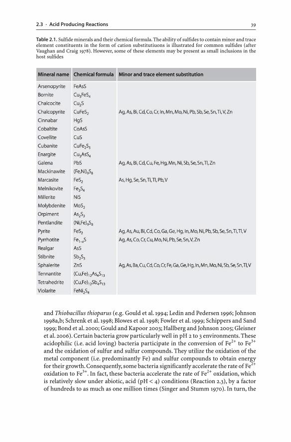
392.3 · Acid Producing Reactions
and Thiobacillus thioparus (e.g. Gould et al. 1994; Ledin and Pedersen 1996; Johnson1998a,b; Schrenk et al. 1998; Blowes et al. 1998; Fowler et al. 1999; Schippers and Sand1999; Bond et al. 2000; Gould and Kapoor 2003; Hallberg and Johnson 2005; Gleisneret al. 2006). Certain bacteria grow particularly well in pH 2 to 3 environments. Theseacidophilic (i.e. acid loving) bacteria participate in the conversion of Fe2+ to Fe3+
and the oxidation of sulfur and sulfur compounds. They utilize the oxidation of themetal component (i.e. predominantly Fe) and sulfur compounds to obtain energyfor their growth. Consequently, some bacteria significantly accelerate the rate of Fe2+
oxidation to Fe3+. In fact, these bacteria accelerate the rate of Fe2+ oxidation, whichis relatively slow under abiotic, acid (pH < 4) conditions (Reaction 2.3), by a factorof hundreds to as much as one million times (Singer and Stumm 1970). In turn, the
Table 2.1. Sulfide minerals and their chemical formula. The ability of sulfides to contain minor and traceelement constituents in the form of cation substitutiuons is illustrated for common sulfides (afterVaughan and Craig 1978). However, some of these elements may be present as small inclusions in thehost sulfides
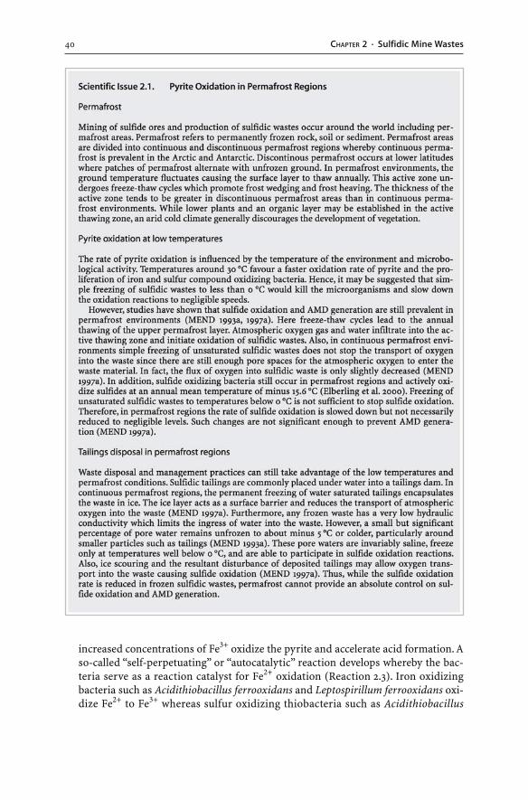
40 CHAPTER 2 · Sulfidic Mine Wastes
increased concentrations of Fe3+ oxidize the pyrite and accelerate acid formation. Aso-called “self-perpetuating” or “autocatalytic” reaction develops whereby the bac-teria serve as a reaction catalyst for Fe2+ oxidation (Reaction 2.3). Iron oxidizingbacteria such as Acidithiobacillus ferrooxidans and Leptospirillum ferrooxidans oxi-dize Fe2+ to Fe3+ whereas sulfur oxidizing thiobacteria such as Acidithiobacillus
412.3 · Acid Producing Reactions
thiooxidans oxidize sulfides and other sulfur compounds. These aerobic bacteriaspeed up the chemical oxidation rate of Fe2+ and sulfur compounds when molecu-lar oxygen is present.
Despite much research on microbiological oxidation of pyrite and especially onthe role of Acidithiobacillus ferrooxidans, it has been argued that abiotic chemicaloxidation of pyrite is more dominant than biotic oxidation and that 95% of bacte-ria associated with AMD are not Acidithiobacillus ferrooxidans (Ritchie 1994a;Morin and Hutt 1997). Indeed, it has been suggested that the microbial ecologyrather than a particular individual microorganism is the catalyst of pyrite oxida-tion and responsible for extreme AMD conditions (Lopez-Archilla et al. 1993; Ritchie1994a). Also, biological parameters – such as population density of the bacteria, rateof bacterial growth, and supply of nutrients – influence the growth and abundanceof the acidophilic bacteria and hence, the rate of pyrite oxidation. Moreover, bacte-ria are ubiquitous, and the presence of a bacterial population in sulfidic wastes mayonly indicate a favourable environment for microbial growth (Ritchie 1994a). Thus,the exact role of individual bacteria and other microorganisms in sulfide oxida-tion is a controversy for some. Also, our knowledge of the microbriology of neutralmine waters is incomplete. A comprehensive understanding of microbial processesin mine waters may enable the development of technologies that may prevent sul-fide oxidation and AMD formation (Hallberg and Johnson 2005).
� Oxygen concentration in the gas and water phase. Oxidation of pyrite may occur inthe atmosphere or in water. A significant correlation exists between the oxidationrate of pyrite and the oxidation concentration of the medium in which oxidationtakes place. Generally, the oxidation rate increases with higher oxygen concentra-tions. Oxygen is essential for the oxidation of sulfides and Ritchie (1994a) considersthat the transport of oxygen to the oxidation sites is the rate limiting process in dumpsand tailings deposits. If the oxidation takes place in water or in saturated pores un-der cover, the reactivity of pyrite is greatly affected by the concentration and rate oftransport of oxygen in water. The concentration of dissolved oxygen in water is partlytemperature-dependent and can vary from 0 mg l–1 to a maximum of 8 mg l–1 at 25 °C.Such a concentration is significantly less than the oxygen concentration in the at-mosphere (21 vol.% or 286 mg l–1 of O2 at 25 °C) (Langmuir 1997). As a result, theoxidation of pyrite in oxygenated water is much slower than the oxidation of pyritein the atmosphere.
Changes in oxygen concentrations also influence the occurrence of aerobic ironand sulfur oxidizing bacteria which require oxygen for their survival. Above thewater table, abundant atmospheric oxygen is available and oxidation rates are usu-ally catalyzed by aerobic bacteria like Acidithiobacillus ferrooxidans. In contrast,oxidation rates in water saturated waste or below the water table are much slowerbecause ground water generally has low dissolved oxygen concentrations and hencelacks catalyzing aerobic bacteria. In extreme cases such as flooded mine workingswith no dissolved oxygen, the lack of dissolved oxygen and the absence of aerobicbacteria can reduce pyrite oxidation to negligible rates.
� Carbon dioxide concentration in the gas and water phase. Sulfide oxidizing anaero-bic bacteria use carbon dioxide as their sole source of carbon in order to build uporganic material for their maintenance and growth (Ledin and Pedersen 1996). Car-bon dioxide is produced in sulfidic waste rock dumps as a result of carbonate disso-
42 CHAPTER 2 · Sulfidic Mine Wastes
lution and subsequent release of carbon dioxide into pore spaces. Thus, elevatedconcentrations of carbon dioxide in the pore space of waste rock dumps have beenreported to increase the oxidation of pyrite as the heightened concentrations favourthe growth of sulfide oxidizing anaerobic bacteria (Ritchie 1994a).
� pH of the solution in contact with pyrite. Acid conditions prevail in microscopic en-vironments surrounding pyrite grains. However, the exact pH of a solution in con-tact with an oxidizing pyrite surface is unknown since current technologies areunable to measure the pH conditions at a submicroscopic level. The pH value ofthe solution in contact with pyrite influences the rate of pyrite oxidation. Underlow to neutral pH conditions, Fe3+ acts as the oxidant of pyrite (i.e. indirectoxidation). The Fe3+ concentration is pH dependent. As a consequence, the oxi-dation rate of pyrite in Fe3+ saturated solutions is pH dependent. Significantdissolved concentrations of Fe3+ only occur at low pH values because the Fe3+
concentration in solution is controlled by the precipitation of insoluble Fe3+ precipi-tates (Reactions 2.5, 2.6). At pH values greater than 3, Fe3+ will precipitate andthe oxidizing agent is removed from solution (Rose and Cravotta 1999; Ficklin andMosier 1999). When the pH value falls below 3, sulfide oxidation becomes markedlyfaster.
Furthermore, the activity of some microorganisms is pH dependent with opti-mal conditions for Acidithiobacillus ferrooxidans and Acidithiobacillus thiooxidansbelow pH 3 (i.e. they are acidophilic), and for Thiobacillus thioparus in the neutralpH range (i.e. they are neutrophilic) (Blowes et al. 1998). Thus, low pH conditionsfavour the activity of acidophilic sulfide oxidizing bacteria. Once pyrite oxidationand acid production have begun, the low pH conditions allow the proliferation ofacidophilic microorganisms which further accelerate the pyrite oxidation rate(Hallberg and Johnson). On the other hand, an increase in pH to more neutral val-ues greatly affects the occurrence of iron oxidizing acidophilic bacteria. They donot contribute significantly to the oxidation process under neutral to alkaline con-ditions.
� Abundance of water. Some researchers consider water to be an essential factor andreactant in the oxidation of pyrite (Rose and Cravotta 1999; Evangelou and Zhang1995); others consider water as a reaction medium (Stumm and Morgan 1995). What-ever the role of water in sulfide oxidation, water is an important transport medium,and alternate wetting and drying of sulfides accelerate the oxidation process. Oxi-dation products can be dissolved and removed by the wetting, leaving a fresh pyritesurface exposed for further oxidation.
� Fe2+/Fe3+ ratio in the solution. The most efficient oxidant for pyrite is dissolved Fe3+
and not oxygen, because Fe3+ oxidizes pyrite more rapidly than oxygen (Luther 1987).Therefore, the amount of Fe3+ produced (Reaction 2.3) controls how much pyrite canbe destroyed (Reaction 2.4). As a result, the oxidation of Fe2+ to Fe3+ by dissolvedoxygen is considered to be the rate limiting step in the indirect abiotic oxidation ofpyrite (Singer and Stumm 1970). The precipitation of dissolved Fe3+ (Reactions 2.5,2.6) places a limit on available dissolved Fe3+ and on the rate of pyrite oxidation (Re-action 2.4).
The rate of pyrite oxidation (i.e. its destruction over a given time period) variesdepending on the above parameters. The rapid destruction of pyrite can potentially
432.3 · Acid Producing Reactions
generate large amounts of acid and mobilize large amounts of metals and metalloids.Consequently, AMD generation and its impact on the environment can be severe. Al-ternatively, if the rate of pyrite oxidation is very slow, the production of acidity anddissolved contaminants occurs over an extended period of time, and AMD genera-tion is negligible.
2.3.2Other Sulfides
Pyrite is the dominant metal sulfide mineral in many ore deposits and as such plays akey role in the formation of AMD. However, other sulfide minerals commonly occurwith pyrite, and their oxidation also influences the chemistry of mine waters. Theweathering of these sulfides may occur via direct or indirect oxidation with the helpof oxygen, iron and bacteria (Romano et al. 2001). The oxidation mechanisms of sul-fides are analogous to those of pyrite but the reaction rates may be very different(Rimstidt et al. 1994; Domvile et al. 1994; Nicholson and Scharer 1994; Janzen et al. 2000;Keith and Vaughan 2000). Factors which influence the oxidation rate of pyrite such astrace element substitutions may or may not influence the oxidation rate of other sul-fides (Jambor 1994; Janzen et al. 2000).
The weathering of various sulfides has been evaluated through laboratory experi-ments and field studies (Rimstidt et al. 1994; Jambor 1994; Domvile et al. 1994;Schmiermund 2000; Janzen et al. 2000; Jennings et al. 2000; Belzile et al. 2004; Yunmeiet al. 2004; Lengke and Tempel 2005; Goh et al. 2006; Walker et al. 2006). The princi-pal conclusion is that sulfide minerals differ in their acid production, reaction rate anddegree of recalcitrance to weathering. Different sulfide minerals have different weath-ering behaviours. Pyrite, marcasite (FeS2), pyrrhotite (Fe1–xS) and mackinawite((Fe,Ni)9S8) appear to be the most reactive sulfides and their oxidation generates lowpH waters. Other sulfides such as covellite (CuS), millerite (NiS) and galena (PbS) aregenerally far less reactive than pyrite. This is partly due to: (a) the greater stability oftheir crystal structure; (b) the lack of iron released; and (c) the formation of low solu-bility minerals such as cerussite (PbCO3) or anglesite (PbSO4), which may encapsulatesulfides like galena preventing further oxidation (Lin 1997; Plumlee 1999). In contrast,the persistence of minerals such as cinnabar (HgS) and molybdenite (MoS2) in oxic en-vironments indicates that they weather very slowly under aerobic conditions (Plumlee1999). These sulfides are most resistant to oxidation and do not generate acidity.
The presence of iron in sulfide minerals or in waters in contact with sulfides ap-pears to be important for sulfide oxidation. Indeed, the amount of iron sulfides presentin an assemblage strongly influences whether and how much acid is generated duringweathering (Plumlee 1999). Sulfidic wastes with high percentages of iron sulfides(e.g. pyrite, marcasite, pyrrhotite), or sulfides having iron as a major constituent(e.g. chalcopyrite, Fe-rich sphalerite), generate significantly more acidity than wasteswith low percentages of iron sulfides or sulfides containing little iron (e.g. galena, Fe-poor sphalerite). Moreover, the release of Fe2+ by the oxidation of Fe2+-bearing sul-fides is important as Fe2+ may be oxidized to Fe3+ which in turn can be hydrolyzedgenerating acidity (Boon et al. 1998; Munroe et al. 1999). Hence, sulfide minerals whichdo not contain iron in their crystal lattice (e.g. covellite, galena or iron-poor sphaler-ite) do not have the capacity to generate significant amounts of acid (Plumlee 1999).
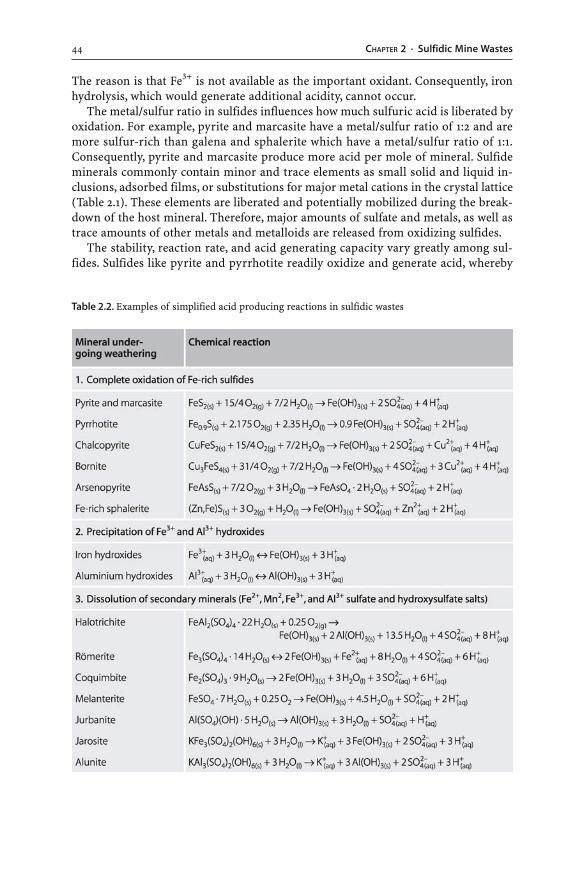
44 CHAPTER 2 · Sulfidic Mine Wastes
The reason is that Fe3+ is not available as the important oxidant. Consequently, ironhydrolysis, which would generate additional acidity, cannot occur.
The metal/sulfur ratio in sulfides influences how much sulfuric acid is liberated byoxidation. For example, pyrite and marcasite have a metal/sulfur ratio of 1:2 and aremore sulfur-rich than galena and sphalerite which have a metal/sulfur ratio of 1:1.Consequently, pyrite and marcasite produce more acid per mole of mineral. Sulfideminerals commonly contain minor and trace elements as small solid and liquid in-clusions, adsorbed films, or substitutions for major metal cations in the crystal lattice(Table 2.1). These elements are liberated and potentially mobilized during the break-down of the host mineral. Therefore, major amounts of sulfate and metals, as well astrace amounts of other metals and metalloids are released from oxidizing sulfides.
The stability, reaction rate, and acid generating capacity vary greatly among sul-fides. Sulfides like pyrite and pyrrhotite readily oxidize and generate acid, whereby
Table 2.2. Examples of simplified acid producing reactions in sulfidic wastes
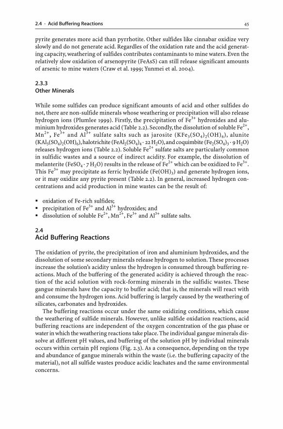
452.4 · Acid Buffering Reactions
pyrite generates more acid than pyrrhotite. Other sulfides like cinnabar oxidize veryslowly and do not generate acid. Regardles of the oxidation rate and the acid generat-ing capacity, weathering of sulfides contributes contaminants to mine waters. Even therelatively slow oxidation of arsenopyrite (FeAsS) can still release significant amountsof arsenic to mine waters (Craw et al. 1999; Yunmei et al. 2004).
2.3.3Other Minerals
While some sulfides can produce significant amounts of acid and other sulfides donot, there are non-sulfide minerals whose weathering or precipitation will also releasehydrogen ions (Plumlee 1999). Firstly, the precipitation of Fe3+ hydroxides and alu-minium hydroxides generates acid (Table 2.2). Secondly, the dissolution of soluble Fe2+,Mn2+, Fe3+ and Al3+ sulfate salts such as jarosite (KFe3(SO4)2(OH)6), alunite(KAl3(SO4)2(OH)6), halotrichite (FeAl2(SO4)4 · 22 H2O), and coquimbite (Fe2(SO4)3 · 9 H2O)releases hydrogen ions (Table 2.2). Soluble Fe2+ sulfate salts are particularly commonin sulfidic wastes and a source of indirect acidity. For example, the dissolution ofmelanterite (FeSO4 · 7 H2O) results in the release of Fe2+ which can be oxidized to Fe3+.This Fe3+ may precipitate as ferric hydroxide (Fe(OH)3) and generate hydrogen ions,or it may oxidize any pyrite present (Table 2.2). In general, increased hydrogen con-centrations and acid production in mine wastes can be the result of:
� oxidation of Fe-rich sulfides;� precipitation of Fe3+ and Al3+ hydroxides; and� dissolution of soluble Fe2+, Mn2+, Fe3+ and Al3+ sulfate salts.
2.4Acid Buffering Reactions
The oxidation of pyrite, the precipitation of iron and aluminium hydroxides, and thedissolution of some secondary minerals release hydrogen to solution. These processesincrease the solution’s acidity unless the hydrogen is consumed through buffering re-actions. Much of the buffering of the generated acidity is achieved through the reac-tion of the acid solution with rock-forming minerals in the sulfidic wastes. Thesegangue minerals have the capacity to buffer acid; that is, the minerals will react withand consume the hydrogen ions. Acid buffering is largely caused by the weathering ofsilicates, carbonates and hydroxides.
The buffering reactions occur under the same oxidizing conditions, which causethe weathering of sulfide minerals. However, unlike sulfide oxidation reactions, acidbuffering reactions are independent of the oxygen concentration of the gas phase orwater in which the weathering reactions take place. The individual gangue minerals dis-solve at different pH values, and buffering of the solution pH by individual mineralsoccurs within certain pH regions (Fig. 2.3). As a consequence, depending on the typeand abundance of gangue minerals within the waste (i.e. the buffering capacity of thematerial), not all sulfide wastes produce acidic leachates and the same environmentalconcerns.
46 CHAPTER 2 · Sulfidic Mine Wastes
2.4.1Silicates
The major reservoir of buffering capacity in the environment are the silicate mineralswhich make up the majority of the minerals in the Earth’s crust. Chemical weatheringof silicate minerals consumes hydrogen ions and occurs via congruent or incongru-ent weathering. Congruent weathering involves the complete dissolution of the sili-cate mineral and the production of only soluble components (Reaction 2.8). Incon-gruent weathering is the more common form of silicate weathering whereby the sili-cate mineral is altered to another phase (Reaction 2.9). The chemical composition ofmost silicates such as olivines, pyroxenes, amphiboles, garnets, feldspars, feldspathoids,clays and micas is restricted to a range of elements. Thus, the two types of silicateweathering can be represented by the following reactions:
2 MeAlSiO4(s) + 2 H+(aq) + H2O → Mex+
(aq) + Al2Si2O5(OH)4(s) (2.8)
MeAlSiO4(s) + H+(aq) + 3 H2O → Mex+
(aq) + Al3+(aq) + H4SiO4(aq) + 3 OH–
(aq) (2.9)
(Me = Ca, Na, K, Mg, Mn or Fe)
Chemical weathering of silicates results in the consumption of hydrogen ions, theproduction of dissolved cations and silicic acid, and the formation of secondary minerals(Purra and Neretnieks 2000). For example, the incongruent destruction of the sodium-rich plagioclase feldspar albite (NaAlSi3O8) may produce montmorillonite (simplified asAl2Si4O10(OH)2) or kaolinite (Al2Si2O5(OH)4), depending on the amount of leaching:
2 NaAlSi3O8(s) + 2 H+(aq) + 4 H2O(l) → 2 Na+
(aq) + Al2Si4O10(OH)2(s) + 2 H4SiO4(aq)(2.10)
2 NaAlSi3O8(s) + 2 H+(aq) + 9 H2O(l) → 2 Na+
(aq) + Al2Si2O5(OH)4(s) + 4 H4SiO4(aq) (2.11)
The incongruent destruction of other feldspars such as the calcium-rich plagio-clase anorthite (CaAl2Si2O8), and that of orthoclase, sanidine, adularia or microcline(KAlSi3O8) can be written as follows:
CaAl2Si2O8(s) + 2 H+(aq) + H2O(l) → Ca2+
(aq) + Al2Si2O5(OH)4(s) (2.12)
Fig. 2.3. Stepwise consumptionof buffering capacity in a hypo-thetical sulfidic waste dump(Salomons 1995). (Reprintedfrom Salomons W (1995) Envi-ronmental impact of metalsderived from mining activities:Processes, predictions, preven-tion. Journal of GeochemicalExploration 52:5–23, with per-mission from Elsevier Science)
472.4 · Acid Buffering Reactions
2 KAlSi3O8(s) + 2 H+(aq) + 9 H2O(l) → 2 K+
(aq) + Al2Si2O5(OH)4(s) + 4 H4SiO4(aq) (2.13)
In most natural environments, the surface water contains dissolved carbon diox-ide. The following reaction represents the incongruent weathering of K-feldspar un-der such conditions more accurately (Ollier and Pain 1997):
6 KAlSi3O8(s) + 4 H2O(l) + 4 CO2(g) → 4 K+(aq) + K2Al4(Si6Al2O20)(OH)4(s)
+ 4 HCO3–(aq) + 12 SiO2(aq) (2.14)
In the above chemical reactions (Reactions 2.10 to 2.14), plagioclase and K-feldsparconsume hydrogen ions in solution or generate bicarbonate ions. In addition, the by-products of feldspar and chlorite weathering are Na+, K+, Ca2+, silicic acid (H4SiO4)and the clay minerals kaolinite (Al2Si2O5(OH)4), illite (K2Al4(Si6Al2O20)(OH)4), ormontmorillonite (simplified as Al2Si4O10(OH)2). The silicic acid or silica may precipi-tate as opaline silica or cryptocrystalline chalcedony (SiO2). New quartz is only rarelyformed, and then it usually overgrows on pre-existing quartz grains. The clay miner-als may weather further and consume hydrogen ions as they dissolve. For example,the dissolution of kaolinite can be represented by the following reaction:
Al2Si2O5(OH)4(s) + 6 H+(aq) → 2 Al3+
(aq) + 2 H4SiO4(aq) + H2O(l) (2.15)
If the dissolved Al3+ is allowed to precipitate as gibbsite (Al(OH)3), this neutraliz-ing mechanism is lost because an equal amount of hydrogen will be released into so-lution (Deutsch 1997):
2 Al3+(aq) + 6 H2O(l) ↔ 2 Al(OH)3(s) + 6 H+
(aq) (2.16)
On the other hand, if gibbsite already exists as a solid phase in the waste rocks, itprovides additional neutralizing ability because it can consume dissolved hydrogenions. Similarly, ferric hydroxide solids (Reaction 2.17) previously precipitated duringpyrite oxidation can be redissolved in acidic waters, thereby consuming hydrogen ions:
Fe(OH)3(s) + 3 H+(aq) ↔ Fe3+
(aq) + 3 H2O(l) (2.17)
Quartz (SiO2), chalcedony (SiO2), opal (SiO2 · nH2O), and other silica minerals donot consume hydrogen when they weather to form silicic acid (Reaction 2.18). Silicic acidis a very weak acid and does not contribute significant hydrogen ions to solution. The acidis unable to donate protons to a solution unless the pH is greater than 9 (Deutsch 1997).
SiO2(s) + 2 H2O(l) ↔ H4SiO4(aq) (2.18)
2.4.2Carbonates
Carbonate minerals play an extremely important role in acid buffering reactions. Min-erals such as calcite (CaCO3), dolomite (CaMg(CO3)2), ankerite (Ca(Fe,Mg)(CO3)2), or
48 CHAPTER 2 · Sulfidic Mine Wastes
magnesite (MgCO3) neutralize acid generated from sulfide oxidation. Calcite is themost important neutralizing agent, because of its common occurrence in a wide rangeof geological environments and its rapid rate of reaction compared to dolomite. Simi-larly to pyrite weathering, grain size, texture and the presence of trace elements in thecrystal lattice of carbonates may increase or decrease their resistance to weathering(Plumlee 1999; Strömberg and Banwart 1999). Calcite neutralizes acid by dissolvingand complexing with hydrogen ion to form bicarbonate (HCO3
–) and carbonic acid(H2CO3) (Stumm and Morgan 1995; Blowes and Ptacek 1994; Strömberg and Banwart1999; Al et al. 2000). Depending on the pH of the weathering solution, acidity is con-sumed either by the production of bicarbonate in weakly acidic to alkaline environ-ments (Reaction 2.19) or by the production of carbonic acid in strongly acidic envi-ronments (Reaction 2.20).
CaCO3(s) + H+(aq) ↔ Ca2+
(aq) + HCO3–(aq) (2.19)
CaCO3(s) + 2 H+(aq) ↔ Ca2+
(aq) + H2CO3(aq) (2.20)
Overall, the dissolution of calcite neutralizes acidity and increases pH and alkalin-ity in waters. A reversal of the Reactions 2.19 and 2.20 is possible when there is a changein temperature, loss of water or loss of carbon dioxide. Reprecipitation of carbonateswill occur, which in turn releases hydrogen ions, causing the pH to fall.
The presence or absence of carbon dioxide strongly influences the solubility of cal-cite (Sherlock et al. 1995; Stumm and Morgan 1995). Calcite dissolution can occur inan open or closed system, depending on whether carbon dioxide is available for gasexchange. If water is in contact with a gas phase, then carbon dioxide can enter thesolution and calcite dissolution occurs in a so-called “open system” (Reaction 2.21). Inthe open system, there is an increased solubility of calcite (Stumm and Morgan 1995).The unsaturated zones of sulfidic waste rock piles represent such open systems. Incontrast, in the water saturated zone of sulfidic waste rock piles or tailings, there is nocarbon dioxide gas phase. Here, calcite dissolves in a closed system (Reaction 2.22):
CaCO3(s) + CO2(g) + H2O(l) ↔ Ca2+(aq) + 2 HCO3
–(aq) (2.21)
CaCO3(s) + H+(aq) ↔ Ca2+
(aq) + HCO3–(aq) (2.22)
Therefore, in an open mine waste environment there is increased calcite dissolu-tion because the calcite is exposed to a carbon dioxide gas phase. More bicarbonate isgenerated and more hydrogen ions are consumed than it would be the case in a closedmine waste environment (Sherlock et al. 1995).
Dissolution of other carbonates such as dolomite, ankerite or magnesite will simi-larly result in the consumption of hydrogen ions and in the release of bicarbonate,calcium and magnesium ions and carbonic acid. However, calcite is more easily dis-solved than dolomite or ankerite. Siderite (FeCO3) is a common gangue mineral incoal deposits and various metal ores. The neutralizing effect of siderite depends onthe redox conditions of the weathering environment. Under reducing conditions, sid-erite dissolves to form bicarbonate and Fe2+ ions. In contrast, in an open system withabundant oxygen, the dissolution of siderite has no neutralizing effect. While the gen-
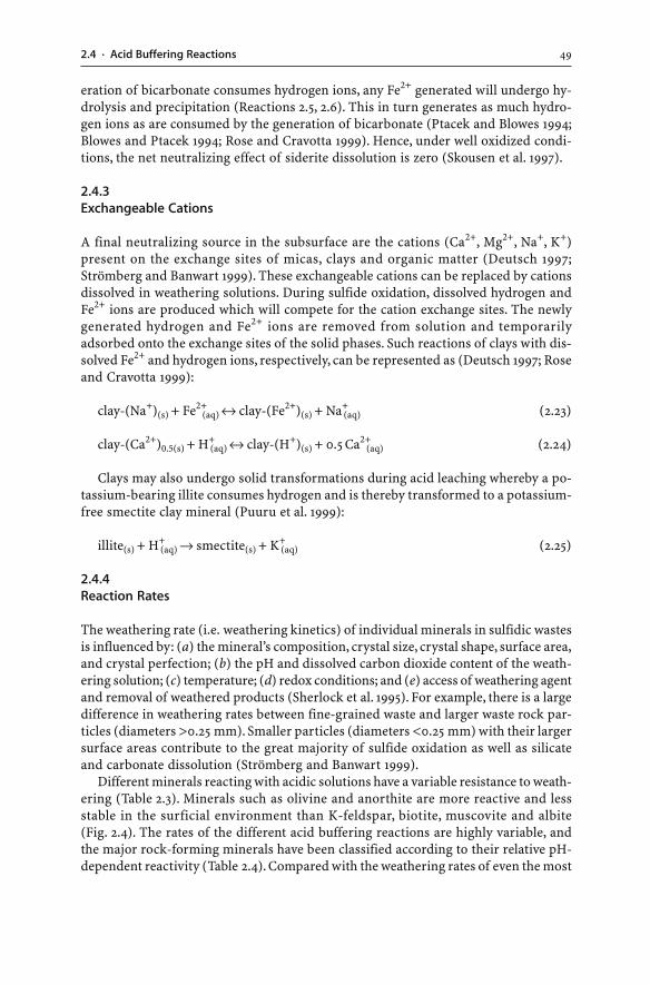
492.4 · Acid Buffering Reactions
eration of bicarbonate consumes hydrogen ions, any Fe2+ generated will undergo hy-drolysis and precipitation (Reactions 2.5, 2.6). This in turn generates as much hydro-gen ions as are consumed by the generation of bicarbonate (Ptacek and Blowes 1994;Blowes and Ptacek 1994; Rose and Cravotta 1999). Hence, under well oxidized condi-tions, the net neutralizing effect of siderite dissolution is zero (Skousen et al. 1997).
2.4.3Exchangeable Cations
A final neutralizing source in the subsurface are the cations (Ca2+, Mg2+, Na+, K+)present on the exchange sites of micas, clays and organic matter (Deutsch 1997;Strömberg and Banwart 1999). These exchangeable cations can be replaced by cationsdissolved in weathering solutions. During sulfide oxidation, dissolved hydrogen andFe2+ ions are produced which will compete for the cation exchange sites. The newlygenerated hydrogen and Fe2+ ions are removed from solution and temporarilyadsorbed onto the exchange sites of the solid phases. Such reactions of clays with dis-solved Fe2+ and hydrogen ions, respectively, can be represented as (Deutsch 1997; Roseand Cravotta 1999):
clay-(Na+)(s) + Fe2+(aq) ↔ clay-(Fe2+)(s) + Na+
(aq) (2.23)
clay-(Ca2+)0.5(s) + H+(aq) ↔ clay-(H+)(s) + 0.5 Ca2+
(aq) (2.24)
Clays may also undergo solid transformations during acid leaching whereby a po-tassium-bearing illite consumes hydrogen and is thereby transformed to a potassium-free smectite clay mineral (Puuru et al. 1999):
illite(s) + H+(aq) → smectite(s) + K+
(aq) (2.25)
2.4.4Reaction Rates
The weathering rate (i.e. weathering kinetics) of individual minerals in sulfidic wastesis influenced by: (a) the mineral’s composition, crystal size, crystal shape, surface area,and crystal perfection; (b) the pH and dissolved carbon dioxide content of the weath-ering solution; (c) temperature; (d) redox conditions; and (e) access of weathering agentand removal of weathered products (Sherlock et al. 1995). For example, there is a largedifference in weathering rates between fine-grained waste and larger waste rock par-ticles (diameters >0.25 mm). Smaller particles (diameters <0.25 mm) with their largersurface areas contribute to the great majority of sulfide oxidation as well as silicateand carbonate dissolution (Strömberg and Banwart 1999).
Different minerals reacting with acidic solutions have a variable resistance to weath-ering (Table 2.3). Minerals such as olivine and anorthite are more reactive and lessstable in the surficial environment than K-feldspar, biotite, muscovite and albite(Fig. 2.4). The rates of the different acid buffering reactions are highly variable, andthe major rock-forming minerals have been classified according to their relative pH-dependent reactivity (Table 2.4). Compared with the weathering rates of even the most
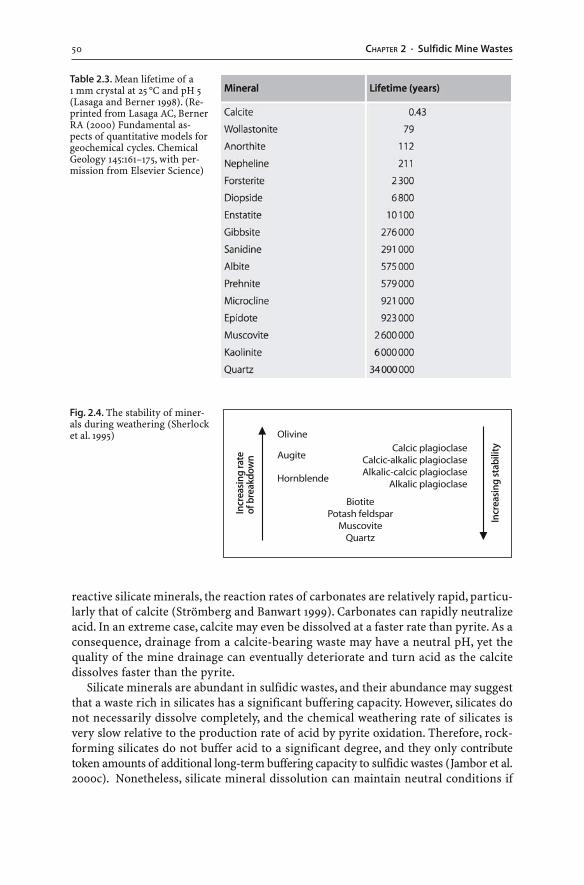
50 CHAPTER 2 · Sulfidic Mine Wastes
reactive silicate minerals, the reaction rates of carbonates are relatively rapid, particu-larly that of calcite (Strömberg and Banwart 1999). Carbonates can rapidly neutralizeacid. In an extreme case, calcite may even be dissolved at a faster rate than pyrite. As aconsequence, drainage from a calcite-bearing waste may have a neutral pH, yet thequality of the mine drainage can eventually deteriorate and turn acid as the calcitedissolves faster than the pyrite.
Silicate minerals are abundant in sulfidic wastes, and their abundance may suggestthat a waste rich in silicates has a significant buffering capacity. However, silicates donot necessarily dissolve completely, and the chemical weathering rate of silicates isvery slow relative to the production rate of acid by pyrite oxidation. Therefore, rock-forming silicates do not buffer acid to a significant degree, and they only contributetoken amounts of additional long-term buffering capacity to sulfidic wastes (Jambor et al.2000c). Nonetheless, silicate mineral dissolution can maintain neutral conditions if
Fig. 2.4. The stability of miner-als during weathering (Sherlocket al. 1995)
Table 2.3. Mean lifetime of a1 mm crystal at 25 °C and pH 5(Lasaga and Berner 1998). (Re-printed from Lasaga AC, BernerRA (2000) Fundamental as-pects of quantitative models forgeochemical cycles. ChemicalGeology 145:161–175, with per-mission from Elsevier Science)
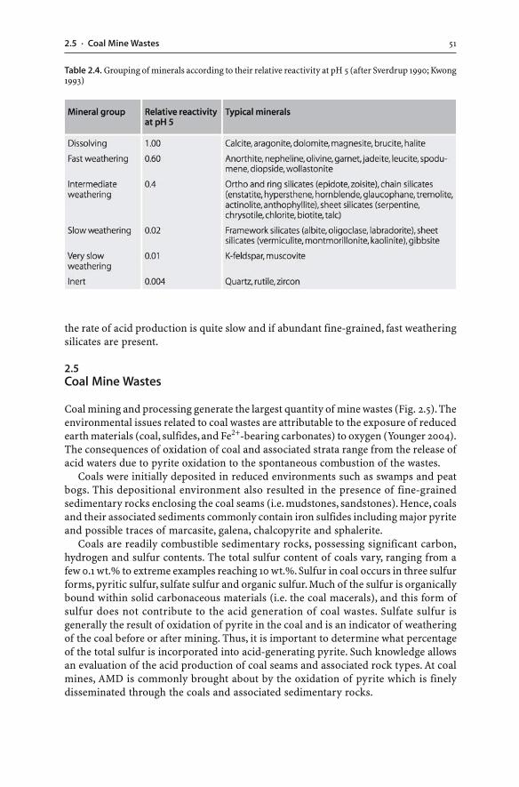
512.5 · Coal Mine Wastes
the rate of acid production is quite slow and if abundant fine-grained, fast weatheringsilicates are present.
2.5Coal Mine Wastes
Coal mining and processing generate the largest quantity of mine wastes (Fig. 2.5). Theenvironmental issues related to coal wastes are attributable to the exposure of reducedearth materials (coal, sulfides, and Fe2+-bearing carbonates) to oxygen (Younger 2004).The consequences of oxidation of coal and associated strata range from the release ofacid waters due to pyrite oxidation to the spontaneous combustion of the wastes.
Coals were initially deposited in reduced environments such as swamps and peatbogs. This depositional environment also resulted in the presence of fine-grainedsedimentary rocks enclosing the coal seams (i.e. mudstones, sandstones). Hence, coalsand their associated sediments commonly contain iron sulfides including major pyriteand possible traces of marcasite, galena, chalcopyrite and sphalerite.
Coals are readily combustible sedimentary rocks, possessing significant carbon,hydrogen and sulfur contents. The total sulfur content of coals vary, ranging from afew 0.1 wt.% to extreme examples reaching 10 wt.%. Sulfur in coal occurs in three sulfurforms, pyritic sulfur, sulfate sulfur and organic sulfur. Much of the sulfur is organicallybound within solid carbonaceous materials (i.e. the coal macerals), and this form ofsulfur does not contribute to the acid generation of coal wastes. Sulfate sulfur isgenerally the result of oxidation of pyrite in the coal and is an indicator of weatheringof the coal before or after mining. Thus, it is important to determine what percentageof the total sulfur is incorporated into acid-generating pyrite. Such knowledge allowsan evaluation of the acid production of coal seams and associated rock types. At coalmines, AMD is commonly brought about by the oxidation of pyrite which is finelydisseminated through the coals and associated sedimentary rocks.
Table 2.4. Grouping of minerals according to their relative reactivity at pH 5 (after Sverdrup 1990; Kwong1993)
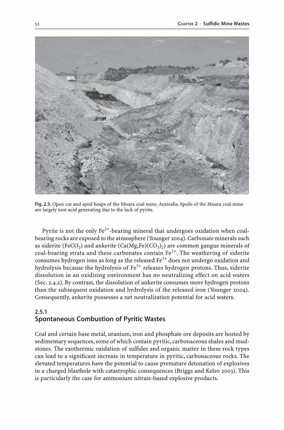
52 CHAPTER 2 · Sulfidic Mine Wastes
Fig. 2.5. Open cut and spoil heaps of the Moura coal mine, Australia. Spoils of the Moura coal mineare largely non-acid generating due to the lack of pyrite.
Pyrite is not the only Fe2+-bearing mineral that undergoes oxidation when coal-bearing rocks are exposed to the atmosphere (Younger 2004). Carbonate minerals suchas siderite (FeCO3) and ankerite (Ca(Mg,Fe)(CO3)2) are common gangue minerals ofcoal-bearing strata and these carbonates contain Fe2+. The weathering of sideriteconsumes hydrogen ions as long as the released Fe2+ does not undergo oxidation andhydrolysis because the hydrolysis of Fe3+ releases hydrogen protons. Thus, sideritedissolution in an oxidizing environment has no neutralizing effect on acid waters(Sec. 2.4.2). By contrast, the dissolution of ankerite consumes more hydrogen protonsthan the subsequent oxidation and hydrolysis of the released iron (Younger 2004).Consequently, ankerite possesses a net neutralization potential for acid waters.
2.5.1Spontaneous Combustion of Pyritic Wastes
Coal and certain base metal, uranium, iron and phosphate ore deposits are hosted bysedimentary sequences, some of which contain pyritic, carbonaceous shales and mud-stones. The exothermic oxidation of sulfides and organic matter in these rock typescan lead to a significant increase in temperature in pyritic, carbonaceous rocks. Theelevated temperatures have the potential to cause premature detonation of explosivesin a charged blasthole with catastrophic consequences (Briggs and Kelso 2003). Thisis particularly the case for ammonium nitrate-based explosive products.
532.5 · Coal Mine Wastes
The development of even higher temperatures may lead to the spontaneous igni-tion of coal and carbonaceous, pyritic shales and mudstones, which has been observednaturally (Mathews and Bustin 1984). It can also occur in underground workings, openpit faces, waste rock dumps, and slag heaps (Bullock and Bell 1997; Puura et al. 1999;Sidenko et al. 2001). It is visible as “smoke”, comprising a variety of gases such as watersteam, sulfur dioxide, carbon dioxide, carbon monoxide, and methane. In particular,colliery spoil and carbonaceous, pyritic waste rock dumps have the tendency to burnand smoke.
The rocks contain abundant, often very fine-grained, micrometer sized framboidalpyrite as well as carbon and organic matter. Spontaneous combustion of this materialis initiated through its exposure to atmospheric oxygen or oxygenated ground water.This leads to the slow exothermic oxidation of pyrite, carbon and organic matter whichin turn results in a gradual rise in temperature of the rock. Any fine-grained rockmaterials will act as heat insulators, and the heat will not be able to escape. At somestage, enough heat is generated to ignite the carbon or organic matter. The oxidationreactions are significantly accelerated as soon as significant amounts of atmosphericoxygen or oxygen dissolved in water are supplied to the carbonaceous material, andlarge surface areas are exposed, for example, as a result of mining. Next, rapid oxida-tion of this hot pyritic, carbonaceous rock is initiated, and spontaneous combustionoccurs. The organic carbon and sulfur begin to burn. Smoke and steam are releasedresembling volcanic fumaroles. The combustion of carbon and organic matter increasesthe heat of the rock which in turn increases the rate of sulfide oxidation. If there is suffi-cient oxygen during the combustion process, the pyrite is converted to hematite and sulfuroxides:
2 FeS2(s) + x O2(g) → Fe2O3(s) + 4 SOx(g) (2.26)
If there is not enough oxygen for complete oxidation, hydrogen sulfide is formed.In extreme cases of oxidation, temperatures reach 1 200 °C and localized melting ofthe rocks and wastes occurs. In such cases, the outer dump layer cracks, and surfaceventing of gases from sulfidic materials becomes significant. The spontaneous com-bustion and subsequent cooling of coal spoil and pyritic waste rock dumps producewaste materials of complex mineralogical composition, including slag-type phases,thermal metamorphic minerals, and weathering related minerals (Puura et al. 1999;Sidenko et al. 2001).
If combustion has already begun in mine waste dumps, disturbing the burning heap– by excavating or reshaping it – will only provide additional atmospheric oxygen tothe waste, and the rate of combustion will increase. Various methods are used to com-bat combustion in mine wastes, including compaction, injection of water, and waterspraying (Fig. 2.6). However, compaction may eventually lead to cracking of the sealby pressurized gases. Also, the use of excessive amounts of water may generate steamand eventually cause steam explosions.
In order to prevent premature detonation of explosives or spontaneous combus-tion in carbonaceous, pyritic rocks, the rocks need to be characterized for their pyriteand organic carbon contents and their temperature. Such characterization should oc-cur before or during mining. This will ensure that any high risk material will undergospecial handling pior to their finite disposal. Disposal options include dumping small
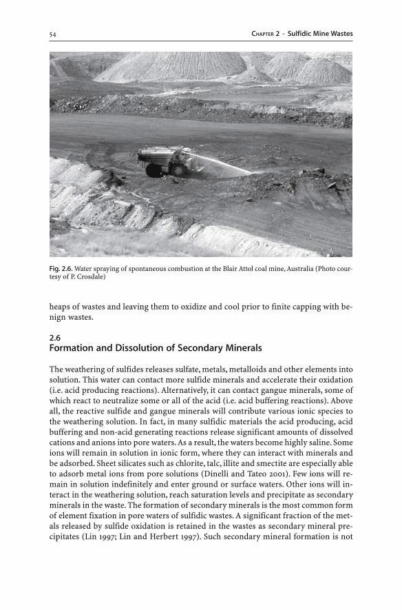
54 CHAPTER 2 · Sulfidic Mine Wastes
heaps of wastes and leaving them to oxidize and cool prior to finite capping with be-nign wastes.
2.6Formation and Dissolution of Secondary Minerals
The weathering of sulfides releases sulfate, metals, metalloids and other elements intosolution. This water can contact more sulfide minerals and accelerate their oxidation(i.e. acid producing reactions). Alternatively, it can contact gangue minerals, some ofwhich react to neutralize some or all of the acid (i.e. acid buffering reactions). Aboveall, the reactive sulfide and gangue minerals will contribute various ionic species tothe weathering solution. In fact, in many sulfidic materials the acid producing, acidbuffering and non-acid generating reactions release significant amounts of dissolvedcations and anions into pore waters. As a result, the waters become highly saline. Someions will remain in solution in ionic form, where they can interact with minerals andbe adsorbed. Sheet silicates such as chlorite, talc, illite and smectite are especially ableto adsorb metal ions from pore solutions (Dinelli and Tateo 2001). Few ions will re-main in solution indefinitely and enter ground or surface waters. Other ions will in-teract in the weathering solution, reach saturation levels and precipitate as secondaryminerals in the waste. The formation of secondary minerals is the most common formof element fixation in pore waters of sulfidic wastes. A significant fraction of the met-als released by sulfide oxidation is retained in the wastes as secondary mineral pre-cipitates (Lin 1997; Lin and Herbert 1997). Such secondary mineral formation is not
Fig. 2.6. Water spraying of spontaneous combustion at the Blair Attol coal mine, Australia (Photo cour-tesy of P. Crosdale)
552.6 · Formation and Dissolution of Secondary Minerals
exclusive to the wastes themselves; numerous salts approach saturation in groundwaters, streams and leachates associated with the weathering of sulfidic wastes. There-fore, a wide range of secondary minerals are known to precipitate in oxidizing sulfidicwastes and AMD environments (Table 2.5). Also, the formation of secondary mineralsis not exclusive to sulfidic wastes and AMD waters. It may occur in any saline waterregardless of its pH.
2.6.1Pre-Mining and Post-Mining Secondary Minerals
Secondary minerals are defined as those that form during weathering. Weathering ofsulfides may occur before, during or after mining. Thus, a distinction has to be madebetween secondary minerals formed by natural processes prior to mining and thoseformed after the commencement of mining (Nordstrom and Alpers 1999a).
Sulfide oxidation prior to mining results in the formation of secondary minerals.For example, if a sulfide orebody has been exposed by erosion and weathered by sur-face waters descending through the unsaturated zone, a near-surface oxidized layer ofsecondary minerals forms (Williams 1990). Some of these secondary minerals are rela-tively insoluble in ground and surface waters. They effectively capture the metals andreduce the release of metals into the environment. Hence, leaching of completely oxi-dized wastes can produce non-acid mine waters. Nonetheless, an abundance of rela-tively soluble sulfates such as gypsum may still result in saline, sulfate-rich drainagewaters.
Sulfide oxidation during and after mining results in the formation of secondaryminerals. Post-mining secondary minerals form because waste and ore have been ex-posed to the atmosphere and subsequently weathered. Such post-mining oxidationproducts occur as cements and masses within the waste and as crusts at or near thewaste’s surface. The surface precipitates are commonly referred to as “efflorescences”.They are particularly common in waste piles, underground workings, stream beds andseepage areas, and on pit faces (Figs. 2.7 and 2.8).
The distinction of pre- from post-mining secondary minerals can be a challengingtask because some minerals, particularly the soluble sulfates, may have formed dur-ing the pre- and post-mining stage. The precipitation of post-mining secondary min-erals takes place in response to one of these following processes (Nordstrom and Alpers1999a):
� Oxidation and hydrolysis of the dissolved cation (Fe2+)� Hydrolysis of the dissolved cation (e.g. Fe3+, Al3+)� Reaction of acid mine waters with acid buffering minerals or alkaline waters� Mixing of acid mine waters with neutral pH waters� Oxidation of sulfides in humid air� Concentration of the mine water due to evaporation
Evaporation is an important mechanism in the formation of mineral salts. Thisprocess concentrates any cations and anions in mine waters until they reach mineralsaturation, forming secondary minerals. Not all precipitates are crystalline, and manysolids are of a poorly crystalline or even amorphous nature. The initial minerals that
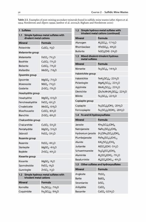
56 CHAPTER 2 · Sulfidic Mine Wastes
Table 2.5. Examples of post-mining secondary minerals found in sulfidic mine wastes (after Alpers et al.1994; Nordstrom and Alpers 1999a; Jambor et al. 2000a,b; Bigham and Nordstrom 2000)
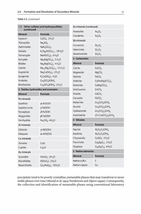
572.6 · Formation and Dissolution of Secondary Minerals
precipitate tend to be poorly crystalline, metastable phases that may transform to morestable phases over time (Murad et al. 1994; Nordstrom and Alpers 1999a). Consequently,the collection and identification of metastable phases using conventional laboratory
Table 2.5. Continued
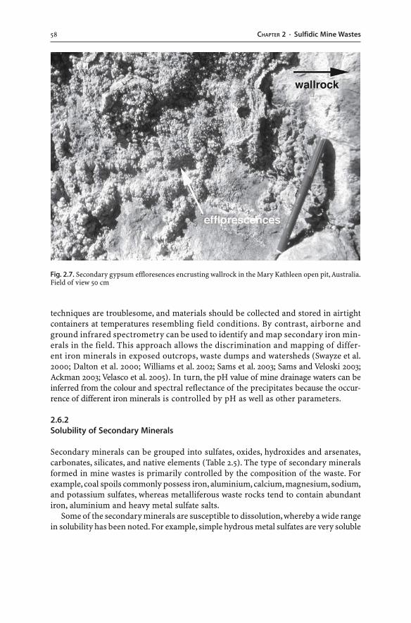
58 CHAPTER 2 · Sulfidic Mine Wastes
techniques are troublesome, and materials should be collected and stored in airtightcontainers at temperatures resembling field conditions. By contrast, airborne andground infrared spectrometry can be used to identify and map secondary iron min-erals in the field. This approach allows the discrimination and mapping of differ-ent iron minerals in exposed outcrops, waste dumps and watersheds (Swayze et al.2000; Dalton et al. 2000; Williams et al. 2002; Sams et al. 2003; Sams and Veloski 2003;Ackman 2003; Velasco et al. 2005). In turn, the pH value of mine drainage waters can beinferred from the colour and spectral reflectance of the precipitates because the occur-rence of different iron minerals is controlled by pH as well as other parameters.
2.6.2Solubility of Secondary Minerals
Secondary minerals can be grouped into sulfates, oxides, hydroxides and arsenates,carbonates, silicates, and native elements (Table 2.5). The type of secondary mineralsformed in mine wastes is primarily controlled by the composition of the waste. Forexample, coal spoils commonly possess iron, aluminium, calcium, magnesium, sodium,and potassium sulfates, whereas metalliferous waste rocks tend to contain abundantiron, aluminium and heavy metal sulfate salts.
Some of the secondary minerals are susceptible to dissolution, whereby a wide rangein solubility has been noted. For example, simple hydrous metal sulfates are very soluble
Fig. 2.7. Secondary gypsum effloresences encrusting wallrock in the Mary Kathleen open pit, Australia.Field of view 50 cm
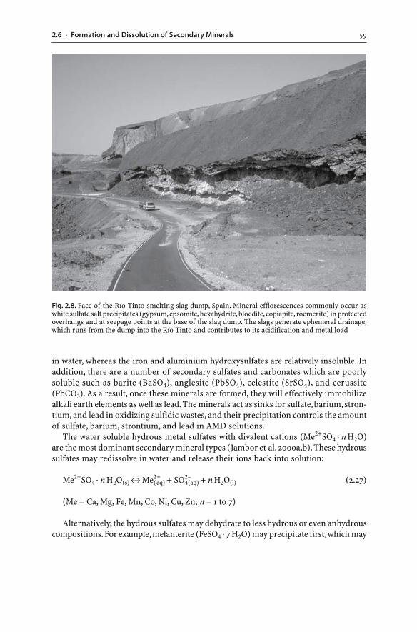
592.6 · Formation and Dissolution of Secondary Minerals
in water, whereas the iron and aluminium hydroxysulfates are relatively insoluble. Inaddition, there are a number of secondary sulfates and carbonates which are poorlysoluble such as barite (BaSO4), anglesite (PbSO4), celestite (SrSO4), and cerussite(PbCO3). As a result, once these minerals are formed, they will effectively immobilizealkali earth elements as well as lead. The minerals act as sinks for sulfate, barium, stron-tium, and lead in oxidizing sulfidic wastes, and their precipitation controls the amountof sulfate, barium, strontium, and lead in AMD solutions.
The water soluble hydrous metal sulfates with divalent cations (Me2+SO4 · n H2O)are the most dominant secondary mineral types (Jambor et al. 2000a,b). These hydroussulfates may redissolve in water and release their ions back into solution:
Me2+SO4 · n H2O(s) ↔ Me2(+aq) + SO4
2–(aq) + n H2O(l) (2.27)
(Me = Ca, Mg, Fe, Mn, Co, Ni, Cu, Zn; n = 1 to 7)
Alternatively, the hydrous sulfates may dehydrate to less hydrous or even anhydrouscompositions. For example, melanterite (FeSO4 · 7 H2O) may precipitate first, which may
Fig. 2.8. Face of the Río Tinto smelting slag dump, Spain. Mineral efflorescences commonly occur aswhite sulfate salt precipitates (gypsum, epsomite, hexahydrite, bloedite, copiapite, roemerite) in protectedoverhangs and at seepage points at the base of the slag dump. The slags generate ephemeral drainage,which runs from the dump into the Río Tinto and contributes to its acidification and metal load
60 CHAPTER 2 · Sulfidic Mine Wastes
then dehydrate to rozenite (FeSO4 · 4 H2O) or szomolnokite (FeSO4 · H2O). Also, thehydrous Fe2+ sulfates may oxidize to Fe2+-Fe3+ or Fe3+ sulfate salts. For instance, theFe2+ mineral melanterite (FeSO4 · 7 H2O) may oxidize to the mixed Fe2+-Fe3+ mineralcopiapite (Fe5(SO4)6(OH)2 · 20 H2O) (Frau 2000; Jerz and Rimstidt 2003). The newlyformed secondary minerals are more stable and resistant to redissolution comparedto their precursors. Thus, secondary minerals may exhibit a paragenetic sequencewhereby the minerals formed in a distinct order. The general trend for the simplehydrous sulfate salts is that the Fe2+ minerals form first, followed by the mixed Fe2+-Fe3+ minerals, and then the Fe3+ minerals (Jambor et al. 2000a,b).
Secondary minerals, be they relatively soluble or insoluble, possess large surfaceareas. Consequently, they adsorb or coprecipitate significant quantities of trace ele-ments including metals and metalloids. The precipitates effectively immobilize ele-ments in acid mine waters and hence provide an important natural attentuation anddetoxification mechanism in mine waters (Lin 1997; Nordstrom and Alpers 1999a;Berger et al. 2000). However, this immobilization of metals is only temporary as manymineral efflorescences, particularly the simple hydrous metal sulfates, tend to besoluble and release their stored metals back into mine waters upon dissolution.
2.6.3Acid Consumption and Production
The precipitation of some secondary minerals may influence the mine water pH astheir formation generates or consumes hydrogen ions. Generally, the formation of Fe3+
or Al3+ hydroxides generates acid, whereas the precipitation of Fe2+, Mn2, Fe3+ and Al3+
sulfate salts such as jarosite (KFe3(SO4)2(OH)6), alunite (KAl3(SO4)2(OH)6), coquimbite(Fe2(SO4)3 · 9 H2O), jurbanite (Al(SO4)(OH) · 5 H2O), halotrichite (FeAl2(SO4)4 · 22 H2O), ormelanterite (FeSO4 · 7 H2O) consumes acid. However, this consumption of acidity isonly temporary as these minerals, particularly the simple hydrous metal sulfates, tendto be soluble and release their stored acidity upon dissolution (Cravotta 1994)(Table 2.2). A generalized reaction for this temporary acid consumption can be writ-ten as follows:
cationsn+(aq) + anionsn–
(aq) + n H+(aq) + n H2O(l) ↔ secondary solids-n H2O(s) (2.28)
The precipitation and redissolution of secondary minerals in sulfidic wastes maygreatly influence the acidity and chemical composition of ground, surface and porewaters (Chap. 3). As a consequence, the amounts and types of secondary salts need tobe determined in sulfidic mine wastes.
2.6.4Coatings and Hardpans
The formation of secondary minerals not only influences the mine water chemistrybut also impacts on potential water-rock reactions. For example, rapid precipitationof secondary minerals – during sulfide oxidation or carbonate dissolution – may coator even encapsulate the acid producing or buffering mineral. Such coatings will makethe mineral less susceptible to continued weathering and dissolution.
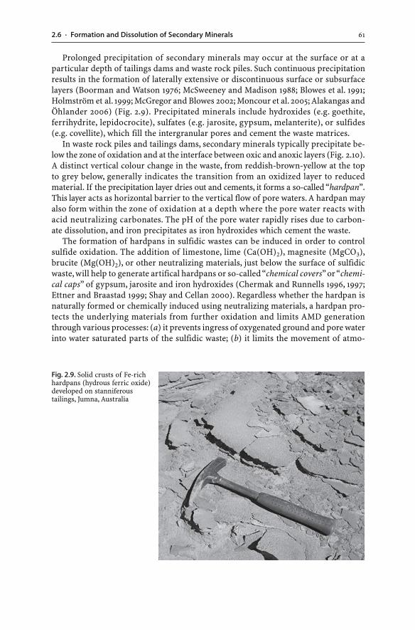
612.6 · Formation and Dissolution of Secondary Minerals
Prolonged precipitation of secondary minerals may occur at the surface or at aparticular depth of tailings dams and waste rock piles. Such continuous precipitationresults in the formation of laterally extensive or discontinuous surface or subsurfacelayers (Boorman and Watson 1976; McSweeney and Madison 1988; Blowes et al. 1991;Holmström et al. 1999; McGregor and Blowes 2002; Moncour et al. 2005; Alakangas andÖhlander 2006) (Fig. 2.9). Precipitated minerals include hydroxides (e.g. goethite,ferrihydrite, lepidocrocite), sulfates (e.g. jarosite, gypsum, melanterite), or sulfides(e.g. covellite), which fill the intergranular pores and cement the waste matrices.
In waste rock piles and tailings dams, secondary minerals typically precipitate be-low the zone of oxidation and at the interface between oxic and anoxic layers (Fig. 2.10).A distinct vertical colour change in the waste, from reddish-brown-yellow at the topto grey below, generally indicates the transition from an oxidized layer to reducedmaterial. If the precipitation layer dries out and cements, it forms a so-called “hardpan”.This layer acts as horizontal barrier to the vertical flow of pore waters. A hardpan mayalso form within the zone of oxidation at a depth where the pore water reacts withacid neutralizing carbonates. The pH of the pore water rapidly rises due to carbon-ate dissolution, and iron precipitates as iron hydroxides which cement the waste.
The formation of hardpans in sulfidic wastes can be induced in order to controlsulfide oxidation. The addition of limestone, lime (Ca(OH)2), magnesite (MgCO3),brucite (Mg(OH)2), or other neutralizing materials, just below the surface of sulfidicwaste, will help to generate artifical hardpans or so-called “chemical covers” or “chemi-cal caps” of gypsum, jarosite and iron hydroxides (Chermak and Runnells 1996, 1997;Ettner and Braastad 1999; Shay and Cellan 2000). Regardless whether the hardpan isnaturally formed or chemically induced using neutralizing materials, a hardpan pro-tects the underlying materials from further oxidation and limits AMD generationthrough various processes: (a) it prevents ingress of oxygenated ground and pore waterinto water saturated parts of the sulfidic waste; (b) it limits the movement of atmo-
Fig. 2.9. Solid crusts of Fe-richhardpans (hydrous ferric oxide)developed on stanniferoustailings, Jumna, Australia
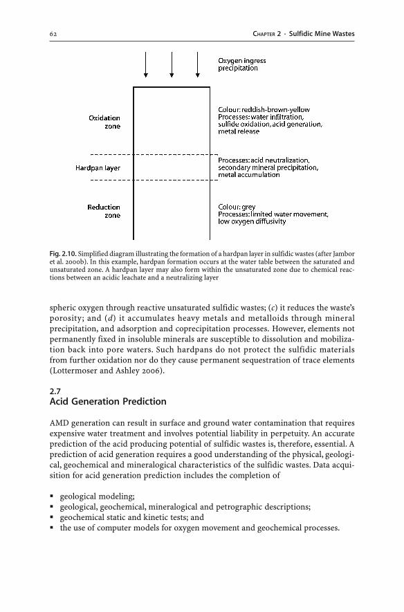
62 CHAPTER 2 · Sulfidic Mine Wastes
spheric oxygen through reactive unsaturated sulfidic wastes; (c) it reduces the waste’sporosity; and (d) it accumulates heavy metals and metalloids through mineralprecipitation, and adsorption and coprecipitation processes. However, elements notpermanently fixed in insoluble minerals are susceptible to dissolution and mobiliza-tion back into pore waters. Such hardpans do not protect the sulfidic materialsfrom further oxidation nor do they cause permanent sequestration of trace elements(Lottermoser and Ashley 2006).
2.7Acid Generation Prediction
AMD generation can result in surface and ground water contamination that requiresexpensive water treatment and involves potential liability in perpetuity. An accurateprediction of the acid producing potential of sulfidic wastes is, therefore, essential. Aprediction of acid generation requires a good understanding of the physical, geologi-cal, geochemical and mineralogical characteristics of the sulfidic wastes. Data acqui-sition for acid generation prediction includes the completion of
� geological modeling;� geological, geochemical, mineralogical and petrographic descriptions;� geochemical static and kinetic tests; and� the use of computer models for oxygen movement and geochemical processes.
Fig. 2.10. Simplified diagram illustrating the formation of a hardpan layer in sulfidic wastes (after Jamboret al. 2000b). In this example, hardpan formation occurs at the water table between the saturated andunsaturated zone. A hardpan layer may also form within the unsaturated zone due to chemical reac-tions between an acidic leachate and a neutralizing layer
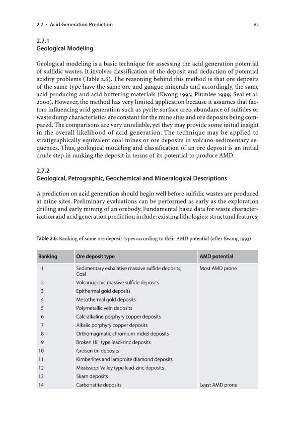
632.7 · Acid Generation Prediction
2.7.1Geological Modeling
Geological modeling is a basic technique for assessing the acid generation potentialof sulfidic wastes. It involves classification of the deposit and deduction of potentialacidity problems (Table 2.6). The reasoning behind this method is that ore depositsof the same type have the same ore and gangue minerals and accordingly, the sameacid producing and acid buffering materials (Kwong 1993; Plumlee 1999; Seal et al.2000). However, the method has very limited application because it assumes that fac-tors influencing acid generation such as pyrite surface area, abundance of sulfides orwaste dump characteristics are constant for the mine sites and ore deposits being com-pared. The comparisons are very unreliable, yet they may provide some initial insightin the overall likelihood of acid generation. The technique may be applied tostratigraphically equivalent coal mines or ore deposits in volcano-sedimentary se-quences. Thus, geological modeling and classification of an ore deposit is an initialcrude step in ranking the deposit in terms of its potential to produce AMD.
2.7.2Geological, Petrographic, Geochemical and Mineralogical Descriptions
A prediction on acid generation should begin well before sulfidic wastes are producedat mine sites. Preliminary evaluations can be performed as early as the explorationdrilling and early mining of an orebody. Fundamental basic data for waste character-ization and acid generation prediction include: existing lithologies; structural features;
Table 2.6. Ranking of some ore deposit types according to their AMD potential (after Kwong 1993)
64 CHAPTER 2 · Sulfidic Mine Wastes
ore and gangue textures and mineralogy; particle size distribution; depth of oxida-tion; and whole rock geochemistry. Geological data such as pyrite content, geochemi-cal analyses (S, C, CO3, metals), and static test data can be used to construct a three-di-mensional block model of different waste rock units prior to mining (Bennett et al. 1997).
Characterization of sulfidic waste materials involves mineralogical, mineral chemi-cal and geochemical investigations (Lin 1997). Mineralogical observations using X-raydiffraction, optical microscopy, scanning electron microscopy, and transmission elec-tron microscopy should note the size, shape, surface areas, degree of crystallinity, dis-tribution, and oxidation state of sulfides, gangue minerals, and weathering products.Textural descriptions are also important as they can reveal protective encapsulationof sulfides in weathering resistant gangue minerals such as quartz.
Mineral chemical investigations using electron microprobe analyses demonstratethe abundance and siting of metals, metalloids and other elements, which may bemobilized during sulfide oxidation (Lu et al. 2005). The speciation, bioavailability andpotential mobility of heavy metals in sulfidic wastes can be evaluated using partialand sequential extraction techniques (Ostergren et al. 1999; Dold 2003; Hudson-Edwards and Edwards 2005). Heavy metals may be present as cations: (a) on exchange-able sites; (b) incorporated in carbonates; (c) incorporated in easily reducible iron andmanganese oxides and hydroxides; (d) incorporated in moderately reducible iron andmanganese oxides and hydroxides; (e) incorporated in sulfides and organic matter;and (f) incorporated in residual silicate and oxide minerals. Thus, geological, petro-graphic, geochemical and mineralogical descriptions of sulfidic wastes provide im-portant information on the nature and distribution of acid producing and acid buff-ering minerals, and on the mineralogical siting of metals and metalloids.
2.7.3Sampling
The distribution of acid producing and acid consuming minerals is generally hetero-geneous on micro- to macroscopic scales. Different ore lenses, coal seams and wastematerials may represent acid producing or acid buffering units. Sulfidic wastes can-not be treated as a homogenous mass.
Waste samples can be obtained during exploration drilling and mining. However,representative sampling from drill cores is very difficult to achieve. The properties ofvein deposits highlight the problems of sampling from drill cores for acid generationprediction (Dobos 2000). For example, a mesothermal gold vein deposit comprises ofa rock mass, which is non-acid generating, and a series of acid generating veins withabundant pyrite (Fig. 2.11). Drilling and sampling of a composite over the entire drillsection will yield a sample, largely comprising of the non-acid generating host rock.In contrast, blasting of this material will cause the rock to break along the veins, re-sulting in the exposure of a disproportionate amount of pyrite veins. If this minedmaterial is dumped, it will generate more acid than the initially drilled and geochemi-cally tested material. Therefore, geologically controlled sampling is most importantin order to ensure that the analyzed samples are representative of the type and distri-bution of acid producing and acid buffering minerals (Dobos 2000). Otherwise, sig-nificant errors may occur when averages of static or kinetic test data are used: (a) to
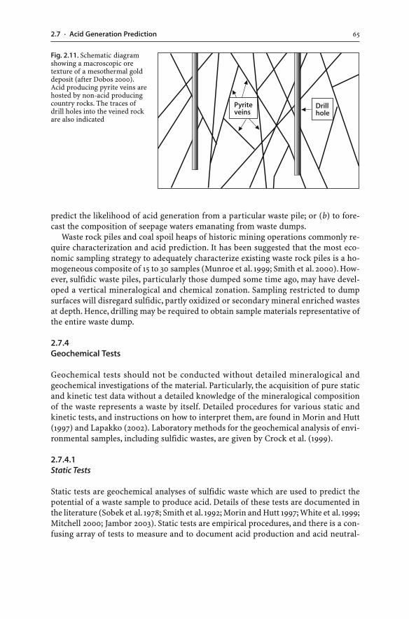
652.7 · Acid Generation Prediction
predict the likelihood of acid generation from a particular waste pile; or (b) to fore-cast the composition of seepage waters emanating from waste dumps.
Waste rock piles and coal spoil heaps of historic mining operations commonly re-quire characterization and acid prediction. It has been suggested that the most eco-nomic sampling strategy to adequately characterize existing waste rock piles is a ho-mogeneous composite of 15 to 30 samples (Munroe et al. 1999; Smith et al. 2000). How-ever, sulfidic waste piles, particularly those dumped some time ago, may have devel-oped a vertical mineralogical and chemical zonation. Sampling restricted to dumpsurfaces will disregard sulfidic, partly oxidized or secondary mineral enriched wastesat depth. Hence, drilling may be required to obtain sample materials representative ofthe entire waste dump.
2.7.4Geochemical Tests
Geochemical tests should not be conducted without detailed mineralogical andgeochemical investigations of the material. Particularly, the acquisition of pure staticand kinetic test data without a detailed knowledge of the mineralogical compositionof the waste represents a waste by itself. Detailed procedures for various static andkinetic tests, and instructions on how to interpret them, are found in Morin and Hutt(1997) and Lapakko (2002). Laboratory methods for the geochemical analysis of envi-ronmental samples, including sulfidic wastes, are given by Crock et al. (1999).
2.7.4.1Static Tests
Static tests are geochemical analyses of sulfidic waste which are used to predict thepotential of a waste sample to produce acid. Details of these tests are documented inthe literature (Sobek et al. 1978; Smith et al. 1992; Morin and Hutt 1997; White et al. 1999;Mitchell 2000; Jambor 2003). Static tests are empirical procedures, and there is a con-fusing array of tests to measure and to document acid production and acid neutral-
Fig. 2.11. Schematic diagramshowing a macroscopic oretexture of a mesothermal golddeposit (after Dobos 2000).Acid producing pyrite veins arehosted by non-acid producingcountry rocks. The traces ofdrill holes into the veined rockare also indicated
66 CHAPTER 2 · Sulfidic Mine Wastes
ization. In addition, static tests and reporting conventions vary (North America: AP,NP, NNP, NPR; Australia and the Asia Pacific region: MPA, ANC, NAPP). Fortunately,static tests can be assigned to three major categories:
� Saturated paste pH and electrical conductivity. A representative crushed waste sam-ple is saturated with distilled water to form a paste. The pH and electrical conduc-tivity (EC) of the paste are determined after a period of equilibration (12 to 24 hours)(Morin and Hutt 1997). A pH value of less than 4 generally indicates that the sampleis acid generating, and an EC value of greater than 20 µS cm–1 indicates a high levelof total dissolved solids in the waste’s leachate. Paste pH and EC values of wastes andsoils forming on waste rock dumps may change over time because sulfide mineralswithin the materials weather and release ions into solution and the materials areflushed by infiltration and runoff waters (Borden 2001).
� Acid Base Accounting (ABA). Acid Base Accounting refers to the numerical data usedto predict acid generation. The three components of the ABA are: (1) determinationof acid production; (2) determination of acid consumption; and (3) calculation ofnet acid production or consumption using the data from (1) and (2).1. Determination of acid production. The Acid Potential (AP), Acid Production Po-
tential (APP), or Maximum Potential Acidity (MPA) tests establish the maximumamount of sulfuric acid produced from sulfidic wastes. This is measured byanalyzing the sample for its sulfur content. For the MPA and APP, the weight percent sulfur is then converted to kilograms of sulfuric acid per tonne of waste (MPAvalue in kg H2SO4 t–1 = wt.% S × 30.625). For the AP, the weight per cent sulfur isconverted to kilograms of calcium carbonate per tonne of waste that would berequired to neutralize the acidity (AP value in kg CaCO3 t–1 = wt.% S × 31.25).
2. Determination of acid consumption. The Neutralization Potential (NP), Acid Neu-tralizing Capacity (ANC) or Acid Consumption (AC) tests measure the amountof acid the sample can neutralize. This is determined by analyzing the acidityconsumption of a sample in acid (HCl or H2SO4). Consequently, the tests estab-lish the buffering capacity of a sample due to dissolution and weathering of gangueminerals, or in other words, the ability of a sample to neutralize acid generatedfrom sulfide oxidation. The NP and ANC are determined by adding acid to a sam-ple, and then back titrating with hydroxide to determine the amount of acid thesample has consumed. The ANC value is reported in the form of kilograms ofsulfuric acid consumption per tonne of waste (kg H2SO4 t–1), whereas the NP valueis given in the form of kilograms of calcium carbonate consumption per tonne ofwaste (kg CaCO3 t–1).
3. Calculation of net acid production or consumption. The Net Acid Production Po-tential (NAPP) represents the theoretical balance of a sample’s capacity to gener-ate acid. In contrast, the Net Neutralization Potential (NNP) gives the waste’s ca-pacity to neutralize any acid generated.3.1 NAPP calculations are based on the net acidity of samples (i.e. kilograms of
H2SO4 per tonne of waste) (Environment Australia 1997). The NAPP is definedas being the difference between the Maximum Potential Acidity (MPA) and theAcid Neutralizing Capacity (ANC), whereby the MPA value is subtracted fromthe ANC value. A positive NAPP value indicates the sample should generateacid, whereas a negative value indicates the potential for acid neutralization.
672.7 · Acid Generation Prediction
NAPP = MPA – ANC
or
NAPP (kg H2SO4 t–1) = S (wt.%) × 30.625 – ANC (kg H2SO4 t–1) (2.29)
3.2 NNP calculations are based on the net neutralizing potential available in thesamples (i.e. kilograms of CaCO3 per tonne of waste) (Mitchell 2000; Whiteet al. 1999; Skousen et al. 2002). The NNP or ABA is defined as being the differ-ence between the Acid Potential (AP) and the Neutralization Potential (NP).In theory, the NNP value is the net amount of limestone required to exactlyneutralize the potential acid-forming rock.
NNP or ABA = NP – AP
or
NNP or ABA (kg CaCO3 t–1) = NP (kg CaCO3 t–1) – AP (kg CaCO3 t–1) (2.30)
Theoretically, rocks with positive NNP values have no potential for acidifica-tion whereas rocks with negative NNP values do. In practice, a safety factor is ap-plied and rocks with a significant positive NNP value are generally regarded ashaving no acidification potential (>+20 or +30 kg CaCO3 t–1). Rocks with a signifi-cant negative NNP value (<–20 or –30 kg CaCO3 t–1) are potentially acid generat-ing. Materials with intermediate NNP values have uncertain acid generation po-tentials (–20 or –30 kg CaCO3 t–1 < NNP < +20 or +30 kg CaCO3 t–1).
Alternatively, the ratio NP/AP, known as the Neutralization Potential Ratio (NPR),or the ratio NP/MPA can be used as the criterion to evaluate the capacity of thematerial to generate AMD (Price et al. 1997; Skousen et al. 2002). Theoretically, aNP/AP ratio less than 1 generally implies that the sample will eventually lead toacidic conditions (Sherlock et al. 1995). A ratio greater than 1 is indicative that thesample will not produce acid upon weathering. In practice, a safety factor is ap-plied and rocks with a NP/AP ratio greater than 2, 3 or 4 are non-acid generating,whereas samples with a NP/AP ratio less than 1 have a likely acidification potential(Price et al. 1997).
� Net Acid Generation (NAG) or Net Acid Production (NAP). The NAG test directly evalu-ates the generation of sulfuric acid in sulfidic wastes. It is based on the principle thata strong oxidizing agent accelerates the oxidation of sulfides. The test simply involvesthe addition of hydrogen peroxide to a pulverized sample and the measurement ofthe solution pH after 24 hours, when the oxidation reaction is thought to be com-plete (final NAG pH). If the NAG pH is below a critical value, then the sample hasthe potential to generate acid in the field (Schafer 2000). Variations of the NAG testprocedure include the static, sequential and kinetic NAG test (Miller 1996, 1998a). Afinal NAG pH greater than or equal to 4.5 classifies the sample as non-acid forming.A final NAG pH result of less than 4.5 confirms that sulfide oxidation generates anexcess of acidity and classifies the material as higher risk. The NAP test is similar tothe NAG test and involves the addition of hydrogen peroxide and titration of the per-
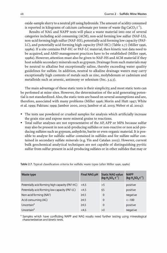
68 CHAPTER 2 · Sulfidic Mine Wastes
oxide-sample slurry to a neutral pH using hydroxide. The amount of acidity consumedis reported in kilograms of calcium carbonate per tonne of waste (kg CaCO3 t–1).
Results of NAG and NAPP tests will place a waste material into one of severalcategories including acid consuming (ACM), non-acid forming low sulfur (NAF-LS),non-acid forming high sulfur (NAF-HS), potentially acid forming low capacity (PAF-LC), and potentially acid forming high capacity (PAF-HC) (Table 2.7) (Miller 1996,1998a). If a site contains PAF-HC or PAF-LC material, then kinetic test data need tobe acquired, and AMD management practices have to be established (Miller 1996,1998a). However, attention must also be given to NAF-HS and ACM material if theyhost soluble secondary minerals such as gypsum. Drainage from such materials maybe neutral to alkaline but exceptionally saline, thereby exceeding water qualityguidelines for sulfate. In addition, neutral to alkaline drainage waters may carryexceptionally high contents of metals such as zinc, molybdenum or cadmium andmetalloids such as arsenic, antimony or selenium (Sec. 3.4.3).
The main advantage of these static tests is their simplicity, and most static tests canbe perfomed at mine sites. However, the determination of the acid generating poten-tial is not standardized. Also, the static tests are based on several assumptions and are,therefore, associated with many problems (Miller 1996; Morin and Hutt 1997; Whiteet al. 1999; Paktunc 1999; Jambor 2000, 2003; Jambor et al. 2003; Weber et al. 2004):
� The tests use powdered or crushed samples for analysis which artificially increasethe grain size and expose more mineral grains to reactions.
� Total sulfur analyses are not representative of the AP, APP or MPA because sulfurmay also be present in non acid-producing sulfides or non-reactive or non acid-pro-ducing sulfates such as gypsum, anhydrite, barite or even organic material. It is pos-sible to analyze for sulfidic sulfur contained in sulfides and for sulfate sulfur con-tained in secondary sulfate minerals (e.g. Yin and Catalan 2003). However, currentbulk geochemical analytical techniques are not capable of distinguishing pyriticsulfur from sulfur present in acid-producing sulfates or in other sulfides that may or
Table 2.7. Typical classification criteria for sulfidic waste types (after Miller 1996, 1998a)
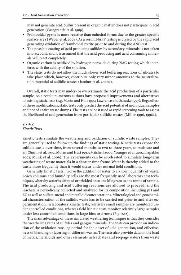
692.7 · Acid Generation Prediction
may not generate acid. Sulfur present in organic matter does not participate in acidgeneration (Casagrande et al. 1989).
� Framboidal pyrite is more reactive than euhedral forms due to the greater specificsurface area (Weber et al. 2004). As a result, NAPP testing is biased by the rapid acidgenerating oxidation of framboidal pyrite prior to and during the ANC test.
� The possible coating of acid producing sulfides by secondary minerals is not takeninto account, and it is assumed that the acid producing and acid consuming miner-als will react completely.
� Organic carbon is oxidized by hydrogen peroxide during NAG testing which inter-feres with the acidity of the solution.
� The static tests do not allow the much slower acid buffering reactions of silicates totake place which, however, contribute only very minor amounts to the neutraliza-tion potential of sulfidic wastes (Jambor et al. 2000c).
Overall, static tests may under- or overestimate the acid production of a particularsample. As a result, numerous authors have proposed improvements and alternativesto existing static tests (e.g. Morin and Hutt 1997; Lawrence and Scheske 1997). Regardlessof these modifications, static tests only predict the acid potential of individual samplesand not of entire waste dumps. The tests are best used as rapid screening tools to assessthe likelihood of acid generation from particular sulfidic wastes (Miller 1996, 1998a).
2.7.4.2Kinetic Tests
Kinetic tests simulate the weathering and oxidation of sulfidic waste samples. Theyare generally used to follow up the findings of static testing. Kinetic tests expose thesulfidic waste over time, from several months to two to three years, to moisture andair (Smith et al. 1992; Morin and Hutt 1997; Mitchell 2000; Younger et al. 2002; Lapakko2002; Munk et al. 2006). The experiments can be accelerated to simulate long-termweathering of waste materials in a shorter time frame. Water is thereby added to thewaste more frequently than it would occur under normal field conditions.
Generally, kinetic tests involve the addition of water to a known quantity of waste.Leach columns and humidity cells are the most frequently used laboratory test tech-niques, whereby water is dripped or trickled onto one kilogram to one tonne of sample.The acid producing and acid buffering reactions are allowed to proceed, and theleachate is periodically collected and analyzed for its composition including pH andEC as well as sulfate, metal and metalloid concentrations. Mineralogical and geochemi-cal characterization of the sulfidic waste has to be carried out prior to and after ex-perimentation. In laboratory kinetic tests, relatively small samples are monitored un-der controlled conditions, whereas field kinetic tests monitor relatively large samplesunder less controlled conditions in large bins or drums (Fig. 2.12).
The main advantage of these simulated weathering techniques is that they considerthe weathering rates of sulfides and gangue minerals. The tests can provide an indica-tion of the oxidation rate, lag period for the onset of acid generation, and effective-ness of blending or layering of different wastes. The tests also provide data on the loadof metals, metalloids and other elements in leachates and seepage waters from waste
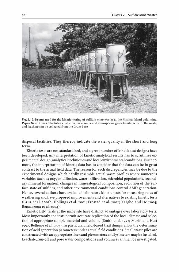
70 CHAPTER 2 · Sulfidic Mine Wastes
disposal facilities. They thereby indicate the water quality in the short and longterm.
Kinetic tests are not standardized, and a great number of kinetic test designs havebeen developed. Any interpretation of kinetic analytical results has to scrutinize ex-perimental design, analytical techniques and local environmental conditions. Further-more, the interpretation of kinetic data has to consider that the data can be in greatcontrast to the actual field data. The reason for such discrepancies may be due to theexperimental designs which hardly resemble actual waste profiles where numerousvariables such as oxygen diffusion, water infiltration, microbial populations, second-ary mineral formation, changes in mineralogical composition, evolution of the sur-face state of sulfides, and other environmental conditions control AMD generation.Hence, several authors have evaluated laboratory kinetic tests for measuring rates ofweathering and have proposed improvements and alternatives to existing kinetic tests(Cruz et al. 2001b; Hollings et al. 2001; Frostad et al. 2002; Kargbo and He 2004;Benzaazoua et al. 2004).
Kinetic field trials at the mine site have distinct advantages over laboratory tests.Most importantly, the tests permit accurate replication of the local climate and selec-tion of appropriate sample material and volume (Smith et al. 1992; Morin and Hutt1997; Bethune et al. 1997). In particular, field-based trial dumps allow the determina-tion of acid generation parameters under actual field conditions. Small waste piles areconstructed with an appropriate liner, and piezometers and lysimeters may be installed.Leachate, run-off and pore water compositions and volumes can then be investigated.
Fig. 2.12. Drums used for the kinetic testing of sulfidic mine wastes at the Misima Island gold mine,Papua New Guinea. The tubes enable meteoric water and atmospheric gases to interact with the waste,and leachate can be collected from the drum base
712.7 · Acid Generation Prediction
The trials reduce the inaccuracies resulting from small test samples and allow a morerealistic assessment of the AMD processes and potential.
2.7.5Modeling the Oxidation of Sulfidic Waste Dumps
Oxygen is essential for the oxidation of sulfides in waste dumps. Simple calculationscan demonstrate that the availability of oxygen controls the oxidation rate of sulfidicwaste (Gibson and Ritchie 1991). For example, a 50 t sulfidic waste rock pile has a sul-fur concentration of 2 wt.%. The waste dump, therefore, contains 1 t of sulfur whichwill require, based on the stoichiometric ratio, 1.75 t of oxygen for its oxidation to sul-fate. A 50 t waste pile with a porosity of 0.3 contains approximately 8 × 10⁻³ t of oxy-gen, which is only 1/200 of the 1.75 t needed for complete oxidation (Gibson and Ritchie1991). Consequently, in order to accomplish complete oxidation of the waste, oxygenmust travel into the heap from the atmosphere.
Indeed, the transport of oxygen to the oxidation sites is considered the rate limit-ing process in dumps and tailings deposits (Ritchie 1994a–c). The gas-phase trans-port of oxygen in waste dumps from the surface to the oxidation sites at depth occursby: (a) diffusion (i.e. flow of oxygen induced by a gas concentration gradient); (b) con-vection (i.e. flow of air induced by wind action, barometric pressure changes, or thermalconvection driven by the heat generated from the exothermic pyrite reaction); and(c) advection (i.e. flow of air induced by a thermal or pressure gradient) (Ritchie 1994a–c;Rose and Cravotta 1999). Minor amounts of oxygen may also be transported into thedump via liquid-phase diffusion and advection (i.e. flow of oxygen via infiltratingprecipitation).
The relative contribution of diffusion, convection or advection to overall gas trans-port is dependent on a variety of parameters including the position of the waste withinthe dump, the component materials and minerals, and the way in which the dump hasbeen constructed. Diffuse transport of oxygen through the gas-filled pore spaces isthought to dominate in unsaturated, newly built waste dumps (Ritchie 1994b; Aachibet al. 2004; Kim and Benson 2004). Uniform diffusion into such waste materials willresult in oxygen profiles with horizontally flat oxygen concentration contours. Gasconvection is limited to the edges of waste dumps, and since dump edges are a smallfraction of the total dump volume, convection is disregarded in the modeling of theoxidation rate of pyritic waste dumps (Ritchie 1994b). However, convective gas fluxhas been reported from newly constructed waste dumps (Cathles 1994). In addition,localized convections have been observed in aged waste dumps, as indicated by highoxygen concentrations at depth and complex oxygen concentration profiles. The ad-vective and convective modes of oxygen transport appear to predominate in porouswaste dumps containing abundant coarse-grained rock fragments (Rose and Cravotta1999). The diffuse mode of oxygen transport predominates in less permeable wastematerials composed of small fragments.
The reactivity of a sulfidic waste pile and its oxidation behaviour in the long termcan be described using the intrinsic oxidation rate (Ritchie 1994a–c). The intrinsicoxidation rate is calculated through a series of mathematical equations. These equa-tions quantify the physical mechanisms which control the oxidation of a pyritic wasteheap. For instance, the oxygen consumption rate represents the rate at which oxygen
72 CHAPTER 2 · Sulfidic Mine Wastes
is consumed by the dump material (in units of kilograms of oxygen per cubic meterof waste per second; kg–1 m–3 s–1 or mol kg–1 s–1). The term quantifies the loss of oxy-gen from the pore space by oxidation reactions in the waste. A typical oxygen consump-tion rate value calculated for waste rock dumps is in the order of 10–8 to 10–11 kg–1 m–3 s–1
(Bennett et al. 1994; Ritchie 1995; Hollings et al. 2001). In this model, it is assumed thatoxygen is only consumed by pyrite. However, oxygen may also be consumed by theoxidation of other sulfides, native elements and organic matter. Furthermore, the sul-fide oxidation rate is dependent on a large number of variables including tempera-ture, pH, Fe3+ concentration, particle size distribution, mineral surface area, bacterialpopulation, trace element substitution, degree of pyrite crystallinity and so forth. Fi-nally, sulfide oxidation rates within a single dump appear to be variable; a dump maycontain pockets of more highly oxidizing materials, particularly toward the dump edges(Linklater et al. 2005). Thus, these weathering models will need further refinement.
2.8Monitoring Sulfidic Wastes
The recognition of sulfide oxidation does not necessarily require sophisticated equip-ment and measurements. In fact, some of the common indicators of sulfide oxidationcan be recognized in the field:
� Abundant yellow to red staining on rocks and flocculants in seepage points, streamsand ponds due to the formation of secondary iron minerals and colloids
� Sulfurous odours� Unsuccessful colonization of waste materials by vegetation� Abundant mineral efflorescences within and on exposed waste materials� Increasing magnetic susceptibility due to the abundance of magnetic secondary iron
oxides and carbonates� Increasing waste temperature due to exothermic pyrite oxidation� Decreasing oxygen concentration in pore gases due to oxygen consumption; and most
importantly� Decreasing pH, increasing EC, and increasing sulfate, metal (Cu, Zn etc) and major
cation (Na, K, Ca, Mg) concentrations in drainage waters with time (Miller 1995)
The latter three indicators of sulfide oxidation are used to monitor sulfidic wastes.Sulfidic waste rock dumps, tailings dams and heap leach piles need monitoring in or-der to detect at the earliest point in time whether the waste material will “turn acid”and generate AMD. Also, rehabilitated waste repositories need monitoring to estab-lish the effectiveness of the control technique used to curtail sulfide oxidation. Themonitoring techniques are designed to identify the early presence of, or the changesto, any products of the acid producing reactions in sulfidic wastes. The products ofthe acid producing reactions are usually quantified by one or more of the followingparameters (Hutchison and Ellison 1992):
� Water analyses of dissolved contaminant concentrations and loads (Sec. 3.8)� Temperature profiles. Pyrite oxidation is an exothermic reaction, and the effects of
heat generation can be assessed by remote or in situ sensing. Remote sensing using
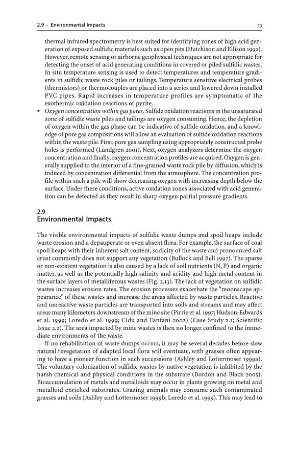
732.9 · Environmental Impacts
thermal infrared spectrometry is best suited for identifying zones of high acid gen-eration of exposed sulfidic materials such as open pits (Hutchison and Ellison 1992).However, remote sensing or airborne geophysical techniques are not appropriate fordetecting the onset of acid generating conditions in covered or piled sulfidic wastes.In situ temperature sensing is used to detect temperatures and temperature gradi-ents in sulfidic waste rock piles or tailings. Temperature sensitive electrical probes(thermistors) or thermocouples are placed into a series and lowered down installedPVC pipes. Rapid increases in temperature profiles are symptomatic of theexothermic oxidation reactions of pyrite.
� Oxygen concentration within gas pores. Sulfide oxidation reactions in the unsaturatedzone of sulfidic waste piles and tailings are oxygen consuming. Hence, the depletionof oxygen within the gas phase can be indicative of sulfide oxidation, and a knowl-edge of pore gas compositions will allow an evaluation of sulfide oxidation reactionswithin the waste pile. First, pore gas sampling using appropriately constructed probeholes is performed (Lundgren 2001). Next, oxygen analyzers determine the oxygenconcentration and finally, oxygen concentration profiles are acquired. Oxygen is gen-erally supplied to the interior of a fine-grained waste rock pile by diffusion, which isinduced by concentration differential from the atmosphere. The concentration pro-file within such a pile will show decreasing oxygen with increasing depth below thesurface. Under these conditions, active oxidation zones associated with acid genera-tion can be detected as they result in sharp oxygen partial pressure gradients.
2.9Environmental Impacts
The visible environmental impacts of sulfidic waste dumps and spoil heaps includewaste erosion and a depauperate or even absent flora. For example, the surface of coalspoil heaps with their inherent salt content, sodicity of the waste and pronounced saltcrust commonly does not support any vegetation (Bullock and Bell 1997). The sparseor non-existent vegetation is also caused by a lack of soil nutrients (N, P) and organicmatter, as well as the potentially high salinity and acidity and high metal content inthe surface layers of metalliferous wastes (Fig. 2.13). The lack of vegetation on sulfidicwastes increases erosion rates. The erosion processes exacerbate the “moonscape ap-pearance” of these wastes and increase the areas affected by waste particles. Reactiveand unreactive waste particles are transported into soils and streams and may affectareas many kilometers downstream of the mine site (Pirrie et al. 1997; Hudson-Edwardset al. 1999; Loredo et al. 1999; Cidu and Fanfani 2002) (Case Study 2.1; ScientificIssue 2.2). The area impacted by mine wastes is then no longer confined to the imme-diate environments of the waste.
If no rehabilitation of waste dumps occurs, it may be several decades before slownatural revegetation of adapted local flora will eventuate, with grasses often appear-ing to have a pioneer function in such successions (Ashley and Lottermoser 1999a).The voluntary colonization of sulfidic wastes by native vegetation is inhibited by theharsh chemical and physical conditions in the substrate (Bordon and Black 2005).Bioaccumulation of metals and metalloids may occur in plants growing on metal andmetalloid enriched substrates. Grazing animals may consume such contaminatedgrasses and soils (Ashley and Lottermoser 1999b; Loredo et al. 1999). This may lead to
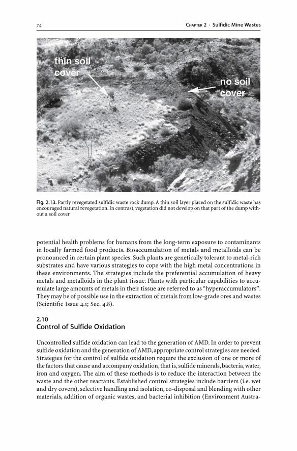
74 CHAPTER 2 · Sulfidic Mine Wastes
potential health problems for humans from the long-term exposure to contaminantsin locally farmed food products. Bioaccumulation of metals and metalloids can bepronounced in certain plant species. Such plants are genetically tolerant to metal-richsubstrates and have various strategies to cope with the high metal concentrations inthese environments. The strategies include the preferential accumulation of heavymetals and metalloids in the plant tissue. Plants with particular capabilities to accu-mulate large amounts of metals in their tissue are referred to as “hyperaccumulators”.They may be of possible use in the extraction of metals from low-grade ores and wastes(Scientific Issue 4.1; Sec. 4.8).
2.10Control of Sulfide Oxidation
Uncontrolled sulfide oxidation can lead to the generation of AMD. In order to preventsulfide oxidation and the generation of AMD, appropriate control strategies are needed.Strategies for the control of sulfide oxidation require the exclusion of one or more ofthe factors that cause and accompany oxidation, that is, sulfide minerals, bacteria, water,iron and oxygen. The aim of these methods is to reduce the interaction between thewaste and the other reactants. Established control strategies include barriers (i.e. wetand dry covers), selective handling and isolation, co-disposal and blending with othermaterials, addition of organic wastes, and bacterial inhibition (Environment Austra-
Fig. 2.13. Partly revegetated sulfidic waste rock dump. A thin soil layer placed on the sulfidic waste hasencouraged natural revegetation. In contrast, vegetation did not develop on that part of the dump with-out a soil cover
752.10 · Control of Sulfide Oxidation
lia 1997; Miller 1998b; Evangelou 1998; SMME 1998; Parker 1999; Brown et al. 2002).More technologically advanced and innovative strategies involve induced hardpanformation, grouting or mineral surface treatments (Scientific Issue 2.3, Fig. 2.14). Bothestablished and innovative sulfide oxidation control strategies are generally designedto induce one or more of the following:
� Exclusion of water� Exclusion of oxygen� pH control� Control of Fe3+ generation� Control of bacterial action� Removal and/or isolation of sulfides
No single technology is appropriate to all mine site situations, and in many cases acombination of technologies offers the best chance of success; that is, a “tool box” oftechnologies should be applied. Reducing oxygen availability, which is generallyachieved using dry or wet covers, is the most effective control on the oxidation rate.These covers are surface barriers designed to limit the influx of oxygen and surfacewater to the waste body.
Alternatively, depending on the mineralogical characteristics of the tailings at amine site, the best environmental result would be to separate different fractions of thesulfidic waste during mineral processing (Mitchell 2000). Selective concentration of py-rite or pyrrhotite during mineral processing would produce a high-sulfide concentrate.The sulfides could then be properly disposed of or used for the production of sulfuric acid.
Finally, the methods currently applied to control sulfide oxidation are not yet provento securely prevent AMD development in the long term. Global climate change willlead to changing rainfall patterns and weathering processes at individual mine sites.In some cases, the applied control technique may only delay the onset of acid genera-tion. Therefore, the following control techniques may only represent the first step tomore sophisticated acid prevention techniques.
2.10.1Wet Covers
Submerging sulfidic waste (i.e. tailings or waste rocks) under water is an effectivecounter to acid generation. The maximum concentration of dissolved oxygen in wa-ter is three orders of magnitude lower than that found in the atmosphere. The lowsolubility of oxygen in water and the slow transport of oxygen in water (i.e. itsdiffusivity) also reduces the transport of oxygen into a mass of sulfidic waste. Oncethe available oxygen in water is consumed, an anoxic environment is established, andthe rate of sulfide oxidation is reduced because the rate of oxygen replacement is rela-tively slow. In addition, erosion is reduced, and the formation of reducing conditionsfosters the growth of sulfate reducing bacteria which will immobilize dissolved met-als as sulfides. However, oxygen can enter surface waters via vertical mixing due tothe orbital motions of wind-induced waves and the turbulent mixing caused by break-ing waves. Hence, the water cover has to be of substantial depth since surface watersare in constant contact and exchange with atmospheric oxygen.
76 CHAPTER 2 · Sulfidic Mine Wastes
Deep-water disposal of sulfidic waste has been popular and successful in Canadafor some time. Possible disposal sites are numerous and readily available there, andannual precipitation exceeds evaporation (Pedersen et al. 1998). The sulfidic wastesare thereby placed in natural or engineered water covers, including former open pits(i.e. in-pit disposal) (Mitchell 2000).
772.10 · Control of Sulfide Oxidation
The major concerns with subaqueous disposal are to achieve stagnant anoxic con-ditions and to maintain complete and continuous water saturation. Sulfidic wasteshould not be exposed to water containing oxygen. Such water can be moved physi-cally to the bottom of the water layer, as a result of temperature differences or wind.In arid and semi-arid regions, the wet cover control technique is not an option be-cause deep water bodies are rare, and there is no sufficient year-round supply of wa-ter that would ensure that the waste remains in a permanently saturated condition.Drying out of a saturated waste will lead to sulfide oxidation and AMD genera-tion. Therefore, wet covers are unsuitable for arid and semi-arid regions. Moreover,the subaqueous deposition of partially or completely oxidized sulfidic materials isnot an option. These wastes contain soluble secondary minerals which will dissolveand release sulfate, metals and metalloids when immersed in water (Li and St-Arnoud1997).
Rapid flooding can be applied to prevent AMD from developing in undergroundmines and open pits. In fact, flooding has been successful for mine workings where
78 CHAPTER 2 · Sulfidic Mine Wastes
they are located below the water table. The submergence of underground workingsand filling of open pits can eliminate atmospheric oxygen and curtail acid generationreactions.
792.10 · Control of Sulfide Oxidation
2.10.2Dry Covers
Capping the sulfidic wastes with a thick layer of solid material is another effectivecounter to acid generation. Such dry covers reduce the oxygen flux and water flow intothe underlying sulfidic waste. By limiting the amount of oxygen entering the waste, theoxidation reaction can be slowed (Harries and Ritchie 1987). Likewise, by reducing theflow of water into the waste rock, the quantity of contaminated drainage can be reduced.
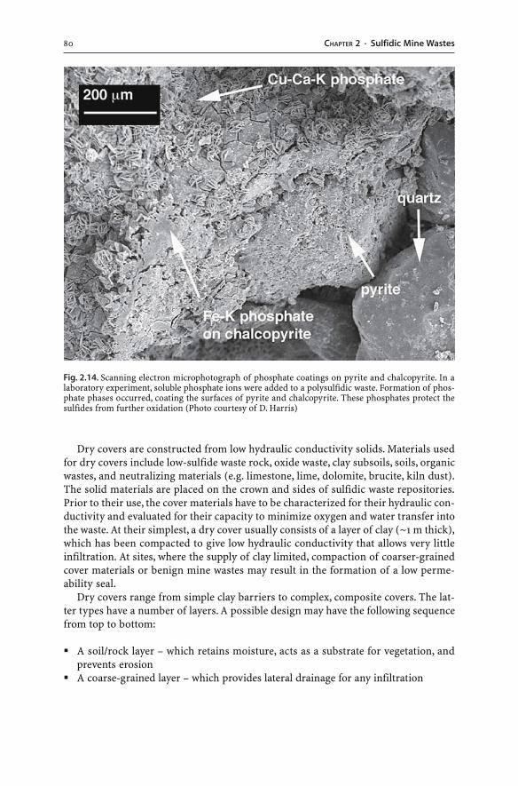
80 CHAPTER 2 · Sulfidic Mine Wastes
Dry covers are constructed from low hydraulic conductivity solids. Materials usedfor dry covers include low-sulfide waste rock, oxide waste, clay subsoils, soils, organicwastes, and neutralizing materials (e.g. limestone, lime, dolomite, brucite, kiln dust).The solid materials are placed on the crown and sides of sulfidic waste repositories.Prior to their use, the cover materials have to be characterized for their hydraulic con-ductivity and evaluated for their capacity to minimize oxygen and water transfer intothe waste. At their simplest, a dry cover usually consists of a layer of clay (~1 m thick),which has been compacted to give low hydraulic conductivity that allows very littleinfiltration. At sites, where the supply of clay limited, compaction of coarser-grainedcover materials or benign mine wastes may result in the formation of a low perme-ability seal.
Dry covers range from simple clay barriers to complex, composite covers. The lat-ter types have a number of layers. A possible design may have the following sequencefrom top to bottom:
� A soil/rock layer – which retains moisture, acts as a substrate for vegetation, andprevents erosion
� A coarse-grained layer – which provides lateral drainage for any infiltration
Fig. 2.14. Scanning electron microphotograph of phosphate coatings on pyrite and chalcopyrite. In alaboratory experiment, soluble phosphate ions were added to a polysulfidic waste. Formation of phos-phate phases occurred, coating the surfaces of pyrite and chalcopyrite. These phosphates protect thesulfides from further oxidation (Photo courtesy of D. Harris)
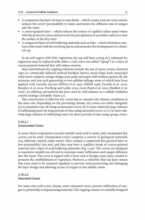
812.10 · Control of Sulfide Oxidation
� A compacted clay layer (at least 30 mm thick) – which creates a low air void content,reduces the cover’s permeability to water, and lowers the diffusion rate of oxygeninto the waste
� A coarse-grained layer – which reduces the contact of capillary saline waste waterswith the protective cover, and prevents the precipitation of secondary salts at or nearthe surface of the dry cover
� A compacted layer of acid buffering materials such as lime – which minimizes reac-tion of the waste with the overlying layers, and promotes the development of a chemi-cal cap
In an arid region with little vegetation, the top soil layer acting as a substrate forvegetation may be replaced with either a rock cover (so-called “riprap”) or a layer ofcoarse-grained material that will reduce erosion.
Non-conventional dry capping solutions include the use of epoxy resins, chemicalcaps (i.e. chemically induced surficial hardpan layers), wood chips, bark, municipalsolid waste compost, sewage sludge, peat, pulp and paper mill residues, grouts, fly ashmixtures, and non-acid generating or low-sulfides tailings, some of which have beenapplied with variable success (Elliott et al. 1997; SMME 1998; Xenidis et al. 2002;Bussière et al. 2004: Forsberg and Ledin 2003, 2006; Pond et al. 2005; Hulshof et al.2006). In addition, permafrost has been used in cold climates as a sulfide oxidationcontrol strategy (Scientific Issue 2.1).
The construction of effective dry covers has to consider the climatic conditions atthe mine site. Depending on the prevailing climate, dry covers are either designed:(a) to maximize run-off using unsaturated covers; (b) to store relatively large volumesof infiltrating water for long periods of time using saturated covers; or (c) to store rela-tively large volumes of infiltrating water for short periods of time using sponge covers.
2.10.2.1Unsaturated Covers
In areas where evaporation exceeds rainfall (semi-arid to arid), only unsaturated drycovers can be used. Unsaturated covers comprise a variety of geological materials(e.g. alluvium, topsoil, oxide waste). They contain a compacted fine-grained layer orlow permeability clay seal, and they may have a capillary break of coarse-grainedmaterial and a layer of acid buffering materials (Fig. 2.15a). The covers are designedto maximize rainfall run-off and to minimize water infiltration and oxygen diffusioninto the waste. The cover is topped with a loose soil or benign waste layer, needed topromote the establishment of vegetation. However, a relatively thin top layer meansthat trees need to be removed regularly to prevent roots penetrating and damagingthe layer design and allowing access of oxygen to the sulfidic waste.
2.10.2.2Saturated Covers
For mine sites with a wet climate, water saturated covers prevent infiltration of oxy-gen to potentially acid generating materials. The capping consists of carefully designed
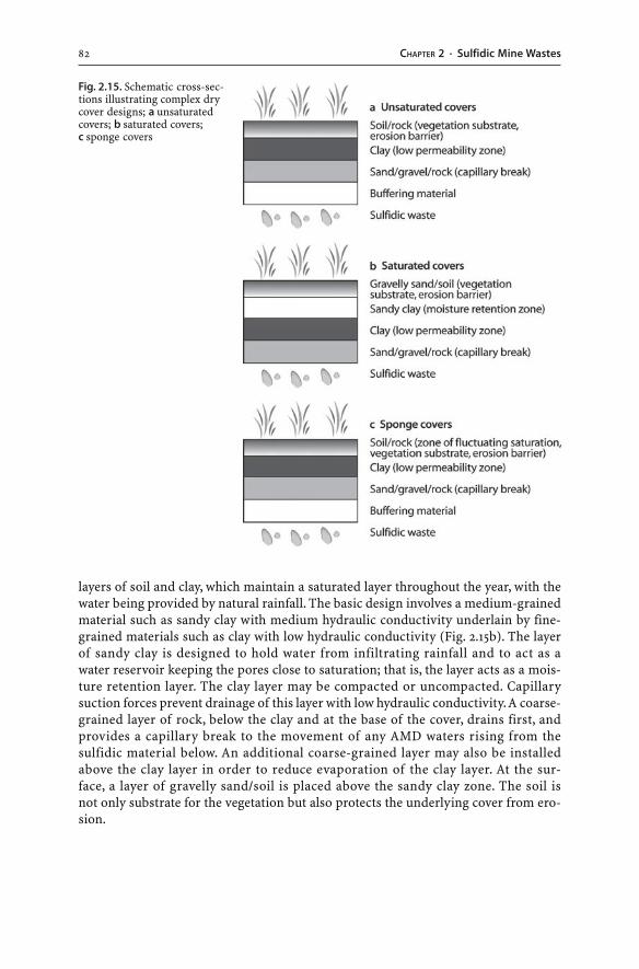
82 CHAPTER 2 · Sulfidic Mine Wastes
layers of soil and clay, which maintain a saturated layer throughout the year, with thewater being provided by natural rainfall. The basic design involves a medium-grainedmaterial such as sandy clay with medium hydraulic conductivity underlain by fine-grained materials such as clay with low hydraulic conductivity (Fig. 2.15b). The layerof sandy clay is designed to hold water from infiltrating rainfall and to act as awater reservoir keeping the pores close to saturation; that is, the layer acts as a mois-ture retention layer. The clay layer may be compacted or uncompacted. Capillarysuction forces prevent drainage of this layer with low hydraulic conductivity. A coarse-grained layer of rock, below the clay and at the base of the cover, drains first, andprovides a capillary break to the movement of any AMD waters rising from thesulfidic material below. An additional coarse-grained layer may also be installedabove the clay layer in order to reduce evaporation of the clay layer. At the sur-face, a layer of gravelly sand/soil is placed above the sandy clay zone. The soil isnot only substrate for the vegetation but also protects the underlying cover from ero-sion.
Fig. 2.15. Schematic cross-sec-tions illustrating complex drycover designs; a unsaturatedcovers; b saturated covers;c sponge covers
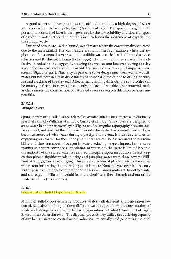
832.10 · Control of Sulfide Oxidation
A good saturated cover promotes run-off and maintains a high degree of watersaturation within the sandy clay layer (Taylor et al. 1998). Transport of oxygen in thepores of this saturated layer is then governed by the low solubility and slow transportof oxygen in water rather than air. This in turn limits the movement of oxygen intothe sulfidic waste.
Saturated covers are used in humid, wet climates where the cover remains saturateddue to the high rainfall. The Rum Jungle uranium mine is an example where the ap-plication of a saturated cover system on sulfidic waste rocks has had limited success(Harries and Ritchie 1988; Bennett et al. 1999). The cover system was particularly ef-fective in reducing the oxygen flux during the wet season; however, during the dryseason the clay seal cracks resulting in AMD release and environmental impacts down-stream (Figs. 2.16, 2.17). Thus, clay as part of a cover design may work well in wet cli-mates but not necessarily in dry climates or seasonal climates due to drying, shrink-ing and cracking of the clay seal. Also, in many mining districts, the soil profiles canbe notably deficient in clays. Consequently, the lack of suitable cover materials suchas clays makes the construction of saturated covers as oxygen diffusion barriers im-possible.
2.10.2.3Sponge Covers
Sponge covers or so-called “store-release” covers are suitable for climates with distinctlyseasonal rainfall (Williams et al. 1997; Currey et al. 1999). The covers are designed tostore water in an upper cover layer (Fig. 2.15c). An irregular topography prevents sur-face run-off, and much of the drainage flows into the waste. The porous, loose top layerbecomes saturated with water during a precipitation event. It then functions as anoxygen ingress barrier for the underlying sulfidic waste. The barrier uses the low solu-bility and slow transport of oxygen in water, reducing oxygen ingress in the samemanner as a water cover does. Percolation of water into the waste is limited becausethe majority of the stored water is removed through evapotranspiration. In fact, veg-etation plays a significant role in using and pumping water from these covers (Will-iams et al. 1997; Currey et al. 1999). The pumping action of plants prevents the storedwater from infiltrating the underlying sulfidic waste. Nonetheless, cover failures maystill be possible. Prolonged droughts or bushfires may cause significant die-off to plants,and subsequent infiltration would lead to a significant flow through and out of thewaste materials (Dobos 2000).
2.10.3Encapsulation, In-Pit Disposal and Mixing
Mining of sulfidic ores generally produces wastes with different acid generation po-tential. Selective handling of these different waste types allows the construction ofwaste rock dumps according to their acid generation potential (Cravotta et al. 1994;Environment Australia 1997). The disposal practice may utilize the buffering capacityof any benign waste to control acid production. Potentially acid generating material
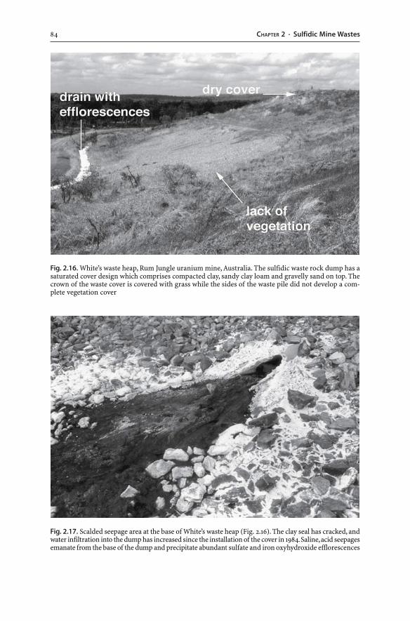
84 CHAPTER 2 · Sulfidic Mine Wastes
Fig. 2.16. White’s waste heap, Rum Jungle uranium mine, Australia. The sulfidic waste rock dump has asaturated cover design which comprises compacted clay, sandy clay loam and gravelly sand on top. Thecrown of the waste cover is covered with grass while the sides of the waste pile did not develop a com-plete vegetation cover
Fig. 2.17. Scalded seepage area at the base of White’s waste heap (Fig. 2.16). The clay seal has cracked, andwater infiltration into the dump has increased since the installation of the cover in 1984. Saline, acid seepagesemanate from the base of the dump and precipitate abundant sulfate and iron oxyhydroxide efflorescences
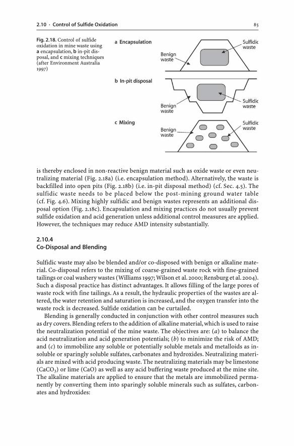
852.10 · Control of Sulfide Oxidation
is thereby enclosed in non-reactive benign material such as oxide waste or even neu-tralizing material (Fig. 2.18a) (i.e. encapsulation method). Alternatively, the waste isbackfilled into open pits (Fig. 2.18b) (i.e. in-pit disposal method) (cf. Sec. 4.5). Thesulfidic waste needs to be placed below the post-mining ground water table(cf. Fig. 4.6). Mixing highly sulfidic and benign wastes represents an additional dis-posal option (Fig. 2.18c). Encapsulation and mixing practices do not usually preventsulfide oxidation and acid generation unless additional control measures are applied.However, the techniques may reduce AMD intensity substantially.
2.10.4Co-Disposal and Blending
Sulfidic waste may also be blended and/or co-disposed with benign or alkaline mate-rial. Co-disposal refers to the mixing of coarse-grained waste rock with fine-grainedtailings or coal washery wastes (Williams 1997; Wilson et al. 2000; Rensburg et al. 2004).Such a disposal practice has distinct advantages. It allows filling of the large pores ofwaste rock with fine tailings. As a result, the hydraulic properties of the wastes are al-tered, the water retention and saturation is increased, and the oxygen transfer into thewaste rock is decreased. Sulfide oxidation can be curtailed.
Blending is generally conducted in conjunction with other control measures suchas dry covers. Blending refers to the addition of alkaline material, which is used to raisethe neutralization potential of the mine waste. The objectives are: (a) to balance theacid neutralization and acid generation potentials; (b) to minimize the risk of AMD;and (c) to immobilize any soluble or potentially soluble metals and metalloids as in-soluble or sparingly soluble sulfates, carbonates and hydroxides. Neutralizing materi-als are mixed with acid producing waste. The neutralizing materials may be limestone(CaCO3) or lime (CaO) as well as any acid buffering waste produced at the mine site.The alkaline materials are applied to ensure that the metals are immobilized perma-nently by converting them into sparingly soluble minerals such as sulfates, carbon-ates and hydroxides:
Fig. 2.18. Control of sulfideoxidation in mine waste usinga encapsulation, b in-pit dis-posal, and c mixing techniques(after Environment Australia1997)
86 CHAPTER 2 · Sulfidic Mine Wastes
CaCO3(s) + H+(aq) + SO4
2–(aq) + Pb2+
(aq) → PbSO4(s) + HCO3–(aq) (2.31)
CaCO3(s) + Pb2+(aq) → PbCO3(s) + Ca2+
(aq) (2.32)
CaO(s) + Zn2+(aq) + H2O(l) → Zn(OH)2(s) + Ca2+
(aq) (2.33)
Surface applications of some alkaline materials or applications under thin soil coverhave not been successful (Smith and Brady 1999). Possible explanations may include:(a) the dissolution of calcite at surface conditions is limited by the partial pressure ofcarbon dioxide; and (b) preferential flow of water occurs through the waste dump, by-passing much of the near surface alkaline material. Thus, uniform mixing of acid buff-ering waste or neutralizing materials with sulfidic waste is of paramount importancein order to achieve consumption of acidity (Smith and Brady 1999). In an already es-tablished sulfidic waste dump, the use of neutralizing agents is limited by the diffi-culty of blending them through waste layers. Thorough mixing is usually difficult, in-efficient and expensive. In addition, a treatment relying on deep disturbance of thewaste has the risk of exposure of additional unoxidized sulfidic mine waste. There-fore, blending has to occur while the waste materials are being dumped at their dis-posal sites.
The major disadvantage of blending is that it does not prevent sulfide oxidation.While blending helps to immobilize dissolved metals such iron, aluminium, copperand lead as insoluble minerals in sulfidic wastes, it may not prevent the release of sul-fate as well as other metals and metalloids (e.g. As, Cd, Mo, Zn) into pore waters. Theseelements are potentially mobile under neutral to alkaline pore water conditions.
2.10.5Addition of Organic Wastes
The addition of organic wastes may also prevent sulfide oxidation. The wastes can beused as a compacted subsurface layer in dry cover designs or as amendments to cre-ate reactive, low permeability biomass surfaces. Trialed organic materials include sew-age sludge, wood chips, sawdust, manure, peat, pulp and paper mill residues, and mu-nicipal solid waste compost (Cabral et al. 1997; Elliott et al. 1997; SMME 1998; Hulshofet al. 2006). The wastes inhibit pyrite oxidation via various mechanisms. Firstly, or-ganic wastes provide a pH buffer and create reducing conditions which inhibit sulfideoxidizing bacteria, reduce sulfate to sulfide, and immobilize metals as sulfides. Sec-ondly, dissolved organic compounds form stable iron-organic complexes or combinewith iron to form stable precipitates. Thirdly, the organic compounds are adsorbedon pyrite surfaces, preventing oxidation (Evangelou 1995, 1998). However, if organicwaste such as sewage sludge is part of a dry cover design, organic acids (simplifiedstoichiometrically as the molecules CH2O and H+) may dissolve iron hydroxide phases(Blowes et al. 1994):
4 Fe(OH)3(s) + CH2O(aq) + 7 H+(aq) → 4 Fe2+
(aq) + HCO3–(aq) + 10 H2O(l) (2.34)
Adsorbed and coprecipitated metals, originally present in the iron precipitates, arealso released into the aqueous phase. The iron and other metals can form stable or-
872.11 · Summary
ganic complexes which may migrate into ground and surface waters. Therefore, it ispossible that the use of organic material enhances the migration of contaminants fromsulfidic wastes (Mitchell 2000).
Organic waste placed at the surface of waste repositories is in constant contact withthe atmosphere and will decompose over time. Such oxidation ensures that the addedorganic material is eventually used up. Consequently, the addition of organic waste,unless regularly done, is a short-term fix to a long-term waste problem.
2.10.6Bactericides
Certain bacteria are known to increase the rate of pyrite oxidation. Hence, anti-bac-terial agents, so-called “bactericides”, have been used to inhibit the growth of thesemicroorganisms (Ledin and Pedersen 1996; Kleinmann 1997, 1999). Many compoundsincluding anionic surfactants, cleaning detergents, organic acids, and food preserva-tives have been screened as selective bactericides. The anionic surfactants sodium lau-ryl sulfate and alkyl benzene sulfonate are considered the most reliable and cost ef-fective inhibitors (Kleinmann 1997, 1999). In the presence of such compounds, hydro-gen ions in the acidic environment move freely into or through bacteria cell mem-branes, causing their deterioration.
While there are clear advantages in the use of bactericides including decreasedpyrite oxidation and metal mobility, there are also disadvantages and potential risks.The applied compound may cause toxicity to other organisms; there is the possibilityof resistance development; and it is difficult to reach all zones of the sulfidic waste(Kleinmann 1999). Bactericides are generally water soluble and leach from the waste,and they may be adsorbed on the surfaces of other minerals. As a result, repetitive treat-ments are necessary to prevent repopulation of the waste by bacteria when the bacte-ricide is depleted (Kleinmann 1999). Alternatively, slow-release pellets may help toprovide long-term bacterial inhibition (Kleinmann 1999). Thus, bactericides are an-other short-term solution to a long-term waste problem, and if applied, they shouldbe part of other control measures (Environment Australia 1997).
2.11Summary
Sulfidic mine wastes, especially those which contain high concentrations of pyrite, arethe major sources of AMD. Pyrite oxidation may occur via biotic or abiotic and director indirect oxidation processes. Biotic indirect oxidation of pyrite is an important acidgenerating process whereby pyrite is oxidized by oxygen and Fe3+ in the presence ofmicroorganisms. Pyrite oxidation is a complex process because it not only involveschemical, electrochemical and biochemical reactions, but it also varies with environ-mental conditions. The following factors all work to enhance the speed of pyrite oxi-dation: large surface area; small particle size; high porosity; poor crystallinity; signifi-cant trace element substitutions of and solid inclusions within the pyrite; acidic pH val-ues of the solution in contact with pyrite; no direct physical contact with other sulfides;high oxygen and high Fe3+ concentrations in the oxidizing medium; high tempera-ture; abundant microbial activity; and alternate wetting and drying of the sulfide grain.
88 CHAPTER 2 · Sulfidic Mine Wastes
Sulfides other than pyrite have different acid production potentials, stabilities andrates of reaction. The metal/sulfur ratio in sulfides influences how much sulfuric acidis liberated by oxidation. Also, the amount of iron sulfides present strongly influenceswhether and how much acid is generated during weathering. Iron sulfides (e.g. pyrite,marcasite, pyrrhotite) or sulfides having iron as a major constituent (e.g. chalcopyrite,iron-rich sphalerite) generate the most acidity. In contrast, sulfide minerals which donot contain iron in their crystal lattice (e.g. covellite, galena or iron-poor sphalerite)do not have the capacity to generate significant amounts of acid. This is because Fe3+
is not available as the important oxidant, and iron hydrolysis cannot occur which wouldgenerate additional hydrogen ions. The production of acid also occurs through thedissolution of secondary soluble Fe2+, Mn2+, Fe3+ and Al3+ sulfate salts, and the pre-cipitation of secondary Fe3+ and Al3+ hydroxides.
Any acid generated can be consumed through the reaction of the hydrogen ionswith gangue minerals. The weathering of silicates results in the consumption of hy-drogen ions, formation of secondary minerals, and release of dissolved cations andsilicic acid. The dissolution of hydroxides and carbonates as well as cation exchangeprocesses on clay minerals also consume acid. The gangue minerals reacting with theacidic solutions have a variable resistance to weathering and therefore, exhibit differ-ent reaction rates. Carbonate minerals show the highest reactivity and highest acidconsumption, whereas silicates have significantly slower reaction rates and provideonly token amounts of additional long-term buffering capacity to sulfidic wastes.
Weathering of sulfidic wastes produces mine waters laden with dissolved salts. Thedissolved salts may approach saturation in pore waters, ground waters, streams andleachates associated with the oxidation and leaching of sulfidic wastes. In fact, numer-ous secondary minerals are known to precipitate in AMD environments. Some sec-ondary minerals may redissolve in AMD waters thereby influencing the mine waterchemistry; others may precipitate and coat acid buffering or acid producing miner-als. Massive precipitation of secondary minerals in wastes results in the formation oflaterally extensive or discontinuous subsurface or surface layers which act as horizontalbarriers to vertical water movements. Thus, the secondary mineralogy of sulfidic wastesplays an important role in controlling how readily and how much acid, metals andsulfate are liberated to drainage waters.
The prediction of AMD generation from sulfidic wastes is possible using geologi-cal and petrographic descriptions, geological modeling, static and kinetic tests, andmathematical models. These tools may be used to estimate potential sulfide oxidationand dissolved metal mobility. Sulfidic waste dumps are major sources of AMD. Oxy-gen advection, convection and diffusion occur in such wastes, which can result in theproduction of acid. Fine-grained wastes have much greater surface areas and hence, agreater acid generation potential than coarse-grained wastes, yet the fine grain sizelimits oxygen diffusion, water ingress and acid generation.
Monitoring techniques of sulfidic wastes are designed to identify the early pres-ence of or the changes to any products of the acid producing reactions. The productscan be identified by obtaining waste temperature measurements, oxygen pore gas con-centration profiles, and leachate analyses for dissolved contaminant concentrationsand loads. Rapid increases in temperature profiles of waste dumps indicate the exo-thermic oxidation of sulfides, whereas the depletion of oxygen concentration withingas pores is also indicative of sulfide oxidation.
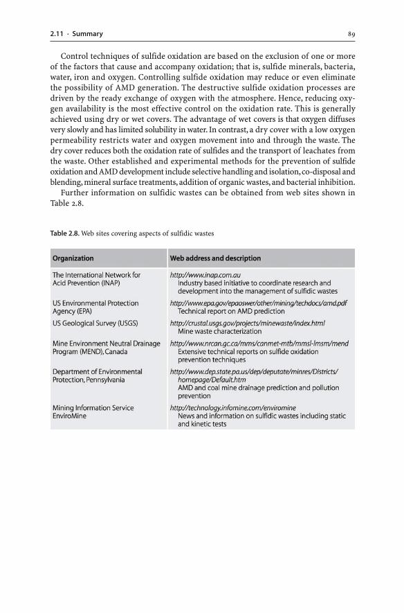
892.11 · Summary
Control techniques of sulfide oxidation are based on the exclusion of one or moreof the factors that cause and accompany oxidation; that is, sulfide minerals, bacteria,water, iron and oxygen. Controlling sulfide oxidation may reduce or even eliminatethe possibility of AMD generation. The destructive sulfide oxidation processes aredriven by the ready exchange of oxygen with the atmosphere. Hence, reducing oxy-gen availability is the most effective control on the oxidation rate. This is generallyachieved using dry or wet covers. The advantage of wet covers is that oxygen diffusesvery slowly and has limited solubility in water. In contrast, a dry cover with a low oxygenpermeability restricts water and oxygen movement into and through the waste. Thedry cover reduces both the oxidation rate of sulfides and the transport of leachates fromthe waste. Other established and experimental methods for the prevention of sulfideoxidation and AMD development include selective handling and isolation, co-disposal andblending, mineral surface treatments, addition of organic wastes, and bacterial inhibition.
Further information on sulfidic wastes can be obtained from web sites shown inTable 2.8.
Table 2.8. Web sites covering aspects of sulfidic wastes
Chapter 3
Mine Water
3.1Introduction
Water is needed at mine sites for dust suppression, mineral processing, coal washing,and hydrometallurgical extraction. For these applications, water is mined from sur-face water bodies and ground water aquifers, or it is a by-product of the mine dewa-tering process. Open pits and underground mining operations commonly extendbelow the regional water table and require dewatering during mining. In particular,mines intersecting significant ground water aquifers, or those located in wet climates,may have to pump more than 100 000 liters per minute to prevent undergroundworkings from flooding. At some stage of the mining operation, water is unwantedand has no value to the operation. In fact, unwanted or used water needs to bedisposed of constantly during mining, mineral processing, and metallurgical extraction.
At modern mine sites, water is collected and discharged to settling ponds and tail-ings dams. In contrast, at historic mine sites, uncontrolled discharge of mine watercommonly occurs from adits and shafts into the environment. Generally, the volumeof mine water produced, used and disposed of at mine sites is much larger thanthe volume of solid waste generated. At mine sites, water comes in contact withminerals and dissolves them. Hence, water at mine sites often carries dissolvedand particulate matter. When such laden waters reach receiving water bodies,lakes, streams or aquifers, the waters can cause undesirable turbidity and sedimenta-tion, they may alter temperatures, or their chemical composition may have toxiceffects on plants and animals. For example, in the United States, it has been estima-ted that 19 300 km of streams and 72 000 ha of lakes and reservoirs have been seri-ously damaged by mine effluents from abandoned coal and metal mines (Kleinmann1989).
The worst example of poor mine water quality and associated environmental im-pacts is acid mine drainage (AMD) water, which originates from the oxidation of sul-fide minerals (Sec. 2.3). Sulfide oxidation is an autocatalytic reaction and therefore,once AMD generation has started, it can be very difficult to halt. AMD is the most se-vere in the first few decades after sulfide oxidation begins, and the systems then pro-duce lower levels of contaminants (Lambert et al. 2004; Demchak et al. 2004). In ex-treme cases, however, AMD may continue for thousands of years (Case Study 3.1,Fig. 3.1).
This chapter summarizes information on AMD waters and gives the principles ofAMD characterization, monitoring, prediction, environmental impact, and treatment.Such aspects of AMD waters are important issues for any mining operation, regard-less whether the mine waters are acid or not.
92 CHAPTER 3 · Mine Water
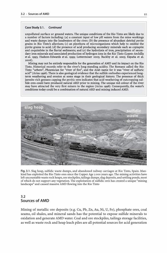
933.2 · Sources of AMD
3.2Sources of AMD
Mining of metallic ore deposits (e.g. Cu, Pb, Zn, Au, Ni, U, Fe), phosphate ores, coalseams, oil shales, and mineral sands has the potential to expose sulfide minerals tooxidation and generate AMD water. Coal and ore stockpiles, tailings storage facilities,as well as waste rock and heap leach piles are all potential sources for acid generation
Fig. 3.1. Slag heap, sulfidic waste dumps, and abandoned railway carriages at Rio Tinto, Spain. Man-kind has exploited the Rio Tinto ores since the Copper Age 5 000 years ago. The mining activities haveleft uncountable waste rock heaps, ore stockpiles, tailings dumps, slag deposits, and settling ponds, mostof which do not support any vegetation. The exploitation of sulfidic ores has created a unique “mininglandscape” and caused massive AMD flowing into the Rio Tinto
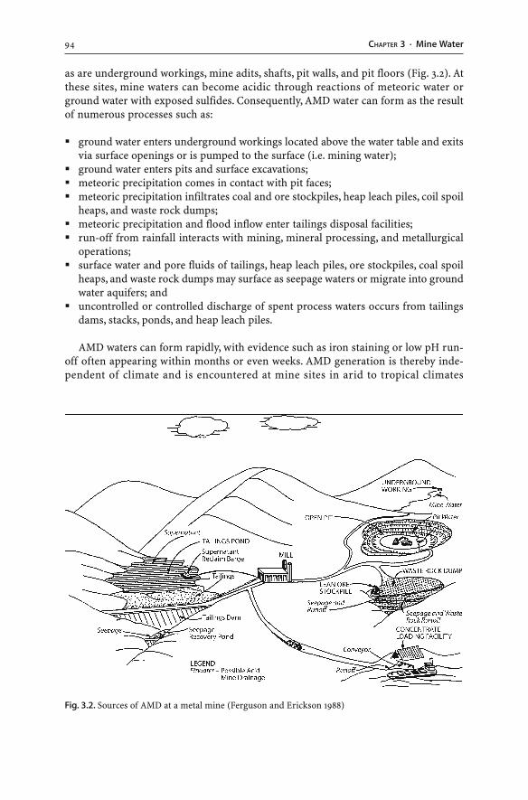
94 CHAPTER 3 · Mine Water
as are underground workings, mine adits, shafts, pit walls, and pit floors (Fig. 3.2). Atthese sites, mine waters can become acidic through reactions of meteoric water orground water with exposed sulfides. Consequently, AMD water can form as the resultof numerous processes such as:
� ground water enters underground workings located above the water table and exitsvia surface openings or is pumped to the surface (i.e. mining water);
� ground water enters pits and surface excavations;� meteoric precipitation comes in contact with pit faces;� meteoric precipitation infiltrates coal and ore stockpiles, heap leach piles, coil spoil
heaps, and waste rock dumps;� meteoric precipitation and flood inflow enter tailings disposal facilities;� run-off from rainfall interacts with mining, mineral processing, and metallurgical
operations;� surface water and pore fluids of tailings, heap leach piles, ore stockpiles, coal spoil
heaps, and waste rock dumps may surface as seepage waters or migrate into groundwater aquifers; and
� uncontrolled or controlled discharge of spent process waters occurs from tailingsdams, stacks, ponds, and heap leach piles.
AMD waters can form rapidly, with evidence such as iron staining or low pH run-off often appearing within months or even weeks. AMD generation is thereby inde-pendent of climate and is encountered at mine sites in arid to tropical climates
Fig. 3.2. Sources of AMD at a metal mine (Ferguson and Erickson 1988)
953.3 · Characterization
from the Arctic Circle to the equator (Scientific Issue 2.1). However, not all miningoperations that expose sulfide-bearing rock will cause AMD. In addition, contami-nant generation and release are not exclusive to AMD environments. They alsooccur in neutral and alkaline drainage environments as shown in the following sections.
3.3Characterization
Constituents dissolved in mine waters are numerous, and mine waters are highly vari-able in their composition. Some waters contain nitrogen compounds (nitrite, NO2
–;nitrate, NO3
–; ammonia, NH3) from explosives used in blasting operations and fromcyanide heap leach solutions used for the extraction of gold (Sec. 5.4). Other minewaters possess chemical additives from mineral processing and hydrometallurgicaloperations (Sec. 4.2.1). For instance, metallurgical processing of many uranium oresis based on leaching the ore with sulfuric acid (Sec. 6.5.1). Spent process waters arecommonly released to tailings repositories, so the liquids of uranium tailings damsare acid and sulfate rich. Also, coal mining may result in the disturbance of the localaquifers and the dissolution of chloride and sulfate salts that are contained in themarine sedimentary rocks present between the coal seams. As a result, coal mine wa-ters can be exceptionally saline.
Therefore, depending on the mined ore and the chemical additives used in min-eral processing and hydrometallurgical extraction, different elements and compoundsmay need to be determined in waters of individual mine sites. Regardless of thecommodity extracted and the mineral processing and hydrometallurgical techniquesapplied, major cations (i.e Al3+, Si4+, Ca2+, Mg2+, Na+ and K+) and anions (i.e Cl–, SO4
2–,CO3
2–, HCO3–) are important constituents of any mine water. Other constituents such
as nitrogen or cyanide compounds, or dissolved and total organic carbon concentra-tions, should be determined depending on site specific conditions. Additional param-eters analyzed and used for the study of mine waters are given in Table 3.1.
3.3.1Sampling and Analysis
Detailed procedures for water sampling, preparation and analysis are found in manu-als and publications (e.g. Ficklin and Mosier 1999; Appelo and Postma 1999). Labora-tory methods for the geochemical analysis of environmental samples including minewaters are given by Crock et al. (1999). Quality assurance/quality control of the ana-lytical results must be ensured using established procedures. The submission of du-plicates or even triplicates of the same sample will allow an evaluation of the analyti-cal precision (i.e. repeatability). Blanks of deionized water should be included in or-der to check for unclean sample processing or inaccurate chemical analysis. The lowpH of AMD waters will aid in preservation of dissolved metals; otherwise, neutral oralkaline waters need to be acidified to keep metals in solution. Degassing of CO2-richsamples is possible after sampling, so containers should be completely filled and tightlyclosed.
The longer the period of time between collection and analysis, the more likely it isthat unreliable analytical results will be measured. Exposure to light and elevated tem-
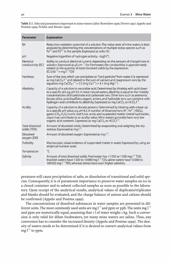
96 CHAPTER 3 · Mine Water
Table 3.1. Selected parameters important to mine waters (after Brownlow 1996; Drever 1997; Appelo andPostma 1999; Ficklin and Mosier 1999)
peratures will cause precipitation of salts, or dissolution of transitional and solid spe-cies. Consequently, it is of paramount importance to preserve water samples on ice ina closed container and to submit collected samples as soon as possible to the labora-tory. Upon receipt of the analytical results, analytical values of duplicates/triplicatesand blanks should be evaluated, and the charge balance of anions and cations shouldbe confirmed (Appelo and Postma 1999).
The concentrations of dissolved substances in water samples are presented in dif-ferent units. The most commonly used units are mg l–1 and ppm or ppb. The units mg l–1
and ppm are numerically equal, assuming that 1 l of water weighs 1 kg. Such a conver-sion is only valid for dilute freshwaters, yet many mine waters are saline. Thus, anyconversion has to consider the increased density (Appelo and Postma 1999). The den-sity of waters needs to be determined if it is desired to convert analytical values frommg l–1 to ppm.
973.4 · Classification
With the advent of modern field equipment, many mine water parameters (i.e. pH,dissolved oxygen, temperature, electrical conductivity, turbidity) should be determinedin the field since these values can quickly change during sample storage (Ficklin andMosier 1999). If possible, an elemental analysis should be accompanied by the mea-surement of the reduction-oxidation (redox) potential (i.e. Eh), or of a redox pair suchas Fe2+/Fe3+. Such an analysis is sufficient to define the redox state of the AMD waterand allows the simulation of redox conditions during geochemical modeling.
3.4Classification
There is no typical composition of mine waters and as a result, the classification ofmine waters based on their constitutents is difficult to achieve. A number of classifi-cation schemes of mine waters have been proposed using one or several water param-eters:
� Major cations and anions. This is a standard technique to characterize ground andsurface waters (e.g. Brownlow 1996; Drever 1997; Appelo and Postma 1999). It involvesplotting the major cation (Ca2+, Mg2+, Na+, K+) and anion (Cl–, SO4
2–, CO32–, HCO3
–)chemistry on a so-called “Piper” or trilinear diagram. The plotted waters are thenclassified according to their cation and anion abundances.
� pH. A basic scheme labels mine waters according to their pH as acidic, alkaline, near-neutral, and others (Morin and Hutt 1997).
� pH and Fe2+ and Fe3+ concentration. This classification technique requires a knowl-edge of the pH and of the amount of Fe2+ and Fe3+ present (Glover 1975; cited byYounger 1995).
� pH vs. combined metals. Mine waters can also be classified according to pH and thecontent of total dissolved metals (Ficklin et al. 1992; Plumlee et al. 1999).
� Alkalinity vs. acidity. This scheme has been devised to allow classification of minewaters according to their treatability using passive treatment methods (Hedin et al.1994a). It requires a knowledge of the alkalinity and acidity of the waters as deter-mined by titration (Kirby and Cravotta 2005a,b). The categorization is useful for theselection of aerobic or anaerobic treatment methods as net acid waters requireanaerobic treatment and net alkaline waters require aerobic remediation.
� Alkalinity vs. acidity and sulfate concentration. This classification considers both thealkalinity and acidity as well as the sulfate content of mine waters (Younger 1995).
The above classifications have one or several short-comings: (a) the classificationsdo not include waters with neutral pH values and extraordinary salinities; (b) theschemes do not consider mine waters with elevated concentrations of arsenic, anti-mony, mercury, cyanide compounds, and other process chemicals; (c) the categoriza-tions do not consider iron, manganese and aluminium which are present in majorconcentrations in AMD waters; and (d) routine water analyses do not include deter-minations of the Fe2+ and Fe3+ concentrations. Therefore, the categorizations are notinclusive of all mine water types. In this work, the simple classification scheme of Morinand Hutt (1997) has been modified (Table 3.2), and the following presentation of minewaters is given according to their pH.
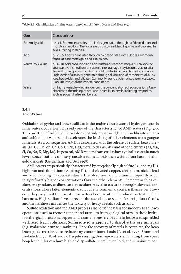
98 CHAPTER 3 · Mine Water
3.4.1Acid Waters
Oxidation of pyrite and other sulfides is the major contributor of hydrogen ions inmine waters, but a low pH is only one of the characteristics of AMD waters (Fig. 3.3).The oxidation of sulfide minerals does not only create acid, but it also liberates metalsand sulfate into waters and accelerates the leaching of other elements from gangueminerals. As a consequence, AMD is associated with the release of sulfate, heavy met-als (Fe, Cu, Pb, Zn, Cd, Co, Cr, Ni, Hg), metalloids (As, Sb), and other elements (Al, Mn,Si, Ca, Na, K, Mg, Ba). In general, AMD waters from coal mines typically contain muchlower concentrations of heavy metals and metalloids than waters from base metal orgold deposits (Geldenhuis and Bell 1998).
AMD waters are particularly characterized by exceptionally high sulfate (>1 000 mg l–1),high iron and aluminium (>100 mg l–1), and elevated copper, chromium, nickel, leadand zinc (>10 mg l–1) concentrations. Dissolved iron and aluminium typically occurin significantly higher concentrations than the other elements. Elements such as cal-cium, magnesium, sodium, and potassium may also occur in strongly elevated con-centrations. These latter elements are not of environmental concern themselves. How-ever, they may limit the use of these waters because of their sodium content or theirhardness. High sodium levels prevent the use of these waters for irrigation of soils,and the hardness influences the toxicity of heavy metals such as zinc.
Sulfide oxidation and the AMD process also form the basis for modern heap leachoperations used to recover copper and uranium from geological ores. In these hydro-metallurgical processes, copper and uranium ores are piled into heaps and sprinkledwith acid leach solutions. Sulfuric acid is applied to dissolve the ore minerals(e.g. malachite, azurite, uraninite). Once the recovery of metals is complete, the heapleach piles are rinsed to reduce any contaminant loads (Li et al. 1996; Shum andLavkulich 1999; Ford 2000). Despite rinsing, drainage waters emanating from spentheap leach piles can have high acidity, sulfate, metal, metalloid, and aluminium con-
Table 3.2. Classification of mine waters based on pH (after Morin and Hutt 1997)
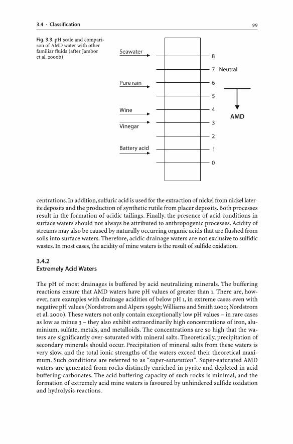
993.4 · Classification
centrations. In addition, sulfuric acid is used for the extraction of nickel from nickel later-ite deposits and the production of synthetic rutile from placer deposits. Both processesresult in the formation of acidic tailings. Finally, the presence of acid conditions insurface waters should not always be attributed to anthropogenic processes. Acidity ofstreams may also be caused by naturally occurring organic acids that are flushed fromsoils into surface waters. Therefore, acidic drainage waters are not exclusive to sulfidicwastes. In most cases, the acidity of mine waters is the result of sulfide oxidation.
3.4.2Extremely Acid Waters
The pH of most drainages is buffered by acid neutralizing minerals. The bufferingreactions ensure that AMD waters have pH values of greater than 1. There are, how-ever, rare examples with drainage acidities of below pH 1, in extreme cases even withnegative pH values (Nordstrom and Alpers 1999b; Williams and Smith 2000; Nordstromet al. 2000). These waters not only contain exceptionally low pH values – in rare casesas low as minus 3 – they also exhibit extraordinarily high concentrations of iron, alu-minium, sulfate, metals, and metalloids. The concentrations are so high that the wa-ters are significantly over-saturated with mineral salts. Theoretically, precipitation ofsecondary minerals should occur. Precipitation of mineral salts from these waters isvery slow, and the total ionic strengths of the waters exceed their theoretical maxi-mum. Such conditions are referred to as “super-saturation”. Super-saturated AMDwaters are generated from rocks distinctly enriched in pyrite and depleted in acidbuffering carbonates. The acid buffering capacity of such rocks is minimal, and theformation of extremely acid mine waters is favoured by unhindered sulfide oxidationand hydrolysis reactions.
Fig. 3.3. pH scale and compari-son of AMD water with otherfamiliar fluids (after Jamboret al. 2000b)
100 CHAPTER 3 · Mine Water
3.4.3Neutral to Alkaline Waters
A low pH is not a universal characteristic of waters influenced by mining. The pH ofmine waters extends to alkaline conditions, and the aqueous concentrations of anionsand cations range from less than 1 mg l–1 to several 100 000 mg l–1. In acid waters, sul-fate is the principal anion, and iron, manganese and aluminium are major cations. Inalkaline waters, sulfate and bicarbonate are the principal anions, and concentrationsof calcium, magnesium and sodium are generally elevated relative to iron and alu-minium (Rose and Cravotta 1999). Substantial concentrations of sulfate, metals (Cd,Hg, Mn Mo, Ni, U, Zn), and metalloids (As, Sb, Se) have been documented in oxidized,neutral to alkaline mine waters (Carroll et al. 1998; Lottermoser et al. 1997b, 1999; Pettitet al. 1999; Plumlee 1999; Plumlee et al. 1999; Younger 2000; Schmiermund 2000;Scharer et al. 2000; Ashley et al. 2003; Craw et al. 2004; Wilson et al. 2004). Such watersare of environmental concern as they may adversely impact on the quality of receiv-ing water bodies. Neutral to alkaline mine waters with high metal, metalloid, and sul-fate contents can be caused by:
� drainage from tailings repositories containing residues of alkaline leach processesor neutralized acidic tailings;
� drainage from non-sulfidic ores and wastes;� drainage from sulfidic ores or wastes that have been completely oxidized during pre-
mining weathering;� drainage from pyrite-rich ores and wastes with abundant acid neutralizing miner-
als such as carbonate; and� drainage from sulfide ores or wastes depleted in acid producing sulfides (e.g. pyrite,
pyrrhotite) and enriched in non-acid producing sulfides (e.g. galena, sphalerite,arsenopyrite, chalcocite, covellite, stibnite).
3.4.4Coal Mine Waters
AMD waters of coal mines are characterized by low pH as well as high electrical con-ductivity, total dissolved solids, sulfate, iron and aluminium values. In addition, indi-vidual mine sites may have waters with elevated manganese and trace metal and met-alloid values (Cravotta and Bilger 2001; Larsen and Mann 2005). Coal contains a rangeof trace elements and leaching of these trace metals (e.g. Cu, Pb, Zn, Ni, Co) and met-alloids (e.g. As, Se) may impact on the receiving environment (e.g. Lussier et al. 2003).
Mine waters of coal mines are not necessarily acid. Many mine waters of coal mineshave near neutral pH values. However, such waters typically contain elevated total dis-solved solids and exhibit high electrical conductivities (Foos 1997; Szczepanska andTwardowska 1999). Salt levels, particularly chloride concentrations, can be extreme.These saline waters originate from saline aquifers as dewatering of the mine may inter-sect deep saline formation waters. Also, atmospheric exposure of saline coals and ma-rine sediments within the stratigraphic sequence, containing abundant salt crystals, willlead to the generation of saline mine waters. Such waters need to be contained on site.
1013.5 · Processes
Discharge off-site should occur when suitable flow conditions in the receiving streamsare achieved, and dilution of saline waters is possible.
In rare cases coals have significant concentrations of uranium, thorium, and radio-active daughter products of the uranium and thorium decay series. Mine waters of suchcoals possess elevated radium-226 (Ra-226) levels. The dissolution of Ra-226 is pos-sible if the waters contain low sulfate concentrations. This allows the dissolution ofbarium and radium (Ra-226) ions and causes elevated radiation levels (Pluta 2001;Schmid and Wiegand 2003).
3.5Processes
There are several geochemical and biogeochemical processes which are important tomine waters, particularly to AMD waters. These processes, directly or indirectly, in-fluence the chemistry of AMD waters. The processes are not exclusive to surface AMDenvironments and also operate below the surface in acid ground waters (e.g. Paschkeet al. 2001).
3.5.1Microbiological Activity
AMD waters are generally thought to be biologically sterile; however, they are hardlylifeless. Microorganisms such as bacteria, fungi, yeasts, algae, archaea, and protozoaare common and abundant in AMD waters (Johnson 1998a,b). For example, there areover 1 300 different forms of microorganisms identified in the infamous acid watersof the Rio Tinto, Spain (Ariza 1998) (Case Study 3.1).
Bacteria isolated from AMD environments are numerous and include Acidithiobacillusthiooxidans, Acidithiobacillus ferrooxidans, Leptospirillum ferrooxidans, and Thiobacillusthioparus (Gould et al. 1994; Ledin and Pedersen 1996; Blowes et al. 1998; Johnson1998a,b; Nordstrom and Alpers 1999a; Gould and Kapoor 2003). These bacteria func-tion best in an acid, aerobic environment (pH < 4). The bacteria need minor nitrogenand phosphor for their metabolism, and they depend on the oxidation of Fe2+, hydro-gen sulfide, thiosulfate, sulfur, and metal sulfides for energy. They also transform in-organic carbon into cell building material (Ledin and Pedersen 1996). The inorganiccarbon may originate from the atmosphere or from the dissolution of carbonates. Thebacterial activity produces metabolic waste (i.e. sulfuric acid, Fe3+) that accelerates theoxidation of sulfides (Sec. 2.3.1).
Algae are common organisms in AMD waters (Fig. 3.4). Such algae are not onlycapable of thriving in hostile AMD waters, they also remove metals and metalloidsfrom solution. In addition, algae such as the protozoa Euglena mutabilis photosyn-thesize oxygen and contribute to dissolved oxygen in mine waters. This facilitates in-organic precipitation of iron and hence, the algae indirectly remove iron from AMDwaters (Brake et al. 2001a,b). There are other life forms apart from bacteria and algaeidentified in AMD environments. For instance, a species of Archaea, Ferroplasmaacidarmanus, has been found to thrive in exceptionally acid (pH 0), metal-rich wa-ters (Edwards et al. 2000).
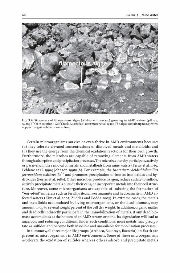
102 CHAPTER 3 · Mine Water
Certain microorganisms survive or even thrive in AMD environments because:(a) they tolerate elevated concentrations of dissolved metals and metalloids; and(b) they use the energy from the chemical oxidation reactions for their own growth.Furthermore, the microbes are capable of removing elements from AMD watersthrough adsorption and precipitation processes. The microbes thereby participate, activelyor passively, in the removal of metals and metalloids from mine waters (Ferris et al. 1989;Leblanc et al. 1996; Johnson 1998a,b). For example, the bacterium Acidithiobacillusferrooxidans oxidizes Fe2+ and promotes precipitation of iron as iron oxides and hy-droxides (Ferris et al. 1989). Other microbes produce oxygen, reduce sulfate to sulfide,actively precipitate metals outside their cells, or incorporate metals into their cell struc-ture. Moreover, some microorganisms are capable of inducing the formation of“microbial” minerals such as ferrihyrite, schwertmannite and hydrozincite in AMD af-fected waters (Kim et al. 2002; Zuddas and Podda 2005). In extreme cases, the metalsand metalloids accumulated by living microorganisms, or the dead biomass, mayamount to up to several weight percent of the cell dry weight. In addition, organic matterand dead cells indirectly participate in the immobilization of metals. If any dead bio-mass accumulates at the bottom of an AMD stream or pond, its degradation will lead toanaerobic and reducing conditions. Under such conditions, most metals may precipi-tate as sulfides and become both insoluble and unavailable for mobilization processes.
In summary, all three major life groups (Archaea, Eukaraya, Bacteria) on Earth arepresent as microorganisms in AMD environments. Some of these microorganismsaccelerate the oxidation of sulfides whereas others adsorb and precipitate metals
Fig. 3.4. Streamers of filamentous algae (Klebsormidium sp.) growing in AMD waters (pH 4.2,7.4 mg l–1 Cu in solution), Gulf Creek, Australia (Lottermoser et al. 1999). The algae contain up to 0.25 wt.%copper. Largest cobble is 20 cm long
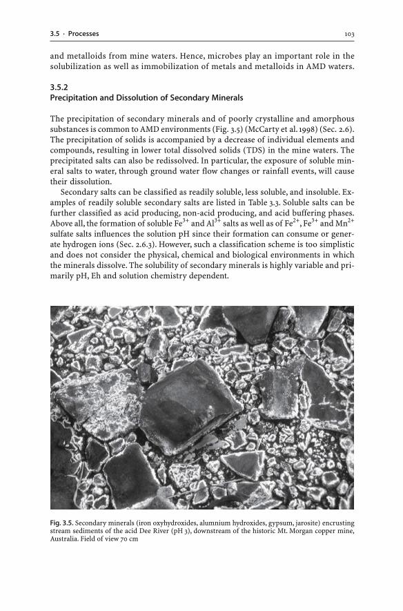
1033.5 · Processes
and metalloids from mine waters. Hence, microbes play an important role in thesolubilization as well as immobilization of metals and metalloids in AMD waters.
3.5.2Precipitation and Dissolution of Secondary Minerals
The precipitation of secondary minerals and of poorly crystalline and amorphoussubstances is common to AMD environments (Fig. 3.5) (McCarty et al. 1998) (Sec. 2.6).The precipitation of solids is accompanied by a decrease of individual elements andcompounds, resulting in lower total dissolved solids (TDS) in the mine waters. Theprecipitated salts can also be redissolved. In particular, the exposure of soluble min-eral salts to water, through ground water flow changes or rainfall events, will causetheir dissolution.
Secondary salts can be classified as readily soluble, less soluble, and insoluble. Ex-amples of readily soluble secondary salts are listed in Table 3.3. Soluble salts can befurther classified as acid producing, non-acid producing, and acid buffering phases.Above all, the formation of soluble Fe3+ and Al3+ salts as well as of Fe2+, Fe3+ and Mn2+
sulfate salts influences the solution pH since their formation can consume or gener-ate hydrogen ions (Sec. 2.6.3). However, such a classification scheme is too simplisticand does not consider the physical, chemical and biological environments in whichthe minerals dissolve. The solubility of secondary minerals is highly variable and pri-marily pH, Eh and solution chemistry dependent.
Fig. 3.5. Secondary minerals (iron oxyhydroxides, alumnium hydroxides, gypsum, jarosite) encrustingstream sediments of the acid Dee River (pH 3), downstream of the historic Mt. Morgan copper mine,Australia. Field of view 70 cm
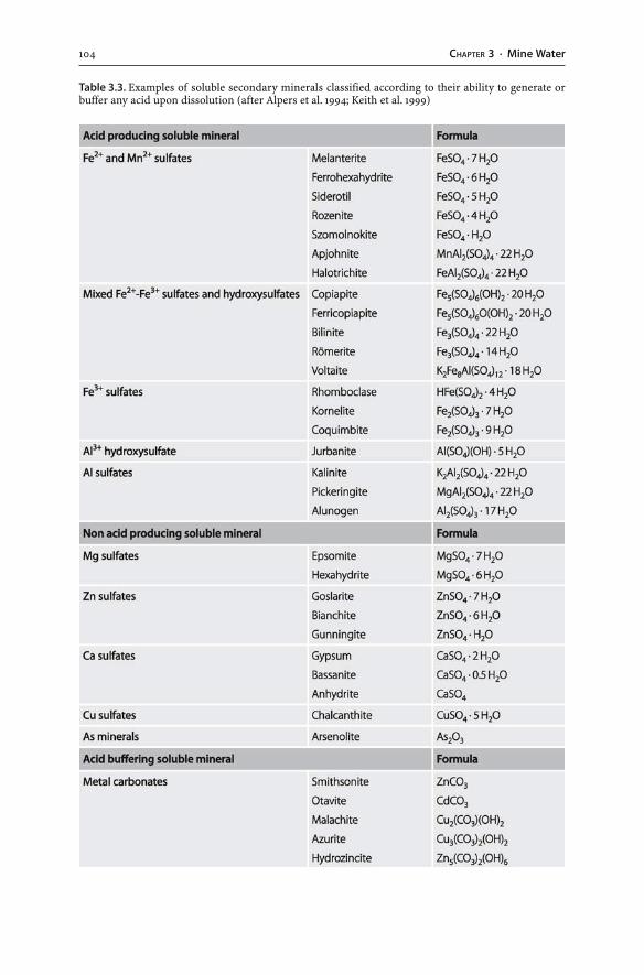
104 CHAPTER 3 · Mine Water
Table 3.3. Examples of soluble secondary minerals classified according to their ability to generate orbuffer any acid upon dissolution (after Alpers et al. 1994; Keith et al. 1999)
1053.5 · Processes
Jarosite-type phases can be viewed as less soluble phases as their dissolution is stronglyinfluenced by the solution’s pH (Smith et al. 2006). Their dissolution can be a two-stepprocess. For example, alunite (KAl3(SO4)2(OH)6) and jarosite (KFe3(SO4)2(OH)6) dis-solution initially consumes acid (Reaction 3.1). This may be followed by the precipita-tion of gibbsite (Al(OH)3), which generates acid (Reaction 3.2). The overall combinedReaction 3.3 illustrates that the dissolution of alunite and jarosite produces acid:
KAl3(SO4)2(OH)6(s) + 6 H+(aq) ↔ K+
(aq) + 3 Al3+(aq) + 6 H2O(l) + 2 SO4
2–(aq) (3.1)
3 Al3+(aq) + 9 H2O(l) ↔ 3 Al(OH)3(s) + 9 H+
(aq) (3.2)
(Reaction 3.1 + Reaction 3.2 = Reaction 3.3)
KAl3(SO4)2(OH)6(s) + 3 H2O(l) ↔ K+(aq) + 3 Al(OH)3(s) + 2 SO4
2–(aq) + 3 H+
(aq) (3.3)
Sulfate salts are particularly common in AMD environments and soluble under oxi-dizing conditions, especially the Ca, Mg, Fe2+, Fe3+ and Mn2+ sulfate salts (Cravotta 1994;Jambor et al. 2000a,b). A decrease in pH is principally caused by the dissolution of Fe2+
sulfate salts, which are capable of producing acidity due to the hydrolysis of Fe3+. Forinstance, melanterite (FeSO4 · 7 H2O) can control the acidity of mine waters (Frau 2000).Melanterite dissolution releases hydrogen ions as shown by the following equations(White et al. 1999):
FeSO4 · 7 H2O(s) ↔ Fe2+(aq) + SO4
2–(aq) + 7 H2O(l) (3.4)
4 Fe2+(aq) + 4 H+
(aq) + O2(g) → 4 Fe3+(aq) + 2 H2O(l) (3.5)
Fe3+(aq) + 3 H2O(l) ↔ Fe(OH)3(s) + 3 H+
(aq) (3.6)
The release of Fe2+ into water does not necessarily result in only the precipitationof iron hydroxides but can also trigger more sulfide oxidation (Keith et al. 1999; Alpersand Nordstrom 1999; Plumlee 1999). The dissolution of melanterite releases Fe2+ whichcan be oxidized to Fe3+. Any pyrite may subsequently be oxidized by Fe3+ as shown bythe following equation:
FeS2(s) + 14 Fe3+(aq) + 8 H2O(l) → 15 Fe2+
(aq) + 16 H+(aq) + 2 SO4
2–(aq) (3.7)
Similarly, the dissolution of römerite (Fe3(SO4)4 · 14 H2O), halotrichite(FeAl2(SO4)4 · 22 H2O), and coquimbite (Fe2(SO4)3 · 9 H2O) generates acid (Cravotta1994; Rose and Cravotta 1999):
Fe3(SO4)4 · 14 H2O(s) ↔ 2 Fe(OH)3(s) + Fe2+(aq) + 4 SO4
2–(aq) + 6 H+
(aq) + 8 H2O(l) (3.8)
4 FeAl2(SO4)4 · 22 H2O(s) + O2(aq) ↔ 4 Fe(OH)3(s) + 8 Al(OH)3(s) + 54 H2O(l)
+ 16 SO42–(aq) + 32 H+
(aq) (3.9)
Fe2(SO4)3 · 9 H2O(s) ↔ 2 Fe(OH)3(s) + 3 SO42–(aq) + 6 H+
(aq) + 3 H2O(l) (3.10)
106 CHAPTER 3 · Mine Water
Generalized reactions for the dissolution of Fe3+ and Al3+ salts and of Fe2+, Fe3+,and Mn2+ sulfate salts can be written as follows:
(Fe3+ and Al3+ salts; Fe2+, Fe3+, and Mn2+ sulfate salts)(s) + n H+(aq)
↔ (Fe2+, Fe3+, Al3+, Mn2+)n+(aq) + anionsn–
(aq) + n H+(aq) + n H2O(l) (3.11)
(Fe2+, Fe3+, Al3+, Mn2+)n+(aq) + n H2O(l) ↔ salts-n H2O(s) + n H+
(aq) (3.12)
(Reaction 3.11 + Reaction 3.12 = Reaction 3.13)
(Fe3+ and Al3+ salts; Fe2+, Fe3+, and Mn2+ sulfate salts)(s) + n H2O(l)
↔ cationsn+(aq) + anionsn–
(aq) + n H+(aq) + salts-n H2O(s) (3.13)
Iron sulfate minerals can be significant sources of acidity and sulfate when laterdissolved. Release of Fe2+ from these salts can also trigger more sulfide oxidation. Fur-thermore, other forms of sulfur such as native sulfur (S0) and thiosulfate (S2O3
2–) canbe intermediate products that tend to be oxidized to sulfate under oxidizing condi-tions. Moreover, many of the secondary minerals allow substitution of iron and alu-minium by numerous other metals (e.g. substitution of Fe by Cu and Zn in melanterite).As a result, dissolution of secondary minerals will lead to the release of major andminor metals, and metalloids (Lin 1997). In contrast, the dissolution of soluble alu-minium (e.g. alunogen: Al2(SO4)3 · 17 H2O), magnesium (e.g. epsomite: MgSO4 · 7 H2O),or calcium sulfate minerals (e.g. gypsum: CaSO4 · 2 H2O) does not generate any acid.Their dissolution does not influence mine water pH (Keith et al. 1999). Other solublesecondary minerals are acid buffering, and a variety of metal carbonates such as smith-sonite (ZnCO3), malachite (Cu2(CO3)(OH)2), and azurite (Cu3(CO3)2(OH)2) are effec-tive acid consumers (Table 3.3).
The presence of soluble salts in unsaturated ground water zones of waste rockdumps, tailings dams, and other waste repositories is important because their disso-lution will lead to a change in the chemistry of drainage waters. Evaporation, espe-cially in arid and seasonally dry regions, causes the precipitation of secondary miner-als which can store metal, metalloids, sulfate, and hydrogen ions. The formation ofsoluble secondary, sulfate-, metal- and metalloid-bearing minerals slows down sulfate,metal and metalloid mobility but only temporarily until the next rainfall (Bayless andOlyphant 1993; Keith et al. 1999). Rapid dissolution of soluble salts and hydrolysis ofdissolved Fe3+ may occur during the onset of the wet season or the beginning of spring.This in turn can result in exceptionally high sulfate, metal and metalloid concentra-tions as well as strong acidity of waters during the initial flushing event (Kwong et al.1997; Keith et al. 2001). In particular, the dissolution of the iron sulfates releases in-corporated sulfate, metals, metalloids, and acidity to ground and surface waters. ThepH of drainage waters may eventually change to more neutral conditions due to in-creased dilution. Such neutral pH values will limit heavy metal mobility. Upon changesto drier conditions, evaporation will again cause the precipitation of secondary min-erals. This type of wetting and drying cycle can result in dramatic seasonal variationsin acidity, and metal and metalloid loads of seepages and local streams (Bayless andOlyphant 1993; Keith et al. 1999). The production of contaminant pulses at the onset
1073.5 · Processes
of rainfall is common to mine sites in seasonally dry climates. In these environments,seasonal variations in the chemistry of drainage waters from sulfidic mine wastes arecaused by the dissolution and precipitation of soluble mineral precipitates.
3.5.3Coprecipitation
Coprecipitation refers to the removal of a trace constituent from solution which oc-curs at the same time as the precipitation of a major salt. This eventuates even whenthe solubility product of the trace constituent is not exceeded. The precipitating solidincorporates the minor constituent as an impurity into the crystal lattice. Variousminerals can thereby host a wide variety of cations as “impurities”. The cations canbe incorporated into the crystal lattice of the minerals via single or coupled substitu-tion. For example, a large number of ions have been reported to substitute for iron inthe goethite crystal lattice (e.g. Al, Cr, Ga, V, Mn, Co, Pb, Ni, Zn, Cd) (Cornell andSchwertmann 1996). Also, jarosite has been found to incorporate various elements intoits mineral structure (e.g. Cu, Zn, Pb, K, Na, Ca) (Levy et al. 1997).
3.5.4Adsorption and Desorption
Trace elements move between dissolved and particulate phases. Adsorption is the termwhich refers to the the removal of ions from solution and their adherence to the sur-faces of solids (Langmuir 1997). The attachment of the solutes onto the solid phasesdoes not represent a permanent bond, and the adsorption is based on ionic attractionof the solutes and the solid phases (Smith 1999). The solid phases can be of organic orinorganic composition and of negative or positive charge attracting dissolved cationsand anions, respectively. Adsorption reactions are an important control on the trans-port, concentration and fate of many elements in waters, including AMD waters.
Adsorption may occur in various AMD environments (Fuge et al. 1994; Bowell andBruce 1995; Swedlund and Webster 2001). It may occur on iron- and aluminium-richparticulates and clay particles suspended in mine waters, on precipitates at seepagepoints, or on clayey sediments of stream beds and ponds. Different ions thereby ex-hibit different adsorption characteristics. Generally, solid compounds adsorb moreanions at low pH and more cations at near neutral pH. In addition, the kind of metaladsorbed and the extent of metal adsorption is a function of: (a) the solution pH;(b) the presence of complexing ligands; and (c) the metal concentration of the AMD.Arsenic and lead are the most effectively adsorbed metals at acid pH values, whereaszinc, cadmium, and nickel are adsorbed at near-neutral pH values (Plumlee et al. 1999).Therefore, when AMD waters are gradually neutralized, various secondary mineralsprecipitate and adsorb metals. Adsorption is selective, and the chemical compositionof the water changes as the pH increases. Ions are removed from solution by this pro-cess, and metal-rich sediment accumulates.
While sediment may remove ions from solution, it may also release adsorbed met-als if the water is later acidified. In contrast, other elements such as arsenic and mo-lybdenum may desorb at near-neutral or higher pH values to form oxyanions in thewater (e.g. AsO4
3–) (Jönsson and Lövgren 2000). Similarly, uranium, copper, and lead
108 CHAPTER 3 · Mine Water
may desorb at near-neutral or higher pH values to form aqueous carbonate complexes.Sulfate may also be released from ferric precipitates if pH values raise to neutral oreven alkaline values (Plumlee et al. 1999; Rose and Elliott 2000). As a result, sulfate,metal, and metalloid ions desorb and regain their mobility at near-neutral or alkalinepH values, and dissolved sulfate, metal, and metalloid concentrations of mine watersmay in fact increase with increasing pH.
Sorption sites of particulates represent only temporary storage facilities for dissolvedmetals, metalloids and sulfate. In a worst case scenario, if excessive neutralization is usedto treat AMD effected streams, sulfate, metals, and metalloids previously fixed in streamsediments may then be redissolved by the treated water. Thus, remediation of AMDwaters should raise the pH only to values necessary to precipitate and adsorb metals.
3.5.5Eh-pH Conditions
The solubility of many dissolved heavy metals is influenced by the pH of the solution.The generation of low pH waters due to sulfide oxidation, or the presence of processchemicals such as sulfuric acid, enhances the dissolution of many elements. This aciditysignificantly increases the mobility and bioavailability of elements, and the concen-tration of total dissolved solids in mine waters. Most of the metals have increasing ionicsolubilities under acid, oxidizing conditions, and the metals are not adsorbed ontosolids at low pH. In many cases, the highest aqueous concentrations of heavy metalsare associated with oxidizing, acid conditions.
Precipitation of many of the dissolved metals occurs during neutralization of lowpH drainage waters, for example, due to mixing with tributary streams or due to themovement of the seepage water over alkaline materials such as carbonate bedrocks.The metals are adsorbed onto solid phases, particularly precipitating iron-rich solids.Alternatively, the metals are incorporated into secondary minerals coating the seep-age area or stream bed. Generally, as pH increases, aqueous metal species are inclinedto precipitate as hydroxide, oxyhydroxide or hydroxysulfate phases (Berger et al. 2000;Munk et al. 2002). The resultant drainage water contains the remaining dissolved metalsand products of the buffering reactions. Therefore, with increasing pH the dissolvedmetal content of mining influenced waters decreases.
While neutralization of AMD causes the removal of most metals, neutral to alka-line mine waters are known to contain elevated metal and metalloid concentrations.In fact, oxidized neutral to alkaline mine waters can have very high metal (Cd, Cu, Hg,Mn, Mo, Ni, Se, U, Zn) and metalloid (As, Sb) values (Carroll et al. 1998; Lottermoseret al. 1997b, 1999; Pettit et al. 1999; Plumlee 1999; Plumlee et al. 1999; Younger 2000;Schmiermund 2000; Scharer et al. 2000). Such waters are of environmental concernbecause the elements tend to remain in solution, despite pH changes. The elementscan be carried for long distances downstream of their source, and they may adverselyimpact on the quality of receiving water bodies.
The ability of water to transport metals is not only controlled by pH but also by theEh of the solution. The reduction-oxidation potential as measured by Eh affects the mo-bility of those metals which can exist in several oxidation states. Metals such as chro-mium, molybdenum, selenium, vanadium, and uranium are much more soluble in theiroxidized states (e.g. U6+, Cr6+) than in their reduced states (e.g. U4+, Cr3+). Oxygenated
1093.5 · Processes
water may oxidize metals present in their reduced, immobile state and allow mobility. Thesesalient aspects of aqueous element chemistry are commonly described by Eh-pH diagrams.The diagrams illustrate the stability and instability of minerals under particular Eh-pHconditions and show the ionic element species present in solution (Brookins 1988).
3.5.6Heavy Metals
The oxidation of various sulfide minerals will release their major and trace elements,including numerous heavy metals (Table 2.1). In some cases, the degradation of or-ganic matter particularly in carbonaceous rocks (i.e. black shales) may release metalssuch as nickel to pore and drainage waters (e.g. Wengel et al. 2006; Falk et al. 2006). Asa result, elevated concentrations of one or more heavy metals are characteristic ofwaters in contact with oxidizing sulfidic and carbonaceous rocks. The controls on heavymetal concentrations in mine waters are numerous, highly metal specific, and con-trolled by environmental conditions such as pH.
Heavy metals can occur in various forms in AMD waters. A metal is either dissolvedin solution as ion and molecule, or it exists as a solid mass. Dissolved metal speciesinclude cations (e.g. Cu2+), simple radicals (e.g. UO2
2+), and inorganic (e.g. CuCO3) andorganic complexes (e.g. Hg(CH3)2). Metals may also be present in a solid form as substi-tutions in precipitates (e.g. Cu in eugsterite Na4Ca(SO4)3 · 2 H2O), as mineral particles(e.g. cerussite PbCO3), and in living biota (e.g. Cu in algae) (Brownlow 1996; Smith andHuyck 1999). There is also a transitional state whereby very small particles, so-called“colloids”, are suspended in water (Stumm and Morgan 1995). A colloid can be definedas a stable electrostatic suspension of very small particles (<10 µm) in a liquid (Stummand Morgan 1995). The composition of colloids can be exceptionally diverse and in-cludes organic and inorganic substances. Metals can be incorporated into organic(e.g. Pb fulvic acid polymers) or inorganic colloids (e.g. FeOOH), or are adsorbed ontothem (e.g. Ni on clays). The stability of these colloids is influenced by a range of physi-cal, chemical and biological changes of the solution (Brownlow 1996; Ranville andSchmiermund 1999). Upon such changes, colloids will aggregate into larger particles;that is, they undergo “flocculation” and occur as suspended particles in the water. Iron-and aluminium-rich colloids and suspended particles are especially common in AMDwaters (Schemel et al. 2000; Zänker et al. 2002).
Metals may be transported in mine waters in various speciations. In AMD waters,most metals occur as simple metal ions or as sulfate complexes. In neutral and alka-line mine waters, elevated metal and metalloid concentrations are promoted by theformation of oxyanions (e.g. AsO4
3–), aqueous metal complexes (e.g. U carbonate com-plexes, Zn sulfate and hydroxide complexes) as well as the lack of adsorption onto andcoprecipitation with secondary iron hydroxides (Plumlee et al. 1999).
The size of the metal species progressively increases from cation to metal particle inliving biota. The different size of the metal species and the common procedure to filterwater prior to chemical analysis have a distinct implication on the analytical result. A com-mon filter pore size used is 0.45 µm. Such filters will allow significant amounts of colloidalmaterial to pass through, and analyses of these samples will reflect dissolved and colloi-dal constituents (Brownlow 1996; Ranville and Schmiermund 1999). For this reason, theUS EPA has suggested the collection of both unfiltered and filtered water samples (Ranville
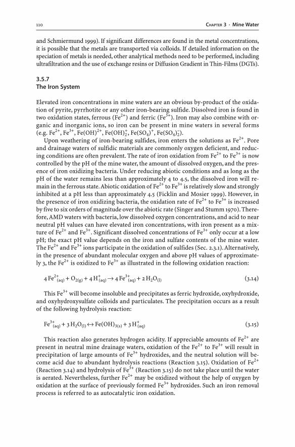
110 CHAPTER 3 · Mine Water
and Schmiermund 1999). If significant differences are found in the metal concentrations,it is possible that the metals are transported via colloids. If detailed information on thespeciation of metals is needed, other analytical methods need to be performed, includingultrafiltration and the use of exchange resins or Diffusion Gradient in Thin-Films (DGTs).
3.5.7The Iron System
Elevated iron concentrations in mine waters are an obvious by-product of the oxida-tion of pyrite, pyrrhotite or any other iron-bearing sulfide. Dissolved iron is found intwo oxidation states, ferrous (Fe2+) and ferric (Fe3+). Iron may also combine with or-ganic and inorganic ions, so iron can be present in mine waters in several forms(e.g. Fe2+, Fe3+, Fe(OH)2+, Fe(OH)2
+, Fe(SO4)+, Fe(SO4)2–).
Upon weathering of iron-bearing sulfides, iron enters the solutions as Fe2+. Poreand drainage waters of sulfidic materials are commonly oxygen deficient, and reduc-ing conditions are often prevalent. The rate of iron oxidation from Fe2+ to Fe3+ is nowcontrolled by the pH of the mine water, the amount of dissolved oxygen, and the pres-ence of iron oxidizing bacteria. Under reducing abiotic conditions and as long as thepH of the water remains less than approximately 4 to 4.5, the dissolved iron will re-main in the ferrous state. Abiotic oxidation of Fe2+ to Fe3+ is relatively slow and stronglyinhibited at a pH less than approximately 4.5 (Ficklin and Mosier 1999). However, inthe presence of iron oxidizing bacteria, the oxidation rate of Fe2+ to Fe3+ is increasedby five to six orders of magnitude over the abiotic rate (Singer and Stumm 1970). There-fore, AMD waters with bacteria, low dissolved oxygen concentrations, and acid to nearneutral pH values can have elevated iron concentrations, with iron present as a mix-ture of Fe2+ and Fe3+. Significant dissolved concentrations of Fe3+ only occur at a lowpH; the exact pH value depends on the iron and sulfate contents of the mine water.The Fe2+ and Fe3+ ions participate in the oxidation of sulfides (Sec. 2.3.1). Alternatively,in the presence of abundant molecular oxygen and above pH values of approximate-ly 3, the Fe2+ is oxidized to Fe3+ as illustrated in the following oxidation reaction:
4 Fe2+(aq) + O2(g) + 4 H+
(aq) → 4 Fe3+(aq) + 2 H2O(l) (3.14)
This Fe3+ will become insoluble and precipitates as ferric hydroxide, oxyhydroxide,and oxyhydroxysulfate colloids and particulates. The precipitation occurs as a resultof the following hydrolysis reaction:
Fe3+(aq) + 3 H2O(l) ↔ Fe(OH)3(s) + 3 H+
(aq) (3.15)
This reaction also generates hydrogen acidity. If appreciable amounts of Fe2+ arepresent in neutral mine drainage waters, oxidation of the Fe2+ to Fe3+ will result inprecipitation of large amounts of Fe3+ hydroxides, and the neutral solution will be-come acid due to abundant hydrolysis reactions (Reaction 3.15). Oxidation of Fe2+
(Reaction 3.14) and hydrolysis of Fe3+ (Reaction 3.15) do not take place until the wateris aerated. Nevertheless, further Fe2+ may be oxidized without the help of oxygen byoxidation at the surface of previously formed Fe3+ hydroxides. Such an iron removalprocess is referred to as autocatalytic iron oxidation.
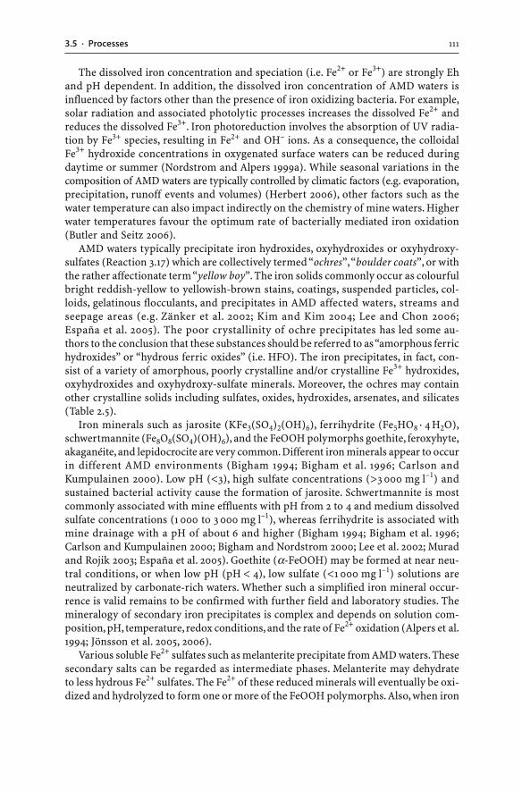
1113.5 · Processes
The dissolved iron concentration and speciation (i.e. Fe2+ or Fe3+) are strongly Ehand pH dependent. In addition, the dissolved iron concentration of AMD waters isinfluenced by factors other than the presence of iron oxidizing bacteria. For example,solar radiation and associated photolytic processes increases the dissolved Fe2+ andreduces the dissolved Fe3+. Iron photoreduction involves the absorption of UV radia-tion by Fe3+ species, resulting in Fe2+ and OH– ions. As a consequence, the colloidalFe3+ hydroxide concentrations in oxygenated surface waters can be reduced duringdaytime or summer (Nordstrom and Alpers 1999a). While seasonal variations in thecomposition of AMD waters are typically controlled by climatic factors (e.g. evaporation,precipitation, runoff events and volumes) (Herbert 2006), other factors such as thewater temperature can also impact indirectly on the chemistry of mine waters. Higherwater temperatures favour the optimum rate of bacterially mediated iron oxidation(Butler and Seitz 2006).
AMD waters typically precipitate iron hydroxides, oxyhydroxides or oxyhydroxy-sulfates (Reaction 3.17) which are collectively termed “ochres”, “boulder coats”, or withthe rather affectionate term “yellow boy”. The iron solids commonly occur as colourfulbright reddish-yellow to yellowish-brown stains, coatings, suspended particles, col-loids, gelatinous flocculants, and precipitates in AMD affected waters, streams andseepage areas (e.g. Zänker et al. 2002; Kim and Kim 2004; Lee and Chon 2006;España et al. 2005). The poor crystallinity of ochre precipitates has led some au-thors to the conclusion that these substances should be referred to as “amorphous ferrichydroxides” or “hydrous ferric oxides” (i.e. HFO). The iron precipitates, in fact, con-sist of a variety of amorphous, poorly crystalline and/or crystalline Fe3+ hydroxides,oxyhydroxides and oxyhydroxy-sulfate minerals. Moreover, the ochres may containother crystalline solids including sulfates, oxides, hydroxides, arsenates, and silicates(Table 2.5).
Iron minerals such as jarosite (KFe3(SO4)2(OH)6), ferrihydrite (Fe5HO8 · 4 H2O),schwertmannite (Fe8O8(SO4)(OH)6), and the FeOOH polymorphs goethite, feroxyhyte,akaganéite, and lepidocrocite are very common. Different iron minerals appear to occurin different AMD environments (Bigham 1994; Bigham et al. 1996; Carlson andKumpulainen 2000). Low pH (<3), high sulfate concentrations (>3 000 mg l–1) andsustained bacterial activity cause the formation of jarosite. Schwertmannite is mostcommonly associated with mine effluents with pH from 2 to 4 and medium dissolvedsulfate concentrations (1 000 to 3 000 mg l–1), whereas ferrihydrite is associated withmine drainage with a pH of about 6 and higher (Bigham 1994; Bigham et al. 1996;Carlson and Kumpulainen 2000; Bigham and Nordstrom 2000; Lee et al. 2002; Muradand Rojik 2003; España et al. 2005). Goethite (α-FeOOH) may be formed at near neu-tral conditions, or when low pH (pH < 4), low sulfate (<1 000 mg l–1) solutions areneutralized by carbonate-rich waters. Whether such a simplified iron mineral occur-rence is valid remains to be confirmed with further field and laboratory studies. Themineralogy of secondary iron precipitates is complex and depends on solution com-position, pH, temperature, redox conditions, and the rate of Fe2+ oxidation (Alpers et al.1994; Jönsson et al. 2005, 2006).
Various soluble Fe2+ sulfates such as melanterite precipitate from AMD waters. Thesesecondary salts can be regarded as intermediate phases. Melanterite may dehydrateto less hydrous Fe2+ sulfates. The Fe2+ of these reduced minerals will eventually be oxi-dized and hydrolyzed to form one or more of the FeOOH polymorphs. Also, when iron
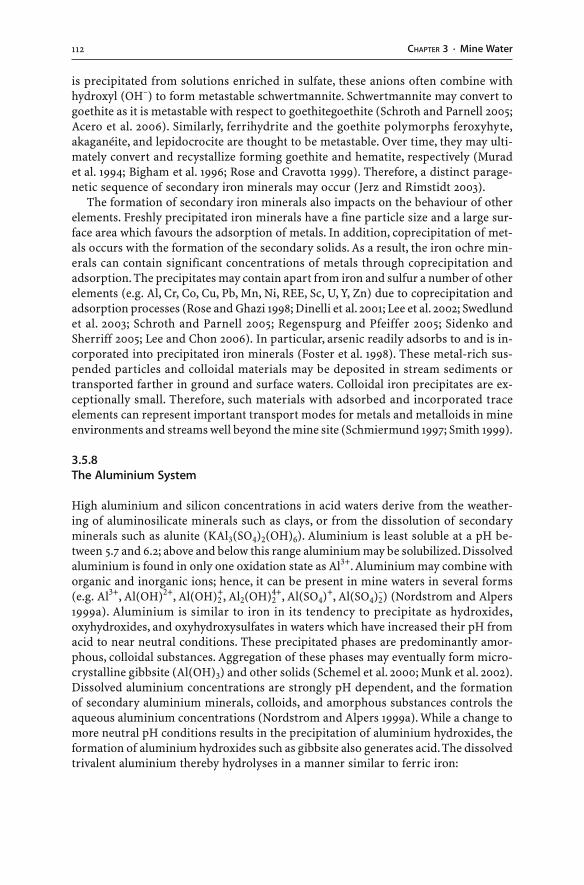
112 CHAPTER 3 · Mine Water
is precipitated from solutions enriched in sulfate, these anions often combine withhydroxyl (OH–) to form metastable schwertmannite. Schwertmannite may convert togoethite as it is metastable with respect to goethitegoethite (Schroth and Parnell 2005;Acero et al. 2006). Similarly, ferrihydrite and the goethite polymorphs feroxyhyte,akaganéite, and lepidocrocite are thought to be metastable. Over time, they may ulti-mately convert and recystallize forming goethite and hematite, respectively (Muradet al. 1994; Bigham et al. 1996; Rose and Cravotta 1999). Therefore, a distinct parage-netic sequence of secondary iron minerals may occur (Jerz and Rimstidt 2003).
The formation of secondary iron minerals also impacts on the behaviour of otherelements. Freshly precipitated iron minerals have a fine particle size and a large sur-face area which favours the adsorption of metals. In addition, coprecipitation of met-als occurs with the formation of the secondary solids. As a result, the iron ochre min-erals can contain significant concentrations of metals through coprecipitation andadsorption. The precipitates may contain apart from iron and sulfur a number of otherelements (e.g. Al, Cr, Co, Cu, Pb, Mn, Ni, REE, Sc, U, Y, Zn) due to coprecipitation andadsorption processes (Rose and Ghazi 1998; Dinelli et al. 2001; Lee et al. 2002; Swedlundet al. 2003; Schroth and Parnell 2005; Regenspurg and Pfeiffer 2005; Sidenko andSherriff 2005; Lee and Chon 2006). In particular, arsenic readily adsorbs to and is in-corporated into precipitated iron minerals (Foster et al. 1998). These metal-rich sus-pended particles and colloidal materials may be deposited in stream sediments ortransported farther in ground and surface waters. Colloidal iron precipitates are ex-ceptionally small. Therefore, such materials with adsorbed and incorporated traceelements can represent important transport modes for metals and metalloids in mineenvironments and streams well beyond the mine site (Schmiermund 1997; Smith 1999).
3.5.8The Aluminium System
High aluminium and silicon concentrations in acid waters derive from the weather-ing of aluminosilicate minerals such as clays, or from the dissolution of secondaryminerals such as alunite (KAl3(SO4)2(OH)6). Aluminium is least soluble at a pH be-tween 5.7 and 6.2; above and below this range aluminium may be solubilized. Dissolvedaluminium is found in only one oxidation state as Al3+. Aluminium may combine withorganic and inorganic ions; hence, it can be present in mine waters in several forms(e.g. Al3+, Al(OH)2+, Al(OH)2
+, Al2(OH)24+, Al(SO4)+, Al(SO4)2
–) (Nordstrom and Alpers1999a). Aluminium is similar to iron in its tendency to precipitate as hydroxides,oxyhydroxides, and oxyhydroxysulfates in waters which have increased their pH fromacid to near neutral conditions. These precipitated phases are predominantly amor-phous, colloidal substances. Aggregation of these phases may eventually form micro-crystalline gibbsite (Al(OH)3) and other solids (Schemel et al. 2000; Munk et al. 2002).Dissolved aluminium concentrations are strongly pH dependent, and the formationof secondary aluminium minerals, colloids, and amorphous substances controls theaqueous aluminium concentrations (Nordstrom and Alpers 1999a). While a change tomore neutral pH conditions results in the precipitation of aluminium hydroxides, theformation of aluminium hydroxides such as gibbsite also generates acid. The dissolvedtrivalent aluminium thereby hydrolyses in a manner similar to ferric iron:
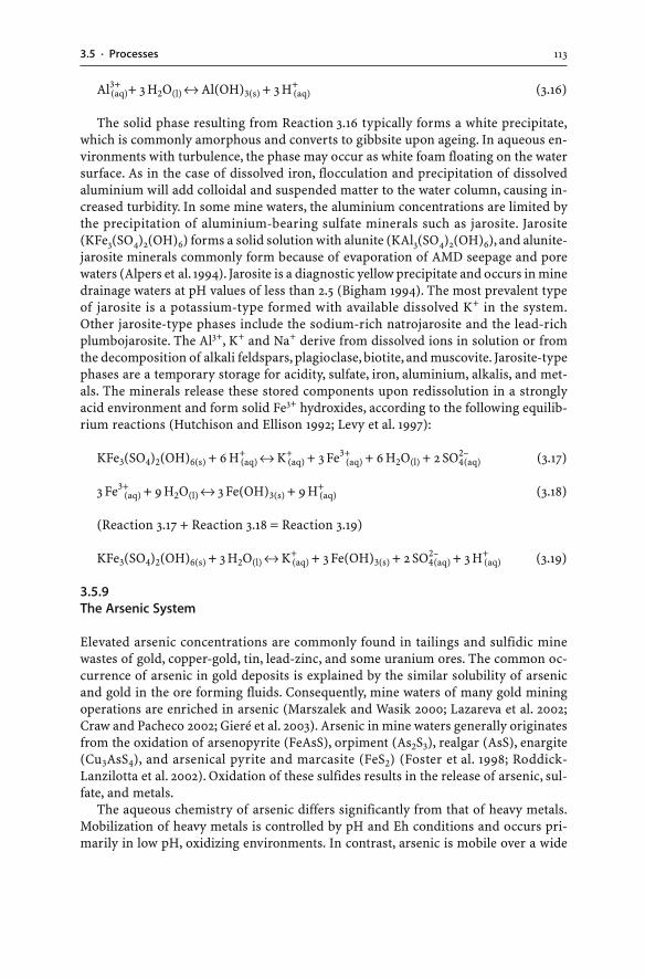
1133.5 · Processes
Al3+(aq)+ 3 H2O(l) ↔ Al(OH)3(s) + 3 H+
(aq) (3.16)
The solid phase resulting from Reaction 3.16 typically forms a white precipitate,which is commonly amorphous and converts to gibbsite upon ageing. In aqueous en-vironments with turbulence, the phase may occur as white foam floating on the watersurface. As in the case of dissolved iron, flocculation and precipitation of dissolvedaluminium will add colloidal and suspended matter to the water column, causing in-creased turbidity. In some mine waters, the aluminium concentrations are limited bythe precipitation of aluminium-bearing sulfate minerals such as jarosite. Jarosite(KFe3(SO4)2(OH)6) forms a solid solution with alunite (KAl3(SO4)2(OH)6), and alunite-jarosite minerals commonly form because of evaporation of AMD seepage and porewaters (Alpers et al. 1994). Jarosite is a diagnostic yellow precipitate and occurs in minedrainage waters at pH values of less than 2.5 (Bigham 1994). The most prevalent typeof jarosite is a potassium-type formed with available dissolved K+ in the system.Other jarosite-type phases include the sodium-rich natrojarosite and the lead-richplumbojarosite. The Al3+, K+ and Na+ derive from dissolved ions in solution or fromthe decomposition of alkali feldspars, plagioclase, biotite, and muscovite. Jarosite-typephases are a temporary storage for acidity, sulfate, iron, aluminium, alkalis, and met-als. The minerals release these stored components upon redissolution in a stronglyacid environment and form solid Fe3+ hydroxides, according to the following equilib-rium reactions (Hutchison and Ellison 1992; Levy et al. 1997):
KFe3(SO4)2(OH)6(s) + 6 H+(aq) ↔ K+
(aq) + 3 Fe3+(aq) + 6 H2O(l) + 2 SO4
2–(aq) (3.17)
3 Fe3+(aq) + 9 H2O(l) ↔ 3 Fe(OH)3(s) + 9 H+
(aq) (3.18)
(Reaction 3.17 + Reaction 3.18 = Reaction 3.19)
KFe3(SO4)2(OH)6(s) + 3 H2O(l) ↔ K+(aq) + 3 Fe(OH)3(s) + 2 SO4
2–(aq) + 3 H+
(aq) (3.19)
3.5.9The Arsenic System
Elevated arsenic concentrations are commonly found in tailings and sulfidic minewastes of gold, copper-gold, tin, lead-zinc, and some uranium ores. The common oc-currence of arsenic in gold deposits is explained by the similar solubility of arsenicand gold in the ore forming fluids. Consequently, mine waters of many gold miningoperations are enriched in arsenic (Marszalek and Wasik 2000; Lazareva et al. 2002;Craw and Pacheco 2002; Gieré et al. 2003). Arsenic in mine waters generally originatesfrom the oxidation of arsenopyrite (FeAsS), orpiment (As2S3), realgar (AsS), enargite(Cu3AsS4), and arsenical pyrite and marcasite (FeS2) (Foster et al. 1998; Roddick-Lanzilotta et al. 2002). Oxidation of these sulfides results in the release of arsenic, sul-fate, and metals.
The aqueous chemistry of arsenic differs significantly from that of heavy metals.Mobilization of heavy metals is controlled by pH and Eh conditions and occurs pri-marily in low pH, oxidizing environments. In contrast, arsenic is mobile over a wide
114 CHAPTER 3 · Mine Water
pH range (i.e. extremely acid to alkaline), and mine waters of an oxidized, neutral toalkaline pH nature can contain several mg l–1 of arsenic (Marszalek and Wasik 2000;Williams 2001; Roddick-Lanzilotta et al. 2002). Thus, contamination of mine watersby arsenic is not exclusive to AMD waters.
Arsenic exists in natural waters in two principal oxidation states, as As3+ in arsen-ite (AsO3
3–) and as As5+ in arsenate (AsO43–) (Yamauchi and Fowler 1994). In oxygen-
ated environments, As5+ is the stable species. In more reduced environments, As3+ isthe dominant form. The more reduced species As3+ is more soluble, mobile and toxicthan As5+ (Yamauchi and Fowler 1994). The oxidation of As3+ to As5+ is relatively fastand increases with pH and salinity in the presence of particular bacteria and proto-zoa (Casiot et al. 2003; Casiot et al. 2004).
Iron exerts an important control on the mobility of arsenic in water (Bednar et al.2005). In an oxidizing environment with a pH greater than 3, hydrous ferric oxides(HFO) are abundantly precipitated. Dissolved arsenic species are adsorbed by andcoprecipitated with these ferric hydroxides, and As5+ is thereby more strongly sorbedthan As3+ (Manceau 1995; Roddick-Lanzilotta et al. 2002). Adsorption onto andcoprecipitation with Fe3+ hydroxides are very efficient removal mechanisms of arsenicfrom mine waters. The formation of jarosite, schwertmannite and ferrihydrite may alsoremove arsenic from solution (Fukushi et al. 2003; Gault et al. 2005; Courtin-Nomadeet al. 2005). In general, precipitation of Fe3+ from mine waters is accompanied by areduction in the concentration of dissolved arsenic.
The solubility of arsenic is also limited by: (a) the adsorption of arsenic onto clays;(b) the formation of amorphous iron sulfoarsenates and secondary arsenic mineralssuch as scorodite (FeAsO4 · 2 H2O), arsenolite (As2O3), or iron-calcium arsenates such aspharmacolite (Ca(AsO3OH) · 2 H2O); and (c) the substitution of arsenic for sulfate injarosite and gypsum, and for carbonate in calcite (Foster et al. 1998; Savage et al. 2000;Gieré et al. 2003; Lee et al. 2005). In turn, the dissolution of arsenic salts will lead toarsenic release and mobilization. For instance, arsenolite (As2O3) is a high solubilityphase that readily liberates arsenic into waters (Williams 2001). Also, scorodite is acommon arsenic mineral which is formed during the oxidation of arsenopyrite-richwastes. Scorodite solubility is strongly controlled by pH (Krause and Ettel 1988). It issoluble at very low pH; its solubility is at its minimum at approximately pH 4; and thesolubility increases above pH 4 again. Hence, scorodite leads to the fixation of arsenicat approximately pH 4 whereas waters of low pH (<pH 3) and high pH (>pH 5) cancontain significant amounts of arsenic.
While precipitation of secondary arsenic minerals and adsorption can limit themobility of arsenic, the mobilization of arsenic from minerals back into mine watersmay be triggered through various processes. Important processes include: (a) desorp-tion at high pH (pH > 8.5) under oxidizing conditions; (b) desorption and Fe3+ hy-droxide dissolution due to a change to reducing conditions; and (c) arsenic mineraldissolution (Smedley and Kinniburgh 2002; Salzsauler et al. 2005). In particular, re-ducing conditions can lead to the desorption of arsenic from Fe3+ hydroxides and tothe reductive dissolution of Fe3+ hydroxides, also leading to an arsenic release(Pedersen et al. 2006). Therefore, the reduction of Fe3+ to Fe2+ increases the mobilityof arsenic. However, strongly reducing conditions do not favour arsenic mobility be-cause both iron and hydrogen sulfide would be present, leading to the coprecipitationof arsenic sulfide with iron sulfide. In contrast, mildly reducing environments that lack
1153.5 · Processes
hydrogen sulfide can allow the dissolution of arsenic. In such environments, iron is inthe soluble Fe2+ state, and arsenic is present as As3+ in the arsenite form (AsO3
3–). Inmildly reducing environments such as saturated tailings, precipitated Fe3+ hydroxidesand oxides can be reduced with the help of microorganisms to form dissolved Fe2+
and As3+ (McCreadie et al. 2000; Macur et al. 2001). Consequently, pore and seepagewaters of such tailings repositories may contain strongly elevated iron and arsenic con-centrations. When these seepage waters reach the surface, oxidation of the waters willresult in the precipitation of iron and coprecipitation of arsenic, forming arsenic-richyellow boys.
3.5.10The Mercury System
The determination of mercury speciation in mine waste requires the application ofappropriate methods (Sladek et al. 2002; Sladek and Gustin 2003; Kim et al. 2004).Mercury in mine waters is sourced from the weathering of cinnabar (HgS), metacin-nabar (HgS), calomel (HgCl), quicksilver (Hg(l)), livingstonite (HgSb4S7), and nativemercury (Hg). It may also be released from mercury amalgams present in historic al-luvial gold mines. While cinnabar weathers slowly under aerobic conditions (Barnettet al. 2001), the slow oxidation of mercury-bearing sulfides can still provide elevatedmercury levels to mine waters. Mercury exists in natural waters as elemental mercury(Hg0) and ionic mercury (Hg+ and Hg2+), and it is prone to be adsorbed onto organicmatter, iron hydroxides, and clay minerals (Covelli et al. 2001; Domagalski 1998, 2001).As a result, mercury can be transported in natural waters as dissolved species andadsorbed onto suspended particles and colloids. Furthermore, mercury is transformedby bacteria into organic forms, notably monomethyl mercury (CH3Hg+) and dimethylmercury ((CH3)2Hg) (Gray et al. 2002b; Bailey et al. 2002). These organic forms arehighly toxic, fat-soluble compounds and tend to bioaccumulate in the foodchain(Ganguli et al. 2000; Hinton and Veiga 2002). Factors encouraging mercury methyla-tion include high concentrations of dissolved carbon and organic matter, abundantbacteria and acidic water. Consequently, AMD waters are especially susceptible tomercury methylation.
3.5.11The Sulfate System
Upon oxidation of sulfides, the sulfur S2– (S: 2–) in the sulfides will be oxidized to el-emental sulfur (S: 0), and more commonly to sulfate SO4
2– (S: 6+). The sulfate may re-main in solution or precipitate to form secondary minerals (e.g. melanteriteFeSO4 · 7 H2O). However, sulfides may not be completely oxidized to form dissolvedsulfate ions or sulfate minerals. The sulfur may be oxidized to metastable, intermedi-ate sulfur oxyanions. These include sulfite SO3
2– (S: 4+), thiosulfate S2O32– (S: 2+), and
polythionates (SnO62–), which are then subsequently oxidized to sulfate (Moses et
al. 1987; Descostes et al. 2004). The occurrence of these intermediate sulfur spe-cies in mine waters is controversial, yet such reactions are supported by the occur-rence of sulfite and thiosulfate minerals as natural weathering products (Braithwaiteet al. 1993).
116 CHAPTER 3 · Mine Water
AMD waters carry significant concentrations of sulfate which exceed those of ironand heavy metals. Strongly elevated sulfate concentrations are prevalent because rela-tively few natural processes remove sulfate from ground and surface waters. Only theprecipitation of secondary sulfate minerals influences the concentration of sulfate insolution. The formation of secondary sulfates generally occurs in response to evapo-ration or neutralization reactions. Gypsum and other sulfates such as epsomite(MgSO4 · 7 H2O) and jarosite (KFe3(SO4)2(OH)6) are such precipitates in AMD affectedseepages, streams, and ponds. Gypsum is the most common sulfate salt in AMD envi-ronments. The Ca2+ for gypsum formation is released by the acid weathering of car-bonate and silicate minerals such as dolomite, calcite, and plagioclase. The concen-tration of calcium sulfate in mine waters may rise to a level at which gypsum precipi-tates. This level is not influenced by pH and is dependent on the detailed chemicalconditions of the water such as the amount of magnesium in solution. Gypsumformation may also be due to neutralization of AMD waters. Neutralization reactions be-tween AMD waters and calcite or dolomite result in gypsum (Reaction 3.20) andepsomite precipitation (Reaction 3.21). The reactions can be written as follows:
CaCO3(s) + H2SO4(aq) + 2 H2O(l) → CaSO4 · 2 H2O(s) + H2CO3(aq) (3.20)
CaMg(CO3)2(s) + 2 H2SO4(aq) + 9 H2O(l) → MgSO4 · 7 H2O(s) + CaSO4 · 2 H2O(s)
+ 2 H2CO3(aq) (3.21)
While the formation of gypsum and other sulfates reduces the dissolved sulfateconcentration, the minerals’ solubility in water is also high. The major chemical mecha-nism that removes sulfate from solution also causes elevated sulfate concentrations inwater. In addition, many oxidized ores may contain gypsum as a pre-mining mineral.Thus, not all high sulfate concentrations of mine waters are caused by sulfide oxida-tion; they can also be the result of the dissolution of gypsum and other sulfates.
AMD processes lead to high concentrations of dissolved sulfate at the AMD source.Once released into solution, the sulfate ion has the tendency to remain in solution.Sulfate concentrations in AMD waters are exceptionally high when compared to thoseof uncontaminated streams. Therefore, the sulfate ion can be used to trace thebehaviour of contaminant plumes impacting on streams and aquifers. For example,sulfate-rich mine waters discharge into a surface stream with little organic activity,and there is a decrease in sulfate concentration downstream from the discharge point.This can only be ascribed to dilution by non-contaminated streams (Schmiermund1997; Ghomshei and Allen 2000). If other mine derived constituents such as metalsdecrease to a greater extent in the same reach of the stream, then they must have beenremoved from the water by geochemical processes such as adsorption or coprecipi-tation. The behaviour of sulfate helps to trace and assess the fate of other mine waterconstituents.
3.5.12The Carbonate System
The so-called “carbonic acid system” or “carbonate system” greatly affects the bufferintensity and neutralizing capacity of waters (Brownlow 1996; Langmuir 1997). The
1173.5 · Processes
system comprises a series of reactions involving carbon dioxide (CO2), bicarbonate(HCO3
–), carbonate (CO32–), and carbonic acid (H2CO3). The reactions affecting these
different species are very important in ground and surface waters and involve the trans-fer of carbon among the solid, liquid and gas phase. This transfer of carbon also re-sults in the production of carbonic acid. Carbonic acid in water can be derived fromseveral sources, the most important of which are the weathering of carbonate rocks(Reactions 3.22–3.24) and the uptake of carbon dioxide from the atmosphere (Reac-tion 3.25):
CaCO3(s) ↔ Ca2+(aq) + CO3
2–(aq) (3.22)
CO32–(aq) + H+
(aq) ↔ HCO3–(aq) (3.23)
HCO3–(aq) + H+
(aq) ↔ H2CO3(aq) (3.24)
CO2(g) + H2O(l) ↔ H2CO3(aq) (3.25)
Contribution of carbonic acid from weathering processes of carbonate rocks is farmore important than the uptake of carbon dioxide from the atmosphere. Which car-bonate species will be present in the water is determined by the pH of the water, whichin turn is controlled by the concentration and ionic charge of the other chemical com-pounds in solution. Bicarbonate is the dominant species found in natural waters witha pH greater than 6.3 and less than 10.3; carbonate is dominant at pH greater than 10.3;carbonic acid is the dominant species below pH 6.3 (Sherlock et al. 1995; Brownlow1996; Langmuir 1997).
The distinction between bicarbonate and carbonic acid is important for the evalu-ation of AMD chemistry. Firstly, bicarbonate is a charged species whereas carbonicacid does not contribute any electrical charge or electrical conductivity to the water.In other words, in a low pH AMD water, the carbonic acid does not contribute a sig-nificant amount of anionic charge or conductivity to the water. With increasing pHvalue of the AMD water, the proportions of carbonic acid and bicarbonate will change.This alters the amount of negative charge and conductivity because bicarbonate ionswill contribute to the negative charge. Secondly, dissolved bicarbonate ions consumehydrogen ions; hence, bicarbonate ions provide neutralizing capacity to the water asillustrated by the following reaction:
HCO3–(aq) + H+
(aq) ↔ H2CO3(aq) (3.26)
Bicarbonate removes free hydrogen from the solution, lowering the solution’s acidity.Thus, the greater the total concentration of the bicarbonate species, the greater thebuffering capacity and alkalinity of the AMD water. The alkalinity of a water is a mea-sure of the bicarbonate and carbonate concentration, indicating the buffering capac-ity of the water (Table 3.1). The greater the alkalinity, the greater the hydrogen con-centration that can be balanced by the carbonate system.
The reaction of free hydrogen with bicarbonate is easily reversible (Reaction 3.26).Consequently, carbonic acid formation does not cause a permanent reduction in acidityof AMD waters. The consumed hydrogen may be released back into the mine water. In
118 CHAPTER 3 · Mine Water
fact, Reaction 3.26 is part of a series of equilibrium reactions (Reaction 3.27): bicar-bonate reacts with hydrogen ions to form carbonic acid; carbonic acid then reacts todissolved carbon dioxide and water, and finally to gaseous carbon dioxide and water:
HCO3–(aq) + H+
(aq) ↔ H2CO3(aq) ↔ CO2(aq) + H2O(l) ↔ CO2(g) + H2O(l) (3.27)
These equilibrium reactions can be forced to react towards the production of gas-eous carbon dioxide. For example, if AMD water is neutralized with limestone andstirred at the same time, the carbon dioxide exsolves as a gas phase; the dissolved car-bon dioxide content is lowered. As a result, the degassing of carbon dioxide does notallow the equilibrium reactions to proceed back to the production of hydrogen ions.Carbon dioxide degassing supports the permanent consumption of hydrogen by bi-carbonate ions, and the acidity of AMD waters can be permanently lowered (Carrollet al. 1998).
3.5.13pH Buffering
At mine sites, water reacts with minerals of rocks, soils, sediments, wastes, and aqui-fers. Different minerals possess different abilities to buffer the solution pH (Blowesand Ptacek 1994). Figure 2.3 shows a schematic diagram of AMD production for a hy-pothetical sulfidic waste dump. The initial drainage stage involves the exposure ofsulfide to water and oxygen. The small amount of acid generated will be neutralizedby any acid buffering minerals such as calcite in the waste. This maintains the solu-tion pH at about neutral conditions. As acid generation continues and the calcite hasbeen consumed, the pH of the water will decrease abruptly. As shown in Fig. 2.3, thepH will proceed in a step-like manner. Each plateau of relatively steady pH representsthe weathering of specific buffering materials at that pH range. In general, mineralsresponsible for various buffering plateaus are the calcite, siderite, silicate, clay, aluminiumhydroxysulfate, aluminium/iron hydroxide, and ferrihydrite buffers (Sherlock et al.1995; Jurjovec et al. 2002). Theoretically, steep transitions followed by pH plateausshould be the result of buffering by different minerals. Such distinct pH buffering pla-teaus may be observed in pore and seepage waters of sulfidic tailings, waste rock piles,spoil heaps or in ground waters underlying sulfidic materials. However, in reality, suchdistinct transitions and sharp plateaus are rarely observed as many different miner-als within the waste undergo kinetic weathering simultaneously and buffer the minewater pH.
The buffering reactions of the various minerals operate in different pH ranges. None-theless, there are great discrepancies in the literature about the exact pH values of thesezones (Blowes and Ptacek 1994; Ritchie 1994b; Sherlock et al. 1995). Broad pH bufferingof calcite occurs around neutral pH (pH 6.5 to 7.5) in an open or closed system (Sec. 2.4.2):
CaCO3(s) + CO2(g) + H2O(l) ↔ Ca2+(aq) + 2 HCO3
–(aq) (3.28)
CaCO3(s) + H+(aq) ↔ Ca2+
(aq) + HCO3–(aq) (3.29)
1193.5 · Processes
The presence of bicarbonate is influenced by the pH of the solution. Below pH 6.3,the dominant carbonate species in solution is carbonic acid. Hence, bicarbonate mayform carbonic acid as follows:
HCO3–(aq) + H+
(aq) ↔ H2CO3(aq) (3.30)
If all of the calcite has been dissolved by acid, or the mineral is absent, then sider-ite provides buffering between pH values of approximately 5 and 6 (Blowes and Ptacek1994; Sherlock et al. 1995):
FeCO3(s) + H+(aq) ↔ HCO3
–(aq) + Fe2+
(aq) (3.31)
The silicate minerals provide neutralizing capacity between pH 5 and 6. Theirchemical weathering can be congruent (Reaction 3.32) or incongruent (Reaction 3.33)(Sec. 2.4.1). Either reaction pathway results in the consumption of hydrogen ions:
MeAlSiO4(s) + H+(aq) + 3 H2O → Mex+
(aq) + Al3+(aq) + H4SiO4(aq) + 3 OH–
(aq) (3.32)
2 MeAlSiO4(s) + 2 H+(aq) + H2O → Mex+
(aq) + Al2Si2O5(OH)4(s) (3.33)
(Me = Ca, Na, K, Mg, Mn or Fe)
Exchange buffering of clay minerals is dominant between pH 4 and 5 and causesalkali and alkali earth cation release:
clay-(Ca2+)0.5(s) + H+(aq) → clay-(H+)(s) + 0.5 Ca2+
(aq) (3.34)
Aluminium and iron hydroxide buffering of minerals (e.g. ferrihydrite, goethite,gibbsite, hydroxysulfates, and amorphous iron and aluminium hydroxides) occurs ata lower pH than all other minerals; that is, between pH values of approximately 3 and 5.Their buffering results in the release of aluminium and iron cations:
Al(OH)3(s) + 3 H+(aq) ↔ Al3+
(aq) + 3 H2O(l) (3.35)
Fe(OH)3(s) + 3 H+(aq) ↔ Fe3+
(aq) + 3 H2O(l) (3.36)
3.5.14Turbidity
Turbidity is the ability of a water to disperse and adsorb light. It is caused by suspendedparticles floating in the water column. The suspended particles of AMD affectedstreams and seepages are diverse in composition. Firstly, they may include flocculatedcolloids due to hydrolysis and particulate formation. Such flocculants are typically com-posed of poorly crystalline iron hydroxides, oxyhydroxides, and oxyhydroxysulfates(e.g. schwertmannite), and less commonly of aluminium hydroxides (Sullivan and
120 CHAPTER 3 · Mine Water
Drever 2001; Mascaro et al. 2001). Secondly, suspended particles may also originatefrom the overflow of tailings dams and from the erosion of roads, soils, and fine-grainedwastes during periods of heavy rainfall. These particulate may consist of clays and otherinorganic and organic compounds.
Regardless of their origin, suspended solids can be important in transporting iron,aluminium, heavy metals, metalloids, and other elements in solid forms far beyondthe mine site (Schemel et al. 2000). The poorly crystalline nature of suspended par-ticulates also allows the release of the incorporated or adsorbed elements back intothe water column. The release may be initiated due to bacterial activity, reduction orphotolytic degradation (McKnight et al. 1988).
3.6Prediction of Mine Water Composition
The prediction of mine water quality is an important aspect of mining and mineralprocessing activities. Static and kinetic test data on sulfidic wastes provide informationon the potential of wastes to generate acid (Sec. 2.7.4). However, the prediction of minewater composition is a very complex task and remains a major challenge for scientistsand operators (Younger et al. 2002). Nevertheless, the mine operator would like to knowin advance: (a) the composition of the mine water at the site; (b) whether or not minewater can be discharged without treatment; (c) whether or not mine water will meeteffluent limits; and (d) whether or not the drainage water will turn acid, and if so, when.
3.6.1Geological Modeling
The geological approach is an initial step in assessing the mine water quality of a par-ticular ore deposit. Similar to the geological modeling of sulfidic wastes (Sec. 2.7.1),geological modeling of mine waters involves the classification of the deposit and thededuction of water quality problems (Plumlee et al. 1999). The reasoning behind thismethod is that the same types of ore deposits have the same ore and gangue minerals,meaning the same acid producing and acid buffering materials. Consequently, the minewaters should be similar in terms of pH and combined metal contents. This empiricalclassification constrains the potential ranges in pH and ranges in metal concentra-tions of mine waters that may develop. However, the technique cannot be applied topredict the exact compositions of mine waters (Plumlee et al. 1999).
3.6.2Mathematical and Computational Modeling
There are simple mathematical models and computational tools which help to pre-dict the chemistry of water at a mine site. All presently available mathematical andcomputational models have limitations and rely on good field and laboratory dataobtained from solid mine wastes and mine waters. In other words, any modeling willonly be as good as the data used to generate the model.
A simple mathematical model for predicting the chemistry of water seeping fromwaste rock piles has been presented by Morin and Hutt (1994). This empirical model
1213.6 · Prediction of Mine Water Composition
provides rough estimates of future water chemistries emanating from waste rock piles.It considers several factors including:
1. the production rates of metals, non-metals, acidity, and alkalinity under acid andpH neutral conditions from a unit weight of rock;
2. the volume of water flow through the waste pile based on the infiltration of precipi-tation;
3. the elapsed time between infiltration events;4. the residence time of the water within the rock pile; and5. the percentage of mine rock in the pile flushed by the flowing water.
In Morin and Hutt’s (1994) example, a hypothetical waste rock pile is 600 m long,300 m wide, and 20 m high, and contains 6.5 Mt of rock. The long-term productionrate of zinc has been obtained from kinetic test data at 5 mg kg–1 per week (factor 1).Rainfall occurs every second day and generates 1 mm of infiltration. Such infiltrationconverts to 180 000 l of water over the surface of the waste pile (factor 2). The elapsedtime between rainfall and infiltration events is assumed to be equal to the infiltrationevents of every two days (factor 3). As a result, the waste pile accumulates 1.4 mg kg–1
zinc between events (5 mg kg–1 Zn per 7 days × 2 days = 1.4 mg kg–1 Zn). The residencetime of the water within the waste is also assumed to be two days (factor 4), and thepercentage of the total waste flushed by the pore water is assumed to be 10% (factor 5).Accordingly, the predicted zinc concentration in the waste rock seepage amounts to506 mg l–1 (1.4 mg kg–1 Zn × 6.5 Mt × 10% / 180 000 l = 506 mg l–1 Zn).
While such simple mathematical models provide some insight into seepage chem-istry, complex geochemical processes occurring in mine waters need to be modelledusing computational software (Gerke et al. 2001; Fala et al. 2005; Accornero et al. 2005).There are computer programs which model geochemical databases, mass balances,secondary mineral saturations, phase diagrams, speciations, equilibria, reactions paths,and flows (Perkins et al. 1997). Each computational tool has been developed for slightlydifferent purposes. Each geochemical model relies on accurate and complete data sets.Input parameters may include water composition, mineralogy, bacterial activity, re-active surface area, temperature, oxygen availability, water balance, waste rock pilestructure and composition, humidity cell and leach column test data, and thermody-namic data (Perkins et al. 1997).
The predicted concentrations of individual metals, metalloids, and anions in minewaters obtained from computational geochemical models should be compared withactual mine water chemistries measured in the field or obtained through kinetictest work. Geochemical modeling programs of waters are also able to calculate themineral saturation indices and to identify minerals that might be forming andlimiting solution concentrations of these constituents. In low pH environments, manymetals are mobilized and present at concentrations which cause precipitation ofsecondary minerals. Adsorption is also an important geochemical process operatingin these waters. Precipitation and adsorption capabilities of an acidic system needto be evaluated using computational software (Smith 1999). The computational pro-grams are used to predict the precipitation of secondary minerals from mine waters.These predicted mineral precipitates have to be verified by comparing them with thosesecondary minerals actually identified in the AMD environment.
122 CHAPTER 3 · Mine Water
Modeling is not an exact science; its application has numerous pitfalls, uncertain-ties, and limitations, and the calculations are at best well-educated guesses (Nordstromand Alpers 1999a; Alpers and Nordstrom 1999). None of the programs should be usedto predict the exact water composition even though they can be used to improve theunderstanding of geochemical processes and to perform comparisons between pos-sible mine water scenarios (Perkins et al. 1997).
3.7Field Indicators of AMD
Any seepage water flowing from a mine, mine waste pile, tailings dam or pond may beacid. The most common indicators in the field for the presence of AMD waters are:
� pH values less than 5.5. Many natural surface waters are slightly acidic (pH ~5.6) dueto the dissolution of atmospheric carbon dioxide in the water column and the pro-duction of carbonic acid. Waters with a pH of less than 5.5 may have obtained theiracidity through the oxidation of sulfide minerals.
� Disturbed or absent aquatic and riparian fauna and flora. AMD waters have low pHvalues and can carry high levels of heavy metals, metalloids, sulfate, and total dis-solved solids. This results in the degradation or even death of aquatic and terrestrialecosystems.
� Precipitated mineral efflorescences covering stream beds and banks. The observationof colourful yellow-red-brown precipitates, which discolour seepage points andstream beds, is typical for the AMD process. The sight of such secondary iron-richprecipitates (i.e. yellow boy) is a signal that AMD generation is well underway.
� Discoloured, turbid or exceptionally clear waters. AMD water can have a distinct yel-low-red-brown colouration, caused by an abundance of suspended iron hydroxidesparticles. The turbidity of the AMD water generally decreases downstream as theiron and aluminium flocculate, and salts precipitate with increasing pH. As a result,acid waters can also be exceptionally clear and may give the wrong impression ofbeing of good quality.
� Abundant algae and bacterial slimes. Elevated sulfate levels in AMD waters favourthe growth of algae, and acid waters may contain abundant slimy streamers of greenor brown algae.
3.8Monitoring AMD
Mine water monitoring is largely based on the analysis and measurement of ground,pore and surface waters over a significant time period because their chemistry com-monly changes over time (Scientific Issue 3.1). The monitoring of waters in and aroundmine sites is designed: (a) to define natural baseline conditions; (b) to identify the earlypresence of or the changes to dissolved or suspended constituents; (c) to ensure thatdischarged water meets a specified water quality standard; (d) to protect the qualityof the region’s water resources; and (e) to provide confirmation that AMD controlmeasures on sulfide oxidation are operating as intended. The acquisition of baselinedata prior to mining is particularly important as some sulfide orebodies may have
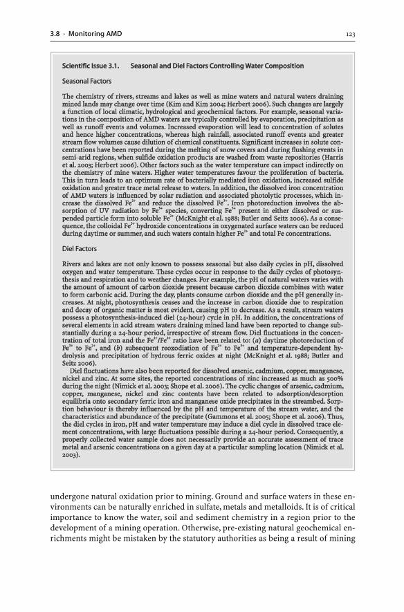
1233.8 · Monitoring AMD
undergone natural oxidation prior to mining. Ground and surface waters in these en-vironments can be naturally enriched in sulfate, metals and metalloids. It is of criticalimportance to know the water, soil and sediment chemistry in a region prior to thedevelopment of a mining operation. Otherwise, pre-existing natural geochemical en-richments might be mistaken by the statutory authorities as being a result of mining
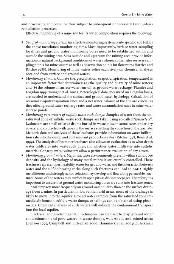
124 CHAPTER 3 · Mine Water
and processing and could be thus subject to subsequent unnecessary (and unfair)remediation processes.
Effective monitoring of a mine site for its water composition requires the following.
� Setup of monitoring system. An effective monitoring system is site specific and fulfillsthe above mentioned monitoring aims. Most importantly, surface water samplinglocalities and ground water monitoring bores need to be established within andoutside the mining area. Sites outside and upstream the mining area provide infor-mation on natural background conditions of waters whereas other sites serve as sam-pling points for mine waters as well as observation points for flow rates (Harries andRitchie 1988). Monitoring of mine waters relies exclusively on chemical analysesobtained from surface and ground waters.
� Monitoring climate. Climate (i.e. precipitation, evapotranspiration, temperature) isan important factor that determines: (a) the quality and quantity of mine waters;and (b) the volume of surface water run-off vs. ground water recharge (Plumlee andLogsdon 1999; Younger et al. 2002). Meterological data, measured on a regular basis,are needed to understand site surface and ground water hydrology. Calculation ofseasonal evapotranspiration rates and a net water balance at the site are crucial asthey affect ground water recharge rates and water accumulation rates in mine waterstorage ponds.
� Monitoring pore waters of sulfidic waste rock dumps. Samples of water from the un-saturated zone of sulfidic waste rock dumps are taken using so-called “lysimeters”.Lysimeters are small or large drums buried in waste piles, in some cases under drycovers, and connected with tubes to the surface enabling the collection of the leachate.Meteoric data and analyses of these leachates provide information on water infiltra-tion rate into the dump and contaminant production rates (Ritchie 1998; Bews et al.1999). The analysis of lysimeter leachates also allows an evaluation as to what depthwater infiltrates into waste rock piles, and whether water infiltrates into sulfidicmaterial. Consequently, lysimeters allow a performance evaluation of dry covers.
� Monitoring ground waters. Major fractures are commonly present within sulfidic oredeposits, and the hydrology of many metal mines is structurally controlled. Thesefractures represent permeability zones for ground water, and the interaction betweenwater and the sulfide-bearing rocks along such fractures can lead to AMD. Highlymetalliferous and strongly acidic solution may develop and flow along permeable frac-tures. Some of the waters may surface in open pits as distinct seepages. Therefore, it isimportant to ensure that ground water monitoring bores are sunk into fracture zones.
AMD impacts more frequently on ground water quality than on the surface drain-age from a mine. In particular, in low rainfall arid areas, most of the drainage islikely to move into the aquifer. Ground water samples from the saturated zone im-mediately beneath sulfidic waste dumps or tailings can be obtained using piezo-meters. Chemical analyses of such waters will indicate the contaminant transportinto the local aquifer.
Electrical and electromagnetic techniques can be used to map ground watercontamination and pore waters in waste dumps, watersheds and mined areas(Benson 1995; Campbell and Fitterman 2000; Hammack et al. 2003a,b; Ackman
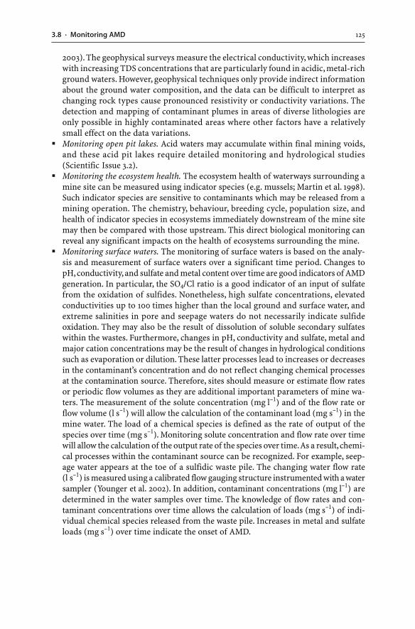
1253.8 · Monitoring AMD
2003). The geophysical surveys measure the electrical conductivity, which increaseswith increasing TDS concentrations that are particularly found in acidic, metal-richground waters. However, geophysical techniques only provide indirect informationabout the ground water composition, and the data can be difficult to interpret aschanging rock types cause pronounced resistivity or conductivity variations. Thedetection and mapping of contaminant plumes in areas of diverse lithologies areonly possible in highly contaminated areas where other factors have a relativelysmall effect on the data variations.
� Monitoring open pit lakes. Acid waters may accumulate within final mining voids,and these acid pit lakes require detailed monitoring and hydrological studies(Scientific Issue 3.2).
� Monitoring the ecosystem health. The ecosystem health of waterways surrounding amine site can be measured using indicator species (e.g. mussels; Martin et al. 1998).Such indicator species are sensitive to contaminants which may be released from amining operation. The chemistry, behaviour, breeding cycle, population size, andhealth of indicator species in ecosystems immediately downstream of the mine sitemay then be compared with those upstream. This direct biological monitoring canreveal any significant impacts on the health of ecosystems surrounding the mine.
� Monitoring surface waters. The monitoring of surface waters is based on the analy-sis and measurement of surface waters over a significant time period. Changes topH, conductivity, and sulfate and metal content over time are good indicators of AMDgeneration. In particular, the SO4/Cl ratio is a good indicator of an input of sulfatefrom the oxidation of sulfides. Nonetheless, high sulfate concentrations, elevatedconductivities up to 100 times higher than the local ground and surface water, andextreme salinities in pore and seepage waters do not necessarily indicate sulfideoxidation. They may also be the result of dissolution of soluble secondary sulfateswithin the wastes. Furthermore, changes in pH, conductivity and sulfate, metal andmajor cation concentrations may be the result of changes in hydrological conditionssuch as evaporation or dilution. These latter processes lead to increases or decreasesin the contaminant’s concentration and do not reflect changing chemical processesat the contamination source. Therefore, sites should measure or estimate flow ratesor periodic flow volumes as they are additional important parameters of mine wa-ters. The measurement of the solute concentration (mg l–1) and of the flow rate orflow volume (l s–1) will allow the calculation of the contaminant load (mg s–1) in themine water. The load of a chemical species is defined as the rate of output of thespecies over time (mg s–1). Monitoring solute concentration and flow rate over timewill allow the calculation of the output rate of the species over time. As a result, chemi-cal processes within the contaminant source can be recognized. For example, seep-age water appears at the toe of a sulfidic waste pile. The changing water flow rate(l s–1) is measured using a calibrated flow gauging structure instrumented with a watersampler (Younger et al. 2002). In addition, contaminant concentrations (mg l–1) aredetermined in the water samples over time. The knowledge of flow rates and con-taminant concentrations over time allows the calculation of loads (mg s–1) of indi-vidual chemical species released from the waste pile. Increases in metal and sulfateloads (mg s–1) over time indicate the onset of AMD.
126 CHAPTER 3 · Mine Water
3.9AMD from Sulfidic Waste Rock Dumps
Sulfidic waste rock dumps and spoil heaps are, because of their sheer volume, the majorsources of AMD. The chemistry and volume of AMD seepage waters emanating fromsulfidic piles are largely influenced by the properties of the waste materials. AMD de-velopment in waste heaps occurs via complex weathering reactions (Sec. 2.2). The dif-ferent rates of the various weathering reactions within the waste may cause temporalchanges to the drainage chemistry. Thus, the composition of drainage waters fromwaste rock piles depends on three factors:
1273.9 · AMD from Sulfidic Waste Rock Dumps
� The hydrology of the waste pile� The presence of different weathering zones within the pile� The rate of weathering reactions (i.e. weathering kinetics), causing temporal changes
to the composition of the drainage waters
3.9.1Hydrology of Waste Rock Dumps
Waste rock piles have physical and hydrological properties unlike the unmined, in situwaste. Mining and blasting increase the volume and porosity of waste rocks and cre-ate large pores and channels through which atmospheric gases and water can be trans-ported.
Waste rock dumps frequently contain “perched aquifers” located well above the un-derlying bedrock (Younger et al. 2002). The dumps generally contain an unsaturatedand a saturated zone separated by a single continuous water table with a moderatehydraulic gradient (Blowes and Ptacek 1994; Hawkins 1999; Younger et al. 2002)(Fig. 3.6). The water table tends to reflect the waste dump surface topography. Withinthe unsaturated part, water typically fills small pores and occurs as films on particlesurfaces. Flow rates of the water vary from relatively rapid movements through inter-
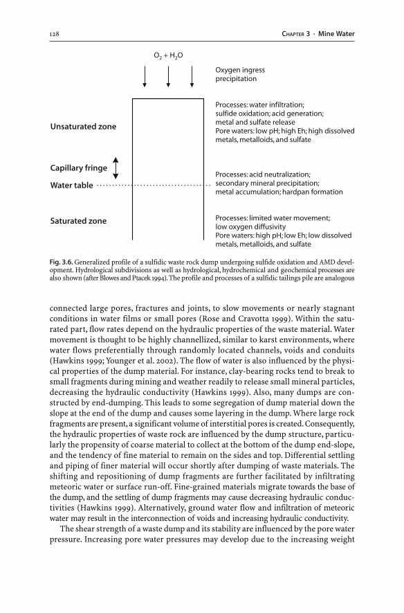
128 CHAPTER 3 · Mine Water
connected large pores, fractures and joints, to slow movements or nearly stagnantconditions in water films or small pores (Rose and Cravotta 1999). Within the satu-rated part, flow rates depend on the hydraulic properties of the waste material. Watermovement is thought to be highly channellized, similar to karst environments, wherewater flows preferentially through randomly located channels, voids and conduits(Hawkins 1999; Younger et al. 2002). The flow of water is also influenced by the physi-cal properties of the dump material. For instance, clay-bearing rocks tend to break tosmall fragments during mining and weather readily to release small mineral particles,decreasing the hydraulic conductivity (Hawkins 1999). Also, many dumps are con-structed by end-dumping. This leads to some segregation of dump material down theslope at the end of the dump and causes some layering in the dump. Where large rockfragments are present, a significant volume of interstitial pores is created. Consequently,the hydraulic properties of waste rock are influenced by the dump structure, particu-larly the propensity of coarse material to collect at the bottom of the dump end-slope,and the tendency of fine material to remain on the sides and top. Differential settlingand piping of finer material will occur shortly after dumping of waste materials. Theshifting and repositioning of dump fragments are further facilitated by infiltratingmeteoric water or surface run-off. Fine-grained materials migrate towards the base ofthe dump, and the settling of dump fragments may cause decreasing hydraulic conduc-tivities (Hawkins 1999). Alternatively, ground water flow and infiltration of meteoricwater may result in the interconnection of voids and increasing hydraulic conductivity.
The shear strength of a waste dump and its stability are influenced by the pore waterpressure. Increasing pore water pressures may develop due to the increasing weight
Fig. 3.6. Generalized profile of a sulfidic waste rock dump undergoing sulfide oxidation and AMD devel-opment. Hydrological subdivisions as well as hydrological, hydrochemical and geochemical processes arealso shown (after Blowes and Ptacek 1994). The profile and processes of a sulfidic tailings pile are analogous
1293.9 · AMD from Sulfidic Waste Rock Dumps
and height of the waste dump, or due to increasing seepage through the dump. Excesspore water pressures are usually associated with fine-grained materials since theypossess lower permeabilities and higher moisture contents than coarse-grained wastes.Fine-grained wastes may, therefore, become unstable and fail at lower pore water pres-sures than coarse-grained wastes.
The hydraulic properties of wastes (e.g. hydraulic conductivity, transmissivity, po-rosity, pore water velocity, recharge) vary greatly. As a result, the flow direction andpaths of pore waters, as well as the location and elevation of saturated zones are oftendifficult to predict. Detailed hydrological models are required to understand waterstorage and transport in waste rock dumps (Moberly et al. 2001).
3.9.2Weathering of Waste Rock Dumps
Perkins et al. (1997) have provided a simplified model for the generation of drainagewaters from sulfidic waste rock piles. The production and flow of drainage from wasterock piles is controlled by wetting and drying cycles. The waste piles are intermittentlywetted by meteoric water and seasonal run-off; they are dried by drainage and evapo-ration. The time it takes to complete the entire wetting-drying cycle is dependent uponporosity, permeability, and climatic factors. A complete wetting-drying cycle, for a wasterock pile located in a region of moderate to high rainfall with distinct seasons, con-sists of four sequential stages (Perkins et al. 1997):
1. Sulfide oxidation and formation of secondary minerals2. Infiltration of water into the dump3. Drainage of water from the dump4. Evaporation of pore water
The first stage represents the atmospheric oxidation of sulfides which results in thedestruction of sulfides and the formation of secondary minerals. The second stage isthe infiltration of meteoric water and seasonal run-off. Pores are wetted to the extentthat weathering of minerals occurs. The third stage involves drainage of water fromthe pore spaces. Solutes dissolved in the pore water are transported to the water tableor are channelled to surface seepages. Air replaces the pore water during drainage, anda thin pore water film is left behind, coating individual grains. The fourth stage is theevaporation of the water film during the drying cycle. During drying, the relative im-portance of drainage compared to evaporation is determined by the physical proper-ties of the waste rock pile such as hydraulic conductivity. The drying results in theprecipitation of secondary minerals that may coat the sulfide mineral surfaces. If dry-ing continues, some of these minerals may dehydrate, crack, and spall from the sul-fide surfaces, exposing fresh sulfides to atmospheric oxygen (Perkins et al. 1997). Inan arid climate, there are no percolating waters present, and the flow of water througha waste rock pile is greatly reduced. In such locations, sulfide oxidation occurs, andthe secondary salts generated from the limited available moisture reside within thewaste. As a result, the first (i.e. sulfide oxidation and formation of secondary miner-als) and fourth (i.e. evaporation of pore water) stages of the wetting-drying cycle mayonly be important (Perkins et al. 1997). In an arid environment, sulfide destruction
130 CHAPTER 3 · Mine Water
does not necessarily lead to drainage from waste rock piles. However, during high rain-fall events, excess moisture is present, and the secondary weathering products are dis-solved and transported with the water moving through the material to the saturatedzone or surface seepages.
The position of the water table in mine wastes has an important role in influencingthe composition of drainage waters (Fig. 3.6). This is because the water table eleva-tion fluctuates in response to seasonal conditions, forming a zone of cyclic wettingand drying. Such fluctuations provide optimal conditions for the oxidation of sulfidesin the unsaturated zone and subsequent leaching of sulfides and associated second-ary weathering products.
Ritchie (1994b) and Paktunc (1998) provide a model for the weathering of a hypo-thetical sulfidic waste rock dump. Weathering has proceeded for some time in thedump. Such a “mature” dump has three distinct domains (i.e outer unsaturated zone,unsaturated inner zone, saturated lower zone), reflecting the different distribution ofoxidation sites and chemical reactions. This model implies that the types and rates ofreactions and resulting products are different in the individual zones (Ritchie 1994b;Paktunc 1998). The outer zone of a mature waste pile is expected to have low levels ofsulfide minerals. It is rich in insoluble primary and secondary minerals and can bedepleted in readily soluble components. In contrast, the unsaturated inner zone isenriched in soluble and insoluble secondary minerals. In this zone, oxidation of sul-fides should occur along a front slowly moving down towards the water table of thedump.
On the other hand, some authors reject the model of a stratified waste rock profile.They have argued: (a) that sulfidic waste dumps are heterogeneous; and (b) that anyinfiltrating rainwater would follow preferential flow paths acting as hydraulic conduits(Hutchison and Ellison 1992; Eriksson 1998; Hawkins 1999). Such discrete hydrogeo-logical channels would limit water-rock interactions. In addition, local seeps from asingle waste dump are known to have substantially different water qualities, whichsupports the hypothesis of preferential flow paths in waste piles. Also, the abundanceand distribution of acid producing and acid buffering minerals vary from one par-ticle to another. Waste parcels with abundant pyrite, free movement of air, and im-peded movement of water are expected to develop higher acidities than equal volumesthat contain less pyrite or that are completely saturated with water (Rose and Cravotta1999). Chemical and physical conditions within waste dumps vary even on a micro-scopic scale. The resulting drainage water is a mixture of fluids from a variety ofdynamic micro-environments within the dump. Consequently, the water quality indifferent parts of waste dumps exhibits spatial and temporal variations. One could con-clude that prediction of drainage water chemistry from waste dumps is difficult andimprecise.
3.9.3Temporal Changes to Dump Seepages
When mine wastes are exposed to weathering processes, some soluble minerals goreadily into solution whereas other minerals take their time and weather at differentrates (Morin and Hutt 1997). The drainage chemistry of readily soluble minerals re-mains constant over time as only a limited, constant amount of salt is able to dissolve
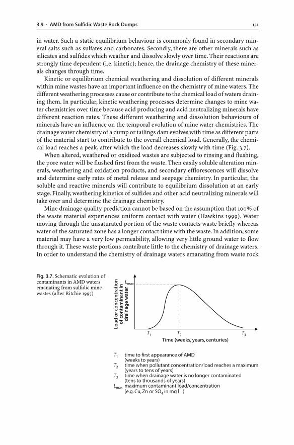
1313.9 · AMD from Sulfidic Waste Rock Dumps
in water. Such a static equilibrium behaviour is commonly found in secondary min-eral salts such as sulfates and carbonates. Secondly, there are other minerals such assilicates and sulfides which weather and dissolve slowly over time. Their reactions arestrongly time dependent (i.e. kinetic); hence, the drainage chemistry of these miner-als changes through time.
Kinetic or equilibrium chemical weathering and dissolution of different mineralswithin mine wastes have an important influence on the chemistry of mine waters. Thedifferent weathering processes cause or contribute to the chemical load of waters drain-ing them. In particular, kinetic weathering processes determine changes to mine wa-ter chemistries over time because acid producing and acid neutralizing minerals havedifferent reaction rates. These different weathering and dissolution behaviours ofminerals have an influence on the temporal evolution of mine water chemistries. Thedrainage water chemistry of a dump or tailings dam evolves with time as different partsof the material start to contribute to the overall chemical load. Generally, the chemi-cal load reaches a peak, after which the load decreases slowly with time (Fig. 3.7).
When altered, weathered or oxidized wastes are subjected to rinsing and flushing,the pore water will be flushed first from the waste. Then easily soluble alteration min-erals, weathering and oxidation products, and secondary efflorescences will dissolveand determine early rates of metal release and seepage chemistry. In particular, thesoluble and reactive minerals will contribute to equilibrium dissolution at an earlystage. Finally, weathering kinetics of sulfides and other acid neutralizing minerals willtake over and determine the drainage chemistry.
Mine drainage quality prediction cannot be based on the assumption that 100% ofthe waste material experiences uniform contact with water (Hawkins 1999). Watermoving through the unsaturated portion of the waste contacts waste briefly whereaswater of the saturated zone has a longer contact time with the waste. In addition, somematerial may have a very low permeability, allowing very little ground water to flowthrough it. These waste portions contribute little to the chemistry of drainage waters.In order to understand the chemistry of drainage waters emanating from waste rock
Fig. 3.7. Schematic evolution ofcontaminants in AMD watersemanating from sulfidic minewastes (after Ritchie 1995)
132 CHAPTER 3 · Mine Water
dumps, it is important to determine what waste portions are contacted by water andwhat is the nature of this contact (Hawkins 1999).
3.10Environmental Impacts of AMD
AMD water from tailings dams, mine waste dumps, heap leach pads, and ore stock-piles should not be released from the mine site due to the presence of suspended sol-ids and dissolved contaminants such as acid, salts, heavy metals, metalloids, and sul-fate. The uncontrolled discharge of AMD waters into the environment may impact onsurface waters, aquatic life, soils, sediments, and ground waters.
� Surface water contamination. The release of AMD waters with their high metal andsalt concentrations impacts on the use of the waterways downstream for fishing, ir-rigation, and stock watering (Table 3.4). Potable water supplies can be affected whennational drinking water quality guidelines are not met (Cidu and Fanfani 2002). Poorwater quality also limits its reuse as process water at the mine site and may causecorrosion to and encrustation of the processing circuit. Seasonally high concentra-tions of acidity and metals and increased conductivity, total dissolved and suspendedsolids, and turbidity can be observed in AMD waters at the beginning of the wet sea-son or spring (e.g. Gray 1998). Specifically, the first flush can cause distinct impactson downstream ecosystems with potentially severe effects on biota.
� Impact on aquatic life. The high acidity of AMD waters can destroy the natural bi-carbonate buffer system which keeps the pH of natural waters within a distinct pHrange. The destruction of the bicarbonate system by excessive hydrogen ions willresult in the conversion of bicarbonate to carbonic acid and then to water and car-bon dioxide (Reaction 3.27). Photosynthetic aquatic organisms use bicarbonate astheir inorganic carbon source; thus, the loss of bicarbonate will have an adverseimpact on these organisms. They will not be able to survive in waters below a pHvalue of less than 4.3 (Brown et al. 2002). In addition, the bulk of the metal load inAMD waters is available to organisms and plants since the contaminants are presentin ionic forms. Heavy metals and metalloids, at elevated bioavailable concentrations,are lethal to aquatic life and of concern to human and animal health (Gerhardt et al.2004). Moreover, the methylation of dissolved mercury and other metals and metal-loids is favoured by a low pH which turns the elements into more toxic forms. Theimpact on aquatic ecosystems and on downstream drainage channel plant and ani-mal life can be severe (Gray 1998). A reduction of biodiversity, depletion of numbersof sensitive species, or even fish kills and death of other species are possible (Ta-ble 3.4).
� Sediment contamination. Improper disposal of contaminated water from mining,mineral processing, and metallurgical operations releases contaminants into theenvironment (Herr and Gray 1997; Gray 1997) (Table 3.4). If mine waters are releasedinto local stream systems, the environmental impact will depend on the quality ofthe released effluent. Precipitation of dissolved constituents may result in abundantcolourful mineral coatings (Fig. 3.8). This may cause soils, floodplain sediments, and
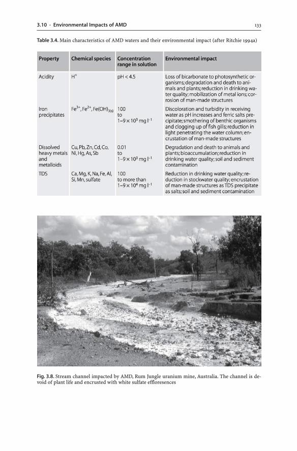
1333.10 · Environmental Impacts of AMD
Table 3.4. Main characteristics of AMD waters and their environmental impact (after Ritchie 1994a)
Fig. 3.8. Stream channel impacted by AMD, Rum Jungle uranium mine, Australia. The channel is de-void of plant life and encrusted with white sulfate effloresences
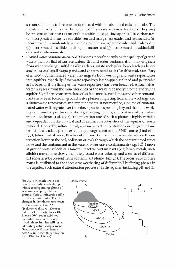
134 CHAPTER 3 · Mine Water
stream sediments to become contaminated with metals, metalloids, and salts. Themetals and metalloids may be contained in various sediment fractions. They maybe present as cations: (a) on exchangeable sites; (b) incorporated in carbonates;(c) incorporated in easily reducible iron and manganese oxides and hydroxides; (d)incorporated in moderately reducible iron and manganese oxides and hydroxides;(e) incorporated in sulfides and organic matter; and (f) incorporated in residual sili-cate and oxide minerals.
� Ground water contamination. AMD impacts more frequently on the quality of groundwaters than on that of surface waters. Ground water contamination may originatefrom mine workings, sulfidic tailings dams, waste rock piles, heap leach pads, orestockpiles, coal spoil heaps, ponds, and contaminated soils (Paschke et al. 2001; Earyet al. 2003). Contaminated water may migrate from workings and waste repositoriesinto aquifers, especially if the waste repository is uncapped, unlined and permeableat its base, or if the lining of the waste repository has been breached. At such sites,water may leak from the mine workings or the waste repository into the underlyingaquifer. Significant concentrations of sulfate, metals, metalloids, and other contami-nants have been found in ground water plumes migrating from mine workings andsulfidic waste repositories and impoundments. If not rectified, a plume of contami-nated water will migrate over time downgradient, spreading beyond the mine work-ings and waste repositories, surfacing at seepage points, and contaminating surfacewaters (Lachmar et al. 2006). The migration rate of such a plume is highly variableand dependent on the physical and chemical characteristics of the aquifer or wastematerial. Generally, sulfate, metal, and metalloid concentrations in the ground wa-ter define a leachate plume extending downgradient of the AMD source (Lind et al.1998; Johnson et al. 2000; Paschke et al. 2001). Contaminant levels depend on the in-teraction between the soil, sediment or rock through which the contaminated waterflows and the contaminant in the water. Conservative contaminants (e.g. SO4
2–) moveat ground water velocities. However, reactive contaminants (e.g. heavy metals, met-alloids) move more slowly than the ground water velocity, and a series of differentpH zones may be present in the contaminant plume (Fig. 3.9). The occurrence of thesezones is attributed to the successive weathering of different pH buffering phases inthe aquifer. Such natural attentuation processes in the aquifer, including pH and Eh
Fig. 3.9. Schematic cross-sec-tion of a sulfidic waste dumpwith a corresponding plume ofacid water seeping into theground. Various minerals bufferthe acid ground water. The pHchanges in the plume are shownfor the cross-section AA'(Jurjovec et al. 2002). (Reprin-ted from Jurjovec J, Ptacek CJ,Blowes DW (2002) Acid neu-tralization mechanisms andmetal release in mine tailings: Alaboratory column experiment.Geochimica et CosmochimicaActa 66:1511–1523, with permissionfrom Elsevier Science)
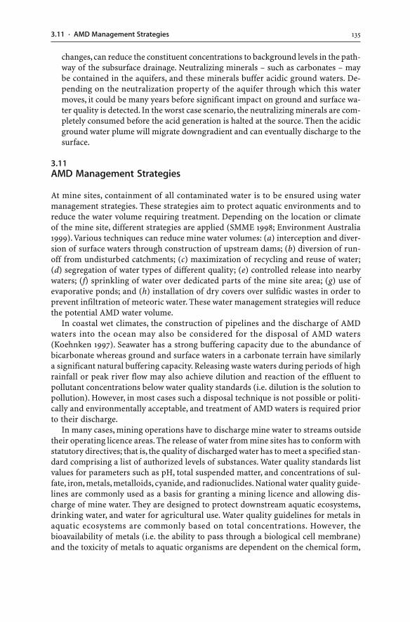
1353.11 · AMD Management Strategies
changes, can reduce the constituent concentrations to background levels in the path-way of the subsurface drainage. Neutralizing minerals – such as carbonates – maybe contained in the aquifers, and these minerals buffer acidic ground waters. De-pending on the neutralization property of the aquifer through which this watermoves, it could be many years before significant impact on ground and surface wa-ter quality is detected. In the worst case scenario, the neutralizing minerals are com-pletely consumed before the acid generation is halted at the source. Then the acidicground water plume will migrate downgradient and can eventually discharge to thesurface.
3.11AMD Management Strategies
At mine sites, containment of all contaminated water is to be ensured using watermanagement strategies. These strategies aim to protect aquatic environments and toreduce the water volume requiring treatment. Depending on the location or climateof the mine site, different strategies are applied (SMME 1998; Environment Australia1999). Various techniques can reduce mine water volumes: (a) interception and diver-sion of surface waters through construction of upstream dams; (b) diversion of run-off from undisturbed catchments; (c) maximization of recycling and reuse of water;(d) segregation of water types of different quality; (e) controlled release into nearbywaters; (f) sprinkling of water over dedicated parts of the mine site area; (g) use ofevaporative ponds; and (h) installation of dry covers over sulfidic wastes in order toprevent infiltration of meteoric water. These water management strategies will reducethe potential AMD water volume.
In coastal wet climates, the construction of pipelines and the discharge of AMDwaters into the ocean may also be considered for the disposal of AMD waters(Koehnken 1997). Seawater has a strong buffering capacity due to the abundance ofbicarbonate whereas ground and surface waters in a carbonate terrain have similarlya significant natural buffering capacity. Releasing waste waters during periods of highrainfall or peak river flow may also achieve dilution and reaction of the effluent topollutant concentrations below water quality standards (i.e. dilution is the solution topollution). However, in most cases such a disposal technique is not possible or politi-cally and environmentally acceptable, and treatment of AMD waters is required priorto their discharge.
In many cases, mining operations have to discharge mine water to streams outsidetheir operating licence areas. The release of water from mine sites has to conform withstatutory directives; that is, the quality of discharged water has to meet a specified stan-dard comprising a list of authorized levels of substances. Water quality standards listvalues for parameters such as pH, total suspended matter, and concentrations of sul-fate, iron, metals, metalloids, cyanide, and radionuclides. National water quality guide-lines are commonly used as a basis for granting a mining licence and allowing dis-charge of mine water. They are designed to protect downstream aquatic ecosystems,drinking water, and water for agricultural use. Water quality guidelines for metals inaquatic ecosystems are commonly based on total concentrations. However, thebioavailability of metals (i.e. the ability to pass through a biological cell membrane)and the toxicity of metals to aquatic organisms are dependent on the chemical form,
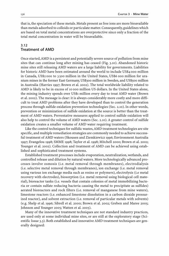
136 CHAPTER 3 · Mine Water
that is, the speciation of these metals. Metals present as free ions are more bioavailablethan metals adsorbed to colloids or particulate matter. Consequently, guidelines whichare based on total metal concentrations are overprotective since only a fraction of thetotal metal concentration in water will be bioavailable.
3.12Treatment of AMD
Once started, AMD is a persistent and potentially severe source of pollution from minesites that can continue long after mining has ceased (Fig. 3.10). Abandoned historicmine sites still releasing AMD waters are a large liability for governments. Liabilitiesfor historic AMD have been estimated around the world to include US$4 000 millionin Canada, US$2 000 to 3 500 million in the United States, US$6 000 million for ura-nium mines in the former East Germany, US$300 million in Sweden, and US$500 millionin Australia (Harries 1997; Brown et al. 2002). The total worldwide liability related toAMD is likely to be in excess of 10 000 million US dollars. In the United States alone,the mining industry spends over US$1 million every day to treat AMD water (Brownet al. 2002). The message is clear: it is always considerably more costly and more diffi-cult to treat AMD problems after they have developed than to control the generationprocess through sulfide oxidation prevention technologies (Sec. 2.10). In other words,prevention or minimization of sulfide oxidation at the source is better than the treat-ment of AMD waters. Preventative measures applied to control sulfide oxidation willalso help to control the volume of AMD waters (Sec. 2.10). A greater control of sulfideoxidation creates a smaller volume of AMD water requiring treatment.
Like the control techniques for sulfidic wastes, AMD treatment technologies are sitespecific, and multiple remediation strategies are commonly needed to achieve success-ful treatment of AMD waters (Skousen and Ziemkiewicz 1996; Environment Australia1997; Evangelou 1998; SMME 1998; Taylor et al. 1998; Mitchell 2000; Brown et al. 2002;Younger et al. 2002). Collection and treatment of AMD can be achieved using estab-lished and sophisticated treatment systems.
Established treatment processes include evaporation, neutralization, wetlands, andcontrolled release and dilution by natural waters. More technologically advanced pro-cesses involve osmosis (i.e. metal removal through membranes), electrodialysis(i.e. selective metal removal through membranes), ion exchange (i.e. metal removalusing various ion exchange media such as resins or polymers), electrolysis (i.e metalrecovery with electrodes), biosorption (i.e. metal removal using biological cell mate-rial), bioreactor tanks (i.e. vessels that contain colonies of metal immobilizing bacte-ria or contain sulfate reducing bacteria causing the metal to precipitate as sulfides)aerated bioreactors and rock filters (i.e. removal of manganese from mine waters),limestone reactors (i.e. enhanced limestone dissolution in a carbon dioxide pressur-ized reactor), and solvent extraction (i.e. removal of particular metals with solvents)(e.g. Shelp et al. 1996; Sibrell et al. 2000; Brown et al. 2002; Greben and Maree 2005;Johnson and Younger 2005; Watten et al. 2005).
Many of the innovative treatment techniques are not standard industry practices,are used only at some individual mine sites, or are still at the exploratory stage (Sci-entific Issue 3.3). Both established and innovative AMD treatment techniques are gen-erally designed:
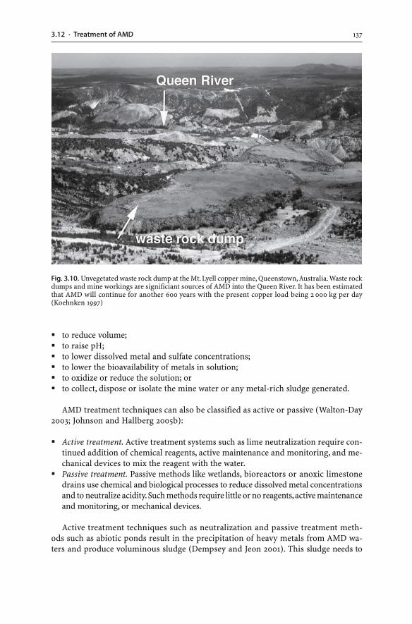
1373.12 · Treatment of AMD
� to reduce volume;� to raise pH;� to lower dissolved metal and sulfate concentrations;� to lower the bioavailability of metals in solution;� to oxidize or reduce the solution; or� to collect, dispose or isolate the mine water or any metal-rich sludge generated.
AMD treatment techniques can also be classified as active or passive (Walton-Day2003; Johnson and Hallberg 2005b):
� Active treatment. Active treatment systems such as lime neutralization require con-tinued addition of chemical reagents, active maintenance and monitoring, and me-chanical devices to mix the reagent with the water.
� Passive treatment. Passive methods like wetlands, bioreactors or anoxic limestonedrains use chemical and biological processes to reduce dissolved metal concentrationsand to neutralize acidity. Such methods require little or no reagents, active maintenanceand monitoring, or mechanical devices.
Active treatment techniques such as neutralization and passive treatment meth-ods such as abiotic ponds result in the precipitation of heavy metals from AMD wa-ters and produce voluminous sludge (Dempsey and Jeon 2001). This sludge needs to
Fig. 3.10. Unvegetated waste rock dump at the Mt. Lyell copper mine, Queenstown, Australia. Waste rockdumps and mine workings are significiant sources of AMD into the Queen River. It has been estimatedthat AMD will continue for another 600 years with the present copper load being 2 000 kg per day(Koehnken 1997)
138 CHAPTER 3 · Mine Water
be removed from the treatment system on a regular basis. The sludge is either disposed ofin appropriate impoundments or treated further for metal recovery. In fact, the recoveryof metals from sludge may partly pay for the costs of water treatment (Miedecke et al. 1997).
3.12.1Neutralization
Neutralization involves collecting the leachate, selecting an appropriate chemical, andmixing the chemical with the AMD water. In the process, acid is neutralized, and met-
1393.12 · Treatment of AMD
als and sulfate are removed from solution and precipitated as sludge. Neutralizationtreatment systems for AMD include:
1. A neutralizing agent. A large variety of natural, by-product or manufactured chemi-cals are used for AMD treatment including local waste rock with high ANC (Table 3.5).Each of these neutralizing agents has different advantages and disadvantages. Forexample, the advantages of using limestone (largely CaCO3) include low cost, easeof use, and formation of a dense, easily handled sludge. Disadvantages include slowreaction times and coating of the limestone particles with iron precipitates. In thereaction of limestone with AMD waters, hydrogen ions are consumed, bicarbonateions generated, and dissolved metals are converted into sparingly soluble mineralssuch as sulfates, carbonates, and hydroxides:
CaCO3(s) + H+(aq) + SO4
2–(aq) + Pb2+
(aq) → PbSO4(s) + HCO3–(aq) (3.37)
CaCO3(s) + Pb2+(aq) → PbCO3(s) + Ca2+
(aq) (3.38)
CaCO3(s) + Zn2+(aq) + 2 H2O(l) → Zn(OH)2(s) + Ca2+
(aq) + H2CO3(aq) (3.39)
Also, hydrated lime (Ca(OH)2) is easy and safe to use, effective, and relativelyinexpensive. The major disadvantages are the voluminous sludge produced and highinitial costs for the establishment of the active treatment plant (Zinck and Griffith2000; Brown et al. 2002). In this process, acid is neutralized (Reaction 3.40), metals(Me2+/Me3+) are precipitated in the form of metal hydroxides (Reaction 3.41), andgypsum is formed, if sufficient sulfate is in solution (Reaction 3.42):
Ca(OH)2(s) + 2 H+(aq) → Ca2+
(aq) + 2 H2O(l) (3.40)
Ca(OH)2(s) + Me2+ / Me3+(aq) → Me(OH)2(s) / Me(OH)3(s) + Ca2+
(aq) (3.41)
Ca2+(aq) + SO4
2–(aq) + 2 H2O(l) → CaSO4 · 2H2O(s) (3.42)
Lime neutralization is efficient for removing metals such as cadmium, copper,iron, lead, nickel, and zinc from solution. Nonetheless, the solubility of metals var-ies with pH, and the lowest dissolved metal concentration is not achieved at the samepH (Kuyucak 2000; Brown et al. 2002). Not all metals can be precipitated at the samepH, and a combination of neutralizing agents (e.g. lime plus limestone) and otherchemical additives may be needed to achieve acceptable water quality. Caustic soda(NaOH) is especially effective for treating AMD waters having a high manganese con-tent. Manganese is difficult to remove from mine waters because the pH must beraised to above 10 before manganese will precipitate. Caustic soda raises the pH toabove 10. Major disadvantages of caustic soda are its high costs, the dangers in han-dling the chemical, and poor sludge properties. Other rock types (serpentinite;Bernier 2005) and unconventional industrial waste or byproducts such as fly ash fromcoal power stations or kiln dust from cement factories have been suggested for the treat-ment of AMD waters. However, fly ash commonly contains elevated metal and metal-loid concentrations, and its reaction rate is slow compared to lime (Kuyucak 2000).
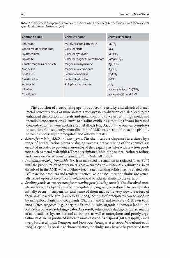
140 CHAPTER 3 · Mine Water
The addition of neutralizing agents reduces the acidity and dissolved heavymetal concentrations of mine waters. Excessive neutralization can also lead to theenhanced dissolution of metals and metalloids and to waters with high metal andmetalloid concentrations. Neutral to alkaline oxidizing conditions favour increasedconcentrations of some metals and metalloids (e.g. As, Sb, U) as ions or complexesin solution. Consequently, neutralization of AMD waters should raise the pH onlyto values necessary to precipitate and adsorb metals.
2. Means for mixing AMD and the agents. The chemicals are dispensed as a slurry by arange of neutralization plants or dosing systems. Active mixing of the chemicals isessential in order to prevent armouring of the reagent particles with reaction prod-ucts such as metal hydroxides. These precipitates inhibit the neutralization reactionsand cause excessive reagent consumption (Mitchell 2000).
3. Procedures to delay iron oxidation. Iron may need to remain in its reduced form (Fe2+)until the precipitation of other metals has occurred and additional alkalinity has beendissolved in the AMD waters. Otherwise, the neutralizing solids may be coated withFe3+ reaction products and rendered ineffective. Anoxic limestone drains are gener-ally relied upon to keep iron in solution and to add alkalinity to the system.
4. Settling ponds or vat reactors for removing precipitating metals. The dissolved met-als are forced to hydrolyze and precipitate during neutralization. The precipitatesinitially occur in suspension, and some of them may settle very slowly because oftheir small particle size (Kairies et al. 2005). Settling of precipitates can be sped upby using flocculants and coagulants (Skousen and Ziemkiewicz 1996; Brown et al.2002). Such reagents (e.g. inorganic Fe and Al salts, organic polymers) lead to theformation of larger solid aggregates. As a result, voluminous sludge, composed mainlyof solid sulfates, hydroxides and carbonates as well as amorphous and poorly crys-talline material, is produced which in most cases needs disposal (MEND 1997b; Zinck1997; Ford et al. 1998; Dempsey and Jeon 2001; Younger et al. 2002; Widerlund et al.2005). Depending on sludge characteristics, the sludge may have to be protected from
Table 3.5. Chemical compounds commonly used in AMD treatment (after Skousen and Ziemkiewicz1996; Environment Australia 1997)
1413.12 · Treatment of AMD
oxidation, leaching, and potential metal mobilization. This is achieved by mixing itwith more alkaline reagents prior to its disposal. Alternatively, depending on the min-eralogical and chemical characteristics of the AMD sludge, metals can be recoveredfrom the sludges using strong acids. Very pure Fe3+ hydroxide sludges may be used aspigments in the production of coloured bricks and concrete.
In many cases, the simple addition of neutralizing agents is not sufficient to reducemetal and metalloid concentrations in mine waters to acceptable levels. These watersneed other chemical treatments to lower dissolved metal and metalloid loads. Pondsor wetlands may be required to further improve water quality prior to the dischargeto a receiving stream.
3.12.2Other Chemical Treatments
Waste waters with elevated antimony, arsenic, chromium, iron, manganese, mercury,molybdenum, and selenium contents may require chemical treatment methodsother than neutralization. These methods do not employ the traditional addition ofalkaline reagents like lime. They use unconventional industrial byproducts such as slagsor rely on oxidation, reduction, precipitation, adsorption, or cation exchange processes(Skousen and Ziemkiewicz 1996; Brant et al. 1999; Kuyucak 2000; Younger et al. 2002;Ahn et al. 2003).
Mine waters may have elevated arsenic values at acid to alkaline pH values. A re-duction in the dissolved arsenic content of AMD waters is achieved through aerationor the addition of ferric or ferrous salts (Taschereau and Fytas 2000; Seidel et al. 2005).This causes the coprecipitation and adsorption of arsenic with ferric hydroxides, orthe precipitation of arsenic as an arsenate phase (AsO4
3–). Some arsenates are consid-ered to be stable (e.g. ferric arsenate) or unstable phases (e.g. calcium arsenate) un-der neutral pH conditions. Consequently, arsenate formation may result only in thetemporary fixation of arsenic.
Other treatment techniques involve the addition of oxidants (e.g. Cl2, O2, NaOCl,CaCl2, FeCl3, H2O2, KMnO4) which will convert dissolved Fe2+ to insoluble Fe3+ pre-cipitates, aqueous Mn2+ to insoluble Mn3+ precipitates, and As3+ to less toxic As5+. Also,the addition of barium chloride (BaCl2) or barium sulfide (BaS) forces the precipita-tion of barium sulfate (BaSO4) and associated lowering of aqueous sulfate and metalconcentrations (Maree et al. 2004). The treatment of AMD waters with zerovalent ironcauses the formation of secondary metal reaction products and the adsorption ofmetals onto solids (Herbert 2003).
The removal of metals from solutions may also be achieved through sulfide precipi-tation. The precipitation process relies on the generation of sulfide activity, eitherthrough reagent addition (e.g. compost) or by the microbiological reduction of sulfateto hydrogen sulfide in wetlands or a specially designed reactor. Sulfate reducing bacteriathereby convert the dissolved sulfate to hydrogen sulfide. The sulfide produced reacts withthe dissolved metals, which precipitate as insoluble solid sulfides. The presence or evenaddition of organic-rich materials such as compost to AMD waters does not only pro-mote removal of dissolved metals from AMD solutions but also pH neutralization(Gibert et al. 2005; Johnson and Hallberg 2005a). Moreover, the addition of soluble sulfide
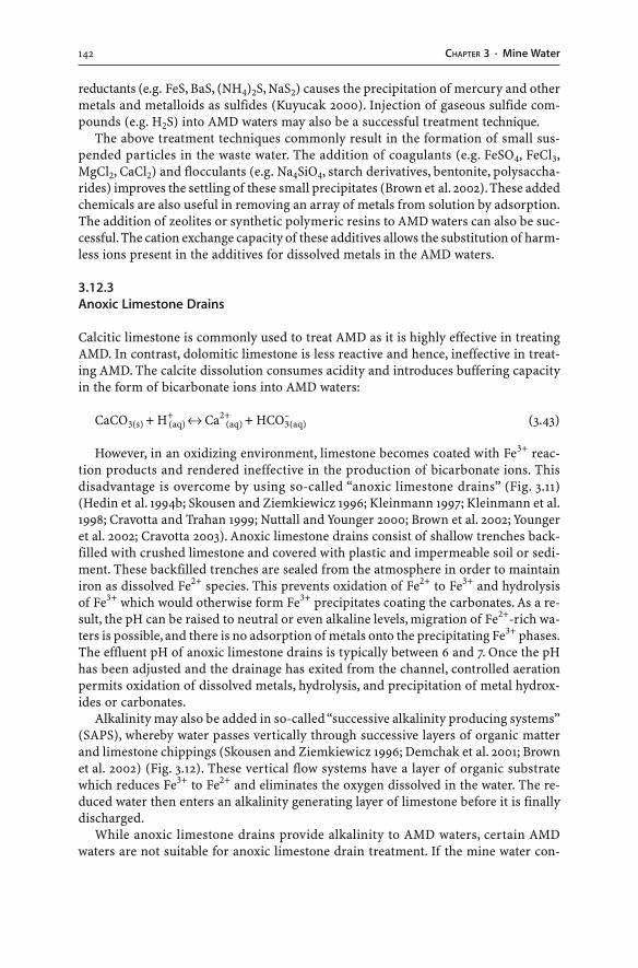
142 CHAPTER 3 · Mine Water
reductants (e.g. FeS, BaS, (NH4)2S, NaS2) causes the precipitation of mercury and othermetals and metalloids as sulfides (Kuyucak 2000). Injection of gaseous sulfide com-pounds (e.g. H2S) into AMD waters may also be a successful treatment technique.
The above treatment techniques commonly result in the formation of small sus-pended particles in the waste water. The addition of coagulants (e.g. FeSO4, FeCl3,MgCl2, CaCl2) and flocculants (e.g. Na4SiO4, starch derivatives, bentonite, polysaccha-rides) improves the settling of these small precipitates (Brown et al. 2002). These addedchemicals are also useful in removing an array of metals from solution by adsorption.The addition of zeolites or synthetic polymeric resins to AMD waters can also be suc-cessful. The cation exchange capacity of these additives allows the substitution of harm-less ions present in the additives for dissolved metals in the AMD waters.
3.12.3Anoxic Limestone Drains
Calcitic limestone is commonly used to treat AMD as it is highly effective in treatingAMD. In contrast, dolomitic limestone is less reactive and hence, ineffective in treat-ing AMD. The calcite dissolution consumes acidity and introduces buffering capacityin the form of bicarbonate ions into AMD waters:
CaCO3(s) + H+(aq) ↔ Ca2+
(aq) + HCO3–(aq) (3.43)
However, in an oxidizing environment, limestone becomes coated with Fe3+ reac-tion products and rendered ineffective in the production of bicarbonate ions. Thisdisadvantage is overcome by using so-called “anoxic limestone drains” (Fig. 3.11)(Hedin et al. 1994b; Skousen and Ziemkiewicz 1996; Kleinmann 1997; Kleinmann et al.1998; Cravotta and Trahan 1999; Nuttall and Younger 2000; Brown et al. 2002; Youngeret al. 2002; Cravotta 2003). Anoxic limestone drains consist of shallow trenches back-filled with crushed limestone and covered with plastic and impermeable soil or sedi-ment. These backfilled trenches are sealed from the atmosphere in order to maintainiron as dissolved Fe2+ species. This prevents oxidation of Fe2+ to Fe3+ and hydrolysisof Fe3+ which would otherwise form Fe3+ precipitates coating the carbonates. As a re-sult, the pH can be raised to neutral or even alkaline levels, migration of Fe2+-rich wa-ters is possible, and there is no adsorption of metals onto the precipitating Fe3+ phases.The effluent pH of anoxic limestone drains is typically between 6 and 7. Once the pHhas been adjusted and the drainage has exited from the channel, controlled aerationpermits oxidation of dissolved metals, hydrolysis, and precipitation of metal hydrox-ides or carbonates.
Alkalinity may also be added in so-called “successive alkalinity producing systems”(SAPS), whereby water passes vertically through successive layers of organic matterand limestone chippings (Skousen and Ziemkiewicz 1996; Demchak et al. 2001; Brownet al. 2002) (Fig. 3.12). These vertical flow systems have a layer of organic substratewhich reduces Fe3+ to Fe2+ and eliminates the oxygen dissolved in the water. The re-duced water then enters an alkalinity generating layer of limestone before it is finallydischarged.
While anoxic limestone drains provide alkalinity to AMD waters, certain AMDwaters are not suitable for anoxic limestone drain treatment. If the mine water con-
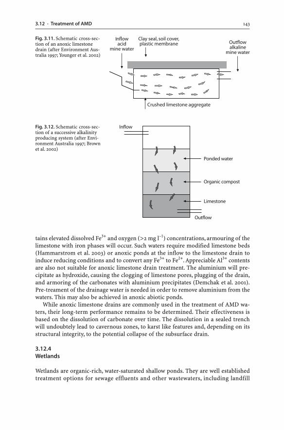
1433.12 · Treatment of AMD
tains elevated dissolved Fe3+ and oxygen (>2 mg l–1) concentrations, armouring of thelimestone with iron phases will occur. Such waters require modified limestone beds(Hammarstrom et al. 2003) or anoxic ponds at the inflow to the limestone drain toinduce reducing conditions and to convert any Fe3+ to Fe2+. Appreciable Al3+ contentsare also not suitable for anoxic limestone drain treatment. The aluminium will pre-cipitate as hydroxide, causing the clogging of limestone pores, plugging of the drain,and armoring of the carbonates with aluminium precipitates (Demchak et al. 2001).Pre-treament of the drainage water is needed in order to remove aluminium from thewaters. This may also be achieved in anoxic abiotic ponds.
While anoxic limestone drains are commonly used in the treatment of AMD wa-ters, their long-term performance remains to be determined. Their effectiveness isbased on the dissolution of carbonate over time. The dissolution in a sealed trenchwill undoubtely lead to cavernous zones, to karst like features and, depending on itsstructural integrity, to the potential collapse of the subsurface drain.
3.12.4Wetlands
Wetlands are organic-rich, water-saturated shallow ponds. They are well establishedtreatment options for sewage effluents and other wastewaters, including landfill
Fig. 3.11. Schematic cross-sec-tion of an anoxic limestonedrain (after Environment Aus-tralia 1997; Younger et al. 2002)
Fig. 3.12. Schematic cross-sec-tion of a successive alkalinityproducing system (after Envi-ronment Australia 1997; Brownet al. 2002)
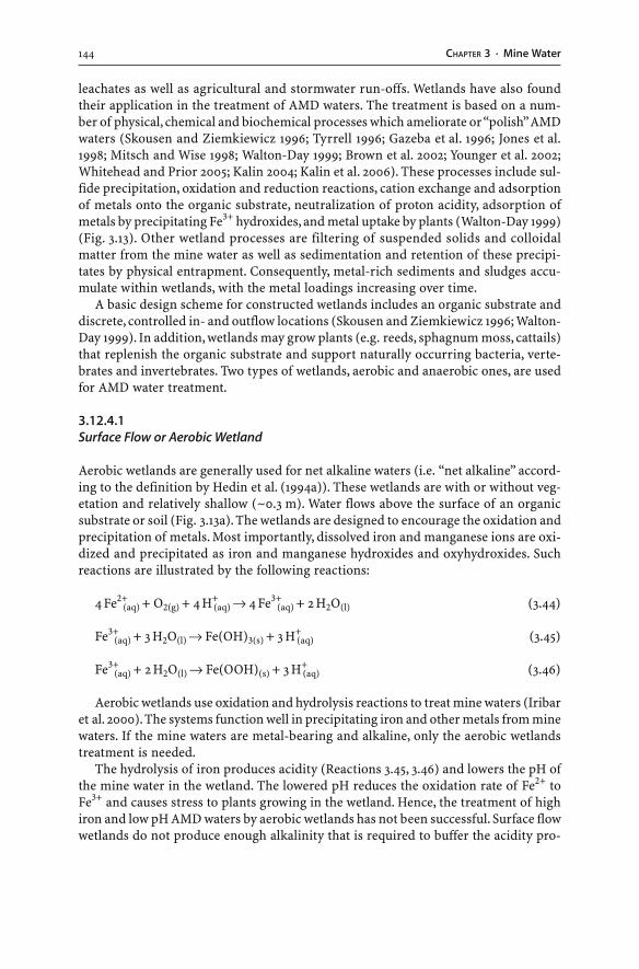
144 CHAPTER 3 · Mine Water
leachates as well as agricultural and stormwater run-offs. Wetlands have also foundtheir application in the treatment of AMD waters. The treatment is based on a num-ber of physical, chemical and biochemical processes which ameliorate or “polish” AMDwaters (Skousen and Ziemkiewicz 1996; Tyrrell 1996; Gazeba et al. 1996; Jones et al.1998; Mitsch and Wise 1998; Walton-Day 1999; Brown et al. 2002; Younger et al. 2002;Whitehead and Prior 2005; Kalin 2004; Kalin et al. 2006). These processes include sul-fide precipitation, oxidation and reduction reactions, cation exchange and adsorptionof metals onto the organic substrate, neutralization of proton acidity, adsorption ofmetals by precipitating Fe3+ hydroxides, and metal uptake by plants (Walton-Day 1999)(Fig. 3.13). Other wetland processes are filtering of suspended solids and colloidalmatter from the mine water as well as sedimentation and retention of these precipi-tates by physical entrapment. Consequently, metal-rich sediments and sludges accu-mulate within wetlands, with the metal loadings increasing over time.
A basic design scheme for constructed wetlands includes an organic substrate anddiscrete, controlled in- and outflow locations (Skousen and Ziemkiewicz 1996; Walton-Day 1999). In addition, wetlands may grow plants (e.g. reeds, sphagnum moss, cattails)that replenish the organic substrate and support naturally occurring bacteria, verte-brates and invertebrates. Two types of wetlands, aerobic and anaerobic ones, are usedfor AMD water treatment.
3.12.4.1Surface Flow or Aerobic Wetland
Aerobic wetlands are generally used for net alkaline waters (i.e. “net alkaline” accord-ing to the definition by Hedin et al. (1994a)). These wetlands are with or without veg-etation and relatively shallow (~0.3 m). Water flows above the surface of an organicsubstrate or soil (Fig. 3.13a). The wetlands are designed to encourage the oxidation andprecipitation of metals. Most importantly, dissolved iron and manganese ions are oxi-dized and precipitated as iron and manganese hydroxides and oxyhydroxides. Suchreactions are illustrated by the following reactions:
4 Fe2+(aq) + O2(g) + 4 H+
(aq) → 4 Fe3+(aq) + 2 H2O(l) (3.44)
Fe3+(aq) + 3 H2O(l) → Fe(OH)3(s) + 3 H+
(aq) (3.45)
Fe3+(aq) + 2 H2O(l) → Fe(OOH)(s) + 3 H+
(aq) (3.46)
Aerobic wetlands use oxidation and hydrolysis reactions to treat mine waters (Iribaret al. 2000). The systems function well in precipitating iron and other metals from minewaters. If the mine waters are metal-bearing and alkaline, only the aerobic wetlandstreatment is needed.
The hydrolysis of iron produces acidity (Reactions 3.45, 3.46) and lowers the pH ofthe mine water in the wetland. The lowered pH reduces the oxidation rate of Fe2+ toFe3+ and causes stress to plants growing in the wetland. Hence, the treatment of highiron and low pH AMD waters by aerobic wetlands has not been successful. Surface flowwetlands do not produce enough alkalinity that is required to buffer the acidity pro-
1453.12 · Treatment of AMD
duced from sulfide oxidation at the AMD source and hydrolysis reactions in the wet-land. Alkalinity may have to be added to such waters. This can be achieved by grow-ing certain plants in the wetland (e.g. reeds). Reeds are capable of passing oxygenthrough their root zone and the organic substrate. As a result, oxygen is converted tocarbon dioxide. The carbon dioxide gas dissolves in the mine water, consumes hydro-gen and adds alkalinity in the form of bicarbonate. Alternatively, anoxic limestonedrains may have to be installed at the inflow location of the wetland.
3.12.4.2Subsurface Flow or Anaerobic Wetland
Anaerobic wetlands are generally used for net acid waters (i.e. “net acid” according tothe definition by Hedin et al. (1994a)). Water flows through a relatively deep (~1 m),permeable, and anoxic organic substrate (Fig. 3.13b). Placement of organic waste(e.g. mushroom compost, saw dust, manure) into wetlands helps to establish the re-ducing conditions. Anoxic conditions favour the proliferation of sulfate reducing bac-teria (SRB) (Gould and Kapoor 2003). Bacterial sulfate reduction, or reduction of oxi-dized acid waters by reactive organic matter (simplified as organic molecule CH2O),results in a number of chemical reactions (Blowes et al. 1994; Deutsch 1997; Mills 1999;Walton-Day 1999; Mitchell 2000). The most important reaction is the reduction of dis-solved sulfate to hydrogen sulfide gas:
2 CH2O(s) + SO42–(aq) + 2 H+
(aq) → H2S(g) + 2 CO2(g) + H2O(l) (3.47)
2 CH2O(s) + SO42–(aq) → H2S(g) + 2 HCO3
–(aq) (3.48)
Fig. 3.13. Generalized profilesof a aerobic and b anaerobicwetlands (after Younger et al.2002). Physical and chemicalprocesses contributing to metalretention in wetlands are alsoshown (after Walton-Day 1999)
146 CHAPTER 3 · Mine Water
The hydrogen sulfide gas formed during sulfate reduction may react with dissolvedmetals. Consequently, solid metal sulfides precipitate:
Zn2+(aq) + H2S(aq) → ZnS(s) + 2 H+
(aq) (3.49)
Fe2+(aq) + H2S(aq) → FeS(s) + 2 H+
(aq) (3.50)
Precipitation of metal sulfides results in the production of hydrogen ions. However,the sulfate reducing reactions (Reactions 3.47, 3.48) generate more alkalinity; thus, netalkaline conditions prevail. If bacterially mediated sulfate reduction is not achieved, areduction in dissolved sulfate concentrations occurs through the precipitation of gyp-sum. Other chemical reactions will consume any dissolved oxygen, cause the precipi-tation of metal sulfides, convert iron and manganese hydroxides to sulfides, reducemetals, reduce sulfate to sulfur or sulfide, and generate bicarbonate (Tyrrell 1996;Walton-Day 1999). In addition, oxidation/hydrolysis reactions may occur at thewetland’s surface.
Alkalinity is produced in the form of bicarbonate in the sulfate reduction reactions(Reactions 3.49 and 3.50). The bicarbonate acts a buffer to neutralize any hydrogenions. However, the bicarbonate is not necessarily permanent. It will be permanent only ifthe hydrogen sulfide is removed by degassing. Alternatively, the sulfide ion reacts: (a) withan organic compound to form an organic sulfide; or (b) with a dissolved metal ion suchas Zn2+ or Fe2+ to form a solid metal sulfide (Reactions 3.49, 3.50) (Walton-Day 1999).
Overall, the chemical reactions result in sulfate reduction, the precipitation of metalsulfides, and an increase in pH and alkalinity. Other wetland processes include sedi-mentation, physical entrapment of solid particulates and colloids, removal of metalsthrough adsorption onto and coprecipitation with wetland particulates, complexationwith organic materials, and plant assimilation (Ledin and Pedersen 1996; Walton-Day1999). Some aquatic plants growing in wetlands or mine water ponds can take up largeamounts of heavy metals and metalloids (Hozhina et al. 2001). Other plant speciestolerate high metal concentrations and do not bioaccumulate metals to any signifi-cant degree, compared to the overall metal retention by the wetland substrate(Karathanasis and Johnson 2003).
3.12.4.3Use of Wetlands
Wetland processes aim to decrease acidity and dissolved metal and sulfate concentra-tions. Effluents produced should be of such quality that they can be discharged to othersurface water bodies. Nonetheless, in order to achieve adequate treatment of AMDwaters, the aerobic or anaerobic wetlands may require additions. Alkalinity produc-ing systems such as anoxic limestone drains may need to be installed where additionalbicarbonate is needed (Barton and Karathanasis 1999). Also, manganese is persistentin mine waters unless the pH has been raised to above 9. Therefore, manganese canbe carried for long distances downstream of a source of mine drainage. Aerobic andanaerobic wetlands are incapable of lowering dissolved manganese concentrations toa significant degree. Rock filters, bioreactors or limestone cobble ponds may need tobe constructed in order to remove the elevated manganese concentrations (Brant et al.
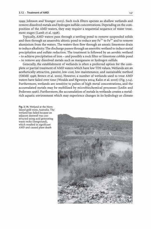
1473.12 · Treatment of AMD
1999; Johnson and Younger 2005). Such rock filters operate as shallow wetlands andremove dissolved metals and hydrogen sulfide concentrations. Depending on the com-position of the AMD waters, they may require a sequential sequence of water treat-ment stages (Lamb et al. 1998).
Typically, AMD waters pass through a settling pond to remove suspended solidsand then through an anaerobic abiotic pond to reduce any Fe3+ to Fe2+ and to removealuminium from the waters. The waters then flow through an anoxic limestone drainto induce alkalinity. The discharge passes through an anerobic wetland to induce metalprecipitation and sulfate reduction. The treatment is followed by an aerobic wetland– to achieve precipitation of iron – and possibly a rock filter or limestone cobble pond– to remove any dissolved metals such as manganese or hydrogen sulfide.
Generally, the establishment of wetlands is often a preferred option for the com-plete or partial treatment of AMD waters which have low TDS values. Wetlands are anaesthetically attractive, passive, low-cost, low-maintenance, and sustainable method(SMME 1998; Brown et al. 2002). However, a number of wetlands used to treat AMDwaters have failed over time (Woulds and Ngwenya 2004; Kalin et al. 2006) (Fig. 3.14).Furthermore, wetlands are sensitive to pulses of high metal concentrations, and theaccumulated metals may be mobilized by microbiochemical processes (Ledin andPedersen 1996). Furthermore, the accumulation of metals in wetlands creates a metal-rich aquatic environment which may experience changes in its hydrology or climate
Fig. 3.14. Wetland at the HornIsland gold mine, Australia. Thewetland has failed because anadjacent damwall was con-structed using acid generatingwaste rocks (foreground),which resulted in significantAMD and caused plant death
148 CHAPTER 3 · Mine Water
in the long or short term. A wetland needs a sufficient year-round supply of water thatwould ensure that the wetland remains in a permanently saturated condition (Jonesand Chapman 1995). Drying out of a wetland will lead to the oxidation of biologicalmaterials and sulfides, and the formation of evaporative salts. At the beginning of thenext rain period, sulfuric acid, metals, and salts are released. These contaminants arethen flushed straight through the wetland and into receiving waters. Wetlands with-out sufficient water supply become chemical time bombs and sources of metals, met-alloids, and sulfate. Therefore, semi-arid areas, polar regions as well as areas with dis-tinct seasonal rainfall and run-off are unsuitable for such a remediation measure.
3.12.5Adit Plugging
Adits, shafts and tunnels are common point sources of AMD. Some of them were origi-nally installed to drain the underground mine workings, and sealing such mine open-ings with plugs can reduce the volume of drainage waters (Plumlee and Logsdon 1999;SMME 1998). Adit plugs are concrete and grout hydraulic seals that exert hydrauliccontrol on ground waters emanating from mine openings. The plugs minimize or evenprevent ground waters from escaping from underground workings (Banks et al. 1997).The reasoning for this technique is that the plug removes an AMD point source. Inaddition, ground water will back up in the underground mine workings, precludingatmospheric oxygen from reaching and oxidizing sulfides (Plumlee and Logsdon 1999).Placement of organic material into flooded underground workings may help to in-duce anoxic conditions and prevent sulfide oxidation and AMD generation (SMME1998). Adit plugs can prevent the infiltration of oxygen and water into, and the migra-tion of AMD waters out of, underground workings.
A problem may arise if leakage of drainage water occurs around the plug or otherhydrologic conduits, and pre-mining springs and water tables can be reactivated car-rying now contaminated waters (Plumlee and Logsdon 1999). Moreover, flooding ofhistoric mines with abundant soluble iron salts in the workings may trigger sulfideoxidation. As a consequence, the efficiency and long-term stability of seals are con-troversial, especially as there have been seal failures and associated massive releasesof AMD effluents.
3.12.6Ground Water Treatment
AMD contaminated ground water requires treatment. Unlike seepage and run-off, acidground water cannot be easily intercepted. Current treatment techniques involve pump-ing of the water to the surface and treating it there (ex situ), or trying to contain andtreat the contaminated ground water in the ground (in situ).
Pump-and-treat methods are well established ex situ techniques used to clean upcontaminated waters. Such pump-and-treat systems flush contaminants from the aqui-fer and treat the pumped ground water at the surface using standard metal removalprocesses. The major shortcoming of the pump-and-treat approach is that massiveamounts of ground water – commonly several times the volume of the contaminated
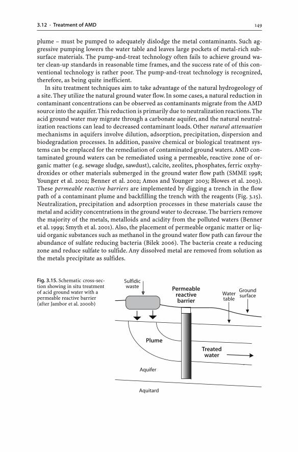
1493.12 · Treatment of AMD
plume – must be pumped to adequately dislodge the metal contaminants. Such ag-gressive pumping lowers the water table and leaves large pockets of metal-rich sub-surface materials. The pump-and-treat technology often fails to achieve ground wa-ter clean-up standards in reasonable time frames, and the success rate of of this con-ventional technology is rather poor. The pump-and-treat technology is recognized,therefore, as being quite inefficient.
In situ treatment techniques aim to take advantage of the natural hydrogeology ofa site. They utilize the natural ground water flow. In some cases, a natural reduction incontaminant concentrations can be observed as contaminants migrate from the AMDsource into the aquifer. This reduction is primarily due to neutralization reactions. Theacid ground water may migrate through a carbonate aquifer, and the natural neutral-ization reactions can lead to decreased contaminant loads. Other natural attenuationmechanisms in aquifers involve dilution, adsorption, precipitation, dispersion andbiodegradation processes. In addition, passive chemical or biological treatment sys-tems can be emplaced for the remediation of contaminated ground waters. AMD con-taminated ground waters can be remediated using a permeable, reactive zone of or-ganic matter (e.g. sewage sludge, sawdust), calcite, zeolites, phosphates, ferric oxyhy-droxides or other materials submerged in the ground water flow path (SMME 1998;Younger et al. 2002; Benner et al. 2002; Amos and Younger 2003; Blowes et al. 2003).These permeable reactive barriers are implemented by digging a trench in the flowpath of a contaminant plume and backfilling the trench with the reagents (Fig. 3.15).Neutralization, precipitation and adsorption processes in these materials cause themetal and acidity concentrations in the ground water to decrease. The barriers removethe majority of the metals, metalloids and acidity from the polluted waters (Benneret al. 1999; Smyth et al. 2001). Also, the placement of permeable organic matter or liq-uid organic substances such as methanol in the ground water flow path can favour theabundance of sulfate reducing bacteria (Bilek 2006). The bacteria create a reducingzone and reduce sulfate to sulfide. Any dissolved metal are removed from solution asthe metals precipitate as sulfides.
Fig. 3.15. Schematic cross-sec-tion showing in situ treatmentof acid ground water with apermeable reactive barrier(after Jambor et al. 2000b)
150 CHAPTER 3 · Mine Water
3.13Summary
The constituents of mine waters are highly variable and include elements and com-pounds from mineral-rock reactions, process chemicals from mineral beneficiationand hydrometallurgical extraction, and nitrogen compounds from blasting operations.Aqueous solutions in contact with oxidizing sulfides will contain increased acidity, iron,sulfate, metal and metalloid concentrations. While AMD waters are well known for theirelevated metal concentrations, neutral to alkaline conditions can also favour the re-lease of metals and metalloids from waste materials. Elevated metal and metalloidconcentrations in neutral to alkaline pH, oxidizing mine waters are promoted by:(a) the formation of ionic species (e.g. Zn2+), oxyanions (e.g. AsO4
3–) and aqueous metalcomplexes (e.g. U carbonate complexes, Zn sulfate complexes); and (b) the lack ofsorption onto and coprecipitation with secondary iron minerals.
Several processes influence the composition of AMD waters. These include bio-chemical processes, the precipitation and dissolution of secondary minerals, and thesorption and desorption of solutes with particulates. Changes to Eh and pH condi-tions influence the behaviour, concentrations and bioavailability of metals and met-alloids.
The oxidation of Fe3+ and hydrolysis of iron in AMD waters produces hydrous ferricoxide (HFO) precipitates (i.e. ochres or yellow boys), which include non-crystalline ironphases as well as iron minerals such as schwertmannite and ferrihydrite. The occur-rence of different iron minerals is largely pH dependent. The iron solids occur as col-ourful bright reddish-yellow to yellowish-brown stains, coatings, suspended particles,colloids, gelatinous flocculants, and precipitates in AMD affected waters. The high spe-cific surface area of hydrous ferric oxide precipitates results in adsorption andcoprecipitation of trace metals. Consequently, these solid phases control the mobility,fate and transport of trace metals in AMD waters.
The dissolution of soluble Fe2+ sulfate salts can be a significant source of acidity,Fe3+ and dissolved metals which were originally adsorbed onto or incorporated in solidphases. Also, the oxidation of Fe2+ to Fe3+ and subsequent hydrolysis of iron can addsignificant acidity to mine waters.
Metals are present in AMD waters as simple metal ions or metal complexes. How-ever, significant metal concentrations can also be transported by colloidal materialsin ground and surface waters. Colloidal iron precipitates with adsorbed metals canrepresent important transport modes for metals in mine environments and streamswell beyond the mine site.
The monitoring of mine waters is designed: (a) to identify the early presence of, orthe changes to, dissolved or suspended constituents; and (b) to ensure that dischargedwater meets a specified water quality standard. Sites should measure or estimate flowrates or periodic flow volumes in order to make calculations of contaminant loadspossible. Possible tools for the prediction of water chemistry include geological, math-ematical and computational modeling. These tools cannot be used, however, to pre-dict the exact chemistry of mine waters.
Sulfidic waste rock dumps are the major sources of AMD because of their sheervolume. The quality and volume of AMD seepages emanating from sulfidic piles areinfluenced by the properties of the waste materials. Despite their heterogeneity, waste
1513.13 · Summary
dumps generally exhibit a single continuous water table with a moderate hydraulicgradient. The physical and chemical conditions, and mineralogical composition ofwaste materials vary on a microscopic scale. Therefore, drainage water from a sulfidicwaste dump represents a mixture of fluids from a variety of dynamic micro-environ-ments within the pile. The different rates of the various weathering reactions withinthe waste can cause temporal changes to the seepage chemistry.
At mine sites, water management strategies aim to protect aquatic environmentsand to reduce the water volume requiring treatment. Treatment techniques for AMDwaters are designed: to reduce volume; to raise pH; to lower dissolved metal and sul-fate concentrations; to lower the bioavailability of metals; to oxidize or reduce the so-lution; and to collect, dispose or isolate any waste waters or metal-rich precipitates.Established AMD treatment options include: neutralization using a range of possibleneutralizing materials; construction of aerobic or anaerobic wetlands; installation ofanoxic limestone drains; and successive alkalinity producing systems. Acid groundwaters are treated using pump-and-treat, natural attenuation, and permeable reactivebarrier technologies.
Further information on mine waters can be obtained from web sites shown inTable 3.6.
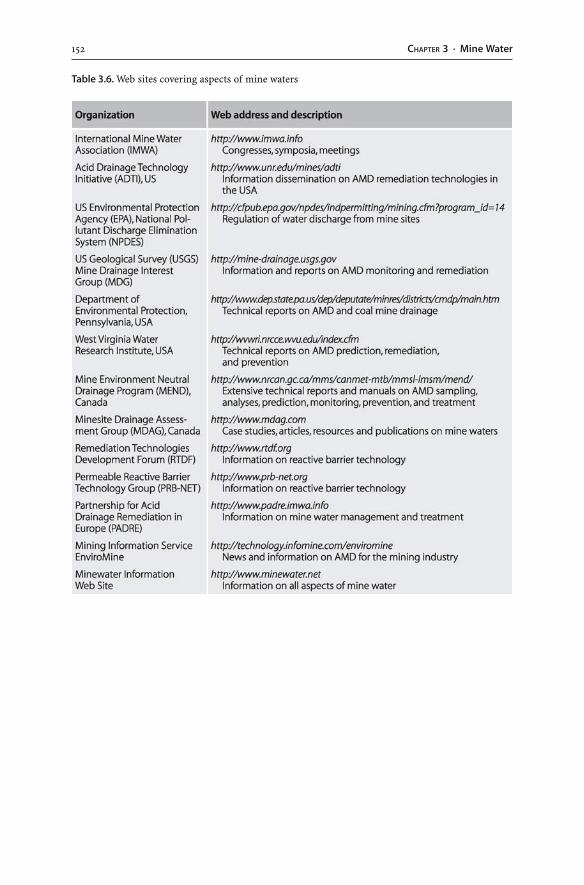
152 CHAPTER 3 · Mine Water
Table 3.6. Web sites covering aspects of mine waters
Chapter 4
Tailings
4.1Introduction
Mineral processing of hard rock metal ores (e.g. Au, Cu, Pb, Zn, U) and industrial min-eral deposits (e.g. phosphate, bauxite) involves size reduction and separation of theindividual minerals. In the first stage of mineral processing, blocks of hard rock oreup to a meter across are reduced to only a few millimeters or even microns in diam-eter. This is achieved by first crushing and then grinding and milling the ore (Fig. 1.2).Crushing is a dry process; grinding involves the abrasion of the particles that are gen-erally suspended in water. The aim of the size reduction is to break down the ore sothat the ore minerals are liberated from gangue phases. In the second stage of mineralprocessing, the ore minerals are separated from the gangue minerals. This stage mayinclude several methods which use the different gravimetric, magnetic, electrical orsurface properties of ore and gangue phases (Fig. 1.2). Coal differs from hard rock oreand industrial mineral deposits as it does not pass through a mill. Instead, the coal iswashed, and coal washeries produce fine-grained slurries that are discarded as wastesin suitable repositories. Consequently, the end products of ore or industrial mineralprocessing and coal washing are the same: (a) a concentrate of the sought-after com-modity; and (b) a quantity of residue wastes known as “tailings”. Tailings typicallyare produced in the form of a particulate suspension, that is, a fine-grained sediment-water slurry. The tailings dominantly consist of the ground-up gangue from which mostof the valuable mineral(s) or coal has been removed. The solids are unwanted miner-als such as silicates, oxides, hydroxides, carbonates, and sulfides. Recoveries of valu-able minerals are never 100%, and tailings always contain small amounts of the valu-able mineral or coal. Tailings impoundments may also receive very high concentra-tions of valuable minerals or coal during times of inadequate mineral processing orcoal washing.
At nearly every metal mine site, some form of mineral processing occurs, and tail-ings are being produced. In metal mining, the extracted ore minerals represent only asmall fraction of the whole ore mass; the vast majority of the mined material ends upas tailings. More than 99% of the original material mined may finally become tailingswhen low-grade metal ores are utilized. Tailings represent, therefore, the most volu-minous waste at metal mine sites.
This chapter documents the characteristics, disposal options, and environmentalimpacts of tailings. The main focus is on tailings from metal ores. Other aspects im-portant to tailings such as sulfide oxidation and geochemical processes in AMD wa-ters have already been presented (Chaps. 2, 3). Sulfidic tailings and AMD waters ofsulfidic tailings may be characterized and treated with the same type of approaches
154 CHAPTER 4 · Tailings
used to characterize and treat sulfidic waste rocks and AMD waters as discussed inthe previous chapters.
4.2Tailings Characteristics
Tailings vary considerably in their chemical and physical characteristics. These char-acteristics include: mineralogical and geochemical compositions; specific gravity oftailings particles; settling behaviour; permeability vs. density relationships; soil plas-ticity (i.e. Atterberg limits); consolidation behaviour; rheology/viscosity characteris-tics; strength characteristics; pore water chemistry; and leaching properties (Environ-ment Australia 1995). Detailed procedures for tailings sampling, preparation and analy-sis are found in Ficklin and Mosier (1999). Laboratory methods for the mineralogicaland geochemical analysis of tailings solids and waters are given by Jambor (1994),Crock et al. (1999), and Petruk (2000).
Tailings consist of solids and liquids. The solids are commonly discharged with spentprocess water into a tailings storage facility, most commonly a tailings dam. As a re-sult, the waste repository contains liquids in the form of surface and pore waters. Thesetailings liquids tend to contain high concentrations of process chemicals. The follow-ing presentation of tailings is given in terms of process chemicals, tailings liquids, andtailings solids.
4.2.1Process Chemicals
Many of the mineral beneficiation and hydrometallurgical operations process thecrushed ore in water. Ground or surface water is exploited and used in the process cir-cuits as so-called “process water”. The composition of process water is largely a func-tion of the applied mineral processing and hydrometallurgical techniques. Hydromet-allurgical processing requires specific chemicals for different ore characteristics andmineral behaviours. The chemicals can be classified as flotation reagents, modifiers,flocculants/coagulents, hydrometallurgical agents, and oxidants (Table 4.1). Flotationreagents are a group of chemicals used for froth flotation which is a common mineralprocessing technique to recover sulfides. Froth flotation works on the principle thatwater and a frothing agent are added to finely crushed mineral particles. The ore min-erals cling to air bubbles and form a froth on top of the water. The froth is recoveredand dried. The remaining water contains unwanted solids which are pumped to a tail-ings disposal facility.
Much of the process water accumulates in decant ponds of tailings dams. The tail-ings water can be decanted for reuse and pumped back to the plant. Recycling of pro-cess water and process chemicals makes economic sense and can reduce the load ofcontaminants contained in ponds and tailings dams. However, a proportion of the dis-charged process water remains in the tailings disposal facility. Various fractions of thechemical additives ultimately find their way into tailings, and tailings liquids oftencontain some levels of organic chemicals, cyanide, sulfuric acid, and other reagentsused to achieve mineral recovery.
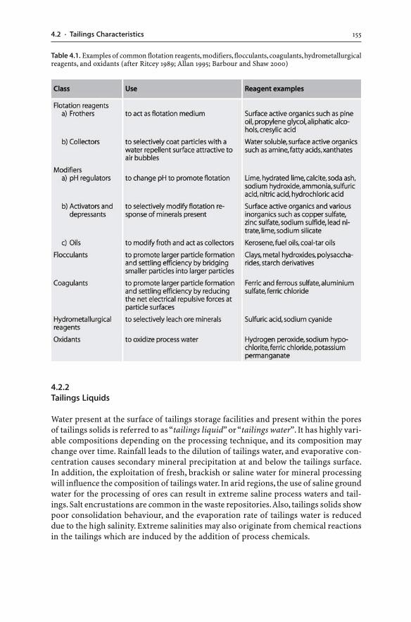
1554.2 · Tailings Characteristics
Table 4.1. Examples of common flotation reagents, modifiers, flocculants, coagulants, hydrometallurgicalreagents, and oxidants (after Ritcey 1989; Allan 1995; Barbour and Shaw 2000)
4.2.2Tailings Liquids
Water present at the surface of tailings storage facilities and present within the poresof tailings solids is referred to as “tailings liquid” or “tailings water”. It has highly vari-able compositions depending on the processing technique, and its composition maychange over time. Rainfall leads to the dilution of tailings water, and evaporative con-centration causes secondary mineral precipitation at and below the tailings surface.In addition, the exploitation of fresh, brackish or saline water for mineral processingwill influence the composition of tailings water. In arid regions, the use of saline groundwater for the processing of ores can result in extreme saline process waters and tail-ings. Salt encrustations are common in the waste repositories. Also, tailings solids showpoor consolidation behaviour, and the evaporation rate of tailings water is reduceddue to the high salinity. Extreme salinities may also originate from chemical reactionsin the tailings which are induced by the addition of process chemicals.
156 CHAPTER 4 · Tailings
Process chemicals, used to extract ore minerals, may influence the behaviour ofmetals and other elements in tailings. For example, thiosalts (S2O3
2–, S3O62–, S4O6
2–) canoxidize to sulfate in waste repositories causing the acidification of waters, and organicchemicals may complex metals present in the tailings. As a consequence, the pore andsurface waters of tailings dams may contain strongly elevated concentrations of vari-ous elements and compounds, including process chemicals. Some of the process re-agents such as organics and cyanides may be destroyed with time by natural bacte-rial, chemical or photolytic degradation processes (Sec. 5.8). Other compounds mayrequire naturally enhanced or engineered destruction; some elements have to be per-manently isolated by the tailings impoundment (e.g. radionuclides, metals, metalloids).
The acidity of tailings waters is influenced by the applied processing technique. Forinstance, the digestion of bauxite ore and the dissolution of gold using cyanide solu-tions are conducted under alkaline conditions. In contrast, the hydrometallurgicalextraction of copper, nickel, and uranium is based on the use of sulfuric acid underoxidizing conditions. This sulfuric acid or that generated by sulfide oxidation will leachthe tailings minerals. For example, the acid leaching of the mineral fluorite (CaF2) re-leases fluorine into waters (Petrunic and Al 2005). The fluorine in turn forms strongcomplexes with aluminium and enhances the dissolution of aluminosilicate minerals.As a result, strongly elevated Al contents can be present in tailings waters. In extremecases, different processing techniques can create strongly acid or alkaline tailingswaters with high concentrations of iron, manganese, aluminium, trace metals, metal-loids, fluoride, chloride and sulfate (Bodénan et al. 2004).
4.2.3Tailings Solids
At metal mines, the amount of the ore mineral(s) extracted from an ore is relativelysmall, and the vast majority of mined and processed ore ends up as tailings. At mod-ern gold mines, more than 99.999% of the originally mined and processed ore mayfinally become tailings. The dry weight of tailings produced is nearly equal to the dryweight of the ore mined.
The grain size of tailings is relatively restricted and ranges from clay to sand(i.e. 2 µm to 2 mm). In some cases, the tailings solids have distinct grain sizes, and thesolids are then referred to as “slimes” and “sands”. Dry tailings typically consist of70 to 80 wt.% sand-sized particles and 20 to 30 wt.% finer clay-sized particles (Fig. 4.1).The grain size depends on the liberation characteristics of the ore and gangue miner-als and the applied crushing and grinding process. The grain size influences the resis-tance of the tailings solids to wind and water erosion and the behaviour and settlingcharacteristics of particles in tailings dams. The mineralogical and geochemical com-position of tailings solids is site specific, and such variations provide different chal-lenges. For example, sulfide-rich tailings are potential sources of AMD whereas ura-nium tailings have elevated levels of radiation.
It is often assumed that tailings contain minerals similar to those of the ore, onlyin much smaller grain size. Nonetheless, tailings comprise a material which is signifi-cantly different to the mined ore in terms of grain size, mineralogy, and chemistry. Bynature, mineral processing is designed to change the physical and chemical charac-
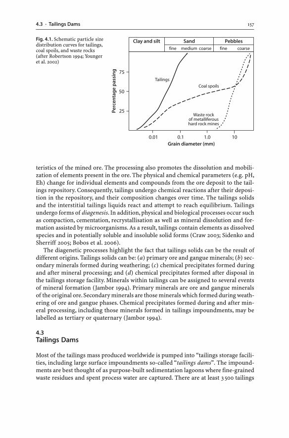
1574.3 · Tailings Dams
Fig. 4.1. Schematic particle sizedistribution curves for tailings,coal spoils, and waste rocks(after Robertson 1994; Youngeret al. 2002)
teristics of the mined ore. The processing also promotes the dissolution and mobili-zation of elements present in the ore. The physical and chemical parameters (e.g. pH,Eh) change for individual elements and compounds from the ore deposit to the tail-ings repository. Consequently, tailings undergo chemical reactions after their deposi-tion in the repository, and their composition changes over time. The tailings solidsand the interstitial tailings liquids react and attempt to reach equilibrium. Tailingsundergo forms of diagenesis. In addition, physical and biological processes occur suchas compaction, cementation, recrystallisation as well as mineral dissolution and for-mation assisted by microorganisms. As a result, tailings contain elements as dissolvedspecies and in potentially soluble and insoluble solid forms (Craw 2003; Sidenko andSherriff 2005; Bobos et al. 2006).
The diagenetic processes highlight the fact that tailings solids can be the result ofdifferent origins. Tailings solids can be: (a) primary ore and gangue minerals; (b) sec-ondary minerals formed during weathering; (c) chemical precipitates formed duringand after mineral processing; and (d) chemical precipitates formed after disposal inthe tailings storage facility. Minerals within tailings can be assigned to several eventsof mineral formation (Jambor 1994). Primary minerals are ore and gangue mineralsof the original ore. Secondary minerals are those minerals which formed during weath-ering of ore and gangue phases. Chemical precipitates formed during and after min-eral processing, including those minerals formed in tailings impoundments, may belabelled as tertiary or quaternary (Jambor 1994).
4.3Tailings Dams
Most of the tailings mass produced worldwide is pumped into “tailings storage facili-ties, including large surface impoundments so-called “tailings dams”. The impound-ments are best thought of as purpose-built sedimentation lagoons where fine-grainedwaste residues and spent process water are captured. There are at least 3 500 tailings
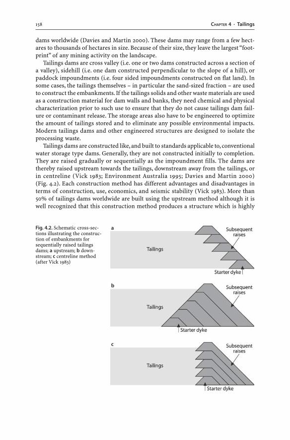
158 CHAPTER 4 · Tailings
dams worldwide (Davies and Martin 2000). These dams may range from a few hect-ares to thousands of hectares in size. Because of their size, they leave the largest “foot-print” of any mining activity on the landscape.
Tailings dams are cross valley (i.e. one or two dams constructed across a section ofa valley), sidehill (i.e. one dam constructed perpendicular to the slope of a hill), orpaddock impoundments (i.e. four sided impoundments constructed on flat land). Insome cases, the tailings themselves – in particular the sand-sized fraction – are usedto construct the embankments. If the tailings solids and other waste materials are usedas a construction material for dam walls and banks, they need chemical and physicalcharacterization prior to such use to ensure that they do not cause tailings dam fail-ure or contaminant release. The storage areas also have to be engineered to optimizethe amount of tailings stored and to eliminate any possible environmental impacts.Modern tailings dams and other engineered structures are designed to isolate theprocessing waste.
Tailings dams are constructed like, and built to standards applicable to, conventionalwater storage type dams. Generally, they are not constructed initially to completion.They are raised gradually or sequentially as the impoundment fills. The dams arethereby raised upstream towards the tailings, downstream away from the tailings, orin centreline (Vick 1983; Environment Australia 1995; Davies and Martin 2000)(Fig. 4.2). Each construction method has different advantages and disadvantages interms of construction, use, economics, and seismic stability (Vick 1983). More than50% of tailings dams worldwide are built using the upstream method although it iswell recognized that this construction method produces a structure which is highly
Fig. 4.2. Schematic cross-sec-tions illustrating the construc-tion of embankments forsequentially raised tailingsdams; a upstream; b down-stream; c centreline method(after Vick 1983)
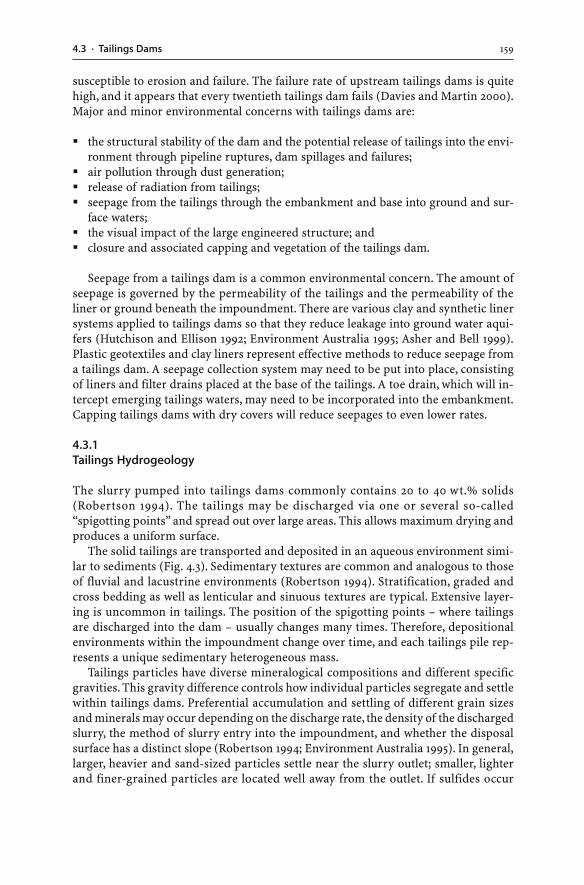
1594.3 · Tailings Dams
susceptible to erosion and failure. The failure rate of upstream tailings dams is quitehigh, and it appears that every twentieth tailings dam fails (Davies and Martin 2000).Major and minor environmental concerns with tailings dams are:
� the structural stability of the dam and the potential release of tailings into the envi-ronment through pipeline ruptures, dam spillages and failures;
� air pollution through dust generation;� release of radiation from tailings;� seepage from the tailings through the embankment and base into ground and sur-
face waters;� the visual impact of the large engineered structure; and� closure and associated capping and vegetation of the tailings dam.
Seepage from a tailings dam is a common environmental concern. The amount ofseepage is governed by the permeability of the tailings and the permeability of theliner or ground beneath the impoundment. There are various clay and synthetic linersystems applied to tailings dams so that they reduce leakage into ground water aqui-fers (Hutchison and Ellison 1992; Environment Australia 1995; Asher and Bell 1999).Plastic geotextiles and clay liners represent effective methods to reduce seepage froma tailings dam. A seepage collection system may need to be put into place, consistingof liners and filter drains placed at the base of the tailings. A toe drain, which will in-tercept emerging tailings waters, may need to be incorporated into the embankment.Capping tailings dams with dry covers will reduce seepages to even lower rates.
4.3.1Tailings Hydrogeology
The slurry pumped into tailings dams commonly contains 20 to 40 wt.% solids(Robertson 1994). The tailings may be discharged via one or several so-called“spigotting points” and spread out over large areas. This allows maximum drying andproduces a uniform surface.
The solid tailings are transported and deposited in an aqueous environment simi-lar to sediments (Fig. 4.3). Sedimentary textures are common and analogous to thoseof fluvial and lacustrine environments (Robertson 1994). Stratification, graded andcross bedding as well as lenticular and sinuous textures are typical. Extensive layer-ing is uncommon in tailings. The position of the spigotting points – where tailingsare discharged into the dam – usually changes many times. Therefore, depositionalenvironments within the impoundment change over time, and each tailings pile rep-resents a unique sedimentary heterogeneous mass.
Tailings particles have diverse mineralogical compositions and different specificgravities. This gravity difference controls how individual particles segregate and settlewithin tailings dams. Preferential accumulation and settling of different grain sizesand minerals may occur depending on the discharge rate, the density of the dischargedslurry, the method of slurry entry into the impoundment, and whether the disposalsurface has a distinct slope (Robertson 1994; Environment Australia 1995). In general,larger, heavier and sand-sized particles settle near the slurry outlet; smaller, lighterand finer-grained particles are located well away from the outlet. If sulfides occur
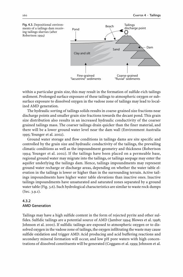
160 CHAPTER 4 · Tailings
within a particular grain size, this may result in the formation of sulfide-rich tailingssediment. Prolonged surface exposure of these tailings to atmospheric oxygen or sub-surface exposure to dissolved oxygen in the vadose zone of tailings may lead to local-ized AMD generation.
The hydraulic sorting of tailings solids results in coarse-grained size fractions neardischarge points and smaller grain size fractions towards the decant pond. This grainsize distribution also results in an increased hydraulic conductivity of the coarsergrained tailings mass. The coarser tailings drain quicker than the finer material, andthere will be a lower ground water level near the dam wall (Environment Australia1995; Younger et al. 2002).
Ground water storage and flow conditions in tailings dams are site specific andcontrolled by the grain size and hydraulic conductivity of the tailings, the prevailingclimatic conditions as well as the impoundment geometry and thickness (Robertson1994; Younger et al. 2002). If the tailings have been placed on a permeable base,regional ground water may migrate into the tailings, or tailings seepage may enter theaquifer underlying the tailings dam. Hence, tailings impoundments may representground water recharge or discharge areas, depending on whether the water table el-evation in the tailings is lower or higher than in the surrounding terrain. Active tail-ings impoundments have higher water table elevations than inactive ones. Inactivetailings impoundments have unsaturated and saturated zones separated by a groundwater table (Fig. 3.6). Such hydrological characteristics are similar to waste rock dumps(Sec. 3.9.1).
4.3.2AMD Generation
Tailings may have a high sulfide content in the form of rejected pyrite and other sul-fides. Sulfidic tailings are a potential source of AMD (Jambor 1994; Blowes et al. 1998;Johnson et al. 2000). If sulfidic tailings are exposed to atmospheric oxygen or to dis-solved oxygen in the vadose zone of tailings, the oxygen infiltrating the waste may causesulfide oxidation and trigger AMD. Acid producing and acid buffering reactions andsecondary mineral formation will occur, and low pH pore waters with high concen-trations of dissolved constituents will be generated (Coggans et al. 1999; Johnson et al.
Fig. 4.3. Depositional environ-ments of a tailings dam receiv-ing tailings slurries (afterRobertson 1994)
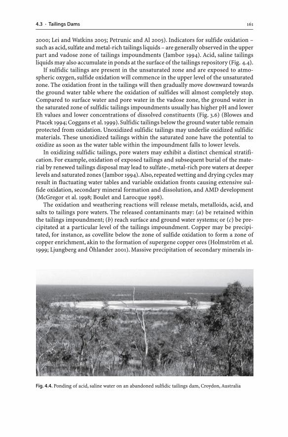
1614.3 · Tailings Dams
2000; Lei and Watkins 2005; Petrunic and Al 2005). Indicators for sulfide oxidation –such as acid, sulfate and metal-rich tailings liquids – are generally observed in the upperpart and vadose zone of tailings impoundments (Jambor 1994). Acid, saline tailingsliquids may also accumulate in ponds at the surface of the tailings repository (Fig. 4.4).
If sulfidic tailings are present in the unsaturated zone and are exposed to atmo-spheric oxygen, sulfide oxidation will commence in the upper level of the unsaturatedzone. The oxidation front in the tailings will then gradually move downward towardsthe ground water table where the oxidation of sulfides will almost completely stop.Compared to surface water and pore water in the vadose zone, the ground water inthe saturated zone of sulfidic tailings impoundments usually has higher pH and lowerEh values and lower concentrations of dissolved constituents (Fig. 3.6) (Blowes andPtacek 1994; Coggans et al. 1999). Sulfidic tailings below the ground water table remainprotected from oxidation. Unoxidized sulfidic tailings may underlie oxidized sulfidicmaterials. These unoxidized tailings within the saturated zone have the potential tooxidize as soon as the water table within the impoundment falls to lower levels.
In oxidizing sulfidic tailings, pore waters may exhibit a distinct chemical stratifi-cation. For example, oxidation of exposed tailings and subsequent burial of the mate-rial by renewed tailings disposal may lead to sulfate-, metal-rich pore waters at deeperlevels and saturated zones (Jambor 1994). Also, repeated wetting and drying cycles mayresult in fluctuating water tables and variable oxidation fronts causing extensive sul-fide oxidation, secondary mineral formation and dissolution, and AMD development(McGregor et al. 1998; Boulet and Larocque 1998).
The oxidation and weathering reactions will release metals, metalloids, acid, andsalts to tailings pore waters. The released contaminants may: (a) be retained withinthe tailings impoundment; (b) reach surface and ground water systems; or (c) be pre-cipitated at a particular level of the tailings impoundment. Copper may be precipi-tated, for instance, as covellite below the zone of sulfide oxidation to form a zone ofcopper enrichment, akin to the formation of supergene copper ores (Holmström et al.1999; Ljungberg and Öhlander 2001). Massive precipitation of secondary minerals in-
Fig. 4.4. Ponding of acid, saline water on an abandoned sulfidic tailings dam, Croydon, Australia
162 CHAPTER 4 · Tailings
cluding oxides (e.g. goethite, ferrihydrite, lepidocrocite, schwertmannite), sulfates(e.g. jarosite, gypsum, melanterite), and sulfides (e.g. covellite) may occur at particu-lar levels within the tailings impoundment (McGregor et al. 1998; Dold and Fontbote2001). Mineral precipitation can cement sulfidic tailings at or near the depth of sul-fide oxidation. Prolonged precipitation causes the formation of a hardpan layer whichacts as a diffusion barrier to oxygen and limits the downward migration of low pH,saline pore waters (Blowes et al. 1991; Coggans et al. 1999) (Sec. 2.6.4).
If sulfidic tailings are exposed to the atmosphere for extended periods, evapora-tion of tailings water commonly leads to the formation of sulfate-bearing mineral saltssuch as gypsum or jarosite (Johnson et al. 2000; Dold and Fontbote 2001). These sec-ondary mineral blooms occur on or immediately below the impoundment surface, andsurficial tailings materials may form a cohesive, rigidly cemented material. Solublesecondary minerals may redissolve upon rainfall events or due to increased water lev-els within the tailings dam.
While the oxidation of sulfidic tailings is possible, most tailings deposits generallyremain water saturated during the operating life. This limits the transfer of air intothe tailings and the supply of oxygen to sulfide minerals (Blowes and Ptacek 1994).Moreover, if unoxidized sulfidic tailings are flooded, deposition of organic materialmay occur, and layers rich in iron and manganese oxyhydroxides may develop at thewater-tailings interface. These layers can prevent the release of metals into the overly-ing water column through adsorption and coprecipitation processes (Holmström andÖhlander 1999, 2001).
Tailings are much finer grained and have a much higher specific surface area(i.e. m2 g–1) available for oxidation and leaching reactions than waste rocks. Thus, theonset of AMD development in tailings can be more rapid than in waste rocks of thesame deposit, yet crushing and milling of sulfidic ores do not necessarily increase theoxidation rate of pyrite in tailings dams. The rate of AMD generation in tailings isreduced by:
� Uniform and fine grain size. Tailings possess a uniform and fine particle size whichleads to a much lower permeability than that in waste rock piles. Compared to coarse-grained waste rocks, tailings exhibit: (a) less and slower water and oxygen move-ment into the waste; (b) reduced contact of sulfides with oxygen due to slower oxy-gen transport into the waste; (c) slower water movement and slower replenishmentof consumed oxygen; and (d) very slow seepage of an AMD plume to outlets of thewaste impoundment because the generally low hydraulic conductivity of tailings willdelay movement of the AMD plume (Ljungberg and and Öhlander 2001). The be-haviours of oxygen and water influence the depth and rate of AMD generation. Con-sequently, tailings permit a smaller depth of active acid generation than coarse-grained wastes, and sulfidic tailings often generate AMD more slowly than coarser,more permeable waste rock from the same deposit (Mitchell 2000).
� Addition of alkaline process chemicals. Some tailings have a high pH due to the ad-dition of alkaline materials during mineral processing (Craw et al. 1999). Any acidgenerated may immediately be neutralized by residual alkaline processing agents.Tailings may also be stabilized through the addition of neutralizing materials suchas lime, crushed limestone or fly ash (Stouraiti et al. 2002). This may prevent highlyreactive sulfidic tailings from developing AMD waters.
1634.3 · Tailings Dams
4.3.3Tailings Dam Failures
Tailings dams should be constructed to contain waste materials indefinitely. The im-poundment should be designed to achieve negligible seepage of tailings liquids intoground and surface waters and to prevent failures of tailings dam structures. There-fore, the dams should be engineered for: (a) long-term stability against erosion andmass movement; (b) prevention of environmental contamination of ground and sur-face waters; and (c) return of the area for future land use. The overall design objectiveof tailings dams should be to achieve a safe, stable post-operational tailings impound-ment (Environment Australia 1995; Davies and Martin 2000).
The stability of tailings dams is controlled by the embankment height and slope aswell as the degree of compaction, nature, and strength of foundation and embank-ment materials (Environment Australia 1995). Conventional tailings dams can exceed100 m in height and have to hold back a significant pool of water and up to severalhundred million cubic meters of water saturated tailings. The easiest way to maintaindam stability during operation is to keep the decant pond as small as possible and asfar as possible from the containing embankment as practical (Environment Australia1995). This ensures that the phreatic surface remains at low levels. Nonetheless, themechanical stability of tailings is very poor due to the small grain size and the usuallyhigh water content. The level of the water table in the impoundment and embankmentfalls as tailings discharge ceases. This results in the increased stability of the embank-ment and tailings mass. Any further accumulation of water on the dam is preventedby capping the impoundment.
In the past 70 years, numerous incidents involving operating tailings dams haveoccurred (e.g. Wagener et al. 1998). There have been about 100 documented signifi-cant upstream tailings dam failures (Davies and Martin 2000) (Table 4.2). The causesfor tailings dam failures include:
� Liquefaction. Earthquakes are associated with the release of seismic waves whichcause increased shear stresses on the embankment and increased pore pressures insaturated tailings. Tailings and the dam may liquefy during seismic events (e.g. Vetade Agua, Chile; 03.03.1985). Liquefaction may also be caused by mine blasting ornearby motion and vibrations of heavy equipment.
� Rapid increase in dam wall height. If an upstream dam is raised too quickly, veryhigh internal pore pressures are produced within the tailings. High pore pressuresdecrease the dam stability and may lead to dam failure (e.g. Tyrone, USA; 13.10.1980).
� Foundation failure. If the base below the dam is too weak to support the dam, move-ment along a failure plane will occur (e.g. Los Frailes, Spain; 25.04.1998).
� Excessive water levels. Dam failure can occur if the phreatic surface raises to a criti-cal level; that is, the beach width between the decant pond and the dam crest be-comes too small (Fig. 4.3). Flood inflow, high rainfall, rapid melting of snow, andimproper water management of the mill operator may cause excessive water levelswithin the impoundment, which then may lead to overtopping and collapse of theembankment (e.g. Baia Mare, Romania; 30.01.2000; Case Study 5.1). If overtoppingof the dam crest occurs, breaching, erosion, and complete failure of the impound-ment are possible.
164 CHAPTER 4 · Tailings
� Excessive seepage. Seepage within or beneath the dam causes erosion along theseepage flow path. Excessive seepage may result in failure of the embankment(e.g. Zlevoto, Yugoslavia; 01.03.1976).
If failure occurs, tailings may enter underground workings or more commonly, thewastes spill into waterways and travel downstream. Depending on the dam’s location,failures of tailings dams can have catastrophic consequences. Streams can be pollutedfor a considerable distance downstream, large surface areas can become covered withthick metal-rich mud, the region’s sediment and water quality can be reduced, andcontaminants may enter ecosystems (e.g. Benito et al. 2001; Hudson-Edwards et al.2003; Macklin et al. 2003). Tailings dam failures in numerous countries have causedthe loss of human life and major economic and environmental costs (Table 4.2) (Min-ing Journal Research Services 1996).
The prevention of tailings dam failures requires: (a) an effective geotechnical char-acterization of the tailings site; and (b) a detailed understanding of the risk of localnatural hazards such as earthquakes, landslides, and catastrophic meteorologicalevents. It is important to design tailings dams to such a standard that they can copewith extreme geological and climatic events.
Most tailings dam failures have been in humid, temperate regions. In contrast,there have been very few tailings dam failures in semi-arid and arid regions. However,tailings dams in semi-arid climates suffer from other chronic difficulties inclu-ding seepage problems, supernatant ponds with high levels of process chemicals,dust generation, and surface crusting. Crusting prevents drying out of tailings,and rehabilitation cannot be undertaken for many years after tailings deposition hasceased.
4.3.4Monitoring
Monitoring of tailings dam structures is essential in order to prevent environmentalpollution and tailings dam failures and spillages. Site specific conditions require tai-lored monitoring programs. The monitoring program should address the followingaspects:
� Dam performance. Performance monitoring of tailings dams includes measurementsof the filling rate, consolidation, grain size distribution, water balance, and processchemical concentrations such as cyanide.
� Impoundment stability. Impoundment stability monitoring establishes the phreaticsurface in the embankment and tailings as well as the slope stability and pore pres-sure within the tailings.
� Environmental aspects. Environmental monitoring includes: meteorological obser-vations; measurements of radioactivity levels; investigations of the tailings chemis-try and mineralogy; performance of geochemical static and kinetic tests for AMDgeneration potential; and chemical analyses of ground, surface and seepage waters,downstream stream sediments, and dust particles. Ground water monitoringis an integral part of tailings monitoring and allows an evaluation of tailingsseepage into aquifers (Robertson 1994; Environment Australia 1995). Piezometers
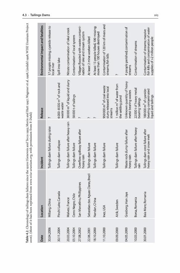
1654.3 · Tailings Dams
Tab
le 4
.2. C
hron
olog
y of
taili
ngs
dam
failu
res
sinc
e th
e 19
20s
(Gen
evoi
s an
d Te
cca
1993
; Mor
in a
nd H
utt 1
997;
Wag
ener
et a
l. 19
98; L
inda
hl 19
98; W
ISE
Ura
nium
Pro
ject
2006
). (M
ost o
f it
has
bee
n re
prin
ted
from
ww
w.w
ise-
uran
ium
.org
, wit
h pe
rmis
sion
from
P. D
iehl
)
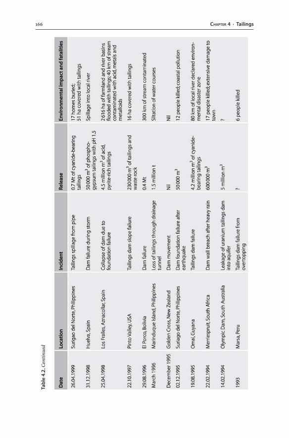
166 CHAPTER 4 · Tailings
Tab
le 4
.2. C
onti
nued
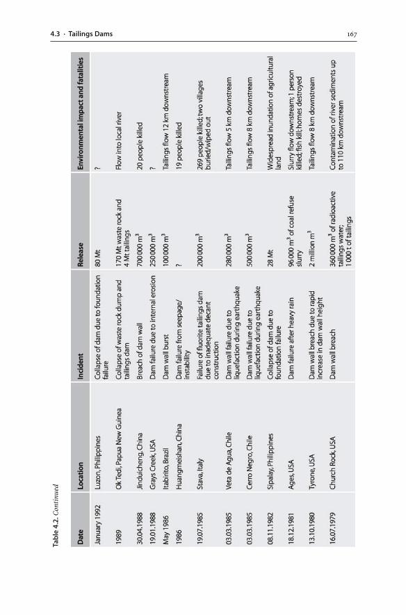
1674.3 · Tailings Dams
Tab
le 4
.2. C
onti
nued
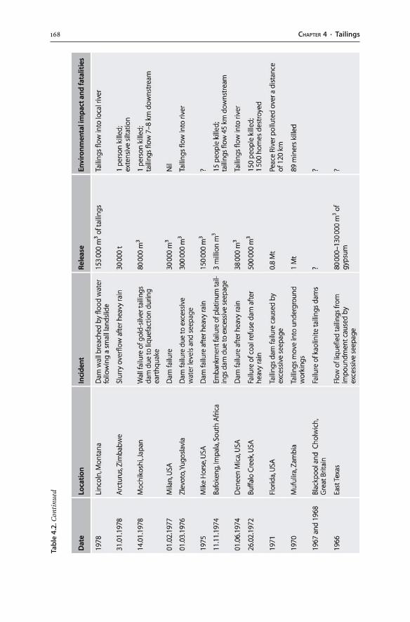
168 CHAPTER 4 · Tailings
Tab
le 4
.2. C
onti
nued
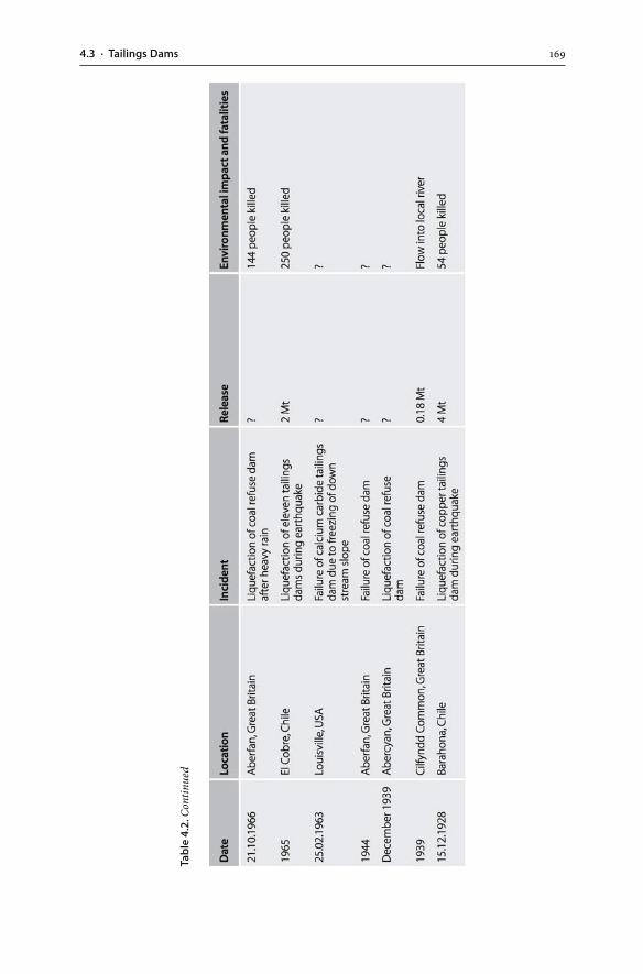
1694.3 · Tailings Dams
Tab
le 4
.2. C
onti
nued
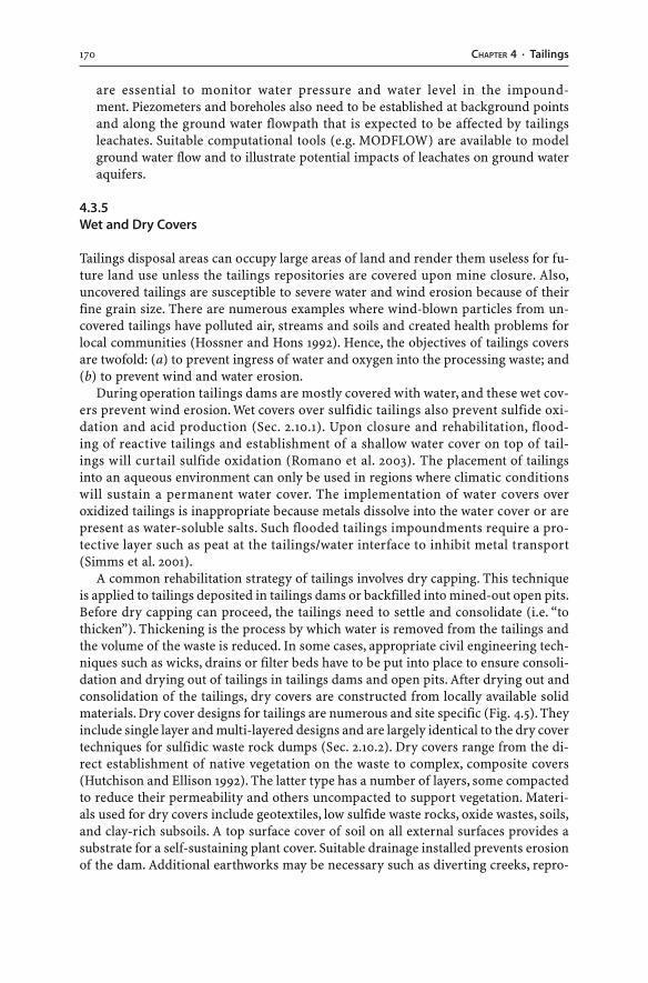
170 CHAPTER 4 · Tailings
are essential to monitor water pressure and water level in the impound-ment. Piezometers and boreholes also need to be established at background pointsand along the ground water flowpath that is expected to be affected by tailingsleachates. Suitable computational tools (e.g. MODFLOW) are available to modelground water flow and to illustrate potential impacts of leachates on ground wateraquifers.
4.3.5Wet and Dry Covers
Tailings disposal areas can occupy large areas of land and render them useless for fu-ture land use unless the tailings repositories are covered upon mine closure. Also,uncovered tailings are susceptible to severe water and wind erosion because of theirfine grain size. There are numerous examples where wind-blown particles from un-covered tailings have polluted air, streams and soils and created health problems forlocal communities (Hossner and Hons 1992). Hence, the objectives of tailings coversare twofold: (a) to prevent ingress of water and oxygen into the processing waste; and(b) to prevent wind and water erosion.
During operation tailings dams are mostly covered with water, and these wet cov-ers prevent wind erosion. Wet covers over sulfidic tailings also prevent sulfide oxi-dation and acid production (Sec. 2.10.1). Upon closure and rehabilitation, flood-ing of reactive tailings and establishment of a shallow water cover on top of tail-ings will curtail sulfide oxidation (Romano et al. 2003). The placement of tailingsinto an aqueous environment can only be used in regions where climatic conditionswill sustain a permanent water cover. The implementation of water covers overoxidized tailings is inappropriate because metals dissolve into the water cover or arepresent as water-soluble salts. Such flooded tailings impoundments require a pro-tective layer such as peat at the tailings/water interface to inhibit metal transport(Simms et al. 2001).
A common rehabilitation strategy of tailings involves dry capping. This techniqueis applied to tailings deposited in tailings dams or backfilled into mined-out open pits.Before dry capping can proceed, the tailings need to settle and consolidate (i.e. “tothicken”). Thickening is the process by which water is removed from the tailings andthe volume of the waste is reduced. In some cases, appropriate civil engineering tech-niques such as wicks, drains or filter beds have to be put into place to ensure consoli-dation and drying out of tailings in tailings dams and open pits. After drying out andconsolidation of the tailings, dry covers are constructed from locally available solidmaterials. Dry cover designs for tailings are numerous and site specific (Fig. 4.5). Theyinclude single layer and multi-layered designs and are largely identical to the dry covertechniques for sulfidic waste rock dumps (Sec. 2.10.2). Dry covers range from the di-rect establishment of native vegetation on the waste to complex, composite covers(Hutchison and Ellison 1992). The latter type has a number of layers, some compactedto reduce their permeability and others uncompacted to support vegetation. Materi-als used for dry covers include geotextiles, low sulfide waste rocks, oxide wastes, soils,and clay-rich subsoils. A top surface cover of soil on all external surfaces provides asubstrate for a self-sustaining plant cover. Suitable drainage installed prevents erosionof the dam. Additional earthworks may be necessary such as diverting creeks, repro-
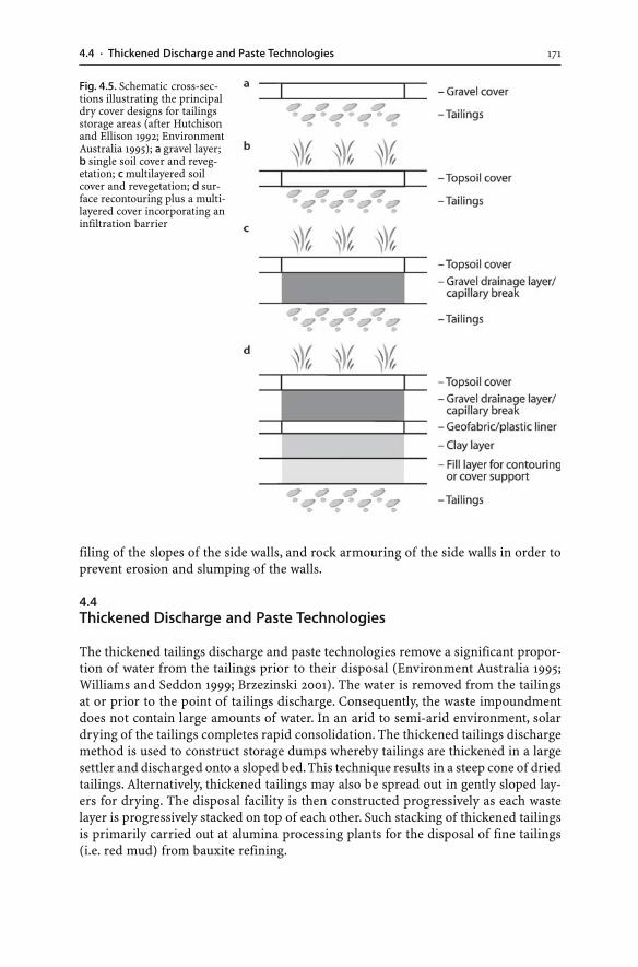
1714.4 · Thickened Discharge and Paste Technologies
Fig. 4.5. Schematic cross-sec-tions illustrating the principaldry cover designs for tailingsstorage areas (after Hutchisonand Ellison 1992; EnvironmentAustralia 1995); a gravel layer;b single soil cover and reveg-etation; c multilayered soilcover and revegetation; d sur-face recontouring plus a multi-layered cover incorporating aninfiltration barrier
filing of the slopes of the side walls, and rock armouring of the side walls in order toprevent erosion and slumping of the walls.
4.4Thickened Discharge and Paste Technologies
The thickened tailings discharge and paste technologies remove a significant propor-tion of water from the tailings prior to their disposal (Environment Australia 1995;Williams and Seddon 1999; Brzezinski 2001). The water is removed from the tailingsat or prior to the point of tailings discharge. Consequently, the waste impoundmentdoes not contain large amounts of water. In an arid to semi-arid environment, solardrying of the tailings completes rapid consolidation. The thickened tailings dischargemethod is used to construct storage dumps whereby tailings are thickened in a largesettler and discharged onto a sloped bed. This technique results in a steep cone of driedtailings. Alternatively, thickened tailings may also be spread out in gently sloped lay-ers for drying. The disposal facility is then constructed progressively as each wastelayer is progressively stacked on top of each other. Such stacking of thickened tailingsis primarily carried out at alumina processing plants for the disposal of fine tailings(i.e. red mud) from bauxite refining.
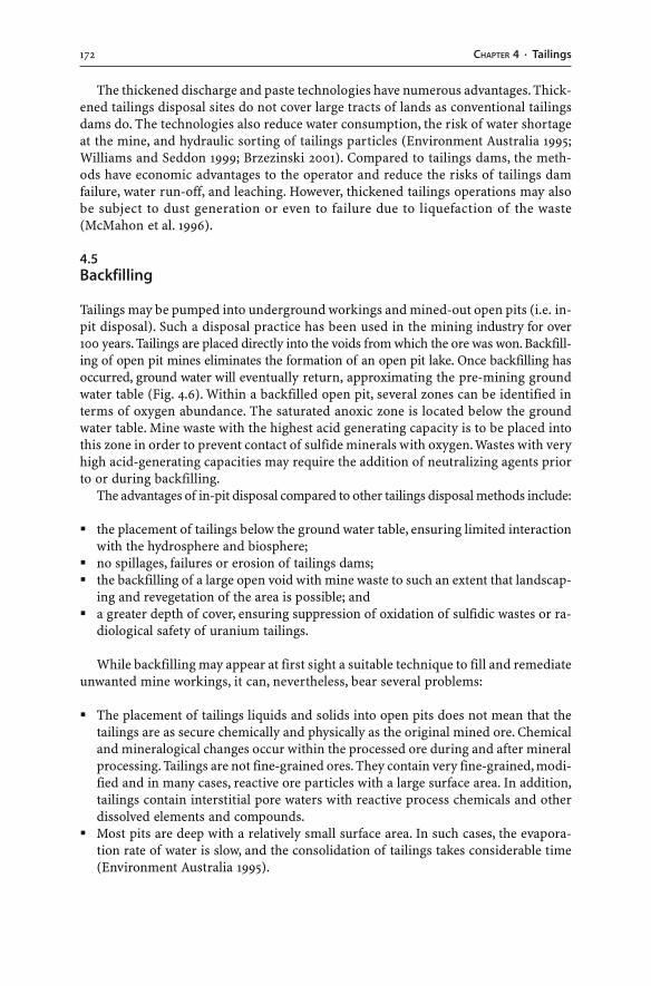
172 CHAPTER 4 · Tailings
The thickened discharge and paste technologies have numerous advantages. Thick-ened tailings disposal sites do not cover large tracts of lands as conventional tailingsdams do. The technologies also reduce water consumption, the risk of water shortageat the mine, and hydraulic sorting of tailings particles (Environment Australia 1995;Williams and Seddon 1999; Brzezinski 2001). Compared to tailings dams, the meth-ods have economic advantages to the operator and reduce the risks of tailings damfailure, water run-off, and leaching. However, thickened tailings operations may alsobe subject to dust generation or even to failure due to liquefaction of the waste(McMahon et al. 1996).
4.5Backfilling
Tailings may be pumped into underground workings and mined-out open pits (i.e. in-pit disposal). Such a disposal practice has been used in the mining industry for over100 years. Tailings are placed directly into the voids from which the ore was won. Backfill-ing of open pit mines eliminates the formation of an open pit lake. Once backfilling hasoccurred, ground water will eventually return, approximating the pre-mining groundwater table (Fig. 4.6). Within a backfilled open pit, several zones can be identified interms of oxygen abundance. The saturated anoxic zone is located below the groundwater table. Mine waste with the highest acid generating capacity is to be placed intothis zone in order to prevent contact of sulfide minerals with oxygen. Wastes with veryhigh acid-generating capacities may require the addition of neutralizing agents priorto or during backfilling.
The advantages of in-pit disposal compared to other tailings disposal methods include:
� the placement of tailings below the ground water table, ensuring limited interactionwith the hydrosphere and biosphere;
� no spillages, failures or erosion of tailings dams;� the backfilling of a large open void with mine waste to such an extent that landscap-
ing and revegetation of the area is possible; and� a greater depth of cover, ensuring suppression of oxidation of sulfidic wastes or ra-
diological safety of uranium tailings.
While backfilling may appear at first sight a suitable technique to fill and remediateunwanted mine workings, it can, nevertheless, bear several problems:
� The placement of tailings liquids and solids into open pits does not mean that thetailings are as secure chemically and physically as the original mined ore. Chemicaland mineralogical changes occur within the processed ore during and after mineralprocessing. Tailings are not fine-grained ores. They contain very fine-grained, modi-fied and in many cases, reactive ore particles with a large surface area. In addition,tailings contain interstitial pore waters with reactive process chemicals and otherdissolved elements and compounds.
� Most pits are deep with a relatively small surface area. In such cases, the evapora-tion rate of water is slow, and the consolidation of tailings takes considerable time(Environment Australia 1995).
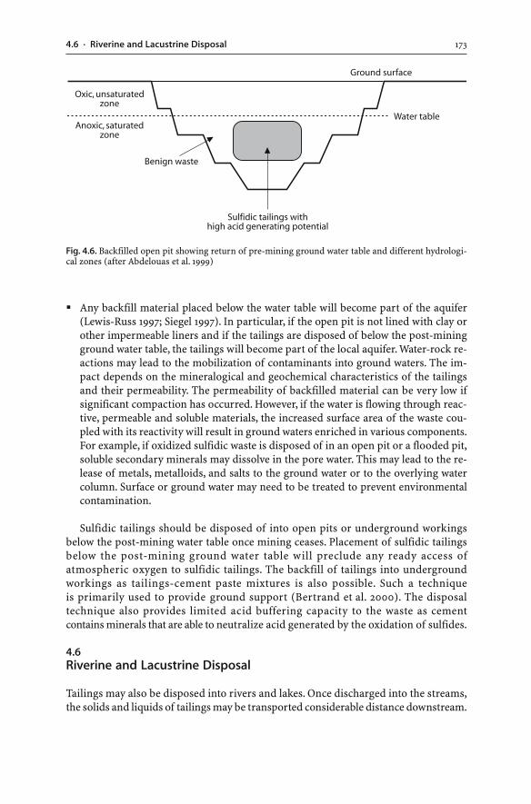
1734.6 · Riverine and Lacustrine Disposal
� Any backfill material placed below the water table will become part of the aquifer(Lewis-Russ 1997; Siegel 1997). In particular, if the open pit is not lined with clay orother impermeable liners and if the tailings are disposed of below the post-miningground water table, the tailings will become part of the local aquifer. Water-rock re-actions may lead to the mobilization of contaminants into ground waters. The im-pact depends on the mineralogical and geochemical characteristics of the tailingsand their permeability. The permeability of backfilled material can be very low ifsignificant compaction has occurred. However, if the water is flowing through reac-tive, permeable and soluble materials, the increased surface area of the waste cou-pled with its reactivity will result in ground waters enriched in various components.For example, if oxidized sulfidic waste is disposed of in an open pit or a flooded pit,soluble secondary minerals may dissolve in the pore water. This may lead to the re-lease of metals, metalloids, and salts to the ground water or to the overlying watercolumn. Surface or ground water may need to be treated to prevent environmentalcontamination.
Sulfidic tailings should be disposed of into open pits or underground workingsbelow the post-mining water table once mining ceases. Placement of sulfidic tailingsbelow the post-mining ground water table will preclude any ready access ofatmospheric oxygen to sulfidic tailings. The backfill of tailings into undergroundworkings as tailings-cement paste mixtures is also possible. Such a techniqueis primarily used to provide ground support (Bertrand et al. 2000). The disposaltechnique also provides limited acid buffering capacity to the waste as cementcontains minerals that are able to neutralize acid generated by the oxidation of sulfides.
4.6Riverine and Lacustrine Disposal
Tailings may also be disposed into rivers and lakes. Once discharged into the streams,the solids and liquids of tailings may be transported considerable distance downstream.
Fig. 4.6. Backfilled open pit showing return of pre-mining ground water table and different hydrologi-cal zones (after Abdelouas et al. 1999)
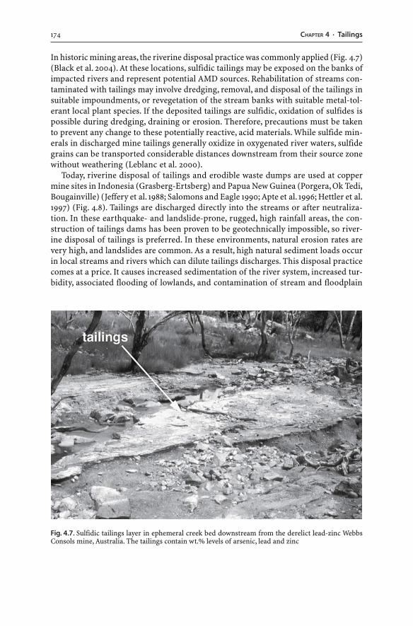
174 CHAPTER 4 · Tailings
In historic mining areas, the riverine disposal practice was commonly applied (Fig. 4.7)(Black et al. 2004). At these locations, sulfidic tailings may be exposed on the banks ofimpacted rivers and represent potential AMD sources. Rehabilitation of streams con-taminated with tailings may involve dredging, removal, and disposal of the tailings insuitable impoundments, or revegetation of the stream banks with suitable metal-tol-erant local plant species. If the deposited tailings are sulfidic, oxidation of sulfides ispossible during dredging, draining or erosion. Therefore, precautions must be takento prevent any change to these potentially reactive, acid materials. While sulfide min-erals in discharged mine tailings generally oxidize in oxygenated river waters, sulfidegrains can be transported considerable distances downstream from their source zonewithout weathering (Leblanc et al. 2000).
Today, riverine disposal of tailings and erodible waste dumps are used at coppermine sites in Indonesia (Grasberg-Ertsberg) and Papua New Guinea (Porgera, Ok Tedi,Bougainville) (Jeffery et al. 1988; Salomons and Eagle 1990; Apte et al. 1996; Hettler et al.1997) (Fig. 4.8). Tailings are discharged directly into the streams or after neutraliza-tion. In these earthquake- and landslide-prone, rugged, high rainfall areas, the con-struction of tailings dams has been proven to be geotechnically impossible, so river-ine disposal of tailings is preferred. In these environments, natural erosion rates arevery high, and landslides are common. As a result, high natural sediment loads occurin local streams and rivers which can dilute tailings discharges. This disposal practicecomes at a price. It causes increased sedimentation of the river system, increased tur-bidity, associated flooding of lowlands, and contamination of stream and floodplain
Fig. 4.7. Sulfidic tailings layer in ephemeral creek bed downstream from the derelict lead-zinc WebbsConsols mine, Australia. The tailings contain wt.% levels of arsenic, lead and zinc
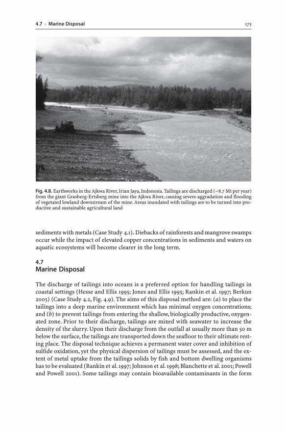
1754.7 · Marine Disposal
sediments with metals (Case Study 4.1). Diebacks of rainforests and mangrove swampsoccur while the impact of elevated copper concentrations in sediments and waters onaquatic ecosystems will become clearer in the long term.
4.7Marine Disposal
The discharge of tailings into oceans is a preferred option for handling tailings incoastal settings (Hesse and Ellis 1995; Jones and Ellis 1995; Rankin et al. 1997; Berkun2005) (Case Study 4.2, Fig. 4.9). The aims of this disposal method are: (a) to place thetailings into a deep marine environment which has minimal oxygen concentrations;and (b) to prevent tailings from entering the shallow, biologically productive, oxygen-ated zone. Prior to their discharge, tailings are mixed with seawater to increase thedensity of the slurry. Upon their discharge from the outfall at usually more than 50 mbelow the surface, the tailings are transported down the seafloor to their ultimate rest-ing place. The disposal technique achieves a permanent water cover and inhibition ofsulfide oxidation, yet the physical dispersion of tailings must be assessed, and the ex-tent of metal uptake from the tailings solids by fish and bottom dwelling organismshas to be evaluated (Rankin et al. 1997; Johnson et al. 1998; Blanchette et al. 2001; Powelland Powell 2001). Some tailings may contain bioavailable contaminants in the form
Fig. 4.8. Earthworks in the Ajkwa River, Irian Jaya, Indonesia. Tailings are discharged (~8.7 Mt per year)from the giant Grasberg-Ertsberg mine into the Ajkwa River, causing severe aggradation and floodingof vegetated lowland downstream of the mine. Areas inundated with tailings are to be turned into pro-ductive and sustainable agricultural land
176 CHAPTER 4 · Tailings
of soluble metal hydroxides and sulfates. In addition, the mobility and bioavailabilityof metals and metalloids may increase once the tailings have been injected into thesea (Blanchette et al. 2001). Therefore, the submarine tailings discharge method re-quires waste characterization as well as modeling and monitoring of the disposal site.
1774.7 · Marine Disposal
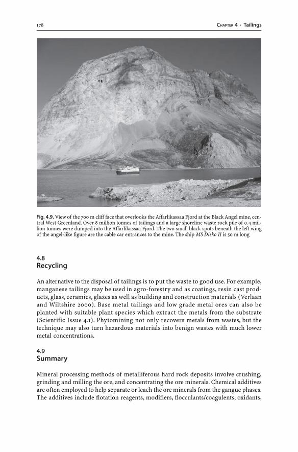
178 CHAPTER 4 · Tailings
4.8Recycling
An alternative to the disposal of tailings is to put the waste to good use. For example,manganese tailings may be used in agro-forestry and as coatings, resin cast prod-ucts, glass, ceramics, glazes as well as building and construction materials (Verlaanand Wiltshire 2000). Base metal tailings and low grade metal ores can also beplanted with suitable plant species which extract the metals from the substrate(Scientific Issue 4.1). Phytomining not only recovers metals from wastes, but thetechnique may also turn hazardous materials into benign wastes with much lowermetal concentrations.
4.9Summary
Mineral processing methods of metalliferous hard rock deposits involve crushing,grinding and milling the ore, and concentrating the ore minerals. Chemical additivesare often employed to help separate or leach the ore minerals from the gangue phases.The additives include flotation reagents, modifiers, flocculants/coagulents, oxidants,
Fig. 4.9. View of the 700 m cliff face that overlooks the Affarlikassaa Fjord at the Black Angel mine, cen-tral West Greenland. Over 8 million tonnes of tailings and a large shoreline waste rock pile of 0.4 mil-lion tonnes were dumped into the Affarlikassaa Fjord. The two small black spots beneath the left wingof the angel-like figure are the cable car entrances to the mine. The ship MS Disko II is 50 m long
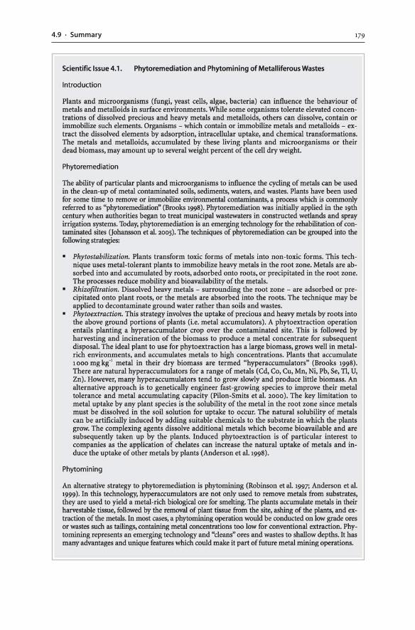
1794.9 · Summary
180 CHAPTER 4 · Tailings
and hydrometallurgical agents. The desired fraction containing the ore minerals isrecovered, and other materials are disposed of as wastes. Such wastes are referred toas tailings. Tailings consist of solids and liquids. The liquids contain process chemi-cals which influence the chemical behaviour and mobility of elements within the wasterepository.
The pH of tailings waters is influenced by the applied processing technique. Anysulfuric acid added as process chemical or generated by sulfide oxidation will leachore and gangue minerals. In extreme cases, the applied processing techniques maycreate highly acid or alkaline tailings with high concentrations of dissolved and solublesalts, metals and metalloids.
Tailings contain minerals similar to those of waste rocks from the same deposit,only in much smaller grain size. Primary minerals are the ore and gangue minerals ofthe original ore. Secondary minerals crystallize during weathering of the ore. Tertiaryand quaternary minerals form before, during, and after the deposition of the tailingsin their impoundment as a result of chemical reactions. Evaporation of tailings watercommonly leads to the formation of mineral salts such as gypsum at and below thetailings surface.
The accumulation of sulfide-rich tailings sediments may occur in an impoundment,and subsequent sulfide oxidation and AMD generation may be possible. In particular,if sulfidic tailings are present within the unsaturated zone of an inactive impound-ment, sulfide oxidation will occur. However, tailings remain water saturated duringoperation and are deposited as fine-grained sediments that have a relatively low per-meability. Consequently, tailings often generate AMD more slowly than coarser, yetmore permeable waste rocks from the same deposit.
Disposal of tailings commonly occurs into engineered tailings dams. Tailings damsare constructed like conventional water storage type dams whereby the tailings arepumped as a water-rich slurry into the impoundment. The safety record of tailingsdams is poor. On average, there has been one major tailings dam failure or spillageevery year in the last thirty years. Tailings dam failures are due to liquefaction, rapidrise in dam wall height, foundation failure, excessive water levels, or excessive seep-age. Tailings dam failures and spillages have caused environmental impacts on eco-systems, loss of life, and damage to property. Other concerns with tailings dams in-clude air pollution through dust generation, release of radiation from tailings, andseepage from the tailings through the embankment into ground and surface waters.Monitoring of tailings dams is essential and includes investigations on dam perfor-mance, impoundment stability, and environmental impacts. Dry capping techniquesof tailings are highly variable and site-specific, and consist of single layer and multi-layered designs using compacted and uncompacted materials.
Tailings disposal, using the thickened discharge or paste technology, results in acone or stack of dried tailings. The methods are based on the discharge of dewateredtailings into the impoundment. Containment of tailings in open pits and undergroundworkings is also possible; nonetheless, consolidation of the wastes may take consider-able periods of time. If the tailings are placed below the post-mining ground watertable, the restricted access of atmospheric oxygen will restrict any sulfide oxidation.An interaction of the tailings with ground water occurs if permeable, reactive, solubletailings materials are present.
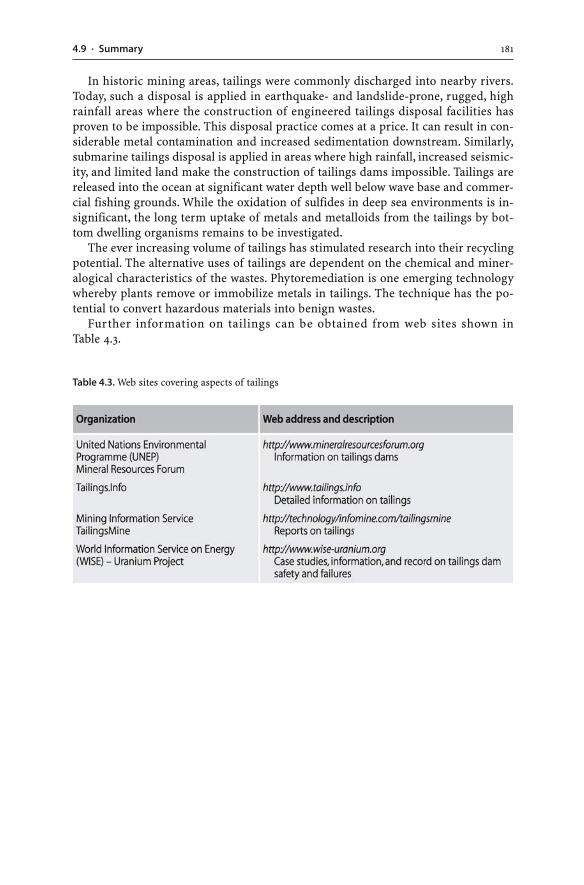
1814.9 · Summary
In historic mining areas, tailings were commonly discharged into nearby rivers.Today, such a disposal is applied in earthquake- and landslide-prone, rugged, highrainfall areas where the construction of engineered tailings disposal facilities hasproven to be impossible. This disposal practice comes at a price. It can result in con-siderable metal contamination and increased sedimentation downstream. Similarly,submarine tailings disposal is applied in areas where high rainfall, increased seismic-ity, and limited land make the construction of tailings dams impossible. Tailings arereleased into the ocean at significant water depth well below wave base and commer-cial fishing grounds. While the oxidation of sulfides in deep sea environments is in-significant, the long term uptake of metals and metalloids from the tailings by bot-tom dwelling organisms remains to be investigated.
The ever increasing volume of tailings has stimulated research into their recyclingpotential. The alternative uses of tailings are dependent on the chemical and miner-alogical characteristics of the wastes. Phytoremediation is one emerging technologywhereby plants remove or immobilize metals in tailings. The technique has the po-tential to convert hazardous materials into benign wastes.
Further information on tailings can be obtained from web sites shown inTable 4.3.
Table 4.3. Web sites covering aspects of tailings
Chapter 5
Cyanidation Wastes of Gold-Silver Ores
5.1Introduction
Cyanide is a general term which refers to a group of chemicals whereby carbon andnitrogen combine to form compounds (CN–). Cyanide leaching is currently the domi-nant process used by the minerals industry to extract gold (and silver) from geologi-cal ores. Gold extraction is accomplished through the selective dissolution of the goldby cyanide solutions, that is, the so-called “process of cyanidation”. This hydrometal-lurgical technique is so efficient that the mining of low-grade precious metal ores hasbecome profitable, and modern gold mining operations extract a few grams of goldfrom a tonne of rock. As a result, exceptionally large quantities of cyanide-bearingwastes are produced for a very small quantity of gold. The wastes of the cyanidationprocess are referred to as cyanidation wastes. At modern gold mining operations,cyanidation wastes occur in the form of heap leach residues, tailings, and spent pro-cess waters. While the bulk of the cyanide used in the mining industry is applied togold ores, cyanide is also added as a modifier in the flotation of base metal sulfide oresin order to separate base metal sulfides from pyrite. Therefore, some process circuitsof base metal ores may generate cyanide-bearing tailings and spent process waters.
This chapter documents the fundamental characteristics of cyanidation wastes.Since an understanding of such wastes requires a knowledge of the chemistry of cya-nide, the chemistry of cyanide is introduced prior to an overview on the use of cya-nide in precious metal extraction. This is followed by a documentation of cyanidationwastes and the monitoring and analysis of cyanide. The release of cyanide to the en-vironment can cause contamination of surface waters, and cyanide can be toxic tohumans and animals. The chapter concludes with the different treatment strategiesused to reduce cyanide levels in mine waters.
5.2Occurrences and Uses of Cyanide
Cyanide occurs naturally. It is found in minute quantities in several foods includingcassava, maize, bamboo, sweet potatoes, sugarcane, peas, and beans, as well as in theseeds and kernels of almond, lemon, lime, apple, pear, cherry, apricot, prune, and plume(Hynes et al. 1998; Logsdon et al. 1999; Mudder and Botz 2001). In addition, cyanide isan important component of vitamin B-12 where it is securely bound and not harmful.There are about 2 650 cyanide producing plant species, and levels of cyanide in cya-nogenic plants can reach hundreds of parts per million (Logsdon et al. 1999; Mudderand Botz 2001). Furthermore, cyanide is produced and used by certain soil bacteria,
184 CHAPTER 5 · Cyanidation Wastes of Gold-Silver Ores
algae, fungi, insects, and arthropods (Logsdon et al. 1999). In nature, the presence ofcyanide in plants and organisms provides protection against predators.
Apart from these natural occurrences of cyanide, there are man-made emissionsof cyanide. Cyanide is released during coal combustion, refining of petroleum, ironand steel production, burning of plastics, incineration of household waste, combus-tion of fossil fuels, and cigarette smoking (Environment Australia 1998). Significantamounts of cyanide may enter surface waters from municipal sewage treatment worksand the dissolution of road salt (Mudder and Botz 2001). Cyanide is also synthesizedand used for numerous industrial processes such as steel hardening and plastics pro-duction. The mining industry consumes only a minor proportion (13%) of the totalworld hydrogen cyanide production (Mudder and Botz 2001). In the mining industry,cyanide is used in hydrometallurgical processes to extract precious metals from geo-logical ores and to separate sulfides in the flotation of base metal sulfide ores. Cya-nide has been chosen for the extraction of gold and silver because: (a) it forms solublecomplexes with gold and silver; and (b) its use is extremely efficient and cost effec-tive. The potential toxicity of cyanide has spurred much research into alternative leach-ing reagents. Ammonia (NH3), thiocyanate (SCN–), thiosulfate (S2O3
2–), and aqua regia(HCl-HNO3) are also able to dissolve gold (McNulty 2001). These alternative leachingagents, however, can be toxic and cause significant environmental harm, so the chemi-cals are not applied in the mining industry.
5.3Cyanide Chemistry
Cyanide chemistry is complex since there are different cyanide compounds presentwithin process waters as well as solid and liquid mine wastes. The different cyanidecompounds have been classified into five general groups: free cyanide; simple cyanidecompounds; weakly complexed cyanide; moderately strong complexed cyanide; andstrongly complexed cyanide (Smith and Mudder 1991, 1999) (Table 5.1). “Weak aciddissociable” or “WAD” cyanide consists of two cyanide forms: (a) cyanide which is al-ready present as free cyanide; and (b) cyanide which is released as free cyanide fromweak and moderately strong complexes when the pH is lowered in a sample to a pH ofapproximately 4.5. The five cyanide groups constitute the “total cyanide” content orthe sum of the different forms of cyanide present (Table 5.1). The term “cyanide” isloosely used in this book to refer to all five cyanide forms.
5.3.1Free Cyanide
The term “free cyanide” refers to two species; the cyanide anion (CN–) dissolved inwater and the hydrogen cyanide or hydrocyanic acid (HCN) formed in solution. Forexample, when solid sodium cyanide (NaCN) dissolves in water, it forms a sodiumcation (Na+) and a cyanide anion (CN–). The cyanide anion then undergoes hydroly-sis and combines with hydrogen ions to form the molecule hydrogen cyanide:
CN–(aq) + H2O(l) ↔ HCN(aq) + OH–
(aq) (5.1)
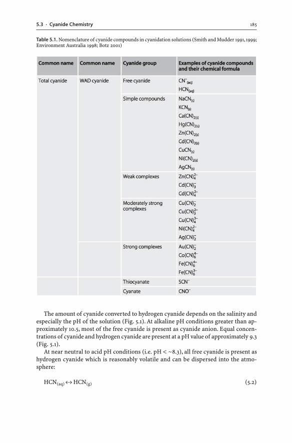
1855.3 · Cyanide Chemistry
The amount of cyanide converted to hydrogen cyanide depends on the salinity andespecially the pH of the solution (Fig. 5.1). At alkaline pH conditions greater than ap-proximately 10.5, most of the free cyanide is present as cyanide anion. Equal concen-trations of cyanide and hydrogen cyanide are present at a pH value of approximately 9.3(Fig. 5.1).
At near neutral to acid pH conditions (i.e. pH < ~8.3), all free cyanide is present ashydrogen cyanide which is reasonably volatile and can be dispersed into the atmo-sphere:
HCN(aq) ↔ HCN(g) (5.2)
Table 5.1. Nomenclature of cyanide compounds in cyanidation solutions (Smith and Mudder 1991, 1999;Environment Australia 1998; Botz 2001)
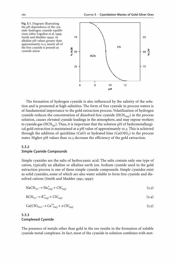
186 CHAPTER 5 · Cyanidation Wastes of Gold-Silver Ores
The formation of hydrogen cyanide is also influenced by the salinity of the solu-tion and is promoted at high salinities. The form of free cyanide in process waters isof fundamental importance to the gold extraction process. Volatilization of hydrogencyanide reduces the concentration of dissolved free cyanide (HCN(aq)) in the processsolution, causes elevated cyanide loadings in the atmosphere, and may expose workersto cyanide gas (HCN(g)). Thus, it is important that the solution pH of hydrometallurgi-cal gold extraction is maintained at a pH value of approximately 10.3. This is achievedthrough the addition of quicklime (CaO) or hydrated lime (Ca(OH)2) to the processwater. Higher pH values than 10.3 decrease the efficiency of the gold extraction.
5.3.2Simple Cyanide Compounds
Simple cyanides are the salts of hydrocyanic acid. The salts contain only one type ofcation, typically an alkaline or alkaline earth ion. Sodium cyanide used in the goldextraction process is one of these simple cyanide compounds. Simple cyanides existas solid cyanides, some of which are also water soluble to form free cyanide and dis-solved cations (Smith and Mudder 1991, 1999):
NaCN(s) → Na+(aq) + CN–
(aq) (5.3)
KCN(s) → K+(aq) + CN–
(aq) (5.4)
Ca(CN)2(s) → Ca2+(aq) + 2 CN–
(aq) (5.5)
5.3.3Complexed Cyanide
The presence of metals other than gold in the ore results in the formation of solublecyanide metal complexes. In fact, most of the cyanide in solution combines with met-
Fig. 5.1. Diagram illustratingthe pH dependence of the cya-nide–hydrogen cyanide equilib-rium (after Logsdon et al. 1999;Smith and Mudder 1999). Atalkaline pH values greater thanapproximately 10.5, nearly all ofthe free cyanide is present ascyanide anion
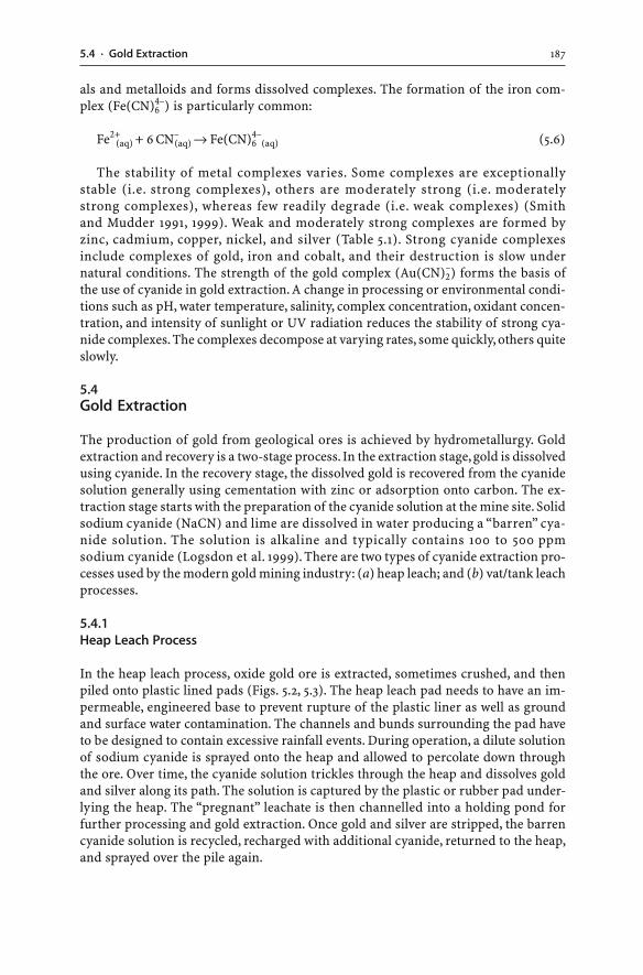
1875.4 · Gold Extraction
als and metalloids and forms dissolved complexes. The formation of the iron com-plex (Fe(CN)6
4–) is particularly common:
Fe2+(aq) + 6 CN–
(aq) → Fe(CN)64–
(aq) (5.6)
The stability of metal complexes varies. Some complexes are exceptionallystable (i.e. strong complexes), others are moderately strong (i.e. moderatelystrong complexes), whereas few readily degrade (i.e. weak complexes) (Smithand Mudder 1991, 1999). Weak and moderately strong complexes are formed byzinc, cadmium, copper, nickel, and silver (Table 5.1). Strong cyanide complexesinclude complexes of gold, iron and cobalt, and their destruction is slow undernatural conditions. The strength of the gold complex (Au(CN)2
–) forms the basis ofthe use of cyanide in gold extraction. A change in processing or environmental condi-tions such as pH, water temperature, salinity, complex concentration, oxidant concen-tration, and intensity of sunlight or UV radiation reduces the stability of strong cya-nide complexes. The complexes decompose at varying rates, some quickly, others quiteslowly.
5.4Gold Extraction
The production of gold from geological ores is achieved by hydrometallurgy. Goldextraction and recovery is a two-stage process. In the extraction stage, gold is dissolvedusing cyanide. In the recovery stage, the dissolved gold is recovered from the cyanidesolution generally using cementation with zinc or adsorption onto carbon. The ex-traction stage starts with the preparation of the cyanide solution at the mine site. Solidsodium cyanide (NaCN) and lime are dissolved in water producing a “barren” cya-nide solution. The solution is alkaline and typically contains 100 to 500 ppmsodium cyanide (Logsdon et al. 1999). There are two types of cyanide extraction pro-cesses used by the modern gold mining industry: (a) heap leach; and (b) vat/tank leachprocesses.
5.4.1Heap Leach Process
In the heap leach process, oxide gold ore is extracted, sometimes crushed, and thenpiled onto plastic lined pads (Figs. 5.2, 5.3). The heap leach pad needs to have an im-permeable, engineered base to prevent rupture of the plastic liner as well as groundand surface water contamination. The channels and bunds surrounding the pad haveto be designed to contain excessive rainfall events. During operation, a dilute solutionof sodium cyanide is sprayed onto the heap and allowed to percolate down throughthe ore. Over time, the cyanide solution trickles through the heap and dissolves goldand silver along its path. The solution is captured by the plastic or rubber pad under-lying the heap. The “pregnant” leachate is then channelled into a holding pond forfurther processing and gold extraction. Once gold and silver are stripped, the barrencyanide solution is recycled, recharged with additional cyanide, returned to the heap,and sprayed over the pile again.
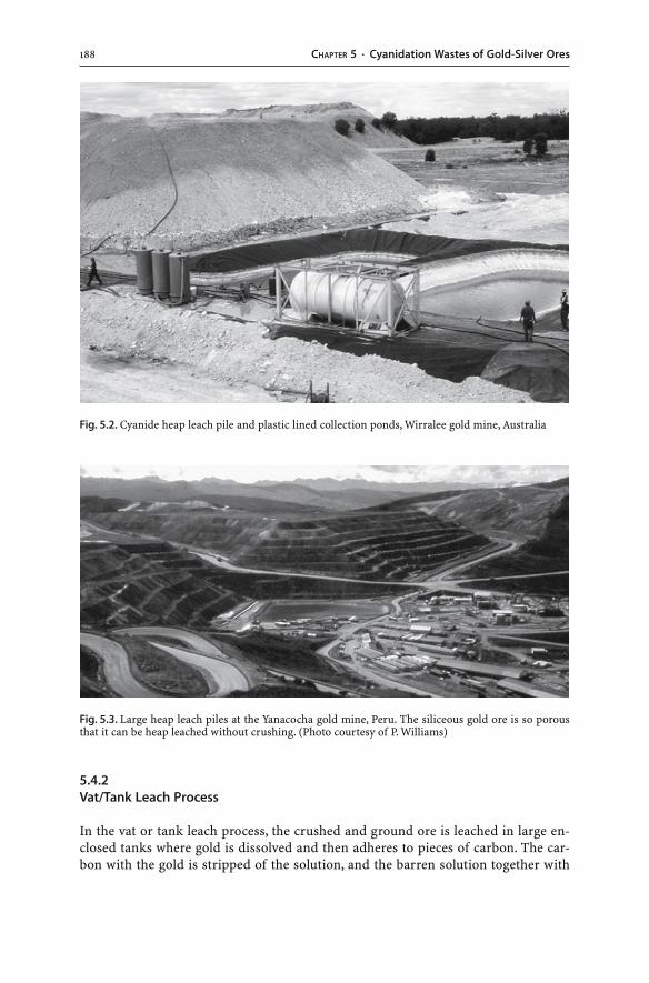
188 CHAPTER 5 · Cyanidation Wastes of Gold-Silver Ores
Fig. 5.2. Cyanide heap leach pile and plastic lined collection ponds, Wirralee gold mine, Australia
Fig. 5.3. Large heap leach piles at the Yanacocha gold mine, Peru. The siliceous gold ore is so porousthat it can be heap leached without crushing. (Photo courtesy of P. Williams)
5.4.2Vat/Tank Leach Process
In the vat or tank leach process, the crushed and ground ore is leached in large en-closed tanks where gold is dissolved and then adheres to pieces of carbon. The car-bon with the gold is stripped of the solution, and the barren solution together with
1895.5 · Hydrometallurgical Wastes
the leached ore is disposed of. Both the heap and the vat/tank leaching processes usethe ability of cyanide to form highly soluble gold complexes. The other necessary com-ponents are oxygen and water. The cyanide dissolves gold according to the followingreaction:
4 Au(s) + 8 NaCN(aq) + O2(g) + 2 H2O(l) → 4 NaAu(CN)2(aq) + 4 NaOH(aq) (5.7)
The equation highlights the fact that free cyanide is needed for the dissolution of goldand that the pH has to be maintained at alkaline levels of approximately 10.3. The re-action with silver is analogous to Reaction 5.7.
Gold ores commonly not only have elevated silver but also elevated metal and met-alloid concentrations which exceed the gold content by several orders of magnitude.The cyanide anion not only dissolves gold and silver, it may also dissolve other metalsand metalloids (e.g. As, Cd, Co, Cu, Fe, Hg, Mo, Ni, Pb, Zn). The dissolution of thesemetals and metalloids depends on how these elements are present within the ore. Incompletely weathered and oxidized ores, metals are present as secondary minerals;most of the metal-bearing minerals and the metals themselves are insoluble in thealkaline process waters. Process waters of the oxidized ores will have low metal con-centrations, yet arsenic and antimony can be present in strongly elevated concentra-tions in cyanide process waters as these metalloids are soluble at alkaline pH condi-tions. Hence, the extraction of gold from oxidized ores is extremely efficient becausethe process waters do not react with other metals. All of the cyanide is used to formfree cyanide as well as gold and silver cyanide complexes. In contrast, the treatmentof sulfide-rich gold ores may lead to sulfide oxidation, acid generation, and a reduc-tion in solution pH. In addition, the sulfide minerals will react with the cyanide pro-cess waters, and soluble thiocyanate (SCN–) and metal cyanide complexes are formed.The sulfide content of some gold ores can be so high that these ores require roastingprior to cyanide leaching. Consequently, the dissolution of sulfide minerals in cyanidesolutions leads to: (a) higher cyanide consumption rates during mineral processing;and (b) a solution containing a range of cyanide species and complexes as well as sig-nificant metal and metalloid concentrations.
5.5Hydrometallurgical Wastes
Precious metal mining and the hydrometallurgical recovery of gold and silver not onlyresult in the production of gold and silver bars, but also in the generation of wasterock dumps, spent process waters, heap leach piles, and tailings. Spent process waters,heap leach residues, and tailings are cyanidation wastes:
� Process water. Once the ore has been leached with cyanide and gold has been recov-ered from the pregnant solution, the process water contains aqueous free cyanide(HCN, CN–), cyanide metal complexes, cyanates (CNO–), thiocyanates (SCN–), andnumerous other dissolved and colloidal chemical species. Much of this barren proc-ess water is recovered and recycled. However, a solution containing excessive amountsof thiocyanates and metal cyanide complexes is discarded from the process circuitbecause the extraction capacity of such process water is exhausted. Thus, a portion
190 CHAPTER 5 · Cyanidation Wastes of Gold-Silver Ores
of the barren solution has to be discharged. The water may be treated to reduce cya-nide levels. It is then pumped to tailings impoundments and ponds, or it is dischargedinto rivers and oceans.
� Heap leach residues. Cyanide heap leach operations result in piles of spent ore afteroperations have ceased. Sulfide oxidation and AMD generation are not commonlyfound in heap leach piles because gold ores containing major amounts of sulfidesare usually not amenable to cyanide leaching. If sulfidic ores are leached, the proc-ess is conducted with a high pH solution (pH 10.3), which introduces a significantneutralizing factor. The leached ore may contain carbonate minerals and therefore,the piles may be strongly alkaline once heap leaching has ceased. A strong alkalinitydoes not allow direct planting of vegetation on the wastes. Alkaline substrates arecharacterized by reduced nutrient availability because many elements are poorlysoluble at high pH and deficiencies of trace elements such as copper, manganese,iron and zinc may occur. Many plants will not be able to tolerate the alkaline pH valuesgreater than 8.5. In addition, the high sodium content of such wastes due to the ap-plication of sodium cyanide will have adverse impacts on the soil structure sincethe sodium will promote the dispersion of clay particles (i.e. sodicity). These stronglyalkaline cyanidation wastes not only require attenuation of cyanide but also pH re-duction to appropriate levels, using native sulfur as a soil amendment. Alternatively,the wastes may need to be capped with benign materials.
� Tailings. Cyanide leached ore accumulates from the vat/tank leaching process. Theleached ore may be pumped as a slurry to a tailings impoundment, which commonlyis a tailings dam. In the waste repository, the pores of the tailings are filled with dilutecyanide solutions, and part of the solution will be collected in a decant pond on topof the tailings. This decanted tailings water is recycled to the processing plant to ex-tract more gold. Alternatively, the leached ore is used as backfill in mined-out open pitand underground workings, or it is dumped into rivers and oceans (Jones and Ellis 1995).
5.6Cyanide Analysis and Monitoring
Cyanide analysis is performed on liquid and solid sample types. For cyanide moni-toring, water samples need to be obtained from background areas, waste dischargepoints, process water ponds, tailings dams, heap leach pads, seepage points, and satu-rated and unsaturated ground water zones (Environment Australia 1998). Solid sampletypes include heap leach residues and tailings. Samples should be refrigerated, andcyanide determinations should be conducted immediately after sampling. Details onsampling, sample preservation, sample treatment, measurement, and analytical meth-ods are found in Environment Australia (1998) and Smith and Mudder (1991, 1999).
Free cyanide is considered the most toxic cyanide form as it causes toxicity at rela-tively low cyanide concentrations. Higher concentrations of other cyanide species areneeded to induce toxicity. For example, hydrogen cyanate and cyanate ions are lesstoxic than hydrogen cyanide, and thiocyanate is relatively non-toxic compared to freecyanide. The toxicity of the different cyanide complexes is influenced by their stabil-ity. The more stable the complex, the less toxic it is, especially to aquatic life. WAD cya-nide is considered to be an appropriate measure for assessing potential toxicity of acyanide-bearing solution to humans and animals.
1915.7 · Environmental Impacts
The concentrations of free cyanide in pore and seepage waters of sulfidic heap leachpiles and tailings may increase over time due to decreasing pH conditions. Such in-creases in free cyanide concentrations are due to the destruction of stable cyanide com-plexes. For instance, cyanide complexes like the ubiquitous iron complex (Fe(CN)6
4–)may become unstable under decreasing pH conditions. Sulfide oxidation and AMDgeneration could result in the dissociation of the iron complex and the release of cya-nide and iron. As a consequence, once acid conditions develop in heap leach piles ortailings dams, increasing free cyanide levels may be generated.
Cyanide analysis should involve the characterization of all cyanide species presentincluding total cyanide, free cyanide, WAD cyanide, strong metal cyanide complexes,cyanate, and thiocyanate. Analysis for only WAD cyanide or only total cyanide is in-appropriate as it will not provide important information on the abundance of indi-vidual cyanide forms. Alternatively, the analysis of both WAD cyanide and total cya-nide provides limited but useful information. Subtraction of the WAD cyanide valuefrom the total cyanide value provides a measure of the essentially non-toxic and stablecomplexed cyanide forms (Mudder and Botz 2001). In addition, water samples needto be characterized for their pH, heavy metal concentrations, and contents of the vari-ous nitrogen species (i.e. total nitrogen N, nitrite NO2
–, nitrate NO3–, ammonia NH3).
The nitrogen compounds should be determined as they are the result of cyanide deg-radation reactions (Mudder and Botz 2001). These degradation products can increasethe solubility of metals and are also toxic to organisms at sufficiently high concentra-tions.
5.7Environmental Impacts
The use of cyanide is well established in the mining industry, yet it remains contro-versial to some. Much of this concern relates to the much publicized use of cyanide ingenocidal crimes, suicides, murders, and judicial executions. On the other hand, hu-man cyanide poisoning from a natural source is less publicized and involves the in-gestion of cyanogenic plants, in particular the consumption of cassava in developingnations. Several thousand cases of natural cyanide poisoning have been documentedwhereas the overall safety record of the mining industry has been exemplary (Mudderand Botz 2001). The concern about cyanide has been so significant that new miningoperations using cyanide heap leach extraction methods have been banned in certainparts of the world (e.g. Montana). The bans have occurred in spite of the natural oc-currence of cyanide, the chronic exposure of humans to cyanide from sources otherthan mining, and numerous cases of natural cyanide poisoning. The controversy hasalso been fuelled by cyanide spillages, transportation accidents, bursting of pipes con-taining cyanide solutions, overtopping of dams, and tailings dam failures (CaseStudy 5.1, Table 5.2).
If released at sufficiently high concentrations, cyanide can pollute surface waters.It is a potentially toxic substance and can be lethal if sufficient amounts are taken upby fish, animals, and humans (Table 5.2). Cyanide is not toxic to plants, and a majorcyanide spill in the Kyrgyz Republic had no impact on plant life (Table 5.2) (Hyneset al. 1998). The non-toxic effects on plants are probably due to the fact that soils tightlyadsorb cyanide. Arid and semi-arid conditions and an abundance of clay may lead to
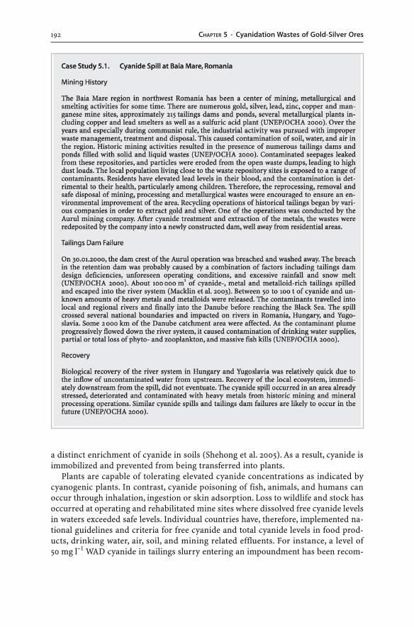
192 CHAPTER 5 · Cyanidation Wastes of Gold-Silver Ores
a distinct enrichment of cyanide in soils (Shehong et al. 2005). As a result, cyanide isimmobilized and prevented from being transferred into plants.
Plants are capable of tolerating elevated cyanide concentrations as indicated bycyanogenic plants. In contrast, cyanide poisoning of fish, animals, and humans canoccur through inhalation, ingestion or skin adsorption. Loss to wildlife and stock hasoccurred at operating and rehabilitated mine sites where dissolved free cyanide levelsin waters exceeded safe levels. Individual countries have, therefore, implemented na-tional guidelines and criteria for free cyanide and total cyanide levels in food prod-ucts, drinking water, air, soil, and mining related effluents. For instance, a level of50 mg l–1 WAD cyanide in tailings slurry entering an impoundment has been recom-
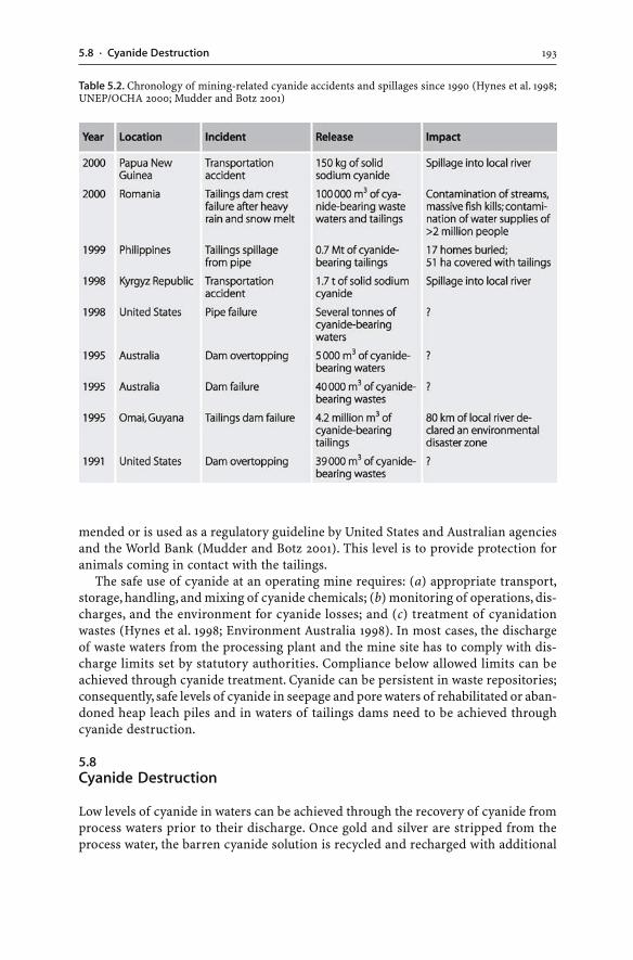
1935.8 · Cyanide Destruction
mended or is used as a regulatory guideline by United States and Australian agenciesand the World Bank (Mudder and Botz 2001). This level is to provide protection foranimals coming in contact with the tailings.
The safe use of cyanide at an operating mine requires: (a) appropriate transport,storage, handling, and mixing of cyanide chemicals; (b) monitoring of operations, dis-charges, and the environment for cyanide losses; and (c) treatment of cyanidationwastes (Hynes et al. 1998; Environment Australia 1998). In most cases, the dischargeof waste waters from the processing plant and the mine site has to comply with dis-charge limits set by statutory authorities. Compliance below allowed limits can beachieved through cyanide treatment. Cyanide can be persistent in waste repositories;consequently, safe levels of cyanide in seepage and pore waters of rehabilitated or aban-doned heap leach piles and in waters of tailings dams need to be achieved throughcyanide destruction.
5.8Cyanide Destruction
Low levels of cyanide in waters can be achieved through the recovery of cyanide fromprocess waters prior to their discharge. Once gold and silver are stripped from theprocess water, the barren cyanide solution is recycled and recharged with additional
Table 5.2. Chronology of mining-related cyanide accidents and spillages since 1990 (Hynes et al. 1998;UNEP/OCHA 2000; Mudder and Botz 2001)
194 CHAPTER 5 · Cyanidation Wastes of Gold-Silver Ores
cyanide. This recovery based process aims to remove cyanide from solution and toreuse it in the metallurgical circuit (Botz 2001).
Low levels of cyanide in waters can also be achieved by converting cyanide into lesstoxic compounds. A large number of processes exist for the destruction of cyanide inwastes (Environment Australia 1998). The degradation of cyanide takes time, and therates of destruction of the different cyanide species are affected by numerous factorsincluding the intensity of light, water temperature, pH, salinity, oxidant concentration,and complex concentration (Smith and Mudder 1991, 1999). Degradation of cyanideoccurs naturally in contaminated soils, process waters, tailings, and heap leach piles.The natural reduction of dissolved cyanide in mine wastes can be sped up by apply-ing enhanced natural or engineered treatment processes.
5.8.1Natural Attenuation
Natural attenuation rates depend on local climatic and environmental conditions andare, therefore, mine site specific. At some mine sites, these natural attenuation pro-cesses are sufficient to achieve cyanide levels which meet regulatory requirements forthe release of cyanide-bearing waters into local drainage systems. Natural attentuationprocesses include: volatilization of hydrogen cyanide gas; precipitation of insolublecyanide compounds; adsorption; degradation by bacteria; oxidation to cyanate; deg-radation of cyanide through UV radiation; and formation of thiocyanate:
� Volatilization. Volatilization of cyanide is the prominent natural attenuation proc-ess. Cyanide is lost from waste waters, tailings, heap leach piles, and contaminatedsoils to the atmosphere as a result of the volatilization of gaseous hydrogen cyanide(HCN(g)) (Reaction 5.2). This can be triggered by adding water with a lower pH tothe cyanide solutions and wastes. Volatilized cyanide will disperse in the atmosphereto background concentrations, or it will undergo chemical and biochemical reac-tions to degrade to ammonium and carbon dioxide (Logsdon et al. 1999).
� Precipitation. The precipitation of complexed cyanide can be achieved through theaddition of a complexing metal. For example, ferrocyanide (Fe(CN)6
4–) andferricyanide (Fe(CN)6
3–) ions are present in solution. If metals (Fe, Cu, Pb, Zn, Ni, Mn,Cd, Sn, Ag) are added to the solution, the ferrocyanide and ferricyanide ions reactwith the dissolved metals to form insoluble metal cyanide solids (Smith and Mudder1991, 1999). The solids precipitate and settle, removing cyanide from solution.
� Adsorption. Free cyanide ions and complexed cyanide can be adsorbed from solu-tion onto mineral surfaces. Clay-rich ores are particularly effective in adsorbing cya-nide. Unless the adsorbed cyanide is oxidized by organic matter, the removal of cya-nide from solution is only temporarily, and the different cyanide forms can bedesorbed from the mineral surfaces back into solution.
� Biological oxidation. Certain bacteria degrade cyanide in order to generate nutri-ents (i.e. carbon and nitrogen) for their growth. The microflora is indigenous tothe waste. The naturally present bacteria (e.g. Pseudomonas) degrade reactivecyanide into harmless products such as dissolved formate (HCOO–), nitrate,ammonia, bicarbonate, and sulfate (Mosher and Figueroa 1996; Oudjehani et al. 2002;
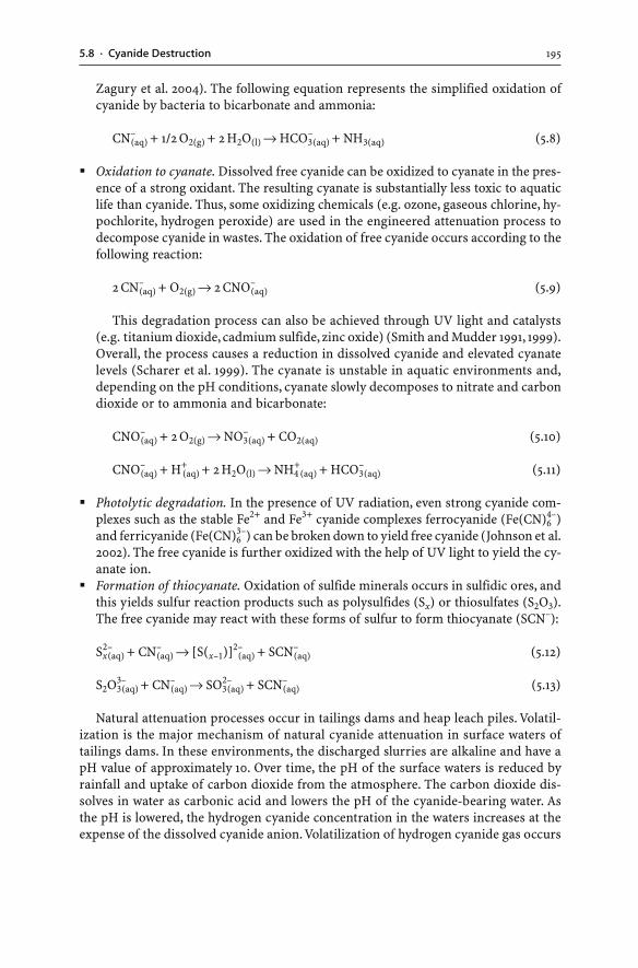
1955.8 · Cyanide Destruction
Zagury et al. 2004). The following equation represents the simplified oxidation ofcyanide by bacteria to bicarbonate and ammonia:
CN–(aq) + 1/2 O2(g) + 2 H2O(l) → HCO3
–(aq) + NH3(aq) (5.8)
� Oxidation to cyanate. Dissolved free cyanide can be oxidized to cyanate in the pres-ence of a strong oxidant. The resulting cyanate is substantially less toxic to aquaticlife than cyanide. Thus, some oxidizing chemicals (e.g. ozone, gaseous chlorine, hy-pochlorite, hydrogen peroxide) are used in the engineered attenuation process todecompose cyanide in wastes. The oxidation of free cyanide occurs according to thefollowing reaction:
2 CN–(aq) + O2(g) → 2 CNO–
(aq) (5.9)
This degradation process can also be achieved through UV light and catalysts(e.g. titanium dioxide, cadmium sulfide, zinc oxide) (Smith and Mudder 1991, 1999).Overall, the process causes a reduction in dissolved cyanide and elevated cyanatelevels (Scharer et al. 1999). The cyanate is unstable in aquatic environments and,depending on the pH conditions, cyanate slowly decomposes to nitrate and carbondioxide or to ammonia and bicarbonate:
CNO–(aq) + 2 O2(g) → NO3
–(aq) + CO2(aq) (5.10)
CNO–(aq) + H+
(aq) + 2 H2O(l) → NH4+
(aq) + HCO3–(aq) (5.11)
� Photolytic degradation. In the presence of UV radiation, even strong cyanide com-plexes such as the stable Fe2+ and Fe3+ cyanide complexes ferrocyanide (Fe(CN)6
4–)and ferricyanide (Fe(CN)6
3–) can be broken down to yield free cyanide (Johnson et al.2002). The free cyanide is further oxidized with the help of UV light to yield the cy-anate ion.
� Formation of thiocyanate. Oxidation of sulfide minerals occurs in sulfidic ores, andthis yields sulfur reaction products such as polysulfides (Sx) or thiosulfates (S2O3).The free cyanide may react with these forms of sulfur to form thiocyanate (SCN–):
Sx2–(aq) + CN–
(aq) → [S(x–1)]2–(aq) + SCN–
(aq) (5.12)
S2O33–(aq) + CN–
(aq) → SO32–(aq) + SCN–
(aq) (5.13)
Natural attenuation processes occur in tailings dams and heap leach piles. Volatil-ization is the major mechanism of natural cyanide attenuation in surface waters oftailings dams. In these environments, the discharged slurries are alkaline and have apH value of approximately 10. Over time, the pH of the surface waters is reduced byrainfall and uptake of carbon dioxide from the atmosphere. The carbon dioxide dis-solves in water as carbonic acid and lowers the pH of the cyanide-bearing water. Asthe pH is lowered, the hydrogen cyanide concentration in the waters increases at theexpense of the dissolved cyanide anion. Volatilization of hydrogen cyanide gas occurs
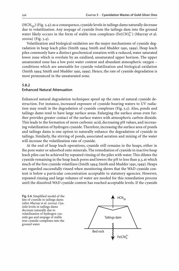
196 CHAPTER 5 · Cyanidation Wastes of Gold-Silver Ores
(HCN(g)) (Fig. 5.4); as a consequence, cyanide levels in tailings dams naturally decreasedue to volatilization. Any seepage of cyanide from the tailings dam into the groundwater likely occurs in the form of stable iron complexes (Fe(CN)6
4–) (Murray et al.2000a) (Fig. 5.4).
Volatilization and biological oxidation are the major mechanisms of cyanide deg-radation in heap leach piles (Smith 1994; Smith and Mudder 1991, 1999). Heap leachpiles commonly have a distinct geochemical zonation with a reduced, water saturatedlower zone which is overlain by an oxidized, unsaturated upper horizon. The upperunsaturated zone has a low pore water content and abundant atmospheric oxygen –conditions which are amenable for cyanide volatilization and biological oxidation(Smith 1994; Smith and Mudder 1991, 1999). Hence, the rate of cyanide degradation ismost pronounced in the unsaturated zone.
5.8.2Enhanced Natural Attenuation
Enhanced natural degradation techniques speed up the rates of natural cyanide de-struction. For instance, increased exposure of cyanide-bearing waters to UV radia-tion may result in the degradation of cyanide complexes (Fig. 5.5). Also, ponds andtailings dams tend to have large surface areas. Enlarging the surface areas even fur-ther provides greater contact of the surface waters with atmospheric carbon dioxide.This leads to the formation of more carbonic acid, decreasing pH values, and increas-ing volatilization of hydrogen cyanide. Therefore, increasing the surface area of pondsand tailings dams is one option to naturally enhance the degradation of cyanide intailings. Similarly, the stirring of ponds, associated aeration and mixing of the waterwill increase the volatilization rate of cyanide.
At the end of heap leach operations, cyanide still remains in the heaps, either inthe pore water or adsorbed onto minerals. The remediation of cyanide in inactive heapleach piles can be achieved by repeated rinsing of the piles with water. This dilutes thecyanide remaining in the heap leach pores and lowers the pH to less than 9.3, at whichmuch of the free cyanide volatilizes (Smith 1994; Smith and Mudder 1991, 1999). Heapsare regarded successfully rinsed when monitoring shows that the WAD cyanide con-tent is below a particular concentration acceptable to statutory agencies. However,repeated rinsing and large volumes of water are needed for this remediation processuntil the dissolved WAD cyanide content has reached acceptable levels. If the cyanide
Fig. 5.4. Simplified model of thefate of cyanide in tailings dams(after Murray et al. 2000a). Cya-nide levels in tailings damsdecrease naturally due tovolatilization of hydrogen cya-nide gas and seepage of stableiron cyanide complexes into theground water
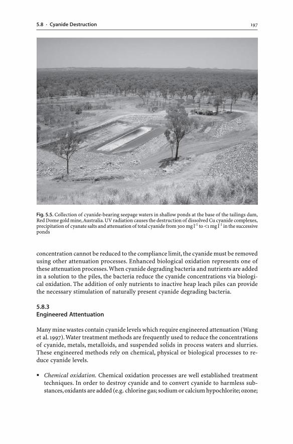
1975.8 · Cyanide Destruction
concentration cannot be reduced to the compliance limit, the cyanide must be removedusing other attenuation processes. Enhanced biological oxidation represents one ofthese attenuation processes. When cyanide degrading bacteria and nutrients are addedin a solution to the piles, the bacteria reduce the cyanide concentrations via biologi-cal oxidation. The addition of only nutrients to inactive heap leach piles can providethe necessary stimulation of naturally present cyanide degrading bacteria.
5.8.3Engineered Attentuation
Many mine wastes contain cyanide levels which require engineered attenuation (Wanget al. 1997). Water treatment methods are frequently used to reduce the concentrationsof cyanide, metals, metalloids, and suspended solids in process waters and slurries.These engineered methods rely on chemical, physical or biological processes to re-duce cyanide levels.
� Chemical oxidation. Chemical oxidation processes are well established treatmenttechniques. In order to destroy cyanide and to convert cyanide to harmless sub-stances, oxidants are added (e.g. chlorine gas; sodium or calcium hypochlorite; ozone;
Fig. 5.5. Collection of cyanide-bearing seepage waters in shallow ponds at the base of the tailings dam,Red Dome gold mine, Australia. UV radiation causes the destruction of dissolved Cu cyanide complexes,precipitation of cyanate salts and attenuation of total cyanide from 300 mg l-1 to <1 mg l-1 in the successiveponds
198 CHAPTER 5 · Cyanidation Wastes of Gold-Silver Ores
hydrogen peroxide; sulfuric acid + hydrogen peroxide = H2SO5, i.e. Caro’s acid orperoxymonosulfuric acid; sulfur dioxide + air = SO2-INCO process; activated car-bon). The reaction products include cyanate, carbon dioxide, bicarbonate, nitrogen,nitrate, ammonia, and sulfate. The hypochlorite ion (OCl–) oxidizes, for instance,cyanide to cyanate:
OCl–(aq) + CN–(aq) → CNO–
(aq) + Cl–(aq) (5.14)
� Physical precipitation. The precipitation process uses the addition of iron whichcauses the precipitation of insoluble metal cyanides. Metals can also be precipitatedas solid metal hydroxides and carbonates through the addition of ferric chloride orsulfate and lime. The iron reagent causes coagulation of suspended solids, and ad-sorption of metals onto coagulated solids occurs. Many gold deposits, especiallyepithermal gold ores, have elevated mercury contents, and the mercury dissolvesduring cyanidation and reports into the waste products. The addition of sodiumsulfide (Na2S) to the waste stream can force the precipitation of mercury as mer-cury sulfide (i.e. cinnabar). The physical precipitates accumulate as sludges in thetreatment plant. Sludges then require disposal in suitable waste repositories such astailings storage facilities.
� Biological oxidation. In most cases, engineered degradation of cyanide relies onchemical oxidation or physical precipitation processes. Both processes result in areduction of dissolved cyanide. Increasingly, biological methods are used to treatcyanide wastes (Botz 2001). The natural capability of microorganisms to decomposecyanide is used on spent heap leach piles and in artificial bioreactor tanks andwetlands (Gessner et al. 2005). Bacteria, however, require the correct nutrient bal-ance for their growth, and nutrients may have to be added to facilitate biologicaloxidation. Both passive and active biological treatment methods remove dissolvedcyanide from solution using either aerobic or anaerobic microorganisms (Mosherand Figueroa 1996; Fischer et al. 1996; Botz 2001).
5.9Summary
Cyanide, a compound made up of carbon and nitrogen, is ubiquitous in nature. It isnaturally produced by plants and lower organisms. It is also released into the atmo-sphere during resource processing, manufacturing and consumption. Furthermore,cyanide is synthesized for numerous industrial applications including the extractionof gold, silver and base metals from geological ores.
Cyanide combines with hydrogen to form hydrogen cyanide and with metals andmetalloids to form complexes. The total cyanide content of a process water consists offive different cyanide forms: free cyanide (i.e. cyanide anion + hydrogen cyanide);simple cyanide compounds; weak complexes; moderately strong complexes; and strongcomplexes. Free cyanide plus weak cyanide and moderately strong complexes aretermed “weak acid dissociable” or “WAD” cyanide. In addition, process waters con-tain dissolved thiocyanate (SCN–) and cyanate (CNO–) species. These different cya-nide compounds and derivatives vary in their stability and toxicity. Iron cyanide com-plexes are very stable and essentially non-toxic whereas WAD cyanide complexes can
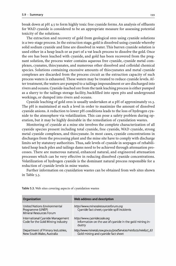
1995.9 · Summary
break down at pH 4.5 to form highly toxic free cyanide forms. An analysis of effluentsfor WAD cyanide is considered to be an appropriate measure for assessing potentialtoxicity of the solutions.
The extraction and recovery of gold from geological ores using cyanide solutionsis a two-stage process. In the extraction stage, gold is dissolved using cyanide wherebysolid sodium cyanide and lime are dissolved in water. This barren cyanide solution isused either in a heap leach or as part of a vat leach process to dissolve the gold. Oncethe ore has been leached with cyanide, and gold has been recovered from the preg-nant solution, the process water contains aqueous free cyanide, cyanide metal com-plexes, cyanates, thiocyanates, and numerous other dissolved and colloidal chemicalspecies. Solutions containing excessive amounts of thiocyanates and metal cyanidecomplexes are discarded from the process circuit as the extraction capacity of suchprocess waters is exhausted. These waters may be treated to reduce cyanide levels. Af-ter treatment, the waters are pumped to a tailings impoundment or are discharged intorivers and oceans. Cyanide-leached ore from the tank leaching process is either pumpedas a slurry to the tailings storage facility, backfilled into open pits and undergroundworkings, or dumped into rivers and oceans.
Cyanide leaching of gold ores is usually undertaken at a pH of approximately 10.3.The pH is maintained at such a level in order to maximize the amount of dissolvedcyanide anions. A reduction to lower pH conditions leads to the loss of hydrogen cya-nide to the atmosphere via volatilization. This can pose a safety problem during op-eration, but it may be highly desirable in the remediation of cyanidation wastes.
Monitoring of cyanide at a mine site involves the complete characterization of allcyanide species present including total cyanide, free cyanide, WAD cyanide, strongmetal cyanide complexes, and thiocyanate. In most cases, cyanide concentrations indischarges from the processing plant and the mine site have to comply with dischargelimits set by statutory authorities. Thus, safe levels of cyanide in seepages of rehabili-tated heap leach piles and tailings dams need to be achieved through attenuation pro-cesses. There are numerous natural, enhanced natural, and engineered attenuationprocesses which can be very effective in reducing dissolved cyanide concentrations.Volatilization of hydrogen cyanide is the dominant natural process responsible for areduction of cyanide levels in mine wastes.
Further information on cyanidation wastes can be obtained from web sites shownin Table 5.3.
Table 5.3. Web sites covering aspects of cyanidation wastes
Chapter 6
Radioactive Wastes of Uranium Ores
6.1Introduction
Uranium ores have the specific issue of radioactivity, and uranium mine wastes areinvariably radioactive. This property differentiates uranium mine wastes from othermine waste types. For example, gold mine tailings contain cyanide, and the cyanidecan be destroyed using natural, naturally enhanced or engineering techniques. Sulfidicwastes have the potential to oxidize, and oxidation of sulfidic wastes can be curtailedusing covers. In contrast, the decay of radioactive isotopes and the associated releaseof radioactivity cannot be destroyed by chemical reactions, physical barriers or so-phisticated engineering methods. Therefore, appropriate disposal and rehabilitation strat-egies of radioactive uranium mine wastes have to ensure that these wastes do not releaseradioactive substances into the environment and cause significant environmental harm.
The fundamental characteristics of uranium mine wastes are given in this chapterwith a particular focus on radioactivity, uranium tailings, and the behaviour of ura-nium in mine waters. Some uranium ores contain abundant sulfides. The presence ofthese minerals in pit faces, underground workings, tailings, and waste rock piles maylead to sulfide oxidation and AMD. The principles of sulfide oxidation and AMD havealready been presented in Chaps. 2 and 3. Sulfidic uranium mine wastes and their acidicwaters may be characterized and treated with the same type of approaches used tocharacterize and treat sulfidic wastes and AMD waters.
6.2Mineralogy and Geochemistry of Uranium
6.2.1Uranium Ores
Uranium ore minerals can be classified as reduced and oxidized species. Reduced ura-nium minerals incorporate uranium as U4+ whereas oxidized species have uraniumas U6+. Uraninite (UO2+x) is the most common reduced U4+ mineral species, and it isthe main ore mineral in many uranium deposits (Burns 1999). Other important ura-nium ore minerals are: brannerite ((U,Ca,Y,Ce)(Ti,Fe)2O6); coffinite (USiO4 · n H2O);and pitchblende (i.e. amorphous or poorly crystalline uranium oxide) (Finch andMurakami 1999). Uranium ore minerals commonly contain minor amounts of thorium,rare earth elements, lead, calcium, and other elements as cation substitutions(Lottermoser 1995). Uranium may also be present as minor substitution in rock-form-ing minerals or in accessory phases such as allanite, xenotime, monazite, zircon, apa-
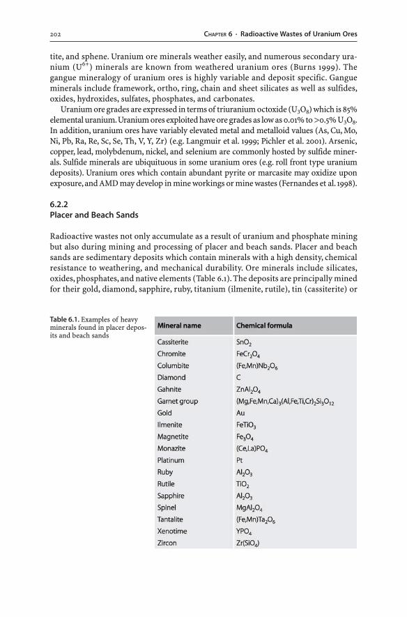
202 CHAPTER 6 · Radioactive Wastes of Uranium Ores
tite, and sphene. Uranium ore minerals weather easily, and numerous secondary ura-nium (U6+) minerals are known from weathered uranium ores (Burns 1999). Thegangue mineralogy of uranium ores is highly variable and deposit specific. Gangueminerals include framework, ortho, ring, chain and sheet silicates as well as sulfides,oxides, hydroxides, sulfates, phosphates, and carbonates.
Uranium ore grades are expressed in terms of triuranium octoxide (U3O8) which is 85%elemental uranium. Uranium ores exploited have ore grades as low as 0.01% to >0.5% U3O8.In addition, uranium ores have variably elevated metal and metalloid values (As, Cu, Mo,Ni, Pb, Ra, Re, Sc, Se, Th, V, Y, Zr) (e.g. Langmuir et al. 1999; Pichler et al. 2001). Arsenic,copper, lead, molybdenum, nickel, and selenium are commonly hosted by sulfide miner-als. Sulfide minerals are ubiquituous in some uranium ores (e.g. roll front type uraniumdeposits). Uranium ores which contain abundant pyrite or marcasite may oxidize uponexposure, and AMD may develop in mine workings or mine wastes (Fernandes et al. 1998).
6.2.2Placer and Beach Sands
Radioactive wastes not only accumulate as a result of uranium and phosphate miningbut also during mining and processing of placer and beach sands. Placer and beachsands are sedimentary deposits which contain minerals with a high density, chemicalresistance to weathering, and mechanical durability. Ore minerals include silicates,oxides, phosphates, and native elements (Table 6.1). The deposits are principally minedfor their gold, diamond, sapphire, ruby, titanium (ilmenite, rutile), tin (cassiterite) or
Table 6.1. Examples of heavyminerals found in placer depos-its and beach sands
2036.3 · Aqueous Chemistry of Uranium
rare earth element (monazite, xenotime) contents. Some deposits may possess elevateduranium and thorium concentrations. In these deposits, the radioactive elements arepresent within chemically and physically stable, weathering resistant gangue miner-als (e.g. monazite, xenotime, zircon, tantalite, columbite). The minerals effectively lockup the uranium and thorium in the crystal lattice and prevent mobilization of theseelements and their radioactive decay products into the environment (Yusof et al. 2001).However, the minerals still emit radiation. Thus, exposure to radiation needs to becontrolled, dust control measures need to be implemented, and appropriate handlingmethods of the radioactive wastes or ores need to be applied.
While the mining and mineral processing of alluvial tin deposits and heavy mineralsands do not result in the mobilization of radioactive elements into the environment, themetallurgical extraction of ore elements from such ores may. For example, the processingof titanium ores obtained from heavy mineral sands is based on sulfuric acid leaching.Acid leaching of titanium ores not only liberates titanium from the crystal lattices of rutileand ilmenite but also releases radionuclides and other metals from gangue phases. Con-sequently, spent process waters of titanium processing plants can exhibit very low pH val-ues and high TDS concentrations (Schuiling and van Gaans 1997a,b).
6.3Aqueous Chemistry of Uranium
Uranium is the typical constituent of surface and ground waters at uranium mine sites.It originates from the leaching of uranium ores as well as from the leaching of solidmining, processing and metallurgical wastes. An understanding of the leaching pro-cesses requires a knowledge of the aqueous chemistry of uranium. The aqueousbehaviour of uranium can be described in terms of oxidative dissolution of uraniumminerals, uranium solubility, and uranium precipitation.
6.3.1Oxidative Dissolution of Uranium Minerals
The most reduced form of uranium (i.e. U4+) is found in uraninite, coffinite, brannerite,and pitchblende. This oxidation state is the least soluble and least mobile form of ura-nium. In contrast, the most oxidized state of uranium (i.e. U6+) is the most soluble andmost mobile (Wanty et al. 1999). As a consequence, if oxygen is available as dissolvedor gaseous species, U4+ can be oxidized to U6+, and uranium dissolves in water as theuranyl oxyanion (UO2
2+). The oxidative dissolution of uranium minerals is achieved pro-gressively through a sequence of chemical reactions (Ragnarsdottir and Charlet 2000).A simplified overall reaction for the oxidative dissolution of uraninite is as follows:
2 UO2(s) + 4 H+(aq) + O2(g) → 2 UO2
2+(aq) + 2 H2O(l) (6.1)
The oxidation of U4+ minerals (i.e. uraninite, coffinite, brannerite, pitchblende) canalso be achieved by the oxidant Fe3+ (Abdelouas et al. 1999). The production of Fe3+ ispossible through the indirect oxidation of iron sulfide minerals within the waste:
4 FeS2(s) + 14 O2(g) + 4 H2O(l) → 4 Fe2+(aq) + 8 H+
(aq) + 8 SO42–(aq) + energy (6.2)
204 CHAPTER 6 · Radioactive Wastes of Uranium Ores
4 Fe2+(aq) + 4 H+
(aq) + O2(g) → 4 Fe3+(aq) + 2 H2O(l) + energy (6.3)
FeS2(s) + 14 Fe3+(aq) + 8 H2O(l) → 15 Fe2+
(aq) + 16 H+(aq) + 2 SO4
2–(aq) + energy (6.4)
In the initial step (Reaction 6.2), pyrite reacts with oxygen and water to producedissolved Fe2+, sulfate and hydrogen ions. The release of hydrogen with the sulfate anionresults in an acidic solution unless other reactions occur to neutralize the hydrogenions. The second step (Reaction 6.3) involves the oxidation of Fe2+ to Fe3+ and occursat a low pH. The Fe3+ turn oxidizes pyrite via Reaction 6.4, which in turn producesmore Fe2+, and so on. The Reactions 6.2, 6.3 and 6.4 represent the indirect oxidationof pyrite (Sec. 2.3.1). However, the Fe3+ produced in Reaction 6.3 may not only oxidizereduced minerals such as pyrite but also reduced U4+ minerals like uraninite:
UO2(s) + 2 Fe3+(aq) → UO2
2+(aq) + 2 Fe2+
(aq) (6.5)
The oxidation of uraninite (Reaction 6.5) generates dissolved uranyl oxyanions andFe2+. This Fe2+ can then be oxidized to Fe3+ via Reaction 6.3, which in turn oxidizesuraninite via Reaction 6.5, which in turn produces more Fe2+, and so on. Reactions 6.3and 6.5 form a continuing cycle of Fe2+ conversion to Fe3+ and subsequent oxidationof uraninite by Fe3+ to produce Fe2+ etc. This cycle continues until the supply of ura-ninite or Fe3+ to the reaction system is exhausted. While oxygen is not required forthe Reaction 6.5 to occur, it is still needed to convert Fe2+ to Fe3+ (Reaction 6.3). Thus,pyrite oxidation produces acid and Fe3+, and these two products enhance the leach-ing and destruction of uranium minerals. The resulting low pH conditions favour thedissolution of uranium, metals, and metalloids within solid uranium mine wastes.
Once uraninite, coffinite, brannerite, and pitchblende are exposed to atmospheric oxy-gen and water, they readily undergo oxidation and dissolution. Other reduced mineralssuch as sulfides in the wastes will also be oxidized. If the waste materials are depleted inacid neutralizing minerals, acid pore waters and leachates will develop. The AMD condi-tions favour the enhanced dissolution of uranium minerals and the transport of dissolveduranium as sulfate complexes. Consequently, the release of uranium, metals, and metal-loids from solid uranium mine wastes is controlled by the availability of oxygen and water.
The oxidative dissolution of uranium minerals appears to be very similar to that ofsulfides (Sec. 2.3): (a) there are certain bacteria which act as catalysts in the destruc-tion of sulfides and uranium minerals (Ragnarsdottir and Charlet 2000); (b) the de-struction of both mineral types can occur through biotic or abiotic and direct or in-direct oxidation processes; (c) the destruction of the minerals is achieved progressivelythrough a sequence of chemical reactions; and (d) various factors including solutionpH, oxygen abundance, microbiological activity, and mineral surface area influencethe rate of mineral dissolution.
6.3.2Uranium Solubility
Uranium occurs in natural waters as U4+ and U6+ ions. The abundance of these ura-nium ions in water is influenced by the presence and abundance of complexing agentsand the prevailing pH and Eh conditions.
2056.3 · Aqueous Chemistry of Uranium
Under reducing conditions and acid pH, uranium is present in water as the U4+ spe-cies. In the absence of ligands, the concentrations of dissolved U4+ never exceed µg l–1
levels (Ragnarsdottir and Charlet 2000). Under oxidizing conditions, conversion ofU4+ to the higher state U6+ results in the formation of the highly soluble, stable andmobile uranyl ion (i.e. UO2
2+). Solubility is enhanced by complexation with sulfate, car-bonate, hydroxide, fluoride, chloride, nitrate, phosphate or organic ligands such ashumic or fulvic acids (Langmuir 1997; Ragnarsdottir and Charlet 2000). Uranium isthen transported as an anion or complexed anion in oxidized ground and surfacewaters. The concentrations of U6+ species in oxidized ground and surface waters reachtens or even thousands of mg l–1, depending on pH and ligand concentrations(Ragnarsdottir and Charlet 2000). Alkaline pH values and elevated bicarbonate con-centrations in oxidized ground and surface waters favour the stabilization and mobi-lization of uranium as uranyl carbonate complex (Abdelouas et al. 1998a). In contrast,the predominant species in acid, oxygenated waters are the uranyl ion and uranyl-sul-fate complex (Wanty et al. 1999; Abdelouas et al. 1999). Thus, acid or alkaline oxygen-ated mine waters may carry significant concentrations of dissolved uranium.
Natural ground and surface waters contain several µg l–1 uranium, and much higheruranium concentrations are found in mineralized areas (Ragnarsdottir and Charlet2000). At uranium mine sites, oxidative dissolution of uranium minerals can be ex-treme, causing strongly elevated uranium concentrations in mine waters. Leachatesof uranium mine wastes may contain tens of mg l–1 uranium. The dissolved uraniumcan migrate many kilometers from its source until changes in solution chemistry leadto the precipitation of uranium minerals.
Leachates of uranium mine wastes may also have elevated thorium and radium-226 levels. Thorium is less soluble than uranium under all conditions. However, tho-rium may be mobilized in low pH mine waters (Langmuir 1997). Once in solution, theelement readily coprecipitates with iron and manganese oxyhydroxides, or it precipi-tates if the pH increases to values above 5 (Wanty et al. 1999).
Thorium-230 is the long-lived parent (half-life: 80 000 years) of the radium isotope Ra-226. This radium isotope is commonly present in waters of uranium mines since it is solubleand mobile under acid conditions; yet high sulfate concentrations in acid mine waterslimit the solubility of Ra-226. Sulfate minerals such as barite (BaSO4), celestite (SrSO4),anglesite (PbSO4), gypsum (CaSO4 · 2 H2O), or jarosite may precipitate from the waters.These minerals incorporate radium in their crystal lattices, limiting Ra-226 mobility.
6.3.3Uranium Precipitation
Precipitation of dissolved uranium is primarily achieved through the destruction ofuranyl complexes. The stability of dissolved uranium is greatly influenced by:coprecipitation; adsorption onto clays or oxyhydroxides; decreasing Eh; microbiologi-cal activity; and composition of the solution. Hence, uranium can be removed fromsolution through the following processes (e.g. Erskine et al. 1997; Abdelouas et al.1998a,b; Wanty et al. 1999; Ragnarsdottir and Charlet 2000):
� Coprecipitation. Coprecipitation of uranium with carbonates and iron or aluminiumleads to the incorporation of uranium into carbonate minerals and iron or aluminium
206 CHAPTER 6 · Radioactive Wastes of Uranium Ores
oxyhydroxides. The coprecipitation of uranium is reversible. For example, reductionand dissolution of solid uranium-rich iron oxyhydroxides release uranium back intothe water column (cf. Sec. 3.5.9).
� Adsorption. Positively charged uranium may be adsorbed onto negatively chargedsurfaces of sulfides, clays and organic matter as well as iron, manganese and alu-minium oxyhydroxide particles. Uranium adsorption is also reversible (cf. Sec. 3.5.4).Desorption of uranium back into solution may occur if the water chemistry allowsredissolution of uranium (e.g. increasing abundance of carbonate complexes at analkaline pH).
� Decreasing Eh. Uranium is a redox-sensitive element, and reaction of U4+-bearingwaters with organic matter or hydrogen sulfide leads to uranium precipitation. Forexample, reduction due to a reaction of uranyl complexes with organic matter (sim-plified as molecule CH2O) results in the precipitation of U6+. The precipitated uraniummay form an insoluble uranium oxide (UO2) or one of its hydrates (Reaction 6.6) thatis stable under reducing conditions. Also, the reduction and precipitation of uraniumcan be due to reactions of uranyl complexes with hydrogen sulfide, which has beengenerated by bacteria living in an anaerobic environment (Reaction 6.7). Such re-duction reactions can occur in stream sediments of humid temperate or tropicalenvironments where organic material is abundantly available to accumulate uranium.
4 UO22+
(aq) + CH2O(s) + H2O(l) → 4 UO2(s) + CO2(aq) + 4 H+(aq) (6.6)
4 UO22+
(aq) + HS–(aq) + 4 H2O(l) → 4 UO2(s) + SO4
2–(aq) + 9 H+
(aq) (6.7)
� Microbiological activity. Microorganisms are capable of removing dissolved uraniumfrom solution and incorporating it into their cell structure. Uranium may also beadsorpted onto the cell surface. In addition, microorganisms can directly convertdissolved U6+ to solid U4+ compounds. As a consequence, the amount of uraniumdissolved in mine waters is reduced.
� Decreasing pH and removal of the complexing agent from the water. Uranium mayprecipitate with phosphate or carbonate ions to form secondary phosphate- or car-bonate-uranium minerals. However, the precipitation of secondary uranium miner-als is unlikely since mine waters are commonly undersaturated with respect to sec-ondary uranium minerals (Wanty et al. 1999). Significant evaporation of waters hasto occur to cause the formation of secondary uranium minerals.
6.4Radioactivity
6.4.1Principles of Radioactivity
An element is characterized by its defined number of protons whereas the number ofneutrons for a particular element may vary, giving rise to several isotopes (Attendornand Bowen 1997). For instance, uranium has 92 protons and either 146, 143 or 142 neu-trons, giving rise to three different isotopes (i.e. U-238, U-235, U-234). Most lighter el-
2076.4 · Radioactivity
ements possess stable isotopes whereas the heavier elements tend to have unstableisotopes, which eventually disintegrate into new isotopes. These unstable or radioac-tive isotopes have an excess energy that is released during the decay in order to achievea lower and more stable energy state. Unstable, radioactive atomic nuclei change theirstructure by absorbing or, more commonly, releasing protons, neutrons, electrons orelectromagnetic waves to become nuclei of new isotopes. Such radioactive atomicnuclei are also referred to as “radionuclides” in order to stress the radioactive natureof these nuclides. Naturally occurring “parent nuclides” break up yielding “daughternuclides”. If the daughter nuclides are radioactive, they will decay further. Any radio-active decay will end with the formation of a stable isotope. The decay of radionuclidesin a series of steps is a so-called “decay series”. The various decay products of a decayseries are referred to as “progeny”. In this chapter, the term “radionuclides” is used torefer to the parent and daughter radionuclides of the uranium-238 (U-238), uranium-235 (U-235), and thorium-232 (Th-232) series.
The process of radioactive decay is associated with the release radiant energy(i.e. “radiation”), which takes the form of particles and electromagnetic waves. Ra-diation levels are assessed using the activity of the radioactive material. “Radioactiv-ity” is defined as the number of disintegrations of an atomic nucleus per unit time.The decay of a radionuclide over time can be measured. The term “half-life” is used todescribe the period of time during which half of the atoms of a particular radionuclidedecay. Measured half-lifes vary from a fraction of a second to several thousand mil-lion years.
Radioactive nuclides differ from stable nuclei in that radioactive nuclides emit “ion-izing radiation” in the form of: (a) alpha particles (i.e. a helium nucleus of atomic massfour consisting of two neutrons and two protons); (b) beta particles (i.e. highly ener-getic electrons); and (c) gamma-rays (i.e. high energy electromagnetic waves). Alphaparticles do not penetrate matter deeply because of their large size and double posi-tive charge. However, they cause an enormous amount of ionization along their shortpath of penetration. They travel only a few centimeters in air and can be stopped by apiece of paper or the outer layer of the skin. Hence, alpha particles present an insig-nificant hazard outside the body, yet they are a potential hazard when ingested or in-haled. Beta particles are more penetrating than alpha particles because of their smallersize and negative charge, but beta particles produce much less ionization than alphaparticles. Beta particles travel a few meters in air and require a couple of centimetersof plastic to stop them. Gamma-rays have neither mass nor charge and are much morepenetrating than particulate radiation. Gamma-rays have an infinite range in air andrequire several centimeters of lead to absorb them.
The three kinds of radiation have very different properties but all are energeticenough to break chemical bonds. The primary effects of alpha particles, beta particles,and gamma-rays are the removal of electrons from atoms and the production of ionsin the materials they strike; therefore, the term “ionizing radiation” is used. Ionizingradiation has the potential to cause biological damage by two principal mechanisms.Firstly, the ionization radiation induces direct damage to atoms and molecules of liv-ing cells and tissue. Secondly, the ionization radiation causes indirect damage to wa-ter molecules in the organism, resulting in highly reactive free radicals and molecules(e.g. hydrogen peroxide) that are chemically toxic to the organism.
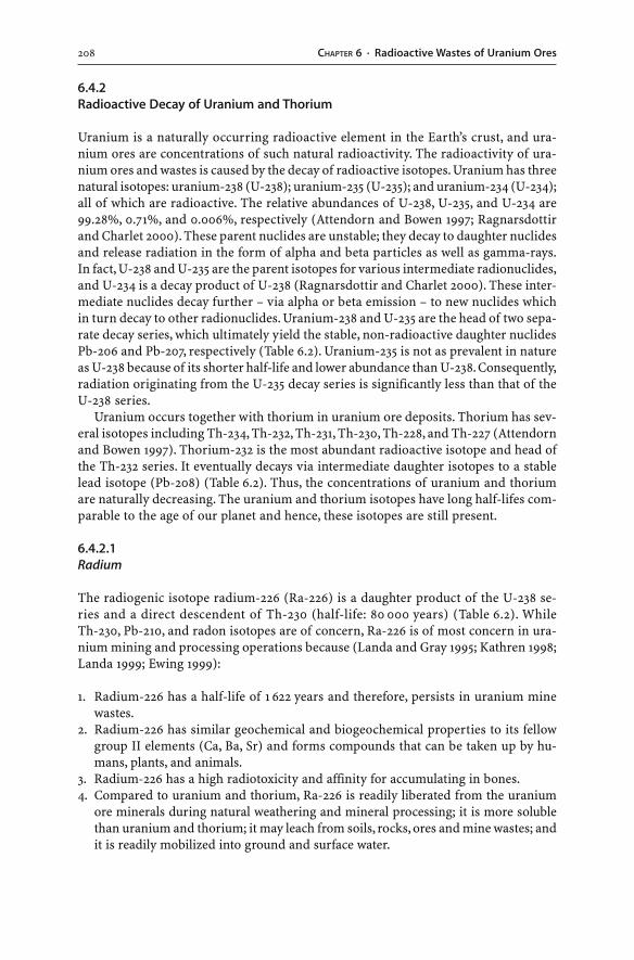
208 CHAPTER 6 · Radioactive Wastes of Uranium Ores
6.4.2Radioactive Decay of Uranium and Thorium
Uranium is a naturally occurring radioactive element in the Earth’s crust, and ura-nium ores are concentrations of such natural radioactivity. The radioactivity of ura-nium ores and wastes is caused by the decay of radioactive isotopes. Uranium has threenatural isotopes: uranium-238 (U-238); uranium-235 (U-235); and uranium-234 (U-234);all of which are radioactive. The relative abundances of U-238, U-235, and U-234 are99.28%, 0.71%, and 0.006%, respectively (Attendorn and Bowen 1997; Ragnarsdottirand Charlet 2000). These parent nuclides are unstable; they decay to daughter nuclidesand release radiation in the form of alpha and beta particles as well as gamma-rays.In fact, U-238 and U-235 are the parent isotopes for various intermediate radionuclides,and U-234 is a decay product of U-238 (Ragnarsdottir and Charlet 2000). These inter-mediate nuclides decay further – via alpha or beta emission – to new nuclides whichin turn decay to other radionuclides. Uranium-238 and U-235 are the head of two sepa-rate decay series, which ultimately yield the stable, non-radioactive daughter nuclidesPb-206 and Pb-207, respectively (Table 6.2). Uranium-235 is not as prevalent in natureas U-238 because of its shorter half-life and lower abundance than U-238. Consequently,radiation originating from the U-235 decay series is significantly less than that of theU-238 series.
Uranium occurs together with thorium in uranium ore deposits. Thorium has sev-eral isotopes including Th-234, Th-232, Th-231, Th-230, Th-228, and Th-227 (Attendornand Bowen 1997). Thorium-232 is the most abundant radioactive isotope and head ofthe Th-232 series. It eventually decays via intermediate daughter isotopes to a stablelead isotope (Pb-208) (Table 6.2). Thus, the concentrations of uranium and thoriumare naturally decreasing. The uranium and thorium isotopes have long half-lifes com-parable to the age of our planet and hence, these isotopes are still present.
6.4.2.1Radium
The radiogenic isotope radium-226 (Ra-226) is a daughter product of the U-238 se-ries and a direct descendent of Th-230 (half-life: 80 000 years) (Table 6.2). WhileTh-230, Pb-210, and radon isotopes are of concern, Ra-226 is of most concern in ura-nium mining and processing operations because (Landa and Gray 1995; Kathren 1998;Landa 1999; Ewing 1999):
1. Radium-226 has a half-life of 1 622 years and therefore, persists in uranium minewastes.
2. Radium-226 has similar geochemical and biogeochemical properties to its fellowgroup II elements (Ca, Ba, Sr) and forms compounds that can be taken up by hu-mans, plants, and animals.
3. Radium-226 has a high radiotoxicity and affinity for accumulating in bones.4. Compared to uranium and thorium, Ra-226 is readily liberated from the uranium
ore minerals during natural weathering and mineral processing; it is more solublethan uranium and thorium; it may leach from soils, rocks, ores and mine wastes; andit is readily mobilized into ground and surface water.
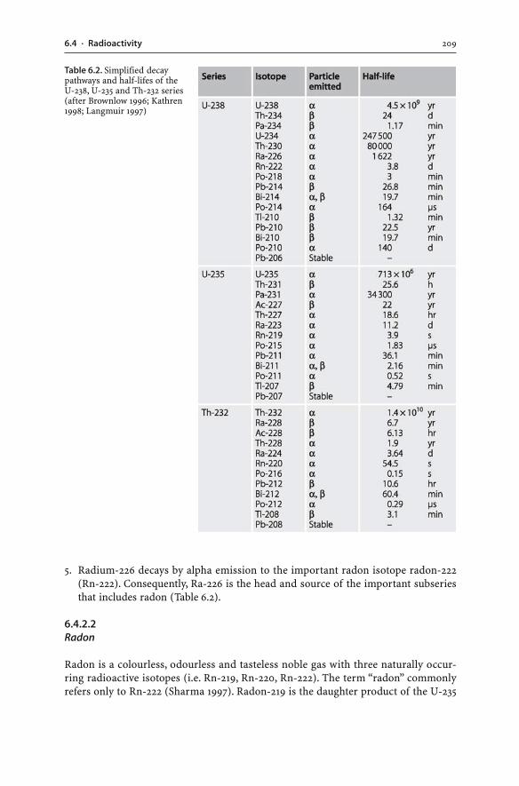
2096.4 · Radioactivity
5. Radium-226 decays by alpha emission to the important radon isotope radon-222(Rn-222). Consequently, Ra-226 is the head and source of the important subseriesthat includes radon (Table 6.2).
6.4.2.2Radon
Radon is a colourless, odourless and tasteless noble gas with three naturally occur-ring radioactive isotopes (i.e. Rn-219, Rn-220, Rn-222). The term “radon” commonlyrefers only to Rn-222 (Sharma 1997). Radon-219 is the daughter product of the U-235
Table 6.2. Simplified decaypathways and half-lifes of theU-238, U-235 and Th-232 series(after Brownlow 1996; Kathren1998; Langmuir 1997)
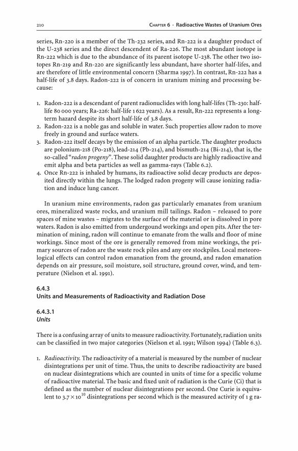
210 CHAPTER 6 · Radioactive Wastes of Uranium Ores
series, Rn-220 is a member of the Th-232 series, and Rn-222 is a daughter product ofthe U-238 series and the direct descendent of Ra-226. The most abundant isotope isRn-222 which is due to the abundance of its parent isotope U-238. The other two iso-topes Rn-219 and Rn-220 are significantly less abundant, have shorter half-lifes, andare therefore of little environmental concern (Sharma 1997). In contrast, Rn-222 has ahalf-life of 3.8 days. Radon-222 is of concern in uranium mining and processing be-cause:
1. Radon-222 is a descendant of parent radionuclides with long half-lifes (Th-230: half-life 80 000 years; Ra-226: half-life 1 622 years). As a result, Rn-222 represents a long-term hazard despite its short half-life of 3.8 days.
2. Radon-222 is a noble gas and soluble in water. Such properties allow radon to movefreely in ground and surface waters.
3. Radon-222 itself decays by the emission of an alpha particle. The daughter productsare polonium-218 (Po-218), lead-214 (Pb-214), and bismuth-214 (Bi-214), that is, theso-called “radon progeny”. These solid daughter products are highly radioactive andemit alpha and beta particles as well as gamma-rays (Table 6.2).
4. Once Rn-222 is inhaled by humans, its radioactive solid decay products are depos-ited directly within the lungs. The lodged radon progeny will cause ionizing radia-tion and induce lung cancer.
In uranium mine environments, radon gas particularly emanates from uraniumores, mineralized waste rocks, and uranium mill tailings. Radon – released to porespaces of mine wastes – migrates to the surface of the material or is dissolved in porewaters. Radon is also emitted from undergound workings and open pits. After the ter-mination of mining, radon will continue to emanate from the walls and floor of mineworkings. Since most of the ore is generally removed from mine workings, the pri-mary sources of radon are the waste rock piles and any ore stockpiles. Local meteoro-logical effects can control radon emanation from the ground, and radon emanationdepends on air pressure, soil moisture, soil structure, ground cover, wind, and tem-perature (Nielson et al. 1991).
6.4.3Units and Measurements of Radioactivity and Radiation Dose
6.4.3.1Units
There is a confusing array of units to measure radioactivity. Fortunately, radiation unitscan be classified in two major categories (Nielson et al. 1991; Wilson 1994) (Table 6.3).
1. Radioactivity. The radioactivity of a material is measured by the number of nucleardisintegrations per unit of time. Thus, the units to describe radioactivity are basedon nuclear disintegrations which are counted in units of time for a specific volumeof radioactive material. The basic and fixed unit of radiation is the Curie (Ci) that isdefined as the number of nuclear disintegrations per second. One Curie is equiva-lent to 3.7 × 10¹⁰ disintegrations per second which is the measured activity of 1 g ra-
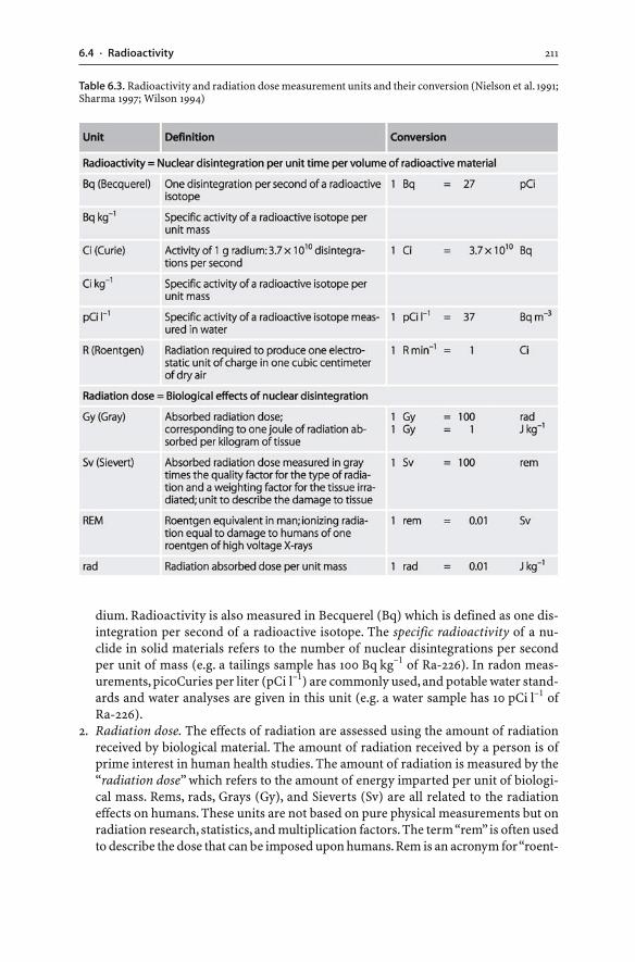
2116.4 · Radioactivity
dium. Radioactivity is also measured in Becquerel (Bq) which is defined as one dis-integration per second of a radioactive isotope. The specific radioactivity of a nu-clide in solid materials refers to the number of nuclear disintegrations per secondper unit of mass (e.g. a tailings sample has 100 Bq kg–1 of Ra-226). In radon meas-urements, picoCuries per liter (pCi l–1) are commonly used, and potable water stand-ards and water analyses are given in this unit (e.g. a water sample has 10 pCi l–1 ofRa-226).
2. Radiation dose. The effects of radiation are assessed using the amount of radiationreceived by biological material. The amount of radiation received by a person is ofprime interest in human health studies. The amount of radiation is measured by the“radiation dose” which refers to the amount of energy imparted per unit of biologi-cal mass. Rems, rads, Grays (Gy), and Sieverts (Sv) are all related to the radiationeffects on humans. These units are not based on pure physical measurements but onradiation research, statistics, and multiplication factors. The term “rem” is often usedto describe the dose that can be imposed upon humans. Rem is an acronym for “roent-
Table 6.3. Radioactivity and radiation dose measurement units and their conversion (Nielson et al. 1991;Sharma 1997; Wilson 1994)
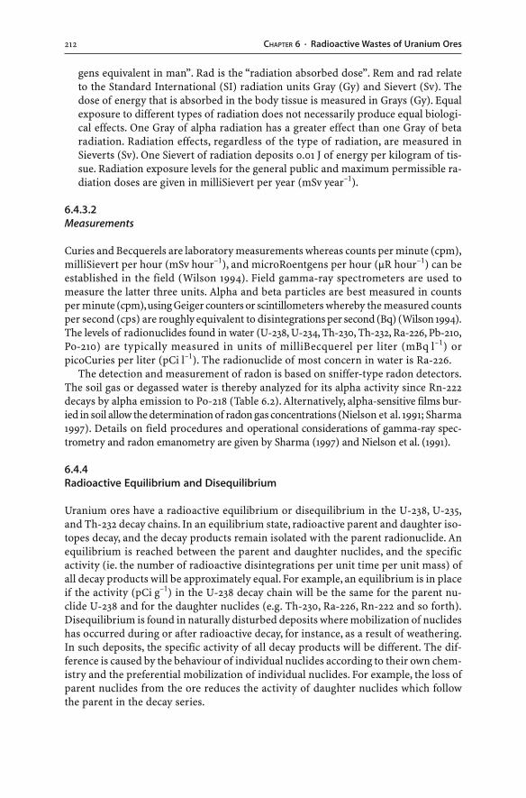
212 CHAPTER 6 · Radioactive Wastes of Uranium Ores
gens equivalent in man”. Rad is the “radiation absorbed dose”. Rem and rad relateto the Standard International (SI) radiation units Gray (Gy) and Sievert (Sv). Thedose of energy that is absorbed in the body tissue is measured in Grays (Gy). Equalexposure to different types of radiation does not necessarily produce equal biologi-cal effects. One Gray of alpha radiation has a greater effect than one Gray of betaradiation. Radiation effects, regardless of the type of radiation, are measured inSieverts (Sv). One Sievert of radiation deposits 0.01 J of energy per kilogram of tis-sue. Radiation exposure levels for the general public and maximum permissible ra-diation doses are given in milliSievert per year (mSv year–1).
6.4.3.2Measurements
Curies and Becquerels are laboratory measurements whereas counts per minute (cpm),milliSievert per hour (mSv hour–1), and microRoentgens per hour (µR hour–1) can beestablished in the field (Wilson 1994). Field gamma-ray spectrometers are used tomeasure the latter three units. Alpha and beta particles are best measured in countsper minute (cpm), using Geiger counters or scintillometers whereby the measured countsper second (cps) are roughly equivalent to disintegrations per second (Bq) (Wilson 1994).The levels of radionuclides found in water (U-238, U-234, Th-230, Th-232, Ra-226, Pb-210,Po-210) are typically measured in units of milliBecquerel per liter (mBq l–1) orpicoCuries per liter (pCi l–1). The radionuclide of most concern in water is Ra-226.
The detection and measurement of radon is based on sniffer-type radon detectors.The soil gas or degassed water is thereby analyzed for its alpha activity since Rn-222decays by alpha emission to Po-218 (Table 6.2). Alternatively, alpha-sensitive films bur-ied in soil allow the determination of radon gas concentrations (Nielson et al. 1991; Sharma1997). Details on field procedures and operational considerations of gamma-ray spec-trometry and radon emanometry are given by Sharma (1997) and Nielson et al. (1991).
6.4.4Radioactive Equilibrium and Disequilibrium
Uranium ores have a radioactive equilibrium or disequilibrium in the U-238, U-235,and Th-232 decay chains. In an equilibrium state, radioactive parent and daughter iso-topes decay, and the decay products remain isolated with the parent radionuclide. Anequilibrium is reached between the parent and daughter nuclides, and the specificactivity (ie. the number of radioactive disintegrations per unit time per unit mass) ofall decay products will be approximately equal. For example, an equilibrium is in placeif the activity (pCi g–1) in the U-238 decay chain will be the same for the parent nu-clide U-238 and for the daughter nuclides (e.g. Th-230, Ra-226, Rn-222 and so forth).Disequilibrium is found in naturally disturbed deposits where mobilization of nuclideshas occurred during or after radioactive decay, for instance, as a result of weathering.In such deposits, the specific activity of all decay products will be different. The dif-ference is caused by the behaviour of individual nuclides according to their own chem-istry and the preferential mobilization of individual nuclides. For example, the loss ofparent nuclides from the ore reduces the activity of daughter nuclides which followthe parent in the decay series.
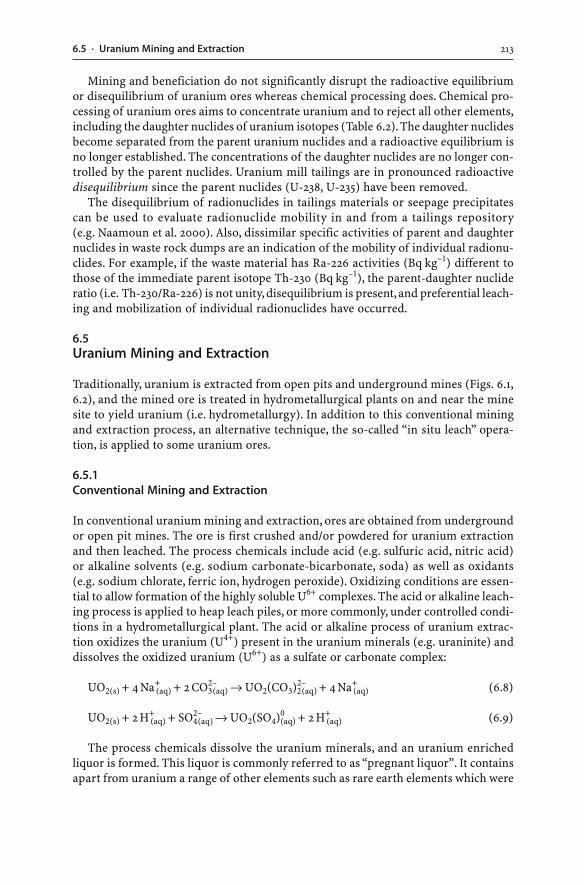
2136.5 · Uranium Mining and Extraction
Mining and beneficiation do not significantly disrupt the radioactive equilibriumor disequilibrium of uranium ores whereas chemical processing does. Chemical pro-cessing of uranium ores aims to concentrate uranium and to reject all other elements,including the daughter nuclides of uranium isotopes (Table 6.2). The daughter nuclidesbecome separated from the parent uranium nuclides and a radioactive equilibrium isno longer established. The concentrations of the daughter nuclides are no longer con-trolled by the parent nuclides. Uranium mill tailings are in pronounced radioactivedisequilibrium since the parent nuclides (U-238, U-235) have been removed.
The disequilibrium of radionuclides in tailings materials or seepage precipitatescan be used to evaluate radionuclide mobility in and from a tailings repository(e.g. Naamoun et al. 2000). Also, dissimilar specific activities of parent and daughternuclides in waste rock dumps are an indication of the mobility of individual radionu-clides. For example, if the waste material has Ra-226 activities (Bq kg–1) different tothose of the immediate parent isotope Th-230 (Bq kg–1), the parent-daughter nuclideratio (i.e. Th-230/Ra-226) is not unity, disequilibrium is present, and preferential leach-ing and mobilization of individual radionuclides have occurred.
6.5Uranium Mining and Extraction
Traditionally, uranium is extracted from open pits and underground mines (Figs. 6.1,6.2), and the mined ore is treated in hydrometallurgical plants on and near the minesite to yield uranium (i.e. hydrometallurgy). In addition to this conventional miningand extraction process, an alternative technique, the so-called “in situ leach” opera-tion, is applied to some uranium ores.
6.5.1Conventional Mining and Extraction
In conventional uranium mining and extraction, ores are obtained from undergroundor open pit mines. The ore is first crushed and/or powdered for uranium extractionand then leached. The process chemicals include acid (e.g. sulfuric acid, nitric acid)or alkaline solvents (e.g. sodium carbonate-bicarbonate, soda) as well as oxidants(e.g. sodium chlorate, ferric ion, hydrogen peroxide). Oxidizing conditions are essen-tial to allow formation of the highly soluble U6+ complexes. The acid or alkaline leach-ing process is applied to heap leach piles, or more commonly, under controlled condi-tions in a hydrometallurgical plant. The acid or alkaline process of uranium extrac-tion oxidizes the uranium (U4+) present in the uranium minerals (e.g. uraninite) anddissolves the oxidized uranium (U6+) as a sulfate or carbonate complex:
UO2(s) + 4 Na+(aq) + 2 CO3
2–(aq) → UO2(CO3)2
2–(aq) + 4 Na+
(aq) (6.8)
UO2(s) + 2 H+(aq) + SO4
2–(aq) → UO2(SO4)0
(aq) + 2 H+(aq) (6.9)
The process chemicals dissolve the uranium minerals, and an uranium enrichedliquor is formed. This liquor is commonly referred to as “pregnant liquor”. It containsapart from uranium a range of other elements such as rare earth elements which were
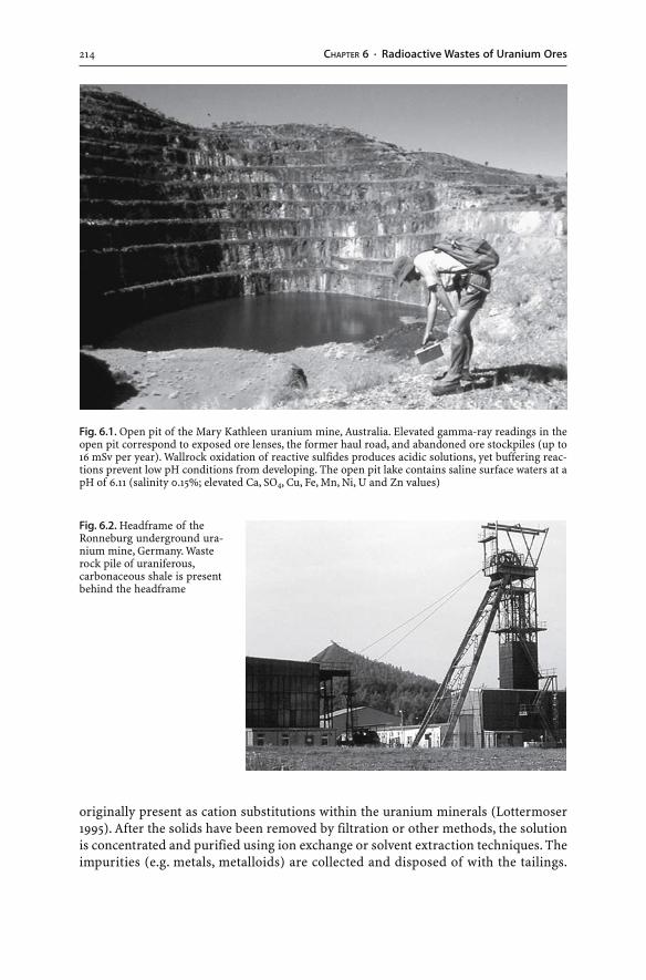
214 CHAPTER 6 · Radioactive Wastes of Uranium Ores
originally present as cation substitutions within the uranium minerals (Lottermoser1995). After the solids have been removed by filtration or other methods, the solutionis concentrated and purified using ion exchange or solvent extraction techniques. Theimpurities (e.g. metals, metalloids) are collected and disposed of with the tailings.
Fig. 6.1. Open pit of the Mary Kathleen uranium mine, Australia. Elevated gamma-ray readings in theopen pit correspond to exposed ore lenses, the former haul road, and abandoned ore stockpiles (up to16 mSv per year). Wallrock oxidation of reactive sulfides produces acidic solutions, yet buffering reac-tions prevent low pH conditions from developing. The open pit lake contains saline surface waters at apH of 6.11 (salinity 0.15%; elevated Ca, SO4, Cu, Fe, Mn, Ni, U and Zn values)
Fig. 6.2. Headframe of theRonneburg underground ura-nium mine, Germany. Wasterock pile of uraniferous,carbonaceous shale is presentbehind the headframe
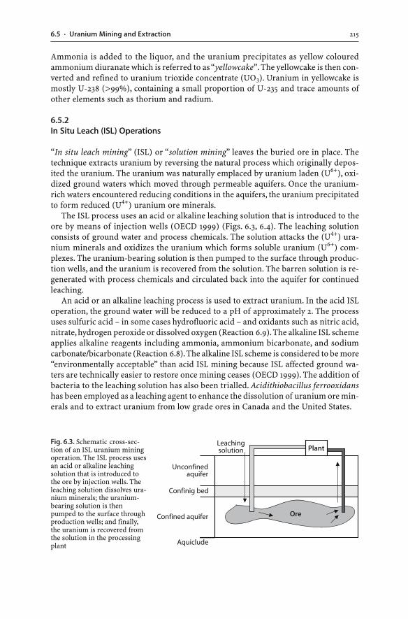
2156.5 · Uranium Mining and Extraction
Ammonia is added to the liquor, and the uranium precipitates as yellow colouredammonium diuranate which is referred to as “yellowcake”. The yellowcake is then con-verted and refined to uranium trioxide concentrate (UO3). Uranium in yellowcake ismostly U-238 (>99%), containing a small proportion of U-235 and trace amounts ofother elements such as thorium and radium.
6.5.2In Situ Leach (ISL) Operations
“In situ leach mining” (ISL) or “solution mining” leaves the buried ore in place. Thetechnique extracts uranium by reversing the natural process which originally depos-ited the uranium. The uranium was naturally emplaced by uranium laden (U6+), oxi-dized ground waters which moved through permeable aquifers. Once the uranium-rich waters encountered reducing conditions in the aquifers, the uranium precipitatedto form reduced (U4+) uranium ore minerals.
The ISL process uses an acid or alkaline leaching solution that is introduced to theore by means of injection wells (OECD 1999) (Figs. 6.3, 6.4). The leaching solutionconsists of ground water and process chemicals. The solution attacks the (U4+) ura-nium minerals and oxidizes the uranium which forms soluble uranium (U6+) com-plexes. The uranium-bearing solution is then pumped to the surface through produc-tion wells, and the uranium is recovered from the solution. The barren solution is re-generated with process chemicals and circulated back into the aquifer for continuedleaching.
An acid or an alkaline leaching process is used to extract uranium. In the acid ISLoperation, the ground water will be reduced to a pH of approximately 2. The processuses sulfuric acid – in some cases hydrofluoric acid – and oxidants such as nitric acid,nitrate, hydrogen peroxide or dissolved oxygen (Reaction 6.9). The alkaline ISL schemeapplies alkaline reagents including ammonia, ammonium bicarbonate, and sodiumcarbonate/bicarbonate (Reaction 6.8). The alkaline ISL scheme is considered to be more“environmentally acceptable” than acid ISL mining because ISL affected ground wa-ters are technically easier to restore once mining ceases (OECD 1999). The addition ofbacteria to the leaching solution has also been trialled. Acidithiobacillus ferrooxidanshas been employed as a leaching agent to enhance the dissolution of uranium ore min-erals and to extract uranium from low grade ores in Canada and the United States.
Fig. 6.3. Schematic cross-sec-tion of an ISL uranium miningoperation. The ISL process usesan acid or alkaline leachingsolution that is introduced tothe ore by injection wells. Theleaching solution dissolves ura-nium minerals; the uranium-bearing solution is thenpumped to the surface throughproduction wells; and finally,the uranium is recovered fromthe solution in the processingplant
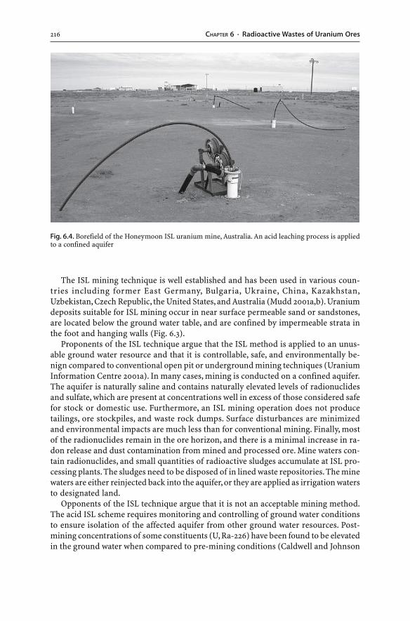
216 CHAPTER 6 · Radioactive Wastes of Uranium Ores
The ISL mining technique is well established and has been used in various coun-tries including former East Germany, Bulgaria, Ukraine, China, Kazakhstan,Uzbekistan, Czech Republic, the United States, and Australia (Mudd 2001a,b). Uraniumdeposits suitable for ISL mining occur in near surface permeable sand or sandstones,are located below the ground water table, and are confined by impermeable strata inthe foot and hanging walls (Fig. 6.3).
Proponents of the ISL technique argue that the ISL method is applied to an unus-able ground water resource and that it is controllable, safe, and environmentally be-nign compared to conventional open pit or underground mining techniques (UraniumInformation Centre 2001a). In many cases, mining is conducted on a confined aquifer.The aquifer is naturally saline and contains naturally elevated levels of radionuclidesand sulfate, which are present at concentrations well in excess of those considered safefor stock or domestic use. Furthermore, an ISL mining operation does not producetailings, ore stockpiles, and waste rock dumps. Surface disturbances are minimizedand environmental impacts are much less than for conventional mining. Finally, mostof the radionuclides remain in the ore horizon, and there is a minimal increase in ra-don release and dust contamination from mined and processed ore. Mine waters con-tain radionuclides, and small quantities of radioactive sludges accumulate at ISL pro-cessing plants. The sludges need to be disposed of in lined waste repositories. The minewaters are either reinjected back into the aquifer, or they are applied as irrigation watersto designated land.
Opponents of the ISL technique argue that it is not an acceptable mining method.The acid ISL scheme requires monitoring and controlling of ground water conditionsto ensure isolation of the affected aquifer from other ground water resources. Post-mining concentrations of some constituents (U, Ra-226) have been found to be elevatedin the ground water when compared to pre-mining conditions (Caldwell and Johnson
Fig. 6.4. Borefield of the Honeymoon ISL uranium mine, Australia. An acid leaching process is appliedto a confined aquifer
2176.6 · Mining, Processing and Hydrometallurgical Wastes
1997). Once mining ceases, ground water restoration of the leached aquifer to pre-mining conditions is difficult if not impossible to achieve. Over time, mobilized andprecipitated mineral particles such as clays, gypsum or jarosite will become trappedin the pore spaces (Mudd 2001a). The permeability of the leached ore horizon will bereduced, and the hydrology of the horizon is irreversibly changed. Acid ISL miningwas not successful in the United States because of high acid consumption in carbon-ate-bearing aquifers and problems with ground water restoration after acid leaching(Mudd 2001a). In contrast, acid ISL operations were common in Eastern Europe andthe former Soviet Union (Mudd 2001a). Where used in inappropriate locations, acidISL mining resulted in significant ground water contamination in Bulgaria, the CzechRepublic, and East Germany (Case Study 6.1).
Ground water restoration programs at former ISL sites rely on various techniques(e.g. reverse osmosis, volume reduction by evaporation, pump-and-treat). Contami-nants are extracted from the ground waters, and some components may even be re-cycled including sulfuric acid, aluminium oxide, ammonia, and gypsum. Moreover,natural attenuation processes within aquifers can restore contaminated ground wa-ters in ISL environments. The key geochemical processes which naturally remove dis-solved radionuclides and heavy metals from ground waters are: (a) anaerobic condi-tions resulting in precipitation of reduced compounds such as uranium minerals andsulfides; (b) coprecipitation of uranium with iron oxyhydroxides, organic matter, andcarbonates; and (c) adsorption of uranium on clay minerals, silicates, and alumino-silicates (Erskine et al. 1997). Such natural restoration mechanisms will of course onlyoperate if the aquifer is anaerobic or contains elevated organic carbon, sulfide, clay aswell as iron and manganese oxyhydroxide concentrations.
6.6Mining, Processing and Hydrometallurgical Wastes
Wastes of uranium mining, processing and hydrometallurgical extraction are invari-ably radioactive. Most uranium mine wastes can be classified as non-radioactive(e.g. overburden, waste rocks) or low-level radioactive wastes (e.g. mine water, heapleach piles, waste rocks, tailings). Low-level radioactive wastes contain low levels ofnuclides, emitting alpha and beta particles and gamma-rays. The greatest volume ofnon-radioactive and low-level radioactive waste products is generated at uraniummines that use conventional mining and extraction methods. At these locations, min-ing, processing and hydrometallurgical uranium recovery generate mine waters, slud-ges, waste rock dumps, heap leach piles, and tailings. In comparison, uranium minesusing ISL techniques produce significant less waste and generate smaller volumes ofradioactive mine waters and sludges. Wastes of uranium mining and extraction canbe grouped into the following four categories:
� Tailings. Uranium extraction at many operating uranium mines is based on:(a) crushing of the ore to a fine powder; and (b) leaching the powdered ore withprocess chemicals in a hydrometallurgical plant. The solids are removed from theprocess circuit and pumped with spent process waters to a tailings repository. Thesewastes are referred to as “uranium tailings” or more commonly as “uranium milltailings”.
218 CHAPTER 6 · Radioactive Wastes of Uranium Ores
� Mine water. Water contaminated with radionuclides, heavy metals, metalloids, andother constituents is commonly generated at an uranium mine site. Such water in-cludes: mill water; process water; mining water from the dewatering of underground
2196.7 · Tailings
and open pit mines; and seepage water emanating from waste rock dumps, heap leachpiles and ore stockpiles. Contaminated water is also produced in association withISL operations and during ground water restoration of former ISL activities. Con-taminated waters require treatment prior to disposal or even discharge of the minelease.
� Waste rocks. Country rocks enclosing uranium ores possess no or subeconomicamounts of uranium minerals, and the mined waste rocks display variable uraniumconcentrations as well as radioactivity and radon levels.
� Heap leach residues. At some mine sites, uranium is removed from low-grade oreusing heap leaching. The leaching solution is sprayed on top of the pile. The solu-tion percolates downwards until it reaches a liner below the pile where it is caughtand pumped to a processing plant. Together with waste rock piles, heap leach pilesrepresent a potential hazard during operation because of the possible release of dust,radon, and seepage waters. If waste rock dumps or heap leach piles are sulfidic, theremay be a potential for AMD development in the long term.
6.7Tailings
Uranium mill tailings are generally disposed of as a slurry. The tailings are best de-scribed in terms of solids and liquids. The solids can be further subdivided based ontheir particle size into slimes and sands. Each of these three tailings components
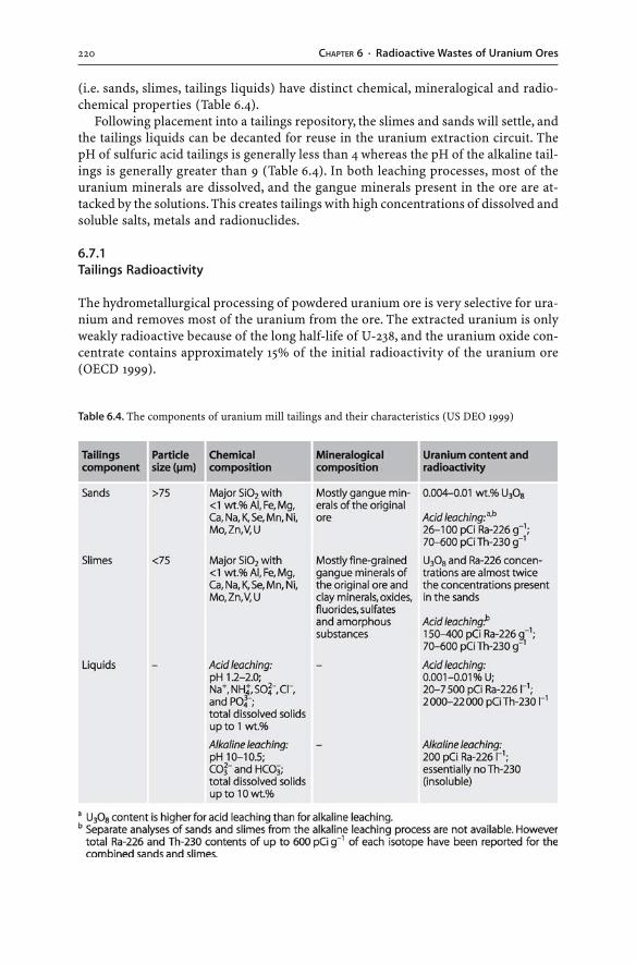
220 CHAPTER 6 · Radioactive Wastes of Uranium Ores
(i.e. sands, slimes, tailings liquids) have distinct chemical, mineralogical and radio-chemical properties (Table 6.4).
Following placement into a tailings repository, the slimes and sands will settle, andthe tailings liquids can be decanted for reuse in the uranium extraction circuit. ThepH of sulfuric acid tailings is generally less than 4 whereas the pH of the alkaline tail-ings is generally greater than 9 (Table 6.4). In both leaching processes, most of theuranium minerals are dissolved, and the gangue minerals present in the ore are at-tacked by the solutions. This creates tailings with high concentrations of dissolved andsoluble salts, metals and radionuclides.
6.7.1Tailings Radioactivity
The hydrometallurgical processing of powdered uranium ore is very selective for ura-nium and removes most of the uranium from the ore. The extracted uranium is onlyweakly radioactive because of the long half-life of U-238, and the uranium oxide con-centrate contains approximately 15% of the initial radioactivity of the uranium ore(OECD 1999).
Table 6.4. The components of uranium mill tailings and their characteristics (US DEO 1999)
2216.7 · Tailings
Hydrometallurgical processing does not achieve complete extraction of uraniumfrom the ores, and discarded tailings always contain small amounts of uranium. More-over, most of the undesired daughter radionuclides of the U-238 and U-235 series endup in the tailings, and the tailings carry the remaining 85% of the initial radioactivityof the uranium ore (Landa 1999; OECD 1999; Abdelouas et al. 1999). As a consequence,uranium mill tailings constitute a high volume, low-level radioactive waste. The ra-dioactivity is caused by: (a) highly radioactive nuclides with relatively short half-lifes(e.g. Po-218, Po-214, Po-210, Pb-210); and (b) less radioactive nuclides with long half-lifes(e.g. Th-230, Ra-226) (Table 6.2). If the uranium ore is enriched in thorium, the tailingswill possess abundant daughter nuclides of the Th-232 series. Hence, radiation levelsand radon emissions from tailings are potentially significant, and the radioactivity ofuranium tailings is greater than that of the yellowcake or uranium oxide concentrate.
6.7.2Tailings Solids
In general, tailings solids can be: (a) primary ore and gangue minerals; (b) secondaryminerals formed during weathering; (c) chemical precipitates formed during and af-ter mineral processing; and (d) chemical precipitates formed after disposal in the tail-ings storage facility (Sec. 4.2.3). In the case of uranium mill tailings, the chemical pre-cipitates form: (a) during and after hydrometallurgical extraction; (b) upon neutral-ization of acid tailings with lime prior to their disposal; and (c) after disposal of thetailings in the storage facility.
The tailings solids can be crystalline, poorly crystalline, and/or amorphous in na-ture, and they contain radionuclides, heavy metals, and metalloids (e.g. Langmuir et al.1999; Pichler et al. 2001). The solids are insoluble or potentially soluble (Willett et al.1994; Landa 1999; Donahue et al. 2000). Detailed analyses have revealed that radionu-clides (i.e. Th-230, Ra-226, U-235, U-238), heavy metals, and metalloids are present in:(a) ion exchangeable, carbonate and readily acid soluble forms; (b) iron and manga-nese hydrous oxides; (c) fluorides; (d) alkaline earth sulfates (e.g. BaSO4, SrSO4);(e) organic matter; (f) sulfides; and (g) arsenates (Willett et al. 1994; Landa and Gray1995; Somot et al. 2000; Donahue et al. 2000; Pichler et al. 2001; Donahue and Hendry2003; Martin et al. 2003). The stability of these solid phases determines the potentialmobilization of radionuclides, heavy metals, and metalloids into tailings pore waters.
Radium-226 is a radionuclide of significant concern in uranium mining. It tendsto be concentrated in the fine fraction of uranium tailings (Landa and Gray 1995)(Table 6.4). Barium and radium have similar geochemical properties, including the lowsolubility of their sulfate salts and the coprecipitation of radium with barium as solidsulfates (Ba(Ra)SO4). In addition, adsorption and coprecipitation processes lead to thefixation of Ra-226 in iron oxyhydroxides, feldspars, clays, amorphous silica, organicmatter, sulfides, barite, and other sulfate grains. Iron oxyhydroxides and alkaline earthand lead sulfates play an important role in the fixation of Ra-226 and other radionu-clides in acid tailings materials (Landa and Gray 1995; Goulden et al. 1998; Landa 1999;Somot et al. 2000; Martin et al. 2003).
Uranium tailings like all tailings undergo chemical reactions in a tailings reposi-tory (cf. Sec. 4.2.3). Over time, the tailings mineralogy and pore water composition maychange. Dissolved radionuclides, metals, and metalloids may: (a) persist in solution;
222 CHAPTER 6 · Radioactive Wastes of Uranium Ores
(b) precipitate or coprecipitate by interacting with other components in the tailings;or (c) be adsorbed by tailings solids such as quartz, kaolinite, clays or amorphous sub-stances (Landa and Gray 1995; Landa 1999). The potential release of radionuclides,metals and metalloids from tailings solids into pore waters and the presence of theseelements in solution are undesirable. Tailings liquids laden with contaminants canescape from the tailings storage area and may impact on aquifers or surface waters.Consequently, the mineralogical siting and chemical reactions in uranium tailings needto be understood in order to determine the long-term behaviour of radionuclides,metals and metalloids in the waste repositories. The mobilization of radionuclides,heavy metals, and metalloids from tailings solids into tailings liquids can be inducedthrough various factors (Landa and Gray 1995):
� AMD development. Tailings may contain abundant sulfide minerals that can oxidizein the tailings impoundment. The acid producing reactions may not be sufficientlybuffered by acid neutralizing reactions, and this leads to the formation of AMD. Thedevelopment of AMD in uranium tailings, heap leach piles and waste rock dumpswill enhance the dissolution of uranium minerals and the mobility of radionuclides.
� Presence of process chemicals. Hydrometallurgical extraction schemes add signifi-cant amounts of sulfuric acid, alkaline materials, nitrate, chloride and/or organicsolvents to the processed ore. The process reagents can leach host phases and act ascomplexing agents for radionuclides and heavy metals. The contaminants may bemobilized from their host minerals and dissolved in tailings waters.
� Acid leaching or reduction of iron and manganese oxyhydroxides. Iron and manga-nese oxyhydroxides represent important host phases to radionuclides, metals, andmetalloids, in particular arsenic. These hosts can become unstable under acid orreducing conditions (e.g. Pichler et al. 2001). The establishment of acid or reducingconditions in uranium tailings may lead to dissolution of oxyhydroxides and to themobilization of the previously fixed radionuclides, metals, and metalloids.
� Bacterial reduction. Sulfate and iron reducing bacteria within tailings can favourenhanced dissolved Ra-226 concentrations. The bacteria reduce solid sulfates andiron oxyhydroxides to sulfides and allow the release of radium from sulfate salts(Martin et al. 2003). The bacteria also convert dissolved sulfate to sulfide and keepthe dissolved sulfate concentrations at relatively low levels. Low sulfate levels pre-vent the formation of insoluble sulfates and the fixation of Ra-226 as Ba(Ra)SO4. Theundesired release of Ra-226 into solution can occur through engineering measures ornatural processes that cause low dissolved oxygen concentrations in tailings liquids.
� Presence of clay minerals. Clay minerals act as sinks for barium and strontium cati-ons in tailings dams. The cations are incorporated into the clay structure which pre-vents the formation of insoluble alkaline earth sulfates and the coprecipitation ofRa-226 as Ba(Ra)SO4. Abundant clay minerals within tailings may greatly enhancethe concentration of Ra-226 in solution.
6.7.3Tailings Liquids
Tailings liquids represent the surface and pore waters of tailings storage facilities. Thetailings liquids tend to contain high concentrations of radionuclides, heavy metals, and
2236.7 · Tailings
metalloids. If neutralization has not been applied to the liquids of an acid leach plant,the tailings liquids are typically acid, saline and enriched in heavy metals, metalloids,radionuclides, iron, manganese, aluminium, alkalis (Na, K, Ca, Mg), sulfate, chloride,fluorine, and process chemicals (Landa 1999). Acid tailings liquids are commonly inequilibrium with a range of secondary salts such as gypsum and aluminium sulfates,which invariably precipitate and redissolve in the waste repository.
At some mine sites, tailings of an acid leach uranium processing plant are partly orcompletely neutralized with lime prior to discharge to a tailings storage facility. Thetailings become saturated with calcium sulfate. The neutralization may result in theprecipitation of gypsum and of numerous elements that were in solution in the acidprocess water (e.g. Fe, Cu, Mn, Mg). The chemical precipitates are primarily metalhydroxides and gypsum.
In the waste repository, natural neutralization of acid tailings liquids may occurthrough the reaction of tailings liquids with tailings solids. Dissolution of carbonateminerals or amorphous solids and the ion exchange uptake of hydrogen by clay min-erals represent possible buffering reactions (Landa 1999). If the acidic tailings liquidsreact with aluminosilicate minerals, then secondary clay minerals, jarosite, and alunitewill be produced. These minerals will plug pore spaces and decrease tailings perme-ability (Sec. 2.6.4). The minerals will also act as adsorptive sinks for radionuclides andheavy metals (Landa 1999). Such neutralization reactions promote the fixation of ra-dionuclides and metals in tailings solids and reduce the ingress of oxygen and waterinto the waste. On the other hand, acidic tailings solutions may react with a clay linerplaced at the bottom of tailings storage facility. A breach of the clay liner may then bepossible.
6.7.4Tailings Disposal
The specific radioactivity of uranium mill tailings is low (a few Ci kg–1) relative to mostother radioactive wastes produced during atomic weapon and nuclear power produc-tion. However, large quantities of uranium mill tailings have accumulated and today,there are probably more than 500 Mt of uranium tailings located around the world(Waggitt 1994). Long-term containment of these low-level radioactive wastes is of greatenvironmental concern. Radionuclides can be leached out of these wastes which mayresult in the contamination of surrounding ground and surface waters, soils, and sedi-ments. Current disposal practices aim: (a) to isolate tailings for a long period of timefrom the surrounding environment; (b) to prevent leakage from the repository; and(c) to protect ground and surface waters from contamination. The disposal of long-term radioactive, fine-grained, sulfidic or even acidic mine wastes requires specialattention.
In the past, uranium mill tailings were often abandoned and left unrehabilitated,or they were discharged into local creek and lake systems. Today, finite disposal op-tions for uranium tailings include: (a) placing them under water in a lake, ocean orwetland environment (e.g. MEND 1993b); (b) backfilling them into a mined-out openpit (cf. Sec. 4.5); and (c) dumping them into a tailings dam. The disposal of ura-nium mill tailings into open pits and tailings dams are the main waste managementstrategies:
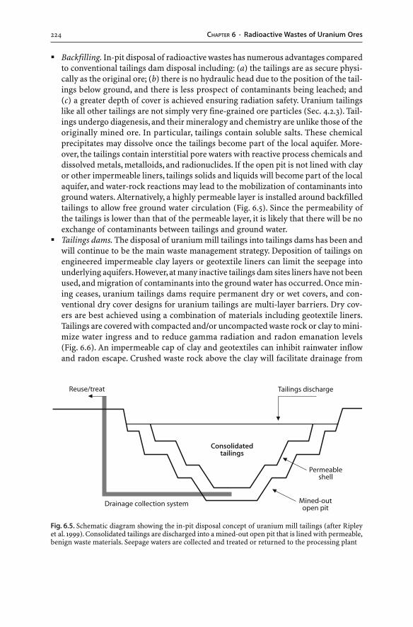
224 CHAPTER 6 · Radioactive Wastes of Uranium Ores
� Backfilling. In-pit disposal of radioactive wastes has numerous advantages comparedto conventional tailings dam disposal including: (a) the tailings are as secure physi-cally as the original ore; (b) there is no hydraulic head due to the position of the tail-ings below ground, and there is less prospect of contaminants being leached; and(c) a greater depth of cover is achieved ensuring radiation safety. Uranium tailingslike all other tailings are not simply very fine-grained ore particles (Sec. 4.2.3). Tail-ings undergo diagenesis, and their mineralogy and chemistry are unlike those of theoriginally mined ore. In particular, tailings contain soluble salts. These chemicalprecipitates may dissolve once the tailings become part of the local aquifer. More-over, the tailings contain interstitial pore waters with reactive process chemicals anddissolved metals, metalloids, and radionuclides. If the open pit is not lined with clayor other impermeable liners, tailings solids and liquids will become part of the localaquifer, and water-rock reactions may lead to the mobilization of contaminants intoground waters. Alternatively, a highly permeable layer is installed around backfilledtailings to allow free ground water circulation (Fig. 6.5). Since the permeability ofthe tailings is lower than that of the permeable layer, it is likely that there will be noexchange of contaminants between tailings and ground water.
� Tailings dams. The disposal of uranium mill tailings into tailings dams has been andwill continue to be the main waste management strategy. Deposition of tailings onengineered impermeable clay layers or geotextile liners can limit the seepage intounderlying aquifers. However, at many inactive tailings dam sites liners have not beenused, and migration of contaminants into the ground water has occurred. Once min-ing ceases, uranium tailings dams require permanent dry or wet covers, and con-ventional dry cover designs for uranium tailings are multi-layer barriers. Dry cov-ers are best achieved using a combination of materials including geotextile liners.Tailings are covered with compacted and/or uncompacted waste rock or clay to mini-mize water ingress and to reduce gamma radiation and radon emanation levels(Fig. 6.6). An impermeable cap of clay and geotextiles can inhibit rainwater inflowand radon escape. Crushed waste rock above the clay will facilitate drainage from
Fig. 6.5. Schematic diagram showing the in-pit disposal concept of uranium mill tailings (after Ripleyet al. 1999). Consolidated tailings are discharged into a mined-out open pit that is lined with permeable,benign waste materials. Seepage waters are collected and treated or returned to the processing plant
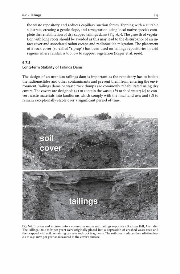
2256.7 · Tailings
Fig. 6.6. Erosion and incision into a covered uranium mill tailings repository, Radium Hill, Australia.The tailings (30.6 mSv per year) were originally placed into a depression of crushed waste rock andthen capped with soil containing calcrete and rock fragments. The soil cover reduces the radiation lev-els to 0.91 mSv per year as measured at the cover’s surface
the waste repository and reduces capillary suction forces. Topping with a suitablesubstrate, creating a gentle slope, and revegetation using local native species com-plete the rehabilitation of dry capped tailings dams (Fig. 6.7). The growth of vegeta-tion with long roots should be avoided as this may lead to the disturbance of an in-tact cover and associated radon escape and radionuclide migration. The placementof a rock cover (so-called “riprap”) has been used on tailings repositories in aridregions where rainfall is too low to support vegetation (Rager et al. 1996).
6.7.5Long-term Stability of Tailings Dams
The design of an uranium tailings dam is important as the repository has to isolatethe radionuclides and other contaminants and prevent them from entering the envi-ronment. Tailings dams or waste rock dumps are commonly rehabilitated using drycovers. The covers are designed: (a) to contain the waste; (b) to shed water; (c) to con-vert waste materials into landforms which comply with the final land use; and (d) toremain exceptionally stable over a significant period of time.
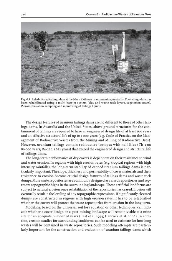
226 CHAPTER 6 · Radioactive Wastes of Uranium Ores
The design features of uranium tailings dams are no different to those of other tail-ings dams. In Australia and the United States, above ground structures for the con-tainment of tailings are required to have an engineered design life of at least 200 yearsand an effective structural life of up to 1 000 years (e.g. Code of Practice on the Man-agement of Radioactive Wastes from the Mining and Milling of Radioactive Ores).However, uranium tailings contain radioactive isotopes with half-lifes (Th-230:80 000 years; Ra-226: 1 622 years) that exceed the engineered design and structural lifeof tailings dams.
The long-term performance of dry covers is dependent on their resistance to windand water erosion. In regions with high erosion rates (e.g. tropical regions with highintensity rainfalls), the long-term stability of capped uranium tailings dams is par-ticularly important. The slope, thickness and permeability of cover materials and theirresistance to erosion become crucial design features of tailings dams and waste rockdumps. Mine waste repositories are commonly designed as raised repositories and rep-resent topographic highs in the surrounding landscape. These artificial landforms aresubject to natural erosion once rehabilitation of the repositories has ceased. Erosion willeventually result in the leveling of any topographic expressions. If significantly elevateddumps are constructed in regions with high erosion rates, it has to be establishedwhether the covers will protect the waste repositories from erosion in the long term.
Modeling, based on the universal soil loss equation or other techniques, can indi-cate whether a cover design or a post-mining landscape will remain viable at a minesite for an adequate number of years (East et al. 1994; Hancock et al. 2006). In addi-tion, erosion studies for surrounding landforms can be used to estimate for how longwastes will be contained in waste repositories. Such modeling attempts are particu-larly important for the construction and evaluation of uranium tailings dams which
Fig. 6.7. Rehabilitated tailings dam at the Mary Kathleen uranium mine, Australia. The tailings dam hasbeen rehabilitated using a multi-barrier system (clay and waste rock layers, vegetation cover).Piezometers allow sampling and monitoring of tailings liquids
2276.8 · Mine Water
are designed to isolate radioactive isotopes from the environment. The relative mag-nitude of the radioactivity and the long half-lifes of particular radionuclides in ura-nium tailings present a problem for the very long term (i.e. >1 000 years) (Landa andGray 1995). Uranium tailings dams have to be secure and stable for over a period ofseveral tens of thousands of years, so the long-term containment of uranium tailingsin engineered structures is an important aspect of uranium mine waste management.
Despite their general acceptance and widespread use in the mining industry, thelong-term stability and performance of capped repositories are unknown. While mod-eling and comparative erosion studies of surrounding landforms can indicate the ero-sive behaviour of waste repositories, only future investigations of capped waste reposi-tories will provide the evidence for their long-term stability. It is a fact that funda-mental geological processes such as erosion eventually result in the leveling of anytopographic highs. If significantly elevated dumps and dams are constructed in highrainfall, erosive regimes, it is certain that the dry covers will not protect the man-madehighlands from erosion in the long term.
6.8Mine Water
Water management at uranium mine sites follows the general principles of watermanagement at all mine sites (Sec. 3.11). These principles require the containment anddisposal of contaminated water in a manner that does not impact on the environment.The release of water from uranium mine sites has to conform with statutory direc-tives. These directives commonly state that the quality of any discharged water has tomeet a specified standard which includes maximum acceptable uranium and otherradionuclide levels. Water management is to ensure that water courses, aquifers, soils,sediments, irrigation crops, farm animals, and aquatic life are not contaminated byradionuclides, heavy metals, metalloids, sulfate, process chemicals, and other contami-nants.
Water management is achieved through collection and disposal. Water is collectedfrom open pit or underground workings, mills, hydrometallurgical plants, waste rockdumps, heap leach piles and ore stockpiles, and channelled into retention ponds(Fig. 6.8). Uncontaminated water can be disposed of by evaporation, land irrigationor discharge whereas contaminated water requires treatment prior to discharge.
6.8.1Constituents
Waters of uranium mine sites have highly variable compositions, yet they are gener-ally characterized by elevated uranium and thorium levels and their decay products(Ra-226, Rn-222, Pb-210, etc). Some radionuclides found in water such as Ra-226 alsooriginate from natural sources, in particular from the leaching of minerals other thanuranium ore minerals. Metal and metalloid concentrations (e.g. As, Be, Cr, Fe, Ni, Se)may be elevated, and oxidation of abundant iron sulfides in mine wastes can lead toAMD development and long-term low pH waters. The geochemical behaviour of ra-dionuclides, metals and metalloids in mine waters is strongly pH and Eh dependent.Enhanced dissolution of radionuclides and heavy metals occurs in acid, oxidized waters.
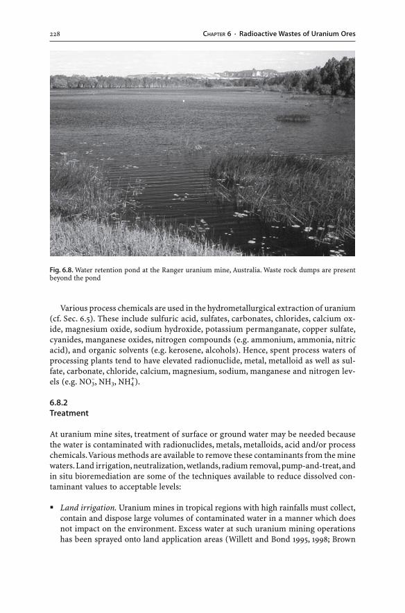
228 CHAPTER 6 · Radioactive Wastes of Uranium Ores
Various process chemicals are used in the hydrometallurgical extraction of uranium(cf. Sec. 6.5). These include sulfuric acid, sulfates, carbonates, chlorides, calcium ox-ide, magnesium oxide, sodium hydroxide, potassium permanganate, copper sulfate,cyanides, manganese oxides, nitrogen compounds (e.g. ammonium, ammonia, nitricacid), and organic solvents (e.g. kerosene, alcohols). Hence, spent process waters ofprocessing plants tend to have elevated radionuclide, metal, metalloid as well as sul-fate, carbonate, chloride, calcium, magnesium, sodium, manganese and nitrogen lev-els (e.g. NO3
–, NH3, NH4+).
6.8.2Treatment
At uranium mine sites, treatment of surface or ground water may be needed becausethe water is contaminated with radionuclides, metals, metalloids, acid and/or processchemicals. Various methods are available to remove these contaminants from the minewaters. Land irrigation, neutralization, wetlands, radium removal, pump-and-treat, andin situ bioremediation are some of the techniques available to reduce dissolved con-taminant values to acceptable levels:
� Land irrigation. Uranium mines in tropical regions with high rainfalls must collect,contain and dispose large volumes of contaminated water in a manner which doesnot impact on the environment. Excess water at such uranium mining operationshas been sprayed onto land application areas (Willett and Bond 1995, 1998; Brown
Fig. 6.8. Water retention pond at the Ranger uranium mine, Australia. Waste rock dumps are presentbeyond the pond
2296.8 · Mine Water
et al. 1998). The soils of the land application areas have to possess adsorptive capaci-ties which retain the contaminants. In particular, soils enriched in iron oxides andorganic matter are capable of adsorbing significant concentrations of uranium. Otherradionuclides (e.g. Ra-226, Pb-210) are also strongly adsorbed by surface soils in ir-rigation areas and do not reach the regional aquifers and surface waters (e.g. Willettand Bond 1995, 1998). The radionuclides will remain in the surface soils and do notleach into ground waters. However, such a disposal method has several disadvan-tages. The topsoil is subject to wind and water erosion, represents the substrate forplants, and may be ingested by animals (Willett and Bond 1998). Furthermore, con-servative, non-reactive ions such as sulfate, nitrate, manganese, magnesium, and cal-cium may migrate into the local aquifer and surface waters (Brown et al. 1998). As aconsequence, the application of excess water to an irrigation area will result in soiland ground water contamination and subsequent stress to and dieback of localvegetation.
� Neutralization. The acidity of uranium mine waters is either due to AMD develop-ment or due to the use of sulfuric acid during uranium extraction. Acid, metal-rich(e.g. Cd, Cu, Mn, Mo, Ni, Zn) mine waters can be treated using the same treatmenttechniques as applied to AMD waters (Sec. 3.12). The chemical treatment of acid,uranium-rich waters with carbonate and lime will reduce dissolved uranium andheavy metal concentrations and neutralize the acidity (Applegate and Kraatz 1991;Fernandes et al. 1998). Dissolved metals and radionuclides precipitate as sludges, andthe sludges need to be disposed of in a waste repository which commonly is the tail-ings storage facility. On the other hand, chemical treatment of acid, uranium-richwaters with carbonate may promote the undesired desorption, mobilization andleaching of uranium from mine wastes. Dissolution of solid carbonate generates bi-carbonate ions, and the uranyl ions are able to complex with the bicarbonate ligands.Consequently, excessive addition of carbonate to uranium mine wastes and contami-nated soils can enhance uranium mobility and exacerbate existing contaminationproblems (Elles and Lee 1998; Wanty et al. 1999) (cf. Sec. 3.12.1).
� Wetlands. Wetlands are successfully used to treat waters with elevated uranium andradium concentrations. Wetlands have abundant clays, organic matter, algae, bacte-ria, fungi, and lichens which are effective in removing dissolved contaminant con-centrations (Noller et al. 1997; Haas et al. 1998). Much of the uranium is adsorptedonto the organic-rich wetland sediments, or the reducing conditions convert themobile U6+ to the immobile U4+ species and cause the precipitation of uranium inthe wetland substrate.
� Radium removal. The removal of radium from water is accomplished by precipita-tion with barium chloride. Barium chloride is introduced into the water circuit, andthe radium will coprecipitate with barium sulfate as illustrated by the following re-action (Benes et al. 1983):
BaCl2(s) + Ra2+(aq) + SO4
2–(aq) → 2 Cl–(aq) + (Ba,Ra)SO4(s) (6.10)
Any calcium present will precipitate as calcium sulfate crystals. Settling and fil-tration of the precipitated salts follow in constructed ponds. Ponds should be linedto prevent contamination of ground waters with radionuclides. Evaporation of wastewaters in ponds lead to the precipitation of salts and sediments. The radioactive
230 CHAPTER 6 · Radioactive Wastes of Uranium Ores
salts and evaporation pond sediments cannot be left in the treatment ponds other-wise they redissolve. The salts and sediments are generally placed with the tailingsinto a tailings storage facility.
Contaminated ground water may be treated using ex situ (e.g. pump-and-treat) orin situ treatment techniques (e.g. bioremediation, permeable reactive barriers):
� Pump-and-treat. The pump-and-treat method aims to capture the impacted groundwater plume. A number of extraction wells pump the contaminated ground water tothe surface. This technique relies on the extraction of uranium and other contami-nants with the water and on fast desorption if the contaminants are adsorpted ontothe host rock in the polluted aquifer (Abdelouas et al. 1998a,b). Following extrac-tion of the contaminated ground water, the water is treated using separation proc-esses such as ion exchange, reverse osmosis, biosorption, bioreduction, bioaccumu-lation, and reductive precipitation of uranium (Abdelouas et al. 1999).
� In situ bioremediation. In situ bioremediation is based on the injection of nutrientsand/or specific bacteria into the aquifer (e.g. Desulfovibrio, Geobacter metallireducens,Shewanella putrefaciens, Colstridium sp.). The bacteria precipitate the dissolved uranylcomplexes as insoluble uranium oxide through the following processes: (a) in-corporation of uranium into cell structures; (b) adsorption of dissolved uraniumfrom solution; and (c) direct or indirect reduction of the mobile U6+ to the immo-bile U4+ species which precipitates as insoluble uraninite (Suzuki and Banfield 1999;Abdelouas et al. 1998b, 1999, 2000). This latter property of microorganisms – to beable to reduce U6+ to the immobile U4+ – is used in the remediation of uranium con-taminated ground waters. Direct reduction of the mobile U6+ to the immobile U4+
species can be performed by particular microorganisms. Indirect reduction of U4+ maybe caused through the proliferation of sulfate-reducing bacteria, which in turn leadto reducing conditions in the uraniferous ground waters. Both direct and indirect re-duction result in the precipitation of dissolved U6+ as insoluble U4+ oxide.
� In situ permeable reactive barriers and reactive zones. In situ permeable reactivebarriers (PRB) and reactive zones (RZ) are based on the placement of solid reactivematerials into the contaminated ground water. The application of permeable reac-tive barriers requires excavation of a trench, placement of the reactive materials intothe trench, and backfilling; hence, the technique is limited to shallow aquifers. Bycontrast, the reactive zone technology uses injection points perpendicular to theground water flow. Reducing materials like metallic iron can be employed to retainuranium and radium on solid particles (Burghardt and Kassahun 2005).
6.9Monitoring
Waste rock dumps, tailings dams, and heap leach piles are potential sources of radio-nuclides, acid, salts, heavy metals, and metalloids. These sources need mineralogical,geochemical and radiochemical characterization. Uranium concentrations in solidmine wastes can be determined using a range of analytical methods whereas uraniummineral identification is primarily achieved through X-ray diffraction (Wolf 1999; Hill1999). Radionuclide concentrations are established using alpha and gamma-ray spec-
2316.10 · Radiation Hazards
trometry whereas radon gas concentrations are investigated using radon emanometry(Nielson et al. 1991; Sharma 1997).
Kinetic tests are commonly applied to simulate the weathering and oxidation ofsulfidic waste samples. The tests expose sulfidic waste over time, from several monthsto several years, to moisture and air (Sec. 2.7.4.2). The field or laboratory based ex-periments are also used to investigate the leaching behaviour of uranium mine wastes.The uranium mine wastes are placed into field bins or columns and subjected to peri-odic or continual leaching in order to simulate the addition of ground or surface wa-ters. The wastes require mineralogical, geochemical and radiochemical characteriza-tion prior to and after leaching. The leachates are monitored for water quality param-eters (e.g. pH and EC) and analyzed for their chemical and radiochemical composi-tion. Data from such experiments can be used to evaluate acid production and themigratory behaviour of radionuclides, heavy metals, and metalloids over time.
Environmental monitoring of uranium mine sites include periodic chemical andradiochemical measurements of ground and surface waters, stream sediments andsoils. In addition, aquatic biota (e.g. fish) are investigated for their radiochemical com-position to detect uptake of radionuclides by aquatic organisms. Mosses and lichensare often used to monitor air contaminants as these rootless organisms reflect atmo-spheric fall-out rather than substrate chemistry (Ripley et al. 1996). Atmospheric mea-surements of radon gas and dust particles are an integrated part of the monitoringprogram. In particular, geochemical analyses of waters and stream sediments are veryuseful for the identification, monitoring, control, and evaluation of environmentalimpacts in the aquatic system (Noller and Hart 1993). The migratory behaviour of dis-solved uranium and other from contamination sources into aquifers can be modelledusing computational software, including mass transport models (e.g. MODFLOW) andgeochemical speciation programs (e.g. HARPHRQ).
The environmental risks of uranium mine wastes will last until the radioactivity of themine wastes has decreased to acceptable levels. Therefore, operating and rehabilitated ura-nium mine sites require monitoring and periodic environmental reviews well beyond mineclosure and for at least 1 000 years (i.e. the engineered life-span of tailings repositories).
6.10Radiation Hazards
A low level of radioactivity is part of the natural environment (Eisenbud and Gesell1997; Ewing 1999; Gaines 2000). Naturally occurring background levels of radiationoriginate from cosmic radiation, the radioactive decay products of radon in the air,and the natural radioactivity of the ground. Much of the radioactivity of rocks andminerals is due to the decay of uranium (i.e. U-238, U-234), thorium (i.e. Th-232), theirradioactive decay products as well as the decay of the potassium isotope K-40. Theabundance of uranium, thorium and potassium varies in different rock types andminerals (Sharma 1997). Hence, the natural radiation dose varies depending on thegeological ground above which and altitude at which people live. Radioactivity is alsopresent in water, air, plants, food, and even internally within the human body (Kathren1998; Ewing 1999). Radiation is unavoidably received by humans and for the greatmajority of the population, exposure to natural radiation exceeds by far that from ar-tificial, medical and occupational sources.
232 CHAPTER 6 · Radioactive Wastes of Uranium Ores
6.10.1Radiation Dose and Human Health
Radioactive nuclides of the U-238, U-235 and Th-232 series emit ionizing radiation inthe form of alpha and beta particles as well as gamma-rays. Animals and humans getexposed to this radiation through: (a) external radiation emitters; and (b) ingestionor inhalation of radionuclides. Very high concentrations of radionuclides may be ac-quired through the foodchain whereby terrestrial or aquatic plants obtain radionu-clides from contaminated air, water and soil. The radionuclides get into organismsusing the transport mechanisms of nutrient ions, so the radionuclides become concen-trated in the foodchain. For example, Ra-226 follows the pathways of calcium. The radio-nuclide accumulates in calcium sinks such as bones and continues to emit ionizing radia-tion.
It is established that work with radioactive materials carries with it an increasedrisk of tissue damage including radiation induced cancers, leukemia, and geneticmutations. Radiation protection standards assume that any dose of radiation – nomatter how small – involves the possibility of risk to human health. Ionizing radia-tion can be particularly harmful if a large enough dose is received (Table 6.5). Whilesmall radiation doses such as medical X-rays are not capable of causing radiation sick-ness or death, they slightly increase the risk of cancer several years after the exposurehas occurred. As more is known about the effects of ionizing radiation, the dose levelsconsidered to be safe have been revised. Radiation exposures for the general publicand in the workplace have been lowered over the years, and the occupational maxi-mum permissible radiation exposure level has dropped to about one tenth of that con-sidered safe in the early 1950s.
The health effects of radon exposure are still debatable, and the effects of low levelradiation dose on cells are still to be determined. While exposure to excessive radia-tion is a health hazard and may even lead to death, a small radiation dose may be benefi-cial for the cure of various ailments. There is a practice of radon consumption andinhalation by the general public in certain parts of the world. In Germany, Austria andPoland, mineral waters and underground mines with known high levels of radon aresuccessfully used for the treatment of various ailments (Kathren 1998). The consump-tion of radon bearing mineral waters and the inhalation of radon-rich air appear tohave a beneficial effect. Will decommissioned uranium mine sites and other non-ura-nium mines with high radon levels have a future as sanatoriums and health spas?
The radiation dose to members of the public from operating uranium mines is inmost cases negligible as access to the mine sites is controlled and occupation of themining areas by the general public is zero. In populated areas, however, environmen-tal dust and radon monitoring programs have to be implemented around uraniummine sites. Direct radiation and ingestion as well as inhalation pathways need to be evalu-ated as well. The potential for significant radiation exposure especially exists for mine staff.
6.10.2Occupational Radiation Exposure
Much of the occupational radiation exposure at uranium mine sites does not origi-nate from the decay of uranium isotopes but from the decay products of U-238 and
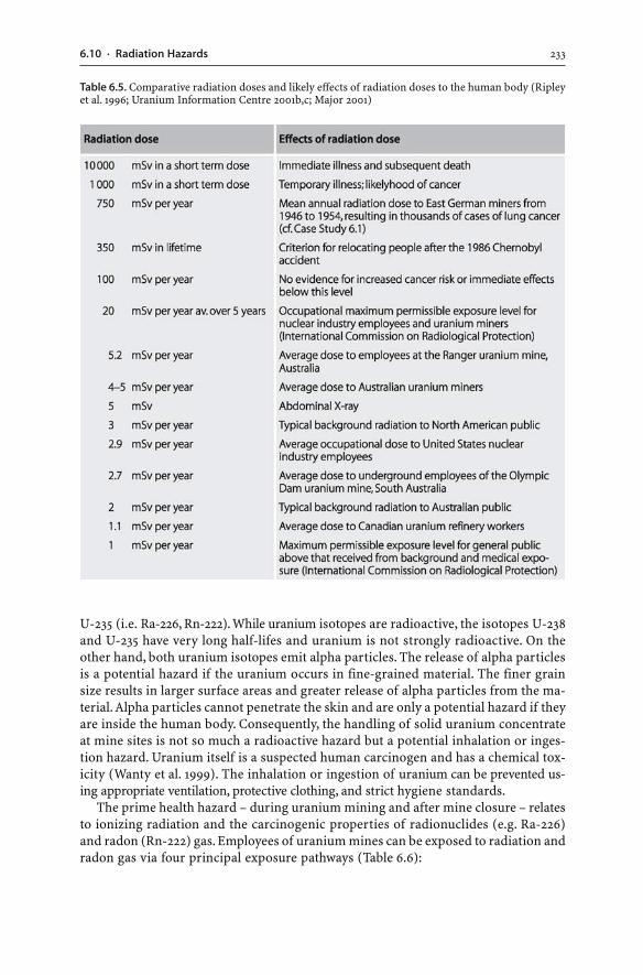
2336.10 · Radiation Hazards
U-235 (i.e. Ra-226, Rn-222). While uranium isotopes are radioactive, the isotopes U-238and U-235 have very long half-lifes and uranium is not strongly radioactive. On theother hand, both uranium isotopes emit alpha particles. The release of alpha particlesis a potential hazard if the uranium occurs in fine-grained material. The finer grainsize results in larger surface areas and greater release of alpha particles from the ma-terial. Alpha particles cannot penetrate the skin and are only a potential hazard if theyare inside the human body. Consequently, the handling of solid uranium concentrateat mine sites is not so much a radioactive hazard but a potential inhalation or inges-tion hazard. Uranium itself is a suspected human carcinogen and has a chemical tox-icity (Wanty et al. 1999). The inhalation or ingestion of uranium can be prevented us-ing appropriate ventilation, protective clothing, and strict hygiene standards.
The prime health hazard – during uranium mining and after mine closure – relatesto ionizing radiation and the carcinogenic properties of radionuclides (e.g. Ra-226)and radon (Rn-222) gas. Employees of uranium mines can be exposed to radiation andradon gas via four principal exposure pathways (Table 6.6):
Table 6.5. Comparative radiation doses and likely effects of radiation doses to the human body (Ripleyet al. 1996; Uranium Information Centre 2001b,c; Major 2001)
234 CHAPTER 6 · Radioactive Wastes of Uranium Ores
� Direct external radiation from uranium ores, tailings and waste rocks. Employees willbe exposed to external radiation in the form of gamma-rays as well as alpha andbeta particles emitted by isotopes of the U-238, U-235 and Th-232 series.
� Ingestion of contaminated water. Leaching of wastes can carry radioactive nuclides,metals, and metalloids to surface and ground waters. Thus, ground and surface wa-ter within or near the mine site can contain elevated levels of dissolved radioactiveisotopes and should not be used as drinking water.
� Inhalation of radon. Radon-222 gas emanates from ores, wastes, and tailings and maybe inhaled by employees. Airborne radionuclides, particularly Rn-222, may impacton the health of humans, because Rn-222 and its radioactive decay products deliveran internal radiation dose to the lungs.
� Inhalation and ingestion of dust containing radioactive isotopes. At uranium minesites, atmospheric emissions are not restricted to radon gas. All mining, tipping,handling, transport, crushing and milling operations produce dust. In addition, dryuncovered tailings can be a source of radioactive dust particles. The ore or tailingsdust contains radioactive isotopes of the U-238, U-235 and Th-232 series, and the dustmay be inhaled and ingested by employees.
Uranium mine wastes emit very low to elevated levels of radiation and variable levelsof radon gas. Today, low level radiation doses for employees can be achieved through(Table 6.6):
� Installation of covers. The release of Rn-222 to the atmosphere from tailings is ma-jor pathway of radon exposure at uranium mine sites. A reduction in radon emana-tion from tailings repositories is generally achieved by installing cover materials. Atoperating uranium mines, tailings are commonly covered with water which reducesradiation levels. Where tailings are collected and kept wet under permanent watercover, the radon flux is reduced to only 1% of the radon flux from dry tailings (Davyand Levins 1984). Wet or dry covers on tailings and other wastes need to be of at least30 cm thickness in order to reduce radiation levels to background levels.
� Dust suppression. The inhalation and ingestion of radionuclides contained in dustneed to be minimized as radionuclides emit gamma-rays and alpha particles. Dustsuppression can be achieved by wetting and covering the potential dust sources.
� Appropriate ventilation. Uranium mine sites are always monitored for levels of ra-don gas that is released during the natural radioactive decay of uranium. Ventila-tion generally reduces radon gas levels, however, in some mines the radiation andradon levels are so high that mining must be done with remote control equipmentand robots. Natural ventilation in an open cut mine removes radon gas whereas anunderground uranium mine requires an engineered ventilation system. Forced ven-tilation reduces radon and radon daughter exposure.
� Radiation dose monitoring. Personal radiation doses are monitored to limit the ra-diation exposure of individual employees.
� Strict hygiene standards, ventilation, and protective clothing. Employees handlinguranium concentrate have to adhere to strict hygiene standards and have to work inprotective clothing in appropriately vented environments. This will minimize theingestion, adsorption and inhalation of uranium.
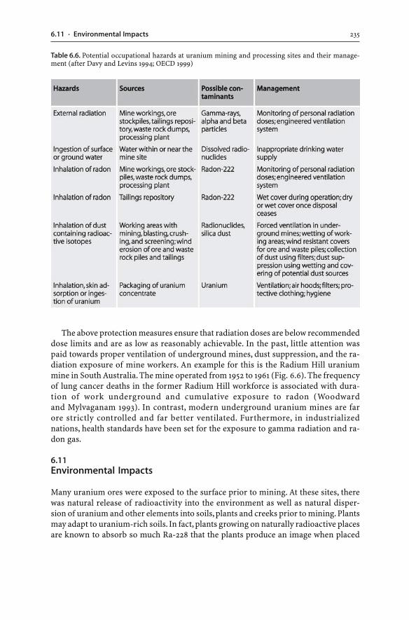
2356.11 · Environmental Impacts
The above protection measures ensure that radiation doses are below recommendeddose limits and are as low as reasonably achievable. In the past, little attention waspaid towards proper ventilation of underground mines, dust suppression, and the ra-diation exposure of mine workers. An example for this is the Radium Hill uraniummine in South Australia. The mine operated from 1952 to 1961 (Fig. 6.6). The frequencyof lung cancer deaths in the former Radium Hill workforce is associated with dura-tion of work underground and cumulative exposure to radon (Woodwardand Mylvaganam 1993). In contrast, modern underground uranium mines are farore strictly controlled and far better ventilated. Furthermore, in industrializednations, health standards have been set for the exposure to gamma radiation and ra-don gas.
6.11Environmental Impacts
Many uranium ores were exposed to the surface prior to mining. At these sites, therewas natural release of radioactivity into the environment as well as natural disper-sion of uranium and other elements into soils, plants and creeks prior to mining. Plantsmay adapt to uranium-rich soils. In fact, plants growing on naturally radioactive placesare known to absorb so much Ra-228 that the plants produce an image when placed
Table 6.6. Potential occupational hazards at uranium mining and processing sites and their manage-ment (after Davy and Levins 1994; OECD 1999)
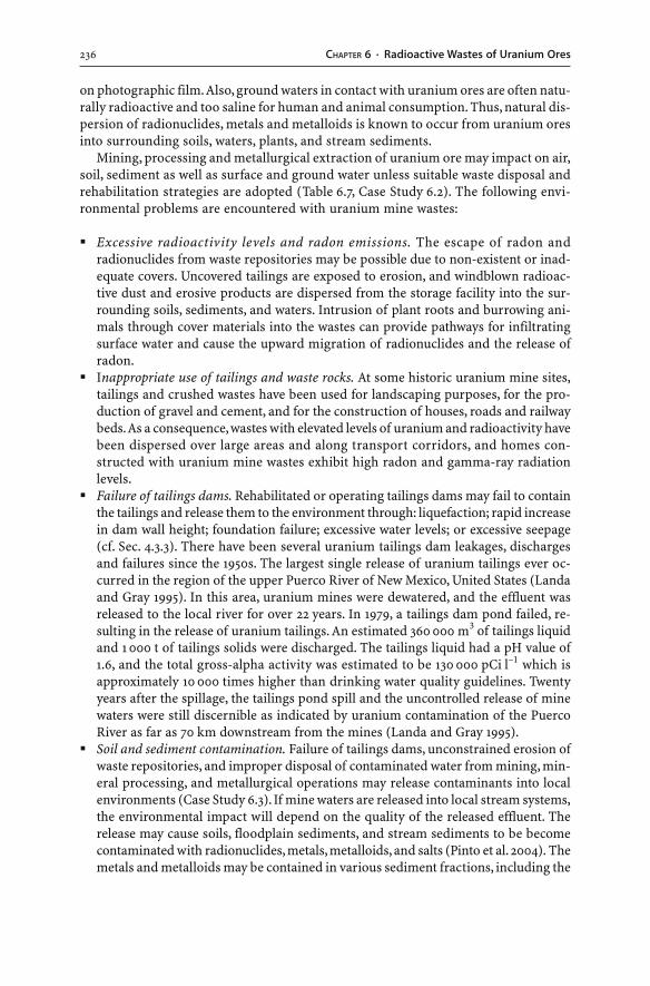
236 CHAPTER 6 · Radioactive Wastes of Uranium Ores
on photographic film. Also, ground waters in contact with uranium ores are often natu-rally radioactive and too saline for human and animal consumption. Thus, natural dis-persion of radionuclides, metals and metalloids is known to occur from uranium oresinto surrounding soils, waters, plants, and stream sediments.
Mining, processing and metallurgical extraction of uranium ore may impact on air,soil, sediment as well as surface and ground water unless suitable waste disposal andrehabilitation strategies are adopted (Table 6.7, Case Study 6.2). The following envi-ronmental problems are encountered with uranium mine wastes:
� Excessive radioactivity levels and radon emissions. The escape of radon andradionuclides from waste repositories may be possible due to non-existent or inad-equate covers. Uncovered tailings are exposed to erosion, and windblown radioac-tive dust and erosive products are dispersed from the storage facility into the sur-rounding soils, sediments, and waters. Intrusion of plant roots and burrowing ani-mals through cover materials into the wastes can provide pathways for infiltratingsurface water and cause the upward migration of radionuclides and the release ofradon.
� Inappropriate use of tailings and waste rocks. At some historic uranium mine sites,tailings and crushed wastes have been used for landscaping purposes, for the pro-duction of gravel and cement, and for the construction of houses, roads and railwaybeds. As a consequence, wastes with elevated levels of uranium and radioactivity havebeen dispersed over large areas and along transport corridors, and homes con-structed with uranium mine wastes exhibit high radon and gamma-ray radiationlevels.
� Failure of tailings dams. Rehabilitated or operating tailings dams may fail to containthe tailings and release them to the environment through: liquefaction; rapid increasein dam wall height; foundation failure; excessive water levels; or excessive seepage(cf. Sec. 4.3.3). There have been several uranium tailings dam leakages, dischargesand failures since the 1950s. The largest single release of uranium tailings ever oc-curred in the region of the upper Puerco River of New Mexico, United States (Landaand Gray 1995). In this area, uranium mines were dewatered, and the effluent wasreleased to the local river for over 22 years. In 1979, a tailings dam pond failed, re-sulting in the release of uranium tailings. An estimated 360 000 m3 of tailings liquidand 1 000 t of tailings solids were discharged. The tailings liquid had a pH value of1.6, and the total gross-alpha activity was estimated to be 130 000 pCi l–1 which isapproximately 10 000 times higher than drinking water quality guidelines. Twentyyears after the spillage, the tailings pond spill and the uncontrolled release of minewaters were still discernible as indicated by uranium contamination of the PuercoRiver as far as 70 km downstream from the mines (Landa and Gray 1995).
� Soil and sediment contamination. Failure of tailings dams, unconstrained erosion ofwaste repositories, and improper disposal of contaminated water from mining, min-eral processing, and metallurgical operations may release contaminants into localenvironments (Case Study 6.3). If mine waters are released into local stream systems,the environmental impact will depend on the quality of the released effluent. Therelease may cause soils, floodplain sediments, and stream sediments to be becomecontaminated with radionuclides, metals, metalloids, and salts (Pinto et al. 2004). Themetals and metalloids may be contained in various sediment fractions, including the
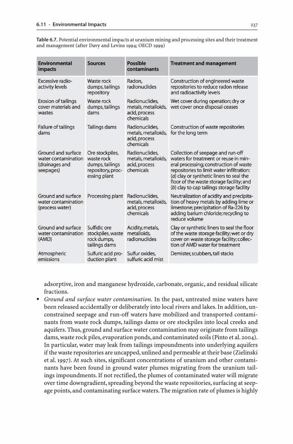
2376.11 · Environmental Impacts
adsorptive, iron and manganese hydroxide, carbonate, organic, and residual silicatefractions.
� Ground and surface water contamination. In the past, untreated mine waters havebeen released accidentally or deliberately into local rivers and lakes. In addition, un-constrained seepage and run-off waters have mobilized and transported contami-nants from waste rock dumps, tailings dams or ore stockpiles into local creeks andaquifers. Thus, ground and surface water contamination may originate from tailingsdams, waste rock piles, evaporation ponds, and contaminated soils (Pinto et al. 2004).In particular, water may leak from tailings impoundments into underlying aquifersif the waste repositories are uncapped, unlined and permeable at their base (Zielinskiet al. 1997). At such sites, significant concentrations of uranium and other contami-nants have been found in ground water plumes migrating from the uranium tail-ings impoundments. If not rectified, the plumes of contaminated water will migrateover time downgradient, spreading beyond the waste repositories, surfacing at seep-age points, and contaminating surface waters. The migration rate of plumes is highly
Table 6.7. Potential environmental impacts at uranium mining and processing sites and their treatmentand management (after Davy and Levins 1994; OECD 1999)
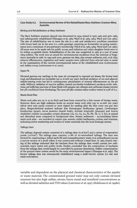
238 CHAPTER 6 · Radioactive Wastes of Uranium Ores
variable and dependent on the physical and chemical characteristics of the aquiferor waste material. The contaminated ground water may not only contain elevateduranium but also high sulfate, nitrate, heavy metal and metalloid concentrations aswell as elevated salinities and TDS values (Lawrence et al. 1997; Abdelouas et al. 1998a).
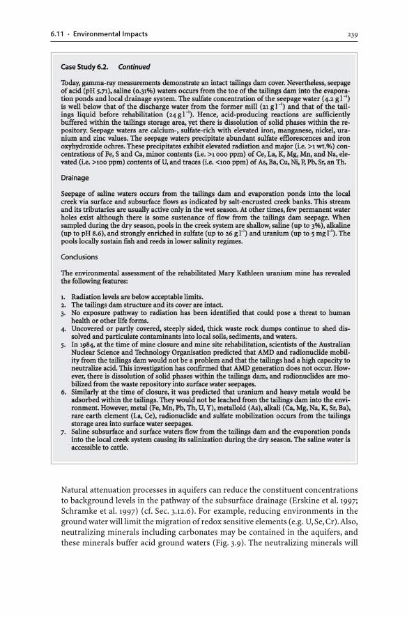
2396.11 · Environmental Impacts
Natural attenuation processes in aquifers can reduce the constituent concentrationsto background levels in the pathway of the subsurface drainage (Erskine et al. 1997;Schramke et al. 1997) (cf. Sec. 3.12.6). For example, reducing environments in theground water will limit the migration of redox sensitive elements (e.g. U, Se, Cr). Also,neutralizing minerals including carbonates may be contained in the aquifers, andthese minerals buffer acid ground waters (Fig. 3.9). The neutralizing minerals will
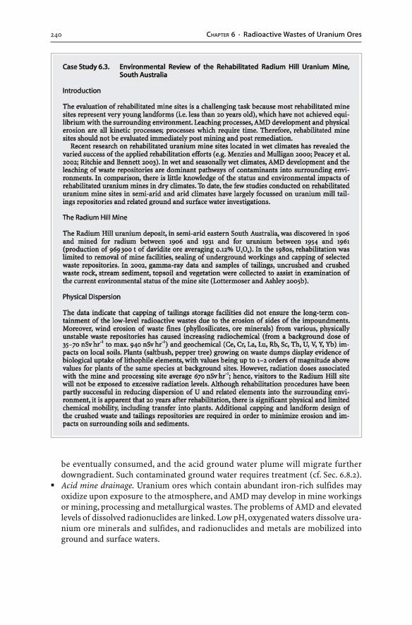
240 CHAPTER 6 · Radioactive Wastes of Uranium Ores
be eventually consumed, and the acid ground water plume will migrate furtherdowngradient. Such contaminated ground water requires treatment (cf. Sec. 6.8.2).
� Acid mine drainage. Uranium ores which contain abundant iron-rich sulfides mayoxidize upon exposure to the atmosphere, and AMD may develop in mine workingsor mining, processing and metallurgical wastes. The problems of AMD and elevatedlevels of dissolved radionuclides are linked. Low pH, oxygenated waters dissolve ura-nium ore minerals and sulfides, and radionuclides and metals are mobilized intoground and surface waters.
2416.12 · Summary
6.12Summary
Radioactivity is the issue which sets uranium mine wastes apart from other minewastes. Uranium commonly occurs in the form of uraninite, brannerite, coffinite, andpitchblende. Much of the radioactivity of uranium ores and wastes is due to the decayof the uranium isotopes U-238 and U-235 and their radioactive decay products. Theseradionuclides serve as a long-term source of ionizing radiation. Radium-226 andRn-222 are intermediate daughter nuclides of the U-238 series. They are of most con-cern in uranium mining, processing, metallurgical extraction, and waste management.Radium-226 is a radionuclide that has: (a) a significant half-life of 1 622 years; (b) a geo-chemical behaviour similar to calcium; (c) a high radiotoxicity; (d) an affinity for ac-cumulating in bones; and (e) a high solubility in ground and surface waters. Radium-226 is the source of Rn-222. Radon-222 is a radionuclide that: (a) has a half-life of3.8 days; (b) is soluble in water; (c) is highly mobile due to its gaseous state and inertchemical properties; and (d) decays to radioactive solid daughter products that canbe deposited in human lungs.
Mineral processing of uranium ores relies on acid or alkaline leaching. Conventionaluranium extraction is based on the leaching of the ore in hydrometallurgical plantsor heap leach piles. In situ leach techniques leave the ore in the ground and inject theprocess chemicals via drill holes into the ore horizon. The process chemicals producea solution from which uranium is obtained.
Mining, mineral processing and metallurgical extraction of uranium ores result inthe production of tailings, mine water, waste rocks, and heap leach residues. Mostwastes of uranium mining and processing operations can be classified in terms of ra-dioactivity as non-radioactive or low-level radioactive waste.
Conventional extraction of uranium in a hydrometallurgical plant produces ura-nium mill tailings. Once the uranium (U-238, U-235, U-234) is recovered from the ore,most of the radioactive daughter nuclides end up in uranium mill tailings. Thus, ura-nium tailings have special containment requirements because of their radioactivity.Tailings carry about 85% of the radioactivity originally present in the uranium ore.
Uranium tailings contain radionuclides, heavy metals and metalloids as: (a) dis-solved species; and (b) insoluble and potentially soluble solid forms. The potentialrelease of radionuclides, heavy metals, and metalloids from tailings solids and thepresence of radionuclides in solution are undesirable. Pore waters laden with contami-nants may migrate into aquifers or surface at seepage points. The mobilization of ra-dionuclides, heavy metals and metalloids from tailings solids into the tailings liquidsmay occur after tailings deposition. Such mobilization can be induced through sev-eral factors: (a) AMD development; (b) presence of process chemicals; (c) acid leach-ing or reduction of iron and manganese oxyhydroxides; (d) bacterial reduction; and(e) presence of clay minerals. Acid leached tailings tend to contain high concentra-tions of soluble and dissolved radionuclides, heavy metals and sulfate unless the tail-ings have been neutralized prior to discharge to the tailings storage facility.
Uranium tailings need to be covered during operation in order to reduce Rn-222emanation. Finite disposal options for uranium tailings include: (a) placing them underwater in a lake, ocean or wetland environment; (b) backfilling them into a mined-out
242 CHAPTER 6 · Radioactive Wastes of Uranium Ores
open pit; and more commonly (c) dumping them into a tailings dam. Once miningceases, uranium tailings repositories require covers, and conventional cover designsare multi-layer barriers. Uranium tailings contain radioactive isotopes with half-lifesexceeding the engineered design and structural life of tailings dams. Therefore, thelong-term stability of uranium tailings dams is important in regions with high ero-sion rates.
Mine water at uranium mine sites is invariably radioactive arising from dissolvedU-238, U-235, Th-230, Ra-226 and Pb-210 ions. The water may also contain various heavymetals and metalloids, and some of the heavy metal load can be the result of sulfideoxidation and resulting AMD. Dissolved uranium in oxidized mine water is mainly inthe form of the uranyl ion (UO2
2+) which forms complexes with carbonate, sulfate, andother ligands. Uranium can be effectively leached from mine wastes under acid, oxi-dizing weathering conditions. The uranium will remain in solution until: (a) the pHis raised to higher levels; (b) coprecipitation or adsorption reactions occur; or (c) re-ducing environments are met. Surface and ground water can be contaminated withradionuclides, metals, metalloids, acid, and process chemicals. Treatment techniquesof such contaminated waters include land irrigation, neutralization, wetlands, andradium removal. Contaminated ground water may be treated using ex situ (pump-and-treat) or in situ (bioremediation, permeable reactive barriers) techniques.
Environmental concerns with uranium mining include radiation hazards, in par-ticular to the workforce. Employees of uranium mines can be exposed to ionizing ra-diation and radon gas via: direct external radiation from uranium ores, tailings andwaste rocks; ingestion of contaminated water; inhalation of radon; and inhalation andingestion of dust containing radioactive isotopes. These radiation hazards can be mini-mized and low level radiation doses can be achieved through: installation of covers;appropriate ventilation; dust suppression; radiation dose monitoring; strict hygienestandards, ventilation, and protective clothing; and installation of covers on tailings.Environmental impacts of uranium mine wastes include: excessive radioactivity lev-els and radon emissions; inappropriate use of tailings and waste rocks; failure of tail-ings dams; soil, sediment, and ground and surface water contamination; and acid minedrainage.
Further information on uranium mine wastes can be obtained from web sites shownin Table 6.8.
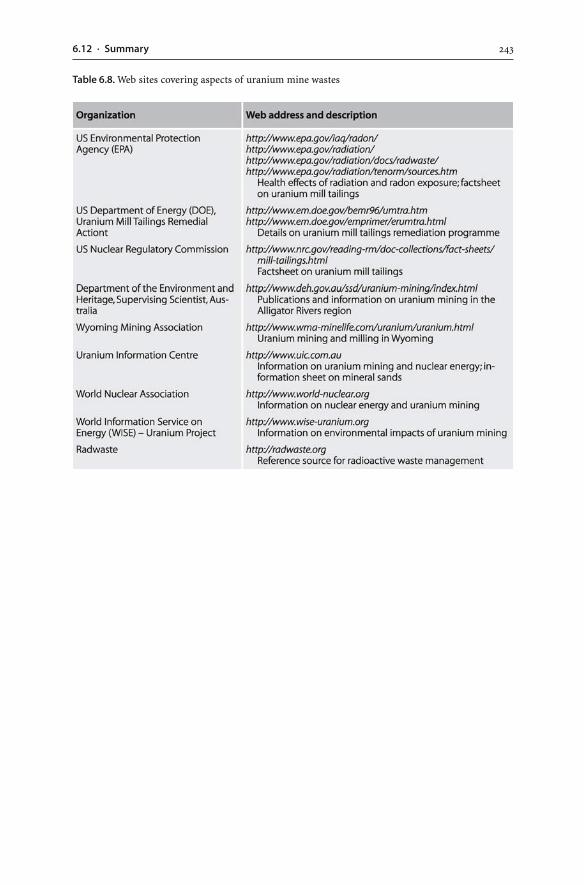
2436.12 · Summary
Table 6.8. Web sites covering aspects of uranium mine wastes
Chapter 7
Wastes of Phosphate and Potash Ores
7.1Introduction
Plants and agricultural crops require phosphorus, potassium, and nitrogen as macro-nutrients. In order to maintain agricultural crop yields, these elements must be addedto replace those lost from the soil. In most cases, the nutrients are added to agricul-tural land as mineral fertilizers (UNEP/IFA 2001). Nitrogen fertilizers are generallyproduced from atmospheric nitrogen, water, and energy. In contrast, the productionof phosphate and potassium fertilizers relies on the provision of phosphate rock andpotash ores. The majority of mined phosphate rock and potash ore is processed tofertilizer; a minor proportion of the mined material is used for other purposes. Worldpopulation growth and the necessity to provide adequate food supplies have resultedin the significant growth of phosphate and potash mining, and fertilizer consump-tion over the last 100 years. This growth has also led to the ever increasing volume ofphosphate and potash mine wastes.
In this chapter, potash and phosphate deposits will be introduced prior to the docu-mentation of the different wastes accumulating at potash and phosphate mines. Thisis because an understanding of phosphate and potash mine wastes requires a knowl-edge of their ore deposits since ore properties influence the characteristics of minewastes. As many of the waste disposal problems and environmental impacts of phos-phate mining and fertilizer manufacturing are centered on phosphogypsum, particu-lar emphasis is placed on this topic.
7.2Potash Mine Wastes
Potash is a generic term which refers to a number of potassium salts includingcarbonate, sulfate and chloride compounds. The production of potash and othersalts principally relies on the mining of evaporitic salt deposits. As with all mining,mineral processing and metallurgical activities, the exploitation of salt ores notonly generates mineral resources but also mine wastes. Salt ores have the specificissue of salinity and hence, potash mine wastes are invariably saline. This proper-ty differentiates potash mine wastes from other mine wastes. Appropriate disposaland rehabilitation strategies of potash mine wastes should ensure that these was-tes do not release salinity into the environment and cause significant environmentalharm.
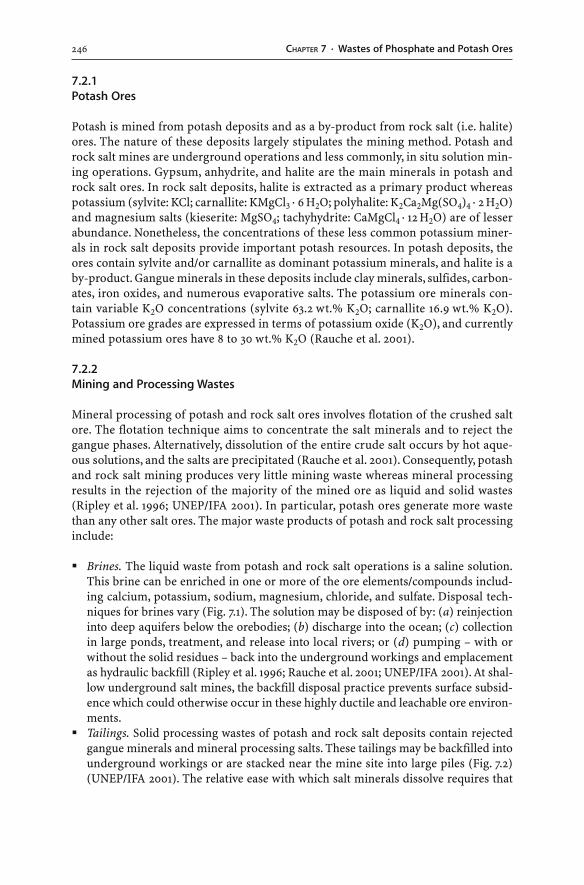
246 CHAPTER 7 · Wastes of Phosphate and Potash Ores
7.2.1Potash Ores
Potash is mined from potash deposits and as a by-product from rock salt (i.e. halite)ores. The nature of these deposits largely stipulates the mining method. Potash androck salt mines are underground operations and less commonly, in situ solution min-ing operations. Gypsum, anhydrite, and halite are the main minerals in potash androck salt ores. In rock salt deposits, halite is extracted as a primary product whereaspotassium (sylvite: KCl; carnallite: KMgCl3 · 6 H2O; polyhalite: K2Ca2Mg(SO4)4 · 2 H2O)and magnesium salts (kieserite: MgSO4; tachyhydrite: CaMgCl4 · 12 H2O) are of lesserabundance. Nonetheless, the concentrations of these less common potassium miner-als in rock salt deposits provide important potash resources. In potash deposits, theores contain sylvite and/or carnallite as dominant potassium minerals, and halite is aby-product. Gangue minerals in these deposits include clay minerals, sulfides, carbon-ates, iron oxides, and numerous evaporative salts. The potassium ore minerals con-tain variable K2O concentrations (sylvite 63.2 wt.% K2O; carnallite 16.9 wt.% K2O).Potassium ore grades are expressed in terms of potassium oxide (K2O), and currentlymined potassium ores have 8 to 30 wt.% K2O (Rauche et al. 2001).
7.2.2Mining and Processing Wastes
Mineral processing of potash and rock salt ores involves flotation of the crushed saltore. The flotation technique aims to concentrate the salt minerals and to reject thegangue phases. Alternatively, dissolution of the entire crude salt occurs by hot aque-ous solutions, and the salts are precipitated (Rauche et al. 2001). Consequently, potashand rock salt mining produces very little mining waste whereas mineral processingresults in the rejection of the majority of the mined ore as liquid and solid wastes(Ripley et al. 1996; UNEP/IFA 2001). In particular, potash ores generate more wastethan any other salt ores. The major waste products of potash and rock salt processinginclude:
� Brines. The liquid waste from potash and rock salt operations is a saline solution.This brine can be enriched in one or more of the ore elements/compounds includ-ing calcium, potassium, sodium, magnesium, chloride, and sulfate. Disposal tech-niques for brines vary (Fig. 7.1). The solution may be disposed of by: (a) reinjectioninto deep aquifers below the orebodies; (b) discharge into the ocean; (c) collectionin large ponds, treatment, and release into local rivers; or (d) pumping – with orwithout the solid residues – back into the underground workings and emplacementas hydraulic backfill (Ripley et al. 1996; Rauche et al. 2001; UNEP/IFA 2001). At shal-low underground salt mines, the backfill disposal practice prevents surface subsid-ence which could otherwise occur in these highly ductile and leachable ore environ-ments.
� Tailings. Solid processing wastes of potash and rock salt deposits contain rejectedgangue minerals and mineral processing salts. These tailings may be backfilled intounderground workings or are stacked near the mine site into large piles (Fig. 7.2)(UNEP/IFA 2001). The relative ease with which salt minerals dissolve requires that
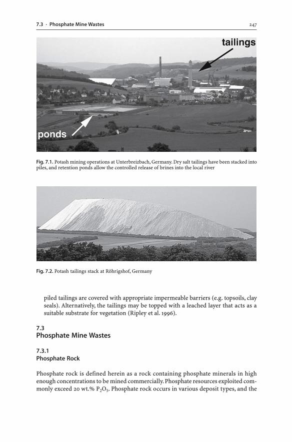
2477.3 · Phosphate Mine Wastes
piled tailings are covered with appropriate impermeable barriers (e.g. topsoils, clayseals). Alternatively, the tailings may be topped with a leached layer that acts as asuitable substrate for vegetation (Ripley et al. 1996).
7.3Phosphate Mine Wastes
7.3.1Phosphate Rock
Phosphate rock is defined herein as a rock containing phosphate minerals in highenough concentrations to be mined commercially. Phosphate resources exploited com-monly exceed 20 wt.% P2O5. Phosphate rock occurs in various deposit types, and the
Fig. 7.1. Potash mining operations at Unterbreizbach, Germany. Dry salt tailings have been stacked intopiles, and retention ponds allow the controlled release of brines into the local river
Fig. 7.2. Potash tailings stack at Röhrigshof, Germany
248 CHAPTER 7 · Wastes of Phosphate and Potash Ores
principal industrial mineral of all deposits is apatite in the form of fluorapatite(Ca5(PO4)3(F)) and/or carbonate fluorapatite (Ca5(PO4,CO3)3(F)). Exploitable phos-phate deposits can be divided into three types: phosphorites; carbonatites and alka-line igneous rocks; guano deposits. Of these deposits, phosphorites constitute the pre-dominantly mined ore.
1. Phosphorites. Phosphorites or marine sedimentary phosphate deposits contain car-bonate fluorapatite with 1 wt.% fluorine and appreciable amounts of carbonate asthe phosphate mineral (e.g. USA, Morocco, Togo, Egypt, eastern Australia). This apa-tite form is also referred to as francolite. The francolite is present as nodules or pel-lets up to several millimeters in diameter which may contain various impurities. Theimpurities occur as physical inclusions (e.g. quartz, clays, iron oxyhydroxides, organicmatter, carbonates) or as crystallographic substitutions within the phosphate min-eral. Ions which will substitute for calcium, phosphate and fluorine within thefrancolite lattice are diverse and mainly include sodium, magnesium, strontium,carbonate, and sulfate as well as various trace elements (e.g. U, Th, REE, Y, Cd, Zn)(Jarvis et al. 1994; Rutherford et al. 1994). Trace heavy metal and metalloid en-richments (e.g. Ag, As, Cd, Cu, Mo, Ni, Sb, Se, V, Zn) of phosphorites are associatedwith abundant organic matter. The enrichment is likely due to the adsorption orincorporation of these elements in organic substances or sulfides.
2. Carbonatites and alkaline igneous rocks. Carbonatites and other alkaline igneousrocks commonly contain elevated phosphate concentrations in the form of fluora-patite (e.g. Russia, Canada). Weathering of these igneous rocks removes soluble car-bonate minerals and leads to the natural concentration of fluorapatite and otherweathering resistant minerals (e.g. magnetite, pyrochlore). Deep weathering profiles– overlying and derived from carbonatites – are known to contain distinctly elevatedphosphate concentrations in the form of fluorapatite (e.g. western Australia, Brazil).Secondary aluminophosphate minerals such as crandallite (CaAl3(PO4)2(OH)5H2O) mayform during weathering of the apatite. These crandallite-rich horizons are not suit-able for phosphate extraction.
3. Guano deposits. Guano deposits on tropical coral islands represent originally birdexcrements which have been leached, oxidized, and redeposited as amorphous andcrystalline phosphates. Commercial guano deposits have largely been mined out, andthere has been no production of mining or processing wastes on site due to the na-ture of the deposits. Some of the mined deposits require extensive rehabilitation(e.g. Christmas Island, Nauru, Ocean Island). For example, phosphate mining on theisland of Nauru has disturbed land to such an extent that only the coastal fringe ofthe island remains habitable.
The presence of elevated radionuclide, arsenic, cadmium, selenium and thalliumconcentrations in some guano and phosphorite deposits can limit the use of thesedeposits. Fertilizers manufactured from such deposits will contain elevated concen-trations of these elements (Lottermoser and Schomberg 1993; Jarvis et al. 1994). Cad-mium, in particular, can accumulate in soils and plants through repeated fertilizer use,and fertilizer application to agricultural land may result in the transfer of cadmiuminto the food chain. Cadmium-rich phosphorites are considered to be unsuitable for fer-tilizer production, and the application of cadmium enriched fertilizers has been restricted
2497.3 · Phosphate Mine Wastes
in some countries. Also, fertilizers contain trace quantities of uranium, and the applica-tion of fertilizer to agricultural land and soil erosion add uranium to local waterways andoceans. For instance, the Everglade wetlands and the Mediterranean Sea contain fertilizer-derived uranium due to phosphate fertilizer inputs (Ragnarsdottir and Charlet 2000).
7.3.1.1Mineralogy and Geochemistry
The principal mineral of all ores is apatite while the gangue mineralogy of phosphatedeposits is deposit specific. Gangue minerals include framework, ortho, ring, chainand sheet silicates as well as sulfides, oxides, hydroxides, sulfates, and carbonates. Thevariation in gangue mineralogy causes the major and trace element geochemistry ofphosphate deposits to be variable. In particular, phosphorite deposits tend to possesselevated uranium, thorium, rare earth element, yttrium, heavy metal and metalloidvalues (Jarvis et al. 1994). Carbonatite and alkaline igneous rock related deposits dis-play high uranium, thorium, rare earth element, yttrium, niobium, tantalum, titaniumand zirconium concentrations.
Some phosphate deposits have elevated radioactivity and radon levels (Rutherfordet al. 1994). The radioactivity and radon originate from abundant uranium and tho-rium, and the daughter nuclides of the U-238, U-235 and Th-232 decay series (Table 6.2).Uranium and thorium concentrations of phosphate deposits are highly variable, andigneous deposits tend to contain lower uranium and higher thorium levels than sedi-mentary phosphorites. Beneficiation of phosphate rocks not only leads to concentra-tion of the phosphate minerals but also to the concentration of the specific radioac-tivity (Ci kg–1) contained in the phosphate rock. Most of the radioactive nuclides arelikely hosted by the apatite crystal lattice or are adsorbed onto surfaces of clays andorganics (Burnett et al. 1995). On the other hand, some radionuclides, such as Ra-226,have ionic radii and charges which are not commensurate with the size and charge ofthe host calcium cation of apatite. As a consequence, Ra-226 may be present in sepa-rate barium-strontium sulfate phases (Rutherford et al. 1994).
7.3.2Mining, Processing and Hydrometallurgical Wastes
Due to the nature of many phosphate deposits, waste rocks or overburden must be re-moved to extract the ore. The mined rock is then processed with water to remove un-wanted gangue minerals and to concentrate the phosphate minerals to a raw materialfor phosphoric acid production. The processing generates a phosphate mineral con-centrate and unwanted fine-grained rock and mineral particles. These tailings are ei-ther discarded in tailings ponds or are discharged into rivers and oceans. The pro-duction of phosphoric acid is commonly achieved by dissolving the washed and con-centrated phosphate minerals in sulfuric acid. The unwanted by-product of such fer-tilizer manufacturing is referred to as “phosphogypsum”. In many cases, fertilizer plantshave been built adjacent to, or in the vicinity of, phosphate mines. As a result, vastquantities of phosphogypsum accumulate at phosphate mine sites. Wastes of phos-phate mining, processing and metallurgical extraction can be grouped into the fol-lowing four main categories (UNEP/IFA 2001) (Fig. 7.3):
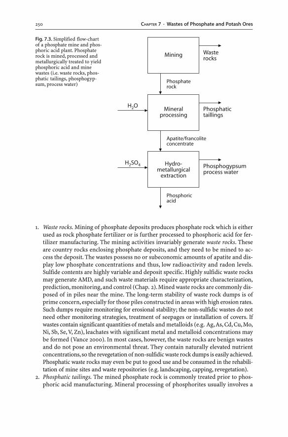
250 CHAPTER 7 · Wastes of Phosphate and Potash Ores
1. Waste rocks. Mining of phosphate deposits produces phosphate rock which is eitherused as rock phosphate fertilizer or is further processed to phosphoric acid for fer-tilizer manufacturing. The mining activities invariably generate waste rocks. Theseare country rocks enclosing phosphate deposits, and they need to be mined to ac-cess the deposit. The wastes possess no or subeconomic amounts of apatite and dis-play low phosphate concentrations and thus, low radioactivity and radon levels.Sulfide contents are highly variable and deposit specific. Highly sulfidic waste rocksmay generate AMD, and such waste materials require appropriate characterization,prediction, monitoring, and control (Chap. 2). Mined waste rocks are commonly dis-posed of in piles near the mine. The long-term stability of waste rock dumps is ofprime concern, especially for those piles constructed in areas with high erosion rates.Such dumps require monitoring for erosional stability; the non-sulfidic wastes do notneed other monitoring strategies, treatment of seepages or installation of covers. Ifwastes contain significant quantities of metals and metalloids (e.g. Ag, As, Cd, Cu, Mo,Ni, Sb, Se, V, Zn), leachates with significant metal and metalloid concentrations maybe formed (Vance 2000). In most cases, however, the waste rocks are benign wastesand do not pose an environmental threat. They contain naturally elevated nutrientconcentrations, so the revegetation of non-sulfidic waste rock dumps is easily achieved.Phosphatic waste rocks may even be put to good use and be consumed in the rehabili-tation of mine sites and waste repositories (e.g. landscaping, capping, revegetation).
2. Phosphatic tailings. The mined phosphate rock is commonly treated prior to phos-phoric acid manufacturing. Mineral processing of phosphorites usually involves a
Fig. 7.3. Simplified flow-chartof a phosphate mine and phos-phoric acid plant. Phosphaterock is mined, processed andmetallurgically treated to yieldphosphoric acid and minewastes (i.e. waste rocks, phos-phatic tailings, phosphogyp-sum, process water)
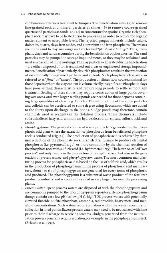
2517.3 · Phosphate Mine Wastes
combination of various treatment techniques. The beneficiation aims: (a) to removefine-grained rock and mineral particles as slimes; (b) to remove coarse-grainedquartz sand particles as sands; and (c) to concentrate the apatite. Organic-rich phos-phate rock may have to be heated prior to processing in order to reduce the organicmatter content to acceptable levels. The rejected gangue minerals include calcite,dolomite, quartz, clays, iron oxides, and aluminium and iron phosphates. The wastesare in the sand to clay size range and are termed “phosphatic tailings”. Thus, phos-phatic clays and sands accumulate during the beneficiation of phosphorites. The sandparticles may be pumped to storage impoundments, or they may be reclaimed andused as a backfill of mine workings. The clay particles – liberated during benefication– are either disposed of to rivers, mined-out areas or engineered storage impound-ments. Beneficiation of particularly clay-rich phosphorites results in the productionof exceptionally fine-grained particles and colloids. Such phosphatic clays are alsoreferred to as “fines” or “slimes”. The production of slimes is, of course, minimal forthose deposits where the clay content is volumetrically insignificant. Phosphatic clayshave poor settling characteristics and require long periods to settle without anytreatment. Settling of these slimes may require construction of large ponds cover-ing vast areas, and even larger settling ponds are needed for those deposits contain-ing large quantities of clays (e.g. Florida). The settling time of the slime particlesand colloids can be accelerated to some degree using flocculants, which are addedto the slurry upon discharge to the ponds. Sludge ponds may, therefore, containchemicals used as reagents in the flotation process. These chemicals includesoda ash, diesel, fatty acid, ammonium hydroxide, sodium silicate, sulfuric acid, andamine.
3. Phosphogypsum. The greatest volume of waste products is generated in the phos-phoric acid plant where the extraction of phosphorus from beneficiated phosphaterock is conducted (Fig. 7.4). The production of phosphoric acid is achieved by ther-mal reduction of the phosphate rock in an electric furnace to produce elementalphosphorus (i.e. pyrometallurgy), or more commonly by the chemical reaction ofthe phosphate rock with sulfuric acid (i.e. hydrometallurgy). The latter, so-called “wetprocess”, not only results in the production of phosphoric acid but also in the gen-eration of process waters and phosphogypsum waste. The most common manufac-turing process for phosphoric acid is based on the use of sulfuric acid, which resultsin the production of phosphogypsum. In the process of phosphoric acid manufac-ture, about 3 to 6 t of phosphogypsum are generated for every tonne of phosphoricacid produced. The phosphogypsum is a substantial waste product of the fertilizerproducing industry and is commonly stored in very large piles near the processingplants.
4. Process water. Spent process waters are disposed of with the phosphogypsum andare commonly pumped to the phosphogypsum repository. Hence, phosphogypsumdumps contain very low pH (as low pH 1), high TDS process waters with potentiallyelevated fluoride, sulfate, phosphate, ammonia, radionuclide, heavy metal and met-alloid concentrations. Such waters require isolation within the waste repository orcollection in lined ponds. Excess process waters may need to be neutralized with limeprior to their discharge to receiving streams. Sludges generated from the neutrali-zation process generally require isolation, for example, in the phosphogypsum stack(Ericson et al. 1997).
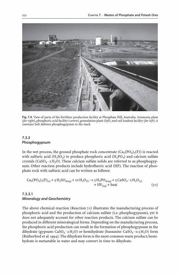
252 CHAPTER 7 · Wastes of Phosphate and Potash Ores
7.3.3Phosphogypsum
In the wet process, the ground phosphate rock concentrate (Ca5(PO4)3(F)) is reactedwith sulfuric acid (H2SO4) to produce phosphoric acid (H3PO4) and calcium sulfatecrystals (CaSO4 · 2 H2O). These calcium sulfate solids are referred to as phosphogyp-sum. Other reaction products include hydrofluoric acid (HF). The reaction of phos-phate rock with sulfuric acid can be written as follows:
Ca5(PO4)3(F)(s) + 5 H2SO4(aq) + 10 H2O(l) → 3 H3PO4(aq) + 5 CaSO4 · 2 H2O(s)
+ HF(aq) + heat (7.1)
7.3.3.1Mineralogy and Geochemistry
The above chemical reaction (Reaction 7.1) illustrates the manufacturing process ofphosphoric acid and the production of calcium sulfate (i.e. phosphogypsum), yet itdoes not adequately account for other reaction products. The calcium sulfate can beproduced in different mineralogical forms. Depending on the manufacturing process,the phosphoric acid production can result in the formation of phosphogypsum in thedihydrate (gypsum: CaSO4 · 2 H2O) or hemihydrate (bassanite: CaSO4 · 0.5 H2O) form(Rutherford et al. 1994). The dihydrate form is the most common waste product; hemi-hydrate is metastable in water and may convert in time to dihydrate.
Fig. 7.4. View of parts of the fertilizer production facility at Phosphate Hill, Australia. Ammonia plant(far right), phosphoric acid facility (centre), granulation plant (left), and rail loadout facility (far left). Aconveyer belt delivers phosphogypsum to the stack
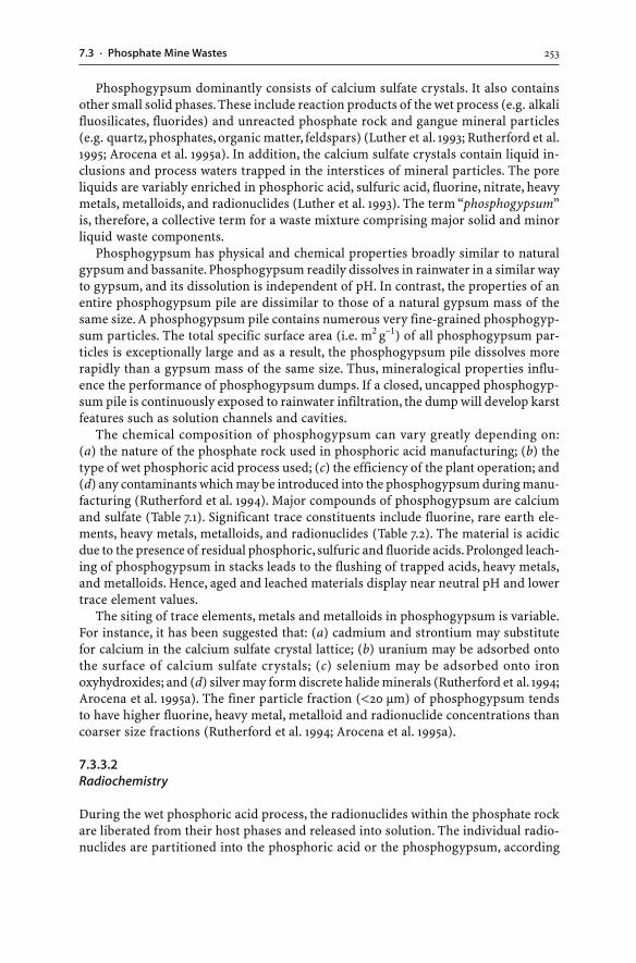
2537.3 · Phosphate Mine Wastes
Phosphogypsum dominantly consists of calcium sulfate crystals. It also containsother small solid phases. These include reaction products of the wet process (e.g. alkalifluosilicates, fluorides) and unreacted phosphate rock and gangue mineral particles(e.g. quartz, phosphates, organic matter, feldspars) (Luther et al. 1993; Rutherford et al.1995; Arocena et al. 1995a). In addition, the calcium sulfate crystals contain liquid in-clusions and process waters trapped in the interstices of mineral particles. The poreliquids are variably enriched in phosphoric acid, sulfuric acid, fluorine, nitrate, heavymetals, metalloids, and radionuclides (Luther et al. 1993). The term “phosphogypsum”is, therefore, a collective term for a waste mixture comprising major solid and minorliquid waste components.
Phosphogypsum has physical and chemical properties broadly similar to naturalgypsum and bassanite. Phosphogypsum readily dissolves in rainwater in a similar wayto gypsum, and its dissolution is independent of pH. In contrast, the properties of anentire phosphogypsum pile are dissimilar to those of a natural gypsum mass of thesame size. A phosphogypsum pile contains numerous very fine-grained phosphogyp-sum particles. The total specific surface area (i.e. m2 g–1) of all phosphogypsum par-ticles is exceptionally large and as a result, the phosphogypsum pile dissolves morerapidly than a gypsum mass of the same size. Thus, mineralogical properties influ-ence the performance of phosphogypsum dumps. If a closed, uncapped phosphogyp-sum pile is continuously exposed to rainwater infiltration, the dump will develop karstfeatures such as solution channels and cavities.
The chemical composition of phosphogypsum can vary greatly depending on:(a) the nature of the phosphate rock used in phosphoric acid manufacturing; (b) thetype of wet phosphoric acid process used; (c) the efficiency of the plant operation; and(d) any contaminants which may be introduced into the phosphogypsum during manu-facturing (Rutherford et al. 1994). Major compounds of phosphogypsum are calciumand sulfate (Table 7.1). Significant trace constituents include fluorine, rare earth ele-ments, heavy metals, metalloids, and radionuclides (Table 7.2). The material is acidicdue to the presence of residual phosphoric, sulfuric and fluoride acids. Prolonged leach-ing of phosphogypsum in stacks leads to the flushing of trapped acids, heavy metals,and metalloids. Hence, aged and leached materials display near neutral pH and lowertrace element values.
The siting of trace elements, metals and metalloids in phosphogypsum is variable.For instance, it has been suggested that: (a) cadmium and strontium may substitutefor calcium in the calcium sulfate crystal lattice; (b) uranium may be adsorbed ontothe surface of calcium sulfate crystals; (c) selenium may be adsorbed onto ironoxyhydroxides; and (d) silver may form discrete halide minerals (Rutherford et al. 1994;Arocena et al. 1995a). The finer particle fraction (<20 µm) of phosphogypsum tendsto have higher fluorine, heavy metal, metalloid and radionuclide concentrations thancoarser size fractions (Rutherford et al. 1994; Arocena et al. 1995a).
7.3.3.2Radiochemistry
During the wet phosphoric acid process, the radionuclides within the phosphate rockare liberated from their host phases and released into solution. The individual radio-nuclides are partitioned into the phosphoric acid or the phosphogypsum, according
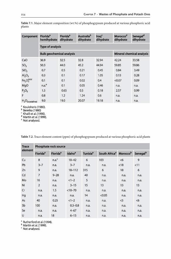
254 CHAPTER 7 · Wastes of Phosphate and Potash Ores
Table 7.1. Major element composition (wt.%) of phosphogypsum produced at various phosphoric acidplants
Table 7.2. Trace element content (ppm) of phosphogypsum produced at various phosphoric acid plants
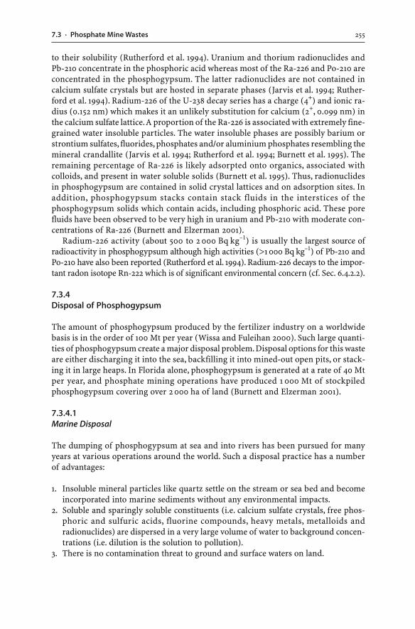
2557.3 · Phosphate Mine Wastes
to their solubility (Rutherford et al. 1994). Uranium and thorium radionuclides andPb-210 concentrate in the phosphoric acid whereas most of the Ra-226 and Po-210 areconcentrated in the phosphogypsum. The latter radionuclides are not contained incalcium sulfate crystals but are hosted in separate phases (Jarvis et al. 1994; Ruther-ford et al. 1994). Radium-226 of the U-238 decay series has a charge (4+) and ionic ra-dius (0.152 nm) which makes it an unlikely substitution for calcium (2+, 0.099 nm) inthe calcium sulfate lattice. A proportion of the Ra-226 is associated with extremely fine-grained water insoluble particles. The water insoluble phases are possibly barium orstrontium sulfates, fluorides, phosphates and/or aluminium phosphates resembling themineral crandallite (Jarvis et al. 1994; Rutherford et al. 1994; Burnett et al. 1995). Theremaining percentage of Ra-226 is likely adsorpted onto organics, associated withcolloids, and present in water soluble solids (Burnett et al. 1995). Thus, radionuclidesin phosphogypsum are contained in solid crystal lattices and on adsorption sites. Inaddition, phosphogypsum stacks contain stack fluids in the interstices of thephosphogypsum solids which contain acids, including phosphoric acid. These porefluids have been observed to be very high in uranium and Pb-210 with moderate con-centrations of Ra-226 (Burnett and Elzerman 2001).
Radium-226 activity (about 500 to 2 000 Bq kg–1) is usually the largest source ofradioactivity in phosphogypsum although high activities (>1 000 Bq kg–1) of Pb-210 andPo-210 have also been reported (Rutherford et al. 1994). Radium-226 decays to the impor-tant radon isotope Rn-222 which is of significant environmental concern (cf. Sec. 6.4.2.2).
7.3.4Disposal of Phosphogypsum
The amount of phosphogypsum produced by the fertilizer industry on a worldwidebasis is in the order of 100 Mt per year (Wissa and Fuleihan 2000). Such large quanti-ties of phosphogypsum create a major disposal problem. Disposal options for this wasteare either discharging it into the sea, backfilling it into mined-out open pits, or stack-ing it in large heaps. In Florida alone, phosphogypsum is generated at a rate of 40 Mtper year, and phosphate mining operations have produced 1 000 Mt of stockpiledphosphogypsum covering over 2 000 ha of land (Burnett and Elzerman 2001).
7.3.4.1Marine Disposal
The dumping of phosphogypsum at sea and into rivers has been pursued for manyyears at various operations around the world. Such a disposal practice has a numberof advantages:
1. Insoluble mineral particles like quartz settle on the stream or sea bed and becomeincorporated into marine sediments without any environmental impacts.
2. Soluble and sparingly soluble constituents (i.e. calcium sulfate crystals, free phos-phoric and sulfuric acids, fluorine compounds, heavy metals, metalloids andradionuclides) are dispersed in a very large volume of water to background concen-trations (i.e. dilution is the solution to pollution).
3. There is no contamination threat to ground and surface waters on land.
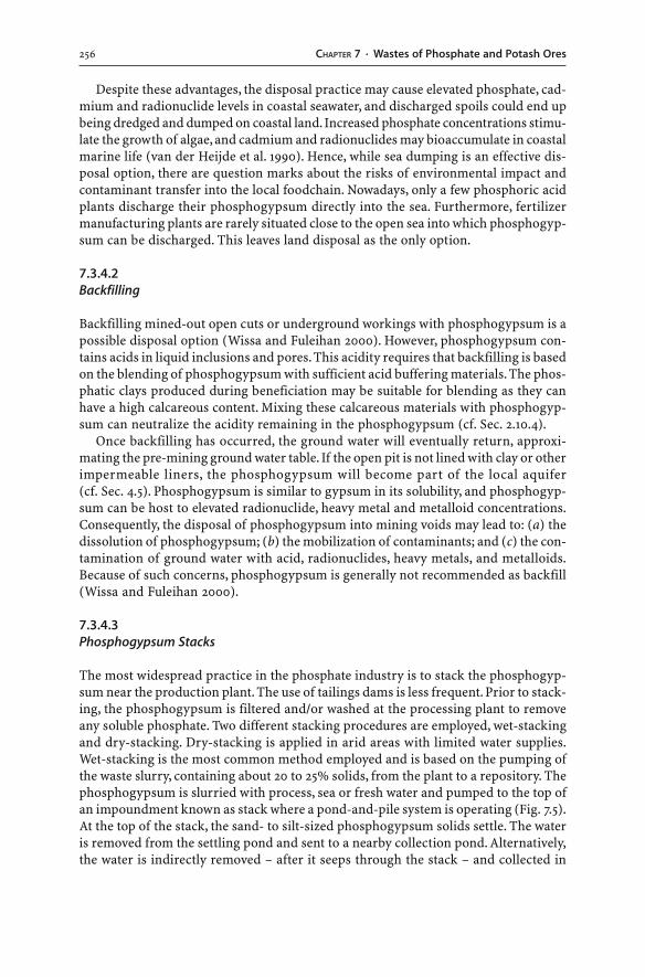
256 CHAPTER 7 · Wastes of Phosphate and Potash Ores
Despite these advantages, the disposal practice may cause elevated phosphate, cad-mium and radionuclide levels in coastal seawater, and discharged spoils could end upbeing dredged and dumped on coastal land. Increased phosphate concentrations stimu-late the growth of algae, and cadmium and radionuclides may bioaccumulate in coastalmarine life (van der Heijde et al. 1990). Hence, while sea dumping is an effective dis-posal option, there are question marks about the risks of environmental impact andcontaminant transfer into the local foodchain. Nowadays, only a few phosphoric acidplants discharge their phosphogypsum directly into the sea. Furthermore, fertilizermanufacturing plants are rarely situated close to the open sea into which phosphogyp-sum can be discharged. This leaves land disposal as the only option.
7.3.4.2Backfilling
Backfilling mined-out open cuts or underground workings with phosphogypsum is apossible disposal option (Wissa and Fuleihan 2000). However, phosphogypsum con-tains acids in liquid inclusions and pores. This acidity requires that backfilling is basedon the blending of phosphogypsum with sufficient acid buffering materials. The phos-phatic clays produced during beneficiation may be suitable for blending as they canhave a high calcareous content. Mixing these calcareous materials with phosphogyp-sum can neutralize the acidity remaining in the phosphogypsum (cf. Sec. 2.10.4).
Once backfilling has occurred, the ground water will eventually return, approxi-mating the pre-mining ground water table. If the open pit is not lined with clay or otherimpermeable liners, the phosphogypsum will become part of the local aquifer(cf. Sec. 4.5). Phosphogypsum is similar to gypsum in its solubility, and phosphogyp-sum can be host to elevated radionuclide, heavy metal and metalloid concentrations.Consequently, the disposal of phosphogypsum into mining voids may lead to: (a) thedissolution of phosphogypsum; (b) the mobilization of contaminants; and (c) the con-tamination of ground water with acid, radionuclides, heavy metals, and metalloids.Because of such concerns, phosphogypsum is generally not recommended as backfill(Wissa and Fuleihan 2000).
7.3.4.3Phosphogypsum Stacks
The most widespread practice in the phosphate industry is to stack the phosphogyp-sum near the production plant. The use of tailings dams is less frequent. Prior to stack-ing, the phosphogypsum is filtered and/or washed at the processing plant to removeany soluble phosphate. Two different stacking procedures are employed, wet-stackingand dry-stacking. Dry-stacking is applied in arid areas with limited water supplies.Wet-stacking is the most common method employed and is based on the pumping ofthe waste slurry, containing about 20 to 25% solids, from the plant to a repository. Thephosphogypsum is slurried with process, sea or fresh water and pumped to the top ofan impoundment known as stack where a pond-and-pile system is operating (Fig. 7.5).At the top of the stack, the sand- to silt-sized phosphogypsum solids settle. The wateris removed from the settling pond and sent to a nearby collection pond. Alternatively,the water is indirectly removed – after it seeps through the stack – and collected in
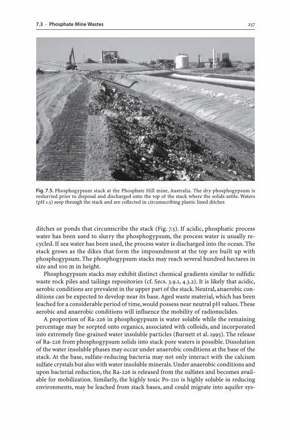
2577.3 · Phosphate Mine Wastes
ditches or ponds that circumscribe the stack (Fig. 7.5). If acidic, phosphatic processwater has been used to slurry the phosphogypsum, the process water is usually re-cycled. If sea water has been used, the process water is discharged into the ocean. Thestack grows as the dikes that form the impoundment at the top are built up withphosphogypsum. The phosphogypsum stacks may reach several hundred hectares insize and 100 m in height.
Phosphogypsum stacks may exhibit distinct chemical gradients similar to sulfidicwaste rock piles and tailings repositories (cf. Secs. 3.9.1, 4.3.2). It is likely that acidic,aerobic conditions are prevalent in the upper part of the stack. Neutral, anaerobic con-ditions can be expected to develop near its base. Aged waste material, which has beenleached for a considerable period of time, would possess near neutral pH values. Theseaerobic and anaerobic conditions will influence the mobility of radionuclides.
A proportion of Ra-226 in phosphogypsum is water soluble while the remainingpercentage may be sorpted onto organics, associated with colloids, and incorporatedinto extremely fine-grained water insoluble particles (Burnett et al. 1995). The releaseof Ra-226 from phosphogypsum solids into stack pore waters is possible. Dissolutionof the water insoluble phases may occur under anaerobic conditions at the base of thestack. At the base, sulfate-reducing bacteria may not only interact with the calciumsulfate crystals but also with water insoluble minerals. Under anaerobic conditions andupon bacterial reduction, the Ra-226 is released from the sulfates and becomes avail-able for mobilization. Similarly, the highly toxic Po-210 is highly soluble in reducingenvironments, may be leached from stack bases, and could migrate into aquifer sys-
Fig. 7.5. Phosphogypsum stack at the Phosphate Hill mine, Australia. The dry phosphogypsum isreslurried prior to disposal and discharged onto the top of the stack where the solids settle. Waters(pH 1.5) seep through the stack and are collected in circumscribing plastic lined ditches
258 CHAPTER 7 · Wastes of Phosphate and Potash Ores
tems (Bennett et al. 1995). Thus, it appears that phosphogypsum wastes share com-mon characteristics with uranium mill tailings (cf. Sec. 6.7). Uranium mill tailings andphosphogypsum may exhibit elevated radioactivity levels due to abundantRa-226, and some of this Ra-226 is hosted by solid phases (possibly sulfates, fluorides,phosphates and/or aluminophosphates). Ra-226 and Po-210 that are contained in sul-fates, may be released by sulfate-reducing bacteria into porewaters, and may subse-quently be mobilized into ground and surface waters.
In order to prevent ground water contamination, any dry or wet stack of phospho-gypsum needs to be constructed with a composite liner (i.e. compacted soil or com-pacted phosphogypsum with a high density polyethylene membrane) and a leachatecollection system (US EPA 1997). Otherwise, process water or trapped liquids withinphosphogypsum may be leached during rainfall events, and the ground water canbecome contaminated with acid, sulfate, phosphate, fluorine, radionuclides, and heavymetals. If a phosphogypsum stack has been constructed on calcareous or clay-richsubsoil or with a clay liner, the fluorine-rich process water may react with the carbon-ate or clay minerals, causing their alteration and dissolution (Arocena et al. 1995b). Thedissolution of these minerals would greatly increase permeability and would lead tothe transfer of contaminants into aquifers. Therefore, engineering designs forphosphogypsum waste impoundments advocate plastic liners (US EPA 1997).
Upon closure, the stack should be capped with an impermeable layer because thedissolution of phosphogypsum and the leaching of contaminants from the waste needto be avoided. If closed stacks are left uncapped, the phosphogypsum will dissolve andkarst-type features will form in the stack (Wissa and Fuleihan 2000). Phosphatic clayswith their long-term acid buffering capacity and alkaline pH may be useful materialsfor the capping of closed phosphogypsum stacks. In addition, compacted phosphogyp-sum may be suitable capping material. Vegetation can be established directly on thephosphogypsum with or without suitable amendments, including limestone, lime orphosphatic clay (Richardson 1995). These amendments are to raise the phosphogypsumpH and to ameliorate the tendency for crusting and cracking of phosphogypsum.Capping the phosphogypsum with materials, such as phosphate waste rocks or phos-phatic clays, not only reduces leaching of contaminants and atmospheric emissionsfrom the stack, it also creates suitable substrates for vegetation.
7.3.4.4Recycling
Much effort has been put into finding alternative uses for phosphogypsum. Thesepossible uses require either reprocessing (e.g. for the production of sulfur or purecalcium sulfate) or minimal/nil reprocessing for large-scale applications (e.g. in agri-culture, mine and landfill reclamation, earthworks and construction) (Korcak 1998;Johnson and Traub 1996).
Reprocessing aims to extract pure elements or pure calcium sulfate solids. For ex-ample, sulfur can be obtained for sulfuric acid production, and calcium sulfate can beextracted for building materials (e.g. gypsum plaster, boards, tiles, cement, hydraulicbinder, mineralizer, artifical marble, fibre boards, glass, glass-ceramics). Some phos-phate rocks contain elevated uranium, yttrium, and/or rare earth element concentra-tions, and their extraction is possible (Scientific Issue 7.1). However, the recovery of
2597.3 · Phosphate Mine Wastes
pure elements or pure calcium sulfate from phosphogypsum is not economically vi-able at this stage. Phosphogypsum has to compete with mined natural gypsum whichis mined at considerably higher purity. Moreover, the use of phosphogypsum as rawmaterial for building purposes can be limited due to residual phosphate, high watercontent, fine particle size, and inconsistent composition. While these characteristicshinder the use of phosphogypsum in building products, it has been found that com-pacted phosphogypsum can form a high strength material for road beds, making it asuitable road base material.
Phosphogypsum has the potential to be used as agricultural amendment. Phospho-gypsum is particularly useful as an amendment for highly weathered, nutrient-poorsoils as well as saline, sodic, acid and calcareous soils (Rutherford et al. 1994). Cropyields and pasture quality have been found to improve on phosphogypsum amendedsoils. Phosphogypsum application can counter crusting of soils, reducing soil runoffand erosion rates. However, elevated radionuclide (Ra-226, Pa-231, Pb-210, Po-210), fluo-rine and heavy metal levels as well as contained acid water with dissolved phosphateand heavy metals all represent problems for possible agricultural applications (El-Mrabet et al. 2003). Eutrophication of waterways is possible, and radionuclides, heavymetals, and metalloids may be taken up by plants.
In the United States, radioactivity limits imposed by the US EPA restrict the use ofphosphogypsum as building material and soil amendment. If phosphogypsum is usedfor building and agricultural applications, purification of phosphogypsum may be
260 CHAPTER 7 · Wastes of Phosphate and Potash Ores
necessary. Separation of radionuclides, heavy metals and metalloids from phosphogyp-sum would have to be achieved through chemical or physical means. The distinctchemical and mineralogical properties of different size fractions form the basis ofproposed purification procedures. The purification is designed to lower the contami-nant load and radioactivity of phosphogypsum. A reduction in contaminant load ispossible to some extent through the removal of the finer size fraction which is enrichedin radionuclides and heavy metals (Arocena et al. 1995a). Despite the research effortsinto alternative uses of phosphogypsum, there are no large-scale applications ofphosphogypsum. As a result, the amount of phosphogypsum piled up around the worldis steadily increasing.
7.3.5Potential Hazards and Environmental Impacts
7.3.5.1Phosphogypsum
The most widespread disposal practice in the phosphate industry is to stack thephosphogypsum near the production plant. Improper phosphogypsum stacking causesmost of the environmental impacts of phosphate mining and processing. The princi-pal potential hazards and environmental impacts of phosphogypsum stacks are:
� Failure of stacks. In the past, several failures of phosphatic tailings ponds andphosphogypsum stacks and dams have occurred. These failures released wastes intowaterways and resulted in damage to the local ecosystem (Table 7.3). Phosphoritedeposits are commonly hosted or enclosed by carbonate rocks which are suscepti-ble to chemical weathering, leaching, and karst development. Hence, there is a karstsinkhole potential, and in Florida, for example, an entire phosphogypsum stack col-lapsed into a karst sinkhole.
� Atmospheric emissions. Phosphogypsum stacks may emit gaseous radon and fluo-rine compounds (SiF4, HF) in significant amounts into the atmosphere. While ra-don emissions from phosphogypsum stacks are generally significantly lower thanthose of uranium mill tailings (cf. Sec. 6.10.2), the US EPA has set radon exhalationlimits for phosphogypsum stacks. Phosphate processing plants may also emit sulfurdioxide, radon, and fluorine compounds (SiF4, HF) in significant amounts into theatmosphere. The technology exists to limit atmospheric emissions of fluorine fromphosphoric acid manufacturing plants to environmentally acceptable levels. Fewoperations recover fluorine by absorption in water using scrubbers, which wouldminimize environmental impacts and prevent potential health impacts on workers.
� Ground water and surface water contamination. Discharge of phosphopgypsum intolocal rivers, seepage of process water from stacks, and leaching of stacks – via rain-water percolating through the heaps – have the potential to contaminate local streamsand aquifers. Ground water contamination has occurred at several phosphogypsumstacks where the repositories have not been lined and leachates were not collected.At these sites, ground water has elevated total dissolved solids and conductivity val-ues as well as high acid, phosphate, fluorine, sulfate, heavy metal, metalloid, and
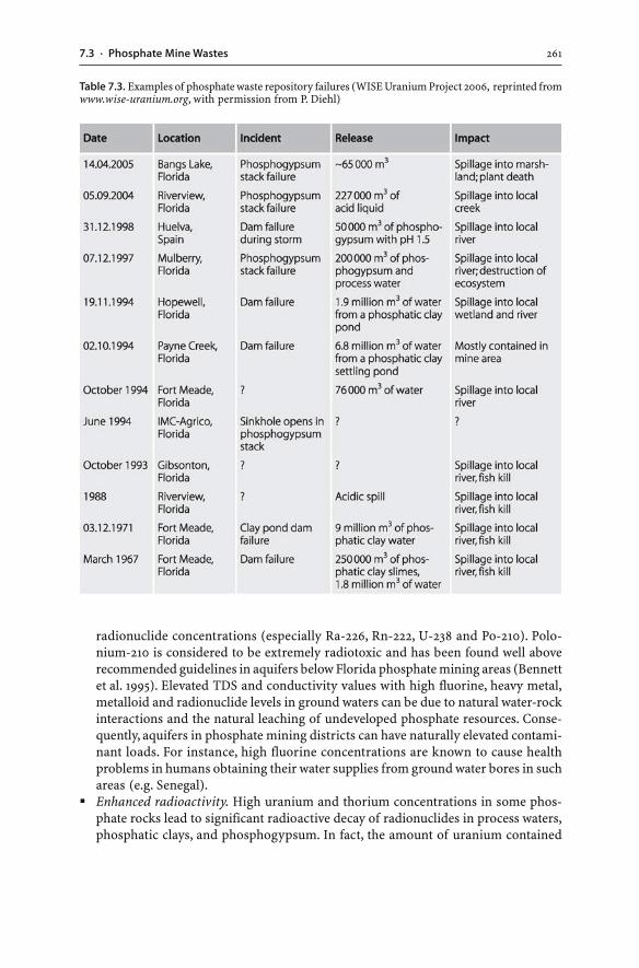
2617.3 · Phosphate Mine Wastes
radionuclide concentrations (especially Ra-226, Rn-222, U-238 and Po-210). Polo-nium-210 is considered to be extremely radiotoxic and has been found well aboverecommended guidelines in aquifers below Florida phosphate mining areas (Bennettet al. 1995). Elevated TDS and conductivity values with high fluorine, heavy metal,metalloid and radionuclide levels in ground waters can be due to natural water-rockinteractions and the natural leaching of undeveloped phosphate resources. Conse-quently, aquifers in phosphate mining districts can have naturally elevated contami-nant loads. For instance, high fluorine concentrations are known to cause healthproblems in humans obtaining their water supplies from ground water bores in suchareas (e.g. Senegal).
� Enhanced radioactivity. High uranium and thorium concentrations in some phos-phate rocks lead to significant radioactive decay of radionuclides in process waters,phosphatic clays, and phosphogypsum. In fact, the amount of uranium contained
Table 7.3. Examples of phosphate waste repository failures (WISE Uranium Project 2006, reprinted fromwww.wise-uranium.org, with permission from P. Diehl)
262 CHAPTER 7 · Wastes of Phosphate and Potash Ores
within some phosphate rocks, particularly phosphorite deposits, is so high – sev-eral tens to hundreds of parts per million – that uranium can be recovered as a by-product. Liquid and solid wastes may then emit radioactivity levels high enough torequire environmental monitoring and safety measures. Thus, improper disposalpractices may lead to enhanced radioactivity levels in soils, sediments and waterssurrounding a phosphate plant (Bolivar et al. 1995).
From a radiation perspective, inhalation of dust containing radioactive isotopes,direct external radiation, ingestion of surface water, and inhalation of radon rep-resent possible risks to human health (cf. Sec. 6.10.2). Radionuclides are emittedfrom phosphate rock mining and processing operations in particulate (e.g. U-238),aqueous (e.g. Ra-226) and gaseous forms (e.g. Rn-222), which primarily cause in-creased radiation exposures in the work force. Phosphogypsum stacks do not posea dust hazard, because the phosphogypsum has the tendency to form crusts andactive phosphogypsum waste repositories are wet enough to prevent dust genera-tion. Radon emissions are the main risk and therefore, Ra-226 – the parent nuclideof Rn-222 – is of prime concern. During mineral processing and phosphoric acidmanufacturing, much of the Ra-226 may be incorporated into the phosphogypsum,which may then contain the bulk of Ra-226 and emit high levels of radiation (sev-eral tens of pCi g–1). The emission of Rn-222 and its progeny, from phosphogypsumstacks and phosphoric acid plants, is variable and has attracted US EPA regulatoryemission standards since there are perceived radiation risks. Moreover, regulationshave been put into place on the maximum permissable radiation levels ofphosphogypsum (10 pCi g–1) when used in construction and agriculture. This inturn reduces the recycling potential of phosphogypsum. Some studies have indi-cated, however, that there is no significant risk to human health as the additionalradiation dose from phosphogypsum is minimal in comparison to natural levelsand background variations (Rutherford et al. 1994).
7.3.5.2Waste Rocks and Tailings
Environmental concerns are not exclusively related to phosphogypsum stacks. Wasterocks removed to access the phosphate rock are generally piled up next to the mineand hence, become exposed to atmospheric leaching. The leaching may generate seep-ages with elevated metal, metalloid or radionuclide concentrations. In some cases,leaching of waste repositories led to the contamination of soils, sediments, waters,plants and aquatic organisms with selenium which in turn caused selenium poison-ing in grazing animals (Vance 2000; Hamilton and Buhl 2004).
Beneficiation of phosphate rocks results in the production of tailings, which in someinstances are discharged into local rivers and coastal marine settings. At such sites,elevated phosphate, fluorine, metal, cadmium and radionuclide levels are found insediments, waters and marine organisms including seafood (Gnandi and Tobschall1999; Gnandi et al. 2006). Increased phosphate concentrations stimulate the growthof algae, and cadmium and radionuclides may bioaccumulate in aquatic life which thenenter the foodchain (van der Heijde et al. 1990).
2637.4 · Summary
7.4Summary
The production of potash and other salts principally relies on the mining of evapor-itic salt deposits. Mineral processing of potash ores involves flotation of the crushedsalt which results in the concentration of the salt minerals and rejection of the ganguephases. Alternatively, dissolution of the entire crude salt occurs by hot aqueous solu-tions, and various salts are precipitated. Currently mined potassium ores have8 to 30 wt.% K2O and consequently, potash mineral processing leads to the rejectionof the majority of the mined ore as liquid and solid wastes. The major waste productsof potash processing include brines and tailings. Brines may be disposed of by:(a) reinjection into deep aquifers below the orebodies; (b) discharge into the ocean;(c) collection in large ponds and release into local rivers; and (d) pumping – with orwithout the solid residues – back into the underground workings and emplacementas hydraulic backfill. Tailings largely consist of mineral processing salts and rejectedprimary gangue minerals, including clay minerals, sulfides, carbonates, iron oxides,and numerous evaporative salts. The tailings may be backfilled into underground work-ings or are stacked near the mine site into large piles.
Phosphate rock is mined from sedimentary and igneous deposits, with phospho-rites being the predominantly mined deposit type. The principle mineral of all deposittypes is apatite in the form of fluorapatite and/or carbonate fluorapatite. Some phos-phate rocks display elevated uranium, thorium, heavy metal, metalloid and rare earthelement levels. Abundant nuclides of the U-238, U-235 and Th-232 decay series can causeelevated radioactivity and radon levels of the phosphate rock and waste products.
Mining, beneficiation and hydrometallurgical processing of phosphate rock gen-erate waste rocks, phosphatic clays, phosphogypsum, and spent process waters. In thewet process, the beneficiated phosphate rock is reacted with sulfuric acid to producephosphoric acid. The product of this chemical reaction is a slurry that consists of phos-phoric acid and suspended solid crystals. The solids are removed from the phospho-ric acid and are termed “phosphogypsum”. The term phosphogypsum is a collectiveterm for a waste mixture, comprising major solid and minor liquid waste components.The solid crystals are mainly calcium sulfate (gypsum or bassanite), minor reactionproducts, and unreacted phosphate rock particles. The calcium sulfate crystals con-tain liquid inclusions and process water trapped in the interstices of mineral particles.The chemical composition of phosphogypsum is characterized by variably elevatedheavy metal, metalloid and radionuclide concentrations. The material is acid due tothe presence of residual phosphoric, sulfuric and fluoride acids. Prolonged leachingof stacked phosphogypsum results in the flushing of trapped acids, metals and metal-loids; therefore, aged and leached materials display near neutral pH values.
The amount of phosphogypsum produced on a worldwide basis is in the order of100 Mt per year, and for every tonne of phosphoric acid produced, there are 3 to 6 t ofphosphogypsum generated. These large quantities of phosphogypsum create a majordisposal problem. The dumping of phosphogypsum at sea has been pursued for manyyears around the globe. Today, land disposal has become the dominant disposal op-tion. Backfilling phosphogypsum into mine voids is not recommended since it may
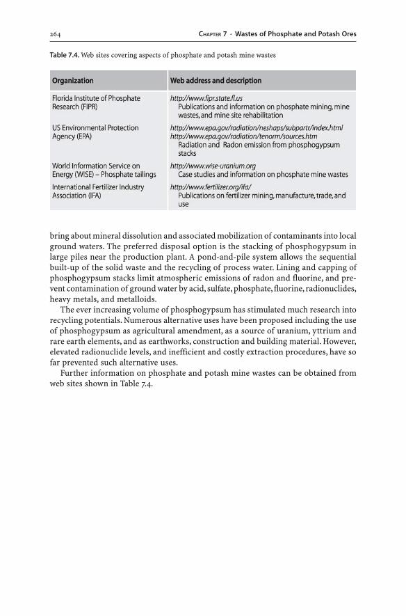
264 CHAPTER 7 · Wastes of Phosphate and Potash Ores
bring about mineral dissolution and associated mobilization of contaminants into localground waters. The preferred disposal option is the stacking of phosphogypsum inlarge piles near the production plant. A pond-and-pile system allows the sequentialbuilt-up of the solid waste and the recycling of process water. Lining and capping ofphosphogypsum stacks limit atmospheric emissions of radon and fluorine, and pre-vent contamination of ground water by acid, sulfate, phosphate, fluorine, radionuclides,heavy metals, and metalloids.
The ever increasing volume of phosphogypsum has stimulated much research intorecycling potentials. Numerous alternative uses have been proposed including the useof phosphogypsum as agricultural amendment, as a source of uranium, yttrium andrare earth elements, and as earthworks, construction and building material. However,elevated radionuclide levels, and inefficient and costly extraction procedures, have sofar prevented such alternative uses.
Further information on phosphate and potash mine wastes can be obtained fromweb sites shown in Table 7.4.
Table 7.4. Web sites covering aspects of phosphate and potash mine wastes
Aachid M, Mbonimpa M, Aubertin M (2004) Measurement and prediction of the oxygen diffusion co-efficient in unsaturated media, with applications to soil covers. Water Air Soil Poll 156:163–193
Abdelouas A, Lutze W, Nuttall E (1998a) Chemical reactions of uranium in ground water at a mill tail-ings site. J Contam Hydrol 34:343–361
Abdelouas A, Nuttall HE, Lutze W, Lu Y (1998b) In situ removal of uranium from ground water. In: Tail-ings and mine waste ’98. Balkema, Rotterdam, pp 669–677
Abdelouas A, Lutze W, Nuttall HE (1999) Uranium contamination in the subsurface: Characterizationand remediation. In: Burns PC, Finch R (eds) Uranium: Mineralogy, geochemistry and the environ-ment. Mineralogical Society of America, Washington (Reviews in mineralogy and geochemistry,vol 38, pp 433–473)
Abdelouas A, Lutze W, Gong W, Nuttall EH, Strietelmeier BA, Travis BJ (2000) Biological reduction ofuranium in groundwater and subsurface soil. Sci Total Environ 250:21–35
Abraitis PK, Pattrick RAD, Kelsall GH, Vaughan DJ (2004) Acid leaching and dissolution of major sul-phide ore minerals: processes and galvanic effects in complex systems. Min Mag 68:343–351
Accornero M, Marini L, Ottonello G, Zuccolini MV (2005) The fate of major constituents and chromi-um and other trace elements when acid waters from the derelict Libiola mine (Italy) are mixed withstream waters. Appl Geochem 20:1368–1390
Acero P, Ayora C, Torrento C, Nieto JM (2006) The behavior of trace elements during schwertmanniteprecipitation and subsequent transformation into goethite and jarosite. Geochim Cosmochim Acta70:4130–4139
Ackman TE (2003) An introduction to the use of airborne technologies for watershed characterizationin mined areas. Mine Water Environ 22:62–68
Agricola G (1556) De re metallica. Translated by Hoover HC, Hoover LH (1950). Dover Publications, NewYork
Ahn JS, Chon CM, Moon HS, Kim KW (2003) Arsenic removal using steel manufacturing byproducts aspermeable reactive materials in mine tailing containment systems. Water Res 37:2478–2488
Al TA, Martin CJ, Blowes DW (2000) Carbonate-mineral/water interactions in sulphide-rich mine tail-ings. Geochim Cosmochim Acta 64:3933–3948
Alakangas L, Öhlander B (2006) Formation and composition of cemented layers in low-sulphide minetailings, Laver, northern Sweden. Environ Geol 50:809–819
Allan RJ (1995) Impact of mining activities on the terrestrial and aquatic environment with emphasison mitigation and remedial measures. In: Salomons W, Förstner U, Mader P (eds) Heavy metals:problems and solutions. Springer, Berlin Heidelberg New York, pp 119–140
Alpers CN, Blowes DW (eds) (1994) Environmental geochemistry of sulfide oxidation. American Chem-ical Society, Washington DC (Symposium Series 550)
Alpers CN, Nordstrom DK (1999) Geochemical modeling of water-rock interactions in mining environ-ments. In: Plumlee GS, Logsdon MS (eds) The environmental geochemistry of mineral deposits. PartA: Processes, techniques and health issues. Society of Economic Geologists, Littleton (Reviews ineconomic geology, vol 6A, pp 289–323)
Alpers CN, Blowes DW, Nordstrom DK, Jambor JL (1994) Secondary minerals and acid mine-water chem-istry. In: Jambor JL, Blowes DW (eds) Environmental geochemistry of sulfide mine-wastes. Minera-logical Association of Canada, Nepean (Short course handbook, vol 22, pp 247–270)
References
References266
Ambers RKR, Hygelund BN (2001) Contamination of two Oregon reservoirs by cinnabar mining andmercury amalgamation. Environ Geol 40:699–707
Amos PW, Younger PL (2003) Substrate characterization for a subsurface reactive barrier to treat col-liery spoil leachate. Water Res 37:108–120
Anderson CWN, Brooks RR, Stewart RB, Simcock R (1998) Harvesting a crop of gold in plants. Nature395:553–554
Anderson CWN, Brooks RR, Chiarucci A, LaCoste CJ, Leblanc M, Robinson BH, Simcock R, Stewart RB(1999) Phytomining for nickel, thallium and gold. J Geochem Explor 67:407–415
Appelo CAJ, Postma D (1999) Geochemistry, groundwater and pollution. Balkema, RotterdamApplegate RJ, Kraatz M (1991) Rehabilitation of Rum Jungle uranium mine. In: Proceedings of the 2nd
international conference on the abatement of acidic drainage. MEND, pp 155–169Apte SC, McNamara J, Bowles KC (1996) Fate of trace metals in the riverine environment downstream
of the Porgera gold mine, PNG. In: Proceedings of 3rd international and 21st annual Minerals Coun-cil of Australia environmental workshop. Minerals Council of Australia, Dickson, pp 38–49
Ariza LM (1998) River of vitriol. Sci Amer 279(3):15–18Arocena JM, Rutherford PM, Dudas MJ (1995a) Heterogeneous distribution of trace elements and fluo-
rine in phosphogypsum by-product. Sci Total Environ 162:149–160Arocena JM, Dudas MJ, Poulsen L, Rutherford PM (1995b) Weathering of clay minerals induced by flu-
oride-containing solutions from phosphogypsum by-product. Can J Soil Sci 75:219–226Asher CJ, Bell LC (eds) (1999) Proceedings of the workshop on future directions in tailings environ-
mental management. Australian Centre for Mining Environmental Research, BrisbaneAshley PM, Lottermoser BG (1999a) Geochemical, mineralogical and biogeochemical characterisation
of abandoned metalliferous mine sites, southern New England Orogen. In: Proceedings of the NEO’99Conference. Armidale, Division of Earth Sciences, University of New England, pp 409–418
Ashley PM, Lottermoser BG (1999b) Arsenic contamination at the Mole River mine, northeastern NewSouth Wales, Australia. Austral J Earth Sci 46:861–874
Ashley PM, Craw D, Graham BP, Chappell DA (2003) Environmental mobility of antimony aroundmesothermal stibnite deposits, New South Wales, Australia and southern New Zealand. J GeochemExplor 77:1–14
Asmund G, Broman PG, Lindgren G (1994) Managing the environment at the Black Angel mine, Green-land. Int J Surface Min Reclam Environ 8:37–40
Attendorn HG, Bowen RNC (1997) Radioactive and stable isotope geology. Chapman & Hall, LondonBailey EA, Gray JE, Theodorakos PM (2002) Mercury in vegetation and soils at abandoned mercury mines
in southwestern Alaska, USA. Geochem Explor Environ Anal 2:275–285Banks D, Younger PL, Arnesen R-T, Iversen ER, Banks SB (1997) Mine-water chemistry: the good, the
bad and the ugly. Environ Geol 32:157–174Banks D, Skarphagen H, Wiltshire R, Jessop C (2004) Heat pumps as a tool for energy recovery from
mining wastes. In: Gieré R, Stille P (eds) Energy, waste, and the Environment: a geochemical per-spective. Geological Society London (Special Publications 236, pp 499–513)
Barbour AK, Shaw IC (2000) Ecotoxicological impacts of the extractive industries. In: Warhurst A,Noronha L (eds) Environmental policy in mining. Lewis Publishers, Boca Raton, pp 57–80
Barnett MO, Turner RR, Singer PC (2001) Oxidative dissolution of metacinnabar (β-HgS) by dissolvedoxygen. Appl Geochem 16:1499–1512
Barriga FJAS, Carbalho D (eds) (1997) Geology and VMS deposits of the Iberian pyrite belt. Society ofEconomic Geologists, Littleton (Guidebook series, vol 27)
Barton CD, Karathanasis AD (1999) Renovation of a failed constructed wetland treating acid mine drain-age. Environ Geol 39:39–50
Bayless ER, Olyphant GA (1993) Acid generating salts and their relationship to the chemistry ofgroundwater and storm runoff at an abandoned mine site in southwestern Indiana, USA. J ContamHydrol 12:313–328
Bednar AJ, Garbarino JR, Ranville JF, Wildeman TR (2005) Effects of iron on arsenic speciation and re-dox chemistry in acid mine water. J Geochem Explor 85:55–62
Belzile N, Chen YW, Cai MF, Li Y (2004) A review on pyrrhotite oxidation. J Geochem Explor 84:65–76Benes P, Sebesta F, Sedlacek J, Obdrzalek M, Sandrik R (1983) Particulate forms of radium and barium
in uranium mine waste waters and receiving river waters. Water Res 17:619–624
267References
Benito G, Benito-Calvo A, Gallart F, Martin-Vide JP, Regües D, Bladé E (2001) Hydrological andgeomorphological criteria to evaluate the dispersion risk of waste sludge generated by the Aznalcollarmine spill (SW Spain). Environ Geol 40:417–428
Benner SG, Blowes DW, Gould WD, Herbert RB Jr, Ptacek CJ (1999) Geochemistry of a permeable reac-tive barrier for metals and acid mine drainage. Environ Sci Technol 33:2793–2799
Benner SG, Blowes DW, Ptacek CJ, Mayer KU (2002) Rates of sulfate reduction and metal sulfide pre-cipitation in a permeable reactive barrier. Appl Geochem 17:301–320
Bennett JW, Ritchie AIM (1993) Bio-oxidation of pyrite in mine wastes. Mechanisms which govern pol-lutant generation. In: Biomine ’93, International conference and workshop applications of biotech-nology to the minerals industry. Australian Mineral Foundation, Glenside, pp 12.1–12.9
Bennett JW, Gibson DK, Ritchie AIM, Tan Y, Broman PG, Jönsson H (1994) Oxidation rates and pollu-tion loads in drainage: correlation of measurements in a pyritic waste rock dump. In: Proceedingsof the international land reclamation and mine drainage conference and 3rd international confer-ence on the abatement of acidic drainage, vol 1. United States Department of the Interior, Bureau ofMines (Special Publication SP06A-94, pp 401–409)
Bennett MW, Kempton JH, Maley PJ (1997) Applications of geological block models to environmentalmanagement. In: Proceedings from the 4th international conference on acid rock drainage, vol 1.Vancouver, pp 293–303
Bennett JW, Timms GP, Ritchie AIM (1999) The effectiveness of the covers on waste rock dumps at RumJungle and the impact in the long term. In: Proceedings of the 24th annual Minerals Council of Aus-tralia environmental workshop. Minerals Council of Australia, Dickson, pp 379–388
Benson AK (1995) An integration of geophysical methods and geochemical analysis to map acid minedrainage – a case study. Explo Min Geol 4:411–419
Benzaazoua M, Bussiere B, Dagenais AM, Archambault M (2004) Kinetic test comparison and interpre-tation for prediction of the Joutel tailings acid generation potential. Environ Geol 46:1086–1101
Beretka J (1980) Properties and utilization of by-product gypsum in Australia. In: Borris DP, Boody PW(eds) Proceedings of the international symposium on phosphogypsum. Florida Institute of Phos-phate Research (Publication no 01-001-017)
Berger AC, Bethke CM, Krumhansl JL (2000) A process model of natural attentuation in drainage froma historic mining district. Appl Geochem 15:655–666
Berkun M (2005) Submarine tailings placement by a copper mine in the deep anoxic zone of the BlackSea. Water Res 39:5005–5016
Bernier LR (2005) The potential use of serpentinite in the passive treatment of acid mine drainage: batchexperiments. Environ Geol 47:670–684
Bertrand VJ, Monroy MG, Lawrence RW (2000) Weathering characteristics of cemented paste backfill:mineralogy and solid phase chemistry. In: Proceedings from the 5th international conference on acidrock drainage, vol 2. Society for Mining, Metallurgy, and Exploration, Littleton, pp 863–876
Bethune KJ, Lockington DA, Williams DJ (1997) Acid mine drainage: comparison of laboratory testingto mine site conditions. In: Proceedings from the 4th international conference on acid rock drain-age, vol 1. Vancouver, pp 306–318
Bews BE, Barbour SL, Wickland B (1999) Lysimeter design in theory and practice. In: Tailings and minewaste ’99. Balkema, Rotterdam, pp 13–21
Bigham JM (1994) Mineralogy of ochre deposits formed by sulfide oxidation. In: Jambor JL, Blowes DW(eds) Environmental geochemistry of sulfide mine-wastes. Mineralogical Association of Canada,Nepean (Short course handbook, vol 22, pp 103–132)
Bigham JM, Nordstrom DK (2000) Iron and aluminium hydroxysulfates from acid sulfate waters. In:Alpers CN, Jambor JL, Nordstrom DK (eds) Sulfate minerals: crystallography, geochemistry andenvironmental significance. Mineralogical Society of America, Washington (Reviews in mineralogyand geochemistry, vol 40, pp 351–403)
Bigham JM, Schwertmann U, Traina SJ, Winland RL, Wolf M (1996) Schwertmannite and the chemicalmodeling of iron in acid sulfate waters. Geochim Cosmochim Acta 60:2111–2121
Bilek F (2006) Column tests to enhance sulphide precipitation with liquid organic electron donators toremediate AMD-influenced groundwater. Environ Geol 49:674–683
Black A, Craw D, Younson JH, Karubaba J (2004) Natural recovery rates of a river system impacted bymine tailing discharge: Shag River, East Otago, New Zealand. J Geochem Explor 84:21–34
References268
Blainey G (1991) Gold – a lesson or two? In: Blainey G (ed) Eye on Australia. Schwartz & Wilkinson,Melbourne, pp 181–188
Blanchette MC, Hynes TP, Kwong YTJ, Anderson MR, Veinott G, Payne JF, Stirling C, Sylvester PJ (2001)A chemical and ecotoxicological assessment of the impact of marine tailings disposal. In: Tailingsand mine waste ’01. Balkema, Rotterdam, pp 323–331
Blowes DW, Ptacek CJ (1994) Acid-neutralization mechanisms in inactive mine tailings. In: Jambor JL,Blowes DW (eds) Environmental geochemistry of sulfide mine-wastes. Mineralogical Associationof Canada, Nepean (Short course handbook, vol 22, pp 271–292)
Blowes DW, Reardon EJ, Jambor JL, Cherry JA (1991) The formation and potential importance of ce-mented layers in inactive sulfide mine tailings. Geochim Cosmochim Acta 55:965–978
Blowes DW, Ptacek CJ, Jambor JL (1994) Remediation and prevention of low-quality drainage fromtailings impoundments. In: Jambor JL, Blowes DW (eds) Environmental geochemistry of sulfidemine-wastes. Mineralogical Association of Canada, Nepean (Short course handbook, vol 22,pp 365–380)
Blowes DW, Jambor JL, Hanton-Fong CJ, Lortie L, Gould WD (1998) Geochemical, mineralogical andmicrobiological characterization of a sulphide-bearing carbonate-rich gold-mine tailings impound-ment, Joutel, Québec. Appl Geochem 13:687–705
Blowes DW, Bain JG, Smyth DJ, Ptacek CJ (2003) Treatment of mine drainage using permeable reactivematerials. In: Jambor JL, Blowes DW, Ritchie AIM (eds) Environmental aspects of mine wastes. Min-eralogical Association of Canada, Nepean (Short course handbook, vol 31, pp 361–376)
Bobos I, Duraes N, Noronha F (2006) Mineralogy and geochemistry of mill tailings impoundments fromAlgares (Aljustrel), Portugal: implications for acid sulfate mine waters formation. J Geochem Explor88:1–5
Bodénan F, Baranger P, Piantone P, Lassin A, Azaroual M, Gaucher E, Braibant G (2004) Arsenic behav-iour in gold-ore mill tailings, Massif Central, France: hydrogeochemical study and investigation ofin situ redox signatures. Appl Geochem 19:1785–1800
Boger DV (1998) Environmental rheology and the mining industry. In: Proceedings of AusIMM ’98 TheMining Cycle. Australasian Institute of Mining and Metallurgy, Melbourne, pp 459–461
Bolivar JP, Garcia-Tenorio R, Garcia-Leon M (1995) Enhancement of natural radioactivity in soils andsalt-marshes surrounding a non-nuclear industrial complex. Sci Total Environ 173/174:125–136
Bond PL, Druschel GK, Banfield JE (2000) Comparison of acid mine drainage microbial communitiesin physically and geochemically distinct ecosystems. Appl Environ Microbiol 66:4962–4971
Boon M, Snijder M, Hansfrod GS, Heijnen JJ (1998) The oxidation kinetics of zinc sulphide withThiobacillus ferrooxidans. Hydrometall 48:171–186
Boorman RS, Watson DM (1976) Chemical processes in abandoned sulphide tailings dumps and envi-ronmental implication for northeastern New Brunswick. CIM Bulletin 69:86–96
Borden R (2001) Geochemical evolution of sulphide-bearing waste rock soils at the Bingham Canyonmine, Utah. Geochem Explor Environ Anal 1:15–22
Bordon RK, Black R (2005) Volunteer revegetation of waste rock surfaces at the Bingham Canyon mine,Utah. J Environ Qual 34:2234–2242
Botz M (2001) Cyanide treatment methods. Mining Environmental Management, May 2001:28–30Boulet MP, Larocque ACL (1998) A comparative mineralogical and geochemical study of sulfide mine
tailings at two sites in New Mexico, USA. Environ Geol 33:130–142Bowell RJ, Bruce I (1995) Geochemistry of iron ochres and mine waters from Levant mine, Cornwall.
Appl Geochem 10:237–250Braithwaite RSW, Kampf AR, Pritchard RG, Lamb RPH (1993) The occurrence of thiosulfates and other
unstable sulfur species as natural weathering products of smelting slags. Mineral Petrol 47:255–261Brake SS, Dannelly HK, Connors KA (2001a) Controls on the nature and distribution of an alga in coal
mine-waste environments and its potential impact on water quality. Environ Geol 40:458–469Brake SS, Dannelly HK, Connors KA, Hasiotis ST (2001b) Influence of water chemistry on the distribu-
tion of an acidophilic protozoan in an acid mine drainage system at the abandoned Green Valleycoal mine, Indiana, USA. Appl Geochem 16:1641–1652
Brant DL, Ziemkiewicz PF, Robbins EI (1999) Passive removal of manganese from acid mine drainageat the Shade mining site, Somerset County, PA (USA). In: Goldsack D, Belzile N, Yearwood P, Hall G(eds) Proceedings of Sudbury ’99 Mining and the Environment, vol 3. Sudbury Environmental,Sudbury, Canada, pp 1241–1249
269References
Braungardt CB, Achterberg EP, Elbaz-Poulichet F, Morley NH (2003) Metal geochemistry in a mine-pol-luted estuarine system in Spain. Appl Geochem 18:1757–1771
BRGM (2000) Management of mining, quarrying and ore-processing waste in the European Union.European Commission, Directorate-General Environment, ENV.E.3 – Waste Management (BRGM/RP-50319-FR, http://europa.eu.int/comm/environment/waste/mining_report.pdf)
Briggs TJ, Kelso IJ (2003) Ammonium nitrate-sulfide reactivity at the Century Zn-Pb-Ag mine, north-west Queensland, Australia. Explor Mining Geol 10:177–190
Brookins DG (1988) Eh-pH diagrams for geochemistry. Springer, Berlin Heidelberg New YorkBrooks RR (1998) Plants that hyperaccumulate heavy metals: their role in phytoremediation, microbi-
ology, archaeology, mineral exploration and phytomining. CAB International, WallingordBrown PL, Guerin M, Hankin SI, Lowson RT (1998) Uranium and other contaminant migration in
groundwater at a tropical Australian uranium mine. J Contam Hydrol 35:295–303Brown M, Barley B, Wood H (2002) Minewater treatment: technology, application and policy. Interna-
tional Water Association PublishingBrownlow AH (1996) Geochemistry, 2nd edn. Prentice Hall, Upper Saddle RiverBrzezinski LS (2001) Surface disposal of thickened tailings. Mining Environmental Management 9:7–12Buckby T, Black S, Coleman ML, Hodson ME (2003) Fe-sulphate-rich evaporative mineral precipitates
from the Rio Tinto, southwest Spain. Min Mag 67:263–278Bullock SET, Bell FG (1997) Some problems associated with past mining at a mine in the Witbank coal-
field, South Africa. Environ Geol 33:61–71Burghardt D, Kassahun A (2005) Development of a reactive zone technology for simultaneous in situ
immobilisation of radium and uranium. Environ Geol 49:314–320Burnett WC, Elzerman AW (2001) Nuclide migration and the environmental radiochemistry of Florida
phosphogypsum. J Environ Rad 54:27–51Burnett WC, Cowart JB, LaRock P, Hull CD (1995) Microbiology and radiochemistry of phosphogypsum.
Florida Institute of Phosphate Research, publication no 05-035-115Burns PC (1999) The crystal chemistry of uranium. In: Burns PC, Finch R (eds) Uranium: mineralogy,
geochemistry and the environment. Mineralogical Society of America, Washington (Reviews in min-eralogy and geochemistry, vol 38, pp 23–90)
Bussière B, Benzaazoua M, Aubertin M, Mbonimpa M (2004) A laboratory study of covers made of low-sulphide tailings to prevent acid mine drainage. Environ Geol 45:609–622
Butler TW, Seitz JC (2006) Apparent seasonal variations in iron photoreduction in acidic discharge froma former pyrite mine, Oakland, California. Appl Geochem 21:1109–1122
Bycroft BM, Coller BAW, Deacon GB, Coleman DJ, Lake PS (1982) Mercury contamination of theLerderderg River, Victoria, Australia, from an abandoned gold field. Environ Poll Series A 28:135–147
Cabral A, Lefebvre G, Proulx ME, Audet C, Labbé M, Michaud C (1997) Use of deinking residues as covermaterial in the prevention of AMD generation at an abandoned mine site. In: Tailings and mine waste’97. Balkema, Rotterdam, pp 257–266
Caldwell E, Johnson J (1997) Use of risk-based standards for restoration of ground water at in situ ura-nium mines. In: Tailings and mine waste ’97. Balkema, Rotterdam, pp 21–25
Campbell DL, Fittermann DV (2000) Geoelectrical methods for investigating mine dumps. In: Proceed-ings from the 5th international conference on acid rock drainage, vol 2. Society for Mining, Metal-lurgy, and Exploration, Littleton, pp 1513–1523
Carlson L, Kumpulainen S (2000) Mineralogy of precipitates formed from mine effluents in Finland.In: Tailings and mine waste ’00. Balkema, Rotterdam, pp 269–275
Carroll SA, O’Day PA, Piechowski M (1998) Rock-water interactions controlling zinc, cadmium, and leadconcentrations in surface waters and sediments, US tri-state mining district. 2. Geochemical inter-pretation. Environ Sci Technol 32:956–965
Casagrande DJ, Finkelman RB, Caruccio FT (1989) The nonparticipation of organic sulfur in acid minedrainage. Environ Geochem Health 11:187–192
Casiot C, Morin G, Juillot F, Bruneel O, Personné JC, Leblanc M, Duquesne K, Bonnefoy V, Elbaz-PoulichetF (2003) Bacterial immobilization and oxidation of arsenic in acid mine drainage (Carnoulès creek,France). Water Res 37:2929–2936
Casiot C, Bruneel O, Personné JC, Leblanc M, Elbaz-Poulichet F (2004) Arsenic oxidation andbioaccumulation by the acidophilic protozoan, Euglena mutabilis, in acid mine drainage (Carnoulès,France). Sci Total Environ 320:259–267
References270
Castelo-Branco MA, Santos J, Moreira O, Oliveira A, Pereira Pires F, Magalhaes I, Dias S, Fernandes LM,Gama J, Vieira e Silva JM, Ramalho Ribeiro J (1999) Potential use of pyrite as an amendment forcalcareous soil. J Geochem Explor 66:363–367
Castendyk DN, Mauk JL, Webster JG (2005) A mineral quantification method for wall rocks at open pitmines, and application to the Martha Au-Ag mine, Waihi, New Zealand. Appl Geochem 20:135–156
Castro JM, Moore JN (2000) Pit lakes: their characteristics and the potential for their remediation.Environ Geol 39:1254–1260
Cathles LM (1994) Attempts to model the industrial-scale leaching of copper-bearing mine waste. In:Alpers CN, Blowes DW (eds) Environmental geochemistry of sulfide oxidation. American ChemicalSociety, Washington DC (Symposium Series 550, pp 123–131)
Chapman BM, Jones DR, Jung RF (1983) Processes controlling metal ion attenuation in acid mine drainagestreams. Geochim Cosmochim Acta 47 1957–1973
Chermak JA, Runnells DD (1996) Self-sealing hardpan barriers to minimize infiltration of water intosulfide-bearing overburden, ore, and tailings piles. In: Tailings and mine waste ’96. Balkema, Rotter-dam, pp 265–273
Chermak JA, Runnells DD (1997) Development of chemical caps in acid drainage environments. Min-ing Eng 49:93–97
Cidu R, Fanfani L (2002) Overview of the environmental geochemistry of mining districts in south-western Sardinia, Italy. Geochem Explor Environ Anal 2:243–251
Cleary D, Thornton I (1994) The environmental impact of gold mining in the Brazilian Amazon. In: HesterRE, Harrison RM (eds) Mining and its environmental impact. Issues in Environ Sci Technol 1. RoyalSociety of Chemistry, Cambridge, pp 17–29
Coggans CJ, Blowes DW, Robertson WD, Jambor JL (1999) The hydrogeochemistry of a nickel-mine tail-ings impoundment – Copper Cliff, Ontario. In: Filipek LH, Plumlee GS (eds) The environmentalgeochemistry of mineral deposits. Part B: Case studies and research topics. Society of EconomicGeologists, Littleton (Reviews in economic geology, vol 6B, pp 447–465)
Cornell RM, Schwertmann U (1996) The iron minerals: structure, properties, reactions, occurrence anduses. VCH, Weinheim
Costa MC, Duarte JC (2005) Bioremediation of acid mine drainage using acidic soil and organic wastesfor promoting sulphate-reducing bacteria activity on a column reactor. Water Air Soil Poll 165:325–345
Courtin-Nomade A, Grosbois C, Bril H, Roussel C (2005) Spatial variability of arsenic in some iron-richdeposits generated by acid mine drainage. Appl Geochem 20:383–396
Covelli S, Faganeli J, Horvat M, Brambati A (2001) Mercury contamination of coastal sediments as theresult of long-term cinnabar mining activity (Gulf of Trieste, northern Adriatic sea). Appl Geochem16:541–558
Cravotta CA (1994) Secondary iron-sulfate minerals as sources of sulfate and acidity: geochemical evo-lution of acidic groundwater at a reclaimed surface coal mine in Pennsylvania. In: Alpers CN, BlowesDW (eds) Environmental geochemistry of sulfide oxidation. American Chemical Society, Washing-ton DC (Symposium Series 550, pp 345–364)
Cravotta CA (2003) Size and performance of anoxic limestone drains to neutralize acidic mine drain-age. J Environ Qual 32:1277–1289
Cravotta CA, Bilger MD (2001) Water-quality trends for a stream draining the Southern Anthracite Field,Pennsylvania. Geochem Explor Environ Anal 1:33–50
Cravotta CA, Trahan MK (1999) Limestone drains to increase pH and remove dissolved metals fromacidic mine drainage. Appl Geochem 14:581–606
Cravotta CA, Dugas DL, Brady KBC, Kovalchuk TE (1994) Effects of selective handling pyritic, acid form-ing materials on the chemistry of pore gas and ground water at a reclaimed surface coal mine, Clar-ion County, PA, USA In: Proceedings of the international land reclamation and mine drainage con-ference and 3rd international conference on the abatement of acidic drainage. US Department ofthe Interior, Bureau of Mines (Special Publication SPO6A-94, pp 365–374)
Craw D (2001) Tectonic controls on gold deposits and their environmental impact, New Zealand.J Geochem Explor 73:43–56
Craw D (2003) Geochemical changes in mine tailings during a transition to pressure-oxidation processdischarge, Macraes mine, New Zealand. J Geochem Explor 80:81–94
Craw D, Pacheco (2002) Mobilisation and bioavailability of arsenic around mesothermal gold depositsin a semiarid environment, Otago, New Zealand. The Sci World J 2:308–319
271References
Craw D, Chappell D, Nelson M, Walrond M (1999) Consolidation and incipient oxidation of alkalinearsenopyrite-bearing mine tailings, Macreas Mine, New Zealand. Appl Geochem 14:485–498
Craw D, Wilson N, Ashley PM (2004) Geochemical controls on the environmental mobility of Sb and Asat mesothermal antimony and gold deposits. Trans Inst Min Metall B 113:B3–B10
Crock JG, Arbogast BF, Lamothe PJ (1999) Laboratory methods for the analysis of environmental sam-ples. In: Plumlee GS, Logsdon MS (eds) The environmental geochemistry of mineral deposits. PartA: Processes, techniques and health Issues. Society of Economic Geologists, Littleton (Reviews ineconomic geology, vol 6A, pp 265–287)
Cruz R, Bertrand V, Monroy M, Ganzalez I (2001a) Effect of sulfide impurities on the reactivity of pyriteand pyritic concentrates: a multi-tool approach. Appl Geochem 16:803–819
Cruz R, Mendez BA, Monroy M, Gonzalez I (2001b) Cyclic voltammetry applied to evaluate reactivity insulfide mining residues. Appl Geochem 16:1631–1640
Currey NA, Ritchie PJ, Durham AJP, Wilson GW (1999) Field performance and optimisation of two lowflux soil cover systems for the prevention of acid mine drainage in a semi arid environment. In:Proceedings of the 24th annual Minerals Council of Australia environmental workshop. MineralsCouncil of Australia, Dickson, pp 458–465
Dalton JB, King TVV, Bove DJ, Kokaly RF, Clark RN, Vance JS, Swayze GA (2000) Distribution of acid-generating and acid-buffering minerals in the Animas River watershed as determined by AVIRISspectroscopy. In: Proceedings from the 5th international conference on acid rock drainage, vol 2.Society for Mining, Metallurgy, and Exploration, Littleton, pp 1541–1550
Davies MP, Martin TE (2000) Upstream constructed tailings dams – a review of the basics. In: Tailingsand mine waste ’00. Balkema, Rotterdam, pp 3–15
Davis A, Ashenberg D (1989) The aqueous geochemistry of the Berkeley Pit, Butte, Montana, USA. ApplGeochem 4:23–36
Davis RA Jr, Welty AT, Borrego J, Morales JA, Pendon JG, Ryan JG (2000) Rio Tinto estuary (Spain):5 000 years of pollution. Environ Geol 39:1107–1116
Davy DR, Levins DM (1984) Air and water borne pollutants from uranium mines and mills. MiningMagazine March 1984:283–291
Demchak J, Morrow T, Skousen J (2001) Treatment of acid mine drainage by four vertical flow wetlandsin Pennsylvania. Geochem Explor Environ Anal 1:71–80
Demchak J, Skousen J, McDonald LM (2004) Longevity of acid discharges from underground mineslocated above regional water table. J Environ Qual 33:656–668
Dempsey BA, Jeon B-H (2001) Characteristics of sludge produced from passive treatment of mine drain-age. Geochem Explor Environ Anal 1:89–94
Denimal S, Bertrand C, Mudry J, Paquette Y, Hochart M, Steinmann M (2005) Evolution of theaqueous geochemistry of mine pit lakes – Blanzy-Montceau-les-Mines coal basins (Massif Central,France): origin of sulfate contents; effects of stratification on water quality. Appl Geochem20:825–839
Descostes M, Vitorge P, Beaucaire C (2004) Pyrite oxidation in acidic media. Geochim Cosmochim Acta68:4559–4569
Deutsch WJ (1997) Groundwater geochemistry: fundamentals and applications to contamination. LewisPublishers, Boca Raton
Dinelli E, Tateo F (2001) Sheet silicates as effective carriers of heavy metals in the ophiolitic mine areaof Vigonzano (northern Italy). Min Mag 65:121–132
Dinelli E, Lucchini F, Fabbri M, Cortecci G (2001) Metal distribution and environmental problems relat-ed to sulfide oxidation in the Libiola copper mine area (Ligurian Apennines, Italy). J Geochem Explor74:141–152
Dobos SK (2000) Potential problems with geologically uncontrolled sampling and the interpretation ofchemical tests for waste characterisation and AMD prediction. 4th Australian workshop on acid minedrainage. Australian Centre for Mining Environmental Research, Brisbane
Dold B (2003) Speciation of the most soluble phases in a sequential extraction procedure adapted forgeochemical studies of copper sulfide mine waste. J Geochem Explor 80:55–68
Dold B, Fontbote L (2001) Element cycling and secondary mineralogy in porphyry copper tailings as afunction of climate, primary mineralogy, and mineral processing. J Geochem Explor 74:3–55
Domagalski JL (1998) Occurrence and transport of total mercury and methyl mercury in the SacramentoRiver Basin, California. J Geochem Explor 64:277–291
References272
Domagalski JL (2001) Mercury and methylmercury in water and sediment of the Sacramento River Basin,California. Appl Geochem 16:1677–1691
Domvile SJ, Li MG, Sollner DD, Nesbitt W (1994) Weathering behaviour of mine tailings and waste rock:a surface investigation. In: Proceedings of the international land reclamation and mine drainageconference and 3rd international conference on the abatement of acidic drainage, vol 1. United StatesDepartment of the Interior, Bureau of Mines (Special Publication SP06A-94, pp 167–176)
Donahue R, Hendry MJ (2003) Geochemistry of arsenic in uranium mine mill tailings, Saskatchewan,Canada. Appl Geochem 18:1733–1750
Donahue R, Hendry MJ, Landine P (2000) Distribution of arsenic and nickel in uranium mill tailings,Rabbit Lake, Saskatchewan, Canada. Appl Geochem 15:1097–1119
Doyle GA, Runnells DD (1997) Physical limnology of existing mine pit lakes. Mining Eng 49:76–80Drever JI (1997) The geochemistry of natural waters: surface and groundwater environments. Prentice
Hall, Upper Saddle RiverEary LE (1998) Predicting the effects of evapoconcentration on water quality in mine pit lakes. J Geochem
Explor 64:223–236Eary LE (1999) Geochemical and equilibrium tends in mine pit lakes. Appl Geochem 14:963–987Eary LE, Runnells DD, Esposito KJ (2003) Geochemical controls on ground water composition at the
Cripple Creek mining district, Cripple Creek, Colorado. Appl Geochem 18:1–24East TJ, Uren CJ, Noller BN, Cull RF, Curley PM, Unger CJ (1994) Erosional stability of rehabilitated ura-
nium mine structures incorporating natural landform characteristics, northern tropical Australia.Zeitschrift für Geomorphologie 38:283–298
Edwards KJ, Bond PL, Gihring TM, Banfield JF (2000) An Archaeal iron-oxidizing extreme acidophileimportant in acid mine drainage. Science 287:1796–1799
Eisenbud M, Gesell T (1997) Environmental radioactivity from natural, industrial and military sources.Academic Press, San Diego
Elbaz-Poulichet F, Leblanc M (1996) High metal fluxes from a major mining province to ocean throughacidic rivers (Rio Tinto, Spain). CR Acad Sci II A 322:1047–1052
Elberling B, Schippers A, Sand W (2000) Bacterial and chemical oxidation of pyritic mine tailings atlow temperatures. J Contam Hydrol 41:225–238
Elberling B, Asmund G, Kunzendorf H, Krogstad EJ (2002) Geochemical trends in metal-contaminatedfiord sediments near a former lead-zinc mine in West Greenland. Appl Geochem 17:493–502
Elless MP, Lee SY (1998) Uranium solubility of carbonate-rich uranium-contaminated soils. Water AirSoil Poll 107:147–162
Elliott LCM, Liu L, Stogran SW (1997) Evaluation of single layer organic and inorganic cover materialsfor oxidized tailings. In: Tailings and mine waste ’97. Balkema, Rotterdam, pp 247–256
El-Mrabet R, Abril J-M, Perianez R, Manjon G, Garcia-Tenorio R, Delgado A, Andreu L (2003)Phosphogypsum amendment effect on radionuclide content in drainage water and marsh soils fromsouthwestern Spain. J Environ Qual 32:1262–1268
Environment Australia (1995) Tailings containment. Best practice environmental management in min-ing. Environment Australia, Canberra
Environment Australia (1997) Managing sulphidic mine wastes and acid drainage. Best practice envi-ronmental management in mining. Environment Australia, Canberra
Environment Australia (1998) Cyanide management. Best practice environmental management in min-ing. Environment Australia, Canberra
Environment Australia (1999) Water management. Best practice environmental management in min-ing. Environment Australia, Canberra
Ericson WA, Patel SK, Marek AC, Brown CM (1997) Proposed design for fertilizer gypsum stack andacid pond closure. In: Tailings and mine waste ’97. Balkema, Rotterdam, pp 69–77
Eriksson N (1998) Effect of water flow on mobilisation and transport of weathering products in minewaste rock heaps. In: McLean RW, Bell LC (1998) Proceedings of the 3rd Australian acid mine drain-age workshop. Australian Centre for Mine site Rehabilitation Research, Brisbane, pp 59–67
Ernst WHO (1998) The origin and ecology of contaminated, stabilized and non-pristine soils. In:Vangronsveld J, Cunningham S (eds) Metal contaminated soils: in situ inactivation and phytores-toration. Springer, Berlin Heidelberg New York, pp 17–29
Erskine DW, Yancey CL, Lawrence EP (1997) Natural attenuation of hazardous constituents in groundwaterat uranium mill tailings sites. In: Tailings and mine waste ’97. Balkema, Rotterdam, pp 489–498
273References
España JS, Pamo EL, Santofimia E, Aduvire O, Reyes J, Barettino D (2005) Acid mine drainage in theIberian Pyrite Belt (Odiel river watershed, Huelva, SW Spain): geochemistry, mineralogy and envi-ronmental implications. Appl Geochem 20:1320–1356
España JS, Pamo EL, Pastor ES, Andrés JR, Rubi JAM (2006) The impact of acid mine drainage on thewater quality of the Odiel River (Huelva, Spain): evolution of precipitate mineralogy and aqueousgeochemistry along the Concepcion-Tintillo segment. Water Air Soil Poll 173:121–149
Ettler V, Legendre O, Bodénan F, Touray JC (2001) Primary phases and natural weathering of old lead-zinc pyrometallurgical slag from Pribram, Czech Republic. Can Mineral 39:873–888
Ettler V, Piantone P, Touray JC (2003) Mineralogical control on inorganic contaminant mobility in leachatefrom lead-zinc metallurgical slag: experimental approach and long-term assessment. Min Mag67:1269–1283
Ettner DC, Braastad G (1999) Induced hardpan formation in a historic tailings impoundment, Røros,Norway. In: Tailings and mine waste ’99. Balkema, Rotterdam, pp 457–464
Evangelou VP (1995) Pyrite oxidation and its control. CRC Press, Boca RatonEvangelou VP (1998) Pyrite chemistry: the key for abatement of acid mine drainage. In: Geller W, Klapper
H, Salomons W (eds) Acidic mining lakes: acid mine drainage, limnology and reclamation. Springer,Berlin Heidelberg New York, pp 197–222
Evangelou VP (2001) Pyrite microencapsulation technologies: principles and potential field applica-tions. Ecol Eng 17:165–178
Evangelou VP, Zhang YL (1995) A review: pyrite oxidation mechanisms and acid mine drainage preven-tion. Crit Rev Environ Sci Technol 25:141–199
Ewing RC (1999) Radioactivity and the 20th century. In: Burns PC, Finch R (eds) Uranium: mineralogy,geochemistry and the environment. Mineralogical Society of America, Washington (Reviews in min-eralogy and geochemistry, vol 38, pp 1–21)
Fala O, Molson J, Aubertin M, Bussiere B (2005) Numerical modeling of flow and capillary barrier ef-fects in unsaturated waste rock piles. Mine Water Environ 24:172–185
Falk H, Lavergren U, Bergbäck B (2006) Metal mobility in alum shale from Öland, Sweden. J GeochemExplor 90:157–165
Fennemore GG, Neller WC, Davis A (1998) Modeling pyrite oxidation in arid environments. Environ SciTechnol 32:2680–2687
Ferguson KD, Erickson PM (1988) Pre-mine prediction of acid mine drainage. In: Salomons W, FörstnerU (eds) Environmental management of solid waste, dredged material and mine tailings. Springer,Berlin Heidelberg New York, pp 24–43
Fernandes HM, Franklin MR, Veiga LH (1998) Acid rock drainage and radiological environmental impacts. Astudy case of the uranium mining and milling facilities at Pocos de Caldas. Waste Management 18:169–181
Ferrara R (1999) Mercury mines in Europe: assessment of emissions and environmental contamina-tion. In: Ebinghaus R, Turner RR, de Lacerda LD, Vasiliev O, Salomons W (eds) Mercury contami-nated sites. Springer, Berlin Heidelberg New York, pp 51–72
Ferris FG, Tazaki K, Fyfe WS (1989) Iron oxides in acid mine drainage environments and their associa-tion with bacteria. Chem Geol 74:321–330
Ficklin WH, Mosier EL (1999) Field methods for sampling and analysis of environmental samples forunstable and selected stable constituents. In: Plumlee GS, Logsdon MS (eds) The environmentalgeochemistry of mineral deposits. Part A: Processes, techniques and health issues. Society of Eco-nomic Geologists, Littleton (Reviews in Economic Geology, vol 6A, pp 249–264)
Ficklin WH, Plumlee GS, Smith KS, McHugh JB (1992) Geochemical classification of mine drainagesand natural drainages in mineralized areas. In: Kharaka YK, Maest AS (eds) Proceedings of water-rock interaction no 7. Balkema, Rotterdam, pp 381–384
Finch R, Murakami T (1999) Systematics and paragenesis of uranium minerals. In: Burns PC, Finch R(eds) Uranium: mineralogy, geochemistry and the environment. Mineralogical Society of America,Washington (Reviews in mineralogy and geochemistry, vol 38, pp 91–179)
Fischer RC, Viskocil KH, Thompson LC, Caldwell CS, Seep AE, Williams L, Hubbard J (1996) Pilot-scalebiotreatment of cyanide and metal-containing wastewater at the Summitville Mine Superfund Site.In: Tailings and mine waste ’96. Balkema, Rotterdam, pp 535–545
Flanagan JC, Morton WH, Ward TA (1983) Groundwater management around uranium mine waste are-as, Mary Kathleen, Australia. In: International conference on groundwater and man. Australian Wa-ter Resources Council Conference Series no 8, pp 81–88
References274
Förstner U (1999) Introduction. In: Azcue JM (ed) Environmental impacts of mining activities: empha-sis on mitigation and remedial measures. Springer, Berlin Heidelberg New York, pp 1–3
Foos AM (1997) Geochemical modeling of coal mine drainage, Summit County, Ohio. Environ Geol31:205–210
Ford RC (2000) Closure of copper heap leach facilities in semi-arid and arid climates: challenges for stra-tegic management of acid drainage. In: Proceedings from the 5th international conference on acid rockdrainage, vol 2. Society for Mining, Metallurgy, and Exploration, Littleton, pp 1283–1289
Ford RC, Clapper JL, Romig BR (1998) Stability of water treatment sludge, Climax Mine, Colorado. Part I:Chemical and mineralogical properties. In: Tailings and mine waste ’98. Balkema, Rotterdam,pp 645–656
Forsberg LS, Ledin S (2003) Effects of iron precipitation and organic amendments on porosity and pen-etrability in sulphide mine tailings. Water Air Soil Poll 142:395–408
Forsberg LS, Ledin S (2006) Effects of sewage sludge on pH and plant availability of metals in oxidizingsulphide mine tailings. Sci Total Environ 358:21–35
Foster AL, Brown Jr GE, Tingle TN, Parks GA (1998) Quantitative arsenic speciation in mine tailingsusing X-ray absorption spectroscopy. Amer Mineral 83:553–568
Fowler TA, Holmes PR, Crundwell FK (1999) Mechanism of pyrite dissolution in the presence ofThiobacillus ferrooxidans. Appl Environ Microbiol 65:2987–2993
Frau F (2000) The formation-dissolution-precipitation cycle of melanterite at the abandoned pyrite mineof Genna Luas in Sardinia, Italy: environmental implications. Min Mag 64:995–1006
Frostad S, Klein B, Lawrence RW (2002) Evaluation of laboratory kinetic test methods for measuringrates of weathering. Mine Water Environ 21:183–192
Fuge R, Pearce FM, Pearce NJG, Perkins WT (1994) Acid mine drainage in Wales and influence of ochreprecipitation on water chemistry. In: Alpers CN, Blowes DW (eds) Environmental geochemistry ofsulfide oxidation. American Chemical Society, Washington DC (Symposium Series 550, pp 261–274)
Fukuschi K, Sasaki M, Sato T, Yanase N, Amano H, Ikeda H (2003) A natural attenuation of arsenic indrainage from an abandoned arsenic mine dump. Appl Geochem 18:1267–1278
Furniss G, Hinman NW, Doyle GA, Runnells DD (1999) Radiocarbon-dated ferricrete provides a recordof natural acid rock drainage and paleoclimatic changes. Environ Geol 37:102–106
Fyfe WS (1981) The environmental crisis: quantifying geosphere interactions. Science 213:105–110Fytas K, Evangelou B (1998) Phosphate coating on pyrite to prevent acid mine drainage. Int J Surface
Min Reclam Environ 12:101–104Gaines M (2000) Radiation and risk. New Scientist 2230 (Inside Science, 4 pp)Gammons CH, Nimick DA, Parker SR, Cleasby TE, McCleskey RB (2005) Diel behaviour of iron and other
heavy metals in a mountain stream with acidic to neutral pH: Fisher Creek, Montana, USA. GeochimCosmochim Acta 69:2505–2516
Ganguli PM, Mason RP, Abu-Saba KE, Anderson RS, Flegal AR (2000) Mercury speciation in drainagefrom the New Idria mercury mine, California. Environ Sci Technol 34:4773–4779
Ganne P, Cappuyns V, Vervoort A, Buvé, Swennen R (2006) Leachability of heavy metals and arsenicfrom slags of metal extraction industry at Angleur (eastern Belgium). Sci Total Environ 356:69–85
Gault AG, Cooke DR, Townsend AT, Charnock JM, Polya DA (2005) Mechanisms of arsenic attentuationin acid mine drainage from Mount Bischoff, western Tasmania. Sci Total Environ 345:219–228
Gazeba B, Adam K, Kontopoulos A (1996) A review of passive systems for the treatment of acid minedrainage. Mineral Eng 9:23–42
Geldenhuis S, Bell FG (1998) Acid mine drainage at a coal mine in the eastern Tranvaal, South Africa.Environ Geol 34:234–242
Genevois R, Tecca PR (1993) The tailings dams of Stava (northern Italy): an analysis of the disaster. In:Chowdhury RN, Sivakumar SM (eds) Environmental management geo-water and engineering as-pects. Balkema, Rotterdam, pp 23–36
Georgopoulou ZJ, Fytas K, Soto H, Evangelou B (1996) Feasibility and cost of creating an iron-phos-phate coating on pyrrhotite to prevent oxidation. Environ Geol 28:61–69
Gerhardt A, Janssens de Bisthoven L, Soares AMVM (2004) Macroinvertebrate response to acid minedrainage: community metrics and on-line behavioural toxicity bioassay. Environ Poll 130:263–274
Gerke HH, Molson JW, Frind EO (2001) Modelling the impact of physical and chemical heterogeneityon solute leaching in pyritic overburden mine spoils. Ecol Eng 17:91–101
275References
Gessner TP, Kadlec RH, Reaves RP (2005) Wetland remediation of cyanide and hydrocarbons. Ecol Eng25:457–469
Getaneh W, Alemayehu T (2006) Metal contamination of the environment by placer and primary goldmining in the Adola region of southern Ethiopia. Environ Geol 50:339–352
Ghomshei MM, Allen DM (2000) Hydrochemical and stable isotope assessment of tailings pond leak-age, Nickel Plate Mine, British Columbia. Environ Geol 39:937–944
Gibert O, de Pablo J, Cortina JL, Ayora C (2005) Municipal compost-based mixture for acid mine drain-age bioremediation: metal retention mechanisms. Appl Geochem 20:1648–1657
Gibson DK, Ritchie AIM (1991) Options to control acid generation in existing pyritic mine waste dumps.In: Randol Gold Forum Cairns ’91, pp 109–111
Gieré R, Sidenko NV, Lavareva EV (2003) The role of secondary minerals in controlling the migration ofarsenic and metals from high-sulfide wastes (Berikul gold mine, Siberia). Appl Geochem 18:1347–1359
Gleisner M, Herbert Jr RB, Frogner Kockum PC (2006) Pyrite oxidation by Acidithiobacillus ferrooxidansat various concentrations of dissolved oxygen. Chem Geol 225:16–29
Gnandi K, Tobschall HJ (1999) The pollution of marine sediments by trace elements in the coastal re-gion of Togo caused by dumping of cadmium-rich phosphorite tailing into the sea. Environ Geol38:13–24
Gnandi K, Tchangbedji G, Killi K, Baba G, Abbe K (2006) The impact of phosphate mine tailings on thebioaccumulation of heavy metals in marine fish and crustaceans from the coastal zone of Togo. MineWater Environ 25:56–62
Goh SW, Buckley AN, Lamb RN, Rosenberg RA, Moran D (2006) The oxidation states of copper andiron in mineral sulfides, and the oxides formed on initial exposure of chalcopyrite and bornite toair. Geochim Cosmochim Acta 70:2210–2228
Gould WD, Kapoor A (2003) The microbiology of acid mine drainage. In: Jambor JL, Blowes DW, RitchieAIM (eds) Environmental aspects of mine wastes. Mineralogical Association of Canada, Nepean(Short course handbook, vol 31, pp 203–226)
Gould WD, Bechard G, Lortie L (1994) The nature and role of microorganisms in the tailings environ-ment. In: Jambor JL, Blowes DW (eds) Environmental geochemistry of sulfide mine-wastes. Miner-alogical Association of Canada, Nepean (Short course handbook, vol 22, pp 185–199)
Goulden WD, Hendry MJ, Clifton AW, Barbour SL (1998) Characterization of radium-226 in uraniummill tailings. In: Tailings and mine waste ’98. Balkema, Rotterdam, pp 561–570
Gray NF (1997) Environmental impact and remediation of acid mine drainage: a management prob-lem. Environ Geol 30:62–71
Gray NF (1998) Acid mine drainage composition and the implications for its impact on lotic systems.Water Res 32:2122–2134
Gray JE, Crock JG, Fey DL (2002a) Environmental geochemistry of abandoned mercury mines in West-Central Nevada, USA. Appl Geochem 17:1069–1079
Gray JE, Crock JG, Lasorsa BK (2002b) Mercury methylation at mercury mines in the Humboldt RiverBasin, Nevada, USA. Geochem Explor Environ Anal 2:143–149
Greben HA, Maree JP (2005) Removal of sulphate, metals, and acidity from a nickel and copper mineeffluent in a laboratory scale bioreactor. Mine Water Environ 24:194–198
Haas JR, Bailey EH, Purvis OW (1998) Bioaccumulation of metals by lichens: uptake of aqueous urani-um by Peltigera membranacea as a function of time and pH. Amer Mineral 83:1494–1502
Habashi F, Awadalla FT (1986) The recovery of uranium and lanthanides during the production ofnitrophosphate fertilisers using tertiary amyl alcohol. J Chem Technol Biotechnol 36:1–6
Hallberg KB, Johnson DB (2005) Mine water microbiology. Mine Water Environ 24:28–37Hamilton SJ, Buhl KJ (2004) Selenium in water, sediment, plants, invertebrates, and fish in the Blackfoot
River drainage. Water Air Soil Poll 159:3–34Hammack RW, Sams JI, Veloski GA, Mabie JS (2003a) Geophysical investigation of the Sulphur Bank
Mercury Mine superfund site, Lake county, California. Mine Water Environ 22:69–79Hammack RW, Love EI, Veloski GA, Ackman TE, Harbert W (2003b) Using helicopter electromagnetic
surveys to identify environmental problems at coal mines. Mine Water Environ 22:80–84Hammarstrom JM, Sibrell PL, Belkin HE (2003) Characterization of limestone reacted with acid-mine
drainage in a pulsed limestone bed treatment system at the Friendship Hill National Historical Site,Pennsylvania, USA. Appl Geochem 18705–1721
References276
Hancock GR, Grabham MK, Martin P, Evans KG, Bollhöfer A (2006) A methodology for the assessmentof rehabilitation success of post mining landscapes – sediment and radionuclide transport at theformer Nabarlek uranium mine, Northern Territory, Australia. Sci Total Environ 354:103–119
Harries JR (1997) Acid mine drainage in Australia: its extent and potential future liability. SupervisingScientist report 125. Supervising Scientist, Canberra
Harries JR, Ritchie AIM (1987) The effect of rehabilitation on the rate of oxidation of pyrite in a minewaste rock dump. Environ Geochem Health 9:27–36
Harries JR, Ritchie AIM (1988) Rehabilitation measures at the Rum Jungle mine site. In: Salomons W,Förstner U (eds) Environmental management of solid waste, dredged material and mine tailings.Springer, Berlin Heidelberg New York, pp 131–151
Harris DL, Lottermoser BG (2006a) Phosphate stabilization of polyminerallic mine wastes. Min Mag70:1–13
Harris DL, Lottermoser BG (2006b) Evaluation of phosphate fertilizers for ameliorating acid mine waste.Appl Geochem 21:1216–1225
Harrison D (2002) Minesite remediation with seawater neutralised red mud. Groundwork 5:32–33Hassinger BW (1997) Erosion. In: Marcus JJ (ed) Mining environmental handbook: effects of mining on
the environment and American environmental controls on mining. Imperial College Press, London,pp 136–140
Hawkins JW (1999) Hydrogeologic characteristics of surface-mine spoil. In: Coal mine drainage pre-diction and pollution prevention in Pennsylvania. The Pennsylvania Department of EnvironmentalProtection, pp 3-1 to 3-11 (http://www.dep.state.pa.us/dep/deputate/minres/districts/cmdp/main.htm)
Hedin RS, Nairn RW, Kleinmann RLP (1994a) Passive treatment of coal mine drainage. US Bureau ofMines Information Circular 9389, US Department of the Interior, Bureau of Mines, Pittsburgh
Hedin RS, Watzlaff GR, Nairn RW (1994b) Passive treatment of acid mine drainage with limestone.J Environ Qual 23:1338–1345
Heijde HB van der, Klijn PJ, Duursma K, Eisma D, de Groot AJ, Hagel P, Köster HW, Nooyen JL (1990)Environmental aspects of phosphate fertilizer production in the Netherlands with particular refer-ence to the disposal of phosphogypsum. Sci Total Environ 90:203–225
Herbert RB (2003) Zinc immobilization by zerovalent Fe: surface chemistry and mineralogy of reac-tion products. Min Mag 67:1285–1298
Herbert RB (2006) Seasonal variations in the composition of mine drainage-contaminated groundwaterin Dalarna, Sweden. J Geochem Explor 90:197–214
Herr C, Gray NF (1997) Sampling riverine sediments impacted by acid mine drainage: problems andsolutions. Environ Geol 29:37–45
Hesse CA, Ellis DV (1995) Quartz Hill, Alaska: a case history of engineering and environmental require-ments for STD in the USA. Marine Geores Geotechnol 13:135–182
Hettler J, Lehmann B (1995) Environmental impact of large-scale mining in Papua New Guinea: miningresidue disposal by the Ok Tedi copper-gold mine. A176-II, Berliner GeowissenschaftlicheAbhandlungen, Freie Universität Berlin
Hettler J, Irion G, Lehmann B (1997) Environmental impact of mining waste disposal on a tropical low-land river system: a case study on the Ok Tedi mine, Papua New Guinea. Mineralium Deposita32:280–291
Higueras P, Oyarzun R, Oyarzun J, Maturana H, Lillo J, Morata D (2004) Environmental assessmemt ofcopper-gold-mercury mining in the Andacollo and Punitaqui districts, northern Chile. Appl Geochem19:1855–1864
Hill FC (1999) Identification of selected uranium-bearing minerals and inorganic phases by X-ray powderdiffraction. In: Burns PC, Finch R (eds) Uranium: mineralogy, geochemistry and the environment.Mineralogical Society of America, Washington (Reviews in mineralogy and geochemistry, vol 38,pp 653–679)
Hinton JJ, Veiga MM (2002) Earthworms as bioindicators of mercury pollution from mining and otherindustrial activities. Geochem Explor Environ Anal 2:269–274
Hodson ME (2004) Heavy metals: geochemical bogey men? Environ Poll 129:341–343Hodson ME, Valsami-Jones E, Cotter-Howells JD (2000) Metal phosphates and remediation of contam-
inated land. In: Cotter-Howells JD, Campbell LS, Valsami-Jones E, Batchelder M (eds) Environmen-tal mineralogy: microbial interactions, anthropogenic influences, contaminated land and wastemanagement. Mineralogical Society, London (Mineralogical Society Series no 9, pp 291–311)
277References
Hollings P, Hendry MJ, Nicholson RV, Kirkland RA (2001) Quantification of oxygen consumption andsulphate release rates for waste rock piles using kinetic cells: Cluff lake uranium mine, northernSaskatchewan, Canada. Appl Geochem 16:1215–1230
Holmström H, Öhlander B (1999) Oxygen penetration and subsequent reactions in flooded sulphidicmine tailings: a study at Stekenjokk, northern Sweden. Appl Geochem 14:747–759
Holmström H, Öhlander B (2001) Layers rich in Fe- and Mn-oxyhydroxides formed at the tailings-pondwater interface, a possible trap for trace metals in flooded mine tailings. J Geochem Explor 74:189–203
Holmström H, Ljungberg J, Ekström M, Öhlander B (1999) Secondary copper enrichment in tailings atthe Laver mine, northern Sweden. Environ Geol 38:327–342
Hong S, Candelone JP, Patterson CC, Boutron CF (1996) History of ancient copper smelting pollutionduring Roman and Medieval times recorded in Greenland ice. Science 272:246–249
Hossner LR, Hons FM (1992) Reclamation of mine tailings. Adv Soil Sci 17:311–350Hozhina EI, Khramov AA, Gerasimov PA, Kumarkov AA (2001) Uptake of heavy metals, arsenic, and
antimony by aquatic plants in the vicinity of ore mining and processing industries. J Geochem Explor74:153–162
Huang X, Evangelou VP (1994) Suppression of pyrite oxidation rate by phosphate addition. In: AlpersCN, Blowes DW (eds) Environmental geochemistry of sulfide oxidation. American Chemical Socie-ty, Washington DC (Symposium Series 550, pp 562–573)
Hudson-Edwards KA, Edwards SJ (2005) Mineralogical controls on storage of As, Cu, Pb and Zn at theabandoned Mathiatis massive sulphide mine, Cyprus. Min Mag 69:695–706
Hudson-Edwards KA, Schell C, Macklin MG (1999) Mineralogy and geochemistry of alluvium contam-inated by metal mining in the Rio Tinto area, southwest Spain. Appl Geochem 14:1015–1030
Hudson-Edwards KA, Macklin MG, Jamieson HE, Brewer PA, Coulthard TJ, Howard AJ, Turner JN (2003)The impact of tailings dam spills and clean-up operations on sediment and water quality in riversystems: the Rios Agrio-Guadiamar, Aznalcollar, Spain. Appl Geochem 18:221–239
Hulshof AHM, Blowes DW, Gould WD (2006) Evaluation of in situ layers for treatment of acid minedrainage: a field comparison. Water Res 40:1816–1826
Hutchison I, Ellison R (1992) Mine waste management. Lewis Publishers, Boca RatonHynes TP, Harrison J, Bonitenko E, Doronina TM, Baikowitz H, James M, Zinck JM (1998) The Interna-
tional scientific commission’s assessment of the impact of the cyanide spill at Barskaun, KyrgyzRepublic May 20, 1998. Mining and Mineral Sciences Laboratories Report MMSL 98-039(CR),CANMET (http://envirolab.nrcan.gc.ca/spill-e.htm)
Iribar V, Izco F, Tames P, Antigüedad I, da Silva A (2000) Water contamination and remedial measuresat the Troya abandoned Pb-Zn mine (The Basque country, northern Spain). Environ Geol39:800–806
Jacobson G, Sparksman GF (1988) Acid mine drainage at Captains Flat, New South Wales. BMR Journalof Australian Geology and Geophysics 10:391–393
Jambor JL (1994) Mineralogy of sulfide-rich tailings and their oxidation products. In: Jambor JL, BlowesDW (eds) Environmental geochemistry of sulfide mine-wastes. Mineralogical Association of Cana-da, Nepean (Short course handbook, vol 22, pp 59–102)
Jambor JL (2000) The relationship of mineralogy to acid- and neutralization-potential values in ARD.In: Cotter-Howells JD, Campbell LS, Valsami-Jones E, Batchelder M (eds) Environmental mineralo-gy: microbial interactions, anthropogenic influences, contaminated land and waste management.Mineralogical Society, London (Mineralogical Society Series no 9, pp 141–159)
Jambor JL (2003) Mine-waste mineralogy and mineralogical perspectives of acid-base accounting. In:Jambor JL, Blowes DW, Ritchie AIM (eds) Environmental aspects of mine wastes. Mineralogical As-sociation of Canada, Nepean (Short course handbook, vol 31, pp 117–145)
Jambor JL, Nordstrom DK, Alpers CN (2000a) Metal sulfate salts from sulfide mineral oxidation. In:Alpers CN, Jambor JL, Nordstrom (eds) Sulfate minerals: crystallography, geochemistry and envi-ronmental significance. Mineralogical Society of America, Washington (Reviews in mineralogy andgeochemistry, vol 40, pp 303–350)
Jambor JL, Blowes DW, Ptacek CJ (2000b) Mineralogy of mine wastes and strategies for remediation. In:Vaughan DJ, Wogelius RA (eds) Environmental mineralogy. EMU Notes in Mineralogy, vol 2, pp 255–290
Jambor JL, Dutrizac JE, Chen TT (2000c) Contribution of specific minerals to the neutralization poten-tial in static tests. In: Proceedings from the 5th international conference on acid rock drainage, vol 1.Society for Mining, Metallurgy, and Exploration, Littleton, pp 551–565
References278
Jambor JL, Dutrizac JE, Raudsepp M, Groat LA (2003) Effect of peroxide on neutralization-potentialvalues of siderite and other carbonate minerals. J Environ Qual 32:2373–2378
James LP (1994) The mercury ”tromol” mill: an innovative gold recovery technique, and a possible en-vironmental concern. J Geochem Explor 50:493–500
Janzen MP, Nicholson RV, Scharper JM (2000) Pyrrhotite reaction kinetics: reaction rates foroxidation by oxygen, ferric iron, and for nonoxidative dissolution. Geochim Cosmochim Acta64:1511–1522
Jarvis I, Burnett WC, Nathan Y, Almbaydin FSM, Attia AKM, Castro LN, Flicoteaux R, Hilmy ME, HusainV, Qutawnah AA, Serjani A, Zanin YN (1994) Phosphorite geochemistry: state-of-the-art and envi-ronmental concerns. Ecl Geol Helv 87:643–700
Jarvis AP, Moustafa M, Orme PHA, Younger PL (2006) Effective remediation of grossly polluted acidic,and metal-rich, spoil heap drainage using a novel, low-cost, permeable reactive barrier in North-umberland, UK. Environ Poll 143:261–268
Jaxel R, Gelaude P (1986) New mineral occurrences from the Laurion slags. Mineral Rec 17:183–190Jeffrey J, Marshman N, Salomons W (1988) Behaviour of trace metals in a tropical river system affected
by mining. In: Salomons W, Förstner U (eds) Chemistry and biology of solid waste: dredged materi-als and mine tailings. Springer, Berlin Heidelberg New York, pp 259–274
Jennings SR, Dollhopf DJ, Inskeep WP (2000) Acid production from sulfide minerals using hydrogenperoxide weathering. Appl Geochem 15:235–243
Jerz JK, Rimstidt JD (2003) Efflorescent iron sulfate minerals: paragenesis, relative stability, and envi-ronmental impact. Amer Mineral 88:1919–1932
Jönsson J, Lövgren L (2000) Sorption properties of secondary iron precipitates in oxidized mining waste.In: Proceedings from the 5th international conference on acid rock drainage, vol 1. Society for Min-ing, Metallurgy, and Exploration, Littleton, pp 115–123
Jönsson J, Persson P, Sjöberg S, Lövgren L (2005) Schwertmannite precipitated from acid mine drain-age: phase transformation, sulphate release and surface properties. Appl Geochem 20:179–191
Jönsson J, Jönsson J, Lövgren L (2006) Precipitation of secondary Fe(III) minerals from acid mine drain-age. Appl Geochem 21:437–445
Johansson L, Xydas C, Messios N, Stoltz E, Greger M (2005) Growth and Cu accumulation by plants grownon Cu containing mine tailings in Cyprus. Appl Geochem 20:101–107
Johnson DB (1998a) Biological abatement of acid mine drainage: the role of acidophilic protozoa andother indigenous microflora. In: Geller W, Klapper H, Salomons W (eds) Acidic mining lakes. Springer,Berlin Heidelberg New York, pp 285–301
Johnson DB (1998b) Biodiversity and ecology of acidophilic microorganisms. FEMS Microbiol Ecol27:307–317
Johnson DB, Hallberg KB (2005a) Biogeochemistry of the compost bioreactor components of a com-posite acid mine drainage passive remediation system. Sci Total Environ 338:81–93
Johnson DB, Hallberg KB (2005b) Acid mine drainage remediation options: a review. Sci Total Environ338:3–14
Johnson JR, Traub RJ (1996) Risk estimates for uses of phosphogypsum. Florida Institute of PhosphateResearch (Publication no 05-041-124)
Johnson KL, Younger PL (2005) Rapid manganese removal from mine waters using an aerated packed-bed bioreactor. J Environ Qual 34:987–993
Johnson SW, Rice SD, Moles DA (1998) Effects of submarine mine tailings disposal on juvenile yellowfinsole (Pleuronectes asper): a laboratory study. Marine Poll Bull 36:278–287
Johnson RH, Blowes DW, Robertson WD, Jambor JL (2000) The hydrogeochemistry of the Nickel Rimmine tailings impoundment, Sudbury, Ontario. J Contam Hydrol 41:49–80
Johnson CA, Leinz RW, Grimes DJ, Rye RO (2002) Photochemical changes in cyanide speciation in drain-age from a precious metal ore heap. Environ Sci Technol 36:840–845
Jones DR, Chapman BM (1995) Wetlands to treat AMD – facts and fallacies. In: Grundon NJ, Bell LC(eds) Proceedings of the 2nd Australian acid mine drainage workshop. Australian Centre for MinesiteRehabilitation Research, Brisbane, pp 127–145
Jones SG, Ellis DV (1995) Deep water STD at the Misima gold and silver mine, Papua New Guinea. Ma-rine Geores Geotechnol 13:183–200
279References
Jones DR, Laszcyk H, Ellerbroek (1998) Wetlands for control of acid mine drainage in tailings. In: McLeanRW, Bell LC (eds) Proceedings of the 3rd Australian acid mine drainage workshop. Australian Cen-tre for Minesite Rehabilitation Research, Brisbane, pp 161–170
Jong de JM, Bennett R, McPhail DC, Dunkerley DL (2000) Abandoned alluvial tin mines in NE Tasma-nia: characterisation for successful remediation. Geological Society of Australia, Sydney (15th Aus-tralian geological convention, abstracts no 59, p 124)
Jurjovec J, Ptacek CJ, Blowes DW (2002) Acid neutralization mechanisms and metal release in mine tail-ings: a laboratory column experiment. Geochim Cosmochim Acta 66:1511–1523
Kafwembe BS, Veasey TJ (2001) The problems of artisan mining and mineral processing. Mining Envi-ronmental Management, November 2001:17–21
Kairies CL, Capo RC, Watzlaf GR (2005) Chemical and physical properties of iron hydroxide precipi-tates associated with passively treated coal mine drainage in the Bituminous Region of Pennsylva-nia and Maryland. Appl Geochem 20:1445–1460
Kalin M (2004) Passive mine water treatment: the correct approach? Ecol Eng 22:299–304Kalin M, Fyson A, Wheeler WN (2006) The chemistry of conventional and alternative treatment sys-
tems for the neutralization of acid mine drainage. Sci Total Environ 366:395–408Kambey JL, Farrell AP, Bendell-Young LI (2001) Influence of illegal gold mining on mercury levels in
fish of North Sulawesi’s Minahasa Peninsula, (Indonesia). Environ Poll 114:299–302Karathanasis AD, Johnson CM (2003) Metal removal potential by three aquatic plants in an acid mine
drainage wetland. Mine Water Environ 22:22–30Kargbo DM, He J (2004) A simple accelerated rock weathering method to predict acid generation ki-
netics. Environ Geol 46:775–783Kathren RL (1998) NORM sources and their origins. Appl Rad Isotop 49:149–168Keith CN, Vaughan DJ (2000) Mechanisms and rates of sulphide oxidation in relation to the problems of
acid rock (mine) drainage. In: Cotter-Howells JD, Campbell LS, Valsami-Jones E, Batchelder M (eds)Environmental mineralogy: microbial interactions, anthropogenic influences, contaminated land andwaste management. Mineralogical Society, London (Mineralogical Society Series no 9, pp 117–139)
Keith DC, Runnells DD, Esposito KJ, Chermak JA, Hannula SR (1999) Efflorescent sulfate salts: chemis-try, mineralogy, and effects on ARD streams. In: Tailings and mine waste ’99. Balkema Publishers,Rotterdam, pp 573–579
Keith DC, Runnells DD, Esposito KJ, Chermak JA, Levy DB, Hannula SR, Watts M, Hall L (2001)Geochemical models of the impact of acidic groundwater and evaporative sulfate salts on BoulderCreek at Iron Mountain, California. Appl Geochem 16:947–961
Kelly DP, Wood AP (2000) Reclassification of some species of Thiobacillus to the newly designated gen-era Acidithiobacillus gen. nov., Halothiobacillus gen. nov. and Thermithiobacillus gen. nov. Int J SystEvol Microbiol 50:511–516
Khalil NF, Alnuaimi NM, Mustafa MH (1990) Utilizations of phosphogypsum in Iraq. In: Chang WF (ed)Proceedings of the 3rd international symposium on phosphogypsum. Florida Institute of PhosphateResearch (Publication no 01-060-083)
Kim H, Benson CH (2004) Contributions of advective and diffusive oxygen transport through multilayercomposite caps over mine waste. J Contam Hydrol 71:193–218
Kim JJ, Kim SJ (2004) Seasonal factors controlling mineral precipitation in the acid mine drainage atDonghae coal mine, Korea. Sci Total Environ 325:181–191
Kim JJ, Kim SJ, Tazaki K (2002) Mineralogical characterization of microbial ferrihydrite andschwertmannite, and non-biogenic Al-sulfate precipitates from acid mine drainage in the Donghaemine area, Korea. Environ Geol 42:19–31
Kim CS, Rytuba JJ, Brown GE (2004) Geological and anthropogenic factors influencing mercury sec-tion in mine wastes: an EXAFS spectroscopy study. Appl Geochem 19:379–393
Kirby CS, Cravotta CA (2005a) Net alkalinity and net acidity 1: theoretical considerations. Appl Geochem20:1920–1940
Kirby CS, Cravotta CA (2005b) Net alkalinity and net acidity 2: practical considerations. Appl Geochem20:1941–1964
Kirby CS, Decker SM, Macander NK (1999) Comparison of color, chemical and mineralogical composi-tions of mine drainage sediments to pigment. Environ Geol 37:243–254
References280
Kleinmann RLP (1989) Acid mine drainage in the United States: controlling the impact on streams andrivers. In: 4th world congress on the conservation of built and natural environments. University ofToronto, pp 1–10
Kleinmann RLP (1997) Mine drainage systems. In: Marcus JJ (ed) Mining environmental handbook:effects of mining on the environment and American environmental controls on mining. ImperialCollege Press, London, pp 237–244
Kleinmann RLP (1999) Bactericidal control of acidic drainage. In: Coal mine drainage prediction andpollution prevention in Pennsylvania. The Pennsylvania Department of Environmental Protection,Chapter 15, pp 15-1 to 15-6 (http://www.dep.state.pa.us/dep/deputate/minres/districts/cmdp/main.htm)
Kleinmann RLP, Hedin RS, Nairns RW (1998) Treatment of mine drainage by anoxic limestone drainsand constructed wetlands. In: Geller W, Klapper H, Salomons W (eds) Acidic mining lakes. Springer,Berlin Heidelberg New York, pp 303–319
Koehnken L (1997) Final report Mount Lyell remediation research and demonstration program. Super-vising Scientist report 126. Supervising Scientist, Canberra
Korcak RF (1998) Agricultural uses of phosphogypsum, gypsum and other industrial by-products. In:Wright RJ, Kemper PD, Millner JF, Power JF, Korcak RF (eds) Agricultural uses of municipal, animal,and industrial byproducts. US Department of Agriculture, Agricultural Research Service (Conser-vation research report no 44)
Kouloheris AP (1980) Chemical nature of phosphogypsum as produced by various wet process phos-phoric acid processes. In: Proceedings of the international symposium on phosphogypsum. FloridaInstitute of Phosphate Research (Publication no 01-001-017)
Krause E, Ettel VA (1988) Solubility and stability of scorodite, FeAsO4·2H2O: new data and further dis-cussion. Amer Mineral 73:850–854
Kucha H , Martens A, Ottenburgs R, De Vos W, Viaene W (1996) Primary minerals of Zn-Pb mining andmetallurgical dumps and their environmental behavior at Plombieres, Belgium. Environ Geol 27:1–15
Kuyucak N (2001) Acid mine drainage: treatment options for mining effluents. Mining EnvironmentalManagement 9:12–15
Kwong YTJ (1993) Mine site acid rock drainage assessment and prevention: a new challenge for a min-ing geologist. In: Proceedings of the international mining geology conference, Kalgoorlie, pp 213–217
Kwong YTJ, Roots CF, Roach P, Kettley W (1997) Post-mine metal transport and attenuation in the KenoHill mining district, central Yukon, Canada. Environ Geol 30:98–107
Kwong YTJ, Swerhone GW, Lawrence JR (2003) Galvanic sulphide oxidation as a metal-leaching mech-anism and its environmental implications. Geochem Explor Environ Anal 3:337–343
Lacerda de LD (2003) Updating global Hg emissions from small-scale gold mining and assessing itsenvironmental impacts. Environ Geol 43:308–314
Lacerda de LD, Marins RV (1997) Anthropogenic mercury emissions to the atmosphere in Brazil: theimpact of gold mining. J Geochem Explor 58:223–229
Lacerda de LD, Salomons W (1997) Mercury from gold and silver mining: a chemical time bomb? Springer,Berlin Heidelberg New York
Lachmar T, Burk NI, Kolesar PT (2006) Groundwater contribution of metals from an abandoned mineto the North Fork of the American Fork River, Utah. Water Air Soil Poll 173:103–120
Lamb HM, Dodds-Smith M, Gusek J (1998) Development of a long-term strategy for the treatment ofacid mine drainage at Wheal Jane. In: Geller W, Klapper H, Salomons W (eds) Acidic mining lakes.Springer, Berlin Heidelberg New York, pp 335–346
Lambert JB (1997) Traces of the past. Unraveling the secrets of archaeology through chemistry. AddisonWesley, Reading
Lambert DC, McDonough KM, Dzombak DA (2004) Long-term changes in quality of discharge waterfrom abandoned coal mines in Uniontown Syncline, Fayette County, PA, USA. Water Res 38:277–288
Landa ER (1999) Geochemical and biogeochemical controls on element mobility in and around urani-um mill tailings. In: Filipek LH, Plumlee GS (eds) The environmental geochemistry of mineral de-posits. Part B: Case studies and research topics. Society of Economic Geologists, Littleton (Reviewsin economic geology, vol 6B, pp 527–538)
Landa ER, Gray JR (1995) US Geological Survey research on the environmental fate of uranium miningand milling wastes. Environ Geol 26:19–31
Langmuir D (1997) Aqueous environmental geochemistry. Prentice Hall, Upper Saddle River
281References
Langmuir D, Mahoney J, MacDonald A, Rowson J (1999) Predicting the arsenic source-term from bur-ied uranium mill tailings. In: Tailings and mine waste ’99. Balkema, Rotterdam, pp 503–514
Lapakko K (2002) Metal mine rock and waste characterization tools: an overview. International Insti-tute for Environment and Development (http://www.iied.org/mmsd/)
Laperdina TG (2002) Estimation of mercury and other heavy metal contamination in traditional gold-mining areas of Transbaikalia. Geochem Explor Environ Anal 2:219–223
Lapointe F, Fytas K, McConchie D (2006) Efficiency of bauxsolTM in permeable reactive barriers to treatacid rock drainage. Mine Water Environ 25:37–44
Larsen D, Mann R (2005) Origin of high manganese concentrations in coal mine drainage, eastern Ten-nessee. J Geochem Explor 86:143–163
Lasaga AC, Berner RA (1998) Fundamental aspects of quantitative models for geochemical cycles. ChemGeol 145:161–175
Lawrence RW, Scheske M (1997) A method to calculate the neutralization potential of mining wastes.Environ Geol 32:100–106
Lawrence EP, Erskine DW, Sealy CO (1997) Evaluation of groundwater remediation at a uranium millsite in Uravan, Colorado. In: Tailings and mine waste ’97. Balkema, Rotterdam, pp 565–575
Lazareva EV, Shuvaeva OV, Tsimbalist VG (2002) Arsenic speciation in the tailings impoundment of agold recovery plant in Siberia. Geochem Explor Environ Anal 2:263–268
Leblanc M, Achard B, Othman DB, Luck JM, Bertrand-Sarfati J, Personné JC (1996) Accumulation of arsenicfrom acidic mine waters by ferruginous bacterial accretions (stromatolites). Appl Geochem 11:541–554
Leblanc M, Morales JA, Borrego J, Elbaz-Poulichet F (2000) 4500-year-old mining pollution in south-western Spain: long-term implications for modern mining pollution. Econ Geol 95:655–662
Ledin M, Pedersen K (1996) The environmental impact of mine wastes: roles of microorganisms andtheir significance in treatment of mine wastes. Earth-Sci Rev 41:67–108
Lee JS, Chon HT (2006) Hydrogeochemical characteristics of acid mine drainage in the vicinity of anabandoned mine, Daduk Creek, Korea. J Geochem Explor 88:37–40
Lee G, Bigham JM, Faure G (2002) Removal of trace metals by coprecipitation with Fe, Al and Mn fromnatural waters contaminated with acid mine drainage in the Ducktown mining district, Tennessee.Appl Geochem 17:569–581
Lee PK, Kang MJ, Choi SH, Touray JC (2005) Sulfide oxidation and the natural attenuation of arsenicand trace metals in the waste rocks of the abandoned Seobo tungsten mine, Korea. Appl Geochem20:1687–1703
Lei L, Watkins R (2005) Acid drainage reassessment of mining tailings, Black Swan nickel mine,Kalgoorlie, Western Australia. Appl Geochem 20:661–667
Leigh DS (1997) Mercury-tainted overbank sediment from past gold mining in north Georgia, USA.Environ Geol 30:244–251
Lengke M, Tempel RN (2005) Geochemical modeling of arsenic sulfide oxidation kinetics in a miningenvironment. Geochim Cosmochim Acta 69:341–356
Levy DB, Custis KH, Casey WH, Rock PA (1996) Geochemistry and physical limnology of an acidic pitlake. In: Tailings and mine waste ’96. Balkema, Rotterdam, pp 479–489
Levy DB, Custis KH, Casey WH, Rock PA (1997) A comparison of metal attentuation in mine residueand overburden material from an abandoned copper mine. Appl Geochem 12:203–211
Lewis-Russ A (1997) Ground water quality. In: Marcus JJ (ed) Mining environmental handbook: effectsof mining on the environment and American environmental controls on mining. Imperial CollegePress, London, pp 162–165
Li MG, St-Arnoud L (1997) Hydrogeochemistry of secondary mineral dissolution: column leaching ex-periment using oxidized waste rock. In: Proceedings of the 4th international conference on acid rockdrainage, vol 1. Vancouver, pp 465–477
Li MG, Jacob C, Comeau G (1996) Decommissioning of sulphuric acid-leached heap by rinsing. In: Tail-ings and mine waste ’96. Balkema, Rotterdam, pp 295–304
Limbong D, Kumampung J, Rimper J, Arai T, Miyazaki N (2003) Emissions and environmental implica-tions of mercury from artisanal gold mining in north Sulawesi, Indonesia. Sci Total Environ302:227–236
Lin Z (1997) Mineralogical and chemical characterization of wastes from the sulfuric acid industry inFalun, Sweden. Environ Geol 30:152–162
References282
Lin Z, Herbert Jr RB (1997) Heavy metal retention in secondary precipitates from a mine rock dumpand underlying soil, Dalarna, Sweden. Environ Geol 33:1–12
Lind CJ, Creasey CL, Angeroth C (1998) In-situ alteration of minerals by acidic ground water resultingfrom mining activities: preliminary evaluation of method. J Geochem Explor 64:293–305
Lindahl LA (1998) The accident in Spain – a case study of Los Frailes. In: Proceedings of the workshopon risk assessment and contingency planning in the management of mine tailings. InternationalCouncil on Metals and the Environment, Ottawa, United Nations Environment Programme, Paris,pp 67–90
Linklater CM, Sinclair DJ, Brown PL (2005) Coupled chemistry and transport modeling of sulphidicwaste rock dumps at the Aitik mine site, Sweden. Appl Geochem 20:275–293
Ljungberg J, Öhlander B (2001) The geochemical dynamics of oxidising mine tailings at Laver, north-ern Sweden. J Geochem Explor 74:57–72
Loch R, Jasper D (eds) (2000) Soil research for mine rehabilitation. Austral J Soil Res 38(2)Logsdon MJ, Hagelstein K, Mudder TI (1999) The management of cyanide in gold extraction. Interna-
tional Council on Metals and the Environment, OttawaLopez-Archilla AI, Marin I, Amils R (1993) Bioleaching and interrelated acidophilic microorganisms from
Rio Tinto, Spain. Geomicrobiol J 11:223–233Loredo J, Ordonez A, Gallego JR, Baldo C, Garcia-Iglesias J (1999) Geochemical characterisation of
mercury mining spoil heaps in the area of Mieres (Asturias, northern Spain). J Geochem Explor67:377–390
Loring DH, Asmund G (1989) Heavy metal contamination of a Greenland Fjord system by mine wastes.Environ Geol Water Sci 14:61–71
Lottermoser BG (1995) Rare earth element mineralogy of the Olympic Dam Cu-U-Au-Ag deposit, SouthAustralia: implications for ore genesis. Neues Jahrb Miner, Monatshefte 8:371–384
Lottermoser BG (2002) Mobilization of heavy metals from historical smelting slag dumps, north Queens-land, Australia. Min Mag 66:475–490
Lottermoser BG (2005) Evaporative mineral precipitates from a historical smelting slag dump, Río Tinto,Spain. Neues Jb Miner Abh 181:183–190
Lottermoser BG, Ashley PM (2005a) Tailings dam seepage at the rehabilitated Mary Kathleen uraniummine, Australia. J Geochem Explor 85:119–137
Lottermoser BG, Ashley PM (2005b) Physical dispersion of radioactive mine waste at the rehabilitatedradium Hill uranium mine site, South Australia. Austral J Earth Sci 53:485–499
Lottermoser BG, Ashley PM (2006) Mobility and retention of trace elements in hardpan-cementedcassiterite tailings, north Queensland, Australia. Environ Geol 50:835–846
Lottermoser BG, Schomberg S (1993) Thallium content of fertilizers: environmental implications.Fresenius Environ Bull 2:53–57
Lottermoser BG, Schütz U, Boenecke J, Oberhänsli R, Zolitschka B, Negendank JFW (1997a) Natural andanthropogenic influences on the geochemistry of Quaternary lake sediments from Holzmaar, Ger-many. Environ Geol 31:236–247
Lottermoser BG, Ashley PM, Muller M, Whistler BD (1997b) Metal contamination at the abandoned HallsPeak massive sulphide deposits, New South Wales. In: Ashley PM, Flood PG (eds) Tectonics andmetallogenesis of the New England Orogen. Geological Society of Australia, Sydney (Special Publi-cation no 19, pp 290–299)
Lottermoser BG, Ashley PM, Lawie DC (1999) Environmental geochemistry of the Gulf Creek coppermine area, northeastern New South Wales, Australia. Environ Geol 39:61–74
Lottermoser BG, Ashley PM, Costelloe MT (2005) Contaminant dispersion at the rehabilitated MaryKathleen uranium mine, Australia. Environ Geol 48:748–761
Lu L, Wang R, Chen F, Xue J, Zhang P, Lu J (2005) Element mobility during pyrite weathering: implica-tions for acid and heavy metal pollution at mining-impacted sites. Environ Geol 49:82–89
Lundgren T (2001) The dynamics of oxygen transport into soil covered mining waste deposits in Swe-den. J Geochem Explor 74:163–173
Lussier C, Veiga V, Baldwin S (2003) The geochemistry of selenium associated with coal waste in the ElkRiver valley, Canada. Environ Geol 44:905-913
Luther GW (1987) Pyrite oxidation and reduction: molecular orbital theory considerations. GeochimCosmochim Acta 51:3193–3199
283References
Luther SM, Dudas MJ, Rutherford PM (1993) Radioactivity and chemical characteristics of Albertaphosphogypsum. Water Air Soil Poll 69:277–290
Maboeta MS, van Rensburg L (2003) Bioconversion of sewage sludge and industrially producedwoodchips. Water Air Soil Poll 150:219–233
Macklin MG, Brewer PA, Balteanu D, Coulthard TJ, Driga B, Howard AJ, Zaharia S (2003) The long termfate and environmental significance of contaminant metals released by the January and March 2000mining tailings dam failures in Maramures county, upper Tisa Basin, Romania. Appl Geochem18:241–257
Macur RE, Wheeler, JT, McDermott TR, Inskeep WP (2001) Microbial populations associated with thereduction and enhanced mobilization of arsenic in mine tailings. Environ Sci Technol 35:3676–3682
Mager D, Vels B (1992) Wismut: an example for the uranium industry in eastern Europe? The UraniumInstitute Annual Symposium 1992. The Uranium Institute, London, pp 1–7
Major R (2001) Natural radioactivity, hazards, wastes and the environment in Australia. In: Gostin VA(ed) Gondwana to greenhouse: Australian environmental geoscience. Geological Society of Austral-ia, Sydney (Special Publication no 21, pp 111–124)
Manceau A (1995) The mechanism of anion adsorption on iron oxides: evidence for the bonding of ar-senate tetrahedra on free Fe(O,OH)6 edges. Geochim Cosmochim Acta 59:3647–3653
Maree JP, Hlabela P, Nengovhela R, Geldenhuys AJ, Mbhele N, Nevhulaudzi T, Waanders B (2004) Treat-ment of mine water for sulphate and metal removal using barium sulphide. Mine Water Environ23:195–203
Marszalek H, Wasik M (2000) Influence of arsenic-bearing gold deposits on water quality in Zloty Stokmining area (SW Poland). Environ Geol 39:888–892
Martin P, Hancock GJ, Johnston A, Murray AS (1998) Natural-series radionuclides in traditional northAustralian aboriginal foods. J Environ Rad 40:37–58
Martin JE, Garcia-Tenorio R, Respaldiza MA, Ontalba MA, Bolivar JP, da Silva MF (1999) TTPIXE anal-ysis of phosphate rocks and phosphogypsum. Appl Rad Isotop 50:445–449
Martin AJ, Crusius J, McNee JJ, Yanful EK (2003) The mobility of radium-226 and trace metals in pre-oxidized subaqueous uranium mill tailings. Appl Geochem 18:1095–1110
Mascaro I, Benvenuti B, Corsini F, Costagliola P, Lattanzi P, Parrini P, Tanelli G (2001) Mine wastes at thepolymetallic deposit of Fenice Capanne (southern Tuscany, Italy). Mineralogy, geochemistry, andenvironmental impact. Environ Geol 41:417–429
Mastrine JA, Bonzongo JC, Lyons WB (1999) Mercury concentrations in surface waters from fluvialsystems draining historical precious metals mining areas in southeastern USA. Appl Geochem14:147–158
Mathews WH, Bustin RM (1984) Why do the Smoking Hills smoke? Can J Earth Sci 21:737–742Maxwell P, Govindarajalu S (1999) Do Australian mining companies pay too much? Reflections on the
burden of meeting environmental standards in the late twentieth century. In: Azcue JM (ed) Envi-ronmental impacts of mining activities. Springer, Berlin Heidelberg New York, pp 7–17
McCarty DK, Moore JN, Marcus WA (1998) Mineralogy and trace element association in an acid minedrainage iron oxide precipitate: comparison of selective extractions. Appl Geochem 13:165–176
McConchie D, Clark M, Hanahan C (1998) The use of seawater neutralised red mud from bauxite refin-eries to control acid mine drainage and heavy metal leachates. Geological Society of Australia, Syd-ney (14th Australian Geological Convention, abstracts no 49, p 298)
McConchie D, Clark M, Davies-McConchie F, Hanahan C (2000) Treatment of acid mine waters usingseawater-neutralised bauxite refinery residues. Geological Society of Australia, Sydney (15th Aus-tralian Geological Convention, abstracts no 59, p 320)
McCreadie H, Blowes DW, Ptacek CJ, Jambor JL (2000) Influence of reduction reactions and solid-phasecomposition on porewater concentrations of arsenic. Environ Sci Technol 34:3159–3166
McGregor RG, Blowes DW (2002) The physical, chemical and mineralogical properties of three cementedlayers within sulfide-bearing mine tailings. J Geochem Explor 76:195–207
McGregor RG, Blowes DW, Jambor JL, Robertson WD (1998) Mobilization and attenuation of heavymetals within a nickel mine tailings impoundment near Sudbury, Ontario, Canada. Environ Geol36:305–319
McKnight DM, Kimball BA, Bencala KE (1988) Iron photoreduction and oxidation in an acidic moun-tain stream. Science 240:637–640
References284
McMahon B, Phillips JT, Hutton WA (1996) The evaluation of thickened tailings in a seismic area. InTailings and mine waste ’96. Balkema, Rotterdam, pp 133–143
McNulty T (2001) Alternatives to cyanide for processing precious metal ores. Mining EnvironmentalManagement, May 2001:35–37
McSweeney K, Madison FW (1988) Formation of a cemented subsurface horizon in sulfidic minewaste.J Environ Qual 17:256–262
MEND (1993a) Preventing AMD by disposing of reactive tailings in permafrost. Mine EnvironmentNeutral Drainage Program, Ottawa (MEND report 6.1)
MEND (1993b) A case history of partially submerged pyritic uranium tailings under water. Mine Envi-ronment Neutral Drainage Program, Ottawa (MEND report 3.12.2)
MEND (1997a) Review and assessment of the roles of ice, in the water cover option, and permafrost incontrolling acid generation from sulphidic tailings. Mine Environment Neutral Drainage Program,Ottawa (MEND report 1.61.1)
MEND (1997b) Characterization and stability of acid mine drainage treatment sludges. Mine Environ-ment Neutral Drainage Program, Ottawa (MEND report 3.42.2)
Menzies NW, Mulligan DR (2000) Vegetation dieback on clay-capped pyritic mine wastes. J Environ Qual29:437–442
Meyer WA, Williamson MA, Warren GC, Brown A (1997) Suppression of sulfide mineral oxidation inmine pit walls. Part II: Geochemical modeling. In: Tailings and mine waste ’97. Balkema, Rotterdam,pp 433–441
Miedecke J, Miller S, Gowen M, Ritchie I, Johnston J, McBride P (1997) Remediation options (includingcopper recover by SX/EW) to reduce acid drainage from historical mining operations at Mount Lyell,western Tasmania, Australia. In: Proceedings from the 4th international conference on acid rockdrainage, vol 4. Vancouver, pp 1451–1467
Miller SD (1995) Geochemical indicators of sulfide oxidation and acid generation in the field. In: GrundonNJ, Bell LC (eds) Proceedings of the 2nd Australian acid mine drainage workshop. Australian Cen-tre for Minesite Rehabilitation Research, Brisbane, pp 117–120
Miller SD (1996) Advances in acid drainage: prediction and implications for risk management. In: Pro-ceedings of 3rd international and 21st annual Minerals Council of Australia environmental work-shop, vol 1. Minerals Council of Australia, Dickson, pp 149–157
Miller SD (1998a) Predicting acid drainage. Groundwork 2:8–9Miller SD (1998b) Theory, design and operation of covers for controlling sulfide oxidation in waste rock
dumps. In: McLean RW, Bell LC (eds) Proceedings of the 3rd Australian acid mine drainage work-shop. Australian Centre for Minesite Rehabilitation Research, Brisbane, pp 115–126
Miller GC, Lyons WB, Davis A (1996) Understanding the water quality of pit lakes. Environ Sci Technol30:118A–123A
Miller JR, Lechler PJ, Desilets M (1998) The role of geomorphic processes in the transport and fate ofmercury in the Carson River basin, west-central Nevada. Environ Geol 33:249–262
Mills AL (1999) The role of bacteria in environmental geochemistry. In: Plumlee GS, Logsdon MS (eds)The environmental geochemistry of mineral deposits. Part A: Processes, techniques and health is-sues. Society of Economic Geologists, Littleton (Reviews in economic geology, vol 6A, pp 125–132)
Mining Journal Research Services (1996) Environmental and safety incidents concerning tailings damsat mines. The Mining Journal Ltd, London
Mitchell P (2000) Prediction, prevention, control and treatment of acid rock drainage. In: Warhurst A,Noronha L (eds) Environmental policy in mining: corporate strategy and planning for closure. LewisPublishers, Boca Raton, pp 117–143
Mitsch WJ, Wise KM (1998) Water quality, fate of metals, and predictive model variation of a construct-ed wetland treating acid mine drainage. Water Res 32:1888–1900
Moberly C, Workman SR, Warner RC (2001) Calibration and evaluation of a hydrologic model for loose-dump mine spoil. Int J Surface Min Reclam Environ 15:147–162
Moncur MC, Ptacek CJ, Blowes DW, Jambor JL (2005) Release, transport and attenuation of metals froman old tailings impoundment. Appl Geochem 20:639–659
Monna F, Hamer K, Léveque J, Sauer M (2000) Pb isotopes as a reliable marker of early mining andsmelting in the Northern Harz province (Lower Saxony, Germany). J Geochem Explor 68:201–210
285References
Morin KA, Hutt NM (1994) An empirical technique for predicting the chemistry of water seeping frommine-rock piles. In: Proceedings of the international land reclamation and mine drainage confer-ence and 3rd international conference on the abatement of acidic drainage, vol 1. United States De-partment of the Interior, Bureau of Mines (Special Publication SP06A-94, pp 12–19)
Morin KA, Hutt NM (1997) Environmental geochemistry of minesite drainage. MDAG Publication, Van-couver
Moses CO, Nordstrom DK, Herman JS, Mills AL (1987) Aqueous pyrite oxidation by dissolved oxygenand by ferric iron. Geochim Cosmochim Actan 51:1561–1571
Mosher JB, Figueroa L (1996) Biological oxidation of cyanide: a viable treatment option for the miner-als processing industry? In: Tailings and mine waste ’96. Balkema, Rotterdam, pp 525–533
Mudd GM (2001a) Critical review of acid in situ leach uranium mining: 1. USA and Australia. EnvironGeol 41:390–403
Mudd GM (2001b) Critical review of acid in situ leach uranium mining: 2. Soviet Block and Asia. EnvironGeol 41:404–416
Mudder T, Botz M (2001) A guide to cyanide. Mining Environmental Management 9:8–12Mudder T, Botz M, Smith ACS (2001) Chemistry and treatment of cyanidation wastes. The Mining Jour-
nal Ltd, LondonMulligan DR (ed) (1996) Environmental management in the Australian minerals and energy industries.
University of New South Wales Press, SydneyMunk LA, Faure G, Pride DE, Bigham JM (2002) Sorption of trace metals to an aluminum precipitate in a
stream receiving acid rock-drainage: Snake River, Summit County, Colorado. Appl Geochem 17:421–430Munk LA, Faure G, Koski R (2006) Geochemical evolution of solutions derived from experimental weath-
ering of sulfide-bearing rocks. Appl Geochem 21:1123–1134Munro LD, Clark MW, McConchie D (2004) A BauxsolTM-based permeable reactive barrier for the treat-
ment of acid rock drainage. Mine Water Environ 23:183–194Munroe EA, McLemore VT, Kyle P (1999) Waste rock pile characterization, heterogeneity, and
geochemical anomalies in the Hillsboro Mining District, Sierra County, New Mexico. J GeochemExplor 67:391–405
Murad E, Rojik P (2003) Iron-rich precipitates in a mine drainage environment: influence of pH onmineralogy. Amer Mineral 88:1915–1918
Murad E, Schwertmann U, Bigham JM, Carlson L (1994) Mineralogical characteristics of poorly crys-tallized precipitates formed by oxidation of Fe2+ in acid sulfate waters. In: Alpers CN, Blowes DW(eds) Environmental geochemistry of sulfide oxidation. American Chemical Society, Washington DC(Symposium Series 550, pp 190–200)
Murray L, Thompson M, Voigt K, Jeffery J (2000a) Mine waste management at Ok Tedi mine, Papua NewGuinea. In: Tailings and mine waste ’00. Balkema, Rotterdam, pp 507–515
Murray K, May P, Hefter G, Lotz P, Schulz R, Lye P (2000b) Cyanide waste management. Minerals & En-ergy Research Institute of Western Australia, Perth (Report no 214)
Naamoun T, Degering D, Hebert D, Merkel B (2000) Distribution of radionuclides in the tailings ofSchneckenstein, Germany. In: Tailings and mine waste ’00. Balkema, Rotterdam, pp 353–359
Nelson CH, Lamothe PJ (1993) Heavy metal anomalies in the Tinto and Odiel river and estuary system,Spain. Estuaries 16:496–511
Nicholson RV, Scharer JM (1994) Laboratory studies of pyrrhotite oxidation kinetics. In: Alpers CN,Blowes DW (eds) Environmental geochemistry of sulfide oxidation. American Chemical Society,Washington DC (Symposium Series 550, pp 14–30)
Nicholson RV, Gillham RW, Reardon EJ (1990) Pyrite oxidation in carbonate-buffered solution: 2. Ratecontrol by oxide coatings. Geochim Cosmochim Acta 54:395–402
Nielson DL, Linpei C, Ward SH (1991) Gamma-ray spectrometry and radon emanometry in environ-mental geophysics. In: Ward SH (ed) Geotechnical and environmental geophysics, vol 1. Review andtutorial. Society of Exploration Geophysicists, Tulsa, pp 219–250
Nimick DA, Gammons CH, Cleasby TE, Madison JP, Skaar D, Brick CM (2003) Diel cycles in dissolved metalconcentrations in streams: occurrence and possible causes. Water Resour Res 39:1247 (doi:10.1029/WR001571)
Noller BN, Hart BT (1993) Uranium in sediments from the Magela Creek catchment, Northern Territo-ry, Australia. Environ Technol 14:649–656
References286
Noller BN, Watters RA, Woods PH (1997) The role of biogeochemical processes in minimising uraniumdispersion from a mine site. J Geochem Explor 58:37–50
Nordstrom DK, Alpers CN (1999a) Geochemistry of acid mine waters. In: Plumlee GS, Logsdon MS (eds)The environmental geochemistry of mineral deposits. Part A: Processes, techniques andhealth issues. Society of Economic Geologists, Littleton (Reviews in economic geology, vol 6A,pp 133–160)
Nordstrom DK, Alpers CN (1999b) Negative pH, efflorescent mineralogy, and consequences for envi-ronmental restoration at the Iron Mountain Superfund site, California. Proceedings of the NationalAcademy of Sciences 96:3455–3462
Nordstrom DK, Alpers CN, Ptacek CJ, Blowes DW (2000) Negative pH and extremely acidic mine wa-ters from Iron Mountain, California. Environ Sci Technol 34:254–258
Nriagu JO, Pacyna JM (1988) Quantitative assessment of world-wide contamination of air, water andsoils by trace metals. Nature 333:134–139
Nuttall CA, Younger PL (2000) Zinc removal from hard, calcium-neutral mine waters using a novelclosed-bed limestone reactor. Water Res 34:1262–1268
OECD (Organization for Economic Cooperation and Development) (1999) Environmental activities inuranium mining and milling. Joint report by the OECD Nuclear Energy Agency and the Interna-tional Atomic Energy Agency. OECD Publications, Paris
Ogura T, Ramirez-Ortiz J, Arroyo-Villasenor ZM, Martinez SH, Palafox-Hernandez JP, Garcia de AlbaLH, Fernando Q (2003) Zacatecas (Mexico) companies extract Hg from surface soil contaminatedby ancient mining industries. Water Air Soil Poll 148:167–177
Ollier CD, Pain CF (1997) Regolith, soils and landforms. Wiley, New YorkOstergren JD, Brown GE, Parks GA, Tingle TN (1999) Quantitative speciation of lead in selected mine
tailings from Leadville, CO. Environ Sci Technol 33:1627–1636Oudjehani K, Zagury GJ, Deschenes L (2002) Natural attenuation of cyanide via microbial activity in
mine tailings. Appl Microbiol Biotechnol 58:409–415Paktunc AD (1998) Characterization of mine wastes for prediction of acid mine drainage. In: Azcue JM
(ed) Environmental impacts of mining activities. Springer, Berlin Heidelberg New York, pp 19–40Paktunc AD (1999) Mineralogical constraints on the determination of neutralization potential and pre-
diction of acid mine drainage. Environ Geol 39:103–112Parker G (1999) A critical review of acid generation resulting from sulfide oxidation: processes, treat-
ment and control. In: Acid drainage. Australian Minerals & Energy Environment Foundation, Mel-bourne (Occasional paper no 11, pp 1–182)
Parker G, Noller BN, Woods PH (1996) Water quality and its origin in some mined-out open pits of themonsoonal zone of the Northern Territory, Australia. In: Proceedings of 3rd international and 21stannual Minerals Council of Australia environmental workshop. Minerals Council of Australia,Dickson, pp 50–63
Parsons MB, Bird DK, Einaudi MT, Alpers CN (2001) Geochemical and mineralogical controls on traceelement release from the Penn Mine base-metal slag dump, California. Appl Geochem 16:1567–1593
Paschke SS, Harrison WJ, Walton-Day K (2001) Effects of acidic recharge on groundwater at the St. KevinGulch site, Leadville, Colorado. Geochem Explor Environ Anal 1:3–14
Peacey V, Yanful EK, Payne R (2002) Field study of geochemistry and solute fluxes in flooded uraniummine tailings. Can Geotech J 39:357–376
Pedersen TF, McNee JJ, Flather DH, Mueller B, Pelletier CA (1998) Geochemical behaviour of submergedpyrite-rich tailings in Canadian lakes. In: Geller W, Klapper H, Salomons W (eds) Acidic mining lakes.Springer, Berlin Heidelberg New York, pp 87–125
Pedersen HD, Postma D, Jakobsen R (2006) Release of arsenic associated with the reduction and trans-formation of iron oxides. Geochim Cosmochim Acta 70:4116–4129
Pellicori DA, Gammons CH, Poulson SR (2005) Geochemistry and stable isotope composition of theBerkeley pit lake and surrounding mine waters, Butte, Montana. Appl Geochem 20:2116–2137
Perkins EH, Gunter WD, Nesbitt HW, St-Arnaud LC (1997) Critical review of classes of geochemical com-puter models adaptable for prediction of acidic drainage from mine waste rock. In: Proceedings fromthe 4th international conference on acid rock drainage, vol 2. Vancouver, pp 587–601
Petruk W (ed) (1998) Waste characterization and treatment. Society for Mining, Metallurgy, and Explo-ration, Littleton
Petruk W (2000) Applied mineralogy in the mining industry. Elsevier, Amsterdam
287References
Petrunic BM, Al TA (2005) Mineral/water interactions in tailings from a tungsten mine, Mount Pleas-ant, New Brunswick. Geochim Cosmochim Acta 69:2469–2483
Pettit CM, Scharer JM, Chambers DB, Halbert BE, Kirkaldy JL, Bolduc L (1999) Neutral mine drainage.In: Goldsack D, Belzile N, Yearwood P, Hall G (eds) Proceedings of Sudbury ’99 Mining and the En-vironment, vol 2. Sudbury Environmental, Sudbury, Canada, pp 829–838
Pfeiffer WC, Lacerda LD, Salomons W, Malm O (1993) Environmental fate of mercury from gold miningin the Brazilian Amazon. Environ Rev 1:26–37
Piatak NM, Seal RR, Hammarstrom JM (2004) Mineralogical and geochemical controls on the releaseof trace elements from slag produced by base- and precious-metal smelting at abandoned mine sites.Appl Geochem 19:1039–1064
Pichler T, Hendry MJ, Hall GEM (2001) The mineralogy of arsenic in uranium mine tailings at the Rab-bit Lake in-pit facility, northern Saskatchewan, Canada. Environ Geol 40:495–506
Pilon-Smits EAH, Zhu Y-L, Terry N (2000) Improved metal phytoremediation through plant biotech-nology. In: Tailings and mine waste ’00. Balkema Publishers, Rotterdam, pp 317–320
Pinto MMSC, Silva MMVG, Neiva AMR (2004) Pollution of water and stream sediments associated withthe Vale de Abrutiga uranium mine, central Portugal. Mine Water Environ 23:66–75
Pirrie D, Camm GS, Sear LG, Hughes SH (1997) Mineralogical and geochemical signature of mine wastecontamination, Tresillian River, Fal Estuary, Cornwall, UK. Environ Geol 29:58–65
Plumlee GS (1999) The environmental geology of mineral deposits. In: Plumlee GS, Logsdon MS (eds)The environmental geochemistry of mineral deposits. Part A: Processes, techniques and health is-sues. Society of Economic Geologists, Littleton (Reviews in economic geology, vol 6A, pp 71–116)
Plumlee GS, Logsdon MJ (1999) An Earth-system science toolkit for environmentally friendly mineralresource development. In: Plumlee GS, Logsdon MS (eds) The environmental geochemistry of min-eral deposits. Part A: Processes, techniques and health issues. Society of Economic Geologists, Littleton(Reviews in economic geology, vol 6A, pp 1–27)
Plumlee GS, Smith KS, Montour MR, Ficklin WH, Mosier EL (1999) Geologic controls on the composi-tion of natural waters and mine waters draining diverse mineral-deposit types. In: Filipek LH, PlumleeGS (eds) The environmental geochemistry of mineral deposits. Part B: Case studies and researchtopics. Society of Economic Geologists, Littleton (Reviews in economic geology, vol 6B, pp 373–432)
Pluta I (2001) Barium and radium discharged from coal mines in the Upper Silesia, Poland. EnvironGeol 40:345–348
Poling GW, Ellis DV (1995) Importance of geochemistry: the Black Angel lead-zinc mine, Greenland.Marine Geores Geotechnol 13:101–118
Pond AP, White SA, Milczarek M, Thompson TL (2005) Accelerated weathering of biosolid-amendedcopper mine tailings. J Environ Qual 34:1293–1301
Posey HH, Renkin ML, Woodling J (2000) Natural acid drainage in the upper Alamosa River of Colora-do. In: Proceedings from the 5th international conference on acid rock drainage, vol 1. Society forMining, Metallurgy, and Exploration, Littleton, pp 485–498
Powell JH, Powell RE (2001) Trace elements in fish overlying subaqueous tailings in the tropical westPacific. Water Air Soil Poll 125:81–104
Price WA, Morin K, Hutt N (1997) Guidelines for the prediction of acid rock drainage. Part II. Recom-mended procedures for static and kinetic testing. In: Proceedings from the 4th international con-ference on acid rock drainage, vol 1. Vancouver, pp 15–30
Ptacek CJ, Blowes DW (1994) Influence of siderite on the pore-water chemistry of inactive mine-tail-ings impoundments. In: Alpers CN, Blowes DW (eds) Environmental geochemistry of sulfide oxi-dation. American Chemical Society, Washington DC (Symposium Series 550, pp 172–189)
Puura E, Neretnieks I (2000) Atmospheric oxidation of the pyritic waste rock in Maardu, Estonia. 2: Anassessment of aluminosilicate buffering potential. Environ Geol 39:560–566
Puura E, Neretnieks I, Kirsimäe K (1999) Atmospheric oxidation of the pyritic waste rock in Maardu,Estonia. 1: Field study and modelling. Environ Geol 39:1–19
Rager R, MacClanahan M, Thiers G, Grozescu S (1996) Disposal cell cover selection – riprap vs. grass.In: Tailings and mine waste ’96. Balkema, Rotterdam, pp 219–228
Ragnarsdottir KV, Charlet L (2000) Uranium behaviour in natural environments. Cotter-Howells JD,Campbell LS, Valsami-Jones E, Batchelder M (eds) Environmental mineralogy: microbial interac-tions, anthropogenic influences, contaminated land and waste management. Mineralogical Society,London (Mineralogical Society Series no 9, pp 245–289)
References288
Ramstedt M, Carlsson E, Lövgren L (2003) Aqueous geochemistry in the Udden pit lake, northern Swe-den. Appl Geochem 18:97–108
Rankin M, Miller T, Petrovic S, Zapf-Gilje R, Davidson S, Drysdale K, Van Zyl D (1997) Submarine tail-ings discharge: optimizing the evaluation and monitoring process. In: Tailings and mine waste ’97.Balkema, Rotterdam, pp 303–316
Ranville JF, Schmiermund RL (1999) General aspects of aquatic colloids in environmental geochemistry.In: Plumlee GS, Logsdon MS (eds) The environmental geochemistry of mineral deposits. Part A:Processes, techniques and health issues. Society of Economic Geologists, Littleton (Reviews in eco-nomic geology, vol 6A, pp 183–199)
Rauche HAM, Fulda D, Schwalm V (2001) Tailings and disposal brine reduction – design criteria forpotash production in the 21st century. In: Tailings and mine waste ’01. Balkema, Rotterdam, pp 85–91
Regenspurg S, Pfeiffer S (2005) Arsenate and chromate incorporation in schwertmannite. Appl Geochem20:1226–1239
Rensburg van L, Maboeta MS, Morgenthal TL (2004) Rehabilitation of co-disposed diamond tailings:growth medium rectification procedures and indigenous grass establishment. Water Air Soil Poll154:101–113
Richardson SG (1995) Establishing vegetation cover on phosphogypsum in Florida. Florida Institute ofPhosphate Research (Publication no 01-086-116)
Rimstidt JD, Vaughan DJ (2003) Pyrite oxidation: a state-of-the-art assessment of the reaction mecha-nism. Geochim Cosmochim Acta 67:873–880
Rimstidt JD, Chermak JA, Gagen PM (1994) Rates of reaction of galena, sphalerite, chalcopyrite andarsenopyrite with Fe(III) in acidic solutions. In: Alpers CN, Blowes DW (eds) Environmental geochem-istry of sulfide oxidation. American Chemical Society, Washington DC (Symposium Series 550, pp 2–13)
Ripley EA, Redmann RE, Crowder AA (1996) Environmental effects of mining. St Lucie Press, DelrayBeach
Ritcey GM (1989) Tailings management. Problems and solutions in the mining industry. Elsevier, Am-sterdam
Ritchie AIM (1994a) The waste-rock environment. In: Jambor JL, Blowes DW (eds) Environmentalgeochemistry of sulfide mine-wastes. Mineralogical Association of Canada, Nepean (Short coursehandbook, vol 22, pp 133–161)
Ritchie AIM (1994b) Sulfide oxidation mechanisms: controls and rates of oxygen transport. In: JamborJL, Blowes DW (eds) Environmental geochemistry of sulfide mine-wastes. Mineralogical Associa-tion of Canada, Nepean (Short course handbook, vol 22, pp 201–245)
Ritchie AIM (1994c) Rates of mechanisms that govern pollutant generation from pyritic wastes. In: AlpersCN, Blowes DW (eds) Environmental geochemistry of sulfide oxidation. American Chemical Socie-ty, Washington DC (Symposium Series 550, pp 108–122)
Ritchie AIM (1995) Application of oxidation rates in rehabilitation design. In: Grundon NJ, Bell LC (eds)Proceedings of the 2nd Australian acid mine drainage workshop. Australian Centre for MinesiteRehabilitation Research, Brisbane, pp 101–116
Ritchie AIM (1998) The performance of covers. In: McLean RW, Bell LC (eds) Proceedings of the 3rdAustralian acid mine drainage workshop. Australian Centre for Minesite Rehabilitation Research,Brisbane, pp 135–145
Ritchie AIM, Bennett JW (2003) The Rum Jungle mine – a case study. In: Jambor JL, Blowes DW, RitchieAIM (eds), Environmental aspects of mine wastes. Mineralogical Association of Canada, Ottawa,pp 385–405
Robertson WD (1994) The physical hydrogeology of mill-tailings impoundments. In: Jambor JL, BlowesDW (eds) Environmental geochemistry of sulfide mine-wastes. Mineralogical Association of Cana-da, Nepean (Short course handbook, vol 22, pp 1–17)
Robinson BH, Chiarucci A, Brooks RR, Petit D, Kirkman JH, Gregg PEH, Dominicis de V (1997) The nickelhyperaccumulator plant Alyssum bertolonii as a potential agent for phytoremediation andphytomining of nickel. J Geochem Explor 59:75–86
Roddick-Lanzilotta AJ, McQuillan AJ, Craw D (2002) Infrared spectroscopic characterisation of arse-nate (V) ion adsorption from mine waters, Macreas mine, New Zealand. Appl Geochem 17:445–454
Romano P, Blazquez ML, Alguacil FJ, Munoz JA, Ballester A, Gonzalez F (2001) Comparitive study onthe selective chalcopyrite bioleaching of a molybdenite concentrate with mesophilic and thermophilicbacteria. FEMS Microbiol Lett 196:71–75
289References
Romano CG, Mayer KU, Jones DR, Ellerbroek DA, Blowes DW (2003) Effectiveness of various cover sce-narios on the rate of sulfide oxidation of mine tailings. J Hydrol 271:171–187
Romero A, Gonzalez I, Galan E (2006) Estimation of potential pollution of waste mining dumps at Peñadel Hierro (Pyrite Belt, SW Spain) as a base for future mitigation actions. Appl Geochem 21:1093–1108
Rose AW, Cravotta CA (1999) Geochemistry of coal mine drainage. In: Coal Mine Drainage Predictionand Pollution Prevention in Pennsylvania. The Pennsylvania Department of Environmental Protec-tion, Chapter 1, 1-1 to 1-22 (http://www.dep.state.pa.us/dep/deputate/minres/districts/cmdp/main.htm)
Rose S, Elliott WC (2000) The effects of pH regulation upon the release of sulfate from ferric precipi-tates formed in acid mine drainage. Appl Geochem 15:27–34
Rose S, Ghazi AM (1998) Experimental study of the stability of metals associated with iron oxyhydroxidesprecipitated in acid mine drainage. Environ Geol 36:364–370
Rosman KJR, Boutron CF, Chisholm W, Hong S, Candelone J-P (1997) Lead from Carthaginian and Ro-man Spanish mines isotopically identified in Greenland ice dated from 600 B.C. to 300 A.D. EnvironSci Technol 31:3413–3416
Rutherford PM, Dudas MJ, Samek RA (1994) Environmental impacts of phosphogypsum. Sci TotalEnviron 149:1–38
Rutherford PM, Dudas MJ, Arocena JM (1995) Radioactivity and elemental composition of phospho-gypsum produced from three phosphate rock sources. Waste Management Res 13:407–423
Salomons W (1995) Environmental impact of metals derived from mining activities: processes, predic-tions, prevention. J Geochem Explor 52:5–23
Salomons W, Eagle AM (1990) Hydrology, sedimentology and the fate and distribution of copper in mine-related discharges in the Fly River system, Papua New Guinea. Sci Total Environ 97/98:315–334
Salzsauler KA, Sidenko NV, Sherriff BL (2005) Arsenic mobility in alteration products of sulfide-rich,arsenopyrite-beairng mine wastes, Snow Lake, Manitoba, Canada. Appl Geochem 20:2303–2314
Sams JI, Veloski GA (2003) Evaluation of airborne thermal infrared imagery for locating mine drainagesites in the Lower Kettle Creek and Cook Run Basins, Pennsylvania, USA. Mine Water Environ 22:85–93
Sams JI, Veloski GA, Ackman TE (2003) Evaluation of airborne thermal infrared imagery for locatingmine drainage sites in the lower Youghiogheny River Basin, Pennsylvania, USA. Mine Water Environ22:94–103
Sato M (1992) Persistency-field Eh-pH diagrams for sulfides and their application to supergene oxida-tion and enrichment of sulfide ore bodies. Geochim Cosmochim Acta 56:3133–3156
Savage KS, Tingle TN, O’Day PA, Waychunas GA, Bird DK (2000) Arsenic speciation in pyrite and sec-ondary weathering phases, Mother Lode Gold District, Tuolumne County, California. Appl Geochem15:1219–1244
Schafer WM (2000) Use of the net acid generation pH test for assessing risk of acid generation. In: Pro-ceedings from the 5th international conference on acid rock drainage, vol 1. Society for Mining,Metallurgy, and Exploration, Littleton, pp 613–618
Scharer JM, Arthurs P, Knapp RA, Halbert BE (1999) Fate of cyanate and ammonia in gold tailings. In:Goldsack D, Belzile N, Yearwood P, Hall G (eds) Proceedings of Sudbury ’99 Mining and the Envi-ronment, vol 2. Sudbury Environmental, Sudbury, Canada, pp 617–626
Scharer JM, Pettit CM, Kirkaldy JL, Bolduc L, Halbert BE, Chambers DB (2000) Leaching of metals fromsulphide mine wastes at neutral pH. In: Proceedings from the 5th international conference on acidrock drainage, vol 1. Society for Mining, Metallurgy, and Exploration, Littleton, pp 191–201
Schemel LE, Kimball BA, Bencala KE (2000) Colloid formation and metal transport through two mix-ing zones affected by acid mine drainage near Silverton, Colorado. Appl Geochem 15:1003–1018
Schippers A, Sand W (1999) Bacterial leaching of metal sulfides proceeds by two indirect mechanismsvia thiosulfate or via polysulfides and sulfur. Appl Environ Microbiol 65:319–321
Schmid S, Wiegand J (2003) Radionuclide contamination of surface waters, sediments, and soil causedby coal mining activities in the Ruhr district (Germany). Mine Water Environ 22:130–140
Schmiermund RL (1997) Acid mine drainage and other mining-influenced waters (MW). In: Marcus JJ(ed) Mining environmental handbook: effects of mining on the environment and American envi-ronmental controls on mining. Imperial College Press, London, pp 599–617
Schmiermund RL (2000) Non-acidic, sulfate-poor, copper-enriched drainage from a Precambrianstratabound chalcopyrite/pyrite deposit, Carbon County, Wyoming In: Proceedings from the 5thinternational conference on acid rock drainage, vol 2. Society for Mining, Metallurgy, and Explora-tion, Littleton, pp 1059–1070
References290
Schramke JA, Murphy SF, Lewis RL, Medlock RL, Franko MJ (1997) Natural attenuation of ground waterconstituents at a uranium mill tailings site, Shirley Basin, Wyoming. In: Tailings and mine waste ’97.Balkema, Rotterdam, pp 499–508
Schrenk MO, Edwards KJ, Goodman RM, Hamers RJ, Banfield JF (1998) Distribution of Thiobacillusferrooxidans and Leptospirillum ferrooxidans: implications for generation of acid mine drainage.Science 279:1519–1522
Schuiling RD, van Gaans PFM (1997a) The waste sulfuric acid lake of the TiO2-plant at Armyansk, Crimea,Ukraine. Part I. Self-sealing as an environmental protection mechanism. Appl Geochem 12:181–186
Schuiling RD, van Gaans PFM (1997b) The waste sulfuric acid lake of the TiO2-plant at Armyansk, Cri-mea, Ukraine. Part II. Modeling the chemical evolution with PHRQPITZ. Appl Geochem 12:187–201
Schroth AW, Parnell RA (2005) Trace metal retention through the schwertmannite to goethite transfor-mation as observed in a field setting, Alta mine, MT. Appl Geochem 20:907–917
Schwartz MO, Ploethner D (2000) Removal of heavy metals from mine water by carbonate precipita-tion in the Grootfontein-Omatako Canal, Namibia. Environ Geol 39:1117–1126
Seal RR, Hammarstrom JM (2003) Geoenvironmental models of mineral deposits: examples from mas-sive sulfide and gold deposits. In: Jambor JL, Blowes DW, Ritchie AIM (eds) Environmental aspects ofmine wastes. Mineralogical Association of Canada, Nepean (Short course handbook, vol 31, pp 11–50)
Seal RR, Hammarstrom JM, Foley NK, Alpers CN (2000) Geoenvironmental models for seafloor base-and precious-metal massive sulfide deposits. In: Proceedings from the 5th international conferenceon acid rock drainage, vol 1. Society for Mining, Metallurgy, and Exploration, Littleton, pp 115–123
Seidel H, Görsch K, Amstätter K, Mattusch J (2005) Immobilization of arsenic in a tailings material byferrous iron treatment. Water Res 39:4073–4082
Sharma PV (1997) Environmental and engineering geophysics. Cambridge University Press, CambridgeShay DA, Cellan RR (2000) Use of a chemical cap to remediate acid rock conditions at Homestake’s Santa
Fe mine. In: Tailings and mine waste ’00. Balkema, Rotterdam, pp 203–210Shehong L, Baoshan Z, Jiangming Z, Xiaoying Y (2005) The distribution and natural degradation
of cyanide in gold mine tailings and polluted soils in arid and semiarid areas. Environ Geol47:1150–1154
Shelp GS, Chesworth W, Spiers G (1995) The amelioration of acid mine drainage by an in situ electro-chemical method. Part 1. Employing scrap iron as the sacrificial anode. Appl Geochem 10:705–713
Sherlock EJ, Lawrence RW, Poulin R (1995) On the neutralization of acid rock drainage by carbonateand silicate minerals. Environ Geol 25:43–54
Shevenell LA (2000) Water quality in pit lakes in disseminated gold deposits compared to two natural,terminal lakes in Nevada. Environ Geol 39:807–815
Shevenell LA, Connors KA, Henry CD (1999) Controls on pit lake water quality at sixteen open-pit minesin Nevada. Appl Geochem 14:669–687
Shope CL, Xie Y, Gammons CH (2006) The influence of hydrous Mn-Zn oxides on diel cycling of Zn inan alkaline stream draining abandoned mine lands. Chem Geol 21:476–491
Shotyk W, Cheburkin AK, Appleby PG, Fankhauser A, Kramers JD (1996) Two thousand years of atmos-pheric arsenic, antimony, and lead deposition recorded in an ombrotrophic peat bog profile, JuraMountains, Switzerland. Earth Planet Sci Lett 145:E1–E7
Shum M, Lavkulich L (1999) Speciation and solubility relationships of Al, Cu and Fe in solutions associ-ated with sulfuric acid leached mine waste rock. Environ Geol 38:59–68
Sibrell PL, Watten BJ, Friedrich AE, Vinci BJ (2000) ARD remediation with limestone in a CO2 pressu-rized reactor. In: Proceedings from the 5th international conference on acid rock drainage, vol 2.Society for Mining, Metallurgy, and Exploration, Littleton, pp 1017–1026
Sidenko NV, Sherriff BL (2005) The attenuation of Ni, Zn and Cu, by secondary Fe phases of differentcrystallinity from surface and ground water of two sulfide mine tailings in Manitoba, Canada. ApplGeochem 20:1180–1194
Sidenko NV, Gieré R, Bortnikova SB, Cottard F, Pal’chik NA (2001) Mobility of heavy metals in self-burn-ing waste heaps of the zinc smelting plant in Belovo (Kemerovo Region, Russia). J Geochem Explor74:109–125
Siegel J (1997) Ground water quantity. In: Marcus JJ (ed) Mining environmental handbook: effects ofmining on the environment and American environmental controls on mining. Imperial College Press,London, pp 165–168
291References
Simms PH, Yanful EK, St-Arnaud L, Aubé B (2001) Effectiveness of protective layers in reducing metalfluxes from flooded pre-oxidized mine tailings. Water Air Soil Poll 131:73–96
Singer PC, Stumm W (1970) Acid mine drainage: rate-determining step. Science 167:1121–1123Skousen JG, Ziemkiewicz PF (compilers) (1996) Acid mine drainage control and prevention. West Vir-
ginia University, National Mine Land Rehabilitation Center, MorgantownSkousen J, Renton J, Brown H, Evans P, Leavitt B, Brady K, Cohen L, Ziemkiewicz P (1997) Neutralization
potential of overburden samples containing siderite. J Environ Qual 26:673–681Skousen J, Simmons J, McDonald LM, Ziemkiewicz P (2002) Acid-base accounting to predict post-min-
ing drainage quality on surface mines. J Environ Qual 31:2034–2044Sladek C, Gustin MS (2003) Evaluation of sequential and selective extraction methods for determina-
tion of mercury speciation and mobility in mine waste. Appl Geochem 18:567–576Sladek C, Gustin MS, Kim CS, Biester H (2002) Application of three methods for determining mercury
speciation in mine waste. Geochem Explor Environ Anal 2:369–376Smedley PL, Kinniburgh DG (2002) A review of the source, behaviour and distribution of arsenic in
natural waters. Appl Geochem 17:517–568Smit JP (2000) Potable water from sulphate polluted mine sources. Mining Environmental Management
8:7–9Smith ACS (1994) The geochemistry of cyanide in mill tailings. In: Jambor JL, Blowes DW (eds) Envi-
ronmental geochemistry of sulfide mine-wastes. Mineralogical Association of Canada, Nepean (Shortcourse handbook, vol 22, pp 293–332)
Smith KS (1999) Metal sorption on mineral surfaces: an overview with examples relating to mineraldeposits. In: Plumlee GS, Logsdon MS (eds) The environmental geochemistry of mineral deposits.Part A: Processes, techniques and health issues. Society of Economic Geologists, Littleton (Reviewsin economic geology, vol 6A, pp 161–182)
Smith MW, Brady KBC (1999) Alkaline addition. In: Coal mine drainage prediction and pollution pre-vention in Pennsylvania. The Pennsylvania Department of Environmental Protection, Chapter 13,13-1 to 13-13 (http://www.dep.state.pa.us/dep/deputate/minres/districts/cmdp/main.htm)
Smith KS, Huyck HLO (1999) An overview of the abundance, relative mobility, bioavailability, and hu-man toxicity of metals. In: Plumlee GS, Logsdon MS (eds) The environmental geochemistry of min-eral deposits. Part A: Processes, techniques and health issues. Society of Economic Geologists, Littleton(Reviews in economic geology, vol 6A, pp 29–70)
Smith ACS, Mudder TI (1991) The chemistry and treatment of cyanidation wastes. The Mining Journal,London
Smith ACS, Mudder TI (1999) The environmental geochemistry of cyanide. In: Plumlee GS, LogsdonMS (eds) The environmental geochemistry of mineral deposits. Part A: Processes, techniques andhealth issues. Society of Economic Geologists, Littleton (Reviews in economic geology, vol 6A,pp 229–248)
Smith A, Robertson A, Barton-Bridges J, Hutchison IPG (1992) Prediction of acid generation potential.In: Hutchison IPG, Ellison RD (eds) Mine waste management. Lewis Publishers, Boca Raton,pp 123–199
Smith KS, Ramsey CA, Hageman PL (2000) Sampling strategy for the rapid screening of mine-wastedumps on abandoned mine lands. In: Proceedings from the 5th international conference on acid rockdrainage, vol 2. Society for Mining, Metallurgy, and Exploration, Littleton, pp 1453–1461
Smith AML, Hudson-Edwards KA, Dubbin WE, Wright K (2006) Dissolution of jarosite [KFe3(SO4)2(OH)2]at pH 2 and 8: insights from batch experiments and computational modelling. Geochim CosmochimActa 70:608–621
Smyth DJA, Blowes DW, Benner SG, Hulshof AM (2001) In situ treatment of groundwater impacted byacid mine drainage using permeable reactive materials. In: Tailings and mine waste ’01. Balkema,Rotterdam, pp 313–322
SMME (Society for Mining, Metallurgy, and Exploration) (1998) Remediation of historical mine sites:technical summary and bibliography. Society for Mining, Metallurgy, and Exploration, Littleton
Sobek AA, Schuller WA, Freeman JR, Smith RM (1978) Field and laboratory methods applicable to over-burdens and minesoils. US EPA 600/2-78-054, Washington DC
Somot S, Pagel M, Thiry J, Ruhlmann F (2000) Speciation of 226Ra, uranium and metals in uranium milltailings. In: Tailings and mine waste ’00. Balkema, Rotterdam, pp 343–352
References292
Soner Altundogan H, Attundogan S, Tumen F, Bildik M (2000) Arsenic removal by red mud. Waste Man-agement 20:761–767
Stouraiti C, Xenidis A, Paspaliaris I (2002) Reduction of Pb, Zn and Cd availability from tailings andcontaminated soils by the application of lignite fly ash. Water Air Soil Poll 137:247–265
Strömberg B, Banwart SA (1999) Experimental study of acidity-consuming processes in mine waste rock:some influences of mineralogy and particle size. Appl Geochem 14:1–16
Stumm W, Morgan JJ (1995) Aquatic chemistry, 3rd edn. Wiley, New YorkSullivan AB, Drever JI (2001) Geochemistry of suspended particles in a mine-affected mountain stream.
Appl Geochem 16:1663–1676Suzuki Y, Banfield JF (1999) Geomicrobiology of uranium. In: Burns PC, Finch R (eds) Uranium: miner-
alogy, geochemistry and the environment. Mineralogical Society of America, Washington (Reviewsin mineralogy and geochemistry, vol 38, pp 393–432)
Sverdrup HU (1990) The kinetics of base cation release due to chemical weathering. Lund UniversityPress, Lund
Swayze GA, Smith KS, Clark RN, Sutley SJ, Pearson RM, Vance JS, Hageman PL, Briggs PH, Meier AL,Singleton MJ, Roth S (2000) Using imaging spectroscopy to map acidic mine waste. Environ SciTechnol 34:47–54
Swedlund PJ, Webster JG (2001) Cu and Zn ternary surface complex formation with SO4 on ferrihydriteand schwertmannite. Appl Geochem 16:503–511
Swedlund PJ, Webster JG, Miskelly GM (2003) The effect of SO4 on the ferrihydrite adsorption of Co, Pband Cd: ternary complexes and site heterogeneity. Appl Geochem 18:1671–1689
Szczepanska J, Twardowska I (1999) Distribution and environmental impact of coal-mining wastes inUpper Silesia, Poland. Environ Geol 38:249–258
Taschereau C, Fytas K (2000) Arsenic in mine tailings – the Chimo Mine case study. Int J Surface MinReclam Environ 14:337–347
Taylor JR, Waring CL, Murphy NC, Leake MJ (1998) An overview of acid mine drainage control and treat-ment options, including recent advances. In: McLean RW, Bell LC (eds) Proceedings of the 3rd Aus-tralian acid mine drainage workshop. Australian Centre for Minesite Rehabilitation Research, Bris-bane, pp 147–159
Tempel RN, Shevenell LA, Lechler P, Price J (2000) Geochemical modeling approach to predicting ar-senic concentrations in a mine pit lake. Appl Geochem 15:475–492
Thomas MA, Conaway CH, Steding DJ, Marwin-DiPasquale M, Abu-Saba KE, Flegal AR (2002) Mercurycontamination from historic mining in water and sediment, Guadalupe River and San Francisco Bay,California. Geochem Explor Environ Anal 2:211–217
Thornton I, Ramsey M, Atkinson N (1995) Metals in the global environment: facts and misconceptions.International Council on Metals and the Environment, Ottawa
Toyer GS (1981) The Woodsreef asbestos mine. Its effect on water quality. Mineral 24:5–12Tyrrell W (1996) A review of wetlands for treating coal mine wastewater, particularly in low rainfall
environments in Australia. Australian Minerals & Energy Environment Foundation, Melbourne (Oc-casional paper no 3)
UNEP/IFA (United Nations Environment Programme/International Fertilizer Industry Association)(2001) Environmental aspects of phosphate and potash mining. (http://www.fertilizer.org)
UNEP/OCHA (United Nations Environment Programme/Office for the Co-ordination of Humanitari-an Affairs) (2000) Spill of liquid and suspended waste at the Aurul S.A. retreament plant in BaiaMare. (http://www.mineralresourcesforum.org/)
US DOE (United States Department of Energy) (1999) Integrated data base report – 1996: US spentnuclear fuel and radioactive waste inventories, projections, and characteristics. US Department ofEnergy Office of Environmental Management (http://www.em.doe.gov/idb97/contents.html)
US EPA (United States Environmental Protection Agency) (1997) Feasability analysis: a comparison ofphosphogypsum and uranium mill tailing waste unit design. Office of Solid Waste US Environmen-tal Protection Agency, Washington
USGS (United States Geological Survey) Mineral Resources Program (2001) Minerals yearbook.(http://minerals.usgs.gov/minerals/pubs/myb.html)
Uranium Information Centre (2001a) In situ leach mining of uranium. Uranium Information Centre,Melbourne (Nuclear Issues Briefing Paper 40, http://www.uic.com.au/nip40.htm)
293References
Uranium Information Centre (2001b) Radiation and the nuclear fuel cycle. Uranium Information Cen-tre, Melbourne (Nuclear Issues Briefing Paper 17, http://www.uic.com.au/nip17.htm)
Uranium Information Centre (2001c) Occupational safety in uranium mining. Uranium InformationCentre, Melbourne (Nuclear Issues Briefing Paper 6, http://www.uic.com.au/nip06.htm)
Vance GF (2000) Problems associated with selenium leaching from waste shale. In: Daniels WL,Richardson SG (eds) Proceedings of the 17th annual meeting of the American Society for SurfaceMining and Reclamation. American Society for Surface Mining and Reclamation, pp 71–82
Varnell CJ, Brahana van J, Steele K (2004) The influence of coal quality variation on utilization of waterfrom abandoned coal mines as a municipal water source. Mine Water Environ 23:204–208
Vaughan DJ, Craig JR (1978) Mineral chemistry of metal sulfides. Cambridge Earth Science Series, Cam-bridge University Press, Cambridge
Velasco F, Alvaro A, Suarez S, Herrero JM, Yusta I (2005) Mapping Fe-bearing hydrated sulphate miner-als with short wave infrared (SWIR) spectral analysis at San Miguel mine environment, Iberian Py-rite Belt (SW Spain). J Geochem Explor 87:45–72
Verlaan PA, Wiltshire JC (2000) Manganese tailings: a potential resource? Mining Environmental Man-agement 8:21–22
Vick SG (1983) Planning, design and analysis of tailings dams. Wiley, New YorkWagener FM von, Craig HJ, Blight G, McPhail GI, Williams AAB, Strydom JH (1998) The Merriespruit
tailings dam failure: a review. In: Tailings and mine waste ’98. Balkema, Rotterdam, pp 925–952Waggitt P (1994) A review of worldwide practices for disposal of uranium mill tailings. Technical Mem-
orandum 48, Supervising Scientist for the Alligator Rivers Region, AGPS, CanberraWalker FP, Schreiber ME, Rimstidt JD (2006) Kinetics of arsenopyrite oxidative dissolution by oxygen.
Geochim Cosmochim Acta 70:1668–1676Walton-Day K (1999) Geochemistry of the processes that attenuate acid mine drainage in wetlands. In:
Plumlee GS, Logsdon MS (eds) The environmental geochemistry of mineral deposits. Part A: Proc-esses, techniques and health Issues. Society of Economic Geologists, Littleton (Reviews in economicgeology, vol 6A, pp 215–228)
Walton-Day K (2003) Passive and active treatment of mine drainage. In: Jambor JL, Blowes DW, RitchieAIM (eds) Environmental aspects of mine wastes. Mineralogical Association of Canada, Nepean(Short course handbook, vol 31, pp 335–359)
Wang G, Fayram T, Begeman J (1997) Effluent treatment for removal of cyanide and nitrogen compounds.In: Tailings and mine waste ’97. Balkema, Rotterdam, pp 625–631
Wanty RB, Miller WR, Briggs PH, McHugh JB (1999) Geochemical processes controlling uranium mo-bility in mine drainages. In: Plumlee GS, Logsdon MS (eds) The environmental geochemistry ofmineral deposits. Part A: Processes, techniques and health Issues. Society of Economic Geologists,Littleton (Reviews in economic geology, vol 6A, pp 201–213)
Ward TA, Cox BJ (1985) Rehabilitation of the Mary Kathleen uranium mining and processing site. In:Proceedings of the 9th international symposium uranium and nuclear energy. Uranium Institute,London, pp 222–236
Ward TA, Flannagan JC, Hubery RW (1983) Rehabilitation of the Mary Kathleen uranium mine site af-ter closure. In: Proceedings of the international specialist conference on water regime in relation tomilling, mining and waste treatment including rehabilitation. Australian Water and Wastewater As-sociation, Canberra, 32.1–32.9
Ward TA, Hart KP, Morton WH, Levins DM (1984) Factors affecting groundwater quality at the rehabil-itated Mary Kathleen tailings dam, Australia. In: 6th symposium on uranium mill tailings manage-ment. Colorado State University, pp 319–328
Warhurst A (2000) Mining, mineral processing, and extractive metallurgy: an overview of the technol-ogies and their impact on the physical environment. In: Warhurst A, Noronha L (eds) Environmen-tal policy in mining: corporate strategy and planning for closure. Lewis Publishers, Boca Raton,pp 33–56
Warren GC, Brown A, Meyer WA, Williamson MA (1997) Suppression of sulfide mineral oxidation inmine pit walls. Part I: Hydrologic modeling. In: Tailings and mine waste ’97. Balkema, Rotterdam,pp 425–431
Watten BJ, Sibrell PL, Schwartz MF (2005) Acid neutralization within limestone sand reactors receivingcoal mine drainage. Environ Poll 137:295–304
References294
Watzlaf GR, Ackman TE (2006) Underground mine water for heating and cooling using geothermal heatpump systems. Mine Water Environ 25:1–14
Weber PA, Stewart WA, Skinner WM, Weisener CG, Thomas JE, Smart RSC (2004) Geochemical effectsof oxidation products and framboidal pyrite oxidation in acid mine drainage prediction techniques.Appl Geochem 19:1953–1974
Wendel W (1999) Laurion: Der antike Bergbau von Lavrion in Griechenland. Lapis 24:11–13Wengel M, Kothe E, Schmidt CM, Heide K, Gleixner G (2006) Degradation of organic matter from black
shales and charcoal by the wood-rotting fungus Schizophyllum commune and release of DOC andheavy metals in the aqueous phases. Sci Total Environ 367:383–393
Weterings K, Janssen J (1985) Recovery of uranium, vanadium, yttrium and rare earths from phosphor-ic acid by a precipitation method. Hydrometall 15:173–190
White WW, Lapakko KA, Cox RL (1999) Static-test methods most commonly used to predict acid-minedrainage: practical guidelines and interpretation. In: Plumlee GS, Logsdon MS (eds) The environ-mental geochemistry of mineral deposits. Part A: Processes, techniques and health issues. Societyof Economic Geologists, Littleton (Reviews in economic geology, vol 6A, pp 325–338)
Whitehead PG, Prior H (2005) Bioremediation of acid mine drainage: an introduction to the Wheal Janewetlands project. Scit Total Environ 338:15–21
Widerlund A, Shcherbakova E, Carlsson E, Holmström H, Öhlander B (2005) Laboratory study of cal-cite-gypsum sludge-water interactions in a flooded tailings impoundment at the KristinebergZn-Cu mine, northern Sweden. Appl Geochem 20:973–987
Willett IR, Bond WJ (1995) Sorption of manganese, uranium, and radium by highly weathered soils.J Environ Qual 24:834–845
Willett IR, Bond WJ (1998) Fate of manganese and radionuclides applied in uranium mine waste waterto a highly weathered soil. Geoderma 84:195–211
Willett IR, Noller BN, Beech TA (1994) Mobility of radium and heavy metals from uranium mine tail-ings in acid sulfate soils. Austral J Soil Res 32:335–355
Williams PA (1990) Oxide zone geochemistry. Ellis Horwood, New YorkWilliams DJ (1997) Effectiveness of co-disposing coal washery wastes. In: Tailings and mine waste ’97.
Balkema, Rotterdam, pp 335–341Williams M (2001) Arsenic in mine waters: an international study. Environ Geol 40:267–278Williams MPA, Seddon KD (1999) Thickened tailings discharge: a review of Australian experience. In:
Tailings and mine waste ’99. Balkema, Rotterdam, pp 125–135Williams TM, Smith B (2000) Hydrochemical characterization of acute acid mine drainage at Iron Duke
mine, Mazowe, Zimbabwe. Environ Geol 39:272–278Williams DJ, Wilson GW, Currey NA (1997) A cover system for a potentially acid forming waste rock
dump in a dry climate. In: Tailings and mine waste ’97. Balkema, Rotterdam, pp 231–236Williams TM, Weeks JM, Apostol Jr AN, Miranda CR (1999) Assessment of mercury contamination and
human exposure associated with coastal disposal of waste from a cinnabar mining operation,Palawan, Philippines. Environ Geol 39:51–60
Williams DJ, Bigham JM, Cravotta CA, Traina SJ, Anderson JE, Lyon JG (2002) Assessing mine drainagepH from the colour and spectral reflectance of chemical precipitates. Appl Geochem 17:1273–1286
Wilson WF (1994) A guide to naturally occurring radioactive material (NORM). PennWell Publishing,Tulsa
Wilson GW, Newman LL, Ferguson KD (2000) The co-disposal of waste rock and tailings. In: Proceed-ings from the 5th international conference on acid rock drainage, vol 2. Society for Mining, Metal-lurgy, and Exploration, Littleton, pp 789–796
Wilson NJ, Craw D, Hunter K (2004) Contributions of discharges from a historic antimony mine tometalloid content of river waters, Marlborough, New Zealand. J Geochem Explor 84:127–139
WISE Uranium Project (2006) Chronology of major tailings dam failures. (www.wise-uranium.org)Wissa AEZ, Fuleihan NF (2000) Phosphogypsum stacks and ground-water protection. Phosphorus and
Potassium 227:46–53Wolf SF (1999) Analytical methods for determination of uranium in geological and environmental
materials. In: Burns PC, Finch R (eds) Uranium: mineralogy, geochemistry and the environment.Mineralogical Society of America, Washington (Reviews in mineralogy and geochemistry, vol 38,pp 623–651)
295References
Woodward A, Mylvaganam A (1993) Effects of uranium mining on the health of workers: findings fromRadium Hill. In: Programme and abstracts of the international congress on applied mineralogy.Mineralogy in the Service of Mankind. Fremantle, pp 14–16
Woulds C, Ngwenya BT (2004) Geochemical processs governing the performance of a constructedwetland treating acid mine drainage, central Scotland. Appl Geochem 19:1773–1783
Xenidis A, Mylona E, Paspaliaris I (2002) Potential use of lignite fly ash for the control of acid genera-tion from sulphidic wastes. Waste Manag 22:631–641
Yamauchi H, Fowler BA (1994) Toxicity and metabolism of inorganic and methylated arsenicals. In:Nriagu JO (ed) Arsenic in the environment. Part 1: Cycling and characterization. Wiley, New York
Yin G, Catalan LJJ (2003) Use of alkaline extraction to quantify sulfate concentration in oxidized minetailings. J Environ Qual 32:2410–2413
Younger PL (1995) Hydrogeochemistry of minewaters flowing from abandoned coal workings in Coun-ty Durham. Quart J Eng Geol 28:S101–S113
Younger PL (2000) Nature and practical implications of heterogeneities in the geochemistry of zinc-rich, alkaline mine waters in an underground F-Pb mine in the UK. Appl Geochem 15:1383–1397
Younger PL (2004) Environmental impacts of coal mining and associated wastes: a geochemical per-spective. In: Gieré R, Stille P (eds) Energy, waste, and the environment: a geochemical perspective.Geological Society, London (Special Publications 236:169–209)
Younger PL, Robins NS (2002) Mine water hydrogeology and geochemistry. Geological Society, LondonYounger PL, Banwart SA, Hedin RS (2002) Mine water: hydrology, pollution, remediation. Kluwer Aca-
demic Publishers, DordrechtYunmei Y, Yongxuan Z, Williams-Jones AE, Zhenmin G, Dexian L (2004) A kinetic study of the
oxidation of arsenopyrite in acidic solutions: implications for the environment. Appl Geochem19:435–444
Yusof AM, Mahat MN, Omar N, Wood AKH (2001) Water quality studies in an aquatic environment ofdisused tin-mining pools and in drinking water. Ecol Eng 16:405–414
Zänker H, Moll H, Richter W, Brendler V, Hennig C, Reich T, Kluge A, Hüttig G (2002) The colloid chem-istry of acid rock drainage solution from an abandoned Zn-Pb-Ag mine. Appl Geochem 17:633–648
Zagury GJ, Oudjehani K, Deschenes L (2004) Characterization and availability of cyanide in solid minetailings from gold extraction plants. Sci Total Environ 320:211–224
Zhang YL, Evangelou VP (1998) Formation of ferric hydroxide-silica coatings on pyrite and its oxida-tion behaviour. Soil Science 163:53–62
Zielinski RA, Chafin DT, Banta ER, Szabo BJ (1997) Use of 234U and 238U isotopes to evaluate contam-ination of near-surface groundwater with uranium-mill effluent: a case study in south-central Colo-rado, USA. Environ Geol 32:124–136
Zinck JM (1997) Acid mine drainage treatment sludges in the Canadian mineral industry: physical, chem-ical, mineralogical and leaching characteristics. In: Proceedings from the 4th international confer-ence on acid rock drainage, vol 4. Vancouver, pp 1691–1708
Zinck JM, Griffith WF (2000) An assessment of HDS-type lime treatment processes – efficiency andenvironmental impact. In: Proceedings from the 5th international conference on acid rock drain-age, vol 2. Society for Mining, Metallurgy, and Exploration, Littleton, pp 1027–1034
Zouboulis AI, Kydros KA (1993) Use of red mud for toxic metals removal: the case of nickel. J ChemTechnol 58:95–101
Zuddas P, Podda F (2005) Variations in physico-chemical properties of water associated with bio-pre-cipitation of hydrozincite [Zn5(CO3)2(OH)6] in the waters of Rio Naracauli, Sardinia (Italy). ApplGeochem 20:507–517
Subject Index
A
ABA see acid base accountingAcacia chisholmii 238acid
–, base accounting (ABA) 66–67–, buffering 34, 45, 47, 49, 54–55, 63–64, 69,
76, 81, 85–86, 88, 99, 103, 106, 118, 120, 173,256, 258
–, ground water (AG) 9, 101, 134, 148–149, 239–, mine drainage (AMD) 8, 18–19, 29, 33–34,
36–38, 40–41, 43, 55, 59, 61–63, 67–68,70–72, 74–77, 79, 82–83, 85, 87–89, 91, 93–95,97–99, 101–103, 105, 107–111, 113–119,121–126, 128, 131–144, 146–151, 153, 156,160–162, 164, 174, 180, 190–191, 201–202,204, 219, 222, 227, 229, 239–242, 250
–, neutralizing 61, 99–100, 131, 204, 222–, organic 86–87, 99–, phosphoric 249–253, 256, 259–260,
262–263–, producing 34, 44, 54, 51, 60, 62–65, 69, 72,
85, 88, 93, 100, 103, 120, 131, 222–, rock drainage (ARD) 8, 93–, sulfate waters (ASW) 9–, sulfuric 22, 27, 36–37, 44, 66–67, 75, 88,
92–93, 95, 99, 101, 108, 148, 156, 180, 192, 203,213, 217, 219–220, 222, 228–229, 249, 251–253,255, 263
–, tailings 220–221, 223acidification 14, 78Acidithiobacillus
–, ferrooxidans 38, 41–42, 101–102, 215–, thiooxidans 38, 40–42, 101, 215
acidity 17, 36, 43, 45, 48, 60, 63, 66–67, 69, 73,76–77, 86, 88, 93, 97–98, 105–106, 108, 110, 113,117–118, 121–122, 132, 140, 142, 144, 146, 149–150,156, 229, 238, 256
active treatment 137adit plugs 148adsorption 107, 114, 194, 206aerobic wetlands 144Aerva javanica 238Affarlikassaa Fjord (Greenland) 177–178Ajkwa River (Indonesia) 26, 175akaganéite 111–112algae 38, 76–77, 92, 101–102, 109, 122, 179, 184,
229, 256
alkalinity 48, 97, 117, 121, 138, 140, 142–144,146–147, 151, 190
alluvial tin deposits 203alpha particles 207, 210, 233–234alunite 45, 60, 105, 112–113, 223alunogen 106Amazon (Brasil) 25AMD see acid mine drainageammonia 184, 215, 252anaerobic wetlands 145analysis 65, 68, 95, 97, 109, 122, 124–125, 154, 183,
190–191anglesite 43, 59, 205ankerite 47–48, 52anoxic limestone drains 140, 142antimony 3, 18, 68, 97, 141, 189apatite 79, 202, 248–250, 263ARD see acid rock drainagearid climate 129, 164Aristida longicollis 238arsenate 12, 76, 78, 114, 141, 221arsenic 3, 18–19, 45, 68, 76, 97, 107, 112–114, 123,
141, 174, 177, 189, 222, 238–239, 248arsenolite 114arsenopyrite 45, 100, 113–114artisan mining 21atmospheric emissions 7, 24, 258, 260, 264attenuation, natural 127, 194–195Australia 10, 13, 15, 20–23, 25, 27, 58, 66, 75–76,
83–85, 87, 102–103, 133, 135–138, 140, 143, 154,158–161, 163–164, 171–172, 174, 184–185, 188,190, 193–194, 216, 218, 225–226, 228, 235, 238,240, 248, 252
B
backfilling 172, 224, 256bacteria 38, 40–43, 74–75, 86–87, 92, 101–102,
110–111, 113, 115, 123, 136, 144–145, 149, 179, 183,194, 197, 204, 206, 215, 222, 229–230, 257
bactericides 87Baia Mare (Romania) 192barite 59, 68, 205base metal 3, 12, 19, 23, 76, 78, 92, 98, 183–184, 198
–, sulfide ores 183–184bassanite 239, 252–253, 263bauxite 10, 138, 153, 156, 171beach sands 202
Subject Index298
beneficiation 3, 150, 154, 213, 251, 256, 263beta particles 207–208, 210, 212, 217, 232, 234bioaccumulation 77, 146bioavailability 64, 79, 108, 135, 137, 151, 176, 179biological oxidation 194, 198bioreactor 136, 198bioremediation 228, 230, 242Black Angel Mine (Greenland) 177–178Black Sea 192Blair Attol coal mine (Australia) 54blending 69, 74, 86, 89, 256boulder coats 111brannerite 201, 203–204, 241Brazil 21, 248brucite 61, 80, 138buffering
–, acid 34, 45, 47, 49, 54–55, 63–64, 69, 76, 81,85–86, 88, 99, 103, 106, 118, 120, 173, 256, 258
–, capacity 45–46, 50, 66, 76, 83, 88, 99, 117,135, 142, 173, 258
–, pH 118
C
cadmium 14, 68, 76, 107, 123, 139, 177, 187, 195, 219,248, 253, 256, 262
calcite 14, 34, 47–48, 50, 86, 114, 116, 118–119, 138,142, 149
Canada 76, 215, 218, 248capping 54, 81, 93, 138, 159, 163, 170, 240, 250, 258,
264carbon
–, dioxide 41, 118, 123–, organic 69
carbonate 78, 116–, system 116
catalysts 40–41caustic soda 139celestite 59, 205cerussite 43, 59, 109chalcopyrite 34, 43, 51, 80, 88chemical precipitates 157, 221, 223–224Chillagoe (Australia) 13chloride 78chromium 14cinnabar 43, 45, 115, 198classification 1, 4, 63, 68, 97, 103, 120clay 15, 22, 46, 49, 76, 83, 109, 112, 114, 120, 194,
205–206, 217, 221–222, 229, 248–249, 251, 258–, phosphatic 251, 256, 258, 263
climate 16, 40, 70, 75, 81, 94, 123–124, 129, 135, 147,164, 240–, arid 129, 164, 191, 240–, semi-arid 123, 191, 240
Clostridium sp. 230coagulents 154, 178coal
–, mining 51–, seams 33, 64, 93, 95–, washing 5, 7, 91, 153
coating technologies 79coffinite 201, 203–204, 241
colloids 72, 92, 109–111, 115, 119, 136, 146, 251, 255,257
combustion, spontaneous 52complexed cyanide 186complexes 86–87, 108–109, 140, 150, 184, 186–187,
189–191, 195–196, 198–199, 204–206, 213, 215,230, 242
contamination 12–15, 18–19, 22–25, 27, 29, 31, 62,77–78, 114, 124–125, 132, 134, 163, 173, 174,176–177, 181, 183, 187, 192, 216–219, 223, 229,231, 236–238, 255–256, 258, 260, 262, 264
continental collision zones 14copper 14, 18, 78, 123, 177coprecipitation 78, 107, 205coquimbite 45, 60, 93, 105covers
–, dry 79–, saturated 81–83–, sponge 81–82–, unsaturated 81–82–, wet 75
Croydon (Australia) 161crushing 3, 10, 12, 37, 153, 162, 178, 188, 217cyanate 191, 194–195, 198cyanidation wastes 2, 183, 189–190, 193, 199cyanide
–, destruction 193–, free 184–186, 189–192, 195–196, 198–199–, simple 186–, WAD 184, 198
Cymbopogon bombycinus 238
D
dam spillages 159Danube River 192daughter nuclides 207–208, 212–213, 221, 241,
249decant ponds 154decay series 101, 208, 212, 249, 255, 263Dee River (Australia) 103deposits
–, gold 14–, guano 248–, minerals 14– ore 14–, placer 99, 202–, tin, alluvial 203
desorption 107, 206Desulfovibrio 230detonation 52–53diagenesis 157, 224diffusion 70, 71, 73, 81, 83, 88, 162dilution 77, 101, 116, 125, 135–136, 149, 155, 255direct oxidation 34discharges 24, 174, 176, 193, 199, 236disposal
–, co- 85–, marine 175, 255–, riverine 174
dolomite 47–48, 80, 116dry covers 79
299Subject Index
drying 42, 106, 127, 129–130, 161dust 7, 10, 18, 23, 80, 91, 139, 145, 159, 164, 172, 192,
203, 216, 219, 231–232, 234–236, 242, 262
E
ecosystem health 125efflorescence 58, 60, 76, 78, 238–239Eh 78–79, 97, 108, 111, 113, 134, 157, 161, 204–206,
227Eisleben (Germany) 24electrometallurgy 6emission, atmospheric 7, 24, 258, 260, 264Enneapogon lindleyanus 238environmental geology 14epsomite 106, 116erosion 11, 14, 16–18, 20, 23, 25, 27, 55, 73, 75, 77,
80–82, 92–93, 120, 159, 163–164, 170, 172, 174,177, 226–227, 229, 236, 238, 240, 242, 249–250,259
evaporation 55, 76, 78, 81–82, 106, 111, 113, 116,123, 125–126, 129, 136, 155, 162, 172, 217, 227, 230,237–239
excessive neutralization 140exothermic 35, 38, 71–72, 88explosives 52–53extraction, metallurgical 3–4, 7–8, 10, 29, 91, 203,
236, 241, 249
F
failures 83, 159, 163–165, 172, 180, 192, 236,260–261
feroxyhyte 111–112ferric hydroxide 36, 45, 47, 79, 110–111, 114, 141ferrihyrite 102Ferroplasma acidarmanus 101fertilizer 2, 10, 245, 248–249, 250–252, 256first flush 132fish 132, 177, 192
– kills 132, 192fjord 177flocculants 72, 92, 111, 140, 142, 154–155, 178, 251flocculation 109, 113flora 14flotation reagents 154–155, 178fly ash 24, 81, 139, 162foodchain 22, 115, 232, 256framboidal pyrite 37francolite 248free cyanide 184, 185–186, 189–192, 195–196,
198–199fungi 38, 179future land use 24, 28, 170, 238
G
galena 34, 38, 43–44, 51, 88, 100gangue minerals 4, 33, 38, 45, 52, 54, 63–64, 66,
69, 76, 78, 88, 98, 120, 153, 157, 180, 203, 220–221, 246, 249, 263
Geobacter metallireducens 230
Germany 10, 18, 20, 24, 216–219, 232, 247gibbsite 47, 105, 112–113, 119, 138goethite 61, 107, 111–112, 119, 138, 162gold
–, deposits 14, 98, 113, 198–, ores 25, 183, 189–190, 198–199
grain size 37, 48, 68, 88, 156, 159–160, 162–164,170, 176, 180, 233
Grasberg-Ertsberg mine, Irian Jaya (Indonesia)26, 174–175
Great Barrier Reef 17Greece 10, 12Greenland 177–178grinding 3, 153, 178ground water 78, 134, 160, 164, 217, 219, 260
–, acid (AG) 9, 101, 134, 148–149, 239–, plumes 134, 237
guano deposits 248
H
halotrichite 45, 60, 105hardpan 61–62, 75, 81, 162health
–, ecosystem 125–, human 18, 211, 232, 239, 262
heap leach 3, 33, 72, 94–95, 98, 132, 134, 183,187–191, 193–196, 198–199, 213, 217, 219, 222,227, 230, 241–, piles 33, 72, 94, 98, 188–191, 193–196,
198–199, 213, 217, 219, 222, 227, 230, 241heavy metals 1, 3, 33, 62, 64, 74, 76–77, 98, 108–109,
113, 116, 120, 122, 132, 134, 137, 146, 179, 191–192,217–219, 221–223, 227, 230–231, 238–239,241–242, 253, 255–256, 258–260, 264
heavy mineral sands 203Honeymoon ISL uranium mine (Australia) 216Horn Island gold mine (Australia) 147human health 18, 211, 232, 239, 262humidity cells 69hydraulic conductivity 40, 80, 82, 128–129, 160,
162hydrolysis 36, 44, 49, 52, 55, 78, 88, 93, 99, 105–106,
110, 142, 144, 146, 184hydrometallurgical agents 154, 180hydrometallurgy 6, 187, 251hydrous ferric oxides (HFO) 114hydrozincite 102hydroxide 12, 36, 45, 47, 68, 78–79, 86, 108–111,
114, 118–119, 139–143, 176, 198, 205, 223, 228,237, 251
I
illite 47, 49, 54infrared spectrometry 58in situ leach mining (ISL) 215–217, 219in-pit disposal 76, 85, 172, 224indirect oxidation 34, 36, 42–43, 87, 203–204Indonesia 22, 26, 174–175industrial minerals 4, 10ingestion 191–192, 232–234, 242, 262
Subject Index300
inhalation 192, 232–234, 242, 262intrinsic oxidation rate 71ionizing radiation 207, 210, 232–233, 241–242irrigation 98, 132, 179, 216, 227–228, 242ISL see in situ leach miningisotopes 201, 206, 208, 210, 212–213, 226–227, 232,
234, 241–242, 262
J
jarosite 45, 60–61, 76, 93, 103, 105, 107, 111, 113–114,116, 162, 205, 217, 223
K
kaolinite 47karst 128, 143, 253, 258, 260kiln dust 80, 139kinetic tests 69, 231Klebsormidium sp. 102
L
land use, future 24, 28, 170, 238leach
–, columns 69–, tank 188–, vat 188
lead 14, 18, 78, 177leakages 236lepidocrocite 61, 111–112, 162Leptospirillum ferrooxidans 38, 40, 101lime 61, 80–81, 85, 127, 139, 162, 183, 198–199, 221,
223, 229, 251, 258limestone 12, 15, 61, 67, 80, 85, 118, 127, 136, 139,
140, 142–143, 145–147, 151, 162, 258–, anoxic drains 140, 142–, cobble ponds 146
liner 70, 159, 187, 219, 223, 238, 258liquefaction 172, 180, 236load 92, 125, 131–132, 137, 154, 176, 242, 260lysimeter 70, 124
M
magnesite 48, 61magnesium 14manganese 123marcasite 43–44, 51, 88, 113, 202marine disposal 175, 255Mary Kathleen uranium mine (Australia) 58,
214, 226, 238–239melanterite 45, 59–61, 105–106, 111, 115, 162mercury 18–19, 25, 115metal
–, heavy 1, 3, 33, 58, 62, 64, 74, 76–77, 98,108–109, 113, 116, 120, 122, 132, 134, 137, 140,146, 179, 191–192, 217–219, 221–223, 227, 229,230–231, 238–239, 241–242, 248–249, 251,253, 255–256, 258–260, 263–264
–, hydroxide 139–140, 142, 176, 198, 223
metalloids 14, 17, 60, 78, 100, 112, 179metallurgical extraction 3–4, 7–8, 10, 29, 91, 203,
236, 241, 249methylation 115, 132microbiological activity 204–205microflora 194microorganism 33–34, 37–38, 40–42, 87, 92–93,
101–102, 115, 157, 179, 198, 206, 230mill water 7milling 37, 153, 162, 178, 218mineral
–, deposits 14–, gangue 4, 33, 38, 45, 48, 54, 63–64, 66, 69,
76, 88, 98, 120, 153, 157, 180, 203, 220–221,246, 249, 253, 263
–, heavy, sands 203–, industrial 1, 4, 10, 153, 248–, ore 3–4, 6–7, 12, 98, 138, 153–154, 156, 178,
201, 208, 215, 227, 246–, processing 3–4, 153, 178, 218, 241, 246, 250,
263–, sands 33, 203–, secondary 12, 45–46, 54–56, 58, 60–61,
68–69, 77, 88, 93, 103–104, 106–108, 112, 115,121, 127, 129–130, 150, 157, 161, 173, 189, 221
–, surface area 72, 204mining 2–4, 7, 13, 15–16, 18, 20–26, 33, 37, 40, 51,
55, 83, 92–93, 127, 164, 192, 213, 217–218, 226,236, 238, 241, 246, 250, 263–, artisan 21–, in situ leach (ISL) 215–217, 219–, solution 215, 246–, water 7, 94, 173, 218
Misima Island gold mine (Papua New Guinea)70
mixing 55, 83, 85modeling 27, 63, 71, 120, 122, 226modifier 154–155, 178molybdenite 43molybdenum 68monitoring 72, 88, 124–125, 164, 190, 199Moura coal mine (Australia) 52Mt. Isa (Australia) 27Mt. Lyell copper mine, Queensland (Australia) 137Mt. Morgan copper mine (Australia) 103mudstones 52mussel 177
N
NAG see net acid generationnative elements 12, 58, 72, 202natural attenuation 127, 194–195net acid generation (NAG) 67–69Nettle Creek, Innot Hot Springs (Australia) 21neutralization 36–37, 66, 69, 85, 108, 116, 134–141,
144, 149, 151, 174, 221, 223, 228, 242, 251–, excessive 140
New England area (Australia) 76New Zealand 14nickel 14, 123
301Subject Index
Noble Island (Australia) 17nutrient 16, 190, 198, 232, 250, 259
O
occupational radiation exposure 232ochres 111oil shales 33, 93Ok Tedi (Papua New Guinea) 174, 176open pits 28, 91, 214ore 1–7, 10, 12, 14, 18–19, 22–23, 26, 29, 33–34, 43,
52, 55, 63–65, 76–78, 92–95, 98, 113, 120, 124,132, 134, 138, 153–154, 156–157, 172, 177–180,183–184, 186–190, 199, 201–203, 208, 210,212–222, 224, 227, 236–238, 241, 245–246,248–249, 263–, deposits 14–, minerals 3–4, 6–7, 12, 98, 138, 153–154, 156,
178, 201, 208, 215, 227, 240, 246–, potash 2, 245–246, 263–, phosphate 33, 93
organic–, acids 86–87, 99–, carbon 69–, matter 28, 49, 52–53, 64, 72–73, 76, 102, 115,
123, 134, 142, 145, 149, 194, 206, 217, 221, 229,248, 253
–, wastes 74, 80, 86–87, 89, 145overburden 4, 22, 217, 249oxidants 42, 44, 88, 187, 194–195, 203oxidation
–, biological 194, 198–, direct 34–, front 161–, gold ores 14–, indirect 34, 36, 42–43, 87, 203–204–, rate
–, intrinsic 71–, pyrite 37, 40–42, 87
oxide 78oxygen
–, abundance 172, 204–, concentration 41, 73
P
Papua New Guinea 70, 174, 176parent nuclides 207, 212–213particle
–, alpha 207, 233–234–, beta 207–208, 210, 212, 217, 232, 234–, size 4, 6, 37, 63, 72, 87, 112, 140, 157, 162, 219,
259–, suspended 109, 115, 119, 142
passive treatment 97, 137paste technologies 171–172pelite 177pepper tree 240permafrost 40, 81permeability 81, 86, 89, 124, 129, 154, 159, 162, 170,
173, 180, 217, 223–224, 226, 258
permeable reactive barriers (PRB) 149, 230, 242pH
–, diel cycle 123–, buffering 118–, natural waters 123–, saturated paste 66–, seasonal cycle 123
phosphate–, ores 33, 93–, rock 245, 249, 250–253, 258–259, 261–263–, stabilization 79
Phosphate Hill (Australia) 252, 257phosphatic
–, clays 251, 256, 258, 263–, tailings 250
phosphogypsum 11, 245, 249–253, 255–260,262–264
phosphoric acid 249–253, 256, 259–260, 262–263phosphorites 248–250, 263photoreduction 111, 123photosynthesis 123phyllosilicates 240phytomining 179phytoremediation 179, 181pipeline ruptures 159pit
–, lakes 27, 32, 125–127–, open 28, 91, 214
pitchblende 201, 203–204, 241placer
–, deposits 99, 202–, sands 202
plagioclase 46–47, 113, 116plant 1, 23, 25, 27–28, 32, 40, 74, 77, 132–133, 139,
146, 154, 171, 174, 177, 179, 183, 190–193, 198–199,213, 215–216, 218–219, 223–224, 236, 240–241,250–252, 256, 259–260, 262, 264–, processing 1, 27, 171, 190, 193, 199, 215–216,
219, 223–224, 251, 256, 260poisoning 23, 25, 191–192, 262pollution 16, 18–19, 22, 77, 92, 135–136, 159, 164,
255ponds 21, 28, 72, 91–94, 107, 116, 124, 126, 134–135,
137–138, 140, 143, 146, 154, 161, 164, 188, 190,192, 196, 218, 227, 229, 237–239, 246–247, 249,251, 257, 260, 263
pore–, gas 72–73–, waters 40, 54, 60–62, 70, 78, 86, 88, 113, 121,
124, 128–129, 131, 138, 154, 161, 172–173, 193,196, 204, 210, 221–222, 224, 257
porosity 37, 62, 71, 87, 127, 129potash ore 2, 245–246, 263precipitates, chemical 157, 221, 223–224prediction 11, 32, 62–65, 88, 91, 120, 130–131, 150,
250process
–, chemical 1, 6–7, 97, 108, 150, 154–156, 162,164, 172, 180, 213, 215, 222–224, 227–228,241–242
–, water 7, 189, 251
Subject Index302
processing plant 1, 27, 171, 190, 193, 199, 215–216,219, 223–224, 251, 256, 260
progeny 210, 262protozoa 38, 114Puerco River, New Mexico (USA) 236pyrite 34, 36–38, 40, 43, 51, 69, 72, 87, 92pyrometallurgical waste 78pyrometallurgy 6, 251pyrrhotite 43–44, 75, 79, 88, 100, 110, 238
Q
Qaamarujuk Fjord (Greenland) 177quartz 34, 47, 64, 138, 248, 251, 253, 255Queen River (Australia) 133Queenstown (Australia) 20, 133
R
radiation 20, 101, 111, 156, 159, 187, 194–195, 203,207–208, 210–211, 218, 221, 224–225, 231–236,238–242, 262–, dose 211, 231–235, 240, 242, 262
radioactive–, disequilibrium 212–213–, equilibrium 212–213–, wastes 240
radioactivity 1–2, 13, 17, 164, 201, 208, 210–211,219, 221, 223, 227, 231, 235–236, 241, 249–250,255, 258–259, 261, 263–, specific 211, 223, 249–, tailings 220
radionuclides 28, 79, 135, 156, 203, 207–208, 210,212–213, 216–218, 220–225, 227–234, 236, 239,241–242, 249, 253, 255–261, 264
radium–, -226 (Ra-226) 101, 205, 208, 210–213, 216,
221–222, 226–227, 229, 232–233, 242, 249,255, 257, 259, 261–262
–, removal 228, 242Radium Hill Mine (South Australia) 225, 235,
240radon 209–210, 234, 241, 262
–, emanation 210, 224, 234–, progeny 210
rainfall 121, 155Ranger uranium mine (Australia) 228rare earth elements 201, 213, 259, 264rate
–, acid production 51–, pyrite oxidation 37, 40–42, 87
reaction rate 43–44, 50, 88, 131, 139reactive zones (RZ) 230recycling 11–12, 15, 154, 178, 192, 258Red Dome gold mine (Australia) 197red mud 138, 171rehabilitation 23, 26, 28, 31, 174, 218, 238revegetation 23, 26, 28, 73–74, 138, 171–172, 174,
218, 225, 250rinsing 98, 131, 196Rio Tinto (Spain) 59, 92–93, 101
riverine disposal 174roasting 7, 19, 189rock filters 146Rörigshof (Germany) 247Romania 163, 192–193Romans 11, 18–19, 93römerite 105Ronneberg uranium mine (Germany) 214Rum Jungle uranium mine (Australia) 83–84,
133
S
salinity 114, 155, 186–187, 194, 239, 245saltbush 240sampling 64–65, 73, 95, 124, 154, 190, 226sand 33, 156, 202–203, 219–220, 251
–, beach 202–, heavy mineral 203–, mineral 33, 203–, placer 202
SAPS see successive alkalinity producing sys-tem
saturated–, covers 81–83–, paste pH 66–, zone 127
schwertmannite 102, 111–112, 114, 119, 162scorodite 76, 114seabird 177seal 177seawater 138, 175, 256secondary minerals 12, 45–46, 54–56, 58, 60–61,
68–69, 77–78, 88, 93, 103–104, 106–108, 112,115, 121, 127, 129–130, 150, 157, 161, 173, 189, 221
sedimentation 26, 91, 144, 146, 157, 174, 176, 181,218
seepage 8, 36, 65, 72, 77–78, 84, 94, 107, 108, 111,113, 115, 118, 121–122, 125–126, 129, 131, 134, 148,151, 159–160, 162–164, 180, 190–191, 193, 196,213, 219, 224, 236–237, 239, 241, 260
seismic stability 158, 218selective handling 83selenium 3, 14, 68, 108, 141, 202, 248, 253, 262serpentinites 14, 139settling ponds 140Shewanella putrefaciens 230siderite 48, 52silicate 50, 78silver 2, 12–13, 18–19, 176, 183–184, 187, 189, 192–193,
198, 253simple cyanides 186slag 7, 11–13, 15, 22, 24, 53, 78, 92slimes 10, 122, 156, 219, 220, 251smectite 49, 54smelting 1, 11–13, 18–20, 22–24, 78, 92, 179, 192soda, caustic 139soil 4, 11–12, 14, 16, 18, 20, 23, 28, 40, 73–74, 77,
80–83, 86, 134, 138, 142, 144, 154, 170–171, 179,183, 190, 192, 210, 225–226, 229, 232, 236, 238,245, 249, 258–259
303Subject Index
solution mining 215, 246South Africa 10Spain 10, 18–20, 92, 101, 163specific radioactivity 211, 223, 249sphalerite 34, 38, 43–44, 51, 88, 100spillages 159, 164, 172, 193spoils 4, 58, 256sponge covers 81–82spontaneous combustion 52stacking 138, 171, 255–256stacks 27, 94, 138, 253, 255, 257–260, 262, 264static tests 65stream
–, acidification 14–, sediments 18, 76–77, 103, 108, 112, 134, 164,
206, 231, 236substitution 15, 38, 72, 106–107, 114, 201, 255successive alkalinity producing system (SAPS)
142, 151sulfate 51, 56, 78, 100sulfidic mine wastes 33, 87sulfide 51, 66, 78, 123, 177, 221sulfite 37, 115sulfuric acid 22, 27, 36–37, 44, 66, 67, 75, 88,
92–93, 95, 99, 101, 108, 148, 156, 180, 192, 203,213, 217, 219–220, 222, 228–229, 249, 251–253,255, 263
surface–, area 37, 49, 53, 60, 63–64, 72, 87–88, 112, 121,
126, 162, 172–173, 196, 204, 218, 233, 253–, water 7, 22, 47, 54–55, 75, 91, 94, 97, 99,
111–112, 116–117, 122, 124–125, 132, 134–135,146, 150, 154, 156, 159, 161, 163, 176, 183–184,187, 191, 195–196, 205, 208, 210, 214, 222–223,229, 231, 234, 236–239, 241, 255, 258, 260,262
suspended–, particles 109, 115, 119, 142–, solids 8, 120, 132, 144, 197–198
T
tailings–, acid 220–221, 223–, dams 2, 13, 33, 38, 61, 72, 91, 94–95, 106, 120,
132, 134, 154, 156–160, 162–164, 170, 172, 174,180–181, 190–193, 195–196, 199, 218, 222–224,226, 236–237, 242, 256
–, liquids 154, 157, 161, 163, 172, 220, 222–223,226, 241
–, mill, uranium 210, 220–221, 223–225,240–241, 258, 260
–, phosphatic 250–, radioactivity 220–, repositories 240–, solids 2, 154–157, 160, 175, 221–224, 236,
241–, storage facilities 2, 10, 93, 155, 157, 198, 222,
230, 240–, submarine disposal 177
tank leach 188
thallium 248thickened tailings discharge 171thickening 170thiocyanate 184, 189, 191, 194–195, 199thiosulfate 37, 101, 106, 115, 184thorium 205, 208toxicity 14, 17, 87, 98, 135, 176, 184, 190, 199, 233trace
–, elements 14, 62, 100–, metals 78, 123
turbidity 119
U
underground workings 4, 12, 24, 27, 32–33, 53, 78,91, 94, 148, 164, 172–173, 180, 190, 199, 201, 227,240, 246, 256, 263
United–, Kingdom 10, 15, 25–, States 15, 25, 91, 136, 193, 215–218, 226, 236,
259unsaturated
–, covers 81–82–, zone 127
Unterbreizbach (Germany) 247uraninite 201uranium
–, -234 (U-234) 206, 208, 212, 231, 241–, -235 (U-235) 206, 208–209, 212–213, 215,
221, 232–234, 241–242, 249, 263–, -238 (U-238) 206, 208–210, 212–213,
215, 221, 231–232, 234, 241–242, 249, 255,261–263
–, mill tailings 210, 220–221, 223–225,240–241, 258, 260
uranyl 203–206, 229–230, 242
V
vat leach 188vegetation 1, 13, 20, 22–23, 26–28, 32, 40, 72–74,
76–77, 80–84, 92–93, 144, 159, 170, 176, 190,225–226, 229, 238, 240, 258
volatilization 186, 194–196
W
WAD cyanide 184, 198waste rocks 1, 4, 10, 47, 58, 75, 83, 127, 162, 170, 180,
210, 217, 219, 234, 236, 241–242, 249–250, 258,263
wastes–, mine, sulfidic 33, 87–, organic 74, 80, 86–87, 89, 145
water–, composition 123–, management strategies 135, 151–, quality standards 135–, table 41, 62, 78, 85, 91, 94, 126–127, 129,
130, 148–149, 151, 160–161, 163, 172–173, 180,216

Subject Index304
weak acid dissociable 184weathering 14, 17, 37, 49–51, 78, 127, 131, 177
–, kinetics 37, 49, 127, 131Webbs Consols mine (Australia) 174wet covers 75wetlands 144–146wetlands
–, aerobic 144–, anaerobic 145
wetting 42, 106, 127, 129–130, 161Wirralee gold mine (Australia) 188Wismut uranium mines (Germany) 218–219
Y
Yanacocha gold mine (Peru) 188yeast 38, 179yellow
–, -cake 215, 221–, boy 111, 115, 122
yttrium 249, 258–259, 264
Z
zinc 14, 18, 123, 177