Field Station Module - Swagelok
24
A Swagelok ® Pre-Engineered Subsystem • Pre-engineered subsystems available in weeks, not months. • Field-tested design ensures optimum system performance. • Preconditions a gas sample at the extraction point • Is highly configurable to match process conditions • Can mount directly to process nozzles Field Station Module Application Guide
-
Upload
khangminh22 -
Category
Documents
-
view
0 -
download
0
Transcript of Field Station Module - Swagelok
A Swagelok® Pre-Engineered
Subsystem
• Pre-engineered subsystems
available in weeks, not months.
• Field-tested design ensures
optimum system performance.
• Preconditions a gas sample at the extraction point
• Is highly configurable to match process conditions
• Can mount directly to process nozzles
Field Station Module Application Guide
Swagelok Pre-Engineered Subsystems
Swagelok now offers a series of
predesigned and preassembled
subsystems for use in all types of
plants and facilities where fluids are
being processed. Use Swagelok pre-
engineered subsystems to create fully
documented fluid sampling and control
systems and bring consistency to your
operations. Easy to install and operate,
these subsystems offer the high quality
and support you expect from Swagelok.
Contents
Why Use a Field Station Module? . . . . . . . . . . 3
Field Station Module Basics . . . . 5
Installing a Field Station Module . . . . . . . . . . . 6
Specifying a Field Station Module . . . . . . . . . . . . 7
Joule-Thomson Cooling Effect . . 8
Materials of Construction. . . . . . . 9
Configurations . . . . . . . . . . . . . . 10
Technical Data . . . . . . . . . . . . . . 13
Testing . . . . . . . . . . . . . . . . . . . . 13
Cleaning and Packaging . . . . . . . 13
Dimensions . . . . . . . . . . . . . . . . . 14
Enclosure Options . . . . . . . . . . . 16
Heating Options . . . . . . . . . . . . . 19
Ordering Information . . . . . . . . . . 21
Accessories . . . . . . . . . . . . . . . . 22
Regulatory Compliance . . . . . . . 24
A Swagelok Pre-Engineered Subsystem Field Station Module
3
The Swagelok Field Station Module (FSM)Why Use a Field Station Module?A Swagelok field station module (FSM) reduces
process gas pressure before transporting it to
an analyzer. Transporting a gas sample at low
pressure offers three major benefits:
• Faster analyzer response time
• Less condensation
• Safer environment
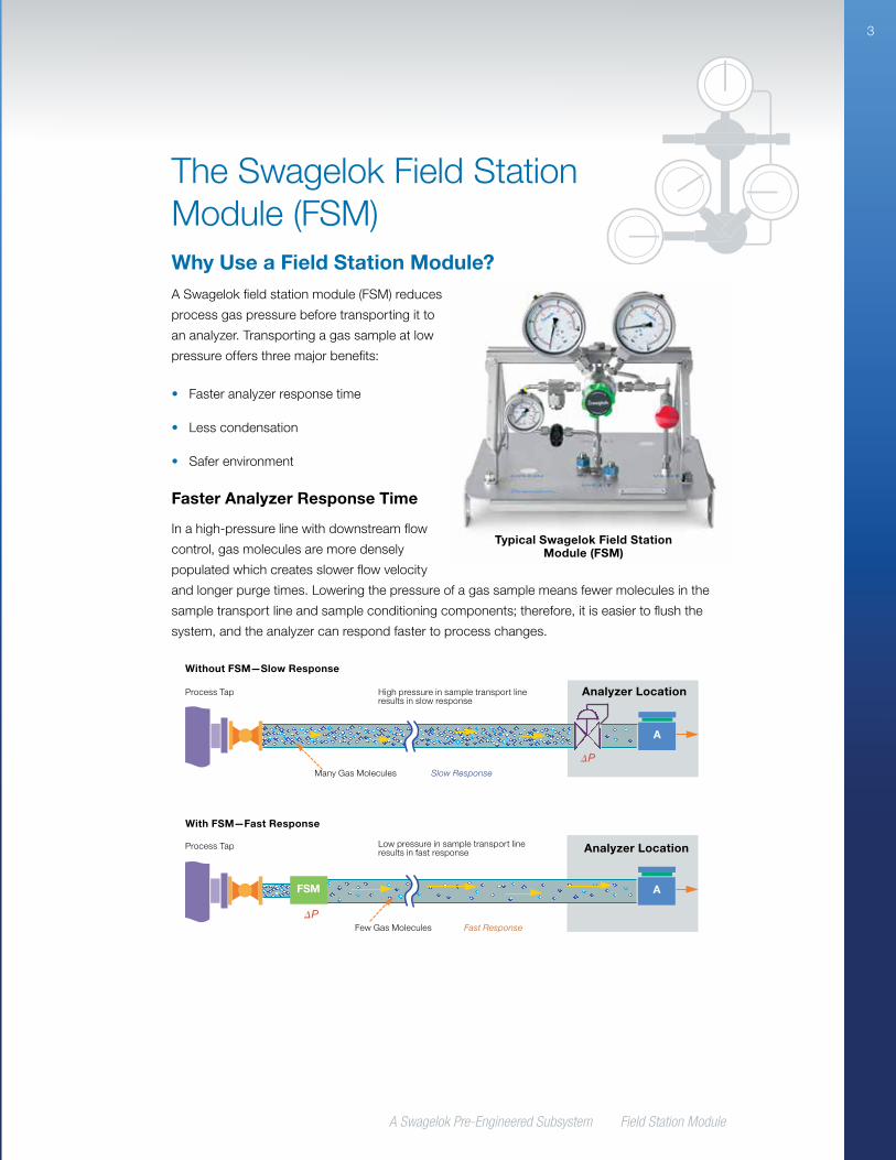
Faster Analyzer Response Time
In a high-pressure line with downstream flow
control, gas molecules are more densely
populated which creates slower flow velocity
and longer purge times. Lowering the pressure of a gas sample means fewer molecules in the
sample transport line and sample conditioning components; therefore, it is easier to flush the
system, and the analyzer can respond faster to process changes.
Typical Swagelok Field Station Module (FSM)
A
A
P
P
FSM
High pressure in sample transport line results in slow response
Low pressure in sample transport line results in fast response
Many Gas Molecules Slow Response
Fast ResponseFew Gas Molecules
Process Tap
Process Tap
Without FSM—Slow Response
Analyzer Location
Analyzer Location
With FSM—Fast Response
A Swagelok Pre-Engineered Subsystem Field Station Module
4
The amount of gas held in the transport line is proportional to its absolute pressure. At half the
absolute pressure, there are half as many gas molecules in the line, so—all other things being
equal—it takes half the time for a fresh sample to reach the analyzer.
Typically, an FSM is used when process pressure is 3 bar (gauge) (43.5 psig) or higher.
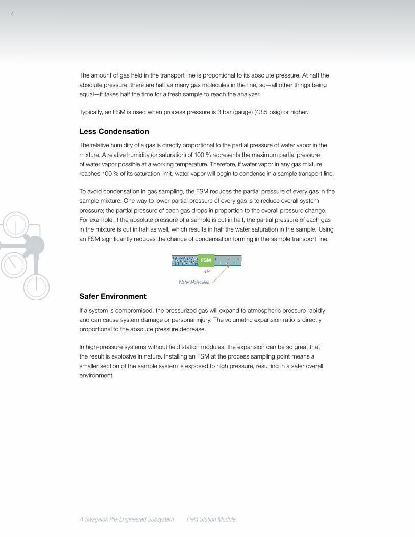
Less Condensation
The relative humidity of a gas is directly proportional to the partial pressure of water vapor in the
mixture. A relative humidity (or saturation) of 100 % represents the maximum partial pressure
of water vapor possible at a working temperature. Therefore, if water vapor in any gas mixture
reaches 100 % of its saturation limit, water vapor will begin to condense in a sample transport line.
To avoid condensation in gas sampling, the FSM reduces the partial pressure of every gas in the
sample mixture. One way to lower partial pressure of every gas is to reduce overall system
pressure; the partial pressure of each gas drops in proportion to the overall pressure change.
For example, if the absolute pressure of a sample is cut in half, the partial pressure of each gas
in the mixture is cut in half as well, which results in half the water saturation in the sample. Using
an FSM significantly reduces the chance of condensation forming in the sample transport line.
Safer Environment
If a system is compromised, the pressurized gas will expand to atmospheric pressure rapidly
and can cause system damage or personal injury. The volumetric expansion ratio is directly
proportional to the absolute pressure decrease.
In high-pressure systems without field station modules, the expansion can be so great that
the result is explosive in nature. Installing an FSM at the process sampling point means a
smaller section of the sample system is exposed to high pressure, resulting in a safer overall
environment.
P
FSM
Water Molecules
A Swagelok Pre-Engineered Subsystem Field Station Module
5
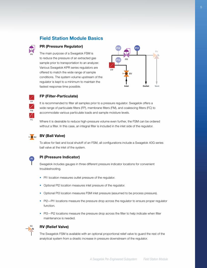
Field Station Module Basics
PR (Pressure Regulator)
The main purpose of a Swagelok FSM is
to reduce the pressure of an extracted gas
sample prior to transportation to an analyzer.
Various Swagelok KPR series regulators are
offered to match the wide range of sample
conditions. The system volume upstream of the
regulator is kept to a minimum to maintain the
fastest response time possible.
FP (Filter-Particulate)
It is recommended to filter all samples prior to a pressure regulator. Swagelok offers a
wide range of particulate filters (FP), membrane filters (FM), and coalescing filters (FC) to
accommodate various particulate loads and sample moisture levels.
Where it is desirable to reduce high-pressure volume even further, the FSM can be ordered
without a filter. In this case, an integral filter is included in the inlet side of the regulator.
BV (Ball Valve)
To allow for fast and local shutoff of an FSM, all configurations include a Swagelok 40G series
ball valve at the inlet of the system.
PI (Pressure Indicator)
Swagelok includes gauges in three different pressure indicator locations for convenient
troubleshooting.
• PI1 location measures outlet pressure of the regulator.
• Optional PI2 location measures inlet pressure of the regulator.
• Optional PI3 location measures FSM inlet pressure (assumed to be process pressure).
• PI2—PI1 locations measure the pressure drop across the regulator to ensure proper regulator
function.
• PI3—PI2 locations measure the pressure drop across the filter to help indicate when filter
maintenance is needed.
RV (Relief Valve)
The Swagelok FSM is available with an optional proportional relief valve to guard the rest of the
analytical system from a drastic increase in pressure downstream of the regulator.
PR
BV
PI2
PI3
PI1
FP
RV
Inlet Outlet Vent
PR
FP
BV
BV
PI
RV
FM
FP
FM
FC
MV NV1
NV
FI
PSV
C
CV SHV
SSV
FFL
SN
PVNV
FI
PR
FP
BV
BV
PI
RV
FM
FP
FM
FC
MV NV1
NV
FI
PSV
C
CV SHV
SSV
FFL
SN
PVNV
FI
PR
FP
BV
BV
PI
RV
FM
FP
FM
FC
MV NV1
NV
FI
PSV
C
CV SHV
SSV
FFL
SN
PVNV
FI
PR
FP
BV
BV
PI
RV
FM
FP
FM
FC
MV NV1
NV
FI
PSV
C
CV SHV
SSV
FFL
SN
PVNV
FIPR
FP
BV
BV
PI
RV
FM
FP
FM
FC
MV NV1
NV
FI
PSV
C
CV SHV
SSV
FFL
SN
PVNV
FI
A Swagelok Pre-Engineered Subsystem Field Station Module
6
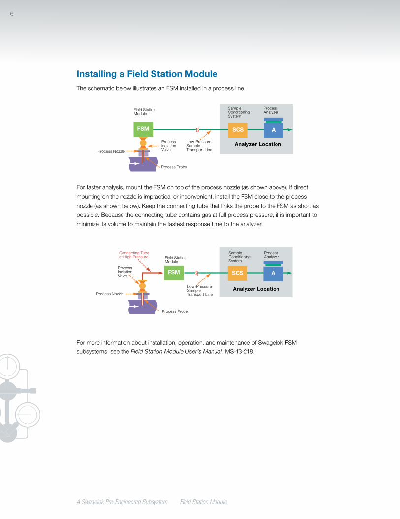
Installing a Field Station ModuleThe schematic below illustrates an FSM installed in a process line.
For faster analysis, mount the FSM on top of the process nozzle (as shown above). If direct
mounting on the nozzle is impractical or inconvenient, install the FSM close to the process
nozzle (as shown below). Keep the connecting tube that links the probe to the FSM as short as
possible. Because the connecting tube contains gas at full process pressure, it is important to
minimize its volume to maintain the fastest response time to the analyzer.
For more information about installation, operation, and maintenance of Swagelok FSM
subsystems, see the Field Station Module User’s Manual, MS-13-218.
ASCSFLM
AFSM SCS
AFSM SCS
Field Station Module
Process Isolation Valve
Process Probe
Low-Pressure Sample Transport Line
Sample Conditioning System
Process Analyzer
Analyzer LocationProcess Nozzle
Process Nozzle
ASCSFLM
AFSM SCS
AFSM SCS
Field Station Module
Connecting Tube at High Pressure
Process Isolation Valve
Process Probe
Low-Pressure Sample Transport Line
Sample Conditioning System
Process Analyzer
Analyzer Location
A Swagelok Pre-Engineered Subsystem Field Station Module
7
Specifying a Field Station ModuleThe FSM can be customized to meet system requirements. To specify an FSM:
• Know the maximum inlet pressure of the FSM. Specify the FSM configuration with the lowest
inlet pressure that is compatible with the highest process pressure.
• Specify pressure gauge dial size, placement, and fill. The measurement ranges of the
pressure gauges are determined automatically from the inlet pressure.
• Swagelok selects the regulator that is suitable for the maximum inlet pressure. The outlet
pressure control range is 0 to 50 psig (0 to 3.4 bar) for all models.
• Choose from five filter or coalescer options: no separate filter, small- or large-particle filter,
membrane separator with gravity drain, and large fibrous coalescer with membrane filter.
• Coalescer options work to remove liquid mist. The coalescer drain may terminate in a
manual blowdown valve that is separate from this system.
• Do not use a coalescer if the sample contains many particulates; the coalescer will clog.
Instead, specify a filter to remove them and, if the liquid mist is volatile, keep the field
station and transport line hot enough to avoid condensation. If necessary, condense and
remove the liquid in the sample conditioning system close to the analyzer. If the sample
contains many particulates and nonvolatile liquid mist, the FSM may not be suitable; ask
for an evaluation by Swagelok.
• Select from three pressure-relief options: no relief valve, preset adjustable relief valve, or
preset adjustable relief valve with manual override handle.
• Caution: Without a relief valve, the outlet pressure gauge and the downstream
equipment are not protected if the pressure regulator fails. A suitable pressure
relief mechanism should be used to protect the system from overpressurization.
• Choose from a wide range of inlet and outlet connections, including Swagelok tube fittings,
NPT fittings, and flanges.
• Select an enclosure option. ABS plastic, fiberglass, and 304 stainless steel enclosures and
sun shades are available. Enclosures are available with or without a window and insulated or
uninsulated.
A Swagelok Pre-Engineered Subsystem Field Station Module
8
Joule-Thomson Cooling EffectField station modules with inlet pressures of 1000 psig (68.9 bar) or higher have a large pressure
drop, and the sample may experience excessive cooling. Although the temperature drop caused
by Joule-Thomson cooling is the same at any flow rate, the heat it absorbs is proportional to
the rate of flow. The FSM offers a wide range of heater options, sufficient for most sampling
applications.

A Swagelok Pre-Engineered Subsystem Field Station Module
9
Materials of ConstructionConfiguration
LabelComponent
Manufacturer, Model
Material Grade / ASTM Specification
BV Isolation ball valveSwagelok 40G series
See Swagelok One-Piece Instrumentation Ball Valves—40G Series and 40 Series catalog,
MS-02-331
FCFilter-coalescing
membrane (configuration 5)
Avenger™ model 38M
See Avenger 30 Series Filters selection guide, www.apluscorporation.com
FMFilter-membrane
separator (configuration 3)
Supreme model 123HP
See Series 100 Genie® Membrane Separators™ selection guide, www.apluscorporation.com
FP
Filter-particulate (small capacity,
configurations 1 and 2)
Swagelok TF series
See Swagelok Filters catalog, MS-01-92
Filter-particulate (large-capacity, configuration 4)
Avenger model 38
See Avenger 30 Series Filters selection guide, www.apluscorporation.com
PI Pressure indicatorSwagelok
B model pressure gauge
See Swagelok Pressure Gauges, Industrial and Process—PGI Series catalog, MS-02-170
PR Pressure regulatorSwagelok KPR series
See Swagelok Pressure Regulators catalog, MS-02-230
RVRelief valve, proportional
Swagelok RL3 and R3A series
See Swagelok Proportional Relief Valves catalog, MS-01-141
System Hardware and Optional Components
— Base plate Swagelok 304 SS / A240
— Flange fittings Swagelok See Swagelok Flange Adapters catalog, MS-02-200
— Hardware Various300 series SS, electroplated steel, hot-dip
galvanized steel, or coated steel
— Mounting brackets Swagelok 304 SS / A240
—Stainless steel tube fittings
Swagelok316 SS / A276 or A182
See Swagelok Gaugeable Tube Fittings and Adapter Fittings catalog, MS-01-140
—Stainless steel
tubingSwagelok
316/316L SS / A213/A269 See Swagelok Stainless Steel Seamless Tubing
catalog, MS-01-1-SCS
—Stainless steel
enclosureSwagelok 304 SS / A240
— ABS enclosureO’Brien
VIPAK® A1See O’Brien Corporation VIPAK catalog,
www. obcorp.com
— Fiberglass enclosureIntertec
DIABOX™ 87See Intertec Instrumentation DIABOX 87 catalog
www.intertec.info/
—Stainless steel sun
shadeSwagelok 304 SS / A240
— ABS sun shadeO’Brien
VIPAK E1BSee O’Brien Corporation VIPAK catalog,
www. obcorp.com
— Fiberglass sun shadeIntertec SD 50
See Intertec Instrumentation SD 50 Shade catalog, www.intertec.info/
— Enclosure heaterIntertec
CP MULTITHERMSee Intertec Instrumentation explosion proof
convection heaters, www.intertec.info/
— Regulator heaterIntertec
SL BLOCKTHERMSee Intertec Instrumentation explosion proof
conduction heaters, www.intertec.info/
— ThermostatIntertec
TS and TAESee Intertec Instrumentation DIABOX 87 catalog,
www.intertec.info/
— Thermometer SwagelokSee Swagelok Temperature Measurement Devices
catalog, MS-02-353
A Swagelok Pre-Engineered Subsystem Field Station Module
10
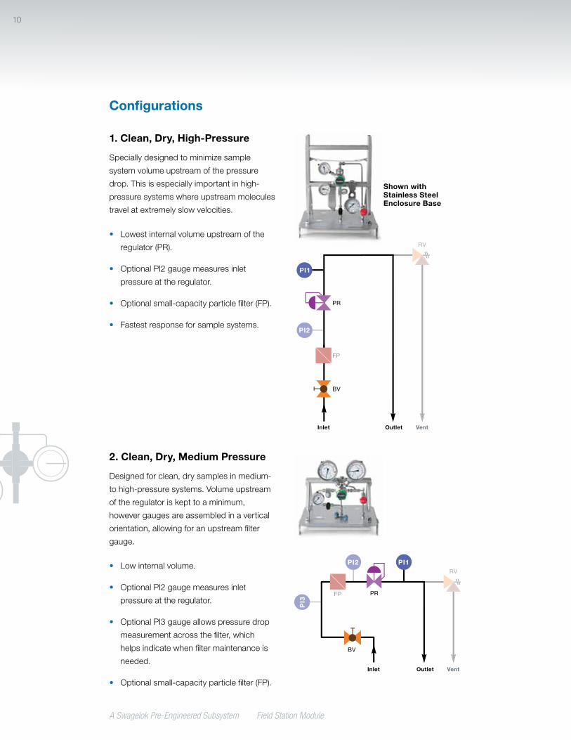
1. Clean, Dry, High-Pressure
Specially designed to minimize sample
system volume upstream of the pressure
drop. This is especially important in high-
pressure systems where upstream molecules
travel at extremely slow velocities.
• Lowest internal volume upstream of the
regulator (PR).
• Optional PI2 gauge measures inlet
pressure at the regulator.
• Optional small-capacity particle filter (FP).
• Fastest response for sample systems.
PR
FP
BV
PI2
PI1
RV
Inlet Outlet Vent
Shown with Stainless Steel Enclosure Base
2. Clean, Dry, Medium Pressure
Designed for clean, dry samples in medium-
to high-pressure systems. Volume upstream
of the regulator is kept to a minimum,
however gauges are assembled in a vertical
orientation, allowing for an upstream filter
gauge.
• Low internal volume.
• Optional PI2 gauge measures inlet
pressure at the regulator.
• Optional PI3 gauge allows pressure drop
measurement across the filter, which
helps indicate when filter maintenance is
needed.
• Optional small-capacity particle filter (FP).
PR
BV
PI3
PI2 PI1
FP
RV
Inlet Outlet Vent
Configurations
A Swagelok Pre-Engineered Subsystem Field Station Module
11
Configurations
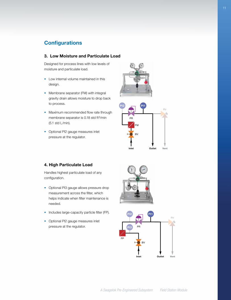
4. High Particulate Load
Handles highest particulate load of any
configuration.
• Optional PI3 gauge allows pressure drop
measurement across the filter, which
helps indicate when filter maintenance is
needed.
• Includes large-capacity particle filter (FP).
• Optional PI2 gauge measures inlet
pressure at the regulator. PR
BV
PI2
PI3
PI1
FP
RV
Inlet Outlet Vent
3. Low Moisture and Particulate Load
Designed for process lines with low levels of
moisture and particulate load.
• Low internal volume maintained in this
design.
• Membrane separator (FM) with integral
gravity drain allows moisture to drop back
to process.
• Maximum recommended flow rate through
membrane separator is 0.18 std ft3/min
(5.1 std L/min).
• Optional PI2 gauge measures inlet
pressure at the regulator.
PR
BV
PI2 PI1
FM
RV
Inlet Outlet Vent
A Swagelok Pre-Engineered Subsystem Field Station Module
12
Configurations
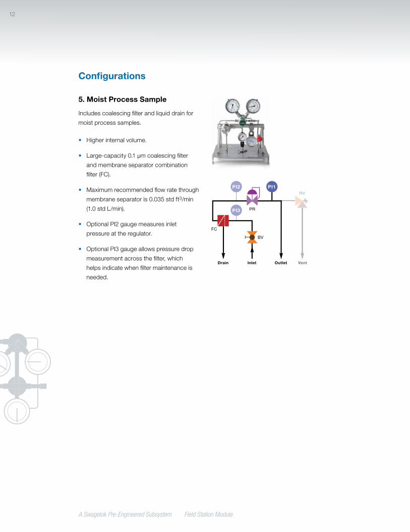
5. Moist Process Sample
Includes coalescing filter and liquid drain for
moist process samples.
• Higher internal volume.
• Large-capacity 0.1 µm coalescing filter
and membrane separator combination
filter (FC).
• Maximum recommended flow rate through
membrane separator is 0.035 std ft3/min
(1.0 std L/min).
• Optional PI2 gauge measures inlet
pressure at the regulator.
• Optional PI3 gauge allows pressure drop
measurement across the filter, which
helps indicate when filter maintenance is
needed.
PR
BV
PI2
PI3
PI1
FC
RV
Inlet OutletDrain Vent

A Swagelok Pre-Engineered Subsystem Field Station Module
13
Technical Data
FSM Configuration
Working Pressurepsig (bar)
Temperature Rating, °F (°C)Maximum Air Flow
std ft3/min (std L/min) Filter Internal Volume
in.3 (cm3)With Relief
ValveWithout
Relief Valve
15 psig (1.0 bar) Outlet
Pressure
30 psig (2.1 bar) Outlet
Pressure
1 Clean, dry, high-pressure
2500 (172) 250 (121) 300 (148) 0.23 (6.5) 0.39 (11.0) 0.30 (4.9)
2 Clean, dry, medium-pressure
2500 (172) 250 (121) 300 (148) 0.23 (6.5) 0.39 (11.0) 0.30 (4.9)
3 Low moisture and particulate load
1000 (68.9) 185 (85) 185 (85) 0.18 (5.1) 0.18 (5.1) 0.56 (9.1)
4 High particulate load
1000 (68.9) 250 (121) 300 (148) 0.23 (6.5) 0.39 (11.0) 3.05 (50.0)
5 Moist process sample
1000 (68.9) 185 (85) 185 (85) 0.035 (1.0) 0.035 (1.0) 3.05 (50.0)
For systems outside these parameters, contact your authorized Swagelok sales and service representative.
TestingEvery Swagelok FSM subsystem is shell
tested with nitrogen at 145 psig (10 bar) to a
requirement of no detectable leakage with a
liquid leak detector.
Cleaning and PackagingAll Swagelok FSM subsystems are cleaned
in accordance with Swagelok Standard
Cleaning and Packaging (SC-10), MS-06-62.
A Swagelok Pre-Engineered Subsystem Field Station Module
14
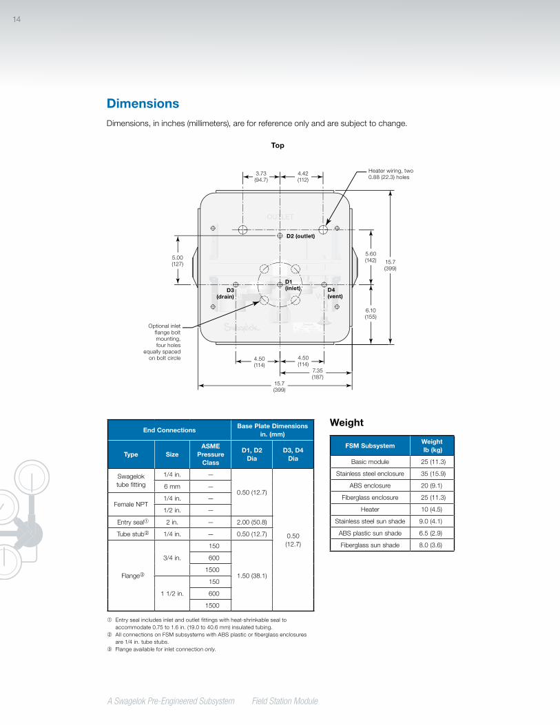
DimensionsDimensions, in inches (millimeters), are for reference only and are subject to change.
Top
D2 (outlet)
Heater wiring, two 0.88 (22.3) holes
Optional inlet flange bolt mounting, four holes
equally spaced on bolt circle
3.73 (94.7)
5.60 (142) 15.7
(399)
6.10 (155)
4.50 (114)
4.50 (114)
15.7 (399)
5.00 (127)
4.42 (112)
7.35 (187)
Weight
FSM SubsystemWeight lb (kg)
Basic module 25 (11.3)
Stainless steel enclosure 35 (15.9)
ABS enclosure 20 (9.1)
Fiberglass enclosure 25 (11.3)
Heater 10 (4.5)
Stainless steel sun shade 9.0 (4.1)
ABS plastic sun shade 6.5 (2.9)
Fiberglass sun shade 8.0 (3.6)
End Connections Base Plate Dimensions
in. (mm)
Type Size ASME
Pressure Class
D1, D2 Dia
D3, D4 Dia
Swagelok tube fitting
1/4 in. —
0.50 (12.7)
0.50 (12.7)
6 mm —
Female NPT1/4 in. —
1/2 in. —
Entry seal➀ 2 in. — 2.00 (50.8)
Tube stub➁ 1/4 in. — 0.50 (12.7)
Flange➂
3/4 in.
150
1.50 (38.1)
600
1500
1 1/2 in.
150
600
1500
➀ Entry seal includes inlet and outlet fittings with heat-shrinkable seal to accommodate 0.75 to 1.6 in. (19.0 to 40.6 mm) insulated tubing.
➁ All connections on FSM subsystems with ABS plastic or fiberglass enclosures are 1/4 in. tube stubs.
➂ Flange available for inlet connection only.
D1 (inlet) D4
(vent)D3
(drain)
A Swagelok Pre-Engineered Subsystem Field Station Module
15
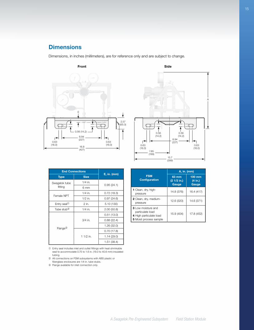
DimensionsDimensions, in inches (millimeters), are for reference only and are subject to change.
FSM Configuration
A, in. (mm)
63 mm (2 1/2 in.)
Gauge
100 mm (4 in.) Gauge
1 Clean, dry, high-pressure
14.8 (376) 16.4 (417)
2 Clean, dry, medium-pressure
12.6 (320) 14.6 (371)
3 Low moisture and particulate load
4 High particulate load5 Moist process sample
15.9 (404) 17.8 (452)
Side
A
15.7 (399)
8.94 (227)
7.85 (199)
0.56 (14.2)
0.63 (16.0)
0.63 (16.0)
0.56 (14.2)
End Connections E, in. (mm)
Type Size
Swagelok tube fitting
1/4 in. 0.95 (24.1)
6 mm
Female NPT1/4 in. 0.72 (18.3)
1/2 in. 0.97 (24.6)
Entry seal➀ 2 in. 5.10 (130)
Tube stub➁ 1/4 in. 2.00 (50.8)
Flange➂
3/4 in.
0.51 (13.0)
0.88 (22.4)
1.26 (32.0)
1 1/2 in.
0.70 (17.8)
1.14 (29.0)
1.51 (38.4)
➀ Entry seal includes inlet and outlet fittings with heat-shrinkable seal to accommodate 0.75 to 1.6 in. (19.0 to 40.6 mm) insulated tubing.
➁ All connections on FSM subsystems with ABS plastic or fiberglass enclosures are 1/4 in. tube stubs.
➂ Flange available for inlet connection only.
Front
16.8 (427)
8.94 (227)
2.57 (65.3)
0.56 (14.2)
0.63 (16.0)
0.63 (16.0)
E
A Swagelok Pre-Engineered Subsystem Field Station Module
16
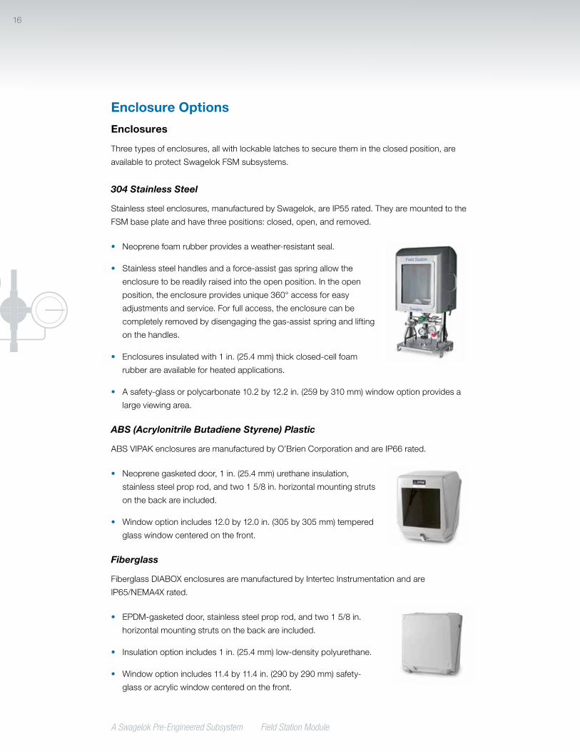
Enclosures
Three types of enclosures, all with lockable latches to secure them in the closed position, are
available to protect Swagelok FSM subsystems.
304 Stainless Steel
Stainless steel enclosures, manufactured by Swagelok, are IP55 rated. They are mounted to the
FSM base plate and have three positions: closed, open, and removed.
• Neoprene foam rubber provides a weather-resistant seal.
• Stainless steel handles and a force-assist gas spring allow the
enclosure to be readily raised into the open position. In the open
position, the enclosure provides unique 360° access for easy
adjustments and service. For full access, the enclosure can be
completely removed by disengaging the gas-assist spring and lifting
on the handles.
• Enclosures insulated with 1 in. (25.4 mm) thick closed-cell foam
rubber are available for heated applications.
• A safety-glass or polycarbonate 10.2 by 12.2 in. (259 by 310 mm) window option provides a
large viewing area.
ABS (Acrylonitrile Butadiene Styrene) Plastic
ABS VIPAK enclosures are manufactured by O’Brien Corporation and are IP66 rated.
• Neoprene gasketed door, 1 in. (25.4 mm) urethane insulation,
stainless steel prop rod, and two 1 5/8 in. horizontal mounting struts
on the back are included.
• Window option includes 12.0 by 12.0 in. (305 by 305 mm) tempered
glass window centered on the front.
Fiberglass
Fiberglass DIABOX enclosures are manufactured by Intertec Instrumentation and are
IP65/NEMA4X rated.
• EPDM-gasketed door, stainless steel prop rod, and two 1 5/8 in.
horizontal mounting struts on the back are included.
• Insulation option includes 1 in. (25.4 mm) low-density polyurethane.
• Window option includes 11.4 by 11.4 in. (290 by 290 mm) safety-
glass or acrylic window centered on the front.
Enclosure Options
17
A Swagelok Pre-Engineered Subsystem Field Station Module
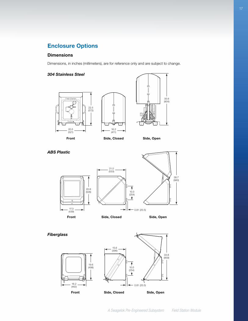
Enclosure Options
Dimensions
Dimensions, in inches (millimeters), are for reference only and are subject to change.
Fiberglass
304 Stainless Steel
ABS Plastic
Front Side, Closed Side, Open
R
R
20.5 (521)
22.5 (572)
16.2 (411)
35.6 (904)
17.3 (439)
20.8 (528)
21.0 (533)
38.7 (983)
Front Side, Closed Side, Open
10.0 (254)
0.81 (20.5)
18.2 (462)
19.6 (498)
15.6 (396)
33.8 (859)
Front Side, Closed Side, Open
10.0 (254)
0.81 (20.5)
A Swagelok Pre-Engineered Subsystem Field Station Module
18
Enclosure Options
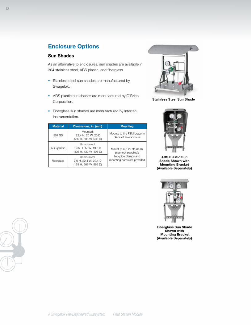
Sun Shades
As an alternative to enclosures, sun shades are available in
304 stainless steel, ABS plastic, and fiberglass.
• Stainless steel sun shades are manufactured by
Swagelok.
• ABS plastic sun shades are manufactured by O’Brien
Corporation.
• Fiberglass sun shades are manufactured by Intertec
Instrumentation.
Material Dimensions, in. (mm) Mounting
304 SSMounted:
22.4 H, 20 W, 20 D(569 H, 508 W, 508 D)
Mounts to the FSM brace in place of an enclosure
ABS plasticUnmounted:
19.5 H, 17 W, 19.5 D(495 H, 432 W, 495 D)
Mount to a 2 in. structural pipe (not supplied);
two pipe clamps and mounting hardware providedFiberglass
Unmounted:7.0 H, 22.4 W, 22.4 D(178 H, 569 W, 569 D)
ABS Plastic Sun Shade Shown with Mounting Bracket
(Available Separately)
Fiberglass Sun ShadeShown with
Mounting Bracket (Available Separately)
Stainless Steel Sun Shade

A Swagelok Pre-Engineered Subsystem Field Station Module
19
Heaters and thermostats for Swagelok FSM
subsystems are manufactured by Intertec
Instrumentation.
Enclosure Heaters
Heaters are available for applications where
environmental temperatures may drop
below the dew point of the gas. Heaters
are mounted inside the enclosure for freeze
protection or temperature maintenance. An
insulated enclosure should be ordered with a
heater to maximize effectiveness.
Enclosure heaters with thermostats are
available with ATEX/IEC or CSA/UL
approvals.
Enclosure Heater Selection
Enclosure heaters typically are selected based on the temperature differential (∆T ) between the
set thermostat temperature and the lowest expected ambient temperature.
Enclosure Configuration
Maximum ∆T, °F (°C)
50 (28) 75 (42) 100 (56) 125 (69) 150 (83)
Heater Wattage Required
Stainless Steel Enclosure
Insulated, no window 100 W 100 W 100 W 200 W —
Insulated, with window 100 W 100 W 200 W 200 W —
ABS and Fiberglass Enclosures
Insulated, no window 50/100 W 50/100 W 100 W 100 W 200 W
Insulated, with window 50/100 W 100 W 100 W 200 W 200 W
Uninsulated, no window➀ 100 W 200 W — — —
Uninsulated, with window➀ 100 W 200 W — — —
➀ Available in fiberglass only.
Heating Options
Enclosure Heater with Thermostat
(ATEX/IEC Approval)
Enclosure Heater with Thermostat
(CSA/UL Approval)
A Swagelok Pre-Engineered Subsystem Field Station Module
20
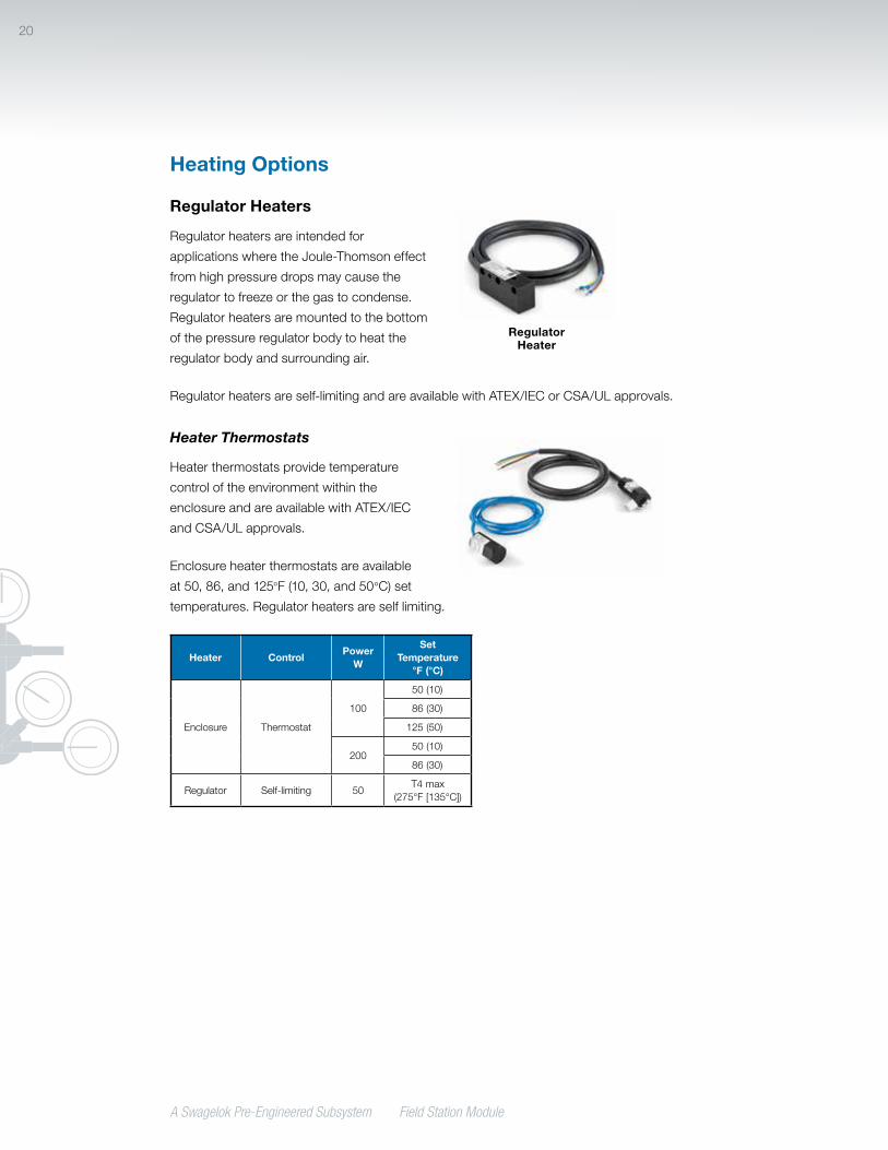
Regulator Heaters
Regulator heaters are intended for
applications where the Joule-Thomson effect
from high pressure drops may cause the
regulator to freeze or the gas to condense.
Regulator heaters are mounted to the bottom
of the pressure regulator body to heat the
regulator body and surrounding air.
Regulator heaters are self-limiting and are available with ATEX/IEC or CSA/UL approvals.
Heater Thermostats
Heater thermostats provide temperature
control of the environment within the
enclosure and are available with ATEX/IEC
and CSA/UL approvals.
Enclosure heater thermostats are available
at 50, 86, and 125°F (10, 30, and 50°C) set
temperatures. Regulator heaters are self limiting.
Heater ControlPower
W
Set Temperature
°F (°C)
Enclosure Thermostat
100
50 (10)
86 (30)
125 (50)
20050 (10)
86 (30)
Regulator Self-limiting 50T4 max
(275°F [135°C])
Regulator Heater
Heating Options
A Swagelok Pre-Engineered Subsystem Field Station Module
21
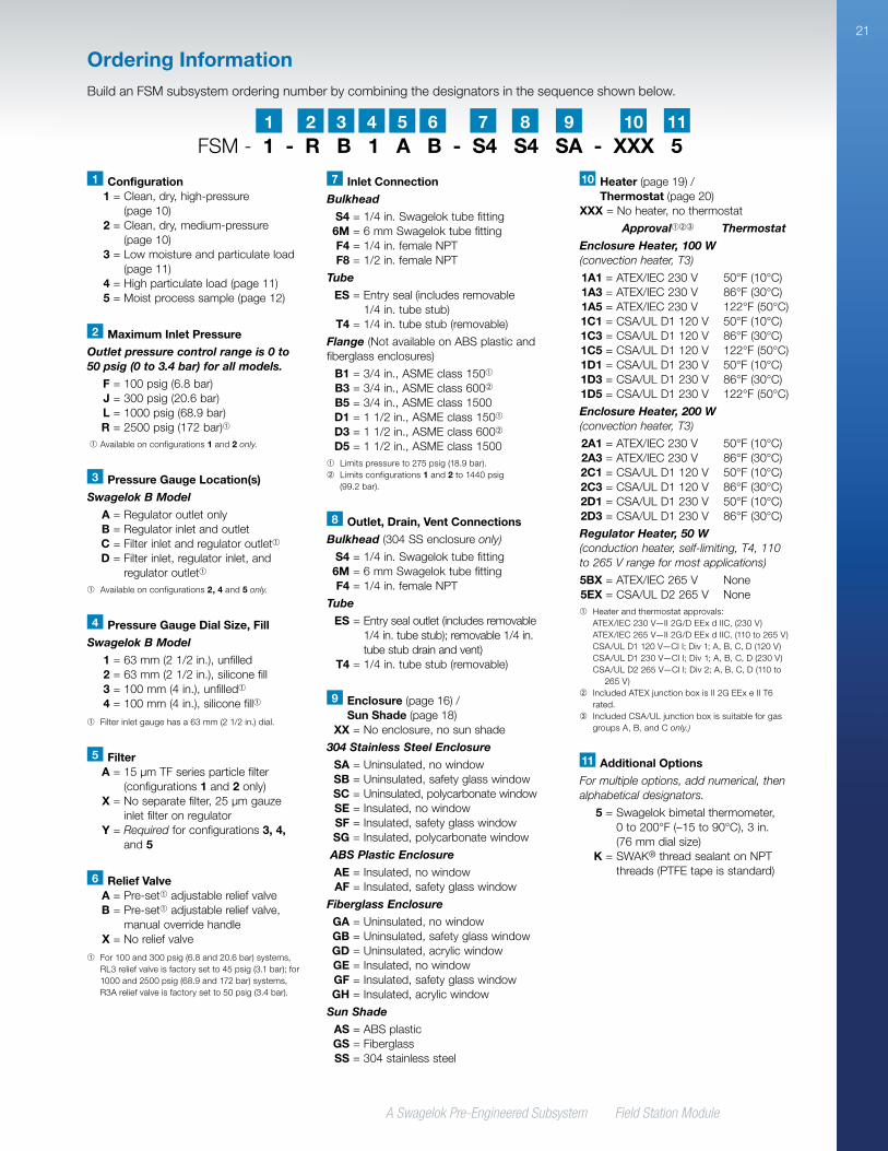
Ordering InformationBuild an FSM subsystem ordering number by combining the designators in the sequence shown below.
FSM - 1 - R B 1 A B - S4 S4 SA - XXX 52 41 3 5 6 7 8 9 10
1 Configuration 1 = Clean, dry, high-pressure
(page 10) 2 = Clean, dry, medium-pressure
(page 10) 3 = Low moisture and particulate load
(page 11) 4 = High particulate load (page 11) 5 = Moist process sample (page 12)
2 Maximum Inlet Pressure
Outlet pressure control range is 0 to 50 psig (0 to 3.4 bar) for all models.
F = 100 psig (6.8 bar) J = 300 psig (20.6 bar) L = 1000 psig (68.9 bar) R = 2500 psig (172 bar)➀
➀ Available on configurations 1 and 2 only.
3 Pressure Gauge Location(s)
Swagelok B Model
A = Regulator outlet only B = Regulator inlet and outlet C = Filter inlet and regulator outlet➀ D = Filter inlet, regulator inlet, and
regulator outlet➀
➀ Available on configurations 2, 4 and 5 only.
8 Outlet, Drain, Vent Connections
Bulkhead (304 SS enclosure only)
S4 = 1/4 in. Swagelok tube fitting 6M = 6 mm Swagelok tube fitting F4 = 1/4 in. female NPT
Tube
ES = Entry seal outlet (includes removable 1/4 in. tube stub); removable 1/4 in. tube stub drain and vent)
T4 = 1/4 in. tube stub (removable)
9 Enclosure (page 16) / Sun Shade (page 18)
XX = No enclosure, no sun shade
304 Stainless Steel Enclosure
SA = Uninsulated, no window SB = Uninsulated, safety glass window SC = Uninsulated, polycarbonate window SE = Insulated, no window SF = Insulated, safety glass window SG = Insulated, polycarbonate window
ABS Plastic Enclosure
AE = Insulated, no window AF = Insulated, safety glass window
Fiberglass Enclosure
GA = Uninsulated, no window GB = Uninsulated, safety glass window GD = Uninsulated, acrylic window GE = Insulated, no window GF = Insulated, safety glass window GH = Insulated, acrylic window
Sun Shade
AS = ABS plastic GS = Fiberglass SS = 304 stainless steel
10 Heater (page 19) / Thermostat (page 20)
XXX = No heater, no thermostat
Approval➀➁➂ Thermostat
Enclosure Heater, 100 W (convection heater, T3)
1A1 = ATEX/IEC 230 V 50°F (10°C) 1A3 = ATEX/IEC 230 V 86°F (30°C) 1A5 = ATEX/IEC 230 V 122°F (50°C) 1C1 = CSA/UL D1 120 V 50°F (10°C) 1C3 = CSA/UL D1 120 V 86°F (30°C) 1C5 = CSA/UL D1 120 V 122°F (50°C) 1D1 = CSA/UL D1 230 V 50°F (10°C) 1D3 = CSA/UL D1 230 V 86°F (30°C) 1D5 = CSA/UL D1 230 V 122°F (50°C)
Enclosure Heater, 200 W (convection heater, T3)
2A1 = ATEX/IEC 230 V 50°F (10°C) 2A3 = ATEX/IEC 230 V 86°F (30°C) 2C1 = CSA/UL D1 120 V 50°F (10°C) 2C3 = CSA/UL D1 120 V 86°F (30°C) 2D1 = CSA/UL D1 230 V 50°F (10°C) 2D3 = CSA/UL D1 230 V 86°F (30°C)
Regulator Heater, 50 W (conduction heater, self-limiting, T4, 110 to 265 V range for most applications)
5BX = ATEX/IEC 265 V None 5EX = CSA/UL D2 265 V None➀ Heater and thermostat approvals:
ATEX/IEC 230 V—II 2G/D EEx d IIC, (230 V) ATEX/IEC 265 V—II 2G/D EEx d IIC, (110 to 265 V) CSA/UL D1 120 V—Cl I; Div 1; A, B, C, D (120 V) CSA/UL D1 230 V—Cl I; Div 1; A, B, C, D (230 V) CS A/UL D2 265 V—Cl I; Div 2; A, B, C, D (110 to
265 V)➁ Included ATEX junction box is II 2G EEx e II T6
rated.➂ Included CSA/UL junction box is suitable for gas
groups A, B, and C only.)
11 Additional Options
For multiple options, add numerical, then alphabetical designators.
5 = Swagelok bimetal thermometer, 0 to 200°F (–15 to 90°C), 3 in. (76 mm dial size)
K = SWAK® thread sealant on NPT threads (PTFE tape is standard)
5 Filter A = 15 µm TF series particle filter
(configurations 1 and 2 only) X = No separate filter, 25 µm gauze
inlet filter on regulator Y = Required for configurations 3, 4,
and 5
4 Pressure Gauge Dial Size, Fill
Swagelok B Model
1 = 63 mm (2 1/2 in.), unfilled 2 = 63 mm (2 1/2 in.), silicone fill 3 = 100 mm (4 in.), unfilled➀
4 = 100 mm (4 in.), silicone fill➀
➀ Filter inlet gauge has a 63 mm (2 1/2 in.) dial.
6 Relief Valve A = Pre-set➀ adjustable relief valve B = Pre-set➀ adjustable relief valve,
manual override handle X = No relief valve
➀ For 100 and 300 psig (6.8 and 20.6 bar) systems, RL3 relief valve is factory set to 45 psig (3.1 bar); for 1000 and 2500 psig (68.9 and 172 bar) systems, R3A relief valve is factory set to 50 psig (3.4 bar).
7 Inlet Connection
Bulkhead
S4 = 1/4 in. Swagelok tube fitting 6M = 6 mm Swagelok tube fitting F4 = 1/4 in. female NPT F8 = 1/2 in. female NPT
Tube
ES = Entry seal (includes removable 1/4 in. tube stub)
T4 = 1/4 in. tube stub (removable)
Flange (Not available on ABS plastic and fiberglass enclosures)
B1 = 3/4 in., ASME class 150➀ B3 = 3/4 in., ASME class 600➁ B5 = 3/4 in., ASME class 1500 D1 = 1 1/2 in., ASME class 150➀ D3 = 1 1/2 in., ASME class 600➁ D5 = 1 1/2 in., ASME class 1500➀ Limits pressure to 275 psig (18.9 bar).➁ Limits configurations 1 and 2 to 1440 psig
(99.2 bar).
11
A Swagelok Pre-Engineered Subsystem Field Station Module
22
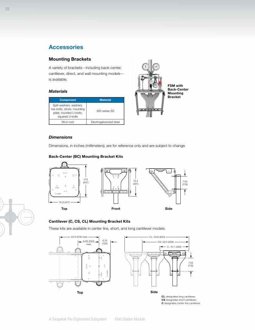
Mounting Brackets
A variety of brackets—including back-center,
cantilever, direct, and wall mounting models—
is available.
Materials
Component Material
Split washers, washers, hex bolts, struts, mounting
plate, rounded U-bolts, squared U-bolts
300 series SS
Strut nuts Electrogalvanized steel
Dimensions
Dimensions, in inches (millimeters), are for reference only and are subject to change.
Back-Center (BC) Mounting Bracket Kits
Cantilever (C, CS, CL) Mounting Bracket Kits
These kits are available in center line, short, and long cantilever models.
FSM with Back-Center Mounting Bracket
15.4 (391)
17.6 (447) 7.00
(178)
16.8 (427)
Front SideTop
CL: 33.6 (853)
9.95 (253)max
22.6 (574) max
7.00 (178)
6.10 (155)
CS: 22.0 (559)
C: 15.7 (399)
SideTopCL designates long cantilever; CS designates short cantilever; C designates center line cantilever.
Accessories
A Swagelok Pre-Engineered Subsystem Field Station Module
23
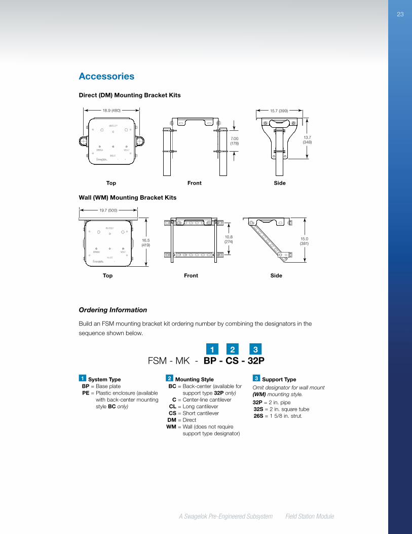
Direct (DM) Mounting Bracket Kits
Wall (WM) Mounting Bracket Kits
15.7 (399)
7.00 (178)
13.7 (348)
18.9 (480)
Front SideTop
10.8 (274)16.5
(419)
15.0 (381)
19.7 (500)
Front SideTop
Accessories
Ordering Information
Build an FSM mounting bracket kit ordering number by combining the designators in the
sequence shown below.
FSM - MK - BP - CS - 32P21 3
1 System Type BP = Base plate PE = Plastic enclosure (available
with back-center mounting style BC only)
2 Mounting Style BC = Back-center (available for
support type 32P only) C = Center-line cantilever CL = Long cantilever CS = Short cantilever DM = Direct WM = Wall (does not require
support type designator)
3 Support Type
Omit designator for wall mount (WM) mounting style.
32P = 2 in. pipe 32S = 2 in. square tube 26S = 1 5/8 in. strut.

Swagelok, SWAK—TM Swagelok CompanyAvenger, Genie, Membrane Separators—TM A+ Manufacturing, LLC; VIPAK—TM O’Brien Corporation; DIABOX—TM Intertec© 2012–2018 Swagelok Company, October 2018, RevD, MS-02-359
Safe Product SelectionWhen selecting a product, the total system design must be considered to ensure safe, trouble-free performance. Function, material compatibility, adequate ratings, proper installation, operation, and maintenance are the responsibilities of the system designer and user.
Caution: Do not mix or interchange Swagelok product components with those of other manufacturers.
Warranty InformationSwagelok products are backed by The Swagelok Limited
Lifetime Warranty. For a copy, visit swagelok.com or contact
your authorized Swagelok representative.
Regulatory Compliance
Europe
• Pressure Equipment Directive (PED) 2014/68/EU
• Atmospheres Explosive Directive (ATEX) 2014/34/EU
• Restriction of Hazardous Substances Directive (RoHS) 2011/65/EU
Americas
• Hazardous location electrical approval (CSA/UL)
• CRN registered in Canada (individual components of assembly)
Contact your authorized Swagelok representative for specific assembly compliance approvals
and certifications available from the manufacturer.
Replacement Filter Element Kits
Kits include filter element and instructions.
FSM Configuration Kit Ordering Number
1 Clean, dry, high-pressure
SS-4F-K4-152 Clean, dry, medium-
pressure
3 Low moisture and particulate load
FSM3-FILTER-K
4 High particulate load FSM4-FILTER-K
5 Moist process sample FSM5-FILTER-K
Accessories