Control station ISOTHERM | Manual
10
Isotherm Control station for constant maintenance of the supply temperature in surface heating systems Installation and Operating Manual (translated from the original operating manual) WattsWater.eu
-
Upload
khangminh22 -
Category
Documents
-
view
1 -
download
0
Transcript of Control station ISOTHERM | Manual

IsothermControl station for constant maintenance of the supply temperature in surface heating systemsInstallation and Operating Manual (translated from the original operating manual)
WattsWater.eu
2 ISOTHERM-IM-DE-W-UK-01-2021-Rev0 | Part no. 10019091
EN ENGLISH
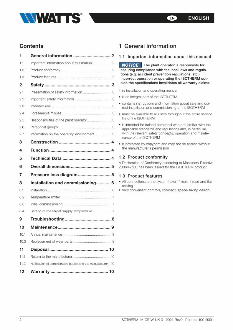
Contents
1 General information ............................... 2
1.1 Important information about this manual ................... 2
1.2 Product conformity .................................................... 2
1.3 Product features ........................................................ 2
2 Safety ........................................................3
2.1 Presentation of safety information .............................. 3
2.2 Important safety information ...................................... 3
2.3 Intended use .............................................................. 3
2.4 Foreseeable misuse ................................................... 3
2.5 Responsibilities of the plant operator ......................... 3
2.6 Personnel groups ...................................................... 3
2.7 Information on the operating environment ................. 3
3 Construction ........................................... 4
4 Function ................................................... 4
5 Technical Data ........................................ 4
6 Overall dimensions ................................. 5
7 Pressure loss diagram ........................... 5
8 Installation and commissioning ............ 6
8.1 Installation .................................................................. 6
8.2 Temperature limiter .................................................... 7
8.3 Initial commissioning .................................................. 7
8.4 Setting of the target supply temperature ................... 7
9 Troubleshooting .......................................8
10 Maintenance ............................................ 9
10.1 Annual maintenance .................................................. 9
10.2 Replacement of wear parts ....................................... 9
11 Disposal ................................................. 10
11.1 Return to the manufacturer .......................................10
11.2 Notification of administrative bodies and the manufacturer ..10
12 Warranty ................................................ 10
1 General information
1.1 Important information about this manual
NOTICE The plant operator is responsible forensuring compliance with the local laws and regula-tions (e.g. accident prevention regulations, etc.). Incorrect operation or operating the ISOTHERM out-side the specifications invalidates all warranty claims.
This installation and operating manual
• is an integral part of the ISOTHERM
• contains instructions and information about safe and cor-rect installation and commissioning of the ISOTHERM
• must be available to all users throughout the entire service life of the ISOTHERM
• is intended for trained personnel who are familiar with the applicable standards and regulations and, in particular, with the relevant safety concepts, operation and mainte-nance of the ISOTHERM
• is protected by copyright and may not be altered without the manufacturer’s permission
1.2 Product conformityA Declaration of Conformity according to Machinery Directive 2006/42/EC has been issued for the ISOTHERM product.
1.3 Product features• All connections to the system have 1" male thread and flat
sealing• Very convenient controls, compact, space-saving design.

ISOTHERM-IM-DE-W-UK-01-2021-Rev0 | Part no. 10019091 3
ENENGLISH
2 Safety
2.1 Presentation of safety information
! DANGER DANGER indicates an imminent danger
that may cause serious physical injury or death if the appropriate safety precautions are not in place.
!! WARNING WARNING indicates a danger arising
through incorrect behavior (e.g. misuse, disregarding notices, etc.) that may cause serious physical injury or death.
!! CAUTION CAUTION indicates a potentially
dangerous situation that may cause minor or slight inju-ries if the appropriate safety precautions are not in place.
NOTICE NOTE indicates a situation that may
cause material damage if the corresponding precautions are not taken.
2.2 Important safety information• Before using the ISOTHERM, read this operating manual
through carefully.
• Connect the ISOTHERM only to a power source that corre-sponds to the mains voltage specified on the rating plate of the ISOTHERM.
• The power supply to the ISOTHERM must be disconnect-ed prior to maintenance, cleaning and repair work.
• Maintenance, cleaning and repair work may be carried out by trained specialist personnel only.
• The ISOTHERM must not be used if it is damaged or is no longer operating correctly. In this case, contact your spe-cialist dealer immediately.
• Observe the maintenance instructions and intervals.
• Protect the ISOTHERM from the weather.
• Never use the ISOTHERM outdoors.
• The unit may be used only in accordance with its intend-ed use.
2.3 Intended useThe control station ISOTHERM is used for constant mainte-nance of the supply temperature in surface heating systems. The control station is intended for use in dry rooms in resi-dential or commercial areas. It is usually installed in the heat-ing room or in a distribution cabinet.
The ISOTHERM is not intended to be operated by people (including children) with limited physical, sensory or mental capacities, or by people with insufficient experience or previ-ous knowledge.
2.4 Foreseeable misuseThe following is considered to be foreseeable misuse:
• Operating the ISOTHERM beyond its specifications.
• Improper use of the ISOTHERM.
• Modifications to the ISOTHERM that have not been agreed with the manufacturer.
• Use of replacement or wear parts that have not been approved by the manufacturer.
• Operating the ISOTHERM outdoors.
2.5 Responsibilities of the plant operatorThe plant operator must ensure that:
• the ISOTHERM is used only for its intended purpose
• the ISOTHERM is installed, operated and maintained according to the specifications of the installation and oper-ating manual
• the ISOTHERM is operated only in accordance with local regulations and occupational health and safety regulations
• all precautionary measures have been taken to avoid dan-gers originating from the ISOTHERM
• all precautions for first aid and firefighting have been taken
• only authorized and trained users have access to the ISOTHERM and operate it
• users have access to this installation and operating manual at all times
2.6 Personnel groupsOnly qualified persons may install and operate the ISOTHERM and carry out maintenance work.
Operators
Operators are deemed to be qualified if they have read these operating instructions and understood the potential hazards associated with improper behavior.
Fitters/commissioning engineers
Fitters/commissioning engineers are in a position to carry out work on the ISOTHERM, taking into consideration the appli-cable standards, provisions, regulations and laws and their technical training and technical knowledge, and can detect and prevent potential hazards.
2.7 Information on the operating environmentCorrosion and chemical and physical reactions can damage the control station.
The system planner is responsible for evaluating these parameters and developing remedies.
4 ISOTHERM-IM-DE-W-UK-01-2021-Rev0 | Part no. 10019091
EN ENGLISH
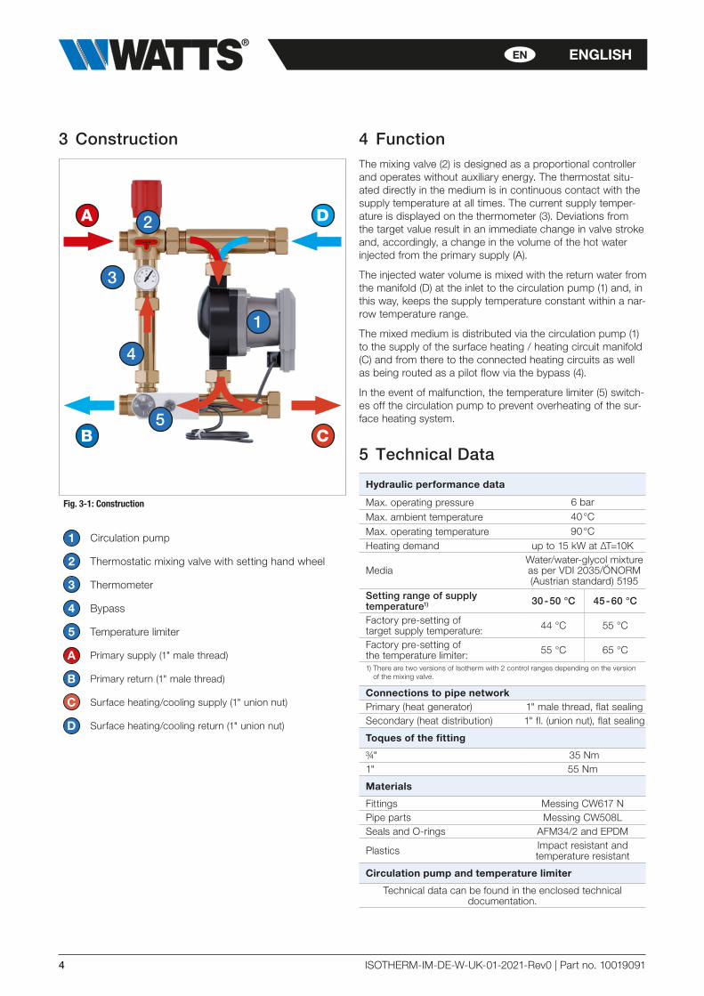
3 Construction
1
3
5
4
2
B
D
C
A
Fig. 3-1: Construction
1 Circulation pump
2 Thermostatic mixing valve with setting hand wheel
3 Thermometer
4 Bypass
5 Temperature limiter
A Primary supply (1" male thread)
B Primary return (1" male thread)
C Surface heating/cooling supply (1" union nut)
D Surface heating/cooling return (1" union nut)
4 FunctionThe mixing valve (2) is designed as a proportional controller and operates without auxiliary energy. The thermostat situ-ated directly in the medium is in continuous contact with the supply temperature at all times. The current supply temper-ature is displayed on the thermometer (3). Deviations from the target value result in an immediate change in valve stroke and, accordingly, a change in the volume of the hot water injected from the primary supply (A).
The injected water volume is mixed with the return water from the manifold (D) at the inlet to the circulation pump (1) and, in this way, keeps the supply temperature constant within a nar-row temperature range.
The mixed medium is distributed via the circulation pump (1) to the supply of the surface heating / heating circuit manifold (C) and from there to the connected heating circuits as well as being routed as a pilot flow via the bypass (4).
In the event of malfunction, the temperature limiter (5) switch-es off the circulation pump to prevent overheating of the sur-face heating system.
5 Technical Data
Hydraulic performance data
Max. operating pressure 6 bar
Max. ambient temperature 40 °C
Max. operating temperature 90 °CHeating demand up to 15 kW at ∆T=10K
MediaWater/water-glycol mixture as per VDI 2035/ÖNORM (Austrian standard) 5195
Setting range of supply temperature1) 30 - 50 °C 45 - 60 °C
Factory pre-setting of target supply temperature: 44 °C 55 °C
Factory pre-setting of the temperature limiter: 55 °C 65 °C
1) There are two versions of Isotherm with 2 control ranges depending on the version of the mixing valve.
Connections to pipe networkPrimary (heat generator) 1" male thread, flat sealingSecondary (heat distribution) 1" fl. (union nut), flat sealing
Toques of the fitting
¾" 35 Nm1" 55 Nm
Materials
Fittings Messing CW617 NPipe parts Messing CW508LSeals and O-rings AFM34/2 and EPDM
Plastics Impact resistant and temperature resistant
Circulation pump and temperature limiter
Technical data can be found in the enclosed technical documentation.

ISOTHERM-IM-DE-W-UK-01-2021-Rev0 | Part no. 10019091 5
ENENGLISH
6 Overall dimensions
212
287
ca. 98
G1"
G1"
37
216
116
1"Fl
.1"
Fl.
)(7
5
Fig. 6-1: Overall dimensions
7 Pressure loss diagram
1
10
100
1.000
10 100 1.000 10.000
KVS 4,5KV2 1,2KV1 0,6KV1 : Bypass
KV2 : Einspritzung / Injection
KVS : Verteilerseitig / Manifold side
Fig. 7-1: Pressure loss diagram
Flow rate [l/h]
Pre
ssur
e lo
ss [m
bar
]
6 ISOTHERM-IM-DE-W-UK-01-2021-Rev0 | Part no. 10019091
EN ENGLISH
8 Installation and commissioning
! DANGER Electrical energy!
Risk of death from electric shock.Work on parts carrying live voltage must be carried out by qualified electricians only.Disconnect the power supply of the system and secure it to prevent it from being switched on again before carrying out any installation, maintenance, cleaning or repair work.
NOTICE The installation and commissioning of
the ISOTHERM must be carried out only by trained per-sonnel who have been authorized by the manufacturer.
!! CAUTION When repairing the unit or replacing
parts, be sure to observe the specified installation posi-tions and flow directions of the parts being replaced!
!! CAUTION Material damage!
Pressure shocks may occur if the stop valve is opened or closed quickly.Always open and close the stop valves slowly and in a controlled way.
!! WARNING Hot water!
Risk of severe scalding.Do not reach into the hot water when emptying the ISOTHERM. Ensure that the ISOTHERM has cooled down before carrying out maintenance, cleaning and repair work.
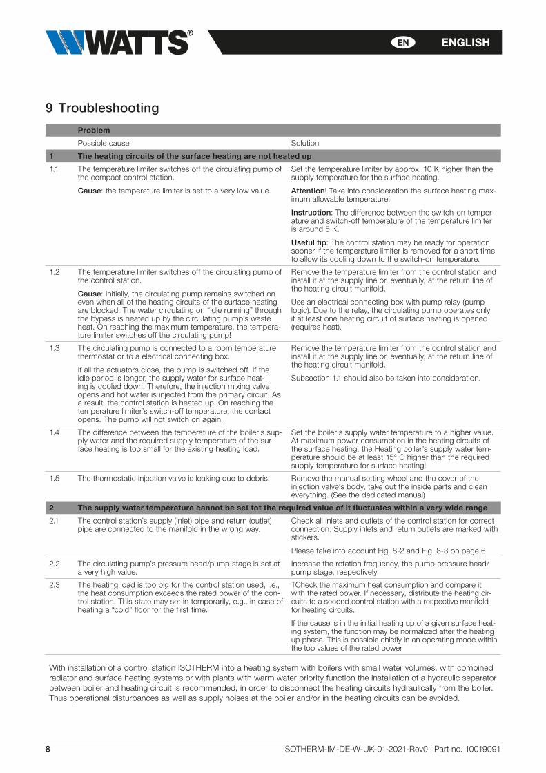
8.1 InstallationThe control station ISOTHERM is supplied ex-works for mounting to the left of the heating circuit manifold with an axis distance of 210 mm. If you want to mount it to the right of the heating circuit manifold, all you have to do is re-plug the thermometer (see Fig. 8-1).
Depending on space limitations and dimensions of the heat-ing circuit manifold, it may be necessary to rotate the pump in the axis of the screw connections. To do this, loosen the two union nuts on the pump, rotate the pump into the required position, and then tighten the screw connections while holding both the pump and the screw connection ele-ment in place.WW
Fig. 8-1
NOTICE We recommend installing a strainer witha mesh size of less than 0.8 mm upstream of the control station. This must be checked at regular intervals and cleaned if necessary.
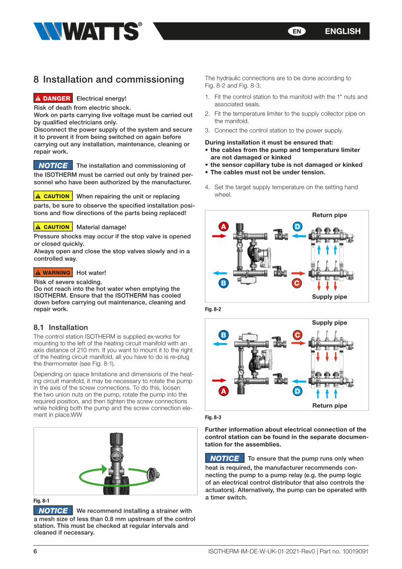
The hydraulic connections are to be done according to Fig. 8-2 and Fig. 8-3.
1. Fit the control station to the manifold with the 1" nuts and associated seals.
2. Fit the temperature limiter to the supply collector pipe on the manifold.
3. Connect the control station to the power supply.
During installation it must be ensured that:• the cables from the pump and temperature limiter
are not damaged or kinked • the sensor capillary tube is not damaged or kinked• The cables must not be under tension.
4. Set the target supply temperature on the setting hand wheel.
B
D
C
A
Supply pipe
Return pipe
Fig. 8-2
B
D
C
A
Supply pipe
Return pipe
Fig. 8-3
Further information about electrical connection of the control station can be found in the separate documen-tation for the assemblies.
NOTICE To ensure that the pump runs only when
heat is required, the manufacturer recommends con-necting the pump to a pump relay (e.g. the pump logic of an electrical control distributor that also controls the actuators). Alternatively, the pump can be operated with a timer switch.

ISOTHERM-IM-DE-W-UK-01-2021-Rev0 | Part no. 10019091 7
ENENGLISH
8.2 Temperature limiterIn the event of a fault, the temperature limiter switches off the circulation pump and so avoids overheating of the surface heating system.
• The factory setting of the temperature limiter is 55 °C or 65 °C, depending on the version.
• The temperature limiter must be fitted to the supply pipe of the control station heating circuit manifold.
8.3 Initial commissioningAll screw fittings must be checked and tightened if necessary prior to installation and commissioning!
Torques of the fittings:
¾" fittings: 35 Nm1" fittings: 55 Nm
1. Connect the control station to the pipe network.2. Fill, flush and vent the heating system.
NOTICE Flushing is permitted only in the direction
of flow of the heating circuits, i.e. the water must enter through the supply manifold pipe and come out of the return! The drain must always be open, as otherwise the high water pressure could damage the heating system. The instructions on flushing in the operating manual for the heating circuit manifold must also be observed.
8.4 Setting of the target supply temperatureIn the event of maximum heat output demand (rated output), the boiler supply temperature must be at least 15°C higher than the desired supply temperature in the surface heating circuit!
Factory setting of the target supply temperature is 44° C or 55 °C, depending on the version of the control station. The pilot pin is flush with the setting hand wheel face. By turning the setting hand wheel in minus "-" or plus "+" direction the target supply temperature is changed accordingly.
The hand wheel clicks with the rotation. Each "click" means a target temperature change of approx 1 °C.
Fig. 8-4: Factory setting
Reduction of the target supply temperature: by turning the setting hand wheel in the clockwise direction ("-").
If the pilot pin moves out from the setting hand wheel, this entails a lower target temperature (see Fig. 8-5 Reduction of the target supply temperature).
Each "click" in the clockwise direction reduces the target supply temperature by approx 1 °C.
Fig. 8-5: Reduction of the target supply temperature
Increase of the supply temperature set point: by turn-ing the setting hand wheel in the anti-clockwise direction ("+" direction).
If the pilot pin moves into the setting hand wheel, this entails a higher target temperature (see Fig. 8-6: Increase of the tar-get supply temperature).
Each "click" in the anti-clockwise direction rises the target temperature by approx 1 °C.
Fig. 8-6: Increase of the target supply temperature
The set temperature range is between 30 and 50 °C or 45 and 60 °C according to the version of ISOTHERM. However, the setting hand wheel can be turned fur-ther in both directions. This causes only small chang-es of the target temperature outside of the tempera-ture range.
8 ISOTHERM-IM-DE-W-UK-01-2021-Rev0 | Part no. 10019091
EN ENGLISH
9 Troubleshooting
Problem
Possible cause Solution
1 The heating circuits of the surface heating are not heated up
1.1 The temperature limiter switches off the circulating pump of the compact control station.
Cause: the temperature limiter is set to a very low value.
Set the temperature limiter by approx. 10 K higher than the supply temperature for the surface heating.
Attention! Take into consideration the surface heating max-imum allowable temperature!
Instruction: The difference between the switch-on temper-ature and switch-off temperature of the temperature limiter is around 5 K.
Useful tip: The control station may be ready for operation sooner if the temperature limiter is removed for a short time to allow its cooling down to the switch-on temperature.
1.2 The temperature limiter switches off the circulating pump of the control station.
Cause: Initially, the circulating pump remains switched on even when all of the heating circuits of the surface heating are blocked. The water circulating on “idle running” through the bypass is heated up by the circulating pump’s waste heat. On reaching the maximum temperature, the tempera-ture limiter switches off the circulating pump!
Remove the temperature limiter from the control station and install it at the supply line or, eventually, at the return line of the heating circuit manifold.
Use an electrical connecting box with pump relay (pump logic). Due to the relay, the circulating pump operates only if at least one heating circuit of surface heating is opened (requires heat).
1.3 The circulating pump is connected to a room temperature thermostat or to a electrical connecting box.
If all the actuators close, the pump is switched off. If the idle period is longer, the supply water for surface heat-ing is cooled down. Therefore, the injection mixing valve opens and hot water is injected from the primary circuit. As a result, the control station is heated up. On reaching the temperature limiter’s switch-off temperature, the contact opens. The pump will not switch on again.
Remove the temperature limiter from the control station and install it at the supply line or, eventually, at the return line of the heating circuit manifold.
Subsection 1.1 should also be taken into consideration.
1.4 The difference between the temperature of the boiler’s sup-ply water and the required supply temperature of the sur-face heating is too small for the existing heating load.
Set the boiler's supply water temperature to a higher value. At maximum power consumption in the heating circuits of the surface heating, the Heating boiler’s supply water tem-perature should be at least 15° C higher than the required supply temperature for surface heating!
1.5 The thermostatic injection valve is leaking due to debris. Remove the manual setting wheel and the cover of the injection valve's body, take out the inside parts and clean everything. (See the dedicated manual)
2 The supply water temperature cannot be set tot the required value of it fluctuates within a very wide range
2.1 The control station’s supply (inlet) pipe and return (outlet) pipe are connected to the manifold in the wrong way.
Check all inlets and outlets of the control station for correct connection. Supply inlets and return outlets are marked with stickers.
Please take into account Fig. 8-2 and Fig. 8-3 on page 6
2.2 The circulating pump’s pressure head/pump stage is set at a very high value.
Increase the rotation frequency, the pump pressure head/pump stage, respectively.
2.3 The heating load is too big for the control station used, i.e., the heat consumption exceeds the rated power of the con-trol station. This state may set in temporarily, e.g., in case of heating a “cold” floor for the first time.
TCheck the maximum heat consumption and compare it with the rated power. If necessary, distribute the heating cir-cuits to a second control station with a respective manifold for heating circuits.
If the cause is in the initial heating up of a given surface heat-ing system, the function may be normalized after the heating up phase. This is possible chiefly in an operating mode within the top values of the rated power
With installation of a control station ISOTHERM into a heating system with boilers with small water volumes, with combined radiator and surface heating systems or with plants with warm water priority function the installation of a hydraulic separator between boiler and heating circuit is recommended, in order to disconnect the heating circuits hydraulically from the boiler. Thus operational disturbances as well as supply noises at the boiler and/or in the heating circuits can be avoided.
ISOTHERM-IM-DE-W-UK-01-2021-Rev0 | Part no. 10019091 9
ENENGLISH
10 Maintenance
! DANGER Electrical energy!
Perform maintenance work on the ISOTHERM only when the power supply has been disconnected.
!! WARNING Hot water!
Risk of severe scalding.Do not reach into the hot water when emptying the ISOTHERM. Ensure that the ISOTHERM has cooled down before carrying out maintenance, cleaning and repair work.
!! WARNING Hot surfaces!Risk of serious burns.Do not touch the pipes or components during operation. Ensure that the ISOTHERM has cooled down before car-rying out maintenance, cleaning and repair work. Wear heat-resistant safety gloves if it is necessary to carry out work on hot components.
NOTICE Maintenance of the ISOTHERM must be
carried out only by trained personnel who have been authorized by the manufacturer.
10.1 Annual maintenance1. General visual inspection
• Check the control station for leaks and retighten sealing connections or replace seals, as required.
2. Functional check
• Check that settings and operating and performance parameters are set correctly.
• Check supply noise during operation.• Ask users if there are any noticeable problems.
3. Action to be taken following maintenance work
• Check that all screw fittings that were unscrewed have been retightened and retighten if necessary.
• Remove all tools, materials and other equipment used from the working area.
• Restore the power supply.• Slowly pressurize the ISOTHERM and vent it. • Readjust the system settings if required.
10.2 Replacement of wear partsPlease note that the ISOTHERM contains parts that, for tech-nical reasons, are subject to wear depending on the intensity of use, even if the specified care and maintenance has been provided. This applies especially to mechanical parts and parts that come into contact with water and steam, such as seals, valves, etc. By their nature, defects caused by wear do not constitute a fault and are therefore not covered by the warranty or any guarantee. Nevertheless, these defects and malfunctions must be remedied by trained specialist personnel only. Contact your specialist dealer for this.
Die im vorliegenden Produktdatenblatt enthaltenen Beschreibungen und Bilder dienen ausschließlich zu Informationszwecken und sind ohne Gewähr. Watts Industries behält sich das Recht auf technische und konstruktive Änderungen an seinen Produkten ohne vorherige Ankündigung vor.
Gewährleistung: Sämtliche Käufe und Kaufverträge setzen ausdrücklich die Anerkennung der Allgemeinen Verkaufs- und Lieferbedingungen durch den Käufer voraus, die auf der Website www.wattswater.de/agb zu finden sind. Watts widerspricht hiermit jeglicher abweichenden oder zusätzlichen Bedingung zu den Allgemeinen Verkaufs- und Lieferbedingungen, die dem
Käufer ohne schriftliche Zustimmung durch einen Watts-Verantwortlichen in irgendeiner Form mitgeteilt wurde.
ISOTHERM-IM-DE-W-UK-01-2021-Rev0 | Part no. 10019091
Watts Industries Deutschland GmbHGodramsteiner Hauptstr. 167 • 76829 Landau • Deutschland
Tel. +49 6341 9656 0 • Fax +49 6341 9656 [email protected] • www.wattswater.de
© 2021 Watts
11 Disposal
!! WARNING Potential for contamination of the
environment and groundwater from improper disposal!The legal regulations and guidelines in the country of operation must be observed when disposing of compo-nents and operating materials.
1. Ensure that all assemblies and components are de-energized.
2. Disassemble the ISOTHERM properly or commission a specialist company to do so.
3. Sort the assemblies and component parts into recyclable materials, hazardous substances and operating materials.
4. Dispose of the assemblies and components in accord-ance with local laws and regulations or take them to be recycled.
11.1 Return to the manufacturerGet in contact with the manufacturer if you would like to return the ISOTHERM or parts of it.
11.2 Notification of administrative bodies and the manufacturer
Inform the manufacturer of decommissioning and disposal of the ISOTHERMfor statistical purposes.
12 WarrantyWATTS products are tested extensively. WATTS there-fore guarantees only to replace or repair components of the products supplied free of charge – at the sole discretion of WATTS – if, in the opinion of WATTS, they exhibit verifia-ble manufacturing faults. Warranty claims due to defects or defects of titemperature limitere may be asserted within one (1) year of delivery/transfer of risk. Excluded from the warran-ty is damage attributable to normal product use or friction and to damage resulting from modifications or unauthorized repairs to the products, for which WATTS rejects all claims for compensation (direct or indirect). (For more detailed infor-mation, please refer to our website.) In all cases, supply is subject to the General Terms and Conditions, which can be found on www.wattswater.eu/gtc/.