
The Miniature Mars Meteorological Station
10
\I) Pergamon Acta Astronautica Vol. 35, Suppl., pp. 435-444, 1995 Elsevier Science Ltd. Printed in Great Britain 0094·5765(94)00209-6 THE MINIATURE MARS METEOROLOGICAL STATION Steven C. Merrihew Ph.D. Candidate, Aeronautics and Astronautics, Stanford University, Stanford, California 94305 Larry G. Lemke Aerospace Engineer, NASA Ames Research Center, Space Projects Division, Moffett Field, California 94035 Paul F. Wercinski Aerospace Engineer, NASA Ames Research Center, Aerothermodynamics Branch, Moffett Field, California 94035 ABSTRACT The Miniature Mars Meteorological (M3)Station is designed to provide the global measurements of atmospheric opacity, pressure and temperature required to characterize the martian climate. The M3 stations must be robust, lightweight and low cost to provide an effective Mars meteorological network of twenty surface stations. The design process for the M3 mission focuses on reducing cost, mass and operational complexity by striving for design simplicity. The candidate M3 surface station that has emerged from our study is the integrated aero-terrabrake hard lander. This system utilizes a common structure for both the atmospheric entry and surface deceleration functions. When coupled with an inflatable ballute system, this aero-terrabrake design simplifies the atmospheric entry, deceleration and landing operations. The M3 station design presented in this paper describes a network of small, simple surface stations that can be developed and delivered to Mars to provide global meteorological data. INTRODUCTION The exploration of Mars began with the Mariner 4 Flyby mission of 1965and continued through the end of the Viking missions in 1982. This fifteen years of robotic exploration has provided the planetary science community with a wealth of information regarding the geology, climate and composition of Mars. The bulk of this data, however, has been collected from orbit as only the two Viking landers have collected data directly from the planetary surface. Measurements made from the surface of Mars can uniquely contribute to the further understanding of planetary geological, meteorological and seismic processes. The nature of these planetary surface investigations often leads to the requirement for global networks of surface stations. One such global network is the Miniature Mars Meteorological (M3) station. The M3 station is designed to provide the pole-to-pole measurements of pressure, temperature and atmospheric opacity required to address the basic problems of global atmospheric circulation. The primary science requirements of the M3 mission are: twenty working stations globally emplaced on the martian surface (± 85 degrees latitude and all longitudes), access to all altitudes less than five kilometers and surface operation for an entire Mars year. Meteorological models will be constructed using frequent samples of pressure, temperature and atmospheric opacity. The vertical structure of the martian atmosphere is to be measured during the atmospheric entry phase of the mission. 435
Transcript of The Miniature Mars Meteorological Station

\I) PergamonActa Astronautica Vol. 35, Suppl., pp. 435-444, 1995
Elsevier Science Ltd. Printed in Great Britain0094·5765(94)00209-6
THEMINIATURE MARSMETEOROLOGICAL
STATION
Steven C. MerrihewPh.D. Candidate, Aeronautics and Astronautics, Stanford University, Stanford, California 94305
Larry G. LemkeAerospace Engineer, NASA AmesResearch Center, Space Projects Division, Moffett Field, California 94035
Paul F. WercinskiAerospace Engineer, NASA AmesResearch Center, Aerothermodynamics Branch, Moffett Field, California 94035
ABSTRACTThe Miniature Mars Meteorological (M3) Station is designed to provide the global measurements
of atmospheric opacity, pressure and temperature required to characterize the martian climate. The M3stations must be robust, lightweight and low cost to provide an effective Mars meteorological network oftwenty surface stations. The design process for the M3 mission focuses on reducing cost, mass andoperational complexity by striving for design simplicity. The candidate M3 surface station that hasemerged from our study is the integrated aero-terrabrake hard lander. This system utilizes a commonstructure for both the atmospheric entry and surface deceleration functions. When coupled with aninflatable ballute system, this aero-terrabrake design simplifies the atmospheric entry, deceleration andlanding operations. The M3 station design presented in this paper describes a network of small, simplesurface stations that can be developed and delivered to Mars to provide global meteorological data.
INTRODUCTIONThe exploration of Mars began with the Mariner 4 Flyby mission of 1965 and
continued through the end of the Viking missions in 1982. This fifteen years of roboticexploration has provided the planetary science community with a wealth of informationregarding the geology, climate and composition of Mars. The bulk of this data,however, has been collected from orbit as only the two Viking landers have collecteddata directly from the planetary surface. Measurements made from the surface of Marscan uniquely contribute to the further understanding of planetary geological,meteorological and seismic processes. The nature of these planetary surfaceinvestigations often leads to the requirement for global networks of surface stations.One such global network is the Miniature Mars Meteorological (M3) station. The M3station is designed to provide the pole-to-pole measurements of pressure, temperatureand atmospheric opacity required to address the basic problems of global atmosphericcirculation.
The primary science requirements of the M3 mission are: twenty workingstations globally emplaced on the martian surface (± 85 degrees latitude and alllongitudes), access to all altitudes less than five kilometers and surface operation for anentire Mars year. Meteorological models will be constructed using frequent samples ofpressure, temperature and atmospheric opacity. The vertical structure of the martianatmosphere is to be measured during the atmospheric entry phase of the mission.
435

436 Low-cost planetary missions
The driving assumptions in the design of the M3 mission are: launch in the 2000to 2004 time frame, availability of an orbiting communications relay at Mars and theautonomous operation of the surface stations. The M3 mission must be designed to besimple and rugged to ensure low development and operating costs.
M3 STATIONDESIGN
Study of Emplacement SchemesIt will soon become evident that the M3 mission design is dominated not by the
science payload nor the communications system, but by the descent and landingsystem. The significance of the atmospheric entry and landing phases is indicated by thenumber of alternative designs that have been proposed (see Table 1).
Table 1. Alternative Surface Station Emplacement SchemesEmplace- Atmospheric Atmosphericment Entry Descent Landing SystemScheme System SystemAirbag Blunt Cone Parachute Pros: simple, approx. 200 G impact(MESURl) Cons: all aspect protection, self righting or double
sided payload required, possible parachute foulingPropulsive Blunt Cone Parachute Pros: known lander attitude, low G landingLander Cons: sensors required for vertical and horizontal(Explorer-) velocity, lander site modified by exhaust blast and
combustion productsAutorotator Blunt Cone Autorotation Pros: simple, approx. 250 G impact, no fouling,
spinning at impact (potential stability aid)Cons: blade separation, potential tip-over,deployment, unproven concept
Terrabrake Integrated Ballute Pros: simple system, known lander attitude, noAero- fouling.Terrabrake Cons: approx. 500 G impact, penetration failure
potential
As is indicated in Table 1, each emplacement scheme presents a compromisebetween landing system complexity and ruggedness. The integrated aero-terrabrakewas selected as the baseline design due to it's inherent simplicity. By designing the aeroterrabrake structure as an integrated atmospheric entry shape and Mars soil penetratorthe requirement for separate structures and systems for the atmospheric entry and soilpenetration functions was eliminated, resulting in a more efficient overall design. Theaero-terrabrake design combined with an inflatable ballute decelerator also reduces therisk of payload fouling upon landing. The terrabrake surface penetration event providesa zenith pointing attitude for the science and communications systems, thereforeremoving the requirement for self-righting systems or double sided payloads.

Low-cost planetary missions 437
MissiQn PhasesThe M3 mission consists of several phases as depicted in Figure 1. Each mission
phase drives the overall M3 design, often in competing directions. FQr example, thelaunch, cruise and Mars arrival phase dictates that the M3 stations be small andlightweight while the surface impact event requires the structure to be large enough toprevent over-penetration and strong enough to survive impact loads.
~(J ~~
.b.b.b Sep"'lion Ph.se ~~~~~'::::lion
HypersonicEntryv~. 6 -7km/sect. Oseeh.1H ....
B. 30 kg/sq. m
V Maximum DecelerationNIna... 29,5gt_ "5 - SOsech. lOkmB .. 30kg/sq.m
~ Subsonic Deceleration
V.<0.'t_125sech.6-9kmB -10kg/sQ. m
Y u,r. ce lmp. CIV.75m/sec.
t .. 190He , SurfaceOperationsNmu- 500g
. -
Figure 1. M3 Mission Phases
A baseline M3 launch, cruise and Mars arrival scenario was selected early in themission design prQcess. A Delta II rocket is utilized to inject up tQ 900 kilograms into aminimum energy trajectory to Mars. Five M3 stations are placed on a spin stabilizedcarrier spacecraft for the interplanetary transfer. This carrier spacecraft will provide allin-flight communications, guidance, navigation and control, electrical pQwer andthermal control for the M3 stations. Upon arrival at Mars, the M3 stations will bedistributed both in latitude and longitude. The latitude separation is provided by theradial velocity imparted from the spin of the carrier spacecraft while longitudeseparation is provided by adjusting the time of arrival at the surface.
Upon separation from the carrier spacecraft, the M3 stations enter the Marsatmosphere with an inertial entry velocity from 6-7 km/sec depending on theinterplanetary trajectory, The entry velocity of the stations relative to the rotating Marsatmosphere will vary by up to ± 0.3 km/sec for posigrade or retrograde entriesrespectively. Prior to entering the atmosphere, the first stage ballute is deployed whichyields a ballistic coefficient of 30 kg/m2.
Figure 2 shQWS a proposed entry trajectory for a M3 station, Peak decelerationoccurs between 45 and 50 seconds after entry with a maximum value of 29.5 g's. When

438 Low-cost planetary missions
the station reaches a sub-sonic velocity of M < 0.9 (at altitudes between 6 - 9 km), thesecond stage ballute is deployed. The second stage ballute adds more drag-area to theentry vehicle, thus decreasing the ballistic coefficient to 10 kg/m2. The proposed secondstage ballute concept is based on designs presented in [aremenko-. The M3 stations aredesigned to impact with a velocity of 75 mlsec which will occur about 190seconds afteratmospheric entry.
8000 140000 30
7000 12000025
6000100000
i sooo ! ~ho
!i 80000 l!
i 4000 E i IS11 -e 60000... 3000
to40000
2000
1000 20000
0 0so 100
Time (sec)ISO 200
Figure 2. Atmospheric Entry Trajectory
The design goals for the impact phase of the mission are a maximum decelerationof 500 earth G's, a maximum penetration depth of less than the penetrator length, asmall angle of attack at impact and zenith pointing for the science payload. Fivehundred G's deceleration was selected as the upper bound as a considerable data baseexists from the Pioneer Venus and Galileo atmospheric probes for flight qualifiedinstrumentation at decelerations of up to 700G's.
Recent models of martian atmospheric circulation indicate that winds can attainvelocities of 40 meters per second at the equator. Reducing the angle of attack (the anglebetween the velocity vector and the terrabrake's vertical axis) requires an increasedterminal velocity which in turn increases the impact deceleration. A terminal verticalvelocity of 75 meters per second was selected as the best compromise between angle ofattack and impact deceleration.
Extensive iterations using an impact analysis programs-f to determine axialdeceleration, velocity and penetration depth as a function of time were performed forvarious terrabrake configurations. Figure 3 presents the results of the impact simulationfor the baseline terrabrake configuration depicted in Figure 4. The plots of decelerationand depth are presented for three soil types ranging from solid ice to loose topsoilwhich are approximate terrestrial analogs of martian soil conditions. As expected, thedecelerations are greatest and the depth of penetration is the least for penetration intosolid ice. Careful tailoring of the dimensions of the first and second conic sections limitsthe peak decelerations below 500 G's even in the hardest of the simulated soils. Over-

Low-cost planetary missions 43<,)
penetration is avoided by providing a final flare on the terrabrake body which halts theterrabrake at a total depth of 136em in the softest soil modeled.
---D- Loose Topsoil
_Loose Sand
-tr-Ice
500
400
§300s
~wulow 2000
100
0
0 5 10 15TIME (msec)
20 25 30
2
1.5
0.5
Figure 3. Impact Deceleration and Depth as a Function of Time
Concerns common to terrabrake and penetrator designs include the potential forfailure due to rock impact or excessive angle of attack or angle of impact (the anglebetween the velocity vector and the ground plane). An extensive database of earthpenetration tests is available primarily from tests conducted at Sandia NationalLaboratories. Earth penetrators have been employed by the thousands as intrusiondetectors in South East Asia (with a gross success rate of 85 percents) and dropped onpolar ice caps in order to determine the thickness of the ice, to name a few cases. A fieldtest performed in support of an earlier Mars penetrator mission study conductedsuccessful penetration tests into both lava fields and loess soils>. The same study foundthat the probability of a penetrator impacting a rock within the Viking 1 lander site(with a size comparable to its diameter of 0.09 meters) to be only 0.09. Recentsimulations of terrabrake impacts in a Viking 1 lander site rock field indicate thatroughly four rocks of significant dimension (greater than 0.125 meters in diameter) willlie within 0.25 meters of the impact point. It has been found that an angle of attack ofroughly two degrees or an angle of impact of roughly thirty degrees can result in lateralloads equivalent to the axial impact loads. Effects of angle of attack or impact on thesuccess of the penetration event are design dependent and as such would requireadditional study and experimentation.
The science gathering operations of the M3 station begin during the descentthrough the atmosphere of Mars. The Atmospheric Structure Instrument (ASI) consistsof a three axis accelerometer, a pressure probe and a temperature probe. The ASI will

440 Low-cost planetary missions
operate for approximately five minutes, collecting acceleration data from approximately100 km altitude to 6 km altitude whereupon pressure and temperature data are thencollected from probes deployed into the free stream. The ASI data is stored in on boardmemory for transmittal following the surface impact phase.
Once emplaced on the surface, the M3 station initiates the long duration surfacescience mission. Designed to operate for an entire Mars year (687days), the M3 stationmust function in temperatures ranging from a maximum of 20°C at the equator to -140°C near the poles with daily variations up to 110° C while in the tenuous martianatmosphere (0.007 bar at the surface). The data collection scheme presented in Table 2 isdesigned to provide the maximum science return within the limited power available.Note that a sol is one Mars day, or 24.6 hours.
3Table 2. M Station Surface OperationsData Type bits/word samples/sol bits/sol
Pressure 9 25 225Atmospheric Opacity 8 13 104Temperature 9 25 225Temperature Mean 9 25 225Temperature Variance 9 25 225Time Update 8 1 8
Subtotal = n/a n/a 101225%Engineering Margin = n/a n/a 253
Total = n/a n/a 1265
The temperature mean and variance provide data on the temperature statisticsduring each approximately hour long measurement period. The temperatureinstrument is operated continuously while the atmospheric opacity and pressuresensors are operated for roughly 2 minutes per hour (daylight only for the atmosphericopacity sensor). Operation of the high latitude stations will be affected by the seasonaladvance and retreat of the polar ice caps as the communications antenna may be buriedby ice. In this case, all science data (excluding the atmospheric opacity data) will berecorded into the 0.5 megabits of non-volatile RAM (approximately 300 days worth ofstorage space) for playback at a later date. This data is transmitted to a communicationsrelay satellite in a sun-synchronous orbit 4209 km above Mars. This communicationsrelay is typically visible for more than 80 minutes each sol/.
SubsystemsThe design of the M3 station structure is driven by the surface impact event. The
exterior configuration must be designed to dissipate the kinetic energy of impactthrough soil work such that the deceleration does not exceed 500 G's while the internalstructure is designed to support the payload and maintain overall integrity. Thestructure must also survive the heating caused by atmospheric entry and deceleration.The layout of the structural elements of the M3 station is presented in Figure 4. Thestructural design is roughly similar to that proposed for the Comet Penetrator proposedfor the Comet Rendezvous Asteroid Flyby missions. The 1.5 meter long and 1.0 meterdiameter terrabrake structure is constructed of titanium. For improved thermal control
Low-cost planetary missions 441
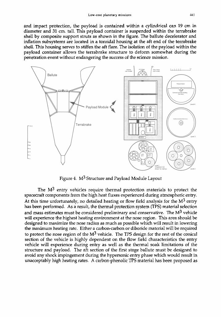
and impact protection, the payload is contained within a cylindrical can 19 em indiameter and 31 cm. tall. This payload container is suspended within the terrabrakeshell by composite support struts as shown in the figure. The ballute decelerator andinflation subsystems are located in a toroidal housing at the aft end of the terrabrakeshell. This housing serves to stiffen the aft flare. The isolation of the payload within thepayload container allows the terrabrake structure to deform somewhat during thepenetration event without endangering the success of the science mission.
Payload Module<
I I t ' ' I ,
Figure 4. M3 Structure and Payload Module Layout
The M3 entry vehicles require thermal protection materials to protect thespacecraft components from the high heat fluxes experienced during atmospheric entry.At this time unfortunately, no detailed heating or flow field analysis for the M3 entryhas been performed. As a result, the thermal protection system (TPS) material selectionand mass estimates must be considered preliminary and conservative. The M3 vehiclewill experience the highest heating environment at the nose region. This area should bedesigned to maximize the nose radius as much as possible which will result in loweringthe maximum heating rate. Either a carbon-carbon or diboride material will be requiredto protect the nose region of the M3 vehicle. The TPS design for the rest of the conicalsection of the vehicle is highly dependent on the flow field characteristics the entryvehicle will experience during entry as well as the thermal soak limitations of thestructure and payload. The aft section of the first stage ballute must be designed toavoid any shock impingement during the hypersonic entry phase which would result inunacceptably high heating rates. A carbon-phenolic TPS material has been proposed as

442 Low-cost planetary missions
the TPS for the conical body but lower density ablators may be used if more detailedflow field and heating analysis establishes better heating estimates.
The M3 science payload is composed of two sets of instruments, the AtmosphericStructure Instrument (ASI) and the surface science package (Figure 4). The ASI, basedon the design utilized in the Viking missions'', consists of a three axis accelerometer, afree stream probe connected to the surface science pressure sensor and a free streamtemperature sensor. During the high speed portion of the atmospheric entry (aboveapproximately Mach 2) the atmospheric state properties of pressure, temperature anddensity can be determined as a function of altitude from probe acceleration data and theinitial conditions of entry. Pressure and temperature may be sampled directly duringthe low speed portion of the descent. The accelerometer utilizes a guidance qualityservo sensor along the vertical axis with two simpler piezoelectric type sensors alignedwith the transverse axes. A Kiel pressure probe, a ducted pitot probe which isinsensitive to angle of attack, is used port the free stream pressure to the surface sciencepressure sensor. The free stream temperature is sensed with an array of thermocouplesdeployed from the body of the M3 station. The approximately 150 kbits of data collectedby the ASI is easily stored in the on board RAM and transmitted following the surfaceimpact event.
The surface science package is configured as depicted in Figure 4. The baselineinstruments are: a silicon capacitive absolute pressure sensor based on the Mars '94sensor by Vaisala of Pinlandl" with a range of 1 to 15 mbar and an accuracy of 0.06mbar, a thermocouple or resistance thermometer with a range of 130 to 320 K and anaccuracy of approximately 0.5 K and a hemispherical array of photodiodes to measureatmospheric opacity with an accuracy of approximately 10%11. The pressure sensormust be provided with an unobstructed inlet, the temperature probe is to be deployedon a 1 meter flexible mast to limit the thermal effects of the M3 station and theatmospheric opacity sensor requires an unobstructed view approximately 60 degreeswide centered on the local vertical axis. Each instrument is paired with a local amplifierto limit signal degradation due to cable losses. Current research underway at the JetPropulsion Laboratory is focused on the development of miniature versions of each ofthese instruments for the MESURNetwork missionl-. These newer technologies may besubstituted for the baseline instruments if warranted by the development program.
The design of the communications subsystem is greatly simplified by theassumed availability of a communications orbiter. The communications subsystemutilizes a 0.3 Watt (input) UHF-band transmitter and an omnidirectional antenna totransmit the 1265 bits of data per sol at an average rate of approximately 130 bits perminute (assuming a conservative communications window of 10 minutes each sol). Asan historical reference, the Viking Landers utilized a UHF link to transmit up to 16kilobits per second to the Viking Orbiters from a 30 Watt transmitter. The processor andmemory sub-system controls the scheduling, power distribution, AID conversion,calculations (temperature mean and variance) and data recording functions for thestation. The communications windows are initiated by a transmission from the orbiter.Once the surface station receives the orbiter's signal the data is transmitted with a tagindicating the serial number, and hence the location, of that particular station. The

Low-cost planetary missions 443
capability to receive a signal prior to transmittal serves to minimize the power requiredfor the communications system (see Table 3 for detailed power requirements).
The requirement for operation at all latitudes on Mars for 687 days following anapproximately nine month long transit to Mars and a 500 G landing impact presents achallenge for the design of the electrical power supply. The power requirements areapproximately 3.6 and 0.5 Watts respectively for periods of transmitting and nontransmitting (see Table 3). The traditional options for such a power supply include solarpower arrays and Radioisotope Thermoelectric Generators (RTG's). Solar arrays can beimmediately discounted as an option due to the requirement for continuous operationof the M3 station at all latitudes. The low power levels required also tend to discountthe classical RTG implementation as utilized by the Viking landers. The selected powersupply is based on the Power Stick, a Radioisotope Heating Unit (RHU) based powersource conceived by the Jet Propulsion Laboratory. The M3 station electrical powersubsystem design utilizes six 238Pu02 fueled RHUs, each producing 1.1 Watts ofthermal power. This thermal power is converted into electrical power using leadtelluride thermoelectric converters operating at 5% efficiency. The resulting designprovides a steady state power output of 240 mW, which when coupled to fourteenLiTiS2 AA battery cells (one Ah each), provides more than adequate power for theoperation of the M3 station. The RHU based power supply is compact and robust. Asignificant advantage of the RHU based power supply is the availability of generousheating for the electronics. Total mission cost, as well as launch approval processcomplexity, is reduced by utilizing a limited number of these flight qualified and launchsafety approved RHUs as opposed to a new RTGbased design.
The integration of the subsystems, including the terrabrake structure, the thermalprotection system (TPS) and the aerodynamic decelerator is summarized in Table 3. TheM3 station concept can be divided into two primary elements as shown in Table 3: thepayload container and the delivery system.
Table 3. M3 Mass and PowerSubsystem Mass (kg) Power(W)
Surface Science 0.90 0.27Atmospheric Structure Instrument 0.90 4.20 *Communications 2.20 2.55 ** -- 0,05 ***Command and Data Handling 1.00 0.05Electrical Power 1.42 n/aThermal Control 1.20 n/aPayload Container Structure 1.88 n/a
Payload Container Subtotal = 9.50 2.87 ** -- 0.36 ***Terrabrake Structure 24.7 n/aThermal Protection System 13.1 n/aAerodynamic Decelerator System 8.1 n/a
Subtotal = 55.4 2.87 ** -- 0.36 ***25 % Margin = 13.8 0.71 ** -- 0.09 ***
M3 Station Total = 69.2 3.58 ** -- 0.47 **** Atmospheric Entry event only*** Non-Communications period
** Communications period

444 Low-cost planetary missions
CONCLUSIONThe near term exploration of Mars should include orbiters, surface rovers and
networks of surface stations. The Miniature Mars Meteorological Station presented inthis paper satisfies the requirement for a simple, low cost global network for the studyof the martian climate. The innovative aero-terrabrake concept utilizes astraightforward and robust design to emplace twenty or more surface stations for themeasurement of pressure, temperature and atmospheric opacity.
The integration of the science payload, subsystems and aero-terrabrake structurediscussed in this paper results in a simple and robust M3 station that promises to satisfythe requirement for global characterization of the martian climate.
ACKNOWLEDGMENTSContributions to the work described here have been made by, among others, R.
Haberle (science goals and requirements) and R. Ramos (communications).
REFERENCES
1. Hubbard, S. G., et. al.: "Mars Environmental Survey (MESUR): Feasibility of a Low Cost GlobalApproach", Space Technology, Vol. 13, Number 4, pp. 363-370, July 1993
2. Lemke, L., Wercinski, P.: "The Mars Explorer -- A Smaller, Cheaper, Faster Human ExplorationPrecursor Mission", The Fourth Annual Symposium of the University of Arizona/NASA SpaceEngineering Research Center for Utilization of Planetary Resources, pp. 184-191, AIS-93, Feb. 1993
3. [aremenko, I. M.: "BALLUTE Characteristics in the 0.1 to 10 Mach Number Speed Regime",AIAA 67-558, Jan. 23, 1967
4. Wercinski, P. F.: "A Users Guide to IMPACT, A penetrator Impact Trajectory Analysis Program",NASA Ames Research Center, 1986
5. Young, C. W.: "Empirical Equations for Predicting Penetration Performance in Layered EarthMaterials for Complex Penetrator Configurations", SC-DR-720523, Sandia National Laboratories,1972
6. Manning, L. A.: "Mars Surface Penetrator - System Description", NASA TM-73243, NASA AmesResearch Center, June 1977
7. Chicarro, A. F., et. al.: "MARSNET, Report on the Phase A Study", ESA, April 19938. Boynton, W. V.: "A Cornet Penetrator for In-Situ Cornet Nuclear Analysis, Volume I: Technical Plan",
A Proposal to the National Aeronautics and Space Administration Solar System ExplorationDivision for the Cornet Rendezvous Asteroid Flyby (CRAF) Mission in Response toAO #OSSA-3-85, University of Arizona, Ball Aerospace
9. Seiff, A.: "The Viking Atmosphere Structure Experiment - Techniques, Instruments and ExpectedAccuracies", NASA Ames Research Center, Space Science Instrumentation, Vol. 2, pp. 381-423,1976
10. "METEGG Surface Stations for the Soviet Mars-94 Mission, Phase A2 Study Report", FinnishMeteorological Institute, Helsinki Finland, August 1989
11. Applebaum, J.: "A Solar Radiation Sensor for Mars", NASA LeRC Directors Discretionary Fund, 199112. Tillman, J. E., Crisp, D., Kaiser, W. J., VanZandt, T. R, Hoenk, M. E.: "Meteorological Measurements
in the Martian Planetary Boundary Layer: Instrumentation and Data Handling Strategies for theMESUR Mission", 1993